Embed Size (px)
Citation preview
The Wye-Delta Center Tapped Transformer Bank
W. H. KerstingWayne Carr
Milsoft Utility Solutions
1
Introduction
• Loads to be served– Three-phase induction motor– 120/240 volt single-phase loads
• Transformer connection– Grounded wye-delta– Ungrounded wye-delta
• The question is should the neutral be grounded, grounded through an impedance or ungrounded?
2
General Thoughts on Grounding
• Always taught that the grounded wye-delta is preferred because when a primary phase is open the secondary will still provide three-phase voltages.
• Always taught that if the neutral is ungrounded upon the loss of a primary phase the secondary will become single-phase.
3
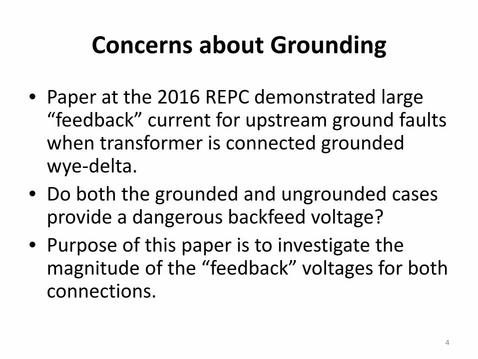
Concerns about Grounding
• Paper at the 2016 REPC demonstrated large “feedback” current for upstream ground faults when transformer is connected grounded wye-delta.
• Do both the grounded and ungrounded cases provide a dangerous backfeed voltage?
• Purpose of this paper is to investigate the magnitude of the “feedback” voltages for both connections.
4
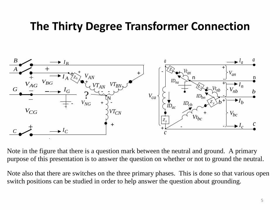
The Thirty Degree Transformer Connection
N
+ +
- -
-
+
+
ANV
ANVT
CNVT
+0Z
+
-
+
-
-
+
+-
+-
n
+
-
+
- nanVt
nbVt
bcVt
caVnbV
bcV
cI
bI
nI
aI
1Z
yZ
zZ
2Z
cbIDacID
a
b
c
?NGV +-
BI+
AGV BNVT
CGV
BGV
CI
GI
anV
a
c
b
AInaID
bnID
+
AB
G
C
Note in the figure that there is a question mark between the neutral and ground. A primary purpose of this presentation is to answer the question on whether or not to ground the neutral. Note also that there are switches on the three primary phases. This is done so that various open switch positions can be studied in order to help answer the question about grounding.
5
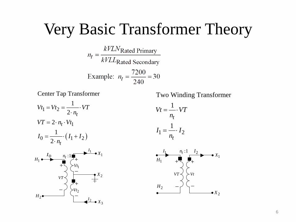
Very Basic Transformer Theory
6
+_
+_
1Vt
2Vt
+
_
VT
0I :1tn1H
2H
1X
2X
3X
1I
2I
+ +
_ _VtVT
1I 2I:1tn1X
2X
1H
2H
1 2
Two Winding Transformer1
1t
t
Vt VTn
I In
= ⋅
= ⋅( )
1 2
1
0 1 2
Center Tap Transformer1
221
2
t
t
t
Vt Vt VTn
VT n Vt
I I In
= = ⋅⋅
= ⋅ ⋅
= ⋅ +⋅
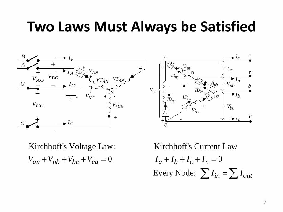
Two Laws Must Always be Satisfied
N
+ +
- -
-
+
+
ANV
ANVT
CNVT
+0Z
+
-
+
-
-
+
+-
+-
n
+
-
+
- nanVt
nbVt
bcVt
caVnbV
bcV
cI
bI
nI
aI
1Z
yZ
zZ
2Z
cbIDacID
a
b
c
?NGV +-
BI+
AGV BNVT
CGV
BGV
CI
GI
anV
a
c
b
AInaID
bnID
+
AB
G
C
7
Kirchhoff's Voltage Law: Kirchhoff's Current Law0 0
Every Node: an nb bc ca a b c n
in out
V V V V I I I II I
+ + + = + + + =
=∑ ∑
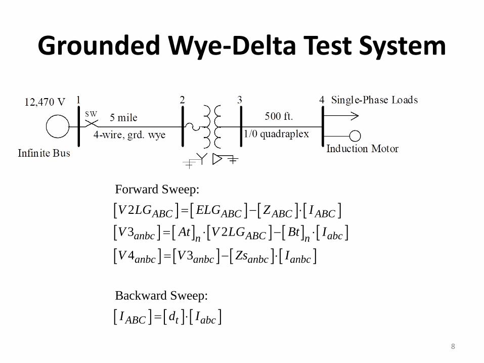
Grounded Wye-Delta Test System
[ ] [ ] [ ] [ ][ ] [ ] [ ] [ ] [ ][ ] [ ] [ ] [ ]
[ ] [ ] [ ]
Forward Sweep:2
3 2
4 3
Backward Sweep:
ABC ABC ABC ABC
anbc ABC abcn n
anbc anbc anbc anbc
ABC t abc
V LG ELG Z I
V At V LG Bt I
V V Zs I
I d I
= − ⋅
= ⋅ − ⋅
= − ⋅
= ⋅
8
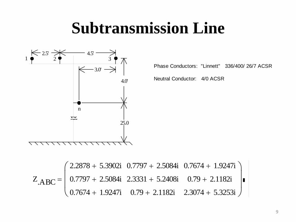
Subtransmission Line
4.0'
2.5' 4.5'
3.0'
3
n
25.0
21Phase Conductors: "Linnett" 336/400/ 26/7 ACSR
Neutral Conductor: 4/0 ACSR
Z.ABC
2.2878 5.3902i+
0.7797 2.5084i+
0.7674 1.9247i+
0.7797 2.5084i+
2.3331 5.2408i+
0.79 2.1182i+
0.7674 1.9247i+
0.79 2.1182i+
2.3074 5.3253i+
=
9
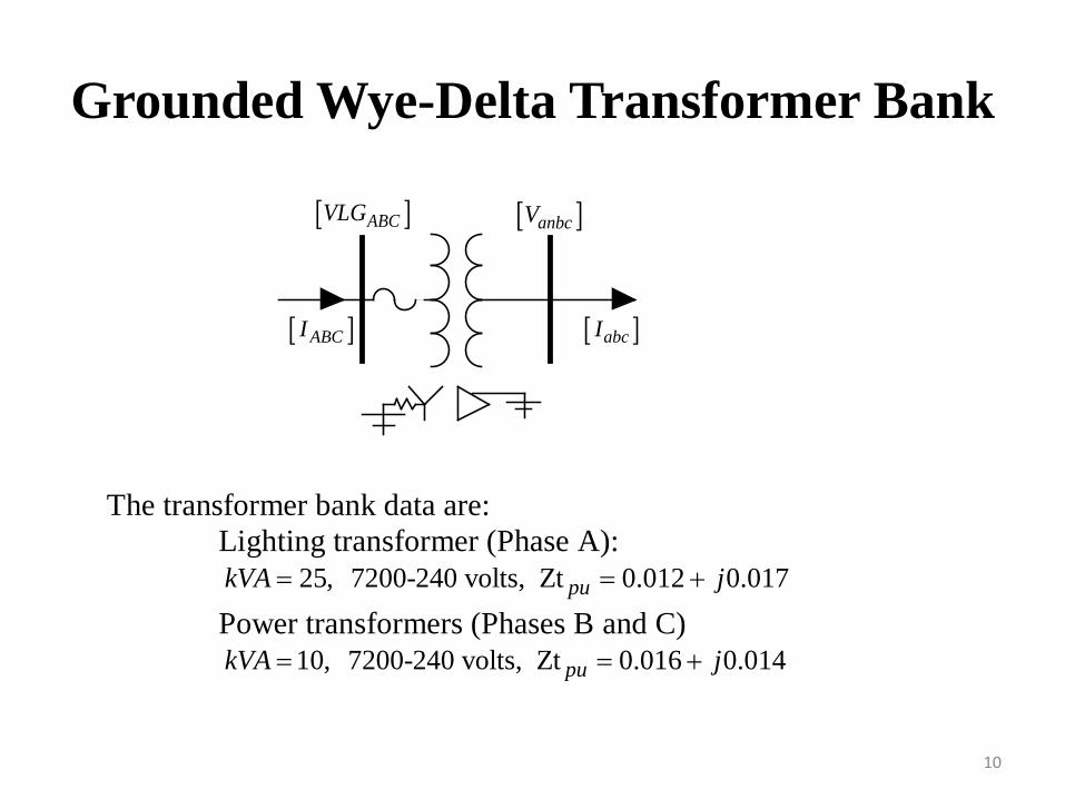
Grounded Wye-Delta Transformer Bank
10
The transformer bank data are: Lighting transformer (Phase A): 25, 7200-240 volts, Zt 0.012 0.017pukVA j= = + Power transformers (Phases B and C) 10, 7200-240 volts, Zt 0.016 0.014pukVA j= = +
[ ]ABCVLG [ ]anbcV
[ ]ABCI [ ]abcI
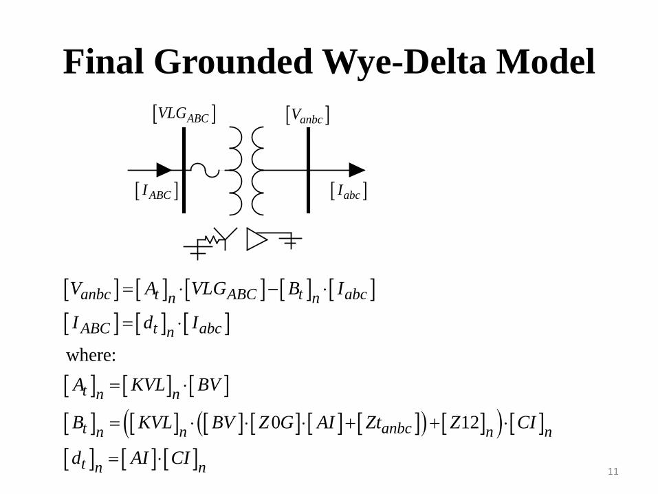
Final Grounded Wye-Delta Model[ ]ABCVLG [ ]anbcV
[ ]ABCI [ ]abcI
11
[ ] [ ] [ ] [ ] [ ][ ] [ ] [ ]
[ ] [ ] [ ][ ] [ ] [ ] [ ] [ ] [ ]( ) [ ]( ) [ ][ ] [ ] [ ]
where:
0 12
anbc t ABC t abcn n
ABC t abcn
t nn
t anbcn n nn
t nn
V A VLG B I
I d I
A KVL BV
B KVL BV Z G AI Zt Z CI
d AI CI
= ⋅ − ⋅
= ⋅
= ⋅
= ⋅ ⋅ ⋅ + + ⋅
= ⋅
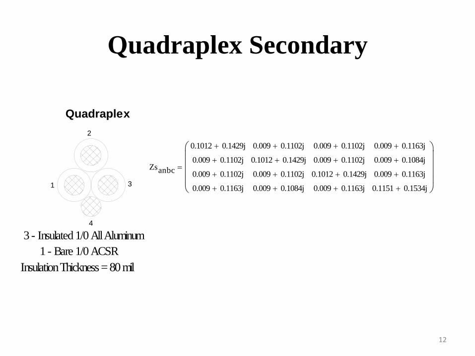
Quadraplex Secondary
Quadraplex
4
1
2
3
3 - Insulated 1/0 All Aluminum1 - Bare 1/0 ACSR
Insulation Thickness = 80 mil
Zsanbc
0.1012 0.1429j+
0.009 0.1102j+
0.009 0.1102j+
0.009 0.1163j+
0.009 0.1102j+
0.1012 0.1429j+
0.009 0.1102j+
0.009 0.1084j+
0.009 0.1102j+
0.009 0.1102j+
0.1012 0.1429j+
0.009 0.1163j+
0.009 0.1163j+
0.009 0.1084j+
0.009 0.1163j+
0.1151 0.1534j+
=
12
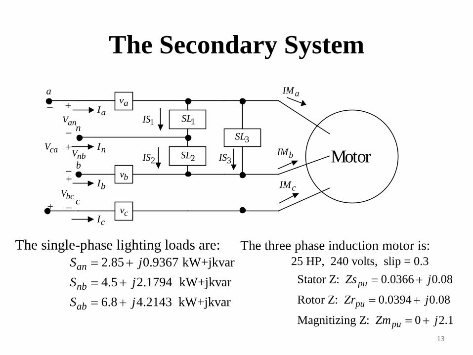
The Secondary System
13
The three phase induction motor is:
25 HP, 240 volts, slip = 0.3 Stator Z: 0.0366 0.08
Rotor Z: 0.0394 0.08
Magnitizing Z: 0 2.1
pu
pu
pu
Zs j
Zr j
Zm j
= +
= +
= +
The single-phase lighting loads are:
2.85 0.9367 kW+jkvar4.5 2.1794 kW+jkvar6.8 4.2143 kW+jkvar
an
nb
ab
S jS jS j
= +
= +
= +
1IS
2IS bIM3IS
cIM
aIM
1SL
2SL3SL
bcV
_anV
_ +
+ _
+
+
_ b
n
c
nbVcaV
aI
nI
bI
cI
av
bv
cv
a
Motor
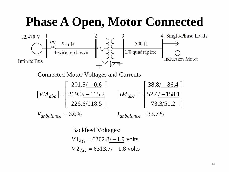
Phase A Open, Motor Connected
14
Backfeed Voltages:1 6302.8/ 1.9 volts2 6313.7/ 1.8 volts
AG
AG
VV
= −
= −
[ ] [ ]
Connected Motor Voltages and Currents201.5/ 0.6 38.8/ 86.4
219.0/ 115.2 52.4/ 158.1226.6/118.5 73.3/51.2
6.6% 33.7%
abc abc
unbalance unbalance
VM IM
V I
− − = − = − = =
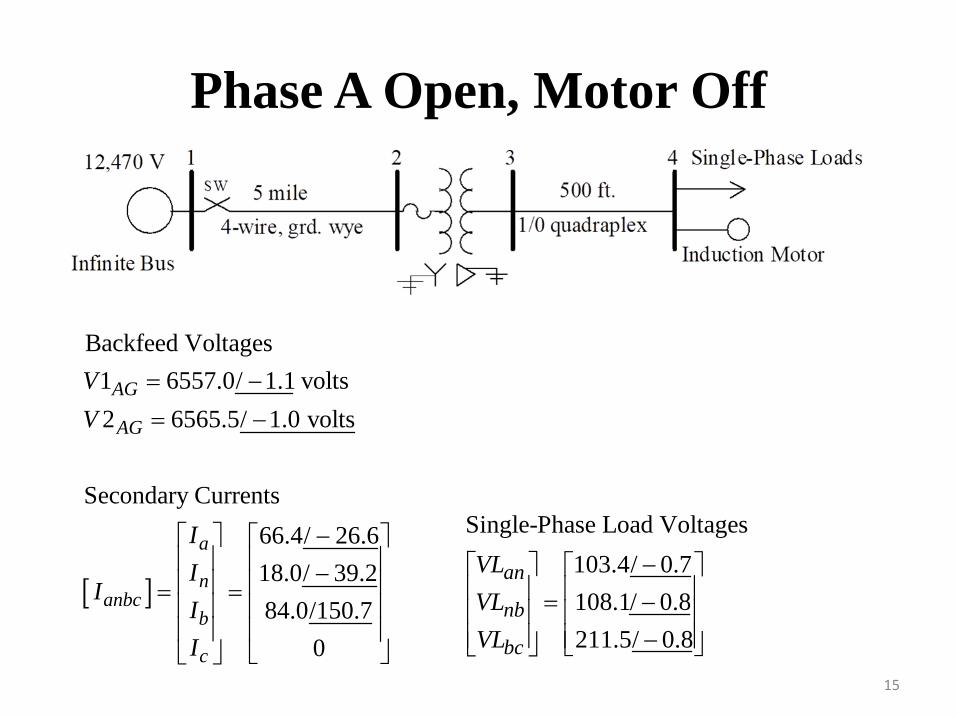
Phase A Open, Motor Off
15
[ ]
Backfeed Voltages1 6557.0/ 1.1 volts2 6565.5/ 1.0 volts
Secondary Currents66.4/ 26.618.0/ 39.284.0/150.7
0
AG
AG
a
nanbc
b
c
VV
II
III
= −
= −
− − = =
Single-Phase Load Voltages103.4/ 0.7108.1/ 0.8211.5/ 0.8
an
nb
bc
VLVLVL
− = − −
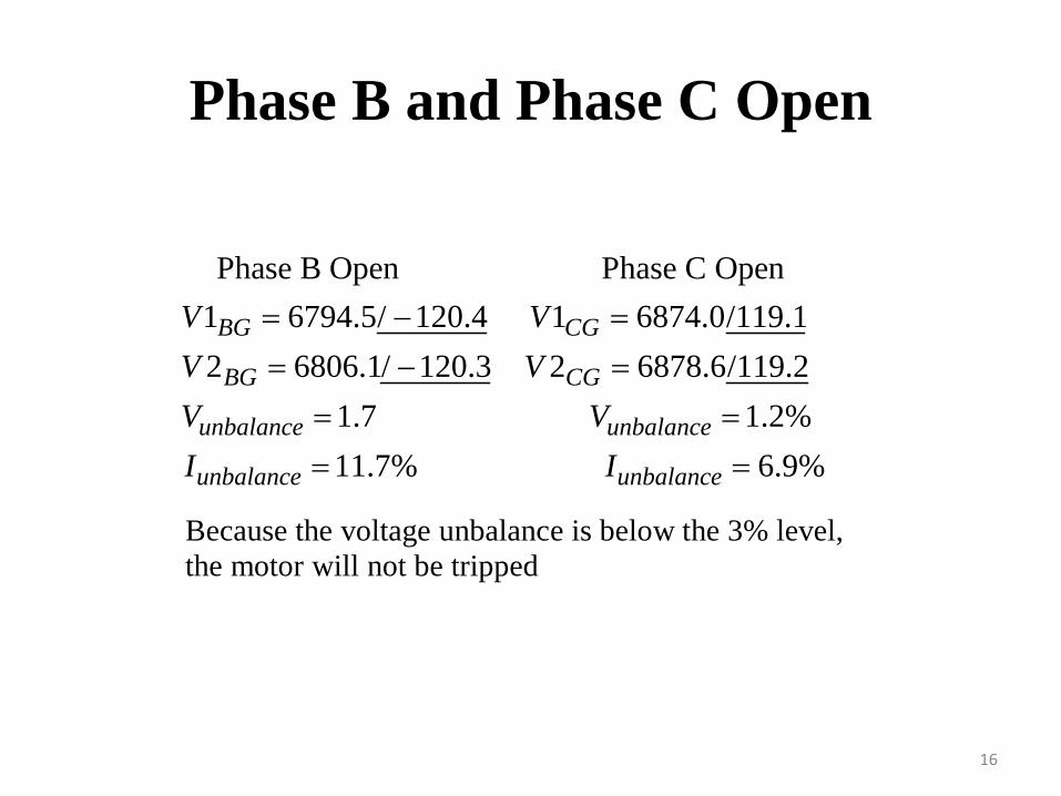
Phase B and Phase C Open
16
Phase B Open Phase C Open1 6794.5/ 120.4 1 6874.0/119.12 6806.1/ 120.3 2 6878.6/119.2
1.7 1.2%11
BG CG
BG CG
unbalance unbalance
unbalance
V VV VV VI
= − =
= − =
= =
= .7% 6.9%unbalanceI =
Because the voltage unbalance is below the 3% level, the motor will not be tripped
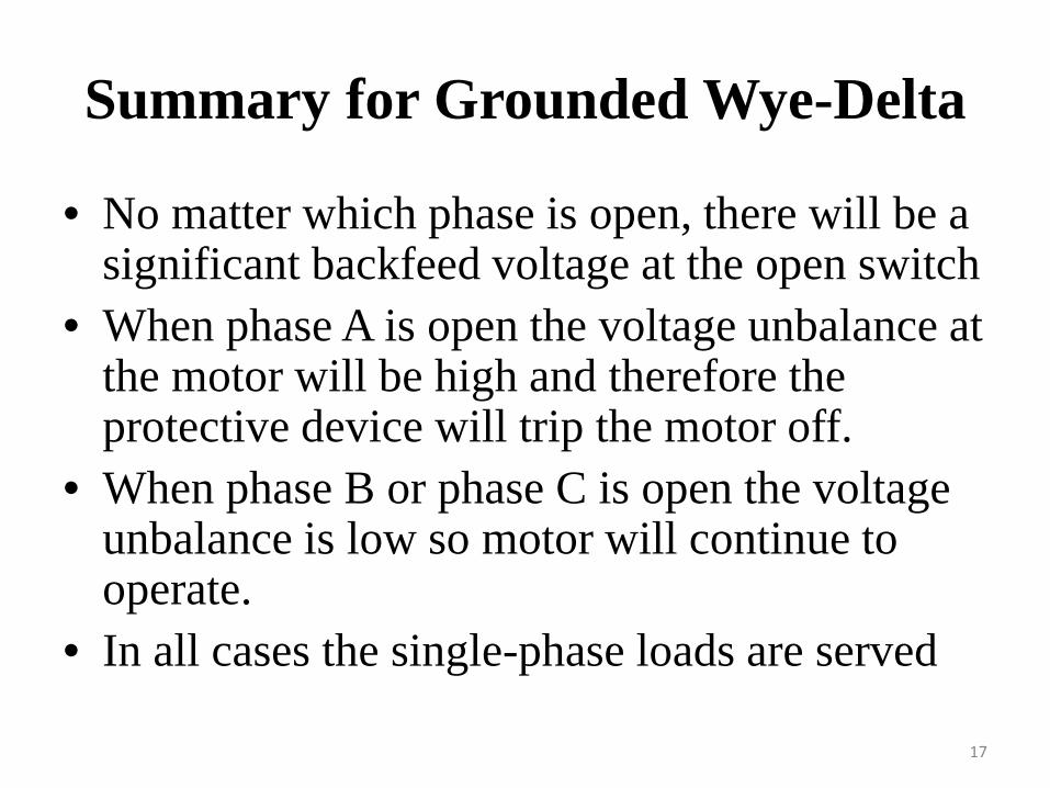
Summary for Grounded Wye-Delta
• No matter which phase is open, there will be a significant backfeed voltage at the open switch
• When phase A is open the voltage unbalance at the motor will be high and therefore the protective device will trip the motor off.
• When phase B or phase C is open the voltage unbalance is low so motor will continue to operate.
• In all cases the single-phase loads are served
17
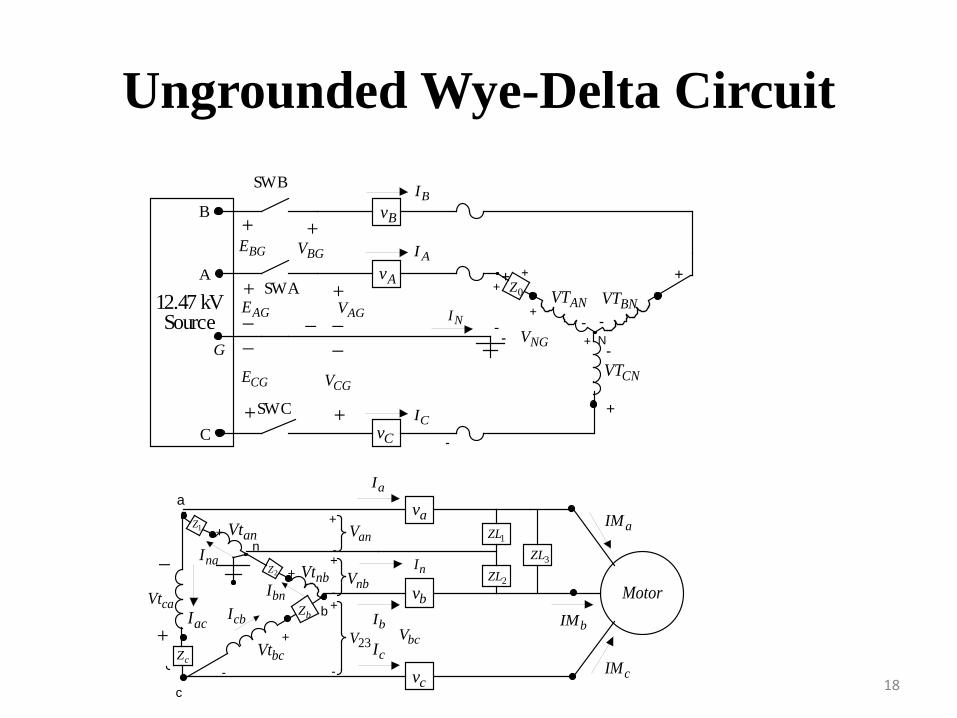
Ungrounded Wye-Delta Circuit
18
N
+ +
- -
-
+
+
++
+
-- NGV
Cv
Bv
AvANVT BNVT
CNVT
0Z
Source NI
B
G
A
C
+
_+__
+
AGV
CGV
BGV
SW B
SW AAGE
BGE
+__
+CGE
SW C
+
12.47 kV
AI
BI
CI
a
+
-
+
-
+-
+
-
n
+
-
+
-
23V
av
bv
cv
Motor
anVt
nbVt
bcVtacI
bnI
naI
cbI+
_
caVt
c
b
bcV
anV
nbV nI
aIM
cIM
bIM
2Z
bZ
cZ
1Z1ZL
2ZL3ZL
aI
bI
cI
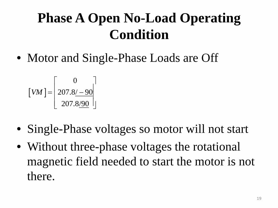
Phase A Open No-Load Operating Condition
• Motor and Single-Phase Loads are Off
• Single-Phase voltages so motor will not start• Without three-phase voltages the rotational
magnetic field needed to start the motor is not there.
19
[ ]0
207.8/ 90207.8/90
VM = −
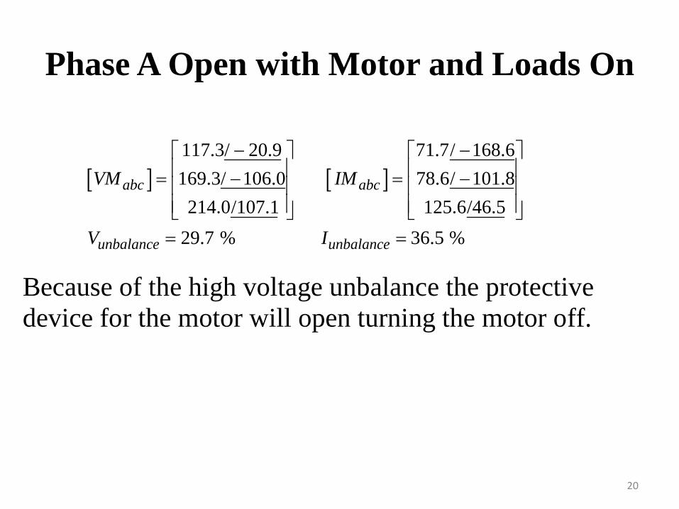
Phase A Open with Motor and Loads On
20
[ ] [ ]117.3/ 20.9 71.7/ 168.6169.3/ 106.0 78.6/ 101.8
214.0/107.1 125.6/46.529.7 % 36.5 %
abc abc
unbalance unbalance
VM IM
V I
− − = − = − = =
Because of the high voltage unbalance the protective device for the motor will open turning the motor off.
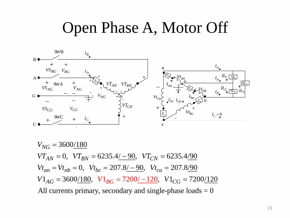
Open Phase A, Motor Off
21
N
+ +
- -
-
+
+
++
+
a
+-
+-
n
+
-
-- NGV
ANVT BNVT
CNVT
anVt
nbVt
bcVt+
_
caVt
c
b
0Z
2Z
bZ
cZ
1Z1SL
2SL3SL
B
A
+
_+__
+
AGV
BGV
SW C
SW A
SW B
+
_
+
+
AGVS
BGVS
CGVS CGV
G
C
BI
AI
CI
naI
bnIcbIacI
aI
nI 1IL
2ILbI 3IL
0cI =
3600/1800, 6235.4/ 90, 6235.4/90
0, 207.8/ 90, 207.8/901 3600/180, , 1 7200/120
All currents primary, secondary and single-phase l1 7
oa200/ 1
ds = 20
NG
AN BN CN
an nb bc ca
AG B CGG
VVT VT VTVt Vt Vt VtV V V
=
= = −
=
=
= = =
= =−
− =
0
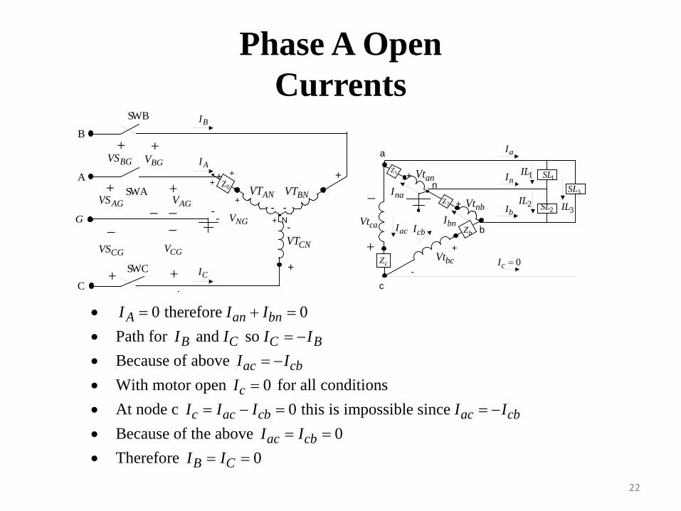
Phase A OpenCurrents
22
N
+ +
- -
-
+
+
++
+
a
+-
+-
n
+
-
-- NGV
ANVT BNVT
CNVT
anVt
nbVt
bcVt+
_
caVt
c
b
0Z
2Z
bZ
cZ
1Z1SL
2SL3SL
B
A
+
_+__
+
AGV
BGV
SW C
SW A
SW B
+
_
+
+
AGVS
BGVS
CGVS CGV
G
C
BI
AI
CI
naI
bnIcbIacI
aI
nI 1IL
2ILbI 3IL
0cI =
• 0 therefore 0A an bnI I I= + = • Path for and so B C C BI I I I= − • Because of above ac cbI I= − • With motor open 0cI = for all conditions • At node c 0 this is impossible since c ac cb ac cbI I I I I= − = = − • Because of the above 0ac cbI I= = • Therefore 0B CI I= =
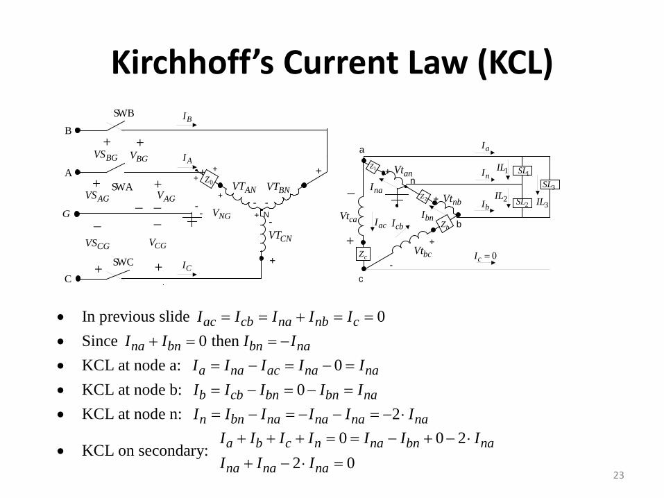
Kirchhoff’s Current Law (KCL)
23
N
+ +
- -
-
+
+
++
+
a
+-
+-
n
+
-
-- NGV
ANVT BNVT
CNVT
anVt
nbVt
bcVt+
_
caVt
c
b
0Z
2Z
bZ
cZ
1Z1SL
2SL3SL
B
A
+
_+__
+
AGV
BGV
SW C
SW A
SW B
+
_
+
+
AGVS
BGVS
CGVS CGV
G
C
BI
AI
CI
naI
bnIcbIacI
aI
nI 1IL
2ILbI 3IL
0cI =
• In previous slide 0ac cb na nb cI I I I I= = + = = • Since 0 then na bn bn naI I I I+ = = − • KCL at node a: 0a na ac na naI I I I I= − = − = • KCL at node b: 0b cb bn bn naI I I I I= − = − = • KCL at node n: 2n bn na na na naI I I I I I= − = − − = − ⋅
• KCL on secondary: 0 0 2
2 0a b c n na bn na
na na na
I I I I I I II I I+ + + = = − + − ⋅
+ − ⋅ =
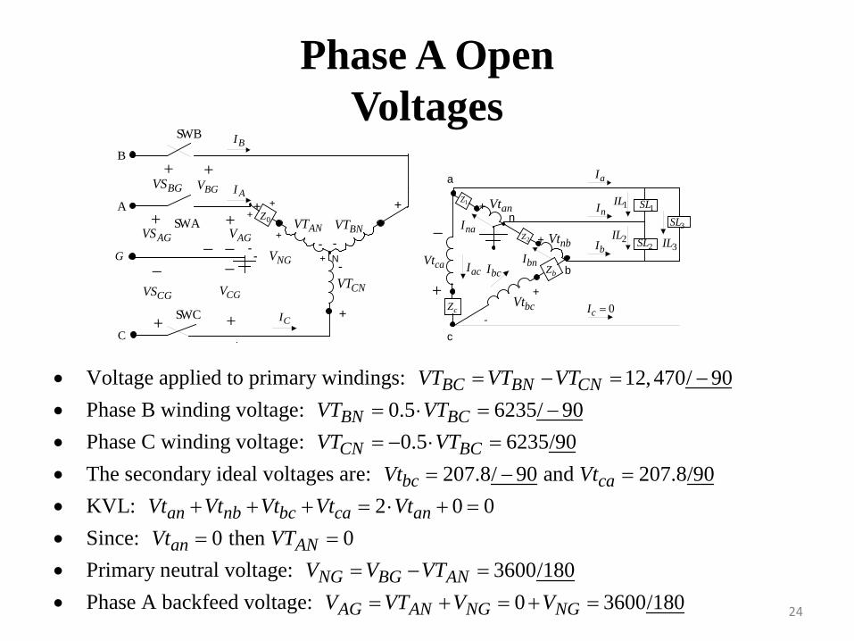
Phase A OpenVoltages
24
N
+ +
- -
-
+
+
++
+
a
+-
+-
n
+
-
- - NGV
ANVT BNVT
CNVT
anVt
nbVt
bcVt+
_
caVt
c
b
0Z
2Z
bZ
cZ
1Z1SL
2SL3SL
BI
AI
naI
bnIbcIacI
aI
nI 1IL
2ILbI 3IL
0cI =CI
B
A
+
_+__
+
AGV
BGV
SW C
SW A
SW B
+
_
+
+
AGVS
BGVS
CGVS CGV
G
C
• Voltage applied to primary windings: 12,470/ 90BC BN CNVT VT VT= − = − • Phase B winding voltage: 0.5 6235/ 90BN BCVT VT= ⋅ = − • Phase C winding voltage: 0.5 6235/90CN BCVT VT= − ⋅ = • The secondary ideal voltages are: 207.8/ 90 and 207.8/90bc caVt Vt= − = • KVL: 2 0 0an nb bc ca anVt Vt Vt Vt Vt+ + + = ⋅ + = • Since: 0 then 0an ANVt VT= = • Primary neutral voltage: 3600/180NG BG ANV V VT= − = • Phase A backfeed voltage: 0 3600/180AG AN NG NGV VT V V= + = + =
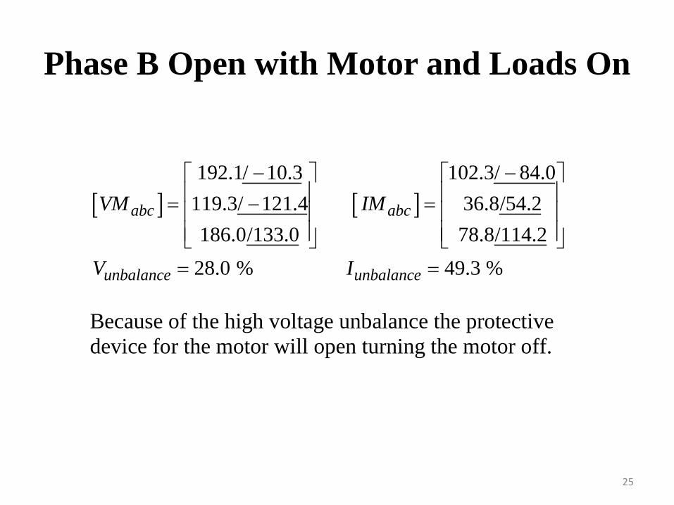
Phase B Open with Motor and Loads On
25
[ ] [ ]192.1/ 10.3 102.3/ 84.0
119.3/ 121.4 36.8/54.2186.0/133.0 78.8/114.2
28.0 % 49.3 %
abc abc
unbalance unbalance
VM IM
V I
− − = − = = =
Because of the high voltage unbalance the protective device for the motor will open turning the motor off.
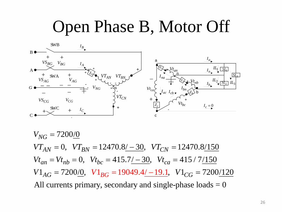
Open Phase B, Motor Off
26
N
+ +
- -
-
+
+
++
+
a
+-
+-
n
+
-
-- NGV
ANVT BNVT
CNVT
anVt
nbVt
bcVt+
_
caVt
c
b
0Z
2Z
bZ
cZ
1Z1SL
2SL3SL
B
A
+
_+__
+
AGV
BGV
SW C
SW A
SW B
+
_
+
+
AGVS
BGVS
CGVS CGV
G
C
BI
AI
CI
naI
bnIcbIacI
aI
nI 1IL
2ILbI 3IL
0cI =
_ _
7200/00, 12470.8/ 30, 12470.8/150
0, 415.7/ 30, 415 / 7/1501 1 19049.4/ 19.7200/0, , 1 7200/120
All currents primary, secondary and single-phase load1
NG
AN BN CN
an nb bc ca
AG CG GB
VVT V
V
T VTVt Vt Vt VtV V
=
= = − =
=
=
= −
−
= =
= =
s = 0
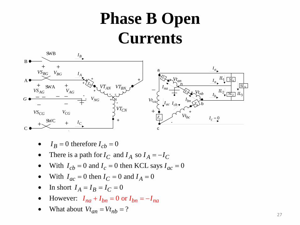
Phase B OpenCurrents
27
N
+ +
- -
-
+
+
++
+
a
+-
+-
n
+
-
-- NGV
ANVT BNVT
CNVT
anVt
nbVt
bcVt+
_
caVt
c
b
0Z
2Z
bZ
cZ
1Z1SL
2SL3SL
B
A
+
_+__
+
AGV
BGV
SW C
SW A
SW B
+
_
+
+
AGVS
BGVS
CGVS CGV
G
C
BI
AI
CI
naI
bnIcbIacI
aI
nI 1IL
2ILbI 3IL
0cI =
_ _
• 0 therefore 0B cbI I= = • There is a path for and so C A A CI I I I= − • With 0 and 0 then KCL says 0cb c acI I I= = = • With 0 then 0 and 0ac C AI I I= = = • In short 0A B CI I I= = = • However: 0 or na bn bn naI I I I+ = = − • What about ?an nbVt Vt= =
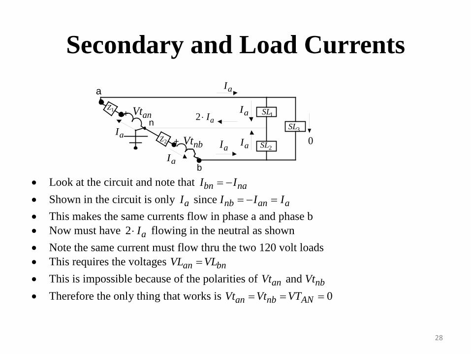
Secondary and Load Currents
28
a
+-
+
-
nanVt
nbVt
b
2Z
1Z1SL
3SL
aI
aI
aIaI
aI
aI
2 aI⋅
02SL
• Look at the circuit and note that bn naI I= − • Shown in the circuit is only since a nb an aI I I I= − = • This makes the same currents flow in phase a and phase b • Now must have 2 aI⋅ flowing in the neutral as shown • Note the same current must flow thru the two 120 volt loads • This requires the voltages an bnVL VL= • This is impossible because of the polarities of and an nbVt Vt • Therefore the only thing that works is 0an nb ANVt Vt VT= = =
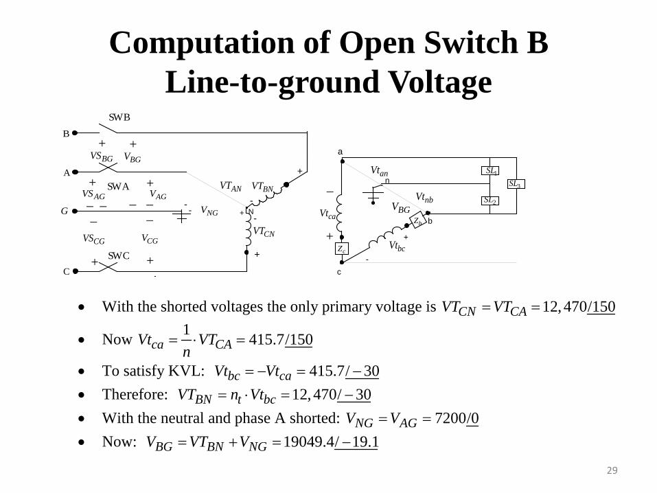
Computation of Open Switch B Line-to-ground Voltage
29
N
+
-
-+
+
a
- n
+
-
- - NGV
ANVT BNVT
CNVT
anVt
nbVt
bcVt+
_
caVt
c
bbZ
cZ
1SL
2SL
3SL
B
A
+
_+__
+
AGV
BGV
SW C
SW A
SW B
+
_
+
+
AGVS
BGVS
CGVS CGV
G
C
_ _-
• With the shorted voltages the only primary voltage is 12,470/150CN CAVT VT= =
• Now 1 415.7/150ca CAVt VTn
= ⋅ =
• To satisfy KVL: 415.7/ 30bc caVt Vt= − = − • Therefore: 12,470/ 30BN t bcVT n Vt= ⋅ = − • With the neutral and phase A shorted: 7200/0NG AGV V= = • Now: 19049.4/ 19.1BG BN NGV VT V= + = −
BGV
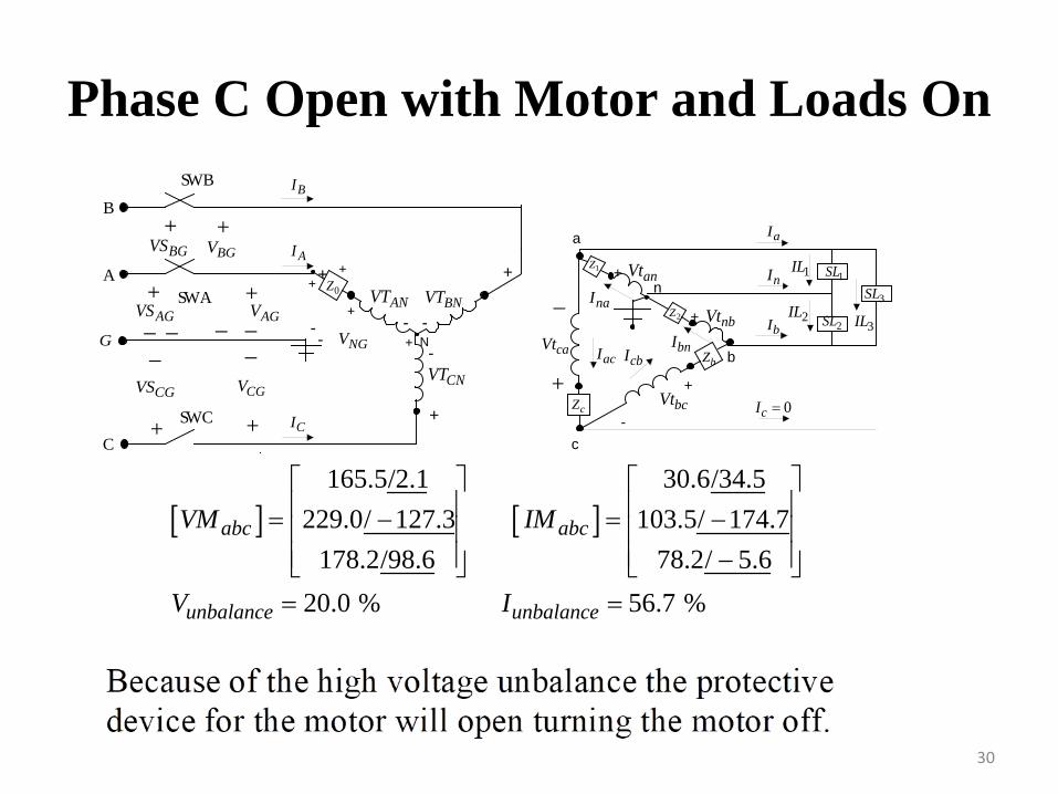
Phase C Open with Motor and Loads On
30
N
+ +
- -
-
+
+
++
+
a
+-
+-
n
+
-
-- NGV
ANVT BNVT
CNVT
anVt
nbVt
bcVt+
_
caVt
c
b
0Z
2Z
bZ
cZ
1Z1SL
2SL3SL
B
A
+
_+__
+
AGV
BGV
SW C
SW A
SW B
+
_
+
+
AGVS
BGVS
CGVS CGV
G
C
BI
AI
CI
naI
bnIcbIacI
aI
nI 1IL
2ILbI 3IL
0cI =
_ _
[ ] [ ]165.5/2.1 30.6/34.5
229.0/ 127.3 103.5/ 174.7178.2/98.6 78.2/ 5.6
20.0 % 56.7 %
abc abc
unbalance unbalance
VM IM
V I
= − = − − = =
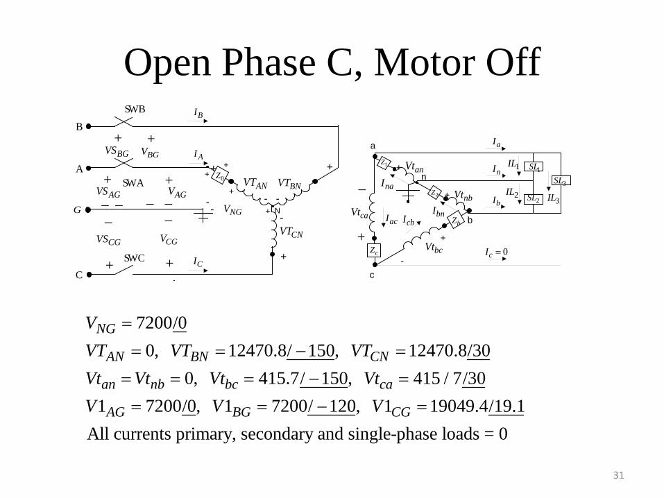
Open Phase C, Motor Off
31
N
+ +
- -
-
+
+
++
+
a
+-
+-
n
+
-
-- NGV
ANVT BNVT
CNVT
anVt
nbVt
bcVt+
_
caVt
c
b
0Z
2Z
bZ
cZ
1Z1SL
2SL3SL
B
A
+
_+__
+
AGV
BGV
SW C
SW A
SW B
+
_
+
+
AGVS
BGVS
CGVS CGV
G
C
BI
AI
CI
naI
bnIcbIacI
aI
nI 1IL
2ILbI 3IL
0cI =
_ _
7200/00, 12470.8/ 150, 12470.8/30
0, 415.7/ 150, 415 / 7/301 7200/0, 1 7200/ 120, 1 19049.4/19.1
All currents primary, secondary and single-phase load
NG
AN BN CN
an nb bc ca
AG BG CG
VVT VT VTVt Vt Vt VtV V V
=
= = − =
= = = − =
= = − =
s = 0
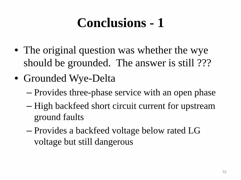
Conclusions - 1
• The original question was whether the wye should be grounded. The answer is still ???
• Grounded Wye-Delta– Provides three-phase service with an open phase– High backfeed short circuit current for upstream
ground faults– Provides a backfeed voltage below rated LG
voltage but still dangerous
32
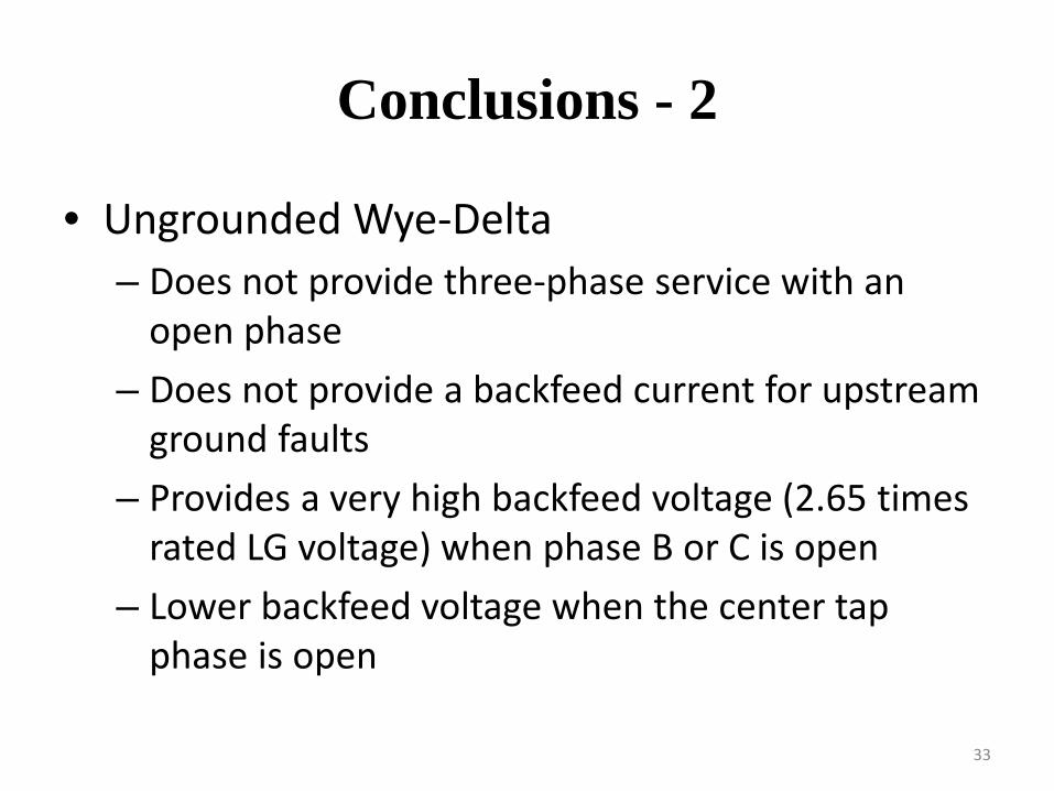
Conclusions - 2
• Ungrounded Wye-Delta– Does not provide three-phase service with an
open phase– Does not provide a backfeed current for upstream
ground faults– Provides a very high backfeed voltage (2.65 times
rated LG voltage) when phase B or C is open– Lower backfeed voltage when the center tap
phase is open
33
Conclusions-3
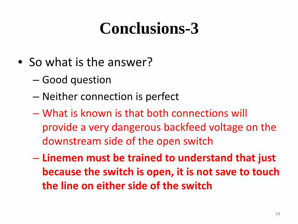
• So what is the answer?– Good question– Neither connection is perfect– What is known is that both connections will
provide a very dangerous backfeed voltage on the downstream side of the open switch
– Linemen must be trained to understand that just because the switch is open, it is not save to touch the line on either side of the switch
34