Embed Size (px)
Citation preview
This article was downloaded by:[ANKOS Consortium]On: 19 February 2008Access Details: [subscription number 772815469]Publisher: Taylor & FrancisInforma Ltd Registered in England and Wales Registered Number: 1072954Registered office: Mortimer House, 37-41 Mortimer Street, London W1T 3JH, UK
Critical Reviews in Solid State andMaterials SciencesPublication details, including instructions for authors and subscription information:http://www.informaworld.com/smpp/title~content=t713610945
Templated Grain Growth of Textured PiezoelectricCeramicsG. L. Messing a; S. Trolier-McKinstry a; E. M. Sabolsky a; C. Duran a; S. Kwon a;B. Brahmaroutu a; P. Park a; H. Yilmaz a; P. W. Rehrig a; K. B. Eitel a; E. Suvacia; M. Seabaugh a; K. S. Oh aa Materials Research Institute and Department of Materials Science andEngineering, Pennsylvania State University, University Park, PA, USA
Online Publication Date: 01 April 2004To cite this Article: Messing, G. L., Trolier-McKinstry, S., Sabolsky, E. M., Duran,C., Kwon, S., Brahmaroutu, B., Park, P., Yilmaz, H., Rehrig, P. W., Eitel, K. B.,
Suvaci, E., Seabaugh, M. and Oh, K. S. (2004) 'Templated Grain Growth of Textured Piezoelectric Ceramics', CriticalReviews in Solid State and Materials Sciences, 29:2, 45 - 96To link to this article: DOI: 10.1080/10408430490490905URL: http://dx.doi.org/10.1080/10408430490490905
PLEASE SCROLL DOWN FOR ARTICLE
Full terms and conditions of use: http://www.informaworld.com/terms-and-conditions-of-access.pdf
This article maybe used for research, teaching and private study purposes. Any substantial or systematic reproduction,re-distribution, re-selling, loan or sub-licensing, systematic supply or distribution in any form to anyone is expresslyforbidden.
The publisher does not give any warranty express or implied or make any representation that the contents will becomplete or accurate or up to date. The accuracy of any instructions, formulae and drug doses should beindependently verified with primary sources. The publisher shall not be liable for any loss, actions, claims, proceedings,demand or costs or damages whatsoever or howsoever caused arising directly or indirectly in connection with orarising out of the use of this material.
Dow
nloa
ded
By:
[AN
KO
S C
onso
rtium
] At:
14:1
3 19
Feb
ruar
y 20
08 Critical Reviews in Solid State and Materials Sciences, 29:45–96, 2004
Copyright c© Taylor & Francis Inc.
ISSN: 1040-8436 print
DOI: 10.1080/10408430490490905
Templated Grain Growth of TexturedPiezoelectric Ceramics
G. L. Messing,∗ S. Trolier-McKinstry, E. M. Sabolsky, C. Duran, S. Kwon,B. Brahmaroutu, P. Park, H. Yilmaz, P. W. Rehrig, K. B. Eitel, E. Suvaci,M. Seabaugh, and K. S. OhMaterials Research Institute and Department of Materials Science and Engineering,
Pennsylvania State University, University Park, PA 16802, USA
ABSTRACT: Crystallographic texturing of polycrystalline ferroelectric ceramics offers a means ofachieving significant enhancements in the piezoelectric response. Templated grain growth (TGG) en-ables the fabrication of textured ceramics with single crystal-like properties, as well as single crystals.In TGG, nucleation and growth of the desired crystal on aligned single crystal template particles resultsin an increased fraction of oriented material with heating. To facilitate alignment during forming, tem-plate particles must be anisometric in shape. To serve as the preferred sites for epitaxy and subsequentoriented growth of the matrix, the template particles need to be single crystal and chemically stableup to the growth temperature. Besides templating the growth process, the template particles may alsoserve as seed sites for phase formation of a reactive matrix. This process, referred to as Reactive TGG(RTGG), has been used to obtain highly oriented Pb(Mg1/3Nb2/3)O3-PbTiO3, Sr0.53Ba0.47Nb2O6, and(Na1/2Bi1/2)TiO3-BaTiO3. Highly oriented Bi4Ti3O12, Sr2Nb2O7, CaBi4Ti4O15, Pb(Mg1/3Nb2/3)O3-PbTiO3, Sr0.53Ba0.47Nb2O6 and (Na1/2Bi1/2)TiO3-BaTiO3 ceramics have been produced by TGG. Theresulting ceramics show texture levels up to 90%, and significant enhancements in the piezoelectricproperties relative to randomly oriented ceramics with comparable densities. For example, piezoelec-tric coefficients of textured piezoelectrics are from 2 to 3 times higher than polycrystalline ceramicsand as high as 90% of the single crystal values. In textured PMN-PT, a low field (<5 kV/cm) piezo-electric coefficient (d33) of ∼1600 pC/N was obtained with >0.3% strain (at 50 kV/cm). The high fielddielectric and electromechanical properties of textured perovskites are more hysteretic than those ofsingle crystals, probably as a result of clamping by the residual template particles, residual randomgrains, the presence of non-ferroelectric second phases, and a wide orientation distribution. Lateralclamping of one grain by another may also be an important factor in fiber-textured samples. Means tofurther improve the quality of texture and thus properties of textured piezoelectric ceramics by TGGare presented.
KEYWORDS: templated grain growth, texture, piezoelectric, single crystals, perovskite, ferro-electric, ceramics.
LIST OF SYMBOLS
c Constant (see Eq. 9)
C1 Constant
C2 Constant
cr Critical supersaturation
D Diffusion coefficient
dij Piezoelectric coefficient
Ec Coercive field strength
fT Number frequency of templates
f Volume fraction of oriented material (texture
fraction)
F( f, r, θ ) Texture distribution
∗E-mail: [email protected]
gijk Piezoelectric voltage coefficient
J Flux
Kij Dielectric constant
kij Electromechanical coupling coefficient
Km Kinetic constant for matrix growth
kt Electromechanical coupling coefficient—
thickness mode
khkl Ratio of Sm to ST
M Molecular weight
P(θ1) Probability that volume fraction of material has
orientation of θ1
P3 Polarization component along the 3 axis
〈P3〉random Net polarization of a random ceramic
45
Dow
nloa
ded
By:
[AN
KO
S C
onso
rtium
] At:
14:1
3 19
Feb
ruar
y 20
08 46 G. L. MESSING ET AL.
〈P3〉textured Net polarization of a textured ceramic
Pr Remanent polarization
Ps Spontaneous polarization
QM Mechanical quality factor
r Orientation parameter
R Gas constant
rm Average matrix grain size
Ro Initial template radius
RT Radius of template plus grown crystal
SB Supersaturation at facet surface
Sm Solubility of matrix grains
ST Solubility of template surface
�S Solubility difference between Sm and ST
T Temperature
t Time
tan δ Dielectric loss
TC Curie temperature
Tmax Temperature of maximum permittivity
TT Template thickness
Vliquid Volume of liquid
Vsolid Volume of solid
xT Template spacing
δ Thickness of liquid layer at matrix-crystal interface
� Molar volume of the solid
φ Angle between grain and a-axis parallel to b-plane
κ ij Permittivity
θ Angle between texture axis and scattering vector
θ1 Angle between grain and a-axis parallel to c-plane
θ2 Angle between grain and c-axis parallel to a-plane
ρ Density of matrix material
σ m Average surface energy for matrix grains
σ T Surface energy of template surface
INTRODUCTION
Piezoelectricity describes the linear relationship between an
applied stress and the induced polarization, or conversely, be-
tween an applied electric field and the induced strain.1 The
effect appears in a number of non-centrosymmetric crystals
and ceramics, and has been used in a wide variety of sensors,
actuators, transducers, and timing standards.2,3
The range of commercial piezoelectric materials, including
both single crystals and ceramics is extensive. In many cases, in
order to maximize the piezoelectric response, compositions are
designed around a morphotropic phase boundary (MPB), which
marks a nearly temperature independent boundary between two
ferroelectric phases, and is characterized by high polarizabil-
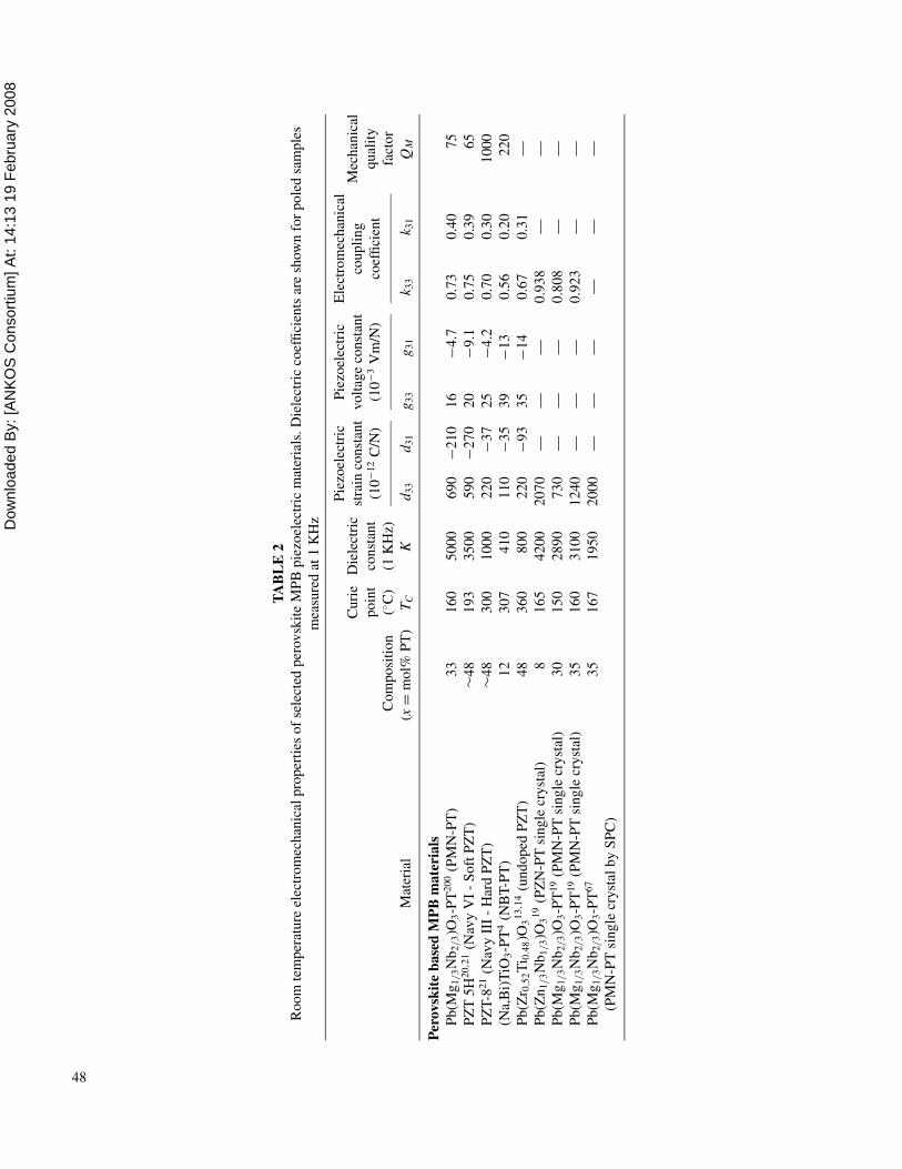
ity. Tables 1 and 2 summarize the room temperature properties
for several of these piezoelectric materials. Non-MPB materi-
als exhibit TC ’s of up to 1000◦C, however they generally have
low permittivity (<500) and small piezoelectric coefficients
(d33 < 200 pC/N). BaTiO3 and (Na1/2Bi1/2)TiO3 (NBT) are
examples of non-MPB perovskite piezoelectric materials that
have relatively large piezoelectric coefficients for this class of
materials.4−6 Perovskite-structured materials have the general
formula ABO3. The processing, physical properties, and sta-
bility of BaTiO3, and other perovskite structure piezoelectrics,
is commonly altered by substitution of isovalent or aliovalent
ions for either A or B sites of the perovskite structure.
Other non-MPB piezoelectrics are based on the tungsten
bronze, Aurivillius phases (or bismuth layer structures), per-
ovskite layer structures, and lithium niobate crystal structures.
PbNb2O6, a non-MPB material in the tungsten bronze family,
has been used in medical ultrasound and non-destructive testing
transducers due to its high bandwidth (low QM or mechanical
loss).7 Solid solutions of perovskite layer compositions, having
the general formula A2B2O7, of Sr2Nb2O7 (SN) and Sr2Ta2O7
display high Curie temperatures TC ∼ 820◦C and piezoelectric
voltage coefficients of g24 = 6.3 × 10⁻³ Vm/N, which makes
them useful for sensing applications.8−10
Non-MPB single crystals such as α-quartz (SiO2), lithium
niobate (LiNbO3), and lithium tantalate (LiTaO3) are some of
the most widely used piezoelectric materials. Quartz is a non-
ferroelectric piezoelectric crystal used as a frequency standard.
Y-cut quartz has a QM > 100,000 and a near zero thermal expan-
sion coefficient, which results in a temperature-stable resonant
frequency. Lithium niobate crystals are widely used in electro-
optic applications due to their high TC (1150◦C) and high piezo-
electric voltage coefficient (g15 = 177 × 10−3 Vm/N).8,11,12
Overall, single crystal quartz, lithium niobate, and lithium tan-
talate are extensively used in industrial applications as a result
of their temperature stability, wide operating temperature range,
and ease of growing large, defect-free single crystals.
MPB piezoelectric materials, such as Pb(Zr0.52Ti0.48)O3
(PZT) show maximum piezoelectric response at composi-
tions near the temperature-independent compositional phase
boundary.13 The MPB for PZT exists between rhombohedral
and tetragonal distortions of the pervoskite structure.14 Under
application of a strong electric field during the poling process,
the large number of thermodynamically equivalent states allows
a high degree of alignment of ferroelectric dipoles. This high
degree of alignment and enhanced polarizability near the MPB
results in a dramatic enhancement of dielectric and piezoelectric
properties.
For high-performance actuators, the piezoelectric material
must show high thermal stability, high strain with an applied
electric field, low mechanical loss, and thus, low hysteresis
in the strain-field response.3,15 Piezoelectric materials for ac-
tuator applications should possess a high phase transition, or
Curie temperature, a high piezoelectric coefficient (dij), and in
some cases a high mechanical quality factor (Qm). For high-
performance medical transducer applications, a high electrome-
chanical coupling coefficient (kij) is also required because kij
dictates the useable bandwidth of the transducer.
The next generation of actuators and transducers requires a
significant increase in some or all of the typical figure of merit
coefficients (dij, kij, and QM ). The various solid solutions based
on PZT are the most widely used piezoelectric ceramics, but the
Dow
nloa
ded
By:
[AN
KO
S C
onso
rtium
] At:
14:1
3 19
Feb
ruar
y 20
08 TEXTURED PIEZOELECTRIC CERAMICS 47
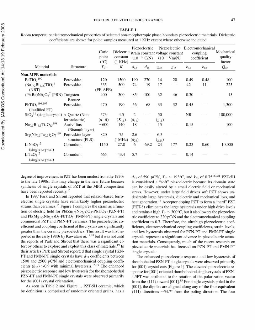
TABLE 1
Room temperature electromechanical properties of selected non-morphotropic phase boundary piezoelectric materials. Dielectric
coefficients are shown for poled samples measured at 1 KHz except where otherwise indicated
Piezoelectric Piezoelectric Electromechanical
strain constant voltage constant coupling
(10−12 C/N) (10−3 Vm/N) coefficient
Material Structure
Curie
point
(◦C)
TC
Dielectric
constant
(1 KHz)
K d33 d15 g33 g15 k33 k15
Mechanical
quality
factor
QM
Non-MPB materials
BaTiO3190 Perovskite 120 1500 190 270 14 20 0.49 0.48 100
(Na1/2Bi1/2)TiO34 Perovskite 335 500 74 19 17 — 42 11 225
(NBT) (FE-AFE)
(Pb,Ba)Nb2O67 (PBN) Tungsten 400 300 85 100 32 46 0.30 — 15
Bronze
PbTiO3196,197 Perovskite 470 190 56 68 33 32 0.45 — 1,300
(modified PT)
SiO211 (single crystal) α-Quartz (Non- 573 4.5 2 — 50 — NR — 100,000
ferroelectric) (α–β) (K11) (d11) (g11)
Na0.5Bi4.5Ti4O15198 Aurivillius ∼600 140 18 — 15 — 0.15 — 100
(Bismuth layer)
Sr2(Nb0.5Ta0.5)2O7199 Perovskite layer 820 75 2.6 — 6.3 — — — —
structure (PLS) (1MHz) (d24) (g24)
LiNbO312 Corundum 1150 27.8 6 69.2 24 177 0.23 0.60 10,000
(single crystal)
LiTaO312 Corundum 665 43.4 5.7 — — — 0.14 — —
(single crystal)
degree of improvement in PZT has been modest from the 1970s
to the late 1990s. This may change in the near future because
synthesis of single crystals of PZT at the MPB composition
have been reported recently.16
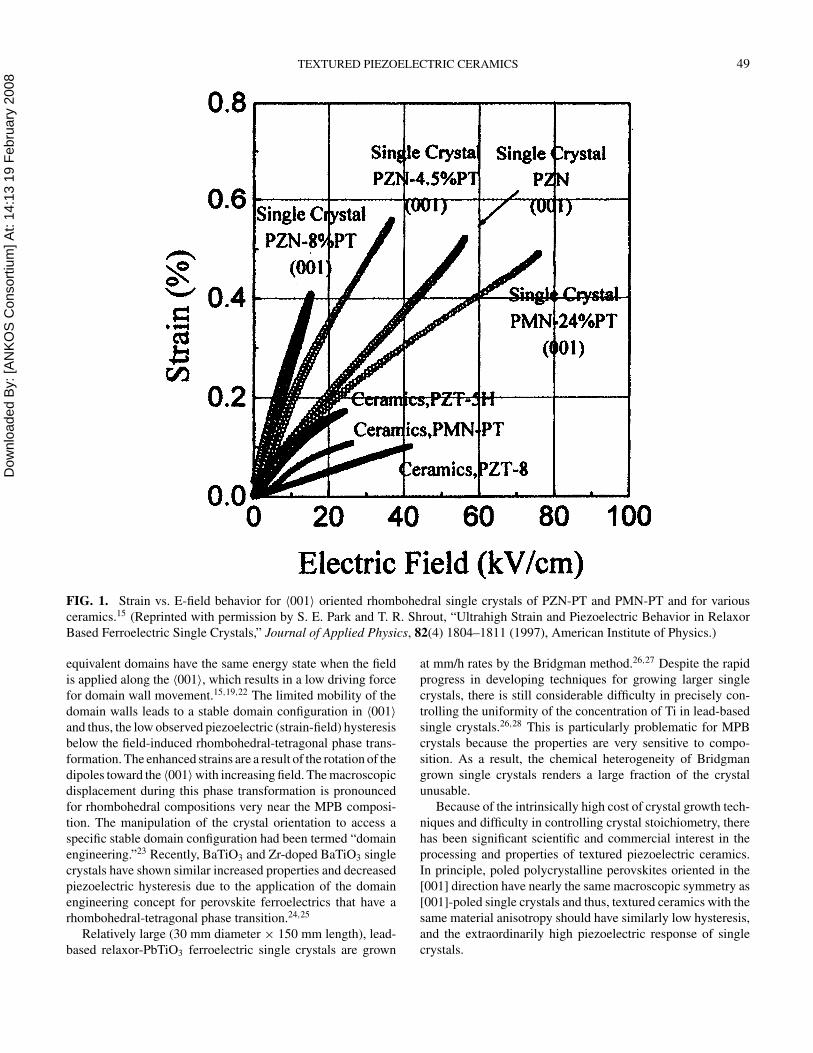
In 1997 Park and Shrout reported that relaxor-based ferro-
electric single crystals have remarkably higher piezoelectric
strains than ceramics.15 Figure 1 compares the strain as a func-
tion of electric field for Pb(Zn1/3Nb2/3)O3-PbTiO3 (PZN-PT)
and Pb(Mg1/3Nb2/3)O3-PbTiO3 (PMN-PT) single crystals and
commercial PZT and PMN-PT ceramics. The piezoelectric co-
efficient and coupling coefficient of the crystals are significantly
greater than the ceramic piezoelectrics. This result was first re-
ported in the early 1980s by Kuwata et al.17,18 but it was not until
the reports of Park and Shrout that there was a significant ef-
fort by others to explore and exploit this class of materials.19 In
their articles Park and Shrout reported that single crystal PZN-
PT and PMN-PT single crystals have d33 coefficients between
1500 and 2500 pC/N and electromechanical coupling coeffi-
cients (k33) >0.9 with minimal hysteresis.15,19 The enhanced
piezoelectric response and low hysteresis for the rhombohedral
PZN-PT and PMN-PT single crystals were observed primarily
for the 〈001〉 crystal orientation.
As seen in Table 2 and Figure 1, PZT-5H ceramic, which
by definition is comprised of randomly oriented grains, has a
d33 of 590 pC/N, TC ∼ 193◦C, and k33 of 0.75.20,21 PZT-5H
is considered a “soft” piezoelectric because its domain state
can be easily altered by a small electric field or mechanical
stress. However, under large field drives soft PZT shows un-
desirably large hysteresis, dielectric and mechanical loss, and
heat generation.14 Acceptor doping PZT to form a “hard” PZT
(PZT-8) eliminates the large hysteresis under high drive levels
and retains a high TC ∼ 300◦C, but it also lowers the piezoelec-
tric coefficient to 220 pC/N and the electromechanical coupling
coefficient to 0.7. Therefore, the ultrahigh piezoelectric coef-
ficients, electromechanical coupling coefficients, strain levels,
and low hysteresis observed for PZN-PT and PMN-PT single
crystals represent a significant advance in piezoelectric actua-
tion materials. Consequently, much of the recent research on
piezoelectric materials has focused on PZN-PT and PMN-PT
single crystals.
The enhanced piezoelectric response and low hysteresis of
rhombohedral PZN-PT single crystals were observed primarily
for 〈001〉 crystal cuts (Figure 1). The elevated piezoelectric re-
sponse for [001] oriented rhombohedral single crystals of PZN-
4.5PT was attributed to the rotation of the polarization vector
from the 〈111〉 toward [001].15 For single crystals poled in the
[001], the dipoles are aligned along any of the four equivalent
〈111〉 directions ∼54.7◦ from the poling direction. The four
Dow
nloa
ded
By:
[AN
KO
S C
onso
rtium
] At:
14:1
3 19
Feb
ruar
y 20
08
TA
BL
E2
Ro
om
tem
per
atu
reel
ectr
om
ech
anic
alp
rop
erti
eso
fse
lect
edp
erov
skit
eM
PB
pie
zoel
ectr
icm
ater
ials
.D
iele
ctri
cco
effi
cien
tsar
esh
ow
nfo
rp
ole
dsa
mp
les
mea
sure
dat
1K
Hz
Pie
zoel
ectr
icP
iezo
elec
tric
Ele
ctro
mec
han
ical
stra
inco
nst
ant
vo
ltag
eco
nst
ant
cou
pli
ng
(10
−12
C/N
)(1
0−
3V
m/N
)co
effi
cien
t
Mat
eria
l
Co
mp
osi
tio
n
(x=
mo
l%P
T)
Cu
rie
po
int
(◦C
)
TC
Die
lect
ric
con
stan
t
(1K
Hz)
Kd
33
d31
g33
g31
k 33
k 31
Mec
han
ical
qu
alit
y
fact
or
QM
Per
ov
skit
eb
ase
dM
PB
ma
teri
als
Pb
(Mg
1/3N
b2/3)O
3-P
T200
(PM
N-P
T)
33
16
05
00
06
90
−2
10
16
−4
.70
.73
0.4
07
5
PZ
T5
H20,2
1(N
avy
VI
-S
oft
PZ
T)
∼4
81
93
35
00
59
0−
27
02
0−
9.1
0.7
50
.39
65
PZ
T-8
21
(Nav
yII
I-
Har
dP
ZT
)∼
48
30
01
00
02
20
−3
72
5−
4.2
0.7
00
.30
10
00
(Na,
Bi)
TiO
3-P
T4
(NB
T-P
T)
12
30
74
10
11
0−
35
39
−1
30
.56
0.2
02
20
Pb
(Zr 0
.52T
i 0.4
8)O
313,1
4(u
nd
op
edP
ZT
)4
83
60
80
02
20
−9
33
5−
14
0.6
70
.31
—
Pb
(Zn
1/3N
b1/3)O
319
(PZ
N-P
Tsi
ng
lecr
yst
al)
81
65
42
00
20
70
——
—0
.93
8—
—
Pb
(Mg
1/3N
b2/3)O
3-P
T19
(PM
N-P
Tsi
ng
lecr
yst
al)
30
15
02
89
07
30
——
—0
.80
8—
—
Pb
(Mg
1/3N
b2/3)O
3-P
T19
(PM
N-P
Tsi
ng
lecr
yst
al)
35
16
03
10
01
24
0—
——
0.9
23
——
Pb
(Mg
1/3N
b2/3)O
3-P
T67
35
16
71
95
02
00
0—
——
——
—
(PM
N-P
Tsi
ng
lecr
yst
alb
yS
PC
)
48
Dow
nloa
ded
By:
[AN
KO
S C
onso
rtium
] At:
14:1
3 19
Feb
ruar
y 20
08 TEXTURED PIEZOELECTRIC CERAMICS 49
FIG. 1. Strain vs. E-field behavior for 〈001〉 oriented rhombohedral single crystals of PZN-PT and PMN-PT and for various
ceramics.15 (Reprinted with permission by S. E. Park and T. R. Shrout, “Ultrahigh Strain and Piezoelectric Behavior in Relaxor
Based Ferroelectric Single Crystals,” Journal of Applied Physics, 82(4) 1804–1811 (1997), American Institute of Physics.)
equivalent domains have the same energy state when the field
is applied along the 〈001〉, which results in a low driving force
for domain wall movement.15,19,22 The limited mobility of the
domain walls leads to a stable domain configuration in 〈001〉
and thus, the low observed piezoelectric (strain-field) hysteresis
below the field-induced rhombohedral-tetragonal phase trans-
formation. The enhanced strains are a result of the rotation of the
dipoles toward the 〈001〉 with increasing field. The macroscopic
displacement during this phase transformation is pronounced
for rhombohedral compositions very near the MPB composi-
tion. The manipulation of the crystal orientation to access a
specific stable domain configuration had been termed “domain
engineering.”23 Recently, BaTiO3 and Zr-doped BaTiO3 single
crystals have shown similar increased properties and decreased
piezoelectric hysteresis due to the application of the domain
engineering concept for perovskite ferroelectrics that have a
rhombohedral-tetragonal phase transition.24,25
Relatively large (30 mm diameter × 150 mm length), lead-
based relaxor-PbTiO3 ferroelectric single crystals are grown
at mm/h rates by the Bridgman method.26,27 Despite the rapid
progress in developing techniques for growing larger single
crystals, there is still considerable difficulty in precisely con-
trolling the uniformity of the concentration of Ti in lead-based
single crystals.26,28 This is particularly problematic for MPB
crystals because the properties are very sensitive to compo-
sition. As a result, the chemical heterogeneity of Bridgman
grown single crystals renders a large fraction of the crystal
unusable.
Because of the intrinsically high cost of crystal growth tech-
niques and difficulty in controlling crystal stoichiometry, there
has been significant scientific and commercial interest in the
processing and properties of textured piezoelectric ceramics.
In principle, poled polycrystalline perovskites oriented in the
[001] direction have nearly the same macroscopic symmetry as
[001]-poled single crystals and thus, textured ceramics with the
same material anisotropy should have similarly low hysteresis,
and the extraordinarily high piezoelectric response of single
crystals.
Dow
nloa
ded
By:
[AN
KO
S C
onso
rtium
] At:
14:1
3 19
Feb
ruar
y 20
08 50 G. L. MESSING ET AL.
FUNDAMENTAL JUSTIFICATION FOR ORIENTATIONIN PIEZOELECTRIC MATERIALS
For large strain actuators and high sensitivity piezoelectric
sensors, maximization of the piezoelectric dijk, gijk, and kij co-
efficients is highly desirable. Development of texture in piezo-
electric materials offers two different routes toward increasing
the available piezoelectric response. First, in uniaxial ferro-
electrics, or materials where the spontaneous polarization is
confined to a plane, texturing enables much more efficient align-
ment of the polar vectors, and increased poling efficiency (and
thus response).29 This is clearly seen if a uniaxial ferroelectric
is considered, in which only two antiparallel domain states are
allowed. In this case, it is very difficult for the polarization to
percolate through the ceramic on poling, as some grains will
not have possible domain states that are nearly aligned with
the field. Such grains may be completely unable to switch, and
may thus block switching of adjacent, better-aligned grains. Ex-
perimentally, this is often manifested in ceramics from certain
low symmetry point groups. In such materials, the measured
remanent polarization may be substantially lower than calcu-
lated based on an ensemble of single crystals with the same
orientation distribution.
A second means of enhancing the piezoelectric response of
perovskite materials is to utilize the inherent anisotropy in the
material properties. It has been suggested that for many per-
ovskites, the presence of multiple phase transitions leads to a
softening of the lattice along particular directions as one of the
transition temperatures is approached, yielding enhancements
in the shear piezoelectric response.30 It is possible to utilize the
large d15 piezoelectric response to increase the effective longi-
tudinal and transverse piezoelectric coefficients in rotated cuts.
In general, optimized properties are observed in [001]-oriented
materials in rhombohedrally distorted perovskites.31,32 Large
responses have also been shown in [101]-oriented rhombohe-
dral perovskite crystals and [111]-oriented tetragonal crystals.33
Although many perovskites show this type of anisotropy, the
largest coefficients are typically observed in the lead-based per-
ovskites. It is critical to note however, that utilization of the en-
hanced response is dependent on the material orientation, and
cannot be fully exploited in randomly oriented polycrystalline
materials. Consequently, single crystals and textured ceramics
are of special interest.34,35
To illustrate this point, the properties of an oriented PZT
ceramic were calculated based on the phenomenologically de-
rived property coefficients of single domain single crystals as
described by Haun.36 As a first approximation, calculations
were made assuming that each grain in an oriented ceramic
acts independent of adjacent grains (i.e., there is no elastic cou-
pling at grain boundaries that would tend to partially clamp the
response). It was also assumed that the polarization direction
in each domain would adopt the configuration closest to that of
the applied poling field. For a random ceramic, the net polariza-
tion is given by averaging over the available spatial orientation
for the polarization in each grain (in spherical coordinates for
a rhombohedrally distorted perovskite):37
〈P3〉random =
∫ 54.7◦
θ=0◦
∫ 90◦
φ=0◦ P3(θ, φ) sin θdθdφ∫ 54.7◦
θ=0◦
∫ 90◦
φ=0◦ sin θdθdφ[1]
To model the effect of orientation in a textured ceramic, the
texture distribution can be described using the March–Dollase
equation:38
F( f, r, θ ) = f
(
r2 cos2 θ +sin2 θ
r
)− 32
+ (1 − f ) [2]
where θ is the angle between the texture (orientation) axis and
the scattering vector, r is the orientation parameter, and f is
the volume fraction of oriented material. The r parameter char-
acterizes the width of the texture (orientation) distribution. For
a random sample r = 1 and for a perfectly textured sample
of tabular grains r = 0. The net polarization for the textured
ceramic case is then given by
〈P3〉textured =
∫ 54.7◦
θ=0◦
∫ 90◦
φ=0◦ P3(θ, φ)F( f, r, θ ) sin θdθdφ∫ 54.7◦
θ=0◦
∫ 90◦
φ=0◦ F( f, r, θ ) sin θdθdφ[3]
Comparable calculations can be made to average the dielectric
and piezoelectric coefficients.
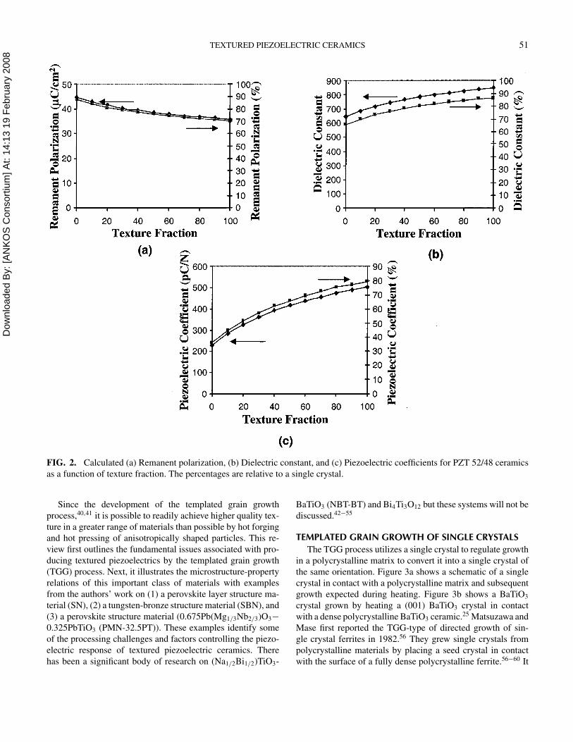
Figure 2 shows the predicted values for P3, K 33, and d33 in a
rhombohedral PZT 52/48 ceramic as a function of the degree of
〈001〉 orientation. In the calculations, r was assigned to 0.2, as
this is comparable to the narrowest orientation distribution that
was observed in Sr0.53Ba0.47Nb2O6 (SBN) ceramics prepared by
TGG.39 The values are normalized to the predicted single crys-
tal value when r = 0 and f = 1 (right y-axis). It is apparent in
Figure 2 that the piezoelectric coefficient increases by more than
a factor of two with the development of 〈001〉 texture in PZT
52/48. As noted for single crystals, this is true even though the
remanent polarization decreases by orienting the grains off the
polar axis. Although the calculation is based on a simple model,
it does point out several important factors for tailoring textured
piezoelectric ceramics. First, there is significant value in pur-
suing textured piezoelectrics even in multiaxial ferroelectrics
such as the perovskites. Second, both the volume fraction and
the width of the orientation distribution significantly impact the
resultant piezoelectric properties of textured materials.
There is a considerable literature on the use of microstruc-
ture texturing to improve the properties of piezoelectric
ceramics.34,35 Most of these materials were processed by hot
pressing or hot forging a powder consisting of relatively large,
anisometric-shaped particles (i.e., needles or tabular particles).
Alternatively, oriented crystallization in glass ceramic precur-
sors was used. The literature describing these materials was
reviewed by Okazaki et al.34
Dow
nloa
ded
By:
[AN
KO
S C
onso
rtium
] At:
14:1
3 19
Feb
ruar
y 20
08 TEXTURED PIEZOELECTRIC CERAMICS 51
FIG. 2. Calculated (a) Remanent polarization, (b) Dielectric constant, and (c) Piezoelectric coefficients for PZT 52/48 ceramics
as a function of texture fraction. The percentages are relative to a single crystal.
Since the development of the templated grain growth
process,40,41 it is possible to readily achieve higher quality tex-
ture in a greater range of materials than possible by hot forging
and hot pressing of anisotropically shaped particles. This re-
view first outlines the fundamental issues associated with pro-
ducing textured piezoelectrics by the templated grain growth
(TGG) process. Next, it illustrates the microstructure-property
relations of this important class of materials with examples
from the authors’ work on (1) a perovskite layer structure ma-
terial (SN), (2) a tungsten-bronze structure material (SBN), and
(3) a perovskite structure material (0.675Pb(Mg1/3Nb2/3)O3−
0.325PbTiO3 (PMN-32.5PT)). These examples identify some
of the processing challenges and factors controlling the piezo-
electric response of textured piezoelectric ceramics. There
has been a significant body of research on (Na1/2Bi1/2)TiO3-
BaTiO3 (NBT-BT) and Bi4Ti3O12 but these systems will not be
discussed.42−55
TEMPLATED GRAIN GROWTH OF SINGLE CRYSTALS
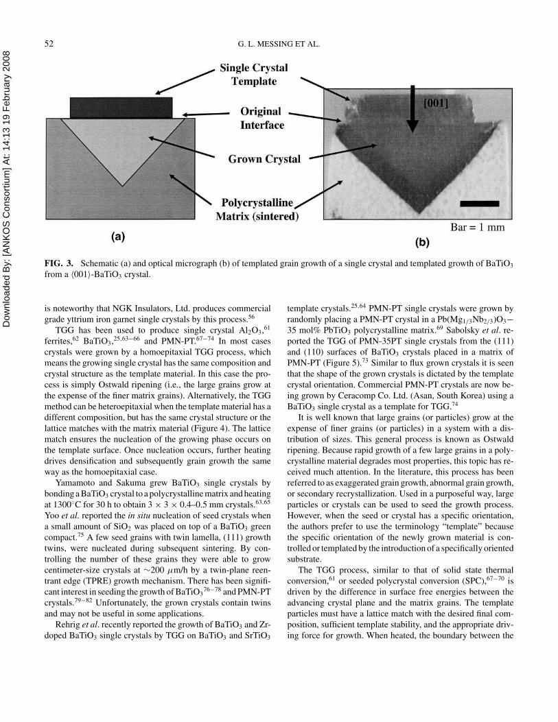
The TGG process utilizes a single crystal to regulate growth
in a polycrystalline matrix to convert it into a single crystal of
the same orientation. Figure 3a shows a schematic of a single
crystal in contact with a polycrystalline matrix and subsequent
growth expected during heating. Figure 3b shows a BaTiO3
crystal grown by heating a (001) BaTiO3 crystal in contact
with a dense polycrystalline BaTiO3 ceramic.25 Matsuzawa and
Mase first reported the TGG-type of directed growth of sin-
gle crystal ferrites in 1982.56 They grew single crystals from
polycrystalline materials by placing a seed crystal in contact
with the surface of a fully dense polycrystalline ferrite.56−60 It
Dow
nloa
ded
By:
[AN
KO
S C
onso
rtium
] At:
14:1
3 19
Feb
ruar
y 20
08 52 G. L. MESSING ET AL.
FIG. 3. Schematic (a) and optical micrograph (b) of templated grain growth of a single crystal and templated growth of BaTiO3
from a 〈001〉-BaTiO3 crystal.
is noteworthy that NGK Insulators, Ltd. produces commercial
grade yttrium iron garnet single crystals by this process.56
TGG has been used to produce single crystal Al2O3,61
ferrites,62 BaTiO3,25,63−66 and PMN-PT.67−74 In most cases
crystals were grown by a homoepitaxial TGG process, which
means the growing single crystal has the same composition and
crystal structure as the template material. In this case the pro-
cess is simply Ostwald ripening (i.e., the large grains grow at
the expense of the finer matrix grains). Alternatively, the TGG
method can be heteroepitaxial when the template material has a
different composition, but has the same crystal structure or the
lattice matches with the matrix material (Figure 4). The lattice
match ensures the nucleation of the growing phase occurs on
the template surface. Once nucleation occurs, further heating
drives densification and subsequently grain growth the same
way as the homoepitaxial case.
Yamamoto and Sakuma grew BaTiO3 single crystals by
bonding a BaTiO3 crystal to a polycrystalline matrix and heating
at 1300◦C for 30 h to obtain 3 × 3 × 0.4–0.5 mm crystals.63,65
Yoo et al. reported the in situ nucleation of seed crystals when
a small amount of SiO2 was placed on top of a BaTiO3 green
compact.75 A few seed grains with twin lamella, (111) growth
twins, were nucleated during subsequent sintering. By con-
trolling the number of these grains they were able to grow
centimeter-size crystals at ∼200 µm/h by a twin-plane reen-
trant edge (TPRE) growth mechanism. There has been signifi-
cant interest in seeding the growth of BaTiO376−78 and PMN-PT
crystals.79−82 Unfortunately, the grown crystals contain twins
and may not be useful in some applications.
Rehrig et al. recently reported the growth of BaTiO3 and Zr-
doped BaTiO3 single crystals by TGG on BaTiO3 and SrTiO3
template crystals.25,64 PMN-PT single crystals were grown by
randomly placing a PMN-PT crystal in a Pb(Mg1/3Nb2/3)O3−
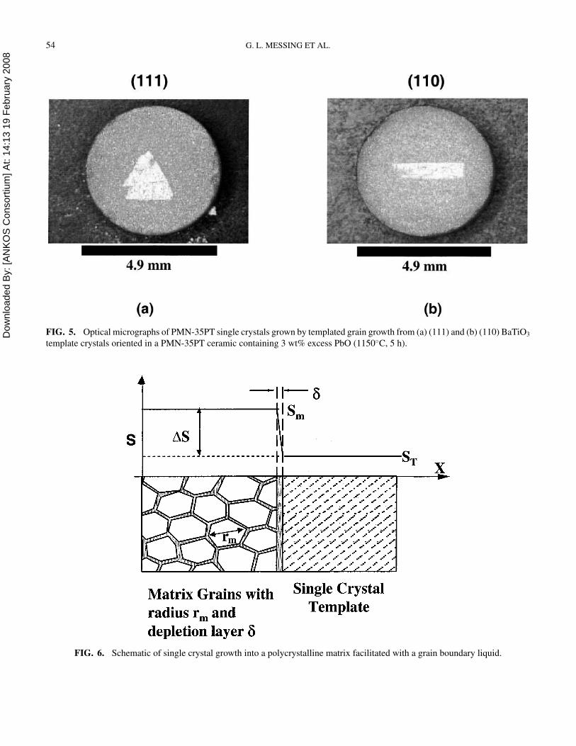
35 mol% PbTiO3 polycrystalline matrix.69 Sabolsky et al. re-
ported the TGG of PMN-35PT single crystals from the (111)
and (110) surfaces of BaTiO3 crystals placed in a matrix of
PMN-PT (Figure 5).73 Similar to flux grown crystals it is seen
that the shape of the grown crystals is dictated by the template
crystal orientation. Commercial PMN-PT crystals are now be-
ing grown by Ceracomp Co. Ltd. (Asan, South Korea) using a
BaTiO3 single crystal as a template for TGG.74
It is well known that large grains (or particles) grow at the
expense of finer grains (or particles) in a system with a dis-
tribution of sizes. This general process is known as Ostwald
ripening. Because rapid growth of a few large grains in a poly-
crystalline material degrades most properties, this topic has re-
ceived much attention. In the literature, this process has been
referred to as exaggerated grain growth, abnormal grain growth,
or secondary recrystallization. Used in a purposeful way, large
particles or crystals can be used to seed the growth process.
However, when the seed or crystal has a specific orientation,
the authors prefer to use the terminology “template” because
the specific orientation of the newly grown material is con-
trolled or templated by the introduction of a specifically oriented
substrate.
The TGG process, similar to that of solid state thermal
conversion,61 or seeded polycrystal conversion (SPC),67−70 is
driven by the difference in surface free energies between the
advancing crystal plane and the matrix grains. The template
particles must have a lattice match with the desired final com-
position, sufficient template stability, and the appropriate driv-
ing force for growth. When heated, the boundary between the
Dow
nloa
ded
By:
[AN
KO
S C
onso
rtium
] At:
14:1
3 19
Feb
ruar
y 20
08 TEXTURED PIEZOELECTRIC CERAMICS 53
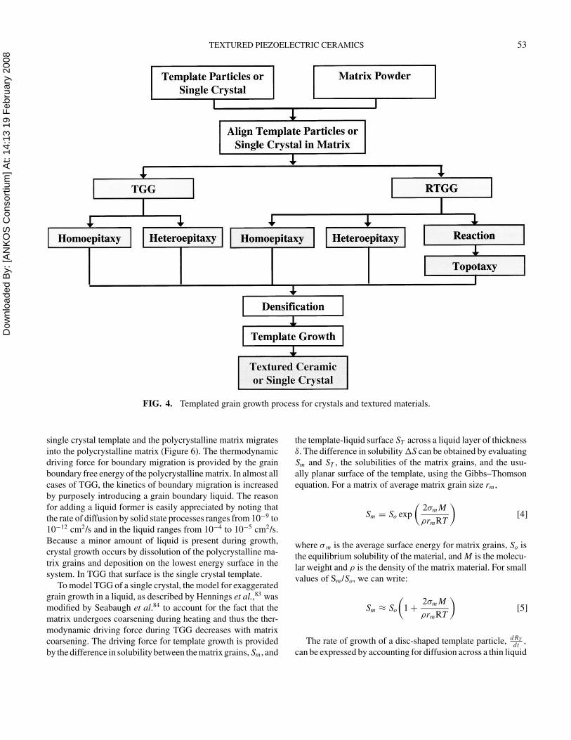
FIG. 4. Templated grain growth process for crystals and textured materials.
single crystal template and the polycrystalline matrix migrates
into the polycrystalline matrix (Figure 6). The thermodynamic
driving force for boundary migration is provided by the grain
boundary free energy of the polycrystalline matrix. In almost all
cases of TGG, the kinetics of boundary migration is increased
by purposely introducing a grain boundary liquid. The reason
for adding a liquid former is easily appreciated by noting that
the rate of diffusion by solid state processes ranges from 10−9 to
10−12 cm2/s and in the liquid ranges from 10−4 to 10−5 cm2/s.
Because a minor amount of liquid is present during growth,
crystal growth occurs by dissolution of the polycrystalline ma-
trix grains and deposition on the lowest energy surface in the
system. In TGG that surface is the single crystal template.
To model TGG of a single crystal, the model for exaggerated
grain growth in a liquid, as described by Hennings et al.,83 was
modified by Seabaugh et al.84 to account for the fact that the
matrix undergoes coarsening during heating and thus the ther-
modynamic driving force during TGG decreases with matrix
coarsening. The driving force for template growth is provided
by the difference in solubility between the matrix grains, Sm , and
the template-liquid surface ST across a liquid layer of thickness
δ. The difference in solubility �S can be obtained by evaluating
Sm and ST , the solubilities of the matrix grains, and the usu-
ally planar surface of the template, using the Gibbs–Thomson
equation. For a matrix of average matrix grain size rm ,
Sm = So exp
(
2σm M
ρrmRT
)
[4]
where σ m is the average surface energy for matrix grains, So is
the equilibrium solubility of the material, and M is the molecu-
lar weight and ρ is the density of the matrix material. For small
values of Sm /So, we can write:
Sm ≈ So
(
1 +2σm M
ρrmRT
)
[5]
The rate of growth of a disc-shaped template particle, d RT
dt,
can be expressed by accounting for diffusion across a thin liquid
Dow
nloa
ded
By:
[AN
KO
S C
onso
rtium
] At:
14:1
3 19
Feb
ruar
y 20
08 54 G. L. MESSING ET AL.
FIG. 5. Optical micrographs of PMN-35PT single crystals grown by templated grain growth from (a) (111) and (b) (110) BaTiO3
template crystals oriented in a PMN-35PT ceramic containing 3 wt% excess PbO (1150◦C, 5 h).
FIG. 6. Schematic of single crystal growth into a polycrystalline matrix facilitated with a grain boundary liquid.
Dow
nloa
ded
By:
[AN
KO
S C
onso
rtium
] At:
14:1
3 19
Feb
ruar
y 20
08 TEXTURED PIEZOELECTRIC CERAMICS 55
layer of thickness δ between the matrix grains and the template,
driven by a difference in solubility �S = Sm − ST . Hennings
et al.83 showed for exaggerated grain growth that
dRT
dt= −
J
ρ=
D�S
ρδ=
DST
ρδ
[
(1 − khkl) +2σm M
ρrmRT
]
[6]
The time dependence for matrix grain growth in a liquid phase
can be expressed as
rm = K tm [7]
where
Km =DST Mσm
ρRT c[8]
the liquid layer thickness, δ = crm
and c =2
3
Vliquid
Vsolid
[9]
The solubility difference does not change significantly with
change in RT . Thus, the initial template radius Ro can be used
at all times. Using Eqs. 7, 8, and 9, Eq. 6 can be rewritten as,
RT −Ro =0.98K
2/3m ρRT
σm M(1−khkl)t
−1/3+1.94K 1/3m t−2/3 [10]
and the growth of template particles can be calculated by inte-
grating Eq. 10,
Rt −Ro = 5.81K 1/3m t1/3+1.48K 2/3
m
[
ρRT
Mσm
(1 - khkl)
]
t2/3 [11]
where khkl is the ratio of the matrix grain solubility to the solu-
bility of the template surface. Note the strong influence of the
matrix grain size on the solubility. Thus, the finer the matrix
grain size, the higher the driving force for TGG.
This model explains the growth of single crystals as well
as the initial stage of template growth in a textured ceramic
produced by TGG. Impingement of growing templated grains
leads to a significant decrease in overall growth rate as a result of
the lower driving force at the boundaries between the impinged
grains. Models to describe post-impingement growth must take
into account the modified growth environment of the impinging
templated grains.
THICKNESS GROWTH
The model just discussed works well for centrosymmetric
systems where there is no crystallographic anisotropy. How-
ever, in non-centrosymmetric systems, like perovskite layer
and tungsten-bronze–structured materials, crystal growth is
strongly anisotropic and results in highly facetted grains. In
these cases, growth of the slower growing surface is often con-
trolled by 2-D nucleation and growth. The relation between su-
persaturation and growth rate for the 2-D nucleation and growth
process can be expressed as85
dTT
dt= C1(SB)n exp
(
−C2
T 2SB
)
[12]
where TT is template thickness, SB is the supersaturation at the
facet surface, the exponent n = 5/6 for the birth and spread
model, and C1 and C2 are constants that depend on the surface
energy of the facetted surface and molar volume of the template
material.
TEMPLATED GROWTH OF BaTiO3 SINGLE CRYSTALS
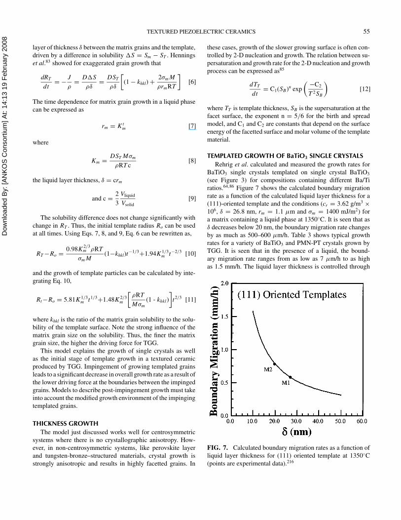
Rehrig et al. calculated and measured the growth rates for
BaTiO3 single crystals templated on single crystal BaTiO3
(see Figure 3) for compositions containing different Ba/Ti
ratios.64,86 Figure 7 shows the calculated boundary migration
rate as a function of the calculated liquid layer thickness for a
(111)-oriented template and the conditions (cr = 3.62 g/m3 ×
106, δ = 26.8 nm, rm = 1.1 µm and σm = 1400 mJ/m2) for
a matrix containing a liquid phase at 1350◦C. It is seen that as
δ decreases below 20 nm, the boundary migration rate changes
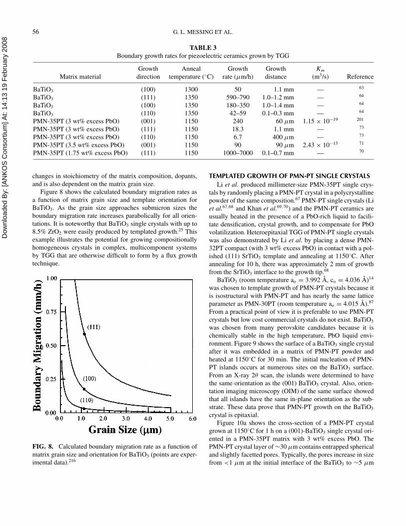
by as much as 500–600 µm/h. Table 3 shows typical growth
rates for a variety of BaTiO3 and PMN-PT crystals grown by
TGG. It is seen that in the presence of a liquid, the bound-
ary migration rate ranges from as low as 7 µm/h to as high
as 1.5 mm/h. The liquid layer thickness is controlled through
FIG. 7. Calculated boundary migration rates as a function of
liquid layer thickness for (111) oriented template at 1350◦C
(points are experimental data).216
Dow
nloa
ded
By:
[AN
KO
S C
onso
rtium
] At:
14:1
3 19
Feb
ruar
y 20
08 56 G. L. MESSING ET AL.
TABLE 3
Boundary growth rates for piezoelectric ceramics grown by TGG
Growth Anneal Growth Growth Km
Matrix material direction temperature (◦C) rate (µm/h) distance (m3/s) Reference
BaTiO3 (100) 1300 50 1.1 mm — 63
BaTiO3 (111) 1350 590–790 1.0–1.2 mm — 64
BaTiO3 (100) 1350 180–350 1.0–1.4 mm — 64
BaTiO3 (110) 1350 42–59 0.1–0.3 mm — 64
PMN-35PT (3 wt% excess PbO) (001) 1150 240 60 µm 1.15 × 10⁻¹⁹ 201
PMN-35PT (3 wt% excess PbO) (111) 1150 18.3 1.1 mm — 73
PMN-35PT (3 wt% excess PbO) (110) 1150 6.7 400 µm — 73
PMN-35PT (3.5 wt% excess PbO) (001) 1150 90 90 µm 2.43 × 10⁻¹³ 71
PMN-35PT (1.75 wt% excess PbO) (111) 1150 1000–7000 0.1–0.7 mm — 70
changes in stoichiometry of the matrix composition, dopants,
and is also dependent on the matrix grain size.
Figure 8 shows the calculated boundary migration rates as
a function of matrix grain size and template orientation for
BaTiO3. As the grain size approaches submicron sizes the
boundary migration rate increases parabolically for all orien-
tations. It is noteworthy that BaTiO3 single crystals with up to
8.5% ZrO2 were easily produced by templated growth.25 This
example illustrates the potential for growing compositionally
homogeneous crystals in complex, multicomponent systems
by TGG that are otherwise difficult to form by a flux growth
technique.
FIG. 8. Calculated boundary migration rate as a function of
matrix grain size and orientation for BaTiO3 (points are exper-
imental data).216
TEMPLATED GROWTH OF PMN-PT SINGLE CRYSTALS
Li et al. produced millimeter-size PMN-35PT single crys-
tals by randomly placing a PMN-PT crystal in a polycrystalline
powder of the same composition.67 PMN-PT single crystals (Li
et al.67,68 and Khan et al.69,70) and the PMN-PT ceramics are
usually heated in the presence of a PbO-rich liquid to facili-
tate densification, crystal growth, and to compensate for PbO
volatilization. Heteroepitaxial TGG of PMN-PT single crystals
was also demonstrated by Li et al. by placing a dense PMN-
32PT compact (with 3 wt% excess PbO) in contact with a pol-
ished (111) SrTiO3 template and annealing at 1150◦C. After
annealing for 10 h, there was approximately 2 mm of growth
from the SrTiO3 interface to the growth tip.68
BaTiO3 (room temperature ao = 3.992 A, co = 4.036 A)14
was chosen to template growth of PMN-PT crystals because it
is isostructural with PMN-PT and has nearly the same lattice
parameter as PMN-30PT (room temperature ao = 4.015 A).87
From a practical point of view it is preferable to use PMN-PT
crystals but low cost commercial crystals do not exist. BaTiO3
was chosen from many perovskite candidates because it is
chemically stable in the high temperature, PbO liquid envi-
ronment. Figure 9 shows the surface of a BaTiO3 single crystal
after it was embedded in a matrix of PMN-PT powder and
heated at 1150◦C for 30 min. The initial nucleation of PMN-
PT islands occurs at numerous sites on the BaTiO3 surface.
From an X-ray 2θ scan, the islands were determined to have
the same orientation as the (001) BaTiO3 crystal. Also, orien-
tation imaging microscopy (OIM) of the same surface showed
that all islands have the same in-plane orientation as the sub-
strate. These data prove that PMN-PT growth on the BaTiO3
crystal is epitaxial.
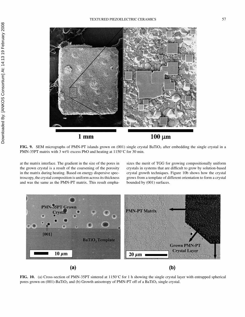
Figure 10a shows the cross-section of a PMN-PT crystal
grown at 1150◦C for 1 h on a (001)-BaTiO3 single crystal ori-
ented in a PMN-35PT matrix with 3 wt% excess PbO. The
PMN-PT crystal layer of ∼30 µm contains entrapped spherical
and slightly facetted pores. Typically, the pores increase in size
from <1 µm at the initial interface of the BaTiO3 to ∼5 µm
Dow
nloa
ded
By:
[AN
KO
S C
onso
rtium
] At:
14:1
3 19
Feb
ruar
y 20
08 TEXTURED PIEZOELECTRIC CERAMICS 57
FIG. 9. SEM micrographs of PMN-PT islands grown on (001) single crystal BaTiO3 after embedding the single crystal in a
PMN-35PT matrix with 3 wt% excess PbO and heating at 1150◦C for 30 min.
at the matrix interface. The gradient in the size of the pores in
the grown crystal is a result of the coarsening of the porosity
in the matrix during heating. Based on energy dispersive spec-
troscopy, the crystal composition is uniform across its thickness
and was the same as the PMN-PT matrix. This result empha-
FIG. 10. (a) Cross-section of PMN-35PT sintered at 1150◦C for 1 h showing the single crystal layer with entrapped spherical
pores grown on (001)-BaTiO3 and (b) Growth anisotropy of PMN-PT off of a BaTiO3 single crystal.
sizes the merit of TGG for growing compositionally uniform
crystals in systems that are difficult to grow by solution-based
crystal growth techniques. Figure 10b shows how the crystal
grows from a template of different orientation to form a crystal
bounded by (001) surfaces.
Dow
nloa
ded
By:
[AN
KO
S C
onso
rtium
] At:
14:1
3 19
Feb
ruar
y 20
08 58 G. L. MESSING ET AL.
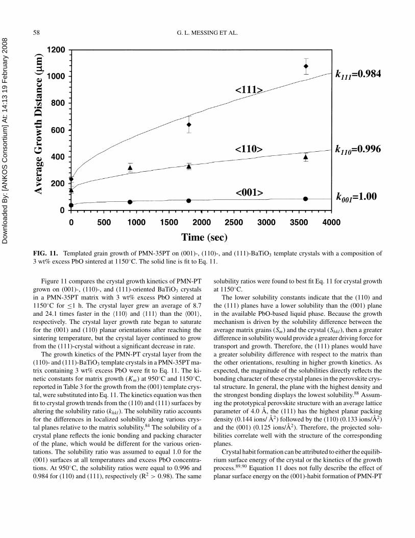
FIG. 11. Templated grain growth of PMN-35PT on (001)-, (110)-, and (111)-BaTiO3 template crystals with a composition of
3 wt% excess PbO sintered at 1150◦C. The solid line is fit to Eq. 11.
Figure 11 compares the crystal growth kinetics of PMN-PT
grown on (001)-, (110)-, and (111)-oriented BaTiO3 crystals
in a PMN-35PT matrix with 3 wt% excess PbO sintered at
1150◦C for ≤1 h. The crystal layer grew an average of 8.7
and 24.1 times faster in the 〈110〉 and 〈111〉 than the 〈001〉,
respectively. The crystal layer growth rate began to saturate
for the (001) and (110) planar orientations after reaching the
sintering temperature, but the crystal layer continued to grow
from the (111)-crystal without a significant decrease in rate.
The growth kinetics of the PMN-PT crystal layer from the
(110)- and (111)-BaTiO3 template crystals in a PMN-35PT ma-
trix containing 3 wt% excess PbO were fit to Eq. 11. The ki-
netic constants for matrix growth (Km) at 950◦C and 1150◦C,
reported in Table 3 for the growth from the (001) template crys-
tal, were substituted into Eq. 11. The kinetics equation was then
fit to crystal growth trends from the (110) and (111) surfaces by
altering the solubility ratio (khkl). The solubility ratio accounts
for the differences in localized solubility along various crys-
tal planes relative to the matrix solubility.84 The solubility of a
crystal plane reflects the ionic bonding and packing character
of the plane, which would be different for the various orien-
tations. The solubility ratio was assumed to equal 1.0 for the
(001) surfaces at all temperatures and excess PbO concentra-
tions. At 950◦C, the solubility ratios were equal to 0.996 and
0.984 for (110) and (111), respectively (R2 > 0.98). The same
solubility ratios were found to best fit Eq. 11 for crystal growth
at 1150◦C.
The lower solubility constants indicate that the (110) and
the (111) planes have a lower solubility than the (001) plane
in the available PbO-based liquid phase. Because the growth
mechanism is driven by the solubility difference between the
average matrix grains (Sm) and the crystal (Shkl), then a greater
difference in solubility would provide a greater driving force for
transport and growth. Therefore, the (111) planes would have
a greater solubility difference with respect to the matrix than
the other orientations, resulting in higher growth kinetics. As
expected, the magnitude of the solubilities directly reflects the
bonding character of these crystal planes in the perovskite crys-
tal structure. In general, the plane with the highest density and
the strongest bonding displays the lowest solubility.88 Assum-
ing the prototypical perovskite structure with an average lattice
parameter of 4.0 A, the (111) has the highest planar packing
density (0.144 ions/ A2) followed by the (110) (0.133 ions/A2)
and the (001) (0.125 ions/A2). Therefore, the projected solu-
bilities correlate well with the structure of the corresponding
planes.
Crystal habit formation can be attributed to either the equilib-
rium surface energy of the crystal or the kinetics of the growth
process.89,90 Equation 11 does not fully describe the effect of
planar surface energy on the (001)-habit formation of PMN-PT
Dow
nloa
ded
By:
[AN
KO
S C
onso
rtium
] At:
14:1
3 19
Feb
ruar
y 20
08 TEXTURED PIEZOELECTRIC CERAMICS 59
because the model focuses on the kinetic issues related to ionic
transport in the liquid medium. The difference in surface energy
between the crystallographic planes is only accounted for in
the difference in solubilities as defined by the Gibbs–Thomson
equation. The surface energy plays a larger role in the ther-
modynamic issues relating to the formation of a stable nuclei
and the final crystal habit.90,91 Therefore, the effects of ionic
attachment and thermodynamic stability of the planes are miss-
ing in the description of the TGG of PMN-PT. At this stage it is
difficult to fully account for the formation of the (001)-habit in
terms of the respective thermodynamic or kinetic contributions.
It should be noted that a significant body of literature has re-
cently evolved to explain the aforementioned processes in more
detail.79−82
TEMPLATED GRAIN GROWTH OF TEXTUREDCERAMICS
Much of the early work on fabricating textured piezoelec-
tric ceramics utilized either hot-forging to induce orientation
of anisometric grains by shear-induced plastic deformation of
grains,92 coupled with subsequent sintering, or crystallizing
glass-ceramics in a temperature gradient.93 These approaches
have limitations either in terms of expense, making large sam-
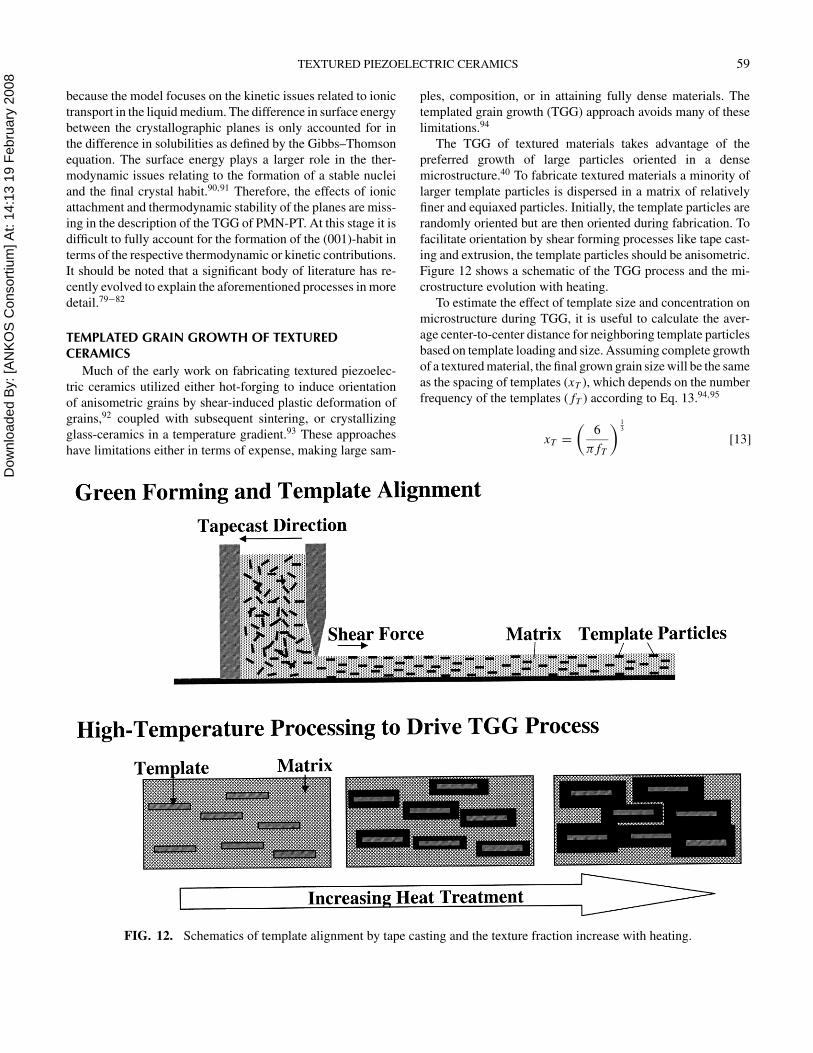
FIG. 12. Schematics of template alignment by tape casting and the texture fraction increase with heating.
ples, composition, or in attaining fully dense materials. The
templated grain growth (TGG) approach avoids many of these
limitations.94
The TGG of textured materials takes advantage of the
preferred growth of large particles oriented in a dense
microstructure.40 To fabricate textured materials a minority of
larger template particles is dispersed in a matrix of relatively
finer and equiaxed particles. Initially, the template particles are
randomly oriented but are then oriented during fabrication. To
facilitate orientation by shear forming processes like tape cast-
ing and extrusion, the template particles should be anisometric.
Figure 12 shows a schematic of the TGG process and the mi-
crostructure evolution with heating.
To estimate the effect of template size and concentration on
microstructure during TGG, it is useful to calculate the aver-
age center-to-center distance for neighboring template particles
based on template loading and size. Assuming complete growth
of a textured material, the final grown grain size will be the same
as the spacing of templates (xT ), which depends on the number
frequency of the templates ( fT ) according to Eq. 13.94,95
xT =
(
6
π fT
)13
[13]
Dow
nloa
ded
By:
[AN
KO
S C
onso
rtium
] At:
14:1
3 19
Feb
ruar
y 20
08 60 G. L. MESSING ET AL.
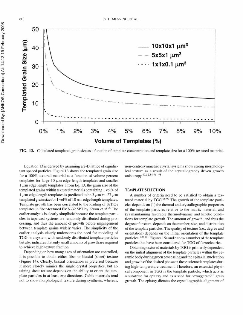
FIG. 13. Calculated templated grain size as a function of template concentration and template size for a 100% textured material.
Equation 13 is derived by assuming a 2-D lattice of equidis-
tant spaced particles. Figure 13 shows the templated grain size
for a 100% textured material as a function of volume percent
templates for large 10 µm edge length templates and smaller
1 µm edge length templates. From Eq. 13, the grain size of the
templated grains within textured materials containing 1 vol% of
1 µm edge length templates is predicted to be 3 µm vs. 27 µm
templated grain size for 1 vol% of 10 µm edge length templates.
Template growth has been correlated to the loading of SrTiO3
templates in fiber-textured PMN-32.5PT by Kwon et al.95 The
earlier analysis is clearly simplistic because the template parti-
cles in tape cast systems are randomly distributed during pro-
cessing, and thus the amount of growth before impingement
between template grains widely varies. The simplicity of the
earlier analysis clearly underscores the need for modeling of
TGG in a system with randomly distributed template particles
but also indicates that only small amounts of growth are required
to achieve high texture fraction.
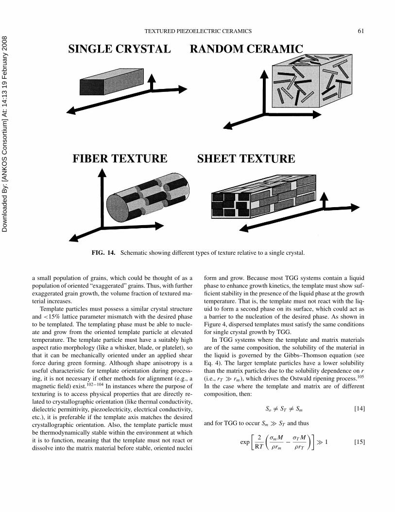
Depending on how many axes of orientation are controlled,
it is possible to obtain either fiber or biaxial (sheet) texture
(Figure 14). Clearly, biaxial orientation is preferred because
it more closely mimics the single crystal properties, but at-
taining sheet texture depends on the ability to orient the tem-
plate particles in at least two directions. Cubic materials tend
not to show morphological texture during synthesis, whereas,
non-centrosymmetric crystal systems show strong morpholog-
ical texture as a result of the crystallography driven growth
anisotropy.40,52,84,96−98
TEMPLATE SELECTION
A number of criteria need to be satisfied to obtain a tex-
tured material by TGG.98,99 The growth of the template parti-
cles depends on (1) the thermal and crystallographic properties
of the template particles relative to the matrix material, and
(2) maintaining favorable thermodynamic and kinetic condi-
tions for template growth. The amount of growth, and thus the
degree of texture, depends on the number, size, and distribution
of the template particles. The quality of texture (i.e., degree and
orientation) depends on the initial orientation of the template
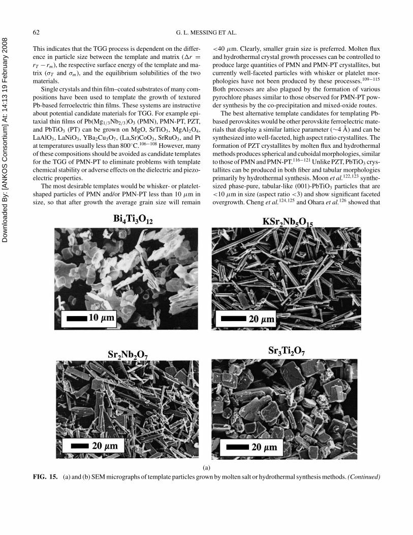
particles.100,101 Figures 15a and b show a number of the template
particles that have been considered for TGG of ferroelectrics.
Obtaining textured materials by TGG is primarily dependent
on the initial alignment of the template particles within the ce-
ramic body during green processing and the epitaxial nucleation
and growth of the desired phase on these oriented templates dur-
ing high-temperature treatment. Therefore, an essential physi-
cal component in TGG is the template particle, which acts as
a substrate for epitaxy and as a seed for “exaggerated” grain
growth. The epitaxy dictates the crystallographic alignment of
Dow
nloa
ded
By:
[AN
KO
S C
onso
rtium
] At:
14:1
3 19
Feb
ruar
y 20
08 TEXTURED PIEZOELECTRIC CERAMICS 61
FIG. 14. Schematic showing different types of texture relative to a single crystal.
a small population of grains, which could be thought of as a
population of oriented “exaggerated” grains. Thus, with further
exaggerated grain growth, the volume fraction of textured ma-
terial increases.
Template particles must possess a similar crystal structure
and <15% lattice parameter mismatch with the desired phase
to be templated. The templating phase must be able to nucle-
ate and grow from the oriented template particle at elevated
temperature. The template particle must have a suitably high
aspect ratio morphology (like a whisker, blade, or platelet), so
that it can be mechanically oriented under an applied shear
force during green forming. Although shape anisotropy is a
useful characteristic for template orientation during process-
ing, it is not necessary if other methods for alignment (e.g., a
magnetic field) exist.102−104 In instances where the purpose of
texturing is to access physical properties that are directly re-
lated to crystallographic orientation (like thermal conductivity,
dielectric permittivity, piezoelectricity, electrical conductivity,
etc.), it is preferable if the template axis matches the desired
crystallographic orientation. Also, the template particle must
be thermodynamically stable within the environment at which
it is to function, meaning that the template must not react or
dissolve into the matrix material before stable, oriented nuclei
form and grow. Because most TGG systems contain a liquid
phase to enhance growth kinetics, the template must show suf-
ficient stability in the presence of the liquid phase at the growth
temperature. That is, the template must not react with the liq-
uid to form a second phase on its surface, which could act as
a barrier to the nucleation of the desired phase. As shown in
Figure 4, dispersed templates must satisfy the same conditions
for single crystal growth by TGG.
In TGG systems where the template and matrix materials
are of the same composition, the solubility of the material in
the liquid is governed by the Gibbs–Thomson equation (see
Eq. 4). The larger template particles have a lower solubility
than the matrix particles due to the solubility dependence on r
(i.e., rT ≫ rm), which drives the Ostwald ripening process.105
In the case where the template and matrix are of different
composition, then:
So = ST = Sm [14]
and for TGG to occur Sm ≫ ST and thus
exp
[
2
RT
(
σm M
ρrm
−σT M
ρrT
)]
≫ 1 [15]
Dow
nloa
ded
By:
[AN
KO
S C
onso
rtium
] At:
14:1
3 19
Feb
ruar
y 20
08 62 G. L. MESSING ET AL.
This indicates that the TGG process is dependent on the differ-
ence in particle size between the template and matrix (�r =
rT − rm), the respective surface energy of the template and ma-
trix (σT and σm), and the equilibrium solubilities of the two
materials.
Single crystals and thin film–coated substrates of many com-
positions have been used to template the growth of textured
Pb-based ferroelectric thin films. These systems are instructive
about potential candidate materials for TGG. For example epi-
taxial thin films of Pb(Mg1/3Nb2/3)O3 (PMN), PMN-PT, PZT,
and PbTiO3 (PT) can be grown on MgO, SrTiO3, MgAl2O4,
LaAlO3, LaNiO3, YBa2Cu3O7, (La,Sr)CoO3, SrRuO3, and Pt
at temperatures usually less than 800◦C.106−108 However, many
of these compositions should be avoided as candidate templates
for the TGG of PMN-PT to eliminate problems with template
chemical stability or adverse effects on the dielectric and piezo-
electric properties.
The most desirable templates would be whisker- or platelet-
shaped particles of PMN and/or PMN-PT less than 10 µm in
size, so that after growth the average grain size will remain
(a)
FIG. 15. (a) and (b) SEM micrographs of template particles grown by molten salt or hydrothermal synthesis methods. (Continued)
<40 µm. Clearly, smaller grain size is preferred. Molten flux
and hydrothermal crystal growth processes can be controlled to
produce large quantities of PMN and PMN-PT crystallites, but
currently well-faceted particles with whisker or platelet mor-
phologies have not been produced by these processes.109−115
Both processes are also plagued by the formation of various
pyrochlore phases similar to those observed for PMN-PT pow-
der synthesis by the co-precipitation and mixed-oxide routes.
The best alternative template candidates for templating Pb-
based perovskites would be other perovskite ferroelectric mate-
rials that display a similar lattice parameter (∼4 A) and can be
synthesized into well-faceted, high aspect ratio crystallites. The
formation of PZT crystallites by molten flux and hydrothermal
methods produces spherical and cuboidal morphologies, similar
to those of PMN and PMN-PT.116−121 Unlike PZT, PbTiO3 crys-
tallites can be produced in both fiber and tabular morphologies
primarily by hydrothermal synthesis. Moon et al.122,123 synthe-
sized phase-pure, tabular-like (001)-PbTiO3 particles that are
<10 µm in size (aspect ratio <3) and show significant faceted
overgrowth. Cheng et al.124,125 and Ohara et al.126 showed that
Dow
nloa
ded
By:
[AN
KO
S C
onso
rtium
] At:
14:1
3 19
Feb
ruar
y 20
08 TEXTURED PIEZOELECTRIC CERAMICS 63
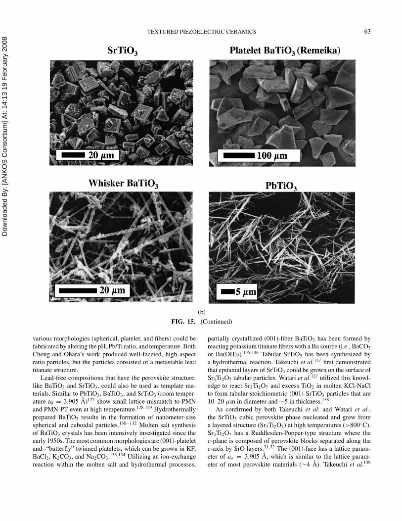
(b)
FIG. 15. (Continued)
various morphologies (spherical, platelet, and fibers) could be
fabricated by altering the pH, Pb/Ti ratio, and temperature. Both
Cheng and Ohara’s work produced well-faceted, high aspect
ratio particles, but the particles consisted of a metastable lead
titanate structure.
Lead-free compositions that have the perovskite structure,
like BaTiO3 and SrTiO3, could also be used as template ma-
terials. Similar to PbTiO3, BaTiO3, and SrTiO3 (room temper-
ature a0 = 3.905 A)127 show small lattice mismatch to PMN
and PMN-PT even at high temperature.128,129 Hydrothermally
prepared BaTiO3 results in the formation of nanometer-size
spherical and cuboidal particles.130−132 Molten salt synthesis
of BaTiO3 crystals has been intensively investigated since the
early 1950s. The most common morphologies are (001)-platelet
and -“butterfly” twinned platelets, which can be grown in KF,
BaCl2, K2CO3, and Na2CO3.133,134 Utilizing an ion-exchange
reaction within the molten salt and hydrothermal processes,
partially crystallized (001)-fiber BaTiO3 has been formed by
reacting potassium titanate fibers with a Ba source (i.e., BaCO3
or Ba(OH)2).135,136 Tabular SrTiO3 has been synthesized by
a hydrothermal reaction. Takeuchi et al.137 first demonstrated
that epitaxial layers of SrTiO3 could be grown on the surface of
Sr3Ti2O7 tabular particles. Watari et al.127 utilized this knowl-
edge to react Sr3Ti2O7 and excess TiO2 in molten KCl-NaCl
to form tabular stoichiometric (001)-SrTiO3 particles that are
10–20 µm in diameter and ∼5 in thickness.138
As confirmed by both Takeuchi et al. and Watari et al.,
the SrTiO3 cubic perovskite phase nucleated and grew from
a layered structure (Sr3Ti2O7) at high temperatures (>800◦C).
Sr3Ti2O7 has a Ruddlesden-Popper-type structure where the
c-plane is composed of perovskite blocks separated along the
c-axis by SrO layers.31,32 The (001)-face has a lattice param-
eter of ao = 3.905 A, which is similar to the lattice param-
eter of most perovskite materials (∼4 A). Takeuchi et al.139
Dow
nloa
ded
By:
[AN
KO
S C
onso
rtium
] At:
14:1
3 19
Feb
ruar
y 20
08 64 G. L. MESSING ET AL.
also showed that epitaxial single crystal layers of (001)-PbTiO3
could grow on (001)-Bi4Ti3O12 platelets, another layered struc-
ture with perovskite-type block. Bi4Ti3O12 is an Aurivillius
compound that consists of three perovskite-like units (BiTiOx)
separated by two (Bi2O2)2+ layers along the c-axis.140 Ramesh
et al.141,142 and Ghonge et al.143 used a thin film of Bi4Ti3O12
to template the epitaxial growth of various heterostructures of
PZT in the [001] by pulsed laser deposition. These reports rein-
force the idea that compositions that possess layered perovskite
structures can be utilized to template cubic perovskite materi-
als, especially Pb-based ferroelectric perovskite compositions
like PMN-PT. This would be very beneficial for the TGG of
PMN-PT, because anisotropic, (001)-faceted particles of lay-
ered perovskite materials are relatively easy to form by molten
salt and hydrothermal processes.
Sabolsky did an extensive study to identify possible template
candidates for texturing PMN-PT ceramics by TGG in the 〈001〉
by comparing various cubic perovskite and layered-perovskite
materials using the criteria previously stated.73 Sabolsky pri-
marily focused on the use of non-lead-based compositions
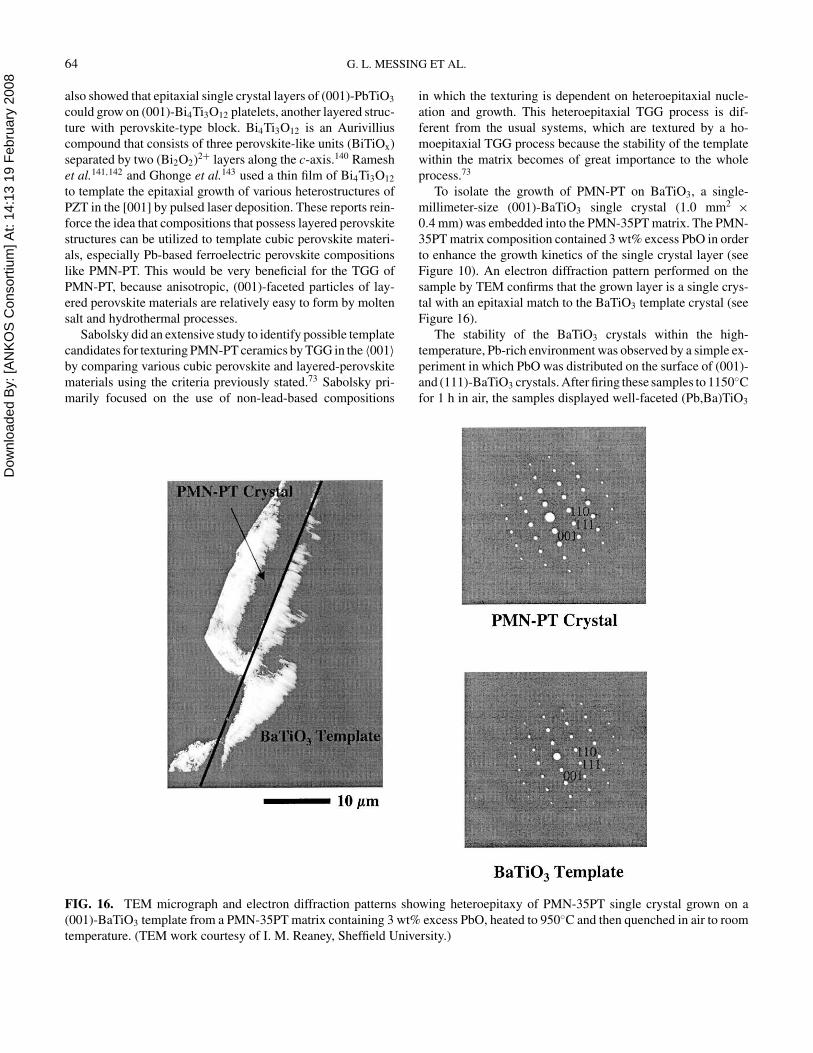
FIG. 16. TEM micrograph and electron diffraction patterns showing heteroepitaxy of PMN-35PT single crystal grown on a
(001)-BaTiO3 template from a PMN-35PT matrix containing 3 wt% excess PbO, heated to 950◦C and then quenched in air to room
temperature. (TEM work courtesy of I. M. Reaney, Sheffield University.)
in which the texturing is dependent on heteroepitaxial nucle-
ation and growth. This heteroepitaxial TGG process is dif-
ferent from the usual systems, which are textured by a ho-
moepitaxial TGG process because the stability of the template
within the matrix becomes of great importance to the whole
process.73
To isolate the growth of PMN-PT on BaTiO3, a single-
millimeter-size (001)-BaTiO3 single crystal (1.0 mm2 ×
0.4 mm) was embedded into the PMN-35PT matrix. The PMN-
35PT matrix composition contained 3 wt% excess PbO in order
to enhance the growth kinetics of the single crystal layer (see
Figure 10). An electron diffraction pattern performed on the
sample by TEM confirms that the grown layer is a single crys-
tal with an epitaxial match to the BaTiO3 template crystal (see
Figure 16).
The stability of the BaTiO3 crystals within the high-
temperature, Pb-rich environment was observed by a simple ex-
periment in which PbO was distributed on the surface of (001)-
and (111)-BaTiO3 crystals. After firing these samples to 1150◦C
for 1 h in air, the samples displayed well-faceted (Pb,Ba)TiO3
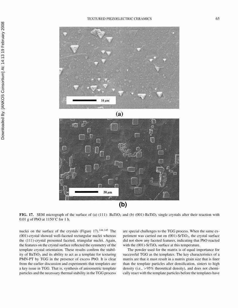
Dow
nloa
ded
By:
[AN
KO
S C
onso
rtium
] At:
14:1
3 19
Feb
ruar
y 20
08 TEXTURED PIEZOELECTRIC CERAMICS 65
FIG. 17. SEM micrograph of the surface of (a) (111)- BaTiO3 and (b) (001)-BaTiO3 single crystals after their reaction with
0.01 g of PbO at 1150◦C for 1 h.
nuclei on the surface of the crystals (Figure 17).144,145 The
(001)-crystal showed well-faceted rectangular nuclei whereas
the (111)-crystal presented faceted, triangular nuclei. Again,
the features on the crystal surface reflected the symmetry of the
template crystal orientation. These results confirm the stabil-
ity of BaTiO3 and its ability to act as a template for texturing
PMN-PT by TGG in the presence of excess PbO. It is clear
from the earlier discussion and experiments that templates are
a key issue in TGG. That is, synthesis of anisometric template
particles and the necessary thermal stability in the TGG process
are special challenges to the TGG process. When the same ex-
periment was carried out on (001)-SrTiO3, the crystal surface
did not show any faceted features, indicating that PbO reacted
with the (001)-SrTiO3 surface at this temperature.
The powder used for the matrix is of equal importance for
successful TGG as the templates. The key characteristics of a
matrix are that it must result in a matrix grain size that is finer
than the template particles after densification, sinters to high
density (i.e., >95% theoretical density), and does not chemi-
cally react with the template particles before the templates have
Dow
nloa
ded
By:
[AN
KO
S C
onso
rtium
] At:
14:1
3 19
Feb
ruar
y 20
08 66 G. L. MESSING ET AL.
served their function. There are basically two approaches for
TGG depending on the nature of the powder.
In TGG, the powder is already in the final phase form and, as
described earlier, texture evolves by growth of the template par-
ticle once the ceramic exceeds 95% density. When the matrix
is a precursor to the final ceramic phase, the template particles
can act as nucleation sites and seed the phase transformation of
the matrix. This process is referred to as Reactive TGG (RTGG)
(Figure 4) because of the dual role of the templates.44,146 It is
important to note that the material seeded by the template also
has the same crystallographic orientation as the template and
thus the effective volume of oriented material prior to densifica-
tion can be significantly greater than with TGG. Alternatively,
the template particle may react with the matrix to obtain the
desired oriented phase. This approach is topotactic and the fi-
nal phase takes the morphological form of the original template
particle.43,147,148
In crystal systems, growth perpendicular to the more densely
packed atomic planes (e.g., (111)) is relatively faster than less
densely packed planes (e.g., (001)). This growth rate anisotropy
means that the dimension of the growing surface must be greater
than the matrix grain size to maintain a thermodynamic advan-
tage for growth. As shown for the growth of single crystals
by TGG, matrix grain growth can reduce the thermodynamic
driving force enough that template growth stops.64 Thus, a large
size difference between the template particles and matrix grains
results in more template growth. It has been shown that the min-
imum size ratio to sustain template growth is ∼1.5,99 which is
consistent with Hillert’s critical size criteria for exaggerated
grain growth. Clearly, a larger size difference is preferred so
that growth is not thermodynamically limited.
After orienting the template particles in the matrix, the
formed part must be densified prior to template growth. Be-
cause pores restrain boundary motion, significant growth can
not occur until >95% density is achieved.99,149 Also, because
the template particles are larger than the matrix particles, they
constrain densification. Therefore, a liquid phase is often used
for sintering to reduce the stress around the template particles as
well as to accelerate the growth process. Template growth is ini-
tially rapid once >95% density is reached. The overall growth
kinetics slow once the growing grains “impinge” and there is
significantly less thermodynamic driving force for growth at
the interface between the impinged grains. A slower growth
process perpendicular to the fast growth direction continues
until the matrix is completely consumed or the matrix grains
coarsen so much that there is no thermodynamic driving force
for growth.
Just like single crystal growth in a polycrystalline matrix,
the kinetics of template growth are well explained by either
interface reaction control or diffusion-controlled models. As
shown for BaTiO3 and PMN-PT, initial growth is diffusion
controlled but changes to interface reaction control if the grains
become faceted. Detailed analyses of these processes are de-
scribed elsewhere.79−82
TEXTURED PIEZOELECTRICS
In this section, the development of texture in a variety of
piezoelectric ceramics is described, with examples of sheet
and fiber-textured materials. From an organizational standpoint,
several low symmetry systems, in which high aspect ratio tem-
plates are readily available, are discussed first. Then, TGG in
a high prototype symmetry ferroelectric (i.e., PMN-PT) is dis-
cussed. The impact of texture on the resulting properties is
evaluated.
Texture can be evaluated by a number of techniques includ-
ing relative peak heights (i.e., Lotgering factor), rocking curves,
OIM, and stereology. Although the authors have used all of
these techniques, they most often use the relative peak heights
to gauge the relative degree of texture between samples. To
estimate the 〈001〉-texture fraction by the Lotgering method.150
f(00l) =P(00l) − Po
1 − Po
[16]
where
P(00l) =
∑
I(00l)
I(hkl)
[17]
P0 =
∑
Io(00l)
Io(hkl)
[18]
� I(00l) is the summation of the XRD peak intensities of all the
(00l) peaks (i.e., 001, 002 . . .) in the textured sample pattern.
� I(hkl) is the summation of the peak intensities of all (hkl) peaks
which appear in the XRD pattern. � Io(00l) and � Io(hkl) are sum-
mations of the XRD peak intensities for a randomly oriented
sample. The f factors were calculated for a 2θ scan between
20–70◦. The calculated f describes the degree of texture de-
fined by the surface area which was characterized by XRD. The
f factor is considered to be an estimation of the volume fraction
of textured material.
Okazaki et al. reviewed the early literature on textured piezo-
electric ceramics up to the mid-1980s.34 Table 4 is a summary of
the most recent data that shows the piezoelectric coefficients of
a number of textured ceramics as a function of texture fraction.
Where possible, the piezoelectric coefficient is compared to the
single crystal value or the polycrystalline value, if the single
crystal value does not exist. As seen in Table 4, when the com-
position was textured in the polarization direction, there was
always an increase in the piezoelectric coefficient relative to
the random ceramic due to the increase in poling efficiency.
The majority of piezoelectric compositions textured to date
possess relatively low symmetry, and thus, these compositions
show an innate ability to form anisometric grains and undergo
anisotropic grain growth. This behavior assists in the initial ori-
entation of the grain structure during green processing and sub-
sequent texture development due to anisotropic grain growth
during high temperature treatment. BaTiO3, pure and modi-
fied Bi0.5(Na0.85K0.15)0.5TiO3, modified PZT, and PMN-PT are
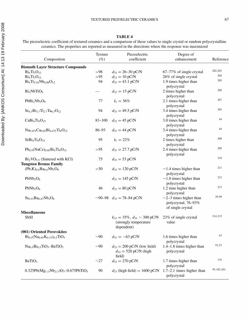
Dow
nloa
ded
By:
[AN
KO
S C
onso
rtium
] At:
14:1
3 19
Feb
ruar
y 20
08 TEXTURED PIEZOELECTRIC CERAMICS 67
TABLE 4
The piezoelectric coefficient of textured ceramics and a comparison of these values to single crystal or random polycrystalline
ceramics. The properties are reported as measured in the directions where the response was maximized
Texture Piezoelectric Degree of
Composition (%) coefficient enhancement Reference
Bismuth Layer Structure Compounds
Bi4Ti3O12 >98 d33 = 26–30 pC/N 67–77% of single crystal 202,203
Bi4Ti3O12 >95 d33 = 10 pC/N 26% of single crystal 204
Bi4Ti2.92Nb0.08O12 94 d33 = 43.1 pC/N 1.9 times higher than
polycrystal
205
Bi3NbTiO9 — d33 = 15 pC/N 2 times higher than
polycrystal
206
PbBi2Nb2O9 77 kt = 36% 2.1 times higher than
polycrystal
207
Sr0.3Bi3.7Ti2.7Ta0.3O12 94 d33 = 49.5 pC/N 3.4 times higher than
polycrystal
205
CaBi4Ti4O15 83–100 d33 = 45 pC/N 3.0 times higher than
polycrystal
44
Na0.475Ca0.05Bi4.475Ti4O15 86–93 d33 = 44 pC/N 3.4 times higher than
polycrystal
44
SrBi4Ti4O15 95 kt = 22% 2 times higher than
polycrystal
208
Pb0.9(NaCe)0.05Bi4Ti4O15 >95 d33 = 27.7 pC/N 2.4 times higher than
polycrystal
209
Bi2VO5.5 (Sintered with KCl) 75 d33 = 53 pC/N 210
Tungsten Bronze Family
(Pb,K)0.4Ba0.6Nb2O6 >50 d33 = 120 pC/N ∼1.4 times higher than
polycrystal
211
PbNb2O6 d33 = 145 pC/N ∼1.8 times higher than
polycrystal
212
PbNb2O6 46 d33 = 80 pC/N 1.2 time higher than
polycrystal
213
Sr0.53Ba0.47Nb2O6 ∼90–98 d33 = 78–84 pC/N ∼2–3 times higher than
polycrystal, 76–93%
of single crystal
39,98
Miscellaneous
SbSI k33 = 35%, d33 ∼ 300 pC/N
(strongly temperature
dependent)
23% of single crystal
value
214,215
(001) Oriented Perovskites
Bi0.5(Na0.85K0.15)0.5TiO3 ∼90 d31 = −63 pC/N 1.6 times higher than
polycrystal
43
Na0.5Bi0.5TiO3–BaTiO3 ∼90 d33 = 200 pC/N (low field)
d33 = 520 pC/N (high
field)
1.4–1.8 times higher than
polycrystal
52,53
BaTiO3 ∼27 d33 = 270 pC/N 1.7 times higher than
polycrystal
135
0.325Pb(Mg1/3Nb2/3)O3–0.675PbTiO3 90 d33 (high field) = 1600 pC/N 1.7–2.1 times higher than
polycrystal
95,182,201
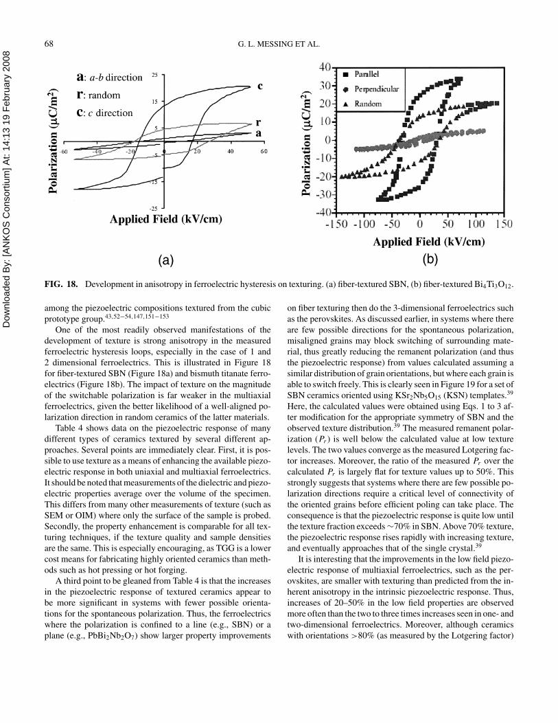
Dow
nloa
ded
By:
[AN
KO
S C
onso
rtium
] At:
14:1
3 19
Feb
ruar
y 20
08 68 G. L. MESSING ET AL.
FIG. 18. Development in anisotropy in ferroelectric hysteresis on texturing. (a) fiber-textured SBN, (b) fiber-textured Bi4Ti3O12.
among the piezoelectric compositions textured from the cubic
prototype group.43,52−54,147,151−153
One of the most readily observed manifestations of the
development of texture is strong anisotropy in the measured
ferroelectric hysteresis loops, especially in the case of 1 and
2 dimensional ferroelectrics. This is illustrated in Figure 18
for fiber-textured SBN (Figure 18a) and bismuth titanate ferro-
electrics (Figure 18b). The impact of texture on the magnitude
of the switchable polarization is far weaker in the multiaxial
ferroelectrics, given the better likelihood of a well-aligned po-
larization direction in random ceramics of the latter materials.
Table 4 shows data on the piezoelectric response of many
different types of ceramics textured by several different ap-
proaches. Several points are immediately clear. First, it is pos-
sible to use texture as a means of enhancing the available piezo-
electric response in both uniaxial and multiaxial ferroelectrics.
It should be noted that measurements of the dielectric and piezo-
electric properties average over the volume of the specimen.
This differs from many other measurements of texture (such as
SEM or OIM) where only the surface of the sample is probed.
Secondly, the property enhancement is comparable for all tex-
turing techniques, if the texture quality and sample densities
are the same. This is especially encouraging, as TGG is a lower
cost means for fabricating highly oriented ceramics than meth-
ods such as hot pressing or hot forging.
A third point to be gleaned from Table 4 is that the increases
in the piezoelectric response of textured ceramics appear to
be more significant in systems with fewer possible orienta-
tions for the spontaneous polarization. Thus, the ferroelectrics
where the polarization is confined to a line (e.g., SBN) or a
plane (e.g., PbBi2Nb2O7) show larger property improvements
on fiber texturing then do the 3-dimensional ferroelectrics such
as the perovskites. As discussed earlier, in systems where there
are few possible directions for the spontaneous polarization,
misaligned grains may block switching of surrounding mate-
rial, thus greatly reducing the remanent polarization (and thus
the piezoelectric response) from values calculated assuming a
similar distribution of grain orientations, but where each grain is
able to switch freely. This is clearly seen in Figure 19 for a set of
SBN ceramics oriented using KSr2Nb5O15 (KSN) templates.39
Here, the calculated values were obtained using Eqs. 1 to 3 af-
ter modification for the appropriate symmetry of SBN and the
observed texture distribution.39 The measured remanent polar-
ization (Pr ) is well below the calculated value at low texture
levels. The two values converge as the measured Lotgering fac-
tor increases. Moreover, the ratio of the measured Pr over the
calculated Pr is largely flat for texture values up to 50%. This
strongly suggests that systems where there are few possible po-
larization directions require a critical level of connectivity of
the oriented grains before efficient poling can take place. The
consequence is that the piezoelectric response is quite low until
the texture fraction exceeds ∼70% in SBN. Above 70% texture,
the piezoelectric response rises rapidly with increasing texture,
and eventually approaches that of the single crystal.39
It is interesting that the improvements in the low field piezo-
electric response of multiaxial ferroelectrics, such as the per-
ovskites, are smaller with texturing than predicted from the in-
herent anisotropy in the intrinsic piezoelectric response. Thus,
increases of 20–50% in the low field properties are observed
more often than the two to three times increases seen in one- and
two-dimensional ferroelectrics. Moreover, although ceramics
with orientations >80% (as measured by the Lotgering factor)
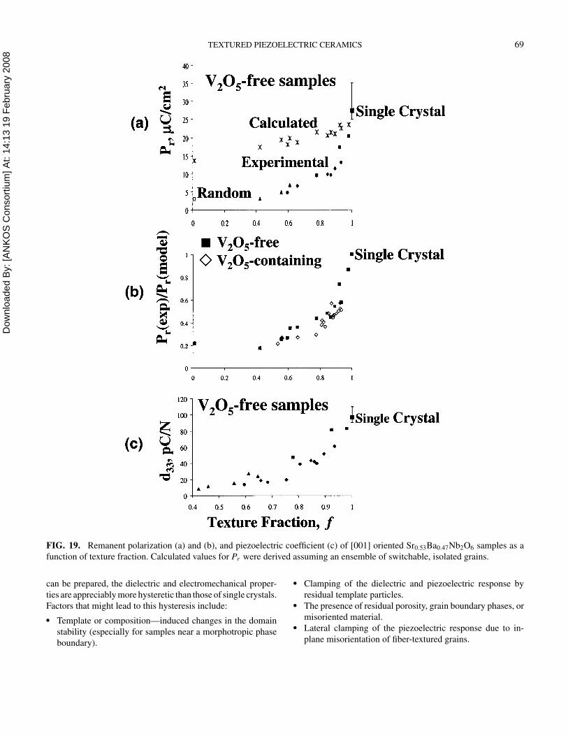
Dow
nloa
ded
By:
[AN
KO
S C
onso
rtium
] At:
14:1
3 19
Feb
ruar
y 20
08 TEXTURED PIEZOELECTRIC CERAMICS 69
FIG. 19. Remanent polarization (a) and (b), and piezoelectric coefficient (c) of [001] oriented Sr0.53Ba0.47Nb2O6 samples as a
function of texture fraction. Calculated values for Pr were derived assuming an ensemble of switchable, isolated grains.
can be prepared, the dielectric and electromechanical proper-
ties are appreciably more hysteretic than those of single crystals.
Factors that might lead to this hysteresis include:
� Template or composition—induced changes in the domain
stability (especially for samples near a morphotropic phase
boundary).
� Clamping of the dielectric and piezoelectric response by
residual template particles.� The presence of residual porosity, grain boundary phases, or
misoriented material.� Lateral clamping of the piezoelectric response due to in-
plane misorientation of fiber-textured grains.
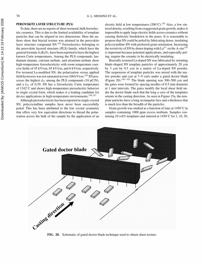
Dow
nloa
ded
By:
[AN
KO
S C
onso
rtium
] At:
14:1
3 19
Feb
ruar
y 20
08 70 G. L. MESSING ET AL.
PEROVSKITE LAYER STRUCTURE (PLS)
To date, there are no reports of sheet-textured, bulk ferroelec-
tric ceramics. This is due to the limited availability of template
particles that can be aligned in two dimensions. Here the au-
thors show that biaxial texture was attained in the perovskite
layer structure compound SN.154 Ferroelectrics belonging to
the perovskite layered structure (PLS) family, which have the
general formula A2B2O7, have been reported to have the highest
known Curie temperatures. Among the PLS compounds, lan-
thanum titanate, calcium niobate, and strontium niobate show
high-temperature ferroelectricity with room temperature coer-
cive fields of 45 kV/cm, 65 kV/cm, and 6 kV/cm, respectively.
For textured La-modified SN, the polarization versus applied
field hysteresis was not saturated at even 100 kV/cm.155 SN pos-
sesses the highest d33 among the PLS compounds (18 pC/N),
and a k33 of 0.29. SN has a ferroelectric Curie temperature
of 1342◦C and shows high-temperature piezoelectric behavior
in single crystal form, which makes it a leading candidate for
device applications in high-temperature environments.156,157
Although piezoelectricity has been reported in single-crystal
SN, polycrystalline samples have never been successfully
poled. This has been attributed to the low crystal symmetry
that offers very few equivalent directions to thread the polar-
ization across the bulk of the sample by the application of an
FIG. 20. Schematic of gated doctor blade technique used to obtain sheet texture.
electric field at low temperatures (200◦C).155 Also, a low sin-
tered density, resulting from exaggerated grain growth, makes it
impossible to apply large electric fields across ceramics without
causing dielectric breakdown in the pores. It is reasonable to
propose that SN could be poled by fabricating dense, insulating
polycrystalline SN with preferred grain orientation. Increasing
the resistivity of SN by donor doping with La3+ on the A-site155
is important because potential applications, and especially pol-
ing, require the ceramic to be electrically insulating.
Biaxially textured La-doped SN was fabricated by orienting
blade-shaped SN template particles of approximately 20 µm
by 3 µm by 0.5 µm in a matrix of La-doped SN powder.
The suspension of template particles was mixed with the ma-
trix powder and cast at 7–9 cm/s under a gated doctor blade
(Figure 20).158−162 The blade opening was 300–500 µm and
the gates were formed by spacing needles of 0.5 mm diameter
at 1 mm intervals. The gates modify the local shear field un-
der the doctor blade such that the long a-axis of the templates
orients in the casting direction. As seen in Figure 15a, the tem-
plate particles have a long rectangular face and a thickness that
is much less than the breadth of the particles.
Grain growth was studied as a function of time at 1450◦C in
samples containing 1000 ppm excess niobium. Samples con-
taining 10 vol% templates and sintered at 1450◦C for 1, 10, 30,
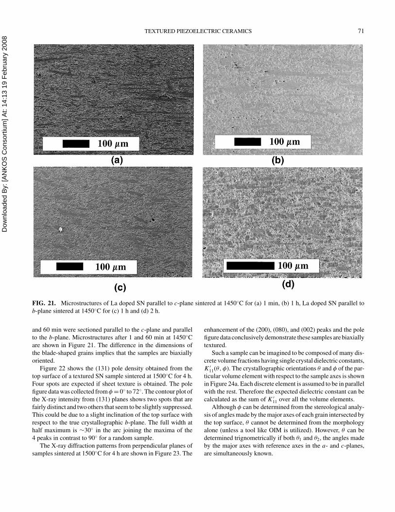
Dow
nloa
ded
By:
[AN
KO
S C
onso
rtium
] At:
14:1
3 19
Feb
ruar
y 20
08 TEXTURED PIEZOELECTRIC CERAMICS 71
FIG. 21. Microstructures of La doped SN parallel to c-plane sintered at 1450◦C for (a) 1 min, (b) 1 h, La doped SN parallel to
b-plane sintered at 1450◦C for (c) 1 h and (d) 2 h.
and 60 min were sectioned parallel to the c-plane and parallel
to the b-plane. Microstructures after 1 and 60 min at 1450◦C
are shown in Figure 21. The difference in the dimensions of
the blade-shaped grains implies that the samples are biaxially
oriented.
Figure 22 shows the (131) pole density obtained from the
top surface of a textured SN sample sintered at 1500◦C for 4 h.
Four spots are expected if sheet texture is obtained. The pole
figure data was collected from φ = 0◦ to 72◦. The contour plot of
the X-ray intensity from (131) planes shows two spots that are
fairly distinct and two others that seem to be slightly suppressed.
This could be due to a slight inclination of the top surface with
respect to the true crystallographic b-plane. The full width at
half maximum is ∼30◦ in the arc joining the maxima of the
4 peaks in contrast to 90◦ for a random sample.
The X-ray diffraction patterns from perpendicular planes of
samples sintered at 1500◦C for 4 h are shown in Figure 23. The
enhancement of the (200), (080), and (002) peaks and the pole
figure data conclusively demonstrate these samples are biaxially
textured.
Such a sample can be imagined to be composed of many dis-
crete volume fractions having single crystal dielectric constants,
K ′11(θ, φ). The crystallographic orientations θ and φ of the par-
ticular volume element with respect to the sample axes is shown
in Figure 24a. Each discrete element is assumed to be in parallel
with the rest. Therefore the expected dielectric constant can be
calculated as the sum of K ′11 over all the volume elements.
Although φ can be determined from the stereological analy-
sis of angles made by the major axes of each grain intersected by
the top surface, θ cannot be determined from the morphology
alone (unless a tool like OIM is utilized). However, θ can be
determined trignometrically if both θ1 and θ2, the angles made
by the major axes with reference axes in the a- and c-planes,
are simultaneously known.
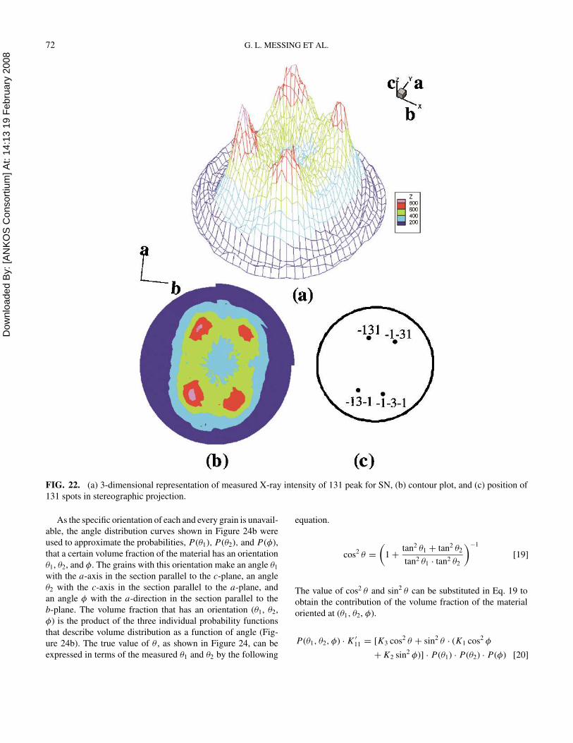
Dow
nloa
ded
By:
[AN
KO
S C
onso
rtium
] At:
14:1
3 19
Feb
ruar
y 20
08 72 G. L. MESSING ET AL.
FIG. 22. (a) 3-dimensional representation of measured X-ray intensity of 131 peak for SN, (b) contour plot, and (c) position of
131 spots in stereographic projection.
As the specific orientation of each and every grain is unavail-
able, the angle distribution curves shown in Figure 24b were
used to approximate the probabilities, P(θ1), P(θ2), and P(φ),
that a certain volume fraction of the material has an orientation
θ1, θ2, and φ. The grains with this orientation make an angle θ1
with the a-axis in the section parallel to the c-plane, an angle
θ2 with the c-axis in the section parallel to the a-plane, and
an angle φ with the a-direction in the section parallel to the
b-plane. The volume fraction that has an orientation (θ1, θ2,
φ) is the product of the three individual probability functions
that describe volume distribution as a function of angle (Fig-
ure 24b). The true value of θ , as shown in Figure 24, can be
expressed in terms of the measured θ1 and θ2 by the following
equation.
cos2 θ =
(
1 +tan2 θ1 + tan2 θ2
tan2 θ1 · tan2 θ2
)−1
[19]
The value of cos2 θ and sin2 θ can be substituted in Eq. 19 to
obtain the contribution of the volume fraction of the material
oriented at (θ1, θ2, φ).
P(θ1, θ2, φ) · K ′11 = [K3 cos2 θ + sin2 θ · (K1 cos2 φ
+ K2 sin2 φ)] · P(θ1) · P(θ2) · P(φ) [20]
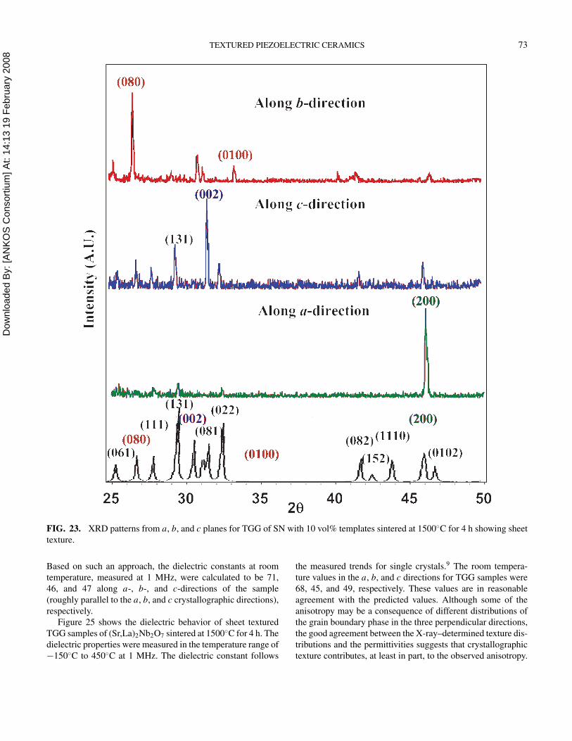
Dow
nloa
ded
By:
[AN
KO
S C
onso
rtium
] At:
14:1
3 19
Feb
ruar
y 20
08 TEXTURED PIEZOELECTRIC CERAMICS 73
FIG. 23. XRD patterns from a, b, and c planes for TGG of SN with 10 vol% templates sintered at 1500◦C for 4 h showing sheet
texture.
Based on such an approach, the dielectric constants at room
temperature, measured at 1 MHz, were calculated to be 71,
46, and 47 along a-, b-, and c-directions of the sample
(roughly parallel to the a, b, and c crystallographic directions),
respectively.
Figure 25 shows the dielectric behavior of sheet textured
TGG samples of (Sr,La)2Nb2O7 sintered at 1500◦C for 4 h. The
dielectric properties were measured in the temperature range of
−150◦C to 450◦C at 1 MHz. The dielectric constant follows
the measured trends for single crystals.9 The room tempera-
ture values in the a, b, and c directions for TGG samples were
68, 45, and 49, respectively. These values are in reasonable
agreement with the predicted values. Although some of the
anisotropy may be a consequence of different distributions of
the grain boundary phase in the three perpendicular directions,
the good agreement between the X-ray–determined texture dis-
tributions and the permittivities suggests that crystallographic
texture contributes, at least in part, to the observed anisotropy.
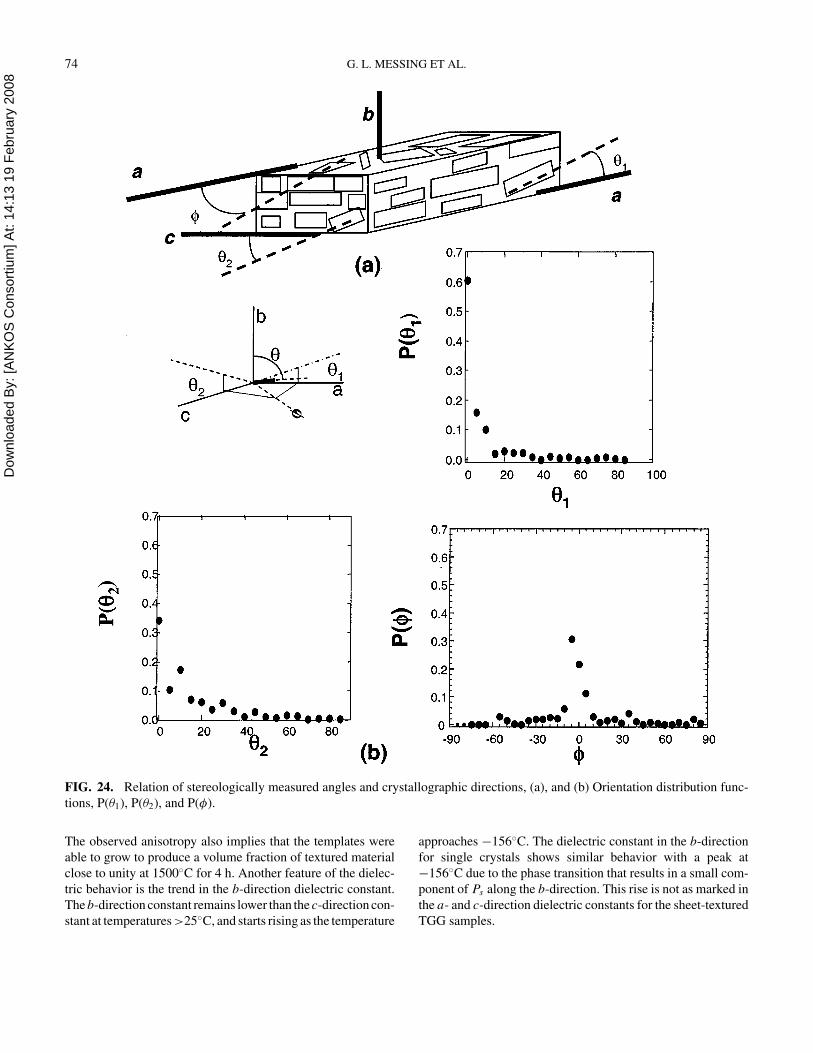
Dow
nloa
ded
By:
[AN
KO
S C
onso
rtium
] At:
14:1
3 19
Feb
ruar
y 20
08 74 G. L. MESSING ET AL.
FIG. 24. Relation of stereologically measured angles and crystallographic directions, (a), and (b) Orientation distribution func-
tions, P(θ1), P(θ2), and P(φ).
The observed anisotropy also implies that the templates were
able to grow to produce a volume fraction of textured material
close to unity at 1500◦C for 4 h. Another feature of the dielec-
tric behavior is the trend in the b-direction dielectric constant.
The b-direction constant remains lower than the c-direction con-
stant at temperatures >25◦C, and starts rising as the temperature
approaches −156◦C. The dielectric constant in the b-direction
for single crystals shows similar behavior with a peak at
−156◦C due to the phase transition that results in a small com-
ponent of Ps along the b-direction. This rise is not as marked in
the a- and c-direction dielectric constants for the sheet-textured
TGG samples.
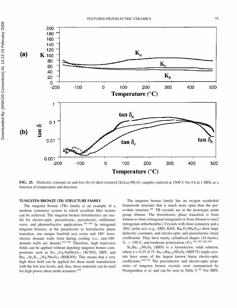
Dow
nloa
ded
By:
[AN
KO
S C
onso
rtium
] At:
14:1
3 19
Feb
ruar
y 20
08 TEXTURED PIEZOELECTRIC CERAMICS 75
FIG. 25. Dielectric constant (a) and loss (b) of sheet textured (Sr,La)2Nb2O7 samples sintered at 1500◦C for 4 h at 1 MHz as a
function of temperature and direction.
TUNGSTEN BRONZE (TB) STRUCTURE FAMILY
The tungsten bronze (TB) family is an example of a
medium symmetry system in which excellent fiber texture
can be achieved. The tungsten bronze ferroelectrics are use-
ful for electro-optic, piezoelectric, pyroelectric, millimeter
wave, and photorefractive applications.163,164 In tetragonal
tungsten bronzes, at the paraelectric to ferroelectric phase
transition, one unique fourfold axis exists and 180◦ ferro-
electric domain walls form during cooling (i.e., non-180◦
domain walls are absent).165,166 Therefore, high transverse
fields can be applied without depoling tungsten bronze com-
positions such as Sr2−xCaxNaNb5O15 (SCNN), SBN, and
Ba2−xSrxK1−yNayNb5O15 (BSKNN). This means that a very
high drive field can be applied for shear mode transduction
with the low loss levels, and, thus, these materials can be used
for high-power shear mode actuators.165
The tungsten bronze family has an oxygen octahedral
framework structure that is much more open than the per-
ovskite structure.167 TB crystals are in the prototypic point
group 4/mmm. The ferroelectric phase transition is from
4/mmm to 4mm (tetragonal-tetragonal) or from 4/mmm to mm2
(tetragonal-orthorhombic). Crystals with 4mm symmetry and a
〈001〉 polar axis (e.g., SBN, KSN, Ba6Ti2Nb8O30) show large
dielectric constants, and electro-optic and piezoelectric strain
coefficients. They have nearly cylindrical shapes (24-facets),
TC < 150◦C, and moderate polarization (P3).164,165,168,169
SrxBa1−xNb2O6 (SBN) is a ferroelectric solid solution,
where x = 0.25–0.75. Sr0.75Ba0.25Nb2O6 (SBN75) single crys-
tals have some of the largest known linear electro-optic
coefficients.164,170 The piezoelectric and electro-optic prop-
erties of tungsten bronze crystals were summarized by
Neurgaonkar et al. and can be seen in Table 5.165 For SBN,
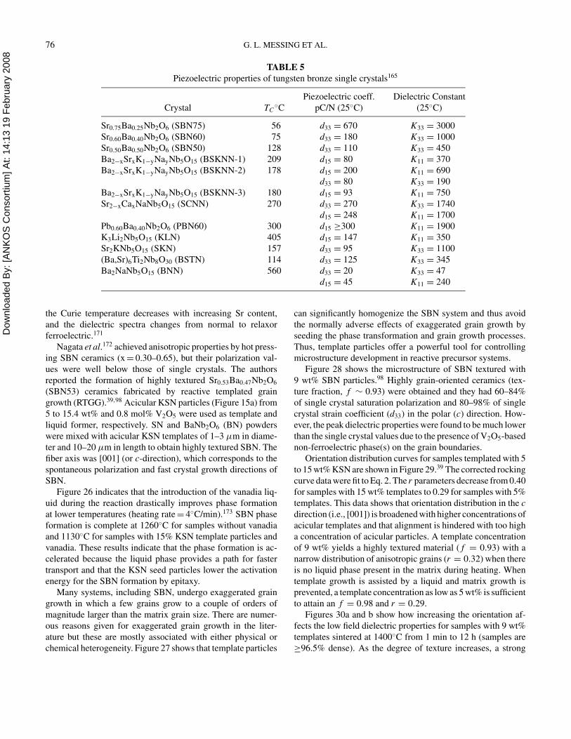
Dow
nloa
ded
By:
[AN
KO
S C
onso
rtium
] At:
14:1
3 19
Feb
ruar
y 20
08 76 G. L. MESSING ET AL.
TABLE 5
Piezoelectric properties of tungsten bronze single crystals165
Piezoelectric coeff. Dielectric Constant
Crystal TC◦C pC/N (25◦C) (25◦C)
Sr0.75Ba0.25Nb2O6 (SBN75) 56 d33 = 670 K33 = 3000
Sr0.60Ba0.40Nb2O6 (SBN60) 75 d33 = 180 K33 = 1000
Sr0.50Ba0.50Nb2O6 (SBN50) 128 d33 = 110 K33 = 450
Ba2−xSrxK1−yNayNb5O15 (BSKNN-1) 209 d15 = 80 K11 = 370
Ba2−xSrxK1−yNayNb5O15 (BSKNN-2) 178 d15 = 200 K11 = 690
d33 = 80 K33 = 190
Ba2−xSrxK1−yNayNb5O15 (BSKNN-3) 180 d15 = 93 K11 = 750
Sr2−xCaxNaNb5O15 (SCNN) 270 d33 = 270 K33 = 1740
d15 = 248 K11 = 1700
Pb0.60Ba0.40Nb2O6 (PBN60) 300 d15 ≥300 K11 = 1900
K3Li2Nb5O15 (KLN) 405 d15 = 147 K11 = 350
Sr2KNb5O15 (SKN) 157 d33 = 95 K33 = 1100
(Ba,Sr)6Ti2Nb8O30 (BSTN) 114 d33 = 125 K33 = 345
Ba2NaNb5O15 (BNN) 560 d33 = 20 K33 = 47
d15 = 45 K11 = 240
the Curie temperature decreases with increasing Sr content,
and the dielectric spectra changes from normal to relaxor
ferroelectric.171
Nagata et al.172 achieved anisotropic properties by hot press-
ing SBN ceramics (x = 0.30–0.65), but their polarization val-
ues were well below those of single crystals. The authors
reported the formation of highly textured Sr0.53Ba0.47Nb2O6
(SBN53) ceramics fabricated by reactive templated grain
growth (RTGG).39,98 Acicular KSN particles (Figure 15a) from
5 to 15.4 wt% and 0.8 mol% V2O5 were used as template and
liquid former, respectively. SN and BaNb2O6 (BN) powders
were mixed with acicular KSN templates of 1–3 µm in diame-
ter and 10–20 µm in length to obtain highly textured SBN. The
fiber axis was [001] (or c-direction), which corresponds to the
spontaneous polarization and fast crystal growth directions of
SBN.
Figure 26 indicates that the introduction of the vanadia liq-
uid during the reaction drastically improves phase formation
at lower temperatures (heating rate = 4◦C/min).173 SBN phase
formation is complete at 1260◦C for samples without vanadia
and 1130◦C for samples with 15% KSN template particles and
vanadia. These results indicate that the phase formation is ac-
celerated because the liquid phase provides a path for faster
transport and that the KSN seed particles lower the activation
energy for the SBN formation by epitaxy.
Many systems, including SBN, undergo exaggerated grain
growth in which a few grains grow to a couple of orders of
magnitude larger than the matrix grain size. There are numer-
ous reasons given for exaggerated grain growth in the liter-
ature but these are mostly associated with either physical or
chemical heterogeneity. Figure 27 shows that template particles
can significantly homogenize the SBN system and thus avoid
the normally adverse effects of exaggerated grain growth by
seeding the phase transformation and grain growth processes.
Thus, template particles offer a powerful tool for controlling
microstructure development in reactive precursor systems.
Figure 28 shows the microstructure of SBN textured with
9 wt% SBN particles.98 Highly grain-oriented ceramics (tex-
ture fraction, f ∼ 0.93) were obtained and they had 60–84%
of single crystal saturation polarization and 80–98% of single
crystal strain coefficient (d33) in the polar (c) direction. How-
ever, the peak dielectric properties were found to be much lower
than the single crystal values due to the presence of V2O5-based
non-ferroelectric phase(s) on the grain boundaries.
Orientation distribution curves for samples templated with 5
to 15 wt% KSN are shown in Figure 29.39 The corrected rocking
curve data were fit to Eq. 2. The r parameters decrease from 0.40
for samples with 15 wt% templates to 0.29 for samples with 5%
templates. This data shows that orientation distribution in the c
direction (i.e., [001]) is broadened with higher concentrations of
acicular templates and that alignment is hindered with too high
a concentration of acicular particles. A template concentration
of 9 wt% yields a highly textured material ( f = 0.93) with a
narrow distribution of anisotropic grains (r = 0.32) when there
is no liquid phase present in the matrix during heating. When
template growth is assisted by a liquid and matrix growth is
prevented, a template concentration as low as 5 wt% is sufficient
to attain an f = 0.98 and r = 0.29.
Figures 30a and b show how increasing the orientation af-
fects the low field dielectric properties for samples with 9 wt%
templates sintered at 1400◦C from 1 min to 12 h (samples are
≥96.5% dense). As the degree of texture increases, a strong
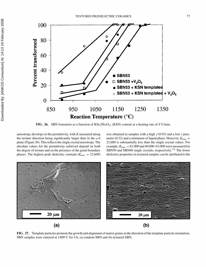
Dow
nloa
ded
By:
[AN
KO
S C
onso
rtium
] At:
14:1
3 19
Feb
ruar
y 20
08 TEXTURED PIEZOELECTRIC CERAMICS 77
FIG. 26. SBN formation as a function of KSr2Nb5O15 (KSN) content at a heating rate of 4◦C/min.
anisotropy develops in the permittivity, with K measured along
the texture direction being significantly larger than in the a-b
plane (Figure 30). This reflects the single crystal anisotropy. The
absolute values for the permittivity achieved depend on both
the degree of texture and on the presence of the grain boundary
phases. The highest peak dielectric constant (Kmax = 23,600)
FIG. 27. Template particles promote the growth and alignment of matrix grains in the direction of the template particle orientation.
SBN samples were sintered at 1400◦C for 4 h, (a) random SBN and (b) textured SBN.
was obtained in samples with a high f (0.93) and a low r para-
meter (0.32) and a minimum of liquid phase. However, Kmax =
23,600 is substantially less than the single crystal values. For
example, Kmax = 81,000 and 40,000–63,000 were measured for
SBN50 and SBN60 single crystals, respectively.174 The lower
dielectric properties in textured samples can be attributed to the
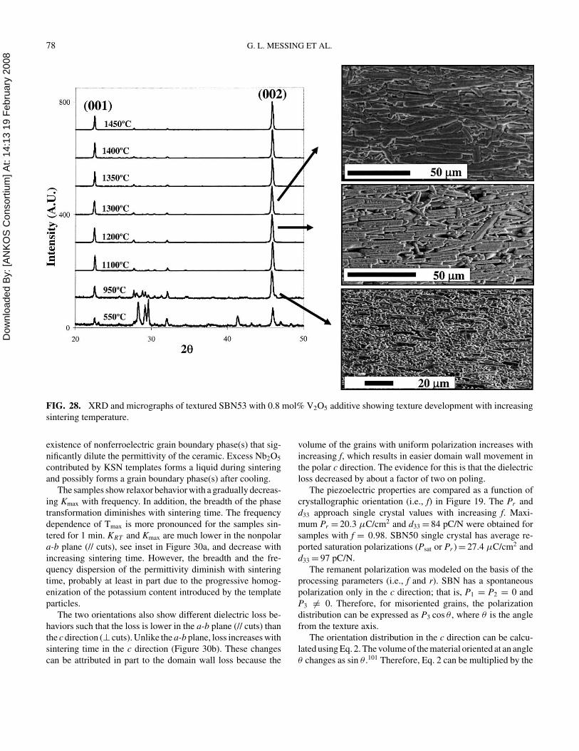
Dow
nloa
ded
By:
[AN
KO
S C
onso
rtium
] At:
14:1
3 19
Feb
ruar
y 20
08 78 G. L. MESSING ET AL.
FIG. 28. XRD and micrographs of textured SBN53 with 0.8 mol% V2O5 additive showing texture development with increasing
sintering temperature.
existence of nonferroelectric grain boundary phase(s) that sig-
nificantly dilute the permittivity of the ceramic. Excess Nb2O5
contributed by KSN templates forms a liquid during sintering
and possibly forms a grain boundary phase(s) after cooling.
The samples show relaxor behavior with a gradually decreas-
ing Kmax with frequency. In addition, the breadth of the phase
transformation diminishes with sintering time. The frequency
dependence of Tmax is more pronounced for the samples sin-
tered for 1 min. KRT and Kmax are much lower in the nonpolar
a-b plane (// cuts), see inset in Figure 30a, and decrease with
increasing sintering time. However, the breadth and the fre-
quency dispersion of the permittivity diminish with sintering
time, probably at least in part due to the progressive homog-
enization of the potassium content introduced by the template
particles.
The two orientations also show different dielectric loss be-
haviors such that the loss is lower in the a-b plane (// cuts) than
the c direction (⊥ cuts). Unlike the a-b plane, loss increases with
sintering time in the c direction (Figure 30b). These changes
can be attributed in part to the domain wall loss because the
volume of the grains with uniform polarization increases with
increasing f, which results in easier domain wall movement in
the polar c direction. The evidence for this is that the dielectric
loss decreased by about a factor of two on poling.
The piezoelectric properties are compared as a function of
crystallographic orientation (i.e., f) in Figure 19. The Pr and
d33 approach single crystal values with increasing f. Maxi-
mum Pr = 20.3 µC/cm2 and d33 = 84 pC/N were obtained for
samples with f = 0.98. SBN50 single crystal has average re-
ported saturation polarizations (Psat or Pr ) = 27.4 µC/cm2 and
d33 = 97 pC/N.
The remanent polarization was modeled on the basis of the
processing parameters (i.e., f and r). SBN has a spontaneous
polarization only in the c direction; that is, P1 = P2 = 0 and
P3 = 0. Therefore, for misoriented grains, the polarization
distribution can be expressed as P3 cos θ , where θ is the angle
from the texture axis.
The orientation distribution in the c direction can be calcu-
lated using Eq. 2. The volume of the material oriented at an angle
θ changes as sin θ .101 Therefore, Eq. 2 can be multiplied by the
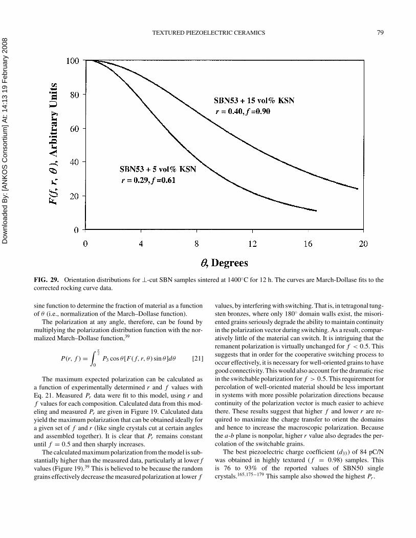
Dow
nloa
ded
By:
[AN
KO
S C
onso
rtium
] At:
14:1
3 19
Feb
ruar
y 20
08 TEXTURED PIEZOELECTRIC CERAMICS 79
FIG. 29. Orientation distributions for ⊥-cut SBN samples sintered at 1400◦C for 12 h. The curves are March-Dollase fits to the
corrected rocking curve data.
sine function to determine the fraction of material as a function
of θ (i.e., normalization of the March–Dollase function).
The polarization at any angle, therefore, can be found by
multiplying the polarization distribution function with the nor-
malized March–Dollase function,39
P(r, f ) =
∫ π2
0
P3 cos θ [F( f, r, θ ) sin θ ]dθ [21]
The maximum expected polarization can be calculated as
a function of experimentally determined r and f values with
Eq. 21. Measured Pr data were fit to this model, using r and
f values for each composition. Calculated data from this mod-
eling and measured Pr are given in Figure 19. Calculated data
yield the maximum polarization that can be obtained ideally for
a given set of f and r (like single crystals cut at certain angles
and assembled together). It is clear that Pr remains constant
until f = 0.5 and then sharply increases.
The calculated maximum polarization from the model is sub-
stantially higher than the measured data, particularly at lower f
values (Figure 19).39 This is believed to be because the random
grains effectively decrease the measured polarization at lower f
values, by interfering with switching. That is, in tetragonal tung-
sten bronzes, where only 180◦ domain walls exist, the misori-
ented grains seriously degrade the ability to maintain continuity
in the polarization vector during switching. As a result, compar-
atively little of the material can switch. It is intriguing that the
remanent polarization is virtually unchanged for f < 0.5. This
suggests that in order for the cooperative switching process to
occur effectively, it is necessary for well-oriented grains to have
good connectivity. This would also account for the dramatic rise
in the switchable polarization for f > 0.5. This requirement for
percolation of well-oriented material should be less important
in systems with more possible polarization directions because
continuity of the polarization vector is much easier to achieve
there. These results suggest that higher f and lower r are re-
quired to maximize the charge transfer to orient the domains
and hence to increase the macroscopic polarization. Because
the a-b plane is nonpolar, higher r value also degrades the per-
colation of the switchable grains.
The best piezoelectric charge coefficient (d33) of 84 pC/N
was obtained in highly textured ( f = 0.98) samples. This
is 76 to 93% of the reported values of SBN50 single
crystals.165,175−179 This sample also showed the highest Pr .
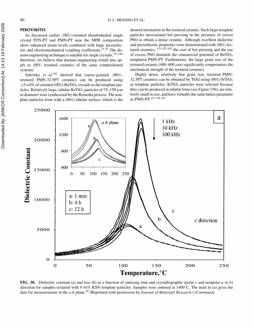
Dow
nloa
ded
By:
[AN
KO
S C
onso
rtium
] At:
14:1
3 19
Feb
ruar
y 20
08 80 G. L. MESSING ET AL.
PEROVSKITES
As discussed earlier, 〈001〉-oriented rhombohedral single
crystal PZN-PT and PMN-PT near the MPB composition
show enhanced strain levels combined with large piezoelec-
tric and electromechanical coupling coefficients.15,19 The do-
main engineering technique is suitable for single crystals,152,180
therefore, we believe that domain engineering would also ap-
ply to 〈001〉 textured ceramics of the same compositional
systems.
Sabolsky et al.181 showed that coarse-grained, 〈001〉-
textured PMN-32.5PT ceramics can be produced using
≤5 vol% of oriented (001)-BaTiO3 crystals as the template par-
ticles. Relatively large, tabular BaTiO3 particles of 75–150 µm
in diameter were synthesized by the Remeika process. The tem-
plate particles form with a (001) tabular surface, which is the
FIG. 30. Dielectric constant (a) and loss (b) as a function of sintering time and crystallographic (polar c and nonpolar a or b)
direction for samples textured with 9 wt% KSN template particles. Samples were sintered at 1400◦C. The inset in (a) gives the
data for measurements in the a-b plane.39 (Reprinted with permission by Journal of Materials Research.) (Continued)
desired orientation in the textured ceramic. Such large template
particles necessitated hot pressing in the presence of excess
PbO to obtain a dense ceramic. Although excellent dielectric
and piezoelectric properties were demonstrated with 〈001〉 tex-
tured ceramics, 151,152,182 the cost of hot pressing and the use
of excess PbO diminish the commercial potential of BaTiO3
templated PMN-PT. Furthermore, the large grain size of the
textured ceramic (400–600 µm) significantly compromises the
mechanical strength of the textured ceramics.
Highly dense, relatively fine grain size, textured PMN-
32.5PT ceramics can be obtained by TGG using (001)-SrTiO3
as template particles. SrTiO3 particles were selected because
they can be produced in tabular form (see Figure 15b), are rela-
tively small in size, and have virtually the same lattice parameter
as PMN-PT.127,138,183
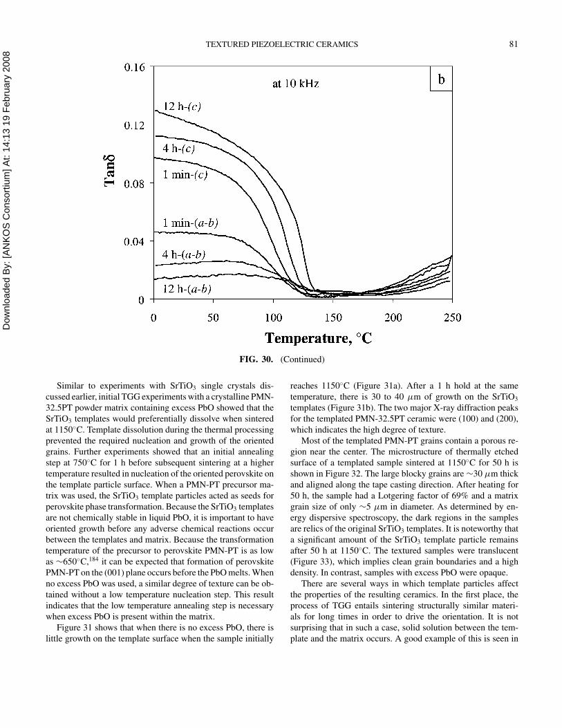
Dow
nloa
ded
By:
[AN
KO
S C
onso
rtium
] At:
14:1
3 19
Feb
ruar
y 20
08 TEXTURED PIEZOELECTRIC CERAMICS 81
FIG. 30. (Continued)
Similar to experiments with SrTiO3 single crystals dis-
cussed earlier, initial TGG experiments with a crystalline PMN-
32.5PT powder matrix containing excess PbO showed that the
SrTiO3 templates would preferentially dissolve when sintered
at 1150◦C. Template dissolution during the thermal processing
prevented the required nucleation and growth of the oriented
grains. Further experiments showed that an initial annealing
step at 750◦C for 1 h before subsequent sintering at a higher
temperature resulted in nucleation of the oriented perovskite on
the template particle surface. When a PMN-PT precursor ma-
trix was used, the SrTiO3 template particles acted as seeds for
perovskite phase transformation. Because the SrTiO3 templates
are not chemically stable in liquid PbO, it is important to have
oriented growth before any adverse chemical reactions occur
between the templates and matrix. Because the transformation
temperature of the precursor to perovskite PMN-PT is as low
as ∼650◦C,184 it can be expected that formation of perovskite
PMN-PT on the (001) plane occurs before the PbO melts. When
no excess PbO was used, a similar degree of texture can be ob-
tained without a low temperature nucleation step. This result
indicates that the low temperature annealing step is necessary
when excess PbO is present within the matrix.
Figure 31 shows that when there is no excess PbO, there is
little growth on the template surface when the sample initially
reaches 1150◦C (Figure 31a). After a 1 h hold at the same
temperature, there is 30 to 40 µm of growth on the SrTiO3
templates (Figure 31b). The two major X-ray diffraction peaks
for the templated PMN-32.5PT ceramic were (100) and (200),
which indicates the high degree of texture.
Most of the templated PMN-PT grains contain a porous re-
gion near the center. The microstructure of thermally etched
surface of a templated sample sintered at 1150◦C for 50 h is
shown in Figure 32. The large blocky grains are ∼30 µm thick
and aligned along the tape casting direction. After heating for
50 h, the sample had a Lotgering factor of 69% and a matrix
grain size of only ∼5 µm in diameter. As determined by en-
ergy dispersive spectroscopy, the dark regions in the samples
are relics of the original SrTiO3 templates. It is noteworthy that
a significant amount of the SrTiO3 template particle remains
after 50 h at 1150◦C. The textured samples were translucent
(Figure 33), which implies clean grain boundaries and a high
density. In contrast, samples with excess PbO were opaque.
There are several ways in which template particles affect
the properties of the resulting ceramics. In the first place, the
process of TGG entails sintering structurally similar materi-
als for long times in order to drive the orientation. It is not
surprising that in such a case, solid solution between the tem-
plate and the matrix occurs. A good example of this is seen in
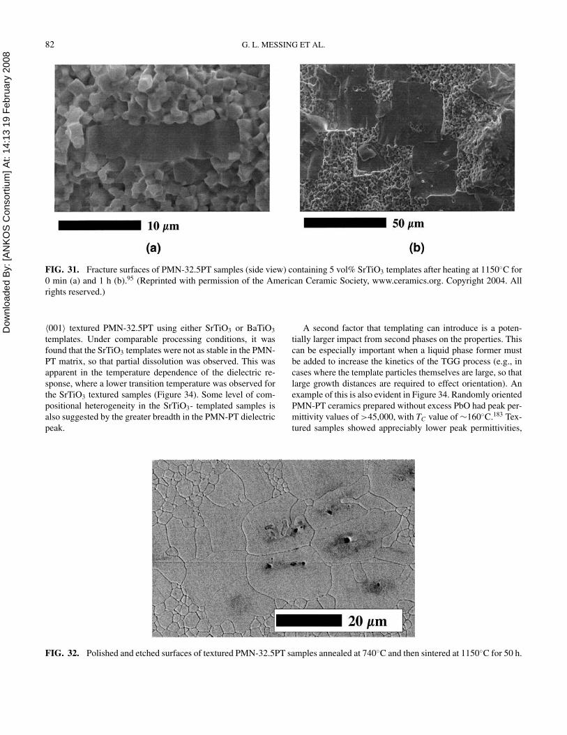
Dow
nloa
ded
By:
[AN
KO
S C
onso
rtium
] At:
14:1
3 19
Feb
ruar
y 20
08 82 G. L. MESSING ET AL.
FIG. 31. Fracture surfaces of PMN-32.5PT samples (side view) containing 5 vol% SrTiO3 templates after heating at 1150◦C for
0 min (a) and 1 h (b).95 (Reprinted with permission of the American Ceramic Society, www.ceramics.org. Copyright 2004. All
rights reserved.)
〈001〉 textured PMN-32.5PT using either SrTiO3 or BaTiO3
templates. Under comparable processing conditions, it was
found that the SrTiO3 templates were not as stable in the PMN-
PT matrix, so that partial dissolution was observed. This was
apparent in the temperature dependence of the dielectric re-
sponse, where a lower transition temperature was observed for
the SrTiO3 textured samples (Figure 34). Some level of com-
positional heterogeneity in the SrTiO3- templated samples is
also suggested by the greater breadth in the PMN-PT dielectric
peak.
FIG. 32. Polished and etched surfaces of textured PMN-32.5PT samples annealed at 740◦C and then sintered at 1150◦C for 50 h.
A second factor that templating can introduce is a poten-
tially larger impact from second phases on the properties. This
can be especially important when a liquid phase former must
be added to increase the kinetics of the TGG process (e.g., in
cases where the template particles themselves are large, so that
large growth distances are required to effect orientation). An
example of this is also evident in Figure 34. Randomly oriented
PMN-PT ceramics prepared without excess PbO had peak per-
mittivity values of >45,000, with TC value of ∼160◦C.183 Tex-
tured samples showed appreciably lower peak permittivities,
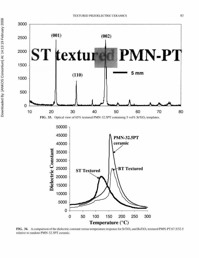
Dow
nloa
ded
By:
[AN
KO
S C
onso
rtium
] At:
14:1
3 19
Feb
ruar
y 20
08 TEXTURED PIEZOELECTRIC CERAMICS 83
FIG. 33. Optical view of 65% textured PMN-32.5PT containing 5 vol% SrTiO3 templates.
FIG. 34. A comparison of the dielectric constant versus temperature response for SrTiO3 and BaTiO3 textured PMN-PT 67.5/32.5
relative to random PMN-32.5PT ceramic.
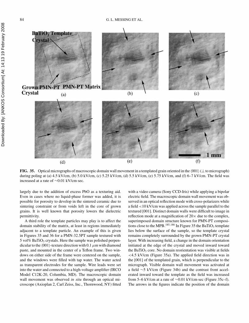
Dow
nloa
ded
By:
[AN
KO
S C
onso
rtium
] At:
14:1
3 19
Feb
ruar
y 20
08 84 G. L. MESSING ET AL.
FIG. 35. Optical micrographs of macroscopic domain wall movement in a templated grain oriented in the 〈001〉 (⊥ to micrograph)
during poling at (a) 4.5 kV/cm, (b) 5.0 kV/cm, (c) 5.25 kV/cm, (d) 5.5 kV/cm, (e) 5.75 kV/cm, and (f) 6–7 kV/cm. The field was
increased at a rate of ∼0.01 kV/cm·sec.
largely due to the addition of excess PbO as a texturing aid.
Even in cases where no liquid-phase former was added, it is
possible for porosity to develop in the sintered ceramic due to
sintering constraint or from voids left in the core of grown
grains. It is well known that porosity lowers the dielectric
permittivity.
A third role the template particles may play is to affect the
domain stability of the matrix, at least in regions immediately
adjacent to a template particle. An example of this is given
in Figures 35 and 36 for a PMN-32.5PT sample textured with
5 vol% BaTiO3 crystals. Here the sample was polished perpen-
dicular to the 〈001〉-texture direction with 0.1 µm with diamond
paste, and mounted in the center of a Teflon frame. Two win-
dows on either side of the frame were centered on the sample,
and the windows were filled with tap water. The water acted
as transparent electrodes for the sample. Wire leads were set
into the water and connected to a high-voltage amplifier (IRCO
Model C12K-20, Columbia, MD). The macroscopic domain
wall movement was observed in situ through an optical mi-
croscope (Axioplan 2, Carl Zeiss, Inc., Thornwood, NY) fitted
with a video camera (Sony CCD-Iris) while applying a bipolar
electric field. The macroscopic domain wall movement was ob-
served in an optical reflection mode with cross-polarizers while
a field <10 kV/cm was applied across the sample parallel to the
textured [001]. Distinct domain walls were difficult to image in
reflection mode at a magnification of 20× due to the complex,
superimposed domain structure known for PMN-PT composi-
tions close to the MPB.185,186 In Figure 35 the BaTiO3 template
lies below the surface of the sample, so the template crystal
remains completely surrounded by the grown PMN-PT crystal
layer. With increasing field, a change in the domain orientation
initiated at the edge of the crystal and moved inward toward
the BaTiO3 core. No domain reorientation was visible at fields
<4.5 kV/cm (Figure 35a). The applied field direction was in
the [001] of the templated grain, which is perpendicular to the
micrograph. Visible domain wall movement was activated at
a field ∼5 kV/cm (Figure 34b) and the contrast front accel-
erated inward toward the template as the field was increased
from 5–6 kV/cm at a rate of ∼0.01 kV/cm·sec (Figure 35c–f).
The arrows in the figures indicate the position of the domain
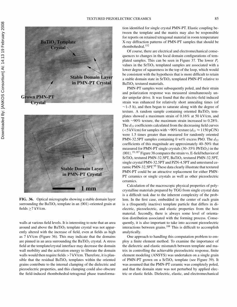
Dow
nloa
ded
By:
[AN
KO
S C
onso
rtium
] At:
14:1
3 19
Feb
ruar
y 20
08 TEXTURED PIEZOELECTRIC CERAMICS 85
FIG. 36. Optical micrographs showing a stable domain layer
surrounding the BaTiO3 template in an 〈001〉-oriented grain at
fields ≥7 kV/cm.
walls at various field levels. It is interesting to note that an area
around and above the BaTiO3 template crystal was not appar-
ently altered with the increase of field, even at fields as high
as 7 kV/cm (Figure 36). This may indicate that the domains
are pinned in an area surrounding the BaTiO3 crystal. A stress
field at the template/crystal interface may decrease the domain
wall mobility and the activation energy to liberate the domain
walls would then require fields >7 kV/cm. Therefore, it is plau-
sible that the residual BaTiO3 templates within the oriented
grains contribute to the internal clamping of the dielectric and
piezoelectric properties, and this clamping could also obscure
the field-induced rhombohedral-tetragonal phase transforma-
tion identified for single crystal PMN-PT. Elastic coupling be-
tween the template and the matrix may also be responsible
for reports on retained tetragonal material in room temperature
X-ray diffraction patterns of PMN-PT samples that should be
rhombohedral.152
Of course, there are electrical and electromechanical conse-
quences to changes in the local domain configurations of tem-
plated samples. This can be seen in Figure 37. The lower Pr
values in the SrTiO3 templated samples are associated with a
lower degree of squareness in the top of the loop, which would
be consistent with the hypothesis that is more difficult to retain
a stable domain state in SrTiO3 templated PMN-PT relative to
BaTiO3 textured materials.
PMN-PT samples were subsequently poled, and their strain
and polarization response was measured simultaneously un-
der unipolar drive. It was found that the electric-field induced
strain was enhanced for relatively short annealing times (of
∼1–5 h), and then began to saturate along with the degree of
texture. A random sample containing oriented BaTiO3 tem-
plates showed a maximum strain of 0.16% at 50 kV/cm, and
with ∼90% texture, the maximum strain increased to 0.28%.
The d33 coefficients calculated from the decreasing field curves
(<5 kV/cm) for samples with ∼90% texture (d33 ≈ 1150 pC/N)
were 1.5 times greater than measured for randomly oriented
PMN-32.5PT samples containing 0 wt% excess PbO. The d33
coefficients of this magnitude are approximately 40–50% that
measured for PMN-PT single crystals (30–35% PbTiO3) in the
〈001〉.19,187 Figure 38 compares the strain vs. E-field behavior of
SrTiO3 textured PMN-32.5PT, BaTiO3 textured PMN-32.5PT,
single crystal PMN-32.5PT and PZN-4.5PT and untextured ce-
ramic PMN-32.5PT.95 These data clearly illustrate that textured
PMN-PT could be an attractive replacement for either PMN-
PT ceramics or single crystals as well as other piezoelectric
ceramics.
Calculation of the macroscopic physical properties of poly-
crystalline materials prepared by TGG from single crystal data
is a difficult task due to the inherent complexity of the prob-
lem. In the first case, embedded in the center of each grain
is a (frequently inactive) template particle that differs in di-
electric, piezoelectric, and elastic properties from the host
material. Secondly, there is always some level of orienta-
tion distribution associated with the forming process. Conse-
quently, it is also important to take into account piezoelectric
interactions between grains.188 This is difficult to accomplish
analytically.
One approach to handling this computation problem to em-
ploy a finite element method. To examine the importance of
the dielectric and elastic mismatch between template and ma-
trix in controlling the achievable piezoelectric response, finite
element modeling (ANSYS) was undertaken on a single grain
of PMN-PT grown on a SrTiO3 template (see Figure 39). It
was assumed that the PMN-PT ceramic was completely poled,
and that the domain state was not perturbed by applied elec-
tric or elastic fields. Dielectric, elastic, and electromechanical
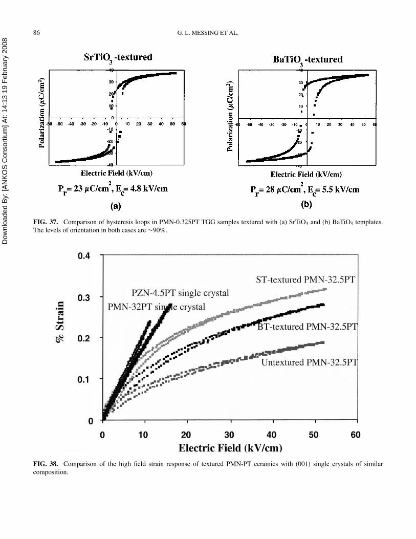
Dow
nloa
ded
By:
[AN
KO
S C
onso
rtium
] At:
14:1
3 19
Feb
ruar
y 20
08 86 G. L. MESSING ET AL.
FIG. 37. Comparison of hysteresis loops in PMN-0.325PT TGG samples textured with (a) SrTiO3 and (b) BaTiO3 templates.
The levels of orientation in both cases are ∼90%.
FIG. 38. Comparison of the high field strain response of textured PMN-PT ceramics with (001) single crystals of similar
composition.
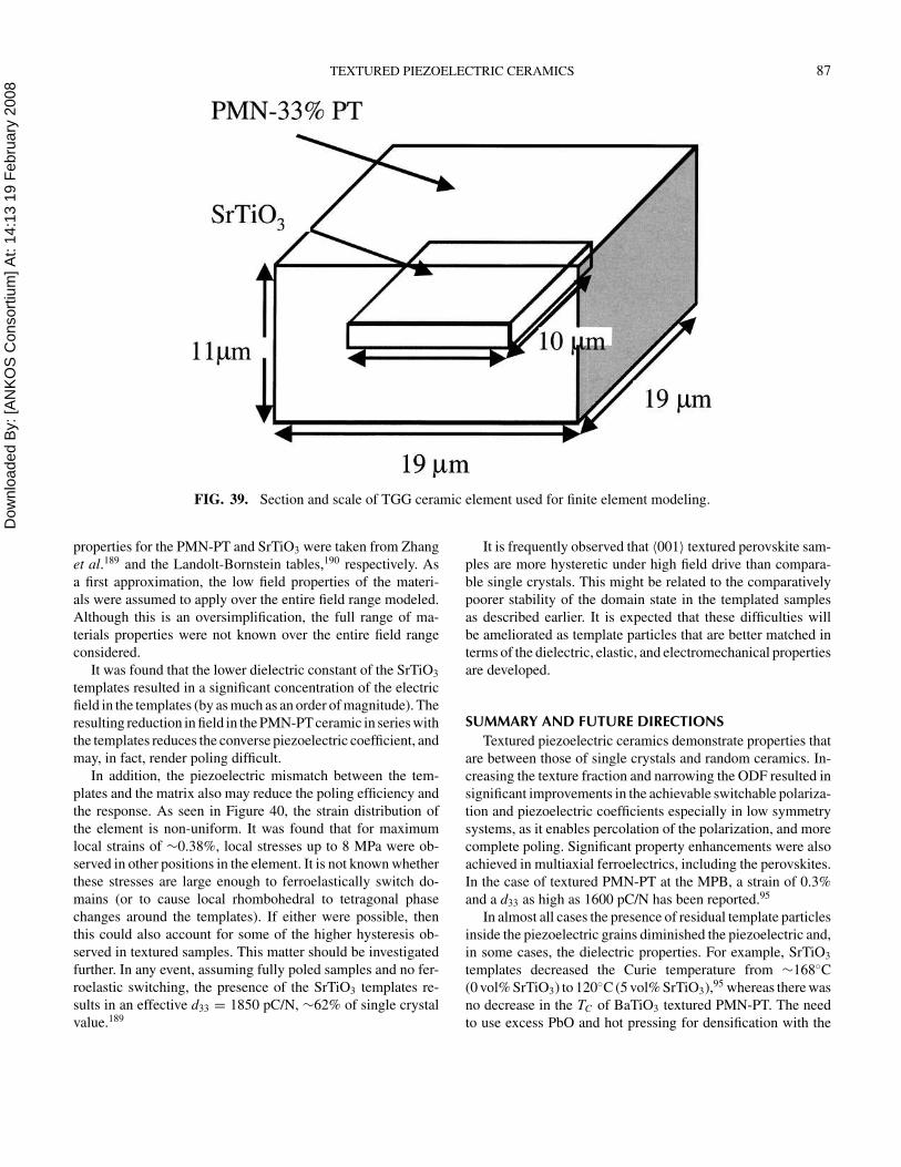
Dow
nloa
ded
By:
[AN
KO
S C
onso
rtium
] At:
14:1
3 19
Feb
ruar
y 20
08 TEXTURED PIEZOELECTRIC CERAMICS 87
FIG. 39. Section and scale of TGG ceramic element used for finite element modeling.
properties for the PMN-PT and SrTiO3 were taken from Zhang
et al.189 and the Landolt-Bornstein tables,190 respectively. As
a first approximation, the low field properties of the materi-
als were assumed to apply over the entire field range modeled.
Although this is an oversimplification, the full range of ma-
terials properties were not known over the entire field range
considered.
It was found that the lower dielectric constant of the SrTiO3
templates resulted in a significant concentration of the electric
field in the templates (by as much as an order of magnitude). The
resulting reduction in field in the PMN-PT ceramic in series with
the templates reduces the converse piezoelectric coefficient, and
may, in fact, render poling difficult.
In addition, the piezoelectric mismatch between the tem-
plates and the matrix also may reduce the poling efficiency and
the response. As seen in Figure 40, the strain distribution of
the element is non-uniform. It was found that for maximum
local strains of ∼0.38%, local stresses up to 8 MPa were ob-
served in other positions in the element. It is not known whether
these stresses are large enough to ferroelastically switch do-
mains (or to cause local rhombohedral to tetragonal phase
changes around the templates). If either were possible, then
this could also account for some of the higher hysteresis ob-
served in textured samples. This matter should be investigated
further. In any event, assuming fully poled samples and no fer-
roelastic switching, the presence of the SrTiO3 templates re-
sults in an effective d33 = 1850 pC/N, ∼62% of single crystal
value.189
It is frequently observed that 〈001〉 textured perovskite sam-
ples are more hysteretic under high field drive than compara-
ble single crystals. This might be related to the comparatively
poorer stability of the domain state in the templated samples
as described earlier. It is expected that these difficulties will
be ameliorated as template particles that are better matched in
terms of the dielectric, elastic, and electromechanical properties
are developed.
SUMMARY AND FUTURE DIRECTIONS
Textured piezoelectric ceramics demonstrate properties that
are between those of single crystals and random ceramics. In-
creasing the texture fraction and narrowing the ODF resulted in
significant improvements in the achievable switchable polariza-
tion and piezoelectric coefficients especially in low symmetry
systems, as it enables percolation of the polarization, and more
complete poling. Significant property enhancements were also
achieved in multiaxial ferroelectrics, including the perovskites.
In the case of textured PMN-PT at the MPB, a strain of 0.3%
and a d33 as high as 1600 pC/N has been reported.95
In almost all cases the presence of residual template particles
inside the piezoelectric grains diminished the piezoelectric and,
in some cases, the dielectric properties. For example, SrTiO3
templates decreased the Curie temperature from ∼168◦C
(0 vol% SrTiO3) to 120◦C (5 vol% SrTiO3),95 whereas there was
no decrease in the TC of BaTiO3 textured PMN-PT. The need
to use excess PbO and hot pressing for densification with the
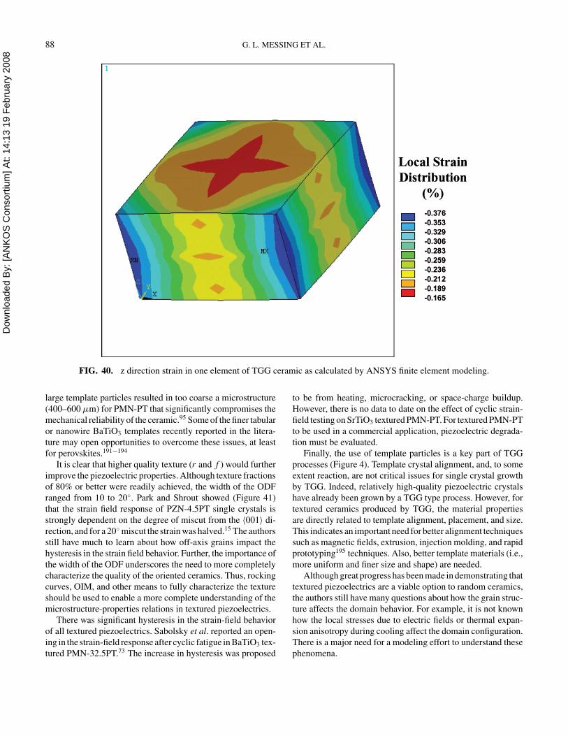
Dow
nloa
ded
By:
[AN
KO
S C
onso
rtium
] At:
14:1
3 19
Feb
ruar
y 20
08 88 G. L. MESSING ET AL.
FIG. 40. z direction strain in one element of TGG ceramic as calculated by ANSYS finite element modeling.
large template particles resulted in too coarse a microstructure
(400–600 µm) for PMN-PT that significantly compromises the
mechanical reliability of the ceramic.95 Some of the finer tabular
or nanowire BaTiO3 templates recently reported in the litera-
ture may open opportunities to overcome these issues, at least
for perovskites.191−194
It is clear that higher quality texture (r and f ) would further
improve the piezoelectric properties. Although texture fractions
of 80% or better were readily achieved, the width of the ODF
ranged from 10 to 20◦. Park and Shrout showed (Figure 41)
that the strain field response of PZN-4.5PT single crystals is
strongly dependent on the degree of miscut from the 〈001〉 di-
rection, and for a 20◦ miscut the strain was halved.15 The authors
still have much to learn about how off-axis grains impact the
hysteresis in the strain field behavior. Further, the importance of
the width of the ODF underscores the need to more completely
characterize the quality of the oriented ceramics. Thus, rocking
curves, OIM, and other means to fully characterize the texture
should be used to enable a more complete understanding of the
microstructure-properties relations in textured piezoelectrics.
There was significant hysteresis in the strain-field behavior
of all textured piezoelectrics. Sabolsky et al. reported an open-
ing in the strain-field response after cyclic fatigue in BaTiO3 tex-
tured PMN-32.5PT.73 The increase in hysteresis was proposed
to be from heating, microcracking, or space-charge buildup.
However, there is no data to date on the effect of cyclic strain-
field testing on SrTiO3 textured PMN-PT. For textured PMN-PT
to be used in a commercial application, piezoelectric degrada-
tion must be evaluated.
Finally, the use of template particles is a key part of TGG
processes (Figure 4). Template crystal alignment, and, to some
extent reaction, are not critical issues for single crystal growth
by TGG. Indeed, relatively high-quality piezoelectric crystals
have already been grown by a TGG type process. However, for
textured ceramics produced by TGG, the material properties
are directly related to template alignment, placement, and size.
This indicates an important need for better alignment techniques
such as magnetic fields, extrusion, injection molding, and rapid
prototyping195 techniques. Also, better template materials (i.e.,
more uniform and finer size and shape) are needed.
Although great progress has been made in demonstrating that
textured piezoelectrics are a viable option to random ceramics,
the authors still have many questions about how the grain struc-
ture affects the domain behavior. For example, it is not known
how the local stresses due to electric fields or thermal expan-
sion anisotropy during cooling affect the domain configuration.
There is a major need for a modeling effort to understand these
phenomena.
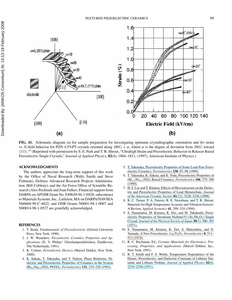
Dow
nloa
ded
By:
[AN
KO
S C
onso
rtium
] At:
14:1
3 19
Feb
ruar
y 20
08 TEXTURED PIEZOELECTRIC CERAMICS 89
FIG. 41. Schematic diagram (a) for sample preparation for investigating optimum crystallographic orientation and (b) strain
vs. E-field behavior for PZN-4.5%PT crystals oriented along 〈001〉 + α, where α is the degree of deviation from 〈001〉 toward
〈111〉.15 (Reprinted with permission by S. E. Park and T. R. Shrout, “Ultrahigh Strain and Piezoelectric Behavior in Relaxor Based
Ferroelectric Single Crystals,” Journal of Applied Physics, 82(4), 1804–1811, (1997), American Institute of Physics.)
ACKNOWLEDGMENTS
The authors appreciate the long-term support of this work
by the Office of Naval Research (Wally Smith and Steve
Fishman), Defense Advanced Research Projects Administra-
tion (Bill Coblenz), and the Air Force Office of Scientific Re-
search (Alex Pechinek and Joan Fuller). Financial support from
DARPA on AFOSR Grant No. F49620-94-1-0428, subcontract
to Materials Systems, Inc., Littleton, MA on DARPA/NAVSEA
N66604-99-C-4622, and ONR Grants N0001-94-1-0007 and
N00014-98-1-0527 are gratefully acknowledged.
REFERENCES1. T. Ikeda, Fundamentals of Piezoelectricity (Oxford University
Press, New York, 1990).
2. J. W. Waanders, Piezoelectric Ceramics Properties and Ap-
plications (N. V. Philips’ Gloeilampenfabrieken, Eindhoven,
The Netherlands, 1991).
3. K. Uchino, Ferroelectric Devices (Marcel Dekker, New York,
2000).
4. K. Sakata, T. Takenaka, and Y. Naitou, Phase Relations, Di-
electric and Piezoelectric Properties of Ceramics in the System
(Bi0.5Na0.5)TiO3-PbTiO3, Ferroelectrics 131, 219–226 (1992).
5. T. Takenaka, Piezoelectric Properties of Some Lead-Free Ferro-
electric Ceramics, Ferroelectrics 230, 87–98 (1999).
6. T. Takenaka, K. Sakata, and K. Toda, Piezoelectric Properties of
(Bi1/2Na1/2)TiO3-Based Ceramics, Ferroelectrics 106, 375–380
(1990).
7. H. S. Lee and T. Kimura, Effects of Microstructure on the Dielec-
tric and Piezoelectric Properties of Lead Metaniobate, Journal
of the American Ceramic Society 81(12), 3228–3236 (1998).
8. R. C. Turner, P. A. Fuierer, R. E. Newnham, and T. R. Shrout,
Materials for High Temperature Acoustic and Vibration Sensors:
A Review, Applied Acoustics 41, 299–324 (1994).
9. S. Nanamatsu, M. Kimura, K. Doi, and M. Takahashi, Ferro-
electric Properties of Strontium Niobate(V) (Sr2Nb2O7) Single
Crystal, Journal of the Physical Society of Japan 30(1), 300–301
(1971).
10. S. Nanamatsu, M. Kimura, K. Doi, S. Matsushita, and N.
Yamada, A New Ferroelectric: La2Ti2O7, Ferroelectrics 8, 511–
513 (1974).
11. R. C. Buchanan, Ed., Ceramic Materials for Electronics: Pro-
cessing, Properties, and Applications (Marcel Dekker, Inc.,
New York, 1991).
12. R. T. Smith and F. S. Welsh, Temperature Dependence of the
Elastic, Piezoelectric, and Dielectric Constants of Lithium Tan-
talate and Lithium Niobate, Journal of Applied Physics 42(6),
2219–2230 (1971).
Dow
nloa
ded
By:
[AN
KO
S C
onso
rtium
] At:
14:1
3 19
Feb
ruar
y 20
08 90 G. L. MESSING ET AL.
13. D. A. Berlincourt, C. Molik, and H. Jaffe, Piezoelectric Prop-
erties of Polycrystalline Lead Titanate Zirconate Compositions,
Proceedings of the IRE 2, 220–229 (1960).
14. B. Jaffe, W. R. Cook, and H. Jaffe, Piezoelectric Ceramics (Aca-
demic Press, New York, 1971).
15. S. E. Park and T. R. Shrout, Ultrahigh Strain and Piezoelectric
Behavior in Relaxor Based Ferroelectric Single Crystals, Journal
of Applied Physics 82(4), 1804–1811 (1997).
16. Z. G. Ye and W. Chen, Growth and Characterization of
Pb(Zr1−x Tix )O3 Single Crystals, Oral Presentation at the US
Navy Meeting on Acoustic Transduction Materials and Devices
(2003).
17. J. Kuwata, K. Uchino, and S. Nomura, Dielectric and Piezo-
electric Properties of 0.91Pb(Zn1/3Nb2/3)O3-0.09PbTiO3 Single
Crystals, Japanese Journal of Applied Physics 21, 1298–1302
(1982).
18. J. Kuwata, K. Uchino, and S. Nomura, Phase Transitions in the
Pb(Zn1/3Nb2/3)O3-PbTiO3 System, Journal of Applied Physics
37, 579–582 (1981).
19. S. E. Park and T. R. Shrout, Characteristics of Relaxor-based
Piezoelectric Single Crystals for Ultrasonic Transducers, IEEE
Transactions on Ultrasonics Ferroelectrics, and Frequency Con-
trol 44(5), 1140–1147 (1997).
20. U.S. Department of Defense. Military Standard: Piezoelec-
tric Ceramic Material and Measurements Guidelines for Sonar
Transducers, MIL-STD-1376B(SH) (Naval Sea Systems Com-
mand, Arlington, VA, 1995).
21. H. Jaffe and D. A. Berlincourt, Piezoelectric Transducer Mate-
rials, Proceedings of the IEEE 53(10), 1379–1386 (1965).
22. J. H. Yin and W. W. Cao, Domain Configurations in Domain En-
gineered 0.955Pb(Zn1/3Nb2/3)O3-0.045PbTiO3 Single Crystals,
Journal of Applied Physics 87(10), 7438–7441 (2000).
23. S. Wada, S. E. Park, L. E. Cross, and T. R. Shrout, Domain
Configuration and Ferroelectric Related Properties of Relaxor
Based Single Crystals, Journal of the Korean Physical Society
32, S1290–S1293 (1998).
24. S. E. Park, S. Wada, L. E. Cross, and T. R. Shrout, Crystallograph-
ically Engineered BaTiO3 Single Crystals for High-performance
Piezoelectrics, Journal of Applied Physics 86(5), 2746–2750
(1999).
25. P. W. Rehrig, S. E. Park, S. Trolier-McKinstry, G. L. Messing,
B. Jones, and T. R. Shrout, Piezoelectric Properties of Zirconium-
Doped Barium Titanate Single Crystals Grown by Templated
Grain Growth, Journal of Applied Physics 86(3), 1657–1661
(1999).
26. S. G. Lee, R. G. Monteiro, R. S. Feigelson, H. S. Lee, M.
Lee, and S. E. Park, Growth and Electrostrictive Properties
of Pb(Mg1/3Nb2/3)O3 Crystals, Applied Physics Letters 74(7),
1030–1032 (1999).
27. J. M. Powers, M. B. Moffett, and F. Nussbaum, Single Crystal
Naval Transducer Development, in Proceedings of the 12th IEEE
International Symposium on Applications of Ferroelectrics (S. K.
Streiffer, B. Gibbons, and T. Tsurumi, eds., IEEE, Piscataway,
NJ, 2000), pp. 351–354.
28. K. T. Zawilski, M. C. C. Custodio, R. C. DeMattei, S. G. Lee, R.
G. Monteiro, H. Odagawa, and R. S. Feigelson, Segregation Dur-
ing the Vertical Bridgman Growth of Lead Magnesium Niobate-
Lead Titanate Single Crystals, Journal of Crystal Growth 258(3–
4), 353–367 (2003).
29. T. Takenaka and K. Sakata, Grain Orientation and Electrical
Properties of Hot-Forged Bi4Ti3O12 Ceramics, Japanese Jour-
nal of Applied Physics 19(10), 31–39 (1980).
30. D. Damjanovic, F. Brem, and N. Setter, Crystal Orientation
Dependence of the Piezoelectric d33 Coefficient in Tetragonal
BaTiO3 as a Function of Temperature, Applied Physics Letters
80(4), 652–654 (2002).
31. A. J. Bell, Phenomenologically Derived Electric Field-
Temperature Phase Diagrams and Piezoelectric Coefficients
for Single Crystal Barium Titanate Under Fields Along Dif-
ferent Axes, Journal of Applied Physics 89(7), 3907–3914
(2001).
32. X. H. Du, J. H. Zheng, U. Belegundu, and K. Uchino, Crystal
Orientation Dependence of Piezoelectric Properties of Lead Zir-
conate Titanate Near the Morphotropic Phase Boundary, Applied
Physics Letters 72(19), 2421–2423 (1998).
33. Y. Lu, D. Y. Jeong, Z. Y. Cheng, Q. M. Zhang, H. S.
Luo, Z. W. Yin, and D. Viehland, Phase Transitional Behav-
ior and Piezoelectric Properties of the Orthorhombic Phase
of Pb(Mg1/3Nb2/3)O3-PbTiO3 Single Crystals, Applied Physics
Letters 78(20), 3109–3111 (2001).
34. K. Okazaki, H. Igarashi, K. Nagata, T. Yamamoto, and S. Tashiro,
Processing, Microstructure, and Properties of Grain-Oriented
Ferroelectric Ceramics, IEEE Transactions on Ultrasonics Fer-
roelectrics, and Frequency Control 33(6), 328–337 (1986).
35. S. Trolier-McKinstry, E. M. Sabolsky, S. Kwon, J. H. Yoshimura,
J. H. Park, G. Zhang, and G. L. Messing, Oriented Films and
Ceramics of Relaxor-Ferroelectric-PbTiO3 Solid Solutions, in
Piezoelectric Materials and Devices (N. Setter, ed., Ceram-
ics Laboratory, EPFL Swiss Federal Institute of Technology,
Lausanne 1015, Switzerland, 2002, pp. 497–518).
36. M. J. Haun, Thermodynamic Theory of the Lead Zirconate-
Titanate Solid Solution System, Ph.D. at The Pennsylvania State
University, University Park, PA (1988).
37. M. G. Minchina and V. P. Dudkevich, Piezoelectric Properties of
Oriented Z’Cuts of PZT-Type Ferroelectric Ceramics, Technical
Physics 43(7), 814–817 (1998).
38. W. A. Dollase, Correction of Intensities for Preferred Orientation
in Powder Diffractometry—Application of the March Model,
Journal of Applied Crystallography 19, 267–272 (1986).
39. C. Duran, S. Trolier-McKinstry, and G. L. Messing, Dielectric
and Piezoelectric Properties of Textured Sr0.53Ba0.47Nb2O6 Ce-
ramics Prepared by Templated Grain Growth, Journal of Mate-
rials Research 18(1), 228–238 (2003).
40. M. M. Seabaugh, I. H. Kerscht, and G. L. Messing, Texture De-
velopment by Templated Grain Growth in Liquid-phase-sintered
α-Alumina, Journal of the American Ceramic Society 80(5),
1181–1188 (1997).
41. M. M. Seabaugh, S. H. Hong, and G. L. Messing, Processing of
Textured Ceramics by Templated Grain Growth, Proceedings of
the International Materials Symposium on Ceramic Microstruc-
tures: Control at the Atomic Level, Ceramic Microstructures:
Control at the Atomic Level, Berkeley, CA (A. P. Tomsia and
A. M. Glaeser, eds., Plenum, New York, NY, 1998), pp. 303–
310.
42. T. Kimura, E. Fukuchi, and T. Tani, Factors Determining Crystal-
lographic Texture in Bi1/2Na1/2TiO3-Based Piezoelectric Ceram-
ics Made by Reactive Templated Grain Growth Method, Ceramic
Transactions 150, 157–169 (2004).
Dow
nloa
ded
By:
[AN
KO
S C
onso
rtium
] At:
14:1
3 19
Feb
ruar
y 20
08 TEXTURED PIEZOELECTRIC CERAMICS 91
43. T. Tani, Crystalline-oriented Piezoelectric Bulk Ceramics with a
Perovskite-type Structure, Journal of the Korean Physical Soci-
ety 32, S1217–S1220 (1998).
44. T. Takeuchi, T. Tani, and Y. Saito, Piezoelectric Properties of Bis-
muth Layer-Structured Ferroelectric Ceramics with a Preferred
Orientation Processed by the Reactive Templated Grain Growth
Method, Japanese Journal of Applied Physics Part 1-Regular
Papers Short Notes & Review Papers 38(9B), 5553–5556
(1999).
45. Y. Seno and T. Tani, TEM Observation of a Reactive Template for
Textured Bi0.5(Na0.87K0.13)0.5TiO3 Polycrystals, Ferroelectrics
224(1–4), 793–800 (1999).
46. T. Takeuchi, T. Tani, and Y. Saito, Unidirectionally Textured
CaBi4Ti4O15 Ceramics by the Reactive Templated Grain Growth
with an Extrusion, Japanese Journal of Applied Physics Part
1-Regular Papers Short Notes & Review Papers 39(9B), 5577–
5580 (2000).
47. E. Fukuchi, T. Kimura, T. Tani, and T. Takeuchi, Oriented
Bi0.5(Na,K)0.5TiO3 Ceramics, Ceramic Transactions 104, 227–
233 (2000).
48. T. Tani, T. Takeuchi, and Y. Seno, Texture Development and
Piezoelectric Properties of Grain-Oriented Bi0.5(Na, K)0.5TiO3
Ceramics Prepared by RTGG Method, Ceramic Transactions
104, 267–274 (2000).
49. E. Fukuchi, T. Kimura, T. Tani, T. Takeuch, and Y. Saito, Effect
of Potassium Concentration on the Grain Orientation in Bismuth
Sodium Potassium Titanate, Journal of the American Ceramic
Society 85(6), 1461–1466 (2002).
50. T. Tani, E. Fukuchi, and T. Kimura, Relationship be-
tween Pre-Sintering Conditions and Sintering Behavior of
Bi0.5(Na,K)0.5TiO3 Ceramics Textured by Reactive Templated
Grain Growth Method, Journal of the Japan Society of Powder
and Powder Metallurgy 49(3), 198–202 (2002).
51. J. A. Horn, S. C. Zhang, U. Selvaraj, G. L. Messing, and S.
Trolier-McKinstry, Templated Grain Growth of Textured Bis-
muth Titanate, Journal of the American Ceramic Society 82(4),
921–926 (1999).
52. H. Yilmaz, G. L. Messing, and S. Trolier-McKinstry, (Reac-
tive) Templated Grain Growth of Textured Sodium Bismuth Ti-
tanate (Na1/2Bi1/2TiO3-BaTiO3) Ceramics-I Processing, Journal
of Electroceramics 11, 207–215 (2003).
53. H. Yilmaz, S. Trolier-McKinstry, and G. L. Messing, (Reactive)
Templated Grain Growth of Textured Sodium Bismuth Titanate
(Na1/2Bi1/2TiO3-BaTiO3) Ceramics-II Dielectric and Piezoelec-
tric Properties, Journal of Electroceramics 11, 217–226 (2003).
54. H. Yilmaz, G. L. Messing, and S. Trolier-McKinstry, Textured
Sodium Bismuth Titanate (Na1/2Bi1/2)0.945Ba0.055TiO3 Ceramics
by Templated Grain Growth, vol. 12, in 2000 IEEE Interna-
tional Symposium on Applications of Ferroelectrics, Honolulu,
HI (S. K. Streiffer, B. Gibbons, and T. Tsurumi, eds., IEEE,
Piscataway, NJ 2000), pp. 405–408.
55. J. A. Horn, S. C. Zhang, U. Selvaraj, G. L. Messing, S.
Trolier-McKinstry, and M. Yokoyama, Fabrication of Textured
Bi4Ti3O12 by Templated Grain Growth, vol. 10, in IEEE In-
ternational Symposium on Applications of Ferroelectrics, East
Brunswick, NJ (B. M. Kulwicki, A. Amin, and A. Safari, eds.,
Institute of Electrical and Electronics Engineers, New York, NY,
1996), pp. 943–946.
56. S. Matsuzawa and S. Mase, Method of Producing a Single Crys-
tal of Ferrite, U.S. Patent No. 4,339,301 (NGK Insulators, Ltd.,
Nagoya, JP, 1982).
57. S. Matsuzawa and S. Mase, Method for Producing a Single Crys-
tal, U.S. Pat. No. 4,402,787 (NGK Insulators, Ltd., Nagoya, JP,
1983).
58. S. Matsuzawa and S. Mase, Method for Producing a Single Crys-
tal, U.S. Pat. No. 4,444,615 (NGK Insulators, Ltd., Nagoya, JP,
1984).
59. S. Matsuzawa and S. Mase, Method for Producing a Single Crys-
tal, U.S. Pat. No. 4,519,870 (NGK Insulators, Ltd., Nagoya, JP,
1985).
60. M. Imaeda and S. Matsuzawa, Growth of Yittrium Iron Gar-
net Single Crystal by Solid-Solid Reaction, First Japan Interna-
tional SAMPE Symposium and Exhibition: New Materials and
Processes for the Future, Chiba, Japan (N. Igata, I. Kimpara,
T. Kishi, E. Nakata, A. Okura, and T. Uryu, eds., Society for the
Advancement of Material and Process Engineering, 1989), pp.
419–424.
61. C. Scott, J. Strok, and L. Levinson, Solid State Thermal Con-
version of Polycrystalline Alumina to Sapphire Using a Seed
Crystal, U. S. Pat. No. 5,549,746 (General Electric Company,
Schenectady, NY, 1996).
62. K. Kugimiya, K. Hirota, and K. Matsuyama, Process for Pro-
ducing Single-Crystal Ceramics, U.S. Pat. No. 4,900,393 (Mat-
sushita Electric Industrial Co., Ltd., Osaka, JP, 1990).
63. T. Yamamoto and T. Sakuma, Fabrication of Barium Titanate Sin-
gle Crystals by Solid-State Grain Growth, Journal of the Amer-
ican Ceramic Society 77(4), 1107–09 (1994).
64. P. W. Rehrig, G. L. Messing, and S. Trolier-McKinstry, Tem-
plated Grain Growth of Barium Titanate Single Crystals, Journal
of the American Ceramic Society 83(11), 2654–2660 (2000).
65. T. Yamamoto and T. Sakuma, Preparation of BaTiO3 Single Crys-
tals by Sintering, 2nd Japanese International SAMPE Sympo-
sium, Dec 11–14, (1991), pp. 209–215.
66. P. W. Rehrig, S. Trolier-McKinstry, S. E. Park, and G. L. Messing,
Dielectric and Electromechanical Properties of Barium Titanate
Single Crystals Grown by Templated Grain Growth, IEEE Trans-
actions on Ultrasonics, Ferroelectrics, and Frequency Control
47(4), 895–902 (2000).
67. T. Li, A. M. Scotch, H. M. Chan, M. P. Harmer, S. E. Park, T. R.
Shrout, and J. R. Michael, Single Crystals of Pb(Mg1/3Nb2/3)O3-
35 mol% PbTiO3 from Polycrystalline Precursors, Journal of the
American Ceramic Society 81(1), 244–248 (1998).
68. T. Li, S. X. Wu, A. Khan, A. M. Scotch, H. M. Chan, and
M. P. Harmer, Heteroepitaxial Growth of Bulk Single-Crystal
Pb(Mg1/3Nb2/3)O3-32 mol% PbTiO3 from (111) SrTiO3, Jour-
nal of Materials Research 14(8), 3189–3191 (1999).
69. A. Khan, F. A. Meschke, T. Li, A. M. Scotch, H. M. Chan, and
M. P. Harmer, Growth of Pb(Mg1/3Nb2/3)O3-35 mol% PbTiO3
Single Crystals from (111) Substrates by Seeded Polycrystal
Conversion, Journal of the American Ceramic Society 82(11),
2958–2962 (1999).
70. A. Khan, E. P. Gorzkowski, A. M. Scotch, E. R. Leite, T. Li,
H. M. Chan, and M. P. Harmer, Influence of Excess PbO Addi-
tions on (111) Single-Crystal Growth of Pb(Mg1/3Nb2/3)O3-35
mol% PbTiO3 by Seeded Polycrystal Conversion, Journal of the
American Ceramic Society 86(12), 2176–2181 (2003).
Dow
nloa
ded
By:
[AN
KO
S C
onso
rtium
] At:
14:1
3 19
Feb
ruar
y 20
08 92 G. L. MESSING ET AL.
71. P. T. King, E. P. Gorzkowski, A. M. Scotch, D. J. Rockosi, H. M.
Chan, and M. P. Harmer, Kinetics of (001) Pb(Mg1/3Nb2/3)O3-
35 mol% PbTiO3 Single Crystals Grown by Seeded Polycrystal
Conversion, Journal of the American Ceramic Society 86(12),
2182–2187 (2003).
72. A. Khan, D. T. Carpenter, A. M. Scotch, H. M. Chan, and
M. P. Harmer, Electron Backscatter Diffraction Analysis of
Pb(Mg1/3Nb2/3)O3-35mol% PbTiO3 Single Crystals Grown by
Seeded Polycrystal Conversion, Journal of Materials Research
16(3), 694–700 (2001).
73. E. M. Sabolsky, Grain-Oriented Pb(Mg1/3Nb2/3)O3-PbTiO3 Ce-
ramics Prepared by Templated Grain Growth, Ph.D. at The Penn-
sylvania State University, University Park (2001).
74. J. B. Lee, T. M. Heo, D. H. Kim, and H. Y. Lee, Solid-State
Growth and Piezoelectric Properties of PMN-PT and High TC
Piezoelectrics and Single Crystals, Oral Presentation at the US
Navy Meeting on Acoustic Transduction Materials and Devices
(2003).
75. Y. S. Yoo, M. K. Kang, J. H. Han, H. Kim, and D. Y. Kim,
Fabrication of BaTiO3 Single Crystals by Using the Exaggerated
Grain Growth Method, Journal of the European Ceramic Society
17(14), 1725–1727 (1997).
76. H. Y. Lee, J. S. Kim, and D. Y. Kim, Effect of Twin-Plane
Reentrant Edge on the Coarsening Behavior of Barium Titanate
Grains, Journal of the American Ceramic Society 85(4), 977–980
(2002).
77. H. Y. Lee, J. S. Kim, N. M. Hwang, and D. Y. Kim, Effect of Sin-
tering Temperature on the Secondary Abnormal Grain Growth of
BaTiO3, Journal of the European Ceramic Society 20(6), 731–
737 (2000).
78. K. A. Hu, B. V. Hiremath, and R. E. Newnham, Twin-Seeded
BaTiO3 Ceramics, Phase Transitions 6, 153–164 (1986).
79. Y. J. Park, N. M. Hwang, and D. Y. Yoon, Abnormal Growth
of Faceted (WC) Grains in a (Co) Liquid Matrix, Metallurgical
and Materials Transactions A-Physical Metallurgy and Materi-
als Science 27(9), 2809–2819 (1996).
80. S. H. Rhee, J. D. Lee, and D. Y. Kim, Effect of Heating Rate on
the Exaggerated Grain Growth Behavior of β-Si3N4, Materials
Letters, 32(2–3), 115–120 (1997).
81. Y. W. Kim, J. Y. Kim, S. H. Rhee, and D. Y. Kim, Effect of
Initial Particle Size on Microstructure of Liquid-Phase Sintered
α-Silicon Carbide, Journal of the European Ceramic Society
20(7), 945–949 (2000).
82. K. Choi, N. R. Hwang, and D. Y. Kim, Effect of VC Addi-
tion on Microstructural Evolution of WC-Co Alloy: Mechanism
of Grain Growth Inhibition, Powder Metallurgy 43(2), 168–172
(2000).
83. D. F. K. Hennings, R. Janssen, and P. J. L. Reynen, Con-
trol of Liquid-Phase-Enhanced Discontinuous Grain-Growth
in Barium-Titanate, Journal of the American Ceramic Society
70(1), 23–27 (1987).
84. M. M. Seabaugh, E. Suvaci, B. Brahmaroutu, and G. L. Mess-
ing, Modeling Anisotropic Single Crystal Growth Kinetics in
Liquid Phase Sintered α-Al2O3, Interface Science 8(2–3), 257–
267 (2000).
85. M. Ohara and R. C. Reid, Modeling Crystal Growth Rates
from Solution (Prentice-Hall Inc., Englewood Cliffs, NJ,
1973).
86. P. W. Rehrig, Templated Grain Growth of BaTiO3-based Per-
ovskite Single Crystals, Ph.D. at The Pennsylvania State Uni-
versity, University Park, PA (1999).
87. B. Noheda, D. E. Cox, G. Shirane, J. Gao, and Z. G. Ye, Phase
Diagram of the Ferroelectric Relaxor (1-x)Pb(Mg1/3Nb2/3)O3-
xPbTiO3, Physical Review B 66(5), (2002).
88. D. Elwell and H. J. Scheel. Crystal Growth from High-
Temperature Solutions (Academic Press, London, New York,
1975).
89. B. Lewis, Nucleation and Growth Theory, Crystal Growth 6,
12–39 (1975).
90. A. G. Walton, The Formation and Properties of Precipitates (P. J.
Elving and I. M. Kolthoff, eds., Robert E. Krieger Publishing
Company, Huntington, NY, 1979).
91. F. W. Perry, Single-Seed Growth of Barium Lead Titanate from
Borate Melts, Journal of Physics and Chemistry of Solids 1, 483–
487 (1967).
92. H. Watanabe, T. Kimura, and T. Yamaguchi, Particle Orientation
During Tape Casting in the Fabrication of Grain-Oriented Bis-
muth Titanate, Journal of the American Ceramic Society 72(2),
289–293 (1989).
93. A. Halliyal, A. Safari, A. S. Bhalla, R. E. Newnham, and L.
E. Cross, Grain-Oriented Glass Ceramics for Piezoelectric De-
vices, Journal of the American Ceramic Society 67(5), 331–335
(1984).
94. G. L. Messing, Textured Ceramics, in The Encyclopedia of Ma-
terials: Science and Technology (K. H. J. Buschow, R. W. Cahn,
M. C. Flemings, B. Ilschner, E. J. Kramer, and S. Mahajan, eds.,
Elsevier Science, 2001), pp. 9129–9131.
95. S. Kwon, E. M. Sabolsky, G. L. Messing, and S. Trolier-
McKinstry, Templated Grain Growth and Piezoelectric Prop-
erties of High Strain 〈001〉 Textured 0.675Pb(Mg1/3Nb2/3)O3-
0.325PbTiO3 Ceramics, Journal of the American Ceramic Soci-
ety (accepted for publication 2004).
96. E. Suvaci, K. S. Oh, and G. L. Messing, Kinetics of Template
Growth in Alumina During the Process of Templated Grain
Growth (TGG), Acta Materialia 49(11), 2075–2081 (2001).
97. I. E. Gonenli and G. L. Messing, Texturing of Mullite by Tem-
plated Grain Growth with Aluminum Borate Whiskers, Journal
of the European Ceramic Society 21(14), 2495–2501 (2001).
98. C. Duran, S. Trolier-McKinstry, and G. L. Messing, Fabrication
and Electrical Properties of Textured Sr0.53Ba0.47Nb2O6 Ceram-
ics by Templated Grain Growth, Journal of the American Ce-
ramic Society 83(9), 2203–2213 (2000).
99. E. Suvaci and G. L. Messing, Critical Factors in the Templated
Grain Growth of Textured Reaction-bonded Alumina, Journal of
the American Ceramic Society 83(8), 2041–2048 (2000).
100. M. M. Seabaugh, G. L. Messing, and M. D. Vaudin, Texture
Development and Microstructure Evolution in Liquid-phase-
sintered α-alumina Ceramics Prepared by Templated Grain
Growth, Journal of the American Ceramic Society 83(12), 3109–
3116 (2000).
101. M. M. Seabaugh, M. D. Vaudin, J. P. Cline, and G. L. Messing,
Comparison of Texture Analysis Techniques for Highly Oriented
α-Al2O3, Journal of the American Ceramic Society 83(8), 2049–
2054 (2000).
102. T. S. Suzuki and Y. Sakka, Fabrication of Textured Titania by
Slip Casting in a High Magnetic Field Followed by Heating,
Dow
nloa
ded
By:
[AN
KO
S C
onso
rtium
] At:
14:1
3 19
Feb
ruar
y 20
08 TEXTURED PIEZOELECTRIC CERAMICS 93
Japanese Journal of Applied Physics Part 2-Letters 41(11A),
L1272–L1274 (2002).
103. T. S. Suzuki, Y. Sakka, and K. Kitazawa, Orientation Amplifi-
cation of Alumina by Colloidal Filtration in a Strong Magnetic
Field and Sintering, Advanced Engineering Materials 3(7), 490–
492 (2001).
104. T. Uchikoshi, T. S. Suzuki, H. Okuyama, and Y. Sakka, Elec-
trophoretic Deposition of α-Alumina Particles in a Strong Mag-
netic Field, Journal of Materials Research 18(2), 254–256
(2003).
105. W. D. Kingery, H. K. Bowen, and D. R. Uhlmann, Introduction
to Ceramics (Wiley, New York, 1976).
106. A. Seifert, F. F. Lange, and J. S. Speck, Epitaxial-Growth of
PbTiO3 Thin-Films on (001)SrTiO3 from Solution Precursors,
Journal of Materials Research 10(3), 680–691 (1995).
107. J. Moon, J. A. Kerchner, J. LeBleu, A. A. Morrone, and J. H.
Adair, Oriented Lead Titanate Film Growth at Lower Tempera-
tures by the Sol-Gel Method on Particle-seeded Substrates, Jour-
nal of the American Ceramic Society 80(10), 2613–2623 (1997).
108. J. H. Park, F. Xu, and S. Trolier-McKinstry, Dielectric and Piezo-
electric Properties of Sol-Gel Derived Lead Magnesium Nio-
bium Titanate Films with Different Textures, Journal of Applied
Physics 89(1), 568–574 (2001).
109. K. Yanagisawa, Formation of Perovskite-Type Pb(Mg1/3
Nb2/3)O3 under Hydrothermal Conditions, Journal of Materials
Science Letters 12(23), 1842–1843 (1993).
110. K. Yanagisawa, Stability of Lead Magnesium Niobate under
Hydrothermal Conditions, Journal of Materials Science 30(5),
1361–1366 (1995).
111. K. Yanagisawa, J. C. Rendon-Angeles, H. Kanai, and Y.
Yamashita, Stability and Single Crystal Growth of Dielectric Ma-
terials Containing Lead under Hydrothermal Conditions, Journal
of the European Ceramic Society 19(6–7), 1033–1036 (1999).
112. K. H. Yoon, Y. S. Cho, and D. H. Kang, The Formation and
Phase-Stability of Lead Magnesium Niobate in the Presence of
a Molten Flux, Journal of Materials Science 30(17), 4244–4248
(1995).
113. K. H. Yoon, Y. S. Cho, D. H. Lee, and D. H. Kang, Powder
Characteristics of Pb(Mg1/3Nb2/3)O3 Prepared by Molten-Salt
Synthesis, Journal of the American Ceramic Society 76(5), 1373–
1376 (1993).
114. Y. Zupei, Q. Shaobo, and T. Changsheng, Effect of Excess PbO
or MgO and Purity of MgO on Phase Structure and Dielectric
Properties of PMN-PT Ceramics Prepared by MSS, Journal of
Materials Science Letters 19(19), 1743–1746 (2000).
115. C. C. Li, C. C. Chiu, and S. B. Desu, Formation of Lead Nio-
bates in Molten-Salt Systems, Journal of the American Ceramic
Society 74(1), 42–47 (1991).
116. M. Traianidis, C. Courtois, A. Leriche, and B. Thierry, Hy-
drothermal Synthesis of Lead Zirconium Titanate (PZT) Pow-
ders and their Characteristics, Journal of the European Ceramic
Society 19(6–7), 1023–1026 (1999).
117. J. Moon, J. A. Kerchner, H. Krarup, and J. H. Adair, Hydrother-
mal Synthesis of Ferroelectric Perovskites from Chemically
Modified Titanium Isopropoxide and Acetate Salts, Journal of
Materials Research 14(2), 425–435 (1999).
118. J. Y. Choi, C. H. Kim, and D. K. Kim, Hydrothermal Synthesis of
Spherical Perovskite Oxide Powders Using Spherical Gel Pow-
ders, Journal of the American Ceramic Society 81(5), 1353–1356
(1998).
119. H. M. Cheng, J. M. Ma, B. Zhu, and Y. H. Cui, Reaction-
Mechanisms in the Formation of Lead Zirconate-Titanate
Solid-Solutions under Hydrothermal Conditions, Journal of the
American Ceramic Society 76(3), 625–629 (1993).
120. T. Kimura, A. Takenaka, T. Mifune, Y. Hayashi, and T.
Yamaguchi, Preparation of Needle-Like TiZrO4 and PZT
Powders, Journal of Materials Science 27(6), 1479–1483
(1992).
121. R. H. Arendt, J. H. Rosolowski, and J. W. Szymaszek, Lead
Zirconate Titanate Ceramics from Molten Salt Solvent Syn-
thesized Powders, Materials Research Bulletin 14, 703–709
(1979).
122. J. Moon, T. Li, C. A. Randall, and J. H. Adair, Low Temperature
Synthesis of Lead Titanate by a Hydrothermal Method, Journal
of Materials Research 12(1), 189–197 (1997).
123. J. Moon, M. L. Carasso, H. G. Krarup, J. A. Kerchner, and
J. H. Adair, Particle-Shape Control and Formation Mechanisms
of Hydrothermally Derived Lead Titanate, Journal of Materials
Research 14(3), 866–875 (1999).
124. H. M. Cheng, J. M. Ma, and Z. G. Zhao, Hydrothermal Synthesis
of PbO-TiO2 Solid-Solution, Chemistry of Materials 6(7), 1033–
1040 (1994).
125. H. M. Cheng, J. M. Ma, Z. G. Zhao, D. Qiang, Y. X. Li, and
X. Yao, Hydrothermal Synthesis of Acicular Lead Titanate Fine
Powders, Journal of the American Ceramic Society 75(5), 1123–
1128 (1992).
126. Y. Ohara, K. Koumoto, T. Shimizu, and H. Yanagida, Hydrother-
mal Synthesis of Fibrous Lead Titanate Powders, Journal of Ma-
terials Science 30(1), 263–266 (1995).
127. K. Watari, B. Brahmaroutu, G. L. Messing, S. Trolier-McKinstry
and S. C. Cheng, Epitaxial Growth of Anisotropically Shaped,
Single-crystal Particles of Cubic SrTiO3, Journal of Materials
Research 15(4), 846–849 (2000).
128. D. Taylor, Thermal-Expansion Data VIII., Complex Oxides,
ABO3, the Perovskites, Transactions and Journal of the British
Ceramic Society 84(6), 181–188 (1985).
129. D. K. Agrawal, R. Roy, and H. A. Mckinstry, Ultra Low Thermal-
Expansion Phases—Substituted “PMN” Perovskites, Materials
Research Bulletin 22(1), 83–88 (1987).
130. J. H. Lee, C. W. Won, T. S. Kim, and H. S. Kim, Characteristics of
BaTiO3 Powders Synthesized by Hydrothermal Process, Journal
of Materials Science 35(17), 4271–4274 (2000).
131. I. J. Clark, T. Takeuchi, N. Ohtori, and D. C. Sinclair, Hydrother-
mal Synthesis and Characterisation of BaTiO3 Fine Powders:
Precursors, Polymorphism and Properties, Journal of Materials
Chemistry 9(1), 83–91 (1999).
132. L. Zhao, A. T. Chien, F. F. Lange, and J. S. Speck, Microstruc-
tural Development of BaTiO3 Powders Synthesized by Aque-
ous Methods, Journal of Materials Research 11(6), 1325–1328
(1996).
133. J. P. Rameika, A Method for Growing Barium Titanate Single
Crystals, Journal of the American Chemical Society 76(3), 940–
941 (1954).
134. R. C. Devries, Observations on Growth of BaTiO3 Crystals from
KF Solutions, Journal of the American Ceramic Society 42(11),
547–558 (1959).
Dow
nloa
ded
By:
[AN
KO
S C
onso
rtium
] At:
14:1
3 19
Feb
ruar
y 20
08 94 G. L. MESSING ET AL.
135. Y. Ohara, K. Koumoto, and H. Yanagida, Barium Titanate Ceram-
ics with High Piezoelectricity Fabricated from Fibrous Particles,
Journal of the American Ceramic Society 68(4), C108–C109
(1985).
136. Y. Hayashi, T. Kimura, and T. Yamaguchi, Preparation of Rod-
Shaped BaTiO3 Powder, Journal of Materials Science 21(3),
757–762 (1986).
137. T. Takeuchi, T. Tani, and T. Satoh, Microcomposite Particles
Sr3Ti2O7-SrTiO3 with an Epitaxial Coreshell Structure, Solid
State Ionics 108(1–4), 67–71 (1998).
138. G. L. Messing, S. Trolier-McKinstry, and K. Watari, Anisotrop-
ically Shaped SrTiO3 Single Crystal Particles, U.S. Pat. No.
6,514,476 (Penn State Research Foundation, University Park,
PA, 2003).
139. T. Takeuchi and T. Tani, Synthesis of Bi4Ti3O12-PbTiO3 Micro-
Composite Particles, Journal of the Ceramic Society of Japan
106(10), 947–950 (1998).
140. H. Idink, V. Srikanth, W. B. White, and E. C. Subbarao, Raman-
Study of Low-Temperature Phase-Transitions in Bismuth Ti-
tanate, Bi4Ti3O12, Journal of Applied Physics 76(3), 1819–1823
(1994).
141. R. Ramesh, H. Gilchrist, T. Sands, V. G. Keramidas, R.
Haakenaasen, and D. K. Fork, Ferroelectric La-Sr-Co-O/Pb-
Zr-Ti-O/La-Sr-Co-O Heterostructures on Silicon Via Template
Growth, Applied Physics Letters 63(26), 3592–3594 (1993).
142. C. L. Canedy, S. Aggarwal, H. Li, T. Venkatesan, R. Ramesh,
F. W. Van Keuls, R. R. Romanofsky and F. A. Miranda,
Structural and Dielectric Properties of Epitaxial Ba1−xSrxTiO3/
Bi4Ti3O12/ZrO2 Heterostructures Grown on Silicon, Applied
Physics Letters, 77(10), 1523–1525 (2000).
143. S. G. Ghonge, E. Goo, R. Ramesh, R. Haakenaasen, and D. K.
Fork, Microstructure of Epitaxial Oxide Thin-Film Heterostruc-
tures on Silicon by Pulsed-Laser Deposition, Applied Physics
Letters 64(25), 3407–3409 (1994).
144. A. Hirata and T. Yamaguchi, Interfacial Reaction of BaTiO3 Ce-
ramics with PbO-B2O3 Glasses, Journal of the American Ce-
ramic Society 80(1), 79–84 (1997).
145. Y. Kuromitsu, S. F. Wang, S. Yoshikawa, and R. E. Newnham, In-
teraction Between Barium-Titanate and Binary Glasses, Journal
of the American Ceramic Society 77(2), 493–498 (1994).
146. S. H. Hong and G. L. Messing, Development of Textured Mullite
by Templated Grain Growth, Journal of the American Ceramic
Society 82(4), 867–872 (1999).
147. Y. Abe and T. Kimura, Preparation of Grain Oriented BNKT-
Based Perovskite Solid Solutions, Asian Ceramic Science for
Electronics II and Electroceramics in Japan V, Proceedings 228-
2, 21–26 (2002).
148. D. L. West and D. A. Payne, Reactive-Templated Grain Growth
of Bi1/2(Na,K)1/2TiO3: Effects of Formulation on Texture Devel-
opment, Journal of the American Ceramic Society 86(7), 1132–
1137 (2003).
149. A. M. Glaeser, Grain Growth, in The Encyclopedia of Materials:
Science and Technology (K. H. J. Buschow, R. W. Cahn, M.
C. Flemings, B. Ilschner, E. J. Kramer, and S. Mahajan, eds.,
Elsevier Science, 2001), pp. 3626–3634.
150. F. K. Lotgering, Topotactical Reactions with Ferrimagnetic Ox-
ides Having Hexagonal Crystal Structures-I, Journal of Inor-
ganic and Nuclear Chemistry 9, 113–123 (1959).
151. E. M. Sabolsky, A. R. James, S. Kwon, S. Trolier-McKinstry,
and G. L. Messing, Piezoelectric Properties of 〈001〉 Textured
Pb(Mg1/3Nb2/3)O3-PbTiO3 Ceramics, Applied Physics Letters
78(17), 2551–2553 (2001).
152. E. M. Sabolsky, S. Kwon, E. Suvaci, A. R. James, G. L.
Messing, and S. Trolier-McKinstry, Dielectric and Electrome-
chanical Properties of 〈001〉-Textured (0.68)Pb(Mg1/3Nb2/3)O3-
(0.32)PbTiO3, vol. 1, Proceedings of the 2000 IEEE Interna-
tional Symposium on Applications of Ferroelectrics, Honolulu,
HI, (S. K. Streiffer, ed., Institute of Electrical and Electronics
Engineers, New York, NY, 2000), pp. 393–396.
153. T. Takeuchi and T. Tani, Texture Engineering of Lead-Containing
Perovskite-Type Ceramics by RTGG Method, Electroceramics
in Japan IV 216, 3–6 (2002).
154. B. Brahmaroutu, G. L. Messing, S. Trolier-McKinstry, and U.
Selvaraj, Templated Grain Growth of Textured Sr2Nb2O7, 10,
ISAF ’96, Proceedings of the IEEE International Symposium
on Applications of Ferroelectrics, East Brunswick, NJ (B. M.
Kulwicki, A. Amin, and A. Safari, eds., Institute of Electri-
cal and Electronics Engineers, New York, NY, 1996), pp. 883–
886.
155. P. A. Fuierer, Grain Oriented Perovskite Layer Structure Ceram-
ics for High Temperature Piezoelectric Applications, Ph.D. at
The Pennsylvania State University, University Park, PA (1991).
156. N. Ishizawa, F. Marumo, and T. Kawamura, The Crystal Structure
of Sr2Nb2O7, a Compound with Perovskite Type Slabs, Acta
Cryst. B131, 1912 (1975).
157. G. H. Broomfield, High-Temperature and Post-Irradiation Piezo-
electric Properties of Strontium Niobate, Metallurgist and Ma-
terials Technologist 16(10), 515–520 (1984).
158. D. S. Park, C. W. Kim, and C. Park, Self-Reinforced Silicon Ni-
tride Composite Containing Unidirectionally Oriented Silicon
Nitride Whisker Seeds, Ceramic Engineering and Science Pro-
ceedings 19(3), 97–104 (1998).
159. D. S. Park and C. W. Kim, Self-Reinforced Silicon Nitride of
Controlled Microstructural Orientation, Journal of Materials
Science 36(3), 785–789 (2001).
160. D. S. Park and C. W. Kim, Anisotropy of Silicon Nitride with
Aligned Silicon Nitride Whiskers, Journal of the American Ce-
ramic Society 82(3), 780–782 (1999).
161. D. S. Park and C. W. Kim, A Modification of Tape Casting for
Aligning the Whiskers, Journal of Materials Science 34(23),
5827–5832 (1999).
162. D. S. Park, Method of Unidirectionally Aligning Whiskers Dur-
ing Tape Casting, U.S. Patent No. 5,993,715 (Korea Institute of
Machinery & Materials, Chungcheongnam-do, Rep. of Korea,
1999).
163. S. N. Murty, K. V. R. Murthy, K. C. Mouli, A. Bhanumathi,
S. B. Raju, G. Padmavathi, and K. L. Murty, Relaxor Behavior
in Certain Tungsten Bronze Ceramics, Ferroelectrics 158(1–4),
325–330 (1994).
164. R. R. Neurgaonkar, W. K. Cory, J. R. Oliver, E. J. Sharp, G.
L. Wood, and G. J. Salamo, Growth and Optical Properties of
Ferroelectric Tungsten Bronze Crystals, Ferroelectrics 142(1–
2), 167–188 (1993).
165. R. R. Neurgaonkar, J. R. Oliver, W. K. Cory, L. E. Cross, and D.
Viehland, Piezoelectricity in Tungsten Bronze Crystals, Ferro-
electrics 160(3–4), 265–276 (1994).

Dow
nloa
ded
By:
[AN
KO
S C
onso
rtium
] At:
14:1
3 19
Feb
ruar
y 20
08 TEXTURED PIEZOELECTRIC CERAMICS 95
166. C. A. Randall, R. Guo, A. S. Bhalla, and L. E. Cross,
Microstructure-Property Relations in Tungsten Bronze Lead
Barium Niobate, Pb1−XBaxNb2O6, Journal of Materials Re-
search 6(8), 1720–1728 (1991).
167. R. E. Kirk, H. F. Mark, D. F. Othmer, M. Grayson, and D. Eckroth,
in Encyclopedia of Chemical Technology (John Wiley & Sons,
Inc., New York, 1978), pp. 14–15.
168. A. M. Glass, Investigation of the Electrical Properties of
Sr1−xBaxNb2O6 with Special Reference to Pyroelectric Detec-
tion, Journal of Applied Physics 40(12), 4699–4713 (1969).
169. A. A. Ballman and H. Brown, The Growth and Properties Stron-
tium Barium Metaniobate, Sr1−xBaxNb2O6, a Tungsten Bronze
Ferroelectric, Journal of Crystal Growth 1, 311–318 (1967).
170. P. V. Lenzo, E. G. Spencer, and A. A. Ballman, Electrooptic
Coefficients of Ferroelectric Strontium Barium Niobate, Applied
Physics Letters 11, 23–24 (1967).
171. D. Viehland, Z. Xu, and W. H. Huang, Structure-Property Rela-
tionships in Strontium Barium Niobate I-Needle-Like Nanopolar
Domains and the Metastably-Locked Incommensurate Structure,
Philosophical Magazine A-Physics of Condensed Matter Struc-
ture Defects and Mechanical Properties 71(2), 205–217 (1995).
172. K. Nagata, Y. Yamamoto, H. Igarashi, and K. Okazaki, Prop-
erties of the Hot-Pressed Strontium Barium Niobate Ceramics,
Ferroelectrics 38, 853–856 (1981).
173. C. Duran, G. L. Messing, and S. Trolier-McKinstry, Den-
sification and Phase Formation in Seeded, Reactively Sin-
tered Sr0.53Ba0.47Nb2O6 Ceramics, Journal of Materials Science
37(23), 5041–5049 (2002).
174. W. J. Lee and T. T. Fang, Densification and Microstructural De-
velopment of the Reaction Sintering of Strontium Barium Nio-
bate, Journal of the American Ceramic Society 81(4), 1019–1024
(1998).
175. R. R. Neurgaonkar, W. K. Cory, and J. R. Oliver, Growth and
Applications of Ferroelectric Tungsten Bronze Family Crystals,
Ferroelectrics 51, 3–8 (1983).
176. R. R. Neurgaonkar, W. F. Hall, J. R. Oliver, W. W. Ho, and W.
K. Cory, Tungsten Bronze SBN: A Case History of Versatility,
Ferroelectrics 87, 167–179 (1988).
177. Q. Tan, J. F. Li, and D. Viehland, The Influence of Mobile vs.
Randomly Quenched Impurities on Ferroelectric Phase Trans-
formations, Ferroelectrics 206(1–4), 275–291 (1998).
178. S. T. Liu, Pyroelectric Properties of Dislocation-Free Ferroelec-
tric SBN50 Crystals, Ferroelectrics 22, 709–710 (1978).
179. T. W. Cline, L. E. Cross, and S. T. Liu, Dielectric Behavior of
SBN50 Crystals, Journal of Applied Physics 49(7), 4298–4300
(1978).
180. G. L. Messing, S. Kwon, and E. M. Sabolsky, Method for Fabrica-
tion of Lead-Based Perovskite Materials, U.S. Pat. No. 6,620,752
B2 (The Penn State Research Foundation, University Park, PA,
2003).
181. E. M. Sabolsky, G. L. Messing, and S. Trolier-McKinstry, Ki-
netics of Templated Grain Growth of 0.65Pb(Mg1/3Nb2/3)O3-
0.35PbTiO3, Journal of the American Ceramic Society 84(11),
2507–2513 (2001).
182. E. M. Sabolsky, S. Trolier-McKinstry, and G. L. Messing, Di-
electric and Piezoelectric Properties of 〈001〉 Fiber-Textured
0.675Pb(Mg1/3Nb2/3)O3-0.325PbTiO3 Ceramics, Journal of Ap-
plied Physics 93(7), 4072–4080 (2003).
183. A. R. James, S. Kwon, G. L. Messing, and S. Trolier-
McKinstry, Improved Dielectric and Piezoelectric Properties of
Pb(Mg1/3Nb2/3)O3-32.5PbTiO3 Ceramics and [001] Textured
PMN-PT., Ceramic Transactions -Morphotropic Phase Bound-
ary Pervskites, High Strain Piezoelectrics, and Dielectric Ce-
ramics 136, 199–210 (2003).
184. S. Kwon, E. M. Sabolsky, and G. L. Messing, Low-temperature
Reactive Sintering of 0.65PMN-0.35PT, Journal of the American
Ceramic Society 84(3), 648–650 (2001).
185. C. S. Tu, C. L. Tsai, V. H. Schmidt, H. S. Luo, and Z.
W. Yin, Dielectric, Hypersonic, and Domain Anomalies of
(Pb(Mg1/3Nb2/3)O3)(1-x)-(PbTiO3)(x) Single Crystals, Journal
of Applied Physics 89(12), 7908–7916 (2001).
186. Z. G. Ye and M. Dong, Morphotropic Domain Structures
and Phase Transitions in Relaxor-based Piezo-/ferroelectric (1-
x)Pb(Mg1/3Nb2/3)O3-xPbTiO3 Single Crystals, Journal of Ap-
plied Physics 87(5), 2312–2319 (2000).
187. T. R. Shrout, Z. P. Chang, N. C. Kim, and S. Markgraf, Dielectric
Behavior of Single-Crystals Near the (1-X) Pb(Mg1/3Nb2/3)O3-
(X) PbTiO3 Morphotropic Phase-Boundary, Ferroelectrics Let-
ters Section 12(3), 63–69 (1990).
188. N. A. Pertsev, A. G. Zembilgotov, and R. Waser, Aggregate
Linear Properties of Ferroelectric Ceramics and Polycrystalline
Thin Films: Calculation by the Method of Effective Piezoelectric
Medium, Journal of Applied Physics 84(3), 1524–1529 (1998).
189. R. Zhang, B. Jiang, and W. W. Cao, Elastic, Piezoelectric, and
Dielectric Properties of Multidomain 0.67Pb(Mg1/3Nb2/3)O3-
0.33PbTiO3 Single Crystals, Journal of Applied Physics 90(7),
3471–3475 (2001).
190. T. Mitsui, S. Nomura, M. Adachi, J. Harada, T. Ikeda, E.
Nakamura, W. Sawaguchi, T. Shigenari, Y. Shiozaki, I. Tatsuzaki,
K. Toyoda, and T. Yamada (eds.) Landolt-Bornstein: Numeri-
cal Data and Functional Relationships in Science and Technol-
ogy: Group III: Crystal and Solid State Physics (Springer-Verlag,
New York, 1981).
191. J. J. Urban, J. E. Spanier, O. Y. Lian, W. S. Yun, and H. Park,
Single-Crystalline Barium Titanate Nanowires, Advanced Mate-
rials 15(5), 423–426 (2003).
192. J. J. Urban, W. S. Yun, Q. Gu, and H. Park, Synthesis of Single-
Crystalline Perovskite Nanorods Composed of Barium Titanate
and Strontium Titanate, Journal of the American Chemical So-
ciety 124(7), 1186–1187 (2002).
193. W. S. Yun, J. J. Urban, Q. Gu, and H. Park, Ferroelectric Prop-
erties of Individual Barium Titanate Nanowires Investigated
by Scanned Probe Microscopy, Nano Letters 2(5), 447–450
(2002).
194. Y. B. Mao, S. Banerjee, and S. S. Wong, Large-Scale Synthesis
of Single-Crystalline Perovskite Nanostructures, Journal of the
American Chemical Society 125(51), 15718–15719 (2003).
195. A. Safari, Processing of Advanced Electroceramic Components
by Fused Deposition Technique, Ferroelectrics 263(1–4), 1345–
1354 (2001).
196. S. Ikegami, I. Ueda, and H. Nagata, Electromechanical Properties
of PbTiO3 Ceramics Containing La and Mn, The Journal of the
Acoustical Society of America 50(4), 1060–1066 (1971).
197. D. Damjanovic, T. R. Gururaja, and L. E. Cross, Anisotropy
in Piezoelectric Properties of Modified Lead Titanate Ceramics,
American Ceramic Society Bulletin 66(4), 699–703 (1987).
Dow
nloa
ded
By:
[AN
KO
S C
onso
rtium
] At:
14:1
3 19
Feb
ruar
y 20
08 96 G. L. MESSING ET AL.
198. S. S. Lopatin, T. G. Lupeiko, T. L. Vasiltsova, N. I. Basenko, and
I. M. Berlizev, Properties of Bismuth Titanate Ceramic Modi-
fied with Group-V and Group-VI Elements, Inorganic Materials
24(9) 1328–1330 (1988).
199. S. Nanamatsu, M. Kimura, and T. Kawamura, Crystallographic
and Dielectric Properties of Ferroelectric Strontium Tantalate
(Sr2Ta2O7) or Niobate (Sr2Nb2O7) Crystals and Their Solid So-
lutions, Journal of the Physical Society of Japan 38(3), 817–824
(1975).
200. S. W. Choi, T. R. Shrout, S. J. Jang, and A. S. Bhalla, Dielec-
tric and Pyroelectric Properties in the Pb(Mg1/3Nb2/3)O3-PbTiO3
System, Ferroelectrics 100, 29–38 (1989).
201. E. M. Sabolsky, G. L. Messing, and S. Trolier-McKinstry, Ki-
netics of Templated Grain Growth of 0.65Pb(Mg1/3Nb2/3)O3-
0.35PbTiO3, Journal of the American Ceramic Society 84(11),
2507–2513 (2000).
202. S. H. Hong, S. Trolier-McKinstry, and G. L. Messing, Dielectric
and Electromechanical Properties of Textured Niobium-Doped
Bismuth Titanate Ceramics, Journal of the American Ceramic
Society 83(1), 113–118 (2000).
203. V. K. Seth and W. A. Schulze, Grain-Oriented Fabrication of
Bismuth Titanate Ceramics and its Electrical Properties, Pro-
ceedings of the 1986 IEEE International Symposium on Appli-
cations of Ferroelectrics (Institute of Electrical and Electronics
Engineers, New York, NY, 1986), pp. 338–343.
204. S. Swartz, W. A. Schulze, and J. V. Biggers, Fabrication and Elec-
trical Properties of Grain-oriented Bismuth Titanate (Bi4Ti3O12)
Ceramics, Ferroelectrics 38, 765–768 (1981).
205. H. Nagata and T. Takenaka, Piezoelectric Properties of Bismuth
Layer-Structured Ferroelectric Ceramics with Sr-Bi-Ti-Ta Sys-
tem, Ferroelectrics 273, 2737–2742 (2002).
206. Z. Zhang, H. Yan, P. Xiang, X. Dong, and Y. Wang, Grain Ori-
entation Effects on the Properties of a Bismuth Layer-Structured
Ferroelectric (BLSF) Bi3NbTiO3 Solid Solution, Journal of the
American Ceramic Society 87(4), 602–605 (2004).
207. H. Igarashi, K. Matsunaga, T. Taniai, and K. Okazaki, Dielec-
tric and Piezoelectric Properties of Grain-Oriented PbBiNb2O9
Ceramics, American Ceramic Society Bulletin 57(9) 815–817
(1978).
208. M. V. Gelfuso, D. Thomazini, and J. A. Eiras, Synthesis
and Structural, Ferroelectric, and Piezoelectric Properties of
SrBi4Ti4O15 Ceramics, Journal of the American Ceramic Society
82(9), 2368–2372 (1999).
209. T. Takenaka and K. Sakata, Grain Orientation Effects on
Electrical Properties of Bismuth Layer-Structured Ferroelectric
Pb(1−x)(NaCe)x/2Bi4Ti4O15 Solid Solution, Journal of Applied
Physics 55(4), 1092–1099 (1984).
210. K. Shantha and K. B. R. Varma, Dielectric, Piezoelectric, and Py-
roelectric Anisotropy in KCl-modified Grain-oriented Bismuth
Vanadate Ceramics, Journal of Materials Research 14(2), 476–
486 (1999).
211. B. Brahmaroutu, Templated Grain Growth of Textured Strontium
Niobate Ceramics, Ph.D. at The Pennsylvania State University,
University Park (1999).
212. M. Granahan, M. Holmes, W. A. Schulze, and R. E. Newnham,
Grain Oriented PbNb2O6 Ceramics, Journal of the American
Ceramic Society 64(4) C68–C69 (1981).
213. M. Allahverdi, A. Hall, R. Brennan, M. E. Ebrahimi, N. M. Hagh,
and A. Safari, An Overview of Rapidly Prototyped Piezoelectric
Actuators and Grain-Oriented Ceramics, Journal of Electroce-
ramics 8(2) 129–137 (2002).
214. Ferroelectricity and Related Phenomena, Vol. 3: Ferroelectrics
and Related Materials, (G. A. Smolenskii, V. A. Bokov, V. A.
Isupov, N. N. Krainik, R. E. Pasynkov, and A. I. Sokolov, eds.,
Gordon and Breach Science Publishers, New York, 1984).
215. K. Okazaki and S. Narushima, Electrical Properties of the
Hot-Pressed SbSI Polycrystals, Yogyu Kyokai Shi 76(1), 19–25
(1968).
216. P. W. Rehrig, B. Brahmaroutu, G. L. Messing, and S. Trolier-
McKinstry, Modeling of Templated Grain Growth of Barium
Titanate Single Crystals, Sintering Science and Technology, Uni-
versity Park, PA, (R. M. German, G. L. Messing, and R. G.
Cornwall, eds., The Pennsylvania State University, University
Park, PA, 1999), pp. 361–368.


