Embed Size (px)
Citation preview
European Data Sheet 1
© The information contained within these data sheets remain the property of RMD Kwikform and is not to be altered or reproduced without permission.
RMD Kwikform reserves the right to change any specification without giving prior notice.
Date: 17/03/2020 Issue : SS02
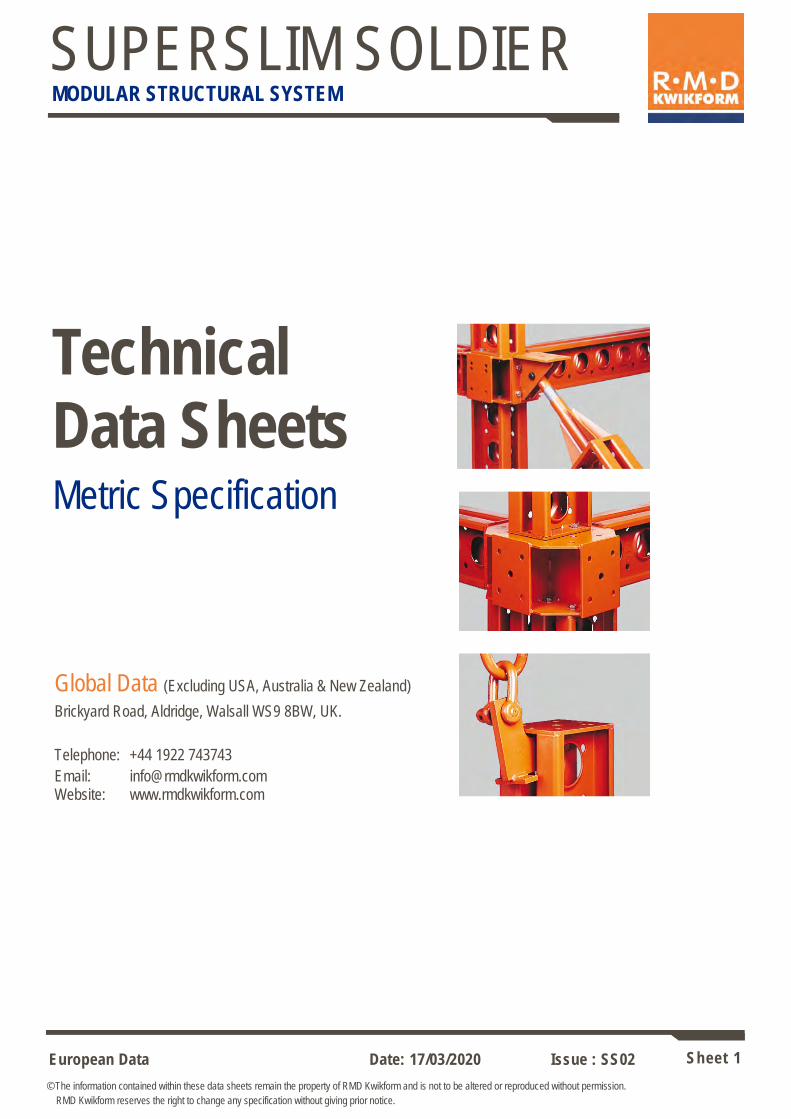
SUPERSLIM SOLDIER MODULAR STRUCTURAL SYSTEM
Technical Data Sheets Metric Specification
Global Data (Excluding USA, Australia & New Zealand) Brickyard Road, Aldridge, Walsall WS9 8BW, UK.
Telephone: +44 1922 743743
Email: [email protected] Website: www.rmdkwikform.com
European Data Sheet 2
© The information contained within these data sheets remain the property of RMD Kwikform and is not to be altered or reproduced without permission.
RMD Kwikform reserves the right to change any specification without giving prior notice.
Date: 17/03/2020 Issue : SS02
SUPERSLIM SOLDIER MODULAR STRUCTURAL SYSTEM
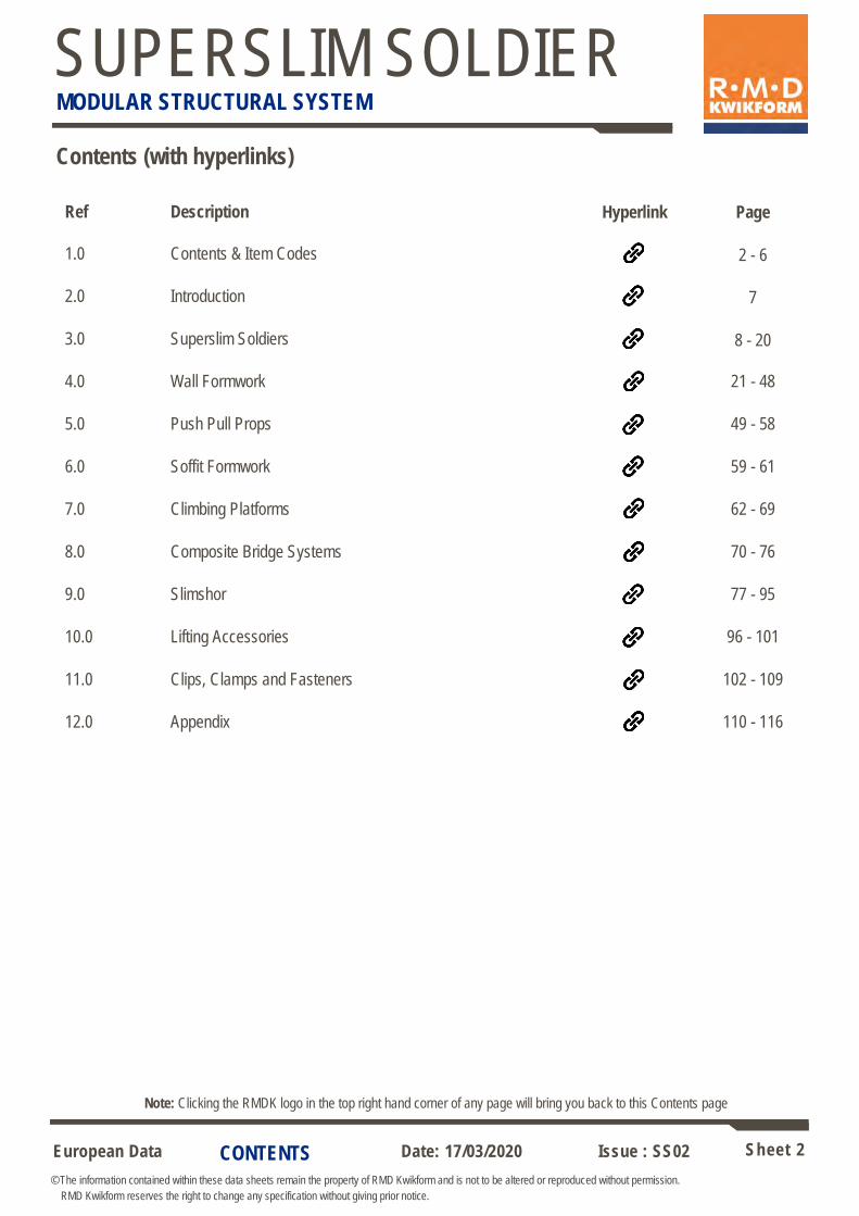
Contents (with hyperlinks)
Ref Description Hyperlink Page
1.0 Contents & Item Codes 2 - 6 2.0 Introduction 7 3.0 Superslim Soldiers 8 - 20
4.0 Wall Formwork 21 - 48
5.0 Push Pull Props 49 - 58
6.0 Soffit Formwork 59 - 61
7.0 Climbing Platforms 62 - 69
8.0 Composite Bridge Systems 70 - 76
9.0 Slimshor 77 - 95
10.0 Lifting Accessories 96 - 101
11.0 Clips, Clamps and Fasteners 102 - 109
12.0 Appendix 110 - 116
Note: Clicking the RMDK logo in the top right hand corner of any page will bring you back to this Contents page
CONTENTS
European Data Sheet 3
© The information contained within these data sheets remain the property of RMD Kwikform and is not to be altered or reproduced without permission.
RMD Kwikform reserves the right to change any specification without giving prior notice.
Date: 17/03/2020 Issue : SS02
SUPERSLIM SOLDIER MODULAR STRUCTURAL SYSTEM
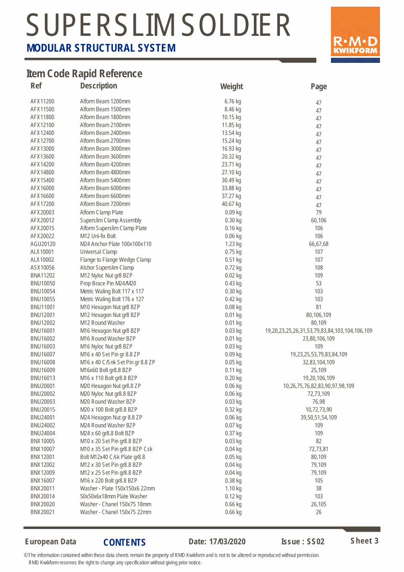
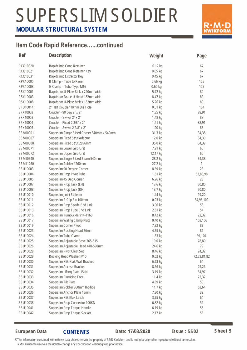
Item Code Rapid Reference
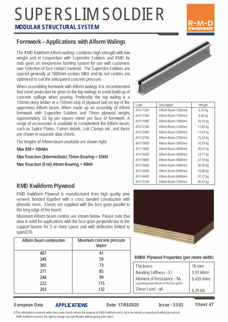
Ref Description Weight Page AFX11200 Alform Beam 1200mm 6.76 kg 47 AFX11500 Alform Beam 1500mm 8.46 kg 47 AFX11800 Alform Beam 1800mm 10.15 kg 47 AFX12100 Alform Beam 2100mm 11.85 kg 47 AFX12400 Alform Beam 2400mm 13.54 kg 47 AFX12700 Alform Beam 2700mm 15.24 kg 47 AFX13000 Alform Beam 3000mm 16.93 kg 47 AFX13600 Alform Beam 3600mm 20.32 kg 47 AFX14200 Alform Beam 4200mm 23.71 kg 47 AFX14800 Alform Beam 4800mm 27.10 kg 47 AFX15400 Alform Beam 5400mm 30.49 kg 47 AFX16000 Alform Beam 6000mm 33.88 kg 47 AFX16600 Alform Beam 6600mm 37.27 kg 47 AFX17200 Alform Beam 7200mm 40.67 kg 47 AFX20003 Alform Clamp Plate 0.09 kg 79
AFX20012 Superslim Clamp Assembly 0.30 kg 60,106
AFX20015 Alform Superslim Clamp Plate 0.16 kg 106
AFX20022 M12 Uni-fix Bolt 0.06 kg 106
AGU20120 M24 Anchor Plate 100x100x110 1.23 kg 66,67,68
ALX10001 Universal Clamp 0.75 kg 107
ALX10002 Flange to Flange Wedge Clamp 0.51 kg 107
ASX10056 Alshor Superslim Clamp 0.72 kg 108
BNA11202 M12 Nyloc Nut gr8 BZP 0.02 kg 109
BNU10050 Prop Brace Pin M24/M20 0.43 kg 53
BNU10054 Metric Waling Bolt 117 x 117 0.30 kg 103
BNU10055 Metric Waling Bolt 176 x 127 0.42 kg 103
BNU11001 M10 Hexagon Nut gr8 BZP 0.08 kg 81
BNU12001 M12 Hexagon Nut gr8 BZP 0.01 kg 80,106,109
BNU12002 M12 Round Washer 0.01 kg 80,109
BNU16001 M16 Hexagon Nut gr8 BZP 0.03 kg 19,20,23,25,26,31,53,79,83,84,103,104,106,109
BNU16002 M16 Round Washer BZP 0.01 kg 23,80,106,109
BNU16003 M16 Nyloc Nut gr8 BZP 0.03 kg 109
BNU16007 M16 x 40 Set Pin gr 8.8 ZP 0.09 kg 19,23,25,53,79,83,84,109
BNU16008 M16 x 40 C/Snk Set Pin gr 8.8 ZP 0.05 kg 32,83,104,109
BNU16009 M16x60 Bolt gr8.8 BZP 0.11 kg 25,109
BNU16013 M16 x 110 Bolt gr8.8 BZP 0.20 kg 19,20,106,109
BNU20001 M20 Hexagon Nut gr8.8 ZP 0.06 kg 10,26,75,76,82,83,90,97,98,109
BNU20002 M20 Nyloc Nut gr8.8 BZP 0.06 kg 72,73,109
BNU20003 M20 Round Washer BZP 0.03 kg 76,98
BNU20015 M20 x 100 Bolt gr8.8 BZP 0.32 kg 10,72,73,90
BNU24001 M24 Hexagon Nut gr 8.8 ZP 0.06 kg 39,50,51,54,109
BNU24002 M24 Round Washer BZP 0.07 kg 109
BNU24004 M24 x 60 gr8.8 Bolt BZP 0.37 kg 109
BNX10005 M10 x 20 Set Pin gr8.8 BZP 0.03 kg 82
BNX10007 M10 x 35 Set Pin gr8.8 BZP Csk 0.04 kg 72,73,81
BNX12001 Bolt M12x40 C/sk Plate gr8.8 0.05 kg 80,109
BNX12002 M12 x 30 Set Pin gr8.8 BZP 0.04 kg 79,109
BNX12009 M12 x 25 Set Pin gr8.8 BZP 0.04 kg 79,109
BNX16007 M16 x 220 Bolt gr8.8 BZP 0.38 kg 105
BNX20011 Washer - Plate 150x150x6 22mm 1.10 kg 38
BNX20014 50x50x6x18mm Plate Washer 0.12 kg 103
BNX20020 Washer - Chanel 150x75 18mm 0.66 kg 26,105
BNX20021 Washer - Chanel 150x75 22mm 0.66 kg 26
CONTENTS
European Data Sheet 4
© The information contained within these data sheets remain the property of RMD Kwikform and is not to be altered or reproduced without permission.
RMD Kwikform reserves the right to change any specification without giving prior notice.
Date: 17/03/2020 Issue : SS02
SUPERSLIM SOLDIER MODULAR STRUCTURAL SYSTEM
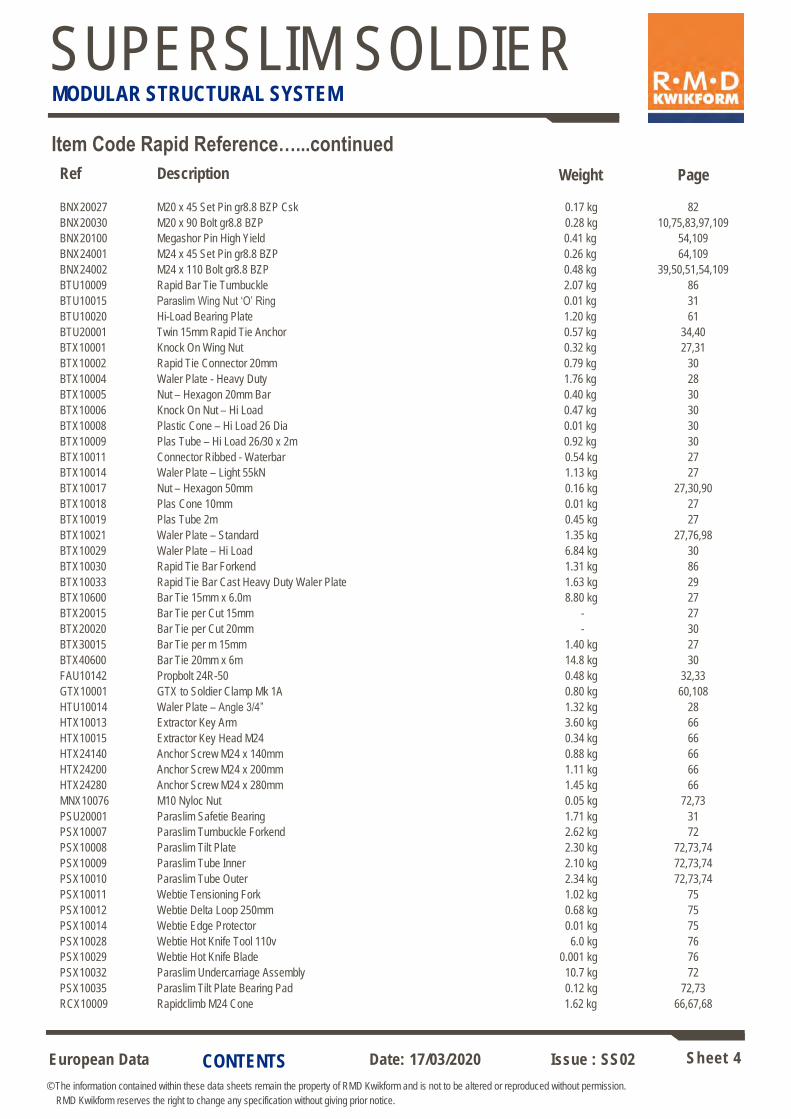
Item Code Rapid Reference…...continued
Ref Description Weight Page
BNX20027 M20 x 45 Set Pin gr8.8 BZP Csk 0.17 kg 82
BNX20030 M20 x 90 Bolt gr8.8 BZP 0.28 kg 10,75,83,97,109
BNX20100 Megashor Pin High Yield 0.41 kg 54,109
BNX24001 M24 x 45 Set Pin gr8.8 BZP 0.26 kg 64,109
BNX24002 M24 x 110 Bolt gr8.8 BZP 0.48 kg 39,50,51,54,109
BTU10009 Rapid Bar Tie Turnbuckle 2.07 kg 86
BTU10015 Paraslim Wing Nut ‘O’ Ring 0.01 kg 31
BTU10020 Hi-Load Bearing Plate 1.20 kg 61
BTU20001 Twin 15mm Rapid Tie Anchor 0.57 kg 34,40
BTX10001 Knock On Wing Nut 0.32 kg 27,31
BTX10002 Rapid Tie Connector 20mm 0.79 kg 30
BTX10004 Waler Plate - Heavy Duty 1.76 kg 28
BTX10005 Nut – Hexagon 20mm Bar 0.40 kg 30
BTX10006 Knock On Nut – Hi Load 0.47 kg 30
BTX10008 Plastic Cone – Hi Load 26 Dia 0.01 kg 30
BTX10009 Plas Tube – Hi Load 26/30 x 2m 0.92 kg 30
BTX10011 Connector Ribbed - Waterbar 0.54 kg 27
BTX10014 Waler Plate – Light 55kN 1.13 kg 27
BTX10017 Nut – Hexagon 50mm 0.16 kg 27,30,90
BTX10018 Plas Cone 10mm 0.01 kg 27
BTX10019 Plas Tube 2m 0.45 kg 27
BTX10021 Waler Plate – Standard 1.35 kg 27,76,98
BTX10029 Waler Plate – Hi Load 6.84 kg 30
BTX10030 Rapid Tie Bar Forkend 1.31 kg 86
BTX10033 Rapid Tie Bar Cast Heavy Duty Waler Plate 1.63 kg 29
BTX10600 Bar Tie 15mm x 6.0m 8.80 kg 27
BTX20015 Bar Tie per Cut 15mm - 27
BTX20020 Bar Tie per Cut 20mm - 30
BTX30015 Bar Tie per m 15mm 1.40 kg 27
BTX40600 Bar Tie 20mm x 6m 14.8 kg 30
FAU10142 Propbolt 24R-50 0.48 kg 32,33
GTX10001 GTX to Soldier Clamp Mk 1A 0.80 kg 60,108
HTU10014 Waler Plate – Angle 3/4” 1.32 kg 28
HTX10013 Extractor Key Arm 3.60 kg 66
HTX10015 Extractor Key Head M24 0.34 kg 66
HTX24140 Anchor Screw M24 x 140mm 0.88 kg 66
HTX24200 Anchor Screw M24 x 200mm 1.11 kg 66
HTX24280 Anchor Screw M24 x 280mm 1.45 kg 66
MNX10076 M10 Nyloc Nut 0.05 kg 72,73
PSU20001 Paraslim Safetie Bearing 1.71 kg 31
PSX10007 Paraslim Turnbuckle Forkend 2.62 kg 72
PSX10008 Paraslim Tilt Plate 2.30 kg 72,73,74
PSX10009 Paraslim Tube Inner 2.10 kg 72,73,74
PSX10010 Paraslim Tube Outer 2.34 kg 72,73,74
PSX10011 Webtie Tensioning Fork 1.02 kg 75
PSX10012 Webtie Delta Loop 250mm 0.68 kg 75
PSX10014 Webtie Edge Protector 0.01 kg 75
PSX10028 Webtie Hot Knife Tool 110v 6.0 kg 76
PSX10029 Webtie Hot Knife Blade 0.001 kg 76
PSX10032 Paraslim Undercarriage Assembly 10.7 kg 72
PSX10035 Paraslim Tilt Plate Bearing Pad 0.12 kg 72,73
RCX10009 Rapidclimb M24 Cone 1.62 kg 66,67,68
CONTENTS
European Data Sheet 5
© The information contained within these data sheets remain the property of RMD Kwikform and is not to be altered or reproduced without permission.
RMD Kwikform reserves the right to change any specification without giving prior notice.
Date: 17/03/2020 Issue : SS02
SUPERSLIM SOLDIER MODULAR STRUCTURAL SYSTEM
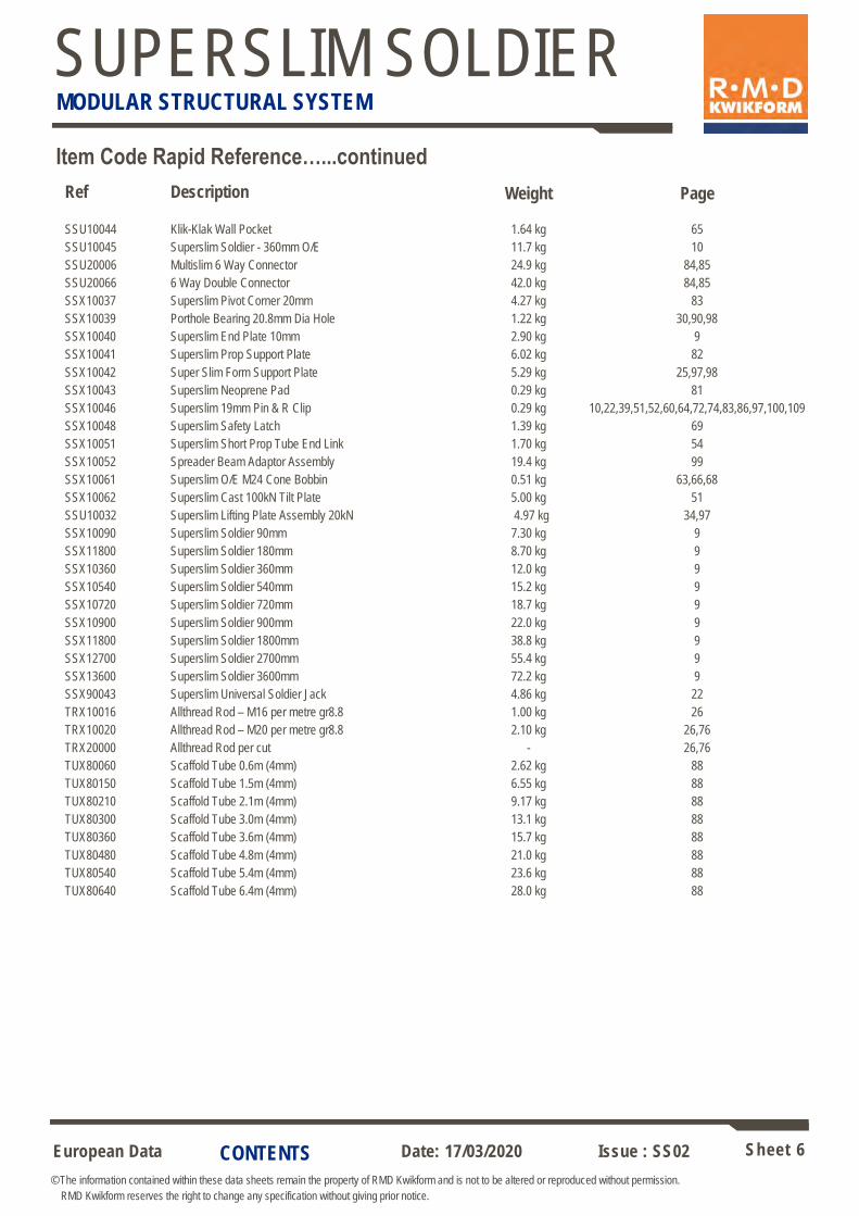
Item Code Rapid Reference…...continued
Ref Description Weight Page
RCX10020 Rapidclimb Cone Retainer 0.12 kg 67
RCX10021 Rapidclimb Cone Retainer Key 0.05 kg 67
RCX10031 Rapidclimb Extractor Key 0.45 kg 67
RPX10005 B Clamp – Tube to Panel 0.66 kg 105
RPX10008 G Clamp – Tube Type M16 0.60 kg 105
RSX10001 Rapidshor U-Plate 8thk x 220mm wide 5.72 kg 80
RSX10003 Rapidshor Brace U Head 182mm wide 8.47 kg 80
RSX10008 Rapidshor U-Plate 8thk x 182mm wide 5.26 kg 80
SFU10014 2” Half Coupler 18mm Dia Hole 0.51 kg 104
SFX10002 Coupler - 90 deg 2” x 2” 1.35 kg 88,91
SFX10003 Coupler - Swivel 2” x 2” 1.48 kg 88
SFX10004 Coupler - Fixed 2 3/8” x 2” 1.41 kg 88,91
SFX10005 Coupler - Swivel 2 3/8” x 2” 1.90 kg 88
SSM00001 Superslim Single Sided Corner 540mm x 540mm 31.3 kg 34,38
SSM00007 Superslim Fixed Strut Adaptor 12.0 kg 34,39
SSM00008 Superslim Fixed Strut 2896mm 35.0 kg 34,39
SSM00071 Superslim Lower Giro Unit 7.91 kg 60
SSM00072 Superslim Upper Giro Unit 12.17 kg 60
SSM10540 Superslim Single Sided Beam 540mm 28.2 kg 34,38
SSM11260 Superslim Soldier 1260mm 27.2 kg 9
SSU10003 Superslim 90 Degree Corner 8.69 kg 23
SSU10004 Superslim Prop Pivot Tube 1.81 kg 53,83,98
SSU10005 Superslim 45 Deg Corner 6.26 kg 23
SSU10007 Superslim Prop Jack (LH) 13.6 kg 50,80
SSU10008 Superslim Prop Jack (RH) 13.7 kg 50,80
SSU10010 Superslim Joint Stiffener 1.44 kg 19,20
SSU10011 Superslim R Clip 5 x 100mm 0.03 kg 54,98,109
SSU10012 Superslim Prop Spade End Link 3.06 kg 53
SSU10013 Superslim Prop Tube End Link 2.81 kg 54
SSU10016 Superslim Turnbuckle 914-1160 8.42 kg 22,32
SSU10017 Superslim Waling Clamp Plate 0.40 kg 103,106
SSU10019 Superslim Corner Pivot 7.32 kg 83
SSU10023 Superslim Rocking Head 36mm 4.35 kg 82
SSU10024 Superslim Tube Clamp 1.33 kg 91,104
SSU10025 Superslim Adjustable Base 365-515 19.0 kg 78,80
SSU10026 Superslim Adjustable Head 440-590mm 24.6 kg 79
SSU10028 Superslim Pivot Cleat Set 8.46 kg 24,32
SSU10029 Rocking Head Washer M10 0.02 kg 72,73,81,82
SSU10030 Superslim Klik-Klak Wall Bracket 6.63 kg 64
SSU10031 Superslim Access Bracket 8.56 kg 25,26
SSU10032 Superslim Lifting Plate 15kN 3.19 kg 34,97
SSU10033 Superslim Plumbing Foot 11.4 kg 22,32
SSU10034 Superslim Tilt Plate 4.89 kg 50
SSU10035 Superslim Soldier 360mm H/Shoe 11.7 kg 63,64
SSU10036 Superslim Anchor Plate 15mm 7.30 kg 32
SSU10037 Superslim Klik Klak Latch 3.95 kg 64
SSU10038 Superslim Prop Connector 100KN 6.82 kg 52
SSU10041 Superslim Prop Torque Handle 6.19 kg 55
SSU10042 Superslim Prop Torque Socket 2.17 kg 55
CONTENTS
European Data Sheet 6
© The information contained within these data sheets remain the property of RMD Kwikform and is not to be altered or reproduced without permission.
RMD Kwikform reserves the right to change any specification without giving prior notice.
Date: 17/03/2020 Issue : SS02
SUPERSLIM SOLDIER MODULAR STRUCTURAL SYSTEM
Item Code Rapid Reference…...continued
Ref Description Weight Page
SSU10044 Klik-Klak Wall Pocket 1.64 kg 65
SSU10045 Superslim Soldier - 360mm O/E 11.7 kg 10
SSU20006 Multislim 6 Way Connector 24.9 kg 84,85
SSU20066 6 Way Double Connector 42.0 kg 84,85
SSX10037 Superslim Pivot Corner 20mm 4.27 kg 83
SSX10039 Porthole Bearing 20.8mm Dia Hole 1.22 kg 30,90,98
SSX10040 Superslim End Plate 10mm 2.90 kg 9
SSX10041 Superslim Prop Support Plate 6.02 kg 82
SSX10042 Super Slim Form Support Plate 5.29 kg 25,97,98
SSX10043 Superslim Neoprene Pad 0.29 kg 81
SSX10046 Superslim 19mm Pin & R Clip 0.29 kg 10,22,39,51,52,60,64,72,74,83,86,97,100,109
SSX10048 Superslim Safety Latch 1.39 kg 69
SSX10051 Superslim Short Prop Tube End Link 1.70 kg 54
SSX10052 Spreader Beam Adaptor Assembly 19.4 kg 99
SSX10061 Superslim O/E M24 Cone Bobbin 0.51 kg 63,66,68
SSX10062 Superslim Cast 100kN Tilt Plate 5.00 kg 51
SSU10032 Superslim Lifting Plate Assembly 20kN 4.97 kg 34,97
SSX10090 Superslim Soldier 90mm 7.30 kg 9
SSX11800 Superslim Soldier 180mm 8.70 kg 9
SSX10360 Superslim Soldier 360mm 12.0 kg 9
SSX10540 Superslim Soldier 540mm 15.2 kg 9
SSX10720 Superslim Soldier 720mm 18.7 kg 9
SSX10900 Superslim Soldier 900mm 22.0 kg 9
SSX11800 Superslim Soldier 1800mm 38.8 kg 9
SSX12700 Superslim Soldier 2700mm 55.4 kg 9
SSX13600 Superslim Soldier 3600mm 72.2 kg 9
SSX90043 Superslim Universal Soldier Jack 4.86 kg 22
TRX10016 Allthread Rod – M16 per metre gr8.8 1.00 kg 26
TRX10020 Allthread Rod – M20 per metre gr8.8 2.10 kg 26,76
TRX20000 Allthread Rod per cut - 26,76
TUX80060 Scaffold Tube 0.6m (4mm) 2.62 kg 88
TUX80150 Scaffold Tube 1.5m (4mm) 6.55 kg 88
TUX80210 Scaffold Tube 2.1m (4mm) 9.17 kg 88
TUX80300 Scaffold Tube 3.0m (4mm) 13.1 kg 88
TUX80360 Scaffold Tube 3.6m (4mm) 15.7 kg 88
TUX80480 Scaffold Tube 4.8m (4mm) 21.0 kg 88
TUX80540 Scaffold Tube 5.4m (4mm) 23.6 kg 88
TUX80640 Scaffold Tube 6.4m (4mm) 28.0 kg 88
CONTENTS
European Data Sheet 7
© The information contained within these data sheets remain the property of RMD Kwikform and is not to be altered or reproduced without permission.
RMD Kwikform reserves the right to change any specification without giving prior notice.
Date: 17/03/2020 Issue : SS02
SUPERSLIM SOLDIER MODULAR STRUCTURAL SYSTEM
Introduction
The Superslim Soldier is the definitive modular structural support system. Robust, easily assembled and having an unrivalled and growing range of accessories, the Superslim Soldier can be used in numerous temporary works applications such as wall formwork, static or travelling gantries, vertical and raking shores, spanning beams and
trusses, façade retention, bridge cantilever edge & deck supports and safety screens for use in hi-rise construction.
Superslim and European Standards.
The majority of the Superslim components were designed before the conception of the EN design standards. Extensive use was made of BS449 backed up by load testing carried out by Birmingham University and in RMD Kwikform labs. Subsequent to the introduction of European Standards we have re-examined the main load-bearing components in the Superslim range using EC3 including the recommendation of EN 12812 to use a partial material factor of 1.1. Where appropriate technical data has been adjusted to suit the output of these calculations and in some instances further load testing in accordance with applicable EN standards has been carried out at University premises to justify published
capacities.
To facilitate design using established permissible load methods in accordance with BS5975, load performance data in this document is displayed as an ‘Allowable Working Load’. Should Limit State Design be required, the Design
Resistance may be obtained by multiplying the Allowable Working Load values by 1.5.
INTRODUCTION
European Data Sheet 8
© The information contained within these data sheets remain the property of RMD Kwikform and is not to be altered or reproduced without permission.
RMD Kwikform reserves the right to change any specification without giving prior notice.
Date: 17/03/2020 Issue : SS02
SUPERSLIM SOLDIER MODULAR STRUCTURAL SYSTEM
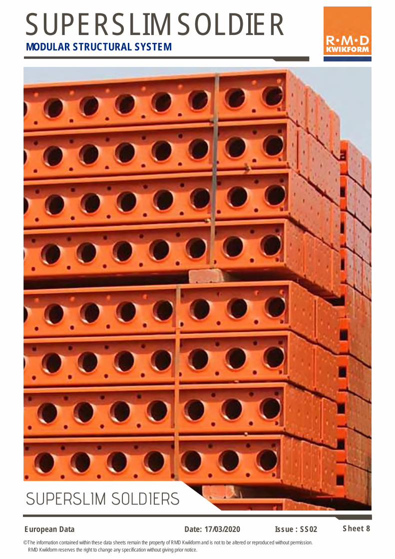
SUPERSLIM SOLDIERS
European Data Sheet 9
© The information contained within these data sheets remain the property of RMD Kwikform and is not to be altered or reproduced without permission.
RMD Kwikform reserves the right to change any specification without giving prior notice.
Date: 17/03/2020 Issue : SS02
SUPERSLIM SOLDIER MODULAR STRUCTURAL SYSTEM
COMPONENTS
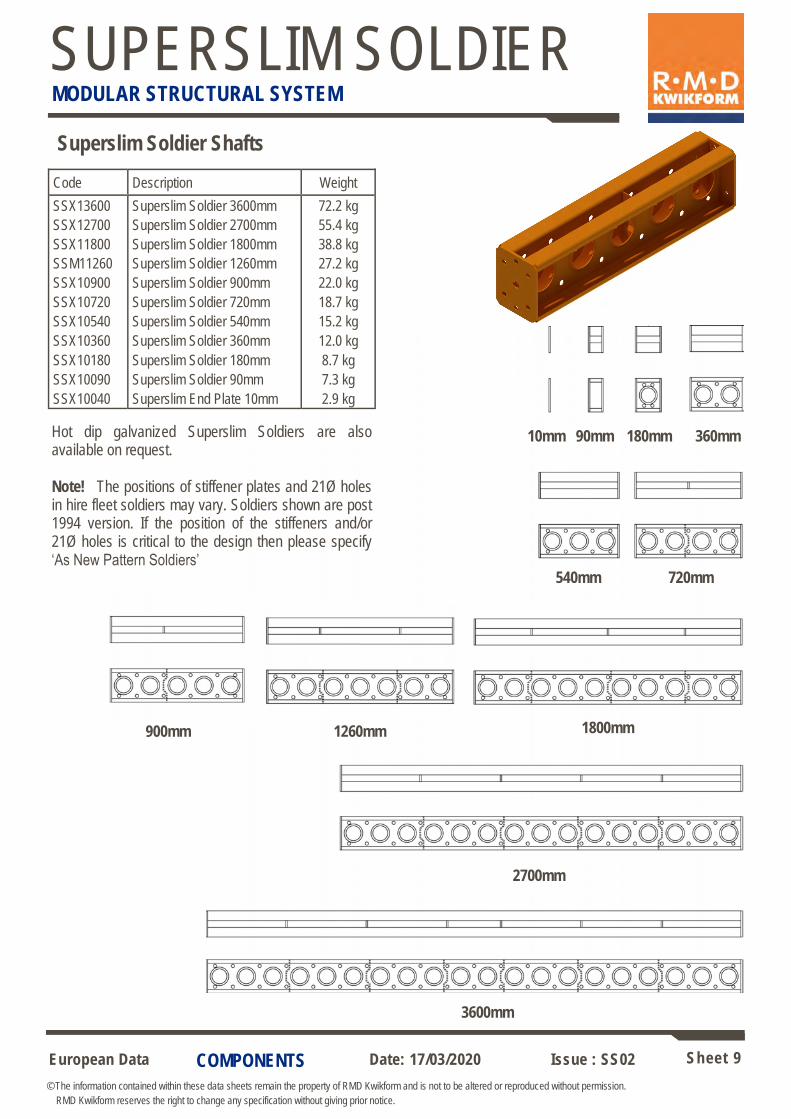
Superslim Soldier Shafts
Hot dip galvanized Superslim Soldiers are also available on request. Note! The positions of stiffener plates and 21Ø holes in hire fleet soldiers may vary. Soldiers shown are post 1994 version. If the position of the stiffeners and/or 21Ø holes is critical to the design then please specify ‘As New Pattern Soldiers’
360mm 90mm 10mm
540mm 720mm
1260mm 1800mm
2700mm
3600mm
Code Description Weight
SSX13600 Superslim Soldier 3600mm 72.2 kg
SSX12700 Superslim Soldier 2700mm 55.4 kg
SSX11800 Superslim Soldier 1800mm 38.8 kg
SSM11260 Superslim Soldier 1260mm 27.2 kg
SSX10900 Superslim Soldier 900mm 22.0 kg
SSX10720 Superslim Soldier 720mm 18.7 kg
SSX10540 Superslim Soldier 540mm 15.2 kg
SSX10360 Superslim Soldier 360mm 12.0 kg
SSX10180 Superslim Soldier 180mm 8.7 kg
SSX10090 Superslim Soldier 90mm 7.3 kg
SSX10040 Superslim End Plate 10mm 2.9 kg
900mm
180mm
European Data Sheet 10
© The information contained within these data sheets remain the property of RMD Kwikform and is not to be altered or reproduced without permission.
RMD Kwikform reserves the right to change any specification without giving prior notice.
Date: 17/03/2020 Issue : SS02
SUPERSLIM SOLDIER MODULAR STRUCTURAL SYSTEM
60mm
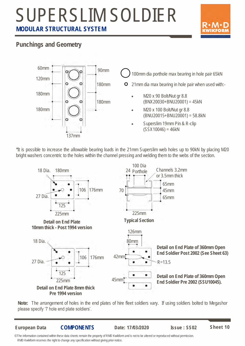
Punchings and Geometry
100mm dia porthole max bearing in hole pair 65kN
Detail on End Plate 10mm thick - Post 1994 version
Typical Section
Detail on End Plate of 360mm Open End Soldier Pre 2002 (SSU10045).
Detail on End Plate of 360mm Open End Soldier Post 2002 (See Sheet 63)
Detail on End Plate 8mm thick Pre 1994 version
Note: The arrangement of holes in the end plates of hire fleet soldiers vary. If using soldiers bolted to Megashor
please specify ‘7 hole end plate soldiers’.
120mm
180mm
180mm
90mm
180mm
180mm
24
45mm
65mm
225mm 225mm
100 Dia
Porthole 180mm
106 176mm
137mm
45mm
80mm
125
27 Dia.
18 Dia.
65mm
225mm
106 176mm
125
27 Dia.
18 Dia.
R=13.5
Channels 3.2mm
or 3.5mm thick
42mm
126mm
70
21mm dia max bearing in hole pair when used with:-
COMPONENTS
*It is possible to increase the allowable bearing loads in the 21mm Superslim web holes up to 90kN by placing M20
bright washers concentric to the holes within the channel pressing and welding them to the webs of the section.
• M20 x 90 Bolt/Nut gr 8.8
(BNX20030+BNU20001) = 45kN
• M20 x 100 Bolt/Nut gr 8.8
(BNU20015+BNU20001) = 58.8kN
• Superslim 19mm Pin & R-clip
(SSX10046) = 46kN
European Data Sheet 11
© The information contained within these data sheets remain the property of RMD Kwikform and is not to be altered or reproduced without permission.
RMD Kwikform reserves the right to change any specification without giving prior notice.
Date: 17/03/2020 Issue : SS02
SUPERSLIM SOLDIER MODULAR STRUCTURAL SYSTEM
COMPONENTS
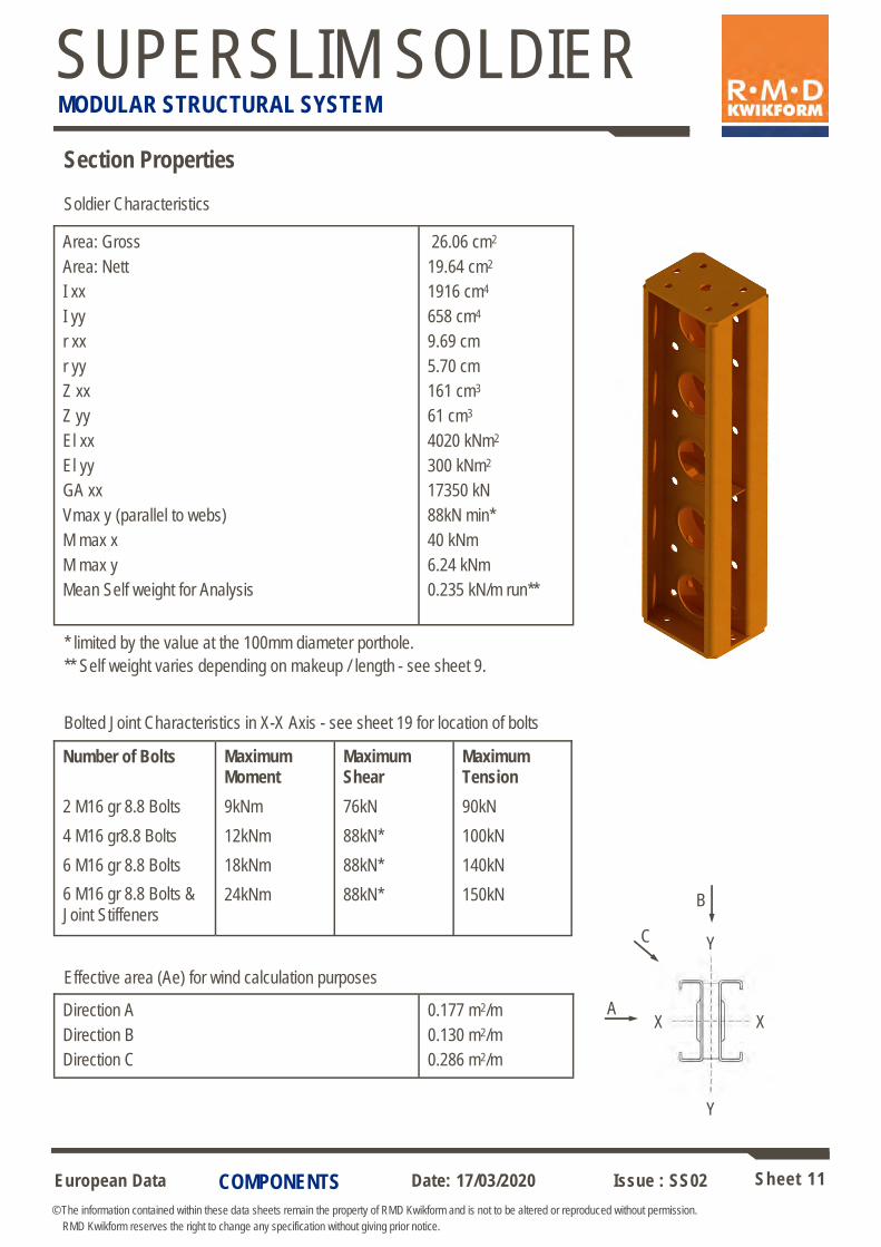
Section Properties
Soldier Characteristics
Area: Gross
Area: Nett
I xx
I yy
r xx
r yy
Z xx
Z yy
El xx
El yy
GA xx
Vmax y (parallel to webs)
M max x
M max y
Mean Self weight for Analysis
26.06 cm2
19.64 cm2
1916 cm4
658 cm4
9.69 cm
5.70 cm
161 cm3
61 cm3
4020 kNm2
300 kNm2
17350 kN
88kN min*
40 kNm
6.24 kNm
0.235 kN/m run**
** Self weight varies depending on makeup / length - see sheet 9.
Y
X X
Y
Direction A
Direction B
Direction C
0.177 m2/m
0.130 m2/m
0.286 m2/m
Effective area (Ae) for wind calculation purposes
A
B
C
Number of Bolts
2 M16 gr 8.8 Bolts
4 M16 gr8.8 Bolts
6 M16 gr 8.8 Bolts
6 M16 gr 8.8 Bolts &
Joint Stiffeners
Maximum Moment
9kNm
12kNm
18kNm
24kNm
Maximum Shear
76kN
88kN*
88kN*
88kN*
Maximum Tension
90kN
100kN
140kN
150kN
Bolted Joint Characteristics in X-X Axis - see sheet 19 for location of bolts
* limited by the value at the 100mm diameter porthole.
European Data Sheet 12
© The information contained within these data sheets remain the property of RMD Kwikform and is not to be altered or reproduced without permission.
RMD Kwikform reserves the right to change any specification without giving prior notice.
Date: 17/03/2020 Issue : SS02
SUPERSLIM SOLDIER MODULAR STRUCTURAL SYSTEM
COMPONENTS
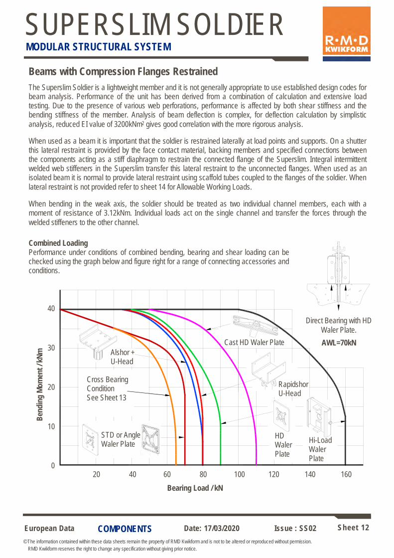
Beams with Compression Flanges Restrained
The Superslim Soldier is a lightweight member and it is not generally appropriate to use established design codes for beam analysis. Performance of the unit has been derived from a combination of calculation and extensive load testing. Due to the presence of various web perforations, performance is affected by both shear stiffness and the bending stiffness of the member. Analysis of beam deflection is complex, for deflection calculation by simplistic
analysis, reduced EI value of 3200kNm2 gives good correlation with the more rigorous analysis.
When used as a beam it is important that the soldier is restrained laterally at load points and supports. On a shutter this lateral restraint is provided by the face contact material, backing members and specified connections between the components acting as a stiff diaphragm to restrain the connected flange of the Superslim. Integral intermittent welded web stiffeners in the Superslim transfer this lateral restraint to the unconnected flanges. When used as an isolated beam it is normal to provide lateral restraint using scaffold tubes coupled to the flanges of the soldier. When
lateral restraint is not provided refer to sheet 14 for Allowable Working Loads.
When bending in the weak axis, the soldier should be treated as two individual channel members, each with a moment of resistance of 3.12kNm. Individual loads act on the single channel and transfer the forces through the
welded stiffeners to the other channel.
Combined Loading Performance under conditions of combined bending, bearing and shear loading can be checked using the graph below and figure right for a range of connecting accessories and conditions.
B
end
ing
Mo
men
t / k
Nm
Bearing Load / kN
Direct Bearing with HD
Waler Plate.
AWL=70kN
40
30
20
10
0
Alshor + U-Head
Cross Bearing Condition See Sheet 13
20 40 60 80 100 120 140 160
Rapidshor U-Head
Hi-Load Waler Plate
HD Waler Plate
Cast HD Waler Plate
STD or Angle Waler Plate
European Data Sheet 13
© The information contained within these data sheets remain the property of RMD Kwikform and is not to be altered or reproduced without permission.
RMD Kwikform reserves the right to change any specification without giving prior notice.
Date: 17/03/2020 Issue : SS02
SUPERSLIM SOLDIER MODULAR STRUCTURAL SYSTEM
COMPONENTS
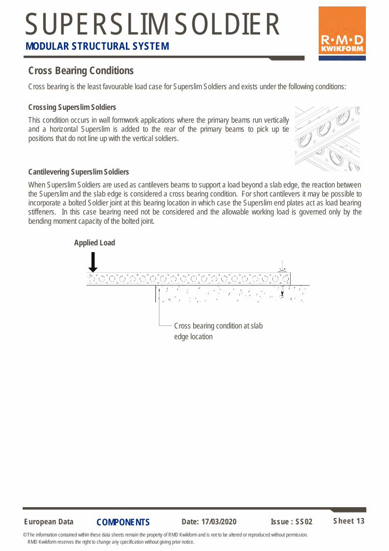
Cross Bearing Conditions
Cross bearing is the least favourable load case for Superslim Soldiers and exists under the following conditions:
Crossing Superslim Soldiers
This condition occurs in wall formwork applications where the primary beams run vertically and a horizontal Superslim is added to the rear of the primary beams to pick up tie
positions that do not line up with the vertical soldiers.
Cantilevering Superslim Soldiers
When Superslim Soldiers are used as cantilevers beams to support a load beyond a slab edge, the reaction between the Superslim and the slab edge is considered a cross bearing condition. For short cantilevers it may be possible to incorporate a bolted Soldier joint at this bearing location in which case the Superslim end plates act as load bearing stiffeners. In this case bearing need not be considered and the allowable working load is governed only by the
bending moment capacity of the bolted joint.
Applied Load
Cross bearing condition at slab
edge location
European Data Sheet 14
© The information contained within these data sheets remain the property of RMD Kwikform and is not to be altered or reproduced without permission.
RMD Kwikform reserves the right to change any specification without giving prior notice.
Date: 17/03/2020 Issue : SS02
SUPERSLIM SOLDIER MODULAR STRUCTURAL SYSTEM
COMPONENTS
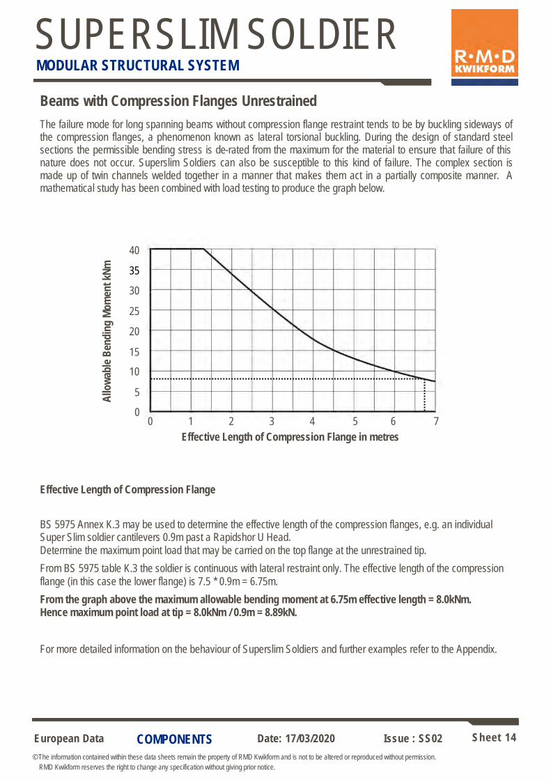
Beams with Compression Flanges Unrestrained
The failure mode for long spanning beams without compression flange restraint tends to be by buckling sideways of the compression flanges, a phenomenon known as lateral torsional buckling. During the design of standard steel sections the permissible bending stress is de-rated from the maximum for the material to ensure that failure of this nature does not occur. Superslim Soldiers can also be susceptible to this kind of failure. The complex section is made up of twin channels welded together in a manner that makes them act in a partially composite manner. A mathematical study has been combined with load testing to produce the graph below.
A
llow
able
Ben
din
g M
om
ent
kNm
0 1 2 3 4 5 6 7
Effective Length of Compression Flange in metres
Effective Length of Compression Flange
BS 5975 Annex K.3 may be used to determine the effective length of the compression flanges, e.g. an individual Super Slim soldier cantilevers 0.9m past a Rapidshor U Head.
Determine the maximum point load that may be carried on the top flange at the unrestrained tip.
From BS 5975 table K.3 the soldier is continuous with lateral restraint only. The effective length of the compression
flange (in this case the lower flange) is 7.5 * 0.9m = 6.75m.
From the graph above the maximum allowable bending moment at 6.75m effective length = 8.0kNm. Hence maximum point load at tip = 8.0kNm / 0.9m = 8.89kN.
For more detailed information on the behaviour of Superslim Soldiers and further examples refer to the Appendix.
0
40
30
20
10
35
25
15
5
European Data Sheet 15
© The information contained within these data sheets remain the property of RMD Kwikform and is not to be altered or reproduced without permission.
RMD Kwikform reserves the right to change any specification without giving prior notice.
Date: 17/03/2020 Issue : SS02
SUPERSLIM SOLDIER MODULAR STRUCTURAL SYSTEM
COMPONENTS
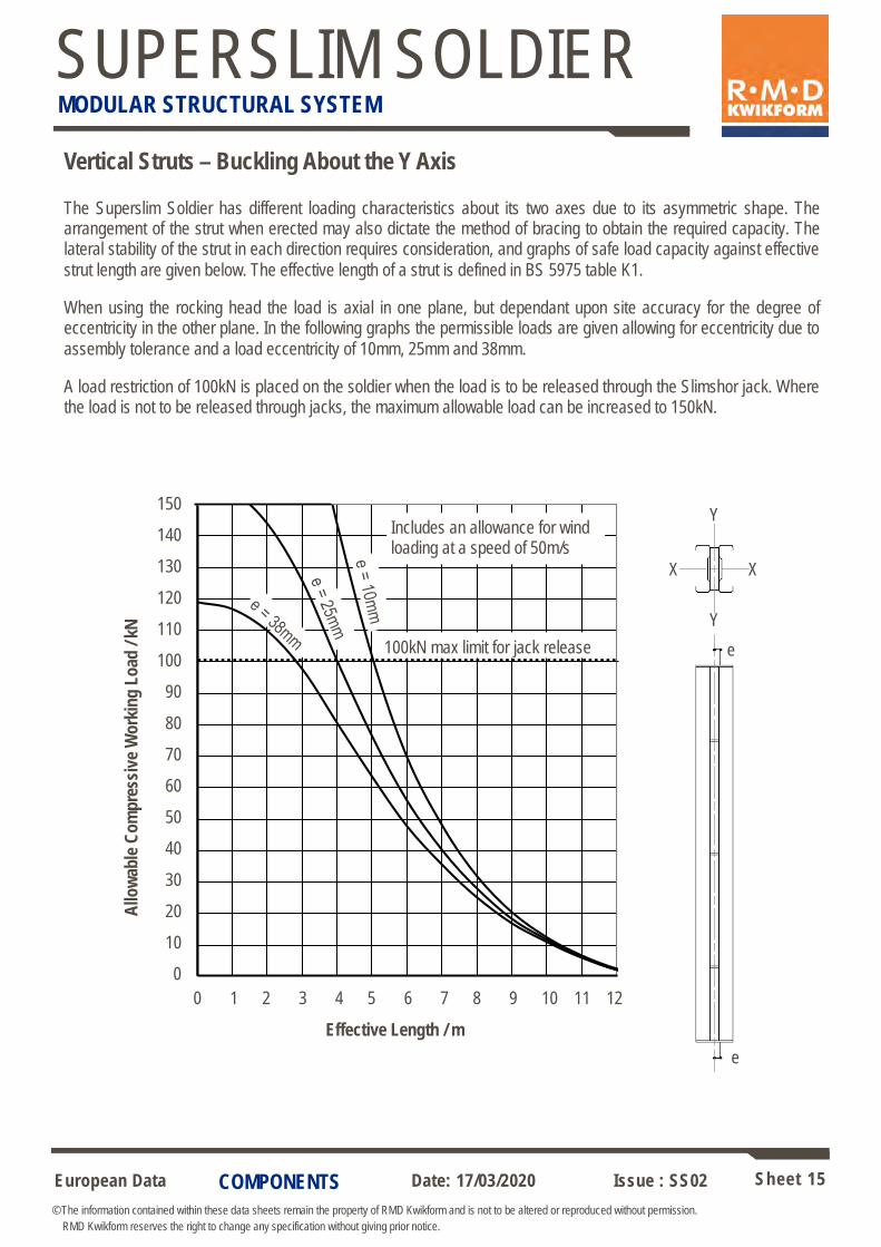
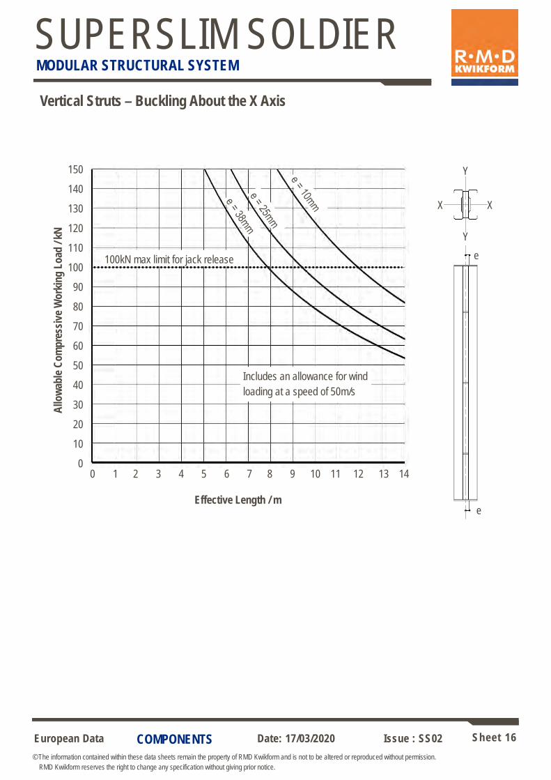
Vertical Struts – Buckling About the Y Axis
The Superslim Soldier has different loading characteristics about its two axes due to its asymmetric shape. The arrangement of the strut when erected may also dictate the method of bracing to obtain the required capacity. The lateral stability of the strut in each direction requires consideration, and graphs of safe load capacity against effective
strut length are given below. The effective length of a strut is defined in BS 5975 table K1.
When using the rocking head the load is axial in one plane, but dependant upon site accuracy for the degree of eccentricity in the other plane. In the following graphs the permissible loads are given allowing for eccentricity due to
assembly tolerance and a load eccentricity of 10mm, 25mm and 38mm.
A load restriction of 100kN is placed on the soldier when the load is to be released through the Slimshor jack. Where the load is not to be released through jacks, the maximum allowable load can be increased to 150kN.
0
10
20
30
40
50
60
70
80
90
100
110
120
130
140
150
0 1 2 3 4 5 6 7 8 9 10 11 12
Allo
wa
ble
Co
mp
res
siv
e W
ork
ing
Lo
ad
/ k
N
Effective Length / m
Includes an allowance for wind loading at a speed of 50m/s
100kN max limit for jack release
Y
X X
Y
e
e
Allo
wab
le C
om
pre
ssiv
e W
ork
ing
Lo
ad /
kN
150
140
130
120
110
100
90
80
70
60
50
40
30
20
10
0
0 1 2 3 4 5 6 7 8 9 10 11 12
Effective Length / m
European Data Sheet 16
© The information contained within these data sheets remain the property of RMD Kwikform and is not to be altered or reproduced without permission.
RMD Kwikform reserves the right to change any specification without giving prior notice.
Date: 17/03/2020 Issue : SS02
SUPERSLIM SOLDIER MODULAR STRUCTURAL SYSTEM
COMPONENTS
Vertical Struts – Buckling About the X Axis
Y
X X
Y
e
e
Includes an allowance for wind
loading at a speed of 50m/s
100kN max limit for jack release
Allo
wab
le C
om
pre
ssiv
e W
ork
ing
Lo
ad /
kN
150
140
130
120
110
100
90
80
70
60
50
40
30
20
10
0
Effective Length / m
0 1 2 3 4 5 6 7 8 9 10 11 12 13 14
European Data Sheet 17
© The information contained within these data sheets remain the property of RMD Kwikform and is not to be altered or reproduced without permission.
RMD Kwikform reserves the right to change any specification without giving prior notice.
Date: 17/03/2020 Issue : SS02
SUPERSLIM SOLDIER MODULAR STRUCTURAL SYSTEM
COMPONENTS
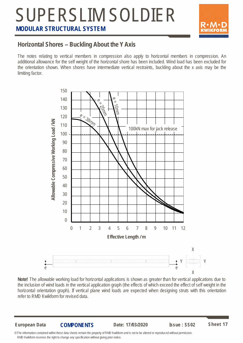
The notes relating to vertical members in compression also apply to horizontal members in compression. An additional allowance for the self weight of the horizontal shore has been included. Wind load has been excluded for the orientation shown. When shores have intermediate vertical restraints, buckling about the x axis may be the
limiting factor.
Horizontal Shores – Buckling About the Y Axis
Note! The allowable working load for horizontal applications is shown as greater than for vertical applications due to the inclusion of wind loads in the vertical application graph (the effects of which exceed the effect of self weight in the horizontal orientation graph). If vertical plane wind loads are expected when designing struts with this orientation
refer to RMD Kwikform for revised data.
0
10
20
30
40
50
60
70
80
90
100
110
120
130
140
150
0 1 2 3 4 5 6 7 8 9 10 11 12
Allo
wa
ble
Co
mp
res
siv
e W
ork
ing
Lo
ad
/ k
N
Effective Length / m
X
X
Y Y
e
100kN max for jack release
e
Allo
wab
le C
om
pre
ssiv
e W
ork
ing
Lo
ad /
kN
150
140
130
120
110
100
90
80
70
60
50
40
30
20
10
0
0 1 2 3 4 5 6 7 8 9 10 11 12
Effective Length / m
European Data Sheet 18
© The information contained within these data sheets remain the property of RMD Kwikform and is not to be altered or reproduced without permission.
RMD Kwikform reserves the right to change any specification without giving prior notice.
Date: 17/03/2020 Issue : SS02
SUPERSLIM SOLDIER MODULAR STRUCTURAL SYSTEM
COMPONENTS
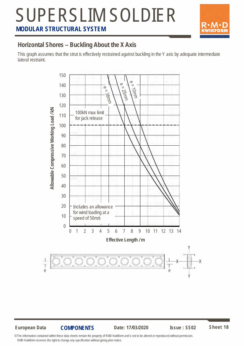
Horizontal Shores – Buckling About the X Axis
100kN max limit for jack release
Includes an allowance for wind loading at a speed of 50m/s
This graph assumes that the strut is effectively restrained against buckling in the Y axis by adequate intermediate lateral restraint.
Y
X X
Y
e e
Allo
wab
le C
om
pre
ssiv
e W
ork
ing
Lo
ad /
kN
150
140
130
120
110
100
90
80
70
60
50
40
30
20
10
0 0 1 2 3 4 5 6 7 8 9 10 11 12 13 14
Effective Length / m
European Data Sheet 19
© The information contained within these data sheets remain the property of RMD Kwikform and is not to be altered or reproduced without permission.
RMD Kwikform reserves the right to change any specification without giving prior notice.
Date: 17/03/2020 Issue : SS02
SUPERSLIM SOLDIER MODULAR STRUCTURAL SYSTEM
COMPONENTS
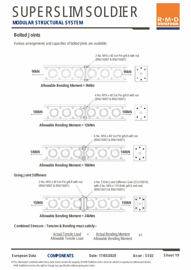
Bolted Joints
Allowable Bending Moment = 18kNm
140kN
6 No. M16 x 40 Set Pin gr8.8 with nut
(BNU16007 & BNU16001)
Allowable Bending Moment = 12kNm
4 No. M16 x 40 Set Pin gr8.8 with nut
(BNU16007 & BNU16001)
100kN
140kN
100kN
Various arrangements and capacities of bolted joints are available:
90kN
Allowable Bending Moment = 9kNm
2 No. M16 x 40 Set Pin gr8.8 with nut
(BNU16007 & BNU16001)
90kN
Allowable Bending Moment = 24kNm
150kN
4 No. S/Slim Joint Stiffeners Galv (SSU10010)with 4 No. M16 x 110 Bolts gr8.8 and nuts
(BNU16013 & BNU16001)
150kN
Combined Stresses - Tension & Bending must satisfy:-
Actual Tensile Load Actual Bending Moment + ≤1
Using Joint Stiffeners
Allowable Tensile Load Allowable Bending Moment
2 No. M16 x 40 Set Pin gr8.8 with nut
(BNU16007 & BNU16001)
European Data Sheet 20
© The information contained within these data sheets remain the property of RMD Kwikform and is not to be altered or reproduced without permission.
RMD Kwikform reserves the right to change any specification without giving prior notice.
Date: 17/03/2020 Issue : SS02
SUPERSLIM SOLDIER MODULAR STRUCTURAL SYSTEM
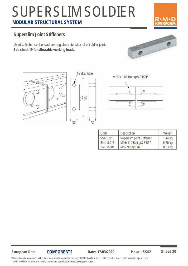
Used to Enhance the load bearing characteristics of a Soldier joint.
See sheet 19 for allowable working loads.
18 dia. hole M16 x 110 Bolt gr8.8 BZP
32 32
125
195
Superslim Joint Stiffeners
Code Description Weight
SSU10010 Superslim Joint Stiffener 1.44 kg
BNU16013 M16x110 Bolt gr8.8 BZP 0.20 kg
BNU16001 M16 Nut gr8 BZP 0.03 kg
COMPONENTS
European Data Sheet 21
© The information contained within these data sheets remain the property of RMD Kwikform and is not to be altered or reproduced without permission.
RMD Kwikform reserves the right to change any specification without giving prior notice.
Date: 17/03/2020 Issue : SS02
SUPERSLIM SOLDIER MODULAR STRUCTURAL SYSTEM
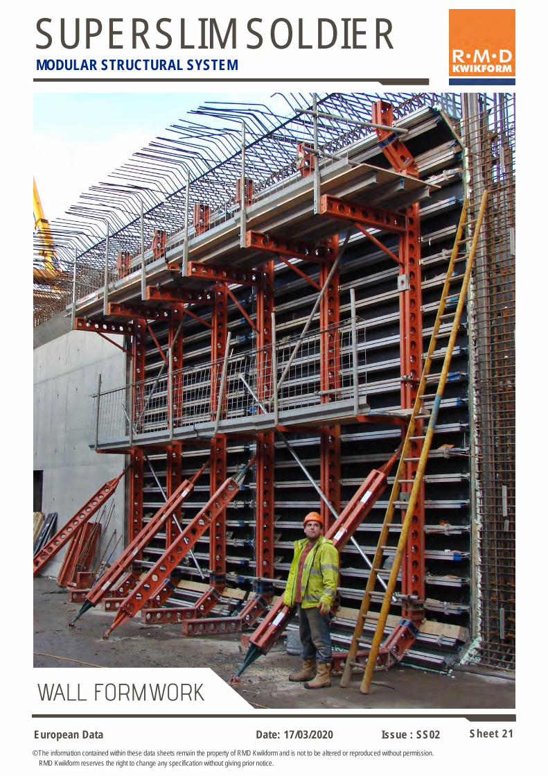
WALL FORMWORK

European Data Sheet 22
© The information contained within these data sheets remain the property of RMD Kwikform and is not to be altered or reproduced without permission.
RMD Kwikform reserves the right to change any specification without giving prior notice.
Date: 17/03/2020 Issue : SS02
SUPERSLIM SOLDIER MODULAR STRUCTURAL SYSTEM
Superslim Turnbuckle & Superslim Plumbing Foot
100x75x6 RSA x 164mm long with 22 dia. hole
1045
737 100
125
19mm Pin & Clip (SSX10046)
19mm Pin & Clip (SSX10046)
Used in single sided base formwork applications.
Allowable Working Load in the Turnbuckle ± 45kN
Code Description Weight
SSU10016 Superslim Turnbuckle 914-1160 8.42 kg
SSU10033 Superslim Plumbing Foot 11.4 kg
SSX10046 Superslim 19mm Pin & R Clip 0.29kg
COMPONENTS
Horizontal
AWL 20kN Vertically – Fully Open AWL 25kN Horizontally – Fully Open AWL 30kN @ 170mm from back of Soldier
Used in both Horizontal and Vertical applications as illustrated below, with a working range of 115mm closed to 400mm fully open. The Universal Jack arm is connected to
the Soldier with 2 No Superslim 19mm Pin & “R” clips.
Note: When used for levelling of Formwork, there is insufficient space to install a Bar Tie Waler Plate & Nut between the jack stem & Soldier. Checks should be carried out based on the tie position shown in the vertical application above
to ensure there will not be unacceptable grout loss / deflection at the kicker.
Vertical
360
180
137
136Ø
33
32Ø 270
115
- 40
0
458
2 No Holes for No
6 Woodscrews
3x22dia Holes
60x40RHS
75-355mm
25-30kN
See below
20kN
Superslim Universal Soldier Jack (SSX90043) Weight 4.86kg
445
min
.
European Data Sheet 23
© The information contained within these data sheets remain the property of RMD Kwikform and is not to be altered or reproduced without permission.
RMD Kwikform reserves the right to change any specification without giving prior notice.
Date: 17/03/2020 Issue : SS02
SUPERSLIM SOLDIER MODULAR STRUCTURAL SYSTEM
COMPONENTS
X
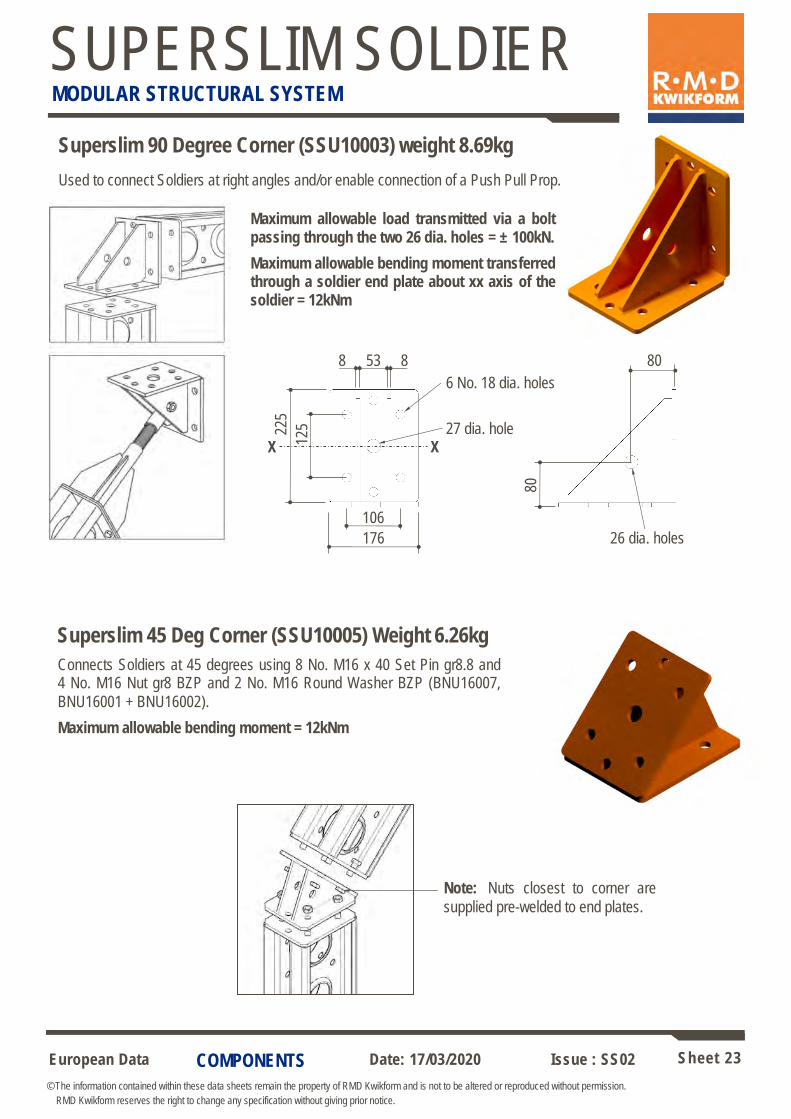
Superslim 90 Degree Corner (SSU10003) weight 8.69kg
Used to connect Soldiers at right angles and/or enable connection of a Push Pull Prop.
X
26 dia. holes
Maximum allowable load transmitted via a bolt passing through the two 26 dia. holes = ± 100kN.
Maximum allowable bending moment transferred through a soldier end plate about xx axis of the soldier = 12kNm
80
80
106
176
53 8 8
27 dia. hole
6 No. 18 dia. holes
225
125
Connects Soldiers at 45 degrees using 8 No. M16 x 40 Set Pin gr8.8 and 4 No. M16 Nut gr8 BZP and 2 No. M16 Round Washer BZP (BNU16007,
BNU16001 + BNU16002).
Maximum allowable bending moment = 12kNm
Superslim 45 Deg Corner (SSU10005) Weight 6.26kg
Note: Nuts closest to corner are
supplied pre-welded to end plates.
European Data Sheet 24
© The information contained within these data sheets remain the property of RMD Kwikform and is not to be altered or reproduced without permission.
RMD Kwikform reserves the right to change any specification without giving prior notice.
Date: 17/03/2020 Issue : SS02
SUPERSLIM SOLDIER MODULAR STRUCTURAL SYSTEM
COMPONENTS
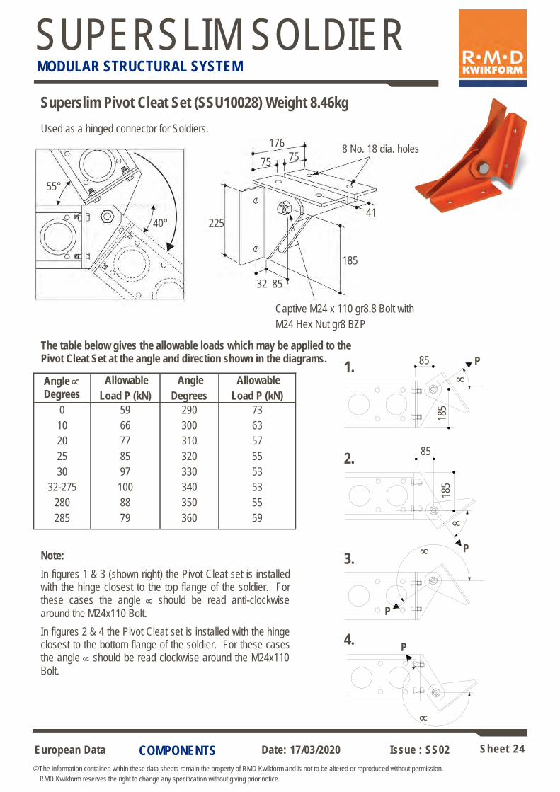
Superslim Pivot Cleat Set (SSU10028) Weight 8.46kg
P
185
85
Captive M24 x 110 gr8.8 Bolt with
M24 Hex Nut gr8 BZP
55°
40° 225
176
32 85
8 No. 18 dia. holes
41
75 75
185
Angle
Degrees
Allowable
Load P (kN)
Angle
Degrees
Allowable
Load P (kN)
0
10
20
25
30
32-275
280
285
59
66
77
85
97
100
88
79
290
300
310
320
330
340
350
360
73
63
57
55
53
53
55
59
The table below gives the allowable loads which may be applied to the Pivot Cleat Set at the angle and direction shown in the diagrams.
Used as a hinged connector for Soldiers.
P
P
1.
85
P
185
4.
2.
3. Note:
In figures 1 & 3 (shown right) the Pivot Cleat set is installed with the hinge closest to the top flange of the soldier. For these cases the angle should be read anti-clockwise
around the M24x110 Bolt.
In figures 2 & 4 the Pivot Cleat set is installed with the hinge closest to the bottom flange of the soldier. For these cases the angle should be read clockwise around the M24x110
Bolt.

European Data Sheet 25
© The information contained within these data sheets remain the property of RMD Kwikform and is not to be altered or reproduced without permission.
RMD Kwikform reserves the right to change any specification without giving prior notice.
Date: 17/03/2020 Issue : SS02
SUPERSLIM SOLDIER MODULAR STRUCTURAL SYSTEM
Superslim Access Bracket (SSU10031) weight 8.56kg
Used to support a three board wide access platform. Has integral spigot to
accept standard scaffold tube for tube guardrails or Ultraguard mesh barrier.
Allowable load on the bracket 3.2 kN UDL
800
Captive Fixing to S/Slim web
holes
14 Dia.
38 O/D
150 38
102
3 No screw holes
Customers Wood Screws
M12x75 Bolt & Nut (BNX12007+BNU12001) 75x50 Customers
Timber
Fixing of scaffold boards for crane handling.
COMPONENTS
85
Formwork
12
Timber packing
150
325
176 106
Superslim Form Support Plate
Used to support the formwork at the base of the Soldiers. Two cantilever lengths are possible by turning the plate around. Note! Support plates should be fitted
to soldier used for lifting.
Allowable Working Load on Arrow ‘A’ = 10kN for a single plate connected
by 2 No. M16 x 40 Set Pins and Nuts
Or 20kN for two plates connected with 2 No M16x60 Bolts & Nuts
A
25
100/125
2 No 18Ø Holes
Code Description Weight
SSX10042 Superslim Form Support Plate 5.29 kg
BNU16001 M16 Nut gr8 BZP 0.03 kg
BNU16007 M16x40 Set Pin gr8.8 BZP 0.09 kg
BNU16009 M16x60 Bolt gr8.8 BZP 0.11 kg

European Data Sheet 26
© The information contained within these data sheets remain the property of RMD Kwikform and is not to be altered or reproduced without permission.
RMD Kwikform reserves the right to change any specification without giving prior notice.
Date: 17/03/2020 Issue : SS02
SUPERSLIM SOLDIER MODULAR STRUCTURAL SYSTEM
COMPONENTS
Hole diameter 18 or 22mm
75
150 22
Channel Washers
6mm thick washers used as a light duty waler plate with Super Slim and Rapid Bar Tie or
allthread rod.
For AWL see sketch below right.
AWL25kN
AWL 20kN
Code Description Weight
BNX20020 Washer - Channel 150x75 18mm 0.66 kg
BNX20021 Washer - Channel 150x75 22mm 0.66 kg
TRX10016 Allthread Rod - M16 per metre gr8.8 1.00 kg
TRX10020 Allthread Rod - M20 per metre gr8.8 2.10 kg
TRX20000 All Thread Rod per cut -
BNU16001 M16 Hex Nut gr8 BZP 0.03 kg
BNU20001 M20 Hex Nut gr8 BZP 0.06 kg
RMDK All Thread Rod is grade 8.8 and has a bright
zinc plated finish.
AWL for Grade 8.8 M16 All Thread Rod is 70kN in
formwork use and 45kN for other applications.
AWL for grade 8.8 M20 All Thread Rod is 108kN in
formwork use and 70kN for other applications.
Superslim Access Bracket (SSU10031) weight 8.56kg - Ultraguard Version
Used to support a three board wide access platform. Has integral socket to
accept standard scaffold tube or Ultraguard guardrails for Ultraguard mesh barrier.
Allowable load on the bracket 3.2 kN UDL
Note: this rectified bracket has the same code as the original Superslim Access Bracket therefore the specific type will need specifying in a text line on material
take-offs.
Side View Section
735
Plan
280 19
5
Ultraguard socket

European Data Sheet 27
© The information contained within these data sheets remain the property of RMD Kwikform and is not to be altered or reproduced without permission.
RMD Kwikform reserves the right to change any specification without giving prior notice.
Date: 17/03/2020 Issue : SS02
SUPERSLIM SOLDIER MODULAR STRUCTURAL SYSTEM
COMPONENTS
120
120
150
180
Used with 15mm diameter Rapid Bar Tie and accessories.
Max allowable tie load = 70kN but depends on co-incident Superslim bending moment (refer to sheet 12).
AWL = 50kN when used with timber (bearing limits).
Waler Plate – Standard (BTX10021) weight 1.35kg
Waler Plate – Light 55kN
Used with 15mm diameter Rapid Bar Tie and accessories. Allowable Tie Load with Superslim = 55kN with maximum co-incident bending moment of 30kNm
20Ø hole
26Ø hole
Code Description Weight
BTX10014 Waler Plate - Light 55kN 1.13 kg
BTX10001 Knock on Wing Nut 0.32 kg
BTX10600 Rapid Bar Tie 15mm x 6.00m 8.80 kg
BTX30015 Bar Tie per m 15mm 1.50 kg
BTX20015 Bar Tie per cut 15mm -
BTX10011 Connector Ribbed - Water Bar 0.54 kg
BTX10017 Nut - Hexagon 50mm 0.16 kg
BTX10018 Plastic Cone 10mm 0.01 kg
BTX10019 Plas Tube 2m 0.45 kg

European Data Sheet 28
© The information contained within these data sheets remain the property of RMD Kwikform and is not to be altered or reproduced without permission.
RMD Kwikform reserves the right to change any specification without giving prior notice.
Date: 17/03/2020 Issue : SS02
SUPERSLIM SOLDIER MODULAR STRUCTURAL SYSTEM
COMPONENTS
180
150
Waler Plate – Angle 3/4” (HTU10014) weight 1.32kg
150
45°
130
For tie angles over 6 degrees provide a stop to prevent the Angle Waler Plate sliding along the Soldier. A neoprene pad can be added between components
to prevent sliding for angles up to 20°
Note: Angle Waler Plates are not weldable.
Used with 15mm diameter Rapid Bar Tie and accessories where the tie is not perpendicular
to the Soldier.
Allowable Tie Load is 70kN but depends on co-incident Superslim bending moment (refer to sheet 12).
Waler Plate – Heavy Duty (BTX10004) weight 1.76kg
Used with 15mm diameter Rapid Bar Tie and accessories.
Maximum allowable tie load with Superslim Soldiers 90kN but varies according to co-incident bending moment (refer to sheet 12).
110kN max when used with special steel channels.
Rear View Front View
26Ø hole
21Ø slot

European Data Sheet 29
© The information contained within these data sheets remain the property of RMD Kwikform and is not to be altered or reproduced without permission.
RMD Kwikform reserves the right to change any specification without giving prior notice.
Date: 17/03/2020 Issue : SS02
SUPERSLIM SOLDIER MODULAR STRUCTURAL SYSTEM
COMPONENTS
Rapid Tie Bar Cast Heavy Duty Waler Plate (BTX10033) weight 1.63kg
Used with 15mm diameter Rapid Bar Tie and accessories.
Maximum allowable tie load with Superslim Soldiers 110kN but varies according to co-incident bending moment (refer to sheet 12).
Cast Waler Plate Correctly Positioned on the Superslim
Soldier
Cast Waler Plate Incorrectly Positioned on the Superslim
Soldier
Note the projections to the underside
do not allow the waler plate to sit flat
onto the Superslim Soldier when
positioned in this orientation.
Side View Section
87
62
20 80
36 43
275
Do Not Use
The Cast Waler Plate can be captivated to the Superslim Soldier using Alshor Superslim Clamps - see sheet 108.

European Data Sheet 30
© The information contained within these data sheets remain the property of RMD Kwikform and is not to be altered or reproduced without permission.
RMD Kwikform reserves the right to change any specification without giving prior notice.
Date: 17/03/2020 Issue : SS02
SUPERSLIM SOLDIER MODULAR STRUCTURAL SYSTEM
COMPONENTS
Used with 20mm diameter Rapid Bar Tie and accessories.
Max allowable tie load 160kN but depends on co-incident bending moment (refer to sheet 12).
Hi-Rapid Tie Knock-on
Wing Nut
180
200
195
100 85
40 15mm Rapid
Bar Tie
Note: M20 Allthread Rod but not 20 Ø Rapid Bar Tie may also be
used Porthole Bearing 20.8mm Dia Hole
(SSX10039)
72
Porthole Bearing 20.8mm Dia Hole (SSX10039) weight 1.22kg Enables connection of a tie rod to a Porthole at any angle.
Allowable Working Load 65kN tension
Waler Plate – Hi Load
Nut – Hexagonal
50mm (BTX10017)
40Ø chamfered hole
Code Description Weight
BTX10029 Waler Plate - Hi Load 6.84 kg
BTX10006 Knock on Nut - Hi Load 0.47 kg
BTX40600 Rapid Bar Tie 20mm x 6.00m 14.8 kg
BTX20020 Bar Tie per cut 20mm -
BTX10002 Connector 20mm - Rapid Tie 0.79 kg
BTX10005 Nut - Hexagon 20mm Bar 0.40 kg
BTX10008 Plastic Cone - Hi Load 26 Dia. 0.01 kg
BTX10009 Plastic Tube - Hi Load 26/30 x 2m 0.92 kg
20
142

European Data Sheet 31
© The information contained within these data sheets remain the property of RMD Kwikform and is not to be altered or reproduced without permission.
RMD Kwikform reserves the right to change any specification without giving prior notice.
Date: 17/03/2020 Issue : SS02
SUPERSLIM SOLDIER MODULAR STRUCTURAL SYSTEM
COMPONENTS
Paraslim Safetie Bearing (PSU20001) weight 1.71kg
A fully rotating, securely captivated bearing used to anchor one
end of a Rapid Bar Tie into the porthole of a Superslim Soldier.
The unit also internally captivates the assembly of a Knock on
Wing Nut and Paraslim Wing Nut ‘O’ Ring; see below.
Note that the Rapid Bar Tie must be inserted fully into the Wing Nut for the stated allowable working load and that the Bar Tie can not pass right through the bearing. Tie bar insertion can be verified through the 12mm diameter hole in the bearing and is made easier
if the end of the tie bar is painted before insertion.
AWL = 65kN
Paraslim Safetie Bearing
(PSU20001)
15mm Rapid
Bar Tie
Knock on Wing Nut & Paraslim Wing Nut ‘O’ Ring(BTX10001 &
BTU10015)
Knock On Wing Nut (BTX10001) weight 0.32kg
AWL = 110kN
Paraslim Wing Nut ’O’ Ring (BTU10015) weight 0.01kg
Used for retaining the Knock On Wing Nut (BTX10001) in the Paraslim Safetie Bearing
(PSU20001).
Retained in Paraslim Safetie Bearing (PSU20001) using the Paraslim Wing Nut ’O’ Ring
(BTU10015).
European Data Sheet 32
© The information contained within these data sheets remain the property of RMD Kwikform and is not to be altered or reproduced without permission.
RMD Kwikform reserves the right to change any specification without giving prior notice.
Date: 17/03/2020 Issue : SS02
SUPERSLIM SOLDIER MODULAR STRUCTURAL SYSTEM
COMPONENTS
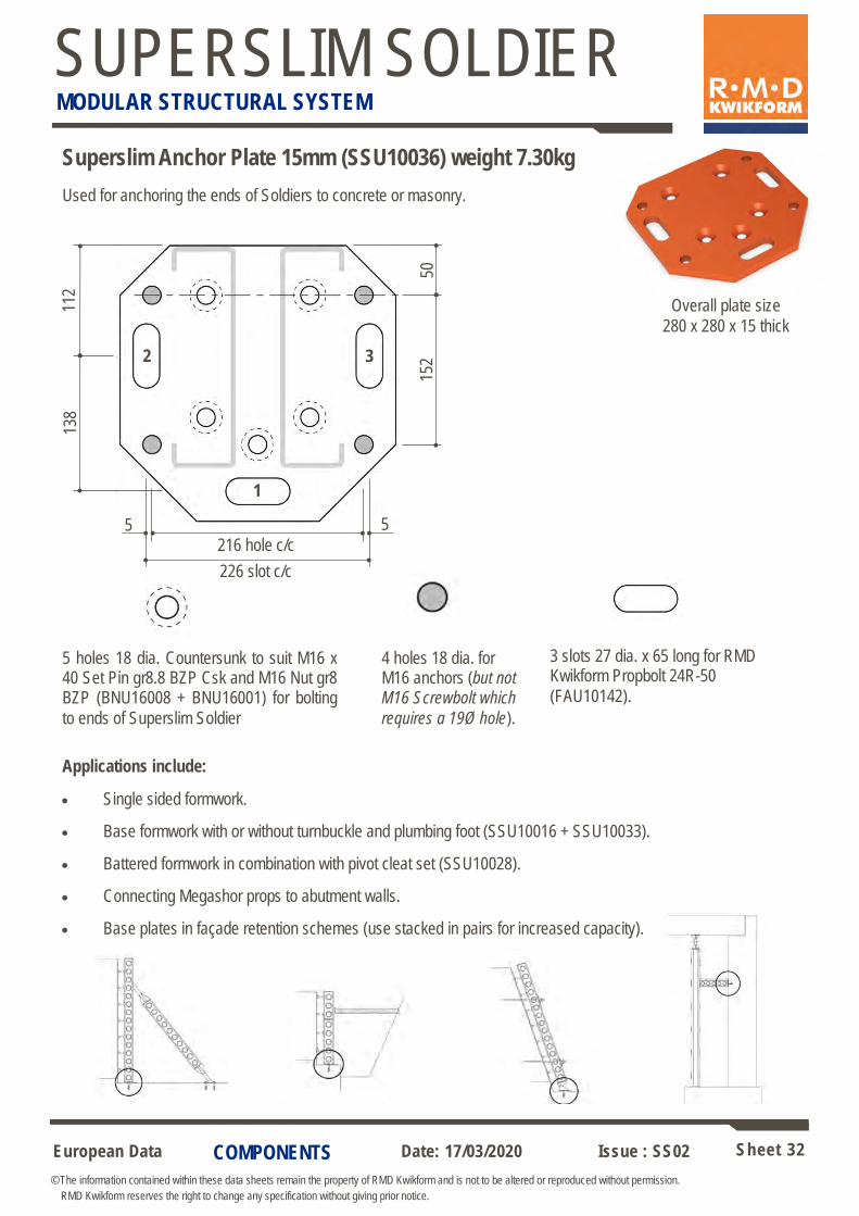
Superslim Anchor Plate 15mm (SSU10036) weight 7.30kg
112
138
226 slot c/c
5 5
50
152
5 holes 18 dia. Countersunk to suit M16 x 40 Set Pin gr8.8 BZP Csk and M16 Nut gr8 BZP (BNU16008 + BNU16001) for bolting
to ends of Superslim Soldier
4 holes 18 dia. for M16 anchors (but not M16 Screwbolt which
requires a 19Ø hole).
3 slots 27 dia. x 65 long for RMD Kwikform Propbolt 24R-50
(FAU10142).
3 2
1
Overall plate size
280 x 280 x 15 thick
Used for anchoring the ends of Soldiers to concrete or masonry.
Applications include:
• Single sided formwork.
• Base formwork with or without turnbuckle and plumbing foot (SSU10016 + SSU10033).
• Battered formwork in combination with pivot cleat set (SSU10028).
• Connecting Megashor props to abutment walls.
• Base plates in façade retention schemes (use stacked in pairs for increased capacity).
216 hole c/c
European Data Sheet 33
© The information contained within these data sheets remain the property of RMD Kwikform and is not to be altered or reproduced without permission.
RMD Kwikform reserves the right to change any specification without giving prior notice.
Date: 17/03/2020 Issue : SS02
SUPERSLIM SOLDIER MODULAR STRUCTURAL SYSTEM
COMPONENTS
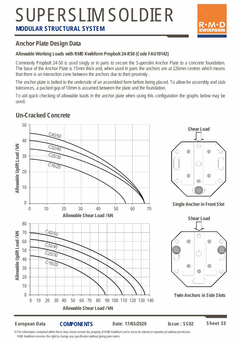
Anchor Plate Design Data
Allowable Working Loads with RMD Kwikform Propbolt 24-R50 (Code FAU10142)
Commonly Propbolt 24-50 is used singly or in pairs to secure the Superslim Anchor Plate to a concrete foundation. The base of the Anchor Plate is 15mm thick and, when used in pairs the anchors are at 226mm centres which means
that there is an interaction zone between the anchors due to their proximity .
The anchor plate is bolted to the underside of an assembled form before being placed. To allow for assembly and slab
tolerances, a packed gap of 10mm is assumed between the plate and the foundation.
To aid quick checking of allowable loads in the anchor plate when using this configuration the graphs below may be
used.
Un-Cracked Concrete
Single Anchor in Front Slot
Twin Anchors in Side Slots
Shear Load
Shear Load
Allo
wab
le U
plif
t L
oad
/ kN
A
llow
able
Up
lift
Lo
ad /
kN
50
40
30
20
10
0
Allowable Shear Load / kN
Allowable Shear Load / kN
0 10 20 30 40 50 60 70
0 10 20 30 40 50 60 70 80 90 100 110 120 130 140
80
70
60
50
40
30
20
10
0
European Data Sheet 34
© The information contained within these data sheets remain the property of RMD Kwikform and is not to be altered or reproduced without permission.
RMD Kwikform reserves the right to change any specification without giving prior notice.
Date: 17/03/2020 Issue : SS02
SUPERSLIM SOLDIER MODULAR STRUCTURAL SYSTEM
APPLICATIONS
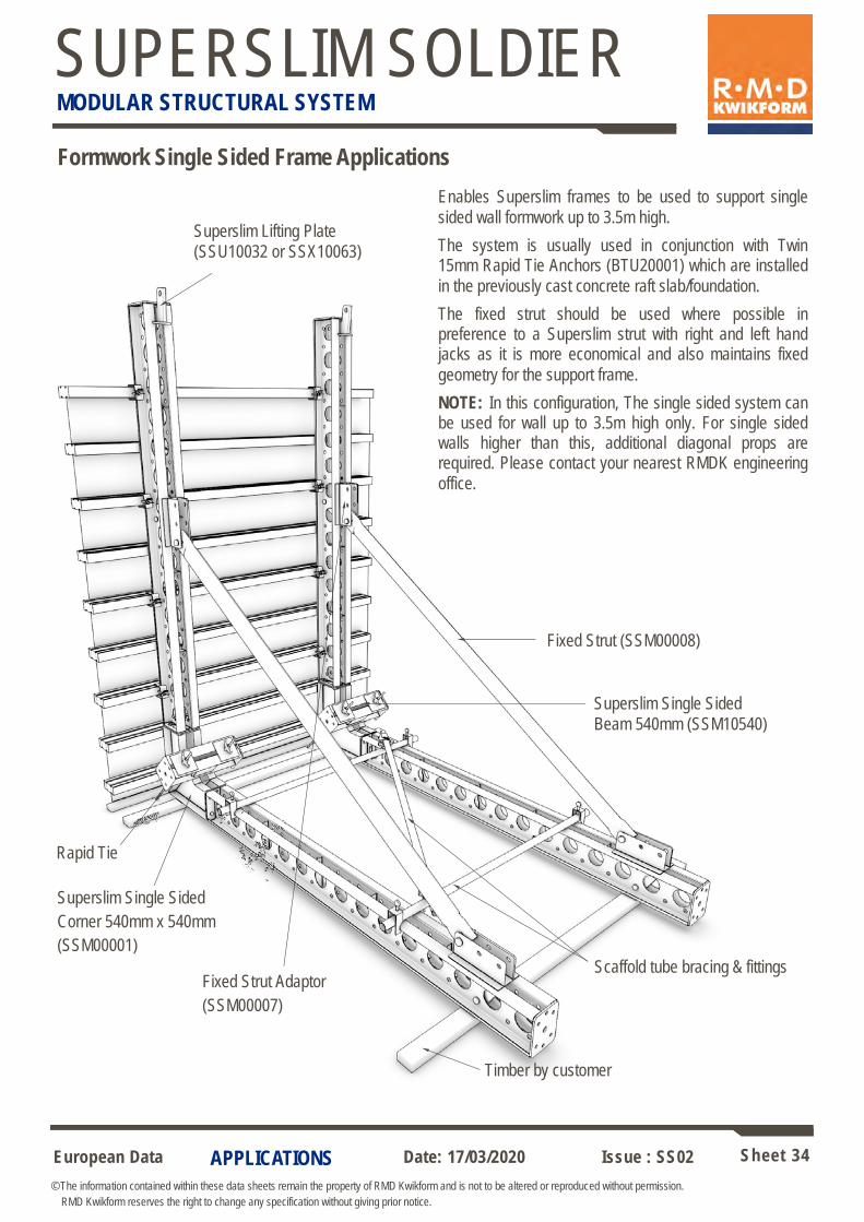
Formwork Single Sided Frame Applications
Enables Superslim frames to be used to support single
sided wall formwork up to 3.5m high.
The system is usually used in conjunction with Twin 15mm Rapid Tie Anchors (BTU20001) which are installed
in the previously cast concrete raft slab/foundation.
The fixed strut should be used where possible in preference to a Superslim strut with right and left hand jacks as it is more economical and also maintains fixed
geometry for the support frame.
NOTE: In this configuration, The single sided system can be used for wall up to 3.5m high only. For single sided walls higher than this, additional diagonal props are required. Please contact your nearest RMDK engineering
office.
Superslim Lifting Plate
(SSU10032 or SSX10063)
Fixed Strut (SSM00008)
Superslim Single Sided
Beam 540mm (SSM10540)
Superslim Single Sided
Corner 540mm x 540mm
(SSM00001)
Timber by customer
Scaffold tube bracing & fittings Fixed Strut Adaptor
(SSM00007)
Rapid Tie
European Data Sheet 35
© The information contained within these data sheets remain the property of RMD Kwikform and is not to be altered or reproduced without permission.
RMD Kwikform reserves the right to change any specification without giving prior notice.
Date: 17/03/2020 Issue : SS02
SUPERSLIM SOLDIER MODULAR STRUCTURAL SYSTEM
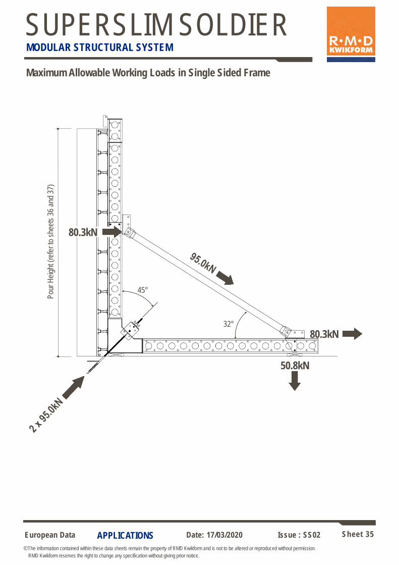
APPLICATIONS
Maximum Allowable Working Loads in Single Sided Frame
80.3kN
80.3kN
50.8kN
45°
Pou
r H
eigh
t (re
fer
to s
heet
s 36
and
37)
32°
European Data Sheet 36
© The information contained within these data sheets remain the property of RMD Kwikform and is not to be altered or reproduced without permission.
RMD Kwikform reserves the right to change any specification without giving prior notice.
Date: 17/03/2020 Issue : SS02
SUPERSLIM SOLDIER MODULAR STRUCTURAL SYSTEM
APPLICATIONS
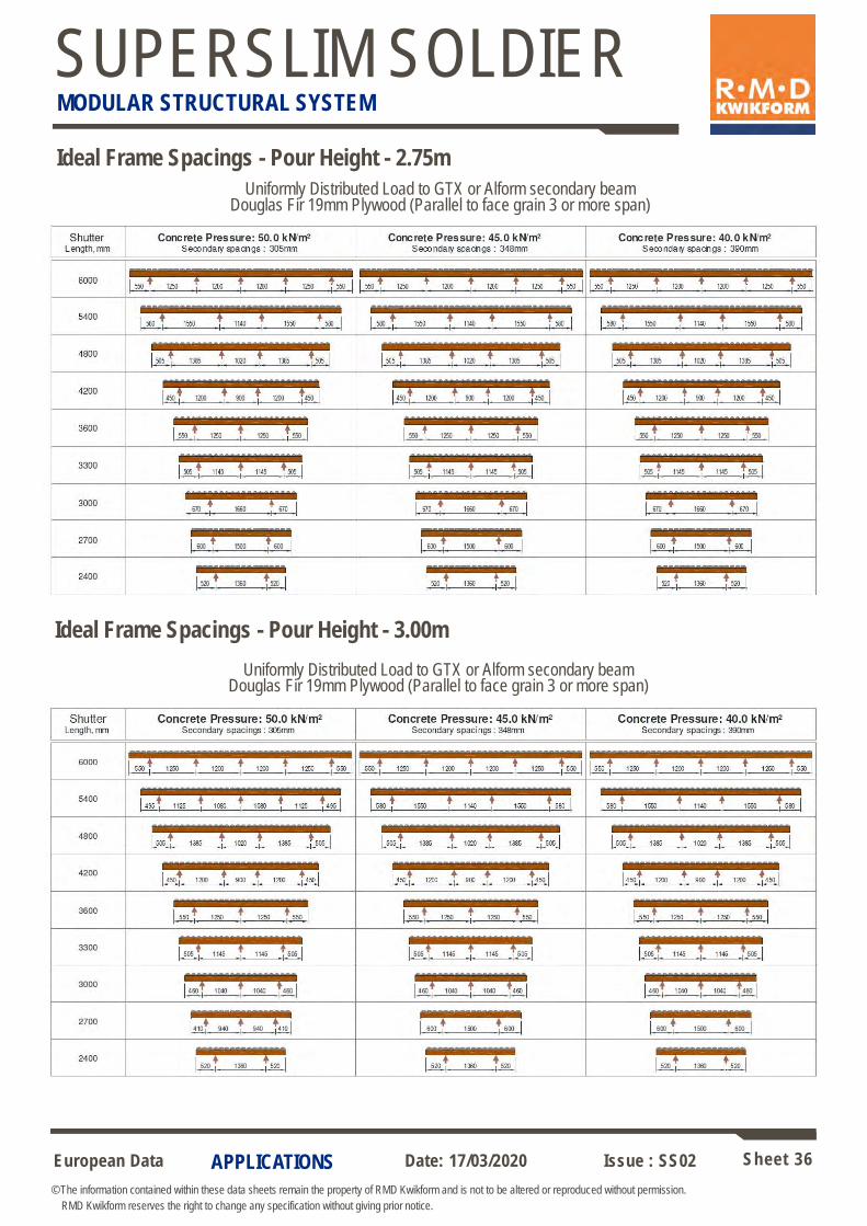
Ideal Frame Spacings - Pour Height - 2.75m
Ideal Frame Spacings - Pour Height - 3.00m
Uniformly Distributed Load to GTX or Alform secondary beam
Douglas Fir 19mm Plywood (Parallel to face grain 3 or more span)
Uniformly Distributed Load to GTX or Alform secondary beam
Douglas Fir 19mm Plywood (Parallel to face grain 3 or more span)
European Data Sheet 37
© The information contained within these data sheets remain the property of RMD Kwikform and is not to be altered or reproduced without permission.
RMD Kwikform reserves the right to change any specification without giving prior notice.
Date: 17/03/2020 Issue : SS02
SUPERSLIM SOLDIER MODULAR STRUCTURAL SYSTEM
APPLICATIONS
Uniformly Distributed Load to GTX or Alform secondary beam
Douglas Fir 19mm Plywood (Parallel to face grain 3 or more span)
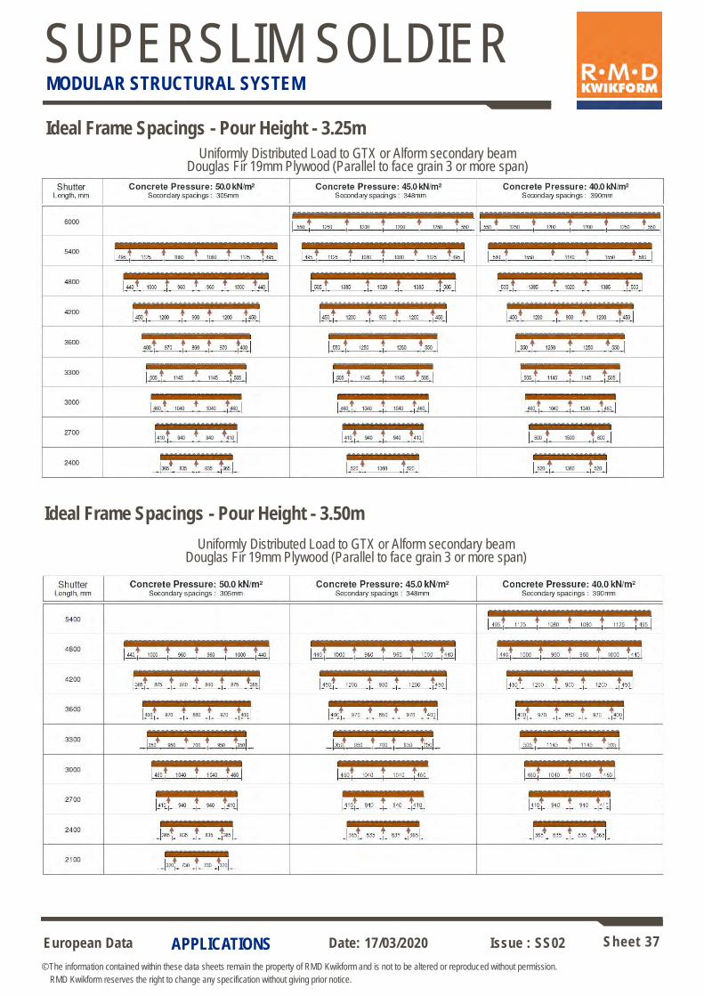
Ideal Frame Spacings - Pour Height - 3.25m
Uniformly Distributed Load to GTX or Alform secondary beam
Douglas Fir 19mm Plywood (Parallel to face grain 3 or more span)
Ideal Frame Spacings - Pour Height - 3.50m

European Data Sheet 38
© The information contained within these data sheets remain the property of RMD Kwikform and is not to be altered or reproduced without permission.
RMD Kwikform reserves the right to change any specification without giving prior notice.
Date: 17/03/2020 Issue : SS02
SUPERSLIM SOLDIER MODULAR STRUCTURAL SYSTEM
COMPONENTS
Superslim Single Sided Corner 540mm x 540mm (SSM00001) weight 31.3kg
Used to connect horizontal and vertical Superslim Soldiers at right angles to form
part of the triangulated frame.
Max permissible tie load using Twin 15mm Rapid Tie Anchors = 95kN x 2 ties
Superslim Single Sided Beam 540mm (SSM10540) weight 28.2kg
Used to tie down Superslim frames to the previously cast concrete at 45 deg to
the horizontal with two diagonal Rapid Ties at each Superslim frame location.
The holes in the end plates are configured such that a Superslim Soldier can
be bolted to the end if required.
Note: Do not use Heavy Duty Waler Plates with the Superslim Single Sided Beam 540mm as there is insufficient
space between the channels to accommodate the boss on the back of the plate.
Aways use 2 No 150 x 150 x 6 x 22mm Plate Washers (BNX20011) per tie position.
Superslim Single Sided Beam 540mm
Superslim Single Sided Corner 540mm x 540mm
15mm Rapid Tie, 2 No 150 x 150 x 6 x 22mm Plate
Washers & Rapid Tie Wing Nut.
15mm Rapid Tie
European Data Sheet 39
© The information contained within these data sheets remain the property of RMD Kwikform and is not to be altered or reproduced without permission.
RMD Kwikform reserves the right to change any specification without giving prior notice.
Date: 17/03/2020 Issue : SS02
SUPERSLIM SOLDIER MODULAR STRUCTURAL SYSTEM
COMPONENTS
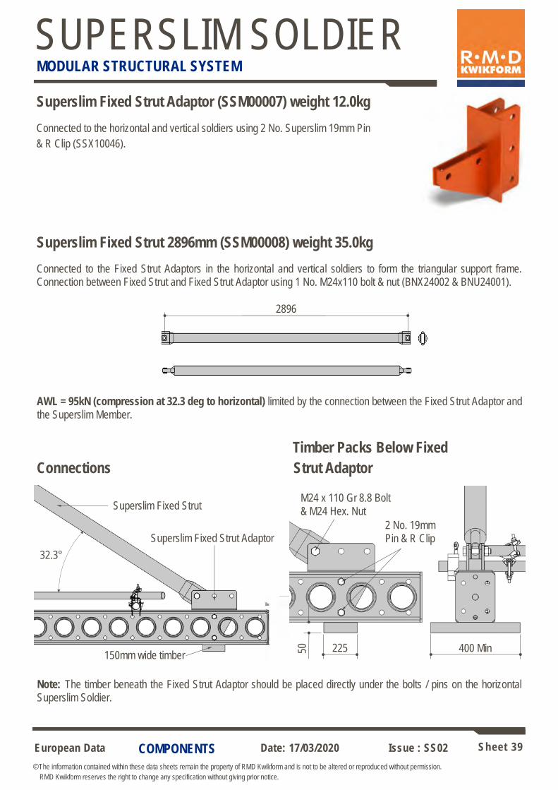
Superslim Fixed Strut Adaptor (SSM00007) weight 12.0kg
Connected to the horizontal and vertical soldiers using 2 No. Superslim 19mm Pin
& R Clip (SSX10046).
Superslim Fixed Strut 2896mm (SSM00008) weight 35.0kg
Connected to the Fixed Strut Adaptors in the horizontal and vertical soldiers to form the triangular support frame.
Connection between Fixed Strut and Fixed Strut Adaptor using 1 No. M24x110 bolt & nut (BNX24002 & BNU24001).
2896
AWL = 95kN (compression at 32.3 deg to horizontal) limited by the connection between the Fixed Strut Adaptor and
the Superslim Member.
Timber Packs Below Fixed
Connections Strut Adaptor
Superslim Fixed Strut
32.3°
M24 x 110 Gr 8.8 Bolt
& M24 Hex. Nut
Superslim Fixed Strut Adaptor
400 Min 225 50
2 No. 19mm
Pin & R Clip
Note: The timber beneath the Fixed Strut Adaptor should be placed directly under the bolts / pins on the horizontal
Superslim Soldier.
150mm wide timber
European Data Sheet 40
© The information contained within these data sheets remain the property of RMD Kwikform and is not to be altered or reproduced without permission.
RMD Kwikform reserves the right to change any specification without giving prior notice.
Date: 17/03/2020 Issue : SS02
SUPERSLIM SOLDIER MODULAR STRUCTURAL SYSTEM
COMPONENTS
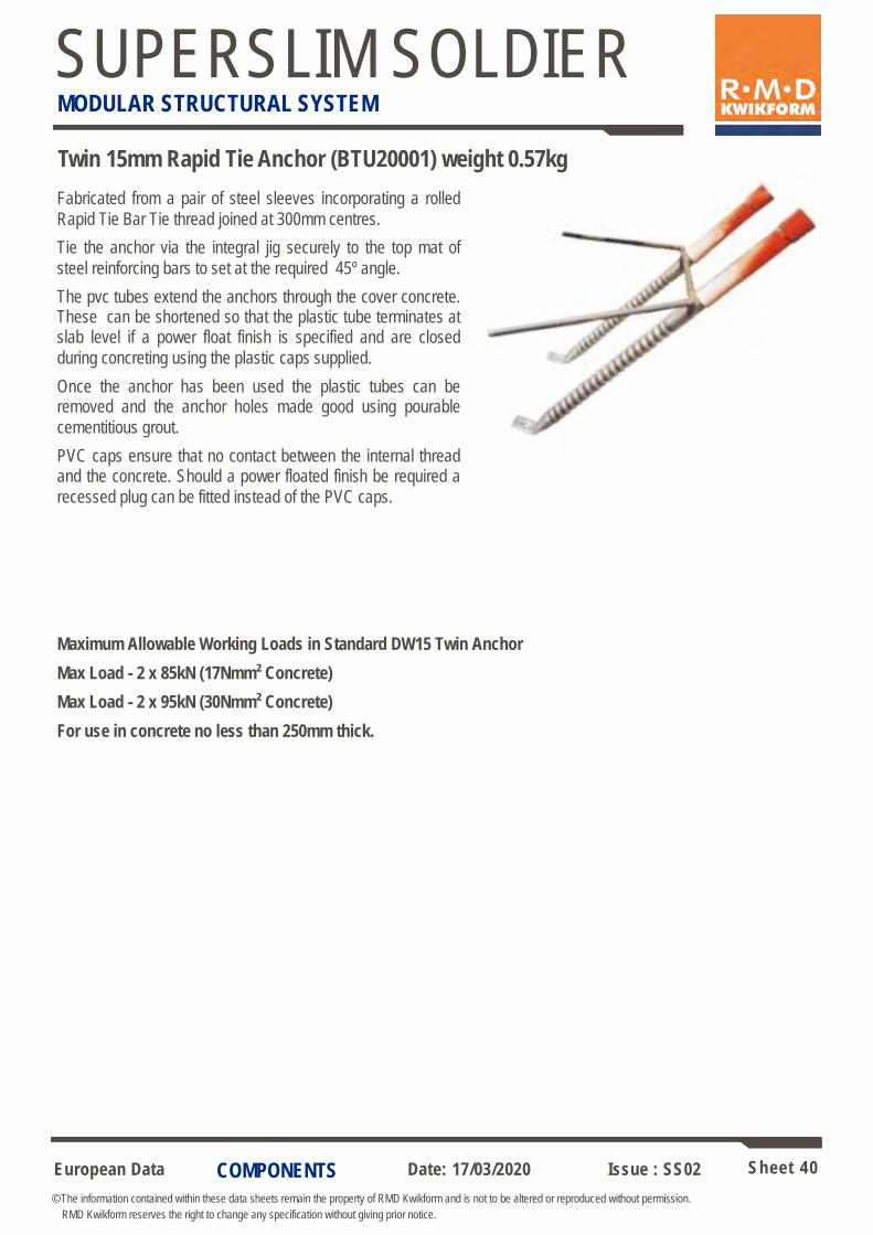
Fabricated from a pair of steel sleeves incorporating a rolled
Rapid Tie Bar Tie thread joined at 300mm centres.
Tie the anchor via the integral jig securely to the top mat of
steel reinforcing bars to set at the required 45º angle.
The pvc tubes extend the anchors through the cover concrete. These can be shortened so that the plastic tube terminates at slab level if a power float finish is specified and are closed
during concreting using the plastic caps supplied.
Once the anchor has been used the plastic tubes can be removed and the anchor holes made good using pourable
cementitious grout.
PVC caps ensure that no contact between the internal thread and the concrete. Should a power floated finish be required a
recessed plug can be fitted instead of the PVC caps.
Maximum Allowable Working Loads in Standard DW15 Twin Anchor
Max Load - 2 x 85kN (17Nmm² Concrete)
Max Load - 2 x 95kN (30Nmm² Concrete)
For use in concrete no less than 250mm thick.
Twin 15mm Rapid Tie Anchor (BTU20001) weight 0.57kg
European Data Sheet 41
© The information contained within these data sheets remain the property of RMD Kwikform and is not to be altered or reproduced without permission.
RMD Kwikform reserves the right to change any specification without giving prior notice.
Date: 17/03/2020 Issue : SS02
SUPERSLIM SOLDIER MODULAR STRUCTURAL SYSTEM
APPLICATIONS
Formwork Applications – Concrete Pressure Data
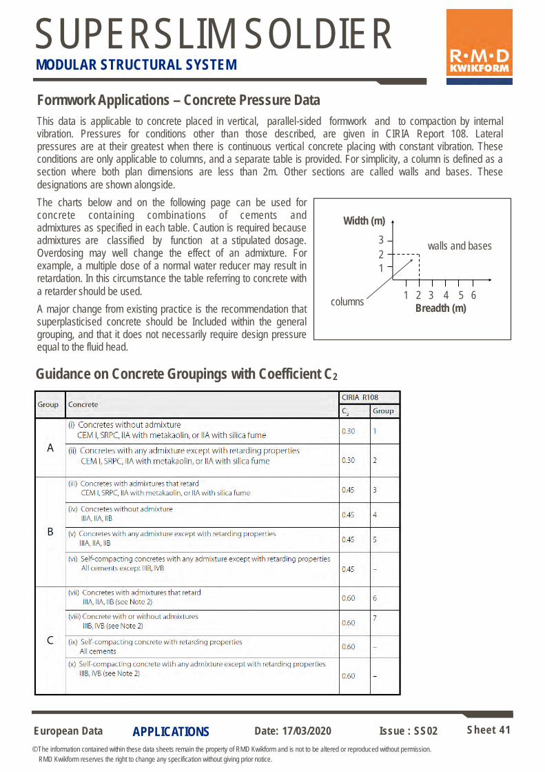
This data is applicable to concrete placed in vertical, parallel-sided formwork and to compaction by internal vibration. Pressures for conditions other than those described, are given in CIRIA Report 108. Lateral pressures are at their greatest when there is continuous vertical concrete placing with constant vibration. These conditions are only applicable to columns, and a separate table is provided. For simplicity, a column is defined as a section where both plan dimensions are less than 2m. Other sections are called walls and bases. These
designations are shown alongside.
The charts below and on the following page can be used for concrete containing combinations of cements and admixtures as specified in each table. Caution is required because admixtures are classified by function at a stipulated dosage. Overdosing may well change the effect of an admixture. For example, a multiple dose of a normal water reducer may result in retardation. In this circumstance the table referring to concrete with
a retarder should be used.
A major change from existing practice is the recommendation that superplasticised concrete should be Included within the general grouping, and that it does not necessarily require design pressure equal to the fluid head.
Width (m)
3 walls and bases
2
1
1 2 3 4 5 6 columns
Breadth (m)
Guidance on Concrete Groupings with Coefficient C2
European Data Sheet 42
© The information contained within these data sheets remain the property of RMD Kwikform and is not to be altered or reproduced without permission.
RMD Kwikform reserves the right to change any specification without giving prior notice.
Date: 17/03/2020 Issue : SS02
SUPERSLIM SOLDIER MODULAR STRUCTURAL SYSTEM
APPLICATIONS
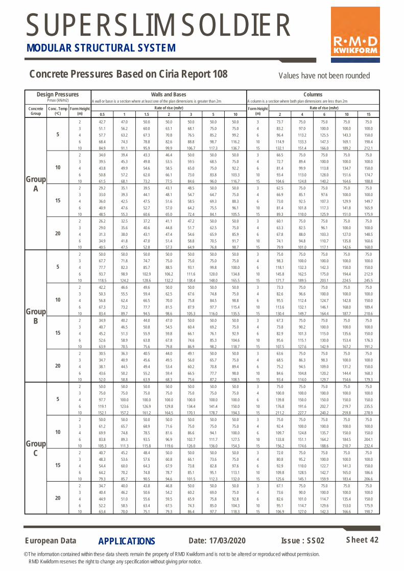
Concrete Pressures Based on Ciria Report 108 Values have not been rounded
Design Pressures
Pmax (kN/m2)
Walls and Bases Columns A wall or base is a section where at least one of the plan dimensions is greater than 2m A column is a section where both plan dimensions are less than 2m
Concrete Group
Conc. Temp (oC)
Form Height (m)
Rate of rise (m/hr) Form Height (m)
Rate of rise (m/hr)
0.5 1 1.5 2 3 5 10 2 4 6 10 15
Group A
5
2 42.7 47.0 50.0 50.0 50.0 50.0 50.0 3 73.7 75.0 75.0 75.0 75.0
3 51.1 56.2 60.0 63.1 68.1 75.0 75.0 4 83.2 97.0 100.0 100.0 100.0
4 57.7 63.2 67.3 70.8 76.5 85.2 99.2 6 96.4 113.2 125.5 143.3 150.0
6 68.4 74.3 78.8 82.6 88.8 98.7 116.2 10 114.9 133.3 147.3 169.1 190.4
10 84.9 91.1 95.9 99.9 106.7 117.3 136.7 15 132.1 151.4 166.0 189.2 212.1
10
2 34.0 39.4 43.3 46.4 50.0 50.0 50.0 3 66.5 75.0 75.0 75.0 75.0
3 39.5 45.3 49.8 53.5 59.5 68.5 75.0 4 72.7 89.4 100.0 100.0 100.0
4 43.8 49.9 54.6 58.5 65.0 75.0 92.2 6 81.4 99.9 113.8 134.7 150.0
6 50.8 57.2 62.0 66.1 73.0 83.8 103.3 10 93.4 113.0 128.0 151.6 174.7
10 61.5 68.1 73.2 77.5 84.6 96.0 116.7 15 104.6 124.8 140.2 164.6 188.8
15
2 29.2 35.1 39.5 43.1 48.5 50.0 50.0 3 62.5 75.0 75.0 75.0 75.0
3 33.0 39.3 44.1 48.1 54.7 64.7 75.0 4 66.9 85.1 97.6 100.0 100.0
4 36.0 42.5 47.5 51.6 58.5 69.3 88.3 6 73.0 92.5 107.3 129.9 149.7
6 40.9 47.6 52.7 57.0 64.2 75.5 96.1 10 81.4 101.8 117.3 141.8 165.9
10 48.5 55.3 60.6 65.0 72.4 84.1 105.5 15 89.3 110.0 125.9 151.0 175.9
20
2 26.2 32.5 37.2 41.1 47.2 50.0 50.0 3 60.1 75.0 75.0 75.0 75.0
3 29.0 35.6 40.6 44.8 51.7 62.5 75.0 4 63.3 82.5 96.1 100.0 100.0
4 31.3 38.0 43.1 47.4 54.6 65.9 85.9 6 67.8 88.0 103.3 127.0 148.5
6 34.9 41.8 47.0 51.4 58.8 70.5 91.7 10 74.1 94.8 110.7 135.8 160.6
10 40.5 47.5 52.8 57.3 64.9 76.8 98.7 15 79.9 101.0 117.1 142.6 168.0
Group B
5
2 50.0 50.0 50.0 50.0 50.0 50.0 50.0 3 75.0 75.0 75.0 75.0 75.0
3 67.7 71.8 74.7 75.0 75.0 75.0 75.0 4 98.3 100.0 100.0 100.0 100.0
4 77.7 82.3 85.7 88.5 93.1 99.8 100.0 6 118.1 132.3 142.3 150.0 150.0
6 93.7 98.9 102.9 106.2 111.6 120.0 134.8 10 145.8 162.5 175.0 194.4 212.9
10 118.5 124.2 128.6 132.2 138.4 148.0 165.5 15 171.7 189.5 203.1 224.5 245.5
10
2 42.2 46.6 49.6 50.0 50.0 50.0 50.0 3 73.3 75.0 75.0 75.0 75.0
3 50.3 55.5 59.4 62.5 67.6 74.8 75.0 4 82.6 96.6 100.0 100.0 100.0
4 56.8 62.4 66.5 70.0 75.8 84.5 98.8 6 95.5 112.4 124.7 142.8 150.0
6 67.3 73.2 77.7 81.5 87.9 97.7 115.4 10 113.6 132.1 146.1 168.0 189.4
10 83.4 89.7 94.5 98.6 105.3 116.0 135.5 15 130.4 149.7 164.4 187.7 210.6
15
2 34.9 40.2 44.0 47.0 50.0 50.0 50.0 3 67.3 75.0 75.0 75.0 75.0
3 40.7 46.5 50.8 54.5 60.4 69.2 75.0 4 73.8 90.2 100.0 100.0 100.0
4 45.2 51.3 55.9 59.8 66.1 76.1 92.9 6 82.9 101.3 115.0 135.6 150.0
6 52.6 58.9 63.8 67.8 74.6 85.3 104.6 10 95.6 115.1 130.0 153.4 176.3
10 63.9 70.5 75.6 79.8 86.9 98.2 118.7 15 107.5 127.6 142.9 167.2 191.2
20
2 30.5 36.3 40.5 44.0 49.1 50.0 50.0 3 63.6 75.0 75.0 75.0 75.0
3 34.7 40.9 45.6 49.5 56.0 65.7 75.0 4 68.5 86.3 98.3 100.0 100.0
4 38.1 44.5 49.4 53.4 60.2 70.8 89.4 6 75.2 94.5 109.0 131.2 150.0
6 43.6 50.2 55.2 59.4 66.5 77.7 98.0 10 84.6 104.8 120.2 144.4 168.3
10 52.0 58.8 63.9 68.3 75.6 87.2 108.5 15 93.4 114.0 129.7 154.6 179.3
Group C
5
2 50.0 50.0 50.0 50.0 50.0 50.0 50.0 3 75.0 75.0 75.0 75.0 75.0
3 75.0 75.0 75.0 75.0 75.0 75.0 75.0 4 100.0 100.0 100.0 100.0 100.0
4 97.7 100.0 100.0 100.0 100.0 100.0 100.0 6 139.8 150.0 150.0 150.0 150.0
6 119.1 123.6 126.9 129.8 134.4 141.4 150.0 10 176.8 191.6 202.7 219.7 235.5
10 152.1 157.2 161.2 164.5 170.1 178.7 194.3 15 211.2 227.7 240.2 259.8 278.9
10
2 50.0 50.0 50.0 50.0 50.0 50.0 50.0 3 75.0 75.0 75.0 75.0 75.0
3 61.2 65.7 68.9 71.6 75.0 75.0 75.0 4 92.4 100.0 100.0 100.0 100.0
4 69.9 74.8 78.5 81.6 86.6 94.1 100.0 6 109.7 124.8 135.7 150.0 150.0
6 83.8 89.3 93.5 96.9 102.7 111.7 127.5 10 133.8 151.1 164.2 184.5 204.1
10 105.3 111.3 115.8 119.6 126.0 136.0 154.3 15 156.2 174.6 188.6 210.7 232.4
15
2 40.7 45.2 48.4 50.0 50.0 50.0 50.0 3 72.0 75.0 75.0 75.0 75.0
3 48.3 53.6 57.6 60.8 66.1 73.6 75.0 4 80.8 95.2 100.0 100.0 100.0
4 54.4 60.0 64.3 67.9 73.8 82.8 97.6 6 92.9 110.0 122.7 141.3 150.0
6 64.2 70.2 74.8 78.7 85.1 95.1 113.1 10 109.8 128.5 142.7 165.0 186.6
10 79.3 85.7 90.5 94.6 101.5 112.3 132.0 15 125.6 145.1 159.9 183.4 206.6
20
2 34.7 40.0 43.8 46.8 50.0 50.0 50.0 3 67.1 75.0 75.0 75.0 75.0
3 40.4 46.2 50.6 54.2 60.2 69.0 75.0 4 73.6 90.0 100.0 100.0 100.0
4 44.9 51.0 55.6 59.5 65.9 75.8 92.8 6 82.6 101.0 114.7 135.4 150.0
6 52.2 58.5 63.4 67.5 74.3 85.0 104.3 10 95.1 114.7 129.6 153.0 175.9
10 63.4 70.0 75.1 79.3 86.4 97.7 118.3 15 106.9 127.0 142.3 166.6 190.7
European Data Sheet 43
© The information contained within these data sheets remain the property of RMD Kwikform and is not to be altered or reproduced without permission.
RMD Kwikform reserves the right to change any specification without giving prior notice.
Date: 17/03/2020 Issue : SS02
SUPERSLIM SOLDIER MODULAR STRUCTURAL SYSTEM
APPLICATIONS
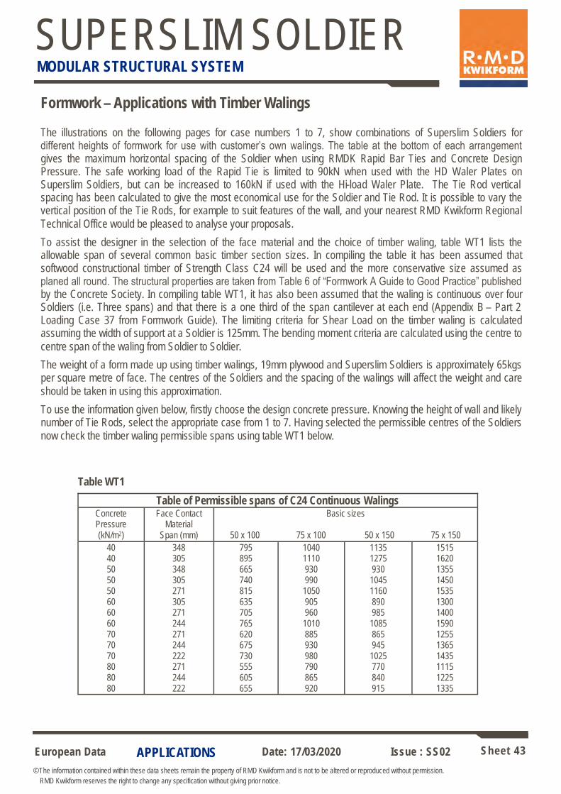
The illustrations on the following pages for case numbers 1 to 7, show combinations of Superslim Soldiers for different heights of formwork for use with customer’s own walings. The table at the bottom of each arrangement gives the maximum horizontal spacing of the Soldier when using RMDK Rapid Bar Ties and Concrete Design Pressure. The safe working load of the Rapid Tie is limited to 90kN when used with the HD Waler Plates on Superslim Soldiers, but can be increased to 160kN if used with the Hi-load Waler Plate. The Tie Rod vertical spacing has been calculated to give the most economical use for the Soldier and Tie Rod. It is possible to vary the vertical position of the Tie Rods, for example to suit features of the wall, and your nearest RMD Kwikform Regional
Technical Office would be pleased to analyse your proposals.
To assist the designer in the selection of the face material and the choice of timber waling, table WT1 lists the allowable span of several common basic timber section sizes. In compiling the table it has been assumed that softwood constructional timber of Strength Class C24 will be used and the more conservative size assumed as planed all round. The structural properties are taken from Table 6 of “Formwork A Guide to Good Practice” published by the Concrete Society. In compiling table WT1, it has also been assumed that the waling is continuous over four Soldiers (i.e. Three spans) and that there is a one third of the span cantilever at each end (Appendix B – Part 2 Loading Case 37 from Formwork Guide). The limiting criteria for Shear Load on the timber waling is calculated assuming the width of support at a Soldier is 125mm. The bending moment criteria are calculated using the centre to
centre span of the waling from Soldier to Soldier.
The weight of a form made up using timber walings, 19mm plywood and Superslim Soldiers is approximately 65kgs per square metre of face. The centres of the Soldiers and the spacing of the walings will affect the weight and care
should be taken in using this approximation.
To use the information given below, firstly choose the design concrete pressure. Knowing the height of wall and likely number of Tie Rods, select the appropriate case from 1 to 7. Having selected the permissible centres of the Soldiers
now check the timber waling permissible spans using table WT1 below.
Formwork – Applications with Timber Walings
Table of Permissible spans of C24 Continuous Walings Concrete Pressure (kN/m2)
Face Contact Material
Span (mm)
Basic sizes
50 x 100 75 x 100 50 x 150 75 x 150
40 40 50 50 50 60 60 60 70 70 70 80 80 80
348 305 348 305 271 305 271 244 271 244 222 271 244 222
795 895 665 740 815 635 705 765 620 675 730 555 605 655
1040 1110 930 990
1050 905 960
1010 885 930 980 790 865 920
1135 1275 930
1045 1160 890 985
1085 865 945
1025 770 840 915
1515 1620 1355 1450 1535 1300 1400 1590 1255 1365 1435 1115 1225 1335
Table WT1
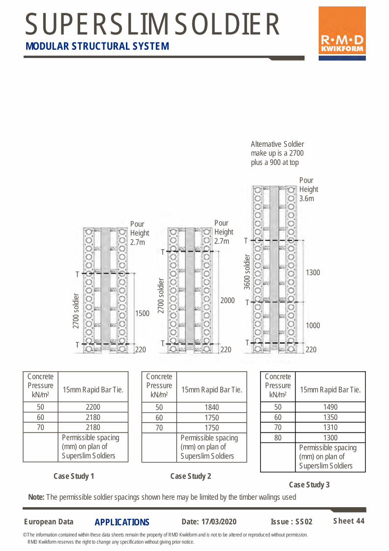
European Data Sheet 44
© The information contained within these data sheets remain the property of RMD Kwikform and is not to be altered or reproduced without permission.
RMD Kwikform reserves the right to change any specification without giving prior notice.
Date: 17/03/2020 Issue : SS02
SUPERSLIM SOLDIER MODULAR STRUCTURAL SYSTEM
APPLICATIONS
Concrete Pressure
kN/m2
15mm Rapid Bar Tie.
50 2200
60 2180
70 2180
Permissible spacing (mm) on plan of
Superslim Soldiers
Case Study 1 Case Study 2 Case Study 3
Alternative Soldier make up is a 2700
plus a 900 at top
Pour Height
3.6m
Pour Height
2.7m
Pour Height
2.7m 36
00 s
oldi
er
T
T T
T
T
T
T
1300
2000
220
1500 2700
sol
dier
1000
220 220
Concrete Pressure
kN/m2
15mm Rapid Bar Tie.
50 1840
60 1750
70 1750
Permissible spacing (mm) on plan of
Superslim Soldiers
Concrete Pressure
kN/m2
15mm Rapid Bar Tie.
50 1490
60 1350
70 1310
80 1300
Permissible spacing (mm) on plan of
Superslim Soldiers
Note: The permissible soldier spacings shown here may be limited by the timber walings used
2700
sol
dier
European Data Sheet 45
© The information contained within these data sheets remain the property of RMD Kwikform and is not to be altered or reproduced without permission.
RMD Kwikform reserves the right to change any specification without giving prior notice.
Date: 17/03/2020 Issue : SS02
SUPERSLIM SOLDIER MODULAR STRUCTURAL SYSTEM
APPLICATIONS
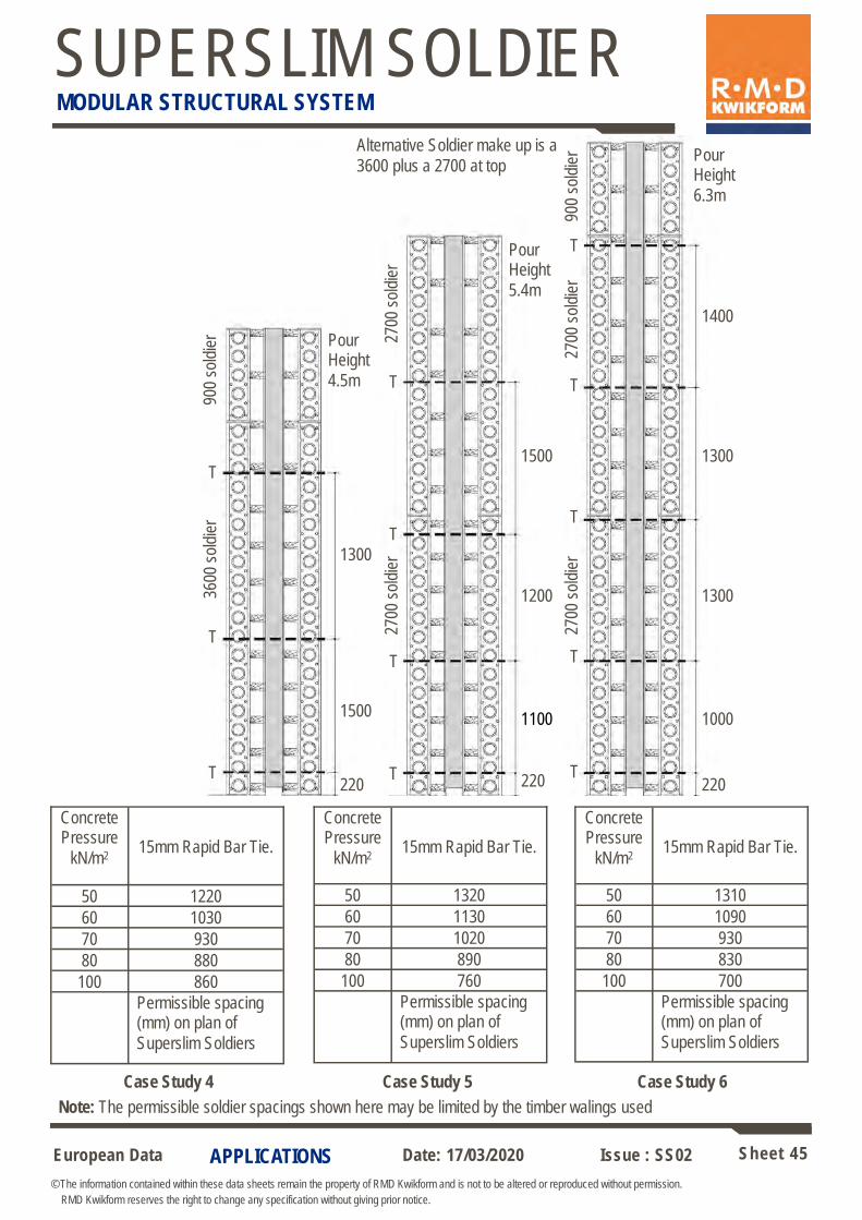
Note: The permissible soldier spacings shown here may be limited by the timber walings used
Case Study 4 Case Study 5 Case Study 6
Pour Height
6.3m
Pour Height
5.4m
Pour Height
4.5m
T
T T
T T
T
T
1300
1500
220
1500 1000
220 220
Alternative Soldier make up is a
3600 plus a 2700 at top
T
T T
T
1300
1400
1200
2700
sol
dier
1100
1300
T
Concrete Pressure
kN/m2
15mm Rapid Bar Tie.
50 1220
60 1030
70 930
80 880
100 860
Permissible spacing (mm) on plan of
Superslim Soldiers
Concrete Pressure
kN/m2
15mm Rapid Bar Tie.
50 1320
60 1130
70 1020
80 890
100 760
Permissible spacing (mm) on plan of
Superslim Soldiers
Concrete Pressure
kN/m2
15mm Rapid Bar Tie.
50 1310
60 1090
70 930
80 830
100 700
Permissible spacing (mm) on plan of
Superslim Soldiers
2700
sol
dier
90
0 so
ldie
r
2700
sol
dier
27
00 s
oldi
er
900
sold
ier
3600
sol
dier
European Data Sheet 46
© The information contained within these data sheets remain the property of RMD Kwikform and is not to be altered or reproduced without permission.
RMD Kwikform reserves the right to change any specification without giving prior notice.
Date: 17/03/2020 Issue : SS02
SUPERSLIM SOLDIER MODULAR STRUCTURAL SYSTEM
APPLICATIONS
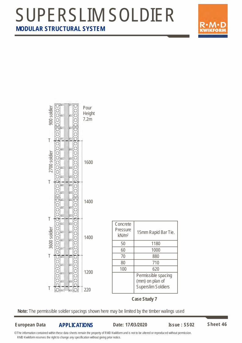
Note: The permissible soldier spacings shown here may be limited by the timber walings used
T
T
T
1400
1200
220
3600
sol
dier
T
T
1400
1600
Pour Height
7.2m
Concrete Pressure
kN/m2
15mm Rapid Bar Tie.
50 1180
60 1000
70 880
80 710
100 620
Permissible spacing (mm) on plan of
Superslim Soldiers
Case Study 7
2700
sol
dier
90
0 so
ldie
r
European Data Sheet 47
© The information contained within these data sheets remain the property of RMD Kwikform and is not to be altered or reproduced without permission.
RMD Kwikform reserves the right to change any specification without giving prior notice.
Date: 17/03/2020 Issue : SS02
SUPERSLIM SOLDIER MODULAR STRUCTURAL SYSTEM
APPLICATIONS
Formwork – Applications with Alform Walings
The RMD Kwikform Alform walings combines high strength with low weight and in conjunction with Superslim Soldiers and RMD tie rods gives an inexpensive forming system for use with customers own Selection of face contact material. The Superslim Soldiers are spaced generally at 1800mm centres MAX and tie rod centres are
optimised to suit the anticipated concrete pressure.
When assembling formwork with Alform walings it is recommended that some protection be given to the top walings to avoid build-up of concrete spillage when pouring. Preferably the top waling is a 150mm deep timber or a 150mm strip of plywood laid on top of the uppermost Alform beam. When made up an assembly of Alform formwork with Superslim Soldiers and 19mm plywood weighs approximately 53 kg per square metre per face of formwork. A range of accessories is available to complement the Alform beam, such as Splice Plates, Corner details, Lok Clamps etc. and these
are shown in separate data sheets.
The lengths of Alform beam available are shown right:
Max BM = 10kNm
Max Reaction (Intermediate) 75mm Bearing = 55kN
Max Reaction (End) 44mm Bearing = 40kN
RMD Kwikform Plywood
RMD Kwikform Plywood is manufactured from high quality pine veneers bonded together with a cross banded construction with phenolic resin. Sheets are supplied with the face grain parallel to
the long edge of the board.
Maximum Alform beam centres are shown below. Please note that data is valid for applications with the face grain perpendicular to the support beams for 3 or more spans and with deflection limited to
span/270.
Alform Beam centres/mm Maximum concrete pressure
kN/m2
407
349
305
271
244
222
203
41
59
73
85
99
115
132
Code Description Weight
AFX11200 Alform Beam 1200mm 6.76 kg
AFX11500 Alform Beam 1500mm 8.46 kg
AFX11800 Alform Beam 1800mm 10.15 kg
AFX12100 Alform Beam 2100mm 11.85 kg
AFX12400 Alform Beam 2400mm 13.54 kg
AFX12700 Alform Beam 2700mm 15.24 kg
AFX13000 Alform Beam 3000mm 16.93 kg
AFX13600 Alform Beam 3600mm 20.32 kg
AFX14200 Alform Beam 4200mm 23.71 kg
AFX14800 Alform Beam 4800mm 27.10 kg
AFX15400 Alform Beam 5400mm 30.49 kg
AFX16000 Alform Beam 6000mm 33.88 kg
AFX16600 Alform Beam 6600mm 37.27 kg
AFX17200 Alform Beam 7200mm 40.67 kg
Thickness
Bending Stiffness - El
Moment of Resistance - Mx
(spanning perpendicular to the face grain)
Shear Load - qA
18 mm
3.97 kNm2
0.439 kNm
8.29 kN
RMDK Plywood Properties (per metre width)
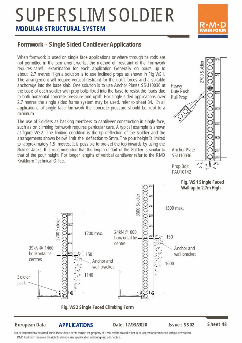
European Data Sheet 48
© The information contained within these data sheets remain the property of RMD Kwikform and is not to be altered or reproduced without permission.
RMD Kwikform reserves the right to change any specification without giving prior notice.
Date: 17/03/2020 Issue : SS02
SUPERSLIM SOLDIER MODULAR STRUCTURAL SYSTEM
APPLICATIONS
When formwork is used on single face applications or where through tie rods are not permitted in the permanent works, the method of restraint of the Formwork requires careful examination for each application. Generally on pours up to about 2.7 metres High a solution is to use inclined props as shown in Fig WS1. The arrangement will require vertical restraint for the uplift forces and a suitable anchorage into the base slab. One solution is to use Anchor Plates SSU10036 at the base of each soldier with prop bolts fixed into the base to resist the loads due to both horizontal concrete pressure and uplift. For single sided applications over 2.7 metres the single sided frame system may be used, refer to sheet 34. In all applications of single face formwork the concrete pressure should be kept to a
minimum.
The use of Soldiers as backing members to cantilever construction in single face, such as on climbing formwork requires particular care. A typical example is shown at figure WS2. The limiting condition is the tip deflection of the Soldier and the arrangements shown below limit the deflection to 5mm. The pour height Is limited to approximately 1.5 metres. It is possible to pre-set the top inwards by using the Soldier Jacks. It is recommended that the length of ‘tail’ of the Soldier is similar to that of the pour height. For longer lengths of vertical cantilever refer to the RMD
Kwikform Technical Office.
Formwork – Single Sided Cantilever Applications
Anchor Plate
SSU10036
2700
Sol
dier
Heavy Duty Push
Pull Prop
Prop Bolt
FAU10142
150
1500 max.
3600
Sol
dier
Fig. WS1 Single Faced Wall up to 2.7m High
150
1600
1200 max.
1140
2700
Sol
dier
24kN @ 600 horizontal tie
centre 39kN @ 1460 horizontal tie
centres
Soldier
Jack
Anchor and
wall bracket
Anchor and
wall bracket
Fig. WS2 Single Faced Climbing Form
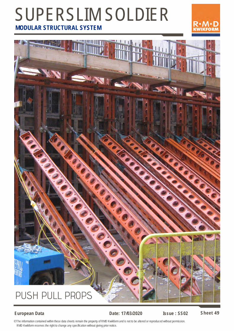
European Data Sheet 49
© The information contained within these data sheets remain the property of RMD Kwikform and is not to be altered or reproduced without permission.
RMD Kwikform reserves the right to change any specification without giving prior notice.
Date: 17/03/2020 Issue : SS02
SUPERSLIM SOLDIER MODULAR STRUCTURAL SYSTEM
PUSH PULL PROPS

European Data Sheet 50
© The information contained within these data sheets remain the property of RMD Kwikform and is not to be altered or reproduced without permission.
RMD Kwikform reserves the right to change any specification without giving prior notice.
Date: 17/03/2020 Issue : SS02
SUPERSLIM SOLDIER MODULAR STRUCTURAL SYSTEM
COMPONENTS
Superslim Tilt Plate
Superslim Prop Jacks
Used in pairs to provide length adjustment to Push Pull
Props.
Allowable Working Load ± 100kN
225
4 No. 18 dia. holes
176
25 dia
405
min
.
635
max
. 310
90
8
50
30
51 O/D Code Description Weight
SSU10007 Superslim Prop Jack L.H. (green) 13.61 kg
SSU10008 Superslim Prop Jack R.H. (orange) 13.68 kg
77
300
87
62
75 30
4
110
26 dia. slot
26 dia. hole
150
12
75 110
50 50
Code Description Weight
SSU10034 Superslim Tilt Plate 4.89 kg
BNU24001 M24 Hex Nut gr8 BZP 0.06 kg
BNX24002 M24x110 Bolt gr8.8 BZP 0.48 kg
Used to connect a Push Pull Prop to a plane surface at any angle. Connect to foundation using either the large hole and slot with 2 No. M24 anchors or using the
4 No. smaller holes with M16 anchors.
Allowable Working load Tension = 65kN* at any angle
Allowable Working Load Compression = 90kN* at any angle
* Unless specific anchor design information has been provided, it is necessary to check the capacity of the anchors/
bolts connecting the unit as a separate process.
Fits 2 3/8” x 2” Swivel or Fixed Couplers
Fits 2” x 2” Swivel or 90 degree Couplers
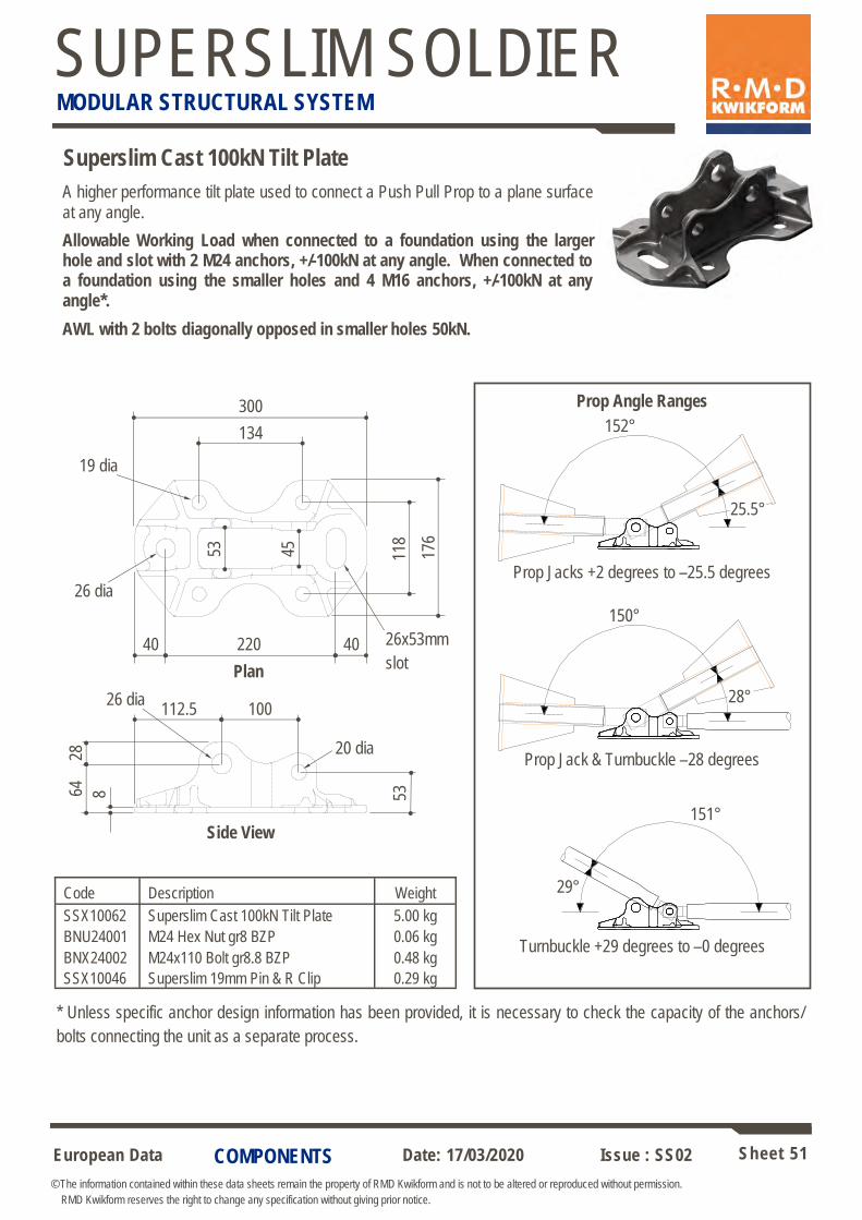
European Data Sheet 51
© The information contained within these data sheets remain the property of RMD Kwikform and is not to be altered or reproduced without permission.
RMD Kwikform reserves the right to change any specification without giving prior notice.
Date: 17/03/2020 Issue : SS02
SUPERSLIM SOLDIER MODULAR STRUCTURAL SYSTEM
COMPONENTS
Superslim Cast 100kN Tilt Plate
Code Description Weight
SSX10062 Superslim Cast 100kN Tilt Plate 5.00 kg
BNU24001 M24 Hex Nut gr8 BZP 0.06 kg
BNX24002 M24x110 Bolt gr8.8 BZP 0.48 kg
SSX10046 Superslim 19mm Pin & R Clip 0.29 kg
A higher performance tilt plate used to connect a Push Pull Prop to a plane surface
at any angle.
Allowable Working Load when connected to a foundation using the larger hole and slot with 2 M24 anchors, +/-100kN at any angle. When connected to a foundation using the smaller holes and 4 M16 anchors, +/-100kN at any angle*.
AWL with 2 bolts diagonally opposed in smaller holes 50kN.
* Unless specific anchor design information has been provided, it is necessary to check the capacity of the anchors/
bolts connecting the unit as a separate process.
176
118
300
134
45
53
220 40 40
26 dia
19 dia
26x53mm
slot
112.5 100
64
28
8
Plan
Side View
20 dia
26 dia
Prop Jack & Turnbuckle –28 degrees
Turnbuckle +29 degrees to –0 degrees
Prop Angle Ranges
Prop Jacks +2 degrees to –25.5 degrees
53
152°
25.5°
150°
28°
151°
29°

European Data Sheet 52
© The information contained within these data sheets remain the property of RMD Kwikform and is not to be altered or reproduced without permission.
RMD Kwikform reserves the right to change any specification without giving prior notice.
Date: 17/03/2020 Issue : SS02
SUPERSLIM SOLDIER MODULAR STRUCTURAL SYSTEM
COMPONENTS
Superslim Prop Connector 100kN (SSU10038) Weight 6.82kg
Used to connect Push Pull Props to Soldiers where a load transfer of more than 65kN
is required.
Allowable Working Load ± 100kN Refer to connector loading graph & soldier capacity graphs.
30
158
240
180 2 No.
22 dia 43
100 44
40
Prop Connector
Push Pull Prop
M24 x 110
bolt & nut
26 dia. Superslim 19mm Pin & R Clip
(SSX10046)
12
AWL for 100kN Prop Connector
75
80
85
90
95
100
605 630 655 680 705 730 755 780 805 830
Extension of Superslim Prop Jack & 100kN Prop
Connector (mm)
AW
L (
kN
)
Note This component enables Push Pull Props to be installed on opposite sides of a Soldier in
the same location.
AWL for 100kN Prop Connector
AW
L (
kN)
Extension of Superslim Prop Jack & 100kN Prop Connector (mm)

European Data Sheet 53
© The information contained within these data sheets remain the property of RMD Kwikform and is not to be altered or reproduced without permission.
RMD Kwikform reserves the right to change any specification without giving prior notice.
Date: 17/03/2020 Issue : SS02
SUPERSLIM SOLDIER MODULAR STRUCTURAL SYSTEM
COMPONENTS
47
Prop Pivot Tube
Spade End Link
M24 Bolt & Nut
S/Slim Adj.
Prop Jack
25 dia. hole
Prop Pivot Tube
Captive
R Clip 3 No. 6
dia. holes
60
127
127
95 8
97
358
469
Prop Spade End Link & Prop Pivot Tube
Used to attach Push Pull Props to Soldiers. Connection to Soldier using
4 No. M16 x 40 Set Pin gr8.8 BZP & M16 Nut (BNU16007 & BNU16001).
Allowable Working Load ± 65kN
95
Code Description Weight
SSU10012 Superslim Prop Spade End Link 3.06 kg
SSU10004 Superslim Prop Pivot Tube 1.81 kg
Prop Brace Pin – M24/M20 (BNU10050) Weight 0.43kg
Used to connect Push Pull Props and twin 60 x 8 flat braces through the same fastener.
Allowable Working Load in prop ± 100kN, in flat braces 80kN per pair tension only.
Load Twin 60 x 8 flat braces
M20 Nut
M20 Nut
Twin 60 x 8 flat braces
77 27
24
27

European Data Sheet 54
© The information contained within these data sheets remain the property of RMD Kwikform and is not to be altered or reproduced without permission.
RMD Kwikform reserves the right to change any specification without giving prior notice.
Date: 17/03/2020 Issue : SS02
SUPERSLIM SOLDIER MODULAR STRUCTURAL SYSTEM
COMPONENTS
Superslim Prop Tube End Link (SSU10013) weight = 2.81kg
Used to connect Super Slim Push Pull Props to Megashor shafts or a pair of
steel beam web stiffeners.
For Max allowable working load see graph (below)
60 dia.
tube
22 dia.
358
90
26 dia.
Megashor
Megashor M20 High Yield pin & R clip (BNX20100 +
SSU10011)
M24 x 110 gr8.8 bolt and nut (BNX24002 +
BNU24001)
Heavy Duty
Push Pull Prop
50
60
70
80
90
100
600 700 800 900 1000
Overall Jack Length (mm)
All
ow
ab
le L
oa
d (
KN
)
Used to connect Super Slim Push Pull Props to Megashor shafts when compression loads greater than can be provided by the above item are required. Connection to Megashor leg
and s/slim jack as detailed above.
For Max allowable compressive load see graph (right)
Max allowable tension = 100kN
*Note: Capacity of prop tube end link limited by bearing on
Megashor to 68kN
60 dia.
tube
22 dia.
158
90
26 dia.
SSX10051
SSX10013
Superslim Short Prop Tube End Link (SSX10051) weight = 1.70kg
Overall Jack Length (mm)
Allo
wab
le L
oad
(kN
)
600 700 800 900 1000
100
90
80
70
60
50
Max 68kN
pin bearing
*68kN limit for M/S bearing
Note: A M20 washer can be welded to the Megashor webs in the channel to enhance the
load bearing capacity to 100kN.

European Data Sheet 55
© The information contained within these data sheets remain the property of RMD Kwikform and is not to be altered or reproduced without permission.
RMD Kwikform reserves the right to change any specification without giving prior notice.
Date: 17/03/2020 Issue : SS02
SUPERSLIM SOLDIER MODULAR STRUCTURAL SYSTEM
APPLICATIONS
Load in Push Pull Prop = W (kN)
Torque measured on Torque Wrench = Tw (Nm)
Torque applied to Push Pull Prop = Tp (Nm)
Tp = 9W
For applying prop load: Tw = Tp ( L )
1.3 + L
For measuring prop load: Tp = Tw ( 1.3 + L )
L
e.g. To apply prop load of 60kN you need to apply a torque to the prop of 540Nm. This can be achieved by applying a
0.7m long torque wrench set to 189Nm to the M20 nut on the Prop Torque Handle.
Note: Prop threads must be fully greased before use to ensure reasonable accuracy.
Heavy Duty
Push Pull Prop
Rotate Prop
Prop Torque Handle
(SSU10041) Customers Torque Wrench
with 30mm A/F Socket
L
Push Pull Props – Load Control
By application of a controlled torque to the Superslim body of a Heavy Duty Push Pull Prop, the load applied by the
prop up to the full 100kN capacity can be applied or measured.
Alternatively the axial force in a loaded Push Pull Prop can be measured by determining the torque required to just
tighten the prop (Note, further turning will increase the load).
Prop Torque Socket
(SSU10042)
1.3 metres
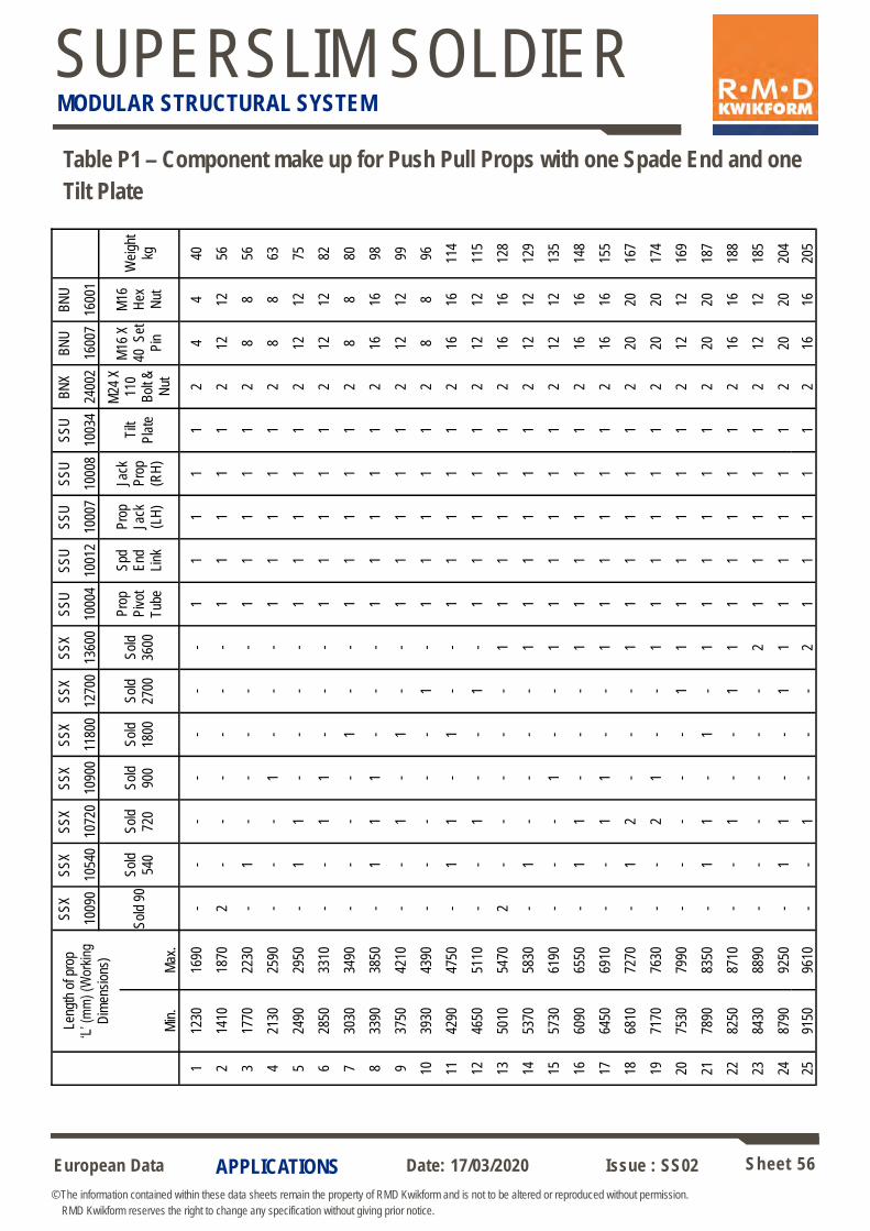
European Data Sheet 56
© The information contained within these data sheets remain the property of RMD Kwikform and is not to be altered or reproduced without permission.
RMD Kwikform reserves the right to change any specification without giving prior notice.
Date: 17/03/2020 Issue : SS02
SUPERSLIM SOLDIER MODULAR STRUCTURAL SYSTEM
APPLICATIONS
Table P1 – Component make up for Push Pull Props with one Spade End and one
Tilt Plate
Leng
th o
f pro
p ‘L
’ (m
m)
(Wor
king
Dim
ensi
ons)
SS
X
1009
0
SS
X
1054
0
SS
X
1072
0
SS
X
1090
0
SS
X
1180
0
SS
X
1270
0
SS
X
1360
0
SS
U
1000
4
SS
U
1001
2
SS
U
1000
7
SS
U
1000
8
SS
U
1003
4
BN
X
2400
2
BN
U
1600
7
BN
U
1600
1
Sol
d 90
S
old
540
Sol
d
720
Sol
d
900
Sol
d
1800
Sol
d
2700
Sol
d
3600
Pro
p P
ivot
Tub
e
Spd
E
nd
Link
Pro
p Ja
ck
(LH
)
Jack
P
rop
(RH
)
Tilt
Pla
te
M24
X
110
B
olt &
Nut
M16
X
40 S
et
Pin
M16
H
ex
Nut
Wei
ght
kg
Min
. M
ax.
1 12
30
1690
-
- -
- -
- -
1 1
1 1
1 2
4 4
40
2 14
10
1870
2
- -
- -
- -
1 1
1 1
1 2
12
12
56
3 17
70
2230
-
1 -
- -
- -
1 1
1 1
1 2
8 8
56
4 21
30
2590
-
- -
1 -
- -
1 1
1 1
1 2
8 8
63
5 24
90
2950
-
1 1
- -
- -
1 1
1 1
1 2
12
12
75
6 28
50
3310
-
- 1
1 -
- -
1 1
1 1
1 2
12
12
82
7 30
30
3490
-
- -
- 1
- -
1 1
1 1
1 2
8 8
80
8 33
90
3850
-
1 1
1 -
- -
1 1
1 1
1 2
16
16
98
9 37
50
4210
-
- 1
- 1
- -
1 1
1 1
1 2
12
12
99
10
3930
43
90
- -
- -
- 1
- 1
1 1
1 1
2 8
8 96
11
4290
47
50
- 1
1 -
1 -
- 1
1 1
1 1
2 16
16
11
4
12
4650
51
10
- -
1 -
- 1
- 1
1 1
1 1
2 12
12
11
5
13
5010
54
70
2 -
- -
- -
1 1
1 1
1 1
2 16
16
12
8
14
5370
58
30
- 1
- -
- -
1 1
1 1
1 1
2 12
12
12
9
15
5730
61
90
- -
- 1
- -
1 1
1 1
1 1
2 12
12
13
5
16
6090
65
50
- 1
1 -
- -
1 1
1 1
1 1
2 16
16
14
8
17
6450
69
10
- -
1 1
- -
1 1
1 1
1 1
2 16
16
15
5
18
6810
72
70
- 1
2 -
- -
1 1
1 1
1 1
2 20
20
16
7
19
7170
76
30
- -
2 1
- -
1 1
1 1
1 1
2 20
20
17
4
20
7530
79
90
- -
- -
- 1
1 1
1 1
1 1
2 12
12
16
9
21
7890
83
50
- 1
1 -
1 -
1 1
1 1
1 1
2 20
20
18
7
22
8250
87
10
- -
1 -
- 1
1 1
1 1
1 1
2 16
16
18
8
23
8430
88
90
- -
- -
- -
2 1
1 1
1 1
2 12
12
18
5
24
8790
92
50
- 1
1 -
- 1
1 1
1 1
1 1
2 20
20
20
4
25
9150
96
10
- -
1 -
- -
2 1
1 1
1 1
2 16
16
20
5
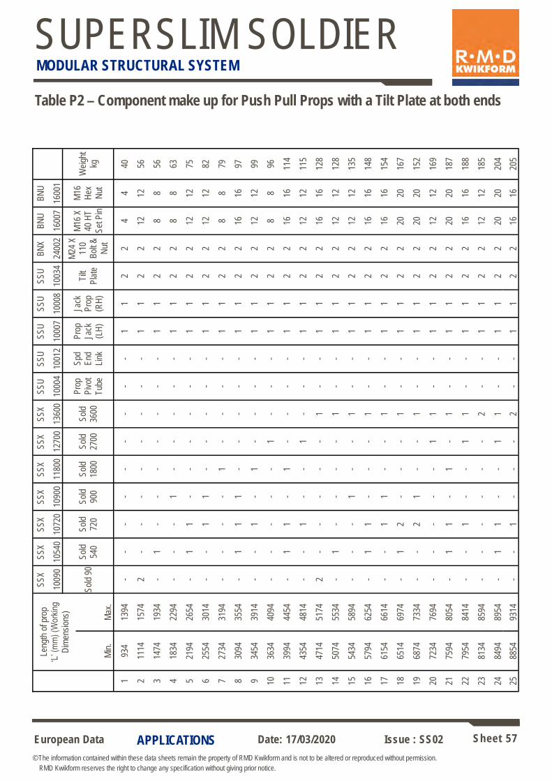
European Data Sheet 57
© The information contained within these data sheets remain the property of RMD Kwikform and is not to be altered or reproduced without permission.
RMD Kwikform reserves the right to change any specification without giving prior notice.
Date: 17/03/2020 Issue : SS02
SUPERSLIM SOLDIER MODULAR STRUCTURAL SYSTEM
APPLICATIONS
Table P2 – Component make up for Push Pull Props with a Tilt Plate at both ends
Leng
th o
f pro
p ‘L
’ (m
m)
(Wor
king
Dim
ensi
ons)
SS
X
1009
0
SS
X
1054
0
SS
X
1072
0
SS
X
1090
0
SS
X
1180
0
SS
X
1270
0
SS
X
1360
0
SS
U
1000
4
SS
U
1001
2
SS
U
1000
7
SS
U
1000
8
SS
U
1003
4
BN
X
2400
2
BN
U
1600
7
BN
U
1600
1
Sol
d 90
S
old
540
Sol
d
720
Sol
d
900
Sol
d
1800
Sol
d
2700
Sol
d
3600
Pro
p P
ivot
Tub
e
Spd
E
nd
Link
Pro
p Ja
ck
(LH
)
Jack
P
rop
(RH
)
Tilt
Pla
te
M24
X
110
Bol
t &
Nut
M16
X
40 H
T
Set
Pin
M16
H
ex
Nut
Wei
ght
kg
Min
. M
ax.
1 93
4 13
94
- -
- -
- -
- -
- 1
1 2
2 4
4 40
2 11
14
1574
2
- -
- -
- -
- -
1 1
2 2
12
12
56
3 14
74
1934
-
1 -
- -
- -
- -
1 1
2 2
8 8
56
4 18
34
2294
-
- -
1 -
- -
- -
1 1
2 2
8 8
63
5 21
94
2654
-
1 1
- -
- -
- -
1 1
2 2
12
12
75
6 25
54
3014
-
- 1
1 -
- -
- -
1 1
2 2
12
12
82
7 27
34
3194
-
- -
- 1
- -
- -
1 1
2 2
8 8
79
8 30
94
3554
-
1 1
1 -
- -
- -
1 1
2 2
16
16
97
9 34
54
3914
-
- 1
- 1
- -
- -
1 1
2 2
12
12
99
10
3634
40
94
- -
- -
- 1
- -
- 1
1 2
2 8
8 96
11
3994
44
54
- 1
1 -
1 -
- -
- 1
1 2
2 16
16
11
4
12
4354
48
14
- -
1 -
- 1
- -
- 1
1 2
2 12
12
11
5
13
4714
51
74
2 -
- -
- -
1 -
- 1
1 2
2 16
16
12
8
14
5074
55
34
- 1
- -
- -
1 -
- 1
1 2
2 12
12
12
8
15
5434
58
94
- -
- 1
- -
1 -
- 1
1 2
2 12
12
13
5
16
5794
62
54
- 1
1 -
- -
1 -
- 1
1 2
2 16
16
14
8
17
6154
66
14
- -
1 1
- -
1 -
- 1
1 2
2 16
16
15
4
18
6514
69
74
- 1
2 -
- -
1 -
- 1
1 2
2 20
20
16
7
19
6874
73
34
- -
2 1
- -
1 -
- 1
1 2
2 20
20
15
2
20
7234
76
94
- -
- -
- 1
1 -
- 1
1 2
2 12
12
16
9
21
7594
80
54
- 1
1 -
1 -
1 -
- 1
1 2
2 20
20
18
7
22
7954
84
14
- -
1 -
- 1
1 -
- 1
1 2
2 16
16
18
8
23
8134
85
94
- -
- -
- -
2 -
- 1
1 2
2 12
12
18
5
24
8494
89
54
- 1
1 -
- 1
1 -
- 1
1 2
2 20
20
20
4
25
8854
93
14
- -
1 -
- -
2 -
- 1
1 2
2 16
16
20
5
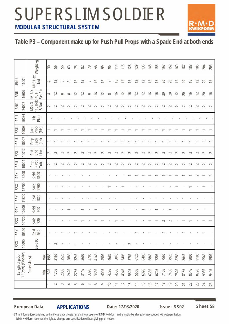
European Data Sheet 58
© The information contained within these data sheets remain the property of RMD Kwikform and is not to be altered or reproduced without permission.
RMD Kwikform reserves the right to change any specification without giving prior notice.
Date: 17/03/2020 Issue : SS02
SUPERSLIM SOLDIER MODULAR STRUCTURAL SYSTEM
APPLICATIONS
Leng
th o
f pro
p
‘L’ (
mm
) (W
orki
ng
Dim
ensi
ons)
SS
X
1009
0
SS
X
1054
0
SS
X
1072
0
SS
X
1090
0
SS
X
1180
0
SS
X
1270
0
SS
X
1360
0
SS
U
1000
4
SS
U
1001
2
SS
U
1000
7
SS
U
1000
8
SS
U
1003
4
BN
X
2400
2
BN
U
1600
7
BN
U
1600
1
Sol
d 90
S
old
540
Sol
d
720
Sol
d
900
Sol
d
1800
Sol
d
2700
Sol
d
3600
Pro
p P
ivot
Tub
e
Spd
E
nd
Link
Pro
p Ja
ck
(LH
)
Jack
P
rop
(RH
)
Tilt
Pla
te
M24
X
110
Bol
t
& N
ut
M16
X
40 H
T
Set
Pin
M16
Hex
Nut
W
eigh
t kg
Min
. M
ax.
1 15
26
1986
-
- -
- -
- -
2 2
1 1
- 2
4 4
30
2 17
06
2166
2
- -
- -
- -
2 2
1 1
- 2
12
12
56
3 20
66
2526
-
1 -
- -
- -
2 2
1 1
- 2
8 8
56
4 24
26
2886
-
- -
1 -
- -
2 2
1 1
- 2
8 8
63
5 27
86
3246
-
1 1
- -
- -
2 2
1 1
- 2
12
12
75
6 31
46
3606
-
- 1
1 -
- -
2 2
1 1
- 2
12
12
82
7 33
26
3786
-
- -
- 1
- -
2 2
1 1
- 2
8 8
79
8 36
86
4146
-
1 1
1 -
- -
2 2
1 1
- 2
16
16
98
9 40
46
4506
-
- 1
- 1
- -
2 2
1 1
- 2
12
12
99
10
4226
46
86
- -
- -
- 1
- 2
2 1
1 -
2 8
8 96
11
4586
50
46
- 1
1 -
1 -
- 2
2 1
1 -
2 16
16
11
4
12
4946
54
06
- -
1 -
- 1
- 2
2 1
1 -
2 12
12
11
5
13
5306
57
66
2 -
- -
- -
1 2
2 1
1 -
2 16
16
12
8
14
5666
61
26
- 1
- -
- -
1 2
2 1
1 -
2 12
12
12
9
15
6026
64
86
- -
- 1
- -
1 2
2 1
1 -
2 12
12
13
5
16
6386
68
46
- 1
1 -
- -
1 2
2 1
1 -
2 16
16
14
8
17
6746
72
06
- -
1 1
- -
1 2
2 1
1 -
2 16
16
15
5
18
7106
75
66
- 1
2 -
- -
1 2
2 1
1 -
2 20
20
16
7
19
7466
79
26
- -
2 1
- -
1 2
2 1
1 -
2 20
20
15
2
20
7826
82
86
- -
- -
- 1
1 2
2 1
1 -
2 12
12
16
9
21
8186
86
46
- 1
1 -
1 -
1 2
2 1
1 -
2 20
20
18
7
22
8546
90
06
- -
1 -
- 1
1 2
2 1
1 -
2 16
16
18
8
23
8726
91
86
- -
- -
- -
2 2
2 1
1 -
2 12
12
18
6
24
9086
95
46
- 1
1 -
- 1
1 2
2 1
1 -
2 20
20
20
4
25
9446
99
06
- -
1 -
- -
2 2
2 1
1 -
2 16
16
20
5
Table P3 – Component make up for Push Pull Props with a Spade End at both ends
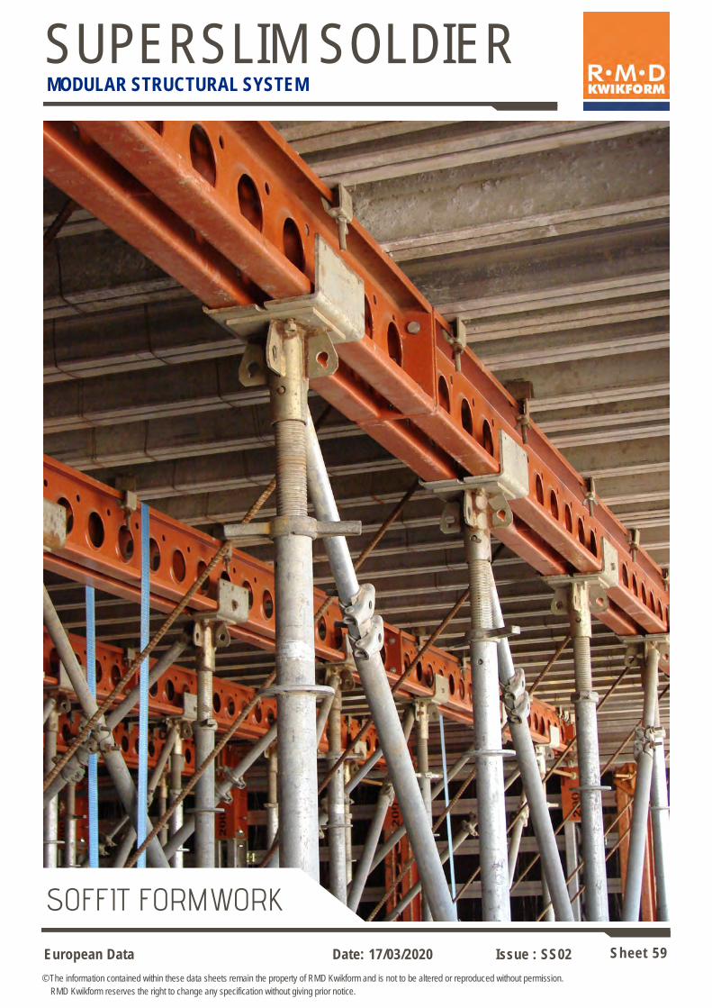
European Data Sheet 59
© The information contained within these data sheets remain the property of RMD Kwikform and is not to be altered or reproduced without permission.
RMD Kwikform reserves the right to change any specification without giving prior notice.
Date: 17/03/2020 Issue : SS02
SUPERSLIM SOLDIER MODULAR STRUCTURAL SYSTEM
SOFFIT FORMWORK

European Data Sheet 60
© The information contained within these data sheets remain the property of RMD Kwikform and is not to be altered or reproduced without permission.
RMD Kwikform reserves the right to change any specification without giving prior notice.
Date: 17/03/2020 Issue : SS02
SUPERSLIM SOLDIER MODULAR STRUCTURAL SYSTEM
COMPONENTS
Superslim Upper Giro Unit (SSM00072) weight 12.17kg
Used in conjunction with the Lower Giro Unit (SSM00071) to connect the outer wing form Superslim Soldiers to the primary Superslim beam. The hinge connection allows for varying angles of the wing form with a minimum of 30 degrees.
Typical Wing Form General Arrangement
Superslim 19mm Pin & R Clip (SSX10046)
GTX to Soldier Clamp (GTX10001)
Superslim Clamp Assembly (AFX20012)
Superslim Lower Giro Unit (SSM00071) weight 7.91kg
Used in conjunction with the Upper Giro Unit (SSM00072) to connect the outer wing form Superslim Soldiers to the primary Superslim beam. Provides up to 195mm of horizontal adjustment of the wing form shutter relative to the preset hole positions in the primary Superslim beam.
α
Allowable Working Load = 50kN Downwards at any angle (α). Allowable Working Load = 30kN Upwards at any angle (α).
Connection Detail
277
46
30 60 120
30
45
45
30
Plan
Side View
22 dia.
22 dia.
Side View
End View
225
125
50
180
106 360
21 dia.
18 dia. 8 no. 10 dia. holes at
82mm ctrs on top flanges

European Data Sheet 61
© The information contained within these data sheets remain the property of RMD Kwikform and is not to be altered or reproduced without permission.
RMD Kwikform reserves the right to change any specification without giving prior notice.
Date: 17/03/2020 Issue : SS02
SUPERSLIM SOLDIER MODULAR STRUCTURAL SYSTEM
COMPONENTS
Hi-Load Bearing Plate (BTU10020) weight 1.20kg
Used to locate and pack apart twin Hi-Load Waler Plates in applications of high bearing load between Superslim Soldiers. The central hole also permits passage
of tie bars which can be used to secure the assembly.
135
20 diameter hole
38 diameter tubes locate into 40mm diameter holes in Hi-Load Waler Plates
10 thick plate packs apart Hi-Load Waler Plates such that integral channels miss each other
Allowable Working Load 160kN
Steel/PC Beams
Superslim on
Header Beam
Rapidshor
2 No. Close spaced Superslims without Hi-Load Waler Plates on Header
Beam*
Detail 1 Detail 2 (preferred)
Connection Between Soldiers in Detail 1
* There will be sufficient elastic take-up due to Superslim flange rotation to assume equal loading of the twin beams.
Steel/PC Beams
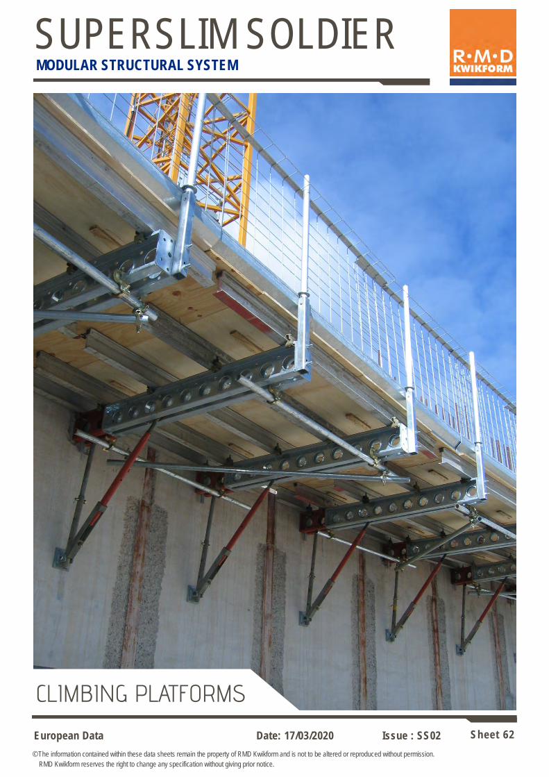
European Data Sheet 62
© The information contained within these data sheets remain the property of RMD Kwikform and is not to be altered or reproduced without permission.
RMD Kwikform reserves the right to change any specification without giving prior notice.
Date: 17/03/2020 Issue : SS02
SUPERSLIM SOLDIER MODULAR STRUCTURAL SYSTEM
CLIMBING PLATFORMS
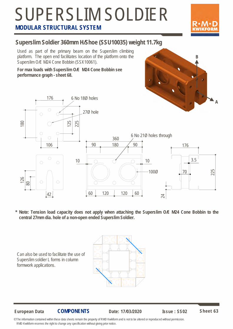
European Data Sheet 63
© The information contained within these data sheets remain the property of RMD Kwikform and is not to be altered or reproduced without permission.
RMD Kwikform reserves the right to change any specification without giving prior notice.
Date: 17/03/2020 Issue : SS02
SUPERSLIM SOLDIER MODULAR STRUCTURAL SYSTEM
COMPONENTS
Superslim Soldier 360mm H/Shoe (SSU10035) weight 11.7kg
Used as part of the primary beam on the Superslim climbing platform. The open end facilitates location of the platform onto the
Superslim O/E M24 Cone Bobbin (SSX10061).
For max loads with Superslim O/E M24 Cone Bobbin see performance graph - sheet 68.
180
125
176
106
225
360
60 60 120 120
90 90 180
42
126
80
225
176
70
24
6 No 18Ø holes
27Ø hole
6 No 21Ø holes through
100Ø
10 10 3.5
Note: Tension load capacity does not apply when attaching the Superslim O/E M24 Cone Bobbin to the central 27mm dia. hole of a non-open ended Superslim Soldier.
*
B
A
Can also be used to facilitate the use of Superslim soldier L forms in column
formwork applications.

European Data Sheet 64
© The information contained within these data sheets remain the property of RMD Kwikform and is not to be altered or reproduced without permission.
RMD Kwikform reserves the right to change any specification without giving prior notice.
Date: 17/03/2020 Issue : SS02
SUPERSLIM SOLDIER MODULAR STRUCTURAL SYSTEM
Superslim Klik-Klak Latch (SSU10037) weight 3.95kg
25 233 79
150
120 160
40
40
40
360mm H/Shoe Soldier
(SSU10035)
Used in conjunction with Superslim Soldier 360mm H/Shoe (SSU10035) to create crane
lifted platform applications.
Allowable Working Load = 25kN
22 dia hole
Superslim 19mm Pin & Clip
(SSX10046)
COMPONENTS
75
200
75
140
26 dia
hole
6 thick Captive
washer
127 x 64 x 14
channel
15
M24 x 45 Sep Pin gr8.8 BZP (BNX24001)
with M24 Anchor Screw
Used wall mounted to support Klik-Klak Latch in applications where the formwork can be removed with each lift or
sufficiently retaracted to provide clearance.
Allowable Working Load = 25kN
Superslim Klik-Klak Wall Bracket (SSU10030) weight 6.63kg
Note: the Superslim soldier length must be between 230 & 250mm shorter than the wall gap to ensure the unit can
not become disconnected at one end of the platform during use.
Check adequate bearing of latches after each lift and wedge gaps between the wall and the end of the Superslim
tight both ends.
115 - 125mm
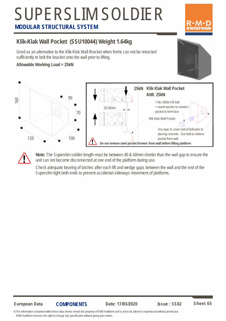
European Data Sheet 65
© The information contained within these data sheets remain the property of RMD Kwikform and is not to be altered or reproduced without permission.
RMD Kwikform reserves the right to change any specification without giving prior notice.
Date: 17/03/2020 Issue : SS02
SUPERSLIM SOLDIER MODULAR STRUCTURAL SYSTEM
COMPONENTS
160
120 100
90
Used as an alternative to the Klik-Klak Wall Bracket when forms can not be retracted
sufficiently to bolt the bracket onto the wall prior to lifting.
Allowable Working Load = 25kN
Note: The Superslim soldier length must be between 40 & 60mm shorter than the wall gap to ensure the
unit can not become disconnected at one end of the platform during use.
Check adequate bearing of latches after each lift and wedge gaps between the wall and the end of the
Superslim tight both ends to prevent accidental sideways movement of platforms.
Klik-Klak Wall Pocket (SSU10044) Weight 1.64kg
70
AWL 25kN
Klik-Klak Wall Pocket
!
25kN 25kN Klik Klak Wall Pocket
AWL 25kN
Klik Klak Wall Pocket
Use tape to cover end of bolt prior to
placing concrete. Use bolt to retrieve
pocket from wall.
Do not remove steel pocket formers from wall before lifting platform
20-30mm
1 No. M20x130 bolt
+ round washer to connect
pocket to form face
AWL 25kN
Klik-Klak Wall Pocket
!
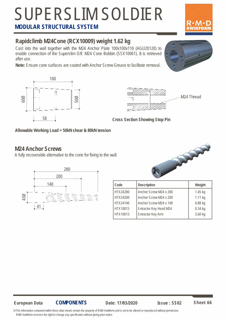
European Data Sheet 66
© The information contained within these data sheets remain the property of RMD Kwikform and is not to be altered or reproduced without permission.
RMD Kwikform reserves the right to change any specification without giving prior notice.
Date: 17/03/2020 Issue : SS02
SUPERSLIM SOLDIER MODULAR STRUCTURAL SYSTEM
COMPONENTS
Rapidclimb M24Cone (RCX10009) weight 1.62 kg Cast into the wall together with the M24 Anchor Plate 100x100x110 (AGU20120) to enable connection of the Superslim O/E M24 Cone Bobbin (SSX10061). It is retrieved after use.
Note: Ensure cone surfaces are coated with Anchor Screw Grease to facilitate removal.
M24 Thread
Cross Section Showing Stop Pin
100 50
Ø
60Ø
58
Allowable Working Load = 50kN shear & 80kN tension
Code Description Weight
HTX24280
HTX24200
HTX24140
HTX10015
HTX10013
Anchor Screw M24 x 280
Anchor Screw M24 x 200
Anchor Screw M24 x 140
Extractor Key Head M24
Extractor Key Arm
1.45 kg
1.11 kg
0.88 kg
0.34 kg
3.60 kg
200
43Ø
140
41
280
M24 Anchor Screws A fully recoverable alternative to the cone for fixing to the wall.

European Data Sheet 67
© The information contained within these data sheets remain the property of RMD Kwikform and is not to be altered or reproduced without permission.
RMD Kwikform reserves the right to change any specification without giving prior notice.
Date: 17/03/2020 Issue : SS02
SUPERSLIM SOLDIER MODULAR STRUCTURAL SYSTEM
COMPONENTS
Rapidclimb Extractor Key (RCX10031) weight 0.45 kg
Used to remove Rapidclimb M24 Cones to allow re-use. The key can be captivated to the cone using a M24x60 set pin to prevent movement of the key when using a 36AF spanner on the hex head if required.
61Ø 41
M24 Thread
Rapidclimb Cone Retainer (RCX10020) weight 0.12kg
Rapidclimb Cone Retainer Key (RCX10021) weight 0.05kg
Used to attach the Rapidclimb M24 Cone or 30kN anchor screw to the shutter prior to pouring. This is nailed to the form face and the anchor is hand tightened onto it.
A 14A/F key used to extract the Cone Retainer from the Rapidclimb M24 Cone after the pouring process.
36
25Ø
58Ø 20
40
14.1
A/F
100
A consumable M24 gr8.8 anchor used with the Rapidclimb M24 Cone (RCX10009).
M24 Anchor Plate 100x100x110 (AGU20120) weight 1.23kg
100x100x10 thick plate
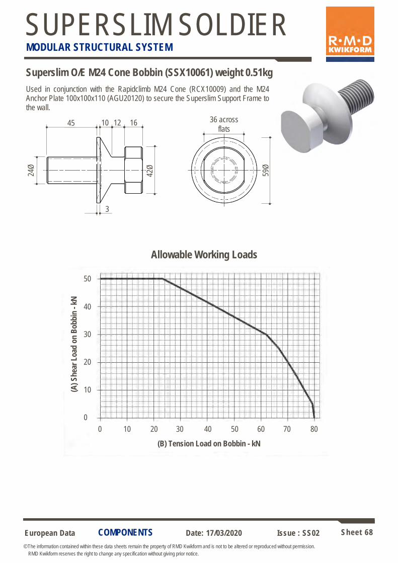
European Data Sheet 68
© The information contained within these data sheets remain the property of RMD Kwikform and is not to be altered or reproduced without permission.
RMD Kwikform reserves the right to change any specification without giving prior notice.
Date: 17/03/2020 Issue : SS02
SUPERSLIM SOLDIER MODULAR STRUCTURAL SYSTEM
Allowable Working Loads
(A)
Sh
ear
Lo
ad o
n B
ob
bin
- k
N
(B) Tension Load on Bobbin - kN
50
40
30
20
10
0
0 10 20 30 40 50 60 70 80
COMPONENTS
Superslim O/E M24 Cone Bobbin (SSX10061) weight 0.51kg
Used in conjunction with the Rapidclimb M24 Cone (RCX10009) and the M24 Anchor Plate 100x100x110 (AGU20120) to secure the Superslim Support Frame to the wall.
24Ø
36 across
flats 45 10 12 16
3
42Ø
59Ø
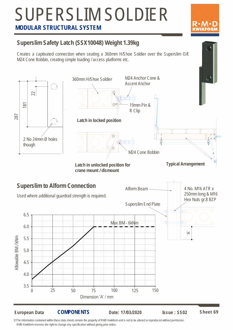
European Data Sheet 69
© The information contained within these data sheets remain the property of RMD Kwikform and is not to be altered or reproduced without permission.
RMD Kwikform reserves the right to change any specification without giving prior notice.
Date: 17/03/2020 Issue : SS02
SUPERSLIM SOLDIER MODULAR STRUCTURAL SYSTEM
COMPONENTS
Creates a captivated connection when seating a 360mm H/Shoe Soldier over the Superslim O/E
M24 Cone Bobbin, creating simple loading / access platforms etc.
Superslim Safety Latch (SSX10048) Weight 1.39kg
Typical Arrangement
287
181
22
2 No 24mm Ø holes
though
Latch in locked position
Latch in unlocked position for crane mount / dismount
360mm H/Shoe Soldier M24 Anchor Cone &
Ascent Anchor
19mm Pin &
R Clip
M24 Cone Bobbin
Superslim to Alform Connection
Used where additional guardrail strength is required.
6.5
6.0
5.5
5.0
4.5
4.0
3.5 0 25 50 75 100 125 150
Allo
wab
le B
M /
kNm
Dimension ’A’ / mm
Max BM - 6kNm
Alform Beam 4 No. M16 ATR x 250mm long & M16
Hex Nuts gr.8 BZP Superslim End Plate
‘A’
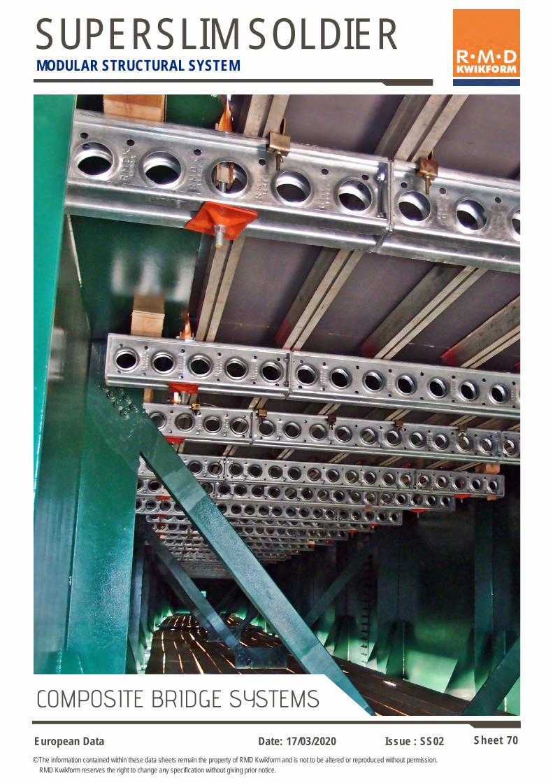
European Data Sheet 70
© The information contained within these data sheets remain the property of RMD Kwikform and is not to be altered or reproduced without permission.
RMD Kwikform reserves the right to change any specification without giving prior notice.
Date: 17/03/2020 Issue : SS02
SUPERSLIM SOLDIER MODULAR STRUCTURAL SYSTEM
COMPOSITE BRIDGE SYSTEMS

European Data Sheet 71
© The information contained within these data sheets remain the property of RMD Kwikform and is not to be altered or reproduced without permission.
RMD Kwikform reserves the right to change any specification without giving prior notice.
Date: 17/03/2020 Issue : SS02
SUPERSLIM SOLDIER MODULAR STRUCTURAL SYSTEM
APPLICATIONS
Paraslim System for Composite Bridge Deck Cantilever Construction
Paraslim is a modular soffit support system designed to facilitate construction of edge projections, parapets and string courses of composite steel girder and precast concrete bridge decks. It may also be used to construct the capping beams to sheet piles or connect to a previously cast wall to produce a simple access
platform for use in low-rise jump formwork applications
The system is based on a triangular frame consisting of a Superslim top chord with a tubular or Superslim undercarriage. Frames are laced together with tube and fittings to produce a module erected and dismantled by crane. All erection, levelling, use and dismantling can be carried out safely from above deck level thus eliminating the need for special access plant and enhancing safety by reducing work at height. The modules can be provided to site preassembled
by RMD Kwikform, thus saving site assembly time and space.
In bridge construction, Paraslim modules are either assembled onto the bridge girders before they are raised into position, in which case they form a full span access platform available for use immediately, or they are craned into position individually alongside the erected bridge beams. Various edge protection options are available ranging from Ultraguard mesh panels to fully hoarded debris shields for use over live
road or rail traffic.
Webtie System for Composite Bridge Deck Slab Support
Webtie modular soffit formwork panels increase the speed and efficiency of the construction of reinforced concrete decks in composite bridges, providing an economical and flexible alternative to permanent formwork between the bridge girders. Load tested and certified polyester Webties readily straddle the top flanges of bridge girders or attaches to 19mm, 22mm or 25mm diameter shear connectors to support Superslim Soldier primary beams below an Alform Beam or GTX Beam and plywood soffit. When the deck has been cast and the formwork removed, Webties are
severed and sealed at the concrete surface using a hot knife tool.
Webtie Saddle Webtie Delta
For full details of Paraslim & Webtie equipment refer to Paraslim Safetie Datasheets.

European Data Sheet 72
© The information contained within these data sheets remain the property of RMD Kwikform and is not to be altered or reproduced without permission.
RMD Kwikform reserves the right to change any specification without giving prior notice.
Date: 17/03/2020 Issue : SS02
SUPERSLIM SOLDIER MODULAR STRUCTURAL SYSTEM
COMPONENTS
An assembly of fully galvanised parts used together with a Superslim Turnbuckle
and a Superslim Soldier to form a Paraslim Frame.
Incorporates the following features:
1. Paraslim Tilt Plate with integral 6mm thick, polypropylene girder
paintwork protection pad.
2. Telescopic Paraslim Inner and Outer Tubes fixed to length with a pin and
R-clip for speedy adjustment in 75mm increments
3. Paraslim Turnbuckle Forkend with pin and R-clip for rapid and easy
assembly with a Superslim Turnbuckle
4. Bottom node connection with M20x100 bolt and Nyloc nut, discourages
unnecessary site disassembly at this location.
For full details of Paraslim equipment refer to Paraslim Safetie Datasheets.
1
2
3 4
Paraslim Undercarriage Assembly (PSX10032) weight 10.7kg
Code Description Weight
PSX10007 Paraslim Turnbuckle Forkend 2.62 kg
PSX10008 Paraslim Tilt Plate 2.30 kg
PSX10009 Paraslim Tube Inner 2.10 kg
PSX10010 Paraslim Tube Outer 2.34 kg
SSX10046 Superslim 19mm Pin & R-clip 0.29 kg
BNU20015 M20x100 Bolt gr8.8 BZP 0.32 kg
BNU20002 M20 Nyloc Nut gr8.8 BZP 0.06 kg
PSX10035 Paraslim Tilt Plate Bearing Pad 0.12 kg
BNX10007 M10x35 Set Pin gr8.8 BZP Csk 0.04 kg
MNX10076 M10 Nyloc Nut 0.05 kg
SSU10029 Rocking Head Washer M10 0.02 kg
Paraslim Turnbuckle Forkend (PSX10007) weight 2.62kg
Connects the Superslim Turnbuckle 914-1160 (SSU10016) to the Paraslim Tilt Plate (PSX10008).
AWL = ±45kN
530
30
Side View
Plan View Section A-A Section B-B
49
40
53
50
53
A
A
B
B Ø22 Hole
Ø22 Hole
190

European Data Sheet 73
© The information contained within these data sheets remain the property of RMD Kwikform and is not to be altered or reproduced without permission.
RMD Kwikform reserves the right to change any specification without giving prior notice.
Date: 17/03/2020 Issue : SS02
SUPERSLIM SOLDIER MODULAR STRUCTURAL SYSTEM
COMPONENTS
Paraslim Tilt Plate (PSX10008) weight 2.30kg
Connects to Paraslim Turnbuckle Forkend (PSX10007) and Paraslim Tube Inner or Outer
(PSX10009 or PSX10010) with M20x100 Bolt & Nyloc Nut (BNU20015 + BNU20002).
AWL = ±40kN
Plan View Side View
150
150
100
100
64
80
10
30
4 No. Ø17 Holes
Ø22 Hole
Paraslim Tilt Plate Bearing Pad (PSX10035) weight 0.12kg
Used for protecting the paintwork on the web of the bridge girder. Bolted to the Paraslim Tilt Plate (PSX10008) with 2 No. M10x35 Csk Set Pins, Rocking Head Washers, & M10
Nyloc Nuts (BNX10007 + SSU10029 + MNX10076).
Plan View Side View
145
102
145
102
4 No. Ø10.5 csk
Holes
6
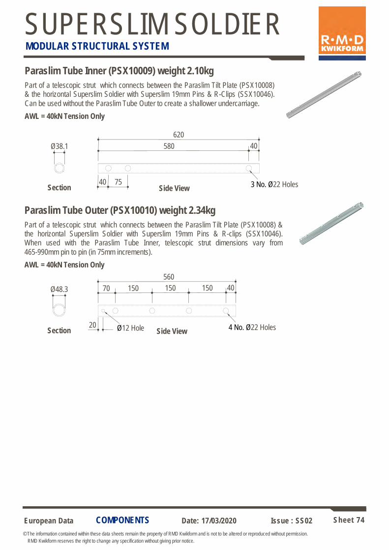
European Data Sheet 74
© The information contained within these data sheets remain the property of RMD Kwikform and is not to be altered or reproduced without permission.
RMD Kwikform reserves the right to change any specification without giving prior notice.
Date: 17/03/2020 Issue : SS02
SUPERSLIM SOLDIER MODULAR STRUCTURAL SYSTEM
COMPONENTS
Paraslim Tube Inner (PSX10009) weight 2.10kg
Part of a telescopic strut which connects between the Paraslim Tilt Plate (PSX10008) & the horizontal Superslim Soldier with Superslim 19mm Pins & R-Clips (SSX10046).
Can be used without the Paraslim Tube Outer to create a shallower undercarriage.
AWL = 40kN Tension Only
620
580 40
40 75
Ø38.1
3 No. Ø22 Holes Side View Section
Paraslim Tube Outer (PSX10010) weight 2.34kg
Part of a telescopic strut which connects between the Paraslim Tilt Plate (PSX10008) & the horizontal Superslim Soldier with Superslim 19mm Pins & R-clips (SSX10046). When used with the Paraslim Tube Inner, telescopic strut dimensions vary from
465-990mm pin to pin (in 75mm increments).
AWL = 40kN Tension Only
560
150 40
20
Ø48.3
4 No. Ø22 Holes Side View Section
150 150 70
Ø12 Hole

European Data Sheet 75
© The information contained within these data sheets remain the property of RMD Kwikform and is not to be altered or reproduced without permission.
RMD Kwikform reserves the right to change any specification without giving prior notice.
Date: 17/03/2020 Issue : SS02
SUPERSLIM SOLDIER MODULAR STRUCTURAL SYSTEM
COMPONENTS
Webtie Edge Protector (PSX10014) weight 0.01kg
Used to prevent the edge of the steel girder top flange from cutting the polyester
Webtie webbing.
.
Webtie Tensioning Fork (PSX10011) weight 1.02kg
Used to connect the Webtie Delta to M20 Allthread Rod via M20x90 Bolt gr8.8 BZP & M20
Hex Nut gr 8 BZP (BNX20030 + BNU20001).
AWL = 30kN Tension Only
Side View End View
Plan View
175
70
46
40
Ø21 Hole
Ø21 Holes
Webtie Delta Loop 250mm (PSX10012) weight 0.68kg
Used to suspend Superslim Soldiers in steel girder composite bridge deck soffit formwork, the forged Delta Link slips over a load tested 19,22 or 25mm diameter shear connector and connects to the Webtie Forkend with an M20x90 Bolt gr8.8 BZP & M20 Hex Nut gr 8
BZP (BNX20030 + BNU20001).
AWL = 30kN Tension Only
Webtie Delta
Loop 250mm
M20x90 Bolt & Nut
Webtie Tensioning Fork
Standard Waler Plate
M20 Allthread Rod with 2 No. Hex Nuts & 1 No. M20
Washer
89
250
50
Webtie Delta Link
(PSX10013)
Webtie Webbing
Loop
Webtie Edge Protector
Grease Allthread Rod & torque nut to 120Nm prior to loading formwork.

European Data Sheet 76
© The information contained within these data sheets remain the property of RMD Kwikform and is not to be altered or reproduced without permission.
RMD Kwikform reserves the right to change any specification without giving prior notice.
Date: 17/03/2020 Issue : SS02
SUPERSLIM SOLDIER MODULAR STRUCTURAL SYSTEM
COMPONENTS
Webtie Hot Knife Tool 110v
Used to cut the webtie flush with the underside of the deck once the formwork has been struck. The Hot Knife Tool melts the Webtie as it cuts through the Webbing Loop and seals the joint at the face of the concrete at the same time.
Spare Blades are available for this tool.
Code Description Weight
PSX10028 Webtie Hot Knife Tool 110v 6.0 kg
PSX10029 Webtie Hot Knife Blade 0.001 kg
Allthread Rod, Nuts, Washers & Plates
Code Description Weight
TRX10020 Allthread Rod - M20 per m Gd8.8 2.10 kg
TRX20000 Allthread Rod per cut -
BNU20001 M20 Hex Nut gr8 BZP 0.06 kg
BNU20003 M20 Round Washer BZP 0.03 kg
BTX10021 Waler Plate - Standard 1.35 kg
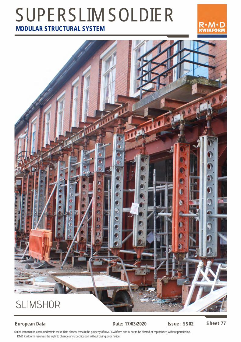
European Data Sheet 77
© The information contained within these data sheets remain the property of RMD Kwikform and is not to be altered or reproduced without permission.
RMD Kwikform reserves the right to change any specification without giving prior notice.
Date: 17/03/2020 Issue : SS02
SUPERSLIM SOLDIER MODULAR STRUCTURAL SYSTEM
SLIMSHOR

European Data Sheet 78
© The information contained within these data sheets remain the property of RMD Kwikform and is not to be altered or reproduced without permission.
RMD Kwikform reserves the right to change any specification without giving prior notice.
Date: 17/03/2020 Issue : SS02
SUPERSLIM SOLDIER MODULAR STRUCTURAL SYSTEM
COMPONENTS
180
130
150
Base Plate Detail
The cup and cone nature of the adjustable base enables a rotation of 7 degrees in
any plane
Jack Handle
M24 Bolt
& Nut
170
365 min.
515 max.
Slimshor Foot
22 dia. holes
Superslim Adjustable Base 365-515 (SSU10025) weight 19.0kg
Used to provide base adjustment and spread load.
Allowable Working Load 150kN, 100kN if load is to be removed by rotation of the jack handle.
Not to be used in tension.
The maximum load that can be applied by rotating the jack handle is 40kN using a scaffold tube
extension when the threads have been well greased.
Fits 2 3/8” x 2” Swivel
or Fixed Couplers
Fits 2” x 2” Swivel or
90 degree Couplers

European Data Sheet 79
© The information contained within these data sheets remain the property of RMD Kwikform and is not to be altered or reproduced without permission.
RMD Kwikform reserves the right to change any specification without giving prior notice.
Date: 17/03/2020 Issue : SS02
SUPERSLIM SOLDIER MODULAR STRUCTURAL SYSTEM
COMPONENTS
38
195
114
440 min.
590 max.
Superslim Adjustable Head 440-590mm (SSU10026) weight 24.6kg
Allowable Working Load 150kN, 100kN if load is to be removed by rotation of the jack handle (subject to design verification of steelwork).
Not to be used in tension.
The maximum load that can be applied by rotating the jack handle is 40kN using a scaffold tube extension when the
threads have been well greased.
Clamp header beams in place using Clamp plates with M12 set pins. Use M12 x 25 set pins for flanges up to 12mm
thick. Use M12 x 30 set pins for flanges between 12 & 20mm thick.
Holes
tapped M12
Max beam flange width = 171mm
Slimshor Head Adaptor
Jack Handle
M24 Bolt & Nut
Connection to Soldier using 4 No. M16 x 40 Set Pin gr8.8 BZP & M16 Nut
(BNU16007 & BNU16001)
Code Description Weight
AFX20003 Clamp Plate 0.09 kg
BNX12009 M12x25 Set Pin gr8.8 BZP 0.04 kg
BNX12002 M12x30 Set Pin gr8.8 BZP 0.04 kg
Fits 2 3/8” x 2” Swivel
or Fixed Couplers
Fits 2” x 2” Swivel or
90 degree Couplers
60
Clamp plates in 114mm c/c holes for flange widths up to 102mm. Clamp plates in 195mm c/c holes for flange widths up to 171mm.
The head should be twisted to suit varying beam widths.
Note: When twisted the head is not suitable for sloping applications.

European Data Sheet 80
© The information contained within these data sheets remain the property of RMD Kwikform and is not to be altered or reproduced without permission.
RMD Kwikform reserves the right to change any specification without giving prior notice.
Date: 17/03/2020 Issue : SS02
SUPERSLIM SOLDIER MODULAR STRUCTURAL SYSTEM
COMPONENTS
Note: The body of the Push Pull Prop requires to be rotated to raise or lower the prop, where bracing Is required to
reduce effective prop length use the Slimshor Prop with the 8mm U Plate.
Slimshor Prop
Rapidshor U Plate
8mm (RSX10008)
Superslim Soldier
Adjustable Base 365-515
(SSU10025)
Rapidshor U Head
(RSX10003)
Prop Jack L/H or R/H Adjustable
(SSU10007 & SSU10008)
Push Pull Prop
Used with Slimshor Props to support a Soldier header beam.
For angles > 6 degrees use neoprene pad in U-Plate.
Allowable Prop Load 80kN – compression only
Rapidshor U-Plate 8thk x 182mm wide (RSX10008) weight 5.26kg
Rapidshor Brace U Head 182mm wide (RSX10003) weight 8.47kg
Used with Push Pull Props to support a Soldier header beam.
Allowable Prop Load 80kN – compression only
Superslim Soldier
Connect with 2 No. M12 x 40 Bolt gr8.8 BZP Csk (BNX12001), 2 No. M16 Round Washers (BNU16002), 2 No. M12 Round Washers (BNU12002) & 2 No M12 Hex Nuts
(BNU12001)
182
220
Note: Use Rapidshor U-Plate 8 thk x 220mm wide (RSX10001) with 203 UC Beams.
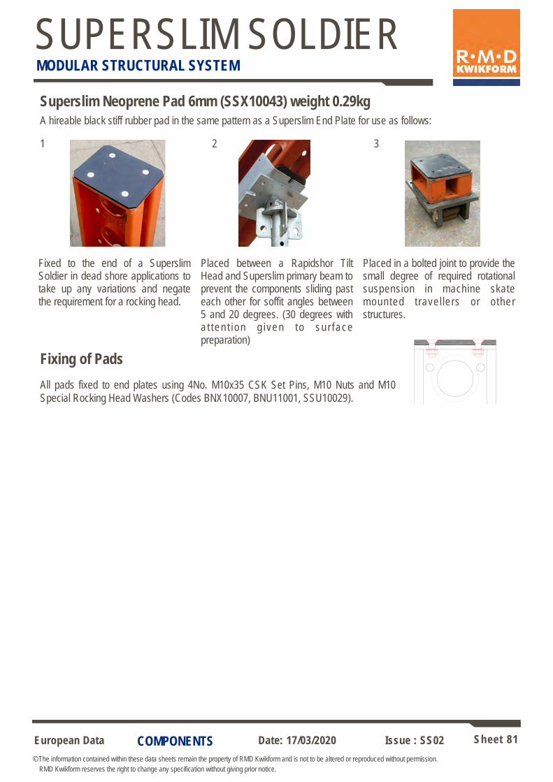
European Data Sheet 81
© The information contained within these data sheets remain the property of RMD Kwikform and is not to be altered or reproduced without permission.
RMD Kwikform reserves the right to change any specification without giving prior notice.
Date: 17/03/2020 Issue : SS02
SUPERSLIM SOLDIER MODULAR STRUCTURAL SYSTEM
COMPONENTS
A hireable black stiff rubber pad in the same pattern as a Superslim End Plate for use as follows:
Fixed to the end of a Superslim Soldier in dead shore applications to take up any variations and negate the requirement for a rocking head.
Placed between a Rapidshor Tilt Head and Superslim primary beam to prevent the components sliding past each other for soffit angles between 5 and 20 degrees. (30 degrees with a t ten t i on g i ven to su r face preparation)
Placed in a bolted joint to provide the small degree of required rotational suspension in machine skate mounted travel lers or other structures.
Superslim Neoprene Pad 6mm (SSX10043) weight 0.29kg
1 2 3
Fixing of Pads
All pads fixed to end plates using 4No. M10x35 CSK Set Pins, M10 Nuts and M10
Special Rocking Head Washers (Codes BNX10007, BNU11001, SSU10029).

European Data Sheet 82
© The information contained within these data sheets remain the property of RMD Kwikform and is not to be altered or reproduced without permission.
RMD Kwikform reserves the right to change any specification without giving prior notice.
Date: 17/03/2020 Issue : SS02
SUPERSLIM SOLDIER MODULAR STRUCTURAL SYSTEM
COMPONENTS
Max.
angle
of tilt
28°
36 M10
Set Pin
220
M12 Tapped
11
270
60
195
12.5 114
4 No. 18
dia. holes
2 No. 22 290
25
180
130
40.5 40.5
Superslim Rocking Head 36mm
Superslim Prop Support Plate
Used to attach header beams onto soldier props. Only to be used in the orientation
shown below (i.e. parallel to Superslim X-X axis).
Allowable Working Load 150kN (subject to design verification of steelwork).
Not to be used in tension. For connection to header beams see sheet 77.
Used to support horizontal Slimshor in trench applications.
180 2 No. M20 x 45
CSK Bolt with Nut
125
75
75
36
38
Code Description Weight
SSU10023 Superslim Rocking Head 36mm 4.35 kg
BNX10005 M10x20 Set Pin gr8.8 BZP 0.03 kg
SSU10029 Rocking Head Washer M10 0.02 kg
Code Description Weight
SSX10041 Superslim Prop Support Plate 6.02 kg
BNX20027 M20x45 Set Pin gr8.8 BZP CSK 0.17 kg
BNU20001 M20 Hex Nut gr8 BZP 0.06 kg
Clamp plates in 114mm c/c holes for flange widths up to
102mm.
Clamp plates in 195mm c/c holes for flange widths up to
171mm.
The head should be twisted to
suit varying beam widths.
Note: When twisted the head is not suitable for sloping
applications.
X
X

European Data Sheet 83
© The information contained within these data sheets remain the property of RMD Kwikform and is not to be altered or reproduced without permission.
RMD Kwikform reserves the right to change any specification without giving prior notice.
Date: 17/03/2020 Issue : SS02
SUPERSLIM SOLDIER MODULAR STRUCTURAL SYSTEM
COMPONENTS
225
Superslim Corner Pivot (SSU10019) weight 7.32kg
Horizontal Soldier can be tilted
up to 15° from the horizontal
176
35 1
06
Prop Pivot Tube & Clip
Assembly (SSU10004)
12
228
185
175
160
12
105
70
115
70
Used to attach Soldiers at right angles and permits limited rotation. Connection to Soldier
using 4 No. M16 x 40 Set Pin gr8.8 BZP & M16 Nut (BNU16007 + BNU16001).
Allowable Working Load ± 65kN
35
50 50 125
Superslim Pivot Corner 20mm (SSX10037) weight 4.27kg
Min / Max Rotation
Alternative fixing 2 No 18 dia
holes
4 No 18 dia c/sk holes for M16x40 c/sk Set pins gr8.8 & Nuts
(BNU16008 + BNU16001)
2 No 21 dia holes
through
Superslim 19mm Pin & R Clip (SSX10046) or M20x90 Bolt gr8.8 BZP & M20 Nut gr8
(BNX20030 + BNU20001)
Used to connect Soldiers perpendicular to each other or allows rotation of connected
soldier when used in the second hole position.
AWL +/-46kN when connected with 19mm Pin & R-Clip.
AWL +/-50kN when connected with M20x100 gr8.8 Bolt & M20 gr8 Hex Nut.
3mm
gap
29mm
gap
40 45 23
83
57
42

European Data Sheet 84
© The information contained within these data sheets remain the property of RMD Kwikform and is not to be altered or reproduced without permission.
RMD Kwikform reserves the right to change any specification without giving prior notice.
Date: 17/03/2020 Issue : SS02
SUPERSLIM SOLDIER MODULAR STRUCTURAL SYSTEM
COMPONENTS
Multislim 6-Way Connector (SSU20006) weight 24.9kg
Enables 6 Soldiers to be connected at a node.
For allowable working Load see sheet 85.
6-Way Double Connector (SSU20066) weight 42.0kg
Enables 8 Soldiers to be connected at a node.
For allowable working Load see sheet 85.
Each soldier bolted to connector using 4 No M16x40 Set Pin gr8.8 & M16 Hex Nut
(BNU16007 + BNU16001)
225x176x10mm End Plates
Note: All Plates are drilled to accept either 6 No Superslims or 6 No Minislims at each node.
4 No 18Ø holes to
accept plan bracing.
AWL for plan brace 20kN
360 450
270 360
250
200
212
Each soldier bolted to connector using 4 No M16x40 Set Pin gr8.8 & M16 Hex
Nut (BNU16007 + BNU16001)
225x176x10mm End Plates
212
212

European Data Sheet 85
© The information contained within these data sheets remain the property of RMD Kwikform and is not to be altered or reproduced without permission.
RMD Kwikform reserves the right to change any specification without giving prior notice.
Date: 17/03/2020 Issue : SS02
SUPERSLIM SOLDIER MODULAR STRUCTURAL SYSTEM
COMPONENTS
6-Way Connectors in use
75 x 75 x 12mm Plate Washer on inside face of
the connector
The allowable tensile load on the Superslim 6 Way Connector or Multislim 6 Way Connector can be increased to 100kN by using 75 x 75 x 12mm Plate Washers on the inside of the members as illustrated above.
A
A
A
The Six Way Connector allows Soldiers to be connected at node, and provides an effective component In making up frame structures with Superslim Soldiers. For particular high concentrations of leg loads a twin 6 Way Connector is
also available.
The allowable bending moment at the connector is dependant upon the direction of the axes of the applied load.
Moment about x-x axis (strong way) on sides 7.6kNm
Moment about x-x axis on top or bottom 4.4kNm
Moment about y-y axis on top, bottom or sides 3.6kNm
Axial loads in direction of arrow ‘A’
SSU20006 150kN Compression
80kN Tension
SSU20066 300kN Compression
160kN Tension
A
Y
X X
Y
Multislim Six Way Connector
(SSU20006)
Six Way Double Connector
(SSU20066)

European Data Sheet 86
© The information contained within these data sheets remain the property of RMD Kwikform and is not to be altered or reproduced without permission.
RMD Kwikform reserves the right to change any specification without giving prior notice.
Date: 17/03/2020 Issue : SS02
SUPERSLIM SOLDIER MODULAR STRUCTURAL SYSTEM
COMPONENTS
Rapid Bar Tie Forkend (BTX10030) weight 1.31kg
Used in conjunction with the Rapid Bar Tie Turnbuckle (BTU10009) to brace Slimshor Towers. The Rapid Bar Tie Forkend pins into the 21mm dia holes in the Superslim Soldier using a 19mm Pin & R-Clip (SSX10046) and connects to
the captive Rapid Tie in the Turnbuckle via a captive Rapid Tie Hexagon Nut.
AWL +/-46kN when connected with 19mm Pin & R-Clip.
AWL +/-50kN when connected with M20x100 gr8.8 Bolt & M20 gr8 Hex Nut.
Rapid Bar Tie Turnbuckle (BTU10009) weight 2.07kg
Used in conjunction with the Rapid Bar Tie Forkend (BTX10030) to brace Slimshor Towers. The Rapid Bar Tie Turnbuckle connects to the captive
Rapid Tie Hexagon Nut in the Rapid Bar Tie Forkend.
AWL +/-46kN when connected with 19mm Pin & R-Clip.
AWL +/-50kN when connected with M20x100 gr8.8 Bolt & M20 gr8 Hex Nut.
300
40
21Ø holes through
50
Captive Nut
311
300
Captive 15mm Bar Tie
58
19mm Pin & R-Clip (SSX10046)
Rapid Bar Tie Turnbuckle
(BTU10009)
Rapid Bar Tie Forkend
(BTX10030)
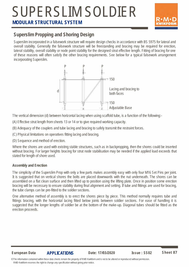
European Data Sheet 87
© The information contained within these data sheets remain the property of RMD Kwikform and is not to be altered or reproduced without permission.
RMD Kwikform reserves the right to change any specification without giving prior notice.
Date: 17/03/2020 Issue : SS02
SUPERSLIM SOLDIER MODULAR STRUCTURAL SYSTEM
APPLICATIONS
Superslim Propping and Shoring Design
P P P
d
150
Lacing and bracing to
both faces
Assembly and Erection
The simplicity of the Superslim Prop with only a few parts makes assembly easy with only four M16 Set Pins per joint. It is suggested that on vertical shores the bolts are placed downwards with the nut underneath. The shores can be assembled on a flat clean surface and then lifted up to position using the lifting plate. Once in position some erection bracing will be necessary to ensure stability during final alignment and setting. If tube and fittings are used for bracing,
the tube clamps can be pre-fitted to the soldier sections.
One alternative method of assembly is to erect the shores piece by piece. This method normally requires tube and fittings bracing, with the horizontal lacing fitted below joints between soldier sections. For ease of handling it is suggested that the longer lengths of soldier be at the bottom of the make-up. Diagonal tubes should be fitted as the
erection proceeds.
The vertical dimension (d) between horizontal lacing when using scaffold tube, is a function of the following:-
(A) Effective strut length from sheets 13 or 14 or to give required working capacity.
(B) Adequacy of the couplers and tube lacing and bracing to safely transmit the restraint forces.
(C) Physical limitations on operatives fitting lacing and bracing.
(D) Sequence and method of erection.
Where the shores are used with existing stable structures, such as in backpropping, then the shores could be inserted without bracing. For larger heights bracing for strut node stabilisation may be needed if the applied load exceeds that
stated for length of shore used.
150
Adjustable Base
Superslim incorporated in a falsework structure will require design checks in accordance with BS 5975 for lateral and overall stability. Generally the falsework structure will be freestanding and bracing may be required for erection, lateral stability, overall stability or node point stability for the designed strut effective length. Fitting of bracing for one of these reasons will often satisfy the other bracing requirements. See below for a typical falsework arrangement
incorporating Superslim.
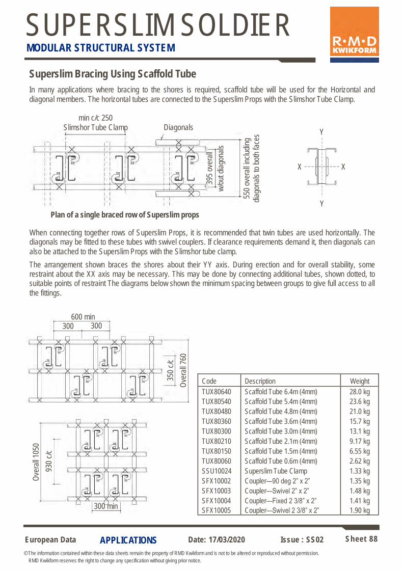
European Data Sheet 88
© The information contained within these data sheets remain the property of RMD Kwikform and is not to be altered or reproduced without permission.
RMD Kwikform reserves the right to change any specification without giving prior notice.
Date: 17/03/2020 Issue : SS02
SUPERSLIM SOLDIER MODULAR STRUCTURAL SYSTEM
APPLICATIONS
Superslim Bracing Using Scaffold Tube
min c/c 250
Slimshor Tube Clamp Diagonals
395
over
all
w/o
ut d
iago
nals
550
ove
rall
incl
udin
g
d
iago
nals
to b
oth
face
s
Y
X
Y
X
Ove
rall
1050
300 min
930
c/c
In many applications where bracing to the shores is required, scaffold tube will be used for the Horizontal and
diagonal members. The horizontal tubes are connected to the Superslim Props with the Slimshor Tube Clamp.
When connecting together rows of Superslim Props, it is recommended that twin tubes are used horizontally. The diagonals may be fitted to these tubes with swivel couplers. If clearance requirements demand it, then diagonals can
also be attached to the Superslim Props with the Slimshor tube clamp.
The arrangement shown braces the shores about their YY axis. During erection and for overall stability, some restraint about the XX axis may be necessary. This may be done by connecting additional tubes, shown dotted, to suitable points of restraint The diagrams below shown the minimum spacing between groups to give full access to all
the fittings.
600 min 300
Ove
rall
760
350
c/c
300
Plan of a single braced row of Superslim props
Code Description Weight
TUX80640 Scaffold Tube 6.4m (4mm) 28.0 kg
TUX80540 Scaffold Tube 5.4m (4mm) 23.6 kg
TUX80480 Scaffold Tube 4.8m (4mm) 21.0 kg
TUX80360 Scaffold Tube 3.6m (4mm) 15.7 kg
TUX80300 Scaffold Tube 3.0m (4mm) 13.1 kg
TUX80210 Scaffold Tube 2.1m (4mm) 9.17 kg
TUX80150 Scaffold Tube 1.5m (4mm) 6.55 kg
TUX80060 Scaffold Tube 0.6m (4mm) 2.62 kg
SSU10024 Superslim Tube Clamp 1.33 kg
SFX10002 Coupler—90 deg 2” x 2” 1.35 kg
SFX10003 Coupler—Swivel 2” x 2” 1.48 kg
SFX10004 Coupler—Fixed 2 3/8” x 2” 1.41 kg
SFX10005 Coupler—Swivel 2 3/8” x 2” 1.90 kg
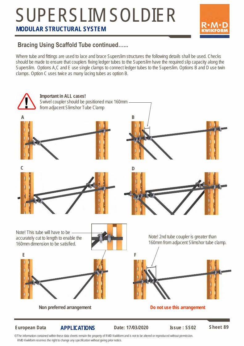
European Data Sheet 89
© The information contained within these data sheets remain the property of RMD Kwikform and is not to be altered or reproduced without permission.
RMD Kwikform reserves the right to change any specification without giving prior notice.
Date: 17/03/2020 Issue : SS02
SUPERSLIM SOLDIER MODULAR STRUCTURAL SYSTEM
APPLICATIONS
Where tube and fittings are used to lace and brace Superslim structures the following details shall be used. Checks should be made to ensure that couplers fixing ledger tubes to the Superslim have the required slip capacity along the Superslim. Options A,C and E use single clamps to connect ledger tubes to the Superslim. Options B and D use twin
clamps. Option C uses twice as many lacing tubes as option B.
Bracing Using Scaffold Tube continued…...
Non preferred arrangement Do not use this arrangement
A B
C
F E
D
Important in ALL cases! Swivel coupler should be positioned max 160mm
from adjacent Slimshor Tube Clamp
Note! This tube will have to be accurately cut to length to enable the
160mm dimension to be satisfied.
Note! 2nd tube coupler is greater than
160mm from adjacent Slimshor tube clamp.
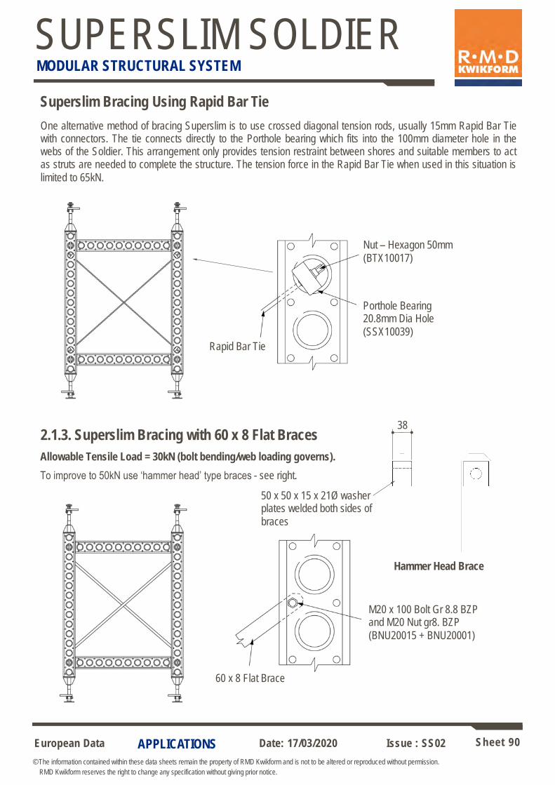
European Data Sheet 90
© The information contained within these data sheets remain the property of RMD Kwikform and is not to be altered or reproduced without permission.
RMD Kwikform reserves the right to change any specification without giving prior notice.
Date: 17/03/2020 Issue : SS02
SUPERSLIM SOLDIER MODULAR STRUCTURAL SYSTEM
APPLICATIONS
Superslim Bracing Using Rapid Bar Tie
Nut – Hexagon 50mm
(BTX10017)
Porthole Bearing 20.8mm Dia Hole
(SSX10039)
Rapid Bar Tie
M20 x 100 Bolt Gr 8.8 BZP and M20 Nut gr8. BZP
(BNU20015 + BNU20001)
60 x 8 Flat Brace
One alternative method of bracing Superslim is to use crossed diagonal tension rods, usually 15mm Rapid Bar Tie with connectors. The tie connects directly to the Porthole bearing which fits into the 100mm diameter hole in the webs of the Soldier. This arrangement only provides tension restraint between shores and suitable members to act as struts are needed to complete the structure. The tension force in the Rapid Bar Tie when used in this situation is
limited to 65kN.
2.1.3. Superslim Bracing with 60 x 8 Flat Braces
Allowable Tensile Load = 30kN (bolt bending/web loading governs).
To improve to 50kN use ‘hammer head’ type braces - see right.
50 x 50 x 15 x 21Ø washer plates welded both sides of
braces
38
Hammer Head Brace
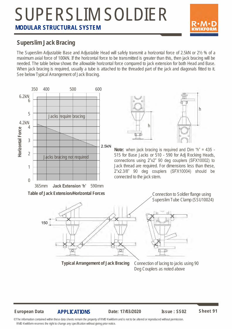
European Data Sheet 91
© The information contained within these data sheets remain the property of RMD Kwikform and is not to be altered or reproduced without permission.
RMD Kwikform reserves the right to change any specification without giving prior notice.
Date: 17/03/2020 Issue : SS02
SUPERSLIM SOLDIER MODULAR STRUCTURAL SYSTEM
APPLICATIONS
The Superslim Adjustable Base and Adjustable Head will safely transmit a horizontal force of 2.5kN or 2½ % of a maximum axial force of 100kN. If the horizontal force to be transmitted is greater than this, then jack bracing will be needed. The table below shows the allowable horizontal force compared to jack extension for both Head and Base. When jack bracing is required, usually a tube is attached to the threaded part of the jack and diagonals fitted to it.
See below Typical Arrangement of Jack Bracing.
365mm Jack Extension ‘h’ 590mm
Ho
rizo
nta
l Fo
rce
350 400 500 600
Connection to Soldier flange using
Superslim Tube Clamp (SSU10024)
150
2.5kN
h
Table of Jack Extension/Horizontal Forces
Jacks require bracing
Jacks bracing not required
Superslim Jack Bracing
h
6.2kN
4.2kN
3
2
0
1
5
6
4
Typical Arrangement of Jack Bracing Connection of lacing to jacks using 90
Deg Couplers as noted above
Note: when jack bracing is required and Dim “h” = 435 - 515 for Base Jacks or 510 - 590 for Adj Rocking Heads, connections using 2”x2” 90 deg couplers (SFX10002) to Jack thread are required. For dimensions less than these, 2”x2.3/8” 90 deg couplers (SFX10004) should be
connected to the jack stem.
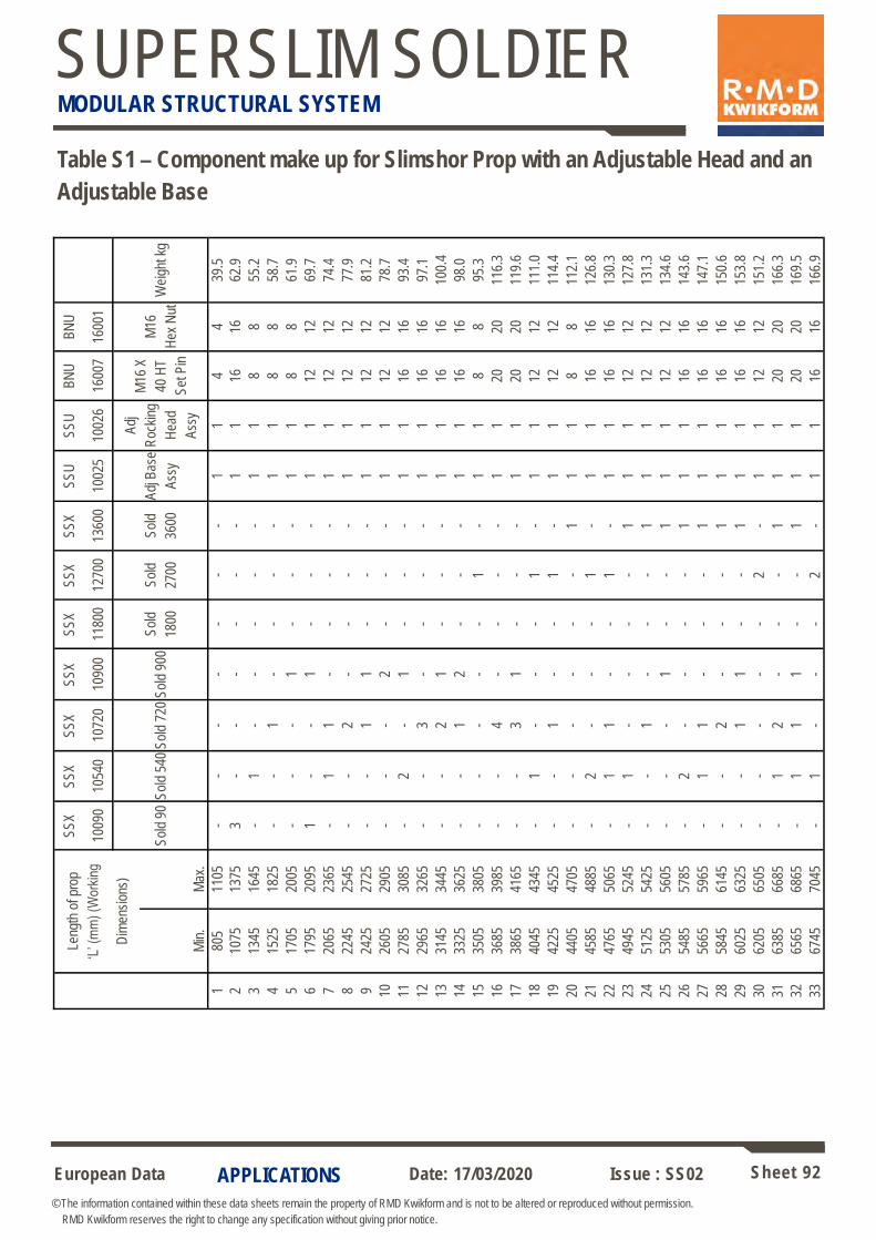
European Data Sheet 92
© The information contained within these data sheets remain the property of RMD Kwikform and is not to be altered or reproduced without permission.
RMD Kwikform reserves the right to change any specification without giving prior notice.
Date: 17/03/2020 Issue : SS02
SUPERSLIM SOLDIER MODULAR STRUCTURAL SYSTEM
APPLICATIONS
Leng
th o
f pro
p
‘L’ (
mm
) (W
orki
ng
Dim
ensi
ons)
SS
X
1009
0
SS
X
1054
0
SS
X
1072
0
SS
X
1090
0
SS
X
1180
0
SS
X
1270
0
SS
X
1360
0
SS
U
1002
5
SS
U
1002
6
BN
U
1600
7
BN
U
1600
1
Sol
d 90
Sol
d 54
0 S
old
720
Sol
d 90
0
Sol
d
1800
Sol
d
2700
Sol
d
3600
Adj
Ba
se
Ass
y
Adj
Roc
king
Hea
d
Ass
y
M16
X
40 H
T
Set
Pin
M16
Hex
Nut
W
eigh
t kg
Min
. M
ax.
1 80
5 11
05
- -
- -
- -
- 1
1 4
4 39
.5
2 10
75
1375
3
- -
- -
- -
1 1
16
16
62.9
3 13
45
1645
-
1 -
- -
- -
1 1
8 8
55.2
4 15
25
1825
-
- 1
- -
- -
1 1
8 8
58.7
5 17
05
2005
-
- -
1 -
- -
1 1
8 8
61.9
6 17
95
2095
1
- -
1 -
- -
1 1
12
12
69.7
7 20
65
2365
-
1 1
- -
- -
1 1
12
12
74.4
8 22
45
2545
-
- 2
- -
- -
1 1
12
12
77.9
9 24
25
2725
-
- 1
1 -
- -
1 1
12
12
81.2
10
2605
29
05
- -
- 2
- -
- 1
1 12
12
78
.7
11
2785
30
85
- 2
- 1
- -
- 1
1 16
16
93
.4
12
2965
32
65
- -
3 -
- -
- 1
1 16
16
97
.1
13
3145
34
45
- -
2 1
- -
- 1
1 16
16
10
0.4
14
3325
36
25
- -
1 2
- -
- 1
1 16
16
98
.0
15
3505
38
05
- -
- -
- 1
- 1
1 8
8 95
.3
16
3685
39
85
- -
4 -
- -
- 1
1 20
20
11
6.3
17
3865
41
65
- -
3 1
- -
- 1
1 20
20
11
9.6
18
4045
43
45
- 1
- -
- 1
- 1
1 12
12
11
1.0
19
4225
45
25
- -
1 -
- 1
- 1
1 12
12
11
4.4
20
4405
47
05
- -
- -
- -
1 1
1 8
8 11
2.1
21
4585
48
85
- 2
- -
- 1
- 1
1 16
16
12
6.8
22
4765
50
65
- 1
1 -
- 1
- 1
1 16
16
13
0.3
23
4945
52
45
- 1
- -
- -
1 1
1 12
12
12
7.8
24
5125
54
25
- -
1 -
- -
1 1
1 12
12
13
1.3
25
5305
56
05
- -
- 1
- -
1 1
1 12
12
13
4.6
26
5485
57
85
- 2
- -
- -
1 1
1 16
16
14
3.6
27
5665
59
65
- 1
1 -
- -
1 1
1 16
16
14
7.1
28
5845
61
45
- -
2 -
- -
1 1
1 16
16
15
0.6
29
6025
63
25
- -
1 1
- -
1 1
1 16
16
15
3.8
30
6205
65
05
- -
- -
- 2
- 1
1 12
12
15
1.2
31
6385
66
85
- 1
2 -
- -
1 1
1 20
20
16
6.3
32
6565
68
65
- 1
1 1
- -
1 1
1 20
20
16
9.5
33
6745
70
45
- 1
- -
- 2
- 1
1 16
16
16
6.9
Table S1 – Component make up for Slimshor Prop with an Adjustable Head and an
Adjustable Base
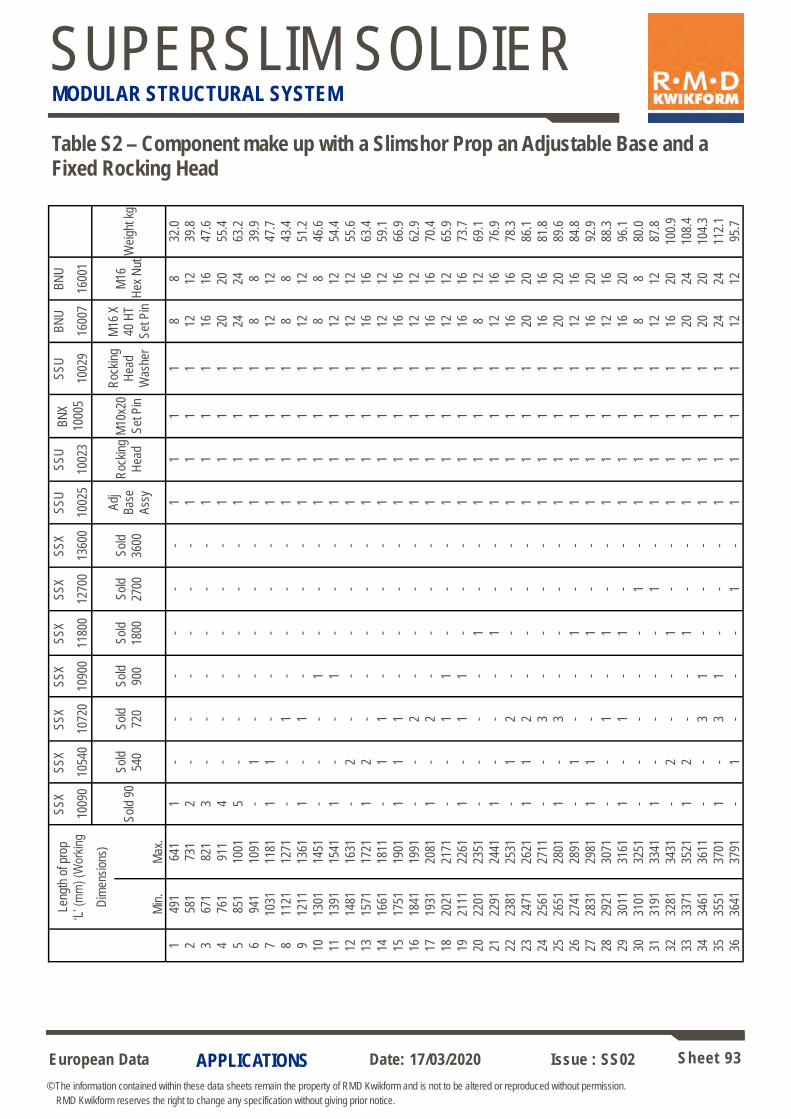
European Data Sheet 93
© The information contained within these data sheets remain the property of RMD Kwikform and is not to be altered or reproduced without permission.
RMD Kwikform reserves the right to change any specification without giving prior notice.
Date: 17/03/2020 Issue : SS02
SUPERSLIM SOLDIER MODULAR STRUCTURAL SYSTEM
APPLICATIONS
Leng
th o
f pro
p
‘L’ (
mm
) (W
orki
ng
Dim
ensi
ons)
SS
X
1009
0
SS
X
1054
0
SS
X
1072
0
SS
X
1090
0
SS
X
1180
0
SS
X
1270
0
SS
X
1360
0
SS
U
1002
5
SS
U
1002
3
BN
X
1000
5
SS
U
1002
9
BN
U
1600
7
BN
U
1600
1
Sol
d 90
S
old
540
Sol
d
720
Sol
d
900
Sol
d
1800
Sol
d
2700
Sol
d
3600
Adj
B
ase
Ass
y
Roc
king
Hea
d
M10
x20
Set
Pin
Roc
king
H
ead
Was
her
M16
X
40 H
T
Set
Pin
M16
Hex
Nut
Wei
ght k
g
Min
. M
ax.
1 49
1 64
1 1
- -
- -
- -
1 1
1 1
8 8
32.0
2 58
1 73
1 2
- -
- -
- -
1 1
1 1
12
12
39.8
3 67
1 82
1 3
- -
- -
- -
1 1
1 1
16
16
47.6
4 76
1 91
1 4
- -
- -
- -
1 1
1 1
20
20
55.4
5 85
1 10
01
5 -
- -
- -
- 1
1 1
1 24
24
63
.2
6 94
1 10
91
- 1
- -
- -
- 1
1 1
1 8
8 39
.9
7 10
31
1181
1
1 -
- -
- -
1 1
1 1
12
12
47.7
8 11
21
1271
-
- 1
- -
- -
1 1
1 1
8 8
43.4
9 12
11
1361
1
- 1
- -
- -
1 1
1 1
12
12
51.2
10
1301
14
51
- -
- 1
- -
- 1
1 1
1 8
8 46
.6
11
1391
15
41
1 -
- 1
- -
- 1
1 1
1 12
12
54
.4
12
1481
16
31
- 2
- -
- -
- 1
1 1
1 12
12
55
.6
13
1571
17
21
1 2
- -
- -
- 1
1 1
1 16
16
63
.4
14
1661
18
11
- 1
1 -
- -
- 1
1 1
1 12
12
59
.1
15
1751
19
01
1 1
1 -
- -
- 1
1 1
1 16
16
66
.9
16
1841
19
91
- -
2 -
- -
- 1
1 1
1 12
12
62
.9
17
1931
20
81
1 -
2 -
- -
- 1
1 1
1 16
16
70
.4
18
2021
21
71
- -
1 1
- -
- 1
1 1
1 12
12
65
.9
19
2111
22
61
1 -
1 1
- -
- 1
1 1
1 16
16
73
.7
20
2201
23
51
- -
- -
1 -
- 1
1 1
1 8
12
69.1
21
2291
24
41
1 -
- -
1 -
- 1
1 1
1 12
16
76
.9
22
2381
25
31
- 1
2 -
- -
- 1
1 1
1 16
16
78
.3
23
2471
26
21
1 1
2 -
- -
- 1
1 1
1 20
20
86
.1
24
2561
27
11
- -
3 -
- -
- 1
1 1
1 16
16
81
.8
25
2651
28
01
1 -
3 -
- -
- 1
1 1
1 20
20
89
.6
26
2741
28
91
- 1
- -
1 -
- 1
1 1
1 12
16
84
.8
27
2831
29
81
1 1
- -
1 -
- 1
1 1
1 16
20
92
.9
28
2921
30
71
- -
1 -
1 -
- 1
1 1
1 12
16
88
.3
29
3011
31
61
1 -
1 -
1 -
- 1
1 1
1 16
20
96
.1
30
3101
32
51
- -
- -
- 1
- 1
1 1
1 8
8 80
.0
31
3191
33
41
1 -
- -
- 1
- 1
1 1
1 12
12
87
.8
32
3281
34
31
- 2
- -
1 -
- 1
1 1
1 16
20
10
0.9
33
3371
35
21
1 2
- -
1 -
- 1
1 1
1 20
24
10
8.4
34
3461
36
11
- -
3 1
- -
- 1
1 1
1 20
20
10
4.3
35
3551
37
01
1 -
3 1
- -
- 1
1 1
1 24
24
11
2.1
36
3641
37
91
- 1
- -
- 1
- 1
1 1
1 12
12
95
.7
Table S2 – Component make up with a Slimshor Prop an Adjustable Base and a Fixed Rocking Head
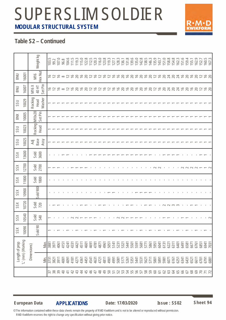
European Data Sheet 94
© The information contained within these data sheets remain the property of RMD Kwikform and is not to be altered or reproduced without permission.
RMD Kwikform reserves the right to change any specification without giving prior notice.
Date: 17/03/2020 Issue : SS02
SUPERSLIM SOLDIER MODULAR STRUCTURAL SYSTEM
APPLICATIONS
Leng
th o
f pro
p
‘L’ (
mm
) (W
orki
ng
Dim
ensi
ons)
SS
X
1009
0
SS
X
1054
0
SS
X
1072
0
SS
X
1090
0
SS
X
1180
0
SS
X
1270
0
SS
X
1360
0
SS
U
1002
5
SS
U
1002
3
BN
X
1000
5
SS
U
1002
9
BN
U
1600
7
BN
U
1600
1
Sol
d 90
S
old
540
Sol
d
720
Sol
d 90
0
Sol
d
1800
Sol
d
2700
Sol
d
3600
Adj
Bas
e
Ass
y
Roc
king
Hea
d
M10
x20
Set
Pin
Roc
king
Hea
d
Was
her
M16
X
40 H
T
Set
Pin
M16
Hex
Nut
W
eigh
t kg
Min
. M
ax.
37
3731
38
81
1 1
- -
- 1
- 1
1 1
1 16
16
10
3.5
38
3821
39
71
- -
1 -
- 1
- 1
1 1
1 12
12
99
.2
39
3911
40
61
1 -
1 -
- 1
- 1
1 1
1 16
16
10
7.0
40
4001
41
51
- -
- -
- -
1 1
1 1
1 8
8 96
.8
41
4091
42
41
1 -
- -
- -
1 1
1 1
1 12
12
10
4.6
42
4181
43
31
- 2
- -
- 1
- 1
1 1
1 16
16
11
1.5
43
4271
44
21
1 2
- -
- 1
- 1
1 1
1 20
20
11
9.3
44
4361
45
11
- 1
1 -
- 1
- 1
1 1
1 16
16
11
5.0
45
4451
46
01
1 1
1 -
- 1
- 1
1 1
1 20
20
12
2.8
46
4541
46
91
- 1
- -
- -
1 1
1 1
1 12
12
11
2.5
47
4631
47
81
1 1
- -
- -
1 1
1 1
1 16
16
12
0.3
48
4721
48
71
- -
1 -
- -
1 1
1 1
1 12
12
11
6.0
49
4811
49
61
1 -
1 -
- -
1 1
1 1
1 16
16
12
3.8
50
4901
50
51
- -
- 1
- -
1 1
1 1
1 12
12
11
9.3
51
4991
51
41
1 -
- 1
- -
1 1
1 1
1 16
16
12
7.1
52
5081
52
31
- 2
- -
- -
1 1
1 1
1 16
16
12
8.3
53
5171
53
21
1 2
- -
- -
1 1
1 1
1 20
20
13
6.1
54
5261
54
41
- 1
1 -
- -
1 1
1 1
1 16
16
13
1.8
55
5351
55
01
1 1
1 -
- -
1 1
1 1
1 20
20
13
9.6
56
5441
55
91
- 1
- 1
- -
1 1
1 1
1 16
16
13
5.0
57
5531
56
81
1 1
- 1
- -
1 1
1 1
1 20
20
14
2.8
58
5621
57
71
- -
1 1
- -
1 1
1 1
1 16
16
13
8.5
59
5711
58
61
1 -
1 1
- -
1 1
1 1
1 20
20
14
6.3
60
5801
59
51
- -
- -
- 2
- 1
1 1
1 12
12
13
5.9
61
5891
60
41
1 -
- -
- 2
- 1
1 1
1 16
16
14
3.7
62
5981
61
31
- 1
2 -
- -
1 1
1 1
1 20
20
15
1.0
63
6071
62
21
1 1
2 -
- -
1 1
1 1
1 24
24
15
8.8
64
6161
63
11
- -
3 -
- -
1 1
1 1
1 20
20
15
4.8
65
6251
64
01
1 -
3 -
- -
1 1
1 1
1 24
24
16
2.3
66
6341
64
91
- 1
- -
- 2
- 1
1 1
1 16
16
15
1.6
67
6431
65
81
1 1
- -
- 2
- 1
1 1
1 20
20
15
9.4
68
6521
66
71
- -
1 -
- 2
- 1
1 1
1 16
16
15
5.1
69
6611
67
61
1 -
1 -
- 2
- 1
1 1
1 20
20
16
2.9
70
6701
68
51
- -
- -
- 1
1 1
1 1
1 12
12
15
2.7
71
6791
69
41
1 -
- -
- 1
1 1
1 1
1 16
16
16
0.5
72
6881
70
31
- 2
- -
- 2
- 1
1 1
1 20
20
16
7.3
Table S2 – Continued
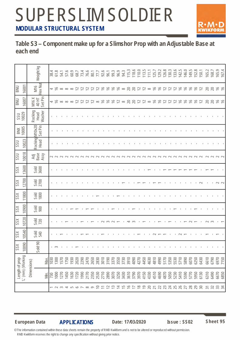
European Data Sheet 95
© The information contained within these data sheets remain the property of RMD Kwikform and is not to be altered or reproduced without permission.
RMD Kwikform reserves the right to change any specification without giving prior notice.
Date: 17/03/2020 Issue : SS02
SUPERSLIM SOLDIER MODULAR STRUCTURAL SYSTEM
APPLICATIONS
Table S3 – Component make up for a Slimshor Prop with an Adjustable Base at each end
Leng
th o
f pro
p
‘L’ (
mm
) (W
orki
ng
Dim
ensi
ons)
SS
X
1009
0
SS
X
1054
0
SS
X
1072
0
SS
X
1090
0
SS
X
1180
0
SS
X
1270
0
SS
X
1360
0
SS
U
1001
8
SS
U
1002
3
BN
X
1000
5
SS
U
1002
9
BN
U
1600
7
BN
U
1600
1
Sol
d 90
S
old
540
Sol
d
720
Sol
d
900
Sol
d
1800
Sol
d
2700
Sol
d
3600
Adj
B
ase
Ass
y
Roc
king
Hea
d
M10
x20
Set
Pin
Roc
king
H
ead
Was
her
M16
X
40 H
T
Set
Pin
M16
Hex
Nut
W
eigh
t kg
Min
. M
ax.
1 73
0 10
30
- -
- -
- -
- 2
- -
- 4
4 38
.4
2 10
00
1300
3
- -
- -
- -
2 -
- -
16
16
61.8
3 12
70
1570
-
1 -
- -
- -
2 -
- -
8 8
54.1
4 14
50
1750
-
- 1
- -
- -
2 -
- -
8 8
57.6
5 16
30
1930
-
- -
1 -
- -
2 -
- -
8 8
60.9
6 17
20
2020
1
- -
1 -
- -
2 -
- -
12
12
68.7
7 19
90
2290
-
1 1
- -
- -
2 -
- -
12
12
73.4
8 21
70
2470
-
1 -
1 -
- -
2 -
- -
12
12
76.6
9 23
50
2650
-
- 1
1 -
- -
2 -
- -
12
12
80.1
10
2530
28
30
- -
- -
1 -
- 2
- -
- 8
12
77.7
11
2710
30
10
- 1
2 -
- -
- 2
- -
- 16
16
92
.6
12
2890
31
90
- -
3 -
- -
- 2
- -
- 16
16
96
.1
13
3070
33
70
- -
2 1
- -
- 2
- -
- 16
16
99
.3
14
3250
35
50
- -
1 -
1 -
- 2
- -
- 12
16
96
.9
15
3430
37
30
- -
- -
- 1
- 2
- -
- 8
8 94
.3
16
3610
39
10
- -
4 -
- -
- 2
- -
- 20
20
11
5.3
17
3790
40
90
- -
3 1
- -
- 2
- -
- 20
20
11
8.6
18
3970
42
70
- 1
- -
- 1
- 2
- -
- 12
12
11
0.0
19
4150
44
50
- -
1 -
- 1
- 2
- -
- 12
12
11
3.5
20
4330
46
30
- -
- -
- -
1 2
- -
- 8
8 11
1.1
21
4510
48
10
- 2
- -
- 1
- 2
- -
- 16
16
12
5.7
22
4690
49
90
- 1
1 -
- 1
- 2
- -
- 16
16
12
9.2
23
4870
51
70
- 1
- -
- -
1 2
- -
- 12
12
12
6.8
24
5050
53
50
- -
1 -
- -
1 2
- -
- 12
12
13
0.3
25
5230
55
30
- -
- 1
- -
1 2
- -
- 12
12
13
3.6
26
5410
57
10
- 2
- -
- -
1 2
- -
- 16
16
14
2.5
27
5590
58
90
- 1
1 -
- -
1 2
- -
- 16
16
14
6.0
28
5770
60
70
- -
2 -
- -
1 2
- -
- 16
16
14
9.5
29
5950
62
50
- -
1 1
- -
1 2
- -
- 16
16
15
2.8
30
6130
64
30
- -
- -
- 2
- 2
- -
- 12
12
15
0.1
31
6310
66
10
- 1
2 -
- -
1 2
- -
- 20
20
16
5.2
32
6490
67
90
- -
3 -
- -
1 2
- -
- 20
20
16
8.7
33
6670
69
70
- 1
- -
- 2
- 2
- -
- 16
16
16
5.9
34
6850
71
50
- -
1 -
- 2
- 2
- -
- 16
16
16
7.4

European Data Sheet 96
© The information contained within these data sheets remain the property of RMD Kwikform and is not to be altered or reproduced without permission.
RMD Kwikform reserves the right to change any specification without giving prior notice.
Date: 17/03/2020 Issue : SS02
SUPERSLIM SOLDIER MODULAR STRUCTURAL SYSTEM
LIFTING ACCESORIES

European Data Sheet 97
© The information contained within these data sheets remain the property of RMD Kwikform and is not to be altered or reproduced without permission.
RMD Kwikform reserves the right to change any specification without giving prior notice.
Date: 17/03/2020 Issue : SS02
SUPERSLIM SOLDIER MODULAR STRUCTURAL SYSTEM
Lifting – Forms up to 4 Tonnes
The Superslim Spreader Beam Assembly is used in combination with a pair of Lifting Plates (SSU10032). Some
equipment is required to be supplied by the customer.
Note: Vertical Lift
Customer’s drop-chains or
slings Lifting Plate
(SSU10032)
Superslim Form Support Plate (SSX10042) should be used on the bottoms of soldiers which contain lifting plates.
APPLICATIONS
Superslim Lifting Plate Assembly 20kN (SSX10063) weight 4.97kg
(F.O.S >3.0) Used in pairs for lifting formwork panels up to 40kN. Supplied with captive shackle.
Lift vertically to avoid applying side loads to the shackle.
Allowable Working Load on arrow ‘A’ 20 kN Allowable Working Load on arrow ‘B’ 10 kN
Item also exists without shackle as Superslim Lifting Plate 15kN (SSU10032) - stamped
for Allowable Working Loads reduced by 25%.
76
152
180
Form face
70
B
A
32
Superslim 19mm Pin & Clip (SSX10046) or
M20x90 Bolt & Nut (BNX20030+BNU20001)

European Data Sheet 98
© The information contained within these data sheets remain the property of RMD Kwikform and is not to be altered or reproduced without permission.
RMD Kwikform reserves the right to change any specification without giving prior notice.
Date: 17/03/2020 Issue : SS02
SUPERSLIM SOLDIER MODULAR STRUCTURAL SYSTEM
APPLICATIONS
Connect Superslims with M20 gr8.8 ATR 450mm long, 2 M20 nuts (BNU20001), M20 round washer (BNU20003). Porthole Bearing
(SSX10039) and Standard Waler Plate (BTX10021).
Note: Vertical Lift
Customer’s drop-chains or
slings
Customer’s lifting
equipment
Prop Pivot Tube(SSU10004) with 2 No
clips (SSU10011)
Soldier bolted to the top
of the shutter
Superslim Form Support Plates (SSX10042) - Required on ALL vertical soldiers that are connected to the horizontal soldier on
the top of the shutter.
Lifting – Forms up to 9 Tonnes
When bolting Soldiers to the top of shutters as shown below remember to check bending moments induced. Some equipment is
required to be supplied by the customer.
Ensure that Superslim bolted joint occurs as shown and lift with Prop Pivot tube in the
Soldier Porthole nearest the joint.
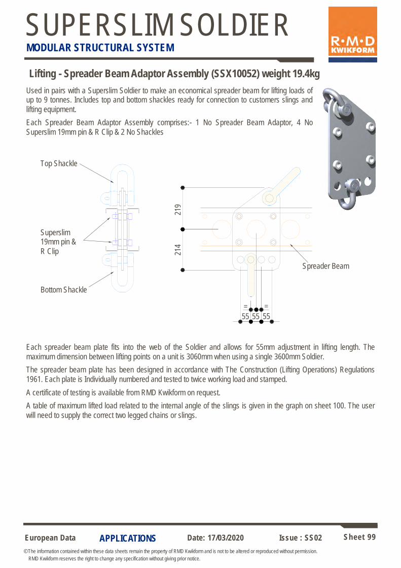
European Data Sheet 99
© The information contained within these data sheets remain the property of RMD Kwikform and is not to be altered or reproduced without permission.
RMD Kwikform reserves the right to change any specification without giving prior notice.
Date: 17/03/2020 Issue : SS02
SUPERSLIM SOLDIER MODULAR STRUCTURAL SYSTEM
APPLICATIONS
Top Shackle
Superslim 19mm pin &
R Clip
Bottom Shackle
55
Spreader Beam
214
219
55
Lifting - Spreader Beam Adaptor Assembly (SSX10052) weight 19.4kg
55
= =
Used in pairs with a Superslim Soldier to make an economical spreader beam for lifting loads of up to 9 tonnes. Includes top and bottom shackles ready for connection to customers slings and
lifting equipment.
Each Spreader Beam Adaptor Assembly comprises:- 1 No Spreader Beam Adaptor, 4 No
Superslim 19mm pin & R Clip & 2 No Shackles
Each spreader beam plate fits into the web of the Soldier and allows for 55mm adjustment in lifting length. The
maximum dimension between lifting points on a unit is 3060mm when using a single 3600mm Soldier.
The spreader beam plate has been designed in accordance with The Construction (Lifting Operations) Regulations
1961. Each plate is Individually numbered and tested to twice working load and stamped.
A certificate of testing is available from RMD Kwikform on request.
A table of maximum lifted load related to the internal angle of the slings is given in the graph on sheet 100. The user
will need to supply the correct two legged chains or slings.
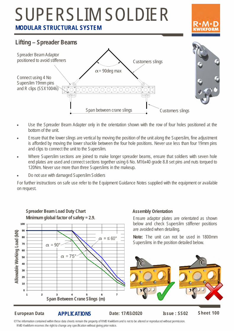
European Data Sheet 100
© The information contained within these data sheets remain the property of RMD Kwikform and is not to be altered or reproduced without permission.
RMD Kwikform reserves the right to change any specification without giving prior notice.
Date: 17/03/2020 Issue : SS02
SUPERSLIM SOLDIER MODULAR STRUCTURAL SYSTEM
APPLICATIONS
Lifting – Spreader Beams
0
10
20
30
40
50
60
70
80
90
100
1 2 3 4 5 6 7
Span Between Crane Slings (m)
Allo
wa
ble
Wo
rkin
g L
oa
d (
kN
)
Spreader Beam Load Duty Chart
Minimum global factor of safety = 2.9.
• Use the Spreader Beam Adapter only in the orientation shown with the row of four holes positioned at the
bottom of the unit.
• Ensure that the lower slings are vertical by moving the position of the unit along the Superslim, fine adjustment is afforded by moving the lower shackle between the four hole positions. Never use less than four 19mm pins
and clips to connect the unit to the Superslim.
• Where Superslim sections are joined to make longer spreader beams, ensure that soldiers with seven hole end plates are used and connect sections together using 6 No. M16x40 grade 8.8 set pins and nuts torqued to
120Nm. Never use more than three Superslims in the makeup.
• Do not use with damaged Superslim Soldiers
For further instructions on safe use refer to the Equipment Guidance Notes supplied with the equipment or available
on request.
α = 90°
α = 75°
α = ≤ 60°
α= 90deg max
Span between crane slings
Customers slings
Connect using 4 No Superslim 19mm pins
and R clips (SSX10046)
Customers slings
Assembly Orientation
Ensure adaptor plates are orientated as shown below and check Superslim stiffener positions
are avoided when detailing.
Note: The unit can not be used in 1800mm
Superslims in the position detailed below.
Spreader Beam Adaptor
positioned to avoid stiffeners
Span Between Crane Slings (m)
Allo
wab
le W
ork
ing
Lo
ad (
kN)
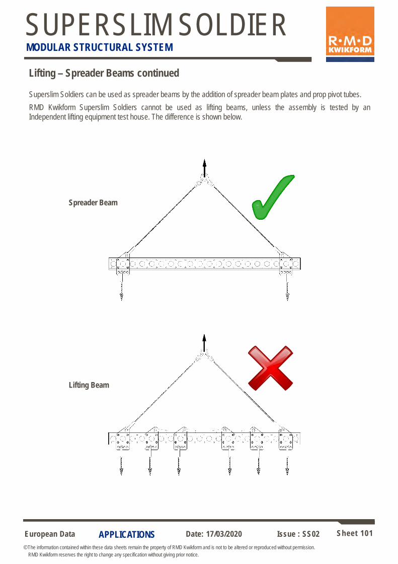
European Data Sheet 101
© The information contained within these data sheets remain the property of RMD Kwikform and is not to be altered or reproduced without permission.
RMD Kwikform reserves the right to change any specification without giving prior notice.
Date: 17/03/2020 Issue : SS02
SUPERSLIM SOLDIER MODULAR STRUCTURAL SYSTEM
APPLICATIONS
Lifting – Spreader Beams continued
Spreader Beam
Lifting Beam
Superslim Soldiers can be used as spreader beams by the addition of spreader beam plates and prop pivot tubes.
RMD Kwikform Superslim Soldiers cannot be used as lifting beams, unless the assembly is tested by an
Independent lifting equipment test house. The difference is shown below.

European Data Sheet 102
© The information contained within these data sheets remain the property of RMD Kwikform and is not to be altered or reproduced without permission.
RMD Kwikform reserves the right to change any specification without giving prior notice.
Date: 17/03/2020 Issue : SS02
SUPERSLIM SOLDIER MODULAR STRUCTURAL SYSTEM
CLIPS, CLAMPS & FASTENERS
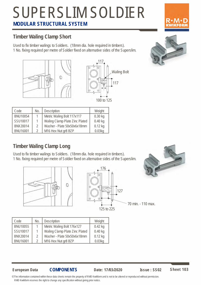
European Data Sheet 103
© The information contained within these data sheets remain the property of RMD Kwikform and is not to be altered or reproduced without permission.
RMD Kwikform reserves the right to change any specification without giving prior notice.
Date: 17/03/2020 Issue : SS02
SUPERSLIM SOLDIER MODULAR STRUCTURAL SYSTEM
COMPONENTS
100 to 125
117
Waling Bolt
117
176
70 min. - 110 max.
127
125 to 225
Timber Waling Clamp Short
Used to fix timber walings to Soldiers. (18mm dia. hole required in timbers).
1 No. fixing required per metre of Soldier fixed on alternative sides of the Superslim.
Timber Waling Clamp Long
Code Description Weight No.
BNU10054 Metric Waling Bolt 117x117 0.30 kg 1
SSU10017 Waling Clamp Plate Zinc Plated 0.40 kg 1
BNX20014 Washer - Plate 50x50x6x18mm 0.12 kg 2
BNU16001 M16 Hex Nut gr8 BZP 0.03kg 2
Used to fix timber walings to Soldiers. (18mm dia. hole required in timbers).
1 No. fixing required per metre of Soldier fixed on alternative sides of the Superslim.
Code Description Weight No.
BNU10055 Metric Waling Bolt 176x127 0.42 kg 1
SSU10017 Waling Clamp Plate Zinc Plated 0.40 kg 1
BNX20014 Washer - Plate 50x50x6x18mm 0.12 kg 2
BNU16001 M16 Hex Nut gr8 BZP 0.03kg 2

European Data Sheet 104
© The information contained within these data sheets remain the property of RMD Kwikform and is not to be altered or reproduced without permission.
RMD Kwikform reserves the right to change any specification without giving prior notice.
Date: 17/03/2020 Issue : SS02
SUPERSLIM SOLDIER MODULAR STRUCTURAL SYSTEM
COMPONENTS
M16 x 40 gr 8.8 CSK Set Pin
and M16 Nut
Half Coupler
Used in pairs to connect scaffold tubes to the end plates of Soldiers. e.g. to create
handrail posts etc.
Allowable Working Load per coupler 6.1kN slip along tube 10kN direct tension
10kN per coupler
6.1kN per coupler
194
60
A
‘A’ Allowable Working Load = 6.1kN
(slip of tube through coupler)
‘B’ Allowable Working Load = 4.0kN
(slip of coupler along soldier)
Note: Clamp is a swivel fitting.
B
Slimshor Tube Clamp (SSU10024) weight 1.33kg
Used to connect scaffold tube to Soldiers at any angle.
Code Description Weight
SFU10014 2” Half Coupler 18mm Dia Hole 0.51 kg
BNU16001 M16 Nut gr8 BZP 0.03 kg
BNU16008 M16x40 St Pin gr8.8 BZP CSK 0.05 kg
36

European Data Sheet 105
© The information contained within these data sheets remain the property of RMD Kwikform and is not to be altered or reproduced without permission.
RMD Kwikform reserves the right to change any specification without giving prior notice.
Date: 17/03/2020 Issue : SS02
SUPERSLIM SOLDIER MODULAR STRUCTURAL SYSTEM
COMPONENTS
119
220
150
75
100
‘B’ Clamp - Tube to Panel (RPX10005) weight 0.66kg
Used to connect scaffold tube to Soldiers at right angles.
When pairs of ‘B’ clamps are used on a tube to soldier connection an allowable working load of 3.25kN may be used in any direction.
‘G’ Clamp, Channel Washer and Bolt
Used to connect tube to Soldiers without projection above the top of the tube.
Allowable Working Load for the tube pulling out of the clamp is 20kN
Note! ‘G’ clamps should be slid along the tube to approx required location before the tube is attached to the formwork panel.
Code Description Weight
BNX16007 M16x220 Bolt gr8.8 BZP 0.38 kg
BNX20020 Washer - Channel 150x75 18mm 0.66 kg
RPX10008 ‘G’ Clamp - Tube Type M16 0.60 kg

European Data Sheet 106
© The information contained within these data sheets remain the property of RMD Kwikform and is not to be altered or reproduced without permission.
RMD Kwikform reserves the right to change any specification without giving prior notice.
Date: 17/03/2020 Issue : SS02
SUPERSLIM SOLDIER MODULAR STRUCTURAL SYSTEM
COMPONENTS
Used to connect Alform beams or Albeams to Soldiers. Clamp is available as
individual components or as an assembly.
Note: If connection is subject to vibration it is recommended to use a M12 Nyloc
Nut with the individual components.
Superslim Clamp Assembly (Sally Clamp)
Clamp Assembly - Superslim
AWL Slip along arrow A = 1.0kN
AWL Slip along arrow B = 0.75kN
AWL Tension along arrow C = 1.5kN
M12 Hex Nut
60
58
13 dia. hole
Unifix Bolt
19
A
Used to connect horizontal Soldiers to vertical Soldiers. Note: 2 No. clamped
connections required per intersection - diagonally opposed.
AWL 1.5kN per pair of connections in slip (when tightened with a hand tool)
Note - check soldier to soldier bearing is not exceeded (see sheet 12).
Waling Clamp Plate
25
1 No. connection comprises of:
C B
Code Description Weight
AFX20015 Superslim Clamp 0.16 kg
BNU12001 M12 Hex Nut gr8 BZP 0.01 kg
AFX20022 Bolt M12 Unifix 0.06 kg
AFX20012 Superslim Clamp Assembly 0.30 kg
Code Description Weight No.
SSU10017 Waling Clamp Plate Zinc Plated 0.40 kg 2
BNU16002 M16 Round Washer BZP 0.10 kg 2
BNU16013 M16x110 Bolt gr8.8 BZP 0.20 kg 1
BNU16001 M16 Hex Nut gr8 BZP 0.03kg 1

European Data Sheet 107
© The information contained within these data sheets remain the property of RMD Kwikform and is not to be altered or reproduced without permission.
RMD Kwikform reserves the right to change any specification without giving prior notice.
Date: 17/03/2020 Issue : SS02
SUPERSLIM SOLDIER MODULAR STRUCTURAL SYSTEM
COMPONENTS
Universal Clamp
(ALX10001) Stagger
Alternate Clamps
Universal Clamp (ALX10001) weight 0.75kg
A light duty clamp with many uses. Note: The clamp is to be fixed hand tight
plus 1/4 turn.
AWL Tension = 2.5kN per clamp
AWL Slip = 0.35kN per clamp
Flange to Flange Wedge Clamp (ALX10002) Weight 0.51kg
A wedge fixed clamp that enables aluminium beams to be clamped to Soldiers at
90 degrees in static soffit applications.
AWL Slip = 1kN per pair of clamps
Soldier
Alform
Alsec
T200

European Data Sheet 108
© The information contained within these data sheets remain the property of RMD Kwikform and is not to be altered or reproduced without permission.
RMD Kwikform reserves the right to change any specification without giving prior notice.
Date: 17/03/2020 Issue : SS02
SUPERSLIM SOLDIER MODULAR STRUCTURAL SYSTEM
COMPONENTS
GTX to Soldier Clamp Mk 1A (GTX10001) weight 0.80kg
Used to connect GTX beams to Superslims on wall formwork or crane handled soffit
schemes.
AWL Tension = 2.0kN
AWL Slip along GTX = 1.0kN
The Alshor Superslim Clamp is used to connect a Superslim primary beam to an Alshor U Head or Rapidshor U Head / U Plate. The item is supplied as an assembly and can not be
taken apart.
A single Alshor Superslim Clamp should be used in standard applications increasing to two
if high tension loads are expected during table lifting operations.
AWL using 1 no. clamp = 5.0kN
AWL using 2 no. clamps = 10.0kN
Alshor Superslim Clamp (ASX10056) weight 0.72kg
GTX to Soldier Connection
'U' Head Connection
S/Slim Primary Beam to
'U' Head Connection
S/Slim Primary Beam to
Alshor Superslim
Clamp (ASX10056)
1 No. Clamp Per Head Connection
Alternate on either side of U Head
'U' Head Connection
S/Slim Primary Beam to
'U' Head Connection
S/Slim Primary Beam to
Alshor Superslim
Clamp (ASX10056)
2 No. Clamps Per Head Connection
Alternate on either side of U Head
1 No. assembly allowed at every intersection, staggered either side of
Superslim Soldier
GTX to Soldier Clamp
Mk 1A (GTX10001)
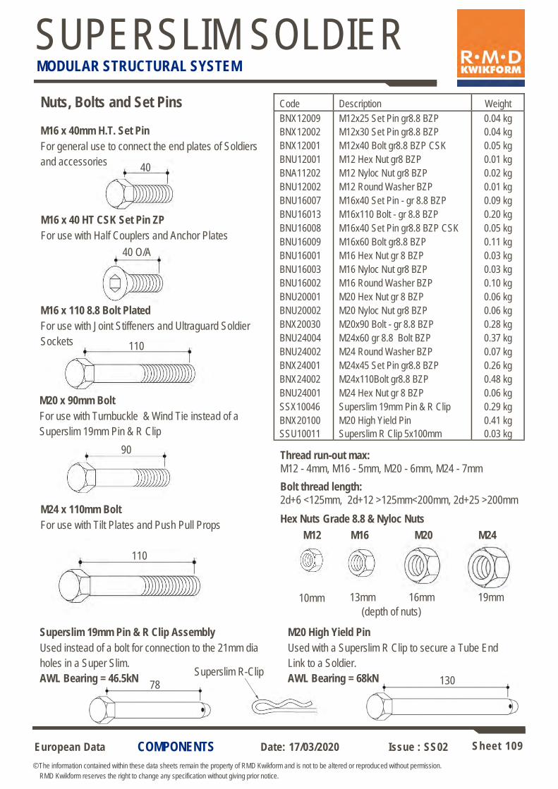
European Data Sheet 109
© The information contained within these data sheets remain the property of RMD Kwikform and is not to be altered or reproduced without permission.
RMD Kwikform reserves the right to change any specification without giving prior notice.
Date: 17/03/2020 Issue : SS02
SUPERSLIM SOLDIER MODULAR STRUCTURAL SYSTEM
COMPONENTS
Nuts, Bolts and Set Pins
M16 x 40mm H.T. Set Pin
For general use to connect the end plates of Soldiers
and accessories
M16 x 110 8.8 Bolt Plated
For use with Joint Stiffeners and Ultraguard Soldier
Sockets
M16 x 40 HT CSK Set Pin ZP
For use with Half Couplers and Anchor Plates
Hex Nuts Grade 8.8 & Nyloc Nuts
M20 x 90mm Bolt
For use with Turnbuckle & Wind Tie instead of a
Superslim 19mm Pin & R Clip
M24 M20 M16
40
110
90
78
Code Description Weight
BNX12009 M12x25 Set Pin gr8.8 BZP 0.04 kg
BNX12002 M12x30 Set Pin gr8.8 BZP 0.04 kg
BNX12001 M12x40 Bolt gr8.8 BZP CSK 0.05 kg
BNU12001 M12 Hex Nut gr8 BZP 0.01 kg
BNA11202 M12 Nyloc Nut gr8 BZP 0.02 kg
BNU12002 M12 Round Washer BZP 0.01 kg
BNU16007 M16x40 Set Pin - gr 8.8 BZP 0.09 kg
BNU16013 M16x110 Bolt - gr 8.8 BZP 0.20 kg
BNU16008 M16x40 Set Pin gr8.8 BZP CSK 0.05 kg
BNU16009 M16x60 Bolt gr8.8 BZP 0.11 kg
BNU16001 M16 Hex Nut gr 8 BZP 0.03 kg
BNU16003 M16 Nyloc Nut gr8 BZP 0.03 kg
BNU16002 M16 Round Washer BZP 0.10 kg
BNU20001 M20 Hex Nut gr 8 BZP 0.06 kg
BNU20002 M20 Nyloc Nut gr8 BZP 0.06 kg
BNX20030 M20x90 Bolt - gr 8.8 BZP 0.28 kg
BNU24004 M24x60 gr 8.8 Bolt BZP 0.37 kg
BNU24002 M24 Round Washer BZP 0.07 kg
BNX24001 M24x45 Set Pin gr8.8 BZP 0.26 kg
BNX24002 M24x110Bolt gr8.8 BZP 0.48 kg
BNU24001 M24 Hex Nut gr 8 BZP 0.06 kg
SSX10046 Superslim 19mm Pin & R Clip 0.29 kg
BNX20100 M20 High Yield Pin 0.41 kg
SSU10011 Superslim R Clip 5x100mm 0.03 kg
40 O/A
Superslim 19mm Pin & R Clip Assembly
Used instead of a bolt for connection to the 21mm dia
holes in a Super Slim.
AWL Bearing = 46.5kN
M24 x 110mm Bolt
For use with Tilt Plates and Push Pull Props
110
M12
10mm 13mm 16mm 19mm
(depth of nuts)
Thread run-out max:
M12 - 4mm, M16 - 5mm, M20 - 6mm, M24 - 7mm
Bolt thread length:
2d+6 <125mm, 2d+12 >125mm<200mm, 2d+25 >200mm
Superslim R-Clip 130
M20 High Yield Pin
Used with a Superslim R Clip to secure a Tube End
Link to a Soldier.
AWL Bearing = 68kN
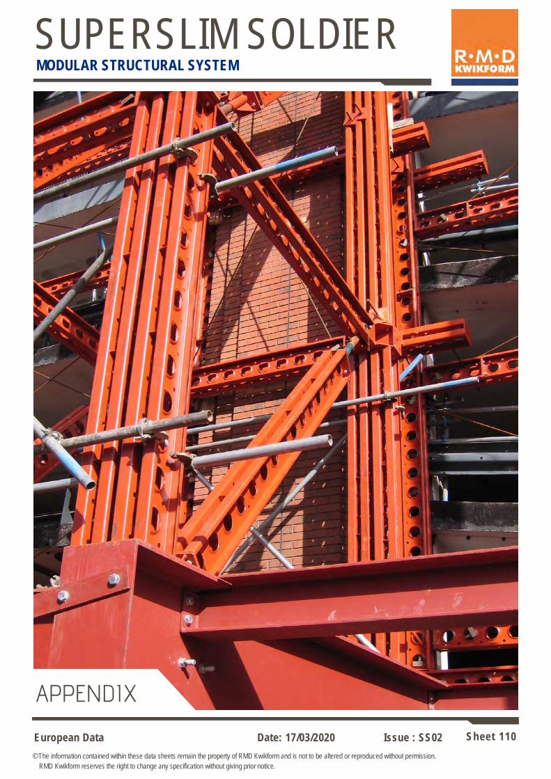
European Data Sheet 110
© The information contained within these data sheets remain the property of RMD Kwikform and is not to be altered or reproduced without permission.
RMD Kwikform reserves the right to change any specification without giving prior notice.
Date: 17/03/2020 Issue : SS02
SUPERSLIM SOLDIER MODULAR STRUCTURAL SYSTEM
APPENDIX
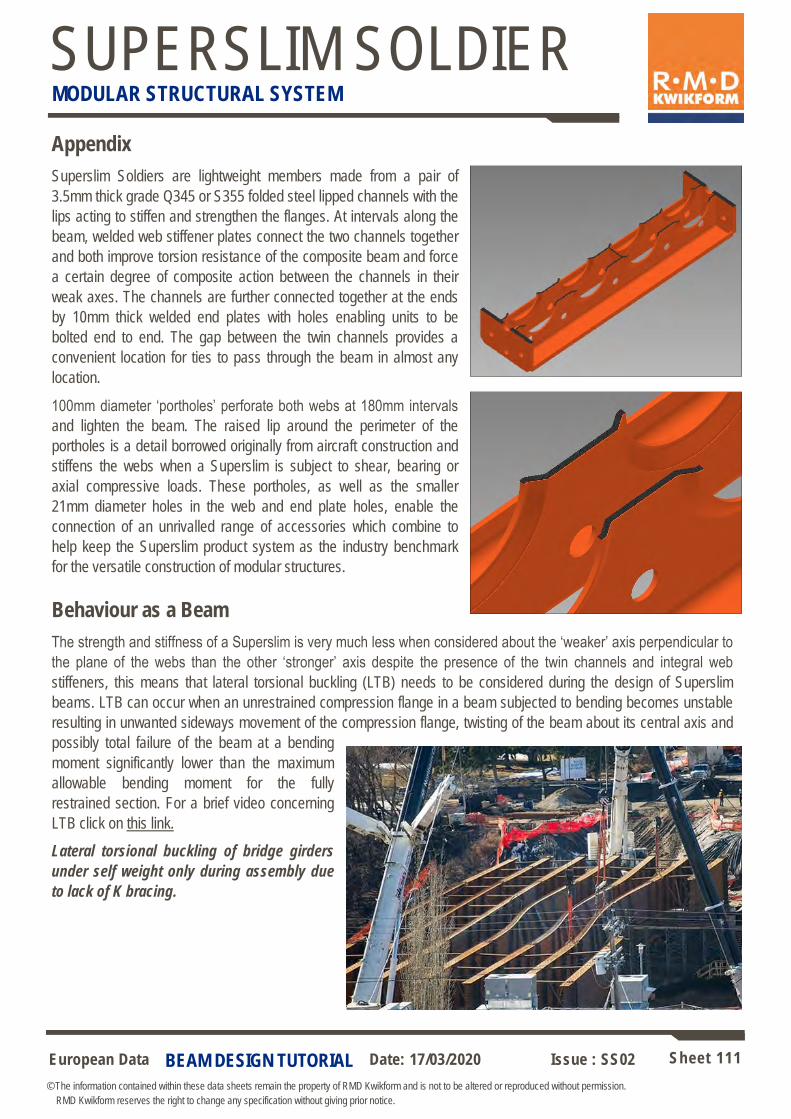
European Data Sheet 111
© The information contained within these data sheets remain the property of RMD Kwikform and is not to be altered or reproduced without permission.
RMD Kwikform reserves the right to change any specification without giving prior notice.
Date: 17/03/2020 Issue : SS02
SUPERSLIM SOLDIER MODULAR STRUCTURAL SYSTEM
BEAM DESIGN TUTORIAL
Appendix
Superslim Soldiers are lightweight members made from a pair of
3.5mm thick grade Q345 or S355 folded steel lipped channels with the
lips acting to stiffen and strengthen the flanges. At intervals along the
beam, welded web stiffener plates connect the two channels together
and both improve torsion resistance of the composite beam and force
a certain degree of composite action between the channels in their
weak axes. The channels are further connected together at the ends
by 10mm thick welded end plates with holes enabling units to be
bolted end to end. The gap between the twin channels provides a
convenient location for ties to pass through the beam in almost any
location.
100mm diameter ‘portholes’ perforate both webs at 180mm intervals
and lighten the beam. The raised lip around the perimeter of the
portholes is a detail borrowed originally from aircraft construction and
stiffens the webs when a Superslim is subject to shear, bearing or
axial compressive loads. These portholes, as well as the smaller
21mm diameter holes in the web and end plate holes, enable the
connection of an unrivalled range of accessories which combine to
help keep the Superslim product system as the industry benchmark
for the versatile construction of modular structures.
Behaviour as a Beam
The strength and stiffness of a Superslim is very much less when considered about the ‘weaker’ axis perpendicular to
the plane of the webs than the other ‘stronger’ axis despite the presence of the twin channels and integral web
stiffeners, this means that lateral torsional buckling (LTB) needs to be considered during the design of Superslim
beams. LTB can occur when an unrestrained compression flange in a beam subjected to bending becomes unstable
resulting in unwanted sideways movement of the compression flange, twisting of the beam about its central axis and
possibly total failure of the beam at a bending
moment significantly lower than the maximum
allowable bending moment for the fully
restrained section. For a brief video concerning
LTB click on this link.
Lateral torsional buckling of bridge girders
under self weight only during assembly due
to lack of K bracing.
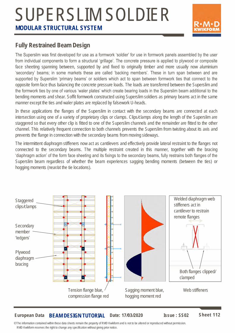
European Data Sheet 112
© The information contained within these data sheets remain the property of RMD Kwikform and is not to be altered or reproduced without permission.
RMD Kwikform reserves the right to change any specification without giving prior notice.
Date: 17/03/2020 Issue : SS02
SUPERSLIM SOLDIER MODULAR STRUCTURAL SYSTEM
BEAM DESIGN TUTORIAL
Fully Restrained Beam Design
The Superslim was first developed for use as a formwork ‘soldier’ for use in formwork panels assembled by the user
from individual components to form a structural ‘grillage’. The concrete pressure is applied to plywood or composite
face sheeting spanning between, supported by and fixed to originally timber and more usually now aluminium
‘secondary’ beams; in some markets these are called ‘backing members’. These in turn span between and are
supported by Superslim ‘primary beams’ or soldiers which act to span between formwork ties that connect to the
opposite form face thus balancing the concrete pressure loads. The loads are transferred between the Superslim and
the formwork ties by one of various ‘waler plates’ which create bearing loads in the Superslim beam additional to the
bending moments and shear. Soffit formwork constructed using Superslim soldiers as primary beams act in the same
manner except the ties and waler plates are replaced by falsework U-heads.
In these applications the flanges of the Superslim in contact with the secondary beams are connected at each
intersection using one of a variety of proprietary clips or clamps. Clips/clamps along the length of the Superslim are
staggered so that every other clip is fitted to one of the Superslim channels and the remainder are fitted to the other
channel. This relatively frequent connection to both channels prevents the Superslim from twisting about its axis and
prevents the flange in connection with the secondary beams from moving sideways.
The intermittent diaphragm stiffeners now act as cantilevers and effectively provide lateral restraint to the flanges not
connected to the secondary beams. The multiple restraint created in this manner, together with the bracing
‘diaphragm action’ of the form face sheeting and its fixings to the secondary beams, fully restrains both flanges of the
Superslim beam regardless of whether the beam experiences sagging bending moments (between the ties) or
hogging moments (near/at the tie locations).
Staggered
clips/clamps
Secondary
member
‘ledgers’
Plywood
diaphragm
bracing
Tension flange blue,
compression flange red
Sagging moment blue,
hogging moment red
Welded diaphragm web
stiffeners act in
cantilever to restrain
remote flanges
Both flanges clipped/
clamped
Web stiffeners
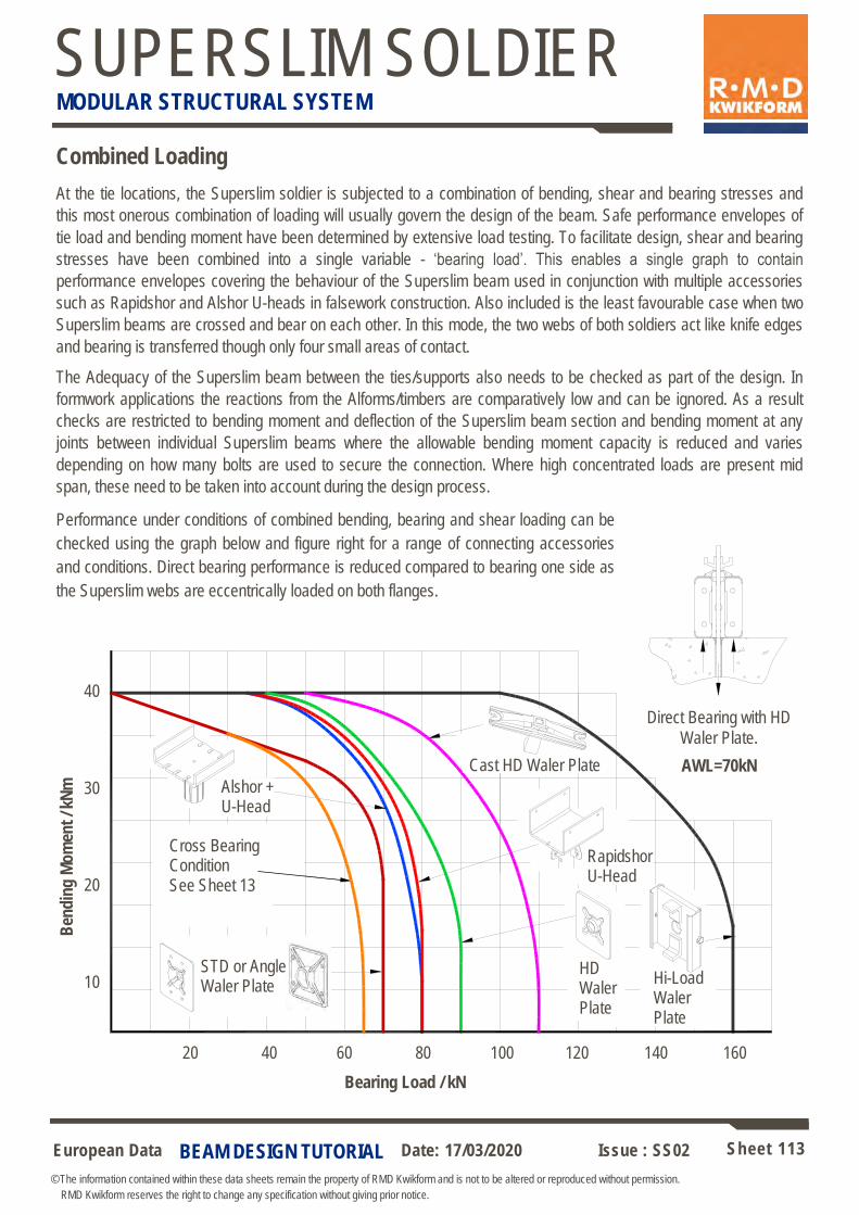
European Data Sheet 113
© The information contained within these data sheets remain the property of RMD Kwikform and is not to be altered or reproduced without permission.
RMD Kwikform reserves the right to change any specification without giving prior notice.
Date: 17/03/2020 Issue : SS02
SUPERSLIM SOLDIER MODULAR STRUCTURAL SYSTEM
BEAM DESIGN TUTORIAL
Combined Loading
At the tie locations, the Superslim soldier is subjected to a combination of bending, shear and bearing stresses and
this most onerous combination of loading will usually govern the design of the beam. Safe performance envelopes of
tie load and bending moment have been determined by extensive load testing. To facilitate design, shear and bearing
stresses have been combined into a single variable - ‘bearing load’. This enables a single graph to contain
performance envelopes covering the behaviour of the Superslim beam used in conjunction with multiple accessories
such as Rapidshor and Alshor U-heads in falsework construction. Also included is the least favourable case when two
Superslim beams are crossed and bear on each other. In this mode, the two webs of both soldiers act like knife edges
and bearing is transferred though only four small areas of contact.
The Adequacy of the Superslim beam between the ties/supports also needs to be checked as part of the design. In
formwork applications the reactions from the Alforms/timbers are comparatively low and can be ignored. As a result
checks are restricted to bending moment and deflection of the Superslim beam section and bending moment at any
joints between individual Superslim beams where the allowable bending moment capacity is reduced and varies
depending on how many bolts are used to secure the connection. Where high concentrated loads are present mid
span, these need to be taken into account during the design process.
Performance under conditions of combined bending, bearing and shear loading can be
checked using the graph below and figure right for a range of connecting accessories
and conditions. Direct bearing performance is reduced compared to bearing one side as
the Superslim webs are eccentrically loaded on both flanges.
B
end
ing
Mo
men
t / k
Nm
Bearing Load / kN
Direct Bearing with HD
Waler Plate.
AWL=70kN
40
30
20
10
Alshor + U-Head
Cross Bearing Condition See Sheet 13
20 40 60 80 100 120 140 160
Rapidshor U-Head
Hi-Load Waler Plate
HD Waler Plate
Cast HD Waler Plate
STD or Angle Waler Plate
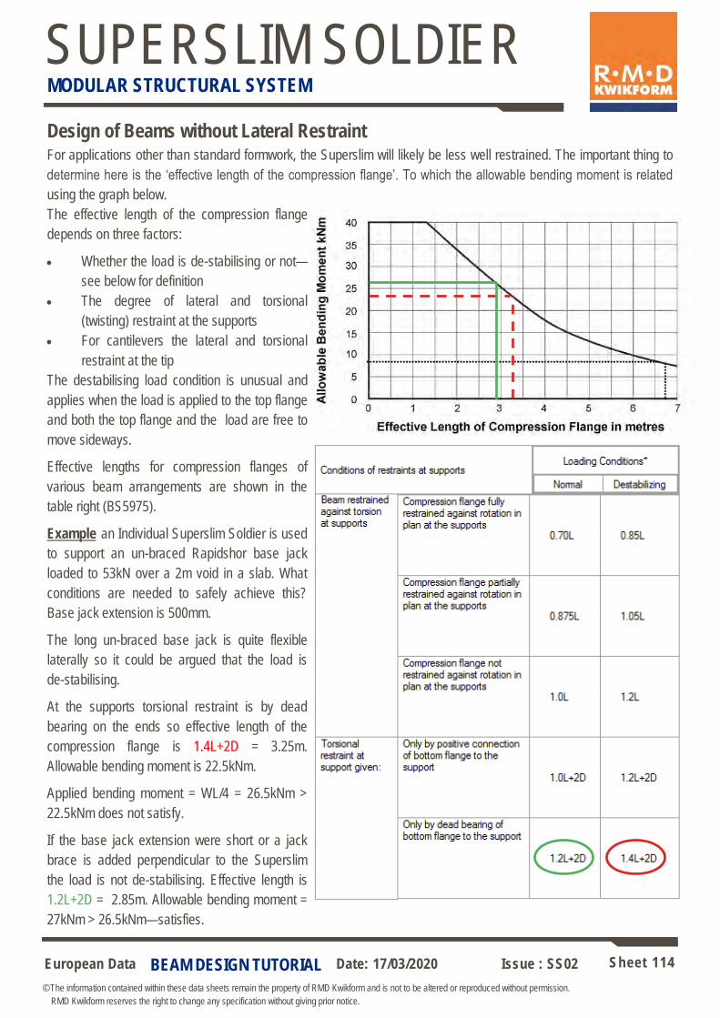
European Data Sheet 114
© The information contained within these data sheets remain the property of RMD Kwikform and is not to be altered or reproduced without permission.
RMD Kwikform reserves the right to change any specification without giving prior notice.
Date: 17/03/2020 Issue : SS02
SUPERSLIM SOLDIER MODULAR STRUCTURAL SYSTEM
Design of Beams without Lateral Restraint For applications other than standard formwork, the Superslim will likely be less well restrained. The important thing to
determine here is the ‘effective length of the compression flange’. To which the allowable bending moment is related
using the graph below.
The effective length of the compression flange
depends on three factors:
• Whether the load is de-stabilising or not—
see below for definition
• The degree of lateral and torsional
(twisting) restraint at the supports
• For cantilevers the lateral and torsional
restraint at the tip
The destabilising load condition is unusual and
applies when the load is applied to the top flange
and both the top flange and the load are free to
move sideways.
Effective lengths for compression flanges of
various beam arrangements are shown in the
table right (BS5975).
Example an Individual Superslim Soldier is used
to support an un-braced Rapidshor base jack
loaded to 53kN over a 2m void in a slab. What
conditions are needed to safely achieve this?
Base jack extension is 500mm.
The long un-braced base jack is quite flexible
laterally so it could be argued that the load is
de-stabilising.
At the supports torsional restraint is by dead
bearing on the ends so effective length of the
compression flange is 1.4L+2D = 3.25m.
Allowable bending moment is 22.5kNm.
Applied bending moment = WL/4 = 26.5kNm >
22.5kNm does not satisfy.
If the base jack extension were short or a jack
brace is added perpendicular to the Superslim
the load is not de-stabilising. Effective length is
1.2L+2D = 2.85m. Allowable bending moment =
27kNm > 26.5kNm—satisfies.
BEAM DESIGN TUTORIAL
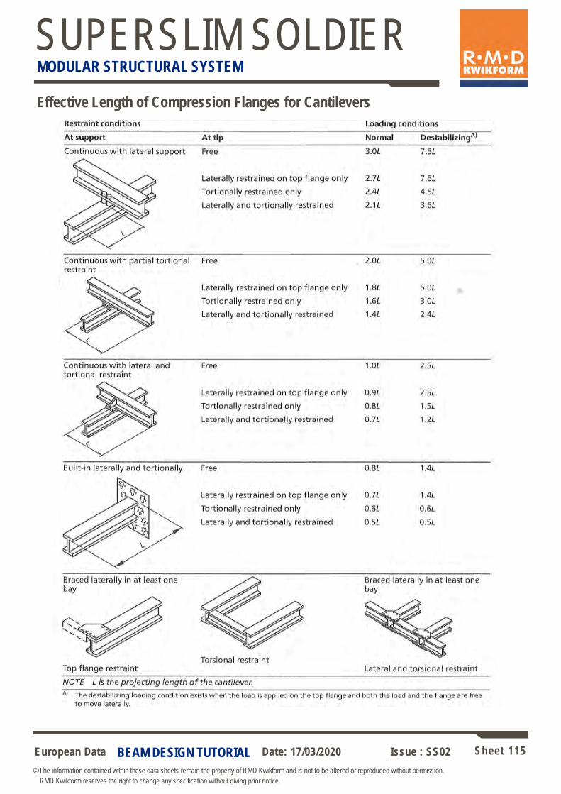
European Data Sheet 115
© The information contained within these data sheets remain the property of RMD Kwikform and is not to be altered or reproduced without permission.
RMD Kwikform reserves the right to change any specification without giving prior notice.
Date: 17/03/2020 Issue : SS02
SUPERSLIM SOLDIER MODULAR STRUCTURAL SYSTEM
BEAM DESIGN TUTORIAL
Effective Length of Compression Flanges for Cantilevers
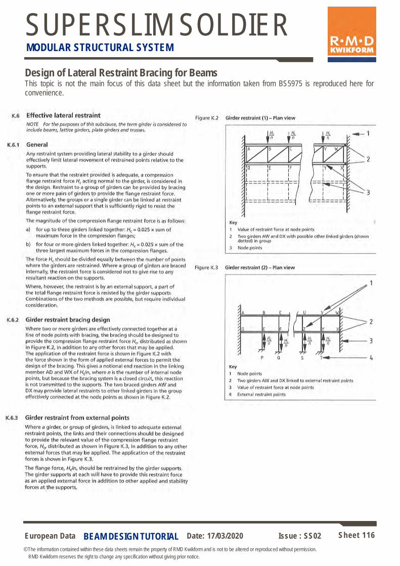
European Data Sheet 116
© The information contained within these data sheets remain the property of RMD Kwikform and is not to be altered or reproduced without permission.
RMD Kwikform reserves the right to change any specification without giving prior notice.
Date: 17/03/2020 Issue : SS02
SUPERSLIM SOLDIER MODULAR STRUCTURAL SYSTEM
BEAM DESIGN TUTORIAL
Design of Lateral Restraint Bracing for Beams This topic is not the main focus of this data sheet but the information taken from BS5975 is reproduced here for convenience.

European Data Sheet 117
© The information contained within these data sheets remain the property of RMD Kwikform and is not to be altered or reproduced without permission.
RMD Kwikform reserves the right to change any specification without giving prior notice.
Date: 17/03/2020 Issue : SS02
SUPERSLIM SOLDIER MODULAR STRUCTURAL SYSTEM
Contact Details: International Offices
Europe
Head Office – United Kingdom
RMD Kwikform, Brickyard Road,
Aldridge, Walsall WS9 8BW, UK.
Tel: +44 1922 743743
Email: [email protected]
Ireland
RMD Kwikform,
Ballyboggan Road,
Finglas, Dublin 11, Ireland.
Tel: +353 1 830 2500
Email: [email protected]
South America
Chile
RMD Kwikform,
La Estera 811,
Parque Industrial Ville Grande,
Lampa, Santiago, Chile.
Tel: +56 2 747 1414
Email: [email protected]
America
USA
9351 Grant Street,
Suite 200,
Thornton, Colorado, 80229
Tel: +1 303 252 7000
Email: [email protected]
South Africa
RMD Kwikform South Africa (Pty) Ltd
26 Venturi Crescent, Hennopspark X5,
Pretoria, South Africa
Tel: +27 (0)12 681 0360
Email: [email protected]
Asia Pacific
Australia
RMD (Australia) Pty. Ltd.
PO Box 169, Melrose Park,
South Australia, 5039.
Tel: +61 8 8179 8200
Email: [email protected]
Hong Kong
RMD Kwikform,
22/F Excel Center,
483A Castle Peak Road,
Cheung Sha Wan, Kowloon, Hong Kong.
Tel: +852 2415 4882
Email: [email protected]
New Zealand
RMD (New Zealand) Ltd.
PO Box 22-316, 101-105 Station Road,
Otahuhu, Auckland 6, New Zealand.
Tel: +64 9 276 5955
Email: [email protected]
Philippines
RMD Kwikform,
Units 2406-2409,
Raffles Corporate Center,
F. Ortigas Jr. Road,
Ortigas Center,
Pasig City,
Philippines.
Tel: +632 696 7635
Email: [email protected]
Guam
RMD Kwikform.
321 East Harmon Industrial Park Road,
Unit F, Tamuning, Guam.
Tel: +671 647 7635
Email: [email protected]
Middle East
UAE
RMD Kwikform,
PO Box 5801, Sharjah,
United Arab Emirates.
Tel: +971 6 5534173
Email: [email protected]
Qatar
RMD Kwikform,
PO Box 405, Doha, Qatar.
Tel: +974 467 5925
Email: [email protected]
Bahrain
RMD Kwikform,
C/O CGH ,
Building 829, Flat 11,
Block 408, Sanabis,
Kingdom of Bahrain.
Tel: +973 1738 2724
Email: [email protected]
Oman
RMD Kwikform Oman LLC
PO Box 889
Post Code 115
Muscat
Sultanate of Oman
Tel: +968 2463 6776
Email: [email protected]
India
RMD Kwikform,
No.28/2, 1st Floor, AMG Towers,
Lawyer Jagannathan Street, G.S.T. Road,
Alandhur, Chennai—60016, Tamil Nadu, India
Tel: +91 44 4915 3333
Email: [email protected]
Saudi Arabia
PO Box 921, Entrance 1, North 2nd Floor, Room 4A
Gulf Star Building, Prince Turki Abdulaziz Street,
Comiche, Al Khobar 31952, Kingdom of Saudi Arabia
Tel: +966 13 896 8665
Email: [email protected]


