Embed Size (px)
Citation preview

Synplify ®
Synplify Reference Manual
April 2002
Synplicity, Inc.935 Stewart Drive
Sunnyvale, CA 94085, USA(U.S.) +1 408 215-6000 direct
(U.S.) +1 408 990-0290 faxwww.synplicity.com

LO
Preface
ii Synplify Reference Manual, April 2002
Preface
Disclaimer of WarrantySynplicity, Inc. makes no representations or warranties, either expressed or implied, by or with respect to anything in this manual, and shall not be liable for any implied warranties of merchantability or fitness for a partic-ular purpose of for any indirect, special or consequential damages.
Copyright NoticeCopyright © 1994-2002 Synplicity, Inc. All Rights Reserved.
Synplicity software products contain certain confidential information of Synplicity, Inc. Use of this copyright notice is precautionary and does not imply publication or disclosure. No part of this publication may be repro-duced, transmitted, transcribed, stored in a retrieval system, or trans-lated into any language in any form by any means without the prior written permission of Synplicity, Inc. While every precaution has been taken in the preparation of this book, Synplicity, Inc. assumes no respon-sibility for errors or omissions. This publication and the features described herein are subject to change without notice.
TrademarksSynplicity, the Synplicity “S” logo, Synplify, Amplify, Certify, Behavior Extracting Synthesis Technology, Embedded Synthesis, HDL Analyst, SCOPE, Simply Better Results, Simply Better Synthesis, and Synthesis Constraints Optimization Environment are registered trademarks, and B.E.S.T., DST, Direct Synthesis Technology, Partition-Driven Synthesis, Physical Optimizer, Total Optimization Physical Synthesis, and TOPS are trademarks of Synplicity, Inc. Verilog is a registered trademark of Cadence Design Systems, Inc. IBM and PC are registered trademarks of International Business Machines Corporation. Microsoft is a registered trademark of Microsoft Corporation. Sun, SPARC, Solaris, and SunOS are trademarks of Sun Microsystems, Inc. Synopsys is a registered trademark of Synopsys, Inc. UNIX is a registered trademark of UNIX Systems Laboratories, Inc. Innoveda and Visual Elite are trademarks of Innoveda, Inc.

Preface
Synplify Reference Manual, April 2002 iii
All other product names mentioned herein are the trademarks or regis-tered trademarks of their respective owners.
Synplicity products are protected under U.S. Patent No. 6,182,268.
Restricted Rights LegendGovernment Users: Use, reproduction, release, modification, or disclosure of this commercial computer software, or of any related documentation of any kind, is restricted in accordance with FAR 12.212 and DFARS 227.7202, and further restricted by the Synplicity Software License Agree-ment. Synplicity, Inc., 935 Stewart Drive, Sunnyvale, CA 94085, U.S.A
Printed in the U.S.AApril 2002

LO
Preface
iv Synplify Reference Manual, April 2002
Synplicity Software License Agreement
Important! READ CAREFULLY BEFORE PROCEEDING
This is a legal agreement between you, the user ("Licensee") and Synplicity, Inc. ("Synplicity") regarding the software program that is attached to or enclosed with this software license agreement, or that is the subject of this documentation (the "SOFTWARE"). The term "SOFTWARE" also includes related documentation (whether in print or electronic form) and, if Licensee is obtaining an update, any pre-existing software and data provided within earlier software releases (to the extent such earlier software and data is retained by, embodied in or in any way used or accessed by the upgraded SOFTWARE provided with this Agreement). If Licensee is a participant in the University Program or has been granted an Evaluation License, then some of the following terms and conditions may not apply (refer to the sections entitled, respectively, Evaluation License and University Program, below).
By opening the packaging of the SOFTWARE, or by installing or using the SOFTWARE, Licensee agrees to be bound by the terms of this Software License Agreement (the "Agreement"). If Licensee does not agree to the terms of this Agreement, then do not install the SOFTWARE and return the copy of the SOFTWARE to the place from which you obtained it.
Evaluation License. The following applies, in addition to the other terms and conditions and as a limit on the license, if Licensee has obtained an Evaluation License. If Licensee has obtained the SOFTWARE pursuant to an evaluation license, then the following additional terms, conditions, and restrictions apply: (a) The license to the SOFTWARE terminates after 20 days (unless otherwise agreed to in writing by Synplicity); and (b) Lic-ensee may use the SOFTWARE only for the sole purpose of tests and other evaluation to determine whether Licensee wishes to license the SOFTWARE on a commercial basis. Licensee shall not use the SOFTWARE to design any integrated circuits for production or pre-production purposes or any other commercial use includ-ing, but not limited to, for the benefit of Licensee's customers. If Licensee breaches any of the foregoing restrictions, then Licensee shall pay to Synplicity a license fee equal to Synplicity's standard license fee for the commercial version of the SOFTWARE.
License. Synplicity grants to Licensee a non-exclusive right to install the SOFTWARE and to use or authorize use of the SOFTWARE by up to the number of nodes for which Licensee has a license and for which Licensee has the security key(s) or authorization code(s) provided by Synplicity or its agents. All SOFTWARE must be used within the country for which the systems were licensed and at Licensee's site (contained within a one kilometer radius); however, remote use is permitted by employees who work at the site but are temporarily telecommuting to that same site from less than 50 miles away (for example, an employee who works at a home office on occasion). In addition, Synplicity grants to Licensee a non-exclusive license to copy and distribute internally the documentation portion of the SOFTWARE in support of its license to use the program portion of the SOFTWARE.
Copy Restrictions. This SOFTWARE is protected by United States copyright laws and international treaty provisions and copying not in accordance with this Agreement is forbidden. Licensee may copy the SOFT-WARE only as follows: (i) to directly support authorized use under the license and (ii) in order to make a copy of the SOFTWARE for backup purposes. Copies must include all copyright and trademark notices.

Preface
Synplify Reference Manual, April 2002 v
Use Restrictions. This SOFTWARE is licensed to Licensee for internal use only. Licensee shall not (and shall not allow any third party to): (i) decompile, disassemble, reverse engineer or attempt to reconstruct, identify or discover any source code, underlying ideas, underlying user interface techniques or algorithms of the SOFT-WARE by any means whatever, or disclose any of the foregoing; (ii) provide, lease, lend, or use the SOFT-WARE for timesharing or service bureau purposes, on an application service provider basis, or otherwise circumvent the internal use restrictions; (iii) modify, incorporate into or with other software, or create a deriva-tive work of any part of the SOFTWARE; (iv) disclose the results of any benchmarking of the SOFTWARE, or use such results for its own competing software development activities, without the prior written permission of Synplicity; or (v) attempt to circumvent any user limits, maximum gate count limits or other license, timing or use restrictions that are built into the SOFTWARE.
Transfer Restrictions. Licensee shall not sublicense, transfer or assign this Agreement or any of the rights or licenses granted under this Agreement, except in the case of a merger or sale of all or substantially all of Lic-ensee’s assets. Permitted transfers, sublicenses or assignments under this Section continue to be subject to the rules regarding Export of the SOFTWARE.
Ownership of the SOFTWARE. Synplicity retains all right, title, and interest in the SOFTWARE (including all copies), and reserves all rights not expressly granted to Licensee. This License is not a sale of the original SOFTWARE or of any copy.
Ownership of Design Techniques. "Design" means the representation of an electronic circuit or device(s), derived or created by Licensee through the use of the SOFTWARE in its various formats, including, but not limited to, equations, truth tables, schematic diagrams, textual descriptions, hardware description languages, and netlists. "Design Techniques" means the Synplicity-supplied data, circuit and logic elements, libraries, algorithms, search strategies, rule bases, and technical information incorporated in the SOFTWARE and employed in the process of creating Designs. Synplicity retains all right, title and interest in and to Design Techniques incorporated into the SOFTWARE, including all intellectual property rights embodied therein. Lic-ensee acknowledges that Synplicity is in the business of licensing SOFTWARE which incorporates Design Techniques. Licensee agrees that in the event Licensee voluntarily discloses any design techniques to Synplic-ity without designating such as Licensee's Confidential Information, Synplicity has an unrestricted, royalty-free right to incorporate those Design Techniques into its software, documentation and other products, and to sublicense third parties to use those incorporated design techniques.
Protection of Confidential Information. "Confidential Information" means (i) the source code of the SOFT-WARE, and any included trade secrets (including any technology, idea, algorithm or information contained in the SOFTWARE, and specifically including Design Techniques); (ii) either party's product plans, designs, costs, prices and names; non-published financial information; marketing plans; business opportunities; person-nel; research; development or know-how; (iii) any information designated by the disclosing party as confiden-tial in writing or, if disclosed orally, designated as confidential at the time of disclosure and reduced to writing and given to the receiving party and designated as confidential in writing within 30 days; and (iv) the terms and conditions of this Agreement; provided, however that "Confidential Information" will not include information that: (a) is or becomes generally known or available by publication, commercial use or otherwise through no fault of the receiving party; (b) is known and has been reduced to tangible form by the receiving party at the time of disclosure and is not subject to restriction; (c) is independently developed by the receiving party with-out use of the disclosing party's Confidential Information; (d) is lawfully obtained from a third party who has the right to make such disclosure; or (e) is released for publication by the disclosing party in writing.
Each party will protect the other's Confidential Information from unauthorized dissemination and use with the

LO
Preface
vi Synplify Reference Manual, April 2002
same degree of care that each such party uses to protect its own like information. Neither party will use the other's Confidential Information for purposes other than those necessary to directly further the purposes of this Agreement. Neither party will disclose to third parties the other's Confidential Information without the prior written consent of the other party.
Termination. Synplicity may terminate this Agreement in the event of breach or default by Licensee. Upon termination Licensee will relinquish all rights under this Agreement, and must cease using the SOFTWARE and return or destroy all copies (and partial copies) of the SOFTWARE and documentation.
Export. Licensee warrants that it is not prohibited from receiving the SOFTWARE under U.S. export laws; that it is not a national of a country subject to trade sanctions; that it will not use the SOFTWARE in a location that is the subject of U.S. trade sanctions that would cover the SOFTWARE and that to its knowledge it is not on the U.S. Department of Commerce, Bureau of Export Administration’s Entity List or otherwise prohibited from obtaining goods of this sort from the United States. Licensee shall not allow the Synplicity SOFTWARE to be sent or used in any country except in compliance with applicable U. S. laws and regulations.
Limited Warranty and Disclaimer. Synplicity warrants that the program portion of the SOFTWARE will per-form substantially in accordance with the accompanying documentation for a period of 90 days from the date of receipt. Synplicity's entire liability and Licensee's exclusive remedy for a breach of the preceding limited warranties shall be, at Synplicity's option, either (a) return of the license fee, or (b) providing a fix, patch, work-around, or replacement of the SOFTWARE that does not meet such limited warranty. In either case, Lic-ensee must return the SOFTWARE to Synplicity with a copy of the purchase receipt or similar document. Replacements are warranted for the remainder of the original warranty period or 30 days, whichever is longer. Some states/jurisdictions do not allow limitations on duration of an implied warranty, so the above limitation may not apply. EXCEPT AS EXPRESSLY SET FORTH ABOVE, NO OTHER WARRANTIES OR CONDI-TIONS, EITHER EXPRESS OR IMPLIED, ARE MADE BY SYNPLICITY WITH RESPECT TO THE SOFT-WARE AND THE ACCOMPANYING DOCUMENTATION (STATUTORY OR OTHERWISE), AND SYNPLICITY EXPRESSLY DISCLAIMS ALL WARRANTIES AND CONDITIONS NOT EXPRESSLY STATED HEREIN, INCLUDING BUT NOT LIMITED TO THE IMPLIED WARRANTIES OR CONDITIONS OF MERCHANTABILITY, NONINFRINGEMENT, AND FITNESS FOR A PARTICULAR PURPOSE. SYNPLIC-ITY DOES NOT WARRANT THAT THE FUNCTIONS CONTAINED IN THE SOFTWARE WILL MEET LIC-ENSEE'S REQUIREMENTS, BE UNINTERRUPTED OR ERROR FREE, OR THAT ALL DEFECTS IN THE PROGRAM WILL BE CORRECTED. Licensee assumes the entire risk as to the results and performance of the SOFTWARE. Some states/jurisdictions do not allow the exclusion of implied warranties, so the above exclu-sion may not apply.
Limitation of Liability. IN NO EVENT SHALL SYNPLICITY OR ITS AGENTS BE LIABLE FOR ANY INDI-RECT, SPECIAL, CONSEQUENTIAL OR INCIDENTAL DAMAGES WHATSOEVER (INCLUDING, WITH-OUT LIMITATION, DAMAGES FOR LOSS OF BUSINESS PROFITS, BUSINESS INTERRUPTIONS, LOSS OF BUSINESS INFORMATION, OR OTHER PECUNIARY LOSS) ARISING OUT OF THE USE OF OR INABIL-ITY TO USE THESE SYNPLICITY PRODUCTS, EVEN IF SYNPLICITY HAS BEEN ADVISED OF THE POS-SIBILITY OF SUCH DAMAGES. In no event will Synplicity be liable to Licensee for damages in an amount greater than the fees paid for the use of the SOFTWARE. Some states/jurisdictions do not allow the limitation or exclusion of incidental or consequential damages, so the above limitations or exclusions may not apply.

Preface
Synplify Reference Manual, April 2002 vii
Intellectual Property Right Infringement. If a claim alleging infringement of an intellectual property right arises concerning the SOFTWARE (including but not limited to patent, trade secret, copyright or trademark rights), Synplicity in its sole discretion may elect to defend or settle such claim. Synplicity in the event of such a claim may also in its sole discretion elect to terminate this Agreement and all rights to use the SOFTWARE, and require the return or destruction of the SOFTWARE, with a refund of the fees paid for use of the SOFT-WARE less a reasonable allowance for use and shipping.
Export. Licensee warrants that it is not prohibited from receiving the SOFTWARE under U.S. export laws; that it is not a national of a country subject to trade sanctions; that it will not use the SOFTWARE in a location that is the subject of U.S. trade sanctions that would cover the SOFTWARE and that to its knowledge it is not on the U.S. Department of Commerce, Bureau of Export Administration’s Entity List or otherwise prohibited from obtaining goods of this sort from the United States.
Miscellaneous. If Licensee is a corporation, partnership or similar entity, then the license to the SOFTWARE that is granted under this Agreement is expressly conditioned upon acceptance by a person who is authorized to sign for and bind the entity. This Agreement is the entire agreement between Licensee and Synplicity with respect to the license to the SOFTWARE, and supersedes any previous oral or written communications or doc-uments (including, if you are obtaining an update, any agreement that may have been included with the initial version of the SOFTWARE). This Agreement is governed by the laws of the State of California, USA. This Agreement will not be governed by the U. N. Convention on Contracts for the International Sale of Goods and will not be governed by any statute based on or derived from the Uniform Computer Information Transactions Act (UCITA). If any provision of this Agreement is found to be invalid or unenforceable, it will be enforced to the extent permissible and the remainder of this Agreement will remain in full force and effect. Failure to pros-ecute a party's rights with respect to a default hereunder will not constitute a waiver of the right to enforce rights with respect to the same or any other breach.
Government Users. The Software contains commercial computer software and commercial computer soft-ware documentation. In accordance with FAR 12.212 and DFARS 227.7202, use, duplication or disclosure is subject to restrictions under paragraph (c)(1)(ii) of the Rights in Technical Data and Computer Software clause at 252.227-7013, and further restricted by this Agreement. Synplicity, Inc., 935 Stewart Drive, Sunnyvale, CA 94085, U. S. A.
SCF Reader. The following terms and conditions apply only to the SCF reader, which provides the functional-ity to support input of designs in SCF format (the "Reader"), and which may be included with the Software. Such terms are in addition to the other terms in this Agreement. With respect to the Reader, Synplicity dis-claims, on its own behalf and on behalf of any of its licensors or suppliers who have contributed to the Reader, any and all warranties and conditions, express or implied, including warranties or conditions of title and non-infringement, and implied warranties or conditions of merchantability and fitness for a particular purpose. Synplicity hereby excludes, on its own behalf and on behalf of any of its licensors or sup-pliers who have contributed to the Reader, any and all liability for damages, including direct, indirect, special, incidental and consequential damages, such as lost profits. The foregoing applies notwithstanding the type of claim (whether contract, tort or otherwise) and notwithstanding the failure of essential purpose of any limited remedy. If there are any terms in this Agreement regarding the Reader that differ from those terms on which Synplicity obtained the Reader, then those terms are offered by Synplicity and not by any other party. If you would like a source code version of the Reader, please contact Synplicity at [email protected], and Syn-plicity will make it available on reasonable terms.
University Program. The following section applies only if Licensee is a participant in Synplicity's University

LO
Preface
viii Synplify Reference Manual, April 2002
Program; it does not replace the remainder of the Agreement and supersedes only those terms that directly conflict.
University Program: License. Subject to the terms and conditions of this Agreement, Synplicity hereby grants to Licensee (a University) for the License Term (defined below), a non-exclusive license, only for purposes of course work or teaching in connection with a university-sponsored class, or for academic research either spon-sored by or conducted under the auspices of Licensee, to (a) install and use the SOFTWARE, and (b) reproduce and distribute copies of the documentation included in the SOFTWARE subject only to payment for those cop-ies (which may be based on the number of users, the number and type of copies, or both). If the SOFTWARE is licensed pursuant to a node-locked license, then the Licensee may install and use the SOFTWARE on the authorized workstations. If the SOFTWARE is licensed pursuant to a floating license, then the Licensee may install the SOFTWARE on the authorized server and use the SOFTWARE on up to the number of nodes for which Licensee has paid license fees and Synplicity has granted authorization.
University Program: License Term and Termination. For purposes of the University Program, "License Term" means one year unless otherwise agreed to in writing. This Agreement will terminate at the end of the License Term, unless earlier terminated in accordance with this Agreement.
University Program: License Restrictions. As Licensee, University may not (i) allow access to the SOFT-WARE by any user not registered for a course or participating in an academic research project for which use of the SOFTWARE has been authorized; (ii) use the SOFTWARE to design any commercial products; or (iii) dis-close the results of any benchmarking of the SOFTWARE, or use such results for its own competing software development activities, without the prior written permission of Synplicity.
University Program: Technical Liaison. Licensee shall appoint a Technical Liaison who will serve as the sin-gle point of contact between Synplicity and Licensee with respect to the subject matter of this Agreement. The Technical Liaison will coordinate installation and maintenance of the SOFTWARE, communicate with Syn-plicity regarding license procedures, administer Licensee's obligations under this Agreement and respond to inquiries by Synplicity related to the subject matter of this Agreement.
University Program: Technical Support in North America. Unless otherwise agreed in writing, Synplicity will accept calls only from the appointed Technical Liaison. No technical support will be provided other than calls from the Technical Liaison relating to installation of the SOFTWARE. SOFTWARE upgrades may be obtained from the Synplicity Web Site.
University Program: International Technical Support. Technical support is provided through Synplicity's authorized distributors in accordance with their applicable policies.
revised 10/01

Synplify Reference Manual, April 2002 ix
Contents
Chapter 1: Product Overview
Licensing . . . . . . . . . . . . . . . . . . . . . . . . . . . . . . . . . . . . . . . . . . . . . . . . . . . . . . . . 1-2
Getting Help . . . . . . . . . . . . . . . . . . . . . . . . . . . . . . . . . . . . . . . . . . . . . . . . . . . . . . 1-3Finding Information . . . . . . . . . . . . . . . . . . . . . . . . . . . . . . . . . . . . . . . . . . . . . 1-3Contacting Customer Support . . . . . . . . . . . . . . . . . . . . . . . . . . . . . . . . . . . . . 1-4
The Synplicity Products . . . . . . . . . . . . . . . . . . . . . . . . . . . . . . . . . . . . . . . . . . . . . 1-5Synplicity® Product Family . . . . . . . . . . . . . . . . . . . . . . . . . . . . . . . . . . . . . . . 1-5Product Audience . . . . . . . . . . . . . . . . . . . . . . . . . . . . . . . . . . . . . . . . . . . . . . . 1-6
Overview of the Synplify Synthesis Tool . . . . . . . . . . . . . . . . . . . . . . . . . . . . . . . . 1-7B.E.S.T. Technology . . . . . . . . . . . . . . . . . . . . . . . . . . . . . . . . . . . . . . . . . . . . 1-7Synthesis Tool Features . . . . . . . . . . . . . . . . . . . . . . . . . . . . . . . . . . . . . . . . . 1-7Supported Platforms . . . . . . . . . . . . . . . . . . . . . . . . . . . . . . . . . . . . . . . . . . . . 1-8User Interface . . . . . . . . . . . . . . . . . . . . . . . . . . . . . . . . . . . . . . . . . . . . . . . . . . 1-8Projects, Implementations and Workspaces . . . . . . . . . . . . . . . . . . . . . . . . . 1-11
Starting the Synthesis Tool . . . . . . . . . . . . . . . . . . . . . . . . . . . . . . . . . . . . . . . . . . 1-12Starting the Synthesis Tool in Interactive Mode . . . . . . . . . . . . . . . . . . . . . . . 1-12Syntax for the synplify Command . . . . . . . . . . . . . . . . . . . . . . . . . . . . . . . . . 1-13
Using the Synplify Synthesis Tool . . . . . . . . . . . . . . . . . . . . . . . . . . . . . . . . . . . . 1-14Synthesis Software Flow . . . . . . . . . . . . . . . . . . . . . . . . . . . . . . . . . . . . . . . . 1-14Synthesizing Your Design . . . . . . . . . . . . . . . . . . . . . . . . . . . . . . . . . . . . . . . 1-15Optimizing for Best Performance . . . . . . . . . . . . . . . . . . . . . . . . . . . . . . . . . . 1-17Optimizing for Area . . . . . . . . . . . . . . . . . . . . . . . . . . . . . . . . . . . . . . . . . . . . 1-19Setting Area/Delay Trade-offs . . . . . . . . . . . . . . . . . . . . . . . . . . . . . . . . . . . . 1-19Setting Fanout Limits . . . . . . . . . . . . . . . . . . . . . . . . . . . . . . . . . . . . . . . . . . . 1-20
FSM Compiler . . . . . . . . . . . . . . . . . . . . . . . . . . . . . . . . . . . . . . . . . . . . . . . . . . . . 1-21What FSM Compiler Does . . . . . . . . . . . . . . . . . . . . . . . . . . . . . . . . . . . . . . . 1-21When to Use FSM Compiler . . . . . . . . . . . . . . . . . . . . . . . . . . . . . . . . . . . . . 1-22Where to Use FSM Compiler (Global vs. Local Use) . . . . . . . . . . . . . . . . . . . 1-22

LO
x Synplify Reference Manual, April 2002
Files . . . . . . . . . . . . . . . . . . . . . . . . . . . . . . . . . . . . . . . . . . . . . . . . . . . . . . . . . . . 1-23Project Files . . . . . . . . . . . . . . . . . . . . . . . . . . . . . . . . . . . . . . . . . . . . . . . . . . 1-23HDL Source Files . . . . . . . . . . . . . . . . . . . . . . . . . . . . . . . . . . . . . . . . . . . . . . 1-23Constraint Files . . . . . . . . . . . . . . . . . . . . . . . . . . . . . . . . . . . . . . . . . . . . . . . 1-25Output Files . . . . . . . . . . . . . . . . . . . . . . . . . . . . . . . . . . . . . . . . . . . . . . . . . . 1-26
Reports and Messages . . . . . . . . . . . . . . . . . . . . . . . . . . . . . . . . . . . . . . . . . . . . . 1-27Log File . . . . . . . . . . . . . . . . . . . . . . . . . . . . . . . . . . . . . . . . . . . . . . . . . . . . . . 1-27Timing Report . . . . . . . . . . . . . . . . . . . . . . . . . . . . . . . . . . . . . . . . . . . . . . . . . 1-28Net Buffering Report . . . . . . . . . . . . . . . . . . . . . . . . . . . . . . . . . . . . . . . . . . . . 1-29Resource Usage Report . . . . . . . . . . . . . . . . . . . . . . . . . . . . . . . . . . . . . . . . . 1-29Informational Files . . . . . . . . . . . . . . . . . . . . . . . . . . . . . . . . . . . . . . . . . . . . . 1-30Errors, Warnings, Notes and Information . . . . . . . . . . . . . . . . . . . . . . . . . . . . 1-30
Chapter 2: User Interface Overview
Windows and Views . . . . . . . . . . . . . . . . . . . . . . . . . . . . . . . . . . . . . . . . . . . . . . . . 2-2Project Window . . . . . . . . . . . . . . . . . . . . . . . . . . . . . . . . . . . . . . . . . . . . . . . . 2-2RTL View . . . . . . . . . . . . . . . . . . . . . . . . . . . . . . . . . . . . . . . . . . . . . . . . . . . . . 2-4Technology View . . . . . . . . . . . . . . . . . . . . . . . . . . . . . . . . . . . . . . . . . . . . . . . 2-5Text Editor View . . . . . . . . . . . . . . . . . . . . . . . . . . . . . . . . . . . . . . . . . . . . . . . . 2-7
Using the Interface Effectively . . . . . . . . . . . . . . . . . . . . . . . . . . . . . . . . . . . . . . . 2-10Using the Mouse . . . . . . . . . . . . . . . . . . . . . . . . . . . . . . . . . . . . . . . . . . . . . . 2-10Setting Project View Display Preferences . . . . . . . . . . . . . . . . . . . . . . . . . . . 2-12Managing Views . . . . . . . . . . . . . . . . . . . . . . . . . . . . . . . . . . . . . . . . . . . . . . . 2-13Setting Text Editor Window Preferences . . . . . . . . . . . . . . . . . . . . . . . . . . . . 2-14Customizing the RTL and Technology Views . . . . . . . . . . . . . . . . . . . . . . . . . 2-14
Chapter 3: Menus, Dialog Boxes . . .
Command Access . . . . . . . . . . . . . . . . . . . . . . . . . . . . . . . . . . . . . . . . . . . . . . . . . . 3-2Menubar . . . . . . . . . . . . . . . . . . . . . . . . . . . . . . . . . . . . . . . . . . . . . . . . . . . . . . 3-2Context-sensitive Popup Menus . . . . . . . . . . . . . . . . . . . . . . . . . . . . . . . . . . . . 3-2Toolbars . . . . . . . . . . . . . . . . . . . . . . . . . . . . . . . . . . . . . . . . . . . . . . . . . . . . . . 3-2Keyboard Shortcuts . . . . . . . . . . . . . . . . . . . . . . . . . . . . . . . . . . . . . . . . . . . . . 3-3Action Buttons . . . . . . . . . . . . . . . . . . . . . . . . . . . . . . . . . . . . . . . . . . . . . . . . . 3-3Tcl Command Equivalents . . . . . . . . . . . . . . . . . . . . . . . . . . . . . . . . . . . . . . . . 3-3
Menubar Menus . . . . . . . . . . . . . . . . . . . . . . . . . . . . . . . . . . . . . . . . . . . . . . . . . . . 3-4File Menu . . . . . . . . . . . . . . . . . . . . . . . . . . . . . . . . . . . . . . . . . . . . . . . . . . . . . 3-4Edit Menu . . . . . . . . . . . . . . . . . . . . . . . . . . . . . . . . . . . . . . . . . . . . . . . . . . . . 3-16View Menu . . . . . . . . . . . . . . . . . . . . . . . . . . . . . . . . . . . . . . . . . . . . . . . . . . . 3-22Project Menu . . . . . . . . . . . . . . . . . . . . . . . . . . . . . . . . . . . . . . . . . . . . . . . . . 3-29Run Menu . . . . . . . . . . . . . . . . . . . . . . . . . . . . . . . . . . . . . . . . . . . . . . . . . . . . 3-42HDL Analyst Menu . . . . . . . . . . . . . . . . . . . . . . . . . . . . . . . . . . . . . . . . . . . . . 3-45

Synplify Reference Manual, April 2002 xi
Menubar Menus (continued)Format Menu . . . . . . . . . . . . . . . . . . . . . . . . . . . . . . . . . . . . . . . . . . . . . . . . . 3-51Options Menu . . . . . . . . . . . . . . . . . . . . . . . . . . . . . . . . . . . . . . . . . . . . . . . . . 3-53Window Menu . . . . . . . . . . . . . . . . . . . . . . . . . . . . . . . . . . . . . . . . . . . . . . . . 3-62Help Menu . . . . . . . . . . . . . . . . . . . . . . . . . . . . . . . . . . . . . . . . . . . . . . . . . . . 3-64
Popup Menus . . . . . . . . . . . . . . . . . . . . . . . . . . . . . . . . . . . . . . . . . . . . . . . . . . . . 3-73Project View Popup Menu . . . . . . . . . . . . . . . . . . . . . . . . . . . . . . . . . . . . . . . 3-73SCOPE Popup Menu . . . . . . . . . . . . . . . . . . . . . . . . . . . . . . . . . . . . . . . . . . . 3-84Text Editor Popup Menu . . . . . . . . . . . . . . . . . . . . . . . . . . . . . . . . . . . . . . . . 3-84RTL View and Technology View Popup Menus . . . . . . . . . . . . . . . . . . . . . . . 3-85
Toolbars . . . . . . . . . . . . . . . . . . . . . . . . . . . . . . . . . . . . . . . . . . . . . . . . . . . . . . . . 3-88Project Toolbar . . . . . . . . . . . . . . . . . . . . . . . . . . . . . . . . . . . . . . . . . . . . . . . . 3-88Analyst Toolbar . . . . . . . . . . . . . . . . . . . . . . . . . . . . . . . . . . . . . . . . . . . . . . . 3-90View Toolbar . . . . . . . . . . . . . . . . . . . . . . . . . . . . . . . . . . . . . . . . . . . . . . . . . 3-91Edit Toolbar . . . . . . . . . . . . . . . . . . . . . . . . . . . . . . . . . . . . . . . . . . . . . . . . . . 3-92
Keyboard Shortcuts . . . . . . . . . . . . . . . . . . . . . . . . . . . . . . . . . . . . . . . . . . . . . . . 3-93
Action Buttons and Options . . . . . . . . . . . . . . . . . . . . . . . . . . . . . . . . . . . . . . . . . 3-97
Chapter 4: Tcl Commands and Scripts
Introduction to Tcl . . . . . . . . . . . . . . . . . . . . . . . . . . . . . . . . . . . . . . . . . . . . . . . . . . 4-2Tcl Conventions . . . . . . . . . . . . . . . . . . . . . . . . . . . . . . . . . . . . . . . . . . . . . . . . 4-2Creating Tcl Scripts . . . . . . . . . . . . . . . . . . . . . . . . . . . . . . . . . . . . . . . . . . . . . 4-3Starting in Batch Mode Using a Project File . . . . . . . . . . . . . . . . . . . . . . . . . . . 4-4Executing Tcl Scripts . . . . . . . . . . . . . . . . . . . . . . . . . . . . . . . . . . . . . . . . . . . . 4-5Including Command Files in a Project . . . . . . . . . . . . . . . . . . . . . . . . . . . . . . . 4-5
Batch Mode . . . . . . . . . . . . . . . . . . . . . . . . . . . . . . . . . . . . . . . . . . . . . . . . . . . . . . . 4-6Starting in Batch Mode Using a Project File . . . . . . . . . . . . . . . . . . . . . . . . . . . 4-6Starting in Batch Mode Using a Tcl Script . . . . . . . . . . . . . . . . . . . . . . . . . . . . 4-7
Tcl Commands for Synthesis . . . . . . . . . . . . . . . . . . . . . . . . . . . . . . . . . . . . . . . . . 4-9add_file . . . . . . . . . . . . . . . . . . . . . . . . . . . . . . . . . . . . . . . . . . . . . . . . . . . . . . . 4-9constraint_file . . . . . . . . . . . . . . . . . . . . . . . . . . . . . . . . . . . . . . . . . . . . . . . . . 4-10get_env . . . . . . . . . . . . . . . . . . . . . . . . . . . . . . . . . . . . . . . . . . . . . . . . . . . . . 4-11get_option . . . . . . . . . . . . . . . . . . . . . . . . . . . . . . . . . . . . . . . . . . . . . . . . . . . 4-12project . . . . . . . . . . . . . . . . . . . . . . . . . . . . . . . . . . . . . . . . . . . . . . . . . . . . . . 4-12project_file . . . . . . . . . . . . . . . . . . . . . . . . . . . . . . . . . . . . . . . . . . . . . . . . . . . 4-14set_option . . . . . . . . . . . . . . . . . . . . . . . . . . . . . . . . . . . . . . . . . . . . . . . . . . . . 4-15Vendor-Specific Tcl Commands . . . . . . . . . . . . . . . . . . . . . . . . . . . . . . . . . . . 4-20
Tcl Script Examples . . . . . . . . . . . . . . . . . . . . . . . . . . . . . . . . . . . . . . . . . . . . . . . 4-21

LO
xii Synplify Reference Manual, April 2002
Chapter 5: Using HDL Analyst
About HDL Analyst . . . . . . . . . . . . . . . . . . . . . . . . . . . . . . . . . . . . . . . . . . . . . . . . . 5-2HDL Analyst Views . . . . . . . . . . . . . . . . . . . . . . . . . . . . . . . . . . . . . . . . . . . . . . 5-2HDL Analyst Commands . . . . . . . . . . . . . . . . . . . . . . . . . . . . . . . . . . . . . . . . . 5-3
Getting Started with HDL Analyst . . . . . . . . . . . . . . . . . . . . . . . . . . . . . . . . . . . . . . 5-4Setting Up HDL Analyst for Synplify . . . . . . . . . . . . . . . . . . . . . . . . . . . . . . . . . 5-4Viewing Object Information in HDL Analyst . . . . . . . . . . . . . . . . . . . . . . . . . . . 5-4Finding Objects by Name . . . . . . . . . . . . . . . . . . . . . . . . . . . . . . . . . . . . . . . . . 5-5Finding Objects . . . . . . . . . . . . . . . . . . . . . . . . . . . . . . . . . . . . . . . . . . . . . . . . 5-6Selecting Objects in HDL Analyst . . . . . . . . . . . . . . . . . . . . . . . . . . . . . . . . . . . 5-6Setting Colors in HDL Analyst . . . . . . . . . . . . . . . . . . . . . . . . . . . . . . . . . . . . . 5-7Changing Amount of Logic Displayed . . . . . . . . . . . . . . . . . . . . . . . . . . . . . . . 5-7
Crossprobing . . . . . . . . . . . . . . . . . . . . . . . . . . . . . . . . . . . . . . . . . . . . . . . . . . . . . . 5-8Crossprobing Across Views . . . . . . . . . . . . . . . . . . . . . . . . . . . . . . . . . . . . . . . 5-8Crossprobing to Visual Elite . . . . . . . . . . . . . . . . . . . . . . . . . . . . . . . . . . . . . . . 5-8Crossprobing with ModelSim . . . . . . . . . . . . . . . . . . . . . . . . . . . . . . . . . . . . . 5-11
Traversing Hierarchy . . . . . . . . . . . . . . . . . . . . . . . . . . . . . . . . . . . . . . . . . . . . . . . 5-12Viewing Objects Across Design Levels and Views . . . . . . . . . . . . . . . . . . . . 5-12Using the Hierarchy Browser . . . . . . . . . . . . . . . . . . . . . . . . . . . . . . . . . . . . . 5-13Using Push/Pop Mode . . . . . . . . . . . . . . . . . . . . . . . . . . . . . . . . . . . . . . . . . . 5-13
Multisheet Schematics in HDL Analyst . . . . . . . . . . . . . . . . . . . . . . . . . . . . . . . . . 5-15Sheet Connectors . . . . . . . . . . . . . . . . . . . . . . . . . . . . . . . . . . . . . . . . . . . . . . 5-15Viewing Other Sheets . . . . . . . . . . . . . . . . . . . . . . . . . . . . . . . . . . . . . . . . . . . 5-15
Filtering Schematics in HDL Analyst . . . . . . . . . . . . . . . . . . . . . . . . . . . . . . . . . . . 5-17
Analyzing Critical Paths in HDL Analyst . . . . . . . . . . . . . . . . . . . . . . . . . . . . . . . . 5-18Viewing Critical Paths in HDL Analyst . . . . . . . . . . . . . . . . . . . . . . . . . . . . . . 5-18Interpreting Critical Path Information . . . . . . . . . . . . . . . . . . . . . . . . . . . . . . . 5-19Handling Negative Slack . . . . . . . . . . . . . . . . . . . . . . . . . . . . . . . . . . . . . . . . 5-21Strategies . . . . . . . . . . . . . . . . . . . . . . . . . . . . . . . . . . . . . . . . . . . . . . . . . . . . 5-23
Chapter 6: Timing Constraints
About Timing Constraints . . . . . . . . . . . . . . . . . . . . . . . . . . . . . . . . . . . . . . . . . . . . 6-2Specifying Timing Constraints . . . . . . . . . . . . . . . . . . . . . . . . . . . . . . . . . . . . . 6-2
SCOPE Window . . . . . . . . . . . . . . . . . . . . . . . . . . . . . . . . . . . . . . . . . . . . . . . . . . . 6-3SCOPE Spreadsheet . . . . . . . . . . . . . . . . . . . . . . . . . . . . . . . . . . . . . . . . . . . . 6-3Opening a Constraint File with the SCOPE Spreadsheet . . . . . . . . . . . . . . . . 6-4SCOPE Constraint Types . . . . . . . . . . . . . . . . . . . . . . . . . . . . . . . . . . . . . . . . . 6-5Clocks Panel . . . . . . . . . . . . . . . . . . . . . . . . . . . . . . . . . . . . . . . . . . . . . . . . . . 6-6Inputs/Outputs Panel . . . . . . . . . . . . . . . . . . . . . . . . . . . . . . . . . . . . . . . . . . . 6-10

Synplify Reference Manual, April 2002 xiii
SCOPE Window (continued)Registers Panel . . . . . . . . . . . . . . . . . . . . . . . . . . . . . . . . . . . . . . . . . . . . . . . 6-11Multi-Cycle Paths Panel . . . . . . . . . . . . . . . . . . . . . . . . . . . . . . . . . . . . . . . . . 6-12False Paths Panel . . . . . . . . . . . . . . . . . . . . . . . . . . . . . . . . . . . . . . . . . . . . . 6-14Attributes Panel . . . . . . . . . . . . . . . . . . . . . . . . . . . . . . . . . . . . . . . . . . . . . . . 6-17Other Panel . . . . . . . . . . . . . . . . . . . . . . . . . . . . . . . . . . . . . . . . . . . . . . . . . . 6-17SCOPE File Conversions . . . . . . . . . . . . . . . . . . . . . . . . . . . . . . . . . . . . . . . . 6-17SCOPE Constraint Wizards . . . . . . . . . . . . . . . . . . . . . . . . . . . . . . . . . . . . . . 6-18
Tcl Constraint Files . . . . . . . . . . . . . . . . . . . . . . . . . . . . . . . . . . . . . . . . . . . . . . . . 6-20Guidelines for Creating Constraint Files . . . . . . . . . . . . . . . . . . . . . . . . . . . . . 6-20Object Naming Syntax . . . . . . . . . . . . . . . . . . . . . . . . . . . . . . . . . . . . . . . . . . 6-21
Individual Timing Constraints . . . . . . . . . . . . . . . . . . . . . . . . . . . . . . . . . . . . . . . . 6-24define_clock . . . . . . . . . . . . . . . . . . . . . . . . . . . . . . . . . . . . . . . . . . . . . . . . . . 6-25define_reg_input_delay . . . . . . . . . . . . . . . . . . . . . . . . . . . . . . . . . . . . . . . . . 6-27define_reg_output_delay . . . . . . . . . . . . . . . . . . . . . . . . . . . . . . . . . . . . . . . . 6-28define_input_delay . . . . . . . . . . . . . . . . . . . . . . . . . . . . . . . . . . . . . . . . . . . . . 6-29define_output_delay . . . . . . . . . . . . . . . . . . . . . . . . . . . . . . . . . . . . . . . . . . . . 6-31define_multicycle_path . . . . . . . . . . . . . . . . . . . . . . . . . . . . . . . . . . . . . . . . . . 6-32define_false_path . . . . . . . . . . . . . . . . . . . . . . . . . . . . . . . . . . . . . . . . . . . . . . 6-34syn_reference_clock . . . . . . . . . . . . . . . . . . . . . . . . . . . . . . . . . . . . . . . . . . . 6-35
Black-Box Timing Models . . . . . . . . . . . . . . . . . . . . . . . . . . . . . . . . . . . . . . . . . . . 6-36Black-box Source Code Directives . . . . . . . . . . . . . . . . . . . . . . . . . . . . . . . . . 6-36
Forward Annotation . . . . . . . . . . . . . . . . . . . . . . . . . . . . . . . . . . . . . . . . . . . . . . . 6-39Altera Max+Plus II . . . . . . . . . . . . . . . . . . . . . . . . . . . . . . . . . . . . . . . . . . . . . 6-39Altera Quartus II . . . . . . . . . . . . . . . . . . . . . . . . . . . . . . . . . . . . . . . . . . . . . . . 6-39Lattice ORCA . . . . . . . . . . . . . . . . . . . . . . . . . . . . . . . . . . . . . . . . . . . . . . . . . 6-41Xilinx . . . . . . . . . . . . . . . . . . . . . . . . . . . . . . . . . . . . . . . . . . . . . . . . . . . . . . . . 6-42
Support for DCM/DLL in Xilinx . . . . . . . . . . . . . . . . . . . . . . . . . . . . . . . . . . . . . . . 6-45
Timing Report . . . . . . . . . . . . . . . . . . . . . . . . . . . . . . . . . . . . . . . . . . . . . . . . . . . . 6-46Timing Report Header . . . . . . . . . . . . . . . . . . . . . . . . . . . . . . . . . . . . . . . . . . 6-46Performance Summary . . . . . . . . . . . . . . . . . . . . . . . . . . . . . . . . . . . . . . . . . 6-47Clock Relationships . . . . . . . . . . . . . . . . . . . . . . . . . . . . . . . . . . . . . . . . . . . . 6-48Interface Information . . . . . . . . . . . . . . . . . . . . . . . . . . . . . . . . . . . . . . . . . . . 6-48Detailed Clock Report . . . . . . . . . . . . . . . . . . . . . . . . . . . . . . . . . . . . . . . . . . 6-49

LO
xiv Synplify Reference Manual, April 2002
Chapter 7: Synthesis Attributes and Directives
Attributes and Directives: Summary . . . . . . . . . . . . . . . . . . . . . . . . . . . . . . . . . . . . 7-2Attributes and Directives: Differences, Specifying . . . . . . . . . . . . . . . . . . . . . . 7-2Attribute and Directive Summary by Vendor . . . . . . . . . . . . . . . . . . . . . . . . . . 7-3Attribute Summary (Alphabetical) . . . . . . . . . . . . . . . . . . . . . . . . . . . . . . . . . . . 7-3Directive Summary (Alphabetical) . . . . . . . . . . . . . . . . . . . . . . . . . . . . . . . . . . 7-7
Specifying Attributes in a Constraint File . . . . . . . . . . . . . . . . . . . . . . . . . . . . . . . . 7-9Specifying Attributes with the SCOPE Spreadsheet . . . . . . . . . . . . . . . . . . . . 7-9SCOPE Attributes Wizard . . . . . . . . . . . . . . . . . . . . . . . . . . . . . . . . . . . . . . . 7-12
Specifying Directives (and Attributes) in HDL . . . . . . . . . . . . . . . . . . . . . . . . . . . . 7-14Verilog Attribute and Directive Syntax . . . . . . . . . . . . . . . . . . . . . . . . . . . . . . 7-15VHDL Attribute and Directive Syntax . . . . . . . . . . . . . . . . . . . . . . . . . . . . . . . 7-16
Attributes . . . . . . . . . . . . . . . . . . . . . . . . . . . . . . . . . . . . . . . . . . . . . . . . . . . . . . . . 7-18alsloc . . . . . . . . . . . . . . . . . . . . . . . . . . . . . . . . . . . . . . . . . . . . . . . . . . . . . . . 7-19alspin . . . . . . . . . . . . . . . . . . . . . . . . . . . . . . . . . . . . . . . . . . . . . . . . . . . . . . . 7-21alspreserve . . . . . . . . . . . . . . . . . . . . . . . . . . . . . . . . . . . . . . . . . . . . . . . . . . . 7-23altera_auto_use_eab . . . . . . . . . . . . . . . . . . . . . . . . . . . . . . . . . . . . . . . . . . . 7-25altera_auto_use_esb . . . . . . . . . . . . . . . . . . . . . . . . . . . . . . . . . . . . . . . . . . . 7-28altera_chip_pin_lc . . . . . . . . . . . . . . . . . . . . . . . . . . . . . . . . . . . . . . . . . . . . . 7-31altera_implement_in_eab . . . . . . . . . . . . . . . . . . . . . . . . . . . . . . . . . . . . . . . . 7-33altera_implement_in_esb . . . . . . . . . . . . . . . . . . . . . . . . . . . . . . . . . . . . . . . . 7-35altera_io_opendrain . . . . . . . . . . . . . . . . . . . . . . . . . . . . . . . . . . . . . . . . . . . . 7-37altera_io_powerup . . . . . . . . . . . . . . . . . . . . . . . . . . . . . . . . . . . . . . . . . . . . . 7-39din . . . . . . . . . . . . . . . . . . . . . . . . . . . . . . . . . . . . . . . . . . . . . . . . . . . . . . . . . . 7-41dout . . . . . . . . . . . . . . . . . . . . . . . . . . . . . . . . . . . . . . . . . . . . . . . . . . . . . . . . 7-42loc . . . . . . . . . . . . . . . . . . . . . . . . . . . . . . . . . . . . . . . . . . . . . . . . . . . . . . . . . . 7-43lock . . . . . . . . . . . . . . . . . . . . . . . . . . . . . . . . . . . . . . . . . . . . . . . . . . . . . . . . . 7-44orca_padtype . . . . . . . . . . . . . . . . . . . . . . . . . . . . . . . . . . . . . . . . . . . . . . . . . 7-45orca_props . . . . . . . . . . . . . . . . . . . . . . . . . . . . . . . . . . . . . . . . . . . . . . . . . . . 7-47ql_padtype . . . . . . . . . . . . . . . . . . . . . . . . . . . . . . . . . . . . . . . . . . . . . . . . . . . 7-49ql_placement . . . . . . . . . . . . . . . . . . . . . . . . . . . . . . . . . . . . . . . . . . . . . . . . . 7-51syn_direct_enable . . . . . . . . . . . . . . . . . . . . . . . . . . . . . . . . . . . . . . . . . . . . . 7-53syn_edif_bit_format . . . . . . . . . . . . . . . . . . . . . . . . . . . . . . . . . . . . . . . . . . . . 7-55syn_edif_name_length . . . . . . . . . . . . . . . . . . . . . . . . . . . . . . . . . . . . . . . . . . 7-58syn_edif_scalar_format . . . . . . . . . . . . . . . . . . . . . . . . . . . . . . . . . . . . . . . . . 7-60syn_encoding . . . . . . . . . . . . . . . . . . . . . . . . . . . . . . . . . . . . . . . . . . . . . . . . . 7-62syn_forward_io_constraints . . . . . . . . . . . . . . . . . . . . . . . . . . . . . . . . . . . . . . 7-65syn_hier . . . . . . . . . . . . . . . . . . . . . . . . . . . . . . . . . . . . . . . . . . . . . . . . . . . . . 7-67syn_maxfan . . . . . . . . . . . . . . . . . . . . . . . . . . . . . . . . . . . . . . . . . . . . . . . . . . 7-70syn_multstyle . . . . . . . . . . . . . . . . . . . . . . . . . . . . . . . . . . . . . . . . . . . . . . . . . 7-72syn_netlist_hierarchy . . . . . . . . . . . . . . . . . . . . . . . . . . . . . . . . . . . . . . . . . . . 7-74

Synplify Reference Manual, April 2002 xv
Attributes (continued)syn_noarrayports . . . . . . . . . . . . . . . . . . . . . . . . . . . . . . . . . . . . . . . . . . . . . . 7-75syn_noclockbuf . . . . . . . . . . . . . . . . . . . . . . . . . . . . . . . . . . . . . . . . . . . . . . . 7-76syn_pipeline . . . . . . . . . . . . . . . . . . . . . . . . . . . . . . . . . . . . . . . . . . . . . . . . . . 7-78syn_preserve_sr_priority . . . . . . . . . . . . . . . . . . . . . . . . . . . . . . . . . . . . . . . . 7-81syn_props . . . . . . . . . . . . . . . . . . . . . . . . . . . . . . . . . . . . . . . . . . . . . . . . . . . . 7-83syn_radhardlevel . . . . . . . . . . . . . . . . . . . . . . . . . . . . . . . . . . . . . . . . . . . . . . 7-85syn_ramstyle . . . . . . . . . . . . . . . . . . . . . . . . . . . . . . . . . . . . . . . . . . . . . . . . . 7-87syn_reference_clock . . . . . . . . . . . . . . . . . . . . . . . . . . . . . . . . . . . . . . . . . . . 7-91syn_replicate . . . . . . . . . . . . . . . . . . . . . . . . . . . . . . . . . . . . . . . . . . . . . . . . . 7-92syn_resources . . . . . . . . . . . . . . . . . . . . . . . . . . . . . . . . . . . . . . . . . . . . . . . . 7-95syn_romstyle (Altera) . . . . . . . . . . . . . . . . . . . . . . . . . . . . . . . . . . . . . . . . . . . 7-97syn_romstyle (Xilinx) . . . . . . . . . . . . . . . . . . . . . . . . . . . . . . . . . . . . . . . . . . 7-100syn_srlstyle . . . . . . . . . . . . . . . . . . . . . . . . . . . . . . . . . . . . . . . . . . . . . . . . . 7-102syn_tristatetomux . . . . . . . . . . . . . . . . . . . . . . . . . . . . . . . . . . . . . . . . . . . . . 7-104syn_useenables . . . . . . . . . . . . . . . . . . . . . . . . . . . . . . . . . . . . . . . . . . . . . . 7-106syn_useioff (Altera) . . . . . . . . . . . . . . . . . . . . . . . . . . . . . . . . . . . . . . . . . . . 7-108syn_useioff (Lattice ORCA) . . . . . . . . . . . . . . . . . . . . . . . . . . . . . . . . . . . . . 7-110syn_useioff (QuickLogic) . . . . . . . . . . . . . . . . . . . . . . . . . . . . . . . . . . . . . . . 7-112syn_useioff (Xilinx) . . . . . . . . . . . . . . . . . . . . . . . . . . . . . . . . . . . . . . . . . . . . 7-114xc_alias . . . . . . . . . . . . . . . . . . . . . . . . . . . . . . . . . . . . . . . . . . . . . . . . . . . . 7-116xc_clockbuftype . . . . . . . . . . . . . . . . . . . . . . . . . . . . . . . . . . . . . . . . . . . . . . 7-117xc_fast . . . . . . . . . . . . . . . . . . . . . . . . . . . . . . . . . . . . . . . . . . . . . . . . . . . . . 7-119xc_fast_auto . . . . . . . . . . . . . . . . . . . . . . . . . . . . . . . . . . . . . . . . . . . . . . . . . 7-121xc_global_buffers . . . . . . . . . . . . . . . . . . . . . . . . . . . . . . . . . . . . . . . . . . . . . 7-123xc_loc . . . . . . . . . . . . . . . . . . . . . . . . . . . . . . . . . . . . . . . . . . . . . . . . . . . . . . 7-124xc_map . . . . . . . . . . . . . . . . . . . . . . . . . . . . . . . . . . . . . . . . . . . . . . . . . . . . . 7-125xc_ncf_auto_relax . . . . . . . . . . . . . . . . . . . . . . . . . . . . . . . . . . . . . . . . . . . . 7-126xc_nodelay . . . . . . . . . . . . . . . . . . . . . . . . . . . . . . . . . . . . . . . . . . . . . . . . . . 7-128xc_padtype . . . . . . . . . . . . . . . . . . . . . . . . . . . . . . . . . . . . . . . . . . . . . . . . . . 7-129xc_props . . . . . . . . . . . . . . . . . . . . . . . . . . . . . . . . . . . . . . . . . . . . . . . . . . . . 7-131xc_pullup / xc_pulldown . . . . . . . . . . . . . . . . . . . . . . . . . . . . . . . . . . . . . . . . 7-132xc_rloc . . . . . . . . . . . . . . . . . . . . . . . . . . . . . . . . . . . . . . . . . . . . . . . . . . . . . 7-134xc_slow . . . . . . . . . . . . . . . . . . . . . . . . . . . . . . . . . . . . . . . . . . . . . . . . . . . . 7-136xc_uset . . . . . . . . . . . . . . . . . . . . . . . . . . . . . . . . . . . . . . . . . . . . . . . . . . . . . 7-137
Directives . . . . . . . . . . . . . . . . . . . . . . . . . . . . . . . . . . . . . . . . . . . . . . . . . . . . . . 7-139black_box_pad_pin . . . . . . . . . . . . . . . . . . . . . . . . . . . . . . . . . . . . . . . . . . . 7-140black_box_tri_pins . . . . . . . . . . . . . . . . . . . . . . . . . . . . . . . . . . . . . . . . . . . . 7-142full_case . . . . . . . . . . . . . . . . . . . . . . . . . . . . . . . . . . . . . . . . . . . . . . . . . . . . 7-144parallel_case . . . . . . . . . . . . . . . . . . . . . . . . . . . . . . . . . . . . . . . . . . . . . . . . 7-147syn_black_box . . . . . . . . . . . . . . . . . . . . . . . . . . . . . . . . . . . . . . . . . . . . . . . 7-149syn_enum_encoding . . . . . . . . . . . . . . . . . . . . . . . . . . . . . . . . . . . . . . . . . . 7-151syn_isclock . . . . . . . . . . . . . . . . . . . . . . . . . . . . . . . . . . . . . . . . . . . . . . . . . . 7-155

LO
xvi Synplify Reference Manual, April 2002
Directives (continued)syn_keep . . . . . . . . . . . . . . . . . . . . . . . . . . . . . . . . . . . . . . . . . . . . . . . . . . . 7-157syn_macro . . . . . . . . . . . . . . . . . . . . . . . . . . . . . . . . . . . . . . . . . . . . . . . . . . 7-161syn_noprune . . . . . . . . . . . . . . . . . . . . . . . . . . . . . . . . . . . . . . . . . . . . . . . . . 7-162syn_preserve . . . . . . . . . . . . . . . . . . . . . . . . . . . . . . . . . . . . . . . . . . . . . . . . 7-167syn_sharing . . . . . . . . . . . . . . . . . . . . . . . . . . . . . . . . . . . . . . . . . . . . . . . . . 7-172syn_state_machine . . . . . . . . . . . . . . . . . . . . . . . . . . . . . . . . . . . . . . . . . . . 7-173syn_tco<n> . . . . . . . . . . . . . . . . . . . . . . . . . . . . . . . . . . . . . . . . . . . . . . . . . . 7-177syn_tpd<n> . . . . . . . . . . . . . . . . . . . . . . . . . . . . . . . . . . . . . . . . . . . . . . . . . . 7-180syn_tristate . . . . . . . . . . . . . . . . . . . . . . . . . . . . . . . . . . . . . . . . . . . . . . . . . . 7-183syn_tsu<n> . . . . . . . . . . . . . . . . . . . . . . . . . . . . . . . . . . . . . . . . . . . . . . . . . . 7-184translate_off/translate_on . . . . . . . . . . . . . . . . . . . . . . . . . . . . . . . . . . . . . . . 7-187xc_isgsr . . . . . . . . . . . . . . . . . . . . . . . . . . . . . . . . . . . . . . . . . . . . . . . . . . . . 7-189
Chapter 8: Verilog Language Support
Language Constructs . . . . . . . . . . . . . . . . . . . . . . . . . . . . . . . . . . . . . . . . . . . . . . . 8-2Supported Verilog Language Constructs . . . . . . . . . . . . . . . . . . . . . . . . . . . . . 8-2Unsupported Language Constructs . . . . . . . . . . . . . . . . . . . . . . . . . . . . . . . . . 8-3Ignored Language Constructs . . . . . . . . . . . . . . . . . . . . . . . . . . . . . . . . . . . . . 8-3Verilog 2001 Support . . . . . . . . . . . . . . . . . . . . . . . . . . . . . . . . . . . . . . . . . . . . 8-3
Verilog Synthesis Guidelines . . . . . . . . . . . . . . . . . . . . . . . . . . . . . . . . . . . . . . . . . 8-7General Synthesis Guidelines . . . . . . . . . . . . . . . . . . . . . . . . . . . . . . . . . . . . . 8-7Verilog Language Guidelines . . . . . . . . . . . . . . . . . . . . . . . . . . . . . . . . . . . . . . 8-8
Verilog Module Template . . . . . . . . . . . . . . . . . . . . . . . . . . . . . . . . . . . . . . . . . . . . 8-9
Scalable Modules . . . . . . . . . . . . . . . . . . . . . . . . . . . . . . . . . . . . . . . . . . . . . . . . . 8-11Creating a Scalable Module . . . . . . . . . . . . . . . . . . . . . . . . . . . . . . . . . . . . . . 8-11Using Scalable Modules . . . . . . . . . . . . . . . . . . . . . . . . . . . . . . . . . . . . . . . . . 8-11
Built-in Gate Primitives . . . . . . . . . . . . . . . . . . . . . . . . . . . . . . . . . . . . . . . . . . . . . 8-14
Combinational Logic . . . . . . . . . . . . . . . . . . . . . . . . . . . . . . . . . . . . . . . . . . . . . . . 8-15Combinational Logic Examples . . . . . . . . . . . . . . . . . . . . . . . . . . . . . . . . . . . 8-15always Blocks for Combinational Logic . . . . . . . . . . . . . . . . . . . . . . . . . . . . . 8-16Continuous Assignments for Combinational Logic . . . . . . . . . . . . . . . . . . . . . 8-18
Sequential Logic . . . . . . . . . . . . . . . . . . . . . . . . . . . . . . . . . . . . . . . . . . . . . . . . . . 8-19Sequential Logic Examples . . . . . . . . . . . . . . . . . . . . . . . . . . . . . . . . . . . . . . 8-19Flip-flops Using always Blocks . . . . . . . . . . . . . . . . . . . . . . . . . . . . . . . . . . . . 8-20Level-sensitive Latches . . . . . . . . . . . . . . . . . . . . . . . . . . . . . . . . . . . . . . . . . 8-21Sets and Resets . . . . . . . . . . . . . . . . . . . . . . . . . . . . . . . . . . . . . . . . . . . . . . . 8-24

Synplify Reference Manual, April 2002 xvii
Verilog State Machines . . . . . . . . . . . . . . . . . . . . . . . . . . . . . . . . . . . . . . . . . . . . . 8-29State Machine Guidelines . . . . . . . . . . . . . . . . . . . . . . . . . . . . . . . . . . . . . . . 8-29State Values . . . . . . . . . . . . . . . . . . . . . . . . . . . . . . . . . . . . . . . . . . . . . . . . . . 8-32Asynchronous State Machines . . . . . . . . . . . . . . . . . . . . . . . . . . . . . . . . . . . . 8-32
RAM Inference . . . . . . . . . . . . . . . . . . . . . . . . . . . . . . . . . . . . . . . . . . . . . . . . . . . 8-34RAMs with Special Write Enables . . . . . . . . . . . . . . . . . . . . . . . . . . . . . . . . . 8-35Limited RAM Resources . . . . . . . . . . . . . . . . . . . . . . . . . . . . . . . . . . . . . . . . . 8-36Additional Components Generated . . . . . . . . . . . . . . . . . . . . . . . . . . . . . . . . 8-36Synchronous READ RAMs . . . . . . . . . . . . . . . . . . . . . . . . . . . . . . . . . . . . . . . 8-37
ROM Inference . . . . . . . . . . . . . . . . . . . . . . . . . . . . . . . . . . . . . . . . . . . . . . . . . . . 8-38ROM Tables . . . . . . . . . . . . . . . . . . . . . . . . . . . . . . . . . . . . . . . . . . . . . . . . . . 8-38
Instantiating Black Boxes in Verilog . . . . . . . . . . . . . . . . . . . . . . . . . . . . . . . . . . . 8-40Instantiating a Black Box . . . . . . . . . . . . . . . . . . . . . . . . . . . . . . . . . . . . . . . . 8-41Instantiating a Technology Vendor I/O . . . . . . . . . . . . . . . . . . . . . . . . . . . . . . 8-41
PREP Verilog Benchmarks . . . . . . . . . . . . . . . . . . . . . . . . . . . . . . . . . . . . . . . . . . 8-42
Hierarchy: Structural Verilog . . . . . . . . . . . . . . . . . . . . . . . . . . . . . . . . . . . . . . . . . 8-43Creating a Hierarchical Design . . . . . . . . . . . . . . . . . . . . . . . . . . . . . . . . . . . . 8-43synthesis Macro . . . . . . . . . . . . . . . . . . . . . . . . . . . . . . . . . . . . . . . . . . . . . . . 8-45
Synthesis Attributes and Directives . . . . . . . . . . . . . . . . . . . . . . . . . . . . . . . . . . . 8-47
Chapter 9: VHDL Language Support
Language Constructs . . . . . . . . . . . . . . . . . . . . . . . . . . . . . . . . . . . . . . . . . . . . . . . 9-2Supported VHDL Language Constructs . . . . . . . . . . . . . . . . . . . . . . . . . . . . . . 9-2Miscellaneous VHDL Language Constructs . . . . . . . . . . . . . . . . . . . . . . . . . . . 9-3Unsupported VHDL Language Constructs . . . . . . . . . . . . . . . . . . . . . . . . . . . . 9-4Ignored VHDL Language Constructs . . . . . . . . . . . . . . . . . . . . . . . . . . . . . . . . 9-4
VHDL Language Constructs . . . . . . . . . . . . . . . . . . . . . . . . . . . . . . . . . . . . . . . . . . 9-5Data Types . . . . . . . . . . . . . . . . . . . . . . . . . . . . . . . . . . . . . . . . . . . . . . . . . . . . 9-5Declaring and Assigning Objects in VHDL . . . . . . . . . . . . . . . . . . . . . . . . . . . . 9-8Signals and Ports . . . . . . . . . . . . . . . . . . . . . . . . . . . . . . . . . . . . . . . . . . . . . . . 9-9Variables . . . . . . . . . . . . . . . . . . . . . . . . . . . . . . . . . . . . . . . . . . . . . . . . . . . . 9-10VHDL Constants . . . . . . . . . . . . . . . . . . . . . . . . . . . . . . . . . . . . . . . . . . . . . . 9-11Libraries and Packages . . . . . . . . . . . . . . . . . . . . . . . . . . . . . . . . . . . . . . . . . 9-11Operators . . . . . . . . . . . . . . . . . . . . . . . . . . . . . . . . . . . . . . . . . . . . . . . . . . . . 9-15VHDL Process . . . . . . . . . . . . . . . . . . . . . . . . . . . . . . . . . . . . . . . . . . . . . . . . 9-18Common Sequential Statements . . . . . . . . . . . . . . . . . . . . . . . . . . . . . . . . . . 9-19Concurrent Signal Assignments . . . . . . . . . . . . . . . . . . . . . . . . . . . . . . . . . . . 9-21Resource Sharing . . . . . . . . . . . . . . . . . . . . . . . . . . . . . . . . . . . . . . . . . . . . . 9-23Combinational Logic . . . . . . . . . . . . . . . . . . . . . . . . . . . . . . . . . . . . . . . . . . . . 9-24

LO
xviii Synplify Reference Manual, April 2002
VHDL Language Constructs (continued)Sequential Logic . . . . . . . . . . . . . . . . . . . . . . . . . . . . . . . . . . . . . . . . . . . . . . . 9-24Component Instantiation in VHDL . . . . . . . . . . . . . . . . . . . . . . . . . . . . . . . . . 9-24VHDL Selected Name Support . . . . . . . . . . . . . . . . . . . . . . . . . . . . . . . . . . . . 9-26User-defined Function Support . . . . . . . . . . . . . . . . . . . . . . . . . . . . . . . . . . . 9-30Demand Loading . . . . . . . . . . . . . . . . . . . . . . . . . . . . . . . . . . . . . . . . . . . . . . 9-32
VHDL Synthesis Guidelines . . . . . . . . . . . . . . . . . . . . . . . . . . . . . . . . . . . . . . . . . 9-33General Synthesis Guidelines . . . . . . . . . . . . . . . . . . . . . . . . . . . . . . . . . . . . 9-33VHDL Language Guidelines . . . . . . . . . . . . . . . . . . . . . . . . . . . . . . . . . . . . . . 9-33Model Template . . . . . . . . . . . . . . . . . . . . . . . . . . . . . . . . . . . . . . . . . . . . . . . 9-34Creating Flip-flops and Registers Using VHDL Processes . . . . . . . . . . . . . . 9-36Clock Edges . . . . . . . . . . . . . . . . . . . . . . . . . . . . . . . . . . . . . . . . . . . . . . . . . . 9-38Defining an Event Outside a Process . . . . . . . . . . . . . . . . . . . . . . . . . . . . . . . 9-39Using a WAIT Statement Inside a Process . . . . . . . . . . . . . . . . . . . . . . . . . . 9-39Level-sensitive Latches Using Concurrent Signal Assignments . . . . . . . . . . 9-40Level-sensitive Latches Using VHDL Processes . . . . . . . . . . . . . . . . . . . . . . 9-41
Sets and Resets . . . . . . . . . . . . . . . . . . . . . . . . . . . . . . . . . . . . . . . . . . . . . . . . . . 9-44Asynchronous Sets and Resets . . . . . . . . . . . . . . . . . . . . . . . . . . . . . . . . . . . 9-44Synchronous Sets and Resets . . . . . . . . . . . . . . . . . . . . . . . . . . . . . . . . . . . . 9-46
State Machines . . . . . . . . . . . . . . . . . . . . . . . . . . . . . . . . . . . . . . . . . . . . . . . . . . . 9-49State Machine Guidelines . . . . . . . . . . . . . . . . . . . . . . . . . . . . . . . . . . . . . . . 9-49Using Enumerated Types for State Values . . . . . . . . . . . . . . . . . . . . . . . . . . 9-52Simulation Tips When Using Enumerated Types . . . . . . . . . . . . . . . . . . . . . . 9-53Asynchronous State Machines in VHDL . . . . . . . . . . . . . . . . . . . . . . . . . . . . 9-54
Hierarchical Designs . . . . . . . . . . . . . . . . . . . . . . . . . . . . . . . . . . . . . . . . . . . . . . . 9-56Creating a Hierarchical Design in VHDL . . . . . . . . . . . . . . . . . . . . . . . . . . . . 9-56
Configuration Specification and Declaration . . . . . . . . . . . . . . . . . . . . . . . . . . . . . 9-60Configuration Specification . . . . . . . . . . . . . . . . . . . . . . . . . . . . . . . . . . . . . . . 9-60Configuration Declaration . . . . . . . . . . . . . . . . . . . . . . . . . . . . . . . . . . . . . . . . 9-64
Scalable Designs . . . . . . . . . . . . . . . . . . . . . . . . . . . . . . . . . . . . . . . . . . . . . . . . . 9-71Creating Scalable Designs . . . . . . . . . . . . . . . . . . . . . . . . . . . . . . . . . . . . . . . 9-71Creating a Scalable Design Using Unconstrained Vector Ports . . . . . . . . . . . 9-71Creating a Scalable Design Using VHDL Generics . . . . . . . . . . . . . . . . . . . . 9-72Using a Scalable Architecture . . . . . . . . . . . . . . . . . . . . . . . . . . . . . . . . . . . . 9-73Creating a Scalable Design Using Generate Statements . . . . . . . . . . . . . . . 9-75
RAM Inference . . . . . . . . . . . . . . . . . . . . . . . . . . . . . . . . . . . . . . . . . . . . . . . . . . . 9-77RAMs with Special Write Enables . . . . . . . . . . . . . . . . . . . . . . . . . . . . . . . . . 9-78
ROM Inference . . . . . . . . . . . . . . . . . . . . . . . . . . . . . . . . . . . . . . . . . . . . . . . . . . . 9-82
Synthesis Attributes and Directives . . . . . . . . . . . . . . . . . . . . . . . . . . . . . . . . . . . 9-85

Synplify Reference Manual, April 2002 xix
Instantiating Black Boxes in VHDL . . . . . . . . . . . . . . . . . . . . . . . . . . . . . . . . . . . . 9-86Black-Box Timing Constraints . . . . . . . . . . . . . . . . . . . . . . . . . . . . . . . . . . . . 9-86Instantiating a Black Box . . . . . . . . . . . . . . . . . . . . . . . . . . . . . . . . . . . . . . . . 9-87Instantiating a Technology-vendor I/O . . . . . . . . . . . . . . . . . . . . . . . . . . . . . . 9-87
VHDL Synthesis Examples . . . . . . . . . . . . . . . . . . . . . . . . . . . . . . . . . . . . . . . . . . 9-89Combinational Logic Examples . . . . . . . . . . . . . . . . . . . . . . . . . . . . . . . . . . . 9-89Sequential Logic Examples . . . . . . . . . . . . . . . . . . . . . . . . . . . . . . . . . . . . . . 9-90
PREP VHDL Benchmarks . . . . . . . . . . . . . . . . . . . . . . . . . . . . . . . . . . . . . . . . . . 9-91
Appendix A: Designing with Actel
Using Actel . . . . . . . . . . . . . . . . . . . . . . . . . . . . . . . . . . . . . . . . . . . . . . . . . . . . . . . A-2Actel Features . . . . . . . . . . . . . . . . . . . . . . . . . . . . . . . . . . . . . . . . . . . . . . . . . A-2Constraint Files . . . . . . . . . . . . . . . . . . . . . . . . . . . . . . . . . . . . . . . . . . . . . . . . A-2Synthesis Reports . . . . . . . . . . . . . . . . . . . . . . . . . . . . . . . . . . . . . . . . . . . . . . A-3Actel Device Mapping Options . . . . . . . . . . . . . . . . . . . . . . . . . . . . . . . . . . . . . A-3Instantiating Macros and Black Boxes in Actel Designs . . . . . . . . . . . . . . . . . . A-5
Actel-specific Tcl Command Options . . . . . . . . . . . . . . . . . . . . . . . . . . . . . . . . . . . A-8set_option Command for Actel . . . . . . . . . . . . . . . . . . . . . . . . . . . . . . . . . . . . . A-8
Actel Attribute and Directive Summary . . . . . . . . . . . . . . . . . . . . . . . . . . . . . . . . . A-10
Appendix B: Designing with Altera
Altera Device-specific Support . . . . . . . . . . . . . . . . . . . . . . . . . . . . . . . . . . . . . . . . B-2
General Guidelines . . . . . . . . . . . . . . . . . . . . . . . . . . . . . . . . . . . . . . . . . . . . . . . . . B-2Specifying Constraints and Attributes to Obtain Quality Results . . . . . . . . . . . B-3Instantiating Verilog and VHDL Macros/Black Boxes . . . . . . . . . . . . . . . . . . . . B-3Instantiating LPMs in the Source Code . . . . . . . . . . . . . . . . . . . . . . . . . . . . . . B-3Inferring General-purpose RAMs . . . . . . . . . . . . . . . . . . . . . . . . . . . . . . . . . . . B-4Inferring General-purpose ROMs . . . . . . . . . . . . . . . . . . . . . . . . . . . . . . . . . . . B-6Automatic Resource Management for ESBs/EABs . . . . . . . . . . . . . . . . . . . . . B-8Place-and-route Tools and EDIF / VQM Filenames . . . . . . . . . . . . . . . . . . . . . B-9Outputting Port Names for the Place-and-route Tools . . . . . . . . . . . . . . . . . . . B-9Inferring Registers with the Compiler . . . . . . . . . . . . . . . . . . . . . . . . . . . . . . . . B-9Mapping to ATOM Primitives . . . . . . . . . . . . . . . . . . . . . . . . . . . . . . . . . . . . . B-10Selecting Implementation Options . . . . . . . . . . . . . . . . . . . . . . . . . . . . . . . . . B-10Viewing Synthesis Reports . . . . . . . . . . . . . . . . . . . . . . . . . . . . . . . . . . . . . . B-11Crossprobing with Quartus II . . . . . . . . . . . . . . . . . . . . . . . . . . . . . . . . . . . . . B-13

LO
xx Synplify Reference Manual, April 2002
Maximizing Results with APEX, APEX II, Mercury, Excalibur . . . . . . . . . . . . . . . . B-14Device Mapping Options (APEX, APEX II, Mercury, Excalibur) . . . . . . . . . . . B-14Setting File Format Options (APEX, APEX II, Mercury, Excalibur) . . . . . . . . B-16Setting Fanout Limits . . . . . . . . . . . . . . . . . . . . . . . . . . . . . . . . . . . . . . . . . . . B-17Packing Registers into I/O Cells . . . . . . . . . . . . . . . . . . . . . . . . . . . . . . . . . . . B-17Forward-annotating Synthesis Files . . . . . . . . . . . . . . . . . . . . . . . . . . . . . . . . B-17Performing Post-synthesis Simulation . . . . . . . . . . . . . . . . . . . . . . . . . . . . . . B-18Running Quartus II from Within the Synthesis Tool . . . . . . . . . . . . . . . . . . . . B-18
Maximizing Results with Stratix . . . . . . . . . . . . . . . . . . . . . . . . . . . . . . . . . . . . . . B-20Device Mapping Options (Stratix) . . . . . . . . . . . . . . . . . . . . . . . . . . . . . . . . . . B-20Setting File Format Options (Stratix) . . . . . . . . . . . . . . . . . . . . . . . . . . . . . . . B-21RAM Inference . . . . . . . . . . . . . . . . . . . . . . . . . . . . . . . . . . . . . . . . . . . . . . . . B-22DSP MAC Inference . . . . . . . . . . . . . . . . . . . . . . . . . . . . . . . . . . . . . . . . . . . . B-23
Maximizing Results with FLEX and ACEX . . . . . . . . . . . . . . . . . . . . . . . . . . . . . . B-26Device Mapping Options (FLEX and ACEX) . . . . . . . . . . . . . . . . . . . . . . . . . B-26Setting File Format Options (FLEX and ACEX) . . . . . . . . . . . . . . . . . . . . . . . B-27Forward-annotating Synthesis Files . . . . . . . . . . . . . . . . . . . . . . . . . . . . . . . . B-28Configuring and Executing MAX+PLUS II . . . . . . . . . . . . . . . . . . . . . . . . . . . B-29
Maximizing Results with MAX . . . . . . . . . . . . . . . . . . . . . . . . . . . . . . . . . . . . . . . . B-32Device Mapping Options (MAX) . . . . . . . . . . . . . . . . . . . . . . . . . . . . . . . . . . . B-32Setting File Format Options (MAX) . . . . . . . . . . . . . . . . . . . . . . . . . . . . . . . . B-33Forward-annotating Synthesis Files . . . . . . . . . . . . . . . . . . . . . . . . . . . . . . . . B-34Configuring and Executing MAX+PLUS II for MAX Designs . . . . . . . . . . . . . B-34
Altera Attribute and Directive Summary . . . . . . . . . . . . . . . . . . . . . . . . . . . . . . . . B-36
Verilog Examples . . . . . . . . . . . . . . . . . . . . . . . . . . . . . . . . . . . . . . . . . . . . . . . . . B-39Specifying I/O Locations . . . . . . . . . . . . . . . . . . . . . . . . . . . . . . . . . . . . . . . . . B-39Mapping Altera EABs . . . . . . . . . . . . . . . . . . . . . . . . . . . . . . . . . . . . . . . . . . . B-40Instantiating LPMs . . . . . . . . . . . . . . . . . . . . . . . . . . . . . . . . . . . . . . . . . . . . . B-41Instantiating Special Buffers as Black Boxes . . . . . . . . . . . . . . . . . . . . . . . . . B-43
VHDL Examples . . . . . . . . . . . . . . . . . . . . . . . . . . . . . . . . . . . . . . . . . . . . . . . . . . B-44Specifying I/O Locations . . . . . . . . . . . . . . . . . . . . . . . . . . . . . . . . . . . . . . . . . B-44Mapping Altera EABs . . . . . . . . . . . . . . . . . . . . . . . . . . . . . . . . . . . . . . . . . . . B-45Instantiating LPMs in VHDL . . . . . . . . . . . . . . . . . . . . . . . . . . . . . . . . . . . . . . B-46Instantiating Special Buffers as Black Boxes . . . . . . . . . . . . . . . . . . . . . . . . . B-49
VHDL Prepared Components . . . . . . . . . . . . . . . . . . . . . . . . . . . . . . . . . . . . . . . . B-51

Synplify Reference Manual, April 2002 xxi
Appendix C: Designing with Atmel
General Guidelines . . . . . . . . . . . . . . . . . . . . . . . . . . . . . . . . . . . . . . . . . . . . . . . . . C-2Supported Atmel Device Families . . . . . . . . . . . . . . . . . . . . . . . . . . . . . . . . . . C-2Obtaining Quality Results Using Constraint Files . . . . . . . . . . . . . . . . . . . . . . . C-2Atmel Device Mapping Options . . . . . . . . . . . . . . . . . . . . . . . . . . . . . . . . . . . . C-2
Atmel-specific Tcl Command Options . . . . . . . . . . . . . . . . . . . . . . . . . . . . . . . . . . . C-4set_option Command for Atmel . . . . . . . . . . . . . . . . . . . . . . . . . . . . . . . . . . . . C-4
Atmel Attribute and Directive Summary . . . . . . . . . . . . . . . . . . . . . . . . . . . . . . . . . C-5
Appendix D: Designing with Cypress
Overview . . . . . . . . . . . . . . . . . . . . . . . . . . . . . . . . . . . . . . . . . . . . . . . . . . . . . . . . . D-2Supported Cypress Device Families . . . . . . . . . . . . . . . . . . . . . . . . . . . . . . . . D-2Obtaining Quality Results Using Constraint Files . . . . . . . . . . . . . . . . . . . . . . . D-2Instantiating LPMs . . . . . . . . . . . . . . . . . . . . . . . . . . . . . . . . . . . . . . . . . . . . . . D-2
Cypress-specific Options . . . . . . . . . . . . . . . . . . . . . . . . . . . . . . . . . . . . . . . . . . . D-11Cypress Device Mapping Options . . . . . . . . . . . . . . . . . . . . . . . . . . . . . . . . . D-11set_option Command for Cypress . . . . . . . . . . . . . . . . . . . . . . . . . . . . . . . . . D-11
Cypress Attribute and Directive Summary . . . . . . . . . . . . . . . . . . . . . . . . . . . . . . D-12Attribute and Directive . . . . . . . . . . . . . . . . . . . . . . . . . . . . . . . . . . . . . . . . . . D-12
Appendix E: Designing with Lattice
Overview . . . . . . . . . . . . . . . . . . . . . . . . . . . . . . . . . . . . . . . . . . . . . . . . . . . . . . . . . E-2Supported Lattice Device Families . . . . . . . . . . . . . . . . . . . . . . . . . . . . . . . . . . E-2Synthesis Output . . . . . . . . . . . . . . . . . . . . . . . . . . . . . . . . . . . . . . . . . . . . . . . E-2Constraint Files . . . . . . . . . . . . . . . . . . . . . . . . . . . . . . . . . . . . . . . . . . . . . . . . E-2Instantiating Macros and Black Boxes . . . . . . . . . . . . . . . . . . . . . . . . . . . . . . . E-2
Lattice ORCA Devices . . . . . . . . . . . . . . . . . . . . . . . . . . . . . . . . . . . . . . . . . . . . . . E-4Device Mapping Options (ORCA) . . . . . . . . . . . . . . . . . . . . . . . . . . . . . . . . . . E-4set_option Command for Lattice ORCA . . . . . . . . . . . . . . . . . . . . . . . . . . . . . . E-6Inferring Registers with the Compiler . . . . . . . . . . . . . . . . . . . . . . . . . . . . . . . . E-6Forward annotation . . . . . . . . . . . . . . . . . . . . . . . . . . . . . . . . . . . . . . . . . . . . . E-8Supported Timing Constraints . . . . . . . . . . . . . . . . . . . . . . . . . . . . . . . . . . . . . E-9Synthesis Reports . . . . . . . . . . . . . . . . . . . . . . . . . . . . . . . . . . . . . . . . . . . . . E-10
Lattice GAL and isp Devices . . . . . . . . . . . . . . . . . . . . . . . . . . . . . . . . . . . . . . . . . E-11Device Mapping Options (GAL and isp) . . . . . . . . . . . . . . . . . . . . . . . . . . . . . E-11set_option Command for GAL and isp . . . . . . . . . . . . . . . . . . . . . . . . . . . . . . E-11GAL and isp Attributes . . . . . . . . . . . . . . . . . . . . . . . . . . . . . . . . . . . . . . . . . . E-12

LO
xxii Synplify Reference Manual, April 2002
MACH Devices . . . . . . . . . . . . . . . . . . . . . . . . . . . . . . . . . . . . . . . . . . . . . . . . . . . E-12Device Mapping Options (MACH) . . . . . . . . . . . . . . . . . . . . . . . . . . . . . . . . . E-12MACH Tcl Command Options . . . . . . . . . . . . . . . . . . . . . . . . . . . . . . . . . . . . E-13MACH Attributes . . . . . . . . . . . . . . . . . . . . . . . . . . . . . . . . . . . . . . . . . . . . . . . E-15
Lattice Attribute and Directive Summary . . . . . . . . . . . . . . . . . . . . . . . . . . . . . . . . E-16
Appendix F: Designing with QuickLogic
Synthesizing with QuickLogic . . . . . . . . . . . . . . . . . . . . . . . . . . . . . . . . . . . . . . . . . F-2Design Guidelines . . . . . . . . . . . . . . . . . . . . . . . . . . . . . . . . . . . . . . . . . . . . . . F-2Device Mapping Options (QuickLogic) . . . . . . . . . . . . . . . . . . . . . . . . . . . . . . . F-3Running the Synthesis Tool From SpDE . . . . . . . . . . . . . . . . . . . . . . . . . . . . . F-4
QuickLogic-specific Tcl Command Options . . . . . . . . . . . . . . . . . . . . . . . . . . . . . . F-6set_option Command for QuickLogic . . . . . . . . . . . . . . . . . . . . . . . . . . . . . . . . F-6
QuickLogic Attribute and Directive Summary . . . . . . . . . . . . . . . . . . . . . . . . . . . . . F-7
QuickLogic SpDE Commands . . . . . . . . . . . . . . . . . . . . . . . . . . . . . . . . . . . . . . . . F-9The .scp Command File . . . . . . . . . . . . . . . . . . . . . . . . . . . . . . . . . . . . . . . . . . F-9QuickLogic portprop Command . . . . . . . . . . . . . . . . . . . . . . . . . . . . . . . . . . . . F-9QuickLogic instprop Command . . . . . . . . . . . . . . . . . . . . . . . . . . . . . . . . . . . . F-10QuickLogic include Directive . . . . . . . . . . . . . . . . . . . . . . . . . . . . . . . . . . . . . . F-11
Appendix G: Designing with Triscend
Synthesizing Triscend Designs . . . . . . . . . . . . . . . . . . . . . . . . . . . . . . . . . . . . . . . . G-2Supported Triscend Device Families . . . . . . . . . . . . . . . . . . . . . . . . . . . . . . . . G-2Obtaining Quality Results Using Constraint Files . . . . . . . . . . . . . . . . . . . . . . . G-2Device Mapping Options (Triscend) . . . . . . . . . . . . . . . . . . . . . . . . . . . . . . . . . G-2
Triscend-specific Tcl Command Options . . . . . . . . . . . . . . . . . . . . . . . . . . . . . . . . G-3set_option Command for Triscend . . . . . . . . . . . . . . . . . . . . . . . . . . . . . . . . . . G-3
Triscend Attribute and Directive Summary . . . . . . . . . . . . . . . . . . . . . . . . . . . . . . . G-4
Appendix H: Designing with Xilinx
Supported Xilinx Devices . . . . . . . . . . . . . . . . . . . . . . . . . . . . . . . . . . . . . . . . . . . . H-2
Device Mapping Options . . . . . . . . . . . . . . . . . . . . . . . . . . . . . . . . . . . . . . . . . . . . . H-2Fanout Guide . . . . . . . . . . . . . . . . . . . . . . . . . . . . . . . . . . . . . . . . . . . . . . . . . . H-2Disable I/O Insertion . . . . . . . . . . . . . . . . . . . . . . . . . . . . . . . . . . . . . . . . . . . . . H-3Force GSR Usage . . . . . . . . . . . . . . . . . . . . . . . . . . . . . . . . . . . . . . . . . . . . . . H-4
Design Considerations . . . . . . . . . . . . . . . . . . . . . . . . . . . . . . . . . . . . . . . . . . . . . . H-5Specifying Constraints and Attributes . . . . . . . . . . . . . . . . . . . . . . . . . . . . . . . H-5Creating Mixed Schematic and HDL Designs . . . . . . . . . . . . . . . . . . . . . . . . . H-5

Synplify Reference Manual, April 2002 xxiii
Design Considerations (continued)Instantiating Startup Blocks . . . . . . . . . . . . . . . . . . . . . . . . . . . . . . . . . . . . . . . H-6Packing IOBs Using syn_useioff . . . . . . . . . . . . . . . . . . . . . . . . . . . . . . . . . . . H-7Instantiating Macros and Black Boxes . . . . . . . . . . . . . . . . . . . . . . . . . . . . . . . H-7Forward-annotating Timing Constraints to Placement and Routing . . . . . . . . . H-8Viewing Resource Usage Reports . . . . . . . . . . . . . . . . . . . . . . . . . . . . . . . . . . H-9
Design Elements . . . . . . . . . . . . . . . . . . . . . . . . . . . . . . . . . . . . . . . . . . . . . . . . . . H-10Inferring RAMs . . . . . . . . . . . . . . . . . . . . . . . . . . . . . . . . . . . . . . . . . . . . . . . . H-10Mapping ROM into Block RAM . . . . . . . . . . . . . . . . . . . . . . . . . . . . . . . . . . . . H-13Inferring Registers with the Compiler . . . . . . . . . . . . . . . . . . . . . . . . . . . . . . . H-14Mapping Latches . . . . . . . . . . . . . . . . . . . . . . . . . . . . . . . . . . . . . . . . . . . . . . H-15Inferring Dynamic Shift Register Lookup (SRL) Tables . . . . . . . . . . . . . . . . . H-15
I/Os and Pin Locations . . . . . . . . . . . . . . . . . . . . . . . . . . . . . . . . . . . . . . . . . . . . . H-18Specifying Pin Locations and Inserting I/Os . . . . . . . . . . . . . . . . . . . . . . . . . . H-18Specifying Relative Location . . . . . . . . . . . . . . . . . . . . . . . . . . . . . . . . . . . . . H-25Controlling Port Names in EDIF . . . . . . . . . . . . . . . . . . . . . . . . . . . . . . . . . . . H-25
Using Spartan . . . . . . . . . . . . . . . . . . . . . . . . . . . . . . . . . . . . . . . . . . . . . . . . . . . . H-27Device Mapping Options (Spartan) . . . . . . . . . . . . . . . . . . . . . . . . . . . . . . . . H-27set_option Command for Spartan . . . . . . . . . . . . . . . . . . . . . . . . . . . . . . . . . H-27project Command for Spartan . . . . . . . . . . . . . . . . . . . . . . . . . . . . . . . . . . . . H-28
Using Virtex . . . . . . . . . . . . . . . . . . . . . . . . . . . . . . . . . . . . . . . . . . . . . . . . . . . . . H-30Device Mapping Options (Virtex) . . . . . . . . . . . . . . . . . . . . . . . . . . . . . . . . . . H-30set_option Command for Virtex . . . . . . . . . . . . . . . . . . . . . . . . . . . . . . . . . . . H-30project Command for Virtex . . . . . . . . . . . . . . . . . . . . . . . . . . . . . . . . . . . . . . H-31Resource Usage . . . . . . . . . . . . . . . . . . . . . . . . . . . . . . . . . . . . . . . . . . . . . . H-32Interfacing with Xilinx Place-and-route Tools . . . . . . . . . . . . . . . . . . . . . . . . . H-32
Using XC4000 . . . . . . . . . . . . . . . . . . . . . . . . . . . . . . . . . . . . . . . . . . . . . . . . . . . . H-34Device Mapping Options (XC4000) . . . . . . . . . . . . . . . . . . . . . . . . . . . . . . . . H-34set_option Command for XC4000 . . . . . . . . . . . . . . . . . . . . . . . . . . . . . . . . . H-34project Command for XC4000 . . . . . . . . . . . . . . . . . . . . . . . . . . . . . . . . . . . . H-35
Using XC3000 and XC5200 . . . . . . . . . . . . . . . . . . . . . . . . . . . . . . . . . . . . . . . . . H-37Device Mapping Options (XC3000 and XC5200) . . . . . . . . . . . . . . . . . . . . . . H-37set_option Command for XC3000 and XC5200 . . . . . . . . . . . . . . . . . . . . . . . H-37project Command for XC3000 and XC5200 . . . . . . . . . . . . . . . . . . . . . . . . . . H-38
Using Xilinx CLPDs . . . . . . . . . . . . . . . . . . . . . . . . . . . . . . . . . . . . . . . . . . . . . . . . H-40Device Mapping Options (CPLDs) . . . . . . . . . . . . . . . . . . . . . . . . . . . . . . . . . H-40set_option Command for Xilinx CPLDs . . . . . . . . . . . . . . . . . . . . . . . . . . . . . H-40project Command for Xilinx CPLDs . . . . . . . . . . . . . . . . . . . . . . . . . . . . . . . . H-41
Xilinx Attribute and Directive Summary . . . . . . . . . . . . . . . . . . . . . . . . . . . . . . . . H-43

LO
xxiv Synplify Reference Manual, April 2002

Synplify Reference Manual, April 2002 1-1
C H A P T E R 1
Product Overview
This reference manual is part of a document set that also includes the Synplify User Guide. The reference manual describes the Synplify synthesis tool user interface, commands, and features. The User Guide contains “how-to” information on performing user tasks.
This chapter provides an introduction to Synplicity’s product family and the Synplify synthesis tool.
• Licensing on page 1-2
• Getting Help on page 1-3
• The Synplicity Products on page 1-5
• Overview of the Synplify Synthesis Tool on page 1-7
• Starting the Synthesis Tool on page 1-12
• Using the Synplify Synthesis Tool on page 1-14
• FSM Compiler on page 1-21
• Files on page 1-23
• Reports and Messages on page 1-27

LO
Chapter 1: Product Overview Licensing
1-2 Synplify Reference Manual, April 2002
Licensing
For the most current and comprehensive licensing information, refer to the licensing and installation instructions that came with the Synplify synthesis software.
The following table summarizes common licensing tasks:
Table 1-1: Common licensing tasks
To... Do...
View, enter, or change licensing information
Choose Help -> License Wizard (see License Wizard Dialog Boxes on page 3-67). Choose Edit or enter license information received from Synplicity at the bottom of the dialog box, then click Next. Follow the instructions.
Request a trial license
Choose Help -> License Wizard (see License Wizard Dialog Boxes on page 3-67). Choose Fill out a form to request a trial license from Synplicity, then click Next. Follow the instructions.
Check floating licenses in use
Choose Help -> Floating License Usage to view the number of floating licenses currently being used, and their users.
Select a default license
Choose Help -> Select Preferred License, then choose one of the licenses. Enable Save as default license type. Restart the Synplify synthesis tool. See Select Preferred License Dialog Box on page 3-71.

Getting Help Chapter 1: Product Overview
Synplify Reference Manual, April 2002 1-3
Getting Help
This section shows you where to find information and how to contact customer support.
Finding InformationBefore you call Synplicity Support, look through the documented informa-tion. You can access the information online from the Help menu, or refer to the corresponding (online or printed) manual. The following table shows you how the information is organized.
Table 1-2: Getting help with Synplicity products
For help with... Refer to the...
Licensing Copyright and License Agreement and the appropriate License Configuration and Setup document for your platform
Synthesis features Synplify Reference Manual
Language and syntax Synplify Reference Manual
Attributes and directives
Synplify Reference Manual
Tcl language Online help (Help -> Tcl Help)
Synthesis Tcl commands
Synplify Reference Manual
Using tool-specific features and attributes
Synplify User Guide
How to... Synplify User Guide, and various application notes available on the Synplicity support web site
Flow information Synplify User Guide and various application notes available on the Synplicity support web site

LO
Chapter 1: Product Overview Getting Help
1-4 Synplify Reference Manual, April 2002
Contacting Customer SupportIf you have a problem, question, or enhancement request, use one of these methods to contact us:
• E-mail us at [email protected]
• Call us at (U.S.) +1 408 215-6000
• Write to us at this address:
Synplicity, Inc.935 Stewart DriveSunnyvale, CA 94085, USA
• FAX us at (U.S.) +1 408 990-0290

The Synplicity Products Chapter 1: Product Overview
Synplify Reference Manual, April 2002 1-5
The Synplicity Products
Synplicity® Product FamilySynplicity’s products are based on core logic synthesis technology, and share a common look and feel.
• The Synplify and Synplify Pro products are logic synthesis tools for FPGAs (field programmable gate arrays) and CPLDs (complex programmable logic devices). The Synplify Pro tool is an advanced version of the Synplify tool, with many additional features.
These tools accept high-level designs written in industry-standard hardware description languages (Verilog and VHDL) and, using Synplicity’s Behavior Extracting Synthesis Technology® (B.E.S.T.� ), convert the designs into small, high performance design netlists for popular technology vendors. They can also write VHDL and Verilog netlists after synthesis, which you can then simulate in order to verify functionality.
• The Amplify Physical Optimizer� product is the first physical synthesis tool for FPGAs, and is a separately licensed option to the Synplify Pro product. You use it to interactively assign physical constraints to a design, by dragging and dropping RTL objects into regions of the design. With this constraint information, the physical optimizer can derive more accurate timing estimates and use them to
Synplify®Certify®
SynthesisBoard Verification
Physical Optimization
Synplify ASIC®
FPGAs
Certify SC�
ASIC
Amplify®Synplify Pro®

LO
Chapter 1: Product Overview The Synplicity Products
1-6 Synplify Reference Manual, April 2002
perform additional optimizations, producing a more highly optimized circuit in fewer iterations.
• The Synplify ASIC® product is an ASIC synthesis tool that is optimized for designer productivity. It is targeted to ASIC designers who generate gate-level netlists from RTL source code, and FPGA designers who are migrating toward ASIC designs by converting existing FPGA designs into ASIC designs. It offers single-pass ASIC synthesis of designs with up to 2 million gates, the development of cores and IP, and reoptimization of existing designs for die size reduction and performance improvements.
• The Certify® product is an electronic design automation (EDA) tool for system-design, system-on-a-chip (SoC), and ASIC teams that require hardware prototypes of their project early in the design phase. It produces a functional ASIC prototype – partitioned among multiple FPGAs – from RTL code (either Verilog or VHDL). It uses built-in synthesis technology to optimize the final prototype perfor-mance. Unlike traditional ASIC prototyping techniques, it enables prototype delivery before ASIC synthesis, in order to allow a design team to recognize and correct problems earlier in the design flow.
• The Certify SC� product is a single-chip version of the Certify tool that supports ASIC prototyping using embedded synthesis technology. It supports the relocation of logic blocks from the FPGA to black boxes, and includes enhanced debugging capabilities with extensive probe functions.
Product AudienceThe Synplicity products are targeted to FPGA and ASIC system devel-opers. Familiarity with the following is recommended for using the tools:
• Design synthesis
• Register transfer level (RTL) code describing the detailed behavior of a design
• FPGAs or CPLDs
• Window-based user interfaces

Overview of the Synplify Synthesis Tool Chapter 1: Product Overview
Synplify Reference Manual, April 2002 1-7
Overview of the Synplify Synthesis Tool
This section provides an overview of the Synplify synthesis tool. The following are covered:
• B.E.S.T. Technology
• Synthesis Tool Features
• Supported Platforms
• User Interface
• Projects, Implementations and Workspaces
B.E.S.T. TechnologyBehavior Extraction Synthesis Technology (B.E.S.T.) is the underlying proprietary technology that the Synplify synthesis tool uses to extract and implement your design structures.
During synthesis, the B.E.S.T. feature recognizes high-level abstract structures like RAMs, ROMs, FSMs and arithmetic operators, and it maintains them, instead of converting the design entirely to the gate level. It automatically maps these high-level structures to technology-specific resources using module generators. For example, it maps RAMs to target-specific RAMs, and adders to carry chains. The B.E.S.T. algorithms also optimize hierarchy automatically.
Synthesis Tool FeaturesThe Synplify synthesis tool has the following built-in features:
• The HDL Analyst® RTL analysis and debugging environment, a graphical tool for analysis and crossprobing. See Chapter 5, Using HDL Analyst.
• The Text Editor window, with a language-sensitive editor for writing and editing HDL code. See Text Editor View on page 2-7.
• The SCOPE� (Synthesis Constraint Optimization Environment� ) tool, which provides a spreadsheet-like interface for managing timing constraints and design attributes. See SCOPE Window on page 6-3.

LO
Chapter 1: Product Overview Overview of the Synplify Synthesis Tool
1-8 Synplify Reference Manual, April 2002
• FSM Compiler, a symbolic compiler that performs advanced finite state machine (FSM) optimizations. See FSM Compiler on page 1-21.
• Other special windows, or views, for analyzing your design.
Supported PlatformsFor information on supported platforms, consult the appropriate Release Notes document for the product.
User InterfaceWith the exception of the Synplify tool, the Synplicity family of products share a common graphical user interface (GUI), in order to ensure a cohesive look and feel across the different products. In the Synplify Pro

Overview of the Synplify Synthesis Tool Chapter 1: Product Overview
Synplify Reference Manual, April 2002 1-9
tool, you can choose whether to use this common GUI or to run the tool in Classic mode, which uses the basic Synplify tool GUI (plus the Tcl window and Log Watch window of the common GUI).
Figure 1-1: Synplify Tool GUI
Project Tree viewImplementation
Menus
Toolbars
Tab to access
Project view
Project viewAction buttons Status
Results view

LO
Chapter 1: Product Overview Overview of the Synplify Synthesis Tool
1-10 Synplify Reference Manual, April 2002
The following table shows where you can find information about different parts of the GUI, some of which are not shown in the above figure. For more information, see the Synplify User Guide.
Table 1-3: User interface – references
For information about... See...
Project window Project Window on page 2-2
RTL view RTL View on page 2-4
Technology view Technology View on page 2-5
Text Editor view Text Editor View on page 2-7
SCOPE spreadsheet SCOPE Window on page 6-3
Other views and windows Windows and Views on page 2-2
Menubar menu commands and their dialog boxes
Menubar Menus on page 3-4
Toolbars Toolbars on page 3-88
Action buttons Action Buttons and Options on page 3-97
Context-sensitive popup menus and their dialog boxes
Popup Menus on page 3-73
Online help Click F1 or Help in a dialog box.

Overview of the Synplify Synthesis Tool Chapter 1: Product Overview
Synplify Reference Manual, April 2002 1-11
Projects, Implementations and WorkspacesProjects contain information about the synthesis run, including the names of design files, constraint files (if used), and other options you have set. A project file (.prj) is in Tcl format. It points to all the files you need for synthesis and contains the necessary optimization settings. In the Project view, a project appears as a folder.
An implementation is one version (also called a revision) of a project, run with certain parameter or option settings. You can synthesize again, with a different set of options, to get a different implementation. In the Project view, an implementation is shown in the folder of its project. The active implementation has a green arrow next to it. The output files generated for the active implementation are displayed in the Implementation Results view on the right.
A workspace allows you to group related projects together. Although a workspace can contain a set of projects, only one implementation is active at a time. All commands operate on the active project and its implementa-tion. You can open a project independently of the workspace it belongs to, if needed. In the Project view, a workspace is shown as a folder at one level above the project folder.

LO
Chapter 1: Product Overview Starting the Synthesis Tool
1-12 Synplify Reference Manual, April 2002
Starting the Synthesis Tool
You can start the Synplify synthesis tool in graphic mode or batch mode. This section discusses the following:
• Starting the Synthesis Tool in Interactive Mode
• Syntax for the synplify Command
Starting the Synthesis Tool in Interactive ModeBefore you can start the Synplify synthesis tool, you must install it and set up the software license appropriately. How you start the tool depends on your environment. For details, see the installation instructions.
This section shows you ways to start interactive use of the Synplify synthesis tool. For information about using the tool in batch mode, see Batch Mode on page 4-6.
• To start the synthesis tool from the Microsoft® Windows® operating system, choose
Start -> Programs -> Synplicity -> Synplify <version>
• To start the tool from a DOS command line, specify the executable:
synplify_installation_dir\bin\synplify.exe
The executable name is the name of the product followed by an “exe” file extension (.exe).
• To start the synthesis tool from a UNIX platform, type this command at the UNIX prompt: synplify

Starting the Synthesis Tool Chapter 1: Product Overview
Synplify Reference Manual, April 2002 1-13
Syntax for the synplify CommandThis command lets you run synthesis in batch mode. It starts the Synplify synthesis tool and opens the Project window. It opens the project file or Tcl file, if you specified it.
Syntaxsynplify -batch [<projectFile>]
The following table describes the command options.
Table 1-4: synplify command options
Option Description
-batch Starts the Synplify synthesis tool in batch mode, without opening the Project window. It opens any project file that you specified.
-log Writes all output to the specified log file

LO
Chapter 1: Product Overview Using the Synplify Synthesis Tool
1-14 Synplify Reference Manual, April 2002
Using the Synplify Synthesis Tool
This section gives you an overview of the synthesis software flow and describes how to run the synthesis tool and optimize synthesis results. It discusses the following:
• Synthesis Software Flow
• Synthesizing Your Design
• Optimizing for Best Performance
• Optimizing for Area
• Setting Fanout Limits
Synthesis Software FlowWhen you run the Synplify synthesis tool, it performs logic synthesis. This consists of two stages: 1) logic compilation (HDL language synthesis) and optimization, and 2) technology mapping.
Logic compilation and optimization: The synthesis tool first compiles input HDL source code, which describes the design at a high level of abstrac-tion, to known structural elements. Next, it optimizes the design, making it as small as possible and improving circuit performance. These optimi-zations are technology independent.

Using the Synplify Synthesis Tool Chapter 1: Product Overview
Synplify Reference Manual, April 2002 1-15
Technology mapping: During this stage, the tool optimizes the logic for the target technology, by mapping it to technology-specific components. It uses architecture-specific techniques to perform additional optimizations. Finally, it generates a design netlist for place-and-route.
Synthesizing Your DesignThe Synplify synthesis tool accepts high-level designs written in industry-standard hardware description languages (Verilog and VHDL) and uses Behavior Extracting Synthesis Technology® (B.E.S.T.� ) to keep the design at a high level of abstraction, for better optimization. The tool can also write VHDL and Verilog netlists after synthesis, which you can simulate to verify functionality.
You perform the following actions to synthesize your design using the GUI. For details, see the Synplify User Guide, Chapter 7, Synplify Tutorial.
1. Access your design’s project: open an existing project or create a new one.
2. Specify the input source files to use. Right-click the project name in the Project view, then choose Add Source Files.
Select the desired Verilog or VHDL file(s), then click OK. (See the examples in the directory installation_dir/examples, where installation_dir is the directory where the product is installed.)
HDL Design Entry
Placement and Routing
FPGA Configuration
Logic Synthesis
Logic Compilation and Optimization
Technology Mapping

LO
Chapter 1: Product Overview Using the Synplify Synthesis Tool
1-16 Synplify Reference Manual, April 2002
You can also add source files in the Project view by dragging and dropping them there from a Windows® Explorer folder (Microsoft® Windows® only).
Top-level file: The last file compiled is the top-level file. You can desig-nate a new top-level file by moving the desired file to the bottom of the source files list in the Project view, or by using the Implementation Options dialog box.
3. Add design constraints. Use the SCOPE spreadsheet to assign system-level and circuit-path timing constraints that can be forward-annotated to the supported place-and-route tools.
See Specifying Timing Constraints on page 6-2, for details on the SCOPE spreadsheet.
4. Choose Project -> Implementation Options and choose the following:
– Target architecture and technology specifications
– Optimization options and design constraints
– Outputs
For an initial run, use the default options settings for the technology, and no timing goal (Frequency = 0 MHz).
5. Synthesize the design by clicking the Run button.
This step performs logic synthesis. While synthesizing, the Synplify synthesis tool displays the status (Compiling... or Mapping...). You can monitor messages by checking the log file (View -> View Log File). The log file contains reports with information on timing, resource usage, and net buffering.
If synthesis is successful, you see the message Done! or Done (warnings). If processing stops because of syntax errors or other design problems, you see the message Errors! displayed, along with the error status in the log file. If the tool displays Done (warnings), there might be potential problems with the design that you should investigate.
6. After synthesis, do one of the following:
– If there were no synthesis warnings or error messages (Done!), analyze your results in the RTL and Technology views. You can then resynthesize with different implementation options, or use the synthesis results to simulate or place-and-route your design.

Using the Synplify Synthesis Tool Chapter 1: Product Overview
Synplify Reference Manual, April 2002 1-17
– If there were synthesis warnings (Done (warnings)) or error messages (Errors!), then check them in the log file. You can double-click an error or warning message in any of these places, to jump to the corresponding source code: the log file, the HDL file in the Project view, or the Tcl window. Use Next Error and Previous Error from the Run menu to navigate.
Correct any errors, then rerun synthesis.
Optimizing for Best PerformanceWhen you optimize for improved timing and fast results, there are two issues to consider:
• The timing/area trade-off. When you optimize for timing, area used usually increases. See Optimizing for Area on page 1-19 and Setting Area/Delay Trade-offs on page 1-19 for additional information.
• The correlation between synthesis timing and post-routing timing. During timing analysis, the Synplify synthesis tool uses statistical modeling to determine routing delays. A given net delay in a routed design can actually be larger or shorter than the synthesis estimate.
The following lists some things you can try to improve performance.
• Set a global frequency goal in the Project view (Impl Options button -> Options/Constraints panel, Frequency (MHz) field).
• Use timing constraints in addition to setting the clock frequency. For details, see Chapter 6, Timing Constraints, or the appropriate vendor appendix.
– If you have multiple clocks, override the default clock frequency with the define_clock timing constraint. Use the SCOPE spreadsheet to place timing constraints and attributes in a constraint file, and then add the file to the project’s source files list.
– Use define_clock to specify clock groups.
– If you know the delays outside the chip for inputs and outputs, set them with the define_input_delay and define_output_delay timing constraints.
– Use define_reg_input_delay and define_reg_output_delay to define register delays.

LO
Chapter 1: Product Overview Using the Synplify Synthesis Tool
1-18 Synplify Reference Manual, April 2002
– Use define_multicycle_path and define false_path to identify multicycle paths and false paths, respectively.
– Use the following for black-box combinational delay, setup delay for input pins, and output delay through the black box, respectively: syn_tpd<n>, syn_tsu<n>, and syn_tco<n>.
• Improve the accuracy of the results by using the -improve and -route option with the timing constraints. The -improve option restructures the design to speed up the path and meet the frequency goal. The -route option accounts for the routing delay difference by adding or subtracting a value.
• Set the following implementation options using Project -> Implementation Options:
– Choose a faster speed grade.
– Decrease the fanout limit. See Setting Fanout Limits on page 1-20 for information on setting a fanout limit. For very large fanout nets, consider instantiating a global buffer if it exists in the technology you are targeting. In addition to reducing delay for a large fanout net, it can free up routing resources for other signals.
– Use vendor-specific options available for the technology you are using. You can also set vendor-specific or technology-specific attributes using the SCOPE spreadsheet.
• If the design contains state machines, consider enabling the FSM Compiler option to possibly improve timing.
• Analyze the design using HDL Analyst (RTL or Technology view) and other specialized views, looking for opportunities to improve the results. For example, HDL Analyst might display a very long path, and you might be able to modify the source code to avoid the long delay.
Double-check that synthesis constraints are set properly, in particular, false paths and multicycle paths, then synthesize the design and check the result. If you are within 5 to 10 percent of the desired frequency, placement and routing of the design will likely meet the goal. You may also need to set certain options in the place-and-route tools.

Using the Synplify Synthesis Tool Chapter 1: Product Overview
Synplify Reference Manual, April 2002 1-19
Optimizing for AreaOptimizing for area usually decreases design timing performance. See Setting Area/Delay Trade-offs, below, for additional information about this trade-off.
However, if you find that you do need to decrease area, you can try changing constraints, optimization switches such as resource sharing, or source code, then rerun synthesis. Analyze your results using the HDL Analyst RTL and Technology views and/or crossprobing.
Setting Area/Delay Trade-offsNot all designs respond significantly to this area/delay trade-off control. You do not need this control for synthesizing FPGAs, but you can use it for CPLDs.
Area/Delay Trade-off for CPLDs
For CPLDs, you can control an area/delay trade-off by setting the percentage of the design you want optimized for timing.
1. Choose Project -> Implementation Options -> Device, and enable Percent of design to optimize for timing.
2. Enter a percentage (integer value) of the paths to which you want to apply timing optimizations.
Set a percent value that is just high enough to reach the maximum optimization. Large values (greater than 50 percent) are usually counterproductive because the program can not make trade-offs. Start with the control set to low (for example, 5 percent), and gradu-ally work up, 5 or 10 percent at a time, until you obtain the desired result.
3. Synthesize your design.
The paths are first ordered through the design from longest to shortest. Then timing optimizations are first applied to the longest paths, and then other paths are optimized until the percentage of paths you specified has been optimized.
LO
Chapter 1: Product Overview Using the Synplify Synthesis Tool
1-20 Synplify Reference Manual, April 2002
Area/Delay for FPGAs
An area/delay trade-off control is not necessary (or supported) for synthesis to FPGAs. Instead, set a clock frequency in the Project view so that the Synplify synthesis tool can target your timing goal.
Setting Fanout LimitsLarge fanouts can increase delays and cause routability problems. You can set a fanout limit for the Synplify synthesis tool to use during technology mapping. The tool tries to keep the fanout under the limit, which is a guideline rather than a hard limit.
1. Choose Project -> Implementation Options, and set Fanout limit to an integer.
The value represents the fanout guideline for a given driver in the design. If you do not set the fanout limit, it defaults to a number appropriate for the target architecture.
2. Synthesize the design.
The synthesis tool first reduces fanout by replicating the driver of the high fanout net and splitting the net into segments. Replication can affect the number of register bits in the design. If replication is not possible, the synthesis tool buffers the signal. Buffering is more expensive in terms of intrinsic delay and consumption of resources, and is not used until a higher fanout limit is specified.
Net timing affects the fanout limit for a net. Critical nets are repli-cated or buffered more aggressively.
3. Review the log file.
The log file contains a net buffering report that shows how many nets were buffered or had their source replicated, and the number of segments created for the net. Click the View Log action button in the Project view to display the net buffering report.

FSM Compiler Chapter 1: Product Overview
Synplify Reference Manual, April 2002 1-21
FSM Compiler
What FSM Compiler DoesOther synthesis tools treat state machines as regular logic, but the Synplicity’s FSM Compiler performs advanced, proprietary state machine optimization techniques. You simply enable the FSM compiler; you do not need special directives or attributes to locate the state machines in the design. You can also, however, turn on the FSM compiler for selected individual state machines, using synthesis directives in the HDL descrip-tion.
When you enable the FSM compiler, state machines are discovered and extracted into symbolic graph form, then special optimizations are performed. These include re-encoding state representations, which gener-ates a better starting point for logic optimization.
The FSM compiler examines your design for state machines. It looks for registers with feedback that is controlled by the current value of the register, such as case or if-then-else statements that test the current value of a state register. It converts state machines to a symbolic form that provides a better starting point for logic optimization. Several proprietary optimizations are performed on each symbolic state machine.
Converting from an encoded state machine to a one-hot state machine often produces better results. However, one-hot implementations are not always the best choice, even in FPGAs and CPLDs. For example, one-hot state machines might result in higher speeds in CPLDs, but cause fitting problems because of the larger number of global signals. An example in which the one-hot implementation can be detrimental in an FPGA is when the state machine drives a large decoder, generating many output signals. In a 16-state state machine, for instance, the output decoder logic might reference eight signals in a one-hot implementation, but only four signals in an encoded representation.
During synthesis, a state encoding for an FSM is determined, based on certain predefined characteristics of the state machine. The optional FSM Explorer feature enhances this capability by automatically determining and using the best encoding styles for the state machines based on the design constraints and the area/delay requirements. You can force the use of a particular encoding style for a state machine by including the appropriate directive in the HDL description.

LO
Chapter 1: Product Overview FSM Compiler
1-22 Synplify Reference Manual, April 2002
The log file contains a description of each state machine extracted, including a list of the reachable states and the state encoding used.
When to Use FSM CompilerUse the symbolic FSM compiler to generate better results for the state machines, or to debug them. If you do not want to use the symbolic FSM compiler on the final circuit, you can decide to use it during just initial synthesis, in order to check that the state machines are described correctly. Many common state machine description errors result in unreachable states, which are then optimized away during synthesis, resulting in a smaller number of states than you may expect. Reachable states are reported in the log file.
To view a textual description of an FSM in terms of inputs, states, and transitions, select the state machine in the RTL view. Right-click, then choose View FSM Info File in the popup menu. You can view the same infor-mation graphically with the FSM viewer. The graphical description of a state machine makes it easier to verify behavior.
Where to Use FSM Compiler (Global vs. Local Use)Enable the FSM Compiler check box in the Project view to turn on FSM synthesis. This allows the tool to recognize, extract and optimize the state machines in the design.
The following table summarizes the operations you can carry out. For more information, see the Synplify User Guide, Chapter 5, Design Optimiza-tion, section Using the Symbolic FSM Compiler.
Table 1-5: FSM Compiler operations
To... Do this...
Globally enable (disable) the FSM Compiler
Enable (disable) the FSM Compiler check box in the Project view.
Enable (disable) the FSM compiler for a specific register
Enable (disable) the FSM Compiler check box, and set the Verilog syn_state_machine directive to 1 (0), or the VHDL syn_state_machine directive to true (false), for that instance of the state register.

Files Chapter 1: Product Overview
Synplify Reference Manual, April 2002 1-23
Files
This section contains an overview of the files used by the Synplify synthesis tool.
• Project Files
• HDL Source Files
• Constraint Files
• Output Files
• Log File
Project FilesA project file (.prj) is a repository for all of the information required to complete a design. It is in Tcl format, and contains references to source files, compilation, mapping and optimization switches, specifications for target technology and other runtime options.
HDL Source FilesHDL source files can be in either VHDL or Verilog format, but they must all be one or the other.
VHDL
The Synplify synthesis tool supports a synthesizable subset of VHDL93 (IEEE 1076), and the following IEEE library packages:
• numeric_bit
• numeric_std
• std_logic_1164

LO
Chapter 1: Product Overview Files
1-24 Synplify Reference Manual, April 2002
The synthesis tool also supports the following industry standards in the IEEE libraries:
• std_logic_arith
• std_logic_signed
• std_logic_unsigned
The Synplify synthesis tool contains built-in macro libraries for vendor macros like gates, counters, flip-flops, and I/Os. If you use the built-in macro libraries, you can easily instantiate vendor macros directly into the VHDL designs, and forward-annotate them to the output netlist. Refer to the appropriate vendor support chapter for more information.
The Synplify synthesis tool library contains an attributes package (installation_dir/lib/vhd/synattr.vhd) of built-in attributes and timing constraints that you can use with VHDL designs. The package includes declarations for timing constraints (including black-box timing constraints), vendor-specific attributes and synthesis attributes. To access these built-in attributes, add the following two lines to the begin-ning of each of the VHDL design units that uses them:
library synplify;use synplify.attributes.all;
For more information about the VHDL language and the synthesis commands and attributes you can include, see Chapter 9, VHDL Language Support. The following is a list of recommended VHDL reading:
• Ben Cohen, VHDL Coding Styles and Methodologies, Boston, MA: Kluwer Academic Publishers, 1995.
• IEEE Standard VHDL Language Reference Manual (ANSI/IEEE Std 1076-1993), New York, NY: The Institute of Electrical and Electronics Engineers, Inc, 1994.
• Sundar Rajan, Essential VHDL: RTL Synthesis Done Right, S & G Publishing, 1998.

Files Chapter 1: Product Overview
Synplify Reference Manual, April 2002 1-25
Verilog
The Synplify synthesis tool supports a synthesizable subset of Verilog 2001 and Verilog95 (IEEE 1364). For more information about the Verilog language and the synthesis commands and attributes you can include, see Chapter 8, Verilog Language Support.
The Synplify synthesis tool contains built-in macro libraries for vendor macros like gates, counters, flip-flops, and I/Os. If you use the built-in macro libraries, you can easily instantiate vendor macros directly into the Verilog designs, and forward-annotate them to the output netlist. Refer to the appropriate vendor support chapter for more information.
Here is a list of recommended Verilog reading:
• Donald E. Thomas and Philip R. Moorby, The Verilog Hardware Description Language, Second Edition, Boston, MA: Kluwer Academic Publishers, 1995.
• Sternheim, Singh, Madhavan and Trivedi, Digital Design and Synthesis with Verilog HDL, San Jose, CA: Automata Publishing Company, 1993.
• Verilog Hardware Description Language Reference Manual (LRM) Version 2.0, Los Gatos, CA: Open Verilog International, 1993.
Constraint FilesTiming constraints help improve synthesis results. You can specify constraints in any of these ways:
• Attributes added to the source files. See Chapter 7, Synthesis Attributes and Directives.
• Constraints in a Tcl file. See Chapter 6, Timing Constraints.
• Constraints added interactively to a constraints file (.sdc), using the SCOPE spreadsheet. See SCOPE Window on page 6-3 for more informa-tion.
Constraint files are optional. A constraint file contains information on constraints that you can set for design objects, such as clock param-eters, I/O delays and multicycle paths. See SCOPE Window on page 6-3 for more information.

LO
Chapter 1: Product Overview Files
1-26 Synplify Reference Manual, April 2002
• STAMP model files for black-box timing constraints. See the Synplify User Guide for more information.
For more information about constraints, see Chapter 6, Timing Constraints.
Output FilesIn addition to reports about the synthes is run, the Synplify synthesis tool generates files that you can use for simulation or placement and routing. For more information about the log file and the report files, see Reports and Messages on page 1-27.
You use the Implementation Results panel of the Options for Implementation dialog box to choose the kinds of output files you want to generate.
• Vendor-specific synthesized netlist files
The synthesized netlist is written out in a format appropriate to the technology you are using, and to the place-and-route tool being used. Generally, this format is EDIF. This file is also referred to as the “results” file because it contains the synthesis results.
• Constraints file for forward annotation
Depending on the vendor, you can forward-annotate some constraints to the place-and-route tool. Refer to the vendor chapters for specific information about the constraints you can forward-annotate.
• Mapped Verilog/VHDL netlist files
You can generate an optional post-synthesis netlist file in Verilog (.vma) or VHDL (.vhm) format. This is a structural netlist of the synthesized design, and differs from the original netlist you used as input for synthesis.
Typically, you use this netlist for gate-level simulation, to verify your synthesis results. Some designers prefer to simulate before and after synthesis, and also after place-and-route. This approach helps them to isolate the stage of the design process where a problem occurred. Most place-and-route tools work best with structural Verilog netlists, so a structural VHDL netlist is generally only needed for simulation.

Reports and Messages Chapter 1: Product Overview
Synplify Reference Manual, April 2002 1-27
The Verilog and VHDL output files are for functional simulation only. When you input stimulus into a simulator for functional simulation, use a cycle time for the stimulus of 1000 time ticks.
• .srr – A synthesis log file that provides information on the synthesis run, as well as area and timing reports.
• .srm – A file output by the mapper stage of the process. It contains the actual technology-specific mapped design. This is the representa-tion that is displayed graphically through the Technology view.
• .srs – A file output by the compiler stage of the synthesis process. It contains the RTL-level (schematic) view of the design. This is the representation that is displayed graphically through the RTL view.
Reports and Messages
This section describes messages, such as errors and warnings, and report files that are generated by the Synplify synthesis tool.
• Log File
• Timing Report
• Net Buffering Report
• Resource Usage Report
• Informational Files
• Errors, Warnings, Notes and Information
Log FileThe Synplify synthesis tool writes messages and all reports on synthesis, timing and usage to the log file, which is located in the implementation directory (folder). This file, project_name.srr, is (re-)written each time you compile or synthesize (compile and map) the project. When you compile a project without mapping it the log file contains only compilation informa-tion, such as syntax errors and warnings.

LO
Chapter 1: Product Overview Reports and Messages
1-28 Synplify Reference Manual, April 2002
(You can view the log file via the View Log action button in the Project view. See Action Buttons and Options on page 3-97.)
Log File ContentsThe log file includes information like the following:
• List of compiled files compiled
• Syntax or synthesis warnings, errors, and notes
• List of user options set for synthesis
• State machine extraction information, including a list of reachable states, if the symbolic FSM compiler is turned on during synthesis
• Reports appropriate to the technology, including the following:
– Timing Report
– Net Buffering Report
– Resource Usage Report
Log File Color CodingThe log file uses different colors to identify different types of message:
Timing ReportA timing report on the critical path is written to the log file (project_name.srr) in the “START TIMING REPORT” section. See Timing Report on page 6-46 for detailed information about the timing report.
Color Message Type Example
Blue Information (@I)Notes (@N)
@I::"D:\t\alu.v"
@N:"D:\t\p.v":58:0:58:5|Trying to extract...
Purple Warnings (@W) @W:"D:\t\e.v":53:9:53:12|Creating black_b...
Red Errors(@E) @E:"D:\t\e.v":53:9:53:12|Reference to und...

Reports and Messages Chapter 1: Product Overview
Synplify Reference Manual, April 2002 1-29
Net Buffering ReportNet buffering reports are generated for most of the supported FPGAs and CPLDs. This information is written in the log file (project_name.srr).
The net buffering report provides the following information:
• The nets that were buffered, or had their source replicated
• The number of segments created for that net
• The total number of buffers added during buffering
• The number of registers and look-up tables (or other cells) added during replication
Example: Net Buffering Report
Net buffering Report:Badd_c[2] - loads: 24, segments 2, buffering sourceBadd_c[1] - loads: 32, segments 2, buffering sourceBadd_c[0] - loads: 48, segments 3, buffering sourceAadd_c[0] - loads: 32, segments 3, buffering sourceAdded 10 BuffersAdded 0 Registers via replicationAdded 0 LUTs via replication
Resource Usage ReportA resource usage report is written in the log file (project_name.srr) every time you compile or synthesize (compile and map). The format of the resource usage report varies, depending on the architecture you are using.
The report provides the following information:
• The total number of cells, and the number of combinational and sequential cells in the design
• The number of clock buffers and I/O cells
• Details of how many of each type of cell in the design

LO
Chapter 1: Product Overview Reports and Messages
1-30 Synplify Reference Manual, April 2002
Informational FilesDepending on your design, additional report files may be generated. These are listed in the Project view, after synthesis.
• .info contains detailed information about design components like state machines or ROMs.
• .fse contains information about state machine encodings.
Errors, Warnings, Notes and InformationErrors, warnings and notes detected during synthesis are reported in the Project view, the log file and the Tcl window.
• Error messages begin with “@E”.
• Warning messages begin with “@W”.
• Notes begin with “@N”.

Synplify Reference Manual, April 2002 2-1
C H A P T E R 2
User Interface Overview
This chapter presents tools and technologies that are built into the Synplify synthesis software to enhance your productivity. This presenta-tion does not treat the HDL Analyst or the SCOPE spreadsheet features, which are described in Chapter 5, Using HDL Analyst, and Chapter 6, Timing Constraints, respectively. Individual commands, menus and dialog boxes are detailed in Chapter 3, Menus, Dialog Boxes . . ..
• Windows and Views on page 2-2
• Using the Interface Effectively on page 2-10

LO
Chapter 2: User Interface Overview Windows and Views
2-2 Synplify Reference Manual, April 2002
Windows and Views
The Synplify synthesis tool’s GUI provides windows and views that help you manage input and output files, direct the synthesis process, and analyze your design and its results. This section presents these windows and views, except for the SCOPE tool window, which is described in SCOPE Spreadsheet on page 6-3.
• Project Window on page 2-2
• RTL View on page 2-4
• Technology View on page 2-5
• Text Editor View on page 2-7
Project WindowThe Project view (window) lets you create or open projects, create new implementations, set device options and synthesize designs. This is the main working window. It contains a list of files, and also has action buttons for quick access to common commands. For information about setting display options in the Project view, see Setting Project View Display Preferences on page 2-12.
The Project window has three main parts:
• Action buttons and user options give you immediate access to some of the more common commands. (See Action Buttons and Options on page 3-97.)
• The Project Tree view lists the workspaces and projects, and their associated HDL source files and constraint files (see Projects, Imple-mentations and Workspaces on page 1-11).
• The Implementation Results view lists the result files for the current (active) implementation.
You can only view one set of implementation results at a time. You click an implementation in the Project Tree view to make it active and view its result files.
The Implementation Results view lists the names and types of the result files, and the dates they were last modified. You can click a

Windows and Views Chapter 2: User Interface Overview
Synplify Reference Manual, April 2002 2-3
column heading to sort the file list accordingly. Click again to reverse the sort direction. An arrow in the column header displays the sorting direction.
Figure 2-1: Project view
Project Tree viewImplementation
Menus
Toolbars
Tab to access
Project view
Project viewAction buttons Status
Results view

LO
Chapter 2: User Interface Overview Windows and Views
2-4 Synplify Reference Manual, April 2002
RTL ViewThe RTL view includes the RTL Schematic view and the corresponding Hierarchy Browser. The RTL view is only available after a design has been successfully compiled. To display it, do one of the following:
• Choose a hierarchical or flattened view from the HDL Analyst -> RTL menu.
• Click the RTL View toolbar icon ( ).
The RTL view shows your design as a high-level, technology-independent schematic. The RTL view has two panes (you can drag the pane divider left and right with the mouse): the Hierarchy Browser on the left, and the RTL Schematic view on the right. The bar at the top displays the name of the view, the current level (sheet), and the total number of sheets in the schematic. The schematic offers a graphic abstraction of your design. The design is represented using technology-independent components like variable width adders, registers, large muxes, and state machines.
Figure 2-2: RTL view
The RTL view offers the following analysis and debugging features:
• Hierarchy browser – A hierarchical breakdown providing easy access to the inputs, outputs, nets, gates, and registers, and their quick identification via symbols and names.
Hierarchy Browser RTL View RTL Schematic View

Windows and Views Chapter 2: User Interface Overview
Synplify Reference Manual, April 2002 2-5
• Push/pop hierarchy – Incremental traversal of the design hierarchy, pushing down level by level, all the way to the primitive gate level.
• Sheet views – Quick access to a specific sheet in a multisheet project.
• Net drivers – Easy identification of what drives selected nets.
• Driven instance selection– Quick selection of logic instances that are driven by a given net.
• Cross probing of your design between different views (text, schematic).
• Schematic filtering – Lets you isolate logic between inputs, outputs and registers, to help you refine your design.
• Searching for instances, symbols, nets, ports and properties in your schematic, by name.
See the following for additional information:
• Customizing the RTL and Technology Views on page 2-14
• Managing Views on page 2-13
• Chapter 5, Using HDL Analyst
Technology ViewThe Technology view is only available after a design has been synthesized (compiled and mapped). To display the Technology view, do one of the following:
• Choose a view from the HDL Analyst -> Technology menu.
• Click the Technology View toolbar icon ( ).
The Technology view displays the design as a low-level, technology-specific schematic. Like the RTL view, it consists of the Hierarchy Browser on the left and a schematic view on the right. The bar at the top displays the name of the view, the current level, and the total number of sheets in the schematic. The Technology Schematic view shows technology-specific components, such as look-up tables, cascade and carry chains, F and H Maps, muxes, and flip-flops.

LO
Chapter 2: User Interface Overview Windows and Views
2-6 Synplify Reference Manual, April 2002
Figure 2-3: Technology view
The Technology view offers the following features:
• Critical path selection – Selection and highlighting of instances and nets in the critical path of your design, with display of associated individual timings.
• Schematic filtering – isolation of selected logic elements, using various criteria.
• Searching for instances, symbols, nets, ports, and properties in your schematic, by name.
• Design views – Various views in which to analyze your design: hierar-chical, partially or totally flattened (to the gate level), and critical path (hierarchical or flattened).
See the following for additional information:
• Customizing the RTL and Technology Views on page 2-14
• Managing Views on page 2-13
• Chapter 5, Using HDL Analyst
Technology Schematic ViewHierarchical Browser Technology View

Windows and Views Chapter 2: User Interface Overview
Synplify Reference Manual, April 2002 2-7
Text Editor ViewThe Text Editor view displays text files. These can be constraint files, source code files, log files, or other informational files and reports. You can enter and edit text in the window. You use this window to update source code and fix syntax or synthesis errors. You can also use it to crossprobe the design.
Figure 2-4: Text Editor view
Starting the Text Editor
To open the Text Editor to edit an existing file, do one of the following:
• Double-click a source code file (.v or .vhd) in the Project view.
• Choose File -> Open. In the dialog box displayed, double-click a file to open it.

LO
Chapter 2: User Interface Overview Windows and Views
2-8 Synplify Reference Manual, April 2002
With the Microsoft® Windows® operating system, you can instead drag and drop a source file from a Windows folder into the gray background area of the GUI (not into any particular view).
To open the Text Editor on a new file, do one of the following:
• Choose File -> New, then specify the kind of text file you want to create.
• Click the HDL toolbar icon ( ).
The Text Editor colors HDL source code keywords such as module and output blue, and comments green. For information about display options in this window, refer to Setting Text Editor Window Preferences on page 2-14.
Text Editor Features
The Text Editor has the following features:
Table 2-1: Text Editor features
Feature Description
Color coding Keywords are blue, comments green, and strings red. All other text is black.
Editing text You can use the Edit menu or keyboard shortcuts for basic editing operations like Cut, Copy, Paste, Find, Replace, and Goto.
Completing keywords A keyword is automatically completed if you type enough characters for it to be unique, then press the Esc key.
Indenting a block of text
The Tab key indents a selected block of text to the right. Shift-Tab indents text to the left.
Inserting a bookmark Click the line you want to bookmark. Choose Edit -> Toggle Bookmark, type Ctrl-F2, or click the Toggle Bookmark icon ( ) on the Edit toolbar. The line number is highlighted to indicate that there is a bookmark at the beginning of the line.
Deleting a bookmark Click the line with the bookmark. Choose Edit -> Toggle Bookmark, type Ctrl-F2, or click the Toggle Bookmark icon ( ) on the Edit toolbar. The line number is no longer highlighted, after the bookmark is deleted.

Windows and Views Chapter 2: User Interface Overview
Synplify Reference Manual, April 2002 2-9
Deleting all bookmarks
Choose Edit -> Delete all Bookmarks, type Ctrl-Shift-F2, or click the Clear All Bookmarks icon ( ) on the Edit toolbar. The line numbers are no longer highlighted, after the bookmarks are deleted.
Editing columns Press and hold Alt, then drag the mouse down a column of text, to select it.
Commenting out code Choose Edit -> Advanced -> Comment Code. The rest of the current line is commented out: the appropriate comment prefix is inserted at the current text cursor position.
Checking syntax Use Run -> Syntax Check to highlight syntax errors, such as incorrect keywords and punctuation, in source code. If the active window shows an HDL file, then only that file is checked. Otherwise, the entire project is checked.
Checking synthesis Use Run -> Synthesis Check to highlight hardware-related errors in source code, like incorrectly coded flip-flops. If the active window shows an HDL file, then only that file is checked. Otherwise, the entire project is checked.
Table 2-1: Text Editor features (Continued)
Feature Description

LO
Chapter 2: User Interface Overview Using the Interface Effectively
2-10 Synplify Reference Manual, April 2002
Using the Interface Effectively
This section describes some techniques and procedures for using the user interface more effectively. It covers the following topics:
• Using the Mouse on page 2-10
• Setting Project View Display Preferences on page 2-12
• Managing Views on page 2-13
• Setting Text Editor Window Preferences on page 2-14
• Customizing the RTL and Technology Views on page 2-14
Using the MouseThe mouse button operations in Synplicity’s products are fairly standard, so it is likely that you are already familiar with them; Using The Mouse Buttons on page 2-11 contains a summary, in case you are not.
Synplify also has support for a mouse wheel; Using The Mouse Wheel (MS Windows Only) on page 2-11 describes this.
Note: Terminology — “Click” in the Synplicity documentation means click with the left mouse button: press and release it without moving the mouse.“Double-click” means click twice rapidly, without moving the mouse. “Right-click” means click with the right mouse button.“Drag” means press the left mouse button, hold it down while moving the mouse, then release it. Dragging initiated over an object often moves it to where the mouse is released; then, releasing is sometimes called “dropping”. Dragging initiated when the mouse is not over an object often traces a selection rectangle, or box (also called a “lasso”), whose diagonal corners are at the press and release positions.“Press” and “hold” are sometimes used as abbreviations for “press and hold”.

Using the Interface Effectively Chapter 2: User Interface Overview
Synplify Reference Manual, April 2002 2-11
Using The Mouse Buttons
• You can select an (unselected) object by clicking it. You can unselect a (selected) object by clicking it.
• You can select and unselect multiple objects by pressing and holding the Control key (Ctrl) while clicking each of them.
• You can select all of the objects in a region by tracing a selection rectangle around them (lassoing).
• You can select text by dragging the mouse over it. You can alterna-tively select a single “word” (text surrounded by whitespace such as spaces) by double-clicking it.
• You can access a contextual popup menu by right-clicking or pressing and holding the right mouse button. The menu displayed is specific to the current context, including the object or window under the mouse. For example, right-clicking a project name in the Project view displays a popup menu with operations appropriate to the project file. Right-clicking a source (HDL) file in the Project view displays a popup menu with operations applicable to source files.
• Double-clicking often both selects an object and immediately initiates a default action with it. For example, double-clicking a source file in the Project view opens the file in a Text Editor window.
Using The Mouse Wheel (MS Windows Only)
If your mouse has a wheel, you can use it to scroll and zoom, as follows:
• Whenever a horizontal scroll bar is visible, rotating the wheel scrolls the window horizontally.
• Whenever a vertical scroll bar is visible, rotating the wheel while pressing and holding the Shift key scrolls the window vertically.
• In a window that can be zoomed, such as a graphics window, rotating the wheel while pressing and holding the Ctrl key zooms the window.

LO
Chapter 2: User Interface Overview Using the Interface Effectively
2-12 Synplify Reference Manual, April 2002
Setting Project View Display PreferencesYou can customize the organization and display of project files, as follows.
1. Choose Options -> Project View Options.
The Project View Options dialog box opens (see Project View Options Dialog Box on page 3-84).
2. To organize different kinds of files in folders, enable View Project Files in Folders in the dialog box.
This creates separate folders in the Project view for constraint files and source files.
View Project Files in Folders enabled View Project Files in Folders disabled

Using the Interface Effectively Chapter 2: User Interface Overview
Synplify Reference Manual, April 2002 2-13
3. To automatically display all the files, enable Show Project Library. If this is disabled, the Project view does not display the names of files inside a folder until you click its plus symbol ( ) to expand the folder.
4. To determine how filenames are displayed, choose (click) one of the radio buttons in the Project File Name Display zone of the dialog box. You can choose to display the filename only, the relative path, or the absolute path.
Managing ViewsAs you work on a project, you move between different views of the design. The following guidelines can help you manage the different views you have open.
1. Enable View ->Workbook Mode.
Below the Project view, you then see tabs like the following, one for each open view. The icons accompanying the view name on the tab indicate the kind of view.
2. To bring an open view to the front and make it current (active), click any visible part of the window, or click the window’s tab.
If you previously minimized the view, it will be activated but will remain minimized. To raise (display) it, you double-click a minimized window.
3. To bring the next window to the front, type Ctrl-F6. Repeating this cycles through all the open windows.
4. To close a view, type Ctrl-F4 in that window, or choose File -> Close.
Project 2
Project 1

LO
Chapter 2: User Interface Overview Using the Interface Effectively
2-14 Synplify Reference Manual, April 2002
5. You can rearrange open windows using the Window menu: you can cascade them (stack them, slightly offset) or tile them horizontally or vertically.
Setting Text Editor Window PreferencesYou can use the Editor Options dialog box to customize the Text Editor so that it displays fonts and colors you choose (see Editor Options Dialog Box on page 3-56).
Customizing the RTL and Technology ViewsYou can customize the colors used in the RTL view and Technology view schematics, and specify the number of objects to display in a schematic sheet.
1. Edit the .ini file. On the Microsoft® Windows® operating system, this file is in the WINDOWS (or WINNT) directory. On UNIX workstations, it is in the windows subdirectory of your home directory (~/windows, where ~ is your home directory, which can be set via environment variable $HOME).
2. Adjust the RGB (red, green, blue) values in the “[Schematics]” section of the file.
Here are some examples of RGB values:
0 0 0 = black255 255 255 = white255 0 0 = red200 200 200 = gray
Table 2-2: Adjusting RGB values
To Change... Adjust Variable...
The default color for instances, nets and ports SSC_DEFAULT_LINE
The highlight (selected object) color SSC_HILIT
The color for unselected objects SSC_NOSELECTED
The window background color SSC_BACKGROUND

Using the Interface Effectively Chapter 2: User Interface Overview
Synplify Reference Manual, April 2002 2-15
3. To change the amount of logic displayed on a single schematic sheet, use the PartitionSize=value statement.
– To see your entire design on a single page, set the value to a number larger than the total number of components in the design. A larger value means displaying takes longer.
– To see a smaller area of your design on each page, set the value to a lower number.

LO
Chapter 2: User Interface Overview Using the Interface Effectively
2-16 Synplify Reference Manual, April 2002

Synplify Reference Manual, April 2002 3-1
C H A P T E R 3
Menus, Dialog Boxes . . .
This chapter describes the different ways the graphical user interface (GUI) lets you access commands, the commands themselves, and their associated dialog boxes.
• Command Access on page 3-2
• Menubar Menus on page 3-4
• Popup Menus on page 3-73
• Toolbars on page 3-88
• Keyboard Shortcuts on page 3-93
• Action Buttons and Options on page 3-97

LO
Chapter 3: Menus, Dialog Boxes . . . Command Access
3-2 Synplify Reference Manual, April 2002
Command Access
Interactive commands can be accessed by menubar menus, context-sensitive popup menus, toolbar icons, or action buttons. Keyboard shortcuts are also available for commonly used commands, and Tcl command equivalents are defined for most of the interactive commands available in the Project view.
Menubar The menubar consists of pulldown menus which vary with the active view. The set of commands available on a given menubar menu varies according to view, design status, task to be performed, and selected object. For example, the File menu commands in the Project view differ slightly from those in the RTL view File menu. Menu items that are not available for the current context are grayed out (dimmed).
Figure 3-1: Project view menubar
Context-sensitive Popup MenusPopup menus, available by right-clicking, offer access to commonly used commands that are specific to the current context. For example, if you right-click a project name in the Project Tree view, you get a popup menu with project file commands. Many popup menu commands are also avail-able from the menubar.
ToolbarsToolbars contain active icons (iconic action buttons) associated with commonly used commands. See Toolbars on page 3-88 for details. You can also access the toolbar commands from the menubar.

Command Access Chapter 3: Menus, Dialog Boxes . . .
Synplify Reference Manual, April 2002 3-3
Keyboard ShortcutsKeyboard shortcuts are available for commonly used commands. The shortcut is displayed next to the command in the menu. See Keyboard Shortcuts on page 3-93 for details.
Action ButtonsThe Project view has action buttons for quick access to commonly used commands and options. See Action Buttons and Options on page 3-97 for details.
Tcl Command EquivalentsTcl commands can be included in Tcl scripts that you can run in batch mode. For information about Tcl commands, see Chapter 4, Tcl Commands and Scripts.

LO
Chapter 3: Menus, Dialog Boxes . . . Menubar Menus
3-4 Synplify Reference Manual, April 2002
Menubar Menus
Most commands are accessible via menubar menus. Some of these menus vary, according to the current context. For example, the View menubar menu contains the command Show Line Numbers in the Text Editor view, but not in other views. Similarly, the View menu in the RTL and Technology views contains several commands that are not in the View menu of other views.
The individual menubar menus, their commands (menu items) and the associated dialog boxes, are described in the following sections:
• File Menu on page 3-4
• Edit Menu on page 3-16
• View Menu on page 3-22
• Project Menu on page 3-29
• Run Menu on page 3-42
• HDL Analyst Menu on page 3-45
• Format Menu on page 3-51
• Options Menu on page 3-53
• Window Menu on page 3-62
• Help Menu on page 3-64
File MenuYou use the File menubar menu for such tasks as opening, creating, saving and closing projects and files. The available File menu commands vary according to the current view (Project, Text Editor, RTL or Technology view) and the synthesis technology being used. The following figure shows the File menu in the Project view.

Menubar Menus Chapter 3: Menus, Dialog Boxes . . .
Synplify Reference Manual, April 2002 3-5
The File menu commands and their associated dialog boxes are described in the following sections:
• File Menu Commands on page 3-5
• New Dialog Box on page 3-7
• Open Dialog Box on page 3-9
• Save As Dialog Box on page 3-10
• Select Files to Add to Project Dialog Box on page 3-11
• Open Project Dialog Box on page 3-12
• Select Projects to Include in Workspace Dialog Box on page 3-14
• Print Dialog Box on page 3-14
• Page Setup Dialog Box on page 3-15
• Print Setup Dialog Box on page 3-16
File Menu Commands
The following table describes the File menu commands, beginning with those commands that appear in every view, followed by those that appear only in certain views.
Table 3-1: File menu commands
Command Description
File Menu Commands Available in All Views
New... Displays a dialog box for opening a new file for your project. Available file types include text, Tcl script, VHDL, Verilog, constraint, and project. See New Dialog Box on page 3-7.
Open... Displays a dialog box where you choose an existing file to open. See Open Dialog Box on page 3-9.
Close Closes the active view and any associated files.
Save Saves the contents of the current view to its associated file. The first time you save a file, you use the Save As dialog box to specify the name, type and directory of the file to be saved.

LO
Chapter 3: Menus, Dialog Boxes . . . Menubar Menus
3-6 Synplify Reference Manual, April 2002
Save As... Displays the Save As dialog box, where you specify the name, type and directory of the file to be saved. See Save As Dialog Box on page 3-10.
Save All Saves all open files.
Build Project... Creates a project based on the file open in the Text Editor (if active), or lets you choose files to add to a new project. See Select Files to Add to Project Dialog Box on page 3-11.
Open Project... Opens a project. See Open Project Dialog Box on page 3-12.
Close Project Closes the current project.
Recent Projects Lists recently accessed projects. Choose a project listed in the submenu to open it.
Recent files (listed as separate menu items)
The last six files you opened, as separate menu items. Choose a file to open it.
Exit Exits the session.
File Menu Commands Available in Specific Views
Print... Available in all views except the Project view. Displays a standard Print dialog box. See Print Dialog Box on page 3-14. For more information about printing, see the appropriate License Configuration and Set Up document for your platform.
Print Preview Available in all views except the Project view. Previews print results. In the Text Editor, if any text is selected (highlighted), then only the lines of the selected text are previewed for printing.
Page Setup... Available only in the Text Editor view, but settings apply to all views that support printing. Sets header and footer information. See Page Setup Dialog Box on page 3-15.
Print Setup... Available in all views except the Project view. Displays the standard Print Setup dialog box, where you specify printer parameters. See Print Setup Dialog Box on page 3-16.
Table 3-1: File menu commands (Continued)
Command Description

Menubar Menus Chapter 3: Menus, Dialog Boxes . . .
Synplify Reference Manual, April 2002 3-7
New Dialog Box
You use File -> New to create a new file of the selected type and add it to your project. This displays the New dialog box:
Figure 3-2: New dialog box (File -> New)
Print Image Available only in the HDL Analyst RTL and Technology views. Prints an image of a region you define in the view. You define the region to be printed by dragging the camera pointer, then release the mouse button to display the standard Print dialog box.
Save Project Available in all views except the Project view. Saves the current project.
New Project Available only in the Project view. Opens a new project.
New Workspace... Available only in the Project view. Creates a project workspace. Prompts you to select projects to add to the workspace. See Select Projects to Include in Workspace Dialog Box on page 3-14.
Table 3-1: File menu commands (Continued)
Command Description

LO
Chapter 3: Menus, Dialog Boxes . . . Menubar Menus
3-8 Synplify Reference Manual, April 2002
Table 3-2: New dialog box features
Feature Description
File Type A list of supported file types. Click a type to select it. Double-clicking a type immediately creates the new file, without adding it to the project (you are prompted for a filename when you close the file).
Add to Project This check box appears when a File Type other than Project is selected with a single click. Turn this box on to add the new file to the project when you click OK.
File Name The name of the file to be created. Do not enter a file type extension; the appropriate extension for the selected file type is added automatically.
File Location The directory where the file is to be created.
... You can use this button to browse and select the project file.
Full Path A read-only field that shows the full path of the file. It is updated automatically, when you enter the filename.
OK Opens the new file. If the Add to Project check box is enabled, the file is also added to the project.
Cancel Cancels the file creation, and closes the dialog box.

Menubar Menus Chapter 3: Menus, Dialog Boxes . . .
Synplify Reference Manual, April 2002 3-9
Open Dialog Box
You use File -> Open to select a file and open it. This displays the Open dialog box:
Figure 3-3: Open dialog box (File -> Open)
Table 3-3: Open dialog box features
Feature Description
Look in The directory where the file to be opened is located. You can use the pulldown directory list and the Up One Level button to choose the desired directory.
List of files and subdirectories (large unnamed zone in the center)
The files and directories currently in the chosen directory. The files are those that match the file type(s) specified in the field Files of type. Select a file, then click Open to open it. Alternatively, double-click a file to open it.
File name The name of the file to open. If you enter a name using the keyboard, then you must include the file-type extension.
Choose directory
Specify (filter) file types
Specify (filter) filenames
Optionally prevent modification

LO
Chapter 3: Menus, Dialog Boxes . . . Menubar Menus
3-10 Synplify Reference Manual, April 2002
Save As Dialog Box
You use File -> Save As to save a file, specifying its name, type, and direc-tory. This displays the Save As dialog box:
Figure 3-4: Save As dialog box (File -> Save As)
Files of type A description of file types, with wildcard expressions to match the file to open. Only files in the chosen directory that match the expressions are displayed in the list of files. You can use the pulldown list to choose the desired file types to match.
Open as read only When this check box is enabled, the file is opened for viewing only, not editing. (This check box is only available in appropriate contexts.)
Open Opens the chosen file, and closes the dialog box.
Cancel Cancels the file opening, and closes the dialog box.
Table 3-3: Open dialog box features (Continued)
Feature Description

Menubar Menus Chapter 3: Menus, Dialog Boxes . . .
Synplify Reference Manual, April 2002 3-11
Select Files to Add to Project Dialog Box
You use File -> Build Project to build a new project. When an active Text Editor window displaying an HDL file is open, File -> Build Project creates a project with the same name as that of the open file; no dialog box is displayed. When no Text Editor window is active, File -> Build Project prompts you to add files to the project, using the Select Files to Add to Project dialog box. This is the same dialog box displayed via Project -> Add Source File (see Select Files to Add to Project Dialog Box on page 3-38).
The name of the new project is the name of the first HDL file added.
Table 3-4: Save As dialog box features
Feature Description
Save in The directory where the file is to be saved. You can use the pulldown directory list and the Up One Level button to choose the directory.
List of files and subdirectories (large unnamed zone in the center)
The files and directories currently in the chosen directory. The files are those that match the file type(s) specified in the field Save as type.
File name The name of the file to be saved. This field initially contains the name of the file associated with the active tool view or window. You can enter a new name for the file. Do not include a file-type extension.
Save as type The type of the file to be saved. This also determines which existing files are listed, by wildcard matching.
Save Saves the named file in the specified directory. If you changed the File name, then you are first asked if the newly named file is to replace the original file in the project files list.
Cancel Cancels the file saving, and closes the dialog box.

LO
Chapter 3: Menus, Dialog Boxes . . . Menubar Menus
3-12 Synplify Reference Manual, April 2002
Open Project Dialog Box
You use File -> Open Project to open an existing project, a new project, a new workspace, or a Project Wizard.
Figure 3-5: Open Project dialog box (File -> Open Project)
Table 3-5: Open Project dialog box features
Feature Description
Recent Projects A list of recent projects (maintained in your .ini file).
Existing Project... Displays the Open dialog box for opening an existing project.
New Project Creates a new project, and places it in the Project view.
New Workspace... displays the Select Projects to Include in Workspace dialog box, which you use to create a new workspace.
Project Wizard... Calls up the project wizard, which helps you set up a new project or workspace. There are different kinds of projects to choose from. See Project Wizard Dialog Boxes on page 3-13 for more information.
OK Opens the project selected in the list of Recent Projects (equivalent to double-clicking the project name).
Cancel Cancels opening a project, and closes the dialog box

Menubar Menus Chapter 3: Menus, Dialog Boxes . . .
Synplify Reference Manual, April 2002 3-13
Project Wizard Dialog Boxes
The Project Wizard walks you through the steps needed to create a project or workspace. In the first dialog box displayed (New Project), select the type of project (Synthesis or Workspace Project), give the project a name, then click Next.
Figure 3-6: New Project dialog box (File -> Open Project -> Project Wizard)
The second dialog box displayed depends on the type of project selected, as follows:
Table 3-6:
Project Type Steps to Follow
Synthesis Click Add Files, add the files to the project, and click OK. Click Next. Set any desired implementation, constraint, and VHDL / Verilog options on the subsequent dialog boxes. Click Finish when you are done.
Workspace Project Click Add Files and add project files to the workspace. Click Finish.

LO
Chapter 3: Menus, Dialog Boxes . . . Menubar Menus
3-14 Synplify Reference Manual, April 2002
Select Projects to Include in Workspace Dialog Box
You use File -> New Workspace to create a new project workspace, named “workspace.” This opens the Select Projects to Include in Workspace dialog box, which you use to add project files to the new project workspace.
This is the same dialog box displayed via the Project view popup menu item Insert Project; see Select Projects to Include in Workspace Dialog Box on page 3-80, for details.
After a workspace is created, you can change its name by right-clicking it in the Project view, then selecting Save Workspace from the popup menu; that displays the Save Project As dialog box, where you can specify a new name (see Save Project As Dialog Box on page 3-84).
Print Dialog Box
You use File -> Print to display the Print dialog box, where you can print the current view. You can use File -> Print Preview to preview the result, before actually printing.)
Figure 3-7: Print dialog box (File -> Print)
Note: For more information about printing, see the appropriate License Configuration and Set Up document for your platform.
Choosea printer
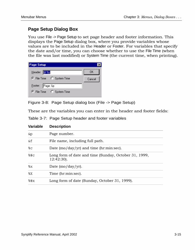
Menubar Menus Chapter 3: Menus, Dialog Boxes . . .
Synplify Reference Manual, April 2002 3-15
Page Setup Dialog Box
You use File -> Page Setup to set page header and footer information. This displays the Page Setup dialog box, where you provide variables whose values are to be included in the Header or Footer. For variables that specify the date and/or time, you can choose whether to use the File Time (when the file was last modified) or System Time (the current time, when printing).
Figure 3-8: Page Setup dialog box (File -> Page Setup)
These are the variables you can enter in the header and footer fields:
Table 3-7: Page Setup header and footer variables
Variable Description
&p Page number.
&f File name, including full path.
%c Date (mo/day/yr) and time (hr:min:sec).
%#c Long form of date and time (Sunday, October 31, 1999, 12:42:30).
%x Date (mo/day/yr).
%X Time (hr:min:sec).
%#x Long form of date (Sunday, October 31, 1999).

LO
Chapter 3: Menus, Dialog Boxes . . . Menubar Menus
3-16 Synplify Reference Manual, April 2002
Print Setup Dialog Box
You use File -> Print Setup to specify printing parameters. This displays the Print Setup dialog box:
Figure 3-9: Print Setup dialog box (File -> Print Setup)
Edit MenuYou use the Edit menubar menu to edit project and source files. This includes cutting, copying, pasting, finding and replacing text, manipu-lating bookmarks, and commenting-out code lines. Which Edit menu commands are available at any time depends on which window or view (Project, Text Editor, SCOPE spreadsheet, RTL, Technology) is active. This is the Edit menu in the Text Editor view:
The Edit menu commands and their associated dialog boxes are described in the following sections:
• Edit Menu Commands on page 3-17
• Find Dialog Box on page 3-19
• Replace Dialog Box on page 3-20
• Goto Dialog Box on page 3-21

Menubar Menus Chapter 3: Menus, Dialog Boxes . . .
Synplify Reference Manual, April 2002 3-17
Edit Menu Commands
The following table describes the Edit menu commands available in different views and windows:
Table 3-8: Edit menu commands
Edit Menu Commands in the Text Editor View
Command Description
Undo Undoes the last action.
Redo Performs the action undone by Undo.
Cut Removes the selected text, and makes it available to be Pasted.
Copy Duplicates the selected text, and makes it available to be Pasted.
Paste Places a copy of the most recently Cut or Copy’d text at a selected location.
Select All Selects all text in the file.
Find... Searches the file for text matching a given search string. See Find Dialog Box on page 3-19.
Replace... Finds and replaces text. See Replace Dialog Box on page 3-20.
Goto Goes to specific line number. See Goto Dialog Box on page 3-21.
Advanced -> Comment Code Inserts the appropriate comment prefix at the current text cursor location.
Advanced -> Uppercase Makes the selected string all upper case.
Advanced -> Lowercase Makes the selected string all lower case.
Toggle bookmark Alternately inserts and removes a bookmark to the line containing the text cursor.
Next bookmark Takes you to the next bookmark.
Previous bookmark Takes you to the previous bookmark.
Delete all bookmarks Removes all bookmarks from the Text Editor window.

LO
Chapter 3: Menus, Dialog Boxes . . . Menubar Menus
3-18 Synplify Reference Manual, April 2002
Edit Menu Commands in the SCOPE Window
Undo Undoes the last action. The full name of the menu item reflects the specific action to be undone; for example, Undo Insert Rows stands for undoing the action of inserting rows.
Redo Performs the action undone by Undo. The full name of the menu item reflects the specific action to be redone; for example, Redo Insert Rows stands for redoing the action of inserting rows.
Cut Removes the selected text, and makes it available to be Pasted.
Copy Duplicates the selected text, and makes it available to be Pasted.
Paste Places a copy of the most recently Cut or Copy’d text at a selected location.
Clear Clears a row of information.
Fill Down Copies the information in a cell to other cells below it in the same column. Click the cell you want copied, highlight the cells below it where you want the information filled in, then click Fill Down.
Remove Rows Removes selected rows from the SCOPE spreadsheet.
Insert Row Inserts a new row above the selected row, or, when no row is selected, at the bottom of the spreadsheet.
Insert Wizard... Opens a wizard to help you define constraints for a particular SCOPE pane, or attributes for an object. See SCOPE Constraint Wizards on page 6-18, for descriptions of the constraint wizards, and SCOPE Attributes Wizard on page 7-12 for information about the attributes wizard.
Insert Quick Automatically inserts constraints for all objects that apply to the current SCOPE pane (for example all clocks in the Clocks panel).
Table 3-8: Edit menu commands (Continued)

Menubar Menus Chapter 3: Menus, Dialog Boxes . . .
Synplify Reference Manual, April 2002 3-19
Find Dialog Box
Search for text in the Text Editor.
Figure 3-10: Find dialog box (Edit -> Find)
Find... Searches the current SCOPE column for text matching a given search string. This is similar to the Find command in the Text Editor (see Find Dialog Box on page 3-19), but in the SCOPE window you cannot use a regular expression for the search string, there is no wrap-around searching, and there is no line-number highlighting (Mark All).
Replace... Finds and replaces text. This is similar to the Replace command in the Text Editor (see Replace Dialog Box on page 3-20), but in the SCOPE window you cannot use a regular expression for the search string, there is no wrap-around search, and the search direction is always down.
Find again Continues the search initiated by the last Find.
Edit Menu Commands in RTL/Technology Views
Copy Image Lets you select and copy elements from your existing schematic in the RTL or Technology view.
Table 3-8: Edit menu commands (Continued)

LO
Chapter 3: Menus, Dialog Boxes . . . Menubar Menus
3-20 Synplify Reference Manual, April 2002
Replace Dialog Box
Finds and optionally replaces text in the Text Editor.
Figure 3-11: Replace dialog box (Edit -> Replace)
Table 3-9: Find dialog box features
Feature Description
Find What Search string matching the text to be found. You can use the pulldown list to view and reuse search strings used previously in the current session.
Match Case When enabled, searching is case sensitive.
Regular expression When enabled, wildcard characters (* and ?) can be used in the search string: ? matches any single character; * matches any string of characters, including the empty string.
Wrap around search When enabled, searching starts again after reaching the end (Down) or the beginning (Up) of the file.
Direction Radio buttons for selecting the search direction (Up or Down).
Find Next Initiates a search for the search string (see Find What).
Mark All Highlights the numbers of all lines containing text matching the search string. Closes the dialog box.
Cancel Cancels searching and closes the dialog box.

Menubar Menus Chapter 3: Menus, Dialog Boxes . . .
Synplify Reference Manual, April 2002 3-21
Goto Dialog Box
Goes to a specified line number in the Text Editor.
Figure 3-12: Goto dialog box (Edit -> Goto)
Table 3-10: Replace dialog box features
Feature Description
Find What Search string matching the text to be found. You can use the pulldown list to view and reuse search strings used previously in the current session.
Replace With Replacement text, which will replace found text. You can use the pulldown list to view and reuse replacement text used previously in the current session.
Match Case When enabled, searching is case sensitive.
Regular expression When enabled, wildcard characters (* and ?) can be used in the search string: ? matches any single character; * matches any string of characters, including the empty string.
Wrap around search When enabled, searching starts again after reaching the end (Down) or the beginning (Up) of the file.
Direction Radio buttons for selecting the search direction (Up or Down).
Find Next Initiates a search for the search string (see Find What).
Replace Replaces the found text with the replacement text, and locates the next match.
Replace All Replaces all text that matches the search string.
Cancel Cancels replacement and closes the dialog box.

LO
Chapter 3: Menus, Dialog Boxes . . . Menubar Menus
3-22 Synplify Reference Manual, April 2002
View MenuThe View menubar menu varies with the active view. You use this menu to set the display and viewing options, choose which toolbars are to be visible (Project view), and display result files.
The View menu commands and their associated dialog boxes are described in the following sections:
• View Menu Commands on page 3-22
• Toolbars Dialog Box on page 3-24
• Customize Dialog Box on page 3-26
• Sheet Selection Dialog Box on page 3-27
• Display Settings Dialog Box on page 3-28
View Menu Commands
The following table describes the View menu commands, beginning with the commands common to all views, and followed by the commands unique to specific views.
Table 3-11: View menu commands
Command Description
Common View Menu Commands
Toolbars... Defines which toolbars to display.
Status Bar When enabled, context-sensitive information is displayed in the lower left corner of the main window as you move your pointer over design elements. This information includes element identification.
Workbook Mode When enabled, the various views may be accessed by clicking corresponding tabs near the bottom of the Project window.
View Log File... Displays the log file, which includes a net report and a performance summary on your design’s speed.
View Result File... Displays a detailed netlist report.

Menubar Menus Chapter 3: Menus, Dialog Boxes . . .
Synplify Reference Manual, April 2002 3-23
View Menu Commands in RTL/Technology Views
Push/Pop Hierarchy Toggles traversing the hierarchy. When an vertical arrow pointer is active, clicking pushes down (down arrow) or pops up (up arrow) through the hierarchy at the pointer position, to show the next hierarchical level below or above.
Previous Sheet Displays the previous sheet of a multiple-sheet schematic.
Next Sheet Displays the next sheet of a multiple-sheet schematic.
View Sheets Displays a dialog box where you can select a sheet to display from a list of all sheets. See Sheet Selection Dialog Box on page 3-27.
Select All -> InstancesSelect All -> NetsSelect All -> Ports
Selects all instances, nets, or ports on the current schematic or sheet.
Goto Net Driver Displays a net driver for a selected net.
Select Net Driver Selects the driver of a selected net.
Select Net Instances Selects instances driven by the net.
Unselect All Unselects all elements in the view.
Zoom In Toggles zooming in. When the Z-shaped pointer is active, you can zoom in on the view by clicking or dragging a box around (lassoing) the region. Clicking zooms in on the center of the view; lassoing zooms in on the lassoed region. You can also right-click to remove the Z-shaped pointer and exit zooming mode.
Zoom Out Toggles zooming out. When the Z-shaped pointer is active, you can click to zoom out from the view. You can also right-click to remove the Z-shaped pointer and exit zooming mode.
Pan Pans (scrolls) the view to show elements that might not otherwise be visible. Click in the schematic, then drag and release in the direction to pan.
Pan Center Centers the window on the design.
Table 3-11: View menu commands (Continued)
Command Description

LO
Chapter 3: Menus, Dialog Boxes . . . Menubar Menus
3-24 Synplify Reference Manual, April 2002
Toolbars Dialog Box
Toolbar icons (iconic action buttons) exist for several commands in the File, Edit, View, and HDL Analyst menus (see Toolbars on page 3-88). You can add icons to any of the existing toolbars or you can create additional, custom toolbars with your own choice of icons.
Full View Zooms the active view so that it shows the entire the design.
Normal View Zooms the active view, when you click it, to full (normal) size.
Zoom Lock When enabled, if you resize the window the displayed schematic is resized proportionately, so that it occupies the same portion of the window.
View Menu Commands in Text Editor Window
Show Line Numbers Displays consecutive line numbers for lines of code in the file.
View Menu Commands in SCOPE Window
Zoom In Zooms in on the spreadsheet a small amount.
Zoom Out Zooms out from the spreadsheet a small amount.
Normal View Zooms the spreadsheet to full (normal) size.
ReadOnly Locks the SCOPE spreadsheet, to prevent changes.
Properties... Sets the display settings for the SCOPE spreadsheet. See Display Settings Dialog Box on page 3-28.
Table 3-11: View menu commands (Continued)
Command Description

Menubar Menus Chapter 3: Menus, Dialog Boxes . . .
Synplify Reference Manual, April 2002 3-25
You use View -> Toolbars to choose which toolbars are displayed, and to specify their icons.
Figure 3-13: Toolbars dialog box (View -> Toolbars)
Table 3-12: Toolbars dialog box features
Toolbars Lists the standard and custom toolbars. You enable just those toolbars that you want to display.
Close Closes the dialog box.
New... Prompts for the name of a new custom toolbar. You enter a name, then click OK. This displays a new, empty toolbar, and opens the Customize dialog box, where you can add icons to the toolbar. See Customize Dialog Box on page 3-26.
Customize... Displays the Customize dialog box, where you can specify which icons belong to each toolbar (standard or custom). See Customize Dialog Box on page 3-26.
Reset Resets a selected standard (predefined) toolbar to its default set of icons. (Only available when a standard toolbar is selected.)
Delete Deletes a selected custom toolbar. (Only available when a custom toolbar is selected.)
Toolbar name Displays the name of the selected toolbar. You can edit the names of custom toolbars.

LO
Chapter 3: Menus, Dialog Boxes . . . Menubar Menus
3-26 Synplify Reference Manual, April 2002
Customize Dialog Box
The Customize dialog box is displayed when you click Customize... in the Toolbars dialog box, or when you enter a custom toolbar name after clicking New in the Toolbars dialog box. You use the Commands panel of the dialog box to define which icons belong to which toolbars. You do this by dragging and dropping individual icons to or from any displayed toolbars (standard or custom). The Toolbars panel of the dialog box offers the same operations as the Toolbars dialog box (see Toolbars Dialog Box on page 3-24).
Figure 3-14: Toolbars panel, Customize dialog box
Show Tooltips When enabled, a descriptive tooltip is displayed whenever you position the pointer over a toolbar icon.
Cool Look When enabled, toolbar icons are outlined only when you pass the mouse pointer over them; otherwise, they blend with the background. When disabled, toolbar icons are always outlined.
Large Buttons When enabled, large toolbar icons are used.
Table 3-12: Toolbars dialog box features (Continued)

Menubar Menus Chapter 3: Menus, Dialog Boxes . . .
Synplify Reference Manual, April 2002 3-27
Figure 3-15: Commands panel, Customize dialog box
Sheet Selection Dialog Box
View -> View Sheets displays the Sheet Selection dialog box, which you use to select a particular sheet for display or print. This dialog box is only avail-able in an RTL or Technology view, and only when a multiple-sheet design is present.
Figure 3-16: Sheet Selection dialog box (View -> View Sheets)
Icons on the selected toolbar (Analyst)
Function ofthe selected icon

LO
Chapter 3: Menus, Dialog Boxes . . . Menubar Menus
3-28 Synplify Reference Manual, April 2002
Display Settings Dialog Box
View -> Properties is only available in the SCOPE view. It displays the Display Settings dialog box, where you can edit SCOPE view settings: row, line, and button settings, and colors for table lines.
Figure 3-17: Display Settings dialog box (View -> Properties, in SCOPE view)
Table 3-13: Display Settings dialog box features
Feature Description
Preview A preview of the current dialog box settings, so you can see their effect before accepting them by clicking OK.
3D-Buttons When enabled, row numbers and column headings are displayed as apparently 3-dimensional buttons.
Vertical Lines When enabled, vertical lines are shown between columns.
Horizontal Lines When enabled, horizontal lines are shown between rows.
Mark Current Row When enabled, the selected row’s number is highlighted; for example, its 3D button appears depressed.

Menubar Menus Chapter 3: Menus, Dialog Boxes . . .
Synplify Reference Manual, April 2002 3-29
Project MenuYou use the Project menubar menu to set implementation options, add or remove files from a project, change project filenames, and create new implementations. The Project menu commands are the same in all views.
The Project menu commands and their associated dialog boxes are described in the following sections:
• Project Menu Commands on page 3-30
• Options for implementation Dialog Box on page 3-31
• Select Files to Add to Project Dialog Box on page 3-38
• Source File Dialog Box on page 3-40
• File Options Dialog Box (VHDL) on page 3-41
• Options for implementation Dialog Box (New Implementation) on page 3-41
Mark Current Column When enabled, the selected column’s heading is highlighted; for example, its 3D button appears depressed.
Color Sets the color for the selected spreadsheet feature. For example, if Grid Lines is selected, then horizontal and vertical grid lines are set to appear in the selected color.
User Properties Sets the value of the indicated Attribute to the Value you choose in the pulldown list.
Table 3-13: Display Settings dialog box features (Continued)
Feature Description

LO
Chapter 3: Menus, Dialog Boxes . . . Menubar Menus
3-30 Synplify Reference Manual, April 2002
Project Menu Commands
The following table describes the Project menu commands and functions.
Table 3-14: Project menu commands
Command Description
Implementation Options... Displays the Options for implementation dialog box, which you use to set options for implementing your design. See Options for implementation Dialog Box on page 3-31.
Add Source File... Displays the Select Files to Add to Project dialog box, where you can add Verilog (.v), VHDL (.vhd), Tcl script (.tcl) and constraint (.sdc) files to your design. See Select Files to Add to Project Dialog Box on page 3-38.
Remove Files From Project Removes selected files from your project.
Change File... Lets you replace a file in your project. See Source File Dialog Box on page 3-40.
Set VHDL Library... Displays the File Options dialog box, where you choose the library (Library Name) where your VHDL files are to be synthesized. The default library is called work. See File Options Dialog Box (VHDL) on page 3-41.
New Implementation... Creates a new implementation for current design. Each implementation pertains to the same design, but it can have different options settings and/or constraints for synthesis runs. Same as Project -> Implementation Options (see Options for implementation Dialog Box (New Implementation) on page 3-41).

Menubar Menus Chapter 3: Menus, Dialog Boxes . . .
Synplify Reference Manual, April 2002 3-31
Options for implementation Dialog Box
You use the Options for implementation dialog box to define the selected project’s implementation options. You can access this dialog box via Project -> Implementation Options, as well as a few other ways. This is one of the most important and frequently used dialog boxes.
Figure 3-18: Options for implementation dialog box
The dialog box includes the following panels:
• Device Panel on page 3-32
• Options/Constraints Panel on page 3-33
• Implementation Results Panel on page 3-33
• Timing Report Panel on page 3-35
• VHDL and Verilog Panels on page 3-36

LO
Chapter 3: Menus, Dialog Boxes . . . Menubar Menus
3-32 Synplify Reference Manual, April 2002
Device PanelYou use the Device panel to set mapping options for the selected technology. See the Synplify User Guide for details. See also the vendor appendices of this reference manual, for information on options for specific technologies.
Figure 3-19: Device panel, Options for Implementation dialog box
Technology vendor Part
Optiondescription
Devicemappingoptions
Speed grade Package

Menubar Menus Chapter 3: Menus, Dialog Boxes . . .
Synplify Reference Manual, April 2002 3-33
Options/Constraints PanelYou use the Options/Constraints panel to specify optimization switches, target frequency, and timing constraint files for design compilation. See the Synplify User Guide for details.
Figure 3-20: Options/Constraints panel, Options for Implementation dialog box
Implementation Results PanelYou use the Implementation Results panel to specify the implementation name (default: rev_1), the results directory, and the name and format of the top-level output netlist file (result file). You can also specify output constraint and netlist files. See the Synplify User Guide for more informa-tion.
Set optimizationswitches forcompiling
Set globalfrequencyconstraint
Check constraintfiles to apply to theimplementation

LO
Chapter 3: Menus, Dialog Boxes . . . Menubar Menus
3-34 Synplify Reference Manual, April 2002
The results directory is a subdirectory of the project file directory. You can change the location of the results directory, but its name must be identical to the implementation name.
Enable one or more of the optional output file check boxes to generate the corresponding Verilog netlist, VHDL netlist or vendor constraint files. To show these files in the Project files list, enable Show all files in results directory under Options -> Project View Options (see Project View Options Dialog Box on page 3-55).
Figure 3-21: Implementation Results panel, Options for Implementation dialog box
Implementationname
directory
Result
Optionaloutput files
filename
Results
Resultformat

Menubar Menus Chapter 3: Menus, Dialog Boxes . . .
Synplify Reference Manual, April 2002 3-35
Timing Report PanelYou use the Timing Report panel to set criteria for the output timing report. You specify the number of start and end points, and the number of critical paths to appear in the timing report.
Figure 3-22: Timing Report panel, Options for implementation dialog box
Set options

LO
Chapter 3: Menus, Dialog Boxes . . . Menubar Menus
3-36 Synplify Reference Manual, April 2002
VHDL and Verilog PanelsYou use the VHDL and Verilog panels in the Options for implementation dialog box to specify various language-related options, as described in the tables below. With mixed HDL designs, both panels are present.
Figure 3-23: VHDL and Verilog panels, Options for Implementation dialog box
Table 3-15: Verilog panel features
Top Level Module The name of the top-level module of your design.
Include Path Order The search path to be used by the include commands in the project’s Verilog design files.
Enumeration encoding
Search path
Top-level module/entity
Use Verilog 2001
Push Tristates across Process/Block boundaries

Menubar Menus Chapter 3: Menus, Dialog Boxes . . .
Synplify Reference Manual, April 2002 3-37
Example: Push Tristates across Process/Block boundaries check box
When this option is enabled (default), the tristate is pushed across the flip-flop. When disabled, it is implemented before the flip-flop.
Verilog 2001 When enabled, the default Verilog standard for the project is Verilog 2001. When disabled, the default standard is Verilog 95. You can override a project’s Verilog standard for an individual source file via the File Options dialog box (see File Options Dialog Box on page 3-78).For more information on Verilog 2001 support, see Verilog 2001 Support on page 8-3.
Push Tristates across Process/Block boundaries
When enabled (default), tristates are pushed across process/block boundaries, as an optimization.
Table 3-16: VHDL panel features
Top Level Entity The name of the top-level entity of your design.
Default Enum Encoding The default enumeration encoding to use.
Note that this is only for enumerated types; state-machine encoding is selected automatically by the FSM compiler, or you can specify it using the syn_encoding attribute.
Push Tristates across Process/Block boundaries When enabled (default), tristates are pushed across process/block boundaries, as an optimization.
Table 3-15: Verilog panel features

LO
Chapter 3: Menus, Dialog Boxes . . . Menubar Menus
3-38 Synplify Reference Manual, April 2002
Figure 3-24: Push Tristates across Process/Block boundaries enabled
Figure 3-25: Push Tristates across Process/Block boundaries disabled
Select Files to Add to Project Dialog Box
You use Project -> Add Source File to add source files to your project. This displays the Select Files to Add to Project dialog box. (There are other ways to access this dialog box.)

Menubar Menus Chapter 3: Menus, Dialog Boxes . . .
Synplify Reference Manual, April 2002 3-39
Figure 3-26: Select Files to Add to Project dialog box
Table 3-17: Select Files to Add to Project dialog box features
Feature Description
Look in The directory to look in for the file to be added. You can use the pulldown directory list and the Up One Level button to choose the directory.
List of files and subdirectories (large unnamed zone)
The files and directories currently in the chosen directory. The files are those that match the file type(s) specified in the field Save as type. Select a file to be added, then click <- Add to add it to the list of Files to Add to Project. Alternatively, double-click a file to immediately add only it to a new project named after it (this closes the dialog box).
File name The name of a file to add to the project. If you enter a name using the keyboard, then you must include the file-type extension.
Select files toadd them to the Files To Add To
Add file
Remove fileaction buttons
Project list
action buttons
Choose directory
Specify file type

LO
Chapter 3: Menus, Dialog Boxes . . . Menubar Menus
3-40 Synplify Reference Manual, April 2002
Source File Dialog Box
You use Project -> Change File to replace a file in the project files list with another of the same type. You must first select the file to be replaced, in the Project view, before you can use this command. This displays the Source File dialog box, where you specify the replacement file.
Files of type A description of file types, with wildcard expressions to match the file to add. Only files in the chosen directory that match the expressions are displayed in the list of files. You can use the pulldown list to choose the file types to match.
Files To Add To Project The files to be added to the project. You add files to this list with the <- Add and <- Add All action buttons. You remove files from this list with the Remove -> and Remove All -> buttons.
<- Add All Adds all of the files currently displayed in the directory to the Files to Add to Project list.
<- Add Adds the file named in the File name field to the Files to Add to Project list.
Remove -> Removes a selected file from the Files to Add to Project list.
Remove All -> Removes all of the files from the Files to Add to Project list.
OK Adds the files named in the Files to Add to Project list to a new project named for the first file in the list, and closes the dialog box.
Cancel Cancels adding files, and closes the dialog box.
Table 3-17: Select Files to Add to Project dialog box features (Continued)
Feature Description

Menubar Menus Chapter 3: Menus, Dialog Boxes . . .
Synplify Reference Manual, April 2002 3-41
Figure 3-27: Source File dialog box (Project -> Change File)
File Options Dialog Box (VHDL)
You use Project -> Set VHDL Library to view VHDL file properties and specify the VHDL library name. This displays the File Options dialog box, where you provide this information. This is the same dialog box displayed by right-clicking a VHDL filename in the Project view and choosing File -> Options (see File Options Dialog Box on page 3-78).
Options for implementation Dialog Box (New Implementation)
You use Project -> New Implementation to create a new implementation for the selected project. This displays the Options for implementation dialog box, where you define the project’s implementation options.
Then, choose thereplacement file
First, select a file in the Project view

LO
Chapter 3: Menus, Dialog Boxes . . . Menubar Menus
3-42 Synplify Reference Manual, April 2002
This is the same dialog box displayed by Project -> Implementation Options (see Options for implementation Dialog Box on page 3-31), except that there is no list of implementations to the right of the tabbed panels.
Figure 3-28: Options for implementation dialog box
Run MenuYou use the Run menubar menu to perform tasks such as the following:
• Compile and synthesize a design
• Check design syntax and synthesis
• Run Tcl scripts
• Check the task status
• Navigate to the next and previous source code errors in the Text Editor window.

Menubar Menus Chapter 3: Menus, Dialog Boxes . . .
Synplify Reference Manual, April 2002 3-43
The Run menu commands and their associated dialog boxes are described in the following sections:
• Run Menu Commands on page 3-43
• Open Dialog Box on page 3-44
• Job Status Dialog Box on page 3-45
Run Menu Commands
In addition to the Run menu commands described below, there are popup menu commands available by right-clicking in the Project view. See Project View Popup Menu on page 3-73, for details.
The following table describes the Run menu commands.
Table 3-18: Run menu commands
Command Description
Synthesize Compiles and maps the design, which you can then view in the RTL and Technology views.
Compile Only Compiles the design into technology-independent high-level structures. You can view the result in the RTL view.
Syntax Check Runs a syntax check on your design’s coding. The status bar at the bottom of the window displays any error messages. If the active window shows an HDL file, then only that file is checked; otherwise, the entire project is checked.
Synthesis Check Runs a synthesis check on your design’s coding. This includes a syntax check and a check to see if the synthesis tool could map the design to the hardware. No optimizations are carried out. The status bar at the bottom of the window displays any error messages. If the active window shows an HDL file, then only that file is checked; otherwise, the entire project is checked.
Run Tcl Script... Runs a selected Tcl script. See Open Dialog Box on page 3-44.

LO
Chapter 3: Menus, Dialog Boxes . . . Menubar Menus
3-44 Synplify Reference Manual, April 2002
Open Dialog Box
You use Run -> Run Tcl Script to run a Tcl script. This displays the Open dialog box, where you specify the Tcl script file to use. The File name area is prefilled with the wildcard string “*.tcl”, corresponding to Tcl files.
This dialog box is the same as that displayed via File -> Open, except that no Open as read-only check box is present. See Open Dialog Box on page 3-9, for an explanation of the features in the Open dialog box.
Figure 3-29: Open dialog box (Run -> Run Tcl Script)
Job Status Tells you the name of the job, and gives you the runtime and directory location of your design, during compilation. This option is enabled during synthesis. See Job Status Dialog Box on page 3-45.
Next Error Shows the next error in your source code file.
Previous Error Shows the previous error in your source code file.
Table 3-18: Run menu commands (Continued)
Command Description
Choose the directory
Specify Tcl file type“*.tcl” matches Tcl files

Menubar Menus Chapter 3: Menus, Dialog Boxes . . .
Synplify Reference Manual, April 2002 3-45
Job Status Dialog Box
You use Run -> Job Status to monitor the synthesis jobs that are running, their run times, and their associated commands. This information is displayed in the Job Status dialog box.
You can cancel a displayed job by selecting it in the dialog box and clicking Cancel Job.
Figure 3-30: Job Status dialog box
HDL Analyst MenuThe HDL Analyst menubar menu gives you multiple schematic views of your project. It has the following submenus:
• RTL – shows your design at a register-transfer level (see RTL Submenu on page 3-46).
• Technology – shows your design at a technology-primitive level (see Technology Submenu on page 3-46).
• Visual Elite Cross Probing – lets you access Visual Elite�, provided that you have set up that software correctly. Visual Elite is a GUI that you can use to create and edit HDL designs. Cross probing is available, in both directions, between Synplicity’s synthesis tools and Visual Elite. Visual Elite is a product of Innoveda�; for more information see http://www.innoveda.com/products/datasheets_HTML/visualelite.asp.
To cancel a job, select it,then click the Cancel button

LO
Chapter 3: Menus, Dialog Boxes . . . Menubar Menus
3-46 Synplify Reference Manual, April 2002
The HDL Analyst menu commands and the associated dialog box are described in the following sections:
• Hdl Analyst Menu Commands on page 3-46
• Object Query Dialog Box on page 3-49
Hdl Analyst Menu Commands
RTL SubmenuBefore you can access the RTL view, you must successfully compile your design. The RTL submenu then offers the following views:
• Hierarchical View
• Flattened View
Technology SubmenuBefore you can access the Technology view, you must synthesize (compile and map) your design. The Technology submenu then offers the following views:
• Hierarchical View
• Flattened View
• Flattened to Gates View
• Hierarchical Critical Path
• Flattened Critical Path
The following table describes the HDL Analyst menu commands.
Note: RTL submenu commands are available only after your design is compiled. Technology submenu commands are available only after your design is synthesized (compiled and mapped).

Menubar Menus Chapter 3: Menus, Dialog Boxes . . .
Synplify Reference Manual, April 2002 3-47
Table 3-19: HDL Analyst menu commands
Command Description
RTL -> Hierarchical View Shows a hierarchical schematic view of the design.
RTL -> Flattened View Removes the hierarchy from the schematic.
Technology -> Hierarchical View Displays a hierarchical schematic of the design.
Technology -> Flattened View Removes the hierarchy from the schematic.
Technology -> Flattened to Gates View Flattens the hierarchy to the primitive gate level.
Technology -> Hierarchical Critical Path Highlights the critical path, without flattening the hierarchy.
Technology -> Flattened Critical Path Highlights the critical path, after flattening the hierarchy.
Set Slack Margin... Displays a dialog box where you set the slack margin value. This is subtracted from the slack time to get a slack range. Only instances within the range are listed in the log file.a
Show Critical Path Displays the most critical path in your design.b
Show Timing Information Annotates the schematic view with timing numbers.b
Filter Schematic Filters the selected objects and groups them together on a new schematic.a
Flatten current schematic Displays a flattened view of the current schematic.a
Flatten current schematic to gates Displays a flattened view, at the gate level, of the current schematic.b

LO
Chapter 3: Menus, Dialog Boxes . . . Menubar Menus
3-48 Synplify Reference Manual, April 2002
Find... Displays the Object Query dialog box, which lets you search for instances, symbols, nets, and ports, by name. See Object Query Dialog Box on page 3-49.a
Expand Expands a selected input or output net in a filtered view, to show the adjacent object in the path.a
Expand to register/port Expands a selected input or output net in a filtered view, to show everything in the path, until a register or a port is reached.a
Expand paths Shows all logic between two or more instances.a
Visual Elite Cross Probing-> Connect to Visual Elite-> Disconnect from Visual Elite
Connects the Synplify synthesis tool to Visual Elite, or disconnects it if already connected. Visual Elite must be set up correctly for this to be available. SeeCrossprobing Across Views on page 5-8, for details.a
Visual Elite Cross Probing -> Cross Probing Enabled When turned on, enables crossprobing between the synthesis tool and Visual Elite. See Crossprobing Across Views on page 5-8, for details.a
External Cross Probing Engaged Enables crossprobing to an external text file. See Crossprobing with ModelSim on page 5-11 for an example.a
a. Available only in the RTL and Technology views.b. Available only in the Technology view.
Table 3-19: HDL Analyst menu commands (Continued)
Command Description

Menubar Menus Chapter 3: Menus, Dialog Boxes . . .
Synplify Reference Manual, April 2002 3-49
Object Query Dialog Box
You use HDL Analyst -> Find to display the Object Query dialog box, which lets you search for instances, symbols, nets, and ports, by name. The located elements are highlighted in red in the RTL or Technology view. The elements available for searching are those in the current hierarchy level; the located elements can appear at any hierarchy level, and on multiple sheets.
Figure 3-31: Object Query dialog box (HDL Analyst -> Find)
Table 3-20: Object Query dialog box features
Feature Description
Instances, Symbols, Nets, Ports
Tabbed panels for finding different kinds of objects. Each panel shows a list of all objects of the corresponding type at the current hierarchy level (in the Unhighlighted zone). Choose a panel for a given object type by clicking its tab.
Unhighlighted Names of all objects of the current panel’s type. To select an object for highlighting, click its name in the list (select multiple names by pressing the Ctrl or Shift key while clicking) or use Highlight Wildcard (see below) to select a set of matching objects. The number of objects selected for highlighting, and the total number listed, are displayed above the list: # selected / # total.

LO
Chapter 3: Menus, Dialog Boxes . . . Menubar Menus
3-50 Synplify Reference Manual, April 2002
Highlight Wildcard (*?) Selects names in the Unhighlighted area, based on a match string you input. The string can contain the pattern-matching characters *, which matches any sequence of characters, and ?, which matches any single character. You can reuse previously entered match strings via the pulldown list.
-> Moves the selected names from the Unhighlighted area to the Highlighted area, and highlights their objects in the RTL and Technology views.
<- Moves the selected names from the Highlighted area to the Unhighlighted area, and unhighlights their objects in the RTL and Technology views.
All -> Moves all names from the Unhighlighted to the Highlighted area, and highlights their objects in the RTL and Technology views.
<- All Moves all names from the Highlighted to the Unhighlighted area, and unhighlights their objects in the RTL and Technology views.
Highlighted Complementary and analogous to the Unhighlighted area. You select object names here as candidates for moving to the Unhighlighted list, which unhighlights their corresponding objects.
Unhighlight Wildcard (*?) Complementary and analogous to the Unhighlight Wildcard area: selects names in the Highlighted area, based on a match string you input.
Jump Location When enabled, the target objects are displayed.
OK Closes the Object Query dialog box.
Cancel Cancels any changes to object highlighting made since opening the dialog box, and closes it.
Table 3-20: Object Query dialog box features (Continued)
Feature Description

Menubar Menus Chapter 3: Menus, Dialog Boxes . . .
Synplify Reference Manual, April 2002 3-51
Format MenuThe Format menubar menu is available only when the SCOPE view is active. You can use it to configure SCOPE spreadsheet cells, rows and columns, and to set text alignment and style.
The Format menu commands and their associated dialog boxes are described in the following sections:
• Format Menu Commands on page 3-51
• Cells Dialog Box on page 3-52
• Styles Dialog Box on page 3-52
Format Menu Commands
The following table describes the Format menu commands.
Table 3-21: Format menu commands
Command Description
Cells... Specifies the font and color to use, and adds borders to the cells. See Cells Dialog Box on page 3-52.
Resize Rows Changes the row height to fit the text.
Resize Columns Changes the column width to fit the text.
Cover Cells Temporarily hides cells from view.
Remove Covering Removes the covering previously placed on cells by Cover Cells, so they become visible again.
Styles... Changes the styles of columns, rows and warnings. See Styles Dialog Box on page 3-52.
Align Aligns text in columns and rows to the left, center, or right.
Style Makes text bold, italic, or underlined.

LO
Chapter 3: Menus, Dialog Boxes . . . Menubar Menus
3-52 Synplify Reference Manual, April 2002
Cells Dialog Box
You access the Cells dialog box via Format > Cells. You use the Cells dialog box to set options like font, color, border, and alignment for the SCOPE spreadsheet cells. The dialog box has panels for the different options.
Figure 3-32: Cells dialog box (Format -> Cells)
Styles Dialog Box
You access the Styles dialog box via Format -> Styles. You use the Styles dialog box to change the styles of your columns, rows, and warnings. Select the item to change, then click the Change button to display a dialog box for the selected item that is equivalent to the Cells dialog box (see Cells Dialog Box on page 3-52).

Menubar Menus Chapter 3: Menus, Dialog Boxes . . .
Synplify Reference Manual, April 2002 3-53
Figure 3-33: Styles dialog box (Format -> Styles)
Options MenuYou use the Options menubar menu to configure the VHDL and Verilog compilers, customize toolbars, and set options for the schematic display, Project view and Text Editor. When using certain technologies, additional menu items let you run the vendor’s software from this menu.
The Options menu commands and their associated dialog boxes are described in the following sections:
• Options Menu Commands on page 3-54
• Options for implementation Dialog Box – VHDL on page 3-54
• Options for implementation Dialog Box – Verilog on page 3-55
• Customize Dialog Box on page 3-55
• Project View Options Dialog Box on page 3-55
• Editor Options Dialog Box on page 3-56
• Schematic Options Dialog Box on page 3-59

LO
Chapter 3: Menus, Dialog Boxes . . . Menubar Menus
3-54 Synplify Reference Manual, April 2002
Options Menu Commands
The following table describes the Options menu commands.
Options for implementation Dialog Box – VHDL
You use Options -> Configure VHDL Compiler to configure the VHDL compiler. This displays the Options for implementation dialog box (see Options for implemen-tation Dialog Box on page 3-31), where you use the VHDL panel (see VHDL and Verilog Panels on page 3-36) to set the top-level entity and the encoding method for enumerated types. Note that state-machine encoding is automatically determined by the FSM compiler, or you can specify it explicitly using the syn_encoding attribute.
Table 3-22: Options menu commands
Command Description
Configure VHDL Compiler... Lets you set the encoding method for enumerated types, and the top-level entity. See Options for implementation Dialog Box – VHDL on page 3-54.
Configure Verilog Compiler... Lets you specify the top-level module and the ‘include search path. See Options for implementation Dialog Box – Verilog on page 3-55.
Customize... Customizes your toolbars. See Customize Dialog Box on page 3-55.
Project View Options... Sets options for organizing files in the Project view. See Project View Options Dialog Box on page 3-55.
Editor Options... Sets your syntax coloring, font, and tabs, for the Text Editor. See Editor Options Dialog Box on page 3-56.
Schematic Options... Sets display preferences for the RTL and Technology views. See Schematic Options Dialog Box on page 3-59.
Quartus (Altera only) Lets you set place-and-route options or run Quartus II placement and routing in either foreground or background.
Xilinx (Xilinx only) Runs Design Manager, Floorplanner, or ISE Project Navigator from the Synplicity environment.

Menubar Menus Chapter 3: Menus, Dialog Boxes . . .
Synplify Reference Manual, April 2002 3-55
Options for implementation Dialog Box – Verilog
You use Options -> Configure Verilog Compiler to configure the Verilog compiler. This displays the Options for implementation dialog box (see Options for implemen-tation Dialog Box on page 3-31), where you use the Verilog panel (see VHDL and Verilog Panels on page 3-36) to specify the top-level module and the ‘include search path.
Customize Dialog Box
You use Options -> Customize to customize and enable toolbars. This displays the Customize dialog box (see Customize Dialog Box on page 3-26), which has two panels, Toolbars and Commands. You use the Toolbars panel to select and enable existing toolbars, and create new, custom toolbars. You use the Commands panel to customize the selected toolbar. For more information on customizing toolbars, see Toolbars on page 3-88.
Project View Options Dialog Box
You use Options -> Project View Options to define how projects appear and are organized. This displays the Project View Options dialog box, which lets you work on multiple projects and define how files are arranged in them.
Figure 3-34: Project View Options dialog box (Options -> Project View Options)

LO
Chapter 3: Menus, Dialog Boxes . . . Menubar Menus
3-56 Synplify Reference Manual, April 2002
The following table describes the Project View Options dialog box features.
For more information on using the Project View Options dialog box, see Setting Project View Display Preferences on page 2-12.
Editor Options Dialog Box
You use Options -> Editor Options to choose either an internal or an external text editor. This displays the Editor Options dialog box, where you specify the editor to use.
Table 3-23: Project View Options dialog box features
Feature Description: When Feature is Enabled . . .
Show Project File Library When enabled, displays the corresponding VHDL library next to each source filename, in the Project Tree view of the Project view. (See also File Options Dialog Box (VHDL) on page 3-41, for how to change a file’s library.)
Beep when a job completes An audible signal is given whenever a project finishes running.
View project files in folders Project files are organized into separate folders, by type.
Show file name only Displays only filenames.
Show relative file path Displays relative paths, as well as filenames.
Show full file path Displays full paths and filenames.

Menubar Menus Chapter 3: Menus, Dialog Boxes . . .
Synplify Reference Manual, April 2002 3-57
Figure 3-35: Editor Options dialog box (Options -> Editor Options)
The following table describes the Editor Options dialog box features.
Editor Color, Font, and Tab OptionsThe Options action button of the Editor Options dialog box (Internal Editor only) lets you define various text editing preferences for the built-in Synplicity Text Editor.
Table 3-24: Editor Options dialog box features
Feature Description
Internal Editor Sets the Synplicity Text Editor as the default text editor.
Options (Only available when Internal Editor is enabled.) Lets you define the whitespace format, syntax coloring, and font to use for selected file types. See Editor Color, Font, and Tab Options on page 3-57.
External Editor Uses the specified external text editor program to view text files from within the Synplicity tool. Note that files opened with an external editor cannot be crossprobed.
... You can use this button to browse and select an external editor program.

LO
Chapter 3: Menus, Dialog Boxes . . . Menubar Menus
3-58 Synplify Reference Manual, April 2002
You can use this editor for the following types of files:
Select a file type, then click OK. A second dialog box then opens (also named Editor Options). You can use this box to define the whitespace format, syntax coloring, and font to use for the selected file type. See the Synplify User Guide for more information.
Figure 3-36: Syntax Coloring and Font dialog boxes
Verilog VHDL Constraint
Tcl Log C/C++
Cyn++ default
After you choose a filetype,use Editor Options to setsyntax coloring and font

Menubar Menus Chapter 3: Menus, Dialog Boxes . . .
Synplify Reference Manual, April 2002 3-59
Schematic Options Dialog Box
You use Options -> Schematic Options to define your preferences for the HDL Analyst schematic windows (RTL and Technology views). This displays the Schematic Options dialog box, where you specify what you want.
The result is the same as setting preferences in your .ini file. Some preferences take effect immediately; others only take effect in the next view you open. For details see the Synplify User Guide.
Figure 3-37: Schematic Options dialog box

LO
Chapter 3: Menus, Dialog Boxes . . . Menubar Menus
3-60 Synplify Reference Manual, April 2002
The following table describes the Schematic Options dialog box features.
Table 3-25: Schematic Options dialog box features
Feature Description
Show Hierarchy Browser When enabled, the Hierarchy Browser pane is displayed, on the left side of the RTL and Technology views.
Enhanced Text Crossprobing When enabled, you can crossprobe to a place-and-route report file. See Using the Enhanced Text Crossprobing Option on page 3-61 for more information.
Show Cell Interior When enabled, the internal logic of cells is displayed.
Show Sheet Connector Index When enabled, connecting sheet page numbers are displayed inside sheet-connector symbols.
Compress Buses When enabled, the display of buses is compressed, to reduce clutter.
No Buses in Technology View When enabled, buses are not displayed; they are only indicated as bits in the Technology View.
Maximum Instances Defines the maximum number of instances to display on a single sheet.
Maximum Filtered Instances Defines the maximum number of instances to display on a single sheet in a filtered view. This must be at least the Maximum Instances value.
Maximum Sheet Pins Defines the maximum number of pins on a sheet.
Maximum Instance Ports Defines the maximum number of ports on an instance.
Show Text Enables the display of labels. Which labels are actually displayed is governed by the other Show * features, below.
Show Instance Name When enabled, instance names are displayed.
Show Port Name When enabled, port names are displayed.
Show Symbol Name When enabled, symbol names are displayed.
Show Pin Name When enabled, pin names are displayed.
Show Conn Name When enabled, connectivity names are displayed.

Menubar Menus Chapter 3: Menus, Dialog Boxes . . .
Synplify Reference Manual, April 2002 3-61
Using the Enhanced Text Crossprobing OptionTo use the Enhanced Text Crossprobing option, follow these steps:
1. Select a path in a text file – If the objects in the path are in a column, hold down the Alt key and drag the mouse to select the column. The column is highlighted.
2. Right-click.
3. To select all the objects in the highlighted path, choose Select All from the popup menu.
4. To further filter the objects to crossprobe:
– Choose Select From from the popup menu.
– In the displayed Select element list dialog box, choose the objects that you want to cross probe, then click OK. The objects are then highlighted where they appear in other views.
Font Shows the current text font. To change it, click Change, then choose a new font from the displayed list.
Size Shows the current font size. To change it, click Change, and choose a new font size from the displayed list.
Change Displays a dialog box where you can change Font Options (Font and Size).
Table 3-25: Schematic Options dialog box features (Continued)
Feature Description

LO
Chapter 3: Menus, Dialog Boxes . . . Menubar Menus
3-62 Synplify Reference Manual, April 2002
Window MenuYou use the Window menubar menu to do tasks such as the following:
• create a new window as a copy (clone) of the current window (except the Project View),
• arrange windows, by cascading or tiling them,
• arrange minimized windows (icons),
• close all windows,
• quickly raise and activate a window.
Note: The windows manipulated with the Window menu do not include the Tcl window or the Log Watch window.
Window Menu Commands
The following table describes the Window menu commands.
Commands Cascade, Tile Horizontally, and Tile Vertically determine how existing windows are arranged.
Table 3-26: Window menu commands
Command Description
New Window Creates a new window as a copy (clone) of the current (active) window. Not available in the Project view.
Cascade Stacks all windows so that they are slightly offset from each other. See Cascade on page 3-63.
Tile Horizontally Tiles views horizontally, so that they do not overlap. See Tile Horizontally on page 3-63.
Tile Vertically Tiles views vertically, so that they do not overlap. See Tile Vertically on page 3-64.
Arrange Icons Arranges minimized windows along the bottom of the overall application window.
Close All Closes all windows except the Project view.

Menubar Menus Chapter 3: Menus, Dialog Boxes . . .
Synplify Reference Manual, April 2002 3-63
Cascade
Figure 3-38: Cascading windows display
Window -> Cascade stacks windows on top of each other, offsetting them slightly.
Tile Horizontally
Figure 3-39: Horizontally tiled windows display
Window -> Tile Horizontally arranges windows horizontally, in such a way that they do not overlap.

LO
Chapter 3: Menus, Dialog Boxes . . . Menubar Menus
3-64 Synplify Reference Manual, April 2002
Tile Vertically
Figure 3-40: Vertically tiled windows display
Window -> Tile Vertically arranges windows vertically, in such a way that they do not overlap.
Help MenuThe Help menubar menu changes according to the view—SCOPE spread-sheet, Project, RTL, Technology or Text Editor. Menu commands give information about the help system, additional products, finding online documentation, licensing, and using the Synplify synthesis tool. Some commands are only available in certain views.
The Help menu commands and their associated dialog boxes are described in the following sections:
• Help Menu Commands on page 3-65
• Help Topics Dialog Box on page 3-66
• License Wizard Dialog Boxes on page 3-67
• License Editor Dialog Box on page 3-69
• Select Preferred License Dialog Box on page 3-71
• Tip of the Day Dialog Box on page 3-72

Menubar Menus Chapter 3: Menus, Dialog Boxes . . .
Synplify Reference Manual, April 2002 3-65
Help Menu Commands
The following table describes the Help menu commands.
Table 3-27: Help menu commands
Command Description
Help Displays hyperlinked online help for the product.
Additional Products Displays a form that you can fill out, fax, or e-mail to Synplicity, to request product information.
How to Use Help Displays online help on how to use the online help (!).
Online Documents Displays hyperlinked PDF documentation on the product: release notes, user guide, reference manual, and configuration and setup help. You need Adobe’s Acrobat Reader to view the PDF files.
Synplify vs. Synplify Pro Details the differences between these products. Only available in the Project view.
TCL Help Displays help for Tcl commands.
License Agreement Displays the Synplify software license agreement.
License Wizard Opens the license wizard, to help you request or install your license. See License Wizard Dialog Boxes on page 3-67 for details.
License Editor Lets you edit your current (node-locked) license information. See License Editor Dialog Box on page 3-69 for details. Only available in the Project view.
Floating License Usage Specifies the number of floating licenses currently being used, and their users.
Preferred License Selection Displays the floating licenses that are available for your selection. See Select Preferred License Dialog Box on page 3-71.
Tip of the Day Displays a daily tip on how to use the Synplify synthesis tools better. See Tip of the Day Dialog Box on page 3-72.
About this program Specifies the synthesis tool product name, license expiration date, version number, and copyright.

LO
Chapter 3: Menus, Dialog Boxes . . . Menubar Menus
3-66 Synplify Reference Manual, April 2002
Help Topics Dialog Box
Most of the online help is provided via the Help Topics dialog box. This documents different things, depending on how it is accessed:
• help on the Synplify synthesis tool, via Help -> Help
• help on how to use the online help itself, via Help -> How to Use Help
• help on Tcl/Tk (standard Tcl commands), via Help -> TCL Help
In all cases, the Help Topics dialog box, has three panels: Contents, Index, and Find. For more information, try Help -> How to Use Help.
Contents PanelDisplays the table of contents for the online help. Double-click a closed book ( ) icon to list its contents. Double-click an open book ( ) icon to close it. Double-click a document icon ( ) to display its document.
.
Figure 3-41: Help Topics dialog box, Contents panel

Menubar Menus Chapter 3: Menus, Dialog Boxes . . .
Synplify Reference Manual, April 2002 3-67
Index PanelDisplays an alphabetical index of principal topics. Type the first few letters of the topic you are searching for, or scroll through the index, then double-click the topic of interest to display it.
Figure 3-42: Help Topics dialog box, Index panel
Find PanelSearches the help database for a text string. Enter a string, then click one of the matching topics to display it.
License Wizard Dialog Boxes
You use the License Wizard to do either of the following:
• Fill out a form to request a trial license from Synplicity
• Edit or enter license information received from Synplicity

LO
Chapter 3: Menus, Dialog Boxes . . . Menubar Menus
3-68 Synplify Reference Manual, April 2002
You choose which to do in the License Wizard Introduction dialog box, accessed via Help -> License Wizard. Choose one of these options by enabling the corresponding radio button, then follow the directions in subse-quently displayed License Wizard dialog boxes.
Figure 3-43: Introduction dialog box (Help -> License Wizard)
If you choose Fill out a form to request a trial license from Synplicity, you will be asked for additional information regarding your context, such as name, company, host IDs, platforms, vendors, languages, and so on. You can either fax or e-mail the request to Synplicity.
If you choose Edit or enter license information received from Synplicity, then the License Editor dialog box is displayed, where you can view and edit the infor-mation received. SeeLicense Editor Dialog Box on page 3-69, for details.
Click a button for help withlicensing issues

Menubar Menus Chapter 3: Menus, Dialog Boxes . . .
Synplify Reference Manual, April 2002 3-69
License Editor Dialog Box
You use Help > License Editor to view and edit your current license informa-tion (node-locked license only), via the License Editor dialog box. Refer to the product installation notes for the most current information.
Figure 3-44: License Editor dialog box (Help -> License Editor)
Follow these steps to edit your current license information:
1. If you are using the Microsoft® Windows® operating system, and your license file is not in the recommended directory, then specify the location with the variable SYNPLICITY_LICENSE_FILE or LM_LICENSE_FILE (Environment Variable Used option).
Update and validatelicense informationusing these actionbuttons

LO
Chapter 3: Menus, Dialog Boxes . . . Menubar Menus
3-70 Synplify Reference Manual, April 2002
If you are using a UNIX system, then specify the location of the license file with the variable LM_LICENSE_FILE.
2. If your licensing information (Synplicity Software Authorization form) is in the form of an e-mail or a text file, then enter the information automatically as follows:
If the information is not in the form of an e-mail or a text file, then enter the licensing information manually in the appropriate fields.
– To add a value to VENDOR_STRING, click the Add icon ( ) and type the feature name.
– To delete an entry, click the Delete icon ( ).
– To reorder entries, select them, then use the Move Up ( ) and Move Down ( ) arrow icons to move them.
Table 3-28: Entering licensing information automatically
Format Do this...
E-mail Copy the licensing information. Click the Clipboard action button. The licensing information from the copied document is automatically pasted into the dialog box.
Text file Click the Text File action button, then specify the name of the file. The licensing information in the file is automatically pasted into the dialog box.
# FEATURE synplify_pc synplctyd 2.590 31-dec-99 0 12345678901234567890 \# VENDOR_STRING=fpga HOSTID=SKEY=FFFFFFFF ck=00

Menubar Menus Chapter 3: Menus, Dialog Boxes . . .
Synplify Reference Manual, April 2002 3-71
– Place HDL Analyst last on the list in a field. (The other feature names can be in any order).
3. Click Validate. If all information has been correctly entered, a happy face will display.
4. Click Save.
Select Preferred License Dialog Box
You use Help > Preferred License Selection to choose a preferred license, when multiple licenses exist. This displays the Select Preferred License dialog box, which lists the available licenses for you to choose from. Select a license from the License Type column, click Save, close the Synplify synthesis tool, then restart it. The new session will use the preferred license you selected.
Figure 3-45: Select Preferred License dialog box
Add
Delete Move Up
Move Down

LO
Chapter 3: Menus, Dialog Boxes . . . Menubar Menus
3-72 Synplify Reference Manual, April 2002
Tip of the Day Dialog Box
You use Help -> Tip of the Day to display the Tip of the Day dialog box, with a daily tip on how to best use the Synplify synthesis tool. This box also opens automatically when you first start the tool. To prevent it from redis-playing at product startup, just disable Show Tips at Startup.
Figure 3-46: Tip of the Day dialog box (Help -> Tip of the Day)

Popup Menus Chapter 3: Menus, Dialog Boxes . . .
Synplify Reference Manual, April 2002 3-73
Popup Menus
Popup menus, available by right-clicking, offer quick ways to access commonly used commands that are specific to the view where you click, or are otherwise dependent on the current context. Which popup menu items appear at any given time vary, depending on that context. Items that are shown grayed out (dimmed) are currently inaccessible. Most popup menu items are also available from a menubar menu.
The individual popup menus, their commands (menu items) and the associated dialog boxes, are described in the following sections:
• Project View Popup Menu on page 3-73
• SCOPE Popup Menu on page 3-84
• Text Editor Popup Menu on page 3-84
• RTL View and Technology View Popup Menus on page 3-85
Project View Popup MenuThe popup menu commands available in the Project view vary, depending on what, if anything, is currently selected. The commands and their associated dialog boxes are described in the following sections:
• Project View Popup Menu Commands on page 3-74
• File Options Dialog Box on page 3-78
• Project Properties Dialog Box on page 3-80
• Select Projects to Include in Workspace Dialog Box on page 3-80
• Select Files to Add to Project Dialog Box on page 3-82
• Open Project Dialog Box on page 3-83
• Build Workspace Dialog Box on page 3-83
• Project View Options Dialog Box on page 3-84
• Save Project As Dialog Box on page 3-84

LO
Chapter 3: Menus, Dialog Boxes . . . Popup Menus
3-74 Synplify Reference Manual, April 2002
Project View Popup Menu Commands
The Project view popup menu varies, depending on which object in the view is selected, if any, and where in the view you open the popup menu (by right-clicking). The following tables describe the Project view popup menu commands in these various contexts.
Table 3-29: Project view popup menu commands, nothing selected
Command Description
Open Project... Opens a new or existing project. Same as File -> Open Project (see Open Project Dialog Box on page 3-12).
New Project... Creates a new project, and places it in the Project view.
Build Workspace... Creates a project workspace. In the Project view, select existing projects that you want to include in the project workspace. Refer to Build Workspace Dialog Box on page 3-83.
Project View Options... Lets you define how projects are organized in the Project view. Same as Options -> Project View Options (see Project View Options Dialog Box on page 3-55).
Refresh Cleans up the window display.
Table 3-30: Project view popup menu commands, HDL source file selected
Command Description
File Options... Displays the File Options dialog box, which showsgeneral properties of the selected file such as its modification date, path, and type. (See File Options Dialog Box on page 3-78.)
Open Opens the selected file.
Syntax Check Checks source file syntax. Same as Run -> Syntax Check (see Run Menu Commands on page 3-43).
Synthesis Check Checks synthesis. Same as Run -> Synthesis Check (see Run Menu Commands on page 3-43).

Popup Menus Chapter 3: Menus, Dialog Boxes . . .
Synplify Reference Manual, April 2002 3-75
Copy File... Displays the Copy File dialog box, where you copy the selected file and add it to the current project. You specify a new name for the file. (See Copy File Dialog Box on page 3-79.)
Change File... Displays the Source File dialog box, where you choose a file to replace the selected file. Same as Project -> Change File (see Source File Dialog Box on page 3-40).
Remove File from Project... Removes the selected file from the project.
Table 3-31: Project view popup menu commands, constraint file selected
Command Description
File Options... Displays the File Options dialog box, which showsgeneral properties of the selected file such as its modification date, path, and type. (See File Options Dialog Box on page 3-78.)
Open Opens the selected file.
Open as Text Opens the selected file in the Text Editor.
Copy File... Displays the Copy File dialog box, where you copy the selected file and add it to the current project. You specify a new name for the file. (See Copy File Dialog Box on page 3-79.)
Change File... Displays the Source File dialog box, where you choose a file to replace the selected file. Same as Project -> Change File (see Source File Dialog Box on page 3-40).
Remove File from Project... Removes the selected file from the project.
Table 3-30: Project view popup menu commands, HDL source file selected
Command Description

LO
Chapter 3: Menus, Dialog Boxes . . . Popup Menus
3-76 Synplify Reference Manual, April 2002
Table 3-32: Project view popup menu commands, results file selected
Command Description
File Options... Displays the File Options dialog box, which showsgeneral properties of the selected file such as its modification date, path, and type. (See File Options Dialog Box on page 3-78.)
Open Opens the selected file.
Open as Text Opens the selected file in the Text Editor, even if the file is of a type, such as .sdc or .info, that is normally viewed otherwise.
Delete File Removes the selected file from the Implementation Results view.
Table 3-33: Project view popup menu commands, project selected
Command Description
Project Options... Displays project properties such as name and location. You can click a selected implementation to make it current. Refer to Project Properties Dialog Box on page 3-80.
Open as Text Opens the selected file in the Text Editor, even if the file is of a type, such as .sdc or .info, that is normally viewed otherwise.
Add Source File... Adds a source file to the selected project. Same as Project -> Add Source File (see Select Files to Add to Project Dialog Box on page 3-11).
New Implementation... Creates a new implementation for your design.
Synthesize Synthesizes (compiles and maps) your design.
Compile Only Compiles your design, without mapping it.

Popup Menus Chapter 3: Menus, Dialog Boxes . . .
Synplify Reference Manual, April 2002 3-77
Save Project Saves the selected project.
Remove Project From Workspace Removes the selected project from the selected workspace, upon confirmation. Available only if selected project is within a workspace.
Close Project Closes the current project. Same as File -> Close Project (see File Menu Commands on page 3-5). Not available if the selected project is within a workspace—use Close Workspace then, instead.
Table 3-34: Project view popup menu commands, workspace selected
Command Description
Workspace Options... Displays workspace properties such as name and location. You can click a selected implementation to make it current. Refer to Project Properties Dialog Box on page 3-80.
Open as Text Opens the selected file in the Text Editor, even if the file is of a type, such as .sdc or .info, that is normally viewed otherwise.
Insert Project... Adds project files to the project workspace. Refer to Select Projects to Include in Workspace Dialog Box on page 3-80.
Run All Projects Synthesizes the current implementation of each project in the workspace.
Save Workspace Saves the selected workspace and its projects to a file you name. Refer to Save Project As Dialog Box on page 3-84.
Close Workspace Closes the project workspace and its projects.
Table 3-33: Project view popup menu commands, project selected (Continued)
Command Description

LO
Chapter 3: Menus, Dialog Boxes . . . Popup Menus
3-78 Synplify Reference Manual, April 2002
File Options Dialog Box
You use File Options in the Project view popup menu to view or specify various properties of a file. This displays the File Options dialog box, where you can specify the file type, and whether to save the file relative to the project or with an absolute path. It is in the project file (.prj) that the path type is used: the file is either listed with an absolute path or with no path.
For a Verilog file, you can specify the Verilog Standard to use for the file (Verilog 95 or Verilog 2001), or choose to use the project’s default Verilog standard. The default standard for the project is set via the Verilog 2001 checkbox on the Verilog panel of the Options for implementation dialog box (see VHDL and Verilog Panels on page 3-36).
For a VHDL file, you can specify the Library Name, which must be compat-ible with VHDL simulators. In the case of a VHDL file, the dialog box is the same as that accessed via Project -> Set VHDL Library, (see File Options Dialog Box (VHDL) on page 3-41).
Table 3-35: Project view popup menu commands, implementation selected
Command Description
Implementation Options... Same as Project -> Implementation Options (see Options for implementation Dialog Box on page 3-31).
Change Implementation Name... Displays the Implementation Name dialog box, where you rename the selected implementation. (See Implementation Name Dialog Box on page 3-79.)
Copy Implementation... Copies the selected implementation, and adds it to the current project. Displays the Implementation Name dialog box, where you specify a name for the copy.
Remove Implementation Removes the selected implementation from the project.
Run Runs synthesis on a selected implementation.

Popup Menus Chapter 3: Menus, Dialog Boxes . . .
Synplify Reference Manual, April 2002 3-79
Figure 3-47: File Options dialog box
Copy File Dialog Box
You use Copy File in the Project view popup menu to copy the selected file and add it to the current project. This displays the Copy File dialog box, where you specify the name of the new file.
Figure 3-48: Copy File dialog box
Implementation Name Dialog Box
You use Change Implementation Name in the Project view popup menu to rename the selected implementation. This displays the Implementation Name dialog box, where you specify the new name.
Figure 3-49: Implementation Name dialog box
Path to file
File type
Path type
Verilog/VHDL options
File to be copied
New file (copy)
New implementation name

LO
Chapter 3: Menus, Dialog Boxes . . . Popup Menus
3-80 Synplify Reference Manual, April 2002
Project Properties Dialog Box
You use the Project Options and Workspace Options popup menu items to change which of a project’s implementations is active. This menu item is only accessible when a project or workspace is selected in the Project view.
Choosing this item displays the Project Properties dialog box, which indicates the Project Name and Project Location (full path and filename). In the dialog box, select an implementation in the Implementations list, then click OK or Apply, to make it the project’s active implementation.
Figure 3-50: Project Properties dialog box
Select Projects to Include in Workspace Dialog Box
You use the Insert Project popup menu item to add projects to a workspace. This menu item is only accessible when a workspace is selected in the Project view. Both projects and workspaces can be inserted into a workspace.

Popup Menus Chapter 3: Menus, Dialog Boxes . . .
Synplify Reference Manual, April 2002 3-81
Choosing this menu item displays the Select Projects to Include in Workspace dialog box, where you select the project files to add to the workspace. This is the same dialog box as that displayed via File -> New Workspace (see Select Projects to Include in Workspace Dialog Box on page 3-14).
Figure 3-51: Select Projects to Include in Workspace dialog box
Table 3-36: Select Projects to Include in Workspace dialog box features
Feature Description
Look in The directory to look in for the projects to be included. You can use the pulldown directory list and the Up One Level button to choose the directory.
File name The name of a project file to add to the workspace. If you enter a name using the keyboard, then you must include the file-type extension here.

LO
Chapter 3: Menus, Dialog Boxes . . . Popup Menus
3-82 Synplify Reference Manual, April 2002
Select Files to Add to Project Dialog Box
You use the Add Source File popup menu item to add files to an existing project. This menu item is only accessible when a project is selected in the Project view.
Choosing this item displays the Select Files to Add to Project dialog box, where you select the files to add to the project. This is the same dialog box displayed via Project -> Add Source File (see Select Files to Add to Project Dialog Box on page 3-38).
Options for implementation Dialog Box
You use the New Implementation popup menu item to define the selected project’s implementation options. This menu item is only accessible when a project is selected in the Project view.
Files of type A description of file types, with wildcard expressions to match the file to add. Only files in the chosen directory that match the expressions are displayed in the list of files. You can use the pulldown list to choose the file types to match. However, only files of type .prj can be added to a workspace.
Files To Add To Project The project files to be added to the workspace. You add files to this list with the <- Add and <- Add All action buttons. You remove files from this list with the Remove -> and Remove All -> buttons.
<- Add All Adds all of the files currently displayed in the directory to the Files to Add to Project list.
<- Add Adds the file named in the File name field to the Files to Add to Project list.
Remove -> Removes a selected file from the Files to Add to Project list.
Remove All -> Removes all of the files from the Files to Add to Project list.
OK Adds the project files named in the Files to Add to Project list to the workspace, and closes the dialog box.
Cancel Cancels adding files, and closes the dialog box.
Table 3-36: Select Projects to Include in Workspace dialog box features
Feature Description

Popup Menus Chapter 3: Menus, Dialog Boxes . . .
Synplify Reference Manual, April 2002 3-83
Choosing this menu item displays the Options for implementation dialog box. This is the same dialog box displayed via Project -> Implementation Options (see Options for implementation Dialog Box on page 3-31).
Open Project Dialog Box
You use the Open Project popup menu item to open a project or workspace. This menu item is only accessible when nothing is selected in the Project view.
Choosing this menu item displays the Open Project dialog box, where you can open an existing project, a new project, a new workspace, or a project wizard. This is the same dialog box displayed via File -> Open Project (see Open Project Dialog Box on page 3-12).
Build Workspace Dialog Box
You use the Build Workspace popup menu item to build a project workspace. This menu item is only accessible when nothing is selected in the Project view. Choosing the item displays the Build Workspace dialog box, where you select the projects to include in the workspace. If no projects exist yet, click OK to build an empty workspace.
Figure 3-52: Build Workspace dialog box

LO
Chapter 3: Menus, Dialog Boxes . . . Popup Menus
3-84 Synplify Reference Manual, April 2002
Project View Options Dialog Box
You use the Project View Options popup menu item to define how projects are organized in the Project view. This menu item is only accessible when nothing is selected in the Project view.
Choosing this menu item displays the Project View Options dialog box, where you define how projects are organized in the Project view. This is the same dialog box displayed via Options -> Project View Options (see Project View Options Dialog Box on page 3-55).
Save Project As Dialog Box
You use the Save Workspace popup menu item to save a workspace. This menu item is only accessible when a workspace is selected in the Project view. Choosing this menu item displays the Save Project As dialog box, where you specify the workspace’s filename and location.
This is the same as the Save As dialog box (see Save As Dialog Box on page 3-10). The Save as type zone is predefined as Project Files (Project) (*.prj).
SCOPE Popup MenuThe popup menu in the SCOPE window contains commonly used commands from the menubar Edit menu (see Edit Menu Commands in the SCOPE Window on page 3-18): Undo, Cut/Disable, Copy, Paste, Clear/Enable, Remove Rows, Insert Row, Fill Down, Find, and Insert Wizard. The Cut/Disable and Clear/Enable commands act just like the Edit menu Cut and Clear commands, respectively, except when they are used in the SCOPE window Enabled column. Then, they simply turn the Enabled check box on and off.
Text Editor Popup MenuThe popup menu in the Text Editor window contains commonly used text-editing commands from the menubar Edit menu (see Edit Menu Commands in the Text Editor View on page 3-17): Undo, Redo, Cut, Copy, Paste, and Toggle Bookmark.

Popup Menus Chapter 3: Menus, Dialog Boxes . . .
Synplify Reference Manual, April 2002 3-85
RTL View and Technology View Popup MenusThe popup menus in the RTL and Technology views are the same. The commands are the same as commands in either the View menubar menu (see View Menu Commands on page 3-22) or the HDL Analyst menubar menu (see Hdl Analyst Menu Commands on page 3-46), with the following exceptions, described below:
• Dissolve Selected Instances
• View FSM Info File
• the SCOPE submenu: SCOPE -> Edit Attributes
Commands Shared with the View Menu
The following commands are shared with the View menubar menu:
Push/Pop Hierarchy, Previous Sheet, Next Sheet, View Sheets, Select All, Unselect All, Zoom In, Zoom Out, Pan, Pan Center, Full View, Normal View, Zoom Lock. See View Menu Commands in RTL/Technology Views on page 3-23.
Commands Shared with the HDL Analyst Menu
The following commands are shared with the HDL Analyst menubar menu:
Show Critical Path, Show Timing Information, Filter Schematic, Flatten current schematic, Flatten current schematic to gates, Find, Expand, Expand to register/port, Expand paths. See Hdl Analyst Menu Commands on page 3-46.
Commands Occurring Only in the Popup Menus
The following commands occur only in the RTL view and Technology view popup menus:
Dissolve Selected Instances, View FSM Info File, the SCOPE submenu commands.
Dissolve Selected InstancesThe Dissolve Selected Instances command replaces instances that you have selected by their equivalents at the next lower level of the hierarchy. In effect, each selected instance is replaced, in the current view (RTL or

LO
Chapter 3: Menus, Dialog Boxes . . . Popup Menus
3-86 Synplify Reference Manual, April 2002
Technology), by what you would see if you were to push into it using the Push/Pop Hierarchy down arrow pointer. The rest of the view, which was not selected, remains unchanged.
View FSM Info FileTo access the View FSM Info Filecommand, you must first select a finite state machine module in the RTL or Technology view.
• View FSM Info File – Displays information about the selected finite state machine, including the number of states and inputs and a table of the states and transitions.
SCOPE SubmenuThe Edit Attributes command of the popup menu’s SCOPE submenu displays the SCOPE Attributes dialog box, which you use to edit the attributes of an instance selected in the RTL or Technology view.
Figure 3-53: SCOPE Attributes dialog box
Table 3-37: SCOPE Attributes dialog box features
Feature Description
Enable Enables the Attribute on the same line.
Attribute Clicking the Attribute column displays a pulldown list of available attributes. You choose an attribute, then define its Value. The attribute’s type and description are indicated at the bottom of the dialog box.
Value Clicking a cell in the Value column displays its attribute’s default value. You can use the pulldown list to assign one of the available values.

Popup Menus Chapter 3: Menus, Dialog Boxes . . .
Synplify Reference Manual, April 2002 3-87
Comment You can enter a comment here.
OK Updates the attribute information in the constraint file, and closes the dialog box.
Cancel Cancels any changes you may have made, and closes the dialog box.
Add Row Adds an new, empty row above the current row in the table.
Remove Row Removes the selected row from the table.
Undo Undoes the last action.
Redo Performs the action undone by Undo.
Table 3-37: SCOPE Attributes dialog box features (Continued)
Feature Description

LO
Chapter 3: Menus, Dialog Boxes . . . Toolbars
3-88 Synplify Reference Manual, April 2002
Toolbars
Toolbars provide a quick way to access common menu commands. They have icons (iconic action buttons) grouped by related function.
You can toggle the display of individual toolbars, move them around, and dock them along the top or side of the application (main) window. You can also change the size (large or small) of the toolbar icons. See Customize Dialog Box on page 3-26 for details.
The following toolbars are available.
• Project Toolbar — contains icons for project control and file manipula-tion.
• Analyst Toolbar — contains icons for manipulating RTL and Technology views.
• View Toolbar — controls viewing and hierarchy navigation in different views.
• Edit Toolbar — contains text editing and bookmarking icons, for the Text Editor view.
Project ToolbarThe Project toolbar provides the following icons, by default:
Figure 3-54: Project toolbar
Save all files
Find
Redo
Undo
Open project
New HDL file
Copy
PasteCutOpen a file
New Constraint File (SCOPE) PrintSave
current file

Toolbars Chapter 3: Menus, Dialog Boxes . . .
Synplify Reference Manual, April 2002 3-89
The following table describes the Project toolbar icons.
Table 3-38: Project toolbar icons
Icon Description
Open project Displays the Open Project dialog box to create a new project or open an existing project. A project wizard can help you specify and arrange project files.
New HDL file Opens the Text Editor window with a new, empty source file.
New constraint file (SCOPE) Opens the SCOPE spreadsheet with a new, empty constraint file.
Open Displays the Open dialog box, to open a file.
Save Saves the current file. If the file has not yet been saved, this displays the Save As dialog box, where you to specify the filename. The kind of file depends on the active view.
Save all Saves all files associated with the current design.
Print Prints the active view (RTL, Technology or Text Editor).
Cut Cuts text or graphics from the active view.
Paste Pastes previously cut or copied text or graphics to the active view.
Undo Undoes the last action taken.
Redo Performs the action undone by Undo.
Find Finds text in the Text Editor or objects in an RTL or technology view.

LO
Chapter 3: Menus, Dialog Boxes . . . Toolbars
3-90 Synplify Reference Manual, April 2002
Analyst ToolbarThe Analyst toolbar becomes active once a design has been compiled.
Figure 3-55: Analyst toolbar
The following table describes the Analyst toolbar icons.
Table 3-39: Analyst toolbar icons
Icon Description
RTL View Opens an RTL Schematic view of the compiled design, with associated Hierarchy Browser.
Technology View Opens a Technology Schematic view of the mapped (synthesized) design, with associated Hierarchy Browser.
Show Critical Path Highlights the critical path in an active Technology view.
Filter on Selected Gates Redisplays the Technology and RTL views, showing only the selected gates. Click the toolbar icon again to redisplay the view with no filtering.
RTL View
Technology View
Show Critical Path
Filter on Selected Gates

Toolbars Chapter 3: Menus, Dialog Boxes . . .
Synplify Reference Manual, April 2002 3-91
View ToolbarThe View toolbar allows you to zoom in and out of your schematic, push up and down to traverse your hierarchy, and view your design sheet by sheet.
Figure 3-56: View toolbar
The following table describes the View toolbar icons.
Table 3-40: View toolbar icons
Icon Description
Zoom 100% Zooms the active view, when you click, to full (normal) size. Same as View -> Normal View (see View Menu Commands on page 3-22).a
a. Available only in SCOPE spreadsheet, RTL and Technology views.
Zoom In Toggles zooming in. Same as View -> Zoom In (see View Menu Commands on page 3-22).a
Zoom Out Toggles zooming out. Same as View -> Zoom Out (see View Menu Commands on page 3-22).a
Zoom Full Zooms the active view so that it shows the entire design. Same as View -> Full View.b
Push/Pop Hierarchy Toggles traversing the hierarchy. Same as View -> Push/Pop Hierarchy (see View Menu Commands on page 3-22).b
b. Available only in RTL and Technology views.
Previous Sheet Displays the previous sheet of a multiple-sheet schematic.
Next Sheet Displays the next sheet of a multiple-sheet schematic.
Zoom 100%
Zoom In
Zoom Out
Zoom Full
Push/PopHierarchy
Previous Sheet
Next Sheet

LO
Chapter 3: Menus, Dialog Boxes . . . Toolbars
3-92 Synplify Reference Manual, April 2002
Edit ToolbarThe Edit toolbar is active whenever the Text Editor is. You use it to edit bookmarks in the file.
Figure 3-57: Edit toolbar
The following table describes the Edit toolbar icons.
Table 3-41: Edit toolbar icons
Icon Description
Toggle Bookmark Alternately inserts and removes a bookmark to the line containing the text cursor. Same as Edit -> Toggle bookmark (see Edit Menu Commands on page 3-17).
Next Bookmark Takes you to the next bookmark. Same as Edit -> Next bookmark (see Edit Menu Commands on page 3-17).
Previous Bookmark Takes you to the previous bookmark. Same as Edit -> Previous bookmark (see Edit Menu Commands on page 3-17).
Clear All Bookmarks Removes all bookmarks from the Text Editor window. Same as Edit -> Delete all bookmarks (see Edit Menu Commands on page 3-17).
Toggle Bookmark
Next Bookmark
Previous Bookmark
Clear All Bookmarks

Keyboard Shortcuts Chapter 3: Menus, Dialog Boxes . . .
Synplify Reference Manual, April 2002 3-93
Keyboard Shortcuts
Keyboard equivalents, or shortcuts, are key sequences that you type in order to run a command. Menus list keyboard equivalents next to the corresponding commands. For example, to check syntax, you can press and hold the Shift key while you type the F7 key, instead of picking the menu item Run -> Syntax Check.
Figure 3-58: Keyboard shortcut indicated in menu
The following table describes the keyboard shortcuts.
Table 3-42: Keyboard shortcuts
Keyboard Shortcut Description
Ctrl-1 Zooms the active view, when you click, to full (normal) size. Same as View -> Normal View (see View Menu Commands on page 3-22). Available only in RTL and Technology views.
Ctrl-F2 Alternately inserts and removes a bookmark to the line containing the text cursor. Same as Edit -> Toggle bookmark (see Edit Menu Commands on page 3-17).
Ctrl-F4 Closes the current window. Same as File -> Close (see File Menu Commands on page 3-5).
Ctrl-F6 Activates the next window.
Ctrl-a Centers the window on the design. Same as View -> Pan Center (see View Menu Commands on page 3-22).
Ctrl-c Copies the selected object. Same as Edit -> Copy (see Edit Menu Commands on page 3-17).

LO
Chapter 3: Menus, Dialog Boxes . . . Keyboard Shortcuts
3-94 Synplify Reference Manual, April 2002
Ctrl-f Finds the selected object. Same as Edit -> Find in the Text Editor (see Edit Menu Commands on page 3-17). Same as HDL Analyst -> Find in an RTL or Technology view (see Object Query Dialog Box on page 3-49).
Ctrl-g Jumps to the specified line in the Text Editor. Same as Edit -> GoTo (see Edit Menu Commands on page 3-17).
Ctrl-h In the Text Editor, replaces text: same as Edit -> Replace (see Edit Menu Commands on page 3-17). In an RTL or Technology view, enables/disables crossprobing to Visual Elite: same as HDL Analyst -> Visual Elite Crossprobing -> Connect to Visual Elite / Disconnect from Visual Elite (see Hdl Analyst Menu Commands on page 3-46).
Ctrl-k Enables crossprobing to windows in other tools. Same as HDL Analyst -> External Crossprobing Engaged (see Hdl Analyst Menu Commands on page 3-46).
Ctrl-l When enabled, if you resize the window the displayed schematic is resized proportionately, so that it occupies the same portion of the window. Same as View -> Zoom Lock. Available only in RTL and Technology views.
Ctrl-n Opens a new file or project. Same as File -> New (see File Menu Commands on page 3-5).
Ctrl-o Opens an existing file or project. Same as File -> Open (see File Menu Commands on page 3-5).
Ctrl-p Prints the current view. Same as File -> Print (see File Menu Commands on page 3-5).
Ctrl-r Displays a net driver for a selected net. Same as View -> Goto Net Driver (see View Menu Commands on page 3-22).
Ctrl-s In the Project View, saves the file: same as File -> Save (see File Menu Commands on page 3-5). In an RTL or Technology view, selects the sheet number in a multipage schematic: same as View -> View Sheets (see View Menu Commands on page 3-22).
Ctrl-v Pastes the last object copied or cut. Same as Edit -> Paste (see Edit Menu Commands on page 3-17).
Ctrl-x Cuts the selected object or objects. Same as Edit -> Cut (see Edit Menu Commands on page 3-17).
Table 3-42: Keyboard shortcuts (Continued)
Keyboard Shortcut Description

Keyboard Shortcuts Chapter 3: Menus, Dialog Boxes . . .
Synplify Reference Manual, April 2002 3-95
Ctrl-y Performs the action undone by Undo. Same as Edit -> Redo (see Edit Menu Commands on page 3-17).
Ctrl-z Undoes the last action. Same as Edit -> Undo (see Edit Menu Commands on page 3-17).
Ctrl-Shift-F2 Removes all bookmarks from the Text Editor window. Same as Edit -> Delete all bookmarks (see Edit Menu Commands on page 3-17).
Ctrl-Shift-i Selects all instances in an RTL or Technology view. Same as View -> Select all -> Instances (see View Menu Commands in RTL/Technology Views on page 3-23).
Ctrl-Shift-n Selects all nets in an RTL or Technology view. Same as View -> Select all -> Nets (see View Menu Commands in RTL/Technology Views on page 3-23).
Ctrl-Shift-p Selects all ports in an RTL or Technology view. Same as View -> Select all -> Ports (see View Menu Commands in RTL/Technology Views on page 3-23).
d Selects the driver for the selected net. Same as View -> Select Net Driver in an RTL or Technology view (see View Menu Commands in RTL/Technology Views on page 3-23).
Delete Removes the selected files from the project. Same as Project -> Remove Files From Project (see Project Menu Commands on page 3-30).
e Expands the path to include instances connected to the selected pin. Same as HDL Analyst -> Expand in an RTL or Technology view (see Hdl Analyst Menu Commands on page 3-46).
E (Shift-e) Expands the path in the selected direction, from the selected pin up to the next register or port. Same as HDL Analyst -> Expand to Register/Port (see Hdl Analyst Menu Commands on page 3-46).
F1 Provides context-sensitive help. Same as Help -> Help (see Help Menu Commands on page 3-65).
F2 In an RTL or Technology view, toggles traversing the hierarchy: same as View -> Push/Pop Hierarchy (see View Menu Commands on page 3-22).In the Text Editor, takes you to the next bookmark.
Table 3-42: Keyboard shortcuts (Continued)
Keyboard Shortcut Description

LO
Chapter 3: Menus, Dialog Boxes . . . Keyboard Shortcuts
3-96 Synplify Reference Manual, April 2002
F4 In the Project view, adds a file to the project: same as Project -> Add Source File (see Select Files to Add to Project Dialog Box on page 3-11). In an RTL or Technology view, zooms the view so that it shows the entire design: same as View -> Full View.
F5 Displays the next source file error. Same as Run -> Next Error (see Run Menu Commands on page 3-43).
F7 Compiles your design, without mapping it. Same as Run -> Compile Only (see Run Menu Commands on page 3-43).
F8 Synthesizes (compiles and maps) your design. Same as Run -> Synthesize (see Run Menu Commands on page 3-43).
F10 In an RTL or Technology view, pans the view in the direction you drag the pointer. Same as View -> Pan (see View Menu Commands on page 3-22).
F11 Toggles zooming in. Same as View -> Zoom In (see View Menu Commands on page 3-22).
F12 Filters the schematic to show only the selected objects and their connections. Same as HDL Analyst -> Filter Schematic (see Hdl Analyst Menu Commands on page 3-46).
i Selects instances connected to the selected net. Same as View -> Select Net Instances in an RTL or Technology view (see View Menu Commands on page 3-22).
p Shows all the logic between the selected instances. Same as HDL Analyst -> Expand Paths (see Hdl Analyst Menu Commands on page 3-46).
Shift-F2 In the Text Editor, takes you to the previous bookmark.
Shift-F5 Displays the previous source file error. Same as Run -> Previous Error (see Run Menu Commands on page 3-43).
Shift-F7 Checks source file syntax. Same as Run -> Syntax Check (see Run Menu Commands on page 3-43).
Shift-F8 Checks synthesis. Same as Run -> Synthesis Check (see Run Menu Commands on page 3-43).
Table 3-42: Keyboard shortcuts (Continued)
Keyboard Shortcut Description
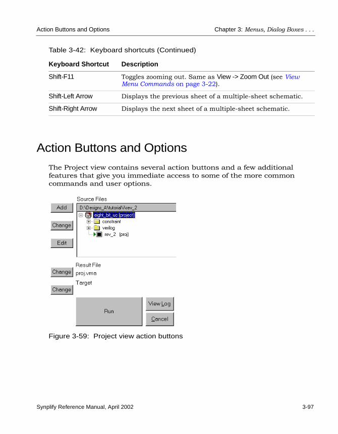
Action Buttons and Options Chapter 3: Menus, Dialog Boxes . . .
Synplify Reference Manual, April 2002 3-97
Action Buttons and Options
The Project view contains several action buttons and a few additional features that give you immediate access to some of the more common commands and user options.
Figure 3-59: Project view action buttons
Shift-F11 Toggles zooming out. Same as View -> Zoom Out (see View Menu Commands on page 3-22).
Shift-Left Arrow Displays the previous sheet of a multiple-sheet schematic.
Shift-Right Arrow Displays the next sheet of a multiple-sheet schematic.
Table 3-42: Keyboard shortcuts (Continued)
Keyboard Shortcut Description

LO
Chapter 3: Menus, Dialog Boxes . . . Action Buttons and Options
3-98 Synplify Reference Manual, April 2002
The following table describes the Project View action buttons and options.
Table 3-43: Project view action buttons and options
Button / Option Action
Frequency (MHz) You use this field to set the global frequency, which you can override locally with attributes. Same as setting the frequency with Project -> Implementation Options (see Project Menu Commands on page 3-30).
Symbolic FSM Compiler
Turning this on enables special FSM optimizations. Same as enabling the FSM Compiler option with Project -> Implementation Options (see Project Menu Commands on page 3-30).
Resource Sharing When enabled, makes the synthesis use resource sharing techniques. Same as enabling the Resource Sharing option on the Options/Constraints panel of the Options for implementation dialog box (see Options/Constraints Panel on page 3-33). This produces the resource sharing report in the log file (see Resource Usage Report on page 1-29).
Run Runs synthesis (compilation and mapping). Same as the Run -> Synthesize command (see Run Menu Commands on page 3-43).

Synplify Reference Manual, April 2002 4-1
C H A P T E R 4
Tcl Commands and Scripts
The following topics contain information about Tcl commands and scripts:
• Introduction to Tcl on page 4-2
• Batch Mode on page 4-6
• Tcl Commands for Synthesis on page 4-9
• Tcl Script Examples on page 4-21

LO
Chapter 4: Tcl Commands and Scripts Introduction to Tcl
4-2 Synplify Reference Manual, April 2002
Introduction to Tcl
Tcl (Tool Command Language) is a popular scripting language for control-ling software applications. Synplicity has extended the Tcl command set with additional commands that you can use to run the Synplicity programs. These commands are not intended for use in controlling inter-active debugging, but you can use them to run synthesis multiple times with alternate options to try different technologies, timing goals, or constraints on a design.
Tcl scripts are text files that have a “tcl” file extension (.tcl) and contain a set of Tcl commands designed to complete a task on set of tasks.
The Synplicity Tcl commands are described in this chapter. For informa-tion on the standard Tcl commands, syntax, language and conventions, refer to the Tcl online help provided in your installation directory (Help -> TCL Help).
Tcl ConventionsHere is a list of conventions to respect when entering Tcl commands and/or creating Tcl scripts.
• Tcl is case sensitive.
• Comments begin with a hash mark or pound sign (#).
• Enclose all path names and filenames in double quotes (" ").
• Use a forward slash (/) as the separator between directory and path names, even on the PC. For example:
designs/big_design/test.v

Introduction to Tcl Chapter 4: Tcl Commands and Scripts
Synplify Reference Manual, April 2002 4-3
Creating Tcl ScriptsThis section provides information on creating Tcl scripts. However, details on the commands used are not provided here. For information on command syntax and usage, see the individual command sections of this chapter. To create a Tcl script:
1. Open a text file for the script and specify a new project using the project -new command.
2. Add HDL source files to the script for your project by using the add_file -verilog or add_file -vhdl command.
3. Use synthesis control Tcl commands to set the target technology, design speed goal, enable the symbolic FSM compiler and to set other options with the set_option command.
4. Use vendor-specific Tcl commands to set your target technology, part, package and speed grade, and to change the default mapping options for your target technology such as fan-out limit. Refer to the section for your vendor for more information.
5. (Optional): Load a constraint file using the add_file -constraint command to set timing constraints and vendor-specific attributes.
6. Specify synthesis of your Project using the project -run command. If you want, you can leave out the project -run command and instead, click the Run button in the Project window after running your Tcl script.
7. Save the script using a “tcl” file extension (.tcl).

LO
Chapter 4: Tcl Commands and Scripts Introduction to Tcl
4-4 Synplify Reference Manual, April 2002
Starting in Batch Mode Using a Project FileBatch mode is only available if you have a floating license. You can run batch mode from a project file or a Tcl script; the former is easier. For information about using a Tcl script for batch mode, see Starting in Batch Mode Using a Tcl Script on page 4-7.
1. Create a project file either from the Project window, or by typing the appropriate Tcl commands into a .prj project file with an ASCII text editor. A project file is a Tcl file that contains Tcl synthesis commands.
– Set implementation options (Project -> Implementation Options or the set_option Tcl command). See Tcl Commands and Scripts on page 4-1, for information about the Tcl commands you can include.
– Add project files such as HDL source files, constraint files, and Tcl scripts (File -> Build Project or the add_file Tcl command).
– Save the project file (File -> Save). If you are typing the commands into a text file, make sure the file has a “prj” extension (.prj).
2. From the command prompt, go to the directory where the project file is located.
3. Type the command that initiates batch mode for the tool you are using at a UNIX or DOS command line. For example:
% synplify -batch project_name.prj
The Synplify synthesis tool starts in batch mode, and synthesizes the design using the options you set in the .prj project file.
4. Check the results in the project_name.srr file.
If there are errors, see the stdout (usually the monitor) in UNIX or the stdout.log file in Microsoft Windows.

Introduction to Tcl Chapter 4: Tcl Commands and Scripts
Synplify Reference Manual, April 2002 4-5
Executing Tcl ScriptsTo execute a Tcl script:
1. Choose Run -> Run Tcl Script.
2. Choose your Tcl script file from the list.
3. Click Open.
Including Command Files in a Project You can include a Tcl command file in the source files list of a project. To do this, right-click in the Project view, then choose Add Source File in the popup menu. From the source file list, select the Tcl command file you want to include.

LO
Chapter 4: Tcl Commands and Scripts Batch Mode
4-6 Synplify Reference Manual, April 2002
Batch Mode
Starting in Batch Mode Using a Project FileBatch mode is only available if you have a floating license. You can run batch mode from a project file or a Tcl script; the former is easier. For information about using a Tcl script for batch mode, see Starting in Batch Mode Using a Tcl Script on page 4-7.
1. Create a project file, either from the Project window in the GUI, or by typing the appropriate Tcl commands into a .prj project file using an ASCII text editor. A project file is a Tcl file that contains Tcl synthesis commands.
– Set implementation options as needed (Project -> Implementation Options or the set_option Tcl command). See Tcl Commands for Synthesis on page 4-9 for information about the Tcl commands you can include.
– Add project files such as HDL source files, constraint files, and Tcl scripts (File -> Build Project, the Add File button in the Project view, or the add_file Tcl command).
– Save the project file (File -> Save). If you are typing the commands into a text file, make sure the file has a “prj” extension (.prj).
2. From the command prompt, go to the directory where the project file is located.
3. Type the following command, which initiates batch mode, at a UNIX or DOS command line:
% synplify -batch project_name.prj
The Synplify synthesis tool starts in batch mode, and synthesizes the design using the options you set in the .prj project file.
4. Check the results in the project_name.srr file.
If there are errors, see stdout (usually the monitor) in UNIX, or file stdout.log in Microsoft Windows.

Batch Mode Chapter 4: Tcl Commands and Scripts
Synplify Reference Manual, April 2002 4-7
Starting in Batch Mode Using a Tcl ScriptBatch mode is only available if you have a floating license. You can run batch mode from a project file or a Tcl script. Running through a project file is generally easier (see Starting in Batch Mode Using a Project File on page 4-4 for information). Tcl (Tool command language) is a popular, easy-to-use scripting language for controlling software applications. A project file is also in the Tcl format, but it has a “prj” extension (.prj). A Tcl synthesis script has a “tcl” extension (.tcl).
You can use a Tcl script to do a single synthesis run, or for different runs using different technologies, timing goals and constraints. Advanced users, in particular, often use a single script to run multiple synthesis implementations with different options. You can run a Tcl script in batch mode as described here, from the Project view using Run->Run Tcl Script.
To run a Tcl script in batch mode:
1. Using an ASCII text editor, enter the beginning and ending Tcl commands.
project -new
#All other Tcl commands go here
project -runexit
2. Enter the Tcl commands. For a complete list of Tcl commands, see Tcl Commands for Synthesis on page 4-9.
3. Save the file using a .tcl file extension in the same directory as the other project files, HDL source files, constraint files, and possibly Tcl scripts.
4. At the command prompt in a command or Tcl window, navigate to the directory where the Tcl files are located.
5. At the command prompt, type this command to initiate the batch process:
synplify -batch Tcl_script_name.tcl
This command runs the Synplify synthesis tool in batch mode, without opening the Project window. It synthesizes the design using the commands in the Tcl file.

LO
Chapter 4: Tcl Commands and Scripts Batch Mode
4-8 Synplify Reference Manual, April 2002
6. Check the results in stdout and the file project_name.srr.
The synthesis tool reports process status via return codes, stdout and .srr files. For UNIX systems, stdout is usually directed to the monitor. For Microsoft Windows, file stdout.log is written.
Synthesis status (compilation and mapping) and errors are written to the .srr log file for each project. The synthesis tool also reports success and failure return codes: 0 for successful process comple-tion; 1 for process failure or error conditions. Warnings return a successful process return code of 0. If the Tcl script incurs an error, check the stdout.

Tcl Commands for Synthesis Chapter 4: Tcl Commands and Scripts
Synplify Reference Manual, April 2002 4-9
Tcl Commands for Synthesis
You use the following Tcl commands to create and synthesize projects, add and open files, and control synthesis. The commands are listed in alphabetical order.
• add_file on page 4-9
• constraint_file on page 4-10
• get_env on page 4-11
• get_option on page 4-11
• project on page 4-12
• project_file on page 4-13
• set_option on page 4-15
• Vendor-Specific Tcl Commands on page 4-19
add_file Adds files to a project.
Syntaxadd_file [-language] [-lib libraryName] [-_include] fileName
where language is one of the following:.
Depending on the language specified, the remaining command line arguments may or may not be available. The command line syntax for adding Verilog and VHDL files is as follows:
add_file -verilog fileName.v
language file extension
-verilog .v
-vhdl .vhd, .vhdl
-constraint .sdc

LO
Chapter 4: Tcl Commands and Scripts Tcl Commands for Synthesis
4-10 Synplify Reference Manual, April 2002
add_file -vhdl [-lib libraryName] fileName.vhd
Examples
Read in the Verilog and constraint files for the design called top.
% add_file -verilog controller.v% add_file -verilog interface.v% add_file -verilog memory.v% add_file -verilog top.v% add_file -constraint top.sdc
Read in the VHDL IP files for the design called cpu.
% add_file -vhdl -lib work hard_IP1.vhd% add_file -vhdl -lib work hard_IP2.vhd
constraint_file Manipulates the constraint files used by the active implementation.
Syntaxconstraint_file {-enable constraintFileName | -disable constraintFileName |
-list | -all | -clear }
The following table describes the command options.
Table 4-1: constraint_file Tcl command options
Option Description
-enable Selects the specified constraint file to be used by the active implementation.
-disable Excludes the specified constraint file from being used for the active implementation
-list Lists the constraint files used by the active implementation
-all Selects (includes) all the project constraint files for the active implementation.
-clear Clears (excludes) all the constraint files for the active implementation

Tcl Commands for Synthesis Chapter 4: Tcl Commands and Scripts
Synplify Reference Manual, April 2002 4-11
Examples
List all constraint files added to a project, then disable one of these files for the next synthesis run.
% constraint_file -list attributes.sdc clocks1.sdc clocks2.sdc eight_bit_uc.sdc
% constraint_file -disable eight_bit_uc.sdc
Disable all constraint files previously enabled for the project, then enable only one of them for the next synthesis run.
% constraint_file -clear
% constraint_file -enable clocks2.sdc
get_envReports the value of a predefined system variable.
Syntaxget_env system_variable
Once you use this command in a Tcl script, you can subsequently specify the value of the variable using the $system_variable syntax. This can be useful for specifying paths in your scripts. For example, if you have defined the path to your project file in a MY_PROJECT variable, you could include the following in a Tcl script:
add_file $MY_PROJECT
get_optionReports the settings of predefined project and device options. The options are the same as those for set_option. See set_option on page 4-15 for details.
Syntaxget_option -optionName

LO
Chapter 4: Tcl Commands and Scripts Tcl Commands for Synthesis
4-12 Synplify Reference Manual, April 2002
project Runs job flows, to create, load, save, and close projects, and to change and examine project status.
Syntaxproject {-run mode |
-new [projectPath] | -load projectPath | -close | -save | -result_file [resultFilePath] | -result_format [resultFormat] | -log_file [logfileName] | -active [projectName] | -dir | -file | -name | -list | -filelist }
The following table describes the command options.
Table 4-2: project command options
Option Description
-run mode Performs the indicated action (mode) on the currently active project, where mode is one of the following keywords:• compile – Compiles (only) the currently active project.• synthesis – Compiles (if necessary) and synthesizes the
currently active project.• synthesis_check – Verifies that the design is functionally
correct; errors are reported in the log file.• syntax_check – Verifies that the HDL is syntactically correct;
errors are reported in the log file.
-new Creates a new workspace/project in the current working directory. If projectPath is specified, creates the project in the specified project directory. The workspace project name defaults to Workspace.
-load Loads the project file specified by projectPath.
-close Closes the currently active project.
-save Saves the currently active project.
-result_format Sets the synthesis result file format. If resultFormat is specified, changes the result file type to the format specified. The format varies with the vendor and the technology used.
-log_file Reports the name of the project log file. If logfileName is specified, changes the base name of the log file.

Tcl Commands for Synthesis Chapter 4: Tcl Commands and Scripts
Synplify Reference Manual, April 2002 4-13
Examples
Load the project top.prj and compile the design only, for example, so you can create a .sdc file in the SCOPE spreadsheet or see an RTL schematic representation of the design.
% project -load top.prj% project -run compile
Load a project, specify a log filename other than the default (top.srr), and synthesize the design.
% project -load top.prj% project -log_file top_Feb14.srr% project -run synthesis
In the example above, you can also use the command project -run, since the default is synthesis.
project_file Used to manipulate and examine project files.
-active Shows the active project. If projectName is specified, makes the specified project the active project.
-result_file Names the synthesis result file. If resultFilePath is specified, changes the name/location of the result file to the path specified.
-dir Shows the project directory for the active project.
-file Shows the active project filename.
-name Returns the active project name.
-list Returns a list of the loaded projects.
-insert Adds selected projects to the workspace project.
Table 4-2: project command options (Continued)
Option Description

LO
Chapter 4: Tcl Commands and Scripts Tcl Commands for Synthesis
4-14 Synplify Reference Manual, April 2002
Syntaxproject_file {-lib fileName [libName] | -name fileName [newPath] |
-time fileName [format] | -date fileName |-type fileName | -move fileName1 [fileName2] |-remove fileName }
The following table describes the command options.
Examples
List the files added to a project and remove a file.
% project -filelistpath_name1/cpu.v path_name1/cpu_cntrl.v path_name2/cpu_cntrl.vhd
% project_file -remove path_name2/cpu_cntrl.vhd
Table 4-3: project_file command options
Option Description
-lib Shows the project file library associated with fileName. If libName is specified, changes the project file library for the specified file to libName.
-name Shows the project file path for the specified file. If newPath is specified, changes the location of the specified project file to the directory path specified by newPath.
-time Shows the file time stamp. If a format is specified, changes the composition of the time stamp according to the combination of the following time formatting codes: %H (hour 00-23)%M (minute 00-59)%S (second 00-59)%d (day 01-31)%b (abbreviated month)%Y (year with century).
-date Shows the file date.
-type Shows the file type.
-move Positions fileName1 after fileName2 in HDL file list. If fileName2 is not specified, moves fileName1 to the top of the list.
-remove Removes the specified file from the project file list.

Tcl Commands for Synthesis Chapter 4: Tcl Commands and Scripts
Synplify Reference Manual, April 2002 4-15
set_optionSets the settings of predefined project and device options.
Syntaxset_option -optionName optionValue
The following table lists the generic arguments for setting the device technology, part and speed grade. These options are equivalent to the options available on the Device panel of the Project -> Implementation Options dialog box.
The following table is an alphabetical list of other arguments to the set_option and get_option commands, with brief descriptions and UI equiva-lents from the Project -> Implementation Options dialog box. Some options are technology-specific, and others have technology-specific defaults or limitations. The table in Vendor-Specific Tcl Commands on page 4-19 summa-rizes where to go for vendor-specific details.
Table 4-4: set_option Tcl command options: technology, part, speed grade
Option Name Description
-technology keyword Sets the target technology for the implementation. Keyword is the vendor architecture. Refer to the appropriate vendor chapter or check the Device panel of the Options for implementation dialog box (see Device Panel on page 3-32) for a list of supported families.
-part part_name Specifies a part for the implementation. Check the Device panel of the Options for implementation dialog box (see Device Panel on page 3-32) for available choices.
-speed_grade value Sets the speed grade for the implementation. Check the Device panel of the Options for implementation dialog box (see Device Panel on page 3-32) for available choices.
-package value Sets the package for the implementation. This option is not available for certain vendor families, because it is set in the place-and-route software. Check the Device panel of the Options for implementation dialog box (see Device Panel on page 3-32) for available choices.
-grade value Same as -speed_grade. Included for backwards compatibility.

LO
Chapter 4: Tcl Commands and Scripts Tcl Commands for Synthesis
4-16 Synplify Reference Manual, April 2002
Table 4-5: set_option and get_option Tcl command options
Option Description GUI Equivalenta
-areadelay percent_value-area_delay_percentpercent_value
Sets the percentage of paths you want optimized. This option is available only in certain device technologies.
Percent of design to optimize for timing dialog box zone, Device Panel. See also Area/Delay Trade-off for CPLDs on page 1-19.
-autosm 1 | 0-symbolic_fsm_compiler 1 | 0
Enables/disables the FSM compiler.
FSM Compiler check box, Options/Constraints Panel.
-block 1 | 0 Enables/disables I/O insertion in some technologies. Same as -disable_io_insertion.
Disable I/O Insertion check box, Device Panel.
-clique 1 | 0-cliquing 1 | 0
Enables/disables the grouping of logic functions in Altera technologies.
Perform Cliquing check box, Device Panel.
-compiler_compatible 0 | 1 Disables pushing of tristates across process/block boundaries.
Complement of the Push Tristates Across Process/ Block Boundaries check box, VHDL and Verilog Panels
-default_enum_encoding default | onehot | gray | sequential
(VHDL only) Sets the default for enumerated types.
Default Enum Encoding, VHDL panel (see VHDL and Verilog Panels on page 3-36).
-disable_io_insertion 1 | 0 Enables/disables I/O insertion in some technologies. Same as -block.
Disable I/O Insertion, Device Panel.
-domap 1 | 0 Same as -map_logic for Xilinx macrocells. Supported for backwards compatibility.
Map Logic to Macrocells, Device Panel.

Tcl Commands for Synthesis Chapter 4: Tcl Commands and Scripts
Synplify Reference Manual, April 2002 4-17
-force_gsr yes | no | auto Enables/disables the forced use of the global set/reset routing resources in Lattice ORCA and Xilinx Spartan technologies. The auto setting allows the Synplify synthesis tool to decide whether to use the global set/reset resources.
Force GSR Usage, Device Panel.
-frequency value Sets the global frequency. Frequency, Options/Constraints Panel.
-include_path path (Verilog only) Defines the search path used by the ‘include commands in Verilog design files.
Include Path Order, Verilog panel (see VHDL and Verilog Panels).
-map_logic 1 | 0 Turns on direct mapping to technology-specific devices during synthesis. Applies to Altera (ATOMs and LCells), Lattice, and Xilinx (Macrocells) technologies.
Map Logic to ATOMs | LCells | Macrocells, Device Panel.
-maxterms value-max_terms_per_macrocellvalue
Sets the maximum number of terminals per macrocell. This option is available only if -map_logic is set to true. It applies to Lattice devices.
Maximum Terms/Macrocell, Device Panel.
-maxfan value-fanout_guide value
Sets the fanout limit guideline for the current project. Applies to Actel, Lattice ORCA, QuickLogic, and Xilinx technologies.
Fanout Guide, Device Panel.
Table 4-5: set_option and get_option Tcl command options (Continued)
Option Description GUI Equivalenta

LO
Chapter 4: Tcl Commands and Scripts Tcl Commands for Synthesis
4-18 Synplify Reference Manual, April 2002
-maxfan_hard 1 For Actel designs, it specifies that the -maxfan value is a hard fanout limit that the Synplify synthesis tool must not exceed.
Hard Limit to Fanout, Device Panel.
-maxfanin 1 | 0-fanin_limit value
Specifies the maximum fan-in (Lattice ispMach and Altera Max designs).
Maximum Cell Fanin, Device Panel.
-no_time_gated_clock Device Panel.
-num_critical_paths value Specifies the number of critical paths to report in the timing report.
Number of Critical Paths, Timing Report Panel.
-num_startend_points value Specifies the number of start and end points to include when reporting paths with the worst slack in the timing report.
Number of Start/End Points, Timing Report Panel.
-report_path value Sets the maximum number of critical paths in a forward-annotated SDF constraint file (Actel 500K and PA designs only).
Max Number of Critical Paths in SDF, Device Panel.
-resource_sharing 1 | 0 Enables/disables resource sharing.
Resource Sharing, Options/Constraints Panel.
-result_file filename Specifies the name of the results file.
Result File Name and Result Format, Implementation Results Panel.
-soft 1 | 0-soft_buffers 1 | 0
Makes non-critical Lcells soft in Altera MAX designs.
Soft LCELLs, Device Panel.
-top_module name Specifies the top-level module.
Top-level Entity/Module, VHDL and Verilog Panels.
Table 4-5: set_option and get_option Tcl command options (Continued)
Option Description GUI Equivalenta

Tcl Commands for Synthesis Chapter 4: Tcl Commands and Scripts
Synplify Reference Manual, April 2002 4-19
Vendor-Specific Tcl CommandsYou can find vendor-specific Tcl commands in the appropriate vendor appendix.
-use_reset_pin 1 | 0-userstpin 1 | 0
Determines whether the reset pin is used. (For Xilinx XC3000 only)
Use Dedicated Reset Pin, Device Panel.
-use_scan_for_test (tab)
-write_apr_constraint 1 | 0 Writes vendor-specific constraint files.
Write Vendor Constraint File, Implementation Results Panel.
-write_verilog 1 | 0-write_vhdl 1 | 0
Writes Verilog or VHDL mapped netlists.
Write Mapped Verilog/VHDL Netlist, Implementation Results Panel.
-xilinx_m1 (tab)
a. The panels referenced here belong to the Options for implementation dialog box.
Table 4-6: Vendor-specific Tcl commands
Vendor/Family Tcl Commands Described in...
Actel Actel-specific Tcl Command Options on page A-8
Altera FLEX and ACEX Maximizing Results with FLEX and ACEX on page B-26
Altera APEX, Excalibur and Mercury
Maximizing Results with APEX, APEX II, Mercury, Excalibur on page B-14
Altera MAX Maximizing Results with MAX on page B-32
Atmel Atmel-specific Tcl Command Options on page C-4
Cypress Cypress-specific Options on page D-11
Lattice GAL/PAL and isp Lattice GAL and isp Devices on page E-11
Lattice Mach MACH Devices on page E-12
Lattice ORCA Lattice ORCA Devices on page E-4
Table 4-5: set_option and get_option Tcl command options (Continued)
Option Description GUI Equivalenta

LO
Chapter 4: Tcl Commands and Scripts Tcl Commands for Synthesis
4-20 Synplify Reference Manual, April 2002
QuickLogic QuickLogic-specific Tcl Command Options on page F-6
Triscend Triscend-specific Tcl Command Options on page G-3
Xilinx Spartan Using Spartan on page H-27
Xilinx Virtex Using Virtex on page H-30
Xilinx XC4000 Using XC4000 on page H-34
Xilinx XC3000, XC5200, XC9500, CoolRunner, CoolRunner-II CPLDs
Using XC3000 and XC5200 on page H-37
Table 4-6: Vendor-specific Tcl commands (Continued)
Vendor/Family Tcl Commands Described in...

Tcl Script Examples Chapter 4: Tcl Commands and Scripts
Synplify Reference Manual, April 2002 4-21
Tcl Script Examples
This section provides examples of Tcl scripts.
• Using Several Target Technologies
• Different Clock Frequency Goals
• Setting Options and Timing Constraints
• Bottom-up Synthesis
Using Several Target Technologies
# Run synthesis multiple times without exiting while trying different# target technologies. View their implementations in HDL Analyst.
# Open a new Project.project -new
# Set the design speed goal to 33.3 MHz.set_option -frequency 33.3
# Add a Verilog file to the source file list.add_file -verilog "andorxor.v"
# Create a new Tcl variable, to be known as $try_these, that will be # used to synthesize the design using different target technologies.
set try_these {ACT3APEX20K3200DXFLEX10KMAX9000pLSI1KORCA2CpASIC1MACHXC4000EXC4000EXXC4000XLXC5200XC9500VirtexVirtexe

LO
Chapter 4: Tcl Commands and Scripts Tcl Script Examples
4-22 Synplify Reference Manual, April 2002
Virtex2}
# Loop through synthesis for each target technology.foreach technology $try_these {
# Set the target technology from the $try_these listset_option -technology $technology
# Run synthesis.project -run
# Display the Technology View showing the implementation.open_file -technology_view
}
# Display one RTL View showing the RTL level schematic. # The RTL level schematic is the same for all synthesis runs since the# design has not changed.
open_file -rtl_view
Different Clock Frequency Goals
# Run synthesis six times on the same design using different clock # frequency goals. We want to see what the speed/area tradeoffs are for # the different timing goals.
# Load an existing Project. This Project was created from an # interactive session by saving the Project file after adding all the# necessary files, and setting options in the Project->Implementation #Options dialog box.
project -load "design.prj"
# Create a Tcl variable, called $try_these, that will be used to # synthesize the design with different frequencies.
set try_these {20.024.028.032.036.040.0
}
# Loop through each frequency, trying each oneforeach frequency $try_these {

Tcl Script Examples Chapter 4: Tcl Commands and Scripts
Synplify Reference Manual, April 2002 4-23
# Set the frequency from the try_these listset_option -frequency $frequency
# Since I want to keep all Log Files, save each one. Otherwise # the default Log File name "<project_name>.srr" is used, which is# ovewritten on each run. Use the name "<$frequency>.srr" obtained from the# $try_these Tcl variable.
project -log_file $frequency.srr
# Run synthesis.project -run
# Display the Log File for each synthesis runopen_file -edit_file $frequency.srr}
Setting Options and Timing Constraints
# Set a number of options and use timing constraints on the design.
# Open a new Projectproject -new
# Set the target technology, part number, package, and speed grade options.set_option -technology XC4000Eset_option -part XC4013Eset_option -package PC84set_option -speed_grade -1
# Load the necessary VHDL files. Add the top-level design last.add_file -vhdl "statemach.vhd"add_file -vhdl "rotate.vhd"add_file -vhdl "memory.vhd"add_file -vhdl "top_level.vhd"
# Add a timing Constraint file and vendor-specific attributes.add_file -constraint "design.sdc"
# The top level file ("top_level.vhd") has two different designs, of # which the last is the default entity. Try the first entity (design1)# for this run. In VHDL, you could also specify the top level architecture# using <entity>.<arch>
set_option -top_module design1
# Turn on the Symbolic FSM Compiler to re-encode the state machine # into one-hot.
set_option -symbolic_fsm_compiler true

LO
Chapter 4: Tcl Commands and Scripts Tcl Script Examples
4-24 Synplify Reference Manual, April 2002
# Set the design frequency.set_option -frequency 30.0
# Save the existing Project to a file. The default synthesis Result File # is named "<project_name>.<ext>" so, if you wanted the synthesis Result# File to be named something other than "design.xnf", you will change # it with the project -result_file "<name>.xnf" command
project -save "design.prj"
# Synthesize the existing Projectproject -run
# Open an RTL Viewopen_file -rtl_view
# Open a Technology Viewopen_file -technology_view
# --------------------------------------------------# This constraint file, "design.sdc," is read by "test3.tcl"# with the add_file -constraint "design.sdc" command. Constraint files # are for timing constraints and synthesis attributes.# --------------------------------------------------# Timing Constraints:# --------------------------------------------------# The default design frequency goal is 30.0 MHz for four clocks. Except# that clk_fast needs to run at 66.0 MHz. Override the 30.0 MHz default# for clk_fast.
define_clock {clk_fast} -freq 66.0
# The inputs are delayed by 4 nsdefine_input_delay -default 4.0
# except for the "sel" signal, which is delayed by 8 nsdefine_input_delay {sel} 8.0
# The outputs have a delay off-chip of 3.0 nsdefine_output_delay -default 3.0
# From a previous run it was noticed in Technology View that the critical# paths are the flip-flop to flip-flop paths going to register "inst3.q[0]"# (in the memory). Improve the paths going to inst3.q[0] by 3.0 ns.
define_reg_input_delay {inst3.q[0]} -improve 3.0
# ---------------------------------------------------# Xilinx-specific Attribute Constraint:# ---------------------------------------------------

Tcl Script Examples Chapter 4: Tcl Commands and Scripts
Synplify Reference Manual, April 2002 4-25
# Assign a location for scalar port "sel". These VHDL object names are # case sensitive.
define_attribute {sel} xc_loc "P139"
# Assign a pad location to all bits of a bus.define_attribute {b[7:0]} xc_loc "P14, P12, P11, P5, P21, P18, P16, P15"
# Assign a fast output type to the pad.define_attribute {a[5]} xc_fast 1
# Use a regular buffer, not a clock buffer for clock "clk_slow". Save the# clock buffers for the fast clocks
define_attribute {clk_slow} syn_noclockbuf 1
# Do not do regular buffering for "clk_slow", because its the# slow clock and the timing can be relaxed on it.
# Set the maximum fanout to 10000.define_attribute {clk_slow} syn_maxfan 10000
Bottom-up Synthesis
# Bottom-up synthesis of a large design.
# The Source command reads in other Tcl scripts. Each of these scripts does# a compile of one logic block and has its own constraint file.
source "statemach.tcl"source "microproc.tcl"source "handshake.tcl"source "fifo.tcl"source "cherstrp.tcl"
# After synthesizing the individual logic blocks, create a Project for the# top-level design.
project -new
# Add the top level VHDL file.add_file -vhdl top_level.vhd
# Add the top level global constraint file.add_file -constraint top_level.sdc
# Set the top level optionsset_option -technology FLEX10Kset_option -part EPF10K70set_option -speed_grade -3set_option -frequency 50.0set_option -symbolic_fsm_compiler true

LO
Chapter 4: Tcl Commands and Scripts Tcl Script Examples
4-26 Synplify Reference Manual, April 2002
# Set the output file informationproject -result_file top_level.edfproject -log_file top_level.srr
# Save the Project to fileproject -save top_level.prj
# Run the Projectproject -run
# Open the top level RTL and Technology Viewsopen_file -rtl_viewopen_file -technology_view
# --------------------------------------------------# This file, "statemach.tcl," is read by "bottom_up.tcl," (the # bottom up Tcl script) with the command "source statemach.tcl."# The other .tcl scripts are similar.# --------------------------------------------------# Open a new Project for "statemach"
project -new
# Add the VHDL file for this logic block.add_file -vhdl statemach.vhd
# Add the constraint file for this logic block.add_file -constraint statemach.sdc
# Set the other options for "statemach".set_option -technology FLEX10Kset_option -part EPF10K70set_option -speed_grade -3set_option -frequency 50.0set_option -symbolic_fsm_compiler true
# Set the Project outputsproject -result_file statemach.edfproject -log_file statemach.srr
# Save this Projectproject -save statemach.prj
# Run this Projectproject -run
# ---------------------------------------------# This file (statemach.sdc) is the constraint file read by# "statemach.tcl," with the command add_file -constraint statemach.sdc.# This constraint file is specific to this logic block " statemach "

Tcl Script Examples Chapter 4: Tcl Commands and Scripts
Synplify Reference Manual, April 2002 4-27
# ---------------------------------------------# Timing Constraints:# ---------------------------------------------
define_input_delay -default -100define_output_delay -default -100define_input_delay RESET -10define_reg_input_delay {q[8]} -improve 4.0
# --------------------------------------------# Altera-Specific Attributes:# --------------------------------------------
define_attribute {inst1.sqrt8} altera_implement_in_eab 1

LO
Chapter 4: Tcl Commands and Scripts Tcl Script Examples
4-28 Synplify Reference Manual, April 2002

Synplify Reference Manual, April 2002 5-1
C H A P T E R 5
Using HDL Analyst
This chapter describes the HDL Analyst and its commands:
• About HDL Analyst on page 5-2
• Getting Started with HDL Analyst on page 5-4
• Traversing Hierarchy on page 5-12
• Multisheet Schematics in HDL Analyst on page 5-15
• Filtering Schematics in HDL Analyst on page 5-17
• Analyzing Critical Paths in HDL Analyst on page 5-18

LO
Chapter 5: Using HDL Analyst About HDL Analyst
5-2 Synplify Reference Manual, April 2002
About HDL Analyst
HDL Analyst is a graphical productivity tool that helps you visualize your synthesis results and analyze how you can improve the performance and area results of a device. HDL Analyst is an option to the Synplify synthesis tool.
HDL Analyst ViewsHDL Analyst consists of two schematic views that graphically display the design information after compilation and mapping, respectively:
• The RTL-level schematic view
The RTL view displays your design as a high-level, technology-independent schematic. It consists of a Hierarchy Browser and a schematic, which represents a graphical view of the design after compilation. For a more detailed description of the view, see RTL View on page 2-4.
• The technology-primitive level schematic
The Technology view is a low-level, vendor-specific view of your design after technology mapping. Like the RTL view, it consists of a Hierarchy Browser and schematic, which shows vendor-specific components like look-up tables, cascade and carry chains, F and H Maps, muxes, and flip-flops. For a more detailed description of the view, see Technology View on page 2-5.
By graphically displaying the information, HDL Analyst makes it easy to analyze your design and debug it where necessary. It helps you visualize where coding changes or timing constraints might reduce the area or increase performance. You can crossprobe between the RTL and Technology views, the HDL source code, and the FSM viewer. HDL Analyst also lets you highlight and isolate parts of the design, like critical paths, so that you can analyze problem areas, add timing constraints, and resynthesize.

About HDL Analyst Chapter 5: Using HDL Analyst
Synplify Reference Manual, April 2002 5-3
HDL Analyst CommandsThe HDL Analyst menu choices become available after you run synthesis. You can also get to these commands from a popup menu that you access by right clicking in an RTL or Technology view. There are four places to access HDL Analyst commands:
• HDL Analyst menubar menu commands
These are the commands on the HDL Analyst menubar menu. Not all the menu choices are available all the time; availability depends on which view is active and which objects are selected. The HDL Analyst menu commands are repeated in the popup menu in the RTL and Technology views. See Hdl Analyst Menu Commands on page 3-46, for more information about the commands.
• HDL Analyst popup menu commands
Open a popup menu by right-clicking in an RTL or Technology view. The popup menu includes commonly used commands from the View and HDL Analyst menubar menus. Availability of particular commands depends on which view is active and which objects are selected. See RTL View and Technology View Popup Menus on page 3-85, for more infor-mation.
• HDL Analyst toolbar icons
The HDL Analyst toolbar is the quickest way to access to open views and filter objects. See Analyst Toolbar on page 3-90, for more informa-tion.
• View menubar menu Commands
When an RTL view or Technology view is the active window, the View menubar menu contains additional commands for graphical analysis. Some commands are duplicated in the popup menu. For a description of the additional View menu commands see View Menu Commands on page 3-22.

LO
Chapter 5: Using HDL Analyst Getting Started with HDL Analyst
5-4 Synplify Reference Manual, April 2002
Getting Started with HDL Analyst
This section contains general information to familiarize yourself with HDL Analyst and the RTL and Technology views. It discusses the following topics:
• Setting Up HDL Analyst for Synplify
• Viewing Object Information in HDL Analyst
• Finding Objects by Name
• Selecting Objects in HDL Analyst
• Crossprobing
• Setting Colors in HDL Analyst
• Changing Amount of Logic Displayed
Setting Up HDL Analyst for SynplifyHDL Analyst is included with some Synplicity products, but is sold as an option for the Synplify tool; it then requires an additional license to run. If you have an HDL Analyst license, enter it into your Synplify tool license file. If you need assistance entering this feature, ask your system admin-istrator or contact Synplicity at this e-mail address:
Viewing Object Information in HDL Analyst
Tooltip Information
When you put the mouse pointer over an object, you see a tooltip flag that displays information about the object. Tooltips display the names of instances, nets, ports, sheet connectors and attributes attached to them. For example, Instance: a_aux[7:0] of primitive type dff. If you are viewing a critical path in a Technology view, it also displays timing infor-mation. This following example shows tooltip information for a state machine:

Getting Started with HDL Analyst Chapter 5: Using HDL Analyst
Synplify Reference Manual, April 2002 5-5
To prevent tooltips from displaying, choose View -> Toolbars and disable Show Tooltips.
Status Bar Information
As you move the mouse pointer over objects, the status bar at the bottom of the window displays information about the object. The status bar displays the names of instances, nets, ports, sheet connectors and attributes attached to them. If you are viewing a critical path in a Technology view, it also displays timing information. The information is the same as that displayed in a tooltip, but it might contain a little additional information. This is an example of what you see for a net:
Net clk (local net clk) Fanout=4
If you prefer information not to be displayed when you move your mouse, turn off the View -> Status Bar menu item.
Finding Objects by NameIf you cannot locate the object you want based on the information in the tooltips or status bar, use the HDL Analyst -> Find command. The Object Properties dialog box lists objects by type (instances, symbols, nets, and ports) and lets you use wildcards to find them. For more information, see Find Dialog Box on page 3-19.

LO
Chapter 5: Using HDL Analyst Getting Started with HDL Analyst
5-6 Synplify Reference Manual, April 2002
Finding ObjectsYou can use the Hierarchy Browser to browse and find objects. You can also use commands from the popup menu to find and select objects like net drivers or registers on a path.
Selecting Objects in HDL AnalystThis section outlines how to select and unselect objects in HDL Analyst.
Selecting Objects
This is the default mouse pointer mode, indicated by the crosshair pointer. You also have Push/Pop mode, indicated by one or two vertical arrows (Using Push/Pop Mode on page 5-13). To return to the default pointer mode from another mode, click the right mouse button.
• To select a single object, click it in the schematic or click its name in the Hierarchy Browser (left pane of the view).
HDL Analyst highlights the selected object in red. Use the Hierarchy Browser to locate objects by name. You can also use the Find command to locate the objects you want.
• To select more than one object, do one of the following:
– Drag a selection rectangle around the objects to select.
– Add objects to the current selection by pressing and holding the Control key (Ctrl) while clicking the objects to be added.
• To select all of the objects of a certain type, right-click and choose Select All -> <object> from the popup menu.
• To select all the instances on a net or the net drivers, use the commands from the popup menu.
Unselecting Objects
To unselect highlighted objects, click the left mouse button in a blank area of the schematic or click the right mouse button to bring up the popup menu and choose Unselect All.

Getting Started with HDL Analyst Chapter 5: Using HDL Analyst
Synplify Reference Manual, April 2002 5-7
Setting Colors in HDL AnalystYou can customize the colors used in the RTL view and Technology view schematics by editing the synplify.ini file. On the Microsoft® Windows® operating system, this file is in the WINDOWS (or WINNT) directory. On the UNIX operating system, it is in the windows subdirectory of your home directory (~/windows, where ~ is your home directory, which can be set via environment variable $HOME).
You adjust the RGB (red, green, blue) values in the “[Schematics]” section of the file by editing the appropriate variables, as shown in the following table.
Here are some example RGB values:
0 0 0 = black255 255 255 = white255 0 0 = red200 200 200 = gray
Changing Amount of Logic DisplayedYou can change the amount of logic displayed on a single schematic sheet in the Technology view, by editing the PartitionSize=value statement in the .ini file, as follows:
• To see your entire design on a single page, value should be greater than the total number of components in the design. Remember that a larger value generally means a longer time to display.
• To see a smaller area of your design on each schematic page, use a lower value.
Table 5-1: Adjusting RGB values in HDL Analyst
To Change... Adjust Variable...
The default color for instances, nets, and ports,
SSC_DEFAULT_LINE
The highlight (selected object) color SSC_HILIT
The color for unselected objects SSC_NOSELECTED
The window background color SSC_BACKGROUND

LO
Chapter 5: Using HDL Analyst Crossprobing
5-8 Synplify Reference Manual, April 2002
Crossprobing
Crossprobing Across ViewsYou can crossprobe objects and logic back and forth, from the RTL and Technology views to source code, post-place-and-route timing-report files, or a log file. Not all objects or source code crossprobe to other views, because some source code and RTL view logic is optimized away during synthesis.The following table summarizes crossprobing to and from the HDL Analyst view (RTL and Technology).
Crossprobing to Visual EliteVisual Elite� is a GUI that you can use to create and edit HDL designs. Cross probing is available, in both directions, between Synplicity’s synthesis tools and Visual Elite. Visual Elite is a product of Innoveda�; for more information see http://www.innoveda.com/.
Table 5-2: Crossprobing with HDL Analyst views
Crossprobe From To... Do...
HDL Analyst view Other open view
Select an object in the RTL or Technology view. The object is automatically highlighted in all other open views.
HDL Analyst view Unopened source code view
Double-click the object in the HDL Analyst view.For example, if you double-click a look-up table in a Technology view, the Synplify synthesis tool opens a source code window and highlights the part of the code that contains the selected look-up table.
A source code window
HDL Analyst view
Open the HDL Analyst view. To crossprobe to the Technology view, you must also have the RTL view open. The RTL view can be iconized. Select a part of the HDL code in the source code window. To jump to a specific RTL view sheet with the logic when you crossprobe, click the right mouse button over the selected text, and choose the sheet number.

Crossprobing Chapter 5: Using HDL Analyst
Synplify Reference Manual, April 2002 5-9
You can crossprobe to Visual Elite and trace component cause if you set up the Visual Elite software correctly. The following sections describe the setup for the Microsoft® Windows® and Unix operating systems, and describe how to crossprobe between the two.
• Setup on Microsoft® Windows® Operating System
• Setup on Unix Operating System
• Launching Synthesis from Visual Elite
• Crossprobing to Trace Component Cause
Setup on Microsoft® Windows® Operating System
To use Visual Elite and the Synplicity software together on the Microsoft® Windows® operating system, you need to do the following:
1. Make sure that Visual Elite tool is installed on your system, with a valid license.
2. Set variables.
– Set the VSH_LIB environment variable to point to the directory:
synplify_installation_dir/lib/innoveda/visual
– Point the VSH_VISUAL_COMMAND environment variable to either the VHDL or Verilog versions:
Vis_installation_dir/bin/vis_vhdl_version.exeVis_installation_dir/bin/vis_verilog_version.exe
– Set the LM_LICENSE_FILE environment variable to include the Synplicity license.
3. Set the path to include synplify_installation_dir/bin/mbin.
4. Set Visual Elite options:
– Open Visual Elite, go to the Primary menu bar, and choose Options -> Synthesis -> Remote Configuration, which brings up a dialog box.
– In the dialog box, choose No for the Remote Synthesis option.
– In the Synthesis Directory text box, enter the path to any directory for which you have write permission. Click OK.

LO
Chapter 5: Using HDL Analyst Crossprobing
5-10 Synplify Reference Manual, April 2002
Setup on Unix Operating System
To use Visual Elite and the Synplicity software together on a UNIX platform, you need to do the following:
1. Make sure that the Visual Elite tool is installed on your system, and its license is in effect.
2. Set environment variables.
– Set the VSH_LIB environment variable to point to the directory:
synplify_installation_dir/lib/innoveda/visual
– Point the VSH_VISUAL_COMMAND environment variable to either the Verilog or VHDL version:
Vis_installation_dir/Vis_VHDL_version/platform/bin/visual_elite
Vis_installation_dir/Vis_Verilog_version/platform/bin/visual_ver
3. Set the path.
set path = (synplify_installation_dir/bin $path)
Launching Synthesis from Visual Elite
To launch synthesis from Visual Elite, do the following:
1. In Visual Elite, specify that the HDL to be generated from your design is intended for synthesis by the Synplify tool.
2. Open the editing window for the top-level design, then choose Synthesis -> Script to open the Synthesis Script editing window.
3. In the Synthesis Script window, choose Tools -> Run.
4. In the Run Synplify dialog box, enter the path to a predefined project file, and specify the required mode of work: batch or interactive.
Alternatively, you can choose the Synthesis -> Run Synplify command in the design unit’s editing window without having to first specify your synthesis tool.

Crossprobing Chapter 5: Using HDL Analyst
Synplify Reference Manual, April 2002 5-11
Crossprobing to Trace Component Cause
You can crossprobe to trace the cause of a component from an RTL or Technology view back to a Visual Elite editor.
1. Open an RTL or Technology view.
2. Choose HDL Analyst -> External Cross Probing Engaged.
3. Click or double-click the component whose cause you want to trace.
Clicking once opens the Visual Elite editor and highlights the cause of that component. Double-clicking highlights the cause in Visual Elite, and also indicate the cause in the Synplicity synthesis tool source file window.
Crossprobing with ModelSimThe Model Technology, Inc. ModelSim HDL simulator can be integrated into the Synplify tool, to help you to debug your design by crossprobing waveforms.
1. Make sure you have the following:
– An installed copy of ModelSim EE or ModelSim PE, v5.2 or later.
– A compiled project for crossprobing.
Refer to the ModelSim User Guide for complete information on installing, starting, and running ModelSim.
2. In your Synplicity synthesis tool, do the following:
– Compile your project.
– Choose HDL Analyst -> External Crossprobing Engaged or type Ctrl-k to engage external crossprobing.
3. Start ModelSim, and do the following:
– Load your design.
– Type
source synplify_installation_dir/lib/mti/manager.tcl

LO
Chapter 5: Using HDL Analyst Traversing Hierarchy
5-12 Synplify Reference Manual, April 2002
– Engage crossprobing by clicking the Enable Cross Probe button in ModelSim.
4. To crossprobe waveforms, do the following:
– Identify signals by selecting ports, internal nets, and buses in the RTL view.
– Direct ModelSim to crossprobe those signals in the ModelSim waveform window.
Traversing Hierarchy
Schematic views have different layers of design hierarchy. HDL Analyst provides you with two ways of traversing hierarchy, the Hierarchy Browser, and Push/Pop mode. This section discusses the following hierarchy-related topics:
• Viewing Objects Across Design Levels and Views on page 5-12
• Using the Hierarchy Browser on page 5-13
• Using Push/Pop Mode on page 5-13
Viewing Objects Across Design Levels and ViewsSelecting an item in a given view or Hierarchy Browser causes that item to be crossprobed in all other open views and their Hierarchy Browsers. Items that can be crossprobed include ports, registers, and combination logic that has not been transformed.
Views track with their respective Hierarchy Browsers. Selecting an item causes the corresponding Hierarchy Browser to track or scroll to display the item. Selecting an item in a Hierarchy Browser causes the view to track to display that item. Views do not track when you crossprobe.
When a net is selected, HDL Analyst highlights it through all the hierar-chical instances it traverses. As you traverse the hierarchy, you see the continuation of the selected net highlighted at different levels.

Traversing Hierarchy Chapter 5: Using HDL Analyst
Synplify Reference Manual, April 2002 5-13
Using the Hierarchy BrowserThe Hierarchy Browser is best used for an overview, or when you need to browse and find an object of which you are unsure. If you want to move between design levels of a particular object, the Push/Pop mode is more direct. Refer to Using Push/Pop Mode on page 5-13 for details.
When you start an RTL or Technology view, a Hierarchy Browser automat-ically starts in the left side of the view. The RTL browser displays the hierarchy specified in the RTL design description. The Technology browser displays the hierarchy of your design after technology mapping.
The Hierarchy Browsers allow you to traverse hierarchy and select ports, internal nets, components, and submodules. The browsers list the names of the objects and a symbol. A plus sign in a square icon indicates that there is hierarchy under that object. A minus sign indicates that the design hierarchy has been expanded.
Using Push/Pop ModePush/Pop mode is best suited for traversing a specific hierarchy. If you want a general view, use the Hierarchy Browsers described in Using the Hierarchy Browser on page 5-13.
1. To start Push/Pop mode, do one of the following:
– Choose View -> Push/Pop Hierarchy.
– Click the right mouse button while the mouse pointer is in an RTL or Technology view, then choose Push/Pop Hierarchy from the popup menu.
– From the toolbar, click the Push/Pop Hierarchy button. This is the button containing an arrow pointing downward and an arrow pointing upward.
– Press F2.
The mouse pointer changes to an arrow. An arrow pointing down means that you can push into (descend) the instance under the pointer. An arrow pointing up indicates there is a hierarchical level above this one. You see this arrow when the pointer is over blank areas of the schematic. The status bar at the bottom of the window reports information about the objects over which you move the

LO
Chapter 5: Using HDL Analyst Traversing Hierarchy
5-14 Synplify Reference Manual, April 2002
pointer, including when an object is a primitive. You cannot push into a primitive.
2. To push (descend) into an object, click it.
3. To pop (ascend) a level, move the mouse pointer to a blank area, then click.
4. To exit Push/Pop mode, do one of the following:
– Right-click in an RTL or Technology view.
– Choose Push/Pop Hierarchy from the View menu.
– Click the Push/Pop Hierarchy icon in the toolbar.
– Press F2.

Multisheet Schematics in HDL Analyst Chapter 5: Using HDL Analyst
Synplify Reference Manual, April 2002 5-15
Multisheet Schematics in HDL Analyst
Sheet ConnectorsWhen you view a schematic that is too large to view on a single HDL Analyst schematic sheet, HDL Analyst partitions the design into multiple sheets. The Synplify synthesis tool inserts sheet connectors for nets that span multiple sheets. You can move to the sheet indicated by the connector by clicking the symbol.
Figure 5-1: Sheet connector
Viewing Other SheetsThe title bar in the RTL view or Technology view indicates how many sheets there are for the RTL-level or technology-primitive-level schematic. The schematic is initially opened to the first sheet (sheet number 1). For example:
adder: (RTL View) - sheet 1 of 1
alu: (Technology View) - sheet 1 of 13
The following steps show you common multisheet operations:
1. To view the next sheet of a multisheet schematic, do one of the following:
– Choose View -> Next Sheet.
– Right-click, and choose Next Sheet from the popup menu.
– Click the Next Sheet icon ( ).
– Type Ctrl-n.
2. To view the previous sheet, do one of the following:
– Choose View -> Previous Sheet.

LO
Chapter 5: Using HDL Analyst Multisheet Schematics in HDL Analyst
5-16 Synplify Reference Manual, April 2002
– Right-click, then choose Previous Sheet from the popup menu.
– Click the Previous Sheet icon ( ).
– Type Ctrl-p.
3. To view a specific sheet number, do any of the following:
– Choose View -> View Sheets, then specify the sheet number you want to view.
– Right-click, then choose View Sheets from the popup menu, and specify the sheet number.
– Type Ctrl-s to bring up the Sheet Selection dialog box, then specify the sheet number.
4. To view a schematic of selected items only, filter the schematic as described in Filtering Schematics in HDL Analyst on page 5-17.
5. To follow a net across sheets, click the right mouse button on a sheet connector to open the sheet to which the net is connected.
Sheet connectors are symbols for nets that span multiple sheets. If the net is connected to multiple sheets, a popup menu lets you select the sheet.

Filtering Schematics in HDL Analyst Chapter 5: Using HDL Analyst
Synplify Reference Manual, April 2002 5-17
Filtering Schematics in HDL Analyst
In HDL Analyst, you can put selected objects into their own schematic sheet. This is very useful for analyzing portions of your design. To do this, you use the Filter Schematic command, which takes all selected objects and groups them together in one schematic, filtering or removing all other objects.
This procedure shows you how to filter your schematic.
1. Select one or more objects that you want to filter. For example, you can select the objects on a critical path.
2. Execute the Filter Schematic command, using one of these methods:
– Choose HDL Analyst -> Filter Schematic.
– Right-click, then choose Filter Schematic from the popup menu.
– Click the Filter on Selected Gates icon ( ).
– Type the F12 key.
You see a new schematic window with just the objects you selected.
3. To return to the previous schematic view, run the Filter Schematic command again, using one of the methods described in the previous step.

LO
Chapter 5: Using HDL Analyst Analyzing Critical Paths in HDL Analyst
5-18 Synplify Reference Manual, April 2002
Analyzing Critical Paths in HDL Analyst
HDL Analyst can display the internal nets and instances in the critical path of your design only after you have successfully run synthesis. You can also view timing reports in the log file.
This section discusses the following topics:
• Viewing Critical Paths in HDL Analyst
• Interpreting Critical Path Information
• Handling Negative Slack
• Strategies
Viewing Critical Paths in HDL AnalystTo view critical paths in HDL Analyst:
1. Synthesize your design by clicking the Run button or choosing Run -> Synthesize.
2. Open a Technology view by choosing HDL Analyst -> Technology View.
3. Flatten your schematic using HDL Analyst -> Flatten current schematic.
4. Turn on critical path highlighting by choosing the HDL Analyst -> Show Critical Path menu item, then analyze the highlighted path. You can also click the Show Critical Path icon ( ), or the Show Critical Path command from the popup menu (right-click).
The command highlights the instances and nets in the critical paths of your design and displays timing numbers above every instance. You can analyze your critical paths from this window, or you can isolate them into their own schematic by filtering them. For informa-tion on analyzing the path, see Interpreting Critical Path Information on page 5-19.
5. To isolate instances with the worst-case slack time in the critical path, choose HDL Analyst -> Filter Schematic. Alternatively, you can click the Filter on Selected Gates icon ( ), or choose Filter Schematic from the popup menu.

Analyzing Critical Paths in HDL Analyst Chapter 5: Using HDL Analyst
Synplify Reference Manual, April 2002 5-19
This command takes all selected objects and groups them together in one schematic, removing all other objects. All the selected instances are shown, regardless of their original sheet numbers.
6. Use the Filter Schematic command to restore your original schematic.
7. Use the Slack Margin control to view instances in your critical path that have less than the worst-case slack time.
– Determine the slack time for your design.
– Choose HDL Analyst -> Set Slack Margin.
– Set a value for the slack margin, and click OK. The values are converted to negative values, and the slack margin is subtracted from the slack time for the design. The Technology view displays those instances that fall within the filtered range.
For example, if your slack time is 10 ns, and you set a slack margin of 4 ns, the critical path displays all instances with slack times between -6 ns and -10 ns. If your slack margin is 6 ns, you see all instances with slack times between -4 ns and -10 ns. To return to viewing just the instances with the worst-case slack time, enter a zero. For additional information on slack times, see Handling Negative Slack on page 5-21.
8. Add constraints, rerun synthesis, and check your results.
Refer to Strategies on page 5-23 for more information about strategies to use.
Interpreting Critical Path InformationHDL Analyst makes it simple to find and examine critical paths and the relevant source code.
1. Open a Technology view after synthesis.
2. For hierarchical designs, flatten the design by choosing HDL Analyst -> Flatten Schematic.
3. Turn on critical path highlighting by choosing HDL Analyst -> Show Critical Path, then analyze the highlighted path. You can also click the Show Critical Path icon ( ) or the Show Critical Path command from the popup menu (right-click).

LO
Chapter 5: Using HDL Analyst Analyzing Critical Paths in HDL Analyst
5-20 Synplify Reference Manual, April 2002
The command highlights the instances and nets in the critical paths of your design and displays timing numbers above every instance. You can analyze your critical paths from this window, or you can isolate them in their own schematic to make it easier to analyze. This figure shows you how to interpret the numbers above the instance:
4. To isolate instances with the worst-case slack time in the critical path, choose HDL Analyst -> Filter Schematic. Alternatively, you can click the Filter on Selected Gates icon ( ), or choose Filter Schematic from the popup menu.
This command takes all selected objects and groups them together in one schematic, removing all other objects. All the selected instances are shown, regardless of the sheet on which they were originally.
5. Use the Filter Schematic command to restore your original schematic.
6. View instances in the critical path that have less than the worst-case slack time:
– Determine the slack time for your design.
– Choose HDL Analyst -> Set Slack Margin.
– Set a value for the slack margin, and click OK. The Synplify synthesis tool subtracts this number from the slack time to get a range, and the Technology view displays the instances that fall within the range.
For example, if your slack time is -10 ns, and you set a slack margin of 4 ns, the command displays all instances with slack times between -6 ns and -10 ns. If your slack margin is 6 ns, you see all instances with slack times between -4 ns and -10 ns. To return to viewing just the instances with the worst-case slack time, enter a zero.
out[0] (dfm7a), Delay: 12.9 ns, Slack: -10.5 ns
For combinational logic, this is the cumulative delay to the output of the instance, including the net delay of the output. For flip-flops, this is the portion of the path delay attributed to the flip flop. The delay can be associated with either the input path or output path, whichever is worse, because the flip flop is the end of one path and the start of another.
Slack time of the worst path that goes through the instance.A negative value indicates that timing has failed.

Analyzing Critical Paths in HDL Analyst Chapter 5: Using HDL Analyst
Synplify Reference Manual, April 2002 5-21
7. Use crossprobing to check the RTL view and the source code. Analyze the code and the schematic to determine how to address the problem. You can add more constraints or make code changes.
8. Rerun synthesis, and check your results.
HDL Analyst displays any remaining critical paths Repeat this step until none or few critical paths remain.
When you are within 5 to 10 percent of your desired result, place-and-route your design to see if you have met your goal. If so, you are done. If your vendor provides timing-driven placement and routing , you might improve your results further by adding timing constraints to placement and routing.
Handling Negative SlackPositive slack time values (greater than or equal to 0 ns) are good, while negative slack time values (less than 0 ns) indicate the design has failed timing requirements. The negative slack value indicates the amount by which the timing is off because of delays in the critical paths of your design.
The following procedure shows you how to add constraints to fix negative slack. Timing constraints can improve your design by 10 percent to 20 percent.
1. Isolate the critical path with Filter Schematic, and check the end points of the paths that are displayed. Look at the instances.
The start point can be a primary input or a flip-flop. The end point can be a primary output or a flip-flop.
2. Determine whether there is a timing exception, like a false or multicycle path. If this is the cause of the negative slack, set the appropriate timing constraint.
If there are fewer start points, pick a start point to add the constraint. If there are fewer end points, add the attribute to an end point.
3. If there are no timing exceptions and timing is within about 20 percent of the goal, you can use the -improve option to speed up the design and meet timing:

LO
Chapter 5: Using HDL Analyst Analyzing Critical Paths in HDL Analyst
5-22 Synplify Reference Manual, April 2002
– To speed up paths from primary inputs, add the define_input_delay timing constraint to the input. Use the input name displayed in HDL Analyst as the input port name argument for the timing constraint because names can vary depending on the source code: in Verilog, the name comes from the reg register_name declaration; in VHDL, the instance name is the signal name to which you assigned values to create the register. Specify the slack value as the -improve value. If the slack time is -2.4 ns, use -improve 2.4. The Synplify synthesis tool tries to optimize timing to meet this constraint.
– To speed up paths from flip-flops, add the define_reg_output_delay timing constraint to the flip-flop. Use the instance name displayed in HDL Analyst as the register name for the timing constraint. Specify the slack value as the -improve value.
– To speed up a path to a primary output, add the define_output_delay timing constraint to that output. Use the instance name displayed in HDL Analyst as the register name for the timing constraint. Specify the slack value as the -improve value.
– To speed up paths to flip-flops, add the define_reg_input_delay timing constraint on that flip-flop. Use the instance name displayed in HDL Analyst as the register name for the timing constraint. Specify the slack value as the -improve value.
4. If your design does not meet timing by 20 percent or more, you might need to make structural changes. You could do this by
– Using options like resource sharing.
– Changing the source code.
Rerun synthesis and check your results.

Analyzing Critical Paths in HDL Analyst Chapter 5: Using HDL Analyst
Synplify Reference Manual, April 2002 5-23
StrategiesRerun the Synplify synthesis tool and check your results. Timing constraints can get you a 10 percent or 20 percent improvement. Rerun the tool, and then check your results with HDL Analyst. HDL Analyst displays any remaining critical paths. Add timing constraints and rerun. Follow this methodology until none or few critical paths remain.
When you are within 5 to 10 percent of your desired result, place-and-route your design to see if your vendor says that you have made your goal. If so, you are done. If your vendor provides timing-driven placement and routing, you might improve your results by adding timing constraints to placement and routing.

LO
Chapter 5: Using HDL Analyst Analyzing Critical Paths in HDL Analyst
5-24 Synplify Reference Manual, April 2002

Synplify Reference Manual, April 2002 6-1
C H A P T E R 6
Timing Constraints
This chapter contains information about timing constraints.
• About Timing Constraints on page 6-2
• SCOPE Window on page 6-3
• Tcl Constraint Files on page 6-20
• Individual Timing Constraints on page 6-24
• Black-Box Timing Models on page 6-36
• Forward Annotation on page 6-39
• Support for DCM/DLL in Xilinx on page 6-45
• Timing Report on page 6-46

LO
Chapter 6: Timing Constraints About Timing Constraints
6-2 Synplify Reference Manual, April 2002
About Timing Constraints
This section provides an introduction to the timing constraints used in the Synplify synthesis tool. It lists the types of timing constraints and the methods you can use to specify them.
Specifying Timing ConstraintsTiming constraints define the timing targets for the design that the Synplify synthesis tool must meet in order to improve synthesis results. Timing constraints define the performance goals for a design. They are passed to the synthesis environment in constraint files, called SDC (Synplicity design constraints) files. These files contain Tcl commands and have an “sdc” file extension (.sdc). Currently, you can define timing constraints using these methods:
• As attributes or constraints in the SCOPE spreadsheet, which automatically generates constraint files in Tcl format
This is the easiest method for specifying constraints. Use it instead of the other methods wherever possible. You can use it for most constraints, except for source code directives. See SCOPE Window on page 6-3 for more information about this tool.
• As Tcl commands in an .sdc file that you create manually in a text editor.
It is easier to use the SCOPE spreadsheet to generate the constraint syntax, as described in SCOPE Constraint Types on page 6-5. For infor-mation about Tcl constraint syntax for manually created constraint files, see Tcl Constraint Files on page 6-20.
• As source code attributes or directives
You must enter timing directives like black-box directives in the source code, but you can use the SCOPE spreadsheet to enter attributes. See Specifying Attributes with the SCOPE Spreadsheet on page 7-9 for details. Including timing constraints in the source code makes the source code less portable and requires that you recompile the design for the constraints to take effect.

SCOPE Window Chapter 6: Timing Constraints
Synplify Reference Manual, April 2002 6-3
SCOPE Window
This section describes the following aspects of the SCOPE spreadsheet:
• SCOPE Spreadsheet on page 6-3
• Opening a Constraint File with the SCOPE Spreadsheet on page 6-4
• SCOPE Constraint Types on page 6-5
• Clocks Panel on page 6-6
• Inputs/Outputs Panel on page 6-10
• Registers Panel on page 6-11
• Multi-Cycle Paths Panel on page 6-12
• False Paths Panel on page 6-14
• Attributes Panel on page 6-17
• Other Panel on page 6-17
• SCOPE File Conversions on page 6-17
• SCOPE Constraint Wizards on page 6-18
SCOPE SpreadsheetThe SCOPE (Synthesis Constraints Optimization Environment�) window presents a spreadsheet interface for entering and managing timing constraints and synthesis attributes.
From the SCOPE window you can set
• Timing constraints for clocks, ports, and registers. For more informa-tion, see Individual Timing Constraints on page 6-24. You cannot set black-box constraints from the SCOPE window. The information you enter in the SCOPE window is stored in an .sdc constraint file that must be included in your project.
• Synthesis attributes. For more information, see Chapter 7, Synthesis Attributes and Directives.
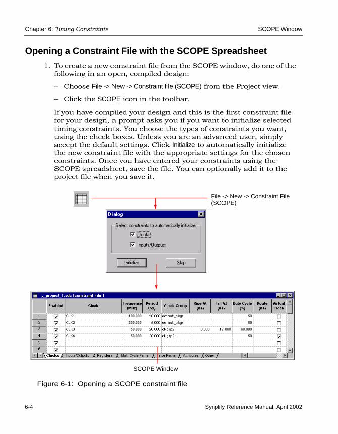
LO
Chapter 6: Timing Constraints SCOPE Window
6-4 Synplify Reference Manual, April 2002
Opening a Constraint File with the SCOPE Spreadsheet1. To create a new constraint file from the SCOPE window, do one of the
following in an open, compiled design:
– Choose File -> New -> Constraint file (SCOPE) from the Project view.
– Click the SCOPE icon in the toolbar.
If you have compiled your design and this is the first constraint file for your design, a prompt asks you if you want to initialize selected timing constraints. You choose the types of constraints you want, using the check boxes. Unless you are an advanced user, simply accept the default settings. Click Initialize to automatically initialize the new constraint file with the appropriate settings for the chosen constraints. Once you have entered your constraints using the SCOPE spreadsheet, save the file. You can optionally add it to the project file when you save it.
Figure 6-1: Opening a SCOPE constraint file
SCOPE Window
File -> New -> Constraint File (SCOPE)

SCOPE Window Chapter 6: Timing Constraints
Synplify Reference Manual, April 2002 6-5
The SCOPE window opens. It has panels with tabs along the bottom edge. Each panel has different fields where you can set constraints and attributes. The window also includes a wizard for each of the first three panels (Clocks, Inputs/Outputs, Registers), to help you enter clock, input / output, and register constraints.
2. To open an existing constraint file in the SCOPE spreadsheet, do either of the following:
– Double-click the file in the Project view.
– Choose File -> Open in the Project view. Change the Files of type: filter to Constraint files (SCOPE), then double-click to select the file you want.
If you use a text editor to edit a constraint file, close the SCOPE spread-sheet before editing the file so the save operation does not overwrite the text editor save operation or vice versa.
SCOPE Constraint TypesUse the different SCOPE panels to enter specific constraint information. The following table shows the constraints you can set:
You can also use the SCOPE spreadsheet to set attributes. See Specifying Attributes with the SCOPE Spreadsheet on page 7-9 for details.
Table 6-1: SCOPE panel constraints
Constraints SCOPE Panel
Clock Clocks Panel on page 6-6
Input/output delays Inputs/Outputs Panel on page 6-10
Register constraints Registers Panel on page 6-11
Multicycle path exceptions
Multi-Cycle Paths Panel on page 6-12
False path exceptions False Paths Panel on page 6-14
Other constraints Other Panel on page 6-17

LO
Chapter 6: Timing Constraints SCOPE Window
6-6 Synplify Reference Manual, April 2002
Clocks PanelYou use the Clocks panel of the SCOPE spreadsheet to define a signal as a clock. The equivalent Tcl constraint file command is define_clock; its syntax is described in define_clock on page 6-25. For information about the Clocks wizard, see SCOPE Constraint Wizards on page 6-18.
Clocks fields include the following parameters:
Table 6-2: SCOPE Clocks panel
Field Description
Enabled Turn this on to enable the constraint.
Clock (Required.) Specifies the name of the clock. The name can be either a top-level port in the design or the name of an internal instance used as a clock generator for the chip. In the case of virtual clocks, the field must contain a unique name not associated with any port or instance in the design. See the Virtual Clock field for more information.
Frequency (Mhz) (Required.) Specifies the clock frequency in MHz. If you fill in this field, and click in the Period field, the Period value is filled in automatically. For frequencies other than that implied by the clock pin, refer to syn_reference_clock on page 6-35.
Period (ns) (Required.) Specifies the clock period in nanoseconds. If you fill in this field, and click in the Frequency field, the frequency is filled in automatically.
Clock Group Allows you to specify clock relationships. You put related (synchronized) clocks in the same clock group, and put unrelated clocks in different groups.• The Synplify synthesis tool calculates the relationship
between clocks in the same clock group, and analyzes all paths between them. Paths between clocks in different groups are ignored (considered to be false paths).
• By default, clocks are in the same clock group (default_clkgroup is the default name).
See Clock Groups on page 6-7 for more information.

SCOPE Window Chapter 6: Timing Constraints
Synplify Reference Manual, April 2002 6-7
Clock Groups
The timing engine uses clock groups to analyze and optimize the design. It assumes that clocks in the same clock group are synchronized with each other and treats them as related clocks. Typically, clocks in a clock group are derived from the same base clock. The timing analyzer automatically calculates the relationships between the related clocks in a clock group and analyzes all paths between them. For paths between clocks of the same group, the timing engine calculates the time available based on the period of the two clocks.
Rise At (ns)Fall At (ns)
By default, the tool assumes that the clock is a 50% duty cycle clock, with rising edge at 0 and falling edge at Period/2. You can specify different rising and falling edges. See Rise and Fall Constraints on page 6-9 for details.
Duty Cycle (%) Specifies the clock duty cycle as a percentage of the clock period. If you have a duty cycle that is not 50% (the default), specify the rising and falling edge values to get the duty cycle you want.
Route (ns) Improves the path delays of registers controlled by the clock. The value shrinks the effective period for synthesis, without affecting the clock period that is forward-annotated to the place-and-route tool. This is an advanced user option.
Virtual Clock Designates the clock as a virtual clock. A virtual clock allows you to associate arrival and required times with clocks external to the chip (or block) that you are synthesizing. The clock name field must be a unique name not associated with any port or instance in the synthesized design.
Comment Lets you enter comments that are included in the constraints file.
Table 6-2: SCOPE Clocks panel (Continued)
Field Description

LO
Chapter 6: Timing Constraints SCOPE Window
6-8 Synplify Reference Manual, April 2002
The waveforms in the following figure show how the Synplify synthesis tool determines the worst posedge-to-posedge timing between clocks CLK1 and CLK2. All paths that begin at CLK1 rising and end at CLK2 rising are constrained at 10 ns.
Figure 6-2: Worst case posedge-to-posedge timing
The following figure shows how the timing analyzer calculates worst case edge-to-edge timing between all possible transitions of the two related clocks. In this example, CLK1 has a period of 5 ns and CLK2 has a period of 10 ns.
Figure 6-3: Worst case edge-to-edge timing
Conversely, clocks in different clock groups are considered unrelated or asynchronous. Paths between clocks from different groups are automati-cally marked as false paths and ignored during timing analysis and optimization.
By default, all clocks in a design are assigned to the same clock group, called default_clkgroup. Although setting a clock group is optional, it is recommended that you assign all clocks to explicit clock groups. If you have an unrelated clock, you must re-assign the unrelated clock to a new clock group using the Clock Group field in the SCOPE spreadsheet.
CLK1
CLK2
0 15 30 45 60 75 90 105 120 135
0 20 40 60 80 100 120 140
10ns 20ns 30ns
CLK1
CLK2
r-r r-f f-r f-f
Period = 5 ns
Period = 10 ns

SCOPE Window Chapter 6: Timing Constraints
Synplify Reference Manual, April 2002 6-9
For example, if your design has three clocks (clk1, clk2 and clk3), by default they are all assigned to default_clkgroup. All paths between the three clocks are analyzed and optimized. If clk2 is unrelated to the other two clocks but is left in the same clock group, it skews the results of timing analysis and negatively affects optimization because the timing engine treats it as a related clock. Similarly, in cases where clock relationships are forward-annotated, it negatively affects place-and-route results.
For more accurate results, specify a different clock group name for clk2, such as clkgrp2. The timing analyzer now only analyzes the relationship between clk1 and clk3. Paths between clk1 and clk2, and clk3 and clk2 are considered false paths and are ignored.
Rise and Fall Constraints
The Synplify synthesis tool assumes an ideal clock network. By default, the constraints assume a 50% duty cycle clock with the rising edge at 0 and the falling edge at Period/2.
The synthesis tool computes relationships between the source clock and destination clock on a path by using the Rise At and Fall At numbers. To understand how the relationships between source and destination clocks are computed using the Rise At and Fall At numbers, consider the following example.
Figure 6-4: Defining clocks with the SCOPEspreadsheet
In this example,
• Clk1 is a clock with a period of 10 ns in clock group default_clkgroup. Since none of the other fields are specified, this is a 50% duty cycle clock rising at 0 and falling at 5.

LO
Chapter 6: Timing Constraints SCOPE Window
6-10 Synplify Reference Manual, April 2002
• Clk2 is a 200 MHz (5ns) clock, also in default_clkgroup. This means that the timing analyzer considers all paths from Clk1 to Clk2 and from Clk2 to Clk1.
• Clk3 is a clock with a period of 20 ns in clkgrp2. This means all paths between Clk3 and either Clk1 or Clk2 are automatically treated as false paths. In addition, Clk3 has a Rise At value of 0 and a Fall At value of 12, which means it has a 60% duty cycle.
• Clk4 is a virtual clock. This means that there can be no port or instance named Clk4 in this design. However, there may be top-level ports on the chip which are clocked by Clk4 outside the chip. Input arrival times and output required times for such ports can be speci-fied relative to Clk4.
Inputs/Outputs PanelThis panel models the interface of the FPGA with the outside environ-ment. You use it to specify delays outside the device. The default delay outside the FPGA is 0.0 ns. The equivalent Tcl constraint file commands are define_input_delay and define_output_delay. See define_input_delay on page 6-29 and define_output_delay on page 6-31 for details For information about the Inputs/Outputs wizard, see SCOPE Constraint Wizards on page 6-18.
T= 5 10 150
T= 12 200

SCOPE Window Chapter 6: Timing Constraints
Synplify Reference Manual, April 2002 6-11
The SCOPE Inputs/Outputs fields are shown in the following table:
Registers PanelSpeeds up paths feeding into or out of a register by a given number of nanoseconds. See define_reg_input_delay on page 6-27, and define_reg_output_delay on page 6-28, for details. For information about the Registers wizard, see SCOPE Constraint Wizards on page 6-18.
Table 6-3: SCOPE Inputs/Outputs panel
Field Description
Enabled (Required.) Turn this on to enable the constraint.
Port (Required.) Specifies the name of the port. If you have initialized a compiled design, you can select a port name from the pulldown list. The first two entries let you specify global input and output delays.
Type (Required.) Specifies whether the delay is an input or output delay. See define_input_delay on page 6-29 and define_output_delay on page 6-31 for details
Clock Edge The rising or falling edge that controls the event. The syntax for this field is the clock name, followed by a colon and the edge: r for rising, and f for falling. For example, CLK1:r.
Value (Required.) Specifies the delay value. You do not need this value if you supply a Route value.
Route Improves the delay of the paths to and from the port. The value shrinks the effective synthesis constraint without affecting the constraint that is forward-annotated to the place-and-route tool. This is an advanced user option.
Comment Lets you enter comments that are included in the constraints file.

LO
Chapter 6: Timing Constraints SCOPE Window
6-12 Synplify Reference Manual, April 2002
The Registers SCOPE panel includes the following fields:
Multi-Cycle Paths PanelThis panel lets you specify paths with multiple clock cycles. The following table defines the parameters for this constraint.
Table 6-4: SCOPE Registers panel
Field Description
Enabled (Required.) Turn this on to enable the constraint.
Register (Required.) Specifies the name of the register. If you have initialized a compiled design, you can choose from the pulldown list.
Type (Required.) Specifies whether the delay is an input or output delay. See define_reg_input_delay on page 6-27, and define_reg_output_delay on page 6-28, for details
Route Improves the speed of the paths to or from the register. The value shrinks the effective period for the constrained registers without affecting the clock period that is forward-annotated to the place-and-route tool. This is an advanced user option.
Comment Lets you enter comments that are included in the constraints file.
Table 6-5: SCOPE Multi-Cycle Paths panel
Field Description
Enabled (Required.) Turn this on to enable the constraint.
From Specifies the starting point for the timing exception. From points can be registers, top-level input or bidirectional ports. For more information, see Defining Paths/Points for Timing Exceptions on page 6-15.
To Specifies the ending point for the timing exception. To points can be registers, top-level output or bidirectional ports. See Defining Paths/Points for Timing Exceptions on page 6-15 for more information.

SCOPE Window Chapter 6: Timing Constraints
Synplify Reference Manual, April 2002 6-13
Any combination of from, to, and through points is allowed: from–through, from, from–through–to, and so on. The following shows an example:
Figure 6-5: Multicycle paths example
In the following figure, CLK1 has a period of 10 ns. The data in this path has only 1 clock cycle before it must reach D2. To allow more time for the signal to complete this path, add a multicycle constraint that specifies 2 clock cycles (or 20 ns) for the data to reach D2.
Through Specifies the intermediate points for the timing exception. You can use any nets in the design as intermediate points. The intermediate points can be specified as a space-separated list, which is treated as an OR list. The exception is applied to all paths that cross any instance in the list. See Defining Paths/Points for Timing Exceptions on page 6-15.
Cycles Number of cycles for the required time calculated for the path.
Comment Lets you enter comments that are included in the constraints file.
Table 6-5: SCOPE Multi-Cycle Paths panel (Continued)
Field Description

LO
Chapter 6: Timing Constraints SCOPE Window
6-14 Synplify Reference Manual, April 2002
Figure 6-6: Multicycle constraint example
False Paths PanelUse the False Paths constraint to specify clock paths that you want the Synplify synthesis tool to ignore during timing analysis and assign low (or no) priority during optimization.
Table 6-6: SCOPE False Paths panel
Field Description
Enabled (Required.) Turn this on to enable the constraint.
From Specifies the starting point for the timing exception. From points can be registers, top-level input or bidirectional ports, or black-box outputs. For more information, see Defining Paths/Points for Timing Exceptions on page 6-15.
CLK1
10CLK1
0 20 30
D2 Q2D1 Q1
10 ns
CLK1
D2 Q2D1 Q1
20 ns
Q1
D2
D2
without constraint with multicycle path 2
required time required time
(w/o constraint)
(multicycle path=2)

SCOPE Window Chapter 6: Timing Constraints
Synplify Reference Manual, April 2002 6-15
Any combination of from, to, and through points is allowed: from–through, from, from–through–to, and so on. The following is an example:
Figure 6-7: Specifying false paths
Defining Paths/Points for Timing Exceptions
Multicycle paths and false paths are timing exceptions that you must identify. You specify points for multicycle and false paths from the appro-priate SCOPE panels. For both types of paths, you can specify the excep-tions as constraints on starting (From), ending (To), or intermediate (Through) points.
The following table lists the that objects you can constrain as starting and ending points. If you have compiled your design, you can choose the object you want from the pulldown list.
To Specifies the ending point for the timing exception. To points can be registers, top-level output or bidirectional ports, or black-box inputs. For more information, see Defining Paths/Points for Timing Exceptions on page 6-15.
Through Specifies the intermediate points for the timing exception. You can use any nets in the design as intermediate points. The intermediate points can be specified as a space-separated list, which is treated as an OR list. The exception is applied to all paths that cross any instance in the list. See Defining Paths/Points for Timing Exceptions on page 6-15.
Comment Lets you enter comments that are included in the constraints file.
Table 6-6: SCOPE False Paths panel (Continued)
Field Description

LO
Chapter 6: Timing Constraints SCOPE Window
6-16 Synplify Reference Manual, April 2002
You can specify multiple From points in a single constraint, such as all the bits of a bus: From A[0:15]. Similarly, you can specify multiple To points in a single constraint. You can combine starting and ending points to specify a constraint From A[0:15] to B, for example. In this case, the constraint starts at any of the bits of A and ends at B. If you specify multiple starting points and multiple ending points such as From A[0:15] to B[0:15], the constraint applies from any start point to any end point. In this example, the excep-tion applies to all 16 * 16 = 256 combinations of start/end points.
Intermediate points are nets in the design, that you specify in the Through field. You can specify a list of intermediate points as a space-separated list (A B C). This list is treated as an OR list, and the constraint is applied to any path being analyzed that crosses any of the specified Through points. The order of intermediate points is not important. If you specify a bus as a Through point, it is treated as any other list: the path must go through at least one of the bits of the bus.
If you have multiple constraints on the same object, the timing analyzer uses the following rules to determine how the constraints are applied:
• Bit constraints override bus constraints. For example, if you have a constraint From A[0:15] to B, and a second constraint From A[8] to B, only the second constraint applies to paths starting from A[8]. The first constraint applies to paths starting from A[0:7, 9:15].
• If the previous rule does not apply and there are multiple constraints, the Synplify synthesis tool uses the tightest constraint. If you have a 3-cycle constraint From A To B and a 4-cycle constraint From A To B Through C, all paths starting at A and ending at B (including paths that cross C) are constrained to 3 cycles.
Table 6-7: Constrainable objects
Starting Points Ending Points Intermediate Points
Registers Registers Nets
Top-level input or bidirectional ports
Top-level output or bidirectional ports
Buses
Black-box outputs Black-box inputs ———

SCOPE Window Chapter 6: Timing Constraints
Synplify Reference Manual, April 2002 6-17
Attributes PanelYou use this panel to specify design attributes. For details, see Specifying Attributes with the SCOPE Spreadsheet on page 7-9.
Other PanelThe Other panel is intended for advanced users to enter newly-supported constraint file commands. This panel contains the following fields
SCOPE File Conversions• If you use version 7.0 or later to open a SCOPE constraint file gener-
ated with an older version, check the following:
– Previously entered values are displayed, but not modified. Only commands entered in the new SCOPE window are saved. When you save the constraints, the constraints are saved in the new format.
– Check warnings for clock_to_clock delays, which are no longer supported.
– Check designs with multiple clocks. By default, all clocks are assigned to the default group.
• If you use an older version of the Synplify synthesis tool to open a SCOPE file generated with a version of the tool after 7.0, you see warnings for unsupported constraints, like path constraints.
Table 6-8: Other panel
Field Description
Enabled (Required.) Turn this on to enable the constraint.
Command (Required.) Specifies the command that you want to pass to the place-and-route tool.
Arguments (Required.) Specifies arguments to the command.
Comment Lets you enter a comment about the commands that you are passing to the place-and-route tool.

LO
Chapter 6: Timing Constraints SCOPE Window
6-18 Synplify Reference Manual, April 2002
• If you open a SCOPE file that is generated by another Synplicity product, you might see warnings for unsupported constraints.
SCOPE Constraint WizardsSome SCOPE panels have a wizard that you can use to help you enter constraints. To start its wizard, display a SCOPE panel, right-click, and choose Insert Wizard from the popup menu. The wizard is best used for entering a number of constraints, or for setting defaults.
Each constraint wizard guides you through two dialog boxes similar to these:
Figure 6-8: Insert Wizard dialog box (Inputs/Outputs panel)
Step 1 Step 2

SCOPE Window Chapter 6: Timing Constraints
Synplify Reference Manual, April 2002 6-19
The following table shows you what to do for each SCOPE panel:
Table 6-9: SCOPE panel wizards
Wizard (SCOPE Panel)
Step 1 Step 2
Clocks For each clock, select the clock from the list, then click the right arrow to move it to the selected list. If you do not see a list, disable Exclude Duplicates. Click Next.
Set the Period and turn on the Enabled check box. The other fields are optional. Click Finish.
Inputs/Outputs For each constraint select the port from the list, then click the right arrow to move it to the selected list. If you do not see a list, disable Exclude Duplicates. Click Next.
Set the values you want, and turn on the Enabled check box. Click Finish.
Registers For each constraint select the register from the list, then click the right arrow to move it to the selected list. If you do not see a list, disable Exclude Duplicates. Click Next.
Set the values you want and turn on the Enabled check box. Click Finish.

LO
Chapter 6: Timing Constraints Tcl Constraint Files
6-20 Synplify Reference Manual, April 2002
Tcl Constraint Files
You can manually create constraint files in a text editor using Tcl commands, but it is recommended that you instead use the SCOPE window to generate the file automatically. Manually generated constraint files must have an “sdc” file extension (.sdc). They can include timing constraints, general attributes, and vendor-specific attributes.
After you create the constraint file, include it in the project. Add constraint files to the source files list of a project by clicking Add in the Project view and then selecting the file from the list. You might need to change the List Files of Type option to constraint (.sdc) files to view the avail-able constraint files. Alternatively, you can read in a constraint file during a synthesis run from the project file with the add_file -constraint command.
Guidelines for Creating Constraint FilesThe following are general guidelines for writing constraint files:
• Constraint files are written in Tcl, which is case sensitive.
• Make sure object names (signals, ports, instances) match the names found in the RTL view.
• Enclose all objects with curly braces { }. For example: {foo[2]}.
• Use a period (.) as the separator character between levels of hierarchy to reference instances in lower levels of the design hierarchy.
• Distinguish between instances and ports with the same name by using the correct prefix to identify the object. For example, a prefix of p: indicates that the constraint is attached to a port. See Object Naming Syntax on page 6-21 for details about the prefixes.
• Use a prefix of n: for internal nets, as described in Object Naming Syntax on page 6-21.

Tcl Constraint Files Chapter 6: Timing Constraints
Synplify Reference Manual, April 2002 6-21
Object Naming SyntaxThis section describes the prefix syntax for identifying objects when different design objects share the same name. Objects like Verilog modules, VHDL design units, component instances, ports, and internal nets can have shared names. The prefix identifiers are used in constraint files to assign timing constraints and synthesis attributes to the correct object. The syntax varies slightly, depending on the language used to define the module or component.
Verilog
This section provides syntax for object names in Verilog. No spaces are allowed in names. You can use the * and ? characters as wildcards in names. These characters do not match the dot (.) used as a hierarchy separator.
Verilog uses the following syntax for module names:
v: cell
Instance, ports and net names have the following syntax:
cell typespec object_path
v: Identifies a view object
cell The name of the Verilog module
cell The name of the Verilog module
typespec A single letter followed by a colon. The letter can be one of the following, and is used to determine the kind of object when objects have the same names:i: identifies the name of an instance.p: identifies the name of an entire port (the port itself).b: identifies the name of a slice of a port (bit-slice of the port).n: identifies the name of an internal net. This designation is requiredfor all internal nets.
object_path An instance path with a dot (.) used as a hierarchy separator in the name. The object path ends with the name of the desired object.

LO
Chapter 6: Timing Constraints Tcl Constraint Files
6-22 Synplify Reference Manual, April 2002
See Object Naming Examples on page 6-23.
VHDL
This section provides syntax for object names in VHDL. No spaces are allowed in names. You can use the * and ? characters as wildcards in names. These characters do not match the dot (.) used as a hierarchy separator.
VHDL has the following syntax for design unit names:
v:[lib.]cell [.view ]
Instance, port and net names have the following syntax:
[ [lib.]cell [.view] ] | [typespec] objpath
v: Identifies a view object
lib The name of a library that contains the design unit. The default is the library containing the top-level design unit.
cell The name of the design unit’s entity.
view The name of the design unit’s architecture. The use of view with VHDL designs is optional, and is required only when the design unit has more than one architecture.
lib The name of a library that contains the design unit. The default is the library containing the top-level design unit.
cell The name of the VHDL entity.

Tcl Constraint Files Chapter 6: Timing Constraints
Synplify Reference Manual, April 2002 6-23
See Object Naming Examples on page 6-23.
Naming Objects in the SCOPE Window
If you choose an object from a SCOPE pulldown menu, it has the appro-priate prefix appended automatically. If you drag and drop an object from an RTL view, for example, make sure to add the prefix appropriate to the language used for the module.
Object Naming Examples
To identify all bits of instance statereg in module statemod:
statemod|i:statereg[*]
To identify instances one level of hierarchy from the top with names that begin with state:
i:*.state*
To identify port mybus[19:0] instead of a driving register that also has the name mybus[19:0]:
p:mybus[19:0]
view The name of the design unit architecture. The use of view with VHDL designs is optional, and is required only when the design unit has more than one architecture.
typespec A single letter followed by a colon that is used (if needed) to resolve the ambiguity of two or more objects in the design that have the same name. typespec can have the following values:i: identifies the name of an instance.p: identifies the name of an entire port (the port itself).b: identifies the name of a slice of a port (bit-slice of the port).n: identifies the name of an internal net. This designation is required for all internal nets.
object_path An instance path using dot (.) as a hierarchy separator. The object path ends with the name of the desired object.

LO
Chapter 6: Timing Constraints Individual Timing Constraints
6-24 Synplify Reference Manual, April 2002
To identify top-level port mybus bit 1 instead of a driving register that also has the name mybus[1]:
b:mybus[1]
The following shows the constraint file (.sdc) entries that correspond to the previous source code examples:
define_attribute {statemod|i:statereg[*]} syn_encoding sequentialdefine_multicycle_path -to {*.*slowreg[*]} 2
Individual Timing Constraints
This section discusses the following timing constraints:
• define_clock on page 6-25
• define_reg_input_delay on page 6-27
• define_reg_output_delay on page 6-28
• define_input_delay on page 6-29
• define_output_delay on page 6-31
• define_multicycle_path on page 6-32
• define_false_path on page 6-34
• syn_reference_clock on page 6-35
For black-box timing models, see Black-Box Timing Models on page 6-36.
The synthesis tool global frequency constraint is set in the Frequency (MHz) field of the Project view. This constraint can also be set in the project file using the set_option -frequency Tcl command.

Individual Timing Constraints Chapter 6: Timing Constraints
Synplify Reference Manual, April 2002 6-25
define_clockDefines a clock with a specific frequency or clock period goal, and duty cycle. For the equivalent SCOPE interface, see Clocks Panel on page 6-6.
You can have multiple clocks with different clock frequencies. Set the default frequency for all clocks with the set_option -frequency Tcl command. Then use the define_clock timing constraint to override the default, and to specify unique clock frequency goals for specific clock signals. Addition-ally, you can use the define_clock timing constraint to set the clock frequency for a clock signal output of clock divider logic. The clock name is the output signal name for the register instance.
This is the syntax:
define_clock [-disable] [-name {clock_name}] [{-freq MHz | -period ns}] [-clockgroup domain] {[-rise value] [-fall value] | [-duty_pct percent]} [-route ns] -virtual -comments
-disable Disables a previous clock definition.
-name (Required). Specifies the clock name. The name can be either a top-level port in the design or the name of an internal instance used as a clock generator for the chip. In the case of virtual clocks, the field can contain a unique name not associated with any port or instance in the design.
-freq Defines the frequency of the clock in MHz. You can specify either this or -period, but not both.
-period Specifies the period of the clock in ns. You can specify either this or-freq, but not both.
-clockgroup Allows you to specify clock relationships. You put related (synchronized) clocks in the same clock group, and put unrelated clocks in different groups.• The Synplify synthesis tool calculates the relationship between
clocks in the same clock group, and analyzes all paths between them. Paths between clocks in different groups are ignored (considered to be false paths).
• By default, clocks are in the same clock group (default_clkgroup is the default name).
See Clock Groups on page 6-7 for more information.

LO
Chapter 6: Timing Constraints Individual Timing Constraints
6-26 Synplify Reference Manual, April 2002
Here are some examples:
define_clock -name {clock} -period 10.0 -clockgroup d1
define_clock -virtual -name {CLK5} -period 20.0 -clockgroup d2
define_clock -name {CLK4} -period 20.000 -clockgroup d2 -rise 0.000 -fall 10.000
-rise / -fall Specifies a non-default duty cycle. By default, the Synplify synthesis tool assumes that the clock is a 50% duty cycle clock, with the rising edge at 0 and the falling edge at period/2. If you have another duty clock cycle, specify the appropriate Rise At and Fall At values. For more information, see Rise and Fall Constraints on page 6-9.
-duty_pct Specifies the duty cycle of the clock as a percentage of the period. When the file is saved, the Synplify synthesis tool translates this to -rise and -fall.
-route An advanced user option that improves the path delays of registers controlled by this clock. The value used is the difference between the synthesis timing report value of the path delays and the value in the timing report generated from the place-and-route tool. The -route constraint applies globally to the clock domain, and can overconstrain registers where constraints are not needed. Before you use this option, evaluate the path delays on individual registers in the optimization timing report, and try to improve the delays with the define_reg_input_delay and define_reg_output_delay constraints only on the registers that need it. See define_reg_input_delay on page 6-27 and define_reg_output_delay on page 6-28 for more information.
-virtual Specifies arrival and required times on top level ports that are enabled by clocks external to the chip (or block) that you are synthesizing. When specifying -name for the virtual clock, the field can contain a unique name not associated with any port or instance in the design.

Individual Timing Constraints Chapter 6: Timing Constraints
Synplify Reference Manual, April 2002 6-27
define_reg_input_delaySpeeds up paths feeding a register by a given number of nanoseconds. The Synplify synthesis tool attempts to meet the global clock frequency goals for a design as well as the individual clock frequency goals (set with define_clock). Use this constraint to speed up the paths feeding a register. For information about the equivalent SCOPE interface, see Registers Panel on page 6-11.
This is the syntax:
define_reg_input_delay register_name [-route ns] -comments
The slack time reported on a register is the amount of time by which the clock frequency goal is exceeded (positive slack time), or not met (negative slack time). You can view slack times through HDL Analyst or in the timing report section of the log file.
Example: -route option
Use this option if you do not meet timing goals because the routing delay after placement and routing exceeds the delay predicted by the Synplify synthesis tool.
Rerun synthesis using this option, including the actual route delay (from place-and-route results) so that the tool can meet the required clock frequency. Assume the frequency goal is 50 MHz (clock period goal of 20.0 ns). If the synthesis timing reports show the frequency goal is met, but the detailed timing report from placement and routing shows that the actual clock period is 21.8 ns because of paths to reg_a, you can either tighten the constraints in the place-and-route tool, or you can rerun optimization using -route 1.8 to the define_reg_input_delay constraint.
define_reg_input_delay reg_a -route 1.8
-disable Disables a previous clock definition.
register_name A single bit register. For multiple-bit registers (buses), use multiple define_reg_input_delay constraints.
-route Advanced user option that you use to tighten constraints during resynthesis, when the place-and-route timing report shows the timing goal is not met because of long paths to the register. See Example: -route option on page 6-27 for an example of its use.

LO
Chapter 6: Timing Constraints Individual Timing Constraints
6-28 Synplify Reference Manual, April 2002
Using this option adds 1.8 ns to the route calculations for paths to reg_a so that timing is improved by 1.8 ns.
define_reg_output_delaySpeeds up paths coming from a register by a given number of nanosec-onds. The Synplify synthesis tool attempts to meet the global clock frequency goals for a design as well as the individual clock frequency goals (set with define_clock). Use this constraint to speed up the paths coming from a register. For information about the equivalent SCOPE interface, see Registers Panel on page 6-11.
This is the syntax:
define_reg_output_delay register_name [-route ns] -comments
The slack time reported on a register is the amount of time by which the clock frequency goal is exceeded (positive slack time), or under achieved (negative slack time). You can see these slack times through HDL Analyst or in the timing report section of the log file.
-disable Disables a previous clock definition.
register_name A single bit register. For multiple register bits (buses), use multiple define_reg_output_delay constraints.
-route Advanced user option that you use to tighten constraints during resynthesis, when the place-and-route timing report shows the timing goal is not met because of long paths from the register. For an example of its use (on an input register), see Example: -route option on page 6-27.

Individual Timing Constraints Chapter 6: Timing Constraints
Synplify Reference Manual, April 2002 6-29
define_input_delaySpecifies the external input delays on top-level ports in the design. It is the delay outside the chip before the signal arrives at the input pin. This constraint is used to model the interface of the inputs of the FPGA with the outside environment. The default delay outside the FPGA is 0.0 ns. Signals typically do not arrive with 0.0 ns delay, but the tool has no way of knowing what the input delay is unless you specify it in a timing constraint. For information about the equivalent SCOPE interface, see Inputs/Outputs Panel on page 6-10.
Here is the syntax:
define_input_delay -disable [{input_port_name} | -default] ns [-route ns] -ref clock:r | f -comments
-disable Disables a previous delay specification on the named port.
input_port_name
The name of the input port.
-default Sets a default input delay for all inputs. Use this option to set an input delay for all inputs. You can then set define_input_delay on individual inputs to override the default constraint. This example sets a default input delay of 3.0 ns:define_input_delay -default 3.0 This constraint overrides the default and sets the delay on input_a to 10.0 ns:define_input_delay {input_a} 10.0
-ref Clock name and edge that triggers the event. Value must be either - rising edge f - falling edgeFor example: define_input_delay {portb[7:0]} 10.00 -ref clock2:f
-route An advanced option, which includes route delay when the Synplify synthesis tool tries to meet the clock frequency goal. Use the -route option on an input port when the place-and-route timing report shows that the timing goal is not met because of long paths through the input port. See Example: -route option on page 6-30 for an example of its use.

LO
Chapter 6: Timing Constraints Individual Timing Constraints
6-30 Synplify Reference Manual, April 2002
Here are some examples of the define_input_delay constraint:
define_input_delay {porta[7:0]} -ref clock:rdefine_input_delay {A} -ref CLK1:fdefine_input_delay -disable {resetn}
The slack time reported on an instance along a path from an input port is the amount of time by which the clock frequency goal is exceeded (positive slack), or not met (negative slack) because of the input delay. You can view slack times through HDL Analyst or in the timing report section of the log file.
Example: -route option
Use this option if you do not meet timing goals because the routing delay after placement and routing exceeds the delay predicted by the Synplify synthesis tool.
Rerun synthesis using this option, including the actual route delay (from place-and-route results) so that the tool can meet the required clock frequency. Assume the frequency goal is 50 MHz (clock period goal of 20.0 ns). If the synthesis timing reports show the frequency goal is met, but the detailed timing report from placement and routing shows that the actual clock period is 21.8 ns because of paths through input_a, you can either tighten the constraints in the place-and-route tool, or you can rerun optimization using -route 1.8 to the define_input_delay constraint.
# In this example, input_a has a 10.0 ns input delay. # Rerun synthesis with an added 1.8 ns constraint, to# improve accuracy and match post-place-and-route results.
define_input_delay {input_a} 10.0 -route 1.8
Using this option adds 1.8 ns to the route calculations for paths to input_a and improves timing by 1.8 ns.

Individual Timing Constraints Chapter 6: Timing Constraints
Synplify Reference Manual, April 2002 6-31
define_output_delaySpecifies the delay of the logic outside the FPGA driven by the top-level outputs. This constraint is used to model the interface of the outputs of the FPGA with the outside environment. The default delay outside the FPGA is 0.0 ns. Output signals typically drive logic that exists outside the FPGA, but the tool has no way of knowing the delay for that logic unless you specify it using a timing constraint. For information about the equiva-lent SCOPE interface, see Inputs/Outputs Panel on page 6-10.
Here is the syntax:
define_output_delay -disable [{output_port_name} | -default] ns [-route ns ] [-ref clkname:edge] -comments
-disable Disables a previous delay specification on the named port.
output_port_name
The name of the output port.
-default Sets a default input delay for all outputs. Use this option to set a delay for all outputs. You can then set define_output_delay on individual outputs to override the default constraint. This example sets a default output delay of 8.0 ns. The delay is outside the FPGA.define_output_delay -default 8.0 The following constraint overrides the default and sets the output delay on output_a to 10.0 ns. This means that output_a drives 10 ns of combinational logic before the relevant clock edge. define_output_delay {output_a} 10.0
-ref Defines the clock name and edge that controls the event. Value must be one of the following: r - rising edgef - falling edgeFor example: define_output_delay {portb[7:0]} 10.00 -ref clock2:f
-route An advanced option, which includes route delay when the Synplify synthesis tool tries to meet the clock frequency goal. See Example: -route option on page 6-30 for an example of its use with an input register.

LO
Chapter 6: Timing Constraints Individual Timing Constraints
6-32 Synplify Reference Manual, April 2002
The slack time reported on an instance driving an output port is the amount of time by which the clock frequency goal is exceeded (positive slack), or not met (negative slack) because of the output delay. You can view slack times with HDL Analyst or in the timing report section of the log file.
define_multicycle_pathSpecifies a path that is a timing exception because it uses multiple clock cycles. This constraint provides extra clock cycles to the designated paths for timing analysis and optimization. For information about the equiva-lent SCOPE interface, see Multi-Cycle Paths Panel on page 6-12.
Here is the syntax:
define_multicycle_path {-from reg | input | -to reg | output | -through net} clock_cycles -comments
-disable Disables a previous delay specification on the named port.
-from Specifies the starting point for the multicycle timing exception. From points can be registers, top-level input, or bidirectional ports. For more information, see Defining Paths/Points for Timing Exceptions on page 6-15. You can combine this option with -to or -through to get a specific path.
-to Specifies the ending point for the timing exception. To points can be registers, top-level output, or bidirectional ports. For more information, see Defining Paths/Points for Timing Exceptions on page 6-15. You can combine this option with -from or -through to get a specific path.
-through Specifies the intermediate points for the timing exception. You can use any nets in the design as intermediate points. The intermediate points can be specified as a space-separated list, which is treated as an OR list. The exception is applied to all paths that cross any instance in the list. See Defining Paths/Points for Timing Exceptions on page 6-15.You can combine this option with -to or -from to get a specific path. To keep the signal name intact throughout synthesis when you this option, set the syn_keep directive (Verilog or VHDL) on the signal.
clock_cycles
The number of clock cycles of the start clock to be used for this path.

Individual Timing Constraints Chapter 6: Timing Constraints
Synplify Reference Manual, April 2002 6-33
Here are some examples of the define_multicycle_path constraint syntax:
define_multicycle_path -from{i:regs.addr[4:0]}-to{i:special_regs.w[7:0]} 2
define_multicycle_path -to {i:special_regs.inst[11:0]} 2
define_multicycle_path -from {p:porta[7:0]} -through {n:prgmcntr.pc_sel44[0]} -to {p:portc[7:0]} 2
The following case illustrates where you might use a multicycle timing exception. Your design has a multiplier that multiplies signal_a with signal_b and puts the result into signal_c. Assume signal_a and signal_b are outputs of registers register_a and register_b, respectively. On clock cycle 1, a state machine enables an input enable signal to load signal_a into register_a and signal_b into register_b. At the beginning of clock cycle 2, the multiply begins. After two clock cycles, the state machine enables an output_enable signal on clock cycle 3 to load the result of the multiplication (signal_c) into an output register (register_c).
The design frequency goal is 50 MHz (20 ns) and the multiply function takes 35 ns, but it is given 2 clock cycles. After optimization, this 35 ns path would normally be reported as a timing violation because it is more than the 20 ns clock-cycle timing goal. To avoid reporting the paths as timing violations or impacting optimization, you would include the following in the timing constraint file:
# Paths from register_a use 2 clock cyclesdefine_multicycle_path -from register_a 2
# Paths from register_b use 2 clock cyclesdefine_multicycle_path -from register_b 2
Alternatively, you can specify that the paths to the output register use multiple clock cycles:
# Paths to register_c use 2 clock cyclesdefine_multicycle_path -to register_c 2

LO
Chapter 6: Timing Constraints Individual Timing Constraints
6-34 Synplify Reference Manual, April 2002
define_false_pathDefines paths to ignore (remove) during timing analysis and assign lower (or no) priority during optimization. The false paths are also passed on to supported place-and-route tools. For information about the equivalent SCOPE interface, see False Paths Panel on page 6-14.
Here is the syntax:
define_false_path {-from reg | input | -to reg | output | -through reg} -comments
The following case uses a define_false_path constraint. Your design frequency goal is 50 MHz (20ns), and the path from register_a to register_c is a false path with a large delay of 35 ns. After optimization, this 35 ns path would normally be reported as a timing violation because it is more than the 20 ns clock-cycle timing goal.
To lower the priority of this path during optimization, define it as a false path. If all paths from register_a to any register or output pins are not timing-critical, then add the following line to the timing constraint file:
#Paths from register_a are ignoreddefine_false_path -from register_a
-disable Disables a previous delay specification on the named port.
-from Specifies the starting point for the false path. From points can be: registers, top-level input, or bidirectional ports. For more information, see Defining Paths/Points for Timing Exceptions on page 6-15. You can combine this option with -to or -through to get a specific path.
-to Specifies the ending point for the false path. To points can be: registers, top-level output or bidirectional ports. For more information, see Defining Paths/Points for Timing Exceptions on page 6-15. You can combine this option with -from or -through to get a specific path.
-through Specifies the intermediate points for the timing exception. You can use any nets in the design as intermediate points. The intermediate points can be specified as a space-separated list, which is treated as an OR list. The exception is applied to all paths that cross any instance in the list. See Defining Paths/Points for Timing Exceptions on page 6-15.You can combine this option with -to or -from to get a specific path. To keep the signal name intact throughout synthesis when you this option, set the syn_keep directive (Verilog or VHDL) on the signal.

Individual Timing Constraints Chapter 6: Timing Constraints
Synplify Reference Manual, April 2002 6-35
If all paths to register_c are not timing-critical, then add the following line in the timing constraint file:
#Paths to register_c are ignoreddefine_false_path -to register_c
syn_reference_clockThis is an attribute that specifies a clock frequency other than that implied by the signal on the clock pin of the register. For example, when flip-flops have an enable with a regular pattern, such as every second clock cycle, use syn_reference_clock to have the timing analyzer treat the flip-flops as if they were connected to a clock at half the frequency. You can also set this attribute from the SCOPE spreadsheet Attributes panel, as described in Specifying Attributes with the SCOPE Spreadsheet on page 7-9, or in the source code.
Here is the syntax:
define_attribute register syn_reference_clock clock
To use syn_reference_clock, define a new clock using the define_clock constraint. Name the clock, then apply the name of the new clock to the registers you want to change.
This example show how to use syn_reference_clock:
define_clock dummy -period 40.0 -virtualdefine_attribute myreg[31:0] syn_reference_clock dummy
This next example applies syn_reference_clock to all registers enabled by signal en40.
define_attribute {find -reg -enable en40} syn_reference_clock clk2

LO
Chapter 6: Timing Constraints Black-Box Timing Models
6-36 Synplify Reference Manual, April 2002
Black-Box Timing Models
Black-box Source Code DirectivesBlack-box timing models are specific to components that you have instan-tiated (or declared) as black boxes using syn_black_box. You specify the models with source code directives.
You must put the directives in the source code because the models are specific to individual instances. There are no corresponding Tcl directives available for use in a constraint file. The following are the attributes you use with syn_black_box to characterize black-box timing:
• syn_tpdn – timing propagation for combinational delay through the black box. See syn_tpd<n> on page 7-180 for details.
• syn_tsun – timing setup delay required for input pins relative to the clock. See syn_tsu<n> on page 7-184 for details.
• syn_tcon – timing clock to output delay through the black box, where n is an integer from 1 through 10, inclusive. See syn_tco<n> on page 7-177 for details.
There are 10 instances of each of these attributes available, for example: syn_tpd1, syn_tpd2, syn_tpd3, … syn_tpd10. If you need more than 10, you can declare the desired amount (start with an integer greater than 10), for example:
attribute syn_tpd11 : string;attribute syn_tpd12 : string;
A bundle is a collection of buses and scalar signals. To assign values to bundles, use the following syntax. The values are in ns.
For syn_tpd: "bundle -> bundle = value "For syn_tsu: "bundle -> [!]clock = value "For syn_tco: "[!]clock -> bundle = value "
The optional exclamation mark (!) indicates a negative edge for a clock. The objects of a bundle must be separated by commas with no spaces between. A valid bundle is A,B,C which lists three signals.

Black-Box Timing Models Chapter 6: Timing Constraints
Synplify Reference Manual, April 2002 6-37
VHDL ExampleIn addition to the syntax used in the code below, you can also use the following Verilog-style syntax to specify the black-box attributes:
attribute syn_tco1 of inputfifo_coregen : component is "rd_clk->dout[48:0]=3.0";
The following is an example of a VHDL black box:
-- A USE clause for the the synthesis tool Attributes -- package was included earlier to make the attribute -- definitions visible here.architecture top of top iscomponent rcf16x4z port (
ado, ad1, ad2, ad3 : in std_logic;dio, di1, di2, di3 : in std_logic;wren, wpe : in std_logic;tri : in std_logic;do0, do1, do2, do3 : out std_logic);
end component;
attribute syn_tco1 of rcf16x4z : component is"clk -> do0,do1 = 4.0";
attribute syn_tpd1 of rcf16x4z : component is"ado,ad1,ad2,ad3 -> do0,do1,do2,do3 = 2.1";
attribute syn_tpd2 of rcf16x4z : component is"tri -> do0,do1,do2,do3 = 2.0";
attribute syn_tsu1 of rcf16x4z : component is"ado,ad1,ad2,ad3 -> ck = 1.2";
attribute syn_tsu2 of rcf16x4z : component is"wren,wpe -> ck = 0.0";
-- Other code

LO
Chapter 6: Timing Constraints Black-Box Timing Models
6-38 Synplify Reference Manual, April 2002
Verilog Examplemodule ram32x4(z, d, addr, we, clk);/* synthesis black_boxsyn_tco1="clk->z[3:0]=4.0"syn_tpd1=”addr[3:0]->z[3:0]=8.0”syn_tsu1=”addr[3:0]->clk=2.0”syn_tsu2=”we->clk=3.0” */output [3:0] z;input [3:0] d;input [3:0] addr;input we;input clk;
endmodule

Forward Annotation Chapter 6: Timing Constraints
Synplify Reference Manual, April 2002 6-39
Forward Annotation
The Synplify synthesis tool generates vendor-specific constraint files that can be forward-annotated (read in and used) with the place-and-route tools. The constraint files are generated by default. To disable this feature, go to the Implementation Results panel of the Options for implementation dialog box (Project -> Implementation Options), and disable the Write Vendor Constraint File option. Constraint files for these vendors are forward-annotated: Lattice, Altera and Xilinx.
Altera Max+Plus IIThe constraint file generated for Altera Max+Plus II place-and-route tools has a “acf” file extension (.acf). The following constraints are forward-annotated to Altera Max+Plus II in this file:
• define_clock
• define_input_delay
• define_output_delay
Altera Quartus IIThe constraint file generated for Quartus II place-and-route tools has a “tcl” file extension (.tcl). The following constraints are forward-annotated to Quartus II in this file for APEX:
• define_clock
• define_false_path
• define_input_delay
• define_multicycle_path
• define_output_delay
In addition to these constraints, the Synplify synthesis tool forward-annotates relationships between different clocks.

LO
Chapter 6: Timing Constraints Forward Annotation
6-40 Synplify Reference Manual, April 2002
In designs to be sent to Quartus II, the synthesis tool forward-annotates the define_input_delay and define_output_delay timing constraints to Quartus II if you use the syn_forward_io_constraints attribute. A value of 1 enables forward annotation, while a value of 0 (default behavior) disables forward annotation. Use this attribute on the top level of a VHDL or Verilog file, or place it on the global object in the Attributes panel in the SCOPE spread-sheet.
syn_forward_io_constraints = { 1 | 0 }
Verilog Example module top (a,b,c) /*synthesis syn_forward_io_constraints = 1 */;
input a, b ;output c;assign c = a | b;
endmodule
VHDL Example library Ieee;use ieee.std_logic_1164.all;entity top is port (
a : in std_logic;b : in std_logic;o1 : out std_logic);
end top;
architecture archtop of top isattribute syn_forward_io_constraints : boolean;attribute syn_forward_io_constraints of archtop :
architecture is true;begin
o1 <= a and b;end archtop;
SDC Example define_global_attribute syn_forward_io_constraints {1}

Forward Annotation Chapter 6: Timing Constraints
Synplify Reference Manual, April 2002 6-41
Lattice ORCAThe constraint file generated for Lattice's ORCA Foundry place-and-route tools has a “lp” file extension (.lp). The Lattice ORCA flow requires that you copy the .lp file containing the constraints from the Synplify synthesis tool or a text editor into Lattice ORCA's .prf file.
Follow these steps to forward-annotate your synthesis constraint file to ORCA Foundry:
1. Set your constraints in the SCOPE spreadsheet (see SCOPE Spreadsheet on page 6-3).
2. Run your design. The synthesis tool creates an .lp file in the same directory as your result files.
3. Open Lattice's ORCA Foundry place-and-route tool. Run the Map stage, which creates the .prf file.
4. From any text editor, copy the .lp file and place it at the bottom of the .prf file. Do not copy over the .prf file with the .lp file.
5. Run the PAR and BIT stages in Foundry.
The following constraints are forward-annotated to ORCA Foundry in this file:
• define_clock
• define_input_delay
• define_multicycle_path
• define_output_delay

LO
Chapter 6: Timing Constraints Forward Annotation
6-42 Synplify Reference Manual, April 2002
Xilinx The constraint file generated for Xilinx place-and-route tools has an “ncf” file extension (.ncf). The following constraints are forward-annotated to Xilinx in this file:
• define_clock
• define_false_path
• define_input_delay
• define_multicycle_path
• define_output_delay
In addition to these constraints, the Synplify synthesis tool forward-annotates relationships between different clocks.
Forward-annotating I/O Timing Constraints
The Synplify synthesis tool forward-annotates the define_input_delay and define_output_delay constraints to the Xilinx .ncf file. The syn_forward_io_constraints attribute controls forward annotation. An attribute value of 1 (default behavior) enables forward annotation, while a value of 0 disables forward annotation. Use this attribute at the top level of a VHDL or Verilog file, or place it on the global object in the Attributes panel of the SCOPE spreadsheet.
syn_forward_io_constraints = { 1 | 0 }
Verilog Example module top (a,b,c) /* synthesis syn_forward_io_constraints = 1 */;
input a, b ;output c;assign c = a | b;
endmodule

Forward Annotation Chapter 6: Timing Constraints
Synplify Reference Manual, April 2002 6-43
VHDL Example library Ieee;use ieee.std_logic_1164.all;entity top is port (
a : in std_logic;b : in std_logic;o1 : out std_logic);
end top;
architecture archtop of top isattribute syn_forward_io_constraints : boolean;attribute syn_forward_io_constraints of archtop :
architecture is true;begin
o1 <= a and b;end archtop;
SDC Example define_global_attribute syn_forward_io_constraints {1}
Relaxing Forward-annotated Constraints
You use the xc_ncf_auto_relax attribute to control the automatic relaxation of constraints that are forward-annotated to the .ncf file. A value of 0 disables this feature; the default value is 1.
The Synplify synthesis tool constrains input-to-register, register-to-register and register-to-output paths with the frequency constraint. However, if the period constraint is too tight for the input-to-register or register-to-output paths, the tool will try to relax the constraints to these paths. You can disable this relaxation by setting the xc_ncf_auto_relax attribute to 0 if your design requires it:
define_global_attribute xc_ncf_auto_relax {0}
Constraint Filedefine_global_attribute xc_ncf_auto_relax {0}

LO
Chapter 6: Timing Constraints Forward Annotation
6-44 Synplify Reference Manual, April 2002
Verilog Examplemodule test_relax (clk, rst, a, b, out1)
/* synthesis xc_ncf_auto_relax = 0 */;
// Other codeendmodule
VHDL Examplelibrary ieee;use ieee.std_logic_1164.all;entity test_relax is
port(clk, rst, a, b : in std_logic;
out1 : out std_logic );
end test_relax;
architecture behave of test_relax isattribute xc_ncf_auto_relax : boolean;attribute xc_ncf_auto_relax of behave : architecture is false;
-- Other code
end behave;

Support for DCM/DLL in Xilinx Chapter 6: Timing Constraints
Synplify Reference Manual, April 2002 6-45
Support for DCM/DLL in Xilinx
The Synplify synthesis tool is able to take advantage of the Frequency Synthesis and Phase Shifting features of Digital Clock Manager (DCM) and Delay Locked Loop (DLL) for Xilinx devices.
If you are using a DLL or DCM for on-chip clock generation, you need only define the clock at the primary inputs. The synthesis tool will propagate clocks through any number of DLLs or DCMs. It will automatically generate clocks at the outputs of a DLL or DCM, as needed, taking into account any phase shift or frequency change.
You can specify the phase shift and frequency multiplication parameters using Xilinx standard properties like duty_cycle_correction and clkdv_divide, as well as properties like clkfx_multiply and clkfx_divide for DCMs if needed.
The synthesis tool also takes into account the fact that these clocks are related (synchronized) with each other, by putting them in the same clock-group.
However only the clock at the input of a DLL/DCM is forward-annotated in the .ncf file, because the backend tools understand the DLL and DCMs, and do their own clock propagation across them.

LO
Chapter 6: Timing Constraints Timing Report
6-46 Synplify Reference Manual, April 2002
Timing Report
The timing report is part of the log file (project_name.srr) in the results directory. You can find it by opening the log file (View -> Log File) after a synthesis run, and searching for “START TIMING REPORT”.
You can control the size of the timing report by choosing Project -> Implemen-tation Options and clicking the Timing Report panel. This panel lets you specify the number of start/end points, and the number of critical paths to be reported.
The timing report consists of the following sections:
• Timing Report Header on page 6-46
• Performance Summary on page 6-47
• Clock Relationships on page 6-48
• Interface Information on page 6-48
• Detailed Clock Report on page 6-49
Timing Report HeaderThe timing report header lists the date and time, the name of the top-level module, the number of paths requested for the timing report, and the constraint files used.
Figure 6-9: Timing Report header

Timing Report Chapter 6: Timing Constraints
Synplify Reference Manual, April 2002 6-47
Performance SummaryThe performance summary section of the timing report reports clock infor-mation, with the clocks sorted by negative slack. You can set the number of critical paths reported by choosing Project -> Implementation Options and setting the number of paths you want on the Timing Report panel. The timing report has another section for detailed clock information (see Detailed Clock Report on page 6-49). The Performance Summary lists the following information for each clock in the design:
The Synplify synthesis tool does not report inferred clocks with an unrea-sonable slack time. You might also have a real clock with a negative period, for example, a clock going to only one flip-flop, which has only one path going to an output. If you specify a –1000 output delay on this output, the synthesis tool cannot calculate the clock frequency. It reports a negative period and no clock.
Table 6-10: Performance summary
Performance Summary Description
Starting clock The name of the clock. If the clock name is “none,” you
Clock group The name of the clock group to which the clock belongs.
Requested Frequency Target frequency goal.
Estimated Frequency Estimated value after synthesis.
Requested Period Target clock period.
Estimated Period Estimated value after synthesis.
Slack Difference between estimated and requested period.
Slack for starting clock listed as “none” is the worst slack for all paths in the none category. The none category is a collection of clocks with an undefined clock event. This can include clocks when you specify a global frequency.
Clock type Describes the type of clock. A clock can be an inferred, declared, derived or system clock.

LO
Chapter 6: Timing Constraints Timing Report
6-48 Synplify Reference Manual, April 2002
Clock RelationshipsFor each pair of clocks in the design, the Clock Relationships section of the timing report lists both the required time (constraint) and the worst slack time for each of the intervals rise to rise, fall to fall, rise to fall and fall to rise.
This information is provided for the paths between related clocks (that is, clocks in the same clock group). If there is no path at all between two clocks, then that pair is not reported. If there is no path for a given pair of edges between two clocks, then an entry of No paths appears.
For information about how these relationships are calculated, see Clock Groups on page 6-7.
Figure 6-10: Clock Relationships report
Interface InformationThe interface section of the timing report contains information on arrival times, required times and slack for the top-level ports. It is divided into two subsections, one each for inputs and outputs. Bidirectional ports are listed under both. For each port, the interface report contains the following information.
Table 6-11: Interface report
Port Parameter Description
Port Name Port name.
Reference Clock The reference clock.
User Constraint The input/output delay. If a port has multiple delay records, the report contains the values for the record with the worst slack. The reference clock corresponds to the worst slack delay record.

Timing Report Chapter 6: Timing Constraints
Synplify Reference Manual, April 2002 6-49
Detailed Clock ReportEach clock reported in the performance summary also has a detailed clock report section in the timing report. The clocks are listed by negative slack.
For each critical path, the Synplify synthesis tool uses this report format: Output pin—Input pin—Output pin—Input pin, without including the intervening nets. The following table describes the critical path information reported:
Arrival Time User-specified delay (for inputs).
Required time The difference between the requested period and the setup time of the destination (for outputs).
Slack The difference between the required time and the arrival time.
Table 6-12: Detailed clock report
Clock Information Description
N most critical start points
Starting points can be input ports or registers. If the starting point is a register, you see the starting pin in the report. To change the number of start points reported, choose Project -> Implementation Options, and set the number on the Timing Report panel.
N most critical end points
End points can be output ports or registers. If the end point is a register, you see the ending pin in the report. To change the number of start points reported, select Project -> Implementation Options, and set the number on the Timing Report panel.
N critical path tables (see the next table for details)
You can change the number of critical paths on the Timing Report panel of the Implementation Options dialog box. Paths from clock A to clock B are reported as critical paths in the section for clock A.
Table 6-11: Interface report (Continued)
Port Parameter Description

LO
Chapter 6: Timing Constraints Timing Report
6-50 Synplify Reference Manual, April 2002
Table 6-13: Critical path reports
Critical Path Information Description
Instance/Net Name Technology view names for the instances and nets in the critical path
Type Type of cell
Pin Name Name of the pin
Pin Dir Pin direction
Arrival Time Clock delay at the source + the propagation delay through the path
Delay The delay value.
Arrival Time Arrival time of the signal
Fanout Number of fanouts for the point in the path

Synplify Reference Manual, April 2002 7-1
C H A P T E R 7
Synthesis Attributes and Directives
This chapter shows you how to specify attributes and directives, and contains individual attribute and directive descriptions, syntax defini-tions, and examples.
These are the chapter topics:
• Attributes and Directives: Summary on page 7-2
• Specifying Attributes in a Constraint File on page 7-9
• Specifying Directives (and Attributes) in HDL on page 7-14
• Attributes on page 7-18
• Directives on page 7-139

LO
Chapter 7: Synthesis Attributes and Directives Attributes and Directives: Summary
7-2 Synplify Reference Manual, April 2002
Attributes and Directives: Summary
The following sections summarize the synthesis attributes and directives:
• Attributes and Directives: Differences, Specifying on page 7-2
• Attribute and Directive Summary by Vendor on page 7-3
• Attribute Summary (Alphabetical) on page 7-3
• Directive Summary (Alphabetical) on page 7-7
For detailed descriptions of individual attributes and directives, see Attributes on page 7-18 and Directives on page 7-139, respectively.
Attributes and Directives: Differences, SpecifyingSynthesis attributes and directives let you direct the way a design is analyzed, optimized, and mapped during synthesis. For example, you can specify how you want the Synplify synthesis tool to manage hierarchy during optimization or which objects to treat as black boxes.
Attributes control mapping optimizations. Directives control compiler optimizations.
Because of this difference, directives must be entered in the HDL source code, but attributes can be entered either in an .sdc constraint file (recommended) or in HDL source code.
If you specify attributes in source code, whenever you change them you must recompile the design. Recompilation can be very time consuming for large designs. If you use a constraint file instead, you can easily change attributes at any time, without compiling. The preferred way to specify attributes is using the SCOPE spreadsheet (see SCOPE Window on page 6-3), which automatically generates and edits an .sdc constraint file.
For information on specifying attributes in constraint files, in particular via the SCOPE spreadsheet, see Specifying Attributes in a Constraint File on page 7-9.
For information on specifying directives (and attributes) in the HDL source code, see Specifying Directives (and Attributes) in HDL on page 7-14. Remember, though, that it is generally best to specify attributes through the SCOPE spreadsheet.

Attributes and Directives: Summary Chapter 7: Synthesis Attributes and Directives
Synplify Reference Manual, April 2002 7-3
Attribute and Directive Summary by VendorFor a list of vendor-specific attributes and directives, see the appropriate vendor chapters, as shown in the following table. For alphabetical summaries of attributes and directives, see Attribute Summary (Alphabetical) on page 7-3 and Directive Summary (Alphabetical) on page 7-7, respectively.
Attribute Summary (Alphabetical)The following table summarizes the synthesis attributes. For details on individual attributes, see the alphabetized list in section Attributes on page 7-18, . For a summary of the directives, see Directive Summary (Alpha-betical) on page 7-7.
Table 7-1: Vendor-specific attributes and directives
Vendor Attributes and Directives
Actel Actel Attribute and Directive Summary on page A-10
Altera Altera Attribute and Directive Summary on page B-36
Atmel Atmel Attribute and Directive Summary on page C-5
Cypress Cypress Attribute and Directive Summary on page D-12
Lattice Lattice Attribute and Directive Summary on page E-16
Quicklogic QuickLogic Attribute and Directive Summary on page F-7
Triscend Triscend Attribute and Directive Summary on page G-4
Xilinx Xilinx Attribute and Directive Summary on page H-43
Table 7-2: Attributes, alphabetical summary
Attribute Description
alsloc Preserves relative placement in Actel designs.
alspin Assigns scalar or bus ports to I/O pin numbers in Actel designs.
alspreserve Specifies nets that must be preserved by the Actel place-and-route tool.

LO
Chapter 7: Synthesis Attributes and Directives Attributes and Directives: Summary
7-4 Synplify Reference Manual, April 2002
altera_auto_use_eab Automatically implements large RAMs and ROMs as extended array blocks (EABs) for FLEX10K and ACEX, and MAX designs.
altera_auto_use_esb Automatically implements large RAMs and ROMs as PTERMs in embedded system blocks (ESBs) for APEX20K/20KC/20KE, APEX II and Mercury designs.
altera_chip_pin_lc Specifies pin locations for Altera I/Os and forward-annotates information to place-and-route tool.
altera_implement_in_eab Implements a logic design unit as extended array blocks (EABs) for FLEX10K and ACEX designs.
altera_implement_in_esb Implements a logic design unit as a PTERM in an extended system block (ESB) in APEX, APEX II, Excalibur and Mercury designs.
altera_io_opendrain Specifies open drain mode for Altera output and bidirectional ports.
altera_io_powerup Controls the power up mode for Altera I/O registers.
din
dout
loc Specifies I/O pin locations for Lattice ORCA designs.
lock Specifies I/O pin locations for Lattice designs.
orca_padtype Specifies I/O pin locations for Lattice ORCA designs.
orca_props Specifies Lattice ORCA I/O properties for forward annotation.
ql_padtype Specifies I/O pin locations for Quicklogic designs.
ql_placement Marks I/O pad locations for forward annotation (Quicklogic).
Table 7-2: Attributes, alphabetical summary (Continued)
Attribute Description

Attributes and Directives: Summary Chapter 7: Synthesis Attributes and Directives
Synplify Reference Manual, April 2002 7-5
syn_direct_enable Assigns clock enable nets to dedicated flip-flop enable pins. It can also be used as a compiler directive that marks flip-flops with clock enables for inference.
syn_edif_bit_format Formats bus names and delimiters in a Xilinx output EDIF file.
syn_edif_name_length Determines the length of port names in an Altera output EDIF file.
syn_edif_scalar_format Formats scalar names in a Xilinx output EDIF file.
syn_encoding Specifies the encoding style for state machines.
syn_forward_io_constraints Controls forward annotation of I/O timing constraints.
syn_hier Determines hierarchical control across module or component boundaries.
syn_maxfan Sets maximum fanout for individual nets or registers, overriding the default.
syn_multstyle Determines whether multipliers are implemented in logic or hardware blocks.
syn_netlist_hierarchy Controls hierarchy generation in EDIF output files
syn_noarrayports Specifies ports as individual signals or bus arrays.
syn_noclockbuf Disables automatic clock buffer insertion.
syn_preserve_sr_priority Forces set/resets to observe priority (Actel).
syn_props Specifies Triscend attributes for forward annotation
syn_radhardlevel Specifies radiation-resistant design technique (Actel).
syn_ramstyle Determines how RAMs are implemented.
syn_reference_clock Specifies a clock frequency other than that implied by the signal on the clock pin of the register.
syn_replicate Controls replication in Xilinx devices.
Table 7-2: Attributes, alphabetical summary (Continued)
Attribute Description

LO
Chapter 7: Synthesis Attributes and Directives Attributes and Directives: Summary
7-6 Synplify Reference Manual, April 2002
syn_resources Specifies resources for black boxes.
syn_romstyle (Altera)syn_romstyle (Xilinx)
Specifies how inferred ROMs should be implemented.
syn_srlstyle Determines how sequential shift components are implemented (Xilinx).
syn_tristatetomux Controls conversion of tristate buses to muxes.
syn_useenables Generates clock enable pins for registers.
syn_useioff (Altera)syn_useioff (Lattice ORCA)syn_useioff (QuickLogic)syn_useioff (Xilinx)
Controls register packing in I/Os.
xc_alias Aliases names for XNF Writer (Xilinx).
xc_clockbuftype Specifies clock buffer type for clock ports
xc_fast Speeds up transition times for output drivers (Xilinx 4000).
xc_fast_auto Determines whether fast or slow output buffers are inferred (Xilinx).
xc_global_buffers Determines the number of global buffers available (Xilinx).
xc_loc Specifies port locations (Xilinx).
xc_map Specifies primitive to use for relative location (Xilinx).
xc_ncf_auto_relax Relaxes I/O timing constraints (Xilinx).
xc_nodelay Controls insertion of default input delay (Xilinx).
xc_padtype Specifies I/O buffer standard (Xilinx).
xc_props Specifies Xilinx attributes for forward annotation (Xilinx).
xc_pullup / xc_pulldown Defines pullup / pulldown ports (Xilinx).
Table 7-2: Attributes, alphabetical summary (Continued)
Attribute Description

Attributes and Directives: Summary Chapter 7: Synthesis Attributes and Directives
Synplify Reference Manual, April 2002 7-7
Directive Summary (Alphabetical)The following table summarizes the synthesis directives. For details on individual directives, see the alphabetized list in section Directives on page 7-139, . For a summary of the attributes, see Attribute Summary (Alpha-betical) on page 7-3.
xc_rloc Specifies the relative location of instances (Xilinx).
xc_slow Slows down transition times for output drivers (Xilinx).
xc_uset Specifies a group of instances for relative placement (Xilinx).
Table 7-3: Directives, alphabetical summary
Directive Description
black_box_pad_pin Specifies that a pin on a black box is an I/O pad. It is applied to a component, architecture, or module, with a value that specifies the set of pins on the module or entity.
black_box_tri_pins Specifies that a pin on a black box is a tristate pin. It is applied to a component, architecture, or module, with a value that specifies the set of pins on the module or entity.
full_case Specifies that a Verilog case statement has covered all possible cases.
parallel_case Specifies a parallel multiplexed structure in a Verilog case statement, rather than a priority-encoded structure.
syn_black_box Defines a black box for synthesis.
syn_direct_enable When used as a compiler directive, this attribute marks the flip-flops with clock enables for the compiler to infer.
syn_enum_encoding Specifies the encoding style for enumerated types (VHDL only).
Table 7-2: Attributes, alphabetical summary (Continued)
Attribute Description

LO
Chapter 7: Synthesis Attributes and Directives Attributes and Directives: Summary
7-8 Synplify Reference Manual, April 2002
syn_isclock Specifies that a black-box input port is a clock, even if the name does not indicate it is one.
syn_keep Prevents the internal signal from being removed during synthesis and optimization.
syn_macro
syn_noprune Controls the automatic removal of instances that have outputs that are not driven.
syn_preserve (D) Enables or prevents sequential optimizations, which eliminate redundant registers and registers with constant drivers.
syn_sharing Enables/disables resource sharing of operators inside a module.
syn_state_machine Determines if the FSM Compiler extracts a structure as a state machine.
syn_tco<n> Defines timing clock to output delay through the black box. The n indicates a value between 1 and 10.
syn_tpd<n> Specifies timing propagation for combinational delay through the black box. The n indicates a value between 1 and 10.
syn_tristate Specifies that a black-box pin is a tristate pin.
syn_tsu<n> Specifies the timing setup delay for input pins, relative to the clock. The n indicates a value between 1 and 10.
translate_off/translate_on Specifies sections of code to exclude from synthesis, such as simulation-specific code.
xc_isgsr Specifies black-box ports that are connected to internal startup blocks (Xilinx).
Table 7-3: Directives, alphabetical summary (Continued)
Directive Description

Specifying Attributes in a Constraint File Chapter 7: Synthesis Attributes and Directives
Synplify Reference Manual, April 2002 7-9
Specifying Attributes in a Constraint File
Attributes direct the way a design is optimized during the mapping phase of synthesis. You can specify attributes in either HDL source code (see Specifying Directives (and Attributes) in HDL on page 7-14) or a constraint file (.sdc). A constraint file can be either generated automatically by the SCOPE spreadsheet or typed in manually using a text editor.
Note: If you specify attributes in source code, whenever you change them you must recompile the design. Recompilation can be very time consuming for large designs. If you use a constraint file, you can easily change attributes at any time, without compiling.
Specifying Attributes with the SCOPE SpreadsheetPerhaps the best way to specify attributes is with the SCOPE spreadsheet (see SCOPE Window on page 6-3). This automatically generates and updates a constraint file (.sdc) that specifies the attributes.
To use the SCOPE spreadsheet to enter attributes, start with a compiled design. This allows the tool to access the objects and values from the design. Then, click the SCOPE toolbar icon ( ). When the SCOPE spreadsheet opens, click the Attributes tab. Use this tab’s panel to specify attributes either directly in the fields or through the wizard, described in SCOPE Attributes Wizard on page 7-12. The Attributes panel fields are as follows:
Table 7-4: SCOPE Attribute fields
Field Description
Enabled (Required.) Turn this on to enable the constraint.
Object Type Specifies the type of object to which the attribute is assigned. Choose from the pulldown list, to filter the available choices in the Object field.
Object (Required.) Specifies the object to which the attribute is attached. This field is synchronized with the Attribute field, so selecting an object here filters the available choices in the Attribute field.

LO
Chapter 7: Synthesis Attributes and Directives Specifying Attributes in a Constraint File
7-10 Synplify Reference Manual, April 2002
Enter the appropriate attributes and corresponding values, by setting the attributes manually, clicking in the field and choosing from the pulldown menus, dragging and dropping objects from the RTL or Technology views into the Object field, or by using the wizard. For more information about the Attributes wizard, see SCOPE Attributes Wizard on page 7-12. When you have entered the attributes, save the file and add it to your project. This creates a constraint file with an “sdc” file extension (.sdc).
Figure 7-1: SCOPE Attributes panel
Attribute (Required.) Specifies the attribute name. You can choose from a pulldown list that includes all available attributes for the specified technology. This field is synchronized with the Object field. If you select an object first, the attribute list is filtered. If you select an attribute first, the Synplify synthesis tool filters the available choices in the Object field. You must select an attribute before entering a value.
Value (Required.) Specifies the attribute value. You must specify the attribute first. Clicking in the column displays the default value; a drop-down arrow lists available values where appropriate.
Val Type Specifies the kind of value for the attribute. For example, string or boolean.
Description Contains a one-line description of the attribute.
Comment Lets you enter notes comments about the attributes.
Table 7-4: SCOPE Attribute fields (Continued)

Specifying Attributes in a Constraint File Chapter 7: Synthesis Attributes and Directives
Synplify Reference Manual, April 2002 7-11
Add the constraint file to the source file list. Choose Project -> Implementation Options, and check that the file is selected on the Options/Constraints panel before you run synthesis. If you have more than one constraint file, select all those that apply to the implementation.
Figure 7-2: Specifying constraint files
.sdc File Syntax
When you use the SCOPE spreadsheet to create and modify the timing constraint files, the proper syntax is automatically generated. This is the syntax used to define attributes in the .sdc file.
define_attribute {object} attribute_name {value}
where:
• object is the appropriate design object, such as module, signal, input, instance, port, or wire name. The object naming syntax varies, depending on whether your source code is in Verilog or VHDL format. See Object Naming Syntax on page 6-21 for details about the syntax conventions.

LO
Chapter 7: Synthesis Attributes and Directives Specifying Attributes in a Constraint File
7-12 Synplify Reference Manual, April 2002
• attribute_name is the name of the synthesis attribute. This must be an attribute, not a directive, as directives are not supported in constraint files.
• value is either a string or Boolean (0 | 1).
SCOPE Attributes WizardThe SCOPE Attributes wizard provides an easy interface to add attributes to design objects. The wizard consists of two dialog boxes.
To add an attribute using the SCOPE wizard, right-click in the SCOPE spreadsheet Attributes panel, then choose Insert Wizard from the popup menu.
Figure 7-3: Insert Wizard Step 1 dialog box

Specifying Attributes in a Constraint File Chapter 7: Synthesis Attributes and Directives
Synplify Reference Manual, April 2002 7-13
In the first dialog box displayed, select the object to which you want to attach the attribute, using either the browser pane on the left or wildcards to filter your choices. Move your selection to the Selected column on the right by clicking the right arrow. Click Next to display the next dialog box.
Figure 7-4: Insert Wizard Step 2 dialog box
This next dialog box shows you the attributes for the object. You Enable or Disable the attribute, specify the Value you want for it, then click Finish. The SCOPE spreadsheet reflects your choices.
The following table shows you what to do for each SCOPE panel:

LO
Chapter 7: Synthesis Attributes and Directives Specifying Directives (and Attributes) in HDL
7-14 Synplify Reference Manual, April 2002
Specifying Directives (and Attributes) in HDL
Directives control the design analysis during the compilation phase of synthesis. Because they are required at the time a design is compiled, directives can only be specified in the HDL source code.
Attributes are read after a design is compiled, during the mapping phase of synthesis, and they can therefore be specified in either HDL source code or an .sdc constraint file. Specifying attributes in a constraint file provides the flexibility of changing them at any time without having to recompile the design and is the recommended method. See Specifying Attributes in a Constraint File on page 7-9 for more information.
The following sections describe how to specify directives and attributes in Verilog or VHDL source code.
Table 7-5: SCOPE panel wizards
Wizard (SCOPE Panel)
Step 1 Step 2
Clocks For each clock, select the clock from the list, then click the right arrow to move it to the selected list. If you do not see a list, disable Exclude Duplicates. Click Next.
Set the period and turn on Enabled. The other fields are optional. Click Finish.
Inputs/Outputs For each constraint select the port from the list, then click the right arrow to move it to the selected list. If you do not see a list, disable Exclude Duplicates. Click Next.
Set the values you want and turn on Enabled. Click Finish.
Registers For each constraint select the register from the list, then click the right arrow to move it to the selected list. If you do not see a list, disable Exclude Duplicates. Click Next.
Set the values you want and turn on Enabled. Click Finish.

Specifying Directives (and Attributes) in HDL Chapter 7: Synthesis Attributes and Directives
Synplify Reference Manual, April 2002 7-15
Verilog Attribute and Directive SyntaxTo define the directives (or attributes) that specify your synthesis prefer-ences, attach them to the appropriate objects in the source code as regular Verilog or C-style comments. Each specification begins with the keyword synthesis. The directive or attribute value is either a string, placed within double quotes, or a Boolean integer (0 or 1). Directives, attributes, and their values, are case sensitive and are usually in lower case.
Here is the syntax using a regular Verilog comment:
// synthesis directive | attribute = "value"
This example shows how you would use the syn_hier attribute:
// synthesis syn_hier = "firm"
This example shows the parallel_case directive:
// synthesis parallel_case
This directive forces a multiplexed structure in Verilog designs and is implied to be true whenever you use it, which is why there is no associ-ated value. Here is the syntax for the C-style comment:
/* synthesis directive | attribute = "value" */
This example shows how you use the syn_hier attribute in a C-style comment:
/* synthesis syn_hier = "firm" */
To specify more than one directive or attribute for a given design object, place them within the same comment, separated by whitespace. Do not use commas. Here is an example where the syn_preserve and syn_implement directives are specified in a single comment:
module radhard_dffrs(q,d,c,s,r)/* synthesis syn_preserve=1 syn_state_machine=0 */;
If you specify a directive or attribute using a /* . . . */ C-style comment, you must place the comment before the statement’s semicolon. For example:
module bl_box(out, in) /* synthesis syn_black_box */ ;

LO
Chapter 7: Synthesis Attributes and Directives Specifying Directives (and Attributes) in HDL
7-16 Synplify Reference Manual, April 2002
VHDL Attribute and Directive SyntaxAll of the Synplify synthesis tool directives and attributes that you can use to specify your synthesis preferences are predefined in the attributes package in the synthesis tool library.
You can either use the attributes package (recommended) or redeclare the types of directives and attributes each time you use them.
Using the attributes Package
Here is the syntax for using directives and attributes from the attributes package in your code:
library synplify;use synplify.attributes.all;-- design_unit_declarationsattribute synplify_attribute of object : object_type is value ;
The attributes package can be found in the following location:
synplify_installation_dir/lib/vhd/synattr.vhd
The following is an example using syn_noclockbuf from the attributes package:
library synplify;use synplify.attributes.all;entity simpledff is
port (q : out bit_vector(7 downto 0);d : in bit_vector(7 downto 0);clk : in bit);
// Note that no explicit type declaration is necessaryattribute syn_noclockbuf of clk : signal is true;
-- Other code

Specifying Directives (and Attributes) in HDL Chapter 7: Synthesis Attributes and Directives
Synplify Reference Manual, April 2002 7-17
Without Using the attributes Package
Here is the syntax for explicitly defining directives and attributes in your code, without referencing the attributes package:
-- design_unit_declarationsattribute attribute_name : data_type ;attribute attribute_name of object : object_type is value ;
Here is an example using the syn_noclockbuf attribute:
entity simpledff isport (q : out bit_vector(7 downto 0);
d : in bit_vector(7 downto 0);clk : in bit);
// Note the explicit type declarationattribute syn_noclockbuf : boolean;attribute syn_noclockbuf of clk : signal is true;
-- Other code

LO
Chapter 7: Synthesis Attributes and Directives Attributes
7-18 Synplify Reference Manual, April 2002
Attributes
The individual synthesis attributes are detailed in this section, in alpha-betical order. Each attribute description includes the following:
• Technology support
• Detailed attribute description
• File syntax and examples for the following:
– .sdc constraint file (the recommended method for defining attributes)
– Verilog source code
– VHDL source code
For an alphabetical summary of the attributes, see Attribute Summary (Alphabetical) on page 7-3. For a summary of the attributes by vendor, refer to the appropriate vendor chapter or see Attribute and Directive Summary by Vendor on page 7-3.
For general information about specifying attributes, see Specifying Attributes in a Constraint File on page 7-9.
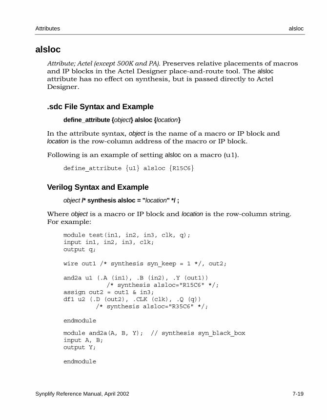
Attributes alsloc
Synplify Reference Manual, April 2002 7-19
alsloc Attribute; Actel (except 500K and PA). Preserves relative placements of macros and IP blocks in the Actel Designer place-and-route tool. The alsloc attribute has no effect on synthesis, but is passed directly to Actel Designer.
.sdc File Syntax and Example
define_attribute {object} alsloc {location}
In the attribute syntax, object is the name of a macro or IP block and location is the row-column address of the macro or IP block.
Following is an example of setting alsloc on a macro (u1).
define_attribute {u1} alsloc {R15C6}
Verilog Syntax and Example
object /* synthesis alsloc = "location" */ ;
Where object is a macro or IP block and location is the row-column string. For example:
module test(in1, in2, in3, clk, q);input in1, in2, in3, clk;output q;
wire out1 /* synthesis syn_keep = 1 */, out2;
and2a u1 (.A (in1), .B (in2), .Y (out1))/* synthesis alsloc="R15C6" */;
assign out2 = out1 & in3;df1 u2 (.D (out2), .CLK (clk), .Q (q))
/* synthesis alsloc="R35C6" */;
endmodule
module and2a(A, B, Y); // synthesis syn_black_boxinput A, B;output Y;
endmodule
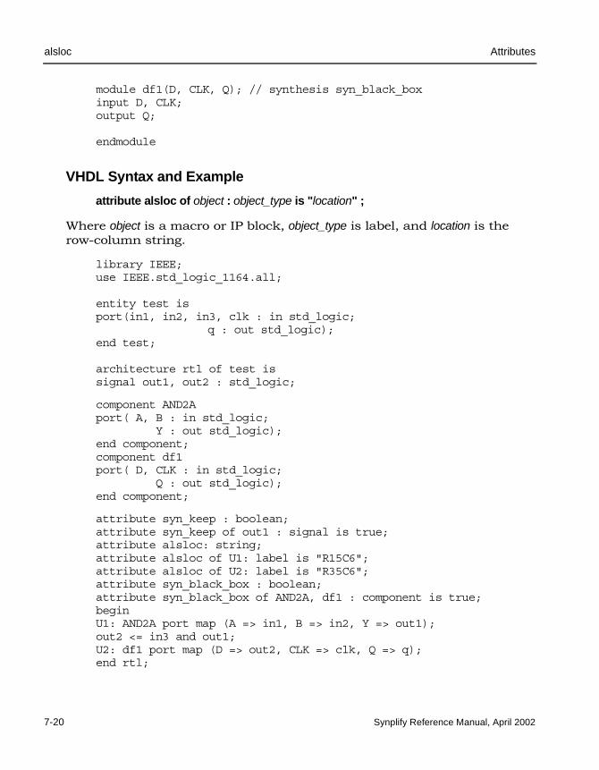
LO
alsloc Attributes
7-20 Synplify Reference Manual, April 2002
module df1(D, CLK, Q); // synthesis syn_black_boxinput D, CLK;output Q;
endmodule
VHDL Syntax and Example
attribute alsloc of object : object_type is "location" ;
Where object is a macro or IP block, object_type is label, and location is the row-column string.
library IEEE;use IEEE.std_logic_1164.all;
entity test is port(in1, in2, in3, clk : in std_logic; q : out std_logic);end test;
architecture rtl of test issignal out1, out2 : std_logic;
component AND2Aport( A, B : in std_logic; Y : out std_logic);end component;component df1port( D, CLK : in std_logic; Q : out std_logic);end component;
attribute syn_keep : boolean;attribute syn_keep of out1 : signal is true;attribute alsloc: string;attribute alsloc of U1: label is "R15C6";attribute alsloc of U2: label is "R35C6";attribute syn_black_box : boolean;attribute syn_black_box of AND2A, df1 : component is true;beginU1: AND2A port map (A => in1, B => in2, Y => out1);out2 <= in3 and out1;U2: df1 port map (D => out2, CLK => clk, Q => q);end rtl;

Attributes alspin
Synplify Reference Manual, April 2002 7-21
alspinAttribute; Actel (except 500K and PA). The alspin attribute assigns the scalar or bus ports of the design to Actel I/O pin numbers (pad locations). Refer to the Actel databook for valid pin numbers. If you want to use alspin for bus ports or for slices of bus ports, you must also use the syn_noarrayports attribute. See .sdc File Syntax and Example below for information on assigning pin numbers to buses and slices.
.sdc File Syntax and Example
define_attribute {port_name} alspin {pin_number}
In the attribute syntax, port_name is the name of the port and pin_number is the Actel I/O pin.
define_attribute {DATAOUT} alspin {48}
If you want to assign pin numbers to a bus port, or to a single or multiple bit slice of a bus port, edit the constraint file as follows:
1. Specify the syn_noarrayports attribute to your design to “bit blast” all bus ports.
2. Specify the alspin attribute for the individual bits of the bus.
The following example illustrates these steps.
define_attribute {ADDRESS0} syn_noarrayports {1};define_attribute {ADDRESS0[4]} alspin {26}define_attribute {ADDRESS0[3]} alspin {30}define_attribute {ADDRESS0[2]} alspin {33}define_attribute {ADDRESS0[1]} alspin {38}define_attribute {ADDRESS0[0]} alspin {40}
Verilog Syntax and Example
object /* synthesis alspin = "pin_number" */ ;
Where object is the port and pin_number is the Actel I/O pin. For example:

LO
alspin Attributes
7-22 Synplify Reference Manual, April 2002
module comparator (datain, clk, dataout);output dataout /* synthesis alspin="48" */;input [7:0] datain;input clk;
// Other code
VHDL Syntax and Example
attribute alspin of object : object_type is "pin_number" ;
Where object is the port, object_type is signal, and pin_number is the Actel I/O pin. For example:
entity comparator isport (datain : in bit_vector(7 downto 0);
clk : in bit;dataout : out bit);
attribute alspin : string;attribute alspin of dataout : signal is "48";
-- Other code

Attributes alspreserve
Synplify Reference Manual, April 2002 7-23
alspreserve Attribute; Actel (except 500K and PA). Specifies a net that should not be removed (optimized away) by the Actel Designer place-and-route tool. The alspreserve attribute has no effect on synthesis, but is passed directly to the Actel Designer place-and-route software. However, to prevent the net from being removed during the synthesis process, you must also use the syn_keep directive.
.sdc File Syntax and Example
define_attribute {n:net_name} alspreserve {1}
In the attribute syntax, net_name is the name of the net to be preserved.
define_attribute {n:and_out3} alspreserve {1};define_attribute {n:or_out1} alspreserve {1};
Verilog Syntax and Example
object /* synthesis alspreserve = 1 */ ;
Where object is the name of the net to preserve. For example:
module complex (in1, out1);input [6:1] in1;ohoutput out1;wire out1;wire or_oosut1 /* synthesis syn_keep=1 alspreserve=1 */;wire and_out1;wire and_out2;wire and_out3 /* synthesis syn_keep=1 alspreserve=1 */;assign and_out1 = in1[1] & in1[2];assign and_out2 = in1[3] & in1[4];assign and_out3 = in1[5] & in1[6];assign or_out1 = and_out1 | and_out2;assign out1 = or_out1 & and_out3;endmodule
VHDL Syntax and Example
attribute alspreserve of object : object_type is true ;
Where object is the name of the net to be preserved and object_type is signal.

LO
alspreserve Attributes
7-24 Synplify Reference Manual, April 2002
For example:
library ieee;use ieee.std_logic_1164.all;library synplify;use synplify.attributes.all;entity complex isport (input : in std_logic_vector (6 downto 1);output : out std_logic);end complex;
architecture RTL of complex issignal and_out1 : std_logic;signal and_out2 : std_logic;signal and_out3 : std_logic;signal or_out1 : std_logic;attribute syn_keep of and_out3 : signal is true;attribute syn_keep of or_out1 : signal is true;attribute alspreserve of and_out3 : signal is true;attribute alspreserve of or_out1 : signal is true;
beginand_out1 <= input(1) and input(2);and_out2 <= input(3) and input(4);and_out3 <= input(5) and input(6);or_out1 <= and_out1 or and_out2;output <= or_out1 and and_out3;end;

Attributes altera_auto_use_eab
Synplify Reference Manual, April 2002 7-25
altera_auto_use_eabAttribute. Altera (FLEX and ACEX families). Automatically implements large inferred RAMs and ROMs as embedded block arrays (EABs) for FLEX10K and ACEX, and MAX designs. Altera mappers automatically use EAB resources for inferred RAMs and ROMs. However, a potential for the mapper to overuse these resources is possible since the mapper is not aware of resources used whenever you specify the altera_implement_in_eab attribute or resources used through black boxes or instantiated LPMs. When you set altera_auto_use_eab to 0 or false, inferred RAMs and ROMs are not implemented in ESBs.
You can override this attribute for specific RAMs and/or ROMs. To do this for RAMs, set the syn_ramstyle attribute to block_ram and apply it to a specific RAM. Likewise, for ROMs, set the syn_romstyle to block_rom and apply it to a specific ROM.
The usage summary in the .srr file shows the number of EAB resources used, the number available, and percent utilization.
.sdc File Syntax and Example
define_global_attribute altera_auto_use_eab {0 | 1}
For example:
define_global_attribute altera_auto_use_eab {0}
Verilog Syntax and Example
object /* synthesis altera_auto_use_eab = 0 | 1 */ ;
For example:
module rom2(z, a);output [3:0] z;input [4:0] a;reg [3:0] z ;always @(a)begincase (a)5'b00000: z = 4'b1011;5'b00001: z = 4'b0001;5'b00100: z = 4'b0011;5'b00110: z = 4'b0010;

LO
altera_auto_use_eab Attributes
7-26 Synplify Reference Manual, April 2002
5'b00111: z = 4'b1110;5'b01001: z = 4'b0111;5'b01010: z = 4'b0101;5'b01101: z = 4'b0100;5'b10000: z = 4'b1100;5'b10001: z = 4'b1101;5'b10010: z = 4'b1111;5'b10011: z = 4'b1110;5'b11000: z = 4'b1010;5'b11010: z = 4'b1011;5'b11110: z = 4'b1001;5'b11111: z = 4'b1000;default: z = 4'b0000;endcaseendendmodule
module top (z, a) /* synthesis altera_auto_use_eab = 0 */;output [3:0] z;input [4:0] a;rom2 myrom (.z(z) , .a(a));endmodule
VHDL Syntax and Example
attribute altera_auto_use_eab of object : object_type is false | true ;
For example:
library IEEE;use IEEE.std_logic_1164.all;entity rom6 isport ( a: in std_logic_vector(3 downto 0);
z: out std_logic_vector(3 downto 0));
end rom6;architecture rtl of rom6 isbeginprocess(a)begincase a iswhen "0000" => z <= "1010";when "0001" => z <= "0100";when "0010" => z <= "0111";when "0011" => z <= "0010";when "0100" => z <= "0101";

Attributes altera_auto_use_eab
Synplify Reference Manual, April 2002 7-27
when "0101" => z <= "1001";when "0110" => z <= "1011";when "0111" => z <= "0011";when "1000" => z <= "1101";when "1001" => z <= "0001";when "1010" => z <= "1111";when "1011" => z <= "0110";when "1100" => z <= "1000";when "1101" => z <= "1110";when "1110" => z <= "1100";when others => z <= "0000";end case;end process;end rtl;
library IEEE;use IEEE.std_logic_1164.all;entity top is port (a: in std_logic_vector(3 downto 0);z: out std_logic_vector(3 downto 0));end top;architecture archtop of top iscomponent rom6 is port (
a: in std_logic_vector(3 downto 0); z: out std_logic_vector(3 downto 0));
end component;attribute altera_auto_use_eab : boolean;attribute altera_auto_use_eab of archtop : architecture is false;beginU1: rom6 port map (
a =>a,z =>z);
end archtop;

LO
altera_auto_use_esb Attributes
7-28 Synplify Reference Manual, April 2002
altera_auto_use_esbAttribute. Altera (APEX families). Automatically implements large, inferred RAMs and ROMs as PTERMs in embedded system blocks (ESBs) for APEX20K/20KC/20KE, APEX II and Mercury designs. Altera mappers automatically use ESB resources for inferred RAMs and ROMs. However, a potential for the mapper to overuse these resources is possible since the mapper is not aware of resources used whenever you specify the altera_implement_in_esb attribute or resources used through black boxes or instantiated LPMs. When you set altera_auto_use_esb to 0 or false, inferred RAMs and ROMs are not implemented in ESBs.
You can override this attribute for specific RAMs and/or ROMs. To do this for RAMs, set the syn_ramstyle attribute to block_ram and apply it to a specific RAM. Likewise, for ROMs, set the syn_romstyle to block_rom and apply it to a specific ROM.
The usage summary in the .srr file shows the number of ESB resources used, the number available, and percent utilization.
.sdc File Syntax and Example
define_global_attribute altera_auto_use_esb {0 | 1}
For example:
define_global_attribute altera_auto_use_esb {0}
Verilog Syntax and Example
object /* synthesis altera_auto_use_esb = 0 | 1 */ ;
For example:
module rom2(z, a);output [3:0] z;input [4:0] a;reg [3:0] z ;always @(a)begincase (a)5'b00000: z = 4'b1011;5'b00001: z = 4'b0001;5'b00100: z = 4'b0011;5'b00110: z = 4'b0010;

Attributes altera_auto_use_esb
Synplify Reference Manual, April 2002 7-29
5'b00111: z = 4'b1110;5'b01001: z = 4'b0111;5'b01010: z = 4'b0101;5'b01101: z = 4'b0100;5'b10000: z = 4'b1100;5'b10001: z = 4'b1101;5'b10010: z = 4'b1111;5'b10011: z = 4'b1110;5'b11000: z = 4'b1010;5'b11010: z = 4'b1011;5'b11110: z = 4'b1001;5'b11111: z = 4'b1000;default: z = 4'b0000;endcaseendendmodule
module top (z, a) /* synthesis altera_auto_use_esb = 0 */;output [3:0] z;input [4:0] a;rom2 myrom (.z(z) , .a(a));endmodule
VHDL Syntax and Example
attribute altera_auto_use_esb of object : object_type is false | true ;
For example:
library IEEE;use IEEE.std_logic_1164.all;entity rom6 isport ( a: in std_logic_vector(3 downto 0);
z: out std_logic_vector(3 downto 0));
end rom6;architecture rtl of rom6 isbeginprocess(a)begincase a iswhen "0000" => z <= "1010";when "0001" => z <= "0100";when "0010" => z <= "0111";when "0011" => z <= "0010";when "0100" => z <= "0101";

LO
altera_auto_use_esb Attributes
7-30 Synplify Reference Manual, April 2002
when "0101" => z <= "1001";when "0110" => z <= "1011";when "0111" => z <= "0011";when "1000" => z <= "1101";when "1001" => z <= "0001";when "1010" => z <= "1111";when "1011" => z <= "0110";when "1100" => z <= "1000";when "1101" => z <= "1110";when "1110" => z <= "1100";when others => z <= "0000";end case;end process;end rtl;
library IEEE;use IEEE.std_logic_1164.all;entity top is port (
a: in std_logic_vector(3 downto 0); z: out std_logic_vector(3 downto 0));
end top;architecture archtop of top iscomponent rom6 is port (
a: in std_logic_vector(3 downto 0); z: out std_logic_vector(3 downto 0));
end component;attribute altera_auto_use_esb : boolean;attribute altera_auto_use_esb of archtop : architecture is false;beginU1: rom6 port map (
a =>a,z =>z);
end archtop;

Attributes altera_chip_pin_lc
Synplify Reference Manual, April 2002 7-31
altera_chip_pin_lc Attribute; Altera. Specifies pin locations for Altera I/Os and forward-annotates information to placement and routing tool. Refer to the Altera databook for valid pin numbers.
.sdc File Syntax and Examples
define_attribute {port_name} altera_chip_pin_lc {@pin_number}
The following examples show bus pin assignments for the APEX, ACEX, and FLEX technologies. Notice the APEX technology syntax does not use the @ sign prefix.
APEX Example define_attribute {DATA0[7:0]} altera_chip_pin_lc {14,12,
11,5,21,18,16,15}
ACEX and FLEX Exampledefine_attribute {DATA0[7:0]} altera_chip_pin_lc {@14,@12,
@11,@5,@21,@18,@16,@15}
Verilog Syntax and Examples
object /* synthesis altera_chip_pin_lc = "@pin_number" */ ;
The following Verilog examples show bus pin assignment for the APEX, ACEX, and FLEX technologies. Notice the APEX technology syntax does not use the @ sign prefix.
APEX Exampleoutput [7:0} DATA0
/* synthesis altera_chip_pin_lc = "14,12,11,5,21,18,16,15" */;
ACEX, FLEX Exampleoutput [7:0} DATA0/* synthesis altera_chip_pin_lc="@14,@12,@11,@5,@21,@18,@16,@15" */;

LO
altera_chip_pin_lc Attributes
7-32 Synplify Reference Manual, April 2002
VHDL Syntax and Examples
attribute altera_chip_pin_lc of object : object_type is "@pin_number" ;
The following VHDL examples show bus pin assignment for both the APEX and the ACEX and FLEX technologies. Notice the APEX technology syntax does not use the @ sign prefix.
APEX Exampleentity prep2_2 is
port(data0: out std_logic_vector(7 downto 0);...qout: out std_logic_vector(7 downto 0));
attribute altera_chip_pin_lc of data0: signal is"14,12,11,5,21,18,16,15";
end prep2_2;
ACEX and FLEX Example entity prep2_2 is
port(data0: out std_logic_vector(7 downto 0);...qout: out std_logic_vector(7 downto 0));
attribute altera_chip_pin_lc of data0: signal is"@14,@12,@11,@5,@21,@18,@16,@15";
end prep2_2;

Attributes altera_implement_in_eab
Synplify Reference Manual, April 2002 7-33
altera_implement_in_eabAttribute; Altera (FLEX10K and ACEX). Implements a logic design unit as extended array blocks (EABs) for FLEX10K and ACEX designs.
.sdc File Syntax and Example
define_attribute {v:module_or_architecture_name} altera_implement_in_eab {1}
The following example implements the instance sqrt8 as an Altera EAB.
define_attribute {v:mymux} altera_implement_in_eab {1}
Verilog Syntax and Example
object /* synthesis altera_implement_in_eab = 1 */ ;
The following Verilog example implements an instance of a 2-to-1 multi-plexor as an Altera EAB:
module mymux (in1 , sel, dout);input [9:0] in1;input sel;output [9:0] dout;assign dout = sel ? in1 : ~in1;endmodulemodule esb_test (a, s, o);input [9:0] a;input s;output [9:0] o;mymux my (.in1(a), .sel(s), .dout(o)) /* synthesis altera_implement_in_eab = 1 */;endmodule

LO
altera_implement_in_eab Attributes
7-34 Synplify Reference Manual, April 2002
VHDL Syntax and Example
attribute altera_implement_in_eab of object : object_type is 1 */ ;
The following example implements an instance of a 2-to-1 multiplexor as an Altera EAB:
module mymux (in1 , sel, dout);input [9:0] in1;input sel;output [9:0] dout;assign dout = sel ? in1 : ~in1;endmodulemodule esb_test (a, s, o);input [9:0] a;input s;output [9:0] o;mymux my (.in1(a), .sel(s), .dout(o)) /* synthesis altera_implement_in_eab = 1 */;endmodule

Attributes altera_implement_in_esb
Synplify Reference Manual, April 2002 7-35
altera_implement_in_esb Attribute; Altera. Implements a logic design unit as a PTERM in an extended system block (ESB) in APEX, APEX II, Excalibur, and Mercury designs. You can apply this attribute to either a module or an instance. To use altera_implement_in_esb, make your design hierarchical. Then, instantitate the module or instance in the ESB at its top level.
.sdc File Syntax and Example
define_attribute {v:module_or_architecture_name} altera_implement_in_esb {1}
Examples:
// Applied to a moduledefine_attribute {v:mymux} altera_implement_in_esb {1}
//Applied to an instancedefine_attribute {i:my} altera_implement_in_esb {1}
Verilog Syntax and Example
object /* synthesis altera_implement_in_esb = 1 */ ;
The following Verilog example shows how to implement a 2:1 multiplexer as a PTERM in an extended system block (ESB).
module mymux (in1 , sel, dout);input [9:0] in1;input sel;output [9:0] dout;
assign dout = sel ? in1 : ~in1;endmodule
module esb_test (a, s, o);input [9:0] a;input s;output [9:0] o;
// Apply attribute to instancemymux my (.in1(a), .sel(s), .dout(o))
/* synthesis altera_implement_in_esb = 1 */;endmodule

LO
altera_implement_in_esb Attributes
7-36 Synplify Reference Manual, April 2002
VHDL Syntax and Example
The following VHDL example shows how to implement a 2:1 multiplexer as a PTERM in an extended system block (ESB).
library ieee;use ieee.std_logic_1164.all;entity mymux isport (in1: in std_logic_vector(9 downto 0);
sel : in std_logic;dout : out std_logic_vector(9 downto 0));
end mymux;
architecture behave of mymux isbegin
dout <= in1 when sel = '1' else(NOT in1) when sel = '0' else
(others => 'X');end behave;
library ieee;use ieee.std_logic_1164.all;
entity esb_test is port (a: in std_logic_vector(9 downto 0);
s: in std_logic;o: out std_logic_vector(9 downto 0));
end esb_test;
architecture arch1 of esb_test iscomponent mymux is
port (in1: in std_logic_vector (9 downto 0); sel : in std_logic; dout: out std_logic_vector (9 downto 0));
end component mymux;
attribute altera_implement_in_esb : boolean;attribute altera_implement_in_esb of U1: label is true;
beginU1: mymux port map (
in1 => a,sel => s,dout => o);
end arch1;

Attributes altera_io_opendrain
Synplify Reference Manual, April 2002 7-37
altera_io_opendrain Attribute; Altera, APEX20KE. Supports an open-drain mode for output and bidirectional ports for I/Os. The value is Boolean and the default is 0, which disables open-drain mode.
.sdc File Syntax and Example
define_attribute {output | bidir } altera_io_opendrain {1 | 0}
For example:
define_attribute {alucout} altera_io_opendrain {1}
You can apply the altera_io_opendrain attribute to a port, bus, or slice of a bus using the SCOPE spreadsheet, whereas in the source code, this attribute can be applied only to the port definition.
1. On the Attributes panel of the SCOPE spreadsheet, select the port in the Object column.
2. Click the pull-down menu in the Attribute column and choose altera_io_opendrain.
3. Assign the appropriate Boolean value in the Value field.
Verilog Syntax and Example
object /* synthesis altera_io_opendrain = 1 | 0 */ ;
You can only apply the altera_io_opendrain attribute to the port definition. For example:
module alu (..., aluop, alua, alub, alu_cout, aluz, aluout); input [3:0] aluop;
// Apply to a bi-directional bus portinout [7:0] alua /* synthesis altera_io_opendrain=0 */, alub;
// Apply to a bit portoutput alu_cout /* synthesis altera_io_opendrain=1 */, aluz;

LO
altera_io_opendrain Attributes
7-38 Synplify Reference Manual, April 2002
// Apply to a bus portoutput [7:0] aluout /* synthesis altera_io_opendrain=1 */;
// Other code
VHDL Syntax and Example
attribute altera_io_opendrain of object : object_type is true | false ;
You can only apply the altera_io_opendrain attribute to the port definition. For example:
entity ALU is port (A : inout std_logic_vector(7 downto 0);ALUOUT : out std_logic_vector(7 downto 0);ALUCOUT : out std_logic;
-- Other code);
attribute altera_io_opendrain : boolean;
-- Apply to a bi-directional bus portattribute altera_io_opendrain of A : signal is false;
-- Apply to a bus portattribute altera_io_opendrain of ALUOUT : signal is true;
-- Apply to a bit portattribute altera_io_opendrain of ALUCOUT : signal is true;end ALU;

Attributes altera_io_powerup
Synplify Reference Manual, April 2002 7-39
altera_io_powerupAttribute; Altera APEX20KE. Controls the power-up mode of registers in the I/O port (bit or bus). However, you can only specify this attribute if the I/O register does not have a defined preset or clear condition.
If the I/O register has a preset, powerup is set to high. If the I/O register has a clear, powerup is set to low. You can only specify the altera_io_powerup attribute to control the powerup mode if the I/O register is not defined.
By default, Quartus II sets the power-up mode of the I/O to low.
If register cannot be packed into an I/O, the Synplify synthesis tool issues a warning saying it has ignored the attribute.
.sdc File Syntax and Examples
define_attribute {port} altera_io_powerup {high | low}
You can apply the altera_io_powerup attribute to a port, bus, or slice of a bus in the SCOPE spreadsheet, whereas in the source code this attribute can only be applied to a port definition.
1. In the SCOPE spreadsheet, click the port in the Object column.
2. Click the pull-down menu in the Attribute column and choose altera_io_powerup.
3. Enter the appropriate string in the Value column: high or low.
Following is an example:
define_attribute {seg [31:0]} altera_io_powerup {high}
Verilog Syntax and Example
object /*synthesis altera_io_powerup = "high | low" */ ;
The following example demonstrates how to apply the altera_io_powerup attribute to a single-bit port in Verilog.

LO
altera_io_powerup Attributes
7-40 Synplify Reference Manual, April 2002
module dff_or(q, a, b, clk);output q /* synthesis altera_io_powerup="low" */;input a, b, clk;reg q;
// Other code
VHDL Syntax and Example
attribute altera_io_powerup of object : object_type is "high | low" ;
The following demonstrates how to apply the altera_io_powerup attribute to a 32-bit bus port in VHDL.
entity eight_bit_uc isport (
clock : in std_logic;resetn : in std_logic;com : out std_logic_vector(3 downto 0);seg : out std_logic_vector(31 downto 0);porta : inout std_logic_vector(7 downto 0);portb : inout std_logic_vector(7 downto 0);portc : inout std_logic_vector(7 downto 0));
attribute altera_io_powerup : string;attribute altera_io_powerup of seg : signal is "high";end EIGHT_BIT_UC;

Attributes din
Synplify Reference Manual, April 2002 7-41
din Attribute; Lattice ORCA. Specifies that an input register goes in the location next to the I/O pad. You can attach din to top-level ports or manually-instantiated input cells. The din attribute takes an empty string (“”) as its only value.
.sdc File Syntax and Example
define_attribute {input_port_name} din ""
For example:
define_attribute {load} din ""
Verilog Syntax and Example
object /* synthesis din = "" */ ;
This is an example of the din attribute in a Verilog source file:
module counter4 (cout, out, in, ce, load, clk, rst);
// Place the flip-flops near the load inputinput load /* synthesis din="" */;endmodule
VHDL Syntax and Example
attribute din of object : object_type is "" ;
This is an example of the din attribute in a VHDL source file:
entity counter4 isport (cout: out bit;
output_vector: out bit_vector (3 downto 0);input_vector: in bit_vector (3 downto 0);ce, load, clk, rst: in bit);
-- Place the flip-flops near "input_vector"attribute din : string;attribute din of input_vector : signal is "";end counter4;

LO
dout Attributes
7-42 Synplify Reference Manual, April 2002
dout Attribute; Lattice ORCA. Specifies that an output register goes in the location next to the I/O pad. You can attach dout to top-level ports or manually-instantiated input cells. The dout attribute is takes an empty string ("") as its value.
.sdc File Syntax and Example
define_attribute {output_port_name} dout ""
For example:
define_attribute {cout} dout ""
Verilog Syntax and Example
object /* synthesis dout = "" */ ;
This is an example of the dout attribute in a Verilog source file:
module counter4 (cout, out, in, ce, load, clk, rst);
// Place the flip-flops near the cout outputoutput cout /* synthesis dout="" */;endmodule
VHDL Syntax and Example
attribute dout of object : object_type signal is "" ;
This is an example of the dout attribute in a VHDL source file:
entity counter4 isport (cout: out bit;
output_vector: out bit_vector (3 downto 0);input_vector: in bit_vector (3 downto 0);ce, load, clk, rst: in bit);
-- Place the flip-flops near "output_vector"attribute dout : string;attribute dout of output_vector: signal is "";end counter4;

Attributes loc
Synplify Reference Manual, April 2002 7-43
loc Attribute; Lattice. The loc attribute specifies pin locations for Lattice MACH and ORCA I/Os. See also lock on page 7-44. Refer to the Lattice databook for valid pin location values.
.sdc File Syntax and Example
define_attribute {port_name} loc {pin_location}
The following example assigns a pad location to all bits of a bus:
define_attribute {DATA0[3:0]} loc {P14,P12,P11,P5}
Verilog Syntax and Example
object /* synthesis loc = "pin_location" */ ;
For example:
input [3:0]DATA0 /* synthesis loc = "p10,p12,p11,p15" */;
VHDL Syntax and Example
attribute loc of object : object_type is "pin_location" ;
For example:
entity mycomp is port(DATA0 : in std_logic_vector (3 downto 0);...);
attribute loc : string;attribute loc of DATA0 : signal is "p10,p12,p11,p15";

LO
lock Attributes
7-44 Synplify Reference Manual, April 2002
lockAttribute; Lattice. The lock attribute specifies pin locations for Lattice ISP I/Os. See also loc on page 7-43. Refer to the appropriate Lattice databook for valid pin numbers.
.sdc File Syntax and Example
define_attribute {port_name} lock {pin_number}
For example:
define_attribute {ADDR[3:0]} lock {P6,P8,P10,P14}

Attributes orca_padtype
Synplify Reference Manual, April 2002 7-45
orca_padtype Attribute; Lattice ORCA. The orca_padtype attribute specifies the pad type for a Lattice ORCA I/O.
.sdc File Syntax and Example
define_attribute {port_name} orca_padtype {pad_type}
Values for pad_type are defined in the Lattice ORCA databook. The default for inputs is IBM, which is a CMOS pad type. The default for outputs is OB6.
This example defines bit 3 of AIN to be an ORCA TTL input pad.
define_attribute {AIN[3]} orca_padtype {IBT}
Verilog Syntax and Example
object /* synthesis orca_padtype = "pad_type" */ ;
This is an example of the orca_padtype attribute in a Verilog source file:
module counter4 (cout, out, in, ce, load, clk, rst);
// Choose IBT padtype to select a TTL input pad for "load"input load /* synthesis orca_padtype="IBT" */;endmodule

LO
orca_padtype Attributes
7-46 Synplify Reference Manual, April 2002
VHDL Syntax and Example
attribute orca_padtype of object : object_type is "pad_type" ;
This is an example of the orca_padtype attribute in a VHDL source file:
entity counter4 isport (cout: out bit;
output_vector: out bit_vector (3 downto 0);input_vector: in bit_vector (3 downto 0);ce, load, clk, rst: in bit);
-- Choose OB12 padtype for "output_vector".-- The OB12 padtype is being set for all four -- bits in "output_vector".attribute orca_padtype : string;attribute orca_padtype of output_vector: signal is "OB12";end counter4;

Attributes orca_props
Synplify Reference Manual, April 2002 7-47
orca_propsAttribute; Lattice ORCA. Specifies Lattice ORCA I/O properties on selected ports that are forward-annotated.
.sdc File Syntax and Example
define_attribute {p:port } orca_props {property=value}
For more information about the properties and their values, see I/O Proper-ties and Values on page 7-48. The following is an example of the syntax:
define_attribute {p:data_in} orca_props {LEVELMODE=LVDS}
Verilog Syntax and Example
object /* synthesis orca_props = "property=value" */;
where object can be an input, output, bidirectional, or tristate ports. For more information about the properties and their values, see I/O Properties and Values on page 7-48. The following is an example of the syntax:
output data_out /* synthesis orca_props = "LEVELMODE=LVDS" */;
If multiple properties are required, separate them with commas. This is an example of an object with more than one property:
output data_out/* synthesis orca_props = "BUFMODE=FAST,LEVELMODE=LVTTL" */;
VHDL Syntax and Example
attribute orca_props : string;attribute orca_props of object : object_type is "property=value" ;
For more information about the properties and their values, see I/O Proper-ties and Values on page 7-48. The following is an example of the VHDL syntax:
Entity test is port (a : in std_logic; b : out std_logic;);attribute orca_props : string;attribute orca_props of a :signal is "LEVELMODE=LVDS";

LO
orca_props Attributes
7-48 Synplify Reference Manual, April 2002
This is an example of the syntax when you have multiple properties:
Entity test is port (a : in std_logic; b : out std_logic;);attribute orca_props : string;attribute orca_props of a :signal is "LEVELMODE=LVDS, AMPSMODE=6";
I/O Properties and Values
The following table lists the properties and values that are currently supported.
Table 7-6: I/O properties
Property Valid Values Attached to Notes
AMPSMODE 6 | 12 | 24 Bidirectional or output ports
Must be set in conjunction with levelmode set to LVTTL or LVCMOS2.
BUFMODE SLOW | FAST Bidirectional or output ports
Must be set in conjunction with levelmode set to LVTTL or LVCMOS2.
DELAYMODE true | false Input ports
KEEPERMODE off | on Bidirectional or tristate ports
LEVELMODE LVTTL | LVCMOS2 |LVCMOS18 | PCI |SSTL2 | SSTL3 | HSTL1|HSTL3 | GTL | GTLPLUS|PECL | LVPECL | LVDS
Any port
RESISTOR off | on Input or output ports
Must be set in conjunction with levelmode set to LVDS or LVPECL.

Attributes ql_padtype
Synplify Reference Manual, April 2002 7-49
ql_padtype Attribute; QuickLogic. Overrides the default pad types that the Synplify synthesis tool chooses for inputs, outputs, and inout (bidirectional) ports. By default, the tool infers pad types, using the available high-drive and clock pads where appropriate.
.sdc File Syntax and Example
define_attribute {port_name} ql_padtype {pad_type}
For example:
define_attribute {clk} ql_padtype {CLOCK}
Values for pad_type are:
• INPUT – A high-drive input. QuickLogic parts have high-drive inputs that vary in quantity depending upon the device. The number of high-drives varies with the part, refer to the QuickLogic data book for more information.
• BIDIR – An input, output, or bidirectional pad.
• CLOCK – A clock pad. QuickLogic clock pads are high-drive inputs that are routed on special clock wires (clock trees). CLOCK pad types can also be used for sets and resets, a feature the Synplify synthesis tool normally infers.
• CLOCKB – A special clock pad used only for QuickPCI QL5064 devices.
Verilog Syntax and Example
object /* synthesis ql_padtype = "pad_type" */ ;
For example:
module ql_padtype_example (d, q, clk, rst);input d /* synthesis ql_padtype = "INPUT" */;input clk /* synthesis ql_padtype = "CLOCK" */;input rst /* synthesis ql_padtype = "INPUT" */;output q /* synthesis ql_padtype = "BIDIR" */;reg q;

LO
ql_padtype Attributes
7-50 Synplify Reference Manual, April 2002
always@(posedge clk or posedge rst)if (rst)
q = 1'b0;else
q = d;endmodule
VHDL Syntax and Example
attribute ql_padtype of object : object_type is "pad_type" ;
For example:
library ieee;use ieee.std_logic_1164.all;
entity ql_padtype_example isport (
d : in std_logic;q : out std_logic;clk : in std_logic;rst : in std_logic
);
attribute ql_padtype: string;attribute ql_padtype of d: signal is "INPUT";attribute ql_padtype of clk: signal is "CLOCK";attribute ql_padtype of rst: signal is "INPUT";attribute ql_padtype of q: signal is "BIDIR";end ql_padtype_example;
architecture rtl of ql_padtype_example isbegin
process(clk, rst)begin if (rst='1')then q <= '0'; elsif (clk'event and clk='1')then q <= d; end if;end process;
end rtl;

Attributes ql_placement
Synplify Reference Manual, April 2002 7-51
ql_placement Attribute; QuickLogic. Used for forward annotation of pad locations for use by the QuickLogic QuickWorks place-and-route tool. ql_placement overrides the default pad locations chosen by QuickWorks.
Values for ql_placement depend on the device package documented in the QuickLogic data book. All placement names must match the pin names as they appear in the QuickLogic data book (for example, A21, B23).
.sdc File Syntax and Example
define_attribute {port_or_instance_name} ql_placement {placement}
Examples:
define_attribute {d} ql_placement {A21}define_attribute {q} ql_placement {B40}define_attribute {clk} ql_placement {B23}
Verilog Syntax and Example
object /* synthesis ql_placement = "placement" */ ;
For example:
module ql_placement_example (d, q, clk, rst);input d /* synthesis ql_placement = "A21" */;input clk /* synthesis ql_placement = "B23" */;input rst /* synthesis ql_placement = "A31" */;output q /* synthesis ql_placement = "B40" */;reg q;
always@(posedge clk or posedge rst)if (rst)
q = 1'b0;else
q = d;endmodule
VHDL Syntax and Example
attribute ql_placement of object : object_type is "placement" ;

LO
ql_placement Attributes
7-52 Synplify Reference Manual, April 2002
library ieee;use ieee.std_logic_1164.all;
entity ql_placement_example isport (
d : in std_logic;q : out std_logic;clk : in std_logic;rst : in std_logic);
attribute ql_placement: string;attribute ql_placement of d: signal is "A21";attribute ql_placement of clk: signal is "B23";attribute ql_placement of rst: signal is "A31";attribute ql_placement of q: signal is "B40";end ql_placement_example;
architecture rtl of ql_placement_example isbegin
process(clk, rst)begin
if (rst='1') then q <= '0';
elsif (clk'event and clk='1') thenq <= d;
end if;end process;
end rtl;

Attributes syn_direct_enable
Synplify Reference Manual, April 2002 7-53
syn_direct_enableAttribute; The syn_direct_enable attribute controls the assignment of a clock enable net to the dedicated enable pin of a storage element (flip-flop). Using this attribute, you can direct the mapper to use a particular net as the only clock enable when the design has multiple clock-enable candi-dates.
You can also use this attribute as a compiler directive to infer flip-flops with clock enables. To do so, enter syn_direct_enable as a directive in source code, not the SCOPE spreadsheet.
This directive is supported in the following technologies:
The syn_direct_enable data type is Boolean. A value of 1 or true enables net assignment to the clock enable pin.
Verilog Syntax and Example
object /* synthesis syn_direct_enable = 1 */ ;
For example:
Table 7-7: syn_direct_enable attribute
Altera Xilinx
ACEX Virtex
APEX20K Virtex-E
Virtex2
Virtex2p
FLEX10K Spartan2
XC4000
Stratix XC5200

LO
syn_direct_enable Attributes
7-54 Synplify Reference Manual, April 2002
`timescale 1 ns/ 100 psmodule dff2(q1, d1, clk, e1, e2, e3);input [4:0] d1;input clk;output [4:0] q1;reg [4:0] q1;input e1, e3;input e2 /* synthesis syn_direct_enable = 1 */;
always @(posedge clk)begin
if (e1 & e2 & e3 ) beginq1 = d1;
endendendmodule
VHDL Syntax and Examples
attribute syn_direct_enable of object : object_type is true;
The first example shows signals:
architecture dff2_arch of dff2 issignal enable : std_logic;attribute syn_direct_enable : boolean;attribute syn_direct_enable of enable : signal is true;
The second example shows ports in an entity.
entity dff2 isport (q1 : out std_logic_vector (4 downto 0);
dl: in std_logic_vector (4 downto 0);clk , e1, e2 , e3 : in std_logic);
attribute syn_direct_enable : boolean;attribute syn_direct_enable of e2 : signal is true;end dff2;

Attributes syn_edif_bit_format
Synplify Reference Manual, April 2002 7-55
syn_edif_bit_format Attribute; Xilinx. Global character formatting attribute to use with vector (bus) port names to control the naming style in the EDIF output file. The first argument (%n, %d, or %u) controls the case of the names, while the second argument (%i) controls the appearance of the vector range. The default preserves the character case of the names as they appear in source code. To change the character formatting of scalar ports, see the syn_edif_scalar_format attribute.
.sdc File Syntax and Examples
The constraint file syntax for the global attribute is:
define_global_attribute syn_edif_bit_format { %n | %u | %d [char] %i [char] }
Use this attribute to control the following:
1. Up-shift (%u) or down-shift (%d) the character case of entire names; %n means leave case as is.
2. Append the vector range to the end of names.
3. Append additional characters to the end of names.
4. Convert the default bus delimiters to another representation (parentheses, square brackets or angle brackets). By default, Verilog designs produce square bracket delimiters in EDIF and VHDL designs produce parenthesis delimiters in EDIF.
Example: Converting Bus DelimitersThe port definition as it would appear in Verilog source code:
input[31:0] AbCd;
Specifying the attribute in a constraint file to convert the bus delimiters to angle brackets(<%i>) in the EDIF file:
define_global_attribute syn_edif_bit_format {%n<%i>}
The port definition as it would appear in the EDIF output file; note the use of angle brackets as bus delimiters:
(port (array (rename abcd "AbCd<31:0>") 32) (direction INPUT))

LO
syn_edif_bit_format Attributes
7-56 Synplify Reference Manual, April 2002
Example: Appending the Vector RangeThe port definition as it appears in Verilog source code:
input[31:0] AbCd;
Specifying the attribute in a constraint file to append the vector range (_%i) in the EDIF file:
define_global_attribute syn_edif_bit_format {%n_%i}
The port definition as it appears in the EDIF output file; note the appended vector ranges:
(port (array (rename abcd "AbCd_31") 32) (direction INPUT))(port (array (rename abcd "AbCd_30") 32) (direction INPUT))(port (array (rename abcd "AbCd_29") 32) (direction INPUT))
.
.
.(port (array (rename abcd "AbCd_0") 32) (direction INPUT))
Example: Changing All Characters to UppercaseThe port definition as it appears in Verilog source code:
input[31:0] AbCd;
Specifying the attribute in a constraint file to shift the names to upper-case (%u) and use parentheses as the bus delimiters ((%i)):
define_global_attribute syn_edif_bit_format {%u(%i)}
The port definition as it appears in the EDIF output file; note the upper-case name and the use of parentheses as bus delimiters:
(port (array (rename abcd "ABCD(31:0)") 32) (direction INPUT))
Example: Appending Additional CharactersThe port definition as it appears in Verilog source code:
input[31:0] AbCd;
Specifying the attribute in a constraint file to append additional charac-ters (_mydesign) and use parentheses as the bus delimiters ((%i)):
define_global_attribute syn_edif_bit_format {%n_mydesign(%i)}

Attributes syn_edif_bit_format
Synplify Reference Manual, April 2002 7-57
The port definition as it appears in the EDIF output file; note the appended characters and the use of parentheses as bus delimiters
(port (array (rename abcd "AbCd_mydesign(31:0)") 32) (direction INPUT)))
Verilog Syntax and Example
object /* synthesis syn_edif_bit_format = "%n | %u | %d [char] %i [char]" */ ;
The following example shows how to set the bus format for a Verilog module. In the EDIF output file the case of the name will be unchanged (%n) and the bus delimiters will be angle brackets (<%i>):
module pci_lc_i (...)/* synthesis syn_black_box syn_edif_bit_format = "%n<%i>" */;
VHDL Syntax and Example
attribute syn_edif_bit_format of object : object_type is "%n | %u | %d [ch] %i [ch]" ;
The following example shows how to specify angle brackets as the bus delimiters for the VHDL black-box component pci_lc_i:
component pci_lc_iport (
.
.
.);
end component;attribute syn_edif_bit_format of pci_lc_i : component is "%n<%i>";
The following example shows how to shift the name to uppercase and specify square brackets as the bus delimiters for the VHDL black-box architecture rtl:
architecture rtl of pci_top isattribute syn_edif_bit_format of rtl : architecture is "%u[%i]";

LO
syn_edif_name_length Attributes
7-58 Synplify Reference Manual, April 2002
syn_edif_name_lengthAttribute; Altera. Global truncation attribute that determines the length of port names written to the EDIF output file for Altera designs. If your target place-and-route tool is Quartus II, the length of the port names does not matter. However, if Max+PlusII is the target tool, port names cannot be more than 30 characters in length.
You specify this attribute globally on the top-level module or architecture. The value of the attribute can be either restricted or unrestricted. The restricted setting (the default) limits the port names to 30 characters. Use this setting with Max+PlusII. If you set the attribute to unrestricted, the port names are not truncated. Use this value if you are targeting Quartus II as the place-and-route tool.
.sdc File Syntax
The constraint file syntax for the global attribute is as follows:
define_global_attribute syn_edif_name_length {restricted | unrestricted}
Verilog Syntax and Example
object /* synthesis syn_edif_name_length = "restricted | unrestricted" */ ;
Attach the attribute to the top-level module. The following is an example:
module test(in1, in2 , out )/* synthesis syn_edif_name_length = "restricted" */;
input in1, in2;output out;testbox inst1(.in1(in1), .in2(in2), .abcdefghijklmnopqrstuvwxyz
_abcdefghijklmnopqrstuvwxyz(out));endmodule

Attributes syn_edif_name_length
Synplify Reference Manual, April 2002 7-59
VHDL Syntax and Example
attribute syn_edif_name_length of object:object_type is "restricted | unrestricted" ;
Attach the attribute to the top-level entity, as shown in this example:
architecture beh of test iscomponent testbox is port(in1, in2 : in std_logic;abcdefghijklmnopqrstuvwxyz_abcdefghijklmnopqrstuvwxyz : out
std_logic);end component;
attribute syn_black_box : boolean;attribute syn_black_box of testbox : component is true;attribute syn_edif_name_length : string;attribute syn_edif_name_length of beh : architecture is
"Unrestricted";
beginu0: testbox port map (in1 => in1, in2 => in2,
abcdefghijklmnopqrstuvwxyz_abcdefghijklmnopqrstuvwxyz => out1);
end beh;

LO
syn_edif_scalar_format Attributes
7-60 Synplify Reference Manual, April 2002
syn_edif_scalar_formatAttribute; Xilinx. Global character formatting attribute to use with scalar port names to up-shift (%u) or down-shift (%d) the character case of the name in the EDIF output file. The default (syn_edif_scalar_format {%n}) preserves the character case of the names as they appear in source code. To change the character formatting and style of vector (bus) signals and ports, see the syn_edif_bit_format attribute.
.sdc File Syntax and Examples
The constraint file syntax for the global attribute is:
define_global_attribute syn_edif_scalar_format {%u | %d | %n}
For example, the port definition as it would appear in source code:
input AbCd;
Specifying the attribute in a constraint file to up-shift the base names:
define_global_attribute syn_edif_scalar_format {%u}
The port definition as it would appear in the EDIF output file.
(port (rename AbCd "ABCD") (direction INPUT))
Verilog Syntax and Example
object /* synthesis syn_black_box syn_edif_scalar_format = "%u | %d | %n" */ ;
where object is a black-box module.
The following example shows how to shift all scalar port names of the Verilog black-box module pci_lc_i to uppercase:
module pci_lc_i (...)/* synthesis syn_black_box syn_edif_scalar_format = "%u" */;

Attributes syn_edif_scalar_format
Synplify Reference Manual, April 2002 7-61
VHDL Syntax and Examples
attribute syn_edif_scalar_format of object : object_type is "%u | %d | %n" ;
where object is a VHDL black-box component or architecture.
The following example shows how to shift all scalar port names of the VHDL black-box component pci_lc_i to uppercase:
component pci_lc_iport (
.
.
.);
end component;
attribute syn_black_box of pci_lc_i : component is true;attribute syn_edif_scalar_format of pci_lc_i : component is "%u";
The following example shows how to shift all scalar port names of the VHDL black-box architecture rtl to lowercase:
architecture rtl of pci_top isattribute syn_black_box of rtl : architecture is true;attribute syn_edif_scalar_format of rtl : architecture is "%d";

LO
syn_encoding Attributes
7-62 Synplify Reference Manual, April 2002
syn_encodingAttribute. Overrides the default FSM Compiler encoding for a state machine. This attribute takes effect only when FSM Compiler is enabled. See FSM Compiler on page 1-21, for more information on FSM Compiler.
The default encoding style automatically assigns encoding based on the number of states in the state machine as follows:
• sequential for 0-4 states
• onehot for 5-24 states
• gray for >24 states
Use the syn_encoding attribute when you want to override these defaults. You can also use syn_encoding when you want to disable the FSM Compiler globally but there are a select number of state registers in your design that you want extracted. In this case, you would use this attribute with the syn_state_machine directive on just those specific registers.
syn_encoding can have the following values:
• default – synthesis selects encoding style based on the number of states. See default values above.
• onehot – Only two bits of the state register change (one goes to ‘0’, one goes to ‘1’) and only one of the state registers is hot (driven by ‘1’) at a time. For example:
0001, 0010, 0100, 1000
• gray – More than one of the state registers can be hot. The Synplify synthesis tool attempts to have only one bit of the state registers change at a time, but it might allow more than one bit to change, depending upon certain conditions for optimization. For example:
000, 001, 011, 010, 110
• sequential – More than one bit of the state register can be hot. The synthesis tool makes no attempt at limiting the number of bits that can change at a time. For example:
000, 001, 010, 011, 100
• safe – This implements the state machine in the default encoding, and adds reset logic to force the state machine to a known state if it

Attributes syn_encoding
Synplify Reference Manual, April 2002 7-63
reaches an invalid state. This option can be used in combination with any of the other encoding styles described above. For example, if the default encoding is onehot, and the state machine reaches a state where all the bits are 0, which is an invalid state, the safe value ensures that the state machine is reset to a valid state.
The encoding style is implemented during the mapping phase. A message is displayed when the synthesis tool extracts a state machine, for example:
@N: "c:\design\..."|Trying to extract state machine for register current_state
The log file reports the encoding styles used for the state machines in your design.
See also the following:
• For information on enabling state machine optimization for individual modules, see syn_state_machine on page 7-173.
• For VHDL designs, see syn_encoding Versus syn_enum_encoding on page 7-154 for comparative usage information.
Verilog Syntax and Examples
object /* synthesis syn_encoding = "value" */ ;
where object can be reg (register definition signals that hold the state values of state machines) and value can be: onehot, gray, sequential, safe, default.
In this example, syn_encoding overrides the default encoding style for current_state using the gray encoding style.
module prep3 (CLK, RST, IN, OUT);input CLK, RST;input [7:0] IN;output [7:0] OUT;reg [7:0] OUT;reg [7:0] current_state /* synthesis syn_encoding="gray" */;
// Other code

LO
syn_encoding Attributes
7-64 Synplify Reference Manual, April 2002
5. Here is an example using safe,gray.
module prep3 (CLK, RST, IN, OUT);input CLK, RST;input [7:0] IN;output [7:0] OUT;reg [7:0] OUT;reg [7:0] current_state /* synthesis syn_encoding="safe,gray" */;
// Other code
In this example, the encoding style for register out is gray and, by speci-fying safe, if the state machine reaches an invalid state, the Synplify synthesis tool will reset the values to a valid state.
VHDL Syntax and Example
attribute syn_encoding of object : object_type is "string" ;
where object is a signal that holds the state values of the state machines. Here is an example of using syn_encoding to define the gray encoding style for the signal s1.
library synplify;package my_states istype state is (Xstate, st0, st1, st2, st3, st4, st5, st6, st7,
st8, st9, st10, st11, st12, st13, st14, st15);signal s1 : state;attribute syn_encoding : string;attribute syn_encoding of s1 : signal is "gray";end my_states;

Attributes syn_forward_io_constraints
Synplify Reference Manual, April 2002 7-65
syn_forward_io_constraintsAttribute; Altera, Xilinx. Enables/disables forward annotation of the define_input_delay and define_output_delay timing constraints in the .tcl or .ncf file for the place-and-route tool. The default is 1 for Xilinx (I/O constraints are forward-annotated) and 0 for Altera (I/O constraints are not forward-annotated).
Use this attribute on the top level of a VHDL or Verilog file, or you can place syn_forward_io_constraints on a global object in the .sdc file.
.sdc File Syntax and Example
define_global_attribute syn_forward_io_constraints = {1 | 0}
For example:
define_global_attribute syn_forward_io_constraints {1}
Verilog Syntax and Example
object /* synthesis syn_forward_io_constraints = 1 | 0 */;
For example:
module test (a,b,c,d,clk,rst)/* synthesis syn_forward_io_constraints = 1 */;
input a,b,c;input clk, rst;output d;wire temp;reg d;assign temp = a && b || c;always@(posedge clk or posedge rst)if (rst)
d = 1 'b0;else
d=temp;endmodule

LO
syn_forward_io_constraints Attributes
7-66 Synplify Reference Manual, April 2002
VHDL Syntax and Example
attribute syn_forward_io_constraints of object : object_type is true | false ;
For example:
library IEEE;use ieee.std_logic_1164.all;entity test is port (
a : in std_logic;b : in std_logic;clk :in std_logic;rst : in std_logic;d: out std_logic);
end test;
architecture archtest of test isattribute syn_forward_io_constraints : boolean;attribute syn_forward_io_constraints of all :architecture is true;signal temp : std_logic;begintemp <= a and b;
process (clk, rst)beginif (rst ='1')then
d <='0';elsif (clk'event and clk ='1')then
d <= temp;end if;end process;
end archtest;

Attributes syn_hier
Synplify Reference Manual, April 2002 7-67
syn_hier Attribute. Allows you to control the amount of hierarchical transformation that occurs across boundaries on module or component instances during optimization.
During synthesis, the Synplify tool dissolves as much hierarchy as possible to allow efficient optimization of logic across hierarchical bound-aries while maintaining optimal run times. The tool then rebuilds the hierarchy to be as close as possible to the original source code in an effort to preserve the topology of the design. However, you can use the syn_hier attribute to address any specific needs you might have to maintain design hierarchy during optimization. This attribute allows you manual control over flattening for instances, modules or architectures in the design.
Here are the values you can use for syn_hier:
• soft (default) – when you use soft, the synthesis tool determines the best optimization across hierarchical boundaries. This attribute affects only the design unit in which it is specified.
• firm – preserves the interface of the design unit and allows for cell packing across the boundary. This attribute affects only the design unit in which it is specified.
• hard – (Actel, except 500K and PA; Altera and Xilinx; other vendors: same as firm) preserves the interface of the design unit with no exceptions. This attribute affects only the specified design units.
• remove – removes the level of hierarchy for the design unit in which it is specified. The hierarchy at lower levels is unaffected.
• macro – (Actel except 500K and PA, Altera, Lattice ORCA and QuickLogic only) preserves the interface and contents of the design with no exceptions.
• flatten – flattens the hierarchy of all levels below, but not the one in which it is specified. By default, the hierarchy of the design is restored in the output netlist and in the HDL Analyst schematic view.
You can optionally use flatten in combination with other syn_hier options as shown below:
– flatten,soft – same as flatten.

LO
syn_hier Attributes
7-68 Synplify Reference Manual, April 2002
– flatten,firm – flattens all lower levels of the design but preserves the interface of the design unit in which it is specified. This option also allows optimization of cell packing across the boundary.
– flatten,remove – flattens all lower levels of the design including the one in which it is specified.
If you use flatten in combination with another option, the tool flattens as directed until encountering another syn_hier attribute at a lower level. The lower level syn_hier attribute then takes precedence over the higher level one.
Here is an example of two versions of a design: one with syn_hier set on modules inc and reg4; the other shows what happens to those modules with the automatic flattening that occurs during synthesis.
.sdc File Syntax and Example
define_attribute {object} syn_hier {value}
where object can be module declarations or architecture names. Check the attribute values to determine where you should attach the attribute. The syntax is
define_attribute {v:fifo} syn_hier {hard}
With syn_hier=”hard”
Automatic flattening,counter inferred

Attributes syn_hier
Synplify Reference Manual, April 2002 7-69
Verilog Syntax and Examples
object /* synthesis syn_hier = "value" */ ;
where object can be a module declaration. Check the attribute values to determine where you should attach the attribute. The Verilog syntax is
module fifo(out, in) /* synthesis syn_hier = "firm" */;
// Other code
This next example demonstrates the flatten,remove value which states flatten the current level of the hierarchy and all levels below it (unless another syn_hier attribute is found at a lower level).
module top1 (Q, CLK, RST, LD, CE, D)/* synthesis syn_hier = "flatten,remove" */;
// Other code
VHDL Syntax and Examples
attribute syn_hier of object : object_type is "value" ;
where object can be architecture names. Check the attribute values to determine the level at which you should attach the attribute.
architecture struct of cpu is
attribute syn_hier : string;attribute syn_hier of struct: architecture is "firm";
-- Other code
This next example demonstrates the flatten,remove value for this attribute. This value flattens the current level of the hierarchy and all levels below it (unless another syn_hier attribute is found at a lower level).
architecture struct of cpu is
attribute syn_hier : string;attribute syn_hier of struct: architecture is "flatten,remove";
-- Other code

LO
syn_maxfan Attributes
7-70 Synplify Reference Manual, April 2002
syn_maxfanAttribute; No Cypress or Lattice support. Overrides the default (global) fanout guide for an individual input port, net or register output. You set the default Fanout Guide for a design through the Device panel on the Options for Implementation dialog box (see Options for implementation Dialog Box on page 3-31) or using the set_option -fanout_limit command or -fanout_guide (for Virtex) in the project file. Use the syn_maxfan attribute to specify a different (local) value for individual I/Os.
Both syn_maxfan and the default fanout guide are suggested guidelines only; they do not function as hard limits. This means that the Synplify synthesis tool takes them into account but does not always respect them absolutely. If they impose constraints that interfere with optimization they are not respected.
You can apply the syn_maxfan attribute to an input port, register output, or a net. If you apply it to a net, the Synplify synthesis tool creates a KEEPBUF component, and attaches the attribute to it, because the net itself might be optimized away during synthesis. If you attach the attribute to a lower level module or entity that is subsequently optimized during synthesis, the synthesis tool moves the syn_maxfan attribute up to the next higher level. If you do not want syn_maxfan moved up during optimization, set the syn_hier attribute for the entity or module to hard. This prevents the module or entity from being flattened when the design is optimized.
The syn_maxfan attribute is often used along with the syn_noclockbuf attribute on an input port that you do not want buffered. There are a limited number of clock buffers in a design, so if you want to save these special clock buffer resources for other clock inputs, put the syn_noclockbuf attribute on the clock signal. If timing for that clock signal is not critical, you can turn off buffering completely, to save area. To turn off buffering, set the maximum fanout to a very high number; for example, 1000.
.sdc File Syntax and Example
define_attribute {object} syn_maxfan {integer}
The following example limits the fanout for the signal clk to 200:
define_attribute {clk} syn_maxfan {200}

Attributes syn_maxfan
Synplify Reference Manual, April 2002 7-71
Verilog Syntax and Example
object /* synthesis syn_maxfan = "value" */ ;
For example:
module test (registered_data_out, clock, data_in);output [31:0] registered_data_out;input clock;input [31:0] data_in /* synthesis syn_maxfan=1000 */;reg [31:0] registered_data_out /* synthesis syn_maxfan=1000 */;
// Other code
VHDL Syntax and Example
attribute syn_maxfan of object : object_type is "value" ;
For example:
entity test isport(clock : in bit;
data_in : in bit_vector(31 downto 0);registered_data_out: out bit_vector(31 downto 0))
attribute syn_maxfan : integer;attribute syn_maxfan of data_in : signal is 1000;
-- Other code

LO
syn_multstyle Attributes
7-72 Synplify Reference Manual, April 2002
syn_multstyleAttribute; Altera Stratix, Xilinx Virtex2/Virtex2p.
This attribute determines how multipliers are implemented: as dedicated hardware multiplier blocks or as logic. You can apply it to multiplier instances of Altera Stratix or Xilinx Virtex2/Virtex2p devices.
For Altera Stratix, the default implementation uses DSP MAC blocks. You can override this behavior by specifying value lpm_mult or logic. The imple-mentation uses LPMs when the value is lpm_mult; it uses logic when the value is logic.
For Xilinx Virtex2/Virtex2p, the default implementation uses block multi-pliers (this corresponds to the attribute value block_mult). You can override this behavior by specifying a valueof logic; the implementation then uses logic.
.sdc File Syntax and Example
define_attribute {object} syn_multstyle {block_mult | logic | lpm_mult}
This example specifies that multipliers are to be implemented as logic.
define_attribute {temp[15:0]} syn_multstyle {logic}
Verilog Syntax and Example
object /* synthesis syn_multstyle = "block_mult | logic | lpm_mult" */ ;
module mult(a,b,c,r,en);input [7:0] a,b;output [15:0] r;input [15:0] c;input en;
wire [15:0] temp /* synthesis syn_multstyle="logic" */;assign temp = a*b;assign r = en ? temp : c;endmodule

Attributes syn_multstyle
Synplify Reference Manual, April 2002 7-73
VHDL Syntax and Example
attribute syn_multstyle of object : object_type is "block_mult | logic | lpm_mult" ;
library ieee;use ieee.std_logic_1164.all;--use ieee.std_logic_arith.all;use ieee.std_logic_unsigned.all;
entity onereg is port (r : out std_logic_vector(15 downto 0);en : in std_logic;a: in std_logic_vector(7 downto 0);b: in std_logic_vector(7 downto 0);c : in std_logic_vector(15 downto 0));
end onereg;
architecture beh of onereg issignal temp : std_logic_vector(15 downto 0);
attribute syn_multstyle : string;attribute syn_multstyle of temp : signal is "logic";
begintemp <= a * b;
r <= temp when en='1' else c;end beh;

LO
syn_netlist_hierarchy Attributes
7-74 Synplify Reference Manual, April 2002
syn_netlist_hierarchyAttribute; Actel, Altera, Lattice ORCA, Xilinx. A global attribute that controls the generation of hierarchy in the EDIF output (result file) when you assign it to the top-level module of your design. The default (true) is to allow hierarchy generation.
.sdc File Syntax and Example
define_global_attribute syn_netlist_hierarchy {0 | 1}
For example:
define_global_attribute syn_netlist_hierarchy {0}
Verilog Syntax and Example
object /* synthesis syn_netlist_hierarchy = 0 | 1 */ ;
where object can be a top-level module declaration. For example:
module top (clk, qout, a, b)/*synthesis syn_netlist_hierarchy=0 */;
// Other code
VHDL Syntax and Example
attribute syn_netlist_hierarchy of object : object_type is true | false ;
where object can be a top-level architecture name. The data type is Boolean. For example:
architecture top of top is
attribute syn_netlist_hierarchy : boolean;attribute syn_netlist_hierarchy of top : architecture is false;
-- Other code
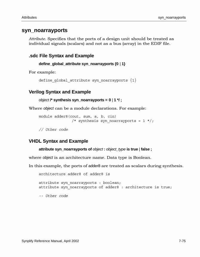
Attributes syn_noarrayports
Synplify Reference Manual, April 2002 7-75
syn_noarrayportsAttribute. Specifies that the ports of a design unit should be treated as individual signals (scalars) and not as a bus (array) in the EDIF file.
.sdc File Syntax and Example
define_global_attribute syn_noarrayports {0 | 1}
For example:
define_global_attribute syn_noarrayports {1}
Verilog Syntax and Example
object /* synthesis syn_noarrayports = 0 | 1 */ ;
Where object can be a module declarations. For example:
module adder8(cout, sum, a, b, cin)/* synthesis syn_noarrayports = 1 */;
// Other code
VHDL Syntax and Example
attribute syn_noarrayports of object : object_type is true | false ;
where object is an architecture name. Data type is Boolean.
In this example, the ports of adder8 are treated as scalars during synthesis.
architecture adder8 of adder8 is
attribute syn_noarrayports : boolean;attribute syn_noarrayports of adder8 : architecture is true;
-- Other code

LO
syn_noclockbuf Attributes
7-76 Synplify Reference Manual, April 2002
syn_noclockbufAttribute. Actel, Atmel, QuickLogic, Xilinx. The Synplify synthesis tool uses clock buffer resources, if they exist in the target module, and puts them on the highest fanout clock nets. You can turn off automatic clock buffer usage by using the syn_noclockbuf attribute. For example, you might want to put a clock buffer on a lower fanout clock that has a higher frequency and tighter timing constraint.
You can turn off automatic clock buffering for entire modules or nets, or just for specific input ports. The value is Boolean with 1 or true turning off automatic clock buffering.
.sdc File Syntax and Example
define_attribute {clock_port} syn_noclockbuf {1 | 0}
define_global_attribute syn_noclockbuf {1 | 0}
For example:
define_attribute {clk} syn_noclockbuf {1}
define_global_attribute syn_noclockbuf {1}
Verilog Syntax and Examples
object /* synthesis syn_noclockbuf = 1 | 0 */ ;
Here is an example of turning off automatic clock buffering for an entire module.
module my_design(out, in, clk_in)/* synthesis syn_noclockbuf = 1 */;
This next example demonstrates turning off automatic clock buffering for a specific input port:
module my_design(out, in, clk_in); output out;input in; input clk_in /* synthesis syn_noclockbuf = 1 */;
// Other code

Attributes syn_noclockbuf
Synplify Reference Manual, April 2002 7-77
VHDL Syntax and Examples
attribute syn_noclockbuf of object : object_type is true | false ;
Where object can be an architecture or an input (clock) port.
This example turns off automatic clock buffering for an entire architecture using the syn_noclockbuf attribute from the Synplicity attributes package.
library ieee, synplify;use ieee.std_logic_1164.all;entity simpledff is
port (q : out std_logic_vector(7 downto 0);d : in std_logic_vector(7 downto 0);clk : in std_logic);
end simpledff;
architecture behavior of simpledff is-- Turn off automatic clock buffers for this architecture, by -- setting the attribute on the architecture itself.
attribute syn_noclockbuf : boolean;attribute syn_noclockbuf of behavior : architecture is true;
-- Coding for the behavior of this architecture
The next example demonstrates turning off automatic clock buffering for and individual signal:
library ieee, synplify;use ieee.std_logic_1164.all;entity simpledff is
port (q : out std_logic_vector(7 downto 0);d : in std_logic_vector(7 downto 0);clk : in std_logic);
-- Turn off automatic clock buffering on clkattribute syn_noclockbuf : boolean;attribute syn_noclockbuf of clk : signal is true;end simpledff;
architecture behavior of simpledff is
-- Coding for the behavior of this architecture

LO
syn_pipeline Attributes
7-78 Synplify Reference Manual, April 2002
syn_pipelineAttribute; Altera (APEX, FLEX10K, Mercury, Excalibur, ACEX, and ACEX II); Xilinx (XC4000 and Virtex families). Specifies that registers be moved into multipliers to improve frequency. For Xilinx, you can also pipeline ROMs for the XC4000 and Virtex architectures if registers exist in the RTL code.
.sdc File Syntax and Example
define_attribute {register} syn_pipeline {1 | 0}
For example:
define_attribute {res[15:0]} syn_pipeline {1}
Verilog Syntax and Example
object /* synthesis syn_pipeline = 1 | 0 */ ;
This example shows you how to pipeline a multiplier with syn_pipeline.
`define lefta 7`define leftb 7module mult(r, a, b, preset, clk);output [`lefta+`leftb +1:0] r;input [`lefta:0] a;input [`leftb:0] b;input clk;input preset;
reg [`lefta:0] a_aux;reg [`leftb:0] b_aux;reg [`lefta+`leftb+1:0] res /* synthesis syn_pipeline = 1 */;reg [`lefta+`leftb+1:0] res1 ;wire [`lefta+`leftb+1:0] res_out1 = a_aux * b_aux;wire [`lefta+`leftb+1:0] res_out2 = res ;
always @(posedge clk or posedge preset)beginif (preset)
res = 16'hFFF;else
res = res_out1;end

Attributes syn_pipeline
Synplify Reference Manual, April 2002 7-79
always @(posedge clk or posedge preset)beginif (preset)
res1 = 16'hFFFF;else
res1 = res_out2;end
always @(posedge clk)begin
a_aux = a;b_aux = b;
end
assign r = res1;endmodule
VHDL Syntax and Example
attribute syn_pipeline of object : object_type is true | false ;
For example:
library ieee;use ieee.std_logic_1164.all;use ieee.std_logic_unsigned.all;
entity onereg is port (r : out std_logic_vector(31 downto 0);a : in std_logic_vector(15 downto 0);b : in std_logic_vector(15 downto 0);clk , rst : in std_logic );
end onereg;
architecture beh of onereg issignal temp1, temp2, temp3, wire : std_logic_vector(31 downto 0);attribute syn_pipeline : boolean;attribute syn_pipeline of temp1 : signal is true;attribute syn_pipeline of temp2 : signal is true;attribute syn_pipeline of temp3 : signal is true;

LO
syn_pipeline Attributes
7-80 Synplify Reference Manual, April 2002
beginprocess(clk,rst)
beginif rst='1' then
temp1 <= (others => '0');temp2 <= (others => '0');temp3 <= (others => '0');
elsifclk'event and clk='1' then
temp1 <= a * b;temp2 <= temp1;temp3 <= temp2;
end if;end process;
wire <= temp3;r <= wire;end beh;

Attributes syn_preserve_sr_priority
Synplify Reference Manual, April 2002 7-81
syn_preserve_sr_priorityAttribute; Actel. Globally implements hardware that forces set/reset flip-flops to honor the priority for the set or reset, as coded in the design. This attribute can increase the area of your design.
Actel’s sequential components do not have a well-defined behavior when both the set and reset signals are simultaneously active, but you can have the Synplify synthesis tool automatically add hardware to force the priority that you have coded in the source code of your design.
.sdc File Syntax and Example
define_global_attribute syn_preserve_sr_priority {1}
For example:
define_global_attribute syn_preserve_sr_priority {1}
Most language models for a set/reset level-sensitive latch or D flip-flop define the behavior for this condition. Using this attribute sets the priority of set/reset as it is specified in your HDL source code. The following Verilog code implies that reset has priority over set if both are active:
if (reset)q=0;
else if (set)q=1;
else q=d;
end if;
Verilog Syntax and Example
object /* synthesis syn_preserve_sr_priority = 1 */ ;
The following example sets the syn_preserve_sr_priority attribute on the latch3 module. The value 1 indicates that the attribute is on.
module latch3(q,data,set,reset,clk)/* synthesis syn_preserve_sr_priority = 1 */;
output q;input data, clk, set, reset ;reg q;

LO
syn_preserve_sr_priority Attributes
7-82 Synplify Reference Manual, April 2002
always @(clk or data or set or reset)begin
if (reset) q = 0;
else if (set) q = 1;
else if (clk)q = data;
endendmodule
VHDL Syntax and Example
attribute syn_preserve_sr_priority of object : object_type is true ;
Where object is the entity and object_type is architecture.
Here is an example:
library ieee;use ieee.std_logic_1164.all;entity dff1 is port (data, clk, reset, set : in std_logic;
qrs: out std_logic);
end dff1;
architecture async_set_reset of dff1 is
-- Set the attribute to "true" for async_set_reset architectureattribute syn_preserve_sr_priority : boolean;attribute syn_preserve_sr_priority of async_set_reset :
architecture is true;beginsetreset: process (clk, reset, set)
beginif reset = '1' then
qrs <= '0';elsif set = '1' then
qrs <= '1';elsif rising_edge(clk)then
qrs <= data;end if;
end process setreset;end async_set_reset;

Attributes syn_props
Synplify Reference Manual, April 2002 7-83
syn_propsAttribute; Triscend only. Specifies Triscend attributes to forward-annotate to the gate-level netlist.
.sdc File Syntax and Example
define_attribute {i:instance} syn_props {property=value}
For example:
define_attribute {U0} syn_props {INITV=0x00ff}
Verilog Syntax and Example
object /* synthesis syn_props = "property=value" */ ;
where object is an instance.
module romtest(A, out1, out2);input [4:0] A;output out1;output out2;
ROM16X1 U0 (.A3(A[3]), .A2(A[2]), .A1(A[1]), .A0(A[0]),.O(out1)) /* synthesis syn_props = "INITV=0x00ff" */;
ROM32X1 U1 (.A4(A[4]), .A3(A[3]), .A2(A[1]), .A1(A[1]), .A0(A[0]),.O(out2))/* synthesis syn_props="INITV=0xffffffff" */;
endmodule

LO
syn_props Attributes
7-84 Synplify Reference Manual, April 2002
VHDL Syntax and Example
attribute syn_props of object : object_type is "property=value" ;
where object is an instance and object_type is an instance.
library ieee;use ieee.std_logic_1164.all;library triscend;use triscend.components.all;
entity vhdrom is port (A : in std_logic_vector(4 downto 0);out1, out2 : out std_logic);end vhdrom;
architecture beh of vhdrom isattribute syn_props : string;attribute syn_props of U0 : label is "INITV=0x00ff";attribute syn_props of U1 : label is "INITV=0xFFFFFFFF";
beginU0 : ROM16X1 port map (A3 => A(3), A2 => A(2), A1 => A(1), A0 => A(0), O => out1);U1 : ROM32X1 port map (A4 => A(4), A3 => A(3), A2 => A(2), A1 => A(1), A0 => A(0), O => out2);end beh;

Attributes syn_radhardlevel
Synplify Reference Manual, April 2002 7-85
syn_radhardlevel Attribute; Actel (RT, RH and RD radhard devices). Specifies the radiation-resis-tant design technique to use on an object. This attribute can be applied to a module or architecture, or a register output signal (inferred register in VHDL), and must be one of the techniques available in the project. You can apply syn_radhardlevel globally to the top-level module or architecture of your design and then selectively override it on different portions of the design. You can also control the design technique to apply on individual registers.
Values for syn_radhardlevel are:
• none – standard design techniques are used.
• cc – combinatorial cells with feedback are used to implement storage rather than flip-flop or latch primitives.
• tmr – triple module redundancy or triple voting is used to implement registers. Each register is implemented by three flip-flops or latches that “vote” to determine the state of the register.
• tmr_cc – triple module redundancy is used where each voting register is composed of combinatorial cells with feedback rather than flip-flop or latch primitives.
Some techniques are not available or appropriate for all Actel families. Contact Actel technical support for more information.
syn_radhardlevel is only effective when the corresponding Actel Verilog (.v) or VHDL (.vhd) file for the specified design technique is included in the source files list of your Project. If you include more than one file, the first Actel file specified in the list determines the default design technique. You can add syn_radhardlevel to individual registers to override the default in the file.
For example, to use both cc and tmr techniques in a Verilog design, include the following files in the source files list of your Project.
• synplify_installation_dir/lib/actel/cc.v
• synplify_installation_dir/lib/actel/tmr.v
Then use syn_radhardlevel to choose between cc, tmr, and none. Where there is no attribute specified, the cc design technique applies, because it is the first Actel file in the list.

LO
syn_radhardlevel Attributes
7-86 Synplify Reference Manual, April 2002
.sdc File Syntax and Example
define_attribute {object} syn_radhardlevel {none | cc | tmr | tmr_cc}
where object is a register. For example:
define_attribute {dataout[3:0]} syn_radhardlevel {cc}
Verilog Syntax and Example
object /* synthesis syn_radhardlevel ="none | cc | tmr | tmr_cc" */ ;
Where object is a module or a register output signal. For example:
module top (clk, dataout, a, b);input clk;input a;input b;output dataout [3:0];reg [3:0] dataout /* synthesis syn_radhardlevel="cc" */;
// Other code
VHDL Syntax and Example
attribute syn_radhardlevel of object : object_type is "none | cc | tmr | tmr_cc" ;
Where object is a module or a register output signal, object_type is architec-ture or signal. For example:
library synplify;architecture top of top isattribute syn_radhardlevel : string;attribute syn_radhardlevel of top: architecture is "cc";
-- Other code

Attributes syn_ramstyle
Synplify Reference Manual, April 2002 7-87
syn_ramstyle Attribute. The syn_ramstyle attribute specifies the implementation to use for an inferred RAM. To turn off RAM inference, set the attribute to registers. You can apply syn_ramstyle to the instance name of a RAM.
The attribute is only available for certain technologies. The following table summarizes information about the values and implementations in the supported technologies.
Table 7-8: syn_ramstyle support
Vendor Technology Values Implementation
Altera Flex10K, ACEX
registers
block_ram
Default: Small RAMs implemented as registers. Large RAMs implemented as EABs, if altera_auto_use_eab=1 or true.
Registers
EABs.
APEX families
registers
block_ram
Default: Small RAMs implemented as registers. Large RAMs implemented as ESBs, if altera_auto_use_esb=1 or true.
Registers
ESBs
Stratix
registers
block_ram
no_rw_check
Default: EABs
.
Registers
ESBs.
EABs without read/write address conflict (glue) logic.
Atmel 40K
registers
Default: RAMs implemented as LPMs (which use dedicated RAM cells)
RAMs implemented as registers.
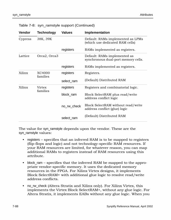
LO
syn_ramstyle Attributes
7-88 Synplify Reference Manual, April 2002
The value for syn_ramstyle depends upon the vendor. These are the syn_ramstyle values:
• registers – specifies that an inferred RAM is to be mapped to registers (flip-flops and logic) and not technology-specific RAM resources. If your RAM resources are limited, for whatever reason, you can map additional RAMs to registers instead of RAM resources using this attribute.
• block_ram – specifies that the inferred RAM be mapped to the appro-priate vendor-specific memory. It uses the dedicated memory resources in the FPGA. For Xilinx Virtex designs, it implements Block SelectRAM+ with additional glue logic to resolve read/write address conflicts.
• no_rw_check (Altera Stratix and Xilinx only). For Xilinx Virtex, this implements the Virtex Block SelectRAM+, without any glue logic. For Altera Stratix, it implements EABs without any glue logic. When you
Cypress 38K, 39K
registers
Default: RAMs implemented as LPMs (which use dedicated RAM cells)
RAMs implemented as registers.
Lattice Orca2, Orca3
registers
Default: RAMs implemented as synchronous dual-port memory cells.
RAMs implemented as registers.
Xilinx XC4000 families
registers
select_ram
Registers.
(Default) Distributed RAM
Xilinx Virtex families
registers
block_ram
no_rw_check
select_ram
Registers and combinatorial logic.
Block SelectRAM plus read/write address conflict logic
Block SelectRAM without read/write address conflict (glue) logic
(Default) Distributed RAM
Table 7-8: syn_ramstyle support (Continued)
Vendor Technology Values Implementation

Attributes syn_ramstyle
Synplify Reference Manual, April 2002 7-89
read and write to the same Block SelectRAM+ address, the value of the output is indeterminate. An indeterminate output can create a simulation mismatch between RTL and post-synthesis simulations. Without no_rw_check, the Synplify synthesis tool inserts bypass logic around the RAM to prevent the mismatch. If you know your design does not read and write to the same address simultaneously, use no_rw_check to eliminate bypass logic. Use this value only when you cannot simultaneously read and write to the same RAM location and you want to minimize overhead logic.
• select_ram – (Xilinx only; default value). Implements RAMs using the distributed RAM resources in the CLBs. For distributed RAMs, the write operation must be synchronous and the read operation asynchronous. For dual port RAMs, the synthesis tool adds glue logic to direct the RAM input to go to the output when the read address is the same as the write address.
.sdc File Syntax and Example
define_attribute {signal_name[bit_range]} syn_ramstyle {string}
If you edit a constraint file to apply syn_ramstyle, be sure to include the range of the signal with the signal name. For example:
define_attribute {mem[7:0]} syn_ramstyle {registers};
Verilog Syntax and Example
object /* synthesis syn_ramstyle = "string" */ ;
where object can be register definition (reg) signals. The data type is string.
Here is an example:
module ram4 (datain,dataout,clk);output dataout[31:0];input clk;input datain[31:0];reg [7:0] dataout[31:0] /* synthesis syn_ramstyle="registers" */;
// Other code

LO
syn_ramstyle Attributes
7-90 Synplify Reference Manual, April 2002
VHDL Syntax and Example
attribute syn_ramstyle of object : object_type is "string" ;
where object can be signals that define RAMs, and labels of component instances. Data type is string.
Signal Defining the RAMlibrary ieee;use ieee.std_logic_1164.all;entity ram4 is
port (d : in std_logic_vector(7 downto 0);addr : in std_logic_vector(2 downto 0);we : in std_logic; clk : in std_logic;ram_out : out std_logic_vector(7 downto 0));
end ram4;
library synplify;architecture rtl of ram4 istype mem_type is array (127 downto 0) of std_logic_vector (7
downto 0);signal mem : mem_type;-- mem is the signal that defines the RAM
attribute syn_ramstyle : string;attribute syn_ramstyle of mem : signal is "block_ram";
-- Other code

Attributes syn_reference_clock
Synplify Reference Manual, April 2002 7-91
syn_reference_clockAttribute. The syn_reference_clock attribute lets you specify a clock frequency other than that implied by the signal on the clock pin of the register. For example, when flip-flops have an enable with a regular pattern, such as every second clock cycle, use syn_reference_clock to have timing analysis treat the flip-flops as if they were connected to a clock at half the frequency.
To use syn_reference_clock, define a new clock, then apply its name to the registers you want to change.
.sdc File Syntax and Examples
define_attribute {register} syn_reference_clock {clk_name}
For example:
define_attribute {myreg[31:0]} syn_reference_clock {sloClock}
You can also use syn_reference_clock to constrain multicycle paths through the enable signal. This example shows how you can apply the constraint to all registers with the specified enable signal:
define_attribute {find -reg -enable en40} syn_reference_clock{clk2}

LO
syn_replicate Attributes
7-92 Synplify Reference Manual, April 2002
syn_replicateAttribute; Xilinx. Disables replication in Xilinx designs. The Synplify synthesis tool automatically replicates registers during the following optimization processes: meeting maximum fanout requirements, packing I/Os, and improving quality of results.
You can use this attribute to disable replication either globally or on a per-register basis. When you disable replication globally, it disables I/O packing and quality of results optimizations. The synthesis tool uses only buffering to meet maximum fanout guidelines.
You can use this attribute to disable I/O packing on specific registers by setting the attribute to 0. Similarly, you can use it on a register between clock boundaries to prevent replication. For example, the synthesis tool would replicate a register that is clocked by clk1 but whose fanin cone is driven by clk2, even though clk2 is an unrelated clock in another clock group. By setting the attribute for the register to 0, you can disable repli-cation.
.sdc File Syntax and Example
define_global_attribute syn_replicate = {1 | 0}
For example, to disable all replication in the design:
define_global_attribute syn_replicate {0}
Verilog Syntax and Example
object /* synthesis syn_replicate = 1 | 0 */;
For example:
module norep (Reset, Clk, Drive, OK, ADPad, IPad, ADOut);input Reset, Clk, Drive, OK;input [31:0] ADOut;inout [31:0] ADPad;output [31:0] IPad;

Attributes syn_replicate
Synplify Reference Manual, April 2002 7-93
reg [31:0] IPad;
reg DriveA /* synthesis syn_replicate = 0 */;
assign ADPad = DriveA ? ADOut : 32'bz;always @(posedge Clk or negedge Reset)
if (!Reset)begin
DriveA <= 0;IPad <= 0;
endelse
beginDriveA <= Drive & OK;IPad <= ADPad;
endendmodule
VHDL Syntax and Example
attribute syn_replicate of object : object_type is true | false ;
For example:
library IEEE;use ieee.std_logic_1164.all;entity norep is port (
Reset : in std_logic;Clk : in std_logic;Drive : in std_logic;OK : in std_logic;ADPad : inout std_logic_vector (31 downto 0);IPad : out std_logic_vector (31 downto 0);ADOut : in std_logic_vector (31 downto 0));
end norep;
architecture archnorep of norep issignal DriveA : std_logic;attribute syn_replicate : boolean;attribute syn_replicate of DriveA : signal is false;

LO
syn_replicate Attributes
7-94 Synplify Reference Manual, April 2002
beginADPad <= ADOut when DriveA='1' else (others => 'Z');process (Clk, Reset)
beginif Reset='0' then
DriveA <= '0';IPad <= (others => '0');
elsif rising_edge(clk) thenDriveA <= Drive and OK;IPad <= ADPad;
end if;end process;end archnorep;

Attributes syn_resources
Synplify Reference Manual, April 2002 7-95
syn_resourcesAttribute; Altera Xilinx . Specifies the resources available for black boxes. It is attached to Verilog black-box modules and VHDL architectures or component definitions. For Altera designs, use this attribute instead of the obsolete altera_area.
The value of the attribute is any combination of the following, where luts specifies the number of lookup tables, regs specifies the number of regis-ters, and blockrams specifies the number of RAM resources:
luts=integer
regs=integer
blockrams =integer
The value listed in the area usage report is the larger of the luts or registers value. For the Altera Apex families, the Synplify synthesis tool calculates the ATOM resources as the maximum of the larger of either the luts or regis-ters value.
.sdc File Syntax and Example
define_attribute {v:module_name} syn_resources {value}
For example:
define_attribute {v:bb} syn_resources {luts=500, regs=400, blockrams=10}
Verilog Syntax and Example
object /* synthesis syn_resources = value */ ;
In Verilog, you can only attach this attribute to a module. Here is an example:
module bb (o,i)/* synthesis
syn_black_box syn_resources = "Luts=500,Regs=463,Blockrams=10" */;
input i;output o;
endmodule

LO
syn_resources Attributes
7-96 Synplify Reference Manual, April 2002
module top_bb (o,i);input i;output o;bb u1 (o,i);
endmodule
VHDL Syntax and Example
attribute syn_resources of object : object_type is string ;
In VHDL, this attribute can be placed on either an architecture or on a on a component declaration.
architecture top of top iscomponent decoder
port (clk : in bit;a, b : in bit;qout : out bit_vector(7 downto 0)
);end component;
attribute syn_resources : string;attribute syn_resources of decoder: component is
"Luts=500,Regs=463,Blockrams=10";
-- Other code

Attributes syn_romstyle (Altera)
Synplify Reference Manual, April 2002 7-97
syn_romstyle (Altera)Attribute; Altera (APEX, ACEX, and FLEX10K families). You can describe a ROM structure in RTL code using a case statement. By applying the syn_romstyle attribute to the signal output value, you can control if the ROM structure is implemented as discrete logic or as an ESB block for APEX or EAB blocks for FLEX and ACEX.
By default, small ROMs (less than seven address bits) are implemented as logic, and large ROMs (seven or more address bits) as ESBs for APEX or EABs for FLEX and ACEX.
You can globally disable automatic use of ESBs/EABs for inferred ROMs by setting altera_auto_use_eab = 0 (FLEX and ACEX) or altera_auto_use_esb = 0 (APEX).
Setting syn_romstyle=logic in an APEX, ACEX, or FLEX device forces an implementation using discrete logic primitives. Setting syn_romstyle=block_rom forces an ESB implementation when targeting APEX devices, and an EAB implementation when targeting FLEX and ACEX devices.
.sdc File Syntax and Example
define_attribute {rom_primitive} syn_romstyle {logic | block_rom | lpm}
For example:
define_attribute {z_20[3:0]} syn_romstyle {block_rom}
Verilog Syntax and Examples
object /* synthesis syn_romstyle = "logic | block_rom | lpm" */ ;
The following example shows you how to use the syn_romstyle attribute to implement a ROM structure as block_rom, which forces an ESB/EAB implementation.
reg [3:0] z /* synthesis syn_romstyle = "block_rom" */;
The following example shows you how to use the syn_romstyle attribute to implement a ROM structure as logic, which forces an implementation using discrete logic primitives.
reg [8:0] z /* synthesis syn_romstyle = "logic" */;

LO
syn_romstyle (Altera) Attributes
7-98 Synplify Reference Manual, April 2002
VHDL Syntax and Examples
attribute syn_romstyle of object : object_type is "logic | block_rom | lpm" ;
The following example shows you how to use the syn_romstyle attribute to implement a ROM structure as block_rom, which will force an EAB/ESB implementation.
signal z : std_logic_vector(3 downto 0);attribute syn_romstyle : string;attribute syn_romstyle of z : signal is "block_rom";
The following example shows you how to use the syn_romstyle attribute to implement a ROM structure as logic, which forces an implementation using discrete logic primitives.
signal z : std_logic_vector(8 downto 0);attribute syn_romstyle : string;attribute syn_romstyle of z : signal is "logic";
Inferring ROMs (Examples)
The following examples show you how to infer a ROM.
Example: Inferring ROMs (Verilog)// Sparsely populated ROMmodule rom2(z, a);output [3:0] z;input [4:0] a;reg [3:0] z /* synthesis syn_romstyle = "block_rom" */;always @(a) begin
case (a)5'b00000: z = 4'b1011;5'b00001: z = 4'b0001;5'b00100: z = 4'b0011;5'b00110: z = 4'b0010;5'b00111: z = 4'b1110;5'b01001: z = 4'b0111;5'b01010: z = 4'b0101;5'b01101: z = 4'b0100;5'b10000: z = 4'b1100;5'b10001: z = 4'b1101;5'b10010: z = 4'b1111;5'b10011: z = 4'b1110;5'b11000: z = 4'b1010;

Attributes syn_romstyle (Altera)
Synplify Reference Manual, April 2002 7-99
5'b11010: z = 4'b1011;5'b11110: z = 4'b1001;5'b11111: z = 4'b1000;default: z = 4'b0000;
endcaseendendmodule
Example: Inferring ROMs (VHDL)library IEEE;use IEEE.std_logic_1164.all;entity rom6 isport ( a: in std_logic_vector(3 downto 0);
z: out std_logic_vector(3 downto 0) );
attribute syn_romstyle : string;attribute syn_romstyle of z : signal is "block_rom";end rom6;
architecture rtl of rom6 isbegin
process(a)begin
case a iswhen "0000" => z <= "1010";when "0001" => z <= "0100";when "0010" => z <= "0111";when "0011" => z <= "0010";when "0100" => z <= "0101";when "0101" => z <= "1001";when "0110" => z <= "1011";when "0111" => z <= "0011";when "1000" => z <= "1101";when "1001" => z <= "0001";when "1010" => z <= "1111";when "1011" => z <= "0110";when "1100" => z <= "1000";when "1101" => z <= "1110";when "1110" => z <= "1100";when others => z <= "0000";
end case;end process;
end rtl;
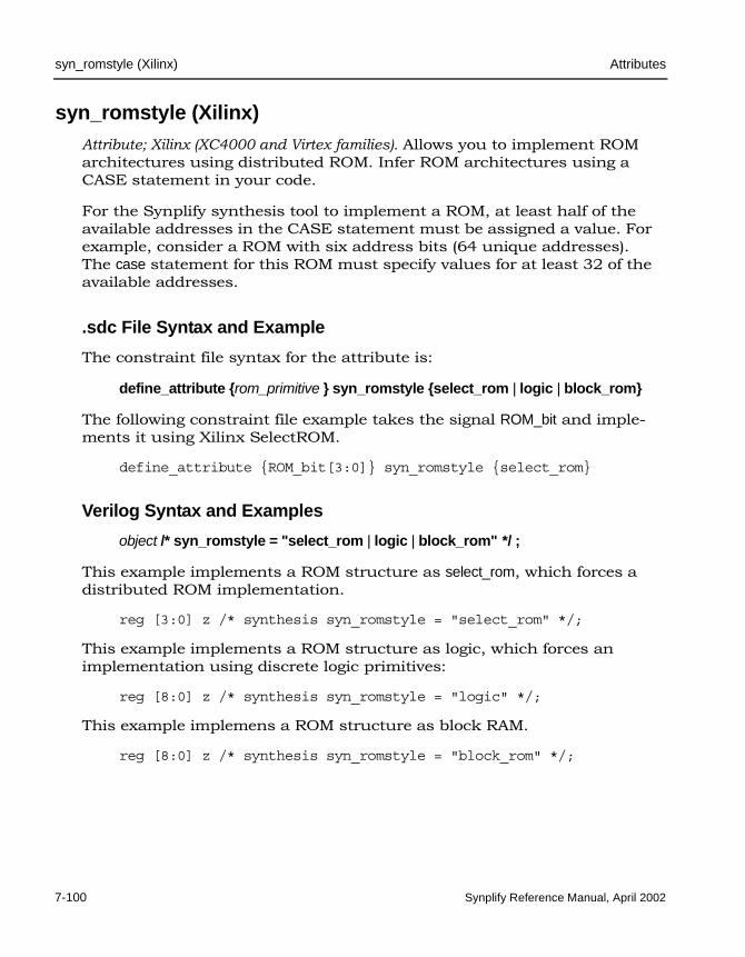
LO
syn_romstyle (Xilinx) Attributes
7-100 Synplify Reference Manual, April 2002
syn_romstyle (Xilinx)Attribute; Xilinx (XC4000 and Virtex families). Allows you to implement ROM architectures using distributed ROM. Infer ROM architectures using a CASE statement in your code.
For the Synplify synthesis tool to implement a ROM, at least half of the available addresses in the CASE statement must be assigned a value. For example, consider a ROM with six address bits (64 unique addresses). The case statement for this ROM must specify values for at least 32 of the available addresses.
.sdc File Syntax and Example
The constraint file syntax for the attribute is:
define_attribute {rom_primitive } syn_romstyle {select_rom | logic | block_rom}
The following constraint file example takes the signal ROM_bit and imple-ments it using Xilinx SelectROM.
define_attribute {ROM_bit[3:0]} syn_romstyle {select_rom}
Verilog Syntax and Examples
object /* syn_romstyle = "select_rom | logic | block_rom" */ ;
This example implements a ROM structure as select_rom, which forces a distributed ROM implementation.
reg [3:0] z /* synthesis syn_romstyle = "select_rom" */;
This example implements a ROM structure as logic, which forces an implementation using discrete logic primitives:
reg [8:0] z /* synthesis syn_romstyle = "logic" */;
This example implemens a ROM structure as block RAM.
reg [8:0] z /* synthesis syn_romstyle = "block_rom" */;

Attributes syn_romstyle (Xilinx)
Synplify Reference Manual, April 2002 7-101
VHDL Syntax and Examples
attribute syn_romstyle of object : object_type is "select_rom | logic | block_rom" ;
This example implements a ROM structure as select_rom.
signal z : std_logic_vector(3 downto 0);attribute syn_romstyle : string;attribute syn_romstyle of z : signal is "select_rom";
This example implements a ROM structure as logic.
signal z : std_logic_vector(8 downto 0);attribute syn_romstyle : string;attribute syn_romstyle of z : signal is "logic";
This example implements a ROM structure as Xilinx block RAM. Refer to Mapping ROM into Block RAM on page H-13 for further details.
signal z : std_logic_vector(8 downto 0);attribute syn_romstyle : string;attribute syn_romstyle of z : signal is "block_rom";

LO
syn_srlstyle Attributes
7-102 Synplify Reference Manual, April 2002
syn_srlstyleAttribute; Xilinx (Virtex families). Determines how to implement the sequential shift (seqShift) components.
.sdc File Syntax
define_attribute {object } syn_srlstyle {registers | select_srl | noextractff_srl}
The syn_srlstyle values are:
• registers – implements seqShift components as registers.
• select_srl – implements seqShift components using 16-bit shift register lookup table primitives (SRL16) with flip-flops inserted ahead of the output buffers for improved timing.
• noextractff_srl – implements seqShift components using 16-bit shift register lookup table primitives (SRL16) without output flip-flops.
For example:
define_attribute {regBank[15:0]} syn_srlstyle {registers}
Verilog Syntax and Example
object /* synthesis syn_srlstyle = "select_srl | registers | noextractff_srl" */ ;
In the above syntax, object is a register declaration.
This example implements seqShift components as SRL16 without output flip-flops.
module test_srl(clk, enable, dataIn, result, addr);input clk, enable;input [3:0] dataIn;input [3:0] addr;output [3:0] result;reg [3:0] regBank[15:0]
/* synthesis syn_srlstyle="noextractff_srl" */;integer i;

Attributes syn_srlstyle
Synplify Reference Manual, April 2002 7-103
always @(posedge clk) beginif (enable == 1) begin
for (i=15; i>0; i=i-1) beginregBank[i] <= regBank[i-1];end
regBank[0] <= dataIn;end
endassign result = regBank[addr];endmodule
VHDL Syntax and Example
attribute syn_srlstyle of object : signal is "select_srl | registers | noextractff_srl" ;
In the above syntax, object is a register.
The example below implements seqShift components as SRL16 primitives without inserting timing improvement flip-flops between the SRL outputs and the output buffers.
library ieee;use ieee.std_logic_1164.all;use ieee.std_logic_unsigned.all;entity d_p isport (clk : in std_logic;data_out : out std_logic_vector(127 downto 0));end d_p;
architecture rtl of d_p istype dataAryType is array(3 downto 0) of
std_logic_vector(127 downto 0);signal h_data_pip_i : dataAryType;attribute syn_srlstyle : string;attribute syn_srlstyle of h_data_pip_i : signalis "noextractff_srl";
begin process (Clk)begin
if (Clk'Event And Clk = '1') thenh_data_pip_i <= (h_data_pip_i(2 DOWNTO 0)) &

LO
syn_tristatetomux Attributes
7-104 Synplify Reference Manual, April 2002
h_data_pip_i(3);end if;
end process;data_out <= h_data_pip_i(0);end rtl;
syn_tristatetomuxAttribute; Xilinx (XC4000 and Virtex families). Forces each net to be analyzed in the design that is driven by tristate drivers and convert those drivers to a mux. This is done if the number of tristates drivers on the net is less than the value of the integer argument.
All drivers on the nets that could be converted to muxes must be tristate drivers, otherwise the conversion fails and a warning is issued.
.sdc File Syntax and Example
define_attribute {object} syn_tristatetomux {integer}
For example:
define_attribute {v:tristate2} syn_tristatetomux {4}
Verilog Syntax and Example
object /* synthesis syn_tristatetomux = integer */ ;
For example:
module tristate2 (input0, input1, input2, input3, enable, qout)/* synthesis syn_tristatetomux = 4 */;
input [7:0] input0, input1, input2, input3;input [3:0] enable;output [7:0] qout;wire [7:0] temp;assign temp = (enable[0]) ? input0 : 8'hZZ;assign temp = (enable[1]) ? input1 : 8'hZZ;assign temp = (enable[2]) ? input2 : 8'hZZ;assign temp = (enable[3]) ? input3 : 8'hZZ;assign qout = temp & input0;endmodule

Attributes syn_tristatetomux
Synplify Reference Manual, April 2002 7-105
VHDL Syntax and Example
attribute syn_tristatetomux of object : object_type is integer ;
Here is a VHDL example of multiple tristate drivers on a bus.
library ieee;library synplify;use ieee.std_logic_1164.all;entity tristate2 is
port (input3,input2,input1,input0: in std_logic_vector (7 downto 0);enable : in std_logic_vector (3 downto 0);qout : out std_logic_vector (7 downto 0) );
end tristate2;
architecture multiple_drivers of tristate2 isattribute syn_tristatetomux : integer;attribute syn_tristatetomux of multiple_drivers :
architecture is 4;signal temp : std_logic_vector (7 downto 0);
begintemp <= input3 when enable(3) = '1'
else "ZZZZZZZZ" ;
temp <= input2 when enable(2) = '1'else "ZZZZZZZZ" ;
temp <= input1 when enable(1) = '1'else "ZZZZZZZZ" ;
temp <= input0 when enable(0) = '1'else "ZZZZZZZZ" ;
qout <= temp and input0;end multiple_drivers;

LO
syn_useenables Attributes
7-106 Synplify Reference Manual, April 2002
syn_useenables Attribute; Actel (54SX), Altera, Lattice, Xilinx. Generates register instances with clock enable pins. By default, the Synplify synthesis tool tries to use the enable pin. You set syn_useenables to 0 to turn off clock-enable extraction.
.sdc File Syntax and Example
The constraint file syntax for the attribute is:
define attribute {register | signal} syn_seenables {0 | 1}
For example:
define_attribute {q[3:0]} syn_useenables {0}
Verilog Syntax and Example
object /* synthesis syn_useenables = 0 | 1 */ ;
where object can be a component register or signal. Data type is Boolean.
For example:
reg [3:0] q /* synthesis syn_useenables = 0 */;always @(posedge clk)if (enable)
q <= d;

Attributes syn_useenables
Synplify Reference Manual, April 2002 7-107
VHDL Syntax and Example
attribute syn_useenables of object : object_type is true | false ;
where object can be labels of component registers or signals.
For example:
signal q_int : std_logic_vector(3 downto 0);attribute syn_useenables of q_int : signal is false;...begin...
process(clk)begin
if (clk'event and clk = '1') thenif (enable = '1') then
q_int <= d;end if;
end if;end process;

LO
syn_useioff (Altera) Attributes
7-108 Synplify Reference Manual, April 2002
syn_useioff (Altera)Attribute; Altera (APEX families). Controls I/O register packing when targeting Apex families. syn_useioff is a boolean attribute. A value of 1 enables register packing, and 0 disables register packing. By default, syn_useioff is disabled (not enabled).
Note: With Altera Stratix, when this attribute is enabled, registers are not packed into Multiply/Accumulate (MAC) blocks.
You can place this attribute on individual ports, or apply it globally.
.sdc File Syntax and Examples
define_attribute {port_name} syn_useioff {1 | 0}
define_global_attribute syn_useioff {1 | 0}
For example:
define_attribute {z[3:0]} syn_useioff {1}
define_global_attribute syn_useioff {1}
Verilog Syntax and Examples
object /* synthesis syn_useioff = 1 | 0 */ ;
To use this attribute globally, apply it to the module.
module test (a, b, clk, rst, d) /* synthesis syn_useioff = 1 */;
To use this attribute on individual ports, apply it to individual port decla-rations.
module test (a, b, clk, rst, d);input a;input b /* synthesis syn_useioff = 1 */;

Attributes syn_useioff (Altera)
Synplify Reference Manual, April 2002 7-109
VHDL Syntax and Examples
attribute syn_useioff of object : object_type is true | false ;
To use this attribute globally, apply it to the architecture.
Entity test is port (...);
end test;
architecture archtest of test issignal temp : std_logic;signal temp1 : std_logic;signal temp2 : std_logic;signal temp3 : std_logic;
attribute syn_useioff : boolean;attribute syn_useioff of archtest : architecture is true;
To use this attribute on individual ports, apply it to the ports in the entity section.
entity test is port (a : in std_logic;
.
.
.);
attribute syn_useioff : boolean;attribute syn_useioff of a : signal is true;end test,

LO
syn_useioff (Lattice ORCA) Attributes
7-110 Synplify Reference Manual, April 2002
syn_useioff (Lattice ORCA)Attribute; Lattice ORCA (Orca3). Controls I/O register packing when targeting the Orca Series3 family. syn_useioff is a Boolean attribute: 1 enables (default) and 0 disables register packing.
You can place this attribute on individual ports, or apply it globally. The attribute is supported in Verilog, VHDL, and .sdc file formats.
.sdc File Syntax and Example
define_attribute {port_name} syn_useioff {0 | 1}
define_global_attribute syn_useioff {0 | 1}
For example:
define_attribute {z[3:0]} syn_useioff {1}
define_global_attribute syn_useioff {1}
Verilog Syntax and Examples
object synthesis syn_useioff = {1 | 0} */ ;
If you need to use this attribute globally, apply it to the module.
module test (a, b, clk, rst, d) /* synthesis syn_useioff = 1 */;
If you need to use this attribute on individual ports, apply it to individual port declarations.
module test (a, b, clk, rst, d);input a;input b /* synthesis syn_useioff = 1 */;

Attributes syn_useioff (Lattice ORCA)
Synplify Reference Manual, April 2002 7-111
VHDL Syntax and Examples
attribute syn_useioff of object : object_type is true | false ;
If you want to use this attribute globally, apply it to the architecture:
architecture archtest of test issignal temp : std_logic;signal temp1 : std_logic;signal temp2 : std_logic;signal temp3 : std_logic;
attribute syn_useioff : boolean;attribute syn_useioff of archtest : architecture is true;
If you want to use this attribute on individual ports, apply it to the ports in the entity section.
entity test is port (a : in std_logic;...);
attribute syn_useioff : boolean;attribute syn_useioff of a : signal is true;end test;

LO
syn_useioff (QuickLogic) Attributes
7-112 Synplify Reference Manual, April 2002
syn_useioff (QuickLogic)Attribute; Eclipse, QuickDSP, and QuickSD. Controls I/O register packing when you target the listed QuickLogic families. syn_useioff is a Boolean attribute: 1 enables (default) and 0 disables register packing.
You can place this attribute on individual ports, or apply it globally. When applied globally, the Synplify synthesis tool packs all input, output, and I/O registers into pads. When applied to a port, the synthesis tool packs all flip-flops attached to the port into the I/O pad. You can enter the attribute in Verilog, VHDL, and .sdc file formats.
.sdc File Syntax and Example
define_attribute {port_name} syn_useioff {0 | 1}
define_global_attribute syn_useioff {0 | 1}
For example:
define_attribute {z[3:0]} syn_useioff {1}
define_global_attribute syn_useioff {1}
Verilog Syntax and Examples
object synthesis syn_useioff = {1 | 0} */ ;
If you need to use this attribute globally, apply it to the module.
module test (a, b, clk, rst, d) /* synthesis syn_useioff = 1 */;
If you need to use this attribute on individual ports, apply it to individual port declarations.
module test (a, b, clk, rst, d);input a;input b /* synthesis syn_useioff = 1 */;
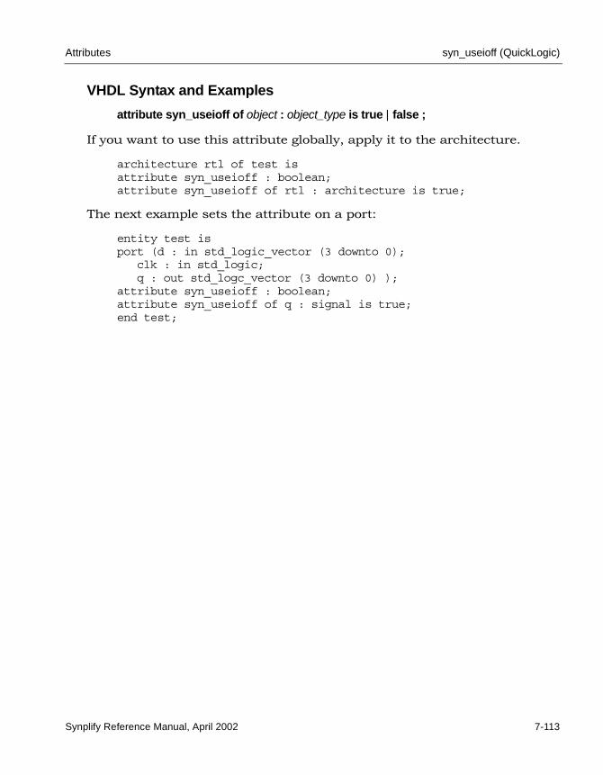
Attributes syn_useioff (QuickLogic)
Synplify Reference Manual, April 2002 7-113
VHDL Syntax and Examples
attribute syn_useioff of object : object_type is true | false ;
If you want to use this attribute globally, apply it to the architecture.
architecture rtl of test isattribute syn_useioff : boolean;attribute syn_useioff of rtl : architecture is true;
The next example sets the attribute on a port:
entity test isport (d : in std_logic_vector (3 downto 0);
clk : in std_logic;q : out std_logc_vector (3 downto 0) );
attribute syn_useioff : boolean;attribute syn_useioff of q : signal is true;end test;

LO
syn_useioff (Xilinx) Attributes
7-114 Synplify Reference Manual, April 2002
syn_useioff (Xilinx)Attribute; Xilinx (Virtex, XC4000 and Spartan 2 families). Overrides the default behavior to pack I/Os based on timing preferences. When syn_useioff is set to 1 (or true), flip-flops are embedded in the IOBs.
.sdc File Syntax and Examples
define_attribute {port} syn_useioff {1 | 0}
define_global_attribute syn_useioff {1 | 0}
For example, to embed flip-flops locally in IOBs:
define_attribute {p:q[3:0]} syn_useioff {1}
To embed flip-flops globally:
define_global_attribute syn_useioff {1}
Verilog Syntax and Examples
object /* synthesis syn_useioff = 1 | 0 */ ;
This example sets the attribute on a port:
module test(d, clk, q);input [3:0] d;input clk;output [3:0] q /* synthesis syn_useioff = 1 */;reg q;
This example sets the attribute globally:
module test(d, clk, q) /* synthesis syn_useioff = 1 */;
VHDL Syntax and Examples
attribute syn_useioff of object : object_type is true | false ;
architecture rtl of test isattribute syn_useioff : boolean;attribute syn_useioff of rtl : architecture is true;

Attributes syn_useioff (Xilinx)
Synplify Reference Manual, April 2002 7-115
This example sets the attribute on a port:
entity test isport(d : in std_logic_vector(3 downto 0);clk : in std_logic;
q : out std_logic_vector(3 downto 0));attribute syn_useioff : boolean;attribute syn_useioff of q : signal is true;end test;
This example sets the attribute globally:
architecture rtl of test isattribute syn_useioff : boolean;attribute syn_useioff of rtl : architecture is true;

LO
xc_alias Attributes
7-116 Synplify Reference Manual, April 2002
xc_aliasAttribute; Xilinx (except Virtex). Changes cell names in XNF writer.
define_attribute {cell_name} xc_alias {alias_name}
Verilog Syntax and Example
object /* synthesis xc_alias = "string" */ ;
For example:
module AND4 (O, IO, I1, I2, I3)/*synthesis syn_black_box xc_alias = "AND" */;
VHDL Syntax and Example
attribute xc_alias of object : object_type is "string" ;
For example:
component AND4port (O : out std_logic;
I0, I1, I2, I3 : in std_logic);end component;attribute xc_alias of AND4 : component is "AND" ;

Attributes xc_clockbuftype
Synplify Reference Manual, April 2002 7-117
xc_clockbuftype Attribute; Xilinx (Virtex families). Uses the Clock Delay Locked Loop primitive (CLKDLL) for a clock port. This is inferred as a buffer called BUFGDLL, which includes the CLKDLL primitive.
.sdc File Syntax and Example
define_attribute {port} xc_clockbuftype {BUFGDLL}
For example:
define_attribute {clk} xc_clockbuftype {BUFGDLL}
Verilog Syntax and Example
object /* synthesis xc_clockbuftype = "BUFGDLL" */ ;
For example:
module test_clkbuftype(d, clk, rst, q);input [3:0] d;input clk /* synthesis xc_clockbuftype = "BUFGDLL" */;input rst;output [3:0] q;
// Other code

LO
xc_clockbuftype Attributes
7-118 Synplify Reference Manual, April 2002
VHDL Syntax and Example
attribute xc_clockbuftype of object : object_type is "BUFGDLL" ;
For example:
library ieee, synplify;use ieee.std_logic_1164.all;entity test_clkbuftype is
port (d : in std_logic_vector(3 downto 0);clk, rst : in std_logic;q : out std_logic_vector(3 downto 0));
attribute xc_clockbuftype : string;attribute xc_clockbuftype of clk : signal is "BUFGDLL";end test_clkbuftype;
EDIF Output Example
Applying this attribute causes the resultant EDIF output file to appear similar to the following:
(instance clk_ibuf (viewRef PRIM (cellRef BUFGDLL (libraryRef VIRTEX)))

Attributes xc_fast
Synplify Reference Manual, April 2002 7-119
xc_fastAttribute; Xilinx (XC4000 families). Use this attribute to make the transition time of the output driver fast. The default is for the transition time to be slow (see xc_slow on page 7-136).
The Synplify synthesis tool provides attributes that are passed into the XNF or EDIF netlist for Xilinx placement and routing. These attributes affect the input setup times and output transition times for your I/Os. The xc_fast attribute gets passed to the Xilinx I/O Block Parameter in the XNF or EDIF netlist called “FAST”.
The transition time of the output driver can be programmed to be either fast or slow for XC4000 devices. Use the xc_fast attribute to decrease the transition time for the output driver.
.sdc File Syntax and Example
The constraint file syntax for the attribute is:
define_attribute {output_port} xc_fast {1}
For example:
define_attribute {DATA0[5]} xc_fast {1}
Verilog Syntax and Example
object /* synthesis xc_fast = 0 | 1 */ ;
For example:
output [5:0] DATA0 /* synthesis xc_fast = 1 */;

LO
xc_fast Attributes
7-120 Synplify Reference Manual, April 2002
VHDL Syntax and Example
attribute xc_fast of object : object_type is true | false ;
For example:
entity prep2_2 isport (DATA0 : out std_logic_vector (5 downto 0);
.
.
.);
attribute xc_fast of DATA0 : signal is true;end prep2_2;

Attributes xc_fast_auto
Synplify Reference Manual, April 2002 7-121
xc_fast_autoAttribute; Xilinx (Virtex families). By default (xc_fast_auto value of 1), the Synplify synthesis tool infers the fast output buffers OBUF_F_24, OBUFT_F_24, and IOBUF_F_24. Use this global attribute to force slow buffers to be inferred. In HDL source code you specify xc_fast_auto for the top-level module or architecture. You can override this attribute on an individual basis by using the xc_padtype attribute.
The xc_fast_auto attribute has no affect on output ports specified with the xc_padtype attribute.
.sdc File Syntax and Example
define_global_attribute xc_fast_auto {0 | 1}
For example:
define_global_attribute xc_fast_auto {0};
Verilog Syntax and Example
object /* synthesis xc_fast_auto = 0 | 1 */ ;
For example:
module top (q, d, addr, we, clk) /*synthesis xc_fast_auto=0 */;
// Other code

LO
xc_fast_auto Attributes
7-122 Synplify Reference Manual, April 2002
VHDL Syntax and Example
attribute xc_fast_auto of object : object_type is false | true ;
For example:
library ieee;use ieee.std_logic_1164.all;entity top is
port (q : out std_logic_vector(3 downto 0);d : in std_logic_vector(3 downto 0);addr : in std_logic_vector(2 downto 0);we : in std_logic;clk : in std_logic);
end ramtest;
architecture beh of top isattribute xc_fast_auto : boolean;attribute xc_fast_auto of beh : architecture is false;
-- Other code

Attributes xc_global_buffers
Synplify Reference Manual, April 2002 7-123
xc_global_buffersAttribute; Xilinx. Controls the number of global buffers used in a design. The Synplify synthesis tool automatically adds global buffers for clock nets with high fanout. Use this attribute to specify a maximum number of buffers and restrict the amount of global buffer resources added. Also, if there is a black box in the design that has global buffers, you can use xc_global_buffers to prevent the synthesis tool from inferring clock buffers and exceeding the number of global resources. You can only specify this attribute through a constraint file (cannot be specified in HDL source code).
.sdc File Syntax and Example
define_global_attribute xc_global_buffers {maximum}
For example:
define_global_attribute xc_global_buffers {3}

LO
xc_loc Attributes
7-124 Synplify Reference Manual, April 2002
xc_locAttribute; Xilinx. Specifies the location (placement) of ports. Refer to the Xilinx databook for valid placement locations.
You cannot use xc_loc to specify locations of slices of vector (bus) ports.
.sdc File Syntax and Example
define_attribute {port_design_name} xc_loc {placements}
The following example is a constraint file assignment of a pad location to all bits of an 5-bit bus.
define_attribute {DATA0[4:0]} xc_loc {P14,P12,P11,P5,P21}
Verilog Syntax and Example
object /* synthesis xc_loc = "placements" */ ;
For example:
module prep2_2 (...);...
input [4:0] DATA0 /* synthesis xc_loc = "P14,P12,P11,P5,P21" */;
VHDL Syntax and Example
attribute xc_loc of object : object_type is "placements" ;
For example:
entity prep2_2 isport (DATA0 : in std_logic_vector (4 downto 0);
.
.
.);
attribute xc_loc of DATA0 : signal is "P14,P12,P11,P5,P21";end prep2_2;

Attributes xc_map
Synplify Reference Manual, April 2002 7-125
xc_mapAttribute; Xilinx (XC4000 and Virtex families). Specifies that a design unit is either an fmap, hmap, or lut primitive. This attribute is used only in conjunction with the xc_rloc and xc_uset attributes. See Specifying Relative Location on page H-25 for further information.
.sdc File Syntax and Example
define_attribute {v:primitive_name} xc_map {fmap | hmap | lut}
For example:
define_attribute {v:hmap_xor4} xc_map {fmap}
Verilog Syntax and Example
object /* synthesis xc_map = "fmap | hmap | lut" */ ;
For example:
module fmap_xor4(z, a, b, c, d) /* synthesis xc_map="fmap" */;
VHDL Syntax and Example
attribute xc_map of object : object_type is "fmap | hmap | lut" ;
For example:
architecture rtl of fmap_xor4 isattribute xc_map : string;attribute xc_map of rtl : architecture is "fmap";

LO
xc_ncf_auto_relax Attributes
7-126 Synplify Reference Manual, April 2002
xc_ncf_auto_relaxAttribute; Xilinx (XC4000, XC5200, Virtex families). This attribute controls the automatic relaxation of constraints that are forward-annotated to the .ncf file. A value of 0 disables this feature. The default value is 1. See also Relaxing Forward-annotated Constraints on page 6-43, for the use of this attribute.
.sdc File Syntax and Example
define_global_attribute xc_ncf_auto_relax { 0 | 1}
For example:
define_global_attribute xc_ncf_auto_relax {0}
Verilog Syntax and Example
object /* synthesis xc_ncf_auto_relax = 0 | 1 */ ;
For example:
module test_relax (clk,rst,a,b,out1)/* synthesis xc_ncf_auto_relax = 0 */;
// Other codeendmodule

Attributes xc_ncf_auto_relax
Synplify Reference Manual, April 2002 7-127
VHDL Syntax and Example
attribute xc_ncf_auto_relax of object : object_type is false | true;
For example:
library ieee;use ieee.std_logic_1164.all;entity test_relax is
port(clk, rst, a, b : in std_logic;
out1 : out std_logic );
end test_relax;
architecture behave of test_relax isattribute xc_ncf_auto_relax : boolean;attribute xc_ncf_auto_relax of behave : architecture is false;
-- Other codeend behave;

LO
xc_nodelay Attributes
7-128 Synplify Reference Manual, April 2002
xc_nodelayAttribute; Xilinx (XC4000, Spartan, Spartan-XL, Spartan2, Virtex and Virtex2 families). Removes the input delay that Xilinx inserts for flip-flops and latches. By default Xilinx inserts the input delay. The input delay is inserted in order to guarantee the hold time requirement on the flip-flops at the inputs.
The Synplify synthesis tool provides attributes that are passed into the EDIF/XNF netlist for the Xilinx place-and-route tool that affect the input setup times and output transition times for your I/Os. The xc_nodelay timing attribute gets passed to the Xilinx I/O Block parameter in the EDIF/XNF netlist called NODELAY.
.sdc File Syntax and Example
define_attribute {input_port_name} xc_nodelay {1 | 0}
For example:
define_attribute {din} xc_nodelay {1)

Attributes xc_padtype
Synplify Reference Manual, April 2002 7-129
xc_padtypeAttribute; Xilinx (Virtex families). Specifies an I/O buffer standard. For example, applying AGP to an IBUF would result in the use of an IBUF_AGP instead of an IBUF primitive.
.sdc File Syntax and Examples
define_attribute {port} xc_padtype {buffers_standards}
Note the required underscore (_) between buffers and standards.
Examples:
define_attribute {a[3:0]} xc_padtype {IBUF_GTLP}define_attribute {bidir[3:0]} xc_padtype {IOBUF_AGP}define_attribute {q[3:0]} xc_padtype {OBUF_CTT}
Verilog Syntax and Example
object /* synthesis xc_padtype = "buffers_standards" */ ;
For example:
module test_padtype(a, b, clk, rst, en, bidir, q);input [3:0] a /* synthesis xc_padtype = "IBUF_AGP" */, b;input clk, rst, en;inout [3:0] bidir /* synthesis xc_padtype = "IOBUF_CTT" */;output [3:0] q /* synthesis xc_padtype = "OBUF_F_12" */;
// Other code

LO
xc_padtype Attributes
7-130 Synplify Reference Manual, April 2002
VHDL Syntax and Example
attribute xc_padtype of object : object_type is "buffers_standards" ;
library ieee, synplify;use ieee.std_logic_1164.all;entity test_padtype is
port( a : in std_logic_vector(3 downto 0);b : in std_logic_vector(3 downto 0);clk, rst, en : in std_logic;bidir : inout std_logic_vector(3 downto 0);q : out std_logic_vector(3 downto 0)
);attribute xc_padtype : string;attribute xc_padtype of a : signal is "IBUF_SSTL3_I";attribute xc_padtype of bidir : signal is "IOBUF_HSTL_III";attribute xc_padtype of q : signal is "OBUF_S_8";

Attributes xc_props
Synplify Reference Manual, April 2002 7-131
xc_propsAttribute; Xilinx. Specifies Xilinx attributes to forward-annotate to the gate-level netlist.
.sdc File Syntax and Example
define_attribute {i:instance} xc_props {property=value}
For example:
define_attribute {i:RAM1} xc_props {INIT=FFFF}
Verilog Syntax and Example
object /* synthesis xc_props = "property=value" */ ;
For example:
RAM16X1S RAM1(...) /* synthesis xc_props = "INIT=0000" */;
VHDL Syntax and Example
attribute xc_props of object : object_type is "property=value" ;
For example:
attribute xc_props of RAM1 : label is "INIT=0000";--RAM1 is the name of an instance

LO
xc_pullup / xc_pulldown Attributes
7-132 Synplify Reference Manual, April 2002
xc_pullup / xc_pulldownAttribute; Xilinx (XC4000 and Virtex families). Specifies that a port is either a pull-up or pull-down.
.sdc File Syntax and Example
define_attribute {port_name} xc_pullup {1}define_attribute {port_name} xc_pulldown {1}
For example:
define_attribute {data[3:0]} xc_pullup {1}
define_attribute {qrs[3:0]} xc_pulldown {1}
Verilog Syntax and Example
object /* synthesis xc_pulldown = 1 | 0 */ ;
For example:
module dff1(clk, reset, set, data, qrs);input clk, reset, set;input [3:0] data /* synthesis xc_pullup = 1 */;output [3:0] qrs /* synthesis xc_pulldown = 1 */;reg [3:0] qrs;
// Other code
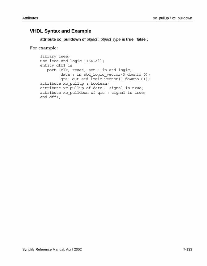
Attributes xc_pullup / xc_pulldown
Synplify Reference Manual, April 2002 7-133
VHDL Syntax and Example
attribute xc_pulldown of object : object_type is true | false ;
For example:
library ieee;use ieee.std_logic_1164.all;entity dff1 is
port (clk, reset, set : in std_logic;data : in std_logic_vector(3 downto 0);qrs: out std_logic_vector(3 downto 0));
attribute xc_pullup : boolean;attribute xc_pullup of data : signal is true;attribute xc_pulldown of qrs : signal is true;end dff1;

LO
xc_rloc Attributes
7-134 Synplify Reference Manual, April 2002
xc_rlocAttribute; Xilinx (XC4000, Virtex families). Specifies the relative locations of all the instances specified with the same xc_uset value. This attribute is used only in conjunction with the xc_uset and xc_map attributes. See Specifying Relative Location on page H-25 for more information.
.sdc File Syntax and Example
define_attribute {design_name} xc_rloc {instance_name}
Examples:
define_attribute {x03} xc_uset {SET1}define_attribute {x03} xc_rloc {R0C0.f}
define_attribute {x47} xc_uset {SET1}define_attribute {x47} xc_rloc {R0C0.g}
define_attribute {zz} xc_uset {SET1}define_attribute {zz} xc_rloc {R0C0.h}
Verilog Syntax and Example
object /* synthesis xc_rloc = "instance_name" */ ;
For example:
module clb_xor9(z, a);output z;input [8:0] a;wire z03, z47;
fmap_xor4 x03 /* synthesis xc_uset="SET1" xc_rloc="R0C0.f" */(z03, a[0], a[1], a[2], a[3]);fmap_xor4 x47 /* synthesis xc_uset="SET1" xc_rloc="R0C0.g" */(z47, a[4], a[5], a[6], a[7]);hmap_xor3 zz /* synthesis xc_uset="SET1" xc_rloc="R0C0.h" */(z, z03, z47, a[8]);endmodule

Attributes xc_rloc
Synplify Reference Manual, April 2002 7-135
VHDL Syntax and Example
attribute xc_rloc of object : object_type is "instance_name" ;
For example:
library IEEE;use IEEE.std_logic_1164.all;entity clb_xor9 is
port ( a : in std_logic_vector(8 downto 0);z : out std_logic);
end clb_xor9;
architecture rtl of clb_xor9 issignal z03, z47 : std_logic;component hmap_xor3
port ( a : in std_logic;b : in std_logic;c : in std_logic;z : out std_logic);
end component;
component fmap_xor4port ( a : in std_logic;
b : in std_logic;c : in std_logic;d : in std_logic;z : out std_logic);
end component;
attribute xc_uset : string;attribute xc_rloc : string;attribute xc_uset of x03 : label is "SET1";attribute xc_rloc of x03 : label is "R0C0.f";attribute xc_uset of x47 : label is "SET1";attribute xc_rloc of x47 : label is "R0C0.g";attribute xc_uset of zz : label is "SET1";attribute xc_rloc of zz : label is "R0C0.h";
beginx03 : fmap_xor4 port map(a(0), a(1), a(2), a(3), z03);x47 : fmap_xor4 port map(a(4), a(5), a(6), a(7), z47);zz : hmap_xor3 port map(z03, z47, a(8), z);
end rtl;

LO
xc_slow Attributes
7-136 Synplify Reference Manual, April 2002
xc_slow Attribute; Xilinx (XC4000 families). Specifies that the transition time of the driver of an output port is slow (the default). You can speed up the transi-tion time with the xc_fast attribute.
The Synplify synthesis tool provides attributes that are passed into the XNF/EDIF netlist for Xilinx placement and routing that affect the input setup times and output transition times for your I/Os. The xc_slow timing attribute gets passed to the Xilinx I/O Block Parameter in the XNF/EDIF netlist called SLOW.
The transition time of the output driver can be programmed to either fast or slow for XC4000 devices. The xc_slow attribute increases the transition time which reduces the noise level in the circuit.
.sdc File Syntax and Example
define_attribute {output_port} xc_slow {1 | 0}
For example:
define_attribute {DATA0[5]} xc_slow {1}
Verilog Syntax and Example
object /* synthesis xc_slow = 1 | 0 */ ;
For example:
output [7:0] DATA0 /* synthesis xc_slow = 1 */;
VHDL Syntax and Example
attribute xc_slow of object : object_type is true ;
For example:
attribute xc_slow of DATA0: signal is true;

Attributes xc_uset
Synplify Reference Manual, April 2002 7-137
xc_uset Attribute; Xilinx (XC4000, Virtex families). Assigns a group name to component instances. This attribute is used with the xc_rloc and xc_map attributes to specify a relative location to a group of components instances. See Speci-fying Relative Location on page H-25for more information.
.sdc File Syntax and Example
define_attribute {instance_name} xc_uset {group_name}
Examples:
define_attribute {x03} xc_uset {SET1};define_attribute {x03} xc_rloc {ROCO.f};
define_attribute {x44} xc_uset {SET1};define_attribute {x44} xc_rloc {ROCO.g};
define_attribute {zz} xc_uset {SET1};define_attribute {zz} xc_rloc {ROCO.h};
Verilog Syntax and Example
object /* synthesis xc_uset = "group_name" */ ;
For example:
module clb_xor9(z, a);output z;input [8:0] a;wire z03, z47;fmap_xor4 x03 /* synthesis xc_uset = "SET1" xc_rloc = "R0C0.f" */
(z03, a[0], a[1], a[2], a[3]);fmap_xor4 x47 /* synthesis xc_uset = "SET1" xc_rloc = "R0C0.g" */
(z47, a[4], a[5], a[6], a[7]);hmap_xor3 zz /* synthesis xc_uset = "SET1" xc_rloc = "R0C0.h" */
(z, z03, z47, a[8]);endmodule

LO
xc_uset Attributes
7-138 Synplify Reference Manual, April 2002
VHDL Syntax and Example
attribute xc_uset of object : object_type is "group_name" ;
For example:
library synplify;architecture rtl of clb_xor9 issignal z03, z47 : std_logic;component hmap_xor3
port (a, b, c : in std_logic;z : out std_logic);
end component;
component fmap_xor4port (a, b, c : in std_logic;
z : out std_logic);end component;
attribute xc_uset : string;attribute xc_rloc : string;attribute xc_uset : string;attribute xc_uset of x03 : label is "SET1";attribute xc_rloc of x03 : label is "R0C0.f";attribute xc_uset of x47 : label is "SET1";attribute xc_rloc of x47 : label is "R0C0.g";attribute xc_uset of zz : label is "SET1";attribute xc_rloc of zz : label is "R0C0.h";
beginx03 : fmap_xor4 port map(a(0), a(1), a(2), a(3), z03);x47 : fmap_xor4 port map(a(4), a(5), a(6), a(7), z47);zz : hmap_xor3 port map(z03, z47, a(8), z);
end rtl;

Directives xc_uset
Synplify Reference Manual, April 2002 7-139
Directives
The individual synthesis directives are described in this section, in alpha-betical order. Each directive description includes the following:
• Technology support
• Directive definition
• File syntax and examples for Verilog and VHDL source code
For an alphabetical summary of the directives, see Directive Summary (Alphabetical) on page 7-7. For a summary of the directives by vendor, refer to the appropriate vendor chapter or see Attribute and Directive Summary by Vendor on page 7-3.
For a general information on specifying directives, see Specifying Directives (and Attributes) in HDL on page 7-14.

LO
black_box_pad_pin Directives
7-140 Synplify Reference Manual, April 2002
black_box_pad_pin Directive. Specifies pins on a user-defined black-box component, as I/O pads that are visible to the environment outside of the black box. If there is more than one port that is an I/O pad, list the ports inside double-quotes separated by commas. (See Verilog and VHDL syntax and examples.)
You can use this directive with any of the following black-box directives:
• black_box_tri_pins
• syn_black_box
• syn_isclock
• syn_tco<n>
• syn_tpd<n>
• syn_tsu<n>
To instantiate an I/O from your programmable logic vendor, you usually do not need to define a black box and this attribute. The Synplify synthesis tool provides predefined black boxes for vendor I/Os. Refer to your vendor section under FPGA and CPLD Support for more information.
Verilog Syntax and Example
object /* synthesis syn_black_box black_box_pad_pin = "port_list" */ ;
For example:
module BBDLHS(D,E,GIN,GOUT,PAD,Q)/* synthesis syn_black_box black_box_pad_pin="PAD" */;

Directives black_box_pad_pin
Synplify Reference Manual, April 2002 7-141
VHDL Syntax and Example
attribute black_box_pad_pin of object : object_type is "port_list" ;
where object can be architectures or component declarations of black boxes. Data type is a string and port_list is the name or names of the ports on black boxes that are I/O pads (enclosed in double quotes). For example:
library ieee;use ieee.std_logic_1164.all;package components is
component BBDLHSport(
D: in std_logic;E: in std_logic;GIN : in std_logic_vector(2 downto 0);Q : out std_logic);
end component;
attribute syn_black_box : boolean;attribute syn_black_box of BBDLHS : component is true;attribute black_box_pad_pin : string;attribute black_box_pad_pin of BBDLHS : component is "GIN(2:0),Q";end components;

LO
black_box_tri_pins Directives
7-142 Synplify Reference Manual, April 2002
black_box_tri_pins Directive. Specifies that an output port, on a component defined as a black box, is tristate. This directive is used to eliminate multiple driver errors when the output of a black box has more than one driver. A multiple driver error is issued unless you use this directive to specify that the outputs are tristate. If there is more than one port that is a tristate, list all of the ports within double-quotes separated by commas.
You can use this directive with any of the following black-box directives:
• black_box_pad_pin
• syn_black_box
• syn_isclock
• syn_tco<n>
• syn_tpd<n>
• syn_tsu<n>
Verilog Syntax and Examples
object /* synthesis syn_black_box black_box_tri_pins = "port_list" */ ;
For example:
module BBDLHS(D,E,GIN,GOUT,PAD,Q)/* synthesis syn_black_box black_box_tri_pins="PAD" */;
The port_list can be a single port name as shown in the previous example, or a list of multiple pins separated by commas.
module bb1(D,E,tri1,tri2,tri3,Q)/* synthesis syn_black_box black_box_tri_pins="tri1,tri2,tri3" */;
For a bus, you must specify the port name followed by all the bits on the bus:
module bb1(D,bus1,E,GIN,GOUT,Q)/* synthesis syn_black_box black_box_tri_pins="bus1[7:0]" */;

Directives black_box_tri_pins
Synplify Reference Manual, April 2002 7-143
VHDL Syntax and Examples
attribute black_box_tri_pins of object : object_type is "port_list" ;
where object can be component declarations or architectures. Object_type is string and port_list is the name, or names of tristate output ports (enclosed in double quotes). For example:
library ieee;use ieee.std_logic_1164.all;package components is
component BBDLHSport(
D: in std_logic;E: in std_logic;GIN : in std_logic;GOUT : in std_logic;PAD : inout std_logic;Q: out std_logic);
end component;
attribute syn_black_box : boolean;attribute syn_black_box of BBDLHS : component is true;attribute black_box_tri_pins : string;attribute black_box_tri_pins of BBDLHS : component is "PAD";
end components;
Multiple pins on the same component can be specified in a list separated by commas as follows:
attribute black_box_tri_pins of bb1 : component is"tri,tri2,tri3";
To apply this attribute to a port which is a bus, you must specify all the bits on the bus:
attribute black_box_tri_pins of bb1 : component is "bus1[7:0]";

LO
full_case Directives
7-144 Synplify Reference Manual, April 2002
full_case Directive. For Verilog designs only. When used with a case, casex, or casez statement, indicates that all possible values have been given, and that no additional hardware is needed to preserve signal values.
Verilog Syntax and Examples
object /* synthesis full_case */
where object can be case, casex, or casez statement declarations.
Suppose you want to use a casez statement to create a 4-input multiplexor with a pre-decoded select bus (a decoded select bus has exactly one bit enabled at a time) as follows:
module muxnew1 (out, a, b, c, d, select);output out;input a, b, c, d;input [3:0] select;reg out;
always @(select or a or b or c or d)
begincasez (select)
4'b???1: out = a;4'b??1?: out = b;4'b?1??: out = c;4'b1???: out = d;
endcaseendendmodule
Notice you are not telling the Synplify synthesis tool what to do if the select bus has all zeros. If the select bus is being driven from outside the current module, the current module has no information about the legal values of select, and the synthesis tool must preserve the value of the output out when all bits of select are zero. Preserving the value of out requires the tool to add extraneous level-sensitive latches if out is not assigned elsewhere through every path of the always block. A warning message similar to the following is issued:
“Latch generated from always block for signal out, probably missing assignment in branch of if or case.”

Directives full_case
Synplify Reference Manual, April 2002 7-145
To instruct the synthesis tool not to preserve the value of out when all bits of select are zero, it is easiest to use a default in the casez with an assign-ment of 'bx (a 'bx in an assignment is treated as a “don't care”). This default assignment takes place every pass through the casez statement in which the select bus does not match one of the explicitly given values; therefore no extraneous level-sensitive latches are needed.
By using a default assignment, you stay within the Verilog language, and avoid using a synthesis directive to get the desired hardware. The technique of assigning a 'bx in the default is also beneficial for simulation because if the select becomes invalid, your debugging will uncover the output being assigned a 'bx.
module muxnew2 (out, a, b, c, d, select);output out;input a, b, c, d;input [3:0] select;reg out;
always @(select or a or b or c or d)
begincasez (select)
4'b???1: out = a;4'b??1?: out = b;4'b?1??: out = c;4'b1???: out = d;default: out = 'bx;
endcaseendendmodule

LO
full_case Directives
7-146 Synplify Reference Manual, April 2002
Use the full_case directive to achieve the same effect as the default case, and instruct the synthesis tool not to preserve the value of out when all bits of select are zero.
module muxnew3 (out, a, b, c, d, select);output out;input a, b, c, d;input [3:0] select;reg out;
always @(select or a or b or c or d)
begincasez (select) /* synthesis full_case */
4'b???1: out = a;4'b??1?: out = b;4'b?1??: out = c;4'b1???: out = d;
endcaseendendmodule
If the select bus is decoded in the same module as the case statement, the synthesis tool automatically determines that all possible values are speci-fied, and the full_case directive is unnecessary. Also using the full_case directive can lead to mismatches between pre- and post-synthesis simula-tion because the simulator does not use this directive.

Directives parallel_case
Synplify Reference Manual, April 2002 7-147
parallel_case Directive. For Verilog designs only. Forces a parallel multiplexed structure rather than a priority encoded structure. This is useful because case state-ments are defined to work in priority order; defined to execute the first (and only the first) statement with a tag that matches the select value.
If the select bus is being driven from outside the current module, the current module has no information about the legal values of select, and a chain of disabling logic must be created so that a match on a statement’s tag disables all following statements. If, for example, you know that the only legal values of select are 4'b1000, 4'b0100, 4'b0010, and 4'b0001, then only one of the tags can be matched at a time, and tag matching logic can be parallel and independent instead of chained.
You specify the directive as a comment immediately following the select value of the case statement.
Verilog Syntax and Example
object /* synthesis parallel_case */
where object can be applied to case, casex, or casez statement declarations.
module muxnew4 (out, a, b, c, d, select);output out;input a, b, c, d;input [3:0] select;reg out;
always @(select or a or b or c or d)
begincasez (select) /* synthesis parallel_case */
4'b???1: out = a;4'b??1?: out = b;4'b?1??: out = c;4'b1???: out = d;default: out = 'bx;
endcaseendendmodule

LO
parallel_case Directives
7-148 Synplify Reference Manual, April 2002
If the select bus is decoded within the same module as the case statement, the parallelism of the tag matches is automatically determined, and the this directive is unnecessary.

Directives syn_black_box
Synplify Reference Manual, April 2002 7-149
syn_black_box Directive. Specifies that a module or component is a black box with only its interface defined for synthesis. The contents of a black box cannot be optimized during synthesis. A module can be a black box whether or not it is empty. This directive has a Boolean value, implied to be 1 or true. Common uses of syn_black_box include the following:
• Vendor primitives and macros (including I/Os).
• User-designed macros whose functionality is defined in a schematic editor, IP, or another input source in which the place-and-route tool merges design netlists from different sources.
To instantiate vendor I/Os and other vendor macros, you usually do not need to define a black box since the Synplify synthesis tool provides pre-defined black boxes for the vendor macros.
You can use this directive with any of the following black-box attributes:
• black_box_pad_pin
• black_box_tri_pins
• syn_isclock
• syn_tco<n>
• syn_tpd<n>
• syn_tsu<n>
See Instantiating Black Boxes in VHDL on page 9-86 for more information on black boxes.
Verilog Syntax and Example
object /* synthesis syn_black_box */ ;
where object can be module declarations. For example:
module bl_box(out,data,clk) /* synthesis syn_black_box */;
// Other code
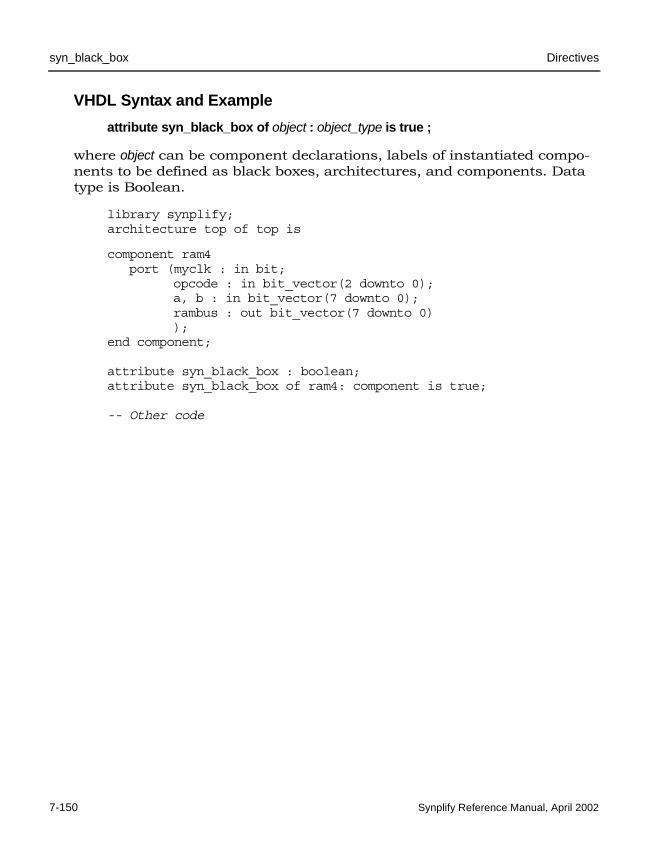
LO
syn_black_box Directives
7-150 Synplify Reference Manual, April 2002
VHDL Syntax and Example
attribute syn_black_box of object : object_type is true ;
where object can be component declarations, labels of instantiated compo-nents to be defined as black boxes, architectures, and components. Data type is Boolean.
library synplify;architecture top of top is
component ram4port (myclk : in bit;
opcode : in bit_vector(2 downto 0);a, b : in bit_vector(7 downto 0);rambus : out bit_vector(7 downto 0));
end component;
attribute syn_black_box : boolean;attribute syn_black_box of ram4: component is true;
-- Other code

Directives syn_enum_encoding
Synplify Reference Manual, April 2002 7-151
syn_enum_encodingDirective. For VHDL designs. Defines how enumerated data types are implemented. The type of implementation affects the performance and device utilization.
If FSM Compiler is enabled, do not use this directive to specify the encoding styles of extracted state machines; use the syn_encoding attribute instead. However, if you have enumerated data types and you turn off the FSM Compiler so that no state machines are extracted, the syn_enum_encoding style is implemented in the final circuit. See syn_encoding Versus syn_enum_encoding on page 7-154 for more information.
Values for syn_enum_encoding can be:
• default – automatically assigns an encoding style based on the number of states:
– sequential for 0-4 enumerated types
– onehot for 5-24 enumerated types
– gray for >24 enumerated types
• sequential – More than one bit of the state register can change at a time, but because more than one bit can be hot the value must be decoded to determine the state. For example,
000, 001, 010, 011, 100
• onehot – Only two bits of the state register change (one goes to ‘0’, and one goes to ‘1’) and only one of the state registers is hot (driven by a '1') at a time. For example,
0000, 0001, 0010, 0100, 1000
• gray – Only one bit of the state register changes at a time, but because more than one bit can be hot, the value must be decoded to deter-mine the state. For example,
000, 001, 011, 010, 110
A message is displayed in the log file when you use the syn_enum_encoding directive, for example,
@N:"c:\design\..":17:11:17:12|Using onehot encoding for type mytype (red="10000000")

LO
syn_enum_encoding Directives
7-152 Synplify Reference Manual, April 2002
Effect of Encoding Styles
The following figure provides an example of two versions of a design: one using the default encoding style, the other overriding the default with the syn_enum_encoding directive for an enumerated data type defining a set of eight colors.
Figure 7-5: syn_enum_encoding
In this example, using the default value for syn_enum_encoding, onehot is assigned because there are 8 states in this design. The onehot style imple-ments the output color as 8 bits wide and creates decode logic to convert the input sel to the output. Using sequential for syn_enum_encoding, the logic is reduced to a buffer. The size of output color is 3 bits.
See the following section VHDL Syntax and Examples for the source code used to generate the schematics in Figure 7-5.
syn_enum_encoding = “sequential”
syn_enum_encoding = “default”Based on 8 states, onehot assigned

Directives syn_enum_encoding
Synplify Reference Manual, April 2002 7-153
VHDL Syntax and Examples
attribute syn_enum_encoding of object : object_type is "value" ;
Where object can be enumerated types and value can be: default, sequential, onehot, gray.
Here is the code used to generate the second schematic in Figure 7-5. (The first schematic will be generated instead, if ”sequential” is replaced by ”onehot” as the syn_enum_encoding value.)
package testpkg istype mytype is (red, yellow, blue, green, white,
violet, indigo, orange);attribute syn_enum_encoding : string;attribute syn_enum_encoding of mytype : type is "sequential";end package testpkg;
library IEEE;use IEEE.std_logic_1164.all;use work.testpkg.all;entity decoder isport(
sel : in std_logic_vector(2 downto 0);color : out mytype
);end decoder;architecture rtl of decoder isbegin
process(sel)begin
case sel is when "000" => color <= red; when "001" => color <= yellow; when "010" => color <= blue; when "011" => color <= green; when "100" => color <= white; when "101" => color <= violet; when "110" => color <= indigo; when others => color <= orange;
end case;end process;
end rtl;
Here is an example using “gray” for data type state.

LO
syn_enum_encoding Directives
7-154 Synplify Reference Manual, April 2002
library synplify;package my_states istype state is (Xstate, st0, st1, st2, st3, st4, st5, st6, st7,
st8, st9, st10, st11, st12, st13, st14, st15);
-- Define the attribute as a gray encoding styleattribute syn_enum_encoding : string;attribute syn_enum_encoding of state : type is "gray";
end my_states;
syn_encoding Versus syn_enum_encoding
To implement a state machine with a particular encoding style when the FSM Compiler is enabled, you need to use the syn_encoding attribute. This attribute affects how the technology mapper implements state machines in the final netlist. The syn_enum_encoding directive only affects how the compiler interprets the associated enumerated data types. Therefore, the encoding defined by syn_enum_encoding is not propagated to the implementa-tion of the state machine.
However, when FSM Compiler is disabled, the value of syn_enum_encoding is implemented in the final circuit.

Directives syn_isclock
Synplify Reference Manual, April 2002 7-155
syn_isclock Directive. Specifies an input port on a black box is a clock.
Use the syn_isclock directive to specify that an input port on a black box is a clock, even though its name does not correspond to one of the recognized names. It will connect it to a clock buffer if appropriate. The data type is Boolean. You can use this directive with any of the following black-box attributes:
• black_box_pad_pin
• black_box_tri_pins
• syn_black_box
• syn_tco<n>
• syn_tpd<n>
• syn_tsu<n>
Verilog Syntax and Examples
object /* synthesis syn_isclock = 0 | 1 */ ;
where object is input ports on black boxes.
module ram4 (myclk,out,opcode,a,b) /* synthesis syn_black_box */;output [7:0] out;input myclk /* synthesis syn_isclock = 1 */;input [2:0] opcode;input [7:0] a, b;
//Other code

LO
syn_isclock Directives
7-156 Synplify Reference Manual, April 2002
VHDL Syntax and Examples
attribute syn_isclock of object: object_type is true ;
where object can be black-box input ports.
Example:
library synplify;
entity ram4 isport (myclk : in bit;
opcode : in bit_vector(2 downto 0);a, b : in bit_vector(7 downto 0);rambus : out bit_vector(7 downto 0));
attribute syn_isclock : boolean;attribute syn_isclock of myclk: signal is true;
-- Other code

Directives syn_keep
Synplify Reference Manual, April 2002 7-157
syn_keep Directive. Keeps the specified net intact during optimization. This directive preserves a net throughout synthesis. When you use this attribute, the compiler places a temporary keep buffer primitive on the net as a place-holder throughout synthesis. You can view this buffer in the schematic views (see Effects of Using syn_keep on page 7-158 for an example). However the buffer is not part of the final netlist, so no extra logic is generated.
As a result of optimization, the compiler might remove some nets, although it maintains ports, registers, and instantiated components. If a net needs to be preserved for simulation results or to obtain a different synthesis implementation, use syn_keep on the net.
There are other situations that might require you to use syn_keep. For example, use this attribute to prevent duplicate cells from being merged during optimization.
You can also use syn_keep as a placeholder to apply the -through option of the define_multicycle_path or define_false_path timing constraint allowing you to specify a unique path as a multicycle or false path. Apply the constraint to the keep buffer.
Do not apply syn_keep to a reg or signal that will become a sequential object.
Note: With Altera Stratix, a syn_keep between the adder and the multiplier of a Multiply/Accumulate (MAC) block will prevent inferencing of altmult_add and altmult_accum, but not plain multi-pliers.

LO
syn_keep Directives
7-158 Synplify Reference Manual, April 2002
Effects of Using syn_keep
The following figure shows the technology view for two versions of a design. One version shows syn_keep set on two registers, out1 and out2, to prevent sharing. The other version is without syn_keep.
Figure 7-6: syn_keep directive used to prevent sharing
syn_keep was applied at the input of the registers to obtain registered outputs for out1 and out2. Without syn_keep, out1 and out2 optimize to one register. See the following HDL syntax and example sections for the source code used to generate the schematics in the figure above.
Usage Compared: syn_keep, syn_preserve, syn_noprune
This comparison may help you to keep the three directives syn_keep, syn_preserve and syn_noprune straight:
• syn_keep assures that 1) a wire will be kept during synthesis and 2) no optimizations will cross the wire. It is usually used to break unwanted optimizations and to assure manually created replica-tions. It works only on nets and combinational logic.
• syn_preserve assures that registers are not optimized away.
With syn_keep
Without syn_keep

Directives syn_keep
Synplify Reference Manual, April 2002 7-159
• syn_noprune assures that black boxes are not optimized away, unless the output is driven by them.
Verilog Syntax and Example
object /* synthesis syn_keep = 1 */ ;
where object can be wire or reg declarations. Make sure that there is a space between the object name and the beginning of the comment slash, or the Synplify synthesis tool will not honor the attribute.
Here is the source code used to produce the results shown in Effects of Using syn_keep on page 7-158
module example2(out1, out2, clk, in1, in2);output out1, out2;input clk;input in1, in2;wire and_out;wire keep1 /* synthesis syn_keep=1 */;wire keep2 /* synthesis syn_keep=1 */;reg out1, out2;
assign and_out=in1&in2;assign keep1=and_out;assign keep2=and_out;
always @(posedge clk)begin;out1<=keep1;out2<=keep2;
endendmodule

LO
syn_keep Directives
7-160 Synplify Reference Manual, April 2002
VHDL Syntax and Example
attribute syn_keep of object : object_type is true ;
where object can be single and multiple-bit signals.
Here is the source code used to produce the schematics shown in Effects of Using syn_keep on page 7-158.
entity example2 isport (
in1, in2 : in bit; clk : in bit;out1, out2 : out bit);
end example2;
architecture rt1 of example2 isattribute syn_keep : boolean;signal and_out, keep1, keep2: bit;attribute syn_keep of keep1, keep2 : signal is true;
beginand_out <= in1 and in2;keep1 <= and_out;keep2 <= and_out;
process(clk)begin
if (clk'event and clk = '1') thenout1 <= keep1;out2 <= keep2;
end if;end process;
end rt1;

Directives syn_macro
Synplify Reference Manual, April 2002 7-161
syn_macro Directive; QuickLogic only. Prevents instantiated macros from being merged or otherwise optimized away. This directive can only be placed in your HDL source code and not defined in the SCOPE spreadsheet.
Verilog Syntax and Example
object /* synthesis syn_macro = 1 | 0 */ ;
For example:
multipler_moduledecoder_macro1 (out, in, clk_in) /* synthesis syn_macro=1 */,decoder_macro2 (out, in, clk_in) /* synthesis syn_macro=1 */,decoder_macro3 (out, in, clk_in) /* synthesis syn_macro=1 */;
VHDL Syntax and Example
attribute syn_macro of object : object_type is true ;
For example:
architecture top of top is
component decoder_macroport (clk : in bit;
opcode : in bit_vector(2 downto 0);a : in bit_vector(7 downto 0);data0 : out bit_vector(7 downto 0));
end component;
-- The components u1, u2, u3, and u4 are instantiations-- of the decoder_macro which are specified later the body of-- this architecture.attribute syn_macro : boolean;attribute syn_macro of u1 : label is true;attribute syn_macro of u2 : label is true;attribute syn_macro of u3 : label is true;attribute syn_macro of u4 : label is true;
-- Other code

LO
syn_noprune Directives
7-162 Synplify Reference Manual, April 2002
syn_noprune Directive. Prevents instance optimization for black-box modules (including technology-specific primitives) with unused output ports. During optimi-zation, if a module does not drive any logic, it is removed by the Synplify synthesis tool. If you want to keep the black-box instance of the module in the design, use the syn_noprune directive.
Effects of using syn_noprune
The following figure shows the technology view for two versions of a design: one version using syn_noprune on black-box instance U1, and one without syn_noprune.
Figure 7-7: syn_noprune directive used to prevent instance optimization
With syn_noprune, module U1 remains in the design. Without syn_noprune the module is optimized away. See the following HDL syntax and example sections for the source code used to generate the schematics in this figure.
With syn_noprune
Without syn_noprune

Directives syn_noprune
Synplify Reference Manual, April 2002 7-163
Usage Compared: syn_keep, syn_preserve, syn_noprune
This comparison may help you to keep the three directives syn_keep, syn_preserve and syn_noprune straight:
• syn_keep assures that 1) a wire will be kept during synthesis and 2) no optimizations will cross the wire. It is usually used to break unwanted optimizations and to assure manually created replications. It works only on nets and combinational logic.
• syn_preserve assures that registers are not optimized away.
• syn_noprune assures that black boxes are not optimized away, unless the output is driven by them.
.sdc File Syntax and Example
define_attribute {module | instance} syn_noprune {0|1}
For example:
define_attribute {u101} syn_noprune {1}
Verilog Syntax and Examples
object /* synthesis syn_noprune = 1 */ ;
where object can be a module declaration or an instance. The data type is Boolean.
The following example shows the source code used for the schematics in Figure 7-7.
module top(a1,b1,c1,d1,y1,clk);
output y1;input a1,b1,c1,d1;input clk;wire x2,y2;reg y1;syn_noprune u1(a1,b1,c1,d1,x2,y2) /* synthesis syn_noprune=1 */;
always @(posedge clk)y1<= a1;
endmodule

LO
syn_noprune Directives
7-164 Synplify Reference Manual, April 2002
// The syn_noprune module is a black box.module syn_noprune (a,b,c,d,x,y);output x,y;input a,b,c,d;endmodule
In this example, syn_noprune can be applied in two places, on the module declaration of syn_noprune or in the top-level instantiation. The most common place to use syn_noprune is in the declaration of the module. By placing it here, all instances of the module are protected.
module syn_noprune (a,b,c,d,x,y); /* synthesis syn_noprune=1 */;
// Other code
Here is an example of using syn_noprune on black-box instances. If your design uses multiple instances with a single module declaration, the synthesis comment must be placed before the comma (,) following the port list for each of the instances.
my_design my_design1(out,in,clk_in) /* synthesis syn_noprune=1 */;my_design my_design2(out,in,clk_in) /* synthesis syn_noprune=1 */;
In this example, only the instance my_design2 will be removed if the output port is not mapped.
my_designmy_design1 (out, in, clk_in) /* synthesis syn_noprune=1 */,my_design2 (out, in, clk_in),my_design3 (out, in, clk_in) /* synthesis syn_noprune=1 */;
VHDL Syntax and Example
attribute syn_noprune of object : object_type is true | false ;
where the data type is boolean, and object can be architectures, compo-nents or labels of instantiated components. See Architectures on page 7-166, Component Declaration on page 7-166, Component Instance on page 7-166, for details of the objects.
The following example shows the source code used for the schematics in Figure 7-7 on page 7-162.

Directives syn_noprune
Synplify Reference Manual, April 2002 7-165
library ieee;use ieee.std_logic_1164.all;entity noprune is
port (a, b, c,d : in std_logic;x,y : out std_logic);
end noprune;
architecture behave of noprune is
begin-- Empty architecture represents a black box.
end behave;
library ieee;use ieee.std_logic_1164.all;entity top is
port (a1, b1 : in std_logic;c1,d1,clk : in std_logic;y1 :out std_logic);
end ;
architecture behave of top iscomponent noprune port (
a, b, c, d : in std_logic;x,y : out std_logic);
end component;
signal x2,y2 : std_logic;attribute syn_noprune : boolean;attribute syn_noprune of u1 : label is true;begin
u1: noprune port map(a1, b1, c1, d1, x2, y2);process beginwait until (clk = '1') and clk'event ;
y1 <= a1;end process;
end;

LO
syn_noprune Directives
7-166 Synplify Reference Manual, April 2002
ArchitecturesThe syn_noprune attribute is normally associated with the names of archi-tectures. Once it is associated, any component instantiation of the archi-tecture (design unit) is protected from being deleted.
library synplify;architecture mydesign of rtl is
attribute syn_noprune : boolean;attribute syn_noprune of mydesign : architecture is true;
-- Other code
Component DeclarationHere is an example:
architecture top_arch of top iscomponent gsr
port (gsr : in std_logic);end component;
attribute syn_noprune : boolean;attribute syn_noprune of gsr: component is true;
See Instantiating Black Boxes in VHDL on page 9-86, for more information.
Component InstanceThe syn_noprune attribute works the same on component instances as with a component declaration.
architecture top_arch of top iscomponent gsr
port (gsr : in bit);end component;
attribute syn_noprune : boolean;attribute syn_noprune of u1_gsr: label is true;

Directives syn_preserve
Synplify Reference Manual, April 2002 7-167
syn_preserveDirective. Prevents sequential optimization such as constant propagation, inverter push-through and FSM extraction.
Note: With Altera Stratix, when this directive is enabled, registers are not packed into Multiply/Accumulate (MAC) blocks.
Use syn_preserve when you need to keep registers for simulation purposes or when you want to preserve the logic of registers driven by constant ‘1’ or ‘0’. To preserve the associated flip-flop and to prevent optimization of the signal, you can set syn_preserve on individual registers or on the module/architecture so that the directive is applied to all registers in the module. For example, assume that the input of a flip-flop is always driven to the same value, such as logic ‘1’. The Synplify synthesis tool ties that signal to VCC and removes the flip-flop. Using syn_preserve on the regis-tered signal prevents the removal of the flip-flop.
Another use for this attribute is to preserve a particular state machine. When you enable the symbolic FSM compiler for your entire design and state-machine optimizations are performed, you can use syn_preserve to retain a particular state machine during optimization.

LO
syn_preserve Directives
7-168 Synplify Reference Manual, April 2002
Effects of using syn_preserve
The following figure shows an example where reg1 and out2 are preserved during optimization using syn_preserve.
Figure 7-8: How syn_preserve retains registers during optimization
Without syn_preserve, reg1 and reg2 are shared because they are driven by the same source. out2 obtains the result of the AND of reg2 and NOT reg1. This is equivalent to the AND of reg1 and NOT reg1 which is a ‘0’. As this is a constant, register out2 is also removed, and output out2 is always ‘0’.
When registers are removed during synthesis, a warning message is displayed in the log file. For example,
@W:...Register bit out2 is always 0, optimizing ...
See the HDL syntax and example sections below for the source code used to generate the schematics in the figure above.
Usage Compared: syn_keep, syn_preserve, syn_noprune
This comparison may help you to keep the three directives syn_keep, syn_preserve and syn_noprune straight:
• syn_keep assures that 1) a wire will be kept during synthesis and 2) no optimizations will cross the wire. It is usually used to break
With syn_preserve
Without syn_preserve

Directives syn_preserve
Synplify Reference Manual, April 2002 7-169
unwanted optimizations and to assure manually created replications. It works only on nets and combinational logic.
• syn_preserve assures that registers are not optimized away.
• syn_noprune assures that black boxes are not optimized away, unless the output is driven by them.
Verilog Syntax and Examples
object /* synthesis syn_preserve = 0 | 1 */ ;
where object can be register definition signals or modules.
In the following example, syn_preserve is used on a registered signal so that the flip-flop is not removed and optimization does not occur across the register. This is useful when you are not finished with the design but want to synthesize to find the area utilization.
reg foo /* synthesis syn_preserve = 1 */;
Following is an example of using syn_preserve for a state register.
reg [3:0] curstate /* synthesis syn_preserve = 1 */;
The following example shows the source code used for the schematics in Figure 7-8 on page 7-168.
module syn_preserve (out1,out2,clk,in1,in2)/* synthesis syn_preserve=1 */;
output out1, out2;input clk;input in1, in2;
reg out1;reg out2;reg reg1;reg reg2;
always@ (posedge clk)beginreg1 <= in1 &in2;

LO
syn_preserve Directives
7-170 Synplify Reference Manual, April 2002
reg2 <= in1&in2;out1 <= !reg1;out2 <= !reg1 & reg2;
endendmodule
VHDL Syntax and Examples
attribute syn_preserve of object : object_type is true ;
where object can be output ports and internal signals that hold the value of state registers or architectures.
library ieee, synplify;use ieee.std_logic_1164.all;entity simpledff is
port (q : out std_logic_vector(7 downto 0);d : in std_logic_vector(7 downto 0);clk : in std_logic);
-- Turn on flip-flop preservation for the q outputattribute syn_preserve : boolean;attribute syn_preserve of q : signal is true;end simpledff;
architecture behavior of simpledff isbegin
process(clk)begin
if rising_edge(clk) then-- Notice the continual assignment of "11111111" to q.
q <= (others => '1');end if;
end process;end behavior;
In this example, syn_preserve is used on the signal curstate that is later used in a state machine to hold the value of the state register.
architecture behavior of mux isbeginsignal curstate : state_type;attribute syn_preserve of curstate : signal is true;
-- Other code

Directives syn_preserve
Synplify Reference Manual, April 2002 7-171
The following example shows the source code for the schematics in Figure 7-8 on page 7-168.
library ieee;use ieee.std_logic_1164.all;entity mod_preserve is
port (out1 : out std_logic;out2 : out std_logic;in1,in2,clk : in std_logic);
end mod_preserve;
architecture behave of mod_preserve isattribute syn_preserve : boolean;attribute syn_preserve of behave: architecture is true;
signal reg1 : std_logic;signal reg2 : std_logic;
begin process beginwait until clk'event and clk = '1';
reg1 <= in1 and in2;reg2 <= in1 and in2;out1 <= not ( reg1);out2 <= (not (reg1) and reg2) ;
end process;end behave;

LO
syn_sharing Directives
7-172 Synplify Reference Manual, April 2002
syn_sharing Directive. Enables/disables the resource sharing of operators inside a module during synthesis. Values for syn_sharing are 1 or 0, for Verilog, and true or false, for VHDL. By default, the attribute is enabled (value 1 for Verilog, true for VHDL). If the Resource Sharing check box in the Project view (see Action Buttons and Options on page 3-97) is disabled, you can still enable resource sharing using the syn_sharing directive.
Verilog Syntax and Example
object / * synthesis syn_sharing = 1 | 0 */ ;
where object can be module definitions.
module my_design(out,in,clk_in) /* synthesis syn_sharing=0 */;
// Other code
VHDL Syntax and Example
attribute syn_sharing of object : object_type is " true | false" ;
where object can be architecture names.
library ieee;use ieee.std_logic_1164.all;use ieee.std_logic_unsigned.all;entity alu is
port ( a, b : in std_logic_vector (7 downto 0);opcode: in std_logic_vector (1 downto 0);clk: in std_logic;result: out std_logic_vector (7 downto 0) );
end alu;
architecture behave of alu is-- Turn on resource sharing for the architecture.attribute syn_sharing of behave : architecture is "true";
begin-- Behavioral source code for the design goes here.end behave;

Directives syn_state_machine
Synplify Reference Manual, April 2002 7-173
syn_state_machine Directive. Enables/disables state-machine optimization on individual state registers in the design. If you disable FSM Compiler such that the state-machines in your design are not automatically extracted, but you would like some of them extracted, you can use this directive on just those individual state-registers. Conversely, if FSM Compiler is enabled, but there are state machines in your design that you do not want extracted, you can use syn_state_machine to override extraction on just those individual state registers.
Also, when FSM Compiler is enabled, all state machines are usually detected during synthesis. However, on occasion there are cases in which certain state machines are not detected. You can use this directive to declare those undetected registers as state machines.
The following figure shows an example of two implementations of a state machine: one with syn_state_machine enabled, the other with the directive disabled.
Figure 7-9: syn_state_machine directive example
syn_state_machine=0
syn_state_machine=1
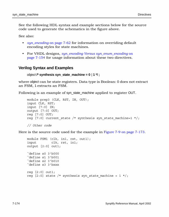
LO
syn_state_machine Directives
7-174 Synplify Reference Manual, April 2002
See the following HDL syntax and example sections below for the source code used to generate the schematics in the figure above.
See also:
• syn_encoding on page 7-62 for information on overriding default encoding styles for state machines.
• For VHDL designs, syn_encoding Versus syn_enum_encoding on page 7-154 for usage information about these two directives.
Verilog Syntax and Examples
object /* synthesis syn_state_machine = 0 | 1 */ ;
where object can be state registers. Data type is Boolean: 0 does not extract an FSM, 1 extracts an FSM.
Following is an example of syn_state_machine applied to register OUT.
module prep3 (CLK, RST, IN, OUT);input CLK, RST;input [7:0] IN;output [7:0] OUT;reg [7:0] OUT;reg [7:0] current_state /* synthesis syn_state_machine=1 */;
// Other code
Here is the source code used for the example in Figure 7-9 on page 7-173.
module FSM1 (clk, in1, rst, out1);input clk, rst, in1;output [2:0] out1;
`define s0 3'b000`define s1 3'b001`define s2 3'b010`define s3 3'bxxx
reg [2:0] out1;reg [2:0] state /* synthesis syn_state_machine = 1 */;

Directives syn_state_machine
Synplify Reference Manual, April 2002 7-175
reg [2:0] next_state;
always @(posedge clk or posedge rst)if (rst) state <= `s0;else state <= next_state;
// Combined Next State and Output Logicalways @(state or in1)
case (state)`s0 : beginout1 <= 3'b000;if (in1) next_state <= `s1;else next_state <= `s0;end`s1 : begin
out1 <= 3'b001;if (in1) next_state <= `s2;else next_state <= `s1;
end`s2 : begin
out1 <= 3'b010;if (in1) next_state <= `s3;else next_state <= `s2;
enddefault : begin
out1 <= 3'bxxx;next_state <= `s0;
endendcase
endmodule
VHDL Syntax and Examples
attribute syn_state_machine of object : object_type is true|false ;
where object can be signals that hold the values of the state machines. For example:
attribute syn_state_machine of current_state: signal is true;
Following is the source code used for the example in Figure 7-9 on page 7-173.

LO
syn_state_machine Directives
7-176 Synplify Reference Manual, April 2002
library ieee;use ieee.std_logic_1164.all;entity FSM1 is
port(clk,rst,in1 : in std_logic;out1 : out std_logic_vector (2 downto 0)
);end FSM1;
architecture behave of FSM1 istype state_values is ( s0, s1, s2,s3 );signal state, next_state: state_values;attribute syn_state_machine : boolean;attribute syn_state_machine of state : signal is false;
beginprocess (clk, rst)begin
if rst = '1' then state <= s0;elsif rising_edge(clk) then
state <= next_state;end if;
end process;
process (state, in1) begincase state is
when s0 =>out1 <= "000";if in1 = '1' then next_state <= s1;
else next_state <= s0;end if;
when s1 =>out1 <= "001";if in1 = '1' then next_state <= s2;
else next_state <= s1;end if;
when s2 =>out1 <= "010";if in1 = '1' then next_state <= s3;
else next_state <= s2;end if;
when others =>out1 <= "XXX"; next_state <= s0;
end case;end process;
end behave;

Directives syn_tco<n>
Synplify Reference Manual, April 2002 7-177
syn_tco<n>Directive. Supplies clock-output timing-delay information through a black box. You can use syn_tco with any of the following black-box directives:
• black_box_pad_pin
• black_box_tri_pins
• syn_black_box
• syn_isclock
• syn_tpd<n>
• syn_tsu<n>
Verilog Syntax and Example
object /* syn_tcon = " [!]clock -> bundle = value" */ ;
A bundle is a collection of buses and scalar signals. To assign values to bundles, use the following syntax. The values are assumed to be in ns.
"[!]clock -> bundle = value"
The optional exclamation mark (!) indicates a negative edge for a clock. The objects of a bundle must be separated by commas with no spaces between. A valid bundle is A,B,C which lists three signals.
An example defining syn_tco<n> with other black-box constraints follows:
module ram32x4(z,d,addr,we,clk);/* synthesis syn_black_box syn_tco1="clk->z[3:0]=4.0"
syn_tpd1="addr[3:0]->z[3:0]=8.0"syn_tsu1="addr[3:0]->clk=2.0"syn_tsu2="we->clk=3.0" */
output [3:0] z;input [3:0] d;input [3:0] addr;input we;input clk;endmodule

LO
syn_tco<n> Directives
7-178 Synplify Reference Manual, April 2002
VHDL Syntax and Examples
attribute syn_tcon of object : object_type is " [!]clock -> bundle = value" ;
A bundle is a collection of buses and scalar signals. To assign values to bundles, use the following syntax. The values are assumed to be in ns.
"[!]clock -> bundle = value"
The optional exclamation mark (!) indicates a negative edge for a clock. The objects of a bundle must be separated by commas with no spaces between. A valid bundle is A,B,C which lists three signals.
There are 10 instances of each of these timing constraints available, for example: syn_tco1, syn_tco2, … syn_tco10. If you need more than 10, you can declare the desired amount (start with an integer greater than 10), for example:
attribute syn_tco11 : string;attribute syn_tco12 : string;
In addition to the syntax used in the code below, you can also use the following Verilog-style syntax to specify this attribute:
attribute syn_tco1 of inputfifo_coregen : component is "rd_clk->dout[48:0]=3.0";
Following is an example of assigning syn_tco<n> along with some of the other black-box constraints:
-- A USE clause for the Synplify Attributes package -- was included earlier to make the timing constraint -- definitions visible here.architecture top of top iscomponent rcf16x4z port (
ad0, ad1, ad2, ad3 : in std_logic;di0, di1, di2, di3 : in std_logic;clk, wren, wpe : in std_logic;tri : in std_logic;do0, do1, do2, do3 : out std_logic);
end component;

Directives syn_tco<n>
Synplify Reference Manual, April 2002 7-179
attribute syn_tco1 of rcf16x4z : component is"clk -> do0,do1 = 4.0";
attribute syn_tpd1 of rcf16x4z : component is"ad0,ad1,ad2,ad3 -> do0,do1,do2,do3 = 2.1";
attribute syn_tpd2 of rcf16x4z : component is"tri -> do0,do1,do2,do3 = 2.0";
attribute syn_tsu1 of rcf16x4z : component is"ad0,ad1,ad2,ad3 -> clk = 1.2";
attribute syn_tsu2 of rcf16x4z : component is"wren,wpe -> clk = 0.0";
-- Other code

LO
syn_tpd<n> Directives
7-180 Synplify Reference Manual, April 2002
syn_tpd<n>Directive. Supplies information on timing propagation for combinatorial delay through a black box.
You can use syn_tpd with any of the following black-box directives:
• black_box_pad_pin
• black_box_tri_pins
• syn_black_box
• syn_isclock
• syn_tco<n>
• syn_tsu<n>
Verilog Syntax and Example
object /* syn_tpdn = " [!]clock -> bundle = value" */ ;
A bundle is a collection of buses and scalar signals. To assign values to bundles, use the following syntax. The values are assumed to be in ns.
"[!]clock -> bundle = value"
The optional exclamation mark (!) indicates a negative edge for a clock. The objects of a bundle must be separated by commas with no spaces between. A valid bundle is A,B,C which lists three signals.
Following is an example of defining syn_tpd<n> along with some of the other black-box timing constraints:
module ram32x4(z,d,addr,we,clk); /* synthesis syn_black_boxsyn_tpd1="addr[3:0]->z[3:0]=8.0"syn_tsu1="addr[3:0]->clk=2.0"syn_tsu2="we->clk=3.0" */
output [3:0] z;input [3:0] d;input [3:0] addr;input we;input clk;endmodule

Directives syn_tpd<n>
Synplify Reference Manual, April 2002 7-181
VHDL Syntax and Examples
attribute syn_tpdn of object : object_type is " [!]clock -> bundle = value" ;
There are 10 instances of each of these timing constraints available, for example: syn_tpd1, syn_tpd2, … syn_tpd10.
If you need more than 10, you can declare the desired amount (start with an integer greater than 10), for example:
attribute syn_tpd11 : string;attribute syn_tpd12 : string;
A bundle is a collection of buses and scalar signals. To assign values to bundles, use the following syntax. The values are assumed to be in ns.
"[!]clock -> bundle = value"
The optional exclamation mark (!) indicates a negative edge for a clock. The objects of a bundle must be separated by commas with no spaces between. A valid bundle is A,B,C which lists three signals.
In addition to the syntax used in the code below, you can also use the following Verilog-style syntax to specify this attribute:
attribute syn_tpd1 of inputfifo_coregen : component is "rd_clk->dout[48:0]=3.0";
Following is an example of assigning syn_tpd<n> along with some of the of the black-box constraints:
-- A USE clause for the Synplify Attributes package -- was included earlier to make the timing constraint -- definitions visible here.architecture top of top iscomponent rcf16x4z port (
ad0, ad1, ad2, ad3 : in std_logic;di0, di1, di2, di3 : in std_logic;clk, wren, wpe : in std_logic;tri : in std_logic;do0, do1, do2, do3 : out std_logic);
end component;

LO
syn_tpd<n> Directives
7-182 Synplify Reference Manual, April 2002
attribute syn_tpd1 of rcf16x4z : component is"ad0,ad1,ad2,ad3 -> do0,do1,do2,do3 = 2.1";
attribute syn_tpd2 of rcf16x4z : component is"tri -> do0,do1,do2,do3 = 2.0";
attribute syn_tsu1 of rcf16x4z : component is"ad0,ad1,ad2,ad3 -> clk = 1.2";
attribute syn_tsu2 of rcf16x4z : component is"wren,wpe -> clk = 0.0";
-- Other code

Directives syn_tristate
Synplify Reference Manual, April 2002 7-183
syn_tristate Directive. Specifies that an output port, on a module defined as a black box, is tristate. Use this directive to eliminate multiple driver errors if the output of a black box has more than one driver. A multiple driver error is issued unless you use this directive to specify that the outputs are tristate.
Verilog Syntax and Examples
object /* synthesis syn_tristate = 0 | 1 */ ;
where object can be black-box output ports. For example:
module BUFE(O, I, E); /* synthesis syn_black_box */output O /* synthesis syn_tristate = 1 */;
// Other code

LO
syn_tsu<n> Directives
7-184 Synplify Reference Manual, April 2002
syn_tsu<n>Directive. Supplies information on timing setup delay required for input pins (relative to the clock) in a black box. You can use syn_tsu with any of the following black-box directives:
• black_box_pad_pin
• black_box_tri_pins
• syn_black_box
• syn_isclock
• syn_tco<n>
• syn_tpd<n>
Verilog Syntax and Example
object /* syn_tsun = " [!]clock -> bundle = value" */ ;
A bundle is a collection of buses and scalar signals. To assign values to bundles, use the following syntax. The values are assumed to be in ns.
"[!]clock -> bundle = value"
The optional exclamation mark (!) indicates a negative edge for a clock. The objects of a bundle must be separated by commas with no spaces between. A valid bundle is A,B,C which lists three signals.
Following is an example of defining syn_tsu<n> along with some of the other black-box constraints:
module ram32x4(z,d,addr,we,clk);/* synthesis syn_black_box syn_tpd1="addr[3:0]->z[3:0]=8.0"
syn_tsu1="addr[3:0]->clk=2.0"syn_tsu2="we->clk=3.0" */
output [3:0] z;input [3:0] d;input [3:0] addr;input we;input clk;endmodule

Directives syn_tsu<n>
Synplify Reference Manual, April 2002 7-185
VHDL Syntax and Examples
attribute syn_tsun of object : object_type is " [!]clock -> bundle = value" ;
There are 10 instances of each of these timing constraints available, for example: syn_tsu1, syn_tsu2, … syn_tsu10.
If you need more than 10, you can declare the desired amount (start with an integer greater than 10), for example:
attribute syn_tsu11 : string;attribute syn_tsu12 : string;
A bundle is a collection of buses and scalar signals. To assign values to bundles, use the following syntax. The values are assumed to be in ns.
"[!]clock -> bundle = value"
The optional exclamation mark (!) indicates a negative edge for a clock. The objects of a bundle must be separated by commas with no spaces between. A valid bundle is A,B,C which lists three signals.
In addition to the syntax used in the code below, you can also use the following Verilog-style syntax to specify this attribute:
attribute syn_tsu1 of inputfifo_coregen : component is "rd_clk->dout[48:0]=3.0";
Following is an example of assigning syn_tsu<n> along with some of the other black-box constraints:

LO
syn_tsu<n> Directives
7-186 Synplify Reference Manual, April 2002
-- A USE clause for the Synplify Attributes package -- was included earlier to make the timing constraint -- definitions visible here.architecture top of top iscomponent rcf16x4z port (
ad0, ad1, ad2, ad3 : in std_logic;di0, di1, di2, di3 : in std_logic;clk, wren, wpe : in std_logic;tri : in std_logic;do0, do1, do2, do3 : out std_logic);
end component;
attribute syn_tco1 of rcf16x4z : component is"ad0,ad1,ad2,ad3 -> do0,do1,do2,do3 = 2.1";
attribute syn_tpd2 of rcf16x4z : component is"tri -> do0,do1,do2,do3 = 2.0";
attribute syn_tsu1 of rcf16x4z : component is"ad0,ad1,ad2,ad3 -> clk = 1.2";
attribute syn_tsu2 of rcf16x4z : component is"wren,wpe -> clk = 0.0";
-- Other code

Directives translate_off/translate_on
Synplify Reference Manual, April 2002 7-187
translate_off/translate_onDirective. Used for compatibility with synthesis tools from other vendors than Synplicity, translate_off and translate_on, allow you to synthesize designs originally written for use with other synthesis tools, without needing to modify source code. All source code that is between these two directives is ignored during synthesis.
Another use of these directives is to prevent the synthesis of stimulus source code that only has meaning for logic simulation. You can use translate_off/translate_on to skip over simulation-specific lines of code that are not synthesizable.
When you use translate_off in a module, the Synplify synthesis tool halts the synthesis of all source code that follows until translate_on is encountered. Every translate_off must have a corresponding translate_on. These directives cannot be nested, therefore, the translate_off directive can only be followed by a translate_on directive.
Verilog Syntax and Example
For Verilog designs, you can use the synthesis macro with the Verilog ‘ifdef directive instead of the translate on/off directives. See synthesis Macro on page 8-45 for information.
The Verilog syntax for these directives is as follows:
/* synthesis translate_off */
/* synthesis translate_on */
For example:
module adder8(cout, sum, a, b, cin);
// Place code here that you WANT synthesized
/* synthesis translate_off */
// Place code here that you DO NOT want synthesized.

LO
translate_off/translate_on Directives
7-188 Synplify Reference Manual, April 2002
/* synthesis translate_on */
// Place code here that you WANT synthesized.
endmodule
VHDL Syntax and Example
synthesis translate_off
synthesis translate_on
For example:
architecture behave of ram4 isbegin
-- synthesis translate_offstimulus: process (clk, a, b)
-- Source code you DO NOT want synthesized
end process;-- synthesis translate_on
-- Other source code you WANT synthesized

Directives xc_isgsr
Synplify Reference Manual, April 2002 7-189
xc_isgsrDirective; Xilinx (XC4000 families). Specifies that a port on a black box is connected to an internal STARTUP block. Use this directive with designs targeting XC4000 families where the Synplify synthesis tool infers a STARTUP block.
.sdc File Syntax and Example
define_attribute {instance.reset_port} xc_isgsr {1 | 0}
For example:
define_attribute {bbgsr.gsrin} xc_isgsr {1}
Verilog Syntax and Example
object /* synthesis xc_isgsr = {1|0} */ ;
For example:
module bbgsr(gsrin, a, b); /* synthesis syn_black_box */input gsrin /* synthesis xc_isgsr = 1 */;
// Other code

LO
xc_isgsr Directives
7-190 Synplify Reference Manual, April 2002
VHDL Syntax and Example
attribute xc_isgsr of object : object_type is true | false ;
For example:
library IEEE;use IEEE.std_logic_1164.all;library synplify;
entity bbgsr isport( gsrin : in std_logic;
b: in std_logic;a : out std_logic);
attribute xc_isgsr : boolean;attribute xc_isgsr of gsrin : signal is true;end bbgsr;
architecture bb of bbgsr isattribute syn_black_box : boolean;attribute syn_black_box of bb : architecture is true;
-- Other code

Synplify Reference Manual, April 2002 8-1
C H A P T E R 8
Verilog Language Support
This chapter discusses Verilog support in the Synplify synthesis tool, including the following topics:
• Language Constructs on page 8-2
• Verilog Synthesis Guidelines on page 8-7
• Verilog Module Template on page 8-9
• Scalable Modules on page 8-11
• Built-in Gate Primitives on page 8-14
• Combinational Logic on page 8-15
• Sequential Logic on page 8-19
• Verilog State Machines on page 8-29
• RAM Inference on page 8-34
• Instantiating Black Boxes in Verilog on page 8-40
• PREP Verilog Benchmarks on page 8-42
• Hierarchy: Structural Verilog on page 8-43
• Synthesis Attributes and Directives on page 8-47

LO
Chapter 8: Verilog Language Support Language Constructs
8-2 Synplify Reference Manual, April 2002
Language Constructs
The following sections define the supported, unsupported, and ignored language constructs for Verilog.
Supported Verilog Language ConstructsThe Synplify synthesis tool supports the following Verilog constructs:
• Net types: wire, tri, supply1, supply0; register types: reg, integer, time (64 bit reg); arrays of reg.
• Continuous assignments.
• Gate primitive and module instantiations.
• always blocks, user tasks, user functions.
• inputs, outputs, and inouts to a module.
• All operators (+, -, *, /, %, <, >, <=, >=, ==, !=, ===, !==, &&, ||, !, ~, &, ~&, |, ~|, ^~, ~^, ^, <<, >>, ?:, { }, {{ }}) [Note: / and % are supported for compile-time constants and constant powers of 2.]
• Procedural statements: if-else-if, case, casex, casez, for, repeat, while, forever, begin, end, fork, join.
• Procedural assignments: blocking assignments =, nonblocking assignments <= (Note: <= cannot be mixed with = for the same register. We recommend parameter override: # and defparam (down one level of hierarchy only).
• Compiler directives: `define, `ifdef, `else, `endif, `include, `undef
• Miscellaneous:
– Integer ranges and parameter ranges.
– Local declarations to begin-end block.
– Variable indexing of bit vectors on the left and right sides of assignments.

Language Constructs Chapter 8: Verilog Language Support
Synplify Reference Manual, April 2002 8-3
Unsupported Language ConstructsThe Synplify synthesis tool does not support the following Verilog constructs. If found, it generates an error message and halts.
• Net types: trireg, wor, trior, wand, triand, tri0, tri1, and charge strength; register type: real.
• Built-in unidirectional and bidirectional switches, and pull-up, pull-down.
• Procedural statements: assign, deassign, , wait.
• Named events and event triggers.
• UDPs and specify blocks.
• force, release, and hierarchical net names (for simulation only).
Ignored Language ConstructsThe Synplify synthesis tool ignores the following Verilog constructs and continues the synthesis run.
• delay, delay control, and drive strength.
• scalared, vectored.
• initial block.
• Compiler directives (except for `define, `ifdef, `else, `endif, `include, and `undef, which are supported).
• Calls to system tasks and system functions (they are only for simula-tion).
Verilog 2001 SupportYou can choose which Verilog standard to use for a project or given files within a project: Verilog ‘95 or Verilog 2001 (see File Options Dialog Box on page 3-78 and VHDL and Verilog Panels on page 3-36). The Synplify synthesis tool supports the following Verilog 2001 features:

LO
Chapter 8: Verilog Language Support Language Constructs
8-4 Synplify Reference Manual, April 2002
Example: Combined Data, Port Types (ANSI C-style Modules)
Verilog ‘95module adder_16 (sum, cout, cin, a, b);output [15:0] sum;output cout;input [15:0] a, b;input cin;
reg [15:0] sum;reg cout;wire [15:0] a, b;wire cin;
Table 8-1: Supported Verilog 2001 features
Feature Description
Combined data and port types You can combine module data and port type declarations, for conciseness.
Comma-separated sensitivity list Commas are allowed as separators in sensitivity lists (as in other Verilog lists).
Wildcards in sensitivity list You can use @* or @(*) to include all signals in a procedural block, eliminating mismatches between RTL and post-synthesis simulation.
Signed arithmetic expressions Data types net and reg, module ports, integers of different bases and signals can all be signed. Signed signals can be assigned and compared. Signed operations can be performed for vectors of any length.
Power (exponent) operator (**) Implemented as a left shift. Only base 2 is supported.
Generate You use it to create multiple instances of an object in a module. You can use generate with loops and conditional statements.

Language Constructs Chapter 8: Verilog Language Support
Synplify Reference Manual, April 2002 8-5
Verilog 2001module adder_16(output reg [15:0] sum;
output reg cout; input wire cin; input wire [15:0] a, b);
Example: Comma-separated Sensitivity List
Verilog ‘95always @(a or b or cin)
sum = a + b + cin;
always @(posedge clock or negedge reset)if (!reset)
q <= 0;else
q <= d;
Verilog 2001always @(a, b or cin)
sum = a + b + cin;
always @(posedge clock, negedge reset)if (!reset)
q <= 0;else
q <= d;
Example: Wildcard (*) in Sensitivity List
Verilog ‘95always @(a or b or cin)
sum = a + b + cin;

LO
Chapter 8: Verilog Language Support Language Constructs
8-6 Synplify Reference Manual, April 2002
Verilog 2001// One stylealways @(*)
sum = a + b + cin;
// Another stylealways @*
sum = a + b + cin;
Examples: Signed Signals (Verilog 2001)
Declarationmodule adder (output reg signed [31:0] sum,
wire signed input [31:0] a, b;
Assignmentwire signed [3:0] a = 4’sb1001;
Comparisonwire signed [1:0] sel;parameter p0 = 2’sb00, p1 = 2’sb01,
p2 = 2’sb10, p3 = 2’sb11;case sel
p0: ...p1: ...p2: ...p3: ...
endcase
Examples: Generate Statement (Verilog 2001)
// for loopgenerategenvar i;
for (i=0; i<=7; i=i+1)begin :inst
adder8 add (sum [8*i+7 : 8*i], c0[i+1], a[8*i+7 : 8*i], b[8*i+7 : 8*i], c0[i]);
endendgenerate

Verilog Synthesis Guidelines Chapter 8: Verilog Language Support
Synplify Reference Manual, April 2002 8-7
// if-elsegenerate
if (adder_width < 8)ripple_carry # (adder_width) u1 (a, b, sum);
elsecarry_look_ahead # (adder_width) u1 (a, b, sum);
endgenerate
// caseparameter WIDTH=1;generate
case (WIDTH)1: adder1 x1 (c0, sum, a, b, ci);2: adder2 x1 (c0, sum, a, b, ci);default: adder # width (c0, sum, a, b, ci);
endcaseendgenerate
Verilog Synthesis Guidelines
General Synthesis GuidelinesSome general guidelines are presented here to help you synthesize your Verilog design. See Verilog Module Template on page 8-9 for additional infor-mation.
• Top-level module – The Synplify synthesis tool always picks the last module compiled that is not referenced in another module as the top-level module. Module selection can be overridden from the Verilog panel of the Options for Implementation dialog box.
• Simulate your design before synthesis – you should simulate your design before synthesis to expose logic errors. Logic errors that you do not catch are passed through the synthesis tool, and the synthe-sized results will contain the same logic errors.
• Simulate your design after placement and routing – Have the place-and-route tool generate a post placement and routing (timing-accurate) simulation netlist, and do a final simulation before programming your devices.

LO
Chapter 8: Verilog Language Support Verilog Synthesis Guidelines
8-8 Synplify Reference Manual, April 2002
• Avoid asynchronous state machines – To use the synthesis tool for asynchronous state machines, make a netlist of technology primi-tives from your target library.
• Level-sensitive latches – For modeling level-sensitive latches, use continuous assignment statements.
Verilog Language Guidelines
always Blocks
An always block can have more than one event control argument, provided they are all edge-triggered events or all signals; these two kinds of arguments cannot be mixed in the same always block.
Examples// OK: Both arguments are edge-triggered eventsalways @(posedge clk or posedge rst)
// OK: Both arguments are signalsalways @(A or B)
// No good: One edge-triggered event, one signalalways @(posedge clk or rst)
An always block represents either sequential logic or combinational logic. The one exception is that you can have an always block that specifies level-sensitive latches and combinational logic. This is not a recom-mended style because it is easy to have user errors or unwanted level-sensitive latches.
An event expression with posedge / negedge keywords implies edge-triggered sequential logic; and without posedge / negedge keywords implies combinational logic, a level-sensitive latch, or both.
Each sequential always block is triggered from exactly one clock (and optional sets and resets).
You must declare every signal assigned a value inside an always block as a reg or integer. An integer is a 32-bit quantity by default, and is used with the Verilog operators to do two's complement arithmetic. The Synplify synthesis tool also supports range specifications for integers, allowing you to create an integer size other than 32 bits.
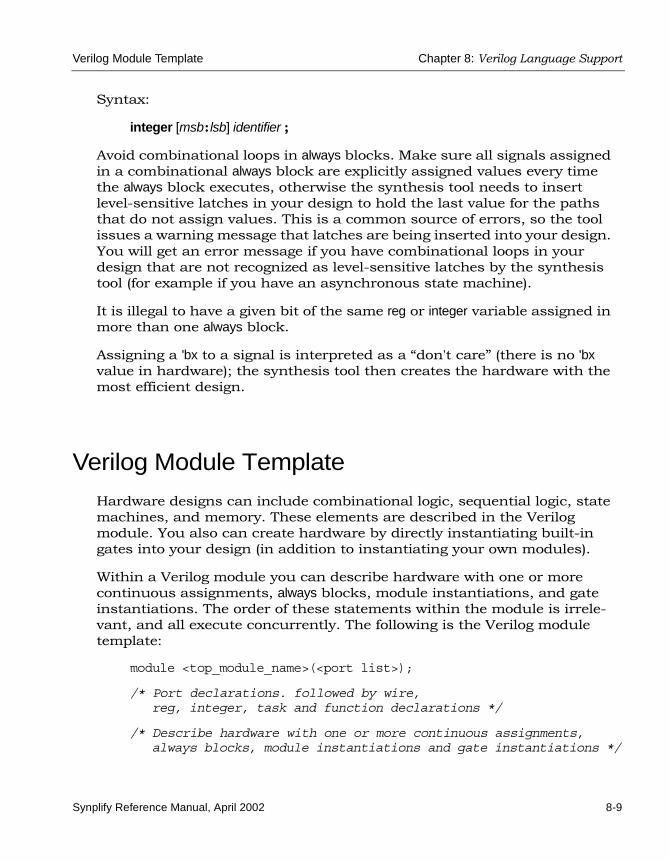
Verilog Module Template Chapter 8: Verilog Language Support
Synplify Reference Manual, April 2002 8-9
Syntax:
integer [msb: lsb] identifier ;
Avoid combinational loops in always blocks. Make sure all signals assigned in a combinational always block are explicitly assigned values every time the always block executes, otherwise the synthesis tool needs to insert level-sensitive latches in your design to hold the last value for the paths that do not assign values. This is a common source of errors, so the tool issues a warning message that latches are being inserted into your design. You will get an error message if you have combinational loops in your design that are not recognized as level-sensitive latches by the synthesis tool (for example if you have an asynchronous state machine).
It is illegal to have a given bit of the same reg or integer variable assigned in more than one always block.
Assigning a 'bx to a signal is interpreted as a “don't care” (there is no 'bx value in hardware); the synthesis tool then creates the hardware with the most efficient design.
Verilog Module Template
Hardware designs can include combinational logic, sequential logic, state machines, and memory. These elements are described in the Verilog module. You also can create hardware by directly instantiating built-in gates into your design (in addition to instantiating your own modules).
Within a Verilog module you can describe hardware with one or more continuous assignments, always blocks, module instantiations, and gate instantiations. The order of these statements within the module is irrele-vant, and all execute concurrently. The following is the Verilog module template:
module <top_module_name>(<port list>);
/* Port declarations. followed by wire,reg, integer, task and function declarations */
/* Describe hardware with one or more continuous assignments, always blocks, module instantiations and gate instantiations */

LO
Chapter 8: Verilog Language Support Verilog Module Template
8-10 Synplify Reference Manual, April 2002
// Continuous assignmentwire <result_signal_name>;assign <result_signal_name> = <expression>;
// always blockalways @(<event expression>)
begin// Procedural assignments// if statements// case, casex, and casez statements// while, repeat and for loops// user task and user function calls
end
// Module instantiation<module_name> <instance_name> (<port list>);
// Instantiation of built-in gate primitivegate_type_keyword (<port list>);
endmodule
The statements between the begin and end statements in an always block execute sequentially from top to bottom. If you have a fork-join statement in an always block, the statements within the fork-join execute concurrently.
You can add comments in Verilog by preceding your comment text with // (two forward slashes). Any text from the slashes to the end of the line is treated as a comment, and is ignored by the Synplify synthesis tool. To create a block comment, which can span any number of lines, start the comment with /* (forward slash followed by asterisk) and end the comment with */ (asterisk followed by forward slash). Block comments cannot be nested.

Scalable Modules Chapter 8: Verilog Language Support
Synplify Reference Manual, April 2002 8-11
Scalable Modules
Creating a Scalable ModuleYou can create a Verilog module that is scalable, so that it can be stretched or shrunk to handle a user-specified number of bits in the port list buses.
Declare parameters with default parameter values. The parameters can be used to represent bus sizes inside a module.
Syntax
parameter parameter_name = value ;
You can define more than one parameter per declaration by using comma-separated parameter_name = value pairs.
Example
parameter size = 1;parameter word_size = 16, byte_size = 8;
Using Scalable ModulesTo use scalable modules, instantiate the scalable module and then override the default parameter value with the defparam keyword. Give the instance name of the module you are overriding, the parameter name, and the new value.
Syntax
defparam instance_name.parameter_name = new_value ;
Example
big_register my_register (q, data, clk, rst);defparam my_register.size = 64;
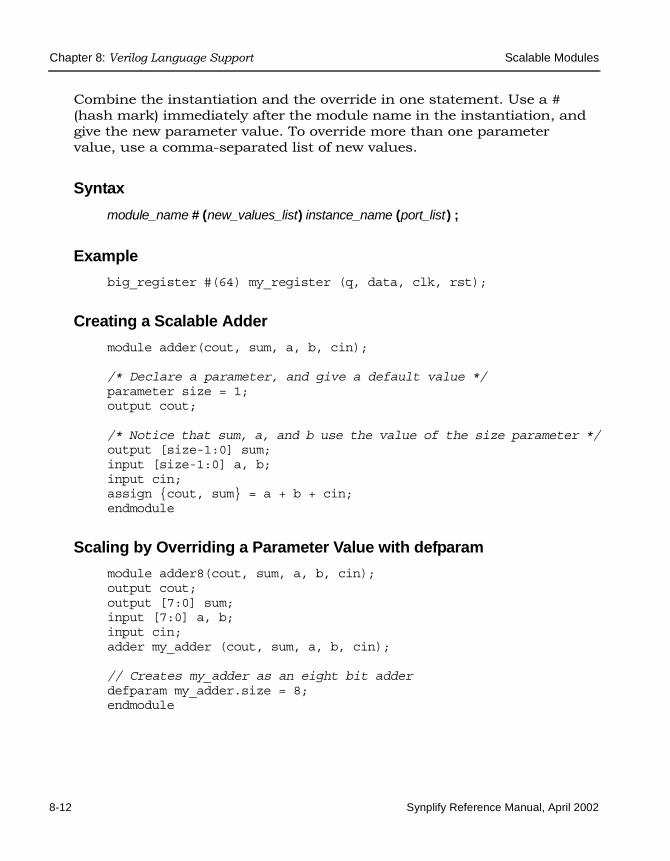
LO
Chapter 8: Verilog Language Support Scalable Modules
8-12 Synplify Reference Manual, April 2002
Combine the instantiation and the override in one statement. Use a # (hash mark) immediately after the module name in the instantiation, and give the new parameter value. To override more than one parameter value, use a comma-separated list of new values.
Syntax
module_name # (new_values_list) instance_name (port_list ) ;
Example
big_register #(64) my_register (q, data, clk, rst);
Creating a Scalable Adder
module adder(cout, sum, a, b, cin);
/* Declare a parameter, and give a default value */parameter size = 1;output cout;
/* Notice that sum, a, and b use the value of the size parameter */output [size-1:0] sum;input [size-1:0] a, b;input cin;assign {cout, sum} = a + b + cin;endmodule
Scaling by Overriding a Parameter Value with defparam
module adder8(cout, sum, a, b, cin);output cout;output [7:0] sum;input [7:0] a, b;input cin;adder my_adder (cout, sum, a, b, cin);
// Creates my_adder as an eight bit adderdefparam my_adder.size = 8;endmodule

Scalable Modules Chapter 8: Verilog Language Support
Synplify Reference Manual, April 2002 8-13
Scaling by Overriding the Parameter Value with #
module adder16(cout, sum, a, b, cin);output cout;
/* You can define a parameter at this level of hierarchy, and pass that value down to the lower level instance. In thisexample, we declare a parameter called my_size. Note: you can declare a parameter with the same name as the lower level name (size) because this level of hierarchy has a different name scope than the lower level and there is noconflict -- but there is no correspondence between the two names either, so you still have to explicitly pass theparameter value down through the hierarchy. */
parameter my_size = 16; // I want a sixteen bit adderoutput [my_size-1:0] sum;input [my_size-1:0] a, b;input cin;
/* my_size overrides size inside instance my_adder of adder */// Creates my_adder as a sixteen bit adderadder #(my_size) my_adder (cout, sum, a, b, cin);endmodule

LO
Chapter 8: Verilog Language Support Built-in Gate Primitives
8-14 Synplify Reference Manual, April 2002
Built-in Gate Primitives
You can create hardware by directly instantiating built-in gates into your design (in addition to instantiating your own modules.) The built-in Verilog gates are called primitives.
Syntax
gate_type_keyword [instance_name] (port_list) ;
The gate type keywords for simple and tristate gates are listed in the following tables. The instance_name is a unique instance name, and is optional. The signal names in the port_list can be given in any order with the restriction that all outputs must come before the inputs. For tristate gates, outputs come first, then inputs, and then enable.
The followin tables list the available keywords.
Table 8-2: Simple gates
Keyword Definition
buf buffer
not inverter
and and gate
nand nand gate
or or gate
nor nor gate
xor exclusive or gate
xnor exclusive nor gate
Table 8-3: Tristate gates
Keyword Definition
bufif1 tristate buffer with logic one enable

Combinational Logic Chapter 8: Verilog Language Support
Synplify Reference Manual, April 2002 8-15
Combinational Logic
Combinational logic is hardware in which the output values are based on some function of the current input values. There is no clock, and no saved states. Most hardware is a mixture of combinational and sequential logic.
You create combinational logic with an always block and/or continuous assignments.
Combinational Logic ExamplesThe following combinational logic synthesis examples are included in the synplicity_install_dir/examples/verilog/combinat directory:
• Adders
• ALU
• Bus Sorter
• 3-to-8 Decoder
• 8-to-3 Priority Encoders
• Comparator
• Multiplexors (concurrent signal assignments, case statements, or if-then-else statements can be used to create multiplexors; the Synplify synthesis tool automatically creates parallel multiplexers when the conditions in the branches are mutually exclusive)
• Parity Generator
• Tristate Drivers
bufif0 tristate buffer with logic zero enable
notif1 tristate inverter with logic one enable
notif0 tristate inverter with logic zero enable
Table 8-3: Tristate gates (Continued)

LO
Chapter 8: Verilog Language Support Combinational Logic
8-16 Synplify Reference Manual, April 2002
always Blocks for Combinational LogicUse the Verilog always blocks to model combinational logic as shown in the following template.
always @(event_expression)begin
// Procedural assignment statements,// if, case, casex, and casez statements// while, repeat, and for loops// task and function calls
end
When modeling combinational logic with always blocks, keep the following in mind:
• The always block must have exactly one event control (@(event_ expres-sion)) in it, located immediately after the always keyword.
• You should list all signals feeding into the combinational logic in the event expression. This includes all signals that affect signals that are assigned inside the always block. All signals on the right side of an assignment inside an always block should be listed. The Synplify synthesis tool assumes that the sensitivity list is complete, and generates the desired hardware. However, it will issue a warning message if any signals on the right side of an assignment inside an always block are not listed, because your pre- and post-synthesis simulation results might not match.
• You must explicitly declare as reg or integer all signals you assign in the always block.
Note: Make sure all signals assigned in a combinational always block are explicitly assigned values every time the always block executes. Otherwise, the synthesis tool must insert level-sensitive latches in your design to hold the last value for the paths that do not assign values. This will occur, for instance, if there are combinational loops in your design. This often represents a coding error. The synthesis tool issues a warning message that latches are being inserted into your design because of combinational loops. You will get an error

Combinational Logic Chapter 8: Verilog Language Support
Synplify Reference Manual, April 2002 8-17
message if you have combinational loops in your design that are not recognized as level-sensitive latches by the synthesis tool.
Event Expression
Every always block must have one event control (@(event_expression)), that specifies the signal transitions that trigger the always block to execute. This is analogous to specifying the inputs to logic on a schematic by drawing wires to gate inputs. If there is more than one signal, separate the names with the or keyword.
Syntaxalways @ (signal1 or signal2 ...)
Example/* The first line of an always block for a mux that triggers
when 'a', 'b' or 'sel' changes */always @(a or b or sel)
Locate the event control immediately after the always keyword. Do not use the posedge or negedge keywords in the event expression; they imply edge-sensitive sequential logic.
Example: Multiplexor See also Example: Comma-separated Sensitivity List on page 8-5.
module mux (out, a, b, sel);output out;input a, b, sel;reg out;
always @(a or b or sel)begin
if (sel)out = a;
elseout = b;
endendmodule

LO
Chapter 8: Verilog Language Support Combinational Logic
8-18 Synplify Reference Manual, April 2002
Continuous Assignments for Combinational LogicUse continuous assignments to model combinational logic. To create a continuous assignment:
1. Declare the assigned signal as a wire using the syntax:
wire [msb : lsb] result_signal ;
2. Specify your assignment with the assign keyword, and give the expression (value) to assign.
assign result_signal = expression ;
or ...
Combine the wire declaration and assignment into one statement:
wire [msb : lsb] result_signal = expression ;
Each time a signal on the right side of the equal sign (=) changes value, the expression re-evaluates, and the result is assigned to the signal on the left side of the equal sign. You can use any of the built-in operators to create the expression.
The bus range [msb : lsb] is only necessary if your signal is a bus (more than one bit wide).
All outputs and inouts to modules default to wires; therefore the wire declaration is redundant for outputs and inouts and “assign result_signal = expression ;” is sufficient.
Example: Bit-wise AND
module bitand (out, a, b);output [3:0] out;input [3:0] a, b;/* This wire declaration is not required because "out" is an
output in the port list */wire [3:0] out;
assign out = a & b;
endmodule

Sequential Logic Chapter 8: Verilog Language Support
Synplify Reference Manual, April 2002 8-19
Example: 8-bit Adder
module adder_8 (cout, sum, a, b, cin);output cout;output [7:0] sum;input cin;input [7:0] a, b;
assign {cout, sum} = a + b + cin;
endmodule
Sequential Logic
Sequential logic is hardware that has an internal state or memory. The state elements are either flip-flops that update on the active edge of a clock signal or level-sensitive latches that update during the active level of a clock signal.
Because of the internal state, the output values might depend not only on the current input values, but also on input values at previous times. Sequential logic in which the updated state values depend on the previous state values is a state machine. There are standard ways of modeling state machines in Verilog. Most hardware is a mixture of combinational and sequential logic.
You create sequential logic with always blocks and/or continuous assign-ments.
Sequential Logic ExamplesThe following sequential logic synthesis examples are included in the synplicity_install_dir/examples/verilog/sequentl directory:
• Flip-flops and level-sensitive latches
• Counters (up, down, and up/down)
• Register file

LO
Chapter 8: Verilog Language Support Sequential Logic
8-20 Synplify Reference Manual, April 2002
• Shift registers
• State machines
For additional information on synthesizing flip-flops and latches, see these topics:
• Flip-flops Using always Blocks on page 8-20
• Level-sensitive Latches on page 8-21
• Sets and Resets on page 8-24
Flip-flops Using always BlocksThe easiest way to create flip-flops/registers is to assign values to the signals in an always block, and specify the active clock edge in the event expression.
always Block Template
always @(event_expression)begin
// Procedural statementsend
The always block must have one event control (@(event_expression)) immedi-ately after the always keyword that specifies the clock signal transitions that trigger the always block to execute.
Syntaxalways @ (edge_keyword clock_name)
where edge_keyword is posedge (for positive-edge triggered) or negedge (for negative-edge triggered).
Examplealways @(posedge clk)

Sequential Logic Chapter 8: Verilog Language Support
Synplify Reference Manual, April 2002 8-21
Assignments to Signals in always Blocks
• You must explicitly declare as reg or integer any signal you assign inside an always block.
• Any signal assigned within an edge-triggered always block will be implemented as a register; for instance, signal q in the following example.
Examplemodule dff_or (q, a, b, clk);output q;input a, b, clk;reg q; // Declared as reg, since assigned in always block
always @(posedge clk)begin
q <= a | b;endendmodule
In this example, the result of a | b connects to the data input of a flip-flop, and the q signal connects to the q output of the flip-flop.
Level-sensitive LatchesThe preferred method of modeling level-sensitive latches in Verilog is to use continuous assignment statements.
Example
module latchor1 (q, a, b, clk);output q;input a, b, clk;
assign q = clk ? (a | b) : q;endmodule
Whenever clk, a, or b change, the expression on the right side re-evalu-ates. If your clk becomes true (active, logic 1), a|b is assigned to the q output. When the clk changes and becomes false (deactivated), q is assigned to q (holds the last value of q). If a or b changes and clk is already active, the new value a|b is assigned to q.

LO
Chapter 8: Verilog Language Support Sequential Logic
8-22 Synplify Reference Manual, April 2002
Although it is simpler to specify level-sensitive latches using continuous assignment statements, you can create level-sensitive latches from always blocks. Use an always block and follow these guidelines for event expres-sion and assignments.
always Block Template
always@(event_expression)begin // Procedural statementsend
Whenever the assignment to a signal is incompletely defined, the event expression specifies the clock signal and the signals that feed into the data input of the level-sensitive latch.
Syntax always @ (clock_name or signal1 or signal2 ... )
Examplealways @(clk or data)begin
if (clk)q <= data;
end
The always block must have exactly one event control (@(event_expression)) in it, and must be located immediately after the always keyword.
Assignments to Signals in always Blocks
• You must explicitly declare as reg or integer any signal you assign inside an always block.
• Any incompletely-defined signal that is assigned within a level-triggered always block will be implemented as a register.
Note: Whenever level-sensitive latches are generated from an always block, the Synplify synthesis tool issues a warning message, so that you can verify if a given level-sensitive latch is really

Sequential Logic Chapter 8: Verilog Language Support
Synplify Reference Manual, April 2002 8-23
what you intended. (If you model a level-sensitive latch using continuous assignment then no warning message is issued.)
Example: Creating Level-sensitive Latches You Wantmodule latchor2 (q, a, b, clk);output q;input a, b, clk;reg q;
always @(clk or a or b)begin
if (clk)q <= a | b;
endendmodule
If clk, a, or b change, and clk is a logic 1, then set q equal to a|b.
Notice that we did not specify what to do when clk is a logic zero (there is no else in the if statement), so when clk is a logic 0, the last value assigned is maintained (there is an implicit q=q). The Synplify synthesis tool correctly recognizes this as a level-sensitive latch, and creates a level-sensitive latch in your design. The tool issues a warning message when you compile this module (after examination, you may choose to ignore this message).
Example: Creating Unwanted Level-sensitive Latchesmodule mux4to1 (out, a, b, c, d, sel);output out;input a, b, c, d;input [1:0] sel;reg out;
always @(sel or a or b or c or d)begin
case (sel)2'd0: out = a;2'd1: out = b;2'd3: out = d;
endcaseendendmodule

LO
Chapter 8: Verilog Language Support Sequential Logic
8-24 Synplify Reference Manual, April 2002
In the above example, the sel case value 2'd2 was intentionally omitted. Accordingly, out is not updated when the select line has the value 2'd2, and a level-sensitive latch must be added to hold the last value of out under this condition. The Synplify synthesis tool issues a warning message when you compile this module, and there can be mismatches between RTL simulation and post-synthesis simulation. You can avoid generating level-sensitive latches by adding the missing case in the case statement; using a “default” case in the case statement; or using the Verilog full_case directive.
Sets and ResetsA set signal is an input to a flip-flop that, when activated, sets the state of the flip-flop to a logic one. Asynchronous sets take place independent of the clock, whereas synchronous sets only occur on an active clock edge.
A reset signal is an input to a flip-flop that, when activated, sets the state of the flip-flop to a logic zero. Asynchronous resets take place independent of the clock, whereas synchronous resets take place only at an active clock edge.
Asynchronous Sets and Resets
Asynchronous sets and resets are independent of the clock. When active, they set flip-flop outputs to one or zero (respectively), without requiring an active clock edge. Therefore, list them in the event control of the always block, so that they trigger the always block to execute, and so that you can take the appropriate action when they become active.
Event Control Syntaxalways @ ( edge_keyword clock_signal or edge_keyword reset_signal or edge_keyword set_signal )
Edge_keyword is posedge for active-high set or reset (or positive-edge triggered clock) or negedge for active-low set or reset (or negative-edge triggered clock)
You can list the signals in any order.

Sequential Logic Chapter 8: Verilog Language Support
Synplify Reference Manual, April 2002 8-25
Example: Event Control// Asynchronous, active-high set (rising-edge clock)always @(posedge clk or posedge set)
// Asynchronous, active-low reset (rising-edge clock)always @(posedge clk or negedge reset)
// Asynchronous, active-low set and active-high reset // (rising-edge clock)always @(posedge clk or negedge set or posedge reset)
Example: always Block Template with Asynchronous, Active-high reset, setalways @(posedge clk or posedge set or posedge reset)begin
if (reset) begin
/* Set the outputs to zero */
end else if (set) begin
/* Set the outputs to one */
end else begin
/* Clocked logic */end
end

LO
Chapter 8: Verilog Language Support Sequential Logic
8-26 Synplify Reference Manual, April 2002
Example: flip-flop with Asynchronous, Active-high reset and setmodule dff1 (q, qb, d, clk, set, reset);input d, clk, set, reset;output q, qb;// Declare q and qb to be reg because assigned inside alwaysreg q, qb;
always @(posedge clk or posedge set or posedge reset)begin
if (reset) beginq <= 0;qb <= 1;
end else if (set) beginq <= 1;qb <= 0;
end else beginq <= d;qb <= ~d;
endendendmodule
For simple, single variable flip-flops, the following template can be used.
always @(posedge clk or posedge set or posedge reset)
q = reset ? 1'b0 : set ? 1'b1 : d;
Synchronous Sets and Resets
Synchronous sets and resets set flip-flop outputs to logic 1 or 0 (respec-tively) on an active clock edge.
Do not list the set and reset signal names in the event expression of an always block because they should not trigger the always block to execute upon changing. Instead, trigger the always block on the active clock edge, and check the reset and set inside the always block first.
RTL View PrimitivesThe Verilog compiler can detect and extract the following flip-flops with synchronous sets and resets and display them in the RTL schematic view:
• sdffr—flip-flop with synchronous reset
• sdffs—flip-flop with synchronous set

Sequential Logic Chapter 8: Verilog Language Support
Synplify Reference Manual, April 2002 8-27
• sdffrs—flip-flop with both synchronous set and reset
• sdffpat—vectored flip-flop with synchronous set/reset pattern
• sdffre—enabled flip-flop with synchronous reset
• sdffse—enabled flip-flop with synchronous set
• sdffpate—enabled, vectored flip-flop with synchronous set/reset pattern
Note: You can check the name (type) of any primitive by placing your mouse pointer over it in the RTL view; a tooltip displays the name.
Figure 8-1: Flip-flops with synchronous sets and resets
Event Control Syntaxalways @ (edge_keyword clock_name )
In the syntax line, edge_keyword is posedge for a positive-edge triggered clock or negedge for a negative-edge triggered clock.

LO
Chapter 8: Verilog Language Support Sequential Logic
8-28 Synplify Reference Manual, April 2002
Example: Event Control // Positive edge triggered always @(posedge clk)
// Negative edge triggered always @(negedge clk)
Example: always Block Template with Synchronous, Active-high reset, setalways @(posedge clk)begin
if (reset) begin/* Set the outputs to zero */
end else if (set) begin/* Set the outputs to one */
end else begin/* Clocked logic */
endend
Example: D Flip-flop with Synchronous, Active-high set, resetmodule dff2 (q, qb, d, clk, set, reset);input d, clk, set, reset;output q, qb;reg q, qb;
always @(posedge clk)begin
if (reset) beginq <= 0;qb <= 1;
end else if (set) beginq <= 1;qb <= 0;
end else beginq <= d;qb <= ~d;
endendendmodule

Verilog State Machines Chapter 8: Verilog Language Support
Synplify Reference Manual, April 2002 8-29
Verilog State Machines
A finite state machine is hardware that advances from state to state at a clock edge.
State Machine GuidelinesThe Synplify synthesis tool works best with synchronous state machines. The recommended practice is to write a fully synchronous design, and to avoid asynchronous paths, such as a path through the asynchronous reset of a register. See Asynchronous State Machines on page 8-32 for infor-mation about asynchronous state machines.
• The state machine must have a synchronous or asynchronous reset to be inferred. State machines must have an asynchronous or synchronous reset to set the hardware to a valid state after power-up, and to reset your hardware during operation (asynchro-nous resets are available freely in most FPGA architectures).
• You can define state machines using multiple event controls in an always block only if the event control expressions are identical (for example, @(posedge clk)). These state machines are known as implicit state machines. However it is better to use the explicit style described here and shown in Example: FSM Coding Style on page 8-30.
• Separate the sequential from the combinational always block state-ments. Besides making it easier to read, it makes what is being regis-tered very obvious. It also gives better control over the type of register element used.
• Represent states with defined labels or enumerated types.
• It is easiest to use a case statement in an always block to check the current state at the clock edge, advance to the next state, then set the output values. You could also use if statements in an always block, but generally you should stay with case statements for coding-style consistency.
• Always use a default assignment as the last assignment in your case statement and set the state variable to 'bx. See Example: default Assign-ment on page 8-31.

LO
Chapter 8: Verilog Language Support Verilog State Machines
8-30 Synplify Reference Manual, April 2002
• Set encoding style with the syn_encoding directive. This attribute overrides the default encoding assigned during compilation. The default encoding is determined by the number of states. If you have a syn_encoding attribute, its value is used during the mapping stage to determine encoding style.
attribute syn_encoding : string;attribute syn_encoding of <typename> : type is "sequential";
See Chapter 7, Synthesis Attributes and Directives, for details about the syntax and values.
One-hot implementations are not always the best choice for state machines, even in FPGAs and CPLDs. For example, one-hot state machines might result in larger implementations, which can cause fitting problems. An example in an FPGA in which one-hot imple-mentation can be detrimental is when the state machine drives a large decoder, generating many output signals. In a 16-state state machine, for instance, the output decoder logic might reference sixteen signals in a one-hot implementation, but only four signals in a sequential representation.
Example: FSM Coding Style
module FSM1 (clk, rst, enable, data_in, data_out, state0, state1,state2);
input clk, rst, enable;input [2:0] data_in;output data_out, state0, state1, state2;
/* Defined state labels; this style preferred over ‘defines*/parameter deflt=2'bxx;parameter idle=2'b00;parameter read=2'b01;parameter write=2'b10;
reg data_out, state0, state1, state2;reg [1:0] state, next_state;
/* always block with sequential logic*/always @(posedge clk or negedge rst)
if (!rst) state <= idle;else state <= next_state;

Verilog State Machines Chapter 8: Verilog Language Support
Synplify Reference Manual, April 2002 8-31
/* always block with combinatorial logic*/always @(state or enable or data_in) begin
/* Default values for FSM outputs*/state0 <= 1'b0;state1 <= 1'b0;state2 <= 1'b0;data_out <= 1'b0;
case (state)idle : if (enable) begin
state0 <= 1'b1;data_out <= data_in[0];next_state <= read;
endelse begin
next_state <= idle;end
read : if (enable) beginstate1 <= 1'b1;data_out <= data_in[1];next_state <= write;
endelse begin
next_state <= read;end
write : if (enable) beginstate2 <= 1'b1;data_out <= data_in[2];next_state <= idle;
endelse begin
next_state <= write;end
/* Default assignment for simulation */default : next_state <= deflt;
endcaseendendmodule
Example: default Assignment
default: state = 'bx;
Assigning 'bx to the state variable (which is a “don't care” for synthesis) tells the Synplify synthesis tool that you have specified all the used states in your case statement. Any remaining states are not used, and the

LO
Chapter 8: Verilog Language Support Verilog State Machines
8-32 Synplify Reference Manual, April 2002
synthesis tool can remove unnecessary decoding and gates associated with the unused states. You do not have to add any special, non-Verilog directives.
If you set the state to a used state for the default case (for example, default state = state1), the tool generates the same logic as if you assign 'bx, but there will be pre- and post-synthesis simulation mismatches until you reset the state machine. These mismatches occur because all inputs are unknown at start up on the simulator. You therefore go immediately into the default case, which sets the state variable to state1. When you power up the hardware, it can be in a used state, such as state2, and then advance to a state other than state1. Post-synthesis simulation behaves more like hardware with respect to initialization.
State ValuesIn Verilog, you must give explicit state values for states. This is usually done using parameters or `defines. The preferred method is to use parame-ters. The state names are shown in the FSM Viewer only if you use parameters.
Example 1: Using Parameters for State Values (Recommended)
parameter state1 = 2'h1, state2 = 2'h2;...current_state = state2; // Setting current state to 2'h2
Example 2: Using `define for State Values
`define state1 2'h1`define state2 2'h2...current_state = `state2; // Setting current state to 2'h2
Asynchronous State MachinesAvoid defining asynchronous state machines in Verilog. An asynchronous state machine has states, but no clearly defined clock, and has combina-tional loops.
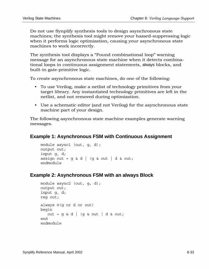
Verilog State Machines Chapter 8: Verilog Language Support
Synplify Reference Manual, April 2002 8-33
Do not use Synplify synthesis tools to design asynchronous state machines; the synthesis tool might remove your hazard-suppressing logic when it performs logic optimization, causing your asynchronous state machines to work incorrectly.
The synthesis tool displays a “Found combinational loop” warning message for an asynchronous state machine when it detects combina-tional loops in continuous assignment statements, always blocks, and built-in gate-primitive logic.
To create asynchronous state machines, do one of the following:
• To use Verilog, make a netlist of technology primitives from your target library. Any instantiated technology primitives are left in the netlist, and not removed during optimization.
• Use a schematic editor (and not Verilog) for the asynchronous state machine part of your design.
The following asynchronous state machine examples generate warning messages.
Example 1: Asynchronous FSM with Continuous Assignment
module async1 (out, g, d);output out;input g, d;assign out = g & d | !g & out | d & out;endmodule
Example 2: Asynchronous FSM with an always Block
module async2 (out, g, d);output out;input g, d;reg out;
always @(g or d or out)begin
out = g & d | !g & out | d & out;endendmodule

LO
Chapter 8: Verilog Language Support RAM Inference
8-34 Synplify Reference Manual, April 2002
RAM Inference
The Synplify synthesis tool can infer synchronous and synchronously resettable RAMs from your Verilog source code and, where appropriate, generate technology-specific single or dual-port RAMs. No special input such as attributes or directives in your source code is needed. The primi-tive generated for an inferred RAM has an asynchronous READ, except as noted in Synchronous READ RAMs on page 8-37.
The following table lists the supported technology-specific RAMs that the Synplify synthesis tool can generate.
Example
module ram_test(q, a, d, we, clk);output [7:0] q;input [7:0] d;input [6:0] a;input clk, we;
reg [7:0] mem [127:0];always @(posedge clk) begin
if(we)mem[a] <= d;
end
assign q = mem[a];endmodule
Table 8-4: Generated technology-specific RAMs
TechnologyVendor
Family RAM Type
Altera FLEX10K/10KE Single port
Altera APEX20K/20KE/20KC Single and dual port
Xilinx Virtex, Virtex-E, Virtex2, Virtex2p Single and dual port. Dual port block RAMs have only one write port.

RAM Inference Chapter 8: Verilog Language Support
Synplify Reference Manual, April 2002 8-35
RAMs with Special Write EnablesThe Synplify synthesis tool can infer RAMs when the Write Enable is tied to Vcc or when the Write Enable is nested within IF statements.
always-enabled Write Enable
The RAM extraction code supports the inference of RAMs with their Write Enable tied permanently to Vcc rather than implementing the logic in flip-flops.
Examplemodule xyz (q, d , clk, addr);input clk;input [7:0] addr;input [3:0] d;output [3:0] q;reg [255:0] mem [3:0];wire we;
assign we = 1'b1;always @(posedge clk)begin
if(we)begin
mem[addr] = d;end
end
assign q = mem[addr];endmodule
Nested Write Enable
The RAM extraction code can infer RAMs when the Write Enable is more complex as found in nested if statements. The compilers extract common terms from the feedback MUX Enables to derive the common Write Enable signal.

LO
Chapter 8: Verilog Language Support RAM Inference
8-36 Synplify Reference Manual, April 2002
Examplemodule xyz (q, d , we1, we2, clk, addr);input clk, we1, we2;input [7:0] addr;input [3:0] d;output [3:0] q;reg [255:0] mem [3:0];
always @(posedge clk)begin
if(we1)begin
if(we2)begin
mem[addr] = d;end
endend
assign q = mem[addr];endmodule
Limited RAM ResourcesIf your RAM resources are limited, you can designate additional instances of inferred RAMs as flip-flops and logic using the syn_ramstyle attribute. This attribute takes the string argument of registers – place the attribute on either the output signal driven by the RAM or on the instance name of the RAM. Use the Attributes panel of the SCOPE spreadsheet to assign this and all other attributes.
Additional Components GeneratedAfter inferring a RAM for some technologies, you might notice that the Synplify synthesis tool has generated a few additional components adjacent to the RAM. This glue logic ensures accuracy in your post place-and-route simulation results.

RAM Inference Chapter 8: Verilog Language Support
Synplify Reference Manual, April 2002 8-37
Synchronous READ RAMsAll RAM primitives that the tool generates for inferred RAMs have asynchronous READs, except for single port Altera 10K RAMs and single port Xilinx Virtex block RAMs. For these exceptions, the Synplify synthesis tool generates a synchronous RAM. The following example shows how the address of the RAM must be registered to generate a synchronous READ RAM.
Example
module ram_test(q, a, d, we, clk);output [7:0] q;input [7:0] d;input [6:0] a;input clk, we;
reg [6:0] read_add;reg [7:0] mem [127:0];
always @(posedge clk) beginif(we)
mem[a] <= d;read_add <= a;
end
assign q = mem[read_add];endmodule

LO
Chapter 8: Verilog Language Support ROM Inference
8-38 Synplify Reference Manual, April 2002
ROM Inference
ROM TablesAs part of B.E.S.T. (Behavioral Extraction Synthesis Technology), the Synplify synthesis tool infers ROMs (read-only memories) from your HDL source code, and generates block components in the RTL view for them.
The data contents of the ROMs are stored in a text file named rom.info. To quickly view rom.info in read-only mode, synthesize your HDL source code, open an RTL view, and then push down into the ROM component.
Generally, the Synplify synthesis tool infers ROMs from HDL source code that uses case statements, or equivalent if statements, to make 16 or more signal assignments using constant values (words). The constants must all be the same width.
Another requirement for ROM inference is that values must be specified for at least half of the address space. For example, if the ROM has 5 address bits, then the address space is 32 and at least 16 of the different addresses must be specifed.
Example
module rom(z,a);output [3:0] z;input [4:0] a;reg [3:0] z;
always @(a) begincase (a)5'b00000 :z = 4'b0001;5'b00001 :z = 4'b0010;5'b00010 :z = 4'b0110;5'b00011 :z = 4'b1010;5'b00100 :z = 4'b1000;5'b00101 :z = 4'b1001;5'b00110 :z = 4'b0000;5'b00111 :z = 4'b1110;5'b01000 :z = 4'b1111;5'b01001 :z = 4'b1110;5'b01010 :z = 4'b0001;5'b01011 :z = 4'b1000;

ROM Inference Chapter 8: Verilog Language Support
Synplify Reference Manual, April 2002 8-39
5'b01100 :z = 4'b1110;5'b01101 :z = 4'b0011;5'b01110 :z = 4'b1111;5'b01111 :z = 4'b1100;5'b10000 :z = 4'b1000;5'b10001 :z = 4'b0000;5'b10010 :z = 4'b0011;default :z = 4'b0111;endcase
endendmodule
ROM Table Data (rom.info File)
Note: This data is for viewing only
ROM work.rom4(behave)-z_1[3:0]address width: 5data width: 4inputs:0: a[0]1: a[1]2: a[2]3: a[3]4: a[4]outputs:0: z_1[0]1: z_1[1]2: z_1[2]3: z_1[3]
data:00000 -> 000100001 -> 001000010 -> 011000011 -> 101000100 -> 100000101 -> 100100110 -> 000000111 -> 111001000 -> 111101001 -> 111001010 -> 000101011 -> 100001100 -> 111001101 -> 0011

LO
Chapter 8: Verilog Language Support Instantiating Black Boxes in Verilog
8-40 Synplify Reference Manual, April 2002
01110 -> 001001111 -> 001010000 -> 001010001 -> 001010010 -> 0010default -> 0111
Instantiating Black Boxes in Verilog
Black boxes are modules in which just the interface is specified; internal information is ignored by the Synplify synthesis tool. Black boxes can be used to directly instantiate:
• Technology-vendor primitives and macros (including I/Os).
• User-designed macros whose functionality was defined in a schematic editor, or another input source. (When the place-and-route tool can merge design netlists from different sources.)
Black boxes are specified with the syn_black_box synthesis directive. If the macro is an I/O, use black_box_pad_pin=1 on the external pad pin. See below for details, and Verilog Examples on page B-39.
Note: For most of the technology-vendor architectures, macro libraries are provided (in installation_dir/lib/tech-nology/family.v) that predefine the black boxes for their prim-itives and macros (including I/Os).
Although the synthesis tool ignores the internals of black-box modules, you need to define their functionality if you plan to simulate with a Verilog simulator. The contents are simply ignored during synthesis.
If the black box has tristate outputs, you must define these outputs with a black_box_tri_pins directive (see black_box_tri_pins on page 7-142).

Instantiating Black Boxes in Verilog Chapter 8: Verilog Language Support
Synplify Reference Manual, April 2002 8-41
Instantiating a Black BoxTo instantiate a black box:
1. Create an interface for the macro with no contents (you can have contents, but they are ignored during synthesis.)
The interface only declares the ports and the port directions. You tell the synthesis tool to ignore the contents by putting syn_black_box just before the semicolon ( ; ) in the module declaration. Here is an example:
module myram(out, in, addr, we) /* synthesis syn_black_box */ ;output [15:0] out;input [15:0] in;input [4:0] addr;input we;endmodule
2. Make an instance of the stub in your design (just as you would any other module).
3. Compile the stub, along with the module containing the instantiation of the stub. After synthesis, the synthesis result file will contain a reference to myram.
Instantiating a Technology Vendor I/O If you want to instantiate a pad from a vendor library and you are creating a black box for a pad, you must also specify which pin is the external pad pin with the black_box_pad_pin=1 directive.
Example: Input Pad Black Box
module vendors_input_pad(out, in) /* synthesis syn_black_box */;input in /* synthesis black_box_pad_pin=1 */; output out ;...

LO
Chapter 8: Verilog Language Support PREP Verilog Benchmarks
8-42 Synplify Reference Manual, April 2002
Example: Output Pad Black Box
module vendors_output_pad(out, in) /* synthesis syn_black_box */;input in;output out /* synthesis black_box_pad_pin=1 */;...
Before placement and routing, you typically merge the synthesis result file and the netlist representing the black box. Technology vendors have different methods of merging netlists. Refer to the section for your vendor under FPGA and CPLD Support, for more information.
PREP Verilog Benchmarks
PREP (Programmable Electronics Performance) Corporation distributes benchmark results that show how FPGA vendors compare with each other in terms of device performance and area. The following PREP bench-marks are included in the synplicity_install_dir/examples/verilog/prep directory:
• PREP VHDL Benchmark 1. Data Path
• PREP VHDL Benchmark 2. Timer/Counter
• PREP VHDL Benchmark 3. Small State Machine
• PREP VHDL Benchmark 4. Large State Machine
• PREP VHDL Benchmark 5. Arithmetic Circuit
• PREP VHDL Benchmark 6. 16-Bit Accumulator
• PREP VHDL Benchmark 7. 16-Bit Counter
• PREP VHDL Benchmark 8. 16-Bit Pre-scaled Counter
• PREP VHDL Benchmark 9. Memory Map
The source code for the benchmarks can be used for design examples for synthesis or for doing your own FPGA vendor comparisons.
PREP Corp. has disbanded, but you can still obtain information from their Web site: www.prep.org.

Hierarchy: Structural Verilog Chapter 8: Verilog Language Support
Synplify Reference Manual, April 2002 8-43
Hierarchy: Structural Verilog
The Synplify synthesis tool accepts and processes hierarchical Verilog designs. You create hierarchy by instantiating a module or a built-in gate primitive within another module.
The signals connect across the hierarchical boundaries through the port list, and can either be listed by position (the same order that you declare them in the lower-level module), or by name (where you specify the name of the lower-level signals to connect to).
Connecting by name minimizes errors, and is recommended when the instantiated module has many ports.
Creating a Hierarchical DesignTo create a hierarchical design:
1. Create modules.
2. Instantiate the modules within other modules. (When you instantiate modules inside of others, the ones that you have instantiated are sometimes called “lower-level modules” to distinguish them from the “top-level” module that is not inside of another module.)
3. Connect signals in the port list together across the hierarchy either “by position” or “by name” (see the examples, below).
Example: Creating Modules (Interfaces Shown)
module mux(out, a, b, sel); // muxoutput [7:0] out;input [7:0] a, b;input sel;
// <mux functionality>
endmodule

LO
Chapter 8: Verilog Language Support Hierarchy: Structural Verilog
8-44 Synplify Reference Manual, April 2002
module reg8(q, data, clk, rst); // Eight-bit registeroutput [7:0] q;input [7:0] data;input clk, rst;// <Eight-bit register functionality>endmodule
module rotate(q, data, clk, r_l, rst); // Rotates bits or loadsoutput [7:0] q;input [7:0] data;input clk, r_l, rst;// When r_l is high, it rotates; if low, it loads data// < Rotate functionality>endmodule
Example: Top-level Module with Ports Connected by Position
module top1(q, a, b, sel, r_l, clk, rst);output [7:0] q;input [7:0] a, b;input sel, r_l, clk, rst;wire [7:0] mux_out, reg_out;
// The order of the listed signals here will match// the order of the signals in the mux module declaration.mux mux_1 (mux_out, a, b, sel);reg8 reg8_1 (reg_out, mux_out, clk, rst);rotate rotate_1 (q, reg_out, clk, r_l, rst);
endmodule
Example: Top-level Module with Ports Connected by Name
module top2(q, a, b, sel, r_l, clk, rst);output [7:0] q;input [7:0] a, b;input sel, r_l, clk, rst;wire [7:0] mux_out, reg_out;

Hierarchy: Structural Verilog Chapter 8: Verilog Language Support
Synplify Reference Manual, April 2002 8-45
/* The syntax to connect a signal "by name" is:.<lower_level_signal_name>(<local_signal_name>)*/mux mux_1 (.out(mux_out), .a(a), .b(b), .sel(sel));
/* Ports connected "by name" can be in any order */reg8 reg8_1 (.clk(clk), .data(mux_out), .q(reg_out), .rst(rst));rotate rotate_1 (.q(q), .data(reg_out), .clk(clk), .r_l(r_l),
.rst(rst));
endmodule
synthesis MacroUse this text macro along with the Verilog `ifdef compiler directive to condi-tionally exclude part of your Verilog code from being synthesized. The most common use of the synthesis macro is to avoid synthesizing stimulus that only has meaning for logic simulation.
The Synplify synthesis tool defines the synthesis macro so that the state-ment `ifdef synthesis is true. The tool compiles the statements in the `ifdef branch (usually there are none), and ignores the stimulus statements in the `else branch.
Note: Because Verilog simulators do not recognize a synthesis macro, the compiler for your simulator will use the stimulus in the `else branch.
The following example is implemented as an AND gate, because the Synplify synthesis tool uses the assign c = a & b branch:
`define DOANDmodule top (a,b,c);
input a,b;output c;
`ifdef synthesisassign c = a & b;
`elseassign c = a | b;
`endifendmodule
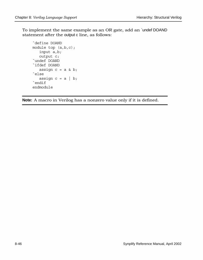
LO
Chapter 8: Verilog Language Support Hierarchy: Structural Verilog
8-46 Synplify Reference Manual, April 2002
To implement the same example as an OR gate, add an `undef DOAND statement after the output c line, as follows:
`define DOANDmodule top (a,b,c);
input a,b;output c;
`undef DOAND`ifdef DOAND
assign c = a & b;`else
assign c = a | b;`endifendmodule
Note: A macro in Verilog has a nonzero value only if it is defined.

Synthesis Attributes and Directives Chapter 8: Verilog Language Support
Synplify Reference Manual, April 2002 8-47
Synthesis Attributes and Directives
Verilog synthesis attributes and directives allow you to associate informa-tion with your design to control the way it is analyzed, compiled, and mapped.
• Attributes direct the way your design is optimized and mapped during synthesis. Although you can place synthesis attributes directly in your source code, you should use the Attributes panel of the SCOPE spreadsheet to specify them in a constraint file. That way, changes can be made (via the constraint file), without requiring you to recom-pile.
• Directives control the way your design is analyzed prior to mapping. They must therefore be included directly in your source code; they cannot be specified in a constraint file.
Because Verilog does not have predefined attributes or directives for synthesis, you attach attributes and directives to source code items as comments.
In addition to the general attributes and directives described in Chapter 7, Synthesis Attributes and Directives, the Synplify synthesis tool also supports vendor-specific directives and attributes that apply to the specific programmable logic vendor you are targeting for your design.

LO
Chapter 8: Verilog Language Support Synthesis Attributes and Directives
8-48 Synplify Reference Manual, April 2002

Synplify Reference Manual, April 2002 9-1
C H A P T E R 9
VHDL Language Support
This chapter discusses how you can use the VHDL language to create HDL source code for the Synplify synthesis tool:
• Language Constructs on page 9-2
• VHDL Language Constructs on page 9-5
• VHDL Synthesis Guidelines on page 9-33
• Sets and Resets on page 9-44
• State Machines on page 9-49
• Hierarchical Designs on page 9-56
• Configuration Specification and Declaration on page 9-60
• Scalable Designs on page 9-71
• RAM Inference on page 9-77
• Synthesis Attributes and Directives on page 9-85
• Instantiating Black Boxes in VHDL on page 9-86
• VHDL Synthesis Examples on page 9-89
• PREP VHDL Benchmarks on page 9-91

LO
Chapter 9: VHDL Language Support Language Constructs
9-2 Synplify Reference Manual, April 2002
Language Constructs
The following sections define the supported, unsupported, and ignored language constructs for VHDL.
Supported VHDL Language ConstructsThe following is a compact list of language constructs that are supported.
• Entity, architecture and package design units.
• Function and procedure subprograms.
• All IEEE library packages, including:
– std_logic_1164
– std_logic_unsigned
– std_logic_signed
– std_logic_arith
– numeric_std and numeric_bit
– standard library package (std)
• In, out, inout, buffer, linkage ports.
• Signals, constants, and variables.
• Aliases.
• Integer, physical and enumeration data types; subtypes of these.
• Arrays of scalars and records.
• Record data types.
• All operators (+, -, *, /, **, mod, rem, abs, not, =, /=, <, <=, >, >=, and, or, nand, nor, xor, xnor, sll, srl, sla, sra, rol, ror, &).

Language Constructs Chapter 9: VHDL Language Support
Synplify Reference Manual, April 2002 9-3
Note: Operators /, mod, and rem are supported for compile-time constants or when the right argument is a power of 2. Oper-ator ** is supported when the arguments are compile-time constants. The left operand must always be a power of 2 (or be zero). When the left operand is 2, the right operand can be a variable. Operators sla, rol, and ror are supported when the shift distance is a compile-time constant).
• Sequential statements: signal and variable assignment, wait, if, case, loop, for, while, return, null, function, and procedure call.
• Concurrent statements: signal assignment, process, block, generate (for and if), component instantiation, function, and procedure call.
• Component declarations and four methods of component instantia-tions.
• Configuration specification and declaration
• Generics; attributes; overloading.
• Next and exit looping control constructs.
• Predefined attributes: t'base, t'left, t'right, t'high, t'low, t'succ, t'pred, t'val, t'pos, t'leftof, t'rightof, integer'image, a'left, a'right, a'high, a'low, a'range, a'reverse_range, a'length, a'ascending, s'stable, s'event.
Miscellaneous VHDL Language Constructs• Unconstrained ports in entities.
• Variable indexing of arrays; aggregates (and others clauses).
• Block ports and generics.
• Initializing signals and variables (except for initializing a variable declared in a process).
• Ranges in case statements.
• Nesting of functions.

LO
Chapter 9: VHDL Language Support Language Constructs
9-4 Synplify Reference Manual, April 2002
Unsupported VHDL Language ConstructsIf any of these constructs are found, an error message is reported and the synthesis run is cancelled.
• Access, and file types
• Register and bus kind signals
• Guarded blocks
• Expanded (hierarchical) names
• Global signals declared in packages
• User-defined resolution functions. The Synplify synthesis tool only supports the resolution functions for std_logic and std_logic_vector.
Ignored VHDL Language ConstructsThe Synplify synthesis tool ignores the following constructs in your design. If found, the tool parses and ignores them and continues with the synthesis run.
• disconnect
• assert and report

VHDL Language Constructs Chapter 9: VHDL Language Support
Synplify Reference Manual, April 2002 9-5
VHDL Language Constructs
This section describes the synthesis language support that the Synplify synthesis tool provides for each VHDL construct. The language informa-tion is taken from the most recent VHDL Language Reference Manual (Revision ANSI/IEEE Std 1076-1993). The section names match those from the LRM for easy reference.
• Data Types
• Declaring and Assigning Objects in VHDL
• Signals and Ports
• Variables
• VHDL Constants
• Libraries and Packages
• Operators
• VHDL Process
• Common Sequential Statements
• Concurrent Signal Assignments
• Resource Sharing
• Combinational Logic
• Sequential Logic
• Component Instantiation in VHDL
• Creating a Scalable Design Using Generate Statements
Data Types
Predefined Enumeration Types
Enumeration types have a fixed set of unique values. The two predefined data types – bit and Boolean, as well as the std_logic type defined in the std_logic_1164 package are the types that represent hardware values. You

LO
Chapter 9: VHDL Language Support VHDL Language Constructs
9-6 Synplify Reference Manual, April 2002
can declare signals and variables (and constants) that are vectors (arrays) of these types by using the types bit_vector, and std_logic_vector. You are recommended to use std_logic and std_logic_vector because they are highly flexible for synthesis and simulation.
Table 9-1: Type std_logic
Values Treated by the Synplify synthesis tool as:
'U' (uninitialized) don't care
'X' (forcing unknown) don't care
'0' (forcing logic 0) logic 0
'1' (forcing logic 1) logic 1
'Z' (high impedance) high impedance
'W' (weak unknown) don't care
'L' (weak logic 0) logic 0
'H' (weak logic 1) logic 1
'-' (don't care) don't care
Table 9-2: Type bit
Values Treated by the Synplify synthesis tool as:
'0' logic 0
'1' logic 1
Table 9-3: Type boolean
Values Treated by the Synplify synthesis tool as:
false logic 0
true logic 1

VHDL Language Constructs Chapter 9: VHDL Language Support
Synplify Reference Manual, April 2002 9-7
User-defined Enumeration Types
You can create your own enumerated types. This is common for state machines because it allows you to work with named values rather than individual bits or bit vectors.
Syntaxtype type_name is (value_list) ;
Examplestype states is ( state0, state1, state2, state3);type traffic_light_state is ( red, yellow, green);
Integers
An integer is a predefined VHDL type that has 32 bits. When you declare an object as an integer, you should generally restrict the range of values to those you are using. This results in a minimum number of bits for implementation and on ports.
Data Types for Signed and Unsigned Arithmetic
For signed arithmetic, you have three choices:
• Use the std_logic_vector data type defined in the std_logic_1164 package, and the package std_logic_signed.
• Use the signed data type, and signed arithmetic defined in the package std_logic_arith.
• Use an integer subrange (for example: signal mysig: integer range -8 to 7;). If the range includes negative numbers, the Synplify synthesis tool uses a twos-complement bit vector of minimum width to represent it (four bits in this example). Using integers limits you to a 32-bit range of values, and is only recommended to represent small buses. Integers are most commonly used for indexes.
• Use the signed data type from the numeric_std or numeric_bit packages.

LO
Chapter 9: VHDL Language Support VHDL Language Constructs
9-8 Synplify Reference Manual, April 2002
For unsigned arithmetic, you have three choices:
• Use the std_logic_vector data type defined in the std_logic_1164 package and the package std_logic_unsigned.
• Use the unsigned data type and unsigned arithmetic defined in the package std_logic_arith.
• Use an integer subrange (for example: signal mysig: integer range 0 to 15;). If the integers are restricted to positive values, the Synplify synthesis tool uses an unsigned bit vector of minimum width to represent it (four bits in this example). Using integers limits you to a 32-bit range of values, and is only recommend to represent small buses (integers are most commonly used for indexes).
• Use the unsigned data type from the numeric_std or numeric_bit packages.
Declaring and Assigning Objects in VHDLVHDL objects (object classes) include signals (and ports), variables, and constants. The Synplify synthesis tool does not support the file object class.
Naming Objects
VHDL is case insensitive. A VHDL name (identifier) must start with a letter and can be followed by any number of letters, numbers, or under-scores ('_'). Underscores cannot be the first or last character in a name and cannot be used twice in a row. No special characters such as '$', '?', '*', '-', or '!', can be used as part of a VHDL identifier.
Syntax
object_class object_name : data_type [ := initial_value ] ;
Where:
• object_class is signal, variable, or constant.
• object_name is the name (the identifier) of the object.

VHDL Language Constructs Chapter 9: VHDL Language Support
Synplify Reference Manual, April 2002 9-9
• data_type can be any predefined data type (such as bit or std_logic_vector) or user-defined data type.
Assignment Operators
<= Signal assignment operator.
:= Variable assignment and initial value operator.
Signals and PortsIn VHDL, the port list of the entity lists the I/O signals for the design. Ports of mode in can be read from, but not assigned (written) to. Ports of mode out can be assigned to, but not read from. Ports of mode inout are bidirectional and can be read from and assigned to. Ports of mode buffer are like inout ports but can have only one internal driver on them.
Internal signals are declared in the architecture declarative area and can be read from or assigned to anywhere within the architecture.
Examples
signal my_sig1 : std_logic; -- Holds a single std_logic bitbegin -- An architecture statement areamy_sig1 <= '1'; -- Assign a constant value '1'
-- My_sig2 is a 4-bit integersignal my_sig2 : integer range 0 to 15;begin -- An architecture statement areamy_sig2 <= 12;
-- My_sig_vec1 holds 8 bits of std_logic, indexed from 0 to 7signal my_sig_vec1 : std_logic_vector (0 to 7) ;begin -- An architecture statement area
-- Simple signal assignment with a literal valuemy_sig_vec1 <= "01001000";
-- 16 bits of std_logic, indexed from 15 down to 0signal my_sig_vec2 : std_logic_vector (15 downto 0) ;begin -- An architecture statement area
-- Simple signal assignment with a vector valuemy_sig_vec2 <= "0111110010000101";

LO
Chapter 9: VHDL Language Support VHDL Language Constructs
9-10 Synplify Reference Manual, April 2002
-- Assigning with a hex value FFFFmy_sig_vec2 <= X"FFFF";
-- Use package Std_Logic_Signedsignal my_sig_vec3 : signed (3 downto 0);begin -- An architecture statement area
-- Assigning a signed value, negative 7my_sig_vec3 <= "1111";
-- Use package Std_Logic_Unsignedsignal my_sig_vec4 : unsigned (3 downto 0);begin -- An architecture statement area
-- Assigning an unsigned value of 15my_sig_vec4 <= "1111";
-- Declare an enumerated type, a signal of that type, and-- then make an valid assignment to the signaltype states is ( state0, state1, state2, state3);signal current_state : states;begin -- An architecture statement areacurrent_state <= state2;
VariablesVHDL variables are declared within a process or subprogram and then used internally. Generally, variables are not visible outside the process or subprogram they are declared unless passed as a parameter to another subprogram.
Example
process (clk) -- What follows is the process declaration areavariable my_var1 : std_logic := '0'; -- Initial value '0'
begin -- What follows is the process statement areamy_var1 := '1';
end process;
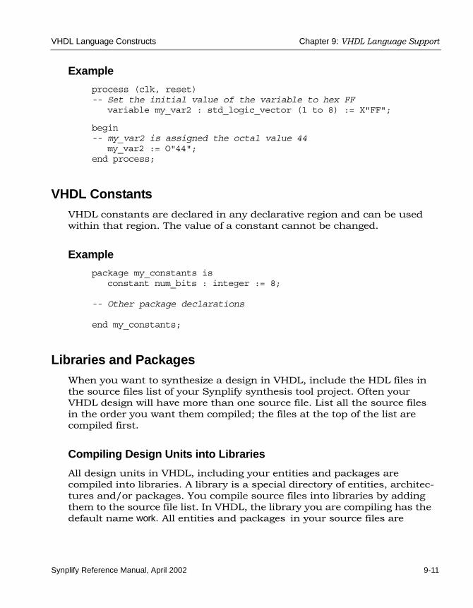
VHDL Language Constructs Chapter 9: VHDL Language Support
Synplify Reference Manual, April 2002 9-11
Example
process (clk, reset)-- Set the initial value of the variable to hex FF
variable my_var2 : std_logic_vector (1 to 8) := X"FF";
begin-- my_var2 is assigned the octal value 44
my_var2 := O"44";end process;
VHDL ConstantsVHDL constants are declared in any declarative region and can be used within that region. The value of a constant cannot be changed.
Example
package my_constants isconstant num_bits : integer := 8;
-- Other package declarations
end my_constants;
Libraries and Packages When you want to synthesize a design in VHDL, include the HDL files in the source files list of your Synplify synthesis tool project. Often your VHDL design will have more than one source file. List all the source files in the order you want them compiled; the files at the top of the list are compiled first.
Compiling Design Units into Libraries
All design units in VHDL, including your entities and packages are compiled into libraries. A library is a special directory of entities, architec-tures and/or packages. You compile source files into libraries by adding them to the source file list. In VHDL, the library you are compiling has the default name work. All entities and packages in your source files are

LO
Chapter 9: VHDL Language Support VHDL Language Constructs
9-12 Synplify Reference Manual, April 2002
automatically compiled into work. You can keep source files anywhere on your disk, even though you add them to libraries. You can have as many libraries as are needed.
1. To add a file to a library, select the file in the Project view.
The library structure is maintained in the Project view. The name of the library to which a file belongs is displayed on the same line as the filename, and directly in front of it.
2. Choose Project -> Set Library from the menu bar, then type the library name. You can add any number of files to a library.
3. If you want to use a design unit that you compiled into a library (one that is no longer in the default work library), you must use a library clause in the VHDL source code to reference it.
For example, if you add a source file for the entity ram16x8 to library my_rams, and instantiate the 16x8 RAM in the design called top_level, you need to add library my_rams; just before defining top_level.
Predefined Packages
The Synplify synthesis tool supports the two standard libraries std and ieee that contain packages (most are now standardized) containing commonly used definitions of data types, functions, and procedures. These libraries and their packages are built in to the synthesis tool, so you never need to compile them. The packages are described in the following table.
Table 9-4: Predefined VHDL libraries and packages
Library Package Description
std standard Defines the basic VHDL types including bit and bit_vector
ieee std_logic_1164 Defines the 9-value std_logic and std_logic_vector types
ieee numeric_std Defines arithmetic operations on types defined in std_logic_1164

VHDL Language Constructs Chapter 9: VHDL Language Support
Synplify Reference Manual, April 2002 9-13
Accessing Packages
To gain access to a package include a library clause in your VHDL source code to specify the library the package is contained in, and a use clause to specify the name of the package. The library and use clauses must be included immediately before the design unit (entity or architecture) that uses the package definitions.
Syntaxlibrary library_name ;use library_name.package_name.all ;
To access the data types, functions and procedures declared in std_logic_1164, std_logic_arith, std_logic_signed, or std_logic_unsigned, you need a library ieee clause and a use clause for each of the packages you want to use.
Examplelibrary ieee;use ieee.std_logic_1164.all ;use ieee.std_logic_signed.all ;
-- Other code
ieee std_logic_arith Defines the signed and unsigned types, and arithmetic operations for the signed and unsigned types
ieee std_logic_signed Defines signed arithmetic for std_logic and std_logic_vector
ieee std_logic_unsigned Defines unsigned arithmetic for std_logic and std_logic_vector
Table 9-4: Predefined VHDL libraries and packages (Continued)
Library Package Description

LO
Chapter 9: VHDL Language Support VHDL Language Constructs
9-14 Synplify Reference Manual, April 2002
Library and Package Rules
To access the standard package, no library or use clause is required. The standard package is predefined (built-in) in VHDL, and contains the basic data types of bit, bit_vector, Boolean, integer, real, character, string, and others along with the operators and functions that work on them.
If you create your own package, and compile it into the work library to access its definitions, you still need a use clause before the entity using them, but not a library clause (because work is the default library.)
To access packages other than those in work and std, you need to provide a library and use clause for each package as shown in the following example of creating a resource library.
-- Compile this in library myliblibrary ieee;use ieee.std_logic_1164.all;
package my_constants isconstant max: std_logic_vector(3 downto 0):="1111";
.
.
.end package;
-- Compile this in library worklibrary ieee, mylib;use ieee.std_logic_1164.all;use mylib.my_constants.all;
entity compare isport(a: in std_logic_vector(3 downto 0);
z: out std_logic);end compare;
architecture rtl of compare isbegin
z <= '1' when (a = max) else '0';end rtl;
Note: The rising_edge and falling_edge functions are defined in the std_logic_1164 package. If you use these functions, your clock signal must to be declared as type std_logic.

VHDL Language Constructs Chapter 9: VHDL Language Support
Synplify Reference Manual, April 2002 9-15
Instantiating Components in a Design
No library or use clause is required to instantiate components (entities and their associated architectures) compiled in the default work library. The files containing the components must be listed in the source files list before the file(s) that instantiates them.
To instantiate components from the built-in technology-vendor macro libraries, you need to include the appropriate use and library clauses in your source code. Refer to the section for your vendor for more informa-tion.
To create a separate resource library to hold your components, put all the entities and architectures in one source file, and assign that source file the library components in the Synplify synthesis tool Project view. To access the components from your source code, put the clause library components; before the designs that instantiates them. There is no need for a use clause.
OperatorsThe Synplify synthesis tool supports creating expressions using all predefined VHDL operators:
Table 9-5: VHDL arithmetic operators
Operator Description
+ addition
- subtraction
* multiplication
/ division (supported for compile-time constants and when divisor is a power of 2)
** exponentiation (supported for compile-time constants and when left operand is 2; right operand can be a variable)
mod modulus (supported for compile-time constants and when right operand is a power of 2)
rem remainder (supported for compile-time constants and when right operand is a power of 2)

LO
Chapter 9: VHDL Language Support VHDL Language Constructs
9-16 Synplify Reference Manual, April 2002
Table 9-6: VHDL relational operators
Operator Description
= equal (if either operand has a bit with an 'X' or 'Z' value, the result is 'X')
/= not equal (if either operand has a bit with an 'X' or 'Z' value, the result is 'X')
< less than (if, because of unknown bits in the operands, the relation is ambiguous, then the result is the unknown value 'X')
<= less than or equal to (if, because of unknown bits in the operands, the relation is ambiguous, then the result is the unknown value 'X')
> greater than (if, because of unknown bits in the operands, the relation is ambiguous, then the result is the unknown value 'X')
>= greater than or equal to (if, because of unknown bits in the operands, the relation is ambiguous, then the result is the unknown value 'X')
Table 9-7: VHDL logical operators
Operator Description
and and
or or
nand nand
nor nor
xor xor
xnor xnor
not not (takes only one operand)

VHDL Language Constructs Chapter 9: VHDL Language Support
Synplify Reference Manual, April 2002 9-17
Note: Initially, X's are treated as don’t cares, but are eventually converted to 0's or 1's, whichever minimizes hardware.
Table 9-8: VHDL shift operators
Operator Description
sll shift left logical – logically shifted left by R index positions
srl shift right logical – logically shifted right by R index positions
sla shift left arithmetic – arithmetically shifted left by R index positions
sra shift right arithmetic – arithmetically shifted right by R index positions
rol rotate left logical – rotated left by R index positions
ror rotate right logical – rotated right by R index positions
Table 9-9: Other VHDL operators
Operator Description
+ identity
- negation
& concatenation

LO
Chapter 9: VHDL Language Support VHDL Language Constructs
9-18 Synplify Reference Manual, April 2002
VHDL ProcessThe VHDL keyword process introduces a block of logic that is triggered to execute when one or more signals change value. Use processes to model combinational and sequential logic.
process Template to Model Combinational Logic
<optional_label> : process (<sensitivity_list>)
-- Declare local variables, data types,-- and other local declarations here
begin-- Sequential statements go here, including:-- signal and variable assignments-- if and case statements-- while and for loops-- function and procedure calls
end process <optional_label>;
Sensitivity List
The sensitivity list specifies the signal transitions that trigger the process to execute. This is analogous to specifying the inputs to logic on a schematic by drawing wires to gate inputs. If there is more than one signal, separate the names with commas.
A warning is issued when a signal is not in the sensitivity list but is used in the process, or when the signal is in the sensitivity list but not used by the process.
Syntax
process (signal1, signal2, ...) ;
A process can have only one sensitivity list, located immediately after the keyword process, or one or more wait statements. If there are one or more wait statements, one of these wait statements must be either the first or last statement in the process.
List all signals feeding into the combinational logic (all signals that affect signals assigned inside the process) in the sensitivity list. If you forget to list all signals, the Synplify synthesis tool generates the desired hardware,

VHDL Language Constructs Chapter 9: VHDL Language Support
Synplify Reference Manual, April 2002 9-19
and reports a warning message that you are not triggering the process every time the hardware is changing its outputs, and therefore your pre- and post-synthesis simulation results might not match.
Any signals assigned in the process must either be outputs specified in the port list of the entity or declared as signals in the architecture declar-ative area.
Any variables assigned in the process are local and must be declared in the process declarative area.
Note: Make sure all signals assigned in a combinational process are explicitly assigned values every time the process executes,. Otherwise, the synthesis tool must insert level-sensitive latches in your design, in order to hold the last value for the paths that don't assign values (if, for example, you have combinational loops in your design). This usually represents coding error, so the synthesis tool issues a warning message that level-sensitive latches are being inserted into the design because of combinational loops. You will get an error message if you have combinational loops in your design that are not recognized as level-sensitive latches.
Common Sequential Statements
if-then-else Statement
Syntaxif condition1 then
sequential_statement(s)[elsif condition2 then
sequential_statement(s)][else
sequential_statement(s)] end if ;
Note: The else and elsif clauses are optional.

LO
Chapter 9: VHDL Language Support VHDL Language Constructs
9-20 Synplify Reference Manual, April 2002
Examplelibrary ieee;use ieee.std_logic_1164.all;entity mux is
port (output_signal : out std_logic;a, b, sel : in std_logic );
end mux;
architecture if_mux of mux isbegin
process (sel, a, b)begin
if sel = '1' thenoutput_signal <= a;
elsif sel = '0' thenoutput_signal <= b;
elseoutput_signal <= 'X';
end if;end process ;
end if_mux;
case Statement
Syntaxcase expression is
when choice1 => sequential_statement(s)when choice2 => sequential _statement(s)
-- Other case choices
when choiceN => sequential_statement(s)end case ;
Note: VHDL requires that the expression match one of the given choices. To create a default, have the final choice be when others => sequential_statement(s) or null. (Null means not to do anything.)

VHDL Language Constructs Chapter 9: VHDL Language Support
Synplify Reference Manual, April 2002 9-21
Examplelibrary ieee;use ieee.std_logic_1164.all;entity mux is
port (output_signal : out std_logic;a, b, sel : in std_logic );
end mux;
architecture case_mux of mux isbegin
process (sel, a, b)begin
case sel iswhen '1' =>
output_signal <= a;when '0' =>
output_signal <= b;when others =>
output_signal <= 'X';end case;
end process;end case_mux;
Concurrent Signal AssignmentsThere are three types of concurrent signal assignments in VHDL.
• Simple
• Selected (with-select-when)
• Conditional (when-else)
Use the concurrent signal assignment to model combinational logic. Put the concurrent signal assignment in the architecture body. You can have as many statements as you need to describe the implementation of your hardware. Because all statements are concurrently active, the order you place them in the architecture body is not important.

LO
Chapter 9: VHDL Language Support VHDL Language Constructs
9-22 Synplify Reference Manual, April 2002
Re-evaluation of Signal Assignments
Every time any signal on the right side of the assignment operator (<=) changes value (including signals used in the expressions, values, choices, or conditions), the assignment statement is re-evaluated, and the result is assigned to the signal on the left side of the assignment operator. You can use any of the predefined operators to create the assigned value.
Simple Signal Assignments
Syntaxsignal <= expression ;
Example architecture simple_example of simple isbegin
c <= a nand b ;end simple_example;
Selected Signal Assignments
Syntax with expression selectsignal <= value1 when choice1 ,
value2 when choice2 ,...valueN when choiceN ;
Examplelibrary ieee;use ieee.std_logic_1164.all;entity mux is
port (output_signal : out std_logic;a, b, sel : in std_logic );
end mux;

VHDL Language Constructs Chapter 9: VHDL Language Support
Synplify Reference Manual, April 2002 9-23
architecture with_select_when of mux isbegin
with sel select output_signal <= a when '1',
b when '0','X' when others;
end with_select_when;
Conditional Signal Assignments
Syntaxsignal <= value1 when condition1 else
value2 when condition2 elsevalueN-1 when conditionN-1 elsevalueN ;
Examplelibrary ieee;use ieee.std_logic_1164.all;entity mux is
port (output_signal: out std_logic;a, b, sel: in std_logic);
end mux;
architecture when_else_mux of mux isbeginoutput_signal <= a when sel = '1' else
b when sel = '0' else'X';
end when_else_mux;
Resource SharingWhen you have mutually exclusive operators in a case statement, the Synplify synthesis tool shares resources for the operators in the case statements. For example, automatic sharing of operator resources includes adders, subtractors, incrementors, decrementors, and multi-pliers.

LO
Chapter 9: VHDL Language Support VHDL Language Constructs
9-24 Synplify Reference Manual, April 2002
Combinational LogicCombinational logic is hardware in which the output values are based on some function of the current input values. There is no clock and no saved states. Most hardware is a mixture of combinational and sequential logic.
Create combinational logic with concurrent signal assignments and/or processes.
Sequential Logic Sequential logic is hardware that has an internal state or memory. The state elements are either flip-flops that update on the active edge of a clock signal, or level-sensitive latches, that update during the active level of a clock signal.
Because of the internal state, the output values might depend not only on the current input values, but also on input values at previous times. State machines are made of sequential logic in which the updated state values depend on the previous state values. There are standard ways of modeling state machines in VHDL. Most hardware is a mixture of combinational and sequential logic.
Create sequential logic with processes and/or concurrent signal assign-ments.
Component Instantiation in VHDLA structural description of a design is made up of component instantia-tions that describe the subsystems of the design and their signal inter-connects. The Synplify synthesis tool supports four major methods of component instantiation:
• Simple component instantiation (described below)
• Selected component instantiation
• Direct entity instantiation
• Configurations described in Configuration Specification on page 9-60

VHDL Language Constructs Chapter 9: VHDL Language Support
Synplify Reference Manual, April 2002 9-25
Simple Component Instantiation
In this method, a component is first declared either in the declaration region of the architecture, or in a package of (typically) component decla-rations, and then instantiated in the architecture’s statement region. By default, the synthesis process binds a named entity (and architecture) in the working library to all component instances that specify a component declaration with the same name.
Syntaxlabel : [component] declaration_name
[generic map (actual_generic1, actual_generic2, ... ) ][port map ( port1, port2, ... ) ] ;
The use of the reserved word component is optional in component instantia-tions.
Example: VHDL 1987architecture struct of hier_add iscomponent add
generic (size : natural);port (a : in bit_vector(3 downto 0);b : in bit_vector(3 downto 0);result : out bit_vector(3 downto 0));
end component;
begin-- Simple component instantiationadd1: add
generic map(size => 4)port map(a => ain,
b => bin,result => q);
-- Other code

LO
Chapter 9: VHDL Language Support VHDL Language Constructs
9-26 Synplify Reference Manual, April 2002
Example: VHDL 1993architecture struct of hier_add iscomponent add
generic (size : natural);port (a : in bit_vector(3 downto 0);
b : in bit_vector(3 downto 0);result : out bit_vector(3 downto 0));
end component;
begin-- Simple component instantiationadd1: component add -- Component keyword new in 1993
generic map(size => 4)port map(a => ain,
b => bin, result => q);
-- Other code
Note: If no entity is found in the working library named the same as the declared component, all instances of the declared compo-nent are mapped to a black box and the error message “Unbound component mapped to black box” is issued.
VHDL Selected Name SupportSelected Name Support (SNS) is provided in VHDL for constants, opera-tors, and functions in library packages. SNS eliminates ambiguity in a design referencing elements with the same names, but that have unique functionality when the design uses the elements with the same name defined in multiple packages. By specifying the library, package, and specific element (constant, operator, or function), SNS designates the specific constant, operator, or function used. This section discusses all facets of SNS. Complete VHDL examples are included to assist you in understanding how to use SNS effectively.

VHDL Language Constructs Chapter 9: VHDL Language Support
Synplify Reference Manual, April 2002 9-27
Constants
SNS lets you designate which constant to use from multiple library packages. To incorporate a constant into a design, specify the library, package, and constant. Using this feature eliminates ambiguity when multiple library packages have identical names for constants and are used in an entity-architecture pair.
The following example has two library packages available to the design CONSTANTS. Each library package has a constant defined by the name C1 and each has a different value. To distinguish between the constants and determine which one is used, SNS is used to specify the constant (see WORK.PACKAGE.C1 in the constants example below).
-- CONSTANTS PACKAGE1library IEEE;use IEEE.std_logic_1164.all;package PACKAGE1 is
constant Cl: std_logic_vector := "10001010";end PACKAGE1;
-- CONSTANTS PACKAGE2library IEEE;use IEEE.std_logic_1164.all;package PACKAGE2 is
constant C1: std_logic_vector := "10110110";end PACKAGE2;
-- CONSTANTS EXAMPLElibrary IEEE;use IEEE.std_logic_1164.all;use IEEE.std_logic_arith.all;use IEEE.std_logic_unsigned.all;
entity CONSTANTS isgeneric (num_bits : integer := 8) ;
port (a,b: in std_logic_vector (num_bits -1 downto 0);out1, out2: out std_logic_vector (num_bits -1 downto 0)
);end CONSTANTS;
architecture RTL of CONSTANTS isbegin
out1 <= a + work.PACKAGE1.Cl; --Example of specifying SNS out2 <= b + work.PACKAGE2.C1; --Example of specifying SNS
end RTL;

LO
Chapter 9: VHDL Language Support VHDL Language Constructs
9-28 Synplify Reference Manual, April 2002
In the above design, outputs out1 and out2 use two C1 constants from two different packages. Although each output uses a constant named C1, the constants are not equivalent. For out1, the constant C1 is from PACKAGE1. For out2, the constant C1 is from PACKAGE2. For example:
out1 <= a + work.PACKAGE1.Cl; is equivalent to out1 <= a + "10001010";
whereas:
out2 <= b + work.PACKAGE2.Cl; is equivalent to out2 <= b + "10110110";
The constants have different values in different packages. SNS specifies the package and eliminates ambiguity within the design.
Functions and Operators
Functions and operators in VHDL library packages customarily have overlapping naming conventions. For example, the add operator in the IEEE standard library exists in both the std_logic_signed and std_logic_unsigned packages. Depending upon which add operator is used, different values result. Defining only one of the IEEE library packages is a straightforward solution to eliminate ambiguity, but applying this solution is not always possible. A design requiring both std_logic_signed and std_logic_unsigned package elements must use SNS to eliminate ambiguity.
FunctionsIn the following example, multiple IEEE packages are declared in a 256x8 RAM design. Both std_logic_signed and std_logic_unsigned packages are included. In the RAM definition, the signal address_in is converted from type std_logic_vector to type integer using the CONV_INTEGER function, but which CONV_INTEGER function will be called? SNS determines which function the design uses. The RAM definition clearly declares the std_logic_unsigned package as the source for the CONV_INTEGER function.
library IEEE;use IEEE.std_logic_1164.all;use IEEE.std_logic_unsigned.all;use IEEE.std_logic_arith.all;use IEEE.std_logic_signed.all;use IEEE.numeric_std.all;

VHDL Language Constructs Chapter 9: VHDL Language Support
Synplify Reference Manual, April 2002 9-29
entity FUNCTIONS isport( address : in std_logic_vector(7 downto 0);
data_in : in std_logic_vector(7 downto 0);data_out : out std_logic_vector(7 downto 0);we : in std_logic;clk : in std_logic
);
end FUNCTIONS;
architecture RTL of FUNCTIONS is
type mem_type is array (255 downto 0) of std_logic_vector (7 downto 0); signal mem: mem_type;signal address_in: std_logic_vector(7 downto 0);
begin data_out <= mem(IEEE.std_logic_unsigned.CONV_INTEGER(address_in));process (clk)
begin if rising_edge(clk) then
if (we = '1') thenmem(IEEE.std_logic_unsigned.CONV_INTEGER(address_in))<= data_in;
end if; address_in <= address;
end if; end process;end RTL;
OperatorsIn this example, comparator functions from the IEEE std_logic_signed and std_logc_unsigned library packages are used. Depending upon which comparator is called, a signed or an unsigned comparison results. In the assigned outputs below, the op1 and op2 functions show the valid SNS syntax for operator implementation.
library IEEE;use IEEE.std_logic_1164.std_logic_vector;use IEEE.std_logic_signed.">";use IEEE.std_logic_unsigned.">";

LO
Chapter 9: VHDL Language Support VHDL Language Constructs
9-30 Synplify Reference Manual, April 2002
entity OPERATORS isport (
in1 :std_logic_vector(1 to 4);in2 :std_logic_vector(1 to 4);in3 :std_logic_vector(1 to 4);in4 :std_logic_vector(1 to 4);op1,op2 :out boolean
);end OPERATORS;
architecture RTL of OPERATORS isbegin
process(in1,in2,in3,in4)begin
--Example of specifying SNSop1 <= IEEE.std_logic_signed.">"(in1,in2);
--Example of specifying SNSop2 <= IEEE.std_logic_unsigned.">"(in3,in4);
end process;end RTL;
User-defined Function SupportSNS is not limited to predefined standard IEEE packages and packages supported by the Synplify synthesis tool; SNS also supports user-defined packages. You can create library packages that access constants, opera-tors, and functions in the same manner as the packages supported by IEEE or the synthesis tool.
The following example incorporates two user-defined packages in the design. Each package includes a function named func. In PACKAGE1, func is an XOR gate, whereas in PACKAGE2, func is an AND gate. Depending on which package is called, func results in either an XOR or an AND gate. The function call uses SNS to distinguish which function is called.
-- USER DEFINED PACKAGE1library IEEE;use IEEE.std_logic_1164.all;package PACKAGE1 is
function func(a,b: in std_logic) return std_logic; end PACKAGE1;

VHDL Language Constructs Chapter 9: VHDL Language Support
Synplify Reference Manual, April 2002 9-31
package body PACKAGE1 isfunction func(a,b: in std_logic) return std_logic is
beginreturn(a xor b);
end func;end PACKAGE1;
-- USER DEFINED PACKAGE2library IEEE;use IEEE.std_logic_1164.all;
package PACKAGE2 isfunction func(a,b: in std_logic) return std_logic;
end PACKAGE2;
package body PACKAGE2 isfunction func(a,b: in std_logic) return std_logic is
beginreturn(a and b);
end func;end PACKAGE2;
-- USER DEFINED FUNCTION EXAMPLElibrary IEEE;use IEEE.std_logic_1164.all;
entity USER_DEFINED_FUNCTION isport (
in0: in std_logic;in1: in std_logic;out0: out std_logic;out1: out std_logic
);end USER_DEFINED_FUNCTION;
architecture RTL of USER_DEFINED_FUNCTION isbegin
out0 <= work.PACKAGE1.func(in0, in1);out1 <= work.PACKAGE2.func(in0, in1);
end RTL;

LO
Chapter 9: VHDL Language Support VHDL Language Constructs
9-32 Synplify Reference Manual, April 2002
Demand LoadingIn the previous section, the user-defined function example successfully uses SNS to determine which func function to implement. However, neither PACKAGE1 nor PACKAGE2 was declared as a use package clause (for example, work.PACKAGE1.all;). How could func have been executed without a use package declaration? A feature of SNS is demand loading, which loads the necessary package without explicit use declarations. Demand loading lets you create designs using SNS without use package declarations, which supports all necessary constants, operators, and functions.

VHDL Synthesis Guidelines Chapter 9: VHDL Language Support
Synplify Reference Manual, April 2002 9-33
VHDL Synthesis Guidelines
General Synthesis GuidelinesSome general guidelines are presented here to help you synthesize your VHDL design.
• Top-level entity and architecture. The Synplify synthesis tool chooses the top-level entity and architecture – the last architecture for the last entity in the last file compiled. Entity selection can be overridden from the VHDL panel of the Options for Implementation dialog box. Files are compiled in the order in which they appear – from top to bottom in the Project view source files list.
• Simulate your design before synthesis because it exposes logic errors. Logic errors that are not caught are passed through the synthesis tool, and the synthesized results will contain the same logic errors.
• Simulate your design after placement and routing. Have the place-and-route tool generate a post placement and routing (timing-accurate) simulation netlist, and do a final simulation before programming your devices.
• Avoid asynchronous state machines. To use the synthesis tool for asynchronous state machines, make a netlist of technology primi-tives from your target library.
• For modeling level-sensitive latches, it is simplest to use concurrent signal assignments.
VHDL Language GuidelinesThis section discusses VHDL language guidelines.
Processes
• A process must have either a sensitivity list or one wait statement.
• Each sequential process can be triggered from exactly one clock and only one edge of clock (and optional sets and resets).

LO
Chapter 9: VHDL Language Support VHDL Synthesis Guidelines
9-34 Synplify Reference Manual, April 2002
• Avoid combinational loops in processes. Make sure all signals assigned in a combinational process are explicitly assigned values every time the process executes; otherwise, the Synplify synthesis tool needs to insert level-sensitive latches in your design to hold the last value for the paths that don’t assign values. This might repre-sent a mistake on your part, so the Synplify synthesis tool issues a warning message that level-sensitive latches are being inserted into your design. You will get an warning message if you have combina-tional loops in your design that are not recognized as level-sensitive latches (for example, if you have an asynchronous state machine).
Assignments
• Assigning an 'X' or '-' to a signal is interpreted as a “don't care”, so the Synplify synthesis tool creates the hardware that is the most efficient design.
Data Types
• Integers are 32-bit quantities. If you declare a port to be an “integer” data type, you should specify a range (for example, my_input: in integer range 0 to 7). Otherwise, your synthesis result file will contain a 32-bit port.
• Enumeration types are represented as a vector of bits. The encoding can be sequential, gray, or one hot. You might need to manually choose the encoding for ports with an enumeration type.
Model Template You can place any number of concurrent statements (signal assignments, processes, component instantiations, and generate statements) in your architecture body as shown in the following example. The order of these statements within the architecture is not important as all can execute concurrently.
• The statements between the begin and the end in a process execute sequentially, in the order you type them from top to bottom.
• You can add comments in VHDL by proceeding your comment text with two dashes “--”. Any text from the dashes to the end of the line is treated as a comment, and ignored by the Synplify synthesis tool.

VHDL Synthesis Guidelines Chapter 9: VHDL Language Support
Synplify Reference Manual, April 2002 9-35
-- List libraries/packages that contain definitions you uselibrary <library_name> ;use <library_name>.<package_name>.all ;
-- The entity describes the interface for your design.entity <entity_name> is
generic ( <define_interface_constants_here> ) ;port ( <port_list_information_goes_here> ) ;
end <entity_name> ;
-- The architecture describes the functionality (implementation) -- of your designarchitecture <architecture_name> of <entity_name> is
-- Architecture declaration region. -- Declare internal signals, data types, and subprograms here
-- If you will create hierarchy by instantiating a-- component (which is just another architecture), then-- declare its interface here with a component declaration;component <entity_name_instantiated_below>
port (<port_list_information_as_defined_in_the_entity>) ;end component ;
begin -- Architecture body, describes functionality
-- Use concurrent statements here to describe the functionality -- of your design. The most common concurrent statements are the-- concurrent signal assignment, process, and component-- instantiation.
-- Concurrent signal assignment (simple form):<result_signal_name> <= <expression> ;
-- Process:process <sensitivity list>)-- Declare local variables, data types,-- and other local declarations herebegin-- Sequential statements go here, including:
-- signal and variable assignments-- if and case statements-- while and for loops-- function and procedure calls
end process;

LO
Chapter 9: VHDL Language Support VHDL Synthesis Guidelines
9-36 Synplify Reference Manual, April 2002
-- Component instantiation <instance_name> : <entity_name>
generic map (<override values here >)port map (<port list>) ;
end <architecture_name> ;
Creating Flip-flops and Registers Using VHDL ProcessesIt is easy to create flip-flops and registers using a process in your VHDL design.
process Template
process (<sensitivity list>)begin
<sequential statement(s)>end;
To create a flip-flop:
1. List your clock signal in the sensitivity list. Recall that if the value of any signal listed in the sensitivity list changes, the process is triggered, and executes. For example,
process (clk)
2. Check for rising_edge or falling_edge as the first statement inside the process. For example,
process (clk)beginif rising_edge(clk) then<sequential statement(s)>
or
process (clk)beginif falling_edge(clk) then<sequential statement(s)>

VHDL Synthesis Guidelines Chapter 9: VHDL Language Support
Synplify Reference Manual, April 2002 9-37
Note: Alternatively you could use an if clk'event and clk = '1' then state-ment to test for a rising edge (or if clk'event and clk = '0' then for a falling edge). Although these statements work, for clarity and consistency, use the rising_edge and falling_edge functions from the VHDL 1993 standard.
3. Set your flip-flop output to a value, with no delay, if the clock edge occurred. For example, q <= d ;.
Complete Example
library ieee;use ieee.std_logic_1164.all;
entity dff_or is port (a, b, clk: in std_logic;
q: out std_logic);end dff_or;
architecture sensitivity_list of dff_or isbeginprocess (clk) -- Clock name is in sensitivity listbegin
if rising_edge(clk) thenq <= a or b;
end if;end process;end sensitivity_list ;
In this example, if clk has an event on it, the process is triggered and starts executing. The first statement (the if statement) then checks to see if a rising edge has occurred for clk. If the if statement evaluates to true, there was a rising edge on clk and the q output is set to the value of a or b. If the clk changes from 1 to 0, the process is triggered and the if statement executes, but it evaluates to false and the q output is not updated. This is the functionality of a flip-flop, and synthesis correctly recognizes it as such and connects the result of the a or b expression to the data input of a D-type flip-flop and the q signal to the q output of the flip-flop.
Note: The signals you set inside the process will drive the data inputs of D-type flip-flops.

LO
Chapter 9: VHDL Language Support VHDL Synthesis Guidelines
9-38 Synplify Reference Manual, April 2002
Clock EdgesThere are many ways to correctly represent clock edges within a process including those shown here.
The recommended rising clock edge representation is:
rising_edge(clk) -- Easiest
Other supported rising clock edge representations are:
clk = '1' and clk'eventclk'last_value = '0' and clk'eventclk'event and clk /= '0'
The recommended falling clock edge representation is:
falling_edge(clk) -- Easiest
Other supported falling clock edge representations are:
clk = '0' and clk'eventclk'last_value = '1' and clk'eventclk'event and clk /= '1'
Incorrect or Unsupported Representations for Clock Edges
Rising clock edge:
clk = '1'clk and clk'event -- Because clk is not a Boolean
Falling clock edge:
clk = '0'not clk and clk'event -- Because clk is not a Boolean

VHDL Synthesis Guidelines Chapter 9: VHDL Language Support
Synplify Reference Manual, April 2002 9-39
Defining an Event Outside a ProcessThe 'event attribute can be used outside of a process block. For example, the process block
process (clk,d)begin
if (clk='1' and clk'event) thenq <= d;
end if;end process;
can be replaced by including the following line outside of the process state-ment:
q <= d when (clk='1' and clk'event);
Using a WAIT Statement Inside a ProcessThe Synplify synthesis tool supports a wait statement inside a process to create flip-flops, instead of using a sensitivity list.
Example
library ieee;use ieee.std_logic_1164.all;entity dff_or is
port (a, b, clk: in std_logic;q: out std_logic);
end dff_or;
architecture wait_statement of dff_or isbeginprocess -- Note the absence of a sensitivity list.begin-- The process waits here until the condition becomes true
wait until rising_edge(clk);q <= a or b;
end process;
end wait_statement;

LO
Chapter 9: VHDL Language Support VHDL Synthesis Guidelines
9-40 Synplify Reference Manual, April 2002
Rules for Using wait Statements Inside a Process
• It is illegal in VHDL to have a process with a wait statement and a sensitivity list.
• The wait statement must either be the first or the last statement of the process.
Clock Edge Representation in wait Statements
The recommended rising clock edge representation is:
wait until rising_edge(clk);
Other supported rising clock edge representations are:
wait until clk = '1' and clk'eventwait until clk'last_value = '0' and clk'eventwait until clk'event and clk /= '0'
The recommended falling clock edge representation is:
wait until falling_edge(clk)
Other supported falling clock edge representations are:
wait until clk = '0' and clk'eventwait until clk'last_value = '1' and clk'eventwait until clk'event and clk /= '1'
Level-sensitive Latches Using Concurrent Signal AssignmentsTo model level-sensitive latches in VHDL, we recommend using a concur-rent signal assignment statement. You would use the conditional signal assignment form (also known as when-else).
Syntax
signal <= value1 when condition1 elsevalue2 when condition2 elsevalueN-1 when conditionN-1 elsevalueN ;

VHDL Synthesis Guidelines Chapter 9: VHDL Language Support
Synplify Reference Manual, April 2002 9-41
Example
In VHDL, you are not allowed to read the value of ports of mode out inside of an architecture that it was declared for. Ports of mode buffer can be read from and written to, but must have no more than one driver for the port in the architecture. In the following port statement example, q is defined to be of mode buffer.
library ieee;use ieee.std_logic_1164.all;entity latchor1 is
port (a, b, clk : in std_logic;-- q has mode buffer so it can be read inside architecture
q: buffer std_logic );end latchor1;
architecture behave of latchor1 isbegin
q <= a or b when clk = '1' else q;end behave;
Whenever clk, a, or b changes, the expression on the right side re-evalu-ates. If clk becomes true (active, logic 1), the value of a or b is assigned to the q output. When the clk changes and becomes false (deactivated), q is assigned to q (holds the last value of q). If a or b changes, and clk is already active, the new value of a or b is assigned to q.
Level-sensitive Latches Using VHDL ProcessesAlthough it is simpler to specify level-sensitive latches using concurrent signal assignment statements, you can create level-sensitive latches with VHDL processes. Follow the guidelines given here for the sensitivity list and assignments.
process Template
process (<sensitivity list>)begin
<sequential statement(s)>end process;

LO
Chapter 9: VHDL Language Support VHDL Synthesis Guidelines
9-42 Synplify Reference Manual, April 2002
Sensitivity List
The sensitivity list specifies the clock signal, and the signals that feed into the data input of the level-sensitive latch. The sensitivity list must be located immediately after the process keyword.
Syntaxprocess (clock_name, signal1, signal2, ...)
Exampleprocess (clk, data)
process Template for a Level-sensitive Latchprocess (<clock, data_signals ... > ...)begin
if (<clock> = <active_value>)<signals> <= <expression involving data signals> ;end if;
end process ;
All data signals assigned in this manner become logic into data inputs of level-sensitive latches.
Note: Whenever level-sensitive latches are generated from a process, the Synplify synthesis tool issues a warning message so that you can verify if level-sensitive latches are really what you intended. Often a thorough simulation of your architecture will reveal mistakes in coding style that would cause level-sensitive latches to be created during synthesis.
Example: Creating Level-sensitive Latches that You Wantlibrary ieee;use ieee.std_logic_1164.all;entity latchor2 is
port (a, b, clk : in std_logic ;q: out std_logic );
end latchor2;

VHDL Synthesis Guidelines Chapter 9: VHDL Language Support
Synplify Reference Manual, April 2002 9-43
architecture behave of latchor2 isbeginprocess (clk, a, b)begin
if clk = '1' thenq <= a or b;
end if;end process ;end behave;
If there is an event (change in value) on either clk, a or b, and clk is a logic 1, set q to a or b.
Notice that we did not specify what to do when clk is a logic 0 (there is no else) so when clk is a logic zero, the last value assigned is maintained (there is an implicit q=q). The Synplify synthesis tool correctly recognizes this as a level-sensitive latch, and creates a level-sensitive latch in your design. It will issue a warning message when you compile this architecture, but after examination, this warning message can safely be ignored.
Example: Creating Unwanted Level-sensitive LatchesThis design demonstrates the level-sensitive latch warning caused by a missed assignment in the when two => case. The message generated is:
"Latch generated from process for signal odd, probably caused by a missing assignment in an if or case statement".
This information will help you find a functional error even before simula-tion.
library ieee;use ieee.std_logic_1164.all;entity mistake is
port (inp: in std_logic_vector (1 downto 0);outp: out std_logic_vector (3 downto 0);even, odd: out std_logic);
end mistake;
architecture behave of mistake isconstant zero: std_logic_vector (1 downto 0):= "00";constant one: std_logic_vector (1 downto 0):= "01";constant two: std_logic_vector (1 downto 0):= "10";constant three: std_logic_vector (1 downto 0):= "11";
beginprocess (inp)

LO
Chapter 9: VHDL Language Support Sets and Resets
9-44 Synplify Reference Manual, April 2002
begincase inp is
when zero =>outp <= "0001";even <= '1';odd <= '0';
when one =>outp <= "0010";even <= '0';odd <= '1';
when two =>outp <= "0100";even <= '1';
-- Note that assignment to odd is mistakenly commented out next.-- odd <= '0';
when three =>outp <= "1000";even <= '0';odd <= '1';
end case;end process;end behave;
Sets and Resets
A set signal is an input to a flip-flop that, when activated, sets the state of the flip-flop to a logic one.
A reset signal is an input to a flip-flop that, when activated, sets the state of the flip-flop to a logic zero.
Asynchronous Sets and ResetsBy definition, asynchronous sets and resets are independent of the clock and do not require an active clock edge. Therefore, you must include the set and reset signals in the sensitivity list of your process so they trigger the process to execute.

Sets and Resets Chapter 9: VHDL Language Support
Synplify Reference Manual, April 2002 9-45
Sensitivity List
The sensitivity list is a list of signals (including ports) that, when there is an event (change in value), triggers the process to execute.
Syntaxprocess (clk_name, set_signal_name, reset_signal_name )
The signals are listed in any order, separated by commas.
Example: process Template with Asynchronous, Active-high reset, setprocess (clk, reset, set)begin
if reset = '1' then-- Reset the outputs to zero.
elsif set = '1' then-- Set the outputs to one.
elsif rising_edge(clk) then -- Rising clock edge clock-- Clocked logic goes here.
end if;end process;
Example: D Flip-flop with Asynchronous, Active-high reset, setlibrary ieee;use ieee.std_logic_1164.all;entity dff1 is
port (data, clk, reset, set : in std_logic;qrs: out std_logic);
end dff1;
architecture async_set_reset of dff1 isbeginsetreset: process(clk, reset, set)
beginif reset = '1' then
qrs <= '0';elsif set = '1' then
qrs <= '1';elsif rising_edge(clk) then
qrs <= data;end if;
end process setreset;end async_set_reset;

LO
Chapter 9: VHDL Language Support Sets and Resets
9-46 Synplify Reference Manual, April 2002
Synchronous Sets and Resets Synchronous sets and resets set flip-flop outputs to logic '1' or '0' respec-tively on an active clock edge.
Do not list the set and reset signal names in the sensitivity list of a process because they should not trigger the process to execute upon changing. Instead, trigger the process when the clock signal changes, and then check the reset and set as the first statements.
RTL View Primitives
The VHDL compiler can detect and extract the following flip-flops with synchronous sets and resets and display them in the RTL schematic view:
• sdffr—flip-flop with synchronous reset
• sdffs—flip-flop with synchronous set
• sdffrs—flip-flop with both synchronous set and reset
• sdffpat—vectored flip-flop with synchronous set/reset pattern
• sdffre—enabled flip-flop with synchronous reset
• sdffse—enabled flip-flop with synchronous set
• sdffpate—enabled, vectored flip-flop with synchronous set/reset pattern
Note: You can check the name (type) of any primitive by placing your mouse pointer over it in the RTL view; a tooltip displays the name.

Sets and Resets Chapter 9: VHDL Language Support
Synplify Reference Manual, April 2002 9-47
Figure 9-1: Flip-flops with synchronous sets and resets
Sensitivity List
The sensitivity list is a list of signals (including ports) that, when there is an event (change in value), triggers the process to execute.
Syntaxprocess (clk_signal_name )
Example: process Template with Synchronous, Active-high reset, setprocess(clk)begin
if rising_edge(clk) thenif reset = '1' then
-- Set the outputs to '0'.elsif set = '1' then
-- Set the outputs to '1'.else
-- Clocked logic goes here.end if ;
end if ;end process;

LO
Chapter 9: VHDL Language Support Sets and Resets
9-48 Synplify Reference Manual, April 2002
Example: D Flip-flop with Synchronous, Active-high reset, setlibrary ieee;use ieee.std_logic_1164.all;entity dff2 is
port (data, clk, reset, set : in std_logic;qrs: out std_logic);
end dff2;
architecture sync_set_reset of dff2 isbeginsetreset: process (clk)begin
if rising_edge(clk) thenif reset = '1' then
qrs <= '0';elsif set = '1' then
qrs <= '1';else
qrs <= data;end if;
end if;end process setreset;
end sync_set_reset;

State Machines Chapter 9: VHDL Language Support
Synplify Reference Manual, April 2002 9-49
State Machines
State Machine GuidelinesA finite state machine (FSM) is hardware that advances from state to state at a clock edge.
The Synplify synthesis tool works best with synchronous state machines. The recommended practice is to write a fully synchronous design, avoiding asynchronous paths such as those through the asynchronous reset of a register. See Asynchronous State Machines in VHDL on page 9-54 for information about asynchronous state machines.
The following are guidelines for coding FSMs:
• The state machine must have a synchronous or asynchronous reset to be inferred. State machines must have an asynchronous or synchronous reset to set the hardware to a valid state after power-up, and to reset your hardware during operation (asynchro-nous resets are available freely in most FPGA architectures).
• The synthesis tool does not infer implicit state machines that are created using multiple wait statements in a process.
• Separate the sequential process statements from the combinational ones. Besides making it easier to read, it makes what is being regis-tered very obvious. It also gives better control over the type of register element used.
• Represent states with defined labels or enumerated types.
• It is easiest to use a case statement in a process to check the current state at the clock edge, advance to the next state, and set the output values. You can also use if-then-else statements.
• Assign default values to outputs derived from the FSM before the case statement. This helps prevent the generation of unwanted latches and makes it easier to read because there is less clutter from rarely used signals.
• If you do not have case statements for all possible combinations of the selector, use a when others assignment as the last assignment in your case statement and set the state vector to some valid state. If your state vector is not an enumerated type, set the value to X. Assign the

LO
Chapter 9: VHDL Language Support State Machines
9-50 Synplify Reference Manual, April 2002
state to X in the default clause of the case statement, to avoid mismatches between pre- and post-synthesis simulations. See Example: Default Assignment on page 9-52.
• Override the default encoding style with the syn_encoding attribute. The default encoding is determined by the number of states. However, if you have a syn_encoding attribute, its value is used during the mapping stage to determine encoding style.
attribute syn_encoding : string;attribute syn_encoding of <typename> : type is “sequential”;
See Chapter 7, Synthesis Attributes and Directives, for details about the syntax and values.
One-hot implementations are not always the best choice for state machines, even in FPGAs and CPLDs. For example, one-hot state machines might result in higher speeds in CPLDs, which can cause fitting problems because of the larger number of global signals. An example in an FPGA in which one-hot implementation is most ineffective is when the state machine drives a large decoder, gener-ating many output signals. In a 16-state state machine, for example, the output decoder logic might reference sixteen signals in a one-hot implementation, but only four signals in an encoded representation.
In general, do not use syn_enum_encoding to set the encoding style. Use syn_encoding instead. The value of syn_enum_encoding is used by the compiler to interpret the enumerated data types but is ignored by the mapper when the state machine is actually implemented. syn_enum_encoding affects the final circuit only when you have turned off the FSM Compiler. Therefore, if you are not using FSM Compiler or the syn_state_machine attribute, both of which use syn_encoding, you can use syn_enum_encoding to set the encoding style. See Chapter 7, Synthesis Attributes and Directives, for details about the syntax and values.

State Machines Chapter 9: VHDL Language Support
Synplify Reference Manual, April 2002 9-51
Example: FSM Coding Style
architecture behave of test istype state_value is (deflt, idle, read, write);signal state, next_state: state_value;
begin
-- Figure out the next stateprocess (clk, rst)begin
if rst = '0' thenstate <= idle;
elsif rising_edge(clk) thenstate <= next_state;
end if;end process;process (state, enable, data_in)
begindata_out <= '0';-- Catch missing assignments to next_statenext_state <= idle; state0 <= '0';state1 <= '0';state2 <= '0';case state is
when idle =>if enable = '1' then
state0 <= '1' ;data_out <= data_in(0);next_state <= read;
else next_state <= idle;end if;
when read =>if enable = '1' then
state1 <= '1'; data_out <= data_in(1);next_state <= write;
else next_state <= read;end if;
when deflt =>if enable = '1' then
state2 <= '1' ;data_out <= data_in(2);next_state <= idle;
else next_state <= write;

LO
Chapter 9: VHDL Language Support State Machines
9-52 Synplify Reference Manual, April 2002
end if;when others => next_state <= deflt;
end case;end process;
end behave;
Example: Default Assignment
The second others keyword in the following example pads (covers) all the bits. In this way, you do not need to remember the exact number of X’s needed for the state variable or output signal.
when others =>state := (others => 'X') ;
Assigning X to the state variable (which is a “don’t-care” for synthesis) tells the Synplify synthesis tool that you have specified all the used states in your case statement, and any unnecessary decoding and gates related to other cases can therefore be removed. You do not have to add any special, non-VHDL directives.
If you set the state to a used state for the when others case (for example: when others => state <= delft), the synthesis tool generates the same logic as if you assign X, but there will be pre- and post-synthesis simulation mismatches until you reset the state machine.These mismatches occur because all inputs are unknown at start up on the simulator. You there-fore go immediately into the when others case, which sets the state variable to state1. When you power up the hardware, it can be in a used state, such as state2, and then advance to a state other than state1. Post-synthesis simulation behaves more like hardware with respect to initialization.
Using Enumerated Types for State ValuesGenerally, you represent states in VHDL with a user-defined enumerated type.
Syntax
type type_name is ( state1_name, state2_name, ... , stateN_name ) ;

State Machines Chapter 9: VHDL Language Support
Synplify Reference Manual, April 2002 9-53
Example
type states is (st1, st2, st3, st4, st5, st6, st7, st8);begin -- The statement region of a process or subprogram.next_state := st2 ;-- Setting the next state to st2
Simulation Tips When Using Enumerated TypesInitialization in simulation should mimic the behavior of hardware when it powers up. Therefore, you should not initialize your state machine to a known state during simulation, because the hardware will not be in a known state when it powers up.
Creating an Extra Initialization State
If you use an enumerated type for your state vector, create an extra initial-ization state in your type definition (for example, stateX), and place it first in the list, as shown in the example below.
type state is (stateX, state1, state2, state3, state4);
In VHDL, the default initial value for an enumerated type is the leftmost value in the type definition (in this example, stateX). When you begin the simulation, you will be in this initial (simulation only) state.
Detecting Reset Problems
In your state machine case statement, create an entry for staying in stateX when you get in stateX. For example:
when stateX => next_state := stateX;
Look for your design entering stateX. This means that your design is not resetting properly.
Note: The Synplify synthesis tool does not create hardware to repre-sent this initialization state (stateX). It is removed during opti-mization.

LO
Chapter 9: VHDL Language Support State Machines
9-54 Synplify Reference Manual, April 2002
Detecting Forgotten Assignment to the Next State
Assign your next state value to stateX right before your state machine case statement.
Examplenext_state := stateX;case (current_state) is...
when state3 =>if (foo = '1') then
next_state := state2;end if;
...end case;
Asynchronous State Machines in VHDLAvoid defining asynchronous state machines in VHDL. An asynchronous state machine has states, but no clearly defined clock, and has combina-tional loops. However, if you must use asynchronous state machines, you can do one of the following.
• Create a netlist of the technology primitives from your technology-vendor’s target library. Any instantiated primitives that are left in the netlist are not removed during optimization.
• Use a schematic editor for the asynchronous state machine part of your design.
Do not use the Synplify synthesis tool to design asynchronous state machines; the tool might remove your hazard-suppressing logic when it performs logic optimization, causing your asynchronous state machine to work incorrectly.
The synthesis tool displays a “found combinational loop” warning message for an asynchronous FSM when it detects combinational loops in continuous assignment statements, processes and built-in gate-primitive logic.

State Machines Chapter 9: VHDL Language Support
Synplify Reference Manual, April 2002 9-55
Asynchronous State Machines that Generate Error Messages
library ieee;use ieee.std_logic_1164.all;entity async is-- output is a buffer mode so that it can be read
port (output : buffer std_logic ;g, d : in std_logic ) ;
end async ;
Asynchronous FSM from Concurrent Assignment Statement
architecture async1 of async is begin
output <= (((((g and d) or (not g)) and output) or d) andoutput);
end async1;
Asynchronous FSM Created with a process
architecture async2 of async is beginprocess(g, d, output)begin
output <= (((((g and d) or (not g)) and output) or d) and output);
end process;end async2;

LO
Chapter 9: VHDL Language Support Hierarchical Designs
9-56 Synplify Reference Manual, April 2002
Hierarchical Designs
Creating a Hierarchical Design in VHDLCreating hierarchy is similar to creating a schematic. You place available parts from a library onto a schematic sheet and connect them.
To create a hierarchical design in VHDL, you instantiate one design unit inside of another. In VHDL, the design units you instantiate are called components. Before you can instantiate a component, you must declare it (step 2, below).
The basic steps for creating a hierarchical VHDL design are:
1. Write the design units (entities and architectures) for the parts you wish to instantiate.
2. Declare the components (entity interfaces) you will instantiate.
3. Instantiate the components, and connect (map) the signals (including top-level ports) to the formal ports of the components to wire them up. For examples, see VHDL Examples on page B-44 of the Synplify Reference Manual.
Step 1 – Write Entities and Architectures
Write entities and architectures for the design units to be instantiated.
library ieee;use ieee.std_logic_1164.all;entity muxhier is
port (outvec: out std_logic_vector (7 downto 0); a_vec, b_vec: in std_logic_vector (7 downto 0); sel: in std_logic);
end muxhier;
architecture mux_design of muxhier isbegin-- <mux functionality>end mux_design;

Hierarchical Designs Chapter 9: VHDL Language Support
Synplify Reference Manual, April 2002 9-57
library ieee;use ieee.std_logic_1164.all;entity reg8 is
port (q: buffer std_logic_vector (7 downto 0); data: in std_logic_vector (7 downto 0); clk, rst: in std_logic);
end reg8;
architecture reg8_design of reg8 is -- Eight bit registerbegin-- <Eight bit register functionality>end reg8_design;
library ieee;use ieee.std_logic_1164.all;entity rotate is
port (q: buffer std_logic_vector (7 downto 0); data: in std_logic_vector (7 downto 0); clk, rst, r_l: in std_logic);
end rotate;
architecture rotate_design of rotate isbegin -- Rotates bits or loads-- When r_l is high, it rotates; if low, it loads data-- <Rotatation functionality>end rotate_design;
Step 2 – Declare the Components
Components are declared in the declarative region of the architecture with a component declaration statement.
The component declaration syntax is:
component entity_nameport (port_list ) ;
end component ;
The entity_name and port_list of the component must match exactly that of the entity you will be instantiating.

LO
Chapter 9: VHDL Language Support Hierarchical Designs
9-58 Synplify Reference Manual, April 2002
Examplearchitecture structural of top_level_design is-- Component declarations are placed here in the -- declarative region of the architecture.
component muxhier -- Component declaration for muxport (outvec: out std_logic_vector (7 downto 0);
a_vec, b_vec: in std_logic_vector (7 downto 0);sel: in std_logic);
end component;
component reg8 -- Component declaration for reg8port (q: out std_logic_vector (7 downto 0);
data: in std_logic_vector (7 downto 0); clk, rst: in std_logic);
end component;
component rotate -- Component declaration for rotateport (q: buffer std_logic_vector (7 downto 0);
data: in std_logic_vector (7 downto 0);clk, rst, r_l: in std_logic);
end component;begin-- The structural description goes here.end structural;
Step 3 – Instantiate the Components
Use the following syntax to instantiate your components:
unique_instance_name : component_name[generic map (override_generic_values ) ]
port map (port_connections ) ;
You can connect signals either with positional mapping (the same order declared in the entity) or with named mapping (in which you specify the name of the lower-level signals to which connections will be made). Connecting by name minimizes errors, and is recommended when the component has many ports. To use configuration specification and decla-ration, refer to Configuration Specification and Declaration on page 9-60.

Hierarchical Designs Chapter 9: VHDL Language Support
Synplify Reference Manual, April 2002 9-59
Examplelibrary ieee;use ieee.std_logic_1164.all;entity top_level is
port (q: buffer std_logic_vector (7 downto 0); a, b: in std_logic_vector (7 downto 0); sel, r_l, clk, rst: in std_logic);
end top_level;
architecture structural of top_level is-- The component declarations shown in Step 2 go here.-- Declare the internal signals heresignal mux_out, reg_out: std_logic_vector (7 downto 0);
begin-- The structural description goes here.-- Instantiate a mux, name it inst1, and wire it up.-- Map (connect) the ports of the mux using positional association.inst1: muxhier port map (mux_out, a, b, sel);
-- Instantiate a rotate, name it inst2, and map its ports.inst2: rotate port map (q, reg_out, clk, r_l, rst);
-- Instantiate a reg8, name it inst3, and wire it up.-- reg8 is connected with named association.-- The port connections can be given in any order.-- Note that the actual (local) signal names are on-- the right of the '=>' mapping operators, and the -- formal signal names from the component-- declaration are on the left.inst3: reg8 port map (
clk => clk,data => mux_out,q => reg_out,rst => rst);
end structural;

LO
Chapter 9: VHDL Language Support Configuration Specification and Declaration
9-60 Synplify Reference Manual, April 2002
Configuration Specification and Declaration
A configuration declaration or specification can be used to define binding information of component instantiations to design entities (entity-archi-tecture pairs) in a hierarchical design. After the structure of one level of a design has been fully described using components and component instantiations, a designer must describe the hierarchical implementation of each component.
A configuration declaration or specification can also be used to define binding information of design entities (entity-architecture pairs) that are compiled in different libraries.
This section discusses usage models of the configuration declaration statement supported by the Synplify synthesis tool. The following topics are covered:
• Configuration Specification
• Configuration Declaration
Component declarations and component specifications are not required for a component instantiation where the component name is the same as the entity name. In this case, the entity and its last architecture denote the default binding. In direct-entity instantiations, the binding informa-tion is available as the entity is specified, and the architecture is option-ally specified. Configuration declaration and/or configuration specifica-tion are required when the component name does not match the entity name. If configurations are not used in this case, VHDL simulators give error messages, and the synthesis tool creates a black box and continues synthesis.
Configuration SpecificationA configuration specification associates binding information with compo-nent labels that represent instances of a given component declaration. A configuration specification is used to bind a component instance to a design entity, and to specify the mapping between the local generics and ports of the component instance and the formal generics and ports of the entity. Optionally, a configuration specification can bind an entity to one

Configuration Specification and Declaration Chapter 9: VHDL Language Support
Synplify Reference Manual, April 2002 9-61
of its architectures. The Synplify synthesis tool supports a subset of configuration specification commonly used in RTL synthesis; this section discusses that support.
The following Backus-Naur Form (BNF) grammar is supported (VHDL-93 LRM pp.73-79):
configuration_specification ::=
for component_specification binding_indication ;
component_specification ::=
instantiation_list : component_name
instantiation_list ::=
instantiation_label {, instantiation_label } | others | all
binding_indication ::= [ use entity_aspect ]
entity_aspect ::=
entity entity_name [ ( architecture_identifier ) ] |configuration configuration_name
for others: AND_GATE use entity work.AND_GATE(structure);for all: XOR_GATE use entity work.XOR_GATE;
Example: Configuration Specification
In the following example, two architectures (RTL and structural) are defined for an adder. There are two instantiations of an adder in design top. A configuration statement defines which adder architecture to use for each instantiation.
for L1: XOR_GATE use entity work.XOR_GATE(behavior);
instantiation_labelcomponent_name
entity_name architecture_identifier
entity_aspect
binding_indication
component_specification

LO
Chapter 9: VHDL Language Support Configuration Specification and Declaration
9-62 Synplify Reference Manual, April 2002
library IEEE;use IEEE.std_logic_1164.all;entity adder is
port ( a : in std_logic; b : in std_logic; cin : in std_logic;
s : out std_logic; cout : out std_logic);
end adder;
library IEEE;use IEEE.std_logic_unsigned.all;architecture rtl of adder issignal tmp : std_logic_vector(1 downto 0);begin
tmp <= ('0' & a) + b + cin;s <= tmp(0);cout <= tmp(1);
end rtl;
architecture structural of adder isbegin
s <= a xor b xor cin;cout <= ((not a) and b and cin) or ( a and (not b) and cin)
or (a and b and (not cin)) or ( a and b and cin);end structural;
library IEEE;use IEEE.std_logic_1164.all;entity top is
port ( a : in std_logic_vector(1 downto 0); b : in std_logic_vector(1 downto 0); c : in std_logic; cout : out std_logic; sum : out std_logic_vector(1 downto 0));
end top;
architecture top_a of top iscomponent myadder
port ( a : in std_logic; b : in std_logic; cin : in std_logic; s : out std_logic; cout : out std_logic);
end component;

Configuration Specification and Declaration Chapter 9: VHDL Language Support
Synplify Reference Manual, April 2002 9-63
signal carry : std_logic;for s1 : myadder use entity work.adder(structural);for r1 : myadder use entity work.adder(rtl);begin
s1 : myadder port map ( a(0), b(0), c, sum(0), carry);r1 : myadder port map ( a(1), b(1), carry, sum(1), cout);
end top_a;
Results
Unsupported Constructs for Configuration Specification
The following are the configuration specification constructs that are not supported by the Synplify synthesis tool. Appropriate messages are issued in the log file when these constructs are used.
1. The VHDL-93 LRM defines the binding indication in the configuration statement as:
binding_indication ::=
[use entity_aspect]
[generic_map_aspect]
[port_map_aspect]
for s1 : myadder use entity work.adder(structural); end for;
for r1 : myadder use entity work.adder(rtl); end for;

LO
Chapter 9: VHDL Language Support Configuration Specification and Declaration
9-64 Synplify Reference Manual, April 2002
The synthesis tool supports the entity_aspect of a binding indication. It does not yet support the generic_map_aspect and port_map_aspect. If used, a warning is issued, and the tool ignores the generic and port maps.
2. The VHDL-93 LRM defines entity_aspect in the binding indication as:
entity_aspect ::=
entity entity_name [ ( architecture_identifier) ] |configuration configuration_name | open
The synthesis tool supports entity_name and configuration_name in the entity_aspect of a binding indication. The tool does not yet support the open construct.
Configuration DeclarationConfiguration declaration specifies binding information of component instantiations to design entities (entity-architecture pairs) in a hierar-chical design. Configuration declaration can bind component instantia-tions in an architecture, in either a block statement, a for…generate state-ment or an if…generate statement. It is also possible to bind different entity-architecture pairs to different indices of a for...generate statement.
The Synplify synthesis tool supports a subset of configuration declaration commonly used in RTL synthesis. The following Backus-Naur Form (BNF) grammar is supported (VHDL-93 LRM pp.11-17):
configuration_declaration ::=
configuration identifier of entity_name is
block_configuration
end [ configuration ] [configuration_simple_name ] ;
block_configuration ::=
for block_specification
{ configuration_item }
end for ;

Configuration Specification and Declaration Chapter 9: VHDL Language Support
Synplify Reference Manual, April 2002 9-65
block_specification ::=
achitecture_name | block_statement_label |generate_statement_label [ ( index_specification ) ]
index_specification ::=
discrete_range | static_expression
configuration_item ::=
block_configuration | component_configuration
component_configuration ::=
for component_specification[ binding_indication ; ][ block_configuration ]
end for ;
The BNF grammar for component_specification and binding_indication is described in Configuration Specification on page 9-60.
Example 1: Configuration Declaration
The following example shows a configuration declaration describing the binding in a 3-level hierarchy, for…generate statement labeled label1, within block statement blk1 in architecture arch_gen3. Each architecture imple-mentation of an instance of my_and1 is determined in the configuration declaration and depends on the index value of the instance in the for…generate statement.
entity and1 isport(a,b: in bit ; o: out bit);
end;
architecture and_arch1 of and1 isbegin
o <= a and b;end;
architecture and_arch2 of and1 isbegin
o <= a and b;end;

LO
Chapter 9: VHDL Language Support Configuration Specification and Declaration
9-66 Synplify Reference Manual, April 2002
architecture and_arch3 of and1 isbegin
o <= a and b;end;
library WORK; use WORK.all;entity gen3_config is
port(a,b: in bit_vector(0 to 7); res: out bit_vector(0 to 7));
end;
library WORK; use WORK.all;architecture arch_gen3 of gen3_config is
component my_and1 port(a,b: in bit ; o: out bit); end component;begin
label1: for i in 0 to 7 generateblk1: blockbegin
a1: my_and1 port map(a(i),b(i),res(i));end block;
end generate;end;
library work;configuration config_gen3_config of gen3_config is
for arch_gen3 -- ARCHITECTURE block_configuration "for block_specification"
for label1 (0 to 3) --GENERATE block_config "for block_specification"
for blk1 -- BLOCK block_configuration "for block_specification"
-- {configuration_item}for a1 : my_and1 -- component_configuration-- Component_specification "for idList : compName"
use entity work.and1(and_arch1); -- binding_indication
end for; -- a1 component_configurationend for; -- blk1 BLOCK block_configuration
end for; -- label1 GENERATE block_configurationfor label1 (4) -- GENERATE block_configuration "for
block_specification"for blk1
for a1 : my_and1 use entity work.and1(and_arch3);
end for; end for;
end for;

Configuration Specification and Declaration Chapter 9: VHDL Language Support
Synplify Reference Manual, April 2002 9-67
for label1 (5 to 7) for blk1
for a1 : my_and1 use entity work.and1(and_arch2);
end for;end for;
end for; end for; -- ARCHITECTURE block_configuration
end config_gen3_config;
Example 2: Configuration Declaration
In the following example, two architectures (RTL and structural) are defined for an adder. There are two instantiations of an adder in design top. A configuration declaration defines which adder architecture to use for each instantiation. This example is similar to the configuration specifi-cation example.
library IEEE;use IEEE.std_logic_1164.all;entity adder is
port ( a : in std_logic; b : in std_logic; cin : in std_logic; s : out std_logic; cout : out std_logic);
end adder;
library IEEE;use IEEE.std_logic_unsigned.all;architecture rtl of adder issignal tmp : std_logic_vector(1 downto 0);begin
tmp <= ('0' & a) + b + cin;s <= tmp(0);cout <= tmp(1);
end rtl;
architecture structural of adder isbegin
s <= a xor b xor cin;cout <= ((not a) and b and cin) or ( a and (not b) and cin) or
(a and b and (not cin)) or ( a and b and cin);end structural;

LO
Chapter 9: VHDL Language Support Configuration Specification and Declaration
9-68 Synplify Reference Manual, April 2002
library IEEE;use IEEE.std_logic_1164.all;entity top is
port ( a : in std_logic_vector(1 downto 0); b : in std_logic_vector(1 downto 0);
c : in std_logic; cout : out std_logic; sum : out std_logic_vector(1 downto 0));
end top;
architecture top_a of top iscomponent myadder
port ( a : in std_logic; b : in std_logic; cin : in std_logic; s : out std_logic; cout : out std_logic);
end component;
signal carry : std_logic;begin
s1 : myadder port map ( a(0), b(0), c, sum(0), carry);r1 : myadder port map ( a(1), b(1), carry, sum(1), cout);
end top_a;
library work;configuration config_top of top is -- configuration_declaration
for top_a -- block_configuration "for block_specification"-- component_configuration
for s1: myadder -- component_specificationuse entity work.adder (structural); -- binding_indication
end for; -- component_configuration-- component_configuration
for r1: myadder -- component_specificationuse entity work.adder (rtl); -- binding_indication
end for; -- component_configurationend for; -- block_configuration
end config_top;

Configuration Specification and Declaration Chapter 9: VHDL Language Support
Synplify Reference Manual, April 2002 9-69
Results
Unsupported Constructs for Configuration Declaration
The following are the configuration declaration constructs that are not supported by the Synplify synthesis tool. Appropriate messages are displayed in the log file if these constructs are used.
1. The VHDL-93 LRM defines the configuration declaration as:
configuration_declaration ::=
configuration identifier of entity_name isconfiguration_declarative_partblock_configuration
end [ configuration ] [configuration_simple_name ] ;
configuration_declarative_part ::= { configuration_declarative_item }
configuration_declarative_item ::=
use_clause | attribute_specification | group_declaration
The synthesis tool does not support the configuration_declarative_part. It parses the use_clause and attribute_specification without any warning message. The group_declaration is not supported and an error message is issued.
for s1 : myadder use entity work.adder (structural); end for;
for r1 : myadder use entity work.adder (rtl); end for;

LO
Chapter 9: VHDL Language Support Configuration Specification and Declaration
9-70 Synplify Reference Manual, April 2002
2. VHDL-93 LRM defines entity aspect in the binding indication as:
entity_aspect ::=
entity entity_name [ ( architecture_identifier) ] |configuration configuration_name | open
block_configuration ::=
for block_specification{ use_clause }{ configuration_item }
end for ;
The synthesis tool does not support use_clause in block_configuration. This construct is parsed and ignored.

Scalable Designs Chapter 9: VHDL Language Support
Synplify Reference Manual, April 2002 9-71
Scalable Designs
Creating Scalable DesignsYou can create a VHDL design that is scalable, meaning that it can handle a user-specified number of bits or components. Any of these methods can be used to create scalable designs:
• Unconstrained vector ports
• VHDL generics
• VHDL generates statements.
Creating a Scalable Design Using Unconstrained Vector PortsDo not size (constrain) the ports until you need them. This first example is coding the adder using the + operator, and gives much better synthesized results than the second and third scalable design examples, which code the adders as random logic.
Example
library ieee;use ieee.std_logic_1164.all;use ieee.std_logic_unsigned.all;entity addn is-- Note: the a, b, and result ports are not constrained.-- In VHDL, they automatically size to whatever is connected-- to them.port(result : out std_logic_vector;
cout : out std_logic;a, b : in std_logic_vector;cin : in std_logic);
end addn;
architecture stretch of addn issignal tmp : std_logic_vector (a'length downto 0);
begin-- Note: this next line works because "+" sizes to-- the largest operand (also, you just need to pad one -- argument).

LO
Chapter 9: VHDL Language Support Scalable Designs
9-72 Synplify Reference Manual, April 2002
tmp <= ('0' & a) + b + cin;result <= tmp(a'length - 1 downto 0);cout <= tmp(a'length);assert result'length = a'length;assert result'length = b'length;end stretch;
-- Top level design-- Here is where you specify the size for a, b, -- and result. It is illegal to leave your top -- level design ports unconstrained.
library ieee;use ieee.std_logic_1164.all;entity addntest is
port (result : out std_logic_vector (7 downto 0);cout : out std_logic;a, b : in std_logic_vector (7 downto 0);cin : in std_logic);
end addntest;
architecture top of addntest iscomponent addn
port (result : std_logic_vector;cout : std_logic;a, b : std_logic_vector;cin : std_logic);
end component;
begintest : addn port map (
result => result,cout => cout, a => a,b => b,cin => cin
);end;
Creating a Scalable Design Using VHDL GenericsCreate a VHDL generic with default value. The generic is used to represent bus sizes inside a architecture, or a number of components. You can define more than one generic per declaration by separating the generic definitions with semicolons (;).

Scalable Designs Chapter 9: VHDL Language Support
Synplify Reference Manual, April 2002 9-73
Syntax
generic (generic_1_name : type [:= default_value]) ;
Examples
generic (num : integer := 8) ;generic (top : integer := 16; num_bits : integer := 32);
Using a Scalable ArchitectureInstantiate the scalable architecture, and override the default generic value with the generic map statement.
Syntax
generic map (list_of_overriding_values )
Examples
Generic map constructgeneric map (16)-- These values will get mapped in order given.generic map (8, 16)
Creating a scalable adderlibrary ieee;use ieee.std_logic_1164.all;entity adder is
generic(num_bits : integer := 4); -- Default adder -- Size is 4 bits
port (a : in std_logic_vector (num_bits downto 1);b : in std_logic_vector (num_bits downto 1);cin : in std_logic;sum : out std_logic_vector (num_bits downto 1);cout : out std_logic);
end adder;

LO
Chapter 9: VHDL Language Support Scalable Designs
9-74 Synplify Reference Manual, April 2002
architecture behave of adder isbeginprocess (a, b, cin)
variable vsum : std_logic_vector (num_bits downto 1);variable carry : std_logic;
begincarry := cin;for i in 1 to num_bits loop
vsum(i) := (a(i) xor b(i)) xor carry;carry := (a(i) and b(i)) or (carry and (a(i) or b(i)));
end loop;sum <= vsum;cout <= carry;
end process;end behave;
Scaling the Adder by Overriding the generic Statementlibrary ieee;use ieee.std_logic_1164.all;entity adder16 is
port (a : in std_logic_vector (16 downto 1);b : in std_logic_vector (16 downto 1);cin : in std_logic;sum : out std_logic_vector (16 downto 1);cout : out std_logic);
end adder16;
architecture behave of adder16 is-- The component declaration goes here. -- This allows you to instantiate the adder.component adder -- The default adder size is 4 bits.
generic(num_bits : integer := 4);port (a : in std_logic_vector ;
b : in std_logic_vector;cin : in std_logic;sum : out std_logic_vector;cout : out std_logic);
end component;

Scalable Designs Chapter 9: VHDL Language Support
Synplify Reference Manual, April 2002 9-75
beginmy_adder : adder
generic map (16) -- Use a 16 bit adderport map(a, b, cin, sum, cout);
end behave;
Creating a Scalable Design Using Generate StatementsA VHDL generate statement allows you to repeat logic blocks in your design without having to write the code to instantiate each one individu-ally.
Creating a 1-bit Adder
library ieee;use ieee.std_logic_1164.all;entity adder is
port (a, b, cin : in std_logic;sum, cout : out std_logic);
end adder;
architecture behave of adder isbegin
sum <= (a xor b) xor cin;cout <= (a and b) or (cin and a) or (cin and b);end behave;
Instantiating the 1-bit Adder Many Times with a generate Statement
library ieee;use ieee.std_logic_1164.all;entity addern is
generic(n : integer := 8);port (a, b : in std_logic_vector (n downto 1);
cin : in std_logic;sum : out std_logic_vector (n downto 1);cout : out std_logic);
end addern;

LO
Chapter 9: VHDL Language Support Scalable Designs
9-76 Synplify Reference Manual, April 2002
architecture structural of addern is-- The adder component declaration goes here. component adder
port (a, b, cin : in std_logic;sum, cout : out std_logic);
end component;
signal carry : std_logic_vector (0 to n);begin-- Generate instances of the single-bit adder n times.-- You don't need to declare the index 'i' because-- indices are implicitly declared for all FOR-- generate statements.
gen: for i in 1 to n generateadd: adder port map(
a => a(i),b => b(i),cin => carry(i - 1),sum => sum(i),cout => carry(i));
end generate;
carry(0) <= cin;cout <= carry(n);
end structural;

RAM Inference Chapter 9: VHDL Language Support
Synplify Reference Manual, April 2002 9-77
RAM Inference
The Synplify synthesis tool can infer synchronous and synchronously resettable RAMs from your VHDL code. When appropriate, it can also generate technology-specific single or dual port RAMs. No special input is needed, such as attributes or directives in your source code. The primitive generated for an inferred RAM has an asynchronous READ, except where noted below, in Synchronous READ RAMs on page 9-81.
The following table lists the supported technology-specific RAMs that can be generated by the Synplify synthesis tool.
Example
library ieee;use ieee.std_logic_1164.all;use ieee.std_logic_unsigned.all;
entity ram_test isport (
d : in std_logic_vector(7 downto 0);a : in std_logic_vector(6 downto 0);we : in std_logic;clk : in std_logic;q : out std_logic_vector(7 downto 0));
end ram_test;
architecture rtl of ram_test istype mem_type is array (127 downto 0) of
std_logic_vector (7 downto 0);
Table 9-10: Generated technology-specific RAMs
Technologyvendor
Family RAM Type
Altera APEX20K/20KE/20KC Single and dual port
Altera FLEX10K/10KE Single port
Xilinx Virtex, Virtex-E, Virtex2, Virtex2p Single and dual port. Dual port block RAMs have only one write port.

LO
Chapter 9: VHDL Language Support RAM Inference
9-78 Synplify Reference Manual, April 2002
signal mem: mem_type;begin process (clk)
beginif rising_edge(clk) then
if (we = '1') thenmem(conv_integer (a)) <= d;
end if;end if;
end process;
q <= mem(conv_integer (a));
end rtl ;
RAMs with Special Write EnablesThe Synplify synthesis tool can infer RAMs when the Write Enable is tied to Vcc or when the Write Enable is nested within if statements.
always-enabled Write Enable
The RAM extraction code supports the inference of RAMs with their Write Enable tied permanently to Vcc rather than implementing the logic in flip-flops.

RAM Inference Chapter 9: VHDL Language Support
Synplify Reference Manual, April 2002 9-79
Examplelibrary IEEE;use IEEE.std_logic_1164.all;use IEEE.std_logic_signed.all;
entity WEtrue isgeneric (ram_depth : integer := 1024;
addr_width : integer := 10;data_width : integer := 8);
port (clk : in std_logic;addr : in std_logic_vector(addr_width-1 downto 0);data_in : in std_logic_vector(data_width-1 downto 0);data_out: out std_logic_vector(data_width-1 downto 0));
end WEtrue;
architecture rtl of WEtrue istype ram_type is array(ram_depth-1 downto 0)ofstd_logic_vector(data_width-1 downto 0);
signal ram : ram_type;signal we : std_logic;
begin
we <= '1';
process(clk)begin
if(clk'event and clk='1') thenif(we = '1') then
ram(CONV_INTEGER(addr)) <= data_in;end if;
end if;end process;
data_out <= ram(CONV_INTEGER(addr));
end rtl;
Nested Write Enable
The RAM extraction code can infer RAMs when the Write Enable is more complex as found in nested IF statements. The compilers extract common terms from the feedback MUX Enables to derive the common Write Enable signal.

LO
Chapter 9: VHDL Language Support RAM Inference
9-80 Synplify Reference Manual, April 2002
Examplelibrary IEEE;use IEEE.std_logic_1164.all;use IEEE.std_logic_signed.all;
entity WEnestedif isgeneric (ram_depth : integer := 1024;
addr_width : integer := 10;data_width : integer := 8);
port( addr : in std_logic_vector(addr_width-1 downto 0);data_in : in std_logic_vector(data_width-1 downto 0);we1, we2, clk: in std_logic;data_out : out std_logic_vector(data_width-1 downto 0));
end WEnestedif;
architecture rtl of WEnestedif istype ram_type is array(ram_depth-1 downto 0)ofstd_logic_vector(data_width-1 downto 0);
signal ram : ram_type;
begindata_out <= ram(conv_integer(addr));
process(clk, addr, we1, we2)begin
if(clk'event and clk='1') thenif(we1 = '1') then
if (we2 = '1') thenram(conv_integer(addr)) <= data_in;end if;
end if;end if;
end process;end rtl;
Limited RAM Resources
If your RAM resources are limited, designate additional instances of inferred RAMs as flip-flops and logic using the syn_ramstyle attribute. This attribute takes the string argument of registers, and places it on either the output signal driven by the RAM or on the instance name of the RAM. Alternatively, you can use the Attributes panel of the SCOPE spreadsheet to assign this and all other attributes. Using the spreadsheet lets you modify attributes without requiring you to recompile the source code.

RAM Inference Chapter 9: VHDL Language Support
Synplify Reference Manual, April 2002 9-81
Additional Components Generated
After inferring a RAM for some technologies, you might notice that the Synplify synthesis tool has generated a few additional components adjacent to the RAM. These components assure accuracy in your post placement and routing simulation results.
Synchronous READ RAMs
All RAM primitives that the Synplify synthesis tool generates for inferred RAMs have asynchronous READs, except for single port Altera 10K RAMs and Xilinx Virtex block SelectRAM+ devices. For these exceptions, the tool generates a synchronous RAM. The following example shows how the address of the RAM must be registered to generate a synchronous READ RAM.
library ieee;use ieee.std_logic_1164.all;use ieee.std_logic_unsigned.all;entity ram_test isport (
d : in std_logic_vector(7 downto 0);a : in std_logic_vector(6 downto 0);we : in std_logic;clk : in std_logic;q : out std_logic_vector(7 downto 0));
end ram_test;architecture rtl of ram_test istype mem_type is array (127 downto 0) of
std_logic_vector (7 downto 0);signal mem: mem_type;signal read_add : std_logic_vector(6 downto 0);begin
process (clk)begin
if rising_edge(clk) thenif (we = '1') then
mem(conv_integer(a)) <= d;end if;read_add <= a;
end if;end process;
q <= mem(conv_integer(read_add));end rtl ;

LO
Chapter 9: VHDL Language Support ROM Inference
9-82 Synplify Reference Manual, April 2002
ROM Inference
As part of B.E.S.T. (Behavioral Extraction Synthesis Technology), the Synplify synthesis tool infers ROMs (read-only memories) from your HDL source code, and generates block components in the RTL view for them.
The data contents of the ROMs are stored in a text file named rom.info. To quickly view rom.info in read-only mode, synthesize your HDL source code, open an RTL view, and then push down into the ROM component. For an example of the ROM data, refer to ROM Table Data (rom.info File) on page 8-39.
Generally, the Synplify synthesis tool infers ROMs from HDL source code that uses case statements, or equivalent if statements, to make 16 or more signal assignments using constant values (words). The constants must all be the same width.
Another requirement for ROM inference is that values must be specified for at least half of the address space. For example, if the ROM has 5 address bits, then the address space is 32 and at least 16 of the different addresses must be specifed.
Example
library ieee;use ieee.std_logic_1164.all;entity rom4 is
port (a : in std_logic_vector(4 downto 0);z : out std_logic_vector(3 downto 0));
end rom4;
architecture behave of rom4 isbegin
process(a)begin
if a = "00000" thenz <= "0001";
elsif a = "00001" thenz <= "0010";
elsif a = "00010" thenz <= "0110";
elsif a = "00011" thenz <= "1010";

ROM Inference Chapter 9: VHDL Language Support
Synplify Reference Manual, April 2002 9-83
elsif a = "00100" thenz <= "1000";
elsif a = "00101" thenz <= "1001";
elsif a = "00110" thenz <= "0000";
elsif a = "00111" thenz <= "1110";
elsif a = "01000" thenz <= "1111";
elsif a = "01001" thenz <= "1110";
elsif a = "01010" thenz <= "0001";
elsif a = "01011" thenz <= "1000";
elsif a = "01100" thenz <= "1110";
elsif a = "01101" thenz <= "0011";
elsif a = "01110" thenz <= "1111";
elsif a = "01111" thenz <= "1100";
elsif a = "10000" thenz <= "1000";
elsif a = "10001" thenz <= "0000";
elsif a = "10010" thenz <= "0011";
elsez <= "0111";
end if;end process;
end behave;
ROM Table Data (rom.info file)
Note: This data is for viewing only
ROM work.rom4(behave)-z_1[3:0]address width: 5data width: 4inputs:0: a[0]1: a[1]

LO
Chapter 9: VHDL Language Support ROM Inference
9-84 Synplify Reference Manual, April 2002
2: a[2]3: a[3]4: a[4]outputs:0: z_1[0]1: z_1[1]2: z_1[2]3: z_1[3]
data:00000 -> 000100001 -> 001000010 -> 011000011 -> 101000100 -> 100000101 -> 100100110 -> 000000111 -> 111001000 -> 111101001 -> 111001010 -> 000101011 -> 100001100 -> 111001101 -> 001101110 -> 001001111 -> 001010000 -> 001010001 -> 001010010 -> 0010default -> 0111

Synthesis Attributes and Directives Chapter 9: VHDL Language Support
Synplify Reference Manual, April 2002 9-85
Synthesis Attributes and Directives
VHDL synthesis attributes and directives allow you to associate informa-tion with your design to control the way it is analyzed, compiled, and mapped.
• Attributes direct the way your design is optimized and mapped during synthesis. Although you can place synthesis attributes directly in your source code, you should use the Attributes panel of the SCOPE spreadsheet to specify them in a constraint file. That way, changes can be made (via the constraint file), without requiring you to recom-pile.
• Directives control the way your design is analyzed prior to synthesis. Because of this, they must be included directly in your VHDL source code and cannot be specified in a constraint file.
Only directives are required to be specified in your source code (attributes can be specified in a constraint file).
In addition to the general attributes and directives described in Chapter 7, Synthesis Attributes and Directives, the Synplify synthesis tool also supports vendor-specific directives and attributes that apply to the specific programmable logic vendor you are targeting for your design.
The VHDL attributes and directives are predefined in a package provided in the Synplify synthesis tool library (installation_dir/lib/vhd/synattr.vhd). You can either use this package (recommended) or redefine the attributes and directives each time you want to include them in source code. The library contains the built-in attributes, along with declarations for timing constraints (including black-box timing constraints) and vendor-specific attributes. To access the library, add the following to the beginning of each of the VHDL design units that uses the attributes:
library synplify;use synplify.attributes.all;

LO
Chapter 9: VHDL Language Support Instantiating Black Boxes in VHDL
9-86 Synplify Reference Manual, April 2002
Instantiating Black Boxes in VHDL
Black boxes are design units in which just the interface is specified; internal information is ignored by the Synplify synthesis tool. Black boxes can be used to directly instantiate:
• Technology-vendor primitives and macros (including I/Os).
• User-defined macros whose functionality was defined in a schematic editor, or another input source (when the place-and-route tool can merge design netlists from different sources).
Black boxes are specified with the syn_black_box synthesis directive, in conjunction with other directives. If the black box is a technology-vendor I/O pad, use the black_box_pad_pin directive instead. Here is a list of the directives that you can use to specify modules as black boxes, and to define design objects on the black box for consideration during synthesis:
• syn_black_box
• black_box_pad_pin
• black_box_tri_pins
• syn_isclock
• syn_tco<n>
• syn_tpd<n>
• syn_tsu<n>
For descriptions of the black-box attributes and directives, see Chapter 7, Synthesis Attributes and Directives.
Black-Box Timing ConstraintsYou can provide timing information for your individual black box instances. The following are the three predefined timing constraints avail-able for black boxes.
• syn_tpd<n> – Timing propagation for combinational delay through the black box.
Instantiating Black Boxes in VHDL Chapter 9: VHDL Language Support
Synplify Reference Manual, April 2002 9-87
• syn_tsu<n> – Timing setup delay required for input pins (relative to the clock).
• syn_tco<n>– Timing clock to output delay through the black box.
Here, n is an integer from 1 through 10, inclusive. See Black-box Source Code Directives on page 6-36, for details about constraint syntax.
Instantiating a Black BoxBefore instantiating a black box, you must define its functionality using a predefined macro or by designing it. Although the Synplify synthesis tool ignores the internals of black-box design units, you must define the functionality if you plan to simulate with a VHDL simulator.
Most programmable logic architectures provide macro libraries with predefined black boxes for primitives and macros (including I/Os). Refer to the section for your vendor for more information about predefined macros.
To instantiate a black box:
1. Create a component declaration for the black-box user macro or technology-vendor cell.
2. Declare the syn_black_box attribute to be a Boolean attribute.
3. Define the syn_black_box attribute on the black-box component to be TRUE.
Instantiating a Technology-vendor I/OTo instantiate a technology-vendor I/O:
1. Create a component declaration for your technology-vendor pad.
2. Declare the black_box_pad_pin directive to be a string attribute.
3. Define the black_box_pad_pin directive on the component to be the external pin name for the pad.

LO
Chapter 9: VHDL Language Support Instantiating Black Boxes in VHDL
9-88 Synplify Reference Manual, April 2002
Example
library synplify;entity top is
port (clk, rst, en, data: in bit; q: out bit);end top;
architecture structural of top is-- In this example, GIZMO is a user-defined macro -- that was created in a schematic editor, and that -- you want to directly instantiate in your design-- as a black box.component GIZMO
port(Q: out bit; D, C, CLR: in bit);end component;
-- Set the syn_black_box attribute on GIZMO.attribute syn_black_box : boolean;attribute syn_black_box of GIZMO: component is true;
-- In this example, MYBUF is a user I/O macro that-- was created in a schematic editor, and that -- you want to directly instantiate in your -- design as a black box.component MYBUF
port(O: out bit; I: in bit);end component;
-- Set the black_box_pad_pin attribute on MYBUF-- to the pin, "I", that interfaces with the-- external world.attribute black_box_pad_pin : string;attribute black_box_pad_pin of MYBUF: component is "I";signal data_core: bit;
begin-- Instantiate an MYBUF. Map (connect) data to I and -- data_core to O.data_pad: MYBUF port map (
O => data_core,I => data);
-- Instantiate a GIZMO and map (connect) the ports.my_gizmo: GIZMO port map (
Q => q,D => data_core,C => clk,CLR => rst);
end structural;

VHDL Synthesis Examples Chapter 9: VHDL Language Support
Synplify Reference Manual, April 2002 9-89
VHDL Synthesis Examples
This section lists the VHDL synthesis examples included with the tool.
Combinational Logic ExamplesThe following combinational logic synthesis examples are included in the synplify_install_dir/examples/vhdl/combinat directory:
• Adders
• ALU
• Bus Sorter (illustrates using procedures in VHDL)
• 3-to-8 Decoders
• 8-to-3 Priority Encoders
• Comparator
• Interrupt Handler (coded with an if-then-else statement for the desired priority encoding)
• Multiplexors (concurrent signal assignments, case statements, or if-then-else statements can be used to create multiplexors; the Synplify synthesis tool automatically creates parallel multiplexors when the conditions in the branches are mutually exclusive)
• Parity Generator
• Tristate Drivers

LO
Chapter 9: VHDL Language Support VHDL Synthesis Examples
9-90 Synplify Reference Manual, April 2002
Sequential Logic ExamplesThe following sequential logic synthesis examples are included in the synplify_install_dir/examples/vhdl/sequentl directory:
• Flip-flops and level-sensitive latches
• Counters (up, down, and up/down)
• Register file
• Shift register
• State machines
For additional information on synthesizing flip-flops and latches, see:
• Creating Flip-flops and Registers Using VHDL Processes on page 9-36
• Level-sensitive Latches Using Concurrent Signal Assignments on page 9-40
• Level-sensitive Latches Using VHDL Processes on page 9-41
• Asynchronous Sets and Resets on page 9-44
• Synchronous Sets and Resets on page 9-46

PREP VHDL Benchmarks Chapter 9: VHDL Language Support
Synplify Reference Manual, April 2002 9-91
PREP VHDL Benchmarks
PREP (Programmable Electronics Performance) Corporation distributes benchmark results that show how FPGA vendors compare with each other in terms of device performance and area.
The following PREP benchmarks are included in the synplify_install_dir/examples/vhdl/prep directory:
• PREP VHDL Benchmark 1. Data Path
• PREP VHDL Benchmark 2. Timer/Counter
• PREP VHDL Benchmark 3. Small State Machine
• PREP VHDL Benchmark 4. Large State Machine
• PREP VHDL Benchmark 5. Arithmetic Circuit
• PREP VHDL Benchmark 6. 16-Bit Accumulator
• PREP VHDL Benchmark 7. 16-Bit Counter
• PREP VHDL Benchmark 8. 16-Bit Pre-scaled Counter
• PREP VHDL Benchmark 9. Memory Map
The source code for the benchmarks can be used for design examples for synthesis or for doing your own FPGA vendor comparisons.
PREP Corp. has disbanded, but you can still obtain information from their Web site: www.prep.org.

LO
Chapter 9: VHDL Language Support PREP VHDL Benchmarks
9-92 Synplify Reference Manual, April 2002

Synplify Reference Manual, April 2002 A-1
A P P E N D I X A
Designing with Actel
This section discusses the following vendor-specific topics:
• Using Actel on page A-2
• Actel-specific Tcl Command Options on page A-8
• Actel Attribute and Directive Summary on page A-10

LO
Appendix A: Designing with Actel Using Actel
A-2 Synplify Reference Manual, April 2002
Using Actel
The Synplify synthesis tool creates technology-specific netlists for a number of Actel families of FPGAs. New devices are added on an ongoing basis. For the most current list of supported devices, check the Device panel of the Options for implementation dialog box (see Options for implementation Dialog Box on page 3-31).
After synthesis, the synthesis tool generates EDIF netlists ready for the Actel Designer Series place-and-route tool.
The rest of this chapter discusses the following topics:
• Actel Features on page A-2
• Constraint Files on page A-2
• Synthesis Reports on page A-3
• Actel Device Mapping Options on page A-3
• Instantiating Macros and Black Boxes in Actel Designs on page A-5
Actel FeaturesThe Synplify synthesis tool contains the following Actel-specific features:
• Direct mapping to Actel’s c-modules and s-modules
• Timing-driven mapping, replication, and buffering
• Inference of counters, adders, subtractors, etc., and module genera-tion
• Automatic use of clock buffers for clocks and reset signals
• Automatic I/O insertion
Constraint FilesOptimize your design by using constraint files. Constraint files can contain timing constraints, general attributes, and Actel-specific attributes. Use the SCOPE spreadsheet to create and manage the files.

Using Actel Appendix A: Designing with Actel
Synplify Reference Manual, April 2002 A-3
Add the constraint files to the project list along with your HDL source files. For more information about constraint files, refer to the chapter on timing constraints.
Synthesis Reports The Synplify synthesis tool generates a resource usage report, a timing report, and a net buffering report for the Actel designs that you synthe-size.To view the synthesis reports, click View Log.
Actel Device Mapping OptionsYou select device mapping options for Actel technologies from the Device tab in the Options for Implementation dialog box (click Impl Options in the Project window or select Project -> Implementation Options to display the dialog box). You can set the following:
• Fanout Limits
• I/O Insertion
• Maximum Number of Critical Paths (Actel 500K and PA only)
Fanout Limits
Large fanouts can cause large delays and routability problems. During technology mapping, the Synplify synthesis tool automatically maintains reasonable fanout limits, keeping the fanout under the limit you specify (a guideline limit is a limit that the synthesis tool tries to stay under, but which it might exceed if there are excessive speed or area costs).
Setting a Fanout GuidelineTo set a guideline other than the default for the fanout limit:
1. Open the Device tab in the Options for Implementation dialog box.
2. Type in an integer for Fanout Guide. The value entered is a guideline for the number of fanouts for a given driver.
The fanout limit is only a guideline for the synthesis tool unless you specify it as a hard limit (see Setting a Hard Fanout Limit on page A-4).

LO
Appendix A: Designing with Actel Using Actel
A-4 Synplify Reference Manual, April 2002
The synthesis tool first reduces fanout by replicating the driver of the high fanout net and splitting the net into segments. Replication can affect the number of register bits in your design. If replication is not possible, the algorithm buffers the signals. Buffering is more expensive in terms of intrinsic delay and resource consumption, and is therefore not used unless the fanout exceeds the guideline. Timing also affects the fanout limit for a net. Critical nets can be replicated or buffered more aggres-sively.
The log file contains the net buffering report that shows how many nets were buffered or had their sources replicated and the number of segments created for each net.
Setting a Hard Fanout LimitThe Fanout Guide value is only a guideline. When you specify a hard limit, the Synplify synthesis tool will never exceed the Fanout Guide value. You set a hard fanout limit as follows:
1. Set the Fanout Guide value as previously described (see Fanout Limits on page A-3).
2. On the Device tab of the Options for Implementation dialog box, check the Hard limit to Fanout box.
3. Following synthesis, click the View Log button to display the net buffering report.
The Hard limit to Fanout option is not available for the PA family.
I/O Insertion
The Synplify synthesis tool inserts I/O pads for inputs, outputs, and bidirectionals in the output netlist unless you disable I/O insertion. You can override which I/O pads are used by instantiating the Actel I/O pads directly. If you manually insert I/O pads, you only insert them for the pins that require them.
1. If you do not want to automatically insert any I/O pads, check the Disable I/O Insertion box on the Device tab of the Options for Implementation dialog box.
This is useful to see how much area your blocks of logic take up, before synthesizing an entire FPGA. Note that if you disable

Using Actel Appendix A: Designing with Actel
Synplify Reference Manual, April 2002 A-5
automatic I/O insertion, you will not get any I/O pads in your design unless you manually instantiate them yourself.
2. Manually instantiate I/O pads for specific pins, if you need them.
Maximum Number of Critical Paths
This feature, available for Actel 500K and PA only, allows you to set the maximum number of critical paths in a forward-annotated constraint file (.sdf). To set a maximum number of critical paths:
1. Open the Device tab in the Options for Implementation dialog box and make sure that the Actel 500K or PA technology is selected.
2. Enter a value for Max number of critical paths in SDF.
The default value is 4000. Due to varying design characteristics, experi-ment with a range of values to achieve the best circuit performance possible.
The .sdf file displays a prioritized list of the worst-case paths in a design. Actel Designer prioritizes routing to ensure that the worst-case paths are routed efficiently.
Instantiating Macros and Black Boxes in Actel DesignsYou can instantiate ACTgen macros or other Actel macros like gates, counters, flip-flips, or I/Os by using the supplied Actel macro libraries to pre-define the Actel macro black boxes.
For general information on instantiating black boxes, see Instantiating Black Boxes in VHDL on page 9-86, and Instantiating Black Boxes in Verilog on page 8-40. For Actel-specific Verilog and VHDL details, see the following:
• Actel Macro Libraries (Verilog)
• Using ACTgen Macros with Verilog Designs
• Actel Macro Libraries (VHDL)
• Using ACTgen Macros with VHDL Designs

LO
Appendix A: Designing with Actel Using Actel
A-6 Synplify Reference Manual, April 2002
Actel Macro Libraries (Verilog)
The Actel macro libraries contain pre-defined black boxes for the Actel macros so that you can manually instantiate them in your design. To instantiate a macro, add the appropriate Actel macro library filename at the top of the source files list. The files for the Actel macro libraries are located in the synplify_install_dir/lib/actel and synplify_install_dir/lib/proasic directories; the latter is reserved for the 500K and PA families. Use the macro library file that corresponds to your target architecture. If you are targeting the 1200XL architecture, use the act2.v macro library.
Using ACTgen Macros with Verilog Designs
To use ACTgen macros with Verilog designs, do the following:
1. In ACTgen, generate the function you want to include.
2. Use the Actel netlist translation utility to convert the resulting EDIF netlist to Verilog.
3. Include the appropriate Actel macro library file for your target architecture in your the source files list for your project.
Make sure that the Actel macro library is first in the source files list, followed by the ACTgen Verilog files, followed by the other source files.
4. Include the Verilog version of the ACTgen result in your source files list.
Actel Macro Libraries (VHDL)
The Actel macro libraries supplied with the Synplify synthesis tool contain pre-defined black boxes for the Actel macros, so that you can manually instantiate them into your design. Simply add the appropriate library and use clauses to the top of the files that instantiate the macros.
Syntaxlibrary family ;use family.components.all ;

Using Actel Appendix A: Designing with Actel
Synplify Reference Manual, April 2002 A-7
Examplelibrary act3;use act3.components.all;
Using ACTgen Macros with VHDL Designs
To use ACTgen macros with VHDL designs:
1. In ACTgen, generate the function you want to include.
2. Use the Actel netlist translation utility to convert the resulting EDIF netlist to VHDL.
3. Edit the ACTgen converted VHDL file, and add the appropriate library clause at the top of the file:
library family ;use family.components.all
4. Include the VHDL version of the ACTgen result in your source files list.

LO
Appendix A: Designing with Actel Actel-specific Tcl Command Options
A-8 Synplify Reference Manual, April 2002
Actel-specific Tcl Command Options
This section describes the Actel-specific set_option Tcl command options. These are the options you set for synthesis such as the target technology, device architecture, and synthesis styles.
set_option Command for ActelThe set_option command lets you specify the same device mapping options as the dialog box offers (Project -> Implementation Options).
This table provides information on specific options for Actel architectures. For a complete list of options for this command, refer to set_option on page 4-15.
.Table A-1: Actel set_option command
Option Description
-technology keyword Sets the target technology for the implementation. Keyword must be one of the following Actel architecture names3200DX, 40MX, 42MX, 54SX, 54SXA, 54SXS, ACT1, ACT2, ACT3, EX, 500K, PAFor the 1200XL architecture, use ACT2
-part part_name Specifies a part for the implementation. Check the Device tab (Project -> Implementation Options) for available part choices.
-speed_grade value Sets the speed grade for the implementation. Check the Device tab (Project -> Implementation Options) for available speed grade choices. This option is not supported by the Actel 500K and PA architectures.
-fanout_guide value Sets the fanout limit guideline for the current project. If you want to set a hard limit, you must also set the -maxfan_hard option to true. For more information about fanout limits, see Fanout Limits on page A-3.

Actel-specific Tcl Command Options Appendix A: Designing with Actel
Synplify Reference Manual, April 2002 A-9
Note: You cannot specify a package (-package option) in the Synplify synthesis tool environment. You must use Actel Designer for this.
-maxfan_hard 1 Specifies that the specified -fanout_guide value is a hard fanout limit that the Synplify synthesis tool must not exceed. To set a guideline limit, see the -fanout_guide option. For more information about fanout limits, see Fanout Limits on page A-3.
-disable_io_insertion 1 | 0 Prevents (1) or allows (0) I/O pads to be inserted during synthesis. The default value is false (enable I/0 pad insertion). For additional information about disabling I/O pads, see I/O Insertion on page A-4.
-report_path value Sets the maximum number of critical paths in a forward-annotated SDF constraint file. This option applies only to the Actel 500K and PA architectures. For information about setting critical paths, see Maximum Number of Critical Paths on page A-5.
Table A-1: Actel set_option command (Continued)
Option Description

LO
Appendix A: Designing with Actel Actel Attribute and Directive Summary
A-10 Synplify Reference Manual, April 2002
Actel Attribute and Directive Summary
The following table summarizes the synthesis and Actel-specific attributes and directives available with the Actel technology. Complete descriptions and examples are in Chapter 7, Synthesis Attributes and Directives.
Table A-2: Synthesis and Actel-specific attributes and directives
Attribute/Directive Description
alsloc Forward-annotates the relative placements of macros and IP blocks to Actel Designer. This attribute does not apply to Actel 500K and PA designs.
alspin Assigns scalar or bus ports to Actel I/O pin numbers. This attribute does not apply to Actel 500K and PA designs.
alspreserve Specifies that a net be preserved, and prevents it from being removed during place-and-route optimization. This attribute does not apply to Actel 500K and PA designs.
black_box_pad_pin (D) Specifies that a pin on a black box is an I/O pad. It is applied to a component, architecture, or module, with a value that specifies the set of pins on the module or entity.
black_box_tri_pins (D) Specifies that a pin on a black box is a tristate pin. It is applied to a component, architecture, or module, with a value that specifies the set of pins on the module or entity.
full_case (D) Specifies that a Verilog case statement has covered all possible cases.
parallel_case (D) Specifies a parallel multiplexed structure in a Verilog case statement, rather than a priority-encoded structure.
syn_black_box (D) Defines a black box for synthesis.
syn_encoding Specifies the encoding style for state machines.
syn_enum_encoding (D) Specifies the encoding style for enumerated types (VHDL only).
(D) indicates directives; all others are attributes.

Actel Attribute and Directive Summary Appendix A: Designing with Actel
Synplify Reference Manual, April 2002 A-11
syn_hier Controls the handling of hierarchy boundaries of a module or component during optimization and mapping.
syn_isclock (D) Specifies that a black-box input port is a clock, even if the name does not indicate it is one.
syn_keep (D) Prevents the internal signal from being removed during synthesis and optimization.
syn_maxfan Sets a fanout guideline for an individual input port or register output.
syn_netlist_hierarchy Determines whether the EDIF output netlist is flat or hierarchical.
syn_noarrayports Prevents the ports in the EDIF output netlist from being grouped into arrays, and leaves them as individual signals.
syn_noclockbuf Turns off the automatic insertion of clock buffers.
syn_noprune (D) Controls the automatic removal of instances that have outputs that are not driven.
syn_preserve (D) Prevents sequential optimizations across a flip-flop boundary during optimization, and preserves the signal.
syn_preserve_sr_priority Forces set/reset flip-flops to honor the coded priority for the set or reset.
syn_radhardlevel Specifies the radiation-resistant design technique to apply to a module, architecture, or register.
syn_sharing (D) Specifies resource sharing of operators.
syn_state_machine (D) Determines if the FSM Compiler extracts a structure as a state machine.
syn_tco<n> (D) Defines timing clock to output delay through the black box. The n indicates a value between 1 and 10.
syn_tpd<n> (D) Specifies timing propagation for combinational delay through the black box. The n indicates a value between 1 and 10.
Table A-2: Synthesis and Actel-specific attributes and directives (Continued)
Attribute/Directive Description
(D) indicates directives; all others are attributes.

LO
Appendix A: Designing with Actel Actel Attribute and Directive Summary
A-12 Synplify Reference Manual, April 2002
syn_tristate (D) Specifies that a black-box pin is a tristate pin.
syn_tsu<n> (D) Specifies the timing setup delay for input pins, relative to the clock. The n indicates a value between 1 and 10.
syn_useenables Prevents generation of registers with clock enable pins for 54SX designs.
translate_off/translate_on (D) Specifies sections of code to exclude from synthesis, such as simulation-specific code.
Table A-2: Synthesis and Actel-specific attributes and directives (Continued)
Attribute/Directive Description
(D) indicates directives; all others are attributes.

Synplify Reference Manual, April 2002 B-1
A P P E N D I X B
Designing with Altera
The following topics describe how to best design and synthesize with the Altera technology:
• Altera Device-specific Support on page B-2
• General Guidelines on page B-2
• Maximizing Results with APEX, APEX II, Mercury, Excalibur on page B-14
• Maximizing Results with Stratix on page B-20
• Maximizing Results with FLEX and ACEX on page B-26
• Maximizing Results with MAX on page B-32
• Altera Attribute and Directive Summary on page B-36
• Verilog Examples on page B-39
• VHDL Examples on page B-44
• VHDL Prepared Components on page B-51

LO
Appendix B: Designing with Altera Altera Device-specific Support
B-2 Synplify Reference Manual, April 2002
Altera Device-specific Support
The Synplify synthesis tool creates technology-specific netlists for a number of Altera programmable logic devices. New devices are added on an ongoing basis. For the most current list of supported devices, check the Device panel of the Options for implementation dialog box (see Options for implementation Dialog Box on page 3-31).
The synthesis tool outputs FLEX, MAX, and ACEX netlists as input to the MAX+PLUS II place-and-route tool. It generates APEX20K/E/C, APEX II, Excalibur, Stratix and Mercury netlists (.vqm) as input for the Quartus II place-and-route tool. Because the accepted netlists are updated periodi-cally, check the most current version of the synthesis tool.
General Guidelines
These general guidelines will help you achieve the best design and imple-mentation in Altera technologies:
• Specifying Constraints and Attributes to Obtain Quality Results on page B-3
• Instantiating Verilog and VHDL Macros/Black Boxes on page B-3
• Instantiating LPMs in the Source Code on page B-3
• Inferring General-purpose RAMs on page B-4
• Inferring General-purpose ROMs on page B-6
• Place-and-route Tools and EDIF / VQM Filenames on page B-9
• Inferring Registers with the Compiler on page B-9
• Mapping to ATOM Primitives on page B-10
• Selecting Implementation Options on page B-10
• Viewing Synthesis Reports on page B-11

General Guidelines Appendix B: Designing with Altera
Synplify Reference Manual, April 2002 B-3
Specifying Constraints and Attributes to Obtain Quality Results Specify timing constraints, general HDL attributes, and Altera-specific attributes to improve your design. Manage these files with the SCOPE constraints and attributes editor.
See Chapter 6, Timing Constraints and Altera Attribute and Directive Summary on page B-36.
Instantiating Verilog and VHDL Macros/Black BoxesSelect from Altera’s library of predefined macros—for example, soft, global, carry, and cascade—and instantiate them as black boxes. Instantiate global buffers for clocks, resets, sets, and other heavily loaded signals. The number of global buffers available varies with the part.
For Verilog designs, make sure the macro library file is the first file in your list of source files. The path name is:
synplify_install_dir/lib/altera/altera.v
For VHDL designs, instantiate Altera VHDL macro library elements as predefined black boxes into your design. Add the library and use clauses to the top of the source files in which you instantiate the macros, using the syntax below:
library altera ;use altera.maxplus2.all ;
See Verilog Examples on page B-39 and VHDL Examples on page B-44.
Refer to your Altera documentation for supported macros.
Instantiating LPMs in the Source CodeAltera’s Library of Parameterized Modules (LPMs) contains technology-independent logic functions parameterized for scalability and adaptability. The library is derived from LPM version 2.2.0, which offers architecture-independent design entry for all MAX+PLUS II- and Quartus II-supported devices.

LO
Appendix B: Designing with Altera General Guidelines
B-4 Synplify Reference Manual, April 2002
Instantiating LPMs in Verilog
In Verilog, define LPMs as black boxes, specify attributes, and then instantiate them into a higher-level module. See Instantiating LPMs on page B-41 and Prepared-components Method on page B-48.
Instantiating LPMs in VHDL
In VHDL, instantiate LPMs as either black boxes or as prepared compo-nents (predefined, generic LPMs). See VHDL Examples on page B-44, and VHDL Prepared Components on page B-51 for examples.
See Altera documentation for supported LPMs.
Black-box MethodInstantiate a black-box component from the LPM; then assign LPM-specific attributes. This method works for all Altera LPMs. However, this method requires more coding than the prepared-components method.
See LPM_RAM_DQ Defined as a Black Box on page B-42, and LPM_RAM_DQ Instantiated in a Higher-level Module on page B-42 for examples.
For further details on attributes, see VHDL Attribute and Directive Syntax on page 7-16.
Prepared-components MethodConsult the list of prepared components, before choosing the black-box method. Prepared components are available as component declarations in LPM_COMPONENTS. See VHDL Prepared Components on page B-51.
Specify the appropriate library and use clauses. Then instantiate the prepared components and map the ports and values. See Prepared-compo-nents Method on page B-48 for details.
Inferring General-purpose RAMsFrom the HDL source code, the Synplify synthesis tool automatically infers synchronous RAMs and generates general-purpose, single- or dual-port RAMS. This section describes RAM inference for all Altera families except Stratix; for Stratix, see RAM Inference on page B-22.

General Guidelines Appendix B: Designing with Altera
Synplify Reference Manual, April 2002 B-5
Choosing a RAM Implementation
Inferred RAMs are mapped to LPM RAM primitives. In FLEX architectures, they are implemented in EAB blocks. For APEX20K/E/C, Mercury, ACEX, APEX II, and Excalibur architectures, they are implemented in ESBs.
If the RAM size or address width meets the minimum specifications shown below, the RAM is automatically implemented in EAB/ESB. If the specifi-cations are not met, the RAM is implemented in registers.
If ESB/EAB resources are limited, you should specify that individual RAMs be inferred as registers and logic. Use the syn_ramstyle attribute (Verilog or VHDL) with a value of registers to designate these instances.
Example formats for specifying RAMs to be inferred as logic include the following.
.sdc File Exampledefine_attribute {ram_dout[7:0]} syn_ramstyle {registers};
Verilog Examplereg[127:0] ram_dout[7:0] /* synthesis syn_ramstyle=”registers” */;
VHDL Exampletype ram_memtype is array (127 downto 0) of std_logic_vector
(7 downto 0);signal ram_dout : ram_memtype;attribute syn_ramstyle of ram_dout : signal is “registers”;
See Altera Attribute and Directive Summary on page B-36.
Table B-1: Minimum specifications for implementing inferred RAM (Altera)
Technology Minimum RAM Size for Inference (bits)
Address Width (bits)
FLEX10K/FLEX10KE/ACEX 128 5
APEX20K/E/C, APEX II, Excalibur, and Mercury
64 4

LO
Appendix B: Designing with Altera General Guidelines
B-6 Synplify Reference Manual, April 2002
Inferring General-purpose ROMsFrom your HDL source code, the Synplify synthesis tool automatically infers ROMs and maps them to ESBs/EABs. This is described below.
You can, however, use the syn_romstyle attribute (Verilog or VHDL) with a value of logic to designate individual ROM instances that are to be mapped to logic instead of ESBs/EABs. See syn_romstyle (Altera) on page 7-97.
FLEX, ACEX, Mercury and APEX II
For FLEX10K/FLEX10KE, ACEX, APEX20K/E/C, Mercury and APEX II architectures, the Synplify synthesis tool maps inferred ROM to lpm_rom megafunctions; Quartus II then implements the lpm_rom in ESBs/EABs. Only asynchronous ROM are mapped for these architectures.
If the ROM size or address width meets the minimum specifications shown below, the ROM is automatically implemented in EAB/ESB. If the specifications are not met, the ROM is implemented in registers.
APEX20K/E/C, Stratix and Excalibur
For APEX20K/E/C, Stratix and Excalibur architectures, the synthesis tool maps inferred ROM directly to device RAM primitives whenever the ROM function is complex enough:
• apex20k_ram_slice for APEX20K
• apex20ke_ram_slice for APEX20KE and Excalibur
• apex20kc_ram_slice for APEX20KC
• stratix_ram_block for Stratix
Otherwise, it maps the ROM to logic. For APEX20K/E/C and Excalibur, both synchronous and asynchronous ROM are mapped; for Stratix, only synchronous ROM are mapped.
Table B-2: Minimum specifications for implementing inferred ROM(Altera)
Technology Size in Bits Address Width in Bits
FLEX10K/FLEX10KE/ACEX 128 7
Mercury, APEX II 64 4

General Guidelines Appendix B: Designing with Altera
Synplify Reference Manual, April 2002 B-7
Mapping Synchronous ROM in APEX20K/E/C You can register either the read address or the data output, or both, in order to make the ROM synchronous. The register itself can optionally have an asynchronous clear (aclr) and/or clock enable (clken) control signal.
Mapping Synchronous ROM in Stratix You must register the read address, in order to make the ROM synchro-nous; you may also register the data output. The read address register cannot have a clear control signal; it can optionally have a clock enable signal. The data output register can optionally have an asynchronous clear (aclr) and/or clock enable (clken) control signal.
Examples: Usage of syn_romstyle
See syn_romstyle (Altera) on page 7-97, for more information on this directive.
.sdc File ExampleThe inferred ROM here would normally be mapped to ESBs/EABs. Explic-itly specifying logic as the value of syn_romstyle forces the ROM to be mapped to logic.
define_attribute {rom_dout[7:0]} syn_romstyle {logic};
Verilog ExampleThe inferred ROM here would normally be mapped to logic. Explicitly specifying block_rom forces the ROM to be mapped to ESBs/EABs.
// Map the inferred ROM to ESBs/EABs, not to logic.reg [7:0] rom_dout [1:0] /* synthesis syn_romstyle=”block_rom” */;
VHDL Exampletype rom_memtype is array (127 downto 0) of std_logic_vector
(7 downto 0);signal rom_dout : rom_memtype;
-- Map the inferred ROM to logic, not to ESBs/EABs.attribute syn_romstyle : string;attribute syn_romstyle of rom_dout : signal is ”logic”;

LO
Appendix B: Designing with Altera General Guidelines
B-8 Synplify Reference Manual, April 2002
Automatic Resource Management for ESBs/EABsThe Synplify synthesis tool automatically infers both RAM and ROM, mapping them to ESBs/EABs. As the available ESBs/EABs are limited, the tool maps inferred RAM and ROM to them in the following order: design entities that are explicitly attributed to ESBs/EABs are mapped first, then unattributed inferred RAM is mapped, followed by unattributed ROM.
Explicit attribution to ESBs/EABs includes all of the following. These are always mapped to ESBs/EABs.
• Black boxes are mapped to ESBs/EABs. You determine the number of ESBs/EABs to be used for a black box by assigning it the syn_resources attribute (in addition to syn_black_box). For example, syn_resources = ”block_ram=2” tells the synthesis tool that two ESBs/EABs are to be used for this particular black box.
• RTL-based design entities that are assigned the attribute altera_implement_in_esb or altera_implement_in_eab are mapped to ESBs or EABs, respectively. The number of ESBs/EABs used is determined automatically by the synthesis tool.
• Inferred RAMs with a syn_ramstyle attribute value of block_ram are mapped to ESBs/EABs. The number of ESBs/EABs used is deter-mined automatically by the synthesis tool.
• Inferred ROMs with a syn_romstyle attribute value of block_rom are mapped to ESBs/EABs. The number of ESBs/EABs used is deter-mined automatically by the synthesis tool.
After mapping design entities that are explicitly attributed to ESBs/EABs, inferred RAM, are mapped to any remaining ESBs/EABs, followed by inferred ROM:
1. Inferred RAMs without any syn_ramstyle attribute are mapped to remaining ESBs/EABs, provided the inferred RAMs meet the minimum conditions noted in the above table (Minimum specifications for implementing inferred RAM (Altera) on page B-5).
2. Inferred ROM without any syn_romstyle attribute are mapped to remaining ESBs/EABs, provided the inferred ROMs meet the minimum conditions noted in the above table (Minimum specifications for implementing inferred ROM(Altera) on page B-6).

General Guidelines Appendix B: Designing with Altera
Synplify Reference Manual, April 2002 B-9
Within each of these categories of mapping, larger inferred RAM or ROM are mapped before smaller ones.
If, at any time during this mapping process, the remaining ESB/EAB count is insufficient for further mapping of inferred RAMs/ROMs, the synthesis tool will try to use registers or logic to implement them, instead.
Place-and-route Tools and EDIF / VQM Filenames Altera requires the name (sans extension) of an EDIF or VQM file to be identical to the top-level design name inside the file. For this reason, be sure to give your synthesis result file the same name as your top-level Verilog module or VHDL entity.
Because the synthesis result filename defaults to your HDL source filename (but with the “edf” extension: .edf), give the source file and the top-level module/entity the same name (sans extension). If you fail to give identical names, an Altera error message such as the following will appear:
"Can't find top level cell <filename>"
To keep track of the files generated by MAX+PLUS II or Quartus II, it is a good idea to create a subdirectory for the EDIF or VQM result files before executing the place-and-route tool.
Outputting Port Names for the Place-and-route ToolsMAX+PLUS II cannot handle port names that are more than 30 characters in length, but Quartus II can. When you generate an output synthesis file for MAX+PLUS II, check that the syn_edif_name_length attribute is set to restricted, so that port names are generated correctly.
Inferring Registers with the CompilerThe compiler can infer additional register primitive types so that the mapper can implement a better solution, when it targets Altera technolo-gies:
• Registers with clock enables—The compiler identifies and extracts clock-enable logic for registers. The RTL view displays registers with

LO
Appendix B: Designing with Altera General Guidelines
B-10 Synplify Reference Manual, April 2002
enables as special primitives with an extra pin for the enable signal. The special primitives are DFFE, DFFRE, DFFSE, DFFRSE, DFFPATRE and DFFPATRSE. Set syn_direct_enable in the HDL source file (not in the SCOPE spreadsheet or a constraint file) to direct the compiler to infer desirable clock enables. For further syntax details see syn_direct_enable on page 7-53. By default, registers without clock enables will be inferred.
• Registers with synchronous sets/resets—The compiler identifies and extracts registers with synchronous sets and resets, and passes them to the mapper. The special primitives are SDFFR, SDFFS, SDFFRS, SDFFPAT, SDFFRE, SDFFSE and SDFFPATE. The compiler does this automatically and does not require a directive.
Mapping to ATOM PrimitivesBecause the Synplify synthesis tool maps technology components directly to Quartus II ATOM primitives (for example, logic elements, memory elements, and I/O cells), the total runtime for placement and routing is reduced. Using the Verilog netlist as input, Quartus II builds the logic database, skips synthesis, and performs placement and routing. Thus, the synthesis tool is able to more precisely control the logic implementa-tion in APEX20K/E/C, Stratix, Excalibur, APEX II, and Mercury devices, and more accurately estimate timing.
Selecting Implementation OptionsTo achieve optimal design results, set the correct implementation options. These options control the following: target technology and related param-eters, mapping options to use during synthesis, state machine optimiza-tion, output and output formats, results directories, and so forth. Use one of the following methods to set implementation options:
• Select Project -> Implementation Options in the Project view.
• Click the Target button.

General Guidelines Appendix B: Designing with Altera
Synplify Reference Manual, April 2002 B-11
Viewing Synthesis Reports Synplicity tools generate resource usage and timing reports. For the MAX family, only a resource usage report is generated. To view these reports, click the View Log button in the Project view or select View -> View Log File from the menu.
Resource Usage Reports
Resource usage reports for Altera include:
• Cell usage
– carry chains
– flip-flops
– logic element atoms (APEX20K/E/C, APEX II, Mercury, Excalibur, Stratix)
– LUTs
– DSP blocks (Stratix)
• Memory cell usage
– ESB (APEX20K/E/C, APEX II, Mercury, Excalibur)
– MegaRAMs (Stratix)
– M4Ks (Stratix)
– M512s (Stratix)
• Number of I/Os
• Percent of utilization

LO
Appendix B: Designing with Altera General Guidelines
B-12 Synplify Reference Manual, April 2002
Example: Altera Apex20K Resource Usage Report
I/O ATOMs: 42
Total LUTs: 247 of 4160 ( 5%)Logic resources: 258 ATOMs of 4160 ( 6%)ATOM count by mode: normal: 242 arithmetic: 11 counter: 4 qfbk_counter: 1
ESBs: 0 (0% of 26)ATOMs using regout pin: 72 also using enable pin: 56 also using combout pin: 0 with no input combinational logic: 11 (uses cell for routing)
ATOMs using combout pin: 141ATOMs using cascin pin: 50
Number of Inputs on ATOMs: 1056Number of Nets: 470
Example: Altera Stratix Resource Usage Report
I/O ATOMs: 42
Total LUTs: 275 of 10570 ( 2%)Logic resources: 276 ATOMs of 10570 ( 2%)ATOM count by mode: normal: 263 arithmetic: 13
DSP Blocks: 0 (0 nine-bit DSP elements).MegaRAMs: 0 (0% of 1)M4Ks: 0 (0% of 60)M512s: 0 (0% of 94)
ATOMs using regout pin: 72 also using enable pin: 56 also using combout pin: 0 with no input combinational logic: 1 (uses cell for routing)

General Guidelines Appendix B: Designing with Altera
Synplify Reference Manual, April 2002 B-13
ATOMs using combout pin: 203ATOMs using cascin pin: 0
Number of Inputs on ATOMs: 1144Number of Nets: 458
Example: Altera FLEX10K Resource Usage Report
Total LUTs: 1314 of 576 (228%)Logic resources: 1314 LCs of 576 (228%)Number of Nets: 3176Number of Inputs: 8438Register bits: 712 (364 using enable)EABs: 0 (0% of 3)I/O cells: 268
Details:Cells in logic mode: 656Cells in arith mode: 12Cells in cascade mode: 148Cells in counter mode: 23DFFs with no input combinational logic: 476 (uses cell for routing)LUTs driving both DFF and logic: 54
Crossprobing with Quartus IIYou can do bidirectional crossprobing between Quartus II Floorplanner and the Synplify synthesis tool’s HDL Analyst. From the synthesis tool, open a schematic view and enable external crossprobing from the HDL Analyst menu. Open the project in Quartus II and enable crossprobing (Tools -> Options -> EDA Tool Options).

LO
Appendix B: Designing with Altera Maximizing Results with APEX, APEX II, Mercury, Excalibur
B-14 Synplify Reference Manual, April 2002
Maximizing Results with APEX, APEX II, Mercury, Excalibur
This section discusses the following techniques that will help you maximize your results with APEX20K/E/C, APEX II, Excalibur, and Mercury architectures:
• Device Mapping Options (APEX, APEX II, Mercury, Excalibur) on page B-14
• Setting File Format Options (APEX, APEX II, Mercury, Excalibur) on page B-16
• Setting Fanout Limits on page B-17
• Packing Registers into I/O Cells on page B-17
• Forward-annotating Synthesis Files on page B-17
• Performing Post-synthesis Simulation on page B-18
• Running Quartus II from Within the Synthesis Tool on page B-18
Device Mapping Options (APEX, APEX II, Mercury, Excalibur)Use one of the following methods to set device mapping options, such as target technology, device architecture, and synthesis styles:

Maximizing Results with APEX, APEX II, Mercury, Excalibur Appendix B: Designing with Altera
Synplify Reference Manual, April 2002 B-15
Using the Menu
Select Project -> Implementation Options from the menu . Select the Device tab and specify options as follows:
set_option Command for APEX, APEX II, Mercury, Excalibur
The set_option Tcl command offers an alternative way to set implementation options like target technology, device architecture, and synthesis styles. Options set with this command can be saved as a file and re-executed.
The following table lists the arguments specific to the Altera APEX20K/E/C, APEX II, Excalibur, and Mercury families. For a complete list of all available set_option options, see set_option on page 4-15.
Table B-3: APEX20K/E/C, APEX II, Excalibur, and Mercury, menu options
Menu Option Purpose/Usage
Map Logic to Atoms Maps logic directly to Altera ATOM primitives. See Mapping to ATOM Primitives on page B-10 for more information. By default, this is enabled.
Disable I/O Insertion Enables or disables I/O insertion during synthesis. The default is false, so I/O ATOMs are inserted.
Perform Cliquing Groups critical path logic functions in floating regions and forward-annotates them to Quartus II. Does not apply to Mercury devices.
Table B-4: APEX, APEX II, Excalibur, Mercury set_option command arguments
set_option Argument Purpose/Usage
-technology keyword Specifies the target technology. The keyword can be APEXII, EXCALIBUR_ARM, MERCURY, APEX20K, APEX20KC, or APEX20KE.
-part part_name Specifies a part for the implementation. Refer to the databook for choices.
-speed_grade value Sets the speed grade. Refer to the databook for choices.
-package package_name Specifies the package. Refer to the databook for choices.

LO
Appendix B: Designing with Altera Maximizing Results with APEX, APEX II, Mercury, Excalibur
B-16 Synplify Reference Manual, April 2002
Setting File Format Options (APEX, APEX II, Mercury, Excalibur)Use one of the following methods to set options for result file formats and design filenames:
Using the Menu
Select Project -> Implementation Options from the menu. Select the Implementation Results tab and specify options for results files.
Using the project Tcl Command
The project Tcl command specifies the result file formats and filenames for your design. The table below describes the command options that are specific to APEX20K/E/C, APEX II, Mercury and Excalibur. For a complete list of the options, see project on page 4-12.
-block 1 | 0-disable_io_insertion 1 | 0
Enables/disables I/O insertion during synthesis. The default value is 0 for inserting I/Os.
-clique 1 | 0-cliquing 1 | 0
Enables/disables the grouping of logic functions, for example all logic critical to speed. If enabled, the compiler keeps cliqued members together when it fits the project. The default value is 1 (enabled). Does not apply to Mercury devices.
-map_logic 1 | 0 Turns on direct mapping to ATOMs during synthesis. Default is 1 for ON.
Table B-4: APEX, APEX II, Excalibur, Mercury set_option command arguments
set_option Argument Purpose/Usage

Maximizing Results with APEX, APEX II, Mercury, Excalibur Appendix B: Designing with Altera
Synplify Reference Manual, April 2002 B-17
Setting Fanout Limits When a design’s high-fanout nets are reported by the placement and routing tool as critical nets, use the syn_maxfan attribute to control the fanouts selectively. This generally results in either buffering or replication of the net’s driver. See syn_maxfan on page 7-70 for further details.
Packing Registers into I/O Cells Use the syn_useioff attribute to pack registers into APEX20K/E/C, Excal-ibur, APEX II, and Mercury I/O cells, thereby improving input or output path timing. To pack registers globally, set syn_useioff=1 on the top-level module. To pack them locally, set syn_useioff=1 on a specific port. By default, the I/O registers are not packed. See syn_useioff (Altera) on page 7-108 for further details.
Forward-annotating Synthesis FilesSynthesis automatically generates Altera .tcl constraint files for APEX20K/E/C, APEX II, Stratix, Mercury and Excalibur devices. These files contain timing constraints, pin assignments, part information, and cliques. If you launch Quartus II from the Synplify synthesis tool, these files are automatically forward-annotated. If you execute Quartus II from its own environment, request that the files be read.
Table B-5: APEX, APEX II, Excalibur, Mercury project Tcl command arguments
project Argument Purpose/Usage
-result_format vqm Specifies the Verilog synthesis result file format and its keyword vqm. This argument should appear at the end of the Tcl file, before any project run or project save commands.
-result_file filename Names the Verilog synthesis result file. This argument should appear at the end of the Tcl file, before anyproject run or project save commands.

LO
Appendix B: Designing with Altera Maximizing Results with APEX, APEX II, Mercury, Excalibur
B-18 Synplify Reference Manual, April 2002
To disable generation of these files, select the Impl Options button in the Project view. Choose the Implementation Results tab and toggle the Write Vendor Constraint File button. Or, use the set_option Tcl command.
The constraint file generated for Quartus II place-and-route tools has a “tcl” file extension (.tcl). The following constraints are forward-annotated to Quartus II in this file:
• define_clock
• define_false_path
• define_input_delay
• define_multicycle_path
• define_output_delay
In addition to these constraints, the Synplify synthesis tool forward-annotates relationships between different clocks.
Performing Post-synthesis Simulation To perform post-synthesis simulation with the Synplify synthesis tool, use as input the Quartus II ATOM and component simulation library files from the Quartus II EDA simulation library directory (eda/sim_lib). For example, to map a VHDL design to APEX 20KE devices, use apex_20ke_atoms.vhd and apex_20ke_components.vhd as input files. To map a Verilog design to APEX 20KE devices, use apex20ke_atoms.v as input file.
See Altera documentation for further details.
Running Quartus II from Within the Synthesis ToolYou can run Quartus II from within the Synplify synthesis tool, synthe-sizing your design. You do this by choosing one of the following items from the Options -> Quartus submenu: Set Options, Foreground Compile or Background Compile. Each of these builds a Quartus II project based on the device, synthesized Verilog netlist, timing constraints, and pin assign-ments that are forward-annotated via the design’s .tcl file.
Refer to Altera’s documentation for further information on the Quartus II place-and-route tool.

Maximizing Results with APEX, APEX II, Mercury, Excalibur Appendix B: Designing with Altera
Synplify Reference Manual, April 2002 B-19
Table 2-6: Options -> Quartus submenu items
Command Description
Set Options Runs the Quartus II user interface. You can set place-and-route options, such as locations and slew rates, before initiating placement and routing from the Quartus II interface.
Foreground Compile Runs the Quartus II user interface, launching placement and routing immediately, without giving you a chance to change place-and-route settings.
Background Compile Runs Quartus II in the background (batch) immediately. The Quartus II user interface is not opened. You are not given a chance to change place-and-route settings. A log of placement and routing is displayed as the process progresses. When finished, the Quartus II Computation Report File (.csf.rpt) is displayed.

LO
Appendix B: Designing with Altera Maximizing Results with Stratix
B-20 Synplify Reference Manual, April 2002
Maximizing Results with Stratix
This section discusses the following techniques that will help you maximize your results with the Stratix architecture:
• Device Mapping Options (Stratix) on page B-20
• Setting File Format Options (Stratix) on page B-21
Device Mapping Options (Stratix)Use one of the following methods to set device mapping options, such as target technology, device architecture, and synthesis styles:
Using the Menu
Select Project -> Implementation Options from the menu or click the Impl Options or New Impl buttons in the Project view. Select the Device tab and specify options as follows:
set_option Command for Stratix
The set_option Tcl command offers an alternative way to set implementa-tion options like target technology, device architecture, and synthesis styles. Options set with this command can be saved as a file and re-executed.
The table below lists the arguments specific to the Stratix family. For a complete list of all available set_option options, see set_option on page 4-15. You can also enter the following in a Tcl Script window:
help set_option
Table B-7: Stratix menu options
Menu Option Purpose/Usage
Map Logic to Atoms Maps logic directly to Altera ATOM primitives. See Mapping to ATOM Primitives on page B-10 for more information. The default is enabled.
Disable I/O Insertion Enables or disables I/O insertion during synthesis. The default is false, so I/O ATOMs are inserted.

Maximizing Results with Stratix Appendix B: Designing with Altera
Synplify Reference Manual, April 2002 B-21
Setting File Format Options (Stratix)Use one of the following methods to set options for result file formats and design filenames:
Using the Menu
Select Project -> Implementation Options from the menu or click the Impl Options button in the Project view. Select the Implementation Results tab and specify options for results files.
Using the project Tcl Command
The project Tcl command specifies the result file formats and filenames for your design. The table below describes the command options that are specific to the Stratix family. For a complete list of the options, see project on page 4-12. You can also type the following in a Tcl Script window:
help project
Table B-8: Stratix set_option Tcl command arguments
set_option Argument Purpose/Usage
-technology keyword Specifies the target technology. The keyword must be STRATIX.
-part part_name Specifies a part for the implementation. Refer to the databook for choices.
-speed_grade value Sets the speed grade. Refer to the databook for choices.
-package package_name Specifies the package. Refer to the databook for choices.
-block 1 | 0-disable_io_insertion 1 | 0
Enables/disables I/O insertion during synthesis. The default is 0 for inserting I/Os.
-map_logic 1 | 0 Turns on direct mapping to ATOMs during synthesis. Default is 1 for ON.

LO
Appendix B: Designing with Altera Maximizing Results with Stratix
B-22 Synplify Reference Manual, April 2002
RAM InferenceThe table below shows how the Synplify synthesis tool infers RAMs for Stratix. In general, the tool recognizes and extracts the altsyncram megafunction. (For information on ROM inference for Stratix, see Inferring General-purpose ROMs on page B-6.)
Some Verilog statements with blocking assignments may not be mapped to block RAM, so Verilog users are advised to avoid blocking statements when modeling RAMs.
Table B-9: Stratix project Tcl command arguments
project Argument Purpose/Usage
-result_file filename Names the Verilog synthesis result file. This argument should appear at the end of the Tcl file, before anyproject run or project save commands.
Table B-10: RAM inference in Altera Stratix
RAMs with... Mapped to...
Synchronous read and write altsyncram. The read operation can be synchronized by registering either the read address or output of the RAM.
Asynchronous read or write Logic.
Only one address bus altsyncram, in single-port mode. However, because old data cannot be obtained using altsyncram in single-port mode, these RAM cases are mapped to dual-port mode.
Two address buses (one each for read and write)
altsyncram, in dual-port mode. Glue logic is created if new data has to be obtained in dual-port mode. You can disable the creation of glue logic by setting the syn_ramstyle value to no_rw_check.
Two address buses, (one for read and write, the other for read only)
altsyncram, in BIDIR mode.

Maximizing Results with Stratix Appendix B: Designing with Altera
Synplify Reference Manual, April 2002 B-23
DSP MAC InferenceAltera Stratix devices have dedicated DSP MAC blocks that can be config-ured as multipliers, multiplier adders or multiplier accumulators. The DSP MAC blocks are specified in a VQM netlist file by means of Altera’s megafunctions altmult_add, altmult_accum and lpm_mult. Structural VHDL and Verilog simulation netlists also contain these functions.
The Synplify synthesis tool automatically recognizes and extracts these functions, then passes them to Quartus II, which maps them directly to the dedicated DSP MAC blocks. The following table summarizes when DSP MAC blocks are inferred.
Table B-11: DSP MAC block inference in Altera Stratix
Configuration The Synplify synthesis tool implements...
Multiply-only mode
A standalone signed or unsigned multiplierx = a*b;
One of the following:36x36-bit multiplier(36-bit inputs, at most) 18x18-bit multiplier(18-bit inputs, at most)9x9-bit multiplier(9-bit inputs, at most)
The lpm_mult megafunction.

LO
Appendix B: Designing with Altera Maximizing Results with Stratix
B-24 Synplify Reference Manual, April 2002
Multiply-add mode
2, 3, or 4 multipliers (all signed or all unsigned) feeding an adder
The second and/or fourth multipliers’ outputs can be negated.
x = a*b + c*d;x = a*b - c*d;x = a*b + c*d + e*f;x = a*b - c*d + e*f;x = a*b + c*d - e*f;x = a*b - c*d - e*f;x = (a*b + c*d) + (e*f + g*h);x = (a*b - c*d) + (e*f + g*h);x = (a*b + c*d) + (e*f - g*h);x = (a*b - c*d) + (e*f - g*h);
The altmult_add megafunction.
The multiplier inputs and outputs can be registered. The output of the final adder can also be registered. The registers can have an asynchronous reset and/or enable. A maximum of four clocks (with or without enables) and four asynchronous resets can be used in an altmult_add to control the registers.
The width of each multiplier bus is rounded up to the next highest multiple of 9 bits, and the larger of the two widths is taken as the size of the multiplier. Unused most significant bits (MSBs) are automatically sign extended.
Multiply-accumulate mode
1 multiplier driving an accumulatorx = x + a*b;x = x - a*b;
The altmult_accum megafunction.
The multiplier can be signed or unsigned. The multiplier input and outputs can be registered. The accumulator register can have an asynchronous reset and/or enable.
The accumulator width can be between 4 and 52; the multiplier width must be between 4 and 18.
The width of each multiplier bus is rounded up to the next highest multiple of 9 bits, and the larger of the two widths is taken as the size of the multiplier. Unused most significant bits (MSBs) will automatically be set to zero, sign extended.
Table B-11: DSP MAC block inference in Altera Stratix (Continued)
Configuration The Synplify synthesis tool implements...

Maximizing Results with Stratix Appendix B: Designing with Altera
Synplify Reference Manual, April 2002 B-25
DSP MAC inference takes the following attributes and directives into account:
• syn_useioff, syn_preserve – Registers with either of these are not packed into MACs.
• syn_keep – A syn_keep directive between the adder and the multiplier prevents inference of multipliers altmult_add and altmult_accum, but not plain multipliers.
• syn_multstyle (Stratix only) – This attribute is used to choose between lpm implementation and logic. The default implementation uses dedicated multiplier blocks (MAC); you specify logic or lpm_mult for alternative implementations. A multiplier with syn_multstyle attribute value of logic is mapped to logic, not packed into a MAC.

LO
Appendix B: Designing with Altera Maximizing Results with FLEX and ACEX
B-26 Synplify Reference Manual, April 2002
Maximizing Results with FLEX and ACEX
This section discusses manual, fine-tuning techniques and automatic- optimization steps that will help you maximize your results with FLEX and ACEX architectures.
• Device Mapping Options (FLEX and ACEX) on page B-26
• Setting File Format Options (FLEX and ACEX) on page B-27
• Forward-annotating Synthesis Files on page B-28
• Configuring and Executing MAX+PLUS II on page B-29
Device Mapping Options (FLEX and ACEX)Use one of the two following methods to set device mapping options, such as target technology, device architecture, and synthesis styles:
Using the Menu
Select Project -> Implementation Options from the menu. In the Device tab, specify options as follows:
set_option Command for FLEX and ACEX
The set_option Tcl command is an alternative way to specify implementa-tion options like target technology, device architecture, and synthesis styles. Commands entered this way can be saved as a file and
Table B-12: FLEX and ACEX menu options
Menu Option Purpose/Usage
Map logic to LCELLs Maps logic directly to Altera LCELLs, instead of to primitive gates. See Configuring and Executing MAX+PLUS II on page B-29 and Forward-annotating Synthesis Files on page B-28 for more information.
Perform Cliquing Groups critical path logic functions together and forward-annotates them to MAX+PLUS II.

Maximizing Results with FLEX and ACEX Appendix B: Designing with Altera
Synplify Reference Manual, April 2002 B-27
re-executed. The following table lists options that are specific to FLEX and ACEX. For a complete list of set_option command arguments, see set_option on page 4-15.
Setting File Format Options (FLEX and ACEX)Use one of the two following methods to set options for result file formats and design filenames:
Using the Menu
Select Project -> Implementation Options from the menu. Select the Device tab and specify options for results files:
Table B-13: FLEX and ACEX set_option Tcl command arguments
set_option Argument Purpose/Usage
-technology keyword Specifies the target technology. The keyword is FLEX10K, FLEX6000, FLEX8000, or ACEX1K.
-part part_name Specifies a part for the implementation. Refer to the databook for choices.
-speed_grade value Sets the speed grade. Refer to the databook for choices.
-package package_name Specifies the package. Refer to the databook for choices.
-map_logic 1 | 0 Enables/disables direct mapping to LCELLs during synthesis. Default is 1 for ON.
-clique 1 | 0 Enables/disables the grouping of logic functions, for example all logic critical to speed. If enabled, the compiler keeps cliqued members together when it fits the project. Default is 1 for ON.
-block 1 | 0 Enables/disables I/O insertion during synthesis. The default is 0 for Insert I/Os.

LO
Appendix B: Designing with Altera Maximizing Results with FLEX and ACEX
B-28 Synplify Reference Manual, April 2002
Using the project Tcl Command
The project Tcl command specifies the result file formats and filenames for your design. The project command arguments in the following table are specific to ACEX and FLEX designs. For a complete list of the arguments, see project on page 4-12.
Forward-annotating Synthesis FilesSynthesis automatically generates Altera .acf constraint files for FLEX and ACEX devices. These files can then be forward-annotated to MAX+PLUS II and Quartus II for use during placement and routing.
To disable generation of these files, select the Impl Options button in the Project view. Choose the Implementation Results tab and toggle the Write Vendor Constraint File button. Or, use the set_option Tcl command.
The constraint file generated for Altera place-and-route tools has an “acf” file extension (.acf). The following constraints are forward-annotated to Max+Plus II and Quartus II in this file:
• define_clock
• define_input_delay
• define_output_delay
Table B-14: FLEX and ACEX project Tcl command arguments
project Argument Purpose/Usage
-result_format filename Names the Verilog synthesis result file. This argument should appear at the end of the Tcl file, before any project run or project save commands.
-result_file edif | ahdl Specifies the format of the Verilog synthesis result file. Enter either edif or ahdl. This argument should appear at the end of the Tcl file, before any project run or project save commands.

Maximizing Results with FLEX and ACEX Appendix B: Designing with Altera
Synplify Reference Manual, April 2002 B-29
Configuring and Executing MAX+PLUS II Altera’s MAX+PLUS II software provides LAB arrays containing Logic Cells (LCELLs), global routing between LABs, and local routing within LABs. LCELLs implement many, simple logic gates. Taken together, these elements control mapping for the FLEX and ACEX architectures.
Although most synthesis tools pass unmapped, random logic gates or higher level modules to MAX+PLUS II, and depend upon the place-and-route software to map them to devices, the Synplify synthesis tool maps technology directly to Altera LCELLs. The Synplify tool inserts LCELLS into its netlist to improve performance and logic use. By default MAX+PLUS II maps the logic and packs it into LCELLs on the device.
Refer to With Mapped LCELLs on page B-29 for further details.
Even if you specify the Synplify tool to map your design, and you have configured MAX+PLUS II properly to work with the resulting netlist, proper packing does not always result—the design may be too big or too slow. If this occurs, turn off mapping.
Refer to Without Mapped LCELLs on page B-30 to learn more about the results when MAX+PLUS II does the mapping.
With Mapped LCELLs
To map logic to LCELLs, follow these steps:
1. Do the following in the Synplify synthesis tool graphic user interface, then run synthesis:
– Turn on the Map Logic to LCELLs option (Device tab of the Options for implementation dialog box), and synthesize the design.
– If necessary, set the syn_edif_name_length attribute to restricted. This attribute ensures that port names in the EDIF output file do not exceed 30 characters in length.
2. In MAX+PLUS II, select Assign -> Global Project Logic Synthesis and change Global Project Synthesis Style to WYSIWYG (the default is NORMAL). You may also turn ON the following two options:
– Automatic I/O Cell Registers—This option moves registers into the I/Os, reducing area and improving I/O performance, but selecting this option might worsen internal clock frequency.

LO
Appendix B: Designing with Altera Maximizing Results with FLEX and ACEX
B-30 Synplify Reference Manual, April 2002
– Automatic Register Packing—This option (in FLEX10K) packs unrelated logic and flip-flops into the same cells, reducing area and sometimes delay, but selecting this option might worsen routability.
3. Click the Define Synthesis Style button, then the Advanced Options button. The Advanced Options dialog box displays.
4. Turn OFF the NOT Gate Push-Back option. Click OK three times to exit the dialog boxes.
5. Run the place-and-route software.
6. Review the cell types in the MAX+PLUS II report file. If cell types include LCELL, carry, cascade, dff, and dffe, then MAX+PLUS II honored the mapping instructions, and you are finished. If the report file contains a high percentage of and2, or2, or similar cell types, or if many such cells exist along your critical paths, then MAX+PLUS II did not honor the instructions and may have worsened the results. If such unwanted cell types occur, see the instructions in Without Mapped LCELLs on page B-30.
7. If you want faster timing, reset timing options in the synthesis tool interface, re-execute the tool on your design, and re-execute MAX+PLUS II.
Without Mapped LCELLs
To obtain either fast performance or small area, when mapping cannot be used, follow the steps below.
1. Use either of the following methods to turn off the LCELLS option:
– Select Project -> Implementation Options -> Device and click off Map Logic to LCELLs.
– Use the set_option Tcl command.
2. If necessary, set the syn_edif_name_length attribute to restricted, and synthesize the design.
This attribute ensures that port names in the EDIF output file do not exceed 30 characters in length.
3. f you want fast performance, take these steps:

Maximizing Results with FLEX and ACEX Appendix B: Designing with Altera
Synplify Reference Manual, April 2002 B-31
– In MAX+PLUS II, choose Assign -> Global Project Logic Synthesis. In the dialog box, change Style to FAST (the default is NORMAL).
– Set Automatic I/O Cell Register and Automatic Register Packing to ON.
Automatic I/O Cell Registers moves registers into the I/Os, saving area and improving I/O performance, but perhaps worsening internal clock frequency.
Automatic Register Packing (in FLEX10K) packs unrelated logic and flip-flops into the same cells. This saves area and sometimes delay, but may worsen routability.
– Click OK to exit the form.
– Execute placement and routing.
4. If you want small area, perform these steps:
– In MAX+PLUS II, choose Assign -> Global Project Logic Synthesis. In the dialog box, change Style to SLOW (the default is NORMAL).
– Set Automatic I/O Cell Register and Automatic Register Packing to ON.
Automatic I/O Cell Registers moves registers into the I/Os, saving area and improving I/O performance, but perhaps worsening internal clock frequency.
Automatic Register Packing (in FLEX10K) packs unrelated logic and flip-flops into the same cells. This saves area and sometimes delay, but may worsen routability.
– Click the Define Synthesis Style button.
– Click the Use Default button in the dialog box. Change the Carry Chain and Cascade Chain settings from Ignore to Manual.
– Click OK twice to exit the forms.
– Execute placement and routing.

LO
Appendix B: Designing with Altera Maximizing Results with MAX
B-32 Synplify Reference Manual, April 2002
Maximizing Results with MAX
This section discusses manual, fine-tuning techniques and automatic- optimization steps that will help you maximize your results with MAX architectures.
• Device Mapping Options (MAX) on page B-32
• Setting File Format Options (MAX) on page B-33
• Forward-annotating Synthesis Files on page B-34
• Configuring and Executing MAX+PLUS II for MAX Designs on page B-34
Device Mapping Options (MAX)Use one of the two following methods to set device mapping options, such as target technology, device architecture, and synthesis styles:
Using the Menu
Select Project -> Implementation Options from the menu. Select the Device tab and specify options for MAX as follows:
Table B-15: MAX menu options
Menu Option Purpose/Usage
Maximum Cell Fanin Sets the maximum fanin for synthesis.
Map logic to LCELLs Maps logic directly to Altera LCELLs, instead of to primitive gates. See Configuring and Executing MAX+PLUS II for MAX Designs on page B-34 for more information.
Soft LCELLs Adds soft buffers during synthesis.
Percent of designs to optimize for timing
Specifies the percentage of nets to optimize during synthesis. See Area/Delay Trade-off for CPLDs on page 1-19.

Maximizing Results with MAX Appendix B: Designing with Altera
Synplify Reference Manual, April 2002 B-33
set_option Command for MAX
The set_option Tcl command offers an alternative way to enter user inter-face implementation options like target technology, device architecture, and synthesis styles. Commands entered this way can be saved as a file and re-executed. The following table lists the MAX-specific arguments. For a complete list of the arguments, see set_option on page 4-15.
Setting File Format Options (MAX)Use one of the two following methods to set options for result file formats and design filenames:
Using the Menu
Select Project -> Implementation Options from the menu. Select the Implementation Results tab and specify options for results files.
Table B-16: MAX set_option Tcl command arguments
set_option Argument Purpose/Usage
-technology keyword Specifies the target technology. The keyword can be MAX3000, MAX7000, or MAX9000.
-part part_name Specifies a part for the implementation. Refer to the databook for choices.
-map_logic 1 | 0 Turns on direct mapping to LCELLs during synthesis. Default is 1 for ON.
-area_delay_percent value Specifies the percentage of nets to optimize during synthesis. Use only when map_logic is true. The default value is 0.
-fanin_limit value Sets the maximum fanin during synthesis. Use only when map_logic is true.To improve routability reduce the quantity. The default value is 40.
-soft_buffers true | false Adds soft buffer (true) or does not add them (false) during synthesis. The default value is true.

LO
Appendix B: Designing with Altera Maximizing Results with MAX
B-34 Synplify Reference Manual, April 2002
Using the project Tcl Command
The project Tcl command specifies the result file formats and filenames for your design. The following table lists the MAX-specific arguments. See project on page 4-12 for a complete list of command arguments.
Forward-annotating Synthesis FilesSynthesis automatically generates Alteran .acf constraint files for MAX devices. These files can then be forward-annotated to MAX+PLUS II. To disable generation of these files, select the Impl Options button in Project view. Choose the Implementation Results tab and toggle the Write Vendor Constraint File button. Or, use the set_option Tcl command.
The following constraints are forward-annotated to MAX+PLUS II in the .acf constraint file for MAX devices:
• define_clock
• define_input_delay
• define_output_delay
Configuring and Executing MAX+PLUS II for MAX DesignsIn the Synplify synthesis tool, make sure the port names in your output file are the right length for MAX+PLUS II . Then select a synthesis style that matches your objectives and configure MAX+PLUS II to access the LMF. See Selecting Synthesis Style on page B-35 and Accessing the LMF on page B-35 for further configuration details.
Table B-17: MAX project Tcl command arguments
project Argument Purpose/Usage
-result_file edif | ahdl Specifies the format of the Verilog synthesis result file. Enter either edif or ahdl. This argument should appear at the end of the Tcl file, before any project run or project save commands.

Maximizing Results with MAX Appendix B: Designing with Altera
Synplify Reference Manual, April 2002 B-35
Setting Length of Port Names
Make sure that the syn_edif_name_length attribute is set to restricted, so that the port names in the EDIF output file do not exceed 30 characters.
Selecting Synthesis Style
Select a synthesis style as follows:
1. From Altera MAX+PLUS II open the Assign -> Global Project Logic Synthesis dialog box.
2. Set the Global Project Synthesis Style option to either FAST or NORMAL.
If you select FAST for a congested part, MAX+PLUS II may be unable to place-and-route your design, because global routing connections to LABs are overloaded with LCELLs. If this congestion occurs, let synthesis automatically map the logic into LCELLs.
Accessing the LMF
MAX+PLUS II uses the LMF to interpret primitives in EDIF netlists. After choosing the compiler, configure it as follows:
1. From the Interfaces menu, select EDIF Netlist Reader Settings.
2. Click the CUSTOMIZE button. A text box will display.
3. Enter the full path to the LMF:
synplify_install_dir/lib/synplcty.lmf
4. Click the small box to the left of the path name.
5. Make sure the power and ground signal names are set to default values of VCC and GND.

LO
Appendix B: Designing with Altera Altera Attribute and Directive Summary
B-36 Synplify Reference Manual, April 2002
Altera Attribute and Directive Summary
The table below summarizes attributes available with Altera technology.
Table B-18: Attributes and directives for Altera technology
Attribute/Directive Description
altera_auto_use_eab Automatically implements large RAMs and ROMs in embedded array blocks (EABs).(FLEX , ACEX)
altera_auto_use_esb Automatically implements large RAMs and ROMs in embedded system blocks (ESBs). (Excalibur, APEX II, Mercury, APEX20K/E/C, Stratix)
altera_chip_pin_lc Specifies pin locations for Altera I/Os and forward-annotates information to the place-and-route tool.
altera_implement_in_eab Implements a logic design unit as embedded array blocks (EABs). (FLEX, ACEX)
altera_implement_in_esb Implements a logic design unit as a PTERM in an embedded system block (ESB). (APEX20K/E/C, APEX II, Excalibur, Mercury, Stratix)
altera_io_opendrain Sets open-drain mode for output and bidirectional ports. (APEX20KE, APEX II, Mercury)
altera_io_powerup Controls the power-up mode for I/O registers that do not have predefined preset or clear conditions. (APEX20KE, APEX II, Mercury)
black_box_pad_pin (D) Specifies that a pin on a black box is an I/O pad. It is applied to a component, architecture, or module, with a value that specifies the set of pins on the module or entity.
black_box_tri_pins (D) Specifies that a pin on a black box is a tristate pin. It is applied to a component, architecture, or module, with a value that specifies the set of pins on the module or entity.
full_case (D) Specifies that a Verilog case statement has covered all possible cases.
(D) indicates directive; (D) and (A) indicates both directive and attribute. All others are attributes.

Altera Attribute and Directive Summary Appendix B: Designing with Altera
Synplify Reference Manual, April 2002 B-37
parallel_case (D) Specifies a parallel, multiplexed structure in a Verilog case statement, rather than a priority-encoded structure.
syn_black_box (D) Defines a black box for synthesis.
syn_direct_enable (D and A) Identifies which signal is to be used as the enable input to an enable flip-flop when multiple candidates are possible.
syn_edif_name_length Determines the length of port names in an Altera output EDIF file.
syn_encoding Specifies the encoding style for state machines.
syn_enum_encoding (D) Specifies the encoding style for enumerated types (VHDL only).
syn_forward_io_constraints Enables I/O constraints to be forward-annotated to the place-and-route tool.
syn_hier Controls the handling of hierarchy boundaries of a module or component during optimization and mapping.
syn_isclock (D) Specifies that a black-box input port is a clock, even if the name does not indicate it is one.
syn_keep (D) Prevents the internal signal from being removed during synthesis and optimization.
syn_maxfan Sets a fanout limit for an individual port or register output.
syn_multstyle (Stratix only) Determines whether multipliers are implemented in logic or hardware blocks.
syn_netlist_hierarchy Determines whether the EDIF output netlist is flat or hierarchical.
syn_noarrayports Prevents the ports in the EDIF output netlist from being grouped into arrays, and leaves them as individual signals.
Table B-18: Attributes and directives for Altera technology (Continued)
Attribute/Directive Description
(D) indicates directive; (D) and (A) indicates both directive and attribute. All others are attributes.

LO
Appendix B: Designing with Altera Altera Attribute and Directive Summary
B-38 Synplify Reference Manual, April 2002
syn_noprune (D) Controls the automatic removal of instances with outputs that are not driven.
syn_preserve (D) Enables or prevents sequential optimizations, which eliminate redundant registers and registers with constant drivers.
syn_ramstyle Determines how RAMs are implemented.
syn_reference_clock Specifies a clock frequency other than that implied by the signal on the clock pin of the register.
syn_resources Specifies the resources available for black boxes. It is attached to Verilog black-box modules or VHDL architectures or component definitions.
syn_romstyle (Altera) Determines how ROM architectures are implemented.
syn_sharing (D) Specifies resource sharing of operators.
syn_state_machine (D) Determines if the FSM Compiler extracts a structure as a state machine.
syn_tco<n> (D) Defines the clock to output delay timing through the black box. The n indicates a value between 1 and 10.
syn_tpd<n> (D) Specifies timing propagation for combinational delay through the black box. The n indicates a value between 1 and 10.
syn_tristate Specifies that a black box is a tristate pin.
syn_tsu<n> (D) Specifies the timing setup delay for input pins, relative to the clock. The n indicates a value between 1 and 10.
translate_off/translate_on (D) Specifies sections of code to exclude from synthesis, such as simulation-specific code.
Table B-18: Attributes and directives for Altera technology (Continued)
Attribute/Directive Description
(D) indicates directive; (D) and (A) indicates both directive and attribute. All others are attributes.

Verilog Examples Appendix B: Designing with Altera
Synplify Reference Manual, April 2002 B-39
Verilog Examples
This section shows the following Verilog design examples:
• Specifying I/O Locations on page B-39
• Mapping Altera EABs on page B-40
• Instantiating LPMs on page B-41
• Instantiating Special Buffers as Black Boxes on page B-43
Specifying I/O Locations The following examples show I/O locations specified with the attribute altera_chip_pin_loc for different technologies. See altera_chip_pin_lc on page 7-31 for further details.
Example: FLEX
module adder_8(cout, sum, a, b, cin);
/* Put the cout output on pin 159. */output cout /* synthesis altera_chip_pin_lc="@159" */;output [7: 0] sum /* synthesis altera_chip_pin_lc="@17,@166,@191,@152,@15,@148,@147,@149" */;
syn_useenables Prevents generation of registers with clock enable pins.
syn_useioff (Altera) Determines whether flip-flops are packed in the I/O ring to improve input/output path timing in these designs: APEX20K/E/C, Stratix, Excalibur.
Table B-18: Attributes and directives for Altera technology (Continued)
Attribute/Directive Description
(D) indicates directive; (D) and (A) indicates both directive and attribute. All others are attributes.

LO
Appendix B: Designing with Altera Verilog Examples
B-40 Synplify Reference Manual, April 2002
/* Put the "a" input bus from bits 7 through 0 on pins194, 177, 70, 97, 109, 6, 174, and 204, respectively. */
input [7: 0] a /* synthesis altera_chip_pin_lc="@194,@177,@70,@97,@109,@6,@174,@204" */;
/* Let Altera place the "b" and "cin" inputs. */input [7:0] b;input cin;assign {cout, sum} = a + b + cin;endmodule
Example: APEX20K/E/C, Excalibur, and Mercury
module alu(out1, opcode, a, b, sel, clk);output [7:0] out1 /*synthesis altera_chip_pin_lc =
"14,12,11,5,21,18,16,15" */;input [2:0] opcode;input [7:0] a,b;input sel, clk;reg [7:0] alu_tmp;reg [7:0] out1;
Mapping Altera EABs The following example shows use of the altera_implement_in_eab attribute to map logic into EABs for Altera FLEX devices. An integer square root of an input bus of width 2n with a result bus size of n was computed. This complicated function is mapped to a 256x4 block of RAM. See altera_implement_in_eab on page 7-33 for further details.
module sqrtb(z, a);parameter asize = 8;output [(asize/2)-1:0] z;input [asize-1:0] a;reg [(asize/2)-1:0] z;
always @(a) begin :lblinteger i;// r is remainder, tt is delta for adding one bit// v is current sqrt valuereg [asize-1:0] v, r, tt;

Verilog Examples Appendix B: Designing with Altera
Synplify Reference Manual, April 2002 B-41
v = 0;r = a;for (i = asize/2 - 1; i >= 0; i = i - 1) begin
tt = (v << (i + 1)) | (1 << (i + i));if (tt <= r) begin
v = v | (1 << i);r = r - tt;
endendz = v;endendmodule
The error in an integer sqrt as the difference between the original input and the square of the square root was computed.
module sqrterr(e, a);output [7:0] e;input [7:0] a;wire [3:0] sqa;sqrtb sq (.z(sqa), .a(a)) /* synthesis
altera_implement_in_eab=1 */;defparam sq.asize = 8;wire [7:0] zz = sqa * sqa;
assign e = a - zz;
endmodule
Instantiating LPMsIn the following examples, the Altera LPM_RAM_DQ is defined as a black box and instantiated at a higher level. In addition, LVDS is instantiated as a black box.
LPM_RAM_DQ is a parameterized RAM with separate input and output ports, for implementing asynchronous memory or memory with synchro-nous inputs and/or outputs.
See Instantiating Black Boxes in Verilog on page 8-40 for further details.

LO
Appendix B: Designing with Altera Verilog Examples
B-42 Synplify Reference Manual, April 2002
LPM_RAM_DQ Defined as a Black Box
Define a black box with the name myram_64x16. The syn_black_box directive and its arguments have been specified between the port list and the semicolon ';'. LPM_TYPE is specified as “LPM_RAM_DQ.” See syn_black_box on page 7-149 for further details.
module myram_64x16 (data, address, inclock, outclock, we, q)/* synthesis syn_black_box
LPM_WIDTH=16 LPM_WIDTHAD=6 LPM_TYPE="LPM_RAM_DQ" */;
input [15:0] data;winput [5:0] address;input inclock, outclock;input we;output [15:0] q;// This is an empty moduleendmodule
LPM_RAM_DQ Instantiated in a Higher-level Module
module myram(clock, we, data, address, q);input clock, we;input [15:0] data;input [5:0] address;output [15:0] q;
myram_64x16 inst1 (data, address, clock, clock, we, q);
endmodule
LVDS Instantiated as a Black Box
An I/O standard used for high-speed I/O interfaces, LVDS (low-voltage differential signaling) uses differential inputs without a reference voltage. It uses two wires carrying differential values, to create a single channel. Two pins are required to determine the state of the signal. The LVDS I/O standard uses a differential signal, an output (VCCIO) voltage of 3.3 V and the input/output buffers are determined by LVDS. The LVDS I/O standard is supported by the following Altera device families: APEX20K/C/E, Excalibur, Mercury, Stratix.
In this example, LVDS is instantiated as a black box.

Verilog Examples Appendix B: Designing with Altera
Synplify Reference Manual, April 2002 B-43
See syn_black_box on page 7-149 for further details.
module mylvds_tx (tx_in, tx_inclock, tx_out)/* synthesis syn_black_box
number_of_channels = 1deserialization_factor = 4inclock_period = 20000lpm_type = "ALTLVDS_TX" */;
input [3:0] tx_in;input tx_inclock;output [0:0] tx_out;endmodule
module top (tx_in, tx_inclock, tx_out);input [3:0] tx_in;input tx_inclock;output [0:0] tx_out;mylvds_tx u1 (tx_in, tx_inclock, tx_out);endmodule
Instantiating Special Buffers as Black BoxesWith the Synplify synthesis tool, define a black-box module named global. In your Verilog source files, include global buffers for clocks, resets, sets and other heavily loaded signals.
See Altera documentation for more information.
See syn_black_box on page 7-149 for further details.
Examplemodule global(a_out, a_in) /* synthesis syn_black_box */ ;output a_out;input a_in;
/* This continuous assignment is used for simulation,but is ignored by synthesis. */
assign a_out = a_in;endmodule

LO
Appendix B: Designing with Altera VHDL Examples
B-44 Synplify Reference Manual, April 2002
module top(clk, pad_clk) ;output pad_clk;input clk;// pad_clk is the primary input global clk_buf(pad_clk, clk);endmodule
VHDL Examples
This section shows the following VHDL design examples:
• Specifying I/O Locations on page B-44
• Mapping Altera EABs on page B-40
• Instantiating LPMs in VHDL on page B-46
• Instantiating Special Buffers as Black Boxes on page B-43
Specifying I/O Locations The following examples show I/O locations specified with the altera_chip_pin_lc attribute for different technologies. See altera_chip_pin_lc on page 7-31 for further details.
FLEX10K, ACEX, and MAX Examplelibrary ieee, synplify;use ieee.std_logic_1164.all;use ieee.std_logic_arith.all;use ieee.std_logic_unsigned.all;
entity adder_8 isport ( a, b: in std_logic_vector (7 downto 0);
result: out std_logic_vector(7 downto 0) );
-- Assign the "result" output bus from bits 7 down-- through 0 on pins 17, 166, 191, 152, 15, 148, 147,-- and 149, respectively attribute altera_chip_pin_lc : string;attribute altera_chip_pin_lc of result : signal is
"@17, @166, @191, @152, @15, @148, @147, @149";

VHDL Examples Appendix B: Designing with Altera
Synplify Reference Manual, April 2002 B-45
-- Assign the "a" input bus from bits 7 through 0 on -- pins 194, 177, 70, 97, 109, 6, 174, and 204.attribute altera_chip_pin_lc of a : signal is
"@194, @177, @70, @97, @109, @6, @174, @204";
-- Let the "b" input be placed by Alteraend adder_8;
architecture behave of adder_8 isbegin
result <= a + b;end;
Example: APEX20K/E/C, APEX II, Mercury, and Excaliburattribute altera_chip_pin_lc : string;attribute altera_chip_pin_lc of data0 : signal is "14, 12, 11, 5,
21, 18, 16, 15";
Mapping Altera EABs This example shows use of the altera_implement_in_eab attribute to map logic into EABs for Altera FLEX devices. See altera_implement_in_eab on page 7-33 for further details.
library ieee, synplify;use ieee.std_logic_1164.all;
entity mymux isport (in1: in std_logic_vector(9 downto 0);
sel : in std_logic;dout : out std_logic_vector(9 downto 0));
end mymux;
architecture behave of mymux isbegindout <= in1 when sel = '1' else
(NOT in1) when sel = '0' else(others => 'X');
end behave;
library ieee;use ieee.std_logic_1164.all;

LO
Appendix B: Designing with Altera VHDL Examples
B-46 Synplify Reference Manual, April 2002
entity eab_test is port(a: in std_logic_vector(9 downto 0);
s: in std_logic;o: out std_logic_vector(9 downto 0));
end eab_test;
architecture arch1 of eab_test iscomponent mymux is
port (in1: in std_logic_vector (9 downto 0);in2: in std_logic_vector (9 downto 0);sel : in std_logic;dout: out std_logic_vector (9 downto 0));
end component mymux;attribute altera_implement_in_eab : boolean;attribute altera_implement_in_eab of U1: label is true;
beginU1: mymux port map (
in1 => a,sel => s,dout => o);
end arch1;
Instantiating LPMs in VHDLIn VHDL two methods exist for instantiating Altera LPMs:
• the black-box method uses coded attributes, and
• the prepared-components method uses selected components you declare from LPM_COMPONENTS.
For further details on attributes, see Chapter 7, Synthesis Attributes and Directives.
For further details on instantiation, see Component Instantiation in VHDL on page 9-24 and Prepared-components Method on page B-48.
Black-box Method
In the following examples, the Altera LPM_RAM_DQ is defined as a black box and instantiated at a higher level. LPM_RAM_DQ is a parameterized RAM with separate input and output ports, for implementing asynchro-nous memory or memory with synchronous inputs and/or outputs.

VHDL Examples Appendix B: Designing with Altera
Synplify Reference Manual, April 2002 B-47
LPM_RAM_DQ uses EABs in FLEX devices, and latch arrays in other device families. In FLEX devices, use synchronous rather than asynchro-nous RAM functions.
See Instantiating Black Boxes in VHDL on page 9-86 for further details.
Example of Instantiating LPM_RAM_DQlibrary synplify;entity myram is
port (clock, we: in bit;data : in bit_vector (3 downto 0);address: in bit_vector (1 downto 0);q: out bit_vector (3 downto 0));
end myram;
architecture arch1 of myram iscomponent myram_4x4
port (data: in bit_vector (3 downto 0);address: in bit_vector (1 downto 0);inclock, outclock, we: in bit;q: out bit_vector (3 downto 0));
end component;
-- Assign the appropriate attribute values.attribute syn_black_box : boolean;attribute syn_black_box of myram_4x4: component is true;attribute LPM_WIDTH : POSITIVE;attribute LPM_WIDTH of myram_4x4: component is 4;attribute LPM_WIDTHAD: POSITIVE;attribute LPM_WIDTHAD of myram_4x4: component is 2;
-- Specify that the LPM to be used is "LPM_RAM_DQ"attribute LPM_TYPE: STRING;attribute LPM_TYPE of myram_4x4: component is "LPM_RAM_DQ";
begin-- Instantiate the LPM componentu1: myram_4x4 port map
(data, address, clock, clock, we, q);end arch1;

LO
Appendix B: Designing with Altera VHDL Examples
B-48 Synplify Reference Manual, April 2002
Example of Instantiating LVDS
See syn_black_box on page 7-149 for further details.
library ieee;use ieee.std_logic_1164.all;--Use Lpm.lpm_components.all;
entity test2 is port ( rx_in : std_logic_vector (0 downto 0);Rx_inclock : in std_logic;Rx_out : out std_logic_vector (3 downto 0));
end test2;
architecture archtest of test2 iscomponent altlvds_rx_syn is port(rx_in : std_logic_vector (0 downto 0);
Rx_inclock : in std_logic;Rx_out : out std_logic_vector (3 downto 0));
end component;
attribute syn_black_box : boolean;attribute syn_black_box of altlvds_rx_syn : component is true;attribute number_of_channels : integer;attribute number_of_channels of altlvds_rx_syn : component is 1;attribute deserialization_factor : integer;attribute deserialization_factor of altlvds_rx_syn: component is 4;attribute inclock_period : integer;attribute inclock_period of altlvds_rx_syn : component is 20000;attribute lpm_type : string;attribute lpm_type of altlvds_rx_syn : component is "ALTLVDS_RX";
beginI0: altlvds_rx_syn port map (rx_in => rx_in,
Rx_inclock => rx_inclock, Rx_out => rx_out);
end archtest;
Prepared-components Method
Prepared LPM Components, available as component declarations in LPM_COMPONENTS, use generics instead of attributes to specify different design parameters. After you specify library and use clauses, instantiate the components and assign (map) the ports and the values for the generics. Refer to the MAX+PLUS II or Quartus II documentation for ports and

VHDL Examples Appendix B: Designing with Altera
Synplify Reference Manual, April 2002 B-49
generics that require mapping. See Component Instantiation in VHDL on page 9-24 and VHDL Prepared Components on page B-51 for available LPM components.
Example of Instantiating a Prepared ComponentThis example shows the instantiation of the prepared component lpm_ram_dq:
library lpm;use lpm.lpm_components.all;library ieee;use ieee.std_logic_1164.all;
entity lpm_inst is port (clock, we: in std_logic;
data : in std_logic_vector(3 downto 0);address : in std_logic_vector(3 downto 0);q : out std_logic_vector (3 downto 0));
end lpm_inst;
architecture arch1 of lpm_inst isbegin
I0 : lpm_ram_dqgeneric map (LPM_WIDTH => 4,
LPM_WIDTHAD => 4, LPM_TYPE => "LPM_RAM_DQ")
port map (data => data, address => address, we => we, inclock => clock, outclock => clock, q => q);
end arch1;
Instantiating Special Buffers as Black BoxesWith the Synplify synthesis tool, you can specify special buffers in your VHDL source files that Altera will accept. To access global buffers for clocks, resets, sets, and heavily loaded signals, create a black-box module named global. Use global to buffer the signals you want assigned to special

LO
Appendix B: Designing with Altera VHDL Examples
B-50 Synplify Reference Manual, April 2002
buffers. The quantity of available global buffers varies with the part. Refer to your Altera documentation for more information. See syn_black_box on page 7-149 for further details.
Example of Instantiating Special Buffers as Black Boxeslibrary ieee;use ieee.std_logic_1164.all;library synplify;use synplify.attributes.all;
entity top isport (clk : out std_logic;
pad_clk : in std_logic);end top;
architecture structural of top is-- In this example, "global" is an Altera vendor macro-- that is to be directly instantiate in the Altera-- VHDL design as a black box.
component globalport(a_out : out std_logic; a_in : in std_logic) ;end component;
-- Set the syn_black_box attribute on global to be "true".attribute syn_black_box of global: component is true;
-- Declare clk, the internal global clock signalbegin-- pad_clk is the primary inputclk_buf: global port map (clk, pad_clk);end structural;

VHDL Prepared Components Appendix B: Designing with Altera
Synplify Reference Manual, April 2002 B-51
VHDL Prepared Components
The following VHDL prepared LPM components are provided by Synplicity. You will find their VHDL source code definitions in this file: synplify_install_dir/lib/vhd/lpm.vhd.
altcam_syn altcdr_rx altcdr_tx altclklock
altclklock_syn altddio_bidir altddio_out altdpram
altlvds_rx altlvds_tx altqpram csfifo
dcfifo lpm_abs lpm_add_sub lpm_and
lpm_bustri lpm_clshift lpm_compare lpm_components
lpm_constant lpm_counter lpm_decode lpm_divide
lpm_ff lpm_fifo lpm_fifo_dc lpm_inv
lpm_latch lpm_mult lpm_mux lpm_ram_dp
lpm_ram_dq lpm_ram_io lpm_or lpm_rom
lpm_shiftreg lpm_xor scfifo

LO
Appendix B: Designing with Altera VHDL Prepared Components
B-52 Synplify Reference Manual, April 2002

Synplify Reference Manual, April 2002 C-1
A P P E N D I X C
Designing with Atmel
This chapter discusses the following topics:
• General Guidelines on page C-2
• Atmel-specific Tcl Command Options on page C-4
• Atmel Attribute and Directive Summary on page C-5

LO
Appendix C: Designing with Atmel General Guidelines
C-2 Synplify Reference Manual, April 2002
General Guidelines
The following sections discuss Atmel-specific synthesis features.
Supported Atmel Device FamiliesThe Synplify synthesis tool creates technology-specific netlists for a number of Atmel FPGA families. New devices are added on an ongoing basis. For the most current list of supported devices, check the Device panel of the Options for implementation dialog box (see Options for implementation Dialog Box on page 3-31).
These netlists are input to the Figaro place-and-route tool.
Obtaining Quality Results Using Constraint FilesConstraint files are for user-specified timing constraints and vendor-specific attributes and are added to the source files list along with your HDL source files. Constraint files can contain timing constraints and general attributes (Verilog or VHDL). Use the SCOPE constraints and attributes editor to manage your constraint files.
Atmel Device Mapping OptionsDevice mapping options are selected from the Device tab in the Options for Implementation dialog box (click the Impl Options button in the Project window or select Project -> Implementation Options from the Project view to display the dialog box).
For Atmel 40K FPGAs, the only supported device mapping option is Disabling I/O Insertion.
Disabling I/O Insertion
The Synplify synthesis tool inserts I/O pads into your design. You can manually insert I/O pads in which case the tool will insert I/O pads only for the pins that require them.

General Guidelines Appendix C: Designing with Atmel
Synplify Reference Manual, April 2002 C-3
To prevent the tool from inserting any I/O pads into your design, click the Disable I/O Insertion check box on the Device panel of the Options for Implementa-tion dialog box.
Figure C-1: Device panel in Options for Implementation dialog box
Setting this option is useful to see how much area your blocks of logic take up before synthesizing to an entire FPGA.
Note: If you disable I/O insertion, you will not get any I/O pads in your design unless you instantiate them.

LO
Appendix C: Designing with Atmel Atmel-specific Tcl Command Options
C-4 Synplify Reference Manual, April 2002
Atmel-specific Tcl Command Options
This section describes the Atmel-specific set_option Tcl command options. These are the options you set for synthesis such as the target technology, device architecture, and synthesis styles.
set_option Command for AtmelThe set_option command lets you specify the same device mapping options as you do through the dialog box displayed in the Project view with Project -> Implementation Options.
This section provides information on specific options for Atmel architec-tures. For a complete list of options for this command, see set_option on page 4-15.
help set_option
The set_option command supports the following options for the Atmel architecture:
Table C-1: Atmel set_option command options
Option Description
-technology keyword Sets the target technology for the implementation. keyword must be AT40K, AT40KAL, or ATFPSLIC.
-part part_name Specifies a part for the implementation. Refer to the Project -> Implementation Options dialog box for available part choices.
-speed_grade value Sets the speed grade for the implementation. Refer to the Project -> Implementation Options dialog box for available speed grades.
-block 1 | 0 Turns off (or on) I/O insertion during synthesis. The default is false, so I/Os are inserted by default. To disable I/O insertion, set this option to true.

Atmel Attribute and Directive Summary Appendix C: Designing with Atmel
Synplify Reference Manual, April 2002 C-5
Atmel Attribute and Directive Summary
The following table summarizes the synthesis and Atmel-specific attributes and directives. For complete descriptions and examples of the attributes and directives, see Chapter 7, Synthesis Attributes and Directives.
Table C-2: Atmel attributes and directives
Attribute/Directive Description
black_box_pad_pin (D) Specifies that a pin on a black box is an I/O pad. It is applied to a component, architecture, or module, with a value that specifies the set of pins on the module or entity.
black_box_tri_pins (D) Specifies that a pin on a black box is a tristate pin. It is applied to a component, architecture, or module, with a value that specifies the set of pins on the module or entity.
full_case (D) Specifies that a Verilog case statement has covered all possible cases.
parallel_case (D) Specifies a parallel multiplexed structure in a Verilog case statement, rather than a priority-encoded structure.
syn_black_box (D) Defines a black box for synthesis.
syn_encoding Specifies the encoding style for state machines.
syn_enum_encoding (D) Specifies the encoding style for enumerated types (VHDL only).
syn_hier Controls the handling of hierarchy boundaries of a module or component during optimization and mapping.
syn_isclock (D) Specifies that a black-box input port is a clock, even if the name does not indicate it is one.
syn_keep (D) Prevents the internal signal from being removed during synthesis and optimization.
syn_maxfan Sets a fanout limit for an individual input port or register output.
syn_noclockbuf Turns off the automatic insertion of clock buffers.
(D) indicates directives; all others are attributes.

LO
Appendix C: Designing with Atmel Atmel Attribute and Directive Summary
C-6 Synplify Reference Manual, April 2002
syn_noprune (D) Controls the automatic removal of instances that have outputs that are not driven.
syn_preserve (D) Prevents sequential optimizations across a flip-flop boundary during optimization, and preserves the signal.
syn_ramstyle Determines the way in which RAMs are implemented for the 40K family only.
syn_sharing (D) Specifies resource sharing of operators.
syn_state_machine (D) Determines if the FSM Compiler extracts a structure as a state machine.
syn_tco<n> (D) Defines timing clock to output delay through the black box. The n indicates a value between 1 and 10.
syn_tpd<n> (D) Specifies timing propagation for combinational delay through the black box. The n indicates a value between 1 and 10.
syn_tristate (D) Specifies that a black-box pin is a tristate pin.
syn_tsu<n> (D) Specifies the timing setup delay for input pins, relative to the clock. The n indicates a value between 1 and 10.
translate_off/translate_on (D) Specifies sections of code to exclude from synthesis, such as simulation-specific code.
Table C-2: Atmel attributes and directives (Continued)
Attribute/Directive Description
(D) indicates directives; all others are attributes.

Synplify Reference Manual, April 2002 D-1
A P P E N D I X D
Designing with Cypress
This chapter describes the following topics for Cypress:
• Overview on page D-2
• Cypress-specific Options on page D-11
• Cypress Attribute and Directive Summary on page D-12

LO
Appendix D: Designing with Cypress Overview
D-2 Synplify Reference Manual, April 2002
Overview
Supported Cypress Device FamiliesThe Synplify synthesis tool creates .vhn technology-specific netlist files for various Cypress CPLD families. For the most current list of supported devices, check the Device panel of the Options for implementation dialog box (see Options for implementation Dialog Box on page 3-31).
The synthesis tool outputs netlists ready for Cypress Warp place-and-route tools.
Obtaining Quality Results Using Constraint FilesConstraint files are for user-specified timing constraints and vendor-specific attributes and are added to the source files list along with your HDL source files. Constraint files can contain timing constraints and general attributes. Use the SCOPE spreadsheet to manage your constraint files.
Instantiating LPMsLPMs (Library of Parameterized Modules) are technology-independent logic functions that are parameterized to achieve scalability and adapt-ability. Cypress has implemented LPMs, also called parameterized functions, from LPM version 2.2.0 that offer architecture-independent design entry for Ultra37000, Quantum38K and Delta39K devices.
The Synplify synthesis tool supports instantiation of LPMs. It also supports inference of LPMs for the following structures:
adders comparators counters
multipliers RAMs subtractors
incrementors decrementors

Overview Appendix D: Designing with Cypress
Synplify Reference Manual, April 2002 D-3
Instantiating LPMs in Verilog
The Synplify synthesis tool supports instantiating LPMs as black boxes in Verilog when you define the LPM parameters as comments. You can find the available descriptions of ports and parameters in the Cypress Warp documentation. When instantiating Cypress LPMs in Verilog, you must add the parameter lpm_type and set it equal to the exact LPM name. For example, lpm_type = "MADD_SUB".
Verilog ExampleThe following example shows you how to implement a MADD_SUB compo-nent in the design of an adder.
module my_madd_sub(dataa, datab, cin, add_sub, result, cout, overflow)/* synthesis syn_black_box
lpm_width = 4lpm_representation = "LPM_UNSIGNED"lpm_direction = "LPM_NO_TYP"lpm_hint = "SPEED"lpm_type = "MADD_SUB"
*/;output [3:0] result;output cout;output overflow;input [3:0] dataa;input [3:0] datab;input cin;input add_sub;endmodule
module adder(r, a, b);output [3:0] r;input [3:0] a, b;my_madd_sub inst0(.dataa(a), .datab(b), .cin(0), .add_sub(1), .result(r), .cout(), .overflow());endmodule

LO
Appendix D: Designing with Cypress Overview
D-4 Synplify Reference Manual, April 2002
Instantiating LPMs in VHDL
In VHDL there are two methods for instantiating Cypress LPMs:
• Black-box method using attributes
• Prepared-component method using generics. For a list of these prepared components, see the Generics Method section of this chapter.
Black-box MethodThe black-box method can be used for any LPM supported by Cypress, but requires more coding than the prepared components method. The prepared-component method is simpler and easier to use, so check to see if there is a prepared component available that you can use before choosing the black-box method.
In the black-box method, instantiate a black-box component for the LPM, then assign LPM-specific attributes. This method works for all Cypress LPMs.
VHDL ExampleThe following shows you how to instantiate an adder as a black-box component.
library ieee;use ieee.std_logic_1164.all;use ieee.std_logic_unsigned.all;library synplify;
entity adder is port (dataA : in std_logic_vector(7 downto 0);dataB : in std_logic_vector(7 downto 0);
sum : out std_logic_vector(7 downto 0));end adder;
architecture archadder of adder iscomponent madd_subport (dataa: in std_logic_vector(7 downto 0);
datab : in std_logic_vector(7 downto 0);cin : in std_logic := '0';

Overview Appendix D: Designing with Cypress
Synplify Reference Manual, April 2002 D-5
add_sub: in std_logic := '1';result: out std_logic_vector(7 downto 0);cout : out std_logic;overflow: out std_logic);
end component;
attribute black_box : boolean;attribute black_box of madd_sub : component is true;attribute lpm_width : positive;attribute lpm_width of madd_sub : component is 8;attribute lpm_representation : string;attribute lpm_representation of madd_sub : component is
"LPM_UNSIGNED";attribute lpm_direction : string;attribute lpm_directionof madd_sub : component is "LPM_NO_TYP";attribute lpm_type : string;attribute lpm_type of madd_sub: component is "madd_sub";attribute lpm_hint : string;attribute lpm_hint of madd_sub: component is "SPEED";
beginU1: Madd_sub -- Configured as an adder
port map (dataA => dataA,dataB => dataB, -- cin => zero,-- add_sub => one,result => sum, cout => open,overflow => open);
end archadder;
Generics MethodIn VHDL, you can instantiate Cypress LPMs using generics. Selected LPMs have been prepared (written) for you that use generics. These selected LPMs are available as component declarations in a package called lpmpkg. After providing the appropriate library and use clauses, instantiate the components and assign (map) the ports and the values for the generics. Refer to Cypress documentation for which ports and generics are required to be mapped. See List of Prepared LPM Components (VHDL) on page D-7.

LO
Appendix D: Designing with Cypress Overview
D-6 Synplify Reference Manual, April 2002
VHDL ExampleThe following example shows you how to implement a MADD_SUB component in the design of an adder.
library ieee;use ieee.std_logic_1164.all;use ieee.std_logic_unsigned.all;library cypress;use cypress.lpmpkg.all;
entity adder is port (dataA : in std_logic_vector(7 downto 0);dataB : in std_logic_vector(7 downto 0); sum : out std_logic_vector(7 downto 0));
end adder;
architecture archadder of adder isbegin
U1: MADD_SUB -- Configured as an addergeneric map (
lpm_width => 8,lpm_representation => lpm_unsigned,lpm_direction => lpm_add,lpm_hint => speed);
port map (dataA => dataA,dataB => dataB,-- cin => zero,-- add_sub => one,result => sum,cout => open,overflow => open );
end archadder;

Overview Appendix D: Designing with Cypress
Synplify Reference Manual, April 2002 D-7
List of Prepared LPM Components (VHDL)
This section provides a list of available Cypress LPM components and related VHDL source code.
madd_subcomponent madd_sub
generic(lpm_width: positive;lpm_representation : repre_type := LPM_UNSIGNED;lpm_direction: arith_type := LPM_NO_TYP;lpm_type: string := "madd_sub";lpm_hint: goal_type := SPEED);
port (dataa: in std_logic_vector(lpm_width-1 downto 0);datab : in std_logic_vector(lpm_width-1 downto 0);cin : in std_logic := '0';add_sub: in std_logic := '1';result: out std_logic_vector(lpm_width-1 downto 0);cout : out std_logic;overflow: out std_logic);
end component;
mbufcomponent mbuf
generic(lpm_width: positive;lpm_type: string := "mbuf";lpm_hint: goal_type := SPEED);
port (data: in std_logic_vector(lpm_width-1 downto 0);result: out std_logic_vector(lpm_width-1 downto 0));
end component;
mclshiftcomponent mclshift
generic(lpm_width: positive;lpm_widthdist: positive;lpm_shifttype: shift_type := LPM_LOGICAL;lpm_type: string := "mclshift";lpm_hint: goal_type := SPEED);
madd_sub mbuf mclshift
mcompare mcounter mmult
mram_dq cy_ram_dp mrom

LO
Appendix D: Designing with Cypress Overview
D-8 Synplify Reference Manual, April 2002
port (data: in std_logic_vector(lpm_width-1 downto 0);distance: in std_logic_vector(lpm_widthdist-1 downto 0);direction : in std_logic := '0';result: out std_logic_vector(lpm_width-1 downto 0);overflow: out std_logic;underflow: out std_logic);
end component;
mcomparecomponent mcompare
generic(lpm_width: positive;lpm_representation : repre_type := LPM_UNSIGNED;lpm_type: string := "mcompare";lpm_hint: goal_type := SPEED);
port ( dataa: in std_logic_vector(lpm_width-1 downto 0);datab : in std_logic_vector(lpm_width-1 downto 0);alb : out std_logic;aeb : out std_logic;agb : out std_logic;ageb : out std_logic;aleb : out std_logic;aneb : out std_logic);
end component;
mcountercomponent mcounter
generic(lpm_width: positive;lpm_direction: ctdir_type := LPM_NO_DIR;lpm_avalue: std_logic_vector := "";lpm_svalue: std_logic_vector := "";lpm_pvalue: std_logic_vector := "";lpm_hint: goal_type := SPEED;lpm_type: string := "mcounter";lpm_modulus: positive := 1);
port (data: in std_logic_vector(lpm_width-1 downto 0);clock : in std_logic;clk_en: in std_logic := '1';cnt_en: in std_logic := '1';updown: in std_logic := '1';q : out std_logic_vector(lpm_width-1 downto 0);aset : in std_logic := '0';aclr : in std_logic := '0';

Overview Appendix D: Designing with Cypress
Synplify Reference Manual, April 2002 D-9
aload : in std_logic := '0';sset : in std_logic := '0';sclr : in std_logic := '0';sload : in std_logic := '0';testenab: in std_logic := '0';testin: in std_logic := '0';testout: out std_logic);
end component;
mmultcomponent mmult
generic(lpm_widtha: positive;lpm_widthb: positive;lpm_widths: natural := 0;lpm_widthp: positive ;lpm_representation : repre_type := LPM_UNSIGNED;lpm_hint: goal_type := SPEED;lpm_type: string := "mmult";lpm_avalue: std_logic_vector := "");
port (dataa: in std_logic_vector(lpm_widtha-1 downto 0);datab : in std_logic_vector(lpm_widthb-1 downto 0);sum : in std_logic_vector(lpm_widths-1 downto 0);result: out std_logic_vector(lpm_widthp-1 downto 0));
end component;
mram_dqcomponent mram_dq
generic(lpm_width: positive;lpm_widthad: positive;lpm_numwords: natural := 0;lpm_indata: regis_type := LPM_REGISTERED;lpm_address_control : regis_type := LPM_REGISTERED;lpm_outdata: regis_type := LPM_REGISTERED;lpm_file: string := "";lpm_type: string := "mram_dq";lpm_hint: goal_type := SPEED);
port (data: in std_logic_vector(lpm_width-1 downto 0);address: in std_logic_vector(lpm_widthad-1 downto 0);q : out std_logic_vector(lpm_width-1 downto 0);inclock: in std_logic := '0';outclock: in std_logic := '0';we : in std_logic;outreg_ar: in std_logic := '0');
end component;

LO
Appendix D: Designing with Cypress Overview
D-10 Synplify Reference Manual, April 2002
cy_ram_dpcomponent cy_ram_dp
generic(lpm_width: positive;lpm_widthad: positive;lpm_numwords: natural := 0;lpm_indata: regis_type := LPM_REGISTERED;lpm_address_control : regis_type := LPM_REGISTERED;lpm_outdata_a: regis_type := LPM_REGISTERED;lpm_outdata_b: regis_type := LPM_REGISTERED;lpm_file: string := "";lpm_type: string := "cy_ram_dp";lpm_hint: goal_type := SPEED);
port (data_a: in std_logic_vector(lpm_width-1 downto 0);data_b: in std_logic_vector(lpm_width-1 downto 0);address_a: in std_logic_vector(lpm_widthad-1 downto 0);address_b: in std_logic_vector(lpm_widthad-1 downto 0);q_a : out std_logic_vector(lpm_width-1 downto 0);q_b : out std_logic_vector(lpm_width-1 downto 0);addr_matchb: out std_logic;wea : in std_logic;web : in std_logic;inclock_a: in std_logic := '0';inclock_b: in std_logic := '0';outclock_a: in std_logic := '0';outclock_b: in std_logic := '0';outrega_ar: in std_logic := '0';outregb_ar: in std_logic := '0');
end component;
mromcomponent mrom
generic(lpm_width:positive;lpm_widthad:positive;lpm_numwords:natural := 0;lpm_address_control :regis_type := LPM_UNREGISTERED;lpm_file:string := "init";lpm_type: string := "mrom";lpm_outdata:regis_type := LPM_UNREGISTERED);
port (address: in std_logic_vector(lpm_widthad-1 downto 0); q: out std_logic_vector(lpm_width-1 downto 0); memenab : in std_logic := '1');
end component;

Cypress-specific Options Appendix D: Designing with Cypress
Synplify Reference Manual, April 2002 D-11
Cypress-specific Options
This section describes the Cypress-specific options that you can set in either the GUI or a Tcl script.
Cypress Device Mapping OptionsWhen you select Project -> Implementation Options, you can set the target Cypress technology.
set_option Command for CypressThe set_option command lets you specify the same device mapping options as you do through the dialog box displayed in the Project view with Project -> Implementation Options.
This section provides information on specific options for the Cypress architecture. For a complete list of available options, refer to set_option on page 4-15.
The set_option command supports the following option for the Cypress architecture:
• -technology keyword – sets the target technology for the implementation. The keyword must be one the following Cypress architecture names:
Delta39K Flash370i PSI Quantum38K Ultra37000

LO
Appendix D: Designing with Cypress Cypress Attribute and Directive Summary
D-12 Synplify Reference Manual, April 2002
Cypress Attribute and Directive Summary
Attribute and Directive The following table summarizes the synthesis and Cypress-specific attributes and directives available with the Cypress technology. Complete descriptions and examples can be found in .Chapter 7, Synthesis Attributes and Directives
Table D-1: Cypress attributes and directives
Attribute/Directive Description
black_box_pad_pin (D) Specifies that a pin on a black box is an I/O pad. It is applied to a component, architecture, or module, with a value that specifies the set of pins on the module or entity.
black_box_tri_pins (D) Specifies that a pin on a black box is a tristate pin. It is applied to a component, architecture, or module, with a value that specifies the set of pins on the module or entity.
full_case (D) Specifies that a Verilog case statement has covered all possible cases.
parallel_case (D) Specifies a parallel multiplexed structure in a Verilog case statement, rather than a priority-encoded structure.
syn_black_box (D) Defines a black box for synthesis.
syn_encoding (D) Specifies the encoding style for state machines.
syn_enum_encoding (D) Specifies the encoding style for enumerated types (VHDL only).
syn_hier Controls the handling of hierarchy boundaries of a module or component during optimization and mapping.
syn_isclock (D) Specifies that a black-box input port is a clock, even if the name does not indicate it is one.
syn_keep (D) Prevents the internal signal from being removed during synthesis and optimization.
(D) indicates directives; all others are attributes.

Cypress Attribute and Directive Summary Appendix D: Designing with Cypress
Synplify Reference Manual, April 2002 D-13
syn_noprune (D) Controls the automatic removal of instances that have outputs that are not driven.
syn_preserve (D) Prevents sequential optimizations across a flip-flop boundary during optimization, and preserves the signal.
syn_ramstyle Determines the way in which RAMs are implemented for the 38K and 39K families only.
syn_sharing (D) Specifies resource sharing of operators.
syn_state_machine (D) Determines if the FSM Compiler extracts a structure as a state machine.
syn_tco<n> (D) Defines timing clock to output delay through the black box. The n indicates a value between 1 and 10.
syn_tpd<n> (D) Specifies timing propagation for combinational delay through the black box. The n indicates a value between 1 and 10.
syn_tristate (D) Specifies that a black-box pin is a tristate pin.
syn_tsu<n> (D) Specifies the timing setup delay for input pins, relative to the clock. The n indicates a value between 1 and 10.
translate_off/translate_on (D) Specifies sections of code to exclude from synthesis, such as simulation-specific code.
Table D-1: Cypress attributes and directives (Continued)
Attribute/Directive Description
(D) indicates directives; all others are attributes.

LO
Appendix D: Designing with Cypress Cypress Attribute and Directive Summary
D-14 Synplify Reference Manual, April 2002

Synplify Reference Manual, April 2002 E-1
A P P E N D I X E
Designing with Lattice
This chapter discusses the following topics for synthesizing Lattice designs:
• Overview on page E-2
• Lattice ORCA Devices on page E-4
• Lattice GAL and isp Devices on page E-11
• MACH Devices on page E-12
• Lattice Attribute and Directive Summary on page E-16

LO
Appendix E: Designing with Lattice Overview
E-2 Synplify Reference Manual, April 2002
Overview
Supported Lattice Device FamiliesThe Synplify synthesis tool creates technology-specific netlists for various Lattice device families. New devices are added on an ongoing basis. For the most current list of supported devices, check the Device panel of the Options for implementation dialog box (see Options for implementation Dialog Box on page 3-31).
Synthesis OutputThe Synplify synthesis tool outputs EDIF netlist files for use with the Lattice ispExpert application and the ORCA Foundry place-and-route tool. These EDIF files have extension “edf” for ispDesignExpert and “edn” for ORCA Foundry.
Constraint FilesYou use constraint files to specify timing constraints, general attributes (Verilog and/or VHDL) and Lattice-specific attributes. You can use the SCOPE spreadsheet (see SCOPE Window on page 6-3) to generate and manage your constraint files.
Instantiating Macros and Black Boxes You can instantiate Lattice macros, such as gates, counters, flip-flops and I/Os, by using the Synplify synthesis tool-supplied Lattice macro libraries, which contain predefined Lattice black-box macros.
Using Lattice Macro Libraries (Verilog)
To instantiate the supplied Verilog Lattice macro libraries, you add the appropriate Lattice macro library filename to the top of your source files list. These are the files containing the Verilog Lattice macro libraries:
• for ORCA devices:synplify_install_dir/lib/lucent/orca*.v

Overview Appendix E: Designing with Lattice
Synplify Reference Manual, April 2002 E-3
• for non-ORCA devices: synplify_installation_dir/lib/cpld/Lattice.v
For general information about instantiating black boxes in Verilog, see Instantiating Black Boxes in Verilog on page 8-40.
Using Lattice Macro Libraries (VHDL)
The supplied VHDL Lattice macro libraries are only required when performing simulation. However, it is generally good practice to add them to the code. The names of the libraries depend on the map name that the simulator uses to point to the specified libraries. The map name is often user-defined.
To use the supplied VHDL Lattice macro libraries, you add the appro-priate library and use clauses to your VHDL source code at the beginning of the design units that instantiate the macros.
library Lattice;use Lattice.components.all;
See also Instantiating Black Boxes in VHDL on page 9-86.
Here are examples of the VHDL syntax to add for the Lattice ORCA Series 2 and ORCA Series 3:
Example: Orca Series 2 VHDL Syntaxlibrary orca2; use orca2.orcacomp.all;
Example: Orca Series 3 VHDL Syntaxlibrary orca3; use orca3.orcacomp.all;
See also Instantiating Black Boxes in VHDL on page 9-86.

LO
Appendix E: Designing with Lattice Lattice ORCA Devices
E-4 Synplify Reference Manual, April 2002
Lattice ORCA Devices
Device Mapping Options (ORCA)Device mapping options are selected from the Device tab in the Options for Implementation dialog box (click Impl Options in the Project window or select Project -> Implementation Options from the Project view to display the dialog box).
Fanout Limits
Large fanouts can cause large delays and routability problems. During technology mapping, the Synplify synthesis tool automatically maintains reasonable fanout limits, keeping the fanout under the limit you specified.
1. To set a guideline other than the default for the fanout limit, display the Device tab of the Options for Implementation dialog box.
2. Type in an integer for the guideline limit. This is a guideline for the number of fanouts for a given driver. The default is 100.
The synthesis tool uses the fanout limit as a guideline unless you specify it as a hard limit. The tool first reduces fanout by replicating the driver of the high fanout net and splitting the net into segments. Replication can affect the number of register bits in your design. If replication is not possible, the tool buffers the signals. Buffering is more expensive in terms of intrinsic delay and resource consump-tion, and is therefore not used unless the fanout exceeds the guide-line.
3. Click the View Log button to display the net buffering report.
The log file contains a net buffering report that shows how many nets were buffered or had their source replicated, and the number of segments created for the net.

Lattice ORCA Devices Appendix E: Designing with Lattice
Synplify Reference Manual, April 2002 E-5
I/O Insertion
The Synplify synthesis tool inserts I/O pads for inputs, outputs, and bidirectionals in the output netlist unless you disable I/O insertion. You can override which I/O pads are used by instantiating the I/O pads directly. If you manually insert I/O pads, you only insert them for the pins that require them.
1. If you do not want the synthesis tool to insert any I/O pads, click the Disable I/O Insertion check box on the Device tab of the Options for Implementation dialog box.
This option is useful to see how much area your blocks of logic take up before synthesizing an entire FPGA. Note that if you disable automatic I/O insertion, you will not get any I/O pads in your design unless you manually instantiate them yourself.
2. Manually instantiate I/O pads for specific pins, if you need them.
GSR Resource
The ORCA family has a resource for a GSR (global set reset) signal. The resource is a prerouted signal that goes to the reset input of each flip-flop in the FPGA. The GSR is connected to all flip-flops that are tied to the GSR line, regardless of any other defined reset signals. When the GSR is activated, all registers will be reset.
The Synplify synthesis tool creates a GSR instance to access the resource, if it is appropriate for your design. Using this resource instead of general routing for a reset signal can have a significant positive impact on the routability and performance of your design.
By default, if there is a single reset in your design, the synthesis tool connects that reset signal to a GSR instance. It forces this even if some flip-flops have no reset. Usually, flip-flops without set or reset can be safely initialized because the reset is only used when the device is turned on. If this is not the case, you must turn off the tool’s forced use of GSR.
To turn off the use of GSR, click off the Force GSR Usage check box on the Device tab of the Options for Implementation dialog box. When this option is off, all flip-flops must have resets, and all the resets use the same signal before the tool uses GSR.

LO
Appendix E: Designing with Lattice Lattice ORCA Devices
E-6 Synplify Reference Manual, April 2002
set_option Command for Lattice ORCAThrough the set_option command you specify the same device mapping options as you do through the dialog box displayed in the Project view with Project -> Implementation Options.
This section provides information on specific options for the Lattice ORCA architecture. For a complete list of options, see set_option on page 4-15.
The set_option command supports the following options for Lattice ORCA.
Inferring Registers with the CompilerThe compiler can infer additional register primitive types so that the mapper can implement a better solution when it targets Lattice ORCA technologies:
• Registers with clock enables—The compiler identifies and extracts clock enable logic for registers. The RTL view displays registers with
Table E-1: Lattice ORCA set_options command
Option Description
-technology keyword Sets the target technology for the implementation. Keyword must be one of the following Lattice ORCA architecture names: orcafpsc, orca2c, or orca3c, orca4e.
-part part_name Specifies a part for the implementation. Refer to the Project -> Implementation Options dialog box for available part choices. The Package option is set in Lattice’s ORCA Foundry.
-speed_grade value Sets the speed grade for the implementation.
-maxfan value Sets the fanout limit guideline for the open Project. The default fanout limit is 100. For information about setting fanout limits, see Fanout Limits on page E-4.
-force_gsr 1 | 0 Enables (1) or disables (0) the forced usage of the global Set/Reset routing resources for the open Project. The default value is true. For additional information about GSR, see GSR Resource on page E-5.
-block 1 | 0 Prevents (1) or allows (0) I/O pad insertion during synthesis for the open Project. The default value is false (enable I/0 pad insertion). For additional information about disabling I/O pads, see I/O Insertion on page E-5.

Lattice ORCA Devices Appendix E: Designing with Lattice
Synplify Reference Manual, April 2002 E-7
enables as special primitives with an extra pin for the enable signal. The special primitives are DFFE, DFFRE, DFFSE, DFFRSE, DFFPATRE and DFFPATRSE. Set syn_direct_enable in the HDL source file (not in the SCOPE spreadsheet or a constraint file) to direct the compiler to infer desirable clock enables. For further syntax details see syn_direct_enable on page 7-53. By default, registers without clock enables will be inferred.
Figure E-1: Registers with Clock Enables
• Registers with synchronous sets/resets—The compiler identifies and extracts registers with synchronous sets and resets, and passes them to the mapper. The special primitives are SDFFR, SDFFS, SDFFRS, SDFFPAT, SDFFRE, SDFFSE and SDFFPATE. The compiler does this automatically and does not require a directive.
Figure E-2: Flip-flops with Synchronous Sets and Resets

LO
Appendix E: Designing with Lattice Lattice ORCA Devices
E-8 Synplify Reference Manual, April 2002
Forward annotationThe Synplify synthesis tool generates Lattice ORCA-compliant constraint files from selected constraints that are forward-annotated (read in and then used) by the Lattice ORCA place-and-route program. The Lattice ORCA constraint files have a “prf” extension (.prf).
By default, Lattice ORCA constraint files are generated from the synthesis tool’s constraints. You can then forward-annotate these files to the place-and-route tool. To disable this feature, untoggle the Write Vendor Constraint File box (on the Implementation Results tab of the Options for implementa-tion dialog box).
The synthesis tool generates constraint files for Lattice's ORCA Foundry place-and-route tool. Lattice ORCA's flow automatically copies the contents of the synthesis tool’s .prf file into the Lattice ORCA .prf file.
To forward-annotate your constraint files from the SCOPE spreadsheet to the ORCA Foundry:
1. Set your constraints using the SCOPE spreadsheet.
Multicycle Paths (to, from or through) – Choose the Multicycle Paths tab, select or type the relevant instance under the to, from or through column. Next, type the number of clock cycles under the cycles column.
False Paths (to, from or through) – Choose the False Paths tab, select or type the relevant instance under the to, from or through column.
Other pane from and to – Type define_false_path and/or define multi-cycle path in the Command field. In the Arguments field, type -from and the source port or register name, and -to and the destination port or register name. The table below shows you an example of using from and to in the SCOPE spreadsheet’s Other tab.
Table E-2: Example: the SCOPE spreadsheet’s Other tab, from and to
Command Arguments
define_false_path -from in1_int -to output
define_multicycle_path -from in0_int -to output 2
define_false_path -from in* -to out*

Lattice ORCA Devices Appendix E: Designing with Lattice
Synplify Reference Manual, April 2002 E-9
2. Run your design. The Synplify synthesis tool creates a .prf file in the same directory as your result files.
3. Open Lattice's ORCA Foundry place-and-route tool. Run the Map stage, which will create the .prf file.
4. This .prf file will automatically incorporate all information present in the .prf file generated by the synthesis tool.
5. Run the PAR and BIT stages in Foundry.
The following table summarizes forward annotation options supported by the Synplify synthesis tool for Lattice ORCA in the SCOPE spreadsheet.
Supported Timing ConstraintsThe following timing constraints are supported for Lattice ORCA:
• define_reg_input_delay
• define_reg_output_delay
• define_clock
• define_multicycle_path
• define_false_path
• global frequency
Table E-3: Forward-annotated Lattice ORCA options using the SCOPE spreadsheet
ORCA Options in the SCOPE Spreadsheet
Options -from -to -from and -to using the Other tab in the spreadsheet
False Paths X X X
Multicycle Paths X X X
(Timing-driven synthesis and forward annotation) (forward annotation only)

LO
Appendix E: Designing with Lattice Lattice ORCA Devices
E-10 Synplify Reference Manual, April 2002
Synthesis ReportsThe Synplify synthesis tool generates synthesis reports for Lattice ORCA designs that include a resource usage report, a timing report, and a net buffering report. You view these reports via View -> View Log File.
• The net buffering report lists each net that had its source replicated, and the number of segments created for the net. The summary reports the number of registers and LUTs added by replication.
• The resource usage report lists the number of each type of cell used, and the number of look-up tables and registers.
In the ORCA families, four 4-input look-up tables and four registers fit into each “function unit” (PFU). After placement and routing, the ORCA Foundry software issues a report with the number of occupied PFUs. An occupied PFU indicates that at least one look-up table or register was used. Because the synthesis tool report references LUTs, comparison between the tool’s report and the Foundry report should be based on LUTs.
Example: Lattice ORCA 2C Resource Usage Report
Logic resources: 2 PFUs of 100 (2%)Register bits: 2 of 400 (1%)I/O cells: 10
Details:FD1S3AX: 1FD1S3IX: 1GSR: 1IBM: 6INV: 2OB6: 4ORCALUT4: 0 (packable)ORCALUT4: 1 (not packable)VHI: 1VLO: 1

Lattice GAL and isp Devices Appendix E: Designing with Lattice
Synplify Reference Manual, April 2002 E-11
Lattice GAL and isp Devices
Device Mapping Options (GAL and isp)You set device mapping options for the Lattice GAL and isp technologies from the Device tab in the Options for implementation dialog box (click Impl Options in the Project window or select Project -> Implementation Options from the Project view to display the dialog box). You can set the technology, part, speed grade, and package.
set_option Command for GAL and ispYou use this command to set options like the target technology, device architecture, and synthesis styles. This command lets you specify the same device mapping options as you do with Project -> Implementation Options .
This section provides information on specific options for the Lattice GAL and isp architectures. For a complete list of options for this command refer to set_option on page 4-15.
Table E-4: Lattice GAL and isp set_option command options
Option Description
-technology keyword Sets the target technology for the implementation. Keyword must be one of the following Lattice GAL and isp architecture names: ispgal, ispgdx, ispgdx2, plsi1k, plsi2k, isplsi5000ve_ups, plsi5k, or plsi8k.
-part part_name Specifies a part for the implementation. Refer to the GUI for the most current list (Project -> Implementation Options).
-speed_grade value Sets the speed grade for the implementation. Refer to the GUI for the most current list (Project -> Implementation Options).
-package package_name Specifies a package for the implementation. Refer to the GUI for the most current list (Project -> Implementation Options).

LO
Appendix E: Designing with Lattice MACH Devices
E-12 Synplify Reference Manual, April 2002
GAL and isp AttributesSee Lattice Attribute and Directive Summary on page E-16 for a summary of the synthesis attributes and directives you can use with GAL and isp technol-ogies.
MACH Devices
Device Mapping Options (MACH)Select device mapping options for the Lattice MACH technology from the Device tab in the Options for implementation dialog box (click Impl Options in the Project window or select Project -> Implementation Options from the Project view to display the dialog box). .
Map Logic to Macrocells
When this option is set (checked), the design is mapped to macrocells cells (instead of primitive gates) during synthesis. The default value is unchecked which can sometimes give a smaller result.
If you set this option, the following three additional options are available:
• Percentage of Design to Optimize for Timing on page E-12
• Maximum Cell Fanin on page E-13
• Maximum Terms/Macrocell on page E-13
Percentage of Design to Optimize for Timing
The Percent of design to optimize for timing option is available only when the Map logic to macrocells option is enabled. This option sets the percentage of nets you want optimized during synthesis. The default value is 0 percent. See Area/Delay Trade-off for CPLDs on page 1-19.

MACH Devices Appendix E: Designing with Lattice
Synplify Reference Manual, April 2002 E-13
Maximum Cell Fanin
The Maximum Cell Fanin option sets the maximum fanin during synthesis. You may be able to improve routability by reducing the fanin limit. The default value is 20. The Maximum Cell Fanin option is available only when the Map logic to macrocells option is enabled.
Maximum Terms/Macrocell
The Maximum Terms/Macrocell option sets the maximum number of terms per macrocell during synthesis. The default value is 16.
MACH Tcl Command Options
set_option Command for MACH
You use this command to set synthesis options such as the target technology, device architecture, and synthesis styles. Through the set_option command you specify the same device mapping options as you do through the dialog box displayed in the Project view with Project -> Imple-mentation Options or the Impl Options or New Impl button.
This section provides information on specific options for the Lattice MACH architecture. For a complete list of options for this command, refer to set_option on page 4-15.
Table E-5: Lattice MACH set_option command options
Option Description
-technology keyword Sets the target technology for the implementation. Keyword is the MACH architecture name: mach, ispmach4000b, ispmach4000c, ispmach5000b, ispmach5000mx or ispmach5000vg.
-part part_name Specifies a part for the implementation. Refer to the Project -> Implementation Options dialog box for available part choices. The package and speedgrade options are set in the Lattice software.

LO
Appendix E: Designing with Lattice MACH Devices
E-14 Synplify Reference Manual, April 2002
project Command for MACH
This section provides information on specific project command options for the Lattice MACH architecture. For a complete list of options for this command, refer to project on page 4-12.
The project command supports the following option for the Lattice MACH architecture:
• -result_format edif Changes the synthesis result file format for the open Project. The synthesis result file contains the synthesized netlist created by the Synplify synthesis tool.
If you use this command, it should immediately precede the command for setting the path to the synthesis result file (project -result_file) at the end of the Tcl file, just before any project -run or project -save commands.
-map_logic 1 | 0 Turns on (1) or off (0) direct mapping to the macrocells cells (instead of primitive gates) during synthesis for the open project. The default value is 0, which can sometimes give a smaller result.If you set this option to true, the following three additional Tcl command options (described below) are available: -areadelay, -maxfanin, -maxterms.
-areadelay percent_value Sets the percentage of nets you want optimized during synthesis for the open project. This option is available only if set_option -map_logic is set to true. The default value is 0.
-maxfanin value Sets the maximum fanin during synthesis for the open project. You might improve routability by reducing the fanin limit. The default value is 20. This option is available only if set_option -map_logic is set to true.
-maxterms value Sets the maximum number of terms per macrocell during synthesis for the open project. The default value is 16. This option is available only if set_option -map_logic is set to 1.
Table E-5: Lattice MACH set_option command options (Continued)
Option Description

MACH Devices Appendix E: Designing with Lattice
Synplify Reference Manual, April 2002 E-15
Using this command is equivalent to interactively choosing the Implementa-tion Results tab in the Options for implementation dialog box and setting the Result Format value.
MACH AttributesSee Lattice Attribute and Directive Summary on page E-16 for a summary of the synthesis attributes and directives you can use with MACH technologies.

LO
Appendix E: Designing with Lattice Lattice Attribute and Directive Summary
E-16 Synplify Reference Manual, April 2002
Lattice Attribute and Directive Summary
The following table summarizes the synthesis and Lattice-specific attributes and directives available with the Lattice Technology. Complete descriptions and examples can be found in Chapter 7, Synthesis Attributes and Directives.
Table E-6: Lattice attributes and directives
Attribute/Directive Description
black_box_pad_pin (D) Specifies that a pin on a black box is an I/O pad. It is applied to a component, architecture, or module, with a value that specifies the set of pins on the module or entity.
black_box_tri_pins (D) Specifies that a pin on a black box is a tristate pin. It is applied to a component, architecture, or module, with a value that specifies the set of pins on the module or entity.
din Specifies that the input register be placed next to the I/O pad.
dout Specifies that the output register be placed next to the I/O pad. (ORCA 2 family only; in ORCA 3 and ORCA 4 FPGAs this has been replaced by registered I/Os)
full_case (D) Specifies that a Verilog case statement has covered all possible cases.
loc, lock Specifies pin locations for Lattice I/Os. (loc: ORCA; lock: non-ORCA)
orca_padtype Specifies the pad type for a Lattice ORCA I/O. (ORCA only)
orca_props Specifies Lattice ORCA I/O properties for forward annotation. (ORCA only)
parallel_case (D) Specifies a parallel multiplexed structure in a Verilog case statement, rather than a priority-encoded structure.
syn_black_box (D) Defines a black box for synthesis.
(D) indicates directives; all others are attributes.

Lattice Attribute and Directive Summary Appendix E: Designing with Lattice
Synplify Reference Manual, April 2002 E-17
syn_direct_enable (D) Identifies which signal is to be used as the enable input to an enable flip-flop when multiple candidates are possible. (ORCA only)
syn_encoding Specifies the encoding style for state machines.
syn_enum_encoding (D) Specifies the encoding style for enumerated types (VHDL only).
syn_hier Controls the handling of hierarchy boundaries of a module or component during optimization and mapping.
syn_isclock (D) Specifies that a black-box input port is a clock, even if the name does not indicate it is one.
syn_keep (D) Prevents the internal signal from being removed during synthesis and optimization.
syn_maxfan Sets a fanout limit for an individual input port or register output. (ORCA only)
syn_netlist_hierarchy Determines if the EDIF output netlist is flat or hierarchical. (ORCA only)
syn_noarrayports Prevents the ports in the EDIF output netlist from being grouped into arrays, and leaves them as individual signals. (ORCA only)
syn_noclockbuf Turns off the automatic insertion of clock buffers. (ORCA only)
syn_noprune (D) Controls the automatic removal of instances that have outputs that are not driven.
syn_preserve (D) Prevents sequential optimizations across a flip-flop boundary during optimization, and preserves the signal.
syn_ramstyle Determines the way in which RAMs are implemented for the Orca2 and Orca3 families. (ORCA only)
syn_sharing (D) Specifies resource sharing of operators.
Table E-6: Lattice attributes and directives (Continued)
Attribute/Directive Description
(D) indicates directives; all others are attributes.

LO
Appendix E: Designing with Lattice Lattice Attribute and Directive Summary
E-18 Synplify Reference Manual, April 2002
syn_state_machine (D) Determines if the FSM Compiler extracts a structure as a state machine.
syn_tco<n> (D) Defines timing clock to output delay through the black box. The n indicates a value between 1 and 10.
syn_tpd<n> (D) Specifies timing propagation for combinational delay through the black box. The n indicates a value between 1 and 10.
syn_tristate (D) Specifies that a black-box pin is a tristate pin.
syn_tsu<n> (D) Specifies the timing setup delay for input pins, relative to the clock. The n indicates a value between 1 and 10.
syn_useioff (Lattice ORCA) Packs flip-flops in the I/O ring to improve input/output path timing in Orca3 designs. (ORCA only)
translate_off/translate_on (D) Specifies sections of code to exclude from synthesis, such as simulation-specific code.
Table E-6: Lattice attributes and directives (Continued)
Attribute/Directive Description
(D) indicates directives; all others are attributes.

Synplify Reference Manual, April 2002 F-1
A P P E N D I X F
Designing with QuickLogic
This chapter contains guidelines for synthesizing QuickLogic designs. It discusses the following topics:
• Synthesizing with QuickLogic on page F-2
• QuickLogic-specific Tcl Command Options on page F-6
• QuickLogic Attribute and Directive Summary on page F-7
• QuickLogic SpDE Commands on page F-9

LO
Appendix F: Designing with QuickLogic Synthesizing with QuickLogic
F-2 Synplify Reference Manual, April 2002
Synthesizing with QuickLogic
The Synplify synthesis tool creates technology-specific netlists for a various QuickLogic technologies. New devices are added on an ongoing basis. For the most current list of supported devices, check the Device panel of the Options for implementation dialog box (see Options for implementation Dialog Box on page 3-31).
The synthesis tool outputs QDIF netlists (.qdf files), ready for use with the QuickLogic SpDE place-and-route program.
The rest of this section discusses the following topics:
• Design Guidelines on page F-2
• Device Mapping Options (QuickLogic) on page F-3
• Running the Synthesis Tool From SpDE on page F-4
Design Guidelines Consider the following guidelines when working with QuickLogic designs:
• Use the asynchronous sets and resets built into the QuickLogic architectures.
• The QuickLogic architectures do not have internal tristates, only output and bidirectional tristates. If you code an internal tristate and target a QuickLogic device, the Synplify synthesis tool reports an error message such as this one:
"Mapper Error: Found internal tristate driver on net <netname>. Tristates may be used to drive top level ports only."
• The synthesis tool buffers high fanout nets, but the QuickLogic SpDE program does not. You may get better timing results if you turn off buffering by the Synplify synthesis tool and turn on SpDE buffering. To turn off buffering, enter a very high number as the fanout limit (for example, 10,000). To turn on SpDE buffering, set the Tools -> Options -> LogicOptimization Speed option in SpDE.

Synthesizing with QuickLogic Appendix F: Designing with QuickLogic
Synplify Reference Manual, April 2002 F-3
Obtaining Quality Results Using Constraint Files
Use the SCOPE spreadsheet to manage your constraint files. Use constraint files (.sdc) to specify your timing constraints and Quick-Logic-specific attributes. Add them to the source files list along with the HDL source files. The directives must be specified in your Verilog or VHDL source code, not in the SCOPE spreadsheet.
Packing IOBs Using syn_useioff
For some QuickLogic families (Eclipse, QuickSD, and QuickDSP), you can enable register packing. By default, the Synplify synthesis tool packs I/Os based on timing preferences. However, you can override this behavior by using the syn_useioff attribute to locally or globally embed peripheral regis-ters into the I/O cells.
• Applying the attribute globally packs input, output, and bidirectional registers into the pads.
• Applying the attribute to a single port packs all flip-flops attached to that port into the pad.
See syn_useioff (QuickLogic) on page 7-112 for syntax details.
Handling Mixed Schematic and HDL Designs
QuickLogic lets you create a mixed schematic and behavioral HDL design. Create a schematic in QuickWorks, write it out as a Verilog or VHDL source code file, and then include that file with the project source files. When you synthesize, the Synplify synthesis tool recompiles and remaps your design.
Device Mapping Options (QuickLogic)Select device mapping options from the Device tab in the Options for implemen-tation dialog box (click Impl Options in the Project window or select Project -> Implementation Options from the Project view to display the dialog box).

LO
Appendix F: Designing with QuickLogic Synthesizing with QuickLogic
F-4 Synplify Reference Manual, April 2002
Fanout
For faster devices, lower the fanout limit. Enter a smaller Fanout Guide value on the Device tab in the Options for implementation dialog box. The default is 16; the lowest limit is 6. In QuickLogic’s SpDE, select the options to remove buffers in the input netlist and insert buffers for timing.
The Synplify synthesis tool might do some buffering to avoid fanout limit errors when your design is read into SpDE. Remember that the synthesis tool buffers will be removed in SpDE when you set the two SpDE options as described above.
Running the Synthesis Tool From SpDETo run the Synplify synthesis tool from SpDE:
1. From the SpDE File menu, choose Import -> Verilog or Import -> VHDL and select the source file that contains your design. SpDE automatically fills in the source file and synthesis result filenames in the Project window.
2. If needed, change the default part, package, and speed grade on the Device panel of the Options for implementation dialog box.
3. If you want to, change the synthesis result filename on the Implementation Results panel of the Options for implementation dialog box.
4. Optionally, specify a command filename.
The command file is used for additional commands such as pad placements. Click the Add File button and select your command file from the dialog box. The command file must have an sc* extension (.sc*).
5. Synthesize the design by clicking Run and check the log file.
If there are problems, a red status line appears below the source file (example: “-> Errors: 2, Warnings: 1, Notes: 0”). Double click the red error status line to view problems in the QuickLogic editor.
6. Save this configuration in a project file by selecting File -> Save As. Projects are files that contain the data you entered for your design such as a list of source files, the synthesis result filename, and your part, package, and speed-grade settings.

Synthesizing with QuickLogic Appendix F: Designing with QuickLogic
Synplify Reference Manual, April 2002 F-5
Handling Synthesis Problems
If there are errors in your source files, the Synplify synthesis tool informs you of the number and type of error (errors, warnings, or notes). To view the problems in the QuickLogic editor, double-click the status line with the error.
If you get warnings but no errors, the synthesis tool completes compila-tion and mapping to your target device. Even though the tool completes its run, it is important for you to analyze any warning messages before continuing further.
If you want SpDE to use the result file even if there are warnings, choose Exit from the File menu. To abort the synthesis run and not use the result file, first click Cancel button, and then Exit.
If there are syntax or synthesis errors, you can correct them, then click Run to resynthesize.
Viewing the Synthesis Tool Reports
The Synplify synthesis tool generates an estimate resource usage report for QuickLogic FPGAs. To view the usage report, click View Log.

LO
Appendix F: Designing with QuickLogic QuickLogic-specific Tcl Command Options
F-6 Synplify Reference Manual, April 2002
QuickLogic-specific Tcl Command Options
This section describes the QuickLogic-specific set_option Tcl command options. These are the options you set for synthesis such as the target technology, device architecture, and synthesis styles.
set_option Command for QuickLogicThrough the set_option command you specify the same device mapping options as you do through the dialog box displayed in the Project view with Project -> Implementation Options.
This section provides information on specific options for the QuickLogic architecture. For a complete list of options for this command, see set_option on page 4-15 or enter the following in the Tcl Script window:
help set_option
The set_option command supports the following options for the QuickLogic architecture:
Table F-1: QuickLogic set_option command options
Option Description
-technology keyword Sets the target technology for the implementation. Keyword must be one the following QuickLogic architecture name: eclipse, pASIC1, pASIC2, pASIC3, QuickFC, QuickDSP, QuickPCI, QuickRAM, or QuickSD.
-part part_name Specifies a part for the implementation. Refer to the Project -> Implementation Options dialog box for available part choices.
-package package_name Specifies the package for the implementation. Refer to the Project -> Implementation Options dialog box for available package choices.
-speed_grade value Sets the speed grade for the implementation. Refer to the Project -> Implementation Options dialog box for available speed grades.
-maxfan value Sets the maximum fanout during synthesis. You might be able to improve routability by reducing the fanout limit. The default is 16.

QuickLogic Attribute and Directive Summary Appendix F: Designing with QuickLogic
Synplify Reference Manual, April 2002 F-7
QuickLogic Attribute and Directive Summary
The following table summarizes the synthesis and QuickLogic-specific attributes and directives available with the QuickLogic technology. Complete descriptions and examples can be found in Chapter 7, Synthesis Attributes and Directives.
Table F-2: QuickLogic attributes and directives
Attribute/Directive Description
black_box_pad_pin (D) Specifies that a pin on a black box is an I/O pad. It is applied to a component, architecture, or module, with a value that specifies the set of pins on the module or entity.
black_box_tri_pins (D) Specifies that a pin on a black box is a tristate pin. It is applied to a component, architecture, or module, with a value that specifies the set of pins on the module or entity.
full_case (D) Specifies that a Verilog case statement has covered all possible cases.
parallel_case (D) Specifies a parallel multiplexed structure in a Verilog case statement, rather than a priority-encoded structure.
ql_padtype Specifies pad types.
ql_placement Specifies pad or instance locations.
syn_black_box (D) Defines a black box for synthesis.
syn_encoding Specifies the encoding style for state machines.
syn_enum_encoding (D) Specifies the encoding style for enumerated types (VHDL only).
syn_hier Controls the handling of hierarchy boundaries of a module or component during optimization and mapping.
syn_isclock (D) Specifies that a black-box input port is a clock, even if the name does not indicate it is one.
(D) indicates directives; all others are attributes.

LO
Appendix F: Designing with QuickLogic QuickLogic Attribute and Directive Summary
F-8 Synplify Reference Manual, April 2002
syn_keep (D) Prevents the internal signal from being removed during synthesis and optimization.
syn_macro (D) Prevents instantiated macros from being optimized.
syn_maxfan Sets a fanout limit for an individual port or register output.
syn_noclockbuf Turns off the automatic insertion of clock buffers.
syn_noprune (D) Controls the automatic removal of instances that have outputs that are not driven.
syn_preserve (D) Prevents sequential optimizations across a flip-flop boundary during optimization, and preserves the signal.
syn_sharing (D) Specifies resource sharing of operators.
syn_state_machine (D) Determines if the FSM Compiler extracts a structure as a state machine.
syn_tco<n> (D) Defines timing clock to output delay through the black box. The n indicates a value between 1 and 10.
syn_tpd<n> (D) Specifies timing propagation for combinational delay through the black box. The n indicates a value between 1 and 10.
syn_tristate (D) Specifies that a black-box pin is a tristate pin.
syn_tsu<n> (D) Specifies the timing setup delay for input pins, relative to the clock. The n indicates a value between 1 and 10.
syn_useioff (QuickLogic) Controls I/O packing.
translate_off/translate_on (D) Specifies sections of code to be excluded from synthesis, such as simulation-specific code.
Table F-2: QuickLogic attributes and directives (Continued)
Attribute/Directive Description
(D) indicates directives; all others are attributes.

QuickLogic SpDE Commands Appendix F: Designing with QuickLogic
Synplify Reference Manual, April 2002 F-9
QuickLogic SpDE Commands
The Synplify synthesis tool accepts an optional command file for Quick-Logic devices in which you can enter special synthesis commands. This section discusses the command file and the command you can include in the file.
The .scp Command FileSpDE creates the .scp command file, which contains the pad placements made during placement and routing, and maintains those you specify in the command file. To preserve pad locations, execute this file the next time you resynthesize.
Because the command file is case sensitive, character names and case in the command file should exactly match the corresponding names and cases in the VHDL source file.
Use the command file to specify where to place input, output, and inout pads, flip-flops, and to specify particular padtypes. You can include the following commands:
• QuickLogic portprop Command on page F-9
• QuickLogic instprop Command on page F-10
• QuickLogic include Directive on page F-11
QuickLogic portprop CommandThe portprop command overrides the automatically selected pad place-ments and pad types for your input, output, and inout ports.
Syntax
portprop port_name ql_placement = "placement", ql_padtype = "padtype" ;
Use ql_placement = placement to override the default pad location chosen by QuickWorks. The placement value is a string specifying the pad location for the port_name. Legal values, which depend on device packages, are documented in the QuickLogic data book.

LO
Appendix F: Designing with QuickLogic QuickLogic SpDE Commands
F-10 Synplify Reference Manual, April 2002
Note: Start all placement arguments with “io”. For example: "io8," "IO6," "Io32," "io3."
Use ql_padtype = padtype to override the pad type.
Legal values for padtype strings are as follows:
• BIDIR – A normal input, output, or bidirectional pad will be used.
• INPUT – A high-drive input pad will be used. The number of high-drive pads available varies with the part. Refer to the Quick-Logic data book for more information.
• CLOCK – A clock pad is used. The QuickLogic clock pads are routed to special clock wires that cover the entire chip. The QuickLogic software also uses clock pads for reset and set signals.
You can specify either ql_placement or ql_padtype by itself, or you can specify them together, in any order. Their values (strings) are case insensitive. The command line should conclude with a semicolon (;).
Examples
portprop inb ql_placement = "IO5";portprop ina ql_placement = "io3", ql_padtype = "INPUT";
QuickLogic instprop CommandUse the instprop command to specify QuickLogic’s placement of instances during placement and routing.You can place explicitly netlisted Quick-Logic I/O pads (high-drive, clock, input, output, tristate, and bidirectional pads) and flip-flops. Refer to the information on Fixed Placement in the QuickLogic pASIC Toolkit User's Guide for more information.
Syntax
instprop instance_path ql_placement = "placement" ;
• The placement argument is a string giving the placement location for your instance_path. Legal values depend on the device package. (Examples: "G5", "io6", "io32", "io3".)

QuickLogic SpDE Commands Appendix F: Designing with QuickLogic
Synplify Reference Manual, April 2002 F-11
• The placement argument is a case-insensitive string. Do not forget the semicolon at the end of the command line.
Note: The instance_path value can be a hierarchical path name to the instance. Following Tcl formatting rules, if instance_path is hier-archical, you do not include the top-level module in the value. Start with the name of the first instance in the top-level module that makes up the hierarchical name.
Examples
instprop fast_flip_flop ql_placement = "G5";instprop my_io_pad ql_placement = "IO5";
QuickLogic include DirectiveThe include directive is used to read in another command file from within your command file (which could be either a project file or a Tcl script).
Syntax
include "filename" ;
The filename argument follows the naming conventions of the operating system (not case sensitive for PCs, but case sensitive for UNIX), and it must be enclosed in double quotes ("").
include allows you to use the SpDE place-and-route pad placement location file during resynthesis, after placement and routing. For example, synthe-size a design, place-and-route it through SpDE, and burn in some parts. Then, modify and resynthesize the design, keeping the same pin locations so that the new part works in the existing system, without changed FPGA connections. If you include the pad placement location file initially gener-ated by SpDE, the Synplify synthesis tool preserves the pad locations during synthesis. The file extension of the pad placement location file created by SpDE is “scp” (.scp).

LO
Appendix F: Designing with QuickLogic QuickLogic SpDE Commands
F-12 Synplify Reference Manual, April 2002

Synplify Reference Manual, April 2002 G-1
A P P E N D I X G
Designing with Triscend
This chapter contains guidelines for synthesizing QuickLogic designs. It discusses the following topics:
• Synthesizing Triscend Designs on page G-2
• Triscend-specific Tcl Command Options on page G-3
• Triscend Attribute and Directive Summary on page G-4

LO
Appendix G: Designing with Triscend Synthesizing Triscend Designs
G-2 Synplify Reference Manual, April 2002
Synthesizing Triscend Designs
Supported Triscend Device FamiliesThe Synplify synthesis tool creates technology-specific netlists for various Triscend FPGA families. New devices are added on an ongoing basis. For the most current list of supported devices, check the Device panel of the Options for implementation dialog box (see Options for implementation Dialog Box on page 3-31).
Obtaining Quality Results Using Constraint FilesConstraint files contain user-specified timing constraints and vendor-specific attributes. Add them to the source files list along with your HDL source files. Constraint files can contain timing constraints, general attributes (Verilog or VHDL), and Triscend-specific Attributes. Use the SCOPE constraints editor to manage your constraint files.
Device Mapping Options (Triscend)Device mapping options vary from vendor to vendor and, when included, are selected from the Device tab in the Options for implementation dialog box (click Impl Options in the Project window or select Project -> Implementation Options from the Project view to display the dialog box).
I/O Insertion
The Synplify synthesis tool suppresses I/O pad insertion for inputs, outputs, and bidirectionals in the output netlist unless you enable I/O insertion. The default setting turns this option off. You can override which I/O pads are used by instantiating the I/O pads directly. If you manually insert I/O pads, you only insert them for the pins that require them.
1. If you want the synthesis tool to insert any I/O pads, click the Disable I/O Insertion check box on the Device tab of the Options for implementation dialog box.

Triscend-specific Tcl Command Options Appendix G: Designing with Triscend
Synplify Reference Manual, April 2002 G-3
Triscend-specific Tcl Command Options
This section describes the Triscend-specific set_option Tcl command options. These are the options you set for synthesis such as the target technology, device architecture, and synthesis styles.
set_option Command for TriscendThrough the set_option command you specify the same device mapping options as you do through the dialog box displayed in the Project view with Project -> Implementation Options or the Impl Options or New Impl button.
This section provides information on specific options for the Triscend architecture. For a complete list of options for this command, see set_option on page 4-15
The set_option command supports the following options for Triscend:
Table G-1: Triscend set_option Tcl command options
Option Description
-technology keyword Sets the target technology for the implementation. Keyword must be one of the following Triscend architecture names: TRISCENDA7 or TRISCENDE5.
-part part_name Specifies a part for the implementation. Refer to Project -> Implementation Options dialog box for available part choices.
-speed_grade value Sets the speed grade for the implementation. Refer to Project -> Implementation Options dialog box for available choices.
-block 1 | 0 Prevents (1) or allows (0) I/O pad insertion during synthesis for the open project. The default value is false (enable I/0 pad insertion). For additional information about disabling I/O pads, see I/O Insertion on page G-2.

LO
Appendix G: Designing with Triscend Triscend Attribute and Directive Summary
G-4 Synplify Reference Manual, April 2002
Triscend Attribute and Directive Summary
The following table summarizes the synthesis and Triscend-specific attributes and directives available with the Triscend Technology. Complete descriptions and examples can be found in Chapter 7, Synthesis Attributes and Directives.
Table G-2: Triscend attributes and directives
Attribute Description
syn_encoding Specifies the encoding style for state machines.
syn_hier Controls the handling of hierarchy boundaries of a module or component during optimization and mapping.
syn_netlist_hierarchy Determines if the EDIF output netlist is flat or hierarchical.
syn_noarrayports Prevents the ports in the EDIF output netlist from being grouped into arrays, and leaves them as individual signals.
syn_noclockbuf Turns off the automatic insertion of clock buffers.
syn_props Specifies Triscend attributes to forward-annotate to the gate-level netlist.
syn_useenables Prevents generation of registers with clock enable pins.
(D) indicates directives; all others are attributes.

Synplify Reference Manual, April 2002 H-1
A P P E N D I X H
Designing with Xilinx
This chapter contains guidelines for synthesizing Xilinx designs. It discusses the following topics:
• Supported Xilinx Devices on page H-2
• Device Mapping Options on page H-2
• Design Considerations on page H-5
• Design Elements on page H-10
• I/Os and Pin Locations on page H-18
• Using Spartan on page H-27
• Using Virtex on page H-30
• Using XC4000 on page H-34
• Using XC3000 and XC5200 on page H-37
• Using Xilinx CLPDs on page H-40
• Xilinx Attribute and Directive Summary on page H-43

LO
Appendix H: Designing with Xilinx Supported Xilinx Devices
H-2 Synplify Reference Manual, April 2002
Supported Xilinx Devices
The Synplify synthesis tool creates technology-specific netlists for various Xilinx FPGA and CPLD families. New devices are added on an ongoing basis. For the most current list of supported devices, check the Device panel of the Options for implementation dialog box (see Options for implementation Dialog Box on page 3-31).
The synthesis tool generates XNF or EDIF netlists that are used as input to the Xilinx place-and-route tools. EDIF netlists are for use with the Xilinx ISE place-and-route software.
With the exception of Virtex and Spartan2 families, Xilinx does not support D flip-flops with both asynchronous sets and resets. A warning message is reported if you code them in your design. You can find defini-tions for D flip-flops in the synplify_install_dir/lib/xilinx directory.
Device Mapping Options
Set device mapping optimization options before you synthesize your design. Specific instructions are included in the following sections: Using Spartan on page H-27, Using Virtex on page H-30, Using XC4000 on page H-34, and Using XC3000 and XC5200 on page H-37.
The following device mapping options are briefly described:
• Fanout Guide on page H-2
• Disable I/O Insertion on page H-3
• Force GSR Usage on page H-4
Fanout GuideLarge fanouts can cause large delays and routability problems. The Synplify synthesis tool maintains reasonable fanout guides automatically, while providing you the flexibility to suggest maximum fanout guidelines. You set this global fanout guide via the Device panel of the Options for

Device Mapping Options Appendix H: Designing with Xilinx
Synplify Reference Manual, April 2002 H-3
implementation dialog box (see Options for implementation Dialog Box on page 3-31), by entering an integer value in the Fanout Guide field. The minimum value you can enter is 8. The default is 100.
During technology mapping, the Synplify synthesis tool tries to keep the fanout to less than the specified fanout guide. However, the fanout guide serves only as a guideline, not a hard limit. This means that the synthesis tool takes it into account but does not always respect it absolutely. If it imposes constraints that interfere with optimization then it is not respected.
Fanout is first reduced by replicating the driver of the high fanout net and splitting the net into segments. This replication can affect the number of register bits and LUTs in your design. If replication is not possible, the signals are buffered. Buffering increases intrinsic delay and consumes more resources, and is therefore not used until a slightly higher fanout limit has been reached than is specified.
For extremely large clock fanout nets, consider inserting a global buffer (BUFG) in your design. A global buffer reduces delay for a large fanout net and can free up routing resources for other signals.
Click View Log to display the net buffering report in the log file. The report report shows how many nets were buffered or had their sources repli-cated, and the number of segments created for the net.
See also syn_maxfan on page 7-70, for information on the syn_maxfan attribute. The fanout guide provides a global fanout guideline, whereas the syn_maxfan attribute provides a fanout guideline that you can assign locally to an individual input port or register output.
Disable I/O Insertion I/O (input/output) pads are automatically inserted into the design. If you manually instantiate I/Os, I/Os are inserted only for the pins that need them.
If you do not want to insert any I/Os in the design, select the Disable I/O Insertion check box in the Set Device Options dialog box. This is useful for bottom-up compiles, because you can check the area your logic blocks use before you synthesize the whole design. If you disable I/O insertion, you will not get any I/Os in the design unless you manually instantiate them.

LO
Appendix H: Designing with Xilinx Device Mapping Options
H-4 Synplify Reference Manual, April 2002
Force GSR UsageAll Xilinx XC families have a startup block for Global Set/Reset (GSR). The GSR resource is a pre-routed signal that goes to the set or reset input of each flip-flop in your design. Using this resource instead of general routing for a set or reset signal can have a significant positive impact on the routability and performance of your design.
For XC4000 families, the Synplify synthesis tool forces the creation of a startup block to access the GSR resource, if it is appropriate for your design.
• Single set/reset design –By default, if your design has a single set or reset used in your design, it is connected to a startup block. This is done even if some flip-flops have no sets or resets. Usually, flip-flops without sets or resets can be safely initialized because the set or reset is only used when the device is turned on. If this is not the case, then you will need to turn off the Force GSR Usage option. To turn off the Force GSR Usage option, choose Project->Implementation Options -> Device, and clear the Force GSR Usage check box. With the Force GSR Usage option disabled, all flip-flops are required to have a set or reset and the set or reset must be the same before GSR is used.
• Multiple set/reset design –When multiple set or reset signals are used in your design, the Synplify synthesis tool does not automatically create a startup block for GSR. If you still want to use one of the set or reset signals for GSR, you must instantiate a STARTUP_GSR component manually.
For Virtex designs, you must manually instantiate the startup block with a STARTUP_GSR component. Refer to Instantiating Startup Blocks on page H-6 for more information about this process.

Design Considerations Appendix H: Designing with Xilinx
Synplify Reference Manual, April 2002 H-5
Design Considerations
The following topics should be considered when implementing designs that use any of the supported Xilinx technology families:
• Specifying Constraints and Attributes on page H-5
• Creating Mixed Schematic and HDL Designs on page H-5
• Instantiating Startup Blocks on page H-6
• Packing IOBs Using syn_useioff on page H-7
• Instantiating Macros and Black Boxes on page H-7
• Forward-annotating Timing Constraints to Placement and Routing on page H-8
• Viewing Resource Usage Reports on page H-9
Specifying Constraints and Attributes Specify timing constraints, general HDL attributes, and Xilinx-specific attributes to improve your design. Manage these files with the SCOPE constraints and attributes editor. See Synthesis Attributes and Directives on page 7-1 and the Synplify User Guide for more information.
Creating Mixed Schematic and HDL DesignsTo create a mixed schematic and behavioral HDL design:
1. Create the schematic. Use your Xilinx-compatible schematic editor and write out the schematic as an EDIF or XNF file.
2. Write the HDL design. When you create your Verilog or VHDL design, instantiate a black box for the schematic block to define the port interface. Make sure the entity/module name matches the EDIF/XNF name from the schematic.
3. Synthesize the design. The generated EDIF or XNF file will contain a reference to your black box. See Instantiating Black Boxes in Verilog on page 8-40, or Instantiating Black Boxes in VHDL on page 9-86 for more information.

LO
Appendix H: Designing with Xilinx Design Considerations
H-6 Synplify Reference Manual, April 2002
4. Merge the schematic and HDL design. Place the EDIF or XNF file for your schematic in the same directory as the EDIF or XNF file generated during synthesis, then use the Xilinx place-and-route tool to merge them.
Instantiating Startup BlocksXilinx startup blocks are provided in the synplify_install_dir/lib/xilinx directory. They are available in both Verilog (.v) and VHDL (.vhd) formats. The following table summarizes the information for different families.
Table H-1: Xilinx startup block assignment, by family
Family Filenamea
a. Both Verilog (.v) and VHDL (.vhd) files are provided.
Component Usage
Virtex virtex STARTUP_VIRTEX_GSRSTARTUP_VIRTEX_GTSSTARTUP_VIRTEX_CLK
Instantiate the components directly. You can use them independently, because the three blocks are merged to form a single startup block in the EDIF result file.
Virtex-E virtexe
Virtex2 virtex2 STARTUP_VIRTEX2 Instantiate the component.
Virtex2p virtex2p STARTUP_VIRTEX2 Instantiate the component.
XC4000 orXC5200
xc4000 STARTUP_GSRSTARTUP_GTSSTARTUP_CLK
Instantiate the components directly. You can use them independently, because the three blocks are merged to form a single startup block in the EDIF result file.
Spartan2 spartan2 STARTUP_SPARTAN2_GSRSTARTUP_SPARTAN2_GTSSTARTUP_SPARTAN2_CLK
Instantiate the components directly. You can use them independently, because the three blocks are merged to form a single startup block in the EDIF result file.

Design Considerations Appendix H: Designing with Xilinx
Synplify Reference Manual, April 2002 H-7
Packing IOBs Using syn_useioffWhen a register drives an output, or an input drives a register, you can place the register in a CLB or in an IOB. Depending on the design require-ments, you may want to pack the registers in the IOB instead of the CLB. Reasons for this include:
• The chip interfaces with another chip and either the register-to-output or input-to-register delay has to be minimized. Packing the register in the IOB instead of the CLB is more advanta-geous.
• If CLB resources are limited, it may be worth packing the registers in IOBs to free up CLB resources.
By default, the Synplify synthesis tool packs I/Os based on timing prefer-ences. However, you can override this behavior by using the syn_useioff attribute to locally or globally embed flip-flops in the IOBs.
Instantiating Macros and Black Boxes You can create an instance of any externally defined macro, including a user-defined macro or Xilinx macro such as an I/O or flip-flop, by instan-tiating a black box in your Verilog or VHDL source code. These black boxes are empty Verilog module descriptions and VHDL component decla-rations.
To instantiate Xilinx macros such as gates, counters, flip-flops, or I/Os in a Verilog design, use the predefined macro libraries that define the Xilinx macros as black boxes. The Verilog libraries are in the synplify_install_dir/lib/xilinx directory.
For VHDL designs, add the appropriate library and use clauses to the beginning of the design units that instantiate the macros.
library family;use family.components.all;
To review the available macros, check the VHDL libraries (family.vhd) in the synplify_install_dir/lib/xilinx directory.

LO
Appendix H: Designing with Xilinx Design Considerations
H-8 Synplify Reference Manual, April 2002
Forward-annotating Timing Constraints to Placement and Routing
The Synplify synthesis tool forward-annotates different timing constraints to placement and routing through a Xilinx constraint (.ncf) file. These timing constraints include input/output delay, clock period, multicycle paths, and false paths. During synthesis, the Xilinx constraint file is generated using synthesis tool attributes and constraints.
By default, Xilinx constraint files are generated. You can disable this feature in the Project view. To do this, bring up the Options for implementation dialog box (Project -> Implementation Options), then, on the Implementation Results panel, disable Write Vendor Constraint File.
The following constraints are forward-annotated to Xilinx in the .ncf file:
• define_clock
• define_false_path
• define_input_delay
• define_multicycle_path
• define_output_delay
By default, the Synplify synthesis tool forward-annotates the define_input_delay and define_output_delay timing constraints to the Xilinx .ncf file.
The syn_forward_io_constraints attribute controls the forward annotation of the input and output delay constraints. A value of "1" or true (default) enables forward annotation, while a value of "0" or false disables forward annotation.
Use this attribute on the top level VHDL entity/architecture or Verilog module, or use the Attributes panel of the SCOPE spreadsheet to add the attribute as a global object.
If the constraint is too tight for the input-to-register or register-to-output paths, the tool will try to relax the constraints to these paths. (See Relaxing Forward-annotated Constraints on page 6-43.)

Design Considerations Appendix H: Designing with Xilinx
Synplify Reference Manual, April 2002 H-9
Viewing Resource Usage Reports Synthesis reports are generated that include a resource usage report, a timing report, and a net buffering report for Xilinx designs. To view these synthesis reports, click View Log in the Project view.
Resource usage reports for Xilinx include:
• Cell usage (for example, carry chains, flip-flops)
• Total registers
• Registers packed in I/Os
• Memory cell usage
• Number of I/Os
• Global buffer usage
• LUTs
• Percent of utilization
The number of CLBs reported is within a few percentage points of the number reported by Xilinx after placement and routing.
Example: Xilinx Virtex2 Resource Usage Report
Mapping to part: xc2v40cs144-5Cell usage:
FDP 4 usesFDC 13 usesMUXF5 25 usesMUXCY_L 8 usesMUXCY 1 useXORCY 5 usesFDCE 55 usesGND 1 useVCC 1 use
I/O primitives:IBUF 12 usesOBUF 29 usesBUFGP 1 use

LO
Appendix H: Designing with Xilinx Design Elements
H-10 Synplify Reference Manual, April 2002
I/O Register bits: 0Register bits not including I/Os: 72 (14%)
Global Clock Buffers: 1 of 8 (12%)
Mapping Summary:Total LUTs: 190 (37%)
Design Elements
The following topics describe how specific design elements are imple-mented in the Xilinx technologies:
• Inferring RAMs on page H-10
• Inferring Registers with the Compiler on page H-14
• Mapping Latches on page H-15
• Inferring Dynamic Shift Register Lookup (SRL) Tables on page H-15
Inferring RAMsDepending on the family, you can infer general purpose or block RAMs. You can also disable automatic RAM inference.
Inferring General Purpose RAMs
The Synplify synthesis tool can infer synchronous RAMs for theXilinx 4000 and Virtex families from your HDL source code and generate single- or dual-port RAMs using the distributed RAM resources in the CLBs. No special input such as attributes or directives is needed. See RAM Inference on page 8-34, RAM Inference on page 9-77, and the application note RAM Inferencing with Synplify in the Synplify Support section of the Synplicity web site (www.synplicity.com) for in-depth details.

Design Elements Appendix H: Designing with Xilinx
Synplify Reference Manual, April 2002 H-11
Inferring Single- and Dual-port Block RAMs in Virtex Designs
Block RAMs allow the use of enable and reset to control RAM read and write and also support multiple clocks. You can infer a Virtex family Block SelectRAM by specifying the syn_ramstyle attribute with a value of block_ram (by default, inferred RAMs use the distributed RAM resources in the CLBs). This attribute is specified for the signal (VHDL) or reg port (Verilog) that defines the RAM, or the label of the RAM component instance. For syntax information, see syn_ramstyle on page 7-87.
See RAM Inference on page 8-34 and RAM Inference on page 9-77 for in-depth details.
Single-port Block RAMsIn single-port block RAMs, the Enable signal has the highest priority; while this signal is inactive, all read and write operations are disabled. When Enable is active:
• If Reset is active, data_out is 0 (write operations and memory contents are unaffected).
• If Reset is inactive:
– if Write Enable is active, data_in goes to data_out and is updated in memory
– if Write Enable is inactive, data_out reflects the memory contents
The following segment of Verilog code defines the behavior of a Xilinx single-port block RAM.
module RAMB4_S4 (data_out, ADDR, data_in, EN, CLK, WE, RST); output[3:0] data_out;input [7:0] ADDR;input [3:0] data_in;input EN, CLK, WE, RST;reg [3:0] mem [255:0] /* synthesis syn_ramstyle="block_ram" */;reg [3:0] data_out;
always@(posedge CLK)if(EN)
if(RST == 1)data_out <= 0;
elsebegin

LO
Appendix H: Designing with Xilinx Design Elements
H-12 Synplify Reference Manual, April 2002
if(WE == 1)data_out <= data_in;
elsedata_out <= mem[ADDR];
end
always @(posedge CLK)if (EN && WE) mem[ADDR] = data_in;
endmodule
For a code segment to map to a single-port block RAM, there must be a one-to-one correspondence between the following signals:
• read and write clocks
• read and write addresses
• enable signal
• write enable signal
Virtex2/Virtex2p block RAM supports three write modes: writefirst, readfirst, and nochange. These modes determine what appears at data_out when Write Enable is active.
• Writefirst – data_in goes to data_out
• Readfirst – memory goes to data_out
• Nochange – data_out remains unchanged
Virtex and Virtex-E only support the writefirst mode. Accordingly, a code segment that can be mapped to a Virtex2/Virtex2p single-port block RAM may not be able to be mapped to Virtex or Virtex-E single-port block RAM. These code segments can be mapped to distributed RAM. For more infor-mation, see the description of block RAM inference in theUser Guide.
Dual-port Block RAMsExcept for the addition of address collision recovery logic, a dual-port RAM is essentially two, independent single-port RAMs sharing a common memory. The dual-port RAM has only one write port.
The following segment of Verilog code defines the behavior of a Virtex/Virtex2p dual-port block RAM (address collision recovery code is not shown).

Design Elements Appendix H: Designing with Xilinx
Synplify Reference Manual, April 2002 H-13
module DP_Block_Ram (ADDRA, ADDRB, data_in, CLK, WEA, data_out);output[3:0] data_out;input [9:0] ADDRA;input [9:0] ADDRB;input [3:0] data_in;input CLK, WEA;
reg [3:0] mem [1023:0] /* synthesis syn_ramstyle="block_ram" */;reg [9:0] ADDRB_reg;
always@(posedge CLK)if(WEA)mem[ADDRA] = data_in;
always @(posedge CLK)ADDRB_reg <= ADDRB;
assign data_out = mem[ADDRB_reg];endmodule
Disabling RAM Inference
If your RAM resources are limited, designate additional instances of inferred RAMs as flip-flops and logic using the syn_ramstyle attribute (Verilog or VHDL) with a value of registers. This attribute is specified for the signal (VHDL) or reg port (Verilog) that defines the RAM, or the label of the RAM component instance. For syntax information, see syn_ramstyle on page 7-87.
Mapping ROM into Block RAMThe software in Xilinx Virtex and Virtex2 architectures supports the mapping of ROM into block RAM, provided you meet the conditions listed below and specify the block_rom option of the syn_romstyle attribute (this option is selected by default).
1. Place a dff register in front of the ROM, or place one of the following after the ROM:

LO
Appendix H: Designing with Xilinx Design Elements
H-14 Synplify Reference Manual, April 2002
where dffe is an enabled flip-flop, dffre is an enabled flip-flop with asynchronous reset, dffse is an enabled flip-flop with asynchronous set, and dffpatre is an enabled, vectored flip-flop with asynchronous reset pattern.
2. Ensure registers and ROMs are within the same hierarchy.
3. Ensure that the number of the candidate ROM’s inputs is:
– no fewer than 8 and no more than 12 for Virtex/VirtexE, Spartan2
or
– no fewer than 9 and no more than 14 for Virtex2/Virtex2p
4. Ensure that the number of the candidate ROM’s outputs is 64 or fewer.
5. At least half of the addresses must possess assigned values. For example, in a ROM with ten address bits (1024 unique addresses), at least 512 of those unique addresses must be assigned values.
Inferring Registers with the CompilerThe compiler can infer additional register primitive types so that the mapper can implement a better solution when it targets Xilinx technolo-gies:
• Registers with clock enables—The compiler identifies and extracts clock-enable logic for registers. The RTL view displays registers with enables as special primitives with an extra pin for the enable signal. The special primitives are DFFE, DFFRE, DFFSE, DFFRSE, DFFPATRE and DFFPATRSE. Set syn_direct_enable in the HDL source file (not in the
Table H-2: Registers that can follow ROM (Xilinx)
Asynchronous Synchronous
dff, dffe
dffr, dffre sdffr, sdffre
dffs, dffse sdffs, sdffse
dffpatr, dffpatre sdffpatr, sdffpatre

Design Elements Appendix H: Designing with Xilinx
Synplify Reference Manual, April 2002 H-15
SCOPE spreadsheet or a constraint file) to direct the compiler to infer desirable clock enables. For further syntax details see syn_direct_enable on page 7-53. By default, registers without clock enables will be inferred.
• Registers with synchronous sets/resets—The compiler identifies and extracts registers with synchronous sets and resets, and passes them to the mapper. The special primitives are SDFFR, SDFFS, SDFFRS, SDFFPAT, SDFFRE, SDFFSE and SDFFPATE. The compiler does this automatically and does not require a directive.
Mapping Latches For Xilinx architectures that do not support level-sensitive latches, the latches are mapped to the latch components Ld_1 (level-sensitive latch), Ldc_1 (level-sensitive latch with clear), Ldp_1 (level-sensitive latch with preset), and Ldcp_1 (level-sensitive latch with preset and clear) so that you can supply implementations. Sample XNF files are included containing implementations you can use when you run the Xilinx place-and-route tool. Alternatively, you can change the XNF files for these latches to create your own implementations, before performing placement and routing.
The sample XNF files (with extension “xnf”) for these latches are located in the synplify_install_dir/lib/xilinx directory.
Inferring Dynamic Shift Register Lookup (SRL) Tables The Synplify synthesis tool infers dynamic and static sequential shift components in Xilinx Virtex architectures. If you do not want to automat-ically infer the shift registers, set the syn_srlstyle attribute to registers.
For static sequential shift components, the synthesis tool uses the output of the last register. For dynamic sequential shift components, all words in the component must have the same reset pattern in order to be inferred. Words are reset to all 0 or all 1. See the Synplify User Guide for details.
VHDL Example
This is a VHDL example of a shift register with no resets. It has four 8-bit wide registers and a 2-bit wide read address. Registers shift when the write enable is 1.

LO
Appendix H: Designing with Xilinx Design Elements
H-16 Synplify Reference Manual, April 2002
library IEEE;use IEEE.std_logic_1164.all;
entity srltest isport ( inData: std_logic_vector(7 downto 0);
clk, en : in std_logic;outStage : in integer range 3 downto 0;outData: out std_logic_vector(7 downto 0)
);end srltest;
architecture rtl of srltest istype dataAryType is array(3 downto 0) of std_logic_vector(7
downto 0);signal regBank : dataAryType;
beginoutData <= regBank(outStage);process(clk, inData)
beginif (clk'event and clk = '1') then
if (en='1') thenregBank <= (regBank(2 downto 0) & inData);end if;
end if;end process;
end rtl;

Design Elements Appendix H: Designing with Xilinx
Synplify Reference Manual, April 2002 H-17
Verilog Example
module test_srl(clk, enable, dataIn, result, addr);input clk, enable;input [3:0] dataIn;input [3:0] addr;output [3:0] result;reg [3:0] regBank[15:0];integer i;
always @(posedge clk) beginif (enable == 1) begin
for (i=15; i>0; i=i-1) beginregBank[i] <= regBank[i-1];
endregBank[0] <= dataIn;
endend
assign result = regBank[addr];
endmodule

LO
Appendix H: Designing with Xilinx I/Os and Pin Locations
H-18 Synplify Reference Manual, April 2002
I/Os and Pin Locations
I/Os for inputs, outputs, and bidirectionals (such as IBUFs and OBUFs), are automatically inserted and the Xilinx place-and-route tool chooses the I/O locations. You can specify your own I/O locations, rather than relying on the I/O locations automatically chosen by Xilinx.
You can also manually instantiate I/Os, and even specify I/O locations for some or all of your instantiated I/Os. If you do that, I/Os only for the pins that need them are inserted.
Specifying Pin Locations and Inserting I/OsI/Os for inputs, outputs, and bidirectionals (such as IBUFs and OBUFs), are automatically inserted, and the Xilinx place-and-route tool chooses the I/O locations. See Automatically Inserting I/Os and Assigning Locations in Verilog on page H-19 and Manually Inserting I/Os and Assigning Locations in VHDL on page H-23.
You can also manually instantiate I/Os—see Manually Inserting I/Os and Assigning Locations in Verilog on page H-20 and Manually Inserting I/Os and Assigning Locations in VHDL on page H-23. You can also specify I/O locations for some or all of your instantiated I/Os. If you do that, I/Os are inserted by the place-and-route tool only for the pins that need them.
Using Xilinx Macro Libraries with Verilog and VHDL
For Verilog designs, add the appropriate Xilinx macro library file to the top of your project’s source files list. The files (family.v) for the libraries are located in the synplify_install_dir/lib/xilinx directory. Review the file for your target family for available macros.
For VHDL designs, add the appropriate library and use clauses to the begin-ning of your design units that instantiate the macros. You do not need to add files to your Project’s source files list to make the Xilinx libraries available to your designs. The files (family.vhd) for the libraries are located in the synplify_install_dir/lib/xilinx directory. Review the file for your target family for available macros.

I/Os and Pin Locations Appendix H: Designing with Xilinx
Synplify Reference Manual, April 2002 H-19
Here is the syntax:
library family ;use family.components.all;
where family isxc3000, xc4000, xc9500, coolrunner, coolrunner2 virtex, virtexe or virtex2.
Here is an example:
library virtex;use virtex.components.all ;
Assigning I/O Locations with the SCOPE Spreadsheet
You can assign I/O locations using the Attributes panel of the SCOPE spreadsheet. This is a convenient method that also makes it easy to maintain vendor independence. Here is an example of assigning locations using the xc_loc attribute.
Figure 8-1: Assigning I/O locations with the SCOPE spreadsheet
Automatically Inserting I/Os and Assigning Locations in Verilog
Create a new top-level module and instantiate your Verilog design. Create this new top-level module to specify your I/O locations so that your vendor-specific information is separate from the rest of your design. Once you have done this, set the xc_loc attribute with the appropriate value for the I/Os you want to specify the locations for. If you do not specify the xc_loc attribute for certain I/Os, the Xilinx place-and-route tool will choose the I/O locations for them.
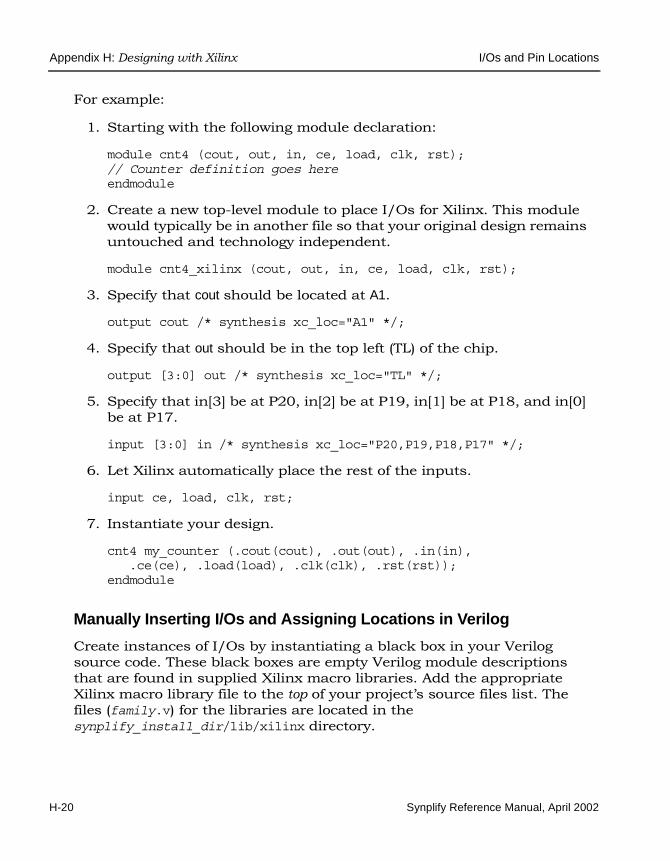
LO
Appendix H: Designing with Xilinx I/Os and Pin Locations
H-20 Synplify Reference Manual, April 2002
For example:
1. Starting with the following module declaration:
module cnt4 (cout, out, in, ce, load, clk, rst);// Counter definition goes hereendmodule
2. Create a new top-level module to place I/Os for Xilinx. This module would typically be in another file so that your original design remains untouched and technology independent.
module cnt4_xilinx (cout, out, in, ce, load, clk, rst);
3. Specify that cout should be located at A1.
output cout /* synthesis xc_loc="A1" */;
4. Specify that out should be in the top left (TL) of the chip.
output [3:0] out /* synthesis xc_loc="TL" */;
5. Specify that in[3] be at P20, in[2] be at P19, in[1] be at P18, and in[0] be at P17.
input [3:0] in /* synthesis xc_loc="P20,P19,P18,P17" */;
6. Let Xilinx automatically place the rest of the inputs.
input ce, load, clk, rst;
7. Instantiate your design.
cnt4 my_counter (.cout(cout), .out(out), .in(in),.ce(ce), .load(load), .clk(clk), .rst(rst));
endmodule
Manually Inserting I/Os and Assigning Locations in Verilog
Create instances of I/Os by instantiating a black box in your Verilog source code. These black boxes are empty Verilog module descriptions that are found in supplied Xilinx macro libraries. Add the appropriate Xilinx macro library file to the top of your project’s source files list. The files (family.v) for the libraries are located in the synplify_install_dir/lib/xilinx directory.

I/Os and Pin Locations Appendix H: Designing with Xilinx
Synplify Reference Manual, April 2002 H-21
If you instantiate I/Os, the Xilinx place-and-route tool will choose their locations. Or, you can specify your own I/O locations as follows:
1. Create a new top-level module and instantiate your Verilog design.
2. Manually instantiate the Xilinx I/Os.
3. Add the appropriate Xilinx macro library filename to the to the top of your Project’s source files list.
4. If you want to specify I/O locations, set the xc_loc attribute for those I/Os you want to specify the locations for. If you do not specify I/O locations for some of your I/Os, the Xilinx place-and-route tool will choose the locations for them.
Verilog Examplemodule cnt4 (cout, out, in, ce, load, clk, rst);/* Your counter definition goes here, */endmodule/* Create a top level to place I/Os specifically
for Xilinx. Any top level pins which do not have I/Os will be automatically inserted */
module cnt4_xilinx(cout, out, in, ce, load, clk, rst);output [3:0] out;output cout;input [3:0] in;input ce, load, clk, rst;
wire [3:0] out_c, in_c;wire cout_c;
/* The xc_loc attribute can be added right after the instance name like that shown below, or right beforethe semicolon. */
IBUF i3 /* synthesis xc_loc="P20" */ (.O(in_c[3]), .I(in[3]));IBUF i2 /* synthesis xc_loc="P19" */ (.O(in_c[2]), .I(in[2]));IBUF i1 /* synthesis xc_loc="P18" */ (.O(in_c[1]), .I(in[1]));IBUF i0 /* synthesis xc_loc="P17" */ (.O(in_c[0]), .I(in[0]));
OBUF o3 /* synthesis xc_loc="TL" */ (.O(out[3]), .I(out_c[3]));OBUF o2 /* synthesis xc_loc="TL" */ (.O(out[2]), .I(out_c[2]));OBUF o1 /* synthesis xc_loc="TL" */ (.O(out[1]), .I(out_c[1]));OBUF o0 /* synthesis xc_loc="TL" */ (.O(out[0]), .I(out_c[0]));
OBUF cout_p /* synthesis xc_loc="BL" */ (.O(cout), .I(cout_c));

LO
Appendix H: Designing with Xilinx I/Os and Pin Locations
H-22 Synplify Reference Manual, April 2002
cnt4 it(.cout(cout_c), .out(out_c), .in(in_c), .ce(ce), .load(load), .clk(clk), .rst(rst));
endmodule
Automatically Inserting I/Os and Assigning Locations in VHDL
Create a new top-level design unit and instantiate your VHDL design. Use this new top-level design unit to specify your I/O locations so that your vendor-specific information is separate from the rest of your design. Specify the xc_loc attribute with the appropriate value for the locations of the I/Os you want to specify. If you do not specify the xc_loc attribute for certain I/Os, the Xilinx place-and-route tool will choose locations for them.
VHDL Examplelibrary synplify;entity cnt4 is
port (cout: out bit;output: out bit_vector (3 downto 0);input: in bit_vector (3 downto 0);ce, load, clk, rst: in bit);
end cnt4;
architecture behave of cnt4 isbegin-- Behavioral description of the counter.end behave;
-- New top level entity, created specifically -- to place I/Os for Xilinx. This entity typically -- would be in another file, so that your original-- design stays untouched, and technology independent.
entity cnt4_xilinx isport (cout: out bit;
output: out bit_vector (3 downto 0);input: in bit_vector (3 downto 0);ce, load, clk, rst: in bit);
-- Place a single I/O for cout at location A1.attribute xc_loc : string;attribute xc_loc of cout: signal is "A1";

I/Os and Pin Locations Appendix H: Designing with Xilinx
Synplify Reference Manual, April 2002 H-23
-- Place all bits of "output" in the -- top-left of the chip.attribute xc_loc of output: signal is "TL";
-- Place input(3) at P20, input(2) at P19,-- input(1) at P18, and input(0) at P17 attribute xc_loc of input: signal is "P20, P19, P18, P17";
-- Let Xilinx place the rest of the inputs.end cnt4_xilinx;
-- New top level architecture instantiates your design.architecture structural of cnt4_xilinx is-- Component declaration for your entity.
component cnt4port (cout: out bit;
output: out bit_vector (3 downto 0);input: in bit_vector (3 downto 0);ce, load, clk, rst: in bit);
end component;begin
-- Instantiate your VHDL design here:my_counter: cnt4 port map (cout, output, input,
ce, load, clk, rst);end structural;
Manually Inserting I/Os and Assigning Locations in VHDL
For VHDL designs, add the appropriate library and use clauses to the begin-ning of your design units that instantiate the macros. The Xilinx libraries are always visible in the Synplify synthesis tool, so do not add library files to your project’s source files list. To see which design units are available, use a text editor of your choice and view the files (family.vhd) for the libraries which are located at synplify_install_dir/lib/xilinx (do not edit these files in any way).
Syntaxlibrary family ;use family.components.all;
Where family is , xc4000, virtex, virtexe, or virtex2.

LO
Appendix H: Designing with Xilinx I/Os and Pin Locations
H-24 Synplify Reference Manual, April 2002
Steps1. Create a new top-level module and instantiate your VHDL design.
2. Instantiate the Xilinx I/Os.
3. Add the appropriate library and use clauses (see source code below) to the beginning of your design unit that instantiates the I/Os.
4. If you wish to specify I/O locations, add the xc_loc attribute to the I/O instances for which you want to specify the locations, and give the locations values. If you leave out the xc_loc attribute, the Xilinx place-and-route tool will choose the locations.
The following example is a behavioral D flip-flop with instantiated data input I/O. The other ports will have synthesized I/Os.
VHDL Examplelibrary ieee, synplify;use synplify.attributes.all;use ieee.std_logic_1164.all;-- Now the library and use clauses for access-- to the Xilinx Macro Library.library xc4000;use xc4000.components.all;entity place_example is
port (q: out std_logic;d, clk: in std_logic);
end place_example;
architecture behave of place_example issignal dz: std_logic;
attribute xc_loc of I1: label is "P3";beginI1: IBUF port map (I=>d,O=>dz);
process (clk) beginif rising_edge(clk) then
q<=dz;end if;
end process;
end behave;

I/Os and Pin Locations Appendix H: Designing with Xilinx
Synplify Reference Manual, April 2002 H-25
Specifying Relative LocationThe following three Xilinx-specific attributes specify relative position of components in your designs.
• xc_map
• xc_rloc
• xc_uset
The general steps are as follows:
1. Create design units (modules) and use the xc_map attribute to specify them as fmap or hmap, or lut (for Virtex, Virtex-E, and Virtex2/Virtex2p).
2. Instantiate these design units at a higher level.
3. Use the xc_uset attribute to group a number of instances together.
4. Use the xc_rloc attribute to specify the relative locations of all instances with the same xc_uset value.
5. Create a top-level design unit instantiating your design.
See xc_map on page 7-125, xc_rloc on page 7-134, and xc_uset on page 7-137 for syntax details.
Controlling Port Names in EDIFYou can control the appearance of port names in the EDIF output files generated for your designs. This is especially useful in controlling the appearance of port names for black-box components (usually IP compo-nents) that you instantiate. By default, the character case of port names is preserved as it appears in the HDL source code.
Two attributes are used, depending on whether you want to control the names of scalar (individual) ports or bus ports. Specify the attributes on individual components in your HDL source code, or globally by using constraint files and the SCOPE spreadsheet.

LO
Appendix H: Designing with Xilinx I/Os and Pin Locations
H-26 Synplify Reference Manual, April 2002
Scalar Ports
For scalar port names, the syn_edif_scalar_format attribute determines if port names are all uppercase or all lowercase (for example, AbCd becomes ABCD).
Bus Ports
For bus port names, the syn_edif_bit_format attribute determines:
• If names are all uppercase or all lowercase (for example, AbCd becomes ABCD)
• If additional characters are appended to the end of names (for example, qout becomes qout_IP)
• If the bus range is appended to the end of names (for example, qout becomes qout[31:1])
• The appearance of the range delimiter when a range is appended (for example, qout<31:0> or qout[31:0])
Using Spartan Appendix H: Designing with Xilinx
Synplify Reference Manual, April 2002 H-27
Using Spartan
Device Mapping Options (Spartan)Device mapping options are optimization algorithms that you can enable during synthesis. You can set the device mapping options for the design in the UI, through Project -> Implementation Options -> Device (or you can use Impl Options or New Impl buttons to display this dialog box).
• Fanout Guide – sets the fanout limit. Default is 100. See Fanout Guide on page H-2 for details.
• Disable I/O Insertion – prevents I/O insertion during synthesis when you click on this option. Default is false (I/O insertion mode). See Disable I/O Insertion on page H-3 for details.
• Force GSR Usage – enables the forced use of the global set/reset routing resources during synthesis. See Force GSR Usage on page H-4 for details. This option is not available for Spartan2 designs.
PipeliningModularRetimingYou can also use the set_option Tcl command to enable/disable these options. See set_option Command for Spartan below for more information.
set_option Command for SpartanSpecifies the implementation options for a design. These are the options you set for synthesis such as the target technology, device architecture and synthesis styles.
Through the set_option Tcl command you specify the same implementation options as you do through the dialog box displayed in the Project view with Project -> Implementation Options
This section provides information on some of the specific options for the Spartan architectures. For a complete list of options, see set_option on page 4-15 .
The set_option command has the following options for Spartan technolo-gies:

LO
Appendix H: Designing with Xilinx Using Spartan
H-28 Synplify Reference Manual, April 2002
project Command for SpartanThis section provides information on some of the options for the project Tcl command for Spartan. See project on page 4-12 for syntax. .
The project command has the following options specific to Spartan technol-ogies:
Table H-3: Spartan set_option Tcl command options
Option Description
-technology keyword Sets the target technology for the implementation. keyword can be SPARTAN, SPARTAN2E, SPARTAN-XL, or SPARTAN2.
-part part_name Specifies a part for the implementation. Refer to the Project -> Implementation Options dialog box for the part choices.
-speed_grade value Sets the speed grade for the implementation. Refer to the Project -> Implementation Options dialog box for available speed grade choices.
-package package_name Specifies the package for the implementation. Refer to the Project -> Implementation Options dialog box for available package choices.
-maxfan value Sets the fanout limit. Default is 100.
-force_gsr 1 | 0 Enables/disables the forced use of the global set/reset routing resources during synthesis (only available for Spartan and Spartan-XL). The default is true.
-pipe 1 | 0 Allows you to run designs at a faster frequency by moving registers after the multiplier into the multiplier. This option is only available for Spartan2 and Spartan2E.
-block 1 | 0 Prevents I/O insertion during synthesis. The default is false, (I/O insertion mode). To disable I/O insertion, set this option to true.
-retiming 1 | 0 Determines whether registers are moved into combinatorial logic to improve performance. You must also set -pipe. The -retiming option is only available for Spartan2 and Spartan2E.

Using Spartan Appendix H: Designing with Xilinx
Synplify Reference Manual, April 2002 H-29
Table H-4: Spartan project Tcl command options
Option Description
-result_format “format” Changes the synthesis result file format for the implementation which contains the synthesized netlist created by the Synplify synthesis tool. The format must be in lower-case letters: edif or xnf (Spartan and Spartan-XL only).
-result_file value Specifies the name of the synthesized netlist for the implementation. If you use this option, it should precede the synthesis result file specification using project -result_file at the end of the Tcl file, and before any project -run or project -save commands.The result file format can also be set in the UI through Project -> Implementation Options (Implementation Results panel).

LO
Appendix H: Designing with Xilinx Using Virtex
H-30 Synplify Reference Manual, April 2002
Using Virtex
Device Mapping Options (Virtex)Device mapping options are optimization algorithms that you can enable during synthesis. You can set the device mapping options for the design in the UI, through Project -> Implementation Options -> Device (or you can use Impl Options or New Impl buttons to display this dialog box).
• Fanout Guide – sets the fanout limit. Default is 100. See Fanout Guide on page H-2 for details.
• Disable I/O Insertion – prevents I/O insertion during synthesis when you click on this option. Default is false (I/O insertion mode). See Disable I/O Insertion on page H-3 for details.
You can also use the set_option Tcl command to enable/disable these options. See set_option Command for Virtex on page H-30 for more informa-tion.
set_option Command for VirtexSpecifies the implementation options for a design. These are the options you set for synthesis such as the target technology, device architecture and synthesis styles.
Through the set_option Tcl command you specify the same implementation options as you do through the dialog box displayed in the Project view with Project -> Implementation Options.
This section provides information on some of the specific options for the Virtex architectures.See set_option on page 4-15 for the syntax.
The set_option command has the following options for Virtex, Virtex-E, Virtex2, and Virtex2p:

Using Virtex Appendix H: Designing with Xilinx
Synplify Reference Manual, April 2002 H-31
project Command for VirtexThis section provides information on some of the options for the project Tcl command for Virtex technologies.See project on page 4-12 for syntax.
The project has the following option specific to Virtex technologies:
Table H-5: Virtex set_option Tcl command options
Option Description
-technology keyword Sets the target technology for the implementation. keyword can be virtex, virtex-e or virtex2.
-part part_name Specifies a part for the implementation. Refer to the Project -> Implementation Options form for available part choices.
-speed_grade value Sets the speed grade for the implementation. Refer to the Project -> Implementation Options form for available speed grade choices.
-package package_name Specifies the package for the implementation. Refer to the Project -> Implementation Options form for available package choices.
-maxfan value Sets the fanout limit. Default is 100.
-block 1 | 0 Prevents I/O insertion during synthesis. The default is false, (I/O insertion mode). To disable I/O insertion, set this option to 1.
Table H-6: Virtex project Tcl command options
Option Description
-result_format “format" Changes the synthesis result file format for the implementation which contains the synthesized netlist created by the Synplify synthesis tool. The format must be in lower-case letters: edif.
-result_file value Specifies the name of the synthesized netlist for the implementation.

LO
Appendix H: Designing with Xilinx Using Virtex
H-32 Synplify Reference Manual, April 2002
Resource Usage The Synplify synthesis tool generates a resource usage report in the log file. To view it, click the View Log button in the Project window.
Resource usage reports for Xilinx include the following information:
• Xilinx-specific components and the number of times they are used
• I/O primitives
• Global buffers
• Total number of LUTs
• Memory cells used
Interfacing with Xilinx Place-and-route ToolsWhen you invoke the Xilinx ISE Project Navigator or Design Manager place-and-route tool directly from the Synplify synthesis tool, the corre-sponding Xilinx project is created automatically.
To start the place-and-route tool from the synthesis tool, do the following:
1. Create a new project or open an existing project in the synthesis tool, select a Xilinx technology, and add the project source files,
2. Before you run synthesis, review the option settings for your design in the Project -> Implementation Options dialog box.
3. Synthesize your design with the synthesis tool. After successful synthesis, choose Options -> Xilinx -> Start ISE Project Navigator or Options -> Xilinx -> Start Design Manager to start the place-and-route tool.
This displays the place-and-route tool user interface, places the synthesis-generated netlist in a Xilinx project, and names that project.
4. Configure your Xilinx project settings in the place-and-route tool.
5. Run the Xilinx place-and-route tool.
For more information on Xilinx place-and-route tools, refer to the appro-priate Xilinx documentation.

Using Virtex Appendix H: Designing with Xilinx
Synplify Reference Manual, April 2002 H-33
Guidelines for NGDBuild
When reading the Synplify synthesis tool netlist files into the Xilinx place-and-route tool, define the timing constraints that are not forward-annotated by the synthesis tool in a user constraint file (.ucf). From the command line, read the .ucf file into Xilinx place-and-route NGDBuild with the -uc command.
Refer to the Xilinx documentation for more information on setting timing constraints.
Guidelines for MAP
Do not map to 5-input functions. Do not use the -k command line option.
Guidelines for PAR
Do not use the default effort level of 5. Instead, set it to 4 with the -l 4 command line option.

LO
Appendix H: Designing with Xilinx Using XC4000
H-34 Synplify Reference Manual, April 2002
Using XC4000
Device Mapping Options (XC4000)Device mapping options are optimization algorithms that you can enable during synthesis. You can set the device mapping options for the design in the UI, through Project -> Implementation Options -> Device (or you can use Impl Options or New Impl buttons to display this dialog box). See Device Mapping Options (XC3000 and XC5200) on page H-37 for explanations of the options for other XC families.
• Disable I/O Insertion – prevents I/O insertion during synthesis when you click on this option. Default is false (I/O insertion mode). See Disable I/O Insertion on page H-3 for details.
• Force GSR Usage – enables the forced use of the global set/reset routing resources during synthesis. See Force GSR Usage on page H-4 for details.
set_option Command for XC4000Specifies the implementation options for a design. These are the options you set for synthesis such as the target technology, device architecture and synthesis styles.
Through the set_option Tcl command you specify the same implementation options as you do through the dialog box displayed in the Project view with Project -> Implementation Options
This section provides information on some of the specific options for the XC architectures. For the complete set of options, see set_option on page 4-15 .
The set_option command has the following options for XC4000 technolo-gies:

Using XC4000 Appendix H: Designing with Xilinx
Synplify Reference Manual, April 2002 H-35
project Command for XC4000This section provides information on some of the options for the project Tcl command for the XC4000 technologies. For the complete set of options, see project on page 4-12.
Table H-7: XC4000 set_option Tcl command options
Option Description
-technology keyword Sets the target technology for the implementation. keyword can be XC4000, XC4000E, XC4000EX, XC4000XL, XC4000XLA, XC4000L, or XC4000XV.
-part part_name Specifies a part for the implementation. Refer to the Project -> Implementation Options form for available part choices.
-speed_grade value Sets the speed grade for the implementation. Refer to the Xilinx databook for available speed grade choices.
-package package_name Specifies the package for the implementation. Refer to the Project -> Implementation Options for available package choices.
-maxfan value Sets the fanout limit. Default is 100.
-force_gsr 1 | 0 Enables/disables the forced use of the global set/reset routing resources during synthesis. The default is true.
-block 1 | 0 Prevents I/O insertion during synthesis. The default is false, (I/O insertion mode). To disable I/O insertion, set this option to true.

LO
Appendix H: Designing with Xilinx Using XC4000
H-36 Synplify Reference Manual, April 2002
The project command has the following options specific to these technolo-gies:
If you use this option, it should immediately precede the synthesis result file specification using project -result_file at the end of the Tcl file, and before any project -run or project -save commands.
The result file format can also be set from the UI in the Results Format field through Project -> Implementation Options -> Implementation Results.
Table H-8: XC4000 project Tcl command options
Option Description
-result_format “format" Changes the synthesis result file format for the implementation which contains the synthesized netlist created by the Synplify synthesis tool. The format must be in lower-case letters: edif or xnf.
-result_file value Specifies the name of the synthesized netlist for the implementation.

Using XC3000 and XC5200 Appendix H: Designing with Xilinx
Synplify Reference Manual, April 2002 H-37
Using XC3000 and XC5200
Device Mapping Options (XC3000 and XC5200)Device mapping options are optimization algorithms that you can enable during synthesis. You can set the device mapping options for the design in the UI, through Project -> Implementation Options -> Device (or you can use Impl Options or New Impl buttons to display this dialog box).
• Fanout Guide – sets the fanout limit. Default is 100. See Fanout Guide on page H-2 for details.
• Disable I/O Insertion – prevents I/O insertion during synthesis when you click on this option. Default is false (I/O insertion mode). See Disable I/O Insertion on page H-3 for details.
• Force GSR Usage – enables the forced use of the global set/reset routing resources during synthesis (XC3000 and XC5200 only). See Force GSR Usage on page H-4 for details.
• Use Dedicated Reset Pin – enables the use of the dedicated reset pin (XC3000 only).
You can also use the set_option Tcl command to enable/disable these options. See set_option Command for Spartan below for more information.
set_option Command for XC3000 and XC5200Specifies the implementation options for a design. These are the options you set for synthesis such as the target technology, device architecture and synthesis styles.
Through the set_option Tcl command you specify the same implementation options as you do through the dialog box displayed in the Project view with Project -> Implementation Options.
This section provides information on some of the specific options for the XC3000 and XC5200 architectures. For a complete list of options, see set_option on page 4-15 .
The set_option command has the following options for these technologies:

LO
Appendix H: Designing with Xilinx Using XC3000 and XC5200
H-38 Synplify Reference Manual, April 2002
project Command for XC3000 and XC5200This section provides information on specific options for the project Tcl command for these technologies. See project on page 4-12 for a complete list of options .
The project command has the following option specific to these technolo-gies:
Table H-9: XC3000 and XC5200 set_option Tcl command options
Option Description
-technology keyword Sets the target technology for the implementation. keyword can be XC3000 or XC5200.
-part part_name Specifies a part for the implementation. Refer to the Project -> Implementation Options dialog box for available part choices.
-speed_grade value Sets the speed grade for the implementation. Refer to the Project -> Implementation Options dialog box for available speed grade choices.
-package package_name Specifies the package for the implementation. Refer to the Project -> Implementation Options dialog box for available package choices.
-maxfan value Sets the fanout limit. Default is 100.
-force_gsr 1 | 0 Enables/disables the forced use of the global set/reset routing resources during synthesis. The default is true.
-userstpin 1 | 0 Enables/disables the use of the dedicated reset pin (XC3000 only).
-block 1 | 0 Prevents I/O insertion during synthesis. The default is false, (I/O insertion mode). To disable I/O insertion, set this to 1

Using XC3000 and XC5200 Appendix H: Designing with Xilinx
Synplify Reference Manual, April 2002 H-39
Table H-10: XC3000 and XC5200 project Tcl command options
Option Description
-result_format “format” Changes the synthesis result file format for the implementation which contains the synthesized netlist created by the Synplify synthesis tool. The format must be in lower-case letters: edif or xnf.
-result_file value Specifies the name of the synthesized netlist for the implementation. If you use this option, it should precede the synthesis result file specification using project -result_file at the end of the Tcl file, and before any project -run or project -save commands.The result file format can also be set in the UI through Project -> Implementation Options (Implementation Results panel).

LO
Appendix H: Designing with Xilinx Using Xilinx CLPDs
H-40 Synplify Reference Manual, April 2002
Using Xilinx CLPDs
Device Mapping Options (CPLDs)Device mapping options are optimization algorithms that you can enable during synthesis. You can set the device mapping options for the design in the UI, through Project -> Implementation Options -> Device (or you can use Impl Options or New Impl buttons to display this dialog box). Xilinx CPLDs include the XC9500, CoolRunner and CoolRunner-II CPLDs technologicies. The device mapping options for these technologies are the following:
• Fanout Guide – sets the fanout limit. Default is 100. See Fanout Guide on page H-2 for details.
• Disable I/O Insertion – prevents I/O insertion during synthesis when you click on this option. Default is false (I/O insertion mode). See Disable I/O Insertion on page H-3 for details.
You can also use the set_option Tcl command to enable/disable these options. See set_option Command for Spartan below for more information.
set_option Command for Xilinx CPLDsSpecifies the implementation options for a design. These are the options you set for synthesis such as the target technology, device architecture and synthesis styles.
Through the set_option Tcl command you specify the same implementation options as you do through the dialog box displayed in the Project view with Project -> Implementation Options.
This section provides information on some of the specific options for the Xilinx CPLD architectures (XC9500, CoolRunner and CoolRunner-II CPLDs). For a complete list of options, see set_option on page 4-15 .
The set_option command has the following options for these technologies:

Using Xilinx CLPDs Appendix H: Designing with Xilinx
Synplify Reference Manual, April 2002 H-41
project Command for Xilinx CPLDsThis section provides information on specific options for the project Tcl command for the Xilinx CPLD architectures (XC9500, CoolRunner and CoolRunner-II CPLDs). See project on page 4-12 for a complete list of options .
Table H-11: Xilinx CPLDs set_option Tcl command options
Option Description
-technology keyword Sets the target technology for the implementation. keyword can be XC9500, XC9500-XL, XC9500-XV, CoolRunner or CoolRunner-II CPLDs.
-part part_name Specifies a part for the implementation. Refer to the Project -> Implementation Options dialog box for available part choices.
-speed_grade value Sets the speed grade for the implementation. Refer to the Project -> Implementation Options dialog box for available speed grade choices.
-package package_name Specifies the package for the implementation. Refer to the Project -> Implementation Options dialog box for available package choices.
-maxfan value Sets the fanout limit. Default is 100.
-block 1 | 0 Prevents I/O insertion during synthesis. The default is false, (I/O insertion mode). To disable I/O insertion, set this option to 1

LO
Appendix H: Designing with Xilinx Using Xilinx CLPDs
H-42 Synplify Reference Manual, April 2002
The project command has the following option specific to these technolo-gies:
Table H-12: Xilinx CPLDs project Tcl command options
Option Description
-result_format “format” Changes the synthesis result file format for the implementation which contains the synthesized netlist created by the Synplify synthesis tool. The format must be in lower-case letters: edif or xnf.
-result_file value Specifies the name of the synthesized netlist for the implementation. If you use this option, it should precede the synthesis result file specification using project -result_file at the end of the Tcl file, and before any project -run or project -save commands.The result file format can also be set in the UI through Project -> Implementation Options (Implementation Results panel).

Xilinx Attribute and Directive Summary Appendix H: Designing with Xilinx
Synplify Reference Manual, April 2002 H-43
Xilinx Attribute and Directive Summary
The following table summarizes the synthesis and Xilinx-specific attributes and directives available with the Xilinx Technology. Complete descriptions and examples can be found in Chapter 7, Synthesis Attributes and Directives.
Table H-13: Synthesis and Xilinx attributes and directives
Attribute / Directive Description
black_box_pad_pin (D) Specifies that a pin on a black box is an I/O pad. It is applied to a component, architecture, or module, with a value that specifies the set of pins on the module or entity.
black_box_tri_pins (D) Specifies that a pin on a black box is a tristate pin. It is applied to a component, architecture, or module, with a value that specifies the set of pins on the module or entity.
full_case (D) Specifies that a Verilog case statement has covered all possible cases.
parallel_case (D) Specifies a parallel multiplexed structure in a Verilog case statement, rather than a priority-encoded structure.
syn_black_box (D) Defines a black box for synthesis.
syn_direct_enable Identifies which signal is to be used as the enable input to an enable flip-flop when multiple candidates are possible.
syn_edif_bit_format Controls the character formatting and style of bus signal names, port names, and vector ranges in the EDIF output file.
syn_edif_scalar_format Controls the character formatting of scalar signal and port names in the EDIF output file.
syn_encoding Specifies the encoding style for state machines.
syn_enum_encoding (D) Specifies the encoding style for enumerated types (VHDL only).
syn_forward_io_constraints Enables I/O constraints to be forward-annotated to the Xilinx place-and-route tools.
(D) indicates directives; all others are attributes.
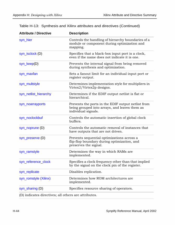
LO
Appendix H: Designing with Xilinx Xilinx Attribute and Directive Summary
H-44 Synplify Reference Manual, April 2002
syn_hier Controls the handling of hierarchy boundaries of a module or component during optimization and mapping.
syn_isclock (D) Specifies that a black-box input port is a clock, even if the name does not indicate it is one.
syn_keep(D) Prevents the internal signal from being removed during synthesis and optimization.
syn_maxfan Sets a fanout limit for an individual input port or register output.
syn_multstyle Determines implementation style for multipliers in Virtex2/Virtex2p designs.
syn_netlist_hierarchy Determines if the EDIF output netlist is flat or hierarchical.
syn_noarrayports Prevents the ports in the EDIF output netlist from being grouped into arrays, and leaves them as individual signals.
syn_noclockbuf Controls the automatic insertion of global clock buffers.
syn_noprune (D) Controls the automatic removal of instances that have outputs that are not driven.
syn_preserve (D) Prevents sequential optimizations across a flip-flop boundary during optimization, and preserves the signal.
syn_ramstyle Determines the way in which RAMs are implemented.
syn_reference_clock Specifies a clock frequency other than that implied by the signal on the clock pin of the register.
syn_replicate Disables replication.
syn_romstyle (Xilinx) Determines how ROM architectures are implemented.
syn_sharing (D) Specifies resource sharing of operators.
Table H-13: Synthesis and Xilinx attributes and directives (Continued)
Attribute / Directive Description
(D) indicates directives; all others are attributes.

Xilinx Attribute and Directive Summary Appendix H: Designing with Xilinx
Synplify Reference Manual, April 2002 H-45
syn_srlstyle Determines how to implement the sequential shift (seqShift) components. This attribute applies to Virtex families.
syn_state_machine (D) Determines if the FSM Compiler extracts a structure as a state machine.
syn_tco<n> (D) Defines timing clock to output delay through the black box. The n indicates a value between 1 and 10.
syn_tpd<n> (D) Specifies timing propagation for combinational delay through the black box. The n indicates a value between 1 and 10.
syn_tristate (D) Specifies that a black-box pin is a tristate pin.
syn_tristatetomux Converts tristate drivers that drive nets below a certain limit to muxes. This only applies to the XC4000 and Virtex families
syn_tsu<n> (D) Specifies the timing setup delay for input pins, relative to the clock. The n indicates a value between 1 and 10.
syn_useenables Prevents generation of registers with clock enable pins.
syn_useioff (Xilinx) Packs flip-flops in the I/Os to improve input/output path timing.
translate_off/translate_on (D) Specifies sections of code to be excluded from synthesis, such as simulation-specific code.
xc_alias Changes the cell name in XNF for all families except Virtex families.
xc_clockbuftype Specifies that a clock port use the Clock Delay Locked Loop primitive, CLKDLL, in Virtex designs.
xc_fast Speeds up the transition time of the output driver in XC4000 designs
xc_fast_auto Controls the instantiation of fast output buffers in Virtex designs.
Table H-13: Synthesis and Xilinx attributes and directives (Continued)
Attribute / Directive Description
(D) indicates directives; all others are attributes.

LO
Appendix H: Designing with Xilinx Xilinx Attribute and Directive Summary
H-46 Synplify Reference Manual, April 2002
xc_global_buffers Controls the number of global buffers to use in a design.
xc_isgsr Specifies that a black-box port is connected to an internal STARTUP block in non-Virtex designs, and prevents the Synplify synthesis tool from inferring a STARTUP block.
xc_loc Specifies the placement of ports and design units.
xc_map Specifies the Xilinx fmap or hmap primitive in XC4000, and the LUT in Virtex designs.
xc_ncf_auto_relax Controls the automatic relaxation of constraints that are forward-annotated to the .ncf file.
xc_nodelay Controls the Xilinx insertion of input delay for flip-flops and latches in the XC4000 family.
xc_padtype Specifies an I/O buffer standard in Virtex designs.
xc_props Specifies Xilinx attributes to forward to the gate-level netlist.
xc_pullup / xc_pulldown Specifies that a port is a pull-up or pull-down port.
xc_rloc Specifies the relative locations of all instances with the same xc_uset attribute value. This attribute applies to XC4000 and Virtex families.
xc_slow Specifies a slow transition time for the driver of an output port.
xc_uset Assigns a group name to component instances.
Table H-13: Synthesis and Xilinx attributes and directives (Continued)
Attribute / Directive Description
(D) indicates directives; all others are attributes.

A B C D E F G H I J K L M N O P Q R S T U V W X Y Z
Synplify Reference Manual, April 2002 Index-1
Index
Symbols&f header and footer variable 3-15&p header and footer variable 3-15... action button
Editor Options dialog box 3-57New dialog box 3-8
.fse file 1-30
.info file 1-30, 8-38
.ini file 2-14, 5-7
.prj file 1-23
.scp command file F-9
.sdc file 1-25, 6-2, 6-20, 8-47attribute syntax 7-11
.srm file 1-27
.srr file 1-27, 4-23
.srs file 1-27
.vhm file 1-26
.vma file 1-26<- action button
Object Query dialog box 3-50<- Add action button
Select Files to Add to Project dialog box 3-40
Select Projects to Include in Workspace dialog box 3-82
<- Add All action buttonSelect Files to Add to Project dialog
box 3-40Select Projects to Include in Workspace
dialog box 3-82<- All action button
Object Query dialog box 3-50-> action button
Object Query dialog box 3-50-_include command option 4-9‰#c header and footer variable 3-15‰#x header and footer variable 3-15‰c header and footer variable 3-15‰X header and footer variable 3-15
‰x header and footer variable 3-15
Numerics3D-Buttons check box, Display Settings dia-
log box 3-28
Aaborting a synthesis run 3-45About this program menu item
Help menu 3-65Absolute Path radio button
File Options dialog box 3-78accessing commands 3-2accessing LMF, Max+Plus II B-35accessing packages, VHDL 9-13ACEX set_option Tcl command arguments
(table) B-27Actel A-1
ACTgen macros (Verilog) A-6ACTgen macros (VHDL) A-7alsloc attribute 7-19alspin attribute 7-21alspreserve attribute 7-23assigning I/O pin numbers to
ports 7-21attributes A-10device mapping options A-3directives A-10fanout limits A-3features A-2I/O insertion A-4instantiating black boxes A-5instantiating macros A-5macro libraries examples A-7preserving relative placement 7-19product families A-2reports A-3set_option Tcl command A-8syn_preserve_sr_priority attribute 7-81

Index A B C D E F G H I J K L M N O P Q R S T U V W X Y Z
Index-2 Synplify Reference Manual, April 2002
Actel (continued)syn_radhardlevel attribute 7-85Tcl commands A-8using macro libraries (Verilog) A-6using macro libraries (VHDL) A-6
Actel set_option command (table) A-8action buttons 3-2
... 3-8, 3-57<- 3-50<- All 3-50<- Add
Select Files to Add to Project dialog box 3-40
Select Projects to Include in Work-space dialog box 3-82
<- Add AllSelect Files to Add to Project dialog
box 3-40Select Projects to Include in Work-
space dialog box 3-82-> 3-50Add icon 3-70Add Row 3-87All -> 3-50Cancel Job 3-45Change 3-40, 3-61Clear All Bookmarks (toolbar icon) 3-92Clipboard 3-70closed book icon (online help) 3-66Customize 3-25Cut (toolbar icon) 3-89Delete 3-25Delete icon 3-70document icon (online help) 3-66Existing Project 3-12Filter on Selected Gates (toolbar
icon) 3-90Find (toolbar icon) 3-89Find Next
Find dialog box 3-20Replace dialog box 3-21
Mark All 3-20Move Down icon 3-70Move Up icon 3-70New 3-25New Constraint (SCOPE) (toolbar
icon) 3-89New HDL file (toolbar icon) 3-89New Project 3-12New Workspace 3-12
Next Bookmark (toolbar icon) 3-92Next Sheet (toolbar icon) 3-91Next Tip 3-72Open 3-10Open (toolbar icon) 3-89open book icon (online help) 3-66Open project (toolbar icon) 3-89Options 3-57Paste (toolbar icon) 3-89Previous Bookmark (toolbar icon) 3-92Previous Sheet (toolbar icon) 3-91Previous Tip 3-72Print (toolbar icon) 3-89Project view 3-97Project Wizard 3-12Push/Pop Hierarchy (toolbar icon) 3-91Redo 3-87Redo (toolbar icon) 3-89Remove All ->
Select Files to Add to Project dialog box 3-40
Select Projects to Include in Work-space dialog box 3-82
Remove Row 3-87Remove ->
Select Files to Add to Project dialog box 3-40
Select Projects to Include in Work-space dialog box 3-82
Replace 3-21Replace All 3-21Reset 3-25RTL View (toolbar icon) 3-90Save 3-11, 3-71Save (toolbar icon) 3-89Save all (toolbar icon) 3-89Show Critical Path (toolbar icon) 3-90Technology View (toolbar icon) 3-90Text File 3-70Toggle Bookmark (toolbar icon) 3-92Undo 3-87Undo (toolbar icon) 3-89Validate 3-71Zoom 100% (toolbar icon) 3-91Zoom Full (toolbar icon) 3-91Zoom In (toolbar icon) 3-91Zoom Out (toolbar icon) 3-91
-active command option 4-13Add icon
License Editor dialog box 3-70

IndexA B C D E F G H I J K L M N O P Q R S T U V W X Y Z
Synplify Reference Manual, April 2002 Index-3
Add Row action buttonSCOPE Attributes dialog box 3-87
Add Source File menu item 3-82Project menu 3-30Project View popup menu 3-76
Add to Project dialog box zoneNew dialog box 3-8
add_file Tcl command 4-3, 4-4, 4-6, 4-9, 6-20examples of use 4-10
Additional Products menu itemHelp menu 3-65
Adjusting RGB values (table) 2-14Adjusting RGB values in HDL Analyst
(table) 5-7Advanced submenu
Edit menu 3-17Align menu item
Format menu 3-51All -> action button
Object Query dialog box 3-50-all command option 4-11alsloc attribute (Actel) 7-19
examplessdc file 7-19Verilog 7-19VHDL 7-20
alspin attribute (Actel) 7-21examples
sdc file 7-21Verilog 7-21VHDL 7-22
alspreserve attribute (Actel) 7-23examples
sdc file 7-23Verilog 7-23VHDL 7-23
Alt keyboard shortcut (Text Editor) 2-9, 3-61Altera B-1
ACEXdevice mapping options B-26file format options B-27project Tcl command B-28set_option Tcl command B-26, B-27
altera_auto_use_eab attribute 7-25altera_auto_use_esb attribute 7-28altera_chip_pin_lc attribute 7-31altera_implement_in_eab attribute 7-33altera_implement_in_esb attribute 7-35
altera_io_opendrain attribute 7-37altera_io_powerup attribute 7-39APEX
device mapping options B-14file format options B-16project Tcl command B-16set_option Tcl command B-15
APEX IIdevice mapping options B-14file format options B-16project Tcl command B-16set_option Tcl command B-15
attributes summary B-36cliquing B-15clock enable net assignment 7-53constraints B-3device mapping options
ACEX B-26APEX B-14APEX II B-14Excalibur B-14FLEX B-26MAX B-32Mercury B-14Stratix B-20
device support B-2directives summary B-36EDIF and VQM filenames B-9Excalibur
device mapping options B-14file format options B-16project Tcl command B-16set_option Tcl command B-15
fanout limits B-17file format options
ACEX B-27APEX B-16APEX II B-16Excalibur B-16FLEX B-27MAX B-33Mercury B-16Stratix B-21
FLEXdevice mapping options B-26file format options B-27project Tcl command B-28set_option Tcl command B-26

Index A B C D E F G H I J K L M N O P Q R S T U V W X Y Z
Index-4 Synplify Reference Manual, April 2002
Altera (continued)forward annotating
to Max+Plus II 6-39, B-28to Quartus II 6-39
forward annotation B-34ACEX B-28APEX B-17APEX II B-17Excalibur B-17FLEX B-28Mercury B-17Stratix B-17
I/O insertion B-15I/O registers power-up mode 7-39implementation options B-10inferring
RAM B-4registers B-9ROM B-6
instantiatingLPMs
in Verilog B-4, B-41in VHDL B-4, B-46
macros/black boxesin Verilog B-3in VHDL B-3
special buffersin Verilog B-43in VHDL B-49
mapping EABs B-40, B-45mapping to ATOMs B-10
APEX B-15APEX II, Excalibur, Mercury B-15
MAXdevice mapping options B-32file format options B-33project Tcl command B-34set_option Tcl command B-33
Max+Plus II, forward-annotating to 6-39, B-28
Mercurydevice mapping options B-14file format options B-16project Tcl command B-16set_option Tcl command B-15
open-drain mode 7-37
packing registers into I/O cells B-17pin locations 7-31project Tcl command
ACEX B-28APEX B-16APEX II B-16Excalibur B-16FLEX B-28MAX B-34Mercury B-16Stratix B-21
Quartus II, forward-annotating to 6-39RAM inference B-4reports B-11ROM inference B-6simulation (post-synthesis) in
APEX B-18specifying I/O locations B-39, B-44Stratix
device mapping options B-20DSP MAC block inference B-23file format options B-21I/O insertion B-20mapping to ATOMs B-20project Tcl command B-21RAM inference B-22set_option Tcl command B-20
syn_romstyle attribute 7-97syn_useioff attribute 7-108timing constraints 6-39VHDL prepared components B-51
altera_auto_use_eab attribute (Altera) 7-25examples
sdc file 7-25Verilog 7-25VHDL 7-26
altera_auto_use_esb attribute (Altera) 7-28examples
sdc file 7-28Verilog 7-28VHDL 7-29
altera_chip_pin_lc attribute (Altera) 7-31examples
sdc file 7-31Verilog 7-31VHDL 7-32

IndexA B C D E F G H I J K L M N O P Q R S T U V W X Y Z
Synplify Reference Manual, April 2002 Index-5
altera_implement_in_eab attribute (Altera) 7-33
examplessdc file 7-33Verilog 7-33VHDL 7-34
altera_implement_in_esb attribute (Altera) 7-35
examplessdc file 7-35Verilog 7-35VHDL 7-36
altera_io_opendrain attribute (Altera) 7-37examples
sdc file 7-37Verilog 7-37VHDL 7-38
altera_io_powerup attribute (Altera) 7-39examples
sdc file 7-39Verilog 7-39VHDL 7-40
always blocksVerilog 8-8
combinational logic 8-16flip-flops 8-20level-sensitive latches 8-22
always-enabled write enableVHDL 9-78
amount of logic displayed, changing 5-7Amplify Physical Optimizer tool
overview 1-5Analyst toolbar 3-90
Filter on Selected Gates icon 3-90RTL View icon 3-90Show Critical Path icon 3-90Technology View icon 3-90
Analyst toolbar (figure) 3-90Analyst toolbar icons (table) 3-90analyzing critical paths in HDL Analyst 5-18APEX II menu options (table) B-15APEX II project Tcl command arguments
(table) B-17APEX II set_option Tcl command arguments
(table) B-15
APEX menu options (table) B-15APEX project Tcl command arguments
(table) B-17APEX set_option Tcl command arguments
(table) B-15area, optimizing for 1-19-area_delay_percent command
option 4-16, B-33-areadelay command option 4-16, E-14Argument column
SCOPE spreadsheet 6-17arithmetic operators
Verilog 8-2VHDL 9-15
Arrange Icons menu itemWindow menu 3-62
arranging windows 3-62Assigning I/O locations with the SCOPE
spreadsheet (figure) H-19assignment operators
Verilog 8-2VHDL 9-9
assignment statementcombinational logic (Verilog) 8-18level-sensitive latches (Verilog) 8-21VHDL 9-34
asynchronous sets and resetsVerilog 8-24VHDL 9-44
asynchronous state machinescreated with a process (VHDL) 9-55that generate errors (VHDL) 9-55Verilog 8-32, 8-33VHDL 9-54
Atmel C-1device mapping options C-2I/O pad insertion C-2product families C-2set_option Tcl command C-4
Atmel attributes and directives (table) C-5Atmel set_option command options
(table) C-4ATOM mapping, Altera B-10Attribute column
SCOPE spreadsheet 7-10Attribute dialog box zone
SCOPE Attributes dialog box 3-86

Index A B C D E F G H I J K L M N O P Q R S T U V W X Y Z
Index-6 Synplify Reference Manual, April 2002
attributes 7-1Actel A-10alphabetical summary 7-3alsloc (Actel) 7-19alspin (Actel) 7-21alspreserve (Actel) 7-23Altera B-36altera_auto_use_eab (Altera) 7-25altera_auto_use_esb (Altera) 7-28altera_chip_pin_lc (Altera) 7-31altera_implement_in_eab 7-33altera_implement_in_esb 7-35altera_io_opendrain 7-37altera_io_powerup 7-39defining in source code 7-14din (Lattice) 7-41dout (Lattice) 7-42individual descriptions 7-18loc (Lattice) 7-43lock (Lattice) 7-44orca_padtype (Lattice) 7-45orca_props (Lattice) 7-47overview 7-2ql_padtype (QuickLogic) 7-49ql_placement (QuickLogic) 7-51specifying 7-9specifying in SCOPE spreadsheet 7-10specifying in Verilog 7-15specifying in VHDL 7-16syn_direct_enable 7-53syn_edif_bit_format 7-55syn_edif_name_length 7-58syn_edif_scalar_format 7-60syn_encoding 7-62syn_forward_io_constraints 7-65syn_hier 7-67syn_maxfan 4-25, 7-70, B-17, H-3syn_multstyle 7-72
DSP MAC inference in Altera Stratix B-25
syn_netlist_hierarchy 7-74syn_noarrayports 7-75syn_noclockbuf 4-25, 7-76syn_pipeline 7-78syn_preserve_sr_priority (Actel) 7-81syn_props (Triscend) 7-83syn_radhardlevel (Actel) 7-85syn_ramstyle 7-87, 8-36syn_reference_clock 6-35, 7-91syn_replicate 7-92syn_resources 7-95
syn_romstyleAltera 7-97Xilinx 7-100
syn_srlstyle 7-102syn_tristatetomux 7-104syn_useenables 7-106syn_useioff
Altera 7-108DSP MAC inference in Altera
Stratix B-25Lattice ORCA 7-110QuickLogic 7-112Xilinx 7-114
syntax.sdc file 7-11Verilog 7-15VHDL 7-16
Verilog 8-47VHDL 9-85VHDL library package 9-85VHDL package 7-16VHDL syntax 7-16xc_alias (Xilinx) 7-116xc_clockbuftype (Xilinx) 7-117xc_fast (Xilinx) 4-25, 7-119xc_fast_auto (Xilinx) 7-121xc_global_buffers (Xilinx) 7-123xc_loc (Xilinx) 4-25, 7-124xc_map (Xilinx) 7-125xc_ncf_auto_relax 6-43xc_ncf_auto_relax (Xilinx) 6-43, 7-126xc_nodelay (Xilinx) 7-128xc_padtype (Xilinx) 7-129xc_props (Xilinx) 7-131xc_pulldown (Xilinx) 7-132xc_pullup (Xilinx) 7-132xc_rloc (Xilinx) 7-134xc_slow (Xilinx) 7-136xc_uset (Xilinx) 7-137Xilinx H-5, H-43
Attributes (table) 7-3attributes and directives
defining in source code 7-14overview 7-2Verilog 8-47VHDL 9-85
Attributes and directives for Altera technolo-gy (table) B-36

IndexA B C D E F G H I J K L M N O P Q R S T U V W X Y Z
Synplify Reference Manual, April 2002 Index-7
Attributes panelObject column 7-9Object Type column 7-9SCOPE spreadsheet 6-17, 7-9
attributes wizard 7-12-autosm command option 4-16
BBackground Compile menu item
Options menu, Quartus submenu B-19-batch command option 1-13batch mode 1-13, 4-4, 4-6, 4-7Beep when a job completes check box
Project View Options dialog box 3-56bit enumeration data type (VHDL) 9-6black boxes
See also macrosActel A-5black_box_pad_pin 7-140black_box_tri_pins 7-142instantiating in Verilog 8-40instantiating in VHDL 9-86internal startup box (Xilinx) 7-189Lattice E-2syn_black_box directive 7-149syn_isclock 7-155syn_resources 7-95syn_tco directive 7-177syn_tpd directive 7-180syn_tristate directive 7-183syn_tsu directive 7-184timing constraints in VHDL 9-86using Verilog macro libraries (Actel) A-6using VHDL macro libraries (Actel) A-6Verilog 8-40VHDL 9-86Xilinx H-7
black_box_pad_pin directive 7-140examples
Verilog 7-140VHDL 7-141
black_box_tri_pins directive 7-142examples
Verilog 7-142VHDL 7-143
black-box source code directives 6-36
black-box timing constraints 6-36VHDL 9-86
-block command option 4-16, B-16, B-21, B-27, C-4, E-6,G-3, H-28, H-31, H-35, H-38, H-41
bookmarksdeleting 2-8inserting 2-8removing all 3-92using toolbar icons to manipulate 3-92
boolean enumeration data type (VHDL) 9-6bottom-up synthesis 4-25browsers 5-12
traversing hierarchy 5-12BUFG H-3Build Project menu item 3-11
File menu 3-6Build Workspace dialog box 3-83
Projects zone 3-83Build Workspace dialog box (figure) 3-83Build Workspace menu item 3-83
Project View popup menu 3-74built-in gate primitives, Verilog 8-14bundle 6-36buttons
See action buttonsbypass logic 7-89
CCancel Job action button
Job Status dialog box 3-45canceling a synthesis run 3-45Cascade menu item 3-63
Window menu 3-62cascading windows 3-63Cascading windows display (figure) 3-63case statement (VHDL) 9-20Cells dialog box 3-52Cells dialog box (figure) 3-52Cells menu item 3-52
Format menu 3-51Certify
overview 1-6Certify SC
overview 1-6

Index A B C D E F G H I J K L M N O P Q R S T U V W X Y Z
Index-8 Synplify Reference Manual, April 2002
Change action buttonSchematic Options dialog box 3-61Source File dialog box 3-40
Change File menu item 3-40Project menu 3-30Project View popup menu 3-75
Change Implementation Name menu itemProject View popup menu 3-78
check boxes3D-Buttons 3-28Beep when a job completes 3-56Compress Buses 3-60Cool Look 3-26Enable 3-86Enhanced Text Crossprobing 3-60Horizontal Lines 3-28Jump Location 3-50Large Buttons 3-26Mark Current Column 3-29Mark Current Row 3-28Match Case 3-20, 3-21No Buses in Technology View 3-60Project view 3-97Push Tristates across Process/Block
boundaries 3-37Regular expression 3-20, 3-21Resource Sharing 3-98, 7-172Run 3-98Show Cell Interior 3-60Show Conn Name 3-60Show Hierarchy Browser 3-60Show Instance Name 3-60Show Pin Name 3-60Show Port Name 3-60Show Project File Library 3-56Show Project Library 2-13Show Sheet Connector Index 3-60Show Symbol Name 3-60Show Text 3-60Show Tips at Startup 3-72Show Tooltips 3-26Symbolic FSM Compiler 3-98Verilog 2001 3-37, 3-78Vertical Lines 3-28View project files in folders 2-12, 3-56Wrap around search 3-20, 3-21Write Vendor Constraint File 6-39
checking syntax 2-9checking synthesis 2-9Clear All Bookmarks icon
Edit toolbar 3-92-clear command option 4-11Clear menu item
Edit menu 3-18Clipboard action button
License Editor dialog box 3-70-clique command option 4-16, B-16, B-27-cliquing command option 4-16cliquing, Altera B-15CLKDLLs
xc_clockbuftype attribute 7-117clock buffering 7-76Clock column
SCOPE spreadsheet 6-6Clock Edge column
SCOPE spread sheet 6-11clock edge representation in wait statements
(VHDL) 9-40clock edges
VHDL 9-38clock enable net assignment 7-53clock enables
syn_useenables attribute 7-106clock enables, inferring with the
compiler 7-53clock frequency
syn_reference_clock attribute 6-35clock group 6-25Clock Group column
SCOPE spreadsheet 6-6clock groups 6-7, 6-48
default_clkgroup 6-8in Performance Summary report 6-47using define_clock Tcl command 6-25
clock pathsignoring 6-14
Clock Relationships report (figure) 6-48clock relationships, timing report 6-48-clockgroup command option 6-25clocks
edges in VHDL 9-38edges in WAIT statements 9-40grouping 6-7on black boxes 7-155related 6-7
Clocks panelSCOPE spreadsheet 6-6

IndexA B C D E F G H I J K L M N O P Q R S T U V W X Y Z
Synplify Reference Manual, April 2002 Index-9
Clocks panel wizardSCOPE spreadsheet 6-19, 7-14
cloning a window 3-62Close All menu item
Window menu 3-62-close command option 4-13Close menu item
File menu 3-5Close Project menu item
File menu 3-6Project View popup menu 3-77
Close Workspace menu itemProject View popup menu 3-77
closed book icon (online help) 3-66color coding in Text Editor 2-8Color dialog box zone
Display Settings dialog box 3-29color preferences 2-14colors
changing in HDL Analyst 5-7defining for HDL Analyst 2-14setting in RTL and Technology
views 2-14combinational logic
continuous assignments (Verilog) 8-18Verilog 8-15, 8-18
examples 8-15VHDL 9-24
examples 9-89command access methods 3-2Command column
SCOPE spreadsheet 6-17command line operation 4-4, 4-6, 4-7command options
-_include 4-9-active 4-13-all 4-11-area_delay_percent 4-16, B-33-areadelay 4-16, E-14-autosm 4-16-batch 1-13-block 4-16, B-16, B-21, B-27, C-4, E-6, G-3,
H-28, H-31, H-35, H-38, H-41-clear 4-11-clique 4-16, B-16, B-27-cliquing 4-16, B-16-clockgroup 6-25-close 4-13-compiler_compatible 4-17
-constraint 4-3, 4-9, 6-20-date 4-14-default 6-29, 6-31-default_enum_encoding 4-17-dir 4-13-disable 4-10, 6-25, 6-27, 6-28, 6-29, 6-31, 6-
32, 6-34-disable_io_insertion 4-17, A-9, B-16, B-21-domap 4-17-duty_pct 6-26-enable 4-10-fall 6-26-fanin_limit 4-18, B-33-fanout_guide 4-18, 7-70, A-8-fanout_limit 7-70-file 4-13-force_gsr 4-17, E-6, H-28, H-35, H-38-freq 6-25-frequency 4-17, 6-24, 6-25-from 6-32, 6-34-grade 4-16-improve 1-18, 5-21-include_path 4-17-insert 4-13-k (Xilinx) H-33-l (Xilinx) H-33-lib 4-9, 4-14-list 4-11, 4-13-load 4-12-log 1-13-log_file 4-13-map_logic 4-18, B-16, B-21, B-27, B-33, E-1
4-max_terms_per_macrocell 4-18-maxfan 4-18, E-6, F-6, H-28, H-31, H-35, H-
38, H-41-maxfan_hard 4-18, A-9-maxfanin 4-18, E-14-maxterms 4-18, E-14-move 4-14-name 4-13, 4-14, 6-25-new 4-3, 4-12-no_time_gated_clock 4-18-num_critical_paths 4-18-num_startend_points 4-18-package 4-16, A-9, B-15, B-21, B-27, E-11, F
-6, H-28, H-31, H-35, H-38, H-41-part 4-15, A-8, B-15, B-21, B-27, B-33, C-4, E
-6, E-11, E-13, F-6, G-3, H-28, H-31, H-35, H-38, H-41
-period 6-25

Index A B C D E F G H I J K L M N O P Q R S T U V W X Y Z
Index-10 Synplify Reference Manual, April 2002
command options (continued)-pipe H-28-ref 6-29, 6-31-remove 4-14-report_path 4-19, A-9-resource_sharing 4-19-result_file 4-13, 4-19, B-17, B-22, B-28, B-3
4, H-29, H-31, H-36, H-39, H-42-result_format 4-13, B-17, B-28, E-14, H-29,
H-31, H-36, H-39, H-42-retiming H-28-rise 6-26-route 1-18, 6-26, 6-27, 6-28, 6-29, 6-30, 6-31
define_clock 6-26define_input_delay 6-29define_output_delay 6-31define_reg_input_delay 6-27, 6-28define_reg_output_delay 6-28
-run 4-3, 4-12-save 4-13-soft 4-19-soft_buffers 4-19, B-33-speed_grade 4-15, A-8, B-15, B-21, B-27, C-
4, E-6, E-11, F-6, G-3, H-28, H-31, H-35,H-38, H-41
-symbolic_fsm_compiler 4-16-technology 4-15, A-8, B-15, B-21, B-27, B-3
3, C-4, D-11, E-6, E-11, E-13, F-6, G-3, H-28, H-31, H-35, H-38, H-41
-through 6-32, 6-34, 7-157-time 4-14-to 6-32, 6-34-top_module 4-19-type 4-14-use_reset_pin 4-19-use_scan_for_test 4-19-userstpin 4-19, H-38-verilog 4-3, 4-9-vhdl 4-3, 4-9-virtual 6-26-write_apr_constraint 4-19-write_verilog 4-19-write_vhdl 4-19-xilinx_m1 4-19
commandsFile menu 3-5Format menu 3-51HDL Analyst menu 3-46
Help menu 3-65Options menu 3-54Project menu 3-30Project View popup menu 3-74, 3-85Run menu 3-43Tcl command equivalents 3-3Tcl constraint file 6-2View menu 3-22Window menu 3-62
Commands panelCustomize dialog box 3-26
Commands panel, Customize dialog box (figure) 3-27
Comment Code menu itemEdit menu, Advanced submenu 3-17
Comment columnSCOPE spreadsheet 6-7, 6-11, 6-12, 6-13,
6-15, 6-17, 7-10Comment dialog box zone
SCOPE Attributes dialog box 3-87commenting out code (Text Editor) 2-9comments 7-10
SCOPE spreadsheetClocks panel 6-7False Paths panel 6-15Inputs/Outputs panel 6-11Multi-Cycle panel 6-13Other panel 6-17Registers panel 6-12
syntaxVerilog 8-10
comments, syntaxVHDL 9-34
Common licensing tasks (table) 1-2Compile Only menu item
Project View popup menu 3-76Run menu 3-43
compilerinferring flip-flops with clock
enables. 7-53-compiler_compatible command option 4-17compiling design units into libraries
VHDL 9-11completion of keywords, Text Editor 2-8component information files 1-30component instantiation, VHDL 9-24

IndexA B C D E F G H I J K L M N O P Q R S T U V W X Y Z
Synplify Reference Manual, April 2002 Index-11
componentscreating resource VHDL library 9-15instantiating in VHDL 9-15, 9-24, 9-25specifying VHDL configurations 9-61using VHDL configuration
declarations 9-64using VHDL vendor macro
libraries 9-15Compress Buses check box
Schematic Options dialog box 3-60concurrent signal assignments (VHDL) 9-21configuration
declaration (VHDL) 9-64specification (VHDL) 9-60
Configure Verilog Compiler menu item 3-55Options menu 3-54
Configure VHDL Compiler menu item 3-54Options menu 3-54
configuring, Altera Max+Plus II (MAX) B-34Connect to Visual Elite menu item
HDL Analyst menu, Visual Elite Cross Probing submenu 3-48
constantsdeclaring in VHDL 9-11designating using SNS in VHDL 9-27VHDL 9-11
Constrainable objects (table) 6-16-constraint command option 4-3, 4-9, 6-20constraint file Tcl commands 6-2constraint files 1-25, 6-2, 6-20, 7-10, 8-47
created manually 6-20creating 6-20manual creation 6-20writing guidelines 6-20
constraint typesSCOPE spreadsheet 6-5
constraint wizardsSCOPE spreadsheet 6-18
constraint_file Tcl command 4-10examples of use 4-11
constraint_file Tcl command options (table) 4-10
constraintsAltera B-3forward-annotating 6-39
Lattice ORCA E-8relaxing with xc_ncf_auto_relax
attribute (Xilinx) 7-126timing 1-17, 6-2
Xilinx H-5contacting Synplicity customer support 1-4Contents panel
Help Topics dialog box 3-66context-sensitive popup menus 3-2, 3-73continuous assignment
used for level-sensitive latches (Verilog) 8-21
continuous assignments for combinational logic, Verilog 8-18
Cool Look check boxToolbars dialog box 3-26
CoolRunner, CoolRunner-II CPLDs (Xilinx) H-40
Copy File dialog box 3-79Implementation Name zone 3-79New File Name zone 3-79Original File Name zone 3-79
Copy File dialog box (figure) 3-79Copy File menu item
Project View popup menu 3-75Copy Image menu item
Edit menu 3-19Copy Implementation menu item
Project View popup menu 3-78Copy menu item
Edit menu 3-17, 3-18Cover Cells menu item
Format menu 3-51CPLDs, Xilinx H-40creating a hierarchical design
Verilog 8-43VHDL 9-56
creating a scalable adder, Verilog example 8-12
creating a scalable designusing generate statements (VHDL) 9-75using generics (VHDL) 9-72using unconstrained vector ports
(VHDL) 9-71VHDL 9-71
creating a timing report 6-46creating an extra initialization state
(VHDL) 9-53creating constraint files 6-20creating flip-flops and registers using VHDL
processes 9-36

Index A B C D E F G H I J K L M N O P Q R S T U V W X Y Z
Index-12 Synplify Reference Manual, April 2002
creating sequential logicVerilog 8-19
creating Tcl scripts 4-3critical path information, interpreting 5-19Critical path reports (table) 6-50critical paths
analyzing in HDL Analyst 5-18HDL Analyst 5-18highlighting 5-18maximum number (Actel) A-5viewing 5-19
Cross Probing Enabled menu itemHDL Analyst menu, Visual Elite Cross
Probing submenu 3-48crossprobing 5-8
filtering text objects 3-61HDL Analyst 5-8ModelSim 5-11to trace component cause 5-11Visual Elite 5-8
Crossprobing with HDL Analyst views (table) 5-8
Ctrl keyboard shortcut (with mouse) 2-11Ctrl-1 keyboard shortcut 3-93Ctrl-a keyboard shortcut 3-93Ctrl-c keyboard shortcut 3-93Ctrl-f keyboard shortcut 3-94Ctrl-F2 keyboard shortcut 3-93
Text Editor 2-8Ctrl-F4 keyboard shortcut 2-13, 3-93Ctrl-F6 keyboard shortcut 2-13, 3-93Ctrl-g keyboard shortcut 3-94Ctrl-h keyboard shortcut 3-94Ctrl-I (Shift i) keyboard shortcut 3-95Ctrl-k keyboard shortcut 3-94, 5-11Ctrl-l keyboard shortcut 3-94Ctrl-N (Shift n) keyboard shortcut 3-95Ctrl-n keyboard shortcut 3-94, 5-15Ctrl-o keyboard shortcut 3-94Ctrl-P (Shift p) keyboard shortcut 3-95Ctrl-p keyboard shortcut 3-94, 5-16Ctrl-r keyboard shortcut 3-94Ctrl-s keyboard shortcut 3-94, 5-16Ctrl-Shift-F2 keyboard shortcut 3-95
Text Editor 2-9Ctrl-Shift-i keyboard shortcut 3-95Ctrl-Shift-n keyboard shortcut 3-95Ctrl-Shift-p keyboard shortcut 3-95
Ctrl-v keyboard shortcut 3-94Ctrl-x keyboard shortcut 3-94Ctrl-y keyboard shortcut 3-95Ctrl-z keyboard shortcut 3-95customer support, contacting 1-4Customize action button
Toolbars dialog box 3-25Customize dialog box 3-26, 3-55
Commands panel 3-26Toolbars panel 3-26
Customize menu item 3-55Options menu 3-54
customizingdisplay of project files 2-12RTL and Technology views 2-14toolbars 3-55
Cut iconProject toolbar 3-89
Cut menu itemEdit menu 3-17, 3-18
Cycles columnSCOPE spreadsheet 6-13
Cypress D-1instantiating LPMs in VHDL D-4product families D-2set_option Tcl command D-11
Cypress attributes and directives (table) D-12
Dd keyboard shortcut 3-95data types
for arithmetic in VHDL 9-7VHDL 9-5, 9-34
date and time header and footer variable (printing) 3-15
-date command option 4-14date header and footer variable
(printing) 3-15declaring and assigning objects, VHDL 9-8default clock group 6-8-default command option 6-29, 6-31Default Enum Encoding dialog box zone
Options for implementation dialog box 3-37
default_clkgroup clock group 6-8-default_enum_encoding command
option 4-17

IndexA B C D E F G H I J K L M N O P Q R S T U V W X Y Z
Synplify Reference Manual, April 2002 Index-13
define_clock Tcl constraint file command 4-24, 6-6, 6-25
examples of use 6-26forward annotation
Altera Max+Plus II 6-39, B-28Altera Quartus 6-39, B-18, B-34Lattice ORCA 6-41Xilinx 6-42, H-8
define_false_path Tcl constraint file command 6-34
forward annotationAltera Quartus 6-39, B-18Xilinx 6-42, H-8
syn_keep and -through option 7-157define_input_delay Tcl constraint file
command 4-24, 5-22, 6-10, 6-29examples of use 6-29, 6-30forward annotation
Altera Max+Plus II 6-39, B-28Altera Quartus 6-39, B-18, B-34Lattice ORCA 6-41with syn_forward_io_constraints 7-65Xilinx 6-42, H-8
-route option 6-30define_multicycle_path Tcl constraint file
command 6-32examples of use 6-33forward annotation
Altera Quartus 6-39, B-18Lattice ORCA 6-41Xilinx 6-42, H-8
syn_keep and -through option 7-157define_output_delay Tcl constraint file
command 4-24, 5-22, 6-10, 6-31examples of use 6-31forward annotation
Altera Max+Plus II 6-39, B-28Altera Quartus 6-39, B-18, B-34Lattice ORCA 6-41with syn_forward_io_constraints 7-65Xilinx 6-42, H-8
define_reg_input_delay Tcl constraint file command 4-24, 5-22, 6-27
examples of use 6-27-route option 6-27
define_reg_output_delay Tcl constraint file command 5-22, 6-28
defining an event outside a process
(VHDL) 9-39defining attributes 7-9Defining clocks with the SCOPE spreadsheet
(figure) 6-9defining directives and attributes 7-14
in source code 7-14defining paths/points for timing
exceptions 6-15defining timing constraints 6-2Delete action button
Toolbars dialog box 3-25Delete all bookmarks menu item
Edit menu 3-17Delete File menu item
Project View popup menu 3-76Delete icon
License Editor dialog box 3-70Delete keyboard shortcut 3-95deleting bookmarks 2-8Description column
SCOPE spreadsheet 7-10deselecting objects in HDL Analyst 5-6design size, amount displayed on a
sheet 2-15design unit name syntax, VHDL 6-22designing with vendor technologies
Actel A-1Altera B-1Atmel C-1Cypress D-1Lattice E-1QuickLogic F-1Triscend G-1Xilinx H-1
detailed clock report 6-49Detailed clock report (table) 6-49detecting forgotten assignment to the next
state (VHDL) 9-54detecting reset problems (VHDL) 9-53device mapping options
Actel A-3Altera
ACEX B-26APEX B-14APEX II B-14Excalibur B-14FLEX B-26MAX B-32

Index A B C D E F G H I J K L M N O P Q R S T U V W X Y Z
Index-14 Synplify Reference Manual, April 2002
device mapping options (continued)Mercury B-14Stratix B-20
Atmel C-2Lattice
GAL/isp E-11MACH E-12ORCA E-4
QuickLogic F-3Triscend G-2Xilinx
CoolRunner H-40CoolRunner-II CPLDs H-40CPLDs H-40Spartan H-27Virtex H-30XC3000, XC5200 H-37XC4000 H-34XC9500 H-40
Device panelOptions for implementation dialog
box 3-32Device panel in Options for implementation
dialog box (figure) C-3Device panel, Options for Implementation di-
alog box (figure) 3-32dialog boxes 3-2
Build Workspace 3-83Cells 3-52Copy File 3-79Customize 3-26, 3-55Display Settings 3-28Edit menu 3-19Editor Options 3-56, 3-58File menu 3-7File Options 3-41, 3-78File Options (VHDL) 3-41Find 3-19Font 3-58Format menu 3-52Goto 3-21HDL Analyst menu 3-49Help menu 3-66Help Topics 3-66Implementation Name 3-79Job Status 3-45License Editor 3-69License Wizard 3-67New 3-7
New Project 3-13Object Query 3-49Open 3-9, 3-44Open Project 3-12, 3-83Options for
implementation 3-31, 3-41, 3-54, 3-82
Options menu 3-54Page Setup 3-15popup menus, Project View 3-80Print 3-14Print Setup 3-16Project menu 3-31Project Properties 3-80Project View Options 2-12, 3-55, 3-84Project Wizard 3-13Replace 3-20Run menu 3-44Save As 3-10Save Project As 3-84Schematic Options 3-59SCOPE Attributes 3-86, 7-12Select element list 3-61Select Files to Add to
Project 3-11, 3-38, 3-82Select Preferred License 3-71Select Projects to Include in
Workspace 3-14, 3-80, 3-81Sheet Selection 3-27, 5-16Source File 3-40Styles 3-52Syntax Coloring 3-58Tip of the Day 3-72Toolbars 3-24View menu 3-24
different clock frequency goals 4-22din attribute (Lattice) 7-41
examples 7-41-dir command option 4-13Direction dialog box zone
Find dialog box 3-20Replace dialog box 3-21
directives 7-1Actel A-10alphabetical summary 7-7Altera B-36black box instantiation (VHDL) 9-86black_box_pad_pin 7-140black_box_tri_pins 7-142black-box source code 6-36defining in source code 7-14

IndexA B C D E F G H I J K L M N O P Q R S T U V W X Y Z
Synplify Reference Manual, April 2002 Index-15
directives (continued)full_case 7-144include (QuickLogic) F-11individual descriptions 7-139overview 7-2parallel_case (Verilog) 7-147specifying 7-14specifying in Verilog 7-15specifying in VHDL 7-16summary 7-7syn_black_box 7-149, 8-41syn_enum_encoding 7-151syn_isclock 7-155syn_keep 7-157
DSP MAC inference in Altera Stratix B-25
syn_macro 7-161syn_noprune 7-162syn_preserve 7-167
DSP MAC inference in Altera Stratix B-25
syn_sharing 7-172syn_state_machine 7-173syn_tco 7-177syn_tpd 7-180syn_tristate 7-183syn_tsu 7-184syntax
Verilog 7-15VHDL 7-16
translate_off 7-187translate_on 7-187Verilog 8-47VHDL 9-85xc_isgsr (Xilinx) 7-189Xilinx H-43
directives and attributesdefining in source code 7-14overview 7-2
-disable command option 4-10, 6-25, 6-27, 6-28, 6-29, 6-31, 6-32, 6-34
-disable_io_insertion command option 4-17, A-9, B-16, B-21
disabling I/O packing 7-92disabling replication 7-92Disconnect to Visual Elite menu item
HDL Analyst menu, Visual Elite Cross Probing submenu 3-48
display of project files, preferences 2-12Display Settings dialog box 3-28
3D-Buttons check box 3-28Color zone 3-29Horizontal Lines check box 3-28Mark Current Column check box 3-29Mark Current Row check box 3-28Preview zone 3-28User Properties zone 3-29Vertical Lines check box 3-28
Display Settings dialog box (figure) 3-28Display Settings dialog box features
(table) 3-28Dissolve Selected Instances menu item 3-85
Technology View popup menu 3-85document icon (online help) 3-66-domap command option 4-17dout attribute (Lattice) 7-42
examples 7-42DSP MAC block inference
Altera Stratix B-23DSP MAC block inference in Altera Stratix
(table) B-23Duty Cycle column
SCOPE spreadsheet 6-7-duty_pct command option 6-26
EE (Shift-e) keyboard shortcut 3-95e keyboard shortcut 3-95EABs
altera_auto_use_eab 7-25EDIF output file
appending characters 7-56appending vector range 7-56converting parentheses 7-55filenames in Altera B-9hierachy control 7-74keeping scalars 7-75name format 7-55port names in Altera 7-58scalar name format 7-60syn_edif_bit_format 7-55syn_edif_name_length 7-58syn_edif_scalar_format 7-60using upper case 7-56

Index A B C D E F G H I J K L M N O P Q R S T U V W X Y Z
Index-16 Synplify Reference Manual, April 2002
Edit Attributes menu itemRTL View popup menu, SCOPE
submenu 3-86Technology View popup menu, SCOPE
submenu 3-86Edit menu 3-16
Advanced submenu 3-17Comment Code item 3-17Lowercase item 3-17Uppercase item 3-17
Clear item 3-18commands 3-17Copy Image item 3-19Copy item 3-17, 3-18Cut item 3-17, 3-18Delete all bookmarks item 3-17dialog boxes 3-19Fill Down item 3-18Find again item 3-19Find item 3-17, 3-19Goto item 3-17Insert Quick item 3-18Insert Rows item 3-18Insert Wizard item 3-18Next bookmark item 3-17Paste item 3-17, 3-18Previous bookmark item 3-17Redo item 3-17, 3-18Remove Rows item 3-18Replace item 3-17, 3-19Select All item 3-17Toggle bookmark item 3-17Undo item 3-17, 3-18
Edit Menu commandsin RTL/Technology views 3-19in SCOPE window 3-18in Text Editor view 3-17
Edit menu commands (table) 3-17Edit or enter license information received
from Synplicity radio buttonIntroduction dialog box (License
Wizard) 3-67Edit toolbar 3-92
Clear All Bookmarks icon 3-92Next Bookmark icon 3-92Previous Bookmark icon 3-92Toggle Bookmark icon 3-92
Edit toolbar (figure) 3-92Edit toolbar icons (table) 3-92editor options 3-56
Editor Options dialog box 3-56, 3-58... action button 3-57External Editor radio button 3-57Internal Editor radio button 3-57Options action button 3-57
Editor Options dialog box (figure) 3-57Editor Options dialog box features
(table) 3-57Editor Options menu item
Options menu 3-54, 3-56effect of encoding styles 7-152Enable check boxes
SCOPE Attributes dialog box 3-86-enable command option 4-10Enabled column
SCOPE spreadsheet 6-6, 6-11, 6-12, 6-14,6-17, 7-9
ending pointsmulticycle and false paths 6-15
Enhanced Text Crossprobing check boxSchematic Options dialog box 3-60
enhanced text crossprobing option 3-61Entering licensing information automatically
(table) 3-70enumerated types
syn_enum_encoding directive 7-151tips for simulation (VHDL) 9-53
enumeration encoding, setting (VHDL) 3-54Environment Variable Used dialog box zone
License Editor dialog box 3-69environment variables
examples, accessing 4-11LM_LICENSE_FILE 5-9VSH_LIB 5-9, 5-10VSH_VISUAL_COMMAND 5-9, 5-10
ESBsaltera_auto_use_esb 7-28altera_implement_in_esb 7-35
Esc keyboard shortcut (Text Editor) 2-8event, defining outside a process (VHDL) 9-39Example: the SCOPE spreadsheet’s Other tab
from and to (table) E-8examples
accessing a popup menu 2-11accessing environment variables 4-11accessing libraries (VHDL) 9-13accessing packages (VHDL) 9-13

IndexA B C D E F G H I J K L M N O P Q R S T U V W X Y Z
Synplify Reference Manual, April 2002 Index-17
examples (continued)alsloc attribute
sdc file 7-19Verilog 7-19VHDL 7-20
alspin attributesdc file 7-21Verilog 7-21VHDL 7-22
alspreserve attributesdc file 7-23Verilog 7-23VHDL 7-23
Altera Quartus II, forward annotation 6-40
altera_auto_chip_pin_lc attributesdc file 7-31Verilog 7-31VHDL 7-32
altera_auto_use_eab attributesdc file 7-25Verilog 7-25VHDL 7-26
altera_auto_use_esb attributesdc file 7-28Verilog 7-28VHDL 7-29
altera_implement_in_eab attributesdc file 7-33Verilog 7-33VHDL 7-34
altera_implement_in_esb attributesdc file 7-35Verilog 7-35VHDL 7-36
altera_io_opendrain attributesdc file 7-37Verilog 7-37VHDL 7-38
altera_io_powerup attributesdc file 7-39Verilog 7-39VHDL 7-40
always blocks, event control (Verilog) 8-17
always blocks, multiple event control arguments (Verilog) 8-8
asynchronous sets and resets (Verilog) 8-24
asynchronous state machines (Verilog) 8-33
asynchronous state machines (VHDL) 9-55
attributes and directives, syntaxVerilog 7-15VHDL 7-16, 7-17
black_box_pad_pin directiveVerilog 7-140VHDL 7-141
black_box_tri_pins directiveVerilog 7-142VHDL 7-143
calculation of relationships between source and destination clocks 6-9
case statement (VHDL) 9-21clock groups, worst case timing
calculation 6-8color coding in log file 1-28combinational logic (Verilog) 8-15combined data, port types (Verilog) 8-4comma-separated sensitivity list
(Verilog) 8-5conditional signal assignments
(VHDL) 9-23configuration declaration (VHDL) 9-65configuration specification (VHDL) 9-61constants (VHDL) 9-11continuous assignments for
combinational logic (Verilog) 8-18creating a hierarchical design
(Verilog) 8-43creating a hierarchical design
(VHDL) 9-59creating a resource library (VHDL) 9-14creating a scalable adder (Verilog) 8-12creating a scalable design (VHDL)
using generics 9-73using unconstrained vector
ports 9-71creating a scalable design using
generate statements (VHDL) 9-75creating a scalable module
(Verilog) 8-11creating flip-flops and registers using
processes (VHDL) 9-37creating flip-flops in VHDL 9-36creating level-sensitive latches
(VHDL) 9-42

Index A B C D E F G H I J K L M N O P Q R S T U V W X Y Z
Index-18 Synplify Reference Manual, April 2002
examples (continued)creating unwanted level-sensitive
latches (VHDL) 9-43D flip-flop with asynchronous,
active-high reset, set (VHDL) 9-45D flip-flop with synchronous,
active-high reset, set (VHDL) 9-48default assignment (VHDL) 9-52defining paths/points for timing
exceptions 6-16delivered with synthesis tool 1-15detecting forgotten assignment to the
next state (VHDL) 9-54din attribute 7-41directory 1-15dout attribute 7-42false paths 6-15forward annotation, Altera Quartus
II 6-40FSM coding (Verilog) 8-30FSM coding style (VHDL) 9-51FSM default state assignment
(Verilog) 8-31FSM, defining state values
(Verilog) 8-32full_case directive 7-144generate statement (Verilog 2001) 8-6generating synchronous read RAMs
(VHDL) 9-81if-then-else statement (VHDL) 9-20inferring RAM with special write
enables (Verilog) 8-35inferring RAMs, nested write enables
(VHDL) 9-80inferring ROMs (VHDL) 9-82instantiating a technology-vendor I/O
(VHDL) 9-88level-sensitive latches (Verilog) 8-21level-sensitive latches using concurrent
signal assignments (VHDL) 9-41loc attribute 7-43lock attribute 7-44model template (VHDL) 9-34multicycle paths 6-13multiple constraints on the same
object 6-16multiplexor lVerilog) 8-17net buffering report 1-29object naming 6-23orca_padtype attribute 7-45orca_props attribute 7-47overriding a parameter value
with # (Verilog) 8-13with defparam (Verilog) 8-12
parallel_case directive 7-147ql_padtype attribute
sdc file 7-49Verilog 7-49VHDL 7-50
ql_placement attributesdc file 7-51Verilog 7-51VHDL 7-51
RAM inference (VHDL) 9-77RAMs with always-enabled write
enables (VHDL) 9-79RAMs with special write enables
(VHDL) 9-78resource usage report
Altera B-12RGB (color) value adjustment in HDL
Analyst 2-14, 5-7rise and fall constraints 6-9ROM inference (Verilog) 8-38selected signal assignments
(VHDL) 9-22sequential logic (Verilog) 8-19signal assignments in always blocks
(Verilog) 8-21signals and ports (VHDL) 9-9signed signals (Verilog 2001) 8-6simple component instantiation
(VHDL) 9-25simple signal assignments (VHDL) 9-22SNS (VHDL)
constants 9-27functions 9-28operators 9-29user-defined functions 9-30
specifying black-box attributesVerilog 6-38VHDL 6-37
status bar information, HDL Analyst 5-5
syn_black_box directive 7-149syn_direct_enable attribute
Verilog 7-53VHDL 7-54
syn_edif_bit_format attributesdc file 7-55Verilog 7-57VHDL 7-57

IndexA B C D E F G H I J K L M N O P Q R S T U V W X Y Z
Synplify Reference Manual, April 2002 Index-19
examples (continued)syn_edif_name_length attribute
Verilog 7-58VHDL 7-59
syn_edif_scalar_format attribute 7-60syn_encoding attribute
Verilog 7-63VHDL 7-64
syn_enum_encoding directive 7-152syn_forward_io_constraints attribute
sdc file 7-65Verilog 7-65VHDL 7-66
syn_hier attribute 7-68syn_isclock directive 7-155syn_keep directive 7-158syn_macro directive 7-161syn_maxfan attribute
sdc file 7-70Verilog 7-71VHDL 7-71
syn_multstyle attributesdc file 7-72Verilog 7-72VHDL 7-73
syn_netlist_hierarchy attribute 7-74syn_noarrayports attribute 7-75syn_noclockbuf attribute
sdc file 7-76Verilog 7-76VHDL 7-77
syn_noprune directive 7-162syn_pipeline attribute
sdc file 7-78Verilog 7-78VHDL 7-79
syn_preserve directive 7-168syn_preserve_sr_priority attribute
sdc file 7-81Verilog 7-81VHDL 7-82
syn_props attribute 7-83syn_radhardlevel attribute 7-86syn_ramstyle attribute 7-89syn_reference_clock attribute 6-35, 7-91syn_replicate attribute
sdc file 7-92Verilog 7-92
VHDL 7-93syn_resources attribute
sdc file 7-95Verilog 7-95VHDL 7-96
syn_romstyle attributesdc file 7-97, 7-100Verilog 7-97, 7-100VHDL 7-98, 7-101
syn_sharing directive 7-172syn_srlstyle attribute
Verilog 7-102VHDL 7-103
syn_state_machine directive 7-173syn_tco directive
Verilog 7-177VHDL 7-178
syn_tpd directiveVerilog 7-180VHDL 7-181
syn_translate_off directiveVerilog 7-187VHDL 7-188
syn_translate_on directiveVerilog 7-187VHDL 7-188
syn_tristate directive 7-183syn_tristatetomux attribute
sdc file 7-104Verilog 7-104VHDL 7-105
syn_tsu directiveVerilog 7-184VHDL 7-185
syn_useenables attribute 7-106syn_useioff attribute
sdc file 7-108, 7-110, 7-112, 7-114Verilog 7-108, 7-110, 7-112, 7-114VHDL 7-109, 7-111, 7-113, 7-114
synchronous READ RAMs (Verilog) 8-37synchronous sets and resets
(Verilog) 8-26Tcl scripts 4-21tooltip information, state machine 5-4use of Push Tristates across
Process/Block boundaries option 3-37
user-defined enumeration types (VHDL) 9-7

Index A B C D E F G H I J K L M N O P Q R S T U V W X Y Z
Index-20 Synplify Reference Manual, April 2002
examples (continued)using a scalable architecture
(VHDL) 9-73using a scalable module (Verilog) 8-11using a wait statement inside a process
(VHDL) 9-39using Actel macro libraries A-7using add_file Tcl command 4-10using constraint_file Tcl command 4-11using define_clock Tcl constraint file
command 6-26using define_input_delay Tcl constraint
file command 6-30with -route option 6-30
using define_input_delay Tcl constraint file command with -default option 6-29
using define_multicycle_path Tcl constraint file command 6-33
using define_output_delay Tcl constraint file command with -default option 6-31
using define_reg_input_delay Tcl constraint file command with -route option 6-27
using project_file Tcl command 4-15using projectTcl command 4-13using Slack Margin to find critical path
instances with worst-case slack 5-19, 5-20
using syn_ramstyle attributeAltera B-5
using syn_romstyle attributeAltera B-7
using synthesis macro (Verilog) 8-45variables (VHDL) 9-10Verilog
always blocks, event control 8-17always blocks, multiple event control
arguments 8-8asynchronous sets and resets 8-24asynchronous state machines 8-33attribute and directive syntax 7-15combinational logic 8-15combined data, port types 8-4comma-separated sensitivity list 8-5continuous assignments for combi-
national logic 8-18creating a hierarchical design 8-43creating a scalable adder 8-12
creating a scalable module 8-11FSM coding 8-30FSM default state assignment 8-31FSM, defining state values 8-32generate statement (Verilog 2001) 8-6inferring RAM with special write
enables 8-35level-sensitive latches 8-21multiplexor 8-17overriding a parameter value
with # 8-13with defparam 8-12
ROM inference 8-38sequential logic 8-19signal assignments in always
blocks 8-21signed signals (Verilog 2001) 8-6specifying black-box attributes 6-38synchronous READ RAMs 8-37synchronous sets and resets 8-26using a scalable module 8-11using synthesis macro 8-45wildcard (*) in sensitivity list 8-5
VHDLaccessing libraries 9-13accessing packages 9-13asynchronous state machines 9-55attribute and directive
syntax 7-16, 7-17case statement 9-21conditional signal assignments 9-23configuration declaration 9-65configuration specification 9-61constants 9-11creating a hierarchical design 9-59creating a resource library 9-14creating a scalable design using gen-
erate statements 9-75creating a scalable design using
generics 9-73creating a scalable design using un-
constrained vector ports 9-71creating flip-flops and registers using
processes 9-37creating level-sensitive latches 9-42

IndexA B C D E F G H I J K L M N O P Q R S T U V W X Y Z
Synplify Reference Manual, April 2002 Index-21
examples (continued)creating unwanted level-sensitive
latches 9-43D flip-flop with asynchronous, ac-
tive-high reset, set 9-45D flip-flop with synchronous, ac-
tive-high reset, set 9-48default assignment 9-52detecting forgotten assignment to the
next state 9-54FSM coding style 9-51generating synchronous read
RAMs 9-81if-then-else statement 9-20inferring RAMs, nested write
enables 9-80inferring ROMs 9-82instantiating a technology-vendor
I/O 9-88level-sensitive latches using concur-
rent signal assignments 9-41model template 9-34RAM inference 9-77RAMs with always-enabled write
enables 9-79RAMs with special write enables 9-78selected signal assignments 9-22signals and ports 9-9simple component instantiation 9-25simple signal assignments 9-22SNS constants 9-27SNS functions 9-28SNS operators 9-29SNS user-defined functions 9-30specifying black-box attributes 6-37user-defined enumeration types 9-7using a scalable architecture 9-73using a wait statement inside a
processprocesses 9-39variables 9-10
wildcard (*) in sensitivity list (Verilog) 8-5
xc_alias attribute 7-116xc_clockbuftype attribute 7-117xc_fast attribute 7-119xc_fast_auto attribute 7-121xc_global_buffers attribute 7-123
xc_isgsr directive 7-189xc_loc attribute 7-124xc_map attribute 7-125xc_ncf_auto_relax attribute 7-126xc_nodelay attribute 7-128xc_padtype attribute 7-129xc_props attribute 7-131xc_pulldown attribute 7-132xc_pullup attribute 7-132xc_rloc attribute
sdc file 7-134Verilog 7-134VHDL 7-135
xc_slow attribute 7-136xc_uset attribute 7-137
examples directory 1-15Excalibur menu options (table) B-15Excalibur project Tcl command arguments
(table) B-17Excalibur set_option Tcl command argu-
ments (table) B-15executing Tcl scripts 4-5Existing Project action button
Open Project dialog box 3-12Exit menu item
File menu 3-6Expand menu item
HDL Analyst menu 3-48Expand paths menu item
HDL Analyst menu 3-48Expand to register/port menu item
HDL Analyst menu 3-48External Cross Probing Engaged menu
item 5-11HDL Analyst menu 3-48
External Editor radio buttonEditor Options dialog box 3-57
FF1 keyboard shortcut 3-95F10 keyboard shortcut 3-96F11 keyboard shortcut 3-96F12 keyboard shortcut 3-96, 5-17F2 keyboard shortcut 3-95, 5-13, 5-14F4 keyboard shortcut 3-96F5 keyboard shortcut 3-96F7 keyboard shortcut 3-96F8 keyboard shortcut 3-96

Index A B C D E F G H I J K L M N O P Q R S T U V W X Y Z
Index-22 Synplify Reference Manual, April 2002
Fall At columnSCOPE spreadsheet 6-7
-fall command option 6-26false paths 6-14
constraint points 6-15define_false_path timing
constraint 6-34examples 6-15
False Paths panelComment column 6-15Enabled column 6-14From column 6-14SCOPE spreadsheet 6-14Through column 6-15To column 6-15
-fanin_limit command option 4-18, B-33fanout guide, overriding default 7-70fanout limits
Actelhard limit A-4
Altera B-17Lattice ORCA E-4
fanout limitsActelguideline A-3
-fanout_guide command option 4-18, 7-70, A-8
-fanout_limit command option 7-70fanouts, Xilinx H-2-file command option 4-13file format options
AlteraACEX B-27FLEX B-27MAX B-33Stratix B-21
Altera APEX B-16Altera APEX II B-16Altera Excalibur B-16Altera Mercury B-16
File Location dialog box zoneNew dialog box 3-8
File menuBuild Project item 3-6, 3-11Close item 3-5Close Project item 3-6commands 3-5dialog boxes 3-7Exit item 3-6New item 3-5
New Project item 3-7New Workspace item 3-7, 3-14Open item 3-5Open Project item 3-6Page Setup item 3-6, 3-15Print Image item 3-7Print item 3-6Print Preview item 3-6, 3-14Print Setup item 3-6, 3-16recent files list 3-6Recent Projects item 3-6Save All item 3-6Save As item 3-6Save item 3-5Save Project item 3-7
File menu commands (table) 3-5File Name dialog box zone
New dialog box 3-8File name dialog box zone 3-81
Open dialog box 3-9Save As dialog box 3-11Select Files to Add to Project dialog
box 3-39Select Projects to Include in Workspace
dialog box 3-81Source File dialog box 3-40
file name header and footer variable (printing) 3-15
File Options dialog box 3-41, 3-78Absolute Path radio button 3-78File Path zone 3-78File type zone 3-78Library Name zone 3-78Relative to Project radio button 3-78Save file zone 3-78Verilog 2001 check box 3-78Verilog Standard zone 3-78
File Options dialog box (figure) 3-79File Options dialog box (VHDL) 3-41File Options menu item
Project View popup menu 3-74, 3-75, 3-76Project view popup menu 3-78
File Path dialog box zoneFile Options dialog box 3-78
File Time radio button 3-15File Type dialog box zone
New dialog box 3-8File type dialog box zone
File Options dialog box 3-78files

IndexA B C D E F G H I J K L M N O P Q R S T U V W X Y Z
Synplify Reference Manual, April 2002 Index-23
.fse 1-30
.info 1-30, 8-38
.ini 2-14, 5-7
.prj 1-23
.sdc 1-25, 6-2, 6-20, 8-47
.srm 1-27
.srr 1-27, 4-23
.srs 1-27
.vhm 1-26
.vma 1-26compiler output 1-27component information 1-30constraint 1-25, 6-2, 6-20, 8-47forward annotation for P&R tools 1-26initialization 2-14, 5-7input
.ini 2-14, 5-7HDL source 1-23
log 1-27, 4-23mapper output 1-27netlist 1-26organization into folders 2-12output 1-26
.info 1-30, 8-38
.sdc 1-25, 6-2, 6-20, 8-47
.srm 1-27
.srr 1-27, 4-23
.srs 1-27
.vhm 1-26
.vma 1-26project 1-11, 1-23
setting name display 2-13replacing project files 3-40rom.info 8-38RTL view 1-27state machine encoding 1-30structural Verilog netlist 1-26structural VHDL netlist 1-26synthesis output 1-26Technology view 1-27
Files of type dialog box zone 3-82Open dialog box 3-10Select Files to Add to Project dialog
box 3-40Select Projects to Include in Workspace
dialog box 3-82Source File dialog box 3-40
Files To Add To Project dialog box zone 3-82Select Files to Add to Project dialog
box 3-40
Files to Add To Project dialog box zoneSelect Projects to Include in Workspace
dialog box 3-82Fill Down menu item
Edit menu 3-18Fill out a form to request a trial license from
Synplicity radio buttonIntroduction dialog box (License
Wizard) 3-67Filter on Selected Gates icon
Analyst toolbar 3-90, 5-17, 5-18, 5-20Filter Schematic menu item 5-17, 5-18, 5-20
HDL Analyst menu 3-47filtering schematics in HDL Analyst 5-17Find again menu item
Edit menu 3-19Find dialog box 3-19
Direction zone 3-20Find Next action button 3-20Find What zone 3-20Mark All action button 3-20Match Case check box 3-20Regular expression check box 3-20, 3-21Wrap around search check
box 3-20, 3-21Find dialog box (figure) 3-19Find dialog box features (table) 3-20Find icon
Project toolbar 3-89Find menu item 3-49
Edit menu 3-17, 3-19HDL Analyst menu 3-48
Find Next action buttonFind dialog box 3-20Replace dialog box 3-21
Find panelHelp Topics dialog box 3-67
Find What dialog box zoneFind dialog box 3-20Replace dialog box 3-21
finding objects, HDL Analyst 5-6Flatten current schematic menu item
HDL Analyst menu 3-47Flatten current schematic to gates menu item
HDL Analyst menu 3-47Flattened Critical Path menu item
HDL Analyst menu, Technology submenu 3-47
Flattened to Gates View menu item

Index A B C D E F G H I J K L M N O P Q R S T U V W X Y Z
Index-24 Synplify Reference Manual, April 2002
HDL Analyst menu, Technology submenu 3-47
Flattened View menu itemHDL Analyst menu
RTL submenu 3-47Technology submenu 3-47
FLEX and ACEX menu options (table) B-26FLEX and ACEX project Tcl command argu-
ments (table) B-28FLEX set_option Tcl command arguments
(table) B-27flip-flops
using always blocks (Verilog) 8-20using VHDL wait statement 9-39Verilog 8-20VHDL 9-36
Flip-flops with synchronous sets and resets (figure) 8-27, 9-47
Floating License Usage menu itemHelp menu 3-65
folders for organizing project files 2-12following objects across design levels and
views 5-12Font dialog box 3-58Font dialog box zone
Schematic Options dialog box 3-61Font Options dialog box zone
Schematic Options dialog box 3-59Footer dialog box zon 3-15-force_gsr command
option 4-17, E-6, H-28, H-35, H-38Foreground Compile menu item
Options menu, Quartus submenu (Altera) B-19
Format menu 3-51Align item 3-51Cells item 3-51, 3-52commands 3-51Cover Cells item 3-51dialog boxes 3-52Remove Covering item 3-51Resize Columns item 3-51Resize Rows item 3-51Style item 3-51Styles item 3-51, 3-52
Format menu commands (table) 3-51forward annotation 6-39
Altera B-34ACEX B-28
APEX B-17APEX II B-17Excalibur B-17FLEX B-28Max+Plus II 6-39Mercury B-17Quartus 6-39Stratix B-17
I/O timing constraints 6-42Lattice ORCA 6-41Max+Plus II (Altera) 6-39, B-28ORCA Foundry 6-41properties (Triscend) 7-83properties (Xilinx) 7-131Quartus II (Altera) 6-39, B-28relaxing Xilinx constraints 6-43syn_forward_io_constraints 7-65Xilinx 6-42, H-8
-freq command option 6-25Frequency (MHz) dialog box zone
Project view 3-98Frequency column
SCOPE spreadsheet 6-6-frequency command option 4-17, 6-24, 6-25From column
SCOPE spreadsheet 6-12, 6-14-from command option 6-32, 6-34fse file 1-30FSM Compiler
enabling and disabling with GUI 1-22FSM Compiler operations (table) 1-22FSM Compiler, enabling and disabling with
-symbolic_fsm_compiler command option 4-16, 4-23
FSM encoding file 1-30FSM encoding style
syn_encoding attribute 7-62FSMs
encoding style (Verilog) 8-30encoding style (VHDL) 9-50optimization 1-21Verilog 8-29
Full Path dialog box zoneNew dialog box 3-8
Full View menu itemView menu 3-24
full_case directive 7-144examples 7-144

IndexA B C D E F G H I J K L M N O P Q R S T U V W X Y Z
Synplify Reference Manual, April 2002 Index-25
functions (VHDL)selected name support 9-28selected name support for
user-defined 9-30
Ggate primitives, Verilog 8-14General Options dialog box zone
Schematic Options dialog box 3-59generate statement
Verilog 2001, examples 8-6VHDL 9-75
Generated technology-specific RAMs (table) 8-34, 9-77
generating a timing report 6-46get_env Tcl command 4-11get_option Tcl command 4-12Getting help with Synplicity products
(table) 1-3global buffers
xc_global_buffers attribute 7-123Xilinx H-3
global set/reset 7-189Xilinx H-4
glue logic 7-89disabling creation in Altera Stratix B-22
Goto dialog box 3-21Goto dialog box (figure) 3-21Goto Line Number dialog box zone
Goto dialog box 3-21Goto menu item
Edit menu 3-17Goto Net Driver menu item
View menu 3-23-grade command option 4-16graphical user interface 1-8GSR resource, Lattice ORCA E-5GUI, overview 1-8, 2-1
HHDL Analyst 5-1, 5-2, 8-38, 9-82
analyzing critical paths 5-18changing amount of logic displayed 5-7changing the colors used 5-7color adjustment examples 2-14, 5-7color preferences 2-14commands 5-3
critical paths 5-18crossprobing 5-8
ModelSim 5-11crossprobing to Visual Elite 5-8filtering schematics 5-17finding objects 5-5, 5-6getting started 5-4handling negative slack 5-21Hierarchy Browser 5-12interpreting critical path
information 5-19multi-sheet schematics 5-15opening windows 5-2Push/Pop mode 5-13ROM table viewer 8-38, 9-82selecting objects 5-6setting colors 2-14, 5-7setup/licensing 5-4sheet connectors 5-15status bar 5-5tooltip information 5-4unselecting objects 5-6viewing critical paths 5-18viewing other sheets 5-15views 5-2
HDL Analyst menu 3-45command summary 3-46commands 3-46dialog boxes 3-49Expand item 3-48Expand path item 3-48Expand to register/port item 3-48External Cross Probing Engaged
item 3-48, 5-11Filter Schematic
item 3-47, 5-17, 5-18, 5-20Find item 3-48, 3-49Flatten current schematic item 3-47Flatten current schematic to gates
item 3-47RTL submenu 3-46, 3-47
Flattened View item 3-47Hierarchical View item 3-47
Set Slack Margin item 3-47Show Critical Path item 3-47Show Timing Information item 3-47

Index A B C D E F G H I J K L M N O P Q R S T U V W X Y Z
Index-26 Synplify Reference Manual, April 2002
HDL Analyst menu (continued)Technology submenu 3-46, 3-47
Flattened Critical Path item 3-47Flattened to Gates View item 3-47Flattened View item 3-47Hierarchical Critical Path item 3-47Hierarchical View item 3-47
Visual Elite Cross Probing submenu 3-45, 3-48
Connect to Visual Elite item 3-48Cross Probing Enabled item 3-48Disconnect to Visual Elite item 3-48
HDL Analyst menu commands (table) 3-47header and footer variables (printing) 3-15Header dialog box zone 3-15header, timing report 6-46help (Synplicity customer support) 1-4Help menu 3-64
About this program item 3-65Additional Products item 3-65commands 3-65dialog boxes 3-66Floating License Usage item 3-65Help item 3-65, 3-66How to Use Help item 3-65, 3-66License Agreement item 3-65License Editor item 3-65, 3-69License Wizard item 3-65Online Documents item 3-65Preferred License Selection 3-71Preferred License Selection item 3-65Synplify vs. Synplify Pro item 3-65TCL Help item 3-65, 3-66, 4-2Tip of the Day item 3-65, 3-72
Help menu commands (table) 3-65Help menu item 3-66
Help menu 3-65Help Topics dialog box 3-66
Contents panel 3-66Find panel 3-67Index panel 3-67
Help Topics dialog box, Contents panel (figure) 3-66
Help Topics dialog box, Index panel (figure) 3-67
Hierarchical Critical Path menu itemHDL Analyst menu, Technology
submenu 3-47
hierarchical designs, VHDL 9-56Hierarchical View menu item
HDL Analyst menu, RTL submenu 3-47HDL Analyst menu, Technology
submenu 3-47hierarchy
Verilog 8-43VHDL 9-56viewing 3-91
Hierarchy BrowserRTL view 2-4Technology view 2-5
hierarchy, flattening (syn_hier attribute) 7-67Highlight Wildcard (*?) dialog box zone
Object Query dialog box 3-50Highlighted dialog box zone
Object Query dialog box 3-50highlighting critical path 5-18Horizontal Lines check box, Display Settings
dialog box 3-28Horizontally tiled windows display
(figure) 3-63How syn_preserve retains registers during
optimization (figure) 7-168How to Use Help menu item 3-66
Help menu 3-65
Ii keyboard shortcut 3-96I/O insertion
Actel A-4Altera B-15
Stratix B-20Xilinx, automatic insertion H-22Xilinx, manual H-23Xilinx, VHDL H-24
I/O locations in Altera B-39I/O packing, disabling 7-92I/O properties (table) 7-48I/O registers, power-up mode (Altera) 7-39I/O timing constraints, forward
annotation 6-42I/Os
See also portsinstantiating in Verilog 8-40instantiating in VHDL 9-87
iconified windows, arranging 3-62

IndexA B C D E F G H I J K L M N O P Q R S T U V W X Y Z
Synplify Reference Manual, April 2002 Index-27
iconsAnalyst toolbar 3-90Edit toolbar 3-92Project toolbar 3-88View toolbar 3-91
IEEE 1364 Verilog 95 standard 1-25ieee library (VHDL) 9-12if-then-else statement (VHDL) 9-19ignored language constructs
Verilog 8-3VHDL 9-4
Implementation Name dialog box 3-79Implementation Name dialog box (figure) 3-79Implementation Name dialog box zone
Copy File dialog box 3-79implementation options in Altera B-10Implementation Options menu item
Project Menu 3-30Project View popup menu 3-78
Implementation Results panelOptions for implementation dialog
box 1-26, 3-33Implementation Results panel, Options for
Implementation dialog box (figure) 3-34
implementationscreating 3-41naming 3-33
Implementations dialog box zoneProject Properties dialog box 3-80
-improve command option 1-18, 5-21include directive (QuickLogic) F-11Include Path Order dialog box zone
Options for implementation dialog box 3-36
-include_path command option 4-17including command files in a project 4-5indenting text (Text Editor) 2-8Index panel
Help Topics dialog box 3-67Inferring RAM
Xilinx H-10inferring RAM
Altera B-4inferring registers
Altera B-9Lattice ORCA E-6Xilinx H-14
inferring ROMAltera B-6
inferring SRL tables (Xilinx) H-15info file 1-30, 8-38ini file 2-14, 5-7input delays, removing (Xilinx) 7-128Inputs/Outputs panel
Clock Edge column 6-11Comment column 6-11Enabled column 6-11Port column 6-11Route column 6-11SCOPE spreadsheet 6-10, 6-11Type column 6-11Value column 6-11
Inputs/Outputs panel wizard, SCOPE spreadsheet 6-19, 7-14
-insert command option 4-13Insert Project menu item 3-80
Project View popup menu 3-77Insert Quick menu item
Edit menu 3-18Insert Rows menu item
Edit menu 3-18Insert Wizard dialog box (Inputs/Outputs
panel) (figure) 6-18Insert Wizard menu item
Edit menu 3-18Insert Wizard Step 1 dialog box (figure) 7-12Insert Wizard Step 2 dialog box (figure) 7-13inserting bookmarks 2-8instance name syntax
Verilog 6-21VHDL 6-22
Instances menu itemView menu, Select All submenu 3-23
Instances panelObject Query dialog box 3-49
instances, preserving with syn_noprune directive 7-162
instantiating a technology-vendor I/OVerilog 8-41VHDL 9-87
instantiating black boxesAltera
Verilog B-3VHDL B-3

Index A B C D E F G H I J K L M N O P Q R S T U V W X Y Z
Index-28 Synplify Reference Manual, April 2002
instantiating black boxes (continued)Lattice E-2Verilog 8-40, 8-41VHDL 9-86, 9-87
instantiating components, VHDL 9-15instantiating LPMs
AlteraVerilog B-4, B-41VHDL B-4, B-46
CypressVHDL D-4
instantiating macrosAltera
Verilog B-3VHDL B-3
Lattice E-2Xilinx H-7
instantiating special buffers in AlteraVerilog B-43VHDL B-49
instprop Tcl command (QuickLogic) F-10integer data type (VHDL) 9-7interface information, timing report 6-48Interface report (table) 6-48Internal Editor radio button
Editor Options dialog box 3-57interpreting critical path 5-19Introduction dialog box
Edit or enter license information received from Synplicity radio button 3-67
Fill out a form to request a trial license from Synplicity radio button 3-67
Introduction dialog box (figure) 3-68ispDesignExpert (Lattice) E-2
JJob Command dialog box zone
Job Status dialog box 3-45Job Name dialog box zone
Job Status dialog box 3-45Job Status dialog box 3-45
Cancel Job action button 3-45Job Command zone 3-45Job Name zone 3-45Run Time zone 3-45
Job Status dialog box (figure) 3-45
Job Status menu itemRun menu 3-44, 3-45
Jump Location check boxObject Query dialog box 3-50
K-k command option (Xilinx) H-33keyboard shortcuts 3-2, 3-3, 3-93
Alt (Text Editor) 2-9, 3-61Ctrl (with mouse) 2-11Ctrl-1 3-93Ctrl-a 3-93Ctrl-c 3-93Ctrl-f 3-94Ctrl-F2 3-93
Text Editor 2-8Ctrl-F4 2-13, 3-93Ctrl-F6 2-13, 3-93Ctrl-g 3-94Ctrl-h 3-94Ctrl-I (Shift i) 3-95Ctrl-k 3-94, 5-11Ctrl-l 3-94Ctrl-n 3-94, 5-15Ctrl-N (Shift n) 3-95Ctrl-o 3-94Ctrl-p 3-94, 5-16Ctrl-P (Shift p) 3-95Ctrl-r 3-94Ctrl-s 3-94, 5-16Ctrl-Shift-F2 3-95
Text Editor 2-9Ctrl-Shift-i 3-95Ctrl-Shift-n 3-95Ctrl-Shift-p 3-95Ctrl-v 3-94Ctrl-x 3-94Ctrl-y 3-95Ctrl-z 3-95d 3-95Delete 3-95e 3-95E (Shift-e) 3-95Esc (Text Editor) 2-8F1 3-95F10 3-96F11 3-96F12 3-96, 5-17F2 3-95, 5-13, 5-14F4 3-96

IndexA B C D E F G H I J K L M N O P Q R S T U V W X Y Z
Synplify Reference Manual, April 2002 Index-29
keyboard shortcuts (continued)F5 3-96F7 3-96F8 3-96i 3-96p 3-96Shift (scrolling with mouse) 2-11Shift-e 3-95Shift-F11 3-97Shift-F2 3-96Shift-F5 3-96Shift-F7 3-96Shift-F8 3-96Shift-Left Arrow 3-97Shift-Right Arrow 3-97Shift-Tab (Text Editor) 2-8Tab (Text Editor) 2-8
Keyboard shortcuts (table) 3-93Keyboard shortcuts indicated in menus
(figure) 3-93keyword completion, text editing 2-8
L-l command option (Xilinx) H-33language constructs
Verilog 8-2ignored 8-3supported 8-2unsupported 8-3
VHDL 9-5ignored 9-4miscellaneous 9-3supported 9-2unsupported 9-4
language guidelinesVerilog 8-8VHDL 9-33
Large Buttons check boxToolbars dialog box 3-26
latchesalways blocks (Verilog) 8-22concurrent signal assignment
(VHDL) 9-40continuous assignments (Verilog) 8-21creating in VHDL 9-40error message (VHDL) 9-43level-sensitive 8-22, 8-23
process blocks (VHDL) 9-41Xilinx H-15
Lattice E-1black boxes E-2device mapping options
GAL/isp E-11MACH E-12ORCA E-4
din attribute 7-41dout attribute 7-42GAL/isp
device mapping options E-11set_option Tcl command E-11
loc attribute 7-43lock attribute 7-44MACH
project Tcl command E-14set_option Tcl command E-13
MACH device mapping options E-12macros E-2ORCA
device mapping options E-4fanout control E-4forward annotation 6-41forward-annotation 6-41, E-8GSR resource E-5I/O properties 7-47inferring registers E-6pad types 7-45pin locations 7-43set_option Tcl command E-6syn_useioff attribute 7-110timing constraints 6-41
orca_padtype attribute 7-45orca_props attribute 7-47pin locations 7-44product families E-2
Lattice attributes and directives (table) E-16Lattice GAL/isp set_option command options
(table) E-11Lattice MACH set_option command options
(table) E-13launching synthesis from Visual Elite 5-10level-sensitive latches 8-22, 8-23
using always blocksVerilog 8-22
using concurrent signal assignmentsVHDL 9-40

Index A B C D E F G H I J K L M N O P Q R S T U V W X Y Z
Index-30 Synplify Reference Manual, April 2002
level-sensitive latches (continued)using continuous assignments
Verilog 8-21using VHDL processes 9-41
-lib command option 4-9, 4-14libraries 6-22, 8-40, 8-41, 9-2
macro 1-24setting up 3-41VHDL 1-24, 9-11
library and package rules, VHDL 9-14Library Name dialog box zone
File Options dialog box 3-78library packages
accessing 9-13standard package 9-14
library statement (VHDL) 9-13license
HDL Analyst 5-4selection, preferred 1-2specifying in batch mode 1-13usage, floating 3-65wizard 3-67
license agreement for Synplicity software 1-iii, 1-iv
License Agreement menu itemHelp menu 3-65
License Editor dialog box 3-69Add icon 3-70Clipboard action button 3-70Delete icon 3-70Environment Variable Used zone 3-69Move Down icon 3-70Move Up icon 3-70Save action button 3-71Text File action button 3-70Validate action button 3-71
License Editor dialog box (figure) 3-69License Editor menu item 3-69
Help menu 3-65license file
editing 3-70entering information 3-70specifying location 3-69
License Type dialog box zoneSelect Preferred License dialog box 3-71
License Wizard (figure) 3-68License Wizard dialog boxes 3-67License Wizard menu item
Help menu 3-65
licensing, common tasks 1-2limited RAM resources
Verilog 8-36VHDL 9-80
-list command option 4-11, 4-13LM_LICENSE_FILE environment
variable 3-69, 5-9-load command option 4-12loc attribute (Lattice) 7-43
examples 7-43lock attribute (Lattice) 7-44
examples 7-44-log command option 1-13log file 1-27, 4-23
color coding 1-28-log_file command option 4-13logical operators, VHDL 9-16long date and time header and footer variable
(printing) 3-15long date header and footer variable
(printing) 3-15Look in dialog box zone
Open dialog box 3-9Select Files to Add to Project dialog
box 3-39Select Projects to Include in Workspace
dialog box 3-81Source File dialog box 3-40
Lowercase menu itemEdit menu, Advanced submenu 3-17
Mmacros
Actel A-5Actel ACTgen (Verilog) A-6Actel ACTgen (VHDL) A-7Lattice E-2libraries 1-24preserving with syn_macro
directive 7-161Verilog 8-40Xilinx H-7, H-18Xilinx (Verilog) H-18Xilinx (VHDL) H-18
managing views 2-13-map_logic command
option 4-18, B-16, B-21, B-27, B-33,E-14

IndexA B C D E F G H I J K L M N O P Q R S T U V W X Y Z
Synplify Reference Manual, April 2002 Index-31
mapper output file 1-27mapping EABs in Altera B-40, B-45mapping to ATOMs, Altera
APEX B-15APEX II, Excalibur, Mercury B-15Stratix B-20
Mark All action buttonFind dialog box 3-20
Mark Current Column check boxDisplay Settings dialog box 3-29
Mark Current Row check boxDisplay Settings dialog box 3-28
Match Case check boxFind dialog box 3-20Replace dialog box 3-21
MAX menu options (table) B-32MAX project Tcl command arguments
(table) B-34MAX set_option Tcl command arguments
(table) B-33Max+Plus II
ACEX, configuring B-29configuring for area B-31configuring for speed B-31FLEX10K, configuring B-29forward annotation 6-39, B-28MAX
accessing LMF B-35configuring B-34selecting synthesis style B-35
subdirectories for EDIF B-9subdirectories for VQM B-9
-max_terms_per_macrocell command option 4-18
-maxfan command option 4-18, E-6, F-6, H-28, H-31, H-35,H-38, H-41
-maxfan_hard command option 4-18, A-9-maxfanin command option 4-18, E-14Maximum Filtered Instances dialog box zone
Schematic Options dialog box 3-60Maximum Instance Ports dialog box zone
Schematic Options dialog box 3-60Maximum Instances dialog box zone
Schematic Options dialog box 3-60Maximum Sheet Pins dialog box zone
Schematic Options dialog box 3-60-maxterms command option 4-18, E-14
menubar 3-2menus 3-4
menus 3-2Advanced 3-17Edit 3-16Format 3-51HDL Analyst 3-45Help 3-64menubar 3-4Options 3-53popup 3-73
Project view 3-73RTL view 3-85SCOPE window 3-84Technology view 3-85Text Editor window 3-84
Project 3-29RTL 3-46, 3-47Run 3-42SCOPE 3-86Select All 3-23Technology 3-46, 3-47View 3-22Visual Elite Cross Probing 3-45, 3-48Window 3-62
Mercury menu options (table) B-15Mercury project Tcl command arguments
(table) B-17Mercury set_option Tcl command arguments
(table) B-15Microsoft Windows platform setup 5-9Minimum Specifications for Implementing In-
ferred ROM (Altera) (table) B-5, B-6miscellaneous language constructs
VHDL 9-3mixed-level schematics, Xilinx H-6model template, VHDL 9-34ModelSim, crossprobing with 5-11module name syntax, Verilog 6-21module template, Verilog 8-9modules, Verilog 8-9mouse 2-10
buttons (selecting, popup menu) 2-11wheel (scrolling and zooming) 2-11
-move command option 4-14Move Down icon
License Editor dialog box 3-70

Index A B C D E F G H I J K L M N O P Q R S T U V W X Y Z
Index-32 Synplify Reference Manual, April 2002
Move Up iconLicense Editor dialog box 3-70
Multicycle constraint example (figure) 6-14multicycle paths 6-12
constraint points 6-15examples 6-13syn_reference_clock attribute 7-91
Multicycle paths example (figure) 6-13Multi-Cycle Paths panel
Comment column 6-13Cycles column 6-13Enabled column 6-12From column 6-12SCOPE spreadsheet 6-12Through column 6-13To column 6-12
multiple constraintsexamples 6-16
multipliers, style 7-72
N-name command option 4-13, 4-14, 6-25naming examples 6-23naming objects
SCOPE spreadsheet 6-23VHDL 9-8
negative slack, handling 5-21nested write enable (VHDL) 9-79net buffering report 1-29
examples 1-29net name syntax
Verilog 6-21VHDL 6-22
netlist file, Verilog 1-26netlist file, VHDL 1-26netlists
structural Verilog 1-26structural VHDL 1-26
netspreserving in Actel designs 7-23preserving with syn_keep
directive 7-157Nets panel
Object Query dialog box 3-49New action button
Toolbars dialog box 3-25-new command option 4-3, 4-12
New Constraint file (SCOPE) iconProject toolbar 3-89
New dialog box 3-7... action button 3-8Add to Project zone 3-8File Location zone 3-8File Name zone 3-8File Type zone 3-8Full Path zone 3-8
New dialog box (figure) 3-7New dialog box features (table) 3-8New File Name dialog box zone
Copy File dialog box 3-79New HDL file icon
Project toolbar 3-89New Implementation menu item 3-41, 3-82
Project menu 3-30Project View popup menu 3-76
New menu itemFile menu 3-5
New Project action buttonOpen Project dialog box 3-12
New Project dialog box 3-13Select Project Type zone 3-13
New Project dialog box (figure) 3-13New Project menu item
File menu 3-7Project View popup menu 3-74
New Window menu itemWindow menu 3-62
New Workspace action buttonOpen Project dialog box 3-12
New Workspace menu item 3-14File menu 3-7
Next Bookmark iconEdit toolbar 3-92
Next bookmark menu itemEdit menu 3-17
Next Error menu itemRun menu 3-44
Next Sheet iconView toolbar 3-91
Next Sheet menu itemView menu 3-23
Next Tip action buttonTip of the Day dialog box 3-72
No Buses in Technology View check boxSchematic Options dialog box 3-60
-no_time_gated_clock command option 4-18

IndexA B C D E F G H I J K L M N O P Q R S T U V W X Y Z
Synplify Reference Manual, April 2002 Index-33
Normal View menu itemView menu 3-24
-num_critical_paths command option 4-18-num_startend_points command option 4-18numeric_bit package (VHDL) 9-2numeric_std package (VHDL) 9-2, 9-12
OObject column
SCOPE spreadsheet 7-9object information, HDL Analyst 5-4object naming examples 6-23object naming syntax
Verilog 6-21VHDL 6-22
Object Query dialog box 3-49<- action button 3-50<- All action button 3-50-> action button 3-50All -> action button 3-50Highlight Wildcard (*?) zone 3-50Highlighted zone 3-50Instances panel 3-49Jump Location check box 3-50Nets panel 3-49Ports panel 3-49Symbols panel 3-49Unhighlight Wildcard (*?) zone 3-50Unhighlighted zone 3-49
Object Query dialog box (figure) 3-49Object Query dialog box features (table) 3-49Object Type column
SCOPE spreadsheet 7-9objects, declaring in VHDL 9-8Online Documents menu item
Help menu 3-65Open action button
Open dialog box 3-10Open as read only check box
Open dialog box 3-10Open as Text menu item
Project View popup menu 3-75, 3-76, 3-77open book icon (online help) 3-66Open dialog box 3-9, 3-44
File name zone 3-9Files of type zone 3-10Look in zone 3-9Open action button 3-10
Open as read only zone 3-10Open dialog box (figure) 3-9, 3-44Open dialog box features (table) 3-9Open icon
Project toolbar 3-89Open menu item
File menu 3-5Project View popup menu 3-74, 3-75, 3-76
Open Project dialog box 3-12, 3-83Existing Project action button 3-12New Project action button 3-12New Workspace action button 3-12Project Wizard action button 3-12Recent Projects zone 3-12
Open Project dialog box (figure) 3-12Open Project dialog box features (table) 3-12Open project icon
Project toolbar 3-89Open Project menu item 3-83
File menu 3-6Project View popup menu 3-74
open-drain mode (Altera) 7-37Opening a SCOPE constraint file (figure) 6-4opening constraint file with SCOPE
spreadsheet 6-4opening windows, HDL Analyst 5-2operators
selected name support (VHDL) 9-29sharing in VHDL CASE statements 9-23VHDL 9-15
optimizationfor area 1-19state machines 1-21
optionsProject view 3-97Resource Sharing 7-172text editor 3-56See also command options
Options- > Quartus submenu items (table) B-19
Options action buttonEditor Options dialog box 3-57
Options for implementation dialog box 3-31, 3-41, 3-54, 3-82
Device panel 3-32Implementation Results panel 1-26, 3-33Options/Constraints panel 1-17, 3-33Timing Report panel 3-35, 6-46

Index A B C D E F G H I J K L M N O P Q R S T U V W X Y Z
Index-34 Synplify Reference Manual, April 2002
Options for implementation dialog box (continued)
Verilog panel 3-36Include Path Order zone 3-36Push Tristates across Process/Block
boundaries check box 3-37Verilog 2001 check box 3-37
VHDL panel 3-36Default Enum Encoding zone 3-37Push Tristates across Process/Block
boundaries check box 3-37Options for implementation dialog box
(figure) 3-31, 3-42Options menu 3-53
commands 3-54Configure Verilog Compiler
item 3-54, 3-55Configure VHDL Compiler item 3-54Customize item 3-54, 3-55dialog boxes 3-54Editor Options item 3-54, 3-56Project View Options item 3-54, 3-55Quartus submenu (Altera) 3-54
Background Compile item B-19Foreground Compile item B-19Set Options item B-19
Schematic Options item 3-54, 3-59Xilinx item 3-54
Options menu commands (table) 3-54Options/Constraints panel
Options for implementation dialog box 1-17, 3-33
Options/Constraints panel, Options for Im-plementation dialog box (figure) 3-33
ORCA Foundry (Lattice) E-2orca_padtype attribute (Lattice) 7-45
examples 7-45orca_props attribute (Lattice) 7-47
examples 7-47organizing views 2-13Original File Name dialog box zone
Copy File dialog box 3-79Other panel
Argument column 6-17Command column 6-17Comment column 6-17Enabled column 6-17SCOPE spreadsheet 6-17
Other panel (table) 6-17
Other VHDL operators (table) 9-17output drivers
slowing transition times 7-136speeding transition time 7-119
output filesSee files, output
Pp keyboard shortcut 3-96-package command
option 4-16, A-9, B-15, B-21, B-27, E-11, F-6, H-28, H-31, H-35, H-38, H-41
packages, VHDL 9-11packing registers into I/O cells, Altera B-17pad locations
See also pin locationsQuickLogic 7-51
pad typesLattice ORCA 7-45QuickLogic 7-49Xilinx 7-129
page number header and footer variable (printing) 3-15
Page Setup dialog box 3-15Page Setup dialog box (figure) 3-15Page Setup header and footer variables
(table) 3-15Page Setup menu item 3-15
File menu 3-6Pan Center menu item
View menu 3-23Pan menu item
View menu 3-23panels
Attributes 6-17, 7-9Clocks 6-6Contents 3-66Customize 3-26Device 3-32False Paths 6-14Find 3-67Implementation Results 1-26, 3-33Index 3-67Inputs/Outputs 6-10, 6-11Instances 3-49Multi-Cycle Paths 6-12Nets 3-49Options/Constraints 1-17, 3-33

IndexA B C D E F G H I J K L M N O P Q R S T U V W X Y Z
Synplify Reference Manual, April 2002 Index-35
panels (continued)Other 6-17Ports 3-49Registers 6-11Symbols 3-49Timing Report 3-35, 6-46Toolbars 3-26Verilog 3-36VHDL 3-36
parallel_case directive (Verilog) 7-147examples 7-147
-part command option 4-15, A-8, B-15, B-21, B-27, B-33, C-4,E-6, E-11, E-13, F-6, G-3, H-28, H-31, H-35, H-38,H-41
Paste iconProject toolbar 3-89
Paste menu itemEdit menu 3-17, 3-18
Performance summary (table) 6-47performance summary, timing report 6-47Period column
SCOPE spreadsheet 6-6-period command option 6-25physical synthesis
See Amplifypin locations
Actel 7-21Altera 7-31Lattice 7-43, 7-44Xilinx, automatic insertion H-22
-pipe command option H-28pipelining
syn_pipeline attribute 7-78platform setup
Microsoft Windows 5-9Unix 5-10
popup (tooltip) information, HDL Analyst 5-4popup menu dialog boxes, Project View 3-80popup menus 3-2, 3-73
Project view 3-73RTL view 3-85SCOPE window 3-84Technology view 3-85Text Editor window 3-84
Port columnSCOPE spreadsheet 6-11
port definitions, VHDL 9-9port locations, Xilinx 7-124port name syntax
Verilog 6-21VHDL 6-22
portprop Tcl command (QuickLogic) F-9ports and signals, VHDL 9-9Ports panel
Object Query dialog box 3-49predefined enumeration types, VHDL 9-5predefined packages, VHDL 9-12Predefined VHDL libraries and packages
(table) 9-12preferences
colors in HDL Analyst 2-14display of project files 2-12Project view display 2-12Text Editor window 2-14
preferred license selection 1-2Preferred License Selection menu item 3-71
Help menu 3-65PREP benchmarks
Verilog 8-42VHDL 9-91
preserving instances with syn_noprune directive 7-162
preserving macros with syn_macro directive 7-161
preserving nets in Actel designs 7-23preserving nets with syn_keep directive 7-157preserving registers for simulation with
syn_preserve directive 7-167Preview dialog box zone, Display Settings dia-
log box 3-28Previous Bookmark icon
Edit toolbar 3-92Previous bookmark menu item
Edit menu 3-17Previous Error menu item
Run menu 3-44Previous Sheet icon
View toolbar 3-91Previous Sheet menu item
View menu 3-23Previous Tip action button
Tip of the Day dialog box 3-72primitives, Verilog 8-14Print dialog box 3-14

Index A B C D E F G H I J K L M N O P Q R S T U V W X Y Z
Index-36 Synplify Reference Manual, April 2002
Print dialog box (figure) 3-14Print icon
Project toolbar 3-89Print Image menu item
File menu 3-7Print menu item
File menu 3-6Print Preview menu item 3-14
File menu 3-6Print Setup dialog box 3-16Print Setup dialog box (figure) 3-16Print Setup menu item 3-16
File menu 3-6printing a region of a graphic view 3-7prj file 1-23process template
modeling combinational logic (VHDL) 9-18
VHDL 9-36process VHDL keyword 9-18processes, VHDL 9-33project command options (table) 4-12Project File Name Display dialog box
zone 2-13Project View Options dialog box 3-55
project files 1-11, 1-23, 4-4organization into folders 2-12replacing 3-40running in batch mode 4-4, 4-6setting name display 2-13
Project Location dialog box zoneProject Properties dialog box 3-80
Project menu 3-29Add Source File item 3-30Change File item 3-30, 3-40commands 3-30dialog boxes 3-31Implementation Options item 3-30New Implementation item 3-30, 3-41Remove Files From Project item 3-30Set VHDL Library item 3-30, 3-41
Project menu commands (table) 3-30Project Name dialog box zone 3-13
Project Properties dialog box 3-80Project Options menu item 3-80
Project View popup menu 3-76Project Properties dialog box 3-80
Implementations zone 3-80Project Location zone 3-80
Project Name zone 3-80Project Properties dialog box (figure) 3-80project Tcl command 4-3, 4-12
AlteraACEX B-28APEX B-16APEX II B-16Excalibur B-16FLEX B-28MAX B-34Mercury B-16Stratix B-21
examples of use 4-13Lattice
MACH E-14Xilinx
CoolRunner H-41CoolRunner-II CPLDs H-41CPLDs H-41Spartan H-28Virtex H-31XC3000, XC5200 H-38XC4000 H-35XC9500 H-41
Project toolbar 3-88Cut icon 3-89Find icon 3-89New Constraint file (SCOPE) icon 3-89New HDL file icon 3-89Open icon 3-89Open project icon 3-89Paste icon 3-89Print icon 3-89Redo icon 3-89Save all icon 3-89Save icon 3-89Undo icon 3-89
Project toolbar (figure) 3-88Project toolbar icons (table) 3-89Project view 2-2
action buttons 3-97dialog boxes 3-78Frequency (MHz) zone 3-98options 3-97Resource Sharing check box 3-98Run check box 3-98setting up 3-55Symbolic FSM Compiler check box 3-98
Project view (figure) 2-3

IndexA B C D E F G H I J K L M N O P Q R S T U V W X Y Z
Synplify Reference Manual, April 2002 Index-37
Project view action buttons (figure) 3-97Project view action buttons and options
(table) 3-98Project view menubar (figure) 3-2Project View Options dialog
box 2-12, 3-55, 3-84Beep when a job completes check
box 3-56Project File Name Display zone 3-55Project Window zone 3-55Show file name only radio button 3-56Show full file path radio button 3-56Show Project File Library check
box 3-56Show relative file path radio
button 3-56View project files in folders check
box 3-56Project View Options dialog box (figure) 3-55Project View Options dialog box features
(table) 3-56Project View Options menu item
Options menu 3-54, 3-55Project View popup menu 3-74Project view popup menu 3-84
Project View popup menu 3-73Add Source File item 3-76, 3-82Build Workspace item 3-74, 3-83Change File item 3-75Change Implementation Name
item 3-78Close Project item 3-77Close Workspace item 3-77command summary 3-85commands 3-74Compile Only item 3-76Copy File item 3-75Copy Implementation item 3-78Delete File item 3-76File Options item 3-74, 3-75, 3-76, 3-78Implementation Options item 3-78Insert Project item 3-77, 3-80New Implementation item 3-76, 3-82New Project item 3-74Open as Text item 3-75, 3-76, 3-77Open item 3-74, 3-75, 3-76Open Project item 3-74, 3-83Project Options item 3-76, 3-80Project View Options item 3-74, 3-84Refresh item 3-74
Remove File from Project item 3-75Remove Implementation item 3-78Remove Project From Workspace
item 3-77Run All Projects item 3-77Run item 3-78Save Project item 3-77Save Workspace item 3-77, 3-84Syntax Check item 3-74Synthesis Check item 3-75Synthesize item 3-76Workspace Options item 3-77, 3-80
Project view popup menu commands, con-straint file selected (table) 3-75
Project view popup menu commands, HDL source file selected (table) 3-74
Project view popup menu commands, imple-mentation selected (table) 3-78
Project view popup menu commands, nothing selected (table) 3-74
Project view popup menu commands, project selected (table) 3-76
Project view popup menu commands, results file selected (table) 3-76
Project view popup menu commands, work-space selected (table) 3-77
Project window 2-2Project Window dialog box zone
Project View Options dialog box 3-55Project Wizard action button
Open Project dialog box 3-12Project Wizard dialog box 3-13project_file command options (table) 4-14project_file Tcl command 4-14
examples of use 4-15Projects dialog box zone
Build Workspace dialog box 3-83Properties menu item
View menu 3-24properties, SCOPE spreadsheet display 3-28

Index A B C D E F G H I J K L M N O P Q R S T U V W X Y Z
Index-38 Synplify Reference Manual, April 2002
Push Tristates across Process/Block bound-aries check box
Options for implementation dialog box 3-37
Push/Pop Hierarchy iconView toolbar 3-91
Push/Pop Hierarchy menu itemView menu 3-23
Push/Pop mode, HDL Analyst 5-12, 5-13
Qql_padtype attribute
examplessdc file 7-49Verilog 7-49VHDL 7-50
ql_padtype attribute (QuickLogic) 7-49ql_placement attribute
examplessdc file 7-51Verilog 7-51VHDL 7-51
ql_placement attribute (QuickLogic) 7-51Quartus II
compilation in foreground and background B-19
forward annotation 6-39Quartus menu (Altera)
Background Compile item B-19Foreground Compile item B-19Set Options item B-19
Quartus submenuOptions menu 3-54
QuickLogic F-1design guidelines F-2device mapping options F-3getting results F-2guidelines F-2how to run Synplify from SpDE F-4include directive F-11instprop Tcl command F-10mixed-level designs F-3pad locations 7-51pad types 7-49portprop Tcl command F-9ql_padtype attribute 7-49ql_placement attribute 7-51reports from Synplify F-5
set_option Tcl command F-6syn_useioff attribute 7-112synthesis command file F-9synthesis commands F-9
QuickLogic attributes and directives (table) F-7
QuickLogic set_option command options (table) F-6
quitting a synthesis run 3-45
Rradiation level 7-85radio buttons
Absolute Path 3-78Edit or enter license information
received from Synplicity 3-67External Editor 3-57Fill out a form to request a trial license
from Synplicity radio button 3-67Internal Editor 3-57Relative to Project 3-78Show file name only 2-13, 3-56Show full file path 2-13, 3-56Show relative file 2-13Show relative file path 3-56
RAMadditional components 8-36altera_auto_use_eab attribute 7-25altera_auto_use_esb 7-28implementation in Altera B-5inference in Verilog 8-34limited resources (Verilog) 8-34syn_ramstyle attribute 7-87with special write enable 9-78
VHDL 9-78with special write enables
Verilog 8-35RAM inference
additional logic (VHDL) 9-81Altera B-4
Stratix B-22synchronous RAM (VHDL) 9-81VHDL 9-77working with limited RAM resources
(VHDL) 9-80Xilinx H-10
RAM inference in Altera Stratix (table) B-22ReadOnly menu item
View menu 3-24

IndexA B C D E F G H I J K L M N O P Q R S T U V W X Y Z
Synplify Reference Manual, April 2002 Index-39
recent files list, File menu 3-6Recent Projects dialog box zone
Open Project dialog box 3-12Recent Projects menu item
File menu 3-6recommended reading
Verilog 1-25VHDL 1-24
Redo action buttonSCOPE Attributes dialog box 3-87
Redo iconProject toolbar 3-89
Redo menu itemEdit menu 3-17, 3-18
-ref command option 6-29, 6-31reference manual, role in document set 1-1Refresh menu item
Project View popup menu 3-74Register column
SCOPE spreadsheet 6-12register packing
Altera syn_useioff attribute 7-108Lattice ORCA syn_useioff
attribute 7-110QuickLogic syn_useioff attribute 7-112Xilinx syn_useioff attribute 7-114
Registers panelComment column 6-12Enabled column 6-12Register column 6-12Route column 6-12SCOPE spreadsheet 6-11Type column 6-12
Registers panel wizardSCOPE spreadsheet 6-19, 7-14
Registers that can follow ROM (Xilinx) (table) H-14
registers, VHDL 9-36Regular expression check box
Find dialog box 3-20, 3-21related clocks 6-7relational operators, VHDL 9-16relative location
alsloc (Actel) 7-19xc_map (Xilinx) 7-125xc_rloc (Xilinx) 7-134xc_uset (Xilinx) 7-137
relative position, Xilinx components H-25
Relative to Project radio buttonFile Options dialog box 3-78
relaxing forward-annotated constraints (Xilinx) 6-43
Remove All -> action buttonSelect Files to Add to Project dialog
box 3-40Select Projects to Include in Workspace
dialog box 3-82-remove command option 4-14Remove Covering menu item
Format menu 3-51Remove File from Project menu item
Project View popup menu 3-75Remove Files From Project menu item
Project menu 3-30Remove Implementation menu item
Project View popup menu 3-78Remove Project From Workspace menu item
Project View popup menu 3-77Remove Row action button
SCOPE Attributes dialog box 3-87Remove Rows menu item
Edit menu 3-18Remove -> action button
Select Files to Add to Project dialog box 3-40
Select Projects to Include in Workspace dialog box 3-82
Replace action buttonReplace dialog box 3-21
Replace All action buttonReplace dialog box 3-21
Replace dialog box 3-20Direction zone 3-21Find Next action button 3-21Find What zone 3-21Match Case check box 3-21Replace action button 3-21Replace All action button 3-21Replace With zone 3-21
Replace dialog box (figure) 3-20Replace dialog box features (table) 3-21Replace menu item
Edit menu 3-17, 3-19Replace With dialog box zone
Replace dialog box 3-21replication, disabling 7-92-report_path command option 4-19, A-9

Index A B C D E F G H I J K L M N O P Q R S T U V W X Y Z
Index-40 Synplify Reference Manual, April 2002
reportsActel A-3Altera B-11Lattice E-10net buffering 1-29QuickLogic F-5resource usage 1-29Xilinx H-9, H-32
Reset action buttonToolbars dialog box 3-25
resets, Verilog 8-24, 8-26Resize Columns menu item
Format menu 3-51Resize Rows menu item
Format menu 3-51resource sharing
operators in VHDL CASE statements 9-23
syn_sharing 7-172VHDL 9-23
Resource Sharing check boxProject view 3-98, 7-172
resource usage report 1-29examples
Altera B-12-resource_sharing command option 4-19-result_file command
option 4-13, 4-19, B-17, B-22, B-28, B-34, H-29, H-31, H-36, H-39, H-42
-result_format command option 4-13, B-17, B-28, E-14, H-29, H-31, H-36, H-39, H-42
resultsfaster 1-17smaller 1-19
-retiming command option H-28RGB values, defining for HDL Analyst 2-14rise and fall timing constraints 6-9Rise At column
SCOPE spreadsheet 6-7-rise command option 6-26ROM
altera_auto_use_eab attribute 7-25altera_auto_use_esb 7-28syn_romstyle (Xilinx) 7-100syn_romstyle attribute (Altera) 7-97
ROM inferenceAltera B-6Verilog 8-38
VHDL 9-82ROM tables 8-38, 9-82
HDL Analyst viewer 8-38, 9-82Verilog 8-38
rom.info file 8-38Route column
SCOPE spreadsheet 6-7, 6-11, 6-12-route command
option 1-18, 6-26, 6-27, 6-28, 6-29,6-30, 6-31
define_clock 6-26define_input_delay 6-29, 6-30define_output_delay 6-31define_reg_input_delay 6-27, 6-28define_reg_output_delay 6-28
RTL submenuHDL Analyst menu 3-46, 3-47
RTL view 2-4, 4-22, 5-2customizing 2-14file 1-27popup menu 3-85primitives (VHDL) 9-46Verilog primitives 8-26
RTL view (figure) 2-4RTL view dialog boxes 3-86RTL View icon
Analyst toolbar 3-90RTL View popup menu
Dissolve Selected Instances item 3-85SCOPE submenu 3-86
Edit Attributes item 3-86View FSM Info File item 3-86
Run All Projects menu itemProject View popup menu 3-77
Run check boxProject view 3-98
-run command option 4-3, 4-12Run menu 3-42
commands 3-43Compile Only item 3-43dialog boxes 3-44Job Status item 3-44, 3-45Next Error item 3-44Previous Error item 3-44Run Tcl Script item 3-43, 3-44, 4-7Syntax Check item 3-43Synthesis Check item 3-43Synthesize item 3-43
Run menu commands (table) 3-43

IndexA B C D E F G H I J K L M N O P Q R S T U V W X Y Z
Synplify Reference Manual, April 2002 Index-41
Run menu itemProject View popup menu 3-78Tools menu (Visual Elite) 5-10
Run Synplify dialog box (Visual Elite) 5-10Run Tcl Script menu item 3-44, 4-7
Run menu 3-43Run Time dialog box zone
Job Status dialog box 3-45running Tcl scripts 4-5running the synthesis tool 1-14
SSave action button
License Editor dialog box 3-71Save As dialog box 3-11Select Preferred License dialog box 3-71
Save all iconProject toolbar 3-89
Save All menu itemFile menu 3-6
Save As dialog box 3-10File name zone 3-11Save action button 3-11Save as type zone 3-11Save in zone 3-11
Save As dialog box (figure) 3-10Save As dialog box features (table) 3-11Save As menu item
File menu 3-6Save as type dialog box zone
Save As dialog box 3-11-save command option 4-13Save file dialog box zone
File Options dialog box 3-78Save icon
Project toolbar 3-89Save in dialog box zone
Save As dialog box 3-11Save menu item
File menu 3-5Save Project As dialog box 3-84Save Project menu item
File menu 3-7Project View popup menu 3-77
Save Workspace menu item 3-84Project View popup menu 3-77
scalable adder, creation in Verilog (example) 8-12
scalable architecture, using (VHDL) 9-73scalable designs
VHDL 9-71scaling by overriding a parameter value
with # (Verilog example) 8-13with defparam (Verilog example) 8-12
Schematic Options dialog box 3-59Change action button 3-61Compress Buses check box 3-60Enhanced Text Crossprobing check
box 3-60Font Options dialog box zone 3-59Font zone 3-61General Options zone 3-59Maximum Filtered Instances zone 3-60Maximum Instance Ports zone 3-60Maximum Instances zone 3-60Maximum Sheet Pins zone 3-60No Buses in Technology View check
box 3-60Sheet Size Options zone 3-59Show Cell Interior check box 3-60Show Conn Name check box 3-60Show Hierarchy Browser check
box 3-60Show Instance Name check box 3-60Show Pin Name check box 3-60Show Port Name check box 3-60Show Sheet Connector Index check
box 3-60Show Symbol Name check box 3-60Show Text check box 3-60Size zone 3-61Text Label Options zone 3-59
Schematic Options dialog box (figure) 3-59Schematic Options dialog box features
(table) 3-60Schematic Options menu item 3-59
Options menu 3-54schematics
filtering 5-17multi-sheet 5-15page size 2-15
SCOPE Attribute fields (table) 7-9SCOPE Attributes dialog box 3-86, 7-12
Add Row action button 3-87Attribute zone 3-86Comment zone 3-87Enable check boxes 3-86Redo action button 3-87

Index A B C D E F G H I J K L M N O P Q R S T U V W X Y Z
Index-42 Synplify Reference Manual, April 2002
SCOPE Attributes dialog box (continued)Remove Row action button 3-87Undo action button 3-87Value zone 3-86
SCOPE Attributes dialog box (figure) 3-86SCOPE Attributes dialog box features
(table) 3-86SCOPE Attributes panel (figure) 7-10SCOPE Attributes wizard 7-12SCOPE Clocks panel (table) 6-6SCOPE False Paths panel (table) 6-14SCOPE Inputs/Outputs panel (table) 6-11SCOPE Multi-Cycle Paths panel (table) 6-12SCOPE panel constraints (table) 6-5SCOPE panel wizards (table) 6-19, 7-14SCOPE Registers panel (table) 6-12SCOPE spreadsheet 6-3
Attributes panel 6-17, 7-9Attribute column 7-10Comment column 7-10Description column 7-10Enabled column 7-9Object column 7-9Object Type column 7-9Val Type column 7-10Value column 7-10wizard 7-12
changing column headings 3-52changing display properties 3-28Clocks panel 6-6
Clock column 6-6Clock Group column 6-6Comment column 6-7Duty Cycle column 6-7Enabled column 6-6Fall At column 6-7Frequency column 6-6Period column 6-6Rise At column 6-7Route column 6-7Virtual Clock column 6-7wizard 6-19, 7-14
constraint types 6-5constraint wizards 6-18False Paths panel 6-14
Comment column 6-15Enabled column 6-14
From column 6-14Through column 6-15To column 6-15
file conversions 6-17Inputs/Outputs panel 6-10, 6-11
Clock Edge column 6-11Comment column 6-11Enabled column 6-11Port column 6-11Route column 6-11Type column 6-11Value column 6-11
multicycle paths 6-12Multi-Cycle Paths panel 6-12
Comment column 6-13Cycles column 6-13Enabled column 6-12From column 6-12Through column 6-13To column 6-12
naming objects 6-23object naming 6-21opening constraint file 6-4Other panel 6-17
Argument column 6-17Command column 6-17Comment column 6-17Enabled column 6-17
panel wizards 6-19, 7-13panels 6-5popup menu 3-84Registers panel 6-11
Comment column 6-12Enabled column 6-12Register column 6-12Route column 6-12Type column 6-12
setting up 3-51specifying attributes 7-9, 7-10starting 6-4timing constraints 6-3wizards 6-19, 7-13
SCOPE submenuRTL View popup menu 3-86Technology View popup menu 3-86
SCOPE window 6-3Script menu item
Synthesis menu (Visual Elite) 5-10

IndexA B C D E F G H I J K L M N O P Q R S T U V W X Y Z
Synplify Reference Manual, April 2002 Index-43
sdc file 1-25, 6-2, 6-20, 8-47Select All menu item
Edit menu 3-17Select All submenu
View menu 3-23Select Editor dialog box zone 3-56Select element list dialog box 3-61Select Files to Add to Project dialog
box 3-11, 3-38, 3-82<- Add action button 3-40<- Add All action button 3-40File name zone 3-39Files of type zone 3-40Files to Add to Project zone 3-40Look in zone 3-39Remove All -> action button 3-40Remove -> action button 3-40
Select Files to Add to Project dialog box (figure) 3-39
Select Files to Add to Project dialog box fea-tures (table) 3-39
Select From menu item 3-61Select Net Driver menu item
View menu 3-23Select Net Instances menu item
View menu 3-23Select Preferred License dialog box 3-71
License Type dialog box zone 3-71Save action button 3-71
Select Preferred License dialog box (figure) 3-71
Select Project Type dialog box zoneNew Project dialog box 3-13
Select Projects to Include in Workspace dialog box 3-14, 3-80, 3-81
<- Add action button 3-82<- Add All action button 3-82File name zone 3-81Files of type zone 3-82Files To Add To Project zone 3-82Look in zone 3-81Remove All -> action button 3-82Remove -> action button 3-82
Select Projects to Include in Workspace dialog box (figure) 3-81
Select Projects to Include in Workspace dialog box features (table) 3-81
selected name support (SNS) 9-26
Selected Name Support, VHDL 9-26selecting a text column (Text Editor) 2-9selecting objects, HDL Analyst 5-6selecting synthesis style, Max+Plus II
(MAX) B-35sensitivity list (VHDL) 9-18sequential logic
Verilog 8-19, 8-20, 8-21, 8-24, 8-26examples 8-19
VHDL 9-24examples 9-90
sequential optimization, preventing with syn_preserve directive 7-167
sequential shift componentssyn_srlstyle attribute 7-102Verilog H-17VHDL H-15
set and reset signals, VHDL 9-44Set Options menu item
Options menu, Quartus submenu (Altera) B-19
Set Slack Margin menu itemHDL Analyst menu 3-47
Set VHDL Library menu item 3-41Project menu 3-30
set/reset priority 7-81set_option and get_option Tcl command op-
tions (table) 4-16set_option Tcl command 4-3, 4-4, 4-6, 4-15
Actel A-8Altera
ACEX B-26, B-27APEX B-15APEX II B-15Excalibur B-15FLEX B-26MAX B-33Mercury B-15Stratix B-20
Atmel C-4Cypress D-11Lattice
GAL/isp E-11MACH E-13ORCA E-6
QuickLogic F-6Triscend G-3

Index A B C D E F G H I J K L M N O P Q R S T U V W X Y Z
Index-44 Synplify Reference Manual, April 2002
set_option Tcl command (continued)Xilinx
CoolRunner H-40CoolRunner-II CPLDs H-40CPLDs H-40Spartan H-27Virtex H-30XC3000, XC5200 H-37XC4000 H-34XC9500 H-40
set_option Tcl command options: technology, part, speed grade (table) 4-15
sets and resetsVerilog 8-24, 8-26VHDL 9-44
setting colors, HDL Analyst 5-7setting options and timing constraints 4-23setting Project view display preferences 2-12setting Text Editor window preferences 2-14setting up HDL Anlayst 5-4Sheet connector (figure) 5-15sheet connectors, HDL Analyst 5-15Sheet Selection dialog box 3-27, 5-16Sheet Selection dialog box (figure) 3-27Sheet Size Options dialog box zone
Schematic Options dialog box 3-59sheets, viewing other 5-15Shift keyboard shortcut (scrolling with
mouse) 2-11shift operators, VHDL 9-17Shift-Ctrl-F2 keyboard shortcut 3-95Shift-Ctrl-i keyboard shortcut 3-95Shift-Ctrl-n keyboard shortcut 3-95Shift-Ctrl-p keyboard shortcut 3-95Shift-e (E) keyboard shortcut 3-95Shift-F11 keyboard shortcut 3-97Shift-F2 keyboard shortcut 3-96Shift-F5 keyboard shortcut 3-96Shift-F7 keyboard shortcut 3-96Shift-F8 keyboard shortcut 3-96Shift-Left Arrow keyboard shortcut 3-97Shift-Right Arrow keyboard shortcut 3-97Shift-Tab keyboard shortcut (Text Editor) 2-8shortcuts, keyboard
See keyboard shortcutsShow Cell Interior check box
Schematic Options dialog box 3-60
Show Conn Name check boxSchematic Options dialog box 3-60
Show Critical Path icon 5-18, 5-19Analyst toolbar 3-90
Show Critical Path menu itemHDL Analyst menu 3-47
Show file name only radio button 2-13Project View Options dialog box 3-56
Show full file path radio button 2-13Project View Options dialog box 3-56
Show Hierarchy Browser check boxSchematic Options dialog box 3-60
Show Instance Name check boxSchematic Options dialog box 3-60
Show Line Numbers menu itemView menu 3-24
Show Pin Name check boxSchematic Options dialog box 3-60
Show Port Name check boxSchematic Options dialog box 3-60
Show Project File Library check boxProject View Options dialog box 3-56
Show Project Library check box 2-13Show relative file path radio button 2-13
Project View Options dialog box 3-56Show Sheet Connector Index check box
Schematic Options dialog box 3-60Show Symbol Name check box
Schematic Options dialog box 3-60Show Text check box
Schematic Options dialog box 3-60Show Timing Information menu item
HDL Analyst menu 3-47Show Tips at Startup check box
Tip of the Day dialog box 3-72Show Tooltips check box
Toolbars dialog box 3-26signal assignments
concurrent (VHDL) 9-21conditional (VHDL) 9-23selected (VHDL) 9-22simple (VHDL) 9-22VHDL 9-9
signals and ports, VHDL 9-9signed arithmetic 9-7signed signal examples, Verilog 2001 8-6simple component instantiation, VHDL 9-25Simple gates (table) 8-14

IndexA B C D E F G H I J K L M N O P Q R S T U V W X Y Z
Synplify Reference Manual, April 2002 Index-45
simple gates, Verilog 8-14simulation (post-synthesis) in Altera
APEX B-18simulation using enumerated types,
VHDL 9-53Size dialog box zone
Schematic Options dialog box 3-61slack 6-47
analysis 5-18handling 5-21on registers 6-27setting margins 5-20
SNSconstants (VHDL) 9-27demand loading (VHDL) 9-32functions and operators (VHDL) 9-28user-defined function support
(VHDL) 9-30-soft command option 4-19-soft_buffers command option 4-19, B-33Software Authorization form, Synplicity 3-70source code black-box directives 6-36Source File dialog box 3-40
Change action button 3-40File name zone 3-40Files of type zone 3-40Look in zone 3-40
Source File dialog box (figure) 3-41source files, adding to VHDL design
library 9-11Spartan (Xilinx) H-27Spartan project Tcl command options
(table) H-29Spartan set_option Tcl command options
(table) H-28specifying attributes 7-9Specifying constraint files (figure) 7-11specifying directives and attributes 7-14Specifying false paths (figure) 6-15specifying I/O locations in Altera B-44specifying timing constraints 6-2-speed_grade command
option 4-15, A-8, B-15, B-21, B-27, C-4,E-6, E-11, F-6, G-3, H-28, H-31, H-35, H-38, H-41
srm file 1-27srr file 1-27, 4-23srs file 1-27
standard package (VHDL) 9-12starting in batch mode
using a project file 4-4, 4-6using a Tcl script 4-7
starting points, multicycle and false paths 6-15
starting the Text Editor 2-7startup block, Xilinx H-4state machine guidelines
Verilog 8-29VHDL 9-49
state machinesasynchronous
See asynchronous state machinesencoding file 1-30optimization 1-21setting enumerated type in VHDL 9-52Verilog 8-29, 8-31, 8-32VHDL 9-49
state values (FSM), Verilog 8-32Status Bar menu item
View menu 3-22status bar, HDL Analyst 5-5std library (VHDL) 9-12std package (VHDL) 9-2std_logic enumeration data type (VHDL) 9-6std_logic_1164 IEEE package (VHDL) 9-2std_logic_1164 package (VHDL) 9-12std_logic_arith package (VHDL) 9-2, 9-13std_logic_signed package (VHDL) 9-2, 9-13std_logic_unsigned package (VHDL) 9-2, 9-13stopping a synthesis run 3-45Stratix menu options (table) B-20Stratix project Tcl command arguments
(table) B-22Stratix set_option Tcl command arguments
(table) B-21structural designs, Verilog 8-43structural Verilog netlist file 1-26structural VHDL netlist file 1-26Style menu item 3-51Styles dialog box 3-52Styles dialog box (figure) 3-53Styles menu item 3-52
Format menu 3-51

Index A B C D E F G H I J K L M N O P Q R S T U V W X Y Z
Index-46 Synplify Reference Manual, April 2002
submenusAdvanced 3-17RTL 3-46, 3-47SCOPE 3-86Select All 3-23Technology 3-46, 3-47Visual Elite Cross Probing 3-45, 3-48
supported language constructsVerilog 8-2VHDL 9-2
supported standardsVerilog 1-25VHDL 1-23
Supported Verilog 2001 features (table) 8-4Symbolic FSM Compiler check box
Project view 3-98-symbolic_fsm_compiler command
option 4-16Symbols panel
Object Query dialog box 3-49syn_black_box directive 7-149, 8-41
examples 7-149syn_direct_enable attribute 7-53
examplesVerilog 7-53VHDL 7-54
syn_direct_enable attribute (table) 7-53syn_edif_bit_format attribute 7-55
examplessdc file 7-55Verilog 7-57VHDL 7-57
syn_edif_name_length attribute 7-58examples
Verilog 7-58VHDL 7-59
syn_edif_scalar_format attribute 7-60examples 7-60
syn_encoding attribute 7-62examples
Verilog 7-63VHDL 7-64
FSM encoding style (Verilog) 8-30FSM encoding style (VHDL) 9-50versus syn_enum_encoding
directive 7-154syn_enum_encoding (figure) 7-152syn_enum_encoding directive 7-151
examples 7-152not for FSM encoding 9-50versus syn_encoding attribute 7-154
syn_forward_io_constraints attribute 6-40, 6-42, 7-65
examplessdc file 7-65Verilog 7-65VHDL 7-66
syn_hier attribute 7-67examples 7-68using with fanout guides 7-70
syn_isclock directive 7-155examples 7-155
syn_keep directive 7-157compared with syn_preserve and
syn_noprune 7-158DSP MAC inference in Altera
Stratix B-25examples 7-158
syn_keep directive used to prevent sharing (figure) 7-158
syn_macro directive 7-161examples 7-161
syn_maxfan attribute 4-25, 7-70, B-17, H-3examples
sdc file 7-70Verilog 7-71VHDL 7-71
syn_multstyle attribute 7-72DSP MAC inference in Altera
Stratix B-25examples
sdc file 7-72Verilog 7-72VHDL 7-73
syn_netlist_hierarchy attribute 7-74examples 7-74
syn_noarrayports attribute 7-75examples 7-75
syn_noclockbuf attribute 4-25, 7-76examples
sdc file 7-76Verilog 7-76VHDL 7-77
using with fanout guides 7-70syn_noprune directive 7-162
compared with syn_keep and syn_preserve 7-163

IndexA B C D E F G H I J K L M N O P Q R S T U V W X Y Z
Synplify Reference Manual, April 2002 Index-47
examples 7-162syn_noprune directive used to prevent in-
stance optimization (figure) 7-162syn_pipeline attribute 7-78
examplessdc file 7-78Verilog 7-78VHDL 7-79
syn_preserve directive 7-167compared with syn_keep and
syn_noprune 7-168DSP MAC inference in Altera
Stratix B-25examples 7-168
syn_preserve_sr_priority attributeexamples
sdc file 7-81Verilog 7-81VHDL 7-82
syn_preserve_sr_priority attribute (Actel) 7-81
syn_props attribute (Triscend) 7-83examples 7-83
syn_radhardlevel attribute (Actel) 7-85examples 7-86
syn_ramstyle attribute 7-87, 8-36See also RAM inferenceexamples 7-89examples of use
Altera B-5syn_ramstyle support (table) 7-87syn_reference_clock attribute 6-35, 7-91
examples 6-35, 7-91syn_replicate attribute 7-92
examplessdc file 7-92Verilog 7-92VHDL 7-93
syn_resources attribute 7-95examples
sdc file 7-95Verilog 7-95VHDL 7-96
syn_romstyle attributeAltera 7-97examples
sdc file 7-97, 7-100Verilog 7-97, 7-100
VHDL 7-98, 7-101examples of use
Altera B-7Xilinx 7-100
syn_sharing directive 7-172examples 7-172
syn_srlstyle attribute 7-102examples
Verilog 7-102VHDL 7-103
syn_state_machine directive 7-173examples 7-173
syn_state_machine directive example (figure) 7-173
syn_tco directive 7-177black-box timing constraint 6-36examples
Verilog 7-177VHDL 7-178
syn_tpd directive 7-180black-box timing constraint 6-36examples
Verilog 7-180VHDL 7-181
syn_translate_off directiveexamples
Verilog 7-187VHDL 7-188
syn_translate_on directiveexamples
Verilog 7-187VHDL 7-188
syn_tristate directive 7-183examples 7-183
syn_tristatetomux attribute 7-104examples
sdc file 7-104Verilog 7-104VHDL 7-105
syn_tsu directive 7-184black-box timing constraint 6-36examples
Verilog 7-184VHDL 7-185
syn_useenables attribute 7-106examples 7-106

Index A B C D E F G H I J K L M N O P Q R S T U V W X Y Z
Index-48 Synplify Reference Manual, April 2002
syn_useioff attributeAltera 7-108DSP MAC inference in Altera
Stratix B-25examples
sdc file 7-108, 7-110, 7-112, 7-114Verilog 7-108, 7-110, 7-112, 7-114VHDL 7-109, 7-111, 7-113, 7-114
Lattice ORCA 7-110QuickLogic 7-112Xilinx 7-114
synchronous FSM from concurrent assign-ment statement (VHDL) 9-55
synchronous READ RAMVerilog 8-37VHDL 9-81
synchronous sets and resetsVerilog 8-26VHDL 9-46
Synplicity customer support, contacting 1-4Synplicity Software Authorization form 3-70SYNPLICITY_LICENSE_FILE environment
variable 3-69Synplify ASIC synthesis tool, overview 1-6synplify command-line command 1-13Synplify Pro synthesis tool, overview 1-5Synplify synthesis tool, overview 1-5Synplify Tool GUI (figure) 1-9Synplify vs. Synplify Pro menu item
Help menu 3-65Syntax Check menu item
Project View popup menu 3-74Run menu 3-43
syntax checking 2-9Syntax Coloring and Font dialog boxes
(figure) 3-58Syntax Coloring dialog box 3-58synthesis
guidelines, Verilog 8-8macro, Verilog 8-45running 1-14
Synthesis and Actel-specific attributes and directives (table) A-10
Synthesis and Lattice-specific attributes and directives (table) E-16
Synthesis and Xilinx attributes and directives (table) H-43
synthesis attributesindividual descriptions 7-18overview 7-1
synthesis attributes and directivesVerilog 8-47VHDL 9-85
Synthesis Check menu itemProject View popup menu 3-75Run menu 3-43
synthesis checking 2-9Synthesis Constraints Optimization Environ-
ment (SCOPE) 6-3synthesis directives
individual descriptions 7-139overview 7-1
Synthesis directives (table) 7-7synthesis examples, VHDL 9-89synthesis guidelines
Verilog 8-7VHDL 8-7, 9-33
synthesis log file 1-27, 4-23synthesis macro, Verilog 8-45Synthesis menu (Visual Elite) 5-10Synthesis Script window (Visual Elite) 5-10Synthesize menu item
Project View popup menu 3-76Run menu 3-43
System Time radio button 3-15
TTab keyboard shortcut (Text Editor) 2-8tabbed panels
See panelstabs
See panelsTcl (Tool Command Language) 4-2Tcl commands 3-3, 4-1
Actel A-8add_file 4-3, 4-4, 4-6, 4-9, 6-20constraint file 6-24constraint_file 4-10define_clock 6-6, 6-25define_false_path 6-34define_input_delay 6-10, 6-29define_multicycle_path 6-32define_output_delay 6-10, 6-31define_reg_input_delay 6-27define_reg_output_delay 6-28

IndexA B C D E F G H I J K L M N O P Q R S T U V W X Y Z
Synplify Reference Manual, April 2002 Index-49
Tcl commands (continued)for constraint files 6-2for synthesis 4-9get_env 4-11get_option 4-12instprop (QuickLogic) F-10portprop (QuickLogic) F-9project 4-3, 4-12
Altera ACEX B-28Altera APEX B-16Altera APEX II B-16Altera Excalibur B-16Altera FLEX B-28Altera MAX B-34Altera Mercury B-16Altera Stratix B-21Lattice MACH E-14Xilinx CoolRunner H-41Xilinx CoolRunner-II CPLDs H-41Xilinx CPLDs H-41Xilinx Spartan H-28Xilinx Virtex H-31Xilinx XC3000, XC5200 H-38Xilinx XC4000 H-35Xilinx XC9500 H-41
project_file 4-14set_option 4-3, 4-4, 4-6, 4-15
Actel A-8Altera ACEX B-26Altera APEX B-15Altera APEX II B-15Altera Excalibur B-15Altera FLEX B-26Altera MAX B-33Altera Mercury B-15Altera Stratix B-20Atmel C-4Cypress D-11Lattice GAL/isp E-11Lattice MACH E-13Lattice ORCA E-6QuickLogic F-6Triscend G-3Xilinx CoolRunner H-40Xilinx CoolRunner-II CPLDs H-40Xilinx CPLDs H-40Xilinx Spartan H-27
Xilinx Virtex H-30Xilinx XC3000, XC5200 H-37Xilinx XC4000 H-34Xilinx XC9500 H-40
timing constraints 6-24Tcl constraint file commands 6-2Tcl constraint files 6-20Tcl conventions 4-2TCL Help menu item 3-66, 4-2
Help menu 3-65Tcl scripts 4-1, 4-3, 4-7
creating 4-3examples 4-21running 3-44, 4-5
-technology command option 4-15, A-8, B-15, B-21, B-27, B-33, C-4,D-11, E-6, E-11, E-13, F-6, G-3, H-28, H-31, H-35, H-38, H-41
Technology Schematic view 2-5Technology submenu
HDL Analyst menu 3-46, 3-47Technology view 2-5, 4-22, 5-2
amount of logic displayed 5-7customizing 2-14dialog boxes 3-86file 1-27popup menu 3-85Technology Schematic view 2-5
Technology view (figure) 2-6Technology View icon
Analyst toolbar 3-90Technology View popup menu
Dissolve Selected Instances item 3-85SCOPE submenu 3-86
Edit Attributes item 3-86View FSM Info File item 3-86
Technology View toolbar icon 2-5text crossprobing option 3-61Text Editor
features 2-8options 3-56popup menu 3-84removing all bookmarks 3-92selecting text columns 2-9

Index A B C D E F G H I J K L M N O P Q R S T U V W X Y Z
Index-50 Synplify Reference Manual, April 2002
Text Editor (continued)starting 2-7view 2-7
Text Editor features (table) 2-8Text Editor view (figure) 2-7Text File action button
License Editor dialog box 3-70Text Label Options dialog box zone
Schematic Options dialog box 3-59Through column
SCOPE spreadsheet 6-13, 6-15-through command option 6-32, 6-34, 7-157through points, multicycle and false
paths 6-15Tile Horizontally menu item 3-63
Window menu 3-62Tile Vertically menu item 3-64
Window menu 3-62-time command option 4-14time header and footer variable
(printing) 3-15timing analysis of critical paths in HDL
Analyst 5-18timing constraints 6-1, 6-2
Altera 6-39black-box 6-36define_clock 4-24, 6-6, 6-25define_false_path 6-34define_input_delay 4-24, 5-22, 6-10, 6-29define_multicycle_path 6-32define_output_delay 4-24, 5-22, 6-10, 6-31define_reg_input_delay 4-24, 5-22, 6-27define_reg_output_delay 5-22, 6-28forward-annotating 6-39Lattice ORCA 6-41rise and fall 6-9role in optimization 1-17SCOPE spreadsheet 6-3specifying 6-2syn_forward_io_constraints 7-65Tcl commands 6-24Xilinx 6-42
timing exceptions 5-21See multicycle paths, false pathsdefining paths/points 6-15specifying 6-12
timing failures 5-21timing report 6-46
clock relationships 6-48
detailed clock report 6-49generating 6-46header 6-46interface information 6-48performance summary 6-47Xilinx H-32
Timing Report header (figure) 6-46Timing Report panel
Options for implementation dialog box 3-35, 6-46
Timing Report panel, Options for implemen-tation dialog box (figure) 3-35
Tip of the Day dialog box 3-72Next Tip action button 3-72Previous Tip action button 3-72Show Tips at Startup check box 3-72
Tip of the Day dialog box (figure) 3-72Tip of the Day menu item
Help menu 3-65, 3-72To column
SCOPE spreadsheet 6-12, 6-15-to command option 6-32, 6-34Toggle Bookmark icon
Edit toolbar 3-92Toggle bookmark menu item
Edit menu 3-17Tool Command Language (Tcl) 4-7Toolbar name dialog box zone
Toolbars dialog box 3-25toolbars 3-2, 3-88
Analyst 3-90customizing 3-55Edit 3-92overview 3-88Project 3-88View 3-91
Toolbars dialog box 3-24Cool Look check box 3-26Customize action button 3-25Delete action button 3-25Large Buttons check box 3-26New action button 3-25Reset action button 3-25Show Tooltips check box 3-26Toolbar name zone 3-25Toolbars zone 3-25
Toolbars dialog box (figure) 3-25Toolbars dialog box features (table) 3-25

IndexA B C D E F G H I J K L M N O P Q R S T U V W X Y Z
Synplify Reference Manual, April 2002 Index-51
Toolbars dialog box zoneToolbars dialog box 3-25
Toolbars menu itemView menu 3-22
Toolbars panelCustomize dialog box 3-26
Toolbars panel, Customize dialog box (figure) 3-26
Tools menuVisual Elite 5-10
tooltips 5-4-top_module command option 4-19translate_off directive 7-187translate_on directive 7-187Triscend G-1
device mapping options G-2product families G-2set_option Tcl command G-3
Triscend attributes and directives (table) G-4Triscend set_option Tcl command options
(table) G-3Trisend
syn_props attribute 7-83Tristate gates (table) 8-14tristate gates, Verilog 8-14tristates
black_box_tri_pins 7-142converting drivers to muxes 7-104syn_tristate directive 7-183
Type bit (table) 9-6Type boolean (table) 9-6Type column
SCOPE spreadsheet 6-11, 6-12-type command option 4-14Type std_logic (table) 9-6
U-uc command (Xilinx) H-33Undo action button
SCOPE Attributes dialog box 3-87Undo icon
Project toolbar 3-89Undo menu item
Edit menu 3-17, 3-18Unhighlight Wildcard (*?) dialog box zone
Object Query dialog box 3-50
Unhighlighted dialog box zoneObject Query dialog box 3-49
Unix platform setup 5-10Unselect All menu item
View menu 3-23unselecting objects in HDL Analyst 5-6unsigned arithmetic 9-8unsupported constructs
for configuration declaration (VHDL) 9-69
for configuration specification (VHDL) 9-63
unsupported language constructsVerilog 8-3VHDL 9-4
Uppercase menu itemEdit menu, Advanced submenu 3-17
use statement (VHDL) 9-13-use_reset_pin command option 4-19-use_scan_for_test command option 4-19User interface - references (table) 1-10user interface, overview 1-8, 2-1User Properties dialog box zone
Display Settings dialog box 3-29user-defined enumeration data types,
VHDL 9-7-userstpin command option 4-19, H-38using a scalable architecture, VHDL 9-73using enumerated types for state values
(VHDL) 9-52using several target technologies 4-21
VVal Type column
SCOPE spreadsheet 7-10Validate action button
License Editor dialog box 3-71Value column
SCOPE spreadsheet 6-11, 7-10Value dialog box zone
SCOPE Attributes dialog box 3-86variables
date and time for header and footer (printing) 3-15
date for header and footer (printing) 3-15
examples, accessing 4-11

Index A B C D E F G H I J K L M N O P Q R S T U V W X Y Z
Index-52 Synplify Reference Manual, April 2002
variables (continued)file name for header and footer
(printing) 3-15for page header and footer
(printing) 3-15LM_LICENSE_FILE 3-69, 5-9long date and time for header and footer
(printing) 3-15long date for header and footer
(printing) 3-15page number for header and footer
(printing) 3-15SYNPLICITY_LICENSE_FILE 3-69time for header and footer
(printing) 3-15VHDL 9-10VSH_LIB 5-9, 5-10VSH_VISUAL_COMMAND 5-9, 5-10
vendor I/O instantiation, Verilog 8-41VENDOR_STRING license value 3-70Vendor-specific attributes (table) 7-3vendor-specific Tcl commands 4-20Vendor-specific Tcl commands (table) 4-20Verilog
always blocks 8-8for combinational logic 8-16
assignment operators 8-2asynchronous sets and resets 8-24asynchronous state machines 8-32, 8-33attribute syntax 7-15attributes and directives 8-47attributes specified as C-style
comments 7-15black box instantiation 8-40built-in gate primitives 8-14combinational logic 8-15, 8-18comments, syntax 8-10continuous assignments 8-18, 8-21creating a hierarchical design 8-43creating a scalable adder (example) 8-12creating a scalable module 8-11creating combinational logic 8-15creating sequential logic 8-19directives 8-47examples
always blocks, event control 8-17asynchronous sets and resets 8-24asynchronous state machines 8-33combinational logic 8-15
continuous assignments for combi-national logic 8-18
creating a hierarchical design 8-43creating a scalable adder 8-12creating a scalable module 8-11FSM coding 8-30FSM default state assignment 8-31FSM, defining state values 8-32inferring RAM with special write
enables 8-35level-sensitive latches 8-21multiplexor 8-17overriding a parameter value
with # 8-13with defparam 8-12
ROM inference 8-38sequential logic 8-19signal assignments in always
blocks 8-21synchronous READ RAMs 8-37synchronous sets and resets 8-26using a scalable module 8-11using synthesis macro 8-45
flip-flops using always blocks 8-20FSM 8-29full_case directive 7-144gate primitives 8-14general synthesis guidelines 8-7hierarchy 8-43I/O instantiation 8-40ignored language constructs 8-3instance name syntax 6-21instantiating a technology-vendor
I/O 8-41instantiating black boxes 8-40, 8-41instantiating gate primitives 8-14language constructs 8-2language guidelines 8-8language support 8-1level-sensitive latches
using always blocks 8-22using continuous assignments 8-21
limited RAM resources 8-36module name syntax 6-21module template 8-9net name syntax 6-21netlist file 1-26object naming syntax 6-21

IndexA B C D E F G H I J K L M N O P Q R S T U V W X Y Z
Synplify Reference Manual, April 2002 Index-53
Verilog (continued)operators
arithmetic 8-2assignment 8-2
parallel_case directive 7-147port name syntax 6-21PREP Benchmarks 8-42PREP benchmarks 8-42primitives 8-14RAM inference 8-34RAM with special write enables 8-35recommended reading 1-25ROM inference 8-38ROM tables 8-38scalable modules 8-11scaling by overriding a parameter value
with # (example) 8-13with defparam (example) 8-12
sequential logic 8-19, 8-20, 8-21, 8-22, 8-24, 8-26
examples 8-19sequential logic examples 8-19sequential shift components H-17sets and resets 8-24simple gates 8-14state machine guidelines 8-29state machines 8-29state values (FSM) 8-32statements, assignment 8-18structural netlist file 1-26structural Verilog 8-43supported language constructs 8-2supported standards 1-25synchronous READ RAM 8-37synchronous sets and resets 8-26synthesis attributes and directives 8-47synthesis guidelines 8-7synthesis macro 8-45tristate gates 8-14unsupported language constructs 8-3using macro libraries (Actel) A-6using scalable modules 8-11
Verilog 2001 1-25generate statement examples 8-6signed signals examples 8-6
Verilog 2001 check boxFile Options dialog box 3-78Options for implementation dialog
box 3-37Verilog 95 1-25
-verilog command option 4-3, 4-9Verilog panel
Options for implementation dialog box 3-36
Verilog panel features (table) 3-36Verilog Standard dialog box zone
File Options dialog box 3-78Vertical Lines check box, Display Settings di-
alog box 3-28Vertically tiled windows display (figure) 3-64VHDL
accessing packages 9-13adding source files to design
library 9-11always-enabled write enable 9-78assignment operators 9-9assignments 9-34asynchronous FSM created with a
process 9-55asynchronous sets and resets 9-44asynchronous state machines 9-54
that generate error messages 9-55attributes 9-85
syntax 7-16attributes package 7-16, 9-85bit enumeration data type 9-6black boxes 9-86black-box timing constraints 9-86boolean enumeration data type 9-6case statement 9-20clock edge representation in wait
statements 9-40clock edges 9-38combinational logic 9-24
examples 9-89comments, syntax 9-34compiling design units into
libraries 9-11component instantiation 9-24concurrent signal assignments 9-21conditional signal assignments 9-23configuration
declaration 9-64specification 9-60
constants 9-11designating with SNS 9-27SNS 9-27
creating a hierarchical design 9-56

Index A B C D E F G H I J K L M N O P Q R S T U V W X Y Z
Index-54 Synplify Reference Manual, April 2002
VHDL (continued)creating a scalable design 9-71
using generate statements 9-75using generics 9-72using unconstrained vector
ports 9-71creating an extra initialization
state 9-53creating flip-flops and registers using
processes 9-36data types 9-5, 9-34
for signed and unsigned arithmetic 9-7
integer data type 9-7signed arithemetic 9-7unsigned arithmetic 9-8
declaring and assigning objects 9-8defining an event outside a process 9-39demand loading 9-32design libraries 9-11design unit syntax 6-22detecting forgotten assignment to the
next state 9-54detecting reset problems 9-53directives 9-85event outside a process block 9-39examples
accessing libraries 9-13accessing packages 9-13asynchronous state machines 9-55case statement 9-21conditional signal assignments 9-23configuration declaration 9-65configuration specification 9-61constants 9-11creating a hierarchical design 9-59creating a resource library 9-14creating a scalable design using gen-
erate statements 9-75creating a scalable design using
generics 9-73creating a scalable design using un-
constrained vector ports 9-71creating flip-flops and registers using
processes 9-37, 9-39creating level-sensitive latches 9-42creating unwanted level-sensitive
latches 9-43
D flip-flop with asynchronous, ac-tive-high reset, set 9-45
D flip-flop with synchronous, ac-tive-high reset, set 9-48
default assignment 9-52detecting forgotten assignment to the
next state 9-54FSM coding style 9-51generating synchronous read
RAMs 9-81if-then-else statement 9-20inferring RAMs, nested write
enables 9-80inferring ROMs 9-82instantiating a technology-vendor
I/O 9-88level-sensitive latches using concur-
rent signal assignments 9-41model template 9-34RAM inference 9-77RAMs with always-enabled write
enables 9-79RAMs with special write enables 9-78selected signal assignments 9-22signals and ports 9-9simple component instantiation 9-25simple signal assignments 9-22SNS constants 9-27SNS functions 9-28SNS operators 9-29SNS user-defined functions 9-30user-defined enumeration types 9-7using a scalable architecture 9-73variables 9-10
flip-flops, example of creating 9-36generics for scalable designs 9-72hierarchical designs 9-56if-then-else statement 9-19ignored language constructs 9-4inferring RAM 9-77instance name syntax 6-22instantiating a technology-vendor
I/O 9-87instantiating black boxes 9-86, 9-87instantiating components 9-15, 9-24integer data type 9-7language constructs 9-2, 9-5
supported 9-2

IndexA B C D E F G H I J K L M N O P Q R S T U V W X Y Z
Synplify Reference Manual, April 2002 Index-55
VHDL (continued)language guidelines 9-33language support 9-1latch error 9-43level-sensitive latches
concurrent signal assignment 9-40process blocks 9-41
libraries 1-24, 9-11setting up 3-41
library and package rules 9-14library packages
accessing 9-13accessing standard package 9-14attributes package 9-85IEEE supported packages 9-2predefined 9-12
library statement 9-13limited RAM resources 9-80miscellaneous language constructs 9-3model template 9-34naming objects 9-8nested write enable 9-79net name syntax 6-22object naming syntax 6-22objects 9-8operators 9-15
arithmetic 9-15logical 9-16miscellaneous 9-17relational 9-16shift 9-17
packages 9-11port definitions 9-9port name syntax 6-22ports and signals 9-9predefined enumeration types 9-5predefined packages 9-12PREP benchmarks 9-91prepared components (Altera) B-51process keyword 9-18process template 9-36
to model combinational logic 9-18processes 9-33
creating flip-flops and register 9-36RAM inference 9-77RAM with special write enable 9-78recommended reading 1-24registers 9-36resource sharing 9-23
ROM inference 9-82RTL view primitives 9-46scalable architecture, using 9-73scalable designs 9-71
generate statement 9-75generics 9-72unconstrained vector ports 9-71
Selected Name Support 9-26selected signal assignments 9-22sensitivity list 9-18sequential logic 9-24
examples 9-90sequential shift components H-15sequential statements 9-19set and reset signals 9-44
asynchronous 9-44synchronous 9-46
setting enumeration encoding 3-54sharing operators in case
statements 9-23signal assignments 9-9
conditional 9-23selected 9-22simple 9-22
signals and ports 9-9simple component instantiation 9-25simple signal assignments 9-22simulation using enumerated
types 9-53SNS 9-26
constants 9-27demand loading 9-32functions and operators 9-28user-defined function support 9-30
state machines 9-49guidelines 9-49
statementscase 9-20generate 9-75if-then-else 9-19library 9-13use 9-13WAIT 9-40wait 9-39
std_logic enumeration data type 9-6structural netlist file 1-26supported language constructs 9-2supported standards 1-23

Index A B C D E F G H I J K L M N O P Q R S T U V W X Y Z
Index-56 Synplify Reference Manual, April 2002
VHDL (continued)synchronous FSM from concurrent
assignment statement 9-55synchronous READ RAM 9-81synchronous sets and resets 9-46synthesis attributes and directives 9-85synthesis examples 9-89synthesis guidelines 9-33unsupported language constructs 9-4
for configuration declaration 9-69for configuration specification 9-63
use statement 9-13user-defined enumeration data
types 9-7using enumerated types for state
values 9-52using macro libraries (Actel) A-6variables 9-10wait statement 9-39wait statement inside a process 9-39
VHDL and Verilog panels, Options for Imple-mentation dialog box (figure) 3-36
VHDL arithmetic operators (table) 9-15-vhdl command option 4-3, 4-9VHDL logical operators (table) 9-16VHDL panel
Options for implementation dialog box 3-36
VHDL panel features (table) 3-37VHDL relational operators (table) 9-16VHDL shift operators (table) 9-17vhm file 1-26View FSM Info File menu item
RTL View popup menu 3-86Technology View popup menu 3-86
View Log File menu itemView menu 3-22
View menu 3-22commands 3-22dialog boxes 3-24Full View item 3-24Goto Net Driver item 3-23Next Sheet item 3-23Normal View item 3-24Pan Center item 3-23Pan item 3-23Previous Sheet item 3-23Properties item 3-24Push/Pop Hierarchy item 3-23ReadOnly item 3-24
Select All submenu 3-23Instances item 3-23Nets item 3-23Ports item 3-23
Select Net Driver item 3-23Select Net Instances item 3-23Show Line Numbers item 3-24Status Bar item 3-22Toolbars item 3-22Unselect All item 3-23View Log File item 3-22View Result File item 3-22View Sheets item 3-23Workbook Mode item 2-13, 3-22Zoom In item 3-23, 3-24Zoom Lock item 3-24Zoom Out item 3-23, 3-24
View Menu commandsall views 3-22in RTL/Technology views 3-23in SCOPE window 3-24
View menu commands (table) 3-22View project files in folders check box 2-12
Project View Options dialog box 3-56View Result File menu item
View menu 3-22View Sheets menu item
View menu 3-23View toolbar 3-91
Next Sheet icon 3-91Previous Sheet icon 3-91Push/Pop Hierarchy icon 3-91Zoom 100% icon 3-91Zoom Full icon 3-91Zoom In icon 3-91Zoom Out icon 3-91
View toolbar (figure) 3-91View toolbar icons (table) 3-91viewing critical paths, HDL Analyst 5-18viewing objects across design levels and
views 5-12viewing other sheets 5-15views 2-2
arranging 3-62managing 2-13Project 2-2RTL 2-4, 4-22, 5-2Technology 2-5, 4-22, 5-2, 5-7
Virtex (Xilinx) H-30

IndexA B C D E F G H I J K L M N O P Q R S T U V W X Y Z
Synplify Reference Manual, April 2002 Index-57
Virtex project Tcl command options (table) H-31
Virtex set_option Tcl command options (table) H-31
Virtual Clock columnSCOPE spreadsheet 6-7
-virtual command option 6-26Visual Elite
crossprobing 5-8crossprobing to trace component
cause 5-11launching synthesis from 5-10Tools menu 5-10
Visual Elite Cross Probing submenuHDL Analyst menu 3-45, 3-48
vma file 1-26VQM filenames in Altera B-9VSH_LIB environment variable 5-9, 5-10VSH_VISUAL_COMMAND environment
variable 5-9, 5-10
Wwait statement inside a process (VHDL) 9-39Window menu 3-62
Arrange Icons item 3-62Cascade item 3-62, 3-63Close All item 3-62commands 3-62New Window item 3-62Tile Horizontally item 3-62, 3-63Tile Vertically item 3-62, 3-64
Window menu commands (table) 3-62windows 2-2
arranging 3-62arranging horizontally 3-63arranging vertically 3-64cascading 3-63cloning 3-62copying 3-62HDL Analyst 5-2Project 2-2
Windows (Microsoft) platform setup 5-9wires, preserving with syn_keep
directive 7-157Workbook Mode menu item 2-13
View menu 3-22Workspace Options menu item 3-80
Project View popup menu 3-77
Worst case edge-to-edge timing (figure) 6-8Worst case posedge-to-posedge timing
(figure) 6-8Wrap around search check box
Find dialog box 3-20, 3-21Write Vendor Constraint File check box 6-39-write_apr_constraint command option 4-19-write_verilog command option 4-19-write_vhdl command option 4-19
Xxc_alias attribute (Xilinx) 7-116
examples 7-116xc_clockbuftype attribute (Xilinx) 7-117
examples 7-117xc_fast attribute (Xilinx) 4-25, 7-119
examples 7-119xc_fast_auto attribute (Xilinx) 7-121
examples 7-121xc_global_buffers attribute (Xilinx) 7-123
examples 7-123xc_isgsr directive (Xilinx) 7-189
examples 7-189xc_loc attribute (Xilinx) 4-25, 7-124
examples 7-124xc_map attribute (Xilinx) 7-125
examples 7-125xc_ncf_auto_relax attribute
(Xilinx) 6-43, 7-126examples 7-126
xc_nodelay attribute (Xilinx) 7-128examples 7-128
xc_padtype attribute (Xilinx) 7-129examples 7-129
xc_props attribute (Xilinx) 7-131examples 7-131
xc_pulldown attribute (Xilinx) 7-132examples 7-132
xc_pullup attribute (Xilinx) 7-132examples 7-132
xc_rloc attribute (Xilinx) 7-134examples
sdc file 7-134Verilog 7-134VHDL 7-135
xc_slow attribute (Xilinx) 7-136examples 7-136

Index A B C D E F G H I J K L M N O P Q R S T U V W X Y Z
Index-58 Synplify Reference Manual, April 2002
xc_uset attribute (Xilinx) 7-137examples 7-137
XC3000 and XC5200 project Tcl command options (table) H-39
XC3000 and XC5200 set_option Tcl com-mand options (table) H-38
XC3000, XC5200 (Xilinx) H-37XC4000 (Xilinx) H-34XC4000 project Tcl command options
(table) H-36XC4000 set_option Tcl command options
(table) H-35XC9500 (Xilinx) H-40Xilinx H-1
attributes H-5, H-43black boxes H-7BUFG H-3bus port names H-26clock enable net assignment 7-53constraints H-5CoolRunner
device mapping options H-40project Tcl command H-41set_option Tcl command H-40
CoolRunner-II CPLDsdevice mapping options H-40project Tcl command H-41set_option Tcl command H-40
CPLDs H-40device mapping options H-40project Tcl command H-41set_option Tcl command H-40
Design Manager H-32directives H-43dynamic srl H-15EDIF port names H-25fanouts H-2forward annotation 6-42, H-8global set/reset H-4I/O insertion
automatic H-22manual H-23
inferring registers H-14interfacing with place and route H-32level-sensitive latches H-15macros H-7, H-18MAP guidelines H-33mixed-level schematics H-5
packing IOBs using syn_useioff 7-114, F-3, H-7
pad types 7-129PAR guidelines H-33pin locations for automatically inserted
I/Os H-22port locations 7-124RAM inference H-10relative position H-25relaxing timing constraints 6-43resource usage report H-32SelectRAM H-11Spartan
device mapping options H-27project Tcl command H-28set_option Tcl command H-27
startup block H-4support for D flip-flops H-2supported families H-2syn_maxfan attribute H-3syn_romstyle attribute 7-100syn_useioff attribute 7-114timing constraints 6-42Virtex
device mapping options H-30project Tcl command H-31set_option Tcl command H-30
xc_alias attribute 7-116xc_clockbuftype attribute 7-117xc_fast attribute 7-119xc_fast_auto attribute 7-121xc_global_buffers attribute 7-123xc_isgsr directive 7-189xc_loc attribute 7-124xc_map attribute 7-125xc_ncf_auto_relax attribute 6-43, 7-126xc_nodelay attribute 7-128xc_padtype attribute 7-129xc_props attribute 7-131xc_pulldown attribute 7-132xc_pullup attribute 7-132xc_rloc attribute 7-134xc_slow attribute 7-136xc_uset attribute 7-137XC3000, XC5200
device mapping options H-37project Tcl command H-38set_option Tcl command H-37

IndexA B C D E F G H I J K L M N O P Q R S T U V W X Y Z
Synplify Reference Manual, April 2002 Index-59
XC4000device mapping options H-34project Tcl command H-35set_option Tcl command H-34
XC9500device mapping options H-40project Tcl command H-41set_option Tcl command H-40
Xilinx CPLDs project Tcl command options (table) H-42
Xilinx CPLDs set_option Tcl command op-tions (table) H-41
Xilinx menu itemOptions menu 3-54
Xilinx startup block assignment, by family (table) H-6
-xilinx_m1 command option 4-19
ZZoom 100% icon
View toolbar 3-91Zoom Full icon
View toolbar 3-91Zoom In icon
View toolbar 3-91Zoom In menu item
View menu 3-23, 3-24Zoom Lock menu item
View menu 3-24Zoom Out icon
View toolbar 3-91Zoom Out menu item
View menu 3-23, 3-24zooming 3-91

Index A B C D E F G H I J K L M N O P Q R S T U V W X Y Z
Index-60 Synplify Reference Manual, April 2002