Embed Size (px)
Citation preview
Storage Foundation forOracle® RAC 7.1Administrator's Guide -Linux
Storage Foundation for Oracle RAC Administrator'sGuide
Last updated: 2018-01-23
Document version: 7.1 Rev 0
Legal NoticeCopyright © 2016 Veritas Technologies LLC. All rights reserved.
Veritas, the Veritas Logo, Veritas InfoScale, and NetBackup are trademarks or registeredtrademarks of Veritas Technologies LLC or its affiliates in the U.S. and other countries. Othernames may be trademarks of their respective owners.
This product may contain third party software for which Veritas is required to provide attributionto the third party (“Third Party Programs”). Some of the Third Party Programs are availableunder open source or free software licenses. The License Agreement accompanying theSoftware does not alter any rights or obligations you may have under those open source orfree software licenses. Refer to the third party legal notices document accompanying thisVeritas product or available at:
https://www.veritas.com/about/legal/license-agreements
The product described in this document is distributed under licenses restricting its use, copying,distribution, and decompilation/reverse engineering. No part of this document may bereproduced in any form by any means without prior written authorization of Veritas TechnologiesLLC and its licensors, if any.
THE DOCUMENTATION IS PROVIDED "AS IS" AND ALL EXPRESS OR IMPLIEDCONDITIONS, REPRESENTATIONS AND WARRANTIES, INCLUDING ANY IMPLIEDWARRANTY OF MERCHANTABILITY, FITNESS FOR A PARTICULAR PURPOSE ORNON-INFRINGEMENT, ARE DISCLAIMED, EXCEPT TO THE EXTENT THAT SUCHDISCLAIMERS ARE HELD TO BE LEGALLY INVALID. VERITAS TECHNOLOGIES LLCSHALL NOT BE LIABLE FOR INCIDENTAL OR CONSEQUENTIAL DAMAGES INCONNECTION WITH THE FURNISHING, PERFORMANCE, OR USE OF THISDOCUMENTATION. THE INFORMATION CONTAINED IN THIS DOCUMENTATION ISSUBJECT TO CHANGE WITHOUT NOTICE.
The Licensed Software and Documentation are deemed to be commercial computer softwareas defined in FAR 12.212 and subject to restricted rights as defined in FAR Section 52.227-19"Commercial Computer Software - Restricted Rights" and DFARS 227.7202, et seq."Commercial Computer Software and Commercial Computer Software Documentation," asapplicable, and any successor regulations, whether delivered by Veritas as on premises orhosted services. Any use, modification, reproduction release, performance, display or disclosureof the Licensed Software and Documentation by the U.S. Government shall be solely inaccordance with the terms of this Agreement.
Veritas Technologies LLC
500 E Middlefield RoadMountain View, CA 94043
http://www.veritas.com
Technical SupportTechnical Support maintains support centers globally. All support services will be deliveredin accordance with your support agreement and the then-current enterprise technical supportpolicies. For information about our support offerings and how to contact Technical Support,visit our website:
https://www.veritas.com/support
You can manage your Veritas account information at the following URL:
https://my.veritas.com
If you have questions regarding an existing support agreement, please email the supportagreement administration team for your region as follows:
[email protected] (except Japan)
DocumentationMake sure that you have the current version of the documentation. Each document displaysthe date of the last update on page 2. The document version appears on page 2 of eachguide. The latest documentation is available on the Veritas website:
https://sort.veritas.com/documents
Documentation feedbackYour feedback is important to us. Suggest improvements or report errors or omissions to thedocumentation. Include the document title, document version, chapter title, and section titleof the text on which you are reporting. Send feedback to:
You can also see documentation information or ask a question on the Veritas community site:
http://www.veritas.com/community/
Veritas Services and Operations Readiness Tools (SORT)Veritas Services and Operations Readiness Tools (SORT) is a website that provides informationand tools to automate and simplify certain time-consuming administrative tasks. Dependingon the product, SORT helps you prepare for installations and upgrades, identify risks in yourdatacenters, and improve operational efficiency. To see what services and tools SORT providesfor your product, see the data sheet:
https://sort.veritas.com/data/support/SORT_Data_Sheet.pdf
Section 1 SF Oracle RAC concepts andadministration ....................................................... 10
Chapter 1 Overview of Storage Foundation for Oracle RAC........................................................................................... 11
About Storage Foundation for Oracle RAC ........................................ 11Benefits of SF Oracle RAC ....................................................... 12
How SF Oracle RAC works (high-level perspective) ............................. 14Component products and processes of SF Oracle RAC ........................ 18
Communication infrastructure ................................................... 19Cluster interconnect communication channel ................................ 21Low-level communication: port relationship between GAB and
processes ....................................................................... 26Cluster Volume Manager (CVM) ................................................ 26Cluster File System (CFS) ........................................................ 33Cluster Server (VCS) .............................................................. 36About I/O fencing ................................................................... 39Oracle RAC components ......................................................... 40Oracle Disk Manager .............................................................. 43RAC extensions ..................................................................... 44
Periodic health evaluation of SF Oracle RAC clusters .......................... 45About Virtual Business Services ...................................................... 46
Features of Virtual Business Services ......................................... 47Sample virtual business service configuration ............................... 47
About Veritas InfoScale Operations Manager ..................................... 49About Veritas Services and Operations Readiness Tools (SORT) ........... 50
Chapter 2 Administering SF Oracle RAC and itscomponents ................................................................... 51
Administering SF Oracle RAC ......................................................... 51Setting the environment variables for SF Oracle RAC .................... 53Starting or stopping SF Oracle RAC on each node ........................ 53Applying Oracle patches on SF Oracle RAC nodes ....................... 58
Contents
Migrating Pluggable Databases (PDB) between ContainerDatabases (CDB) ............................................................. 59
Installing Veritas Volume Manager, Veritas File System, or ODMpatches on SF Oracle RAC nodes ....................................... 63
Applying operating system updates on SF Oracle RAC nodes..................................................................................... 63
Adding storage to an SF Oracle RAC cluster ................................ 64Recovering from storage failure ................................................. 65Backing up and restoring Oracle database using Veritas
NetBackup ...................................................................... 65Enhancing the performance of SF Oracle RAC clusters .................. 66Administering SmartIO ............................................................ 67Creating snapshots for offhost processing ................................... 67Managing database storage efficiently using SmartTier .................. 68Optimizing database storage using Thin Provisioning and
SmartMove ..................................................................... 68Scheduling periodic health checks for your SF Oracle RAC cluster
..................................................................................... 68Using environment variables to start and stop VCSMM modules
..................................................................................... 69Verifying the nodes in an SF Oracle RAC cluster ........................... 70
Administering VCS ....................................................................... 70Viewing available Veritas device drivers ...................................... 71Starting and stopping VCS ....................................................... 73Environment variables to start and stop VCS modules ................... 74Adding and removing LLT links .................................................. 76Configuring aggregated interfaces under LLT ............................... 80Displaying the cluster details and LLT version for LLT links ............. 82Configuring destination-based load balancing for LLT .................... 83Enabling and disabling intelligent resource monitoring for agents
manually ........................................................................ 83Administering the AMF kernel driver ........................................... 86
Administering I/O fencing ............................................................... 87About administering I/O fencing ................................................. 87About the vxfentsthdw utility ..................................................... 88About the vxfenadm utility ........................................................ 96About the vxfenclearpre utility .................................................. 101About the vxfenswap utility ..................................................... 105Enabling or disabling the preferred fencing policy ........................ 117About I/O fencing log files ....................................................... 119Migrating from disk-based fencing to server-based fencing using
the installer .................................................................... 120
5Contents
Migrating from server-based fencing to disk-based fencing usingthe installer .................................................................... 122
Administering the CP server .......................................................... 125Refreshing registration keys on the coordination points for
server-based fencing ....................................................... 126Replacing coordination points for server-based fencing in an online
cluster .......................................................................... 128Migrating from non-secure to secure setup for CP server and SF
Oracle RAC cluster communication .................................... 131Administering CFS ...................................................................... 133
Adding CFS file systems to a VCS configuration ......................... 133Resizing CFS file systems ...................................................... 134Verifying the status of CFS file system nodes and their mount
points ........................................................................... 134Administering CVM ..................................................................... 135
Listing all the CVM shared disks .............................................. 136Establishing CVM cluster membership manually ......................... 136Changing the CVM master manually ......................................... 136Importing a shared disk group manually .................................... 139Deporting a shared disk group manually ................................... 140Starting shared volumes manually ............................................ 140Verifying if CVM is running in an SF Oracle RAC cluster ............... 140Verifying CVM membership state ............................................. 141Verifying the state of CVM shared disk groups ............................ 141Verifying the activation mode ................................................... 141
Administering Flexible Storage Sharing ........................................... 142About Flexible Storage Sharing disk support .............................. 142About the volume layout for Flexible Storage Sharing disk groups
.................................................................................... 143Setting the host prefix ............................................................ 143Exporting a disk for Flexible Storage Sharing .............................. 145Setting the Flexible Storage Sharing attribute on a disk group
.................................................................................... 146Using the host disk class and allocating storage .......................... 147Administering mirrored volumes using vxassist ........................... 147Displaying exported disks and network shared disk groups ........... 149Tuning LLT for memory and performance in FSS environments
.................................................................................... 150Backing up and restoring disk group configuration data ................ 151
Administering SF Oracle RAC global clusters ................................... 153About setting up a disaster recovery fire drill ............................... 154About configuring the fire drill service group using the Fire Drill
Setup wizard .................................................................. 155
6Contents
Verifying a successful fire drill .................................................. 156Scheduling a fire drill ............................................................. 157Sample fire drill service group configuration ............................... 157
Section 2 Performance and troubleshooting ............... 159
Chapter 3 Troubleshooting SF Oracle RAC ................................. 160
About troubleshooting SF Oracle RAC ............................................ 160Gathering information from an SF Oracle RAC cluster for support
analysis ........................................................................ 161SF Oracle RAC log files ......................................................... 163About SF Oracle RAC kernel and driver messages ...................... 166VCS message logging ........................................................... 166
Restarting the installer after a failed network connection ..................... 173Installer cannot create UUID for the cluster ...................................... 173Troubleshooting SF Oracle RAC pre-installation check failures ............ 174Troubleshooting LLT health check warning messages ........................ 178Troubleshooting I/O fencing .......................................................... 181
SCSI reservation errors during bootup ...................................... 181The vxfentsthdw utility fails when SCSI TEST UNIT READY
command fails ................................................................ 181Node is unable to join cluster while another node is being ejected
.................................................................................... 182System panics to prevent potential data corruption ...................... 182Cluster ID on the I/O fencing key of coordinator disk does not
match the local cluster’s ID ............................................... 182Fencing startup reports preexisting split-brain ............................. 183Registered keys are lost on the coordinator disks ........................ 186Replacing defective disks when the cluster is offline ..................... 186Troubleshooting I/O fencing health check warning messages ....
1 8 9Troubleshooting CP server ..................................................... 190Troubleshooting server-based fencing on the SF Oracle RAC
cluster nodes ................................................................. 192Issues during online migration of coordination points .................... 193
Troubleshooting Cluster Volume Manager in SF Oracle RAC clusters.......................................................................................... 194Restoring communication between host and disks after cable
disconnection ................................................................ 194Shared disk group cannot be imported in SF Oracle RAC cluster
.................................................................................... 195
7Contents
Error importing shared disk groups in SF Oracle RAC cluster.................................................................................... 195
Unable to start CVM in SF Oracle RAC cluster ............................ 196CVM group is not online after adding a node to the SF Oracle
RAC cluster ................................................................... 196CVMVolDg not online even though CVMCluster is online in SF
Oracle RAC cluster ......................................................... 197Shared disks not visible in SF Oracle RAC cluster ....................... 197
Troubleshooting CFS ................................................................... 198Incorrect order in root user's <library> path ............................... 198
Troubleshooting interconnects ....................................................... 198Example entries for mandatory devices ..................................... 199
Troubleshooting Oracle ................................................................ 199Error when starting an Oracle instance in SF Oracle RAC ............. 199Clearing Oracle group faults .................................................... 200Oracle log files show shutdown called even when not shutdown
manually ....................................................................... 200DBCA fails while creating an Oracle RAC database ..................... 200Oracle's clusterware processes fail to start ................................. 200Oracle Clusterware fails after restart ......................................... 201Troubleshooting the Virtual IP (VIP) configuration in an SF Oracle
RAC cluster ................................................................... 201Troubleshooting Oracle Clusterware health check warning
messages in SF Oracle RAC clusters ................................. 202Troubleshooting ODM in SF Oracle RAC clusters .............................. 203
File System configured incorrectly for ODM shuts down Oracle.................................................................................... 203
Troubleshooting Flex ASM in SF Oracle RAC clusters ........................ 204
Chapter 4 Prevention and recovery strategies ............................ 205
Verification of GAB ports in SF Oracle RAC cluster ............................ 205Examining GAB seed membership ................................................. 206Manual GAB membership seeding ................................................. 207Evaluating VCS I/O fencing ports ................................................... 208Verifying normal functioning of VCS I/O fencing ................................ 209Managing SCSI-3 PR keys in SF Oracle RAC cluster ......................... 209
Evaluating the number of SCSI-3 PR keys on a coordinator LUN,if there are multiple paths to the LUN from the hosts .............. 210
Detecting accidental SCSI-3 PR key removal from coordinatorLUNs ........................................................................... 210
Identifying a faulty coordinator LUN ................................................ 211
8Contents
Chapter 5 Tunable parameters ........................................................ 212
About SF Oracle RAC tunable parameters ....................................... 212About GAB tunable parameters ..................................................... 213
About GAB load-time or static tunable parameters ....................... 213About GAB run-time or dynamic tunable parameters .................... 215
About LLT tunable parameters ....................................................... 220About LLT timer tunable parameters ......................................... 221About LLT flow control tunable parameters ................................. 225Setting LLT timer tunable parameters ........................................ 227
About VXFEN tunable parameters .................................................. 228Configuring the VXFEN module parameters ............................... 230
Tuning guidelines for campus clusters ............................................. 231
Section 3 Reference ...................................................................... 232
Appendix A List of SF Oracle RAC health checks ........................ 233
LLT health checks ....................................................................... 233I/O fencing health checks ............................................................. 237PrivNIC health checks in SF Oracle RAC clusters .............................. 238Oracle Clusterware health checks in SF Oracle RAC clusters .............. 239CVM, CFS, and ODM health checks in SF Oracle RAC clusters ........... 240
Appendix B Error messages ................................................................ 242
About error messages ................................................................. 242VxVM error messages ................................................................. 242VXFEN driver error messages ....................................................... 243
VXFEN driver informational message ........................................ 243Node ejection informational messages ...................................... 244
Glossary ........................................................................................................... 245
Index .................................................................................................................. 249
9Contents
SF Oracle RAC conceptsand administration
■ Chapter 1. Overview of Storage Foundation for Oracle RAC
■ Chapter 2. Administering SF Oracle RAC and its components
1Section
Overview of StorageFoundation for OracleRAC
This chapter includes the following topics:
■ About Storage Foundation for Oracle RAC
■ How SF Oracle RAC works (high-level perspective)
■ Component products and processes of SF Oracle RAC
■ Periodic health evaluation of SF Oracle RAC clusters
■ About Virtual Business Services
■ About Veritas InfoScale Operations Manager
■ About Veritas Services and Operations Readiness Tools (SORT)
About Storage Foundation for Oracle RACStorage Foundation™ for Oracle® RAC (SF Oracle RAC) leverages proprietarystorage management and high availability technologies to enable robust,manageable, and scalable deployment of Oracle RAC on UNIX platforms. Thesolution uses Veritas Cluster File System technology that provides the dualadvantage of easy file system management as well as the use of familiar operatingsystem tools and utilities in managing databases.
The solution comprises the Cluster Server (VCS), Veritas Cluster Volume Manager(CVM), Veritas Oracle Real Application Cluster Support (VRTSdbac), Veritas OracleDisk Manager (VRTSodm), Veritas Cluster File System (CFS), and Storage
1Chapter
Foundation, which includes the base Veritas Volume Manager (VxVM) and VeritasFile System (VxFS).
Benefits of SF Oracle RACSF Oracle RAC provides the following benefits:
■ Support for file system-based management. SF Oracle RAC provides a genericclustered file system technology for storing and managing Oracle data files aswell as other application data.
■ Support for different storage configurations:Shared storageFlexible Storage Sharing (FSS): Sharing of Direct Attached Storage (DAS) andinternal disks over network
■ Faster performance and reduced costs per I/O per second (IOPS) using SmartIO.SmartIO supports read caching for the VxFS file systems that are mounted onVxVM volumes, in several caching modes and configurations. SmartIO alsosupports block-level read caching for applications running on VxVM volumes.
■ Use of Cluster File System and Cluster Volume Manager for placement of OracleCluster Registry (OCR) and voting disks. These technologies provide robustshared block interfaces for placement of OCR and voting disks. In the absenceof SF Oracle RAC, separate LUNs need to be configured for OCR and votingdisks.
■ Support for a standardized approach toward application and databasemanagement. Administrators can apply their expertise of technologies towardadministering SF Oracle RAC.
■ Increased availability and performance using Dynamic Multi-Pathing (DMP).DMP provides wide storage array support for protection from failures andperformance bottlenecks in the Host Bus Adapters (HBA), Storage Area Network(SAN) switches, and storage arrays.
■ Easy administration and monitoring of multiple SF Oracle RAC clusters usingVeritas InfoScale Operations Manager.
■ VCS OEM plug-in provides a way to monitor SF Oracle RAC resources fromthe OEM console.For more information, see the Veritas InfoScale Storage and AvailabilityManagement for Oracle Databases guide.
■ Improved file system access times using Oracle Disk Manager (ODM).
■ Ability to configure Oracle Automatic Storage Management (ASM) disk groupsover CVM volumes to take advantage of Dynamic Multi-Pathing (DMP).
12Overview of Storage Foundation for Oracle RACAbout Storage Foundation for Oracle RAC

■ Enhanced scalability and availability with access to multiple Oracle RACinstances per database in a cluster.
■ Support for backup and recovery solutions using volume-level and filesystem-level snapshot technologies, Storage Checkpoints, and Database StorageCheckpoints.For more information, see the Veritas InfoScale Storage and AvailabilityManagement for Oracle Databases guide.
■ Support for space optimization using periodic deduplication in a file system toeliminate duplicate data without any continuous cost.For more information, see the Storage Foundation Administrator's documentation.
■ Ability to fail over applications with minimum downtime using Cluster Server(VCS) and Veritas Cluster File System (CFS).
■ Prevention of data corruption in split-brain scenarios with robust SCSI-3Persistent Group Reservation (PGR) based I/O fencing or Coordination PointServer-based I/O fencing. The preferred fencing feature also enables you tospecify how the fencing driver determines the surviving subcluster.
■ Support for sharing application data, in addition to Oracle database files, acrossnodes.
■ Support for policy-managed databases in Oracle RAC 11g Release 2 and laterversions.
■ Support for container and pluggable databases in Oracle RAC 12c and laterversions.
■ Fast disaster recovery with minimal downtime and interruption to users. Userscan transition from a local high availability site to a wide-area disaster recoveryenvironment with primary and secondary sites. If a site fails, clients that areattached to the failed site can reconnect to a surviving site and resume accessto the shared database.
■ Verification of disaster recovery configuration using fire drill technology withoutaffecting production systems.
■ Support for a wide range of hardware replication technologies as well asblock-level replication using VVR.
■ Support for campus clusters with the following capabilities:
■ Consistent detach with Site Awareness
■ Site aware reads with VxVM mirroring
■ Monitoring of Oracle resources
■ Protection against split-brain scenarios
13Overview of Storage Foundation for Oracle RACAbout Storage Foundation for Oracle RAC
HowSFOracle RACworks (high-level perspective)Oracle Real Application Clusters (RAC) is a parallel database environment thattakes advantage of the processing power of multiple computers. Oracle stores datalogically in the form of tablespaces and physically in the form of data files. TheOracle instance is a set of processes and shared memory that provide access tothe physical database. Specifically, the instance involves server processes actingon behalf of clients to read data into shared memory and make modifications to it,and background processes that interact with each other and with the operatingsystem to manage memory structure and do general housekeeping.
SF Oracle RAC provides the necessary infrastructure for running Oracle RAC andcoordinates access to the shared data for each node to provide consistency andintegrity. Each node adds its processing power to the cluster as a whole and canincrease overall throughput or performance.
At a conceptual level, SF Oracle RAC is a cluster that manages applications (Oracleinstances), networking, and storage components using resources contained inservice groups. SF Oracle RAC clusters have the following properties:
■ A cluster interconnect enables cluster communications.
■ A public network connects each node to a LAN for client access.
■ Shared storage is accessible by each node that needs to run the application.
Figure 1-1 displays the basic layout and individual components required for a SFOracle RAC installation.
14Overview of Storage Foundation for Oracle RACHow SF Oracle RAC works (high-level perspective)
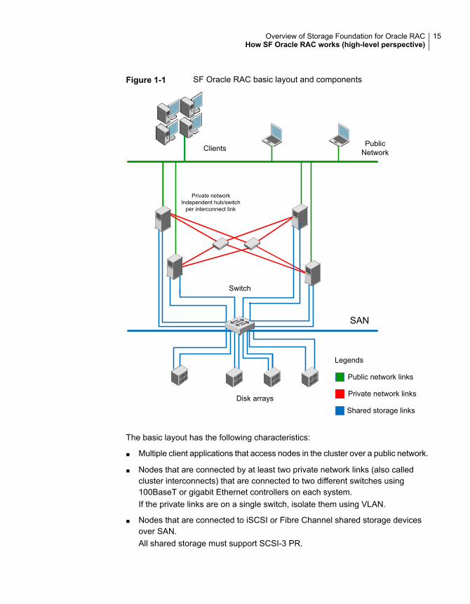
Figure 1-1 SF Oracle RAC basic layout and components
Clients
Private networkIndependent hub/switch
per interconnect link
Switch
PublicNetwork
SAN
Disk arrays
Legends
Public network links
Private network links
Shared storage links
The basic layout has the following characteristics:
■ Multiple client applications that access nodes in the cluster over a public network.
■ Nodes that are connected by at least two private network links (also calledcluster interconnects) that are connected to two different switches using100BaseT or gigabit Ethernet controllers on each system.If the private links are on a single switch, isolate them using VLAN.
■ Nodes that are connected to iSCSI or Fibre Channel shared storage devicesover SAN.All shared storage must support SCSI-3 PR.
15Overview of Storage Foundation for Oracle RACHow SF Oracle RAC works (high-level perspective)
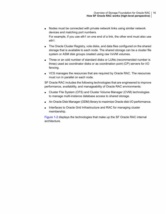
■ Nodes must be connected with private network links using similar networkdevices and matching port numbers.For example, if you use eth1 on one end of a link, the other end must also useeth1.
■ The Oracle Cluster Registry, vote disks, and data files configured on the sharedstorage that is available to each node. The shared storage can be a cluster filesystem or ASM disk groups created using raw VxVM volumes.
■ Three or an odd number of standard disks or LUNs (recommended number isthree) used as coordinator disks or as coordination point (CP) servers for I/Ofencing.
■ VCS manages the resources that are required by Oracle RAC. The resourcesmust run in parallel on each node.
SF Oracle RAC includes the following technologies that are engineered to improveperformance, availability, and manageability of Oracle RAC environments:
■ Cluster File System (CFS) and Cluster Volume Manager (CVM) technologiesto manage multi-instance database access to shared storage.
■ An Oracle Disk Manager (ODM) library to maximize Oracle disk I/O performance.
■ Interfaces to Oracle Grid Infrastructure and RAC for managing clustermembership.
Figure 1-2 displays the technologies that make up the SF Oracle RAC internalarchitecture.
16Overview of Storage Foundation for Oracle RACHow SF Oracle RAC works (high-level perspective)
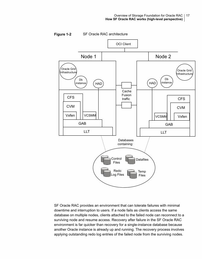
Figure 1-2 SF Oracle RAC architecture
OCI Client
Node 1 Node 2
HAD
Databasescontaining:
Datafiles
RedoLog Files
ControlFiles
TempFiles
CFS
CVM
LLT
GAB
Vxfen VCSMM
CFS
CVM
LLT
GAB
VxfenVCSMM
HAD
CacheFusiontraffic
Dbinstance
Dbinstance
Oracle GridInfrastructure Oracle Grid
Infrastructure
SF Oracle RAC provides an environment that can tolerate failures with minimaldowntime and interruption to users. If a node fails as clients access the samedatabase on multiple nodes, clients attached to the failed node can reconnect to asurviving node and resume access. Recovery after failure in the SF Oracle RACenvironment is far quicker than recovery for a single-instance database becauseanother Oracle instance is already up and running. The recovery process involvesapplying outstanding redo log entries of the failed node from the surviving nodes.
17Overview of Storage Foundation for Oracle RACHow SF Oracle RAC works (high-level perspective)
Component products and processes of SFOracleRAC
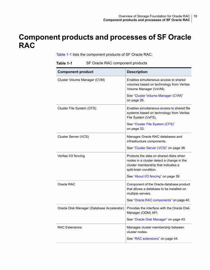
Table 1-1 lists the component products of SF Oracle RAC.
Table 1-1 SF Oracle RAC component products
DescriptionComponent product
Enables simultaneous access to sharedvolumes based on technology from VeritasVolume Manager (VxVM).
See “Cluster Volume Manager (CVM)”on page 26.
Cluster Volume Manager (CVM)
Enables simultaneous access to shared filesystems based on technology from VeritasFile System (VxFS).
See “Cluster File System (CFS)”on page 33.
Cluster File System (CFS)
Manages Oracle RAC databases andinfrastructure components.
See “Cluster Server (VCS)” on page 36.
Cluster Server (VCS)
Protects the data on shared disks whennodes in a cluster detect a change in thecluster membership that indicates asplit-brain condition.
See “About I/O fencing” on page 39.
Veritas I/O fencing
Component of the Oracle database productthat allows a database to be installed onmultiple servers.
See “Oracle RAC components” on page 40.
Oracle RAC
Provides the interface with the Oracle DiskManager (ODM) API.
See “Oracle Disk Manager” on page 43.
Oracle Disk Manager (Database Accelerator)
Manages cluster membership betweencluster nodes.
See “RAC extensions” on page 44.
RAC Extensions
18Overview of Storage Foundation for Oracle RACComponent products and processes of SF Oracle RAC
Communication infrastructureTo understand the communication infrastructure, review the data flow andcommunication requirements.
Data flowThe CVM, CFS, ODM, and Oracle RAC elements reflect the overall data flow, ordata stack, from an instance running on a server to the shared storage. The variousOracle processes composing an instance -- such as DBWR (Database Writer),LGWR (Log Writer process), CKPT (Storage Checkpoint process), and ARCH(Archive process (optional )) -- read and write data to the storage through the I/Ostack. Oracle communicates through the ODM interface to CFS, which in turnaccesses the storage through the CVM.
Figure 1-3 represents the overall data flow.
19Overview of Storage Foundation for Oracle RACComponent products and processes of SF Oracle RAC
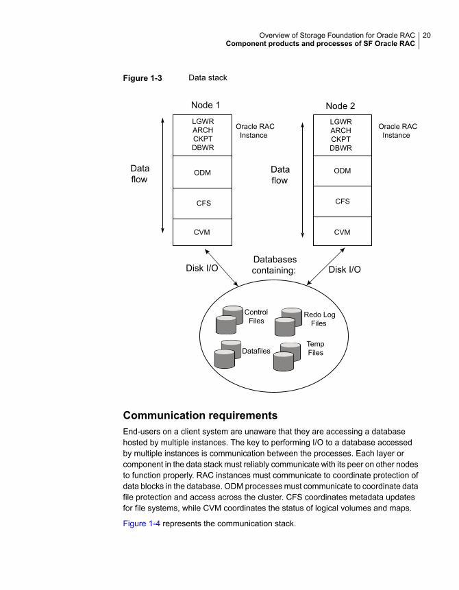
Figure 1-3 Data stack
Databasescontaining:
Node 1 Node 2
Dataflow
Dataflow
Disk I/ODisk I/O
CVM
CFS
ODM
LGWRARCHCKPTDBWR
CVM
CFS
ODM
ControlFiles
Redo LogFiles
DatafilesTempFiles
Oracle RACInstance
LGWRARCHCKPTDBWR
Oracle RACInstance
Communication requirementsEnd-users on a client system are unaware that they are accessing a databasehosted by multiple instances. The key to performing I/O to a database accessedby multiple instances is communication between the processes. Each layer orcomponent in the data stack must reliably communicate with its peer on other nodesto function properly. RAC instances must communicate to coordinate protection ofdata blocks in the database. ODM processes must communicate to coordinate datafile protection and access across the cluster. CFS coordinates metadata updatesfor file systems, while CVM coordinates the status of logical volumes and maps.
Figure 1-4 represents the communication stack.
20Overview of Storage Foundation for Oracle RACComponent products and processes of SF Oracle RAC
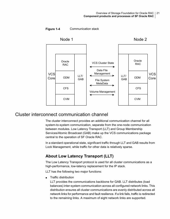
Figure 1-4 Communication stack
CVM
CFS
ODM
CVM
CFS
ODM
Node 1 Node 2
OracleRAC
OracleRAC
LLT/GAB
LLT/GAB
VCSCore
VCSCore
VCS Cluster State
Data FileManagement
File SystemMetaData
Volume Management
Cluster interconnect communication channelThe cluster interconnect provides an additional communication channel for allsystem-to-system communication, separate from the one-node communicationbetween modules. Low Latency Transport (LLT) and Group MembershipServices/Atomic Broadcast (GAB) make up the VCS communications packagecentral to the operation of SF Oracle RAC.
In a standard operational state, significant traffic through LLT and GAB results fromLock Management, while traffic for other data is relatively sparse.
About Low Latency Transport (LLT)The Low Latency Transport protocol is used for all cluster communications as ahigh-performance, low-latency replacement for the IP stack.
LLT has the following two major functions:
■ Traffic distributionLLT provides the communications backbone for GAB. LLT distributes (loadbalances) inter-system communication across all configured network links. Thisdistribution ensures all cluster communications are evenly distributed across allnetwork links for performance and fault resilience. If a link fails, traffic is redirectedto the remaining links. A maximum of eight network links are supported.
21Overview of Storage Foundation for Oracle RACComponent products and processes of SF Oracle RAC
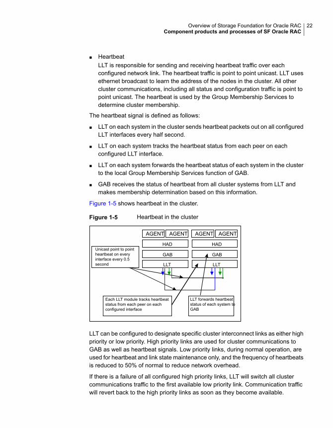
■ HeartbeatLLT is responsible for sending and receiving heartbeat traffic over eachconfigured network link. The heartbeat traffic is point to point unicast. LLT usesethernet broadcast to learn the address of the nodes in the cluster. All othercluster communications, including all status and configuration traffic is point topoint unicast. The heartbeat is used by the Group Membership Services todetermine cluster membership.
The heartbeat signal is defined as follows:
■ LLT on each system in the cluster sends heartbeat packets out on all configuredLLT interfaces every half second.
■ LLT on each system tracks the heartbeat status from each peer on eachconfigured LLT interface.
■ LLT on each system forwards the heartbeat status of each system in the clusterto the local Group Membership Services function of GAB.
■ GAB receives the status of heartbeat from all cluster systems from LLT andmakes membership determination based on this information.
Figure 1-5 shows heartbeat in the cluster.
Figure 1-5 Heartbeat in the cluster
HADUnicast point to pointheartbeat on everyinterface every 0.5second
Each LLT module tracks heartbeatstatus from each peer on eachconfigured interface
LLT forwards heartbeatstatus of each system toGAB
AGENT AGENT AGENT AGENT
HAD
GABGAB
LLTLLT
LLT can be configured to designate specific cluster interconnect links as either highpriority or low priority. High priority links are used for cluster communications toGAB as well as heartbeat signals. Low priority links, during normal operation, areused for heartbeat and link state maintenance only, and the frequency of heartbeatsis reduced to 50% of normal to reduce network overhead.
If there is a failure of all configured high priority links, LLT will switch all clustercommunications traffic to the first available low priority link. Communication trafficwill revert back to the high priority links as soon as they become available.
22Overview of Storage Foundation for Oracle RACComponent products and processes of SF Oracle RAC
While not required, best practice recommends to configure at least one low prioritylink, and to configure two high priority links on dedicated cluster interconnects toprovide redundancy in the communications path. Low priority links are typicallyconfigured on the public or administrative network.
If you use different media speed for the private NICs, Veritas recommends that youconfigure the NICs with lesser speed as low-priority links to enhance LLTperformance. With this setting, LLT does active-passive load balancing across theprivate links. At the time of configuration and failover, LLT automatically choosesthe link with high-priority as the active link and uses the low-priority links only whena high-priority link fails.
LLT sends packets on all the configured links in weighted round-robin manner. LLTuses the linkburst parameter which represents the number of back-to-back packetsthat LLT sends on a link before the next link is chosen. In addition to the defaultweighted round-robin based load balancing, LLT also provides destination-basedload balancing. LLT implements destination-based load balancing where the LLTlink is chosen based on the destination node id and the port. With destination-basedload balancing, LLT sends all the packets of a particular destination on a link.However, a potential problem with the destination-based load balancing approachis that LLT may not fully utilize the available links if the ports have dissimilar traffic.Veritas recommends destination-based load balancing when the setup has morethan two cluster nodes and more active LLT ports. You must manually configuredestination-based load balancing for your cluster to set up the port to LLT linkmapping.
See “Configuring destination-based load balancing for LLT” on page 83.
LLT on startup sends broadcast packets with LLT node id and cluster id informationonto the LAN to discover any node in the network that has same node id and clusterid pair. Each node in the network replies to this broadcast message with its clusterid, node id, and node name.
LLT on the original node does not start and gives appropriate error in the followingcases:
■ LLT on any other node in the same network is running with the same node idand cluster id pair that it owns.
■ LLT on the original node receives response from a node that does not have anode name entry in the /etc/llthosts file.
How LLT supports RDMA capability for faster interconnects betweenapplicationsLLT and GAB support fast interconnect between applications using RDMAtechnology over InfiniBand and Ethernet media (RoCE). To leverage the RDMAcapabilities of the hardware and also support the existing LLT functionalities, LLT
23Overview of Storage Foundation for Oracle RACComponent products and processes of SF Oracle RAC

maintains two channels (RDMA and non-RDMA) for each of the configured RDMAlinks. Both RDMA and non-RDMA channels are capable of transferring data betweenthe nodes and LLT provides separate APIs to their clients, such as, CFS, CVM, touse these channels. The RDMA channel provides faster data transfer by leveragingthe RDMA capabilities of the hardware. The RDMA channel is mainly used fordata-transfer when the client is capable to use this channel. The non-RDMA channelis created over the UDP layer and LLT uses this channel mainly for sending andreceiving heartbeats. Based on the health of the non-RDMA channel, GAB decidescluster membership for the cluster. The connection management of the RDMAchannel is separate from the non-RDMA channel, but the connect and disconnectoperations for the RDMA channel are triggered based on the status of the non-RDMAchannel
If the non-RDMA channel is up but due to some issues in RDMA layer the RDMAchannel is down, in such cases the data-transfer happens over the non-RDMAchannel with a lesser performance until the RDMA channel is fixed. The systemlogs displays the message when the RDMA channel is up or down.
LLT uses the Open Fabrics Enterprise Distribution (OFED) layer and the driversinstalled by the operating system to communicate with the hardware. LLT overRDMA allows applications running on one node to directly access the memory ofan application running on another node that are connected over an RDMA-enablednetwork. In contrast, on nodes connected over a non-RDMA network, applicationscannot directly read or write to an application running on another node. LLT clientssuch as, CFS and CVM, have to create intermediate copies of data beforecompleting the read or write operation on the application, which increases thelatency period and affects performance in some cases.
LLT over an RDMA network enables applications to read or write to applicationson another node over the network without the need to create intermediate copies.This leads to low latency, higher throughput, and minimized CPU host usage thusimproving application performance. Cluster volume manager and Cluster FileSystems, which are clients of LLT and GAB, can use LLT over RDMA capabilityfor specific use cases.
Group Membership Services/Atomic BroadcastThe GAB protocol is responsible for cluster membership and cluster communications.
Figure 1-6 shows the cluster communication using GAB messaging.
24Overview of Storage Foundation for Oracle RACComponent products and processes of SF Oracle RAC
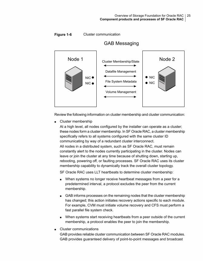
Figure 1-6 Cluster communication
Node 1 Node 2
GAB Messaging
Datafile Management
File System Metadata
Volume Management
Cluster Membership/State
NIC
NIC
NICNIC
Review the following information on cluster membership and cluster communication:
■ Cluster membershipAt a high level, all nodes configured by the installer can operate as a cluster;these nodes form a cluster membership. In SF Oracle RAC, a cluster membershipspecifically refers to all systems configured with the same cluster IDcommunicating by way of a redundant cluster interconnect.All nodes in a distributed system, such as SF Oracle RAC, must remainconstantly alert to the nodes currently participating in the cluster. Nodes canleave or join the cluster at any time because of shutting down, starting up,rebooting, powering off, or faulting processes. SF Oracle RAC uses its clustermembership capability to dynamically track the overall cluster topology.
SF Oracle RAC uses LLT heartbeats to determine cluster membership:
■ When systems no longer receive heartbeat messages from a peer for apredetermined interval, a protocol excludes the peer from the currentmembership.
■ GAB informs processes on the remaining nodes that the cluster membershiphas changed; this action initiates recovery actions specific to each module.For example, CVM must initiate volume recovery and CFS must perform afast parallel file system check.
■ When systems start receiving heartbeats from a peer outside of the currentmembership, a protocol enables the peer to join the membership.
■ Cluster communicationsGAB provides reliable cluster communication between SF Oracle RAC modules.GAB provides guaranteed delivery of point-to-point messages and broadcast
25Overview of Storage Foundation for Oracle RACComponent products and processes of SF Oracle RAC
messages to all nodes. Point-to-point messaging involves sending andacknowledging the message. Atomic-broadcast messaging ensures all systemswithin the cluster receive all messages. If a failure occurs while transmitting abroadcast message, GAB ensures all systems have the same information afterrecovery.
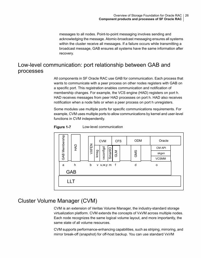
Low-level communication: port relationship between GAB andprocesses
All components in SF Oracle RAC use GAB for communication. Each process thatwants to communicate with a peer process on other nodes registers with GAB ona specific port. This registration enables communication and notification ofmembership changes. For example, the VCS engine (HAD) registers on port h.HAD receives messages from peer HAD processes on port h. HAD also receivesnotification when a node fails or when a peer process on port h unregisters.
Some modules use multiple ports for specific communications requirements. Forexample, CVM uses multiple ports to allow communications by kernel and user-levelfunctions in CVM independently.
Figure 1-7 Low-level communication
LLT
GAB
GA
BM
embe
rshi
p
HA
D
VX
FEN
GLM
GM
S
CVM CFS ODM Oracle
CM API
skgxn
VCSMM
a h b v f d o
kmsg
vxco
nfig
d
Sm
artIO
u,w,y m
Cluster Volume Manager (CVM)CVM is an extension of Veritas Volume Manager, the industry-standard storagevirtualization platform. CVM extends the concepts of VxVM across multiple nodes.Each node recognizes the same logical volume layout, and more importantly, thesame state of all volume resources.
CVM supports performance-enhancing capabilities, such as striping, mirroring, andmirror break-off (snapshot) for off-host backup. You can use standard VxVM
26Overview of Storage Foundation for Oracle RACComponent products and processes of SF Oracle RAC
commands from one node in the cluster to manage all storage. All other nodesimmediately recognize any changes in disk group and volume configuration withno user interaction.
For detailed information, see the Storage Foundation Cluster File System HighAvailability Administrator's Guide.
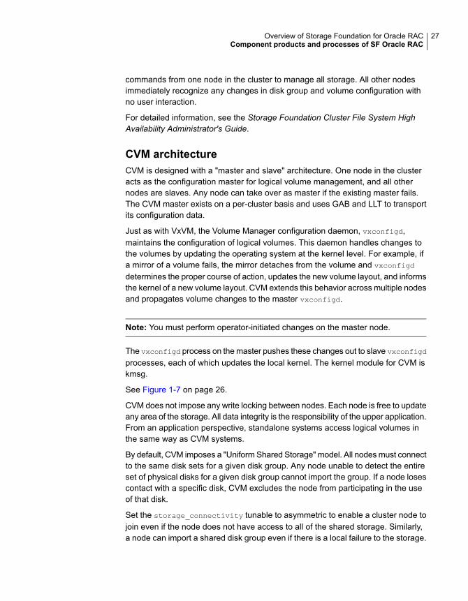
CVM architectureCVM is designed with a "master and slave" architecture. One node in the clusteracts as the configuration master for logical volume management, and all othernodes are slaves. Any node can take over as master if the existing master fails.The CVM master exists on a per-cluster basis and uses GAB and LLT to transportits configuration data.
Just as with VxVM, the Volume Manager configuration daemon, vxconfigd,maintains the configuration of logical volumes. This daemon handles changes tothe volumes by updating the operating system at the kernel level. For example, ifa mirror of a volume fails, the mirror detaches from the volume and vxconfigd
determines the proper course of action, updates the new volume layout, and informsthe kernel of a new volume layout. CVM extends this behavior across multiple nodesand propagates volume changes to the master vxconfigd.
Note: You must perform operator-initiated changes on the master node.
The vxconfigd process on the master pushes these changes out to slave vxconfigd
processes, each of which updates the local kernel. The kernel module for CVM iskmsg.
See Figure 1-7 on page 26.
CVM does not impose any write locking between nodes. Each node is free to updateany area of the storage. All data integrity is the responsibility of the upper application.From an application perspective, standalone systems access logical volumes inthe same way as CVM systems.
By default, CVM imposes a "Uniform Shared Storage" model. All nodes must connectto the same disk sets for a given disk group. Any node unable to detect the entireset of physical disks for a given disk group cannot import the group. If a node losescontact with a specific disk, CVM excludes the node from participating in the useof that disk.
Set the storage_connectivity tunable to asymmetric to enable a cluster node tojoin even if the node does not have access to all of the shared storage. Similarly,a node can import a shared disk group even if there is a local failure to the storage.
27Overview of Storage Foundation for Oracle RACComponent products and processes of SF Oracle RAC
For detailed information, see the Storage Foundation Cluster File System HighAvailability Administrator's Guide.
CVM communicationCVM communication involves various GAB ports for different types ofcommunication. For an illustration of these ports:
See Figure 1-7 on page 26.
CVM communication involves the following GAB ports:
■ Port wMost CVM communication uses port w for vxconfigd communications. Duringany change in volume configuration, such as volume creation, plex attachmentor detachment, and volume resizing, vxconfigd on the master node uses portw to share this information with slave nodes.When all slaves use port w to acknowledge the new configuration as the nextactive configuration, the master updates this record to the disk headers in theVxVM private region for the disk group as the next configuration.
■ Port mCVM uses port m for SmartIO VxVM cache coherency using Group LockManager (GLM).
■ Port vCVM uses port v for kernel-to-kernel communication. During specific configurationevents, certain actions require coordination across all nodes. An example ofsynchronizing events is a resize operation. CVM must ensure all nodes see thenew or old size, but never a mix of size among members.CVM also uses this port to obtain cluster membership from GAB and determinethe status of other CVM members in the cluster.
■ Port uCVM uses the group atomic broadcast (GAB) port u to ship the commands fromthe slave node to the master node.
■ Port yCVM uses port y for kernel-to-kernel communication required while shippingI/Os from nodes that might have lost local access to storage to other nodes inthe cluster.
CVM recoveryWhen a node leaves a cluster, the new membership is delivered by GAB, to CVMon existing cluster nodes. The fencing driver (VXFEN) ensures that split-brainscenarios are taken care of before CVM is notified. CVM then initiates recovery of
28Overview of Storage Foundation for Oracle RACComponent products and processes of SF Oracle RAC
mirrors of shared volumes that might have been in an inconsistent state followingthe exit of the node.
For database files, when ODM is enabled with SmartSync option, Oracle Resilveringhandles recovery of mirrored volumes. For non-database files, this recovery isoptimized using Dirty Region Logging (DRL). The DRL is a map stored in a specialpurpose VxVM sub-disk and attached as an additional plex to the mirrored volume.When a DRL subdisk is created for a shared volume, the length of the sub-disk isautomatically evaluated so as to cater to the number of cluster nodes. If the sharedvolume has Fast Mirror Resync (FlashSnap) enabled, the DCO (Data ChangeObject) log volume created automatically has DRL embedded in it. In the absenceof DRL or DCO, CVM does a full mirror resynchronization.
Configuration differences with VxVMCVM configuration differs from VxVM configuration in the following areas:
■ Configuration commands occur on the master node.
■ Disk groups are created and imported as shared disk groups. (Disk groups canalso be private.)
■ Disk groups are activated per node.
■ Shared disk groups are automatically imported when CVM starts.
About Flexible Storage SharingFlexible Storage Sharing (FSS) enables network sharing of local storage, clusterwide. The local storage can be in the form of Direct Attached Storage (DAS) orinternal disk drives. Network shared storage is enabled by using a networkinterconnect between the nodes of a cluster.
FSS allows network shared storage to co-exist with physically shared storage, andlogical volumes can be created using both types of storage creating a commonstorage namespace. Logical volumes using network shared storage provide dataredundancy, high availability, and disaster recovery capabilities, without requiringphysically shared storage, transparently to file systems and applications.
FSS can be used with SmartIO technology for remote caching to service nodesthat may not have local SSDs.
FSS is supported on clusters containing up to 64 nodes with CVM protocol versions140 and above. For more details, refer to the Veritas InfoScale Release Notes.
Figure 1-8 shows a Flexible Storage Sharing environment.
29Overview of Storage Foundation for Oracle RACComponent products and processes of SF Oracle RAC
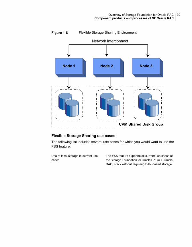
Figure 1-8 Flexible Storage Sharing Environment
Node 1 Node 2 Node 3
Network Interconnect
CVM Shared Disk Group
Flexible Storage Sharing use casesThe following list includes several use cases for which you would want to use theFSS feature:
The FSS feature supports all current use cases ofthe Storage Foundation for Oracle RAC (SF OracleRAC) stack without requiring SAN-based storage.
Use of local storage in current usecases
30Overview of Storage Foundation for Oracle RACComponent products and processes of SF Oracle RAC
Data Migration:
■ From shared (SAN) storage to network sharedstorage
■ From network shared storage to SAN storage■ From storage connected to one node
(DAS)/cluster to the storage connected to adifferent node (DAS)/cluster, that do not sharethe storage
Back-up/Snapshots:
An additional node can take a back-up by joiningthe cluster and reading from volumes/snapshotsthat are hosted on the DAS/shared storage, whichis connected to one or more nodes of the cluster,but not the host taking the back-up.
Off-host processing
■ Mirroring across DAS SSDs connected toindividual nodes of the cluster. DAS SSDsprovides better performance than SAN storage(including SSDs). FSS provides a way to sharethese SSDs across cluster.
■ Keeping one mirror on the SSD and another onthe SAN storage provides faster read accessdue to the SSDs, and also provide highavailability of data due to the SAN storage.
■ There are several best practices for using SSDswith Storage Foundation. All the use-cases arepossible with SAN attached SSDs in clusteredenvironment. With FSS, DAS SSDs can alsobe used for similar purposes.
DAS SSD benefits leveraged withexisting SF Oracle RAC features
If the nodes in the cluster have internal SSDs aswell as HDDs, the HDDs can be shared over thenetwork using FSS. You can use SmartIO to setup a read/write-back cache using the SSDs. Theread cache can service volumes created using thenetwork-shared HDDs.
FSS with SmartIO for file systemcaching
31Overview of Storage Foundation for Oracle RACComponent products and processes of SF Oracle RAC
FSS works with SmartIO to provide cachingservices for nodes that do not have local SSDdevices.
In this scenario, Flexible Storage Sharing (FSS)exports SSDs from nodes that have a local SSD.FSS then creates a pool of the exported SSDs inthe cluster. From this shared pool, a cache area iscreated for each node in the cluster. Each cachearea is accessible only to that particular node forwhich it is created. The cache area can be of type,VxVM or VxFS.
The cluster must be a CVM cluster.
The volume layout of the cache area on remoteSSDs follows the simple stripe layout, not thedefault FSS allocation policy of mirroring acrosshost. If the caching operation degradesperformance on a particular volume, then cachingis disabled for that particular volume. The volumesthat are used to create cache areas must becreated on disk groups with disk group version 200or later. However, data volumes that are createdon disk groups with disk group version 190 or latercan access the cache area created on FSSexported devices.
Note: CFS write-back caching is not supportedfor cache areas created on remote SSDs.
For more information, see the document VeritasInfoScale SmartIO for Solid State Drives SolutionsGuide.
FSS with SmartIO for remote caching
Campus clusters can be set up without the needfor Fibre Channel (FC) SAN connectivity betweensites.
Campus cluster configuration
See “Administering Flexible Storage Sharing” on page 142.
Limitations of Flexible Storage SharingNote the following limitations for using Flexible Storage Sharing (FSS):
■ FSS is only supported on clusters of up to 64 nodes.
■ Disk initialization operations should be performed only on nodes with localconnectivity to the disk.
32Overview of Storage Foundation for Oracle RACComponent products and processes of SF Oracle RAC
■ FSS does not support the use of boot disks, opaque disks, and non-VxVM disksfor network sharing.
■ Hot-relocation is disabled on FSS disk groups.
■ The VxVM cloned disks operations are not supported with FSS disk groups.
■ FSS does not support non-SCSI3 disks connected to multiple hosts.
■ Dynamic LUN Expansion (DLE) is not supported.
■ FSS only supports instant data change object (DCO), created using the vxsnap
operation or by specifying "logtype=dco dcoversion=20" attributes during volumecreation.
■ By default creating a mirror between SSD and HDD is not supported throughvxassist, as the underlying mediatypes are different. To workaround this issue,you can create a volume with one mediatype, for instance the HDD, which isthe default mediatype, and then later add a mirror on the SSD.For example:
# vxassist -g diskgroup make volume size init=none
# vxassist -g diskgroup mirror volume mediatype:ssd
# vxvol -g diskgroup init active volume
See “Administering mirrored volumes using vxassist” on page 147.
Cluster File System (CFS)CFS enables you to simultaneously mount the same file system on multiple nodesand is an extension of the industry-standard Veritas File System. Unlike other filesystems which send data through another node to the storage, CFS is a true SANfile system. All data traffic takes place over the storage area network (SAN), andonly the metadata traverses the cluster interconnect.
In addition to using the SAN fabric for reading and writing data, CFS offers StorageCheckpoint and rollback for backup and recovery.
Access to cluster storage in typical SF Oracle RAC configurations use CFS. Rawaccess to CVM volumes is also possible but not part of a common configuration.
For detailed information, see the Storage Foundation Cluster File System HighAvailability Administrator's documentation.
33Overview of Storage Foundation for Oracle RACComponent products and processes of SF Oracle RAC
CFS architectureSF Oracle RAC uses CFS to manage a file system in a large database environment.Since CFS is an extension of VxFS, it operates in a similar fashion and cachesmetadata and data in memory (typically called buffer cache or vnode cache). CFSuses a distributed locking mechanism called Global Lock Manager (GLM) to ensureall nodes have a consistent view of the file system. GLM provides metadata andcache coherency across multiple nodes by coordinating access to file systemmetadata, such as inodes and free lists. The role of GLM is set on a per-file systembasis to enable load balancing.
CFS involves a primary/secondary architecture. One of the nodes in the cluster isthe primary node for a file system. Though any node can initiate an operation tocreate, delete, or resize data, the GLM master node carries out the actual operation.After creating a file, the GLM master node grants locks for data coherency acrossnodes. For example, if a node tries to modify a block in a file, it must obtain anexclusive lock to ensure other nodes that may have the same file cached have thiscached copy invalidated.
SF Oracle RAC configurations minimize the use of GLM locking. Oracle RACaccesses the file system through the ODM interface and handles its own locking;only Oracle (and not GLM) buffers data and coordinates write operations to files.A single point of locking and buffering ensures maximum performance. GLM lockingis only involved when metadata for a file changes, such as during create and resizeoperations.
CFS communicationCFS uses port f for GLM lock and metadata communication. SF Oracle RACconfigurations minimize the use of GLM locking except when metadata for a filechanges.
CFS file system benefitsMany features available in VxFS do not come into play in an SF Oracle RACenvironment because ODM handles such features. CFS adds such features ashigh availability, consistency and scalability, and centralized management to VxFS.Using CFS in an SF Oracle RAC environment provides the following benefits:
■ Increased manageability, including easy creation and expansion of filesIn the absence of CFS, you must provide Oracle with fixed-size partitions. WithCFS, you can grow file systems dynamically to meet future requirements.
■ Less prone to user error
34Overview of Storage Foundation for Oracle RACComponent products and processes of SF Oracle RAC
Raw partitions are not visible and administrators can compromise them bymistakenly putting file systems over the partitions. Nothing exists in Oracle toprevent you from making such a mistake.
■ Data center consistencyIf you have raw partitions, you are limited to a RAC-specific backup strategy.CFS enables you to implement your backup strategy across the data center.
CFS configuration differencesThe first node to mount a CFS file system as shared becomes the primary nodefor that file system. All other nodes are "secondaries" for that file system.
Mount the cluster file system individually from each node. The -o cluster option ofthe mount command mounts the file system in shared mode, which means you canmount the file system simultaneously on mount points on multiple nodes.
When using the fsadm utility for online administration functions on VxFS file systems,including file system resizing, defragmentation, directory reorganization, and queryingor changing the largefiles flag, run fsadm from any node.
CFS recoveryThe vxfsckd daemon is responsible for ensuring file system consistency when anode crashes that was a primary node for a shared file system. If the local node isa secondary node for a given file system and a reconfiguration occurs in which thisnode becomes the primary node, the kernel requests vxfsckd on the new primarynode to initiate a replay of the intent log of the underlying volume. The vxfsckddaemon forks a special call to fsck that ignores the volume reservation protectionnormally respected by fsck and other VxFS utilities. The vxfsckd can check severalvolumes at once if the node takes on the primary role for multiple file systems.
After a secondary node crash, no action is required to recover file system integrity.As with any crash on a file system, internal consistency of application data forapplications running at the time of the crash is the responsibility of the applications.
Comparing raw volumes and CFS for data filesKeep these points in mind about raw volumes and CFS for data files:
■ If you use file-system-based data files, the file systems containing these filesmust be located on shared disks. Create the same file system mount point oneach node.
■ If you use raw devices, such as VxVM volumes, set the permissions for thevolumes to be owned permanently by the database account.
35Overview of Storage Foundation for Oracle RACComponent products and processes of SF Oracle RAC
VxVM sets volume permissions on import. The VxVM volume, and any filesystem that is created in it, must be owned by the Oracle database user.
Cluster Server (VCS)Cluster Server (VCS) directs SF Oracle RAC operations by controlling the startupand shutdown of components layers and providing monitoring and notification forfailures.
In a typical SF Oracle RAC configuration, the Oracle RAC service groups for VCSrun as "parallel" service groups rather than "failover" service groups; in the eventof a failure, VCS does not attempt to migrate a failed service group. Instead, thesoftware enables you to configure the group to restart on failure.
VCS architectureThe High Availability Daemon (HAD) is the main VCS daemon running on eachnode. HAD tracks changes in the cluster configuration and monitors resource statusby communicating over GAB and LLT. HAD manages all application services usingagents, which are installed programs to manage resources (specific hardware orsoftware entities).
The VCS architecture is modular for extensibility and efficiency. HAD does not needto know how to start up Oracle or any other application under VCS control. Instead,you can add agents to manage different resources with no effect on the engine(HAD). Agents only communicate with HAD on the local node and HADcommunicates status with HAD processes on other nodes. Because agents do notneed to communicate across systems, VCS is able to minimize traffic on the clusterinterconnect.
SF Oracle RAC provides specific agents for VCS to manage CVM, CFS, and Oraclecomponents like Oracle Grid Infrastructure and database (including instances).
VCS communicationVCS uses port h for HAD communication. Agents communicate with HAD on thelocal node about resources, and HAD distributes its view of resources on that nodeto other nodes through GAB port h. HAD also receives information from other clustermembers to update its own view of the cluster.
About the IMF notification moduleThe notification module of Intelligent Monitoring Framework (IMF) is theAsynchronous Monitoring Framework (AMF).
AMF is a kernel driver which hooks into system calls and other kernel interfaces ofthe operating system to get notifications on various events such as:
36Overview of Storage Foundation for Oracle RACComponent products and processes of SF Oracle RAC
■ When a process starts or stops.
■ When a block device gets mounted or unmounted from a mount point.
AMF also interacts with the Intelligent Monitoring Framework Daemon (IMFD) toget disk group related notifications. AMF relays these notifications to various VCSAgents that are enabled for intelligent monitoring.
See “About resource monitoring” on page 37.
About resource monitoringVCS agents poll the resources periodically based on the monitor interval (in seconds)value that is defined in the MonitorInterval or in the OfflineMonitorInterval resourcetype attributes. After each monitor interval, VCS invokes the monitor agent functionfor that resource. For example, for process offline monitoring, the process agent'smonitor agent function corresponding to each process resource scans the processtable in each monitor interval to check whether the process has come online. Forprocess online monitoring, the monitor agent function queries the operating systemfor the status of the process id that it is monitoring. In case of the mount agent, themonitor agent function corresponding to each mount resource checks if the blockdevice is mounted on the mount point or not. In order to determine this, the monitorfunction does operations such as mount table scans or runs statfs equivalents.
With intelligent monitoring framework (IMF), VCS supports intelligent resourcemonitoring in addition to poll-based monitoring. IMF is an extension to the VCSagent framework. You can enable or disable the intelligent monitoring functionalityof the VCS agents that are IMF-aware. For a list of IMF-aware agents, see theCluster Server Bundled Agents Reference Guide.
See “How intelligent resource monitoring works” on page 38.
See “Enabling and disabling intelligent resource monitoring for agents manually”on page 83.
Poll-based monitoring can consume a fairly large percentage of system resourcessuch as CPU and memory on systems with a huge number of resources. This notonly affects the performance of running applications, but also places a limit on howmany resources an agent can monitor efficiently.
However, with IMF-based monitoring you can either eliminate poll-based monitoringcompletely or reduce its frequency. For example, for process offline and onlinemonitoring, you can completely avoid the need for poll-based monitoring withIMF-based monitoring enabled for processes. Similarly for vxfs mounts, you caneliminate the poll-based monitoring with IMF monitoring enabled. Such reductionin monitor footprint will make more system resources available for other applicationsto consume.
37Overview of Storage Foundation for Oracle RACComponent products and processes of SF Oracle RAC
Note: Intelligent Monitoring Framework for mounts is supported only for the VxFS,CFS, and NFS mount types.
With IMF-enabled agents, VCS will be able to effectively monitor larger number ofresources.
Thus, intelligent monitoring has the following benefits over poll-based monitoring:
■ Provides faster notification of resource state changes
■ Reduces VCS system utilization due to reduced monitor function footprint
■ Enables VCS to effectively monitor a large number of resources
Consider enabling IMF for an agent in the following cases:
■ You have a large number of process resources or mount resources under VCScontrol.
■ You have any of the agents that are IMF-aware.
For information about IMF-aware agents, see the following documentation:
■ See the Cluster Server Bundled Agents Reference Guide for details on whetheryour bundled agent is IMF-aware.
■ See the Cluster Server Agent for Oracle Installation and Configuration Guidefor IMF-aware agents for Oracle.
■ See the Storage Foundation Cluster File System High Availability InstallationGuide for IMF-aware agents in CFS environments.
How intelligent resource monitoring worksWhen an IMF-aware agent starts up, the agent initializes with the IMF notificationmodule. After the resource moves to a steady state, the agent registers the detailsthat are required to monitor the resource with the IMF notification module. Forexample, the process agent registers the PIDs of the processes with the IMFnotification module. The agent's imf_getnotification function waits for any resourcestate changes. When the IMF notification module notifies the imf_getnotificationfunction about a resource state change, the agent framework runs the monitor agentfunction to ascertain the state of that resource. The agent notifies the state changeto VCS which takes appropriate action.
A resource moves into a steady state when any two consecutive monitor agentfunctions report the state as ONLINE or as OFFLINE. The following are a fewexamples of how steady state is reached.
■ When a resource is brought online, a monitor agent function is scheduled afterthe online agent function is complete. Assume that this monitor agent functionreports the state as ONLINE. The next monitor agent function runs after a time
38Overview of Storage Foundation for Oracle RACComponent products and processes of SF Oracle RAC
interval specified by the MonitorInterval attribute. If this monitor agent functiontoo reports the state as ONLINE, a steady state is achieved because twoconsecutive monitor agent functions reported the resource state as ONLINE.After the second monitor agent function reports the state as ONLINE, theregistration command for IMF is scheduled. The resource is registered with theIMF notification module and the resource comes under IMF control.The defaultvalue of MonitorInterval is 60 seconds.A similar sequence of events applies for taking a resource offline.
■ Assume that IMF is disabled for an agent type and you enable IMF for the agenttype when the resource is ONLINE. The next monitor agent function occurs aftera time interval specified by MonitorInterval. If this monitor agent function againreports the state as ONLINE, a steady state is achieved because two consecutivemonitor agent functions reported the resource state as ONLINE.A similar sequence of events applies if the resource is OFFLINE initially andthe next monitor agent function also reports the state as OFFLINE after youenable IMF for the agent type.
See “About the IMF notification module” on page 36.
Cluster configuration filesVCS uses two configuration files in a default configuration:
■ The main.cf file defines the entire cluster, including the cluster name, systemsin the cluster, and definitions of service groups and resources, in addition toservice group and resource dependencies.
■ The types.cf file defines the resource types. Each resource in a cluster isidentified by a unique name and classified according to its type. VCS includesa set of pre-defined resource types for storage, networking, and applicationservices.
Additional files similar to types.cf may be present if you add agents. For example,SF Oracle RAC includes additional resource types files, such as OracleTypes.cf,PrivNIC.cf, and MultiPrivNIC.cf.
About I/O fencingI/O fencing protects the data on shared disks when nodes in a cluster detect achange in the cluster membership that indicates a split-brain condition.
The fencing operation determines the following:
■ The nodes that must retain access to the shared storage
■ The nodes that must be ejected from the cluster
39Overview of Storage Foundation for Oracle RACComponent products and processes of SF Oracle RAC
This decision prevents possible data corruption. The installer installs the I/O fencingdriver, part of VRTSvxfen RPM, when you install Veritas InfoScale Enterprise. Toprotect data on shared disks, you must configure I/O fencing after you install VeritasInfoScale Enterprise and configure SF Oracle RAC.
With disk-based or server-based I/O fencing, coordination points can be eithercoordinator disks or coordination point servers (CP servers) or both. You canconfigure disk-based or server-based I/O fencing:
I/O fencing that uses coordinator disks is referredto as disk-based I/O fencing.
Disk-based I/O fencing ensures data integrity in asingle cluster.
Disk-based I/O fencing
I/O fencing that uses at least one CP server systemis referred to as server-based I/O fencing.Server-based fencing can include only CP servers,or a mix of CP servers and coordinator disks.
Server-based I/O fencing ensures data integrity inclusters.
Server-based I/O fencing
For detailed information, see the Cluster Server Administrator's Guide.
Review the following notes:
■ The CP server provides an alternative arbitration mechanism without having todepend on SCSI-3 compliant coordinator disks. Data disk fencing in CVM willstill require SCSI-3 I/O fencing.
■ SF Oracle RAC requires at least 3 CP servers to function as coordination pointsin the cluster.
See the Storage Foundation for Oracle RAC Configuration and Upgrade Guide.
Oracle RAC componentsThis section provides a brief description of Oracle Clusterware/Grid Infrastructure,the Oracle Cluster Registry, application resources, and the voting disk.
Note: Refer to the Oracle RAC documentation for additional information.
40Overview of Storage Foundation for Oracle RACComponent products and processes of SF Oracle RAC
Oracle Clusterware/Grid InfrastructureOracle Clusterware/Grid Infrastructure manages Oracle cluster-related functionsincluding membership, group services, global resource management, and databases.Oracle Clusterware/Grid Infrastructure is required for every Oracle RAC instance.
Oracle Clusterware/Grid Infrastructure requires the following major components:
■ A cluster interconnect that allows for cluster communications
■ A private virtual IP address for cluster communications over the interconnect
■ A public virtual IP address for client connections
■ For Oracle 11g Release 2 and later versions, a public IP address as a SingleClient Access Name (SCAN) address on the Domain Name Server (DNS) forround robin resolution to three IP addresses (recommended) or at least one IPaddress
■ Shared storage accessible by each node
Co-existence with VCSOracle Clusterware/Grid Infrastructure supports co-existence with vendorclusterwares such as Cluster Server. When you install Oracle Clusterware/GridInfrastructure on an SF Oracle RAC cluster, Oracle Clusterware/Grid Infrastructuredetects the presence of VCS by checking the presence of the Veritas membershipmodule (VCSMM) library. It obtains the list of nodes in the cluster from the VCSMMlibrary at the time of installation.
When a node fails to respond across the interconnect, Oracle Clusterware/GridInfrastructure waits before evicting another node from the cluster. This wait-time isdefined by the CSS miss-count value. Oracle Clusterware/Grid Infrastructure setsthe CSS miss-count parameter to a larger value (600 seconds) in the presence ofVCS. This value is much higher than the LLT peer inactivity timeout interval. Thus,in the event of a network split-brain, the two clusterwares, VCS and OracleClusterware/Grid Infrastructure, do not interfere with each other’s decisions onwhich nodes remain in the cluster. I/O fencing is allowed to decide on the survivingnodes first, followed by Oracle Clusterware/Grid Infrastructure.
VCS uses LLT for communicating between cluster nodes over private interconnectswhile Oracle Clusterware/Grid Infrastructure uses private IP addresses configuredover the private interconnects to communicate between the cluster nodes. Tocoordinate membership changes between VCS and Oracle Clusterware/GridInfrastructure, it is important to configure the Oracle Clusterware/Grid Infrastructureprivate IP address over the network interfaces used by LLT. VCS uses the CSSDagent to start, stop, and monitor Oracle Clusterware/Grid Infrastructure. The CSSDagent ensures that the OCR, the voting disk, and the private IP address resourcesrequired by Oracle Clusterware/Grid Infrastructure are brought online by VCS before
41Overview of Storage Foundation for Oracle RACComponent products and processes of SF Oracle RAC
Oracle Clusterware/Grid Infrastructure starts. This prevents the premature startupof Oracle Clusterware/Grid Infrastructure, which causes cluster failures.
Oracle Cluster RegistryThe Oracle Cluster Registry (OCR) contains cluster and database configurationand state information for Oracle RAC and Oracle Clusterware/Grid Infrastructure.
The information maintained in the OCR includes:
■ The list of nodes
■ The mapping of database instances to nodes
■ Oracle Clusterware application resource profiles
■ Resource profiles that define the properties of resources under OracleClusterware/Grid Infrastructure control
■ Rules that define dependencies between the Oracle Clusterware/GridInfrastructure resources
■ The current state of the cluster
In Oracle RAC 11g Release 2 and later versions, the OCR data exists on ASM ora cluster file system that is accessible to each node.
Use CVM mirrored volumes to protect OCR data from failures.OracleClusterware/Grid Infrastructure faults nodes if OCR is not accessible because ofcorruption or disk failure. Oracle automatically backs up OCR data. You can alsoexport the OCR contents before making configuration changes in OracleClusterware/Grid Infrastructure. This way, if you encounter configuration problemsand are unable to restart Oracle Clusterware/Grid Infrastructure, you can restorethe original contents.
Consult the Oracle documentation for instructions on exporting and restoring OCRcontents.
Application resourcesOracle Clusterware/Grid Infrastructure application resources are similar to VCSresources. Each component controlled by Oracle Clusterware/Grid Infrastructureis defined by an application resource, including databases, instances, services, andnode applications.
Unlike VCS, Oracle Clusterware/Grid Infrastructure uses separate resources forcomponents that run in parallel on multiple nodes.
42Overview of Storage Foundation for Oracle RACComponent products and processes of SF Oracle RAC
Resource profilesResources are defined by profiles, which are similar to the attributes that defineVCS resources. The OCR contains application resource profiles, dependencies,and status information.
Oracle Clusterware/Grid Infrastructure node applicationsOracle Clusterware/Grid Infrastructure uses these node application resources tomanage Oracle components, such as databases, listeners, and virtual IP addresses.Node application resources are created during Oracle Clusterware/Grid Infrastructureinstallation.
Voting diskThe voting disk is a heartbeat mechanism used by Oracle Clusterware/GridInfrastructure to maintain cluster node membership.
In Oracle RAC 11g Release 2 and later versions, voting disk data exists on ASMor on a cluster file system that is accessible to each node.
The Oracle Clusterware Cluster Synchronization Service daemon (ocssd) providescluster node membership and group membership information to RAC instances.On each node, ocssd processes write a heartbeat to the voting disk every second.If a node is unable to access the voting disk, Oracle Clusterware/Grid Infrastructuredetermines the cluster is in a split-brain condition and panics the node in a way thatonly one sub-cluster remains.
Oracle Disk ManagerSF Oracle RAC requires Oracle Disk Manager (ODM), a standard API publishedby Oracle for support of database I/O. SF Oracle RAC provides a library for Oracleto use as its I/O library.
ODM architectureWhen the Veritas ODM library is linked, Oracle is able to bypass all caching andlocks at the file system layer and to communicate directly with raw volumes. TheSF Oracle RAC implementation of ODM generates performance equivalent toperformance with raw devices while the storage uses easy-to-manage file systems.
All ODM features can operate in a cluster environment. Nodes communicate witheach other before performing any operation that could potentially affect anothernode. For example, before creating a new data file with a specific name, ODMchecks with other nodes to see if the file name is already in use.
43Overview of Storage Foundation for Oracle RACComponent products and processes of SF Oracle RAC
Veritas ODM performance enhancementsVeritas ODM enables the following performance benefits provided by Oracle DiskManager:
■ Locking for data integrity.
■ Few system calls and context switches.
■ Increased I/O parallelism.
■ Efficient file creation and disk allocation.
Databases using file systems typically incur additional overhead:
■ Extra CPU and memory usage to read data from underlying disks to the filesystem cache. This scenario requires copying data from the file system cacheto the Oracle cache.
■ File locking that allows for only a single writer at a time. Allowing Oracle toperform locking allows for finer granularity of locking at the row level.
■ File systems generally go through a standard Sync I/O library when performingI/O. Oracle can make use of Kernel Async I/O libraries (KAIO) with raw devicesto improve performance.
ODM communicationODM uses port d to communicate with ODM instances on other nodes in the cluster.
RAC extensionsOracle RAC relies on support services provided by VCS such as Veritas ClusterServer Membership Manager (VCSMM) to protect data integrity.
Veritas Cluster Server membership managerTo protect data integrity by coordinating locking between RAC instances, Oraclemust know which instances actively access a database. Oracle provides an APIcalled skgxn (system kernel generic interface node membership) to obtaininformation on membership. SF Oracle RAC implements this API as a library linkedto Oracle after you install Oracle RAC. Oracle uses the linked skgxn library to makeioctl calls to VCSMM, which in turn obtains membership information for clustersand instances by communicating with GAB on port o.
Oracle and cache fusion trafficPrivate IP addresses are required by Oracle for cache fusion traffic.
44Overview of Storage Foundation for Oracle RACComponent products and processes of SF Oracle RAC
You must use UDP IPC for the database cache fusion traffic.
Periodic health evaluation of SF Oracle RACclusters
SF Oracle RAC provides a health check utility that evaluates the components andconfiguration in an SF Oracle RAC cluster. The utility when invoked gathers real-timeoperational information on cluster components and displays the report on yoursystem console. You must run the utility on each node in the cluster.
The utility evaluates the health of the following components:
■ Low Latency Transport (LLT)
■ LLT Multiplexer (LMX)
■ VCSMM
■ I/O fencing
■ Oracle Clusterware/Grid Infrastructure
■ PrivNIC and MultiPrivNIC
The health check utility is installed at/opt/VRTSvcs/rac/healthcheck/healthcheck during the installation of SF OracleRAC.
The utility determines the health of the components by gathering information fromconfiguration files or by reading the threshold values set in the health checkconfiguration file /opt/VRTSvcs/rac/healthcheck/healthcheck.cf
The utility displays a warning message when the operational state of the componentviolates the configured settings for the component or when the health scoreapproaches or exceeds the threshold value. You can modify the health checkconfiguration file to set the threshold values to the desired level.
The health checks for the I/O fencing, PrivNIC, MultiPrivNIC, and Oracle Clusterwarecomponents do not use threshold settings.
Note: You must set the ORACLE_HOME and CRS_HOME parameters in the configurationfile as appropriate for your setup.
Table 1-2 provides guidelines on changing the threshold values.
45Overview of Storage Foundation for Oracle RACPeriodic health evaluation of SF Oracle RAC clusters
Table 1-2 Setting threshold values
Setting the thresholdRequirement
Reduce the corresponding threshold value.To detect warnings early
Increase the corresponding threshold value.
Warning: Using very high threshold values can prevent thehealth check utility from forecasting potential problems in thecluster. Exercise caution with high values.
To suppress warnings
Note: You can schedule periodic health evaluation of your clusters, by schedulingthe utility to run as a cron job.
See “Scheduling periodic health checks for your SF Oracle RAC cluster” on page 68.
For detailed information on the list of health checks performed for each component,see the appendix List of SF Oracle RAC health checks.
About Virtual Business ServicesVirtual Business Services provide continuous high availability and reduce frequencyand duration of service disruptions for multi-tier business applications running onheterogeneous operating systems and virtualization technologies. A Virtual BusinessService represents the multi-tier application as a single consolidated entity andbuilds on the high availability and disaster recovery provided for the individual tiersby products such as Cluster Server and ApplicationHA. Additionally, a VirtualBusiness Service can also represent all the assets used by the service such asarrays, hosts, and file systems, though they are not migrated between server tiers.A Virtual Business Service provides a single consolidated entity that represents amulti-tier business service in its entirety. Application components that are managedby Cluster Server or ApplicationHA can be actively managed through a VirtualBusiness Service.
You can configure and manage Virtual Business Services created in VeritasInfoScale Operations Manager by using Veritas InfoScale Operations ManagerVirtual Business Services Availability Add-on. Besides providing all the functionalitythat was earlier available through Business Entity Operations Add-on, VBSAvailability Add-on provides the additional ability to configure fault dependenciesbetween the components of the multi-tier application.
46Overview of Storage Foundation for Oracle RACAbout Virtual Business Services
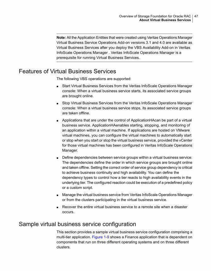
Note:All the Application Entities that were created using Veritas Operations ManagerVirtual Business Service Operations Add-on versions 3.1 and 4.0 are available asVirtual Business Services after you deploy the VBS Availability Add-on in VeritasInfoScale Operations Manager . Veritas InfoScale Operations Manager is aprerequisite for running Virtual Business Services.
Features of Virtual Business ServicesThe following VBS operations are supported:
■ Start Virtual Business Services from the Veritas InfoScale Operations Managerconsole: When a virtual business service starts, its associated service groupsare brought online.
■ Stop Virtual Business Services from the Veritas InfoScale Operations Managerconsole: When a virtual business service stops, its associated service groupsare taken offline.
■ Applications that are under the control of ApplicationHAcan be part of a virtualbusiness service. ApplicationHAenables starting, stopping, and monitoring ofan application within a virtual machine. If applications are hosted on VMwarevirtual machines, you can configure the virtual machines to automatically startor stop when you start or stop the virtual business service, provided the vCenterfor those virtual machines has been configured in Veritas InfoScale OperationsManager.
■ Define dependencies between service groups within a virtual business service:The dependencies define the order in which service groups are brought onlineand taken offline. Setting the correct order of service group dependency is criticalto achieve business continuity and high availability. You can define thedependency types to control how a tier reacts to high availability events in theunderlying tier. The configured reaction could be execution of a predefined policyor a custom script.
■ Manage the virtual business service from Veritas InfoScale Operations Manageror from the clusters participating in the virtual business service.
■ Recover the entire virtual business service to a remote site when a disasteroccurs.
Sample virtual business service configurationThis section provides a sample virtual business service configuration comprising amulti-tier application. Figure 1-9 shows a Finance application that is dependent oncomponents that run on three different operating systems and on three differentclusters.
47Overview of Storage Foundation for Oracle RACAbout Virtual Business Services
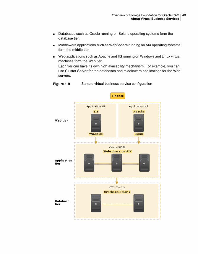
■ Databases such as Oracle running on Solaris operating systems form thedatabase tier.
■ Middleware applications such as WebSphere running on AIX operating systemsform the middle tier.
■ Web applications such as Apache and IIS running on Windows and Linux virtualmachines form the Web tier.Each tier can have its own high availability mechanism. For example, you canuse Cluster Server for the databases and middleware applications for the Webservers.
Figure 1-9 Sample virtual business service configuration
48Overview of Storage Foundation for Oracle RACAbout Virtual Business Services
Each time you start the Finance business application, typically you need to bringthe components online in the following order – Oracle database, WebSphere,Apache and IIS. In addition, you must bring the virtual machines online before youstart the Web tier. To stop the Finance application, you must take the componentsoffline in the reverse order. From the business perspective, the Finance service isunavailable if any of the tiers becomes unavailable.
When you configure the Finance application as a virtual business service, you canspecify that the Oracle database must start first, followed by WebSphere and theWeb servers. The reverse order automatically applies when you stop the virtualbusiness service. When you start or stop the virtual business service, thecomponents of the service are started or stopped in the defined order.
For more information about Virtual Business Services, refer to the Virtual BusinessService–Availability User’s Guide.
About Veritas InfoScale Operations ManagerVeritas InfoScale Operations Manager provides a centralized management consolefor Veritas InfoScale products. You can use Veritas InfoScale Operations Managerto monitor, visualize, and manage storage resources and generate reports.
Veritas recommends using Veritas InfoScale Operations Manager to manageStorage Foundation and Cluster Server environments.
You can download Veritas InfoScale Operations Manager fromhttps://sort.veritas.com/.
Refer to the Veritas InfoScale Operations Manager documentation for installation,upgrade, and configuration instructions.
The Veritas Enterprise Administrator (VEA) console is no longer packaged withVeritas InfoScale products. If you want to continue using VEA, a software versionis available for download fromhttps://www.veritas.com/product/storage-management/infoscale-operations-manager.Storage Foundation Management Server is deprecated.
If you want to manage a single cluster using Cluster Manager (Java Console), aversion is available for download fromhttps://www.veritas.com/product/storage-management/infoscale-operations-manager.You cannot manage the new features of this release using the Java Console. ClusterServer Management Console is deprecated.
49Overview of Storage Foundation for Oracle RACAbout Veritas InfoScale Operations Manager
About Veritas Services andOperations ReadinessTools (SORT)
Veritas Services and Operations Readiness Tools (SORT) is a Web site thatautomates and simplifies some of the most time-consuming administrative tasks.SORT helps you manage your datacenter more efficiently and get the most out ofyour Veritas products.
SORT can help you do the following:
■ List product installation and upgrade requirements, includingoperating system versions, memory, disk space, andarchitecture.
■ Analyze systems to determine if they are ready to install orupgrade Veritas products.
■ Download the latest patches, documentation, and highavailability agents from a central repository.
■ Access up-to-date compatibility lists for hardware, software,databases, and operating systems.
Prepare for your nextinstallation or upgrade
■ Get automatic email notifications about changes to patches,array-specific modules (ASLs/APMs/DDIs/DDLs), and highavailability agents from a central repository.
■ Identify and mitigate system and environmental risks.■ Display descriptions and solutions for hundreds of Veritas error
codes.
Manage risks
■ Find and download patches based on product version andplatform.
■ List installed Veritas products and license keys.■ Tune and optimize your environment.
Improve efficiency
Note: Certain features of SORT are not available for all products. Access to SORTis available at no extra cost.
To access SORT, go to:
https://sort.veritas.com
50Overview of Storage Foundation for Oracle RACAbout Veritas Services and Operations Readiness Tools (SORT)
Administering SF OracleRAC and its components
This chapter includes the following topics:
■ Administering SF Oracle RAC
■ Administering VCS
■ Administering I/O fencing
■ Administering the CP server
■ Administering CFS
■ Administering CVM
■ Administering Flexible Storage Sharing
■ Administering SF Oracle RAC global clusters
Administering SF Oracle RACThis section provides instructions for the following SF Oracle RAC administrationtasks:
■ Setting the environment variablesSee “Setting the environment variables for SF Oracle RAC” on page 53.
■ Starting or stopping SF Oracle RAC on each nodeSee “Starting or stopping SF Oracle RAC on each node” on page 53.
■ Applying Oracle patches on SF Oracle RAC nodesSee “Applying Oracle patches on SF Oracle RAC nodes” on page 58.
2Chapter
■ Installing Veritas Volume Manager or Veritas File System patches or ODMpatches on SF Oracle RAC nodesSee “Installing Veritas Volume Manager, Veritas File System, or ODM patcheson SF Oracle RAC nodes” on page 63.
■ Applying operating system updates on SF Oracle RAC nodesSee “Applying operating system updates on SF Oracle RAC nodes” on page 63.
■ Adding storage to an SF Oracle RAC clusterSee “Adding storage to an SF Oracle RAC cluster” on page 64.
■ Recovering from storage failureSee “Recovering from storage failure” on page 65.
■ Backing up and restoring the Oracle database using Veritas NetBackupSee “Backing up and restoring Oracle database using Veritas NetBackup”on page 65.
■ Enhancing the performance of SF Oracle RAC clustersSee “Enhancing the performance of SF Oracle RAC clusters” on page 66.
■ Administering SmartIOSee “Administering SmartIO” on page 67.
■ Creating snapshots for offhost processingSee “Creating snapshots for offhost processing” on page 67.
■ Managing database storage efficiently using SmartTierSee “Managing database storage efficiently using SmartTier” on page 68.
■ Optimizing database storage using Thin Provisioning and SmartMoveSee “Optimizing database storage using Thin Provisioning and SmartMove”on page 68.
■ Scheduling periodic health checks for your SF Oracle RAC clusterSee “Scheduling periodic health checks for your SF Oracle RAC cluster”on page 68.
■ Using environment variables to start and stop VCSMM modulesSee “Using environment variables to start and stop VCSMM modules”on page 69.
■ Verifying the nodes in an SF Oracle RAC clusterSee “Verifying the nodes in an SF Oracle RAC cluster” on page 70.
If you encounter issues while administering SF Oracle RAC, refer to thetroubleshooting section for assistance.
See “About troubleshooting SF Oracle RAC” on page 160.
52Administering SF Oracle RAC and its componentsAdministering SF Oracle RAC
Setting the environment variables for SF Oracle RACSet the MANPATH variable in the .profile file (or other appropriate shell setup filefor your system) to enable viewing of manual pages.
Based on the shell you use, type one of the following:
# export MANPATH=$MANPATH:\/opt/VRTS/man
For sh, ksh, or bash
# setenv MANPATH /usr/share/man:\/opt/VRTS/man
For csh
# setenv MANPATH $MANPATH:/opt/VRTS/manFor csh
Some terminal programs may display garbage characters when you view the manpages. Set the environment variable LC_ALL=C to resolve this issue.
Set the PATH environment variable in the .profile file (or other appropriate shellsetup file for your system) on each system to include installation and othercommands.
Based on the shell you use, type one of the following:
# PATH=/usr/sbin:/sbin:/usr/bin:\/opt/VRTS/bin\$PATH; export PATH
For sh, ksh, or bash
Starting or stopping SF Oracle RAC on each nodeYou can start or stop SF Oracle RAC on each node in the cluster using the SFOracle RAC installer or manually.
Using installer:
See “Starting SF Oracle RAC using the script-based installer”on page 54.
Manual:
See “Starting SF Oracle RAC manually on each node”on page 54.
To start SF Oracle RAC
53Administering SF Oracle RAC and its componentsAdministering SF Oracle RAC
Using installer:
See “Stopping SF Oracle RAC using the script-based installer”on page 55.
Manual:
See “Stopping SF Oracle RAC manually on each node”on page 56.
To stop SF Oracle RAC
Starting SF Oracle RAC using the script-based installerRun the installer with the -start option to start SF Oracle RAC on each node.
Note: Start SF Oracle RAC on all nodes in the cluster. Specifying only some of thenodes in the cluster may cause some of the components that depend on GABseeding to fail.
To start SF Oracle RAC using the installer
1 Log into one of the nodes in the cluster as the root user.
2 Start SF Oracle RAC:
# /opt/VRTS/install/installer -start sys1 sys2
Starting SF Oracle RAC manually on each nodePerform the steps in the following procedures to start SF Oracle RAC manually oneach node.
To start SF Oracle RAC manually on each node
1 Log into each node as the root user.
2 Start LLT:
# /etc/init.d/llt start
3 Start GAB:
# /etc/init.d/gab start
4 Start fencing:
# /etc/init.d/vxfen start
54Administering SF Oracle RAC and its componentsAdministering SF Oracle RAC
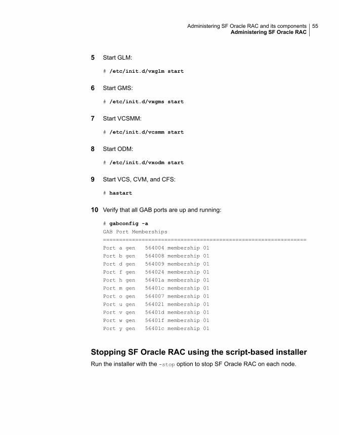
5 Start GLM:
# /etc/init.d/vxglm start
6 Start GMS:
# /etc/init.d/vxgms start
7 Start VCSMM:
# /etc/init.d/vcsmm start
8 Start ODM:
# /etc/init.d/vxodm start
9 Start VCS, CVM, and CFS:
# hastart
10 Verify that all GAB ports are up and running:
# gabconfig -a
GAB Port Memberships
===============================================================
Port a gen 564004 membership 01
Port b gen 564008 membership 01
Port d gen 564009 membership 01
Port f gen 564024 membership 01
Port h gen 56401a membership 01
Port m gen 56401c membership 01
Port o gen 564007 membership 01
Port u gen 564021 membership 01
Port v gen 56401d membership 01
Port w gen 56401f membership 01
Port y gen 56401c membership 01
Stopping SF Oracle RAC using the script-based installerRun the installer with the -stop option to stop SF Oracle RAC on each node.
55Administering SF Oracle RAC and its componentsAdministering SF Oracle RAC
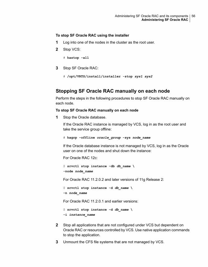
To stop SF Oracle RAC using the installer
1 Log into one of the nodes in the cluster as the root user.
2 Stop VCS:
# hastop -all
3 Stop SF Oracle RAC:
# /opt/VRTS/install/installer -stop sys1 sys2
Stopping SF Oracle RAC manually on each nodePerform the steps in the following procedures to stop SF Oracle RAC manually oneach node.
To stop SF Oracle RAC manually on each node
1 Stop the Oracle database.
If the Oracle RAC instance is managed by VCS, log in as the root user andtake the service group offline:
# hagrp -offline oracle_group -sys node_name
If the Oracle database instance is not managed by VCS, log in as the Oracleuser on one of the nodes and shut down the instance:
For Oracle RAC 12c:
$ srvctl stop instance -db db_name \
-node node_name
For Oracle RAC 11.2.0.2 and later versions of 11g Release 2:
$ srvctl stop instance -d db_name \
-n node_name
For Oracle RAC 11.2.0.1 and earlier versions:
$ srvctl stop instance -d db_name \
-i instance_name
2 Stop all applications that are not configured under VCS but dependent onOracle RAC or resources controlled by VCS. Use native application commandsto stop the application.
3 Unmount the CFS file systems that are not managed by VCS.
56Administering SF Oracle RAC and its componentsAdministering SF Oracle RAC
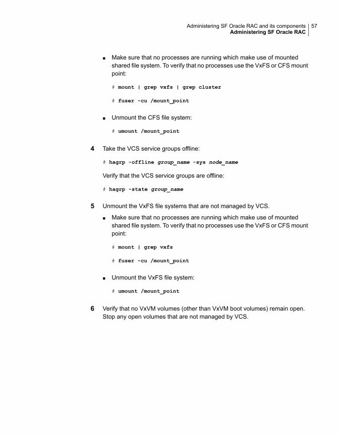
■ Make sure that no processes are running which make use of mountedshared file system. To verify that no processes use the VxFS or CFS mountpoint:
# mount | grep vxfs | grep cluster
# fuser -cu /mount_point
■ Unmount the CFS file system:
# umount /mount_point
4 Take the VCS service groups offline:
# hagrp -offline group_name -sys node_name
Verify that the VCS service groups are offline:
# hagrp -state group_name
5 Unmount the VxFS file systems that are not managed by VCS.
■ Make sure that no processes are running which make use of mountedshared file system. To verify that no processes use the VxFS or CFS mountpoint:
# mount | grep vxfs
# fuser -cu /mount_point
■ Unmount the VxFS file system:
# umount /mount_point
6 Verify that no VxVM volumes (other than VxVM boot volumes) remain open.Stop any open volumes that are not managed by VCS.
57Administering SF Oracle RAC and its componentsAdministering SF Oracle RAC
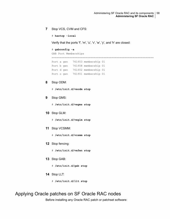
7 Stop VCS, CVM and CFS:
# hastop -local
Verify that the ports 'f', 'm', 'u', 'v', 'w', 'y', and 'h' are closed:
# gabconfig -a
GAB Port Memberships
===============================================================
Port a gen 761f03 membership 01
Port b gen 761f08 membership 01
Port d gen 761f02 membership 01
Port o gen 761f01 membership 01
8 Stop ODM:
# /etc/init.d/vxodm stop
9 Stop GMS:
# /etc/init.d/vxgms stop
10 Stop GLM:
# /etc/init.d/vxglm stop
11 Stop VCSMM:
# /etc/init.d/vcsmm stop
12 Stop fencing:
# /etc/init.d/vxfen stop
13 Stop GAB:
# /etc/init.d/gab stop
14 Stop LLT:
# /etc/init.d/llt stop
Applying Oracle patches on SF Oracle RAC nodesBefore installing any Oracle RAC patch or patchset software:
58Administering SF Oracle RAC and its componentsAdministering SF Oracle RAC
■ Review the latest information on supported Oracle RAC patches and patchsets:https://www.veritas.com/support/en_US/article.DOC4039
■ You must have installed the base version of the Oracle RAC software.
To apply Oracle patches
1 Freeze the service group that contains the Oracle resource and the cssdresource:
# hagrp -freeze grp_name
2 Install the patches or patchsets required for your Oracle RAC installation. Seethe Oracle documentation that accompanies the patch or patchset.
If the patch is for Oracle database software, after applying the patch, beforestarting the database or database instance, relink the SF Oracle RAC librarieswith Oracle libraries.
3 Unfreeze the service group that contains the Oracle resource and the cssdresource:
# hagrp -unfreeze grp_name
Migrating Pluggable Databases (PDB) between Container Databases(CDB)
You can use the hapdbmigrate utility to perform a planned end-to-end migrationof pluggable databases across containers of the same database version. Thedestination container database may be on the same node or on another node. ThePDB must have its own independent storage.
If the PDB has parent groups, they will be unlinked and frozen by the utility duringthe migration. After successful migration, they will be relinked and unfrozen by theutility.
The migration is supported on database version 12.1.0.2.
The configuration must meet the following requirements:
■ The PDB and CDB databases must be on Veritas Cluster File System (CFS) orVeritas File system (VxFS).
■ There must be no parent resources for the PDB resource.
■ The PDB must be plugged in to the source CDB. The PDB resources may ormay not be offline.
■ The source and destination CDB resources for the migration must be different.
59Administering SF Oracle RAC and its componentsAdministering SF Oracle RAC
■ The version of the destination CDB must be the same as the source CDB.
■ The PDB to be migrated is mounted on an independent file system (separatemount points for CDB and PDB datafiles).
■ The CDB and PDB resources must be configured in the same service group.
The utility performs the following actions during the migration:
■ Unlinks and freezes the parent groups, if any, depending on the source CDBgroup where the PDB resource to be migrated is configured.
■ Takes PDB resources offline.
■ Unplugs the PDB from the CDB and creates an XML file,<pdb_res_name>_<dest_cdb_res_name>.xml in the XML directory provided bythe user.
■ Drops the PDB from the CDB keeping the datafiles.
■ Takes offline all the PDB child resources. Unlinks the PDB resource from thesource CDB resource and deletes the PDB resource. Unlinks and deletes allPDB child resources.
■ Recreates the PDB resource and all its children with original dependencies inthe destination CDB service group.
■ Brings online the PDB child resources on all the nodes where the destinationCDB service group is online
■ Plugs the PDB in the destination CDB.
■ Brings the PDB resource online after successful plugging. Unfreezes and linksthe parent group to the source CDB group.
The hapdbmigrate utility performs certain pre-requisite checks before the migrationto verify that the cluster is ready for PDB migration. If the utility encounters anyissues, you will need to manually fix the issues.
The utility is present in the $VCSHOME/bin directory.
The log files of the migration are located at $VCSLOG/log/hapdbmigrate.log. Thelogs are rotated after the file exceeds 5 MB and is saved in .gz formathapdbmigrate.log[1..7].gz.
You can find sample configuration files for Oracle RAC at/etc/VRTSvcs/conf/sample_rac/sfrac18_main.cf.
Note: Ensure that only one instance of the hapdbmigrate utility is running at a time.
60Administering SF Oracle RAC and its componentsAdministering SF Oracle RAC
To migrate Pluggable Databases (PDB) between Container Databases (CDB)
1 Back up the VCS configuration file /etc/VRTSvcs/conf/config/main.cf:
# cp /etc/VRTSvcs/conf/config/main.cf \
/etc/VRTSvcs/conf/config/main.cf.save
2 Verify that the high availability daemon (had) is running on all the nodes in thecluster.
# hastatus -summary
3 Verify that there are no resources in faulted or unknown state.
# hares -state|grep FAULTED
# hares -state|grep UNKNOWN
4 Verify that the PDBName attribute is present for the PDB resource with the correctvalue in the main.cf configuration file.
5 Verify that the source and destination CDB resources are online.
# hares -state resname
6 On the destination CDB, verify the following:
■ The destination CDB is not in suspended mode.Any instance of the destination CDB is not in mounted state.See the Oracle documentation for more information.
■ If any instance of the destination CDB is in restricted state, ensure thatthe PDB resource you want to migrate has the StartUpOpt attribute set torestricted.
# haconf -makerw
# hares -modify pdb1 StartUpOpt \
RESTRICTED
# haconf -dump -makero
7 Verify that existing dependencies do not conflict with the migration process.
The PDB child resources must not be dependent on the CDB resource or anyof its child resources.
The PDB child resources must not have any parent, which is not a part of thePDB child hierarchy.
61Administering SF Oracle RAC and its componentsAdministering SF Oracle RAC
8 Verify that the XML data directory has read and write permissions for the"oracle" user. The XML data directory must be located either on PDB mountsor at a location accessible to both source and destination CDBs.
9 Run the hapdbmigrate utility as the root user:
Note: If there are parent groups dependent on the source CDB group, specifythe -ignoreparentgrp option.
# $VCS_HOME/bin/hapdbmigrate -pdbres pdb_resname -cdbres cdb_resname \
-XMLdirectory xml_directory [-ignoreparentgrp] [-prechecks]
-pdbres: Name of the PDB resource, which needs to be migrated
-cdbres: Name of the CDB resource, where the PDB needs to migrate
-XMLdirectory: XML directory location for the unplugged PDB
-ignoreparentgrp: Utility proceeds even
if the PDB group has parent groups
-prechecks: Performs prechecks and validation
-help|h: Prints usage
The migration log file is located at $VCSLOG/log/hapdbmigrate.log.
10 Verify that the PDB resource is online on the destination CDB.
# hares -state pdb_resname
11 Relink the parent service group of the source CDB group manually to thedestination CDB group, if it depends on the migrated PDB.
# haconf -makerw
# hagrp -dep parent_sg
#Parent Child Relationship
parent_sg source_CDB online local firm
# hagrp -offline parent_sg -any
# hagrp -unlink parent_sg source_CDB
# hagrp -link parent_sg dest_CDB online local firm
# hagrp -dep parent_sg
#Parent Child Relationship
parent_sg dest_CDB online local firm
# haconf -dump -makero
62Administering SF Oracle RAC and its componentsAdministering SF Oracle RAC
Installing Veritas Volume Manager, Veritas File System, or ODMpatches on SF Oracle RAC nodes
Perform the steps on each node in the cluster to install Veritas Volume Manager,Veritas File System, or ODM patches.
To install Veritas Volume Manager, Veritas File System, or ODM patches onSF Oracle RAC nodes
1 Log in as the root user.
2 Stop SF Oracle RAC on each node.
See “Stopping SF Oracle RAC using the script-based installer” on page 55.
3 Install the VxVM, VxFS, or ODM patch as described in the corresponding patchdocumentation.
4 If there are applications that are not managed by VCS, start the applicationsmanually using native application commands.
Applying operating system updates on SF Oracle RAC nodesIf you need to apply updates to the base version of the operating system, performthe steps in this section on each node of the cluster, one node at a time.
Ensure that you check the following website for the operating system updates thatare supported by Veritas:
https://sort.veritas.com/
To apply operating system updates
1 Log in to the node as the root user and change to /opt/VRTS/install directory:
# cd /opt/VRTS/install
2 Take the VCS service groups offline:
# hagrp -offline grp_name -sys node_name
3 Stop SF Oracle RAC:
# ./installer -stop
4 Upgrade the operating system.
See the operating system documentation.
63Administering SF Oracle RAC and its componentsAdministering SF Oracle RAC
5 If the node is not rebooted after the operating system upgrade, reboot the node:
# shutdown -r now
6 Repeat all the steps on each node in the cluster.
Adding storage to an SF Oracle RAC clusterYou can add storage to an SF Oracle RAC cluster in the following ways:
Use the vxdg command to add a disk to adisk group.
See the vxdg (1M) manual page forinformation on various options.
See “To add storage to an SF Oracle RACcluster by adding a disk to a disk group”on page 64.
Add a disk to a disk group
Use the vxresize command to change thelength of a volume containing a file system.It automatically locates available disk spaceon the specified volume and frees up unusedspace to the disk group for later use.
See the vxresize (1M) manual page forinformation on various options.
See “To add storage to an SF Oracle RACcluster by extending the volume space on adisk group” on page 65.
Extend the volume space on a disk group
Note: The steps in the following procedures are applicable to non-FSS configurationsonly.
To add storage to an SF Oracle RAC cluster by adding a disk to a disk group
◆ Add a disk to the disk group:
# vxdg -g dg_name adddisk disk_name
64Administering SF Oracle RAC and its componentsAdministering SF Oracle RAC
To add storage to an SF Oracle RAC cluster by extending the volume spaceon a disk group
1 Determine the length by which you can increase an existing volume.
# vxassist [-g diskgroup] maxsize
For example, to determine the maximum size the volume oradatavol in thedisk group oradatadg can grow, given its attributes and free storage available:
# vxassist -g oradatadg maxsize
2 Extend the volume, as required. You can extend an existing volume to a certainlength by specifying the new size of the volume (the new size must include theadditional space you plan to add). You can also extend a volume by a certainlength by specifying the additional amount of space you want to add to theexisting volume.
For example, to extend the volume oradata_vol of size 10 GBin the disk group oradata_dg to 30 GB:
# vxresize -g oradata_dg \oradata_vol 30g
To extend a volumeto a certain length
For example, to extend the volume oradata_vol of size 10 GBin the disk group oradata_dg by 10 GB:
# vxresize -g oradata_dg \oradata_vol +10g
To extend a volumeby a certain length
Recovering from storage failureVeritas Volume Manager (VxVM) protects systems from disk and other hardwarefailures and helps you to recover from such events. Recovery procedures help youprevent loss of data or system access due to disk and other hardware failures.
For information on various failure and recovery scenarios, see the Veritas InfoScaleTroubleshooting Guide.
Backing up and restoring Oracle database using Veritas NetBackupVeritas NetBackup integrates the database backup and recovery capabilities of theOracle Recovery Manager (RMAN) with the backup and recovery managementcapabilities of NetBackup.
65Administering SF Oracle RAC and its componentsAdministering SF Oracle RAC
NetBackup for Oracle supports the following types of backups:
■ Full backup
■ Incremental backup
■ Multilevel incremental backup
■ Differential incremental backup
■ Cumulative incremental backup
While Oracle RMAN performs backup, restore, and recovery of physical Oracledatabase objects (data files, tablespaces, control files, and archived redo logs), theNetBackup for Oracle XML export and XML import utilities provide backup andrestore of logical database objects (tables, users, and rows).
See the Veritas NetBackup for Oracle Administrator's Guide.
Enhancing the performance of SF Oracle RAC clustersThe main components of clustering that impact the performance of an SF OracleRAC cluster are:
■ Kernel components, specifically LLT and GAB
■ VCS engine (had)
■ VCS agents
Each VCS agent process has two components—the agent framework and the agentfunctions. The agent framework provides common functionality, such ascommunication with the HAD, multithreading for multiple resources, schedulingthreads, and invoking functions. Agent functions implement functionality that isparticular to an agent.
For various options provided by the clustering components to monitor and enhanceperformance, see the chapter "VCS performance considerations" in the ClusterServer Administrator's Guide.
Veritas Volume Manager can improve system performance by optimizing the layoutof data storage on the available hardware.
For more information on tuning Veritas Volume Manager for better performance,see the chapter "Performance monitoring and tuning" in the Veritas StorageFoundation Administrator's Guide.
Volume Replicator Advisor (VRAdvisor) is a planning tool that helps you determinean optimum Volume Replicator (VVR) configuration.
66Administering SF Oracle RAC and its componentsAdministering SF Oracle RAC
For installing VRAdvisor and evaluating various parameters using the data collectionand data analysis process, see the Veritas InfoScale Replication Administrator'sGuide.
Mounting a snapshot file system for backups increases the load on the system asit involves high resource consumption to perform copy-on-writes and to read datablocks from the snapshot. In such situations, cluster snapshots can be used to dooff-host backups. Off-host backups reduce the load of a backup application fromthe primary server. Overhead from remote snapshots is small when compared tooverall snapshot overhead. Therefore, running a backup application by mountinga snapshot from a relatively less loaded node is beneficial to overall clusterperformance.
Administering SmartIOThe SmartIO feature of Storage Foundation and High Availability Solutions (SFHASolutions) enables data efficiency on your solid-state drives (SSD) through I/Ocaching.
SmartIO uses a cache area on target devices. The cache area is the storage spacethat SmartIO uses to store the cached data and the metadata about the cacheddata. The type of the cache area determines whether it supports VxFS caching orVxVM caching. To start using SmartIO, you can create a cache area with a singlecommand, while the application is online. When the application issues an I/O request,SmartIO checks to see if the I/O can be serviced from the cache. As applicationsaccess data from the underlying volumes or file systems, certain data is moved tothe cache based on the internal heuristics. Subsequent I/Os are processed fromthe cache.
SmartIO supports read caching for the VxFS file systems that are mounted on VxVMvolumes, in several caching modes and configurations. SmartIO also supportsblock-level read caching for applications running on VxVM volumes.
Note: SmartIO writeback caching is currently not supported in SF Oracle RACenvironments.
For more information on using and administering SmartIO, see the Veritas InfoScaleSmartIO for Solid State Drives Solutions Guide.
Creating snapshots for offhost processingYou can capture a point-in-time copy of actively changing data at a given instant.You can then perform system backup, upgrade, and other maintenance tasks onthe point-in-time copies while providing continuous availability of your critical data.
67Administering SF Oracle RAC and its componentsAdministering SF Oracle RAC
If required, you can offload processing of the point-in-time copies onto another hostto avoid contention for system resources on your production server.
See the Veritas InfoScale Solutions Guide.
Managing database storage efficiently using SmartTierSmartTier matches data storage with data usage requirements. After data matching,the data can be relocated based upon data usage and other requirementsdetermined by the storage or database administrator (DBA). The technology enablesthe database administrator to manage data so that less frequently used data canbe moved to slower, less expensive disks. This also permits the frequently accesseddata to be stored on faster disks for quicker retrieval.
See the Veritas InfoScale Storage and Availability Management for OracleDatabases guide.
Optimizing database storage using Thin Provisioning and SmartMoveThin Provisioning is a storage array feature that optimizes storage use by automatingstorage provisioning. With Storage Foundation’s SmartMove feature, Veritas FileSystem (VxFS) lets Veritas Volume Manager (VxVM) know which blocks have data.VxVM, which is the copy engine for migration, copies only the used blocks andavoids the empty spaces, thus optimizing thin storage utilization.
See the Veritas InfoScale Solutions Guide.
Scheduling periodic health checks for your SF Oracle RAC clusterYou can manually invoke the health check utility at any time or schedule the utilityto run as a cron job.
If the health check completes without any warnings, the following message isdisplayed:
Success: The SF Oracle RAC components are working fine on this node.
If you manually invoke the health check, run the utility on each node in the cluster.The results of the check are displayed on the console.
68Administering SF Oracle RAC and its componentsAdministering SF Oracle RAC
To run health checks on a cluster
1 Log in as the root user on each node in the cluster.
2 Using vi or any text editor, modify the health check parameters as requiredfor your installation setup.
Note: You must set the ORACLE_HOME and CRS_HOME parameters in theconfiguration file as appropriate for your setup.
# cd /opt/VRTSvcs/rac/healthcheck/
# vi healthcheck.cf
3 Run the health check utility:
# ./healthcheck
If you want to schedule periodic health checks for your cluster, create a cron jobthat runs on each node in the cluster. Redirect the health check report to a file.
Using environment variables to start and stop VCSMM modulesThe start and stop environment variables for VCSMM define the default behaviorto start the modules during system restart or stop the modules during systemshutdown.
Note: The startup and shutdown of VCSMM is inter-dependent on other stackmodules such as LLT, GAB, fencing, and ODM. For a clean startup or shutdownof SF Oracle RAC, you must either enable or disable startup and shutdown for allthese modules.
Table 2-1 lists the environment variables to start and stop VCSMM.
Table 2-1 Environment variables to start and stop VCSMM
DescriptionVariable
Startup mode for the VCSMM driver. By default, the VCSMM driveris enabled to start up after a system reboot.
This environment variable is defined in the following file:/etc/sysconfig/vcsmm
Default: 1
VCSMM_START
69Administering SF Oracle RAC and its componentsAdministering SF Oracle RAC
Table 2-1 Environment variables to start and stop VCSMM (continued)
DescriptionVariable
Shutdown mode for the VCSMM driver. By default, the VCSMMdriver is enabled to stop during a system shutdown.
This environment variable is defined in the following file:/etc/sysconfig/vcsmm
Default: 1
VCSMM_STOP
Verifying the nodes in an SF Oracle RAC clusterTable 2-2 lists the various options that you can use to periodically verify the nodesin your cluster.
Table 2-2 Options for verifying the nodes in a cluster
DescriptionType of check
Use the Veritas Services and Operations Readiness Tools (SORT)to evaluate your systems before and after any installation,configuration, upgrade, patch updates, or other routineadministrative activities. The utility performs a number ofcompatibility and operational checks on the cluster that enableyou to diagnose and troubleshoot issues in the cluster. The utilityis periodically updated with new features and enhancements.
For more information and to download the utility, visithttp://sort.veritas.com.
Veritas Services andOperations ReadinessTools (SORT)
SF Oracle RAC provides a health check utility that examines thefunctional health of the components in an SF Oracle RAC cluster.The utility when invoked gathers real-time operational informationon cluster components and displays the report on your systemconsole. You must run the utility on each node in the cluster.
To schedule periodic health checks:
See “Periodic health evaluation of SF Oracle RAC clusters”on page 45.
SF Oracle RAC healthchecks
Administering VCSThis section provides instructions for the following VCS administration tasks:
■ Viewing available Veritas devices and driversSee “Viewing available Veritas device drivers” on page 71.
70Administering SF Oracle RAC and its componentsAdministering VCS
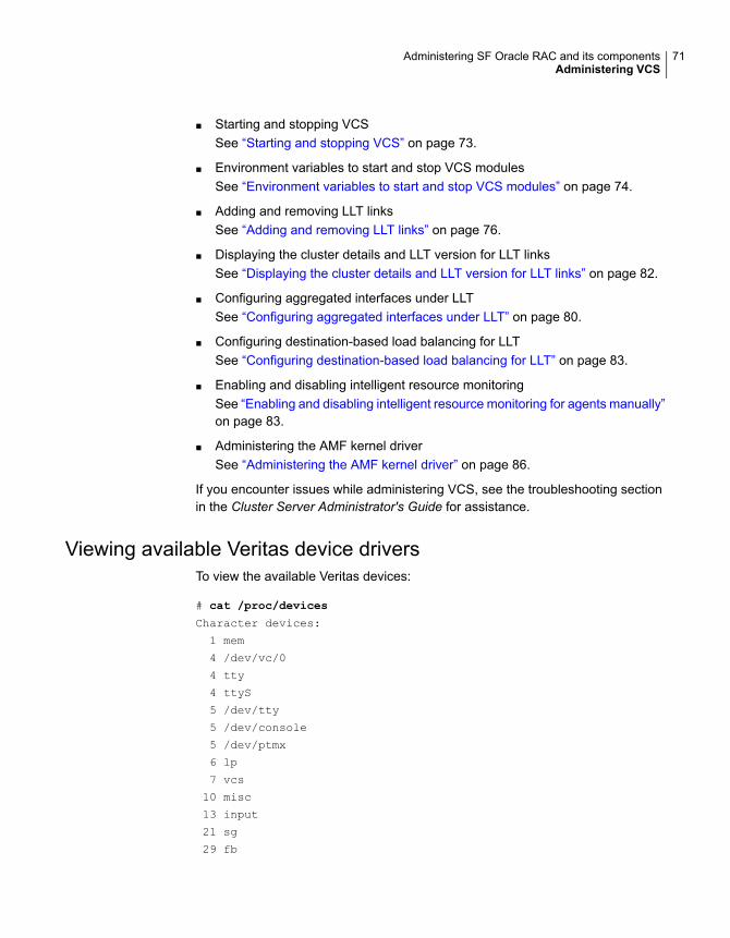
■ Starting and stopping VCSSee “Starting and stopping VCS” on page 73.
■ Environment variables to start and stop VCS modulesSee “Environment variables to start and stop VCS modules” on page 74.
■ Adding and removing LLT linksSee “Adding and removing LLT links” on page 76.
■ Displaying the cluster details and LLT version for LLT linksSee “Displaying the cluster details and LLT version for LLT links” on page 82.
■ Configuring aggregated interfaces under LLTSee “Configuring aggregated interfaces under LLT” on page 80.
■ Configuring destination-based load balancing for LLTSee “Configuring destination-based load balancing for LLT” on page 83.
■ Enabling and disabling intelligent resource monitoringSee “Enabling and disabling intelligent resource monitoring for agents manually”on page 83.
■ Administering the AMF kernel driverSee “Administering the AMF kernel driver” on page 86.
If you encounter issues while administering VCS, see the troubleshooting sectionin the Cluster Server Administrator's Guide for assistance.
Viewing available Veritas device driversTo view the available Veritas devices:
# cat /proc/devices
Character devices:
1 mem
4 /dev/vc/0
4 tty
4 ttyS
5 /dev/tty
5 /dev/console
5 /dev/ptmx
6 lp
7 vcs
10 misc
13 input
21 sg
29 fb
71Administering SF Oracle RAC and its componentsAdministering VCS
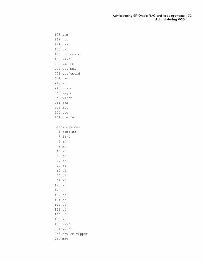
128 ptm
136 pts
162 raw
180 usb
189 usb_device
199 VxVM
200 VxSPEC
202 cpu/msr
203 cpu/cpuid
246 vxgms
247 amf
248 vcsmm
249 vxglm
250 vxfen
251 gab
252 llt
253 uio
254 pcmcia
Block devices:
1 ramdisk
3 ide0
8 sd
9 md
65 sd
66 sd
67 sd
68 sd
69 sd
70 sd
71 sd
128 sd
129 sd
130 sd
131 sd
132 sd
133 sd
134 sd
135 sd
199 VxVM
201 VxDMP
253 device-mapper
254 mdp
72Administering SF Oracle RAC and its componentsAdministering VCS
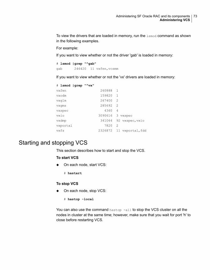
To view the drivers that are loaded in memory, run the lsmod command as shownin the following examples.
For example:
If you want to view whether or not the driver 'gab' is loaded in memory:
# lsmod |grep "^gab"
gab 246420 11 vxfen,vcsmm
If you want to view whether or not the 'vx' drivers are loaded in memory:
# lsmod |grep "^vx"
vxfen 260888 1
vxodm 159820 1
vxglm 267400 2
vxgms 285692 2
vxspec 4360 4
vxio 3090616 3 vxspec
vxdmp 341064 92 vxspec,vxio
vxportal 7820 2
vxfs 2326872 11 vxportal,fdd
Starting and stopping VCSThis section describes how to start and stop the VCS.
To start VCS
◆ On each node, start VCS:
# hastart
To stop VCS
◆ On each node, stop VCS:
# hastop -local
You can also use the command hastop -all to stop the VCS cluster on all thenodes in cluster at the same time; however, make sure that you wait for port 'h' toclose before restarting VCS.
73Administering SF Oracle RAC and its componentsAdministering VCS
Environment variables to start and stop VCS modulesThe start and stop environment variables for AMF, LLT, GAB, VxFEN, and VCSengine define the default VCS behavior to start these modules during system restartor stop these modules during system shutdown.
Note: The startup and shutdown of AMF, LLT, GAB, VxFEN, and VCS engine areinter-dependent. For a clean startup or shutdown of SF Oracle RAC, you musteither enable or disable the startup and shutdown modes for all these modules.
Table 2-3 describes the start and stop variables for VCS.
Table 2-3 Start and stop environment variables for VCS
Definition and default valueEnvironmentvariable
Startup mode for the AMF driver. By default, the AMF driver isenabled to start up after a system reboot.
This environment variable is defined in the following file:
/etc/sysconfig/amf
Default: 1
AMF_START
Shutdown mode for the AMF driver. By default, the AMF driver isenabled to stop during a system shutdown.
This environment variable is defined in the following file:
/etc/sysconfig/amf
Default: 1
AMF_STOP
Startup mode for LLT. By default, LLT is enabled to start up after asystem reboot.
This environment variable is defined in the following file:
/etc/sysconfig/llt
Default: 1
LLT_START
Shutdown mode for LLT. By default, LLT is enabled to stop duringa system shutdown.
This environment variable is defined in the following file:
/etc/sysconfig/llt
Default: 1
LLT_STOP
74Administering SF Oracle RAC and its componentsAdministering VCS
Table 2-3 Start and stop environment variables for VCS (continued)
Definition and default valueEnvironmentvariable
Startup mode for GAB. By default, GAB is enabled to start up aftera system reboot.
This environment variable is defined in the following file:
/etc/sysconfig/gab
Default: 1
GAB_START
Shutdown mode for GAB. By default, GAB is enabled to stop duringa system shutdown.
This environment variable is defined in the following file:
/etc/sysconfig/gab
Default: 1
GAB_STOP
Startup mode for VxFEN. By default, VxFEN is enabled to start upafter a system reboot.
This environment variable is defined in the following file:
/etc/sysconfig/vxfen
Default: 1
VXFEN_START
Shutdown mode for VxFEN. By default, VxFEN is enabled to stopduring a system shutdown.
This environment variable is defined in the following file:
/etc/sysconfig/vxfen
Default: 1
VXFEN_STOP
Startup mode for VCS engine. By default, VCS engine is enabled tostart up after a system reboot.
This environment variable is defined in the following file:
/etc/sysconfig/vcs
Default: 1
VCS_START
Shutdown mode for VCS engine. By default, VCS engine is enabledto stop during a system shutdown.
This environment variable is defined in the following file:
/etc/sysconfig/vcs
Default: 1
VCS_STOP
75Administering SF Oracle RAC and its componentsAdministering VCS
Adding and removing LLT linksIn an SF Oracle RAC cluster, Oracle Clusterware heartbeat link must be configuredas an LLT link. If Oracle Clusterware and LLT use different links for theircommunication, then the membership change between VCS and Oracle Clusterwareis not coordinated correctly. For example, if only the Oracle Clusterware links aredown, Oracle Clusterware kills one set of nodes after the expiry of the css-misscountinterval and initiates the Oracle Clusterware and database recovery, even beforeCVM and CFS detect the node failures. This uncoordinated recovery may causedata corruption.
If you need additional capacity for Oracle communication on your privateinterconnects, you can add LLT links. The network IDs of the interfaces connectedto the same physical network must match. The interfaces specified in the PrivNICor MultiPrivNIC configuration must be exactly the same in name and total numberas those which have been used for LLT configuration.
You can use the lltconfig command to add or remove LLT links when LLT isrunning.
LLT links can be added or removed while clients are connected.
See the lltconfig(1M) manual page for more details.
Note: When you add or remove LLT links, you need not shut down GAB or the highavailability daemon, had. Your changes take effect immediately, but are lost on thenext restart. For changes to persist, you must also update the /etc/llttab file.
To add LLT links
1 Depending on the LLT link type, run the following command to add an LLT link:
■ For ether link type:
# lltconfig -t devtag -d device
[-b ether ] [-s SAP] [-m mtu] [-I] [-Q]
■ For UDP link type:
# lltconfig -t devtag -d device
-b udp [-s port] [-m mtu]
-I IPaddr -B bcast
■ For UDP6 link type:
76Administering SF Oracle RAC and its componentsAdministering VCS
# lltconfig -t devtag -d device
-b udp6 [-s port] [-m mtu]
-I IPaddr [-B mcast]
■ For RDMA link type:
# lltconfig -t devtag -d device
-b rdma -s port [-m mtu]
-I IPaddr -B bcast
Where:
Tag to identify the linkdevtag
Device name of the interface.
For link type ether, you can specify the device name as an interfacename. For example, eth0. Preferably, specify the device name aseth-macaddress. For example, eth- xx:xx:xx:xx:xx:xx.
For link types udp and udp6, the device is the udp and udp6 devicename respectively.
For link type rdma, the device name is udp.
device
Broadcast address for the link type udp and rdmabcast
Multicast address for the link type udp6mcast
IP address for link types udp, udp6 and rdmaIPaddr
SAP to bind on the network links for link type etherSAP
Port for link types udp, udp6 and rdmaport
Maximum transmission unit to send packets on network linksmtu
For example:
■ For ether link type:
# lltconfig -t eth4 -d eth4 -s 0xcafe -m 1500
■ For UDP link type:
# lltconfig -t link1 -d udp -b udp -s 50010
-I 192.168.1.1 -B 192.168.1.255
■ For UDP6 link type:
77Administering SF Oracle RAC and its componentsAdministering VCS

# lltconfig -t link1 -d udp6 -b udp6 -s 50010 -I 2000::1
■ For RDMA link:
# lltconfig -t link1 -d udp -b rdma -s 50010
-I 192.168.1.1 -B 192.168.1.255
78Administering SF Oracle RAC and its componentsAdministering VCS
Note: If you want the addition of LLT links to be persistent after reboot, thenyou must edit the /etc/lltab with LLT entries.
2 For Oracle RAC 11g Release 1 and earlier versions: If you want to configurethe link under PrivNIC or MultiPrivNIC as a failover target in the case of linkfailure, modify the PrivNIC or MultiPrivNIC configuration as follows:
# haconf -makerw
# hares -modify resource_name Device device
device_id [-sys hostname]
# haconf -dump -makero
The following is an example of configuring the link under PrivNIC.
Assuming that you have two LLT links configured under PrivNIC as follows:
PrivNIC ora_priv (
Critical = 0
Device@sys1 = { eth1 = 0, eth2 = 1 }
Device@sys2 = { eth1 = 0, eth2 = 1 }
Address@sys1 = "192.168.12.1"
Address@sys2 = "192.168.12.2"
NetMask = "255.255.255.0"
)
To configure the new LLT link under PrivNIC, run the following commands:
# haconf -makerw
# hares -modify ora_priv Device eth1 0 eth2 1 eth3 2 -sys sys1
# hares -modify ora_priv Device eth1 0 eth2 1 eth3 2 -sys sys2
# haconf -dump -makero
The updated PrivNIC resource now resembles:
PrivNIC ora_priv (
Critical = 0
Device@sys1 = { eth1 = 0, eth2 = 1, eth3 = 2 }
Device@sys2 = { eth1 = 0, eth2 = 1, eth3 = 2 }
Address@sys1 = "192.168.12.1"
Address@sys2 = "192.168.12.2"
NetMask = "255.255.255.0"
)
79Administering SF Oracle RAC and its componentsAdministering VCS
To remove an LLT link
1 If the link you want to remove is configured as a PrivNIC or MultiPrivNICresource, you need to modify the resource configuration before removing thelink.
If you have configured the link under PrivNIC or MultiPrivNIC as a failovertarget in the case of link failure, modify the PrivNIC or MultiPrivNIC configurationas follows:
# haconf -makerw
# hares -modify resource_name Device link_name \
device_id [-sys hostname]
# haconf -dump -makero
For example, if the links eth1, eth2, and eth3 were configured as PrivNICresources, and you want to remove eth3:
# haconf -makerw
# hares -modify ora_priv Device eth1
0 eth2 1
where eth1 and eth2 are the links that you want to retain in your cluster.
# haconf -dump -makero
2 Run the following command to disable a network link that is configured underLLT.
# lltconfig -t devtag -L disable
3 Wait for the 16 seconds (LLT peerinact time).
4 Run the following command to remove the link.
# lltconfig -u devtag
Configuring aggregated interfaces under LLTIf you want to configure LLT to use aggregated interfaces after installing andconfiguring VCS, you can use one of the following approaches:
■ Edit the /etc/llttab fileThis approach requires you to stop LLT. The aggregated interface configurationis persistent across reboots.
■ Run the lltconfig command
80Administering SF Oracle RAC and its componentsAdministering VCS
This approach lets you configure aggregated interfaces on the fly. However, thechanges are not persistent across reboots.
To configure aggregated interfaces under LLT by editing the /etc/llttab file
1 If LLT is running, stop LLT after you stop the other dependent modules.
# /etc/init.d/llt stop
See “Starting or stopping SF Oracle RAC on each node” on page 53.
2 Add the following entry to the /etc/llttab file to configure an aggregated interface.
link tag device_name systemid_range link_type sap mtu_size
Tag to identify the linktag
Device name of the aggregated interface.device_name
Range of systems for which the command is valid.
If the link command is valid for all systems, specify a dash (-).
systemid_range
The link type must be ether.link_type
SAP to bind on the network links.
Default is 0xcafe.
sap
Maximum transmission unit to send packets on network linksmtu_size
3 Restart LLT for the changes to take effect. Restart the other dependent modulesthat you stopped in step 1.
# /etc/init.d/llt start
See “Starting or stopping SF Oracle RAC on each node” on page 53.
81Administering SF Oracle RAC and its componentsAdministering VCS
To configure aggregated interfaces under LLT using the lltconfig command
◆ When LLT is running, use the following command to configure an aggregatedinterface:
lltconfig -t devtag -d device
[-b linktype ] [-s SAP] [-m mtu]
Tag to identify the linkdevtag
Device name of the aggregated interface.device
The link type must be ether.link_type
SAP to bind on the network links.
Default is 0xcafe.
sap
Maximum transmission unit to send packets on network linksmtu_size
See the lltconfig(1M) manual page for more details.
You need not reboot after you make this change. However, to make thesechanges persistent across reboot, you must update the /etc/llttab file.
See “To configure aggregated interfaces under LLT by editing the /etc/llttabfile” on page 81.
Displaying the cluster details and LLT version for LLT linksYou can use the lltdump command to display the LLT version for a specific LLTlink. You can also display the cluster ID and node ID details.
See the lltdump(1M) manual page for more details.
82Administering SF Oracle RAC and its componentsAdministering VCS
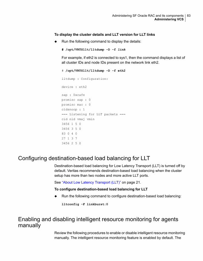
To display the cluster details and LLT version for LLT links
◆ Run the following command to display the details:
# /opt/VRTSllt/lltdump -D -f link
For example, if eth2 is connected to sys1, then the command displays a list ofall cluster IDs and node IDs present on the network link eth2.
# /opt/VRTSllt/lltdump -D -f eth2
lltdump : Configuration:
device : eth2
sap : 0xcafe
promisc sap : 0
promisc mac : 0
cidsnoop : 1
=== Listening for LLT packets ===
cid nid vmaj vmin
3456 1 5 0
3456 3 5 0
83 0 4 0
27 1 3 7
3456 2 5 0
Configuring destination-based load balancing for LLTDestination-based load balancing for Low Latency Transport (LLT) is turned off bydefault. Veritas recommends destination-based load balancing when the clustersetup has more than two nodes and more active LLT ports.
See “About Low Latency Transport (LLT)” on page 21.
To configure destination-based load balancing for LLT
◆ Run the following command to configure destination-based load balancing:
lltconfig -F linkburst:0
Enabling and disabling intelligent resource monitoring for agentsmanually
Review the following procedures to enable or disable intelligent resource monitoringmanually. The intelligent resource monitoring feature is enabled by default. The
83Administering SF Oracle RAC and its componentsAdministering VCS
IMF resource type attribute determines whether an IMF-aware agent must performintelligent resource monitoring.
See “About resource monitoring” on page 37.
To enable intelligent resource monitoring
1 Make the VCS configuration writable.
# haconf -makerw
2 Run the following command to enable intelligent resource monitoring.
■ To enable intelligent monitoring of offline resources:
# hatype -modify resource_type IMF -update Mode 1
■ To enable intelligent monitoring of online resources:
# hatype -modify resource_type IMF -update Mode 2
■ To enable intelligent monitoring of both online and offline resources:
# hatype -modify resource_type IMF -update Mode 3
3 If required, change the values of the MonitorFreq key and the RegisterRetryLimitkey of the IMF attribute.
See the Cluster Server Bundled Agents Reference Guide for agent-specificrecommendations to set these attributes.
Review the agent-specific recommendations in the attribute definition tablesto set these attribute key values.
4 Save the VCS configuration.
# haconf -dump -makero
84Administering SF Oracle RAC and its componentsAdministering VCS
5 Make sure that the AMF kernel driver is configured on all nodes in the cluster.
/etc/init.d/amf status
If the AMF kernel driver is configured, the output resembles:
AMF: Module loaded and configured
Configure the AMF driver if the command output returns that the AMF driveris not loaded or not configured.
See “Administering the AMF kernel driver” on page 86.
6 Restart the agent. Run the following commands on each node.
# haagent -stop agent_name -force -sys sys_name
# haagent -start agent_name -sys sys_name
To disable intelligent resource monitoring
1 Make the VCS configuration writable.
# haconf -makerw
2 To disable intelligent resource monitoring for all the resources of a certain type,run the following command:
# hatype -modify resource_type IMF -update Mode 0
3 To disable intelligent resource monitoring for a specific resource, run thefollowing command:
# hares -override resource_name IMF
# hares -modify resource_name IMF -update Mode 0
4 Save the VCS configuration.
# haconf -dump -makero
Note: VCS provides haimfconfig script to enable or disable the IMF functionalityfor agents. You can use the script with VCS in running or stopped state. Use thescript to enable or disable IMF for the IMF-aware bundled agents, enterprise agents,and custom agents.
85Administering SF Oracle RAC and its componentsAdministering VCS
Administering the AMF kernel driverReview the following procedures to start, stop, or unload the AMF kernel driver.
See “About the IMF notification module” on page 36.
See “Environment variables to start and stop VCS modules” on page 74.
To start the AMF kernel driver
1 Set the value of the AMF_START variable to 1 in the following file, if the valueis not already 1:
# /etc/sysconfig/amf
2 Start the AMF kernel driver. Run the following command:
# /etc/init.d/amf start
To stop the AMF kernel driver
1 Set the value of the AMF_STOP variable to 1 in the following file, if the valueis not already 1:
# /etc/sysconfig/amf
2 Stop the AMF kernel driver. Run the following command:
# /etc/init.d/amf stop
To unload the AMF kernel driver
1 If agent downtime is not a concern, use the following steps to unload the AMFkernel driver:
■ Stop the agents that are registered with the AMF kernel driver.The amfstat command output lists the agents that are registered with AMFunder the Registered Reapers section.See the amfstat manual page.
■ Stop the AMF kernel driver.See “To stop the AMF kernel driver” on page 86.
■ Start the agents.
2 If you want minimum downtime of the agents, use the following steps to unloadthe AMF kernel driver:
■ Run the following command to disable the AMF driver even if agents arestill registered with it.
86Administering SF Oracle RAC and its componentsAdministering VCS
# amfconfig -Uof
■ Stop the AMF kernel driver.See “To stop the AMF kernel driver” on page 86.
Administering I/O fencingThis section describes I/O fencing and provides instructions for common I/O fencingadministration tasks.
■ About administering I/O fencingSee “About administering I/O fencing” on page 87.
■ About vxfentsthdw utilitySee “About the vxfentsthdw utility” on page 88.
■ About vxfenadm utilitySee “About the vxfenadm utility” on page 96.
■ About vxfenclearpre utilitySee “About the vxfenclearpre utility” on page 101.
■ About vxfenswap utilitySee “About the vxfenswap utility” on page 105.
Note: I/O fencing no longer supports the raw disk policy for fencing. Only dmp diskpolicy is supported.
If you encounter issues while administering I/O fencing, refer to the troubleshootingsection for assistance.
See “Troubleshooting I/O fencing” on page 181.
See “About administering I/O fencing” on page 87.
About administering I/O fencingThe I/O fencing feature provides the following utilities that are available through theVRTSvxfen RPM:
Tests SCSI-3 functionality of the disks for I/O fencing
See “About the vxfentsthdw utility” on page 88.
vxfentsthdw
87Administering SF Oracle RAC and its componentsAdministering I/O fencing
Configures and unconfigures I/O fencing
Lists the coordination points used by the vxfen driver.
vxfenconfig
Displays information on I/O fencing operations and managesSCSI-3 disk registrations and reservations for I/O fencing
See “About the vxfenadm utility” on page 96.
vxfenadm
Removes SCSI-3 registrations and reservations from disks
See “About the vxfenclearpre utility” on page 101.
vxfenclearpre
Replaces coordination points without stopping I/O fencing
See “About the vxfenswap utility” on page 105.
vxfenswap
Generates the list of paths of disks in the disk group. This utilityrequires that Veritas Volume Manager (VxVM) is installed andconfigured.
vxfendisk
The I/O fencing commands reside in the /opt/VRTS/bin folder. Make sure you addedthis folder path to the PATH environment variable.
Refer to the corresponding manual page for more information on the commands.
About the vxfentsthdw utilityYou can use the vxfentsthdw utility to verify that shared storage arrays to be usedfor data support SCSI-3 persistent reservations and I/O fencing. During the I/Ofencing configuration, the testing utility is used to test a single disk. The utility hasother options that may be more suitable for testing storage devices in otherconfigurations. You also need to test coordinator disk groups.
See the Storage Foundation for Oracle RAC Configuration and Upgrade Guide toset up I/O fencing.
The utility, which you can run from one system in the cluster, tests the storage usedfor data by setting and verifying SCSI-3 registrations on the disk or disks you specify,setting and verifying persistent reservations on the disks, writing data to the disksand reading it, and removing the registrations from the disks.
Refer also to the vxfentsthdw(1M) manual page.
General guidelines for using the vxfentsthdw utilityReview the following guidelines to use the vxfentsthdw utility:
■ The utility requires two systems connected to the shared storage.
88Administering SF Oracle RAC and its componentsAdministering I/O fencing
Caution: The tests overwrite and destroy data on the disks, unless you use the-r option.
■ The two nodes must have SSH (default) or rsh communication. If you use rsh,launch the vxfentsthdw utility with the -n option.After completing the testing process, you can remove permissions forcommunication and restore public network connections.
■ To ensure both systems are connected to the same disk during the testing, youcan use the vxfenadm -i diskpath command to verify a disk’s serial number.See “Verifying that the nodes see the same disk” on page 101.
■ For disk arrays with many disks, use the -m option to sample a few disks beforecreating a disk group and using the -g option to test them all.
■ The utility indicates a disk can be used for I/O fencing with a messageresembling:
The disk /dev/sdx is ready to be configured for
I/O Fencing on node sys1
If the utility does not show a message stating a disk is ready, verification hasfailed.
■ The -o option overrides disk size-related errors and the utility proceeds withother tests, however, the disk may not setup correctly as the size may be smallerthan the supported size. The supported disk size for data disks is 256 MB andfor coordinator disks is 128 MB.
■ If the disk you intend to test has existing SCSI-3 registration keys, the test issuesa warning before proceeding.
About the vxfentsthdw command optionsTable 2-4 describes the methods that the utility provides to test storage devices.
Table 2-4 vxfentsthdw options
When to useDescriptionvxfentsthdwoption
Use when rsh is used forcommunication.
Utility uses rsh forcommunication.
-n
89Administering SF Oracle RAC and its componentsAdministering I/O fencing
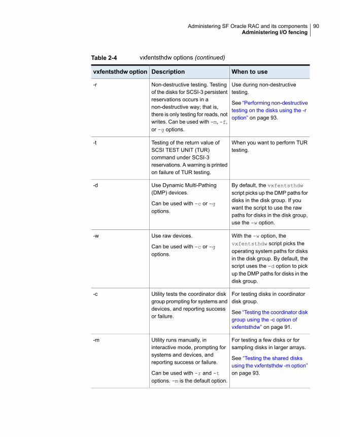
Table 2-4 vxfentsthdw options (continued)
When to useDescriptionvxfentsthdwoption
Use during non-destructivetesting.
See “Performing non-destructivetesting on the disks using the -roption” on page 93.
Non-destructive testing. Testingof the disks for SCSI-3 persistentreservations occurs in anon-destructive way; that is,there is only testing for reads, notwrites. Can be used with -m, -f,or -g options.
-r
When you want to perform TURtesting.
Testing of the return value ofSCSI TEST UNIT (TUR)command under SCSI-3reservations. A warning is printedon failure of TUR testing.
-t
By default, the vxfentsthdwscript picks up the DMP paths fordisks in the disk group. If youwant the script to use the rawpaths for disks in the disk group,use the -w option.
Use Dynamic Multi-Pathing(DMP) devices.
Can be used with -c or -goptions.
-d
With the -w option, thevxfentsthdw script picks theoperating system paths for disksin the disk group. By default, thescript uses the -d option to pickup the DMP paths for disks in thedisk group.
Use raw devices.
Can be used with -c or -goptions.
-w
For testing disks in coordinatordisk group.
See “Testing the coordinator diskgroup using the -c option ofvxfentsthdw” on page 91.
Utility tests the coordinator diskgroup prompting for systems anddevices, and reporting successor failure.
-c
For testing a few disks or forsampling disks in larger arrays.
See “Testing the shared disksusing the vxfentsthdw -m option”on page 93.
Utility runs manually, ininteractive mode, prompting forsystems and devices, andreporting success or failure.
Can be used with -r and -toptions. -m is the default option.
-m
90Administering SF Oracle RAC and its componentsAdministering I/O fencing
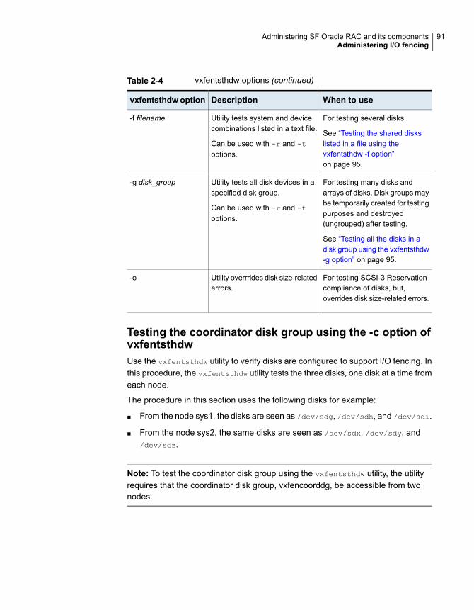
Table 2-4 vxfentsthdw options (continued)
When to useDescriptionvxfentsthdwoption
For testing several disks.
See “Testing the shared diskslisted in a file using thevxfentsthdw -f option”on page 95.
Utility tests system and devicecombinations listed in a text file.
Can be used with -r and -toptions.
-f filename
For testing many disks andarrays of disks. Disk groups maybe temporarily created for testingpurposes and destroyed(ungrouped) after testing.
See “Testing all the disks in adisk group using the vxfentsthdw-g option” on page 95.
Utility tests all disk devices in aspecified disk group.
Can be used with -r and -toptions.
-g disk_group
For testing SCSI-3 Reservationcompliance of disks, but,overrides disk size-related errors.
Utility overrrides disk size-relatederrors.
-o
Testing the coordinator disk group using the -c option ofvxfentsthdwUse the vxfentsthdw utility to verify disks are configured to support I/O fencing. Inthis procedure, the vxfentsthdw utility tests the three disks, one disk at a time fromeach node.
The procedure in this section uses the following disks for example:
■ From the node sys1, the disks are seen as /dev/sdg, /dev/sdh, and /dev/sdi.
■ From the node sys2, the same disks are seen as /dev/sdx, /dev/sdy, and/dev/sdz.
Note: To test the coordinator disk group using the vxfentsthdw utility, the utilityrequires that the coordinator disk group, vxfencoorddg, be accessible from twonodes.
91Administering SF Oracle RAC and its componentsAdministering I/O fencing
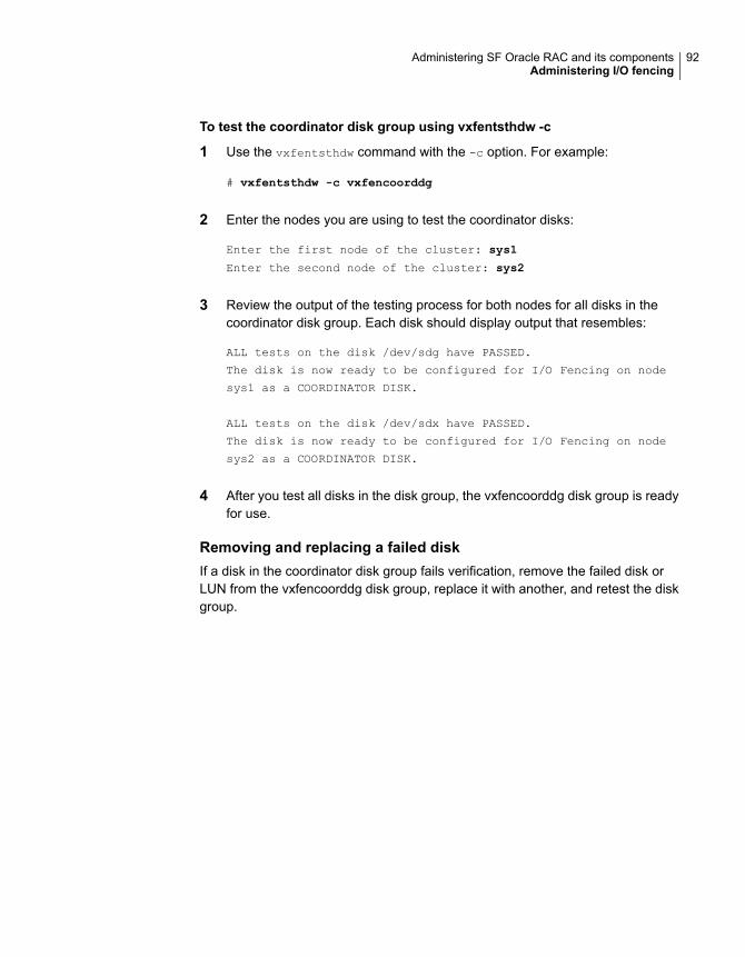
To test the coordinator disk group using vxfentsthdw -c
1 Use the vxfentsthdw command with the -c option. For example:
# vxfentsthdw -c vxfencoorddg
2 Enter the nodes you are using to test the coordinator disks:
Enter the first node of the cluster: sys1
Enter the second node of the cluster: sys2
3 Review the output of the testing process for both nodes for all disks in thecoordinator disk group. Each disk should display output that resembles:
ALL tests on the disk /dev/sdg have PASSED.
The disk is now ready to be configured for I/O Fencing on node
sys1 as a COORDINATOR DISK.
ALL tests on the disk /dev/sdx have PASSED.
The disk is now ready to be configured for I/O Fencing on node
sys2 as a COORDINATOR DISK.
4 After you test all disks in the disk group, the vxfencoorddg disk group is readyfor use.
Removing and replacing a failed diskIf a disk in the coordinator disk group fails verification, remove the failed disk orLUN from the vxfencoorddg disk group, replace it with another, and retest the diskgroup.
92Administering SF Oracle RAC and its componentsAdministering I/O fencing
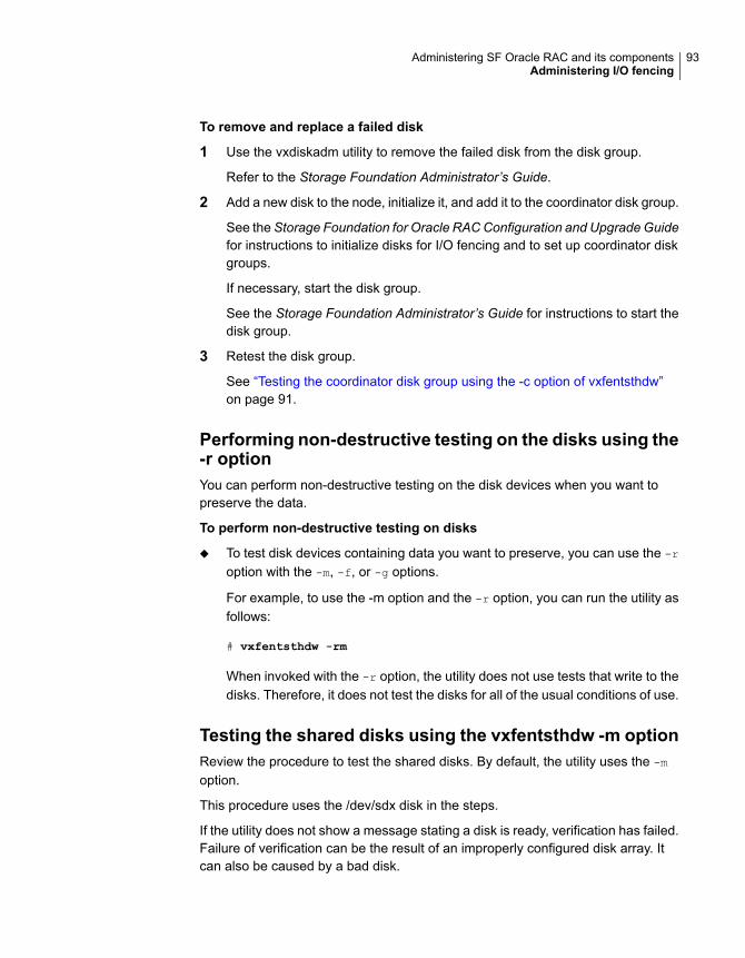
To remove and replace a failed disk
1 Use the vxdiskadm utility to remove the failed disk from the disk group.
Refer to the Storage Foundation Administrator’s Guide.
2 Add a new disk to the node, initialize it, and add it to the coordinator disk group.
See theStorage Foundation for Oracle RACConfiguration and Upgrade Guidefor instructions to initialize disks for I/O fencing and to set up coordinator diskgroups.
If necessary, start the disk group.
See the Storage Foundation Administrator’s Guide for instructions to start thedisk group.
3 Retest the disk group.
See “Testing the coordinator disk group using the -c option of vxfentsthdw”on page 91.
Performing non-destructive testing on the disks using the-r optionYou can perform non-destructive testing on the disk devices when you want topreserve the data.
To perform non-destructive testing on disks
◆ To test disk devices containing data you want to preserve, you can use the -r
option with the -m, -f, or -g options.
For example, to use the -m option and the -r option, you can run the utility asfollows:
# vxfentsthdw -rm
When invoked with the -r option, the utility does not use tests that write to thedisks. Therefore, it does not test the disks for all of the usual conditions of use.
Testing the shared disks using the vxfentsthdw -m optionReview the procedure to test the shared disks. By default, the utility uses the -m
option.
This procedure uses the /dev/sdx disk in the steps.
If the utility does not show a message stating a disk is ready, verification has failed.Failure of verification can be the result of an improperly configured disk array. Itcan also be caused by a bad disk.
93Administering SF Oracle RAC and its componentsAdministering I/O fencing
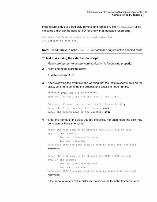
If the failure is due to a bad disk, remove and replace it. The vxfentsthdw utilityindicates a disk can be used for I/O fencing with a message resembling:
The disk /dev/sdx is ready to be configured for
I/O Fencing on node sys1
Note: For A/P arrays, run the vxfentsthdw command only on active enabled paths.
To test disks using the vxfentsthdw script
1 Make sure system-to-system communication is functioning properly.
2 From one node, start the utility.
# vxfentsthdw [-n]
3 After reviewing the overview and warning that the tests overwrite data on thedisks, confirm to continue the process and enter the node names.
******** WARNING!!!!!!!! ********
THIS UTILITY WILL DESTROY THE DATA ON THE DISK!!
Do you still want to continue : [y/n] (default: n) y
Enter the first node of the cluster: sys1
Enter the second node of the cluster: sys2
4 Enter the names of the disks you are checking. For each node, the disk maybe known by the same name:
Enter the disk name to be checked for SCSI-3 PGR on node
sys1 in the format:
for dmp: /dev/vx/rdmp/sdx
for raw: /dev/sdx
Make sure it's the same disk as seen by nodes sys1 and sys2
/dev/sdr
Enter the disk name to be checked for SCSI-3 PGR on node
sys2 in the format:
for dmp: /dev/vx/rdmp/sdx
for raw: /dev/sdx
Make sure it's the same disk as seen by nodes sys1 and sys2
/dev/sdr
If the serial numbers of the disks are not identical, then the test terminates.
94Administering SF Oracle RAC and its componentsAdministering I/O fencing
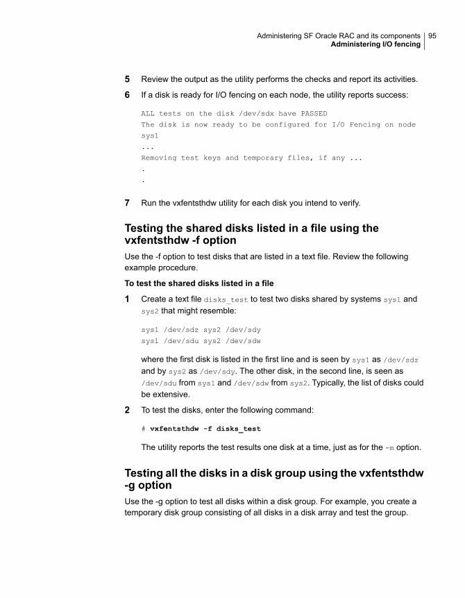
5 Review the output as the utility performs the checks and report its activities.
6 If a disk is ready for I/O fencing on each node, the utility reports success:
ALL tests on the disk /dev/sdx have PASSED
The disk is now ready to be configured for I/O Fencing on node
sys1
...
Removing test keys and temporary files, if any ...
.
.
7 Run the vxfentsthdw utility for each disk you intend to verify.
Testing the shared disks listed in a file using thevxfentsthdw -f optionUse the -f option to test disks that are listed in a text file. Review the followingexample procedure.
To test the shared disks listed in a file
1 Create a text file disks_test to test two disks shared by systems sys1 andsys2 that might resemble:
sys1 /dev/sdz sys2 /dev/sdy
sys1 /dev/sdu sys2 /dev/sdw
where the first disk is listed in the first line and is seen by sys1 as /dev/sdz
and by sys2 as /dev/sdy. The other disk, in the second line, is seen as/dev/sdu from sys1 and /dev/sdw from sys2. Typically, the list of disks couldbe extensive.
2 To test the disks, enter the following command:
# vxfentsthdw -f disks_test
The utility reports the test results one disk at a time, just as for the -m option.
Testing all the disks in a disk group using the vxfentsthdw-g optionUse the -g option to test all disks within a disk group. For example, you create atemporary disk group consisting of all disks in a disk array and test the group.
95Administering SF Oracle RAC and its componentsAdministering I/O fencing
Note: Do not import the test disk group as shared; that is, do not use the -s optionwith the vxdg import command.
After testing, destroy the disk group and put the disks into disk groups as you need.
To test all the disks in a disk group
1 Create a disk group for the disks that you want to test.
2 Enter the following command to test the disk group test_disks_dg:
# vxfentsthdw -g test_disks_dg
The utility reports the test results one disk at a time.
Testing a disk with existing keysIf the utility detects that a coordinator disk has existing keys, you see a messagethat resembles:
There are Veritas I/O fencing keys on the disk. Please make sure
that I/O fencing is shut down on all nodes of the cluster before
continuing.
******** WARNING!!!!!!!! ********
THIS SCRIPT CAN ONLY BE USED IF THERE ARE NO OTHER ACTIVE NODES
IN THE CLUSTER! VERIFY ALL OTHER NODES ARE POWERED OFF OR
INCAPABLE OF ACCESSING SHARED STORAGE.
If this is not the case, data corruption will result.
Do you still want to continue : [y/n] (default: n) y
The utility prompts you with a warning before proceeding. You may continue aslong as I/O fencing is not yet configured.
About the vxfenadm utilityAdministrators can use the vxfenadm command to troubleshoot and test fencingconfigurations.
The command’s options for use by administrators are as follows:
96Administering SF Oracle RAC and its componentsAdministering I/O fencing
read the keys on a disk and display the keys in numeric, character, andnode format
Note: The -g and -G options are deprecated. Use the -s option.
-s
read SCSI inquiry information from device-i
register with disks-m
make a reservation with disks-n
remove registrations made by other systems-p
read reservations-r
remove registrations-x
Refer to the vxfenadm(1M) manual page for a complete list of the command options.
About the I/O fencing registration key formatThe keys that the vxfen driver registers on the data disks and the coordinator disksconsist of eight bytes. The key format is different for the coordinator disks and datadisks.
The key format of the coordinator disks is as follows:
76543210Byte
nID 0xnID 0xcID 0xcID 0xcID 0xcID 0xFVValue
where:
■ VF is the unique identifier that carves out a namespace for the keys (consumestwo bytes)
■ cID 0x is the LLT cluster ID in hexadecimal (consumes four bytes)
■ nID 0x is the LLT node ID in hexadecimal (consumes two bytes)
The vxfen driver uses this key format in both sybase mode of I/O fencing.
The key format of the data disks that are configured as failover disk groups underVCS is as follows:
76543210Byte
SCVA+nIDValue
where nID is the LLT node ID
97Administering SF Oracle RAC and its componentsAdministering I/O fencing
For example: If the node ID is 1, then the first byte has the value as B (‘A’ + 1 = B).
The key format of the data disks configured as parallel disk groups under ClusterVolume Manager (CVM) is as follows:
76543210Byte
DGcountDGcountDGcountDGcountRGPA+nIDValue
where DGcount is the count of disk groups in the configuration (consumes fourbytes).
By default, CVM uses a unique fencing key for each disk group. However, somearrays have a restriction on the total number of unique keys that can be registered.In such cases, you can use the same_key_for_alldgs tunable parameter to changethe default behavior. The default value of the parameter is off. If your configurationhits the storage array limit on total number of unique keys, you can change thevalue to on using the vxdefault command as follows:
# vxdefault set same_key_for_alldgs on
# vxdefault list
KEYWORD CURRENT-VALUE DEFAULT-VALUE
...
same_key_for_alldgs on off
...
If the tunable is changed to on, all subsequent keys that the CVM generates ondisk group imports or creates have '0000' as their last four bytes (DGcount is 0).You must deport and re-import all the disk groups that are already imported for thechanged value of the same_key_for_alldgs tunable to take effect.
Displaying the I/O fencing registration keysYou can display the keys that are currently assigned to the disks using the vxfenadm
command.
The variables such as disk_7, disk_8, and disk_9 in the following procedurerepresent the disk names in your setup.
To display the I/O fencing registration keys
1 To display the key for the disks, run the following command:
# vxfenadm -s disk_name
For example:
98Administering SF Oracle RAC and its componentsAdministering I/O fencing
■ To display the key for the coordinator disk /dev/sdx from the system withnode ID 1, enter the following command:
# vxfenadm -s /dev/sdx
key[1]:
[Numeric Format]: 86,70,68,69,69,68,48,48
[Character Format]: VFDEED00
* [Node Format]: Cluster ID: 57069 Node ID: 0 Node Name: sys1
The -s option of vxfenadm displays all eight bytes of a key value in threeformats. In the numeric format,
■ The first two bytes, represent the identifier VF, contains the ASCII value86, 70.
■ The next four bytes contain the ASCII value of the cluster ID 57069encoded in hex (0xDEED) which are 68, 69, 69, 68.
■ The remaining bytes contain the ASCII value of the node ID 0 (0x00)which are 48, 48. Node ID 1 would be 01 and node ID 10 would be 0A.
An asterisk before the Node Format indicates that the vxfenadm commandis run from the node of a cluster where LLT is configured and is running.
■ To display the keys on a CVM parallel disk group:
# vxfenadm -s /dev/vx/rdmp/disk_7
Reading SCSI Registration Keys...
Device Name: /dev/vx/rdmp/disk_7
Total Number Of Keys: 1
key[0]:
[Numeric Format]: 66,80,71,82,48,48,48,49
[Character Format]: BPGR0001
[Node Format]: Cluster ID: unknown Node ID: 1 Node Name: sys2
■ To display the keys on a Cluster Server (VCS) failover disk group:
# vxfenadm -s /dev/vx/rdmp/disk_8
Reading SCSI Registration Keys...
Device Name: /dev/vx/rdmp/disk_8
Total Number Of Keys: 1
key[0]:
[Numeric Format]: 65,86,67,83,0,0,0,0
99Administering SF Oracle RAC and its componentsAdministering I/O fencing
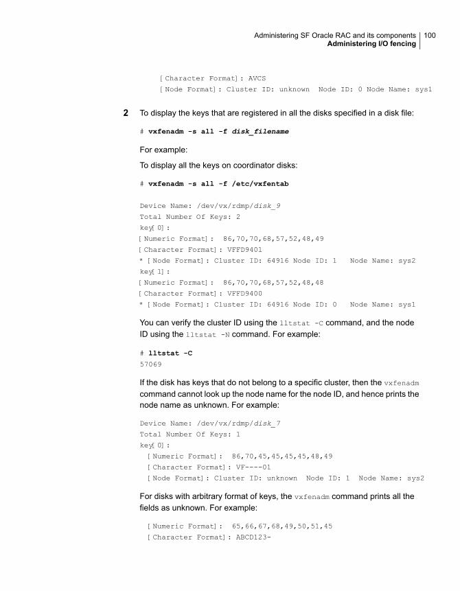
[Character Format]: AVCS
[Node Format]: Cluster ID: unknown Node ID: 0 Node Name: sys1
2 To display the keys that are registered in all the disks specified in a disk file:
# vxfenadm -s all -f disk_filename
For example:
To display all the keys on coordinator disks:
# vxfenadm -s all -f /etc/vxfentab
Device Name: /dev/vx/rdmp/disk_9
Total Number Of Keys: 2
key[0]:
[Numeric Format]: 86,70,70,68,57,52,48,49
[Character Format]: VFFD9401
* [Node Format]: Cluster ID: 64916 Node ID: 1 Node Name: sys2
key[1]:
[Numeric Format]: 86,70,70,68,57,52,48,48
[Character Format]: VFFD9400
* [Node Format]: Cluster ID: 64916 Node ID: 0 Node Name: sys1
You can verify the cluster ID using the lltstat -C command, and the nodeID using the lltstat -N command. For example:
# lltstat -C
57069
If the disk has keys that do not belong to a specific cluster, then the vxfenadm
command cannot look up the node name for the node ID, and hence prints thenode name as unknown. For example:
Device Name: /dev/vx/rdmp/disk_7
Total Number Of Keys: 1
key[0]:
[Numeric Format]: 86,70,45,45,45,45,48,49
[Character Format]: VF----01
[Node Format]: Cluster ID: unknown Node ID: 1 Node Name: sys2
For disks with arbitrary format of keys, the vxfenadm command prints all thefields as unknown. For example:
[Numeric Format]: 65,66,67,68,49,50,51,45
[Character Format]: ABCD123-
100Administering SF Oracle RAC and its componentsAdministering I/O fencing
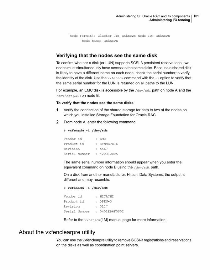
[Node Format]: Cluster ID: unknown Node ID: unknown
Node Name: unknown
Verifying that the nodes see the same diskTo confirm whether a disk (or LUN) supports SCSI-3 persistent reservations, twonodes must simultaneously have access to the same disks. Because a shared diskis likely to have a different name on each node, check the serial number to verifythe identity of the disk. Use the vxfenadm command with the -i option to verify thatthe same serial number for the LUN is returned on all paths to the LUN.
For example, an EMC disk is accessible by the /dev/sdr path on node A and the/dev/sdt path on node B.
To verify that the nodes see the same disks
1 Verify the connection of the shared storage for data to two of the nodes onwhich you installed Storage Foundation for Oracle RAC.
2 From node A, enter the following command:
# vxfenadm -i /dev/sdr
Vendor id : EMC
Product id : SYMMETRIX
Revision : 5567
Serial Number : 42031000a
The same serial number information should appear when you enter theequivalent command on node B using the /dev/sdt path.
On a disk from another manufacturer, Hitachi Data Systems, the output isdifferent and may resemble:
# vxfenadm -i /dev/sdt
Vendor id : HITACHI
Product id : OPEN-3
Revision : 0117
Serial Number : 0401EB6F0002
Refer to the vxfenadm(1M) manual page for more information.
About the vxfenclearpre utilityYou can use the vxfenclearpre utility to remove SCSI-3 registrations and reservationson the disks as well as coordination point servers.
101Administering SF Oracle RAC and its componentsAdministering I/O fencing
See “Removing preexisting keys” on page 102.
This utility now supports server-based fencing. You can use the vxfenclearpre utilityto clear registrations from coordination point servers (CP servers) for the currentcluster. The local node from where you run the utility must have the UUID of thecurrent cluster at the /etc/vx/.uuids directory in the clusuuid file. If the UUID file forthat cluster is not available on the local node, the utility does not clear registrationsfrom the coordination point servers.
Note: You can use the utility to remove the registration keys and the registrations(reservations) from the set of coordinator disks for any cluster you specify in thecommand, but you can only clear registrations of your current cluster from the CPservers. Also, you may experience delays while clearing registrations on thecoordination point servers because the utility tries to establish a network connectionwith the IP addresses used by the coordination point servers. The delay may occurbecause of a network issue or if the IP address is not reachable or is incorrect.
For any issues you encounter with the vxfenclearpre utility, you can you can referto the log file at, /var/VRTSvcs/log/vxfen/vxfen.log file.
See “Issues during fencing startup on SF Oracle RAC cluster nodes set up forserver-based fencing” on page 192.
Removing preexisting keysIf you encountered a split-brain condition, use the vxfenclearpre utility to removeCP Servers, SCSI-3 registrations, and reservations on the coordinator disks,Coordination Point servers, as well as on the data disks in all shared disk groups.
You can also use this procedure to remove the registration and reservation keysof another node or other nodes on shared disks or CP server.
To clear keys after split-brain
1 Stop VCS on all nodes.
# hastop -all
2 Make sure that the port h is closed on all the nodes. Run the following commandon each node to verify that the port h is closed:
# gabconfig -a
Port h must not appear in the output.
102Administering SF Oracle RAC and its componentsAdministering I/O fencing

3 Stop I/O fencing on all nodes. Enter the following command on each node:
# /etc/init.d/vxfen stop
4 If you have any applications that run outside of VCS control that have accessto the shared storage, then shut down all other nodes in the cluster that haveaccess to the shared storage. This prevents data corruption.
5 Start the vxfenclearpre script:
# /opt/VRTSvcs/vxfen/bin/vxfenclearpre
103Administering SF Oracle RAC and its componentsAdministering I/O fencing
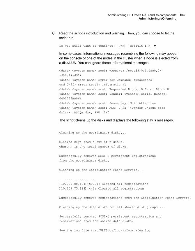
6 Read the script’s introduction and warning. Then, you can choose to let thescript run.
Do you still want to continue: [y/n] (default : n) y
In some cases, informational messages resembling the following may appearon the console of one of the nodes in the cluster when a node is ejected froma disk/LUN. You can ignore these informational messages.
<date> <system name> scsi: WARNING: /sbus@3,0/lpfs@0,0/
sd@0,1(sd91):
<date> <system name> Error for Command: <undecoded
cmd 0x5f> Error Level: Informational
<date> <system name> scsi: Requested Block: 0 Error Block 0
<date> <system name> scsi: Vendor: <vendor> Serial Number:
0400759B006E
<date> <system name> scsi: Sense Key: Unit Attention
<date> <system name> scsi: ASC: 0x2a (<vendor unique code
0x2a>), ASCQ: 0x4, FRU: 0x0
The script cleans up the disks and displays the following status messages.
Cleaning up the coordinator disks...
Cleared keys from n out of n disks,
where n is the total number of disks.
Successfully removed SCSI-3 persistent registrations
from the coordinator disks.
Cleaning up the Coordination Point Servers...
...................
[10.209.80.194]:50001: Cleared all registrations
[10.209.75.118]:443: Cleared all registrations
Successfully removed registrations from the Coordination Point Servers.
Cleaning up the data disks for all shared disk groups ...
Successfully removed SCSI-3 persistent registration and
reservations from the shared data disks.
See the log file /var/VRTSvcs/log/vxfen/vxfen.log
104Administering SF Oracle RAC and its componentsAdministering I/O fencing
You can retry starting fencing module. In order to restart the whole
product, you might want to reboot the system.
7 Start the fencing module on all the nodes.
# /etc/init.d/vxfen start
8 Start VCS on all nodes.
# hastart
About the vxfenswap utilityThe vxfenswap utility allows you to add, remove, and replace coordinator points ina cluster that is online. The utility verifies that the serial number of the new disksare identical on all the nodes and the new disks can support I/O fencing.
This utility supports both disk-based and server-based fencing.
The utility uses SSH, RSH, or hacli for communication between nodes in the cluster.Before you execute the utility, ensure that communication between nodes is set upin one these communication protocols.
Refer to the vxfenswap(1M) manual page.
See the Storage Foundation for Oracle RAC Configuration and Upgrade Guide fordetails on the I/O fencing requirements.
You can replace the coordinator disks without stopping I/O fencing in the followingcases:
■ The disk becomes defective or inoperable and you want to switch to a new diskgroup.See “Replacing I/O fencing coordinator disks when the cluster is online”on page 106.See “Replacing the coordinator disk group in a cluster that is online” on page 110.If you want to replace the coordinator disks when the cluster is offline, you cannotuse the vxfenswap utility. You must manually perform the steps that the utilitydoes to replace the coordinator disks.See “Replacing defective disks when the cluster is offline” on page 186.
■ The keys that are registered on the coordinator disks are lost.In such a case, the cluster might panic when a network partition occurs. Youcan replace the coordinator disks with the same disks using the vxfenswap
105Administering SF Oracle RAC and its componentsAdministering I/O fencing
command. During the disk replacement, the missing keys register again withoutany risk of data corruption.See “Refreshing lost keys on coordinator disks” on page 116.
In server-based fencing configuration, you can use the vxfenswap utility to performthe following tasks:
■ Perform a planned replacement of customized coordination points (CP serversor SCSI-3 disks).See “Replacing coordination points for server-based fencing in an online cluster”on page 128.
■ Refresh the I/O fencing keys that are registered on the coordination points.See “Refreshing registration keys on the coordination points for server-basedfencing” on page 126.
You can also use the vxfenswap utility to migrate between the disk-based and theserver-based fencing without incurring application downtime in the SF Oracle RACcluster.
If the vxfenswap operation is unsuccessful, then you can use the -a cancel of thevxfenswap command to manually roll back the changes that the vxfenswap utilitydoes.
■ For disk-based fencing, use the vxfenswap -g diskgroup -a cancel commandto cancel the vxfenswap operation.You must run this command if a node fails during the process of diskreplacement, or if you aborted the disk replacement.
■ For server-based fencing, use the vxfenswap -a cancel command to cancelthe vxfenswap operation.
Replacing I/O fencing coordinator disks when the clusteris onlineReview the procedures to add, remove, or replace one or more coordinator disksin a cluster that is operational.
Warning: The cluster might panic if any node leaves the cluster membership beforethe vxfenswap script replaces the set of coordinator disks.
To replace a disk in a coordinator disk group when the cluster is online
1 Make sure system-to-system communication is functioning properly.
2 Determine the value of the FaultTolerance attribute.
# hares -display coordpoint -attribute FaultTolerance -localclus
106Administering SF Oracle RAC and its componentsAdministering I/O fencing
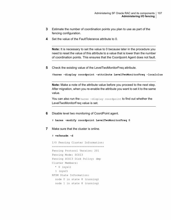
3 Estimate the number of coordination points you plan to use as part of thefencing configuration.
4 Set the value of the FaultTolerance attribute to 0.
Note: It is necessary to set the value to 0 because later in the procedure youneed to reset the value of this attribute to a value that is lower than the numberof coordination points. This ensures that the Coordpoint Agent does not fault.
5 Check the existing value of the LevelTwoMonitorFreq attribute.
#hares -display coordpoint -attribute LevelTwoMonitorFreq -localclus
Note: Make a note of the attribute value before you proceed to the next step.After migration, when you re-enable the attribute you want to set it to the samevalue.
You can also run the hares -display coordpoint to find out whether theLevelTwoMonitorFreq value is set.
6 Disable level two monitoring of CoordPoint agent.
# hares -modify coordpoint LevelTwoMonitorFreq 0
7 Make sure that the cluster is online.
# vxfenadm -d
I/O Fencing Cluster Information:
================================
Fencing Protocol Version: 201
Fencing Mode: SCSI3
Fencing SCSI3 Disk Policy: dmp
Cluster Members:
* 0 (sys1)
1 (sys2)
RFSM State Information:
node 0 in state 8 (running)
node 1 in state 8 (running)
107Administering SF Oracle RAC and its componentsAdministering I/O fencing
8 Import the coordinator disk group.
The file /etc/vxfendg includes the name of the disk group (typically,vxfencoorddg) that contains the coordinator disks, so use the command:
# vxdg -tfC import ‘cat /etc/vxfendg‘
where:
-t specifies that the disk group is imported only until the node restarts.
-f specifies that the import is to be done forcibly, which is necessary if one ormore disks is not accessible.
-C specifies that any import locks are removed.
9 If your setup uses VRTSvxvm version, then skip to step 10. You need not setcoordinator=off to add or remove disks. For other VxVM versions, performthis step:
Where version is the specific release version.
Turn off the coordinator attribute value for the coordinator disk group.
# vxdg -g vxfencoorddg set coordinator=off
10 To remove disks from the coordinator disk group, use the VxVM diskadministrator utility vxdiskadm.
11 Perform the following steps to add new disks to the coordinator disk group:
■ Add new disks to the node.
■ Initialize the new disks as VxVM disks.
■ Check the disks for I/O fencing compliance.
■ Add the new disks to the coordinator disk group and set the coordinatorattribute value as "on" for the coordinator disk group.
See theStorage Foundation for Oracle RACConfiguration and Upgrade Guidefor detailed instructions.
Note that though the disk group content changes, the I/O fencing remains inthe same state.
12 From one node, start the vxfenswap utility. You must specify the disk group tothe utility.
The utility performs the following tasks:
■ Backs up the existing /etc/vxfentab file.
108Administering SF Oracle RAC and its componentsAdministering I/O fencing
■ Creates a test file /etc/vxfentab.test for the disk group that is modifiedon each node.
■ Reads the disk group you specified in the vxfenswap command and addsthe disk group to the /etc/vxfentab.test file on each node.
■ Verifies that the serial number of the new disks are identical on all the nodes.The script terminates if the check fails.
■ Verifies that the new disks can support I/O fencing on each node.
13 If the disk verification passes, the utility reports success and asks if you wantto commit the new set of coordinator disks.
14 Confirm whether you want to clear the keys on the coordination points andproceed with the vxfenswap operation.
Do you want to clear the keys on the coordination points
and proceed with the vxfenswap operation? [y/n] (default: n) y
15 Review the message that the utility displays and confirm that you want tocommit the new set of coordinator disks. Else skip to step 16.
Do you wish to commit this change? [y/n] (default: n) y
If the utility successfully commits, the utility moves the /etc/vxfentab.test
file to the /etc/vxfentab file.
16 If you do not want to commit the new set of coordinator disks, answer n.
The vxfenswap utility rolls back the disk replacement operation.
17 If coordinator flag was set to off in step 9, then set it on.
# vxdg -g vxfencoorddg set coordinator=on
18 Deport the diskgroup.
# vxdg deport vxfencoorddg
109Administering SF Oracle RAC and its componentsAdministering I/O fencing
19 Re-enable the LevelTwoMonitorFreq attribute of the CoordPoint agent.Youmay want to use the value that was set before disabling the attribute.
# hares -modify coordpoint LevelTwoMonitorFreq Frequencyvalue
where Frequencyvalue is the value of the attribute.
20 Set the FaultTolerance attribute to a value that is lower than 50% of the totalnumber of coordination points.
For example, if there are four (4) coordination points in your configuration, thenthe attribute value must be lower than two (2).If you set it to a higher valuethan two (2) the CoordPoint agent faults.
Replacing the coordinator disk group in a cluster that isonlineYou can also replace the coordinator disk group using the vxfenswap utility. Thefollowing example replaces the coordinator disk group vxfencoorddg with a newdisk group vxfendg.
To replace the coordinator disk group
1 Make sure system-to-system communication is functioning properly.
2 Determine the value of the FaultTolerance attribute.
# hares -display coordpoint -attribute FaultTolerance -localclus
3 Estimate the number of coordination points you plan to use as part of thefencing configuration.
4 Set the value of the FaultTolerance attribute to 0.
Note: It is necessary to set the value to 0 because later in the procedure youneed to reset the value of this attribute to a value that is lower than the numberof coordination points. This ensures that the Coordpoint Agent does not fault.
5 Check the existing value of the LevelTwoMonitorFreq attribute.
# hares -display coordpoint -attribute LevelTwoMonitorFreq -localclus
Note: Make a note of the attribute value before you proceed to the next step.After migration, when you re-enable the attribute you want to set it to the samevalue.
110Administering SF Oracle RAC and its componentsAdministering I/O fencing
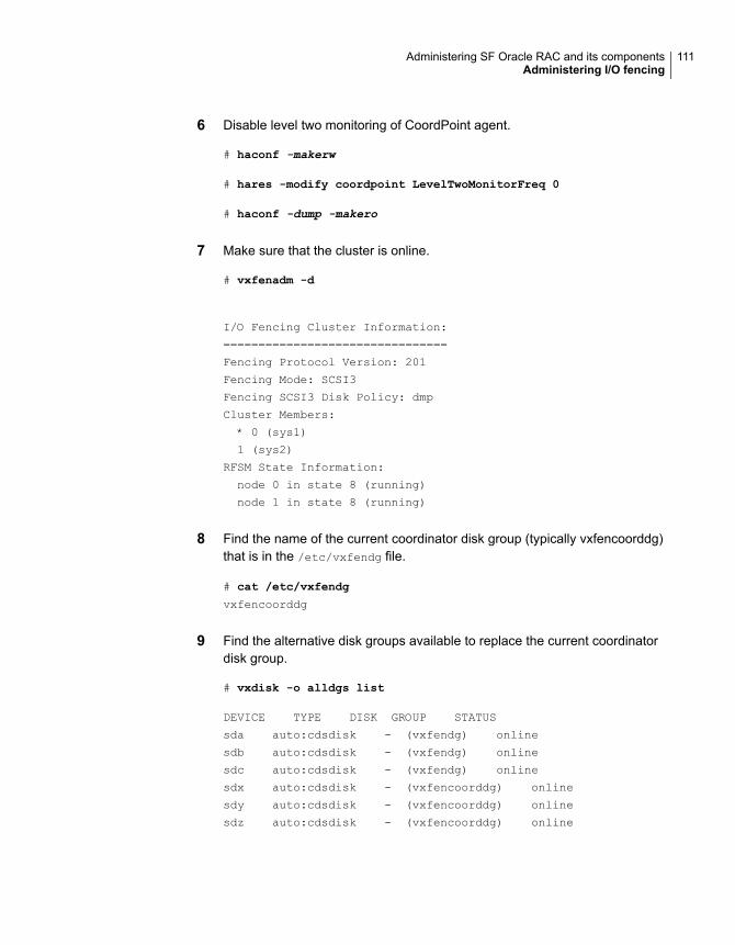
6 Disable level two monitoring of CoordPoint agent.
# haconf -makerw
# hares -modify coordpoint LevelTwoMonitorFreq 0
# haconf -dump -makero
7 Make sure that the cluster is online.
# vxfenadm -d
I/O Fencing Cluster Information:
================================
Fencing Protocol Version: 201
Fencing Mode: SCSI3
Fencing SCSI3 Disk Policy: dmp
Cluster Members:
* 0 (sys1)
1 (sys2)
RFSM State Information:
node 0 in state 8 (running)
node 1 in state 8 (running)
8 Find the name of the current coordinator disk group (typically vxfencoorddg)that is in the /etc/vxfendg file.
# cat /etc/vxfendg
vxfencoorddg
9 Find the alternative disk groups available to replace the current coordinatordisk group.
# vxdisk -o alldgs list
DEVICE TYPE DISK GROUP STATUS
sda auto:cdsdisk - (vxfendg) online
sdb auto:cdsdisk - (vxfendg) online
sdc auto:cdsdisk - (vxfendg) online
sdx auto:cdsdisk - (vxfencoorddg) online
sdy auto:cdsdisk - (vxfencoorddg) online
sdz auto:cdsdisk - (vxfencoorddg) online
111Administering SF Oracle RAC and its componentsAdministering I/O fencing
10 Validate the new disk group for I/O fencing compliance. Run the followingcommand:
# vxfentsthdw -c vxfendg
See “Testing the coordinator disk group using the -c option of vxfentsthdw”on page 91.
11 If the new disk group is not already deported, run the following command todeport the disk group:
# vxdg deport vxfendg
12 Perform one of the following:
■ Create the /etc/vxfenmode.test file with new fencing mode and diskpolicy information.
■ Edit the existing the /etc/vxfenmode with new fencing mode and disk policyinformation and remove any preexisting /etc/vxfenmode.test file.
Note that the format of the /etc/vxfenmode.test file and the /etc/vxfenmode fileis the same.
See theStorage Foundation for Oracle RACConfiguration and Upgrade Guidefor more information.
13 From any node, start the vxfenswap utility. For example, if vxfendg is the newdisk group that you want to use as the coordinator disk group:
# vxfenswap -g vxfendg [-n]
The utility performs the following tasks:
■ Backs up the existing /etc/vxfentab file.
■ Creates a test file /etc/vxfentab.test for the disk group that is modifiedon each node.
■ Reads the disk group you specified in the vxfenswap command and addsthe disk group to the /etc/vxfentab.test file on each node.
■ Verifies that the serial number of the new disks are identical on all the nodes.The script terminates if the check fails.
■ Verifies that the new disk group can support I/O fencing on each node.
14 If the disk verification passes, the utility reports success and asks if you wantto replace the coordinator disk group.
112Administering SF Oracle RAC and its componentsAdministering I/O fencing

15 Confirm whether you want to clear the keys on the coordination points andproceed with the vxfenswap operation.
Do you want to clear the keys on the coordination points
and proceed with the vxfenswap operation? [y/n] (default: n) y
16 Review the message that the utility displays and confirm that you want toreplace the coordinator disk group. Else skip to step 21.
Do you wish to commit this change? [y/n] (default: n) y
If the utility successfully commits, the utility moves the /etc/vxfentab.test
file to the /etc/vxfentab file.
The utility also updates the /etc/vxfendg file with this new disk group.
17 Import the new disk group if it is not already imported before you set thecoordinator flag "on".
# vxdg -t import vxfendg
18 Set the coordinator attribute value as "on" for the new coordinator disk group.
# vxdg -g vxfendg set coordinator=on
Set the coordinator attribute value as "off" for the old disk group.
# vxdg -g vxfencoorddg set coordinator=off
19 Deport the new disk group.
# vxdg deport vxfendg
20 Verify that the coordinator disk group has changed.
# cat /etc/vxfendg
vxfendg
The swap operation for the coordinator disk group is complete now.
21 If you do not want to replace the coordinator disk group, answer n at the prompt.
The vxfenswap utility rolls back any changes to the coordinator disk group.
113Administering SF Oracle RAC and its componentsAdministering I/O fencing
22 Re-enable the LevelTwoMonitorFreq attribute of the CoordPoint agent. Youmay want to use the value that was set before disabling the attribute.
# haconf -makerw
# hares -modify coordpoint LevelTwoMonitorFreq Frequencyvalue
# haconf -dump -makero
where Frequencyvalue is the value of the attribute.
23 Set the FaultTolerance attribute to a value that is lower than 50% of the totalnumber of coordination points.
For example, if there are four (4) coordination points in your configuration, thenthe attribute value must be lower than two (2).If you set it to a higher valuethan two (2) the CoordPoint agent faults.
Adding disks from a recovered site to the coordinator diskgroupIn a campus cluster environment, consider a case where the primary site goesdown and the secondary site comes online with a limited set of disks. When theprimary site restores, the primary site's disks are also available to act as coordinatordisks. You can use the vxfenswap utility to add these disks to the coordinator diskgroup.
To add new disks from a recovered site to the coordinator disk group
1 Make sure system-to-system communication is functioning properly.
2 Make sure that the cluster is online.
# vxfenadm -d
I/O Fencing Cluster Information:
================================
Fencing Protocol Version: 201
Fencing Mode: SCSI3
Fencing SCSI3 Disk Policy: dmp
Cluster Members:
* 0 (sys1)
1 (sys2)
RFSM State Information:
node 0 in state 8 (running)
node 1 in state 8 (running)
114Administering SF Oracle RAC and its componentsAdministering I/O fencing

3 Verify the name of the coordinator disk group.
# cat /etc/vxfendg
vxfencoorddg
4 Run the following command:
# vxdisk -o alldgs list
DEVICE TYPE DISK GROUP STATUS
sdx auto:cdsdisk - (vxfencoorddg) online
sdy auto - - offline
sdz auto - - offline
5 Verify the number of disks used in the coordinator disk group.
# vxfenconfig -l
I/O Fencing Configuration Information:
======================================
Count : 1
Disk List
Disk Name Major Minor Serial Number Policy
/dev/vx/rdmp/sdx 32 48 R450 00013154 0312 dmp
6 When the primary site comes online, start the vxfenswap utility on any nodein the cluster:
# vxfenswap -g vxfencoorddg [-n]
7 Verify the count of the coordinator disks.
# vxfenconfig -l
I/O Fencing Configuration Information:
======================================
Single Disk Flag : 0
Count : 3
Disk List
Disk Name Major Minor Serial Number Policy
/dev/vx/rdmp/sdx 32 48 R450 00013154 0312 dmp
/dev/vx/rdmp/sdy 32 32 R450 00013154 0313 dmp
/dev/vx/rdmp/sdz 32 16 R450 00013154 0314 dmp
115Administering SF Oracle RAC and its componentsAdministering I/O fencing
Refreshing lost keys on coordinator disksIf the coordinator disks lose the keys that are registered, the cluster might panicwhen a network partition occurs.
You can use the vxfenswap utility to replace the coordinator disks with the samedisks. The vxfenswap utility registers the missing keys during the disk replacement.
To refresh lost keys on coordinator disks
1 Make sure system-to-system communication is functioning properly.
2 Make sure that the cluster is online.
# vxfenadm -d
I/O Fencing Cluster Information:
================================
Fencing Protocol Version: 201
Fencing Mode: SCSI3
Fencing SCSI3 Disk Policy: dmp
Cluster Members:
* 0 (sys1)
1 (sys2)
RFSM State Information:
node 0 in state 8 (running)
node 1 in state 8 (running)
3 Run the following command to view the coordinator disks that do not havekeys:
# vxfenadm -s all -f /etc/vxfentab
Device Name: /dev/vx/rdmp/sdx
Total Number of Keys: 0
No keys...
...
4 Copy the /etc/vxfenmode file to the /etc/vxfenmode.test file.
This ensures that the configuration details of both the files are the same.
116Administering SF Oracle RAC and its componentsAdministering I/O fencing
5 On any node, run the following command to start the vxfenswap utility:
# vxfenswap -g vxfencoorddg [-n]
6 Verify that the keys are atomically placed on the coordinator disks.
# vxfenadm -s all -f /etc/vxfentab
Device Name: /dev/vx/rdmp/sdx
Total Number of Keys: 4
...
Enabling or disabling the preferred fencing policyYou can enable or disable the preferred fencing feature for your I/O fencingconfiguration.
You can enable preferred fencing to use system-based race policy, group-basedrace policy, or site-based policy. If you disable preferred fencing, the I/O fencingconfiguration uses the default count-based race policy.
Preferred fencing is not applicable to majority-based I/O fencing.
To enable preferred fencing for the I/O fencing configuration
1 Make sure that the cluster is running with I/O fencing set up.
# vxfenadm -d
2 Make sure that the cluster-level attribute UseFence has the value set to SCSI3.
# haclus -value UseFence
3 To enable system-based race policy, perform the following steps:
■ Make the VCS configuration writable.
# haconf -makerw
■ Set the value of the cluster-level attribute PreferredFencingPolicy as System.
# haclus -modify PreferredFencingPolicy System
■ Set the value of the system-level attribute FencingWeight for each node inthe cluster.
117Administering SF Oracle RAC and its componentsAdministering I/O fencing
For example, in a two-node cluster, where you want to assign sys1 fivetimes more weight compared to sys2, run the following commands:
# hasys -modify sys1 FencingWeight 50
# hasys -modify sys2 FencingWeight 10
■ Save the VCS configuration.
# haconf -dump -makero
■ Verify fencing node weights using:
# vxfenconfig -a
4 To enable group-based race policy, perform the following steps:
■ Make the VCS configuration writable.
# haconf -makerw
■ Set the value of the cluster-level attribute PreferredFencingPolicy as Group.
# haclus -modify PreferredFencingPolicy Group
■ Set the value of the group-level attribute Priority for each service group.For example, run the following command:
# hagrp -modify service_group Priority 1
Make sure that you assign a parent service group an equal or lower prioritythan its child service group. In case the parent and the child service groupsare hosted in different subclusters, then the subcluster that hosts the childservice group gets higher preference.
■ Save the VCS configuration.
# haconf -dump -makero
5 To enable site-based race policy, perform the following steps:
■ Make the VCS configuration writable.
# haconf -makerw
■ Set the value of the cluster-level attribute PreferredFencingPolicy as Site.
# haclus -modify PreferredFencingPolicy Site
118Administering SF Oracle RAC and its componentsAdministering I/O fencing
■ Set the value of the site-level attribute Preference for each site.
For example,
# hasite -modify Pune Preference 2
■ Save the VCS configuration.
# haconf -dump –makero
6 To view the fencing node weights that are currently set in the fencing driver,run the following command:
# vxfenconfig -a
To disable preferred fencing for the I/O fencing configuration
1 Make sure that the cluster is running with I/O fencing set up.
# vxfenadm -d
2 Make sure that the cluster-level attribute UseFence has the value set to SCSI3.
# haclus -value UseFence
3 To disable preferred fencing and use the default race policy, set the value ofthe cluster-level attribute PreferredFencingPolicy as Disabled.
# haconf -makerw
# haclus -modify PreferredFencingPolicy Disabled
# haconf -dump -makero
About I/O fencing log filesRefer to the appropriate log files for information related to a specific utility. The logfile location for each utility or command is as follows:
■ vxfen start and stop logs: /var/VRTSvcs/log/vxfen/vxfen.log
■ vxfenclearpre utility: /var/VRTSvcs/log/vxfen/vxfen.log
■ vxfenctl utility: /var/VRTSvcs/log/vxfen/vxfenctl.log*
■ vxfenswap utility: /var/VRTSvcs/log/vxfen/vxfenswap.log*
■ vxfentsthdw utility: /var/VRTSvcs/log/vxfen/vxfentsthdw.log*
The asterisk ,*, represents a number that differs for each invocation of the command.
119Administering SF Oracle RAC and its componentsAdministering I/O fencing
Migrating from disk-based fencing to server-based fencing using theinstaller
The following procedure lists steps to perform migration using the installer.
Tomigrate from disk-based fencing to server-based fencing using the installer
1 Make sure system-to-system communication is functioning properly.
2 Make sure that the SF Oracle RAC cluster is online and uses disk-basedfencing.
# vxfenadm -d
For example, if SF Oracle RAC cluster uses disk-based fencing:
I/O Fencing Cluster Information:
================================
Fencing Protocol Version: 201
Fencing Mode: SCSI3
Fencing SCSI3 Disk Policy: dmp
Cluster Members:
* 0 (sys1)
1 (sys2)
RFSM State Information:
node 0 in state 8 (running)
node 1 in state 8 (running)
3 On any node in the cluster, start the installer with the -fencing option.
# /opt/VRTS/install/installer -fencing
Note the location of log files which you can access in the event of any problemwith the configuration process.
4 Confirm that you want to proceed with the I/O fencing configuration.
The installer verifies whether I/O fencing is configured in enabled mode.
5 Confirm that you want to reconfigure I/O fencing.
6 Review the I/O fencing configuration options that the program presents. Type4 to migrate to server-based I/O fencing.
Select the fencing mechanism to be configured in this
Application Cluster [1-4,q] 4
120Administering SF Oracle RAC and its componentsAdministering I/O fencing
7 From the list of coordination points that the installer presents, select thecoordination points that you want to replace.
For example:
Select the coordination points you would like to remove
from the currently configured coordination points:
1) emc_clariion0_62
2) emc_clariion0_65
3) emc_clariion0_66
4) All
5) None
b) Back to previous menu
Enter the options separated by spaces: [1-5,b,q,?] (5)? 1 2
If you want to migrate to server-based fencing with no coordinator disks, type4 to remove all the coordinator disks.
8 Enter the total number of new coordination points.
If you want to migrate to server-based fencing configuration with a mix ofcoordination points, the number you enter at this prompt must be a total of boththe new CP servers and the new coordinator disks.
9 Enter the total number of new coordinator disks.
If you want to migrate to server-based fencing with no coordinator disks, type0 at this prompt.
10 Enter the total number of virtual IP addresses or host names of the virtual IPaddress for each of the CP servers.
11 Enter the virtual IP addresses or host names of the virtual IP address for eachof the CP servers.
12 Verify and confirm the coordination points information for the fencingreconfiguration.
13 Review the output as the installer performs the following tasks:
■ Removes the coordinator disks from the coordinator disk group.
■ Updates the application cluster details on each of the new CP servers.
■ Prepares the vxfenmode.test file on all nodes.
■ Runs the vxfenswap script.Note the location of the vxfenswap.log file which you can access in theevent of any problem with the configuration process.
■ Completes the I/O fencing migration.
121Administering SF Oracle RAC and its componentsAdministering I/O fencing
14 If you want to send this installation information to Veritas, answer y at theprompt.
Would you like to send the information about this installation
to Veritas to help improve installation in the future? [y,n,q,?] (y) y
15 After the migration is complete, verify the change in the fencing mode.
# vxfenadm -d
For example, after the migration from disk-based fencing to server-basedfencing in the SF Oracle RAC cluster:
I/O Fencing Cluster Information:
================================
Fencing Protocol Version: 201
Fencing Mode: Customized
Fencing Mechanism: cps
Cluster Members:
* 0 (sys1)
1 (sys2)
RFSM State Information:
node 0 in state 8 (running)
node 1 in state 8 (running)
16 Verify the current coordination points that the vxfen driver uses.
# vxfenconfig -l
Migrating from server-based fencing to disk-based fencing using theinstaller
The following procedure lists the steps to perform migration using the installer.
122Administering SF Oracle RAC and its componentsAdministering I/O fencing
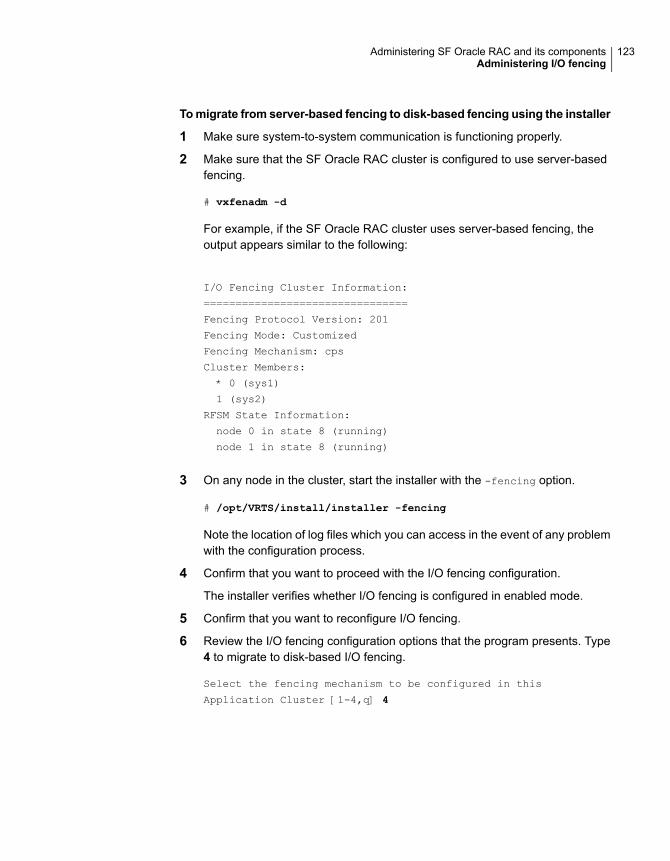
Tomigrate from server-based fencing to disk-based fencing using the installer
1 Make sure system-to-system communication is functioning properly.
2 Make sure that the SF Oracle RAC cluster is configured to use server-basedfencing.
# vxfenadm -d
For example, if the SF Oracle RAC cluster uses server-based fencing, theoutput appears similar to the following:
I/O Fencing Cluster Information:
================================
Fencing Protocol Version: 201
Fencing Mode: Customized
Fencing Mechanism: cps
Cluster Members:
* 0 (sys1)
1 (sys2)
RFSM State Information:
node 0 in state 8 (running)
node 1 in state 8 (running)
3 On any node in the cluster, start the installer with the -fencing option.
# /opt/VRTS/install/installer -fencing
Note the location of log files which you can access in the event of any problemwith the configuration process.
4 Confirm that you want to proceed with the I/O fencing configuration.
The installer verifies whether I/O fencing is configured in enabled mode.
5 Confirm that you want to reconfigure I/O fencing.
6 Review the I/O fencing configuration options that the program presents. Type4 to migrate to disk-based I/O fencing.
Select the fencing mechanism to be configured in this
Application Cluster [1-4,q] 4
123Administering SF Oracle RAC and its componentsAdministering I/O fencing
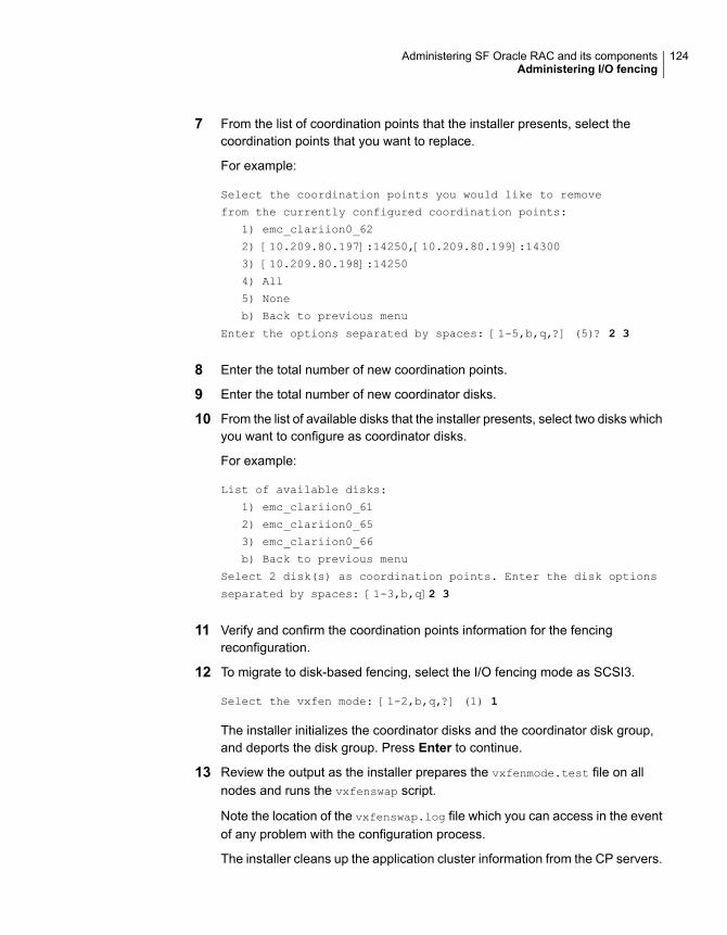
7 From the list of coordination points that the installer presents, select thecoordination points that you want to replace.
For example:
Select the coordination points you would like to remove
from the currently configured coordination points:
1) emc_clariion0_62
2) [10.209.80.197]:14250,[10.209.80.199]:14300
3) [10.209.80.198]:14250
4) All
5) None
b) Back to previous menu
Enter the options separated by spaces: [1-5,b,q,?] (5)? 2 3
8 Enter the total number of new coordination points.
9 Enter the total number of new coordinator disks.
10 From the list of available disks that the installer presents, select two disks whichyou want to configure as coordinator disks.
For example:
List of available disks:
1) emc_clariion0_61
2) emc_clariion0_65
3) emc_clariion0_66
b) Back to previous menu
Select 2 disk(s) as coordination points. Enter the disk options
separated by spaces: [1-3,b,q]2 3
11 Verify and confirm the coordination points information for the fencingreconfiguration.
12 To migrate to disk-based fencing, select the I/O fencing mode as SCSI3.
Select the vxfen mode: [1-2,b,q,?] (1) 1
The installer initializes the coordinator disks and the coordinator disk group,and deports the disk group. Press Enter to continue.
13 Review the output as the installer prepares the vxfenmode.test file on allnodes and runs the vxfenswap script.
Note the location of the vxfenswap.log file which you can access in the eventof any problem with the configuration process.
The installer cleans up the application cluster information from the CP servers.
124Administering SF Oracle RAC and its componentsAdministering I/O fencing
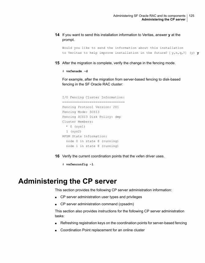
14 If you want to send this installation information to Veritas, answer y at theprompt.
Would you like to send the information about this installation
to Veritas to help improve installation in the future? [y,n,q,?] (y) y
15 After the migration is complete, verify the change in the fencing mode.
# vxfenadm -d
For example, after the migration from server-based fencing to disk-basedfencing in the SF Oracle RAC cluster:
I/O Fencing Cluster Information:
================================
Fencing Protocol Version: 201
Fencing Mode: SCSI3
Fencing SCSI3 Disk Policy: dmp
Cluster Members:
* 0 (sys1)
1 (sys2)
RFSM State Information:
node 0 in state 8 (running)
node 1 in state 8 (running)
16 Verify the current coordination points that the vxfen driver uses.
# vxfenconfig -l
Administering the CP serverThis section provides the following CP server administration information:
■ CP server administration user types and privileges
■ CP server administration command (cpsadm)
This section also provides instructions for the following CP server administrationtasks:
■ Refreshing registration keys on the coordination points for server-based fencing
■ Coordination Point replacement for an online cluster
125Administering SF Oracle RAC and its componentsAdministering the CP server
■ Migrating from non-secure to secure setup for CP server and SF Oracle RACcluster communication
Refreshing registration keys on the coordination points forserver-based fencing
Replacing keys on a coordination point (CP server) when the SF Oracle RAC clusteris online involves refreshing that coordination point's registrations. You can performa planned refresh of registrations on a CP server without incurring applicationdowntime on the SF Oracle RAC cluster. You must refresh registrations on a CPserver if the CP server agent issues an alert on the loss of such registrations onthe CP server database.
The following procedure describes how to refresh the coordination point registrations.
126Administering SF Oracle RAC and its componentsAdministering the CP server
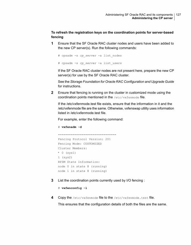
To refresh the registration keys on the coordination points for server-basedfencing
1 Ensure that the SF Oracle RAC cluster nodes and users have been added tothe new CP server(s). Run the following commands:
# cpsadm -s cp_server -a list_nodes
# cpsadm -s cp_server -a list_users
If the SF Oracle RAC cluster nodes are not present here, prepare the new CPserver(s) for use by the SF Oracle RAC cluster.
See theStorage Foundation for Oracle RACConfiguration and Upgrade Guidefor instructions.
2 Ensure that fencing is running on the cluster in customized mode using thecoordination points mentioned in the /etc/vxfenmode file.
If the /etc/vxfenmode.test file exists, ensure that the information in it and the/etc/vxfenmode file are the same. Otherwise, vxfenswap utility uses informationlisted in /etc/vxfenmode.test file.
For example, enter the following command:
# vxfenadm -d
================================
Fencing Protocol Version: 201
Fencing Mode: CUSTOMIZED
Cluster Members:
* 0 (sys1)
1 (sys2)
RFSM State Information:
node 0 in state 8 (running)
node 1 in state 8 (running)
3 List the coordination points currently used by I/O fencing :
# vxfenconfig -l
4 Copy the /etc/vxfenmode file to the /etc/vxfenmode.test file.
This ensures that the configuration details of both the files are the same.
127Administering SF Oracle RAC and its componentsAdministering the CP server
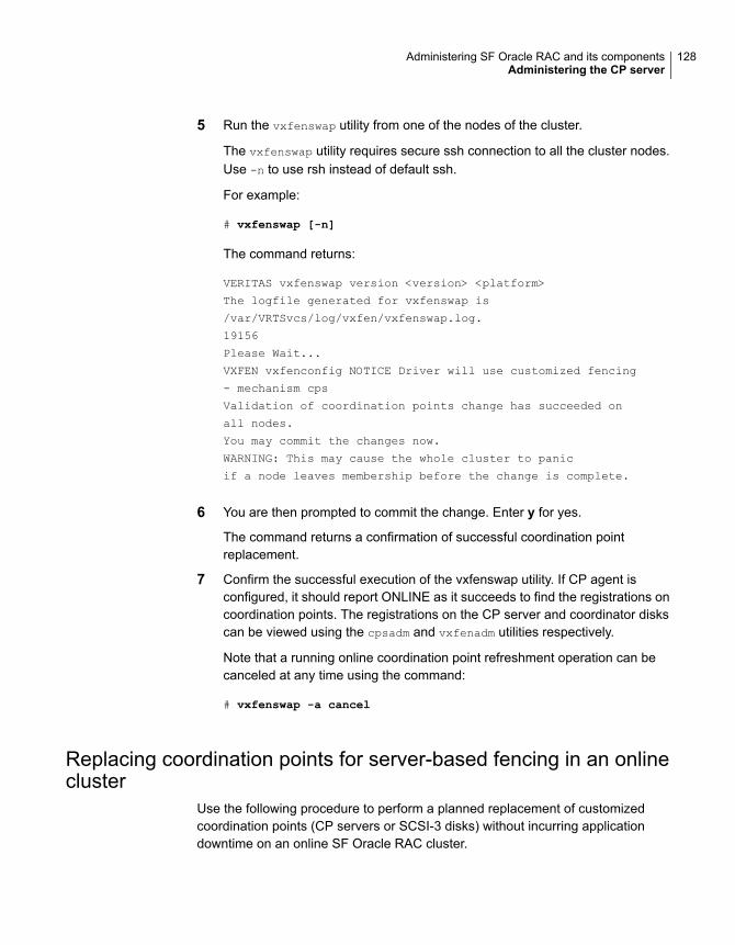
5 Run the vxfenswap utility from one of the nodes of the cluster.
The vxfenswap utility requires secure ssh connection to all the cluster nodes.Use -n to use rsh instead of default ssh.
For example:
# vxfenswap [-n]
The command returns:
VERITAS vxfenswap version <version> <platform>
The logfile generated for vxfenswap is
/var/VRTSvcs/log/vxfen/vxfenswap.log.
19156
Please Wait...
VXFEN vxfenconfig NOTICE Driver will use customized fencing
- mechanism cps
Validation of coordination points change has succeeded on
all nodes.
You may commit the changes now.
WARNING: This may cause the whole cluster to panic
if a node leaves membership before the change is complete.
6 You are then prompted to commit the change. Enter y for yes.
The command returns a confirmation of successful coordination pointreplacement.
7 Confirm the successful execution of the vxfenswap utility. If CP agent isconfigured, it should report ONLINE as it succeeds to find the registrations oncoordination points. The registrations on the CP server and coordinator diskscan be viewed using the cpsadm and vxfenadm utilities respectively.
Note that a running online coordination point refreshment operation can becanceled at any time using the command:
# vxfenswap -a cancel
Replacing coordination points for server-based fencing in an onlinecluster
Use the following procedure to perform a planned replacement of customizedcoordination points (CP servers or SCSI-3 disks) without incurring applicationdowntime on an online SF Oracle RAC cluster.
128Administering SF Oracle RAC and its componentsAdministering the CP server

Note: If multiple clusters share the same CP server, you must perform thisreplacement procedure in each cluster.
You can use the vxfenswap utility to replace coordination points when fencing isrunning in customized mode in an online cluster, with vxfen_mechanism=cps. Theutility also supports migration from server-based fencing (vxfen_mode=customized)to disk-based fencing (vxfen_mode=scsi3) and vice versa in an online cluster.
However, if the SF Oracle RAC cluster has fencing disabled (vxfen_mode=disabled),then you must take the cluster offline to configure disk-based or server-basedfencing.
You can cancel the coordination point replacement operation at any time using thevxfenswap -a cancel command.
See “About the vxfenswap utility” on page 105.
129Administering SF Oracle RAC and its componentsAdministering the CP server
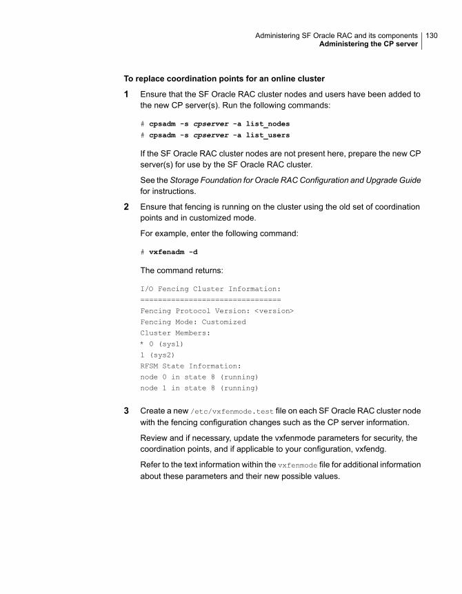
To replace coordination points for an online cluster
1 Ensure that the SF Oracle RAC cluster nodes and users have been added tothe new CP server(s). Run the following commands:
# cpsadm -s cpserver -a list_nodes
# cpsadm -s cpserver -a list_users
If the SF Oracle RAC cluster nodes are not present here, prepare the new CPserver(s) for use by the SF Oracle RAC cluster.
See theStorage Foundation for Oracle RACConfiguration and Upgrade Guidefor instructions.
2 Ensure that fencing is running on the cluster using the old set of coordinationpoints and in customized mode.
For example, enter the following command:
# vxfenadm -d
The command returns:
I/O Fencing Cluster Information:
================================
Fencing Protocol Version: <version>
Fencing Mode: Customized
Cluster Members:
* 0 (sys1)
1 (sys2)
RFSM State Information:
node 0 in state 8 (running)
node 1 in state 8 (running)
3 Create a new /etc/vxfenmode.test file on each SF Oracle RAC cluster nodewith the fencing configuration changes such as the CP server information.
Review and if necessary, update the vxfenmode parameters for security, thecoordination points, and if applicable to your configuration, vxfendg.
Refer to the text information within the vxfenmode file for additional informationabout these parameters and their new possible values.
130Administering SF Oracle RAC and its componentsAdministering the CP server
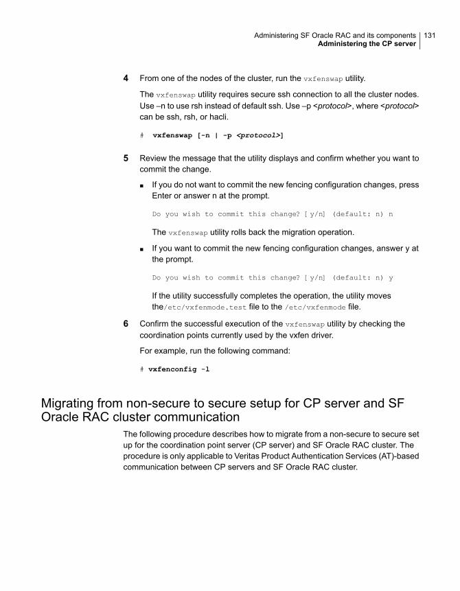
4 From one of the nodes of the cluster, run the vxfenswap utility.
The vxfenswap utility requires secure ssh connection to all the cluster nodes.Use –n to use rsh instead of default ssh. Use –p <protocol>, where <protocol>can be ssh, rsh, or hacli.
# vxfenswap [-n | -p <protocol>]
5 Review the message that the utility displays and confirm whether you want tocommit the change.
■ If you do not want to commit the new fencing configuration changes, pressEnter or answer n at the prompt.
Do you wish to commit this change? [y/n] (default: n) n
The vxfenswap utility rolls back the migration operation.
■ If you want to commit the new fencing configuration changes, answer y atthe prompt.
Do you wish to commit this change? [y/n] (default: n) y
If the utility successfully completes the operation, the utility movesthe/etc/vxfenmode.test file to the /etc/vxfenmode file.
6 Confirm the successful execution of the vxfenswap utility by checking thecoordination points currently used by the vxfen driver.
For example, run the following command:
# vxfenconfig -l
Migrating from non-secure to secure setup for CP server and SFOracle RAC cluster communication
The following procedure describes how to migrate from a non-secure to secure setup for the coordination point server (CP server) and SF Oracle RAC cluster. Theprocedure is only applicable to Veritas Product Authentication Services (AT)-basedcommunication between CP servers and SF Oracle RAC cluster.
131Administering SF Oracle RAC and its componentsAdministering the CP server
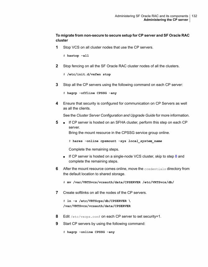
Tomigrate from non-secure to secure setup for CP server and SF Oracle RACcluster
1 Stop VCS on all cluster nodes that use the CP servers.
# hastop -all
2 Stop fencing on all the SF Oracle RAC cluster nodes of all the clusters.
# /etc/init.d/vxfen stop
3 Stop all the CP servers using the following command on each CP server:
# hagrp -offline CPSSG -any
4 Ensure that security is configured for communication on CP Servers as wellas all the clients.
See the Cluster Server Configuration and Upgrade Guide for more information.
5 If CP server is hosted on an SFHA cluster, perform this step on each CPserver.
■
Bring the mount resource in the CPSSG service group online.
# hares -online cpsmount -sys local_system_name
Complete the remaining steps.
■ If CP server is hosted on a single-node VCS cluster, skip to step 8 andcomplete the remaining steps.
6 After the mount resource comes online, move the credentials directory fromthe default location to shared storage.
# mv /var/VRTSvcs/vcsauth/data/CPSERVER /etc/VRTSvcs/db/
7 Create softlinks on all the nodes of the CP servers.
# ln -s /etc/VRTScps/db/CPSERVER \
/var/VRTSvcs/vcsauth/data/CPSERVER
8 Edit /etc/vxcps.conf on each CP server to set security=1.
9 Start CP servers by using the following command:
# hagrp -online CPSSG -any
132Administering SF Oracle RAC and its componentsAdministering the CP server
10 Edit /etc/VRTSvcs/conf/config/main.cf on the first node of the cluster andremove the UseFence=SCSI3 attribute.
Start VCS on the first node and then on all other nodes of the cluster.
11 Reconfigure fencing on each cluster by using the installer.
# /opt/VRTS/install/installer -fencing
Administering CFSThis section describes some of the major aspects of Cluster File System (CFS)administration.
This section provides instructions for the following CFS administration tasks:
■ Adding CFS file systems to VCS configurationSee “Adding CFS file systems to a VCS configuration” on page 133.
■ Resizing CFS file systemsSee “Resizing CFS file systems” on page 134.
■ Verifying the status of CFS file systemsSee “Verifying the status of CFS file system nodes and their mount points”on page 134.
If you encounter issues while administering CFS, refer to the troubleshooting sectionfor assistance.
See “Troubleshooting CFS” on page 198.
Adding CFS file systems to a VCS configurationRun the following command to add a Cluster File System (CFS) file system to theCluster Server (VCS) main.cf file without using an editor.
For example:
# cfsmntadm add oradatadg oradatavol \
/oradata1 all=suid,rw
Mount Point is being added...
/oradata1 added to the cluster-configuration
See the Storage Foundation Cluster File System High Availability Administrator'sGuide for more information on the command.
133Administering SF Oracle RAC and its componentsAdministering CFS
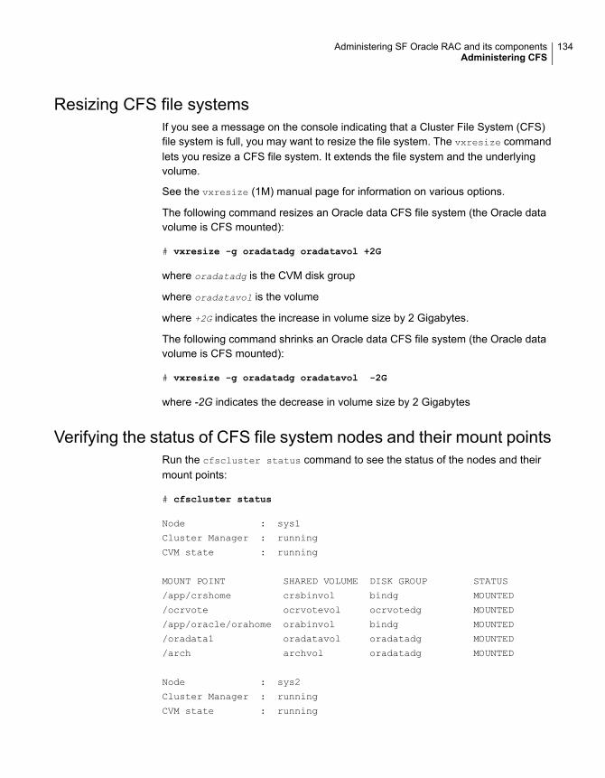
Resizing CFS file systemsIf you see a message on the console indicating that a Cluster File System (CFS)file system is full, you may want to resize the file system. The vxresize commandlets you resize a CFS file system. It extends the file system and the underlyingvolume.
See the vxresize (1M) manual page for information on various options.
The following command resizes an Oracle data CFS file system (the Oracle datavolume is CFS mounted):
# vxresize -g oradatadg oradatavol +2G
where oradatadg is the CVM disk group
where oradatavol is the volume
where +2G indicates the increase in volume size by 2 Gigabytes.
The following command shrinks an Oracle data CFS file system (the Oracle datavolume is CFS mounted):
# vxresize -g oradatadg oradatavol -2G
where -2G indicates the decrease in volume size by 2 Gigabytes
Verifying the status of CFS file system nodes and their mount pointsRun the cfscluster status command to see the status of the nodes and theirmount points:
# cfscluster status
Node : sys1
Cluster Manager : running
CVM state : running
MOUNT POINT SHARED VOLUME DISK GROUP STATUS
/app/crshome crsbinvol bindg MOUNTED
/ocrvote ocrvotevol ocrvotedg MOUNTED
/app/oracle/orahome orabinvol bindg MOUNTED
/oradata1 oradatavol oradatadg MOUNTED
/arch archvol oradatadg MOUNTED
Node : sys2
Cluster Manager : running
CVM state : running
134Administering SF Oracle RAC and its componentsAdministering CFS
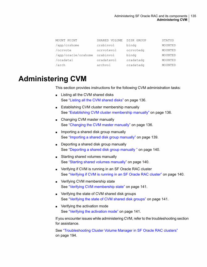
MOUNT POINT SHARED VOLUME DISK GROUP STATUS
/app/crshome crsbinvol bindg MOUNTED
/ocrvote ocrvotevol ocrvotedg MOUNTED
/app/oracle/orahome orabinvol bindg MOUNTED
/oradata1 oradatavol oradatadg MOUNTED
/arch archvol oradatadg MOUNTED
Administering CVMThis section provides instructions for the following CVM administration tasks:
■ Listing all the CVM shared disksSee “Listing all the CVM shared disks” on page 136.
■ Establishing CVM cluster membership manuallySee “Establishing CVM cluster membership manually” on page 136.
■ Changing CVM master manuallySee “Changing the CVM master manually” on page 136.
■ Importing a shared disk group manuallySee “Importing a shared disk group manually” on page 139.
■ Deporting a shared disk group manuallySee “Deporting a shared disk group manually ” on page 140.
■ Starting shared volumes manuallySee “Starting shared volumes manually” on page 140.
■ Verifying if CVM is running in an SF Oracle RAC clusterSee “Verifying if CVM is running in an SF Oracle RAC cluster” on page 140.
■ Verifying CVM membership stateSee “Verifying CVM membership state” on page 141.
■ Verifying the state of CVM shared disk groupsSee “Verifying the state of CVM shared disk groups” on page 141.
■ Verifying the activation modeSee “Verifying the activation mode” on page 141.
If you encounter issues while administering CVM, refer to the troubleshooting sectionfor assistance.
See “Troubleshooting Cluster Volume Manager in SF Oracle RAC clusters”on page 194.
135Administering SF Oracle RAC and its componentsAdministering CVM
Listing all the CVM shared disksYou can use the following command to list all the CVM shared disks:
# vxdisk -o alldgs list |grep shared
Establishing CVM cluster membership manuallyIn most cases you do not have to start Cluster Volume Manager (CVM) manually;it normally starts when Cluster Server (VCS) is started.
Run the following command to start CVM manually:
# vxclustadm -m vcs -t gab startnode
Note that vxclustadm reads the main.cf configuration file for cluster configurationinformation and is therefore not dependent upon VCS to be running. You do notneed to run the vxclustadm startnode command as normally the hastart (VCSstart) command starts CVM automatically.
To verify whether CVM is started properly, run the following command:
# vxclustadm nidmap
Name CVM Nid CM Nid State
sys1 0 0 Joined: Master
sys2 1 1 Joined: Slave
Changing the CVM master manuallyYou can change the Cluster Volume Manager (CVM) master manually from onenode in the cluster to another node, while the cluster is online. CVM migrates themaster node, and reconfigures the cluster.
Veritas recommends that you switch the master when the cluster is not handlingVeritas Volume Manager (VxVM) configuration changes or cluster reconfigurationoperations. In most cases, CVM aborts the operation to change the master, if CVMdetects that any configuration changes are occurring in the VxVM or the cluster.After the master change operation starts reconfiguring the cluster, other commandsthat require configuration changes will fail until the master switch completes.
See “Errors during CVM master switching” on page 139.
To change the master online, the cluster must be cluster protocol version 100 orgreater.
136Administering SF Oracle RAC and its componentsAdministering CVM
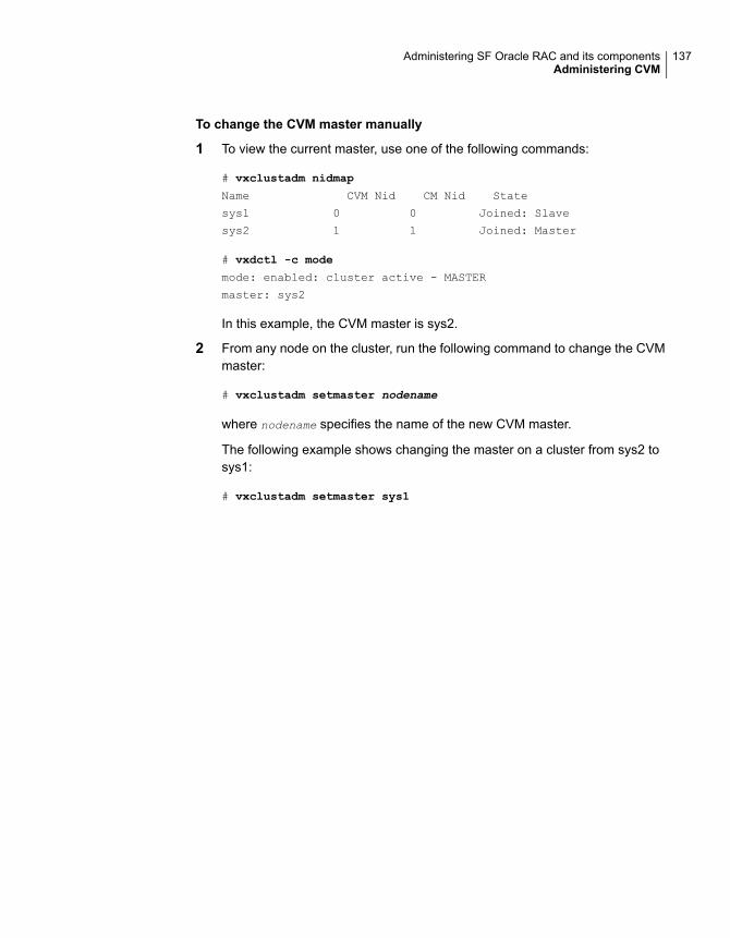
To change the CVM master manually
1 To view the current master, use one of the following commands:
# vxclustadm nidmap
Name CVM Nid CM Nid State
sys1 0 0 Joined: Slave
sys2 1 1 Joined: Master
# vxdctl -c mode
mode: enabled: cluster active - MASTER
master: sys2
In this example, the CVM master is sys2.
2 From any node on the cluster, run the following command to change the CVMmaster:
# vxclustadm setmaster nodename
where nodename specifies the name of the new CVM master.
The following example shows changing the master on a cluster from sys2 tosys1:
# vxclustadm setmaster sys1
137Administering SF Oracle RAC and its componentsAdministering CVM
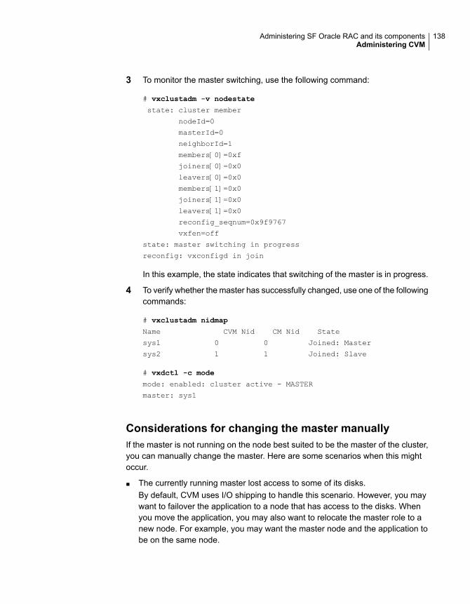
3 To monitor the master switching, use the following command:
# vxclustadm -v nodestate
state: cluster member
nodeId=0
masterId=0
neighborId=1
members[0]=0xf
joiners[0]=0x0
leavers[0]=0x0
members[1]=0x0
joiners[1]=0x0
leavers[1]=0x0
reconfig_seqnum=0x9f9767
vxfen=off
state: master switching in progress
reconfig: vxconfigd in join
In this example, the state indicates that switching of the master is in progress.
4 To verify whether the master has successfully changed, use one of the followingcommands:
# vxclustadm nidmap
Name CVM Nid CM Nid State
sys1 0 0 Joined: Master
sys2 1 1 Joined: Slave
# vxdctl -c mode
mode: enabled: cluster active - MASTER
master: sys1
Considerations for changing the master manuallyIf the master is not running on the node best suited to be the master of the cluster,you can manually change the master. Here are some scenarios when this mightoccur.
■ The currently running master lost access to some of its disks.By default, CVM uses I/O shipping to handle this scenario. However, you maywant to failover the application to a node that has access to the disks. Whenyou move the application, you may also want to relocate the master role to anew node. For example, you may want the master node and the application tobe on the same node.
138Administering SF Oracle RAC and its componentsAdministering CVM
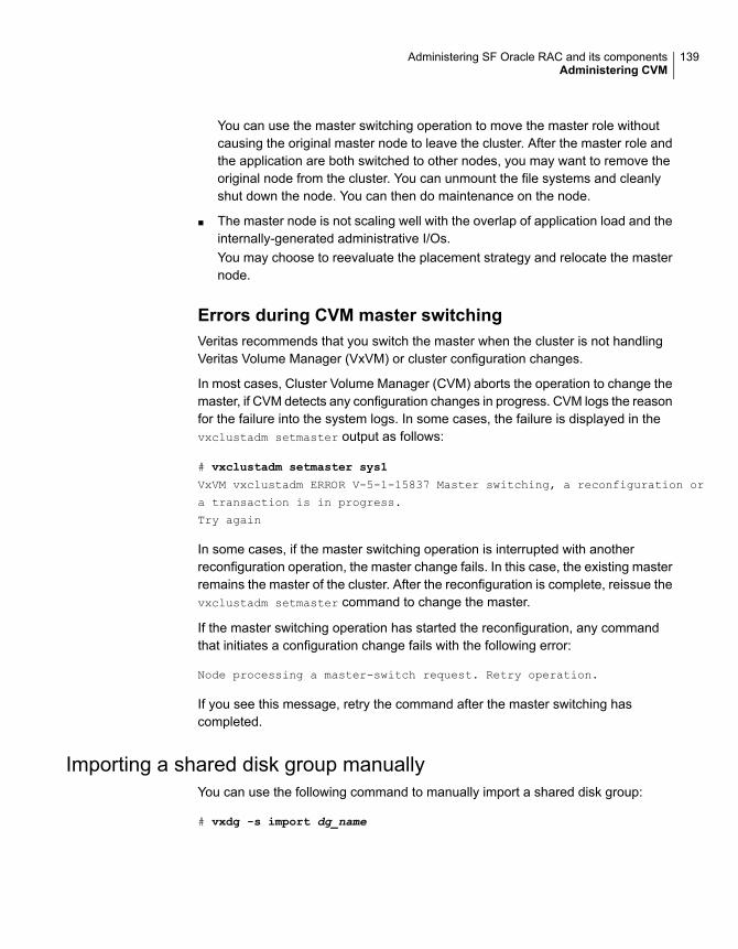
You can use the master switching operation to move the master role withoutcausing the original master node to leave the cluster. After the master role andthe application are both switched to other nodes, you may want to remove theoriginal node from the cluster. You can unmount the file systems and cleanlyshut down the node. You can then do maintenance on the node.
■ The master node is not scaling well with the overlap of application load and theinternally-generated administrative I/Os.You may choose to reevaluate the placement strategy and relocate the masternode.
Errors during CVM master switchingVeritas recommends that you switch the master when the cluster is not handlingVeritas Volume Manager (VxVM) or cluster configuration changes.
In most cases, Cluster Volume Manager (CVM) aborts the operation to change themaster, if CVM detects any configuration changes in progress. CVM logs the reasonfor the failure into the system logs. In some cases, the failure is displayed in thevxclustadm setmaster output as follows:
# vxclustadm setmaster sys1
VxVM vxclustadm ERROR V-5-1-15837 Master switching, a reconfiguration or
a transaction is in progress.
Try again
In some cases, if the master switching operation is interrupted with anotherreconfiguration operation, the master change fails. In this case, the existing masterremains the master of the cluster. After the reconfiguration is complete, reissue thevxclustadm setmaster command to change the master.
If the master switching operation has started the reconfiguration, any commandthat initiates a configuration change fails with the following error:
Node processing a master-switch request. Retry operation.
If you see this message, retry the command after the master switching hascompleted.
Importing a shared disk group manuallyYou can use the following command to manually import a shared disk group:
# vxdg -s import dg_name
139Administering SF Oracle RAC and its componentsAdministering CVM
Deporting a shared disk group manuallyYou can use the following command to manually deport a shared disk group:
# vxdg deport dg_name
Note that the deport of a shared disk group removes the SCSI-3 PGR keys on thedisks.
Starting shared volumes manuallyFollowing a manual Cluster Volume Manager (CVM) shared disk group import, thevolumes in the disk group need to be started manually, as follows:
# vxvol -g dg_name startall
To verify that the volumes are started, run the following command:
# vxprint -htrg dg_name | grep ^v
The volumes that are started will display the state "enabled."
Verifying if CVM is running in an SF Oracle RAC clusterYou can use the following options to verify whether Cluster Volume Manager is upor not in an SF Oracle RAC cluster.
The following output is displayed on a node that is not a member of the cluster:
# vxdctl -c mode
mode: enabled: cluster inactive
# vxclustadm -v nodestate
state: out of cluster
On the master node, the following output is displayed:
# vxdctl -c mode
mode: enabled: cluster active - MASTER
master: sys1
On the slave nodes, the following output is displayed:
# vxdctl -c mode
mode: enabled: cluster active - SLAVE
master: sys2
140Administering SF Oracle RAC and its componentsAdministering CVM
The following command lets you view all the CVM nodes at the same time:
# vxclustadm nidmap
Name CVM Nid CM Nid State
sys1 0 0 Joined: Master
sys2 1 1 Joined: Slave
Verifying CVM membership stateThe state of Cluster Volume Manager (CVM) can be verified as follows:
# vxclustadm -v nodestate
state: joining
nodeId=0
masterId=0
neighborId=0
members=0x1
joiners=0x0
leavers=0x0
reconfig_seqnum=0x0
reconfig: vxconfigd in join
The state indicates that CVM has completed its kernel level join and is in the middleof a vxconfigd level join.
The vxdctl -c mode command indicates whether a node is a CVM master or aCVM slave.
Verifying the state of CVM shared disk groupsYou can use the following command to list the shared disk groups currently importedin the SF Oracle RAC cluster:
# vxdg list |grep shared
orabinvol_dg enabled,shared,cds 1052685125.1485.csha3
Verifying the activation modeIn an SF Oracle RAC cluster, the activation of shared disk groups should be set to“shared-write” on each of the cluster nodes.
To verify whether the “shared-write” activation is set:
# vxdg list dg_name |grep activation
141Administering SF Oracle RAC and its componentsAdministering CVM
local-activation: shared-write
If "shared-write" activation is not set, run the following command:
# vxdg -g dg_name set activation=sw
Administering Flexible Storage SharingInstalling SF Oracle RAC automatically enables the Flexible Storage Sharing feature(FSS). No additional installation steps are required. LLT, GAB, and fencing mustbe configured before administering FSS. The fencing coordination points can eitherbe SCSI-3 PR capable shared storage or CP servers.
See the Storage Foundation for Oracle RAC Configuration and Upgrade Guide.
FSS administrative tasks include exporting a disk for FSS, setting the FSS optionon a disk group, setting the host prefix for intuitive naming of devices connected tothe host, displaying exported disks and network shared disks, and optionally tuningFSS memory consumption.
See “About Flexible Storage Sharing” on page 29.
See “About Flexible Storage Sharing disk support” on page 142.
About Flexible Storage Sharing disk supportCVM relies on unique disk IDs (UDIDS) for identifying disks across different nodesin the cluster. FSS only supports disks that have the capability of generating uniqueIDs.
FSS supports the following disks:
■ Disks that are listed in the Hardware Compatibility List (HCL)
■ Disks that have a JBOD definition specified using the vxddladm addjbod CLI.You must ensure that the specification is such that it provides a unique way ofidentifying a specific disk in your environment.
■ SCSI-3 disks that provide an IEEE certified NAA ID in the VPD page 0x83 inquirydata
The vxddladm checkfss diskname command can be used to test if the diskcomplies with the required conditions. If the conditions are not met, adding the disksto an FSS configuration using the vxdisk export diskname command fails.
142Administering SF Oracle RAC and its componentsAdministering Flexible Storage Sharing
About the volume layout for Flexible Storage Sharing disk groupsBy default, a volume in disk groups with the FSS attribute set is mirrored acrosshosts. This default layout ensures that data is available if any one host becomesunavailable. Associated instant data change object (DCO) log volumes are alsocreated by default.
The following volume attributes are assumed by default:
■ mirror=host
■ nmirror=2
■ logtype=dco
■ ndcomirror=2
■ dcoversion=30
You can specify the hosts on which to allocate the volume by using the host diskclass.
See “Using the host disk class and allocating storage” on page 147.
Traditionally with disk groups without the FSS attribute set, the default volume layoutis concatenated. However, you can still choose to create concatenated volumes indisk groups with the FSS attribute set by explicitly using the layout=concat optionof the vxassist command.
By default, the mirrored volume is allocated across hosts. If host-specific storageis not available to meet this criteria, then the volume is allocated on external storage,with the default layout as concatenated as with traditional disk groups.
Existing disk classes, such as dm, can be used with FSS. The host prefix in a diskaccess name indicates the host to which the disk is connected.
For example, you can create a volume with one plex on a local disk (disk1), andanother plex on a remote disk(hostA_disk2) where the host prefix (hostA) for theremote disk represents another host in the cluster:
# vxassist -g mydg make vol1 10g layout=mirror dm:disk1 dm:hostA_disk2
See “Administering mirrored volumes using vxassist” on page 147.
You can also use the vxdisk list accessname command to display connectivityinformation, such as information about which hosts are connected to the disk.
Setting the host prefixThe host prefix provides a way to intuitively identify the origin of the disk, for example,the host to which the disk is physically connected. The vxdctl command sets the
143Administering SF Oracle RAC and its componentsAdministering Flexible Storage Sharing
host prefix. By setting the instance for the host prefix, you can set an alternate hostidentifier that satisfies the disk access name length constraint.
Note: Disks from an array enclosure are not displayed with a host prefix.
In the case of direct attached storage (DAS) disks, a host prefix is added to the diskat the time of disk discovery itself to avoid disk naming conflicts.
In the case of array based enclosures connected through the SAN or Fibre Channel(FC), it is possible to connect different enclosures of the same type (same vendor,same model) to different nodes exclusively and thus create a DAS-type topology.In such cases, there is also the possibility of the same VxVM device name gettingassigned to different disks on different nodes. If such disks are exported for use inan FSS environment, the same confusion over names can arise. In such caseshowever, the hostprefix will not be attached to the exported disks. The namingconflicts are resolved by adding a serial number to the VxVM device name for diskswith same name. However, it is recommended that the name of the enclosure bechanged for easy identification and readability.
The difference of naming behavior between DAS disks and enclosure based disksexists due to the following reasons. It is possible for the enclosure to be connectedto only one node at any given instance of a CVM cluster. However, with a node jointhere could be two (or more) nodes connected to the enclosure at another instance.With nodes dynamically joining and leaving the cluster, connectivity to arrayenclosures can also change dynamically. Therefore, it is not reliable to use theconnectivity information to decide if the topology is SAN or DAS, to decide whetherthe host-prefix needs to be added or not. As a result, CVM does not add a hostprefixto VxVM devices based on enclosure connectivity. Instead when a naming conflictoccurs, a serial number is added to the VxVM device name. On the other handDAS disks can be attached to only one node at a time, and thus it is safe to add ahostprefix by default (without waiting for the naming conflict to occur).
By default Cluster Volume Manager (CVM) uses the host name from the ClusterServer (VCS) configuration file as the host prefix. If the hostid in /etc/vx/volboot
file is greater than 15 characters, and if a shorter host prefix is not set using vxdctl,Cluster Manager node IDs (CMID) are used as prefixes.
For more information, see the vxdctl (1M) manual page.
The following command sets/modifies the logical name for the host as the failuredomain:
# vxdctl set hostprefix=logicalname
To unset the logical name for the host as the failure domain, use the followingcommand:
144Administering SF Oracle RAC and its componentsAdministering Flexible Storage Sharing
# vxdctl unset hostprefix
The vxdctl list command displays the logical name set as the host prefix.
Exporting a disk for Flexible Storage SharingTo use disks that are not physically shared across all nodes of a cluster (disks thatare connected to one or more nodes of the cluster), the disks must first be exportedfor network sharing. Exporting a device makes the device available to all nodes inthe cluster. The vxdisk command lets you export or unexport one or more disksfor or from network sharing.
Note: To ensure data protection, FSS uses PGR-based data disk fencing. For disksthat are purely locally attached, fencing is implicitly handled within FSS, since allthe I/Os to the disk go through the node to which the disk is directly connected.Therefore, devices that do not support SCSI3 PGR are supported with FSS withfencing. For disks that are connected to multiple hosts but do not support SCSI3PGR, there is no way to ensure that fencing is enabled and thus this configurationis not supported when fencing is enabled.
The following command exports one or more disks for network sharing:
# vxdisk export accessname1 accessname2
where accessname1 and accessname2 are the access names of the disks youwant to export for network sharing.
In addition, you can use the -o alldisks and -o local options to export all localand all shared disks, and all locally connected disks, respectively.
Note: Boot disks, opaque disks, disks part of imported or deported disks groups,and non-VxVM disks cannot be exported.
Alternately, the following command unexports one or more disks from networksharing:
# vxdisk unexport accessname1 accessname2
where accessname1 and accessname2 are the disk access names of the disksyou want to unexport from network sharing.
In addition, you can use the -o alldisks and -o local options to unexport alllocal and shared disks, and all locally connected disks, respectively.
145Administering SF Oracle RAC and its componentsAdministering Flexible Storage Sharing
Disks can also be configured for FSS by exporting them during initialization usingthe vxdisksetup and vxdisk init commands.
Initialize the disks with network sharing enabled, using one of the followingcommands:
# vxdisksetup -i disk_address export
# vxdisk [-f] init accessname export
where disk_address is the device that corresponds to the disk being operated onand accessname is the system-specific name that relates to the disk address.
After exporting a disk, you can use the vxdisk list and vxprint commands tolist network shared disks, and identify disks that are remote to the node on whichyou run the command.
See “Displaying exported disks and network shared disk groups” on page 149.
Once a disk is exported, you can create shared disk groups using any combinationof network shared disks and physically shared disks. Before adding an exporteddisk to a disk group, the Flexible Storage Sharing attribute needs to be set on theshared disk group.
See “Setting the Flexible Storage Sharing attribute on a disk group” on page 146.
Setting the Flexible Storage Sharing attribute on a disk groupThe FSS attribute needs to be set on a disk group before any exported disks canbe added to the disk group. This prevents the accidental addition of exported disksto disk groups. In addition, the tunable parameter storage_connectivity must beset to asymmetric. The FSS attribute can only be set on shared disk groups.
The vxdg command lets you create a disk group with the FSS attribute turned onor set the FSS attribute on an existing disk group.
Note: The disk group version must be set to 190 or higher in order to create or setan FSS disk group. When setting the FSS attribute on a disk group or importing anexisting disk group as an FSS disk group, you may need to upgrade the disk groupversion.
The following command sets the FSS attribute on a disk group during initialization:
# vxdg -s -o fss init diskgroup [medianame=] accessname
where diskgroup is the disk group name, medianame is the administrative namechosen for a VM disk, and accessname is the device name or disk access name.
146Administering SF Oracle RAC and its componentsAdministering Flexible Storage Sharing
The following command sets the FSS attribute on a disk group:
# vxdg -g diskgroup set fss=on
The following command sets the FSS attribute on a disk group during a disk groupimport:
# vxdg -s -o fss=on import diskgroup
After setting the FSS attribute on a disk group, you can use the vxdg list commandon a specified disk group to list all hosts in the cluster contributing their local disksto the disk group, and storage enclosures from which disks have been added tothe disk group. Once you have created a disk group with the FSS attribute turnedon or set the FSS attribute on an existing disk group, the ioship policy is set to onand the disk detach policy is set to local detach policy.
See “Displaying exported disks and network shared disk groups” on page 149.
Using the host disk class and allocating storageYou can use the vxassist command to use the host disk class for storage allocation.The host class specifies the host from which to allocate storage. The host classonly applies to disk groups configured for FSS.
The host disk class instance is the same as the host name from the Cluster Server(VCS) configuration file, which can be displayed using the vxclustadm nidmap
command.
Mirrored volumes can be created with mirrors across hosts using the host disk classusing the mirror=host parameter:
# vxassist -g mydg make vol1 10g host:vm240v5 host:vm240v6
# vxassist -g mydg make vol1 10g mirror=host
Administering mirrored volumes using vxassistBy default, a volume in disk groups with the FSS attribute set is mirrored acrosshosts. You can use the vxassist command to create mirrored volume sets spanningacross mixed media types, or using a combination of internal disks and externalshared disks (i.e. SAN-attached disks).
Note: In SF Oracle RAC environments that use n-way mirroring, set the nmirror
value to the number of nodes in the cluster when you create a mirrored volume.For example, if you have four nodes in the cluster, set the nmirror value to 4.
147Administering SF Oracle RAC and its componentsAdministering Flexible Storage Sharing
To create a mirrored volume with HDD and SSD disks
1 Create a volume on either the HDD or the SSD disk:
# vxassist -g diskgroup make vol1 maxsize layout=concat init=none
Where diskgroup is the diskgroup name. HDD is selected by default.
2 Add a plex based on SSD(s):
# vxassist -g diskgroup mirror vol1 mediatype:ssd
3 Activate the volume:
# vxvol -g diskgroup init active vol1
Note: The mirrored volume may not preserve allocation constraints set.
If you have created a mirrored volume on an SSD disk using the init=none option,you can manually add a new mirror for a DCO volume using the following command:
# vxassist -g diskgroup mirror volume-dcl diskname
Where diskgroup is the diskgroup name and diskname is the name of a disk fromthe host on which the new data mirror was added. Veritas recommends that youspecify the name of a disk on which the data mirror was created.
To create a mirrored volume using internal disks and external physicallyshared disks
1 Create a volume on either the internal disk or the external physically shareddisks:
# vxassist -g diskgroup make vol1 maxsize layout=concat init=none
host:host1
Where diskgroup is the diskgroup name.
2 Add a plex based on external shared disks:
# vxassist -g diskgroup mirror vol1 enclr:emc0
3 Activate the volume:
# vxvol -g diskgroup init active vol1
148Administering SF Oracle RAC and its componentsAdministering Flexible Storage Sharing
Note: Specifying the host disk class allocates the volume on the internal storagethat is connected to the specified host.
See “Using the host disk class and allocating storage” on page 147.
Displaying exported disks and network shared disk groupsThe vxdisk list and vxprint commands list network shared disks identifying thedisks that are remote to the host from which the command is run. The vxdisk list
command also provides an option to list disks while filtering out all remote disks.
To display exported disks, use the vxdisk list command:
# vxdisk list
DEVICE TYPE DISK GROUP STATUS
disk_01 auto:cdsdisk - - online exported
disk_02 auto:cdsdisk - - online exported
vm240v6_disk_01 auto:cdsdisk - - online remote
vm240v6_disk_02 auto:cdsdisk - - online remote
The disk name includes a prefix that indicates the host to which the disk is attached.For example, for disk vm240v6_disk_01, vm240v6 is the host prefix. The exported
status flag denotes disks that have been exported for FSS. The remote flag denotesdisks that are not local to the host on which the command is run.
If the accessname argument is specified, disk connectivity information is displayedin the long listing output. This information is available only if the node on which thecommand is run is part of a CVM cluster.
The -o local option of the vxdisk list command filters out all remote disks.
For example:
# vxdisk -o local list
DEVICE TYPE DISK GROUP STATUS
disk_01 auto:cdsdisk - - online exported
disk_02 auto:cdsdisk - - online
The -o fullshared option displays all disks that are shared across all active nodes.
The -o partialshared option displays all disks that are partially shared. Partiallyshared disks are connected to more than one node but not all the active nodes inthe cluster.
Alternately, you can use the vxprint command to display remote disks in a diskgroup:
149Administering SF Oracle RAC and its componentsAdministering Flexible Storage Sharing
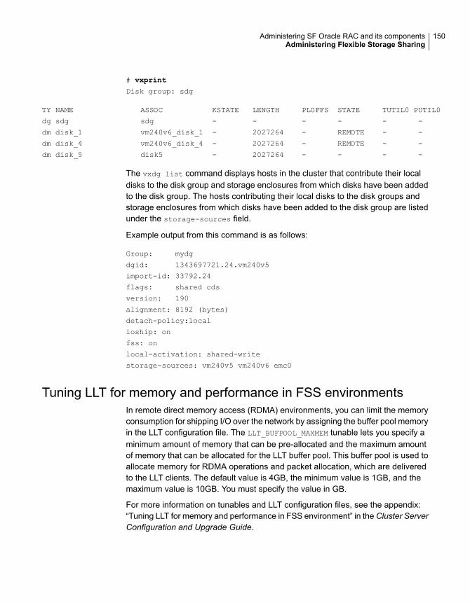
# vxprint
Disk group: sdg
TY NAME ASSOC KSTATE LENGTH PLOFFS STATE TUTIL0 PUTIL0
dg sdg sdg - - - - - -
dm disk_1 vm240v6_disk_1 - 2027264 - REMOTE - -
dm disk_4 vm240v6_disk_4 - 2027264 - REMOTE - -
dm disk_5 disk5 - 2027264 - - - -
The vxdg list command displays hosts in the cluster that contribute their localdisks to the disk group and storage enclosures from which disks have been addedto the disk group. The hosts contributing their local disks to the disk groups andstorage enclosures from which disks have been added to the disk group are listedunder the storage-sources field.
Example output from this command is as follows:
Group: mydg
dgid: 1343697721.24.vm240v5
import-id: 33792.24
flags: shared cds
version: 190
alignment: 8192 (bytes)
detach-policy:local
ioship: on
fss: on
local-activation: shared-write
storage-sources: vm240v5 vm240v6 emc0
Tuning LLT for memory and performance in FSS environmentsIn remote direct memory access (RDMA) environments, you can limit the memoryconsumption for shipping I/O over the network by assigning the buffer pool memoryin the LLT configuration file. The LLT_BUFPOOL_MAXMEM tunable lets you specify aminimum amount of memory that can be pre-allocated and the maximum amountof memory that can be allocated for the LLT buffer pool. This buffer pool is used toallocate memory for RDMA operations and packet allocation, which are deliveredto the LLT clients. The default value is 4GB, the minimum value is 1GB, and themaximum value is 10GB. You must specify the value in GB.
For more information on tunables and LLT configuration files, see the appendix:“Tuning LLT for memory and performance in FSS environment” in the Cluster ServerConfiguration and Upgrade Guide.
150Administering SF Oracle RAC and its componentsAdministering Flexible Storage Sharing
Backing up and restoring disk group configuration dataThe disk group configuration backup and restoration feature allows you to back upand restore all configuration data for disk groups, and for VxVM objects such asvolumes that are configured within the disk groups. The vxconfigbackupd daemonmonitors changes to the VxVM configuration and automatically records anyconfiguration changes that occur. By default, vxconfigbackup stores 5 copies ofthe configuration backup and restoration (cbr) data. You can customize the numberof cbr copies, between 1 to 5 copies.
See the vxconfigbackupd(1M) manual page.
VxVM provides the utilities, vxconfigbackup and vxconfigrestore, for backingup and restoring a VxVM configuration for a disk group.
See the Veritas InfoScale Troubleshooting Guide.
See the vxconfigbackup(1M) manual page.
See the vxconfigrestore(1M) manual page.
Backing up and restoring Flexible Storage Sharing diskgroup configuration dataThe disk group configuration backup and restoration feature also lets you back upand restore configuration data for Flexible Storage Sharing (FSS) disk groups. Thevxconfigbackupd daemon automatically records any configuration changes thatoccur on all cluster nodes. When restoring FSS disk group configuration data, youmust first restore the configuration data on the secondary (slave) nodes in thecluster, which creates remote disks by exporting any locally connected disks. Afterrestoring the configuration data on the secondary nodes, you must restore theconfiguration data on the primary (master) node that will import the disk group.
To back up FSS disk group configuration data
◆ To back up FSS disk group configuration data on all cluster nodes that haveconnectivity to at least one disk in the disk group, type the following command:
# /etc/vx/bin/vxconfigbackup -T diskgroup
151Administering SF Oracle RAC and its componentsAdministering Flexible Storage Sharing
To restore the configuration data for an FSS disk group
1 Identify the master node:
# vxclustadm nidmap
2 Check if the primary node has connectivity to at least one disk in the disk group.The disk can be a direct attached storage (DAS) disk, partially shared disk, orfully shared disks.
3 If the primary node does not have connectivity to any disk in the disk group,switch the primary node to a node that has connectivity to at least one DAS orpartially shared disk, using the following command:
# vxclustadm setmaster node_name
4 Restore the configuration data on all the secondary nodes:
# vxconfigrestore diskgroup
Note: You must restore the configuration data on all secondary nodes thathave connectivity to at least one disk in the disk group.
5 Restore the configuration data on the primary node:
# vxconfigrestore diskgroup
6 Verify the configuration data:
# vxprint -g diskgroup
7 If the configuration data is correct, commit the configuration:
# vxconfigrestore -c diskgroup
152Administering SF Oracle RAC and its componentsAdministering Flexible Storage Sharing
To abort or decommit configuration restoration for an FSS disk group
1 Identify the master node:
# vxclustadm nidmap
2 Abort or decommit the configuration data on the master node:
# vxconfigrestore -d diskgroup
3 Abort or decommit the configuration data on all secondary nodes.
# vxconfigrestore -d diskgroup
Note: You must abort or decommit the configuration data on all secondarynodes that have connectivity to at least one disk in the disk group, and allsecondary nodes from which you triggered the precommit.
See the Veritas InfoScale 7.1 Troubleshooting Guide.
See the vxconfigbackup(1M) manual page.
See the vxconfigrestore(1M) manual page.
Administering SF Oracle RAC global clustersThis section provides instructions for the following global cluster administrationtasks:
■ About setting up a fire drillSee “About setting up a disaster recovery fire drill” on page 154.
■ Configuring the fire drill service group using the wizardSee “About configuring the fire drill service group using the Fire Drill Setupwizard” on page 155.
■ Verifying a successful fire drillSee “Verifying a successful fire drill” on page 156.
■ Scheduling a fire drillSee “Scheduling a fire drill” on page 157.
For a sample fire drill service group configuration:
See “Sample fire drill service group configuration” on page 157.
153Administering SF Oracle RAC and its componentsAdministering SF Oracle RAC global clusters
About setting up a disaster recovery fire drillThe disaster recovery fire drill procedure tests the fault-readiness of a configurationby mimicking a failover from the primary site to the secondary site. This procedureis done without stopping the application at the primary site and disrupting useraccess, interrupting the flow of replicated data, or causing the secondary site toneed resynchronization.
The initial steps to create a fire drill service group on the secondary site that closelyfollows the configuration of the original application service group and contains apoint-in-time copy of the production data in the Replicated Volume Group (RVG).Bringing the fire drill service group online on the secondary site demonstrates theability of the application service group to fail over and come online at the secondarysite, should the need arise. Fire drill service groups do not interact with outsideclients or with other instances of resources, so they can safely come online evenwhen the application service group is online.
You must conduct a fire drill only at the secondary site; do not bring the fire drillservice group online on the node hosting the original application.
You can override the FireDrill attribute and make fire drill resource-specific.
Before you perform a fire drill in a disaster recovery setup that uses VolumeReplicator, perform the following steps:
■ Configure the fire drill service group.See “About configuring the fire drill service group using the Fire Drill Setupwizard” on page 155.
■ Set the value of the ReuseMntPt attribute to 1 for all Mount resources.
■ After the fire drill service group is taken offline, reset the value of the ReuseMntPtattribute to 0 for all Mount resources.
VCS also supports HA fire drills to verify a resource can fail over to another nodein the cluster.
Note: You can conduct fire drills only on regular VxVM volumes; volume sets (vset)are not supported.
VCS provides hardware replication agents for array-based solutions, such as HitachiTruecopy, EMC SRDF, and so on . If you are using hardware replication agents tomonitor the replicated data clusters, refer to the VCS replication agent documentationfor details on setting up and configuring fire drill.
154Administering SF Oracle RAC and its componentsAdministering SF Oracle RAC global clusters
About configuring the fire drill service group using the Fire Drill Setupwizard
Use the Fire Drill Setup Wizard to set up the fire drill configuration.
The wizard performs the following specific tasks:
■ Creates a Cache object to store changed blocks during the fire drill, whichminimizes disk space and disk spindles required to perform the fire drill.
■ Configures a VCS service group that resembles the real application group.
The wizard works only with application groups that contain one disk group. Thewizard sets up the first RVG in an application. If the application has more than oneRVG, you must create space-optimized snapshots and configure VCS manually,using the first RVG as reference.
You can schedule the fire drill for the service group using the fdsched script.
See “Scheduling a fire drill” on page 157.
Running the fire drill setup wizardTo run the wizard
1 Start the RVG Secondary Fire Drill wizard on the Volume Replicator secondarysite, where the application service group is offline and the replication group isonline as a secondary:
# /opt/VRTSvcs/bin/fdsetup
2 Read the information on the Welcome screen and press the Enter key.
3 The wizard identifies the global service groups. Enter the name of the servicegroup for the fire drill.
4 Review the list of volumes in disk group that could be used for aspace-optimized snapshot. Enter the volumes to be selected for the snapshot.Typically, all volumes used by the application, whether replicated or not, shouldbe prepared, otherwise a snapshot might not succeed.
Press the Enter key when prompted.
155Administering SF Oracle RAC and its componentsAdministering SF Oracle RAC global clusters
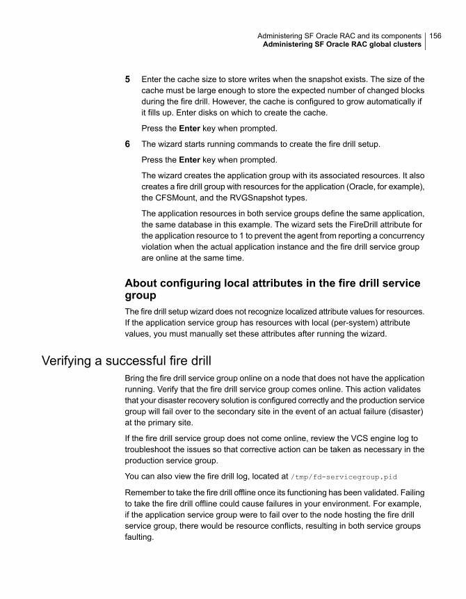
5 Enter the cache size to store writes when the snapshot exists. The size of thecache must be large enough to store the expected number of changed blocksduring the fire drill. However, the cache is configured to grow automatically ifit fills up. Enter disks on which to create the cache.
Press the Enter key when prompted.
6 The wizard starts running commands to create the fire drill setup.
Press the Enter key when prompted.
The wizard creates the application group with its associated resources. It alsocreates a fire drill group with resources for the application (Oracle, for example),the CFSMount, and the RVGSnapshot types.
The application resources in both service groups define the same application,the same database in this example. The wizard sets the FireDrill attribute forthe application resource to 1 to prevent the agent from reporting a concurrencyviolation when the actual application instance and the fire drill service groupare online at the same time.
About configuring local attributes in the fire drill servicegroupThe fire drill setup wizard does not recognize localized attribute values for resources.If the application service group has resources with local (per-system) attributevalues, you must manually set these attributes after running the wizard.
Verifying a successful fire drillBring the fire drill service group online on a node that does not have the applicationrunning. Verify that the fire drill service group comes online. This action validatesthat your disaster recovery solution is configured correctly and the production servicegroup will fail over to the secondary site in the event of an actual failure (disaster)at the primary site.
If the fire drill service group does not come online, review the VCS engine log totroubleshoot the issues so that corrective action can be taken as necessary in theproduction service group.
You can also view the fire drill log, located at /tmp/fd-servicegroup.pid
Remember to take the fire drill offline once its functioning has been validated. Failingto take the fire drill offline could cause failures in your environment. For example,if the application service group were to fail over to the node hosting the fire drillservice group, there would be resource conflicts, resulting in both service groupsfaulting.
156Administering SF Oracle RAC and its componentsAdministering SF Oracle RAC global clusters
Scheduling a fire drillYou can schedule the fire drill for the service group using the fdsched script. Thefdsched script is designed to run only on the lowest numbered node that is currentlyrunning in the cluster. The scheduler runs the command hagrp - online
firedrill_group -any at periodic intervals.
To schedule a fire drill
1 Add the file /opt/VRTSvcs/bin/fdsched to your crontab.
2 To make fire drills highly available, add the fdsched file to each node in thecluster.
Sample fire drill service group configurationThe sample configuration in this section describes a fire drill service groupconfiguration on the secondary site. The configuration uses VVR for replicatingdata between the sites.
The sample service group describes the following configuration:
■ Two SF Oracle RAC clusters, comprising two nodes each, hosted at differentgeographical locations.
■ A single Oracle database that is stored on CFS.
■ The database is managed by the VCS agent for Oracle.The agent starts, stops, and monitors the database.
■ The database uses the Oracle UDP IPC for database cache fusion.
■ A common IP address is used by Oracle Clusterware and database cache fusion.The private IP address is managed by the PrivNIC agent for high availability.
■ One virtual IP address must be configured under the ClusterService groupon each site for inter-cluster communication.
■ The Oracle Cluster Registry (OCR) and voting disk are stored on CFS.
■ Volume Replicator (VVR) is used to replicate data between the sites.
■ The shared volumes replicated across the sites are configured under the RVGgroup.
■ The replication link used by VVR for communicating log information betweensites are configured under the rlogowner group. This is a failover group thatwill be online on only one of the nodes in the cluster at each site.
■ The database group is configured as a global group by specifying the clusterson the primary and secondary sites as values for the ClusterList group attribute.
157Administering SF Oracle RAC and its componentsAdministering SF Oracle RAC global clusters
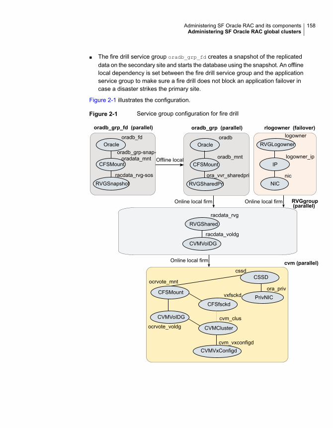
■ The fire drill service group oradb_grp_fd creates a snapshot of the replicateddata on the secondary site and starts the database using the snapshot. An offlinelocal dependency is set between the fire drill service group and the applicationservice group to make sure a fire drill does not block an application failover incase a disaster strikes the primary site.
Figure 2-1 illustrates the configuration.
Figure 2-1 Service group configuration for fire drill
oradb_grp (parallel)
cvm (parallel)
CVMCluster
CSSD
CFSfsckd
cssd
ora_privvxfsckd
cvm_clus
cvm_vxconfigd
CFSMount
ocrvote_mnt
ocrvote_voldg
CVMVoIDG
Oracleoradb
CFSMount
RVGSharedPri
oradb_mnt
ora_vvr_sharedpri
CVMVxConfigd
PrivNIC
logowner
logowner_ip
nic
rlogowner (failover)
RVGLogowner
IP
NIC
racdata_rvg
RVGShared
CVMVoIDG
racdata_voldg
oradb_grp_fd (parallel)
Oracleoradb_fd
CFSMount
RVGSnapshot
oradb_grp-snap-oradata_mnt
racdata_rvg-sos
Offline local
Online local firm Online local firm
Online local firm
RVGgroup(parallel)
158Administering SF Oracle RAC and its componentsAdministering SF Oracle RAC global clusters
Performance andtroubleshooting
■ Chapter 3. Troubleshooting SF Oracle RAC
■ Chapter 4. Prevention and recovery strategies
■ Chapter 5. Tunable parameters
2Section
Troubleshooting SF OracleRAC
This chapter includes the following topics:
■ About troubleshooting SF Oracle RAC
■ Restarting the installer after a failed network connection
■ Installer cannot create UUID for the cluster
■ Troubleshooting SF Oracle RAC pre-installation check failures
■ Troubleshooting LLT health check warning messages
■ Troubleshooting I/O fencing
■ Troubleshooting Cluster Volume Manager in SF Oracle RAC clusters
■ Troubleshooting CFS
■ Troubleshooting interconnects
■ Troubleshooting Oracle
■ Troubleshooting ODM in SF Oracle RAC clusters
■ Troubleshooting Flex ASM in SF Oracle RAC clusters
About troubleshooting SF Oracle RACUse the information in this chapter to diagnose setup or configuration problems thatyou might encounter. For issues that arise from the component products, it may benecessary to refer to the appropriate documentation to resolve it.
3Chapter
Gathering information from an SF Oracle RAC cluster for supportanalysis
Use troubleshooting scripts to gather information about the configuration and statusof your cluster and its modules. The scripts identify RPM information, debuggingmessages, console messages, and information about disk groups and volumes.Forwarding the output of these scripts to Veritas Tech Support can assist withanalyzing and solving any problems.
■ Gathering configuration information using SORT Data CollectorSee “Gathering configuration information using SORT Data Collector”on page 161.
■ Gathering SF Oracle RAC information for support analysisSee “Gathering SF Oracle RAC information for support analysis” on page 161.
■ Gathering VCS information for support analysisSee “Gathering VCS information for support analysis” on page 162.
■ Gathering LLT and GAB information for support analysisSee “Gathering LLT and GAB information for support analysis” on page 162.
■ Gathering IMF information for support analysisSee “Gathering IMF information for support analysis” on page 163.
Gathering configuration information using SORT DataCollectorSORT Data Collector now supersedes the VRTSexplorer utility.
Run the Data Collector with the VxExplorer option to gather system andconfiguration information from a node to diagnose or analyze issues in the cluster.
If you find issues in the cluster that require professional help, run the Data Collectorand send the tar file output to Veritas Technical Support to resolve the issue.
Visit the SORT Website and download the UNIX Data Collector appropriate for youroperating system:
https://sort.veritas.com
For more information:
https://sort.veritas.com/public/help/wwhelp/wwhimpl/js/html/wwhelp.htm
Gathering SFOracle RAC information for support analysisYou must run the getdbac script to gather information about the SF Oracle RACmodules.
161Troubleshooting SF Oracle RACAbout troubleshooting SF Oracle RAC
To gather SF Oracle RAC information for support analysis
◆ Run the following command on each node:
# /opt/VRTSvcs/bin/getdbac -local
The script saves the output to the default file/tmp/vcsopslog.time_stamp.tar.Z
If you are unable to resolve the issue, contact Veritas Technical Support withthe file.
Gathering VCS information for support analysisYou must run the hagetcf command to gather information when you encounterissues with VCS. Veritas Technical Support uses the output of these scripts to assistwith analyzing and solving any VCS problems. The hagetcf command gathersinformation about the installed software, cluster configuration, systems, logs, andrelated information and creates a gzip file.
See the hagetcf(1M) manual page for more information.
To gather VCS information for support analysis
◆ Run the following command on each node:
# /opt/VRTSvcs/bin/hagetcf
The command prompts you to specify an output directory for the gzip file. Youmay save the gzip file to either the default/tmp directory or a different directory.
Troubleshoot and fix the issue.
If the issue cannot be fixed, then contact Veritas technical support with the filethat the hagetcf command generates.
Gathering LLT and GAB information for support analysisYou must run the getcomms script to gather LLT and GAB information when youencounter issues with LLT and GAB. The getcomms script also collects core dumpand stack traces along with the LLT and GAB information.
162Troubleshooting SF Oracle RACAbout troubleshooting SF Oracle RAC
To gather LLT and GAB information for support analysis
1 If you had changed the default value of the GAB_FFDC_LOGDIR parameter,you must again export the same variable before you run the getcomms script.
See “GAB message logging” on page 168.
2 Run the following command to gather information:
# /opt/VRTSgab/getcomms
The script uses rsh by default. Make sure that you have configuredpasswordless rsh. If you have passwordless ssh between the cluster nodes,you can use the -ssh option. To gather information on the node that you runthe command, use the -local option.
Troubleshoot and fix the issue.
If the issue cannot be fixed, then contact Veritas technical support with the file/tmp/commslog.<time_stamp>.tar that the getcomms script generates.
Gathering IMF information for support analysisYou must run the getimf script to gather information when you encounter issueswith IMF (Intelligent Monitoring Framework).
To gather IMF information for support analysis
◆ Run the following command on each node:
# /opt/VRTSamf/bin/getimf
Troubleshoot and fix the issue.
If the issue cannot be fixed, then contact Veritas technical support with the filethat the getimf script generates.
SF Oracle RAC log filesTable 3-1 lists the various log files and their location. The log files contain usefulinformation for identifying issues and resolving them.
163Troubleshooting SF Oracle RACAbout troubleshooting SF Oracle RAC
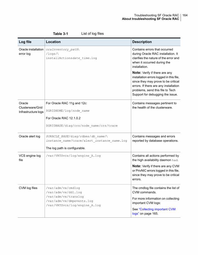
Table 3-1 List of log files
DescriptionLocationLog file
Contains errors that occurredduring Oracle RAC installation. Itclarifies the nature of the error andwhen it occurred during theinstallation.
Note: Verify if there are anyinstallation errors logged in this file,since they may prove to be criticalerrors. If there are any installationproblems, send this file to TechSupport for debugging the issue.
oraInventory_path\/logs/\installActionsdate_time.log
Oracle installationerror log
Contains messages pertinent tothe health of the clusterware.
For Oracle RAC 11g and 12c:
$GRIDHOME/log/node_name
For Oracle RAC 12.1.0.2
$GRIDBASE/diag/crs/node_name/crs/trace
OracleClusterware/GridInfrastructure logs
Contains messages and errorsreported by database operations.
$ORACLE_BASE/diag/rdbms/db_name/\instance_name/trace/alert_instance_name.log
The log path is configurable.
Oracle alert log
Contains all actions performed bythe high availability daemon had.
Note: Verify if there are any CVMor PrivNIC errors logged in this file,since they may prove to be criticalerrors.
/var/VRTSvcs/log/engine_A.logVCS engine logfile
The cmdlog file contains the list ofCVM commands.
For more information on collectingimportant CVM logs:
See “Collecting important CVMlogs” on page 165.
/var/adm/vx/cmdlog/var/adm/vx/ddl.log/var/adm/vx/translog/var/adm/vx/dmpevents.log/var/VRTSvcs/log/engine_A.log
CVM log files
164Troubleshooting SF Oracle RACAbout troubleshooting SF Oracle RAC
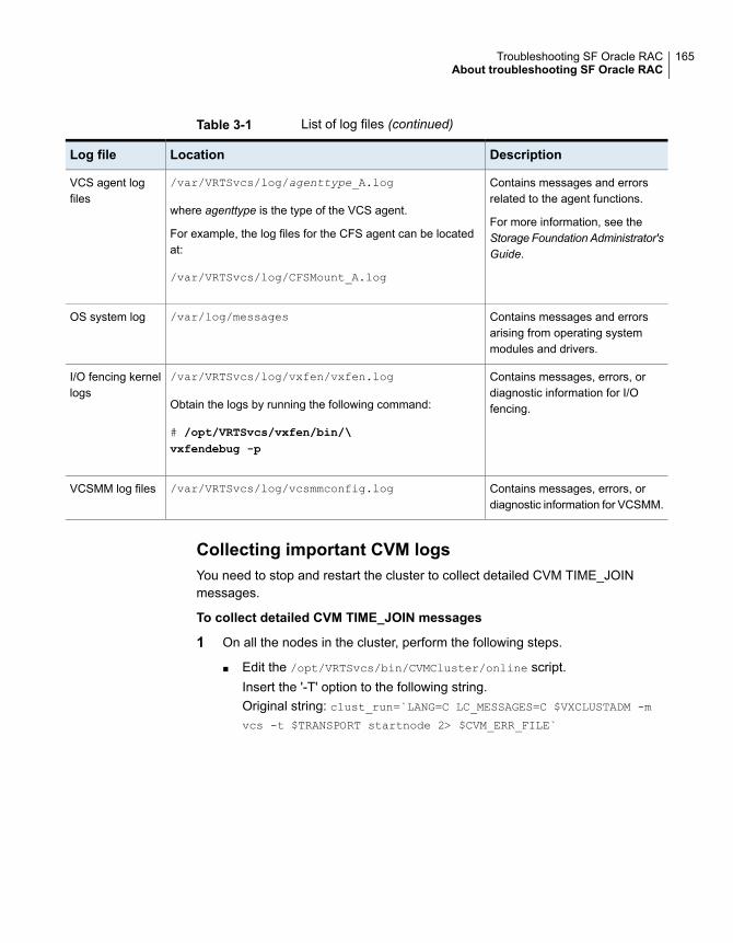
Table 3-1 List of log files (continued)
DescriptionLocationLog file
Contains messages and errorsrelated to the agent functions.
For more information, see theStorage Foundation Administrator'sGuide.
/var/VRTSvcs/log/agenttype_A.log
where agenttype is the type of the VCS agent.
For example, the log files for the CFS agent can be locatedat:
/var/VRTSvcs/log/CFSMount_A.log
VCS agent logfiles
Contains messages and errorsarising from operating systemmodules and drivers.
/var/log/messagesOS system log
Contains messages, errors, ordiagnostic information for I/Ofencing.
/var/VRTSvcs/log/vxfen/vxfen.log
Obtain the logs by running the following command:
# /opt/VRTSvcs/vxfen/bin/\vxfendebug -p
I/O fencing kernellogs
Contains messages, errors, ordiagnostic information for VCSMM.
/var/VRTSvcs/log/vcsmmconfig.logVCSMM log files
Collecting important CVM logsYou need to stop and restart the cluster to collect detailed CVM TIME_JOINmessages.
To collect detailed CVM TIME_JOIN messages
1 On all the nodes in the cluster, perform the following steps.
■ Edit the /opt/VRTSvcs/bin/CVMCluster/online script.Insert the '-T' option to the following string.Original string: clust_run=`LANG=C LC_MESSAGES=C $VXCLUSTADM -m
vcs -t $TRANSPORT startnode 2> $CVM_ERR_FILE`
165Troubleshooting SF Oracle RACAbout troubleshooting SF Oracle RAC
Modified string: clust_run=`LANG=C LC_MESSAGES=C $VXCLUSTADM -T
-d -m vcs -t $TRANSPORT startnode 2> $CVM_ERR_FILE`
2 Stop the cluster.
# hastop -all
3 Start the cluster.
# hastart
At this point, CVM TIME_JOIN messages display in the /var/log/messagesfileand on the console.
You can also enable vxconfigd daemon logging as follows:
# vxdctl debug 9 /var/adm/vx/vxconfigd_debug.out
The debug information that is enabled is accumulated in the system console logand in the text file /var/adm/vx/vxconfigd_debug.out. '9' represents the level ofdebugging. '1' represents minimal debugging. '9' represents verbose output.
Caution: Turning on vxconfigd debugging degrades VxVM performance. Usevxconfigd debugging with discretion in a production environment.
To disable vxconfigd debugging:
# vxdctl debug 0
The CVM kernel message dump can be collected on a live node as follows:
# /etc/vx/diag.d/kmsgdump -d 2000 > \
/var/adm/vx/kmsgdump.out
About SF Oracle RAC kernel and driver messagesSF Oracle RAC drivers such as GAB print messages to the console if the kerneland driver messages are configured to be displayed on the console. Make surethat the kernel and driver messages are logged to the console.
For details on how to configure console messages, see the operating systemdocumentation.
VCS message loggingVCS generates two types of logs: the engine log and the agent log. Log file namesare appended by letters; letter A indicates the first log file, B the second, and C thethird. After three files, the least recent file is removed and another file is created.
166Troubleshooting SF Oracle RACAbout troubleshooting SF Oracle RAC
For example, if engine_A.log is filled to its capacity, it is renamed as engine_B.logand the engine_B.log is renamed as engine_C.log. In this example, the least recentfile is engine_C.log and therefore it is removed. You can update the size of the logfile using the LogSize cluster level attribute.
The engine log is located at /var/VRTSvcs/log/engine_A.log. The format of enginelog messages is:
Timestamp (Year/MM/DD) | Mnemonic | Severity | UMI | Message Text
■ Timestamp: the date and time the message was generated.
■ Mnemonic: the string ID that represents the product (for example, VCS).
■ Severity: levels include CRITICAL, ERROR, WARNING, NOTICE, and INFO(most to least severe, respectively).
■ UMI: a unique message ID.
■ Message Text: the actual message generated by VCS.
A typical engine log resembles:
2011/07/10 16:08:09 VCS INFO V-16-1-10077 Received new
cluster membership
The agent log is located at /var/VRTSvcs/log/<agent>.log. The format of agentlog messages resembles:
Timestamp (Year/MM/DD) | Mnemonic | Severity | UMI | Agent Type | ResourceName | Entry Point | Message Text
A typical agent log resembles:
2011/07/10 10:38:23 VCS WARNING V-16-2-23331
Oracle:VRT:monitor:Open for ora_lgwr failed, setting
cookie to null.
Note that the logs on all nodes may not be identical because
■ VCS logs local events on the local nodes.
■ All nodes may not be running when an event occurs.
VCS prints the warning and error messages to STDERR.
If the VCS engine, Command Server, or any of the VCS agents encounter someproblem, then First Failure Data Capture (FFDC) logs are generated and dumpedalong with other core dumps and stack traces to the following location:
■ For VCS engine: $VCS_DIAG/diag/had
■ For Command Server: $VCS_DIAG/diag/CmdServer
167Troubleshooting SF Oracle RACAbout troubleshooting SF Oracle RAC
■ For VCS agents: $VCS_DIAG/diag/agents/type, where type represents thespecific agent type.
The default value for variable $VCS_DIAG is /var/VRTSvcs/.
If the debug logging is not turned on, these FFDC logs are useful to analyze theissues that require professional support.
GAB message loggingIf GAB encounters some problem, then First Failure Data Capture (FFDC) logs arealso generated and dumped.
When you have configured GAB, GAB also starts a GAB logging daemon(/opt/VRTSgab/gablogd). GAB logging daemon is enabled by default. You canchange the value of the GAB tunable parameter gab_ibuf_count to disable theGAB logging daemon.
See “About GAB load-time or static tunable parameters” on page 213.
This GAB logging daemon collects the GAB related logs when a critical events suchas an iofence or failure of the master of any GAB port occur, and stores the datain a compact binary form. You can use the gabread_ffdc utility as follows to readthe GAB binary log files:
/opt/VRTSgab/gabread_ffdc-kernel_version binary_logs_files_location
You can change the values of the following environment variables that control theGAB binary log files:
■ GAB_FFDC_MAX_INDX: Defines the maximum number of GAB binary log filesThe GAB logging daemon collects the defined number of log files each of eightMB size. The default value is 20, and the files are named gablog.1 throughgablog.20. At any point in time, the most recent file is the gablog.1 file.
■ GAB_FFDC_LOGDIR: Defines the log directory location for GAB binary log filesThe default location is:/var/log/gab_ffdc
Note that the gablog daemon writes its log to the glgd_A.log and glgd_B.log
files in the same directory.
You can either define these variables in the following GAB startup file or use theexport command. You must restart GAB for the changes to take effect.
/etc/sysconfig/gab
About debug log tags usageThe following table illustrates the use of debug tags:
168Troubleshooting SF Oracle RACAbout troubleshooting SF Oracle RAC
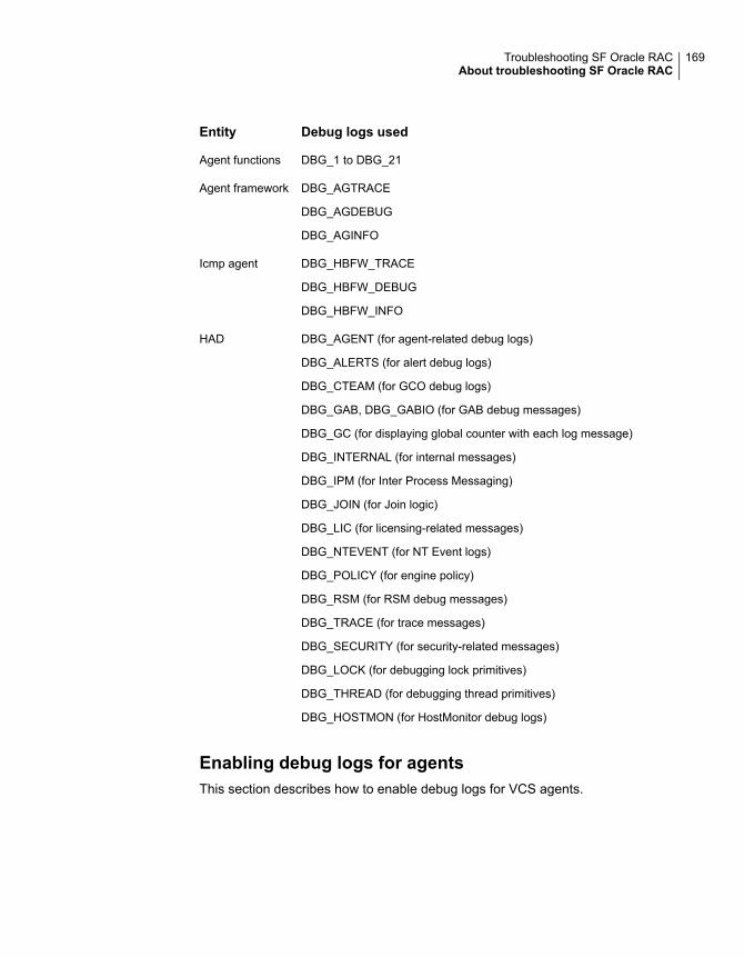
Debug logs usedEntity
DBG_1 to DBG_21Agent functions
DBG_AGTRACE
DBG_AGDEBUG
DBG_AGINFO
Agent framework
DBG_HBFW_TRACE
DBG_HBFW_DEBUG
DBG_HBFW_INFO
Icmp agent
DBG_AGENT (for agent-related debug logs)
DBG_ALERTS (for alert debug logs)
DBG_CTEAM (for GCO debug logs)
DBG_GAB, DBG_GABIO (for GAB debug messages)
DBG_GC (for displaying global counter with each log message)
DBG_INTERNAL (for internal messages)
DBG_IPM (for Inter Process Messaging)
DBG_JOIN (for Join logic)
DBG_LIC (for licensing-related messages)
DBG_NTEVENT (for NT Event logs)
DBG_POLICY (for engine policy)
DBG_RSM (for RSM debug messages)
DBG_TRACE (for trace messages)
DBG_SECURITY (for security-related messages)
DBG_LOCK (for debugging lock primitives)
DBG_THREAD (for debugging thread primitives)
DBG_HOSTMON (for HostMonitor debug logs)
HAD
Enabling debug logs for agentsThis section describes how to enable debug logs for VCS agents.
169Troubleshooting SF Oracle RACAbout troubleshooting SF Oracle RAC
To enable debug logs for agents
1 Set the configuration to read-write:
# haconf -makerw
2 Enable logging and set the desired log levels. Use the following commandsyntax:
# hatype -modify $typename LogDbg DBG_1 DBG_2 DBG_4 DBG_21
The following example shows the command line for the IPMultiNIC resourcetype.
# hatype -modify IPMultiNIC LogDbg DBG_1 DBG_2 DBG_4 DBG_21
See the description of the LogDbg attribute for more information.
3 For script-based agents, run the halog command to add the messages to theengine log:
# halog -addtags DBG_1 DBG_2 DBG_4 DBG_21
4 Save the configuration.
# haconf -dump -makero
If DBG_AGDEBUG is set, the agent framework logs for an instance of the agentappear in the agent log on the node on which the agent is running.
Enabling debug logs for the VCS engineYou can enable debug logs for the VCS engine, VCS agents, and HA commandsin two ways:
■ To enable debug logs at run-time, use the halog -addtags command.
■ To enable debug logs at startup, use the VCS_DEBUG_LOG_TAGS environmentvariable. You must set the VCS_DEBUG_LOG_TAGS before you start HAD orbefore you run HA commands.Examples:
# export VCS_DEBUG_LOG_TAGS="DBG_TRACE DBG_POLICY"
# hastart
# export VCS_DEBUG_LOG_TAGS="DBG_AGINFO DBG_AGDEBUG DBG_AGTRACE"
# hastart
170Troubleshooting SF Oracle RACAbout troubleshooting SF Oracle RAC
# export VCS_DEBUG_LOG_TAGS="DBG_IPM"
# hagrp -list
Note: Debug log messages are verbose. If you enable debug logs, log files mightfill up quickly.
Enabling debug logs for IMFRun the following commands to enable additional debug logs for IntelligentMonitoring Framework (IMF). The messages get logged in the agent-specific logfile /var/VRTSvcs/log/<agentname>_A.log.
To enable additional debug logs
1 For Process, Mount, and Application agents:
# hatype -modify <agentname> LogDbg
DBG_AGDEBUG DBG_AGTRACE DBG_AGINFO DBG_1 DBG_2
DBG_3 DBG_4 DBG_5 DBG_6 DBG_7
2 For Oracle and Netlsnr agents:
# hatype -modify <agentname> LogDbg
DBG_AGDEBUG DBG_AGTRACE DBG_AGINFO DBG_1 DBG_2
DBG_3 DBG_4 DBG_5 DBG_6 DBG_7
DBG_8 DBG_9 DBG_10
3 For CFSMount agent:
# hatype -modify <agentname> LogDbg
DBG_AGDEBUG DBG_AGTRACE DBG_AGINFO DBG_1 DBG_2
DBG_3 DBG_4 DBG_5 DBG_6 DBG_7
DBG_8 DBG_9 DBG_10 DBG_11 DBG_12
DBG_13 DBG_14 DBG_15 DBG_16
DBG_17 DBG_18 DBG_19 DBG_20 DBG_21
171Troubleshooting SF Oracle RACAbout troubleshooting SF Oracle RAC
4 For CVMvxconfigd agent, you do not have to enable any additional debug logs.
5 For AMF driver in-memory trace buffer:
# amfconfig -S errlevel all all
If you had enabled AMF driver in-memory trace buffer, you can view theadditional logs using the amfconfig -p dbglog command.
Message catalogsVCS includes multilingual support for message catalogs. These binary messagecatalogs (BMCs), are stored in the following default locations. The variable languagerepresents a two-letter abbreviation.
/opt/VRTS/messages/language/module_name
The VCS command-line interface displays error and success messages inVCS-supported languages. The hamsg command displays the VCS engine logs inVCS-supported languages.
The BMCs are:
Asynchronous Monitoring Framework (AMF) messagesamf.bmc
fdsetup messagesfdsetup.bmc
GAB command-line interface messagesgab.bmc
gcoconfig messagesgcoconfig.bmc
hagetcf messageshagetcf.bmc
hagui messageshagui.bmc
haimfconfig messageshaimfconfig.bmc
hazonesetup messageshazonesetup.bmc
hazoneverify messageshazoneverify.bmc
LLT command-line interface messagesllt.bmc
uuidconfig messagesuuidconfig.bmc
Agent framework messagesVRTSvcsAgfw.bmc
VCS alert messagesVRTSvcsAlerts.bmc
VCS API messagesVRTSvcsApi.bmc
172Troubleshooting SF Oracle RACAbout troubleshooting SF Oracle RAC
VCS cluster extender messagesVRTSvcsce.bmc
Common module messagesVRTSvcsCommon.bmc
VCS bundled agent messagesVRTSvcs<platform>Agent.bmc
VCS engine (HAD) messagesVRTSvcsHad.bmc
Heartbeat framework messagesVRTSvcsHbfw.bmc
VCS network utilities messagesVRTSvcsNetUtils.bmc
VCS enterprise agent messagesVRTSvcs<platformagent_name>.bmc
VCS trigger messagesVRTSvcsTriggers.bmc
VCS virtualization utilities messagesVRTSvcsVirtUtils.bmc
Wide-area connector process messagesVRTSvcsWac.bmc
Fencing messagesvxfen*.bmc
Restarting the installer after a failed networkconnection
If an installation is aborted because of a failed network connection, restarting theinstaller will detect the previous installation. The installer prompts to resume theinstallation. If you choose to resume the installation, the installer proceeds from thepoint where the installation aborted. If you choose not to resume, the installationstarts from the beginning.
Installer cannot create UUID for the clusterThe installer displays the following error message if the installer cannot find theuuidconfig.pl script before it configures the UUID for the cluster:
Couldn't find uuidconfig.pl for uuid configuration,
please create uuid manually before start vcs
You may see the error message during SF Oracle RAC configuration, upgrade, orwhen you add a node to the cluster using the installer.
Workaround: To start SF Oracle RAC, you must run the uuidconfig.pl script manuallyto configure the UUID on each cluster node.
173Troubleshooting SF Oracle RACRestarting the installer after a failed network connection
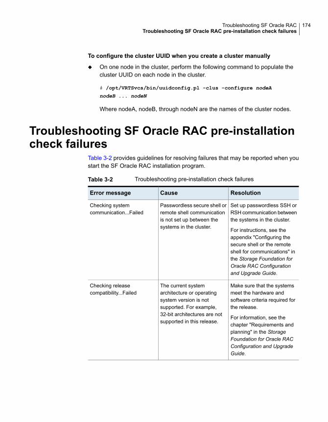
To configure the cluster UUID when you create a cluster manually
◆ On one node in the cluster, perform the following command to populate thecluster UUID on each node in the cluster.
# /opt/VRTSvcs/bin/uuidconfig.pl -clus -configure nodeA
nodeB ... nodeN
Where nodeA, nodeB, through nodeN are the names of the cluster nodes.
Troubleshooting SF Oracle RAC pre-installationcheck failures
Table 3-2 provides guidelines for resolving failures that may be reported when youstart the SF Oracle RAC installation program.
Table 3-2 Troubleshooting pre-installation check failures
ResolutionCauseError message
Set up passwordless SSH orRSH communication betweenthe systems in the cluster.
For instructions, see theappendix "Configuring thesecure shell or the remoteshell for communications" inthe Storage Foundation forOracle RAC Configurationand Upgrade Guide.
Passwordless secure shell orremote shell communicationis not set up between thesystems in the cluster.
Checking systemcommunication...Failed
Make sure that the systemsmeet the hardware andsoftware criteria required forthe release.
For information, see thechapter "Requirements andplanning" in the StorageFoundation for Oracle RACConfiguration and UpgradeGuide.
The current systemarchitecture or operatingsystem version is notsupported. For example,32-bit architectures are notsupported in this release.
Checking releasecompatibility...Failed
174Troubleshooting SF Oracle RACTroubleshooting SF Oracle RAC pre-installation check failures
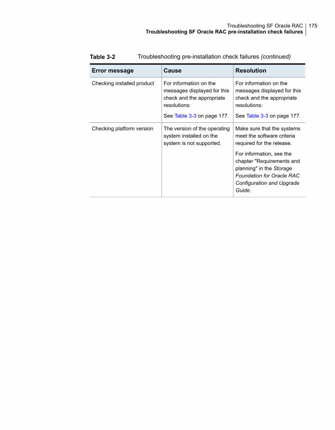
Table 3-2 Troubleshooting pre-installation check failures (continued)
ResolutionCauseError message
For information on themessages displayed for thischeck and the appropriateresolutions:
See Table 3-3 on page 177.
For information on themessages displayed for thischeck and the appropriateresolutions:
See Table 3-3 on page 177.
Checking installed product
Make sure that the systemsmeet the software criteriarequired for the release.
For information, see thechapter "Requirements andplanning" in the StorageFoundation for Oracle RACConfiguration and UpgradeGuide.
The version of the operatingsystem installed on thesystem is not supported.
Checking platform version
175Troubleshooting SF Oracle RACTroubleshooting SF Oracle RAC pre-installation check failures
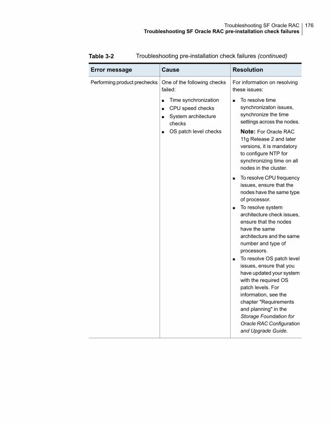
Table 3-2 Troubleshooting pre-installation check failures (continued)
ResolutionCauseError message
For information on resolvingthese issues:
■ To resolve timesynchronizaton issues,synchronize the timesettings across the nodes.
Note: For Oracle RAC11g Release 2 and laterversions, it is mandatoryto configure NTP forsynchronizing time on allnodes in the cluster.
■ To resolve CPU frequencyissues, ensure that thenodes have the same typeof processor.
■ To resolve systemarchitecture check issues,ensure that the nodeshave the samearchitecture and the samenumber and type ofprocessors.
■ To resolve OS patch levelissues, ensure that youhave updated your systemwith the required OSpatch levels. Forinformation, see thechapter "Requirementsand planning" in theStorage Foundation forOracle RACConfigurationand Upgrade Guide.
One of the following checksfailed:
■ Time synchronization■ CPU speed checks■ System architecture
checks■ OS patch level checks
Performing product prechecks
176Troubleshooting SF Oracle RACTroubleshooting SF Oracle RAC pre-installation check failures
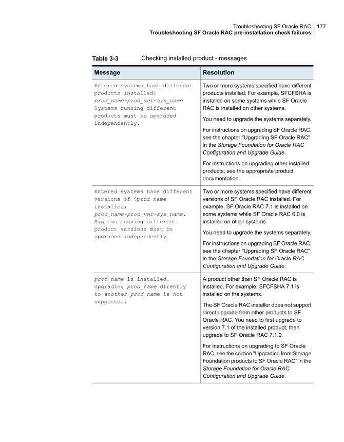
Table 3-3 Checking installed product - messages
ResolutionMessage
Two or more systems specified have differentproducts installed. For example, SFCFSHA isinstalled on some systems while SF OracleRAC is installed on other systems.
You need to upgrade the systems separately.
For instructions on upgrading SF Oracle RAC,see the chapter "Upgrading SF Oracle RAC"in the Storage Foundation for Oracle RACConfiguration and Upgrade Guide.
For instructions on upgrading other installedproducts, see the appropriate productdocumentation.
Entered systems have differentproducts installed:prod_name-prod_ver-sys_nameSystems running differentproducts must be upgradedindependently.
Two or more systems specified have differentversions of SF Oracle RAC installed. Forexample, SF Oracle RAC 7.1 is installed onsome systems while SF Oracle RAC 6.0 isinstalled on other systems.
You need to upgrade the systems separately.
For instructions on upgrading SF Oracle RAC,see the chapter "Upgrading SF Oracle RAC"in the Storage Foundation for Oracle RACConfiguration and Upgrade Guide.
Entered systems have differentversions of $prod_nameinstalled:prod_name-prod_ver-sys_name.Systems running differentproduct versions must beupgraded independently.
A product other than SF Oracle RAC isinstalled. For example, SFCFSHA 7.1 isinstalled on the systems.
The SF Oracle RAC installer does not supportdirect upgrade from other products to SFOracle RAC. You need to first upgrade toversion 7.1 of the installed product, thenupgrade to SF Oracle RAC 7.1.0.
For instructions on upgrading to SF OracleRAC, see the section "Upgrading from StorageFoundation products to SF Oracle RAC" in theStorage Foundation for Oracle RACConfiguration and Upgrade Guide.
prod_name is installed.Upgrading prod_name directlyto another_prod_name is notsupported.
177Troubleshooting SF Oracle RACTroubleshooting SF Oracle RAC pre-installation check failures
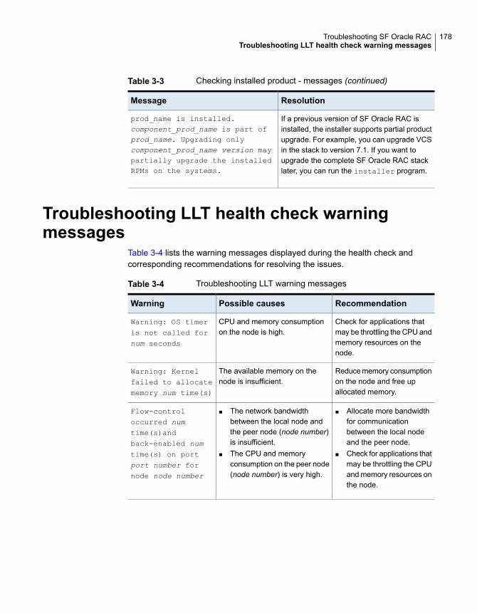
Table 3-3 Checking installed product - messages (continued)
ResolutionMessage
If a previous version of SF Oracle RAC isinstalled, the installer supports partial productupgrade. For example, you can upgrade VCSin the stack to version 7.1. If you want toupgrade the complete SF Oracle RAC stacklater, you can run the installer program.
prod_name is installed.component_prod_name is part ofprod_name. Upgrading onlycomponent_prod_name version maypartially upgrade the installedRPMs on the systems.
Troubleshooting LLT health check warningmessages
Table 3-4 lists the warning messages displayed during the health check andcorresponding recommendations for resolving the issues.
Table 3-4 Troubleshooting LLT warning messages
RecommendationPossible causesWarning
Check for applications thatmay be throttling the CPU andmemory resources on thenode.
CPU and memory consumptionon the node is high.
Warning: OS timeris not called fornum seconds
Reduce memory consumptionon the node and free upallocated memory.
The available memory on thenode is insufficient.
Warning: Kernelfailed to allocatememory num time(s)
■ Allocate more bandwidthfor communicationbetween the local nodeand the peer node.
■ Check for applications thatmay be throttling the CPUand memory resources onthe node.
■ The network bandwidthbetween the local node andthe peer node (node number)is insufficient.
■ The CPU and memoryconsumption on the peer node(node number) is very high.
Flow-controloccurred numtime(s)andback-enabled numtime(s) on portport number fornode node number
178Troubleshooting SF Oracle RACTroubleshooting LLT health check warning messages
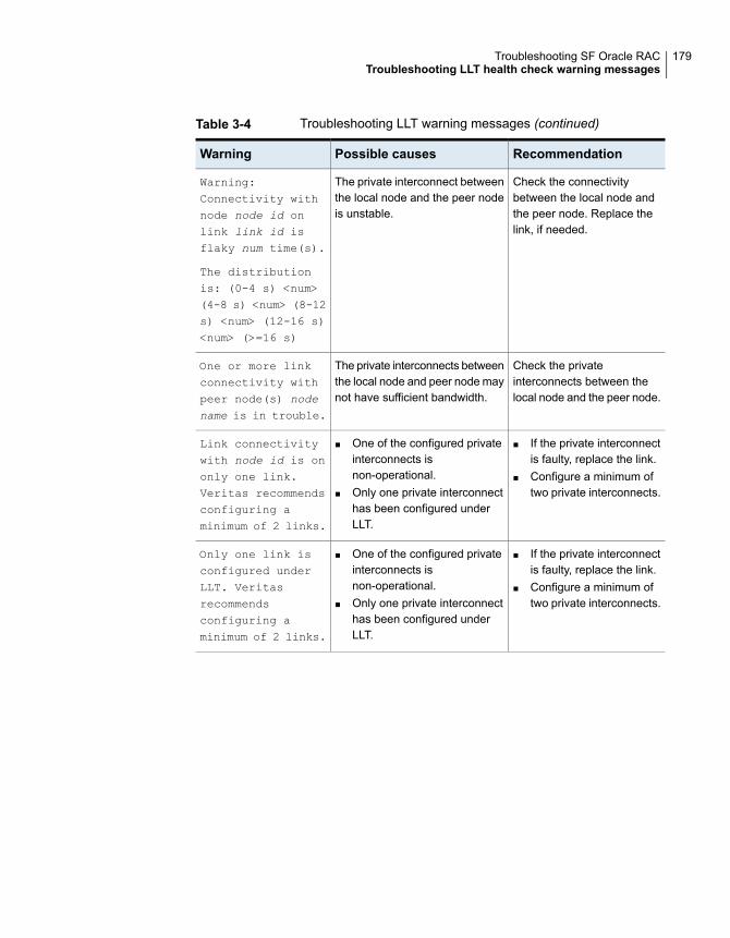
Table 3-4 Troubleshooting LLT warning messages (continued)
RecommendationPossible causesWarning
Check the connectivitybetween the local node andthe peer node. Replace thelink, if needed.
The private interconnect betweenthe local node and the peer nodeis unstable.
Warning:Connectivity withnode node id onlink link id isflaky num time(s).
The distributionis: (0-4 s) <num>(4-8 s) <num> (8-12s) <num> (12-16 s)<num> (>=16 s)
Check the privateinterconnects between thelocal node and the peer node.
The private interconnects betweenthe local node and peer node maynot have sufficient bandwidth.
One or more linkconnectivity withpeer node(s) nodename is in trouble.
■ If the private interconnectis faulty, replace the link.
■ Configure a minimum oftwo private interconnects.
■ One of the configured privateinterconnects isnon-operational.
■ Only one private interconnecthas been configured underLLT.
Link connectivitywith node id is ononly one link.Veritas recommendsconfiguring aminimum of 2 links.
■ If the private interconnectis faulty, replace the link.
■ Configure a minimum oftwo private interconnects.
■ One of the configured privateinterconnects isnon-operational.
■ Only one private interconnecthas been configured underLLT.
Only one link isconfigured underLLT. Veritasrecommendsconfiguring aminimum of 2 links.
179Troubleshooting SF Oracle RACTroubleshooting LLT health check warning messages
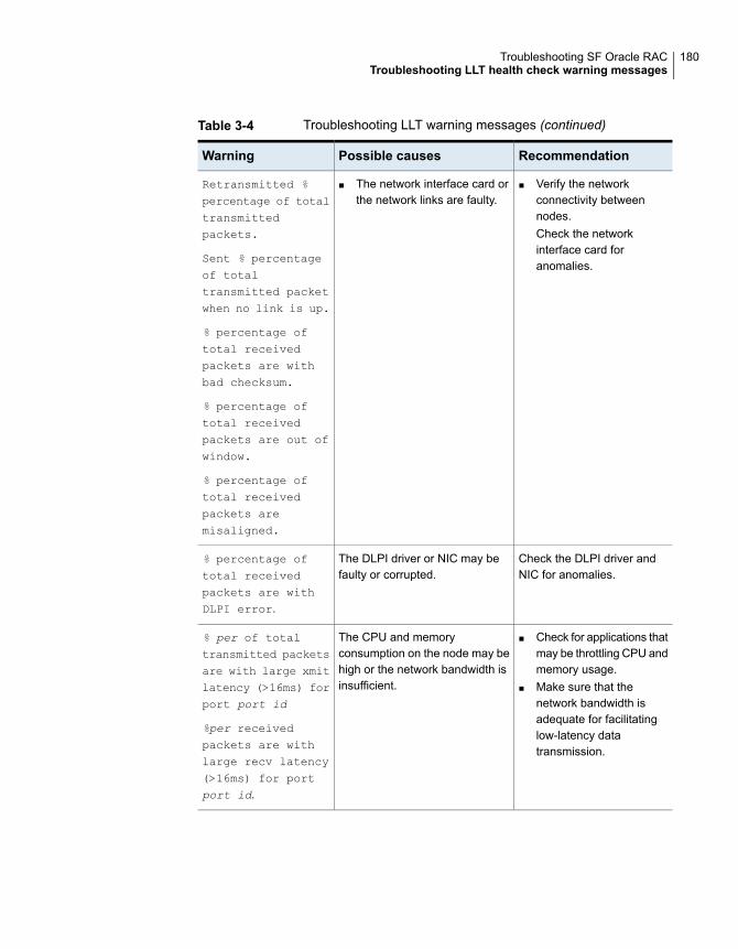
Table 3-4 Troubleshooting LLT warning messages (continued)
RecommendationPossible causesWarning
■ Verify the networkconnectivity betweennodes.Check the networkinterface card foranomalies.
■ The network interface card orthe network links are faulty.
Retransmitted %percentage of totaltransmittedpackets.
Sent % percentageof totaltransmitted packetwhen no link is up.
% percentage oftotal receivedpackets are withbad checksum.
% percentage oftotal receivedpackets are out ofwindow.
% percentage oftotal receivedpackets aremisaligned.
Check the DLPI driver andNIC for anomalies.
The DLPI driver or NIC may befaulty or corrupted.
% percentage oftotal receivedpackets are withDLPI error.
■ Check for applications thatmay be throttling CPU andmemory usage.
■ Make sure that thenetwork bandwidth isadequate for facilitatinglow-latency datatransmission.
The CPU and memoryconsumption on the node may behigh or the network bandwidth isinsufficient.
% per of totaltransmitted packetsare with large xmitlatency (>16ms) forport port id
%per receivedpackets are withlarge recv latency(>16ms) for portport id.
180Troubleshooting SF Oracle RACTroubleshooting LLT health check warning messages
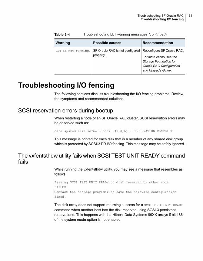
Table 3-4 Troubleshooting LLT warning messages (continued)
RecommendationPossible causesWarning
Reconfigure SF Oracle RAC.
For instructions, see theStorage Foundation forOracle RAC Configurationand Upgrade Guide.
SF Oracle RAC is not configuredproperly.
LLT is not running.
Troubleshooting I/O fencingThe following sections discuss troubleshooting the I/O fencing problems. Reviewthe symptoms and recommended solutions.
SCSI reservation errors during bootupWhen restarting a node of an SF Oracle RAC cluster, SCSI reservation errors maybe observed such as:
date system name kernel: scsi3 (0,0,6) : RESERVATION CONFLICT
This message is printed for each disk that is a member of any shared disk groupwhich is protected by SCSI-3 PR I/O fencing. This message may be safely ignored.
The vxfentsthdw utility fails when SCSI TEST UNIT READY commandfails
While running the vxfentsthdw utility, you may see a message that resembles asfollows:
Issuing SCSI TEST UNIT READY to disk reserved by other node
FAILED.
Contact the storage provider to have the hardware configuration
fixed.
The disk array does not support returning success for a SCSI TEST UNIT READY
command when another host has the disk reserved using SCSI-3 persistentreservations. This happens with the Hitachi Data Systems 99XX arrays if bit 186of the system mode option is not enabled.
181Troubleshooting SF Oracle RACTroubleshooting I/O fencing
Node is unable to join cluster while another node is being ejectedA cluster that is currently fencing out (ejecting) a node from the cluster prevents anew node from joining the cluster until the fencing operation is completed. Thefollowing are example messages that appear on the console for the new node:
...VxFEN ERROR V-11-1-25 ... Unable to join running cluster
since cluster is currently fencing
a node out of the cluster.
If you see these messages when the new node is booting, the vxfen startup scripton the node makes up to five attempts to join the cluster.
To manually join the node to the cluster when I/O fencing attempts fail
◆ If the vxfen script fails in the attempts to allow the node to join the cluster,restart vxfen driver with the command:
# /etc/init.d/vxfen stop
# /etc/init.d/vxfen start
If the command fails, restart the new node.
System panics to prevent potential data corruptionWhen a node experiences a split-brain condition and is ejected from the cluster, itpanics and displays the following console message:
VXFEN:vxfen_plat_panic: Local cluster node ejected from cluster to
prevent potential data corruption.
A node experiences the split-brain condition when it loses the heartbeat with itspeer nodes due to failure of all private interconnects or node hang. Review thebehavior of I/O fencing under different scenarios and the corrective measures tobe taken.
Cluster ID on the I/O fencing key of coordinator disk does not matchthe local cluster’s ID
If you accidentally assign coordinator disks of a cluster to another cluster, then thefencing driver displays an error message similar to the following when you start I/Ofencing:
000068 06:37:33 2bdd5845 0 ... 3066 0 VXFEN WARNING V-11-1-56
Coordinator disk has key with cluster id 48813
which does not match local cluster id 57069
182Troubleshooting SF Oracle RACTroubleshooting I/O fencing
The warning implies that the local cluster with the cluster ID 57069 has keys.However, the disk also has keys for cluster with ID 48813 which indicates that nodesfrom the cluster with cluster id 48813 potentially use the same coordinator disk.
You can run the following commands to verify whether these disks are used byanother cluster. Run the following commands on one of the nodes in the localcluster. For example, on sys1:
sys1> # lltstat -C
57069
sys1> # cat /etc/vxfentab
/dev/vx/rdmp/disk_7
/dev/vx/rdmp/disk_8
/dev/vx/rdmp/disk_9
sys1> # vxfenadm -s /dev/vx/rdmp/disk_7
Reading SCSI Registration Keys...
Device Name: /dev/vx/rdmp/disk_7
Total Number Of Keys: 1
key[0]:
[Numeric Format]: 86,70,48,49,52,66,48,48
[Character Format]: VFBEAD00
[Node Format]: Cluster ID: 48813 Node ID: 0 Node Name: unknown
Where disk_7, disk_8, and disk_9 represent the disk names in your setup.
Recommended action: You must use a unique set of coordinator disks for eachcluster. If the other cluster does not use these coordinator disks, then clear the keysusing the vxfenclearpre command before you use them as coordinator disks in thelocal cluster.
See “About the vxfenclearpre utility” on page 101.
Fencing startup reports preexisting split-brainThe vxfen driver functions to prevent an ejected node from rejoining the clusterafter the failure of the private network links and before the private network links arerepaired.
For example, suppose the cluster of system 1 and system 2 is functioning normallywhen the private network links are broken. Also suppose system 1 is the ejectedsystem. When system 1 restarts before the private network links are restored, itsmembership configuration does not show system 2; however, when it attempts toregister with the coordinator disks, it discovers system 2 is registered with them.
183Troubleshooting SF Oracle RACTroubleshooting I/O fencing
Given this conflicting information about system 2, system 1 does not join the clusterand returns an error from vxfenconfig that resembles:
vxfenconfig: ERROR: There exists the potential for a preexisting
split-brain. The coordinator disks list no nodes which are in
the current membership. However, they also list nodes which are
not in the current membership.
I/O Fencing Disabled!
Also, the following information is displayed on the console:
<date> <system name> vxfen: WARNING: Potentially a preexisting
<date> <system name> split-brain.
<date> <system name> Dropping out of cluster.
<date> <system name> Refer to user documentation for steps
<date> <system name> required to clear preexisting split-brain.
<date> <system name>
<date> <system name> I/O Fencing DISABLED!
<date> <system name>
<date> <system name> gab: GAB:20032: Port b closed
However, the same error can occur when the private network links are working andboth systems go down, system 1 restarts, and system 2 fails to come back up. Fromthe view of the cluster from system 1, system 2 may still have the registrations onthe coordination points.
Assume the following situations to understand preexisting split-brain in server-basedfencing:
■ There are three CP servers acting as coordination points. One of the three CPservers then becomes inaccessible. While in this state, one client node leavesthe cluster, whose registration cannot be removed from the inaccessible CPserver. When the inaccessible CP server restarts, it has a stale registration fromthe node which left the SF Oracle RAC cluster. In this case, no new nodes canjoin the cluster. Each node that attempts to join the cluster gets a list ofregistrations from the CP server. One CP server includes an extra registration(of the node which left earlier). This makes the joiner node conclude that thereexists a preexisting split-brain between the joiner node and the node which isrepresented by the stale registration.
■ All the client nodes have crashed simultaneously, due to which fencing keysare not cleared from the CP servers. Consequently, when the nodes restart, thevxfen configuration fails reporting preexisting split brain.
184Troubleshooting SF Oracle RACTroubleshooting I/O fencing
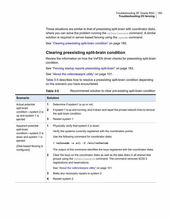
These situations are similar to that of preexisting split-brain with coordinator disks,where you can solve the problem running the vxfenclearpre command. A similarsolution is required in server-based fencing using the cpsadm command.
See “Clearing preexisting split-brain condition” on page 185.
Clearing preexisting split-brain conditionReview the information on how the VxFEN driver checks for preexisting split-braincondition.
See “Fencing startup reports preexisting split-brain” on page 183.
See “About the vxfenclearpre utility” on page 101.
Table 3-5 describes how to resolve a preexisting split-brain condition dependingon the scenario you have encountered:
Table 3-5 Recommened solution to clear pre-existing split-brain condition
SolutionScenario
1 Determine if system1 is up or not.
2 If system 1 is up and running, shut it down and repair the private network links to removethe split-brain condition.
3 Restart system 1.
Actual potentialsplit-braincondition—system 2 isup and system 1 isejected
1 Physically verify that system 2 is down.
Verify the systems currently registered with the coordination points.
Use the following command for coordinator disks:
# vxfenadm -s all -f /etc/vxfentab
The output of this command identifies the keys registered with the coordinator disks.
2 Clear the keys on the coordinator disks as well as the data disks in all shared diskgroups using the vxfenclearpre command. The command removes SCSI-3registrations and reservations.
See “About the vxfenclearpre utility” on page 101.
3 Make any necessary repairs to system 2.
4 Restart system 2.
Apparent potentialsplit-braincondition—system 2 isdown and system 1 isejected
(Disk-based fencing isconfigured)
185Troubleshooting SF Oracle RACTroubleshooting I/O fencing
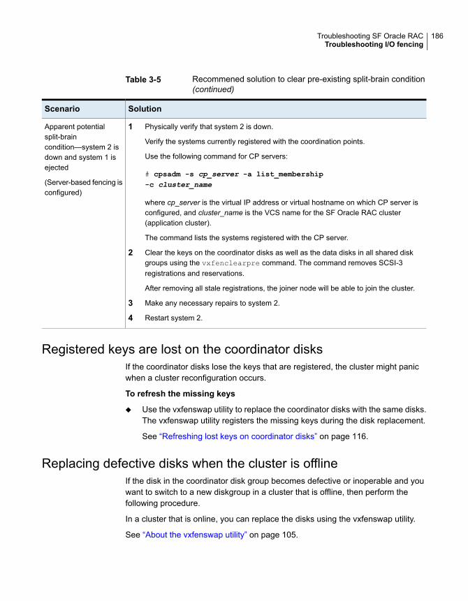
Table 3-5 Recommened solution to clear pre-existing split-brain condition(continued)
SolutionScenario
1 Physically verify that system 2 is down.
Verify the systems currently registered with the coordination points.
Use the following command for CP servers:
# cpsadm -s cp_server -a list_membership-c cluster_name
where cp_server is the virtual IP address or virtual hostname on which CP server isconfigured, and cluster_name is the VCS name for the SF Oracle RAC cluster(application cluster).
The command lists the systems registered with the CP server.
2 Clear the keys on the coordinator disks as well as the data disks in all shared diskgroups using the vxfenclearpre command. The command removes SCSI-3registrations and reservations.
After removing all stale registrations, the joiner node will be able to join the cluster.
3 Make any necessary repairs to system 2.
4 Restart system 2.
Apparent potentialsplit-braincondition—system 2 isdown and system 1 isejected
(Server-based fencing isconfigured)
Registered keys are lost on the coordinator disksIf the coordinator disks lose the keys that are registered, the cluster might panicwhen a cluster reconfiguration occurs.
To refresh the missing keys
◆ Use the vxfenswap utility to replace the coordinator disks with the same disks.The vxfenswap utility registers the missing keys during the disk replacement.
See “Refreshing lost keys on coordinator disks” on page 116.
Replacing defective disks when the cluster is offlineIf the disk in the coordinator disk group becomes defective or inoperable and youwant to switch to a new diskgroup in a cluster that is offline, then perform thefollowing procedure.
In a cluster that is online, you can replace the disks using the vxfenswap utility.
See “About the vxfenswap utility” on page 105.
186Troubleshooting SF Oracle RACTroubleshooting I/O fencing
Review the following information to replace coordinator disk in the coordinator diskgroup, or to destroy a coordinator disk group.
Note the following about the procedure:
■ When you add a disk, add the disk to the disk group vxfencoorddg and retestthe group for support of SCSI-3 persistent reservations.
■ You can destroy the coordinator disk group such that no registration keys remainon the disks. The disks can then be used elsewhere.
To replace a disk in the coordinator disk group when the cluster is offline
1 Log in as superuser on one of the cluster nodes.
2 If VCS is running, shut it down:
# hastop -all
Make sure that the port h is closed on all the nodes. Run the following commandto verify that the port h is closed:
# gabconfig -a
3 Stop the VCSMM driver on each node:
# /etc/init.d/vcsmm stop
4 Stop I/O fencing on each node:
# /etc/init.d/vxfen stop
This removes any registration keys on the disks.
5 Import the coordinator disk group. The file /etc/vxfendg includes the name ofthe disk group (typically, vxfencoorddg) that contains the coordinator disks, souse the command:
# vxdg -tfC import ‘cat /etc/vxfendg‘
where:
-t specifies that the disk group is imported only until the node restarts.
-f specifies that the import is to be done forcibly, which is necessary if one ormore disks is not accessible.
-C specifies that any import locks are removed.
6 To remove disks from the disk group, use the VxVM disk administrator utility,vxdiskadm.
You may also destroy the existing coordinator disk group. For example:
187Troubleshooting SF Oracle RACTroubleshooting I/O fencing
■ Verify whether the coordinator attribute is set to on.
# vxdg list vxfencoorddg | grep flags: | grep coordinator
■ Destroy the coordinator disk group.
# vxdg -o coordinator destroy vxfencoorddg
7 Add the new disk to the node and initialize it as a VxVM disk.
Then, add the new disk to the vxfencoorddg disk group:
■ If you destroyed the disk group in step 6, then create the disk group againand add the new disk to it.See the Storage Foundation for Oracle RAC Configuration and UpgradeGuide for detailed instructions.
■ If the diskgroup already exists, then add the new disk to it.
# vxdg -g vxfencoorddg -o coordinator adddisk disk_name
8 Test the recreated disk group for SCSI-3 persistent reservations compliance.
See “Testing the coordinator disk group using the -c option of vxfentsthdw”on page 91.
9 After replacing disks in a coordinator disk group, deport the disk group:
# vxdg deport ‘cat /etc/vxfendg‘
10 On each node, start the I/O fencing driver:
# /etc/init.d/vxfen start
11 On each node, start the VCSMM driver:
# /etc/init.d/vcsmm start
188Troubleshooting SF Oracle RACTroubleshooting I/O fencing
12 Verify that the I/O fencing module has started and is enabled.
# gabconfig -a
Make sure that port b and port o memberships exist in the output for all nodesin the cluster.
# vxfenadm -d
Make sure that I/O fencing mode is not disabled in the output.
13 If necessary, restart VCS on each node:
# hastart
Troubleshooting I/O fencing health check warning messagesTable 3-6 lists the warning messages displayed during the health check andcorresponding recommendations for resolving the issues.
Table 3-6 Troubleshooting I/O fencing warning messages
RecommendationPossible causesWarning
Configure fencing.
For instructions, see theStorage Foundation forOracle RAC Configurationand Upgrade Guide.
I/O fencing is not enabled in thecluster.
VxFEN is notrunning on allnodes in thecluster.
Start fencing in SCSI3 modeon all nodes in the cluster.
■ If you are using disk-based I/Ofencing, it is not configured inthe SCSI3 mode.
VxFEN is notconfigured in SCSI3mode.
189Troubleshooting SF Oracle RACTroubleshooting I/O fencing
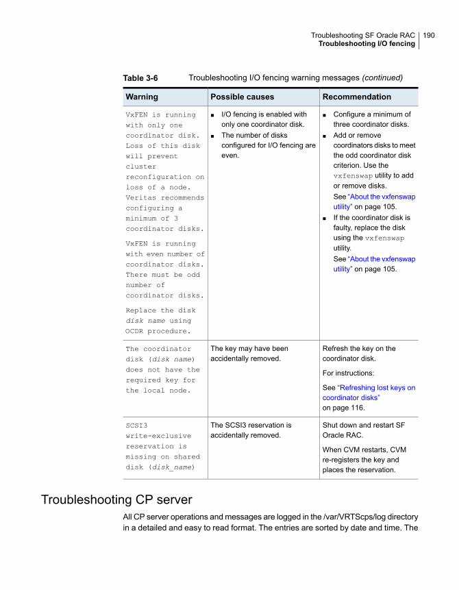
Table 3-6 Troubleshooting I/O fencing warning messages (continued)
RecommendationPossible causesWarning
■ Configure a minimum ofthree coordinator disks.
■ Add or removecoordinators disks to meetthe odd coordinator diskcriterion. Use thevxfenswap utility to addor remove disks.See “About the vxfenswaputility” on page 105.
■ If the coordinator disk isfaulty, replace the diskusing the vxfenswaputility.See “About the vxfenswaputility” on page 105.
■ I/O fencing is enabled withonly one coordinator disk.
■ The number of disksconfigured for I/O fencing areeven.
VxFEN is runningwith only onecoordinator disk.Loss of this diskwill preventclusterreconfiguration onloss of a node.Veritas recommendsconfiguring aminimum of 3coordinator disks.
VxFEN is runningwith even number ofcoordinator disks.There must be oddnumber ofcoordinator disks.
Replace the diskdisk name usingOCDR procedure.
Refresh the key on thecoordinator disk.
For instructions:
See “Refreshing lost keys oncoordinator disks”on page 116.
The key may have beenaccidentally removed.
The coordinatordisk (disk name)does not have therequired key forthe local node.
Shut down and restart SFOracle RAC.
When CVM restarts, CVMre-registers the key andplaces the reservation.
The SCSI3 reservation isaccidentally removed.
SCSI3write-exclusivereservation ismissing on shareddisk (disk_name)
Troubleshooting CP serverAll CP server operations and messages are logged in the /var/VRTScps/log directoryin a detailed and easy to read format. The entries are sorted by date and time. The
190Troubleshooting SF Oracle RACTroubleshooting I/O fencing
logs can be used for troubleshooting purposes or to review for any possible securityissue on the system that hosts the CP server.
The following files contain logs and text files that may be useful in understandingand troubleshooting a CP server:
■ /var/VRTScps/log/cpserver_[ABC].log
■ /var/VRTSvcs/log/vcsauthserver.log (Security related)
■ If the vxcpserv process fails on the CP server, then review the followingdiagnostic files:
■ /var/VRTScps/diag/FFDC_CPS_pid_vxcpserv.log
■ /var/VRTScps/diag/stack_pid_vxcpserv.txt
Note: If the vxcpserv process fails on the CP server, these files are present inaddition to a core file. VCS restarts vxcpserv process automatically in suchsituations.
The file /var/VRTSvcs/log/vxfen/vxfend_[ABC].log contains logs that may be usefulin understanding and troubleshooting fencing-related issues on a SF Oracle RACcluster (client cluster) node.
See “Troubleshooting issues related to the CP server service group” on page 191.
See “Checking the connectivity of CP server” on page 192.
See “Issues during fencing startup on SF Oracle RAC cluster nodes set up forserver-based fencing” on page 192.
See “Issues during online migration of coordination points” on page 193.
Troubleshooting issues related to the CP server servicegroupIf you cannot bring up the CPSSG service group after the CP server configuration,perform the following steps:
■ Verify that the CPSSG service group and its resources are valid and properlyconfigured in the VCS configuration.
■ Check the VCS engine log (/var/VRTSvcs/log/engine_[ABC].log) to see ifany of the CPSSG service group resources are FAULTED.
■ Review the sample dependency graphs to make sure the required resourcesare configured correctly.
191Troubleshooting SF Oracle RACTroubleshooting I/O fencing
Checking the connectivity of CP serverYou can test the connectivity of CP server using the cpsadm command.
You must have set the environment variables CPS_USERNAME andCPS_DOMAINTYPE to run the cpsadm command on the SF Oracle RAC cluster(client cluster) nodes.
To check the connectivity of CP server
◆ Run the following command to check whether a CP server is up and runningat a process level:
# cpsadm -s cp_server -a ping_cps
where cp_server is the virtual IP address or virtual hostname on which the CPserver is listening.
Troubleshooting server-based fencing on the SF Oracle RAC clusternodes
The file /var/VRTSvcs/log/vxfen/vxfend_[ABC].log contains logs files that may beuseful in understanding and troubleshooting fencing-related issues on a SF OracleRAC cluster (application cluster) node.
Issues during fencing startup on SF Oracle RAC clusternodes set up for server-based fencingTable 3-7 Fencing startup issues on SF Oracle RAC cluster (client cluster)
nodes
Description and resolutionIssue
If you receive a connection error message after issuing the cpsadm command on the SFOracle RAC cluster, perform the following actions:
■ Ensure that the CP server is reachable from all the SF Oracle RAC cluster nodes.■ Check the /etc/vxfenmode file and ensure that the SF Oracle RAC cluster nodes use the
correct CP server virtual IP or virtual hostname and the correct port number.■ For HTTPS communication, ensure that the virtual IP and ports listed for the server can
listen to HTTPS requests.
cpsadm command onthe SF Oracle RACcluster gives connectionerror
192Troubleshooting SF Oracle RACTroubleshooting I/O fencing
Table 3-7 Fencing startup issues on SF Oracle RAC cluster (client cluster)nodes (continued)
Description and resolutionIssue
Authorization failure occurs when the nodes on the client clusters and or users are not addedin the CP server configuration. Therefore, fencing on the SF Oracle RAC cluster (clientcluster) node is not allowed to access the CP server and register itself on the CP server.Fencing fails to come up if it fails to register with a majority of the coordination points.
To resolve this issue, add the client cluster node and user in the CP server configurationand restart fencing.
Authorization failure
If you had configured secure communication between the CP server and the SF OracleRAC cluster (client cluster) nodes, authentication failure can occur due to the followingcauses:
■ The client cluster requires its own private key, a signed certificate, and a CertificationAuthority's (CA) certificate to establish secure communication with the CP server. If anyof the files are missing or corrupt, communication fails.
■ If the client cluster certificate does not correspond to the client's private key,communication fails.
■ If the CP server and client cluster do not have a common CA in their certificate chain oftrust, then communication fails.
Authentication failure
Issues during online migration of coordination pointsDuring online migration of coordination points using the vxfenswap utility, theoperation is automatically rolled back if a failure is encountered during validationof coordination points from any of the cluster nodes.
Validation failure of the new set of coordination points can occur in the followingcircumstances:
■ The /etc/vxfenmode.test file is not updated on all the SF Oracle RAC clusternodes, because new coordination points on the node were being picked up froman old /etc/vxfenmode.test file. The /etc/vxfenmode.test file must be updatedwith the current details. If the /etc/vxfenmode.test file is not present, vxfenswapcopies configuration for new coordination points from the /etc/vxfenmode file.
■ The coordination points listed in the /etc/vxfenmode file on the different SFOracle RAC cluster nodes are not the same. If different coordination points arelisted in the /etc/vxfenmode file on the cluster nodes, then the operation failsdue to failure during the coordination point snapshot check.
■ There is no network connectivity from one or more SF Oracle RAC cluster nodesto the CP server(s).
193Troubleshooting SF Oracle RACTroubleshooting I/O fencing
■ Cluster, nodes, or users for the SF Oracle RAC cluster nodes have not beenadded on the new CP servers, thereby causing authorization failure.
Vxfen service group activity after issuing the vxfenswapcommandThe Coordination Point agent reads the details of coordination points from thevxfenconfig -l output and starts monitoring the registrations on them.
Thus, during vxfenswap, when the vxfenmode file is being changed by the user,the Coordination Point agent does not move to FAULTED state but continuesmonitoring the old set of coordination points.
As long as the changes to vxfenmode file are not committed or the new set ofcoordination points are not reflected in vxfenconfig -l output, the CoordinationPoint agent continues monitoring the old set of coordination points it read fromvxfenconfig -l output in every monitor cycle.
The status of the Coordination Point agent (either ONLINE or FAULTED) dependsupon the accessibility of the coordination points, the registrations on thesecoordination points, and the fault tolerance value.
When the changes to vxfenmode file are committed and reflected in the vxfenconfig
-l output, then the Coordination Point agent reads the new set of coordinationpoints and proceeds to monitor them in its new monitor cycle.
Troubleshooting Cluster Volume Manager in SFOracle RAC clusters
This section discusses troubleshooting CVM problems.
Restoring communication between host and disks after cabledisconnection
If a fiber cable is inadvertently disconnected between the host and a disk, you canrestore communication between the host and the disk without restarting.
To restore lost cable communication between host and disk
1 Reconnect the cable.
2 On all nodes, use the fdisk -l command to scan for new disks.
It may take a few minutes before the host is capable of seeing the disk.
194Troubleshooting SF Oracle RACTroubleshooting Cluster Volume Manager in SF Oracle RAC clusters
3 On all nodes, issue the following command to rescan the disks:
# vxdisk scandisks
4 On the master node, reattach the disks to the disk group they were in andretain the same media name:
# vxreattach
This may take some time. For more details, see vxreattach (1M) manualpage.
Shared disk group cannot be imported in SF Oracle RAC clusterIf you see a message resembling:
vxvm:vxconfigd:ERROR:vold_vcs_getnodeid(/dev/vx/rdmp/disk_name):
local_node_id < 0
Please make sure that CVM and vxfen are configured
and operating correctly
First, make sure that CVM is running. You can see the CVM nodes in the clusterby running the vxclustadm nidmap command.
# vxclustadm nidmap
Name CVM Nid CM Nid State
sys1 1 0 Joined: Master
sys2 0 1 Joined: Slave
This above ouput shows that CVM is healthy, with system sys1 as the CVM master.If CVM is functioning correctly, then the output above is displayed when CVM cannotretrieve the node ID of the local system from the vxfen driver. This usually happenswhen port b is not configured.
To verify vxfen driver is configured
◆ Check the GAB ports with the command:
# gabconfig -a
Port b must exist on the local system.
Error importing shared disk groups in SF Oracle RAC clusterThe following message may appear when importing shared disk group:
195Troubleshooting SF Oracle RACTroubleshooting Cluster Volume Manager in SF Oracle RAC clusters
VxVM vxdg ERROR V-5-1-12205 Disk group disk group name: import
failed: No valid disk found containing disk group
You may need to remove keys written to the disk.
For information about removing keys written to the disk:
See “Removing preexisting keys” on page 102.
Unable to start CVM in SF Oracle RAC clusterIf you cannot start CVM, check the consistency between the /etc/llthosts andmain.cf files for node IDs.
You may need to remove keys written to the disk.
For information about removing keys written to the disk:
See “Removing preexisting keys” on page 102.
CVM group is not online after adding a node to the SF Oracle RACcluster
The possible causes for the CVM group being offline after adding a node to thecluster are as follows:
■ The cssd resource is configured as a critical resource in the cvm group.
■ Other resources configured in the cvm group as critical resources are not online.
To resolve the issue if cssd is configured as a critical resource
1 Log onto one of the nodes in the existing cluster as the root user.
2 Configure the cssd resource as a non-critical resource in the cvm group:
# haconf -makerw
# hares -modify cssd Critical 0
# haconf -dump -makero
To resolve the issue if other resources in the group are not online
1 Log onto one of the nodes in the existing cluster as the root user.
2 Bring the resource online:
# hares -online resource_name -sys system_name
196Troubleshooting SF Oracle RACTroubleshooting Cluster Volume Manager in SF Oracle RAC clusters
3 Verify the status of the resource:
# hastatus -resource resource_name
4 If the resource is not online, configure it as a non-critical resource only if theresource is not critical :
# haconf -makerw
# hares -modify resource_name Critical 0
# haconf -dump -makero
CVMVolDg not online even though CVMCluster is online in SF OracleRAC cluster
When the CVMCluster resource goes online, then all shared disk groups that havethe auto-import flag set are automatically imported. If the disk group import fails forsome reason, the CVMVolDg resources fault. Clearing and taking the CVMVolDgtype resources offline does not resolve the problem.
To resolve the resource issue
1 Fix the problem causing the import of the shared disk group to fail.
2 Offline the cvm group containing the resource of type CVMVolDg as well asthe service group containing the CVMCluster resource type.
3 Bring the cvm group containing the CVMCluster resource online.
4 Bring the cvm group containing the CVMVolDg resource online.
Shared disks not visible in SF Oracle RAC clusterIf the shared disks in /dev are not visible, perform the following tasks:
Make sure that all shared LUNs are discovered by the HBA and SCSI layer. Thiscan be verified by running the ls -ltr command on any of the disks under /dev/*.
For example:
# ls -ltr /dev/disk_name
If all LUNs are not discovered by SCSI, the problem might be corrected by specifyingdev_flags or default_dev_flags and max_luns parameters for the SCSI driver.
If the LUNs are not visible in /dev/* files, it may indicate a problem with SANconfiguration or zoning.
197Troubleshooting SF Oracle RACTroubleshooting Cluster Volume Manager in SF Oracle RAC clusters
Troubleshooting CFSThis section discusses troubleshooting CFS problems.
Incorrect order in root user's <library> pathAn incorrect order in the root user’s <library> path can cause the system to hangwhile changing the primary node in the Cluster File System or the RAC cluster.
If the <library> path of the root user contains an entry pointing to a Cluster FileSystem (CFS) file system before the /usr/lib entry, the system may hang when tryingto perform one of the following tasks:
■ Changing the primary node for the CFS file system
■ Unmounting the CFS files system on the primary node
■ Stopping the cluster or the service group on the primary node
This configuration issue occurs primarily in a RAC environment with Oracle binariesinstalled on a shared CFS file system.
The following is an example of a <library path> that may cause the system to hang:
LIBPATH=/app/oracle/orahome/lib:/usr/lib:/usr/ccs/lib
In the above example, /app/oracle is a CFS file system, and if the user tries tochange the primary node for this file system, the system will hang. The user is stillable to ping and telnet to the system, but simple commands such as ls will notrespond. One of the first steps required during the changing of the primary node isfreezing the file system cluster wide, followed by a quick issuing of the fsck
command to replay the intent log.
Since the initial entry in <library> path is pointing to the frozen file system itself, thefsck command goes into a deadlock situation. In fact, all commands (including ls)which rely on the <library> path will hang from now on.
The recommended procedure to correct for this problem is as follows: Move anyentries pointing to a CFS file system in any user's (especially root) <library> pathtowards the end of the list after the entry for /usr/lib
Therefore, the above example of a <library path> would be changed to the following:
LIBPATH=/usr/lib:/usr/ccs/lib:/app/oracle/orahome/lib
Troubleshooting interconnectsThis section discusses troubleshooting interconnect problems.
198Troubleshooting SF Oracle RACTroubleshooting CFS
Example entries for mandatory devicesIf you are using eth2 and eth3 for interconnectivity, use the following procedureexamples to set mandatory devices.
To set mandatory devices entry in the /etc/sysconfig/network/config
Enter:
MANDATORY_DEVICES="eth2-00:04:23:AD:4A:4C
eth3-00:04:23:AD:4A:4D"
To set a persistent name entry in an interface file:
Enter the following information in the file:/etc/sysconfig/network/ifcfg-eth-id-00:09:3d:00:cd:22 (name of the eth0interface file on SLES systems) and in the file:/etc/sysconfig/network-scripts/ifcfg-eth0 (name of the eth0 interface fileon RHEL systems):
BOOTPROTO='static'
BROADCAST='10.212.255.255'
IPADDR='10.212.88.22'
MTU=' '
NETMASK='255.255.254.0'
NETWORK='10.212.88.0'
REMOTE_IP=' '
STARTMODE='onboot'
UNIQUE='RFE1.bBSepP2NetB'
_nm_name='bus-pci-0000:06:07.0'
PERSISTENT_NAME=eth0
Troubleshooting OracleThis section discusses troubleshooting Oracle.
Error when starting an Oracle instance in SF Oracle RACIf the VCSMM driver (the membership module) is not configured, an error displayswhile starting the Oracle instance that resembles:
ORA-29702: error occurred in Cluster Group Operation
To start the VCSMM driver:
199Troubleshooting SF Oracle RACTroubleshooting Oracle
# /etc/init.d/vcsmm start
The command included in the /etc/vcsmmtab file enables the VCSMM driver tobe started at system boot.
Clearing Oracle group faultsIf the Oracle group faults, you can clear the faults and bring the group online byrunning the following commands:
# hagrp -clear oracle_grp
# hagrp -online oracle_grp -sys node_name
Oracle log files show shutdown called even when not shutdownmanually
The Oracle enterprise agent calls shutdown if monitoring of the Oracle resourcesfails. On all cluster nodes, review the following VCS and Oracle agent log files forany errors or status:
/var/VRTSvcs/log/engine_A.log
/var/VRTSvcs/log/Oracle_A.log
DBCA fails while creating an Oracle RAC databaseVerify that the hostname -i command returns the public IP address of the currentnode. This command is used by the installer and the output is stored in the OCR.If hostname -i returns 127.0.0.1, it causes the DBCA to fail.
Oracle's clusterware processes fail to startVerify that the Oracle RAC configuration meets the following configurationrequirements:
■ The correct private IP address is configured on the private link.
■ The OCR and voting disks shared disk groups are accessible.
■ The file systems containing OCR and voting disks are mounted.
Check the CSSD log files to learn more.
You can find the CSSD log files at $GRID_HOME/log/node_name/cssd/*
Consult the Oracle RAC documentation for more information.
200Troubleshooting SF Oracle RACTroubleshooting Oracle
Oracle Clusterware fails after restartIf the Oracle Clusterware fails to start after boot up, check for the occurrence of thefollowing strings in the /var/log/messages file.
Oracle Clusterware may fail due to Oracle CSSDfailure. The Oracle CSSD failure may be caused byone of the following events:
■ Communication failure occurred and OracleClusterware fenced out the node.
■ OCR and Vote disk became unavailable.■ ocssd was killed manually.■ Killing the init.cssd script.
String value in the file:
Oracle CSSD failure.Rebooting for clusterintegrity
The Oracle Clusterware installation is on a shared diskand the init script is waiting for that file system to bemade available.
String value in the file:
Waiting for filesystem containing
The following file is not available or has corrupt entries:
/etc/oracle/scls_scr/\hostname/root/crsstart.
String value in the file:
Oracle Cluster ReadyServices disabled bycorrupt install
The shared file system containing the OCR is notavailable and Oracle Clusterware is waiting for it tobecome available.
String value in the file:
OCR initializationfailed accessing OCRdevice
Troubleshooting the Virtual IP (VIP) configuration in an SF OracleRAC cluster
When troubleshooting issues with the VIP configuration, use the following commandsand files:
■ Check for network problems on all nodes:
# ifconfig -a
■ Verify the /etc/hosts file on each node. Or, make sure that the virtual hostname is registered with the DNS server as follows:
■ Verify the virtual host name on each node.
201Troubleshooting SF Oracle RACTroubleshooting Oracle
# ping virtual_host_name
■ Check the output of the following command:
$GRID_HOME/bin/crsctl stat res -t
■ On the problem node, use the command:
$ $GRID_HOME/bin/srvctl start nodeapps -n node_name
Troubleshooting Oracle Clusterware health check warning messagesin SF Oracle RAC clusters
Table 3-8 lists the warning messages displayed during the health check andcorresponding recommendations for resolving the issues.
Table 3-8 Troubleshooting Oracle Clusterware warning messages
RecommendationPossible causesWarning
■ Bring the cvm group online tostart Oracle Clusterware:
# hagrp -online cvm \-sys system_name
■ Check the VCS log file/var/VRTSvcs/log/engine_A.logto determine the cause and fixthe issue.
Oracle Clusterware is notstarted.
Oracle Clusterware is waitingfor dependencies such asOCR or voting disk or privateIP addresses to be available.
Oracle Clusterwareis not running.
Configure the CSSD resourceunder VCS and bring the resourceonline.
See the Storage Foundation forOracle RAC Configuration andUpgrade Guide.
The CSSD resource is notconfigured under VCS.
No CSSD resource isconfigured underVCS.
■ Start VCS:
# hastart
■ Check the VCS log file/var/VRTSvcs/log/engine_A.logto determine the cause and fixthe issue.
■ VCS is not running.■ The dependent
resources, such as theCFSMount or CVMVolDgresource for OCR andvoting disk are not online.
The CSSD resourcename is notrunning.
202Troubleshooting SF Oracle RACTroubleshooting Oracle
Table 3-8 Troubleshooting Oracle Clusterware warning messages(continued)
RecommendationPossible causesWarning
The private interconnects forOracle Clusterware must use LLTlinks. Configure the private IPaddresses on one of the LLT links.
See the Storage Foundation forOracle RAC Configuration andUpgrade Guide.
The private interconnectsused by Oracle Clusterwareare not configured over LLTinterfaces.
Mismatch betweenLLT links llt nicsand OracleClusterware linkscrs nics.
Configure the PrivNIC resource tomonitor the private IP addressused by Oracle Clusterware.
See the Storage Foundation forOracle RAC Configuration andUpgrade Guide.
The private IP addressesused by Oracle Clusterwareare not configured underPrivNIC.
Mismatch betweenOracle Clusterwarelinks crs nics andPrivNIC linksprivate nics.
Make sure that the host namesconfigured during the OracleClusterware installation are thesame as the host namesconfigured under LLT.
The host names configuredduring the OracleClusterware installation arenot the same as the hostnames configured underLLT.
Mismatch betweenCRS nodes crs nodesand LLT nodes lltnodes.
Troubleshooting ODM in SF Oracle RAC clustersThis section discusses troubleshooting ODM.
File System configured incorrectly for ODM shuts down OracleLinking Oracle RAC with the Veritas ODM libraries provides the best file systemperformance.
Review the instructions on creating the link and confirming that Oracle uses thelibraries. Shared file systems in RAC clusters without ODM libraries linked to OracleRAC may exhibit slow performance and are not supported.
If ODM cannot find the resources it needs to provide support for cluster file systems,it does not allow Oracle to identify cluster files and causes Oracle to fail at startup.
To verify cluster status, run the following command and review the output:
# cat /dev/odm/cluster
203Troubleshooting SF Oracle RACTroubleshooting ODM in SF Oracle RAC clusters
cluster status: enabled
If the status is "enabled," ODM is supporting cluster files. Any other cluster statusindicates that ODM is not supporting cluster files. Other possible values include:
ODM cannot yet communicate with its peers, but anticipatesbeing able to eventually.
pending
ODM cluster support has failed to initialize properly. Checkconsole logs.
failed
ODM is not supporting cluster files. If you think ODM shouldbe supporting the cluster files:
■ Check /dev/odm mount options using mount. If thenocluster option is being used, it can force thedisabled cluster support state.
disabled
If /dev/odm is not mounted, no status can be reported.
Troubleshooting Flex ASM in SF Oracle RACclusters
Table 3-9 lists the Flex ASM issues you may encounter.
Table 3-9 Troubleshooting Flex ASM in SF Oracle RAC clusters
ResolutionIssue
If the migration of a Flex ASM instance to another nodetakes a long time, it may be reported as faulted though theinstance is being taken offline.
To resolve the issue, raise the tolerance limit to 5 (or asuitable value). This will allow for 5 (or more) monitor cyclesbefore the instance is reported as offline or faulted.
Flex ASM instance incorrectlyreported as faulted duringmigration
204Troubleshooting SF Oracle RACTroubleshooting Flex ASM in SF Oracle RAC clusters
Prevention and recoverystrategies
This chapter includes the following topics:
■ Verification of GAB ports in SF Oracle RAC cluster
■ Examining GAB seed membership
■ Manual GAB membership seeding
■ Evaluating VCS I/O fencing ports
■ Verifying normal functioning of VCS I/O fencing
■ Managing SCSI-3 PR keys in SF Oracle RAC cluster
■ Identifying a faulty coordinator LUN
Verification of GAB ports in SFOracle RAC clusterThe following ports need to be up on all the nodes of SF Oracle RAC cluster:
■ Port a (GAB)
■ Port b (I/O fencing)
■ Port d (ODM)
■ Port f (CFS)
■ Port h (VCS)
■ Port m (CVM - for SmartIO VxVM cache coherency)
■ Port o (VCSMM - membership module for SF Oracle RAC)
4Chapter
■ Port v (CVM - kernel messaging)
■ Port w (CVM - vxconfigd)
■ Port u (CVM - to ship commands from slave node to master node)
■ Port y (CVM - I/O shipping)
The following command can be used to verify the state of GAB ports:
# gabconfig -a
GAB Port Memberships
Port a gen 7e6e7e05 membership 01
Port b gen 58039502 membership 01
Port d gen 588a7d02 membership 01
Port f gen 1ea84702 membership 01
Port h gen cf430b02 membership 01
Port m gen cf430b03 membership 01
Port o gen de8f0202 membership 01
Port u gen de4f0203 membership 01
Port v gen db411702 membership 01
Port w gen cf430b02 membership 01
Port y gen 73f449 membership 01
The data indicates that all the GAB ports are up on the cluster having nodes 0 and1.
For more information on the GAB ports in SF Oracle RAC cluster, see the StorageFoundation for Oracle RAC Configuration and Upgrade Guide.
Examining GAB seed membershipThe number of systems that participate in the cluster is specified as an argumentto the gabconfig command in /etc/gabtab. In the following example, two nodes areexpected to form a cluster:
# cat /etc/gabtab
/sbin/gabconfig -c -n2
GAB waits until the specified number of nodes becomes available to automaticallycreate the port “a” membership. Port “a” indicates GAB membership for an SFOracle RAC cluster node. Every GAB reconfiguration, such as a node joining orleaving increments or decrements this seed membership in every cluster membernode.
A sample port ‘a’ membership as seen in gabconfig -a is shown:
206Prevention and recovery strategiesExamining GAB seed membership
Port a gen 7e6e7e01 membership 01
In this case, 7e6e7e01 indicates the “membership generation number” and 01corresponds to the cluster’s “node map”. All nodes present in the node map reflectsthe same membership ID as seen by the following command:
# gabconfig -a | grep "Port a"
The semi-colon is used as a placeholder for a node that has left the cluster. In thefollowing example, node 0 has left the cluster:
# gabconfig -a | grep "Port a"
Port a gen 7e6e7e04 membership ;1
When the last node exits the port “a” membership, there are no other nodes toincrement the membership ID. Thus the port “a” membership ceases to exist onany node in the cluster.
When the last and the final system is brought back up from a complete cluster coldshutdown state, the cluster will seed automatically and form port “a” membershipon all systems. Systems can then be brought down and restarted in any combinationso long as at least one node remains active at any given time.
The fact that all nodes share the same membership ID and node map certifies thatall nodes in the node map participates in the same port “a” membership. Thisconsistency check is used to detect “split-brain” and “pre-existing split-brain”scenarios.
Split-brain occurs when a running cluster is segregated into two or more partitionsthat have no knowledge of the other partitions. The pre-existing network partitionis detected when the "cold" nodes (not previously participating in cluster) start andare allowed to form a membership that might not include all nodes (multiplesub-clusters), thus resulting in a potential split-brain.
Note: I/O fencing prevents data corruption resulting from any split-brain scenarios.
Manual GAB membership seedingIt is possible that one of the nodes does not come up when all the nodes in thecluster are restarted, due to the "minimum seed requirement" safety that is enforcedby GAB. Human intervention is needed to safely determine that the other node isin fact not participating in its own mini-cluster.
The following should be carefully validated before manual seeding, to preventintroducing split-brain and subsequent data corruption:
207Prevention and recovery strategiesManual GAB membership seeding

■ Verify that none of the other nodes in the cluster have a port “a” membership
■ Verify that none of the other nodes have any shared disk groups imported
■ Determine why any node that is still running does not have a port “a” membership
Run the following command to manually seed GAB membership:
# gabconfig -cx
Refer to gabconfig (1M) for more details.
Evaluating VCS I/O fencing portsI/O Fencing (VxFEN) uses a dedicated port that GAB provides for communicationacross nodes in the cluster. You can see this port as port ‘b’ when gabconfig -a
runs on any node in the cluster. The entry corresponding to port ‘b’ in thismembership indicates the existing members in the cluster as viewed by I/O Fencing.
GAB uses port "a" for maintaining the cluster membership and must be active forI/O Fencing to start.
To check whether fencing is enabled in a cluster, the ‘-d’ option can be used withvxfenadm (1M) to display the I/O Fencing mode on each cluster node. Port “b”membership should be present in the output of gabconfig -a and the output shouldlist all the nodes in the cluster.
If the GAB ports that are needed for I/O fencing are not up, that is, if port “a” is notvisible in the output of gabconfig -a command, LLT and GAB must be started onthe node.
The following commands can be used to start LLT and GAB respectively:
To start LLT on each node:
# /etc/init.d/llt start
If LLT is configured correctly on each node, the console output displays:
LLT INFO V-14-1-10009 LLT Protocol available
To start GAB, on each node:
# /etc/init.d/gab start
If GAB is configured correctly on each node, the console output displays:
GAB INFO V-15-1-20021 GAB available
GAB INFO V-15-1-20026 Port a registration waiting for seed port
membership
208Prevention and recovery strategiesEvaluating VCS I/O fencing ports
Verifying normal functioning of VCS I/O fencingIt is mandatory to have VCS I/O fencing enabled in SF Oracle RAC cluster to protectagainst split-brain scenarios. VCS I/O fencing can be assumed to be runningnormally in the following cases:
■ Fencing port 'b' enabled on the nodes
# gabconfig -a
To verify that fencing is enabled on the nodes:
# vxfenadm -d
■ Registered keys present on the coordinator disks
# vxfenadm -s all -f /etc/vxfentab
Managing SCSI-3 PR keys in SF Oracle RACcluster
I/O Fencing places the SCSI-3 PR keys on coordinator LUNs. The format of thekey follows the naming convention wherein ASCII “A” is prefixed to the LLT ID ofthe system that is followed by 7 dash characters.
For example:
node 0 uses A-------
node 1 uses B-------
In an SF Oracle RAC/SF CFS/SF HA environment, VxVM/CVM registers the keyson data disks, the format of which is ASCII “A” prefixed to the LLT ID of the systemfollowed by the characters “PGRxxxx” where ‘xxxx’ = i such that the disk group isthe ith shared group to be imported.
For example: node 0 uses APGR0001 (for the first imported shared group).
In addition to the registration keys, VCS/CVM also installs a reservation key on thedata LUN. There is one reservation key per cluster as only one node can reservethe LUN.
The following command lists the keys on a data disk group:
# vxdg list |grep data
sys1_data1 enabled,shared,cds 1201715530.28.pushover
209Prevention and recovery strategiesVerifying normal functioning of VCS I/O fencing
Select the data disk belonging to sys1_data1:
# vxdisk -o alldgs list |grep sys1_data1
The following command lists the PR keys:
# vxdisk -o listreserve list sdh
........
........
Alternatively, the PR keys can be listed using vxfenadm command:
#echo "/dev/vx/dmp/sdh" > /tmp/disk71
# vxfenadm -s all -f /tmp/disk71
Device Name: /dev/vx/dmp/sdh
Total Number Of Keys: 2
key[0]:
Key Value [Numeric Format]: 66,80,71,82,48,48,48,52
Key Value [Character Format]: BPGR0004
key[1]:
Key Value [Numeric Format]: 65,80,71,82,48,48,48,52
Key Value [Character Format]: APGR0004
Evaluating the number of SCSI-3 PR keys on a coordinator LUN, ifthere are multiple paths to the LUN from the hosts
The utility vxfenadm (1M) can be used to display the keys on the coordinator LUN.The key value identifies the node that corresponds to each key. Each node installsa registration key on all the available paths to the LUN. Thus, the total number ofregistration keys is the sum of the keys that are installed by each node in the abovemanner.
See “About the vxfenadm utility” on page 96.
Detecting accidental SCSI-3 PR key removal from coordinator LUNsThe keys currently installed on the coordinator disks can be read using the followingcommand:
# vxfenadm -s all -f /etc/vxfentab
There should be a key for each node in the operating cluster on each of thecoordinator disks for normal cluster operation. There will be two keys for every nodeif you have a two-path DMP configuration.
210Prevention and recovery strategiesManaging SCSI-3 PR keys in SF Oracle RAC cluster
Identifying a faulty coordinator LUNThe utility vxfentsthdw (1M) provided with I/O fencing can be used to identify faultycoordinator LUNs. This utility must be run from any node in the cluster. Thecoordinator LUN, which needs to be checked, should be supplied to the utility.
See “About the vxfentsthdw utility” on page 88.
211Prevention and recovery strategiesIdentifying a faulty coordinator LUN
Tunable parametersThis chapter includes the following topics:
■ About SF Oracle RAC tunable parameters
■ About GAB tunable parameters
■ About LLT tunable parameters
■ About VXFEN tunable parameters
■ Tuning guidelines for campus clusters
About SF Oracle RAC tunable parametersTunable parameters can be configured to enhance the performance of specific SFOracle RAC features. This chapter discusses how to configure the following SFOracle RAC tunables:
■ GAB
■ LLT
■ VXFEN
Veritas recommends that you do not change the tunable kernel parameters withoutassistance from Veritas support personnel. Several of the tunable parameterspreallocate memory for critical data structures, and a change in their values couldincrease memory use or degrade performance.
Warning:Do not adjust the SF Oracle RAC tunable parameters for LMX and VXFENas described below to enhance performance without assistance from Veritas supportpersonnel.
5Chapter
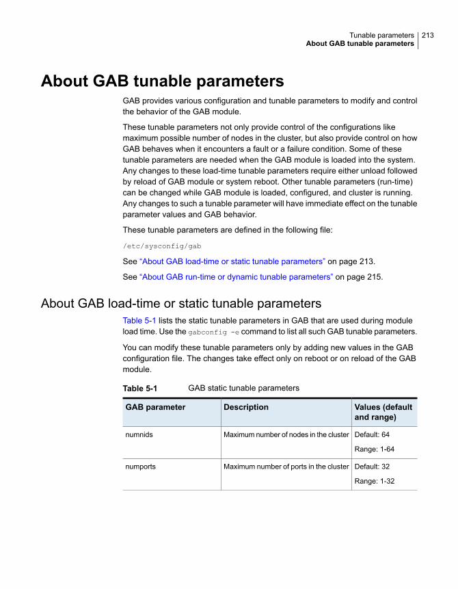
About GAB tunable parametersGAB provides various configuration and tunable parameters to modify and controlthe behavior of the GAB module.
These tunable parameters not only provide control of the configurations likemaximum possible number of nodes in the cluster, but also provide control on howGAB behaves when it encounters a fault or a failure condition. Some of thesetunable parameters are needed when the GAB module is loaded into the system.Any changes to these load-time tunable parameters require either unload followedby reload of GAB module or system reboot. Other tunable parameters (run-time)can be changed while GAB module is loaded, configured, and cluster is running.Any changes to such a tunable parameter will have immediate effect on the tunableparameter values and GAB behavior.
These tunable parameters are defined in the following file:
/etc/sysconfig/gab
See “About GAB load-time or static tunable parameters” on page 213.
See “About GAB run-time or dynamic tunable parameters” on page 215.
About GAB load-time or static tunable parametersTable 5-1 lists the static tunable parameters in GAB that are used during moduleload time. Use the gabconfig -e command to list all such GAB tunable parameters.
You can modify these tunable parameters only by adding new values in the GABconfiguration file. The changes take effect only on reboot or on reload of the GABmodule.
Table 5-1 GAB static tunable parameters
Values (defaultand range)
DescriptionGAB parameter
Default: 64
Range: 1-64
Maximum number of nodes in the clusternumnids
Default: 32
Range: 1-32
Maximum number of ports in the clusternumports
213Tunable parametersAbout GAB tunable parameters
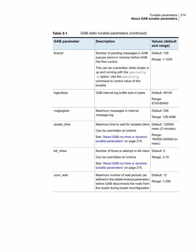
Table 5-1 GAB static tunable parameters (continued)
Values (defaultand range)
DescriptionGAB parameter
Default: 128
Range: 1-1024
Number of pending messages in GABqueues (send or receive) before GABhits flow control.
This can be overwritten while cluster isup and running with the gabconfig-Q option. Use the gabconfigcommand to control value of thistunable.
flowctrl
Default: 48100
Range:8100-65400
GAB internal log buffer size in byteslogbufsize
Default: 256
Range: 128-4096
Maximum messages in internalmessage log
msglogsize
Default: 120000msec (2 minutes)
Range:160000-240000 (inmsec)
Maximum time to wait for isolated client
Can be overridden at runtime
See “About GAB run-time or dynamictunable parameters” on page 215.
isolate_time
Default: 5
Range: 3-10
Number of times to attempt to kill client
Can be overridden at runtime
See “About GAB run-time or dynamictunable parameters” on page 215.
kill_ntries
Default: 12
Range: 1-256
Maximum number of wait periods (asdefined in the stable timeout parameter)before GAB disconnects the node fromthe cluster during cluster reconfiguration
conn_wait
214Tunable parametersAbout GAB tunable parameters
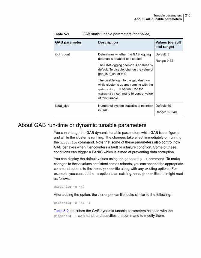
Table 5-1 GAB static tunable parameters (continued)
Values (defaultand range)
DescriptionGAB parameter
Default: 8
Range: 0-32
Determines whether the GAB loggingdaemon is enabled or disabled
The GAB logging daemon is enabled bydefault. To disable, change the value ofgab_ibuf_count to 0.
The disable login to the gab daemonwhile cluster is up and running with thegabconfig -K option. Use thegabconfig command to control valueof this tunable.
ibuf_count
Default: 60
Range: 0 - 240
Number of system statistics to maintainin GAB
kstat_size
About GAB run-time or dynamic tunable parametersYou can change the GAB dynamic tunable parameters while GAB is configuredand while the cluster is running. The changes take effect immediately on runningthe gabconfig command. Note that some of these parameters also control howGAB behaves when it encounters a fault or a failure condition. Some of theseconditions can trigger a PANIC which is aimed at preventing data corruption.
You can display the default values using the gabconfig -l command. To makechanges to these values persistent across reboots, you can append the appropriatecommand options to the /etc/gabtab file along with any existing options. Forexample, you can add the -k option to an existing /etc/gabtab file that might readas follows:
gabconfig -c -n4
After adding the option, the /etc/gabtab file looks similar to the following:
gabconfig -c -n4 -k
Table 5-2 describes the GAB dynamic tunable parameters as seen with thegabconfig -l command, and specifies the command to modify them.
215Tunable parametersAbout GAB tunable parameters
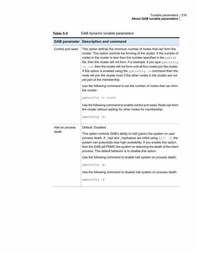
Table 5-2 GAB dynamic tunable parameters
Description and commandGAB parameter
This option defines the minimum number of nodes that can form thecluster. This option controls the forming of the cluster. If the number ofnodes in the cluster is less than the number specified in the gabtabfile, then the cluster will not form. For example: if you type gabconfig-c -n4, then the cluster will not form until all four nodes join the cluster.If this option is enabled using the gabconfig -x command then thenode will join the cluster even if the other nodes in the cluster are notyet part of the membership.
Use the following command to set the number of nodes that can formthe cluster:
gabconfig -n count
Use the following command to enable control port seed. Node can formthe cluster without waiting for other nodes for membership:
gabconfig -x
Control port seed
Default: Disabled
This option controls GAB's ability to halt (panic) the system on userprocess death. If _had and _hashadow are killed using kill -9, thesystem can potentially lose high availability. If you enable this option,then the GAB will PANIC the system on detecting the death of the clientprocess. The default behavior is to disable this option.
Use the following command to enable halt system on process death:
gabconfig -p
Use the following command to disable halt system on process death:
gabconfig -P
Halt on processdeath
216Tunable parametersAbout GAB tunable parameters

Table 5-2 GAB dynamic tunable parameters (continued)
Description and commandGAB parameter
Default: Disabled
If this option is enabled then the system will panic on missing the firstheartbeat from the VCS engine or the vxconfigd daemon in a CVMenvironment. The default option is to disable the immediate panic.
This GAB option controls whether GAB can panic the node or not whenthe VCS engine or the vxconfigd daemon miss to heartbeat with GAB.If the VCS engine experiences a hang and is unable to heartbeat withGAB, then GAB will NOT PANIC the system immediately. GAB will firsttry to abort the process by sending SIGABRT (kill_ntries - default value5 times) times after an interval of "iofence_timeout" (default value 15seconds). If this fails, then GAB will wait for the "isolate timeout" periodwhich is controlled by a global tunable called isolate_time (default value2 minutes). If the process is still alive, then GAB will PANIC the system.
If this option is enabled GAB will immediately HALT the system in caseof missed heartbeat from client.
Use the following command to enable system halt when processheartbeat fails:
gabconfig -b
Use the following command to disable system halt when processheartbeat fails:
gabconfig -B
Missed heartbeathalt
217Tunable parametersAbout GAB tunable parameters
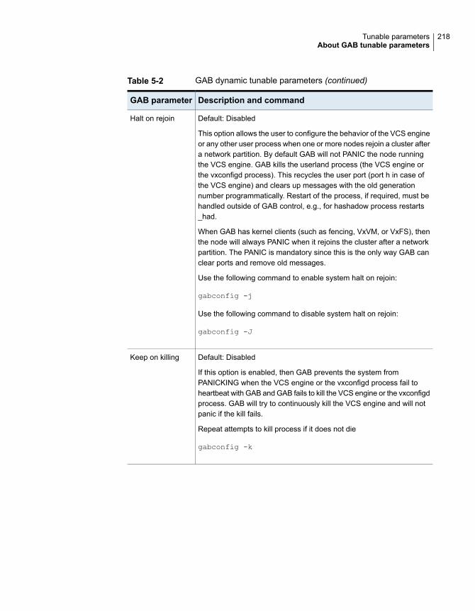
Table 5-2 GAB dynamic tunable parameters (continued)
Description and commandGAB parameter
Default: Disabled
This option allows the user to configure the behavior of the VCS engineor any other user process when one or more nodes rejoin a cluster aftera network partition. By default GAB will not PANIC the node runningthe VCS engine. GAB kills the userland process (the VCS engine orthe vxconfigd process). This recycles the user port (port h in case ofthe VCS engine) and clears up messages with the old generationnumber programmatically. Restart of the process, if required, must behandled outside of GAB control, e.g., for hashadow process restarts_had.
When GAB has kernel clients (such as fencing, VxVM, or VxFS), thenthe node will always PANIC when it rejoins the cluster after a networkpartition. The PANIC is mandatory since this is the only way GAB canclear ports and remove old messages.
Use the following command to enable system halt on rejoin:
gabconfig -j
Use the following command to disable system halt on rejoin:
gabconfig -J
Halt on rejoin
Default: Disabled
If this option is enabled, then GAB prevents the system fromPANICKING when the VCS engine or the vxconfigd process fail toheartbeat with GAB and GAB fails to kill the VCS engine or the vxconfigdprocess. GAB will try to continuously kill the VCS engine and will notpanic if the kill fails.
Repeat attempts to kill process if it does not die
gabconfig -k
Keep on killing
218Tunable parametersAbout GAB tunable parameters
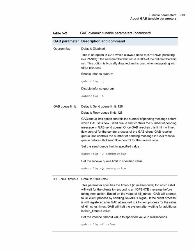
Table 5-2 GAB dynamic tunable parameters (continued)
Description and commandGAB parameter
Default: Disabled
This is an option in GAB which allows a node to IOFENCE (resultingin a PANIC) if the new membership set is < 50% of the old membershipset. This option is typically disabled and is used when integrating withother products
Enable iofence quorum
gabconfig -q
Disable iofence quorum
gabconfig -d
Quorum flag
Default: Send queue limit: 128
Default: Recv queue limit: 128
GAB queue limit option controls the number of pending message beforewhich GAB sets flow. Send queue limit controls the number of pendingmessage in GAB send queue. Once GAB reaches this limit it will setflow control for the sender process of the GAB client. GAB receivequeue limit controls the number of pending message in GAB receivequeue before GAB send flow control for the receive side.
Set the send queue limit to specified value
gabconfig -Q sendq:value
Set the receive queue limit to specified value
gabconfig -Q recvq:value
GAB queue limit
Default: 15000(ms)
This parameter specifies the timeout (in milliseconds) for which GABwill wait for the clients to respond to an IOFENCE message beforetaking next action. Based on the value of kill_ntries , GAB will attemptto kill client process by sending SIGABRT signal. If the client processis still registered after GAB attempted to kill client process for the valueof kill_ntries times, GAB will halt the system after waiting for additionalisolate_timeout value.
Set the iofence timeout value to specified value in milliseconds.
gabconfig -f value
IOFENCE timeout
219Tunable parametersAbout GAB tunable parameters
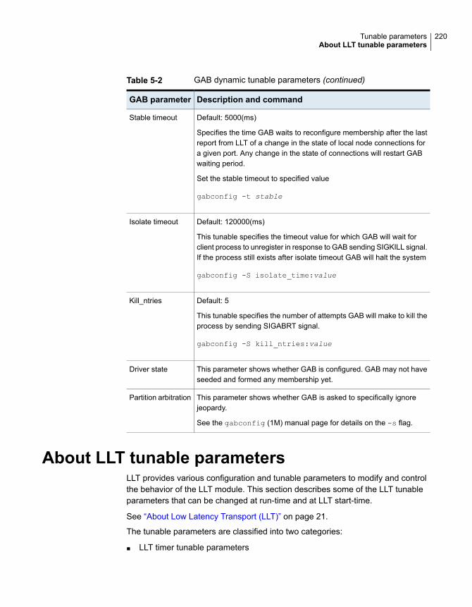
Table 5-2 GAB dynamic tunable parameters (continued)
Description and commandGAB parameter
Default: 5000(ms)
Specifies the time GAB waits to reconfigure membership after the lastreport from LLT of a change in the state of local node connections fora given port. Any change in the state of connections will restart GABwaiting period.
Set the stable timeout to specified value
gabconfig -t stable
Stable timeout
Default: 120000(ms)
This tunable specifies the timeout value for which GAB will wait forclient process to unregister in response to GAB sending SIGKILL signal.If the process still exists after isolate timeout GAB will halt the system
gabconfig -S isolate_time:value
Isolate timeout
Default: 5
This tunable specifies the number of attempts GAB will make to kill theprocess by sending SIGABRT signal.
gabconfig -S kill_ntries:value
Kill_ntries
This parameter shows whether GAB is configured. GAB may not haveseeded and formed any membership yet.
Driver state
This parameter shows whether GAB is asked to specifically ignorejeopardy.
See the gabconfig (1M) manual page for details on the -s flag.
Partition arbitration
About LLT tunable parametersLLT provides various configuration and tunable parameters to modify and controlthe behavior of the LLT module. This section describes some of the LLT tunableparameters that can be changed at run-time and at LLT start-time.
See “About Low Latency Transport (LLT)” on page 21.
The tunable parameters are classified into two categories:
■ LLT timer tunable parameters
220Tunable parametersAbout LLT tunable parameters
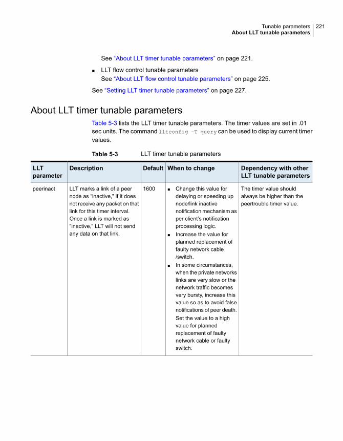
See “About LLT timer tunable parameters” on page 221.
■ LLT flow control tunable parametersSee “About LLT flow control tunable parameters” on page 225.
See “Setting LLT timer tunable parameters” on page 227.
About LLT timer tunable parametersTable 5-3 lists the LLT timer tunable parameters. The timer values are set in .01sec units. The command lltconfig –T query can be used to display current timervalues.
Table 5-3 LLT timer tunable parameters
Dependency with otherLLT tunable parameters
When to changeDefaultDescriptionLLTparameter
The timer value shouldalways be higher than thepeertrouble timer value.
■ Change this value fordelaying or speeding upnode/link inactivenotification mechanism asper client’s notificationprocessing logic.
■ Increase the value forplanned replacement offaulty network cable/switch.
■ In some circumstances,when the private networkslinks are very slow or thenetwork traffic becomesvery bursty, increase thisvalue so as to avoid falsenotifications of peer death.Set the value to a highvalue for plannedreplacement of faultynetwork cable or faultyswitch.
1600LLT marks a link of a peernode as “inactive," if it doesnot receive any packet on thatlink for this timer interval.Once a link is marked as"inactive," LLT will not sendany data on that link.
peerinact
221Tunable parametersAbout LLT tunable parameters
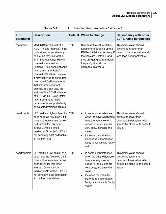
Table 5-3 LLT timer tunable parameters (continued)
Dependency with otherLLT tunable parameters
When to changeDefaultDescriptionLLTparameter
This timer value shouldalways be greater thanpeertrouble timer value andless than peerinact value.
Decrease the value of thistunable for speeding up theRDMA link failure recovery. Ifthe links are unstable, andthey are going up and downfrequently then do notdecrease this value.
700Mark RDMA channel of aRDMA link as "inactive", if thenode does not receive anypacket on that link for thistimer interval. Once RDMAchannel is marked as"inactive", LLT does not sendany data on the RDMAchannel of that link, however,it may continue to send dataover non-RDMA channel ofthat link until peerinactexpires. You can view thestatus of the RDMA channelof a RDMA link using lltstat-nvv -r command. Thisparameter is supported onlyon selected versions of Linux.
rpeerinact
This timer value shouldalways be lower thanpeerinact timer value. Also, Itshould be close to its defaultvalue.
■ In some circumstances,when the private networkslinks are very slow ornodes in the cluster arevery busy, increase thevalue.
■ Increase the value forplanned replacement offaulty network cable /faultyswitch.
200LLT marks a high-pri link of apeer node as "troubled", if itdoes not receive any packeton that link for this timerinterval. Once a link ismarked as "troubled", LLT willnot send any data on that linktill the link is up.
peertrouble
This timer value shouldalways be lower thanpeerinact timer value. Also, Itshould be close to its defaultvalue.
■ In some circumstances,when the private networkslinks are very slow ornodes in the cluster arevery busy, increase thevalue.
■ Increase the value forplanned replacement offaulty network cable /faultyswitch.
400LLT marks a low-pri link of apeer node as "troubled", if itdoes not receive any packeton that link for this timerinterval. Once a link ismarked as "troubled", LLT willnot send any data on that linktill the link is available.
peertroublelo
222Tunable parametersAbout LLT tunable parameters
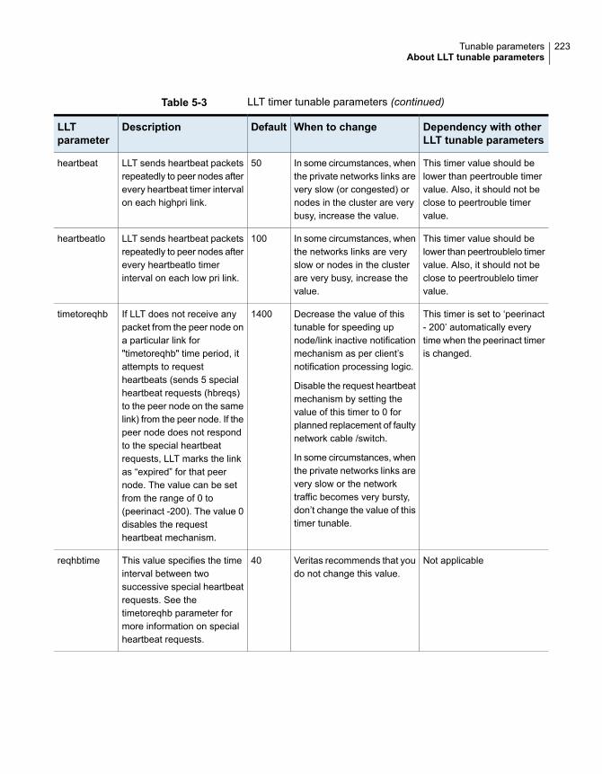
Table 5-3 LLT timer tunable parameters (continued)
Dependency with otherLLT tunable parameters
When to changeDefaultDescriptionLLTparameter
This timer value should belower than peertrouble timervalue. Also, it should not beclose to peertrouble timervalue.
In some circumstances, whenthe private networks links arevery slow (or congested) ornodes in the cluster are verybusy, increase the value.
50LLT sends heartbeat packetsrepeatedly to peer nodes afterevery heartbeat timer intervalon each highpri link.
heartbeat
This timer value should belower than peertroublelo timervalue. Also, it should not beclose to peertroublelo timervalue.
In some circumstances, whenthe networks links are veryslow or nodes in the clusterare very busy, increase thevalue.
100LLT sends heartbeat packetsrepeatedly to peer nodes afterevery heartbeatlo timerinterval on each low pri link.
heartbeatlo
This timer is set to ‘peerinact- 200’ automatically everytime when the peerinact timeris changed.
Decrease the value of thistunable for speeding upnode/link inactive notificationmechanism as per client’snotification processing logic.
Disable the request heartbeatmechanism by setting thevalue of this timer to 0 forplanned replacement of faultynetwork cable /switch.
In some circumstances, whenthe private networks links arevery slow or the networktraffic becomes very bursty,don’t change the value of thistimer tunable.
1400If LLT does not receive anypacket from the peer node ona particular link for"timetoreqhb" time period, itattempts to requestheartbeats (sends 5 specialheartbeat requests (hbreqs)to the peer node on the samelink) from the peer node. If thepeer node does not respondto the special heartbeatrequests, LLT marks the linkas “expired” for that peernode. The value can be setfrom the range of 0 to(peerinact -200). The value 0disables the requestheartbeat mechanism.
timetoreqhb
Not applicableVeritas recommends that youdo not change this value.
40This value specifies the timeinterval between twosuccessive special heartbeatrequests. See thetimetoreqhb parameter formore information on specialheartbeat requests.
reqhbtime
223Tunable parametersAbout LLT tunable parameters
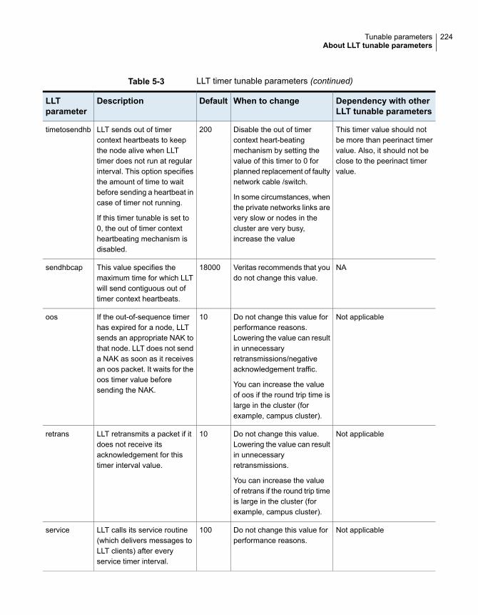
Table 5-3 LLT timer tunable parameters (continued)
Dependency with otherLLT tunable parameters
When to changeDefaultDescriptionLLTparameter
This timer value should notbe more than peerinact timervalue. Also, it should not beclose to the peerinact timervalue.
Disable the out of timercontext heart-beatingmechanism by setting thevalue of this timer to 0 forplanned replacement of faultynetwork cable /switch.
In some circumstances, whenthe private networks links arevery slow or nodes in thecluster are very busy,increase the value
200LLT sends out of timercontext heartbeats to keepthe node alive when LLTtimer does not run at regularinterval. This option specifiesthe amount of time to waitbefore sending a heartbeat incase of timer not running.
If this timer tunable is set to0, the out of timer contextheartbeating mechanism isdisabled.
timetosendhb
NAVeritas recommends that youdo not change this value.
18000This value specifies themaximum time for which LLTwill send contiguous out oftimer context heartbeats.
sendhbcap
Not applicableDo not change this value forperformance reasons.Lowering the value can resultin unnecessaryretransmissions/negativeacknowledgement traffic.
You can increase the valueof oos if the round trip time islarge in the cluster (forexample, campus cluster).
10If the out-of-sequence timerhas expired for a node, LLTsends an appropriate NAK tothat node. LLT does not senda NAK as soon as it receivesan oos packet. It waits for theoos timer value beforesending the NAK.
oos
Not applicableDo not change this value.Lowering the value can resultin unnecessaryretransmissions.
You can increase the valueof retrans if the round trip timeis large in the cluster (forexample, campus cluster).
10LLT retransmits a packet if itdoes not receive itsacknowledgement for thistimer interval value.
retrans
Not applicableDo not change this value forperformance reasons.
100LLT calls its service routine(which delivers messages toLLT clients) after everyservice timer interval.
service
224Tunable parametersAbout LLT tunable parameters
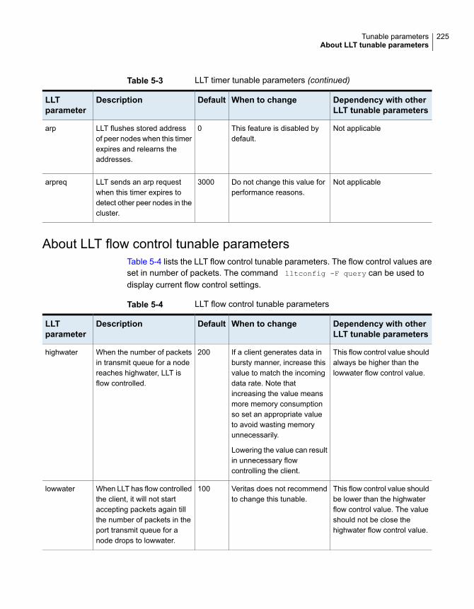
Table 5-3 LLT timer tunable parameters (continued)
Dependency with otherLLT tunable parameters
When to changeDefaultDescriptionLLTparameter
Not applicableThis feature is disabled bydefault.
0LLT flushes stored addressof peer nodes when this timerexpires and relearns theaddresses.
arp
Not applicableDo not change this value forperformance reasons.
3000LLT sends an arp requestwhen this timer expires todetect other peer nodes in thecluster.
arpreq
About LLT flow control tunable parametersTable 5-4 lists the LLT flow control tunable parameters. The flow control values areset in number of packets. The command lltconfig -F query can be used todisplay current flow control settings.
Table 5-4 LLT flow control tunable parameters
Dependency with otherLLT tunable parameters
When to changeDefaultDescriptionLLTparameter
This flow control value shouldalways be higher than thelowwater flow control value.
If a client generates data inbursty manner, increase thisvalue to match the incomingdata rate. Note thatincreasing the value meansmore memory consumptionso set an appropriate valueto avoid wasting memoryunnecessarily.
Lowering the value can resultin unnecessary flowcontrolling the client.
200When the number of packetsin transmit queue for a nodereaches highwater, LLT isflow controlled.
highwater
This flow control value shouldbe lower than the highwaterflow control value. The valueshould not be close thehighwater flow control value.
Veritas does not recommendto change this tunable.
100When LLT has flow controlledthe client, it will not startaccepting packets again tillthe number of packets in theport transmit queue for anode drops to lowwater.
lowwater
225Tunable parametersAbout LLT tunable parameters

Table 5-4 LLT flow control tunable parameters (continued)
Dependency with otherLLT tunable parameters
When to changeDefaultDescriptionLLTparameter
This flow control value shouldalways be higher than therportlowwater flow controlvalue.
If a client generates data inbursty manner, increase thisvalue to match the incomingdata rate. Note thatincreasing the value meansmore memory consumptionso set an appropriate valueto avoid wasting memoryunnecessarily.
Lowering the value can resultin unnecessary flowcontrolling the client on peernode.
200When the number of packetsin the receive queue for a portreaches highwater, LLT isflow controlled.
rporthighwater
This flow control value shouldbe lower than therpothighwater flow controlvalue. The value should notbe close the rporthighwaterflow control value.
Veritas does not recommendto change this tunable.
100When LLT has flow controlledthe client on peer node, it willnot start accepting packetsfor that client again till thenumber of packets in the portreceive queue for the portdrops to rportlowwater.
rportlowwater
This flow control value shouldnot be higher than thedifference between thehighwater flow control valueand the lowwater flow controlvalue.
The value of this parameter(window) should be alignedwith the value of thebandwidth delay product.
Change the value as per theprivate networks speed.Lowering the valueirrespective of network speedmay result in unnecessaryretransmission of out ofwindow sequence packets.
50This is the maximum numberof un-ACKed packets LLT willput in flight.
window
This flow control value shouldnot be higher than thedifference between thehighwater flow control valueand the lowwater flow controlvalue.
For performance reasons, itsvalue should be either 0 or atleast 32.
32It represents the number ofback-to-back packets thatLLT sends on a link beforethe next link is chosen.
linkburst
226Tunable parametersAbout LLT tunable parameters
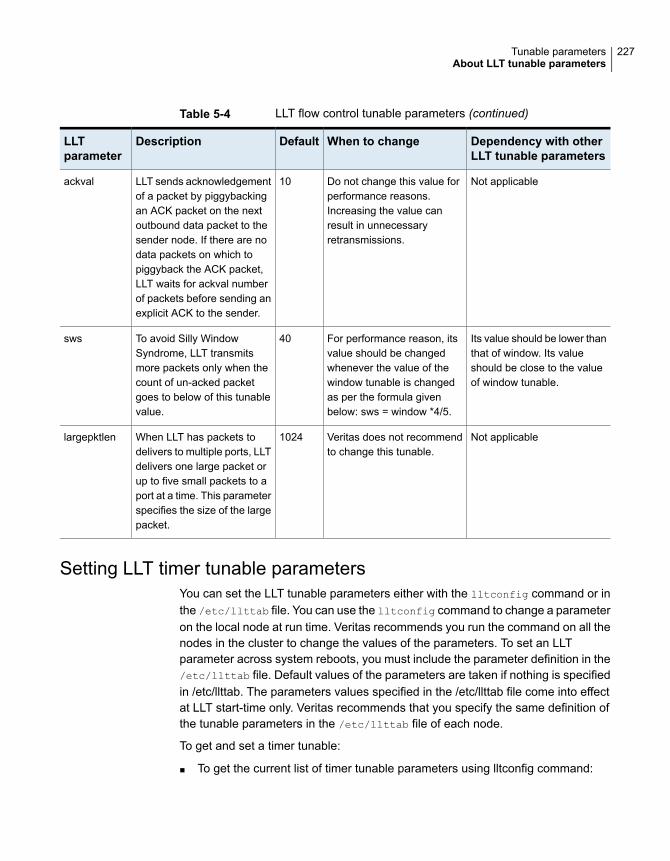
Table 5-4 LLT flow control tunable parameters (continued)
Dependency with otherLLT tunable parameters
When to changeDefaultDescriptionLLTparameter
Not applicableDo not change this value forperformance reasons.Increasing the value canresult in unnecessaryretransmissions.
10LLT sends acknowledgementof a packet by piggybackingan ACK packet on the nextoutbound data packet to thesender node. If there are nodata packets on which topiggyback the ACK packet,LLT waits for ackval numberof packets before sending anexplicit ACK to the sender.
ackval
Its value should be lower thanthat of window. Its valueshould be close to the valueof window tunable.
For performance reason, itsvalue should be changedwhenever the value of thewindow tunable is changedas per the formula givenbelow: sws = window *4/5.
40To avoid Silly WindowSyndrome, LLT transmitsmore packets only when thecount of un-acked packetgoes to below of this tunablevalue.
sws
Not applicableVeritas does not recommendto change this tunable.
1024When LLT has packets todelivers to multiple ports, LLTdelivers one large packet orup to five small packets to aport at a time. This parameterspecifies the size of the largepacket.
largepktlen
Setting LLT timer tunable parametersYou can set the LLT tunable parameters either with the lltconfig command or inthe /etc/llttab file. You can use the lltconfig command to change a parameteron the local node at run time. Veritas recommends you run the command on all thenodes in the cluster to change the values of the parameters. To set an LLTparameter across system reboots, you must include the parameter definition in the/etc/llttab file. Default values of the parameters are taken if nothing is specifiedin /etc/llttab. The parameters values specified in the /etc/llttab file come into effectat LLT start-time only. Veritas recommends that you specify the same definition ofthe tunable parameters in the /etc/llttab file of each node.
To get and set a timer tunable:
■ To get the current list of timer tunable parameters using lltconfig command:
227Tunable parametersAbout LLT tunable parameters
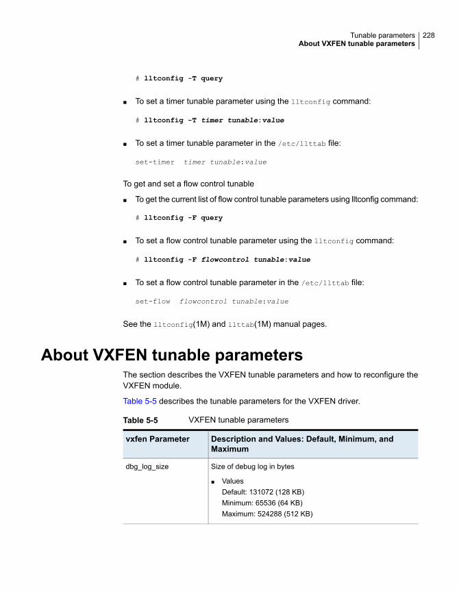
# lltconfig -T query
■ To set a timer tunable parameter using the lltconfig command:
# lltconfig -T timer tunable:value
■ To set a timer tunable parameter in the /etc/llttab file:
set-timer timer tunable:value
To get and set a flow control tunable
■ To get the current list of flow control tunable parameters using lltconfig command:
# lltconfig -F query
■ To set a flow control tunable parameter using the lltconfig command:
# lltconfig -F flowcontrol tunable:value
■ To set a flow control tunable parameter in the /etc/llttab file:
set-flow flowcontrol tunable:value
See the lltconfig(1M) and llttab(1M) manual pages.
About VXFEN tunable parametersThe section describes the VXFEN tunable parameters and how to reconfigure theVXFEN module.
Table 5-5 describes the tunable parameters for the VXFEN driver.
Table 5-5 VXFEN tunable parameters
Description and Values: Default, Minimum, andMaximum
vxfen Parameter
Size of debug log in bytes
■ ValuesDefault: 131072 (128 KB)Minimum: 65536 (64 KB)Maximum: 524288 (512 KB)
dbg_log_size
228Tunable parametersAbout VXFEN tunable parameters
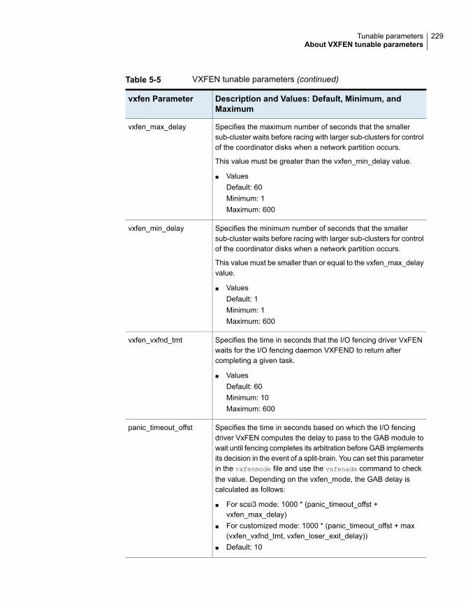
Table 5-5 VXFEN tunable parameters (continued)
Description and Values: Default, Minimum, andMaximum
vxfen Parameter
Specifies the maximum number of seconds that the smallersub-cluster waits before racing with larger sub-clusters for controlof the coordinator disks when a network partition occurs.
This value must be greater than the vxfen_min_delay value.
■ ValuesDefault: 60Minimum: 1Maximum: 600
vxfen_max_delay
Specifies the minimum number of seconds that the smallersub-cluster waits before racing with larger sub-clusters for controlof the coordinator disks when a network partition occurs.
This value must be smaller than or equal to the vxfen_max_delayvalue.
■ ValuesDefault: 1Minimum: 1Maximum: 600
vxfen_min_delay
Specifies the time in seconds that the I/O fencing driver VxFENwaits for the I/O fencing daemon VXFEND to return aftercompleting a given task.
■ ValuesDefault: 60Minimum: 10Maximum: 600
vxfen_vxfnd_tmt
Specifies the time in seconds based on which the I/O fencingdriver VxFEN computes the delay to pass to the GAB module towait until fencing completes its arbitration before GAB implementsits decision in the event of a split-brain. You can set this parameterin the vxfenmode file and use the vxfenadm command to checkthe value. Depending on the vxfen_mode, the GAB delay iscalculated as follows:
■ For scsi3 mode: 1000 * (panic_timeout_offst +vxfen_max_delay)
■ For customized mode: 1000 * (panic_timeout_offst + max(vxfen_vxfnd_tmt, vxfen_loser_exit_delay))
■ Default: 10
panic_timeout_offst
229Tunable parametersAbout VXFEN tunable parameters
In the event of a network partition, the smaller sub-cluster delays before racing forthe coordinator disks. The time delay allows a larger sub-cluster to win the race forthe coordinator disks. The vxfen_max_delay and vxfen_min_delay parametersdefine the delay in seconds.
Configuring the VXFEN module parametersAfter adjusting the tunable kernel driver parameters, you must reconfigure theVXFEN module for the parameter changes to take effect.
The following example procedure changes the value of the vxfen_min_delayparameter.
On each Linux node, edit the file /etc/sysconfig/vxfen to change the value of thevxfen driver tunable global parameters, vxfen_max_delay and vxfen_min_delay.
Note: You must restart the VXFEN module to put any parameter change into effect.
To configure the VxFEN parameters and reconfigure the VxFEN module
1 Shut down all Oracle service groups on the node.
# hagrp -offline oragrp -sys sys1
2 Stop all Oracle client processes, such as sqlplus, svrmgrl, and gsd, on thenode.
3 Stop all the applications that are not configured under VCS. Use nativeapplication commands to stop the application.
4 Stop VCS on all the nodes. Run the following command on each node:
# hastop -local
5 Stop the VxFEN driver.
# /etc/init.d/vxfen stop
6 Edit the /etc/sysconfig/vxfen file.
For example, change the entry from:
vxfen_min_delay=1
to:
vxfen_min_delay=30
230Tunable parametersAbout VXFEN tunable parameters
7 Start the VXFEN module.
# /etc/init.d/vxfen start
8 Bring the service groups online.
# hagrp -online oragrp -sys sys1
9 Start all the applications that are not configured under VCS. Use nativeapplication commands to start the applications.
10 Start VCS.
# hastart
Tuning guidelines for campus clustersAn important consideration while tuning an SF Oracle RAC campus cluster is settingthe LLT peerinact time. Follow the guidelines below to determine the optimum valueof peerinact time:
■ Calculate the roundtrip time using lltping (1M).
■ Evaluate LLT heartbeat time as half of the round trip time.
■ Set the LLT peer trouble time as 2-4 times the heartbeat time.
■ LLT peerinact time should be set to be more than 4 times the heart beat time.
231Tunable parametersTuning guidelines for campus clusters
Reference
■ Appendix A. List of SF Oracle RAC health checks
■ Appendix B. Error messages
3Section
List of SF Oracle RAChealth checks
This appendix includes the following topics:
■ LLT health checks
■ I/O fencing health checks
■ PrivNIC health checks in SF Oracle RAC clusters
■ Oracle Clusterware health checks in SF Oracle RAC clusters
■ CVM, CFS, and ODM health checks in SF Oracle RAC clusters
LLT health checksThis section lists the health checks performed for LLT, the messages displayed foreach check, and a brief description of the check.
Note: Warning messages indicate issues in the components or the general healthof the cluster. Follow the troubleshooting recommendations to resolve the issues.
See “Troubleshooting LLT health check warning messages” on page 178.
Table A-1 lists the health checks performed for LLT.
AAppendix
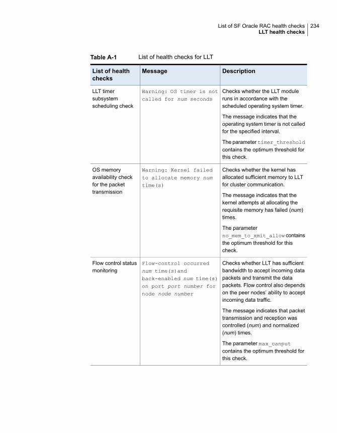
Table A-1 List of health checks for LLT
DescriptionMessageList of healthchecks
Checks whether the LLT moduleruns in accordance with thescheduled operating system timer.
The message indicates that theoperating system timer is not calledfor the specified interval.
The parameter timer_thresholdcontains the optimum threshold forthis check.
Warning: OS timer is notcalled for num seconds
LLT timersubsystemscheduling check
Checks whether the kernel hasallocated sufficient memory to LLTfor cluster communication.
The message indicates that thekernel attempts at allocating therequisite memory has failed (num)times.
The parameterno_mem_to_xmit_allow containsthe optimum threshold for thischeck.
Warning: Kernel failedto allocate memory numtime(s)
OS memoryavailability checkfor the packettransmission
Checks whether LLT has sufficientbandwidth to accept incoming datapackets and transmit the datapackets. Flow control also dependson the peer nodes’ ability to acceptincoming data traffic.
The message indicates that packettransmission and reception wascontrolled (num) and normalized(num) times.
The parameter max_canputcontains the optimum threshold forthis check.
Flow-control occurrednum time(s)andback-enabled num time(s)on port port number fornode node number
Flow control statusmonitoring
234List of SF Oracle RAC health checksLLT health checks
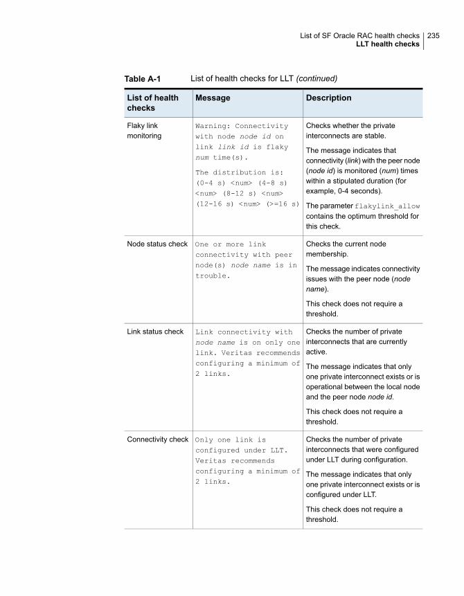
Table A-1 List of health checks for LLT (continued)
DescriptionMessageList of healthchecks
Checks whether the privateinterconnects are stable.
The message indicates thatconnectivity (link) with the peer node(node id) is monitored (num) timeswithin a stipulated duration (forexample, 0-4 seconds).
The parameter flakylink_allowcontains the optimum threshold forthis check.
Warning: Connectivitywith node node id onlink link id is flakynum time(s).
The distribution is:(0-4 s) <num> (4-8 s)<num> (8-12 s) <num>(12-16 s) <num> (>=16 s)
Flaky linkmonitoring
Checks the current nodemembership.
The message indicates connectivityissues with the peer node (nodename).
This check does not require athreshold.
One or more linkconnectivity with peernode(s) node name is introuble.
Node status check
Checks the number of privateinterconnects that are currentlyactive.
The message indicates that onlyone private interconnect exists or isoperational between the local nodeand the peer node node id.
This check does not require athreshold.
Link connectivity withnode name is on only onelink. Veritas recommendsconfiguring a minimum of2 links.
Link status check
Checks the number of privateinterconnects that were configuredunder LLT during configuration.
The message indicates that onlyone private interconnect exists or isconfigured under LLT.
This check does not require athreshold.
Only one link isconfigured under LLT.Veritas recommendsconfiguring a minimum of2 links.
Connectivity check
235List of SF Oracle RAC health checksLLT health checks
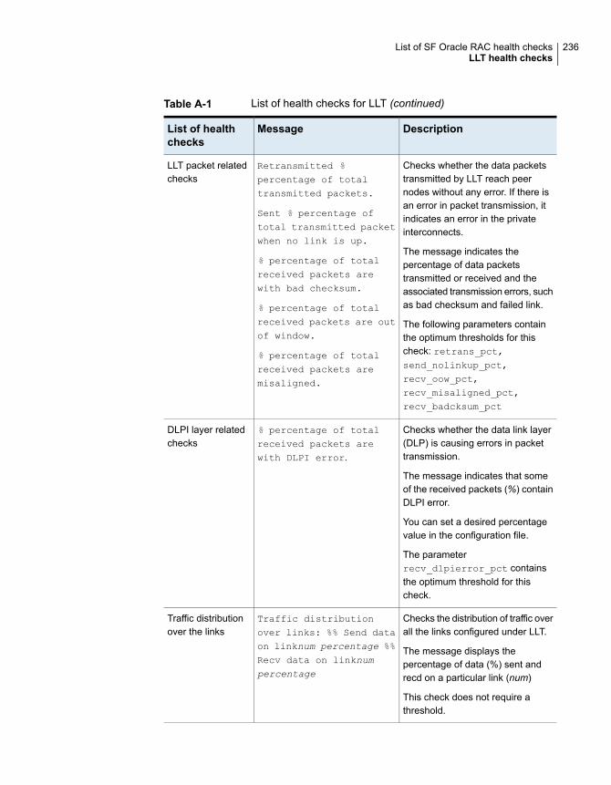
Table A-1 List of health checks for LLT (continued)
DescriptionMessageList of healthchecks
Checks whether the data packetstransmitted by LLT reach peernodes without any error. If there isan error in packet transmission, itindicates an error in the privateinterconnects.
The message indicates thepercentage of data packetstransmitted or received and theassociated transmission errors, suchas bad checksum and failed link.
The following parameters containthe optimum thresholds for thischeck: retrans_pct,send_nolinkup_pct,recv_oow_pct,recv_misaligned_pct,recv_badcksum_pct
Retransmitted %percentage of totaltransmitted packets.
Sent % percentage oftotal transmitted packetwhen no link is up.
% percentage of totalreceived packets arewith bad checksum.
% percentage of totalreceived packets are outof window.
% percentage of totalreceived packets aremisaligned.
LLT packet relatedchecks
Checks whether the data link layer(DLP) is causing errors in packettransmission.
The message indicates that someof the received packets (%) containDLPI error.
You can set a desired percentagevalue in the configuration file.
The parameterrecv_dlpierror_pct containsthe optimum threshold for thischeck.
% percentage of totalreceived packets arewith DLPI error.
DLPI layer relatedchecks
Checks the distribution of traffic overall the links configured under LLT.
The message displays thepercentage of data (%) sent andrecd on a particular link (num)
This check does not require athreshold.
Traffic distributionover links: %% Send dataon linknum percentage %%Recv data on linknumpercentage
Traffic distributionover the links
236List of SF Oracle RAC health checksLLT health checks

Table A-1 List of health checks for LLT (continued)
DescriptionMessageList of healthchecks
Checks the latency period fortransmitting or receiving packets.
The message indicates that somepercentage (%) of thetransmitted/received packets exceedthe stipulated latency time.
The following parameters containthe optimum thresholds for thischeck: hirecvlatencycnt_pct,hixmitlatencycnt_pct.
% per of totaltransmitted packets arewith large xmit latency(>16ms) for port port id
%per received packetsare with large recvlatency (>16ms) for portport id.
LLT Ports statuscheck
Monitors the system workload at thestipulated periodicity (1 second, 5seconds, 15 seconds)
This check does not require athreshold.
Load Information:Average : num,num,num
System loadmonitoring
I/O fencing health checksThis section lists the health checks performed for I/O fencing, the messagesdisplayed for each check, and a brief description of the check.
Note: Warning messages indicate issues in the components or the general healthof the cluster.
For recommendations on resolving the issues, see the troubleshooting chapter inthis document.
Table A-2 lists the health checks performed for I/O fencing.
237List of SF Oracle RAC health checksI/O fencing health checks
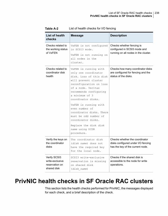
Table A-2 List of health checks for I/O fencing
DescriptionMessageList of healthchecks
Checks whether fencing isconfigured in SCSI3 mode andrunning on all nodes in the cluster.
VxFEN is not configuredin SCSI3 mode.
VxFEN is not running onall nodes in thecluster.
Checks related tothe working statusof VxFEN
Checks how many coordinator disksare configured for fencing and thestatus of the disks.
VxFEN is running withonly one coordinatordisk. Loss of this diskwill prevent clusterreconfiguration on lossof a node. Veritasrecommends configuringa minimum of 3coordinator disks.
VxFEN is running witheven number ofcoordinator disks. Theremust be odd number ofcoordinator disks.
Replace the disk diskname using OCDRprocedure.
Checks related tocoordinator diskhealth
Checks whether the coordinatordisks configured under I/O fencinghas the key of the current node.
The coordinator disk(disk name) does nothave the required keyfor the local node.
Verify the keys onthe coordinatordisks
Checks if the shared disk isaccessible to the node for writeoperations.
SCSI3 write-exclusivereservation is missingon shared disk(disk_name)
Verify SCSI3write-exclusivereservation onshared disk
PrivNIC health checks in SF Oracle RAC clustersThis section lists the health checks performed for PrivNIC, the messages displayedfor each check, and a brief description of the check.
238List of SF Oracle RAC health checksPrivNIC health checks in SF Oracle RAC clusters
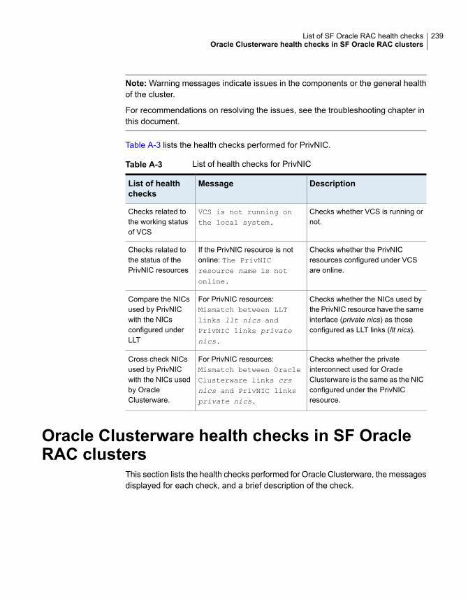
Note: Warning messages indicate issues in the components or the general healthof the cluster.
For recommendations on resolving the issues, see the troubleshooting chapter inthis document.
Table A-3 lists the health checks performed for PrivNIC.
Table A-3 List of health checks for PrivNIC
DescriptionMessageList of healthchecks
Checks whether VCS is running ornot.
VCS is not running onthe local system.
Checks related tothe working statusof VCS
Checks whether the PrivNICresources configured under VCSare online.
If the PrivNIC resource is notonline: The PrivNICresource name is notonline.
Checks related tothe status of thePrivNIC resources
Checks whether the NICs used bythe PrivNIC resource have the sameinterface (private nics) as thoseconfigured as LLT links (llt nics).
For PrivNIC resources:Mismatch between LLTlinks llt nics andPrivNIC links privatenics.
Compare the NICsused by PrivNICwith the NICsconfigured underLLT
Checks whether the privateinterconnect used for OracleClusterware is the same as the NICconfigured under the PrivNICresource.
For PrivNIC resources:Mismatch between OracleClusterware links crsnics and PrivNIC linksprivate nics.
Cross check NICsused by PrivNICwith the NICs usedby OracleClusterware.
Oracle Clusterware health checks in SF OracleRAC clusters
This section lists the health checks performed for Oracle Clusterware, the messagesdisplayed for each check, and a brief description of the check.
239List of SF Oracle RAC health checksOracle Clusterware health checks in SF Oracle RAC clusters
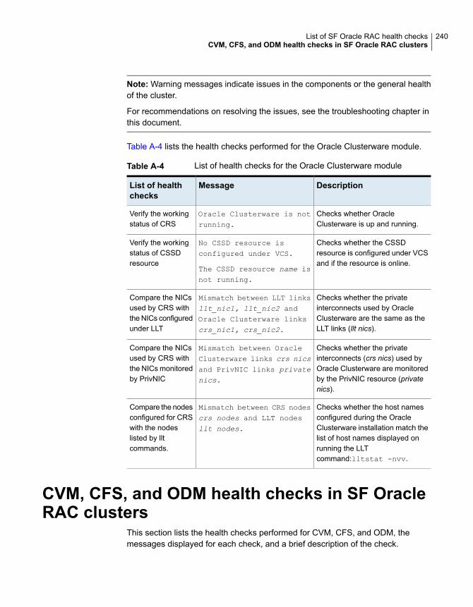
Note: Warning messages indicate issues in the components or the general healthof the cluster.
For recommendations on resolving the issues, see the troubleshooting chapter inthis document.
Table A-4 lists the health checks performed for the Oracle Clusterware module.
Table A-4 List of health checks for the Oracle Clusterware module
DescriptionMessageList of healthchecks
Checks whether OracleClusterware is up and running.
Oracle Clusterware is notrunning.
Verify the workingstatus of CRS
Checks whether the CSSDresource is configured under VCSand if the resource is online.
No CSSD resource isconfigured under VCS.
The CSSD resource name isnot running.
Verify the workingstatus of CSSDresource
Checks whether the privateinterconnects used by OracleClusterware are the same as theLLT links (llt nics).
Mismatch between LLT linksllt_nic1, llt_nic2 andOracle Clusterware linkscrs_nic1, crs_nic2.
Compare the NICsused by CRS withthe NICs configuredunder LLT
Checks whether the privateinterconnects (crs nics) used byOracle Clusterware are monitoredby the PrivNIC resource (privatenics).
Mismatch between OracleClusterware links crs nicsand PrivNIC links privatenics.
Compare the NICsused by CRS withthe NICs monitoredby PrivNIC
Checks whether the host namesconfigured during the OracleClusterware installation match thelist of host names displayed onrunning the LLTcommand:lltstat -nvv.
Mismatch between CRS nodescrs nodes and LLT nodesllt nodes.
Compare the nodesconfigured for CRSwith the nodeslisted by lltcommands.
CVM, CFS, and ODM health checks in SF OracleRAC clusters
This section lists the health checks performed for CVM, CFS, and ODM, themessages displayed for each check, and a brief description of the check.
240List of SF Oracle RAC health checksCVM, CFS, and ODM health checks in SF Oracle RAC clusters
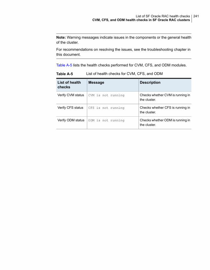
Note: Warning messages indicate issues in the components or the general healthof the cluster.
For recommendations on resolving the issues, see the troubleshooting chapter inthis document.
Table A-5 lists the health checks performed for CVM, CFS, and ODM modules.
Table A-5 List of health checks for CVM, CFS, and ODM
DescriptionMessageList of healthchecks
Checks whether CVM is running inthe cluster.
CVM is not runningVerify CVM status
Checks whether CFS is running inthe cluster.
CFS is not runningVerify CFS status
Checks whether ODM is running inthe cluster.
ODM is not runningVerify ODM status
241List of SF Oracle RAC health checksCVM, CFS, and ODM health checks in SF Oracle RAC clusters
Error messagesThis appendix includes the following topics:
■ About error messages
■ VxVM error messages
■ VXFEN driver error messages
About error messagesError messages can be generated by the following software modules:
■ Veritas Volume Manager (VxVM)
■ Veritas Fencing (VXFEN) driver
VxVM error messagesTable B-1 contains VxVM error messages that are related to I/O fencing.
Table B-1 VxVM error messages for I/O fencing
ExplanationMessage
The vxfen driver is not configured. Follow theinstructions to set up these disks and startI/O fencing. You can then clear the faultedresources and bring the service groupsonline.
vold_vcs_getnodeid(disk_path):failed to open the vxfendevice. Please make surethat the vxfen driver isinstalled and configured.
Incompatible versions of VxVM and the vxfendriver are installed on the system. Install theproper version of SF Oracle RAC.
vold_pgr_register(disk_path):Probably incompatible vxfendriver.
BAppendix
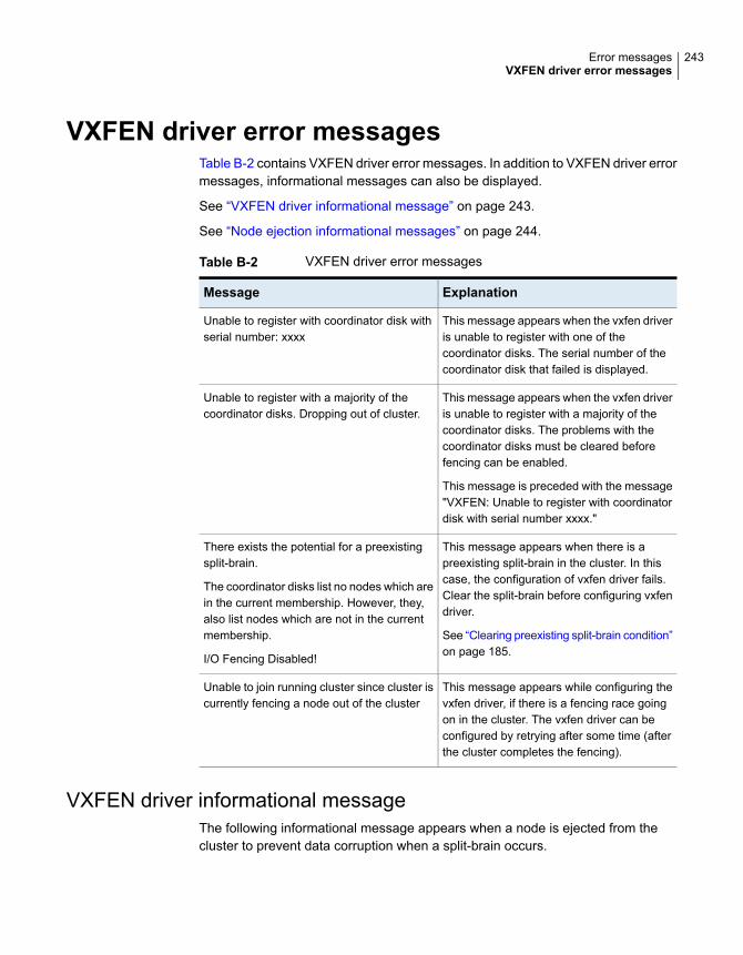
VXFEN driver error messagesTable B-2 contains VXFEN driver error messages. In addition to VXFEN driver errormessages, informational messages can also be displayed.
See “VXFEN driver informational message” on page 243.
See “Node ejection informational messages” on page 244.
Table B-2 VXFEN driver error messages
ExplanationMessage
This message appears when the vxfen driveris unable to register with one of thecoordinator disks. The serial number of thecoordinator disk that failed is displayed.
Unable to register with coordinator disk withserial number: xxxx
This message appears when the vxfen driveris unable to register with a majority of thecoordinator disks. The problems with thecoordinator disks must be cleared beforefencing can be enabled.
This message is preceded with the message"VXFEN: Unable to register with coordinatordisk with serial number xxxx."
Unable to register with a majority of thecoordinator disks. Dropping out of cluster.
This message appears when there is apreexisting split-brain in the cluster. In thiscase, the configuration of vxfen driver fails.Clear the split-brain before configuring vxfendriver.
See “Clearing preexisting split-brain condition”on page 185.
There exists the potential for a preexistingsplit-brain.
The coordinator disks list no nodes which arein the current membership. However, they,also list nodes which are not in the currentmembership.
I/O Fencing Disabled!
This message appears while configuring thevxfen driver, if there is a fencing race goingon in the cluster. The vxfen driver can beconfigured by retrying after some time (afterthe cluster completes the fencing).
Unable to join running cluster since cluster iscurrently fencing a node out of the cluster
VXFEN driver informational messageThe following informational message appears when a node is ejected from thecluster to prevent data corruption when a split-brain occurs.
243Error messagesVXFEN driver error messages

VXFEN CRITICAL V-11-1-20 Local cluster node ejected from cluster
to prevent potential data corruption
Node ejection informational messagesInformational messages may appear on the console of one of the cluster nodeswhen a node is ejected from a disk or LUN.
These informational messages can be ignored.
244Error messagesVXFEN driver error messages
Agent A process that starts, stops, and monitors all configured resources of a type, andreports their status to VCS.
Authentication Broker The Veritas Security Services component that serves, one level beneath the rootbroker, as an intermediate registration authority and a certification authority. Theauthentication broker can authenticate clients, such as users or services, and grantthem a certificate that will become part of the Veritas credential. An authenticationbroker cannot, however, authenticate other brokers. That task must be performedby the root broker.
Cluster A cluster is one or more computers that are linked together for the purpose ofmultiprocessing and high availability. The term is used synonymously with VCScluster, meaning one or more computers that are part of the same GAB membership.
CVM (cluster volumemanager)
The cluster functionality of Veritas Volume Manager.
Disaster Recovery Administrators with clusters in physically disparate areas can set the policy formigrating applications from one location to another if clusters in one geographicarea become unavailable due to an unforeseen event. Disaster recovery requiresheartbeating and replication.
disk array A collection of disks logically arranged into an object. Arrays tend to provide benefitssuch as redundancy or improved performance.
DMP (DynamicMulti-Pathing)
A feature designed to provide greater reliability and performance by using pathfailover and load balancing for multiported disk arrays connected to host systemsthrough multiple paths. DMP detects the various paths to a disk using a mechanismthat is specific to each supported array type. DMP can also differentiate betweendifferent enclosures of a supported array type that are connected to the same hostsystem.
SmartTier A feature with which administrators of multi-volume VxFS file systems can managethe placement of files on individual volumes in a volume set by defining placementpolicies that control both initial file location and the circumstances under whichexisting files are relocated. These placement policies cause the files to which theyapply to be created and extended on specific subsets of a file system’s volume set,known as placement classes. The files are relocated to volumes in other placementclasses when they meet specified naming, timing, access rate, and storagecapacity-related conditions.
Glossary
Failover A failover occurs when a service group faults and is migrated to another system.
GAB (Group AtomicBroadcast)
A communication mechanism of the VCS engine that manages cluster membership,monitors heartbeat communication, and distributes information throughout thecluster.
HA (high availability) The concept of configuring the product to be highly available against system failureon a clustered network using Cluster Server (VCS).
HAD (High AvailabilityDaemon)
The core VCS process that runs on each system. The HAD process maintains andcommunicates information about the resources running on the local system andreceives information about resources running on other systems in the cluster.
IP address An identifier for a computer or other device on a TCP/IP network, written as foureight-bit numbers separated by periods. Messages and other data are routed onthe network according to their destination IP addresses.
See also virtual IP address
Jeopardy A node is in jeopardy when it is missing one of the two required heartbeatconnections. When a node is running with one heartbeat only (in jeopardy), VCSdoes not restart the applications on a new node. This action of disabling failover isa safety mechanism that prevents data corruption.
latency For file systems, this typically refers to the amount of time it takes a given file systemoperation to return to the user.
LLT (Low LatencyTransport)
A communication mechanism of the VCS engine that provides kernel-to-kernelcommunications and monitors network communications.
logical volume A simple volume that resides on an extended partition on a basic disk and is limitedto the space within the extended partitions. A logical volume can be formatted andassigned a drive letter, and it can be subdivided into logical drives.
See also LUN
LUN A LUN, or logical unit, can either correspond to a single physical disk, or to acollection of disks that are exported as a single logical entity, or virtual disk, by adevice driver or by an intelligent disk array’s hardware. VxVM and other softwaremodules may be capable of automatically discovering the special characteristicsof LUNs, or you can use disk tags to define new storage attributes. Disk tags areadministered by using the vxdisk command or the graphical user interface.
main.cf The file in which the cluster configuration is stored.
mirroring A form of storage redundancy in which two or more identical copies of data aremaintained on separate volumes. (Each duplicate copy is known as a mirror.) AlsoRAID Level 1.
Node The physical host or system on which applications and service groups reside. Whensystems are linked by VCS, they become nodes in a cluster.
246Glossary
resources Individual components that work together to provide application services to thepublic network. A resource may be a physical component such as a disk group ornetwork interface card, a software component such as a database server or a Webserver, or a configuration component such as an IP address or mounted file system.
ResourceDependency A dependency between resources is indicated by the keyword "requires" betweentwo resource names. This indicates the second resource (the child) must be onlinebefore the first resource (the parent) can be brought online. Conversely, the parentmust be offline before the child can be taken offline. Also, faults of the children arepropagated to the parent.
Resource Types Each resource in a cluster is identified by a unique name and classified accordingto its type. VCS includes a set of pre-defined resource types for storage, networking,and application services.
root broker The first authentication broker, which has a self-signed certificate. The root brokerhas a single private domain that holds only the names of brokers that shall beconsidered valid.
SAN (storage areanetwork)
A networking paradigm that provides easily reconfigurable connectivity betweenany subset of computers, disk storage and interconnecting hardware such asswitches, hubs and bridges.
Service Group A service group is a collection of resources working together to provide applicationservices to clients. It typically includes multiple resources, hardware- andsoftware-based, working together to provide a single service.
Service GroupDependency
A service group dependency provides a mechanism by which two service groupscan be linked by a dependency rule, similar to the way resources are linked.
Shared Storage Storage devices that are connected to and used by two or more systems.
shared volume A volume that belongs to a shared disk group and is open on more than one nodeat the same time.
SNMP Notification Simple Network Management Protocol (SNMP) developed to manage nodes on anIP network.
State The current activity status of a resource, group or system. Resource states aregiven relative to both systems.
Storage Checkpoint A facility that provides a consistent and stable view of a file system or databaseimage and keeps track of modified data blocks since the last Storage Checkpoint.
System The physical system on which applications and service groups reside. When asystem is linked by VCS, it becomes a node in a cluster.
See Node
types.cf A file that describes standard resource types to the VCS engine; specifically, thedata required to control a specific resource.
247Glossary
VCS (Cluster Server) An open systems clustering solution designed to eliminate planned and unplanneddowntime, simplify server consolidation, and allow the effective management of awide range of applications in multiplatform environments.
Virtual IP Address A unique IP address associated with the cluster. It may be brought up on any systemin the cluster, along with the other resources of the service group. This address,also known as the IP alias, should not be confused with the base IP address, whichis the IP address that corresponds to the host name of a system.
VxFS (Veritas FileSystem)
A module of the Veritas Infoscale product suite that provides high performance andonline management capabilities to facilitate the creation and maintenance of filesystems. A file system is a collection of directories organized into a structure thatenables you to locate and store files.
VxVM (Veritas VolumeManager)
A Veritas Infoscale module installed on storage clients that enables managementof physical disks as logical devices. It enhances data storage management bycontrolling space allocation, performance, data availability, device installation, andsystem monitoring of private and shared systems.
VVR (VolumeReplicator)
A data replication tool designed to contribute to an effective disaster recovery plan.VVR is a feature of Veritas Volume Manager.
248Glossary
Symbols/sbin/vcsmmconfig
starting VCSMM 200
Aabout
Veritas InfoScale Operations Manager 49Administering
FSS 142agent log
format 166location 166
agentsintelligent resource monitoring 37poll-based resource monitoring 37
AMF driver 36
Bbackups
of disk group configuration 151of FSS disk group configuration 151
binary message catalogsabout 172location of 172
CChanging the CVM master 136cluster
Group Membership Services/Atomic Broadcast(GAB) 24
interconnect communication channel 21Cluster File System (CFS)
architecture 34communication 34overview 33
Cluster master nodechanging 136
Cluster Volume Manager (CVM)architecture 27communication 28
Cluster Volume Manager (CVM) (continued)overview 26
clustersFSS 29
commandsformat (verify disks) 195vxdctl enable (scan disks) 195
communicationcommunication stack 20data flow 19GAB and processes port relationship 26Group Membership Services/Atomic Broadcast
GAB 24interconnect communication channel 21requirements 20
configuration backup and restoration 151CVM master
changing 136
Ddisk groups
configuration backup and restoration 151displaying network shared disk groups 149setting the FSS attribute 146volume layout for FSS 143
disksdisplaying exporrted disks 149
driverstunable parameters 212
Eengine log
format 166location 166
environment variablesMANPATH 53
error messagesagent log 166engine log 166message catalogs 172node ejection 244
Index
error messages (continued)VxVM errors related to I/O fencing 242
Ffire drills
about 154disaster recovery 154for global clusters 154
format command 195FSS
administering 142disk support 142displaying exported disks 149displaying network shared disk groups 149export 145functionality 29host disk class 147host prefix 143limitations 32mirrored volumes 147setting on a disk group 146tuning memory consumption 150unexport 145use cases 30volume layout 143vxassist 147
FSS configuration backup and restoration 151FSS disk groups
configuration backup and restoration 151
GGAB
tunable parameters 213GAB tunable parameters
dynamic 215Control port seed 215Driver state 215Gab queue limit 215Halt on process death 215Halt on rejoin 215IOFENCE timeout 215Isolate timeout 215Keep on killing 215Kill_ntries 215Missed heartbeat halt 215Partition arbitration 215Quorum flag 215Stable timeout 215
GAB tunable parameters (continued)static 213
gab_conn_wait 213gab_flowctrl 213gab_isolate_time 213gab_kill_ntries 213gab_kstat_size 213gab_logbufsize 213gab_msglogsize 213gab_numnids 213gab_numports 213
getdbactroubleshooting script 161
Iintelligent resource monitoring
disabling manually 83enabling manually 83
IP addresstroubleshooting VIP configuration 201
Kkernel
tunable driver parameters 212
LLLT
about 21tunable parameters 220
LLT over RDMAfaster interconnects 23
LLT timer tunable parameterssetting 227
log files 190logging
agent log 166engine log 166message tags 166
MMANPATH environment variable 53Master node
changing 136message tags
about 166messages
node ejected 244VXFEN driver error messages 243
250Index
migratingPDB 59
OOracle Disk Manager (ODM)
overview 43Oracle instance
definition 14Oracle patches
applying 58
Rrestoration of disk group configuration 151restoration of FSS disk group configuration 151
Sserver-based fencing
replacing coordination pointsonline cluster 128
SF Oracle RACabout 11architecture 14, 17communication infrastructure 19error messages 242high-level functionality 14overview of components 18tunable parameters 212
SF Oracle RAC componentsCluster Volume Manager (CVM) 26
SF Oracle RAC installationpre-installation tasks
setting MANPATH 53Switching the CVM master 136
Ttroubleshooting
CVMVolDg 197error when starting Oracle instance 199File System Configured Incorrectly for ODM 203getdbac 161logging 166Oracle log files 200overview of topics 194, 198, 203restoring communication after cable
disconnection 194running scripts for analysis 161scripts 161SCSI reservation errors during bootup 181
troubleshooting (continued)shared disk group cannot be imported 195
VVCS
logging 166VCSMM
vcsmmconfig command 200Virtual Business Service
overview 46Virtual Business Services
features 47sample configuration 47
volumeslayout for FSS disk groups 143
vxassisthost disk class 147storage allocation 147
vxdctlsetting host prefix 143
vxdctl command 195vxdg
listing network shared disk groups 149setting FSS attribute 146
vxdiskexporting disks for FSS 145listing exporrted disks 149unexporting disks from FSS 145
vxdisksetupexporting disks for FSS 145
VXFEN driver error messages 243VXFEN driver informational message 243vxprint
listing exporrted disks 149VxVM
error messages related to I/O fencing 242VxVM (Volume Manager)
errors related to I/O fencing 242
251Index