Embed Size (px)
Citation preview
UNCONTROLLED COPY WHEN PRINTED CAE 4000 - MAP-01
MAP-01 Issue 7.1
Manual of Maintenance and Airworthiness Processes
(TABLE OF CONTENTS)
Note: It is advised that you add an additional page navigation tool to your Toolbar; right click in the Toolbar, click ‘More Tools’, scroll down to ‘Page Navigation Toolbar’ and select ‘Previous View’.
MAE Issue - 7.1 Aug 15
Page 1 of 2
CAE 4000 - MAP-01
Intentionally Blank for Print Pagination
Page 2 of 2 MAE Issue - 7.1
Aug 15
UNCONTROLLED COPY WHEN PRINTED CAE 4000 - MAP-01
Issue- 6.1 Apr 15
UNCONTROLLED COPY WHEN PRINTED Chapter 0.0.1 Page 1 of 4
Chapter 0.0.1
Foreword
Table of contents Paragraph
Page
Table of contents ..........................................................................................................1 1 Military Aviation Authority................................................................................ 1 2 Regulatory Structure.........................................................................................1 3 Applicability .......................................................................................................2 4 Scope of Activity ...............................................................................................2 5 Military Applicability ......................................................................................... 2 6 Equal Opportunities Statement........................................................................2 7 Responsibilities.................................................................................................2 8 Regulatory Notifications................................................................................... 3 9 Regulatory Waiver/Exemption ......................................................................... 3 10 Alternative Acceptable Means of Compliance (AAMC).................................. 3 11 Commercial Implications.................................................................................. 3 12 Amendment........................................................................................................4
►This Foreword has been substantially re-written; for clarity, no change marks are presented - please read the Foreword in entirety◄
1 Military Aviation Authority The Military Aviation Authority (MAA) is the single independent regulatory body for all Defence aviation activity. As the ‘Regulator’, Director MAA (D MAA) is accountable to SofS, through the Defence Safety Authority (DSA) for providing a regulatory framework, given effect by a certification, approvals and inspection process for the acquisition, operation and airworthiness of air systems within the Defence aviation environment. Through Director General (DG) DSA, D MAA is responsible for providing assurance to SofS that the appropriate standards of military Air Safety are maintained. DG DSA is the Convening Authority for Service Inquiries into aircraft occurrences.
2 Regulatory Structure D MAA is the owner of the MAA Regulatory Publications (MRP) and has the authority to issue them on behalf of the SofS. There are 3 levels of documentation within the MRP, as outlined below:
1 Overarching documents:
1.1 MAA01: MAA Regulatory Policy. 1.2 MAA02: MAA Master Glossary.
1.3 MAA03: MAA Regulatory Processes.
2 Regulatory Articles (RA):
2.1 1000 Series: General Regulations (GEN).
2.2 2000 Series: Flying Regulations (FLY).
CAE 4000 - MAP-01 UNCONTROLLED COPY WHEN PRINTED
Chapter 0.0.1 Page 2 of 4
UNCONTROLLED COPY WHEN PRINTED
Issue- 6.1 Apr 15
2.3 3000 Series: Air Traffic Management Regulations (ATM).
2.4 4000 Series: Continuing Airworthiness Engineering Regulations (CAE).
2.5 5000 Series: Design and Modification Engineering Regulations (DME).
3 MAA Manuals:
3.1 Manual of Air Safety.
3.2 Manual of Post-Crash Management.
3.3 Manual of Flying Orders for Contractors.
3.4 Manual of Military Air Traffic Management.
3.5 Manual of Aerodrome Design and Safeguarding.
3.6 Display Flying Handbook.
3.7 Defence Aerodrome Manual
3.8 Manual of Maintenance and Airworthiness Process-01.
3.9 Manual of Maintenance and Airworthiness Process-02.
The contents of each series are published on the MAA website, www.gov.uk/maa.
3 Applicability Unless specifically excluded, the MRP documents, RAs and Manuals apply to any personnel be they civilian or military involved in the design, production, maintenance, handling, control or operation of air systems on the UK Military Aircraft Register (MAR) and associated equipment1, under MAA regulations, in accordance with Chapter 4 of MAA01.
4 Scope of Activity The MAA has full oversight of all Defence aviation activity and undertakes the role of the single regulatory authority responsible for regulating all aspects of Air Safety across Defence.
5 Military Applicability The RAs within the MRP (also referred to as “the Regulations”) are Orders within the meaning of the Armed Forces Act. The MRP has primacy over all other Defence aviation orders or instructions, except insofar as any regulation therein has been superseded by a Regulatory Notification.
6 Equal Opportunities Statement All reference to the masculine gender (he, him and his) is to be taken to include the feminine gender (she, her and hers).
7 Responsibilities The Regulations contained within the MRP do not absolve any person from using their best judgement to ensure the safety of air systems and personnel. Where
1 Including Air Traffic Management (ATM) and Aerospace Battle Management (ABM).
UNCONTROLLED COPY WHEN PRINTED CAE 4000 - MAP-01
Issue- 6.1 Apr 15
UNCONTROLLED COPY WHEN PRINTED Chapter 0.0.1 Page 3 of 4
safety or operational imperatives demand, the Regulations may be deviated from provided that a convincing case can be offered in retrospect. Where authorized Individuals issue their own amplifying orders or instructions, they must be based on the Regulations and they must not be more permissive.
8 Regulatory Notifications Where the routine amendment process for the MRP is not sufficiently agile, to effect timely communication of regulatory changes, the MAA will employ one of 2 types of notification, dependent upon the nature of the information conveyed:
1 Regulatory Notice. A Regulatory Notice (RN) will notify changes in structures, procedures, regulations, or provide operational or engineering guidance.
2 Regulatory Instruction. A Regulatory Instruction (RI) will provide mandatory operational or engineering direction.
Notifications will be approved at the appropriate level within the MAA depending on type, complexity and whether the Notification is contentious. They will be promulgated to those with delegated/contracted responsibility for Air Safety such as Aviation Duty Holders (ADH) within the Services and Accountable Managers within Industry. Recipients will be required to acknowledge receipt and copies of the notifications will also be published on the MAA website. Receiving organizations are responsible for cascading notifications internally in an effective way.
9 Regulatory Waiver/Exemption Temporary waivers (for a specified period) or permanent exemptions from extant regulations may be employed2 at the request of a Regulated Entity. For regulatory waivers or exemptions, the process outlined in MAA03 is to be used.
10 Alternative Acceptable Means of Compliance (AAMC) Where the Regulated Entity believes there is an alternative way of satisfying the intent of a Regulation, it may utilise the AAMC process outlined in MAA03 to apply to the MAA for approval.
11 Commercial Implications The MRP will be applied through contract to those commercial organizations designing, producing, maintaining, handling, controlling or operating air systems on the UK MAR and associated equipment1. Compliance with these Regulations will not in itself relieve any person from any legal obligations imposed upon them. These Regulations have been devised solely for the use of the UK Ministry of Defence (MOD), its contractors in the execution of contracts for the MOD and those organizations that have requested to operate their air systems on the UK MAR. To the extent permitted by law, the MOD hereby excludes all liability whatsoever and howsoever arising (including, but without limitation, liability resulting from negligence) for any loss or damage however caused when these Regulations are used for any other purpose. Contractors should be aware of the risks associated with following legacy Regulation and policy which is obsolescent and therefore no longer supported. All future contracts and contractual amendments should ensure that the requirement
1 Including Air Traffic Management (ATM) and Aerospace Battle Management (ABM). 2 When approved by the Regulator.
CAE 4000 - MAP-01 UNCONTROLLED COPY WHEN PRINTED
Chapter 0.0.1 Page 4 of 4
UNCONTROLLED COPY WHEN PRINTED End of Data Module
Issue- 6.1 Apr 15
to comply with the extant MRP is captured at date of contract let or amendment. The MAA will continue to monitor this situation through audit and inspection.
12 Amendment. Sponsorship of the MRP and the authorization of amendments are the responsibility of D MAA. Proposals for amendments to the MRP can be made in accordance with Chapter 4 of MAA01 - MAA Regulatory Policy and MAA03 - MAA Regulatory Processes.
< Original signed > J C DICKSON Group Captain Deputy Head (Regulation) Military Aviation Authority 1 Apr 15
CAE 4000 - MAP-01
Issue - 7.1 Aug 15
UNCONTROLLED COPY WHEN PRINTED Chapter 0.1 Page 1 of 6
Chapter 0.1
Table of Contents Chapter Title Latest Issue 00 Preliminaries 0.0.1 Foreword 6.1 0.1 Table of Contents 7.1 0.2 Index 5 0.3 Preface 7 0.4 Definitions and Abbreviations 5 0.5 Changes 7.1 0.6 Commonly Used Information 7 0.7 Authority Levels and Tasks 7 0.8 Associated Publications 5 01 Organization, Policy and Airworthiness 1.10.2 Station, Ship, Unit and Squadron, Unit Aviation
Engineering Orders 7
02 Operation of Aircraft 2.1 Maintenance of Remotely Piloted Air Systems (RPAS) 7 2.2 Flight Testing of Aircraft 6 2.3 Engineering Aspects of Physical Security of Aircraft at
Foreign and UK Civilian Airfields 7
2.4 Royal Flights and Flights by Specified VIPs 7 2.5 Ground Handling of Aircraft 7.1 2.6 Fuelling Operations for Aircraft on the Ground 7 2.6.1 Replenishment of Liquid and Gaseous Oxygen
Systems in Exceptional Circumstances 7
2.7 Anti-Icing and De-Icing of Parked Aircraft 7 2.8 Flight Servicing 7 2.8.1 Flight Servicing Competency Checks 7 2.9 Continuous Charge 7 2.10 Chemical, Biological, Radiological and Nuclear
Decontamination and Protection 7
2.11 Aircraft Displaying Abnormal Flying Characteristics 7 2.12 Embarked Aviation Policy 7 03 Safety, Health, Environment and Fire 3.3 Aircraft Cabin Pressure Testing – SHEF 7 3.4 Biological Security 7 3.5 Decontamination of Aircraft After Spillage of Body
Fluids 7
3.7 Compressed Gas and Pneumatic Lubricating Equipment Precautions
6
04 Training, Employment and Authorizations 4.1 Training and Competence 7 4.3 Engineering Authorizations 7 4.3.1 Recording of Engineering Authorizations 7 4.3.2 Signatures on Maintenance Documentation 7 4.4 Aircraft Ground Engineers 6
CAE 4000 - MAP-01
Chapter 0.1 Page 2 of 6
UNCONTROLLED COPY WHEN PRINTED Issue - 7.1 Aug 15
Chapter Title Latest Issue 4.5 Self-supervision 6 4.5.1 Elementary Self-supervision 7 4.6 Delineation of Responsibilities for Engineering
Authorizations 7
4.7.1 Authorization of Aircrew to Carry Out Aircraft Maintenance Work
7
4.7.3 Operation of Air Transport Systems by Movements Personnel
6
4.8.1 Contractors' Representatives at Stations, Ships and Units
5
4.8.2 Contractors’ Working Parties Maintaining Aircraft at Stations, Ships and Units
7
05 Maintenance Principles 5.1 Maintenance Philosophy – General 7 5.1.1 Maintenance Philosophy – Composite Materials 7 5.2 Maintenance of Aircraft in Multi-Service Environments 6 5.3 Preventive Maintenance 7 5.3.1 Lifing of Aerospace Components 7 5.4 Corrective Maintenance 7 5.4.2 Deferment of Maintenance - Guidance on the Use of
Limitations and Acceptable Deferred Faults 7
5.5 Maintenance of Aircraft and Equipment in Extreme Environments
5
5.6 Dehumidification of Aircraft 5 5.7 Maintenance of Aircraft in Hardened Aircraft Shelters 7 5.8 Anti-Deterioration Maintenance of Equipment in Store 5 5.9 Ground Training Aids 7 5.10 Ground Instructional Aircraft and Aero-Engines 7 5.12 Control of Aircraft Components used in Ground Test
Facilities 5
5.14 Support Policy Statements 5 5.14.1 Support Policy Statement - Aircraft 7 5.14.2 Support Policy Statement - Equipment 7 06 Maintenance Practices 6.1 Management of Hand Tools and Test and Measuring
Equipment 7
6.1.1 Tool Control Procedures 7 6.1.2 Hand Tool Provisioning 7 6.2 Loose Articles – Precautions and Recovery Procedures 7 6.3 Local Manufacture of Parts for Aircraft and Airborne
Equipment 6
6.4 Electrical Bonding and Earthing of Aircraft and Associated Ground Support Equipment
5
6.5 Aircraft Weighing 7 6.6 Surface Finish of Military Air Environment Equipment 6 6.7 Modular Support Storage and Transportation System 6 6.8 Use and Management of Remote Viewing Aid
Equipment 6
6.9 Checks on Helicopter Blades and Tail Pylons after Spreading Using Automatic or Semi-Automatic Systems
6
6.10 Aircraft Independent Inspections 7
CAE 4000 - MAP-01
Issue - 7.1 Aug 15
UNCONTROLLED COPY WHEN PRINTED Chapter 0.1 Page 3 of 6
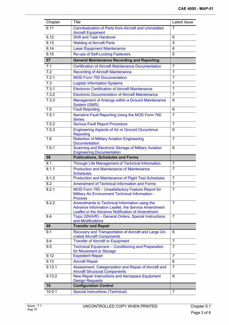
Chapter Title Latest Issue 6.11 Cannibalization of Parts from Aircraft and Uninstalled
Aircraft Equipment 7
6.12 Shift and Task Handover 6 6.13 Welding of Aircraft Parts 5 6.14 Laser Equipment Maintenance 6 6.15 Re-use of Self-Locking Fasteners 5 07 General Maintenance Recording and Reporting 7.1 Certification of Aircraft Maintenance Documentation 7 7.2 Recording of Aircraft Maintenance 7 7.2.1 MOD Form 700 Documentation 7 7.3 Logistic Information Systems 7 7.3.1 Electronic Certification of Aircraft Maintenance 7 7.3.2 Electronic Documentation of Aircraft Maintenance 7 7.3.3 Management of Arisings within a Ground Maintenance
System (GMS) 6
7.5 Fault Reporting 6 7.5.1 Narrative Fault Reporting Using the MOD Form 760
Series 7
7.5.2 Serious Fault Report Procedure 7 7.5.3 Engineering Aspects of Air or Ground Occurrence
Reporting 6
7.6 Retention of Military Aviation Engineering Documentation
7
7.6.1 Scanning and Electronic Storage of Military Aviation Engineering Documentation
6
08 Publications, Schedules and Forms 8.1 Through Life Management of Technical Information 7 8.1.1 Production and Maintenance of Maintenance
Schedules 7
8.1.2 Production and Maintenance of Flight Test Schedules 7 8.2 Amendment of Technical Information and Forms 7 8.2.1 MOD Form 765 – Unsatisfactory Feature Report for
Military Air Environment Technical Information - Process
7
8.2.2 Amendments to Technical Information using the Advance Information Leaflet, the Service Amendment Leaflet or the Advance Notification of Amendment
7
8.4 Topic 2(N/A/R) – General Orders, Special Instructions and Modifications
7
09 Transfer and Repair 9.1 Recovery and Transportation of Aircraft and Large Un-
crated Aircraft Components 6
9.4 Transfer of Aircraft or Equipment 7 9.5 Technical Equipment – Conditioning and Preparation
for Movement or Storage 7
9.12 Expedient Repair 7 9.13 Aircraft Repair 6 9.13.1 Assessment, Categorization and Repair of Aircraft and
Aircraft Structural Components 7
9.13.2 New Repair Instructions and Aerospace Equipment Design Requests
6
10 Configuration Control 10.5.1 Special Instructions (Technical) 7
CAE 4000 - MAP-01
Chapter 0.1 Page 4 of 6
UNCONTROLLED COPY WHEN PRINTED Issue - 7.1 Aug 15
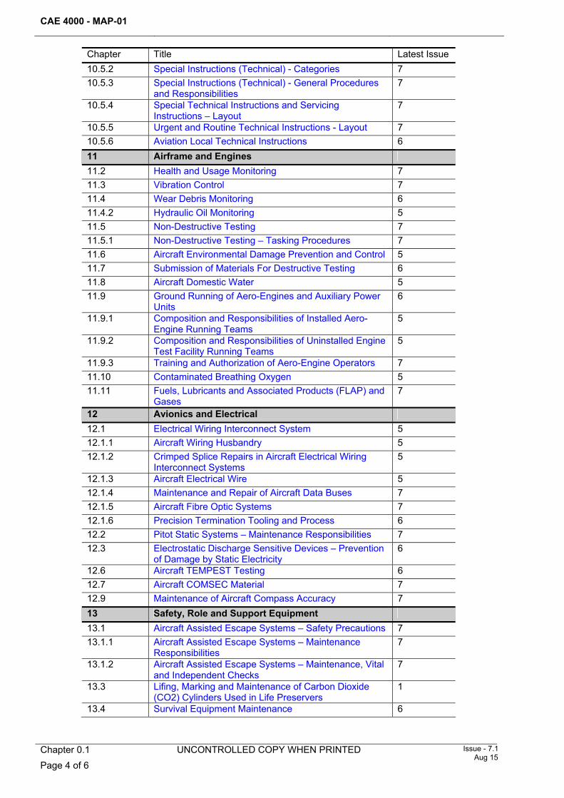
Chapter Title Latest Issue 10.5.2 Special Instructions (Technical) - Categories 7 10.5.3 Special Instructions (Technical) - General Procedures
and Responsibilities 7
10.5.4 Special Technical Instructions and Servicing Instructions – Layout
7
10.5.5 Urgent and Routine Technical Instructions - Layout 7 10.5.6 Aviation Local Technical Instructions 6 11 Airframe and Engines 11.2 Health and Usage Monitoring 7 11.3 Vibration Control 7 11.4 Wear Debris Monitoring 6 11.4.2 Hydraulic Oil Monitoring 5 11.5 Non-Destructive Testing 7 11.5.1 Non-Destructive Testing – Tasking Procedures 7 11.6 Aircraft Environmental Damage Prevention and Control 5 11.7 Submission of Materials For Destructive Testing 6 11.8 Aircraft Domestic Water 5 11.9 Ground Running of Aero-Engines and Auxiliary Power
Units 6
11.9.1 Composition and Responsibilities of Installed Aero-Engine Running Teams
5
11.9.2 Composition and Responsibilities of Uninstalled Engine Test Facility Running Teams
5
11.9.3 Training and Authorization of Aero-Engine Operators 7 11.10 Contaminated Breathing Oxygen 5 11.11 Fuels, Lubricants and Associated Products (FLAP) and
Gases 7
12 Avionics and Electrical 12.1 Electrical Wiring Interconnect System 5 12.1.1 Aircraft Wiring Husbandry 5 12.1.2 Crimped Splice Repairs in Aircraft Electrical Wiring
Interconnect Systems 5
12.1.3 Aircraft Electrical Wire 5 12.1.4 Maintenance and Repair of Aircraft Data Buses 7 12.1.5 Aircraft Fibre Optic Systems 7 12.1.6 Precision Termination Tooling and Process 6 12.2 Pitot Static Systems – Maintenance Responsibilities 7 12.3 Electrostatic Discharge Sensitive Devices – Prevention
of Damage by Static Electricity 6
12.6 Aircraft TEMPEST Testing 6 12.7 Aircraft COMSEC Material 7 12.9 Maintenance of Aircraft Compass Accuracy 7 13 Safety, Role and Support Equipment 13.1 Aircraft Assisted Escape Systems – Safety Precautions 7 13.1.1 Aircraft Assisted Escape Systems – Maintenance
Responsibilities 7
13.1.2 Aircraft Assisted Escape Systems – Maintenance, Vital and Independent Checks
7
13.3 Lifing, Marking and Maintenance of Carbon Dioxide (CO2) Cylinders Used in Life Preservers
1
13.4 Survival Equipment Maintenance 6
CAE 4000 - MAP-01
Issue - 7.1 Aug 15
UNCONTROLLED COPY WHEN PRINTED Chapter 0.1 Page 5 of 6
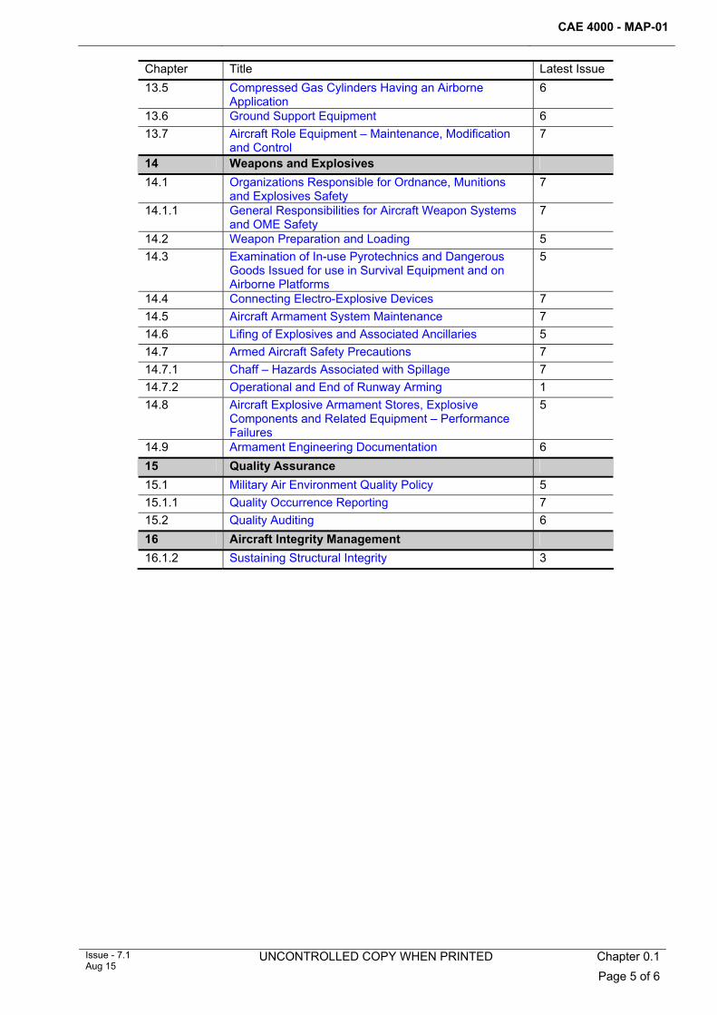
Chapter Title Latest Issue 13.5 Compressed Gas Cylinders Having an Airborne
Application 6
13.6 Ground Support Equipment 6 13.7 Aircraft Role Equipment – Maintenance, Modification
and Control 7
14 Weapons and Explosives 14.1 Organizations Responsible for Ordnance, Munitions
and Explosives Safety 7
14.1.1 General Responsibilities for Aircraft Weapon Systems and OME Safety
7
14.2 Weapon Preparation and Loading 5 14.3 Examination of In-use Pyrotechnics and Dangerous
Goods Issued for use in Survival Equipment and on Airborne Platforms
5
14.4 Connecting Electro-Explosive Devices 7 14.5 Aircraft Armament System Maintenance 7 14.6 Lifing of Explosives and Associated Ancillaries 5 14.7 Armed Aircraft Safety Precautions 7 14.7.1 Chaff – Hazards Associated with Spillage 7 14.7.2 Operational and End of Runway Arming 1 14.8 Aircraft Explosive Armament Stores, Explosive
Components and Related Equipment – Performance Failures
5
14.9 Armament Engineering Documentation 6 15 Quality Assurance 15.1 Military Air Environment Quality Policy 5 15.1.1 Quality Occurrence Reporting 7 15.2 Quality Auditing 6 16 Aircraft Integrity Management 16.1.2 Sustaining Structural Integrity 3

CAE 4000 - MAP-01
Chapter 0.1 Page 6 of 6
UNCONTROLLED COPY WHEN PRINTED Issue - 7.1 Aug 15
Intentionally Blank for Print Pagination
CAE 4000 - MAP-01
MAE Issue - 5 Sep 13
Chapter 0.2 Page 1 of 2
Chapter 0.2
Index
Table of contents Paragraph
Page
1 ............................................................................................................... 1 General1.1 .......................................................................................................................1 Introduction
1 General 1.1 Introduction
The content of this chapter has been removed. Readers should utilize the pdf search facility when looking for specific terms.
CAE 4000 - MAP-01
Chapter 0.2 Page 2 of 2
MAE Issue - 5
Sep 13
Intentionally Blank for Print Pagination
UNCONTROLLED COPY WHEN PRINTED CAE 4000 - MAP-01
Issue - 7 Apr 15
UNCONTROLLED COPY WHEN PRINTED Chapter 0.3 Page 1 of 4
Chapter 0.3
Preface
TABLE OF CONTENTS Paragraph
Page
1 General ............................................................................................................... 1 1.1 Introduction.......................................................................................................... 1 1.2 Applicability ......................................................................................................... 1 2 Structure and layout ......................................................................................... 2 3 Conventions....................................................................................................... 3 3.1 Abbreviations....................................................................................................... 3 3.2 Mandated written entries ..................................................................................... 3 3.3 Equivalent functions ............................................................................................ 3 3.4 Chapter and paragraph numbering system......................................................... 3 3.5 Changes .............................................................................................................. 3 4 Referencing........................................................................................................ 3 4.1 General................................................................................................................ 3 4.2 Referencing between chapters............................................................................ 3 4.3 Referencing within a chapter............................................................................... 3 4.4 Definitions............................................................................................................ 4 5 Amendments...................................................................................................... 4
LIST OF TABLES Table 1. MAP-01 Chapter Structure............................................................................... 2
1 General 1.1 Introduction
The Manual of Maintenance and Airworthiness Processes (MAP-01) contains detailed guidance and processes to support compliance with the Continuing Airworthiness Engineering (CAE) 4000 Series of Regulatory Articles. It also currently contains a significant amount of material that constitutes the Acceptable Means of Compliance (AMC) and Guidance Material (GM) for many of the 4000 Series RAs, together with other legacy content. A major initiative is underway to review the entire document, so as an interim measure to avoid unnecessary staffing of Alternative Acceptable Means of Compliance (AAMC) requests that may be inappropriate, all issues related to deviation from the MAP-01 should firstly be referred to the MAA Reg CAw branch by email (DSA-MAA-REG-CAW4-MAPLIS), who will advise whether a formal AAMC application is required. If it is not, the deviation may be authorised by the appropriate Duty Holder, as promulgated in single Service orders.
1.2 Applicability The content of the MAP-01 supports the 4000 Series of RAs which collectively regulates the Continuing Airworthiness Engineering activity required to sustain military in-service aircraft as safely and efficiently as possible. Its content is focused as much on coherent engineering practices and mission effectiveness as it is with airworthiness.
CAE 4000 - MAP-01 UNCONTROLLED COPY WHEN PRINTED
Chapter 0.3 Page 2 of 4
UNCONTROLLED COPY WHEN PRINTED
Issue - 7 Apr 15
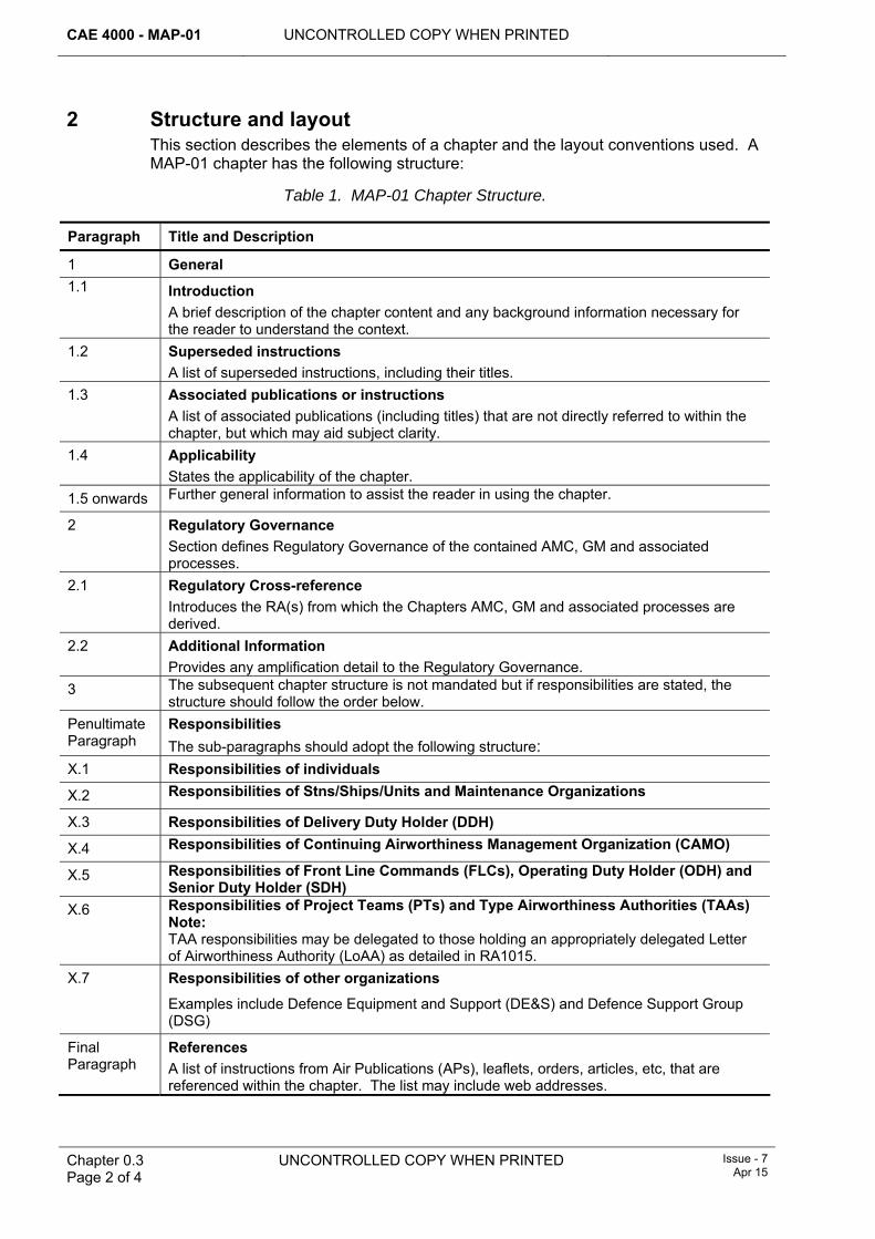
2 Structure and layout This section describes the elements of a chapter and the layout conventions used. A MAP-01 chapter has the following structure:
Table 1. MAP-01 Chapter Structure. Paragraph Title and Description
1 General 1.1 Introduction
A brief description of the chapter content and any background information necessary for the reader to understand the context.
1.2 Superseded instructions A list of superseded instructions, including their titles.
1.3 Associated publications or instructions A list of associated publications (including titles) that are not directly referred to within the chapter, but which may aid subject clarity.
1.4 Applicability States the applicability of the chapter.
1.5 onwards Further general information to assist the reader in using the chapter.
2 Regulatory Governance Section defines Regulatory Governance of the contained AMC, GM and associated processes.
2.1 Regulatory Cross-reference Introduces the RA(s) from which the Chapters AMC, GM and associated processes are derived.
2.2 Additional Information Provides any amplification detail to the Regulatory Governance.
3 The subsequent chapter structure is not mandated but if responsibilities are stated, the structure should follow the order below.
Penultimate Paragraph
Responsibilities The sub-paragraphs should adopt the following structure:
X.1 Responsibilities of individuals
X.2 Responsibilities of Stns/Ships/Units and Maintenance Organizations
X.3 Responsibilities of Delivery Duty Holder (DDH)
X.4 Responsibilities of Continuing Airworthiness Management Organization (CAMO)
X.5 Responsibilities of Front Line Commands (FLCs), Operating Duty Holder (ODH) and Senior Duty Holder (SDH)
X.6 Responsibilities of Project Teams (PTs) and Type Airworthiness Authorities (TAAs) Note: TAA responsibilities may be delegated to those holding an appropriately delegated Letter of Airworthiness Authority (LoAA) as detailed in RA1015.
X.7 Responsibilities of other organizations
Examples include Defence Equipment and Support (DE&S) and Defence Support Group (DSG)
Final Paragraph
References A list of instructions from Air Publications (APs), leaflets, orders, articles, etc, that are referenced within the chapter. The list may include web addresses.
UNCONTROLLED COPY WHEN PRINTED CAE 4000 - MAP-01
Issue - 7 Apr 15
UNCONTROLLED COPY WHEN PRINTED
Chapter 0.3 Page 3 of 4
3 Conventions 3.1 Abbreviations
Common abbreviations, eg MOD, NDT, AP, etc, need not be defined within a chapter. For more specialist abbreviations, the normal convention of defining the abbreviation at first use applies. A list of abbreviations used in MAP-01 is provided in Chapter 0.4 – Definitions and Abbreviations (which is aligned with MAA02 (MAA Master Glossary)).
3.2 Mandated written entries Where a specific wording is mandated for entry on an MOD Form, Job Card, etc, it will be indented and highlighted as in the following example:
‘I certify that work is completed in accordance with…[enter details]’
The mandated entry will be written in bold and advice on the written entry entered in square brackets.
3.3 Equivalent functions All references to engineering function, appointments and tradesmen are to be interpreted as also meaning civilians and non-engineering personnel of equivalent status and competence, see RA 4806 and Chapter 4.1, who are employed by the MOD or by contractors that are required to comply with the 4000 Series of RAs.
3.4 Chapter and paragraph numbering system The legal numbering system is used to identify chapters and paragraphs. This is a hierarchical numbering system that allows numbering to 5 levels of detail from ‘1.’ to ‘1.1.1.1.1’.
3.5 Changes Amended text will be highlighted as follows:
1 Change marks, consisting of inward-facing pairs of red arrowheads which identify the start and end of the amended text, ie Amended text.
2 Deleted text by just inward-facing red arrowheads, ie .
Where a chapter’s content is substantially changed, for instance following a regulatory review, the statement “Chapter completely revised at Issue XX: no amendments marked in chapter body” will appear immediately below the chapter title.
4 Referencing 4.1 General
Chapters and paragraphs are organized to ensure that information is presented within its correct context. Referencing is similarly designed to ensure that information is presented within the context of a chapter.
4.2 Referencing between chapters To ensure that the principles in paragraph 4.1 apply, references between chapters are made to a chapter number and not to a paragraph within the chapter, eg ‘see RA 4806 and Chapter 4.3’.
4.3 Referencing within a chapter To ensure that the principles in paragraph 4.1 apply, references within a chapter are made to a paragraph number, but not to a numbered list, eg ‘see item 3 of paragraph
CAE 4000 - MAP-01 UNCONTROLLED COPY WHEN PRINTED
Chapter 0.3 Page 4 of 4
UNCONTROLLED COPY WHEN PRINTED
Issue - 7 Apr 15
3.2’; however, reference may be made to an item in a numbered list from an item in the same numbered list.
4.4 Definitions Definitions of terms used are detailed in MAA02.
5 Amendments Updates (Issues) to the MAP-01 will only be promulgated on the MAA websites. Post the initial issue, the timing of updates to these separate websites may differ; primacy resides in the most current version of either website available at any location. Amendment proposals to the MAP-01 are to be submitted through the originator’s appropriate Duty Holder or Engineering Policy lead (as defined in their single Service orders) for onward progression. Proposed amendments are to be raised by the Request for Change (RFC) process as detailed on the MAA website (maa.gov.uk).
Note:
Regardless of the method used, all proposals should be forwarded to MRP Enquiries. Additionally, whilst MAA Reg CAw personnel may be approached for Advice and Guidance on the MAP-01, it should be noted:
1 The responsibility for carrying out any background research is the responsibility of those requesting Advice and Guidance.
2 The MAA will not engage in the development of solutions to meet regulatory requirements.
3 AMC, GM and associated processes will be explained and where appropriate, examples of good practice may be offered.
4 Proposed Alternative AMC, GM and associated processes may be debated, but will be without prejudice or commitment to the outcome of any subsequent applications through either of the Alternative AMC and RFC processes.
CAE 4000 - MAP-01
MAE Issue - 5 Sep 13
Chapter 0.4 Page 1 of 2
Chapter 0.4
Definitions and Abbreviations
TABLE OF CONTENTS Paragraph
Page
1 ............................................................................................................... 1 General1.1 .......................................................................................................... 1 Introduction
1 General 1.1 Introduction
The content of this chapter has been transferred to MAA02 - Military Aviation Authority Master Glossary. This Ghost Chapter is left in as a signpost for the reader.

CAE 4000 - MAP-01
Chapter 0.4 Page 2 of 2
MAE Issue - 5
Sep 13
Intentionally Blank for Print Pagination
UNCONTROLLED COPY WHEN PRINTED CAE 4000 - MAP-01
Issue - 7.1 Aug 15
UNCONTROLLED COPY WHEN PRINTED Chapter 0.5 Page 1 of 8
Chapter 0.5
Changes
TABLE OF CONTENTS
Paragraph
Page
1 Chapters............................................................................................................. 1
LIST OF TABLES
Table 1. List of Changes in Issue 7.1. ..........................................................................................1 Table 2. List of Changes in Issue 7. .............................................................................................1
1 Chapters 1.1 List of changes
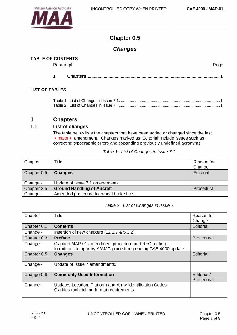
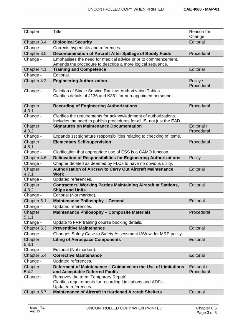
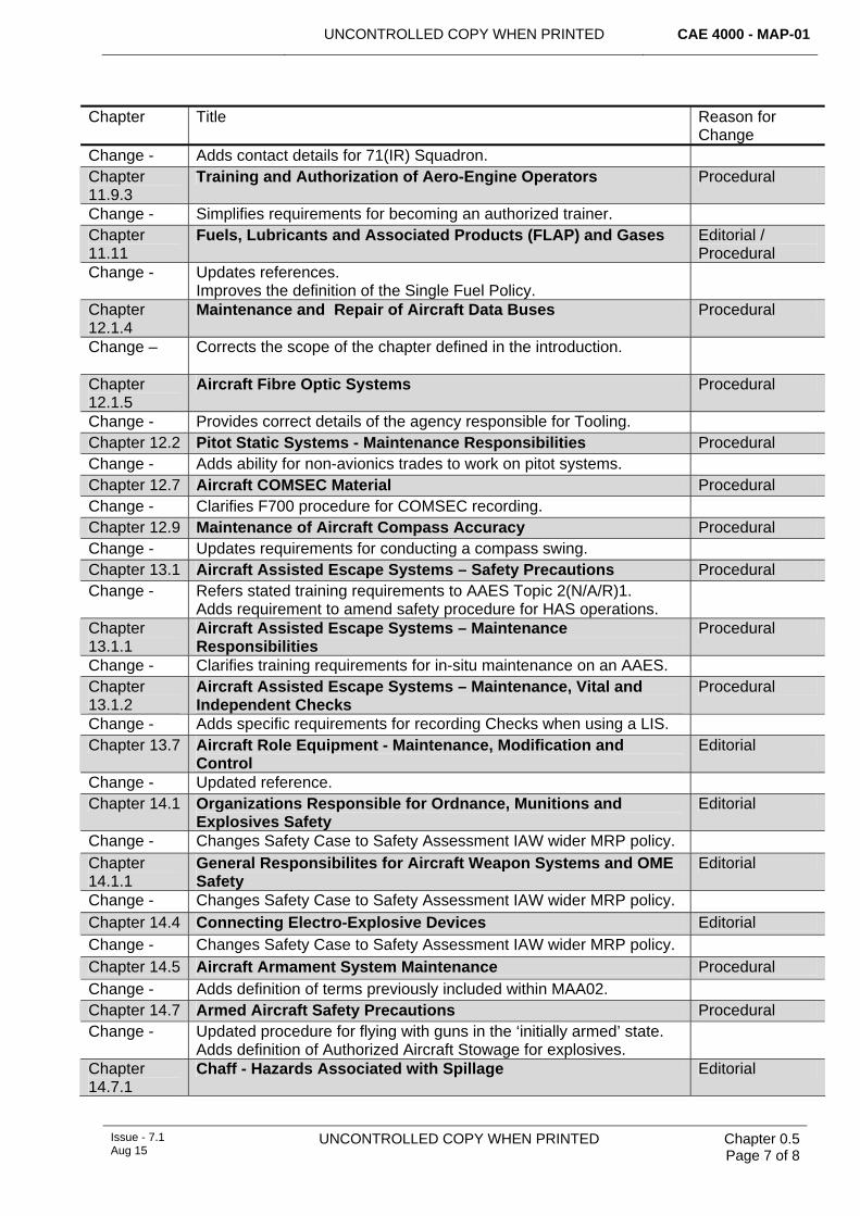
The table below lists the chapters that have been added or changed since the last major amendment. Changes marked as ‘Editorial’ include issues such as correcting typographic errors and expanding previously undefined acronyms.
Table 1. List of Changes in Issue 7.1.
Chapter Title Reason for Change
Chapter 0.5
Changes Editorial
Change - Update of Issue 7.1 amendments. Chapter 2.5 Ground Handling of Aircraft Procedural Change - Amended procedure for wheel brake fires.
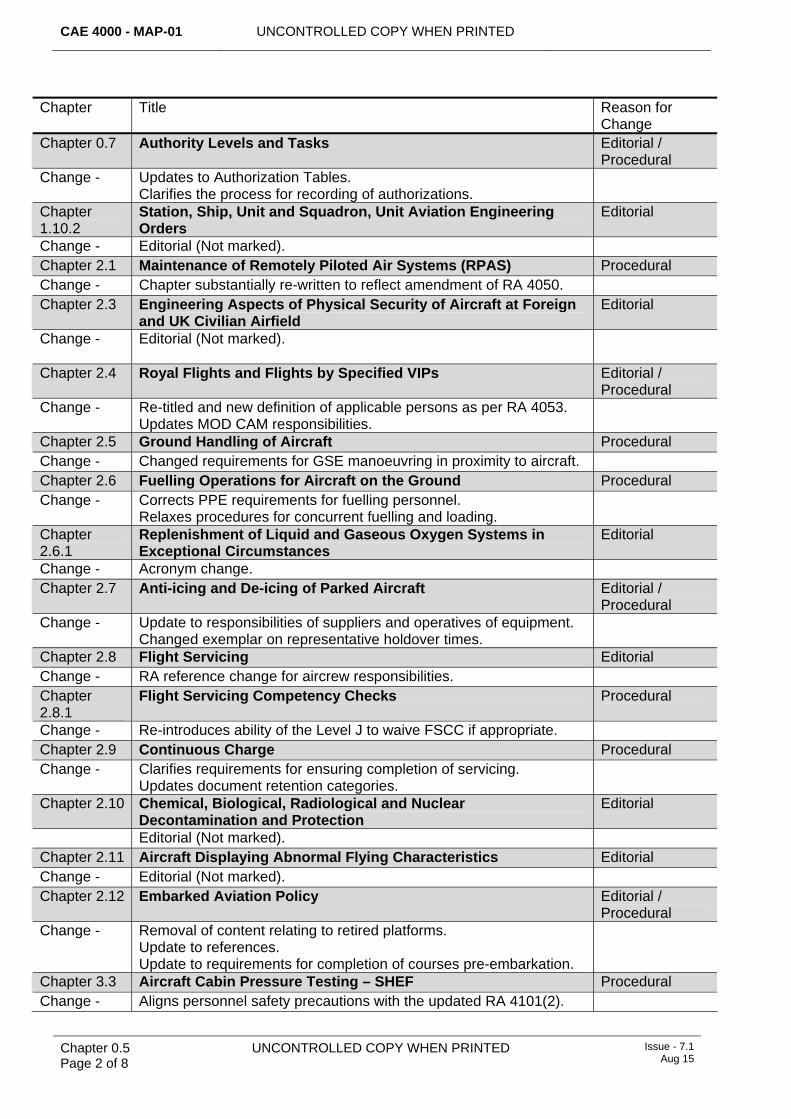
Table 2. List of Changes in Issue 7.
Chapter Title Reason for Change
Chapter 0.1 Contents Editorial Change - Insertion of new chapters (12.1.7 & 5.3.2). Chapter 0.3 Preface Procedural Change - Clarified MAP-01 amendment procedure and RFC routing.
Introduces temporary A/AMC procedure pending CAE 4000 update.
Chapter 0.5
Changes Editorial
Change - Update of Issue 7 amendments.
Change 0.6 Commonly Used Information Editorial / Procedural
Change - Updates Location, Platform and Army Identification Codes. Clarifies tool etching format requirements.
CAE 4000 - MAP-01 UNCONTROLLED COPY WHEN PRINTED
Chapter 0.5 Page 2 of 8
UNCONTROLLED COPY WHEN PRINTED Issue - 7.1 Aug 15
Chapter Title Reason for Change
Chapter 0.7 Authority Levels and Tasks Editorial / Procedural
Change - Updates to Authorization Tables. Clarifies the process for recording of authorizations.
Chapter 1.10.2
Station, Ship, Unit and Squadron, Unit Aviation Engineering Orders
Editorial
Change - Editorial (Not marked). Chapter 2.1 Maintenance of Remotely Piloted Air Systems (RPAS) Procedural Change - Chapter substantially re-written to reflect amendment of RA 4050. Chapter 2.3 Engineering Aspects of Physical Security of Aircraft at Foreign
and UK Civilian Airfield Editorial
Change - Editorial (Not marked).
Chapter 2.4 Royal Flights and Flights by Specified VIPs Editorial / Procedural
Change - Re-titled and new definition of applicable persons as per RA 4053. Updates MOD CAM responsibilities.
Chapter 2.5 Ground Handling of Aircraft Procedural Change - Changed requirements for GSE manoeuvring in proximity to aircraft. Chapter 2.6 Fuelling Operations for Aircraft on the Ground Procedural Change - Corrects PPE requirements for fuelling personnel.
Relaxes procedures for concurrent fuelling and loading.
Chapter 2.6.1
Replenishment of Liquid and Gaseous Oxygen Systems in Exceptional Circumstances
Editorial
Change - Acronym change. Chapter 2.7 Anti-icing and De-icing of Parked Aircraft Editorial /
Procedural Change - Update to responsibilities of suppliers and operatives of equipment.
Changed exemplar on representative holdover times.
Chapter 2.8 Flight Servicing Editorial Change - RA reference change for aircrew responsibilities. Chapter 2.8.1
Flight Servicing Competency Checks Procedural
Change - Re-introduces ability of the Level J to waive FSCC if appropriate. Chapter 2.9 Continuous Charge Procedural Change - Clarifies requirements for ensuring completion of servicing.
Updates document retention categories.
Chapter 2.10 Chemical, Biological, Radiological and Nuclear Decontamination and Protection
Editorial
Editorial (Not marked). Chapter 2.11 Aircraft Displaying Abnormal Flying Characteristics Editorial Change - Editorial (Not marked). Chapter 2.12 Embarked Aviation Policy Editorial /
Procedural Change - Removal of content relating to retired platforms.
Update to references. Update to requirements for completion of courses pre-embarkation.
Chapter 3.3 Aircraft Cabin Pressure Testing – SHEF Procedural Change - Aligns personnel safety precautions with the updated RA 4101(2).
UNCONTROLLED COPY WHEN PRINTED CAE 4000 - MAP-01
Issue - 7.1 Aug 15
UNCONTROLLED COPY WHEN PRINTED
Chapter 0.5 Page 3 of 8
Chapter Title Reason for Change
Chapter 3.4 Biological Security Editorial Change - Corrects hyperlinks and references. Chapter 3.5 Decontamination of Aircraft After Spillage of Bodily Fuids Procedural Change - Emphasises the need for medical advice prior to commencement.
Amends the procedure to describe a more logical sequence.
Chapter 4.1 Training and Competence Editorial Change - Editorial. Chapter 4.3 Engineering Authorization Policy /
Procedural Change - Deletion of Single Service Rank vs Authorization Tables.
Clarifies details of J136 and K361 for non-appointed personnel.
Chapter 4.3.1
Recording of Engineering Authorizations Procedural
Change - Clarifies the requirements for acknowledgment of authorizations. Includes the need to publish procedures for all IS, not just the EAD.
Chapter 4.3.2
Signatures on Maintenance Documentation Editorial / Procedural
Change - Expands 1st signature responsibilities relating to checking of items. Chapter 4.5.1
Elementary Self-supervision Procedural
Change - Clarification that appropriate use of ESS is a CAMO function. Chapter 4.6 Delineation of Responsibilities for Engineering Authorizations Policy Change - Chapter deleted as deemed by FLCs to have no obvious utility. Chapter 4.7.1
Authorization of Aircrew to Carry Out Aircraft Maintenance Work
Editorial
Change - Updated references. Chapter 4.8.2
Contractors’ Working Parties Maintaining Aircraft at Stations, Ships and Units
Editorial
Change - Editorial (Not marked). Chapter 5.1 Maintenance Philosophy – General Editorial Change - Updated references. Chapter 5.1.1
Maintenance Philosophy – Composite Materials Procedural
Change - Update to FRP training course booking details. Chapter 5.3 Preventitive Maintenance Editorial Change - Changes Safety Case to Safety Assessment IAW wider MRP policy. Chapter 5.3.1
Lifing of Aerospace Components Editorial
Change - Editorial (Not marked). Chapter 5.4 Corrective Maintenance Editorial Change - Updated references. Chapter 5.4.2
Deferment of Maintenance – Guidance on the Use of Limitations and Acceptable Deferred Faults
Editorial / Procedural
Change - Removes the term ‘Temporary Repair’. Clarifies requirements for recording Limitations and ADFs. Updated references.
Chapter 5.7 Maintenance of Aircraft in Hardened Aircraft Shelters Editorial
CAE 4000 - MAP-01 UNCONTROLLED COPY WHEN PRINTED
Chapter 0.5 Page 4 of 8
UNCONTROLLED COPY WHEN PRINTED Issue - 7.1 Aug 15
Chapter Title Reason for Change
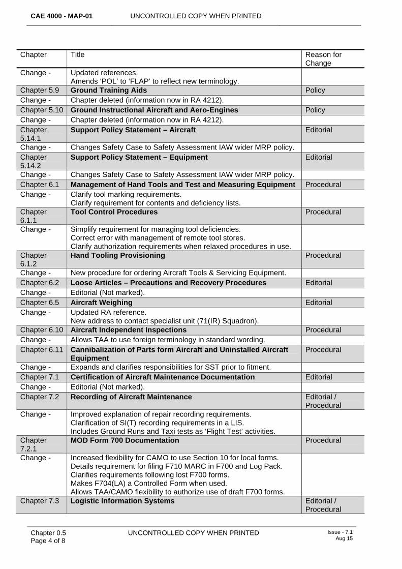
Change - Updated references. Amends ‘POL’ to ‘FLAP’ to reflect new terminology.
Chapter 5.9 Ground Training Aids Policy Change - Chapter deleted (information now in RA 4212). Chapter 5.10 Ground Instructional Aircraft and Aero-Engines Policy Change - Chapter deleted (information now in RA 4212). Chapter 5.14.1
Support Policy Statement – Aircraft Editorial
Change - Changes Safety Case to Safety Assessment IAW wider MRP policy. Chapter 5.14.2
Support Policy Statement – Equipment Editorial
Change - Changes Safety Case to Safety Assessment IAW wider MRP policy. Chapter 6.1 Management of Hand Tools and Test and Measuring Equipment Procedural Change - Clarify tool marking requirements.
Clarify requirement for contents and deficiency lists.
Chapter 6.1.1
Tool Control Procedures Procedural
Change - Simplify requirement for managing tool deficiencies. Correct error with management of remote tool stores. Clarify authorization requirements when relaxed procedures in use.
Chapter 6.1.2
Hand Tooling Provisioning Procedural
Change - New procedure for ordering Aircraft Tools & Servicing Equipment. Chapter 6.2 Loose Articles – Precautions and Recovery Procedures Editorial Change - Editorial (Not marked). Chapter 6.5 Aircraft Weighing Editorial Change - Updated RA reference.
New address to contact specialist unit (71(IR) Squadron).
Chapter 6.10 Aircraft Independent Inspections Procedural Change - Allows TAA to use foreign terminology in standard wording. Chapter 6.11 Cannibalization of Parts form Aircraft and Uninstalled Aircraft
Equipment Procedural
Change - Expands and clarifies responsibilities for SST prior to fitment. Chapter 7.1 Certification of Aircraft Maintenance Documentation Editorial Change - Editorial (Not marked). Chapter 7.2 Recording of Aircraft Maintenance Editorial /
Procedural Change - Improved explanation of repair recording requirements.
Clarification of SI(T) recording requirements in a LIS. Includes Ground Runs and Taxi tests as ‘Flight Test’ activities.
Chapter 7.2.1
MOD Form 700 Documentation Procedural
Change - Increased flexibility for CAMO to use Section 10 for local forms. Details requirement for filing F710 MARC in F700 and Log Pack. Clarifies requirements following lost F700 forms. Makes F704(LA) a Controlled Form when used. Allows TAA/CAMO flexibility to authorize use of draft F700 forms.
Chapter 7.3 Logistic Information Systems Editorial / Procedural
UNCONTROLLED COPY WHEN PRINTED CAE 4000 - MAP-01
Issue - 7.1 Aug 15
UNCONTROLLED COPY WHEN PRINTED
Chapter 0.5 Page 5 of 8
Chapter Title Reason for Change
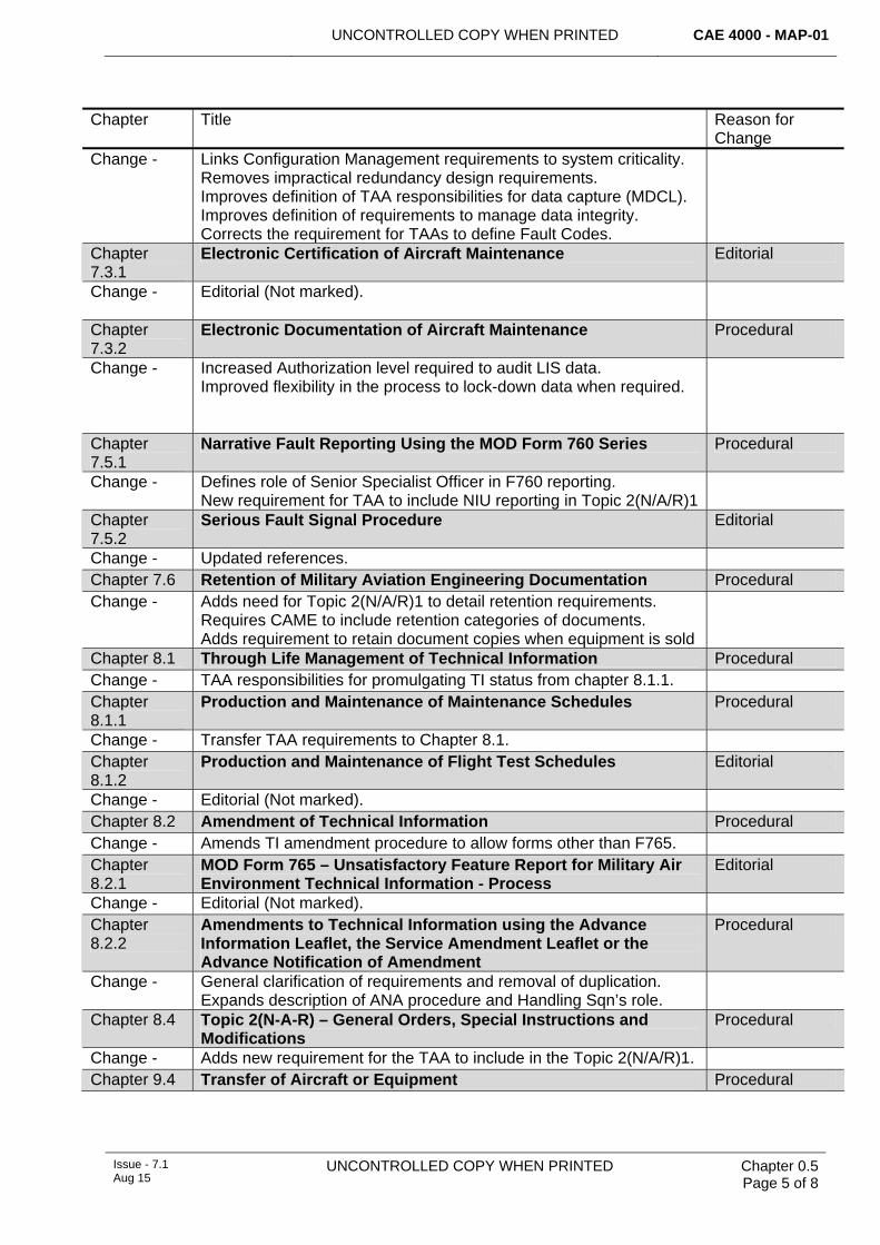
Change - Links Configuration Management requirements to system criticality. Removes impractical redundancy design requirements. Improves definition of TAA responsibilities for data capture (MDCL). Improves definition of requirements to manage data integrity. Corrects the requirement for TAAs to define Fault Codes.
Chapter 7.3.1
Electronic Certification of Aircraft Maintenance Editorial
Change - Editorial (Not marked).
Chapter 7.3.2
Electronic Documentation of Aircraft Maintenance Procedural
Change - Increased Authorization level required to audit LIS data. Improved flexibility in the process to lock-down data when required.
Chapter 7.5.1
Narrative Fault Reporting Using the MOD Form 760 Series Procedural
Change - Defines role of Senior Specialist Officer in F760 reporting. New requirement for TAA to include NIU reporting in Topic 2(N/A/R)1
Chapter 7.5.2
Serious Fault Signal Procedure Editorial
Change - Updated references. Chapter 7.6 Retention of Military Aviation Engineering Documentation Procedural Change - Adds need for Topic 2(N/A/R)1 to detail retention requirements.
Requires CAME to include retention categories of documents. Adds requirement to retain document copies when equipment is sold
Chapter 8.1 Through Life Management of Technical Information Procedural Change - TAA responsibilities for promulgating TI status from chapter 8.1.1. Chapter 8.1.1
Production and Maintenance of Maintenance Schedules Procedural
Change - Transfer TAA requirements to Chapter 8.1. Chapter 8.1.2
Production and Maintenance of Flight Test Schedules Editorial
Change - Editorial (Not marked). Chapter 8.2 Amendment of Technical Information Procedural Change - Amends TI amendment procedure to allow forms other than F765. Chapter 8.2.1
MOD Form 765 – Unsatisfactory Feature Report for Military Air Environment Technical Information - Process
Editorial
Change - Editorial (Not marked). Chapter 8.2.2
Amendments to Technical Information using the Advance Information Leaflet, the Service Amendment Leaflet or the Advance Notification of Amendment
Procedural
Change - General clarification of requirements and removal of duplication. Expands description of ANA procedure and Handling Sqn’s role.
Chapter 8.4 Topic 2(N-A-R) – General Orders, Special Instructions and Modifications
Procedural
Change - Adds new requirement for the TAA to include in the Topic 2(N/A/R)1. Chapter 9.4 Transfer of Aircraft or Equipment Procedural
CAE 4000 - MAP-01 UNCONTROLLED COPY WHEN PRINTED
Chapter 0.5 Page 6 of 8
UNCONTROLLED COPY WHEN PRINTED Issue - 7.1 Aug 15
Chapter Title Reason for Change
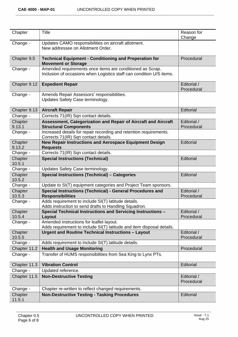
Change - Updates CAMO responsibilities on aircraft allotment. New addressee on Allotment Order.
Chapter 9.5 Technical Equipment - Conditioning and Preperation for Movement or Storage
Procedural
Change - Amended requirements once items are conditioned as Scrap. Inclusion of occasions when Logistics staff can condition U/S items.
Chapter 9.12 Expedient Repair Editorial / Procedural
Change - Amends Repair Assessors’ responsibilities. Updates Safety Case terminology.
Chapter 9.13 Aircraft Repair Editorial Change - Corrects 71(IR) Sqn contact details. Chapter 9.13.1
Assessment, Categorization and Repair of Aircraft and Aircraft Structural Components
Editorial / Procedural
Change - Increased details for repair recording and retention requirements. Corrects 71(IR) Sqn contact details.
Chapter 9.13.2
New Repair Instructions and Aerospace Equipment Design Requests
Editorial
Change - Corrects 71(IR) Sqn contact details. Chapter 10.5.1
Special Instructions (Technical) Editorial
Change - Updates Safety Case terminology. Chapter 10.5.2
Special Instructions (Technical) – Categories Editorial
Change - Update to SI(T) equipment categories and Project Team sponsors. Chapter 10.5.3
Special Instructions (Technical) - General Procedures and Responsibilities
Editorial / Procedural
Change - Adds requirement to include SI(T) latitude details. Adds instruction to send drafts to Handling Squadron.
Chapter 10.5.4
Special Technical Instructions and Servicing Instructions – Layout
Editorial / Procedural
Change - Amended instructions for leaflet layout. Adds requirement to include SI(T) latitude and item disposal details.
Chapter 10.5.5
Urgent and Routine Technical Instructions – Layout Editorial / Procedural
Change - Adds requirement to include SI(T) latitude details. Chapter 11.2 Health and Usage Monitoring Procedural Change - Transfer of HUMS responsibilities from Sea King to Lynx PTs.
Chapter 11.3 Vibration Control Editorial Change - Updated reference. Chapter 11.5 Non-Destructive Testing Editorial /
Procedural
Change - Chapter re-written to reflect changed requirements. Chapter 11.5.1
Non-Destructive Testing - Tasking Procedures Editorial
UNCONTROLLED COPY WHEN PRINTED CAE 4000 - MAP-01
Issue - 7.1 Aug 15
UNCONTROLLED COPY WHEN PRINTED
Chapter 0.5 Page 7 of 8
Chapter Title Reason for Change
Change - Adds contact details for 71(IR) Squadron. Chapter 11.9.3
Training and Authorization of Aero-Engine Operators Procedural
Change - Simplifies requirements for becoming an authorized trainer. Chapter 11.11
Fuels, Lubricants and Associated Products (FLAP) and Gases Editorial / Procedural
Change - Updates references. Improves the definition of the Single Fuel Policy.
Chapter 12.1.4
Maintenance and Repair of Aircraft Data Buses Procedural
Change – Corrects the scope of the chapter defined in the introduction.
Chapter 12.1.5
Aircraft Fibre Optic Systems Procedural
Change - Provides correct details of the agency responsible for Tooling. Chapter 12.2 Pitot Static Systems - Maintenance Responsibilities Procedural Change - Adds ability for non-avionics trades to work on pitot systems. Chapter 12.7 Aircraft COMSEC Material Procedural Change - Clarifies F700 procedure for COMSEC recording. Chapter 12.9 Maintenance of Aircraft Compass Accuracy Procedural Change - Updates requirements for conducting a compass swing. Chapter 13.1 Aircraft Assisted Escape Systems – Safety Precautions Procedural Change - Refers stated training requirements to AAES Topic 2(N/A/R)1.
Adds requirement to amend safety procedure for HAS operations.
Chapter 13.1.1
Aircraft Assisted Escape Systems – Maintenance Responsibilities
Procedural
Change - Clarifies training requirements for in-situ maintenance on an AAES. Chapter 13.1.2
Aircraft Assisted Escape Systems – Maintenance, Vital and Independent Checks
Procedural
Change - Adds specific requirements for recording Checks when using a LIS. Chapter 13.7 Aircraft Role Equipment - Maintenance, Modification and
Control Editorial
Change - Updated reference. Chapter 14.1 Organizations Responsible for Ordnance, Munitions and
Explosives Safety Editorial
Change - Changes Safety Case to Safety Assessment IAW wider MRP policy.
Chapter 14.1.1
General Responsibilites for Aircraft Weapon Systems and OME Safety
Editorial
Change - Changes Safety Case to Safety Assessment IAW wider MRP policy.
Chapter 14.4 Connecting Electro-Explosive Devices Editorial
Change - Changes Safety Case to Safety Assessment IAW wider MRP policy.
Chapter 14.5 Aircraft Armament System Maintenance Procedural
Change - Adds definition of terms previously included within MAA02. Chapter 14.7 Armed Aircraft Safety Precautions Procedural Change - Updated procedure for flying with guns in the ‘initially armed’ state.
Adds definition of Authorized Aircraft Stowage for explosives.
Chapter 14.7.1
Chaff - Hazards Associated with Spillage Editorial
CAE 4000 - MAP-01 UNCONTROLLED COPY WHEN PRINTED
Chapter 0.5 Page 8 of 8
UNCONTROLLED COPY WHEN PRINTED Issue - 7.1 Aug 15
Chapter Title Reason for Change
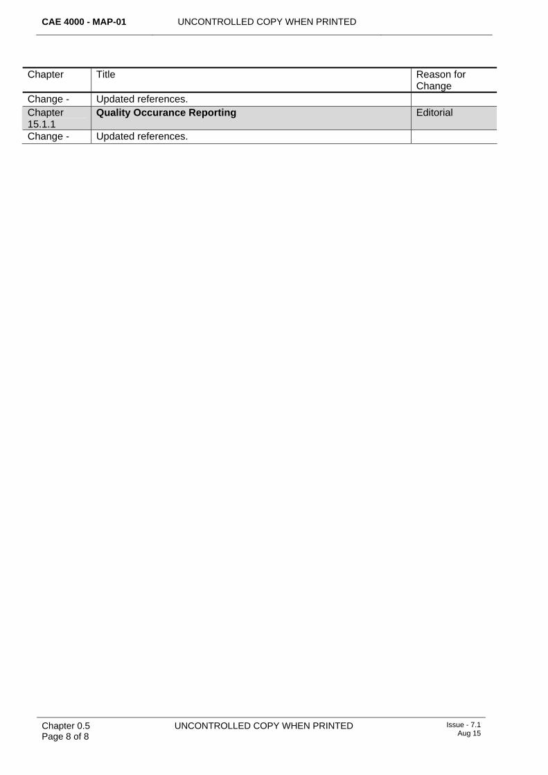
Change - Updated references. Chapter 15.1.1
Quality Occurance Reporting Editorial
Change - Updated references.
UNCONTROLLED COPY WHEN PRINTED CAE 4000 - MAP-01
Issue - 7 Apr 15
UNCONTROLLED COPY WHEN PRINTED Chapter 0.6 Page 1 of 4
Chapter 0.6
Commonly Used Information
TABLE OF CONTENTS Paragraph
Page
1 General ............................................................................................................... 1 2 Aviation Stn/Ship/Unit Location Codes........................................................... 1 3 Army Aviation Unit Identification Codes......................................................... 2 4 METS Generated Platform Identification Codes............................................. 3
LIST OF TABLES Table 1. Station/Ship/Unit Location Codes. ..................................................................................1 Table 2. Army Aviation Unit Location Codes. ...............................................................................2 Table 3. METS Generated Platform Identification Codes.............................................................3
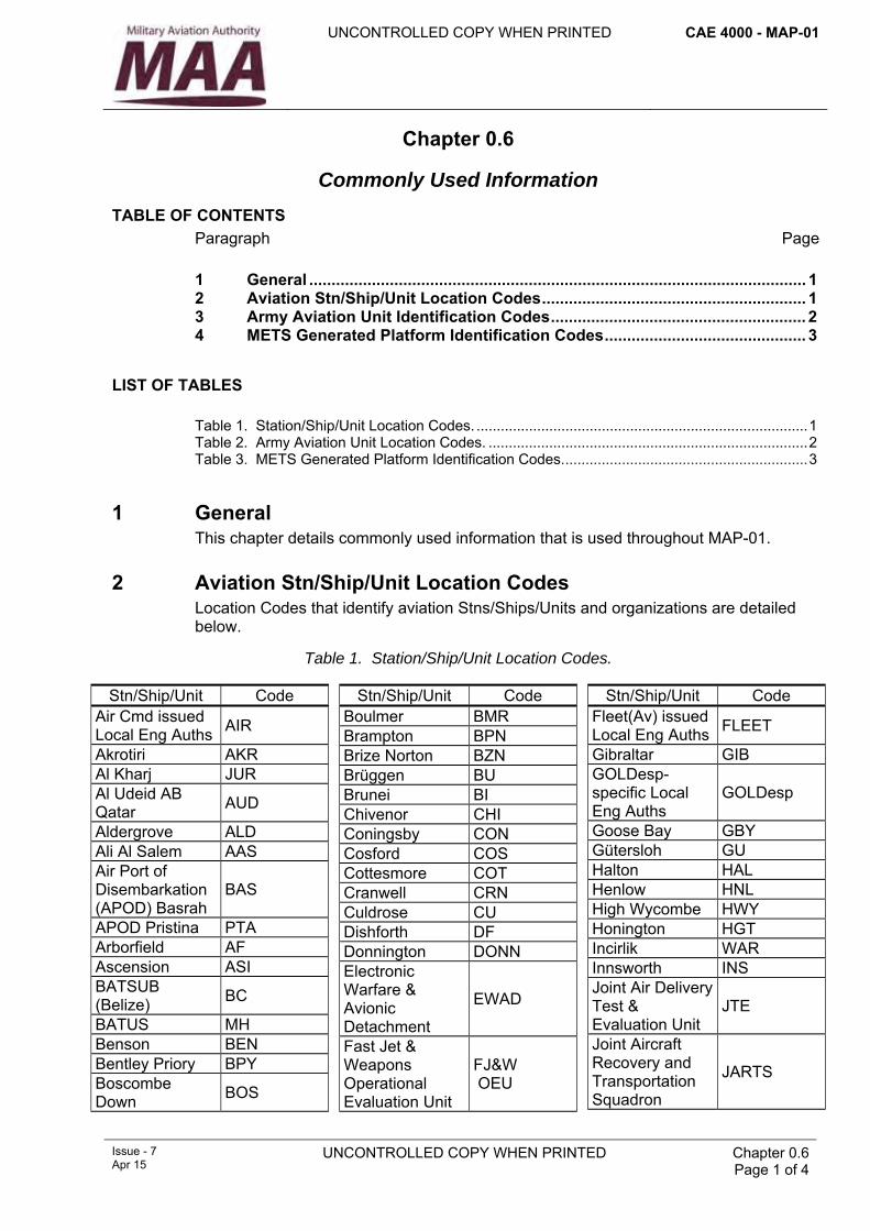
1 General This chapter details commonly used information that is used throughout MAP-01.
2 Aviation Stn/Ship/Unit Location Codes Location Codes that identify aviation Stns/Ships/Units and organizations are detailed below.
Table 1. Station/Ship/Unit Location Codes. Stn/Ship/Unit Code
Air Cmd issued Local Eng Auths AIR
Akrotiri AKR Al Kharj JUR Al Udeid AB Qatar AUD
Aldergrove ALD Ali Al Salem AAS Air Port of Disembarkation (APOD) Basrah
BAS
APOD Pristina PTA Arborfield AF Ascension ASI BATSUB (Belize) BC
BATUS MH Benson BEN Bentley Priory BPY Boscombe Down BOS
Stn/Ship/Unit Code Boulmer BMR Brampton BPN Brize Norton BZN Brüggen BU Brunei BI Chivenor CHI Coningsby CON Cosford COS Cottesmore COT Cranwell CRN Culdrose CU Dishforth DF Donnington DONN Electronic Warfare & Avionic Detachment
EWAD
Fast Jet & Weapons Operational Evaluation Unit
FJ&W OEU
Stn/Ship/Unit Code Fleet(Av) issued Local Eng Auths FLEET
Gibraltar GIB GOLDesp-specific Local Eng Auths
GOLDesp
Goose Bay GBY Gütersloh GU Halton HAL Henlow HNL High Wycombe HWY Honington HGT Incirlik WAR Innsworth INS Joint Air Delivery Test & Evaluation Unit
JTE
Joint Aircraft Recovery and Transportation Squadron
JARTS
CAE 4000 - MAP-01 UNCONTROLLED COPY WHEN PRINTED
Chapter 0.6 Page 2 of 4
UNCONTROLLED COPY WHEN PRINTED Issue - 7 Apr 15
Stn/Ship/Unit Code JHC issued Local Eng Auths JHC
Kinloss KIN Larkhill LARK Leconfield LEC Leeming LEE Leuchars LEU Linton-on-Ouse LIN Lossiemouth LOS Lyneham LYN Marham MAR Maritime Aviation Support Force
MASF
Middle Wallop MW Mount Pleasant MPA Netheravon NV Nimrod Support Group NSG
90 Signals Unit 90SU 901 Expeditionary Air Wing
901
902 Expeditionary Air Wing
902
Stn/Ship/Unit Code 903 Expeditionary Air Wing
903
904 Expeditionary Air Wing
904
905 Expeditionary Air Wing
905
906 Expeditionary Air Wing
906
93 (EA) Sqn 93EA Northolt NOR Northwood NWD Odiham ODI Pan-MAE issued Local Eng Auths JOINT
Scampton SCA Search & Rescue Force SARF
17(R) Sqn at Edwards Air Force Base
EDW17R
71(IR) Sqn 71IR Shawbury SHA
Stn/Ship/Unit Code St Athan MSA St Mawgan STM Stafford SFD Sultan SU Syerston SYN Tactical Data Links Support Unit
TDLSU
22 Training Group issued Local Eng Auths
TG
Tornado Ground Reconnaissance Force
TGRF
Valley VAL Waddington WAD Wattisham WAT Wilton WI Wittering WIT Wyton WYT Yeovilton VL
Notes:
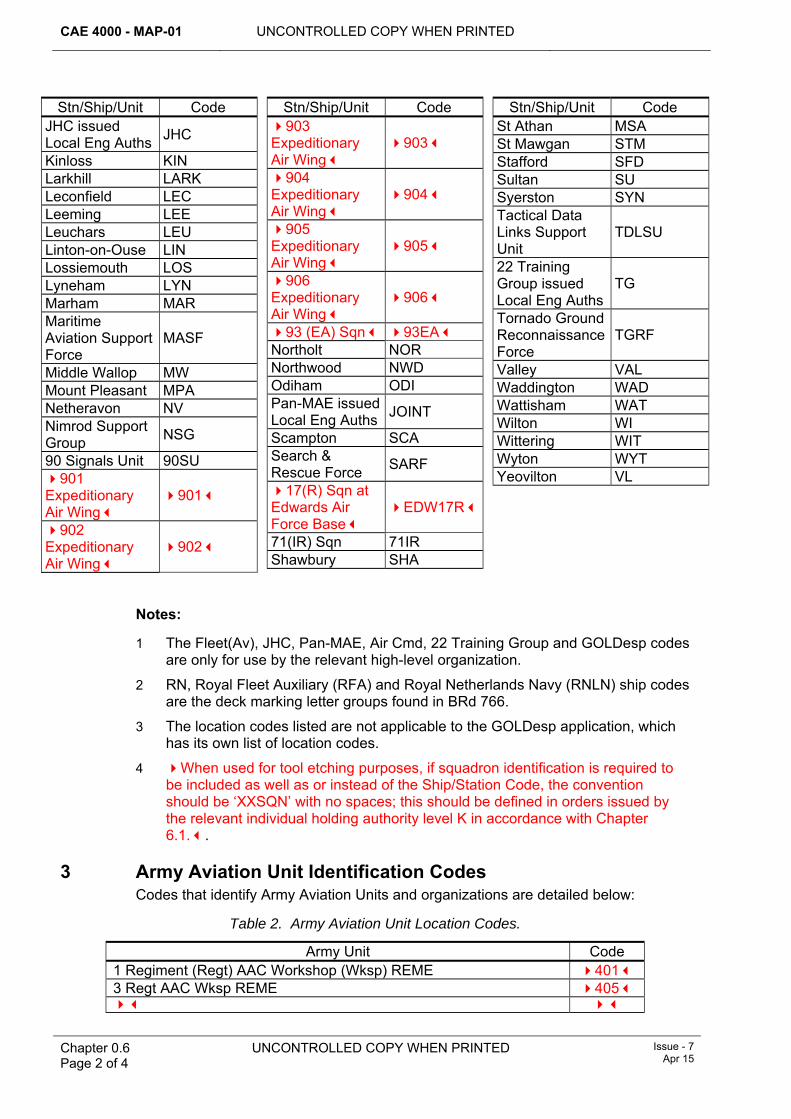
1 The Fleet(Av), JHC, Pan-MAE, Air Cmd, 22 Training Group and GOLDesp codes are only for use by the relevant high-level organization.
2 RN, Royal Fleet Auxiliary (RFA) and Royal Netherlands Navy (RNLN) ship codes are the deck marking letter groups found in BRd 766.
3 The location codes listed are not applicable to the GOLDesp application, which has its own list of location codes.
4 When used for tool etching purposes, if squadron identification is required to be included as well as or instead of the Ship/Station Code, the convention should be ‘XXSQN’ with no spaces; this should be defined in orders issued by the relevant individual holding authority level K in accordance with Chapter 6.1..
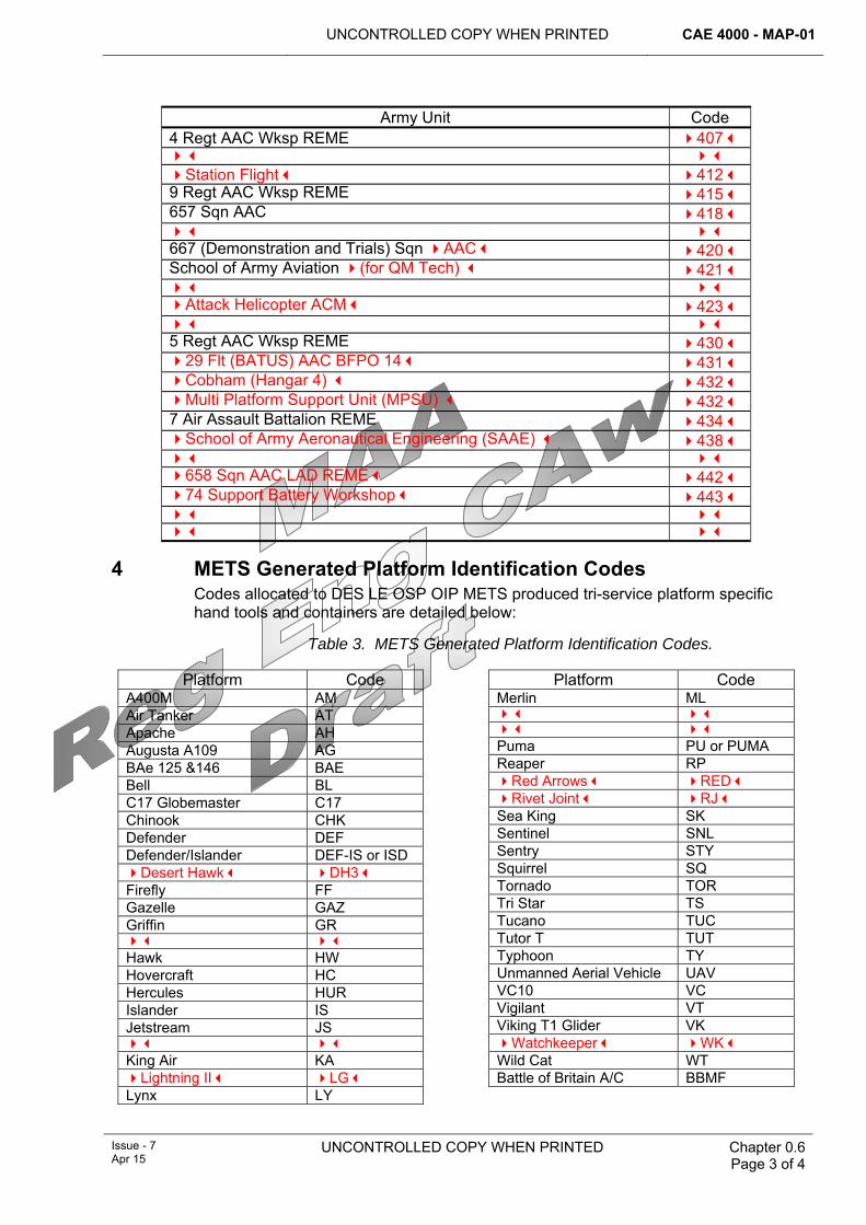
3 Army Aviation Unit Identification Codes Codes that identify Army Aviation Units and organizations are detailed below:
Table 2. Army Aviation Unit Location Codes.
Army Unit Code 1 Regiment (Regt) AAC Workshop (Wksp) REME 401 3 Regt AAC Wksp REME 405
UNCONTROLLED COPY WHEN PRINTED CAE 4000 - MAP-01
Issue - 7 Apr 15
UNCONTROLLED COPY WHEN PRINTED Chapter 0.6 Page 3 of 4
Army Unit Code 4 Regt AAC Wksp REME 407 Station Flight 412 9 Regt AAC Wksp REME 415 657 Sqn AAC 418 667 (Demonstration and Trials) Sqn AAC 420 School of Army Aviation (for QM Tech) 421 Attack Helicopter ACM 423 5 Regt AAC Wksp REME 430 29 Flt (BATUS) AAC BFPO 14 431 Cobham (Hangar 4) 432 Multi Platform Support Unit (MPSU) 432 7 Air Assault Battalion REME 434 School of Army Aeronautical Engineering (SAAE) 438 658 Sqn AAC LAD REME 442 74 Support Battery Workshop 443
4 METS Generated Platform Identification Codes Codes allocated to DES LE OSP OIP METS produced tri-service platform specific hand tools and containers are detailed below:
Table 3. METS Generated Platform Identification Codes.
Platform Code A400M AM Air Tanker AT Apache AH Augusta A109 AG BAe 125 &146 BAE Bell BL C17 Globemaster C17 Chinook CHK Defender DEF Defender/Islander DEF-IS or ISD Desert Hawk DH3 Firefly FF Gazelle GAZ Griffin GR Hawk HW Hovercraft HC Hercules HUR Islander IS Jetstream JS King Air KA Lightning II LG Lynx LY
Platform Code Merlin ML Puma PU or PUMA Reaper RP Red Arrows RED Rivet Joint RJ Sea King SK Sentinel SNL Sentry STY Squirrel SQ Tornado TOR Tri Star TS Tucano TUC Tutor T TUT Typhoon TY Unmanned Aerial Vehicle UAV VC10 VC Vigilant VT Viking T1 Glider VK Watchkeeper WK Wild Cat WT Battle of Britain A/C BBMF

CAE 4000 - MAP-01 UNCONTROLLED COPY WHEN PRINTED
Chapter 0.6 Page 4 of 4
UNCONTROLLED COPY WHEN PRINTED Issue - 7 Apr 15
Intentionally Blank for Print Pagination
UNCONTROLLED COPY WHEN PRINTED CAE 4000 - MAP-01
Issue - 7 Apr 15
UNCONTROLLED COPY WHEN PRINTED Chapter 0.7 Page 1 of 36
Chapter 0.7
Authority Levels and Tasks
TABLE OF CONTENTS Paragraph
Page
1 Introduction ....................................................................................................... 1 2 Record of Engineering Authorizations............................................................ 1
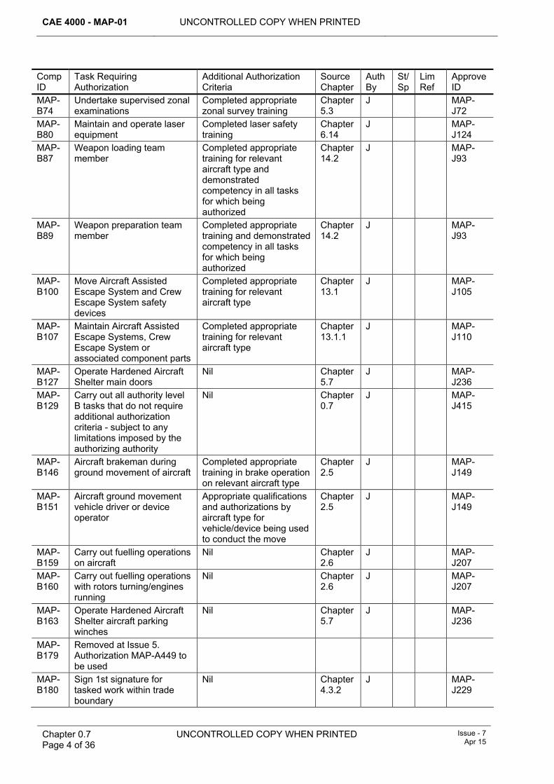
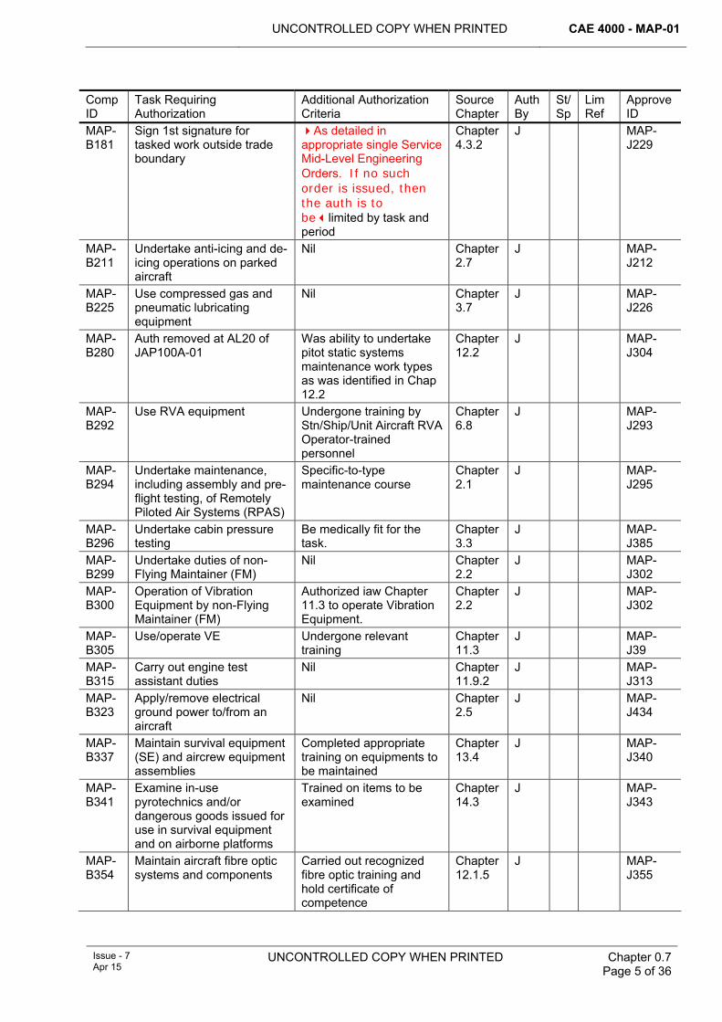
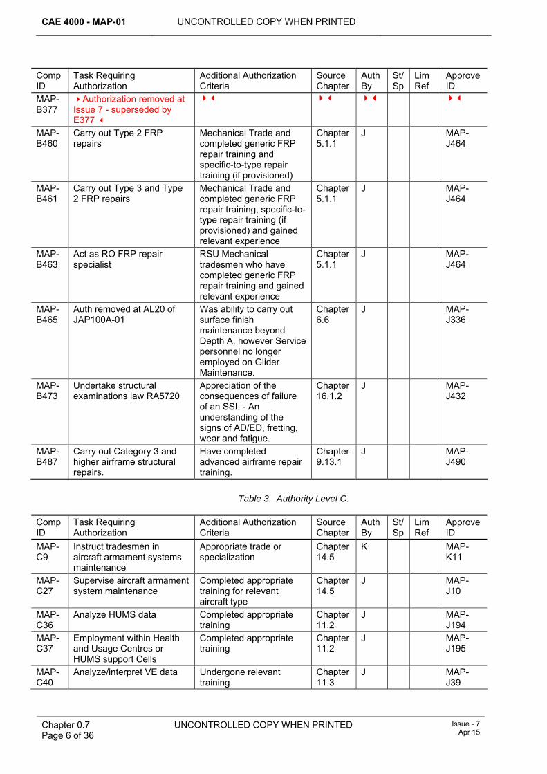
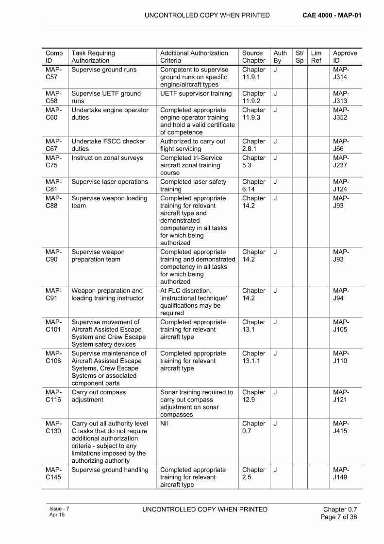
LIST OF TABLES Table 1. Authority Level A.............................................................................................................3 Table 2. Authority Level B.............................................................................................................3 Table 3. Authority Level C.............................................................................................................6 Table 4. Authority Level D.............................................................................................................9 Table 5. Authority Level E...........................................................................................................11 Table 6. Authority Level F. ..........................................................................................................13 Table 7. Authority Level G. .........................................................................................................14 Table 8. Authority Level H...........................................................................................................16 Table 9. Authority Level J. ..........................................................................................................17 Table 10. Authority Level K.........................................................................................................28 Table 11. Aircrew Authorizations. ...............................................................................................32 Table 12. Limitation(s) Placed on Specific Authorization(s). ......................................................33 Table 13. Additional Authorization(s)..........................................................................................34 Table 14. Tradesman’s Declaration and Authorization...............................................................35
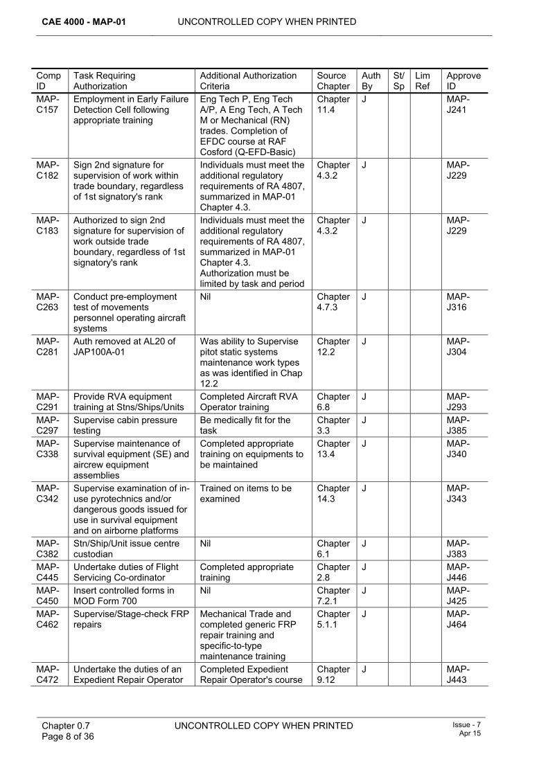
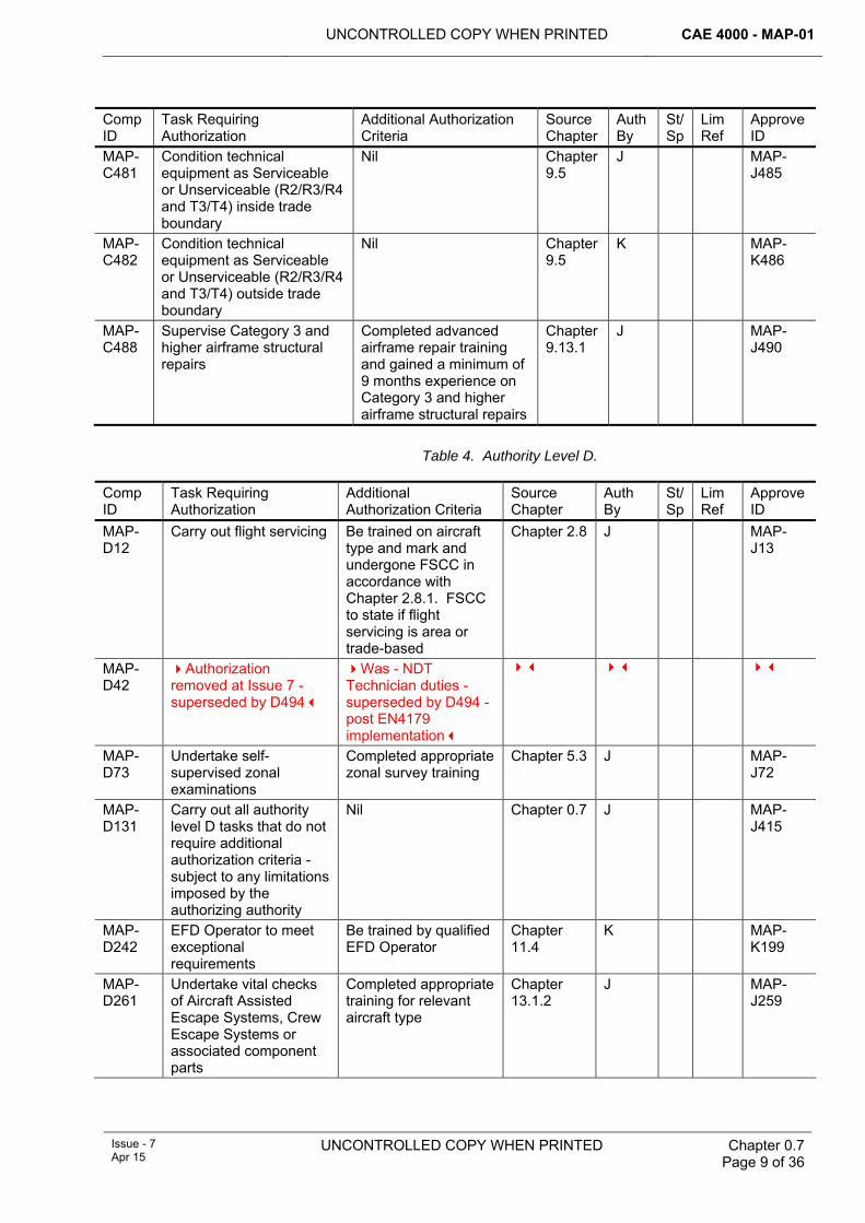
1 Introduction The MAP-01 refers to specific authority levels within individual chapters. These authority levels relate to levels of competence and provide the framework by which personnel can be authorized to sign maintenance documents as detailed in Chapter 4.3. The means by which authority can be granted are detailed in Chapter 4.3.1. The responsibilities associated with a signature are detailed in Chapter 4.3.2.
This chapter summarizes all tasks and associated competencies that have been converged from single-Service regulations and specified in individual MAP-01 chapters; they must be read in conjunction with the source chapter. The tasks are listed according to their authority level. The chapter also provides a means by which authorizations can be granted to personnel when used in conjunction with Chapter 4.3, Chapter 4.3.1 and Chapter 4.3.2.
Single Service regulations remain extant unless otherwise covered within the MAP-01.
2 Record of Engineering Authorizations The Record of Engineering Authorizations is one of the methods detailed in Chapter 4.3.1 by which an individual can be authorized to carry out task(s) and sign the necessary documentation. The Record of Engineering Authorizations is to be completed as follows:
1 Insert the details of the individual to which the Record of Engineering Authorizations applies.
CAE 4000 - MAP-01 UNCONTROLLED COPY WHEN PRINTED
Chapter 0.7 Page 2 of 36
UNCONTROLLED COPY WHEN PRINTED Issue - 7 Apr 15
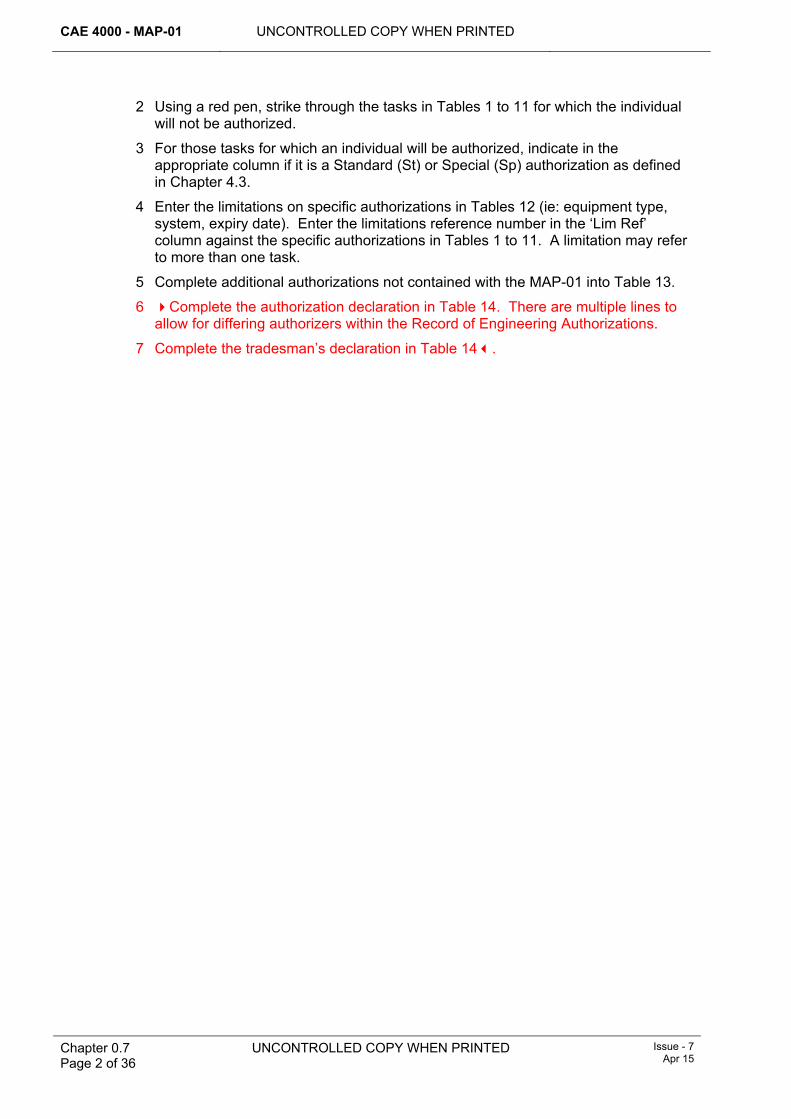
2 Using a red pen, strike through the tasks in Tables 1 to 11 for which the individual will not be authorized.
3 For those tasks for which an individual will be authorized, indicate in the appropriate column if it is a Standard (St) or Special (Sp) authorization as defined in Chapter 4.3.
4 Enter the limitations on specific authorizations in Tables 12 (ie: equipment type, system, expiry date). Enter the limitations reference number in the ‘Lim Ref’ column against the specific authorizations in Tables 1 to 11. A limitation may refer to more than one task.
5 Complete additional authorizations not contained with the MAP-01 into Table 13.
6 Complete the authorization declaration in Table 14. There are multiple lines to allow for differing authorizers within the Record of Engineering Authorizations.
7 Complete the tradesman’s declaration in Table 14.
UNCONTROLLED COPY WHEN PRINTED CAE 4000 - MAP-01
Issue - 7 Apr 15
UNCONTROLLED COPY WHEN PRINTED
Chapter 0.7 Page 3 of 36
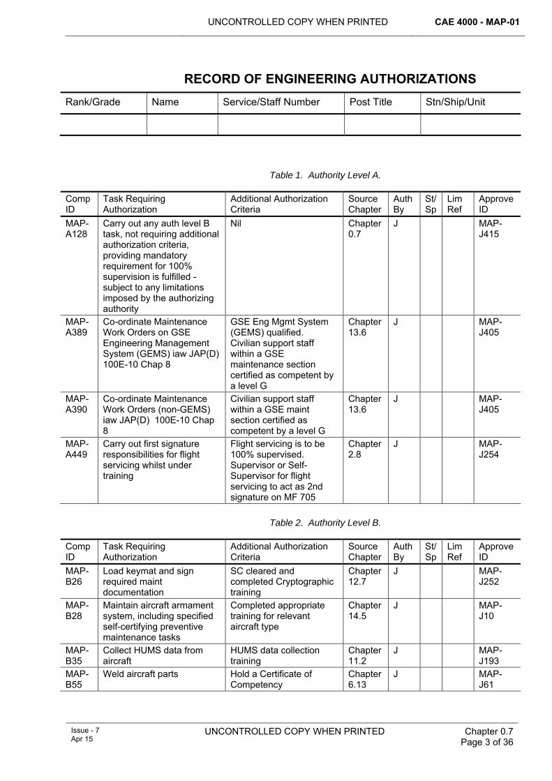
RECORD OF ENGINEERING AUTHORIZATIONS Rank/Grade Name Service/Staff Number Post Title Stn/Ship/Unit
Table 1. Authority Level A.
Comp ID
Task Requiring Authorization
Additional Authorization Criteria
Source Chapter
Auth By
St/Sp
Lim Ref
Approve ID
MAP-A128
Carry out any auth level B task, not requiring additional authorization criteria, providing mandatory requirement for 100% supervision is fulfilled - subject to any limitations imposed by the authorizing authority
Nil Chapter 0.7
J MAP-J415
MAP-A389
Co-ordinate Maintenance Work Orders on GSE Engineering Management System (GEMS) iaw JAP(D) 100E-10 Chap 8
GSE Eng Mgmt System (GEMS) qualified. Civilian support staff within a GSE maintenance section certified as competent by a level G
Chapter 13.6
J MAP-J405
MAP-A390
Co-ordinate Maintenance Work Orders (non-GEMS) iaw JAP(D) 100E-10 Chap 8
Civilian support staff within a GSE maint section certified as competent by a level G
Chapter 13.6
J MAP-J405
MAP-A449
Carry out first signature responsibilities for flight servicing whilst under training
Flight servicing is to be 100% supervised. Supervisor or Self-Supervisor for flight servicing to act as 2nd signature on MF 705
Chapter 2.8
J MAP-J254
Table 2. Authority Level B.
Comp ID
Task Requiring Authorization
Additional Authorization Criteria
Source Chapter
Auth By
St/Sp
Lim Ref
Approve ID
MAP-B26
Load keymat and sign required maint documentation
SC cleared and completed Cryptographic training
Chapter 12.7
J MAP-J252
MAP-B28
Maintain aircraft armament system, including specified self-certifying preventive maintenance tasks
Completed appropriate training for relevant aircraft type
Chapter 14.5
J MAP-J10
MAP-B35
Collect HUMS data from aircraft
HUMS data collection training
Chapter 11.2
J MAP-J193
MAP-B55
Weld aircraft parts Hold a Certificate of Competency
Chapter 6.13
J MAP-J61
CAE 4000 - MAP-01 UNCONTROLLED COPY WHEN PRINTED
Chapter 0.7 Page 4 of 36
UNCONTROLLED COPY WHEN PRINTED Issue - 7 Apr 15
Comp ID
Task Requiring Authorization
Additional Authorization Criteria
Source Chapter
Auth By
St/Sp
Lim Ref
Approve ID
MAP-B74
Undertake supervised zonal examinations
Completed appropriate zonal survey training
Chapter 5.3
J MAP-J72
MAP-B80
Maintain and operate laser equipment
Completed laser safety training
Chapter 6.14
J MAP-J124
MAP-B87
Weapon loading team member
Completed appropriate training for relevant aircraft type and demonstrated competency in all tasks for which being authorized
Chapter 14.2
J MAP-J93
MAP-B89
Weapon preparation team member
Completed appropriate training and demonstrated competency in all tasks for which being authorized
Chapter 14.2
J MAP-J93
MAP-B100
Move Aircraft Assisted Escape System and Crew Escape System safety devices
Completed appropriate training for relevant aircraft type
Chapter 13.1
J MAP-J105
MAP-B107
Maintain Aircraft Assisted Escape Systems, Crew Escape System or associated component parts
Completed appropriate training for relevant aircraft type
Chapter 13.1.1
J MAP-J110
MAP-B127
Operate Hardened Aircraft Shelter main doors
Nil Chapter 5.7
J MAP-J236
MAP-B129
Carry out all authority level B tasks that do not require additional authorization criteria - subject to any limitations imposed by the authorizing authority
Nil Chapter 0.7
J MAP-J415
MAP-B146
Aircraft brakeman during ground movement of aircraft
Completed appropriate training in brake operation on relevant aircraft type
Chapter 2.5
J MAP-J149
MAP-B151
Aircraft ground movement vehicle driver or device operator
Appropriate qualifications and authorizations by aircraft type for vehicle/device being used to conduct the move
Chapter 2.5
J MAP-J149
MAP-B159
Carry out fuelling operations on aircraft
Nil Chapter 2.6
J MAP-J207
MAP-B160
Carry out fuelling operations with rotors turning/engines running
Nil Chapter 2.6
J MAP-J207
MAP-B163
Operate Hardened Aircraft Shelter aircraft parking winches
Nil Chapter 5.7
J MAP-J236
MAP-B179
Removed at Issue 5. Authorization MAP-A449 to be used
MAP-B180
Sign 1st signature for tasked work within trade boundary
Nil Chapter 4.3.2
J MAP-J229
UNCONTROLLED COPY WHEN PRINTED CAE 4000 - MAP-01
Issue - 7 Apr 15
UNCONTROLLED COPY WHEN PRINTED
Chapter 0.7 Page 5 of 36
Comp ID
Task Requiring Authorization
Additional Authorization Criteria
Source Chapter
Auth By
St/Sp
Lim Ref
Approve ID
MAP-B181
Sign 1st signature for tasked work outside trade boundary
As detailed in appropriate single Service Mid-Level Engineering Orders. If no such order is issued, then the auth is to belimited by task and period
Chapter 4.3.2
J MAP-J229
MAP-B211
Undertake anti-icing and de-icing operations on parked aircraft
Nil Chapter 2.7
J MAP-J212
MAP-B225
Use compressed gas and pneumatic lubricating equipment
Nil Chapter 3.7
J MAP-J226
MAP-B280
Auth removed at AL20 of JAP100A-01
Was ability to undertake pitot static systems maintenance work types as was identified in Chap 12.2
Chapter 12.2
J MAP-J304
MAP-B292
Use RVA equipment Undergone training by Stn/Ship/Unit Aircraft RVA Operator-trained personnel
Chapter 6.8
J MAP-J293
MAP-B294
Undertake maintenance, including assembly and pre-flight testing, of Remotely Piloted Air Systems (RPAS)
Specific-to-type maintenance course
Chapter 2.1
J MAP-J295
MAP-B296
Undertake cabin pressure testing
Be medically fit for the task.
Chapter 3.3
J MAP-J385
MAP-B299
Undertake duties of non-Flying Maintainer (FM)
Nil Chapter 2.2
J MAP-J302
MAP-B300
Operation of Vibration Equipment by non-Flying Maintainer (FM)
Authorized iaw Chapter 11.3 to operate Vibration Equipment.
Chapter 2.2
J MAP-J302
MAP-B305
Use/operate VE Undergone relevant training
Chapter 11.3
J MAP-J39
MAP-B315
Carry out engine test assistant duties
Nil Chapter 11.9.2
J MAP-J313
MAP-B323
Apply/remove electrical ground power to/from an aircraft
Nil Chapter 2.5
J MAP-J434
MAP-B337
Maintain survival equipment (SE) and aircrew equipment assemblies
Completed appropriate training on equipments to be maintained
Chapter 13.4
J MAP-J340
MAP-B341
Examine in-use pyrotechnics and/or dangerous goods issued for use in survival equipment and on airborne platforms
Trained on items to be examined
Chapter 14.3
J MAP-J343
MAP-B354
Maintain aircraft fibre optic systems and components
Carried out recognized fibre optic training and hold certificate of competence
Chapter 12.1.5
J MAP-J355
CAE 4000 - MAP-01 UNCONTROLLED COPY WHEN PRINTED
Chapter 0.7 Page 6 of 36
UNCONTROLLED COPY WHEN PRINTED Issue - 7 Apr 15
Comp ID
Task Requiring Authorization
Additional Authorization Criteria
Source Chapter
Auth By
St/Sp
Lim Ref
Approve ID
MAP-B377
Authorization removed at Issue 7 - superseded by E377
MAP-B460
Carry out Type 2 FRP repairs
Mechanical Trade and completed generic FRP repair training and specific-to-type repair training (if provisioned)
Chapter 5.1.1
J MAP-J464
MAP-B461
Carry out Type 3 and Type 2 FRP repairs
Mechanical Trade and completed generic FRP repair training, specific-to-type repair training (if provisioned) and gained relevant experience
Chapter 5.1.1
J MAP-J464
MAP-B463
Act as RO FRP repair specialist
RSU Mechanical tradesmen who have completed generic FRP repair training and gained relevant experience
Chapter 5.1.1
J MAP-J464
MAP-B465
Auth removed at AL20 of JAP100A-01
Was ability to carry out surface finish maintenance beyond Depth A, however Service personnel no longer employed on Glider Maintenance.
Chapter 6.6
J MAP-J336
MAP-B473
Undertake structural examinations iaw RA5720
Appreciation of the consequences of failure of an SSI. - An understanding of the signs of AD/ED, fretting, wear and fatigue.
Chapter 16.1.2
J MAP-J432
MAP-B487
Carry out Category 3 and higher airframe structural repairs.
Have completed advanced airframe repair training.
Chapter 9.13.1
J MAP-J490
Table 3. Authority Level C.
Comp ID
Task Requiring Authorization
Additional Authorization Criteria
Source Chapter
Auth By
St/Sp
Lim Ref
Approve ID
MAP-C9
Instruct tradesmen in aircraft armament systems maintenance
Appropriate trade or specialization
Chapter 14.5
K MAP-K11
MAP-C27
Supervise aircraft armament system maintenance
Completed appropriate training for relevant aircraft type
Chapter 14.5
J MAP-J10
MAP-C36
Analyze HUMS data Completed appropriate training
Chapter 11.2
J MAP-J194
MAP-C37
Employment within Health and Usage Centres or HUMS support Cells
Completed appropriate training
Chapter 11.2
J MAP-J195
MAP-C40
Analyze/interpret VE data Undergone relevant training
Chapter 11.3
J MAP-J39
UNCONTROLLED COPY WHEN PRINTED CAE 4000 - MAP-01
Issue - 7 Apr 15
UNCONTROLLED COPY WHEN PRINTED
Chapter 0.7 Page 7 of 36
Comp ID
Task Requiring Authorization
Additional Authorization Criteria
Source Chapter
Auth By
St/Sp
Lim Ref
Approve ID
MAP-C57
Supervise ground runs Competent to supervise ground runs on specific engine/aircraft types
Chapter 11.9.1
J MAP-J314
MAP-C58
Supervise UETF ground runs
UETF supervisor training Chapter 11.9.2
J MAP-J313
MAP-C60
Undertake engine operator duties
Completed appropriate engine operator training and hold a valid certificate of competence
Chapter 11.9.3
J MAP-J352
MAP-C67
Undertake FSCC checker duties
Authorized to carry out flight servicing
Chapter 2.8.1
J MAP-J66
MAP-C75
Instruct on zonal surveys Completed tri-Service aircraft zonal training course
Chapter 5.3
J MAP-J237
MAP-C81
Supervise laser operations Completed laser safety training
Chapter 6.14
J MAP-J124
MAP-C88
Supervise weapon loading team
Completed appropriate training for relevant aircraft type and demonstrated competency in all tasks for which being authorized
Chapter 14.2
J MAP-J93
MAP-C90
Supervise weapon preparation team
Completed appropriate training and demonstrated competency in all tasks for which being authorized
Chapter 14.2
J MAP-J93
MAP-C91
Weapon preparation and loading training instructor
At FLC discretion, 'instructional technique' qualifications may be required
Chapter 14.2
J MAP-J94
MAP-C101
Supervise movement of Aircraft Assisted Escape System and Crew Escape System safety devices
Completed appropriate training for relevant aircraft type
Chapter 13.1
J MAP-J105
MAP-C108
Supervise maintenance of Aircraft Assisted Escape Systems, Crew Escape Systems or associated component parts
Completed appropriate training for relevant aircraft type
Chapter 13.1.1
J MAP-J110
MAP-C116
Carry out compass adjustment
Sonar training required to carry out compass adjustment on sonar compasses
Chapter 12.9
J MAP-J121
MAP-C130
Carry out all authority level C tasks that do not require additional authorization criteria - subject to any limitations imposed by the authorizing authority
Nil Chapter 0.7
J MAP-J415
MAP-C145
Supervise ground handling Completed appropriate training for relevant aircraft type
Chapter 2.5
J MAP-J149
CAE 4000 - MAP-01 UNCONTROLLED COPY WHEN PRINTED
Chapter 0.7 Page 8 of 36
UNCONTROLLED COPY WHEN PRINTED Issue - 7 Apr 15
Comp ID
Task Requiring Authorization
Additional Authorization Criteria
Source Chapter
Auth By
St/Sp
Lim Ref
Approve ID
MAP-C157
Employment in Early Failure Detection Cell following appropriate training
Eng Tech P, Eng Tech A/P, A Eng Tech, A Tech M or Mechanical (RN) trades. Completion of EFDC course at RAF Cosford (Q-EFD-Basic)
Chapter 11.4
J MAP-J241
MAP-C182
Sign 2nd signature for supervision of work within trade boundary, regardless of 1st signatory's rank
Individuals must meet the additional regulatory requirements of RA 4807, summarized in MAP-01 Chapter 4.3.
Chapter 4.3.2
J MAP-J229
MAP-C183
Authorized to sign 2nd signature for supervision of work outside trade boundary, regardless of 1st signatory's rank
Individuals must meet the additional regulatory requirements of RA 4807, summarized in MAP-01 Chapter 4.3. Authorization must be limited by task and period
Chapter 4.3.2
J MAP-J229
MAP-C263
Conduct pre-employment test of movements personnel operating aircraft systems
Nil Chapter 4.7.3
J MAP-J316
MAP-C281
Auth removed at AL20 of JAP100A-01
Was ability to Supervise pitot static systems maintenance work types as was identified in Chap 12.2
Chapter 12.2
J MAP-J304
MAP-C291
Provide RVA equipment training at Stns/Ships/Units
Completed Aircraft RVA Operator training
Chapter 6.8
J MAP-J293
MAP-C297
Supervise cabin pressure testing
Be medically fit for the task
Chapter 3.3
J MAP-J385
MAP-C338
Supervise maintenance of survival equipment (SE) and aircrew equipment assemblies
Completed appropriate training on equipments to be maintained
Chapter 13.4
J MAP-J340
MAP-C342
Supervise examination of in-use pyrotechnics and/or dangerous goods issued for use in survival equipment and on airborne platforms
Trained on items to be examined
Chapter 14.3
J MAP-J343
MAP-C382
Stn/Ship/Unit issue centre custodian
Nil Chapter 6.1
J MAP-J383
MAP-C445
Undertake duties of Flight Servicing Co-ordinator
Completed appropriate training
Chapter 2.8
J MAP-J446
MAP-C450
Insert controlled forms in MOD Form 700
Nil Chapter 7.2.1
J MAP-J425
MAP-C462
Supervise/Stage-check FRP repairs
Mechanical Trade and completed generic FRP repair training and specific-to-type maintenance training
Chapter 5.1.1
J MAP-J464
MAP-C472
Undertake the duties of an Expedient Repair Operator
Completed Expedient Repair Operator's course
Chapter 9.12
J MAP-J443
UNCONTROLLED COPY WHEN PRINTED CAE 4000 - MAP-01
Issue - 7 Apr 15
UNCONTROLLED COPY WHEN PRINTED
Chapter 0.7 Page 9 of 36
Comp ID
Task Requiring Authorization
Additional Authorization Criteria
Source Chapter
Auth By
St/Sp
Lim Ref
Approve ID
MAP-C481
Condition technical equipment as Serviceable or Unserviceable (R2/R3/R4 and T3/T4) inside trade boundary
Nil Chapter 9.5
J MAP-J485
MAP-C482
Condition technical equipment as Serviceable or Unserviceable (R2/R3/R4 and T3/T4) outside trade boundary
Nil Chapter 9.5
K MAP-K486
MAP-C488
Supervise Category 3 and higher airframe structural repairs
Completed advanced airframe repair training and gained a minimum of 9 months experience on Category 3 and higher airframe structural repairs
Chapter 9.13.1
J MAP-J490
Table 4. Authority Level D.
Comp ID
Task Requiring Authorization
Additional Authorization Criteria
Source Chapter
Auth By
St/Sp
Lim Ref
Approve ID
MAP-D12
Carry out flight servicing Be trained on aircraft type and mark and undergone FSCC in accordance with Chapter 2.8.1. FSCC to state if flight servicing is area or trade-based
Chapter 2.8 J MAP-J13
MAP-D42
Authorization removed at Issue 7 - superseded by D494
Was - NDT Technician duties - superseded by D494 - post EN4179 implementation
MAP-D73
Undertake self-supervised zonal examinations
Completed appropriate zonal survey training
Chapter 5.3 J MAP-J72
MAP-D131
Carry out all authority level D tasks that do not require additional authorization criteria - subject to any limitations imposed by the authorizing authority
Nil Chapter 0.7 J MAP-J415
MAP-D242
EFD Operator to meet exceptional requirements
Be trained by qualified EFD Operator
Chapter 11.4
K MAP-K199
MAP-D261
Undertake vital checks of Aircraft Assisted Escape Systems, Crew Escape Systems or associated component parts
Completed appropriate training for relevant aircraft type
Chapter 13.1.2
J MAP-J259
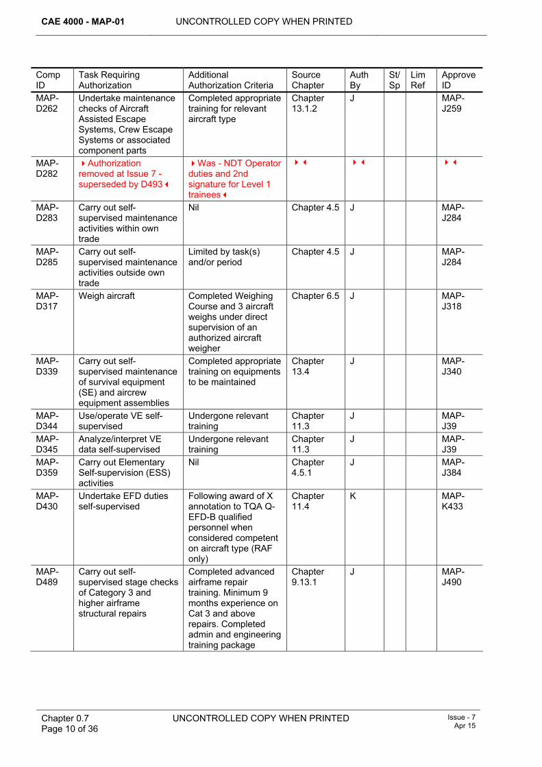
CAE 4000 - MAP-01 UNCONTROLLED COPY WHEN PRINTED
Chapter 0.7 Page 10 of 36
UNCONTROLLED COPY WHEN PRINTED Issue - 7 Apr 15
Comp ID
Task Requiring Authorization
Additional Authorization Criteria
Source Chapter
Auth By
St/Sp
Lim Ref
Approve ID
MAP-D262
Undertake maintenance checks of Aircraft Assisted Escape Systems, Crew Escape Systems or associated component parts
Completed appropriate training for relevant aircraft type
Chapter 13.1.2
J MAP-J259
MAP-D282
Authorization removed at Issue 7 - superseded by D493
Was - NDT Operator duties and 2nd signature for Level 1 trainees
MAP-D283
Carry out self-supervised maintenance activities within own trade
Nil Chapter 4.5 J MAP-J284
MAP-D285
Carry out self-supervised maintenance activities outside own trade
Limited by task(s) and/or period
Chapter 4.5 J MAP-J284
MAP-D317
Weigh aircraft Completed Weighing Course and 3 aircraft weighs under direct supervision of an authorized aircraft weigher
Chapter 6.5 J MAP-J318
MAP-D339
Carry out self-supervised maintenance of survival equipment (SE) and aircrew equipment assemblies
Completed appropriate training on equipments to be maintained
Chapter 13.4
J MAP-J340
MAP-D344
Use/operate VE self-supervised
Undergone relevant training
Chapter 11.3
J MAP-J39
MAP-D345
Analyze/interpret VE data self-supervised
Undergone relevant training
Chapter 11.3
J MAP-J39
MAP-D359
Carry out Elementary Self-supervision (ESS) activities
Nil Chapter 4.5.1
J MAP-J384
MAP-D430
Undertake EFD duties self-supervised
Following award of X annotation to TQA Q-EFD-B qualified personnel when considered competent on aircraft type (RAF only)
Chapter 11.4
K MAP-K433
MAP-D489
Carry out self-supervised stage checks of Category 3 and higher airframe structural repairs
Completed advanced airframe repair training. Minimum 9 months experience on Cat 3 and above repairs. Completed admin and engineering training package
Chapter 9.13.1
J MAP-J490
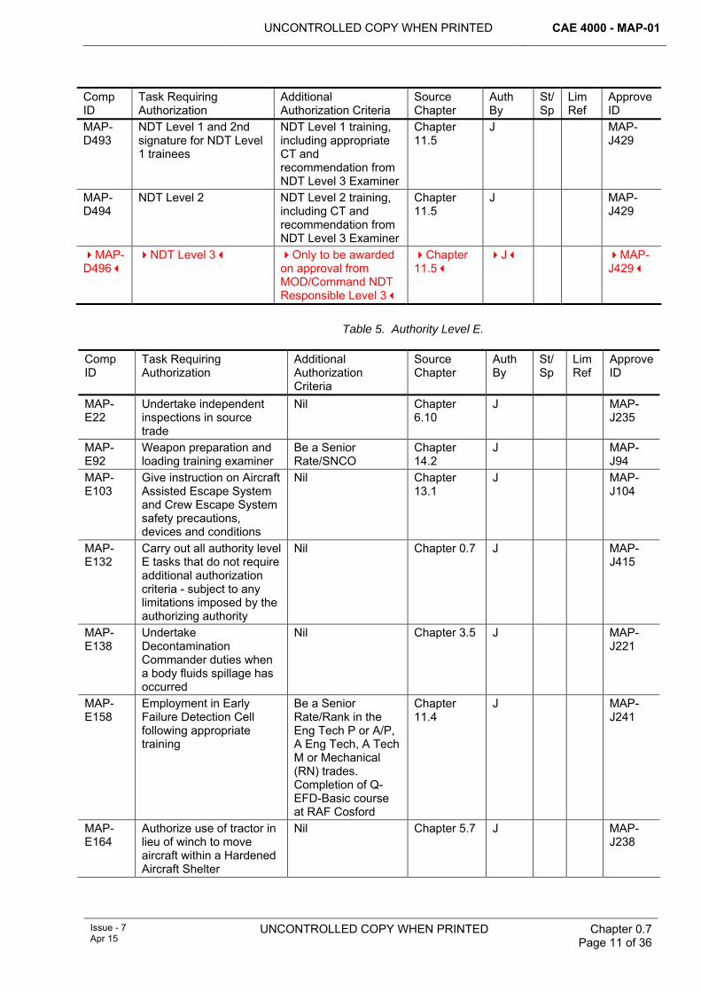
UNCONTROLLED COPY WHEN PRINTED CAE 4000 - MAP-01
Issue - 7 Apr 15
UNCONTROLLED COPY WHEN PRINTED
Chapter 0.7 Page 11 of 36
Comp ID
Task Requiring Authorization
Additional Authorization Criteria
Source Chapter
Auth By
St/Sp
Lim Ref
Approve ID
MAP-D493
NDT Level 1 and 2nd signature for NDT Level 1 trainees
NDT Level 1 training, including appropriate CT and recommendation from NDT Level 3 Examiner
Chapter 11.5
J MAP-J429
MAP-D494
NDT Level 2 NDT Level 2 training, including CT and recommendation from NDT Level 3 Examiner
Chapter 11.5
J MAP-J429
MAP-D496
NDT Level 3 Only to be awarded on approval from MOD/Command NDT Responsible Level 3
Chapter 11.5
J MAP-J429
Table 5. Authority Level E.
Comp ID
Task Requiring Authorization
Additional Authorization Criteria
Source Chapter
Auth By
St/Sp
Lim Ref
Approve ID
MAP-E22
Undertake independent inspections in source trade
Nil Chapter 6.10
J MAP-J235
MAP-E92
Weapon preparation and loading training examiner
Be a Senior Rate/SNCO
Chapter 14.2
J MAP-J94
MAP-E103
Give instruction on Aircraft Assisted Escape System and Crew Escape System safety precautions, devices and conditions
Nil Chapter 13.1
J MAP-J104
MAP-E132
Carry out all authority level E tasks that do not require additional authorization criteria - subject to any limitations imposed by the authorizing authority
Nil Chapter 0.7 J MAP-J415
MAP-E138
Undertake Decontamination Commander duties when a body fluids spillage has occurred
Nil Chapter 3.5 J MAP-J221
MAP-E158
Employment in Early Failure Detection Cell following appropriate training
Be a Senior Rate/Rank in the Eng Tech P or A/P, A Eng Tech, A Tech M or Mechanical (RN) trades. Completion of Q- EFD-Basic course at RAF Cosford
Chapter 11.4
J MAP-J241
MAP-E164
Authorize use of tractor in lieu of winch to move aircraft within a Hardened Aircraft Shelter
Nil Chapter 5.7 J MAP-J238
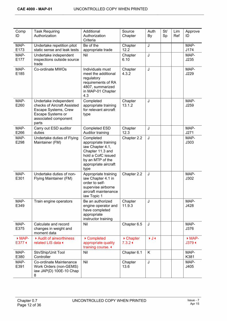
CAE 4000 - MAP-01 UNCONTROLLED COPY WHEN PRINTED
Chapter 0.7 Page 12 of 36
UNCONTROLLED COPY WHEN PRINTED Issue - 7 Apr 15
Comp ID
Task Requiring Authorization
Additional Authorization Criteria
Source Chapter
Auth By
St/Sp
Lim Ref
Approve ID
MAP-E173
Undertake repetition pitot static sense and leak tests
Be of the appropriate trade
Chapter 12.2
J MAP-J174
MAP-E177
Undertake independent inspections outside source trade
Nil Chapter 6.10
J MAP-J235
MAP-E185
Co-ordinate MWOs Individuals must meet the additional regulatory requirements of RA 4807, summarized in MAP-01 Chapter 4.3
Chapter 4.3.2
J MAP-J229
MAP-E260
Undertake independent checks of Aircraft Assisted Escape Systems, Crew Escape Systems or associated component parts
Completed appropriate training for relevant aircraft type
Chapter 13.1.2
J MAP-J259
MAP-E266
Carry out ESD auditor duties
Completed ESD Auditor training
Chapter 12.3
J MAP-J271
MAP-E298
Undertake duties of Flying Maintainer (FM)
Completed appropriate training iaw Chapter 4.1, Chapter 11.3 and hold a CofC issued by an MTP of the appropriate aircraft type
Chapter 2.2 J MAP-J303
MAP-E301
Undertake duties of non-Flying Maintainer (FM)
Appropriate training iaw Chapter 4.1 in order to self-supervise airborne aircraft maintenance iaw Topic 1
Chapter 2.2 J MAP-J302
MAP-E349
Train engine operators Be an authorized engine operator and have completed appropriate instructor training
Chapter 11.9.3
J MAP-J428
MAP-E375
Calculate and record changes in weight and moment data
Nil Chapter 6.5 J MAP-J376
MAP-E377
Audit of airworthiness related LIS data
Completed appropriate quality training course.
Chapter 7.3.2
J MAP-J379
MAP-E380
Stn/Ship/Unit Tool Controller
Nil Chapter 6.1 K MAP-K381
MAP-E391
Co-ordinate Maintenance Work Orders (non-GEMS) iaw JAP(D) 100E-10 Chap 8
Nil Chapter 13.6
J MAP-J405
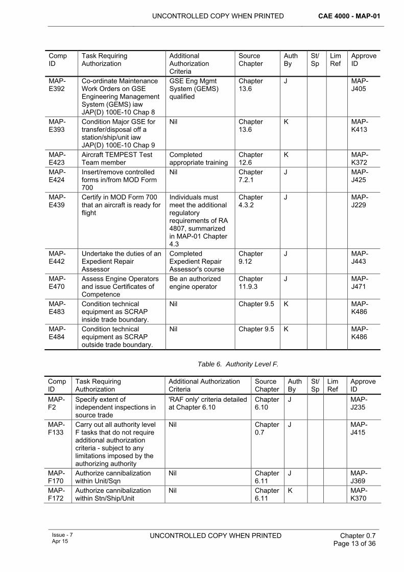
UNCONTROLLED COPY WHEN PRINTED CAE 4000 - MAP-01
Issue - 7 Apr 15
UNCONTROLLED COPY WHEN PRINTED
Chapter 0.7 Page 13 of 36
Comp ID
Task Requiring Authorization
Additional Authorization Criteria
Source Chapter
Auth By
St/Sp
Lim Ref
Approve ID
MAP-E392
Co-ordinate Maintenance Work Orders on GSE Engineering Management System (GEMS) iaw JAP(D) 100E-10 Chap 8
GSE Eng Mgmt System (GEMS) qualified
Chapter 13.6
J MAP-J405
MAP-E393
Condition Major GSE for transfer/disposal off a station/ship/unit iaw JAP(D) 100E-10 Chap 9
Nil Chapter 13.6
K MAP-K413
MAP-E423
Aircraft TEMPEST Test Team member
Completed appropriate training
Chapter 12.6
K MAP-K372
MAP-E424
Insert/remove controlled forms in/from MOD Form 700
Nil Chapter 7.2.1
J MAP-J425
MAP-E439
Certify in MOD Form 700 that an aircraft is ready for flight
Individuals must meet the additional regulatory requirements of RA 4807, summarized in MAP-01 Chapter 4.3
Chapter 4.3.2
J MAP-J229
MAP-E442
Undertake the duties of an Expedient Repair Assessor
Completed Expedient Repair Assessor's course
Chapter 9.12
J MAP-J443
MAP-E470
Assess Engine Operators and issue Certificates of Competence
Be an authorized engine operator
Chapter 11.9.3
J MAP-J471
MAP-E483
Condition technical equipment as SCRAP inside trade boundary.
Nil Chapter 9.5 K MAP-K486
MAP-E484
Condition technical equipment as SCRAP outside trade boundary.
Nil Chapter 9.5 K MAP-K486
Table 6. Authority Level F.
Comp ID
Task Requiring Authorization
Additional Authorization Criteria
Source Chapter
Auth By
St/Sp
Lim Ref
Approve ID
MAP-F2
Specify extent of independent inspections in source trade
'RAF only' criteria detailed at Chapter 6.10
Chapter 6.10
J MAP-J235
MAP-F133
Carry out all authority level F tasks that do not require additional authorization criteria - subject to any limitations imposed by the authorizing authority
Nil Chapter 0.7
J MAP-J415
MAP-F170
Authorize cannibalization within Unit/Sqn
Nil Chapter 6.11
J MAP-J369
MAP-F172
Authorize cannibalization within Stn/Ship/Unit
Nil Chapter 6.11
K MAP-K370
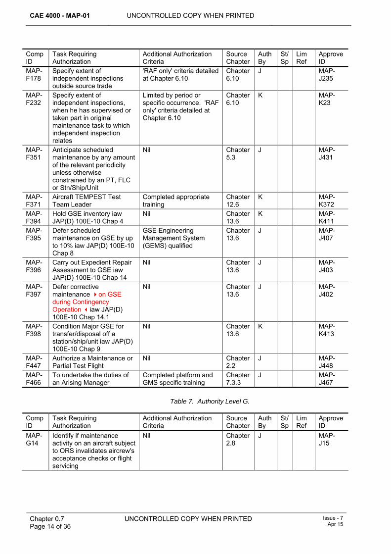
CAE 4000 - MAP-01 UNCONTROLLED COPY WHEN PRINTED
Chapter 0.7 Page 14 of 36
UNCONTROLLED COPY WHEN PRINTED Issue - 7 Apr 15
Comp ID
Task Requiring Authorization
Additional Authorization Criteria
Source Chapter
Auth By
St/Sp
Lim Ref
Approve ID
MAP-F178
Specify extent of independent inspections outside source trade
'RAF only' criteria detailed at Chapter 6.10
Chapter 6.10
J MAP-J235
MAP-F232
Specify extent of independent inspections, when he has supervised or taken part in original maintenance task to which independent inspection relates
Limited by period or specific occurrence. 'RAF only' criteria detailed at Chapter 6.10
Chapter 6.10
K MAP-K23
MAP-F351
Anticipate scheduled maintenance by any amount of the relevant periodicity unless otherwise constrained by an PT, FLC or Stn/Ship/Unit
Nil Chapter 5.3
J MAP-J431
MAP-F371
Aircraft TEMPEST Test Team Leader
Completed appropriate training
Chapter 12.6
K MAP-K372
MAP-F394
Hold GSE inventory iaw JAP(D) 100E-10 Chap 4
Nil Chapter 13.6
K MAP-K411
MAP-F395
Defer scheduled maintenance on GSE by up to 10% iaw JAP(D) 100E-10 Chap 8
GSE Engineering Management System (GEMS) qualified
Chapter 13.6
J MAP-J407
MAP-F396
Carry out Expedient Repair Assessment to GSE iaw JAP(D) 100E-10 Chap 14
Nil Chapter 13.6
J MAP-J403
MAP-F397
Defer corrective maintenance on GSE during Contingency Operation iaw JAP(D) 100E-10 Chap 14.1
Nil Chapter 13.6
J MAP-J402
MAP-F398
Condition Major GSE for transfer/disposal off a station/ship/unit iaw JAP(D) 100E-10 Chap 9
Nil Chapter 13.6
K MAP-K413
MAP-F447
Authorize a Maintenance or Partial Test Flight
Nil Chapter 2.2
J MAP-J448
MAP-F466
To undertake the duties of an Arising Manager
Completed platform and GMS specific training
Chapter 7.3.3
J MAP-J467
Table 7. Authority Level G.
Comp ID
Task Requiring Authorization
Additional Authorization Criteria
Source Chapter
Auth By
St/Sp
Lim Ref
Approve ID
MAP-G14
Identify if maintenance activity on an aircraft subject to ORS invalidates aircrew's acceptance checks or flight servicing
Nil Chapter 2.8
J MAP-J15
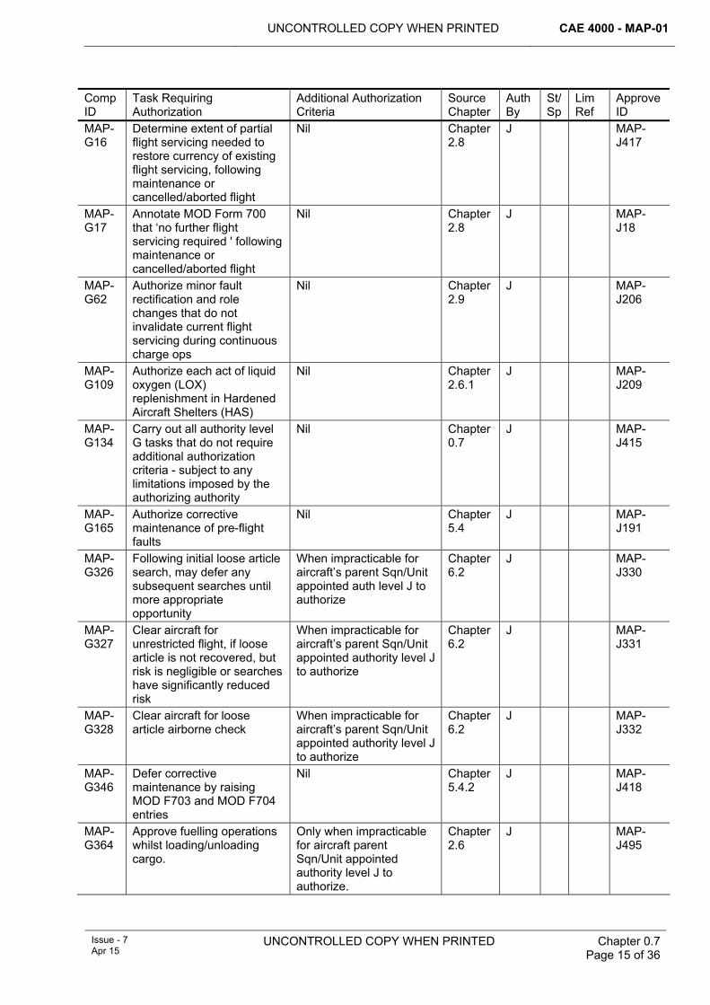
UNCONTROLLED COPY WHEN PRINTED CAE 4000 - MAP-01
Issue - 7 Apr 15
UNCONTROLLED COPY WHEN PRINTED
Chapter 0.7 Page 15 of 36
Comp ID
Task Requiring Authorization
Additional Authorization Criteria
Source Chapter
Auth By
St/Sp
Lim Ref
Approve ID
MAP-G16
Determine extent of partial flight servicing needed to restore currency of existing flight servicing, following maintenance or cancelled/aborted flight
Nil Chapter 2.8
J MAP-J417
MAP-G17
Annotate MOD Form 700 that ‘no further flight servicing required ' following maintenance or cancelled/aborted flight
Nil Chapter 2.8
J MAP-J18
MAP-G62
Authorize minor fault rectification and role changes that do not invalidate current flight servicing during continuous charge ops
Nil Chapter 2.9
J MAP-J206
MAP-G109
Authorize each act of liquid oxygen (LOX) replenishment in Hardened Aircraft Shelters (HAS)
Nil Chapter 2.6.1
J MAP-J209
MAP-G134
Carry out all authority level G tasks that do not require additional authorization criteria - subject to any limitations imposed by the authorizing authority
Nil Chapter 0.7
J MAP-J415
MAP-G165
Authorize corrective maintenance of pre-flight faults
Nil Chapter 5.4
J MAP-J191
MAP-G326
Following initial loose article search, may defer any subsequent searches until more appropriate opportunity
When impracticable for aircraft’s parent Sqn/Unit appointed auth level J to authorize
Chapter 6.2
J MAP-J330
MAP-G327
Clear aircraft for unrestricted flight, if loose article is not recovered, but risk is negligible or searches have significantly reduced risk
When impracticable for aircraft’s parent Sqn/Unit appointed authority level J to authorize
Chapter 6.2
J MAP-J331
MAP-G328
Clear aircraft for loose article airborne check
When impracticable for aircraft’s parent Sqn/Unit appointed authority level J to authorize
Chapter 6.2
J MAP-J332
MAP-G346
Defer corrective maintenance by raising MOD F703 and MOD F704 entries
Nil Chapter 5.4.2
J MAP-J418
MAP-G364
Approve fuelling operations whilst loading/unloading cargo.
Only when impracticable for aircraft parent Sqn/Unit appointed authority level J to authorize.
Chapter 2.6
J MAP-J495
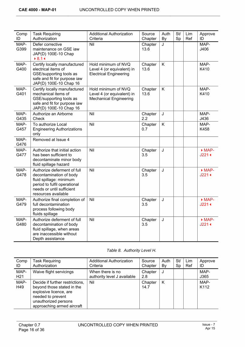
CAE 4000 - MAP-01 UNCONTROLLED COPY WHEN PRINTED
Chapter 0.7 Page 16 of 36
UNCONTROLLED COPY WHEN PRINTED Issue - 7 Apr 15
Comp ID
Task Requiring Authorization
Additional Authorization Criteria
Source Chapter
Auth By
St/Sp
Lim Ref
Approve ID
MAP-G399
Defer corrective maintenance on GSE iaw JAP(D) 100E-10 Chap 8.1
Nil Chapter 13.6
J MAP-J406
MAP-G400
Certify locally manufactured electrical items of GSE/supporting tools as safe and fit for purpose iaw JAP(D) 100E-10 Chap 16
Hold minimum of NVQ Level 4 (or equivalent) in Electrical Engineering
Chapter 13.6
K MAP-K410
MAP-G401
Certify locally manufactured mechanical items of GSE/supporting tools as safe and fit for purpose iaw JAP(D) 100E-10 Chap 16
Hold minimum of NVQ Level 4 (or equivalent) in Mechanical Engineering
Chapter 13.6
K MAP-K410
MAP-G435
Authorize an Airborne Check
Nil Chapter 2.2
J MAP-J436
MAP-G457
To authorize Local Engineering Authorizations only
Nil Chapter 0.7
K MAP-K458
MAP-G476
Removed at Issue 4
MAP-G477
Authorize that initial action has been sufficient to decontaminate minor body fluid spillage hazard
Nil Chapter 3.5
J MAP-J221
MAP-G478
Authorize deferment of full decontamination of body fluid spillage: minimum period to fulfil operational needs or until sufficient resources available
Nil Chapter 3.5
J MAP-J221
MAP-G479
Authorize final completion of full decontamination process following body fluids spillage
Nil Chapter 3.5
J MAP-J221
MAP-G480
Authorize deferment of full decontamination of body fluid spillage, when areas are inaccessible without Depth assistance
Nil Chapter 3.5
J MAP-J221
Table 8. Authority Level H.
Comp ID
Task Requiring Authorization
Additional Authorization Criteria
Source Chapter
Auth By
St/Sp
Lim Ref
Approve ID
MAP-H21
Waive flight servicings When there is no authority level J available
Chapter 2.8
J MAP-J365
MAP-H49
Decide if further restrictions, beyond those stated in the explosive licence, are needed to prevent unauthorized persons approaching armed aircraft
Nil Chapter 14.7
K MAP-K112
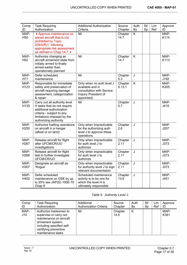
UNCONTROLLED COPY WHEN PRINTED CAE 4000 - MAP-01
Issue - 7 Apr 15
UNCONTROLLED COPY WHEN PRINTED
Chapter 0.7 Page 17 of 36
Comp ID
Task Requiring Authorization
Additional Authorization Criteria
Source Chapter
Auth By
St/Sp
Lim Ref
Approve ID
MAP-H50
Approve maintenance on armed aircraft that is not prohibited by Topic 2(N/A/R)1, following appropriate risk assessment as defined in Chap 14.7.
Nil Chapter 14.7
K MAP-K114
MAP-H52
Authorize changing an aircraft armament state from initially armed to finally armed earlier than operationally planned
Nil Chapter 14.7
K MAP-K113
MAP-H71
Defer scheduled maintenance
Nil Chapter 5.3
J MAP-J192
MAP-H123
Responsible for immediate safety and preservation of aircraft requiring damage assessment, categorization & repair
Only when no auth level J available and in consultation with Service Inquiry President (if appointed)
Chapter 9.13.1
K MAP-K205
MAP-H135
Carry out all authority level H tasks that do not require additional authorization criteria - subject to any limitations imposed by the authorizing authority
Nil Chapter 0.7
J MAP-J415
MAP-H250
Authorize fuelling operations on aircraft in a hangar (afloat or on land)
Only when impracticable for the authorizing auth level J to approve these operations.
Chapter 2.6
J MAP-J207
MAP-H267
Release aircraft for flight after UFCM/CR/UO investigations
Only when impracticable for auth level J to authorize
Chapter 2.11
J MAP-J373
MAP-H268
Release aircraft for flight test to further investigate UFCM/CR/UO
Only when impracticable for auth level J to authorize
Chapter 2.11
J MAP-J373
MAP-H307
Designate an aircraft as ‘Rogue’
Only when impracticable for authority level J to sign relevant documentation
Chapter 2.11
J MAP-J373
MAP-H452
Defer scheduled maintenance on GSE by up to 25% iaw JAP(D) 100E-10 Chap 8
Scheduled maintenance activity is to be one for which the level H is ultimately responsible
Chapter 13.6
J MAP-J451
Table 9. Authority Level J.
Comp ID
Task Requiring Authorization
Additional Authorization Criteria
Source Chapter
Auth By
St/Sp
Lim Ref
Approve ID
MAP-J10
Authorize tradesmen to supervise or carry out maintenance on aircraft armament system, including specified self-certifying preventive maintenance tasks
Nil Chapter 14.5
K MAP-K361
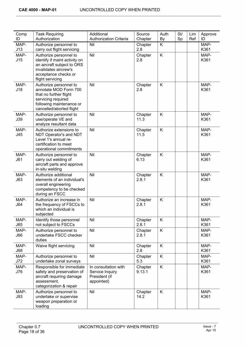
CAE 4000 - MAP-01 UNCONTROLLED COPY WHEN PRINTED
Chapter 0.7 Page 18 of 36
UNCONTROLLED COPY WHEN PRINTED Issue - 7 Apr 15
Comp ID
Task Requiring Authorization
Additional Authorization Criteria
Source Chapter
Auth By
St/Sp
Lim Ref
Approve ID
MAP-J13
Authorize personnel to carry out flight servicing
Nil Chapter 2.8
K MAP-K361
MAP-J15
Authorize personnel to identify if maint activity on an aircraft subject to ORS invalidates aircrew's acceptance checks or flight servicing
Nil Chapter 2.8
K MAP-K361
MAP-J18
Authorize personnel to annotate MOD Form 700 that no further flight servicing required following maintenance or cancelled/aborted flight
Nil Chapter 2.8
K MAP-K361
MAP-J39
Authorize personnel to use/operate VE and analyze resultant data
Nil Chapter 11.3
K MAP-K361
MAP-J45
Authorize extensions to NDT Operator's and NDT Level 1's annual re-certification to meet operational commitments
Nil Chapter 11.5
K MAP-K361
MAP-J61
Authorize personnel to carry out welding of aircraft parts and approve in-situ welding
Nil Chapter 6.13
K MAP-K361
MAP-J63
Authorize additional elements of an individual's overall engineering competency to be checked during an FSCC
Nil Chapter 2.8.1
K MAP-K361
MAP-J64
Authorize an increase in the frequency of FSCCs to which an individual is subjected
Nil Chapter 2.8.1
K MAP-K361
MAP-J65
Identify those personnel not subject to FSCCs
Nil Chapter 2.8.1
K MAP-K361
MAP-J66
Authorize personnel to undertake FSCC checker duties
Nil Chapter 2.8.1
K MAP-K361
MAP-J68
Waive flight servicing Nil Chapter 2.8
K MAP-K361
MAP-J72
Authorize personnel to undertake zonal surveys
Nil Chapter 5.3
K MAP-K361
MAP-J76
Responsible for immediate safety and preservation of aircraft requiring damage assessment, categorization & repair
In consultation with Service Inquiry President (if appointed)
Chapter 9.13.1
K MAP-K361
MAP-J93
Authorize personnel to undertake or supervise weapon preparation or loading
Nil Chapter 14.2
K MAP-K361
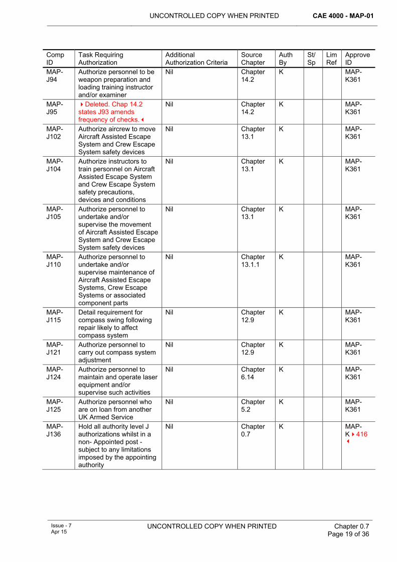
UNCONTROLLED COPY WHEN PRINTED CAE 4000 - MAP-01
Issue - 7 Apr 15
UNCONTROLLED COPY WHEN PRINTED
Chapter 0.7 Page 19 of 36
Comp ID
Task Requiring Authorization
Additional Authorization Criteria
Source Chapter
Auth By
St/Sp
Lim Ref
Approve ID
MAP-J94
Authorize personnel to be weapon preparation and loading training instructor and/or examiner
Nil Chapter 14.2
K MAP-K361
MAP-J95
Deleted. Chap 14.2 states J93 amends frequency of checks.
Nil Chapter 14.2
K MAP-K361
MAP-J102
Authorize aircrew to move Aircraft Assisted Escape System and Crew Escape System safety devices
Nil Chapter 13.1
K MAP-K361
MAP-J104
Authorize instructors to train personnel on Aircraft Assisted Escape System and Crew Escape System safety precautions, devices and conditions
Nil Chapter 13.1
K MAP-K361
MAP-J105
Authorize personnel to undertake and/or supervise the movement of Aircraft Assisted Escape System and Crew Escape System safety devices
Nil Chapter 13.1
K MAP-K361
MAP-J110
Authorize personnel to undertake and/or supervise maintenance of Aircraft Assisted Escape Systems, Crew Escape Systems or associated component parts
Nil Chapter 13.1.1
K MAP-K361
MAP-J115
Detail requirement for compass swing following repair likely to affect compass system
Nil Chapter 12.9
K MAP-K361
MAP-J121
Authorize personnel to carry out compass system adjustment
Nil Chapter 12.9
K MAP-K361
MAP-J124
Authorize personnel to maintain and operate laser equipment and/or supervise such activities
Nil Chapter 6.14
K MAP-K361
MAP-J125
Authorize personnel who are on loan from another UK Armed Service
Nil Chapter 5.2
K MAP-K361
MAP-J136
Hold all authority level J authorizations whilst in a non- Appointed post - subject to any limitations imposed by the appointing authority
Nil Chapter 0.7
K MAP-K416
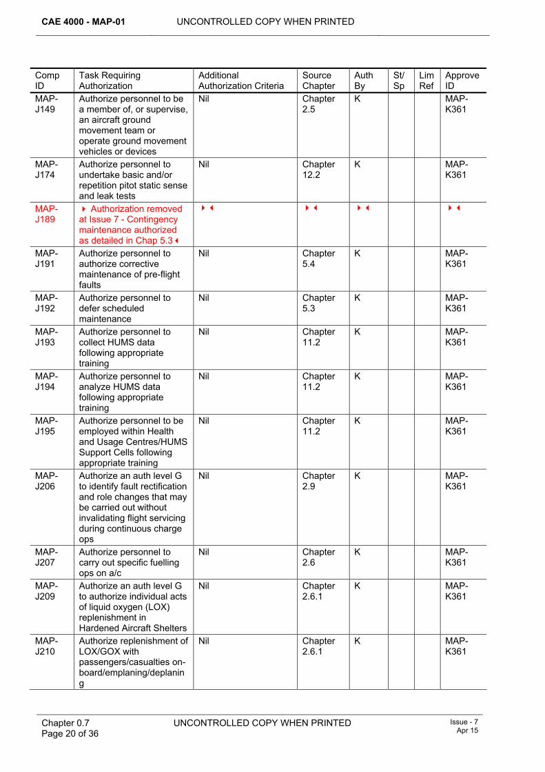
CAE 4000 - MAP-01 UNCONTROLLED COPY WHEN PRINTED
Chapter 0.7 Page 20 of 36
UNCONTROLLED COPY WHEN PRINTED Issue - 7 Apr 15
Comp ID
Task Requiring Authorization
Additional Authorization Criteria
Source Chapter
Auth By
St/Sp
Lim Ref
Approve ID
MAP-J149
Authorize personnel to be a member of, or supervise, an aircraft ground movement team or operate ground movement vehicles or devices
Nil Chapter 2.5
K MAP-K361
MAP-J174
Authorize personnel to undertake basic and/or repetition pitot static sense and leak tests
Nil Chapter 12.2
K MAP-K361
MAP-J189
Authorization removed at Issue 7 - Contingency maintenance authorized as detailed in Chap 5.3
MAP-J191
Authorize personnel to authorize corrective maintenance of pre-flight faults
Nil Chapter 5.4
K MAP-K361
MAP-J192
Authorize personnel to defer scheduled maintenance
Nil Chapter 5.3
K MAP-K361
MAP-J193
Authorize personnel to collect HUMS data following appropriate training
Nil Chapter 11.2
K MAP-K361
MAP-J194
Authorize personnel to analyze HUMS data following appropriate training
Nil Chapter 11.2
K MAP-K361
MAP-J195
Authorize personnel to be employed within Health and Usage Centres/HUMS Support Cells following appropriate training
Nil Chapter 11.2
K MAP-K361
MAP-J206
Authorize an auth level G to identify fault rectification and role changes that may be carried out without invalidating flight servicing during continuous charge ops
Nil Chapter 2.9
K MAP-K361
MAP-J207
Authorize personnel to carry out specific fuelling ops on a/c
Nil Chapter 2.6
K MAP-K361
MAP-J209
Authorize an auth level G to authorize individual acts of liquid oxygen (LOX) replenishment in Hardened Aircraft Shelters
Nil Chapter 2.6.1
K MAP-K361
MAP-J210
Authorize replenishment of LOX/GOX with passengers/casualties on-board/emplaning/deplaning
Nil Chapter 2.6.1
K MAP-K361
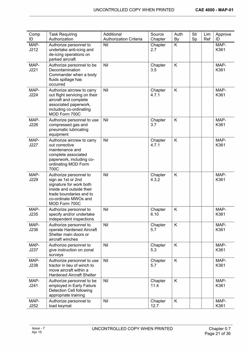
UNCONTROLLED COPY WHEN PRINTED CAE 4000 - MAP-01
Issue - 7 Apr 15
UNCONTROLLED COPY WHEN PRINTED
Chapter 0.7 Page 21 of 36
Comp ID
Task Requiring Authorization
Additional Authorization Criteria
Source Chapter
Auth By
St/Sp
Lim Ref
Approve ID
MAP-J212
Authorize personnel to undertake anti-icing and de-icing operations on parked aircraft
Nil Chapter 2.7
K MAP-K361
MAP-J221
Authorize personnel to be Decontamination Commander when a body fluids spillage has occurred
Nil Chapter 3.5
K MAP-K361
MAP-J224
Authorize aircrew to carry out flight servicing on their aircraft and complete associated paperwork, including co-ordinating MOD Form 700C
Nil Chapter 4.7.1
K MAP-K361
MAP-J226
Authorize personnel to use compressed gas and pneumatic lubricating equipment
Nil Chapter 3.7
K MAP-K361
MAP-J227
Authorize aircrew to carry out corrective maintenance and complete associated paperwork, including co-ordinating MOD Form 700C
Nil Chapter 4.7.1
K MAP-K361
MAP-J229
Authorize personnel to sign as 1st or 2nd signature for work both inside and outside their trade boundaries and to co-ordinate MWOs and MOD Form 700C
Nil Chapter 4.3.2
K MAP-K361
MAP-J235
Authorize personnel to specify and/or undertake independent inspections
Nil Chapter 6.10
K MAP-K361
MAP-J236
Authorize personnel to operate Hardened Aircraft Shelter main doors or aircraft winches
Nil Chapter 5.7
K MAP-K361
MAP-J237
Authorize personnel to give instruction on zonal surveys
Nil Chapter 5.3
K MAP-K361
MAP-J238
Authorize personnel to use tractor in lieu of winch to move aircraft within a Hardened Aircraft Shelter
Nil Chapter 5.7
K MAP-K361
MAP-J241
Authorize personnel to be employed in Early Failure Detection Cell following appropriate training
Nil Chapter 11.4
K MAP-K361
MAP-J252
Authorize personnel to load keymat
Nil Chapter 12.7
K MAP-K361
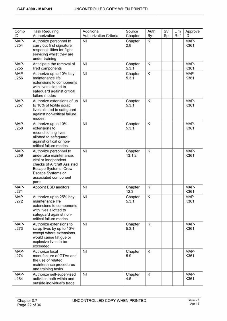
CAE 4000 - MAP-01 UNCONTROLLED COPY WHEN PRINTED
Chapter 0.7 Page 22 of 36
UNCONTROLLED COPY WHEN PRINTED Issue - 7 Apr 15
Comp ID
Task Requiring Authorization
Additional Authorization Criteria
Source Chapter
Auth By
St/Sp
Lim Ref
Approve ID
MAP-J254
Authorize personnel to carry out first signature responsibilities for flight servicing whilst they are under training
Nil Chapter 2.8
K MAP-K361
MAP-J255
Anticipate the removal of lifed components
Nil Chapter 5.3.1
K MAP-K361
MAP-J256
Authorize up to 10% bay maintenance life extensions to components with lives allotted to safeguard against critical failure modes
Nil Chapter 5.3.1
K MAP-K361
MAP-J257
Authorize extensions of up to 10% of textile scrap lives allotted to safeguard against non-critical failure modes
Nil Chapter 5.3.1
K MAP-K361
MAP-J258
Authorize up to 10% extensions to reconditioning lives allotted to safeguard against critical or non-critical failure modes
Nil Chapter 5.3.1
K MAP-K361
MAP-J259
Authorize personnel to undertake maintenance, vital or independent checks of Aircraft Assisted Escape Systems, Crew Escape Systems or associated component parts
Nil Chapter 13.1.2
K MAP-K361
MAP-J271
Appoint ESD auditors Nil Chapter 12.3
K MAP-K361
MAP-J272
Authorize up to 25% bay maintenance life extensions to components with lives allotted to safeguard against non-critical failure modes
Nil Chapter 5.3.1
K MAP-K361
MAP-J273
Authorize extensions to scrap lives by up to 10% except where extensions would cause fatigue or explosive lives to be exceeded
Nil Chapter 5.3.1
K MAP-K361
MAP-J274
Authorize local manufacture of GTAs and the use of related maintenance procedures and training tasks
Nil Chapter 5.9
K MAP-K361
MAP-J284
Authorize self-supervised activities both within and outside individual's trade
Nil Chapter 4.5
K MAP-K361
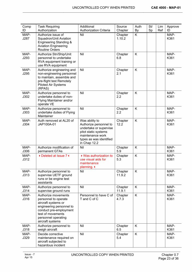
UNCONTROLLED COPY WHEN PRINTED CAE 4000 - MAP-01
Issue - 7 Apr 15
UNCONTROLLED COPY WHEN PRINTED
Chapter 0.7 Page 23 of 36
Comp ID
Task Requiring Authorization
Additional Authorization Criteria
Source Chapter
Auth By
St/Sp
Lim Ref
Approve ID
MAP-J287
Authorize issue of Squadron/Unit Aviation Engineering Standing & Aviation Engineering Routine Orders
Nil Chapter 1.10.2
K MAP-K361
MAP-J293
Authorize Stn/Ship/Unit personnel to undertake RVA equipment training or use RVA equipment
Nil Chapter 6.8
K MAP-K361
MAP-J295
Authorize engineering and non-engineering personnel to maintain, assemble and pre-flight test Remotely Piloted Air Systems (RPAS)
Nil Chapter 2.1
K MAP-K361
MAP-J302
Authorize personnel to undertake duties of non-Flying Maintainer and/or operate VE
Nil Chapter 2.2
K MAP-K361
MAP-J303
Authorize personnel to undertake duties of Flying Maintainer
Nil Chapter 2.2
K MAP-K361
MAP-J304
Auth removed at AL20 of JAP100A-01
Was ability to Authorize personnel to undertake or supervise pitot static systems maintenance work types as was identified in Chap 12.2
Chapter 12.2
K MAP-K361
MAP-J306
Authorize modification of permanent GTAs
Nil Chapter 5.9
K MAP-K361
MAP-J312
Deleted at Issue 7 Was authorization to use visual aids for maintenance planning.
Chapter 5.3
K MAP-K361
MAP-J313
Authorize personnel to supervise UETF ground runs or be engine test assistants
Nil Chapter 11.9.2
K MAP-K361
MAP-J314
Authorize personnel to supervise ground runs
Nil Chapter 11.9.1
K MAP-K361
MAP-J316
Authorize movements personnel to operate aircraft systems or engineering personnel to conduct pre-employment test of movements personnel operating aircraft systems
Personnel to have C of T and C of C
Chapter 4.7.3
K MAP-K361
MAP-J318
Authorize personnel to weigh aircraft
Nil Chapter 6.5
K MAP-K361
MAP-J329
Decide corrective maintenance required on aircraft subjected to hazardous incident
Nil Chapter 5.4
K MAP-K361
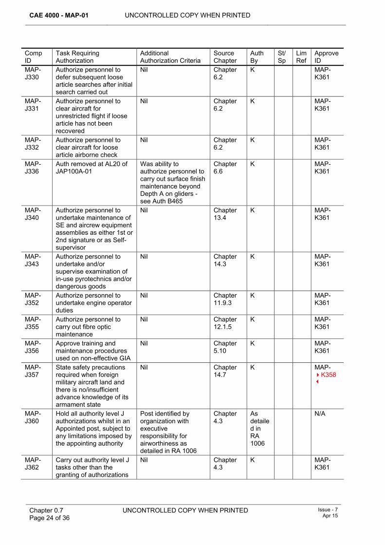
CAE 4000 - MAP-01 UNCONTROLLED COPY WHEN PRINTED
Chapter 0.7 Page 24 of 36
UNCONTROLLED COPY WHEN PRINTED Issue - 7 Apr 15
Comp ID
Task Requiring Authorization
Additional Authorization Criteria
Source Chapter
Auth By
St/Sp
Lim Ref
Approve ID
MAP-J330
Authorize personnel to defer subsequent loose article searches after initial search carried out
Nil Chapter 6.2
K MAP-K361
MAP-J331
Authorize personnel to clear aircraft for unrestricted flight if loose article has not been recovered
Nil Chapter 6.2
K MAP-K361
MAP-J332
Authorize personnel to clear aircraft for loose article airborne check
Nil Chapter 6.2
K MAP-K361
MAP-J336
Auth removed at AL20 of JAP100A-01
Was ability to authorize personnel to carry out surface finish maintenance beyond Depth A on gliders - see Auth B465
Chapter 6.6
K MAP-K361
MAP-J340
Authorize personnel to undertake maintenance of SE and aircrew equipment assemblies as either 1st or 2nd signature or as Self-supervisor
Nil Chapter 13.4
K MAP-K361
MAP-J343
Authorize personnel to undertake and/or supervise examination of in-use pyrotechnics and/or dangerous goods
Nil Chapter 14.3
K MAP-K361
MAP-J352
Authorize personnel to undertake engine operator duties
Nil Chapter 11.9.3
K MAP-K361
MAP-J355
Authorize personnel to carry out fibre optic maintenance
Nil Chapter 12.1.5
K MAP-K361
MAP-J356
Approve training and maintenance procedures used on non-effective GIA
Nil Chapter 5.10
K MAP-K361
MAP-J357
State safety precautions required when foreign military aircraft land and there is no/insufficient advance knowledge of its armament state
Nil Chapter 14.7
K MAP-K358
MAP-J360
Hold all authority level J authorizations whilst in an Appointed post, subject to any limitations imposed by the appointing authority
Post identified by organization with executive responsibility for airworthiness as detailed in RA 1006
Chapter 4.3
As detailed in RA 1006
N/A
MAP-J362
Carry out authority level J tasks other than the granting of authorizations
Nil Chapter 4.3
K MAP-K361
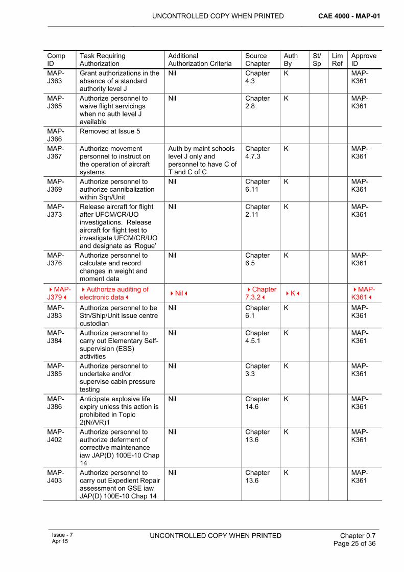
UNCONTROLLED COPY WHEN PRINTED CAE 4000 - MAP-01
Issue - 7 Apr 15
UNCONTROLLED COPY WHEN PRINTED
Chapter 0.7 Page 25 of 36
Comp ID
Task Requiring Authorization
Additional Authorization Criteria
Source Chapter
Auth By
St/Sp
Lim Ref
Approve ID
MAP-J363
Grant authorizations in the absence of a standard authority level J
Nil Chapter 4.3
K MAP-K361
MAP-J365
Authorize personnel to waive flight servicings when no auth level J available
Nil Chapter 2.8
K MAP-K361
MAP-J366
Removed at Issue 5
MAP-J367
Authorize movement personnel to instruct on the operation of aircraft systems
Auth by maint schools level J only and personnel to have C of T and C of C
Chapter 4.7.3
K MAP-K361
MAP-J369
Authorize personnel to authorize cannibalization within Sqn/Unit
Nil Chapter 6.11
K MAP-K361
MAP-J373
Release aircraft for flight after UFCM/CR/UO investigations. Release aircraft for flight test to investigate UFCM/CR/UO and designate as ‘Rogue’
Nil Chapter 2.11
K MAP-K361
MAP-J376
Authorize personnel to calculate and record changes in weight and moment data
Nil Chapter 6.5
K MAP-K361
MAP-J379
Authorize auditing of electronic data Nil Chapter
7.3.2 K MAP-K361
MAP-J383
Authorize personnel to be Stn/Ship/Unit issue centre custodian
Nil Chapter 6.1
K MAP-K361
MAP-J384
Authorize personnel to carry out Elementary Self-supervision (ESS) activities
Nil Chapter 4.5.1
K MAP-K361
MAP-J385
Authorize personnel to undertake and/or supervise cabin pressure testing
Nil Chapter 3.3
K MAP-K361
MAP-J386
Anticipate explosive life expiry unless this action is prohibited in Topic 2(N/A/R)1
Nil Chapter 14.6
K MAP-K361
MAP-J402
Authorize personnel to authorize deferment of corrective maintenance iaw JAP(D) 100E-10 Chap 14
Nil Chapter 13.6
K MAP-K361
MAP-J403
Authorize personnel to carry out Expedient Repair assessment on GSE iaw JAP(D) 100E-10 Chap 14
Nil Chapter 13.6
K MAP-K361
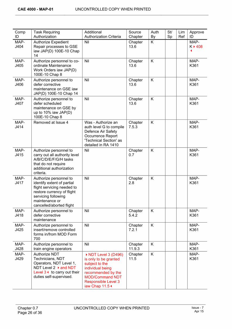
CAE 4000 - MAP-01 UNCONTROLLED COPY WHEN PRINTED
Chapter 0.7 Page 26 of 36
UNCONTROLLED COPY WHEN PRINTED Issue - 7 Apr 15
Comp ID
Task Requiring Authorization
Additional Authorization Criteria
Source Chapter
Auth By
St/Sp
Lim Ref
Approve ID
MAP-J404
Authorize Expedient Repair processes to GSE iaw JAP(D) 100E-10 Chap 14
Nil Chapter 13.6
K MAP-K408
MAP-J405
Authorize personnel to co-ordinate Maintenance Work Orders iaw JAP(D) 100E-10 Chap 8
Nil Chapter 13.6
K MAP-K361
MAP-J406
Authorize personnel to defer corrective maintenance on GSE iaw JAP(D) 100E-10 Chap 14
Nil Chapter 13.6
K MAP-K361
MAP-J407
Authorize personnel to defer scheduled maintenance on GSE by up to 10% iaw JAP(D) 100E-10 Chap 8
Nil Chapter 13.6
K MAP-K361
MAP-J414
Removed at Issue 4 Was - Authorize an auth level G to compile Defence Air Safety Occurrence Report 'Technical Section' as detailed in RA 1410
Chapter 7.5.3
K MAP-K361
MAP-J415
Authorize personnel to carry out all authority level A/B/C/D/E/F/G/H tasks that do not require additional authorization criteria.
Nil Chapter 0.7
K MAP-K361
MAP-J417
Authorize personnel to identify extent of partial flight servicing needed to restore currency of flight servicing following maintenance or cancelled/aborted flight
Nil Chapter 2.8
K MAP-K361
MAP-J418
Authorize personnel to defer corrective maintenance
Nil Chapter 5.4.2
K MAP-K361
MAP-J425
Authorize personnel to insert/remove controlled forms in/from MOD Form 700
Nil Chapter 7.2.1
K MAP-K361
MAP-J428
Authorize personnel to train engine operators
Nil Chapter 11.9.3
K MAP-K361
MAP-J429
Authorize NDT Technicians, NDT Operators, NDT Level 1, NDT Level 2 and NDT Level 3 to carry out their duties self-supervised.
NDT Level 3 (D496) is only to be granted subject to the individual being recommended by the MOD/Command NDT Responsible Level 3 iaw Chap 11.5
Chapter 11.5
K MAP-K361
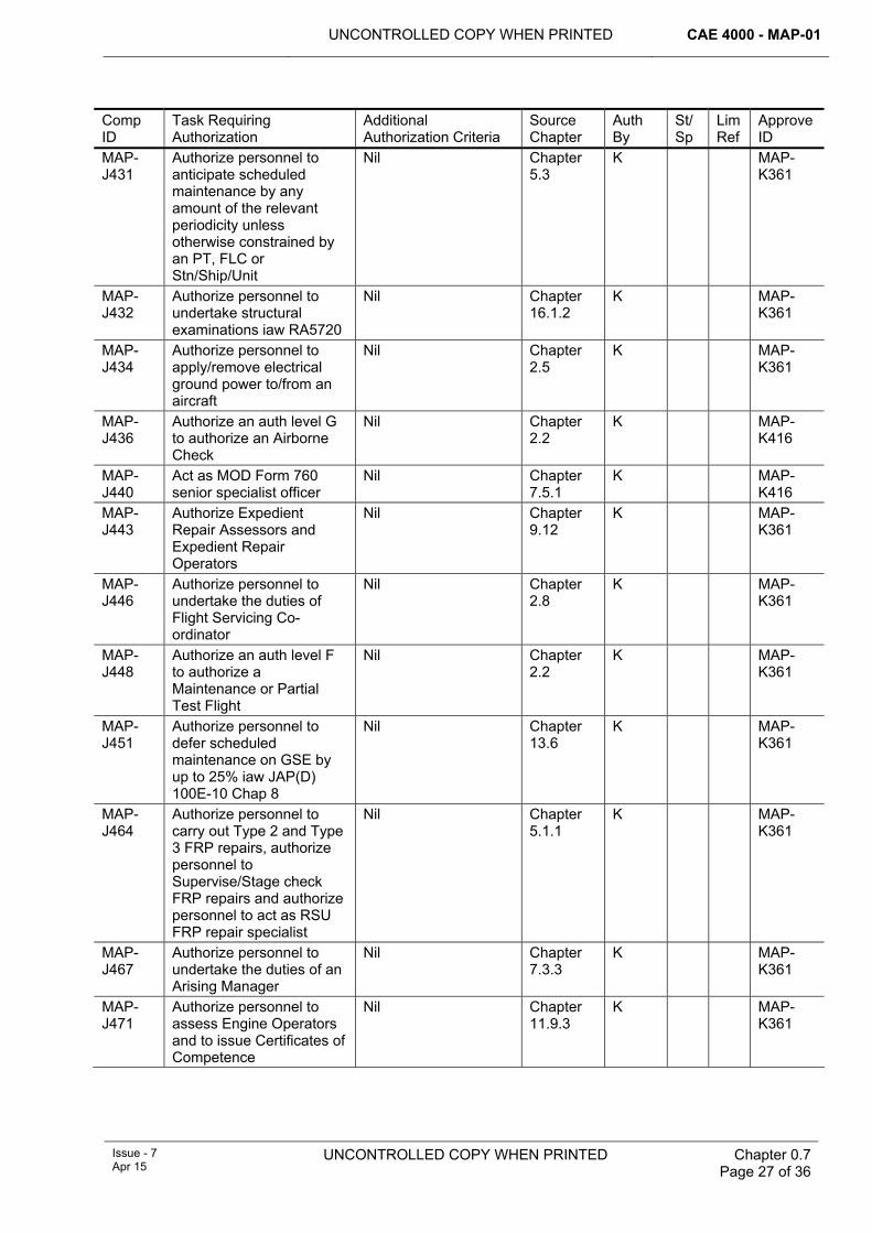
UNCONTROLLED COPY WHEN PRINTED CAE 4000 - MAP-01
Issue - 7 Apr 15
UNCONTROLLED COPY WHEN PRINTED
Chapter 0.7 Page 27 of 36
Comp ID
Task Requiring Authorization
Additional Authorization Criteria
Source Chapter
Auth By
St/Sp
Lim Ref
Approve ID
MAP-J431
Authorize personnel to anticipate scheduled maintenance by any amount of the relevant periodicity unless otherwise constrained by an PT, FLC or Stn/Ship/Unit
Nil Chapter 5.3
K MAP-K361
MAP-J432
Authorize personnel to undertake structural examinations iaw RA5720
Nil Chapter 16.1.2
K MAP-K361
MAP-J434
Authorize personnel to apply/remove electrical ground power to/from an aircraft
Nil Chapter 2.5
K MAP-K361
MAP-J436
Authorize an auth level G to authorize an Airborne Check
Nil Chapter 2.2
K MAP-K416
MAP-J440
Act as MOD Form 760 senior specialist officer
Nil Chapter 7.5.1
K MAP-K416
MAP-J443
Authorize Expedient Repair Assessors and Expedient Repair Operators
Nil Chapter 9.12
K MAP-K361
MAP-J446
Authorize personnel to undertake the duties of Flight Servicing Co-ordinator
Nil Chapter 2.8
K MAP-K361
MAP-J448
Authorize an auth level F to authorize a Maintenance or Partial Test Flight
Nil Chapter 2.2
K MAP-K361
MAP-J451
Authorize personnel to defer scheduled maintenance on GSE by up to 25% iaw JAP(D) 100E-10 Chap 8
Nil Chapter 13.6
K MAP-K361
MAP-J464
Authorize personnel to carry out Type 2 and Type 3 FRP repairs, authorize personnel to Supervise/Stage check FRP repairs and authorize personnel to act as RSU FRP repair specialist
Nil Chapter 5.1.1
K MAP-K361
MAP-J467
Authorize personnel to undertake the duties of an Arising Manager
Nil Chapter 7.3.3
K MAP-K361
MAP-J471
Authorize personnel to assess Engine Operators and to issue Certificates of Competence
Nil Chapter 11.9.3
K MAP-K361
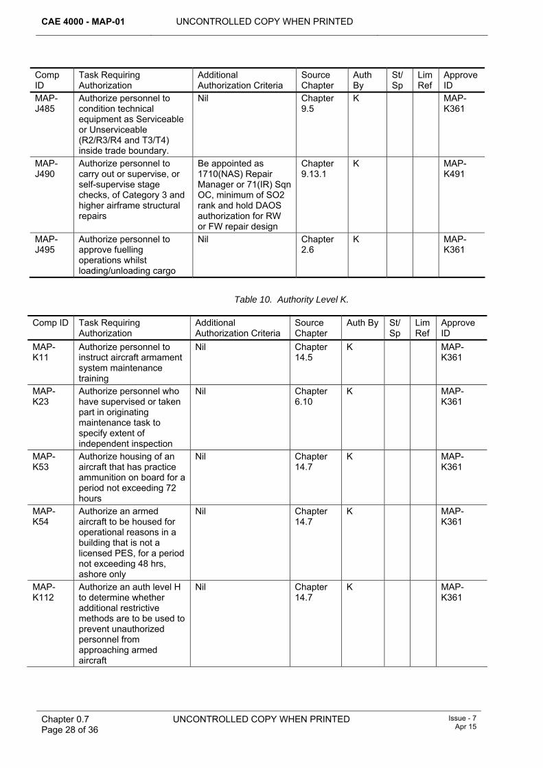
CAE 4000 - MAP-01 UNCONTROLLED COPY WHEN PRINTED
Chapter 0.7 Page 28 of 36
UNCONTROLLED COPY WHEN PRINTED Issue - 7 Apr 15
Comp ID
Task Requiring Authorization
Additional Authorization Criteria
Source Chapter
Auth By
St/Sp
Lim Ref
Approve ID
MAP-J485
Authorize personnel to condition technical equipment as Serviceable or Unserviceable (R2/R3/R4 and T3/T4) inside trade boundary.
Nil Chapter 9.5
K MAP-K361
MAP-J490
Authorize personnel to carry out or supervise, or self-supervise stage checks, of Category 3 and higher airframe structural repairs
Be appointed as 1710(NAS) Repair Manager or 71(IR) Sqn OC, minimum of SO2 rank and hold DAOS authorization for RW or FW repair design
Chapter 9.13.1
K MAP-K491
MAP-J495
Authorize personnel to approve fuelling operations whilst loading/unloading cargo
Nil Chapter 2.6
K MAP-K361
Table 10. Authority Level K.
Comp ID Task Requiring Authorization
Additional Authorization Criteria
Source Chapter
Auth By St/Sp
Lim Ref
Approve ID
MAP-K11
Authorize personnel to instruct aircraft armament system maintenance training
Nil Chapter 14.5
K MAP-K361
MAP-K23
Authorize personnel who have supervised or taken part in originating maintenance task to specify extent of independent inspection
Nil Chapter 6.10
K MAP-K361
MAP-K53
Authorize housing of an aircraft that has practice ammunition on board for a period not exceeding 72 hours
Nil Chapter 14.7
K MAP-K361
MAP-K54
Authorize an armed aircraft to be housed for operational reasons in a building that is not a licensed PES, for a period not exceeding 48 hrs, ashore only
Nil Chapter 14.7
K MAP-K361
MAP-K112
Authorize an auth level H to determine whether additional restrictive methods are to be used to prevent unauthorized personnel from approaching armed aircraft
Nil Chapter 14.7
K MAP-K361
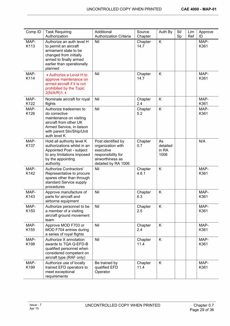
UNCONTROLLED COPY WHEN PRINTED CAE 4000 - MAP-01
Issue - 7 Apr 15
UNCONTROLLED COPY WHEN PRINTED
Chapter 0.7 Page 29 of 36
Comp ID Task Requiring Authorization
Additional Authorization Criteria
Source Chapter
Auth By St/Sp
Lim Ref
Approve ID
MAP-K113
Authorize an auth level H to permit an aircraft armament state to be changed from initially armed to finally armed earlier than operationally planned
Nil Chapter 14.7
K MAP-K361
MAP-K114
Authorize a Level H to approve maintenance on armed aircraft if it is not prohibited by the Topic 2(N/A/R)1.
Nil Chapter 14.7
K MAP-K361
MAP-K122
Nominate aircraft for royal flights
Nil Chapter 2.4
K MAP-K361
MAP-K126
Authorize tradesmen to do corrective maintenance on visiting aircraft from other UK Armed Service, in liaison with parent Stn/Ship/Unit auth level K
Nil Chapter 5.2
K MAP-K361
MAP-K137
Hold all authority level K authorizations whilst in an Appointed Post - subject to any limitations imposed by the appointing authority.
Post identified by organization with executive responsibility for airworthiness as detailed by RA 1006
Chapter 0.7
As detailed in RA 1006
N/A
MAP-K142
Authorize Contractors' Representative to procure spares other than through standard Service supply procedures
Nil Chapter 4.8.1
K MAP-K361
MAP-K143
Approve manufacture of parts for aircraft and airborne equipment
Nil Chapter 6.3
K MAP-K361
MAP-K150
Authorize personnel to be a member of a visiting aircraft ground movement team
Nil Chapter 2.5
K MAP-K361
MAP-K155
Approve MOD F703 or MOD F704 entries during a series of royal flights
Nil Chapter 2.4
K MAP-K361
MAP-K198
Authorize X annotation awards to TQA Q-EFD-B qualified personnel when considered competent on aircraft type (RAF only)
Nil Chapter 11.4
K MAP-K361
MAP-K199
Authorize use of locally trained EFD operators to meet exceptional requirements
Be trained by qualified EFD Operator
Chapter 11.4
K MAP-K361
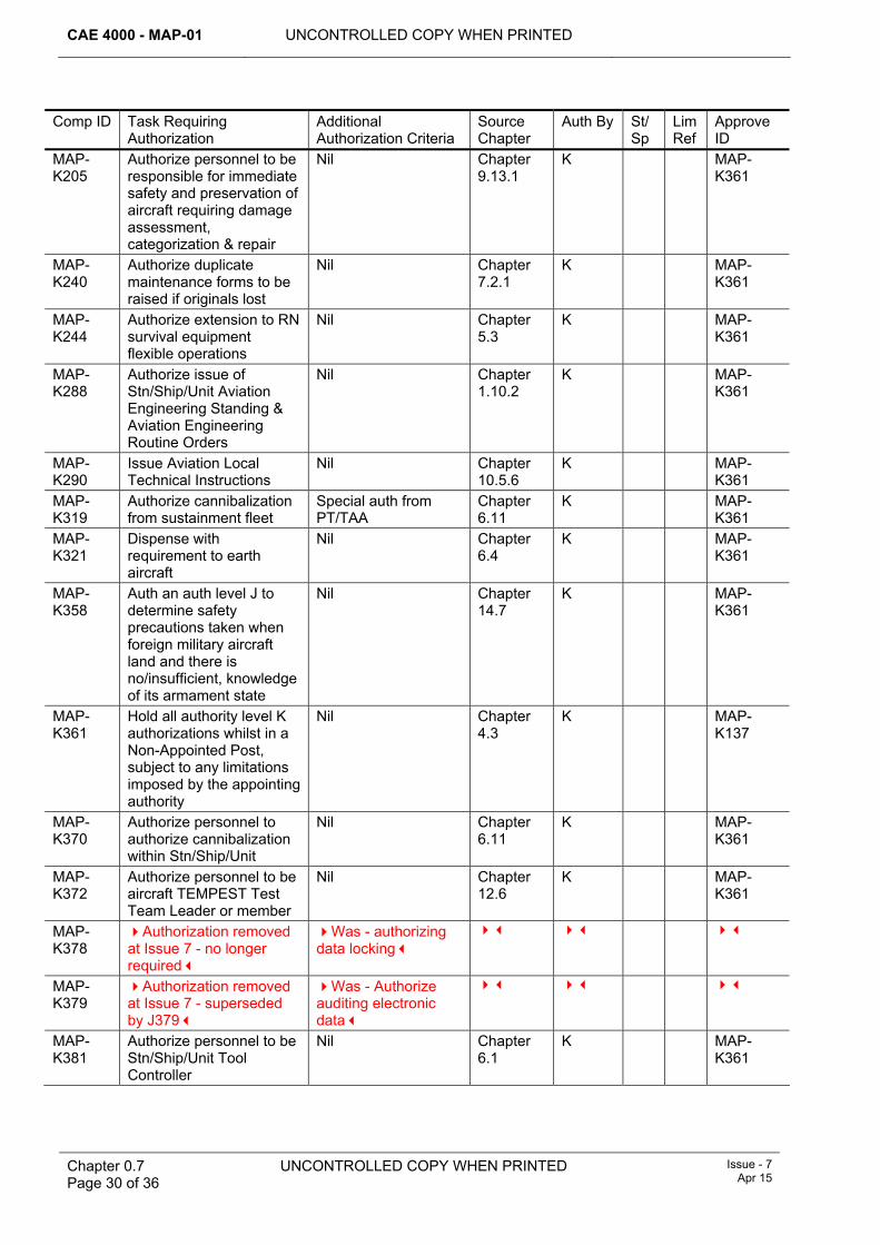
CAE 4000 - MAP-01 UNCONTROLLED COPY WHEN PRINTED
Chapter 0.7 Page 30 of 36
UNCONTROLLED COPY WHEN PRINTED Issue - 7 Apr 15
Comp ID Task Requiring Authorization
Additional Authorization Criteria
Source Chapter
Auth By St/Sp
Lim Ref
Approve ID
MAP-K205
Authorize personnel to be responsible for immediate safety and preservation of aircraft requiring damage assessment, categorization & repair
Nil Chapter 9.13.1
K MAP-K361
MAP-K240
Authorize duplicate maintenance forms to be raised if originals lost
Nil Chapter 7.2.1
K MAP-K361
MAP-K244
Authorize extension to RN survival equipment flexible operations
Nil Chapter 5.3
K MAP-K361
MAP-K288
Authorize issue of Stn/Ship/Unit Aviation Engineering Standing & Aviation Engineering Routine Orders
Nil Chapter 1.10.2
K MAP-K361
MAP-K290
Issue Aviation Local Technical Instructions
Nil Chapter 10.5.6
K MAP-K361
MAP-K319
Authorize cannibalization from sustainment fleet
Special auth from PT/TAA
Chapter 6.11
K MAP-K361
MAP-K321
Dispense with requirement to earth aircraft
Nil Chapter 6.4
K MAP-K361
MAP-K358
Auth an auth level J to determine safety precautions taken when foreign military aircraft land and there is no/insufficient, knowledge of its armament state
Nil Chapter 14.7
K MAP-K361
MAP-K361
Hold all authority level K authorizations whilst in a Non-Appointed Post, subject to any limitations imposed by the appointing authority
Nil Chapter 4.3
K MAP-K137
MAP-K370
Authorize personnel to authorize cannibalization within Stn/Ship/Unit
Nil Chapter 6.11
K MAP-K361
MAP-K372
Authorize personnel to be aircraft TEMPEST Test Team Leader or member
Nil Chapter 12.6
K MAP-K361
MAP-K378
Authorization removed at Issue 7 - no longer required
Was - authorizing data locking
MAP-K379
Authorization removed at Issue 7 - superseded by J379
Was - Authorize auditing electronic data
MAP-K381
Authorize personnel to be Stn/Ship/Unit Tool Controller
Nil Chapter 6.1
K MAP-K361
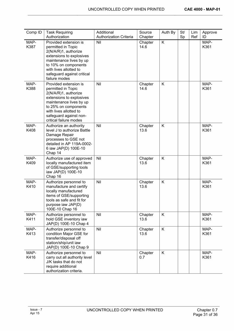
UNCONTROLLED COPY WHEN PRINTED CAE 4000 - MAP-01
Issue - 7 Apr 15
UNCONTROLLED COPY WHEN PRINTED
Chapter 0.7 Page 31 of 36
Comp ID Task Requiring Authorization
Additional Authorization Criteria
Source Chapter
Auth By St/Sp
Lim Ref
Approve ID
MAP-K387
Provided extension is permitted in Topic 2(N/A/R)1, authorize extensions to explosives maintenance lives by up to 10% on components with lives allotted to safeguard against critical failure modes
Nil Chapter 14.6
K MAP-K361
MAP-K388
Provided extension is permitted in Topic 2(N/A/R)1, authorize extensions to explosives maintenance lives by up to 25% on components with lives allotted to safeguard against non-critical failure modes
Nil Chapter 14.6
K MAP-K361
MAP-K408
Authorize an authority level J to authorize Battle Damage Repair processes to GSE not detailed in AP 119A-0002-6 iaw JAP(D) 100E-10 Chap 14
Nil Chapter 13.6
K MAP-K361
MAP-K409
Authorize use of approved locally manufactured item of GSE/supporting tools iaw JAP(D) 100E-10 Chap 16
Nil Chapter 13.6
K MAP-K361
MAP-K410
Authorize personnel to manufacture and certify locally manufactured items of GSE/supporting tools as safe and fit for purpose iaw JAP(D) 100E-10 Chap 16
Nil Chapter 13.6
K MAP-K361
MAP-K411
Authorize personnel to hold GSE inventory iaw JAP(D) 100E-10 Chap 4
Nil Chapter 13.6
K MAP-K361
MAP-K413
Authorize personnel to condition Major GSE for transfer/disposal off station/ship/unit iaw JAP(D) 100E-10 Chap 9
Nil Chapter 13.6
K MAP-K361
MAP-K416
Authorize personnel to carry out all authority level J/K tasks that do not require additional authorization criteria.
Nil Chapter 0.7
K MAP-K361
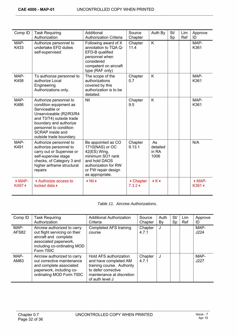
CAE 4000 - MAP-01 UNCONTROLLED COPY WHEN PRINTED
Chapter 0.7 Page 32 of 36
UNCONTROLLED COPY WHEN PRINTED Issue - 7 Apr 15
Comp ID Task Requiring Authorization
Additional Authorization Criteria
Source Chapter
Auth By St/Sp
Lim Ref
Approve ID
MAP-K433
Authorize personnel to undertake EFD duties self-supervised
Following award of X annotation to TQA Q-EFD-B qualified personnel when considered competent on aircraft type (RAF only)
Chapter 11.4
K MAP-K361
MAP-K458
To authorize personnel to authorize Local Engineering Authorizations only.
The scope of the authorizations covered by this authorization is to be detailed.
Chapter 0.7
K MAP-K361
MAP-K486
Authorize personnel to condition equipment as Serviceable or Unserviceable (R2/R3/R4 and T3/T4) outside trade boundary and authorize personnel to condition SCRAP inside and outside trade boundary.
Nil Chapter 9.5
K MAP-K361
MAP-K491
Authorize personnel to authorize personnel to carry out or Supervise or self-supervise stage checks, of Category 3 and higher airframe structural repairs
Be appointed as CO 1710(NAS) or OC 42(ES) Wing, minimum SO1 rank and hold DAOS authorization for RW or FW repair design as appropriate.
Chapter 9.13.1
As detailed in RA 1006
N/A
MAP-K497
Authorize access to locked data
Nil Chapter 7.3.2
K MAP-K361
Table 11. Aircrew Authorizations.
Comp ID Task Requiring Authorization
Additional Authorization Criteria
Source Chapter
Auth By
St/Sp
Lim Ref
Approve ID
MAP-AFS82
Aircrew authorized to carry out flight servicing on their aircraft and complete associated paperwork, including co-ordinating MOD Form 700C
Completed AFS training course
Chapter 4.7.1
J MAP-J224
MAP-AM83
Aircrew authorized to carry out corrective maintenance and complete associated paperwork, including co-ordinating MOD Form 700C
Hold AFS authorization and have completed AM training course. Authority to defer corrective maintenance at discretion of auth level J
Chapter 4.7.1
J MAP-J227
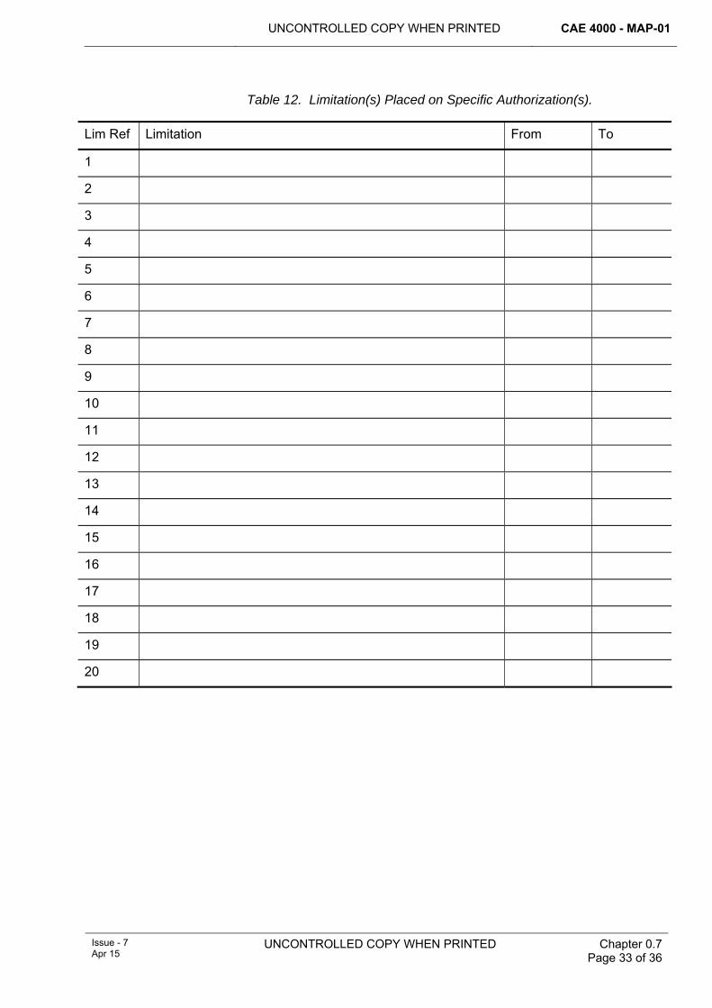
UNCONTROLLED COPY WHEN PRINTED CAE 4000 - MAP-01
Issue - 7 Apr 15
UNCONTROLLED COPY WHEN PRINTED
Chapter 0.7 Page 33 of 36
Table 12. Limitation(s) Placed on Specific Authorization(s).
Lim Ref Limitation From To
1
2
3
4
5
6
7
8
9
10
11
12
13
14
15
16
17
18
19
20
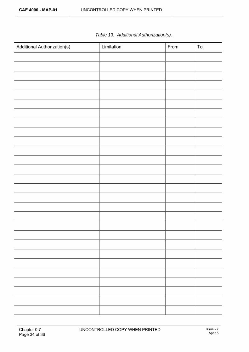
CAE 4000 - MAP-01 UNCONTROLLED COPY WHEN PRINTED
Chapter 0.7 Page 34 of 36
UNCONTROLLED COPY WHEN PRINTED Issue - 7 Apr 15
Table 13. Additional Authorization(s).
Additional Authorization(s) Limitation From To
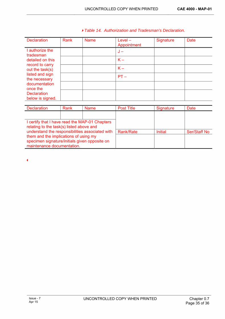
UNCONTROLLED COPY WHEN PRINTED CAE 4000 - MAP-01
Issue - 7 Apr 15
UNCONTROLLED COPY WHEN PRINTED
Chapter 0.7 Page 35 of 36
Table 14. Authorization and Tradesman’s Declaration.
Declaration Rank Name Level – Appointment
Signature Date
J –
K –
K –
PT –
I authorize the tradesman detailed on this record to carry out the task(s) listed and sign the necessary documentation once the Declaration below is signed.
Declaration Rank Name Post Title Signature Date
Rank/Rate Initial Ser/Staff No
I certify that I have read the MAP-01 Chapters relating to the task(s) listed above and understand the responsibilities associated with them and the implications of using my specimen signature/initials given opposite on maintenance documentation.
CAE 4000 - MAP-01 UNCONTROLLED COPY WHEN PRINTED
Chapter 0.7 Page 36 of 36
UNCONTROLLED COPY WHEN PRINTED Issue - 7 Apr 15
Intentionally Blank for Print Pagination
UNCONTROLLED COPY WHEN PRINTED CAE 4000 - MAP-01
MAE Issue - 5 Sep 13
UNCONTROLLED COPY WHEN PRINTED
Chapter 0.8 Page 1 of 2
Chapter 0.8
Associated Publications
TABLE OF CONTENTS Paragraph
Page
1 ............................................................................................................... 1 General1.1 .......................................................................................................... 1 Introduction
1 General 1.1 Introduction
The content of this chapter has been removed. Publications that are relevant to MAP-01 content are detailed at the end of each chapter. This Ghost Chapter is left in as a signpost for the reader.

CAE 4000 - MAP-01
Chapter 0.8 Page 2 of 2
UNCONTROLLED COPY WHEN PRINTED
MAE Issue - 5
Sep 13
Intentionally Blank for Print Pagination
UNCONTROLLED COPY WHEN PRINTED CAE 4000 - MAP-01
Issue - 7 Apr 15
UNCONTROLLED COPY WHEN PRINTED Chapter 1.10.2 Page 1 of 8
Chapter 1.10.2
Station, Ship, Unit and Squadron, Unit Aviation Engineering Orders
TABLE OF CONTENTS Paragraph
Page
1 General ............................................................................................................... 1 1.1 Introduction.......................................................................................................... 1 1.2 Associated publications....................................................................................... 2 2 Regulatory Governance.................................................................................... 2 2.1 Regulatory Cross-reference ................................................................................ 2 2.2 Additional Information.......................................................................................... 2 3 Deconfliction and amalgamation of orders .................................................... 2 3.1 Collocated units of differing Front Line Commands (FLCs) ................................ 2 3.2 Depth Support Units (DSUs) collocated with Forward units................................ 3 4 Scope, structure and layout of Station/Ship/Unit Aviation Engineering
Standing Orders (AESOs)................................................................................. 3 4.1 Scope .................................................................................................................. 3 4.2 Structure.............................................................................................................. 3 4.3 Layout.................................................................................................................. 5 5 AESO issue, review, amendment and withdrawal.......................................... 5 6 Stn/Ship/Unit AESO distribution, reading and recording.............................. 5 6.1 Distribution .......................................................................................................... 5 6.2 Reading and recording ........................................................................................ 5 7 Stn/Ship/Unit Aviation Engineering Routine Orders (AEROs) ...................... 5 8 Sqn/Unit.............................................................................................................. 6 8.1 Sqn/Unit AESOs.................................................................................................. 6 8.2 Sqn/Unit AEROs.................................................................................................. 6 9 Contractor’s Engineering Orders .................................................................... 6 9.1 Contractors employed subject to level K authority .............................................. 6 9.2 Contractors holding level K authority................................................................... 6 9.3 Exception to the issue of Stn/Ship/Unit AESOs .................................................. 7
LIST OF TABLES Table 1. Aviation Engineering Standing Orders, Book 1 – Function, Organization and
Responsibilities. ................................................................................................ 4 Table 2. Aviation Engineering Standing Orders Book 2 – Orders.................................. 4
1 General 1.1 Introduction
Stn/Ship/Unit and Sqn/Unit Aviation Engineering Standing Orders (AESOs) and Aviation Engineering Routine Orders (AEROs) are a method of publicizing low level engineering instructions to a wider audience. This chapter describes the purpose, scope, layout and format of AESOs and AEROs, and defines how they are issued and reviewed. AEROs will be used for promulgating Aviation Local Technical Instructions (ALTIs); as detailed in RA 4462 and Chapter 10.5.6.
CAE 4000 - MAP-01 UNCONTROLLED COPY WHEN PRINTED
Chapter 1.10.2 Page 2 of 8
UNCONTROLLED COPY WHEN PRINTED Issue - 7 Apr 15
1.2 Associated publications This chapter is associated with the following publications:
1 QR RN Paragraph 1101 – Responsibilities of the Ship or Air Station Air Engineer Officer.
2 QR Army Paragraph 5.122 – Orders.
3 AP100B-01 Order 1.1D – Responsibilities of Unit Engineering and Logistic Staff within the Overall Airworthiness Framework.
4 AP7400 – Continuing Airworthiness Engineering (Army).
2 Regulatory Governance 2.1 Regulatory Cross-reference
This chapter supports:
1 RA 4009.
2 RA 4947(1).
2.2 Additional Information The appropriate holder of level K authority is to promulgate aviation engineering orders, which must be classified as Aviation Engineering Standing Orders (AESOs) and Aviation Engineering Routine Orders (AEROs). These may be discrete documents, or may form part of a broader Stn/Ship/Unit publication embracing non-aviation engineering and supply instructions that are an integral part of the Stn/Ship/Unit function. They may also include orders relating to collocated Depth Organizations. However, in all cases, the aviation engineering element must be arranged according to this chapter.
Sqn/Unit authority level Js may issue orders as described at paragraph 8. These orders facilitate the expansion of and compliance with regulations or higher level instructions in order to account for local environment/conditions. They are not to contain nor countermand information in the Regulations without the written approval of the MAA. Any waivers, exemptions or Additional Acceptable Means of Compliance (AAMC) granted should be detailed in the relevant AESO and must be reviewed in accordance with paragraph 5.
3 Deconfliction and amalgamation of orders At locations shared by a number of units, AESOs and AEROs should be amalgamated where possible in order to promote best practice and efficient use of shared facilities and avoid conflicting orders. The following sub-paragraphs amplify this in respect of collocated units of differing Operating Duty Holders (ODH) and Depth Support Units collocated with Forward Units.
3.1 Collocated units of differing Front Line Commands (FLCs) Where 2 or more units of differing FLCs operate from the same location, the AESOs must detail from which FLC the orders emanate, to ensure deconfliction. Deployed units must adhere to their Stn/Ship/Unit or Sqn/Unit AESOs (as appropriate) and should adopt pertinent orders of the hosting Stn/Ship/Unit AESOs. Where deployed/hosting unit orders conflict, the safest or most stringent order must be adopted as best practice.
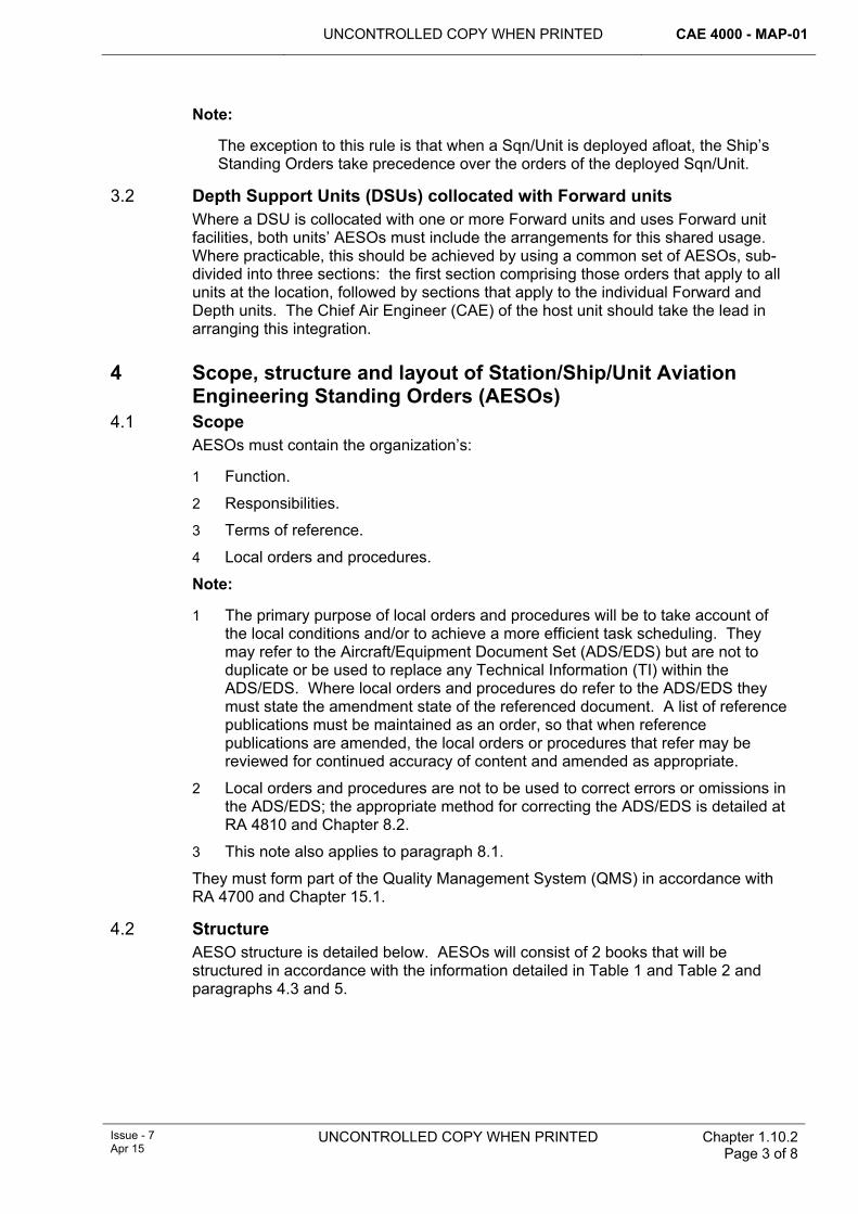
UNCONTROLLED COPY WHEN PRINTED CAE 4000 - MAP-01
Issue - 7 Apr 15
UNCONTROLLED COPY WHEN PRINTED Chapter 1.10.2 Page 3 of 8
Note:
The exception to this rule is that when a Sqn/Unit is deployed afloat, the Ship’s Standing Orders take precedence over the orders of the deployed Sqn/Unit.
3.2 Depth Support Units (DSUs) collocated with Forward units Where a DSU is collocated with one or more Forward units and uses Forward unit facilities, both units’ AESOs must include the arrangements for this shared usage. Where practicable, this should be achieved by using a common set of AESOs, sub-divided into three sections: the first section comprising those orders that apply to all units at the location, followed by sections that apply to the individual Forward and Depth units. The Chief Air Engineer (CAE) of the host unit should take the lead in arranging this integration.
4 Scope, structure and layout of Station/Ship/Unit Aviation Engineering Standing Orders (AESOs)
4.1 Scope AESOs must contain the organization’s:
1 Function.
2 Responsibilities.
3 Terms of reference.
4 Local orders and procedures.
Note:
1 The primary purpose of local orders and procedures will be to take account of the local conditions and/or to achieve a more efficient task scheduling. They may refer to the Aircraft/Equipment Document Set (ADS/EDS) but are not to duplicate or be used to replace any Technical Information (TI) within the ADS/EDS. Where local orders and procedures do refer to the ADS/EDS they must state the amendment state of the referenced document. A list of reference publications must be maintained as an order, so that when reference publications are amended, the local orders or procedures that refer may be reviewed for continued accuracy of content and amended as appropriate.
2 Local orders and procedures are not to be used to correct errors or omissions in the ADS/EDS; the appropriate method for correcting the ADS/EDS is detailed at RA 4810 and Chapter 8.2.
3 This note also applies to paragraph 8.1.
They must form part of the Quality Management System (QMS) in accordance with RA 4700 and Chapter 15.1.
4.2 Structure AESO structure is detailed below. AESOs will consist of 2 books that will be structured in accordance with the information detailed in Table 1 and Table 2 and paragraphs 4.3 and 5.
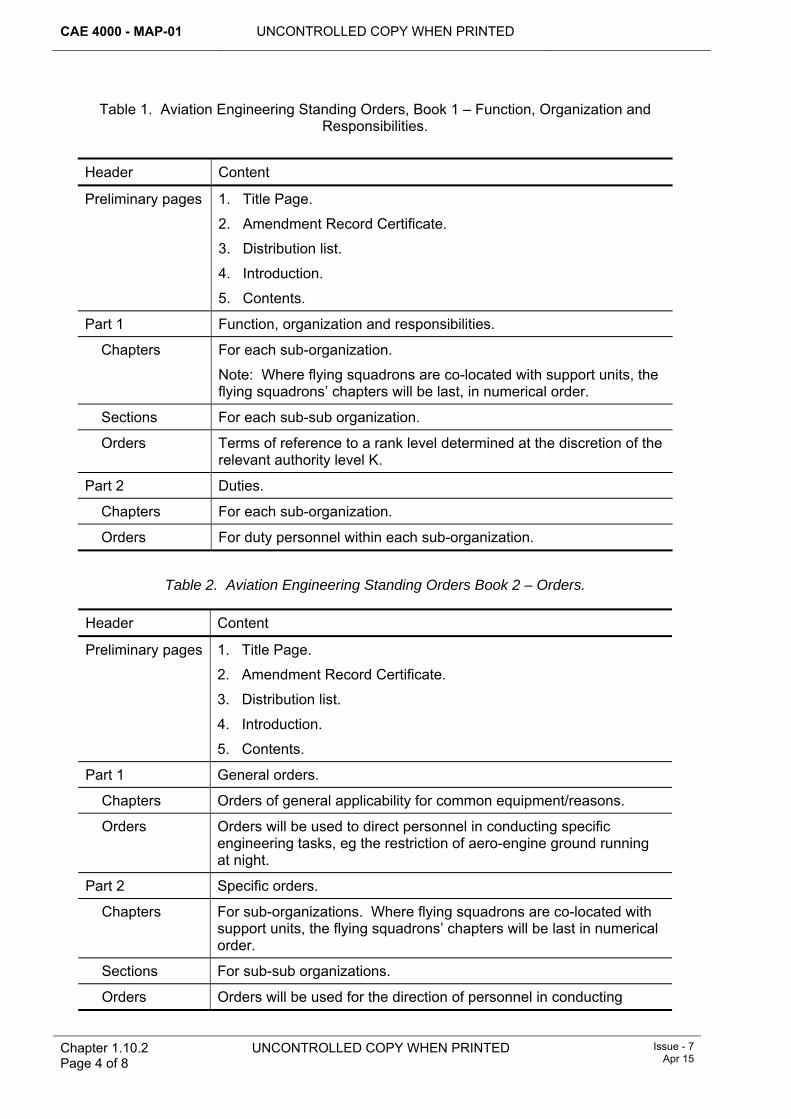
CAE 4000 - MAP-01 UNCONTROLLED COPY WHEN PRINTED
Chapter 1.10.2 Page 4 of 8
UNCONTROLLED COPY WHEN PRINTED Issue - 7 Apr 15
Table 1. Aviation Engineering Standing Orders, Book 1 – Function, Organization and Responsibilities.
Header Content
Preliminary pages 1. Title Page.
2. Amendment Record Certificate.
3. Distribution list.
4. Introduction.
5. Contents.
Part 1 Function, organization and responsibilities.
Chapters For each sub-organization.
Note: Where flying squadrons are co-located with support units, the flying squadrons’ chapters will be last, in numerical order.
Sections For each sub-sub organization.
Orders Terms of reference to a rank level determined at the discretion of the relevant authority level K.
Part 2 Duties.
Chapters For each sub-organization.
Orders For duty personnel within each sub-organization.
Table 2. Aviation Engineering Standing Orders Book 2 – Orders.
Header Content
Preliminary pages 1. Title Page.
2. Amendment Record Certificate.
3. Distribution list.
4. Introduction.
5. Contents.
Part 1 General orders.
Chapters Orders of general applicability for common equipment/reasons.
Orders Orders will be used to direct personnel in conducting specific engineering tasks, eg the restriction of aero-engine ground running at night.
Part 2 Specific orders.
Chapters For sub-organizations. Where flying squadrons are co-located with support units, the flying squadrons’ chapters will be last in numerical order.
Sections For sub-sub organizations.
Orders Orders will be used for the direction of personnel in conducting
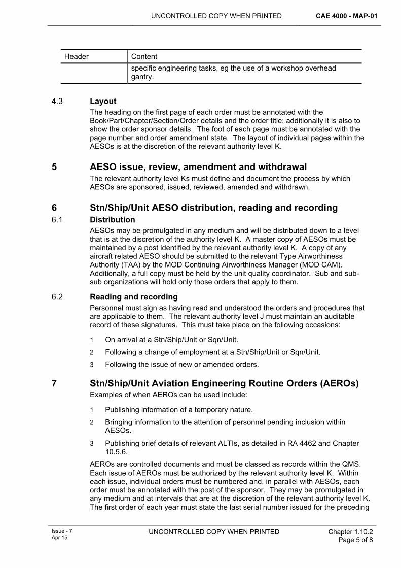
UNCONTROLLED COPY WHEN PRINTED CAE 4000 - MAP-01
Issue - 7 Apr 15
UNCONTROLLED COPY WHEN PRINTED Chapter 1.10.2 Page 5 of 8
Header Content specific engineering tasks, eg the use of a workshop overhead gantry.
4.3 Layout
The heading on the first page of each order must be annotated with the Book/Part/Chapter/Section/Order details and the order title; additionally it is also to show the order sponsor details. The foot of each page must be annotated with the page number and order amendment state. The layout of individual pages within the AESOs is at the discretion of the relevant authority level K.
5 AESO issue, review, amendment and withdrawal The relevant authority level Ks must define and document the process by which AESOs are sponsored, issued, reviewed, amended and withdrawn.
6 Stn/Ship/Unit AESO distribution, reading and recording 6.1 Distribution
AESOs may be promulgated in any medium and will be distributed down to a level that is at the discretion of the authority level K. A master copy of AESOs must be maintained by a post identified by the relevant authority level K. A copy of any aircraft related AESO should be submitted to the relevant Type Airworthiness Authority (TAA) by the MOD Continuing Airworthiness Manager (MOD CAM). Additionally, a full copy must be held by the unit quality coordinator. Sub and sub-sub organizations will hold only those orders that apply to them.
6.2 Reading and recording Personnel must sign as having read and understood the orders and procedures that are applicable to them. The relevant authority level J must maintain an auditable record of these signatures. This must take place on the following occasions:
1 On arrival at a Stn/Ship/Unit or Sqn/Unit.
2 Following a change of employment at a Stn/Ship/Unit or Sqn/Unit.
3 Following the issue of new or amended orders.
7 Stn/Ship/Unit Aviation Engineering Routine Orders (AEROs) Examples of when AEROs can be used include:
1 Publishing information of a temporary nature.
2 Bringing information to the attention of personnel pending inclusion within AESOs.
3 Publishing brief details of relevant ALTIs, as detailed in RA 4462 and Chapter 10.5.6.
AEROs are controlled documents and must be classed as records within the QMS. Each issue of AEROs must be authorized by the relevant authority level K. Within each issue, individual orders must be numbered and, in parallel with AESOs, each order must be annotated with the post of the sponsor. They may be promulgated in any medium and at intervals that are at the discretion of the relevant authority level K. The first order of each year must state the last serial number issued for the preceding
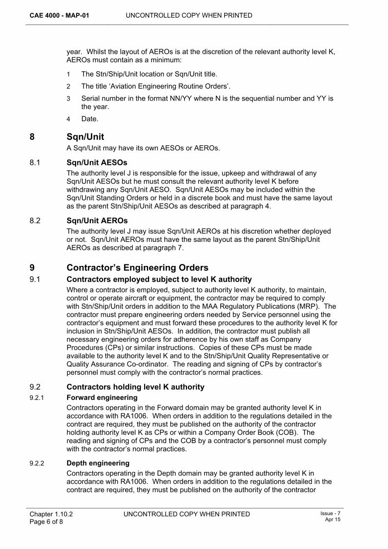
CAE 4000 - MAP-01 UNCONTROLLED COPY WHEN PRINTED
Chapter 1.10.2 Page 6 of 8
UNCONTROLLED COPY WHEN PRINTED Issue - 7 Apr 15
year. Whilst the layout of AEROs is at the discretion of the relevant authority level K, AEROs must contain as a minimum:
1 The Stn/Ship/Unit location or Sqn/Unit title.
2 The title ‘Aviation Engineering Routine Orders’.
3 Serial number in the format NN/YY where N is the sequential number and YY is the year.
4 Date.
8 Sqn/Unit A Sqn/Unit may have its own AESOs or AEROs.
8.1 Sqn/Unit AESOs The authority level J is responsible for the issue, upkeep and withdrawal of any Sqn/Unit AESOs but he must consult the relevant authority level K before withdrawing any Sqn/Unit AESO. Sqn/Unit AESOs may be included within the Sqn/Unit Standing Orders or held in a discrete book and must have the same layout as the parent Stn/Ship/Unit AESOs as described at paragraph 4.
8.2 Sqn/Unit AEROs The authority level J may issue Sqn/Unit AEROs at his discretion whether deployed or not. Sqn/Unit AEROs must have the same layout as the parent Stn/Ship/Unit AEROs as described at paragraph 7.
9 Contractor’s Engineering Orders 9.1 Contractors employed subject to level K authority
Where a contractor is employed, subject to authority level K authority, to maintain, control or operate aircraft or equipment, the contractor may be required to comply with Stn/Ship/Unit orders in addition to the MAA Regulatory Publications (MRP). The contractor must prepare engineering orders needed by Service personnel using the contractor’s equipment and must forward these procedures to the authority level K for inclusion in Stn/Ship/Unit AESOs. In addition, the contractor must publish all necessary engineering orders for adherence by his own staff as Company Procedures (CPs) or similar instructions. Copies of these CPs must be made available to the authority level K and to the Stn/Ship/Unit Quality Representative or Quality Assurance Co-ordinator. The reading and signing of CPs by contractor’s personnel must comply with the contractor’s normal practices.
9.2 Contractors holding level K authority 9.2.1 Forward engineering
Contractors operating in the Forward domain may be granted authority level K in accordance with RA1006. When orders in addition to the regulations detailed in the contract are required, they must be published on the authority of the contractor holding authority level K as CPs or within a Company Order Book (COB). The reading and signing of CPs and the COB by a contractor’s personnel must comply with the contractor’s normal practices.
9.2.2 Depth engineering Contractors operating in the Depth domain may be granted authority level K in accordance with RA1006. When orders in addition to the regulations detailed in the contract are required, they must be published on the authority of the contractor
UNCONTROLLED COPY WHEN PRINTED CAE 4000 - MAP-01
Issue - 7 Apr 15
UNCONTROLLED COPY WHEN PRINTED Chapter 1.10.2 Page 7 of 8
holding authority level K as CPs or within a Company Order Book (COB). The reading and signing of CPs and the COB by a contractor’s personnel must comply with the contractor’s normal practices.
Where Depth units are collocated with Forward units, local orders should be integrated as far as possible; see paragraph 3.2. Where a Depth contractor is not required by the Contracting Authority to comply with MAP-01, the Contracting Authority will require the contractor to agree, with the Forward authority level K, procedures for shared use of facilities. The resulting procedures should be published in Forward AESOs/AEROs and in the CP/COB.
9.3 Exception to the issue of Stn/Ship/Unit AESOs On Stns/Ships/Units where there are so few Service personnel that the issue of AESOs is impractical, the Unit Commander may issue a single order in Stn/Ship/Unit Standing Orders. This order must direct Service personnel to follow contractor’s published procedures, provided that the specific procedures to which the order applies are identified and the conditions for reading and signing the procedures are met.

CAE 4000 - MAP-01 UNCONTROLLED COPY WHEN PRINTED
Chapter 1.10.2 Page 8 of 8
UNCONTROLLED COPY WHEN PRINTED Issue - 7 Apr 15
Intentionally Blank for Print Pagination
UNCONTROLLED COPY WHEN PRINTED CAE 4000 - MAP-01
Issue - 7 Apr 15
UNCONTROLLED COPY WHEN PRINTED Chapter 2.1 Page 1 of 4
This Chapter has been substantially re-written; for clarity no change marks are presented – please read chapter in entirety
Chapter 2.1
Maintenance of Remotely Piloted Air Systems (RPAS)
TABLE OF CONTENTS Paragraph
Page
1 General ............................................................................................................... 1 1.1 Introduction.......................................................................................................... 1 2 Regulatory Governance.................................................................................... 2 2.1 Regulatory Article Cross-reference ..................................................................... 2 3 Maintenance of Class II and III RPAS .............................................................. 2 4 Maintenance of Class I(b), I(c) and I(d) RPAS................................................. 2 4.1 Ground Handling (MAP-01 Chapter 2.5). ............................................................ 2 4.2 Engineering Authorizations (RA 4806 and MAP-01 Chapter 4.3). ...................... 2 4.3 Maintenance by non-engineering tradesmen (MAP-01 Chapter 4.3).................. 2 4.4 Tool Control (MAP-01 Chapter 6.1)..................................................................... 2 4.5 Independent Inspections (MAP-01 Chapter 6.10) ............................................... 2 4.6 Aircraft Maintenance Documentation (MAP-01 Chapters 7.1 and 7.2) ............... 3 5 Maintenance of Class I(a) RPAS ...................................................................... 3 6 Flight Servicing of RPAS .................................................................................. 3 7 Military Airworthiness Review Certificate (MARC)......................................... 3 8 Occurrence Reporting ...................................................................................... 3 9 Quality assurance ............................................................................................. 3 10 Reference ........................................................................................................... 3
1 General 1.1 Introduction
Each RPAS consists of several elements that will be critical to engineering and flight safety, eg a Remote Pilot Station (RPS), launch and recovery systems, and the Remotely Piloted Aircraft (RPA). Critical elements of an RPAS need to be maintained such that flight safety is appropriately and proportionately assured.
There is an increasingly diverse range of RPAS operated across the Defence Aviation Environment; RA 1600 requires that each RPAS is categorized by the MAA in order to define the regulatory requirements. The categorization given to an RPAS is assigned with consideration of the mass of the RPA and the risk to life that its proposed operation presents. The categories granted to an RPAS by the MAA will be one of the following:
1 Class I(a).
2 Class I(b).
3 Class I(c).
4 Class I(d).
5 Class II.
6 Class III.
CAE 4000 - MAP-01 UNCONTROLLED COPY WHEN PRINTED
Chapter 2.1 Page 2 of 4
UNCONTROLLED COPY WHEN PRINTED Issue - 7 Apr 15
2 Regulatory Governance 2.1 Regulatory Article Cross-reference
This chapter supports:
1 RA 1600.
2 RA 4050.
3 Maintenance of Class II and III RPAS RPAS categorized by the MAA as Class II or Class III are operated and maintained in accordance with (iaw) the same policy and procedural requirements applicable to manned aircraft. In respect of continuing airworthiness these RPAS will be maintained iaw the regulatory requirements defined in RA 4000 to RA 4849 as appropriate and the procedures detailed in MAP-01.
4 Maintenance of Class I(b), I(c) and I(d) RPAS For RPAS categorized by the MAA as either Class I(b), I(c) or I(d) the Chief Aircraft Engineer to the Operating Duty Holder may authorize deviation from the processes in MAP-01 in regards to the areas detailed below. The ODH CAE will record the authorization of such deviations to procedures in Front Line Command (FLC) Mid-Level Orders iaw RA 4050. Maintenance organizations maintaining RPAS should refer to FLC Mid-Level Orders or local Aircraft Engineering Standing Orders for the procedures to be followed in respect of the following activities:
4.1 Ground Handling (MAP-01 Chapter 2.5) Such RPAS may be safely handled without full adherence to the procedures detailed in MAP-01 Chapter 2.5. In such cases procedures may be developed and authorized to proportionally and practically minimize the safety risk to both aircraft and personnel during ground handling operations.
4.2 Engineering Authorizations (RA 4806 and MAP-01 Chapter 4.3) All personnel required to undertake RPAS maintenance tasks must have completed the formal specific-to-type training and be appropriately authorized, such as holding MAP-B294. Personnel must successfully undergo appropriate currency and competency checks to allow them to sustain such authorizations.
4.3 Maintenance by non-engineering tradesmen (MAP-01 Chapter 4.3) For such RPAS it may be appropriate to permit non-engineering tradesmen to undertake a wider range of maintenance tasks including: assembly, pre-flight checks, flight servicing, and user maintenance. Engineering authorization MAP-B294 may be granted to non-engineering tradesmen.
4.4 Tool Control (MAP-01 Chapter 6.1) For such RPAS it may be appropriate to adopt an alternate tool control system to that detailed in MAP-01 Chapter 6.1 which is proportionate to the risk of loosing an item on the aircraft, but which still ensures that tools are appropriately controlled.
4.5 Independent Inspections (MAP-01 Chapter 6.10) For many such RPAS the assembly and disassembly of the RPA is part of normal usage and is performed by the operators. Suitable alternative inspection procedures that proportionally and practically confirm the integrity of the RPA and its control system may be adopted in such cases. Some RPAS have Built in Test systems that
UNCONTROLLED COPY WHEN PRINTED CAE 4000 - MAP-01
Issue - 7 Apr 15
UNCONTROLLED COPY WHEN PRINTED Chapter 2.1 Page 3 of 4
confirm correct assembly that may be used as evidence in support of correct assembly when making such decisions.
4.6 Aircraft Maintenance Documentation (MAP-01 Chapters 7.1 and 7.2) Where an RPAS utilises MOD Form 700 documentation then this must be registered and maintained iaw RA 4813 and Chapter 7.2.1. All other documentation and publications used in the maintenance of RPAS are to be approved for use by the Type Airworthiness Authority (TAA) and alternative document management procedures adopted accordingly.
5 Maintenance of Class I(a) RPAS RPAS categorized as Class I(a) are exempt from continuing airworthiness regulation and are not required to be maintained iaw procedures detailed in MAP-01.
6 Flight Servicing of RPAS For all RPAS except those categorized as Class I(a), the TAA in consultation with FLCs may determine that specific elements of the RPAS, eg parts of the RPS, do not require flight servicing as detailed in RA 4057 and Chapter 2.8. In such instances, TAAs/FLCs will issue specific instructions detailing the level of maintenance activity required on each element of the RPAS.
For those components of an RPAS where flight servicing is specified as a requirement in the Aircraft Maintenance Schedule then the regulations regarding waiving of flight servicing detailed in RA 4057 and Chapter 2.8 do not apply and RPAS flight servicing may not be waived.
7 Military Airworthiness Review Certificate (MARC) RPAS categorized as Class II and III are required to hold a valid MARC as specified within RA 4971. The Continuing Airworthiness Management Organization, in consultation with the TAA, will determine the scope of the MARC and which elements of the RPAS are incorporated within it.
8 Occurrence Reporting All RPAS are subject to occurrence reporting iaw RA 1410 and RA 1600(7).
9 Quality assurance All Stns/Ships/Units maintaining RPAS must employ a system of quality assurance iaw RA 4700 and Chapter 15.1.
10 Reference This chapter refers to the following Regulatory Articles:
1 RA 1410 - Occurrence Reporting.
2 RA 1600 - RPAS.
3 RA 4050 - Continuing Airworthiness of RPAS.
4 RA 4057 - Flight Servicing.
5 RA 4059 - Continuous Charge.
6 RA 4700 - Military Air Environment Quality Policy.
CAE 4000 - MAP-01 UNCONTROLLED COPY WHEN PRINTED
Chapter 2.1 Page 4 of 4
UNCONTROLLED COPY WHEN PRINTED Issue - 7 Apr 15
7 RA 4806 - Personnel Requirements (MRP 145.A.30).
8 RA 4807 - Certifying Staff and Support Staff (MRP 145.A.35).
9 RA 4813 - Maintenance Records (MRP 145.A.55).
10 RA 4971 - Airworthiness Review and Certification- MRP Part M Sub Part I.
UNCONTROLLED COPY WHEN PRINTED CAE 4000 - MAP-01
MAE Issue - 6 Mar 14
UNCONTROLLED COPY WHEN PRINTED Chapter 2.2 Page 1 of 6
Chapter 2.2
Flight Testing of Aircraft
TABLE OF CONTENTS Paragraph
Page
1 General ............................................................................................................... 1 1.1 Introduction.......................................................................................................... 1 1.2 Associated publication......................................................................................... 1 2 Regulatory Governance.................................................................................... 1 2.1 Regulatory Article Cross-reference ..................................................................... 1 2.2 Additional Information.......................................................................................... 2 3 Flight testing...................................................................................................... 2 3.1 Maintenance Test Flight (MTF) ........................................................................... 2 3.2 Partial Test Flight (PTF) ...................................................................................... 2 3.3 MTF/PTF engineering authorization.................................................................... 3 4 Airborne check (AC)/taxi check ....................................................................... 3 4.1 AC engineering authorization .............................................................................. 3 5 Recording........................................................................................................... 3 6 Flight testing during continuous charge ........................................................ 3 7 Flight test qualifications ................................................................................... 3 7.1 Aircrew qualifications........................................................................................... 3 7.2 Engineer qualifications ........................................................................................ 4 8 Flight Test Schedule (FTS) ............................................................................... 5 9 Carriage of passengers during flight testing.................................................. 5 10 References ......................................................................................................... 5
1 General 1.1 Introduction
Flight testing is conducted to ensure that the overall performance or handling qualities of an aircraft or airborne equipment have not fallen below defined standards of acceptance. Flight testing may be conducted at a set periodicity, post-scheduled maintenance or to confirm the airworthiness of an aircraft after certain fault rectification or replacement of components when checks for proper operation cannot be carried out on the ground.
1.2 Associated publication This chapter is associated with the following publication:
1 GEN1000 Regulation.
This chapter is applicable to all Stns/Ships/Units operating and maintaining aircraft within the Military Air Environment. It does not cover any form of developmental test and evaluation flying regulations for which are published in FLY2000 regulation. This chapter is also not applicable to manned or unmanned tethered kite balloons.
2 Regulatory Governance 2.1 Regulatory Article Cross-reference
This chapter supports:
CAE 4000 - MAP-01 UNCONTROLLED COPY WHEN PRINTED
Chapter 2.2 Page 2 of 6
UNCONTROLLED COPY WHEN PRINTED MAE Issue - 6
Mar 14
1 RA 4051(1).
2 RA 4051(2).
2.2 Additional Information The FTS is to be published in the relevant Topic 5M (or equivalent civilian document) and developed and maintained by the appropriate Project Team (PT) in accordance with RA 4352 and Chapter 8.1.2. Aircraft may be subject to an AC where the requirement is not covered within the FTS, or where the testing of the system or component in accordance with the FTS is deemed inappropriate.
3 Flight testing The requirements for a flight test and subsequent remedial actions must be entered in aircraft MOD Form 700 in accordance with RA 4813 and Chapter 7.2. The extent of a flight test will vary as detailed below.
3.1 Maintenance Test Flight (MTF) An MTF is conducted to confirm the performance and serviceability of an aircraft and will encompass the full FTS. MTFs must not to be flown under continuous charge in accordance with RA 4059 and Chapter 2.9, or at night. All MTFs must be conducted within the constraints of the RTS and are to take place on the following occasions:
1 At the frequency detailed in the aircraft Topic 5A1, if applicable.
2 As part of the aircraft transfer process detailed in RA 4401 and Chapter 9.4.
3 As directed by the aircraft PT, Fleet Manager or by an authority level J.
Note:
For RN aircraft, scheduled MTFs must be carried out by the station Maintenance Test Pilot (MTP). If the MTP is unable to conduct the MTF or no MTP is borne, it must be carried out by a suitably qualified Sqn Test Pilot. In the case of the latter, another test flight must be conducted by a suitably qualified MTP as soon as practicable.
3.2 Partial Test Flight (PTF) A PTF is conducted to confirm the performance and serviceability of an aircraft related to specific maintenance activity. The content of the test flight will involve selected elements of the FTS as required. PTFs may be undertaken at night or combined with a routine flight at the discretion of the aircrew officer authorizing the flight. All PTFs must be conducted within the constraints of the RTS and must take place on the following occasions:
1 When maintenance activity that is considered to have an effect on an aircraft’s performance or handling requires checks for proper operation that cannot be carried out on the ground.
2 As required in the Aircraft Document Set (ADS).
3 As advised by the PT or requested by an authority level J.
4 When degradation of performance or handling is suspected and a flight test is required to investigate the fault.
5 As detailed in RA 4053 and Chapter 2.4 for royal flights.
6 When mandated in the FTS PTF matrix (if issued by the relevant PT).
UNCONTROLLED COPY WHEN PRINTED CAE 4000 - MAP-01
MAE Issue - 6 Mar 14
UNCONTROLLED COPY WHEN PRINTED
Chapter 2.2 Page 3 of 6
Where the safety and serviceability of the system can only be fully proven in flight the system serviceability assessment must be carried out by aircrew. The results of all such assessments are to be recorded in accordance with paragraph 5. All other test flights require the aircrew to return for a technical debrief by an authority level F before the aircraft may be released for further flight.
3.3 MTF/PTF engineering authorization Engineering personnel required to authorize an MTF or PTF must hold authorization MAP-F447, awarded in accordance with RA 4806 and Chapter 4.3.
4 Airborne check (AC)/taxi check An AC or taxi check is an engineering requirement not covered by the FTS, or where the testing of the system or component in accordance with the FTS is deemed inappropriate. An AC or taxi check may be called up as part of an investigation/diagnostic process or in-flight monitoring of a system, sub-system or component, which cannot be fully functioned whilst stationary on the ground. The procedure on how to raise an AC or taxi check is detailed in RA 4813 and Chapter 7.2.
An AC is not to be used repeatedly in circumstances when an amendment to the FTS is more appropriate using the procedures in RA 4352 and Chapter 8.1.2. If an AC is required in order to search for a lost article, the procedures in RA 4253 and Chapter 6.2 should be followed.
Note:
Any check carried out in accordance with the FTS must be identified as a PTF.
4.1 AC engineering authorization Engineering personnel required to authorize an AC must hold authorization MAP-G435, awarded in accordance with RA 4806 and Chapter 4.3.
5 Recording Recording of MTFs, PTFs and ACs must be carried out in accordance with RA 4813 and Chapter 7.2. All records of MTFs, PTFs and ACs must be retained as Category B documents in accordance with RA 4813 and Chapter 7.6.
6 Flight testing during continuous charge Only PTFs and ACs in which the aircrew can affirm component/system serviceability may be routinely conducted under continuous charge or as part of an operational or training mission. Further guidance on continuous charge is contained in RA 4059 and Chapter 2.9.
Recording requirements for conducting a PTF whilst on continuous charge are detailed in RA 4813 and Chapter 7.2.
7 Flight test qualifications 7.1 Aircrew qualifications
The rules regarding aircrew qualifications, including MTPs and Sqn/Unit Test Pilots, for carrying out flight tests are detailed in FLY 2000 and Front Line Command (FLC) orders.
CAE 4000 - MAP-01 UNCONTROLLED COPY WHEN PRINTED
Chapter 2.2 Page 4 of 6
UNCONTROLLED COPY WHEN PRINTED MAE Issue - 6
Mar 14
7.2 Engineer qualifications 7.2.1 Introduction
Individual FLCs may decide to employ engineering personnel to conduct flight testing of aircraft. The environment in which the aircraft will be routinely flight tested and the FLC “duty of care” to personnel should be taken into account when determining the use of either Flying Maintainer (FM) personnel or Non-FM personnel.
7.2.2 Flying Maintainers (FM) Where employed, an FM is authorized to:
1 Self-supervise airborne aircraft maintenance in accordance with the aircraft Topic 1. This may include adjustments to aircraft systems in flight, such as fuel computer trimming.
2 Carry out airborne fault diagnosis.
3 Operate aircraft Vibration Equipment (VE) in accordance with RA 4501 and Chapter 11.3, complete post-flight analysis of data and recommend subsequent rectification measures.
4 Sit in a seat that has access to flying controls in order to carry out these duties, provided that the FM has carried out recognized ‘front seat’ training and has become ”throttle qualified”, or is under close supervision by a member of aircrew in either the jump seat or within close proximity.
7.2.2.1 FM authorizations FMs required to carry out the duties detailed in paragraph 7.2.2 must hold authorization MAP-E298, authorized by the relevant individual holding authorization MAP-J303, in accordance with RA 4806 and Chapter 4.3. Prior to authorization, FMs must:
1 Hold a Certificate of Competence, issued by the appropriate aircraft type MTP.
2 Hold a Flying Clothing Record Card.
3 Hold an appropriate Flying Log Book, which should be routinely submitted for signature in accordance with Aviation Engineering Standing Orders, see RA 4009 and Chapter 1.10.2.
4 Maintain currency in Survival Equipment and abandoning aircraft drills.
5 Have completed all requisite FM training in accordance with RA 4806 and Chapter 4.1 and FLC Mid-Level Aviation Engineering Policy; see GEN1000.
6 Have completed an initial assessment by a senior FM and undertaken periodic assessments as dictated by the FLC.
7 Have completed sea survival training including underwater escape training (applies only to rotary-wing FM expected to undertake duties within a maritime environment).
7.2.3 Non-FM engineering personnel involved in flight testing Where non-FM engineering personnel are required to participate in flight testing for the purposes listed below, such personnel must be regarded as Supernumerary Crew for the duration of the test flight(s):
1 Observing the performance of the aircraft or its components.
2 Carrying out airborne fault diagnosis.
3 Operating aircraft VE in accordance with RA 4501 and Chapter 11.3.
UNCONTROLLED COPY WHEN PRINTED CAE 4000 - MAP-01
MAE Issue - 6 Mar 14
UNCONTROLLED COPY WHEN PRINTED
Chapter 2.2 Page 5 of 6
4 Self-supervising airborne aircraft maintenance in accordance with the Topic 1. This may include adjustments to aircraft systems in flight, such as a fuel computer.
7.2.3.1 Authorization of non-FM engineering personnel involved in flight testing Non-FM engineering personnel required to undertake flight test duties must comply with the following:
1 For normal flight test duties (either observing the performance of the aircraft or its components or carrying out airborne fault diagnosis), hold authorization MAP-B299 for 1st signature, authorization MAP-C182 or MAP-C183 for 2nd signature or authorization MAP-D131, MAP-D283 or MAP-D285 for self-supervision.
2 For operation of VE, see RA 4501 and Chapter 11.3.
3 For self-supervision of airborne aircraft maintenance in accordance with the Topic 1, hold authorization MAP-E301, awarded in accordance with RA 4806 and Chapter 4.3 and have received appropriate and certified training in accordance with RA 4806 and Chapter 4.1.
Note:
For routine flight test duties within a rotary-wing maritime environment, personnel must have completed sea survival training including underwater escape training. Training must comply with the requirements of RA 4806 and Chapter 4.1.
8 Flight Test Schedule (FTS) Information regarding the specific policy pertaining to FTS production and maintenance is published in RA 4352 and Chapter 8.1.2.
9 Carriage of passengers during flight testing Information regarding the specific regulations pertaining to the carriage of passengers during flight testing is published within individual FLC orders.
10 References This chapter refers to the following RAs and publications:
1 FLY 2000 – Flying Regulations.
2 Topic 1 – Aircraft Maintenance Manual.
3 Topic 5A1 – Master Maintenance Schedule.
4 Topic 5M – Flight Test Schedule.

CAE 4000 - MAP-01 UNCONTROLLED COPY WHEN PRINTED
Chapter 2.2 Page 6 of 6
UNCONTROLLED COPY WHEN PRINTED MAE Issue - 6
Mar 14
Intentionally Blank for Print Pagination
UNCONTROLLED COPY WHEN PRINTED CAE 4000 - MAP-01
Issue - 7 Apr 14
UNCONTROLLED COPY WHEN PRINTED Chapter 2.3 Page 1 of 2
Chapter 2.3
The Engineering Aspects of Physical Security of Aircraft at Foreign and UK Civilian Airfields
TABLE OF CONTENTS Paragraph
Page
1 General ............................................................................................................... 1 1.1 Introduction.......................................................................................................... 1 2 Regulatory Governance.................................................................................... 1 2.1 Regulatory Article Cross-reference ..................................................................... 1 2.2 Additional Information.......................................................................................... 1 3 Airfield location ................................................................................................. 1 3.1 NATO/UK Civilian Airfields .................................................................................. 1 3.2 Non-NATO Foreign Airfields................................................................................ 2 4 Responsibilities................................................................................................. 2 4.1 Front Line Commands (FLCs)............................................................................. 2 4.2 Aircraft Project Teams (PTs) ............................................................................... 2 5 Reference ........................................................................................................... 2
1 General 1.1 Introduction
When UK military aircraft containing classified equipment are at foreign or UK civilian airfields, their physical security is an operational matter that is conducted in accordance with JSP 440. In broad terms, the measures fall into 2 groups: those associated with NATO/UK civilian airfields and those associated with non-NATO foreign airfields. The degree of any aircraft engineering input required will vary according to the threat level.
2 Regulatory Governance 2.1 Regulatory Article Cross-reference
This chapter supports:
1 RA 4805.
2.2 Additional Information This chapter describes the responsibilities of the Front Line Command (FLC) and of the aircraft Project Team (PT).
3 Airfield location 3.1 NATO/UK Civilian Airfields
When a UK military aircraft containing classified equipment is at a NATO or UK civilian airfield the FLC may authorize guarding by the host nation or UK Service personnel respectively – provided that security seals are applied in order to register unauthorized access to classified equipment. RAF F7446 is an example of a security seal.
CAE 4000 - MAP-01 UNCONTROLLED COPY WHEN PRINTED
Chapter 2.3 Page 2 of 2
UNCONTROLLED COPY WHEN PRINTED
Issue - 7 Apr 14
3.2 Non-NATO Foreign Airfields When a UK military aircraft containing classified equipment is at a non-NATO foreign airfield, physical security of the aircraft may be afforded by:
1 Removing classified equipment to an appropriate store in accordance with RA 4559 and Chapter 12.7.
2 Guarding the aircraft in accordance with JSP 440.
3 The use of security seals as appropriate at the discretion of the FLC.
4 Responsibilities 4.1 Front Line Commands (FLCs)
FLCs are responsible for:
1 Deciding the type of security measures to be implemented for a given location.
2 Detailing the action to be taken in the event that seals are found to be broken.
3 Identifying, in consultation with aircraft PTs, those areas of the aircraft that may contain classified equipment and the access points that could be subject to tampering.
4.2 Aircraft Project Teams (PTs) Aircraft PTs are responsible for consulting with FLCs and promulgating instructions within the Topic 2(N/A/R)1 that identify those areas of the aircraft that may contain classified equipment and the access points that could be subject to tampering. The instructions should include diagrams showing where seals are to be applied to such areas. Additionally, the instruction must give guidance on the application and removal of the seals, together with details of the aircraft maintenance documentation required to record these actions.
5 Reference This chapter refers to the following publication:
1 JSP 440 – The Defence Manual of Security.
UNCONTROLLED COPY WHEN PRINTED CAE 4000 - MAP-01
Issue 7 Apr 15
UNCONTROLLED COPY WHEN PRINTED Chapter 2.4 Page 1 of 6
Chapter 2.4
Royal Flights and Flights by Specified VIPs
TABLE OF CONTENTS Paragraph
Page
1 General ............................................................................................................... 1 1.1 Introduction.......................................................................................................... 1 2 Regulatory Governance.................................................................................... 1 2.1 Regulatory Article Cross-reference ..................................................................... 1 2.2 Additional Information.......................................................................................... 1 3 Tasking and selection of aircraft ..................................................................... 2 3.1 General................................................................................................................ 2 3.2 Selection of aircraft.............................................................................................. 2 3.3 Short-notice tasking............................................................................................. 2 4 Preparation of aircraft for Royal Flights ......................................................... 2 4.1 DDH responsibilities for aircraft other than 32(TR) Sqn aircraft .......................... 2 4.2 MOD CAM responsibilities .................................................................................. 2 4.3 Maintenance Organization responsibilities.......................................................... 3 5 Special procedures for Military-Registered Civil-Owned Aircraft
(MRCOA) ............................................................................................................ 4 5.1 Instructions on selection of MRCOA for Royal Flights ........................................ 4 6 References ......................................................................................................... 5
1 General 1.1 Introduction
This chapter identifies the level of responsibility and criteria for the selection and use of RN, RAF, Army and Military-Registered Civil-Owned Aircraft (MRCOA) for Royal Flights and directed flights by government ministers or nominated VIPs. A Royal Flight is one that is organized through the Director of Royal Travel (contacted via the Buckingham Palace switchboard). Adoption of the procedures below for other VIPs is at the discretion of the appropriate Duty Holder or Accountable Manager (Military Flying).
2 Regulatory Governance 2.1 Regulatory Article Cross-reference
This chapter supports:
1 RA 4053(1).
2 RA 4053(2).
3 RA 4947(1).
2.2 Additional Information Members of the Royal Family serving in the armed forces may also fly or be flown in military aircraft as part of their duties. The extent to which additional engineering procedures are to apply will be reflected in the specific instructions issued by the MOD CAM or the associated Operation Order governing conduct of the task.
CAE 4000 - MAP-01 UNCONTROLLED COPY WHEN PRINTED
Chapter 2.4 Page 2 of 6
UNCONTROLLED COPY WHEN PRINTED Issue 7 Apr 15
3 Tasking and selection of aircraft 3.1 General
Members of the Royal Family and Ministers will often be flown in aircraft of 32 (The Royal) Squadron (32(TR) Sqn), with tasking and aircraft selection coordinated by the Communications Fleet Tasking Agency (CFTA). Stns/Ships/Units required to select, prepare and maintain aircraft for Royal Flights are tasked through the normal chain of command. When such tasks arise, the responsibilities of the Delivery Duty Holder (DDH), MOD CAM and the relevant maintenance organization are outlined below and are additional to the normal maintenance requirements in the appropriate Aircraft Maintenance Manual (AMM) for that type and mark of aircraft.
3.2 Selection of aircraft Aircraft selection must take into account the particular aircraft type, the purpose of the flight (as advised by The Director of Royal Travel) and the relevant maintenance considerations. The selection should be made by the appropriate Authority Level K holder for Military Maintenance Organizations (MMO) or the equivalent for Approved Maintenance Organizations (AMO) as defined in their Maintenance Organization Exposition (MOE).
3.3 Short-notice tasking The nature of the operation or exercise may be such that the particular aircraft to be used for the Royal Flight cannot be identified sufficiently in advance to allow full preparation to be completed. In this case, the Operating Duty Holder (ODH) may authorize the use of an aircraft prepared to normal engineering standards and maintained in accordance with practices generally applicable to the operation or exercise in question.
4 Preparation of aircraft for Royal Flights The instructions outlined in this paragraph are additional to the normal maintenance requirements in the appropriate AMM for the type and mark of aircraft.
4.1 DDH responsibilities for aircraft other than 32(TR) Sqn aircraft The DDH with responsibility for the Royal Flight must:
1 Consult with operational staff and the Director of Royal Travel to establish full details of the flying programme and the requirement for additional or reserve aircraft.
2 Liaise with the appropriate unit and inform the MOD CAM of the requirement.
4.2 MOD CAM responsibilities The MOD CAM responsible for the aircraft must:
1 Advise the unit and in consultation with the TAA establish if there are any emerging issues unknown to the operating unit that may affect the airworthiness of particular aircraft.
2 In consultation with the TAA, determine whether any modifications without a full clearance in the Release to Service (RTS) may be retained. Normally, such modifications should be removed unless removal is not safe or practicable.
3 Consider any engineering concessions and any Limitations (Lim) and Acceptable Deferred Faults (ADF) Log entries that cannot be cleared to ensure they are acceptable.
4

UNCONTROLLED COPY WHEN PRINTED CAE 4000 - MAP-01
Issue 7 Apr 15
UNCONTROLLED COPY WHEN PRINTED Chapter 2.4 Page 3 of 6
5 Ensure that all authorized Class A/1 modifications are embodied. In the exceptional case that this is not possible and in consultation with the TAA and DDH determine any necessary mitigating actions.
6 Ensure that all appropriate Urgent and Routine Technical Instructions (UTIs/RTIs), Servicing Instructions (SIs) and Special Technical Instructions (STIs) are completed. In the exceptional case that this is not possible and in consultation with the TAA and DDH determine any necessary mitigating actions.
7 In consultation with the TAA, determine any components whose authorized life extension/latitude will not be approved for the Royal Flight.
8 Select an aircraft that is not the worldwide (including civilian operators) fleet leader in terms of structural integrity life consumption (eg fatigue life, flying hours, number of landings, etc). Should circumstances require that a fleet leader be selected, the matter must be referred to the TAA and ODH for approval. In the case of 32(TR)Sqn, should a Comms Fleet aircraft become a worldwide fleet leader, its suitability for future Royal Flight tasking should be referred to the ODH.
9 Ensure that during a series of Royal Flights, no Lim or ADF Log entries are raised on the aircraft without MOD CAM approval. Exceptionally, when embarked or detached, and communication with the MOD CAM is not possible, the Maintenance Organization may approve these entries in accordance with local authorizations.
10
Note:
For 32(TR) Sqn aircraft the preparation standard of the aircraft must be defined within the relevant aircraft Topic 2(R)1 and must take into consideration all of the requirements detailed above.
4.3 Maintenance Organization responsibilities The Maintenance Organization must:
1 Nominate a co-ordinating engineer to oversee the preparation of the aircraft for royal flying duties and the execution of the Royal Flight.
2 Ideally, there should be personnel continuity during both the preparation and execution of the Royal Flight, or series of flights. Any requests for additional personnel for either the preparation or conduct phases of Royal Flights should be made to the DDH as soon as possible.
3 Ensure that, for the duration of the Royal Flight(s), the aircraft should not require extensions to scheduled maintenance or the normal authorized life of components. If extensions are exceptionally required, the MOD CAM must be informed as soon as possible.
4 In consultation with the MOD CAM, conduct a review of the maintenance history of the aircraft selected for the last 100 flying hours or 3 months, whichever is longer. Any unsatisfactory fault history or health monitoring trend must be investigated and rectified. This is especially applicable to any hazardous incidents, air incidents of an engineering nature, recurring faults and ‘No Fault Found’ arisings.
CAE 4000 - MAP-01 UNCONTROLLED COPY WHEN PRINTED
Chapter 2.4 Page 4 of 6
UNCONTROLLED COPY WHEN PRINTED Issue 7 Apr 15
Note:
For 32(TR) Sqn aircraft the preparation standard of the aircraft must be defined within the relevant aircraft Topic 2(R)1 and must take into consideration all the requirements detailed in item 4.
5 Following instruction from the MOD CAM, remove all modifications in accordance with Paragraph 4.2 sub-para 2.
6
7 If necessary, scope and conduct an airborne check/test flight to confirm the readiness for the Royal Flight.
Note:
The TAA and MOD CAM will consult as appropriate.
For 32(TR)Sqn aircraft the requirement for, and scope of, an airborne check/test flight is the responsibility of the senior engineer and must be so defined within the relevant aircraft Topic 2(R)1.
5 Special procedures for Military-Registered Civil-Owned Aircraft (MRCOA) MRCOA are maintained in accordance with a MOE approved by the MAA which will include compliance with certain European Aviation Safety Agency (EASA) regulations. As a result the requirements for Service aircraft defined in Paragraph 4 are not wholly applicable and additional preparation is required to meet the equivalent Service aircraft standard.
5.1 Instructions on selection of MRCOA for Royal Flights In addition to the normal maintenance requirements of the appropriateMOE, the following additional conditions and activities are to be satisfied before MRCOA are selected and cleared for a Royal Flight:
1 Ensure that aircraft do not and will not for the duration of the Royal Flight(s), require extensions to scheduled maintenance or the normal authorized life of components.
2 Review the maintenance history of the aircraft selected during the last 100 hours or 3 months, whichever is the longer, to ensure that if the aircraft has been the subject of any hazardous incident, as defined in the maintenance manual, all checks have been carried out satisfactorily.
3 Review the contents of the Aircraft Technical Log or, where applicable, the MOD Form 700. All Lim and ADF Logentries are to be cleared or MOD CAM approval must be sought for their retention.
4 Consult the MOD CAM, or TAA if appropriate, for advice on:
4.1 Any emerging issues, unknown to the operating unit that may affect the airworthiness of individual aircraft, or the fleet, before selecting an aircraft.
4.2 The requirement to embody any safety-related modifications that are deemed appropriate.
4.3 Where applicable, the embodiment of outstanding SI(T) for Government Furnished Equipment. Normally, all appropriate UTIs, RTIs, SIs and STIs are to be completed.
UNCONTROLLED COPY WHEN PRINTED CAE 4000 - MAP-01
Issue 7 Apr 15
UNCONTROLLED COPY WHEN PRINTED Chapter 2.4 Page 5 of 6
4.4 The application of Airworthiness Directives, Mandatory/Alert Service Bulletins, including Designer Engineering Instructions or other Airworthiness Instructions. Normally, all Directives, Bulletins and Instructions are to be completed.
4.5 Extant Designer and manufacturer’s/vendor’s Service Bulletins/Instructions. Normally, these are to be reviewed and, where not already mandated by an Airworthiness Directive, consideration must be given to their embodiment.
4.6 The removal of all modifications without a full clearance in the RTS. Any decision not to remove such modifications must be endorsed by the TAA.
4.7 If, after completing the actions detailed above, the MOD CAM has concerns about any aspect of the aircraft’s condition, he must raise these to the DDH.
4.8 Should a short-notice requirement be received, every effort must be made to prepare the aircraft against the requirements of this Instruction. However, for very short-notice requirements, it may be necessary to seek approval from the ODH.
5
6 Following the selection and preparation of the aircraft, if necessary, scope and conduct an airborne check/test flight to confirm the readiness for the Royal Flight.
Note:
The TAA and MOD CAM will consult as appropriate.
6 References This chapter refers to the following publications:
1 Topic 1 – Aircraft Maintenance Manual.
2 Topic 2(R)1 – General Orders, Special Instructions and Modifications.
CAE 4000 - MAP-01 UNCONTROLLED COPY WHEN PRINTED
Chapter 2.4 Page 6 of 6
UNCONTROLLED COPY WHEN PRINTED Issue 7 Apr 15
Intentionally Blank for Print Pagination
UNCONTROLLED COPY WHEN PRINTED CAE 4000 - MAP-01
Issue - 7.1 Aug 15
UNCONTROLLED COPY WHEN PRINTED Chapter 2.5 Page 1 of 8
Chapter 2.5
Ground Handling of Aircraft
TABLE OF CONTENTS
Paragraph
Page
1 General ............................................................................................................... 1 1.1 Introduction.......................................................................................................... 1 2 Regulatory Governance.................................................................................... 1 2.1 Regulatory Article Cross-reference ..................................................................... 1 2.2 Additional Information.......................................................................................... 2 3 Ground movement of aircraft........................................................................... 2 3.1 Ground movement team composition ................................................................. 2 3.2 Aircraft ground movement precautions ............................................................... 2 4 Aircraft ground handling in particular environments .................................... 4 4.1 Operational/exercise situations ........................................................................... 4 4.2 At night or in poor visibility................................................................................... 4 4.3 Strong winds........................................................................................................ 4 4.4 At sea .................................................................................................................. 4 5 Aircraft arrival and departure........................................................................... 4 5.1 Aircraft departure................................................................................................. 4 5.2 Aircraft arrival ...................................................................................................... 5 6 Wheel and brake fires ....................................................................................... 5 7 Ground Support Equipment (GSE) .................................................................. 6 7.1 Self-propelled GSE.............................................................................................. 6 7.2 Mechanically-operated vehicles .......................................................................... 6 8 Aircraft ground movement team authorizations ............................................ 6 8.1 Application of electrical ground power................................................................. 7 9 References ......................................................................................................... 7
1 General 1.1 Introduction
This chapter identifies the general precautions and actions to minimize the safety risk to both aircraft and personnel when ground handling aircraft, other than taxiing. It includes the precautions and actions required when operating Ground Support Equipment (GSE) and vehicles around aircraft. It details additional precautions to be taken in particular environments, including aircraft arrival and departure.
2 Regulatory Governance 2.1 Regulatory Article Cross-reference
This chapter supports:
1 RA 4054(1).
2 RA 4054(2).
3 RA 4054(3).
CAE 4000 - MAP-01 UNCONTROLLED COPY WHEN PRINTED
Chapter 2.5 Page 2 of 8
UNCONTROLLED COPY WHEN PRINTED
Issue - 7.1 Aug 15
2.2 Additional Information This chapter is applicable to all Stns/Ships/Units operating or maintaining UK military aircraft. It does not apply to taxiing of aircraft as this is covered in the 2000 Series of RAs.
3 Ground movement of aircraft 3.1 Ground movement team composition
All ground movement operations are to be conducted by trained personnel who have been assessed as competent and authorized where required in accordance with paragraph 8. A ground movement team must consist of:
1 A ground handling supervisor.
2 An aircraft brakeman, if appropriate.
3 A towing vehicle driver or alternatively a winch operator, if used.
4 Steering arm operator if a steering arm is in use.
5 Chockmen as required.
6 Safety personnel as required.
7 Other personnel as required.
3.2 Aircraft ground movement precautions The ground handling supervisor must ensure that they and the team adhere to the following precautions:
1 Team members are to be briefed on the intended activity, safety precautions, sequence of events and the local movement orders/procedures that are in place.
2 All personnel are to be familiar with the danger zones for the aircraft type being moved.
3 All personnel involved in ground handling are to wear a distinctive garment (preferably of fluorescent international orange colour or yellow) except when operations/exercises dictate otherwise. (See paragraph 4.1)
Note:
Front Line Commands (FLCs) and Project Teams (PTs) should identify in relevant publications any additional distinctive garments to be worn eg arm bands.
4 When conducting movements with personnel wearing NBC IPE, extra care must be taken to ensure that the ground handling team is briefed on the signals that may replace verbal commands.
5 Where appropriate, verbal clearance for the move must be obtained from local operational controllers.
6 The ground handling supervisor must not undertake any other ground handling task, unless:
6.1 They are acting as the winch operator in a Hardened Aircraft Shelter (HAS) and then only when winch controls permit sufficient freedom of movement around the HAS to maintain sight of all ground handling personnel.
6.2 They are part of a Glider Ground Handling Team that, under normal conditions, is considered a 2-man operation. Detailed instructions for a
UNCONTROLLED COPY WHEN PRINTED CAE 4000 - MAP-01
Issue - 7.1 Aug 15
UNCONTROLLED COPY WHEN PRINTED
Chapter 2.5 Page 3 of 8
Glider Ground Handling Team are to be contained within the relevant Topic 2(N/A/R)1.
7 The ground handling supervisor must position themselves so that they have a clear all-round view of the ground handling team, the intended route and, as far as practicable, the aircraft.
8 Effective communications are to exist between all members of the ground handling team at all times. Ground handling supervisors, where practicable, may use a blast-type whistle (not referee type) to complement their verbal commands.
9 All personnel not involved in the move are to remain clear of the aircraft and its intended path.
10 The aircraft must be safe to move with all safety devices set to safe or fitted in accordance with the aircraft Topic 1.
11 The ground handling supervisor, through the brakeman, must ensure that the braking system, if applicable, is serviceable and that there is sufficient brake pressure for the move. When conducting movements on aircraft with unserviceable brake systems, local engineering management must specify any additional precautions prior to authorizing the move.
12 All ground locks must be fitted securely and ladders/panels secured, unless authorized in accordance with maintenance regulations.
13 Nose/tail wheels should be unlocked and/or nose wheel steering disconnected as required by aircraft type.
14 Unless required for the proposed activity and designed to be towed whilst connected to the aircraft, GSE must be disconnected and positioned clear of the proposed route.
15 Loose equipment must be secured.
16 Aircraft surfaces must be set so as to prevent fouling during the aircraft move.
17 Towing equipment must be serviceable and correctly fitted.
18 Where applicable, the aircraft wheels are to be chocked. Chocks must not be removed until instructed by the ground handling supervisor.
19 Personnel are not permitted on the external surfaces of the aircraft during the move.
20 Chockmen, where applicable, must remain alongside the wheels and are never to get ahead of the wheels in the direction of travel. Local authority may be granted to permit chockmen to travel as passengers in authorized vehicles or in the aircraft being towed, provided they are in a position to enable the timely placement of chocks when required.
21 The aircraft must be moved at a pace appropriate to the prevailing circumstances and conditions. Tight turns should be avoided.
22 Additional care should be taken when moving aircraft on soft ground, to reduce the potential for snatch and torsional loads.
23 Checks must be carried out at all stages of the move for overhead clearance.
24 If undulating surfaces cannot be avoided, checks must be carried out for grounding.
CAE 4000 - MAP-01 UNCONTROLLED COPY WHEN PRINTED
Chapter 2.5 Page 4 of 8
UNCONTROLLED COPY WHEN PRINTED
Issue - 7.1 Aug 15
4 Aircraft ground handling in particular environments 4.1 Operational/exercise situations
Local Commanders may reduce or remove the requirement for personnel involved in ground handling to wear distinctive garments for operational/exercise reasons. Tactical and operational requirements specific to the operation of aircraft at Forward Arming and Refuelling Points are detailed and promulgated within Army Air Corps (AAC) Procedures Pamphlets.
4.2 At night or in poor visibility The following additional precautions are to be followed at night or in poor weather:
1 Maximum permissible lighting (NVG compatible if appropriate), including floodlighting, aircraft navigation lights and tractor lights, must be used.
2 The supervisor and safety personnel must be appropriately dressed, including distinctive garments, where appropriate, and use light wands to clearly indicate orders and safe clearances.
3 The supervisor must consider the use of additional safety personnel if hazards are expected on the route.
4 Ground handling must be conducted at a pace appropriate to the prevailing circumstances and conditions.
4.3 Strong winds Additional precautions must be taken, in accordance with the relevant aircraft Topic 1 and local instructions, to ensure the safety of the aircraft and personnel. Precautions should also be taken to secure GSE and other loose items in the vicinity of aircraft.
4.4 At sea When moving aircraft on board a ship, the additional orders, precautions and qualifications detailed in BR 766 Vol 1, 2 & 5 must be adhered to.
5 Aircraft arrival and departure Manual ground handling and aircraft arrival/departure procedures must be conducted in accordance with the appropriate aircraft publication. Aircraft marshalling signals are detailed in STANAG 3117FS. In addition to any specific checks detailed by the aircraft PT, the processes detailed below must be adhered to when aircraft arrive or depart.
5.1 Aircraft departure The following actions must be adhered to when attending aircraft departure:
1 The team attending aircraft departure should comprise of a minimum of 2 personnel.
2 The departure team must ensure that:
2.1 The area is FOD-free and all non-essential GSE is returned to the appropriate stowage.
2.2 All blanks and covers are removed.
2.3 Aircraft safety devices are removed and properly stowed as required.
2.4 Assistance is provided to strap in aircrew, if required.
2.5 Aircraft steps are removed.
UNCONTROLLED COPY WHEN PRINTED CAE 4000 - MAP-01
Issue - 7.1 Aug 15
UNCONTROLLED COPY WHEN PRINTED
Chapter 2.5 Page 5 of 8
2.6 Fire extinguishers are positioned and manned.
2.7 Personnel, vehicles and equipment are clear of aircraft danger zones.
2.8 Assistance is provided to conduct engine starts as required.
2.9 Ground power and other connecting leads are removed as directed by the pilot or authorized crew member conducting the start procedure, and associated aircraft panels secured.
2.10 Chocks are removed as directed by the pilot or authorized crew member conducting the start procedure.
Note:
If an aircraft is required to depart without the normal departure team, the responsible aircrew member will take responsibility in accordance with any instructions passed by Air Traffic Control (ATC) in advance.
5.2 Aircraft arrival The following actions must be adhered to when attending aircraft arrivals:
1 The team attending aircraft arrival should usually comprise a minimum of 2 trained personnel.
2 The arrival team must ensure that:
2.1 The parking area and adjacent equipment is FOD-free.
2.2 Personnel are available to marshal aircraft as required.
2.3 Personnel are available to place chocks and connect ground power, etc, as required by the pilot.
2.4 Fire extinguishers are positioned and manned.
2.5 Aircraft steps are positioned as required.
2.6 Assistance is available to unstrap aircrew if required.
2.7 Blanks, covers and safety devices are fitted as required.
Note:
When an aircraft has landed and the required arrival personnel are not available, the responsible aircrew member will take sole responsibility for parking the aircraft, in accordance with any instructions passed by ATC. To assist him, he may stop short of the final parking area and direct an appropriately trained member(s) of his crew to act as the marshaller(s).
6 Wheel and brake fires The potential for serious injury at wheel and brake fires is such that untrained personnel should not attempt fire-fighting action unless there is a danger to life or serious injury and they have assessed the risk to their own safety. Only trained personnel with the correct equipment should conduct fire-fighting actions.
The following precautions must be adhered to in the event of a wheel and brake fire:
1 If available, professional fire services are to be alerted to the occurrence.
2 All personnel not required to fight the fire should vacate the area.
CAE 4000 - MAP-01 UNCONTROLLED COPY WHEN PRINTED
Chapter 2.5 Page 6 of 8
UNCONTROLLED COPY WHEN PRINTED
Issue - 7.1 Aug 15
3 The fire should be extinguished using a dry chemical extinguisher. Other extinguisher types are acceptable, although extreme caution must be taken if water is used, as the thermal shock may cause components to fracture, resulting in flying debris.
4 Fires should be approached from a safe direction and fought at the range limit of the extinguisher.
5 The wheel and brake assembly should be allowed to cool for a minimum of 30 minutes after the fire has been extinguished, unless a professional fire service representative gives contrary advice, before the aircraft is approached.
7 Ground Support Equipment (GSE) GSE must be positioned safely so as not to pose a hazard to the aircraft when in use: it must be returned to the appropriate storage area when not in use.
7.1 Self-propelled GSE 1 All operators of self-propelled GSE are to be authorized in accordance with JAP
100E-10, Chapter 27.2.
2 Self-propelled GSE is only to be used to tow that for which it was designed.
3 Self-propelled GSE manoeuvred within 5 metres of an aircraft must be marshalled by a safety person.
4 The self-propelled GSE operator must ensure that there is adequate clearance between the GSE and the aircraft and must advise the safety person of his intentions.
5 The safety person must advise the self-propelled GSE operator of his proximity to aircraft or any impending situation.
6 When parked within 5 metres of an aircraft on land, self-propelled GSE must have wheels chocked. At sea, all unattended GSE must be securely lashed to the deck at all times.
7 Movement of self-propelled GSE is confined to hangars and normal aircraft operating areas. It is subject to local traffic regulations.
7.2 Mechanically-operated vehicles 1 The movement of vehicles within 5 metres of an aircraft must be controlled by a
marshaller, except where local conditions and procedures negate this requirement.
2 Vehicles must not approach within 15 metres of an aircraft undergoing repairs to the fuel system.
3 Vehicles with petrol engines must not be brought into hangars unless authorized by the person responsible for the hangar.
4 Equipment or vehicles with engines running must not be left unattended.
8 Aircraft ground movement team authorizations Personnel required to act as a member of an aircraft ground movement team are to undergo training, which must comply with the requirements of RA 4806 and Chapter 4.1.
Personnel fulfilling the roles of either a ground handling supervisor, aircraft brakeman or aircraft movement vehicle driver/device operator, are to hold the following authorizations by aircraft type:
UNCONTROLLED COPY WHEN PRINTED CAE 4000 - MAP-01
Issue - 7.1 Aug 15
UNCONTROLLED COPY WHEN PRINTED
Chapter 2.5 Page 7 of 8
1 Ground handling supervisors: authorization MAP–C145.
2 Aircraft brakemen: authorization MAP–B146.
3 Aircraft movement vehicle drivers or device operators: authorization MAP–B151 and have the appropriate qualifications and authorizations by aircraft type for the vehicle/device being used to conduct the move. Personnel must be familiar with local aircraft movement orders and where appropriate they are to hold an airfield-driving permit, in accordance with JSP 800. Further qualifications specific to the operating environment may also be required.
Non-engineering personnel who receive generic aircraft movements training and authorizations are not limited by aircraft type. When required to move unfamiliar aircraft, the responsible aircrew member must ensure that the ground movement team is briefed prior to the move, with no need for further authorization.
If visiting aircraft need to be moved and there are no suitably authorized personnel by aircraft type, the relevant authority level K may authorize the personnel detailed above to act as members of the visiting aircraft ground movement team.
Authorization of aircrew to act as a member of an aircraft ground movement team must be carried out in accordance with RA 4806 and Chapter 4.7.1.
8.1 Application of electrical ground power Personnel who apply/remove electrical ground power to/from an aircraft are to hold authorization MAP–B323.
9 References This chapter refers to the following publications and websites:
1 JSP 800 – Defence Movements and Transportation Regulations – Volume 5: Road Transport – The Management and Operation of Road Transport in the MOD
2 FLY 2000 – Flying Regulations.
3 Stanag 3117 Edition 8 – Aircraft Marshalling Signals
4 JAP 100E-10 – Management of Ground Support Equipment
5 BR(d) 766 – Embarked Aviation Operating Handbook
6 Topic 1 – Aircraft Maintenance Manual.
7 Topic 2(N/A/R)1 – General Orders and Special Instructions

CAE 4000 - MAP-01 UNCONTROLLED COPY WHEN PRINTED
Chapter 2.5 Page 8 of 8
UNCONTROLLED COPY WHEN PRINTED
Issue - 7.1 Aug 15
Intentionally Blank for Print Pagination
UNCONTROLLED COPY WHEN PRINTED CAE 4000 - MAP-01
Issue - 7 Apr 15
UNCONTROLLED COPY WHEN PRINTED Chapter 2.6 Page 1 of 8
Chapter 2.6
Fuelling Operations for Aircraft on the Ground
TABLE OF CONTENTS Paragraph
Page
1 General ............................................................................................................... 1 1.1 Introduction.......................................................................................................... 1 2 Regulatory Governance.................................................................................... 1 2.1 Regulatory Article Cross-reference ..................................................................... 1 2.2 Additional Information.......................................................................................... 1 3 General safety precautions .............................................................................. 2 4 Bonding procedures ......................................................................................... 3 5 Rotors turning/engines running refuelling ..................................................... 3 6 Fuelling procedures in specific environments............................................... 4 6.1 Fuelling operations in hangars ............................................................................ 4 6.2 Fuelling operations in Hardened Aircraft Shelters (HAS) .................................... 4 6.3 Fuelling operations afloat .................................................................................... 4 7 Fuelling operations whilst loading/unloading cargo or with passengers
on board ............................................................................................................. 5 7.1 Concurrent fuelling operations and loading/unloading of cargo .......................... 5 7.2 Fuelling operations with passengers on board.................................................... 6 7.3 Emplaning/deplaning casualties during fuelling operations................................. 6 8 Fuelling of aircraft belonging to other nations............................................... 6 9 Disposal of fuel removed from aircraft ........................................................... 7 10 Draining and venting of fuel tanks .................................................................. 7 11 Testing of aviation fuel ..................................................................................... 7 12 Authorizations to carry out fuelling operations ............................................. 7 13 References ......................................................................................................... 7
1 General 1.1 Introduction
This chapter identifies the precautions to be followed to minimize the safety risk both to aircraft and personnel during aircraft fuelling operations, in any environment.
2 Regulatory Governance 2.1 Regulatory Article Cross-reference
This chapter supports:
1 RA 4055(1).
2 RA 4055(2).
2.2 Additional Information This chapter is applicable to all Stns/Ships/Units operating or maintaining UK military aircraft. Whenever a civilian aircraft is refuelled, the conditions stated in JSP 886 Vol 6 Pt 2 and JSP 360 are to be complied with.
CAE 4000 - MAP-01 UNCONTROLLED COPY WHEN PRINTED
Chapter 2.6 Page 2 of 8
UNCONTROLLED COPY WHEN PRINTED Issue - 7 Apr 15
3 General safety precautions The following precautions must be adhered to when conducting aircraft fuelling operations:
1 The fuelling point and fuelling equipment must be manned by appropriately authorized personnel at all times during the fuelling operation.
2 Liquid oxygen (LOX) systems must not to be replenished during fuelling operations but, when necessary; LOX packs may be changed during Operational Re-arm servicing.
3 Personnel must ensure the fuelling equipment is serviceable.
4 Personnel must confirm that the fuel dispenser contains fuel appropriate to the aircraft being fuelled, in accordance with the regulations in JSP 317 and the aircraft’s maintenance manual.
5 Fuelling equipment must be sited outside aircraft fire hazard areas where practicable.
6 Appropriate first aid fire-fighting equipment must be suitably located to enable immediate use.
7 Personnel are to wear as a minimum the following Personal Protective Equipment (PPE) - Rubber Soled Shoes/Boots, Approved Protective Clothing (Denims) over at least one layer of under garments (no nylon clothing) and use barrier cream. Locally produced Risk Assessments for aircraft refuelling should be adjusted to include any additional PPE in accordance with JSP 317 to suit the task/conditions/environment.
8 Personnel must not wear studded or metal tipped footwear.
9 Aircraft and fuelling equipment must be electrically bonded in accordance with paragraph 4.
10 Radiation Hazard (RADHAZ) precautions must be followed.
11 When a thunderstorm risk/level High warning has been issued, (see JSP 847, Chapter 5, Annex E, Appendix 2) or thunderstorm activity is apparent in the vicinity of an aircraft, fuelling operations must cease, unless directed by local command for operational reasons. However, when operating from a remote location with no on-site Meteorological Office, the:
11.1 Local Commander (if available).
or
11.2 The authority level J, if no Local Commander present.
may, upon receipt of a generic thunderstorm risk, assess the situation and, provided there is no evidence of thunderstorm activity within 10km of the site, allow fuelling operations to proceed. The relevant aircraft Topic 2(N/A/R)1 is to re-emphasise this requirement.
12 Personnel in the immediate vicinity of the aircraft must be advised that fuelling is taking place.
13 Fuel must be issued to and received from aircraft in accordance with JSP 317.
14 Fuelling operations must cease in the event of a spillage and should not recommence until it has been cleaned up.
UNCONTROLLED COPY WHEN PRINTED CAE 4000 - MAP-01
Issue - 7 Apr 15
UNCONTROLLED COPY WHEN PRINTED Chapter 2.6 Page 3 of 8
15 Authority to use emergency fuels detailed in the aircraft leading particulars is vested with local engineering management, recording amounts and duration in aircraft documentation as necessary. The relevant Project Team (PT) must be informed at the earliest opportunity that an aircraft has been operating with emergency fuel.
4 Bonding procedures The following procedure must be adhered to during fuelling operations on land:
1 Ensure that the fuel bowser earthing mechanism is touching the ground.
2 Connect the bowser bonding lead to an appropriate earthing point on the aircraft.
3 Connect the hose bonding mechanism to a conducting part of the aircraft or specific bonding point, if available.
4 Connect the fuelling hose and commence fuelling.
5 When fuelling is complete, disconnect the bonding in the reverse order.
Note:
For hydrant refuelling the bonding procedures at paragraph 4 sub-items 3, 4 & 5 must be followed.
5 Rotors turning/engines running refuelling Due to the inherently hazardous nature of rotors turning/engines running refuelling, the following additional precautions must be taken:
1 Rotors turning/engines running refuelling must only be conducted on aircraft cleared for the task in accordance with relevant aircraft maintenance manuals and Release to Service. It must be carried out in accordance with the aircraft-specific procedure sponsored and published by the appropriate TAA.
2 All personnel involved in rotors turning/engines running refuelling, including bowser drivers, must be authorized.
3 Rotors turning/engines running refuelling must be at the discretion of the responsible aircrew member.
4 The fuelling hose must be routed so that it does not foul or damage aircraft components and is clear of aircraft heat sources.
5 Fuelling equipment must only to be connected when the pilot has signalled that they are ready for refuelling.
6 Personnel not directly involved in the fuelling process (and, where applicable, rearming) must be kept clear.
7 A safety person should normally to be positioned such that they can maintain visual contact with the fuelling team and be in visual or speech contact with the pilot. They are responsible for initiating the cessation of the fuelling operation in the event of any incident affecting the safety of the aircraft or personnel, by using appropriate marshalling signals.
Notes:
1 Although not an engines running refuel, if use of an APU is required to complete the refuel operation, the procedure must be defined and approved by
CAE 4000 - MAP-01 UNCONTROLLED COPY WHEN PRINTED
Chapter 2.6 Page 4 of 8
UNCONTROLLED COPY WHEN PRINTED Issue - 7 Apr 15
the TAA.An APU that subsequently stops must not to be restarted during the fuelling operation.
2 The above precautions are also applicable to Military Registered Aircraft that use CAA-regulated Ramp Procedures and not the aircraft Topic 1 or Topic 5B1.
6 Fuelling procedures in specific environments In addition to the procedures detailed above, the following rules and safety precautions must be adhered to when conducting fuelling in particular environments.
6.1 Fuelling operations in hangars A fuelling operation must only to take place in a hangar when:
1 It has been authorized.
2 There is adequate ventilation and egress capability.
3 There is high-volume fire-fighting vehicle in attendance.
4 There are suitable towing vehicles and trained personnel immediately available to remove any/all aircraft in the event of an incident.
The fuel bowser should be located outside the hangar. Where entry of the bowser into the hangar is unavoidable, there must be a clearly defined obstruction-free escape route.
6.2 Fuelling operations in Hardened Aircraft Shelters (HAS) Fuelling in a HAS must only to take place with:
1 Front and rear doors opened (where practicable).
2 The ventilation system operating at maximum capacity.
The fuel bowser should be located outside the HAS or in the bowser annex. Where entry of the bowser into the HAS is unavoidable, there must be a clearly defined obstruction-free escape route. If a fuelling vehicle is operating inside with the doors closed, vehicle exhaust fumes must be ducted outside.
6.3 Fuelling operations afloat 6.3.1 Operating at sea
When operating at sea the following additional rules apply:
1 A person holding authorization MAP–H250 may approve fuelling operations to take place in the hangar when it is impracticable for the authorizing authority level J to approve these operations.
2 The responsibility for the handling and quality of aviation fuel up to the refuelling nozzle lies with the ship’s Marine Engineer Officer or Captain Royal Fleet Auxiliary (RFA) as appropriate.
3 The responsibility for accepting fuel for use in aircraft lies with the authority level J. They must ensure that the quality checks required in JSP 317 have been satisfactorily completed.
4 If fuel is taken from a ship where no authority level J is borne, the responsibility detailed at paragraph 6.3.1 item 3 is vested in the responsible aircrew member.
5 The bonding procedures at paragraph 4 sub-items 3, 4 & 5 must be followed.
6 Suitable high-volume fire-fighting equipment must be immediately accessible at all times during fuelling operations.
UNCONTROLLED COPY WHEN PRINTED CAE 4000 - MAP-01
Issue - 7 Apr 15
UNCONTROLLED COPY WHEN PRINTED Chapter 2.6 Page 5 of 8
7 First aid fire-fighting cover, whilst at flying stations, must be provided by designated firesuitmen, or by suitably qualified personnel. At all other times, appropriately qualified personnel must provide fire cover.
8 Where possible, fire-fighting personnel and equipment should be positioned upwind of the aircraft.
9 Fuelling operations must not be carried out in the hanger without permission from the Aircraft Control Room Officer (ACRO). If no ACRO is borne permission must be obtained from HQ1. On RFAs, the bridge should be advised.
10 Fuels with flash points below 140 DegF must not be discharged from aircraft into ships’ stowages. (Ships’ stowages are designed for fuels with flash points 140 DegF and above.)
6.3.2 Aircraft containing AVTUR 1 Prior to embarkation on RN or RFA vessels, all aircraft operating with AVTUR
must be completely defueled, to unusable fuel levels, and refuelled with AVCAT.
2 Where defueling of AVTUR is not possible, the regulations in DBR 1754 must be followed.
2.1 If the aircraft containing AVTUR will be onboard for a short duration, it must be positioned as far from sources of ignition as possible.
2.2 If the aircraft will be onboard for a longer duration, the AVTUR must be defueled into the ship’s drainage tanks and the aircraft completely refuelled with AVCAT before moving to the hangar. If drainage is not possible, the aircraft must remain on deck until all the fuel is expended.
7 Fuelling operations whilst loading/unloading cargo or with passengers on board When it is essential for fuelling operations to take place whilst loading/unloading cargo or with passengers on board, the appropriate person authorizing the activity is to ensure the procedures detailed in paragraph 7.1, 7.2 or 7.3 are followed:
7.1 Concurrent fuelling operations and loading/unloading of cargo Since this practice is the norm for many platforms, authorization requirements should be set locally and the following procedures should be followed:
1 All personnel involved in loading/unloading must be advised that fuelling is taking place.
2 Cargo liable to cause sparks, explosives, oxygen, combustible gases/liquids must not be loaded/unloaded.
3 All Ground Support Equipment (GSE), including cargo ramps, must be positioned sufficiently clear of the aircraft to prevent damage when the aircraft settles under the weight of fuel/cargo.
4 Ramps and stairs must be positioned and kept unobstructed so that personnel can evacuate the aircraft quickly.
5 The aircraft’s centre of gravity must not move beyond acceptable limits as detailed in the appropriate aircraft publication.
6 Cargo loading/unloading vehicles and equipment should not enter fire hazard areas or obstruct the exit route of the refuelling vehicle.
7 Only aircraft services authorized for operation during fuelling in the appropriate aircraft publication may be operated in support of cargo loading/unloading.
CAE 4000 - MAP-01 UNCONTROLLED COPY WHEN PRINTED
Chapter 2.6 Page 6 of 8
UNCONTROLLED COPY WHEN PRINTED Issue - 7 Apr 15
8 Where role equipment is being fitted/removed, it must be flameproof or intrinsically safe.
9 Personnel wearing studded or metal-tipped footwear must not emplane or deplane.
7.2 Fuelling operations with passengers on board Fuelling operations with passengers on board must be authorized by the appropriate Aircraft Commander/Local Operational Commander or Delivery Duty Holder (DDH).
Procedures to be followed:
1 Passengers must be advised that fuelling is taking place and that smoking and the use of portable electrical equipment, including mobile phones, is prohibited.
2 NO SMOKING and EXIT signs, where fitted, must be illuminated throughout the fuelling operation and must not to be switched off until fuelling has been completed.
3 The minimum of internal lighting must be switched on before fuelling commences and must not be switched off until fuelling has been completed.
4 Aircraft main exit doors adjacent to a refuelling point must be closed. All other main exit doors must be open, unobstructed, and steps in place where required.
5 Standard precautions for emplaning/deplaning must be enforced.
6 If carrying casualties, the following extra precautions must be adhered to:
6.1 The aircraft must be parked on a heading where fuel fumes are carried away from the main aircraft door.
6.2 Extra staff/specialist equipment must be positioned to ensure rapid evacuation of casualties.
6.3 Where possible, a high-volume fire-fighting vehicle is to be positioned by the aircraft.
6.4 Electrical equipment required for medical purposes may remain switched on.
6.5 Where possible, the aero-medical team leader should ensure that stretchers are unlocked and that medical staffs are ready to remove patients.
7.3 Emplaning/deplaning casualties during fuelling operations In order to minimize time on the ground and provide the best care for casualties being recovered from an Operational Theatre, there may be a requirement for the emplaning/deplaning of a patient, Aeromed personnel and associated walk-on equipment (including oxygen bottles) during fuelling operations to allow time for patient stabilization prior to take-off.
This activity carries additional risk, which is to be mitigated or accepted by the Duty Holder.
8 Fuelling of aircraft belonging to other nations Fuelling of aircraft belonging to other nations with engines running or rotors turning would normally be subject to prior arrangement. The Command or Joint HQ supporting the operation or exercise is responsible for the co-ordination and correlation of the participating nations’ requirements and for obtaining detailed procedures for the aircraft type(s) involved.
UNCONTROLLED COPY WHEN PRINTED CAE 4000 - MAP-01
Issue - 7 Apr 15
UNCONTROLLED COPY WHEN PRINTED Chapter 2.6 Page 7 of 8
9 Disposal of fuel removed from aircraft Fuel removed from aircraft is suitable for reissue, except when:
1 Removed from damaged self-sealing tanks.
2 It is suspected to have contributed to engine failure.
3 Contamination is suspected.
4 The aircraft has been in storage for over 6 months and fitness for use cannot be determined.
Prior to defueling a person holding MAP-B159 must classify fuel as either:
5 Fit for reissue, or:
6 Contaminated (in which case fuel should be removed and disposed of in accordance with JSP 317 Part 3 Chap 4 (Disposal).
10 Draining and venting of fuel tanks In addition to the general safety precautions, the following must be adhered to when draining and venting fuel tanks:
1 The container, into which fuel must be drained, must be of metal construction and must be electrically bonded to the aircraft.
2 The drain point must be fitted with an appropriate funnelling device to minimize the chance of spillage.
3 Drip trays must to be used to collect minor leaks. These must be bonded to the aircraft, although metal drip trays must also be kept externally clean to maintain a good earth contact.
4 Warning notices must be placed around the aircraft, stating ‘Fuel Tank Venting’ or ‘Open Fuel Tank’.
11 Testing of aviation fuel All aviation fuel must be tested in accordance with JSP 317. Where the fuel has been held in aircraft tanks for a prolonged period it must be regarded as fuel held in bulk storage and tested in accordance with JSP 317 Part 2 Chap 12 Annex I – for visual test only.
12 Authorizations to carry out fuelling operations Personnel involved in fuelling operations must hold the following authorizations:
1 Carry out fuelling operations: authorization MAP–B159.
2 Carry out fuelling operations with rotors turning/engines running: authorization MAP–B160.
3 Approve fuelling operations on aircraft in a hangar (afloat or on land), when it is impracticable for the relevant authority level J to approve these operations: authorization MAP–H250.
13 References This chapter refers to the following publications:
CAE 4000 - MAP-01 UNCONTROLLED COPY WHEN PRINTED
Chapter 2.6 Page 8 of 8
UNCONTROLLED COPY WHEN PRINTED Issue - 7 Apr 15
1 DBR 1754 – Safety Regulations for Storing & Handling of Petroleum Oils, Lubricants & Other Hazardous Stores in HM Ships.
2 JSP 317 – Joint Service Safety Regulations for the Storage and Handling of Fuels and Lubricants
3 JSP 360 – Use of Military Airfields by British and Foreign Civil Aircraft
4 JSP 847 – Defence Meteorological Services Manual (DMSM)
5 JSP 886 – The Defence Logistics Support Chain Manual
6 Topic 1 – Aircraft Maintenance Manual.
7 Topic 2(N/A/R)1 – General Orders and Special Instructions.
8 Topic 5B1 – Flight Servicing Schedule.
UNCONTROLLED COPY WHEN PRINTED CAE 4000 - MAP-01
Issue - 7 Apr 15
UNCONTROLLED COPY WHEN PRINTED Chapter 2.6.1 Page 1 of 4
Chapter 2.6.1
Replenishment of Liquid and Gaseous Oxygen Systems in Exceptional Circumstances
TABLE OF CONTENTS Paragraph
Page
1 General ............................................................................................................... 1 1.1 Introduction.......................................................................................................... 1 1.2 Definitions............................................................................................................ 1 2 Regulatory Governance.................................................................................... 1 2.1 Regulatory Cross-reference ................................................................................ 1 2.2 Additional Information.......................................................................................... 1 3 Liquid oxygen (LOX) replenishment in Hardened Aircraft Shelters (HAS) .. 2 4 Safety precautions for replenishment of oxygen systems with
passengers/casualties on board...................................................................... 2 5 References ......................................................................................................... 3
1 General 1.1 Introduction
Some aircraft have liquid or gaseous oxygen systems, which require replenishing. However, the leakage of oxygen creates an oxygen-rich atmosphere in which any fire will spread rapidly. Furthermore, if certain Fuels, Lubricants and Associated Products (FLAP) contaminate an aircraft oxygen system, the act of replenishment may itself initiate combustion. Due to these hazards, aircraft oxygen systems are never replenished within a ship’s hangar and are not normally replenished when passengers are on board, emplaning or deplaning, except as detailed at paragraph 4. Similarly, liquid oxygen systems are not normally replenished whilst an aircraft is situated within a Hardened Aircraft Shelter (HAS), except as detailed at paragraph 3.
1.2 Definitions The MAA02 defines a passenger as a person or persons, including troops, on board a Military Aircraft not directly concerned with the operation of the aircraft, its systems or the mission.
For the purposes of this chapter, in relation to personnel, a casualty is defined as any person who is declared injured or as a patient to the aircraft aircrew.
2 Regulatory Governance 2.1 Regulatory Cross-reference
This chapter supports:
1 RA 4063.
2.2 Additional Information The replenishment of aircraft oxygen systems in a HAS or with passengers and/or casualties on board, emplaning or deplaning, should be avoided as far as possible.
CAE 4000 - MAP-01 UNCONTROLLED COPY WHEN PRINTED
Chapter 2.6.1 Page 2 of 4
UNCONTROLLED COPY WHEN PRINTED
Issue - 7 Apr 15
3 Liquid Oxygen (LOX) replenishment in Hardened Aircraft Shelters (HAS) LOX converter packs may be replaced in a HAS. However, LOX is not to be stored within any HAS containing weapons, except when those weapons are loaded on or within an aircraft. LOX systems, including converters, are normally to be replenished in the open air. Exceptionally, for operational reasons and when instructed by the Front Line Command (FLC), stns/units may replenish LOX systems or converter packs within HAS, providing that the following regulations are applied to such replenishment:
1 Each act of replenishment must be specifically authorized by an individual holding authorization MAP-G109.
2 The front and rear doors of the HAS must be fully open.
3 The HAS ventilation system must remain fully ON during the replenishment.
4 The HAS floor beneath the aircraft LOX system and the LOX trolley must be clean and free from FLAP, bitumen-based products and timber.
5 Clean, degreased, non-combustible drip trays must be placed under all LOX vents.
6 A CO2 fire extinguisher (minimum 10kg capacity) must be readily available and attended by a safety man.
4 Safety precautions for replenishment of oxygen systems with passengers/casualties on board General safety precautions for replenishing oxygen systems are contained in AP 107D-001-1 and the relevant aircraft publications. When it is operationally essential to carry out oxygen system replenishment with passengers/casualties on board, emplaning or deplaning, it must be specifically authorized by a person holding authorization MAP-J210, with the following safety regulations applied:
1 A fully-manned high-volume foam producing fire-fighting vehicle must be positioned near the aircraft.
2 Passengers must be informed that the aircraft is to be replenished and that, whilst on board or near the aircraft, they must not:
2.1 Smoke.
2.2 Operate electrical equipment (including mobile telephones) or electrical supplies.
2.3 Produce a spark or flame.
3 NO SMOKING and EXIT signs, where fitted, must be illuminated before replenishment commences and are not to be extinguished until replenishment has been completed.
4 Switching of electrical supplies must not be allowed during the replenishment activity.
5 All aircraft main exit doors must be open, with loading stairways/ramps in position; a member of the aircrew must remain present at each exit door to direct the evacuation of the aircraft if necessary.
6 Aircraft servicing and associated activities are not to obstruct the exits from the aircraft.
UNCONTROLLED COPY WHEN PRINTED CAE 4000 - MAP-01
Issue - 7 Apr 15
UNCONTROLLED COPY WHEN PRINTED
Chapter 2.6.1 Page 3 of 4
7 If a ground air conditioning unit is being used, a competent operator must remain in position ready to shut down the unit in an emergency.
8 A member of the aircrew must supervise passengers’ emplaning/deplaning.
9 Loading ramps must be positioned ready for use should emergency evacuation of casualties from the aircraft become necessary.
10 The aero-medical team leader must ensure that all stretcher-locking devices are loosened and that medical attendants are briefed and ready to remove patients in an emergency.
5 References This chapter refers to the following publications:
1 AP 107D-0001-1 – General Information on Aircraft Oxygen Equipment.

CAE 4000 - MAP-01 UNCONTROLLED COPY WHEN PRINTED
Chapter 2.6.1 Page 4 of 4
UNCONTROLLED COPY WHEN PRINTED
Issue - 7 Apr 15
Intentionally Blank for Print Pagination
UNCONTROLLED COPY WHEN PRINTED CAE 4000 - MAP-01
Issue - 7 Apr 15
UNCONTROLLED COPY WHEN PRINTED Chapter 2.7 Page 1 of 4
Chapter 2.7
Anti-Icing and De-Icing of Parked Aircraft
TABLE OF CONTENTS Paragraph
Page
1 General ............................................................................................................... 1 1.1 Introduction.......................................................................................................... 1 2 Regulatory Governance.................................................................................... 1 2.1 Regulatory Article Cross-reference ..................................................................... 1 2.2 Additional Information.......................................................................................... 1 3 Anti-icing and de-icing procedures ................................................................. 2 3.1 Procedures carried out prior to aircrew accepting aircraft ................................... 2 3.2 Procedures carried out post aircrew acceptance of aircraft ................................ 2 4 Holdover times .................................................................................................. 2 5 Responsibilities................................................................................................. 2 5.1 Stn/Ship/Unit ....................................................................................................... 2 5.2 DE&S General Commodities and Services Team (GCST) .......................... 3 5.3 Air Commodities Team (AC Team) ..................................................................... 3 5.4 Type Airworthiness Authority (TAA) .................................................................... 3 6 References ......................................................................................................... 3
LIST OF TABLES Table 1. Exemplar Guide to Holdover Times for a Typical Type II De-icing Fluid…2
1 General 1.1 Introduction
The build-up of frost, ice or snow on aircraft can degrade performance and lead to equipment failure. It is therefore operationally essential that aircraft systems are protected from ice accretion, or where this is not possible, that de-icing measures are adopted as soon as possible. This chapter describes the general policy and responsibilities for the anti-icing and de-icing of parked aircraft.
2 Regulatory Governance 2.1 Regulatory Article Cross-reference
This chapter supports:
1 RA 4056(1).
2 RA 4056(2).
2.2 Additional Information Anti-Icing, and de-icing procedures and approved fluids should be contained in the aircraft Topic 1 (AMM).
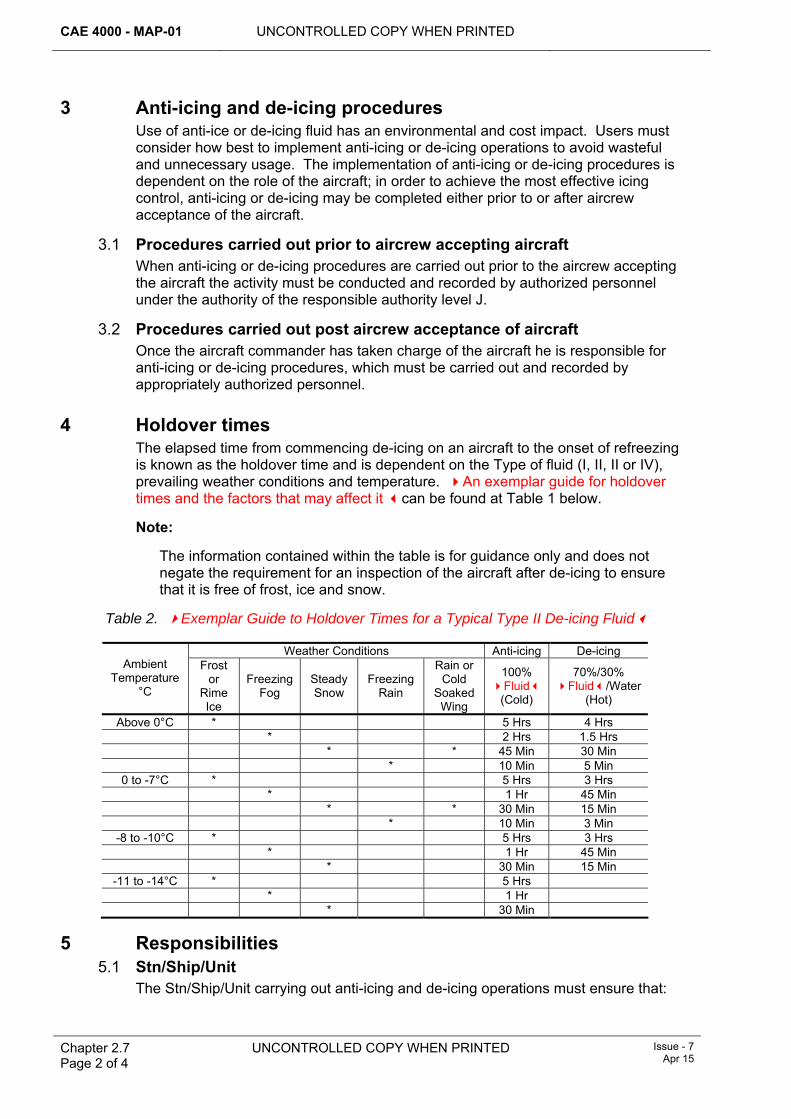
CAE 4000 - MAP-01 UNCONTROLLED COPY WHEN PRINTED
Chapter 2.7 Page 2 of 4
UNCONTROLLED COPY WHEN PRINTED Issue - 7 Apr 15
3 Anti-icing and de-icing procedures Use of anti-ice or de-icing fluid has an environmental and cost impact. Users must consider how best to implement anti-icing or de-icing operations to avoid wasteful and unnecessary usage. The implementation of anti-icing or de-icing procedures is dependent on the role of the aircraft; in order to achieve the most effective icing control, anti-icing or de-icing may be completed either prior to or after aircrew acceptance of the aircraft.
3.1 Procedures carried out prior to aircrew accepting aircraft When anti-icing or de-icing procedures are carried out prior to the aircrew accepting the aircraft the activity must be conducted and recorded by authorized personnel under the authority of the responsible authority level J.
3.2 Procedures carried out post aircrew acceptance of aircraft Once the aircraft commander has taken charge of the aircraft he is responsible for anti-icing or de-icing procedures, which must be carried out and recorded by appropriately authorized personnel.
4 Holdover times The elapsed time from commencing de-icing on an aircraft to the onset of refreezing is known as the holdover time and is dependent on the Type of fluid (I, II, II or IV), prevailing weather conditions and temperature. An exemplar guide for holdover times and the factors that may affect it can be found at Table 1 below.
Note:
The information contained within the table is for guidance only and does not negate the requirement for an inspection of the aircraft after de-icing to ensure that it is free of frost, ice and snow.
Table 2. Exemplar Guide to Holdover Times for a Typical Type II De-icing Fluid
Weather Conditions Anti-icing De-icing Ambient
Temperature °C
Frost or
Rime Ice
Freezing Fog
Steady Snow
Freezing Rain
Rain or Cold
Soaked Wing
100% Fluid
(Cold)
70%/30% Fluid/Water
(Hot)
Above 0°C * 5 Hrs 4 Hrs * 2 Hrs 1.5 Hrs * * 45 Min 30 Min * 10 Min 5 Min
0 to -7°C * 5 Hrs 3 Hrs * 1 Hr 45 Min * * 30 Min 15 Min * 10 Min 3 Min
-8 to -10°C * 5 Hrs 3 Hrs * 1 Hr 45 Min * 30 Min 15 Min
-11 to -14°C * 5 Hrs * 1 Hr * 30 Min
5 Responsibilities 5.1 Stn/Ship/Unit
The Stn/Ship/Unit carrying out anti-icing and de-icing operations must ensure that:
UNCONTROLLED COPY WHEN PRINTED CAE 4000 - MAP-01
Issue - 7 Apr 15
UNCONTROLLED COPY WHEN PRINTED
Chapter 2.7 Page 3 of 4
1 Personnel required to undertake anti-icing and de-icing operations must be authorized to hold MAP-B211. They must have been trained to conduct de-icing operations using appropriate equipment in accordance with RA 4806 and Chapter 4.1 and authorized by the holder of MAP-J212 in accordance with RA 4806 and Chapter 4.3.
2 The requirements of the aircraft Topic 1 are met for the anti-icing and de-icing of parked aircraft.
3 Personnel undertaking anti-icing and de-icing operations are conversant with the contents of Chapter 5.5.
4 Stores and equipment removed from the aircraft are cleaned of anti-icing material prior to storage.
5 Local Orders should contain mixtures and holdover times for the Type of fluid used and operating procedures for the aircraft de-icing equipment.
5.2 DE&S General Commodities and Services Team (GCST) The GCST Fuel, Oils, Lubricants and Gasses Team is responsible for procuring anti-icing fluid that is suitable for use on military aircraft and ensuring it is supplied with appropriate usage data.
5.3 Air Commodities Team (AC Team) The AC Team is responsible for:
1 The acquisition and through-life support of both vehicle-based and portable anti-icing and de-icing equipment.
2 Ensuring that the equipment publications contain appropriate operating procedures.
3 Providing initial training on the use of new de-icing equipment.
5.4 Type Airworthiness Authority (TAA) TAA are responsible for ensuring that the Topic 1 contains approved fluids andappropriate procedures for the anti-icing and de-icing of parked aircraft. The Topic 1 must include:
1 The anti-icing measures to be applied when the aircraft is parked in conditions conducive to icing.
2 The methods and equipment to be employed for the removal of snow.
3 Procedures for de-icing the aircraft that have explosive armament stores fitted.
4 A pre-flight inspection checklist for use following de-icing to ensure that the aircraft is in a safe condition for flight.
6 References This chapter refers to the following publications:
1 Topic 1 – Aircraft Maintenance Manual (AMM).

CAE 4000 - MAP-01 UNCONTROLLED COPY WHEN PRINTED
Chapter 2.7 Page 4 of 4
UNCONTROLLED COPY WHEN PRINTED Issue - 7 Apr 15
Intentionally Blank for Print Pagination
UNCONTROLLED COPY WHEN PRINTED CAE 4000 - MAP-01
Issue - 7 Apr 15
UNCONTROLLED COPY WHEN PRINTED Chapter 2.8 Page 1 of 14
Chapter 2.8
Flight Servicing
TABLE OF CONTENTS Paragraph
Page
1 General ............................................................................................................... 2 1.1 Introduction.......................................................................................................... 2 1.2 Associated publication......................................................................................... 2 1.3 Terms Used......................................................................................................... 2 2 Regulatory Governance.................................................................................... 2 2.1 Regulatory Article Cross-reference ..................................................................... 2 2.2 Additional Information.......................................................................................... 2 3 Types of flight servicing ................................................................................... 2 3.1 Flight servicing regimes....................................................................................... 2 3.2 Selection of flight servicing regime...................................................................... 3 3.3 After Flight (AF), Before Flight (BF) and Turn Round (TR) servicing .................. 3 3.4 Process for applying AF, BF and TR system ...................................................... 4 3.5 Technical Flight Servicing (TFS) and Daily Flight Servicing (DFS) ..................... 5
5666677777888889999
101011121212131313131313
4 Operational Readiness Servicing (ORS) ......................................................... 5 Operational Re-arm (ORA) servicing............................................................... 6 Post-Taxi Recovery (PTR) servicing................................................................ 7 Replenishment Servicing (RS) ......................................................................... 8 Essential Check (EC) servicing........................................................................ 9 Servicing of aircraft in multi-Service environments ...................................... 10 Aircrew checks .................................................................................................. 11 Waiving of flight servicing................................................................................ 11.1 Limitations ........................................................................................................... 11.2 Authorization ....................................................................................................... 11.3 Aircrew instructions ............................................................................................. 12 Validity of flight servicing................................................................................. 12.1 Validity periods .................................................................................................... 12.2 Extensions to validity periods .............................................................................. 12.3 Effects of maintenance activity on flight servicing ............................................... 12.4 Effect of cancelled or aborted flight on a flight servicing ..................................... 12.5 Recording action ................................................................................................. 13 Responsibilities................................................................................................. 13.1 Engineering tradesman ....................................................................................... 13.2 Flight Servicing Co-ordinator............................................................................. 13.3 MOD Form 700C Coordinator ........................................................................... 13.4 Aircrew .............................................................................................................. 14 Flight servicing using an area-based Flight Servicing Schedule (FSS)..... 15 Training and authorizations ........................................................................... 15.1 Carrying out flight servicing ............................................................................... 15.2 Co-ordinating activities ...................................................................................... 15.3 Determining the validity of, or restoring, flight servicing .................................... 15.4 Waiving flight servicing...................................................................................... 15.5 Aircrew .............................................................................................................. 16 Continuous charge.......................................................................................... 17 References .......................................................................................................
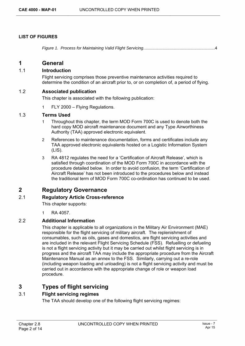
CAE 4000 - MAP-01 UNCONTROLLED COPY WHEN PRINTED
Chapter 2.8 Page 2 of 14
UNCONTROLLED COPY WHEN PRINTED
Issue - 7 Apr 15
LIST OF FIGURES Figure 1. Process for Maintaining Valid Flight Servicing...............................................................4
1 General 1.1 Introduction
Flight servicing comprises those preventive maintenance activities required to determine the condition of an aircraft prior to, or on completion of, a period of flying.
1.2 Associated publication This chapter is associated with the following publication:
1 FLY 2000 – Flying Regulations.
1.3 Terms Used 1 Throughout this chapter, the term MOD Form 700C is used to denote both the
hard copy MOD aircraft maintenance document and any Type Airworthiness Authority (TAA) approved electronic equivalent.
2 References to maintenance documentation, forms and certificates include any TAA approved electronic equivalents hosted on a Logistic Information System (LIS).
3 RA 4812 regulates the need for a ‘Certification of Aircraft Release’, which is satisfied through coordination of the MOD Form 700C in accordance with the procedure detailed below. In order to avoid confusion, the term ‘Certification of Aircraft Release’ has not been introduced to the procedures below and instead the traditional term of MOD Form 700C co-ordination has continued to be used.
2 Regulatory Governance 2.1 Regulatory Article Cross-reference
This chapter supports:
1 RA 4057.
2.2 Additional Information This chapter is applicable to all organizations in the Military Air Environment (MAE) responsible for the flight servicing of military aircraft. The replenishment of consumables, such as oils, gases and domestics, are flight servicing activities and are included in the relevant Flight Servicing Schedule (FSS). Refuelling or defueling is not a flight servicing activity but it may be carried out whilst flight servicing is in progress and the aircraft TAA may include the appropriate procedure from the Aircraft Maintenance Manual as an annex to the FSS. Similarly, carrying out a re-role (including weapon loading and unloading) is not a flight servicing activity and must be carried out in accordance with the appropriate change of role or weapon load procedure.
3 Types of flight servicing 3.1 Flight servicing regimes
The TAA should develop one of the following flight servicing regimes:
UNCONTROLLED COPY WHEN PRINTED CAE 4000 - MAP-01
Issue - 7 Apr 15
UNCONTROLLED COPY WHEN PRINTED Chapter 2.8 Page 3 of 14
1 A regime comprising After Flight (AF), Before Flight (BF) and Turn Round (TR) servicing.
2 A regime comprising Technical Flight Servicing (TFS) and Daily Flight Servicing (DFS).
Note:
Replenishment Servicing (RS), Essential Check (EC), Operational Re-arm (ORA) and Post-Taxi Recovery (PTR) servicing may also be used in conjunction with either normal FSS or ORS regimes.
3.2 Selection of flight servicing regime The TAA, in conjunction with the Operating Duty Holder (ODH), must select the flight servicing regime most suited to an aircraft’s concept of operations and must provide an appropriate FSS. Where an aircraft has different roles and one flight servicing regime is better suited to one role than the other then the TAA may produce FSS for both regimes. The TAA must state in the Support Policy Statement (SPS) in the Topic 2(N/A/R) which regime is authorized for use in which role and detail the process for transfer between regimes.
3.3 After Flight (AF), Before Flight (BF) and Turn Round (TR) servicing 3.3.1 AF servicing
An AF servicing comprises those preventive maintenance activities necessary to determine the condition of an aircraft immediately after a flight, in addition to those maintenance requirements that arise at the frequency of the AF servicing. An AF servicing must be carried out:
1 As soon as possible after each flight, except when a TR servicing is to be carried out.
2 When the expiry point of the AF has been reached and the aircraft is due to fly.
An AF servicing remains valid for the period specified by the TAA within the SPS. Unless otherwise specified in the SPS, this validity period runs from the time that the AF servicing is commenced.
3.3.2 BF servicing BF servicing comprises those maintenance activities necessary to prepare the aircraft for its next flight. When a BF servicing is required immediately after an AF, a combined AF/BF servicing may be carried out. A BF servicing should be started as near as possible to the time of take-off and remains valid for the period specified by the TAA within the SPS. Unless otherwise specified in the SPS, this validity period runs from the time that the BF servicing is commenced.
3.3.3 TR servicing When an aircraft has landed and is expected to take off again within the validity period of the AF, the requirement for flight servicing may be met by a TR servicing. A TR servicing must commence as soon as possible after flight. It comprises preventive maintenance activities to determine the condition of an aircraft immediately after a flight and to prepare it for its next flight. A TR servicing remains valid for the period specified by the TAA within the SPS. Unless otherwise specified in the SPS, this validity period runs from the time that the TR servicing is commenced. The TR servicing validity period may be the same as a BF servicing period, but must not to be of a greater duration.
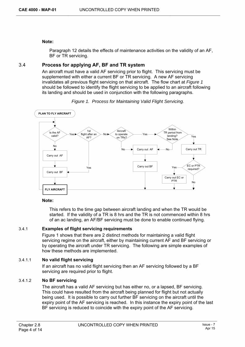
CAE 4000 - MAP-01 UNCONTROLLED COPY WHEN PRINTED
Chapter 2.8 Page 4 of 14
UNCONTROLLED COPY WHEN PRINTED
Issue - 7 Apr 15
Note:
Paragraph 12 details the effects of maintenance activities on the validity of an AF, BF or TR servicing.
3.4 Process for applying AF, BF and TR system An aircraft must have a valid AF servicing prior to flight. This servicing must be supplemented with either a current BF or TR servicing. A new AF servicing invalidates all previous flight servicing on that aircraft. The flow chart at Figure 1 should be followed to identify the flight servicing to be applied to an aircraft following its landing and should be used in conjunction with the following paragraphs.
Figure 1. Process for Maintaining Valid Flight Servicing.
PLAN TO FLY AIRCRAFT
Within TR period from
landing?See Note
1stflight after an
AF?
Is the AFvalid?
Aircraftto operate on TRs?
EC or PTRrequired?
Carry out AF
Carry out BF
FLY AIRCRAFT
Carry out AF
Carry out BF
Carry out TR
Carry out EC orPTR
No
Yes
Yes No YesYes
No No
Yes
No
Note:
This refers to the time gap between aircraft landing and when the TR would be started. If the validity of a TR is 8 hrs and the TR is not commenced within 8 hrs of an ac landing, an AF/BF servicing must be done to enable continued flying.
3.4.1 Examples of flight servicing requirements Figure 1 shows that there are 2 distinct methods for maintaining a valid flight servicing regime on the aircraft, either by maintaining current AF and BF servicing or by operating the aircraft under TR servicing. The following are simple examples of how these methods are implemented.
3.4.1.1 No valid flight servicing If an aircraft has no valid flight servicing then an AF servicing followed by a BF servicing are required prior to flight.
3.4.1.2 No BF servicing The aircraft has a valid AF servicing but has either no, or a lapsed, BF servicing. This could have resulted from the aircraft being planned for flight but not actually being used. It is possible to carry out further BF servicing on the aircraft until the expiry point of the AF servicing is reached. In this instance the expiry point of the last BF servicing is reduced to coincide with the expiry point of the AF servicing.
UNCONTROLLED COPY WHEN PRINTED CAE 4000 - MAP-01
Issue - 7 Apr 15
UNCONTROLLED COPY WHEN PRINTED Chapter 2.8 Page 5 of 14
3.4.1.3 Operate aircraft on TR servicing After a flight, it is possible to operate the aircraft on TR servicing, as long as the original AF is still valid. The aircraft can be operated on continuous TR servicing until the last TR expiry point is forecast to be beyond the expiry of the AF servicing. At this point the expiry point of the last TR is reduced to coincide with the expiry of the AF servicing. At the point when a TR servicing validity period expires, or when the AF expires, an AF/BF servicing is required before the next flight of the aircraft. When a TR servicing has been carried out, but the aircraft does not fly because of unforeseen circumstances, further TR servicing may be carried out within the TR validity period up until the AF servicing validity expires.
3.5 Technical Flight Servicing (TFS) and Daily Flight Servicing (DFS) 3.5.1 TFS
The TFS establishes the baseline for all servicing checks in the next flight servicing cycle. A TFS is valid for a set period, provided it is not invalidated by any other maintenance work carried out during the period. The aim of the TFS is to examine the aircraft and documentation, check and replenish all consumables and prepare the aircraft for the next period of flying. The TFS remains valid from the commencement of the servicing for a period stipulated in the SPS along with details of any backstop; for example 7 days or 25 flying hours.
3.5.2 DFS A DFS is the servicing that is required to prepare the aircraft for flight(s) during the next 24 hours and is valid from the commencement of the servicing within the TFS period. A DFS checks and replenishes all consumables, as well as preparing the aircraft’s documentation for the next period of flying. The first 24 hrs following a TFS does not require a DFS to be carried out, as a TFS incorporates the initial DFS.
The TAA must promulgate the following information in the SPS:
1 The procedure for applying for an extension to this period, if applicable.
2 What level of servicing is required, following a scheduled maintenance activity.
If the currency of a TFS or DFS is likely to expire during a mission, the relevant servicing must be carried out before commencement of that mission.
Note:
Paragraph 12 details the effects of maintenance activities on the validity of a DFS or TFS.
4 Operational Readiness Servicing (ORS) An Operational Readiness Servicing (ORS) regime may be used when an aircraft undergoes a sustained period of operational standby. An ORS must comprise the preventive maintenance, and weapon loading/unloading activities if applicable, necessary to maintain an aircraft in a state of continuous operational readiness for up to 30 days, unless otherwise stipulated by the TAA. An ORS schedule is a substitute for the aircraft’s basic FSS, the requirements of which are suspended throughout the period of operational standby. ORS is sub-divided into three phases:
1 Preparation For Standby phase (PFS). The PFS prepares the aircraft for flight and the specified period of operational readiness. It includes the contents of an AF/BF or TFS, weapon loading, if applicable, and any other maintenance activities that would become due during the standby period. It is valid for the first 24 hrs on standby.
CAE 4000 - MAP-01 UNCONTROLLED COPY WHEN PRINTED
Chapter 2.8 Page 6 of 14
UNCONTROLLED COPY WHEN PRINTED
Issue - 7 Apr 15
2 Standby Servicing phase (SS). The SS is carried out at subsequent daily intervals to maintain the aircraft in a serviceable condition whilst it is on standby. It often comprises maintenance activities drawn from the BF, TR, DFS or replenishment schedules and any maintenance that may be necessary on the weapon fit.
3 Release From Standby phase (RFS). When an aircraft is no longer required to be maintained at a state of operational readiness, an RFS is carried out. It comprises the maintenance activities of an AF or TFS and a weapon unload, if applicable.
An Essential Check (EC) may also be carried out during a period of standby to maintain the serviceability of high-loss systems. If the aircraft taxies, but does not fly, it may be returned to operational readiness by carrying out a Post Taxi Recovery (PTR). If the aircraft flies from standby, when it returns it can be restored to operational standby by carrying out a PFS or prepared for a single flight via a TR/DFS or Operational Re-arm (ORA) servicing.
5 Operational Re-arm (ORA) servicing An ORA is designed to make an operational aircraft ready for flight in the shortest elapsed time. It combines elements of the TR/DFS or RS, as applicable, with refuelling and loading of weapons and/or external stores, as required. An ORA remains valid for the validity period of a TR, DFS or Replenishment Servicing (RS).
6 Post-Taxi Recovery (PTR) servicing A PTR servicing is the maintenance necessary after an aircraft has been started and taxied, but has subsequently returned without having flown. A PTR servicing restores, but does not extend, the validity of the aircraft’s current flight servicing.
7 Replenishment Servicing (RS) An RS must contain the minimum mandatory maintenance activities necessary whenever an aircraft lands and stops its engine(s) between flights. An RS, if required, must be carried out as soon as possible after an aircraft lands and remains valid as promulgated by the TAA.
On completion of replenishing fuel, oxygen, water or oil systems, the details are to be recorded on the relevant Flight Servicing Certificate (FSC) (MOD Form 705) or Oil Replenishment Record (MOD Form 737) in accordance with its Instructions For Use. The signature of the tradesman undertaking the replenishment signifies that:
1 The replenishment has been carried out in accordance with the appropriate technical information.
2 Any hand tools used have been accounted for, in accordance with RA 4808 and Chapter 6.1.1.
3 The correct grade of fuel, oil, etc, has been used.
4 The correct quantity has been recorded.
8 Essential Check (EC) servicing Where aircraft systems lose their contents through natural leakage at a rate that poses an unacceptable constraint on the validity of a particular flight servicing, the TAA may authorize an EC servicing schedule. Such a schedule must be limited to repeating any flight servicing activities necessary to ensure that those systems
UNCONTROLLED COPY WHEN PRINTED CAE 4000 - MAP-01
Issue - 7 Apr 15
UNCONTROLLED COPY WHEN PRINTED Chapter 2.8 Page 7 of 14
remain serviceable within the validity period of the associated flight servicing. The TAA must publish the frequency of any EC servicing in the SPS. An EC servicing may be repeated as often as necessary within the validity period of the associated flight servicing, but it does not extend its validity.
9 Servicing of aircraft in multi-Service environments Servicing of aircraft in multi-service environments, including cross-servicing, is detailed in RA 4806 and Chapter 5.2.
10 Aircrew checks The responsible aircrew member must carry out such checks as detailed in the Topic 14 or other instructions. These checks are vital since it is possible for an aircraft to be cleared for flight although not in a fit condition for flight due to wings or rotors being folded, covers and blanks still in position, etc. Under operational conditions it is not always possible for the aircrew member to carry out these pre-flight checks personally. In such circumstances, arrangements must be made for a responsible tradesman to carry them out and report personally to the Aircraft Commander that they have been done. The Aircraft Commander is responsible for ensuring that this report is made before take-off.
Aircraft acceptance checks by aircrew are not flight servicing and do not form part of the maintenance arrangements for the aircraft. For aircraft subject to ORS, the aircrew will carry out the aircraft acceptance checks, following completion of the ORS. However, a person holding authorization MAP–G14, in consultation with the relevant aircrew, must decide whether the aircraft acceptance check has been invalidated by a maintenance activity on that aircraft.
11 Waiving of flight servicing 11.1 Limitations
Flight servicing should only be waived if specifically authorized by the TAA (via the Topic 2(N/A/R)) and it is operationally essential to generate an aircraft. The Topic 2(N/A/R) must detail the limitations that may be imposed as a result of the flight servicing being waived. This may include restrictions on:
1 Duration of any flight.
2 Elapsed time, ie the period of time over which flight servicing may be waived.
3 The number of landings and/or number of system operations.
In addition, the Topic 2(N/A/R) must also detail any specific maintenance activities that are to be carried out, including the restrictions on subsequent flight servicing (ie must complete an AF/BF rather than a TR).
11.2 Authorization When operational circumstances demand, and provided the conditions at paragraph 11.1 are met, flight servicing between successive flights may be waived on the authority of:
1 A person holding authority level J (which must include MAP-H21).
2 A person holding authorization MAP–H21 when no authority level J is available, countersigned by the Aircraft Commander.
3 The Aircraft Commander in consultation with an authority level J.
CAE 4000 - MAP-01 UNCONTROLLED COPY WHEN PRINTED
Chapter 2.8 Page 8 of 14
UNCONTROLLED COPY WHEN PRINTED
Issue - 7 Apr 15
The statement:
‘Flight servicing waived by: Authority Level H/J/Aircraft Commander*: [Insert Name]’. (* Delete as applicable)
must be entered in the flight servicing block on the relevant FSC. This entry must be counter-signed by either the authority level J or the Aircraft Commander.
11.3 Aircrew instructions Units must consider promulgating local instructions to inform aircrew of the limitations and restrictions associated with the waiving of flight servicing. These instructions must include as a minimum:
1 A verbatim extract from paragraph 11.2 above.
2 A statement of the limitations imposed by the TAA on the waiving of flight servicing.
12 Validity of flight servicing 12.1 Validity periods
The TAA must determine the validity periods of the various forms of flight servicing most suited to their aircraft and publish them in the Topic 2(N/A/R).
12.2 Extensions to validity periods Due to the inherent flexibility of the flight servicing systems there should be no reason, other than an operational emergency, to extend the validity period of a servicing. However, the TAA may include within the Topic 2(N/A/R) the process for obtaining extensions (if applicable) to the flight servicing periods pertinent to their aircraft.
12.3 Effects of maintenance activity on flight servicing 12.3.1 TFS and DFS or BF and TR servicing
Maintenance activities may invalidate TFS and DFS or BF and TR servicing because they may have disturbed or affected the systems or baselines that were confirmed during the flight servicing. A decision must be made by an individual holding the appropriate level G authorization, as to which one of the following options are required to restore the current flight servicing:
1 Carry out a full flight servicing.
2 Carry out a partial flight servicing which restores the affected systems or baselines and record the decision in accordance with paragraph 12.5.
3 Carry out no further flight servicing and record the decision in accordance with paragraph 12.5.
Note:
A partial flight servicing does not increase the validity period of the current flight servicing.
12.3.2 AF Because the AF servicing comprises preventive maintenance activities necessary to determine the condition of an aircraft immediately after a flight, maintenance activities carried out after an AF servicing will not invalidate that flight servicing. The flight servicing requirement on completion of all other maintenance activities under these circumstances is a BF servicing carried out within the AF servicing validity period.
UNCONTROLLED COPY WHEN PRINTED CAE 4000 - MAP-01
Issue - 7 Apr 15
UNCONTROLLED COPY WHEN PRINTED Chapter 2.8 Page 9 of 14
However, in order to restore the AF servicing validity after protracted maintenance activities and re-establish the baseline for the flight servicing cycle utilizing the full flight servicing validity period, the individual responsible for coordinating the MOD Form 700 may determine that a further AF servicing must be carried out.
12.4 Effect of cancelled or aborted flight on a flight servicing If the Aircraft Commander has signed the acceptance certificate on the FSC, but the flight is subsequently cancelled or aborted before the aircraft has taken off, the effect on the validity of the flight servicing must be determined, in consultation with the Aircraft Commander if necessary. Paragraph 12.3 details the actions required to restore the current flight servicing.
12.5 Recording action Following an assessment on the effects on a flight servicing of maintenance or flight cancellation/aborted flight, the recording action detailed in either paragraph 12.5.1 or 12.5.2 must be carried out as appropriate. Full details of the recording action required for a specific aircraft’s FSC are given in the Instructions for Use for that form.
12.5.1 No flight servicing required Where any of the situations detailed in paragraphs 12.3.1, 12.3.2 or 12.4 have not invalidated a flight servicing, the FSC must be annotated with one of the following statements and signed by an individual authorized as detailed at paragraph 15.3:
‘No Flight Servicing Required Following Work at SNOW(s): [Enter SNOW of any work carried out]’
or
‘No Flight Servicing Required Following Cancelled / Aborted* Flight’ (* Delete as applicable)
12.5.2 Partial flight servicing carried out If a partial flight servicing will restore the currency of the existing flight servicing, the FSC must be annotated with the following statement and signed by an individual authorized as detailed at paragraph 15.3:
‘Partial Flight Servicing to be carried out: [enter details of elements to be completed]’
In addition, the tradesman who carries out this work must sign the FSC.
13 Responsibilities 13.1 Engineering tradesman
Engineering tradesmen are to undertake the work as detailed by the Flight Servicing coordinator and sign in the appropriate flight servicing blocks. A signature in the flight servicing block certifies that the flight servicing has been undertaken in accordance with the appropriate FSS and, where required, oil replenishments undertaken have been recorded on the appropriate MOD Form or the IS equivalent has been completed. Additionally, certification of the FSC by a tradesman signifies that any hand tools, used for that aspect of the flight servicing he has undertaken, have been accounted for.
Flight servicing is an Elementary Self-supervised (ESS) activity, however, personnel holding authorization MAP-D12 do not require to hold the ESS authorization MAP-D359 to carry out this activity (see Chapter 4.5, paragraph 6). The tradesman
CAE 4000 - MAP-01 UNCONTROLLED COPY WHEN PRINTED
Chapter 2.8 Page 10 of 14
UNCONTROLLED COPY WHEN PRINTED
Issue - 7 Apr 15
carrying it out must be made aware that he assumes the responsibilities of 1st and 2nd signature, as detailed in RA 4806 and Chapter 4.3.2, for this activity. However, if the risk of error in a particular servicing is high, for example at night, in poor weather, at the end of a shift period or at an austere location, it may be necessary to supervise the servicing team.
13.2 Flight Servicing Co-ordinator 13.2.1 Responsibilities
The Flight Servicing Co-ordinator must define the type of flight servicing required, eg AF, DFS, EC, etc. He is also responsible for:
1 Entering any additional requirements in any numbered spare lines and detailing the appropriate tradesmen to undertake and sign for the work.
2 Identifying in the spare lines any items contained in the flight servicing schedules, eg oxygen replenishment, which he has delegated to tradesmen other than those directed to undertake the flight servicing.
3 Striking through any designated or spare lines not required.
4 Ensuring that, on completion of their task, all tradesmen involved in the flight servicing, including any delegated tasks, have signed for their work in the appropriate signature blocks and are authorized to do so.
5 Updating the ‘valid until’ TDM and airframe hours.
13.2.2 Certification on FSC The Flight Servicing Coordinator must sign on the relevant FSC to certify that he has satisfied himself that:
1 An entry has been raised in the Aircraft Maintenance Log (MOD F707A) for each fault found during the flight servicing.
2 The flight servicing has been completed satisfactorily.
3 The appropriate columns have been completed in the Supplementary Flight Servicing Certificate (MOD F705(SSC)).
4 If applicable, flight servicing details have been updated in the appropriate Information System (IS).
5 The recorded fuel state meets the figure requested for the next planned sortie.
6 The flying hours and component running hours recorded in the flying log and/or equipment-running log have been calculated correctly from the previous sortie details and the totals prior to that sortie.
7 A careful check of oil state figures has been made, paying particular attention to the amount put in.
13.3 MOD Form 700C Coordinator When all the necessary flight servicing have been completed, the MOD Form 700C Co-ordinator clears the aircraft for flight by signing the co-ordinating certificate of the relevant FSC. This signature certifies that, from examination of the MOD Form 700C and, if appropriate, any IS documentation:
1 No limitations or acceptable deferred faults are due for rectification or removal.
2 The flying hours and component running hours recorded in the flying log and equipment running logs have been calculated correctly from the previous sortie details and the totals prior to that sortie.
UNCONTROLLED COPY WHEN PRINTED CAE 4000 - MAP-01
Issue - 7 Apr 15
UNCONTROLLED COPY WHEN PRINTED Chapter 2.8 Page 11 of 14
3 Any flying requirements have been entered in the Aircraft Maintenance Log and the relevant FSC annotated appropriately.
4 With the exception of the scenario of helicopter main rotor blade and tail pylon fold systems as described in Chapter 6.10, the aircraft is serviceable in accordance with RA 4813 and Chapter 7.2.
5 No preventive maintenance or component replacements are due or will become due during the planned sortie.
6 An authorized tradesman has certified all entries in the Acceptable Deferred Husbandry Log (MOD F704A).
7 All hand tools have been accounted for in accordance with RA 4808 and Chapter 6.1.1.
8 The appropriate flight servicing have been completed and certified.
13.4 Aircrew The responsibilities transferred to the Aircraft Commander when the MOD Form 700C is signed are defined in RA 2301(1). They are repeated below for the convenience of maintenance personnel but RA 2301(1) remains the authority.
13.4.1 Aircrew acceptance The responsible aircrew member accepts the aircraft by signing the Acceptance Certificate of the FSC. This signature certifies that, after scrutiny of the MOD Form 700C, the aircrew member is satisfied that:
1 Any limitations are acceptable to him for the intended sortie.
2 He is aware of all acceptable deferred faults.
3 The recorded state of the aircraft in respect of fuel, oxygen, etc, is acceptable to him for the intended sortie.
4 The armament state of the aircraft, as certified on the appropriate FSC or Role Equipment and Expendable Stores certificate (MOD Form 706), is as ordered by the authorizing officer.
5 The documentary check of the MOD Form 700C has been carried out and the Co-ordinating Certificate of the FSC has been signed by the MOD Form 700C co-ordinator.
6 Any flying or ground run requirements are acceptable to him and he has been adequately briefed on any special tests required.
7 If applicable, any aircrew-accepted faults, as entered in the Aircraft Maintenance Log or Continuous Operation Certificate (MOD F705C) if on continuous charge, are acceptable to him.
Note:
Item 2 above: A MOD CAM may authorize the use of a divider to assist aircrew in prioritizing acceptable deferred faults, ie those that would be apparent during crew-in.
13.4.2 After-flight declaration The aircrew member responsible for the aircraft must complete the After Flight Certificate in the FSC. This signature returns the responsibility for the aircraft to the engineering organization and certifies that:
CAE 4000 - MAP-01 UNCONTROLLED COPY WHEN PRINTED
Chapter 2.8 Page 12 of 14
UNCONTROLLED COPY WHEN PRINTED
Issue - 7 Apr 15
1 He has returned the aircraft to the finally armed state in accordance with the Aircraft Flight Reference Cards or that no explosive armament stores are fitted.
2 He had accepted those faults, the Serial Number of Works (SNOWs) for which are listed in the Acceptable Faults block (line 1) against his after flight declaration.
3 An Aircraft Maintenance Log (MOD F707A) entry has been raised for each fault that became evident whilst he was responsible for the aircraft, including pre-flight faults.
4 The results of any Flying Requirements undertaken have been entered in the Aircraft Flying Requirements Certificate (MOD F707B(AFRC)) in accordance with MOD F799/5(AFRC).
5 The Flying Log and Equipment Running Log (MOD F724) or IS equivalent have been completed.
6 Where applicable, the Oil Replenishment Record (MOD F737) has been completed for any oil replenishments carried out whilst he was responsible for the aircraft.
7 He has updated the hours flown and cumulative hours flown in appropriate documentation as required.
8 Where applicable, the aircrew assisted escape system has been placed into the safe for parking condition.
A significant proportion of faults reported by aircrew result in components, particularly radio, electrical and instrument components, being removed from aircraft and subjected to testing that fails to find any fault. To avoid unnecessary expenditure of time, manpower and spares, plus loss of aircraft availability, full and complete debriefing of aircrew by qualified maintenance personnel is essential.
14 Flight servicing using an area-based Flight Servicing Schedule (FSS) If authorized by the TAA, flight servicing may be carried out using an area-based system, detailed in the relevant aircraft FSS. This system divides the aircraft into distinct work areas and will require activities to be done by individuals who would then be working outside their normal trade boundary.
15 Training and authorizations 15.1 Carrying out flight servicing
Personnel required to carry out flight servicing must hold authorization MAP–D12 and have:
1 Completed training in accordance with RA 4806 and Chapter 4.1 for each type/mark of aircraft and regime of flight servicing that they are required to carry out.
2 Carried out and passed a flight servicing competence check in accordance with Chapter 2.8.1.
Note:
Personnel undergoing training are to hold authorization MAP–A449 and are to be subject to 100% supervision. The FSC must be signed by the trainee and endorsed by the supervisor.
UNCONTROLLED COPY WHEN PRINTED CAE 4000 - MAP-01
Issue - 7 Apr 15
UNCONTROLLED COPY WHEN PRINTED Chapter 2.8 Page 13 of 14
15.2 Co-ordinating activities 15.2.1 Flight Servicing Co-ordinator
Personnel required to undertake the duties of Flight Servicing Co-ordinator must hold authorization MAP–C445.
15.2.2 MOD Form 700 Co-ordinator Personnel required to undertake the duties of MOD Form 700 Co-ordinator must hold authorization MAP–E439.
15.3 Determining the validity of, or restoring, flight servicing Personnel required to:
1 Determine whether a maintenance activity carried out on an aircraft, subject to ORS, has invalidated the aircrew’s acceptance checks or the flight servicing must hold authorization MAP–G14.
2 Determine the extent of partial flight servicing that is necessary to restore the currency of the existing flight servicing, following maintenance or a cancelled or aborted flight must hold authorization MAP–G16.
3 Annotate the MOD Form 700 ‘no flight servicing required’ following maintenance or a cancelled / aborted flight after a DFS, TFS, BF or TR servicing has been completed must hold authorization MAP–G17.
15.4 Waiving flight servicing Personnel required to waive flight servicing when there is no authority level J available must hold authorization MAP–H21.
15.5 Aircrew Aircrew authorized to carry out flight servicing in accordance with RA 4806 and Chapter 4.7.1 as detailed in the relevant platform Topic 5B1 (Flight Servicing Schedule) or Topic 5Y (Aircrew Landaway Flight Servicing Schedule) must hold authorization MAP–AFS82.
16 Continuous charge Due to the high usage rate of aircraft during certain operations, it is permissible to place the aircraft on continuous charge whereby it is operated in accordance with RA 4059 and Chapter 2.9. The major benefit of this form of aircraft management is that the aircraft may undergo numerous landings, during which the aircraft’s engine/s may be stopped and restarted, the aircraft refuelled and aircrew changed.
17 References This chapter refers to the following publications:
1 Aircraft Topic 5A1 – Aircraft Maintenance Manual.
2 Aircraft Topic 2(N/A/R) – General Orders, Special Instructions and Modifications.
3 Aircraft Topic 5B1 – Flight Servicing Schedule.
4 Aircraft Topic 5U1/3 – Operational Readiness Servicing Schedule.
5 Aircraft Topic 5Y – Aircrew Landaway Flight Servicing Schedule.

CAE 4000 - MAP-01 UNCONTROLLED COPY WHEN PRINTED
Chapter 2.8 Page 14 of 14
UNCONTROLLED COPY WHEN PRINTED
Issue - 7 Apr 15
Intentionally Blank for Print Pagination
UNCONTROLLED COPY WHEN PRINTED CAE 4000 - MAP-01
Issue - 7 Apr 15
UNCONTROLLED COPY WHEN PRINTED Chapter 2.8.1 Page 1 of 4
Chapter 2.8.1
Flight Servicing Competency Checks
TABLE OF CONTENTS Paragraph
Page
1 General ............................................................................................................... 1 1.1 Introduction.......................................................................................................... 1 2 Regulatory Governance.................................................................................... 1 2.1 Regulatory Article Cross-reference ..................................................................... 1 2.2 Additional Information.......................................................................................... 1 3 Flight servicing.................................................................................................. 1 4 Flight Servicing Competency Check (FSCC).................................................. 2 4.1 Content of FSCC ................................................................................................. 2 4.2 Frequency ........................................................................................................... 2 4.3 Recording ............................................................................................................ 2 4.4 Personnel carrying out the FSCC........................................................................ 2 4.5 FSCC failure........................................................................................................ 2 5 Flight servicing by aircrew ............................................................................... 3 6 Reference ........................................................................................................... 3
1 General 1.1 Introduction
Flight servicing is one of the principle processes utilized within the Military Air Environment (MAE) to maintain the airworthiness of aircraft. It is therefore imperative that high standards of workmanship are employed at all times when carrying out these activities.
2 Regulatory Governance 2.1 Regulatory Article Cross-reference
This chapter supports:
1 RA 4807.
2.2 Additional Information This chapter is associated with the following publications:
1 BRd 763 – Fleet Aviation Quality Manual.
2 AP7400 - Continuing Airworthiness Engineering (Army).
3 AP 100C-10 – RAF Manual of Quality Assurance and Continual Improvement.
3 Flight servicing The process concerning flight servicing is contained within RA 4057 and Chapter 2.8. The following paragraphs detail the specific activities and responsibilities to maintain the required standards of those flight servicings.
CAE 4000 - MAP-01
Chapter 2.8.1 Page 2 of 4
UNCONTROLLED COPY WHEN PRINTED Issue - 7 Apr 15
4 Flight Servicing Competency Check (FSCC) 4.1 Content of FSCC
The FSCC must check that personnel are:
1 Carrying out the work in accordance with the relevant Technical Instructions (TI) and are using the correct tools, ground equipment and materials in the proper manner.
2 Competent to carry out all aspects of the servicing, including periodic self-supervision maintenance activities.
3 Aware of their actions and responsibilities should they discover a problem during the flight servicing.
4 Correctly completing all related documentation.
Note:
An authority level J may identify further elements of the individual’s overall engineering competency to be checked during the FSCC.
4.2 Frequency Individuals that carry out flight servicing must be checked at least every 12 months. However, an authority level J may increase the frequency of these checks based on the following, non-exhaustive, list of examples:
1 The inexperience of newly qualified personnel.
2 Those personnel who have indicated deterioration in their trade practices.
3 Where it is considered that, due to the nature of the working environment, 12 months is too long an interval between checks.
4 Where the servicing documentation or Topic 5B1 has been subject to significant amendment.
Note:
An authority level J may also identify personnel that, by virtue of their skill and authority level and therefore experience, are not subject to FSCCs.
4.3 Recording A local record must be maintained for each individual carrying out flight servicing, which must show the date of last check (including details of who performed the check), the date the next check is due and any other circumstances particular to the individual. If the FSCC is to form an integral part of the local procedure for flight servicing re-certification, no additional recording action will be required.
4.4 Personnel carrying out the FSCC Personnel carrying out FSCC must hold authorization MAP–C67 and be authorized to perform the flight servicing that they are checking. The number of personnel authorized to carry out FSCCs must be kept to the minimum number within each organization. Personnel carrying out FSCCs must be subject to FSCCs to ensure that they maintain their own standard of competency (see paragraph 4.2 note).
4.5 FSCC failure Personnel that fail an FSCC must undergo remedial training/instruction on the areas that were found to be weak. Following a subsequent pass, consideration must be given to increasing the frequency of the individual’s FSCCs.
UNCONTROLLED COPY WHEN PRINTED CAE 4000 - MAP-01
Issue - 7 Apr 15
UNCONTROLLED COPY WHEN PRINTED Chapter 2.8.1 Page 3 of 4
5 Flight servicing by aircrew Aircrew who hold authorization MAP–AFS82 (Authorized to Flight Service), in accordance with RA 4806 and Chapter 4.7.1, are subject to the content of this chapter.
6 Reference This chapter refers to the following publication:
1 Aircraft Topic 5B1 – Flight Servicing Schedule.
CAE 4000 - MAP-01
Chapter 2.8.1 Page 4 of 4
UNCONTROLLED COPY WHEN PRINTED Issue - 7 Apr 15
Intentionally Blank for Print Pagination
UNCONTROLLED COPY WHEN PRINTED CAE 4000 - MAP-01
Issue - 7 Apr 15
UNCONTROLLED COPY WHEN PRINTED Chapter 2.9 Page 1 of 6
555
Chapter 2.9
Continuous Charge
TABLE OF CONTENTS Paragraph
Page
1 General ............................................................................................................... 1 1.1 Introduction.......................................................................................................... 1 1.2 Associated publications....................................................................................... 1 1.3 Applicability ......................................................................................................... 1 1.4 Terms Used......................................................................................................... 2 2 Regulatory Governance.................................................................................... 2 2.1 Regulatory Article Cross-reference ..................................................................... 2 3 Period of continuous charge............................................................................ 2 4 Flight servicing requirements .......................................................................... 2 5 Aircrew qualifications for continuous charge ................................................ 2 6 Aircrew responsibilities.................................................................................... 3 7 Continuous charge procedure ......................................................................... 3 7.1 Preparation for continuous charge ...................................................................... 3 7.2 Procedures during continuous charge................................................................. 3 7.3 Cessation of continuous charge .......................................................................... 4 7.4 Action on completion of continuous charge......................................................... 8 Authorizations ................................................................................................... 9 References .........................................................................................................
1 General 1.1 Introduction
The concept of operations for some aircraft types demands that they land, stop their engine/s, change crews, possibly refuel, restart engine/s and take off again in order to complete a particular mission. When used as such, the aircraft is considered to be on continuous charge and the aircraft and any requirements for flight servicing activities remain the responsibility of the Aircraft Commander throughout the mission. Normally, the operations staff will specify continuous charge as part of the aircraft task requirement.
1.2 Associated publications This chapter is associated with the following publications:
1 JAP 100C-02 – The Maintenance Data System – Work Recording.
2 FLY 2000 – Flying Regulations.
1.3 Applicability This chapter is applicable to all aircraft operating in the Military Air Environment (MAE) that have been specifically authorized to undertake continuous charge by the appropriate Type Airworthiness Authority (TAA) in the aircraft’s Topic 2(N/A/R)1.
CAE 4000 - MAP-01 UNCONTROLLED COPY WHEN PRINTED
Chapter 2.9 Page 2 of 6
UNCONTROLLED COPY WHEN PRINTED Issue - 7 Apr 15
1.4 Terms Used 1 Throughout this chapter, the term MOD Form 700C is used to denote both the
hard copy MOD aircraft maintenance document and any TAA approved electronic equivalent.
2 References to maintenance documentation, forms and certificates include any TAA approved electronic equivalents hosted on a Logistic Information System (LIS).
2 Regulatory Governance 2.1 Regulatory Article Cross-reference
This chapter supports:
1 RA 4059.
3 Period of continuous charge When an aircraft is to be operated on continuous charge, the period of continuous charge starts when the responsible aircrew member signs the aircrew acceptance certificate on the Flight Servicing Certificate (FSC) (MOD Form 705). The period of continuous charge finishes when the criteria at paragraph 4 apply and the final responsible aircrew member completes the after flight declaration on the current FSC.
4 Flight servicing requirements The aircraft TAA should detail in the Topic 2(N/A/R)1 the frequency and extent of any flight servicing activities that must be carried out during a period of continuous charge and how these activities must be recorded. The Project Team (PT) may allow an aircraft to operate on continuous charge for a specified period without the need for any flight servicing activities to be undertaken.
An aircraft may only be subject to continuous charge if it holds a current flight servicing. Continuous charge may be applied to the aircraft but must cease when the next After Flight (AF) servicing or Technical Flight servicing (TFS) becomes due, or:
1 Preventive maintenance (less flight servicing) becomes due.
2 A fault occurs, which is not accepted by the next responsible aircrew member.
3 Charge is transferred back to the maintenance organization.
5 Aircrew qualifications for continuous charge If the expected period of continuous charge is such that some flight servicing activities will be required, the responsible aircrew member or another crewmember must hold authorization MAP-AFS82 (Authority to Flight Service), in accordance with RA 4806 and Chapter 4.7.1.
Continuous charge may be authorized for aircrew under training who do not hold authorization MAP-AFS82, provided that:
1 Operations are conducted in a training sqn.
2 Landings between flights are conducted at a site at which qualified maintenance personnel and qualified authorizing officers are present to undertake relevant flight servicing and documents checks.
UNCONTROLLED COPY WHEN PRINTED CAE 4000 - MAP-01
Issue - 7 Apr 15
UNCONTROLLED COPY WHEN PRINTED Chapter 2.9 Page 3 of 6
6 Aircrew responsibilities Charge of the aircraft must be vested in the responsible aircrew member for the duration of the continuous charge period. During this period they must be responsible for:
1 Completing any flight servicing activities that become due during the period of continuous charge, as detailed in the Topic 5B1 or 5B1A. The flight servicing activities may be delegated to suitably qualified engineering staff, who must advise the responsible aircrew member once servicing is complete. The responsible aircrew member still remains responsible for the conduct of the servicing, and for ensuring that all work is completed.
2 Updating the essential records held within the MOD Form 700.
3 Authorizing crew changes and flight servicing with engines/rotors running, except where specifically forbidden for safety or technical reasons.
7 Continuous charge procedure 7.1 Preparation for continuous charge
A period of continuous charge commences when the responsible aircrew member signs the aircrew acceptance certificate on the FSC and, if applicable, on the Continuous Operation Crew Charge Certificate (COCCC) (MOD Form 705C). In addition, and only if a COCCC is in use, prior to the aircraft being declared available for aircrew acceptance, a COCCC and appropriate Continuous Charge Turn Round Servicing Form/Certificate (MOD Form 705E) must be raised and placed in the MOD Form 700C Section 4 over the current FSC.
7.2 Procedures during continuous charge The following procedures must be followed during continuous charge:
7.2.1 General procedures 1 The on-coming responsible aircrew member is responsible for ensuring the
completion of any flight servicing activities required before the next flight.
2 Any number of aircrew changes may take place during continuous charge; all must have entries in either the current FSC or COCCC.
3 The responsible aircrew member may leave the aircraft between flights but he retains his responsibility as a Specialist User Officer. If the next responsible aircrew member does not intend to man the aircraft immediately, he must attend the aircraft to establish its state as soon as possible after handover.
4 Loading and unloading of expendable stores may take place using standard Load Procedures (LP) in accordance with the Topic 5A6 and Continuous Operation Arming Certificate (COAC) (MOD F705D) certification.
5 The responsible aircrew member may accept faults arising during a sortie for further flight, without rectification activity being undertaken by the maintenance organization. In this instance, the recording requirements of RA 4813 and Chapter 7.2 must be carried out.
6 Pre-flight maintenance (as defined in RA 4205 and Chapter 5.4) and role changes may be authorized by a person holding authorization MAP-G62 without terminating continuous charge. This maintenance may be carried out with engines/rotors running as long as safety and airworthiness are not compromised. Authorized work must comply with the following guidelines:
CAE 4000 - MAP-01 UNCONTROLLED COPY WHEN PRINTED
Chapter 2.9 Page 4 of 6
UNCONTROLLED COPY WHEN PRINTED Issue - 7 Apr 15
6.1 The work can be completed in less time than a certified turnround servicing.
6.2 The responsible aircrew member remains in charge of the aircraft.
6.3 The work boundaries can be precisely defined.
6.4 All relevant serviceability, functional and other mandatory checks can be correctly and effectively completed and certified.
6.5 The necessary personnel, experience levels and support equipment are available and are appropriate to the environment.
6.6 Authorized work must be documented by an entry in the MOD Form 700C. The following entry must be made in the appropriate Maintenance Work Order (MWO) (MOD Form 707B):
‘Pre-flight maintenance to be carried out’
The entry must be cleared by a person holding authorization MAP-G62 stating in the Work Done column:
‘Pre-flight maintenance carried out at …[Insert details of system being maintained] … during period of Continuous Charge. Continuous Charge not broken / Continuous charge broken – flight servicing required’ as appropriate.
7 No preventive maintenance (other than TAA authorized flight servicing activities) is to be carried out on the aircraft.
7.2.2 Flight testing during continuous charge 1 Partial Test Flights (PTFs) in which the aircrew can affirm component/system
serviceability may be routinely conducted under continuous charge or as part of an operational or training mission.
2 Recording requirements for conducting a PTF whilst on continuous charge are detailed in RA 4205 and Chapter 7.2.
7.2.3 Rotary-wing aircraft 1 Engines/rotors running crew changes are permitted at the discretion of the
responsible aircrew member.
2 Refuelling with engine(s)/rotors turning must be conducted in accordance with RA 4055 and Chapter 2.6.
3 Loading/unloading is also permitted with engines/rotors running, where LPs have been specifically authorized.
7.2.4 Fixed-wing aircraft 1 Crew changes with engine(s) running are only permitted when authorized by the
TAA in the aircraft Topic 2(N/A/R)1.
2 Refuelling with engine(s) running must be conducted in accordance with RA 4055 and Chapter 2.6.
3 Weapon loading/unloading is not permitted with engines running.
7.3 Cessation of continuous charge The period of continuous charge terminates when:
1 The responsible aircrew member transfers charge back to the maintenance organization.
UNCONTROLLED COPY WHEN PRINTED CAE 4000 - MAP-01
Issue - 7 Apr 15
UNCONTROLLED COPY WHEN PRINTED Chapter 2.9 Page 5 of 6
2 Scheduled maintenance operations become due.
3 AF or TFS becomes due.
4 A fault occurs, which is not accepted by the next responsible aircrew member.
7.4 Action on completion of continuous charge The following actions must be taken on completion of continuous charge:
1 The MOD Form 700C must be updated with the details of flight servicings carried out during the period of continuous charge.
2 Accepted faults recorded on the COCCC must be transferred to the Aircraft Maintenance Log (MOD F707A). The COCCC is a Category D document so may be destroyed on completion of this action.
3 COAC raised during continuous charge is a Category C document so may be destroyed after 28 days.
4 Electronic documentation must be updated with sortie/flight servicing details from the MOD Form 700C.
8 Authorizations Personnel who are required to authorize minor fault rectification and role changes that do not invalidate current flight servicing during continuous charge operations must hold authorization MAP-G62.
9 References This chapter refers to the following publications:
1 Topic 2(N/A/R)1 – General Orders and Special Instructions.
2 Topic 5A6 – Weapon Loading/Off-Loading Procedures.
3 Topic 5B1 – Flight Servicing Schedule.
4 Topic 5B1A – Continuous Operations Mandatory Maintenance.
CAE 4000 - MAP-01 UNCONTROLLED COPY WHEN PRINTED
Chapter 2.9 Page 6 of 6
UNCONTROLLED COPY WHEN PRINTED Issue - 7 Apr 15
Intentionally Blank for Print Pagination
UNCONTROLLED COPY WHEN PRINTED CAE 4000 - MAP-01
Issue - 7 Apr 15
UNCONTROLLED COPY WHEN PRINTED Chapter 2.10 Page 1 of 6
Chapter 2.10
Chemical, Biological, Radiological and Nuclear Decontamination and Protection
TABLE OF CONTENTS Paragraph
Page
1 General ............................................................................................................... 1 1.1 Introduction.......................................................................................................... 1 1.2 Associated publications....................................................................................... 1 2 Regulatory Governance.................................................................................... 2 2.1 Regulatory Article Cross-reference ..................................................................... 2 2.2 Additional Information.......................................................................................... 2 3 Principles of decontamination ......................................................................... 2 4 Categories of decontamination........................................................................ 2 5 Decontamination procedures........................................................................... 2 5.1 Priorities of aircraft decontamination ................................................................... 2 5.2 Initial actions........................................................................................................ 3 5.3 Decontamination methods................................................................................... 3 6 Sources of advice.............................................................................................. 4 6.1 1710 Naval Air Squadron (1710 NAS) ................................................................ 4 6.2 Defence Chemical Biological Radiological and Nuclear Centre (DCBRNC),
Winterbourne Gunner.......................................................................................... 4 7 Responsibilities................................................................................................. 4 7.1 Stns/Ships/Units .................................................................................................. 4 7.2 Front Line Commands (FLCs)............................................................................. 4 7.3 Air Commodities Team (AC Team) ..................................................................... 4 7.4 Type Airworthiness Authorities (TAA) and commodity Project Teams (PT) ........ 5 7.5 Defence Science and Technology Laboratory (Dstl) ........................................... 5 7.6 Chemical, Biological, Radiological and Nuclear (CBRN) PT............................... 5 8 References ......................................................................................................... 5
1 General 1.1 Introduction
Chemical, Biological, Radiological and Nuclear (CBRN) contamination of aircraft presents health and safety risks to personnel, disrupts operational capability and degrades the performance of aircraft, aircraft equipment, systems and structures. Prompt and appropriate action following incidences of CBRN contamination of aircraft and aircraft equipment reduces risks and effects by absorbing, destroying, neutralizing, making harmless or removing CBRN elements and/or agents. Effective decontamination will return aircraft and aircraft equipment to an operationally acceptable mission-capable state and minimize the spread of agents. Ideally, resistance to CBRN contamination should be included at the design stage of aircraft and aircraft equipment as retrospective hardening against CBRN hazards is expensive and less effective than designed-in hardening characteristics.
1.2 Associated publications This chapter is associated with the following publications:
1 BR 2170 – SHIP CBRNDC MANUAL.
CAE 4000 - MAP-01 UNCONTROLLED COPY WHEN PRINTED
Chapter 2.10 Page 2 of 6
UNCONTROLLED COPY WHEN PRINTED Issue - 7 Apr 15
2 JWP 3-61.1.1 – Joint Manual of NBC Defence.
2 Regulatory Governance 2.1 Regulatory Article Cross-reference
This chapter supports:
1 RA 4060(1).
2 RA 4060(2).
2.2 Additional Information Aircraft materials and maintenance requirements are significantly different from those of land vehicles. Under no circumstances are land vehicle decontaminants to be used on aircraft without specific clearance from the Type Airworthiness Authority (TAA).
3 Principles of decontamination The generic principles of decontamination are detailed in Joint Warfare Publication (JWP) 3-61 and JWP 3-61.1.
4 Categories of decontamination There are four categories of decontamination:
1 Immediate decontamination: designed to minimize casualties, save lives and protect aircraft materials and structures from the effects of contamination.
2 Operational decontamination: designed to reduce the risk to personnel, particularly aircrew, and reduce the risk of cross-contamination, thus allowing the aircraft to be flown in the shortest possible time. It is confined to those areas of the aircraft and aircraft equipment with which personnel or equipment will come into contact when supporting air operations.
3 Thorough decontamination of the aircraft external and internal surfaces: designed to reduce or eliminate the requirement for Personal Protective Equipment (PPE)/Individual Protective Equipment (IPE).
4 Clearance decontamination: designed to eliminate or reduce to a harmless level any remaining hazard and allow the operation of aircraft with minimum degradation.
5 Decontamination procedures 5.1 Priorities of aircraft decontamination
Contamination of aircraft and aircraft equipment may occur by absorption into surfaces and components, seepage into equipment bays, ingestion into engines or auxiliary power units, damage to fibre optics and electronics, and contamination of cockpits and other crew access areas. Depending on the contaminating agent and operational requirements, the priority of aircraft decontamination must be to maintain the serviceability and structure of the aircraft and its engines.
Decontamination of chemical agents in particular should always be regarded as an urgent priority task. Chemical agents will be absorbed rapidly and will structurally weaken polymeric and rubber materials such as transparencies, paints and seals. These surfaces may absorb agents at a rate that renders future decontamination ineffective.
UNCONTROLLED COPY WHEN PRINTED CAE 4000 - MAP-01
Issue - 7 Apr 15
UNCONTROLLED COPY WHEN PRINTED
Chapter 2.10 Page 3 of 6
5.2 Initial actions On determining that CBRN agents have contaminated aircraft and aircraft equipment, the appropriate/highest category of decontamination must be carried out within the operational time constraints as detailed by the operational commanders in accordance with JWP 3.61 Paragraph 459. These instructions will be based on:
1 Lethality.
2 Material/structural performance degradation.
3 Equipment limitations.
4 Transfer and spread.
5 Operational requirements.
5.3 Decontamination methods The Topic 1 and/or aircraft equipment publication must detail the equipments, materials and procedures to be used to decontaminate the aircraft and aircraft equipment for each agent and category of decontamination identified by the Defence Science and Technology Laboratory (Dstl). Aircraft and aircraft equipment must only be decontaminated in accordance with the techniques detailed in the relevant Topic 1.
For each of the agents and categories of decontamination, the Topic 1 and/or aircraft equipment publication must specify:
1 The decontamination measures to be applied to the aircraft.
2 Methods, equipment and materials to be used for decontamination, including PPE/IPE.
3 Procedures for decontaminating aircraft that have explosive armament stores fitted.
4 Measures to contain and limit the spread of contamination within the aircraft and aircraft equipment.
Chemical agent decontaminant must not to be used on Service aircraft and aircraft equipment. Also, materials containing bleach must be avoided, as these are likely to degrade aircraft materials. If cleaning is essential and the Topic 1 and/or aircraft equipment publications are not available or obtainable, the following measures may be employed to reduce contamination of the agents detailed in the following sub-paragraphs:
Note:
During all of these operations, care must be taken to ensure that the contamination is not spread to other areas of the aircraft.
5.3.1 Nuclear/Radiological agent decontamination Nuclear and radiological agent decontamination is limited to removal by brushing or washing, using aircraft foam washing fluid. Care must be taken to minimize the washing of agent into the joints and crevices of the aircraft.
5.3.2 Biological agent decontamination Many biological agents can be destroyed by exposure to ultraviolet (UV) light (such as the UV component of sunlight); however, this will take time. Thorough aircraft washing can wash away biological agents, although this will not remove contamination from aircraft crevices and joints.
CAE 4000 - MAP-01 UNCONTROLLED COPY WHEN PRINTED
Chapter 2.10 Page 4 of 6
UNCONTROLLED COPY WHEN PRINTED Issue - 7 Apr 15
5.3.3 Chemical agent decontamination Chemical agents should be removed as soon as possible as these are likely to have a significant detrimental effect on aircraft materials and non-metallic materials will absorb the contaminants. Aircraft washing foam will remove a significant amount of chemical agent.
Weathering by flying the aircraft may also be an effective method of removing contaminants from the external surfaces. However, due to the complex nature of aircraft construction, it may not be possible to fully decontaminate inaccessible areas.
6 Sources of advice 6.1 1710 Naval Air Squadron (1710 NAS)
1710 NAS will provide advice and investigations on the effect of contaminant and decontamination materials and procedures on aircraft materials.
6.2 Defence Chemical Biological Radiological and Nuclear Centre (DCBRNC), Winterbourne Gunner The DCBRNC will provide advice and is able to carry out Operational and Thorough decontamination of common ground support equipment (GSE).
7 Responsibilities 7.1 Stns/Ships/Units
Stns/Ships/Units must ensure that:
1 Any CBRN agents contaminating aircraft and aircraft equipment are identified as soon as practicable subsequent to a CBRN hazard being indicated.
2 Aircraft and aircraft equipment are decontaminated in accordance with the relevant Topic 1 and/or aircraft equipment publication.
7.2 Front Line Commands (FLCs) FLCs must ensure that:
1 Stns/Ships/Units are issued with the correct equipment for decontaminating aircraft and aircraft equipment.
2 Temporary CBRN hardening of aircraft and aircraft equipment is carried out as detailed by the operational commander.
7.3 Air Commodities Team (AC Team) The AC Team must ensure that:
1 The acquisition and through-life support of common range non-specialist aircraft decontamination equipment and materials.
2 In use equipment publications contain decontamination procedures for their equipment, including aircraft shelters.
3 Suitable hardening of equipment against CBRN agents by design and/or modification.
4 The equipment publications contain instructions for the disposal of contaminated equipment that, once contaminated, cannot be decontaminated.
5 Modifications do not impair or undermine any CBRN hardening of equipment.
UNCONTROLLED COPY WHEN PRINTED CAE 4000 - MAP-01
Issue - 7 Apr 15
UNCONTROLLED COPY WHEN PRINTED
Chapter 2.10 Page 5 of 6
7.4 Type Airworthiness Authorities (TAA) and commodity Project Teams (PT) TAA and commodity PTs responsible for aircraft or aircraft equipment must ensure that:
1 The effect of CBRN contamination and decontamination on the structural integrity of aircraft and aircraft equipment is indentified.
2 The appropriate procedures, materials and equipment required for decontamination are contained in the Topic 1 and/or aircraft equipment publications.
3 Suitable hardening of aircraft/aircraft equipment against CBRN agents, by design and/or modification, is carried out.
4 Modifications do not impair or undermine any CBRN hardening of aircraft and aircraft equipment.
5 The Topic 1 and/or equipment publication, instructions are incorporated for the disposal of contaminated equipment that, once contaminated, cannot be decontaminated.
7.5 Defence Science and Technology Laboratory (Dstl) The Dstl must ensure that:
1 CBRN agents that may contaminate aircraft and aircraft equipments are identified.
2 Guidance, technical advice and support to PTs on all aspects of CBRN contamination and decontamination is provided.
3 Likely contamination sites on aircraft and aircraft equipment, plus contamination categories of the various agents that may contaminate aircraft and aircraft equipment are identified.
4 Decontamination procedures are tested for their effectiveness.
5 Requirements for PPE are detailed.
7.6 Chemical, Biological, Radiological and Nuclear (CBRN) PT The CBRN PT will be responsible for the provision of PPE and specialist CBRN decontamination equipment.
8 References This chapter refers to the following publications:
1 Defence Standard 08-11 – NBC Protection for Air Platforms, Issue 1.
2 JWP 3-61 – NBC Defence in Joint Operations.
3 JWP 3-61.1 – Joint NBC Defence.
4 Topic 1 – Aircraft Maintenance Manual.

CAE 4000 - MAP-01 UNCONTROLLED COPY WHEN PRINTED
Chapter 2.10 Page 6 of 6
UNCONTROLLED COPY WHEN PRINTED Issue - 7 Apr 15
Intentionally Blank for Print Pagination
UNCONTROLLED COPY WHEN PRINTED CAE 4000 - MAP-01
Issue - 7 Apr 15
UNCONTROLLED COPY WHEN PRINTED Chapter 2.11 Page 1 of 6
Chapter 2.11
Aircraft Displaying Abnormal Flying Characteristics
TABLE OF CONTENTS Paragraph
Page
1 General ............................................................................................................... 1 1.1 Introduction.......................................................................................................... 1 2 Regulatory Governance.................................................................................... 2 2.1 Regulatory Article Cross-reference ..................................................................... 2 2.2 Additional Information.......................................................................................... 2 3 Uncommanded Flying Control Movements (UFCM)....................................... 2 3.1 Control restriction (CR)........................................................................................ 2 3.2 Unusual Occurrences (UO) ................................................................................. 2 3.3 Rogue aircraft...................................................................................................... 2 4 Actions in response to an aircraft displaying abnormal flying
characteristics ................................................................................................... 2 4.1 Immediate actions ............................................................................................... 3 4.2 Aircrew actions .................................................................................................... 3 4.3 Investigation ........................................................................................................ 3 4.4 External assistance ............................................................................................. 3 4.5 Flight tests ........................................................................................................... 3 4.6 Release for flight ................................................................................................. 3 4.7 Reporting............................................................................................................. 3 5 Rogue aircraft .................................................................................................... 4 6 Authority levels ................................................................................................. 4 7 Responsibilities................................................................................................. 4 7.1 Maintenance organization ................................................................................... 4 7.2 Continuing Airworthiness Management Organization (CAMO) ........................... 4 7.3 Type Airworthiness Authority (TAA) .................................................................... 5 8 References ......................................................................................................... 5
1 General 1.1 Introduction
Aircraft occasionally display abnormal and inexplicable flying characteristics, the causes of which, if not investigated carefully, may remain unresolved. Aircraft with simple flying controls may experience mechanical failure or control restrictions. However, aircraft are becoming more reliant on complex computer-based flying control systems and, as these are increasingly being integrated with other aircraft systems; other faults such as unexplained control movements due to the generation of spurious control signals can occur. Aircraft experiencing Un-commanded Flying Control Movements (UFCM), Control Restrictions (CR), Unusual Occurrences (UO) or other unacceptable flying characteristics pose potentially serious airworthiness risks; hence there is a need for all such occurrences to be thoroughly investigated. This chapter details the management of these conditions.
CAE 4000 - MAP-01 UNCONTROLLED COPY WHEN PRINTED
Chapter 2.11 Page 2 of 6
UNCONTROLLED COPY WHEN PRINTED Issue - 7 Apr 15
2 Regulatory Governance 2.1 Regulatory Article Cross-reference
This chapter supports:
1 RA 4061(1).
2 RA 4061(2).
2.2 Additional Information The boundaries of what constitutes abnormal flying characteristics will vary according to aircraft type with regard to the specific features of the aircraft flying control system. The applicability, scope and investigation of abnormal flying characteristics for each aircraft type are promulgated by the Type Airworthiness Authority (TAA) within the aircraft Topic 2(N/A/R)1.
3 Uncommanded Flying Control Movements (UFCM) UFCM are defined as any:
1 Unexplained change of aircraft in-flight attitude without a legitimate flying control input.
2 Movement of flying control input controls when there should be none.
3 Movement of flying control surfaces or systems without a corresponding legitimate input.
3.1 Control restriction (CR) CR is defined as:
1 An inability to move the flying control input system to any position within its normal range of travel.
2 A condition when a greater than normal force is required to move a flying control input.
3 The failure of a flying control surface or system to respond correctly to a flying control input.
3.2 Unusual Occurrences (UO) UOs are defined as any other abnormal flying condition involving a primary flying control system, which is not classified as UFCM or CR, which results in an Defence Air Safety Occurrence Report (DASOR) being raised (in accordance with RA 1410(1)).
3.3 Rogue aircraft When an aircraft continues to possess unacceptable flying characteristics, despite a thorough investigation and every reasonable effort to rectify the fault, and the condition is confirmed during UFCM/CR/UO test flights, an authority level J holding authorization MAP-J373 is authorized to designate an aircraft as ‘rogue’.
4 Actions in response to an aircraft displaying abnormal flying characteristics To aid the initial investigation, the aircraft must be retained as closely as possible to its UFCM/CR/UO event condition. Therefore, immediately after such an event is reported, a strictly controlled investigation process must be followed to prevent the loss or masking of important fault indicators due to:
UNCONTROLLED COPY WHEN PRINTED CAE 4000 - MAP-01
Issue - 7 Apr 15
UNCONTROLLED COPY WHEN PRINTED
Chapter 2.11 Page 3 of 6
1 Aircraft engine shutdown.
2 Maintenance activities.
3 Interruption of aircraft electrical power or flying control systems.
4.1 Immediate actions The immediate actions following a UFCM/CR/UO event are:
1 The declaration of an occurrence.
2 The suspension of all maintenance activities other than those needed to make the aircraft safe.
3 The implementation of a formal investigation process as detailed within the aircraft Topic 2(N/A/R)1.
4 Informing the Continuing Airworthiness Management Organization (CAMO).
Whenever possible, the aircraft must be retained in the UFCM/CR/UO event or post-flight condition, to enable maintenance personnel to conduct initial investigations.
Note:
In order to prevent loss of potentially vital data, it may be necessary to keep an aircraft in a flight configuration, which could disrupt other flying activities.
4.2 Aircrew actions On declaration of a UFCM/CR/UO event, maintenance personnel must refer to relevant instructions in the aircraft Topic 2(N/A/R)1 and where appropriate, initiate the immediate actions. These normally entail aircrew-assisted investigation and debrief at the aircraft prior to engine shutdown.
4.3 Investigation Maintenance personnel must comply with the investigation procedures detailed within the aircraft Topic 2(N/A/R)1, Aircraft Maintenance Manual (AMM) and other appropriate local instructions.
4.4 External assistance Investigation and subsequent rectification of UFCM/CR/UO events are the responsibility of the maintenance organization. However external assistance may be sought through the CAMO.
4.5 Flight tests Conditions when flight tests may be required to assist with investigations must be detailed within the aircraft Topic 2(N/A/R)1. These flight tests must be authorized by a minimum of authority level J holding authorization MAP-J373. Flight test procedures are contained within RA 4051 and Chapter 2.2.
4.6 Release for flight Investigations may be curtailed and the aircraft released for flight provided an authority level J holding authorization MAP-J373 (in consultation with the CAMO) is satisfied that all reasonable actions to account for the reported symptoms have been taken.
4.7 Reporting Due to the potential airworthiness risks posed by a UFCM/CR/UO event, a DASOR must be raised for all occurrences in accordance with GEN 1000 Series Regulation.
CAE 4000 - MAP-01 UNCONTROLLED COPY WHEN PRINTED
Chapter 2.11 Page 4 of 6
UNCONTROLLED COPY WHEN PRINTED Issue - 7 Apr 15
Investigation reports must be controlled and distributed as detailed in the aircraft Topic 2(N/A/R)1.
5 Rogue aircraft Rogue aircraft should be quarantined and are not to be flown other than to make further assessment of the fault, and then, where applicable, only by qualified flight test pilots. Whenever practicable and applicable, at least three flight tests should be conducted with different flight test pilots in an effort to diagnose the problem. If this further diagnosis proves to be unsuccessful, the maintenance organization should report the rogue aircraft to the CAMO who will determine the next course of action.
6 Authority levels The appropriate level J holding authorization MAP-J373 may: release an aircraft for flight after UFCM/CR/UO investigations; release aircraft for flight test to investigate UFCM/CR/UO; and designate an aircraft exhibiting a UFCM/CR/UO as ‘Rogue’. Additionally, the following specific authorizations may be granted to an authority level H, by an authority level J, in accordance with RA 4806 and Chapter 4.3, when it is impracticable for the authority level J to sign the relevant documentation:
1 Release an aircraft for flight after a UFCM/CR/UO investigation (MAP-H267).
2 Release an aircraft for flight test to further investigate a UFCM/CR/UO (MAP-H268).
3 Designate an aircraft as ‘rogue’ (MAP-H307).
7 Responsibilities 7.1 Maintenance organization
The maintenance organization must ensure:
1 It has a responsive UFCM/CR/UO event management and investigation capability.
2 A suitably qualified individual is appointed to control and manage the investigation.
3 Immediate action, investigation and reporting procedures are followed.
4 Authority is obtained prior to releasing the aircraft for flight in accordance with paragraphs 4.5 and 6.
Note:
All these responsibilities may be coordinated at Stn level.
7.2 Continuing Airworthiness Management Organization (CAMO) The CAMO must ensure:
1 A register of reported UFCM/CR/UO events is maintained with any detected trends being thoroughly investigated.
2 A suitable course of action is established for aircraft designated as rogue.
UNCONTROLLED COPY WHEN PRINTED CAE 4000 - MAP-01
Issue - 7 Apr 15
UNCONTROLLED COPY WHEN PRINTED
Chapter 2.11 Page 5 of 6
7.3 Type Airworthiness Authority (TAA) The TAA must ensure that:
1 Relevant instructions are promulgated within their aircraft Topic 2(N/A/R)1, to include (as a minimum):
1.1 Procedures for investigating and reporting aircraft displaying abnormal flying characteristics. However, if an aircraft has a simple flying control system, the Project Team (PT) may conclude that detailed instructions are not required. Where this applies, the PT is to make an appropriate statement within the aircraft Topic 2(N/A/R)1.
1.2 Instructions for investigating, designating and reporting rogue aircraft.
2 Formal reporting of airworthiness matters and serious occurrences is considered, in accordance with DE&S Safety and Environmental Protection (SE&P) Leaflet 01/2010.
3 Information regarding UFCM/CR/UO events is analyzed for its impact on type airworthiness.
8 References This chapter refers to the following publications:
1 DE&S Safety and Environmental Protection (SE&P) Leaflet 01/2010.
2 GEN 1000 Series Regulation.
3 Topic 2(N/A/R)1 – General Orders and Special Instructions.
4 RA 1410(1)
5 RA 4051

CAE 4000 - MAP-01 UNCONTROLLED COPY WHEN PRINTED
Chapter 2.11 Page 6 of 6
UNCONTROLLED COPY WHEN PRINTED Issue - 7 Apr 15
Intentionally Blank for Print Pagination
UNCONTROLLED COPY WHEN PRINTED CAE 4000 - MAP-01
Issue - 7 Apr 15
UNCONTROLLED COPY WHEN PRINTED Chapter 2.12 Page 1 of 6
r 2.12
Embarked Aviation
TABLE OF CONTENTS P
Page
1 ........................... 1 1 ........................... 1 2 ........................... 2 2 ........................... 2 2 ........................... 2 3 ........................... 2 4 ........................... 2 5 ........................... 2 5 ........................... 2 5 ........................... 2 5 ........................... 3 6 ........................... 3 6 ........................... 3 6 . ............... ......... 3 7 . ............... ......... 3 7 . ............... ......... 3 8 arking on
. ............... ......... 3 8 . ............... ......... 3 8 . ............... ......... 4 8 . ............... ......... 4 9 . ............... ......... 4 1 . ............... ......... 4 1 . ............... ......... 4 10.2 Embarked maintenance ...................................................................................... 5
mbarkation maintenance........................................................................... 5 tic support to embarked aviation ........................................................... 6
igh-priority demands ......................................................................................... 6 .............................. 6 .............................. 6
Type Airworthiness Authority (TAA) .................................................................... 6 13 References ......................................................................................................... 6
1 General 1.1 Introduction
This chapter deals with the special requirements, training, techniques and regulations regarding air engineering at sea due to the increased risk of operating in the maritime environment.
Chapte
aragraph
General .....................................................................................1 Introduction............................................................................... Regulatory Governance..........................................................1 Regulatory Article Cross –reference .........................................2 Additional Information............................................................... Embarked Aviation................................................................. Introduction ............................................................................ BR 766 – Embarked Aviation Orders..............................1 ...........................................................................................2 LPH (HMS Ocean) ....................................................................3 Authority level K relationships .................................................. Embarked safety......................................................................1 Health and safety responsibilities..............................................2 Flight safety responsibilities .................................................. .. ... Engineering facilities and support .................................... .. ....1 Sources of information .......................................................... .. ... Training and other additional requirements for those emb
...RN/RFA ships ...................................................................... ..
....1 General.................................................................................. ..
....2 ....................................................................................... ..
....3 Flight safety training .............................................................. ..
...
...Flight deck clothing ............................................................ ..
...0 Embarked maintenance procedures ................................. ..0.1 Pre-embarkation maintenance .............................................. ..
10.3 Post e11 Logis11.1 H11.2 Low-priority demands ............................................................12 Responsibilities...................................................................12.1
CAE 4000 - MAP-01 UNCONTROLLED COPY WHEN PRINTED
Chapter 2.12 Page 2 of 6
UNCONTROLLED COPY WHEN PRINTED Issue - 7 Apr 15
2.1 Cross –reference
ter supports:
2.2 aircraft within the Military Air
FA) or foreign naval ating clearance has been received by the Operating Duty Holder
(ODH) and is associated with the following instruction/publication:
t Helicopter
3 Aircraft operations in the maritime environment carry additional risks and must be
e additional guidance and regulation in this chapter. Where l conditions.
e contained within the
4
ding Officer has authority over all ecific ships will be reak down into the e Air Engineering
ds and practices, l equipment maintenance and aviation weapons.
5 BR 766 – Embarked Aviation Orders s information relating to aviation administration and organization by
ins operating classes of ships of
r operating
5.1 5.2 LPH (HMS Ocean)
The authority level J of any embarked Sqn/Unit is accountable to the Ship’s Air Engineer Officer (AEO) for embarked aviation engineering issues, with respect to environmental considerations and integration with the ship. When a Tailored Air Group (TAG) comprises more than one squadron, a TAG AEO must be nominated. This will normally be the most senior (and suitably experienced) Air Engineer. The TAG AEO is responsible to the Ship’s AEO for the TAG embarked standards and practices.
2 Regulatory GovernanceRegulatory Article This chap
1 RA 4805.
Additional Information This chapter is applicable to all Sqns/Units operatingEnvironment (MAE) embarked on RN, Royal Fleet Auxiliary (Rships for which oper
1 Embarked Aviation Operations by Non-RN Helicopters – JoinCommand (JHC) only.
Embarked Aviation
carried out using thnecessary, risk assessments must be completed to suit the environmentaSpecific engineering orders for individual aircraft types must baircraft’s Topic 2(N/A/R)1.
Introduction The Ship’s Commanding Officer is responsible for the safety and conduct of all operations involving the ship. The Commanembarked personnel. The structure of Aviation Departments in spfound in individual Ship’s Standing Orders (SSOs). Larger ships bAir Department, which is responsible for aviation operations, and thDepartment (AED), which is responsible for embarked standarengineering support, surviva
BR 766 containship’s Sqns/Units and Flights in RN and RFA ships. It also contaprocedures and limitations relating to air operations from specificthe RN, the RFA and foreign Navies, in particular the ship/helicoptelimitations applicable to those ships.
UNCONTROLLED COPY WHEN PRINTED CAE 4000 - MAP-01
Issue - 7 Apr 15
UNCONTROLLED COPY WHEN PRINTED Chapter 2.12 Page 3 of 6
5.3 ppropriate level K
Airworthiness ircraft platform
erience. Details of may be found in
used as the basis ion Order(s). This does not preclude the
tionally in the event of operational need, but only where it is rent unit Level K holder.
6 6.1 responsibilities
ealth and Safety on for Health and
nt can be particularly harsh. Pitching decks with limited ditions reduce the ability
ted on dry land nsure that the
t Flight Safety Officers must make themselves conversant with the organization at the
found in BR 766
7 7.1
1 Chap 8, with viation Facility Log ip. The AFL is
A). For smaller ships, it is without an AED, it is held by directed to Aviation
CSAV) who effectively owns them and can offer advice. e refit times and schedules for updating and modifying ships vary, the workshop
For ation. In particular rd must be obtained
to prevent duplication and reduce the embarked logistics footprint.
8 Training and other additional requirements for those embarking on RN/RFA ships
8.1 General Personnel must be medically fit to embark in accordance with current RN requirements. In addition, there is a requirement for all MOD personnel embarking on RN or RFA shipsto have attended the appropriate sea safety training course. It is the responsibility of the embarking Sqn/Unit to organize this training
Authority level K relationships The relationship between the embarked individual holding the aauthority and the parent unit Chief Air Engineer (CAE)/Continuing Manager (MOD CAM) must reflect the respective embarked and aresponsibilities, plus relevant aircraft/type authorizations and expthe generic relationship and responsibilities of other key personnelBR 766 Part 1 Chap 3 Annex A. This information should be for any embarkation and/or relevant OperatShip AEO acting excepnot possible to involve the pa
Embarked safety Health and safetyThe Ship’s Commanding Officer is responsible for ensuring that Hpolicy is promulgated for the ship. Details of the ship’s organizatiSafety will be found in SSOs.
The maritime environmespace and in extremes of temperature and/or cold, wet conof personnel to complete tasks in the same time as would be expecduring temperate conditions. All supervisors and managers must eenvironment is taken into consideration when planning tasks.
6.2 Flight safety responsibilities Embarked Sqn/Uniship’s Flight Safety organization and must integrate into the ship’searliest opportunity. Further details pertinent to flight safety may bePart 1 Chap 15.
Engineering facilities and support Sources of information The basic aviation facilities in ships are detailed in BR 766 Partmore detailed information being contained in the individual ship’s A(AFL) held by the appropriate engineering department within the shheld by the AED for those ships with an AED (RN and RFheld by the Weapon Engineering department. For RFAsthe Chief Officer (XO). Queries about AFLs may also beFacilities within Fleet ACOS (Sincfacilities provided are unlikely to be the same, even in ships of the same class. this reason, liaison with the ship is recommended prior to embarkan accurate list of Ground Support Equipment (GSE) held on boa
CAE 4000 - MAP-01 UNCONTROLLED COPY WHEN PRINTED
Chapter 2.12 Page 4 of 6
UNCONTROLLED COPY WHEN PRINTED Issue - 7 Apr 15
er information available in DIN 2012DIN07-117 or by
ntacting NAVY SSM-SS E CBRNDC SO2.
8.3 8.3.1
r H should attend ific embarked flight afety Centre.
8.3.2 AF/ARMY-Fixed
es and introduces l who have never nderstanding of
areness training ttending must provide
r the course duration. This comprehensive course gives a mbarkation in a maritime environment, including briefings on
al aspects of Flight l and ground
9 ety criteria
st include flame-retardant outer clothing and clothing for
ularly the flight ted supply of
i-d.
10 h that they are
al measures to n of the airframe whilst embarked: these measures may
incur an increased maintenance penalty for embarked operations which will vary depending upon aircraft type.
10.1 Pre-embarkation maintenance The preparation and anti-corrosion treatment of aircraft should be considered early in the embarkation planning process. Thorough preparation of aircraft before embarkation is the key to successfully combating corrosion in arduous conditions.
Pre-embarkation maintenance should be carried out prior to embarkation as detailed in the Topic 5A1 or Topic 2(N/A/R)1.
and the qualification remains valid for a period of four years. Furthon the levels of training required isco
8.2
Flight safety training RN Flight Safety Course (Air 302) It is highly desirable that Sqn/Unit personnel with authority level J othe RN Flight Safety Course (Air 302) to expose them to specsafety issues. This course is conducted by the Royal Navy Flight S
Pre-embarkation flight deck safety and awareness training (Rwing and Rotary Wing (Air 226)) Operating in the maritime environment poses different challengadditional risk to aviation. As such it is essential that all personneembarked on an RN/RFA ship undergo training to enhance their usafe aviation operations in the maritime environment.
Air 226 is a two-day pre-embarkation flight deck safety and awcourse conducted at RNAS Culdrose. Rotary wing units atheir own type aircraft fogood grounding for especific ship’s Health and Safety issues. It concentrates on practicDeck operations using a replica of a CVS deck; utilizing operationainstructional aircraft to practice routine procedures and aircraft crash rescue scenarios.
Flight deck clothing Clothing for aircraft maintenance on board must meet the health and saflaid down for working on board and munon-slip, electrically conductive safety footwear. Some additional personnel operating in hazardous areas will also be required, particdeck. See BR 766 Part 1 Chap 10. Some RN ships have a limisuitable equipment, such as foul weather jackets, protective headgear, goggles, antflash clothing, etc, that can be loane
Embarked maintenance procedures The nature of certain materials used in aircraft construction is sucprone to corrosion and it is therefore necessary to introduce additionaid in the corrosion protectio
UNCONTROLLED COPY WHEN PRINTED CAE 4000 - MAP-01
Issue - 7 Apr 15
UNCONTROLLED COPY WHEN PRINTED Chapter 2.12 Page 5 of 6
maintenance 10.2.1
ion must be given ons. In large ships
ate an area for a ler ships/RFAs ut a jacking
Officer of the Watch immediately prior
must be fully
essary during the whole e not
ividual jacks must d to the deck throughout the procedure. The jacking supervisor
only sufficient personnel necessary to undertake the jacking oted that the
ired to carry out a
10.2.2 hip’s hangar are
flight deck, permission to carry out ground test transmissions
company (may also ations and
itional information and other associated safety ay be found in BR 766 Part 1 Chap 15 and BR 766 Part 2 Chap 24.
10.2.3 hilst embarked.
gyro accuracy, it is ineering staff. For
’s Command. Aircraft
rsonnel of the RN Aircraft here there are no RN Aircraft Handler branch personnel,
onnel may move her details
pertinent to Deck Handling may be found in BR 766 Part 2 Chap 26.
10.2.5 Aircraft washing Due to the heavily salt-laden maritime environment, aircraft washing is usually carried out at a higher frequency than when ashore, even during non-flying periods. Appropriate washing routines must be detailed in the Topic 2(N/A/R)1.
10.3 Post embarkation maintenance Disembarkation maintenance should be carried out in accordance with the aircraft Topic 5A1 or Topic 2(N/A/R)1.
10.2 Embarked Jacking of aircraft Jacking of aircraft is particularly dangerous at sea; due consideratto the operational requirement and the prevailing weather conditithe Hangar Control Officer/Aircraft Control Room Officer must allocjacking procedure to be undertaken (information on jacking on smalmay be obtained from the respective SSOs). Permission to carry oprocedure must be positively obtained from the to and on completion of the jacking procedure. The ship’s motion must be reduced toa minimum during the jacking procedure and the Ship’s Command briefed on the duration and progress of the jacking procedure.
Sufficient aircraft lashings must be fitted and adjusted as necof the jacking procedure. Great care must be taken to ensure lashings aroverstressed but able to restrain the aircraft in an emergency. Indbe securely lashemust ensure thatprocedure remain in the immediate vicinity; however, it should be nnumber of persons required could be considerably more than requsimilar procedure ashore.
RADHAZ and COMSEC Transmissions from radio and radar equipment from aircraft in the snot permitted. On themust be sought from Ship’s Command to prevent inadvertent contravention of COMSEC regimes and RADHAZ dangers to the rest of the ship’s be referred to as SHIPHAZ). General RADHAZ information, regulprocedures are given in BR 2924. Addprocedures m
Gyros and compass systems It is impossible to accurately set up compass systems and gyros wWhere maintenance procedures require checks of compass andnormal to request concessions from appropriately authorized engfurther information, see RA 4561 and Chapter 12.9.
10.2.4 Aircraft movements Aircraft must not to be moved without the permission of Shipmovements in ships must be supervised by qualified peHandler branch. In ships wsuitably qualified and authorized aircraft engineering branch persaircraft once permission from Ship’s Command has been obtained. Furt
CAE 4000 - MAP-01 UNCONTROLLED COPY WHEN PRINTED
Chapter 2.12 Page 6 of 6
UNCONTROLLED COPY WHEN PRINTED Issue - 7 Apr 15
rt to embarked aviation 11.1
propriate Typed using the MATDEM procedure. Demands for
are non-aircraft-specific must be submitted to RNAS Yeovilton,
11.2 All Fleet units operating aircraft must place all low priority demands through RNAS
Further details of Naval Air Stores policy and embarked 886.
12 12.1 Type Airworthiness Authority (TAA)
ith the MOD CAM, the TAA is responsible for producing specific embarked operations to be published in the
tricted)
version)
4 Aircraft type-specific Topic 2(N/A/R)1 – General Orders and Special Instructions.
5 Aircraft type-specific Topic 5A1 – Master Maintenance Schedule.
6 JSP 886 – The Defence Logistics Support Chain Manual
7 DIN 2012DIN07-117: RN and RFA Surface Flotilla Sea Safety Training Requirements
11 Logistic suppoHigh-priority demands Demands for high-priority items must be placed directly with the apAir Station or Main Operating Baseaviation stores thatSupply Chain Operations Cell (SCOC).
Low-priority demands
Yeovilton, SCOC. stores support is provided in JSP
Responsibilities
In consultation wengineering procedures for aircraft onTopic 2(N/A/R)1.
13 References This chapter refers to the following publications:
1 BR 766 – Embarked Aviation Orders. (UK Res2
3 BR 2924 – RF Hazards in the Naval Service. (No electronic
UNCONTROLLED COPY WHEN PRINTED CAE 4000 - MAP-01
Issue - 7 Apr 15
UNCONTROLLED COPY WHEN PRINTED Chapter 3.3 Page 1 of 4
Chapter 3.3
Aircraft Cabin Pressure Testing – Safety Health Environmental and Fire Precautions
TABLE OF CONTENTS Paragraph
Page
1 General ............................................................................................................... 1 1.1 Introduction.......................................................................................................... 1 2 Regulatory Governance.................................................................................... 1 2.1 Regulatory Cross-reference ................................................................................ 1 2.2 Additional Information.......................................................................................... 2 3 General precautions.......................................................................................... 2 3.1 Medical requirements .......................................................................................... 2 3.2 Uncontrolled decompression............................................................................... 2 3.3 Number of personnel in cabin ............................................................................. 2 4 Training and qualification................................................................................. 3 4.1 Training ............................................................................................................... 3 4.2 Qualifications required of a supervisor ................................................................ 3 5 Responsibilities................................................................................................. 3 5.1 Individual Responsibilities ................................................................................... 3 5.2 Supervisor’s responsibilities prior to the test ....................................................... 3 5.3 Supervisor’s responsibilities during the test ........................................................ 4 6 Responsibilities of Type Airworthiness Authorities (TAA) ........................... 4 7 References ......................................................................................................... 4
1 General 1.1 Introduction
Cabin pressure testing is a recurring maintenance task for all aircraft that have pressurized cockpits or cabins. Whether pressurization is achieved through use of a ground test rig or the aircraft’s own engines, the cabin becomes a pressure container during the testing and therefore precautions need to be taken to safeguard both personnel and aircraft. This chapter provides general guidance on the Safety, Health, Environment and Fire (SHEF) aspects of aircraft cabin pressure testing and should be read in conjunction with, but does not override, any specific instructions in the particular aircraft’s Technical Information (TI). The authoritative source for medical aspects is AP1269A Leaflet 3-04 Annex J but key aspects are summarized below for convenience.
2 Regulatory Governance 2.1 Regulatory Cross-reference
This chapter supports:
1 RA 4101(1).
2 RA 4101(2).
CAE 4000 - MAP-01 UNCONTROLLED COPY WHEN PRINTED
Chapter 3.3 Page 2 of 4
UNCONTROLLED COPY WHEN PRINTED
Issue - 7 Apr 15
2.2 Additional Information Cabin pressure testing is a necessary and potentially hazardous part of aircraft maintenance. To minimise the risks involved cabin pressure testing must be carefully controlled.
Personnel must not undertake more than 1 maximum differential pressurization in a 12-hour period unless medical advice is sought and a specific Health and Safety risk assessment conducted. Approval should be granted by the appropriate SHEF authority. On completion of approved pressure testing, the tradesmen must not:
1 Conduct further pressure tests for at least 12 hours.
2 Fly for 12 hours after the period of pressure testing to minimise the potential for decompression illness.
3 Undertake any diving for 6 hours before and 12 hours after exposure. .
Medical advice is drawn from AP1269A, Leaflet 3-04 Annex J: Industrial Hazards - Pressure Testing Aircraft Cabins which takes precedence in the event of any conflict.
3 General precautions 3.1 Medical requirements
Any person who is required to be in a pressurized compartment during cabin pressure testing must be medically examined and confirmed fit on the following occasions:
1 Prior to the first occasion that such a duty is undertaken.
2 At intervals thereafter, as specified in the detailing documents, for as long as there is a requirement to undertake the duty.
3 If there is any reason to believe that an individual has become unfit.
4 On return to duty following a period of sickness potentially associated with aircraft pressure testing.
Requests for medical assessment will be to the Stn/Ship/Unit Medical Officer (MO); the results must be recorded in the individual’s medical record and arrangements made for subsequent routine medical surveillance. The MO will instruct personnel how to clear their Eustachian tubes and advise them of the need to do this during pressurization. The medical requirements for personnel required to be in a pressurized compartment during cabin pressure testing are detailed in AP1269A Leaflet 3-04 Annex J.
3.2 Uncontrolled decompression The danger to personnel through explosive decompression increases with the pressure differential involved. All personnel subjected to any uncontrolled rapid decompression must have immediate medical attention. Details of the duration of the pressurized state and the amounts of pressure applied must be made available to medical staff.
3.3 Number of personnel in cabin Personnel may be present in a pressurized compartment during cabin pressure testing only if it is necessary for them to be there to carry out some part of the test. If there is a need for personnel to be inside the pressurized compartment, their number must be kept to the minimum required to undertake the task. However, for safety reasons, and wherever space permits, there must be a minimum of 2 personnel in the
UNCONTROLLED COPY WHEN PRINTED CAE 4000 - MAP-01
Issue - 7 Apr 15
UNCONTROLLED COPY WHEN PRINTED Chapter 3.3 Page 3 of 4
pressure cabin during testing. One of these must be the supervisor and the second tradesman must be experienced in the test procedure being undertaken. The supervisor may also permit additional persons to be present in the pressurized compartment for familiarization training after their successful completion of formal cabin pressure testing training.
4 Training and qualification 4.1 Training
All personnel undertaking cabin pressure testing must be assessed as competent following an approved training course for the type/mark of aircraft and the method of test and must hold MAP-B296, authorized by an authority level J. Training may be provided through on-job training in accordance with RA 4806 and Chapter 4.1.
4.2 Qualifications required of a supervisor The supervisor of the cabin pressure test must hold MAP-C297, authorized by an authority level J, and one of the following:
1 An airframe engineering technician.
2 An appropriate multi-skilled tradesman.
3 A Ground Engineer.
4 A tradesman of any trade who has successfully completed an authorized cross-training course that includes pressurization of aircraft.
5 Responsibilities 5.1 Individual Responsibilities
All personnel tasked with carrying out cabin pressure testing must ensure that:
1 They have completed type-specific cabin pressurization testing training.
2 They are medically cleared to carry out cabin pressure testing.
3 They consider themselves to be medically fit to carry out cabin pressure testing. If they have any doubts about their fitness, eg difficulty in clearing their ears, they must advise their supervisor and seek medical advice before continuing.
5.2 Supervisor’s responsibilities prior to the test Prior to the test, the supervisor must:
1 Brief all team members participating in the cabin pressure test on communication, safety measures, emergency procedures and personnel positioning. In particular he must ensure that all personnel are aware:
1.1 That doors, hatches, windows or panels may rupture or open violently under pressure.
1.2 Of the possible trajectories of debris resulting from such an incident, that they must keep clear of potential danger areas and warn others who approach these areas.
1.3 That no attempt must be made to open doors, windows, hatches, panels or any other items forming part of the pressurized structure until all pressure has been released from the compartment concerned.
2 Ensure that:
CAE 4000 - MAP-01 UNCONTROLLED COPY WHEN PRINTED
Chapter 3.3 Page 4 of 4
UNCONTROLLED COPY WHEN PRINTED
Issue - 7 Apr 15
2.1 Suitably worded notices, eg ‘KEEP CLEAR – CABIN PRESSURE TESTING IN PROGRESS’, are positioned around the aircraft at a suitable distance as a warning to personnel not involved with the test.
2.2 The aircraft pressurized compartment to be tested is structurally complete, all removable panels, hatches, etc, are fitted and all pressurization system components are fitted and serviceable.
2.3 Personnel in the pressurized compartment have continuous communication, either by intercom or by hand signals, with a safetyman positioned outside the compartment and that this communication is established before testing begins.
2.4 When a cargo compartment must be pressurized and it is not possible/desirable to remove the cargo, the cargo custodian is made aware of the maximum pressure and the pressure differential that will be applied and is content for the test to continue.
2.5 Those personnel who will be present inside a pressurized compartment during cabin pressure testing are cleared and medically fit to do so.
5.3 Supervisor’s responsibilities during the test During the test, the supervisor must ensure that:
1 If unexpected rapid fluctuations in cabin pressure occur, the compartment must be de-pressurized and the test must be discontinued. The cause of the malfunction must be determined and rectified before the test is resumed.
2 If not detailed in the aircraft’s TI, initial pressurization testing should be carried out at minimum cabin differential pressure to allow for obvious leaks or damage to be identified.
3 All personnel remain clear of the possible trajectories of debris caused by doors, hatches, windows or panels rupturing or opening violently.
4 The pressure regulator of any ground test rig used is set to the maximum value specified in the relevant aircraft’s TI.
5 They, or the ground test rig operator, monitors the readings of all indicating instruments throughout the test.
6 Responsibilities of Type Airworthiness Authorities (TAA) The structural repair of pressurized compartments or, exceptionally, scheduled maintenance may require proof pressure testing to a pressure higher than that specified in the relevant cabin pressure testing maintenance procedure. When such an activity requires a proof pressure test, the aircraft TAA must:
1 Authorize the unit concerned to undertake the proof pressure test.
2 State the maximum differential pressure to which the pressurized compartment must be tested.
3 Specify any special safety precautions to be observed.
7 References This chapter refers to the following publications:
1 AP 1269A – Royal Air Force Manual - Assessment of Medical Fitness. 2
UNCONTROLLED COPY WHEN PRINTED CAE 4000 - MAP-01
Issue - 7 Apr 15
UNCONTROLLED COPY WHEN PRINTED Chapter 3.4 Page 1 of 6
Chapter 3.4
Biological Security
TABLE OF CONTENTS Paragraph
Page
1 General ............................................................................................................... 1 1.1 Introduction.......................................................................................................... 1 1.2 Associated publications....................................................................................... 1 1.3 Applicability ......................................................................................................... 2 2 Regulatory Governance.................................................................................... 2 2.1 Regulatory Cross-reference ................................................................................ 2 3 Biological security implications for the MAE ................................................. 2 3.1 Duty of care ......................................................................................................... 2 4 Compliance process ......................................................................................... 2 4.1 Determining policy requirements......................................................................... 2 4.2 Cleaning and disinfecting aircraft and equipment ............................................... 3 4.3 Fumigation of aircraft........................................................................................... 3 4.4 Fumigation of containers ..................................................................................... 4 4.5 Final certification ................................................................................................. 4 5 Sources of advice.............................................................................................. 4 6 Responsibilities................................................................................................. 4 6.1 Stn/Ship/Unit ....................................................................................................... 4 6.2 Front Line Command (FLC) ................................................................................ 4 6.3 Type Airworthiness Authorities (TAAs)................................................................ 4 6.4 SO2 Cap (Mov Sfc) ............................................................................................. 4 7 References ......................................................................................................... 4
1 General 1.1 Introduction
The term ‘Biological Security’ encompasses a number of different but related threats to nations. In simple terms a biological security policy is required to stop the spread of diseases affecting humans, animals and flora, and the spread of pests, flora and fauna to a country or region where they do not currently, or naturally, occur. Biological security policy exists for most countries in a myriad of disparate legislative documents. DE&S Supply Chain Management (SCM), Policy and Compliance (P&C), Movement Policy, has brought together policies from these various sources and consolidated them further by country and subject. Details of these policies can be found at the website detailed in paragraph 4.1.
This chapter is a précis of the compliance process for the biological security of aircraft operated within the Military Air Environment (MAE). For complete MOD biological security policies refer to JSP 800.Vol 3.
1.2 Associated publications 1 AP 100C-75 – RAF Logistics Support for Operations.
2 DAP 3150 – RAF Manual of Movements.
3 JSP 800 – Defence Movements and Transport Regulations.
CAE 4000 - MAP-01 UNCONTROLLED COPY WHEN PRINTED
Chapter 3.4 Page 2 of 6
UNCONTROLLED COPY WHEN PRINTED Issue - 7 Apr 15
1.3 Applicability 1 This policy is not applicable, in any way, to aircraft Nuclear, Biological and
Chemical (NBC) decontamination policy. Detail on aircraft NBC decontamination policy can be found in RA 4060.
2 This policy does not apply to military individuals or groups travelling as civilian personnel on civilian modes of transport.
2 Regulatory Governance 2.1 Regulatory Cross-reference
This chapter supports:
1 RA 4102
3 Biological security implications for the MAE The following paragraphs simplify and generalize the biological security policies detailed in MOD policy in order to provide a basis of understanding of the implications involved in applying this policy within the MAE.
3.1 Duty of care All Commanding Officers responsible for the operational organization and planning of military operations, exercises or expeditions have a duty of care and a legal responsibility to ensure that no diseases, pests, prohibited flora or fauna, etc are transferred from one country to another. In order to comply with this requirement, a full understanding of the biological security policy is required. Policy is listed on the website detailed in paragraph 4.1 for most countries; however, where a destination is not listed, Commanding Officers must contact their respective Front Line Command (FLC) for advice. FLCs should contact SO2 Cap (Mov Sfc) (details in paragraph 5) for guidance.
4 Compliance process In order to comply with MOD biological security policy, the processes detailed in the following paragraphs must be followed.
4.1 Determining policy requirements The biological security policies for all countries that are to be visited must be read in order to ascertain disinfection and fumigation requirements for each international move. These policies can be found on the Biological Security website using the following keystrokes:
1 On the Restricted LAN Interconnect (RLI), go to: http://transportsafety.web.logis.r.mil.uk/MovPolWeb/Vol%203%20Docs/Leaflet-25-Biosecurity.pdf
2 Select ‘Biosecurity Policy’ from publications list on the page.
3 Study and comply fully with the relevant policies.
The procedure for departing from the UK also needs to be checked (if appropriate). Stns/Ships/Units that do not have access to the RLI should seek advice from their FLC.
UNCONTROLLED COPY WHEN PRINTED CAE 4000 - MAP-01
Issue - 7 Apr 15
UNCONTROLLED COPY WHEN PRINTED
Chapter 3.4 Page 3 of 6
4.2 Cleaning and disinfecting aircraft and equipment Once extant requirements have been ascertained, the procedures detailed in the following paragraphs for cleaning and disinfecting aircraft and equipment must be applied as appropriate:
4.2.1 Clean only If mandatory disinfection is not required, all equipment, including aircraft and components that are to be moved across national borders, must be cleaned in accordance with the Aircraft Maintenance Manual (AMM) in order to remove mud, soil and organic material.
4.2.2 Full disinfection If mandatory disinfection is required prior to movement across national borders, affected aircraft, equipment and components must be cleaned in accordance with paragraph 4.2.1 and then disinfected, see Note 1, using the chemicals and procedures detailed in the MOD’s ‘Use of Disinfectants’ policy, see Note 2, in conjunction with any more detailed procedures laid down in the relevant technical instructions. Commanding Officers must ensure that Health and Safety and Control of Substances Hazardous to Health regulations are strictly adhered to in accordance with JSP 375.
The requirement to disinfect can be waived by the Commanding Officer if the equipment has only been stored at, and aircraft have only been operating from, secure locations (eg main airports) where no animals can have had access and the aircraft and/or equipment have been on hard-standing at all times.
Note:
1 Disinfection is only required to decontaminate those parts of the aircraft, equipment or component that have come into contact with mud, soil or organic material.
2 The ‘Use of Disinfectants’ policy can be obtained by following step 1 in paragraph 4.1, then selecting ‘Use of Disinfectants’ from the list of Links at the bottom of the page.
4.2.3 Quarantine Quarantine is an alternative to mandatory disinfection when returning to the UK. Quarantine should be in as remote a hard-standing location as possible, on a secure airfield for a period of not less than 21 days. During this period, the aircraft may be maintained but not flown and every care must be taken to prevent contamination of the host country by personnel who have been in contact with the aircraft during quarantine. Quarantine does not negate the requirement for cleaning in accordance with paragraph 4.2.1; however, this can, in very exceptional circumstances, be carried out during quarantine if cleaning prior to departure was not possible (eg extraction under fire). In such cases, dedicated aircraft washing facilities must be used for aircraft, equipment and components to prevent contamination of the local environment.
4.3 Fumigation of aircraft If aircraft fumigation is required, it must be carried out in accordance with the ‘Fumigation of Aircraft’ policy. This policy can be found on the Biological Security website by following step 1 in paragraph 4.1, then selecting ‘Fumigation of Aircraft’ from the list of Links at the bottom of the page.
CAE 4000 - MAP-01 UNCONTROLLED COPY WHEN PRINTED
Chapter 3.4 Page 4 of 6
UNCONTROLLED COPY WHEN PRINTED Issue - 7 Apr 15
4.4 Fumigation of containers If fumigation of containers is required, it must be carried out in accordance with the ‘Fumigation of Containers’ policy. This policy can be found on the Biological Security website by following step 1 in paragraph 4.1, then selecting ‘Container Fumigation Policy’ from the list of Links at the bottom of the page.
4.5 Final certification The certification required to record the steps taken to decontaminate the aircraft, equipment or component is detailed on the Biological Security website and can be obtained by following step 1 in paragraph 4.1, then selecting ‘Final Certification’ from the list of Links at the bottom of the page.
5 Sources of advice Advice on biological security should be sought from the relevant FLC in the first instance, who should seek guidance from SO2 Movement Assurance on 9679 80978.
6 Responsibilities 6.1 Stn/Ship/Unit
Commanding Officers of Stns/Ships/Units responsible for the organization of military operations, exercises or expeditions are responsible for ensuring that:
1 Local biological security policy and procedures are in place relevant to their role and equipment.
2 The biological security measures detailed in this chapter are strictly adhered to, prior to transiting or entering any country.
3 All applicable biological security policies and procedures have been implemented.
6.2 Front Line Command (FLC) FLCs are responsible for ensuring that:
1 SO2 Cap (Mov Sfc) is informed of any operation, exercise or expedition planned in a country not covered in the ‘Biological Security Policies by Country’ list detailed in paragraph 4.1.
2 Stns/Ships/Units within their Command have a local biological security policy and procedures relevant to their role and equipment.
6.3 Type Airworthiness Authorities (TAAs) TAAs are responsible for ensuring that procedures and disinfectants detailed in the ‘Use of Disinfectants’ policy paper on the Biological Security website detailed in note 2 of paragraph 4.2.2 are suitable for their equipment and, where necessary, detailing further instructions in relevant technical publications.
6.4 SO2 Cap (Mov Sfc) SO2 Cap (Mov Sfc) is responsible for providing advice on MOD Biological Security policy to FLCs and Project Teams (PTs) as requested.
7 References This chapter refers to the following publications and websites:
1 JSP 800 – Defence Movements and Transport Regulations.
UNCONTROLLED COPY WHEN PRINTED CAE 4000 - MAP-01
Issue - 7 Apr 15
UNCONTROLLED COPY WHEN PRINTED
Chapter 3.4 Page 5 of 6
2 Topic 1 – Aircraft Maintenance Manual.
3 JSP 375 – MOD Health and Safety Handbook.
4 http://transportsafety.web.logis.r.mil.uk/MovPolWeb/Vol%203%20Docs/Leaflet-25-Biosecurity.pdf

CAE 4000 - MAP-01 UNCONTROLLED COPY WHEN PRINTED
Chapter 3.4 Page 6 of 6
UNCONTROLLED COPY WHEN PRINTED Issue - 7 Apr 15
Intentionally Blank for Print Pagination
UNCONTROLLED COPY WHEN PRINTED CAE 4000 - MAP-01
Issue - 7 Apr 15
UNCONTROLLED COPY WHEN PRINTED Page 1 of 8
Chapter 3.5
Decontamination of Aircraft after Spillage of Body Fluids
TABLE OF CONTENTS Paragraph
Page
1 General ............................................................................................................... 1 1.1 Introduction.......................................................................................................... 1 1.2 Definition ............................................................................................................. 2 2 Regulatory Governance.................................................................................... 2 2.1 Regulatory Cross-reference ................................................................................ 2 2.2 Additional Information.......................................................................................... 2 3 Decontamination procedure............................................................................. 2 3.1 Initial actions........................................................................................................ 2 3.2 Subsequent actions............................................................................................. 3 4 Post-decontamination procedure .................................................................... 5 5 Responsibilities................................................................................................. 6 5.1 Aircraft Commander ............................................................................................ 6 5.2 Decontamination Commander............................................................................. 6 5.3 Maintenance organization ................................................................................... 6 5.4 Stns/Ships/Units .................................................................................................. 7 5.5 1710 Naval Air Squadron (1710 NAS) ................................................................ 7 5.6 Type Airworthiness Authority (TAA) .................................................................... 7 6 Authorizations ................................................................................................... 7 7 References ......................................................................................................... 7
LIST OF TABLES Table 1. Risk to aircraft materials, structures and components posed by body fluids. .................3 Table 2. Advisory Matrix for Disinfecting Aircraft following Spillage or Contamination with
Body Fluids or Remains....................................................................................................5
1 General 1.1 Introduction
Body fluids may present not only a biological hazard but also a significant corrosive hazard to aircraft structures and materials. Whilst precautions appropriate to the role and use of aircraft should be taken to prevent any spillage of body fluids leaking into aircraft structures, where leakage occurs, timely and effective removal of such substances is essential to reduce health and corrosion risks. This chapter details the procedures required to recover an aircraft following the spillage of body fluids.
Note:
This chapter concentrates on maintenance actions to remove visible fluid spillages from aircraft structure and equipment to reduce potential corrosive
CAE 4000 - MAP-01 UNCONTROLLED COPY WHEN PRINTED
Chapter 3.5 Page 2 of 8
UNCONTROLLED COPY WHEN PRINTED Issue - 7 Apr 15
effects. It is not intended to provide detailed procedures for aircraft sterilization after viral or bacterial contamination but general principles are provided; in the case of likely contagion, specific guidance should be sought from JSP 800, Vol 3 - Movement of Materiel.
1.2 Definition Body fluids are defined as all bodily materials such as saliva, blood, vomit, urine and faeces from all human and animal sources. In all circumstances personnel should assume all human and animal body fluids to be potentially infectious.
2 Regulatory Governance 2.1 Regulatory Cross-reference
This chapter supports:
1 RA 4103.
2.2 Additional Information Duty Holders should take suitable precautions appropriate to the aircrafts role and use to minimize the leakage of spilled body fluids into aircraft structures beyond integral aircraft containment systems.
3 Decontamination procedure The following decontamination procedure is time-consuming but must be carried out meticulously to reduce health and corrosion hazards effectively.
3.1 Initial actions On initial discovery of a body fluid spillage, access to the area must be controlled until decontamination is complete and the following actions must be taken, ensuring that the minimum numbers of personnel are exposed to potential health risks:
3.1.1 Decontamination Commander A person holding authorization MAP-E138 will be nominated as the Decontamination Commander. The Decontamination Commander has the overall responsibility for the conduct of the decontamination operation. The Decontamination Commander must be familiar with the aircraft type, carry out his duties in accordance with this chapter and ensure that, as far as is reasonably practicable, Safety, Health, Environment and Fire (SHEF) precautions as laid down in JSP 375 are adhered to.
3.1.2 Health hazard assessment Prior to commencing the decontamination process, a health hazard assessment of the spillage must be carried out by appropriate unit medical or paramedic personnel in order to advise the Decontamination Commander. The unit Senior Medical Officer should seek advice as required from the Infection Prevention and Control Flight, HQ Tactical Medical Wing, RAF Brize Norton on the following:
1 Additional medical decontamination materials required (eg absorbent pads).
2 Personal Protection Equipment (PPE) required.
3 Required inoculation status of decontamination personnel.
4 Any requirement for pre-provisioning, at Unit Medical Centre level, of suitable Post-Exposure Prophylaxis.
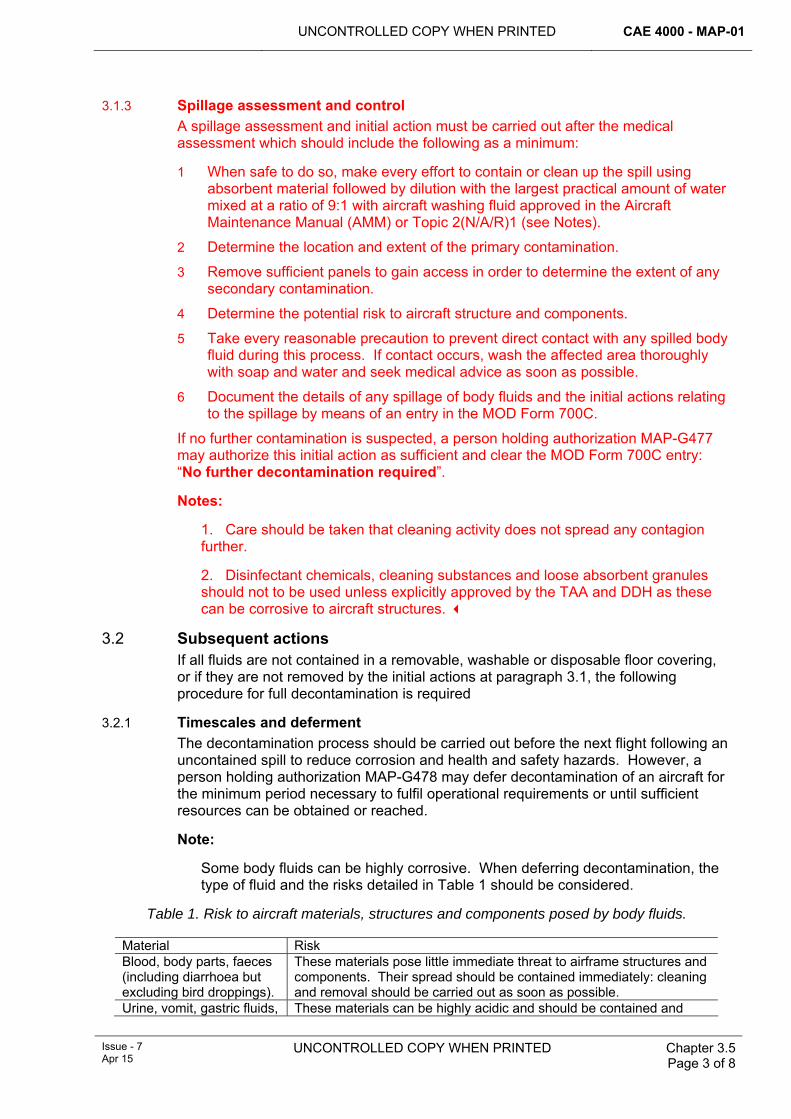
UNCONTROLLED COPY WHEN PRINTED CAE 4000 - MAP-01
Issue - 7 Apr 15
UNCONTROLLED COPY WHEN PRINTED Chapter 3.5 Page 3 of 8
3.1.3 Spillage assessment and control A spillage assessment and initial action must be carried out after the medical assessment which should include the following as a minimum:
1 When safe to do so, make every effort to contain or clean up the spill using absorbent material followed by dilution with the largest practical amount of water mixed at a ratio of 9:1 with aircraft washing fluid approved in the Aircraft Maintenance Manual (AMM) or Topic 2(N/A/R)1 (see Notes).
2 Determine the location and extent of the primary contamination.
3 Remove sufficient panels to gain access in order to determine the extent of any secondary contamination.
4 Determine the potential risk to aircraft structure and components.
5 Take every reasonable precaution to prevent direct contact with any spilled body fluid during this process. If contact occurs, wash the affected area thoroughly with soap and water and seek medical advice as soon as possible.
6 Document the details of any spillage of body fluids and the initial actions relating to the spillage by means of an entry in the MOD Form 700C.
If no further contamination is suspected, a person holding authorization MAP-G477 may authorize this initial action as sufficient and clear the MOD Form 700C entry: “No further decontamination required”.
Notes:
1. Care should be taken that cleaning activity does not spread any contagion further.
2. Disinfectant chemicals, cleaning substances and loose absorbent granules should not to be used unless explicitly approved by the TAA and DDH as these can be corrosive to aircraft structures.
3.2 Subsequent actions If all fluids are not contained in a removable, washable or disposable floor covering, or if they are not removed by the initial actions at paragraph 3.1, the following procedure for full decontamination is required
3.2.1 Timescales and deferment The decontamination process should be carried out before the next flight following an uncontained spill to reduce corrosion and health and safety hazards. However, a person holding authorization MAP-G478 may defer decontamination of an aircraft for the minimum period necessary to fulfil operational requirements or until sufficient resources can be obtained or reached.
Note:
Some body fluids can be highly corrosive. When deferring decontamination, the type of fluid and the risks detailed in Table 1 should be considered.
Table 1. Risk to aircraft materials, structures and components posed by body fluids.
Material Risk Blood, body parts, faeces (including diarrhoea but excluding bird droppings).
These materials pose little immediate threat to airframe structures and components. Their spread should be contained immediately: cleaning and removal should be carried out as soon as possible.
Urine, vomit, gastric fluids, These materials can be highly acidic and should be contained and
CAE 4000 - MAP-01 UNCONTROLLED COPY WHEN PRINTED
Chapter 3.5 Page 4 of 8
UNCONTROLLED COPY WHEN PRINTED Issue - 7 Apr 15
liquid products of decay, bird droppings (uric acid).
removed/neutralized immediately.
3.2.2 3.2.3 3.2.4 Aircraft cleaning 3.2.4.1 Waste containment
Suitable aircraft cleaning facilities should be utilized where practicable to contain waste fluids. Where suitable cleaning facilities are not available, waste fluids should be diluted as much as possible with water. Local restrictions on the disposal of waste fluids must be adhered to at all times.
3.2.4.2 Decontamination materials There are no approved disinfectants that can be safely used on aircraft. Physical removal of the spillage, followed by extensive dilution with water and aircraft washing fluid mixed at a ratio of 9:1 is considered the most effective solution. Fumigating agents are not to be used to combat unpleasant odours.
3.2.4.3 Personal Protection Equipment (PPE) Where possible, advice should always be sought from unit or civilian medical personnel as to the correct PPE to be worn during decontamination; however, in the absence of such advice, the following PPE must be worn during the decontamination process:
1 Full-face protection.
2 Disposable gloves.
3 Waterproof, disposable or washable apron or clothing.
3.2.4.4 Decontamination method 1 Remove all excess body fluids where possible.
2 Remove all contaminated absorbent material, including seat fabric and soundproofing, and dispose of this material in accordance with paragraph 4 or clean in accordance with Table 2.
3 Clean the affected area of the aircraft with copious amounts of low-pressure water and aircraft cleaning fluid. Use absorbent mats to ensure that material and contaminants are not flushed further into the aircraft structure.
4 Remove contaminated components and clean them separately if practicable.
5 Take care to ensure that aircraft systems and components are not damaged and that any captured waste fluid is drained.
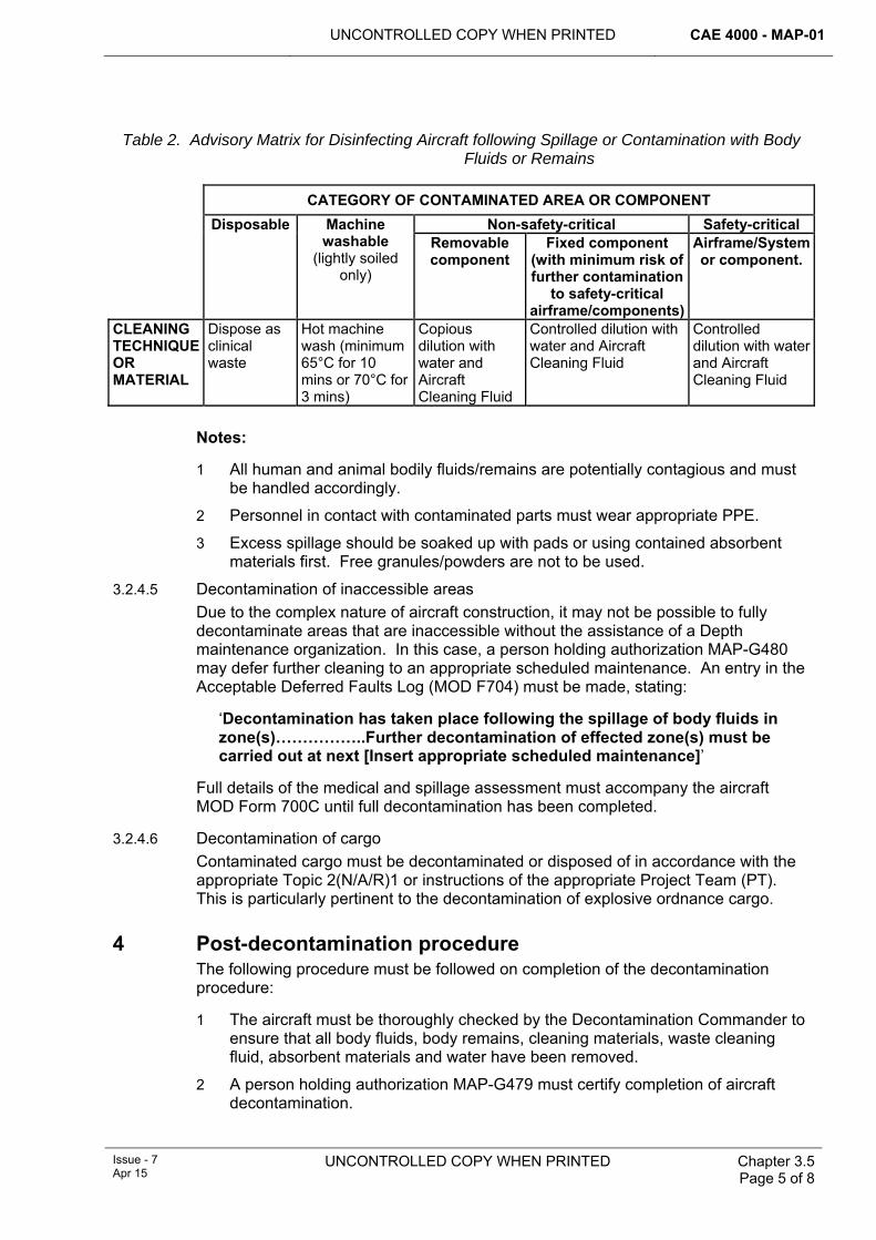
UNCONTROLLED COPY WHEN PRINTED CAE 4000 - MAP-01
Issue - 7 Apr 15
UNCONTROLLED COPY WHEN PRINTED Chapter 3.5 Page 5 of 8
Table 2. Advisory Matrix for Disinfecting Aircraft following Spillage or Contamination with Body Fluids or Remains
CATEGORY OF CONTAMINATED AREA OR COMPONENT
Non-safety-critical Safety-critical Disposable Machine washable
(lightly soiled only)
Removable component
Fixed component (with minimum risk of further contamination
to safety-critical airframe/components)
Airframe/System or component.
CLEANING TECHNIQUE OR MATERIAL
Dispose as clinical waste
Hot machine wash (minimum 65°C for 10 mins or 70°C for 3 mins)
Copious dilution with water and Aircraft Cleaning Fluid
Controlled dilution with water and Aircraft Cleaning Fluid
Controlled dilution with water and Aircraft Cleaning Fluid
Notes:
1 All human and animal bodily fluids/remains are potentially contagious and must be handled accordingly.
2 Personnel in contact with contaminated parts must wear appropriate PPE.
3 Excess spillage should be soaked up with pads or using contained absorbent materials first. Free granules/powders are not to be used.
3.2.4.5 Decontamination of inaccessible areas Due to the complex nature of aircraft construction, it may not be possible to fully decontaminate areas that are inaccessible without the assistance of a Depth maintenance organization. In this case, a person holding authorization MAP-G480 may defer further cleaning to an appropriate scheduled maintenance. An entry in the Acceptable Deferred Faults Log (MOD F704) must be made, stating:
‘Decontamination has taken place following the spillage of body fluids in zone(s)……………..Further decontamination of effected zone(s) must be carried out at next [Insert appropriate scheduled maintenance]’
Full details of the medical and spillage assessment must accompany the aircraft MOD Form 700C until full decontamination has been completed.
3.2.4.6 Decontamination of cargo Contaminated cargo must be decontaminated or disposed of in accordance with the appropriate Topic 2(N/A/R)1 or instructions of the appropriate Project Team (PT). This is particularly pertinent to the decontamination of explosive ordnance cargo.
4 Post-decontamination procedure The following procedure must be followed on completion of the decontamination procedure:
1 The aircraft must be thoroughly checked by the Decontamination Commander to ensure that all body fluids, body remains, cleaning materials, waste cleaning fluid, absorbent materials and water have been removed.
2 A person holding authorization MAP-G479 must certify completion of aircraft decontamination.
CAE 4000 - MAP-01 UNCONTROLLED COPY WHEN PRINTED
Chapter 3.5 Page 6 of 8
UNCONTROLLED COPY WHEN PRINTED Issue - 7 Apr 15
3 Parts removed in the cleaning process must be refitted/replaced in accordance with the relevant AMM.
4 Disposable contaminated materials and disposable PPE must be sealed into yellow plastic clinical waste bags and removed to local medical facilities for disposal/incineration in accordance with the Department of Health, Health Technical Memorandum 07-01 – Safe Management of Healthcare Waste.
5 Removed contaminated aircraft materials must be cleaned in accordance with instructions detailed in the AMM or Topic 2(N/A/R)1.
6 Contaminated washable PPE items must be thoroughly cleaned using a water/detergent mix.
7 Any contained used cleaning fluids must be removed for disposal in accordance with standard local disposal instructions.
8 Full details of the decontamination process and related work must be entered in the MOD Form 700C.
5 Responsibilities 5.1 Aircraft Commander
The Aircraft Commander is responsible for:
1 Controlling access to aircraft contaminated areas until the area is decontaminated or responsibility is handed to the Decontamination Commander.
2 Ensuring that details of any spillage and initial actions relating to the spillage are recorded in the MOD Form 700C and clearance or deferment is complete prior to the next flight.
5.2 Decontamination Commander The Decontamination Commander must ensure that:
1 A health hazard assessment is carried out in accordance with paragraph 3 prior to decontamination activities.
2 All decontamination personnel receive a medical brief from the Medical Hazard assessment representative prior to decontamination activities.
3 Sufficient PPE and suitable decontamination equipment is made available and used.
4 The decontamination process is carried out in accordance with this chapter and the relevant AMM or Topic 2(N/A/R)1.
5 As far as reasonably practicable, the decontamination process adheres to SHEF precautions as laid down in JSP 375.
5.3 Maintenance organization The maintenance organization is responsible for:
1 Ensuring that suitable types and quantities of PPE are available locally for decontamination and that procedures are in place to procure further stocks if necessary. Advice must be sought from unit medical staff and the appropriate single-Service Communicable Disease Control organization.
2 Nominating a person holding authority MAP-E138 as the Decontamination Commander and ensuring that he is made aware of his responsibilities.
3 Ensuring that the appropriately authorized Level G:
UNCONTROLLED COPY WHEN PRINTED CAE 4000 - MAP-01
Issue - 7 Apr 15
UNCONTROLLED COPY WHEN PRINTED Chapter 3.5 Page 7 of 8
3.1 Authorizes clearance of a spillage hazard following initial action.
3.2 Authorizes, for the minimum period necessary, deferment of full decontamination due to operational or resource restrictions.
3.3 Authorizes the final completion of the full decontamination process.
5.4 Stns/Ships/Units Stns/Ships/Units should consider conducting suitable training and briefings for personnel expected to manage and conduct aircraft decontamination operations.
5.5 1710 Naval Air Squadron (1710 NAS) 1710 NAS is responsible for:
1 Providing advice to aircraft PTs on the suitability of existing cleaning compounds for removing and neutralizing body fluids and for identifying suitable alternatives where necessary.
2 Informing the Medical & General Stores (M&GS) PT of the cleaning compounds identified above.
5.6 Type Airworthiness Authority (TAA) The TAA is responsible for:
1 Ensuring that cleaning techniques and materials suitable for the removal of body fluids from aircraft structures and materials are detailed in the AMM or Topic 2(N/A/R)1 in consultation with 1710 NAS.
2 Authorizing, after consultation with the Design Organization (DO), the use of any cleaning compound not already detailed in the AMM or Topic 2(N/A/R)1.
6 Authorizations This chapter identifies the following engineering authorization requirements:
1 Undertake Decontamination Commander duties: authorization MAP-E138.
2 Authorize that initial action has been sufficient to decontaminate minor body fluid spillage hazard: authorization MAP-G477.
3 Defer full decontamination of body fluid spillage for a minimum period to fulfil operational needs or until sufficient resources available: authorization MAP-G478.
4 Defer full decontamination of body fluid spillage, when areas are inaccessible without Depth assistance: authorization MAP-G480.
5 Certify final completion of full decontamination process following body fluids spillage: authorization MAP-G479.
6 Authorize personnel to undertake the above listed body fluid decontamination duties: authorization MAP-J221.
7 References This chapter refers to the following publications:
1 JSP 375 – MOD Health & Safety Handbook.
2 JSP 800 - Defence Movement sand Transports Regulations.
3 Aircraft Topic 2(N/A/R)1 – General Orders and Special Instructions.

CAE 4000 - MAP-01 UNCONTROLLED COPY WHEN PRINTED
Chapter 3.5 Page 8 of 8
UNCONTROLLED COPY WHEN PRINTED Issue - 7 Apr 15
4 Department of Health, Health Technical Memorandum 07-01 – Safe Management of Healthcare Waste.
UNCONTROLLED COPY WHEN PRINTED CAE 4000 - MAP-01
MAE Issue - 6 Mar 14
UNCONTROLLED COPY WHEN PRINTED Chapter 3.7 Page 1 of 4
Chapter 3.7
Control of Compressed Gas and Pneumatic Lubricating Equipment
TABLE OF CONTENTS Paragraph
Page
1 General ............................................................................................................... 1 1.1 Introduction.......................................................................................................... 1 2 Regulatory Governance.................................................................................... 1 2.1 Regulatory Cross-reference ................................................................................ 1 2.2 Additional Information.......................................................................................... 1 3 Hazards .............................................................................................................. 1 4 Operator actions................................................................................................ 2 5 Authorization to use compressed gas and pneumatic lubricating
equipment .......................................................................................................... 2 6 Stn/Ship/Unit authority level J responsibilities .............................................. 2 7 References ......................................................................................................... 3
1 General 1.1 Introduction
This chapter addresses possible Safety, Health, Environment and Fire (SHEF) hazards and responsibilities relating to the use of compressed gas and pneumatic lubricating equipment for aircraft-related maintenance activities. Precautions for specific equipments are contained in the relevant equipment publications. All users should be conversant with JSP 375.
2 Regulatory Governance 2.1 Regulatory Cross-reference
This chapter supports:
1 RA 4104.
2.2 Additional Information The use or misuse of compressed gas and pneumatic lubricating equipment can cause serious injury or death. Personnel must ensure that they are aware of the hazards associated with the use of such equipment and their SHEF responsibilities.
3 Hazards The following are some of the hazards associated with the misuse of compressed gas or pneumatic lubricating equipment.
1 Injection of compressed gases or pneumatically pressurized lubricants into the skin can result in serious injury or death. Pneumatically operated lubricating equipment, including small trolley-mounted types, is particularly dangerous in this respect, as very high pressures can be generated at the lubricating gun.
2 When introducing compressed air or oxygen into enclosed volumes, previously contaminated by flammable substances, a high risk of explosive combustion exists due to the ‘dieseling’ effect.
CAE 4000 - MAP-01 UNCONTROLLED COPY WHEN PRINTED
Chapter 3.7 Page 2 of 4
UNCONTROLLED COPY WHEN PRINTED
MAE Issue - 6
Mar 14
3 Misuse of compressed gas or pneumatic lubricating equipment (for cleaning purposes for example) may result in damage to equipment or aircraft.
4 Operator actions Operators must apply the following safety measures:
1 Discharge nozzles or valves must be pointed in a safe direction and not towards themselves or any persons.
2 Seek immediate medical attention following any accidental injection of compressed gas or pneumatically pressurized lubricant into the skin and report the incident to the responsible supervisor as soon as possible.
3 Compressed gases are not to be discharged into a container or enclosed space such as pneumatic or hydraulic components, accumulators, fuel containers or shock absorbers previously contaminated by flammable substances, unless they have been degassed, cleaned and prepared for ‘hot work’ in accordance with JSP 317.
4 Compressed gas and pneumatic lubricating equipment must be configured correctly before use and operating instructions for the equipment must be followed carefully throughout its operation.
5 Before commencing any charging operation, all delivery hoses must be purged to exclude contamination in the hose.
5 Authorization to use compressed gas and pneumatic lubricating equipment Personnel required to use gas and pneumatic lubricating equipment must hold authorization MAP-B225 in accordance with RA 4806 and Chapter 4.3.
6 Stn/Ship/Unit authority level J responsibilities Personnel of authority level J are responsible for ensuring that the following safety measures are applied:
1 All potential users and maintainers must be suitably trained in accordance with Chapter 4.1.
2 Risk assessments must be carried out on all tasks involving the use of compressed gas and pneumatic lubricating equipment.
3 No high-pressure air appliance may be operated without a suitable relief valve, as detailed in the appropriate equipment AP.
4 Items of compressed gas and pneumatic lubricating equipment must have detailed operating instructions and warnings attached to the equipment in a prominent place.
5 Appropriate safety signs should be prominently displayed adjacent to compressed gas and pneumatic lubrication equipment in accordance with JSP 375.
6 Compressed gas and pneumatic lubricating equipment must be suitable for designated maintenance tasks and must be correctly maintained in accordance with the appropriate maintenance schedules.
7 Personnel must be aware of the dangers of operating compressed gas equipment in enclosed volumes that have previously been contaminated with
UNCONTROLLED COPY WHEN PRINTED CAE 4000 - MAP-01
MAE Issue - 6 Mar 14
UNCONTROLLED COPY WHEN PRINTED
Chapter 3.7 Page 3 of 4
flammable substances. Facilities to prepare for ‘hot work’ in accordance with JSP 317 must be available if required.
7 References This chapter refers to the following publications:
1 JSP 317 – Safety Regulations for the Storage and Handling of Fuels and Lubricants.
2 JSP 375 – MOD Health and Safety Handbook.

CAE 4000 - MAP-01 UNCONTROLLED COPY WHEN PRINTED
Chapter 3.7 Page 4 of 4
UNCONTROLLED COPY WHEN PRINTED End of Data Module
MAE Issue - 6
Mar 14
Intentionally Blank for Print Pagination
UNCONTROLLED COPY WHEN PRINTED CAE 4000 - MAP-01
Issue - 7 Apr 15
UNCONTROLLED COPY WHEN PRINTED Chapter 4.1 Page 1 of 8
Chapter 4.1
Training and Competence
TABLE OF CONTENTS Paragraph
Page
1 General ............................................................................................................... 1 2 Regulatory Governance.................................................................................... 1 2.1 Regulatory Article Cross-Reference.................................................................... 1 3 Training .............................................................................................................. 2 3.1 Defence Systems Approach to Training Quality Standard (DSAT QS)............... 2 3.2 Legacy Training................................................................................................... 2 3.3 Equipment Conversion Courses.......................................................................... 3 4 Training publications ........................................................................................ 3 5 Training Organizations ..................................................................................... 3 5.1 Training Requirements Authority (TRA) .............................................................. 3 5.2 Training Delivery Authority (TDA)........................................................................ 4 5.3 Customer Executive Board (CEB)....................................................................... 4 6 Competence and assessment.......................................................................... 5 6.1 Competence ........................................................................................................ 5 6.2 Assessment......................................................................................................... 5 6.3 Certifying Staff and Support Staff with Supervisory Responsibilities .................. 6 7 Authorization ..................................................................................................... 6 8 References ......................................................................................................... 6
LIST OF FIGURES Figure 1. Generic Certificate of Competence Layout. ...................................................................6
1 General Individual training is designed to develop the competence (the ability to perform a particular skill or range of skills to a prescribed standard, under prescribed conditions) of individual personnel in preparation for their role. Suitably resourced training provides the required numbers of personnel trained appropriately for their individual tasks in order to contribute to the preservation of airworthiness within the Military Air Environment (MAE).
2 Regulatory Governance 2.1 Regulatory Article Cross-Reference
This chapter supports:
1 RA 4806(5).
2 RA 4807(6).
3 RA 4807(7).
4 RA 4150(2).
CAE 4000 - MAP-01 UNCONTROLLED COPY WHEN PRINTED
Chapter 4.1 Page 2 of 8
UNCONTROLLED COPY WHEN PRINTED Issue - 7 Apr 15
3 Training The principles of DSAT QS are to be applied across all training.
Training will be delivered to meet a training performance statement (TPS). A TPS is a list of training objectives describing the end product of training and is achieved through:
1 Phase 1 Training – Initial training in the basic military skills required by all Service personnel.
2 Phase 2 Training – Initial specialist training that prepares Service personnel for their first employment (eg Basic Aircraft Engineering training).
3 Phase 3 Training – Training that prepares Service personnel for further employment with an increased skill base and/or responsibility. It also encompasses training to meet career aspirations and professional development (eg equipment courses, engine operator training).
Training enables personnel to develop the competencies required by their operational performance statement (OPS). An OPS is a detailed statement of the tasks/sub-tasks required to be undertaken by an individual to achieve the operational/workplace performance. It should be written in terms of Performance, Conditions and Standards.
3.1 Defence Systems Approach to Training Quality Standard (DSAT QS) The DSAT QS approach to the analysis, design, delivery, evaluation and governance of training encompasses the following principles:
1 Aim to prepare personnel for their current or future operational or workplace role.
2 Where provided by, or on behalf of, the MOD, have a clearly identified MOD Training Requirements Authority (TRA).
3 Be formally authorized and resourced.
4 Where provided by, or on behalf of, the MOD, be derived from an analysis of the operational/workplace requirements.
5 Be designed to achieve Training Objectives (TOs) based on the results of a training needs analysis.
6 Incorporate TOs that are endorsed by the TRA.
7 Achieve TOs by the most efficient and effective use of resources.
8 Incorporate an evaluation strategy.
9 Be evaluated for the efficiency and effectiveness of the analysis, design and delivery of training in meeting the operational/business requirements in accordance with the evaluation strategy.
10 Be kept current by applying the results of evaluation.
11 Comply with all relevant extant legislation.
3.2 Legacy Training It is recognised that some aspects of Defence Technical Training (DTT) are still working towards compliance with DSAT QS. All non DSAT QS compliant aspects of training being delivered to the MAE must be recorded and a transition plan towards compliance with DSAT QS must be developed by the Training Delivery Authority (TDA) and approved by the TRA. This transition plan should be reviewed at the Customer Executive Board (CEB). The transition plan must:
UNCONTROLLED COPY WHEN PRINTED CAE 4000 - MAP-01
Issue - 7 Apr 15
UNCONTROLLED COPY WHEN PRINTED Chapter 4.1 Page 3 of 8
1 Evaluate the Risk.
2 Dependant on the risk, articulate priorities and targets to be achieved.
3 Stipulate a date as to when the course is to be compliant with DSAT QS, but no later than the next scheduled review.
4 Be made available during 2nd and 3rd party audit visits by HQ No 22 (Trg) Gp and organizations such as OFSTED respectively.
3.3 Equipment Conversion Courses In some instances equipment modifications to aircraft will include conversion courses for ground maintenance staff, which may have been designed to an appropriate, yet different standard to DSAT QS. In such cases the training assurance organization in the respective command/Project Team (PT) must ensure that:
1 The contractor’s standards and regulations equate to those required by DSAT QS.
2 The training provided by the contractor is fit for purpose.
The above must be achieved by cross-mapping the contractor’s training methodology with that of DSAT in terms of training analysis, design, delivery, evaluation and governance. This cross-mapping, which must be undertaken by a DSAT Suitably Qualified and Experienced Person (SQEP), is to be documented and available for HQ No 22(Trg) Gp 2nd party audit. Notwithstanding this, PTs must engage with contractors at an early stage to ensure where possible training is DSAT compliant from the start.
4 Training publications Existing training policy is detailed in the following publications:
1 JSP 822 - Governance and Management of Defence Individual Training, Education and Skills.
2 AP 100T-0100 – Qualifications for Fleet Air Arm Personnel.
3 AP 3376 – Trade Structure of the Royal Air Force.
4 AP 3379 – RAF Manual of Training.
5 AP 7400 - Continuing Airworthiness Engineering (Army).
5 Training Organizations 5.1 Training Requirements Authority (TRA)
1 All courses delivered must have a clearly identified TRA. They are the authority for the derivation and maintenance of the OPS or Competence Framework (CF), and are responsible for the evaluation of the effect of the training and education in achieving that OPS/CF (delivered both in the training school/organization and the workplace).
2 The following single Service appointments are the delegated TRAs responsible for ensuring that the OPS/CF for particular trades or appointments are fit for purpose:
2.1 RN: Deputy Assistant Chief of Staff (Air Engineering).
2.2 Army: Chief Aircraft Engineer (Army).
2.3 RAF: Air Officer A4, HQ Air Command.

CAE 4000 - MAP-01 UNCONTROLLED COPY WHEN PRINTED
Chapter 4.1 Page 4 of 8
UNCONTROLLED COPY WHEN PRINTED Issue - 7 Apr 15
3 Where the training or education to be delivered is to meet the needs of 2 or more Services, the TRA may be a committee of policy leads for the subject, the appropriate representative of the end user of the trained output, and subject matter experts (SMEs).
4 The TRA must carry out the following functions:
4.1 Analysis of the operational/business requirement through Job Analysis to derive and maintain the OPS/CF.
4.2 In conjunction with the training organization/school, the agreement of the Formal Training Statement.
4.3 Management and Ownership of Workplace Learning.
4.4 Measurement of the achievement of the OPS/CF through the coordination and management of External Validation. This includes validation of the totality of training and education, which takes place in both the formal training environment and the workplace.
4.5 Conduct and control the sign-off of Training Needs Analysis (TNA).
5.2 Training Delivery Authority (TDA) The Defence College of Technical Training (DCTT) is the appointed TDA and is responsible for the provision of individual training or education, to agreed standards and in accordance with extant and funded Defence and single Service policies, on behalf of the customer(s). The TDA specific responsibilities are:
1 The command and control of the training organizations/schools.
2 The conduit for the resourcing of the training organizations/schools in accordance with relevant customer supplier agreements.
3 The delivery of training to the agreed TPS, expressed as the Statement of Training Task (SOTT) and supporting functions to its customers.
4 To pursue improved training efficiency compatible with endorsed output standards.
5 To contribute, particularly in a Defence context, to the efficient pipeline management of trainees to minimize the time spent in initial training and between courses.
6 To manage the customer/supplier interface as Chair of the CEB.
5.3 Customer Executive Board (CEB) The CEB must provide a mechanism for stakeholders to develop the scale and content of training to match the operational/business requirement within the available budget, and in accordance with relevant Defence and single Service policies. In doing so the CEB must:
1 Hold the training provider to account for the delivery of quantity, quality and timeliness.
2 Hold the TRAs to account to provide a clear fully justified requirement and their single Service priorities for training.
3 Focus all the stakeholders on identifying future strategic direction.
UNCONTROLLED COPY WHEN PRINTED CAE 4000 - MAP-01
Issue - 7 Apr 15
UNCONTROLLED COPY WHEN PRINTED Chapter 4.1 Page 5 of 8
6 Competence and assessment 6.1 Competence
A competent person is one who has sufficient theoretical and practical knowledge and experience of the relevant subject matter to complete the tasks required of them in a satisfactory manner. Elements of competence are: 1 Theoretical knowledge:
1.1 The completion of individual training that meets the principles of DSAT QS.
1.2 An understanding of the responsibilities associated with the task.
2 Practical ability:
2.1 Comprehends the subject matter and operational situation, including any local considerations.
2.2 A sound grasp of the engineering principles, including the necessary hands on physical skills.
3 Experience gained through observation or practice, resulting from theoretical knowledge and practical ability.
6.2 Assessment To provide an audit trail, personal competence must be assessed and documented. All competence assessment documents must contain the following information:
1 Identification by number, rank and name of the individual concerned.
2 Identification of the activity, limitations, relevant training courses and periods or conditions of validity.
3 Identification of the certifying assessor by name and appointment.
Competence documents may be certificates issued by training organizations, held on an approved information system or locally produced certificates that comply with the standard at Figure 1. Competence documents must be retained and transferred with the individual’s personal records and Personal Development Record (if held).
Note:
1 In assessing an individual’s competence for conducting aircraft maintenance, the assessor must ensure that the individual has received an element of type-specific training and/or familiarization appropriate to the scope of their authorization. Good practice is for such training to be that which leads to the award of a formal qualification in the aircraft type.
2 Likewise, in assessing an individual’s competence for conducting aircraft component/equipment maintenance, the assessor must ensure that the individual has received training and/or familiarization on the relevant component(s)/equipment(s) appropriate to their level of authorization.
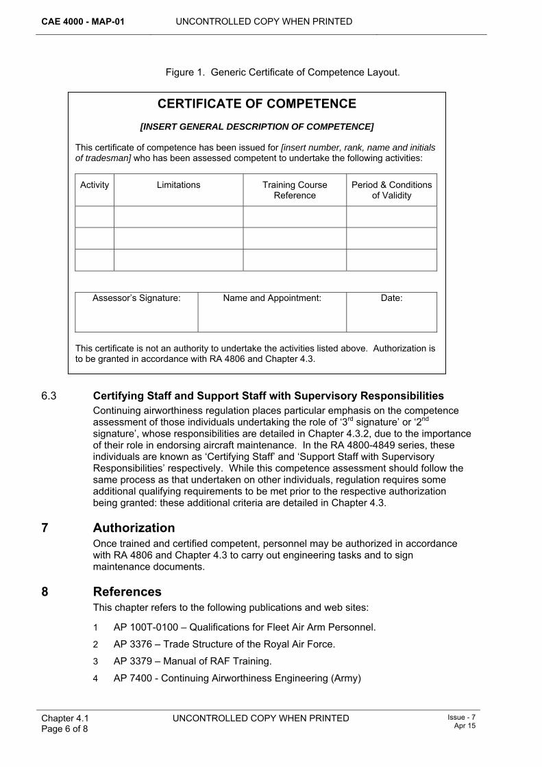
CAE 4000 - MAP-01 UNCONTROLLED COPY WHEN PRINTED
Chapter 4.1 Page 6 of 8
UNCONTROLLED COPY WHEN PRINTED Issue - 7 Apr 15
Figure 1. Generic Certificate of Competence Layout.
CERTIFICATE OF COMPETENCE
[INSERT GENERAL DESCRIPTION OF COMPETENCE]
This certificate of competence has been issued for [insert number, rank, name and initials of tradesman] who has been assessed competent to undertake the following activities:
Activity Limitations Training Course Reference
Period & Conditions of Validity
Assessor’s Signature: Name and Appointment: Date:
This certificate is not an authority to undertake the activities listed above. Authorization is to be granted in accordance with RA 4806 and Chapter 4.3.
6.3 Certifying Staff and Support Staff with Supervisory Responsibilities Continuing airworthiness regulation places particular emphasis on the competence assessment of those individuals undertaking the role of ‘3rd signature’ or ‘2nd signature’, whose responsibilities are detailed in Chapter 4.3.2, due to the importance of their role in endorsing aircraft maintenance. In the RA 4800-4849 series, these individuals are known as ‘Certifying Staff’ and ‘Support Staff with Supervisory Responsibilities’ respectively. While this competence assessment should follow the same process as that undertaken on other individuals, regulation requires some additional qualifying requirements to be met prior to the respective authorization being granted: these additional criteria are detailed in Chapter 4.3.
7 Authorization Once trained and certified competent, personnel may be authorized in accordance with RA 4806 and Chapter 4.3 to carry out engineering tasks and to sign maintenance documents.
8 References This chapter refers to the following publications and web sites:
1 AP 100T-0100 – Qualifications for Fleet Air Arm Personnel.
2 AP 3376 – Trade Structure of the Royal Air Force.
3 AP 3379 – Manual of RAF Training.
4 AP 7400 - Continuing Airworthiness Engineering (Army)
UNCONTROLLED COPY WHEN PRINTED CAE 4000 - MAP-01
Issue - 7 Apr 15
UNCONTROLLED COPY WHEN PRINTED Chapter 4.1 Page 7 of 8
5 JSP 822 Pt 2 – Glossary of Abbreviations, Terms and Definitions.
6 JSP 822 Pt 4 – Defence Systems Approach to Training Quality Standard (DSAT QS).
CAE 4000 - MAP-01 UNCONTROLLED COPY WHEN PRINTED
Chapter 4.1 Page 8 of 8
UNCONTROLLED COPY WHEN PRINTED Issue - 7 Apr 15
Intentionally Blank for Print Pagination
UNCONTROLLED COPY WHEN PRINTED CAE 4000 - MAP-01
Issue - 7 Apr 15
UNCONTROLLED COPY WHEN PRINTED Chapter 4.3 Page 1 of 8
Chapter 4.3
Engineering Authorizations
TABLE OF CONTENTS Paragraph
Page
1 General ............................................................................................................... 1 1.1 Introduction.......................................................................................................... 1 1.2 Equivalent functions ............................................................................................ 1 2 Regulatory Governance.................................................................................... 2 2.1 Regulatory Cross-reference ................................................................................ 2 2.2 Additional Information.......................................................................................... 2 3 General Principles............................................................................................. 2 3.1 Granting authorizations ....................................................................................... 2 3.2 Examples of authorizations and corresponding authority level ........................... 4 3.3 Relationship of single-Service engineering skills/competence with the
authority level structure ....................................................................................... 5 3.4 Forward Support (FS) NDT and Repair Teams................................................... 5 3.5 Local engineering authorizations......................................................................... 6 3.6 Loans of engineering personnel .......................................................................... 6 3.7 Limitations and withdrawal of authorizations....................................................... 6 3.8 Review of Authorizations.............................................................................. 6 4 Authorization of non-engineering personnel ................................................. 6 5 Recording of authorizations............................................................................. 7 6 Single-Service Rank/Rate authorization ranging ........................................... 7 6.1 Single-Service tables........................................................................................... 7
LIST OF TABLES Table 1. Authority levels and examples of authorizations. ...........................................................4
1 General 1.1 Introduction
The authority to carry out engineering tasks and to sign maintenance documentation is granted to personnel who have demonstrated competence. Engineering managers require a range of personnel with a variety of competencies to perform all the engineering activities required to maintain aircraft and equipment to an airworthy standard and to perform their operational roles.
1.2 Equivalent functions All references to engineering function, appointments and tradesmen should be interpreted as also meaning civilians and non-engineering personnel of equivalent status and competence, see RA 4806 and Chapter 4.1, who are employed by the MOD or by contractors that are required to comply with the MAP-01.
Note: The above paragraph also relates to those personnel who, although classified as being ‘engineers’, eg Ground Support Equipment (GSE) engineers, are not of the aviation-based community of engineers.
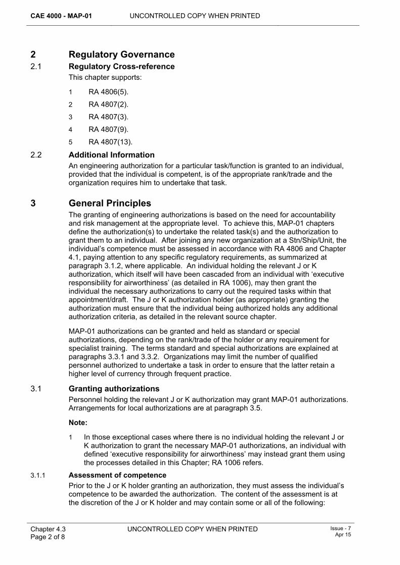
CAE 4000 - MAP-01 UNCONTROLLED COPY WHEN PRINTED
Chapter 4.3 Page 2 of 8
UNCONTROLLED COPY WHEN PRINTED Issue - 7 Apr 15
2 Regulatory Governance 2.1 Regulatory Cross-reference
This chapter supports:
1 RA 4806(5).
2 RA 4807(2).
3 RA 4807(3).
4 RA 4807(9).
5 RA 4807(13).
2.2 Additional Information An engineering authorization for a particular task/function is granted to an individual, provided that the individual is competent, is of the appropriate rank/trade and the organization requires him to undertake that task.
3 General Principles The granting of engineering authorizations is based on the need for accountability and risk management at the appropriate level. To achieve this, MAP-01 chapters define the authorization(s) to undertake the related task(s) and the authorization to grant them to an individual. After joining any new organization at a Stn/Ship/Unit, the individual’s competence must be assessed in accordance with RA 4806 and Chapter 4.1, paying attention to any specific regulatory requirements, as summarized at paragraph 3.1.2, where applicable. An individual holding the relevant J or K authorization, which itself will have been cascaded from an individual with ‘executive responsibility for airworthiness’ (as detailed in RA 1006), may then grant the individual the necessary authorizations to carry out the required tasks within that appointment/draft. The J or K authorization holder (as appropriate) granting the authorization must ensure that the individual being authorized holds any additional authorization criteria, as detailed in the relevant source chapter.
MAP-01 authorizations can be granted and held as standard or special authorizations, depending on the rank/trade of the holder or any requirement for specialist training. The terms standard and special authorizations are explained at paragraphs 3.3.1 and 3.3.2. Organizations may limit the number of qualified personnel authorized to undertake a task in order to ensure that the latter retain a higher level of currency through frequent practice.
3.1 Granting authorizations Personnel holding the relevant J or K authorization may grant MAP-01 authorizations. Arrangements for local authorizations are at paragraph 3.5.
Note:
1 In those exceptional cases where there is no individual holding the relevant J or K authorization to grant the necessary MAP-01 authorizations, an individual with defined ‘executive responsibility for airworthiness’ may instead grant them using the processes detailed in this Chapter; RA 1006 refers.
3.1.1 Assessment of competence Prior to the J or K holder granting an authorization, they must assess the individual’s competence to be awarded the authorization. The content of the assessment is at the discretion of the J or K holder and may contain some or all of the following:
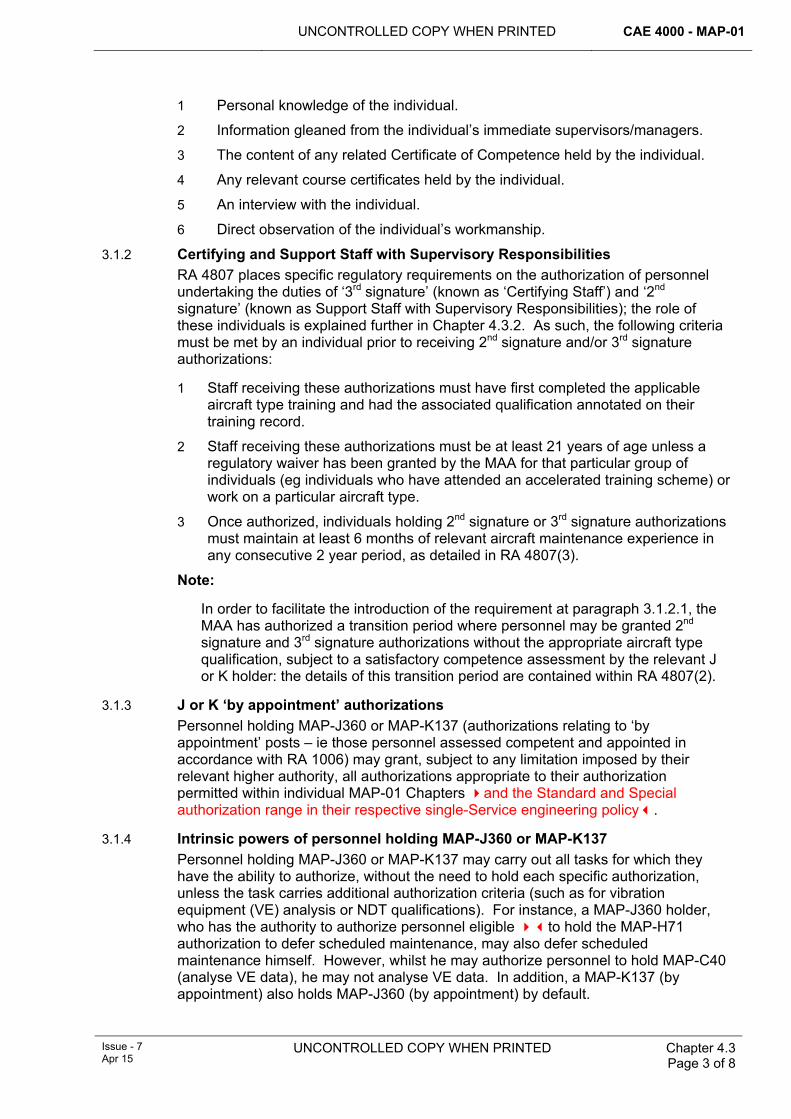
UNCONTROLLED COPY WHEN PRINTED CAE 4000 - MAP-01
Issue - 7 Apr 15
UNCONTROLLED COPY WHEN PRINTED
Chapter 4.3 Page 3 of 8
1 Personal knowledge of the individual.
2 Information gleaned from the individual’s immediate supervisors/managers.
3 The content of any related Certificate of Competence held by the individual.
4 Any relevant course certificates held by the individual.
5 An interview with the individual.
6 Direct observation of the individual’s workmanship.
3.1.2 Certifying and Support Staff with Supervisory Responsibilities RA 4807 places specific regulatory requirements on the authorization of personnel undertaking the duties of ‘3rd signature’ (known as ‘Certifying Staff’) and ‘2nd signature’ (known as Support Staff with Supervisory Responsibilities); the role of these individuals is explained further in Chapter 4.3.2. As such, the following criteria must be met by an individual prior to receiving 2nd signature and/or 3rd signature authorizations:
1 Staff receiving these authorizations must have first completed the applicable aircraft type training and had the associated qualification annotated on their training record.
2 Staff receiving these authorizations must be at least 21 years of age unless a regulatory waiver has been granted by the MAA for that particular group of individuals (eg individuals who have attended an accelerated training scheme) or work on a particular aircraft type.
3 Once authorized, individuals holding 2nd signature or 3rd signature authorizations must maintain at least 6 months of relevant aircraft maintenance experience in any consecutive 2 year period, as detailed in RA 4807(3).
Note:
In order to facilitate the introduction of the requirement at paragraph 3.1.2.1, the MAA has authorized a transition period where personnel may be granted 2nd signature and 3rd signature authorizations without the appropriate aircraft type qualification, subject to a satisfactory competence assessment by the relevant J or K holder: the details of this transition period are contained within RA 4807(2).
3.1.3 J or K ‘by appointment’ authorizations Personnel holding MAP-J360 or MAP-K137 (authorizations relating to ‘by appointment’ posts – ie those personnel assessed competent and appointed in accordance with RA 1006) may grant, subject to any limitation imposed by their relevant higher authority, all authorizations appropriate to their authorization permitted within individual MAP-01 Chapters and the Standard and Special authorization range in their respective single-Service engineering policy.
3.1.4 Intrinsic powers of personnel holding MAP-J360 or MAP-K137 Personnel holding MAP-J360 or MAP-K137 may carry out all tasks for which they have the ability to authorize, without the need to hold each specific authorization, unless the task carries additional authorization criteria (such as for vibration equipment (VE) analysis or NDT qualifications). For instance, a MAP-J360 holder, who has the authority to authorize personnel eligible to hold the MAP-H71 authorization to defer scheduled maintenance, may also defer scheduled maintenance himself. However, whilst he may authorize personnel to hold MAP-C40 (analyse VE data), he may not analyse VE data. In addition, a MAP-K137 (by appointment) also holds MAP-J360 (by appointment) by default.
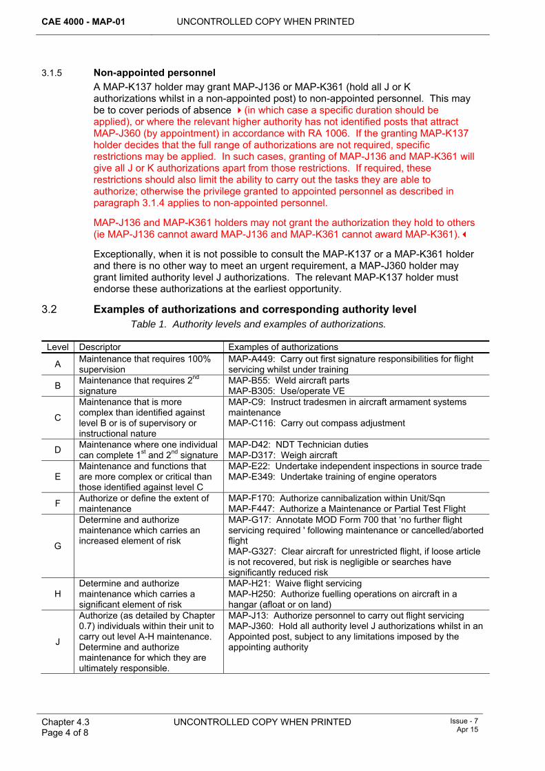
CAE 4000 - MAP-01 UNCONTROLLED COPY WHEN PRINTED
Chapter 4.3 Page 4 of 8
UNCONTROLLED COPY WHEN PRINTED Issue - 7 Apr 15
3.1.5 Non-appointed personnel A MAP-K137 holder may grant MAP-J136 or MAP-K361 (hold all J or K authorizations whilst in a non-appointed post) to non-appointed personnel. This may be to cover periods of absence (in which case a specific duration should be applied), or where the relevant higher authority has not identified posts that attract MAP-J360 (by appointment) in accordance with RA 1006. If the granting MAP-K137 holder decides that the full range of authorizations are not required, specific restrictions may be applied. In such cases, granting of MAP-J136 and MAP-K361 will give all J or K authorizations apart from those restrictions. If required, these restrictions should also limit the ability to carry out the tasks they are able to authorize; otherwise the privilege granted to appointed personnel as described in paragraph 3.1.4 applies to non-appointed personnel.
MAP-J136 and MAP-K361 holders may not grant the authorization they hold to others (ie MAP-J136 cannot award MAP-J136 and MAP-K361 cannot award MAP-K361).
Exceptionally, when it is not possible to consult the MAP-K137 or a MAP-K361 holder and there is no other way to meet an urgent requirement, a MAP-J360 holder may grant limited authority level J authorizations. The relevant MAP-K137 holder must endorse these authorizations at the earliest opportunity.
3.2 Examples of authorizations and corresponding authority level Table 1. Authority levels and examples of authorizations.
Level Descriptor Examples of authorizations
A Maintenance that requires 100% supervision
MAP-A449: Carry out first signature responsibilities for flight servicing whilst under training
B Maintenance that requires 2nd signature
MAP-B55: Weld aircraft parts MAP-B305: Use/operate VE
C
Maintenance that is more complex than identified against level B or is of supervisory or instructional nature
MAP-C9: Instruct tradesmen in aircraft armament systems maintenance MAP-C116: Carry out compass adjustment
D Maintenance where one individual can complete 1st and 2nd signature
MAP-D42: NDT Technician duties MAP-D317: Weigh aircraft
E Maintenance and functions that are more complex or critical than those identified against level C
MAP-E22: Undertake independent inspections in source trade MAP-E349: Undertake training of engine operators
F Authorize or define the extent of maintenance
MAP-F170: Authorize cannibalization within Unit/Sqn MAP-F447: Authorize a Maintenance or Partial Test Flight
G
Determine and authorize maintenance which carries an increased element of risk
MAP-G17: Annotate MOD Form 700 that ‘no further flight servicing required ' following maintenance or cancelled/aborted flight MAP-G327: Clear aircraft for unrestricted flight, if loose article is not recovered, but risk is negligible or searches have significantly reduced risk
H Determine and authorize maintenance which carries a significant element of risk
MAP-H21: Waive flight servicing MAP-H250: Authorize fuelling operations on aircraft in a hangar (afloat or on land)
J
Authorize (as detailed by Chapter 0.7) individuals within their unit to carry out level A-H maintenance. Determine and authorize maintenance for which they are ultimately responsible.
MAP-J13: Authorize personnel to carry out flight servicing MAP-J360: Hold all authority level J authorizations whilst in an Appointed post, subject to any limitations imposed by the appointing authority
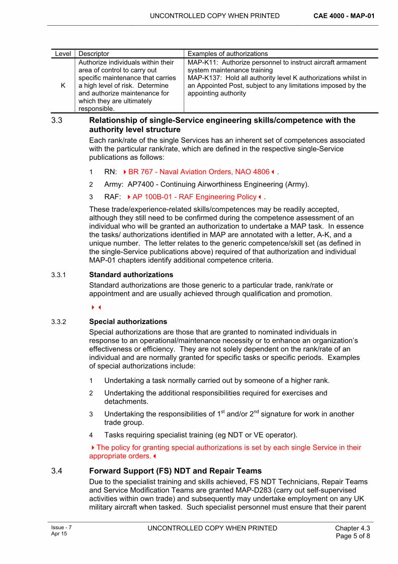
UNCONTROLLED COPY WHEN PRINTED CAE 4000 - MAP-01
Issue - 7 Apr 15
UNCONTROLLED COPY WHEN PRINTED
Chapter 4.3 Page 5 of 8
Level Descriptor Examples of authorizations
K
Authorize individuals within their area of control to carry out specific maintenance that carries a high level of risk. Determine and authorize maintenance for which they are ultimately responsible.
MAP-K11: Authorize personnel to instruct aircraft armament system maintenance training MAP-K137: Hold all authority level K authorizations whilst in an Appointed Post, subject to any limitations imposed by the appointing authority
3.3 Relationship of single-Service engineering skills/competence with the authority level structure Each rank/rate of the single Services has an inherent set of competences associated with the particular rank/rate, which are defined in the respective single-Service publications as follows:
1 RN: BR 767 - Naval Aviation Orders, NAO 4806.
2 Army: AP7400 - Continuing Airworthiness Engineering (Army).
3 RAF: AP 100B-01 - RAF Engineering Policy.
These trade/experience-related skills/competences may be readily accepted, although they still need to be confirmed during the competence assessment of an individual who will be granted an authorization to undertake a MAP task. In essence the tasks/ authorizations identified in MAP are annotated with a letter, A-K, and a unique number. The letter relates to the generic competence/skill set (as defined in the single-Service publications above) required of that authorization and individual MAP-01 chapters identify additional competence criteria.
3.3.1 Standard authorizations Standard authorizations are those generic to a particular trade, rank/rate or appointment and are usually achieved through qualification and promotion.
3.3.2 Special authorizations Special authorizations are those that are granted to nominated individuals in response to an operational/maintenance necessity or to enhance an organization’s effectiveness or efficiency. They are not solely dependent on the rank/rate of an individual and are normally granted for specific tasks or specific periods. Examples of special authorizations include:
1 Undertaking a task normally carried out by someone of a higher rank.
2 Undertaking the additional responsibilities required for exercises and detachments.
3 Undertaking the responsibilities of 1st and/or 2nd signature for work in another trade group.
4 Tasks requiring specialist training (eg NDT or VE operator).
The policy for granting special authorizations is set by each single Service in their appropriate orders.
3.4 Forward Support (FS) NDT and Repair Teams Due to the specialist training and skills achieved, FS NDT Technicians, Repair Teams and Service Modification Teams are granted MAP-D283 (carry out self-supervised activities within own trade) and subsequently may undertake employment on any UK military aircraft when tasked. Such specialist personnel must ensure that their parent
CAE 4000 - MAP-01 UNCONTROLLED COPY WHEN PRINTED
Chapter 4.3 Page 6 of 8
UNCONTROLLED COPY WHEN PRINTED Issue - 7 Apr 15
organization authorization record is available for inspection by the tasking unit. The organization requesting the specialist services of FS NDT Technicians, Repair Teams or Service Modification Teams is responsible for assuring that correct standards and practices are maintained.
3.5 Local engineering authorizations Where a MAP-K137 holder considers that there is a requirement for authorizations that are not detailed in the MAP, they must be published in Aviation Engineering Standing Orders (AESOs) issued in accordance with RA 4009 and Chapter 1.10.2. These authorizations are known as local engineering authorizations (LEAs). Typical examples of local authorizations include opening and closing hangar doors or operating overhead cranes. The MAP-K137 holder must identify who may hold the MAP-G457 authorization (to authorize LEAs only) in AESOs and who may hold the relevant local authorizations. Where there is a need to standardize local authorizations across a number of Ships/Stns/Units or a fleet of aircraft, the MOD Continuing Airworthiness Manager (MOD CAM) or Type Airworthiness Authority (TAA) should issue instructions to control this.
3.6 Loans of engineering personnel For specific tasks or specific periods, engineering personnel who are loaned between organizations for employment retain the standard and special authorizations granted by their parent organization, without the need for further written authorization.
However, receiving organizations need to grant engineering authorizations formally in the following situations:
1 For detachments or protracted periods of loan.
2 Where there are significant differences in local conditions or procedures at the receiving organization.
Personnel on loan must ensure that their parent organization authorization record is available for inspection by the receiving organization.
3.7 Limitations and withdrawal of authorizations All authorizations are subject to the continued demonstration of competence and/or currency. Any authorization may be withdrawn, suspended or limited, at the discretion of the relevant granting J or K authorization holder, as appropriate. Additionally, an individual who is eligible to hold an H-annotated authorization who is responsible for maintenance at an independent detachment or flight may suspend any authorization held by a subordinate.
3.8 Review of Authorizations Unless mandated otherwise in applicable single Service orders, current authorizations may remain extant at the discretion of a new Authorizing Officer taking post, though he may chose an accelerated schedule for re-authorization depending on an assessment of local factors and risks. This approach to authorizations should be promulgated by the new Authorizing Officer as soon as practicable after taking up his position, not to exceed one month.
4 Authorization of non-engineering personnel When non-engineering personnel are required to carry out engineering activities on aircraft or aircraft-associated equipment, they must be authorized in accordance with this chapter and their authorizations recorded in accordance with RA 4806 and
UNCONTROLLED COPY WHEN PRINTED CAE 4000 - MAP-01
Issue - 7 Apr 15
UNCONTROLLED COPY WHEN PRINTED
Chapter 4.3 Page 7 of 8
5
6
Chapter 4.3.1. Such activities may include the refuelling of aircraft by Army Air Corps (AAC) personnel or operation of cargo doors by RAF Movements personnel.
Authorizations must be granted by the relevant J or K authorization holder, as appropriate, who must ensure that personnel meet any additional authorization criteria and that they comply with any periodic checks detailed within the relevant source chapter.
When authorizing non-engineering personnel, reference must be made to the appropriate Front Line Command (FLC) mid-level orders todetermine equivalent status in accordance with paragraph 1.2.
Recording of authorizations Standard, special and local authorizations must be recorded using the methods detailed in RA 4806 and Chapter 4.3.1.
Single-Service Rank/Rate authorization ranging 6.1 Single-Service tables
The respective single-Service engineering policy authorities own the Standard and Special authorization range for each Rank/Rate, and these are defined in the publications detailed at paragraph 3.3.
Where authorizations need to be held by personnel working outside of their direct Service command chain, such as in DE&S, awards should be granted using applicable processes and formally documented.
.

CAE 4000 - MAP-01 UNCONTROLLED COPY WHEN PRINTED
Chapter 4.3 Page 8 of 8
UNCONTROLLED COPY WHEN PRINTED Issue - 7 Apr 15
Intentionally Blank for Print Pagination
UNCONTROLLED COPY WHEN PRINTED CAE 4000 - MAP-01
Issue - 7 Apr 15
UNCONTROLLED COPY WHEN PRINTED Chapter 4.3.1 Page 1 of 2
Chapter 4.3.1
Recording of Engineering Authorizations
TABLE OF CONTENTS Paragraph
Page
1 General ............................................................................................................... 1 1.1 Introduction.......................................................................................................... 1 2 Regulatory Governance.................................................................................... 1 2.1 Regulatory Article Cross-reference ..................................................................... 1 3 Recording of Engineering Authorizations ...................................................... 1 3.1 Authorization record distribution and retention.................................................... 2 3.2 Administration Information Systems (ISs) ........................................................... 2 3.3 Engineering Authorizations Database (EAD) ...................................................... 2 3.4 Operating orders and procedures ................................................................ 2 3.5 Record of Engineering Authorizations................................................................. 2
1 General 1.1 Introduction
Whenever an engineering authorization has been granted to, or withdrawn from, personnel in accordance with RA 4806 and Chapter 4.3, a system is required to ensure that it is recorded in an auditable fashion. This chapter details acceptable methods of recording engineering authorizations.
2 Regulatory Governance 2.1 Regulatory Article Cross-reference
This chapter supports:
1 RA 4806(5).
2 RA 4807(10).
3 RA 4807(11).
3 Recording of Engineering Authorizations Engineering authorizations granted in accordance with RA 4806 and Chapter 4.3 are to be recorded using a system either approved by the Military Aviation Authority (MAA), appropriate Type Airworthiness Authority (TAA) or Duty Holder (DH) for audit purposes. They are to be recorded using the following systems, either in isolation or in combination.
1 Administration Information Systems (IS).
2 Engineering Authorizations Database (EAD).
3 Record of Engineering Authorizations.
4 Existing hardcopy authorization records.
Authorizations take effect from the date the recipient acknowledges understanding of the new responsibilities following authorization by either the authorizing approval code or authorizing signature on hardcopy records. Where these records are held on
CAE 4000 - MAP-01 UNCONTROLLED COPY WHEN PRINTED
Chapter 4.3.1 Page 2 of 2
UNCONTROLLED COPY WHEN PRINTED Issue - 7 Apr 15
an Information System (IS), they may be transferred electronically or by use of magnetic media. This will ensure that engineering documentation can be associated with the authorizations granted to tradesmen, regardless of where the equipment or tradesman is located. Engineering authorization records are to be retained in accordance with RA 4806 and Chapter 4.3.
3.1 Authorization record distribution and retention Personnel must be given a copy of their authorizations (including copies of any subsequent authorizations),either in hard copy or by personal logon to an approved IS where used. Units must ensure that authorization records are maintained for all individuals. The maintenance organization must retain engineering authorizations for at least 24 months after the individual has left the organization. This includes moves of personnel between Units on the same Stn/Ship.
3.2 Administration Information Systems (ISs) Administration ISs used to record engineering authorizations are to be approved by the appropriate DH or TAA. When stored electronically, data must be protected and change access must be limited to authorizing officers and delegated individuals. Electronic data can be certified by authorizing officers using computerized approval codes where available or signed on printouts listing the authorizations awarded.
3.3 Engineering Authorizations Database (EAD) The EAD is supplied through both the internet and intranet MAA Websites. The EAD provides a method of selecting and printing out the authorizations granted to an individual. The printout also provides a facility for recording competencies, limitations and specimen signatures. Authorizations must be granted using the hardcopy record that, when signed, forms the authoritative record – the database is not to be used for certifying authorizations. Instructions for use of the database are located on the MAA Websites:
Note:
In the event of an EAD problem that cannot be resolved via the EAD’s help files, contact DSA MAA AP KE MRP on Abbey Wood (9679) Ext 82504.
3.4 Operating orders and procedures Stns/Ships/Units that use the EAD or an approved IS should create and maintain a robust set of operating procedures in accordance with RA 4009 and Chapter 1.10.2. These orders and procedures should:
1 Detail the restrictions and limitations on who may input and amend the data.
2 Detail the responsibility for maintaining backups.
3 Detail the responsibility for ensuring that updates to the authorizations database are correctly actioned following promulgation by MAA Reg CAw.
4 Detail the procedures to be followed to prevent data loss.
3.5 Record of Engineering Authorizations The Record of Engineering Authorizations provided in Chapter 0.7 may be used to record engineering authorizations. It provides a means of promulgating individual authorizations where the engineering authorizations database or other approved IS cannot be used.
UNCONTROLLED COPY WHEN PRINTED CAE 4000 - MAP-01
Issue - 7 Apr 15
UNCONTROLLED COPY WHEN PRINTED Chapter 4.3.2 Page 1 of 6
Chapter 4.3.2
Signatures on Maintenance Documentation
TABLE OF CONTENTS Paragraph
Page
1 General ............................................................................................................... 1 1.1 Introduction.......................................................................................................... 1 2 Regulatory Governance.................................................................................... 1 2.1 Regulatory Cross-reference ................................................................................ 1 2.2 Additional Information.......................................................................................... 2 3 Principles ........................................................................................................... 2 3.1 1st signature responsibilities ............................................................................... 3 3.2 2nd signature responsibilities .............................................................................. 3 3.3 3rd signature responsibilities............................................................................... 4 4 Authorizations ................................................................................................... 5 4.1 Engineering personnel ........................................................................................ 5 4.2 Non-engineering personnel ................................................................................. 6 4.3 Aircrew ................................................................................................................ 6
LIST OF TABLES Table 1. Equivalence of terms in the RA 4800-4849 series. ........................................................2 Table 2. 1st Signature...................................................................................................................5 Table 3. 2nd Signature..................................................................................................................5 Table 4. 3rd Signature. .................................................................................................................5
1 General 1.1 Introduction
In the interest of safety and airworthiness there is a chain of individual responsibilities for maintenance work and a system for recording any work carried out. Once signed, maintenance documents constitute legally binding certificates; therefore, the importance of correct recording and certification cannot be over-emphasized. It is an offence to sign a certificate without first ensuring its accuracy. This chapter details the responsibilities accepted by individuals when they sign maintenance documentation. These responsibilities are equally applicable to the electronic certification of aircraft maintenance when signing electronically in accordance with RA 4813 and Chapter 7.3.1.
2 Regulatory Governance 2.1 Regulatory Cross-reference
This chapter supports:
1 RA 4806(5)
2 RA 4812(1)
CAE 4000 - MAP-01 UNCONTROLLED COPY WHEN PRINTED
Chapter 4.3.2 Page 2 of 6
UNCONTROLLED COPY WHEN PRINTED Issue - 7 Apr 15
2.2 Additional Information Signatures on maintenance documentation must be made in handwriting with the individual’s name printed immediately below or alongside, as space dictates. The signature must be in permanent black ink unless otherwise specified.
Note:
The only exception to the above requirement to sign and print name against each entry on a Maintenance Work Order (MWO) is when a MOD F707MC is used, in association with a MOD F707MP and MOD F707MS (RAF Form 2988B for older aircraft). In this situation, the individual tradesman must print his name opposite his signature on the MOD Form 707MC. Thereafter the tradesman will provide a signature or initials where necessary on the associated paperwork for the specific work element(s) that he has carried out. For guidance on when to use initials or signatures, refer to MAP-02, Chapter 4.3.
3 Principles To ensure the quality and completeness of maintenance work, the documentation associated with the task is signed at 3 key stages:
1 1st signature – Completed by the tradesman/operator.
2 2nd signature – Completed by the supervisor.
3 3rd signature – Completed by the coordinator.
Notes:
1. For the purposes of this and related chapters, the terms 1st, 2nd and 3rd signature will be used in place of their traditional names.
2. In corresponding Regulatory Articles (RAs), some alternative terminology is used in order to provide parity with contractor maintenance. While these terms are detailed in Table 1 below for completeness, the more commonly used terms 1st, 2nd and 3rd signature will continue to be used throughout the MAP-01.
Table 1. Equivalence of terms in the RA 4800-4849 series.
MAP-01 TERM RA 4800-4849 SERIES TERM 3rd signature Certifying Staff 2nd signature Support Staff with Supervisory Responsibilities 1st signature Support Staff
Each of these stages has specific responsibilities. At each stage the individual who has carried out the work detailed must sign for it. When one or more individuals are involved with a maintenance task, each person must identify and sign for the work that they have carried out themselves. When signing for an activity as a self-supervisor, as defined in RA 4806 and Chapter 4.5, the individual certifying the maintenance documentation accepts the responsibilities of both 1st and 2nd signature in accordance with RA 4806 and Chapter 4.5. On maintenance documentation that has space for only one signature, it is implicit on signing that the individual is accepting both 1st and 2nd signature responsibilities.
Tasks stipulated within MAP-01/associated MOD Form 799s that only make reference to the 2nd signature certification only require a signature in the 2nd signature field: the 1st signature fields may then be ruled through. The certification
UNCONTROLLED COPY WHEN PRINTED CAE 4000 - MAP-01
Issue - 7 Apr 15
UNCONTROLLED COPY WHEN PRINTED Chapter 4.3.2 Page 3 of 6
responsibilities of these tasks must be clearly defined. Additionally, for managerial tasks (eg cross-referencing), there is only a requirement to certify the 2nd signature field.
Note:
If during any stage of a maintenance operation an individual considers himself unable to complete an operation in accordance with the relevant Technical Information (TI) and instructions, or there are any human factors affecting the safe completion of an operation, the individual must inform his chain of command.
3.1 1st signature responsibilities The tradesman signing as 1st signature is responsible for the quality and completeness of his work. The signature certifies that:
1 The task was undertaken and completed in accordance with all applicable TI and any additional instructions issued by the task supervisor.
2 Where replacement components have been installed, they have been physically checked to ensure that they are the correct item as identified in the relevant Parts Catalogue and/or Technical Instruction, and to the correct modification state. Replacement consumable items should be similarly checked, noting also the need to positively identify that reused items are correct if they have previously been removed and stored separately.
3 A loose article check has been carried out in accordance with RA 4253 and Chapter 6.2.
4 All detachable panels and access doors removed or opened during the maintenance task have been closed or refitted.
5 Tool control procedures have been carried out in accordance with RA 4808 and Chapter 6.1.1.
3.2 2nd signature responsibilities The individual signing as 2nd signature certifies that:
1 The tradesman tasked:
1.1 Is authorized and competent to do the job.
1.2 Has been adequately briefed (including the need for any stage inspections or functional tests).
1.3 Has access to the correct tools, equipment, TI to the correct amendment state and instructions necessary to complete the task, including information taken from an IT system, when the 1st signatory cannot access the IT system at the required level.
2 The work has been completed, to his satisfaction, in accordance with all relevant TI.
3 The entries detailing the work carried out on the maintenance documentation are explicit, complete and legible and, where applicable, quote the TI reference and amendment state.
4 Any associated stage checks and functional tests have been correctly documented and, if required, correctly transferred to an associated maintenance document.
CAE 4000 - MAP-01 UNCONTROLLED COPY WHEN PRINTED
Chapter 4.3.2 Page 4 of 6
UNCONTROLLED COPY WHEN PRINTED Issue - 7 Apr 15
5 Any requirement for independent inspections have been correctly identified and documented.
Notes:
1 For maintenance activities that are not self-supervised, the 2nd signature holder must spend sufficient time on the activity to assure himself of its quality and completeness. In doing this, he must take into account the difficulty and nature of the task, the skill and experience of the 1st signature holder and the prevailing circumstances.
2 In addition to 2nd signature responsibilities, individuals may carry out some or all of the managerial responsibilities associated with the task.
3 For clarification for any given aircraft maintenance task, it is the 2nd signature that has the responsibility to ensure that all necessary stage checks, functional tests, and independent inspections have been correctly identified and documented.
3.3 3rd signature responsibilities There are 2 instances where a 3rd signature is required:
1 When a maintenance task has been completed and the associated documentation must be coordinated.
2 When certifying in the MOD Form 700C, or the authorized electronic equivalent, that an aircraft is ready for flight.
3.3.1 Completion of a maintenance task The individual signing 3rd signature is responsible for the correct completion of the form and certifies that:
1 The documented work and any associated stage checks, independent inspections and functional tests have been correctly certified and, if required, transferred to another maintenance document.
2 All documentation for the task is present and correct.
3 The MWO has been correctly co-ordinatedprior to closing the relevant Aircraft Maintenance Log (AML) entry.
4 The relevant Logistic Information System(s) (LIS) have been updated.
Note:
The responsibilities of the 3rd signature may be expanded by Duty Holders or by local senior engineering managers and this should be defined in low-level orders. Where 3rd signature responsibilities are expanded it may be necessary for appropriate further training before their authorization.
3.3.2 Certifying that an aircraft is ready for flight RA 4813 and Chapter 7.2 details the responsibilities associated with co-ordinating an aircraft MOD Form 700C or a Type Airworthiness Authority (TAA) approved electronic equivalent prior to flight. Personnel required to certify that an aircraft is ready for flight will be authorized to do so in accordance with Table 3.
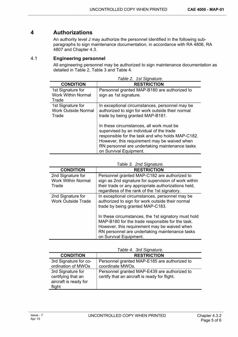
UNCONTROLLED COPY WHEN PRINTED CAE 4000 - MAP-01
Issue - 7 Apr 15
UNCONTROLLED COPY WHEN PRINTED Chapter 4.3.2 Page 5 of 6
4 Authorizations An authority level J may authorize the personnel identified in the following sub-paragraphs to sign maintenance documentation, in accordance with RA 4806, RA 4807 and Chapter 4.3.
4.1 Engineering personnel All engineering personnel may be authorized to sign maintenance documentation as detailed in Table 2, Table 3 and Table 4.
Table 2. 1st Signature. CONDITION RESTRICTION
1st Signature for Work Within Normal Trade
Personnel granted MAP-B180 are authorized to sign as 1st signature.
1st Signature for Work Outside Normal Trade
In exceptional circumstances, personnel may be authorized to sign for work outside their normal trade by being granted MAP-B181. In these circumstances, all work must be supervised by an individual of the trade responsible for the task and who holds MAP-C182. However, this requirement may be waived when RN personnel are undertaking maintenance tasks on Survival Equipment.
Table 3. 2nd Signature. CONDITION RESTRICTION
2nd Signature for Work Within Normal Trade
Personnel granted MAP-C182 are authorized to sign as 2nd signature for supervision of work within their trade or any appropriate authorizations held, regardless of the rank of the 1st signatory.
2nd Signature for Work Outside Trade
In exceptional circumstances, personnel may be authorized to sign for work outside their normal trade by being granted MAP-C183. In these circumstances, the 1st signatory must hold MAP-B180 for the trade responsible for the task. However, this requirement may be waived when RN personnel are undertaking maintenance tasks on Survival Equipment.
Table 4. 3rd Signature. CONDITION RESTRICTION
3rd Signature for co-ordination of MWOs
Personnel granted MAP-E185 are authorized to coordinate MWOs.
3rd Signature for certifying that an aircraft is ready for flight
Personnel granted MAP-E439 are authorized to certify that an aircraft is ready for flight.
CAE 4000 - MAP-01 UNCONTROLLED COPY WHEN PRINTED
Chapter 4.3.2 Page 6 of 6
UNCONTROLLED COPY WHEN PRINTED Issue - 7 Apr 15
4.2 Non-engineering personnel In certain instances, non-engineering personnel may be required to sign maintenance documentation as 1st signature, eg Army Air Corps (AAC) personnel or aircraft wash teams. These instances must be specified and authorized in accordance with RA 4806 and Chapter 4.3 and, unless otherwise stated, the non-engineering personnel must be supervised in accordance with paragraph 3.2.
4.3 Aircrew Aircrew may be authorized to sign maintenance documentation in accordance with RA 4806 and Chapter 4.7.1.
UNCONTROLLED COPY WHEN PRINTED CAE 4000 - MAP-01
MAE Issue 6 Mar 14
UNCONTROLLED COPY WHEN PRINTED Chapter 4.4 Page 1 of 2
Chapter 4.4
Aircraft Ground Engineers
TABLE OF CONTENTS Paragraph
Page
1 General ............................................................................................................... 1 1.1 Introduction.......................................................................................................... 1 1.2 Applicability ......................................................................................................... 1 2 Regulatory Governance.................................................................................... 1 2.1 Regulatory Cross-reference ................................................................................ 1 2.2 Additional Information.......................................................................................... 1 3 Scope of employment of AGEs........................................................................ 2 4 Training and authorization ............................................................................... 2 4.1 Training ............................................................................................................... 2 4.2 Pre-employment training ..................................................................................... 2 4.3 Authorizations...................................................................................................... 2 5 Responsibilities................................................................................................. 2 5.1 Maintenance organization ................................................................................... 2 5.2 Duty Holder ......................................................................................................... 2 5.3 Project Team (PT) ............................................................................................... 2 6 References ......................................................................................................... 2
1 General 1.1 Introduction
Aircraft that operate away from their Stn/Unit may be accompanied by Aircraft Ground Engineers (AGEs) to provide engineering support in order to optimize operational availability at deployed locations. AGEs are specially trained and authorized to undertake a wide range of aircraft type flight servicing and maintenance tasks within and outside their own trade group, with the minimum of technical support and resources as standard, for the period of their tour. The employment of AGEs is currently limited to large RAF aircraft.
1.2 Applicability This chapter is applicable to the support of aircraft types that have been designated as requiring the employment of AGEs.
2 Regulatory Governance 2.1 Regulatory Cross-reference
This chapter supports:
1 RA 4806.
2.2 Additional Information To optimize the availability of aircraft that operate away from their Stn/Unit, tradesmen may be employed as AGEs who will accompany the aircraft and provide engineering support. Only personnel who have undergone AGE training may be authorized to operate as such under the terms of this chapter.
CAE 4000 - MAP-01 UNCONTROLLED COPY WHEN PRINTED
Chapter 4.4 Page 2 of 2
UNCONTROLLED COPY WHEN PRINTED MAE Issue 6 Mar 14
3 Scope of employment of AGEs AGEs will control and/or carry out all maintenance activities on the aircraft to which they are assigned and on which they are authorized when operating away from their Stn/Unit. Consequently, AGEs will be required to work (e.g. self-supervision, independents, etc) both inside and outside their main trade boundary within the constraints of their individual authorizations granted by the relevant and appropriately authorized authority level J.
4 Training and authorization 4.1 Training
Personnel required to undertake training for AGE duties must meet the requirements of AP 3392, Volume 2, Leaflet 527. They must complete formal AGE training at the relevant aircraft maintenance training school. Training must comply with the requirements of RA 4806 and Chapter 4.1.
4.2 Pre-employment training In addition to the formal training received at the relevant training school, and before AGEs can be authorized to operate autonomously they must successfully complete aircraft type pre-employment training at their Stn/Unit. Training must comply with the requirements of RA 4806 and Chapter 4.1. After successful completion of this training, personnel are deemed competent to operate as an AGE on the relevant aircraft type.
4.3 Authorizations Following successful completion of both formal and pre-employment AGE training, the relevant and appropriately authorized authority level J may award an AGE all necessary authorizations, in accordance with RA 4806 and Chapter 4.3, which are required to enable them to efficiently carry out their duties.
5 Responsibilities 5.1 Maintenance organization
A maintenance organization that employs AGEs must ensure that it has a system for authorizing and managing AGEs effectively.
5.2 Duty Holder A Senior Duty Holder (SDH), or if delegated, an Operating Duty Holder (ODH) as the Training Requirements Authority (TRA) must sponsor any associated pre-employment training.
5.3 Project Team (PT) Aircraft PTs are responsible for considering whether AGE support is appropriate for some or all of the aircraft’s roles. Where AGE support is appropriate, the PT must: publish any AGE-specific orders or instructions in the relevant aircraft Topic 2(R)1.
6 References This chapter refers to the following publications:
1 AP 3392 Volume 2 Leaflet 527 – The Aircraft Engineering and Avionics Trade Groups Training and Employment of Aircraft Ground Engineers.
2 Aircraft Topic 2(R)1 – General Orders and Special Instructions.
UNCONTROLLED COPY WHEN PRINTED CAE 4000 - MAP-01
MAE Issue - 6 Mar 14
UNCONTROLLED COPY WHEN PRINTED Chapter 4.5 Page 1 of 6
Chapter 4.5
Self-supervision
TABLE OF CONTENTS Paragraph
Page
1 General ............................................................................................................... 1 1.1 Introduction.......................................................................................................... 1 1.2 Applicability ......................................................................................................... 1 2 Regulatory Governance.................................................................................... 2 2.1 Regulatory Cross-reference ................................................................................ 2 2.2 Additional Information.......................................................................................... 2 3 Identification of activities not suitable for self-supervision.......................... 2 4 Responsibilities associated with delegating and undertaking a self-
supervised activity ............................................................................................ 4 4.1 Prior to activity being undertaken ........................................................................ 4 4.2 Activity acceptance and assessment .................................................................. 4 4.3 Completion of maintenance documentation ........................................................ 4 5 Self-supervision authority level ....................................................................... 4 6 Process for selecting and authorizing self-supervisors ............................... 5 7 References ......................................................................................................... 5
LIST OF FIGURES Figure 1. Identification of Maintenance Activities that are Not Suitable for Self-supervision. ......3
1 General 1.1 Introduction
To maintain the airworthiness of an aircraft, there are 2 distinct sets of responsibilities associated with each task, reflected in the need for a 1st and 2nd signature on the relevant documentation. The specific responsibilities associated with these signatures are detailed in RA 4806 and Chapter 4.3.2. However, studies into maintenance practices have highlighted that significant numbers of activities are capable of being carried out by one person only, who is deemed to possess sufficient experience and capability to undertake both sets of responsibilities. Personnel that undertake this form of working practice, where they assume the responsibilities of both the 1st and 2nd signatures, are known as self-supervisors. This chapter details the procedures for authorizing tradesmen to become self-supervisors. It should be noted that not all maintenance activities are suitable for this form of maintenance practice.
Note:
Personnel who are not eligible to be awarded the authorization to carry out the full range of self-supervised activities, in accordance with this chapter, may be eligible to be awarded an authorization to carry out a reduced range, known as Elementary Self-supervision; see RA 4806 and Chapter 4.5.1.
1.2 Applicability This chapter is applicable to personnel who may be authorized to carry out self-supervision maintenance activities.
CAE 4000 - MAP-01 UNCONTROLLED COPY WHEN PRINTED
Chapter 4.5 Page 2 of 6
UNCONTROLLED COPY WHEN PRINTED MAE Issue - 6
Mar 14
2 Regulatory Governance 2.1 Regulatory Cross-reference
This chapter supports:
1 RA 4806(5).
2 RA 4155(2).
3 RA 4156(2).
2.2 Additional Information Individual tradesmen may be authorized to be self-supervisors and therefore sign both the 1st and associated 2nd signature blocks of relevant documentation. Additionally, self-supervisor responsibilities can only be actioned on maintenance activities that are deemed suitable for self-supervision.
3 Identification of activities not suitable for self-supervision The Type Airworthiness Authority (TAA) must identify maintenance activities that are not suitable for self supervision using the flow chart at Figure 1. The TAA will promulgated these activities in the relevant Topic 2(N/A/R)1 or Topic 5A1.
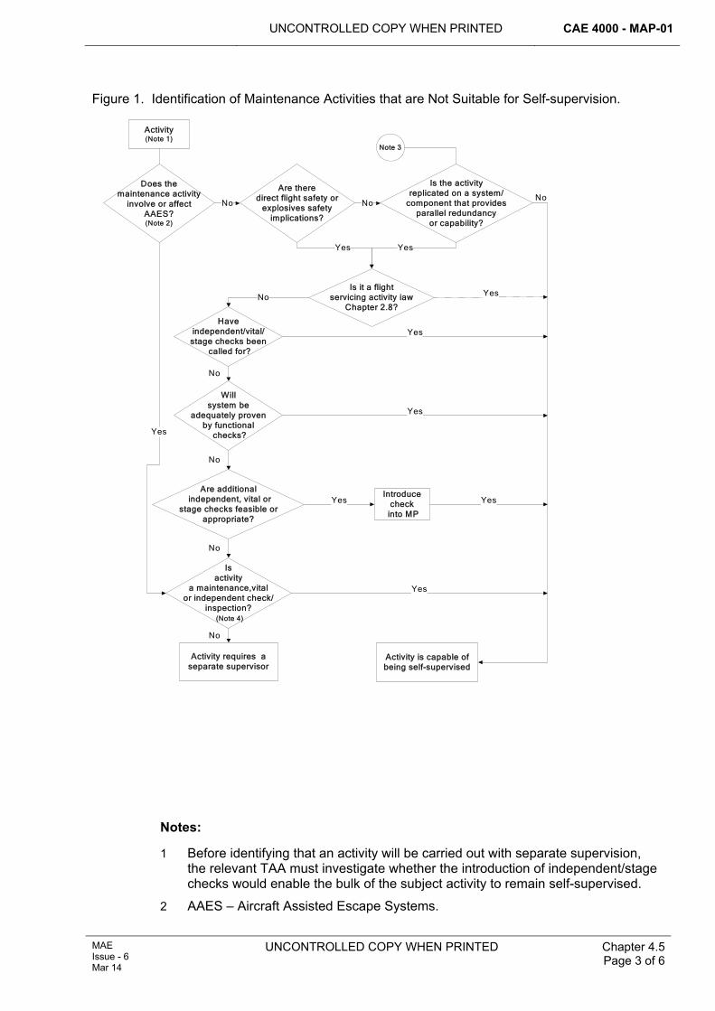
UNCONTROLLED COPY WHEN PRINTED CAE 4000 - MAP-01
MAE Issue - 6 Mar 14
UNCONTROLLED COPY WHEN PRINTED Chapter 4.5 Page 3 of 6
Figure 1. Identification of Maintenance Activities that are Not Suitable for Self-supervision.
Activity(Note 1)
Does the maintenance activity
involve or affect AAES?(Note 2)
Are there direct flight safety or
explosives safety implications?
Is the activity replicated on a system/
component that provides parallel redundancy
or capability?
Note 3
No No
Is it a flight servicing activity iaw
Chapter 2.8?
Yes Yes
Have independent/vital/ stage checks been
called for?
Willsystem be
adequately proven by functional
checks?
Are additional independent, vital or
stage checks feasible or appropriate?
Isactivity
a maintenance,vitalor independent check/
inspection? (Note 4)
No
No
No
No
Activity requires a separate supervisor
No
Yes
Activity is capable of being self-supervised
Yes
Yes
Yes
YesIntroduce
check into MP
Yes
Yes
No
Notes:
1 Before identifying that an activity will be carried out with separate supervision, the relevant TAA must investigate whether the introduction of independent/stage checks would enable the bulk of the subject activity to remain self-supervised.
2 AAES – Aircraft Assisted Escape Systems.
CAE 4000 - MAP-01 UNCONTROLLED COPY WHEN PRINTED
Chapter 4.5 Page 4 of 6
UNCONTROLLED COPY WHEN PRINTED MAE Issue - 6
Mar 14
3 This refers to situations where the same error by a single tradesman, employed on the same activity on 2 or more similar systems/components, could jeopardize safety or airworthiness. This applies to systems/components that provide a parallel redundancy or reserve capability, the combined operation of which allows safe operation or recovery of aircraft.
4 Refer to RA 4815 and Chapter 6.10 and RA 4602 and Chapter 13.1.2 for details relating to maintenance, vital or independent checks/inspections.
4 Responsibilities associated with delegating and undertaking a self-supervised activity
4.1 Prior to activity being undertaken The person delegating/tasking the activity must:
1 Confirm that the task is eligible for self-supervision, in accordance with the Topic 2(N/A/R)1 or Topic 5A1.
2 Select a suitably competent self-supervisor to carry out the task.
4.2 Activity acceptance and assessment As a consequence of being tasked with an activity that may be self-supervised, the self-supervisor must:
1 Confirm that the activity falls within his capabilities and that he accepts the relevant responsibilities in accordance with Chapter 4.3.2.
2 Continually assess the task, as it progresses, to confirm that it continues to be suitable for self-supervision. The following, non-exhaustive list, details some factors which may influence this decision:
2.1 Changes in prevailing weather conditions, ie significant temperature drop or reduction in available light.
2.2 Additional maintenance activities that may be being carried out in the same area.
2.3 Abnormal complications that may arise with the specific maintenance activity.
2.4 SHEF considerations.
Note:
If any of the above conditions are compromised, the self-supervisor must request that the task reverts to a multi-person activity.
4.3 Completion of maintenance documentation A self-supervisor undertakes both 1st and 2nd signature responsibilities, as detailed in RA 4806 and Chapter 4.3.2, when carrying out a self-supervision activity and is required to complete both the 1st and 2nd signature blocks of relevant documentation with original signatures.
5 Self-supervision authority level Authority level D will be granted to individuals required to be self-supervisors. A person holding authorization MAP-D283 is eligible to be a self-supervisor within his/her own trade specialization. Authorization MAP-D285 is a ‘special’ authority level D authorization that is necessary for tradesmen required to carry out self-
UNCONTROLLED COPY WHEN PRINTED CAE 4000 - MAP-01
MAE Issue - 6 Mar 14
UNCONTROLLED COPY WHEN PRINTED Chapter 4.5 Page 5 of 6
supervision activities outside their own trade and is only to be awarded for a specific maintenance activity and/or in exceptional circumstances.
Before authority to self-supervise is granted, tradesmen must hold the authorization to carry out the maintenance activities that they will self-supervise. For example, a tradesman may only be authorized to self-supervise the operation of the vibration equipment if he already holds the authorization to operate vibration equipment.
6 Process for selecting and authorizing self-supervisors Primarily, the selection for, and subsequent authorization of, an individual to be a self-supervisor is based on an assessment of competence, taking full account of relevant aircraft/equipment experience and/or completion of any relevant course, eg the Army Class 2 to Class 1 Technician upgrader’s course. The following, non-exhaustive list, provides a basic process for assessing an individual’s suitability for self-supervisor status:
1 The individual’s immediate line manager must assess the individual’s productive time on the aircraft or equipment type.
Note:
This period, whether continuous or cumulative, is subjective and depends on the complexity of the aircraft or equipment type concerned.
2 Once the individual's immediate line manager assesses the individual as competent to undertake self-supervision activities, the line manager must provide the holder of authorization MAP-J284 with an assessment of the individual and recommend the granting of self-supervision status.
3 The holder of authorization MAP-J284 must interview the individual and, if in agreement with the line manager’s assessment, may grant authorization MAP-D283 or MAP-D285, in accordance with RA 4806 and Chapter 4.3, to carry out either:
3.1 Self-supervision within own trade, or:
3.2 Exceptionally, self-supervision outside of own trade.
When a tradesman is authorized to carry out a specific activity, which by its nature is a self-supervised activity, eg flight servicing, independent inspection, NDT, etc, the granting of authority to carry out that activity includes by default the authority to self-supervise that activity. There is no requirement for personnel so authorized to undergo the procedure detailed above.
7 References This chapter refers to the following publications:
1 Topic 2(N/A/R)1 – General Orders and Special Instructions.
2 Topic 5A1 – Master Maintenance Schedule.

CAE 4000 - MAP-01 UNCONTROLLED COPY WHEN PRINTED
Chapter 4.5 Page 6 of 6
UNCONTROLLED COPY WHEN PRINTED MAE Issue - 6
Mar 14
Intentionally Blank for Page Pagination
UNCONTROLLED COPY WHEN PRINTED CAE 4000 - MAP-01
Issue - 7 Apr 15
UNCONTROLLED COPY WHEN PRINTED Chapter 4.5.1 Page 1 of 4
Chapter 4.5.1
Elementary Self-supervision
TABLE OF CONTENTS Paragraph
Page
1 General ............................................................................................................... 1 1.1 Introduction.......................................................................................................... 1 1.2 Applicability ......................................................................................................... 1 1.3 Definitions............................................................................................................ 2 2 Regulatory Governance.................................................................................... 2 2.1 Regulatory Cross-reference ................................................................................ 2 2.2 Additional Information.......................................................................................... 2 3 Identification of maintenance activities suitable for ESS.............................. 2 3.1 Background ......................................................................................................... 2 3.2 Renaming of historic ESS activities..................................................................... 3 3.3 Additional ESS activities...................................................................................... 3 4 Promulgation of ESS maintenance activities ................................................. 3 4.1 Multi-Stn/Ship/Unit aircraft operation................................................................... 3 5 Authorization ..................................................................................................... 3 6 Responsibilities................................................................................................. 3 6.1 Personnel authorized to carried out ESS activities ............................................. 3 7 Reference ........................................................................................................... 3
1 General 1.1 Introduction
The processes embedded within RA 4155 and Chapter 4.5 requires relevant Type Airworthiness Authorities (TAA) to identify maintenance activities that may not be carried out by self-supervisors. The remaining maintenance activities (ie those that are potentially eligible for self-supervision) encompass the full spectrum of maintenance tasks and consequently include a broad range of complexity, eg from replacing a hydraulic power pack to replacing individual filaments.
RA 4806 and Chapter 4.5 enables personnel to be authorized to be self-supervisors which potentially allows them to carry out all of these activities within the scope of their trade and any local restrictions on the authorization. However, personnel are not eligible for this ‘full’ application of self-supervision until their breadth of experience and/or seniority in rank permits, even though they may be competent to carry out a proportion of self-supervised activities.
It is appropriate to further identify, within the maintenance activities eligible for self-supervision, those that are simple and/or repetitive in nature that can be carried out by less-experienced personnel, thus extending the application of self-supervision. These are called Elementary Self-supervision (ESS) maintenance activities. This chapter details how ESS maintenance activities are identified and how personnel are authorized to carry them out.
1.2 Applicability This chapter is applicable to personnel associated with, or required to undertake, ESS.
CAE 4000 - MAP-01 UNCONTROLLED COPY WHEN PRINTED
Chapter 4.5.1 Page 2 of 4
UNCONTROLLED COPY WHEN PRINTED Issue - 7 Apr 15
1.3 Definitions 1 ESS – a range of self-supervised activities that may be carried out by personnel
with insufficient experience to be granted full self-supervisory status in accordance with RA 4806 and Chapter 4.5.
2 Simple and/or repetitive – for the purposes of this chapter, the collective expression ‘simple and/or repetitive’ is used to refer to a task that can be assessed as being suitable for ESS, where the following sub-paragraphs define the individual terms within the expression:
2.1 Simple – relating to basic maintenance activities, eg replacing a filament.
2.2 Simple and repetitive – relating to an activity that is simple, although it requires the tradesmen to follow simple procedures detailed in relevant technical information (TI), which will be carried out on a frequent basis, eg periodic replacement of an aircraft battery.
2.3 Repetitive – relating to a task that could be complex and requires adherence to procedures detailed in relevant TI, but is carried out frequently, eg repair/overhaul of an item of avionic equipment by the same tradesman on a daily basis.
2 Regulatory Governance 2.1 Regulatory Cross-reference
This chapter supports:
1 RA 4806(5).
2 RA 4156(2).
2.2 Additional Information All maintenance activities that may be carried out by a self-supervisor may be further designated by the Continuing Airworthiness Management Organization (CAMO) or the TAA, as being eligible for ESS. Personnel with insufficient experience to be authorized as full self-supervisors in accordance with RA 4806 and Chapter 4.5 may be authorized to undertake this reduced range of ESS activities.
3 Identification of maintenance activities suitable for ESS 3.1 Background 3.1.1 RN
The RN has historically annotated maintenance activities within the relevant Topic 5A1 with a ‘U’ suffix indicating that the activity may be self-certified. The term self-certified in this context related to the policy that allowed the operative and the supervisor to be the same person. This person signed the documentation twice, as the operative and the supervisor (ie self-supervised). The policy allowed non-supervisors to self-certify ‘U’ scheduled maintenance as detailed in the appropriate maintenance schedule or local orders. The tasks annotated as ‘U’ were those that were simple and/or repetitive and eligible for junior personnel (less experienced) to carry out in the guise of a self-supervised activity.
Note:
Whilst the above paragraph referred to non-supervisory ratings, it was equally applicable to supervisory ratings.
UNCONTROLLED COPY WHEN PRINTED CAE 4000 - MAP-01
Issue - 7 Apr 15
UNCONTROLLED COPY WHEN PRINTED Chapter 4.5.1 Page 3 of 4
3.2 Renaming of historic ESS activities The maintenance tasks detailed in paragraph 3.1.1 will be noted as being ESS activities. There is no requirement to amend the ‘U’ suffix annotation to read ESS within Topic 5A1s until the next review of the topic.
3.3 Additional ESS activities In addition to the historic ESS activities (‘U’ tasks)an appropriately authorized individualin the CAMOmay identify further activities as being ESS, provided that the relevant TAA has not identified that task as one that may not be self-supervised.
4 Promulgation of ESS maintenance activities ESS maintenance activities must be promulgated within Stn/Ship/Unit Aviation Engineering Standing Orders (AESOs). Although ‘U’ tasks have been identified by the TAAs, the appropriate individualwithin the CAMOshould confirm their agreement to them being used as ESS activities by promulgating a supporting statement within Stn/Ship/Unit AESOs. There is no requirement to list the ‘U’ tasks within these Orders.
4.1 Multi-Stn/Ship/Unit aircraft operation Where an aircraft type is operated from more than one Stn/Ship/Unit, the CAMO or TAA must ensure that there is a mechanism in place to ensure that a standard set of ESS maintenance activities is identified for use within their maintenance organizations.
5 Authorization In accordance with RA 4806 and Chapter 4.3, the relevant individual holding authorization MAP-J384 can grant authorization MAP-D359 to authorize a technician to carry out ESS activities.
Notes:
1 The individual holding MAP-J384 must consider limiting the scope of ESS tasks applicable to the authorization.
2 Although Flight Servicing is an ESS activity, personnel holding authorization MAP-D12 are not required to hold the ESS authorization MAP-D359 to carry out this activity (See Chapter 4.5, Paragraph 6).
6 Responsibilities 6.1 Personnel authorized to carried out ESS activities
Personnel awarded authorization MAP-D359 have the same responsibilities as self-supervisors as defined in RA 4806 and Chapter 4.5.
7 Reference This chapter refers to the following publication:
1 Topic 5A1 – Master Maintenance Schedule.

CAE 4000 - MAP-01 UNCONTROLLED COPY WHEN PRINTED
Chapter 4.5.1 Page 4 of 4
UNCONTROLLED COPY WHEN PRINTED Issue - 7 Apr 15
Intentionally Blank for Print Pagination
UNCONTROLLED COPY WHEN PRINTED CAE 4000 - MAP-01
Issue - 7 Apr 15
UNCONTROLLED COPY WHEN PRINTED Chapter 4.6 Page 1 of 2
Chapter 4.6
Delineation of Responsibilities for Engineering Authorizations
TABLE OF CONTENTS Paragraph
Page
1 General ............................................................................................................... 1 1.1 Introduction.......................................................................................................... 1
LIST OF TABLES
1 General 1.1 Introduction
►Delineation of lead responsibility for specific authorizations when Services are operating together should be defined in relevant single Service orders. This Ghost Chapter is left in as a signpost for the reader.◄
CAE 4000 - MAP-01 UNCONTROLLED COPY WHEN PRINTED
Chapter 4.6 Page 2 of 2
UNCONTROLLED COPY WHEN PRINTED End of Data Module
Issue - 7 Apr 15
Intentionally Blank for Print Pagination
UNCONTROLLED COPY WHEN PRINTED CAE 4000 - MAP-01
Issue - 7 Apr 15
UNCONTROLLED COPY WHEN PRINTED Chapter 4.7.1 Page 1 of 6
Chapter 4.7.1
Authorization of Aircrew to Carry Out Aircraft Maintenance Work
TABLE OF CONTENTS Paragraph
Page
1 General ............................................................................................................... 1 1.1 Introduction.......................................................................................................... 1 1.2 Associated publication......................................................................................... 1 1.3 Applicability ......................................................................................................... 1 2 Regulatory Governance.................................................................................... 2 2.1 Regulatory Cross-reference ................................................................................ 2 2.2 Additional Information.......................................................................................... 2 3 Breakdown of ‘maintenance work’ .................................................................. 2 4 Aircrew engineering authorizations ................................................................ 2 4.2 Authority to flight service (AFS)........................................................................... 2 4.3 Authority to maintain (AM)................................................................................... 2 4.4 Self-supervision................................................................................................... 3 5 Training for aircrew to carry out maintenance work...................................... 3 5.1 AFS authorization................................................................................................ 4 5.2 AM authorization ................................................................................................. 5 6 Authorization and validity of AFS and AM...................................................... 5 6.1 Method of recording AFS and AM authorizations................................................ 6 7 References ......................................................................................................... 6
1 General 1.1 Introduction
To increase the flexibility of aircraft operations, aircrew may be authorized to undertake or participate in preventive and corrective maintenance activities, as detailed in RA 4203, RA 4205, RA 4812 and Chapters 5.3 and 5.4, on the aircraft type on which they are currently employed. These are activities that may be carried out solely by aircrew, or by aircrew supplementing the engineering organization. This chapter details the procedure for authorizing the aircrew concerned and identifies their responsibilities.
1.2 Associated publication This chapter is associated with the following publication:
1 2000 Series: Flying Regulations (FLY).
1.3 Applicability This chapter is applicable to any aircrew that may be required to carry out preventive or corrective maintenance activities on an aircraft. It is not applicable to those aircrew who are required to undertake flying activities in direct support of an aircraft maintenance task, e.g. flight test/check or engine ground runs.
Where it is necessary for a contractor-run organization to adopt alternative procedures to those detailed in this chapter (for example, when maintaining Military-Registered Civil-Owned Aircraft (MRCOA)), then the relevant procedures must be detailed in the organization's MRP Part 145 Maintenance Organization Exposition and approved by the MAA.
CAE 4000 - MAP-01 UNCONTROLLED COPY WHEN PRINTED
Chapter 4.7.1 Page 2 of 6
UNCONTROLLED COPY WHEN PRINTED Issue - 7 Apr 15
2 Regulatory Governance 2.1 Regulatory Cross-reference
This chapter supports:
1 RA 4806.
2.2 Additional Information Nil.
3 Breakdown of ‘maintenance work’ There are 2 distinct aspects to preventive or corrective maintenance; the act of doing the maintenance and the completion of the associated documentation: both aspects are of equal importance. Completion of the documentation also breaks down into 2 distinct areas; that associated with the individual maintenance task, plus that associated with the final step of coordinating the MOD Form 700C. The responsibilities associated with these areas, in addition to the requirements for documentation signatures, are detailed in RA 4806 and Chapter 4.3.2.
4 Aircrew engineering authorizations Aircrew required to undertake maintenance work that includes flight servicing or maintenance activities must be authorized by the appropriately authorized Authority level J.
Notes:
1 The provision of 1st, 2nd and coordinating signatures on maintenance documentation applies both to flight servicing and maintenance activities.
2 Issue of AM is predicated on the aircrew holding a current AFS. Exceptionally, where there is a requirement for an aircrew member to undertake a limited range of minor corrective maintenance tasks, the authority level J may waive the requirement to hold AFS.
4.2 Authority to flight service (AFS) AFS encompasses a range of activities associated with carrying out a flight servicing. The following non-exhaustive list gives examples of the major elements of the AFS authorization:
1 Flight servicing (RA 4057 and Chapter 2.8).
2 System replenishments.
3 Fuelling operations (RA 4055 and Chapter 2.6).
4 Loading and unloading of internally carried pyrotechnics (RA 4652 and Chapter 14.2).
5 Supervision of ground handling (RA 4054 and Chapter 2.5).
Consequently, the authorization given (AFS) must explicitly detail the scope of the activities which apply, including coordinating the MOD Form 700C (provided that no corrective maintenance has been carried out) and removing controlled pages.
e.g.: ‘AFS – Limited to fuelling operations only’
4.3 Authority to maintain (AM) AM covers the following activities:
UNCONTROLLED COPY WHEN PRINTED CAE 4000 - MAP-01
Issue - 7 Apr 15
UNCONTROLLED COPY WHEN PRINTED Chapter 4.7.1 Page 3 of 6
1 Minor corrective or preventive maintenance (RA 4203 and Chapter 5.3 and RA 4205 and Chapter 5.4).
2 Role changes (RA 4607 and Chapter 13.7).
3 Defer corrective maintenance (RA 4812(3) and Chapter 5.4.2).
4 Record limitations (RA 4812(3) and Chapter 5.4.2).
Aircrew holding AM may be authorized to carry out one or more of these activities, including coordinating the MOD Form 700C and removing controlled pages.
The TAA should promulgate, in the aircraft Topic 2(N/A/R)1, a list of aircraft items/systems on which aircrew may authorize the deferment of corrective maintenance or record limitations. The relevant holder of authority MAP-J227 must not grant authority to defer corrective maintenance outside this list, but may restrict further the scope of corrective maintenance deferment. The award of AM must detail the scope of this authority by incorporating the list of items/systems to which the award applies. If a fault occurs that is not detailed within this list of items/systems, the aircrew must consult a relevant holder of authority MAP-J227 to determine possible latitude within the list.
Note:
The authorization to defer corrective maintenance or record limitations is restricted to when aircrew are away from the parent Stn/Ship/Unit and when no suitably qualified engineering personnel are available.
4.4 Self-supervision There are occasions where only one member of the aircrew is required to operate an aircraft; this could be a single-seat aircraft or a helicopter where only one aircrew is on board. Maintenance activities undertaken in these situations will require the aircrew to act as a self-supervisor, in accordance with RA 4806 and Chapter 4.5. Therefore, the training given to these aircrew must include the principles and responsibilities of a self-supervisor.
5 Training for aircrew to carry out maintenance work Prior to AFS or AM authorization, the individual must have undertaken a training course, in accordance with RA 4150 and Chapter 4.1, which is normally to be carried out by the relevant engineering organization or recognized aircraft engineering training school. This training must be formulated to provide a complete background to their responsibilities, including completion of the relevant aspects of the MOD Form 700C and the associated elements of the maintenance task, e.g. tool control, hazards and dangers, precautions to be taken with POL, plus Logistics Information Systems (LIS) training to the appropriate level. This training must be of both a theoretical and practical nature, where the aircrew must show competency, through examination, to hold the relevant authorization. The following lists detail the minimum scope of topics for each authorization, which must be covered by the training, and the aims of that specific element of training.
Note:
The training given to aircrew, based on the lists below, must be suitably tailored and approved by an authority level J, to cover those flight-servicing activities associated with the individual’s required authorization.
CAE 4000 - MAP-01 UNCONTROLLED COPY WHEN PRINTED
Chapter 4.7.1 Page 4 of 6
UNCONTROLLED COPY WHEN PRINTED Issue - 7 Apr 15
5.1 AFS authorization Prior to AFS authorization, and subject to the scope of the required authorization, the individual aircrew must:
1 Understand the periodicity of the AFS authorization.
2 Complete a Flight Servicing Competency Check (FSCC) in accordance with RA 4807 and Chapter 2.8.1.
3 Demonstrate a comprehensive working knowledge of the MOD Form 700C.
4 Understand the responsibilities assumed when signing MOD Form 700C documentation (RA 4806 and Chapter 4.3.2).
5 Demonstrate a comprehensive working knowledge of the relevant APs, which must include:
5.1 Flight servicings – Aircraft Topic 5B1 and Topic 14, if applicable, (RA 4057 and Chapter 2.8 and RA 4807 and Chapter 2.8.1).
5.2 Mandatory rules and regulations.
5.3 Special Instructions (Technical) (RA 4457 and Chapter 10.5.1).
5.4 Hazard and Maintenance Information – Aircraft Topic 5A2.
6 Describe the procedures for Continuous Charge (RA 4059 and Chapter 2.9).
7 Describe the procedure for preparing the MOD Form 700C for carriage in its parent aircraft and the methods of returning original documents to the parent Stn/Ship/Unit (RA 4813 and Chapter 7.2.1).
8 State the actions required when preventive maintenance activities become outstanding whilst detached from support facilities.
9 State the tool control procedures and the actions required when a tool is misplaced (RA 4253 and Chapter 6.2). This includes when a component or other item is identified as being misplaced.
10 Be able to identify the correct fuels, fluids and gases, including the authorized alternatives, to be used during the flight servicing activity.
11 Demonstrate an understanding of fuelling activities, as appropriate, whilst observing all safety precautions.
12 Convert fuel quantities, as required, and demonstrate the correct procedures in the event of a fuel spillage (RA 4055 and Chapter 2.6).
13 Be able to check relevant system levels and, ensuring system cleanliness, replenish all aircraft systems using the appropriate equipment.
14 Be able to identify, fit and remove all ground locking devices, gags and blanks.
15 Demonstrate how to lash or tie down the aircraft, if applicable.
16 Be able to act as an aircraft/ground equipment supervisor, brake operative and steering operative, as detailed in RA 4054 and Chapter 2.5, and carry out the correct removal and replacement of chocks during aircraft moves.
17 Identify handling and no-step areas on the aircraft and correctly operate all doors, hatches, canopies, steps and servicing platforms.
18 Identify, check and operate all relevant ground servicing equipment, including fire-fighting equipment and correct fitting and removal of aircraft steering arms.
19 Demonstrate the correct procedures in the event of a fire or other emergency.
UNCONTROLLED COPY WHEN PRINTED CAE 4000 - MAP-01
Issue - 7 Apr 15
UNCONTROLLED COPY WHEN PRINTED Chapter 4.7.1 Page 5 of 6
20 Demonstrate an understanding of loading and unloading of all internally-stowed weapons and pyrotechnics, other than those permitted to be left in the aircraft, and all relevant safety precautions.
21 Demonstrate how to make safe all weapons that may be carried by the aircraft.
22 Be conversant with the safety devices, safety conditions and safety precautions appropriate to the aircraft assisted escape system, if applicable.
Note:
The authorization to defer corrective maintenance or record limitations is restricted to when aircrew are away from the parent Stn/Ship/Unit and when no suitably qualified engineering personnel are available.
5.2 AM authorization The appropriate authority level J must identify topics, additional to those identified for AFS authorization training that are required in order for aircrew to undertake minor maintenance tasks, role changes or to authorize the deferment of corrective maintenance. These must include as a minimum:
1 An understanding of their responsibilities with respect to role changes, as applicable.
2 An appropriate level of training and competence in LIS operation.
Note:
Air Loadmasters (RAF only) and Helicopter Handling Instructors are qualified to undertake role changes by virtue of their training and subsequent re-examination by Group Examining Units/Standards Evaluation Units and therefore do not require additional authorizations for these tasks.
6 Authorization and validity of AFS and AM Granting of AFS and AM must be by the relevant and appropriately authorised Level J holder of the aircrew’s parent Sqn/Unit and must detail:
1 The flight servicings, replenishments, fuelling and loading/unloading of internally carried pyrotechnics that may be undertaken.
2 The range or extent of corrective and preventive maintenance tasks and/or role changes that may be undertaken.
3 Any restriction or conditions under which the individual may provide 1st, 2nd or co-ordinating signatures.
4 The authority to defer corrective maintenance work by making MOD F703 or MOD F704 entries, together with any restrictions or conditions under which extensions may be granted.
Each authorization must be granted in accordance with RA 4806 and Chapter 4.3 and is valid for a maximum period of 1 year or until posting/draft, whichever is the sooner. The authority level J granting the authorization may reduce this period.
Re-authorization is granted following a successful competency check. The format of the AFS competency check is at the discretion of relevant and appropriately authorised authority level J holder, but must comprise a minimum of an FSCC. The format of the AM competency check is at the discretion of the granting authority level J holder.
CAE 4000 - MAP-01 UNCONTROLLED COPY WHEN PRINTED
Chapter 4.7.1 Page 6 of 6
UNCONTROLLED COPY WHEN PRINTED Issue - 7 Apr 15
6.1 Method of recording AFS and AM authorizations The awards of AFS and AM must be recorded in accordance with RA 4806 and Chapter 4.3.1 or within the individual’s ‘Aircrew Log Book’.
7 References This chapter refers to the following publications:
1 Topic 2(N/A/R)1 – General Orders and Special Instructions.
2 Topic 5A2 – Hazard and Maintenance Information.
3 Topic 5B1 – Flight Servicing Schedule.
4 Topic 14 – Aircrew Landaway Flight Servicing Schedule.
UNCONTROLLED COPY WHEN PRINTED CAE 4000 - MAP-01
MAE Issue - 6 Mar 14
UNCONTROLLED COPY WHEN PRINTED Chapter 4.7.3 Page 1 of 4
Chapter 4.7.3
Operation of Air Transport Systems by Movements Personnel
TABLE OF CONTENTS Paragraph
Page
1 General ............................................................................................................... 1 1.1 Introduction.......................................................................................................... 1 1.2 Terms used ......................................................................................................... 1 2 Regulatory Governance.................................................................................... 1 2.1 Regulatory Cross-reference ................................................................................ 1 2.2 Additional Information.......................................................................................... 2 3 Employment....................................................................................................... 2 4 Requirements and training............................................................................... 2 4.1 Instructors............................................................................................................ 2 4.2 Movements personnel ......................................................................................... 2 5 Testing................................................................................................................ 2 6 Certification and authorization ........................................................................ 2 6.1 Instructors............................................................................................................ 2 6.2 Movements personnel ......................................................................................... 3 7 Responsibilities................................................................................................. 3 7.1 Movements Squadrons and Front Line Commands (FLCs)................................ 3 7.2 Aircraft maintenance school ................................................................................ 3 7.3 Type Airworthiness Authorities (TAA) ................................................................. 3 8 Reference ........................................................................................................... 4
1 General 1.1 Introduction
Operation of aircraft systems during the loading and unloading of aircraft is normally undertaken by either aircrew or authorized engineering personnel. However, to increase operational flexibility within the aircraft fleet, movements personnel may be authorized to instruct on, or operate, those aircraft systems necessary for loading and unloading aircraft.
1.2 Terms used For the purposes of this chapter:
1 Movements’ personnel are non-aircraft engineering personnel or aircrew, who are required to load or unload aircraft in the course of their duties.
2 Load and unload refers to the loading and unloading of air cargo and/or passengers from aircraft.
2 Regulatory Governance 2.1 Regulatory Cross-reference
This chapter supports:
1 RA 4806.
CAE 4000 - MAP-01 UNCONTROLLED COPY WHEN PRINTED
Chapter 4.7.3 Page 2 of 4
UNCONTROLLED COPY WHEN PRINTED MAE Issue - 6
Mar 14
2.2 Additional Information Nil.
3 Employment The activities that can be carried out on aircraft, by movements personnel, will vary according to aircraft type and required task. Before commencing work on an aircraft, the senior movements supervisor employed on the task must obtain clearance to operate the appropriate aircraft systems from the senior aircraft engineer present or Aircraft Commander if no engineers are present. When neither aircraft engineers or the Aircraft Commander are present, the senior movements supervisor must confirm that prior approval to operate appropriate aircraft systems has been granted by the supporting engineering organization or Aircraft Commander.
On completion of the task the senior movements supervisor must ensure that all systems operated have been left serviceable and in a safe condition and any faults have been reported to the senior engineer present or the Aircraft Commander if no engineers are present.
4 Requirements and training 4.1 Instructors
Movements’ personnel who are required to instruct on the operation of aircraft systems required for loading and unloading aircraft must be suitably experienced. The training of instructors to operate aircraft systems must be carried out at the appropriate aircraft maintenance school.
4.2 Movements personnel Suitable experienced movements personnel who are required to operate aircraft systems while loading or unloading aircraft must be trained by a qualified instructor.
5 Testing In addition to formal training, instructors and Movements’ personnel are also to undertake a pre-employment test. This test must be conducted by any suitably experienced authority level C aircraft technician.
6 Certification and authorization 6.1 Instructors
After successful completion of the operation of aircraft systems instructors training course, the instructor will be issued with a Certificate of Training (C of T). Having passed the pre-employment test, the instructor will be issued with a Certificate of Competency (C of C) in accordance withRA 4806 and Chapter 4.1. The instructor and the parent Stn/Ship/Unit must hold copies of the certification awarded. Holding a C of T and C of C does not allow the holder to operate any aircraft system or instruct on those systems until authorized as follows:
1 C of T – to be signed by the aircraft maintenance school instructor.
2 C of C – to be signed by the assessor.
3 Authority to Instruct – authorized by the authority level J of the maintenance school in accordance with RA 4806 and Chapter 4.3.1.
UNCONTROLLED COPY WHEN PRINTED CAE 4000 - MAP-01
MAE Issue - 6 Mar 14
UNCONTROLLED COPY WHEN PRINTED Chapter 4.7.3 Page 3 of 4
4 Authority to Operate Aircraft Systems – authorized by the authority level J of the instructor’s parent Stn/Ship/Unit in accordance with RA 4806 and Chapter 4.3.1.
Each certificate is valid for the duration of an individual’s tour or 4 years from the date of issue, whichever is the sooner. On detachments, the authority level J of the receiving Stn/Ship/Unit may allow the instructor to continue operating aircraft systems under the extant authorization issued by the parent Stn/Ship/Unit, having first confirmed the C of T and C of C.
6.2 Movements personnel After successful completion of the operation of aircraft systems training course, movements personnel will be issued with a C of T. Having passed the pre-employment test, movements personnel will be issued with a C of C in accordance with RA 4806 and Chapter 4.1. They and their parent Stn/Ship/Unit must hold copies of the certification awarded. Holding a C of T and C of C does not allow the holder to operate any aircraft system until authorized as follows:
1 C of T – to be signed by the movement instructor.
2 C of C – to be signed by the assessor.
3 Authority to Operate Aircraft Systems – authorized by the authority level J of the operator’s parent Stn/Ship/Unit in accordance with RA 4806 and Chapter 4.3.1.
The authority for movements personnel to operate aircraft systems is valid for 12 months. The authority level J may re-authorize personnel for further 12 month periods without re-examination or re-training, provided that the previous authorization has not lapsed for more than 28 days. The personnel concerned must have been regularly employed on aircraft movements duties during the previous 3 months.
On detachments the authority level J of the receiving Stn/Ship/Unit may allow movements personnel to continue operating aircraft systems under the extant authorization issued by the parent Stn/Ship/Unit, having first confirmed the C of T and C of C. On posting, the authority level J of the receiving Stn/Ship/Unit must re-authorize the operation of aircraft systems, having first confirmed the C of T and C of C.
7 Responsibilities 7.1 Movements Squadrons and Front Line Commands (FLCs)
Movements Squadrons and FLCs are responsible for ensuring that they have sufficient numbers of movements personnel and instructors to operate the aircraft systems necessary for loading and unloading aircraft.
7.2 Aircraft maintenance school Each aircraft maintenance school is responsible for:
1 Ensuring that the training of instructors and movements personnel complies with RA 4150 and Chapter 4.1.
2 Maintaining a register of instructors for 4 years from the date of issue of their authority to instruct.
7.3 Type Airworthiness Authorities (TAA) TAA are responsible for specifying, in the Topic 2(N/A/R)1, those aircraft systems that may be operated by movements personnel.
CAE 4000 - MAP-01 UNCONTROLLED COPY WHEN PRINTED
Chapter 4.7.3 Page 4 of 4
UNCONTROLLED COPY WHEN PRINTED MAE Issue - 6
Mar 14
8 Reference This chapter refers to the following publication:
1 Topic 2(N/A/R)1 – General Orders and Special Instructions.
UNCONTROLLED COPY WHEN PRINTED CAE 4000 - MAP-01
MAE Issue - 5 Sep 13
UNCONTROLLED COPY WHEN PRINTED Chapter 4.8.1 Page 1 of 4
Chapter 4.8.1
Contractors’ Representatives at Stations, Ships and Units
TABLE OF CONTENTS Paragraph
Page
1 General ............................................................................................................... 1 1.1 Introduction.......................................................................................................... 1 1.2 Applicability ......................................................................................................... 1 2 Regulatory Governance.................................................................................... 1 2.1 Regulatory Cross-reference ................................................................................ 1 2.2 Additional Information.......................................................................................... 1 3 Requisitioning a contract ................................................................................. 2 4 Contractors’ representatives ........................................................................... 2 5 Guide to scope and frequency of representative’s reports........................... 2 6 Responsibilities.......................................................................................... 3 6.1 Stn/Ship/Unit ....................................................................................................... 3 6.2 Front Line Command (FLC) ................................................................................ 3 6.3 MOD CAM .................................................................................................... 3 6.4 Project Team (PT) ............................................................................................... 3 7 References ......................................................................................................... 4
1 General 1.1 Introduction
When necessary, a contractor’s representative may be employed, normally under the conditions of DEFCON 76, to give advice to Project Teams (PT) (including Type Airworthiness Authorities (TAA)), Continuing Airworthiness Management Organizations (CAMOs)and Stns/Ships/Units on the maintenance of aircraft or other equipment. The representative may be permanently resident at the Stn/Ship/Unit concerned, or he may be based at his contractor’s works or at another Stn/Ship/Unit and provide his services by visits, either on a regular basis or on request.
1.2 Applicability This chapter is applicable to the Military Air Environment. However, it does not apply to post-design services or technical services contracts, or to those relating to Contractors’ Working Parties. It does not specifically apply to Contractors on Deployed Operations (CONDO); refer to DEFCON 697.
2 Regulatory Governance 2.1 Regulatory Cross-reference
Nil.
2.2 Additional Information Regardless of how they are provided, the services of each representative are covered by an MOD contract. This chapter details the responsibilities for requisitioning, managing and reviewing such contracts and the employment of advice offered under such contracts.
CAE 4000 - MAP-01 UNCONTROLLED COPY WHEN PRINTED
Chapter 4.8.1 Page 2 of 4
UNCONTROLLED COPY WHEN PRINTED MAE Issue - 5
Sep 13
3 Requisitioning a contract A PT that decides, in consultation with Front Line Commands (FLCs) when applicable, that the services of a contractor’s representative or representatives are necessary must:
1 Ensure that funding for a contract is available.
2 Raise a requisition for contract, specifying the full scope of activities to be carried out by the contractor’s representative.
3 Determine the scope, frequency and distribution of a contractor’s representative’s reports and include this as a requirement in the requisition.
4 Nominate an appropriate person to whom the resident representative is responsible at a Stn/Ship/Unit.
4 Contractors’ representatives Contractors’ representatives will normally be specialists in the aircraft or equipment supplied by their companies. To obtain maximum benefit from contractors’ representatives, it is essential that they be required by the contract to submit regular reports on specialist support activities.
Their company and the contracting PT authorize them to give advice on the aircraft and equipment. New advice from contractors’ representatives is only authoritative after it has been endorsed by the appropriate PT; in the case of aircraft, or equipment to be installed on aircraft, this must be the relevant TAA.
Contractors’ representatives are not responsible for, or authorized to certify, the serviceability of an aircraft or associated equipment.
It must be remembered that contractors’ representatives are not members of the Armed Forces and there are certain limitations on their employment. Examples are:
1 They are not to take part in military operations unless specifically contracted to do so.
2 They are not to fly in aircraft on operations unless specifically contracted to do so.
3 They are not to be issued with arms, ammunition, Service clothing or equipment, other than any technical equipment and personal protection equipment required in the course of their contracted engineering duties.
5 Guide to scope and frequency of representative’s reports Requirements for the services of representatives vary considerably and it is the PT’s responsibility to decide, in consultation with its customers, the required periodicity of such reports.
A PT, when stating the required Service distribution for representative’s reports, should also consider having reports countersigned by a nominated MOD engineer at the Stn/Ship/Unit involved. The following list of topics may be used by PTs as a guide when determining the content of contractors’ representative’s reports:
1 Significant advice or assistance provided, and an indication of the frequency of visits to units, squadrons or sections.
2 Progress of special equipment projects, programmes or investigations.
3 Problems causing concern.
UNCONTROLLED COPY WHEN PRINTED CAE 4000 - MAP-01
MAE Issue - 5 Sep 13
UNCONTROLLED COPY WHEN PRINTED Chapter 4.8.1 Page 3 of 4
4 Suggested improvements to maintenance techniques and practices.
5 Details of equipment retained in use that, but for the assistance of the representative, would have required replacement.
6 Particulars of spares obtained, other than through standard Service supply procedures, together with confirmation that the appropriate authority level K had previously consented to the method of procurement used.
7 Particulars of other assistance provided that affects the cost of the contract.
6 Responsibilities The following paragraphs identify the generic responsibilities for managing a contract; specific details are promulgated in individual contracts. All agencies involved in managing or obtaining services from a contract must hold a current copy of both the contract and DEFCON 76 to assist with enforcing contractual provisions.
6.1 Stn/Ship/Unit The Stn/Ship/Unit must provide facilities for representatives in accordance with the contract.
If advice provided by a contractor’s representative to Stn/Ship/Unit personnel represents new information not already generally available, the PT must immediately be made aware of its existence. This information must be accepted by the PT (which, in the case of aircraft and aircraft equipment, must be the TAA) before it is acted upon by the Stn/Ship/Unit.
When a contractor’s representative is permanently resident at a Stn/Ship/Unit, the PT, in consultation with the FLC and Stn/Ship/Unit as appropriate, must nominate a responsible person for the day-to-day control of the representative. This arrangement must be detailed in the contract.
6.2 Front Line Command (FLC) Each FLC participating in a contract is responsible for informing its concerned Stn/Ship/Unit of the arrangements for attachment of, or visits by, a representative. The specific responsibilities will be detailed in the contract and may include:
1 Messing, accommodation, and medical arrangements.
2 Communication, typing and photocopying arrangements.
3 Use of Service transport by the representative.
4 All aspects of security, including provision of an identity document or other required pass.
6.3 MOD CAM The MOD CAM is responsible for:
1 Reviewing contractors’ representatives’ reports and co-ordinate any actions initiated by the TAA.
2 Reviewing and, when appropriate, authorizing the use of new information provided by contractors’ representatives. If may be necessary to forward new type specific information to the TAA for authorization.
6.4 Project Team (PT) The PT concerned is responsible for:
CAE 4000 - MAP-01 UNCONTROLLED COPY WHEN PRINTED
Chapter 4.8.1 Page 4 of 4
UNCONTROLLED COPY WHEN PRINTED MAE Issue - 5
Sep 13
1 Controlling and prioritizing the day-to-day activities of contractor’s representatives who are not resident at a station.
2 Co-ordinating and, as appropriate, initiating actions arising from the contents of contractors’ representatives’ reports. In the case of actions relating to continuing airworthiness, this will most likely require liaison with the CAMO.
3 Nominating, in consultation with the FLC and/or CAMO, an appropriate person to whom the resident representative is responsible at a Stn/Ship/Unit.
4 Reviewing and, when appropriate, authorizing the use of new information provided by contractors’ representatives. In the case of information relating to aircraft and/or aircraft equipment, this authorization must come from the TAA.
5 Undertaking regular (at least annual) documented reviews of the need for a contractor’s representative, the scope of activities being undertaken by the contractor’s representative and the frequency and distribution of their reports.
7 References This chapter refers to the following publications and web sites:
1 DEFCON 76 -Contractor’s Personnel at Government Establishments
2 Acquisition Operating Framework – SSE – Contractors on Deployed Operations
3 DEFCON 697 – Contractors on Deployed Operations.
UNCONTROLLED COPY WHEN PRINTED CAE 4000 - MAP-01
Issue - 7 Apr 15
UNCONTROLLED COPY WHEN PRINTED Chapter 4.8.2 Page 1 of 6
Chapter 4.8.2
Contractors’ Working Parties Maintaining Aircraft at Stations, Ships and Units
TABLE OF CONTENTS Paragraph
Page
1 General ............................................................................................................... 1 1.1 Introduction.......................................................................................................... 1 1.2 Associated publications....................................................................................... 1 1.3 Applicability ......................................................................................................... 2 2 Regulatory Governance.................................................................................... 2 2.1 Regulatory cross-reference ................................................................................. 2 2.2 Additional Information.......................................................................................... 2 3 The contract....................................................................................................... 2 4 Responsibilities................................................................................................. 2 4.1 Contractor............................................................................................................ 2 4.2 Continuing Airworthiness Management Organization (CAMO) ........................... 3 4.3 Stn/Ship/Unit ....................................................................................................... 3 4.4 Project Team (PT) ............................................................................................... 4 4.5 Quality Assurance (QA)....................................................................................... 4 5 Corrective maintenance by CWP ..................................................................... 5 6 CWP waiting time .............................................................................................. 5 7 Unsatisfactory condition of aircraft received from a CWP............................ 6 8 References ......................................................................................................... 6
LIST OF FIGURES Figure 1. Example of the layout of a CWP Waiting Time Certificate. ...........................................6
1 General 1.1 Introduction
This chapter describes the general responsibilities for Contractors’ Working Parties (CWP) undertaking tasks at Stns/Ships/Units. It deals only with those considerations common to all contracts and is not to be interpreted as overriding the specific terms and conditions of individual contracts. Typically, a CWP may be employed to undertake specified maintenance tasks on aircraft at a Stn/Ship/Unit, eg Category 3 repairs, embodiment of modifications, or installations of aircraft equipment.
1.2 Associated publications This chapter is associated with the following publications:
1 DEFCON 76 – Contractor’s Personnel at Government Establishments.
2 DEF STAN 05-61 – Quality Assurance Procedural Requirements Part 4 – Contractor Working Parties.
CAE 4000 - MAP-01 UNCONTROLLED COPY WHEN PRINTED
Chapter 4.8.2 Page 2 of 6
UNCONTROLLED COPY WHEN PRINTED Issue - 7 Apr 15
1.3 Applicability
This chapter does not apply in the following circumstances:
1 When the Service provides facilities for a CWP to undertake a proof installation in accordance with 5000 Series: Design and Modification Engineering Regulations (DME).
2 To fully contractor-run maintenance organizations, approved through the Maintenance Approved Organization Scheme detailed in RA 4800-4849 Series (MRP Part 145).
2 Regulatory Governance 2.1 Regulatory cross-reference
This chapter supports:
1 RA 4161(1).
2 RA 4161(2).
2.2 Additional Information It is particularly important that within the platform Project Team (PT), the Type Airworthiness Authority (TAA) defines and allocates the associated aircraft preparation and recovery tasks.
3 The contract The contract is a legally enforceable agreement between the MOD and a contractor. It is essential that the contractor is not denied the MOD resources detailed in the contract without good cause. Equally, the contractor should not be allowed use of MOD facilities that he should provide and which are reflected in the contract price.
Copies of the contract should be distributed to relevant addressees, including:
1 The Front Line Command (FLC).
2 The Continuing Airworthiness Management Organization (CAMO).
3 The Stn/Ship/Unit concerned.
4 Responsibilities 4.1 Contractor
In general, the contractor is responsible for:
1 Compliance with the pertinent sections of the MAA Regulatory Publications (MRP).
2 Providing competent manpower and appropriate equipment to undertake the work detailed in the contract and for completing the work as required. CWP contracts may typically be expected to state applicable Stn/Ship/Unit orders, including local Foreign Object Damage (FOD) control procedures. Also, the contract will normally require the contractor to implement tool control and loose article measures, and to sign appropriate maintenance documents on completion of his work.
3 Reporting faults revealed in the course of his work to the relevant engineering manager, as identified by the contract, and the relevant PT for confirmation that they are outside the contract and ascertaining whether they are either to be
UNCONTROLLED COPY WHEN PRINTED CAE 4000 - MAP-01
Issue - 7 Apr 15
UNCONTROLLED COPY WHEN PRINTED Chapter 4.8.2 Page 3 of 6
corrected or deferred. The CWP may be authorized to correct such faults as described in paragraph 5 below.
4 Immediately informing the relevant engineering manager and the PT when it first becomes apparent that waiting time may be required.
5 Submitting a regular progress report as detailed in the contract. Details to be reported may include the contract man-hour percentage of task achieved, the ratio of actual elapsed time to estimated elapsed time, reasons for any delay, current and projected floor loadings, and estimated completion dates. When operating a running contract, the contractor will report the manhours expended monthly to the relevant engineering manager for onward transmission as required by paragraph 4.4.8.
Contractor Quality Assurance (QA) responsibilities are detailed in paragraph 4.5.
4.2 Continuing Airworthiness Management Organization (CAMO) 1 Assembling modification kits and unit supply items for issue to the CWP.
2 Providing specialist advice when requested by the CWP.
3 Ensuring that appropriate aircraft records are updated for work undertaken by the CWP, eg component changes may necessitate amendment of equipment record cards.
4.3 Stn/Ship/Unit Subject to contractual agreements, an appropriate engineering manager at the host Stn/Ship/Unit (typically the Delivery Duty Holder Chief Air Engineer (DDH CAE) or a holder of an authority level K) is responsible for:
1 Negotiating with the PT what level of support, equipment, facilities, etc, is available for the CWP as part of the contract, along with any appropriate charges and charging mechanism.
2 Ensuring that the contractor is notified of the serial numbers of aircraft to be worked on, if not detailed in the contract.
3 Positioning and preparing aircraft and equipment to standards detailed in the contract, defueling them if required and taking all anti-deterioration and safety measures necessary before the CWP commences work.
4 Authorizing CWP waiting time and corrective maintenance manhours in accordance with paragraph 8 and paragraph 9.
5 Controlling any work being undertaken by Service personnel on an aircraft on which a CWP is also working and, if the Service and CWP tasks interact, agreeing an appropriate allocation of responsibilities.
6 Completing any maintenance needed to bring aircraft to a serviceable condition after satisfactory completion of work by the CWP.
7 Controlling, on a day-to-day basis, the allocation of work to a CWP operating under cover of a running contract.
8 Raising, and forwarding to the PT monthly reports of manhours expended by a CWP operating under cover of a running contract.
9 Ensuring that disruptions or delays to CWP work caused by Stn/Ship/Unit exercises are minimized.
10 Ensuring that a CWP waiting time certificate is immediately raised whenever he is made aware, and for whatever reason, that waiting time will be needed.
CAE 4000 - MAP-01 UNCONTROLLED COPY WHEN PRINTED
Chapter 4.8.2 Page 4 of 6
UNCONTROLLED COPY WHEN PRINTED Issue - 7 Apr 15
The appropriate engineering manager is not to agree to the Service carrying out any work that should be the responsibility of the contractor and which is paid for under the contract.
Stn/Ship/Unit QA responsibilities are detailed in paragraph 4.5.
4.4 Project Team (PT) For all CWP tasks, the PT must:
1 Negotiate with the appropriate engineering manager of the host Stn/Ship/Unit what level of support, equipment, facilities, etc, is available for the CWP as part of the contract, along with any appropriate charges and charging mechanism.
2 Notify the overall programme to the contractor and the Stns/Ships/Units concerned, eg the location of aircraft and order of priority.
3 Ensure that the preparation and recovery tasks are clearly defined and allocated to Service personnel or the CWP.
4 Determine the level of CWP waiting time and corrective maintenance man-hours that may be authorized at Stn/Ship/Unit level and delegate such authority, on request, to the appropriate engineering manager. The limit of delegation may be expressed in terms of man-hours or as a percentage of the CWP task.
5 Authorize corrective maintenance and CWP waiting time manhours in excess of any powers delegated to the appropriate engineering manager in accordance with paragraphs 5 and 6.
6 Authorize all tasks carried out under cover of a running contract.
7 Give the appropriate engineering manager standing authority from the PT to authorize CWP waiting time and corrective maintenance manhours up to a set limit.
8 On a running contract, monitor the monthly man-hour reports raised by the Stn/Ship/Unit.
PT QA responsibilities are detailed in paragraph 4.5.
4.5 Quality Assurance (QA) It is the prime contractor’s responsibility to ‘assure’ the quality of the product or services provided by the CWP.
However, the responsibility for the ‘quality’ of the delivered product and for assuring a contractor’s compliance with contract conditions rests with the PT. In the event that a TAA, in consultation with the CAMO, perceives that the function/operation of a CWP could present a risk to the deliverable product, the services of an MOD-registered Quality Assurance Representative (QAR) organization can be requested to undertake specific risk-based surveillance to mitigate the perceived risk. Any observations that stem from QAR activity must be reported directly to the TAA and CAMO, who will take/seek the necessary corrective action.
QAR rights of access are essential to the execution of this work and the inclusion, in the contract, of the relevant standards from the Def Stan 05-90 series or DEFCON 608 will ensure the QAR’s right of access at any stage of contract activity and to any facility where contract activity is being undertaken, including those not under the direct control of the prime contractor.
Access by the CAMO for quality assurance activity may also be required, hence suitable contractual arrangements must be in place.
UNCONTROLLED COPY WHEN PRINTED CAE 4000 - MAP-01
Issue - 7 Apr 15
UNCONTROLLED COPY WHEN PRINTED Chapter 4.8.2 Page 5 of 6
PT access is normally restricted to the PT’s Authorized Representative (AR), which is arranged through inclusion of appropriate wording in the contract. The AR’s access is generally confined to routine or specific project management activity such as product specification, testing, rework, concessions, delivery dates, authorizing payment, etc. Unless the PT is a registered QAR organization, the AR has no authority to audit the contractor’s Quality Management System or to undertake on-site risk-based surveillance activity in mitigation of perceived QA risks. However, any observations or recommendations that stem from an AR’s activity should be reported directly to the TAA, who will act as appropriate.
The engineering manager at the Stn/Ship/Unit will not normally have any formal responsibilities for quality assurance surveillance of work undertaken by a CWP or for their engineering standards and practices, except when any such responsibilities have been accepted and the contract reflects these Stn/Ship/Unit responsibilities. However local engineering management may wish to conduct some degree of discretionary assurance activity subject to any contractual constraints.
5 Corrective maintenance by CWP Subject to the contract, the appropriate engineering manager may require the CWP to correct faults discovered during the course of its work. In such instances, the appropriate engineering manager must:
1 Authorize the contractor, in writing, to undertake corrective maintenance to the limit determined by the PT. For corrective maintenance in excess of this limit, he must seek the written agreement of the appropriate PT.
2 Forward a monthly return to the appropriate PT detailing the additional CWP work that he has authorized.
6 CWP waiting time CWP waiting time occurs when, for Service reasons, there is a delay between two otherwise consecutive periods of CWP work and the appropriate Service authority, as defined below, considers that it would be more cost-effective to retain the CWP on site rather than withdraw it temporarily. The grant of waiting time can incur high costs; therefore, it is not to be authorized without careful consideration of all the financial implications. Particular points to be considered are contract requirements that tie CWP work to specific delivery/turn-round times and the existence of liquidated Damages and Force Majeure clauses. The authority for granting waiting time is:
1 The appropriate engineering manager, within limits determined by the PT.
2 The PT for any greater period.
When the need for waiting time becomes apparent, the appropriate engineering manager must complete a waiting time certificate, which must include, as a minimum, the details shown in Figure 1, obtaining authorization from the PT if necessary. He must forward copies of the certificate to the contractor and the appropriate PT and FLC.
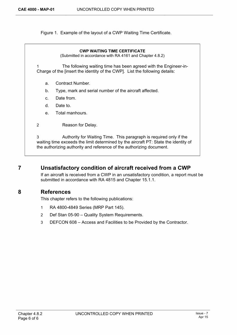
CAE 4000 - MAP-01 UNCONTROLLED COPY WHEN PRINTED
Chapter 4.8.2 Page 6 of 6
UNCONTROLLED COPY WHEN PRINTED Issue - 7 Apr 15
Figure 1. Example of the layout of a CWP Waiting Time Certificate.
CWP WAITING TIME CERTIFICATE (Submitted in accordance with RA 4161 and Chapter 4.8.2)
1 The following waiting time has been agreed with the Engineer-in-Charge of the [insert the identity of the CWP]. List the following details:
a. Contract Number.
b. Type, mark and serial number of the aircraft affected.
c. Date from.
d. Date to.
e. Total manhours. 2 Reason for Delay. 3 Authority for Waiting Time. This paragraph is required only if the waiting time exceeds the limit determined by the aircraft PT: State the identity of the authorizing authority and reference of the authorizing document.
7 Unsatisfactory condition of aircraft received from a CWP If an aircraft is received from a CWP in an unsatisfactory condition, a report must be submitted in accordance with RA 4815 and Chapter 15.1.1.
8 References This chapter refers to the following publications:
1 RA 4800-4849 Series (MRP Part 145).
2 Def Stan 05-90 – Quality System Requirements.
3 DEFCON 608 – Access and Facilities to be Provided by the Contractor.
UNCONTROLLED COPY WHEN PRINTED CAE 4000 - MAP-01
Issue - 7 Apr 15
UNCONTROLLED COPY WHEN PRINTED Chapter 5.1 Page 1 of 6
Chapter 5.1
Maintenance Philosophy – General
TABLE OF CONTENTS Paragraph
Page
1 General ............................................................................................................... 1 1.1 Introduction.......................................................................................................... 1 1.2 Associated publications....................................................................................... 1 2 Regulatory Governance.................................................................................... 2 2.1 Regulatory Cross-reference ................................................................................ 2 2.2 Additional Information.......................................................................................... 2 3 Preventive maintenance ................................................................................... 2 3.1 Servicing.............................................................................................................. 2 3.2 Scheduled maintenance...................................................................................... 3 3.3 Condition-based maintenance............................................................................. 3 4 Corrective maintenance.................................................................................... 3 4.1 Corrective maintenance of materiel..................................................................... 3 4.2 Inspect and Repair as Necessary (IRAN) ........................................................... 3 4.3 Corrective maintenance of software.................................................................... 4 5 Concessions ...................................................................................................... 4 5.1 Application for concessions................................................................................. 4 6 Through-life implementation............................................................................ 4 6.1 Introduction into service ...................................................................................... 4 6.2 In service ............................................................................................................. 4 6.3 Disposal............................................................................................................... 6 7 References ......................................................................................................... 6
1 General 1.1 Introduction
This chapter details the Acceptable Means of Compliance (AMC), Guidance Material (GM) and associated processes for aircraft and equipment maintenance within the Military Air Environment (MAE), the principles on which it is based and the process by which the AMC, GM and associated processes are promulgated.
Maintenance is a combination of the engineering and supporting administrative actions taken to retain materiel in a serviceable condition or to restore it to serviceability. The function of maintenance within the MAE is to maintain, in the most cost-effective manner, aircraft and related equipment in a condition such that they are capable of fulfilling their declared purpose throughout their required life.
Within the MAE, maintenance is implemented through a 2-level construct – Forward and Depth.
1.2 Associated publications This chapter is associated with the following publications:
1 JAP(D) 100C-22 – Procedures for Developing Preventive Maintenance.
2 JAP 100E-10 – Military Aviation Ground Support Equipment Management and Policy.
CAE 4000 - MAP-01 UNCONTROLLED COPY WHEN PRINTED
Chapter 5.1 Page 2 of 6
UNCONTROLLED COPY WHEN PRINTED Issue - 7 Apr 15
3 AP 100D-10 – Support for Mission Software in RAF Systems.
4 ASD Specification 1000D – International Specification for Technical Publications Utilising a Common Source Database.
5 ASD Specification 2000M – The International Specification for Military Materiel Management.
2 Regulatory Governance 2.1 Regulatory Cross-reference
This chapter supports:
1 RA 4200
2.2 Additional Information A philosophy of wholly preventive maintenance could result in low utilization and over-maintenance. Conversely, a philosophy based entirely on corrective maintenance could result in unpredictable availability, poor utilization of resources and could generate an unacceptable number of hazardous or expensive failures. The maintenance philosophy aims to maintain functionality by optimising the balance of preventive and corrective maintenance in order to:
1 Minimize the engineering manpower and other resources required for the task.
2 Minimize faults that would result in a situation hazardous to aircraft, associated equipment or personnel.
3 Minimize faults that would result in unacceptable loss of operational capability.
4 Minimize faults that would result in expensive repairs and/or lengthy down times.
5 Identify methods to improve operability, reliability and/or maintainability.
6 Retain the condition of equipment until its out-of-Service date and to accommodate periods of intensive use if required.
Software maintenance involves some concepts that are distinct from those applied to hardware and mechanical systems. Although corrective maintenance still applies, this relates to the removal of software faults rather than the repair of a physical breakdown. The more significant dimensions of software maintenance are the controlled and configured implementation of perfective, adaptive and enhancement change.
3 Preventive maintenance Preventive maintenance is systematic and prescribed work undertaken at predetermined intervals to reduce the probability of failure, to restore the inherent level of equipment reliability and to ensure that performance is not degraded by time or usage. A more detailed description is provided in RA 4203 and Chapter 5.3. Within the MAE there are 3 types of preventive maintenance: servicing, scheduled and condition-based maintenance.
3.1 Servicing Servicing is that maintenance required to determine the condition of an aircraft or other item of equipment after a period of use and to prepare for its next period of use. It comprises the checking and replenishment of consumables and may include such minor maintenance as the replacement of bulbs and the identification of obvious signs of un-serviceability. The user or operator may carry out servicing.
UNCONTROLLED COPY WHEN PRINTED CAE 4000 - MAP-01
Issue - 7 Apr 15
UNCONTROLLED COPY WHEN PRINTED Chapter 5.1 Page 3 of 6
3.2 Scheduled maintenance Scheduled maintenance is that preventive maintenance undertaken at regular, predetermined intervals to keep an aircraft or other item of equipment in a sound overall condition and to minimize the amount of corrective maintenance and other day-to-day attention it requires. For aircraft, the requirements for scheduled maintenance are derived using a version of Maintenance Steering Group logic and Reliability-Centred Maintenance; similar logic techniques may be applied to other equipment.
Scheduled maintenance tasks may be retained as individual tasks (Flexops), allowing completion to coincide with corrective maintenance or other down time as operations dictate. Alternatively, the individual tasks may be grouped by periodicity and allocated to the appropriate level of maintenance. This grouping defines the scheduled maintenance system, which may be based either on units of usage or calendar time and may, if appropriate, have an upper limit specified in the other unit of measure. A grouping may be divided into smaller groups or packages and equalized over the relevant part of the maintenance cycle so that the whole requirement is satisfied within the specified period.
3.3 Condition-based maintenance Condition-based maintenance is that preventive maintenance initiated as a result of knowledge of the condition of an item gained from routine or continuous monitoring. Where adequate and realistic condition-monitoring techniques are available for a particular item to detect incipient failure (eg wear debris monitoring, NDT techniques and, in some applications, built-in test), condition-based maintenance is applied to the item in preference to routine repair or replacement as part of scheduled or out-of-phase maintenance. Where possible, the requirement for condition monitoring of the item should be included in the relevant servicing or maintenance schedule; otherwise it is incorporated as out-of-phase maintenance. Additionally, the accuracy of the condition-monitoring technique is normally sufficiently refined to permit anticipation of the need to repair or replace the item concurrent with scheduled or other maintenance opportunities.
4 Corrective maintenance 4.1 Corrective maintenance of materiel
Corrective maintenance embraces those maintenance activities carried out after a fault has occurred in order to restore an item to a serviceable state. Maintenance activities undertaken when a fault is indicated, but in the event not confirmed, are also corrective maintenance. A fault may be identified from the application of condition-monitoring techniques as part of preventive maintenance. When a fault is reported to, or detected by, the responsible engineering organization, the main equipment concerned becomes unserviceable and the unserviceability is formalized by raising the appropriate work order entry. A more detailed description of corrective maintenance is provided in RA 4812 and Chapter 5.4.
4.2 Inspect and Repair as Necessary (IRAN) IRAN is a methodology intended to ensure that the most cost-effective corrective maintenance activities are undertaken to return an item to a condition to meet operational commitments. It is rarely necessary to return a faulty component to ‘as new’ condition; consideration should always be given to repairing an identified fault, rather than reconditioning whole equipments.
Type Airworthiness Authorities (TAAs) should incorporate the IRAN principle in the content of Technical Information, including maintenance schedules, manuals and
CAE 4000 - MAP-01 UNCONTROLLED COPY WHEN PRINTED
Chapter 5.1 Page 4 of 6
UNCONTROLLED COPY WHEN PRINTED Issue - 7 Apr 15
repair schemes. Repair contracts are also to clearly state that the principle of IRAN must be followed and must refer to Def Stan 05-61. Def Stan 05-61 specifies the procedures to be followed when the contractor seeks permission to deliver a product that does not comply in full to the contract requirement. Project Teams (PT) are to establish at what point it is more cost-effective to recondition rather than repair a component. In addition, they should establish at what point the cost of repair is uneconomical and the component should be considered as scrap. IRAN must be applied by all maintenance organizations unless otherwise directed by the appropriate TAA or delegated authority.
4.3 Corrective maintenance of software Faults in software may require changes to the design and hence are generally corrected as part of pre-planned program updates embodying multiple change requirements.
5 Concessions Concessions are defined as either TAA approved variations from manufacturing or maintenance specifications, or faults for which repairs have been assessed by the appropriate PT as uneconomic or unnecessary and for which there is no specific timescale for rectification. Concessions must be recorded on the aircraft or component Engineering Record Card and, for the information of maintenance personnel, on the MOD Form 704D (TAA Granted Concessions) within the platform's MOD Form 700C. Deferment of all other corrective maintenance must be logged on the aircraft Limitations Log (Lim) or ADF Log as appropriate; RA 4812 and Chapter 5.4.2 provide guidance on completing these forms.
5.1 Application for concessions Applications for concessions, as described in paragraph 5, must be made to the relevant PT. Where an application concerns aircraft equipment, the application must be copied to affected TAAs.
6 Through-life implementation 6.1 Introduction into service
Whenever a new design, modification or process is under consideration, the concept of ‘cost-effective design for whole life supportability’ should be incorporated in the project as early as possible. Subsequently, Integrated Logistic Support (ILS) should be implemented as described by Def Stan 00-600 or equivalent, supplemented by the Acquisition Operating Framework (AOF), but it may need tailoring to suit.
6.2 In service 6.2.1 Type Airworthiness Authority (TAA) responsibilities
TAAs are responsible for ensuring the Type Airworthiness of their platform-type and must provide a system of assessment that ensures the on-going analysis of the fault management system. A fundamental part of this system is the Fault Reporting And Corrective Action System (FRACAS), which will provide for:
1 The monitoring of all significant incidents and faults that have occurred in flight and faults found during maintenance, highlighting any that appear significant in their own right.
2 The monitoring of repetitive incidents and faults occurring in flight and faults found during maintenance and periodic servicing.
3 The monitoring of ADFs.
UNCONTROLLED COPY WHEN PRINTED CAE 4000 - MAP-01
Issue - 7 Apr 15
UNCONTROLLED COPY WHEN PRINTED Chapter 5.1 Page 5 of 6
4 The analysis of unscheduled removal of components and the performance of aircraft systems for use as part of the maintenance programme efficiency.
5 The review of schedules and maintenance procedures.
A description of the FRACAS must be included in the platform Safety Management Plan.
6.2.2 Continuing Airworthiness Management Organization (CAMO) responsibilities While the establishment of the FRACAS is the responsibility of the TAA, the CAMO is required to develop and control the maintenance programme, including any applicable reliability programme, as detailed in RA 4947(1)(a). As a result, the CAMO will manage the trending and analysis of the effectiveness of the aircraft maintenance programme from a continuing airworthiness perspective. This must be coherent with similar activities conducted by the TAA, as described in paragraph 6.2.1, and data may be shared where appropriate.
6.2.3 Support Policy Statements (SPS) The maintenance philosophy for an aircraft or item of equipment, including software, must be detailed in a multi-disciplinary SPS. The SPS is the executive document specifying the support arrangements for an aircraft or equipment throughout its service life, including disposal, and should be promulgated in either the platform or commodity Topic 2(N/A/R)1 or equipment Topic 5W as determined by the PT. The initial issue SPS will be produced by the ILS Team in conjunction with the contractor; JSP 886 Vol 7 Pt 2 refers. An SPS must be subject to an auditable review by the PT at least every 5 years or whenever there is a substantial change to the support philosophy or there are changes that amend the responsibilities of staffs or formations that provide ILS. Additionally, aircraft SPS must include a breakdown of the aircraft PT responsibilities and those of any associated commodity PT, including the reference of the commodity Topic 2(N/A/R)1, if produced.
RA 4214 and MAP-01 Chapter 5.14 and its subordinate chapters provide additional information on SPS layout and the details to be included.
6.2.4 Contingency maintenance Contingency maintenance is that maintenance considered essential in times of tension or conflict, when maintenance standards may be relaxed and other forms of scheduled and condition-based maintenance may be suspended. If required, for each aircraft and item of equipment, the contingency maintenance requirements must be identified in the Topic 2(N/A/R)1, Topic 5 or equipment publication. Additionally, aircraft and equipment expedient repair procedures may be required.
6.2.5 Anti-deterioration maintenance of equipment in store In the context of anti-deterioration maintenance of equipment in store, the term ‘in store’ means both in store within the supply organization and in forward stores but excludes:
1 Complete aircraft, for which procedures appear in JAP 100V-21.
2 Equipment governed by other specialist regulations, eg aero-engines, explosives, armament stores and dehumidification.
Best use must be made of suitable storage environments and protective packaging in order to make the need for anti-deterioration maintenance while equipment is in store an exception. Such maintenance should only be used in instances where ageing, corrosion, growth of mould or other conditions would adversely affect the equipment concerned to an extent that is unacceptable from a cost or operational availability
CAE 4000 - MAP-01 UNCONTROLLED COPY WHEN PRINTED
Chapter 5.1 Page 6 of 6
UNCONTROLLED COPY WHEN PRINTED Issue - 7 Apr 15
point of view. Shelf-life may be authorized and promulgated in the appropriate Topic 5A1 and Topic 5W only when it is known that the equipment concerned will deteriorate with age regardless of any pre-storage maintenance or precautions undertaken, eg lithium battery life.
6.2.6 Modifications Although sustainment, enhancement, perfective or adaptive modification action is taken primarily to reflect changes in operational requirements or to improve equipment and personnel safety, such action can also improve reliability and maintainability. Modifications are an integral feature of the overall maintenance philosophy of an aircraft or other item of equipment. However, the costs associated with preparing and embodying a modification is significant and the downtime arising from a modification embodiment programme can affect equipment availability. Detailed procedures for authorizing and monitoring modifications are specified in RA 5308 and RA 5313 to ensure that adequate control is maintained.
6.3 Disposal From conception, consideration should be given to the efficient, effective and safe disposal of assets. Once the MOD declares aircraft on the military register to be non-effective, their disposal must be co-ordinated in accordance with JSP 886 Vol 2 Pt 404 and JSP 886 Vol 3 Part 16. This may result in the aircraft remaining within MOD control, ie as static/flying display aircraft or ground instructional use, or it may lead to its sale, gifting or scrapping. A PT’s engineering and Safety, Health, Environment and Fire responsibilities will therefore vary according to the disposal arrangements for each aircraft; these responsibilities are detailed in JSP 886 Vol 2 Pt 404.
Note:
Aircraft retained for static display are not recognized as MAE equipment and therefore CAE 4000 regulations do not apply. The owning organization is responsible for providing support procedures and arrangements that address the potential risks presented by aircraft retained for static display.
7 References This chapter refers to the following publications and websites:
1 JSP 886 – The Defence Logistics Support Chain Manual.
2 Def Stan 00-600 – Integrated Logistic Support.
3 Def Stan 05-61 – Quality Assurance Procedural Requirements Pt 1 – Concessions.
4 JAP 100V-21 – Aircraft Storage.
5 Topic 2(N/A/R)1 – General Orders and Special Instructions.
6 Topic 5A1 – Master Maintenance Schedule.
7 Topic 5W – Summary of Component Repair Plans.
UNCONTROLLED COPY WHEN PRINTED CAE 4000 - MAP-01
Issue - 7 Apr 15
UNCONTROLLED COPY WHEN PRINTED Chapter 5.1.1 Page 1 of 12
Chapter 5.1.1
Maintenance Philosophy – Composite Materials
TABLE OF CONTENTS Paragraph
Page
1 General ............................................................................................................... 1 1.1 Introduction.......................................................................................................... 1 1.2 Associated instructions/publications.................................................................... 2 2 Regulatory Governance.................................................................................... 2 2.1 Regulatory Cross-reference ................................................................................ 2 3 Maintenance of CM............................................................................................ 2 3.1 Definition of CM................................................................................................... 2 3.2 Factors affecting CM durability............................................................................ 3 3.3 Awareness and husbandry.................................................................................. 3 3.4 Inspection and damage assessment................................................................... 4 3.5 Incident/accident management ........................................................................... 4 3.6 Repair of CM ....................................................................................................... 4 3.7 Bonded repair factors .......................................................................................... 5 3.8 Health, safety and environmental factors ............................................................ 5 3.9 Quality Assurance (QA)....................................................................................... 6 3.10 Disposal............................................................................................................... 6 4 Training and Authorization............................................................................... 6 4.1 Training ............................................................................................................... 6 4.2 Authorization ....................................................................................................... 7 4.3 Recording of training and authorization............................................................... 8 5 Maintenance documentation............................................................................ 9 5.1 Structural occurrence recording .......................................................................... 9 5.2 Damage and repair recording.............................................................................. 9 6 Responsibilities................................................................................................. 9 6.1 Military Aviation Authority Certification Structure and Aircraft Design
Standards (MAA Cert S & ADS).......................................................................... 9 6.2 Equipment sponsor ............................................................................................. 9 6.3 Assessment, categorization and repair ............................................................. 10 6.4 Front Line Command (FLC) .............................................................................. 10 6.5 Project Team (PT)/Type Airworthiness Authority (TAA).................................... 10 6.6 Stn/Ship/Unit ..................................................................................................... 10 7 References ....................................................................................................... 11
LIST OF TABLES Table 1. Authorizations to Repair and Supervise/Stage-check FRP Repair. ...............................8
1 General 1.1 Introduction
The use of Composite Materials (CM) within the Military Air Environment (MAE) is continuing to grow because they offer high specific strength (that is, a high strength to weight ratio), high specific stiffness and excellent fatigue resistance, combined with
CAE 4000 - MAP-01 UNCONTROLLED COPY WHEN PRINTED
Chapter 5.1.1 Page 2 of 12
UNCONTROLLED COPY WHEN PRINTED Issue - 7 Apr 15
increased design flexibility when compared with traditional aerospace alloys. This chapter details the Acceptable Means of Compliance (AMC), Guidance Material (GM) and associated processes for maintenance and repair of aircraft structure and components utilizing CM employed within the MAE.
General maintenance philosophy is defined in RA 4200 and Chapter 5.1. However, for CM there are aspects that may require more care, additional husbandry or different processes as compared to those employed in the maintenance of aircraft structure and components constructed from more traditional materials. This chapter sets out the AMC, GM and associated processes required to ensure that aircraft utilizing CM in their construction are retained in a serviceable condition or restored to serviceability in the most cost-effective manner. Further detailed descriptions of the processes and infrastructure requirements can be found within AP 101A-0601-1 – Employment and Repair of Aircraft Composite Materials.
1.2 Associated instructions/publications This chapter is associated with the following instructions/publications:
1 Def Stan 00-970 – Part 1 – Section 4.
2 JAP(D)100C-22 – Procedures for Developing Preventative Maintenance.
3 AP 100N-0150 – Aircraft and Equipment Support Procedures for the Fleet Air Arm (FAA).
4 AP 100T-0100 – Qualifications for FAA Personnel.
5 AP 3376 – Trade Structure of the Royal Air Force (RAF).
6 AP 3379 – Manual of Royal Air Force Training.
7 Compendium of Army Aviation Training Policies.
8 Acquisition Operating Framework.
2 Regulatory Governance 2.1 Regulatory Cross-reference
This chapter supports:
1 RA 4201(1).
2 RA 4201(2).
3 RA 4201(3).
3 Maintenance of CM 3.1 Definition of CM
When used in aerospace applications, the term ‘composite structure’ generally refers to structure manufactured from a very broad band of material types, eg metal alloys, metallic honeycomb sandwich structure and fibre reinforced non-metallic matrix systems. When using the term CM, this chapter is concerned with both monolithic and sandwich structures manufactured from fibre reinforced non-metallic matrix systems, eg Glass Reinforced Plastic (GRP), Carbon (graphite) Fibre Reinforced Plastic (CFRP), Boron fibre reinforced plastic, Aramid (Kevlar ®) reinforced plastic or a hybrid. These materials are generically termed Fibre Reinforced Plastics (FRP). RA 4200 and Chapter 5.1 cover the maintenance of metallic-based composite structures.
UNCONTROLLED COPY WHEN PRINTED CAE 4000 - MAP-01
Issue - 7 Apr 15
UNCONTROLLED COPY WHEN PRINTED
Chapter 5.1.1 Page 3 of 12
3.2 Factors affecting CM durability When manufactured without flaws and maintained in a pristine condition, components and structure manufactured from FRP have a far superior resistance to fatigue than comparative metal components and structure. However, even low levels of impact energy (eg dropped tools) can lead to fibre damage and de-lamination that in turn reduces compressive strength and can lead to further cyclic damage growth if left unrepaired.
This phenomenon is due in part to the laminated construction providing little in the way of through-thickness strength; FRP panel edges and fastener holes are extremely vulnerable to impact and crush damage. Following a high-energy impact, the surface is likely to exhibit surface evidence of damage; however, lower energy impacts could result in sub-surface damage that would impair the structural integrity of the item without leaving any external sign of the impact having occurred.
Through either extreme environments or adjacent systems, the strength of FRP can be adversely affected by excess heat and moisture ingress. FRP can also suffer degradation by fuels, oils, lubricants and UV light if left unprotected. For the superior fatigue performance of FRPs to be maintained throughout the service life of the aircraft structure and components, it is essential to ensure protection from accidental and environmental damage as far as possible.
3.3 Awareness and husbandry Procedures to establish and maintain appropriate levels of awareness and husbandry of CM should be based on the following:
1 When carrying out maintenance on, or beside, components manufactured from FRP, ensure appropriate precautions are taken to prevent damage to the surface coating and underlying FRP.
2 Panel edges are extremely susceptible to damage. Store FRP components in special-to-type containers (STCs), protective packaging or racking when not fitted to the aircraft in such a manner that prevents damage through contact with other components or equipment.
3 FRP is extremely susceptible to crush damage; therefore rigidly adhere to correct torque settings for fasteners.
4 Due to UV ageing, if damage to the surface coating of FRP structure occurs between the inspection periodicities mandated in the ADS, it must be re-protected as soon as reasonably practicable.
5 Clean chemical/fuel/oil contamination off FRP with ADS-prescribed cleaning agents as soon as practicable and inspect the area for signs of leeching through the surface coating.
6 When chemically stripping the surface finish from metallic structure adjacent to FRP structure, protect the FRP to ensure that it is not contaminated.
7 Keep stored FRP components, whether serviceable or awaiting repair/refurbishment, covered and in a dry and non-humid atmosphere as far as reasonably practicable.
8 Take special care when handling damaged FRP components so as not to cause injury to personnel (eg fibre splinters).
9 Encourage all engineering and non-engineering personnel to report any occurrences or signs of damage to FRP, no matter how insignificant the damage may appear.
CAE 4000 - MAP-01 UNCONTROLLED COPY WHEN PRINTED
Chapter 5.1.1 Page 4 of 12
UNCONTROLLED COPY WHEN PRINTED Issue - 7 Apr 15
3.4 Inspection and damage assessment The inspection routines for FRP and metallic structure and components may be similar; however, the damage that occurs is significantly different. The type and thickness of the structure will have a bearing on how it reacts to differing impact energies and, as relatively low levels of energy could result in considerable damage if left unrepaired, particular care must be taken when visually inspecting components. For example, a light source used at oblique angles can reveal slight depressions, known as Barely Visible Impact Damage (BVID), which would otherwise go unnoticed.
When investigating an accident or incident involving aircraft with FRP structure, the Type Airworthiness Authority (TAA), Design Organization (DO) and MOD Subject Matter Experts (SMEs) may need to be consulted. Consideration must be given to the possible extent of unseen damage to FRP following an incident. For example, on CFRP, lightning strikes will result in localized burning of the matrix at both the entry and exit points, and possibly other points in between, with a subsequent reduction in residual strength. Heat transference through metallic structure to FRP may also have a detrimental effect on the adhesive bonds.
The ADS will provide guidance on the manner and methods of inspection within Forward and Depth maintenance organizations, including typical examples of the various types of damage. However, if there is any suspicion that damage is present, specialist NDT advice must be requested in accordance with RA 4504 and Chapter 11.5.
3.5 Incident/accident management Local orders must include procedures for health, safety and environmental protection from toxic fumes or airborne particles that may be released during an FRP incident/accident involving fire.
3.6 Repair of CM Repairs involving FRPs must be carried out within the following framework:
1 Repairs must be carried out using DO-approved materials and procedures as detailed in the ADS. Permanent and temporary repairs may be carried out at both Forward and Depth as detailed in the associated aircraft or equipment Support Policy Statement (SPS), provided that the repair process controls can be implemented.
2 Suitable facilities and equipment must be provided that ensure the appropriate environmental conditions for repair.
3 Where structural damage is beyond the unit capability to categorize or repair, the appropriate Repair Organization (RO) must be contacted for advice in accordance with RA 4815 and Chapter 9.13.1.
4 Stage checks must be carried out at relevant points to ensure adherence to the process. All work must be recorded on maintenance documentation in accordance with RA 4813 and Chapter 7.2 by suitably qualified and authorized personnel.
5 If time, resources and the overriding need to meet operational requirements dictate, it may be necessary to undertake FRP repairs that are outside the limits detailed in the ADS. These repairs are termed Expedient Repairs (ER) and policy relating to the application of ER is contained in RA 4403 and Chapter 9.12.
UNCONTROLLED COPY WHEN PRINTED CAE 4000 - MAP-01
Issue - 7 Apr 15
UNCONTROLLED COPY WHEN PRINTED
Chapter 5.1.1 Page 5 of 12
6 Technological advances with respect to FRP materials, equipment and testing techniques may have an impact on an aircraft’s maintenance philosophy. TAAs must review the techniques and facilities applicable to their respective platform where advised by the DO, FLCs or MOD SMEs.
3.7 Bonded repair factors Unlike metal, once a repair involving FRP has been completed, there is no NDT method currently available to check the durability of the bond between the repair and the substrate. Therefore, durability and bond integrity must be maintained by strict adherence to the repair process laid down in the relevant ADS and by taking account of the following factors:
1 Repair materials management. All materials have management requirements and these are strictest for pre-mixed resins, adhesive films, pre-impregnated fibres and associated compounds, which often require ‘frost free’ storage at below -18ºC to maintain a usable shelf life. Moreover, prior to use, frozen repair materials must remain sealed for up to 24hrs on removal from chilled storage to reduce moisture absorption during thaw. Adherence to specified storage instructions must be ensured throughout the supply chain.
2 Environment management. Excessive temperatures and high relative humidity levels will adversely affect cure quality. Dust and contamination will also reduce adhesive performance. Specialist, dedicated, repair facilities, tooling and equipment are required. AP 101A-0601-1 contains a guide to the technical specification for an FRP repair facility.
3 Repair technician skill. The major cause of bond failure is inadequate pre-bonding surface preparation. Specialist training, regular practice and periodic continuation training are required to maintain the technician’s knowledge, skill of hand, attention to detail and competence in the repair process.
4 Material Selection. The repair scheme detailed in the ADS will specify the materials, and any alternatives, to be used. Similar but unqualified adhesives are not to be used, as they may not provide the bond performance required.
If any part of a bonded repair is carried out outside of the detailed process parameters, the strength and durability of that repair cannot be guaranteed. All deviations shall be recorded.
Note:
In order to provide an additional level of confidence in bond integrity, the approved repair scheme may specify that a test piece be manufactured and destructively tested. The test piece must be manufactured using the same materials and processes at the same time as the repair and cured in tandem to provide representative strength data. A test piece may also be used to provide limited design data that can be used to support a non-standard repair scheme.
3.8 Health, safety and environmental factors FRP material dust is a health hazard, overheating repair materials could give rise to toxic fumes and/or substances and some associated chemicals and compounds are toxic. However, the risk can be managed by providing appropriate personal protective equipment (PPE), process control and suitable ventilation and dust extraction systems in accordance with the material data sheets. Full risk and COSHH assessments must be carried out in the work area and full attention paid to the associated regulations and guidance, which include:
1 Health and Safety at Work Act 1974.
CAE 4000 - MAP-01 UNCONTROLLED COPY WHEN PRINTED
Chapter 5.1.1 Page 6 of 12
UNCONTROLLED COPY WHEN PRINTED Issue - 7 Apr 15
2 Classification, Packaging and Labelling of Dangerous Substances Regulations 1984.
3 The Control of Substances Hazardous to Health Regulations 2002.
4 AP 101A-0601-1, Part 2 Section 1 Chapter 2, Safety Precautions.
Carbon and boron fibrous dust particles are electrically conductive and can cause short-circuiting in electrical, avionic and computer circuitry. Consequently, all electrical equipment, including sockets, panels and fuses, must be protected from composite dust and debris.
3.9 Quality Assurance (QA) The repair of FRP is a special process within the overall quality assurance regime, requiring the creation of extra controls to provide a quality product. All Stns/Ships/Units maintaining and repairing FRP structure and components must ensure that their QA regime takes into account Paragraphs 3.6 and 3.7 above.
3.10 Disposal Disposal advice must be sought through the appropriate authority and publications. Discarded composite material and uncured resins or adhesives must be disposed of as Dangerous Engineering Substances. FRP material must NOT be disposed of by incineration.
4 Training and Authorization 4.1 Training
All FRP training development and provision must comply with RA 4806 and Chapter 4.1 and encompass:
1 Introduction to FRP. For all Engineer Officers and technicians, a basic FRP theory module must be provided at Phase 2 Training, with the addition of a practical module for mechanical tradesmen. This level of training defines the differences between metal and FRP structure with respect to the associated health and safety issues, component handling, damage mechanisms and damage assessment.
2 FRP awareness training. At unit level, the Chief Air Engineer (CAE) or responsible authority level K must ensure that an FRP awareness brief is provided to all engineering and support personnel who regularly come into contact with FRP structure or components. Authority for personnel to work on or in support of aircraft containing structurally significant FRP structure must be managed locally. This training must be presented as a generic package with additions of particular relevance to the aircraft operated; it must be sufficient to maintain the health and safety of personnel, in addition to minimizing the occurrence of accidental damage to FRP structure and components.
3 Specific-to type maintenance training. Aircraft Project Teams (PTs) with provisioned specific-to-type maintenance training must ensure that it encompasses the FRP awareness module at item 2 above.
4 Generic FRP repair training. Tri-Service generic aircraft FRP repair training is provided on the following courses:
a. Tri-Service course STC2043 delivered at RAF Wittering by 71(Inspection & Repair) Sqn. The course comprises 2 modules. Module A (2 days) provides FRP repair familiarisation for those Engineer Officers and technicians of any service that require a
UNCONTROLLED COPY WHEN PRINTED CAE 4000 - MAP-01
Issue - 7 Apr 15
UNCONTROLLED COPY WHEN PRINTED
Chapter 5.1.1 Page 7 of 12
basic understanding of composite repair techniques. Module B (8 days) provides technicians with the relevant skills to perform Type 2 and Type 3 repairs, and/or to supervise composite repairs. RAF technicians are awarded Q-A-FRP upon successful completion of both Modules A and B. For course booking or enquiries please contact FRP Admin on 95351 x 7824 or email 71(IR) Sqn-FRP Admin 01’
b. Tri-Service course TEM028, delivered at HMS Sultan, provides technicians of any service with the relevant skills to perform Type 2 and Type 3 repairs. Whilst the courses are similar in both content and delivery, Q-A-FRP is not awarded on completion of TEM028.
5 Specific-to-type FRP repair training. In addition to generic FRP training, platforms with a specific or unique FRP damage assessment or FRP repair requirement, the aircraft PT should develop specific-to-type FRP repair training in consultation with the aircraft DO and MOD SMEs. The training could comprise 2 separate modules: a description of Type 1 repairs routinely performed on the aircraft type; and instruction of Type 2 and Type 3 repairs published in the ADS.
4.2 Authorization 1 Support personnel. All engineering and support personnel (eg supply staff,
bowser drivers, GSE maintainers etc) who regularly come into contact with FRP aircraft structure or components must complete FRP awareness training. Local management must define which personnel require this awareness training, taking account of the operational and logistic support requirements for that aircraft type.
2 Maintenance personnel. All aircraft tradesmen that have successfully completed FRP awareness training, or specific-to-type maintenance training, may be authorized to carry out maintenance activities on components and/or aircraft comprising significant FRP structure subject to locally-managed authorization following such training and the authorization requirements of RA 4806 and Chapter 4.3.
3 FRP Repair personnel. An FRP repair requires additional quality control procedures to ensure a durable repair. However, the act of repair can be a self-supervised activity. Tradesmen required to carry out, supervise or stage check repairs to FRP structure must hold the minimum authority levels detailed in Table 1. The level of repair for which the authorization is applicable is detailed below:
a. Type 1. Type 1 repairs include manual resin application to dry fibres with an ambient temperature cure in accordance with the ADS.
b. Type 2. Type 2 repairs include manual resin application, or use of pre-impregnated fibres, which may require a controlled elevated temperature cure, in accordance with the ADS.
c. Type 3. Type 3 repairs are as Type 2, but involve novel repairs or repairs iaw the ADS that require a particularly complicated processes.
CAE 4000 - MAP-01 UNCONTROLLED COPY WHEN PRINTED
Chapter 5.1.1 Page 8 of 12
UNCONTROLLED COPY WHEN PRINTED Issue - 7 Apr 15
Table 1. Authorizations to Repair and Supervise/Stage-check FRP Repair.
Task Authority Level/Training Requirements Conduct Type 1 FRP Repair
Tradesman who has completed mechanical trade Phase 2 training. Holds authorization MAP-B129. Completed local FRP awareness training/specific-to-type maintenance training and specific-to-type FRP repair training (if provisioned).
Conduct Type 2 FRP Repair
Tradesman who has completed mechanical trade Phase 2 training. Has completed generic FRP repair training (TEM028 or both STC2043 modules), local FRP awareness training/specific-to-type maintenance training and specific-to-type FRP repair training (if provisioned). Holds authorization MAP-B460.
Conduct Type 3 FRP Repair
Tradesman who has completed mechanical trade Phase 2 training. Has completed generic FRP repair training (TEM028 or both STC2043 modules), local FRP awareness training/specific-to-type maintenance training and specific-to-type FRP repair training (if provisioned). Holds authorization MAP-B461
Supervise/Stage-check all types of FRP Repair
Tradesman who has completed mechanical trade Phase 2 training. Has completed generic FRP repair training (TEM028 or both STC2043 modules), local FRP awareness training/specific-to-type maintenance training and specific-to-type FRP repair training (if provisioned). Holds authorization MAP-C462.
Repair Officer (RO) FRP Repair Specialist
RO mechanical tradesman who has completed generic FRP repair training, holds MAP-B461 and gained relevant experience. On completion of a suitable syllabus of further training RO tradesmen will be awarded MAP Auth B463 (Act as RO FRP Repair specialist). RO Personnel who are required to either supervise FRP repairs or carry out FRP repair process stage checks must have gained both MAP-B461 and B463, they will be awarded authorization MAP-C462 (FRP Repair Supervisor/Stage Checker).
Notes:
1 MAP-B461 is awarded to tradesmen by the responsible authority level J, following consideration of the factors detailed within this chapter, after the tradesman has demonstrated competence and experience of FRP repair.
2 For FW and RW ROs, the specialist repair teams (having completed generic FRP repair training) may be locally authorized to complete all types of repair. The authorizing level J must be satisfied that specific-to-type training is carried out where necessary.
4.3 Recording of training and authorization Successful completion of Generic FRP repair training (TEM028 or both STC2043 modules) must be recorded on the repair tradesman’s personal management documentation. Also to be recorded must be the relevant MAP FRP repair authorization, which is awarded by the responsible authority level J after completion of specific-to-type FRP repair training (if applicable). MAP Authorizations relating to FRP repair must be lifed at 3 years; on expiry, the responsible authority level J must conduct a review of the tradesman’s level of direct contact with FRP repair processes, taking note of the factors detailed in paragraph 3.7, and re-authorize or withdraw the authorization as necessary.
UNCONTROLLED COPY WHEN PRINTED CAE 4000 - MAP-01
Issue - 7 Apr 15
UNCONTROLLED COPY WHEN PRINTED
Chapter 5.1.1 Page 9 of 12
5 Maintenance documentation 5.1 Structural occurrence recording
The operational life of FRP structure is directly related to the amount of accidental damage and environmental damage (AD/ED) sustained in service. If damage and the subsequent actions are not recorded, future residual strength calculations may be inaccurate or impossible without destructive structural sampling. Furthermore, once an FRP repair is completed, it may be extremely difficult to ascertain its exact location and subsequent repairs may conflict with previous repairs. This situation could cause additional stress within the structure and decrease the structure’s fatigue and static strength performance. Consequently, records must be made of all repairs, concessions, modifications and AD/ED as well as changes to configuration of FRP structure and components.
5.2 Damage and repair recording In order to provide the ability to analyse maintenance trends for FRP structure and components, the location, type of damage and repair must be recorded In accordance with Chapter 7.2 and any Platform specific procedures (eg 2(N/A/R)1 Lflt). The details entered must be a true reflection of the damage incurred and the restorative actions; therefore, only a Type 2 or 3 FRP repair-authorized tradesman experienced on the platform concerned must complete the record.
In order to maintain the airworthiness audit trail, the repair process control actions are also to be documented on the maintenance/repair recording system, including:
1 Details of the repair scheme being utilized.
2 Repair material details, batch numbers and expiry dates.
3 Stage checks carried out post damage removal, repair patch lay-up, pre-bonding surface preparation and elevated temperature cure profile (if applicable).
4 Details of any NDT of the repair and test results, including for test pieces (if specified).
5 Confirmation that the repair details have been added to the Structural Occurrence Database.
6 Any deviations from the documented repair process.
6 Responsibilities 6.1 Military Aviation Authority Certification Structure and Aircraft Design
Standards (MAA Cert S & ADS) MAA Cert S & ADS is responsible for:
1 Generic FRP maintenance regulation for the MAE in consultation with other MOD SMEs and appropriate Industry SMEs.
2 Technical sponsorship of the generic FRP technical publication AP 101A-0601-1.
6.2 Equipment sponsor The Equipment Capability Customers (ECCs), or Integrated Logistic Support (ILS) Managers where they exist, are responsible for producing the initial SPS for their aircraft or equipment, including appropriate procedures for maintaining FRP structure and components.
CAE 4000 - MAP-01 UNCONTROLLED COPY WHEN PRINTED
Chapter 5.1.1 Page 10 of 12
UNCONTROLLED COPY WHEN PRINTED Issue - 7 Apr 15
6.3 Assessment, categorization and repair The Regulation, AMC, GM and associated processes for arranging repairs to FRP structure and components outside the capabilities or resources of the Ship/Stn/Unit are detailed in RA 4815 and Chapter 9.13.1.
6.4 Front Line Command (FLC) FLCs, including trade sponsors where appropriate, are responsible for ensuring that:
1 Units with an FRP maintenance and repair requirement are provided with specialist facilities and equipment.
2 Specialist equipment and materiel stocks are adequately maintained to ensure continued serviceability. The Air Commodities Team (AC Team) provides and supports generic FRP repair equipment.
3 Units with a requirement are capable of maintaining and repairing FRP structure and components and that the capability is monitored by a QA organization.
4 Generic aircraft FRP awareness and repair training courses are developed and maintained for relevant engineering and support personnel.
6.5 Project Team (PT)/Type Airworthiness Authority (TAA) PTs/TAAs are responsible for ensuring that:
1 Maintenance and repair of FRP structure and components is detailed in the SPS and this is reviewed and updated as required.
2 Specific-to-type new equipments that do not require a Generic Aircraft Release Process (GARP) or Military Aircraft Release are sponsored in consultation with the ECC.
3 FRP damage assessment and repair techniques are developed for inclusion in the ADS as required.
4 The content of FRP repair equipment and tool kits is developed for their aircraft type, in conjunction with MOD SMEs, the AC Team and relevant RO.
5 Specific-to-type FRP training, including continuation training programme if appropriate, is developed for maintenance and repair technicians employed at aircraft main support units and in deployed teams.
6 Arrangements are in place for PT-controlled Depth organizations to meet the FRP maintenance and repair requirements of this chapter.
7 Other PTs are advised of any repair techniques that may have wider applicability.
6.6 Stn/Ship/Unit Stns/Ships/Units are responsible for:
1 Where required to provide aircraft FRP repair support, establishing an FRP repair continuation training management system for tradesmen.
2 Providing generic aircraft FRP awareness training to engineering and support personnel.
3 Defining which support personnel must receive FRP awareness training, in accordance with operational procedures.
UNCONTROLLED COPY WHEN PRINTED CAE 4000 - MAP-01
Issue - 7 Apr 15
UNCONTROLLED COPY WHEN PRINTED
Chapter 5.1.1 Page 11 of 12
7 References This chapter refers to the following instructions/publications:
1 1000 Series: General Regulations (GEN).
2 4000 Series: Continuing Airworthiness Engineering Regulations (CAE)
3 JAP 100C-02 – Maintenance Data System Work Recording.
4 AP 101A-0601-1 – Employment and Repair of Aircraft Composite Materials.
5 Health and Safety at Work Act 1974.
6 Classification, Packaging and Labelling of Dangerous Substances Regulations 1984.
7 The Control of Substances Hazardous to Health Regulations 2002.

CAE 4000 - MAP-01 UNCONTROLLED COPY WHEN PRINTED
Chapter 5.1.1 Page 12 of 12
UNCONTROLLED COPY WHEN PRINTED Issue - 7 Apr 15
Intentionally Blank for Print Pagination
UNCONTROLLED COPY WHEN PRINTED CAE 4000 - MAP-01
MAE Issue - 6 Mar 14
UNCONTROLLED COPY WHEN PRINTED Chapter 5.2 Page 1 of 4
Chapter 5.2
Maintenance of Aircraft in Multi-Service Environments
TABLE OF CONTENTS Paragraph
Page
1 General ............................................................................................................... 1 1.1 Introduction.......................................................................................................... 1 2 Regulatory Governance.................................................................................... 1 2.1 Regulatory Cross-reference ................................................................................ 1 2.2 Additional Information.......................................................................................... 1 3 Multi-Service maintenance environments ...................................................... 1 4 Inter-Service loan .............................................................................................. 2 5 Temporary augmentation by maintenance personnel from other UK
Armed Services ................................................................................................. 2 5.1 Employment limits ............................................................................................... 2 5.2 Local aircraft familiarization training .................................................................... 2 6 Mixed maintenance force ................................................................................. 2 7 Visiting aircraft from other UK Armed Services............................................. 3 8 Aircraft attached to other Stns/Ships/Units.................................................... 3 9 Embarked operations by non-Naval air units ................................................. 3 10 Military aircraft belonging to foreign countries (Aircraft Cross-Servicing
(ACS)) ................................................................................................................. 4 11 Civil aircraft at UK military air establishments............................................... 4 12 Reference ........................................................................................................... 4
1 General 1.1 Introduction
This chapter details the conditions to be satisfied prior to personnel from one UK Armed Service undertaking any maintenance on an aircraft of another UK Armed Service or on a foreign aircraft under an Aircraft Cross-Servicing (ACS) agreement. It does not address ground handling or fuelling operations, which must be carried out in accordance with RA 4054 and Chapter 2.5 and RA 4055 and Chapter 2.6 respectively.
2 Regulatory Governance 2.1 Regulatory Cross-reference
This chapter supports:
1 RA 4806.
2.2 Additional Information Permission is dependent on personnel being appropriately trained and deemed to be competent and authorized to do so by an authority level J or level K.
3 Multi-Service maintenance environments There are a number of situations where personnel of one UK Armed Service may maintain an aircraft belonging to another UK Armed Service. Such multi-Service maintenance environments can include:

CAE 4000 - MAP-01 UNCONTROLLED COPY WHEN PRINTED
Chapter 5.2 Page 2 of 4
UNCONTROLLED COPY WHEN PRINTED
MAE Issue - 6
Mar 14
1 The inter-Service loan of an aircraft where the receiving Service is wholly responsible for maintenance.
2 The temporary augmentation of a unit by personnel from another UK Armed Service.
3 Drafting/posting of personnel from one UK Armed Service to a unit of another UK Armed Service to form a ‘mixed’ maintenance force.
4 Visiting aircraft. When personnel are already trained and authorized in accordance with RA 4806 and Chapter 4.3 to undertake maintenance on a particular aircraft type, they may also work on an aircraft of that type belonging to another UK Armed Service. When not so trained and authorized, Acceptable Means of Compliance (AMC), Guidance Material (GM) and associated processes specific to each multi-Service environment is detailed in the following sections.
4 Inter-Service loan When one UK Armed Service is responsible for maintaining an aircraft belonging to another UK Armed Service:
1 All maintenance must be conducted using the aircraft’s document set and in accordance with any local constraints.
2 The appropriate Front Line Commands (FLCs) must approve all such loans and mutually agree their respective maintenance responsibilities.
5 Temporary augmentation by maintenance personnel from other UK Armed Services
5.1 Employment limits Aircraft engineering tradesmen on temporary loan from another UK Armed Service, who do not meet the requirements of paragraph 3 for full employment on type, may be employed at authority level B, subject to the following restrictions: 1 They are not to undertake fault diagnosis tasks.
2 They may only carry out flight servicing on satisfactory completion of a local training course and once authorized by an authority level J.
When determining the employment potential of temporary augmentees, the authority level J of the augmented unit must satisfy himself that the augmentees are competent to undertake their allotted tasks.
5.2 Local aircraft familiarization training Augmentees must undergo local aircraft familiarization training commensurate with the extent of work to be performed. This training must include the aircraft and local hazards, the maintenance documents to be used and the regulatory framework of the parent Service under which the aircraft is maintained. Satisfactory completion of this training must be recorded in accordance with RA 4806 and Chapter 4.3.1.
6 Mixed maintenance force Personnel from one UK Armed Service who are drafted/posted on a permanent basis to a unit of another UK Armed Service to form a ‘mixed’ maintenance force must be type-qualified as detailed in paragraph 3. Additionally, the unit’s authority level J must decide, in conjunction with RA 4806 and Chapter 4.3, what tasks he will authorize each tradesman to undertake. However, unless there are over-riding
UNCONTROLLED COPY WHEN PRINTED CAE 4000 - MAP-01
MAE Issue - 6 Mar 14
UNCONTROLLED COPY WHEN PRINTED Chapter 5.2 Page 3 of 4
reasons to restrict a tradesman’s activities, the unit’s authority level J should authorize a tradesman up to the maximum authority level that the tradesman holds within his parent Service and should not restrict the tradesman to the maximum authority level allowed for a tradesman of the equivalent rank within the authority level J’s Service.
7 Visiting aircraft from other UK Armed Services Stns/Ships/Units receiving aircraft from another UK Armed Service are only to provide flight servicing assistance to the aircrew/travelling ground crew; they are not permitted to undertake or sign for flight servicing activities on the aircraft unless they are trained, examined and authorized to do so.
Corrective maintenance may be undertaken on aircraft from another UK Armed Service, provided that:
1 The aircraft’s Continuing Airworthiness Management Organization (CAMO) and the appropriate Chief Aircraft Engineer of the hosting Stn/Ship/Unit agree the extent of the task and both are satisfied that the tradesmen at the host Stn/Ship/Unit are competent to undertake the task.
2 The tradesmen undertaking the task have access to the necessary maintenance documentation and are authorized by the individual holding authority level K of the hosting Stn/Ship/Unit.
3 Work is recorded in the aircraft’s MOD Form 700.
4 Host Stn/Ship/Unit personnel continue to operate within their own procedures.
A Stn/Ship/Unit is also to extend these facilities to a UK Armed Services’ aircraft that has diverted to, or force-landed at, a nearby civil airfield (or, in the case of a helicopter, a nearby location) if requested by the pilot or other appropriate UK military authority.
8 Aircraft attached to other Stns/Ships/Units Aircraft attached on a temporary basis to a Stn/Ship/Unit operated by another UK Armed Service or defence agency must be treated in the same manner as visiting aircraft and the provisions of paragraph 7 apply.
9 Embarked operations by non-Naval air units Army and RAF aircraft may be required to operate from RN ships for varying periods during exercises or operations. On these occasions, the associated Service personnel embarked with the detachment will carry out Forward level maintenance. Aircraft spares, stores, specialist ground equipment, publications and portable workshop facilities (if appropriate) will normally be embarked, dependent on the duration of the detachment. The Regulation, AMC, GM and associated processes for embarked aviation are contained in RA 4805 and Chapter 2.12.
The ship’s authority level K is responsible for all aviation engineering standards and practices on board the ship. In addition, he must ensure that:
1 The procedures adopted for maintenance and movement of other Service’s aircraft conform to local procedures.
2 Embarked personnel from other Services comply with all of the ship’s safety regulations and procedures regarding aircraft operations and maintenance.
CAE 4000 - MAP-01 UNCONTROLLED COPY WHEN PRINTED
Chapter 5.2 Page 4 of 4
UNCONTROLLED COPY WHEN PRINTED End of Data Module
MAE Issue - 6
Mar 14
3 Ship and RN embarked sqn personnel are made fully aware of any specific safety considerations regarding embarked aircraft of other Services.
4 Within the capability and capacity of the ship, aircraft workshop and stores support is made available to the detachment.
10 Military aircraft belonging to foreign countries (Aircraft Cross-Servicing (ACS)) ACS is the servicing of aircraft belonging to one nation by personnel of a different nation. FLCs may negotiate cross-servicing agreements appropriate to their operational commitments. Within NATO, under the ACE ACS Programme, STANAG 3430 sets out details of agreed cross-servicing arrangements.
11 Civil aircraft at UK military air establishments The maintenance of civil aircraft landing on/at MOD Stns/Ships/Units is not to be undertaken by Service personnel except when specifically authorized by respective FLCs.
12 Reference This chapter refers to the following publication:
1 STANAG 3430 – Responsibilities for Aircraft Cross-Servicing (ACS).
UNCONTROLLED COPY WHEN PRINTED CAE 4000 - MAP-01
Issue - 7 Apr 15
UNCONTROLLED COPY WHEN PRINTED Chapter 5.3 Page 1 of 10
Chapter 5.3
Preventive Maintenance
TABLE OF CONTENTS Paragraph
Page
1 General ............................................................................................................... 1 1.1 Introduction.......................................................................................................... 1 1.2 Associated publications....................................................................................... 2 2 Regulatory Governance.................................................................................... 2 2.1 Regulatory Cross-reference ................................................................................ 2 2.2 Additional Information.......................................................................................... 2 3 Implementation of Preventive Maintenance ................................................... 2 4 Scheduled maintenance ................................................................................... 3 4.1 Scheduled maintenance systems........................................................................ 3 5 Scheduled maintenance latitudes ................................................................... 5 6 Anticipation of scheduled maintenance ......................................................... 5 7 Deferment of scheduled maintenance ............................................................ 5 7.1 Deferment of scheduled maintenance at Stn/Ship/Units..................................... 5 7.2 Deferment of scheduled maintenance by TAAs .................................................. 6 7.3 Requests for extension........................................................................................ 6 7.4 Recording requirements ...................................................................................... 7 7.5 Non-flying periods ............................................................................................... 7 8 Maintenance in periods of abnormal usage ................................................... 7 8.1 Aircraft not flown for extended periods................................................................ 8 9 Contingency maintenance (CTY) ..................................................................... 8 9.1 Principle............................................................................................................... 8 9.2 Content of CTY schedule .................................................................................... 8 9.3 Implementation and termination of CTY.............................................................. 8 10 Zonal surveys .................................................................................................... 9 10.1 Training and authority levels ............................................................................... 9 11 Condition surveys ........................................................................................... 10 12 Condition-based maintenance ....................................................................... 10 13 References ....................................................................................................... 10
LIST OF TABLES Table 1. Equalized Maintenance – Example. ...............................................................................4
1 General 1.1 Introduction
Preventive maintenance is one element of the through-life maintenance of materiel within the Military Air Environment (MAE) and is an essential element of the safe operation of aircraft and equipment. Preventive maintenance is systematic, with prescribed work undertaken at pre-determined intervals to reduce the probability of failure and to ensure that performance is not degraded by time or usage. This chapter complements RA 4200 and Chapter 5.1.
CAE 4000 - MAP-01 UNCONTROLLED COPY WHEN PRINTED
Chapter 5.3 Page 2 of 10
UNCONTROLLED COPY WHEN PRINTED Issue - 7 Apr 15
1.2 Associated publications This chapter is associated with the following publications:
1 Acquisition Operating Framework (AOF).
2 Def Stan 00-40 – Reliability and Maintainability.
3 Def Stan 00-45 – Using reliability centred maintenance to manage engineering failures. Part 1 – Requirements for the application of reliability centred maintenance.
4 Def Stan 00-45 – Using reliability centred maintenance to manage engineering failures. Part 2 – Developing an RCM project plan.
5 Def Stan 00-600 – Integrated Logistic Support.
6 1000 Series: General Regulations (GEN).
7 RA 4947 – Continuing Airworthiness Management – MRP Part M Sub Part G.
8 Mil-Std-1629A – Procedures for Performing Failure Modes, Effects and Criticality Analysis.
9 Mil-Std-1843 & 2173(AS) – Reliability Centred Maintenance for Aircraft, Engines, Weapons and Equipment.
2 Regulatory Governance 2.1 Regulatory Cross-reference
This chapter supports:
1 RA 4203.
2.2 Additional Information Preventive maintenance activities incur additional costs; therefore, items should generally be allowed to run to fault, if safe and cost-effective to do so.
Aircraft and equipment must have preventive maintenance philosophies that:
1 Identify the scheduled and condition-based maintenance requirements.
2 Specify the latitudes to be applied to the various scheduled maintenance/inspection periodicities and component lives.
3 Identify those items that are safety-critical, as declared in the Topic 5 (Component Replacement List (CRL)) or equivalent.
These must be implemented for each Type and Mark as applicable, by the preparation, issue and use of:
1 Maintenance schedules in accordance with RA 4351 and Chapter 8.1.1.
2 Maintenance procedures in the maintenance manuals.
3 Implementation of Preventive Maintenance The Type Airworthiness Authority (TAA) must determine the preventive maintenance philosophy in conjunction with the Operating Duty Holder (ODH) during the development phase of the project, using Integrated Logistic Support (ILS), Maintenance Steering Group (MSG) and Reliability Centred Maintenance (RCM) techniques and must publish and maintain a schedule throughout the life of the equipment.
UNCONTROLLED COPY WHEN PRINTED CAE 4000 - MAP-01
Issue - 7 Apr 15
UNCONTROLLED COPY WHEN PRINTED Chapter 5.3 Page 3 of 10
The overall preventive maintenance philosophy for an aircraft or equipment must be published in a Support Policy Statement (SPS) in the Topic 2(N/A/R)1 or Topic 5W or equivalent, produced in accordance with RA 4200 and Chapter 5.1. Schedules must be reviewed by the TAA no later than 5 yrs after introduction of the aircraft or equipment into service. The need for subsequent reviews must be assessed as part of the SPS or maintenance philosophy review process. When reviewing maintenance schedules, an audit trail must be maintained of the decision-making processes. Further guidance on the need for schedule reviews is given in RA 4351 and Chapter 8.1.1. Ordinarily, Maintenance Procedures are validated by use; however, the TAA and the MOD Continuing Airworthiness Manager (MOD CAM) must consider the implications that changes to equipment and usage might have on the maintenance procedure.
Faults discovered during preventive maintenance must become corrective maintenance tasks and must be actioned appropriately.
Scheduled maintenance activities, their forecasting, tracking and recording may be controlled by the use of Information Systems (IS).
4 Scheduled maintenance Scheduled maintenance is the minimum preventive maintenance that needs to be carried out at predetermined regular intervals to achieve maximum availability of the aircraft or equipment and to minimize deterioration. This is achieved by a schedule of tasks and work, based on calendar time, hours or other usage counts derived by RCM analysis in accordance with JAP(D)100C-22 and published by the TAA in the Topic 5A1 or equivalent. The TAA is also required to consider the need for alternative calendar and flying hour or other usage backstops. Where a calendar time base is employed, the TAA must stipulate in the SPS and/or Topic 5A1 whether the interval between scheduled maintenance includes or excludes the time spent carrying out the maintenance. Normally, the forecast next due date is calculated from the date when the scheduled maintenance is complete. However, a TAA may decide that due to environmental or other considerations the time spent carrying out the maintenance must be included. In this circumstance, the forecast next due date must be calculated from the beginning of the scheduled maintenance.
4.1 Scheduled maintenance systems There are a number of tried and proven maintenance systems that have been developed over the years in order to meet differing operating requirements. The principles behind these systems are summarized in the following sub-paragraphs, which will guide the TAA and ODH in determining the maintenance system to be used.
4.1.1 Flexible maintenance system The individual tasks identified by the RCM analysis may be carried out individually at the identified periodicities. These tasks may also be combined into small work packages, carried out within a specified period to coincide with corrective maintenance or other downtime. Each task or work package should have sufficient latitude in its application requirements to permit flexibility in its satisfaction. Flexible maintenance activities may be satisfied and re-forecast individually when carried out on an opportunity basis, or re-calculated upon component replacement when conducting corrective maintenance. This system will tend to generate aircraft quickly, but will involve more frequent requirements for scheduled maintenance.
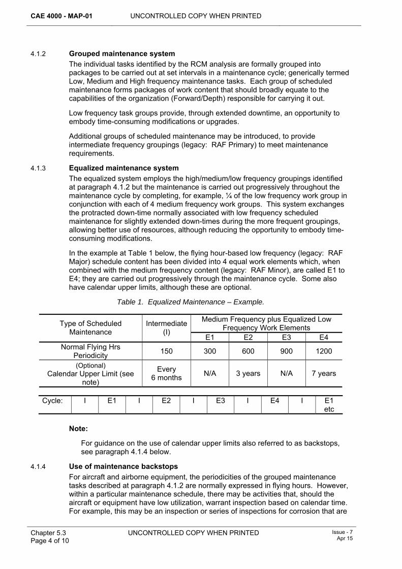
CAE 4000 - MAP-01 UNCONTROLLED COPY WHEN PRINTED
Chapter 5.3 Page 4 of 10
UNCONTROLLED COPY WHEN PRINTED Issue - 7 Apr 15
4.1.2 Grouped maintenance system The individual tasks identified by the RCM analysis are formally grouped into packages to be carried out at set intervals in a maintenance cycle; generically termed Low, Medium and High frequency maintenance tasks. Each group of scheduled maintenance forms packages of work content that should broadly equate to the capabilities of the organization (Forward/Depth) responsible for carrying it out.
Low frequency task groups provide, through extended downtime, an opportunity to embody time-consuming modifications or upgrades.
Additional groups of scheduled maintenance may be introduced, to provide intermediate frequency groupings (legacy: RAF Primary) to meet maintenance requirements.
4.1.3 Equalized maintenance system The equalized system employs the high/medium/low frequency groupings identified at paragraph 4.1.2 but the maintenance is carried out progressively throughout the maintenance cycle by completing, for example, ¼ of the low frequency work group in conjunction with each of 4 medium frequency work groups. This system exchanges the protracted down-time normally associated with low frequency scheduled maintenance for slightly extended down-times during the more frequent groupings, allowing better use of resources, although reducing the opportunity to embody time-consuming modifications.
In the example at Table 1 below, the flying hour-based low frequency (legacy: RAF Major) schedule content has been divided into 4 equal work elements which, when combined with the medium frequency content (legacy: RAF Minor), are called E1 to E4; they are carried out progressively through the maintenance cycle. Some also have calendar upper limits, although these are optional.
Table 1. Equalized Maintenance – Example.
Medium Frequency plus Equalized Low Frequency Work Elements Type of Scheduled
Maintenance Intermediate
(I) E1 E2 E3 E4
Normal Flying Hrs Periodicity 150 300 600 900 1200
(Optional) Calendar Upper Limit (see
note)
Every 6 months N/A 3 years N/A 7 years
Cycle: I E1 I E2 I E3 I E4 I E1
etc
Note:
For guidance on the use of calendar upper limits also referred to as backstops, see paragraph 4.1.4 below.
4.1.4 Use of maintenance backstops For aircraft and airborne equipment, the periodicities of the grouped maintenance tasks described at paragraph 4.1.2 are normally expressed in flying hours. However, within a particular maintenance schedule, there may be activities that, should the aircraft or equipment have low utilization, warrant inspection based on calendar time. For example, this may be an inspection or series of inspections for corrosion that are
UNCONTROLLED COPY WHEN PRINTED CAE 4000 - MAP-01
Issue - 7 Apr 15
UNCONTROLLED COPY WHEN PRINTED Chapter 5.3 Page 5 of 10
embedded in a flying hour-based group of activities. In such cases, a calendar upper limit may be advisable.
4.1.5 Out-of-phase maintenance If, when using a grouped or equalized maintenance system, maintenance activities still do not align to groupings or work blocks, they may be forecast and carried out as individual activities. They are known as out-of-phase operations.
5 Scheduled maintenance latitudes The TAA is responsible for the overall management of scheduled maintenance and must detail arrangements for the management of scheduled maintenance in the Topic 2(N/A/R)1 or the Topic 5 series. In order to meet engineering or operational requirements, scheduled maintenance may be anticipated or deferred within any upper calendar or usage hour limit for that maintenance. In addition, the upper limit may be extended and the scheduled maintenance carried out or deferred within the revised upper limit. When scheduled maintenance is anticipated, due consideration should be given to the increased use of resources, both in terms of manpower and spares. Deferment of scheduled maintenance is not to jeopardise the airworthiness of the aircraft, or contravene other component lifing policies.
The anticipation and deferment latitudes are set out in paragraph 6 and paragraph 7, together with the procedure for anticipating or deferring scheduled maintenance.
The TAA and, in some instances, authorized individuals within the Front Line Command (FLC) may amend the scheduled maintenance latitudes given in the following paragraphs. All agreed latitudes must be promulgated in the SPS. In addition, individual operations may be annotated with the agreed latitudes in the Topic 5A1.
6 Anticipation of scheduled maintenance A TAA may authorize anticipation of scheduled maintenance by any period. A person holding authorization MAP-F351 may anticipate scheduled maintenance by any amount of the relevant periodicity unless otherwise constrained by the TAA, MOD CAM or Delivery Duty Holder’s (DDH’s) Chief Air Engineer (CAE).
7 Deferment of scheduled maintenance To meet engineering requirements or flying commitments, scheduled maintenance may be deferred in accordance with paragraph 7.1 and paragraph 7.2. The TAA may limit or extend the maximum deferral of individual, groups of, or all scheduled maintenance activities. The MOD CAM may further constrain the use of deferments by their units or individuals, but only within any limits set by the TAA. Special Instructions (Technical) (SI(T)) are not to be considered as scheduled maintenance activities when applying latitudes. Any permitted latitudes for SI(T) will be promulgated as part of the instruction in accordance with RA 4457 and Chapter 10.5.4 and Chapter 10.5.5.
7.1 Deferment of scheduled maintenance at Stn/Ship/Units Unless otherwise limited by the TAA or MOD CAM in accordance with paragraph 7 above, or extended by the TAA, an individual holding authority MAP-H71 may defer any scheduled maintenance activity by up to 25% of its periodicity. However, the following constraints apply:
CAE 4000 - MAP-01 UNCONTROLLED COPY WHEN PRINTED
Chapter 5.3 Page 6 of 10
UNCONTROLLED COPY WHEN PRINTED Issue - 7 Apr 15
1 The scheduled maintenance activity must be one for which he is ultimately responsible. If the maintenance activity is one for which he is not ultimately responsible, the agreement of the appropriate individual holding authority level K, MOD CAM and/or TAA must be obtained.
2 Any upper usage hour or calendar limit for the scheduled maintenance being deferred is not to be exceeded.
3 Any more frequent scheduled maintenance is either deferred in its own right or carried out as a penalty scheduled maintenance.
4 Due to the complex lifing of some survival equipment and aircrew equipment assemblies, extensions to scheduled maintenance may only be authorized by the appropriate individual holding authority level K to a maximum of 28 days, with due regard to the details in DAP 108A-0006-2(N/A/R)1.
7.2 Deferment of scheduled maintenance by TAAs The TAA may grant extensions to any scheduled maintenance or calendar or usage upper limit. However, TAAs must record in the relevant Airworthiness Management Group (AMG) report:
1 All extensions exceeding 35% of the scheduled maintenance frequency.
2 The percentage of the fleet with the lowest frequency maintenance activity extended by more than 25%.
TAAs must maintain an auditable record of the decision process for all extensions exceeding 25%.
7.3 Requests for extension All requests for extensions must have an audit trail. Requests for extensions to components must be submitted to the relevant TAA who must liaise with the appropriate commodity Project Team (PT) in assessing the implications to the safety assessment.
7.3.1 Content of request/approval A request for an extension must include the following:
1 Aircraft/component type and Serial Number (CLR reference if applicable).
2 Current airframe hours or component life consumed.
3 Type of maintenance or life due, any extensions already granted and the amount of extension required.
4 Reason for request.
5 Airframe hours or date when maintenance is due or component life expires and, for explosive stores, the storage life and installed life expiry dates.
6 Airframe hours or date when maintenance will be due or component life will expire, if extension granted.
7 Planned date of maintenance or component change.
8 For explosive stores only: Date of Manufacture, Lot Number.
The reply to a request for an extension must be titled EXTENSION REQUEST APPROVAL/REFUSAL, as appropriate, and must be tabulated as follows:
9 Aircraft/component type and Serial Number.
10 Originator’s Reference and DTG.
UNCONTROLLED COPY WHEN PRINTED CAE 4000 - MAP-01
Issue - 7 Apr 15
UNCONTROLLED COPY WHEN PRINTED Chapter 5.3 Page 7 of 10
11 Type of maintenance or life.
12 Percentage/amount of extension granted.
13 When event is due with extension.
14 Additional information.
Note:
Additional information may include supplementary maintenance requirements, MOD Form 760 requirements, disposal instructions, etc.
7.4 Recording requirements A decision to anticipate or defer scheduled maintenance must be recorded on the appropriate MOD Form 700 or equivalent IS raised for the scheduled maintenance. The entry must state the following:
1 The revised timing for the scheduled maintenance.
2 That the condition of the aircraft or equipment justifies the deferment.
3 That where applicable, the appropriately authorised individual responsible for the maintenance activity and/or TAA has agreed the deferment.
The revised timing for the aircraft scheduled maintenance is also to be recorded in the MOD Form 700, in the appropriate forecast log and maintenance record. In the case of deferments, the entry in the forecast log must be made using red ink. If applicable, IS-based recording must be amended in accordance with the appropriate procedures.
7.5 Non-flying periods Under certain conditions it may be justified to temporarily suspend maintenance whilst not formally placing the aircraft in storage. The procedures for preparing an aircraft for a period of non-flying must be prepared and promulgated by the TAA in the Topic 2(N/A/R)1, consulting with the MOD CAM as required. Such procedures must include items that must be carried out at the allotted time and those calendar activities that must be carried out prior to the aircraft or equipment re-entering service.
8 Maintenance in periods of abnormal usage The TAA must specify in the appropriate Technical Information (TI) any additional preventive maintenance required to maintain the condition of aircraft or equipment being operated under adverse conditions, at below-average utilization rates, or which are not flown for extended periods. Examples might include:
1 Cold and hot weather operations. Further details are at Chapter 5.5.
2 Operations in saline environments.
3 Operations in high humidity climates.
4 Operations in continuous high ultra violet conditions.
5 Operations in desert or dusty environments.
6 Embarked operations.
7 Aircraft storage in accordance with JAP 100V-21.
As part of his role in developing the maintenance programme, a MOD CAM must also consider the need for additional maintenance requirements during periods of
CAE 4000 - MAP-01 UNCONTROLLED COPY WHEN PRINTED
Chapter 5.3 Page 8 of 10
UNCONTROLLED COPY WHEN PRINTED Issue - 7 Apr 15
abnormal usage when he assesses such usage as bringing additional risk to the aircraft’s continuing airworthiness. Such additional requirements must be proposed to the TAA in accordance with RA 4947(1)(a).
8.1 Aircraft not flown for extended periods Unless the procedures detailed in JAP 100V-21 have been applied, the condition of aircraft not flown for 28 days must be assessed to determine the anti-deterioration measures to be taken. A re-assessment must be carried out each subsequent 28 days.
In addition to the anti-deterioration measures published in the platform TI, the following non-exhaustive list of general principles must also be considered when carrying out the assessment:
1 Fill all systems to the levels detailed in the aircraft TI. Note that for vented systems, sufficient air space must be left to allow for any expansion of the fluid caused by variations in ambient temperature.
2 Drain and remove drop tanks and ferry tanks from the aircraft.
3 Depressurize those systems pressurized by pumps, accumulators, etc.
4 Raise aircraft on jacks or trestles to reduce the stress on undercarriage components and fluids.
5 Test fuels and lubricants as detailed in JSP 317.
6 Remove those items that require calendar-based maintenance (eg batteries, first aid kits and explosive stores).
7 Apply short-term reserve standards as detailed in JAP 100V-21.
9 Contingency maintenance (CTY) 9.1 Principle
In operational or combat conditions an ODH may decide to implement CTY. Whilst CTY may improve aircraft availability in the short term it will likely require additional ODH risk management. CTY is achieved by one of or a combination of the following:
1 Stopping certain maintenance activities.
2 Decreasing the frequency of scheduled maintenance activities.
3 Allowing greater latitude in the deferment of activities.
9.2 Content of CTY schedule The TAA must annotate those items of preventive maintenance in the Master Maintenance List (MML) that require being included in CTY.
9.3 Implementation and termination of CTY The ODH, in consultation with the TAA, must determine the procedures by which CTY may be implemented and terminated. The TAA must publish their arrangements for CTY in the Topic 2(N/A/R)1, with a summary in the SPS. When formulating the philosophy for a platform, the following points should be considered by the TAA:
1 The requirements to carry out or suspend any SI(T).
2 The actions to be taken on modifications, including Service Modifications.
3 The procedure for reverting from CTY back to the normal scheduled maintenance cycle.
UNCONTROLLED COPY WHEN PRINTED CAE 4000 - MAP-01
Issue - 7 Apr 15
UNCONTROLLED COPY WHEN PRINTED Chapter 5.3 Page 9 of 10
4 Any changes required in the documentation procedures during CTY.
5 The policy for component maintenance during CTY.
When considering the implementation of CTY, ODHs must ensure their maintenance organizations consider the following:
1 During periods of tension or build-up, every effort should be made to maximize the opportunities for scheduled maintenance and component changes, if necessary by anticipating scheduled maintenance activities.
2 The imposition of CTY will place additional emphasis on the activities carried out during flight servicing; therefore, personnel must apply extra vigilance during these tasks.
10 Zonal surveys Zonal surveys are a product of RCM analysis and are a general visual examination of a specified zone, carried out before and after cleaning, to detect damage, deterioration and discrepancies and assess the general condition of the zone. They are an integral and important element of scheduled maintenance that must be carried out in order to preserve aircraft by identifying and recording all visible faults and detecting any dormant faults that may pose a threat through environmental and accidental damage to aircraft structural and systems integrity. Zones may contain structure, systems, equipment and components that are already subject to individual directed maintenance tasks identified elsewhere in the maintenance schedule.
Zonal surveys look for faults, multiple faults and the interaction of faults. A single fault may be constant seepage: a small fluid leak that may go unnoticed between replenishments, although the cumulative contamination damage induced in adjacent equipment, wiring or structure may be substantial. Similarly, the failure of one cable loom support clip may seem inconsequential; but a multiple failure would occur if several clips fail over a period of time and the loom detached and obstructed a control mechanism, with potentially serious consequences.
Certain failures can be attributed to the combination and interaction of separate system faults and failure modes, such as chafed cable looms, hot gas leaks from damaged/poorly maintained ducts/pipes coming into contact with flammable vapours from leaking pressurized systems. JAP(D) 100C-22 describes the principles for developing zonal surveys.
10.1 Training and authority levels DDH CAEs and TAAs responsible for on-aircraft maintenance must ensure that their personnel are trained and authorized as necessary to act as zonal survey instructors and zonal surveyors on Stns/Ships/Units.
The authority levels and training requirements for zonal surveys are as follows:
1 Personnel required to act as Unit Zonal Survey Training Instructors within Air Cmd and JHC must have completed the revised Zonal Survey Instructor training course, CN3209, and hold authorization MAP-C75.
2 Personnel required to carry out self-supervised zonal surveys must have completed zonal survey training at their Stn/Ship/Unit and hold authorization MAP-D73.
3 Personnel required to carry out supervised zonal surveys must have completed zonal survey training at their Stn/Ship/Unit and hold authorization MAP-B74.
CAE 4000 - MAP-01 UNCONTROLLED COPY WHEN PRINTED
Chapter 5.3 Page 10 of 10
UNCONTROLLED COPY WHEN PRINTED Issue - 7 Apr 15
Notes:
1 The revised Zonal Survey Instructors training course is sponsored by HQ Air. Courses are being delivered by DSAE Cosford instructors at selected Air Cmd and JHC units. RAF attendees will be awarded the TQA Q Zonal Fam.
2 For RN personnel, the zonal survey training course (TEM 979) is delivered by specialist instructors at RNAS Culdrose and RNAS Yeovilton followed by aircraft-type specific ‘hot spot’ briefs at the TAS.
11 Condition surveys The procedure for aircraft condition surveys must be determined and promulgated by the TAA.
12 Condition-based maintenance Where adequate and realistic condition-monitoring techniques, eg HUMS, are available for a particular item, the TAA must apply condition-based maintenance to the item in preference to scheduled visual examinations, manual testing and routine component replacement.
13 References This chapter refers to the following publications:
1 JAP(D) 100C-22 – Guide to Developing and Sustaining Preventive Maintenance Programmes.
2 JAP 100V-21 – Aircraft Storage.
3 AP 108 Series 0001-5F(N)s – Survival Equipment Bay Maintenance Schedules.
4 DAP 108A-0006-2(N/A/R)1 – Survival Equipment and Aircrew Equipment Assemblies - Support Authority General Orders.
5 Topic 2(N/A/R)1 – General Orders and Special Instructions.
6 Topic 5A1 – Master Maintenance Schedule.
7 Topic 5W – Summary of Component Repair Plans.
8 RA 4947 – Continuing Airworthiness Management – MRP Part M Sub Part G.
UNCONTROLLED COPY WHEN PRINTED CAE 4000 - MAP-01
Issue - 7 Apr 15
UNCONTROLLED COPY WHEN PRINTED Chapter 5.3.1 Page 1 of 14
Chapter 5.3.1
Lifing of Aerospace Components
TABLE OF CONTENTS Paragraph
Page
1 General ............................................................................................................... 1 1.1 Introduction.......................................................................................................... 1 1.2 Associated publications....................................................................................... 2 1.3 Applicability ......................................................................................................... 2 2 Regulatory Governance.................................................................................... 2 2.1 Regulatory Cross-reference ................................................................................ 2 2.2 Additional Information.......................................................................................... 2 3 Component failure............................................................................................. 3 3.1 Failure modes...................................................................................................... 3 3.2 Critical failure mode............................................................................................. 3 3.3 Critical components............................................................................................. 3 4 Identification of components to be lifed ......................................................... 3 5 Initial assessment of component lives............................................................ 3 5.1 Components justifying fatigue or textile lives ...................................................... 4 5.2 Components subject to deterioration other than fatigue or textile reasons ......... 4 5.3 Approval of component maintenance philosophy................................................ 4 6 Promulgation of component lives ................................................................... 4 6.1 Component life abbreviations.............................................................................. 5 6.2 Changes to component lives ............................................................................... 5 6.3 Penalty Factor Numbering (PFN) ........................................................................ 5 7 Review of lifing measures ................................................................................ 6 7.1 Review of provisional lives .................................................................................. 6 7.2 Procedures for life assessment sampling programmes ...................................... 6 7.3 Review of lives allotted on a non-provisional basis ............................................. 7 8 Recording of life consumption ........................................................................ 7 8.1 Engineering Record Cards (ERC) ....................................................................... 8 8.2 Reporting of component change and modification/repair.................................. 10 9 Latitudes to component life ........................................................................... 10 9.1 Type Airworthiness Authority (TAA) responsibilities.......................................... 10 9.2 Anticipation of component lives at Stn/Ship/Unit............................................... 11 9.3 Extension of component lives at Front Line Command (FLC) or Stn/Ship/Unit. 11 10 Unlifed components liable to fatigue damage.............................................. 12 11 References ....................................................................................................... 12
1 General 1.1 Introduction
Most failures of aerospace components occur in an unpredictable manner that is not related to usage; such failures can only be dealt with by replacing components as and when they become unserviceable. There are, however, some components, usually mechanical ones, for which the probability of failure increases with age and usage. Two groups of such components justify replacement or removal for maintenance on a predetermined basis. They are:
CAE 4000 - MAP-01 UNCONTROLLED COPY WHEN PRINTED
Chapter 5.3.1 Page 2 of 14
UNCONTROLLED COPY WHEN PRINTED Issue - 7 Apr 15
1 Components for which airworthiness and safety considerations require that in-use failure should be minimized or eliminated.
2 Components for which the timely replacement or removal for maintenance would significantly increase system availability or decrease overall costs.
Components that belong to either or both groups are subject to the lifing procedures described in this chapter.
1.2 Associated publications This chapter is associated with the following publications:
1 JSP 482 – Ministry of Defence Explosives Regulations
2 RA 4605 and Chapter 13.5 – Compressed Gas Cylinders Having an Airborne Application.
3 Acquisition Operating Framework (AOF).
4 DAP 108A-0006-2(N/A/R)1 – Survival Equipment and Aircrew Equipment Assemblies.
1.3 Applicability This chapter defines the lifing Acceptable Means of Compliance (AMC), Guidance Material (GM) and associated processes for all aerospace components used in the Military Air Environment (MAE), with the exception of:
1 Aero-engines, modules and accessories, whose lifing details are published in AP 100E-01B or other platform specific publication.
2 Explosives and aerospace components that contain explosives or ancillaries (eg suspension lugs), whose lifing details are contained in RA 4656 and Chapter 14.6.
2 Regulatory Governance 2.1 Regulatory Cross-reference
This chapter supports:
1 RA 4204.
2.2 Additional Information In ascertaining whether or not lifing is applied to an aerospace component, the significance of the component must first be determined. The selection processes for significant items, including Structurally Significant Items (SSI), can be found in RA 5720 and JAP(D) 100C-22. A significant item should be given lifing parameters where it meets the further criteria identified at paragraph 4. Components meeting these criteria must be allocated a component life, measured in usage. Type Airworthiness Authorities (TAAs) responsible for assessing and promulgating component lives must use the criteria and procedures detailed in this chapter.
Note:
Authorizing the life of aerospace components is the responsibility of the TAA for the air system on which the component is installed. However, commodity Project Teams (PTs) may be required to assess the lifing details of components for which they are responsible in support of the TAA; in this instance, they must also follow the criteria and procedures detailed in this chapter prior to presenting their evidence to the TAA for final authorization.
UNCONTROLLED COPY WHEN PRINTED CAE 4000 - MAP-01
Issue - 7 Apr 15
UNCONTROLLED COPY WHEN PRINTED Chapter 5.3.1 Page 3 of 14
3 Component failure 3.1 Failure modes
The term ‘failure mode’ refers to the process that leads to the ultimate failure of a component. Typical failure modes include fatigue, overload, ageing (of explosives or textiles), avionic and mechanical wear, cracking, corrosion and general deterioration. A component can suffer from one or more failure modes.
3.2 Critical failure mode The term ‘critical failure mode’ refers to a failure mode that causes a failure likely to result in the loss of the air system concerned, loss of airworthiness or likely to endanger the life of any person concerned with its operation or maintenance.
3.3 Critical components A significant item that has a critical failure mode is described as a ‘critical component’. The term ‘critical component’ is not applied to components that are duplicated in order to maintain the integrity of the critical function of a system or sub-system.
4 Identification of components to be lifed The TAA must determine which failure modes are applicable to each component installed on their air system, consulting with Design Organizations (DOs), Original Equipment Manufacturers (OEMs), commodity PTs and specialist agencies as necessary. Once identified as a significant item, TAAs must apply lifing to the component when it satisfies both of the following conditions:
1 The component meets either of the following criteria:
1.1 Incipient failure, which cannot be detected using condition-monitoring techniques, or the use of such techniques, will impose an unacceptable maintenance penalty.
1.2 It is known or expected that there will be an unacceptable increase in probability of failure after the component has been in service for some time.
2 The component also meets either of the following criteria:
2.1 Failed components significantly affect airworthiness or safety of the aerospace, or the safety of any person concerned with its operation or maintenance.
2.2 If allowed to fail, components would cause major economic or maintenance penalties.
The lifing of components has severe cost implications both in terms of the scheduled maintenance effort involved and additional provisioning to provide a pool of assets to sustain the repair loop. Therefore, when a decision is made to life a significant item whose failure mode is not critical, the benefits either in terms of increased availability or in through-life support costs must clearly outweigh the other factors involved.
5 Initial assessment of component lives After identifying components to be lifed, TAAs must assess, for each failure mode that merits allotment of a life, the most cost-effective activity (maintenance, reconditioning or scrapping) that will minimize the occurrence of failures in that mode most effectively. Where a component has more than one failure mode, a different
CAE 4000 - MAP-01 UNCONTROLLED COPY WHEN PRINTED
Chapter 5.3.1 Page 4 of 14
UNCONTROLLED COPY WHEN PRINTED Issue - 7 Apr 15
maintenance activity may be required for each mode, giving it a number of lives, eg a bay maintenance life, a recondition life and a scrap life.
5.1 Components justifying fatigue or textile lives The assessment of components for fatigue or textile failure modes is carried out using data drawn from testing, analysis, calculation, surveillance or experience that determine a failure will occur at a predictable stage within the maximum life envisaged for the system.
5.2 Components subject to deterioration other than fatigue or textile reasons Components justifying lifing other than for fatigue or textile considerations are dealt with as follows:
1 The TAA must assess in-service component lives by applying the procedures detailed in JAP(D) 100C-22.
2 The assessment of lives for new components is based on the design characteristics of the item and knowledge of the failure modes that the life is protecting. This assessment may be provided or based on information from either the DO or other specialist organization, or be based on experience gained using the same or similar components on other platforms.
Where, through lack of necessary data, a TAA is unable to allot lives to in-Service components in accordance with JAP(D) 100C-22, or to new components in accordance with the DO’s recommendation, the components must be allotted a provisional life. The components concerned are then to be subject to a review of lifing measures as described at paragraph 7 or, if newly developed, to continued qualification testing. The assessment of provisional lives may affect expenditure on initial spares provisioning and repair facilities. It is therefore essential that any provisional lives allotted are the longest lives that can reasonably be permitted in the circumstances.
5.3 Approval of component maintenance philosophy The responsibility for approving the maintenance philosophy for individual components or equipments used on an air system rests with the TAA. Commodity PTs may be required to establish individual component lives in accordance with the procedures in paragraph 4 and paragraph 5 in support of the TAA, but it is the TAA who is responsible for authorizing the lifing of components installed on their air system. Due to the cost involved in lifing components, the TAA, when deciding the life of a significant item in a failure made that is not critical, must be confident that the expected improvement in availability or in-Service life support costs will outweigh other considerations.
6 Promulgation of component lives The TAA must ensure that component lives are published in the Component Life Register (CLR) and Component Replacement List (CRL) of the relevant Topic 5A1 or equivalent publication and, if appropriate, the Topic 5K, in accordance with the requirements of RA 4351 and Chapter 8.1.1. In the case of lifed components with a multi-user application, the commodity PT must ensure that the relevant TAAs are advised of any revised lifing requirements for their subsequent authorization.
UNCONTROLLED COPY WHEN PRINTED CAE 4000 - MAP-01
Issue - 7 Apr 15
UNCONTROLLED COPY WHEN PRINTED Chapter 5.3.1 Page 5 of 14
6.1 Component life abbreviations
When compiling or amending CRLs and CLRs, the following abbreviations must be used:
1 Critical Failure Mode – C.
2 Fatigue life – F.
3 Explosive life – E.
4 Textile life – T.
5 Bay maintenance life – BM.
6 Reconditioning life – R.
7 Scrap life – Scrap.
8 Provisional life – P.
9 Shelf Life – SL.
Notes:
1 The annotation for shelf life indicates those components that require periodic maintenance whilst held in storage. The Regulation, AMC, GM and associated processes for the shelf life and storage of piece-part spares, including elastomerics, is covered in RA 4210 and Chapter 5.8 and in JSP 886.
2 The introduction of Integrated Operational Support (IOS) contracts across the MAE has highlighted differences in MOD and Industry terminology to define both ’off-aircraft’ maintenance and ’overhaul’. The respective MOD abbreviations ‘BM’ and ’R’ may still be used when compiling or amending CRLs and CLRs, but if the particular PT/IOS contract BM and/or R definition requires further clarification it must be published in the relevant Topic 5A1 – special consideration should be given to circumstances where multiple companies provide support. Differences in definition of BM and R between the companies are to be annotated within the Topic 5W accordingly.
6.2 Changes to component lives The promulgation of amendments to published component lives must be managed in accordance with RA 4810 and Chapter 8.2.1 or Chapter 8.2.2. Continuing Airworthiness Management Organizations (CAMOs) may be provided with advanced notification of the changes by Routine Technical Instruction (RTI); see RA 4457 and Chapter 10.5.3. Advanced notification may allow CAMOs to instruct relevant maintenance organizations to change and/or quarantine components pending the receipt of formal amendment to the Topic 5A1. Advanced notification action is particularly important where component lifing details are contained electronically (LITS, GOLDesp, etc) and the system affords TAAs the ability to amend details centrally. In the case of lifed components that are the responsibility of a commodity PT, that PT must ensure that all relevant TAAs are advised of any revised lifing requirements for their subsequent authorization.
6.3 Penalty Factor Numbering (PFN) Where the same component may be used on different marks or types of aircraft, there may be a requirement to factor the life of the component due to differing operating conditions. Where component lives have a usage factor applied, the Penalty Factor Number (PFN) for each application must be detailed in the aircraft
CAE 4000 - MAP-01 UNCONTROLLED COPY WHEN PRINTED
Chapter 5.3.1 Page 6 of 14
UNCONTROLLED COPY WHEN PRINTED Issue - 7 Apr 15
Topic 5A1 (CRL and/or CLR). Where a TAA considers that an explanation of the management of PFNs is required, it must be contained in the aircraft Topic 2(N/A/R).
7 Review of lifing measures Components are assessed during the introduction into service and a life is established. In cases where there is insufficient evidence to determine a lifing philosophy for a particular component, a provisional life may be promulgated. Components with provisional lives are shown with a suffix (P) in the CRL and may be subject to life sampling procedures. Subsequently, component lives must be re-assessed as part of an equipment’s schedule review process.
7.1 Review of provisional lives TAAs must arrange for every component to which a provisional life has been allotted to be subjected to one of the following procedures in order to confirm, extend or remove the provisional life:
1 Continued qualification testing under arrangements made by the TAA; normally this is applicable to newly developed components only and is undertaken by the DO or OEM.
2 A life assessment sampling programme conducted in accordance with paragraph 7.2 or other instructions specified by the appropriate TAA.
Note:
This paragraph does not apply if it is known that modification action, which will affect the provisional life, is either in progress, or planned, or that the remaining in-Service life of the aerosystem does not justify such action.
The review procedure must be continued or repeated until either the optimum life is established or it is clear that lifing restrictions can be removed.
When continued qualification testing is undertaken, the TAA(s) concerned should consider the findings and recommendations of the investigating agency and determine what change in the life, if any, should be authorized. If the qualification testing will be further continued any revised life authorized is still to be a provisional life.
7.2 Procedures for life assessment sampling programmes 7.2.1 TAA responsibilities
When a life assessment sampling programme is undertaken, the appropriate TAA must:
1 Determine the sampling requirement, taking into account the engineering features and supply status of the component concerned and the total numbers involved; normally a sample batch should consist of at least 6 items.
2 Arrange for publication of the sampling requirement in the Mandatory Fault Reporting Instructions (MFRIs), details of which are at RA 4814 and Chapter 7.5.1. If the TAA requires notifying that an item is approaching its provisional life, include this in the MFRI.
3 Identify the most appropriate agency to carry out the examination.
4 Authorize a temporary life extension for components still installed in order to avoid further component removals whilst awaiting full reports on the condition of the sample batch. Such a temporary life extension must be notified by RTI to
UNCONTROLLED COPY WHEN PRINTED CAE 4000 - MAP-01
Issue - 7 Apr 15
UNCONTROLLED COPY WHEN PRINTED Chapter 5.3.1 Page 7 of 14
users; details of the promulgation of changes to component lives are given at paragraph 6. Temporary extensions should normally be long enough to allow all installed components to remain in place until the action required by item 8 below can be completed.
5 Arrange for the rapid assessment and issue of reports, thereby minimizing the requirement for temporary life extensions.
6 Suspend the requirement for further sampling and arrange for MFRIs to be amended accordingly.
7 When a Service unit undertakes component examinations, forward copies of the MOD F761 examination reports to the relevant DO.
8 When sufficient information has been obtained from examination of the sample batch to enable a decision to be made, the TAA must take whichever of the following actions is appropriate:
8.1 Allot a new provisional life to the component and issue revised MFRI requirements.
8.2 Allot a non-provisional life to the component. If this life is less than that covered by a temporary extension authorized under the terms of note 4 above, the TAA is also to decide whether any installed components that have exceeded the newly-determined non-provisional life must be replaced immediately.
8.3 Remove life limitations from the component.
9 Irrespective of the procedure adopted for reviewing the provisional life, promulgate any change in component life in accordance with paragraph 6.
7.2.2 Stn/Ship/Unit responsibilities A Stn/Ship/Unit that removes a component in response to an MFRI life sampling requirement must:
1 Inform the TAA when a component is approaching its provisional life.
2 Complete an MOD Form 760 in accordance with the requirements of RA 4814 and Chapter 7.5.1. The MOD F760 must be annotated ‘For life sampling examination’.
3 Despatch the component as instructed in the MFRI.
7.3 Review of lives allotted on a non-provisional basis As part of each maintenance schedule revision, the TAA must review formally, in accordance with JAP(D) 100C-22, all available data pertaining to those component lives that it has authorized on a non-provisional basis. The aim of such reviews must extend lives to the maximum practicable or, where appropriate, to remove life limitations altogether. If the lives of the components concerned are based on considerations of fatigue, or of ageing of explosives or textiles, TAAs must conduct their reviews in accordance with any applicable specialist regulations and in consultation with the DO and specialist agencies concerned. On completion of reviews, TAAs must promulgate any changes in lives in accordance with paragraph 6.
8 Recording of life consumption A record of life consumed must be maintained for every lifed component. This record is normally kept within the aircraft MOD Form 700C; however, TAAs may require that some components have their engineering histories recorded on Engineering Record
CAE 4000 - MAP-01 UNCONTROLLED COPY WHEN PRINTED
Chapter 5.3.1 Page 8 of 14
UNCONTROLLED COPY WHEN PRINTED Issue - 7 Apr 15
Cards (ERCs). Instructions for the use of ERCs are contained in MAP-02. Alternatively, a record of life consumed may be maintained, if appropriate, wholly by an electronic system and a hard copy of the ERC printed when required.
8.1 Engineering Record Cards (ERC) On introduction into Service, the TAA must determine whether a component requires an ERC. The requirement for an ERC is normally determined during the Logistic Support Analysis process. After acceptance into service, the TAA assumes responsibility for managing the ERCs associated with the equipment or assembly. The TAA must:
1 Specify ERC requirements and promulgate them in the relevant section of the Topic 5A1.
2 Ensure that components requiring ERCs have been allocated unique serial numbers.
3 Issue instructions on the disposal of ERCs when aircraft are withdrawn from Service. Because of the possibility of spares recovery programmes, ERCs are normally to be retained until all aircraft of the particular type or types have been withdrawn from Service or the item itself is scrapped.
The TAA is responsible for ensuring ERC requirements are published in the Topic 5A1, including details of the type of ERC to be used for each component.
8.1.1 Mandatory requirement for ERCs ERCs must be authorized for equipment in the following categories:
1 An assembly, sub-assembly or component that is allocated a fatigue life.
2 An item whose life is expressed in more than one parameter, eg flying hours, landings and pressurization cycles.
3 An item that requires periodic calibration or proof testing.
4 Aero-engines, modules and accessories.
To provide traceability, supply records for components for which ERCs have been authorized must be annotated.
8.1.2 Multi-national aircraft components Components from multi-national aircraft may have differing national requirements for lifing and recording items that are subject to pool repair. Engineering Integrated Logistic Support Managers and TAAs involved in multi-national projects must make every effort to reach agreement for common documentation. Reference must be made to MAP-02 when it is proposed to introduce a new multi-national ERC.
8.1.3 Components with fatigue lives aligned to platform/assembly life Certain dynamic and fixed structural components have fatigue lives that are aligned with the platform/assembly fatigue life and therefore do not require ERCs. However, such components may subsequently be re-lifed due to a change in operational use or design philosophy and it will then become necessary to assess any consumed life. This process is likely to be wasteful if an accurate assessment of consumed life cannot be made. Furthermore, if the assessed life exceeds the imposed life, the component will have to be scrapped. To obviate these problems, TAAs must consider raising ERCs for specified components that, initially, have ‘unlimited’ lives.
UNCONTROLLED COPY WHEN PRINTED CAE 4000 - MAP-01
Issue - 7 Apr 15
UNCONTROLLED COPY WHEN PRINTED Chapter 5.3.1 Page 9 of 14
8.1.4 Control of ERCs ERCs constitute Part D of the aircraft MOD Form 700 and should, where possible, be retained with the MOD Form 700C on the user unit. When a component is removed for maintenance, the ERC must be completed with details of the removal and the life consumed. The ERC is then to be attached to the MOD F731 and dispatched with the item.
8.1.5 Loss of ERCs The loss of an ERC must be reported to an authority level J, who must quarantine the associated equipment, instigate a full investigation and report his findings to the TAA and MOD CAM. If after the investigation the ERC is not found, the TAA must authorize the issue of a duplicate ERC (RA 4302 and Chapter 7.2.1 paragraph 4.1 refers), or issue disposal instructions as necessary.
8.1.6 Types and relationship of ERCs ERCs are designed to complement each other when used in connection with major assemblies such as airframes, whilst specific ERCs required to support specific aircraft and associated equipment are listed in the relevant Topic 5A1. The relationship between various ERCs is given below.
8.1.6.1 Airframe The master ERC for an airframe is the MOD F744 – Airframe Record Card. The associated ERCs are:
1 MOD F745 – Maintenance and Repair Record Card.
2 MOD F746 – Modification Embodiment Record Card.
3 MOD F747 – SI/STI Record Card.
4 MOD F747A series – SI Applications Record.
5 MOD F748 – Miscellaneous Record Card.
6 MOD F751 series – Aircraft Basic Weight and Moment Record Card.
7 MOD F753 – Inspection Test and Modification Certificate.
8.1.6.2 Assembly/ECU The master ERC for an assembly or ECU is the MOD F749 or MOD F749B series – Assembly Record Card. The associated ERCs are:
1 MOD F753 – Inspection Test and Modification Certificate.
2 MOD F749(ECLS) – Engine Cyclic Life Supplement.
8.1.6.3 Component An ERC for a component will be selected from one of the following:
1 MOD F735 – Component Log Card (Anglo-French).
2 MOD F735A – Component Record Card.
3 MOD F735B – Engineering Record Card (Tri-National).
A component will also have a MOD F753 – Inspection Test and Modification Certificate.
CAE 4000 - MAP-01 UNCONTROLLED COPY WHEN PRINTED
Chapter 5.3.1 Page 10 of 14
UNCONTROLLED COPY WHEN PRINTED Issue - 7 Apr 15
8.2 Reporting of component change and modification/repair 8.2.1 Component change reporting using Management Information – Engineering
Information Services (MI-EIS) In addition to maintaining records of component lives, Stns/Ships/Units who use MI-EIS for maintenance data recording must report removals and installations of lifed components, other than those that are solely calendar life expired, on the appropriate form in the MOD Form 707 series. In addition, certain fatigue-lifed assemblies are noted in blocks on the aircraft Flying Log and Fatigue Data Sheet (MOD Form 725); such blocks must be annotated in accordance with the instructions contained in the relevant MOD Form 799/4F (platform).
8.2.2 Modification/repair of fatigue-lifed components When a fatigue-lifed component (life in Fatigue Index, Fatigue Hours or Damage Index) has been subject to modification or repair that affects the fatigue life, the fatigue life expired at the time of this action must be recorded on the ERC. In addition, for aircraft with fatigue analysis carried out by Management Information – Faults and Fatigue (MI F&F), they must be informed when the modification/repair is carried out. MI F&F will then inform the maintenance organization of the latest value of fatigue life consumed on the component. The maintenance organization must enter the details provided on the appropriate ERC.
9 Latitudes to component life To facilitate maintenance planning and avoid unnecessary restrictions on system availability, some flexibility in the application of authorized lives to individual components is essential. The latitudes permissible for aerospace components covered by this chapter (see paragraph 1.3) are detailed in paragraphs 9.1, 9.2 and 9.3 below. These latitudes may be limited or prohibited either by the appropriate specialist regulations, by individuals holding the appropriate authority within the Front Line Command or the TAA.
9.1 Type Airworthiness Authority (TAA) responsibilities 9.1.1 Variation and restriction of life anticipation and extension limits
A TAA may, after considering all the relevant factors, authorize variations in the application of life anticipations and extensions on components, other than those subject to a fatigue life, see paragraph 9.1.2, that are either greater in magnitude or more widely applicable than those detailed in paragraphs 9.2 and 9.3. When circumstances dictate, a TAA may also restrict or prohibit the application of extensions. TAAs must publish details of such latitude variations in their Support Policy Statement in the Topic 2(N/A/R)1 or, where applicable, in the appropriate specialist publication.
9.1.2 Life extension of components subject to fatigue life For items subject to a fatigue life, the TAA must determine if it is an SSI or a component, the failure of which would jeopardize the aircraft. In such cases any extension to the fatigue life is limited to 1%. Further details on SSI and lifed components are given in RA 5720 and JAP(D) 100C-22. An auditable decision process, recording advice provided by the DO and, risk assessments made, must support any extension granted under the terms of this paragraph. If, when assessing a fatigue-lifed component for life extension, doubt exists on the status or significance of the component, the TAA must seek guidance from Military Aviation Authority Certification Structures & Aircraft Design Standards.
UNCONTROLLED COPY WHEN PRINTED CAE 4000 - MAP-01
Issue - 7 Apr 15
UNCONTROLLED COPY WHEN PRINTED Chapter 5.3.1 Page 11 of 14
9.2 Anticipation of component lives at Stn/Ship/Unit An authority level J may authorize the anticipation of any component life expiry. Anticipation of maintenance activities has resource implications; therefore, when anticipating a component life expiry, every effort must be made to ensure that the action does not result in a shortage of components.
9.3 Extension of component lives at Front Line Command (FLC) or Stn/Ship/Unit
9.3.1 Provisional life The extension of a component subject to a provisional life is prohibited at FLC or Stn/Ship/Unit level.
9.3.2 Fatigue life The extension of a component fatigue life is prohibited at FLC or Stn/Ship/Unit level.
9.3.3 Explosive life The extension of an explosive life at FLC or Stn/Ship/Unit level is prohibited regardless of whether it applies to either critical or non-critical failure modes; RA 4656 and Chapter 14.6 refer.
9.3.4 Textile life 1 The extension of textile scrap lives allotted to safeguard against critical failure
modes of components is prohibited at FLC or Stn/Ship/Unit level.
2 An authority level J may authorize extensions of up to 10% of textile scrap lives allotted to safeguard against non-critical failure modes of components.
9.3.5 Bay maintenance life An authority level J may authorize extensions to bay maintenance lives as follows:
1 Up to 10% on components with lives allotted to safeguard against critical failure modes.
2 Up to 25% on components with lives allotted to safeguard against non-critical failure modes.
9.3.6 Reconditioning life An authority level J may authorize extensions of up to 10% on reconditioning lives allotted to safeguard against either critical or non-critical failure modes.
9.3.7 Scrap life When the extension of a scrap life is being contemplated, the reason for the lifing must be fully understood. The scrap life may have been applied for fatigue reasons and not for economic or reliability concerns: therefore, an authority level J may:
1 Not authorize the extension of scrap lives allotted to safeguard against critical failure modes of components.
2 Extend components by up to 10% except where extensions would cause fatigue lives, allotted to safeguard against non-critical failure modes, to be exceeded.
Notes:
1 Before extending a component life, a check must be made as to whether that component contains an explosive sub-component. If it does, the extension granted is not to compromise the life of the explosive component; see RA 4656 and Chapter 14.6.
CAE 4000 - MAP-01 UNCONTROLLED COPY WHEN PRINTED
Chapter 5.3.1 Page 12 of 14
UNCONTROLLED COPY WHEN PRINTED Issue - 7 Apr 15
2 If a component, which is extended to align with an aircraft/equipment extension, is subsequently removed from the aircraft/equipment the extension is invalidated.
10 Unlifed components liable to fatigue damage Some components that have a critical function and are susceptible to fatigue damage, and which may or may not have been separately provisioned, are not normally lifed because:
1 Their fatigue lives equal or exceed those of their parent assemblies, and
2 They are not expected, in the course of normal maintenance, to be transferred between parent assemblies, eg between airframes.
If, exceptionally, such a component is transferred from its original parent assembly to another, there is an obvious risk that the fatigue life of the component may be exceeded. To safeguard against this eventuality, TAAs must identify such components and arrange for them to be listed in the preliminary pages of the Topic 5A1 under the heading ‘Log Card Required on Transfer between Parent Assemblies’. Where such components need to be transferred from aircraft that are being, or have been, withdrawn from Service, CAMOs, in accordance with RA 4947(1)g, must ensure that fatigue records for the donor aircraft are retained for as long as such components may be required.
If a listed component, or a component which the MOD CAM believes ought to have been listed, is transferred between parent assemblies, the CAMO must:
1 Open an ERC for the component and, pending action by the TAA, assign to the component a fatigue life equal to that of the parent assembly.
2 Determine and enter on the ERC the fatigue life consumed by the component at the time of transfer, together with the aircraft tail number or other identification of the donor assembly and, where possible, the date the component was fitted. In the absence of any other information, the component life consumed must be assumed to be that of the donor assembly and the ERC must be annotated ‘estimate’.
3 Report details of the transfer to the TAA.
The TAA must consider, assess and, where appropriate, promulgate a life for the component. Any component life so promulgated must be annotated ‘Log card required on transfer between parent assemblies’. A TAA who decides not to promulgate a life must provide the CAMO reporting the transfer with instructions on the lifing or other action to be taken.
11 References This chapter refers to the following publications:
1 JAP (D) 100C-22 – Guide to Developing and Sustaining Preventive Maintenance Programmes.
2 AP 100E-01B – Handbook of Removal Criteria for Aero engines, Accessories and Ancillaries.
3 JSP 886 – The Defence Logistics Support Chain Manual
4 MAP-02 – Maintenance and Airworthiness Process Supplement – MOD Form 700 Series of Forms.
UNCONTROLLED COPY WHEN PRINTED CAE 4000 - MAP-01
Issue - 7 Apr 15
UNCONTROLLED COPY WHEN PRINTED Chapter 5.3.1 Page 13 of 14
5 Topic 2(N/A/R) – General Orders, Special Instructions and Modifications.
6 Topic 5A1 – Master Maintenance Schedule.
7 Topic 5K – Schedule of Component Lives (RN only).
8 RA 4947 - Continuing Airworthiness Management - MRP Part M Sub Part G.

CAE 4000 - MAP-01 UNCONTROLLED COPY WHEN PRINTED
Chapter 5.3.1 Page 14 of 14
UNCONTROLLED COPY WHEN PRINTED Issue - 7 Apr 15
Intentionally Blank for Print Pagination
UNCONTROLLED COPY WHEN PRINTED CAE 4000 - MAP-01
Issue - 7 Apr 15
UNCONTROLLED COPY WHEN PRINTED Chapter 5.4 Page 1 of 6
555
Chapter 5.4
Corrective Maintenance
TABLE OF CONTENTS Paragraph
Page
1 General ............................................................................................................... 1 1.1 Introduction.......................................................................................................... 1 1.2 Associated publications....................................................................................... 1 2 Regulatory Governance.................................................................................... 1 2.1 Regulatory Cross-reference ................................................................................ 1 3 Change of serviceability ................................................................................... 2 3.1 Deferment of corrective maintenance ................................................................. 2 4 Allocation of corrective maintenance ............................................................. 2 5 Aircraft pre-flight faults .................................................................................... 3 5.1 Limits on pre-flight corrective action.................................................................... 3 5.2 Pre-flight accepted faults..................................................................................... 3 6 In-flight corrective maintenance ...................................................................... 3 6.1 Limits on in-flight corrective action ...................................................................... 3 6.2 Safety precautions............................................................................................... 4 6.3 Recording ............................................................................................................ 4 6.4 Authorization ....................................................................................................... 4 7 Aircrew-accepted faults.................................................................................... 4 8 Maintenance required following hazardous incidents................................... 4 9 Post-flight reporting of faults........................................................................... 10 Corrective maintenance data gathering and analysis ................................... 11 References .........................................................................................................
1 General 1.1 Introduction
Corrective maintenance includes all those maintenance activities required to return an aircraft or equipment to a serviceable state following an unscheduled arising. Recording of aircraft maintenance must be carried out in accordance with RA 4813 and Chapter 7.2.
1.2 Associated publications This chapter is associated with the following publications:
1 Acquisition Operating Framework (AOF).
2 Def Stan 00-600 – Integrated Logistic Support.
2 Regulatory Governance 2.1 Regulatory Cross-reference
This chapter supports:
1 RA 4205(1).
2 RA 4205(3).
3 RA 4205(4).
CAE 4000 - MAP-01 UNCONTROLLED COPY WHEN PRINTED
Chapter 5.4 Page 2 of 6
UNCONTROLLED COPY WHEN PRINTED Issue - 7 Apr 15
4 RA 4205(5).
5 RA 4205(6).
6 RA 4205(7).
7 RA 4205(8).
8 RA 4812(3).
3 Change of serviceability An aircraft or equipment is considered unserviceable and therefore requires corrective maintenance whenever:
1 A fault is reported to, or detected by, the responsible maintenance organization.
2 A loose article is suspected or confirmed, and throughout the subsequent search and recovery procedures as detailed in RA 4253 and Chapter 6.2.
3 An item is cannibalized as detailed in RA 4812 and Chapter 6.11.
Faults may be reported by aircrew, any personnel involved in pre-flight preparation or post-flight recovery, or engineering personnel carrying out maintenance work. The aircraft or equipment is declared unserviceable by making an entry in the aircraft MOD Form 700C, in accordance with RA 4813 and Chapter 7.2, or on equipment documentation. The aircraft or equipment is made serviceable by completing one of the following actions (normally detailed in the Topic 1) and the associated recording:
1 Diagnosis and test, which proves the affected system and does not confirm a fault.
2 Diagnosis and corrective action, which restores serviceability and then proves the system. This may include a requirement for an airborne check as detailed in RA 4051 and Chapter 2.2.
3 Diagnosis and corrective action, which restores the affected item temporarily to serviceability, followed by deferment of further corrective action.
3.1 Deferment of corrective maintenance Corrective maintenance may be deferred in accordance with RA 4812 and Chapter 5.4.2.
4 Allocation of corrective maintenance Because faults occur randomly, corrective maintenance cannot be pre-planned, but tasks can be allocated to appropriate maintenance organizations. Type Airworthiness Authorities (TAAs) and commodity Project Teams (PTs) must state in their Support Policy Statements (SPS) in the aircraft or equipment Topic 2(N/A/R)1, compiled in accordance with RA 4200 and Chapter 5.1:
1 The extent of corrective maintenance that is within the capabilities of a Forward maintenance organization.
2 The arrangements for corrective maintenance that is beyond the capabilities of a Forward maintenance organization.
On-aircraft and off-aircraft corrective maintenance responsibilities must be included in the aircraft SPS. For temporary operations or exercises, Continuing Airworthiness Management Organizations (CAMO), Front Line Commands or Sqns/Units may need to refine or amend these policies.
UNCONTROLLED COPY WHEN PRINTED CAE 4000 - MAP-01
Issue - 7 Apr 15
UNCONTROLLED COPY WHEN PRINTED
Chapter 5.4 Page 3 of 6
Following maintenance it is often necessary to carry out a test of the system. If a system's test schedule is not divided into individual sections and/or the aircraft/component Technical Instruction does not specify which sections of the full test schedule are required following a specific component change, the TAA may direct, in the Topic 2(N/A/R)1, a procedure to determine the extent of system testing. The Topic 2(N/A/R)1 must specify what authority level may decide the extent of functional testing following maintenance; this is not to be below authority level E.
5 Aircraft pre-flight faults When the responsible aircrew member has signed the acceptance certificate on the MOD Form 705, no further maintenance is normally to be carried out on that aircraft. However, if a fault becomes apparent after a responsible aircrew member has accepted an aircraft, and then only at the specific request of that aircrew member, an appropriate tradesman may attempt limited corrective maintenance on the aircraft or its installed equipment. If, for any reason, supervision of that limited corrective maintenance is not practicable, the work must be carried out by a self-supervisor holding authority level D. Corrective maintenance of pre-flight faults is normally undertaken only on unarmed aircraft unless otherwise authorized.
5.1 Limits on pre-flight corrective action Corrective maintenance on pre-flight faults must be limited to advice to aircrew, recycling of circuit breakers and switches, and any adjustments or component changes detailed by the TAA in the aircraft Topic 2(N/A/R)1 or determined at the time by the holder of authorization MAP-G165, granted by the holder of authorization MAP-J191 in accordance with RA 4806 and Chapter 4.3. In particular, work is not to be attempted that would:
1 Require an independent inspection in accordance with RA 4815 and Chapter 6.10.
2 Affect the declared readiness state of the aircraft.
RA 4057 and Chapter 2.8 give additional guidance on the need for flight servicing after maintenance activities.
5.2 Pre-flight accepted faults The responsible aircrew member may accept pre-flight faults for the subsequent flight. If a pre-flight fault cannot be corrected and that aircrew member does not accept the fault, the aircraft must be declared unserviceable and returned to the responsible maintenance organization.
6 In-flight corrective maintenance On larger multi-crew aircraft, it is feasible to maintain the aircraft’s capability by in-flight corrective maintenance of some systems. Such work must be carried out only at the specific request of the Aircraft Commander.
6.1 Limits on in-flight corrective action In-flight corrective maintenance must be limited to system reconfiguration, adjustments and component changes permitted in the aircraft Topic 2(N/A/R)1, on systems that are:
1 Not directly concerned with the control of flight.
2 Not concerned with any weapon system, except as authorized in the aircraft Topic 14C.
CAE 4000 - MAP-01 UNCONTROLLED COPY WHEN PRINTED
Chapter 5.4 Page 4 of 6
UNCONTROLLED COPY WHEN PRINTED Issue - 7 Apr 15
TAAs, in conjunction with commodity PTs if appropriate, must identify in the aircraft Topic 2(N/A/R)1 the systems on which in-flight corrective maintenance may be attempted and must detail the permissible adjustments and component changes. In particular, no work may be attempted that would require an independent inspection in accordance with RA 4815 and Chapter 6.10 or that might adversely affect airworthiness, flight safety or weapon system safety.
6.2 Safety precautions In addition to those safety precautions normally required when working on the system concerned, procedures must be agreed between the Aircraft Commander and the crewmember concerned regarding electrical isolation and utilization of the system being maintained.
6.3 Recording TAAs must detail in the aircraft Topic 2(N/A/R)1 the method of recording corrective maintenance carried out in flight. After landing, the appropriate fault recording documentation from the MOD Form 700 must be raised and completed for the in-flight corrective maintenance activities.
6.4 Authorization The following personnel may be authorized to carry out in-flight corrective maintenance:
1 Aircrew authorized in accordance with RA 4806 and Chapter 4.7.1.
2 Aircraft Ground Engineers authorized in accordance with RA 4806 and Chapter 4.4.
3 Engineering personnel authorized in accordance with RA 4806 and Chapter 2.2.
7 Aircrew-accepted faults When an aircraft is on continuous charge, or has a Turn Round, Operational Re-Arm or Replenishment servicing, or when flight servicing is waived, Aircraft Commanders may accept faults between successive flights. On landing between flights, the Aircraft Commander must complete his post-flight reporting of faults. If an aircraft is on continuous charge and its Aircraft Commander considers that a fault is unacceptable for further flight, the aircraft must be declared unserviceable and returned to the responsible maintenance organization.
An Aircraft Commander who takes over, or continues to be responsible for, an aircraft that has declared aircrew-accepted faults, must certify as part of his acceptance certificate that he accepts those faults. If he does not accept an existing aircrew-accepted fault, the aircraft must be declared unserviceable and returned to the responsible maintenance organization.
8 Maintenance required following hazardous incidents The aircraft Topic 1 lists typical hazardous incidents that may affect an aircraft and specifies the associated corrective maintenance. Examples of what may constitute a hazardous incident are:
1 Exceedance of an aircraft, engine or component operating parameter.
2 Excessively turbulent flight conditions.
3 High winds or storm conditions whilst parked.
UNCONTROLLED COPY WHEN PRINTED CAE 4000 - MAP-01
Issue - 7 Apr 15
UNCONTROLLED COPY WHEN PRINTED
Chapter 5.4 Page 5 of 6
4 Lightning strike.
5 Bird strike.
6 Shock loading of an engine or component.
7 Heavy landing.
8 Heavy sea spray.
9 Contamination by fire extinguishant or other potentially hazardous gas/fluid.
10 Blast or weapon efflux from an adjacent weapon installation.
When an aircraft is subject to an incident considered hazardous but not listed in the Topic 1, the holder of authorization MAP-J329 must stipulate the level of maintenance required. Where any doubt exists, the advice of the TAA must be sought. In the event of a hazardous incident, the CAMO must be informed.
9 Post-flight reporting of faults The Aircraft Commander of an aircraft is responsible for ensuring that all faults (including pre-flight accepted faults) that become apparent while he is responsible for the aircraft are reported to the responsible maintenance organization as part of the post-flight declaration and entered in the MOD Form 700C. He is also responsible for reporting when an aircraft under his charge has been subject to an exceedance or an incident that may be considered hazardous.
10 Corrective maintenance data gathering and analysis It is important that corrective maintenance trends are analysed and, where appropriate, reflected in changes to preventive maintenance schedules; this is a key role of the CAMO, which will undertake trending and analysis of maintenance data and propose amendments to maintenance schedules, in accordance with RA 4947(1). To achieve this, the TAA, in consultation with the CAMO, should define in the relevant SPS the extent and method of corrective maintenance data reporting. This should be reviewed in accordance with RA 4200 and Chapter 5.1. In formulating a data collection policy, TAAs and CAMOs should endeavour to use existing or emerging Information System applications.
11 References This Chapter refers to the following publications:
1 Topic 1 – Aircraft Maintenance Manual.
2 Topic 2(N/A/R)1 – General Orders and Special Instructions.
3 Topic 14C – Flight Reference Cards.
4 RA 4947 - Continuing Airworthiness Management - MRP Part M.

CAE 4000 - MAP-01 UNCONTROLLED COPY WHEN PRINTED
Chapter 5.4 Page 6 of 6
UNCONTROLLED COPY WHEN PRINTED Issue - 7 Apr 15
Intentionally Blank for Print Pagination
UNCONTROLLED COPY WHEN PRINTED CAE 4000 - MAP-01
Issue - 7 Apr 15
UNCONTROLLED COPY WHEN PRINTED Chapter 5.4.2 Page 1 of 8
Chapter 5.4.2
Deferment of Maintenance – Guidance on the Use of Limitations and Acceptable Deferred Faults
TABLE OF CONTENTS Paragraph
Page
1 General ............................................................................................................... 1 1.1 Introduction.......................................................................................................... 1 1.2 Associated publications....................................................................................... 1 1.3 Applicability ......................................................................................................... 2 2 Regulatory Governance.................................................................................... 2 2.1 Regulatory Cross-reference ................................................................................ 2 2.2 Additional Information.......................................................................................... 2 3 Deferment of maintenance ............................................................................... 2 4 Mitigating the risk.............................................................................................. 2 4.1 Categories of maintenance that are potentially suitable for deferment ............... 2 4.2 Factors for consideration..................................................................................... 4 5 Recording........................................................................................................... 5 6 Period of deferment .......................................................................................... 6 7 Follow-up action by the TAA and CAMO ........................................................ 6 8 Analysis of deferred fault trends ..................................................................... 6 9 ADF Log forms with special applicability ....................................................... 6 10 Authorization to defer maintenance ................................................................ 7
1 General 1.1 Introduction
Aircraft, and role equipment subject to MOD Form 700 management, must be maintained in accordance with the regulations and limits detailed within the Aircraft Document Set (ADS) or Technical Information (TI). However, where operational needs dictate or where it is expedient to do otherwise, it may be necessary to authorize deferment of maintenance that is outside the ADS or TI limits. This chapter provides guidance on factors to be considered and actions to be taken on these occasions.
For guidance on deferment of scheduled maintenance, which is recorded in MOD Form 700 Section 5, see RA 4203 and Chapter 5.3.
1.2 Associated publications This chapter is associated with the following publications:
1 RA 4812 and Chapter 5.4 – Corrective Maintenance.
2 RA 4813 and Chapter 7.2 – Recording of Aircraft Maintenance.
3 MOD F799/2 – Instructions for Use for MOD F703 series forms.
4 MOD F799/3 – Instructions for Use for MOD F704 series forms.
5 JAP(D) 100A-0409-01 – GOLDesp Logistic Information System Procedures Manual.
CAE 4000 - MAP-01 UNCONTROLLED COPY WHEN PRINTED
Chapter 5.4.2 Page 2 of 8
UNCONTROLLED COPY WHEN PRINTED Issue - 7 Apr 15
1.3 Applicability The information in this chapter is applicable both to hard copy documentation (eg MOD F700C) and electronic documentation hosted on Logistics Information Systems (LIS).
2 Regulatory Governance 2.1 Regulatory Cross-reference
This chapter supports:
1 RA 4812(5).
2.2 Additional Information There are occasions when it is not possible to complete a maintenance task before an aircraft is required for flight. Alternatively it is sometimes more efficient to carry out a maintenance task at the same time as other work, such as scheduled maintenance, is undertaken.
3 Deferment of maintenance A person holding authorization MAP-G346 may defer maintenance either:
1 By permitting, in consultation and agreement with the appropriate operations staff, further flight/s with a specified limitation on operation or handling, as recorded in the Limitations Log (Lim Log) (MOD F703) series.
2 By declaring the fault/damage acceptable for further flight without limitation and raising an entry in the Acceptable Deferred Fault Log (ADF Log) (MOD F704) series.
4 Mitigating the risk Deferring maintenance carries risk. When considering deferment, the individual holding authorization MAP-G346 must assess the associated risks and consider all factors that will mitigate the risk. The mitigating factors must be adequately documented in the appropriate maintenance work order/aircraft job report.
4.1 Categories of maintenance that are potentially suitable for deferment Deferrable maintenance can be regarded as falling into the following categories:
1 Faults and damage defined as acceptable within limits stated in the ADS/TI.
2 Out-of-limit faults and damage.
3 Faults and damage for which no limits are given.
4 Maintenance activities that necessarily deviate from relevant TI.
4.1.1 Faults and damage defined as acceptable within limits stated in the ADS/TI Acceptable faults and damage are those that are within Design Organization (DO) or Type Airworthiness Authority (TAA) defined safe limits as published in the ADS/TI and for which deferred rectification is authorized, or no rectification is necessary. Because of their known status, such faults and damage carry the lowest level of risk; however, their deferment must be recorded in order to ensure that:
1 The fault or damage is rectified at a suitable maintenance opportunity.
2 The fault or damage is monitored to check for further degradation.
UNCONTROLLED COPY WHEN PRINTED CAE 4000 - MAP-01
Issue - 7 Apr 15
UNCONTROLLED COPY WHEN PRINTED Chapter 5.4.2 Page 3 of 8
3 Repetitive reporting of the fault or damage is eliminated.
Recording of deferred acceptable faults and damage is normally made in the ADF Log, unless the fault or damage is the subject of a purpose-designed ADF Log (eg MOD Form 704C); see paragraph 9.
4.1.2 Out-of-limit faults and damage Out-of-limits faults and damage are those that are beyond DO or TAA defined limits published in the ADS or TI and would usually require immediate rectification. In such cases deferment may carry an increased level of risk. Thus, greater risk mitigation measures, such as limiting the relevant aspects of the flight envelope will need to be considered, (see paragraph 4.2 for other factors to consider) and it must be clearly determined that the requirement outweighs any additional airworthiness risks before any deferment is authorized. As soon as is practicable, cases must be referred to the TAA for advice on the airworthiness risk, stressing the urgency. Whilst awaiting further guidance, deferment may be granted and must be recorded in the Lim or ADF Log as appropriate. The MOD CAM should, as soon as is practicable, assess all out-of-limits deferments.
4.1.3 Faults and damage where no limits are given In cases where a fault or damage is not recognized in the ADS or TI, the level of risk is uncertain, as historical data and experience of such faults and damage is unlikely to be available. Consequently, the risk assessment, which may be recorded in the Aircraft Maintenance Log (MOD F707A) is likely to require more of the mitigating factors listed at paragraph 4.2 to be taken into account, and it must be clearly determined that the requirement outweighs any additional airworthiness risks before any deferment is authorized. If, after the risk assessment, the person authorizing the deferment deems that further advice is required the case must be referred to the TAA as soon as is practicable for advice on the airworthiness risk, stressing the urgency. Deferment may be granted and must be recorded in the Lim or ADF Log as appropriate. The MOD CAM must be informed of all such deferment and should advise the TAA if he considers that the publication of limits for such faults or damage is necessary.
4.1.4 Maintenance activities that necessarily deviate from relevant TI There may be occasions when a maintenance activity cannot comply with a relevant TI, eg through resource deficiencies or the TI itself proves to be unworkable. In normal circumstances, the maintenance must remain incomplete until resources are available, or amendments to TI are approved and promulgated (see RA 4810 and Chapter 8.2 for TI amendment procedures, both routine and urgent). However, a requirement may necessitate a maintenance activity being completed prior to resources becoming available or a TI amendment being approved by the TAA.
Notes:
1 Resource deficiencies are defined as a lack of GSE, STTE, tools, or Suitably Qualified and Experienced Personnel (SQEP).
2 Unworkable TI is defined as TI that cannot be complied with because the descriptive or procedural information is incomplete, inconsistent or illogical.
3 This category is not to be used for deferring faults and damage that is either in or out of ADS/TI limits or for where no limits are given, as detailed in paragraph 4.1.
CAE 4000 - MAP-01 UNCONTROLLED COPY WHEN PRINTED
Chapter 5.4.2 Page 4 of 8
UNCONTROLLED COPY WHEN PRINTED Issue - 7 Apr 15
The action required to resolve the issue is as follows:
4.1.4.1 Deviation from TI within a Forward organization When a maintenance activity cannot be completed in time to meet a requirement due to a lack of resources or the inability to follow the relevant TI (eg awaiting TAA direction) a risk assessment must be carried out considering the factors listed in paragraph 4.2 to establish the degree of risk. If the risk is considered acceptable, the risk assessment, detailing either the lack of resources or the inability to follow TI, must be documented and the deviation authorized as follows:
1 The related MWO must include the following information:
1.1 Details of the reasons for the deviation, ie resource shortage or unworkable TI.
1.2 Details of the alternative maintenance activity carried out to allow the deviation to be safely deferred.
1.3 In the case of unworkable TI, details of action taken in accordance with RA 4810 and Chapter 8.2 and Chapter 8.2.1 to notify the error to the TI sponsor (and TAA if not the TI sponsor).
1.4 Endorsement by a person holding authorization MAP-G346 stating that the circumstances justify proceeding with the deviation and that deviation is authorized.
1.5 A Lim or ADF Log entry authorized by a person holding authorization MAP-G346should be raised when subsequent recovery action is required.
2 The related Lim or ADF Log entry must:
2.1 Provide details of the deviation and the required recovery action.
2.2 State the operational justification for proceeding with the deviation.
2.3 Be authorized by a person holding authorization MAP-G346.
2.4 Be deferred for review for a period not exceeding 7 calendar days: hastening action must be taken if there has been no response from the TAA for TI-related issues or the Front Line Command for other resource issues, within this timescale.
2.5 In the case of unworkable TI, include the reference of the Urgent Amendment Proposal raised in accordance with RA 4810 and Chapter 8.2.1.
3 The deviation must be notified to the TAA and the Continuing Airworthiness Management Organization (CAMO) at the earliest practicable opportunity; see also paragraph 7.
4.1.4.2 Deviation from TI within a Depth organization Depth organizations are not to deviate from TI. If it is found that a maintenance activity within a Depth organization cannot comply with relevant TI or the TI is found to be unworkable, the maintenance activity must remain incomplete until resources are available, or amendments to TI are approved and promulgated (see RA 4810 and Chapter 8.2 for TI amendment procedures, both routine and urgent) or as directed by the TAA.
4.2 Factors for consideration Before making a decision whether or not to defer maintenance, a person holding authorization MAP-G346 must assess the consequences and/or hazards and
UNCONTROLLED COPY WHEN PRINTED CAE 4000 - MAP-01
Issue - 7 Apr 15
UNCONTROLLED COPY WHEN PRINTED Chapter 5.4.2 Page 5 of 8
associated risk of deferment. The following factors, which are neither prescriptive nor exhaustive, should be considered:
1 Presence of concessions or prescribed fault/damage limits authorized within the ADS/TI.
2 Personal knowledge and experience, knowledge and experience of local experts and relevant information.
3 Consequences or likelihood of failure.
4 Consequences or likelihood of further deterioration.
5 Precedence, based on same or similar occurrences.
6 Imposition of limitations in order to reduce further deterioration/possibility of failure.
7 Aircrew experience/workload/tasking.
8 Flight profile/duration/prevailing conditions.
9 Period of deferment.
10 Ongoing examinations of the fault/damage and any limits of tolerable further degradation.
11 Frequency of examinations.
12 .
13 Remedial actions to prevent further damage.
14 Action to assist future examinations (eg removing paint around cracks or marking crack length).
15 Photographs or sketches of the fault/damage for comparison on future examination and transmission to specialists.
16 Documenting, if appropriate, for future trend analysis.
17 Contacting the TAA or CAMO for further advice or knowledge of previous occurrences, particularly for new/unusual damage.
18 Challenging the TAA if it is believed that prescribed limits are too restrictive.
19 Narrative fault reporting in accordance with RA 4814 and Chapter 7.5.1 or serious fault signal procedure in accordance with RA 4814 and Chapter 7.5.2.
20 Assessment and categorization in accordance with RA 4815 and Chapter 9.13.1.
21 Requesting new repair instructions in accordance with RA 4815 and Chapter 9.13.2.
5 Recording Only one entry is requiredif rectification of a fault that will affect the aircraft’s role or handling must be deferred, the deferment details must be entered in the Lim Log only in accordance with the appropriate Instructions For Use (IFU) (eg MOD F799/2). Where appropriate, limitations should be formulated in consultation with aircraft operators.
If rectification of a fault that will not affect the aircraft’s role or handling must be deferred, the deferment details must be entered in the ADF Log in accordance with the appropriate IFU (eg MOD F799/3).
CAE 4000 - MAP-01 UNCONTROLLED COPY WHEN PRINTED
Chapter 5.4.2 Page 6 of 8
UNCONTROLLED COPY WHEN PRINTED Issue - 7 Apr 15
6 Period of deferment Any deferment must be for a specified period (eg calendar time, flying hours), or to a nominated flight servicing, scheduled maintenance or review date, when the maintenance must be undertaken or the deferment reviewed. When deferring to a specific scheduled maintenance activity and if the nature of the deferment warrants it, consideration should be given to stating a usage and/or calendar backstop to ensure that the entry is reviewed should the maintenance be extended.
In exceptional circumstances, consideration may be given to authorizing the deferment of fault or damage rectification in order to specifically permit an aircraft’s transit to a location where more extensive fault investigation or repair can be carried out. In these situations, particular caution must be applied to using terms such as ‘One Flight Only’ or ‘Return To Base’ with respect to the period of deferment, since further limits must also be applied (eg number of flying hours, total landings) in order to ensure that any additional risk to air safety is minimized. All such deferment must only be authorized by a holder of MAP-G346, in accordance with the procedures contained in this chapter. Furthermore, when such deferment takes place, the authorizing individual must liaise with the aircraft commander or responsible aircrew member in order to ensure that the authorized period of deferment and any associated aircraft limitations are understood.
Extensions to the period of deferment must be carried out in accordance with the relevant IFU.
7 Follow-up action by the TAA and CAMO A TAA or CAMO that has been notified of a deviation from TI must consider the implications and must:
1 Acknowledge receipt within 48 hrs.
2 Provide a formal response and statement of intent within the originator’s deferment period.
3 Take appropriate remedial action to resolve the issue.
8 Analysis of deferred fault trends Both the TAA and the CAMO have a responsibility for establishing a system to conduct an analysis of fault trends on their aircraft, as detailed in RA 4947(1), RA 4200 and Chapter 5.1. This system of assessment must provide a continual analysis of all deferred faults.
9 ADF Log forms with special applicability There are a number of additional forms in the ADF Log (MOD Form 704) series that have special applicability as follows:
1 MOD F704A – Acceptable Deferred Husbandry Log.
2 MOD F704B – Engineering Changes Affecting Maintainability.
3 MOD F704C – Platform-Specific Records/Registers.
4 MOD F704D – TAA-Granted Concessions (see RA 4200 and Chapter 5.1).
5 MOD F704E – List of Modifications and Service Issued Instructions with Maintenance or Configuration Implications.
6 MOD F704LA – Loose Article Register.
UNCONTROLLED COPY WHEN PRINTED CAE 4000 - MAP-01
Issue - 7 Apr 15
UNCONTROLLED COPY WHEN PRINTED Chapter 5.4.2 Page 7 of 8
Instructions for the use of the above forms are contained in the relevant MOD Form 799.
10 Authorization to defer maintenance Personnel required to defer maintenance must hold authorization MAP-G346.

CAE 4000 - MAP-01 UNCONTROLLED COPY WHEN PRINTED
Chapter 5.4.2 Page 8 of 8
UNCONTROLLED COPY WHEN PRINTED Issue - 7 Apr 15
Intentionally Blank for Print Pagination
UNCONTROLLED COPY WHEN PRINTED
CAE 4000 - MAP-01
MAE Issue - 5 Sep 13
UNCONTROLLED COPY WHEN PRINTED
Chapter 5.5 Page 1 of 8
Chapter 5.5
Maintenance of Aircraft and Equipment in Extreme Environments
TABLE OF CONTENTS Paragraph
Page
1 General ............................................................................................................... 1 1.1 Introduction.......................................................................................................... 1 1.2 Associated publications....................................................................................... 1 2 Regulatory Governance.................................................................................... 2 2.1 Regulatory Cross-reference ................................................................................ 2 2.2 Additional Information.......................................................................................... 2 3 Climatic definitions ........................................................................................... 2 3.1 Arctic conditions .................................................................................................. 2 3.2 High temperature environments .......................................................................... 2 4 Aircraft and equipment preparation ................................................................ 2 4.1 General................................................................................................................ 2 5 Aircraft parking, picketing and protection...................................................... 3 5.1 Low temperature environments........................................................................... 3 5.2 High temperature environments .......................................................................... 3 6 Maintenance precautions and personnel management when operating in
extreme environments ...................................................................................... 4 6.1 Personnel management in low temperature environments ................................. 4 6.2 High temperature environments .......................................................................... 6 7 Reference ........................................................................................................... 7
LIST OF TABLES Table 1. Wind-chill effects.............................................................................................................6
1 General 1.1 Introduction
The maintenance of aircraft and equipment in extreme environments may present problems not encountered under normal temperature conditions. The purpose of this chapter is to indicate the preparation required before sending aircraft and associated equipment into environments with either a high or low ambient temperature in order to prevent the associated potential maintenance penalties. The information is of a general nature and relates to all types of aircraft and associated equipments and is a supplement to that which may be offered by Type Airworthiness Authorities (TAAs) and commodity Project Teams (PTs) in their Topic 2(N/A/R).
1.2 Associated publications This chapter is associated with the following publication:
1 AP 101A-0002-1 – Maintaining Aircraft and Associated Equipment in Low Temperature Conditions.
CAE 4000 - MAP-01 UNCONTROLLED COPY WHEN PRINTED
Chapter 5.5 Page 2 of 8
UNCONTROLLED COPY WHEN PRINTED MAE Issue - 5
Sep 13
2 Regulatory Governance 2.1 Regulatory Cross-reference
This chapter supports:
1 Nil.
2.2 Additional Information This preparation is in addition to any specific maintenance requirements detailed within the relevant aircraft or equipment publications.
3 Climatic definitions 3.1 Arctic conditions
In this chapter, the term Arctic is used to describe low temperature conditions in all parts of the world, including severe weather/winter conditions in Europe.
3.2 High temperature environments Tropical climates can be divided into 3 main types, all of which combine to establish ideal conditions for accelerated corrosion on aircraft and equipment. In addition, each type has further effects specific to that environment.
3.2.1 Desert regions Desert regions situated away from the coastal plains in a hot and dry climate may present one or more of the following problems:
1 Direct sunlight causes the paint finish to deteriorate.
2 Sand and dust-laden air abrades aircraft skins and structures, causing additional erosion of the protective paint finish.
3 Large fluctuations in temperature cause condensation and pools of water to form within aircraft structures.
3.2.2 Arid with salt-laden atmosphere near coasts (Gulf States) Climatic conditions are similar to hot and dry but have the additional problem associated with the corrosive aspect of salt-laden air.
3.2.3 Hot and humid (South East Asia) A combination of high rainfall and hot sun produces a humid environment, which causes beads of water to form on metallic surfaces.
4 Aircraft and equipment preparation 4.1 General
Wherever possible the appropriate amount of preparation of aircraft and equipment should be carried out at a base location, before entry into the low/high temperature environment. The following, non-exhaustive, points should be considered as part of the preparation and should be carried out in addition to specific maintenance tasks dictated by the TAA/PT in the relevant publications:
4.1.1 Arctic conditions 1 Embody modifications that the Continuing Airworthiness Management
Organization (CAMO) and/or TAA/PT have considered to improve or maintain the aircraft or associated equipment integrity in arctic conditions.
UNCONTROLLED COPY WHEN PRINTED CAE 4000 - MAP-01
MAE Issue - 5 Sep 13
UNCONTROLLED COPY WHEN PRINTED
Chapter 5.5 Page 3 of 8
2 Clean the aircraft or equipment, to enable a full and comprehensive survey to be carried out, in order to identify faults that may be aggravated by low temperatures. It is essential that the survey includes checks on sealing and draught-proofing of doors and panels.
3 Repair cracks in transparencies, canopies and panels, as they have a high co-efficient of expansion/contraction, with consequent distortion and stress.
4 Carry out bonding checks to prove earthing integrity of the airframe. Static electricity builds up quickly in cold dry climates and therefore poses a serious hazard if not efficiently dissipated.
5 Carry out maximum anticipation of scheduled maintenance tasks, in order to minimize the requirement for maintenance in the arctic environment.
4.1.2 High temperature environments 1 Embody modifications that the CAMO and/or TAA/PT have considered to
improve or maintain the aircraft or associated equipment integrity in hot conditions.
2 Clean the aircraft or equipment, to enable a full and comprehensive survey to be carried out, in order to identify minor faults that may be aggravated by high temperatures. It is essential that the survey should include a check on sealing and draft-proofing of doors and panels.
3 Repair cracks in transparencies, canopies and panels, as they have a high co-efficient of expansion/contraction, with consequent distortion and stress.
5 Aircraft parking, picketing and protection 5.1 Low temperature environments
1 Specific methods for picketing of aircraft are detailed in the Aircraft Maintenance Manual (AMM); however, aircraft should be positioned to ensure that drifts of wind-driven snow do not form in areas where constant attention to snow clearance is necessary to keep access open to traffic.
2 Monitor the effect of accumulations of snow on upper surfaces of aircraft and the subsequent effect on the aircraft’s C of G.
3 Where it is appropriate or mandated by the TAA, completely fill aircraft fuel tanks to reduce the risk of condensation when aircraft will be parked in the open. If the aircraft may be moved to a heated hangar, allow for fuel expansion when filling the tanks.
4 Fit protective covers after the last flight of the day. Ensure that both the aircraft and the covers are dry before they are fitted, to prevent adhesion of the covers to the aircraft. To reduce the possibility of adhesion, apply appropriate anti-icing fluid to all areas being covered.
5.2 High temperature environments 1 Parking of aircraft in tropical regions requires careful study and knowledge of
local conditions; however, the specific procedures for parking and picketing are detailed in the AMM.
2 Where possible, park aircraft in the shade and fit covers to protect transparencies against the effects of UV radiation and prevent ingress of water, insects, sand and dust. If an aircraft is too large to be placed in the shade, all windscreen/window blinds must be fitted/closed and all blanks fitted.
3 Seal aircraft apertures if the aircraft may be parked for any length of time.
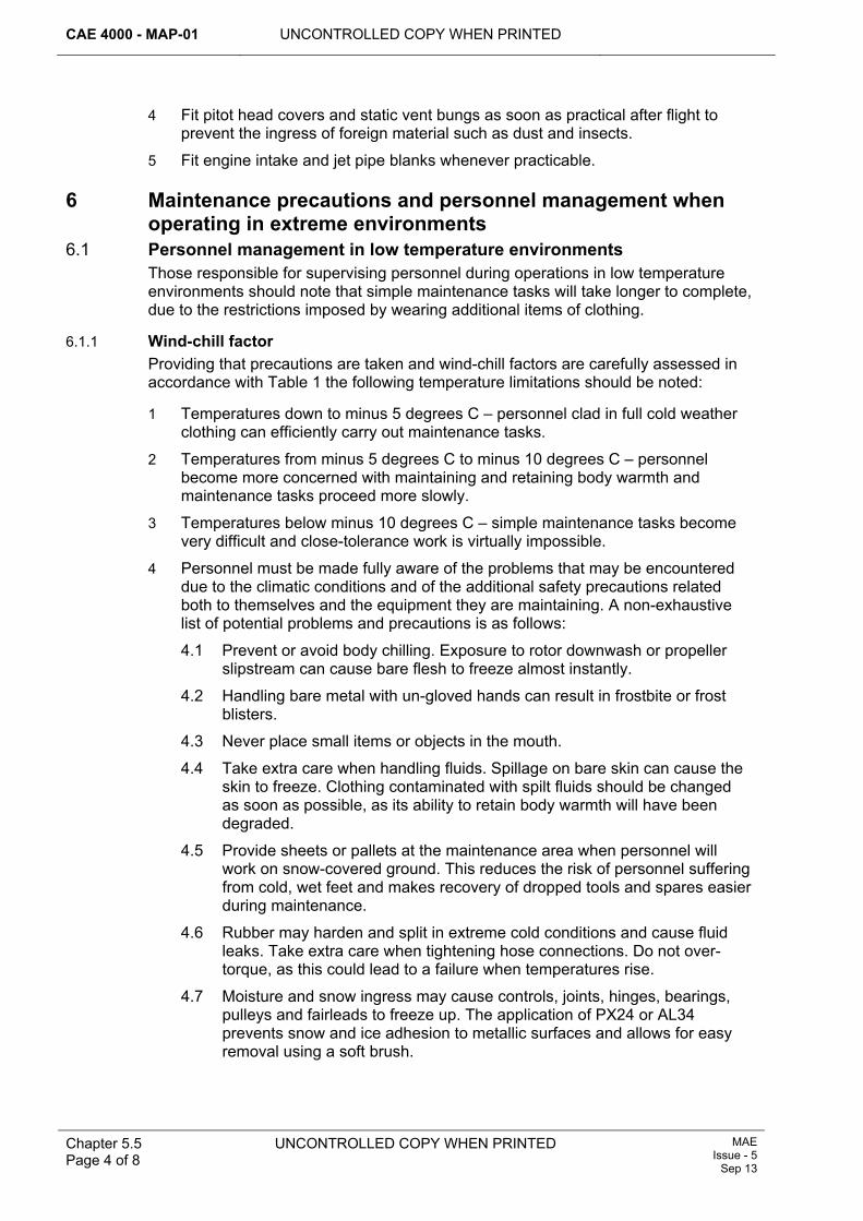
CAE 4000 - MAP-01 UNCONTROLLED COPY WHEN PRINTED
Chapter 5.5 Page 4 of 8
UNCONTROLLED COPY WHEN PRINTED MAE Issue - 5
Sep 13
4 Fit pitot head covers and static vent bungs as soon as practical after flight to prevent the ingress of foreign material such as dust and insects.
5 Fit engine intake and jet pipe blanks whenever practicable.
6 Maintenance precautions and personnel management when operating in extreme environments
6.1 Personnel management in low temperature environments Those responsible for supervising personnel during operations in low temperature environments should note that simple maintenance tasks will take longer to complete, due to the restrictions imposed by wearing additional items of clothing.
6.1.1 Wind-chill factor Providing that precautions are taken and wind-chill factors are carefully assessed in accordance with Table 1 the following temperature limitations should be noted:
1 Temperatures down to minus 5 degrees C – personnel clad in full cold weather clothing can efficiently carry out maintenance tasks.
2 Temperatures from minus 5 degrees C to minus 10 degrees C – personnel become more concerned with maintaining and retaining body warmth and maintenance tasks proceed more slowly.
3 Temperatures below minus 10 degrees C – simple maintenance tasks become very difficult and close-tolerance work is virtually impossible.
4 Personnel must be made fully aware of the problems that may be encountered due to the climatic conditions and of the additional safety precautions related both to themselves and the equipment they are maintaining. A non-exhaustive list of potential problems and precautions is as follows:
4.1 Prevent or avoid body chilling. Exposure to rotor downwash or propeller slipstream can cause bare flesh to freeze almost instantly.
4.2 Handling bare metal with un-gloved hands can result in frostbite or frost blisters.
4.3 Never place small items or objects in the mouth.
4.4 Take extra care when handling fluids. Spillage on bare skin can cause the skin to freeze. Clothing contaminated with spilt fluids should be changed as soon as possible, as its ability to retain body warmth will have been degraded.
4.5 Provide sheets or pallets at the maintenance area when personnel will work on snow-covered ground. This reduces the risk of personnel suffering from cold, wet feet and makes recovery of dropped tools and spares easier during maintenance.
4.6 Rubber may harden and split in extreme cold conditions and cause fluid leaks. Take extra care when tightening hose connections. Do not over-torque, as this could lead to a failure when temperatures rise.
4.7 Moisture and snow ingress may cause controls, joints, hinges, bearings, pulleys and fairleads to freeze up. The application of PX24 or AL34 prevents snow and ice adhesion to metallic surfaces and allows for easy removal using a soft brush.
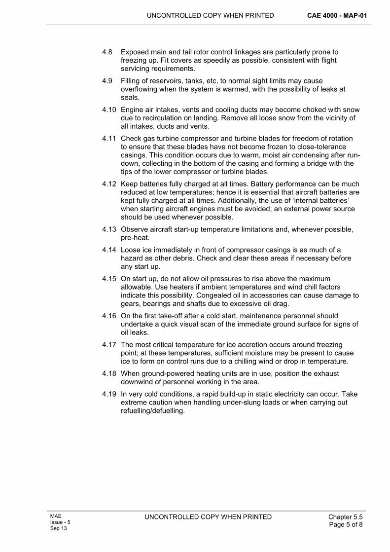
UNCONTROLLED COPY WHEN PRINTED CAE 4000 - MAP-01
MAE Issue - 5 Sep 13
UNCONTROLLED COPY WHEN PRINTED
Chapter 5.5 Page 5 of 8
4.8 Exposed main and tail rotor control linkages are particularly prone to freezing up. Fit covers as speedily as possible, consistent with flight servicing requirements.
4.9 Filling of reservoirs, tanks, etc, to normal sight limits may cause overflowing when the system is warmed, with the possibility of leaks at seals.
4.10 Engine air intakes, vents and cooling ducts may become choked with snow due to recirculation on landing. Remove all loose snow from the vicinity of all intakes, ducts and vents.
4.11 Check gas turbine compressor and turbine blades for freedom of rotation to ensure that these blades have not become frozen to close-tolerance casings. This condition occurs due to warm, moist air condensing after run-down, collecting in the bottom of the casing and forming a bridge with the tips of the lower compressor or turbine blades.
4.12 Keep batteries fully charged at all times. Battery performance can be much reduced at low temperatures; hence it is essential that aircraft batteries are kept fully charged at all times. Additionally, the use of ‘internal batteries’ when starting aircraft engines must be avoided; an external power source should be used whenever possible.
4.13 Observe aircraft start-up temperature limitations and, whenever possible, pre-heat.
4.14 Loose ice immediately in front of compressor casings is as much of a hazard as other debris. Check and clear these areas if necessary before any start up.
4.15 On start up, do not allow oil pressures to rise above the maximum allowable. Use heaters if ambient temperatures and wind chill factors indicate this possibility. Congealed oil in accessories can cause damage to gears, bearings and shafts due to excessive oil drag.
4.16 On the first take-off after a cold start, maintenance personnel should undertake a quick visual scan of the immediate ground surface for signs of oil leaks.
4.17 The most critical temperature for ice accretion occurs around freezing point; at these temperatures, sufficient moisture may be present to cause ice to form on control runs due to a chilling wind or drop in temperature.
4.18 When ground-powered heating units are in use, position the exhaust downwind of personnel working in the area.
4.19 In very cold conditions, a rapid build-up in static electricity can occur. Take extreme caution when handling under-slung loads or when carrying out refuelling/defuelling.
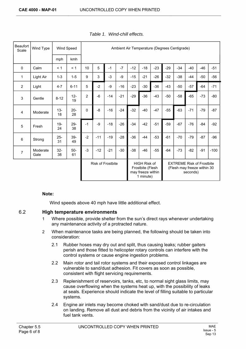
CAE 4000 - MAP-01 UNCONTROLLED COPY WHEN PRINTED
Chapter 5.5 Page 6 of 8
UNCONTROLLED COPY WHEN PRINTED MAE Issue - 5
Sep 13
Table 1. Wind-chill effects.
Beaufort Scale Wind Type Wind Speed Ambient Air Temperature (Degrees Centigrade)
mph kmh
0 Calm < 1 < 1 10 5 -1 -7 -12 -18 -23 -29 -34 -40 -46 -51
1 Light Air 1-3 1-5 9 3 -3 -9 -15 -21 -26 -32 -38 -44 -50 -56
2 Light 4-7 6-11 5 -2 -9 -16 -23 -30 -36 -43 -50 -57 -64 -71
3 Gentle 8-12 12-19
2 -6 -14 -21 -29 -36 -43 -50 -58 -65 -73 -80
4 Moderate 13-18
20-28
0 -8 -16 -24 -32 -40 -47 -55 -63 -71 -79 -87
5 Fresh 19-24
29-38
-1 -9 -18 -26 -34 -42 -51 -59 -67 -76 -84 -92
6 Strong 25-31
39-49
-2 -11 -19 -28 -36 -44 -53 -61 -70 -79 -87 -96
7 Moderate Gale
32-38
50-61
-3 -12 -21 -30 -38 -46 -55 -64 -73 -82 -91 -100
Risk of Frostbite HIGH Risk of Frostbite (Flesh
may freeze within 1 minute)
EXTREME Risk of Frostbite (Flesh may freeze within 30
seconds)
Note:
Wind speeds above 40 mph have little additional effect.
6.2 High temperature environments 1 Where possible, provide shelter from the sun’s direct rays whenever undertaking
any maintenance activity of a protracted nature.
2 When maintenance tasks are being planned, the following should be taken into consideration:
2.1 Rubber hoses may dry out and split, thus causing leaks; rubber gaiters perish and those fitted to helicopter rotary controls can interfere with the control systems or cause engine ingestion problems.
2.2 Main rotor and tail rotor systems and their exposed control linkages are vulnerable to sand/dust adhesion. Fit covers as soon as possible, consistent with flight servicing requirements.
2.3 Replenishment of reservoirs, tanks, etc, to normal sight glass limits, may cause overflowing when the systems heat up, with the possibility of leaks at seals. Experience should indicate the level of filling suitable to particular systems.
2.4 Engine air inlets may become choked with sand/dust due to re-circulation on landing. Remove all dust and debris from the vicinity of air intakes and fuel tank vents.
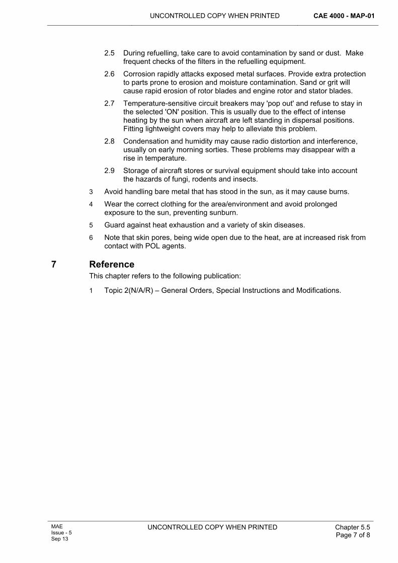
UNCONTROLLED COPY WHEN PRINTED CAE 4000 - MAP-01
MAE Issue - 5 Sep 13
UNCONTROLLED COPY WHEN PRINTED
Chapter 5.5 Page 7 of 8
2.5 During refuelling, take care to avoid contamination by sand or dust. Make frequent checks of the filters in the refuelling equipment.
2.6 Corrosion rapidly attacks exposed metal surfaces. Provide extra protection to parts prone to erosion and moisture contamination. Sand or grit will cause rapid erosion of rotor blades and engine rotor and stator blades.
2.7 Temperature-sensitive circuit breakers may 'pop out' and refuse to stay in the selected 'ON' position. This is usually due to the effect of intense heating by the sun when aircraft are left standing in dispersal positions. Fitting lightweight covers may help to alleviate this problem.
2.8 Condensation and humidity may cause radio distortion and interference, usually on early morning sorties. These problems may disappear with a rise in temperature.
2.9 Storage of aircraft stores or survival equipment should take into account the hazards of fungi, rodents and insects.
3 Avoid handling bare metal that has stood in the sun, as it may cause burns.
4 Wear the correct clothing for the area/environment and avoid prolonged exposure to the sun, preventing sunburn.
5 Guard against heat exhaustion and a variety of skin diseases.
6 Note that skin pores, being wide open due to the heat, are at increased risk from contact with POL agents.
7 Reference This chapter refers to the following publication:
1 Topic 2(N/A/R) – General Orders, Special Instructions and Modifications.

CAE 4000 - MAP-01 UNCONTROLLED COPY WHEN PRINTED
Chapter 5.5 Page 8 of 8
UNCONTROLLED COPY WHEN PRINTED MAE Issue - 5
Sep 13
Intentionally Blank for Print Pagination
UNCONTROLLED COPY WHEN PRINTED CAE 4000 - MAP-01
MAE Issue - 5 Sep 13
UNCONTROLLED COPY WHEN PRINTED Chapter 5.6 Page 1 of 4
Chapter 5.6
Dehumidification of Aircraft
TABLE OF CONTENTS Paragraph
Page
1 General ............................................................................................................... 1 1.1 Introduction.......................................................................................................... 1 2 Regulatory Governance.................................................................................... 1 2.1 Regulatory Article Cross-reference ..................................................................... 1 2.2 Additional Information.......................................................................................... 1 3 Dehumidification of aircraft.............................................................................. 2 4 Responsibilities................................................................................................. 2 4.1 Air Commodities Team (AC Team) ..................................................................... 2 4.2 Type Airworthiness Authorities (TAAs) ........................................................ 2 5 General restrictions on the use of dehumidification equipment .................. 2 6 Documentation .................................................................................................. 3 7 References ......................................................................................................... 3
1 General 1.1 Introduction
The amount of moisture in the air is defined as Relative Humidity (Rh) and is measured as a percentage. At 100% Rh, air is defined as being fully saturated, and the annual average level of Rh in the UK is 80%. At high levels of Rh, moisture quickly condenses on cold surfaces and is also trapped in areas such as avionics compartments where there may be no circulating air. In the short term, a humid environment can cause electrical short-circuits, breakdown of components and wiring insulation and corrosion of circuit boards and connectors. Furthermore, the combined presence of moisture and oxygen with many metals promotes the chemical reaction that produces corrosion of those metals. Lowering the Rh level within an aircraft to below 50% will significantly reduce avionic faults and slow the corrosion process. The purpose of dehumidification is to improve aircraft operational availability and equipment reliability by reducing the Rh of the air within the avionics compartments and aircraft structures.
2 Regulatory Governance 2.1 Regulatory Article Cross-reference
This chapter supports:
1 RA 4208.
2.2 Additional Information All aircraft are to be dehumidified in accordance with the maintenance philosophy issued by the Type Airworthiness Authority (TAA) and the guidance given in this chapter. The requirement to dehumidify an aircraft type is based on measured benefits from trials carried out on active UK military aircraft.
CAE 4000 - MAP-01 UNCONTROLLED COPY WHEN PRINTED
Chapter 5.6 Page 2 of 4
UNCONTROLLED COPY WHEN PRINTED MAE Issue - 5
Sep 13
3 Dehumidification of aircraft For aircraft subject to dehumidification, the relevant equipment is to be fitted as soon as possible after landing, unless time constraints between sorties would render the dehumidification process ineffective. For aircraft undergoing maintenance, dehumidification equipment is to be fitted, unless the maintenance operations render the process ineffective or the aircraft is being maintained in a controlled environment. Aircraft in storage are subject to dehumidification within the provisions of JAP 100V-21.
4 Responsibilities 4.1 Air Commodities Team (AC Team)
AC GSE1 within the AC Team is responsible for:
1 The acquisition and support of aircraft dehumidification equipment.
2 Advising on the most appropriate dehumidification equipment for a particular application.
3 Publishing appropriate technical information in the AP 119 series of publications.
4.2 Type Airworthiness Authorities (TAAs) Where applicable, TAAs are responsible for defining the dehumidification philosophy for their platform, including:
1 Technical and background information on dehumidification.
2 Methods of informing aircrew on the fitting and removal procedures for dehumidification equipment.
3 The approved scaling of suitable dehumidification equipment.
4 Provision for aircraft to be dehumidified during Depth maintenance where practicable and appropriate.
Note:
The basic technical specification of this equipment should be promulgated to allow aircrew or engineering staff to make a judgement as to whether locally available dehumidification equipment would be suitable if the usual equipment were not available.
For new aircraft, TAAs should consider the inclusion of dehumidification in the aircraft’s design, in accordance with Def Stan 00-970.
5 General restrictions on the use of dehumidification equipment There will be circumstances when the use of dehumidification equipment is not compatible with the task being undertaken. These may include:
1 Arming/de-arming operations.
2 Where dehumidification hoses and/or adaptors would prevent direct access to an area being worked.
3 Where connection and operation of the equipment might constitute a safety hazard, such as during aircraft fuelling operations.
TAAs are to detail in the Topic 2(N/A/R)1 those activities that restrict the use of dehumidification equipment.
UNCONTROLLED COPY WHEN PRINTED CAE 4000 - MAP-01
MAE Issue - 5 Sep 13
UNCONTROLLED COPY WHEN PRINTED Chapter 5.6 Page 3 of 4
6 Documentation Installing and removing dehumidification equipment should be treated in a similar manner to aircraft blanks and documented accordingly. If necessary, TAAs should provide appropriate advice in the aircraft technical information.
7 References This chapter refers to the following publications:
1 JAP 100V-21 – Aircraft Storage.
2 Def Stan 00-970 – Design and Airworthiness Requirements for Service Aircraft.
3 Topic 2(N/A/R)1 – General Orders and Special Instructions.

CAE 4000 - MAP-01 UNCONTROLLED COPY WHEN PRINTED
Chapter 5.6 Page 4 of 4
UNCONTROLLED COPY WHEN PRINTED MAE Issue - 5
Sep 13
Intentionally Blank for Print Pagination
UNCONTROLLED COPY WHEN PRINTED CAE 4000 - MAP-01
Issue - 7 Apr 15
UNCONTROLLED COPY WHEN PRINTED Chapter 5.7 Page 1 of 4
Chapter 5.7
Maintenance of Aircraft in Hardened Aircraft Shelters
TABLE OF CONTENTS Paragraph
Page
1 General ............................................................................................................... 1 1.1 Introduction.......................................................................................................... 1 1.2 Applicability ......................................................................................................... 1 2 Regulatory Governance.................................................................................... 2 2.1 Regulatory Article Cross-reference ..................................................................... 2 2.2 Additional information.......................................................................................... 2 3 Operation of HAS doors ................................................................................... 2 4 Ground handling ............................................................................................... 2 5 Aircraft positioning ........................................................................................... 2 6 Aircraft maintenance......................................................................................... 3 6.1 Aero-engine maintenance ground running .......................................................... 3 6.2 Pre-engine start checks....................................................................................... 3 6.3 Start-up and taxi .................................................................................................. 3 6.4 Replenishment of aircraft liquid oxygen/gaseous oxygen systems ..................... 3 6.5 Armament equipment .......................................................................................... 3 6.6 Fuelling................................................................................................................ 3 6.7 Radio frequency (RF) hazards ............................................................................ 4 6.8 Hazardous maintenance ..................................................................................... 4 7 Fuels, Lubricants and Associated Products (FLAP) storage and
disposal.............................................................................................................. 4 8 Safety, Health, Environment and Fire (SHEF) considerations ...................... 4 8.1 HAS ventilation.................................................................................................... 4 8.2 Fire-fighting facilities............................................................................................ 4 8.3 Lone workers....................................................................................................... 4 9 References ......................................................................................................... 4
1 General 1.1 Introduction
A Hardened Aircraft Shelter (HAS) provides dispersed protection for aircraft and essential resources and allows maintenance to continue during hostilities. Because the maintenance personnel involved are more widely dispersed, aircraft maintenance within a HAS complex requires a different approach and organization to that for normal aircraft operating environments. This chapter gives general instructions for the conduct of maintenance work in HASs. Engineering orders specific to aircraft types operated from HASs are published in the relevant aircraft Topic 2(N/A/R)1.
1.2 Applicability This chapter is applicable to Stns/Units maintaining aircraft within a HAS.
CAE 4000 - MAP-01 UNCONTROLLED COPY WHEN PRINTED
Chapter 5.7 Page 2 of 4
UNCONTROLLED COPY WHEN PRINTED Issue - 7 Apr 15
2 Regulatory Governance 2.1 Regulatory Article Cross-reference
This chapter supports:
1 Nil.
2.2 Additional information This chapter does not support any Regulatory Article however it details higher level documents that are associated with Maintenance of Aircraft in Hardened Shelters as well as detailing processes contained in the MAP-01 chapters.
3 Operation of HAS doors During a period of HAS operations, the individual holding authority level J within the maintenance organization must ensure that all ground markings which indicate door positions and hazard areas are clear and legible. Checks for obstructions must be made before HAS main doors are moved and doors must be operated by personnel holding authorization MAP-B127. Door operators must ensure that they can see the doors clearly before operating them. If there is a power failure that prevents electrical opening of the doors, they may be opened:
1 In a first generation HAS, by deselecting the motor and pushing the doors manually.
2 In a third generation HAS, by attaching a suitable block and tackle to the ring on the outside of each door and pulling the door open with a towing vehicle.
4 Ground handling HASs are fitted with winches for pulling aircraft onto the designated parking position. These winches must be operated by personnel holding authorization MAP-B163. Aircraft winch restrictions, as detailed in the appropriate Topic 1 or Topic 2(N/A/R)1, must be adhered to. Aircraft must not be winched with engines running (‘hot winching’) except where expressly authorized in the aircraft Topic 2(N/A/R)1. Personnel holding authorization MAP-E164 may authorize the use of a tractor to move aircraft in lieu of the winch if certain parking configurations are deemed hazardous or when operationally necessary.
5 Aircraft positioning Parking configurations for aircraft subject to HAS operations must be promulgated in the aircraft Topic 2(N/A/R)1. There may be occasions when different aircraft types occupy the same HAS. In these circumstances, the following positioning regulations apply:
1 Any immobilized aircraft must not prevent the emergency evacuation of other aircraft.
2 There must be adequate clearance, allowing for full movement of control surfaces, between any aircraft and any equipment, stores or structure located within a HAS.
UNCONTROLLED COPY WHEN PRINTED CAE 4000 - MAP-01
Issue - 7 Apr 15
UNCONTROLLED COPY WHEN PRINTED Chapter 5.7 Page 3 of 4
6 Aircraft maintenance 6.1 Aero-engine maintenance ground running
The ground running of aero-engines for maintenance purposes within a HAS must comply with RA 4510 Chapter 11.9 and the requirements of paragraph 6.2 and paragraph 6.3.
6.2 Pre-engine start checks Before starting an engine, the supervisor of the running/see-off team must ensure that:
1 All equipment within the HAS is positioned and/or restrained so that it does not constitute a hazard.
2 All loose items such as covers, blanks, flags, etc are removed or securely stowed.
3 If, exceptionally, the HAS contains more than one aircraft:
3.1 All work on the non-running aircraft has been stopped.
3.2 All loose panels and other items that cannot be positively secured to the non-running aircraft are removed.
4 All personnel are wearing the appropriate Personal Protective Equipment (PPE).
Note:
In accordance with advice from the RAF Centre of Aviation Medicine, there is no requirement for personnel to wear Respiratory Protective Equipment when aircraft engines are being operated in a HAS.
6.3 Start-up and taxi Single aircraft may be operated from HAS without restriction. For certain limited combinations of aircraft in HAS, the forward aircraft may be started and taxied. Permissible combinations are shown in the relevant Topic 2(N/A/R)1.
6.4 Replenishment of aircraft liquid oxygen/gaseous oxygen systems The replenishment of aircraft liquid oxygen/gaseous oxygen systems on aircraft housed in a HAS must be carried out in accordance with RA 4063 Chapter 2.6.1.
6.5 Armament equipment 6.5.1 Housing of armed aircraft
Armed aircraft must be housed in a HAS in accordance with JSP 482 and RA 4657 and Chapter 14.7. Additionally, to minimize the accident risk, the main doors of the HAS are to remain closed wherever reasonably practicable.
6.5.2 Storage of weapons, explosives, ejection seats and canopies Explosive armament stores and components must only be stored in a HAS environment in accordance with:
1 RA 4657 and Chapter 14.7 – Armed Aircraft Safety Precautions. 2
3 JSP 482 – MOD Explosives Regulations.
6.6 Fuelling The fuelling of aircraft within a HAS must be carried out in accordance with RA 4055 and Chapter 2.6.
CAE 4000 - MAP-01 UNCONTROLLED COPY WHEN PRINTED
Chapter 5.7 Page 4 of 4
UNCONTROLLED COPY WHEN PRINTED Issue - 7 Apr 15
6.7 Radio frequency (RF) hazards RF transmissions within HAS can be hazardous to personnel and can activate electrically initiated explosive devices. Such transmissions must be made only in accordance with the policy detailed in JSP 482 or in the appropriate Front Line Command (FLC) mid-level aviation engineering policy.
6.8 Hazardous maintenance Maintenance involving hazardous engineering substances or procedures, as defined in JSP 515, that need special facilities, eg surface finishing, is not permitted within a HAS except when authorized by the Type Airworthiness Authority (TAA).
7 Fuels, Lubricants and Associated Products (FLAP) storage and disposal FLAP held forward in each HAS must not exceed one week’s anticipated consumption and must be stored in steel lockers within the aircraft ground equipment annex. Waste fuel and oil must not be allowed to accumulate in drip trays or other containers. Drums containing waste fuel and oil must be located in designated areas outside the HAS and emptied regularly.
8 Safety, Health, Environment and Fire (SHEF) considerations 8.1 HAS ventilation
When operating aircraft from a HAS, doors must be opened prior to engine start and, if operational circumstances permit, left open for at least 10 minutes after aircraft taxi/engine shut down to allow any fumes to dissipate.
8.2 Fire-fighting facilities The scale for first aid fire appliances is detailed in JSP 308. Fire extinguishers are to be positioned so as to ensure that an escape route for personnel can be established in the event of fire.
8.3 Lone workers The restrictions laid down in JSP 375 relating to lone workers are to be adhered to when operating in a HAS environment.
9 References This Chapter refers to the following publications:
1 Aircraft Topic 1: Aircraft Maintenance Manual.
2 Aircraft Topic 2(N/A/R)1: General Orders and Special Instructions.
3 JSP 308: Joint Service Scales of Accommodation Stores - Part 7: Others: Scale JS/164.
4 JSP 375: MOD Health & Safety Handbook. 5
6 JSP 482: Ministry of Defence Explosives Regulations.
7 JSP 515: Hazardous Stores Information System 2 (HSIS 2) - Safety Data Sheet Search.
UNCONTROLLED COPY WHEN PRINTED CAE 4000 - MAP-01
MAE Issue - 5 Sep 13
UNCONTROLLED COPY WHEN PRINTED Chapter 5.8 Page 1 of 4
Chapter 5.8
Anti-Deterioration Maintenance of Equipment in Store
TABLE OF CONTENTS Paragraph
Page
1 General ............................................................................................................... 1 1.1 Introduction.......................................................................................................... 1 1.2 Associated publications....................................................................................... 1 1.3 Applicability ......................................................................................................... 1 2 Regulatory Governance.................................................................................... 2 2.1 Regulatory Article Cross-reference ..................................................................... 2 2.2 Additional Information.......................................................................................... 2 3 Anti-deterioration maintenance (ADM) of equipment in store ...................... 2 4 ADM of equipment in store............................................................................... 2 4.1 Identification of equipment .................................................................................. 2 4.2 Shelf life............................................................................................................... 2 4.3 Engineering support ............................................................................................ 2 4.4 Recording ............................................................................................................ 3 5 Type Airworthiness Authority (TAA) and commodity Project Team (PT)
Responsibilities ............................................................................................. 3 6 References ......................................................................................................... 3
1 General 1.1 Introduction
The condition of certain types of aircraft equipment held in store may deteriorate to an extent that they may no longer be fit for use or economic repair. Equipment held in store can deteriorate through a number of mechanisms; oils and greases can solidify, bearings can dry out, elastomeric and rubber components can harden or deform, desiccants can become ineffective and fabrics can weaken. Appropriate preventive maintenance may therefore be required to ensure that equipment is retained in a suitable condition for issue, repair or reconditioning. However, the use of suitable storage environments and protective packaging should make the need for anti-deterioration maintenance (ADM) of equipment in store the exception rather than the rule.
1.2 Associated publications This chapter is associated with the following publication:
1 JSP 886 Vol 7 Pt 8.02.
1.3 Applicability This chapter applies to ADM of equipment in store, where the term ‘in store’ means both in store within the supply organization and in forward stores, but excludes:
1 Complete aircraft, for which procedures are published in JAP 100V-21.
2 Equipment governed by other specialist regulations, eg aero-engines, explosives and armament stores.
CAE 4000 - MAP-01 UNCONTROLLED COPY WHEN PRINTED
Chapter 5.8 Page 2 of 4
UNCONTROLLED COPY WHEN PRINTED MAE Issue - 5
Sep 13
2 Regulatory Governance 2.1 Regulatory Article Cross-reference
This chapter supports:
1 RA 4210.
2.2 Additional Information Nil.
3 Anti-deterioration maintenance (ADM) of equipment in store Type Airworthiness Authorities (TAAs) and commodity Project Teams (PTs) must consider the quality and standard of packaging and storage conditions when setting the ADM frequency for their equipment held in store.
ADM intervals must be reviewed periodically and, where appropriate, challenged to eliminate unnecessary maintenance effort, minimize costs and optimize equipment availability.
4 ADM of equipment in store 4.1 Identification of equipment
TAAs, through commodity PTs where necessary, must identify those items of their equipment that require periodic ADM and notify the relevant in-Service or contractors’ engineering support organizations of the frequency and depth of maintenance. TAAs and commodity PTs can seek guidance for this activity from in-Service engineering support organizations or from equipment manufacturers. The following is an indicative list of equipment types that have historically required ADM:
1 Barometric instruments.
2 Clocks.
3 Fuel tanks (external, flexible cells and mainplanes with integral tanks).
4 Gearboxes.
5 Gyroscopes.
6 Rotables.
7 Hydraulic components.
4.2 Shelf life Equipment must be given a calendar-based shelf life in accordance with RA 4204 and Chapter 5.3.1 to indicate when a preventive maintenance activity is required. Shelf life must be identified in the Topic 5A1 or Topic 5W or equivalent by the descriptor SL. The shelf life is the period after which an item held in store must not be issued unless it has received appropriate maintenance. Satisfactory completion of the maintenance will re-establish the shelf life of the item, unless limited by other parameters.
4.3 Engineering support TAAs and commodity PTs must ensure that organizations charged with carrying out ADM on equipment whilst in store are provided with the equipment maintenance manual or Topic 2(N/A/R)1 and the necessary servicing and test equipment.
UNCONTROLLED COPY WHEN PRINTED CAE 4000 - MAP-01
MAE Issue - 5 Sep 13
UNCONTROLLED COPY WHEN PRINTED Chapter 5.8 Page 3 of 4
4.4 Recording Maintenance activities must be recorded on appropriate maintenance documentation. A record of ADM and the re-forecast shelf life must be annotated on the equipment label/record card. The shelf life must be updated on asset tracking systems as applicable.
5 Type Airworthiness Authority (TAA) and commodity Project Team (PT) Responsibilities TAAs and commodity PTs must:
1 Identify those items of their equipment that require scheduled ADM in store and instruct the relevant engineering support organizations accordingly.
2 Promulgate the frequency, depth and type of ADM within their equipment maintenance manual or Topic 2(N/A/R)1.
3 Conduct appropriate reviews, in line with schedule reviews as described in RA 4203 and Chapter 5.3, of their ADM requirements for equipment in store, challenging manufacturers’ and in-Service maintenance philosophies where appropriate.
6 References This chapter refers to the following publications:
1 JAP 100V-21 – Aircraft Storage.
2 JSP 886 Vol 7 Pt 8.02 - Packaging, Handling, Storage and Transportation.
3 Topic 2(N/A/R)1 – General Orders and Special Instructions.
4 Topic 5A1 – Master Maintenance Schedule.
5 Topic 5W – Summary of Component Repair Plans.

CAE 4000 - MAP-01 UNCONTROLLED COPY WHEN PRINTED
Chapter 5.8 Page 4 of 4
UNCONTROLLED COPY WHEN PRINTED MAE Issue - 5
Sep 13
Intentionally Blank for Print Pagination
UNCONTROLLED COPY WHEN PRINTED CAE 4000 - MAP-01
Issue - 7 Apr 15
UNCONTROLLED COPY WHEN PRINTED Chapter 5.9 Page 1 of 2
Chapter 5.9
Ground Training Aids
TABLE OF CONTENTS Paragraph
Page
1 General ............................................................................................................... 1 1.1 Introduction.......................................................................................................... 1
1 General 1.1 Introduction
►The content of this chapter has been transferred to RA4212. This Ghost Chapter is left in as a signpost for the reader.◄
CAE 4000 - MAP-01 UNCONTROLLED COPY WHEN PRINTED
Chapter 5.9 Page 2 of 2
UNCONTROLLED COPY WHEN PRINTED Issue - 7 Apr 15
Intentionally Blank for Print Pagination
UNCONTROLLED COPY WHEN PRINTED CAE 4000 - MAP-01
Issue - 7 Apr 15
UNCONTROLLED COPY WHEN PRINTED Chapter 5.10 Page 1 of 2
Chapter 5.10
Ground Instructional Aircraft and Aero-Engines
TABLE OF CONTENTS
Paragraph
Page
1 General ............................................................................................................... 1 1.1 Introduction.......................................................................................................... 1
1 General 1.1 Introduction
►The content of this chapter has been transferred to RA 4212. This Ghost Chapter is left in as a signpost for the reader.◄

CAE 4000 - MAP-01 UNCONTROLLED COPY WHEN PRINTED
Chapter 5.10 Page 2 of 2
UNCONTROLLED COPY WHEN PRINTED Issue - 7 Apr 15
Intentionally Blank for Print Pagination
UNCONTROLLED COPY WHEN PRINTED
CAE 4000 - MAP-01
MAE Issue - 5 Sep 13
UNCONTROLLED COPY WHEN PRINTED
Chapter 5.12 Page 1 of 4
Chapter 5.12
Control of Aircraft Components used in Ground Test Facilities
TABLE OF CONTENTS Paragraph
Page
1 General ............................................................................................................... 1 1.1 Introduction.......................................................................................................... 1 1.2 Term used ........................................................................................................... 1 2 Regulatory Governance.................................................................................... 1 2.1 Regulatory Article Cross-reference ..................................................................... 1 2.2 Additional Information.......................................................................................... 1 3 Ground test facility components ..................................................................... 2 4 Identification, marking and control of aircraft components used in
ground test facilities ......................................................................................... 2 4.1 Components manufactured for a ground test facility........................................... 2 4.2 Permanently modified aircraft components ......................................................... 2 4.3 Temporarily modified aircraft components .......................................................... 2 4.4 Unmodified aircraft components.......................................................................... 2 5 Responsibilities................................................................................................. 3 5.1 Stn/Ship/Unit ....................................................................................................... 3 5.2 Type Airworthiness Authority (TAA) ............................................................. 3
1 General 1.1 Introduction
Ground test facilities enable diagnostic, pre-use or standard serviceability tests to be carried out on aircraft components. In some instances, the component under test is installed in a test facility that uses aircraft components as part of a simulated aircraft system. The latter components may be standard or may be modified for their function in the test facility. Furthermore, the use of such components in a test facility may differ from normal in-service use. As it may be physically possible to subsequently fit these components to an aircraft, it is imperative to ensure that they undergo appropriate maintenance before they are returned to aircraft use. This chapter therefore identifies the procedures to be followed to identify and control aircraft components used in ground test facilities.
1.2 Term used For the purposes of this chapter the term ‘aircraft components’ refers to any component or Line Replaceable Unit that may be used as part of a ground test facility.
2 Regulatory Governance 2.1 Regulatory Article Cross-reference
This chapter supports:
1 RA 4213.
2.2 Additional Information Nil.
CAE 4000 - MAP-01 UNCONTROLLED COPY WHEN PRINTED
Chapter 5.12 Page 2 of 4
UNCONTROLLED COPY WHEN PRINTED MAE Issue - 5
Sep 13
3 Ground test facility components All aircraft components are identified by one or more of a NATO stock number (NSN), section and reference number, part number and serial number; however, some aircraft components used in ground test facilities may be marked further to show their status.
Components used in ground test facilities fall into one of the following categories:
1 Components that have been manufactured specifically for ground test facilities.
2 Aircraft components that have been permanently modified specifically for a ground test facility and are not subsequently to be fitted to an aircraft.
3 Aircraft components that have been temporarily modified for use with a ground test facility and which may, after further appropriate maintenance, subsequently be fitted to an aircraft or aircraft system.
4 Unmodified aircraft components used in a ground test facility.
4 Identification, marking and control of aircraft components used in ground test facilities
4.1 Components manufactured for a ground test facility Components that have been specifically manufactured for a ground test facility must be unable to be physically fitted to an aircraft or aircraft system. They must be identified by the manufacturer’s part number and do not require any visual markings.
4.2 Permanently modified aircraft components Aircraft components that have been permanently modified for use in ground test facilities may still be physically capable of subsequently being fitted to an aircraft or aircraft system. In order to minimize the risk of inadvertent fitting, the relevant Type Airworthiness Authority (TAA) must ensure that the component is issued with a discrete NSN and part number. Additionally, the aircraft component must be permanently and clearly marked in red: “Ground Use Only.” The relevant supporting documentation must clearly state that the component has been permanently modified and is for ground use only. The modification and use of the aircraft component in the ground test facility must be authorized by the relevant TAA.
4.3 Temporarily modified aircraft components Aircraft components that have been temporarily modified for use in ground test facilities will still be capable of being fitted to an aircraft or aircraft system. Accordingly, they must be clearly marked in red: “Ground Use Only”. The TAA responsible for the component must ensure that the relevant supporting documentation states that the component has been temporarily modified, describes the modification and details the maintenance and/or de-modification procedures, including removal of the “Ground Use Only” marking, that must be carried out before the component can subsequently be categorized serviceable and be fitted to an aircraft or aircraft system. Any modification to permit use of an aircraft component in a ground test facility must be authorized by the relevant TAA.
4.4 Unmodified aircraft components Standard unmodified aircraft components can be used in ground test facilities as part of a simulated aircraft system and as such will be physically capable of subsequently being fitted to an aircraft or aircraft system. The TAA responsible for the component must authorize the use of aircraft components in a ground test facility and must detail in the relevant supporting documentation the maintenance procedure to
UNCONTROLLED COPY WHEN PRINTED CAE 4000 - MAP-01
MAE Issue - 5 Sep 13
UNCONTROLLED COPY WHEN PRINTED
Chapter 5.12 Page 3 of 4
be carried out before the component can subsequently be categorized serviceable and be fitted to an aircraft or aircraft system.
5 Responsibilities 5.1 Stn/Ship/Unit
Stns/Ships/Units that use ground test facilities must:
1 Ensure that all aircraft components used in ground test facilities are correctly identified, marked and controlled and that the component’s status is reflected in supporting documentation.
2 Ensure that aircraft components are not used in, or modified for use in, ground test facilities without the authorization of the relevant TAA.
5.2 Type Airworthiness Authority (TAA) TAAs must:
1 Authorize any permanent modification of aircraft components for use in ground test facilities and ensure that components so modified are visually identified and issued with a discrete NSN and part number.
2 Authorize any temporary modification of aircraft components for use in ground test facilities and ensure that the supporting documentation specifies the maintenance and/or de-modification procedures and special marking removal required before the component can be categorized serviceable for use on aircraft or aircraft systems.
3 Authorize the use of standard unmodified aircraft components in ground test facilities and ensure that the supporting documentation specifies the maintenance procedures required before the component can be categorized serviceable for use on aircraft or aircraft systems.

CAE 4000 - MAP-01 UNCONTROLLED COPY WHEN PRINTED
Chapter 5.12 Page 4 of 4
UNCONTROLLED COPY WHEN PRINTED MAE Issue - 5
Sep 13
Intentionally Blank for Print Pagination
UNCONTROLLED COPY WHEN PRINTED CAE 4000 - MAP-01
MAE Issue - 5 Sep 13
UNCONTROLLED COPY WHEN PRINTED Chapter 5.14 Page 1 of 2
Chapter 5.14
Support Policy Statements
TABLE OF CONTENTS Paragraph
Page
1 General ............................................................................................................... 1 1.1 Introduction.......................................................................................................... 1 2 Regulatory Governance.................................................................................... 1 2.1 Regulatory Cross-reference ................................................................................ 1 2.2 Additional Information.......................................................................................... 1 3 Promulgation and content................................................................................ 1 4 SPS periodic review .......................................................................................... 2 5 References ......................................................................................................... 2
1 General 1.1 Introduction
The aircraft Release to Service (RTS) is central to defining the airworthiness of an aircraft (RA 1300 refers). The Aircraft Document Set (ADS) is the hierarchical structure of the suite of documents used to ensure the safe operation of the aircraft. One of the main subordinate documents within the ADS is the Support Policy Statement (SPS).
Integrated Logistic Support (ILS) methodology provides a detailed and robust Support Strategy for aircraft or an item of equipment, including software, in the development and provision of a Support Solution. JSP 886 Vol 7 Part 2 defines the responsibilities of the MOD Integrated Logistic Support Manager (MILSM) who is responsible for promulgating the SPS.
This chapter specifies the requirement for SPSs within the Military Air Environment (MAE) and provides sub-chapters that provide templates for the engineering content of SPSs.
2 Regulatory Governance 2.1 Regulatory Cross-reference
This chapter supports:
1 RA 4214.
2.2 Additional Information Nil.
3 Promulgation and content The SPS must be promulgated as the first leaflet of Part 1 of either the platform or commodity Topic 2(N/A/R)1, (or equivalent) or in the Topic 5W, as determined by the Type Airworthiness Authority (TAA) or commodity Project Team (PT) respectively.
The following sub-chapters provide guidelines and typical content for an SPS:
CAE 4000 - MAP-01 UNCONTROLLED COPY WHEN PRINTED
Chapter 5.14 Page 2 of 2
UNCONTROLLED COPY WHEN PRINTED
MAE Issue - 5
Sep 13
1 Chapter 5.14.1 – Support Policy Statement - Aircraft.
2 Chapter 5.14.2 – Support Policy Statement - Equipment. (To be used for major sub-systems of a weapons system, items of major stand-alone equipment or flight simulators/ synthetic trainers.) The MILSM may tailor the SPS to suit the project’s needs.
4 SPS periodic review An SPS must be subject to an auditable review by the TAA or, in the case of an equipment SPS, commodity PT, at least every 5 years (RA 4200 and Chapter 5.1 refer) or whether there is a significant change to the support policy or there are changes to the responsibilities of staffs or formations that provide the ILS. Where applicable, all reviews should be carried out in consultation with the relevant MOD Continuing Airworthiness Manager (MOD CAM). The review must take account of the four Key Support Areas (KSAs) within the Support Solutions Envelope (SSE):
1 KSA 1: Sustainability.
2 KSA 2: Support Engineering.
3 KSA 3: Joint Support Chain.
4 KSA 4: Logistics Information.
5 References This chapter refers to the following publications:
1 RA 1300 - Release to Service.
2 JSP 886 – The Defence Logistics Support Chain Manual
3 Topic 2(N/A/R)1 – General Orders and Special Instructions.
4 Topic 5W – Summary of Component Repair Plans.
UNCONTROLLED COPY WHEN PRINTED CAE 4000 - MAP-01
Issue - 7 Apr 15
UNCONTROLLED COPY WHEN PRINTED Chapter 5.14.1 Page 1 of 8
Chapter 5.14.1
Support Policy Statement – Aircraft
TABLE OF CONTENTS Paragraph
Page
1 General ............................................................................................................... 1 1.1 Introduction.......................................................................................................... 1 2 Regulatory Governance.................................................................................... 1 2.1 Regulatory Cross-reference ................................................................................ 1 3 Content of an Aircraft Support Policy Statement (SPS) – Introduction ....... 2 4 Content of an SPS – Aim .................................................................................. 2 5 Content of an SPS – Management responsibilities........................................ 2 6 Content of an SPS – Security aspects ............................................................ 3 7 Content of an SPS – Engineering maintenance philosophy ......................... 3 7.1 On-aircraft preventive maintenance philosophy .................................................. 3 7.2 On-aircraft corrective maintenance ..................................................................... 4 7.3 Continuous charge .............................................................................................. 4 7.4 Equipment controlled by other Project Teams (PTs)........................................... 4 7.5 Component maintenance .................................................................................... 4 7.6 Surface finish....................................................................................................... 5 7.7 Structural integrity management ......................................................................... 5 7.8 Software support ................................................................................................. 5 7.9 Quality assurance................................................................................................ 5 7.10 Safety and environment ...................................................................................... 5 8 Content of an SPS – Personnel and training .................................................. 6 9 Content of an SPS – Test and support equipment......................................... 6 10 Content of an SPS – Technical information (TI) ............................................. 6 11 Content of an SPS – Facilities.......................................................................... 7 12 Content of an SPS – IT resources.................................................................... 7 13 Content of an SPS – Deployment plans .......................................................... 7 14 Content of an SPS – Product Support – Through Life Management Plan
(TLMP) ................................................................................................................ 7 15 Content of an SPS – Supply Support Philosophy.......................................... 8
1 General 1.1 Introduction
RA 4214 and Chapter 5.14 outline the role of the Support Policy Statement (SPS). This chapter provides a template for an Aircraft SPS. (Chapter 5.14.2 provides a template for an Equipment SPS).
2 Regulatory Governance 2.1 Regulatory Cross-reference
This Chapter supports:
1 RA 4214.
CAE 4000 - MAP-01 UNCONTROLLED COPY WHEN PRINTED
Chapter 5.14.1 Page 2 of 8
UNCONTROLLED COPY WHEN PRINTED Issue - 7 Apr 15
3 Content of an Aircraft Support Policy Statement (SPS) – Introduction The Introduction provides a brief description of the aircraft, its operational role and the numbers to be supported. The introduction should contain details of:
1 Issue number and date.
2 The ILS Plan from which information contained in this SPS was derived.
3 The previous SPS, which has, if applicable, been superseded.
4 The method of procurement.
5 The number and types of engines and main avionic systems.
6 The agencies responsible for the development of the aircraft and its systems.
7 The dates, where appropriate, for: initial delivery, GARP/MA Release, Release-to-Service (RTS) and In-Service Date (ISD).
8 The planned Aircraft Establishment build-up.
9 The number and location of main operating bases and Operational Conversion Units; if appropriate, there should also be a description of any dispersed operating posture planned for the aircraft.
The Introduction should also mention any unusual features that are likely to influence support arrangements. These might include new construction techniques, variable geometry, and extensive use of materials prone to corrosion, an unusual provisioning policy or requirements for special-to-type support equipment.
4 Content of an SPS – Aim Detail the aim of the SPS as follows:
The aim of this SPS is to define the support arrangements necessary to maintain [Aircraft Type] in the Military Air Environment (MAE).
5 Content of an SPS – Management responsibilities Detail the authorities with management responsibilities. These must include the following:
1 Design Organization (DO) – Identify the Design Organization, eg aircraft, engine, propeller airworthiness and structural integrity.
2 Release to Service Authority (RTSA) – Provide details of the RTSA responsible for approving and issuing the Release to Service (RTS).
3 Type Airworthiness Authority (TAA) – Provide details of the TAA together with any delegated authorities for aircraft support that may include the equipments included in the safety assessment. Aspects to be considered are:
3.1 Engineering.
3.2 Supply.
3.3 Contracts.
3.4 Finance.
3.5 Technical Information.
UNCONTROLLED COPY WHEN PRINTED CAE 4000 - MAP-01
Issue - 7 Apr 15
UNCONTROLLED COPY WHEN PRINTED Chapter 5.14.1 Page 3 of 8
3.6 Aircrew Publications.
3.7 Quality Assurance.
4 Operating Authority – Identify the Operating Authority.
5 Front Line Command (FLC) – Detail the FLC Office responsibilities for:
5.1 Aircraft.
5.2 Ground Support.
5.3 Training.
5.4 Quality Assurance.
6 Unit – Detail the unit responsibilities within the Forward and Depth organizations.
6 Content of an SPS – Security aspects Detail the security classification of the aircraft system. Specify any security protection requirements, eg TEMPEST, and the maintenance of the integrity of such protection: JSP 440 refers. Consider associated equipment SPS, Security Policy Statements and dispersed operation requirements when appropriate.
7 Content of an SPS – Engineering maintenance philosophy The MAE maintenance philosophies are implemented through a 2-level maintenance construct – Forward and Depth. In this section describe the preventive and corrective maintenance philosophies applicable to the platform and its associated equipments.
7.1 On-aircraft preventive maintenance philosophy The on-aircraft preventive maintenance philosophy is defined in RA 4200 and Chapter 5.1, which must be referred to when compiling this part of the SPS.
1 Servicing – Include a description of the flight servicing system authorized for the particular platform, in each of its operational roles. Include details of the periodicity and applicability of each type of servicing. Additionally, include the conditions and limitations for waiving the requirement for flight servicing.
2 Scheduled Maintenance – Provide a full description of the platform’s maintenance cycle, including periodicities and latitudes for anticipation and extensions. Allocate each maintenance cycle to the appropriate maintenance construct – Forward or Depth.
3 Condition-based maintenance – Detail what condition-based maintenance activity is applicable to the platform and the monitoring techniques that must be applied. State where the requirement for condition monitoring of the item must be included, eg in the relevant servicing or maintenance schedule or as out-of-phase maintenance.
4 Contingency-based maintenance – Summarize the arrangements for contingency-based maintenance if applicable.
5 Ground Instructional Aircraft (GIA) – Specify the requirements for GIA used in the ground instructional role; RA 4212, Chapter 5.10 and JSP 886 Vol 7 Pt 2 refer.
6 Anti-deterioration maintenance – State the requirements for any anti-deterioration maintenance; RA 4200 and Chapter 5.1 and RA 4210 and Chapter 5.8 refer.
CAE 4000 - MAP-01 UNCONTROLLED COPY WHEN PRINTED
Chapter 5.14.1 Page 4 of 8
UNCONTROLLED COPY WHEN PRINTED Issue - 7 Apr 15
7 Flight Testing – State the policy document(s) under which flight-testing is referenced and carried out.
8 Aircraft Displaying Abnormal Flying Characteristics – Reference the procedure for dealing with aircraft that experience Uncommanded Flying Control Movement, Control Restriction or Unusual Occurrence; RA 4061 and Chapter 2.11 refer.
9 Health Monitoring System – Detail the health monitoring system fitted to the aircraft, if applicable; RA 4500 and Chapter 11.2 refer.
10 Aircraft weighing – Detail the aircraft weighing policy; RA 4256 and Chapter 6.5 refer.
7.2 On-aircraft corrective maintenance The on-aircraft corrective maintenance philosophy is defined in RA 4205 and Chapter 5.4 which must be referred to when compiling this part of the SPS.
1 Identification of maintenance philosophy – Identify the corrective maintenance activities appropriate to the Forward or Depth construct.
2 Allocation of on-aircraft corrective maintenance – Outline the aircraft corrective maintenance philosophy within the Forward or Depth construct.
3 Expedient repairs – Detail the expedient repair arrangements that must be applied, if applicable.
7.3 Continuous charge State whether continuous charge is authorized for the aircraft; RA 4059 and Chapter 2.9 refer. If continuous charge is authorized:
1 Specify the roles covered by the authorization.
2 State any limitations, eg flying hours, number of landings.
3 Detail specific checks to be undertaken by the aircrew.
7.4 Equipment controlled by other Project Teams (PTs) Identify installed equipment that is the responsibility of other PTs with reference to the Topic 5A1 and/or the relevant SPS. Where the TAA has authorized equipment to be maintained in phase with the aircraft maintenance cycle, details of this authorization should be referenced in the Topic 2(N/A/R)1. (The contents of this section may be consigned to an annex of the SPS if appropriate).
7.5 Component maintenance Detail the arrangements for off-aircraft preventive and corrective maintenance of components. Where a separate SPS or Topic 5W (or equivalent) already exists, a cross-reference will suffice. Identify the activities appropriate to each maintenance construct – Forward or Depth – which should include:
1 Airframe structural components – State the interchangeability requirements for major structural components. Identify the repair organizations required to support the maintenance philosophy.
2 Propulsion system maintenance – State the maintenance philosophy for the aircraft’s engine(s) and its associated systems.
3 Mechanical components – Consider anti-deterioration maintenance requirements for mechanical components in storage; RA 4210 and Chapter 5.8 refer.
UNCONTROLLED COPY WHEN PRINTED CAE 4000 - MAP-01
Issue - 7 Apr 15
UNCONTROLLED COPY WHEN PRINTED Chapter 5.14.1 Page 5 of 8
4 Avionic and electrical components – Detail the arrangements for off-aircraft preventive and corrective maintenance of avionic and electrical components.
When compiling the above, consider the following:
1 Lifing, testing, repair and reconditioning regulations.
2 Condition monitoring requirements.
3 Specific quality assurance measures such as stage and independent inspections and functional tests.
4 Hazards inherent in components or likely to be encountered during maintenance (eg advanced composites may require special facilities). Cross-refer to RA 4201 and Chapter 5.1.1 and the section on safety below where appropriate.
5 Programming facilities for components embodying firmware (non-volatile memory devices containing software code or data) and any special support arrangements.
7.6 Surface finish Detail the aircraft surface finish philosophy; RA 4257 and Chapter 6.6 refer.
7.7 Structural integrity management Identify the major factors affecting structural integrity and the procedures to be used for fatigue management. Refer to RA 5720-5722 (Structural and Propulsion Integrity), RA 5723 (ageing aircraft audit) and 1000 Series: General Regulations (GEN). Details should include:
1 The aircraft fatigue design philosophy.
2 The cleared life of the airframe and the major structural components (such as undercarriages, wings). If further clearance is expected, include the current status of any on-going full-scale fatigue tests.
3 The procedure for the capture and processing of fleet fatigue data.
4 Any special environmental damage prevention and control measures to be undertaken; RA 4507 and Chapter 11.6 refer.
5 A structural integrity plan detailing all the future programmes which will be required to support the aircraft to its Out of Service Date (OSD). Use a time chart to show the expected dates of ageing aircraft audits (RA 5723 refers), operational load measurements programmes, major structural modification programmes, fatigue tests and review of Statement of Operating Intent and Usage.
7.8 Software support Describe the arrangements for software support.
7.9 Quality assurance Detail the aircraft’s Quality Management System (QMS); RA 4700 and Chapter 15.1 refer.
7.10 Safety and environment Detail how the safety of the aircraft and its operating environment must be managed. Identify any safety hazards pertinent to the equipment, in-use and during maintenance. Refer to the aircraft Safety Management System. A non-exhaustive list of topics to be considered is:
1 Environmental: thunderstorm warnings, refuelling operations.
CAE 4000 - MAP-01 UNCONTROLLED COPY WHEN PRINTED
Chapter 5.14.1 Page 6 of 8
UNCONTROLLED COPY WHEN PRINTED Issue - 7 Apr 15
2 Contamination of aircraft by body fluids.
3 Radio frequency.
4 High voltages.
5 Hazardous materials.
6 Laser emissions.
7 Maintenance precautions.
8 Content of an SPS – Personnel and training Specify the trades and levels of skill/experience to be employed, ensuring that the levels set are the minimum required for the task. Detail the requirements for any aircraft or equipment type or pre-employment training; RA 4806, RA 4807 and Chapter 4.1 refer.
9 Content of an SPS – Test and support equipment 1 General Purpose Test and Measurement Equipment (GPTME). State the
reference for scales of GPTME. Detail the maintenance and calibration policy including that for built-in test equipment; JSP 886 Vol 7 Pt 8.17 refers.
2 Special-to-Type Test Equipment (STTE). State the reference for scales for special-to-type test equipment. Provide maintenance policy details as appropriate.
3 Ground Support Equipment (GSE). State the references for the scales of ground support equipment, including general-purpose hand tools; JAP 100E-10 refers.
4 Special-to-type GSE. Identify special-to-type GSE and detail its maintenance requirements and scales for use.
5 Special-to-type hand tools. Identify the requirement for any special-to-type hand tools, if applicable.
10 Content of an SPS – Technical information (TI) 1 Air Publications – Identify all authorized Air Publications for the aircraft and its
associated aircraft equipment, including those publications written by other PTs. This list must specify the standard to which the applicable Air Publications are written.
Note:
TI must be produced, delivered, output and amended in an electronic format unless it can be shown that this does not meet the operational requirement, user needs, or is not cost-effective for the life cycle of the equipment. When compiling this section, refer to the following publications:
1.1 RA 4350 and Chapter 8.1.
1.2 JSP(D) 543 – Defence Technical Documentation – Policy and Requirements.
1.3 AP 100Z-0001 – Air Technical Publications referencing System, Coding Lists and Procedures.
1.4 Def Stan 00-600 Integrated Logistic Support.
1.5 JSP 886 Vol 7 Part 8.05 Technical Documentation.
UNCONTROLLED COPY WHEN PRINTED CAE 4000 - MAP-01
Issue - 7 Apr 15
UNCONTROLLED COPY WHEN PRINTED Chapter 5.14.1 Page 7 of 8
2 Maintenance schedules – Identify maintenance schedules authorized for the aircraft; RA 4351 and Chapter 8.1.1 refer.
3 Engineering maintenance documentation – Detail the maintenance documentation applicable to the platform; RA 4813 and Chapter 7 refer.
4 Fault reporting procedures – Detail the fault reporting and Mandatory Fault Reporting Instruction (MFRI) procedures that are applicable; RA 4814 and Chapter 7.5.1 refer.
5 Special Instruction (Technical) (SI(T)) – Detail the arrangements for issuing SI(T); RA 4457 and Chapter 10.5.1 refer.
6 Fatigue data – State the arrangements for recording and handling fatigue data; RA 5720 refers.
7 Joint-Service responsibilities – Detail the procedures for obtaining support from, or providing support to, other Services.
11 Content of an SPS – Facilities 1 Aircraft support – Identify the resources required to support the aircraft and
installed equipment including any contractor-run maintenance organizations; RA 4800-4825 Series (MRP Part 145) refers.
2 Accommodation – Identify the accommodation and any infrastructure requirements.
3 Flight Simulation and Synthetic Trainers – The Flight Simulation and Synthetic Trainers (FsAST) PT provides support to all FsAST. Specify where applicable FsAST are located.
12 Content of an SPS – IT resources 1 IT Systems – Detail any IT systems that are provided exclusively to support the
aircraft.
2 Logistic Information Systems (LIS) – Detail the utilization of LIS for the aircraft; RA 4303 and Chapter 7.3 refer.
13 Content of an SPS – Deployment plans Detail the provision for logistic support in response to the build-up of aircraft deployment, including dispersed deployment. Detail the arrangements necessary to invoke Expedient Repair; RA 4403 and Chapter 9.12 refer.
14 Content of an SPS – Product Support – Through Life Management Plan (TLMP) The TLMP provides the support solution for the aircraft or equipment and documents the requirement to maintain an effective support system that will include a process for obsolescence management and spares scaling. This section of the SPS must include the arrangements for:
1 Post-Design Services (PDS).
2 Modifications.
3 Aircraft Engineering Development and Investigation Team (AEDIT).
4 Industry and contractual support.
CAE 4000 - MAP-01 UNCONTROLLED COPY WHEN PRINTED
Chapter 5.14.1 Page 8 of 8
UNCONTROLLED COPY WHEN PRINTED Issue - 7 Apr 15
5 Post-production support.
When compiling this section, refer to the following publications: DME 5000 Series, RA 4800-4899 Series (MRP Part 145) and JSP 886 Vol 7 Pt 2.
15 Content of an SPS – Supply Support Philosophy Supply support philosophy is contained within JSP 886, The Defence Logistics Support Chain Manual. PTs are mandated to deliver an assured support solution through the use of the Support Solutions Envelope (SSE). The SSE contains four Key Support Areas (KSAs):
1 Sustainability (KSA 1).
2 Support Engineering (KSA 2).
3 Joint Support Chain (KSA 3).
4 Logistics Information (KSA 4).
5 Detailed advice and guidance on the application of KSA 3 to individual projects is available from the Supply Chain Support, Support Solutions Teams based at MOD Abbey Wood for Fixed Wing projects and RNAS Yeovilton for Rotary Wing projects. Failure to engage with the Support Solutions teams, as early as possible in the development of any proposed support solution, will increase the risk of a non-compliant support solution being developed.
UNCONTROLLED COPY WHEN PRINTED CAE 4000 - MAP-01
Issue - 7 Apr 15
UNCONTROLLED COPY WHEN PRINTED Chapter 5.14.2 Page 1 of 6
Chapter 5.14.2
Support Policy Statement – Equipment
TABLE OF CONTENTS Paragraph
Page
1 General ............................................................................................................... 1 1.1 Introduction.......................................................................................................... 1 2 Regulatory Governance.................................................................................... 1 2.1 Regulatory Cross-reference ................................................................................ 1 3 Content of an Equipment SPS - Introduction ................................................. 1 4 Content of an Equipment SPS - Aim ............................................................... 2 5 Content of an Equipment SPS - Management responsibilities ..................... 2 6 Content of an Equipment SPS - Security Aspects ......................................... 3 7 Content of an Equipment SPS - Engineering maintenance philosophy ...... 3 8 Content of an Equipment SPS - Personnel and training ............................... 4 8.1 Trade and training requirements ......................................................................... 4 9 Content of an Equipment SPS - Test and support equipment ...................... 4 10 Content of an Equipment SPS - Technical Information (TI) .......................... 4 11 Content of an Equipment SPS - IT resources................................................. 5 12 Content of an Equipment SPS - Deployment plans ....................................... 5 13 Content of an Equipment SPS - Product Support – Through Life
Management Plan (TLMP)................................................................................. 5 14 Content of an Equipment SPS - Supply Support Philosophy ....................... 5
1 General 1.1 Introduction
RA 4214 and Chapter 5.14 outline the role of the Support Policy Statement (SPS). This chapter provides a template for an Equipment SPS. (Chapter 5.14.1 provides a template for an Aircraft SPS).
2 Regulatory Governance 2.1 Regulatory Cross-reference
This chapter supports:
1 RA 4214.
3 Content of an Equipment SPS - Introduction Provide a brief description of the equipment, its operational role and the numbers to be supported. The introduction should contain details of:
1 Issue number and date.
2 The ILS Plan from which information contained in this SPS was derived.
3 The previous SPS, which has, if applicable, been superseded.
4 The method of procurement.
5 The numbers procured and their application.
CAE 4000 - MAP-01 UNCONTROLLED COPY WHEN PRINTED
Chapter 5.14.2 Page 2 of 6
UNCONTROLLED COPY WHEN PRINTED Issue - 7 Apr 15
6 The agencies responsible for:
6.1 The development of the equipment.
6.2 Aircraft and/or Platform integration.
7 The dates, where appropriate, for:
7.1 Initial delivery.
7.2 Release-to-Service (RTS).
7.3 In-Service Date (ISD).
8 The planned in-service build up.
9 Any unusual features that are likely to influence support arrangements.
4 Content of an Equipment SPS - Aim Detail the aim of the SPS as follows:
The aim of this SPS is to define the support arrangements necessary to maintain [Equipment] in the Military Air Environment (MAE).
5 Content of an Equipment SPS - Management responsibilities Detail the authorities with management responsibilities. These must include the following:
1 Design Organization (DO) - Identify Design organizations.
2 Release to Service Authority (RTSA) - Provide details of the RTSA responsible for approving the Release to Service (RTS).
3 Project Team (PT) - Provide details of the person nominated within the PT as the Engineering Authority (EA) together with any delegated authorities for aircraft support that may include the equipments included in the safety assessment. Aspects to be considered are:
3.1 Engineering.
3.2 Supply.
3.3 Contracts.
3.4 Finance.
3.5 Technical Information (TI).
3.6 Aircrew Publications.
3.7 Quality Assurance.
4 Operating Authority - Identify the Operating Authority.
5 Role Office - Detail the Role Office responsibilities for:
5.1 Aircraft.
5.2 Ground Support.
5.3 Training.
5.4 Quality Assurance.
6 Unit - Detail the unit responsibilities within the Forward and Depth organizations.
UNCONTROLLED COPY WHEN PRINTED CAE 4000 - MAP-01
Issue - 7 Apr 15
UNCONTROLLED COPY WHEN PRINTED Chapter 5.14.2 Page 3 of 6
6 Content of an Equipment SPS - Security Aspects Detail the security classification of the equipment or system. Specify any security protection requirements, eg TEMPEST, and the maintenance of the integrity of such protection: JSP 440 refers. Consider associated equipment SPSs, Security Policy Statements and dispersed operation requirements when appropriate.
7 Content of an Equipment SPS - Engineering maintenance philosophy MAE maintenance philosophies are implemented through a 2-level maintenance construct – Forward and Depth. In this section, describe the preventive and corrective maintenance policies applicable to the equipment for:
1 Scheduled maintenance - Provide a full description of the equipment’s maintenance cycle, including periodicities and latitudes for anticipation and extensions. Each maintenance cycle must be allocated to the appropriate maintenance construct - Forward or Depth.
2 Out-of-phase maintenance - State the broad requirements for any out-of-phase maintenance; RA 4203 and Chapter 5.3 refer.
3 Equipment acceptance - State the requirement for any pre-issue acceptance checks.
4 Anti-deterioration maintenance - State the requirements for any anti-deterioration maintenance; RA 4200 and Chapter 5.1 and RA 4210 and Chapter 5.8 refer.
5 Maintenance of equipment in storage - State the arrangements for the maintenance of equipment in storage; RA 4203 and Chapter 5.3 refer.
6 Calibration - Detail the requirement for calibrating the equipment. This is necessary if Special Test Equipment (STE) is the subject of the SPS.
7 FsAST-installed equipment - Consider the effect of equipment installed on Flight Simulators and Synthetic Trainers (FsAST).
8 Software support - Describe the arrangements for software support.
9 Quality assurance - Detail the Quality Management System (QMS) for the platform; RA 4700 and Chapter 15.1 refer.
10 Safety and environment - Detail how the safety of the equipment and its operating environment must be managed; RA 4507 and Chapter 11.6 refer. Identify any safety hazards or specific maintenance precautions pertinent to the equipment - in-use and during maintenance. Refer to the equipment Safety Management System. A non-exhaustive list of topics to be considered is:
10.1 Environmental - thunderstorm warning - refuelling operations.
10.2 Contamination of equipment by body fluids.
10.3 Radio frequency.
10.4 High voltages.
10.5 Hazardous materials.
10.6 Laser emissions.
10.7 Maintenance precautions - Specify maintenance precautions to be adopted when maintaining the system/equipment, eg Electro-Sensitive Semiconductors Devices (ESSD). Consider special handling and storage requirements.
CAE 4000 - MAP-01 UNCONTROLLED COPY WHEN PRINTED
Chapter 5.14.2 Page 4 of 6
UNCONTROLLED COPY WHEN PRINTED Issue - 7 Apr 15
8 Content of an Equipment SPS - Personnel and training 8.1 Trade and training requirements
Specify the trades and levels of skill/experience to be employed, ensuring that the levels set are the minimum required for the task. Detail the requirements for any aircraft or equipment type or pre-employment training; RA 4806, RA 4807 and Chapter 4.1 refer.
9 Content of an Equipment SPS - Test and support equipment 1 General Purpose Test and Measurement Equipment (GPTME) - State the
reference for scales of GPTME. Detail the maintenance and calibration policy, including that for built-in test equipment; JSP 886 Vol 7 Pt 8.17 refers.
2 Special-to-Type Test Equipment - State the reference for scales for special-to-type test equipment. Provide maintenance philosophy details as appropriate.
3 Ground support equipment (GSE) - State the references for the scales of GSE including general purpose hand tools; JAP 100E-10 refers.
4 Special-to-type GSE - Identify special-to-type GSE and detail its maintenance requirements and scales for use.
5 Special-to-type hand tools - Identify the requirement for any special-to-type hand tools, if applicable.
10 Content of an Equipment SPS - Technical Information (TI) 1 Air Publications - Identify the authorized air publications for the equipment and
the standard to which they are written. When compiling this section, refer to the following publications:
1.1 RA 4350 and Chapter 8.1.
1.2 JSP(D) 543 - Defence Technical Documentation - Policy and Requirements.
1.3 AP100Z-0001 - Air Technical Publications referencing System, Coding Lists and Procedures.
1.4 JSP 420 - Publishing your MOD Book.
1.5 Def Stan 00-600 Integrated Logistic Support.
1.6 JSP 886 Vol 7 Pt 8.05 Technical Documentation.
Note:
TI must be produced, delivered, output and amended in an electronic format, unless it can be shown that this does not meet the operational requirement, user needs, or is not cost-effective for the life cycle of the equipment.
2 Maintenance schedules - Identify maintenance schedules authorized for the equipment; RA 4351 and Chapter 8.1.1 refer.
3 Engineering maintenance documentation - Detail the maintenance documentation applicable to the equipment; RA 4813 and Chapter 7 section refer.
4 Fault reporting procedures - Detail the fault reporting and Mandatory Fault Reporting Instruction (MFRI) procedures applicable to the equipment; RA 4814 and Chapter 7.5.1 refer.
UNCONTROLLED COPY WHEN PRINTED CAE 4000 - MAP-01
Issue - 7 Apr 15
UNCONTROLLED COPY WHEN PRINTED Chapter 5.14.2 Page 5 of 6
5 Special Instruction (Technical) (SI(T)) - Detail the arrangements for issuing SI(T); RA 4507 and Chapter 10.5.1 refer.
6 Joint-Service responsibilities - Detail the procedures for obtaining support from, or providing support to, other Services.
11 Content of an Equipment SPS - IT resources 1 IT Systems - Detail any IT systems that are provided exclusively to support the
equipment.
2 Logistic Information Systems (LIS) - Detail the utilization of LIS for the equipment; RA 4303 and Chapter 7.3 refer.
12 Content of an Equipment SPS - Deployment plans Detail the provision for logistic support in response to the build-up of equipment deployment, including dispersed deployment. Detail the arrangements necessary to invoke Expedient Repair; RA 4403 and Chapter 9.12 refer.
13 Content of an Equipment SPS - Product Support – Through Life Management Plan (TLMP) The TLMP provides the support solution for an aircraft or equipment and documents the requirement to maintain an effective support system that will include a process for obsolescence management and spares scaling. This section of the SPS must include the arrangements for:
1 Post-Design Services (PDS).
2 Modifications.
3 Industry and contractual support.
4 Post-production support.
When compiling this section refer to the following publications: DME 5000 and JSP 886 Vol 7 Pt 2.
14 Content of an Equipment SPS - Supply Support Philosophy Supply support philosophy is contained within JSP 886, The Defence Logistics Support Chain Manual. PTs are mandated to deliver an assured support solution through the use of the Support Solutions Envelope (SSE). The SSE contains four Key Support Areas (KSAs):
1 Sustainability (KSA 1).
2 Support Engineering (KSA 2).
3 Joint Support Chain (KSA 3).
4 Logistics Information (KSA 4).
5 Detailed advice and guidance on the application of KSA 3 to individual projects is available from the Supply Chain Support, Support Solutions Teams based at MOD Abbey Wood for Fixed Wing projects and RNAS Yeovilton for Rotary Wing projects. Failure to engage with the Support Solutions teams, as early as possible in the development of any proposed support solution, will increase the risk of a non-compliant support solution being developed.
CAE 4000 - MAP-01 UNCONTROLLED COPY WHEN PRINTED
Chapter 5.14.2 Page 6 of 6
UNCONTROLLED COPY WHEN PRINTED Issue - 7 Apr 15
Intentionally Blank for Print Pagination
UNCONTROLLED COPY WHEN PRINTED CAE 4000 - MAP-01
Issue - 7 Apr 15
UNCONTROLLED COPY WHEN PRINTED Chapter 6.1 Page 1 of 8
Chapter 6.1
Management of Hand Tools and Test and Measuring Equipment
TABLE OF CONTENTS Paragraph
Page
1 General ............................................................................................................... 1 1.1 Introduction.......................................................................................................... 1 1.2 Associated publications....................................................................................... 1 2 Regulatory Governance.................................................................................... 2 2.1 Regulatory Article Cross-reference ..................................................................... 2 2.2 Additional Information.......................................................................................... 2 3 Control principles.............................................................................................. 2 3.1 General................................................................................................................ 2 3.2 Availability and use of tools ................................................................................. 2 3.3 Marking of tools ................................................................................................... 3 3.4 Storage of hand tools .......................................................................................... 4 3.5 Tool checks ......................................................................................................... 5 3.6 Consumable tools................................................................................................ 5 4 Contractor tool control ..................................................................................... 6 5 Responsibilities................................................................................................. 6 5.1 Sqn/Unit............................................................................................................... 6 5.2 Stn/Ship/Unit ....................................................................................................... 7 5.3 Type Airworthiness Authority (TAA) .................................................................... 8 6 References ......................................................................................................... 8
LIST OF TABLES Table 1. Examples of Tool Codes..................................................................................................4
1 General 1.1 Introduction
Control and management of hand tools is essential to flight safety and the maintenance of airworthiness and is good engineering practice. This chapter details the general principles for the management of hand tools, in order to reduce the risk of a hand tool being misplaced and becoming a loose article hazard. Tool control and hand tool provisioning procedures are detailed in RA 4808 and Chapter 6.1.1 and Chapter 6.1.2 respectively.
1.2 Associated publications This chapter is associated with the following publications:
1 AP 100P-0101 – Naval Aircraft Support Equipment Manual.
2 DAP 119G-0919-3A(N) – Aircraft and Workshop Tool Outfits Schedule of Spares and Containers.
CAE 4000 - MAP-01 UNCONTROLLED COPY WHEN PRINTED
Chapter 6.1 Page 2 of 8
UNCONTROLLED COPY WHEN PRINTED
Issue - 7 Apr 15
2 Regulatory Governance 2.1 Regulatory Article Cross-reference
This chapter supports:
1 RA 4808(1).
2 RA 4808(2).
2.2 Additional Information For the purposes of this chapter, the term ‘hand tools’ includes both general purpose and special-to-type tooling, and those items of Test and Measuring Equipment (TME) that could be misplaced and become a loose article hazard. Further information on TME policy, responsibilities and procedures are promulgated by the Test Equipment Management Organization (TEMO) in JSP 886 Volume 7 Part 8.06 and JSP 509.
This chapter is applicable to all organizations using hand tools in the Military Air Environment (MAE). The terms ‘Stn/Ship/Unit’ and ‘Sqn/Unit’, where used in this chapter, include Depth Support Units (DSUs) located on an MAE site.
3 Control principles 3.1 General
The tool control measures required in engineering sections may vary depending on the particular flight safety risk associated with them. Within engineering sections undertaking maintenance on equipment that cannot be fitted to an aircraft, tool control measures may be relaxed, at the discretion of the relevant individual holding authority level K. Where the general principles are to be relaxed, the Stn/Ship/Unit relevant individual holding authority level K must determine the tool control procedures to be applied. Where a DSU is collocated with a Forward formation, the respective authority level Ks must agree tool control procedures and any relaxations.
To ensure the necessary degree of overall control, the relevant individual holding authority level K must nominate an individual to act as Tool Controller for their Stn/Ship/Unit. Responsibilities of the Stn/Ship/Unit Tool Controller are detailed at paragraph 5.2.2. Normally, tools are stored in secure areas, known as issue centres, and tool issue and return must be strictly regulated. The responsibilities of the issue centre custodian and issue centre staff are detailed at paragraph 5.1.2 and paragraph 5.1.3 respectively.
Note:
Where tooling arrives with aircraft spares and/or modification kits care should be taken to ensure that appropriate tool control proceedures are adopted in regard to their issue and management.
3.2 Availability and use of tools The Stn/Ship/Unit must have available and use the necessary tools and equipment to undertake maintenance in accordance with the aircraft document set.
3.2.1 Modified Tools Hand tools must not to be modified unless authorized by the relevant platform Type Airworthiness Authority (TAA).
UNCONTROLLED COPY WHEN PRINTED CAE 4000 - MAP-01
Issue - 7 Apr 15
UNCONTROLLED COPY WHEN PRINTED
Chapter 6.1 Page 3 of 8
3.2.2 Locally Manufactured Tools All locally manufactured tools to be used on aircraft or aircraft components must have the design specifications authorized by the relevant TAA before the tool is manufactured.
Notes:
1 JAP100E-10 provides the policy and regulation requirements for tools used on Ground Support Equipment ONLY.
2 Chapter 6.1.2 paragraph 4.6 provides further guidance on ‘Service-designed and manufactured tools’.
3.2.3 Repair Organization Hand Tools Repair Organizations (ROs) (RA 4815 and Chapter 9.13), in order to expeditiously carry out a repair, may be required to modify or locally manufacture a hand tool to complete a task. In this event the authorization required by paragraphs 3.2.1 and 3.2.2 become the responsibility of the on site RO Senior Repair Coordinator (SRC), Team Manager (TM) or Team Leader (TL) who must introduce local procedures to approve and record the modification or local manufacture of a tool. Control of such hand tools must comply with RA 4808 and Chapter 6.1.1. On completion of the repair the SRC, TM or TL must either:
1 Dispose of the tool and record the disposal in accordance with local procedures.
2 Seek authority from the relevant platform TAA to include the tool in the aircraft toolset.
3 Seek approval through Operational Infrastructure Programme Project Team (OIP PT) Military Equipments Tool Solutions (METS) and the Aircraft Servicing Tools and Equipment (ASTE) procedure to include the tool in the RO toolset.
3.3 Marking of tools All hand tools must be permanently marked with a unique identity code. The code should be marked on a metallic, in preference to a plastic or wooden, part of the tool and should not be detrimental to, or compromise, the function of the tool. Where a particular hand tool cannot be marked, it must be stowed in a clearly defined location and a register of unmarked hand tools must be maintained.
TME requiring calibration must not to be permanently marked by the user.
Except for Aircrew Land-away Turn round tool Kits (ALTKits) (see paragraph 3.4.3) and METS tools/kits (see paragraph 3.3.1), the marking format should start with a prefix to identify the Stn/Ship/Unit (examples are available in Chapter 0.6) followed by further coding to identify the hand tool. If an issue centre or tool kit contains more than one hand tool of a particular management code and stock number, each tool must be further identified by adding an individual suffix to the code. Before hand tools are returned to the supply system for disposal, custodians must obliterate existing identity codes and markings.
Where a DSU is collocated with a Forward formation, the DSU must use the same Stn/Ship/Unit prefix code.
CAE 4000 - MAP-01 UNCONTROLLED COPY WHEN PRINTED
Chapter 6.1 Page 4 of 8
UNCONTROLLED COPY WHEN PRINTED
Issue - 7 Apr 15
Table 1. Examples of Tool Codes.
Stn/Ship/Unit Issue Centre/Tool Kit
More than 1 of each type
BZN GMRK 2 28 Hyd Bay/Board 4 7
WIT AMF/Tool Board 1 4
3.3.1 Code allocation As the centralized tool control agency, OIP PT METS will allocate prefix codes for tri-service hand tools and their containers produced by this facility. These codes will be specified in conjunction with project user requirements. The codes are allocated from either table 1 for station codes, table 2 for Army Aviation codes or table 3 for platform specific codes as detailed in Chapter 0.6, .
Generic platform wide kits will be allocated prefix codes by METS, an example of which is shown – GMRK – General Metal Repair Kit.
These prefix codes are detailed in the DAP119G-0919-3A(N), Chapter 1, index.
Once a code has been allocated, OIP PT METS will control the configuration of the container and its contents in conjunction with the DAP119G-0919-3A(N). To comply with airworthiness traceability requirements the allocation of the container and its contents will be entered within the database held at METS. METS will manage an annual census of all tool containers and its contents detailed in this database to ensure airworthiness traceability.
It is the responsibility of a station tool controller to maintain a record of station holdings and the respective codes. Any permanent changes to tool container allocations must be notified to the METS team to allow traceability to be maintained. A METS Toolkit Census must be returned within 30 days of its receipt at a station or unit.
It is prohibited for any Prefix codes from Table 3 to be allocated by any user without the prior authority of the tool outfit Engineering Authority (METS PM1). It is also prohibited to change the configuration of any tool container or its contents without following the amendment process detailed within Chapter 6.1.2, paragraph 3.3.
.
3.4 Storage of hand tools 3.4.1 General
Each hand tool must have a unique storage location within an issue centre or tool kit. Where practicable, this location must be highlighted, for example by a 'shadowed' or cut-out shape so that the absence of a hand tool is immediately apparent. Where hand tools are duplicated within an issue centre or tool kit, where practicable, each location concerned is to be clearly marked with the suffix code allocated in accordance with paragraph 3.3.
3.4.2 Tool kits Hand tools may be stored in a container to form a tool kit. When tool kits are used, each kit must have a contents list or complete equipment schedule clearly detailing each hand tool in or on the kit and a list of approved removals. These lists must be held centrally within the issue centre (see Chapter 6.1.1 for specific documentation
UNCONTROLLED COPY WHEN PRINTED CAE 4000 - MAP-01
Issue - 7 Apr 15
UNCONTROLLED COPY WHEN PRINTED
Chapter 6.1 Page 5 of 8
procedures). Additionally a suitable system must be in place to identify any unapproved removals during tool checks at the point of use, and where it is not practicable to provide an identified location for each hand tool, a copy of the contents list must also to be included in the tool kit. These lists must be adequately secured to prevent inadvertent loss when the container is in use. The deficiency list must identify the reason for the removal of the hand tool. The container, complete with its contents, must be marked, stored and controlled as though it was an individual hand tool.
3.4.3 Aircrew Land-away Turn round tool Kits (ALTKit) On aircraft where authority has been granted to carry an ALTKit in a standard location on the aircraft, as detailed in the aircraft Topic 2(N/A/R)1, the hand tools must be marked with the ALTKit serial number only. This number must be derived from the Stn/Ship/Unit and aircraft type and the number of kits held, eg 815/Lynx/ALTKit 1. The hand tools must be carried in a container restrained within the aircraft, clearly marked with the serial number and locked or sealed by an appropriate telltale system. The ALTKit must also contain contents and deficiency lists. The ALTKit is subject to inspections as detailed in the aircraft Topic 2(N/A/R)1. Control and issue of an ALTKit must be carried out in accordance with RA 4808 and Chapter 6.1.1.
3.4.4 Aircraft in-flight maintenance tool kits On aircraft where it is permissible to carry out maintenance tasks during flight and carriage of a tool kit is authorized by the aircraft TAA, as detailed in the aircraft Topic 2(N/A/R)1, the hand tools must be carried on the aircraft in a restrained, lockable container. The key to the tool kit must be controlled within the issue centre and the content of the tool kit is subject to inspections as detailed in the aircraft Topic 2(N/A/R)1. Procedures for the control and issue of aircraft in-flight maintenance tool kits must be determined by the aircraft TAA and detailed in the appropriate Topic 2(N/A/R)1. Where practicable the procedure should follow that detailed in RA 4808 and Chapter 6.1.1.
3.4.5 Remotely located hand tools When hand tools are held remotely from the issue centre, they must be held in a suitable lockable container. When not in use the container must be locked and the key secured and its issue controlled. The container must contain a MOD F757A(Tools) on which to record tool checks.
3.5 Tool checks Tool checks must be carried out in accordance with RA 4808 and Chapter 6.1.1. The relevant individual holding authority level K must determine the requirement for any additional tool checks. If deemed necessary the authority level K must detail the scope, frequency and recording of such checks. The issue centre custodian must maintain a record of these additional tool checks.
3.6 Consumable tools There will be occasions when deployable units have to take with them large stocks of ready-use consumable tools, eg drill bits, hacksaw blades, reamers, etc. These consumable tools must be strictly controlled by the deployed issue centre custodian or another nominated individual who must ensure that:
1. All consumable tools are held in a secure container.
2. All worn or broken consumable tools are disposed of in an appropriate manner.
CAE 4000 - MAP-01 UNCONTROLLED COPY WHEN PRINTED
Chapter 6.1 Page 6 of 8
UNCONTROLLED COPY WHEN PRINTED
Issue - 7 Apr 15
3. Replacement consumable tools are issued on a strictly one-for-one basis.
Note:
There may be occasions when the usage rate of consumable cutting tools during in-depth repair processes makes it impractical to control these tools in the normal manner. Under these circumstances, and for ROs only, control of consumable cutting tools may be replaced by stringent loose article checks. Such checks must be carried out in accordance with RA 4253 and Chapter 6.2 and must be undertaken independently, both by the RO and the aircraft custodian, on completion of the repair.
4 Contractor tool control Civilian contractors or MOD Agencies employed on Service aircraft, aircraft-associated equipment or ground support equipment (GSE) must control their hand tools. Contracting Authorities must ensure that contracts specify that the civilian contractor or MOD Agency is responsible for devising and implementing tool control principles, procedures and quality audits to ensure that hand tools are not left in aircraft, aircraft-associated equipment or GSE on completion of maintenance work or before the aircraft or equipment is operated. However, if the contractor’s employees or MOD Agency is located such that a different tool control system could conflict with that of a Service unit, the contract must specify that the tool control principles and procedures detailed in this publication must be employed.
Further guidance on contractors’ working parties maintaining aircraft at Stns/Ships/Units can be found in RA 4161 and Chapter 4.8.2.
5 Responsibilities 5.1 Sqn/Unit 5.1.1 Authority level J
The relevant individual holding authority level J is responsible for ensuring that his Sqn/Unit adheres to the principles and procedures detailed in this publication and any additional orders issued by either his FLC or his authority level K. Additionally he may issue local orders to ensure effective management and control of hand tools.
5.1.2 Issue centre custodians Each issue centre within a Sqn/Unit must have an issue centre custodian. The individual must hold authorization MAP-C382. The issue centre custodian is responsible to his authority level J for:
1 The custody, safekeeping and condition of hand tools and their associated containers.
2 The upkeep of associated documentation.
3 Maintaining a register of unmarked hand tools.
4 Reporting lost tools to the Stn/Ship/Unit Tool Controller, including the following information:
4.1 Description of the tool, including reference number and identity code.
4.2 Date the tool was lost.
4.3 Details of where the tool was lost, including the aircraft serial number if the tool is suspected of being lost on an aircraft.
UNCONTROLLED COPY WHEN PRINTED CAE 4000 - MAP-01
Issue - 7 Apr 15
UNCONTROLLED COPY WHEN PRINTED
Chapter 6.1 Page 7 of 8
4.4 Serial number of work relating to any aircraft searches.
5.1.3 Issue centre staff Issue centre staff are responsible to the issue centre custodian for the day-to-day running of the issue centre. Their responsibilities include:
1 Issue and return of hand tools in accordance with RA 4808 and Chapter 6.1.1.
2 Preventing unauthorized access to hand tools.
3 Undertaking the maintenance of hand tools and tool kits and the associated documentation, as directed by the issue centre custodian.
4 Whenever a lost tool is reported, co-ordinating searches of the issue centre and tool kits, if appropriate, and quarantining the associated documentation as directed by the MOD Form 700C controller.
Note:
The responsibilities detailed at paragraphs 5.1.2 and 5.1.3 may be combined.
5.2 Stn/Ship/Unit 5.2.1 Authority level K
The relevant individual holding authority level K is responsible for:
1 The overall engineering management of tool resources on their Stn/Ship/Unit.
2 Issuing local orders that amplify the provisions of this chapter and/or provide for local requirements.
3 Determining the requirement for, and periodicity of, additional tool checks, as detailed in paragraph 3.5.
4 Nominating an individual to undertake the duties of the Stn/Ship/Unit Tool Controller.
5 Coordinating tool control arrangements between collocated Forward and Depth units.
5.2.2 Stn/Ship/Unit Tool Controller The nominated Stn/Ship/Unit Tool Controller must hold authorization MAP-E380. Tool Controllers are responsible to their respective authority level K for:
1 Ensuring that a register, by serial number, of all hand tools/tool kits held by issue centre custodians is maintained.
2 Undertaking periodic and random checks of issue centres, tool kits and registers for compliance with the provisions of this chapter, RA 4808 and Chapter 6.1.1 and any complementary local instructions issued by his authority level K.
3 Co-ordinating all Local Purchase Order requests for tools, in liaison with the appropriate supply staff.
4 Co-ordinating requests for demands for L and C class hand tools without authorized scales.
5 Conditioning hand tools and monitoring the standard of hand tool conditioning carried out by issue centre custodians; see RA 4809 and Chapter 9.5.
6 Maintaining a log of all lost hand tools.
7 Liaising with METS on all tool control matters (if Stn/Ship/Unit uses METS-controlled tool kits).
CAE 4000 - MAP-01 UNCONTROLLED COPY WHEN PRINTED
Chapter 6.1 Page 8 of 8
UNCONTROLLED COPY WHEN PRINTED
Issue - 7 Apr 15
8 Maintaining, by tool kit type, a Form TC5 (Chapter 6.1.2) for any METS-supplied tool kits.
5.3 Type Airworthiness Authority (TAA) The relevant TAA must, if applicable:
1 Authorize the modification of hand tools.
2 Authorize the design specifications of locally manufactured tools.
3 Analyse the potential of tools, modified/manufactured by a RO during a repair activity in the aircraft, to be included in the aircraft tool set.
Note: Detail procedures governing the use and management of aircraft in-flight maintenance tool kits in the Topic 2(N/A/R)1.
6 References This chapter refers to the following publications:
1 Topic 2(N/A/R)1 – General Orders and Special Instructions
2 JSP 509: Management of Test Equipment
3 JSP 886: Vol 7 Part 8.06 Test Equipment
UNCONTROLLED COPY WHEN PRINTED CAE 4000 - MAP-01
Issue - 7 Apr 15
UNCONTROLLED COPY WHEN PRINTED Chapter 6.1.1 Page 1 of 20
Chapter 6.1.1
Tool Control Procedures
TABLE OF CONTENTS Paragraph
Page
1 General ............................................................................................................... 2 1.1 Introduction.......................................................................................................... 2 1.2 Applicability ......................................................................................................... 2 1.3 Terms used ......................................................................................................... 2 2 Regulatory Governance.................................................................................... 2 2.1 Regulatory Article Cross-Reference.................................................................... 2 2.2 Additional Information.......................................................................................... 2 2.3 Clearance for flight or systems check ................................................................. 3 2.4 Relaxation of tool control procedures.................................................................. 3 2.5 Lost hand tools .................................................................................................... 3 3 Tool tallies.......................................................................................................... 3 3.1 Master tool tallies ................................................................................................ 3 3.2 Specialist tool tallies ............................................................................................ 4 3.3 Aircraft Tool Tallies (ATTs).................................................................................. 4 3.4 Tally sets (ITTs and TKTs) .................................................................................. 4 3.5 Line Tool Tallies (LTT) ........................................................................................ 5 3.6 Non-Routine Removal Tallies (NRRT) ................................................................ 6 3.7 Tool tally construction.......................................................................................... 6 4 Documentation .................................................................................................. 6 4.1 MOD Form 707 series ......................................................................................... 7 4.2 MOD Form 757A(Tools) – Tool Kit Issue/Tool Check/Return Log ...................... 8 4.3 MOD Form 757B(Tools) – Non-Routine Removal Log........................................ 8 4.4 MOD Form 757C(Tools) – Hand Tool Register................................................... 8 5 Tool checks........................................................................................................ 9 6 MOD Form 700C ................................................................................................ 9 6.1 Responsibilities of the MOD Form 700C co-ordinator......................................... 9 6.2 Transfer and carriage of tallies............................................................................ 9 7 Issue procedures............................................................................................. 10 7.1 Issue of hand tools using the master maintenance tally (MMT) ........................ 10 7.2 Issue of hand tools using the Master Line Tally (MLT)...................................... 12 7.3 Flight test requirements..................................................................................... 13 7.4 Weapon loading ................................................................................................ 14 7.5 Aircraft see-in/see-off ........................................................................................ 14 7.6 Remotely located hand tools and tool kits......................................................... 14 7.7 Off-unit loan procedure...................................................................................... 15 7.8 Visiting aircraft................................................................................................... 16 7.9 Tool kits deployed with aircraft .......................................................................... 16 7.10 Use of hand tools by aircrew ............................................................................. 16 7.11 Off-aircraft activities........................................................................................... 17 7.12 Multi-aircraft activities........................................................................................ 17 7.13 Control of tools belonging to visiting maintenance teams ................................. 17 8 Aircraft equipment workshops ...................................................................... 18 9 Examples of tool control systems ................................................................. 18 10 Authorizations ................................................................................................. 19 11 Responsibilities............................................................................................... 19 11.1 Authority level K ................................................................................................ 19
CAE 4000 - MAP-01 UNCONTROLLED COPY WHEN PRINTED
Chapter 6.1.1 Page 2 of 20
UNCONTROLLED COPY WHEN PRINTED
Issue - 7 Apr 15
LIST OF TABLES Table 1. Non-routine Removal Tally Identification Codes..............................................................6
LIST OF FIGURES Figure 1. Issue of Hand Tools Using the MMT ...........................................................................11 Figure 2. Issue of Hand Tools Using the MLT ............................................................................13
1 General 1.1 Introduction
No single procedure could fulfil all of the tool control requirements within the Military Air Environment (MAE) but there are some mandatory measures that apply to all Stn/Ship/Unit. This chapter details these together with a set of optional procedures from which Stn/Ship/Unit can select those elements needed to control tools within their operating environment. A Sqn/Unit may opt to use one system for recording the issue of hand tools from the issue centre when operating from its parent Stn/Ship/Unit, but have a modified system when embarked or deployed. Paragraph 9 provides examples of how the procedures within this chapter may be employed.
Details concerning the management and provisioning of hand tools are contained in RA 4808 and Chapter 6.1 and Chapter 6.1.2 respectively.
For hand tools used in aircraft equipment workshops refer to paragraph 8.
1.2 Applicability This chapter is applicable to all organizations using hand tools in the MAE.
1.3 Terms used Throughout this chapter:
1 ‘Line activities’ refers to those activities relating to pre/post-flight servicing and preparation for flight. This includes such activities as flight servicing or aircraft refuelling, but excludes weapon loading/unloading.
2 Throughout this chapter, the term MOD Form 700C is used to denote both the hard copy MOD aircraft maintenance document and any Type Airworthiness Authority (TAA) - approved electronic equivalent.
3 References to maintenance documentation, forms and certificates include any TAA approved electronic equivalents hosted on a Logistic Information System (LIS).
2 Regulatory Governance 2.1 Regulatory Article Cross-Reference
This chapter supports:
1 RA 4808.
2.2 Additional Information Some of the procedures within this chapter are mandatory and are to be used by all units within the MAE; the other procedures will only be used if required by the unit
UNCONTROLLED COPY WHEN PRINTED CAE 4000 - MAP-01
Issue - 7 Apr 15
UNCONTROLLED COPY WHEN PRINTED
Chapter 6.1.1 Page 3 of 20
concerned. The relevant individual holding authority level K is to decide which procedures best suit their Stn/Ship/Unit, the type of tool tallies that are to be used and the method of identifying that a hand tool has been issued. These decisions are to be promulgated in Stn/Ship/Unit Aviation Engineering Standing Orders (AESO) or equivalent.
2.3 Clearance for flight or systems check Before clearing an aircraft for flight, the MOD Form 700C co-ordinator must ensure that all hand tools used on the aircraft have been accounted for. Additionally the supervisor of a task must ensure that the aircraft is not subjected to any system check, which would present a hazard should a hand tool have been inadvertently left in the aircraft, until all hand tools in use on the aircraft have been accounted for.
2.4 Relaxation of tool control procedures Away from aircraft or aircraft equipment maintenance sections, tool control measures may be relaxed. Where the general principles of tool control are to be relaxed, the relevant individual holding authority level K is to assess the flight safety risk and determine the hand tool control procedures that must be applied.
2.5 Lost hand tools If a hand tool is lost, or is suspected of being lost, in an aircraft or aircraft-associated equipment area, action must be taken in accordance with the provisions of RA 4253 and Chapter 6.2. If a hand tool is lost in any other area, a person eligible to hold level G authorizations must decide the extent of any search made.
3 Tool tallies Tool tallies are an essential part of a tool control system and must be used to identify when hand tools are in use. There are 6 classes of tally within the hierarchy of tool tallies, comprising:
1 Master Tool Tallies.
2 Specialist Tool Tallies.
3 Aircraft Tool Tallies (ATT).
4 Tally sets, consisting of either:
4.1 Individual Tool Tallies (ITT).
4.2 Tool Kit Tallies (TKTs).
5 Line Tool Tallies (LTT).
6 Non-Routine Removal Tallies (NRRT).
The construction and marking of tool tallies is detailed at paragraph 3.7. The relevant individual holding authority level K must determine who may issue and control the master and specialist tallies, eg MOD Form 700C co-ordinator.
3.1 Master tool tallies There are 2 types of master tool tally in use: the Master Maintenance Tally (MMT) and the Master Line Tally (MLT). Use of the MMT is mandatory whilst use of the MLT is only required when tools are held forward of the issue centre under the control of the line controller.
1 MMT – Each aircraft must be allocated an MMT. Before hand tools may be used to carry out maintenance of an aircraft, a tradesman must take control of the
CAE 4000 - MAP-01 UNCONTROLLED COPY WHEN PRINTED
Chapter 6.1.1 Page 4 of 20
UNCONTROLLED COPY WHEN PRINTED
Issue - 7 Apr 15
MMT, raise an entry in the aircraft MOD Form 700C to this effect using the appropriate MOD Form 707 series and take it to the issue centre. Whenever the MMT is in the issue centre it indicates that tools may be issued for use on that aircraft. Use of the MMT is detailed in paragraph 7.1.
2 MLT – When hand tools used for line activities are held at the line control rather than the main issue centre, each aircraft must be allocated an MLT. Use of the MLT is detailed in paragraph 7.2.
In derogation to the above, MMTs or MLTs are not required when hand tools are to be used for:
1 Flight-testing – paragraphs 3.2 and 7.3.
2 Weapon loading – paragraphs 3.2 and 7.4.
3 Aircraft see-in/see-off – paragraph 7.5.
4 Aircrew maintenance – paragraph 7.10.
5 Off-aircraft activities – paragraph 7.11.
3.2 Specialist tool tallies In addition to the MMT and MLT, it may be necessary for units to use the following tallies:
1 Flight Test Tally (FTT) – When it is necessary for hand tools to be used for flight test purposes, each aircraft is to be allocated with an FTT. When issued to a user the FTT permits the user to draw only those hand tools required to support the flight test. Procedures for FTT use are at paragraph 7.3.
2 Weapon Loading Tally (WLT) – Whenever hand tools are to be used to undertake the loading/unloading of explosive armament stores, a WLT is to be used to permit the user to draw the hand tools. Procedures for WLT use are detailed at paragraph 7.4.
3.3 Aircraft Tool Tallies (ATTs) Each aircraft must be allocated a set of ATTs: they must be held in the issue centre and activated whenever an aircraft’s MMT is in the issue centre. The tradesman who initially takes the MMT to the issue centre must be allocated the first ATT. When allocated, the ATT must be placed next to a set of ITTs or a tool kit key location, thus linking the aircraft to that set of ITTs or tool kit. Subsequent ATTs must be allocated if another tradesman requires hand tools or if another tool kit is required.
3.4 Tally sets (ITTs and TKTs) An ITT or TKT set must be used to record the issue of a hand tool or number of hand tools. Use of ITTs or TKTs must be determined by the relevant individual holding authority level K.
3.4.1 Individual Tool Tallies (ITTs) sets When used, sets of ITTs must remain within the issue centre and must be allocated to a tradesman whenever hand tools are required. Tool issue procedure using ITTs is as follows:
1 Upon receipt in the issue centre, the MMT must be placed adjacent to the set of ATTs to activate them.
2 An ATT must be placed adjacent to the set of ITTs designated to the tradesman concerned.
UNCONTROLLED COPY WHEN PRINTED CAE 4000 - MAP-01
Issue - 7 Apr 15
UNCONTROLLED COPY WHEN PRINTED
Chapter 6.1.1 Page 5 of 20
3 When every hand tool within the issue centre has its own unique storage location, an ITT is placed adjacent to the hand tool’s storage location and the hand tool is issued to the tradesman.
4 When it is not possible to place the ITT adjacent to the hand tool’s storage location, the ITT must be placed on a suitable tally board and the MOD F757C(Tools) is to be used to record the exchange of an ITT for a hand tool. In this instance a maximum of 4 hand tools may be drawn against a single tool tally.
5 When a tool kit is issued using an ITT, the ITT must replace the tool kit key and the MOD F757A(Tools) must be used to record the issue of the tool kit.
Once allocated, an ITT set must remain within the issue centre at all times. The relevant individual holding authority level K must determine the number of tallies that are contained in an ITT set, up to a maximum of 20.
Notes:
1 When ITT and TKT sets are in use on a Sqn/Unit, tool kits must only be issued by exchanging the tool kit key for an ATT.
2 Where large tool kits are held forward of the issue centre, eg in Depth organizations, it may be necessary for such tool kits to contain a system which identifies the tradesman to whom a hand tool has been issued, for example an ITT set. The relevant individual holding authority level K must determine the requirement for these tallies.
3.4.2 Tool Kit Tally (TKT) sets When a tally set is contained within a tool kit, it forms part of that tool kit and must be accounted for during 100% tool checks of the tool kit. TKTs must be used to supplement the tool kit and must be exchanged, at the issue centre, for hand tools. When a TKT is exchanged for a hand tool, the TKT must be either:
1 Exchanged for the hand tool on a one-for-one basis, with the TKT being placed adjacent to the hand tool’s storage location and the hand tool issued to the tradesman.
2 Placed on a suitable tally board with the MOD F757C(Tools) used to record the exchange of the TKT for a hand tool. In this instance a maximum of 4 hand tools may be drawn against a single TKT.
Note:
When TKT sets are in use on a Sqn/Unit, tool kits must only be issued by exchanging the tool kit key for an ATT.
3.5 Line Tool Tallies (LTT) LTTs must be used in conjunction with line tool kits to permit additional tools to be used to supplement line tool kits. LTTs must be used in accordance with either of the following methods:
1 An LTT must be exchanged for a hand tool on a one-for-one basis and the name of the individual to whom the LTT has been issued must be clearly identified at the LTT’s normal storage position.
2 The issue of a hand tool against an LTT must be recorded using MOD Form 757C(Tools).
CAE 4000 - MAP-01 UNCONTROLLED COPY WHEN PRINTED
Chapter 6.1.1 Page 6 of 20
UNCONTROLLED COPY WHEN PRINTED
Issue - 7 Apr 15
3.6 Non-Routine Removal Tallies (NRRT) The non-routine removal of a hand tool from its storage location must be recorded on the relevant deficiency list and/or the appropriate MOD F757B(Tools) as defined in local orders. When practicable, the hand tool must be replaced by an NRRT.
Each NRRT must be identified by a code, see Table 1, and serial number. In addition NRRTs used for temporary loan to/from another unit on the same Stn/Ship must be identified with the unit identifier.
Table 1. Non-routine Removal Tally Identification Codes.
Code Reason for removal U/S Indicates that the tool is unserviceable and/or a replacement is on
demand. CAL The tool is undergoing calibration. DET The tool has been temporarily removed and taken on detachment.
LOAN Represents the loan of a hand tool to/from another unit on the same Stn/Ship.
3.7 Tool tally construction
As a minimum, tool tallies must be:
1 Made from either a plastic or metal material.
2 Permanently marked as follows:
2.1 MMT – MMT and military aircraft registration number or MMT, visiting aircraft identifier and serial number, eg MMT/ZE697 or MMT/Visit/1.
2.2 MLT – MLT and military aircraft registration number or MLT, visiting aircraft identifier and serial number, eg MLT/ZE697 or MLT/Visit/1.
2.3 FTT – FTT and military aircraft registration number, eg FTT/ZE697.
2.4 WLT – WLT, unit identifier and a serial number, eg WLT/20(R)/1, WLT/20(R)/2, etc.
2.5 ATTs – ATT, Sqn/Unit identifier, set number and a serial number, eg ATT/771 NAS/Set 1/1, ATT/771 NAS/Set 2/2, etc, up to the total number in the set.
2.6 ITTs – ITT set serial number, such that all tallies in the set have the same number.
2.7 TKTs – Tool kit identifier and a serial number, eg HA355/1, HA355/2, etc.
2.8 LTTs – Tool kit identifier and a serial number, eg HA457/1, HA457/2, etc.
2.9 NRRTs – See paragraph 3.6.
4 Documentation The following documentation must be used for the control of hand tools:
1 Relevant MOD Form 707 series – see paragraph 4.1.
2 MOD F757A(Tools) – Tool Kit Issue/Tool Check/Return Log; see paragraph 4.2.
3 MOD F757B(Tools) – Non-Routine Removal Log; see paragraph 4.3.
4 MOD F757C(Tools) – Hand Tool Register; see paragraph 4.4.
UNCONTROLLED COPY WHEN PRINTED CAE 4000 - MAP-01
Issue - 7 Apr 15
UNCONTROLLED COPY WHEN PRINTED
Chapter 6.1.1 Page 7 of 20
The forms detailed above must be retained when complete in order to maintain a hand tool audit trail. The period of retention is at the discretion of the relevant individual holding authority level K, but as a minimum, forms must be retained for a period not less than the frequency of additional checks that can be introduced as detailed in RA 4808 and Chapter 6.1.
Serial numbered forms MOD Form 757A(Tools) and MOD Form 757C(Tools), if applicable, must be contained in a binder system to record the issue and receipt of hand tools and tool kits for the following:
5 Each aircraft.
6 Off-aircraft.
Additionally, when hand tools are held remotely from an issue centre, a MOD Form 757A(Tools) must be held within the tool kit or remote location to permit tool checks to be carried out at the remote location, in accordance with paragraph 7.6.
4.1 MOD Form 707 series Whenever an MMT is required to permit the use of hand tools on an aircraft, an entry must be raised in the appropriate MOD Form 707 series as follows:
‘Tools in use on aircraft and Master Maintenance Tally issued’
On completion of all maintenance and once all hand tools have been returned to the issue centre, the open entry in the appropriate MOD Form 707 series must be closed with the following:
‘No hand tools currently allocated to this aircraft and Master Maintenance Tally returned in accordance with RA 4808 and MAP-01 Chapter 6.1.1’
Notes:
1 The above entries may be hand written, typed or produced by a stamp.
2 Information System recording is not required for this entry.
3 There is no requirement to raise a separate MOD Form 707 series specifically to record the issue/receipt of the MMT; these entries could instead be included on a MOD Form 707 series used to record another maintenance activity. However, if there are several maintenance tasks to be undertaken, it may be useful to record issue/receipt of the MMT on a separate MOD Form 707 series.
The tradesman returning the MMT must complete the ‘Tradesman’ block of the appropriate MOD Form 707 series. Certification of the appropriate MOD Form 707 series by the user signifies that:
4 He has ensured that all MOD F757A(Tools) entries relating to the issue of tool kits for use on that aircraft have been closed and any tool kits returned.
5 No hand tools are booked out to that aircraft using either ITTs or TKTs, cross-referring to the MOD F757C(Tools) if applicable.
6 All ATTs have been returned to their normal location.
7 He has returned the MMT.
The individual who is responsible for the control of the MMT, eg MOD Form 700C co-ordinator, must complete the ‘Supervisor’ block of the appropriate MOD Form 707 series entry. Certification of the ‘Supervisor’ block signifies that the MMT has been returned to his custody.
CAE 4000 - MAP-01 UNCONTROLLED COPY WHEN PRINTED
Chapter 6.1.1 Page 8 of 20
UNCONTROLLED COPY WHEN PRINTED
Issue - 7 Apr 15
4.2 MOD Form 757A(Tools) – Tool Kit Issue/Tool Check/Return Log 4.2.1 MOD Form 757A(Tools) purpose
MOD F757A(Tools) is a mandatory multi-purpose form located in issue centres, flight lines and within tool kits. It is used to record:
1 The removal of a tool kit from, and its subsequent return to, an issue centre or flight line.
2 The removal of a remotely located hand tool storage or tool kit key from, and its subsequent return to, an issue centre.
3 A tool check.
4 Any other opening of the tool kit within an issue centre; such as to replace a deficient tool, to carry out tool/tool kit maintenance or quality assurance checks etc.
4.2.2 MOD Form 757A(Tools) completion Certification of the MOD F757A(Tools) signifies that a 100% tool check has been carried out in accordance with paragraph 5. The MOD Form 757A(Tools) must be completed as follows:
1 Initial issue – The user must complete Columns A to F, identifying initial issue in Column B. When single Service policy mandates, a member of the issue centre staff, the on-coming user or another individual, other than the individual completing Column F, must complete Column G.
2 Tool checks – The off-going user must complete Columns H to L, identifying a tool check in Column J and either a member of the issue centre staff, the on-coming user or another individual, other than the individual completing Column L, must complete Column M. On re-commencement of work, the on-coming user must complete Columns A to F, identifying a tool check in Column B. When single Service policy mandates, a member of the issue centre staff, the on-coming user or another individual, other than the individual completing Column F, must complete Column G.
3 Returning hand tools – The individual returning the tool kit must complete Columns H to L, identifying that they are returning the hand tools in Column J and another individual, normally a member of the issue centre staff, must complete Column M. Certification of Columns L and M signifies that both individuals have carried out a 100% tool check of the tool kit.
4.3 MOD Form 757B(Tools) – Non-Routine Removal Log MOD F757B(Tools) is a mandatory multi-purpose form used to record the removal of a hand tool from an issue centre for any purpose other than a routine issue.
4.4 MOD Form 757C(Tools) – Hand Tool Register MOD F757C(Tools) is an optional form used to record the issue of hand tools to an individual when hand tools are issued against TKTs, ITTs or LTTs. The MOD Form 757C(Tools) must be completed as follows:
1 Issue – The user must complete Columns A to E. When single Service policy mandates, a member of the issue centre staff must complete Column F.
2 Return – The user must complete Columns G to J, another individual, normally an issue centre staff member must complete Column K.
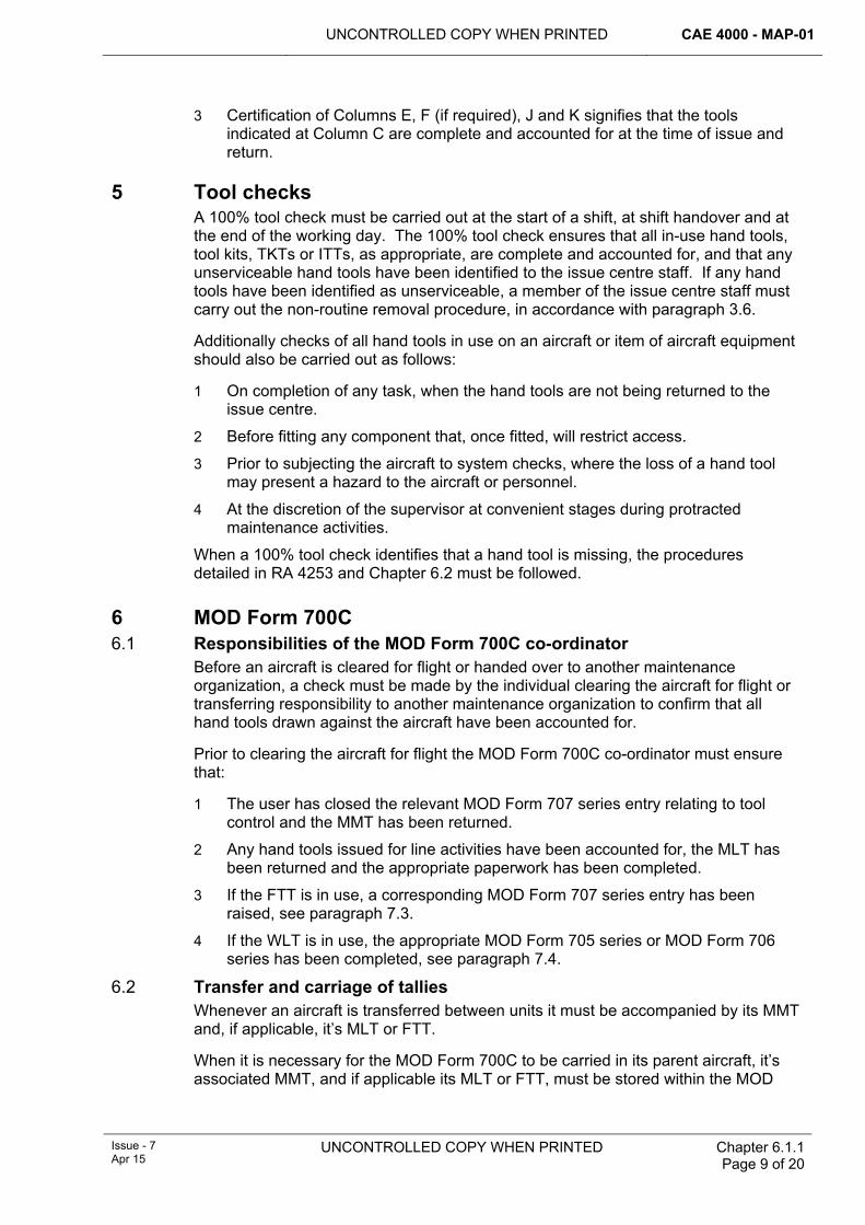
UNCONTROLLED COPY WHEN PRINTED CAE 4000 - MAP-01
Issue - 7 Apr 15
UNCONTROLLED COPY WHEN PRINTED
Chapter 6.1.1 Page 9 of 20
3 Certification of Columns E, F (if required), J and K signifies that the tools indicated at Column C are complete and accounted for at the time of issue and return.
5 Tool checks A 100% tool check must be carried out at the start of a shift, at shift handover and at the end of the working day. The 100% tool check ensures that all in-use hand tools, tool kits, TKTs or ITTs, as appropriate, are complete and accounted for, and that any unserviceable hand tools have been identified to the issue centre staff. If any hand tools have been identified as unserviceable, a member of the issue centre staff must carry out the non-routine removal procedure, in accordance with paragraph 3.6.
Additionally checks of all hand tools in use on an aircraft or item of aircraft equipment should also be carried out as follows:
1 On completion of any task, when the hand tools are not being returned to the issue centre.
2 Before fitting any component that, once fitted, will restrict access.
3 Prior to subjecting the aircraft to system checks, where the loss of a hand tool may present a hazard to the aircraft or personnel.
4 At the discretion of the supervisor at convenient stages during protracted maintenance activities.
When a 100% tool check identifies that a hand tool is missing, the procedures detailed in RA 4253 and Chapter 6.2 must be followed.
6 MOD Form 700C 6.1 Responsibilities of the MOD Form 700C co-ordinator
Before an aircraft is cleared for flight or handed over to another maintenance organization, a check must be made by the individual clearing the aircraft for flight or transferring responsibility to another maintenance organization to confirm that all hand tools drawn against the aircraft have been accounted for.
Prior to clearing the aircraft for flight the MOD Form 700C co-ordinator must ensure that:
1 The user has closed the relevant MOD Form 707 series entry relating to tool control and the MMT has been returned.
2 Any hand tools issued for line activities have been accounted for, the MLT has been returned and the appropriate paperwork has been completed.
3 If the FTT is in use, a corresponding MOD Form 707 series entry has been raised, see paragraph 7.3.
4 If the WLT is in use, the appropriate MOD Form 705 series or MOD Form 706 series has been completed, see paragraph 7.4.
6.2 Transfer and carriage of tallies Whenever an aircraft is transferred between units it must be accompanied by its MMT and, if applicable, it’s MLT or FTT.
When it is necessary for the MOD Form 700C to be carried in its parent aircraft, it’s associated MMT, and if applicable its MLT or FTT, must be stored within the MOD
CAE 4000 - MAP-01 UNCONTROLLED COPY WHEN PRINTED
Chapter 6.1.1 Page 10 of 20
UNCONTROLLED COPY WHEN PRINTED
Issue - 7 Apr 15
Form 700C in order to permit hand tools to be issued for use on that aircraft at any subsequent location, other than its parent unit.
7 Issue procedures 7.1 Issue of hand tools using the master maintenance tally (MMT)
Whenever an MMT is required to permit the use of hand tools on an aircraft, an entry must be made in the MOD Form 707 series, as detailed in paragraph 4.1, and the individual making that entry must take control of the MMT. The procedure to be followed for the issue of a tool kit or ITT set(s) and hand tools using the MMT is shown in Figure 1.
The issue of a tool kit must be recorded by an entry on an MOD F757A(Tools) at the issue centre. On return of the tool kit to the issue centre, the user and another individual, normally a member of the issue centre staff, must undertake and certify as having completed a 100% check of the tool kit in accordance with the provisions of paragraph 5.
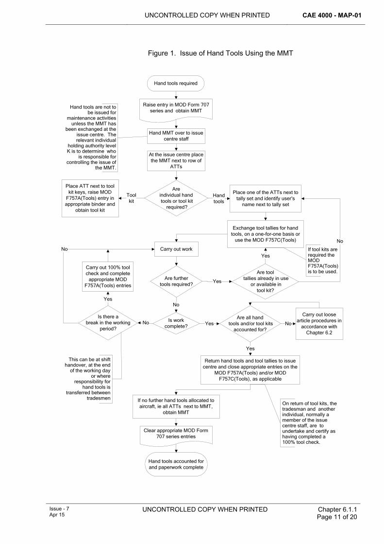
UNCONTROLLED COPY WHEN PRINTED CAE 4000 - MAP-01
Issue - 7 Apr 15
UNCONTROLLED COPY WHEN PRINTED
Chapter 6.1.1 Page 11 of 20
Figure 1. Issue of Hand Tools Using the MMT
Hand tools required
Are individual hand tools or tool kit
required?
At the issue centre place the MMT next to row of
ATTs
Place ATT next to tool kit keys, raise MOD
F757A(Tools) entry in appropriate binder and
obtain tool kit
Place one of the ATTs next to tally set and identify user's
name next to tally set
Carry out work
Raise entry in MOD Form 707 series and obtain MMT
Are further tools required?
Are tool tallies already in use
or available intool kit?
No
Yes
Are all hand tools and/or tool kits
accounted for?
Carry out loose article procedures in
accordance with Chapter 6.2
Is work complete?
Carry out 100% tool check and complete
appropriate MOD F757A(Tools) entries
No No
Return hand tools and tool tallies to issue centre and close appropriate entries on the
MOD F757A(Tools) and/or MOD F757C(Tools), as applicable
Clear appropriate MOD Form 707 series entries
Hand tools accounted for and paperwork complete
Is there abreak in the working
period?
No
Yes
Yes
Yes
Exchange tool tallies for hand tools, on a one-for-one basis or
use the MOD F757C(Tools)
Yes
Hand MMT over to issue centre staff
No
Toolkit
Hand tools
If no further hand tools allocated to aircraft, ie all ATTs next to MMT,
obtain MMT
This can be at shift handover, at the end
of the working day or where
responsibility for hand tools is
transferred between tradesmen
On return of tool kits, the tradesman and another individual, normally a member of the issue centre staff, are to undertake and certify as having completed a 100% tool check.
Hand tools are not to be issued for
maintenance activities unless the MMT has
been exchanged at the issue centre. The relevant individual
holding authority level K is to determine who
is responsible for controlling the issue of
the MMT.
If tool kits are required the MOD F757A(Tools) is to be used.
CAE 4000 - MAP-01 UNCONTROLLED COPY WHEN PRINTED
Chapter 6.1.1 Page 12 of 20
UNCONTROLLED COPY WHEN PRINTED
Issue - 7 Apr 15
7.2 Issue of hand tools using the Master Line Tally (MLT) A Sqn/Unit may choose to list in AESOs those tools that may be used for line activities and drawn without the use of the MMT. In such situations, each aircraft must be allocated an MLT, which must be used to identify that line hand tools are in use on that aircraft. The designated line tools must be assembled as line tool kits and, together with any supplementary hand tools required for flight servicing, eg tyre inflation rigs, held either within line control or in a designated area of the issue centre. The MLT can be issued without an entry in the relevant MOD Form 707 series and permits the user access to a line tool kit and a number of additional LTTs to allow the issue of supplementary hand tools. When line tool kits are being used, corresponding MOD F757A(Tools) entries must be used to record the issue and return of tool kits. Certification of the MOD Form 705 series by a tradesman signifies that any hand tools, used for that aspect of the flight servicing they have undertaken, have been accounted for. The procedure for the use of the MLT is shown in Figure 2.
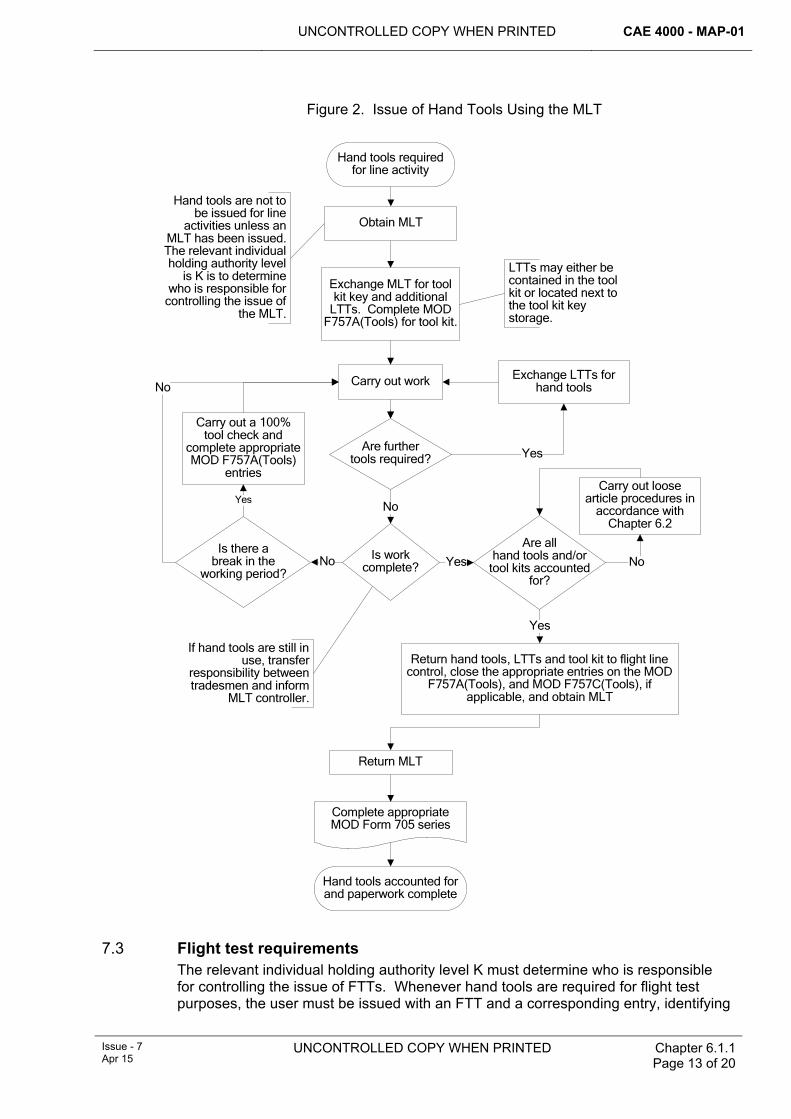
UNCONTROLLED COPY WHEN PRINTED CAE 4000 - MAP-01
Issue - 7 Apr 15
UNCONTROLLED COPY WHEN PRINTED
Chapter 6.1.1 Page 13 of 20
Figure 2. Issue of Hand Tools Using the MLT
Hand tools required for line activity
Exchange MLT for tool kit key and additional
LTTs. Complete MOD F757A(Tools) for tool kit.
Carry out work
Are further tools required?
No
Are all hand tools and/or
tool kits accounted for?
Carry out loose article procedures in
accordance with Chapter 6.2
Is work complete?
Carry out a 100% tool check and
complete appropriate MOD F757A(Tools)
entries
No No
Return hand tools, LTTs and tool kit to flight line control, close the appropriate entries on the MOD
F757A(Tools), and MOD F757C(Tools), if applicable, and obtain MLT
Complete appropriate MOD Form 705 series
Hand tools accounted for and paperwork complete
Is there abreak in the
working period?
No
Yes
Yes
Hand tools are not to be issued for line
activities unless an MLT has been issued. The relevant individual holding authority level
is K is to determine who is responsible for
controlling the issue of the MLT.
Exchange LTTs for hand tools
Return MLT
Obtain MLT
Yes
LTTs may either be contained in the tool kit or located next to the tool kit key storage.
If hand tools are still in use, transfer
responsibility between tradesmen and inform
MLT controller.
Yes
7.3 Flight test requirements
The relevant individual holding authority level K must determine who is responsible for controlling the issue of FTTs. Whenever hand tools are required for flight test purposes, the user must be issued with an FTT and a corresponding entry, identifying
CAE 4000 - MAP-01 UNCONTROLLED COPY WHEN PRINTED
Chapter 6.1.1 Page 14 of 20
UNCONTROLLED COPY WHEN PRINTED
Issue - 7 Apr 15
which hand tools (or tool kits) are in use, must be raised in the appropriate MOD Form 707 series as follows:
‘[Insert details of hand tools] in use on aircraft for flight test purposes, SNOW [insert SNOW relating to the flight test requirement] refers’
On completion of the flight test and subsequent return of the FTT, the MOD Form 707 series entry must be cleared as follows:
‘[Insert details of hand tools] removed from aircraft post-flight test at SNOW [insert SNOW relating to flight test requirement] and Flight Test Tally returned’
Notes:
1 The entries may be hand written, typed or produced by a stamp with the 'blanks' completed in handwriting or type.
2 When use of the hand tools imposes a limitation on the use of the aircraft a separate MOD F703 entry must also be raised.
On production of the FTT at the issue centre, the user must take only those hand tools necessary to undertake the flight test and must complete the appropriate MOD F757A(Tools) or MOD F757C(Tools) for that aircraft. When the FTT is in use, the user is responsible for the control of the hand tools at all times during the flight test. If necessary, the MOD Form 757A(Tools) must be used during the period of the flight test whenever a tool check is carried out.
7.4 Weapon loading The relevant individual holding authority level K must determine who is responsible for controlling the issue of WLTs. Whenever hand tools are to be used to undertake the loading/unloading of explosive armament stores, a WLT must be used. When issued to a weapon loading team, the WLT must be exchanged at the issue centre for either a set of ITTs or the relevant tool kit key. Issue of the tool kit must be certified using the MOD F757A(Tools). To permit the issue of supplementary hand tools, ITTs or TKTs may be used.
Once issued, the tool kit and/or hand tools may be used to undertake the loading/unloading of explosive armament stores of any number of aircraft. Certification of the appropriate loading/unloading documentation in accordance with Chap 14.9 signifies that all hand tools used in loading/unloading the aircraft have been accounted for.
7.5 Aircraft see-in/see-off If any tools are required to see-in/see-off an aircraft, they must be constituted as aircraft see-in/see-off tool kits. All see-in/see-off tool kits in use on a Ship/Stn/Unit must be of a standard design for each aircraft type/mark and the number of tools they contain must be kept to a minimum. However, the relevant individual holding authority level K may authorize the inclusion of the tools required to rectify any commonly occurring pre-flight faults, whose rectification has been approved by the TAA through its Topic 2(N/A/R)1 or by a person holding authorization MAP–G165.
Aircraft see-in/see-off tool kits must be serial numbered and, on issue/return, the user must complete an MOD F757A(Tools).
7.6 Remotely located hand tools and tool kits For those hand tools or tool kits located remotely from an issue centre:
UNCONTROLLED COPY WHEN PRINTED CAE 4000 - MAP-01
Issue - 7 Apr 15
UNCONTROLLED COPY WHEN PRINTED
Chapter 6.1.1 Page 15 of 20
1 The key for the hand tool storage or tool kit must be secured in the issue centre; its removal must be recorded by :
1.1 Raising an entry on the MOD F757A(Tools) in the issue centre.
1.2 Exchanging either an ITT or ATT for the tool kit key.
2 An MOD Form 757A(Tools) binder must be contained in the hand tool storage or tool kit.
3 100% tool checks must be carried out at the start of a shift, at shift handover or at the end of the working day in accordance with paragraph 5 and recorded on the MOD Form 757A(Tools) within the hand tool storage or tool kit.
Note:
Where it is impracticable to secure the key in an issue centre, when the tools are not in use, local arrangements must be made for the key’s custody, safekeeping and issue.
Unless the remotely located hand tools are for use on a particular aircraft only, once the key has been issued and the 100% tool check carried out, hand tools may be issued to individuals in exchange for a tool tally; see paragraph 3.4.
7.7 Off-unit loan procedure The following procedure must be adopted whenever a hand tool is to be loaned to/from another Sqn/Unit on the same Stn/Ship/Unit:
1 The user requiring the tool must draw a loan tally (see paragraph 3.6) at his issue centre, certifying its issue using a MOD F757B(Tools).
2 The user must request the loan of the required hand tool from the loaning unit and, if agreed, he must exchange his loan tally for the required hand tool at the loaning unit’s issue centre.
3 The user must complete a MOD F757B(Tools) entry at the loaning unit’s issue centre.
4 If practicable, the loaning unit must replace the hand tool with the borrowing unit’s loan tally.
5 The loaned hand tool must be returned to the borrowing unit’s issue centre.
6 The loaned hand tool may then be issued from the borrowing unit’s issue centre by use of either a TKT or ITT, as appropriate.
Note:
During the period of the loan the borrowing unit’s issue centre custodian is responsible for the safe custody of the hand tool and also any calibration or testing requirements that may arise during the period of the loan.
The procedure for returning the hand tool to the loaning unit is the reverse of the procedure detailed above.
If loans between Units at different Stn/Ship are likely, the required procedure should be defined in local orders to ensure the appropriate MOD F757B(Tools) of the loaning unit correctly records the approved removal, and the receiving unit places the received item under tool control. The Supply System should be used to ensure custody is formally transferred.
CAE 4000 - MAP-01 UNCONTROLLED COPY WHEN PRINTED
Chapter 6.1.1 Page 16 of 20
UNCONTROLLED COPY WHEN PRINTED
Issue - 7 Apr 15
7.8 Visiting aircraft There are two scenarios associated with the arrival of a visiting aircraft at a Stn/Ship/Unit; either:
1 The MOD Form 700C has accompanied the aircraft.
2 The MOD Form 700C has been retained by the parent unit.
When the MOD Form 700C has accompanied the aircraft, the appropriate tallies will have been despatched with the MOD Form 700C, see paragraph 6.2, and normal tool control procedures must be followed, with a set of ATTs being allocated to the visiting aircraft.
When the MOD Form 700C has been retained by the parent unit, it will be necessary for visiting aircraft MMTs, MLTs, if used, and ATTs to be made available at the hosting unit. Therefore, all units must allocate a sufficient number of MMTs, MLTs, if appropriate, and ATTs to permit the maintenance of visiting aircraft to be carried out.
7.9 Tool kits deployed with aircraft When it is necessary for a tool kit, other than Aircrew Land-away Turn round tool Kits (ALTKits), to be carried within an aircraft to facilitate maintenance at subsequent locations, eg an aircraft ground engineer’s tool kits, the following procedure must be followed:
1 The key for the tool kit must be replaced with the appropriate NRRT in accordance with paragraph 3.6.
2 On completion of a 100% tool check an initial MOD F757A(Tools) entry must be completed at the issue centre.
3 An MOD Form 757A(Tools) must accompany the tool kit.
4 Prior to the tool kit being used, a 100% tool check must be carried out and an entry raised on the accompanying MOD Form 757A(Tools).
5 On completion of any maintenance, a 100% tool check must be carried out and the MOD Form 757A(Tools) entry closed. Aircrew must complete Column M of the MOD Form 757A(Tools) when another tradesman is not available.
6 On return to its parent unit the tool kit must be returned to the issue centre and the original MOD Form 757A(Tools) entry must be completed.
7 All MOD Form 757A(Tools) used during the deployment must be retained with the MOD Form 707 series documentation covering the deployed period.
7.10 Use of hand tools by aircrew Aircrew must complete the relevant MOD F757A(Tools) or MOD F757C(Tools) when it is necessary for hand tools to be issued to aircrew, eg night flying torches or ALTKits. On return of the hand tools, the aircrew must complete the MOD Form 757A(Tools) or MOD Form 757C(Tools). There is no need to use an MMT or MLT to record the issue of these tools (see paragraph 3.1).
When an ALTKit forms part of an aircraft’s inventory and is stored permanently on the aircraft it must be fastened with a tell tale lock and checked periodically. If an aircrew member uses an ALTKit then on completion of the task they must carry out a 100% tool check and certify the ALTKit’s completeness on a F757A contained within the ALTKit. They must then report the ALTKit’s use to the maintenance organization at the earliest opportunity.
UNCONTROLLED COPY WHEN PRINTED CAE 4000 - MAP-01
Issue - 7 Apr 15
UNCONTROLLED COPY WHEN PRINTED
Chapter 6.1.1 Page 17 of 20
7.11 Off-aircraft activities An individual may draw tools for use on non-aircraft equipment. Additionally within a Sqn/Unit maintaining aircraft there may be a need to draw hand tools for work on aircraft equipment not yet assigned to a particular aircraft. In these instances, issue of tool kits or hand tools must be recorded in the MOD F757A(Tools) or MOD F757C(Tools), as appropriate, contained in the off-aircraft binder. The relevant individual holding authority level K must determine whether additional control measures are required, such as off-aircraft master tallies, and promulgate these procedures in local orders.
7.12 Multi-aircraft activities When it is necessary for a maintenance activity to be carried out consecutively on a number of aircraft by a single individual using the same hand tools, the following procedure must be followed:
1 The MMT for each aircraft on which the maintenance is required must be issued in the normal manner and the MMT must be placed next to its ATT set at the issue centre.
2 An ATT from each aircraft must be grouped together and either:
2.1 Placed next to a single ITT set, with ITTs then being used to allow hand tools to be issued for use.
2.2 Exchanged for the key to a tool kit.
Hand tools issued in this way may then be used on any of the aircraft to which they have been issued. Once the work has been completed the hand tools must be returned to the issue centre and on completion of the appropriate tool checks the ATTs may be returned to their stowage next to the corresponding MMT. If it is necessary for a single aircraft to be cleared of hand tools before the work has been completed on all aircraft, all hand tools for that activity must be returned to the issue centre and a tool check carried out. If all hand tools in use for the multi-aircraft activity are accounted for, the ATT for the aircraft being cleared may be returned.
7.13 Control of tools belonging to visiting maintenance teams There are occasions when visiting maintenance teams, such as 42(ES)Wing or 1710 Naval Air Squadron (1710 NAS) personnel, bring their own specialist tools with them. These tools may be taken on charge by the hosting Sqn/Unit’s issue centre and controlled in the same way as the Sqn/Unit’s own tools. Alternatively, if these tools are not to be stored in, and controlled by, the hosting Sqn/Unit’s issue centre, the following procedure must be adopted:
1 On departure from its home base the visiting team must certify that its tool kit(s) is (are) complete, using each tool kit’s MOD F757A(Tools).
2 On arrival at the work location the visiting team must ensure that the aircraft on which they intend to work is on tool control (ie there is an open MOD Form 707 series entry in accordance with paragraph 4.1) and the MMT is located in the issue centre.
3 The visiting team is then to go to the Sqn/Unit’s issue centre where the issue centre custodian must:
3.1 Allocate an ATT to the team; the ATT must be removed from its storage location and not returned until the visiting team has accounted for its tools on completion of its work.
CAE 4000 - MAP-01 UNCONTROLLED COPY WHEN PRINTED
Chapter 6.1.1 Page 18 of 20
UNCONTROLLED COPY WHEN PRINTED
Issue - 7 Apr 15
3.2 Raise an entry in the aircraft’s MOD F757A(Tools) (detailed at paragraph 4) to record the allocation of the visiting team’s tool kit(s) to that aircraft.
4 The team may then take its tools to the aircraft and start its task. The team is wholly responsible for its own tools and, if the task lasts for more than one day, its daily tool checks must be certified on each tool kit’s MOD F757A(Tools).
5 On completion of its task, the visiting team must check that its tool kits are complete and the issue centre custodian must:
5.1 Satisfy them that all of the visiting team’s tools have been accounted for.
5.2 In conjunction with a member of the visiting team, close the aircraft’s MOD F757A(Tools) entry recording the allocation of the team’s tools to the aircraft by signing columns K and L.
5.3 Return the visiting team’s ATT to its normal storage location.
Note:
All of the visiting maintenance team’s tools must be constituted into kits and each kit is to contain an MOD F757A(Tools) to record tool checks.
8 Aircraft equipment workshops In aircraft equipment workshops, hand tools and tool kits must be controlled using the MOD F757A(Tools), which must be completed at the start of a shift, at shift handover and at the end of the working day. Once the tool kit has been issued, dependent upon the size and nature of the workshop, either of the following procedures may be adopted:
1 Provided that the 100% tool checks are carried out in accordance with paragraph 5, no additional action is required to record the removal of a hand tool from its storage location for use within that workshop area.
2 Each individual must be allocated an ITT set, which permits the individual to remove hand tools from the hand tool storage or tool kit on a one-for-one basis. Tally sets and hand tools are to be accounted for as part of the 100% tool checks detailed in paragraph 5.
A tally set must be made available within the workshop, which will permit additional tools to be obtained from a location outside the workshop in accordance with paragraph 7.7.
9 Examples of tool control systems The following outlines example tool control systems that reference the procedures detailed within this chapter. These example systems may be adopted in full, or adapted in local orders to meet specific operating conditions, within the constraints of this Chapter:
1 MMT for each aircraft.
2 MLT for each aircraft, if hand tools to be held in the line control.
3 FTT for each aircraft, if hand tools are required for flight test.
4 ATT set for each aircraft.
5 WLT, if hand tools required for weapon loading activities.
6 MOD F757A(Tools) to record the issue of tool kits.
UNCONTROLLED COPY WHEN PRINTED CAE 4000 - MAP-01
Issue - 7 Apr 15
UNCONTROLLED COPY WHEN PRINTED
Chapter 6.1.1 Page 19 of 20
7 MOD F757B(Tools) to record the non-routine removal of hand tools.
8 And depending upon conditions the most appropriate option of either:
8.1 Use of MOD F757C(Tools) to record the issue of hand tools against a TKT, ITT or LTT; or
8.2 Hand tools exchanged for a TKT, ITT or LTT on a one-for-one basis, with the hand tool being replaced by the relevant tally.
10 Authorizations Personnel required to draw and return hand tools must hold authorization MAP–B180 unless relaxed tool control procedures are in operation (see paragraph 2.4). The authority level for returning hand tools or tool kits may be increased to authority level C at the discretion of the relevant individual holding authority level K.
11 Responsibilities 11.1 Authority level K
The relevant individual holding authority level K of the Stn/Ship/Unit is responsible for determining:
1 Which procedures are best suited to his organization, the type of tool tallies that are to be used and the method of identifying that a hand tool has been issued, ie MOD F757C(Tools) or exchange of tallies.
2 Who may issue and control the master and specialist tallies, eg MOD Form 700C coordinator.
3 For off-aircraft work, whether additional control measures are required, such as off-aircraft master tallies.
4 Whether, away from aircraft or aircraft equipment maintenance sections, tool control measures may be relaxed.
5 The authority level that may draw and return hand tools.
6 Which tools may be included in a see-in/see-off tool kit for the purpose of rectifying commonly occurring pre-flight faults.

CAE 4000 - MAP-01 UNCONTROLLED COPY WHEN PRINTED
Chapter 6.1.1 Page 20 of 20
UNCONTROLLED COPY WHEN PRINTED
Issue - 7 Apr 15
Intentionally Blank for Print Pagination
UNCONTROLLED COPY WHEN PRINTED CAE 4000 - MAP-01
Issue - 7 Apr 15
UNCONTROLLED COPY WHEN PRINTED Chapter 6.1.2 Page 1 of 4
Chapter 6.1.2
Hand Tool Provisioning
TABLE OF CONTENTS Paragraph
Page
1 General ............................................................................................................... 1 1.1 Introduction.......................................................................................................... 1 2 Regulatory Governance.................................................................................... 1 2.1 Regulatory Article Cross-reference ..................................................................... 1 2.2 Additional Information.......................................................................................... 1 3 Organizations responsible for hand tool provisioning.................................. 2 3.1 Operational Infrastructure Programme Project Team (OIP PT) .......................... 2 3.2 Type Airworthiness Authority (TAA) and commodity Project Team (PT) ............ 2 3.3 OIP PT– Military Equipment Tools Solutions (METS) ......................................... 2 3.4 Aircraft Branch..................................................................................................... 2 4 METS-controlled tool kits ................................................................................. 2 4.1 Repair of tool kits................................................................................................. 2 4.2 Replacement hand tools...................................................................................... 3 4.3 Alterations and modifications to tool kits ............................................................. 3 4.4 Application for additional tool kits ........................................................................ 3 4.5 Return of surplus tool kits.................................................................................... 3 4.6 Service-designed and manufactured tools .......................................................... 3 5 Reporting of OIP PT-managed faulty/defective hand tools........................... 4 6 Reference ........................................................................................................... 4
1 General 1.1 Introduction
Most common-user hand tools are generally procured and supplied under arrangements managed by the Operational Infrastructure Programme Project Team (OIP PT). For ranging new equipment, common items are generally selected from the Common Item Catalogue, maintained by the UK National Codification Bureau. This reduces duplication and the need for new items in the Defence Equipment & Support (DE&S) inventory. Although there are still differences in the way each Service manages the supply of hand tools, where possible this has been converged as detailed in this chapter. Hand tool management and tool control procedures are detailed in RA 4808, Chapter 6.1 and Chapter 6.1.1.
2 Regulatory Governance 2.1 Regulatory Article Cross-reference
This chapter supports:
1 Nil
2.2 Additional Information This chapter does not support any Regulatory Article however the chapter does detail the agencies that control and support the provisioning of hand tools.
CAE 4000 - MAP-01 UNCONTROLLED COPY WHEN PRINTED
Chapter 6.1.2 Page 2 of 4
UNCONTROLLED COPY WHEN PRINTED Issue - 7 Apr 15
3 Organizations responsible for hand tool provisioning 3.1 Operational Infrastructure Programme Project Team (OIP PT)
OIP PT Military Equipment Tools Solutions (METS) PM is the tri-Service Engineering Authority (EA) for tools and associated workshop equipment. OIP PT HD Proc provides inventory support for hand tools.
3.2 Type Airworthiness Authority (TAA) and commodity Project Team (PT) TAAs and commodity PT Engineering Authorities (EAs) are responsible for the through-life support of special-to-type hand tools. However, specialist technical assistance is available from OIP PT METS PO3; see paragraph 4.6
3.3 OIP PT– Military Equipment Tools Solutions (METS) METS:
1 Manages the design, manufacture and modification of in-use and new tool kits supplied by them to the Military Air Environment (MAE).
2 Updates respective technical information.
3 Provides configuration control.
4 Ensures adherence to current tool control polices within the MAE.
Procedures for configuring METS-controlled tool kits and for using METS tool control forms are detailed in paragraph 4.
3.4 Aircraft Branch Aircraft Branch is the authority and focal point for all hand tool ranging and scaling within Army Aviation. All hand tool scaled allowances are managed and controlled by Aircraft Branch. Requests to increase/decease these scales must be submitted by Aircraft Servicing Tools and Equipment Proforma (ASTEP) (JAP100E-10 Chap 3.6.2) for amending 041 series ETScales to:
Aircraft Branch Army Aviation Centre Middle Wallop Stockbridge Hants SO20 8DY METS PM1 Tel 9380 23426 [email protected]
METS provisions and supports Army Aviation tool kits.
4 METS-controlled tool kits 4.1 Repair of tool kits
Sqns/Units and workshops are responsible for the repair of their own tool kits (including internal fittings) in all cases, except when:
1 Major structural repairs are required and replacement would not be more expedient.
2 Repairs are impracticable in single aircraft flights detached from the parent unit.
In these cases a new container should be ordered from METS and the faulty container should be returned to METS for repair.
UNCONTROLLED COPY WHEN PRINTED CAE 4000 - MAP-01
Issue - 7 Apr 15
UNCONTROLLED COPY WHEN PRINTED Chapter 6.1.2 Page 3 of 4
4.2 Replacement hand tools The replacement of hand tools and components within tool kits must be strictly controlled in accordance with Stn/Ship/Unit instructions.
Replacement hand tools that have authorized scales must be demanded through normal supply channels in accordance with JSP 886.
Tool kit component parts must only be used to maintain kits at their original standard as issued by METS. They must not be used to modify existing kits or to create additional kits or for any other purpose without the prior approval of METS.
4.3 Alterations and modifications to tool kits Tool kits supplied by METS must not to be altered or modified unless authorized by METS PM. Such authorization will be promulgated by MOD F757TC4. Stn/Ship/Unit Tool Controllers are to implement these modifications within 2 months of receipt of tools. MOD F757TC1 must be raised by user units to advise METS of suggested alterations or modifications of tool kits. MOD F757TC5 and F757TC6 must be used to control the issue of MOD F757TC4 and the embodiment of alterations or modifications to METS tool kits.
4.4 Application for additional tool kits Occasions arise when the task of a Stn/Ship/Unit is changed and a requirement is generated for additional tool kits to meet the new commitment. Applications for such additional tool kits are to be forwarded, in duplicate, on MOD F757TC2, to METS. Stns/Ships/Units raising MOD F757TC2 must allocate a local consecutive serial number and have the form authorized by the Stn/Ship/Unit Tool Controller.
METS is authorized to investigate and approve minor requirements. Any major requirement, ie one that may involve significant cost or a policy change, must be referred to the Front Line Command (FLC) or PT. If the major requirement is supported by the FLC, or PT, the MOD F757TC2 must be forwarded to METS PM for approval and tasking instructions.
Requests for tool kit replacement shells and panels must be submitted to METS using MOD F757TC7.
4.5 Return of surplus tool kits Surplus tool kits must be returned directly to METS.
4.6 Service-designed and manufactured tools For reasons of economy, expediency and availability, non-standard tools that are not available through Service sources may be obtained from METS using the Aircraft Servicing Tools and Equipment (ASTE) procedures.
ASTEs are identified with “ASTE” and the identification numbers, eg ASTE/573. The authority for use of these tools is a Full Technical Approval (FTA) certification, authorized by the relevant TAA or commodity PT EA and held by METS. Following FTA, ASTEs are scaled in the relevant Equipment Table (ET) and authorized by the appropriate ranging/scaling authority. .
Details of the process for the introduction and amendment of ASTEs are held by METS and can be obtained from METS Sp1b.
Requests for additional ASTEs should be submitted to METS Sp1b on a MF757TC7 which is located in Chapter 1.4 of the MAP-02.
CAE 4000 - MAP-01 UNCONTROLLED COPY WHEN PRINTED
Chapter 6.1.2 Page 4 of 4
UNCONTROLLED COPY WHEN PRINTED Issue - 7 Apr 15
5 Reporting of OIP PT-managed faulty/defective hand tools OIP PT-managed tools that are faulty or defective are to be reported using the MOD F760 process detailed in Chapter 7.5.1. Completed MOD F760s are to be sent to:
Unicorn Building PP88 Unicorn Road Portsmouth Naval base Portsmouth Hampshire PO1 3GX
6 Reference This chapter refers to the following publication:
1 JSP 886 – The Defence Logistics Support Chain Manual.
UNCONTROLLED COPY WHEN PRINTED CAE 4000 - MAP-01
Issue - 7 Apr 15
UNCONTROLLED COPY WHEN PRINTED Chapter 6.2 Page 1 of 8
Chapter 6.2
Loose Articles – Precautions and Recovery Procedures
TABLE OF CONTENTS Paragraph
Page
1 General ............................................................................................................... 1 1.1 Introduction.......................................................................................................... 1 1.2 Applicability ......................................................................................................... 1 2 Regulatory Governance.................................................................................... 2 2.1 Regulatory Article Cross-reference ..................................................................... 2 2.2 Additional Information.......................................................................................... 2 3 Precautions to prevent loose articles ............................................................. 2 3.1 Personal precautions........................................................................................... 2 3.2 Tool control procedures....................................................................................... 2 3.3 Aero-engine maintenance ................................................................................... 2 3.4 Carriage of ballast in aircraft ............................................................................... 3 4 Loose article recovery procedure.................................................................... 3 4.1 Purpose ............................................................................................................... 3 4.2 Sequence of searches......................................................................................... 3 4.3 Conduct of searches ........................................................................................... 3 4.4 Clearance for flight .............................................................................................. 4 5 Unknown Loose article found in/on an aircraft .............................................. 5 6 Authorization ..................................................................................................... 6 7 References ......................................................................................................... 6
LIST OF TABLES Table 1. Loose Article Authorizations. ...........................................................................................6
LIST OF FIGURES Figure 1. Flowchart for Recovery of a Loose Article.....................................................................7
1 General 1.1 Introduction
Loose articles are classified as any items that have been dropped, lost, become detached or unaccounted for in and around aircraft, creating a potential hazard to the aircraft. Typical loose articles include items such as hand tools, pens, coins, nuts, bolts, washers and split pins which, when lost within an aircraft, could cause control restrictions and system malfunctions. In addition, engine compressors can also ingest loose articles, leading to significant damage or catastrophic failure. This chapter details the policy and procedures to manage and minimize loose article incidents.
1.2 Applicability This chapter is applicable to all personnel operating or employed on the maintenance of UK Military Registered Aircraft or associated equipment.
CAE 4000 - MAP-01 UNCONTROLLED COPY WHEN PRINTED
Chapter 6.2 Page 2 of 8
UNCONTROLLED COPY WHEN PRINTED Issue - 7 Apr 15
2 Regulatory Governance 2.1 Regulatory Article Cross-reference
This chapter supports:
1 RA 4253(1).
2 RA 4253(2).
3 RA 4253(3).
2.2 Additional Information A loose article that is not recovered may then become FOD. FOD is defined as any item or material, other than birds or wildlife, that originates from any source, either external to, or part of, an aircraft and which then has the potential to cause damage. Propellers, rotor blades and aero-engines are particularly vulnerable to FOD during ground runs, taxiing and take-off. Great care should be exercised in keeping flight decks, runways, aircraft manoeuvring and work areas clear of all debris to reduce the potential risk of damage. In addition, aircraft not immediately required for flight are to have blanks, bungs and covers fitted at all times, unless removed for maintenance, to reduce the risk of collateral FOD. RA1400(2) Flight Safety provides the Regulation, Acceptable Means of Compliance (AMC) and Guidance Material (GM) on FOD damage prevention.
3 Precautions to prevent loose articles 3.1 Personal precautions
When working on aircraft or aircraft equipment, personnel must ensure that:
1 They are free from potential sources of loose articles, such as jewellery, coins, etc.
2 Work areas are kept free of loose articles and debris.
3 Only those items necessary to undertake the task in hand are used in the work area and the issue and return of hand tools is carried out in accordance with RA 4808 and Chapter 6.1.1.
4 Only sufficient nuts, bolts, miscellaneous fasteners, etc, necessary for the tasks in hand are used and they must be accounted for at all times.
5 On completion of the task a loose article check is carried out in the vicinity of the work area and all loose articles and debris removed.
3.2 Tool control procedures Correct tool control procedures must be maintained at all times when undertaking maintenance of aircraft and associated equipment. Whenever a hand tool is suspected of becoming a loose article, the procedures detailed within this chapter must be followed. The principles and procedures for the control of hand tools are detailed in RA 4808 and Chapter 6.1.1.
3.3 Aero-engine maintenance The following precautions must be taken to prevent the ingestion of loose articles by aircraft aero-engines:
1 Intake, auxiliary intake and exhaust blanks and covers must be fitted, except when necessary to meet operational or maintenance requirements. Blanks and covers must be examined prior to being fitted to ensure that they are serviceable and free of loose articles.
UNCONTROLLED COPY WHEN PRINTED CAE 4000 - MAP-01
Issue - 7 Apr 15
UNCONTROLLED COPY WHEN PRINTED Chapter 6.2 Page 3 of 8
2 Uninstalled engines mounted in uninstalled engine test facilities must be treated in the same manner as installed engines.
3 Uninstalled engines, engine modules and components must be protected with blanks and covers.
4 Loose article searches must be carried out at relevant stages during engine build and before turning rotating assemblies.
5 Air intakes must not to be used as footholds or ledges on which to place hand tools or equipment.
6 Aircraft marshallers and ground running supervisors must ensure that, wherever possible, jet efflux or propeller wash is not directed towards other aircraft, particularly those that are not fitted with intake blanks or covers.
3.4 Carriage of ballast in aircraft When it is necessary to carry removable ballast in aircraft such ballast must be detailed in the Aircraft Document Set (ADS) and fitted in accordance with the relevant Technical Information (TI). Ballast must consist of non-magnetic metal or concrete weights; sand or the carriage of personnel as ballast is not permitted. If special provision or instructions do not exist the Type Airworthiness Authority (TAA) is to be consulted.
4 Loose article recovery procedure 4.1 Purpose
The purpose of a loose article search is to recover an item that has been lost or is suspected of having been lost, or to confirm to a high degree of probability that the item is not in or on an aircraft. Whenever a loose article is reported, an entry must be made in the MOD Form 700 of affected aircraft, detailing the item that is missing and the potential search area, if known. The procedures to be implemented to recover a loose article are described in paragraphs 4.2, 4.3 and 4.4. These procedures are summarized in the flowchart at Figure 1.
4.2 Sequence of searches The number and extent of searches required will depend on the nature of the potential hazard and degree of risk. The extent of the search may be as follows:
1 Initial search, with panels removed if appropriate. This may include functional checks to prove full and free movement of control runs after examination of the control run.
2 Follow-up searches, by different tradesmen where possible.
3 Further, deeper searches with more equipment removed.
4 X-ray or other NDT inspection as applicable, if necessary and appropriate.
5 Loose article airborne check as detailed at paragraph 4.4.2 if appropriate.
4.3 Conduct of searches Searches must be systematic maintenance activities and recorded as such in accordance with Chapter 4.3.2. The area to be searched must be made as accessible as reasonably practicable by the removal of panels, components, etc. The extent to which panels and components are removed and the aircraft dismantled is at the discretion of the authorized person, see paragraph 6, who may defer the search in that area and clear the aircraft for flight, in accordance with paragraph 4.4. The authorized person must take into account the following:
CAE 4000 - MAP-01 UNCONTROLLED COPY WHEN PRINTED
Chapter 6.2 Page 4 of 8
UNCONTROLLED COPY WHEN PRINTED Issue - 7 Apr 15
1 The danger to the aircraft of the item being left in place.
2 The danger to the aircraft of the item moving during flight, taking into account the likely attitude of the aircraft during flight and possible migration routes.
3 The degree of difficulty in reaching the suspected location, perhaps in terms of mandatory checks or inspections after refit of any removed components.
4 The ability to restrain the item in place, preventing its movement.
5 The operational need for the aircraft.
6 Whether the loose article is known to have been lost on the aircraft or it is suspected that the loose article is on the aircraft.
4.4 Clearance for flight If the loose article is recovered, the aircraft must be cleared for flight in the normal manner. However, if the appropriate searches detailed at paragraph 4.2 have been completed and the loose article has not been found, the authorized person required to clear the aircraft for flight, see paragraph 6, must consider the flight safety risk and:
1 Continue the search until the loose article is either recovered or the flight safety risk is reduced to an acceptable level in accordance with paragraph 4.3.
2 Carry out a loose article airborne check in accordance with paragraph 4.4.2.
3 Clear the aircraft for flight subject to a further sequence of searches at a more appropriate opportunity in accordance with paragraph 4.4.3.
4 Clear the aircraft for unrestricted flight in accordance with paragraph 4.4.4.
4.4.1 Further searches If it is not appropriate to defer further searches, different tradesmen to those who carried out the initial search should carry them out, wherever possible.
4.4.2 Loose article airborne checks If a loose article is thought to be in an area where inverted flight or other manoeuvres may dislodge and reveal it, an authorized person may authorize a loose article airborne check, when the following mandatory list is followed:
1 The aircrew officer authorizing the flight has agreed the details of the loose article airborne check.
2 The flight is authorized solely for the purpose of recovering the loose article.
3 The flight authorizing officer is advised of the need to terminate the flight immediately after the specified manoeuvres if the article is not revealed or if the article is revealed but cannot be recovered and secured during the flight.
4 The loose article airborne check has been documented in the aircraft’s MOD Form 700 in accordance with the appropriate instructions for use.
If the loose article airborne check fails to reveal the loose article, the authorized person must detail a further search of the suspect area before releasing the aircraft for flight in accordance with paragraph 4.4.
4.4.3 Loose article search deferment If the initial search significantly reduces the risk of a loose article being present, or if it is deemed to have been secured in a safe area, further searches or recovery may be deferred by an authorized person until a more appropriate opportunity. The deferral period will depend on a number of circumstances related to those influencing the deferral decision as above, but options include:
UNCONTROLLED COPY WHEN PRINTED CAE 4000 - MAP-01
Issue - 7 Apr 15
UNCONTROLLED COPY WHEN PRINTED Chapter 6.2 Page 5 of 8
1 The next scheduled maintenance of an appropriate depth to retrieve the item.
2 At the end of a particular exercise or detachment.
3 At the next appropriate component removal.
The deferral of a loose article search must be recorded on the maintenance documentation and is to be closed by cross-referring to an entry on the Acceptable Deferred Faults Log (ADF Log) (MOD F704), or Loose Article Register (MOD F704LA), if platform approved, in accordance with RA 4812 and Chapter 5.4.2.
In operational or combat conditions it may be appropriate to tolerate additional risk to improve aircraft availability. In these circumstances, if the loose article is potentially in a high-risk area and the decision is to fly the aircraft, the deferral period must be as short as possible. In addition, an entry must be made in the ADF Log or the Limitations Log (Lim Log) (MOD F703), as appropriate. The deferral must be signed by an authorized person and must have the flight authorizing officer’s agreement to any imposed limitation.
4.4.4 Unrestricted clearance If the loose article is not recovered, but the risk to the aircraft is considered negligible or searches have significantly reduced the risk of a loose article being present, the aircraft may be cleared for further unrestricted flight by an authorized person.
5 Unknown Loose article found in/on an aircraft It is important to identify the source of any unknown loose article found in/on an aircraft.
1 If the article is positively confirmed as not being an aircraft part then the authorized person should assure themselves that the aircraft is safe to operate using all necessary functional and visual checks.
2 If it is suspected that the article is an aircraft part and it can be proven that the suspected original location(s) of the article are complete and in a safe condition then the authorized person should assure themselves that the aircraft is safe to operate using all necessary functional and visual checks.
3 If it is suspected that the article is an aircraft part and there is potential that the found article could have come from a location not accessible during Forward maintenance activity then:
3.1 The authorized person is to assure themselves that the aircraft is safe to operate using all possible functional and visual checks.
3.2 An ADF Log entry must be raised giving full details of the found article’s discovery and of consequent action taken.
4 If the found loose article cannot be identified using all methods and support agencies available (eg pictures and description sent to PT, CAMO, Depth support areas etc), then:
4.1 The authorized person is to assure themselves that the aircraft is safe to operate using all possible functional and visual checks.
4.2 An ADF Log entry is to be raised giving full details of the found article's discovery, description and subsequent actions taken.
Regardless of the determination of the nature of the found article, if further loose articles are identified, or suspected, the procedures detailed at paragraph 4 are to be implemented.
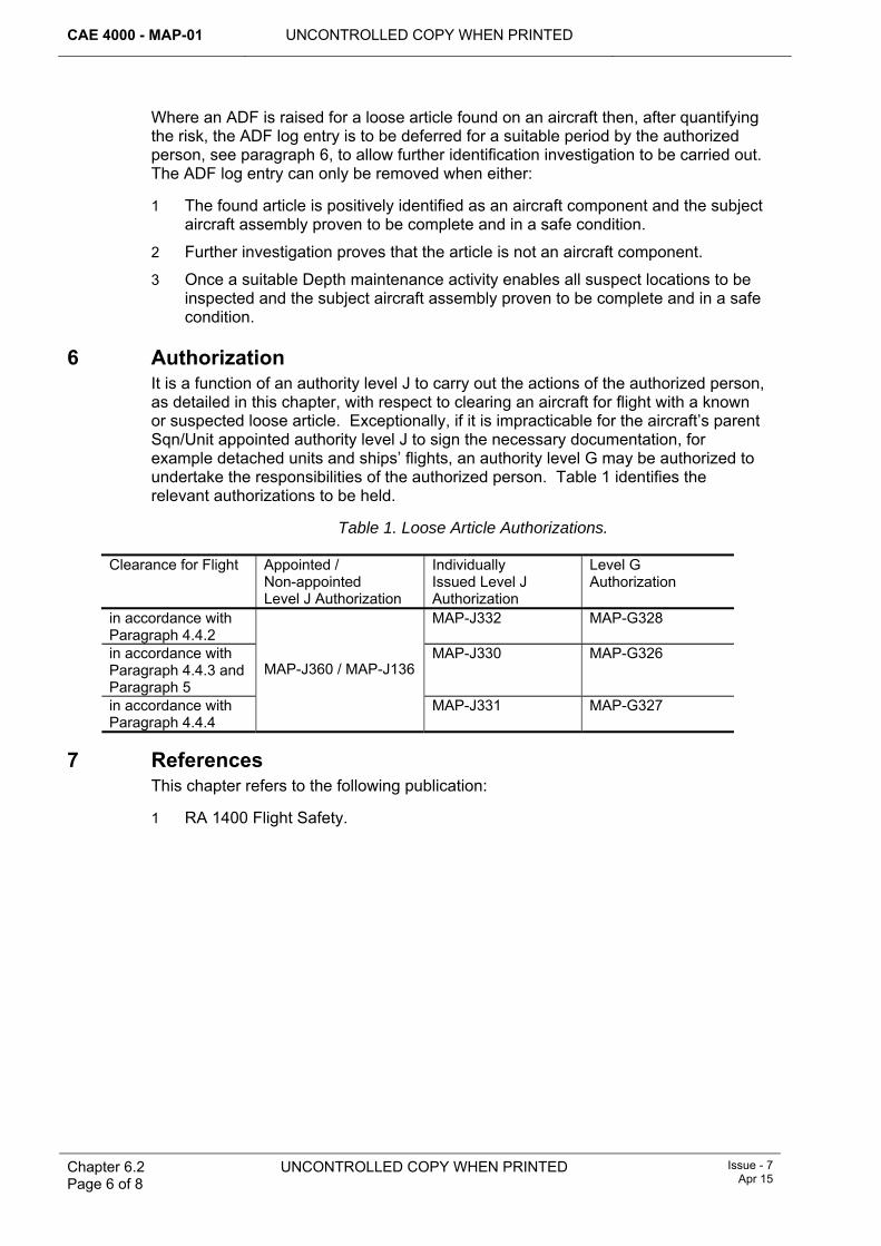
CAE 4000 - MAP-01 UNCONTROLLED COPY WHEN PRINTED
Chapter 6.2 Page 6 of 8
UNCONTROLLED COPY WHEN PRINTED Issue - 7 Apr 15
Where an ADF is raised for a loose article found on an aircraft then, after quantifying the risk, the ADF log entry is to be deferred for a suitable period by the authorized person, see paragraph 6, to allow further identification investigation to be carried out. The ADF log entry can only be removed when either:
1 The found article is positively identified as an aircraft component and the subject aircraft assembly proven to be complete and in a safe condition.
2 Further investigation proves that the article is not an aircraft component.
3 Once a suitable Depth maintenance activity enables all suspect locations to be inspected and the subject aircraft assembly proven to be complete and in a safe condition.
6 Authorization It is a function of an authority level J to carry out the actions of the authorized person, as detailed in this chapter, with respect to clearing an aircraft for flight with a known or suspected loose article. Exceptionally, if it is impracticable for the aircraft’s parent Sqn/Unit appointed authority level J to sign the necessary documentation, for example detached units and ships’ flights, an authority level G may be authorized to undertake the responsibilities of the authorized person. Table 1 identifies the relevant authorizations to be held.
Table 1. Loose Article Authorizations.
Clearance for Flight Appointed / Non-appointed Level J Authorization
Individually Issued Level J Authorization
Level G Authorization
in accordance with Paragraph 4.4.2
MAP-J332 MAP-G328
in accordance with Paragraph 4.4.3 and Paragraph 5
MAP-J330 MAP-G326
in accordance with Paragraph 4.4.4
MAP-J360 / MAP-J136
MAP-J331 MAP-G327
7 References This chapter refers to the following publication:
1 RA 1400 Flight Safety.
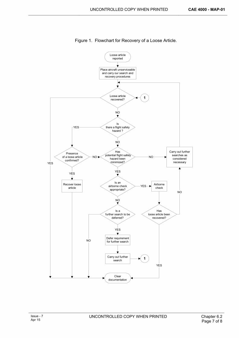
UNCONTROLLED COPY WHEN PRINTED CAE 4000 - MAP-01
Issue - 7 Apr 15
UNCONTROLLED COPY WHEN PRINTED Chapter 6.2 Page 7 of 8
Figure 1. Flowchart for Recovery of a Loose Article.
Loose articlereported
Place aircraft unserviceableand carry our search and
recovery procedures
Loose articlerecovered?
Has potential flight safety
hazard beenminimized?
Is anairborne checkappropriate?
Is afurther search to be
deferred?
Defer requirementfor further search
Carry out furthersearch
Hasloose article been
recovered?
Airbornecheck
YES
YES
YES
NO
YES
NO
Carry out furthersearches asconsiderednecessary
NO
NO
Presence of a loose article
confirmed?
YESIs
there a flight safetyhazard ?
NO
Recover loosearticle
YES
YES
NO
Cleardocumentation
1
1
NO

CAE 4000 - MAP-01 UNCONTROLLED COPY WHEN PRINTED
Chapter 6.2 Page 8 of 8
UNCONTROLLED COPY WHEN PRINTED Issue - 7 Apr 15
Intentionally Blank for Print Pagination
UNCONTROLLED COPY WHEN PRINTED CAE 4000 - MAP-01
MAE Issue - 6 Mar 14
UNCONTROLLED COPY WHEN PRINTED Chapter 6.3 Page 1 of 8
Chapter 6.3
Local Manufacture of Parts for Aircraft and Airborne Equipment
TABLE OF CONTENTS Paragraph
Page
1 General ............................................................................................................... 1 1.1 Introduction.......................................................................................................... 1 1.2 Associated publications....................................................................................... 1 1.3 Applicability ......................................................................................................... 2 2 Regulatory Governance.................................................................................... 2 2.1 Regulatory Article Cross-reference ..................................................................... 2 2.2 Additional Information.......................................................................................... 2 3 Authority to locally manufacture ..................................................................... 2 3.1 Normal manufacture............................................................................................ 2 3.2 Special manufacture............................................................................................ 2 4 Local Manufacturing requirements ................................................................. 3 4.1 Normal manufacture............................................................................................ 3 4.2 Special manufacture – additional requirements .................................................. 4 4.3 Concessions........................................................................................................ 4 5 Marking, recording and labelling of locally manufactured parts .................. 5 5.1 Marking................................................................................................................ 5 5.2 Recording ............................................................................................................ 6 5.3 Labelling .............................................................................................................. 6 6 Responsibilities................................................................................................. 7 6.1 Type Airworthiness Authority (TAA) .................................................................... 7 6.2 Authorizing authority level K................................................................................ 7 6.3 Continuing Airworthiness Management Organization (CAMO) ........................... 7 7 References ......................................................................................................... 7
LIST OF TABLES Table 1. DSG, 71(IR)Sqn and 1710 NAS Code Letters. ..............................................................5
1 General 1.1 Introduction
The local manufacture of parts for aircraft and airborne equipment by Stn/Ship/Units is permitted within the detailed terms of this chapter. Such work is classified as either 'normal' or 'special' manufacture. This chapter defines the circumstances under which the local manufacture of parts for aircraft or airborne equipment may be permitted.
1.2 Associated publications This chapter is associated with following publications:
1 Aircraft Topic 3A (Illustrated Parts Catalogue) – for the relevant aircraft, where the annotation local manufacture (LM), ‘ECC’ (electrical cable chart) or ‘PC’ (pipe chart) indicates that the part is not provisioned but should be manufactured locally from the material specified.
CAE 4000 - MAP-01 UNCONTROLLED COPY WHEN PRINTED
Chapter 6.3 Page 2 of 8
UNCONTROLLED COPY WHEN PRINTED MAE Issue - 6
Mar 14
2 Aircraft Topic 2 (Modification Leaflets and Special Instructions (Technical) (SI(T)s)) – for the relevant aircraft where precise instructions, including drawings, are provided to facilitate the local manufacture of parts.
3 Aircraft Topic 6 (Repair Manual) – which contains specific instructions on the extent and pattern of authorized repairs and the techniques to be used.
4 AP 101A-0300-1 – Aircraft Rigid Pipelines.
5 AP 101A-0301-1 – Aircraft Flexible Hoses with Re-usable End Fittings.
6 AP 119G-002-1 – Heat Treatment of Aluminium Alloys.
7 Repair scheme drawings supplied by the Design Organization (DO), 71 (Inspection and Repair) Squadron (71(IR)Sqn), 1710 Naval Air Squadron (1710 NAS) or Type Airworthiness Authorities (TAA) that authorize LM.
1.3 Applicability This chapter is applicable to the manufacture of any item that has a discrete Part Number and applies to the manufacture of parts for aircraft and airborne equipment that are authorized in accordance with paragraph 3.
2 Regulatory Governance 2.1 Regulatory Article Cross-reference
This chapter supports:
1 RA 4809(3) .
2.2 Additional Information Nil.
3 Authority to locally manufacture Before any plans are finalized to locally manufacture a part for an aircraft or item of airborne equipment, the TAA or an individual holding authorization MAP-K143 authorizing the local manufacturing task must confirm that it will not infringe any Intellectual Property Rights (IPR).
3.1 Normal manufacture Stns/Ships/Units are authorized to locally manufacture parts for aircraft and airborne equipment in accordance with those formal instructions contained in the associated publications at paragraph 1.2. Work undertaken under these provisions is regarded as normal manufacture.
3.2 Special manufacture The local manufacture of parts for aircraft and airborne equipment outside the provisions of paragraph 3.1 is regarded as 'special' manufacture and is not permitted without having first determined availability of the required part through either normal supply channels and/or by approaching the PT responsible for the aircraft or equipment, except when the provisions detailed in the note below apply. Having determined that the required part cannot be provided through normal supply channels to meet the demand priority, the decision to locally manufacture a part for an aircraft and airborne equipment rests with the individual holding authorization MAP-K143. Before authorizing any 'special' manufacture at a Depth organization, the individual holding authorization MAP-K143 must gain approval from the relevant PT. When assessing the requirement for 'special' manufacture, consideration is to be given to the following:
UNCONTROLLED COPY WHEN PRINTED CAE 4000 - MAP-01
MAE Issue - 6 Mar 14
UNCONTROLLED COPY WHEN PRINTED
Chapter 6.3 Page 3 of 8
1 Whether the part is necessary to address an essential or urgent requirement.
2 Whether the part is necessary to satisfy operational, engineering, supply or economic requirements.
3 Whether the part can be obtained or manufactured through local purchase arrangements.
4 The structure or functional importance of the part and the consequence of failure.
5 Whether inter-changeability will be affected in terms of the fit, form or function.
6 The availability of drawings, material specifications, tools, materials and specialist process requirements, etc, and the capabilities and skill levels of the available tradesmen.
7 Whether 'special' manufacture represents the best solution to meet the requirement.
Note:
Exceptionally, an individual holding authorization MAP-K143 may authorize the local manufacture of parts for aircraft and airborne equipment without having first determined availability of the required part through either normal supply channels and/or by approaching the PT responsible for the aircraft or equipment. This authority may only be exercised at a Forward organization when it is impracticable in the prevailing circumstances to determine availability of the required part and it is considered essential to manufacture the part locally.
4 Local Manufacturing requirements 4.1 Normal manufacture
The local manufacture of parts for aircraft and airborne equipment must not be undertaken unless the requirements detailed below are satisfied at the point of manufacture, or the concessions at paragraph 4.3 are applied. When authorized, the following requirements apply to normal manufacture:
1 Except for the concessions detailed at paragraph 4.3, parts must to be manufactured in accordance with the approved data contained in the associated publications at paragraph 1.2.
2 Proof of conformity to specification must be available for all materials used. For metallic and some non-metallic materials this is usually provided by an approved firm’s Release Document or Certificate of Conformity, which is delivered directly from the contractor. Metallic materials may also be identified with overall/line marking or colour coding as detailed in Def Stan 05-69. The same regulations also apply to foreign sourced materials where the appropriate PT must obtain the necessary manufacturer’s release certificate. However, materials supplied under Federal Military Stock (FMS) are underwritten by the US Department of Defense National Quality Assurance Authority and do not require a Certificate of Conformity.
3 An undocumented metal, for which the PT has been unable to obtain any form of release certificate, must only be used subject to a sample being tested and its material specification correctly determined. The test house must issue a certificate detailing the material specification and condition and a batch number to identify the material uniquely. This batch number must be marked on the metal before it is brought on charge.
CAE 4000 - MAP-01 UNCONTROLLED COPY WHEN PRINTED
Chapter 6.3 Page 4 of 8
UNCONTROLLED COPY WHEN PRINTED MAE Issue - 6
Mar 14
4 To preserve the traceability of materials after receipt in the manufacturing area, each Ship/Stn/Unit locally manufacturing parts must operate a controlled material storage system and record the issue of material by identity and quantity against specific tasks or aircraft references. A system for maintaining the identity of materials through all stages of local manufacture must also to be in operation.
5 Local manufacturing processes, including any heat treatment and testing processes, must be carried out as specified in approved instructions and/or drawings.
6 Test pieces must be used for the proving of heat treatment processes, with samples submitted for laboratory testing as required.
Note:
RAF only – The manufacture of parts in station workshops is subject to the procedures detailed in AP 100E-15.
4.2 Special manufacture – additional requirements In addition to the requirements for the local manufacture of parts for aircraft and airborne equipment under normal circumstances, the following requirements apply to special manufacture:
1 The individual holding authorization MAP-K143 must determine the level and extent of quality control checks during and following completion of the manufacturing task.
2 Once the locally manufactured part is fitted to an aircraft, the individual holding authorization MAP-K143 in consultation with the CAMO must decide if it is to remain fitted or be replaced when a part becomes available through normal supply channels. Any such replacement must be the subject of an Acceptable Deferred Fault Log (MOD F704) entry.
4.3 Concessions 4.3.1 Approval by the Type Airworthiness Authority (TAA)
Any concessions to the local manufacturing requirements at paragraphs 4.1 to 4.2 must be approved in writing by the TAA, with advice from the DO, if appropriate, except when the provisions at paragraph 4.3.2 apply. On occasions when the DO is approached for advice on a proposed local manufacturing concession, either through a resident Contractor’s Representative or other contractual agreement, correspondence must be copied to the TAA and the CAMO.
4.3.2 Approval by the authorizing authority level K Exceptionally, the individual holding authorization MAP-K143 may approve concessions to the local manufacturing requirements at paragraph 4.1. This includes occasions when it may be necessary to use the original, or an identical part, as a manufacturing pattern due to the approved instructions and/or drawings not being available, or the time required to obtain such instructions and/or drawings being unacceptable. When approved, local manufacture of the part must be treated as special manufacture and must be conducted in accordance with paragraph 4.2 and the remaining applicable local manufacturing requirements at paragraph 4.1, together with the following additional requirements:
1 The individual holding authorization MAP-K143 must personally endorse the work recording document to signify approval of the concession. This may
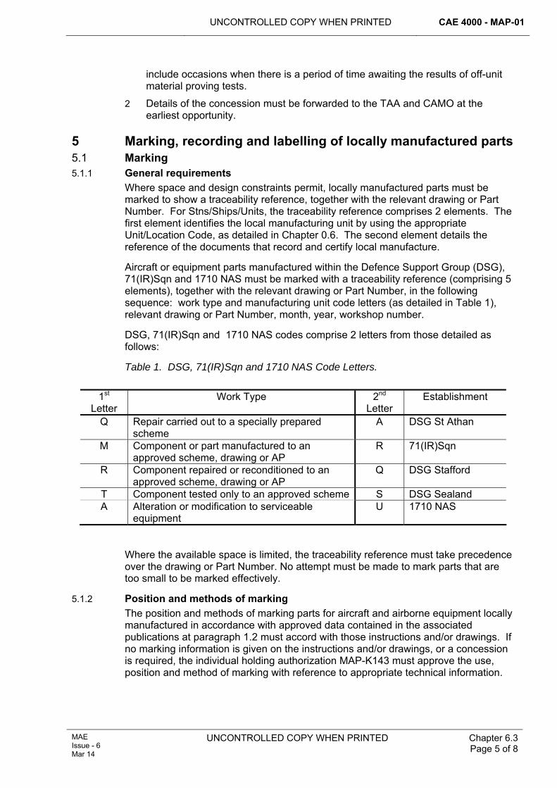
UNCONTROLLED COPY WHEN PRINTED CAE 4000 - MAP-01
MAE Issue - 6 Mar 14
UNCONTROLLED COPY WHEN PRINTED
Chapter 6.3 Page 5 of 8
include occasions when there is a period of time awaiting the results of off-unit material proving tests.
2 Details of the concession must be forwarded to the TAA and CAMO at the earliest opportunity.
5 Marking, recording and labelling of locally manufactured parts 5.1 Marking 5.1.1 General requirements
Where space and design constraints permit, locally manufactured parts must be marked to show a traceability reference, together with the relevant drawing or Part Number. For Stns/Ships/Units, the traceability reference comprises 2 elements. The first element identifies the local manufacturing unit by using the appropriate Unit/Location Code, as detailed in Chapter 0.6. The second element details the reference of the documents that record and certify local manufacture.
Aircraft or equipment parts manufactured within the Defence Support Group (DSG), 71(IR)Sqn and 1710 NAS must be marked with a traceability reference (comprising 5 elements), together with the relevant drawing or Part Number, in the following sequence: work type and manufacturing unit code letters (as detailed in Table 1), relevant drawing or Part Number, month, year, workshop number.
DSG, 71(IR)Sqn and 1710 NAS codes comprise 2 letters from those detailed as follows:
Table 1. DSG, 71(IR)Sqn and 1710 NAS Code Letters.
1st
Letter Work Type 2nd
Letter Establishment
Q Repair carried out to a specially prepared scheme
A DSG St Athan
M Component or part manufactured to an approved scheme, drawing or AP
R 71(IR)Sqn
R Component repaired or reconditioned to an approved scheme, drawing or AP
Q DSG Stafford
T Component tested only to an approved scheme S DSG Sealand A Alteration or modification to serviceable
equipment U 1710 NAS
Where the available space is limited, the traceability reference must take precedence over the drawing or Part Number. No attempt must be made to mark parts that are too small to be marked effectively.
5.1.2 Position and methods of marking The position and methods of marking parts for aircraft and airborne equipment locally manufactured in accordance with approved data contained in the associated publications at paragraph 1.2 must accord with those instructions and/or drawings. If no marking information is given on the instructions and/or drawings, or a concession is required, the individual holding authorization MAP-K143 must approve the use, position and method of marking with reference to appropriate technical information.
CAE 4000 - MAP-01 UNCONTROLLED COPY WHEN PRINTED
Chapter 6.3 Page 6 of 8
UNCONTROLLED COPY WHEN PRINTED MAE Issue - 6
Mar 14
5.2 Recording 5.2.1 General
The local manufacture of a part for an aircraft and airborne equipment must be recorded and certified either on a serial-numbered work card or, if the part is locally manufactured and fitted to an aircraft by the same personnel, directly onto the aircraft’s maintenance documents. The information recorded must include:
1 A description of the locally manufactured part and its drawing or Part Number.
2 The reference of the document or the appointment of the officer authorizing local manufacture.
3 Certification of the satisfaction of any particular inspection and local manufacturing requirements that may be applicable.
Where appropriate, an entry must also be made in the airframe, component or equipment record/log card, or equivalent electronic data record, indicating local manufacture.
5.2.2 CAMO records In accordance with RA 4947(1)g, to ensure traceability and the retention of airworthiness-related documentation the CAMO must maintain a centralized record of all parts locally manufactured to enable coherent reporting action to the relevant TAA. The CAMO must ensure that the following information relating to both normal and special manufacture of parts is recorded, either by retention of maintenance work orders or in any other convenient format:
1 The date of local manufacture and, if known, when fitted to the aircraft and airborne equipment.
2 A description of the part and its drawing and/or part number.
3 The serial number of the work card or maintenance document that recorded and certified local manufacture.
4 Details of any heat treatment processes during local manufacture, including copies of proof testing records.
5 The specification reference, batch details and Certificate of Conformity reference for each item of material used in local manufacture.
6 The serial number of the aircraft or equipment, if known, to which the part was fitted.
The recording requirements of Items 1, 2, 3 and 6 above are to be satisfied for any parts received after local manufacture at another Stn/Ship/Unit. However, if the parts received are batch-produced Class C parts, Item 6 above does not apply.
5.2.3 Retention period Where the parts are primary aircraft structure or equivalent, as defined in the aircraft technical information, records must be kept with the aircraft’s documentation in accordance with current documentation procedures, including electronic data, for the life of the aircraft. Records for the local manufacture of other parts for aircraft and airborne equipment are to be kept for 5 years.
5.3 Labelling Except when locally manufactured parts are made or prepared for immediate fitting by the same personnel, an appropriately completed MOD F731 must be attached to every part before release for fitting, as proof of its inspected serviceable status. If 2 or
UNCONTROLLED COPY WHEN PRINTED CAE 4000 - MAP-01
MAE Issue - 6 Mar 14
UNCONTROLLED COPY WHEN PRINTED
Chapter 6.3 Page 7 of 8
more identical small parts have been made from one batch of stock material by the same processes, all such parts may be attached to, and included on, a single MOD F731. The information recorded must include the drawing or Part Number and the reference of the document that recorded and certified local manufacture, regardless of whether that information is marked on the part or parts.
6 Responsibilities 6.1 Type Airworthiness Authority (TAA)
The TAA is responsible for:
1 If authorizing a local manufacturing task, ensuring that IPR is not infringed.
2 Approving concessions to local manufacturing requirements.
3 Reviewing biannual unit returns of parts locally manufactured under special manufacture requirements (see sub paragraph 2 to paragraph 6.3).
6.2 Authorizing authority level K The individual holding authorization MAP-K143 authorizing local manufacture is responsible for:
1 Ensuring that IPR is not infringed.
2 Authorizing the local manufacture of an aircraft or airborne equipment part in accordance with the guidance given at paragraph 3.2.
3 Seeking any necessary concessions to local manufacturing requirements from the TAA or, in exceptional circumstances, personally authorizing a concession and advising the TAA at the earliest opportunity.
4 Determining the level and extent of quality control checks during and following completion of the local manufacturing task.
5 In consultation with the CAMO, identifying whether a locally manufactured part may remain fitted to an aircraft, or whether it must be replaced when a part becomes available through normal supply channels.
6 Ensure that a record of all parts locally manufactured by their maintenance organizations is provided to the CAMO in accordance with paragraph 5.2.2.
6.3 Continuing Airworthiness Management Organization (CAMO) 1 As stated in RA 4947(1)g, the CAMO should maintain a centralized record, as
defined in paragraph 5.2.2, of all locally manufactured parts to enable coherent reporting action to the TAA.
2 The CAMO must ensure that details of the description, Part Number/Section Reference/NATO Stock Number and quantity of those parts locally manufactured under special manufacture requirements during the previous 6 months are forwarded to the TAA.
7 References This chapter refers to the following publications:
1 AP 100E-15 – Management of General Engineering Workshops and Associated Equipment.
2 AP 119A-0301-1 – Metals and Alloys.
CAE 4000 - MAP-01 UNCONTROLLED COPY WHEN PRINTED
Chapter 6.3 Page 8 of 8
UNCONTROLLED COPY WHEN PRINTED MAE Issue - 6
Mar 14
3 Def Stan 05-69 – Standard Colour Scheme of Metallic Materials for Aerospace Applications.
4 RA 4947 - Continuing Airworthiness Management - MRP Part M Sub-Part G.
UNCONTROLLED COPY WHEN PRINTED CAE 4000 - MAP-01
MAE Issue - 5 Sep 13
UNCONTROLLED COPY WHEN PRINTED Chapter 6.4 Page 1 of 4
Chapter 6.4
Electrical Bonding and Earthing of Aircraft and Associated Ground Support Equipment
TABLE OF CONTENTS Paragraph
Page
1 General ............................................................................................................... 1 1.1 Introduction.......................................................................................................... 1 1.2 Applicability ......................................................................................................... 1 2 Regulatory Governance.................................................................................... 1 2.1 Regulatory Article Cross-reference ..................................................................... 1 2.2 Additional Information.......................................................................................... 1 3 Bonding and earthing leads ............................................................................. 2 4 Bonding.............................................................................................................. 2 5 Earthing.............................................................................................................. 2 6 Use of mains-powered tools and test equipment on aircraft ........................ 3 6.1 Tools.................................................................................................................... 3 6.2 Test equipment.................................................................................................... 3 6.3 Protection ............................................................................................................ 4 7 References ......................................................................................................... 4
1 General 1.1 Introduction
Aircraft and their associated Ground Support Equipment (GSE) are electrically bonded and earthed to prevent:
1 The build-up of electrostatic charges.
2 Equipment frames rising to dangerous voltages under fault conditions or, in alternating current systems, when out-of-balance currents flow in neutral lines.
This chapter details the processes for electrical bonding and earthing of aircraft and associated GSE. It states the requirement and the responsibilities for the provision of earthing facilities and details the Acceptable Means of Compliance, Guidance material and associated processes that apply whenever an aircraft and its associated GSE – in particular a ground power source – are bonded or earthed.
1.2 Applicability The information covered in this chapter does not apply to winch-launched or powered gliders. Glider bonding and earthing processes are to be promulgated by the relevant Type Airworthiness Authority (TAA) in the relevant aircraft Topic 5A2.
2 Regulatory Governance 2.1 Regulatory Article Cross-reference
This chapter supports:
1 RA4255.
2.2 Additional Information Nil.
CAE 4000 - MAP-01 UNCONTROLLED COPY WHEN PRINTED
Chapter 6.4 Page 2 of 4
UNCONTROLLED COPY WHEN PRINTED MAE Issue - 5
Sep 13
3 Bonding and earthing leads Bonding and earthing leads must be used in accordance with AP 113A-0201-1 and must be manufactured and maintained as follows:
1 Aircraft bonding leads must be manufactured in accordance with AP 113A-0307-1.
2 Earthing leads must be manufactured and maintained in accordance with AP 113A-0201-1.
4 Bonding 1 Equipment installed in aircraft must be bonded in accordance with the design
requirements for the aircraft and equipment.
2 Fuelling equipment must be bonded during aircraft fuelling in accordance with RA 4055 and Chapter 2.6 and – during fuelling by engine-driven GSE – in accordance with appropriate single-Service regulations and/or the relevant Equipment Support Publication (ESP).
3 Aircraft access equipment detailed in relevant ESPs must be bonded in accordance with single-Service regulations.
4 Non-electrical GSE does not normally require bonding as metal-to-metal contact will dissipate any electrostatic charge. However, if full metal-to-metal bonding is made impossible by the use of non-metallic materials, bonding links must be fitted during manufacture. The maintenance of such links is detailed in the appropriate single-Service document and/or the relevant ESP.
5 Drop or internal ferry tanks must be bonded to storage racks.
5 Earthing 1 When aircraft are earthed, a dedicated earth lead must be used; aircraft are
never to be regarded as being earthed through their tyres or skids.
2 During embarked operations where earthing is not achievable, aircraft or GSE must be bonded to the ship’s structure using authorized bonding points. The total resistance path between the aircraft or GSE and the ship’s structure must not exceed 10 ohms.
3 Aircraft must be earthed to a supply earth electrode or independent earth electrode having a maximum resistance to earth of 10 ohms, whenever such electrodes are available. If a supply earth electrode or independent earth electrode is not available, the maximum resistance to earth may be relaxed to 10 kilohms using a temporary earth electrode installed in accordance with AP 113A-0201-1, AEP 24(A) or STANAG 3632 AE, as appropriate.
4 Exceptionally, when a supply earth electrode or independent earth electrode is not available, and the use of a temporary earth electrode may be impracticable at a site where aircraft maintenance is required to be carried out, an individual holding authorization MAP-K321 may dispense with the requirement to earth aircraft, provided that:
4.1 The aircraft is not armed.
4.2 When electrical power is applied to the aircraft, the safety of personnel is fully considered in accordance with the Electricity at Work Regulations 1989 as required by JSP 375, Vol 2 Leaflet 12.
UNCONTROLLED COPY WHEN PRINTED CAE 4000 - MAP-01
MAE Issue - 5 Sep 13
UNCONTROLLED COPY WHEN PRINTED Chapter 6.4 Page 3 of 4
4.3 During aircraft refuelling or defueling, the bonding procedures in RA 4055 and Chapter 2.6 are followed.
4.4 A request is submitted for the installation of supply or independent earth electrodes if future use of the site is considered probable.
5 If an aircraft standard servicing earth bolt is damaged or made inaccessible, authority to use an alternative earth point must be sought from the TAA.
6 Aircraft access equipment must be bonded to the aircraft or equipment undergoing maintenance.
7 Non-electrical GSE being used in conjunction with mains-powered equipment must be directly connected to an earth electrode.
8 Aircraft must not be connected directly to earth whenever they are supplied with ground power from, and are earthed through, an electrically driven Ground Power Unit (GPU), Frequency Converter or ship-provided power supply. In such circumstances, aircraft earthing is achieved by the frame and neutral of the output supply being connected to the supply earth electrode through the input cables.
Note:
When operating from a foreign air base and using an electrically driven GPU or Frequency Converter, check that the aircraft will be earthed through the GPU or Frequency Converter.
9 The following GSE must not be directly connected to earth electrodes:
9.1 Engine-driven GPUs and the chassis of air conditioning, compressor, air starter, heating or hydraulic test rig trolleys.
9.2 Except as described in paragraph 5, item 7, non-electrical GSE.
6 Use of mains-powered tools and test equipment on aircraft 6.1 Tools
When no suitable pneumatic tool is available, mains-powered tools may be used on aircraft if all the following criteria apply:
1 Their use is specifically authorized by the responsible engineer officer.
2 There is a Risk Assessment carried out to detail any additional precautions required.
3 The tools are double insulated, or the use of directly earthed tools is specifically authorized by the responsible engineer officer.
4 When used in fuel hazard areas, only intrinsically safe equipment is used.
5 All electrical supplies to the aircraft are switched off.
6 The GSE earthing requirements of paragraph 5, item 7 are satisfied.
6.2 Test equipment Mains-powered test equipment can only be used on aircraft when all the following conditions are met:
1 It is specifically authorized test equipment.
2 It is used in accordance with a test or maintenance procedure.
3 All electrical supplies not directly required for the test are switched off.
CAE 4000 - MAP-01 UNCONTROLLED COPY WHEN PRINTED
Chapter 6.4 Page 4 of 4
UNCONTROLLED COPY WHEN PRINTED MAE Issue - 5
Sep 13
4 The GSE earthing requirements of paragraph 5, item 7 are satisfied.
6.3 Protection Whenever mains-powered tools or test equipment are used on aircraft, personnel and the power source must be protected by a Residual Current Device and a Protected Earth Monitoring System.
7 References This chapter refers to the following publications:
1 AEP 24 – Aircraft Electrical Hazards on the Flight Line.
2 AP 113A-0201-1 – Earthing of Aircraft and Ground Support Equipment.
3 AP 113A-0307-1 – Aircraft Bonding, Screening and Earthing Points.
4 JSP 375 – MOD Health and Safety Handbook. http://defenceintranet.diiweb.r.mil.uk/Jsp375ModHealthSafetyHandbook.htm
5 Topic 5A2 – Hazard and Maintenance Notes.
6 STANAG 3632 AE – Aircraft and Ground Support Equipment Electrical Connections for Groundings.
UNCONTROLLED COPY WHEN PRINTED CAE 4000 - MAP-01
Issue - 7 Apr 15
UNCONTROLLED COPY WHEN PRINTED Chapter 6.5 Page 1 of 8
Chapter 6.5
Aircraft Weighing
TABLE OF CONTENTS Paragraph
Page
1 General ............................................................................................................... 1 1.1 Introduction.......................................................................................................... 1 2 Regulatory Governance.................................................................................... 2 2.1 Regulatory Article Cross-reference ..................................................................... 2 2.2 Additional Information.......................................................................................... 2 3 Occasions when aircraft are to be weighed ................................................... 2 3.1 Extensions or concessions to aircraft weighing requirements............................. 3 3.2 Basic weight and moment tolerances.................................................................. 3 4 Resources .......................................................................................................... 3 4.1 Equipment ........................................................................................................... 3 4.2 Military Air Environment (MAE) Weighing Team ................................................. 3 5 Training of personnel........................................................................................ 4 5.1 Training course.................................................................................................... 4 5.2 Nomination of personnel ..................................................................................... 4 6 Authorizations ................................................................................................... 4 6.1 Aircraft Weighers................................................................................................. 4 6.2 Calculating and recording weight and moment data ........................................... 4 7 Requests for weighing services ...................................................................... 5 8 Documentation .................................................................................................. 5 8.1 Mandatory documentation................................................................................... 5 8.2 Supporting documentation .................................................................................. 5 8.3 Completing and checking documentation ........................................................... 5 9 Weighing procedures........................................................................................ 6 9.1 Aircraft preparation.............................................................................................. 6 9.2 Use of MOD Format 756 series computer weighing spreadsheets..................... 6 9.3 Control and issue of MOD Format 756 series computer weighing
spreadsheets....................................................................................................... 6 9.4 Proposed changes to MOD Format 756 series computer weighing
spreadsheets....................................................................................................... 6 10 Reference ........................................................................................................... 7
LIST OF FIGURES Figure 1. Procedure for implementing changes to MOD Format 756 Series computer
weighing spreadsheets .....................................................................................................7
1 General 1.1 Introduction
One of the essential conditions for the safe and effective operation of aircraft is that the weight and centre of gravity (C of G) remain, at all times, within the limits specified in the Aircraft Release To Service (RTS). If these conditions are not satisfied, the consequences may range from failure to maintain adequate control and
CAE 4000 - MAP-01 UNCONTROLLED COPY WHEN PRINTED
Chapter 6.5 Page 2 of 8
UNCONTROLLED COPY WHEN PRINTED
Issue - 7 Apr 15
stability, loss of performance and increased consumption of fatigue life, to loss of the aircraft.
The Aircraft Commander is responsible for ensuring that his aircraft is correctly loaded and that the weight and C of G position are within the prescribed limits for take-off, landing and all conditions of flight. However, the weight and C of G of an aircraft in flight can only be accurately determined if the weight and C of G are precisely known in a specified unloaded condition, ie the aircraft’s basic weight and C of G.
The aircraft manufacturer determines the basic weight and C of G of each aircraft before its delivery to the MOD. However, these values may change in service as a result of modifications, repainting, replacement of major components, or structural repairs. Although the effects of some of these occurrences can be calculated, it is essential to re-weigh individual aircraft periodically.
2 Regulatory Governance 2.1 Regulatory Article Cross-reference
This chapter supports:
1 RA 4256.
2 RA 4947.
2.2 Additional Information Refer to AP119W-0001-1.
3 Occasions when aircraft are to be weighed Aircraft must be weighed on the following occasions:
1 At a periodicity detailed by the Type Airworthiness Authority (TAA) and promulgated in the Master Maintenance Schedule.
2 After a major modification programme as determined by the aircraft TAA.
3 After Depth D maintenance of the aircraft’s surface finish as defined in RA 4257 and Chapter 6.6.
4 Where Depth C maintenance of the aircraft’s surface finish, as defined in RA 4257 and Chapter 6.6, exceeds 25% of the surface area of the aircraft. However, if the surface finish refurbishment is not considered to have a significant impact on aircraft weight and C of G, the TAA may concess this requirement.
5 When the effect on weight and moment cannot be accurately calculated after the following events:
5.1 Embodiment of a major single Design Modification (DM) or Service Modification (SM).
5.2 Embodiment of a number of individually weight-and-moment insignificant, minor DMs, SMs and/or Special Instructions (Technical) defined by the TAA.
5.3 Major repair or refurbishment.
5.4 Replacement of a component that could significantly alter the aircraft weight or position of the C of G.
UNCONTROLLED COPY WHEN PRINTED CAE 4000 - MAP-01
Issue - 7 Apr 15
UNCONTROLLED COPY WHEN PRINTED
Chapter 6.5 Page 3 of 8
6 Whenever the recorded basic weight, moment and C of G is considered to be suspect.
7 At the request of the Continuing Airworthiness Management Organization (CAMO).
3.1 Extensions or concessions to aircraft weighing requirements The period between scheduled aircraft weighs, as detailed in paragraph 3 (item1), may be extended in accordance with Chapter 5.3.
Concessions to unscheduled weighing requirements, as detailed at paragraph 3 (items 2 to 6), must only be granted by the TAA. These will only be granted in exceptional circumstances. All requests for extensions or concessions are to be made through the appropriate CAMO.
3.2 Basic weight and moment tolerances Permissible tolerances for unexplained differences between weight and C of G figures obtained during an aircraft weigh, and the last recorded weight and C of G figures on the Aircraft Basic Weight and Moment Record Card (MOD F751), or equivalent recording system, must be published by TAA in the Aircraft Maintenance Manual (AMM).
In accordance with RA 4947(1)h the Continuing Airworthiness Management Organization (CAMO) should monitor fleet basic weight, moment and C of G figures and resolve apparent anomalies.
If, on completion of an aircraft weigh, the calculated weight or C of G lies outside the specified tolerances, the personnel weighing the aircraft must ascertain that the aircraft has been correctly prepared and that the MOD F751 or equivalent is accurate.
If the aircraft is weighed using any system other than Low-Profile Platforms (LPPs) and the aircraft weigh result is outside the tolerances published in the AMM, or the aircraft has required re-work on weighing preparation, the aircraft must be re-weighed. If the aircraft is still out of tolerance, or if the 2 weights produce consistent results and the variation from tolerance cannot be explained, the CAMO must be informed. An aircraft should not be flown until any discrepancy with its basic weight and moment has been resolved to the satisfaction of the CAMO.
As the use of LPPs requires 3 separate weighing operations to be undertaken, there is no requirement to undertake a second set of weighing operations before a consistent discrepancy is referred to the CAMO.
4 Resources 4.1 Equipment
The type of equipment used for weighing aircraft must be specified within each weighing procedure in the appropriate AMM. The Air Commodities Team (AC Team) is responsible for the provision and through-life support of generic/specific weighing equipment, including equipment publications.
4.2 Military Air Environment (MAE) Weighing Team The MAE Weighing Team is part of 71 (Inspection & Repair) Sqn (71(IR)Sqn) within 42 (Expeditionary Support) Wing (42(ES)Wing). The Team is based at RAF Wittering and carries out weighing on aircraft as required by TAAs or MOD CAMs. The Weighing Team manages and runs the aircraft Weighing Training Course (see
CAE 4000 - MAP-01 UNCONTROLLED COPY WHEN PRINTED
Chapter 6.5 Page 4 of 8
UNCONTROLLED COPY WHEN PRINTED
Issue - 7 Apr 15
paragraph 5.1) and Team personnel make annual visits to all MOD agencies and Service establishments engaged in aircraft weighing activities in order to advise on current techniques and practices.
5 Training of personnel 5.1 Training course
OC 71(IR)Sqn provides the aircraft Weighing Training Course, CN 3202. Military Aviation Authority Certification Structures and Aircraft Design Standards (MAA Cert S and ADS) sponsors the course.
5.2 Nomination of personnel Nominations of personnel for aircraft weighing training are to be co-ordinated and controlled by the respective FLC, or 71(IR)Sqn.
6 Authorizations 6.1 Aircraft Weighers
Aircraft weighing is a self-supervised activity; see RA 4806 and Chapter 4.5. Therefore, tradesmen required to weigh aircraft within the MAE must hold authorization MAP-D317, which requires them to have completed the Weighing Training Course as detailed at paragraph 5.1 and have completed 3 aircraft weighs under the supervision of an authorized aircraft weigher.
In addition, the following single-Service criteria apply:
1 Army: Personnel must be of the Tech Ac trade and hold a Specialist Qualification in aircraft weighing.
2 RAF: Personnel must be SNCO or civilian equivalent Eng Tech A, A Eng Tech, A Eng Tech A/P or A Tech M who have been awarded either the Trade Qualification Annotation (TQA) Q-A-AWT (all aircraft).
If an aircraft weigher has not weighed an aircraft for 2 years, they must undertake at least one supervised aircraft weigh before being re-authorized. If an aircraft weigher has not carried out an aircraft weigh for 3 years, they must undertake the approved Weighing Training Course again before re-authorization. The appropriate individual holding authority level K must ensure that a record of aircraft weigher currency is maintained.
Contractor personnel weighing aircraft within the MAE under maintenance contract agreements must be qualified to a standard approved by the appropriate FLC or PT.
6.2 Calculating and recording weight and moment data The calculation and subsequent recording of aircraft weight and moment data must be carried out by personnel holding authorization MAP-E375 following:
1 An aircraft weigh.
2 Any change to the aircraft basic weight and moment.
3 Any change to the list of equipment included in the aircraft basic weight, including the record of removing and re-installing these equipments.
4 Any change to the list of equipment not included in the aircraft basic weight, or the list of variable or expendable loads, including the record of removing and re-installing these equipments.
UNCONTROLLED COPY WHEN PRINTED CAE 4000 - MAP-01
Issue - 7 Apr 15
UNCONTROLLED COPY WHEN PRINTED
Chapter 6.5 Page 5 of 8
5 Any change to the aircraft Current Operating Data.
6 Any change to standard role equipment and/or permanently installed items not included in the aircraft basic weight.
7 Requests for weighing services Stns/Ships/Units that do not have authorized aircraft weighers on site must comply with the following requirements:
1 RN: Sqns/Units must submit requests for an aircraft weigh in accordance with the appropriate TAS operational support procedures.
2 Army: Sqns/Units must submit requests for an aircraft weigh to their supporting Workshop. Under normal conditions, 2 weeks notice is to be given.
3 RAF: Sqns/Units must task the MAE Weighing Team, giving 2 weeks notice under normal conditions. Telephone requests are to be followed up by a confirmation signal or facsimile message.
8 Documentation 8.1 Mandatory documentation
The appropriate individual holding authority level K is responsible for maintaining, for each aircraft held on charge, a permanent record of basic weight, moment and C of G data in the form of current and archived documents, using one of the following as approved by the TAA:
1 The MOD Form 756 series, as follows:
1.1 MOD F756A: Aircraft Weighing Report – Single Point Balancing.
1.2 MOD F756C: Aircraft Weighing Report – Multi Point.
1.3 MOD F756D: Aircraft Weighing Report – Surpluses and Deficiencies.
2 GOLDesp or LITS.
3 Aircraft manufacturer’s proprietary system.
When an aircraft manufacturer’s proprietary system is used, the TAA must ensure that the weight and moment information provided is at least equivalent to that provided by the MOD Form 756 series.
All records held must accompany the aircraft on transfer between Stns/Ships/Units.
8.2 Supporting documentation The MOD Form 702 series documentation is available to assist with the management of weight, moment and C of G data. TAAs may mandate the use of the MOD Form 702 series (Weight and Balance Data). AP 119W-0001-1 contains guidance on usage of these forms.
8.3 Completing and checking documentation The appropriate individual holding authority level K must ensure that basic weight, moment and C of G record documentation for aircraft held on charge within their area of responsibility is checked at least annually, and in accordance with the respective Quality Assurance requirements, for the following:
1 Legibility and accuracy of entries, including modification state and record card completeness and:
CAE 4000 - MAP-01 UNCONTROLLED COPY WHEN PRINTED
Chapter 6.5 Page 6 of 8
UNCONTROLLED COPY WHEN PRINTED
Issue - 7 Apr 15
1.1 Confirmation that all individual entries are still applicable to the aircraft, including engine serial numbers (latter not required where engine weight, moment and C of G are not recorded).
1.2 Confirmation that Stns/Ships/Units employing electronic documentation systems are ensuring that the information corresponds with the information required by, or contained on, the MOD F751, or equivalent.
2 On completion of the documentation checks, the MOD F751, or equivalent, must be dated and annotated that the check has been carried out in accordance with Item 1 above, followed by the name, rank and signature of the person carrying out the check. A random sample of MOD Forms 751, or equivalent, must be checked during Stn/Ship/Unit quality audits.
3 The MOD F751, or equivalent, must accompany the aircraft on transfer between Stns/Ships/Units within the Operating Fleet and between the Operating Fleet and the Sustainment Fleet. Prior to transfer, the individual holding appropriate authority level K at the despatching unit must ensure that the MOD F751, or equivalent, is updated and correct.
The CAMO will, as part or the Airworthiness Review process, provide assurance that:
1 Aircraft configuration reflects that recorded in the MF700/technical log/LIS.
2 Changes to weight and moment since last weigh have been accurately calculated and recorded.
9 Weighing procedures 9.1 Aircraft preparation
Aircraft must be prepared for weighing in accordance with the instructions contained within the appropriate AMM. The preparation of an aircraft for weigh, its subsequent recovery and the compilation of the MOD F756D is the responsibility of the Sqn/Unit or the Stn/Ship/Unit at which the aircraft is weighed.
9.2 Use of MOD Format 756 series computer weighing spreadsheets To prevent errors and aid calculation of aircraft basic weight, moment and C of G, aircraft type-specific spreadsheet versions of the MOD Form 756 series have been derived for each aircraft type that is weighed using LPPs. These are known as MOD Format 756 series computer weighing spreadsheets. In the event of a computer/software failure, MOD F756A, MOD F756C and MOD F756D must be used to calculate and record basic weight, moment and C of G of the aircraft.
9.3 Control and issue of MOD Format 756 series computer weighing spreadsheets MAA Cert S and ADS is responsible for the generic MOD Format 756 series computer weighing spreadsheets and process. TAAs are responsible for authorization, control and issue of aircraft type-specific MOD Format 756 series computer weighing spreadsheets.
9.4 Proposed changes to MOD Format 756 series computer weighing spreadsheets Any proposed change to the MOD Format 756 series computer weighing spreadsheets must be generated and processed in accordance with the procedure at Figure 1 below. When processing such changes, TAAs must consider their effect on the aircraft weighing procedure contained in the Aircraft Maintenance Manual (AMM).
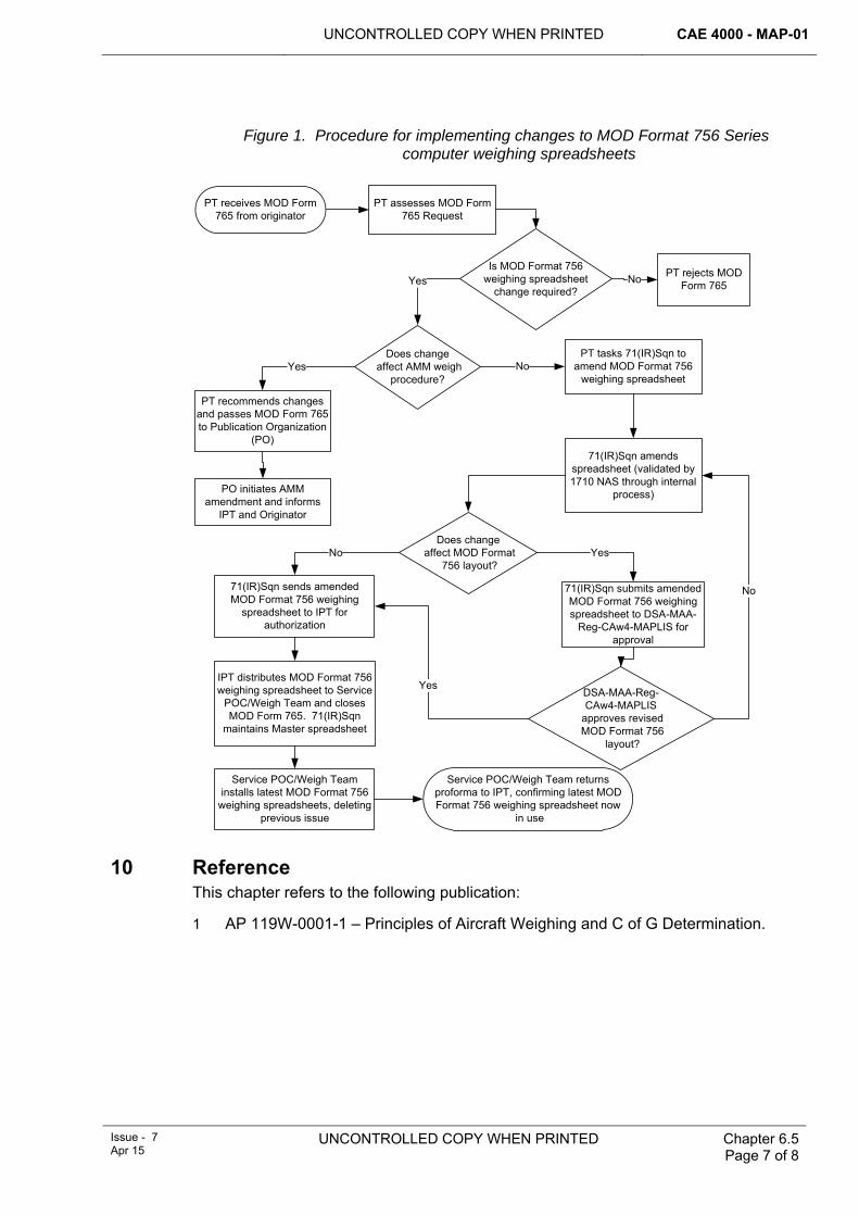
UNCONTROLLED COPY WHEN PRINTED CAE 4000 - MAP-01
Issue - 7 Apr 15
UNCONTROLLED COPY WHEN PRINTED
Chapter 6.5 Page 7 of 8
Figure 1. Procedure for implementing changes to MOD Format 756 Series
computer weighing spreadsheets
NoYes
Yes No
Service POC/Weigh Team returns proforma to IPT, confirming latest MOD Format 756 weighing spreadsheet now
in use
Yes
Yes
No
No
PT recommends changes and passes MOD Form 765 to Publication Organization
(PO)
PT receives MOD Form 765 from originator
PT assesses MOD Form 765 Request
Does change affect AMM weigh
procedure?
PT rejects MOD Form 765
Is MOD Format 756 weighing spreadsheet
change required?
Does change affect MOD Format
756 layout?
PO initiates AMM amendment and informs
IPT and Originator
PT tasks 71(IR)Sqn to amend MOD Format 756
weighing spreadsheet
71(IR)Sqn amends spreadsheet (validated by 1710 NAS through internal
process)
DSA-MAA-Reg-CAw4-MAPLIS
approves revised MOD Format 756
layout?
71(IR)Sqn submits amended MOD Format 756 weighing spreadsheet to DSA-MAA-
Reg-CAw4-MAPLIS for approval
71(IR)Sqn sends amended MOD Format 756 weighing
spreadsheet to IPT for authorization
IPT distributes MOD Format 756 weighing spreadsheet to Service
POC/Weigh Team and closes MOD Form 765. 71(IR)Sqn
maintains Master spreadsheet
Service POC/Weigh Team installs latest MOD Format 756
weighing spreadsheets, deleting previous issue
10 Reference This chapter refers to the following publication:
1 AP 119W-0001-1 – Principles of Aircraft Weighing and C of G Determination.
CAE 4000 - MAP-01 UNCONTROLLED COPY WHEN PRINTED
Chapter 6.5 Page 8 of 8
UNCONTROLLED COPY WHEN PRINTED End of Data Module
Issue - 7 Apr 15
Intentionally Blank for Print Pagination
UNCONTROLLED COPY WHEN PRINTED CAE 4000 - MAP-01
MAE Issue - 6 Mar 14
UNCONTROLLED COPY WHEN PRINTED Chapter 6.6 Page 1 of 8
Chapter 6.6
Surface Finish of Military Air Environment Equipment
TABLE OF CONTENTS Paragraph
Page
1 General ............................................................................................................... 1 1.1 Introduction.......................................................................................................... 1 1.2 Applicability ......................................................................................................... 2 2 Regulatory Governance.................................................................................... 2 2.1 Regulatory Article Cross-reference ..................................................................... 2 2.2 Additional Information.......................................................................................... 2 3 SF maintenance................................................................................................. 2 3.1 Control of SF materials........................................................................................ 2 3.2 Maintenance definitions for paint application ...................................................... 3 3.3 Maintenance definitions for paint removal ........................................................... 3 3.4 Maintenance facilities .......................................................................................... 4 3.5 SF cleaning ......................................................................................................... 4 3.6 SF husbandry ...................................................................................................... 5 4 Aircraft operational markings .......................................................................... 5 5 Training and authorization ............................................................................... 5 5.1 SF cleaning training............................................................................................. 5 5.2 SF removal training ............................................................................................. 5 5.3 SF application training......................................................................................... 5 6 Responsibilities................................................................................................. 6 6.1 Stn/Ship/Unit ....................................................................................................... 6 6.2 Front Line Command (FLC) ................................................................................ 6 6.3 Type Airworthiness Authority (TAA) or commodity Project Team (PT) ............... 6 6.4 Air Commodities Team (AC Team) ..................................................................... 6 6.5 1710 NAS............................................................................................................ 7 7 References ......................................................................................................... 7
LIST OF TABLES Table 1. Maintenance Definitions for Paint Application. ................................................................3 Table 2. Maintenance Definitions for Paint Removal.....................................................................3 Table 3. Types and Descriptions of Surface Finish Maintenance Facilities. .................................4 Table 4. Depth of SF Tasking for Authorized Engineering Personnel. ..........................................5
1 General 1.1 Introduction
The preservation and renewal of surface finishes is an essential part of the overall maintenance of aircraft, aircraft components and equipment, and of associated ground support equipment (GSE).
Throughout this chapter, surface finish (SF) relates to paints, primers, temporary protectives, varnishes and some conversion coatings as promulgated in the AP 119A-0601 series. Sound, well-maintained SFs significantly prolong the life and structural integrity of aircraft, aircraft components and equipment and GSE and are the primary defence against corrosion; see RA 4507 and Chapter 11.6. They can
CAE 4000 - MAP-01 UNCONTROLLED COPY WHEN PRINTED
Chapter 6.6 Page 2 of 8
UNCONTROLLED COPY WHEN PRINTED MAE Issue - 6
Mar 14
also effect conspicuity or reduce electromagnetic properties, provide chemical agent resistance and maintain the cosmetic appearance of the aircraft, aircraft component and equipment or items of GSE. Procedures for protecting SF in extreme environments are detailed in Chapter 5.5.
1.2 Applicability This chapter describes the engineering organization processes for applying and removing SF from aircraft, aircraft components/equipment and GSE within the Military Air Environment (MAE). This does not include surface finish refurbishment of 'gate guardian' or other non-operational aircraft/equipment that are not supported at public expense.
2 Regulatory Governance 2.1 Regulatory Article Cross-reference
This chapter supports:
1 RA 4257.
2.2 Additional Information Paint coatings are known to degrade with time and environmental exposure. TAAs/commodity PTs and Front Line Commands (FLCs) are to ensure that appropriate coating management techniques are employed at appropriate periodicities in order to maintain coating performance and must promulgate these in the relevant aircraft or equipment Topic 2(N/A/R)1.
To address the restriction on the use of chemical paint strippers introduced under the Environmental Protection Act, the use of Media stripping is the preferred paint stripping method for aircraft and GSE, subject to the practicalities of doing so.
3 SF maintenance SF maintenance may include cleaning, removing and applying paint finishes or protective coatings. The processes for maintaining SF are detailed in AP 119A-0601-0A, -0B, -0C and -0D and/or in platform or GSE Technical Information (TI) and JAP 100E-10. SF maintenance for paint application beyond Depth B must only be carried out in specialist SF facilities or authorized locations by authorized personnel. When a Depth B/C SF task is carried out, the MOD F751 must be annotated that surface finish restoration has taken place and detail the approximate aircraft surface area and location restored. When a Depth C/D SF task is thought to exceed 25% of the aircraft surface area, the aircraft may require weighing in accordance with RA 4256 and Chapter 6.5.
Note:
Although no longer used, the terms Depths A-D may continue to be used within specific platform publications to delineate the extent of SF maintenance until TAAs / commodity PTs decide how these depths are translated into their specific Forward and Depth support strategy. However, former references to 1st, 2nd, 3rd and 4th line in Table 1 and Table 2 have been superseded by their Forward and Depth support equivalents.
3.1 Control of SF materials Under Duty of Care requirements of both Health and Safety and Environmental legislation, Section 33A/33B items, paints and associated products controlled by the AC Team must only be issued to authorized inventories. An inventory holder must be
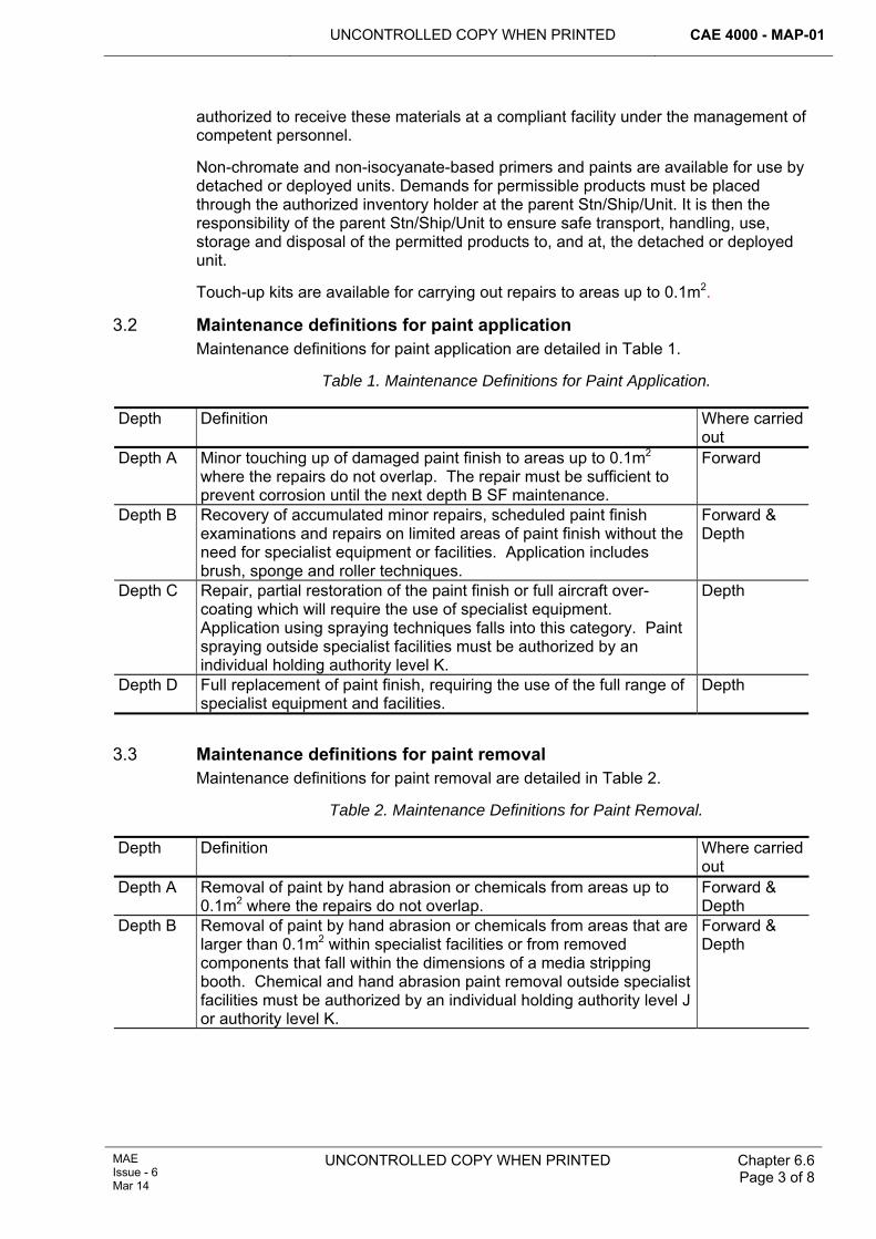
UNCONTROLLED COPY WHEN PRINTED CAE 4000 - MAP-01
MAE Issue - 6 Mar 14
UNCONTROLLED COPY WHEN PRINTED
Chapter 6.6 Page 3 of 8
authorized to receive these materials at a compliant facility under the management of competent personnel.
Non-chromate and non-isocyanate-based primers and paints are available for use by detached or deployed units. Demands for permissible products must be placed through the authorized inventory holder at the parent Stn/Ship/Unit. It is then the responsibility of the parent Stn/Ship/Unit to ensure safe transport, handling, use, storage and disposal of the permitted products to, and at, the detached or deployed unit.
Touch-up kits are available for carrying out repairs to areas up to 0.1m2.
3.2 Maintenance definitions for paint application Maintenance definitions for paint application are detailed in Table 1.
Table 1. Maintenance Definitions for Paint Application. Depth Definition Where carried
out Depth A Minor touching up of damaged paint finish to areas up to 0.1m2
where the repairs do not overlap. The repair must be sufficient to prevent corrosion until the next depth B SF maintenance.
Forward
Depth B Recovery of accumulated minor repairs, scheduled paint finish examinations and repairs on limited areas of paint finish without the need for specialist equipment or facilities. Application includes brush, sponge and roller techniques.
Forward & Depth
Depth C Repair, partial restoration of the paint finish or full aircraft over-coating which will require the use of specialist equipment. Application using spraying techniques falls into this category. Paint spraying outside specialist facilities must be authorized by an individual holding authority level K.
Depth
Depth D Full replacement of paint finish, requiring the use of the full range of specialist equipment and facilities.
Depth
3.3 Maintenance definitions for paint removal
Maintenance definitions for paint removal are detailed in Table 2.
Table 2. Maintenance Definitions for Paint Removal. Depth Definition Where carried
out Depth A Removal of paint by hand abrasion or chemicals from areas up to
0.1m2 where the repairs do not overlap. Forward & Depth
Depth B Removal of paint by hand abrasion or chemicals from areas that are larger than 0.1m2 within specialist facilities or from removed components that fall within the dimensions of a media stripping booth. Chemical and hand abrasion paint removal outside specialist facilities must be authorized by an individual holding authority level J or authority level K.
Forward & Depth
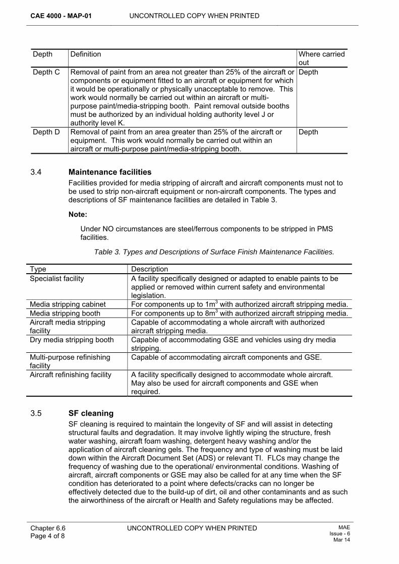
CAE 4000 - MAP-01 UNCONTROLLED COPY WHEN PRINTED
Chapter 6.6 Page 4 of 8
UNCONTROLLED COPY WHEN PRINTED MAE Issue - 6
Mar 14
Depth Definition Where carried out
Depth C Removal of paint from an area not greater than 25% of the aircraft or components or equipment fitted to an aircraft or equipment for which it would be operationally or physically unacceptable to remove. This work would normally be carried out within an aircraft or multi-purpose paint/media-stripping booth. Paint removal outside booths must be authorized by an individual holding authority level J or authority level K.
Depth
Depth D Removal of paint from an area greater than 25% of the aircraft or equipment. This work would normally be carried out within an aircraft or multi-purpose paint/media-stripping booth.
Depth
3.4 Maintenance facilities
Facilities provided for media stripping of aircraft and aircraft components must not to be used to strip non-aircraft equipment or non-aircraft components. The types and descriptions of SF maintenance facilities are detailed in Table 3.
Note:
Under NO circumstances are steel/ferrous components to be stripped in PMS facilities.
Table 3. Types and Descriptions of Surface Finish Maintenance Facilities. Type Description Specialist facility A facility specifically designed or adapted to enable paints to be
applied or removed within current safety and environmental legislation.
Media stripping cabinet For components up to 1m3 with authorized aircraft stripping media.Media stripping booth For components up to 8m3 with authorized aircraft stripping media.Aircraft media stripping facility
Capable of accommodating a whole aircraft with authorized aircraft stripping media.
Dry media stripping booth Capable of accommodating GSE and vehicles using dry media stripping.
Multi-purpose refinishing facility
Capable of accommodating aircraft components and GSE.
Aircraft refinishing facility A facility specifically designed to accommodate whole aircraft. May also be used for aircraft components and GSE when required.
3.5 SF cleaning
SF cleaning is required to maintain the longevity of SF and will assist in detecting structural faults and degradation. It may involve lightly wiping the structure, fresh water washing, aircraft foam washing, detergent heavy washing and/or the application of aircraft cleaning gels. The frequency and type of washing must be laid down within the Aircraft Document Set (ADS) or relevant TI. FLCs may change the frequency of washing due to the operational/ environmental conditions. Washing of aircraft, aircraft components or GSE may also be called for at any time when the SF condition has deteriorated to a point where defects/cracks can no longer be effectively detected due to the build-up of dirt, oil and other contaminants and as such the airworthiness of the aircraft or Health and Safety regulations may be affected.
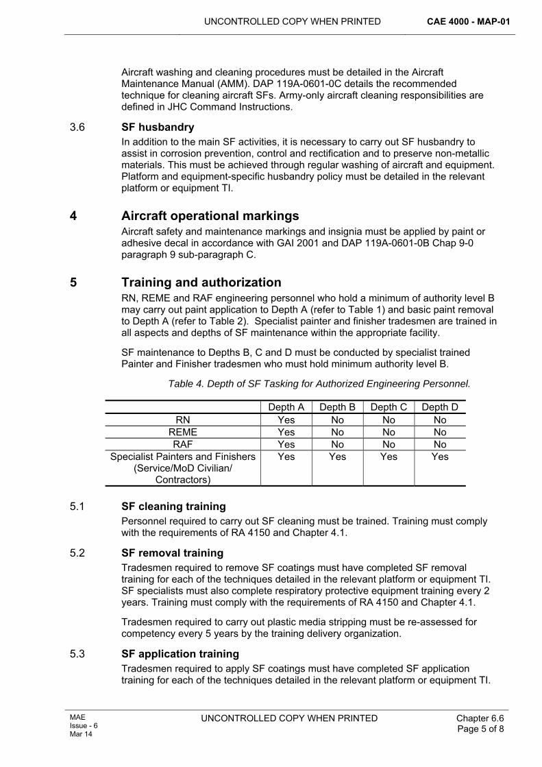
UNCONTROLLED COPY WHEN PRINTED CAE 4000 - MAP-01
MAE Issue - 6 Mar 14
UNCONTROLLED COPY WHEN PRINTED
Chapter 6.6 Page 5 of 8
Aircraft washing and cleaning procedures must be detailed in the Aircraft Maintenance Manual (AMM). DAP 119A-0601-0C details the recommended technique for cleaning aircraft SFs. Army-only aircraft cleaning responsibilities are defined in JHC Command Instructions.
3.6 SF husbandry In addition to the main SF activities, it is necessary to carry out SF husbandry to assist in corrosion prevention, control and rectification and to preserve non-metallic materials. This must be achieved through regular washing of aircraft and equipment. Platform and equipment-specific husbandry policy must be detailed in the relevant platform or equipment TI.
4 Aircraft operational markings Aircraft safety and maintenance markings and insignia must be applied by paint or adhesive decal in accordance with GAI 2001 and DAP 119A-0601-0B Chap 9-0 paragraph 9 sub-paragraph C.
5 Training and authorization RN, REME and RAF engineering personnel who hold a minimum of authority level B may carry out paint application to Depth A (refer to Table 1) and basic paint removal to Depth A (refer to Table 2). Specialist painter and finisher tradesmen are trained in all aspects and depths of SF maintenance within the appropriate facility.
SF maintenance to Depths B, C and D must be conducted by specialist trained Painter and Finisher tradesmen who must hold minimum authority level B.
Table 4. Depth of SF Tasking for Authorized Engineering Personnel.
Depth A Depth B Depth C Depth D RN Yes No No No
REME Yes No No No RAF Yes No No No
Specialist Painters and Finishers (Service/MoD Civilian/
Contractors)
Yes Yes Yes Yes
5.1 SF cleaning training
Personnel required to carry out SF cleaning must be trained. Training must comply with the requirements of RA 4150 and Chapter 4.1.
5.2 SF removal training Tradesmen required to remove SF coatings must have completed SF removal training for each of the techniques detailed in the relevant platform or equipment TI. SF specialists must also complete respiratory protective equipment training every 2 years. Training must comply with the requirements of RA 4150 and Chapter 4.1.
Tradesmen required to carry out plastic media stripping must be re-assessed for competency every 5 years by the training delivery organization.
5.3 SF application training Tradesmen required to apply SF coatings must have completed SF application training for each of the techniques detailed in the relevant platform or equipment TI.
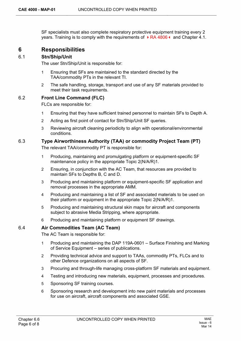
CAE 4000 - MAP-01 UNCONTROLLED COPY WHEN PRINTED
Chapter 6.6 Page 6 of 8
UNCONTROLLED COPY WHEN PRINTED MAE Issue - 6
Mar 14
SF specialists must also complete respiratory protective equipment training every 2 years. Training is to comply with the requirements of RA 4806 and Chapter 4.1.
6 Responsibilities 6.1 Stn/Ship/Unit
The user Stn/Ship/Unit is responsible for:
1 Ensuring that SFs are maintained to the standard directed by the TAA/commodity PTs in the relevant TI.
2 The safe handling, storage, transport and use of any SF materials provided to meet their task requirements.
6.2 Front Line Command (FLC) FLCs are responsible for:
1 Ensuring that they have sufficient trained personnel to maintain SFs to Depth A.
2 Acting as first point of contact for Stn/Ship/Unit SF queries.
3 Reviewing aircraft cleaning periodicity to align with operational/environmental conditions.
6.3 Type Airworthiness Authority (TAA) or commodity Project Team (PT) The relevant TAA/commodity PT is responsible for:
1 Producing, maintaining and promulgating platform or equipment-specific SF maintenance policy in the appropriate Topic 2(N/A/R)1.
2 Ensuring, in conjunction with the AC Team, that resources are provided to maintain SFs to Depths B, C and D.
3 Producing and maintaining platform or equipment-specific SF application and removal processes in the appropriate AMM.
4 Producing and maintaining a list of SF and associated materials to be used on their platform or equipment in the appropriate Topic 2(N/A/R)1.
5 Producing and maintaining structural skin maps for aircraft and components subject to abrasive Media Stripping, where appropriate.
6 Producing and maintaining platform or equipment SF drawings.
6.4 Air Commodities Team (AC Team) The AC Team is responsible for:
1 Producing and maintaining the DAP 119A-0601 – Surface Finishing and Marking of Service Equipment – series of publications.
2 Providing technical advice and support to TAAs, commodity PTs, FLCs and to other Defence organizations on all aspects of SF.
3 Procuring and through-life managing cross-platform SF materials and equipment.
4 Testing and introducing new materials, equipment, processes and procedures.
5 Sponsoring SF training courses.
6 Sponsoring research and development into new paint materials and processes for use on aircraft, aircraft components and associated GSE.
UNCONTROLLED COPY WHEN PRINTED CAE 4000 - MAP-01
MAE Issue - 6 Mar 14
UNCONTROLLED COPY WHEN PRINTED
Chapter 6.6 Page 7 of 8
6.5 1710 NAS 1710 NAS is responsible for:
1 Providing scientific and technical advice and support to the AC Team, TAAs, commodity PTs, FLCs and to other Defence organizations on SF matters.
2 Testing new materials, processes and procedures for introduction into service.
3 Identifying new paint, materials and processes for use on aircraft, aircraft components and GSE.
7 References This chapter refers to the following publications:
1 DAP 119A-0601-0A – Surface Finishing and Marking of Service Equipment: Surface Finishing Policy, Organization and Administration.
2 DAP 119A-0601-0B – Surface Finishing and Marking of Service Equipment: Surface Finish Processes, Procedures, Materials and Equipment.
3 DAP 119A-0601-0C – Surface Finishing and Marking of Service Equipment: Surface Finish Restoration Techniques and Repair Schemes.
4 DAP 119A-0601-0D – Surface Finishing and Marking of Service Equipment: Procedures for the Maintenance and Repair of Fabric and Aircraft Trim.
5 GAI 2001 – External Paint Colour, Type, Finish and Marking of RAF Aircraft (R).
6 JAP 100E-10 – Military Aviation Engineering Management of Ground Support Equipment.
7 JHC Command Instructions.
8 Topic 2(N/A/R)1 – General Orders and Special Instructions.
9 Topic 1 – Aircraft Maintenance Manual.
CAE 4000 - MAP-01 UNCONTROLLED COPY WHEN PRINTED
Chapter 6.6 Page 8 of 8
UNCONTROLLED COPY WHEN PRINTED MAE Issue - 6
Mar 14
Intentionally Blank for Print Pagination
UNCONTROLLED COPY WHEN PRINTED CAE 4000 - MAP-01
MAE Issue - 6 Mar 14
UNCONTROLLED COPY WHEN PRINTED Chapter 6.7 Page 1 of 10
Chapter 6.7
Modular Support Storage and Transportation System
TABLE OF CONTENTS Paragraph
Page
1 General ............................................................................................................... 1 1.1 Introduction.......................................................................................................... 1 1.2 Associated publication......................................................................................... 2 1.3 Applicability ......................................................................................................... 2 2 Regulatory Governance.................................................................................... 2 2.1 Regulatory Article Cross-reference ..................................................................... 2 2.2 Additional Information.......................................................................................... 2 3 MS project .......................................................................................................... 3 3.1 Aviation-capable ships ........................................................................................ 3 3.2 Aircraft types ....................................................................................................... 3 4 Module construction ......................................................................................... 3 5 Module scales.................................................................................................... 3 6 Module marking................................................................................................. 4 7 Control of Aircraft Servicing and Support Equipment (ASSE) in modules . 4 8 POL in modules ................................................................................................. 4 8.1 Stowage of ready-use flight servicing POL ......................................................... 4 8.2 Transportation of POL in modules....................................................................... 4 9 Configuration control of modules ................................................................... 5 9.1 Maintenance........................................................................................................ 5 9.2 Repair.................................................................................................................. 5 9.3 Replacement of module shell .............................................................................. 5 9.4 Fault reporting ..................................................................................................... 5 9.5 Modification proposals......................................................................................... 6 9.6 Stowage of additional equipment within modules ............................................... 6 9.7 Spares ................................................................................................................. 6 9.8 Surplus modules.................................................................................................. 6 10 Quality assurance ............................................................................................. 6 11 Responsibilities................................................................................................. 6 11.1 Stn/Ship/Unit ....................................................................................................... 6 11.2 DES LE OSP OIP METS..................................................................................... 8 12 References ......................................................................................................... 8
LIST OF FIGURES Figure 1. Process Flow Chart for MS Suite of MOD Forms 755(MS)...........................................9
1 General 1.1 Introduction
The Modular Support (MS) integrated storage and transportation system comprises two elements: containers (or ‘modules’) and complementary permanently fixed fittings installed in ships to which modules may be secured.
CAE 4000 - MAP-01 UNCONTROLLED COPY WHEN PRINTED
Chapter 6.7 Page 2 of 10
UNCONTROLLED COPY WHEN PRINTED MAE Issue - 6
Mar 14
Modules house selected Aircraft Servicing and Support Equipment (ASSE), comprising hand tools, test equipment and role equipment, of squadrons or flights, both embarked and ashore. Modules are configured and furnished internally to provide customized stowage for ASSE. They are transportable by road, or by air as air cargo or underslung loads. This chapter describes only the use, maintenance and configuration control of modules in the MS storage and transportation system.
Note:
MS is currently used by the RN in support of a number of aircraft types by Joint Helicopter Command for the Commando Helicopter Force aircraft when embarked. The chapter therefore uses RN organizational terms.
1.2 Associated publication This chapter is associated with the following publication:
1 JSP 317 – Joint Service Safety Regulations for the Storage and Handling of Fuels & Lubricants.
1.3 Applicability This chapter is applicable to Stns/Ships/Units in the Military Air Environment (MAE) that fall within the scope of the MS project, see paragraph 3, and are therefore authorized to use MS, primarily for embarked operations, in accordance with the policy outlined in this chapter.
Note:
This chapter is not applicable to any other ‘modular’ system such as WRSK containers, LACONs, ISO containers, MINICONs, etc that are used to store, deploy or transport equipment.
The MS concept does not currently include the carriage of spares, except in the case of the Commando Helicopter Force. However, a longer term aim is to carry spares in modules; this may be dependent on changes to the current philosophy of embedded aircraft spares on ships in the Consolidated Allowance List and may affect the future use of Priming Equipment Packs, Flyaway Packs or Aircraft Support Packs for particular aircraft types.
2 Regulatory Governance 2.1 Regulatory Article Cross-reference
This Chapter supports:
1 Nil.
2.2 Additional Information This chapter does support any Regulatory Article however the chapter details the agencies that control and support the provisioning of Modular Support Storage and Transportation System.
DES LE OSP OIP METS (Military Equipment Tool Solutions) is the central authority for coordinating requirements for, and the configuration control of, MS within the MAE and is the delegated authority for modules and their interior furnishings. DES LE OSP OIP METS is the Design Organization and DES LE OSP OIP METS ESM1 is the Engineering Authority (EA) for the internal configuration of MS modules. The use, maintenance and the responsibilities for the configuration control of MS modules must be undertaken in accordance with the processes set out in this chapter.
UNCONTROLLED COPY WHEN PRINTED CAE 4000 - MAP-01
MAE Issue - 6 Mar 14
UNCONTROLLED COPY WHEN PRINTED
Chapter 6.7 Page 3 of 10
When embarking on a ship that has not been modified and configured for the MS system, MS modules may still be used to store and transport ASSE. When embarking an aircraft type not supported by MS, alternative arrangements must be made for the carriage, transportation and security of ASSE and, if necessary, for aircraft spares.
3 MS project 3.1 Aviation-capable ships
The MS project managed by DES LE OSP OIP METS SP1c covers all aviation-capable ships, except Type 42 Destroyers and Type 22 Frigates. MS capability is dependent on structural modifications to ships, which can only be embodied during planned refits or initial build.
3.2 Aircraft types The MS project currently covers the following aircraft types:
1 Lynx Mk3 and Mk8.
2 Sea King.
3 Merlin Mk1.
4 Apache AH1.
Other aircraft types such as Lightning II and Wildcat are under consideration for inclusion in the MS project. The following paragraphs scope the construction, maintenance and use of MS modules.
4 Module construction Modules are manufactured and supplied currently by STS Defence Ltd. They are available in 3 sizes, designated bulk, medium and small. Bulk modules have an aluminium tube frame structure with infill panels of pressed aluminium sheet. Medium and small modules are manufactured from pressed aluminium panels. All modules feature:
1 External powder coating, giving a durable, damage-resistant finish.
2 Custom internal fittings to ensure best fit of ASSE.
3 Up-and-over roller shutter doors.
4 Locking mechanisms with key sets, including two master keys.
Note:
The loss of a key without access to a master key would make the module contents inaccessible. Replacement keys must be obtained from the manufacturers.
5 Module scales AP 119G-1602-136 details by each aircraft type or Sqn/Unit:
1 The types and number of modules required.
2 The range and scale of authorized ASSE holdings and their stowage locations within a module suite.
CAE 4000 - MAP-01 UNCONTROLLED COPY WHEN PRINTED
Chapter 6.7 Page 4 of 10
UNCONTROLLED COPY WHEN PRINTED MAE Issue - 6
Mar 14
6 Module marking Modules must be permanently marked on the top front face of the module with a unique identity code comprising a serial number (including the identification letter), the aircraft type and mark, the Ship/Sqn or flight and the local identity to which a module belongs.
Example: 02C5G181B/MER3/829 02FLT/B01
Additionally, all modules must have their maximum all up weight clearly marked on the top front face of the module. Modules may be marked further to indicate their stowage position when embarked or ashore. The application of any other markings, logos or stickers, except as provided for in paragraphs 8.1 and 8.2.1, is prohibited.
7 Control of Aircraft Servicing and Support Equipment (ASSE) in modules The issue and receipt of ASSE from modules must be carried out in accordance with the tool control regulations stated in RA 4808 and Chapter 6.1.1. Additionally, each item of ASSE must be correctly secured in its designated location within a module. When not in use, modules must be kept locked and the keys secured separately.
8 POL in modules Only ready-use flight servicing POL (as defined and identified by METS) and Anti-Corrosion Kit (ACK)-specific POL may be stowed in MS modules and is subject to specific criteria detailed in the following sub-paragraphs.
8.1 Stowage of ready-use flight servicing POL The stowage of ready-use flight servicing-specific POL in modules is permitted providing that:
1 It is attached to flight servicing equipment, e.g. Risbridger guns, etc.
2 The module is specifically configured for the task.
3 The module is clearly marked externally to show the hazardous nature of the contents held within.
Note:
Ready-use flight servicing POL must not be transported in the MS module.
8.2 Transportation of POL in modules Except for ACKs, the transportation of any POL in MS modules is strictly forbidden.
8.2.1 ACK – RN only As the ACK and its authorized contents are within the limited quantity concessions detailed in JSP 445 and the International Maritime Dangerous Goods Code, the ACK is authorized for stowage and transportation in MS modules, provided that:
1 The module is clearly marked externally with ‘LTD QTY’.
2 The ACK is marked with ‘DANGEROUS GOODS IN LIMITED QUANTITIES OF CLASSES 3 AND 8’.
Note:
UNCONTROLLED COPY WHEN PRINTED CAE 4000 - MAP-01
MAE Issue - 6 Mar 14
UNCONTROLLED COPY WHEN PRINTED
Chapter 6.7 Page 5 of 10
Additionally, due care must be exercised during the packing of modules to ensure that there is no spillage of ACK contents.
9 Configuration control of modules METS exercise configuration control of modules in accordance with the general principles for Configuration Management. METS centrally controls the internal configuration of modules by aircraft or Sqn/Unit type through the use of a configuration database. To ensure that this database accurately reflects in-service module interiors and that configuration changes with a wider applicability are highlighted and disseminated throughout the Services, module internal configurations must not to be altered or modified unless authorized by METS. Therefore, actions that affect configuration control of modules, including maintenance, repair, fault reporting, modifications and spares demands, must be carried out in accordance with the following paragraphs and documented using the suite of MS control forms (and the instructions for their use and completion) in MAP-02.
9.1 Maintenance Modules and their interior furnishings must be maintained in accordance with AP 119G-1602-136.
9.2 Repair Modules and their interior furnishings must be repaired in accordance with AP 119G-1602-136 following Inspect and Repair As Necessary (IRAN) principles, (for more information on IRAN, see RA 4200 and Chapter 5.1), except when:
1 A module is damaged beyond the scope of the repair schemes in AP 119G-1602-136.
2 A module is damaged beyond the repair capabilities of a Sqn/Unit.
3 Repairs are impracticable in single aircraft ship’s flights detached from their parent Sqn.
In these cases the damaged module must be returned to the relevant Depth organization for evaluation and possible repair. Any additional technical information required to carry out Depth repair may be obtained from METS SP1c. If Depth repair is impractical, the damaged or faulty module should be returned to the module manufacturers for repair in accordance with instructions obtained from DES LE OSP OIP METS SP1c.
9.3 Replacement of module shell If a module shell is damaged beyond economic repair, a replacement module shell must be demanded directly from METS SP1c; see paragraph 9.7. Interior furnishings must be removed and retained for fitment into the replacement module shell.
Note:
Other than through fair wear and tear, any financial or other losses incurred in repairing a damaged module (including any spares required), or in replacing a module, must be borne by the user organization.
9.4 Fault reporting Faulty and unsatisfactory aspects of modules or their interior furnishings must be reported on MOD F755(MS3) by the Sqn/Unit MS Controller (MSC) to METS SP1c, via the Typed Air Station (TAS) MSC and documented on MOD F755(MS2) and MOD F755(MS6), if appropriate, in accordance with the process outlined in Figure 1. DES
CAE 4000 - MAP-01 UNCONTROLLED COPY WHEN PRINTED
Chapter 6.7 Page 6 of 10
UNCONTROLLED COPY WHEN PRINTED MAE Issue - 6
Mar 14
LE OSP OIP METS will investigate and respond on MOD F755(MS5) detailing what action, if any, is required. Any associated spares must then be demanded directly from METS SP1c; see paragraph 9.7. Fuller instructions for using the suite of MS control forms are in MAP 100A-02.
9.5 Modification proposals Proposals for modifications to the internal configuration of modules must be raised on MOD F755(MS4) by the Sqn/Unit MSC, documented on MOD F755(MS2) and MOD F755(MS6), if appropriate, and forwarded, via the TAS MSC, to METS SP1c in accordance with the process outlined in Figure 1. DES LE OSP OIP METS will investigate the proposal and respond, either with an approval or a rejection, on MOD F755(MS5). Any associated spares must be demanded directly from METS SP1c; see paragraph 9.7. Authorized modifications to module internal configuration promulgated on MOD F755(MS5) must be embodied within 2 months of receipt of spares. Compliance must be reported to METS using the tear-off slip at the bottom of MOD F755(MS5).
9.6 Stowage of additional equipment within modules When Sqn/Unit tasks change, or new or modified ASSE is introduced into service, module internal configurations will need to be revised. Applications for such revisions must be documented and then forwarded to METS SP1c on MOD F755(MS4) following the process outlined in Figure 1. New items of ASSE already subject to MOD F755(MS4) action (for additional equipment stowage within modules) may be temporarily stowed within modules until appropriate MOD F755(MS5) instructions from the DES LE OSP OIP METS have been received.
9.7 Spares AP 119G-1602-136 lists the reference numbers of all items/components required for the repair or replacement of modules and interior furnishings. All demands for spares must be sent directly to METS SP1c on MOD F755(MS1A)(Spares). Records of spares demands must be kept on MOD F755(MS1).
9.8 Surplus modules Any modules surplus to requirement must be declared to DES LE OSP OIP METS SP1c and instructions requested for disposal, or movement to another Stn/Ship/Unit.
10 Quality assurance Modules and their internal furnishings and layouts must be subject to periodic quality assurance audits in accordance with normal Stn/Ship/Unit Quality Management System policy, see Chapter 15.1, to ensure that their maintenance accords with AP 119G-1602-136.
11 Responsibilities 11.1 Stn/Ship/Unit
The following paragraphs detail the responsibilities of MSCs required on a TAS, one aim being to establish a single point of contact on the TAS for the DES LE OSP OIP METS. These appointments and responsibilities may be adapted on Stns/Ships/Units of the other Services, provided their intent with respect to the single point of contact and the management and configuration control of MS is not compromised.
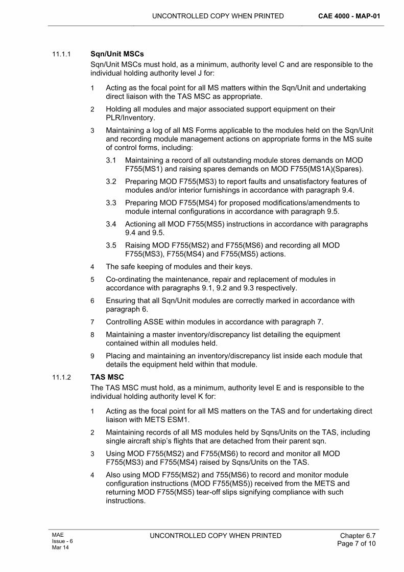
UNCONTROLLED COPY WHEN PRINTED CAE 4000 - MAP-01
MAE Issue - 6 Mar 14
UNCONTROLLED COPY WHEN PRINTED
Chapter 6.7 Page 7 of 10
11.1.1 Sqn/Unit MSCs Sqn/Unit MSCs must hold, as a minimum, authority level C and are responsible to the individual holding authority level J for:
1 Acting as the focal point for all MS matters within the Sqn/Unit and undertaking direct liaison with the TAS MSC as appropriate.
2 Holding all modules and major associated support equipment on their PLR/Inventory.
3 Maintaining a log of all MS Forms applicable to the modules held on the Sqn/Unit and recording module management actions on appropriate forms in the MS suite of control forms, including:
3.1 Maintaining a record of all outstanding module stores demands on MOD F755(MS1) and raising spares demands on MOD F755(MS1A)(Spares).
3.2 Preparing MOD F755(MS3) to report faults and unsatisfactory features of modules and/or interior furnishings in accordance with paragraph 9.4.
3.3 Preparing MOD F755(MS4) for proposed modifications/amendments to module internal configurations in accordance with paragraph 9.5.
3.4 Actioning all MOD F755(MS5) instructions in accordance with paragraphs 9.4 and 9.5.
3.5 Raising MOD F755(MS2) and F755(MS6) and recording all MOD F755(MS3), F755(MS4) and F755(MS5) actions.
4 The safe keeping of modules and their keys.
5 Co-ordinating the maintenance, repair and replacement of modules in accordance with paragraphs 9.1, 9.2 and 9.3 respectively.
6 Ensuring that all Sqn/Unit modules are correctly marked in accordance with paragraph 6.
7 Controlling ASSE within modules in accordance with paragraph 7.
8 Maintaining a master inventory/discrepancy list detailing the equipment contained within all modules held.
9 Placing and maintaining an inventory/discrepancy list inside each module that details the equipment held within that module.
11.1.2 TAS MSC The TAS MSC must hold, as a minimum, authority level E and is responsible to the individual holding authority level K for:
1 Acting as the focal point for all MS matters on the TAS and for undertaking direct liaison with METS ESM1.
2 Maintaining records of all MS modules held by Sqns/Units on the TAS, including single aircraft ship’s flights that are detached from their parent sqn.
3 Using MOD F755(MS2) and F755(MS6) to record and monitor all MOD F755(MS3) and F755(MS4) raised by Sqns/Units on the TAS.
4 Also using MOD F755(MS2) and 755(MS6) to record and monitor module configuration instructions (MOD F755(MS5)) received from the METS and returning MOD F755(MS5) tear-off slips signifying compliance with such instructions.
CAE 4000 - MAP-01 UNCONTROLLED COPY WHEN PRINTED
Chapter 6.7 Page 8 of 10
UNCONTROLLED COPY WHEN PRINTED MAE Issue - 6
Mar 14
11.2 DES LE OSP OIP METS METS act as the Design Organization and EA for MS, is responsible for:
1 Acting as the central authority for coordinating MS requirements in the MAE, including configuration control of interior furnishings.
2 Controlling and allocating master identification codes for the external marking of modules. Standard Unit/Location Codes are detailed in Chapter 0.6.
3 Issuing technical information needed to carry out module repairs at Stns/Ships/Units.
4 Issuing instructions for return to manufacturer of damaged or faulty modules that are beyond the repair capability of a Stn/Ship/Unit.
5 Arranging the replacement of modules damaged beyond economical repair.
6 Coordinating and actioning all demands for module spares.
7 Issuing instructions for the disposal of modules surplus to requirements.
8 Investigating MOD F755(MS3) reports concerning faulty modules or interior furnishings.
9 Investigating MOD F755(MS4) reports proposing modifications/amendments to module interior furnishings configuration.
10 Authorizing repairs and modifications/amendments to interior furnishings configuration by issuing MOD F755(MS5) in response to MOD F755(MS3) and F755(MS4).
11 Designing and testing modules and related equipment.
12 Controlling the internal configuration of modules by aircraft or Sqn/Unit type.
13 Maintaining a module configuration database.
14 Maintaining and issuing amendments to AP 119G-1602-136.
15 Liaising with module manufacturers on all matters concerning the MS project, including:
15.1 Holding and negotiating the MS contract.
15.2 Carrying out pre-delivery inspections of all new modules.
12 References This chapter refers to the following publications:
1 International Maritime Dangerous Goods Code.
2 JSP 445 – Carriage of Dangerous Goods by Road, Rail and Sea.
3 AP 119G-1602-136 – Modular Support General and Technical Information.
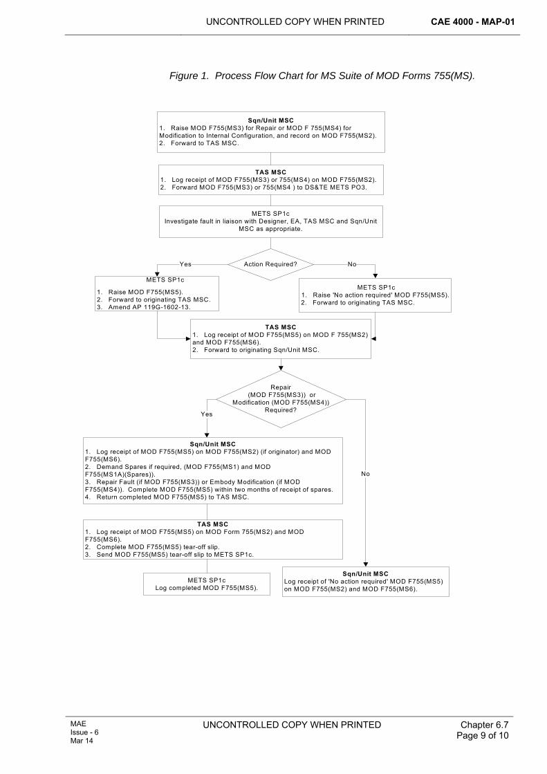
UNCONTROLLED COPY WHEN PRINTED CAE 4000 - MAP-01
MAE Issue - 6 Mar 14
UNCONTROLLED COPY WHEN PRINTED
Chapter 6.7 Page 9 of 10
Figure 1. Process Flow Chart for MS Suite of MOD Forms 755(MS).
Sqn/Unit MSC1. Log receipt of MOD F755(MS5) on MOD F755(MS2) (if originator) and MOD F755(MS6).2. Demand Spares if required, (MOD F755(MS1) and MOD F755(MS1A)(Spares)).3. Repair Fault (if MOD F755(MS3)) or Embody Modification (if MOD F755(MS4)). Complete MOD F755(MS5) within two months of receipt of spares.4. Return completed MOD F755(MS5) to TAS MSC.
Sqn/Unit MSC1. Raise MOD F755(MS3) for Repair or MOD F 755(MS4) for Modification to Internal Configuration, and record on MOD F755(MS2).2. Forward to TAS MSC.
TAS MSC1. Log receipt of MOD F755(MS3) or 755(MS4) on MOD F755(MS2).2. Forward MOD F755(MS3) or 755(MS4 ) to DS&TE METS PO3.
METS SP1c Investigate fault in liaison with Designer, EA, TAS MSC and Sqn/Unit
MSC as appropriate.
METS SP1c
1. Raise MOD F755(MS5).2. Forward to originating TAS MSC.3. Amend AP 119G-1602-13.
TAS MSC1. Log receipt of MOD F755(MS5) on MOD F 755(MS2) and MOD F755(MS6).2. Forward to originating Sqn/Unit MSC.
TAS MSC1. Log receipt of MOD F755(MS5) on MOD Form 755(MS2) and MOD F755(MS6).2. Complete MOD F755(MS5) tear-off slip.3. Send MOD F755(MS5) tear-off slip to METS SP1c.
METS SP1c Log completed MOD F755(MS5).
Sqn/Unit MSCLog receipt of 'No action required' MOD F755(MS5) on MOD F755(MS2) and MOD F755(MS6).
METS SP1c 1. Raise 'No action required' MOD F755(MS5).2. Forward to originating TAS MSC.
Action Required?Yes No
Repair (MOD F755(MS3)) or
Modification (MOD F755(MS4)) Required?Yes
No

CAE 4000 - MAP-01 UNCONTROLLED COPY WHEN PRINTED
Chapter 6.7 Page 10 of 10
UNCONTROLLED COPY WHEN PRINTED MAE Issue - 6
Mar 14
Intentionally Blank for Print Pagination
UNCONTROLLED COPY WHEN PRINTED CAE 4000 - MAP-01
MAE Issue - 6 Mar 14
UNCONTROLLED COPY WHEN PRINTED Chapter 6.8 Page 1 of 4
Chapter 6.8
Usage and Management of Remote Viewing Aid Equipment
TABLE OF CONTENTS Paragraph
Page
1 General ............................................................................................................... 1 1.1 Introduction.......................................................................................................... 1 1.2 Applicability ......................................................................................................... 1 1.3 Definition ............................................................................................................. 1 2 Regulatory Governance.................................................................................... 1 2.1 Regulatory Article Cross-reference ..................................................................... 1 2.2 Additional Information.......................................................................................... 1 3 Training and Authorization............................................................................... 2 3.1 Training ............................................................................................................... 2 4 Responsibilities................................................................................................. 2 4.1 User Stns/Ships/Units ......................................................................................... 2 4.2 Non-Destructive Evaluation Team (NDET) ......................................................... 2 4.3 Air Commodities Team (AC Team) ..................................................................... 3 4.4 Type Airworthiness Authorities (TAAs) and commodity PTs............................... 3
1 General 1.1 Introduction
Remote Viewing Aid (RVA) equipment is the collective term for the optical equipment, video camera system or video viewing aid system used to assist with the visual inspection of aircraft structures, engines and system components. The integrity of such inspections depends on the ability of the tradesman and on the serviceability and suitability of the RVA equipment. This chapter outlines the responsibilities for the training and authorization of tradesmen required to use RVA equipment and for the through-life management of RVA equipment.
1.2 Applicability This chapter is applicable to any Stn/Ship/Unit or PT involved with introducing RVA equipment into service and training personnel to operate such equipment.
1.3 Definition An RVA system is defined as a complete collection of RVA equipment required to provide assistance with a visual inspection, eg endoscopes, light guide and light source box or Flexible Probe Video Viewing Aid.
2 Regulatory Governance 2.1 Regulatory Article Cross-reference
This chapter supports:
1 Nil.
2.2 Additional Information Due to the fragility and value of RVA equipment, its use and management is to be controlled in accordance with the requirements of this chapter.
CAE 4000 - MAP-01 UNCONTROLLED COPY WHEN PRINTED
Chapter 6.8 Page 2 of 4
UNCONTROLLED COPY WHEN PRINTED MAE Issue - 6
Mar 14
3 Training and Authorization 3.1 Training 3.1.1 Aircraft Remote Viewing Aid Operator training
In order to provide a local training facility, selected Stn/Ship/Unit personnel are required to undertake specialist Aircraft Remote Viewing Aid training (RAF: Q-A-RVA) delivered by the Non-Destructive Evaluation Team (NDET) at MOD St Athan. Tradesmen required to undertake the duties of Stn/Ship/Unit Aircraft RVA operator trainer must have completed the Aircraft RVA Operator course at MOD St Athan and hold authorization MAP-C291. Qualified Aircraft RVA Operator Trainer authorization must be granted by an individual holding authorization MAP-J293 in accordance with RA 4806 and Chapter 4.3.
3.1.2 Local RVA familiarization training The use of RVA equipment to assist with any visual inspection is part of the routine work of all aircraft tradesmen. However, only a fundamental knowledge of RVA equipment is included in initial trade training; hence, tradesmen required to use RVA equipment must hold authorization MAP-B292 and have completed training in the care and use of equipment prior to first use. Training must be delivered by a tradesman that has successfully completed Aircraft RVA Operator training (RAF: Q-A-RVA) and must comply with the requirements of RA 4150 and Chapter 4.1. Authority must be granted by an individual holding authorization MAP-J293 in accordance with RA 4806 and Chapter 4.3. Q-A-Non-Destructive Testing (NDT)-qualified personnel are exempt familiarization training.
4 Responsibilities 4.1 User Stns/Ships/Units
The relevant individual holding authority level J at RVA equipment user Stns/Ships/Units must ensure that:
1 Stns/Ships/Units within their responsibility have sufficient Aircraft RVA Operator-trained personnel to carry out in-house familiarization training on RVA equipment.
2 Tradesmen and their supervisors receive local familiarization training in the care and use of RVA equipment prior to first use.
3 Stores personnel responsible for the control of Stn/Ship/Unit RVA equipment receive in-house familiarization training on the care of RVA equipment.
4.2 Non-Destructive Evaluation Team (NDET) The NDET is responsible for:
1 Formal training in the care and use of RVA equipment. The course is to consist of the following elements:
1.1 Information on all equipment types.
1.2 Practical training on all equipment types.
2 Awarding Aircraft RVA Operator qualifications.
3 Issuing local training guides for each RVA system for use by Stn/Ship/Unit Aircraft RVA Operator Trainers.
UNCONTROLLED COPY WHEN PRINTED CAE 4000 - MAP-01
MAE Issue - 6 Mar 14
UNCONTROLLED COPY WHEN PRINT Chapter 6.8 Page 3 of 4
4.3 Air Commodities Team (AC Team) The AC Team is the Engineering Authority (EA) for all RVA equipment and is responsible for:
1 Formulating and promulgating overall policy for the use of RVA equipment.
2 Acting as lead Integrated Logistics Support (ILS) Manager (ILSM).
3 Raising or arranging for appropriate line entries in funding programmes to cover:
3.1 Future requirements for new RVA equipment.
3.2 Training requirements for new equipment, in consultation with the NDET.
3.3 Spares provisioning and maintenance of RVA equipment.
4 Authorizing scale allocations.
5 Coordinating procurement of RVA equipment to meet urgent In-service requirements.
6 Tasking the NDET to provide support for equipment procured under paragraph 5.
7 Taking over responsibility for ILSM at Invitation to Tender (ITT) and implementing the ILS Plan (ILSP) throughout the lifecycle of the equipment.
8 Sponsoring the replacement of current RVA equipment.
4.4 Type Airworthiness Authorities (TAAs) and commodity PTs 1 TAAs and EAs within commodity PTs are responsible for specifying RVA
equipment for use as an aid to visual inspection during the maintenance of aircraft or other equipment for which they are responsible, in consultation with the NDET and AC Team.

CAE 4000 - MAP-01 UNCONTROLLED COPY WHEN PRINTED
Chapter 6.8 Page 4 of 4
UNCONTROLLED COPY WHEN PRINTED MAE Issue - 6
Mar 14
Intentionally Blank for Print Pagination
UNCONTROLLED COPY WHEN PRINTED CAE 4000 - MAP-01
MAE Issue - 6 Mar 14
UNCONTROLLED COPY WHEN PRINTED Chapter 6.9 Page 1 of 2
Chapter 6.9
Checks on Helicopter Blades and Tail Pylons After Spreading Using Automatic or Semi-Automatic Systems
TABLE OF CONTENTS Paragraph
Page
1 General ............................................................................................................... 1 1.1 Introduction.......................................................................................................... 1 2 Regulatory Governance.................................................................................... 1 2.1 Regulatory Article Cross-reference ..................................................................... 1 2.2 Additional Information.......................................................................................... 1 3 Undertaking checks on helicopter blade and pylon fold/spread systems .. 1 3.1 Helicopters with automatic main rotor folding/spreading systems and
automatic pylon systems or pylon spread interlock systems............................... 2 3.2 Helicopters with automatic main rotor folding/spreading systems and manual
pylon spread with interlock systems.................................................................... 2 4 Authorizations ................................................................................................... 2 5 Recording of checks on helicopter blade and pylon fold/spread systems . 2
1 General 1.1 Introduction
Helicopters with an automatic main rotor folding/spreading system and a pylon spread interlock system, or with automatic main rotor and pylon folding/spreading systems, have integral indication and interlock systems to ensure system integrity after spreading. Provided the spreading/folding system has not been disturbed by maintenance, an independent inspection of these systems after spreading is not required. When the spreading/folding system has been disturbed during maintenance, an independent inspection is required and is to be done in accordance with RA 4815 and Chapter 6.10. Helicopters with manual blade folding/spreading systems and tail pylons without pylon spread interlocks are subject to independent inspections as detailed in RA 4815 and Chapter 6.10.
2 Regulatory Governance 2.1 Regulatory Article Cross-reference
This chapter supports:
1 RA 4260(1).
2 RA 4260(2).
2.2 Additional Information Nil.
3 Undertaking checks on helicopter blade and pylon fold/spread systems The checks detailed below must be done in conjunction with the monitoring of cockpit indications and the release of interlocks to ensure the integrity of the system.
CAE 4000 - MAP-01 UNCONTROLLED COPY WHEN PRINTED
Chapter 6.9 Page 2 of 2
UNCONTROLLED COPY WHEN PRINTED End of Data Module
MAE Issue - 6
Mar 14
3.1 Helicopters with automatic main rotor folding/spreading systems and automatic pylon systems or pylon spread interlock systems On spreading the main rotor blades, an authorized individual must check visually from the ground that the geometry of the spread blades is correct and that no obvious malfunction has occurred. These checks must be done on the following occasions:
1 If the blades are already spread – immediately before the aircraft is manned.
2 If the blades are folded when the aircraft is manned – after spreading.
3 If the blades are refolded after the aircraft is manned – after re-spreading.
On completion of these checks, an authorized individual must indicate to the pilot that the geometry of the blades/pylon is correct and that no obvious malfunction has occurred. The pilot must acknowledge the report before attempting to engage the rotors.
3.2 Helicopters with automatic main rotor folding/spreading systems and manual pylon spread with interlock systems For aircraft fitted with pylon spread interlock systems, the following additional checks must be done. On spreading the tail pylon, an authorized individual must check that the pylon locking pins are fully engaged, the warning flag is housed and, by attempting to turn the tail rotor, that the drive coupling is positively engaged.
4 Authorizations The checks detailed at paragraph 3.1 may be done by individuals of any aircraft trade authorized, by type, to flight service in accordance with RA 4057 and Chapter 2.8.
5 Recording of checks on helicopter blade and pylon fold/spread systems 1 There is no recording action required after the checks detailed above.
UNCONTROLLED COPY WHEN PRINTED CAE 4000 - MAP-01
Issue - 7 Apr 15
UNCONTROLLED COPY WHEN PRINTED Chapter 6.10 Page 1 of 12
Chapter 6.10
Aircraft Independent Inspections
TABLE OF CONTENTS Paragraph
Page
1 General ............................................................................................................... 1 1.1 Introduction.......................................................................................................... 1 1.2 Applicability ......................................................................................................... 1 2 Regulatory Governance.................................................................................... 2 2.1 Regulatory Article Cross-reference ..................................................................... 2 2.2 Additional Information.......................................................................................... 2 3 Identification of systems that require independent inspections .................. 2 3.1 General guidance ................................................................................................ 2 3.2 Type Airworthiness Authority (TAA) responsibilities............................................ 3 3.3 Second Signature Responsibilities...................................................................... 3 4 Conduct of an independent inspection........................................................... 3 4.1 Occasions when an independent inspection must be done ................................ 3 4.2 Content of an independent inspection................................................................. 4 5 Raising, specifying and undertaking independent inspections ................... 5 5.1 Raising the requirement for an independent inspection ...................................... 5 5.2 Selection of individuals to specify or undertake independent inspections........... 5 5.3 Considerations when specifying an independent inspection............................... 6 6 Independent inspections on helicopter main rotor blade and tail pylon
fold/spread systems.......................................................................................... 7 6.1 Procedures and clearances for flight after aircrew acceptance........................... 7 7 Authorizations ................................................................................................... 7 7.1 Authorizations to specify and undertake independent inspections...................... 7 7.2 Additional authorizations ..................................................................................... 8 8 Recording independent inspections ............................................................... 8 8.1 General................................................................................................................ 8 8.2 Methods of recording independent inspections................................................... 8 8.3 Procedure for recording independent inspections............................................... 9 9 References ....................................................................................................... 12
1 General 1.1 Introduction
The integrity of aircraft control systems is vital to the safety of an aircraft and its occupants. This chapter details the types of aircraft system that require independent inspections following maintenance activities, including any action that could affect the correct functioning of the system.
1.2 Applicability The provisions within this chapter apply to aircraft control systems, as defined in paragraph 3.1. Independent checks of Aircraft Assisted Escape Systems (AAES) are detailed in RA 4602 and Chapter 13.1.2.
CAE 4000 - MAP-01 UNCONTROLLED COPY WHEN PRINTED
Chapter 6.10 Page 2 of 12
UNCONTROLLED COPY WHEN PRINTED Issue - 7 Apr 15
2 Regulatory Governance 2.1 Regulatory Article Cross-reference
This Chapter supports:
1 RA 4815(2).
2.2 Additional Information The chain of command, the Duty Holder Chief Air Engineer and the Continuing Airworthiness Management Organization (CAMO) may mandate the requirement for an independent inspection on any system. Additionally, a supervisor may require an independent inspection of a system if he considers it justified by the nature or circumstances of the maintenance work done. An independent inspection is a self-supervised activity and is to be conducted in accordance with RA 4806 and Chapter 4.5.
3 Identification of systems that require independent inspections 3.1 General guidance
Unless otherwise specified by the Type Airworthiness Authority (TAA) independent inspections are required whenever maintenance work involves disconnection, replacement, connection, assembly or adjustment of any element of an aircraft control system. This must be interpreted as meaning any system, whether electrical, mechanical or optical, operated by user input or automation, by which an aircraft’s speed, direction, flight attitude or propulsive force are changed in the air or on the ground or by which the undercarriage is retracted or lowered. The term includes power operated and assisted controls, including the immediate connections between those controls and their power systems, and may further be extended to the systems that provide power to such controls. Automatic systems that can be instantly overridden by the pilot are not considered to be aircraft control systems within the meaning of this chapter unless their failure, either in the air or on the ground, would place life or the aircraft at risk.
Any elements of a system, including attachment points to the aircraft structure, linking the appropriate pilot’s control to any of the following must be considered as aircraft control systems. Although the list is not exhaustive, examples of aircraft control systems are:
1 Primary flying controls and reaction control systems.
2 Tabs, flaps, slats and airbrakes.
3 Wing sweep control actuators.
4 Primary power unit control mechanisms, including those for throttles, variable intakes, reverse thrust, high-pressure fuel cocks, propeller constant speed units and rotating nozzles.
5 Helicopter rotor blade transmission and tail rotor transmission and pitch change mechanisms.
6 Undercarriage retraction and lowering and undercarriage steering mechanisms.
7 Aircraft wheel brakes.
8 Automatic flight control systems.
The terms of this chapter are generally intended to apply to installed aircraft control systems. However, in some circumstances, it may be appropriate to subject partial systems or individual major components of systems to independent inspections when
UNCONTROLLED COPY WHEN PRINTED CAE 4000 - MAP-01
Issue - 7 Apr 15
UNCONTROLLED COPY WHEN PRINTED Chapter 6.10 Page 3 of 12
they undergo bay maintenance whilst removed from the aircraft. Examples include Engine Change Units (ECUs) and control units whose control connections are inaccessible when the units are installed in aircraft.
3.2 Type Airworthiness Authority (TAA) responsibilities The TAA must promulgate a list of those aircraft systems that are subject to independent inspections. The requirement for an independent inspection must be detailed in the appropriate system chapters of the aircraft Topic 1 and/or in any of the publications listed below:
1 Aircraft Topic 5A2 – Warnings, Cautions and Maintenance Notes (Army).
2 Aircraft Topic 5A2, Chapter 4 – Cautions (RAF).
3 Aircraft Topic 5A2, Chapter 5 – Systems Requiring Independent Checks.
4 Aircraft Topic 2(N/A/R)1 – General Orders and Special Instructions.
Note:
Where an electronic document set exists, the information must be published in the equivalent electronic document.
The TAA must also identify partial systems, or major components, that are subject to independent inspections when undergoing off-aircraft maintenance and must state when such inspections must be done. Independent inspections of uninstalled partial systems or major components must be specified only when the integrity of partial systems or major components cannot be adequately assured by a stage check during bay maintenance. Requirements for independent inspections of uninstalled partial systems or major components must be included in the applicable bay maintenance schedules.
3.3 Second Signature Responsibilities Depending on the nature or circumstances of the maintenance work, there may be a requirement for additional independent inspections to be carried out on other systems, uninstalled partial systems or major components. In this case, it is the responsibility of the task supervisor to identify the requirement. When the need for such additional independent inspections is likely to arise repeatedly, an MOD F765 must be raised in accordance with the instructions described in RA 4810 and Chapter 8.2 in order to amend the relevant publication.
4 Conduct of an independent inspection 4.1 Occasions when an independent inspection must be done
Normally, independent inspections are required following the disturbance of an aircraft control system. Disturbance of an aircraft system will occur when maintenance work involves disconnection, replacement, connection or assembly of any element in that system, and may also occur when such a system is adjusted. Additionally, disturbance will occur when maintenance work on other systems results in the movement of any component of the aircraft control system from its normal installed position, irrespective of whether or not any connections to the component have been disconnected.
An independent inspection is not required following maintenance work activities that do not disturb a system, eg lubrication, replenishment, examination or operation.
CAE 4000 - MAP-01 UNCONTROLLED COPY WHEN PRINTED
Chapter 6.10 Page 4 of 12
UNCONTROLLED COPY WHEN PRINTED Issue - 7 Apr 15
4.2 Content of an independent inspection An independent inspection consists of 2 elements:
1 An inspection for correct assembly – this inspection cannot be waived.
2 A functional test – The level of disturbance to the system determines the requirement for, and extent of, the functional test; however, in accordance with the provisions detailed in paragraph 5.3, the requirement for an independent functional test may be waived.
4.2.1 Inspection for correct assembly The term “inspect for correct assembly” means an inspection of the system that has been disturbed and the individual must examine, as appropriate:
1 To make sure that the specified system/sub-system has been assembled in accordance with the correct maintenance procedure.
2 For correct locking.
3 For correct routeing – to include movement of the controls, if necessary.
4 For correct mechanical, electrical, optical, fuel, pneumatic and hydraulic connection.
5 For the absence of leaks.
6 To make sure that the results of any calculations used in setting up the system, including tolerances, are correct.
4.2.2 Functional test An independent functional test is to provide the fullest check of the operation of all parts of the system that could have been affected by the maintenance task that necessitates the independent inspection. It may include, but is not limited to, checks for:
1 Correct operation in all modes.
2 Freedom and range of movement.
3 Operation in the correct sense.
4 Friction loading.
5 Synchronization.
6 Rate of operation.
7 Cable tensions.
8 Gauge indications.
9 Correct clearances.
10 Backlash tolerances.
11 Compression checks.
12 Absence of leaks.
13 Other tests or checks as deemed necessary by the TAA.
Prior to undertaking functional tests, structure and panels surrounding the control run and elements of the aircraft system should, wherever possible, be re-fitted to ensure that they do not restrict operation of the system. When functional tests are done without all covers fitted, the person undertaking the functional test must consider repeating the check when the aircraft is in normal flight condition.
UNCONTROLLED COPY WHEN PRINTED CAE 4000 - MAP-01
Issue - 7 Apr 15
UNCONTROLLED COPY WHEN PRINTED Chapter 6.10 Page 5 of 12
5 Raising, specifying and undertaking independent inspections The independent inspection procedure involves 3 activities:
1 Raising the requirement for an independent inspection.
2 The inspection for correct assembly, which involves 2 sub-activities:
2.1 Specifying the extent of the inspection.
2.2 Undertaking the inspection as specified.
3 The independent functional test, which involves 2 sub-activities:
3.1 Specifying the requirement for, and extent of, the independent functional test.
3.2 Undertaking the independent functional test as specified.
Notes:
1 The sub-activities of specifying and undertaking should be immediately consecutive.
2 A single individual may do activities 2 and 3.
3 When the same individual does not do the sub-activities, the recording of the independent inspection must be done on the MOD Form 707C series.
5.1 Raising the requirement for an independent inspection The supervisor of the maintenance task that necessitates the independent inspection is responsible for raising the requirement for an independent inspection at the earliest opportunity after the system has been disturbed. The requirement must be raised on the appropriate form, as detailed in paragraph 8.
In some instances, it may not be possible to inspect all parts of a system because some parts may become obscured or inaccessible when assembled. In such cases, the requirement for an independent inspection must be raised so that the inspection for correct assembly can be done before those parts are obscured or become inaccessible.
5.2 Selection of individuals to specify or undertake independent inspections Generally, the individual undertaking or specifying the extent of an independent inspection is to be authorized in accordance with paragraph 7.1 and must not have been the supervisor of, nor taken part in, the originating maintenance task. However, where the maintenance work includes a clearly defined and documented task of disassembly, an individual who participated in that disassembly task, but not in any of the subsequent maintenance or re-assembly work, may be appointed to specify and/or undertake the independent inspection following re-assembly.
Exceptionally in the Forward environment, when no other authorized individual is available in a timeframe that will allow the aircraft to meet operational commitments, an individual holding authorization MAP-K23 may specially authorize an individual who has taken part in, or supervised, the originating maintenance task to specify the extent of the independent inspection. Such special authority must be granted for a limited and specified period or for a specific occurrence and the authorization must be recorded against the specifying entry.
CAE 4000 - MAP-01 UNCONTROLLED COPY WHEN PRINTED
Chapter 6.10 Page 6 of 12
UNCONTROLLED COPY WHEN PRINTED Issue - 7 Apr 15
5.3 Considerations when specifying an independent inspection 5.3.1 General considerations
The individual who specifies the independent inspection must review the complete maintenance task, as detailed in the appropriate maintenance procedure or publication. The extent of an independent inspection must be based upon the degree of disturbance to the system. In assessing the scope of the independent inspection, they must make reference to the aircraft’s MOD Form 700 documentation and any other reference sources they think appropriate.
In specifying the extent of an independent inspection, the individual must take account of the full extent of work undertaken and not simply the immediate area of disturbance. This is to ensure that distant or remote parts of the system that may have been affected by the disturbance are also subject to independent inspection. Where work has been undertaken on other systems in the vicinity of the system subject to independent inspection for any other reason, eg, as a safety precaution or to enhance accessibility, the effect of that work on the independent inspection must be considered. The following criteria may be used as guidance:
1 Where the disturbance has been such as to cause no possible change to range and freedom of movement, independent functional tests may be restricted to tests relevant to the disturbance.
2 Where the disturbance has been minor and caused no possible change in the function of the system, or where no functional test can physically be carried out, independent functional tests may be waived.
3 Inspection of the system on either side of the area known to have been disturbed should be at least as far as the next undisturbed connection or line replaceable unit (LRU). Where the next connection point is inaccessible, eg within a major assembly, checking either side of a disconnection point may be impossible. In this case, it is acceptable to raise the independent inspection for correct assembly from the disconnection point.
4 The system must be considered as a whole and, if necessary, the independent inspection must be extended to include undisturbed areas in order to ensure full system integrity.
When the full functionality of a system cannot be checked in the area of the maintenance activity, either for safety or other practical reasons, eg no test facility available within a maintenance organization or when engine starting, rotors running or an airborne check is required, the individual specifying the independent inspection must ensure the requirement is identified on either:
1 A MOD F731, to ensure that the requirement for a functional test of a system is transferred between maintenance facilities/levels.
2 A MOD F707B for a ground run to be carried out.
3 A MOD F707B(AFRC) for a flying requirement to be carried out.
or raised as an airborne or taxi check in accordance with the instructions in RA 4051 and Chapter 2.2.
5.3.2 Grouping of independent inspections Before specifying the extent of the inspection for correct assembly and the requirement for, and extent of, the functional test, the individual must take account of other work activities on the aircraft system(s) that may also require independent inspections. Where appropriate, a single all-encompassing independent inspection may be specified.
UNCONTROLLED COPY WHEN PRINTED CAE 4000 - MAP-01
Issue - 7 Apr 15
UNCONTROLLED COPY WHEN PRINTED Chapter 6.10 Page 7 of 12
On occasions when more than one trade works on a system, resulting in each trade requiring an identical or similar independent functional test, a single independent functional test may be done. To ensure that the functional test meets the requirements of each trade, the individual specifying the all-encompassing functional test must consult with similarly authorized personnel of the appropriate trades.
6 Independent inspections on helicopter main rotor blade and tail pylon fold/spread systems Independent inspections after the manual spreading of helicopter main rotor blade and tail pylons, without pylon spread interlocks, are normally to be carried out as detailed above. Automatic and semi-automatic fold/spread systems do not require independent inspection after spreading, provided that they have not been disturbed for maintenance, but may require confirmatory checks as detailed in RA 4260 and Chapter 6.9.
There are specific circumstances when operations dictate that independent inspections of manual helicopter main rotor blade and tail pylon fold/spread systems cannot be carried out until after aircrew acceptance. In such cases, the procedures at paragraph 6.1 must be followed. In addition, Front Line Commands (FLCs) may permit the undertaking of such independent inspections for other than operational reasons, such as a training activity to maintain skill levels.
6.1 Procedures and clearances for flight after aircrew acceptance 1 Whenever the main rotor blades or tail pylon are folded, aircraft must be placed
unserviceable in the MOD Form 700C.
2 On spreading:
2.1 An independent inspection must be carried out in accordance with paragraph 4.2.1 (independent inspection for correct assembly).
2.2 An independent functional test is not required and may be waived in accordance with paragraph 4.2.
3 The aircraft may be cleared for flight and accepted by the pilot on the MOD Form 705 with the above entry open, subject to:
3.1 The flying requirement Serial Number of Work being annotated on the MOD Form 705.
3.2 The MOD Form 700C entries being cleared as soon as possible (normally before take off).
3.3 The individual undertaking the independent inspection positively indicating to the pilot that the inspection is complete and that all items associated with folding and spreading operations are properly secured and locked. The pilot must acknowledge the report before engaging the rotors.
7 Authorizations 7.1 Authorizations to specify and undertake independent inspections
An independent inspection is by its nature a self-supervised activity. Tradesmen required to specify or to undertake independent inspections must hold the following authorizations:
1 Specifying the extent of independent inspections:
1.1 In source trade: MAP-F2.
CAE 4000 - MAP-01 UNCONTROLLED COPY WHEN PRINTED
Chapter 6.10 Page 8 of 12
UNCONTROLLED COPY WHEN PRINTED Issue - 7 Apr 15
1.2 Outside source trade: MAP-F178.
1.3 Having participated in original maintenance task: MAP-F232.
2 Undertaking independent inspections:
2.1 In source trade: MAP-E22.
2.2 Outside source trade: MAP-E177.
Authority must be granted in accordance with RA 4806 and Chapter 4.3 by an appropriately authorized individual holding authority level J. These are standard authorities for work within own trade, with special authorities required for work outside of own trade.
Note:
RAF only:
1 Chief Techs and Sergeants (not aircraft ground engineers (AGEs)) who are required to hold MAP-F2, MAP-F178 or MAP-F232 must have a Trade Q or X competency (or both) for the relevant platform/system and should have completed TEAMT.
2 Flight Sergeants who are required to hold MAP-F2, MAP-F178 or MAP-F232 must have a Trade Q or X competency (or both) for the relevant platform/system or have completed the respective ‘Managers’ course.
3 Engineer Officers and Warrant Officers who are required to hold MAP-F2, MAP-F178 or MAP-F232 must have completed the relevant ‘Managers’ course.
7.2 Additional authorizations Within the limitations detailed in paragraph 5.2, an individual may be specially authorized (authorization MAP-F232) by an individual holding authorization MAP-K23 to specify the extent of an independent inspection where they have been the supervisor of, or taken part in, the originating maintenance task.
8 Recording independent inspections 8.1 General
Whenever a system subject to independent inspection is disturbed:
1 The requirement for an independent inspection must be raised.
2 The system must be independently inspected to the extent deemed necessary.
This section details the procedure for recording these activities, which collectively, constitute the independent inspection process. Individual roles and responsibilities are detailed above.
8.2 Methods of recording independent inspections Independent inspections must be recorded using either a form specified by the TAA or using the wording detailed in the following paragraphs. The entries may be hand written, typed or produced by a stamp with the 'blanks' completed in handwriting or type. Where an electronic maintenance recording and archiving system is used, the TAA must ensure that the procedures used are wholly equivalent. .
Note:
Where the Technical Information provided by the TAA is derived from non-UK sources, such as the USA, terminology will differ from that used below. In such
UNCONTROLLED COPY WHEN PRINTED CAE 4000 - MAP-01
Issue - 7 Apr 15
UNCONTROLLED COPY WHEN PRINTED Chapter 6.10 Page 9 of 12
cases the TAA is to ensure that there can be no ambiguity with equivalent requirements.
8.3 Procedure for recording independent inspections The supervisor of the maintenance task that necessitates the independent inspection must record the requirement for an independent inspection on either the appropriate work order or job report.
When the individual(s) specifies the extent of, and does, each activity, the independent inspections must be recorded on the appropriate MOD Form 707 series Certificate of Work.
When the individual who specifies the extent of either the inspection for correct assembly and/or the independent functional test does not undertake the activity, the independent inspections must be recorded on the MOD Form 707C series.
When independent inspections are required on multiple inter-linked systems, the independent inspections may be recorded on the MOD Form 707C-M series.
When glider school personnel have assembled a glider, the independent inspections may be recorded on MOD F707C(Viking) or MOD F707C(Vigilant) as appropriate.
Note:
For the purposes of this chapter, the MOD Form 707C series comprises the MOD F707C(Ind) and the MOD Form 707C-M series, which itself comprises the MOD F707C-M1(Ind), MOD F707C-M2(Ind),MOD F707C-M3(Ind) and MOD F707C-M4(Ind). It does not include the MOD Form 707C(Glider type).
8.3.1 Independent inspections recorded on the MOD Form 707 series Certificate of Work
8.3.1.1 Certification of independent inspections The individual closing an independent inspection entry, whether completing the full inspection or undertaking a delegated or deferred element of the inspection, must complete both the 1st and 2nd signature blocks of relevant documentation with original signatures and printed name. Where inspections are recorded electronically, an equivalent process must be used
8.3.1.2 Raising the requirement for an independent inspection The supervisor of the maintenance task that necessitates the independent inspection must raise the requirement for an independent inspection, using the following entries and wording in the Work Required column of the appropriate form:
1 Inspection for correct assembly:
'Independent inspection for correct assembly required on ...[insert clear description of the system or sub-system]... system in respect of work at ...[insert clear reference to the appropriate Sheet No and Line No]…’
2 Functional test:
'Independent functional test required on ...[insert clear description of the system or sub-system]... system in respect of work at ...[insert clear reference to the appropriate Sheet No and Line No]…'
Notes:
CAE 4000 - MAP-01 UNCONTROLLED COPY WHEN PRINTED
Chapter 6.10 Page 10 of 12
UNCONTROLLED COPY WHEN PRINTED Issue - 7 Apr 15
1 To provide a clear audit trail, the above 2 entries must be recorded in the MOD Form 707 series documentation as immediately consecutive entries. Where there are multiple inspections for correct assembly, the functional test entry must follow immediately after the last correct assembly entry.
2 The wording of the Work Requirements for correct assembly and functional test may be combined into a single stamp provided that, after stamping and making any necessary deletions, the final wording is as per the appropriate entry above and is legible.
8.3.1.3 Specifying and undertaking an independent inspection When specifying an independent inspection, the individual is responsible for recording the extent of the work done.
When a single all-encompassing independent inspection has been specified to take account of other work activities on the aircraft system(s), each entry raised for the constituent independent inspection elements must be cross-referenced to it. The signature closing each entry raised for the constituent independent inspections certifies that the extent of the single all-encompassing independent inspection is acceptable. Similarly, when an all-encompassing entry has been raised for an independent functional test, the signature closing each entry for constituent trade-specific independent functional tests certifies that the extent of the single all-encompassing independent functional test is acceptable.
8.3.1.3.1 Specifying and undertaking an independent inspection for correct assembly
When an individual specifies and undertakes an independent inspection for correct assembly, he must close the entry raising the requirement for the independent inspection, using the following wording in the Work Done column:
'Independent inspection for correct assembly on …..[insert clear description of the system or sub-system].…. system from ……………………………………………………… to ………………………………………………………………. iaw/for* …………………………. satisfactorily completed.'
*Delete as appropriate
When recording details of the independent inspection for correct assembly, the individual may refer to the appropriate section of the Topic 1 or may record the activities in a narrative format, eg “for correct assembly of item A and inspection for the correct tolerance between point 1 and point 2.”
8.3.1.3.2 Specifying and undertaking an independent functional test
When an individual specifies and undertakes an independent functional test, they must close the entries raising the requirement for the independent inspection, using the following wording in the Work Done column:
'Independent functional test for ………………………………………………………………... iaw [where APs have specific work cards for functional checks of systems] satisfactorily completed.'
When recording details of the independent functional test the individual may refer to the appropriate section of the Topic 1 or may record the activities in a narrative format.
UNCONTROLLED COPY WHEN PRINTED CAE 4000 - MAP-01
Issue - 7 Apr 15
UNCONTROLLED COPY WHEN PRINTED Chapter 6.10 Page 11 of 12
8.3.1.3.3 Waiving the independent functional test
When an individual specifies the extent of an independent inspection for correct assembly, but waives the requirement for an independent functional test, they must close the entry raising the requirement for the independent functional test, using the following wording in the Work Done column:
'Independent functional test waived in accordance with RA 4815 and MAP-01 Chapter 6.10 Paragraph 5.3.1.’
Note:
The wording in paragraphs 8.3.1.3.2 and 8.3.1.3.3 may be combined into a single stamp provided that, after stamping and making any necessary deletions, the final wording is as per the appropriate entry above and is legible.
8.3.2 Independent inspections recorded on the MOD Form 707C(Ind) The MOD F707C(Ind) must be used as a continuation sheet to the appropriate MOD F707.
The MOD Form 707C(Ind) must be completed in accordance with the instructions for use on the back of the form, using equivalent words to those detailed above to record the scope, or waiving, of the inspection activities. Transferring the inspection onto the MOD Form 707C(Ind) must be recorded as detailed below:
8.3.2.1 When the requirement for the independent inspection has already been raised When the requirement for the independent inspection has already been raised on the appropriate work order or job report, the supervisor must close the two open entries, using the following wording in the Work Done column of the appropriate form:
'Independent inspection for correct assembly/independent functional test* recorded on MOD F707C(Ind) sheet number.......................................................... '
*Delete as appropriate.
8.3.2.2 When the requirement for the independent inspection has not already been raised When the requirement for the independent inspection has not already been raised on the appropriate work order or job report and where the supervisor knows that the individual who specifies the extent of the independent inspection will not undertake the inspection, they must initiate the MOD Form 707C(Ind), as detailed in the instructions for use, and insert the following wording on the appropriate work order or job report.
1 Work Required Column:
'Independent inspection for correct assembly and independent functional test required, in respect of work at ...[insert clear reference to the appropriate Sheet No and Line No]….'
2 Work Done Column:
'Recorded on MOD F707C(Ind) sheet number........................................................ '
8.3.3 Independent inspections recorded on the MOD Form 707C-M series The pre-printed MOD Form 707C-M series may be used as a continuation of the appropriate work order or job report. When the MOD Form 707C-M series are used, they must be completed in accordance with the instructions on MOD F799(Ind). In transferring the inspection onto the MOD Form 700C-M series, the transfer must be
CAE 4000 - MAP-01 UNCONTROLLED COPY WHEN PRINTED
Chapter 6.10 Page 12 of 12
UNCONTROLLED COPY WHEN PRINTED Issue - 7 Apr 15
recorded as detailed in paragraphs 8.3.2.1 and 8.3.2.2 above, but replacing "707C(Ind)" with "707C-M?” (where "?" is replaced by 1, 2, 3 or 4, as appropriate).
8.3.4 Additional recording requirement When an individual is specially authorized by an individual holding authorization MAP-K23 to specify the extent of an independent inspection for maintenance work that they have supervised or taken part in, they must record that they hold MAP-F232 in Field 1, Block B of the MOD Form 707C series, or as part of the appropriate specifying entry on the appropriate work order or job report.
8.3.5 Independent inspections recorded on the MOD Form 707C(Glider type) Independent inspections may be recorded on the MOD F707C(Viking) or MOD F707C(Vigilant) when, following glider assembly by glider school personnel, the MOD Form 707C(Glider type) must be used as a continuation sheet of the appropriate work order or job report to record independent inspections and functional tests detailed in the aircraft Topic 2(N/A/R)1. The MOD Form 707C(Glider type) must not be used by RAF glider maintenance personnel, who must record independent inspections in accordance with the procedures detailed above.
9 References This chapter refers to the following publications:
1 Aircraft Topic 1 – Aircraft Maintenance Manual.
2 Aircraft Topic 2(N/A/R)1 – General Orders and Special Instructions.
3 Aircraft Topic 5A2 – Warnings, Cautions and Maintenance Notes (Army).
4 Aircraft Topic 5A2 Chapter 4 – Cautions (RAF).
5 Aircraft Topic 5A2 Chapter 5 – Systems Requiring Independent Checks.
UNCONTROLLED COPY WHEN PRINTED CAE 4000 - MAP-01
Issue - 7 Apr 15
UNCONTROLLED COPY WHEN PRINTED Chapter 6.11 Page 1 of 6
Chapter 6.11
Cannibalization of Parts from Aircraft and Uninstalled Aircraft Equipment
TABLE OF CONTENTS Paragraph
Page
1 General ............................................................................................................... 1 1.1 Introduction.......................................................................................................... 1 1.2 Applicability ......................................................................................................... 1 2 Regulatory Governance.................................................................................... 1 2.1 Regulatory Article Cross-reference ..................................................................... 1 2.2 Additional Information.......................................................................................... 2 3 Control of cannibalization ................................................................................ 2 3.1 General................................................................................................................ 2 3.2 Criteria to be met before cannibalization............................................................. 2 3.3 Authorization of cannibalization........................................................................... 2 4 Procedural responsibilities during cannibalization ....................................... 3 4.1 Supervisor of task that requires a cannibalized part ........................................... 3 4.2 Individual authorizing cannibalization.................................................................. 3 4.3 Individual supervising removal ............................................................................ 3 4.4 Individual supervising installation ........................................................................ 4 5 Use of an information system (IS) to manage cannibalization ..................... 4 6 Responsibilities................................................................................................. 5 6.1 Front Line Command (FLC) ................................................................................ 5 6.2 Continuing Airworthiness Management Organization (CAMO) ........................... 5 6.3 Type Airworthiness Authority (TAA) .................................................................... 5 7 References ......................................................................................................... 5
1 General 1.1 Introduction
Removing serviceable parts from aircraft or uninstalled aircraft equipment in order to make other aircraft serviceable – cannibalization – wastes engineering resources and causes unwanted disturbances to donor aircraft systems or uninstalled aircraft equipment. As an exception, however, cannibalization may be necessary if Stns/Ships/Units are to meet specific tasking. In addition, it may be necessary to cannibalize an item to ensure that an aircraft meets its scheduled rollout date following maintenance/modification.
1.2 Applicability This chapter is not applicable to the transfer of serviceable role equipment from one aircraft to another, which is not classified as cannibalization under the terms of this chapter.
2 Regulatory Governance 2.1 Regulatory Article Cross-reference
This chapter supports:
1 RA 4812(4).
CAE 4000 - MAP-01 UNCONTROLLED COPY WHEN PRINTED
Chapter 6.11 Page 2 of 6
UNCONTROLLED COPY WHEN PRINTED
Issue - 7 Apr 15
2.2 Additional Information RA 4812(4) regulates the need for a ‘Certification of Component Release’ in order to release a component for use by another maintenance organization. Acceptable Means of Compliance (AMC) to RA 4812(4) states that this requirement is satisfied by following the processes for cannibalization as detailed in this Chapter. In order to avoid confusion, the term ‘Certification of Component Release’ has not yet been introduced to the processes below; rather, traditional terminology has continued to be used.
3 Control of cannibalization 3.1 General
Cannibalization is an undesirable but necessary feature of maintaining aircraft in a cost-effective and efficient manner. However, it must be controlled to ensure that it does not result in:
1 Individual aircraft being excessively stripped. An aircraft or equipment must never be cannibalized to such an extent that its eventual restoration is beyond Stn/Ship/Unit resources.
2 The true supply situation being hidden, with possible adverse effects on the future provisioning of cannibalized parts.
3 Excessive diversion of engineering manpower from primary tasks.
4 The introduction of faults during the removal and refitting of components and line replaceable Units.
3.2 Criteria to be met before cannibalization Cannibalization must only be authorized when all of the following circumstances apply:
1 The part is required urgently to restore an aircraft to serviceability.
2 Engineering or supply personnel, as appropriate, have checked all possible sources of uninstalled spares on the Stn/Ship/Unit, considered local manufacture in accordance with RA 4809 and Chapter 6.3, repair or local purchase, if appropriate, and have failed to find a part that could be made available within the necessary timescale.
3 A demand of the appropriate priority has been placed and the delivery forecast (or, for a bay-maintained part, the bay output forecast), is such that the part will not be available within the required timescale.
Where possible, if the part must be transferred between lifed assemblies, including engines, the residual life on the part fitted should be at least equal to that of the part being removed. In cases where there is insufficient life remaining, full details of the part concerned and the time at which it is due for replacement must be entered in the appropriate Engineering Record Card (ERC) and any control authority notified. Unless otherwise stated in the Topic 5A1, Section 2 (Component Replacement List), engine accessories are lifed as for the engine/ECU assembly.
3.3 Authorization of cannibalization Cannibalization must be authorized as follows:
1 Cannibalization within a maintenance organization (eg Sqn) must be authorized by personnel who have been awarded MAP–F170 by the relevant individual holding authorization MAP-J369 in accordance with RA 4806 and Chapter 4.3.
UNCONTROLLED COPY WHEN PRINTED CAE 4000 - MAP-01
Issue - 7 Apr 15
UNCONTROLLED COPY WHEN PRINTED
Chapter 6.11 Page 3 of 6
2 Cannibalization between maintenance organizations within the Forward or Depth domain must be authorized by personnel from the donor organization who have been awarded MAP-F172 in accordance with RA 4806 and Chapter 4.3.
3 Cannibalization between Forward and Depth organizations within a Stn/Ship/Unit must be co-ordinated and controlled through the relevant platform Integrated Logistics Operations Centre (ILOC), with authorization to effect the cannibalization being granted by the individual holding the relevant level K authorization of the donor organization.
4 Cannibalization between organizations at different Stns/Ships/Units must be authorized by the Front Line Command (FLC), or by the relevant platform ILOC on behalf of the FLC.
Note:
Cannibalization of Cat 3 or Cat 4 aircraft undergoing repair requires authorization by the CAMO, RA 4947(1)b refers.
4 Procedural responsibilities during cannibalization 4.1 Supervisor of task that requires a cannibalized part
The individual supervising the task on the aircraft or equipment that requires a cannibalized part must ensure that:
1 The requirement to cannibalize meets the criteria at paragraph 3.2
2 If cannibalizing within the Unit, a suitable donor aircraft or equipment is available.
3 If the part requires a Standard Serviceability Test (SST) prior to installation (see paragraph 6.3), appropriate arrangements are made for it to be carried out at either the donor or receiving Units. If neither Unit can carry out the test, the Unit or detachment senior aircraft engineer officer must decide whether a post-installation BITE or functional check will be adequate to confirm serviceability; if not, an alternative source of part must be found.
4 Once verbal authority has been given to cannibalize a part, either:
4.1 Complete Part A of the MOD F746D (Aircraft/Equipment Cannibalization Certificate) or:
4.2 Ensure that the donor Unit has sufficient information to complete Part A and B of an MOD F746D.
4.2 Individual authorizing cannibalization The individual authorizing cannibalization must:
1 Inform the cannibalization task supervisor of the nominated aircraft or equipment from which the part must be cannibalized and, additionally, issue the unique Cannibalization Certificate serial number, or:
2 Ensure that the donor Unit has raised the MOD F746D and completed both Parts A and B, as appropriate.
4.3 Individual supervising removal The individual supervising the removal of the part from the donor aircraft or equipment must ensure that:
1 There are no outstanding maintenance documentation/IT recording system entries for the part being cannibalized.
CAE 4000 - MAP-01 UNCONTROLLED COPY WHEN PRINTED
Chapter 6.11 Page 4 of 6
UNCONTROLLED COPY WHEN PRINTED
Issue - 7 Apr 15
2 The donor engine or main assembly being used to provide a cannibalized part is not subject to MOD F760 action.
3 That any component/part that holds/stores sensitive data, (including CRYPTO) is handled/transferred IAW JSP440, JSP490 and any local security/crypto orders.
4 The removal is recorded on the appropriate maintenance documentation for the donor aircraft or equipment, together with details of the demand number of the replacement.
5 The MOD F746D, Part B is completed and distributed as follows:
1 Sheet 1 to be attached to the donor aircraft/equipment documentation.
2 Sheet 2 & 3 to the Supply organization and Cannibalization authority.
6 If the part is for another Unit, the MOD F731 (Equipment Conditioning Label) is annotated in one of the following ways:
1 If the donor Unit has carried out the SST on behalf of the receiving Unit, the ‘Serviceable’ side of the MOD F731 must be completed without a caveat.
2 If the part has been removed from an aircraft that is in storage (in accordance with JAP 100V-21), its serviceability will be in doubt. In this case, the Remarks field on the ‘Serviceable’ side of the MOD F731 must be annotated with the words:
‘This part has been removed from a stored aircraft and serviceability cannot be guaranteed. Part to be conditioned at the receiving Unit.’
3 In all other cases the Remarks field on the ‘Serviceable’ side of the MOD F731 is to be annotated with the words:
‘The part was serviceable prior to removal from the donor aircraft or equipment. Any conditioning required prior to installation is the responsibility of the receiving Unit.’
7 If the part is for another Unit, the removed part is transferred to the receiving Unit through the appropriate supply system.
8 All orifices or plugs and sockets exposed by the removal of the part must be blanked off and all necessary measures taken to prevent deterioration.
4.4 Individual supervising installation The individual supervising the installation of the cannibalized part must ensure that:
1 The part is of the correct modification state, including software state, for the receiving aircraft or equipment.
2 Before installation, the part is certified serviceable, having been examined and tested, as appropriate.
3 The Demand State or Priority for the receiving aircraft or equipment is updated.
5 Use of an information system (IS) to manage cannibalization Cannibalization involves a number of activity centres and is one of many inter-related logistic processes that can be more effectively managed using an IS. Therefore, rather than manage cannibalization using the hard copy MOD F746D, it is
UNCONTROLLED COPY WHEN PRINTED CAE 4000 - MAP-01
Issue - 7 Apr 15
UNCONTROLLED COPY WHEN PRINTED
Chapter 6.11 Page 5 of 6
permissible for Stns/Ships/Units and CAMOs to use an IS-based cannibalization management system, provided that, as a minimum, the IS:
1 Ensures that cannibalization is controlled and managed in accordance with this chapter.
2 Records all the details contained on the MOD F746D.
3 Is subject to robust procedures to ensure that the authorizations and actions associated with this chapter are carried out and are auditable; eg who authorized the cannibalization.
4 Enables all relevant organizations to access the IS in order to carry out their actions, eg Joint Support Chain (JSC).
5 Is able to print an MOD Format F746D (in accordance with Chapter 7.2.1), with all relevant details, which must be attached to the donor aircraft/equipment documentation (‘Sheet 3’ at paragraph 4.35 above).
Notes:
1 A Logistic Information System (LIS)-generated cannibalization certificate is acceptable where it contains, as a minimum, the details required by the MOD F746D.
2 It is acceptable to annotate signature blocks of the printed MOD Format F746D with:
“Electronically authorized”
6 Responsibilities 6.1 Front Line Command (FLC)
Engineering and supply staffs at FLCs must monitor the need for, and the incidents of, cannibalization within their Commands to ensure that the spares procurement/repair balance is appropriate to meet the required aircraft availability. FLCs must forward data on cannibalization to the responsible PT for the aircraft or equipment at an agreed periodicity, unless otherwise stated by the relevant PT(s).
6.2 Continuing Airworthiness Management Organization (CAMO) The CAMO is responsible for:
1 Monitoring the need for, and incidents of, cannibalization within their fleet and if concerned notify the TAA and Duty Holder.
2 Authorizing the cannibalization of Cat 3 or Cat 4 aircraft undergoing repair.
6.3 Type Airworthiness Authority (TAA) TAAs must specify, in the Topic 2(N/A/R)1, all parts for which mandatory SSTs are required after being cannibalized from an aircraft or equipment and before installation in another aircraft or equipment.
7 References This chapter refers to the following publications:
1 JAP 100V-21 – Aircraft Storage.
2 Topic 2(N/A/R)1 – General Orders and Special Instructions.
3 Topic 5A1 – Master Maintenance Schedule.

CAE 4000 - MAP-01 UNCONTROLLED COPY WHEN PRINTED
Chapter 6.11 Page 6 of 6
UNCONTROLLED COPY WHEN PRINTED
Issue - 7 Apr 15
Intentionally Blank for Print Pagination
UNCONTROLLED COPY WHEN PRINTED CAE 4000 - MAP-01
MAE Issue - 6 Mar 14
UNCONTROLLED COPY WHEN PRINTED Chapter 6.12 Page 1 of 2
Chapter 6.12
Shift and Task Handover
TABLE OF CONTENTS Paragraph
Page
1 General ............................................................................................................... 1 1.1 Introduction.......................................................................................................... 1 2 Regulatory Governance.................................................................................... 1 2.1 Regulatory Article Cross-reference ..................................................................... 1 2.2 Additional Information.......................................................................................... 1 3 General principles ............................................................................................. 1 3.1 Shift handover ..................................................................................................... 2 3.2 Task handover..................................................................................................... 2 4 Responsibilities................................................................................................. 2 4.1 Stn/Ship/Unit ....................................................................................................... 2
1 General 1.1 Introduction
Human error in aircraft maintenance and inspection has been a causal factor in a number of civil and military ground and air accidents and incidents in the past. Aircraft maintenance and inspection tasks can be very complex and varied in an environment where opportunities for error abound. Particularly within the Military Air Environment (MAE), maintenance personnel frequently work under operational pressures and in inhospitable environments. It is universally recognized that at the point of changing shift, or handing over a task, the need for effective communication between the outgoing and incoming personnel in aircraft maintenance is an extremely important process that can help reduce human error.
The procedures introduced by this chapter are not intended to replace the aircraft maintenance documentation, which provides the airworthiness audit trail, but to support the Human Factors pan-Defence policy detailed in the GEN 1000 Series of RAs.
2 Regulatory Governance 2.1 Regulatory Article Cross-reference
This chapter supports:
1 RA 4811(3).
2.2 Additional Information Nil.
3 General principles The primary objective of handovers must be to ensure that all necessary information is accurately and reliably communicated between the outgoing and incoming personnel. The handover can either be verbal or written but must be commensurate with the complexity of the task and must focus on all relevant aircraft maintenance documentation.
CAE 4000 - MAP-01 UNCONTROLLED COPY WHEN PRINTED
Chapter 6.12 Page 2 of 2
UNCONTROLLED COPY WHEN PRINTED MAE Issue - 6
Mar 14
3.1 Shift handover The primary objective of a shift handover must be to ensure effective communication of the current status of ongoing tasks and other information that may be required to allow safe and efficient continuation of the maintenance process. Where possible the shift handover must be conducted in a quiet environment without undue interruption. A non-exhaustive list of suggested topics for inclusion at shift handover is as follows:
1 Work status.
2 Flying programme.
3 Flying requirements.
4 Logistic issues.
5 Manning.
6 Facilities.
7 Technical information.
3.2 Task handover The primary objective of a task handover must be to exchange detailed information related to the individual task and which focuses on the status of the relevant maintenance work order(s).
In addition, the following topics are suggested for inclusion in the task handover:
1 Location of removed parts.
2 Logistic issues.
3 Tool control.
4 Time constraints.
Where practicable this handover must take place at the aircraft, or workplace, face-to-face. Where this is not possible, a written handover must be produced and is to include the same information that would have been communicated in a face-to-face handover. Consideration should also be given to producing a written handover if the task is not going to be worked for a period of time, even if the same person is expected to recommence the task.
4 Responsibilities 4.1 Stn/Ship/Unit
The Stn/Ship/Unit must ensure that a robust and formal shift and task handover procedure is in place.
UNCONTROLLED COPY WHEN PRINTED CAE 4000 - MAP-01
MAE Issue - 5 Sep 13
UNCONTROLLED COPY WHEN PRINTED Chapter 6.13 Page 1 of 4
Chapter 6.13
Welding of Aircraft Parts
TABLE OF CONTENTS Paragraph
Page
1 General ............................................................................................................... 1 1.1 Introduction.......................................................................................................... 1 2 Regulatory Governance.................................................................................... 1 2.1 Regulatory Article Cross-reference ..................................................................... 1 2.2 Additional Information.......................................................................................... 1 3 In-situ welding ................................................................................................... 1 3.1 General safety precautions for in-situ welding .................................................... 2 3.2 General safety precautions for on-aircraft in-situ welding ................................... 2 4 Responsibilities................................................................................................. 2 4.1 Ship/Stn/Unit ....................................................................................................... 2 4.2 Type Airworthiness Authority (TAA) ............................................................. 2 5 Authorization to weld aircraft parts................................................................. 3 6 References ......................................................................................................... 3
1 General 1.1 Introduction
There are occasions when it may be necessary to fabricate or repair parts for aircraft and aircraft equipment utilizing welding techniques. This welding can either be carried out in-situ (where the part remains fitted to the next higher assembly) or stand-alone (where the part is isolated from the next higher assembly). The risks involved in carrying out in-situ welding are such that stand-alone welding should always be considered as the first option. Where it is necessary to perform in-situ welding, advice should be sought from the Type Airworthiness Authority (TAA). The purpose of this chapter is to state processes and procedure for the welding of parts for aircraft and aircraft equipment and to outline the general precautions for in-situ welding.
2 Regulatory Governance 2.1 Regulatory Article Cross-reference
This chapter supports:
1 RA 4264(1).
2 RA 4264(2).
2.2 Additional Information Welding operations are to comply with AP 119G-0008-1.
3 In-situ welding The additional risks associated with in-situ welding warrant a number of safety precautions that supplement those detailed in AP 119G-0008-1. To ensure that the risk is minimized, the TAA must specifically authorize in-situ welding operations. Each in-situ welding operation must be approved locally by an individual holding
CAE 4000 - MAP-01 UNCONTROLLED COPY WHEN PRINTED
Chapter 6.13 Page 2 of 4
UNCONTROLLED COPY WHEN PRINTED MAE Issue - 5
Sep 13
authorization MAP-J61. In-situ welding operations must be supervised by an aircraft tradesman with a minimum authority level C. The supervisor must be present at all stages of the in-situ welding operation and must ensure compliance with paragraph 3.1 and paragraph 3.2.
3.1 General safety precautions for in-situ welding 1 A risk assessment must be carried out in accordance with JSP 375 prior to the
welding operation. Particular attention must be made to:
1.1 Explosive armament stores and components (see JSP 482).
1.2 Fuel and fuel vapour hazards.
1.3 Compressed gases, avionic and other systems and components that may be affected by the welding operation.
2 The aircraft or assembly to be welded must be earthed in accordance with Chapter 6.4; all internal and external power supplies must be disconnected and generators isolated.
3 A ‘Combustible Gas Indicator Test Set’ or ‘Indicator Combustible Gases’ must be used to confirm that the vicinity of the welding operation is free from flammable vapours prior to the start of welding.
4 The area surrounding the welding operation must be segregated and warning signs displayed, bearing the words: WELDING IN PROGRESS – KEEP OUT.
5 On completion of the welding operation, the supervisor must examine the aircraft or assembly and surrounding area to ensure that no hot metal or welding waste remains.
3.2 General safety precautions for on-aircraft in-situ welding 1 Whenever practicable, the aircraft subject to welding must be positioned in the
open air. Where this is not practicable, doors of the enclosed structure must be open. Additionally, and where possible, the aircraft should be positioned so that it can be moved outside immediately with the minimum of activity. For example, the aircraft is prepared for towing and is attached to a towing vehicle, using the vehicle brakes to restrain the aircraft. The risk assessment carried out in accordance with paragraph 3.1 is to identify the minimum condition.
2 Throughout the welding operation, a fully manned major foam-producing fire vehicle must be positioned near the aircraft.
4 Responsibilities 4.1 Ship/Stn/Unit
The Ship/Stn/Unit authority level J must:
1 Authorize tradesman to carry out welding of aircraft parts in accordance with paragraph 5.
2 Approve in-situ welding in accordance with paragraph 3.
4.2 Type Airworthiness Authority (TAA) The TAA must:
1 Ensure that the permitted fabrication/repairs to aircraft parts are published in the relevant technical information.
2 Identify which in-situ repairs can be carried out.
UNCONTROLLED COPY WHEN PRINTED CAE 4000 - MAP-01
MAE Issue - 5 Sep 13
UNCONTROLLED COPY WHEN PRINT Chapter 6.13 Page 3 of 4
5 Authorization to weld aircraft parts Personnel required to carry out welding of aircraft parts must hold authorization MAP–B55 and have a current competency certificate issued in accordance with AP 119G-0008-1.
6 References This chapter refers to the following publications:
1 AP 119G-0008-1 – Welding Practices and Procedures
2 AP 119G-0008-1(N) – Welding Practices and Procedures
3 JSP 375 – MOD Health & Safety Handbook
4 JSP 482 – Ministry of Defence Explosives Regulations.

CAE 4000 - MAP-01 UNCONTROLLED COPY WHEN PRINTED
Chapter 6.13 Page 4 of 4
UNCONTROLLED COPY WHEN PRINTED MAE Issue - 5
Sep 13
Intentionally Blank for Print Pagination
UNCONTROLLED COPY WHEN PRINTED CAE 4000 - MAP-01
MAE Issue - 6 Mar 14
UNCONTROLLED COPY WHEN PRINTED Chapter 6.14 Page 1 of 2
Chapter 6.14
Laser Equipment Maintenance
TABLE OF CONTENTS Paragraph
Page
1 General ............................................................................................................... 1 1.1 Introduction.......................................................................................................... 1 1.2 Applicability ......................................................................................................... 1 2 Regulatory Governance.................................................................................... 1 2.1 Regulatory Article Cross-reference ..................................................................... 1 2.2 Additional Information.......................................................................................... 1 3 Laser safety regulations ................................................................................... 1 3.1 Unit Laser Safety Officer ..................................................................................... 2 4 Training and authorization ............................................................................... 2 5 Firing laser equipment...................................................................................... 2 6 Reference ........................................................................................................... 2
1 General 1.1 Introduction
The operation of a laser can result in injury to the skin and eyes. The purpose of this chapter is to mitigate these risks by detailing the regulations for the maintenance of laser equipment.
1.2 Applicability This chapter is applicable to all personnel maintaining (including functionally testing) lasers that are used within the Military Air Environment (MAE) and includes weapons, range-finding and Special-to-Type Test Equipment (STTE) lasers used both on and off aircraft.
2 Regulatory Governance 2.1 Regulatory Article Cross-reference
This chapter supports:
1 RA 4265.
2.2 Additional Information All personnel involved in the maintenance of aircraft laser equipment are to comply with the individual aircraft and equipment publications and JSP 390.
3 Laser safety regulations Individual aircraft and equipment publications detail the particular safety precautions that must be taken during maintenance of laser equipments. In addition, JSP 390 details those precautions that are of a more general application. The regulations in JSP 390 include those governing the organization for laser safety on units, conduct of laser equipment maintenance, safeguarding the health of those engaged in such work and the investigation of any laser radiation incidents that occur. A copy of JSP 390 must be held by, or be available to, all organizations maintaining and operating lasers.
CAE 4000 - MAP-01 UNCONTROLLED COPY WHEN PRINTED
Chapter 6.14 Page 2 of 2
UNCONTROLLED COPY WHEN PRINTED
MAE Issue - 6
Mar 14
3.1 Unit Laser Safety Officer A Unit Laser Safety Officer must be appointed in accordance with JSP 390. Responsibilities include the preparation and amendment of local laser safety orders. Key areas of consideration are the establishment and use of laser hazard areas and laser protective enclosures that meet the requirements of JSP 390. These local laser safety orders must be specific to the unit and the laser systems operated at that unit.
4 Training and authorization Personnel required to maintain laser equipment must have completed laser safety training and hold authorization MAP-B80, awarded in accordance with Chapter 4.3. Personnel required to supervise laser firings must have completed laser safety training and hold authorization MAP-C81, awarded in accordance with RA 4806 and Chapter 4.3. Training must comply with the requirements of RA 4150 and Chapter 4.1 and a certificate of competence issued which must state:
1 The type of laser equipment that can be operated or maintained.
2 The limitations applicable to the maintenance or operation.
5 Firing laser equipment When maintenance involves firing laser equipment, a supervisor authorized as detailed in paragraph 4 must be present at all stages of the firing. The supervisor must ensure:
1 Compliance with JSP 390 and any local laser safety orders.
2 That the laser equipment is returned to a safe condition after firing.
All firings during bay maintenance must take place in a protective enclosure. The physical features of the protective enclosure and the conduct of the firings must satisfy all the relevant safety regulations of JSP 390.
To correctly deal with an accident or mishap that occurs during firing in a maintenance bay, a minimum of two tradesmen must be present in the protective enclosure area. Both tradesmen must be authorized as detailed in paragraph 4 appropriate to the laser equipment concerned. Should a laser accident or incident occur, the reporting procedures in JSP 390 must be followed.
Whenever firing of laser equipment takes place, all personnel present in the protective enclosure area must wear protective goggles of the type designated in the equipment publication concerned. Each individual must undertake a pre-use check of his goggles. Those that have scratched or marked lenses must be discarded as unserviceable and replaced by a serviceable pair. Goggles must be returned to their protective cases immediately they are removed from the face.
Good illumination is important in areas where laser eye protection is worn. 1500 lux is considered optimum but is not a mandatory requirement. Lighting levels must, however, be sufficient to allow personnel to work safely whilst wearing laser eye protection.
6 Reference This chapter refers to the following publication:
1 JSP 390 – Military Laser Safety.
UNCONTROLLED COPY WHEN PRINTED CAE 4000 - MAP-01
MAE Issue - 5 Sep 13
UNCONTROLLED COPY WHEN PRINTED Chapter 6.15Page 1 of 4
Chapter 6.15
Re-use of Self-locking Fasteners
TABLE OF CONTENTS Paragraph
Page
1 General ............................................................................................................... 1 1.1 Introduction.......................................................................................................... 1 2 Regulatory Governance.................................................................................... 1 2.1 Regulatory Article Cross-reference ..................................................................... 1 2.2 Additional Information.......................................................................................... 1 3 General Rules .................................................................................................... 1 4 Exceptions to the general rules ....................................................................... 2 5 Responsibilities................................................................................................. 2 5.1 Type Airworthiness Authority (TAA) ............................................................. 2 5.2 Equipment Project Team (PT)............................................................................. 2 5.3 Military Aviation Authority Certification Structures and Aircraft Design
Standards (MAA Cert S & ADS).......................................................................... 2 6 References ......................................................................................................... 3
1 General 1.1 Introduction
AP 119A-0428-1 sets out the detailed requirements for aircraft tradesmen to carry out specific checks when installing or re-installing self-locking fasteners. This chapter summarizes the procedures for checking aircraft self-locking fasteners and highlights the existence of the detailed instructions in AP 119A-0428-1 Chapter 3. Information regarding stiffnuts is detailed in AP 119A-0428-1 Chapter 2-8.
2 Regulatory Governance 2.1 Regulatory Article Cross-reference
This chapter supports:
1 RA 4266.
2.2 Additional Information Self-locking fasteners are defined as any nut and bolt combination that is designed to retain its set position in service without the use of additional mechanical locking such as split pins or wire locking.
3 General Rules As a general rule, the male threaded portion and nut may be removed from the assembly and re-used more than once, the nut must meet the minimum run-down torque criteria detailed in each platform Aircraft Maintenance Manual (AMM) Topic 1 on each application and must achieve a minimum of 1.5 threads protruding beyond the nut when the final locking torque is achieved. For small stiffnuts of 6mm O/D and below, the run-down torque must be greater than that which can be applied with finger pressure. Further generic instructions on the procedures that must be used for
CAE 4000 - MAP-01 UNCONTROLLED COPY WHEN PRINTED
Chapter 6.15 Page 2 of 4
UNCONTROLLED COPY WHEN PRINTED MAE Issue - 5
Sep 13
checking aircraft self-locking fasteners is included in AP 119A-0428-1 Chap 3 paragraph 7. An entry referring to these generic procedures must be included in each AMM.
4 Exceptions to the general rules Exceptions to the general rules are as follows:
1 Procedures and policy specified by a Design Organization (DO) and authorized for use by a TAA override general procedures. However, a TAA must seek guidance from Military Aviation Authority Certification Structures and Aircraft Design Standards (MAA Cert S & ADS) if DO-specified procedures do not meet the spirit of the general rules above.
2 Self-locking nuts with a fibre or nylon friction element must be single-use only and must be discarded on every removal from the assembly. They must not be used as substitutes for all-metal self-locking nuts.
3 All-metal self-locking nuts used in locations vital to aircraft safety, where loss of nut torque would lead to loss of the aircraft, must be single-use only.
4 In areas of heavy vibration, such as engine applications, self-locking nuts of any type must be single-use only unless TAAs have authorized DO-specified policy and procedures on the re-use of self-locking nuts.
TAAs must identify in the AMM all applications that meet the criteria at items 3 and 4 and state clearly the maintenance procedure for self-locking nuts used in these applications.
5 Responsibilities 5.1 Type Airworthiness Authority (TAA)
TAAs must:
1 Ensure that references to AP 119A-0428-1 are published in the relevant AMM.
2 Identify in the AMM those locations where loss of nut torque on an all-metal self-locking nut would lead to loss of an aircraft and state clearly in the AMM that these self-locking nuts must be single-use only.
3 Identify in the AMM those locations subject to heavy vibration where self-locking nuts of any type must be single-use only.
4 Seek guidance from MAA Cert S & ADS on DO-specified procedures that do not meet the spirit of the general rules at paragraph 3.
5.2 Equipment Project Team (PT) Equipment PTs must ensure that TAAs are made aware of equipment-specific requirements on the re-use of self-locking fasteners.
5.3 Military Aviation Authority Certification Structures and Aircraft Design Standards (MAA Cert S & ADS) MAA Cert S & ADS must provide advice to TAA/PTs that seek guidance on instances of DO-specified procedures that do not meet the spirit of the general rules at paragraph 3.
UNCONTROLLED COPY WHEN PRINTED CAE 4000 - MAP-01
MAE Issue - 5 Sep 13
UNCONTROLLED COPY WHEN PRINTED
Chapter 6.15 Page 3 of 4
6 References This chapter refers to the following publications:
1 AP 119A-0428-1 – Identification of Threaded Fasteners.
2 Topic 1 – Aircraft Maintenance Manual (AMM).

CAE 4000 - MAP-01 UNCONTROLLED COPY WHEN PRINTED
Chapter 6.15 Page 4 of 4
UNCONTROLLED COPY WHEN PRINTED MAE Issue - 5
Sep 13
Intentionally Blank for Print Pagination
UNCONTROLLED COPY WHEN PRINTED CAE 4000 - MAP-01
Issue - 7 Apr 15
UNCONTROLLED COPY WHEN PRINTED Chapter 7.1 Page 1 of 2
Chapter 7.1
Certification of Aircraft Maintenance Documentation
TABLE OF CONTENTS Paragraph
Page
1 General ............................................................................................................... 1 1.1 Introduction.......................................................................................................... 1 2 Regulatory Governance.................................................................................... 1 2.1 Regulatory Article Cross-reference ..................................................................... 1 3 Certification of aircraft maintenance work ..................................................... 1 4 Requirements for certification ......................................................................... 2 4.1 Background ......................................................................................................... 2 4.2 Reasons for certification...................................................................................... 2 5 Methods of certification.................................................................................... 2
1 General 1.1 Introduction
In the interest of flight safety and airworthiness integrity, there is a chain of individual responsibility for maintenance work carried out within the Military Air Environment (MAE) and a supporting system of recording and certification, which ensures full accountability for all such work.
In specific instances, particularly in the context of aircraft, an individual's certification affirms that the equipment is operationally ready and that operators may entrust their lives to it. Therefore, the importance of correct recording and certification cannot be over-emphasized and all personnel are reminded that it is a serious offence to certify a maintenance record without first ensuring its accuracy. Electronic certification of aircraft maintenance documentation is legally equivalent to certification on hardcopy maintenance documents.
This chapter details the tri-Service process for the certification of aircraft maintenance documentation, whether in paper or electronic form.
2 Regulatory Governance 2.1 Regulatory Article Cross-reference
This chapter supports:
1 RA 4813.
3 Certification of aircraft maintenance work A maintenance record must only be certified by an appropriately qualified and/or authorized person. When certifying a maintenance record, they are implicitly stating that they have completed or supervised the maintenance/servicing task in accordance with applicable orders, leaflets and instructions and that they have correctly recorded the serviceability state of the aircraft/equipment.
CAE 4000 - MAP-01 UNCONTROLLED COPY WHEN PRINTED
Chapter 7.1 Page 2 of 2
UNCONTROLLED COPY WHEN PRINTED
Issue - 7 Apr 15
4 Requirements for certification 4.1 Background
Certification for aircraft/equipment maintenance is required to provide a fully auditable trail of the work carried out. It identifies, uniquely, those responsible for the work in a manner that may be authenticated. Further guidance on the responsibilities associated with signatures on maintenance documentation can be found in RA 4806 and Chapter 4.3.2.
4.2 Reasons for certification The reasons for certification include, but may not be limited to:
1 Accepting responsibility for work carried out.
2 Identifying those carrying out the work to confirm that they are authorized.
3 Accepting custody or transfer of an aircraft or equipment, eg acceptance by aircrew.
4 Accepting responsibility as a supervisor or coordinator.
5 Authorizing changes to work operations, eg scoping independent inspections, deferments or extensions.
6 Identifying the time and date that an action is carried out.
All of the above rely on a system that can both identify and authenticate the individual concerned.
5 Methods of certification The default method of certification for all aircraft maintenance documents is a signature. The use of initials, in place of a signature, may be permitted under certain specifically defined circumstances. Where electronic certification is used, the minimum standard of certification is mandated by RA 4813 and Chapter 7.3.1.
UNCONTROLLED COPY WHEN PRINTED CAE 4000 - MAP-01
Issue - 7 Apr 15
UNCONTROLLED COPY WHEN PRINTED Chapter 7.2 Page 1 of 14
Chapter 7.2
Recording of Aircraft Maintenance
TABLE OF CONTENTS Paragraph
Page
1 ............................................................................................................... 2 General1.1 .......................................................................................................... 2 Introduction1.2 ......................................................................................................... 2 Terms Used2 .................................................................................... 2 Regulatory Governance2.1 ..................................................................... 2 Regulatory Article Cross-reference2.2 .......................................................................................... 2 Additional Information3 ..................................... 2 Recording aircraft and non/off aircraft maintenance4 .............................................................. 3 Aircraft maintenance documentation4.1 .......................................................................... 3 Aircraft Maintenance Log (AML)4.2 .......................................................................... 3 Maintenance Procedures (MPs)4.3 ................................................................................. 4 LIS Produced Work Orders4.4 ............................................................................................................... 4 Formats4.5 .............................. 6 Electronic Documentation Systems that generate PPMWOs4.6
................................................................................................... 6 3rd signature system for Maintenance Records (MRs) and Omnibus Work Orders (OWOs)
5 ....................... 7 Use of aircraft and component maintenance documentation5.1 ........................................................................................................ 7 Requirement5.2 ............................................................................... 7 Inspection of documentation6 ..................................................................... 7 Serviceability state of an aircraft7 ................................................................................... 8 Preventive maintenance8 .................................................................................... 8 Corrective maintenance9 .................................................................................. 9 Component replacement10 ............................................................................................................... 9 Repairs11 ............................ 10 Environmental Damage Prevention and Control (EDPC)12 ................................................................................................... 10 Modifications12.1 ............................................................................................................... 10 Aircraft12.2 .................................................................................... 10 Uninstalled components12.3 ................................................................................................. 10 Role equipment13 ........................... 10 Compliance with Special Instructions (Technical) (SI(T))13.1 .............................................................................................................. 10 General13.2 ...................................................................... 11 Recording compliance with SI(T)13.3 ...................................................... 11 Stored aircraft and uninstalled components14 ................................................................................. 11 Recording of man-hours15 .................................................................................. 12 Flight testing of aircraft15.1 ..................................................... 12 Continuous charge Partial Test Flight (PTF)16 .......................................................... 12 Pre-flight and aircrew-accepted faults16.1 .................................................................................................. 12 Pre-flight faults16.2 .................................................................................... 13 Aircrew-accepted Faults17 ........................................ 13 Maintenance tasks requiring aircraft preparation18 ......... 13 Ground running of helicopters for maintenance with rotors turning19 ................................................................................. 14 Miscellaneous activities20 ....................................................................................... 14 Administration tasks21 ....................................................................................................... 14 References
CAE 4000 - MAP-01 UNCONTROLLED COPY WHEN PRINTED
Chapter 7.2 Page 2 of 14
UNCONTROLLED COPY WHEN PRINTED
Issue - 7 Apr 15
LIST OF TABLES Table 1. MAA Enabled Formats other than PPMWO....................................................................5 Table 2. Certificate of Work Format for Completing Aircraft Preparation. ..................................13
1 General 1.1 Introduction
The principal functions of documentation used in the maintenance of aircraft and associated equipment are that it must provide a:
1 Means of showing the serviceability state of an aircraft or item of equipment.
2 Means of certifying and recording that certain maintenance work has been carried out.
3 Technical history throughout the life of an aircraft or certain specified aircraft components.
4 Forecast of when maintenance requirements will become due.
5 Method for asset management and tracking.
MAP-01 Chapter 4.3.2 details the policy for signing aircraft maintenance documents.
Recording of maintenance work carried out on aircraft in storage must be carried out in accordance with JAP 100V-21.
1.2 Terms Used 1 Throughout this chapter, the term MOD Form 700C is used to denote both the
hard copy MOD aircraft maintenance document and any Type Airworthiness Authority (TAA) approved electronic equivalent.
2 References to maintenance documentation, forms and certificates include any TAA-approved electronic equivalents hosted on a Logistic Information System (LIS).
3 An Electronic Documentation System is an application which is capable of generating pre-populated Maintenance Work Orders but is not TAA-approved.
2 Regulatory Governance 2.1 Regulatory Article Cross-reference
This Chapter supports:
1 RA 4813(1) .
2.2 Additional Information Documentation used in maintaining aircraft and associated equipment is, wherever possible, to be agreed Joint-Service aircraft documentation. Mandatory methods for correcting erroneous entries or cross-referencing entries are published in MAP-02 Chapter 4.1 – Military Aviation Engineering Documentation – Conventions and Guidance.
3 Recording aircraft and non/off aircraft maintenance All maintenance work carried out on aircraft or equipment must be recorded on the appropriate maintenance documentation. For each task the person reporting the fault
UNCONTROLLED COPY WHEN PRINTED CAE 4000 - MAP-01
Issue - 7 Apr 15
UNCONTROLLED COPY WHEN PRINTED Chapter 7.2 Page 3 of 14
or detailing the work must raise an entry in the MOD Form 707A Aircraft Maintenance Log (AML) or the Non/Off Aircraft Maintenance Work Order Log (eg MOD F707A(N/O/A)). When more than one tradesman is detailed to work on the task, each tradesman must identify and sign for the work he actually completes within that task. On any maintenance task, all work must be recorded progressively on the appropriate maintenance or other associated documentation.
4 Aircraft maintenance documentation Aircraft maintenance documentation must be produced in accordance with MAP-02 and generated using any one of the following methods:
1 Hardcopy MOD Form 700 Series forms.
2 DES LogNEC controlled Logistic Information Systems (LIS).
3 MOD Form 700 Series formats from MAP-02 Chap 1.8 controlled by a Level J.
4 Electronic Documentation Systems controlled by a Level K.
4.1 Aircraft Maintenance Log (AML) All aircraft maintenance work is raised and controlled on the MOD Form 707A AML, which provides the mechanism to record all maintenance tasks. A Serial Number of Work (SNOW), coupled with the date that the task was raised, uniquely identifies each task. The SNOW, Military Aircraft Serial Number and date that the task is raised all combine to create the task’s Original Reference Number (RON). SNOW numbers must run sequentially from 0001 to 9999. The sequence must recommence at 0001 when the aircraft enters a Scheduled Base Maintenance (SBM) or Depth maintenance equivalent (for RN aircraft), or a Major (for RAF and Army aircraft). For aircraft not maintained to SBM/Major cycles (eg Equalized), the SNOW must continue through to 9999 before recommencing at 0001, irrespective of when scheduled maintenance occurs. Upon completion of the task, a brief explanation of work done must be detailed in the ‘Action Taken’ block on the AML.
4.2 Maintenance Procedures (MPs) 4.2.1 Allowable formats
Maintenance activities that are complex or require specific sequences of operation are detailed in Maintenance Procedures (MPs). TAAs must specify MPs in the aircraft Topic 2(N/A/R) and also the method of documenting MPs, utilizing any of the following formats:
1 Pre-printed expendable work cards in MOD F707MP, MOD F707MS or RAF F2988B format.
2 Pre-printed job cards/process sheets. Use of pre-printed expendable work cards for other MPs is at the discretion of local management.
3 Electronically recorded MPs on an LIS.
4.2.2 Precautions To avoid the possibility of using an MP at an incorrect amendment state: 1 The issue of an MP must be strictly controlled and the required documentation is
only to be produced when specifically required for use.
2 The MP must be issued complete with visible certification that the amendment state is correct.
CAE 4000 - MAP-01 UNCONTROLLED COPY WHEN PRINTED
Chapter 7.2 Page 4 of 14
UNCONTROLLED COPY WHEN PRINTED
Issue - 7 Apr 15
For hard copy documentation the top of each page must be annotated with the SNOW and continuation sheet number. When only part of an MP is required, remaining unused entries must be lined through and a brief explanatory note added.
When elements of the MP are transferred to another part of the aircraft documentation, a clear reference must be inserted next to the work being transferred and the entry must be certified by the 2nd signature. Completed MPs must be retained and disposed of as required by RA 4813 and in accordance with the instructions for completed MOD Form 707Bs; see Chapter 7.6.
4.3 LIS Produced Work Orders LIS may provide a facility for producing pre-printed work orders using the Maintenance Work Order (MWO) MOD Form 707B format for a range of common tasks. These work orders standardize the entries required to certify compliance with a task, but they do not replace the content of the aircraft Topic 1. LIS-produced work orders are maintained by the appropriate LIS Reference Data Cell and must be authorized for use subject to the following:
1 The TAA is responsible for the content of a LIS-produced work order.
2 Changes to work orders must be authorized by the TAA.
3 The work orders must use the latest version of the appropriate MOD Form 700 Series format from the MAP-02.
4 The complete list of pre-printed work orders for a particular platform must be made available by the LIS reference data cell or be generated automatically by the LIS. This list must include adequate information to assure currency of the maintenance data contained within each work order. Where the list is generated manually, the list must include:
4.1 Report number.
4.2 Title.
4.3 Version number.
4.4 Brief note on the last change.
5 When the list of pre-printed work orders is generated manually, the list must be amended whenever a change is made to any work order.
6 Before using a work order, the individual undertaking the work must certify that the version number (or equivalent identifier) is correct.
4.4 Formats 4.4.1 Types
A format is an electronic version of an MOD Form 700 Series form and must be authorized by the MAA and included in the MAP-02. There are two types of formats:
1 Standard Format. A standard format is an Adobe PDF that can be downloaded, populated and printed. This format type, when completed, cannot be saved electronically. When printed, these formats are to be used in accordance with MAP-01 Chapter 7.2.1.
2 Enabled Format. An enabled format is an Adobe PDF or legacy Microsoft Word document that can be downloaded, pre-populated, printed and saved locally. These formats can be either Pre-Printed Maintenance Work Orders (PPMWO) or alternatively one of a small selection of MAA-agreed MOD Form 700 enabled formats, see Table 1.
UNCONTROLLED COPY WHEN PRINTED CAE 4000 - MAP-01
Issue - 7 Apr 15
UNCONTROLLED COPY WHEN PRINTED Chapter 7.2 Page 5 of 14
4.4.2 Enabled Formats - PPMWO Tasks of a repetitive nature, for which there is no MP or existing LIS produced work order, may be recorded using a PPMWO format. These are electronic versions of the MOD Form 707B(ADP), 707B(IS) and 707BE and are classed as enabled formats. PPMWO formats may refer to authorized aircraft maintenance tasks, but must not contain so much technical content as to invalidate the necessity to refer to the aircraft maintenance manuals. Authorization and control of PPMWOs must be by the appropriate individual holding authority level J. Tasks identified as suitable for inclusion on formats must be either:
1 Specific to a Ship/Stn/Unit’s work practice and not an aircraft maintenance task where a TAA authorized MP, Topic 1 procedure or LIS work order would be more appropriate.
2 A combination of existing authorized tasks on one work order for ease of management.
4.4.3 Enabled Formats - Additional Formats The formats listed at Table 1 may be downloaded from MAP-02, pre-populated and saved locally. Authorization and control of enabled formats must be by the appropriate individual holding authority level J.
Table 1. MAA Enabled Formats other than PPMWO.
Format Number Format Title 701(Tornado IDS) Leading Particulars(Platform) 705(SSR) Supplementary Flight Servicing Register 713 Register of Controlled Forms 721B Forecast Sheet 727C Supplementary Maintenance Register 727D Supplementary Maintenance Register 760 Narrative Fault Report 765 Unsatisfactory Feature Report
4.4.4 Control of Formats Where a need is identified, the relevant individual holding authority level J is responsible for the following:
1 Approving the content and order of data.
2 Where the content can be affected by changes to other documents, publications or policy, ensuring processes are in place to amend the formats to reflect those changes.
3 Ensuring processes are in place to ensure only authorized and current versions of formats are used. The process must require the user to certify that the version is correct before use by reference to MAP-02, the local serial number and/or version number shown on the format.
4 Carry out an annual review of the validity and continued requirement for the format.
5 Ensuring a register of local formats is maintained. The register must record:
5.1 The amendment state of the MOD Form 700 format
5.2 A unique local serial number.
CAE 4000 - MAP-01 UNCONTROLLED COPY WHEN PRINTED
Chapter 7.2 Page 6 of 14
UNCONTROLLED COPY WHEN PRINTED
Issue - 7 Apr 15
5.3 Title.
5.4 Date of next review.
6 Any processes authorized to control the use of formats must be subject to external quality audits.
7 Printing of formats complies with MAP-02 Chapter 1.1 and once printed a format must be used in accordance with MAP-01 Chapter 7.2.1.
4.5 Electronic Documentation Systems that generate PPMWOs It may be necessary to introduce a locally controlled Electronic Documentation System which can generate PPMWOs using any of the MOD Form 707 formats. These PPMWOs are not restricted to PDF and do not require to be registered with DSA-MAA-Reg-CAw4-MAPLIS. Where the need for such a locally controlled Electronic Documentation System is identified, the relevant individual holding authority level K is responsible for the following:
1 Authorizing the use of locally controlled Electronic Documentation Systems in place of the MAP-02 Chap 1.8 formats and carrying out an annual review of its validity and continued requirement.
2 Approving the data integrity of the output of the Electronic Documentation System.
3 Where the content can be affected by changes to regulations, technical publications or policy, that processes are in place to amend the Electronic Documentation System accordingly.
4 Where the Electronic Documentation System generates packages of PPMWOs, that the production organization:
4.1 Certifies that the format version is correct by reference to MAP-02 revision dates.
4.2 Certifies that the content of each package is complete and correct.
5 Ensuring printing of formats complies with MAP-02 Chap 1.1 and once printed is used in accordance with MAP-01 Chap 7.2.1.
4.6 3rd signature system for Maintenance Records (MRs) and Omnibus Work Orders (OWOs) Where MRs (eg MOD F707MS, MOD F707MP and RAF F2988B), or OWOs (eg MOD F707P), are used for subordinate tasks within an overall task (eg where MPs are carried out within scheduled maintenance), the following hierarchical co-ordinating system must be applied:
1 The 3rd signature on the MR, or OWO, certifies that, for the work specified within the Maintenance Record or Omnibus Work Order line, the requirements of RA 4806 and Chapter 4.3.2 have been met.
2 The 3rd signature on the associated MWO and/or OWO, together with the printed name on the AML entry, certifies that documentation for all work separately completed under the requirements of RA 4806 and Chapter 4.3.2 are present and that all 3rd signatures have been given by qualified and authorized personnel.
UNCONTROLLED COPY WHEN PRINTED CAE 4000 - MAP-01
Issue - 7 Apr 15
UNCONTROLLED COPY WHEN PRINTED Chapter 7.2 Page 7 of 14
5 Use of aircraft and component maintenance documentation 5.1 Requirement 5.1.1 Mandatory forms
Mandatory documentation and LIS data applicable to aircraft and aircraft components will be promulgated by the relevant TAA. Instructions for completing individual mandatory MOD Forms included as part of the MOD Form 700C can be found in the MOD Form 799 series Instructions For Use (IFU). Instructions for completing mandatory MOD Forms, other than those applicable to the MOD Form 700C, can be found in the following publications, or on the form itself:
1 MAP-02.
2 DAP 116P-05109-2(NR).
3 JAP(D) 100A-0409-2.
5.1.2 Non-mandatory forms A number of non-mandatory MOD forms and means of LIS data capture are provided when required. The function and instructions for use are, wherever possible, included on the form itself. Alternatively this information may be promulgated in the MAP-02 Chapter 2 or the appropriate single-Service AP.
5.1.3 Manufacturer’s responsibilities Aircraft or component manufacturers must raise documentation requirements as contracted by the PT. However, all Stns/Ships/Units receiving aircraft or components that require supporting documentation must check such documentation and raise any additional forms that may be required.
5.1.4 Retention of forms MOD forms and associated documents must be categorized and retained as required by RA 4813(3) and Chapter 7.6. Chapter 7.6.1, also governed by RA 4813(3), details the Regulation, Acceptable Means of Compliance, Guidance Material and associated processes for scanning and electronically storing hard copy of Military Aircraft Engineering Documentation (MAED) such that the original documents will be able to be safely destroyed.
5.2 Inspection of documentation The responsible individual holding authority level K is to ensure that all documents and operational LIS data and forms used in aircraft maintenance are inspected periodically.
5.2.1 Impounding of documents following an accident In the event of an aircraft accident, the MOD Form 700C, MOD Form 700A and any associated LIS data for the aircraft involved must be impounded immediately in accordance with a procedure promulgated by the Continuing Airworthiness Management Organization (CAMO), as required by RA 4947(1)g. When a Service Inquiry is ordered, or as directed by the MAA, the CAMO must arrange for the aircraft documents, and any associated LIS data, to be produced for examination.
6 Serviceability state of an aircraft Regardless of any additional detailed recording made elsewhere, the MOD Form 700C must at all times reflect the serviceability state of the aircraft. The MOD Form 700C can show an aircraft to be unserviceable in one of the following ways:
CAE 4000 - MAP-01 UNCONTROLLED COPY WHEN PRINTED
Chapter 7.2 Page 8 of 14
UNCONTROLLED COPY WHEN PRINTED
Issue - 7 Apr 15
1 If a limitation or an Acceptable Deferred Fault (ADF) is shown as due for rectification in the Limitations Log (MOD F703) or ADF Log (MOD F704).
2 If a component replacement is shown as due in the appropriate forecast sheet or LIS equivalent.
3 If a scheduled maintenance operation is shown as due in the appropriate forecast sheet.
4 If compliance with a Special Instruction (Technical) (SI(T)) is due.
5 If there is an open entry for any reason, other than a flight test.
Note:
An aircraft may be serviceable despite an open electronic MWO when operating under off-line procedures.
An aircraft must only be cleared for flight where:
6 It is not shown as unserviceable as in items 1 to 5 above.
7 The completion of the necessary flight servicing has been certified.
7 Preventive maintenance Preventive maintenance must be carried out as mandated by RA 4203 and Chapter 5.3. When a preventive maintenance operation becomes due, the aircraft must be placed unserviceable by making an entry in the AML.
On completion of preventive maintenance the individual with 3rd signature responsibility must ensure that the operation has been re-forecast in the appropriate forecast sheet. Latitudes in preventive maintenance operations, which are permitted in accordance with RA 4203 and Chapter 5.3, must be made effective by amending the relevant forecast sheet or LIS database. This must be authorized by the authorized individual certifying the relevant entry in the MWO. The individual with 3rd signature responsibility must print their name on the relevant AML entry to certify that all the work required by that entry has been completed and correctly documented.
8 Corrective maintenance Corrective maintenance must be carried out as mandated by RA 4204 and Chapter 5.4. Any person considering an aircraft to be unserviceable for any reason must record the fact immediately in the AML in accordance with the appropriate Instructions For Use (IFU). The person making the entry must inform the individual in charge of the aircraft of the action they have taken. The tradesmen responsible for undertaking the rectification are responsible for completing the appropriate documentation in accordance with the appropriate IFU or AP.
Entries in the AML referring to faults that are acceptable for flight or which cannot be rectified immediately, may be cleared by transferring them to the Limitations Log or ADF Log in accordance with RA 4812 and Chapter 5.4.2. For LIS which support a hard copy MOD F700C, a hard copy printout of the report must be inserted in the appropriate section of the MOD Form 700C. Signature of the appropriate MWO, by the individual authorizing the deferment or imposing the limitation, signifies that this action has been carried out.
The individual with 3rd signature responsibility must print their name on the relevant AML entry once all the work required by that entry has been completed and correctly documented.
UNCONTROLLED COPY WHEN PRINTED CAE 4000 - MAP-01
Issue - 7 Apr 15
UNCONTROLLED COPY WHEN PRINTED Chapter 7.2 Page 9 of 14
9 Component replacement Parts dismantled or components removed for access or replaced by another component require an entry to this effect recorded on the reverse of the appropriate MWO.
The entry must contain the nomenclature and serial number of the component and must refer to any associated Technical Information reference that details its removal. Any associated log cards must also be changed over.
The tradesman responsible for fitting a component must ensure that any associated preventive maintenance tasks are either:
1 Complied with prior to the component being fitted to the aircraft, or:
2 Appropriately forecast in the aircraft MOD Form 700C.
The tradesman must ensure that any related outstanding Limitations Log or ADF Log entries are updated as appropriate.
Brief details of the suspected fault must be annotated on the Equipment Conditioning Label (MOD F731) as mandated by RA 4809 and Chapter 9.5. When a lifed component is replaced, the relevant forecast sheet must be updated. If components have log cards, or the LIS equivalent, that include weight and centre of gravity data for the component, the aircraft basic weight and centre of gravity must be recalculated.
10 Repairs In addition to the requirements ofRA 4815(2) and Chapter 9.13.1, when work carried out on an aircraft involves a repair (see note 1), the individual responsible for carrying out the work must enter brief particulars of the repair, the reference or authority and any relevant batch numbers/material identification on the MWO. On occasions when metal used to effect an aircraft primary structure repair has been supplied in any other than its finally heat-treated condition, Certificate of Conformity details must also be recorded.
In all instances, details of completed repairs (see note 2) must be recorded in the relevant LIS history record and:
1 Block 1 of the Maintenance & Repair Record Card (MOD F745), or:
2 The appropriate section of the Assembly/Component record card (MOD F749/735 Series) or:
3 For Military Registered Civil-Owned Aircraft (MRCOA), the appropriate document/record as directed by the relevant CAMO.
Notes:
1 This includes all Topic 6 repairs, repairs carried out by units within the owner Service’s Forward maintenance resources and those carried out by an external repair or Depth organization, whether Service or civilian, eg 1710 NAS, BAe Systems, etc.
2 The details to be recorded on the record/log card is to be, as a minimum, the date the repair was carried out, the repair scheme that was followed and a unique reference number to link the record/log card entry to the specific MWO, eg ORN or SNOW, on which the repair was recorded/certified
CAE 4000 - MAP-01 UNCONTROLLED COPY WHEN PRINTED
Chapter 7.2 Page 10 of 14
UNCONTROLLED COPY WHEN PRINTED
Issue - 7 Apr 15
3 If the repair results from an accident, details of the accident should be recorded in Section 5 of the MOD F744 Airframe Record Card..
11 Environmental Damage Prevention and Control (EDPC) In addition to the requirements of RA 4507 and Chapter 11.6, whenever EDPC activities are carried out, a record to this effect must be recorded in the relevant LIS history record and either:
1 The Maintenance & Repair Record Card (MOD F745), or:
2 The appropriate section of the Assembly/Component record card (MOD F749/735 Series).
Details of husbandry faults of a minor nature that cannot be rectified immediately, eg localized areas of finish requiring touch-up, , specific areas requiring cleaning, etc, are to be entered directly on the Acceptable Deferred Husbandry Log (MOD F704A) in accordance with the IFU. Husbandry faults of this nature need not be entered initially in the Aircraft Maintenance Log (AML).
12 Modifications 12.1 Aircraft
When it is necessary to embody or remove a modification, the aircraft must be placed unserviceable in the AML. The serial number of the modification and authority for embodiment/removal must also be recorded. If a modification is embodied/removed in part only, the state of the embodiment/removal must be shown in detail. If the modification entails a change in basic weight and moment, the change must be stated and the aircraft basic weight and centre of gravity recalculated. The instructions for the embodiment/removal may also state what additional recording must be taken.
The associated Airframe Log Card must be updated with the modification details.
Certification of modification embodiment/removal must be made on the appropriate MWO.
12.2 Uninstalled components Certification of a modification embodiment or removal to/from an uninstalled component must be carried out on the appropriate MWO. In addition, any associated record card must be updated with details of the modification. Whenever a modification is removed, the assembly or component affected must be examined and any markings referring to the modification embodiment must be deleted.
12.3 Role equipment Role equipment, although listed as a modification, is intended to be installed and removed to meet operational requirements. Therefore, it is inappropriate to record role changes on the Airframe Log Card. The role change must be identified in the AML and certification of the changes must be recorded on the MWO. Weight and moment changes should not affect basic weight and moment data, and only the current operating weight must be recalculated and documented as appropriate.
13 Compliance with Special Instructions (Technical) (SI(T)) 13.1 General
Compliance with an SI(T) must be recorded using the AML. When it is necessary for a component to be dismantled, replaced or removed for access as part of the SI(T),
UNCONTROLLED COPY WHEN PRINTED CAE 4000 - MAP-01
Issue - 7 Apr 15
UNCONTROLLED COPY WHEN PRINTED Chapter 7.2 Page 11 of 14
separate entries detailing the requirement for the disassembly, assembly, removal or refitting must be recorded on the MWO.
13.2 Recording compliance with SI(T) To enable effective data exploitation as required by RA 1140, it is essential that maintenance activity is correctly categorized when completion is recorded. In the absence of specific guidance in the Topic 2(N/A/R)1 or equivalent, or in the relevant LIS process manual, the following categories are to be used to record compliance with SI(T).
13.2.1 Recurrent SI(T) The SI(T) reference number and periodicity must be entered in the appropriate forecast sheet. Initial compliance must be recorded in the same manner as a corrective maintenance activity; see paragraph 8. Subsequent compliance must be recorded in the same manner as a preventive maintenance activity; see paragraph 7.
13.2.2 Non-recurrent SI(T) On initial receipt of an SI(T) that is not automatically forecast by an LIS, the aircraft must be placed unserviceable by making an entry in the AML, detailing the SI(T) reference number and title. This entry may be cleared prior to compliance with the SI(T) by transferring the entry to the appropriate forecast sheet or, quoting the latitude in the leaflet. Compliance with the SI(T) must be recorded in the same manner as a corrective maintenance activity; see paragraph 8.
Note:
Additional recording requirements may also be detailed on the SI(T).
13.3 Stored aircraft and uninstalled components 13.3.1 Stored aircraft and Effective Ground Instructional Aircraft
On initial receipt of an SI(T) and as directed by the CAMO, Stns/Ships/Units holding aircraft in reserve, storage or as Effective Ground Instructional Aircraft must enter details in the aircraft documentation and arrange compliance as directed in the SI(T) leaflet. When aircraft are transferred prior to compliance, any SI(T) deferment must be clearly recorded in the aircraft documents.
13.3.2 Uninstalled equipment Compliance with SI(T) for components held as spares must be as directed in the SI(T) leaflet. Compliance with the SI(T) must be recorded on the assembly or component itself, on the record or log card, where one exists, and in the LIS database if applicable. Where no record or log card exists, compliance must be recorded on the MOD F731. Non-compliance must also be clearly recorded on the MOD F731.
14 Recording of man-hours With the exception of flight servicing and aircraft see-off/see-in, man-hours must be recorded for all work carried out on aircraft or aircraft equipment. On all aircraft maintenance documentation the man-hours recorded must represent the total time taken to complete the job by the personnel employed on it; the figure must include but is not limited to:
1 1st signature man-hours.
2 2nd signature man-hours.
CAE 4000 - MAP-01 UNCONTROLLED COPY WHEN PRINTED
Chapter 7.2 Page 12 of 14
UNCONTROLLED COPY WHEN PRINTED
Issue - 7 Apr 15
3 Man-hours spent by 2nd signature briefing tradesmen.
4 Man-hours spent diagnosing the fault.
5 Man-hours by tradesmen giving trade assistance.
6 Man-hours spent reading publications and instructions.
7 Man-hours spent collecting tools, equipment and spares.
8 Man-hours spent completing documentation and LIS data.
15 Flight testing of aircraft All flight tests must be undertaken as mandated by RA 4051 and Chapter 2.2.
Whenever any maintenance work undertaken on an aircraft needs a flight test, airborne check, taxi check or ground run by aircrew prior to flight to prove the serviceability of the system, the individual with 2nd signature responsibility must detail the extent of the test(s) or check(s) as a flying requirement on the MWO concerned. They must then raise an AML entry and Aircraft Flying Requirement Certificate (AFRC) (MOD F707B(AFRC)) in accordance with the associated IFU. The AFRC must specify the extent of the requirement and, if applicable, cross-refer to any associated Flight Test Schedule (FTS).
As part of the after flight declaration on completion of the required activity the responsible aircrew member must complete the AFRC in accordance with the associated IFUs.
The details on the recording of checks/requirements immediately prior to take-off, or adjustments carried out during flight testing, must be on the IFU for the AFRC (MOD F799/5(AFRC)).
15.1 Continuous charge Partial Test Flight (PTF) The only acceptable maintenance tasks that can be carried out under a continuous charge PTF are those identified in RA 4059 and Chapter 2.9.
When clearing an aircraft for a continuous charge PTF, the procedure detailed in RA 4059 and Chapter 2.9 must be followed. In addition, the following statement must be made on the reverse of the MWO and signed by an individual holding auth MAP-G435.
‘Aircraft authorized for continuous charge operations subject to satisfactory PTF’
16 Pre-flight and aircrew-accepted faults 16.1 Pre-flight faults
RA 4205 and Chapter 5.4 give details of the extent of maintenance that may be carried out once the responsible aircrew member has accepted the aircraft on the Flight Servicing Certificate (MOD Form 705). Recording of pre-flight maintenance is essential for two reasons:
1 It provides a record not only of maintenance activity, but also any advice issued to the responsible aircrew member or other crew member. Such a record may subsequently be especially important in situations where advice is offered but not followed.
2 It ensures that TAAs and CAMOs get visibility of potentially mission-limiting pre-flight faults. The data provided can be used to introduce reliability modifications.
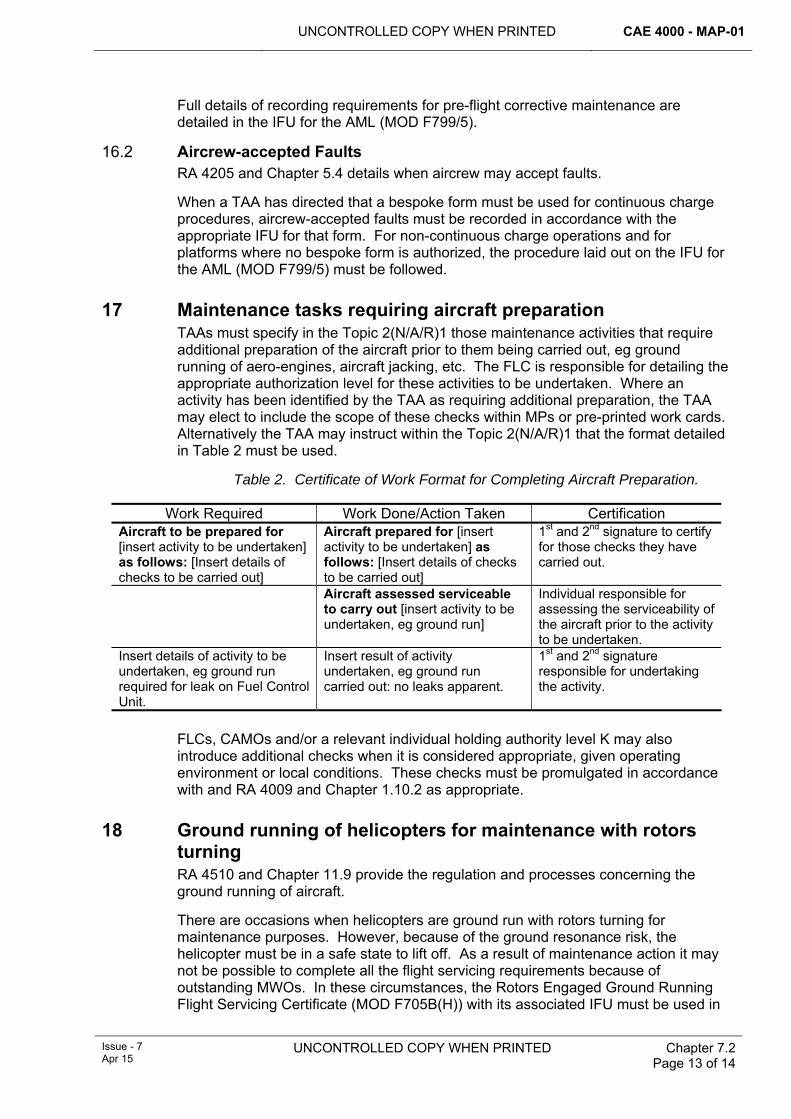
UNCONTROLLED COPY WHEN PRINTED CAE 4000 - MAP-01
Issue - 7 Apr 15
UNCONTROLLED COPY WHEN PRINTED Chapter 7.2 Page 13 of 14
Full details of recording requirements for pre-flight corrective maintenance are detailed in the IFU for the AML (MOD F799/5).
16.2 Aircrew-accepted Faults RA 4205 and Chapter 5.4 details when aircrew may accept faults.
When a TAA has directed that a bespoke form must be used for continuous charge procedures, aircrew-accepted faults must be recorded in accordance with the appropriate IFU for that form. For non-continuous charge operations and for platforms where no bespoke form is authorized, the procedure laid out on the IFU for the AML (MOD F799/5) must be followed.
17 Maintenance tasks requiring aircraft preparation TAAs must specify in the Topic 2(N/A/R)1 those maintenance activities that require additional preparation of the aircraft prior to them being carried out, eg ground running of aero-engines, aircraft jacking, etc. The FLC is responsible for detailing the appropriate authorization level for these activities to be undertaken. Where an activity has been identified by the TAA as requiring additional preparation, the TAA may elect to include the scope of these checks within MPs or pre-printed work cards. Alternatively the TAA may instruct within the Topic 2(N/A/R)1 that the format detailed in Table 2 must be used.
Table 2. Certificate of Work Format for Completing Aircraft Preparation.
Work Required Work Done/Action Taken Certification Aircraft to be prepared for [insert activity to be undertaken] as follows: [Insert details of checks to be carried out]
Aircraft prepared for [insert activity to be undertaken] as follows: [Insert details of checks to be carried out]
1st and 2nd signature to certify for those checks they have carried out.
Aircraft assessed serviceable to carry out [insert activity to be undertaken, eg ground run]
Individual responsible for assessing the serviceability of the aircraft prior to the activity to be undertaken.
Insert details of activity to be undertaken, eg ground run required for leak on Fuel Control Unit.
Insert result of activity undertaken, eg ground run carried out: no leaks apparent.
1st and 2nd signature responsible for undertaking the activity.
FLCs, CAMOs and/or a relevant individual holding authority level K may also introduce additional checks when it is considered appropriate, given operating environment or local conditions. These checks must be promulgated in accordance with and RA 4009 and Chapter 1.10.2 as appropriate.
18 Ground running of helicopters for maintenance with rotors turning RA 4510 and Chapter 11.9 provide the regulation and processes concerning the ground running of aircraft.
There are occasions when helicopters are ground run with rotors turning for maintenance purposes. However, because of the ground resonance risk, the helicopter must be in a safe state to lift off. As a result of maintenance action it may not be possible to complete all the flight servicing requirements because of outstanding MWOs. In these circumstances, the Rotors Engaged Ground Running Flight Servicing Certificate (MOD F705B(H)) with its associated IFU must be used in
CAE 4000 - MAP-01 UNCONTROLLED COPY WHEN PRINTED
Chapter 7.2 Page 14 of 14
UNCONTROLLED COPY WHEN PRINTED
Issue - 7 Apr 15
lieu of the relevant Flight Servicing Certificate to prepare the aircraft for flight and aircrew acceptance. The results of the ground run must then be recorded on the relevant MWO. If the ground run is conducted without rotors turning, no additional forms are required and all recording and certification action takes place on the relevant MWO. The Rotors Engaged Ground Running Flight Servicing Certificate must not be used if it is intended that the helicopter take off immediately after the ground run.
19 Miscellaneous activities During aircraft maintenance there are a number of activities that must be recorded in the MOD Form 700C but which do not necessarily need to be reported for fault analysis purposes, eg tool control entries, movement of ejection seat safety pins and manual folding/spreading of helicopter rotor blades. In these instances, a single AML and associated MWO may be raised to record these activities, rather than raising a separate entry for each activity. This entry must remain open until all such activities have been completed, at which point it may be closed in the normal manner.
20 Administration tasks Once an aircraft has been prepared for flight or is on continuous charge, there may be occasions when, in order to carry out an administrative task, a requirement exists to make an entry in the MOD F700C. Such entries do not render the aircraft unserviceable provided that the airworthiness of the aircraft is not compromised by the administrative task.
All such entries must be made in the AML and the appropriate MWO raised. The entry must be cleared by an individual holding MAP-G17, stating in the Work Done column:
‘For recording purposes only’
21 References This chapter refers to the following publications:
1 DAP 116P-05109-2(NR) – EHUDS General Orders and Special Instructions.
2 MAP-02 – Maintenance and Airworthiness Processes – MOD Form 700 Series of forms.
3 JAP 100V-21 – Aircraft Storage.
4 Topic 2(N/A/R) – General Orders, Special instructions and Modifications.
5 RA 4947 – Continuing Airworthiness Management - MRP Part M Sub-Part G.
6 JAP(D) 100A-0409-2 – GOLDesp Support Policy and General Orders
UNCONTROLLED COPY WHEN PRINTED CAE 4000 - MAP-01
Issue - 7 Apr 15
UNCONTROLLED COPY WHEN PRINTED Chapter 7.2.1 Page 1 of 8
Chapter 7.2.1
MOD Form 700 Documentation
TABLE OF CONTENTS Paragraph
Page
1 General ............................................................................................................... 1 1.1 Introduction.......................................................................................................... 1 2 Regulatory Governance.................................................................................... 1 2.1 Regulatory Article Cross-reference ..................................................................... 1 2.2 Additional Information.......................................................................................... 2 3 MOD Form 700 – binders and dividers............................................................ 2 3.1 General................................................................................................................ 2 3.2 MOD Form 700A – Aircraft Log Cover ................................................................ 2 3.3 MOD Form 700C – Aircraft Maintenance Form Cover ........................................ 2 3.4 MOD Form 700D – Engineering Record Card Cover.......................................... 3 3.5 Work recording on Logistic Information Systems (LIS) ....................................... 3 4 Control of MOD Form 700 and MOD Form 700 numerical series forms....... 3 4.1 Control of forms by Stns/Ships/Units and individuals.......................................... 3 4.2 Carriage of MOD Form 700C in parent aircraft ................................................... 6 4.3 Development of new forms.................................................................................. 7 5 Responsibilities................................................................................................. 7 5.1 Stn/Ship/Unit ....................................................................................................... 7 5.2 MOD Continuing Airworthiness Manager (MOD CAM) ....................................... 7 5.3 Type Airworthiness Authorities (TAAs) and commodity Project Teams (PTs) .... 8 5.4 MAA Reg CAw .................................................................................................... 8 6 References ......................................................................................................... 8
LIST OF TABLES Table 1. MAA Reg CAw - Mandatory MOD Form 700 Forms ......................................................3 Table 2. MAA Reg CAw - Designated MOD Form 700 Controlled Forms...................................4
1 General 1.1 Introduction
The MOD Form 700 is an omnibus title given to a collection of MOD Forms in the 700 numerical series. When assembled and allocated to a specific aircraft, flight simulator, Uninstalled Engine Test Facility (UETF) or associated equipment, these forms provide the means of compiling a complete technical history of the in-service use of that aircraft/equipment and provide a current statement of its condition. This chapter provides processes and instructions for the use of the MOD Form 700.
2 Regulatory Governance 2.1 Regulatory Article Cross-reference
This chapter supports:
1 RA 4813.
CAE 4000 - MAP-01 UNCONTROLLED COPY WHEN PRINTED
Chapter 7.2.1 Page 2 of 8
UNCONTROLLED COPY WHEN PRINTED Issue - 7 Apr 15
2.2 Additional Information The MOD Form 700 provides a technical history of an aircraft or equipment and a statement of its condition.
3 MOD Form 700 – binders and dividers 3.1 General
The MOD Form 700 consists of a variety of specified loose-leaf forms, selected from the MOD Form 700 numerical series, to suit the maintenance philosophy and the particular needs of a given aircraft type, flight simulator, UETF or associated equipment. The forms, along with the MOD Form 700 (Divider Cards), are held in 3 binders:
1 MOD Form 700A – Aircraft Log Cover.
2 MOD Form 700C – Aircraft Maintenance Form Cover.
3 MOD Form 700D – Engineering Record Card Cover (optional).
3.2 MOD Form 700A – Aircraft Log Cover The MOD Form 700A is a loose-leaf binder for the stowage of controlled forms, as defined in paragraph 4.1.3, removed from the MOD Form 700C.
3.3 MOD Form 700C – Aircraft Maintenance Form Cover The MOD Form 700C consists of a hard-back, loose-leaf binder and a series of forms in the MOD Form 700 numerical series. When assembled and allocated to either a specific aircraft, flight simulator, UETF or associated equipment by its serial number, the MOD Form 700C provides a working document in which current maintenance records are kept. The specific MOD Form 799/1 (Platform) lists those forms (including mandatory and controlled forms) identified by Military Aviation Authority Regulations Continuing Airworthiness (MAA Reg CAw) and the aircraft/equipment Project Team (PT), from the MOD Form 700 numerical series, that must be placed in each section of the MOD Form 700C. The sections are:
1 Section 1 – Aircraft Maintenance Log.
2 Section 2 – Limitations Log.
3 Section 3 – Acceptable Deferred Faults (ADF) Log.
4 Section 4 – Flight Servicing and Usage.
5 Section 5 – Forecast of Preventive Maintenance.
6 Section 6 – Aircraft Weight and Moment Data.
7 Section 7 – Mechanical Information.
8 Section 8 – Avionic Information.
9 Section 9 – Role Equipment and Weapons (forms other than MOD F706 series).
10 Section 10 – Used at PT Discretion.
11 Section 11 – Index, Leading Particulars, General Instructions for Use.
Depending on the aircraft/equipment type, not all sections are used. Section 10 may contain non-MOD Form 700 series documents at the MOD CAM or TAA’s discretion. The MOD Form 799/1(platform) should be amended if inclusion is anticipated to be for a prolonged period.
UNCONTROLLED COPY WHEN PRINTED CAE 4000 - MAP-01
Issue - 7 Apr 15
UNCONTROLLED COPY WHEN PRINTED
Chapter 7.2.1 Page 3 of 8
The MOD Form 700C must be adopted by all platforms although it is optional for simulators.
3.4 MOD Form 700D – Engineering Record Card Cover An A4 binder can be utilised as the MOD Form 700D, when in use, to store all the Engineering Record Cards (ERCs) for components fitted to a specific aircraft/equipment. Mandatory documents for inclusion in the optional MOD Form 700D must be listed in the relevant aircraft Topic 2(N/A/R)1 or Topic 5A1.
3.5 Work recording on Logistic Information Systems (LIS) When recording work, or associated activities, on a Logistic Information System (LIS), the method of recording and organizing maintenance data must be detailed in the appropriate operating manual. There is no requirement to use specific MOD Form 700 numerical series layouts for displaying information on the LIS screen; however, any forms printed must comply with the provisions of paragraph 4.
4 Control of MOD Form 700 and MOD Form 700 numerical series forms
4.1 Control of forms by Stns/Ships/Units and individuals 4.1.1 Mandatory forms
The following MOD Forms should be contained in all platform MOD Form 700C.
Table 1. MAA Reg CAw - Mandatory MOD Form 700 Forms MOD Form series Form Title IFU series 701 Leading Particulars Nil 702 Series (see Note 1)
Weight & Balance Data 799/9(W&B)
703 Limitations Log 799/2 704 Acceptable Deferred Faults (ADF) Log 799/3 705(Platform) Flight Servicing Certificate (FSC) 799/4 705 SSR Supplementary Flight Servicing Register 799/4 (SFS) 705 SSC Supplementary Flight Servicing Certificate 707A Aircraft Maintenance Log 799/5 710 (see Note 2) Military Airworthiness Review Certificate
(MARC)
713 Register of Controlled MOD Forms 799/1 721 Series (see Note 3)
Forecast Sheet 799/6
799/1 General Instructions For Use Nil 799/1(Platform) Aircraft Maintenance Form (MOD Form
700) - Index Nil
Notes:
1 The MOD Form 700C is to contain the MOD Form 702 and any other appropriate forms from the MOD Form 702 series or an alternative (eg LIS printout or platform specific form) approved by MAA Reg CAw.
2 The MOD Form 710 is mandatory when issued as required by RA 4970 and RA 4971 and should be held in each aircraft MOD Form 700C. If the original MOD Form 710 MARC is filed in the MOD Form 700A Log Pack, a copy should be included in Section 11 of MOD Form 700C.
CAE 4000 - MAP-01 UNCONTROLLED COPY WHEN PRINTED
Chapter 7.2.1 Page 4 of 8
UNCONTROLLED COPY WHEN PRINTED Issue - 7 Apr 15
3 The MOD Form 700C is to contain the MOD Form 721 and any other appropriate forms from the MOD Form 721 series or an alternative (eg LIS printout or platform specific form) approved by MAA Reg CAw.
4.1.2 Sponsorship of forms Aircraft/equipment-specific MOD Form 700 numerical series forms are sponsored by the appropriate TAA or commodity PT. MAA Reg CAw sponsors all other MOD Form 700 numerical series forms.
Note:
Although sponsored by the TAA, any changes made to the MOD Form 799/1(Platform) should only be made after consultation with the relevant CAMO(s).
4.1.3 Controlled forms MAA Reg CAw designates a number of forms in the MOD Form 700 numerical series as controlled forms; their use and disposal is subject to specific conditions. Table 2 lists these controlled forms:
Table 2. MAA Reg CAw - Designated MOD Form 700 Controlled Forms.
MOD Form No MOD Form No MOD F703 MOD F705(SSC) & MOD F705(SSR) MOD F703AE MOD F706B or MOD Form 706B(Platform) MOD F703A1 & MOD F703A2 MOD F707A MOD F703B or MOD Form 703B(Platform) MOD F713 MOD F704 MOD F721B MOD F704A MOD F721C or MOD Form 721C(Platform) MOD F704B MOD F724 or MOD Form 724(Platform) MOD F704D MOD F725(Platform) MOD F704LA (where used)
The appropriate MOD Form 799/1(Platform) details which forms are controlled within a particular aircraft/equipment type MOD Form 700C.
4.1.4 Insertion and removal of controlled forms into/from MOD Form 700 A person holding authorization MAP-C450 may insert controlled forms into the MOD Form 700C.
A person holding authorization MAP-E424 may insert/remove controlled forms into/from the MOD Form 700C.
Instructions for the insertion and removal of controlled forms into/from MOD Form 700C are detailed on the MOD Form 799/1 General Instructions For Use.
4.1.5 Amendments to existing forms When an amendment to a form is considered necessary, the proposer must submit an amendment request in accordance with MAP-02 Chapter 0.3.
4.1.6 Electronic versions of forms The electronic version of a form is known as a format. It replicates a hard copy form and allows completion by computer. Not all forms have corresponding formats and some formats exist as formats only, without supporting hard copy forms. A format may be generated by an LIS (eg LITS, GOLDesp) or downloaded from MAP-02
UNCONTROLLED COPY WHEN PRINTED CAE 4000 - MAP-01
Issue - 7 Apr 15
UNCONTROLLED COPY WHEN PRINTED
Chapter 7.2.1 Page 5 of 8
Chapter 1.8. There are 2 levels of functionality applied to formats: those that can be typed in to, printed but can not be saved with content and those which can be typed in to, printed and can be saved with content.
The use of any Format is subject to the following conditions:
1 Only formats provided in the MAP-02 or by a LIS are authorized for use.
2 Printing of formats must comply with the requirements of MAP-02 Chapter 1.1 paragraph 4.
3 MAP-02 formats will be automatically amended to reflect any change made to the corresponding form. It is the responsibility of the user to ensure the correct revision of a format is being used.
4 To change a format that has a supporting form, the proposer should request an amendment to the form, not the format, as detailed in paragraph 4.1.5.
5 To change the editable fields, request that a format be enabled to allow saving with content or amend a format without a supporting form, the proposer must raise an MOD Form 765 ►◄as detailed in MAP-02 Chapter 0.3 against the format.
4.1.7 Loss of aircraft maintenance forms In accordance with RA 4947(1)g, the Continuing Airworthiness Management Organization (CAMO) is required to develop a procedure for lost aircraft maintenance forms, which should include any search or investigation requirements and a policy on the use of duplicated documents. While the detail of the CAMO-approved procedure has precedence, it may be based on the following generic procedure:
The loss of any aircraft maintenance forms or electronic data must initially be reported to the appropriate individual holding authority level J who must inquire into the circumstances of each reported loss and initiate appropriate investigations. When there are operational or safety implications, the loss must also be reported to the appropriate individual holding authority level K, who must consult with the appropriate TAA or MOD CAM and, when required, instigate further investigations. Duplicate forms may be raised on the authority of the appropriate individual holding authorization MAP-K240, using a Duplicate Engineering Documentation Authorization Certificate (MOD Form 700Z). All duplicate form(s) raised must be endorsed “Duplicate Form” in red ink across the top and should detail (on the reverse of the attached MF 700Z) the actions involved in the searches and investigations for the missing form along with any cross-referencing to remedial actions .
When documentation is lost after it has undergone electronic data capture, the loss of the documentation must be dealt with by the relevant individual holding authority level J in a manner that he deems appropriate to ensure an adequate audit trail. When the loss relates to ERCs, the relevant equipment must be quarantined at the Stn/Ship/Unit reporting the loss until the ERC is found, a duplicate is authorized, or the PT issues disposal instructions.
4.1.8 Transfer of aircraft maintenance forms When aircraft and components are transferred between Stns/Ships/Units, the associated aircraft maintenance forms must be forwarded to the receiving organization or document custodian (where applicable). The documents must be dispatched by the most suitable means under cover of a completed MOD Form 743. Associated management and historical documents may also be enclosed with the aircraft maintenance forms. The documents must be sealed in plastic bags to prevent contamination and must not be attached to, or be enclosed with, the
CAE 4000 - MAP-01 UNCONTROLLED COPY WHEN PRINTED
Chapter 7.2.1 Page 6 of 8
UNCONTROLLED COPY WHEN PRINTED Issue - 7 Apr 15
equipment to which they refer, unless the equipment PT has granted dispensation. The receiving organization must check the documents and return the Receipt and Discrepancy Certificate (part of the MOD Form 743) to the dispatching organization.
4.1.9 Retention of documentation Retention instructions for forms in the 700 numerical series are mandated by RA 4813 and Chapter 7.6 and may be reiterated in the appropriate MOD F799/1 (Platform). Copies of Limitations Log and Acceptable Deferred Faults (ADF) Log pages produced in accordance with Paragraph 4.2.3 must be retained until a person holding MAP-E424 authorizes their destruction.
4.2 Carriage of MOD Form 700C in parent aircraft 4.2.1 General
An MOD Form 700C may be carried in its parent aircraft during flight but provision must be made to retain original signatures for work carried out and measures put in place to aid the re-construction of the document in the event of its loss. Therefore, a MOD Form 700C may be carried if:
1 All documentation bearing original signatures for work carried out are removed prior to flight.
2 A copy of the information contained in Section 2 (Limitations Log) and Section 3 (ADF Log – excluding the Husbandry Log) is retained by a ground based engineering organization.
4.2.2 Removal of documents bearing original signatures Documents bearing original signatures must be removed, however; where the information contained in the removed documentation must remain with the aircraft, a copy of the original documentation must be substituted. Only in exceptional circumstances, when the aircraft is operating in the Forward environment and there is no other way of returning such documentation, may it be carried in its parent aircraft. Such documentation must be removed and despatched to the aircraft’s parent Stn/Ship/Unit at the first available opportunity. Instructions for removing pages from the MOD Form 700C in order to make it suitable for carriage are given in the MOD Form 799/1 filed in the MOD Form 700C.
4.2.3 Copying of information contained in MOD F700C Section 2 and Section 3 The information contained in MOD Form 700C Section 2 and Section 3 is a record of the condition of the aircraft drawn from a number of sources. Reconstruction of these sections in the event of loss of the MOD Form 700C is difficult and time consuming. Therefore, prior to the carriage of the MOD Form 700C in its parent aircraft, extant entries in Section 2 (Limitations Log) and Section 3 (ADF Log – see Note 1) must be copied prior to flight. However, where the source of an entry can be retained, the following may be applied:
1 Where copies have been taken but time constraints preclude copying of subsequent entries, the entries may be carried without copying, however; the parent Maintenance Work Order(s) (MWO) must be retained until the aircraft ceases to carry the MOD Form 700C during flight.
2 Prior to operation in an area where copying facilities may be unavailable, an aircraft’s parent Stn/Ship/Unit (see Note 2) must ensure that copies of extant entries on all the forms contained in Section 2 & 3 (excluding the Husbandry Log) are taken and retained. Subsequent entries may be carried without copying but the parent MWOs must be retained until the aircraft ceases to carry the MOD Form 700C during flight.
UNCONTROLLED COPY WHEN PRINTED CAE 4000 - MAP-01
Issue - 7 Apr 15
UNCONTROLLED COPY WHEN PRINTED
Chapter 7.2.1 Page 7 of 8
3 Where the aircraft is supported by an LIS that hosts the current Section 2 and Section 3 of the MOD Form 700C and when the LIS has been used to produce the original pages currently held in the binder, the requirement for additional copies to be produced and retained as described above may be disregarded. Any documents from Section 2 or Section 3 that are not hosted by the LIS must be copied and retained as described above.
4 When the aircraft ceases to carry the MOD Form 700C during flight, a person holding MAP-E424 may authorize destruction of the copies (see Note 3).
Notes:
1 This process applies to all forms in Sections 2 & 3 that contain entries (excluding the Husbandry Log) eg, the ‘List of Modifications and Service Issued Instructions of Direct Operating Interest to Aircrew’ and ‘TAA-Granted Concessions’, etc.
2 Copies of Section 2 & 3 must be made by the Stn/Ship/Unit best placed to provide support for the application, be it a Main, Detached or Forward Operating Base (MOB, DOB, FOB).
3 Where it better suits an aircraft’s method of operation, MOD Continuing Airworthiness Managers (MOD CAMs) may authorize the maintenance of a permanent copy of the forms contained in Sect 2 & 3 on condition that procedures are in place to ensure that the copy meets the requirements of this Chapter.
4.3 Development of new forms To maintain configuration control, new forms must not be created and used within the MOD Form 700 numerical series unless endorsed by MAA Reg CAw via MF765 as detailed in MAA03 . Once endorsed by MAA Reg CAw, only the relevant TAA can authorize their use within the MOD Form 700C and/or MOD Form 700D by sponsoring a change to the appropriate MOD Form 799/1(Platform). Where an immediate requirement exists to insert a non MOD Form 700 series form in the MOD Form 700C and/or MOD Form 700D, approval should be granted by the appropriate TAA or MOD CAM via local orders. With the exception of the MOD Form 700C Section 10 (Paragraph 3.3 refers) the insertion should be for a defined period pending publication of the MOD Form 700 series or expiry of the temporary requirement.
5 Responsibilities 5.1 Stn/Ship/Unit
Stns/Ships/Units are responsible for:
1 Inserting and removing controlled forms into/from the MOD Form 700C.
2 Where necessary, preparing MOD Form 700C for carriage in its parent aircraft, including the production of copies of original documents when required.
3 Taking appropriate action when aircraft maintenance forms or electronic data are lost.
4 Transferring aircraft maintenance forms when aircraft and components are transferred between Stns/Ships/Units.
5.2 MOD Continuing Airworthiness Manager (MOD CAM) MOD CAMs are responsible for:
CAE 4000 - MAP-01 UNCONTROLLED COPY WHEN PRINTED
Chapter 7.2.1 Page 8 of 8
UNCONTROLLED COPY WHEN PRINTED Issue - 7 Apr 15
1 Authorizing the maintenance of a permanent copy of the forms contained in the MOD Form 700C Sections 2 & 3, where it better suits an aircraft’s method of operation.
2 Through the CAMO, developing a procedure for lost aircraft maintenance forms, which should include any search or investigation requirements and a policy on the use of duplicated documents, in accordance with RA 4947(1)g.
5.3 Type Airworthiness Authorities (TAAs) and commodity Project Teams
(PTs) TAAs and commodity PTs are responsible for:
1 Specifying which MOD Form 700 numerical series forms, specific to their aircraft type, are to be included in the MOD Form 700C/MOD Form 700D.
2 Sponsoring any special-to-type MOD Form 700 series forms raised for the aircraft or equipment.
3 When appropriate and in consultation with the CAMO, detailing forms that are to be “controlled forms”. These will be annotated on the appropriate MOD Form 799/1 (Platform).
5.4 MAA Reg CAw MAA Reg CAw is responsible for:
1 Designating those MOD Forms that are mandatory for inclusion in all aircraft MOD Forms 700.
2 Designating those forms that are “controlled forms”.
3 Approving all forms for inclusion in the MOD Form 700C.
6 References This chapter refers to the following publications:
1 Topic 2(N/A/R)1 – General Orders and Special Instructions.
2 Topic 5A1 – Master Maintenance Schedule.
3 RA 4947 - Continuing Airworthiness Management - MRP Part M Sub-Part G.
UNCONTROLLED COPY WHEN PRINTED CAE 4000 - MAP-01
Issue - 7 Apr 15
UNCONTROLLED COPY WHEN PRINTED Chapter 7.3 Page 1 of 6
Chapter 7.3
Logistic Information Systems
TABLE OF CONTENTS Paragraph
Page
1 General ............................................................................................................... 1 1.1 Introduction.......................................................................................................... 1 2 Regulatory Governance.................................................................................... 1 2.1 Regulatory Article cross-reference ...................................................................... 1 3 Use of Logistic Information Systems (LIS) ..................................................... 1 4 LIS application................................................................................................... 2 4.1 Security ............................................................................................................... 2 4.2 Configuration management ................................................................................. 2 4.3 Certification ......................................................................................................... 2 4.4 Look and feel....................................................................................................... 2 4.5 Redundancy/reversionary mode ......................................................................... 3 4.6 Automatic arising management........................................................................... 3 4.7 LIS on portable IT................................................................................................ 3 5 Data..................................................................................................................... 3 5.1 Minimum Data Capture Lists (MDCL) ................................................................. 3 5.2 Initial guidance from the Type Airworthiness Authority (TAA) ............................. 3 5.3 Business/reference data...................................................................................... 3 5.4 Component record creation................................................................................. 4 5.5 Fault codes.......................................................................................................... 4 5.6 Archiving.............................................................................................................. 4 5.7 Actions in the event of an aircraft accident.......................................................... 4 6 LIS through-life management........................................................................... 5 7 References ......................................................................................................... 5
1 General 1.1 Introduction
For the purpose of this chapter, a Logistic Information System (LIS) is defined as any electronic information system that allows the management, planning and detailed co-ordination of engineering and logistic operations within the Military Air Environment (MAE). .
2 Regulatory Governance 2.1 Regulatory Article cross-reference
This chapter supports:
1 RA 4303(1).
2 RA 4303(2).
3 Use of Logistic Information Systems (LIS) The Type Airworthiness Authority (TAA) is ultimately responsible for any item of hardware or software used for the operation and/or maintenance of their platform.
CAE 4000 - MAP-01 UNCONTROLLED COPY WHEN PRINTED
Chapter 7.3 Page 2 of 6
UNCONTROLLED COPY WHEN PRINTED Issue - 7 Apr 15
TAAs utilizing a LIS are therefore responsible for ensuring its compliance with the regulation. This applies even if the LIS is used by multiple platforms.
Note:
Commodity Project Teams (PTs) may authorize a LIS for use in support of their equipment when uninstalled from its associated air platform. In this instance, such PTs are to follow the procedures detailed for TAAs in this Chapter.
4 LIS application Preliminary Hazard Listing will identify hazards related to the use of the LIS. Furthermore, utilization of an appropriate Safety Management System (SMS) will facilitate rigorous testing to ensure that safety-relevant business data is not corrupted or incorrectly manipulated: the test results must complement the Air System Safety Case. The LIS application should be permissive for multiple levels of user authorizations. When in-built business procedures are contravened, the system must warn the user and prevent further processing. However, the system should allow users, in the Forward environment only, and with the appropriate authorization, set by the TAA, to over-ride such procedures if dictated by the operational situation. When the warning is over-ridden, this action must be recorded against the individual who certifies the over-ride.
4.1 Security Generic details relating to IS security can be found in JSP 440. For LIS, generic ‘log-ons’ are allowed, but each certifiable action must be attributable to the individual carrying it out. This is normally achieved through a Personal Identification Device/Personal Identification Number system as mandated by RA 4813(1)and Chapter 7.3.1. Security accreditation is a mandatory requirement for all Information Technology (IT)-based systems that electronically store, process or forward official information. JSP 440 contains details of the security accreditation process and where advice can be obtained.
4.2 Configuration management LIS configuration must be managed by the aircraft/equipment PT, with the levels of control being commensurate with the system criticality. Where the in-service airworthiness and safety of the aircraft/equipment is managed by a LIS, the LIS must be maintained in accordance with a SMS that includes auditing, fault reporting and recording at all maintenance levels. This must include any updates to airworthiness-relevant procedures or information. Historical information must be retained so that, through the date-time stamp, the policy, regulations and software version in use at the time of any safety certification can be identified.
4.3 Certification The electronic certification of maintenance is mandated by RA 4813(1)and Chapter 7.3.1.
4.4 Look and feel A LIS should present information to the user in a clear, unambiguous and logical manner, conforming where possible to corporate or application ‘common look and feel’. As a general principle, the system should initially display the minimum amount of information required by the user to complete a specific task, with the ability to easily interrogate the database should more detailed information be required. When information is output for further processing in paper form, Military Aviation Authority Regulation Continuing Airworthiness MAP and Logistic Information System
UNCONTROLLED COPY WHEN PRINTED CAE 4000 - MAP-01
Issue - 7 Apr 15
UNCONTROLLED COPY WHEN PRINTED
Chapter 7.3 Page 3 of 6
(DSA-MAA-Reg-CAw4-MAPLIS) must approve the MOD Format as mandated by RA 4813 and Chapter 7.2.1.
4.5 Redundancy/reversionary mode A LIS that is being relied upon to provide airworthiness information must be designed such that it has sufficient redundancy to allow the system to remain operational and ensure continuity and assurance of flight safety and airworthiness in the event of catastrophic LIS failure. The TAA must ensure that his system has sufficient redundancy to meet the above criteria. .
4.6 Automatic arising management The TAA must detail and document the criteria and procedures for automatic arising management (eg voltage drops during engine start or high main rotor speed during autorotation). The regulation for Management of Arisings is RA 4306 and Chapter 7.3.3.
4.7 LIS on portable IT Where a LIS is used via portable IT, it is the responsibility of the TAA to ensure that the IT is suitable and approved for use on or around the intended aircraft/equipment. Advice should be sought from the Defence Support Group Through Life Support (DSG TLS) Manager.
5 Data Control of data is essential to the integrity and airworthiness of both LIS and the aircraft/equipment they support. Unless specified, the data will remain under the control of the TAA and all requests for changes to datasets must be co-ordinated by the relevant staff within the platform PT. Further detail on LIS data management is contained in JSP 886 Vol 3..
5.1 Minimum Data Capture Lists (MDCL) An MDCL is a list of parameters/metrics that must be captured by a LIS to enable continuing airworthiness management, achieve the Support Policy and allow effective data exploitation. The TAA must determine the criteria as to what constitutes an MDCL for a particular platform, noting that he is ultimately responsible for ensuring that the LIS delivers the intent of the F700C hard copy documentation system. If it is planned for a new platform to utilize an existing LIS, early engagement with the LIS sponsor is required to ensure that the capability exists to capture all the relevant parameters/metrics.
5.2 Initial guidance from the Type Airworthiness Authority (TAA) Clear procedures for data management are to be provided by the TAA and considered procedurally within the SMS.
5.3 Business/reference data Access to the system business/reference data must only be by personnel authorized by the TAA. Changes to business/reference data must be approved and certified by either the generic LIS sponsor or an individual approved by the associated TAA. Furthermore, the TAA authority for change should be recorded against the action in order to maintain a full audit trail.
CAE 4000 - MAP-01 UNCONTROLLED COPY WHEN PRINTED
Chapter 7.3 Page 4 of 6
UNCONTROLLED COPY WHEN PRINTED Issue - 7 Apr 15
5.4 Component record creation 5.4.1 Prior to use on LIS
Prior to the use of an asset within an LIS environment, details of the asset's usage, configuration, build, scheduled maintenance requirements and condition must be recorded on the LIS to create an Electronic Service Record (ESR) for the asset. Additionally, when an asset previously recorded on the LIS returns to the LIS environment (having been outside the LIS environment), the ESR for the asset on the LIS must be updated prior to its use.
5.4.2 Preservation of data integrity System functionality and/or business processes must be implemented to minimise the risk of duplicate asset creation, and to detect it at the earliest opportunity. Such measures must consider deployed Sqns/Units that may not have access to, or have been provided with, ‘live’ asset data. In that case, local input of asset data by authorized personnel must be permitted to allow for the creation, modification or change of function of an asset, eg re-handing of an undercarriage assembly.
5.4.3 Asset maintenance outside LIS boundary Aircraft/equipment that have been registered on a LIS may be maintained outside the system’s boundary, eg whilst allotted to a Depth non-LIS contractor for any form of maintenance. In these instances, arrangements must be made for data relating to LIS-pertinent maintenance activities to be captured and fed back to the LIS in order to maintain the currency of the LIS database.
5.4.4 Time zones Stns/Ships/Units must adopt one of the following 2 time zone options:
1 The time zone must be included on all maintenance documentation. The authority to use local time zones on a LIS must be approved by the TAA.
2 All recorded times must be in Zulu (Greenwich Mean Time), unless local requirements dictate otherwise.
5.5 Fault codes TAAs should select and promulgate the most appropriate fault codes to support their data exploitation strategy as required by RA 1140. Generic codes are detailed in JAP(D) 100C-02 if required.
5.6 Archiving The TAA, in consultation with the CAMO, must mandate the archiving policy for data used by the LIS. The TAA must ensure that the following criteria are met:
1 As a minimum, data selected by the TAA must be archived in accordance with the current paperwork retention periods mandated by RA 4311 and Chapter 7.6.
2 The frequency and methods of archiving must be mandated by the TAA to maximize the performance of the LIS whilst maintaining availability of essential data.
3 A LIS must be able to retrieve archived data within the timescale specified by the TAA. Therefore, if the LIS application is amended such that it can no longer retrieve/process archived data, that version of the LIS application in use at the time of amendment must also be archived to allow future retrieval.
5.7 Actions in the event of an aircraft accident In the event of an aircraft accident, all data held within a LIS must be backed up and quarantined. The data is then, using system specific processes and coordinated by
UNCONTROLLED COPY WHEN PRINTED CAE 4000 - MAP-01
Issue - 7 Apr 15
UNCONTROLLED COPY WHEN PRINTED
Chapter 7.3 Page 5 of 6
the CAMO, to be transferred to the Military Air Accident Investigation Branch (MAAIB) on request.
6 LIS through-life management A TAA utilizing a bespoke LIS is responsible for the ultimate approval and assurance of any current or future capability delivered by the LIS and its development with the contractor.
Organizations maintaining a generic LIS for a broad spectrum of aircraft are responsible for the assurance and approval of any current or future capability delivered by the LIS and its development contractor. The utilization of a generic LIS is a TAA’s decision and therefore the ultimate responsibility for airworthiness lies with the TAA.
The integrity and assurance of electronic data transferred between a military-controlled LIS and a contractor-controlled LIS is the responsibility of the TAA. The TAA is to ensure that data made available to the contractor from a military LIS is of an acceptable format to enable the contractor to meet his maintenance responsibilities. The TAA is also responsible for ensuring that data received from a contractor's LIS is capable of being accurately transferred to a military LIS.
7 References This chapter refers to the following publications:
1 JSP 440 – The Defence Manual of Security.
2 JAP(D) 100C-02 – MOD Fault Reporting Documentation – Compilation Guidelines.
3 JSP 886 Vol 3 Part 11 - Logistic Information System Data Management.

CAE 4000 - MAP-01 UNCONTROLLED COPY WHEN PRINTED
Chapter 7.3 Page 6 of 6
UNCONTROLLED COPY WHEN PRINTED Issue - 7 Apr 15
Intentionally Blank for Print Pagination
UNCONTROLLED COPY WHEN PRINTED CAE 4000 - MAP-01
Issue - 7 Apr 15
UNCONTROLLED COPY WHEN PRINTED Chapter 7.3.1 Page 1 of 4
Chapter 7.3.1
Electronic Certification of Aircraft Maintenance
TABLE OF CONTENTS Paragraph
Page
1 General ............................................................................................................... 1 1.1 Introduction.......................................................................................................... 1 1.2 Associated instructions........................................................................................ 1 2 Regulatory Governance.................................................................................... 1 2.1 Regulatory Article Cross-reference ..................................................................... 1 3 Requirements for certification ......................................................................... 2 3.1 Certification point................................................................................................. 2 3.2 Certification action............................................................................................... 2 3.3 Certifiable data .................................................................................................... 2 3.4 Operational override capability............................................................................ 2 4 Principles of electronic certification ............................................................... 2 4.1 Introduction.......................................................................................................... 2 4.2 Responsibilities of the individual ......................................................................... 2 4.3 Storage and disposal of certified data ................................................................. 2 5 Methods of electronic certification using electronic signatures .................. 2 6 Legal implications of electronic signatures ................................................... 3 6.1 Introduction.......................................................................................................... 3 6.2 Handling and security of data used for incident or accident investigation........... 3 6.3 Admissibility......................................................................................................... 3 7 References ......................................................................................................... 3
1 General 1.1 Introduction
With the use of Logistic Information Systems (LIS) in recording maintenance there is a requirement to certify maintenance actions using electronic signatures. This chapter describes the Acceptable Means of Compliance (AMC) and Guidance Material (GM) for the electronic certification of maintenance documentation in the Military Air Environment (MAE).
1.2 Associated instructions This chapter is associated with the following instructions:
1 EC Directive 1999/93/EC – Community Framework for Electronic Signatures.
2 JSP 740 – Acceptable Use Policy for Users of MOD IT & Telecommunications Networks.
2 Regulatory Governance 2.1 Regulatory Article Cross-reference
This chapter supports:
1 RA 4813(1).
CAE 4000 - MAP-01 UNCONTROLLED COPY WHEN PRINTED
Chapter 7.3.1 Page 2 of 4
UNCONTROLLED COPY WHEN PRINTED Issue - 7 Apr 15
3 Requirements for certification 3.1 Certification point
A LIS using electronic signature functionality for the recording of activities using electronic documentation must provide logical junctures to allow users to certify those activities that have been completed. These junctures are known as the certification points.
3.2 Certification action A LIS used for electronic maintenance documentation recording must provide an auditable trail of activities carried out. Certification by an individual will link those responsible for the activity to the activity itself. These certified actions must comply with the responsibilities and authority levels mandated by RA 4806 and Chapter 4.3.2.
3.3 Certifiable data The LIS must provide a complete reviewable data set to which the certification attests. This must include any additional certified data on which the above certification is dependent. This data will be known as certifiable data. Certified data, once created, must be unalterable. System audit procedures must include explicit checks for the misuse of, or tampering with, certified data.
3.4 Operational override capability In the Forward environment only, the system must be capable of allowing an override by the user in the event of operational need. All such override actions must be strictly controlled and fully auditable. The relevant Type Airworthiness Authority (TAA) must provide a stringent system of audit that is capable of clearly identifying why, when and by whom the system has been overridden.
4 Principles of electronic certification 4.1 Introduction
The principle of electronic certification of maintenance activities must reflect the certification process used for the hardcopy documentation as mandated by RA 4813 and Chapter 7.2.
4.2 Responsibilities of the individual In the interest of flight safety and airworthiness integrity, there is a chain of individual responsibility for maintenance carried out within the MAE and a supporting system of recording and certification that ensures full accountability for all such activities.
In specific instances an individual’s certification affirms that the equipment is fit for purpose. Therefore, the importance of correct recording and certification cannot be over-emphasized and all personnel are reminded that it is a serious offence to certify a maintenance record without first ensuring its accuracy.
4.3 Storage and disposal of certified data Certified data is to be retained as mandated by RA 4813 and Chapter 7.6.
5 Methods of electronic certification using electronic signatures Examples of electronic signature are Smart Card and Personal Identification Number (PIN), Physical Input Devices (PID), Biometrics and Physical signature capture/recognition.
UNCONTROLLED COPY WHEN PRINTED CAE 4000 - MAP-01
Issue - 7 Apr 15
UNCONTROLLED COPY WHEN PRINTED
Chapter 7.3.1 Page 3 of 4
6 Legal implications of electronic signatures 6.1 Introduction
Maintenance documentation is open to scrutiny, especially during incident or accident investigations. Hardcopy maintenance documentation can be easily presented as evidence in legal proceedings; however, the ability to present the same information from an electronic source and provide evidence of its integrity for legal proceedings is more complex.
6.2 Handling and security of data used for incident or accident investigation When an investigation of an incident or accident requires evidence from a LIS, it is imperative that the data can be secured and handled in a way that maintains the best evidence principle. Data handling and storage methods acceptable for use as best evidence are outlined in ISO/IEC 27002:2005.
6.3 Admissibility Guidance on admissibility is contained in the Electronic Communications Act 2000 Chapter 7. The strength of admissibility may be dependent on the level of authentication, authorization and integrity control applied within the LIS. TAAs must ensure that their electronic signature solution will withstand legal scrutiny should matters relating to airworthiness or culpability of an individual be under investigation. Further clarification may be sought from Defence Legal Services.
7 References This chapter refers to the following publications:
1 ISO/IEC 27002:2005 Information Technology – Security Techniques Code of Practice for Information Security Management.
2 Electronic Communications Act 2000 Chapter 7.

CAE 4000 - MAP-01 UNCONTROLLED COPY WHEN PRINTED
Chapter 7.3.1 Page 4 of 4
UNCONTROLLED COPY WHEN PRINTED Issue - 7 Apr 15
Intentionally Blank for Print Pagination
UNCONTROLLED COPY WHEN PRINTED CAE 4000 - MAP-01
Issue - 7 Apr 15
UNCONTROLLED COPY WHEN PRINTED Chapter 7.3.2 Page 1 of 6
Chapter 7.3.2
Electronic Documentation of Aircraft Maintenance
TABLE OF CONTENTS Paragraph
Page
1 General ............................................................................................................... 1 1.1 Introduction.......................................................................................................... 1 2 Regulatory Governance.................................................................................... 2 2.1 Regulatory Article Cross-reference ..................................................................... 2 3 Electronic Documentation (ED) of aircraft maintenance............................... 2 4 Maintenance documentation............................................................................ 2 4.1 Use of ED ............................................................................................................ 2 5 Data management ............................................................................................. 2 5.1 Data backup ........................................................................................................ 2 5.2 Archiving.............................................................................................................. 3 5.3 Data retrieval ....................................................................................................... 3 5.4 Copy .................................................................................................................... 3 5.5 Auditing ............................................................................................................... 3 5.6 Data locking......................................................................................................... 3 5.7 Amendment and configuration control................................................................. 4 5.8 Transfer of data ................................................................................................... 4 6 Authorization ..................................................................................................... 4 7 Deployment........................................................................................................ 4 8 References ......................................................................................................... 5
1 General 1.1 Introduction
This chapter details the process for Electronic Documentation (ED) of aircraft maintenance within the Military Air Environment (MAE). The chapter gives guidance on ED that Type Airworthiness Authorities (TAAs) should aim to adopt during initial procurement or midlife upgrades of aircraft and aircraft equipment. It is appreciated however that it may not be practicable or cost-effective for legacy aircraft and aircraft equipment to adopt some of the ED philosophy.
When utilized, ED of aircraft maintenance offers a number of potential advantages over traditional paper systems. These advantages can be summarized as follows:
1 The concept of ‘write once, access many times’ will avoid duplication that is prevalent in current paper documentation and simplify and enhance maintenance data accuracy.
2 Time spent on data recording, associated with aircraft maintenance, will be reduced.
3 There will be cost benefits through significantly reduced requirements for paper forms.
4 Backup and electronic archiving of maintenance data will be readily achievable.
5 The need for asset tracking using manual returns will be reduced or in some cases removed altogether.
CAE 4000 - MAP-01 UNCONTROLLED COPY WHEN PRINTED
Chapter 7.3.2 Page 2 of 6
UNCONTROLLED COPY WHEN PRINTED Issue - 7 Apr 15
2 Regulatory Governance 2.1 Regulatory Article Cross-reference
This chapter supports:
1 RA 4305:
3 Electronic Documentation (ED) of aircraft maintenance Data must be managed within the guidelines of the Data Protection Act 1998 and JSP 440. The philosophy on ED of aircraft maintenance is subject to continuous review by Military Aviation Authority Regulations Engineering Continuing Airworthiness in liaison with appropriate Subject Matter Experts (SMEs), in order to ensure that the most advantageous use will be made of new and emerging technologies.
4 Maintenance documentation Aircraft maintenance is documented in order to provide the following:
1 A technical history of aircraft, equipment and certain specified components.
2 A means of showing the serviceability state of aircraft, equipment and certain specified components.
3 A means of certifying and recording that maintenance work has been carried out.
4 A means of forecasting when maintenance work is due.
5 A record of aircraft and equipment configuration.
4.1 Use of ED Maintenance data on aircraft, equipment and specified components may be recorded electronically, in preference to recording on the equivalent paper form, provided that:
1 None of the reasons for recording engineering data set out in paragraph 4 are compromised.
2 A clear audit trail exists for the certification of aircraft maintenance work.
3 Where data is required to be printed, it is presented in a legible format to allow engineering decisions to be made, ie it is not left in ‘raw data’ format. Data printed to MOD F700 registered forms must comply with RA 4813 and Chapter 7.2.1.
4 When electronic signatures are utilized, they comply with RA 4813 and Chapter 7.3.1.
5 Data management 5.1 Data backup
Data backup is the strategy taken to ensure that data can be restored, to that point in time, when aircraft airworthiness is assured following a catastrophic Information System (IS) failure. A catastrophic failure can be described as a malfunction or event that affects all live data transactions, eg virus attack. To ensure subsequent restoration, data must be backed up at regular intervals and stored remotely from the data source.
UNCONTROLLED COPY WHEN PRINTED CAE 4000 - MAP-01
Issue - 7 Apr 15
UNCONTROLLED COPY WHEN PRINTED
Chapter 7.3.2 Page 3 of 6
5.2 Archiving Archiving is the process of removing a quantity of data from an IS for storage elsewhere, in order to optimize system performance. The archiving periodicity is dependent upon the capability of, and the operating demands placed upon, the individual IS. High performance systems, or those with a significant amount of spare capacity, may require less archiving than lower specification or more heavily utilized systems. As a result of these inter-dependent factors and evolving technologies, it is accepted that ED regulations cannot dictate rigidly on this subject. However, as a minimum, the following principles are to be followed:
1 Archived data must be stored on media or an IS that will allow it, with suitable media updates, to be readily interrogated throughout the service life of the aircraft/equipment. This process should not impact on the originating system performance and the data is not to be over-written.
2 Storage facilities for the selected data/media must comply with current security regulations and must be capable of preserving the data/media for the service life of the aircraft/equipment.
3 Personnel with appropriate skills to enable successful interrogation of archived data should be available when required.
The deletion of archived data, and subsequent disposal of media, must be carried out in accordance with current data disposal security requirements and the MAE engineering documentation retention requirements of RA 4813 and Chapter 7.6.
5.3 Data retrieval Data retrieval is the process of accessing data previously removed from the live system. The appropriate TAA must authorize data retrieval.
5.4 Copy A copy is a read-only electronic duplication of data at a specific point in time and must not be confused with archiving. A copy of ED of aircraft maintenance must be subject to the same rules that govern paper copies as detailed in JSP 440 and local QA procedures. A summary of these rules is as follows:
1 The copy must be marked to indicate that it is a copy and therefore that it will not be subject to amendment.
2 The copy must be marked with the same security classification as the original.
3 Appropriate authorization will be required to retrieve a copy from the system.
4 Disposal of the copy must be carried out in accordance with its security classification.
5.5 Auditing Auditing of data must be conducted by suitably qualified personnel of minimum authority level E, granted MAP-E377 by an individual holding MAP-J379, in accordance RA 4806 and Chapter 4.3, who have completed appropriate quality training courses. Suitable qualifications will vary depending on the quality management system employed by the Stn/Ship/Unit. Audits must be within the quality standard and scope of the auditing practices to which the Stn/Ship/Unit subscribes, as deemed suitable by the relevant individual holding authority level K.
5.6 Data locking To support an investigation (eg a Service Inquiry into an aircraft incident or accident) there may be a need to quarantine specific data sets, eg data for a complete aircraft
CAE 4000 - MAP-01 UNCONTROLLED COPY WHEN PRINTED
Chapter 7.3.2 Page 4 of 6
UNCONTROLLED COPY WHEN PRINTED Issue - 7 Apr 15
or from specific equipment, when required. Local orders should define the process to be followed and the authorization required to ensure that the capability is always available as required by the CAMO. This action, known as data locking, is required to ensure that data integrity is maintained. Data locking and release actions for data specific to an aircraft or equipment must not impact on the normal operation of the IS with respect to data for other aircraft or equipment on the system.
5.6.1 Access to locked data Access to locked data, including copies and the live system, must be controlled through a means acceptable to both the Continuing Airworthiness Management Organization (CAMO) and the relevant individual holding authority level K, so as not to prejudice any investigation.
5.6.2 Data unlocking Correct authorization and timeliness of release of the data back on to the system for full read/write access post locking must be strictly controlled, eg by the Military Air Accident Investigation Branch (MilAAIB) in the case of a Service Inquiry.
5.7 Amendment and configuration control Incorrect recording of data may lead to problems with airworthiness, configuration control or data integrity. TAAs, in consultation with the CAMO, must establish procedures to correct such occurrences and allow data to be amended or modified when a user identifies an anomaly. The IS must allow the data owner (TAA) to be able to identify when a change is required and allow authorized personnel to amend the data. An authorized supervisor must then check independently that the change has been carried out correctly and a third person, within the delegated airworthiness chain, must confirm that the change does not affect the aircraft’s airworthiness. Although spelling and minor text amendments could be considered inconsequential, issues regarding any asset details and life recording, etc, could have serious implications. A robust policy containing details of data maintenance must be in place, to ensure continued quality assurance and an audit trail. Further information on configuration management of IS can be found in RA 4303 and Chapter 7.3.
5.8 Transfer of data Transfer of data will be required from time to time. This could include internal transfer between Stns/Ships/Units and externally to support agencies and industry. TAAs, in consultation with CAMOs, must consider and specify methods of data capture, transfer and re-population. The impact of the Data Protection Act 1998 and security regulations in JSP 440 must be taken into account.
6 Authorization Read and write access to an IS must be commensurate with existing MAE engineering documentation procedures. Access to electronic functions must equate to manual documentation certification mandated by RA 4813 and Chapter 7.1.
7 Deployment If ED of aircraft maintenance is used whilst on deployed operations, access to the main IS may not be continuously available. Where the connection between the deployed and main IS cannot be guaranteed, the TAA must ensure that there is a timely and robust method of updating and backing up the system during deployment and on subsequent return to the home Stn/Ship/Unit.
UNCONTROLLED COPY WHEN PRINTED CAE 4000 - MAP-01
Issue - 7 Apr 15
UNCONTROLLED COPY WHEN PRINTED
Chapter 7.3.2 Page 5 of 6
8 References This chapter refers to the following publications:
1 Data Protection Act 1998.
2 JSP 440 – Defence Manual of Security.

CAE 4000 - MAP-01 UNCONTROLLED COPY WHEN PRINTED
Chapter 7.3.2 Page 6 of 6
UNCONTROLLED COPY WHEN PRINTED Issue - 7 Apr 15
Intentionally Blank for Print Pagination
UNCONTROLLED COPY WHEN PRINTED CAE 4000 - MAP-01
MAE Issue - 6 Mar 14
UNCONTROLLED COPY WHEN PRINTED Chapter 7.3.3 Page 1 of 4
Chapter 7.3.3
Management of Arisings within a Ground Maintenance System (GMS)
TABLE OF CONTENTS Paragraph
Page
1 General ............................................................................................................... 1 1.1 Introduction.......................................................................................................... 1 1.2 Associated publications....................................................................................... 1 1.3 Definitions............................................................................................................ 1 2 Regulatory Governance.................................................................................... 2 2.1 Regulatory Article Cross-reference ..................................................................... 2 2.2 Additional Information.......................................................................................... 2 3 Features of a GMS tool required for arising management ............................ 2 3.1 Pre-processing of arisings................................................................................... 2 3.2 Arising Managers ................................................................................................ 2 3.3 Assigning arisings ............................................................................................... 3 3.4 Arising status....................................................................................................... 3 3.5 Retention and disposal of arising data ................................................................ 4 4 Training and authorization ............................................................................... 4 4.1 Pre-employment training ..................................................................................... 4 4.2 Authorization ....................................................................................................... 4 5 Responsibilities................................................................................................. 4 5.1 Stn/Ship/Unit ....................................................................................................... 4 5.2 Type Airworthiness Authority (TAA) .................................................................... 4 6 Reference ........................................................................................................... 4
LIST OF TABLES Table 1. Arising Status Amendment. .............................................................................. 3
1 General 1.1 Introduction
For platforms utilizing a Ground Maintenance System (GMS), an arising indication represents a potential aircraft system fault or exceedance generated from a monitoring system either electronically recorded or manually reported as a symptom or work required. This chapter describes the procedures in categorizing and managing these arisings.
1.2 Associated publications This chapter is associated with the following publication:
1 JSP 440 – Defence Manual of Security.
1.3 Definitions For the purposes of this chapter the following definitions apply:
1 Arising – an indication of a potential requirement to perform maintenance.
CAE 4000 - MAP-01 UNCONTROLLED COPY WHEN PRINTED
Chapter 7.3.3 Page 2 of 4
UNCONTROLLED COPY WHEN PRINTED MAE Issue - 6
Mar 14
2 Arising Manager (AM) – GMS user authorized to ratify arisings and apply an appropriate status in order to prepare the arisings for possible maintenance; see Table 1.
3 User – GMS user authorized to carry out amendment of arising status using a reduced range of processes; see Table 1.
4 Pre-processing – Automatic filtering of arising data using Designer-defined algorithms and limits, ie the process optimizes outputs by reducing, through grouping, arisings displayed to the Arising Manager.
5 Arising status – Condition of an arising after pre-processing (ie Pending, Accepted, Assigned or Cleared).
6 Group – Assign to related arising(s).
7 Promote – Assign as the prime to a group of subordinate arisings.
8 Demote – Assign as a child of another arising.
2 Regulatory Governance 2.1 Regulatory Article Cross-reference
This chapter supports:
1 RA 4306(1).
2 RA 4806(5).
2.2 Additional Information Nil.
3 Features of a GMS tool required for arising management GMS tools utilized for arising management must provide the means to:
1 Display clear details of aircraft/equipment serviceability status.
2 Display clear details of the arising status.
3 Record all data transactions carried out.
4 Certify actions carried out on an arising.
5 View all arising transactions.
6 Log and recall, in an approved manner, processed arising histories.
7 Group arisings to aid in the management of related arisings.
8 Where capability exists, filter arisings using Designer-defined algorithms to optimize outputs.
3.1 Pre-processing of arisings A GMS tool may automatically filter arising data, using Designer-defined algorithms, to optimize outputs. Arisings filtered out by this method may not be presented to the AM and should not be assigned a status. Therefore, the quantity of information displayed to the AM, in the form of arisings, will accurately reflect the potential maintenance required.
3.2 Arising Managers Arising Managers ratify arisings prior to commencement of maintenance activities. Amendment of the status during the maintenance process may be carried out by a
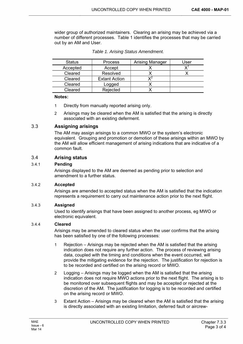
UNCONTROLLED COPY WHEN PRINTED CAE 4000 - MAP-01
MAE Issue - 6 Mar 14
UNCONTROLLED COPY WHEN PRINTED Chapter 7.3.3 Page 3 of 4
wider group of authorized maintainers. Clearing an arising may be achieved via a number of different processes. Table 1 identifies the processes that may be carried out by an AM and User.
Table 1. Arising Status Amendment.
Status Process Arising Manager User Accepted Accept X X1 Cleared Resolved X X Cleared Extant Action X2 Cleared Logged X Cleared Rejected X
Notes:
1 Directly from manually reported arising only.
2 Arisings may be cleared when the AM is satisfied that the arising is directly associated with an existing deferment.
3.3 Assigning arisings The AM may assign arisings to a common MWO or the system’s electronic equivalent. Grouping and promotion or demotion of these arisings within an MWO by the AM will allow efficient management of arising indications that are indicative of a common fault.
3.4 Arising status 3.4.1 Pending
Arisings displayed to the AM are deemed as pending prior to selection and amendment to a further status.
3.4.2 Accepted Arisings are amended to accepted status when the AM is satisfied that the indication represents a requirement to carry out maintenance action prior to the next flight.
3.4.3 Assigned Used to identify arisings that have been assigned to another process, eg MWO or electronic equivalent.
3.4.4 Cleared Arisings may be amended to cleared status when the user confirms that the arising has been satisfied by one of the following processes:
1 Rejection – Arisings may be rejected when the AM is satisfied that the arising indication does not require any further action. The process of reviewing arising data, coupled with the timing and conditions when the event occurred, will provide the mitigating evidence for the rejection. The justification for rejection is to be recorded and certified on the arising record or MWO.
2 Logging – Arisings may be logged when the AM is satisfied that the arising indication does not require MWO actions prior to the next flight. The arising is to be monitored over subsequent flights and may be accepted or rejected at the discretion of the AM. The justification for logging is to be recorded and certified on the arising record or MWO.
3 Extant Action – Arisings may be cleared when the AM is satisfied that the arising is directly associated with an existing limitation, deferred fault or aircrew-
CAE 4000 - MAP-01 UNCONTROLLED COPY WHEN PRINTED
Chapter 7.3.3 Page 4 of 4
UNCONTROLLED COPY WHEN PRINTED MAE Issue - 6
Mar 14
accepted fault. Reference to the associated action – including the SNOW – is to be recorded and certified on the arising record or MWO.
4 Resolved – Assigned arisings only are resolved when all tasks associated with the arising are completed in the approved manner.
3.5 Retention and disposal of arising data RA 4813 and Chapter 7.6 mandate retention and disposal of arising data.
4 Training and authorization 4.1 Pre-employment training
To become an authorized AM, users must successfully complete both platform and GMS specific training. Training is to comply with RA 4150 and Chapter 4.1.
4.2 Authorization Users must hold a minimum of authority level B. AMs must hold a minimum of authority level F and hold authorization MAP-F466. Users and AMs must be re-assessed for competency as directed by the relevant Type Airworthiness Authority (TAA) in consultation with the Continuing Airworthiness Management Organization (CAMO).
5 Responsibilities 5.1 Stn/Ship/Unit
The Stn/Ship/Unit is responsible for ensuring that sufficient users are nominated and authorized as AMs.
5.2 Type Airworthiness Authority (TAA) TAAs are responsible for ensuring that:
1 Arising management training for their platform is to the appropriate level in consultation with the CAMO.
2 Arising management-specific orders or instructions are published in their platform’s Topic 2(N/A/R)1.
6 Reference This chapter refers to the following publication:
1 Platform Topic 2(N/A/R)1 – General Orders and Special Instructions.
UNCONTROLLED COPY WHEN PRINTED CAE 4000 - MAP-01
MAE Issue - 6 Mar 14
UNCONTROLLED COPY WHEN PRINTED Chapter 7.5 Page 1 of 6
Chapter 7.5
Fault Reporting
TABLE OF CONTENTS Paragraph
Page
1 General ............................................................................................................... 1 1.1 Introduction.......................................................................................................... 1 1.2 Associated publications....................................................................................... 1 2 Regulatory Governance.................................................................................... 2 2.1 Regulatory Article cross-reference ...................................................................... 2 2.2 Additional Information.......................................................................................... 2 3 Fault reporting ................................................................................................... 2 3.1 Routine fault reporting using the MOD Form 707 series ..................................... 2 3.2 Narrative fault reporting....................................................................................... 2 3.3 Serious faults....................................................................................................... 2 3.4 Air and ground occurrence reports...................................................................... 2 3.5 Aviation material received on transfer in an unsatisfactory condition.................. 2 3.6 Faults with Air Publications and forms in the MOD Form 700 series .................. 3 3.7 Faulty packaging ................................................................................................. 3 4 Equipment with specific fault reporting procedures ..................................... 3 4.1 Fault reporting for air-launched torpedoes and associated equipment ............... 3 5 References ......................................................................................................... 5
LIST OF TABLES Table 1. Equipment with Specific or Modified Reporting Procedures. ..........................................3 Table 2. Faulty Equipment – Form................................................................................................4
1 General 1.1 Introduction
The accurate and timely reporting of faults in aircraft and airborne equipment is essential to ensuring airworthiness. It enables the cost-effective utilization of assets through improved reliability and maintainability. All faults are reported through a routine system; some, considered of particular interest, are given an additional reporting route, which ensures that particular attention is paid to the nature of the fault and possibly to any affected components as well. This chapter describes the various methods of reporting faults and provides references to detailed reporting procedures.
1.2 Associated publications This chapter is associated with the following publications:
1 JAP 100C-02 – The Maintenance Data System Work Recording.
2 AP 100K-10 – Army Aircraft Engineering – General Procedures.
3 JAP(D) 100A-0409 -01 - GOLDesp Logistic Information System Procedures Manual.
4 AP 300A-01 – LITS Enabling Document.
CAE 4000 - MAP-01 UNCONTROLLED COPY WHEN PRINTED
Chapter 7.5 Page 2 of 6
UNCONTROLLED COPY WHEN PRINTED MAE Issue - 6
Mar 14
2 Regulatory Governance 2.1 Regulatory Article cross-reference
This chapter supports:
1 RA 4814(1).
2.2 Additional Information Nil.
3 Fault reporting There are a variety of fault reporting procedures used in the Military Aviation Environment (MAE). Procedures can be divided broadly into those for particular circumstances and those that are specific to equipment types. In practice a combination of methods may be used, eg a fault that is the subject of an air occurrence would also be routinely reported using the MOD Form 707 series and may also warrant a narrative fault report using the MOD Form 760 procedure.
3.1 Routine fault reporting using the MOD Form 707 series Faults are routinely reported using the MOD Form 707 series of forms. Details of a fault are initially recorded on the appropriate MOD Form 707 and may then be transferred to an electronic data collection process. Alternatively, faults may be reported directly to electronic documentation systems where data collection is automatic. Such data can then be used for determining fault trends and equipment performance and reliability.
3.2 Narrative fault reporting When a fault on a piece of equipment warrants further investigation, a narrative fault report is raised using the MOD Form 760 series of forms. The procedure for raising and processing a MOD F760 is at Chapter 7.5.1.
3.3 Serious faults When a fault is discovered which is considered to be serious, it must be reported directly, by the fastest means available, to the Continuing Airworthiness Management Organization (CAMO), Type Airworthiness Authority (TAA) and/or commodity Project Team (PT). Examples that would warrant serious fault reporting are those faults that:
1 Adversely affect the airworthiness of the aircraft or equipment.
2 Endanger personnel or equipment.
3 Significantly reduce the operational effectiveness or availability of the equipment.
4 Put at risk the security of airborne communication equipment.
The procedure for raising a Serious Fault Report (SFR) is at Chapter 7.5.2.
3.4 Air and ground occurrence reports Air and ground occurrences may involve technical faults. Engineering aspects of air and ground occurrence reporting are detailed in Chapter 7.5.3.
3.5 Aviation material received on transfer in an unsatisfactory condition Specific instructions exist for reporting aviation material received in an unsatisfactory condition. This includes items received with faults that could have been reasonably identified by the dispatching Stn/Ship/Unit. The procedure for reporting such instances is at RA 4815 and Chapter 15.1.1.
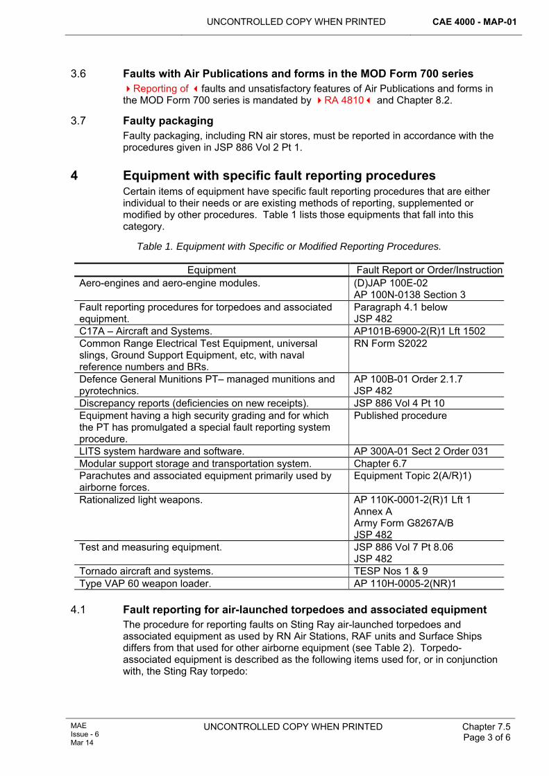
UNCONTROLLED COPY WHEN PRINTED CAE 4000 - MAP-01
MAE Issue - 6 Mar 14
UNCONTROLLED COPY WHEN PRINTED
Chapter 7.5 Page 3 of 6
3.6 Faults with Air Publications and forms in the MOD Form 700 series Reporting of faults and unsatisfactory features of Air Publications and forms in the MOD Form 700 series is mandated by RA 4810 and Chapter 8.2.
3.7 Faulty packaging Faulty packaging, including RN air stores, must be reported in accordance with the procedures given in JSP 886 Vol 2 Pt 1.
4 Equipment with specific fault reporting procedures Certain items of equipment have specific fault reporting procedures that are either individual to their needs or are existing methods of reporting, supplemented or modified by other procedures. Table 1 lists those equipments that fall into this category.
Table 1. Equipment with Specific or Modified Reporting Procedures.
Equipment Fault Report or Order/InstructionAero-engines and aero-engine modules. (D)JAP 100E-02
AP 100N-0138 Section 3 Fault reporting procedures for torpedoes and associated equipment.
Paragraph 4.1 below JSP 482
C17A – Aircraft and Systems. AP101B-6900-2(R)1 Lft 1502 Common Range Electrical Test Equipment, universal slings, Ground Support Equipment, etc, with naval reference numbers and BRs.
RN Form S2022
Defence General Munitions PT– managed munitions and pyrotechnics.
AP 100B-01 Order 2.1.7 JSP 482
Discrepancy reports (deficiencies on new receipts). JSP 886 Vol 4 Pt 10 Equipment having a high security grading and for which the PT has promulgated a special fault reporting system procedure.
Published procedure
LITS system hardware and software. AP 300A-01 Sect 2 Order 031 Modular support storage and transportation system. Chapter 6.7 Parachutes and associated equipment primarily used by airborne forces.
Equipment Topic 2(A/R)1)
Rationalized light weapons. AP 110K-0001-2(R)1 Lft 1 Annex A Army Form G8267A/B JSP 482
Test and measuring equipment. JSP 886 Vol 7 Pt 8.06 JSP 482
Tornado aircraft and systems. TESP Nos 1 & 9 Type VAP 60 weapon loader. AP 110H-0005-2(NR)1
4.1 Fault reporting for air-launched torpedoes and associated equipment The procedure for reporting faults on Sting Ray air-launched torpedoes and associated equipment as used by RN Air Stations, RAF units and Surface Ships differs from that used for other airborne equipment (see Table 2). Torpedo-associated equipment is described as the following items used for, or in conjunction with, the Sting Ray torpedo:
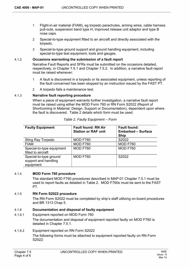
CAE 4000 - MAP-01 UNCONTROLLED COPY WHEN PRINTED
Chapter 7.5 Page 4 of 6
UNCONTROLLED COPY WHEN PRINTED MAE Issue - 6
Mar 14
1 Flight-in-air material (FIAM), eg torpedo parachutes, arming wires, cable harness pull-outs, suspension band type H, improved release unit adaptor and type B nose caps.
2 Special-to-type equipment fitted to an aircraft and directly associated with the torpedo.
3 Special-to-type ground support and ground handling equipment, including special-to-type test equipment, tools and gauges.
4.1.2 Occasions warranting the submission of a fault report Narrative Fault Reports and SFRs must be submitted on the occasions detailed, respectively, in Chapter 7.5.1 and Chapter 7.5.2. In addition, a narrative fault report must be raised whenever:
1 A fault is discovered in a torpedo or its associated equipment, unless reporting of the fault concerned has been stopped by an instruction issued by the FAST PT.
2 A torpedo fails a maintenance test.
4.1.3 Narrative fault reporting procedure When a piece of equipment warrants further investigation, a narrative fault report must be raised using either the MOD Form 760 or RN Form S2022 (Report of Shortcoming in Material, Design, Support or Documentation), dependent upon where the fault is discovered. Table 2 details which form must be used.
Table 2. Faulty Equipment – Form
Faulty Equipment Fault found: RN Air Station or RAF unit
Fault found: Embarked – Surface Ship
Sting Ray Torpedo MOD F760 S2022 FIAM MOD F760 MOD F760 Special-to-type equipment fitted to aircraft
MOD F760 MOD F760
Special-to-type ground support and handling equipment
MOD F760 S2022
4.1.4 MOD Form 760 procedure
The standard MOD F760 procedures described in MAP-01 Chapter 7.5.1 must be used to report faults as detailed in Table 2. MOD F760s must be sent to the FAST PT.
4.1.5 RN Form S2022 procedure The RN Form S2022 must be completed by ship’s staff utilizing on-board procedures and BR 1313 Chap 5.
4.1.6 Documentation and disposal of faulty equipment 4.1.6.1 Equipment reported on MOD Form 760
The documentation and disposal of equipment reported faulty on MOD F760 is detailed in Chapter 7.5.1.
4.1.6.2 Equipment reported on RN Form S2022 The following forms must be attached to equipment reported faulty on RN Form S2022:
UNCONTROLLED COPY WHEN PRINTED CAE 4000 - MAP-01
MAE Issue - 6 Mar 14
UNCONTROLLED COPY WHEN PRINTED
Chapter 7.5 Page 5 of 6
1 MOD Form 731, marked in capital letters, in red, ‘SUBJECT TO FAULT REPORT RN FORM S2022 REFERENCE [insert reference number].
2 The torpedo log book.
Faulty equipment must be quarantined pending receipt of disposal instructions.
5 References This chapter refers to the following instructions:
1 JSP 886 Vol 2 Pt 1. - Policy and Process for Inventory Management.
2 Publications and instructions identified in Table 1.
3 BR 1313 – Maintenance Management in Surface Ships.

CAE 4000 - MAP-01 UNCONTROLLED COPY WHEN PRINTED
Chapter 7.5 Page 6 of 6
UNCONTROLLED COPY WHEN PRINTED MAE Issue - 6
Mar 14
Intentionally Blank for Print Pagination
UNCONTROLLED COPY WHEN PRINTED CAE 4000 - MAP-01
Issue - 7 Apr 15
UNCONTROLLED COPY WHEN PRINTED Chapter 7.5.1 Page 1 of 10
Chapter 7.5.1
Narrative Fault Reporting Using the MOD Form 760 Series
TABLE OF CONTENTS Paragraph
Page
1 General ............................................................................................................... 1 1.1 Introduction.......................................................................................................... 1 1.2 Associated publications....................................................................................... 2 2 Regulatory Governance.................................................................................... 2 2.1 Regulatory Article Cross-reference ..................................................................... 2 2.2 Additional Information.......................................................................................... 2 3 Exclusions and/or additional reporting requirements................................... 2 4 Classification of equipment ............................................................................. 2 4.1 Not-in-use (NIU) equipment ................................................................................ 2 4.2 In-use (IU) equipment.......................................................................................... 2 5 Fault reporting implementation ....................................................................... 2 5.1 Occasions for raising a Narrative Fault Report ................................................... 2 5.2 Forms in the MOD Form 760 series .................................................................... 3 5.3 Responsibility for raising MOD Form 760............................................................ 3 5.4 Compiling and progressing MOD Form 760........................................................ 3 6 Mandatory Fault Reporting Instruction (MFRI) ............................................... 4 7 Handling, quarantine and disposal of faulty equipment ............................... 4 8 Responsibilities for MOD Form 760 fault reporting ....................................... 4 8.1 Detached or embarked Sqn/Unit or Flight ........................................................... 4 8.2 Parent Stns/Ships/Units ...................................................................................... 5 8.3 Type Airworthiness Authority (TAA) .................................................................... 5 8.4 Actions by Joint Support Chain (JSC) Logistic Commodities and Services
(LCS) ................................................................................................................... 6 9 References ......................................................................................................... 7 10 Guidance on completion of MOD Form 760.................................................... 8
LIST OF FIGURES Figure 1. Process for Fault Reporting Using the MOD Form 760 Series of Forms......... 8
1 General 1.1 Introduction
Most faults with aircraft and equipment in the Military Air Environment (MAE) are resolved by repair or replacement of components, accompanied by routine reporting procedures as described in RA 4814 and Chapter 7.5. Some faults, however, warrant a deeper, more detailed investigation to isolate the cause and/or explain an unexpected failure. In addition to routine fault reporting, the MOD F760 Narrative Fault Report is used to provide the additional information needed to undertake this investigation. This chapter describes the occasions for, and methods of, raising Narrative Fault Reports and defines how these reports must be handled and the faults investigated.
CAE 4000 - MAP-01 UNCONTROLLED COPY WHEN PRINTED
Chapter 7.5.1 Page 2 of 10
UNCONTROLLED COPY WHEN PRINTED Issue - 7 Apr 15
1.2 Associated publications This chapter is associated with following publications:
1 JSP 886 – The Defence Logistics Support Chain Manual.
2 Regulatory Governance 2.1 Regulatory Article Cross-reference
This chapter supports:
1 RA 4814(1).
2.2 Additional Information In addition to recording faults on the MOD Form 707 series of forms, when it is considered that a fault warrants a more in-depth investigation, a report is to be raised using the MOD F760 Narrative Fault Report procedure.
If a fault presents a serious threat to airworthiness, a Serious Fault Report (SFR) is to be raised, as detailed in Chapter 7.5.2.
3 Exclusions and/or additional reporting requirements The ranges of aviation equipment wholly or partly exempt from the MOD Form 760 fault reporting procedure are described in RA 4814 and Chapter 7.5.
4 Classification of equipment 4.1 Not-in-use (NIU) equipment
Not-in-use (NIU) equipment is defined as equipment that has not been put to its intended use. The term embraces new, reconditioned, recalibrated, or repaired equipment (except equipment repaired by the user) up to the stage of satisfying any initial visual, dimensional, functional or installation checks, including flight testing where appropriate, following its issue from store.
Note:
Where the traditional user repair functions are carried out by non-military personnel under a support contract managed by the responsible Project Team (PT), the Project Team Leader (PTL) is to publish the equipment exempt from NIU categorization in the appropriate Support Policy.
4.2 In-use (IU) equipment In-use (IU) equipment is defined as all equipment that cannot be classed as NIU.
Note:
All faults on Aircraft Integrity Monitoring equipment must be classified as IU.
5 Fault reporting implementation 5.1 Occasions for raising a Narrative Fault Report
According to circumstances, Stns/Ships/Units must report faults by SFR and/or MOD F760. A MOD Form 760 must be raised on the following occasions:
1 Automatically, in support of an SFR.
UNCONTROLLED COPY WHEN PRINTED CAE 4000 - MAP-01
Issue - 7 Apr 15
UNCONTROLLED COPY WHEN PRINTED
Chapter 7.5.1 Page 3 of 10
2 At the discretion of the responsible officer when it is considered that the fault may affect safety, equipment availability or performance or where it is considered worthy of detailed investigation.
3 For any fault in NIU equipment.
4 On faults which are considered by local management to merit Continuing Airworthiness Management Organization (CAMO), Type Airworthiness Authority (TAA) or commodity PT attention.
5 When instructed to do so by, or on behalf of, a TAA or commodity PT in a Special Instruction (Technical) (SI(T)) or Mandatory Fault Reporting Instruction (MFRI), (paragraph 6 refers) or in any other instruction.
6 When instructed to do so by a Service Inquiry.
5.2 Forms in the MOD Form 760 series The MOD Form 760 Narrative Fault Reporting System comprises the following forms:
1 MOD F760 – Narrative Fault Report.
2 MOD F760A – Fault Investigation Request.
3 MOD F760B – Narrative Fault Report – Request for MFRI Action.
4 MOD F760C – Compilation Instructions for MOD Form 760.
5 MOD F760E – Faulty Equipment Label.
6 MOD F760F – Narrative Fault Report Transit Folder.
7 MOD F761 – Fault Investigation Report.
8 MOD F761A – Overhaul/Investigation Report.
Where a form is passed by e-mail between organizations for action, a facsimile signature should not be used in any signature block. Organizations documenting their action must place a signed copy on file and annotate “File Copy Signed” in the relevant block of the e-mailed version.
5.3 Responsibility for raising MOD Form 760 The following personnel are responsible for raising MOD F760:
1 The person holding the faulty aircraft or equipment on charge at the time a reportable fault is discovered.
2 The investigating officer of an aircraft accident or other investigation where equipment or parts of the aircraft have been removed for further investigation.
5.4 Compiling and progressing MOD Form 760 The MOD F760 must be compiled following the instructions given in the MOD F760C. The Senior Specialist Officer is ultimately responsible for ensuring the expeditious dispatch of an accurate and relevant F760 from the Stn/Ship/Unit to the relevant TAA or PT, noting it is for individual single Service policy to define the level at which Authorization J440 is held. The flow chart at Figure 1 provides guidance on handling and progressing narrative fault reports and reflects the Engineering Authority (EA) and Design Organization (DO) functions embedded within a PT. Detailed arrangements for a specific aircraft type or range of equipment may vary slightly from the processes illustrated, but must not alter any of the principles implicit in the guidance shown. Further details of arrangements for specific aircraft or equipment can be obtained from the appropriate PT.
CAE 4000 - MAP-01 UNCONTROLLED COPY WHEN PRINTED
Chapter 7.5.1 Page 4 of 10
UNCONTROLLED COPY WHEN PRINTED Issue - 7 Apr 15
6 Mandatory Fault Reporting Instruction (MFRI) MFRIs are issued and managed internally by the TAA when MOD Forms 760 are required on specific items of equipment: Log NEC Information Exploitation (IX) Team. TAAs may seek the advice of their maintenance data organization. Limited fault statistics may be provided by maintenance data organizations; hence the use of MFRIs should be restricted to the following:
1 Monitoring the performance of new equipment.
2 Validating current lifing policies.
3 Monitoring the effectiveness of modifications or SI(T).
4 When further information is required to supplement fault case histories.
MOD Form 760B may be used to formally task the person within the PT that is responsible for internal management of MFRIs. An MFRI can be set either for a period of time or for a number of arisings and may be restricted to particular units. TAAs are to publish MFRIs for their aircraft in the Topic 2(N/A/R)1.
7 Handling, quarantine and disposal of faulty equipment All equipment subject to MOD F760 action must remain quarantined pending receipt of disposal instructions. The MOD Form 760 originator is responsible for quarantining or arranging the quarantine of faulty items. Items must be maintained in the condition existing at the time of failure. Blanks should be fitted to pipeline connections and orifices and measures taken to protect the items in transit. Samples of foreign matter, fuel, oil, etc, should be taken, quarantined and despatched with the faulty equipment. The following forms must be attached to the faulty equipment:
1 Completed MOD F731 – Equipment Label (to include the serial number of the relevant MOD Form 760).
2 Completed MOD F760E – Faulty Equipment Label.
3 A copy of the MOD Form 760, if unclassified.
4 The Engineering Record Card, if applicable.
The TAA should be contacted for disposal instructions for materiel under quarantine.
8 Responsibilities for MOD Form 760 fault reporting 8.1 Detached or embarked Sqn/Unit or Flight
When a reportable fault is discovered on an aircraft or equipment while detached or embarked, the Sqn/Unit or Flight must:
1 Carry out an initial investigation of the fault, consulting the parent Stn/Ship/Unit engineering staff as necessary.
2 Complete as much as possible of the MOD F760; if the unit does not hold a MOD Form 760 register, the reference must be left blank for completion by the parent Stn/Ship/Unit.
3 Dispatch a copy of the MOD Form 760 to the parent Stn/Ship/Unit.
4 If unclassified, attach a copy of the MOD Form 760 to the faulty item.
5 Dispatch the faulty item to the parent Stn/Ship/Unit for quarantining. Guided weapons should be returned to the nearest armament depot.
UNCONTROLLED COPY WHEN PRINTED CAE 4000 - MAP-01
Issue - 7 Apr 15
UNCONTROLLED COPY WHEN PRINTED
Chapter 7.5.1 Page 5 of 10
Note:
Where appropriate, detached embarked units/flights may route MOD Forms 760 through their parent squadron who may then complete some of the tasks listed below prior to forwarding the MOD Form 760 to the parent Stn/Ship/Unit for completion.
8.2 Parent Stns/Ships/Units Parent Stns/Ships/Units are responsible for:
1 Processing MOD F760 for faults arising on the Stn/Ship/Unit.
2 Processing MOD Form 760 received from detached and embarked Sqns/Units or Flights including the following:
2.1 If required, carrying out further investigation of the fault.
2.2 Completing the MOD Form 760, if necessary inserting the fault report reference.
2.3 Distributing the MOD Form 760 in accordance with Figure 1.
3 Quarantining faulty equipment, including that received from detached or embarked Sqns/Units or Flights, until receipt of disposal instructions.
4 Dispatching faulty equipment and informing the investigation agency of dispatch details.
8.3 Type Airworthiness Authority (TAA) 8.3.1 Action on receipt of MOD Form 760
The TAA is the focal point for fault investigation on equipment for which they are responsible. A TAA that receives a MOD F760 must:
1 Within 10 working days, acknowledge receipt to the MOD F760 originator.
2 Within 28 days of receiving a MOD Form 760, decide whether or not an investigation is required and:
2.1 Record that decision on the MOD F760.
2.2 Arrange initial investigation of the fault and the instigation of remedial action as deemed appropriate.
2.3 Notify the decision to the originating unit and other MOD F760 addressees.
3 Consider whether a fault justifies mandatory reporting and take the appropriate action.
4 Decide whether a fault case history is required and, if so, ask their maintenance data organization to provide one.
5 Inform the appropriate JSC LCS of any engineering requirement to examine or quarantine depot stocks.
If a TAA decides that further investigation is not required, the MOD Form 760 must be completed accordingly. If a TAA decides that further investigation is required, a suitable investigation agency must be tasked to carry out the investigation. Staffing of the MOD Form 760, MOD F760A and MOD F761 must follow the flow chart at Figure 1. On receipt of a MOD Form 761, Fault Investigation Report, from an investigation agency, the TAA must consider the findings and recommendations and must initiate any remedial action considered necessary. If a TAA is not satisfied with the investigation, or considers that further investigation is warranted, the original MOD Form 760A and MOD Form F761 must be completed; a new investigation
CAE 4000 - MAP-01 UNCONTROLLED COPY WHEN PRINTED
Chapter 7.5.1 Page 6 of 10
UNCONTROLLED COPY WHEN PRINTED Issue - 7 Apr 15
agency must be appointed, if appropriate, and a new MOD Form 760A must be raised and clearly marked:
‘FURTHER INVESTIGATION’ Copies of the new MOD Form 760A and the original MOD Form 760 and MOD Form 761 must be distributed as shown in Figure 1.
8.3.2 Decision not to take action on a fault report or to reject proposed remedial actions A decision not to take action in response to a reported fault, whether by MOD F760, SFR or following an aircraft incident/accident reported by RN Form A25/A25A, AAC Form 5/5A or RAF F765B, or to reject remedial actions proposed by an appointed investigation agency are not to be taken lightly. The TAA must ensure that such decisions are made and recorded by a holder of the appropriate level of Airworthiness Authority.
8.3.3 Advising other affected platform and commodity PTs TAAs are vested with prime responsibility for maintaining the type airworthiness, performance and safety of a platform. Such responsibility encompasses sub-systems and equipment (commodities) essential to and installed in, loaded to, or carried/worn in the platform. Accordingly, PTs responsible for these sub-systems (commodities) are to formally advise TAAs of any engineering changes or faults that may affect the operation of aviation equipment under their control and which may in turn affect the airworthiness or safety of the platform. Similarly, TAAs are responsible for informing commodity PTs of any changes to the platform that may impact the safety of commodity items.
8.4 Actions by Joint Support Chain (JSC) Logistic Commodities and Services (LCS) For NIU equipment, the appropriate JSC LCS repair centre is responsible for providing specialist advice to the TAA. On receipt of the MOD F760, and only when instructed by the TAA, the JSC LCS repair centre must:
1 Confirm that the MOD Form 760 relates to:
1.1 An NIU item.
1.2 An item that is within the JSC LCS sphere of responsibility.
Note:
If either condition is not met, the TAA must be informed and the form returned.
2 Provide an initial appraisal of the fault.
3 Examine existing stock to determine the extent of the fault and quarantine stock as necessary.
4 Act as an investigation agency and carry out a fault investigation. Unless the TAA specifically authorizes otherwise, the work done during an investigation must not exceed the depth of maintenance normally carried out on an item by the JSC LCS unit.
JSC LCS recommendations must be recorded on the relevant MOD Form 760, which must be sent to the TAA. JSC LCS units must not undertake fault investigations without direction from the TAA.
UNCONTROLLED COPY WHEN PRINTED CAE 4000 - MAP-01
Issue - 7 Apr 15
UNCONTROLLED COPY WHEN PRINTED
Chapter 7.5.1 Page 7 of 10
9 References This chapter refers to the following publications and forms:
1 AAC Form 5 – Air/Ground Occurrence Investigation Report.
2 AAC Form 5A – Air/Ground Occurrence Investigation Report.
3 RAF F765B – Flight Safety Investigation Report.
4 RN Form A25 – Report on Aircraft Accident/Incident.
5 RN Form A25A – Report on Aircraft Ground Accident/Incident.
6 Topic 2(N/A/R)1 – General Orders and Special Instructions.
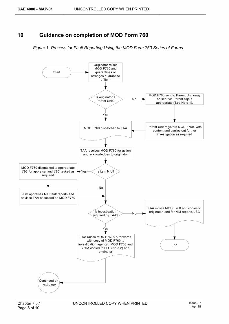
CAE 4000 - MAP-01 UNCONTROLLED COPY WHEN PRINTED
Chapter 7.5.1 Page 8 of 10
UNCONTROLLED COPY WHEN PRINTED Issue - 7 Apr 15
10 Guidance on completion of MOD Form 760
Figure 1. Process for Fault Reporting Using the MOD Form 760 Series of Forms.
Start
Originator raises MOD F760 and quarantines or
arranges quarantine of item
Is originator a Parent Unit?
MOD F760 sent to Parent Unit (may be sent via Parent Sqn if appropriate)(See Note 1).
Parent Unit registers MOD F760, vets content and carries out further
investigation as required
TAA receives MOD F760 for action and acknowledges to originator
MOD F760 dispatched to TAA
Is item NIU?MOD F760 dispatched to appropriate JSC for appraisal and JSC tasked as
required
JSC appraises NIU fault reports and advises TAA as tasked on MOD F760
Is investigation required by TAA?
TAA closes MOD F760 and copies to originator, and for NIU reports, JSC
End
TAA raises MOD F760A & forwards with copy of MOD F760 to
investigation agency. MOD F760 and 760A copied to FLC (Note 2) and
originator
No
Yes
Yes
No
Yes
Continued on next page
No
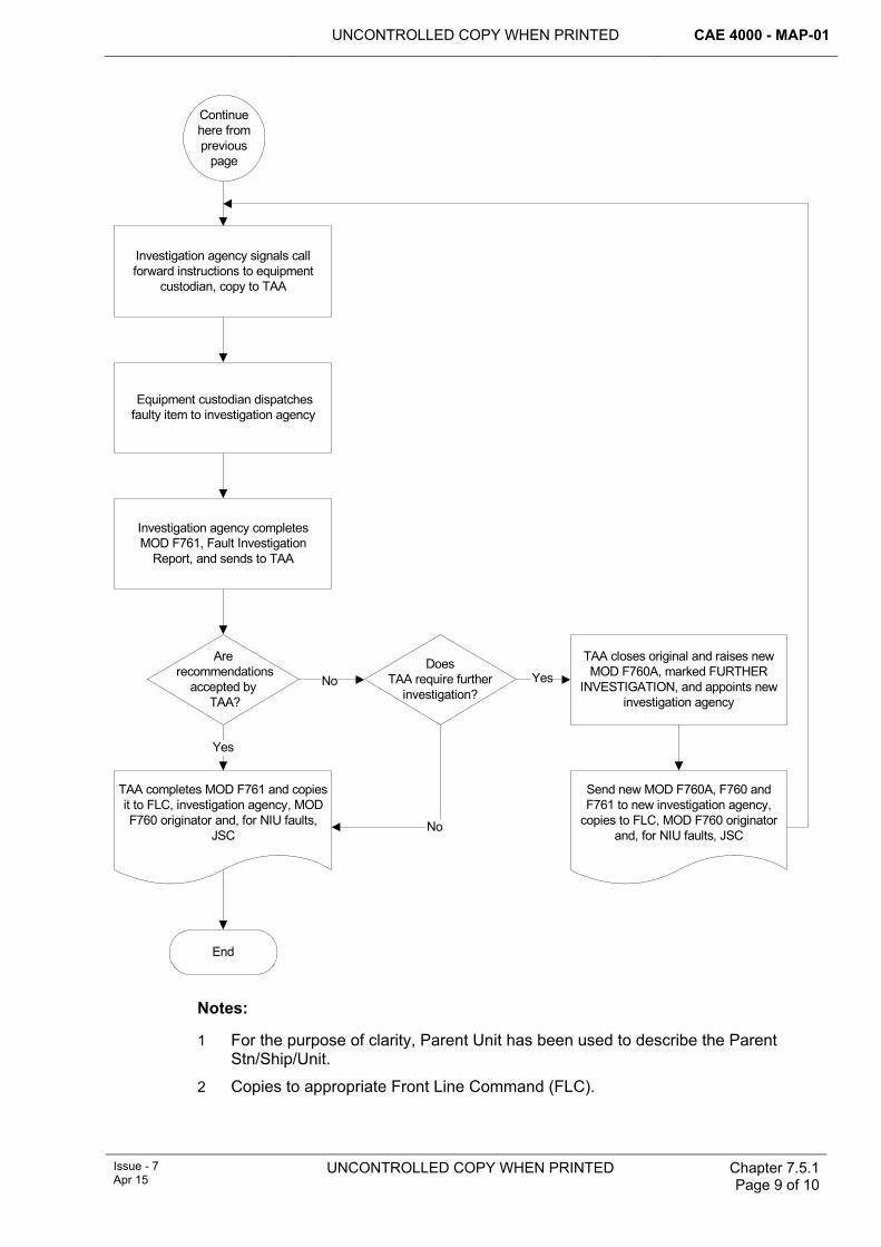
UNCONTROLLED COPY WHEN PRINTED CAE 4000 - MAP-01
Issue - 7 Apr 15
UNCONTROLLED COPY WHEN PRINTED
Chapter 7.5.1 Page 9 of 10
Investigation agency signals call forward instructions to equipment
custodian, copy to TAA
Equipment custodian dispatches faulty item to investigation agency
Investigation agency completesMOD F761, Fault Investigation
Report, and sends to TAA
Are recommendations
accepted by TAA?
Does TAA require further
investigation?
TAA closes original and raises new MOD F760A, marked FURTHER
INVESTIGATION, and appoints new investigation agency
Send new MOD F760A, F760 and F761 to new investigation agency,
copies to FLC, MOD F760 originator and, for NIU faults, JSC
TAA completes MOD F761 and copies it to FLC, investigation agency, MOD F760 originator and, for NIU faults,
JSC
End
Yes
No Yes
No
Continue here from previous
page
Notes:
1 For the purpose of clarity, Parent Unit has been used to describe the Parent Stn/Ship/Unit.
2 Copies to appropriate Front Line Command (FLC).

CAE 4000 - MAP-01 UNCONTROLLED COPY WHEN PRINTED
Chapter 7.5.1 Page 10 of 10
UNCONTROLLED COPY WHEN PRINTED Issue - 7 Apr 15
Intentionally Blank for Print Pagination
UNCONTROLLED COPY WHEN PRINTED CAE 4000 - MAP-01
Issue - 7 Apr 15
UNCONTROLLED COPY WHEN PRINTED Chapter 7.5.2 Page 1 of 6
Chapter 7.5.2
Serious Fault Report Procedure
TABLE OF CONTENTS Paragraph
Page
1 General ............................................................................................................... 1 1.1 Introduction.......................................................................................................... 1 2 Regulatory Governance.................................................................................... 1 2.1 Regulatory Article Cross-reference ..................................................................... 1 3 Reporting a Serious Fault................................................................................. 2 4 Implementation.................................................................................................. 2 4.1 SFR compilation .................................................................................................. 2 5 Action on receipt of SFR .................................................................................. 4 5.1 Continuing Airworthiness Management Organization (CAMO) ........................... 4 5.2 Front Line Command (FLC) ................................................................................ 4 5.3 Type Airworthiness Authorities (TAAs) and commodity Project Teams (PTs) .... 5 5.4 Logistic Services (Log Svcs) ............................................................................... 5 6 References ......................................................................................................... 5
LIST OF TABLES Table 1. Serious Fault Report Text. ................................................................................ 4
1 General 1.1 Introduction
The Serious Fault Report (SFR) is the method used to notify the discovery of a fault that may have immediate and serious implications to an aircraft fleet, or range of equipment. Serious Faults should be:
1 Initially reported by the most expeditious means available (eg telephone, e-mail, fax, signal)
and
2 Submitted on a D-ASOR, on ASIMS; RA1410 refers.
Note:
ASIMS may be used to both report and record a Serious Fault if the originator considers it to be the most expeditious means available. The need to confirm receipt by action addressees must be considered.
2 Regulatory Governance 2.1 Regulatory Article Cross-reference
This chapter supports:
1 RA 1410.
2 RA 4814.
CAE 4000 - MAP-01 UNCONTROLLED COPY WHEN PRINTED
Chapter 7.5.2 Page 2 of 6
UNCONTROLLED COPY WHEN PRINTED Issue - 7 Apr 15
3 Reporting a Serious Fault An SFR must be raised by the person responsible for the aircraft or equipment whenever a fault is discovered that could:
1 Adversely affect the airworthiness of the aircraft or equipment.
2 Endanger personnel or equipment.
3 Significantly reduce the operational effectiveness or availability of the equipment.
4 Put at risk the security of airborne Communications Security equipment.
4 Implementation An SFR must not be delayed in order to complete detailed initial investigations other than confirming the presence of the fault on other local assets. Should further information become available after dispatch, a follow-up report must be sent to the same addressees. If, following further investigation, it is considered that the SFR was not warranted, a cancellation report must be sent to the same addressees as the original report. A MOD Form 760 Narrative Fault Report must be raised following the dispatch of an SFR. The procedure for raising MOD F760 is detailed in MAP Chapter 7.5.1.
4.1 SFR compilation 4.1.1 Urgency for transmission
The urgency for transmission of an SFR must be appropriate to the circumstances. Where faults could adversely affect airworthiness, the appropriate Type Airworthiness Authority (TAA) must be informed by the fastest possible means (eg telephone, e-mail, fax, electronic reporting).
4.1.2 Security classification The security classification of an SFR must be appropriate to the equipment concerned and operational circumstances . Originators are to note that ASIMS is an UNCLASSIFIED system and therefore must ensure an SFR raised on a D-ASOR is suitably redacted before transmission.
4.1.3 Action addressees SFR action addressees must include the:
1 TAA or commodity Project Team (PT) responsible for the subject aircraft or equipment. If the commodity PT for a particular item of equipment cannot be established, SFRs must be sent to the TAA for the aircraft or commodity PT for the other main equipment the item forms part of.
2 Front Line Command (FLC) of the originating Stn/Ship/Unit.
3 Parent Stn/Ship/Unit if sent from an embarked or detached RN unit.
4 Appropriate Joint Support Chain (JSC) Logistic Commodities and Services (LCS) if the SFR relates only to Not-In-Use (NIU) equipment.
5 DE&S SCISHenlow/Yeovilton for LITS/GOLDesp, where serious software faults involving loss or corruption of aircraft structure or schedule data are identified and where there is potential for wider applicability.
4.1.4 Information addressees
Information addressees must include:
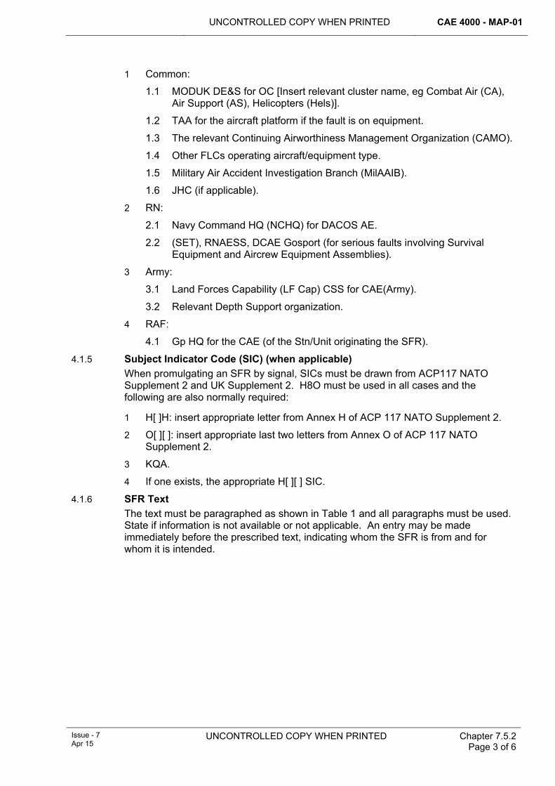
UNCONTROLLED COPY WHEN PRINTED CAE 4000 - MAP-01
Issue - 7 Apr 15
UNCONTROLLED COPY WHEN PRINTED Chapter 7.5.2 Page 3 of 6
1 Common:
1.1 MODUK DE&S for OC [Insert relevant cluster name, eg Combat Air (CA), Air Support (AS), Helicopters (Hels)].
1.2 TAA for the aircraft platform if the fault is on equipment.
1.3 The relevant Continuing Airworthiness Management Organization (CAMO).
1.4 Other FLCs operating aircraft/equipment type.
1.5 Military Air Accident Investigation Branch (MilAAIB).
1.6 JHC (if applicable).
2 RN:
2.1 Navy Command HQ (NCHQ) for DACOS AE.
2.2 (SET), RNAESS, DCAE Gosport (for serious faults involving Survival Equipment and Aircrew Equipment Assemblies).
3 Army:
3.1 Land Forces Capability (LF Cap) CSS for CAE(Army).
3.2 Relevant Depth Support organization.
4 RAF:
4.1 Gp HQ for the CAE (of the Stn/Unit originating the SFR).
4.1.5 Subject Indicator Code (SIC) (when applicable) When promulgating an SFR by signal, SICs must be drawn from ACP117 NATO Supplement 2 and UK Supplement 2. H8O must be used in all cases and the following are also normally required:
1 H[ ]H: insert appropriate letter from Annex H of ACP 117 NATO Supplement 2.
2 O[ ][ ]: insert appropriate last two letters from Annex O of ACP 117 NATO Supplement 2.
3 KQA.
4 If one exists, the appropriate H[ ][ ] SIC.
4.1.6 SFR Text The text must be paragraphed as shown in Table 1 and all paragraphs must be used. State if information is not available or not applicable. An entry may be made immediately before the prescribed text, indicating whom the SFR is from and for whom it is intended.
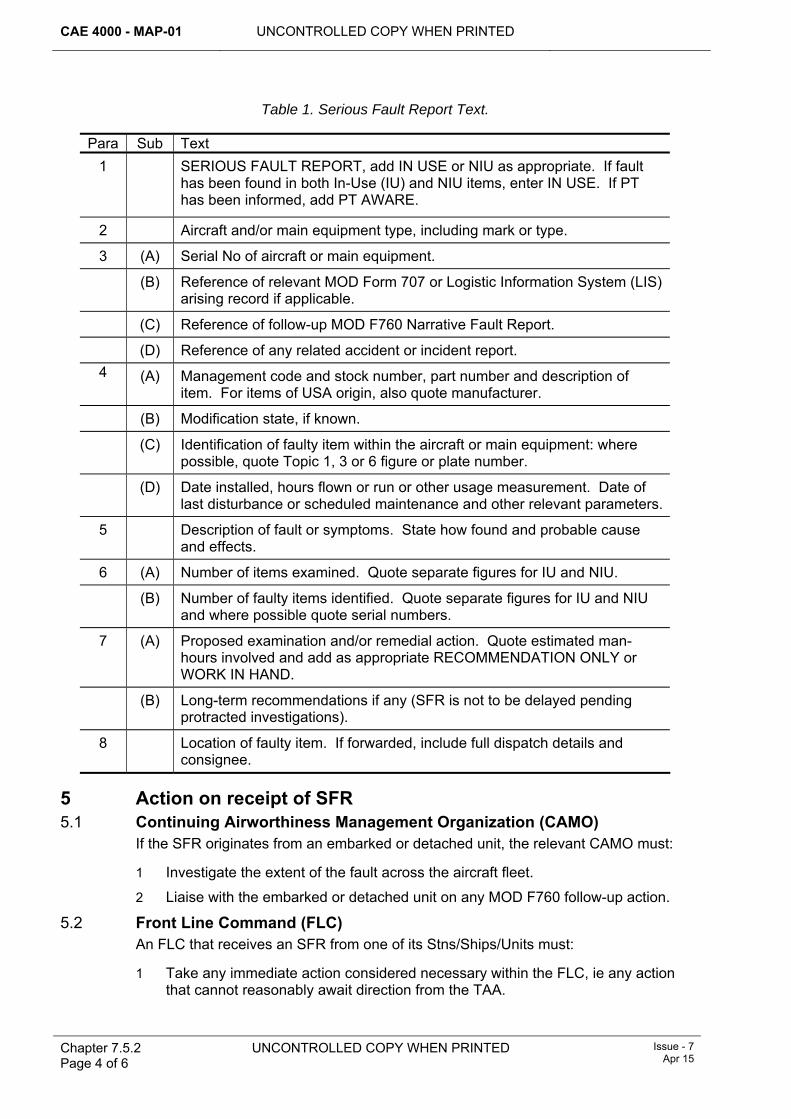
CAE 4000 - MAP-01 UNCONTROLLED COPY WHEN PRINTED
Chapter 7.5.2 Page 4 of 6
UNCONTROLLED COPY WHEN PRINTED Issue - 7 Apr 15
Table 1. Serious Fault Report Text.
Para Sub Text 1 SERIOUS FAULT REPORT, add IN USE or NIU as appropriate. If fault
has been found in both In-Use (IU) and NIU items, enter IN USE. If PT has been informed, add PT AWARE.
2 Aircraft and/or main equipment type, including mark or type.
3 (A) Serial No of aircraft or main equipment. (B) Reference of relevant MOD Form 707 or Logistic Information System (LIS)
arising record if applicable. (C) Reference of follow-up MOD F760 Narrative Fault Report. (D) Reference of any related accident or incident report.
4 (A) Management code and stock number, part number and description of item. For items of USA origin, also quote manufacturer.
(B) Modification state, if known. (C) Identification of faulty item within the aircraft or main equipment: where
possible, quote Topic 1, 3 or 6 figure or plate number. (D) Date installed, hours flown or run or other usage measurement. Date of
last disturbance or scheduled maintenance and other relevant parameters.
5 Description of fault or symptoms. State how found and probable cause and effects.
6 (A) Number of items examined. Quote separate figures for IU and NIU.
(B) Number of faulty items identified. Quote separate figures for IU and NIU and where possible quote serial numbers.
7 (A) Proposed examination and/or remedial action. Quote estimated man-hours involved and add as appropriate RECOMMENDATION ONLY or WORK IN HAND.
(B) Long-term recommendations if any (SFR is not to be delayed pending protracted investigations).
8 Location of faulty item. If forwarded, include full dispatch details and consignee.
5 Action on receipt of SFR 5.1 Continuing Airworthiness Management Organization (CAMO)
If the SFR originates from an embarked or detached unit, the relevant CAMO must:
1 Investigate the extent of the fault across the aircraft fleet.
2 Liaise with the embarked or detached unit on any MOD F760 follow-up action.
5.2 Front Line Command (FLC) An FLC that receives an SFR from one of its Stns/Ships/Units must:
1 Take any immediate action considered necessary within the FLC, ie any action that cannot reasonably await direction from the TAA.
UNCONTROLLED COPY WHEN PRINTED CAE 4000 - MAP-01
Issue - 7 Apr 15
UNCONTROLLED COPY WHEN PRINTED Chapter 7.5.2 Page 5 of 6
2 Liaise with the TAA on the possible effect that the fault or potential remedial actions may have on operations.
5.3 Type Airworthiness Authorities (TAAs) and commodity Project Teams (PTs) A TAA or commodity PT that receives an SFR must take the following actions in consultation, as necessary, with the CAMO:
1 If the fault affects airworthiness, take actions appropriate to the seriousness of the effects, including considering formal reporting action.
2 If required, task the appropriate Log Svcs with the examination or quarantining of depot stock.
3 If considered necessary, initiate a detailed investigation in accordance with the procedures detailed in Chapter 7.5.1, using the most appropriate agency.
4 Distribute the SFR to appropriate contractors.
5 Inform other branches as required.
6 Provide feedback to originator, apprising them of the actions arising from the SFR.
5.4 Logistic Services (Log Svcs) On receipt of an SFR, and only when instructed by the TAA, the Log Svcs must:
1 Confirm that the SFR relates to an NIU item and that the item is within the depot’s sphere of responsibility. If neither condition is met, the Log Svcs must inform the responsible TAA.
2 Respond to tasking from the TAA.
6 References This chapter refers to the following publications:
1 ACP 117 NATO Supplement 2 – NATO Subject Indicator System.
2 ACP 117 UK Supplement 2 – NATO Subject Indicator System.

CAE 4000 - MAP-01 UNCONTROLLED COPY WHEN PRINTED
Chapter 7.5.2 Page 6 of 6
UNCONTROLLED COPY WHEN PRINTED Issue - 7 Apr 15
Intentionally blank for Print Pagination
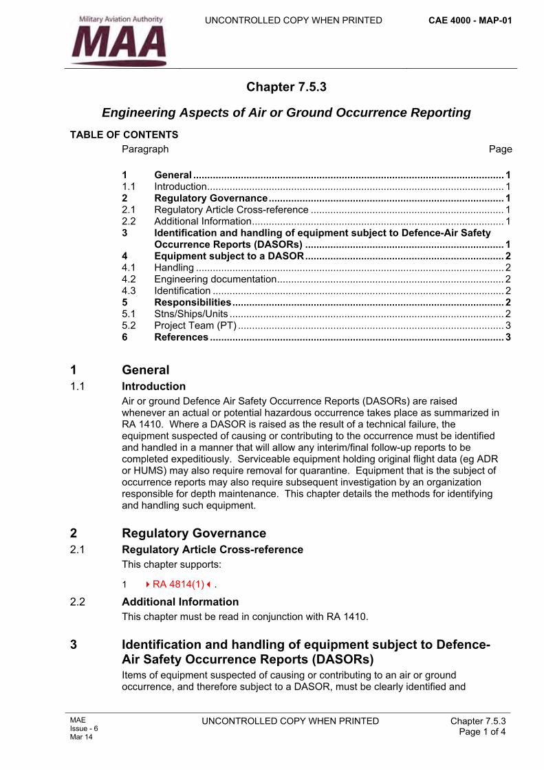
UNCONTROLLED COPY WHEN PRINTED CAE 4000 - MAP-01
MAE Issue - 6 Mar 14
UNCONTROLLED COPY WHEN PRINTED Chapter 7.5.3 Page 1 of 4
Chapter 7.5.3
Engineering Aspects of Air or Ground Occurrence Reporting
TABLE OF CONTENTS Paragraph
Page
1 General ............................................................................................................... 1 1.1 Introduction.......................................................................................................... 1 2 Regulatory Governance.................................................................................... 1 2.1 Regulatory Article Cross-reference ..................................................................... 1 2.2 Additional Information.......................................................................................... 1 3 Identification and handling of equipment subject to Defence-Air Safety
Occurrence Reports (DASORs) ....................................................................... 1 4 Equipment subject to a DASOR....................................................................... 2 4.1 Handling .............................................................................................................. 2 4.2 Engineering documentation................................................................................. 2 4.3 Identification ........................................................................................................ 2 5 Responsibilities................................................................................................. 2 5.1 Stns/Ships/Units .................................................................................................. 2 5.2 Project Team (PT) ............................................................................................... 3 6 References ......................................................................................................... 3
1 General 1.1 Introduction
Air or ground Defence Air Safety Occurrence Reports (DASORs) are raised whenever an actual or potential hazardous occurrence takes place as summarized in RA 1410. Where a DASOR is raised as the result of a technical failure, the equipment suspected of causing or contributing to the occurrence must be identified and handled in a manner that will allow any interim/final follow-up reports to be completed expeditiously. Serviceable equipment holding original flight data (eg ADR or HUMS) may also require removal for quarantine. Equipment that is the subject of occurrence reports may also require subsequent investigation by an organization responsible for depth maintenance. This chapter details the methods for identifying and handling such equipment.
2 Regulatory Governance 2.1 Regulatory Article Cross-reference
This chapter supports:
1 RA 4814(1).
2.2 Additional Information This chapter must be read in conjunction with RA 1410.
3 Identification and handling of equipment subject to Defence-Air Safety Occurrence Reports (DASORs) Items of equipment suspected of causing or contributing to an air or ground occurrence, and therefore subject to a DASOR, must be clearly identified and
CAE 4000 - MAP-01 UNCONTROLLED COPY WHEN PRINTED
Chapter 7.5.3 Page 2 of 4
UNCONTROLLED COPY WHEN PRINTED MAE Issue - 6
Mar 14
handled in order to promote the expeditious completion of fault investigations, any interim follow-up reports and/or a final report. Any item of serviceable equipment that is identified, by the authority that has ordered the occurrence investigation, as an aid to investigating a DASOR (eg ADR or HUMS) is also to be handled expeditiously.
4 Equipment subject to a DASOR Equipment that is suspected of causing or contributing to the cause of a DASOR is, if practical, to be investigated with the equipment in-situ, as mandated by RA 4061 and Chapter 2.11, and, if removed, retained by the operating Sqn/Unit until the original fault has been rectified and any associated functional tests, including flight tests, have been carried out. The retention of equipment (whether at forward or depth maintenance level) until the fault has been positively eliminated will enable the correct component to be identified for investigative reporting. The authority that has ordered the occurrence investigation may require serviceable equipment holding original flight data (eg ADR or HUMS) to be removed and quarantined.
4.1 Handling On confirmation or positive elimination of the fault, the suspect equipment must be prepared for transit to the appropriate depth support maintenance organization, having taken care to preserve it in the condition found on removal from the aircraft or main equipment. Any fuels, lubricants or operating media that may be considered an aid to future fault diagnosis must be contained within the equipment, or must be collected and despatched with the equipment. Equipment in quarantine must only be worked on or moved under the instruction of the authority that has ordered the occurrence investigation.
4.2 Engineering documentation All engineering documentation raised in support of a DASOR must be cross-referenced to that DASOR serial number. At the discretion of the relevant individual holding authority level K, engineering documentation may be annotated ‘DASOR’ in red ink as a management aid.
4.3 Identification Equipment subject to a DASOR that requires further investigation at a deeper level of maintenance must be conditioned as mandated by RA 4809 and Chapter 9.5 and identified by annotating the MOD F731 with the DASOR serial number and ‘DASOR’ in red ink.
5 Responsibilities 5.1 Stns/Ships/Units
Stns/Ships/Units are responsible for:
1 Raising, progressing and coordinating DASOR engineering investigations as detailed in RA 1410.
2 Ensuring that documentation raised in support of an DASOR engineering investigation is cross-referenced to the DASOR serial number.
3 Ensuring that the MOD F731, attached to equipment suspected of having caused an occurrence, is clearly identified by annotating the MOD F731 with the DASOR serial number and ‘DASOR’ in red ink.
UNCONTROLLED COPY WHEN PRINTED CAE 4000 - MAP-01
MAE Issue - 6 Mar 14
UNCONTROLLED COPY WHEN PRINTED
Chapter 7.5.3 Page 3 of 4
5.2 Project Team (PT) Where maintenance of the equipment has been contractorized, both aircraft and commodity PTs are responsible for ensuring that the contract states the requirement for the contractor to carry out DASOR engineering investigations, raise interim follow-up reports and/or a final report, and certify their completion.
6 References This chapter refers to the following publication:
1 RA 1410 - Occurrence Reporting.
2 ASIMS – Aviation Safety Information Management System.

CAE 4000 - MAP-01 UNCONTROLLED COPY WHEN PRINTED
Chapter 7.5.3 Page 4 of 4
UNCONTROLLED COPY WHEN PRINTED MAE Issue - 6
Mar 14
Intentionally Blank for Print Pagination
UNCONTROLLED COPY WHEN PRINTED CAE 4000 - MAP-01
Issue - 7 Apr 15
UNCONTROLLED COPY WHEN PRINTED Chapter 7.6 Page 1 of 8
Chapter 7.6
Retention of Military Aviation Engineering Documentation
TABLE OF CONTENTS Paragraph
Page
1 General ............................................................................................................... 1 1.1 Introduction.......................................................................................................... 1 1.2 Applicability ......................................................................................................... 2 2 Regulatory Governance.................................................................................... 2 2.1 Regulatory Article Cross-reference ..................................................................... 2 3 Military Aviation Engineering Documentation (MAED) retention
categories .......................................................................................................... 2 4 Promulgation of categorization and retention period.................................... 2 5 MAED categories............................................................................................... 3 5.1 Category A .......................................................................................................... 3 5.2 Category B .......................................................................................................... 3 5.3 Category C .......................................................................................................... 3 5.4 Category D .......................................................................................................... 4 5.5 Category E .......................................................................................................... 4 5.6 Category I............................................................................................................ 4 5.7 Category M.......................................................................................................... 4 6 Retention periods.............................................................................................. 4 6.1 Retention periods for each MAED category ........................................................ 4 6.2 Contractor Records ...................................................................................... 5 6.3 Documents in support of the Airworthiness Review Certificate (ARC)................ 6 6.4 Material Accounting records................................................................................ 6 7 Specific criteria for electronic data retained on logistic information
systems (LIS) ..................................................................................................... 6 7.1 Retention of data ................................................................................................. 6 7.2 Data blocks.......................................................................................................... 6 7.3 Data held discrete from the main storage area ................................................... 6 7.4 Data disposal....................................................................................................... 6 8 Aircraft withdrawn from Service ...................................................................... 6 8.1 Aircraft written off charge following an accident/incident..................................... 6 8.2 Aircraft subject to disposal .................................................................................. 7 8.3 Aircraft consigned to Ground Instruction or to a Museum ................................... 7 9 Transfer of aircraft and equipment to civilian register or foreign
government........................................................................................................ 7 10 References ......................................................................................................... 7
LIST OF TABLES Table 1. Minimum Retention Period for MAED.............................................................................4
1 General 1.1 Introduction
To maintain an audit trail for maintenance activities it is necessary to retain certain records. The period for which these records must be retained is dependent on the
CAE 4000 - MAP-01 UNCONTROLLED COPY WHEN PRINTED
Chapter 7.6 Page 2 of 8
UNCONTROLLED COPY WHEN PRINTED Issue - 7 Apr 15
category of the document. Military Aviation Engineering Documentation (MAED) is categorized according to the relevance of the information to the continuing airworthiness of the aircraft to which it relates: it also provides an aid to engineering investigations. Additionally, with the introduction of electronic work recording and/or asset management, a large amount of the information recorded previously on MAED is now entered directly into the relevant logistic information system (LIS). Therefore, in this chapter, any reference to forms or documents includes their electronic equivalents that are entered directly into, and subsequently stored by, a LIS.
RA 1300 and RA 1335 regulate the Release to Service (RTS) document and its retention requirements. All TAA documentation that supports the RTS document and/or relates to airworthiness or the Air System Safety Case, eg Service Modification forms and Special Instructions (Technical), must be classed as Category A documentation.
This chapter details the retention categories applicable to MAED and the equivalent electronic data entered directly into, and subsequently stored by, a LIS. It also details how the categories are selected and provides the generic retention/disposal instructions for the form/data. RA 4813 and Chapter 7.6.1 details the process for scanning and electronically storing hard copy MAED such that the original documents will be able to be safely destroyed.
1.2 Applicability This chapter is applicable both to paper and electronic aircraft documentation.
This chapter only applies to MOD Forms/Formats that are within the scope of MAP-02 Chapter 1.
2 Regulatory Governance 2.1 Regulatory Article Cross-reference
This chapter supports:
1 RA 4813(3) .
2 RA 4953.
3 Military Aviation Engineering Documentation (MAED) retention categories All MAED must be categorized by its sponsor according to the relevance of its content to either the maintenance of airworthiness or support of airworthiness investigations. Completed documentation should be retained only if the information it contains continues to be relevant to either the maintenance of airworthiness or support of airworthiness investigations. The period must be determined by the form’s sponsor in consultation with DSA MAA Reg CAw4-MAPLIS and, if appropriate, the relevant TAA. Electronic work orders and records must be retained for the same period as the MOD Form equivalent.
4 Promulgation of categorization and retention period MAED must be categorized into one of the seven categories detailed in paragraph 5. Sponsors of forms must identify the appropriate category and retention period of the form and, together with any specific-to-document disposal and/or retention instructions, ensure that this information is detailed on the appropriate Instructions for Use, under the title ‘Retention and Disposal Instructions’. If no instructions are
UNCONTROLLED COPY WHEN PRINTED CAE 4000 - MAP-01
Issue - 7 Apr 15
UNCONTROLLED COPY WHEN PRINTED Chapter 7.6 Page 3 of 8
issued, Table 1 details the minimum retention periods for each documentation category, together with the location at which the documents are to be retained.
5 MAED categories 5.1 Category A
Category A documents contain information that is required to maintain an audit trail of key events that could affect the airworthiness of the aircraft through its life. The documents must be retained for the life of the individual aircraft or equipment in MOD service, plus 5 years, unless additional arrangements are made. An example of this document category is the Airframe Record Card (MOD F744), which contains details, amongst other data, of all aircraft transfers.
5.2 Category B Category B documents contain airworthiness information that must be retained to maintain an audit trail of key events for the period that the documented work could affect the airworthiness of the aircraft or inform airworthiness investigations. The documentation must be retained until the work it records has been invalidated by documented work carried out subsequently. This may be managed by linking retention of some Category B documents to a Scheduled Base Maintenance (SBM), Major or equivalent Depth Maintenance if the work carried out at SBM, Major or Depth invalidates previous work. An example of this document category would be Maintenance Work Order (MOD Form 707B(IS)).
If the Type Airworthiness Authority (TAA) or Continuing Airworthiness Management Organization (CAMO) consider that elements of a platform’s Depth maintenance does not invalidate previous work (or cannot be confirmed to invalidate previous work), the TAA/CAMO must specify, in their platform’s Topic 2(N/A/R)1 or AESO, the retention requirements peculiar to their platform’s circumstance. As a minimum Category B documents that record the following activities should be retained for the same period as Category A documents:
1 Initial compliance with a SI(T).
2 Aircraft or component repairs, including Topic 6 repairs and any associated off-aircraft records relating to the local manufacture of parts used to affect the repair.
3 Installation of lifed components that will remain installed for a duration exceeding the periodicity between SBM, Major or Depth maintenance.
Category B documents that are to be retained for the same period as Category A documents should be held in a separate folder/location to other Category B documents, in order to ease retention/disposal and the retrieval of records for the airworthiness review process.
Note: The requirement to re-categorize documents from Category B to Category A does not apply to the Maintenance Log (eg MOD F707A), as all relevant information is recorded on the appropriate Maintenance Work Order (eg MOD F707B(IS)).
5.3 Category C Category C documents contain airworthiness information that must be retained until it can no longer affect the aircraft. Such information is only required to maintain an audit trail of events that could affect, or have affected, the airworthiness of the aircraft until a further check of the same system is carried out. An example of this document
CAE 4000 - MAP-01 UNCONTROLLED COPY WHEN PRINTED
Chapter 7.6 Page 4 of 8
UNCONTROLLED COPY WHEN PRINTED Issue - 7 Apr 15
category is the Helicopter Ground Running Flight Servicing Certificate (MOD F705B(H)).
5.4 Category D Category D documents contain airworthiness information that, once replaced, transferred or cleared, is no longer of any airworthiness value. Such documents, providing all information has been replaced, transferred or cleared, may be disposed of. An example of this document category is an Acceptable Deferred Faults Log (MOD F704), which, once all entries are cleared or transferred to another page, is of no airworthiness value and may be discarded.
5.5 Category E Category E documents do not contain airworthiness information required to maintain an audit trail, but may contain information required for later reference. These documents may be retained at the discretion of the relevant Continuing Airworthiness Management Organization (CAMO) in exercising their duty to retain maintenance records, as detailed in RA 4953.
5.6 Category I Category I documents contain specific retention and disposal instruction detailed on the appropriate Instructions for Use.
5.7 Category M Category M (Miscellaneous) documents do not neatly fall within the above categories. Additional information/disposal instructions are contained within the comments field of MAP-02 Chapter 1 for the associated form.
6 Retention periods 6.1 Retention periods for each MAED category
Minimum document retention period categories are listed in MAP-02 Chapter 1 for the associated form. Completed forms must be treated as UNCLASSIFIED unless the publication sponsor has specified a higher grading.
Table 1 details the minimum retention periods for each documentation category, together with the location at which the documents must be retained. However, when necessary, longer periods of retention and specific retention locations may be determined by the document sponsor and promulgated on the appropriate Instructions for Use.
Table 1. Minimum Retention Period for MAED.
Category Minimum Retention Period Retention Location
Example Form
A Retain for the life of the individual aircraft or equipment in MOD service, plus 5 years unless additional arrangements are made.
Service-dependent
(Note 1)
Airframe Record Card (MOD F744)
B Retain until invalidated by subsequent work. (Note 2)
Service-dependent
(Note 1)
Aircraft Maintenance Log (MOD F707A)
UNCONTROLLED COPY WHEN PRINTED CAE 4000 - MAP-01
Issue - 7 Apr 15
UNCONTROLLED COPY WHEN PRINTED Chapter 7.6 Page 5 of 8
Category Minimum Retention Period Retention Location
Example Form
C May be disposed of when the information contained no longer has any bearing on the airworthiness of the aircraft. They are to be retained for a minimum of 28 days, or as specified on the relevant Instructions for Use.
Flt/Sqn (Note 3)
Helicopter Ground Running Flight
Servicing Certificate (MOD F705B(H))
D May be disposed of when the information contained is replaced, transferred or cleared and is therefore no longer of any airworthiness value.
Flt/Sqn Limitations Log (MOD F703)
E Retain at the discretion of the CAMO. Service-dependent
(Note 1)
JARTS Task Folder (MOD F767L)
I Retain as per specific retention and disposal instructions detailed on the appropriate Instruction for Use.
Detailed on appropriate
Instructions for Use
RTC Adjustment Record Card
(MOD F701A(VC10))
M Retain as per additional information/disposal instructions contained within the comments field of MAP-02 Chapter 1 pending inclusion of this information in the associated Instructions for Use.
Service-dependent
(Note 1)
Fuel Leak Location Chart (MOD F704C
(Dominie))
Notes:
1 Non/Off Aircraft: retain at user section unless specified in local orders. On Aircraft: Service-specific arrangements:
1.1 RN – Retained by the raising unit for a minimum of 6 months. With agreement of the AEO of the parent air station, documents may be stored at the parent air station for the remainder of their retention period.
1.2 Army – Category A retained by the relevant Depth support organization. All other categories remain with the aircraft.
1.3 RAF – Retained by Stn Engineering Records department.
2 See paragraph 5.2 for details of when Category B documents should be retained for the same period as Category A documents. Front Line Commands (FLCs), in consultation with CAMOs where appropriate, must define in mid-level aviation engineering policy the high-frequency activities recorded on a Maintenance Work Order (MWO), where the minimum retention period may be relaxed to 28 days, eg blade folding, tool control, ejection seat pins, etc. The minimum retention period for MOD F707MC, F707MP and F707MS is until completion of the next like maintenance activity that includes the same work content, plus 28 days.
3 A fully completed Flight Servicing Certificate (MOD F705(XXX)) series form may be discarded before the 28-day period stated within Table 1 for a Cat C Form, once the AF/TFS information has been replaced by the details of the next like servicing on a subsequent Flight Servicing Certificate.
6.2 Contractor Records When Forward or Depth maintenance is provided solely by a contractor organization who utilize their own record system or a civilian technical log system to
CAE 4000 - MAP-01 UNCONTROLLED COPY WHEN PRINTED
Chapter 7.6 Page 6 of 8
UNCONTROLLED COPY WHEN PRINTED Issue - 7 Apr 15
record details of aircraft maintenance, the MOD Continuing Airworthiness Manager (MOD CAM) is to ensure that the Continuing Airworthiness Management Exposition (CAME) details the retention periods relevant to those documents.
6.3 Documents in support of the Airworthiness Review Certificate (ARC) Irrespective of the retention period normally associated with its MAED category, as detailed in Paragraph 6.1, the CAMO must retain a copy of all documents that support the issue of an ARC until 5 years after the aircraft has been permanently withdrawn from Service; RA 4953(1) refers.
6.4 Material Accounting records Policy for the retention of Material Accounting documentation, such as the MOD Form 640, is contained within JSP 886, Vol 4, Pt 1.
7 Specific criteria for electronic data retained on logistic information systems (LIS)
7.1 Retention of data The period of retention for data on an LIS’s main storage area is at the discretion of the TAA, in consultation with the CAMO, but must meet the minimum detailed in this chapter.
Note:
RA 4305 and Chapter 7.3.2 details criteria for archiving data somewhere other than on the main storage area.
7.2 Data blocks Data within a LIS may be stored in blocks containing a mixture of categorizations. Where this is the case, data must be retained according to the most restrictive applicable category.
7.3 Data held discrete from the main storage area Data held on stand-alone processing units (ie laptop computers) discrete from the main storage area must be regarded as secondary to that held on the main storage area and need not be retained once the main storage area has been updated. TAAs must provide instructions in the platform Topic 2(N/A/R)1 to control transfer of data between stand-alone units and the main storage area.
7.4 Data disposal Data disposal must be carried out using a structured and controlled process to maintain an auditable record for the life of the system. For a Main Operating Base with more than one storage/processing unit, the disposal must be carried out centrally to maintain a consistent standard of data information across the units. TAAs must ensure that all stakeholders are consulted before permanent disposal of data is carried out.
8 Aircraft withdrawn from Service 8.1 Aircraft written off charge following an accident/incident
When an aircraft is written off charge following an accident or incident, the CAMO, in conjunction with the TAA if necessary, is responsible for authorizing the disposal of maintenance documentation peculiar to the aircraft serial number. Where this write-off action follows an aircraft accident, to safeguard the MOD's interests in claims for compensation in the case of a fatality or injury, or to maintain the MOD’s overall
UNCONTROLLED COPY WHEN PRINTED CAE 4000 - MAP-01
Issue - 7 Apr 15
UNCONTROLLED COPY WHEN PRINTED Chapter 7.6 Page 7 of 8
reputation, maintenance documentation may need to be retained for an extended period. The actual period will be a matter for the FLC to judge, based on the legal circumstances and media interest in the accident. The CAMO/TAA must consult with the FLC before disposing of any documentation.
8.2 Aircraft subject to disposal For aircraft subject to disposal following withdrawal from Service, the TAA, in consultation with the CAMO (when possible), should determine the process for document retention and disposal activity, noting the requirements detailed in this Chapter to retain Category A documentation and any further documentation used to support the issue of an ARC, for a minimum of 5 years following withdrawal from Service.
8.3 Aircraft consigned to Ground Instruction or to a Museum When an aircraft is re-categorized for Ground Instruction or is consigned to a museum, the maintenance documentation must be transferred as mandated by RA 4813 and Chapter 7.2.1. Notwithstanding the requirement to retain Category A documentation for a minimum of 5 years after the aircraft has been withdrawn from Service, and any other minimum retention periods imposed by the FLC or CAMO, the receiving unit/museum may dispose of other documentation, if required, after a minimum of 2 years.
For non-effective Ground Instructional Aircraft (GIA), capable of aero-engine ground run and/or manoeuvre under own power, careful consideration must be given to applying the full maintenance documentation retention requirements throughout its use as detailed in this chapter.
9 Transfer of aircraft and equipment to civilian register or foreign government When aircraft are sold and are to continue to fly on the civilian register or with a foreign government, the current MOD Form 700 as mandated by RA 4813 and Chapter 7.2.1 must be transferred in total, with the exception of any classified documentation where further guidance should be obtained from JSP 440. The MOD should retain copies of transferred MAED for the period as specified in Table 1; scanned electronic copies are acceptable in accordance with MAP-01 Chapter 7.6.1.
10 References This chapter refers to the following publications:
1 MAP-02 – Maintenance and Airworthiness Processes – MOD Form 700 Series of Forms.
2 JSP 440 – The Defence Manual of Security.
3 RA 1300 - Release to Service.
4 RA 1310 - Aircraft Document Set.
5 RA 1335 - The RTS Audit Trail.
6 JSP 886 Vol 4 Pt 1 – Fundamentals of Material Accounting.
7 Topic 2(N/A/R)1 – General Orders and Special Instructions.
8 RA 4953 - Record Keeping - MRP Part M Sub-Part G.

CAE 4000 - MAP-01 UNCONTROLLED COPY WHEN PRINTED
Chapter 7.6 Page 8 of 8
UNCONTROLLED COPY WHEN PRINTED Issue - 7 Apr 15
Intentionally blank for Print Pagination
UNCONTROLLED COPY WHEN PRINTED CAE 4000 - MAP-01
MAE Issue - 6 Mar 14
UNCONTROLLED COPY WHEN PRINTED Chapter 7.6.1 Page 1 of 4
Chapter 7.6.1
Scanning and Electronic Storage of Military Aviation Engineering Documentation
TABLE OF CONTENTS Paragraph
Page
1 General ............................................................................................................... 1 1.1 Introduction.......................................................................................................... 1 1.2 Applicability ......................................................................................................... 1 1.3 Associated publications....................................................................................... 1 2 Regulatory Governance.................................................................................... 2 2.1 Regulatory Article Cross-reference ..................................................................... 2 2.2 Additional Information.......................................................................................... 2 3 Scanning Military Aviation Engineering Documentation (MAED)................. 2 3.1 Legality of scanned documentation..................................................................... 2 3.2 Criteria before destruction of original .................................................................. 2 3.3 Minimum requirements for scanning ................................................................... 2 3.4 Minimum requirements for verification ................................................................ 2 3.5 Minimum requirements for Digital Storage Media (DSM).................................... 3 4 Destruction of original documents.................................................................. 3 5 Responsibilities................................................................................................. 3 6 References ......................................................................................................... 3
1 General 1.1 Introduction
The regulation for the retention of Military Aviation Engineering Documentation (MAED) is mandated by RA 4813 and Chapter 7.6. In the case of hard copy, this creates a document storage commitment. A large proportion comprises Category B documents, eg MOD Form 707 series, retained until 6 months after completion of the next Depth maintenance or equivalent SBM/Major. Hence the document storage commitment can become significant and problematical.
To alleviate this storage problem, this chapter defines a procedure for scanning and electronically storing hard copy MAED such that the original documents may safely be destroyed.
1.2 Applicability This chapter applies only to the MAED forms listed in MAP-02 Chapter 1. The procedures must not be applied to other documents and, in particular, those that comprise the Aircraft Document Set (ADS).
There is no requirement for a Ship/Stn/Unit to implement this regulation if scanning and electronic storage resources are not available and/or there are adequate storage facilities for hard copy.
1.3 Associated publications This chapter is associated with the following publications:
1 The Civil Evidence Act 1995.
CAE 4000 - MAP-01 UNCONTROLLED COPY WHEN PRINTED
Chapter 7.6.1 Page 2 of 4
UNCONTROLLED COPY WHEN PRINTED MAE Issue - 6
Mar 14
2 The Police & Criminal Evidence Act 1995.
3 British Standards Institution BSI 0008-Evidential Weight and Legal Admissibility of Electronic Information.
2 Regulatory Governance 2.1 Regulatory Article Cross-reference
This chapter supports:
1 RA 4813(1).
2.2 Additional Information. Nil.
3 Scanning Military Aviation Engineering Documentation (MAED) Completed MAED may be scanned and stored electronically. Processes must be put in place to ensure and certify that each scanned page is a legible facsimile before originals are destroyed.
3.1 Legality of scanned documentation Provided that a verifiable audit trail is maintained from the original document, the Directorate of Legal Services (DLS) confirms that a legible electronic copy, referred to as a facsimile, is an acceptable record for all MoD purposes.
3.2 Criteria before destruction of original Before an original document can be destroyed, a certificate to the effect that the electronic facsimile is legible and has captured the entire document or page must be produced. To satisfy the legal requirement, this must be carried out for a document in its entirety, ie every page must be checked and verified. A percentage check of pages within a batch is not acceptable. However, a single certificate for a batch check is acceptable. Particular attention must be taken to ensure that signatures on maintenance documentation are captured.
3.3 Minimum requirements for scanning Guidelines for scanning are contained in British Standard PD 0016:2001. For documents scanned under authority of this chapter, the following minimum requirements are to be met:
1 The scan resolution must be a minimum of 200 dots per inch.
2 The image must be captured in “Greyscale”.
3.4 Minimum requirements for verification 3.4.1 Documentation List
In addition to any control of document movements between operating units and a records office, a list of documents to be scanned must be prepared on MOD Format 740(SDC) for use in the Completeness & Quality check detailed below.
3.4.2 Completeness & Quality check and certification Using the prepared list on MOD Format 740(SDC), the certificate that each and every page of a document has been scanned, is legible and has been reproduced in its entirety on the final storage media, must be completed. When completed, the MOD Format 740(SDC) must be kept at the documentation retention location mandated by
UNCONTROLLED COPY WHEN PRINTED CAE 4000 - MAP-01
MAE Issue - 6 Mar 14
UNCONTROLLED COPY WHEN PRINTED Chapter 7.6.1 Page 3 of 4
RA 4813 and Chapter 7.6. Separate forms must be created where the final storage media has been duplicated. A person eligible to hold C annotated authorizations must certify the Completeness & Quality Check.
3.5 Minimum requirements for Digital Storage Media (DSM) 3.5.1 Retention period
Documents stored on DSM must be retained for the periods mandated by RA 4813 and Chapter 7.6.
3.5.2 DSM safeguards To avoid DSM degrading or being compromised:
1 Documents stored on DSM must allow reproduction of the original document(s) for the entire period of retention, ie the media must not become unreadable due to degradation over time or due to advances in Information Technology (IT). DSM must be regularly checked, in accordance with JSP 441 Chap 6 Annex C, for physical degradation and replaced as required to ensure that information remains available. If data is transferred to new or replacement DSM, the quality of data on the new media must be assured before the old media is destroyed. Transfer of data to new media must be recorded on MOD Format 740(SDC).
2 Data held on any DSM must be read-only.
3.5.3 Archive of DSM In addition to the requirements of JSP 441 and those quoted above, consideration should be given to duplicating and storing DSM in separate locations.
4 Destruction of original documents Authorization to destroy original documents must only be given after completion of the Completeness & Quality certificate on MOD Format 740(SDC). The authorization to destroy must be certified on MOD Format 740(SDC) and the completed form must be kept at the documentation retention location mandated by RA 4813 and Chapter 7.6. Separate forms must be created and retained where the DSM has been duplicated for storage in a separate location.
5 Responsibilities A relevant individual holding authority level J is responsible for authorizing the destruction of original documents scanned to DSM.
A person eligible to hold level C authorizations must complete the Completeness & Quality certificate.
6 References This chapter refers to the following publications:
1 British Standard PD 0016:2001 – Document Scanning. Guide to Business Documents.
2 JSP 441 – Defence Records Management Manual.
3 MAP-02 – Maintenance and Airworthiness Processes – MOD Form 700 Series of Forms.

CAE 4000 - MAP-01 UNCONTROLLED COPY WHEN PRINTED
Chapter 7.6.1 Page 4 of 4
UNCONTROLLED COPY WHEN PRINTED MAE Issue - 6
Mar 14
Intentionally Blank for Print Pagination
UNCONTROLLED COPY WHEN PRINTED CAE 4000 - MAP-01
Issue - 7 Apr 15
UNCONTROLLED COPY WHEN PRINTED Chapter 8.1 Page 1 of 6
Chapter 8.1
Through Life Management of Technical Information
TABLE OF CONTENTS
Paragraph
Page
Table of contents ..........................................................................................................1 1 General ...............................................................................................................1 1.1 Introduction..........................................................................................................1 1.2 Associated publications....................................................................................... 2 2 Regulatory Governance....................................................................................2 2.1 Regulatory Article Cross-reference ..................................................................... 2 3 Use of Technical Information (TI) .................................................................... 2 4 Production .........................................................................................................2 4.1 Management plan................................................................................................3 4.2 Verification of TI .................................................................................................. 3 5 Delivery ..............................................................................................................3 5.1 General................................................................................................................3 5.2 Distribution of data as physical products............................................................. 3 5.3 Distribution of data through electronic means ..................................................... 3 6 Output.................................................................................................................3 7 Maintenance.......................................................................................................4 7.1 Amendment ......................................................................................................... 4 7.2 Management of physical documents and publications........................................ 4 8 Responsibilities.................................................................................................4 8.1 Type Airworthiness Authority (TAA) .................................................................... 4 8.2 Subject Matter Expert (SME)............................................................................... 5 8.3 Publication Organization (PO)............................................................................. 5 8.4 Joint Support Chain – Support Chain Management – Engineering Through
Life Support - Technical Documentation (JSC-SCM-EngTLS-TD)...................... 6 8.5 Stn/Ship/Unit .......................................................................................................6 9 Reference ...........................................................................................................6
1 General 1.1 Introduction
This chapter details the philosophy on the production, delivery, output and maintenance of Technical Information (TI) within the Military Air Environment (MAE). Whilst the conversion of legacy TI to Electronic TI (ETI) is encouraged, there will remain a significant number of paper-based publications.
TI is the information necessary to operate, maintain, repair, support and dispose of equipment throughout its life. It includes paper, fiche, drawings, Computer-Aided Design data, electronic text and non-textual data (eg graphics, video) for:
1 Illustrated Parts Lists.
2 System description and operation.
3 System servicing and maintenance.
4 Diagnostic support.
5 Repair information.
CAE 4000 - MAP-01 UNCONTROLLED COPY WHEN PRINTED
Chapter 8.1 Page 2 of 6
UNCONTROLLED COPY WHEN PRINTED Issue - 7 Apr 15
6 Supporting flow, system and wiring diagrams.
7 Software documentation.
8 Logistic Support Analysis reports.
9 Policy documents.
10 Aides Memoirs.
11 Training information.
1.2 Associated publications JSP 420 – Publishing your MOD Book and JSP(D) 543 – Defence Technical Documentation – Policy and Requirements give further guidance on the MOD approved publication and distribution procedures.
The publication standard and issue status of MAE TI is promulgated in AP 100Z-0001.
The following publications give further guidance on the MOD policy on ETI and the specific standards for ETI:
1 Acquisition Operating Framework – MOD Technical Documentation Policy Statement.
2 ASD Specification 1000D – The International Specification for Technical Publications Utilising a Common Source Database.
3 ASD Specification 2000M – The International Specification for Military Materiel Management.
2 Regulatory Governance 2.1 Regulatory Article Cross-reference
This chapter supports:
1 RA 4350.
3 Use of Technical Information (TI) Technical Information (TI) should be made available to the Duty Holder (DH) and DH-Facing Organizations in an electronic format, as ETI, unless it does not meet the operational requirement, user needs, or is not cost-effective for the life cycle of the equipment. Def Stan 00-600 Integrated Logistic Support and JSP 886 Vol 7 Pt 8.05 Technical Documentation detail standards for the production of TI.
When ETI is produced in electronic format it must be produced in a neutral, non-proprietary, data format and must be viewable with any Internet browser software with minimal requirements for non-standard plug-in software modules. Where plug-in software modules may be required, they must be provided with the source data.
Where TI has been produced to standards other than Def Stan 00-600 and JSP 886 Vol 7 Pt 8.05, it must be maintained and administered in accordance with the publishing standard and the associated processes to which it was written.
4 Production TI production is the creation of the original data and content of the document. Additional procedures for producing and maintaining Maintenance Schedules and
UNCONTROLLED COPY WHEN PRINTED CAE 4000 - MAP-01
Issue - 7 Apr 15
UNCONTROLLED COPY WHEN PRINTED Chapter 8.1 Page 3 of 6
Flight Test Schedules are detailed at RA 4351 and Chapter 8.1.1 and RA 4352 and Chapter 8.1.2 respectively.
4.1 Management plan TI production must be managed using an Integrated Support Plan, which will include requirements for First and Second Verification of TI as appropriate.
4.2 Verification of TI In verifying TI as ‘fit for purpose’ the TI sponsor must identify what information is critical for the airworthiness of a platform or a system and must conduct full verification of such data. Verification must involve undertaking the task in representative conditions, or, if this is not possible, via simulation.
5 Delivery 5.1 General
TI delivery is the means of providing the information at the point of use. Whilst TI has traditionally required the distribution of physical products such as books, the use of Internet technology and shared data environments means that ETI distribution may not require the movement of any physical items. However, when distribution of a removable media, ie a CD-ROM or DVD, is required to promulgate ETI, the distribution procedure detailed at paragraph 5.2 must be used.
5.2 Distribution of data as physical products The delivery of data as physical products, either as books or as ETI on removable media, is provided by the Logistic Commodities and Services (LCS) distribution system within the Joint Support Chain (JSC). The TI sponsor may approve an alternative method of delivery provided that it is at least as robust as that provided by LCS.
5.3 Distribution of data through electronic means The Publication Organization (PO) is responsible for ensuring that electronically-distributed data, either in shared data environments or by means of a distributed database, will use delivery procedures that are at least as effective as those detailed in Def Stan 00-600 and JSP 886 Vol 7 Pt 8.05.
6 Output TI output is the means of presenting the data to the user. For paper-based TI, this is dictated by the publication standard used. For ETI, the data output is dependent on the data layout determined by the publication standard, the viewing software used and the physical display hardware.
Where an aircraft or equipment is provided with ETI and paper TI, the layout of the ETI and paper versions of the TI must be the same, within the limits of the different media used.
The Type Airworthiness Authority (TAA) is responsible for the Aircraft Document Set (ADS) and therefore responsible for any ETI used as part of the ADS, including the interaction with any browser software. The TAA should ensure that any users are aware of any content amendments and software updates, and that a suitable procedure is in place to ensure data source integrity during the amendment process.
CAE 4000 - MAP-01 UNCONTROLLED COPY WHEN PRINTED
Chapter 8.1 Page 4 of 6
UNCONTROLLED COPY WHEN PRINTED Issue - 7 Apr 15
7 Maintenance TI maintenance is the action taken to preserve it in good order. TI maintenance involves both amending the TI and managing the amendment procedure.
7.1 Amendment TI must be amended through a "closed loop" auditable system. The procedure for amending TI is at RA 4810 and Chapter 8.2. As detailed in RA 4457 and Chapter 10.5.3, a Routine Technical Instruction (RTI) or Urgent Technical Instruction (UTI) should not be used to amend any MOD-administered publication.
7.2 Management of physical documents and publications When data is distributed as physical documents, the amendment procedure requires that the superseded pages be destroyed once their replacements have been included within the TI. Where removable media is used, care must be taken to ensure that superseded media cannot be inadvertently used after it has been superseded. If the original media is not returned to a central point for destruction, the individual who carries out the amendment must ensure that the old removable media is rendered unreadable by destroying or damaging it, eg by scoring the optical surface of a CD-ROM.
8 Responsibilities 8.1 Type Airworthiness Authority (TAA)
The TAA, supported by TI sponsors when applicable, are responsible for:
1 The overall coherence of the publication and, where appropriate, integration of individual instructions.
2 Approval of all content prior to publication of TI.
3 The airworthiness implications of the published TI.
4 Specifying the publication standard of the TI including, where applicable, ETI and its delivery system in accordance with paragraph 2.
5 Initial procurement of the TI, inclusive of ETI and its viewing system.
6 Ensuring that TI is sponsored for use within the appropriate Services, meets the user requirements and that processes are in place to action discrepancies when they are identified.
7 Ensuring that the required through-life management procedures are in place for the TI. These procedures must cover Post-Design Service contract requirements, TI delivery, content review timescales, amendment, printing, distribution and regular review of distribution lists.
8 Ensuring that the TI amendment procedures are appropriate, given the operational requirements/capabilities of the platform on which the aircraft or equipment is used.
9 Ensuring that software and hardware is available both to produce and read ETI throughout the life of the TI.
10 Where ETI is hosted on existing Information Systems, ensuring that any necessary hardware updates are identified and embodied, regression testing has been conducted and clearances obtained to allow hosting of the ETI data, and viewer software where appropriate, prior to introduction of the documentation.
11 When issuing hardware to support ETI:
UNCONTROLLED COPY WHEN PRINTED CAE 4000 - MAP-01
Issue - 7 Apr 15
UNCONTROLLED COPY WHEN PRINTED Chapter 8.1 Page 5 of 6
11.1 Ensuring that the System Administrator is provided with the appropriate information to produce System Security Procedures and Security Operating Procedures in accordance with JSP 440, including mechanisms for the control of access to classified information.
11.2 Ensuring that any hardware is cleared for use in all necessary environments. In particular, Electro-Magnetic Capability and RadHaz clearances should be obtained for use on board ship and in the close vicinity of aircraft.
12 Appointing a Subject Matter Expert (SME) to manage specialist content of the TI when appropriate.
13 Appointing a PO.
14 Assuring the quality of a TI deliverable
15 Collating, maintaining and making available a list of all TI authorized for use on a particular type of aircraft or equipment including any cross platform publications referred to in the Aircraft Document Set.(ADS). This list must contain the publication sponsor and the latest amendment state.
8.2 Subject Matter Expert (SME) An SME is required to ensure that the content of any TI that the SME produces on behalf of a TI sponsor is accurate and understandable. In addition, for ETI, the SME must ensure that it is produced to a consistent manner by use of Document Type Definition or another appropriate set of rules. Unless otherwise contracted, the SME is responsible for:
1 Providing the sponsor with complete and technically accurate information. When a Design Organization, or other non-MOD organization, acts as an SME for ETI, it must provide data that is first verified and approved.
2 Notifying the TI sponsor of requirements for new instructions or amendments to maintain the completeness and technical accuracy of the information that they provide.
3 Reviewing existing instructions at least every three years and notifying the TI sponsor of changes that are required to update the instruction.
4 Notifying the TI sponsor of the requirement to cancel an instruction as soon as there is no further need for it.
8.3 Publication Organization (PO) The PO is responsible for:
1 Ensuring that TI, including ETI and its delivery system, are specification-compliant.
2 Ensuring the quality of a TI deliverable.
3 Arranging TI publication and distribution on behalf of the TI sponsor.
4 In respect of ETI, the PO is also responsible for:
4.1 Ensuring that the amendment system does not affect the correct operation of the ETI viewing software.
4.2 Obtaining the agreement of the network authorities for the delivery and hosting of the data, where ETI is delivered via corporate Wide Area Networks and Local Area Networks, eg INCA, RLI and LDCN.
CAE 4000 - MAP-01 UNCONTROLLED COPY WHEN PRINTED
Chapter 8.1 Page 6 of 6
UNCONTROLLED COPY WHEN PRINTED Issue - 7 Apr 15
8.4 Joint Support Chain – Support Chain Management – Engineering Through Life Support - Technical Documentation (JSC-SCM-EngTLS-TD) JSC SCM EngTLS-TD is responsible for:
1 Providing and promulgating MOD TI policy.
2 Providing advice and guidance to TI sponsors on the implementation of MOD TI policy.
8.5 Stn/Ship/Unit Stns/Ships/Units are responsible for the distribution and control of TI that they receive and for providing required TI to personnel at the point of use. In addition, Stns/Ships/Units must publish local orders in accordance with Chap 1.10.2 that:
1 Ensure suitable accounting and control processes are in place to maintain their TI in an airworthy state. This will include processes by which individual TI holders can:
1.1 Ensure that TI is at the latest issued amendment state.
1.2 Demand amendments for TI when discrepancies are identified.
2 Detail suitable management checks to ensure the airworthiness of their TI holdings.
3 Detail suitable procedures for data security as required by JSP 440.
4 Ensure the timely and accurate distribution of TI amendments within their organization.
5 Detail procedures for disposing of superseded removable media.
9 Reference This chapter refers to the following publications:
1 JSP 440 – Defence Manual of Security.
2 Def Stan 00-600 Integrated Logistic Support.
3 JSP 886 Vol 7 Pt 8.05 Technical Documentation.
UNCONTROLLED COPY WHEN PRINTED CAE 4000 - MAP-01
Issue - 7 Apr 15
UNCONTROLLED COPY WHEN PRINTED Chapter 8.1.1 Page 1 of 6
Chapter 8.1.1
Production and Maintenance of Maintenance Schedules
TABLE OF CONTENTS Paragraph
Page
1 General ............................................................................................................... 1 1.1 Introduction.......................................................................................................... 1 1.2 Terms used ......................................................................................................... 1 1.3 Applicability ......................................................................................................... 2 2 Regulatory Governance.................................................................................... 2 2.1 Regulatory Article Cross-reference ..................................................................... 2 3 Production and maintenance of maintenance schedules ............................. 2 4 Production of maintenance schedules ........................................................... 2 4.1 General................................................................................................................ 2 4.2 Schedule standardization measures ................................................................... 2 5 Maintenance of schedules................................................................................ 3 5.1 First schedule review........................................................................................... 3 5.2 Subsequent reviews ............................................................................................ 3 5.3 Reviews by civilian contractors ........................................................................... 3 5.4 Amendment of schedules.................................................................................... 3 5.5 Schedule standardization measures for older aircraft ......................................... 4 6 Aircrew Landaway Flight Servicing Schedules.............................................. 4 6.1 Background ......................................................................................................... 4 6.2 Production ........................................................................................................... 4 6.3 Amendment ......................................................................................................... 4 7 Responsibilities................................................................................................. 5 7.1 MAA Regulations & Certification Group .............................................................. 5 7.2 Type Airworthiness Authority (TAA) .................................................................... 5 7.3 1710 Naval Air Squadron (1710 NAS) ................................................................ 5 7.4 Repair & NDT Squadron ..................................................................................... 5 7.5 MAA Certification Structures and Aircraft Design Standards (MAA Cert S and
ADS).................................................................................................................... 5 8 References ......................................................................................................... 5
1 General 1.1 Introduction
This chapter details the specific instructions, additional to those detailed by RA 4350 and Chapter 8.1, concerning the production and maintenance responsibilities for maintenance schedules. It also provides guidance on the measures that must be taken to achieve standardization of such schedules and details procedures for their production, initial issue, revision and amendment. These measures may be achieved either through a task on a Service organization or under a contract with an external organization.
1.2 Terms used Throughout this chapter the generic term 'schedule' must be interpreted as meaning any aircraft, airborne equipment or air-launched guided weapons and their installed or associated equipment maintenance schedule.
CAE 4000 - MAP-01 UNCONTROLLED COPY WHEN PRINTED
Chapter 8.1.1 Page 2 of 6
UNCONTROLLED COPY WHEN PRINTED
Issue - 7 Apr 15
1.3 Applicability This chapter applies to all aircraft and associated equipment maintenance schedule publications used in the Military Air Environment (MAE). It does not include Flight Test Schedules (Topic 5M), procedures for which are detailed in Chapter 8.1.2. The range of maintenance schedules that may be issued for an aircraft type are listed in JAP(D)100C-20:
2 Regulatory Governance 2.1 Regulatory Article Cross-reference
This chapter supports:
1 RA 4351.
3 Production and maintenance of maintenance schedules The preventive maintenance requirements identified in the Support Policy Statement (SPS) for an aircraft or equipment must be implemented by the production, issue and use of maintenance schedules. A maintenance schedule must be derived, using the methodology of Reliability-Centred Maintenance (RCM) analysis, to avoid or reduce the consequences of failure or degradation for every type and mark of aircraft or associated equipment that requires preventive maintenance. Once in being, a maintenance schedule must be maintained throughout the life of the type and mark of aircraft or equipment to which it refers, using RCM.
4 Production of maintenance schedules 4.1 General
A comprehensive range of maintenance schedules for aircraft and equipment introduced using Integrated Logistic Support (ILS) must be written to the definitions in this chapter and must conform to the standards detailed in paragraph 4.2. Each schedule must be published and be available for use by the Logistic Support Date (LSD) of the aircraft or equipment. Project Teams (PT) must ensure that a task is placed on the Design Organization (DO) or another Subject Matter Expert (SME), at an early stage in the procurement cycle to meet the LSD. PTs must make similar provision, when appropriate, for the production of aircraft storage schedules.
Where aircraft Technical Information (TI) is provided as electronic TI (ETI), the layout of the schedule information must mirror, or improve on, the layout of the paper Topic 5; however, where an aircraft is provided with both ETI and paper TI, the layout of the ETI and paper versions of schedules must be the same within the limits of the display media used.
4.2 Schedule standardization measures The requirements of JAP(D)100C-20 and JAP(D)100C-22 are the preferred options to ensure that standardization measures are applied to maintenance schedules for aircraft, air-launched guided weapons and their installed equipment. A Type Airworthiness Authority (TAA) must seek advice from the relevant SME on which data is required to produce an RCM-based maintenance schedule before the appropriate contract is let. If the maintenance schedule is to be RCM based, then the TAA should require the following deliverables from a contractor:
1 A Failure Modes Effects and Criticality Analysis for each new aircraft and equipment programme and a Failure Modes Effects Analysis for existing schedules under review; produced in accordance with JAP(D)100C-22.
UNCONTROLLED COPY WHEN PRINTED CAE 4000 - MAP-01
Issue - 7 Apr 15
UNCONTROLLED COPY WHEN PRINTED
Chapter 8.1.1 Page 3 of 6
2 The RCM analysis to an agreed format.
3 The list of Structurally Significant Items, critical components (see RA 4204 and Chapter 5.3.1) and associated inspection periodicities.
The preferred format for TI is detailed in RA 4350 and Chapter 8.1. The requirements of this chapter are mandatory for the amendment and revision of maintenance schedules originally produced using RCM. Owing to the adoption of ILS and the possibility of schedule maintenance reviews being conducted under contract by an organization external to the MAE, it is important that there is compliance with the procedures detailed in this chapter. Much of the data required to satisfactorily apply the provisions of JAP(D)100C-20 and JAP(D)100C-22 to aircraft or equipment schedules can be obtained only from the aircraft/equipment manufacturer.
5 Maintenance of schedules 5.1 First schedule review
The TAA should conduct the first review of a maintenance schedule no later than 5 years from the Introduction to Service Date.
5.2 Subsequent reviews The TAA must set a frequency for subsequent schedule reviews as detailed in MAP Chapter 8.1 and publish it in the relevant SPS. The periodicity must be re-assessed as part of the SPS review process, taking account of the full range of airworthiness, performance and safety issues and the cost of conducting a review. Factors that may bear on this process are as follows:
1 Aircraft maturity and design stability.
2 Changes to life parameters of major structural systems.
3 Changes in aircraft role, fit or capability.
4 The cumulative effect of schedule amendments, which may have degraded the schedule's overall logic and coherence.
5 The potential for achieving significant savings in maintenance costs.
The TAA must endorse changes to the schedule review frequency, including any deferment to subsequent financial years, and must engage the appropriate SME and Front Line Command (FLC) staffs in the schedule review process, so that those organizations can plan accordingly.
5.3 Reviews by civilian contractors The TAA may decide to use a competent civilian contractor to act as an SME and carry out schedule reviews if a Service source is not available or the capacity of Service sources is exceeded, or it is judged that this offers the best value for money. The TAA retains the responsibility as TI sponsor and must ensure such schedules comply with all MOD standards and that the final deliverables of the contract include auditable RCM documents in a format compatible with current procedures.
5.4 Amendment of schedules Schedules must be maintained by appropriate amendment action as detailed in RA 4810 and Chapter 8.2. Personnel at all levels using, or otherwise associated with, schedules must contribute to their correctness by reporting errors and anomalies as soon as they are apparent and by suggesting improvements whenever they are conceived. Amendments to a schedule must be initiated as detailed in RA 4810 and Chapter 8.2. Routine amendments must be effected by reissue of the pages
CAE 4000 - MAP-01 UNCONTROLLED COPY WHEN PRINTED
Chapter 8.1.1 Page 4 of 6
UNCONTROLLED COPY WHEN PRINTED
Issue - 7 Apr 15
concerned and not by handwritten entries, which, as detailed in RA 4810 and Chapter 8.2, must only be authorized when airworthiness is affected or the error could endanger personnel or equipment.
5.5 Schedule standardization measures for older aircraft TAAs managing older aircraft types and associated equipment with maintenance schedules produced before the introduction of RCM, and for which the necessary manufacturer's data is not available, must make every effort to obtain such data before the next schedule revision. Where the cost of obtaining such RCM data is judged prohibitive, or the data is otherwise unobtainable, TAAs may seek a waiver from MAA Reg & Cert Hd in accordance with MAA03.
6 Aircrew Landaway Flight Servicing Schedules 6.1 Background
The Topic 5Y (Aircrew Landaway Flight Servicing Schedule (ALFSS)) may be produced in response to a FLC Staff requirement or a specific business need. The ALFSS details the technical requirements of the flight servicing schedules to enable the aircrew, when away from their maintenance support, to carry out the required examinations and replenishments in a clear and logical manner that can be combined with the aircrew pre-flight checks. Where possible, the correct engineering support should be used. The ALFSS must not alter, or reduce, the flight servicing requirements from the Topic 5B1 (Flight Servicing Schedule) simply because the servicing is to be carried out by aircrew.
6.2 Production The ALFSS should be developed and produced from the Topic 5B1 for that particular aircraft type and ideally be an extract of the Topic 5B1 for configuration control and amendment action. This is achieved in consultation, where necessary, with the Course Design Team for new aircraft or OC Aircraft Standards Team (eg STANEVAL) for in-service aircraft. Sponsorship of the ALFSS resides with the PT. OC Handing Squadron (OC HS) will normally act as Publishing Organization (PO) for the ALFSS and will format and publish it on behalf of the TAA.
6.3 Amendment 6.3.1 Amendment to ALFSS
Amendments to ALFSS must be proposed using the processes detailed in RA 4810 and Chapter 8.2.
6.3.2 Amendments to ALFSS as a result of changes in the Topic 5B1 The TAA must ensure that any amendment to the Topic 5B1 is, when necessary, reflected in the ALFSS. Where possible, amendments to the Topic 5B1 and ALFSS should be issued concurrently. In order to control amendment action, the following procedure may be adopted:
1 On completion of the Topic 5B1 amendment process by the appropriate SME, a proof copy of the amendment, marked 'ADVANCE COPY – NOT SUBJECT TO AMENDMENT', should be passed for comment to addressees nominated by the aircraft PT and to OC HS.
2 OC HS should produce a print-ready copy of the ALFSS amendment and forward 2 copies to the TAA for approval and one copy to the appropriate SME for comment. Once approved, the PT should return the amendment to OC HS for production and incorporation in the ALFSS.
UNCONTROLLED COPY WHEN PRINTED CAE 4000 - MAP-01
Issue - 7 Apr 15
UNCONTROLLED COPY WHEN PRINTED
Chapter 8.1.1 Page 5 of 6
7 Responsibilities 7.1 MAA Regulations & Certification Group
MAA Reg & Cert Group has the following responsibilities in the production and maintenance of maintenance schedules:
1 MAA Reg & Cert Hd must formulate and promulgate overall MAE philosophy for schedules.
2 MAA Certification Structures and Aircraft Design Standards (MAA Cert S and ADS) also maintain schedules, on behalf of PTs, dealing with the various aspects of storage. Schedules are maintained at Abbey Wood North for FW aircraft and Middle Wallop for RW aircraft.
7.2 Type Airworthiness Authority (TAA) As TI sponsor, a TAA should exercise overall control of the content of all maintenance schedules throughout the life of a particular type of aircraft or equipment and ensure that it complies with MOD policy.
1 TAAs must specify the requirements for maintenanceschedules, at an early stage in the procurement of an aircraft or equipment project and must appoint a suitable SME/SMA to produce the appropriate schedules.
2 For aircraft and associated equipment introduced under ILS, responsibility for the production of schedules rests with the Design Organization (DO). In the event that the DO is unable to produce the schedules, the TAA may transfer the task to an alternative SME.
3 When required, the TAA is responsible for producing, authorizing and maintaining an ALFSS, ensuring that any amendment of the FSS is reflected in the corresponding ALFSS in order to maintain the airworthiness of the aircraft.
4. .
7.3 1710 Naval Air Squadron (1710 NAS) 1710 NAS within FLEET Forward Support (Air) based at Unicorn House, HM Dockyard Portsmouth, is the SME for RW Topics 5G (Schedules for Non-Destructive Testing) and provides NDT support for RW aircraft.
7.4 Repair & NDT Squadron The Repair & NDT Squadron, 42 Expeditionary Air Wing (Repair & NDT Sqn 42 EAW) based at St Athan, is the SME for FW Topics 5G and provides NDT support for FW aircraft.
7.5 MAA Certification Structures and Aircraft Design Standards (MAA Cert S and ADS) MAA Cert S and ADS is the SME for aircraft storage and is responsible for the formulation and promulgation of aircraft storage in JAP100V-21.
8 References This chapter refers to the following publications:
1 JAP(D) 100C-20 – Preparation and Amendment of Maintenance Schedules.
2 JAP(D) 100C-22 – Guide to Developing and Sustaining Preventative Maintenance Programmes.
3 JAP 100V-21 – Aircraft Storage.
CAE 4000 - MAP-01 UNCONTROLLED COPY WHEN PRINTED
Chapter 8.1.1 Page 6 of 6
UNCONTROLLED COPY WHEN PRINTED
Issue - 7 Apr 15
Intentionally Blank for Print Pagination
UNCONTROLLED COPY WHEN PRINTED CAE 4000 - MAP-01
Issue - 7 Apr 15
UNCONTROLLED COPY WHEN PRINTED Chapter 8.1.2 Page 1 of 4
Chapter 8.1.2
Production and Maintenance of Flight Test Schedules
TABLE OF CONTENTS Paragraph
Page
1 General ............................................................................................................... 1 1.1 Introduction.......................................................................................................... 1 1.2 Applicability ......................................................................................................... 1 2 Regulatory Governance.................................................................................... 1 2.1 Regulatory Article Cross-reference ..................................................................... 1 3 Flight Test Schedule (FTS) production ........................................................... 1 4 Maintenance of FTS .......................................................................................... 2 4.1 FTS Review......................................................................................................... 2 4.2 Action after maintenance schedule review.......................................................... 2 4.3 FTS amendment.................................................................................................. 2 5 Responsibilities................................................................................................. 2 5.1 Type Airworthiness Authority (TAA) .................................................................... 2 5.2 Subject Matter Expert (SME)............................................................................... 3 5.3 Publication Organization (PO)............................................................................. 3 6 References ......................................................................................................... 3
1 General 1.1 Introduction
This chapter details the specific policy and instructions, additional to those detailed in RA 4350 and Chapter 8.1, on the production and maintenance responsibilities for Flight Test Schedules (FTS).
1.2 Applicability This chapter applies to all aircraft Flight Test Schedule publications used in the Military Air Environment (MAE).
2 Regulatory Governance 2.1 Regulatory Article Cross-reference
This chapter supports:
1 RA 4352.
3 Flight Test Schedule (FTS) production The Type Airworthiness Authority (TAA) is the Technical Information (TI) sponsor for an aircraft’s FTS and is responsible for ensuring that, when introducing a new type or mark of aircraft, an FTS is available for use on the first aircraft delivery. OC Handling Squadron (OC HS), or an alternative Subject Matter Expert (SME), may, with the authority of the TAA, and the Release To Service Authority (RTSA) if the Release To Service (RTS) has been signed, arrange to provide an interim FTS if a fully approved FTS cannot be provided by the time the first aircraft is delivered.
CAE 4000 - MAP-01 UNCONTROLLED COPY WHEN PRINTED
Chapter 8.1.2 Page 2 of 4
UNCONTROLLED COPY WHEN PRINTED Issue - 7 Apr 15
4 Maintenance of FTS 4.1 FTS Review
The FTS must be subject to an annual review of its content.
4.2 Action after maintenance schedule review The FTS content must be reviewed and amended as necessary to:
1 Take account of changes to maintenance activities as aircraft age or are modified.
2 Reflect changes following the periodic review of maintenance schedules required by RA 4351 and Chapter 8.1.1.
Changes to the content of the FTS must be approved using the FTS amendment procedure. Any resulting changes in the flight test periodicity must be published in the aircraft Support Policy Statement (SPS) and, if necessary, the Topic 5(A)1.
4.3 FTS amendment Urgent or routine amendments to an FTS must be carried out as detailed in RA 4810 and Chapter 8.2.
5 Responsibilities 5.1 Type Airworthiness Authority (TAA)
The TAA’s responsibilities as TI sponsor are detailed in RA 4350 and Chapter 8.1 and RA 4810 and Chapter 8.2.
For new aircraft entering service, the TAA must:
1 Define those parts of the aircraft and its equipment that cannot be checked for proper operation on the ground following maintenance activities.
2 Derive a detailed list of functional tests, complete with parameters, limitations and recommendations, to be included in the FTS ensuring that the engineering content of the FTS is complete, accurate and reflects only those test points that cannot be functionally checked on the ground.
3 Ensure that an FTS is produced. In producing the FTS the TAA must ensure that the following data is considered:
3.1 The contractor’s Maintenance Task Analysis (MTA) detailing those items that cannot be satisfactorily functionally tested on the ground.
3.2 The contractor’s draft FTS based upon his MTA. All functional checks identified in the MTA that require the aircraft to be flown should appear in the draft FTS.
3.3 The manufacturer’s production FTS, the relevant Civil Aviation Authority (CAA) airworthiness FTS, if applicable, and any other relevant material.
4 Ensure all relevant documents are available to the SME to allow production of the FTS.
5 Task an appropriate Test Agency or contractor to prove the FTS in the air.
6 Define the periodicity of in-service flight testing within the aircraft SPS in the individual aircraft Topic 2(N/A/R)1. The TAA should consider the need for flight testing to be carried out on a calendar basis and also to be linked to the aircraft maintenance cycle.
UNCONTROLLED COPY WHEN PRINTED CAE 4000 - MAP-01
Issue - 7 Apr 15
UNCONTROLLED COPY WHEN PRINTED Chapter 8.1.2 Page 3 of 4
7 Nominate a Publication Organization (PO) for FTS. OC HS responsibilities as PO are detailed in RA1310.
In addition, for all aircraft, the TAA must:
1 Ensure that the responsibilities detailed in paragraph 5.2 are carried out within the PT, or by an SME on their behalf.
2 Ensure that appropriate auditable reviews of the FTS content and flight test periodicity are carried out.
5.2 Subject Matter Expert (SME) While the TAA is responsible for producing and maintaining the FTS, the day-to-day responsibility for co-ordinating FTS requirements, and much of the detailed work on individual FTS, may be delegated to an SME. OC HS role as the SME for FTS is detailed in RA1310. In addition to the responsibilities detailed in RA 4350 and Chapter 8.1, and RA 4810 and Chapter 8.2, the SME for FTS is responsible for:
1 Reviewing the provisional FTS and, after agreement with the TAA, inserting any additional test points considered necessary to enhance aircrew confidence in aircraft serviceability.
2 Approving the flying aspects of the FTS, subject to the TAA tasking an appropriate Test Agency or contractor to prove the FTS in the air.
3 Ensuring that the test points in the FTS, as defined by the TAA, can be achieved in a safe and expeditious manner in the air.
5.3 Publication Organization (PO) The PO is responsible for arranging publication of the authorized FTS.
6 References This chapter refers to the following publications:
1 RA 1310 - Aircraft Document Set.
2 Aircraft type-specific Topic 2(N/A/R)1 – General Orders and Special Instructions.

CAE 4000 - MAP-01 UNCONTROLLED COPY WHEN PRINTED
Chapter 8.1.2 Page 4 of 4
UNCONTROLLED COPY WHEN PRINTED Issue - 7 Apr 15
Intentionally Blank for Print Pagination
UNCONTROLLED COPY WHEN PRINTED CAE 4000 - MAP-01
Issue - 7 Apr 15
UNCONTROLLED COPY WHEN PRINTED Chapter 8.2 Page 1 of 6
Chapter 8.2
Amendment of Technical Information
TABLE OF CONTENTS Paragraph
Page
1 General ............................................................................................................... 1 1.1 Introduction.......................................................................................................... 1 1.2 Terms used ......................................................................................................... 1 1.3 Applicability ......................................................................................................... 2 2 Regulatory Governance.................................................................................... 2 2.1 Regulatory Article Cross-reference ..................................................................... 2 3 Maintaining Technical Information (TI) ........................................................... 2 4 Notification of TI amendment proposals......................................................... 2 4.1 Criteria for raising amendment proposals ........................................................... 2 4.2 Action by originator.............................................................................................. 2 4.3 Specialist Officer, User Authenticator or Authorized Individual responsibilities... 3 4.4 Urgent amendment proposals ............................................................................. 3 5 Assessment of TI amendment proposals ....................................................... 3 5.1 TI sponsor responsibilities on receipt of an amendment proposal ...................... 3 5.2 Subject Matter Expert (SME) responsibilities on receipt of a proposal
assessment request ............................................................................................ 3 5.3 TI sponsor responsibilities on receipt of a proposal assessment ........................ 3 5.4 Rejection of amendment proposals..................................................................... 4 6 Promulgation of amendments to TI other than forms.................................... 4 6.1 General................................................................................................................ 4 6.2 TI sponsor responsibilities................................................................................... 4 6.3 Amendments to legacy TI.................................................................................... 4 7 Promulgation of amendments to forms .......................................................... 5 8 Amendment processes for Electronic TI (ETI) ............................................... 5 9 References ......................................................................................................... 6
LIST OF TABLES Table 1. MOD F765 Variant Applicability......................................................................................2
1 General 1.1 Introduction
To ensure that personnel working in the Military Air Environment (MAE) have accurate and relevant information available to them, there is a simple process for proposing amendments to Technical Information (TI). This chapter details the policy for the amendment process.
1.2 Terms used The following terms are used in this chapter:
1 TI: includes Electronic TI (ETI), MOD forms and posters used within the MAE.
2 TI sponsor: the sponsor of the TI that is the subject of the amendment proposal.
CAE 4000 - MAP-01 UNCONTROLLED COPY WHEN PRINTED
Chapter 8.2 Page 2 of 6
UNCONTROLLED COPY WHEN PRINTED Issue - 7 Apr 15
3 Originator: the person that identifies the need for the TI amendment.
4 User Authenticator: the person responsible for considering, from the operator’s perspective, amendment proposals relating to aircrew publications.
5 Authorized Individual: the person responsible for considering amendment proposals in organizations where no Specialist Officer or User Authenticator has been appointed.
6 Publication Organization: the organization responsible to the TI sponsor for producing and distributing both the initial TI and any subsequent amendments.
1.3 Applicability This chapter is applicable to all TI used in the MAE, regardless of its format. Additional procedures for producing and maintaining maintenance schedules and Flight Test Schedules are detailed in RA 4351 and MAP Chapter 8.1.1 and RA 4352 and MAP Chapter 8.1.2 respectively. Additional guidance regarding amendment proposals to Logistic Information System (LIS) Reference/Business Data, or to resolve inconsistencies between equivalent elements of traditional TI and LIS Reference/Business Data, may be found in the relevant LIS support policy. Originators must ensure that all known data/hard copy synchronization issues are fully addressed when notifying amendment proposals.
2 Regulatory Governance 2.1 Regulatory Article Cross-reference
This chapter supports:
1 RA 4810(3).
3 Maintaining Technical Information (TI) All personnel working in the MAE are responsible for proposing amendments to TI whenever an unsatisfactory feature, error or omission is identified. Amendment proposals must be considered by the TI sponsor, Subject Matter Expert (SME) and Publication Organization (PO) as detailed. All amendment proposals and subsequent actions should be recorded using the approved Unsatisfactory Feature Report (UFR) as endorsed by the TI sponsor and MAA in accordance with the appropriate Regulatory Article and MAA03. This should be the MOD F765 or F765X (see paragraph 4.2) unless a suitable alternative can be justified.
4 Notification of TI amendment proposals 4.1 Criteria for raising amendment proposals
An amendment proposal must be submitted whenever:
1 Factual errors, conflicts, omissions or obscurities are found in TI.
2 When it is considered that there is a better way of undertaking a task than that described.
3 When the TI content or design is found to present problems in use.
4.2 Action by originator Where any of the criteria listed at paragraph 4.1 are met, the originator must notify the TI sponsor, through the Specialist Officer, User Authenticator or Authorized Individual, using the following forms or an approved alternative:
Table 1. MOD F765 Variant Applicability.
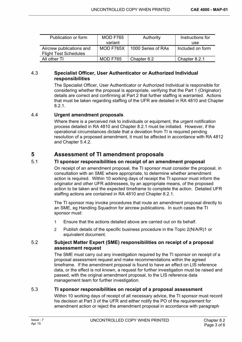
UNCONTROLLED COPY WHEN PRINTED CAE 4000 - MAP-01
Issue - 7 Apr 15
UNCONTROLLED COPY WHEN PRINTED Chapter 8.2 Page 3 of 6
Publication or form MOD F765
variant Authority Instructions for
use Aircrew publications and Flight Test Schedules
MOD F765X 1000 Series of RAs Included on form
All other TI MOD F765 Chapter 8.2 Chapter 8.2.1 4.3 Specialist Officer, User Authenticator or Authorized Individual
responsibilities The Specialist Officer, User Authenticator or Authorized Individual is responsible for considering whether the proposal is appropriate, verifying that the Part 1 (Originator) details are correct and confirming at Part 2 that further staffing is warranted. Actions that must be taken regarding staffing of the UFR are detailed in RA 4810 and Chapter 8.2.1.
4.4 Urgent amendment proposals Where there is a perceived risk to individuals or equipment, the urgent notification process detailed in RA 4810 and Chapter 8.2.1 must be initiated. However, if the operational circumstances dictate that a deviation from TI is required pending resolution of a proposed amendment, it must be affected in accordance with RA 4812 and Chapter 5.4.2.
5 Assessment of TI amendment proposals 5.1 TI sponsor responsibilities on receipt of an amendment proposal
On receipt of an amendment proposal, the TI sponsor must consider the proposal, in consultation with an SME where appropriate, to determine whether amendment action is required. Within 10 working days of receipt the TI sponsor must inform the originator and other UFR addressees, by an appropriate means, of the proposed action to be taken and the expected timeframe to complete the action. Detailed UFR staffing actions are contained in RA 4810 and Chapter 8.2.1.
The TI sponsor may invoke procedures that route an amendment proposal directly to an SME, eg Handling Squadron for aircrew publications. In such cases the TI sponsor must:
1 Ensure that the actions detailed above are carried out on its behalf.
2 Publish details of the specific business procedure in the Topic 2(N/A/R)1 or equivalent document.
5.2 Subject Matter Expert (SME) responsibilities on receipt of a proposal assessment request The SME must carry out any investigation required by the TI sponsor on receipt of a proposal assessment request and make recommendations within the agreed timeframe. If the amendment proposal is found to have an effect on LIS reference data, or the effect is not known, a request for further investigation must be raised and passed, with the original amendment proposal, to the LIS reference data management team for further investigation.
5.3 TI sponsor responsibilities on receipt of a proposal assessment Within 10 working days of receipt of all necessary advice, the TI sponsor must record his decision at Part 3 of the UFR and either notify the PO of the requirement for amendment action or reject the amendment proposal in accordance with paragraph
CAE 4000 - MAP-01 UNCONTROLLED COPY WHEN PRINTED
Chapter 8.2 Page 4 of 6
UNCONTROLLED COPY WHEN PRINTED Issue - 7 Apr 15
5.4. The time from receipt of the amendment proposal to the TI sponsor completing Part 3 should not exceed 3 months. Where the process takes significantly longer than the timeframe originally notified, the TI sponsor is responsible for providing appropriate additional feedback to the UFR addressees.
5.4 Rejection of amendment proposals In the event that an amendment proposal is rejected, the TI sponsor must state in Part 3 the reasons for the rejection (including details of any alternative actions being taken) and inform the originator and all UFR addressees.
6 Promulgation of amendments to TI other than forms 6.1 General
Amendments to TI other than forms must be promulgated with one of the following 3 urgencies:
1 Routine – where information is issued on an agreed formal amendment cycle as a one-for-one replacement page or publication.
2 Rapid – where urgent information is required to be distributed outside the formal amendment cycle.
3 Immediate – where information is required to be distributed very quickly, normally in less than 24 hours.
Note:
Rapid or Immediate amendments involve the inclusion of additional data, or of handwritten amendments, but do not amend the master data set held by, or on behalf of, the TI sponsor.
The selection of the most appropriate amendment process must be based on the perceived urgency of the amendment, the expected speed of the amendment processes or the contractual, or other agreements, between the TI sponsor and an SME. In all cases the TI sponsor must ensure that an immediate amendment process is available.
6.2 TI sponsor responsibilities The TI sponsor must determine the most appropriate amendment procedure and, within 10 working days of the decision, notify the outcome to the originator and other addressees. Whenever possible, the routine amendment procedure should be used; however, if this procedure is considered unsuitable, a rapid or immediate process, such as the Advance Information Leaflet (AIL) or Service Amendment Leaflet (SAL), or, for aircrew publications, an Advance Notice of Amendment (ANA) – all detailed in RA 4810 and Chapter 8.2.2 – should be used. When an amendment proposal identifies an error or omission that, in the opinion of the TI sponsor, could endanger personnel or equipment (see paragraph 4.4), the TI sponsor need carry out only those actions detailed above that are necessary to provide suitable advice to promulgate an Immediate amendment. Further action should then be taken to produce a formal amendment, an AIL, SAL or ANA, or issue a new data module.
6.3 Amendments to legacy TI For legacy publications, the timeframes detailed at paragraph 6.1 are met using the following processes:
1 Formal Amendment – Authorized for use and issued by, or on behalf of, the TI sponsor. The formal amendment is issued through a formal print contract and
UNCONTROLLED COPY WHEN PRINTED CAE 4000 - MAP-01
Issue - 7 Apr 15
UNCONTROLLED COPY WHEN PRINTED Chapter 8.2 Page 5 of 6
meets the routine timeframe. In the case of Designer-produced data, a formal amendment is issued with the full agreement of the Designer.
2 AIL, SAL or ANA – Authorized for use and issued by, or on behalf of, the TI sponsor. The AIL/SAL should be issued through the Joint Support Chain (JSC) Logistics Commodities and Services (LCS) to meet the rapid timeframe, or by the fastest means available to meet the immediate timeframe; however, the TI sponsor may also consider the use of fax or electronic media to distribute an AIL/SAL. The exception to the above procedure is for aircrew publications, where Handling Sqn will issue the AIL or ANA on behalf of the TI sponsor.
Note:
Where the full amendment process may be carried out inside the MOD, such as with the amendment of schedules, the formal amendment may be as quick as the Rapid amendment and the use of an AIL may not be necessary.
7 Promulgation of amendments to forms DSA MAA REG CAw sponsors all common-use forms contained in the Manual of Maintenance and Airworthiness Process Supplement - MOD Form 700 Series of Forms (MAP-02) and available to order from LCS. Aircraft or equipment-specific forms are sponsored and approved by the individual Project Team (PT) and authorized for use by DSA MAA REG Caw MAPLIS. Amendments to forms must be promulgated to meet one of the following 3 timeframes:
1 Routine – the form is re-issued in line with the normal print cycle (ie when all existing forms have been used).
2 Rapid – the form is sent for printing immediately after approval by the PT and authorized by DSA MAA REG Caw MAPLIS, once available for issue, replaces the superseded form. The normal print cycle will take up to 6 weeks before a form becomes available for issue from LCS and available to view in the MAP-02.
3 Immediate – where an error or omission in a form has airworthiness or safety implications, DSA MAA REG Caw MAPLIS will prioritize development of a new/revised form; which may, in extremes, be printed directly from the MAP-02 (refer to MAP-02 Chap 1.1). The form sponsor is responsible for determining cutover procedures.
8 Amendment processes for Electronic TI (ETI) The amendment process for ETI is the same as that for all other TI and forms, unless dispensation has been granted in accordance with paragraph 2. Specific considerations when proposing electronic amendment processes are detailed below:
1 Where an electronic procedure is used to propose and or promulgate amendments to ETI, the procedures should be as detailed in Def Stan 00-600 Integrated Logistic Support and JSP 886 Vol 7 Pt 8.05 Technical Documentation.
2 The alternative closed-loop notification system must provide a record of the receipt of the amendment proposal notification and/or promulgation, which can be retained by the sender. The response should be produced by a positive action by the recipient and consequently, where e-mail is used, an automated ‘read receipt’ is not considered sufficient.
CAE 4000 - MAP-01 UNCONTROLLED COPY WHEN PRINTED
Chapter 8.2 Page 6 of 6
UNCONTROLLED COPY WHEN PRINTED Issue - 7 Apr 15
9 References This chapter refers to the following publication:
1 Topic 2(N/A/R)1 – General Orders and Special Instructions.
2 Def Stan 00-600 Integrated Logistic Support.
3 JSP 886 Vol 7 Pt 8.05 Technical Documentation.
UNCONTROLLED COPY WHEN PRINTED CAE 4000 - MAP-01
Issue - 7 Apr 15
UNCONTROLLED COPY WHEN PRINTED Chapter 8.2.1 Page 1 of 4
Chapter 8.2.1
MOD Form 765 – Unsatisfactory Feature Report for Military Air Environment Technical Information – Process
TABLE OF CONTENTS Paragraph
Page
1 General ............................................................................................................... 1 1.1 Introduction.......................................................................................................... 1 1.2 Applicability ......................................................................................................... 1 1.3 Terms used ......................................................................................................... 1 2 Regulatory Governance.................................................................................... 2 2.1 Regulatory Article Cross-reference ..................................................................... 2 3 Instructions for completion of MOD F765 – Unsatisfactory Feature
Report for Military Air Environment Technical Information (UFR) ............... 2 3.1 Part 1 – Actions by the originator ........................................................................ 2 3.2 Part 2 – Actions by the Specialist Officer, User Authenticator or Authorized
Individual ............................................................................................................. 3 3.3 Part 3 – Actions by the TI sponsor ...................................................................... 3 3.4 Part 4 – Actions by the Publication Organization (PO)........................................ 3 4 Notification of urgent amendment proposals................................................. 3 4.1 Specific considerations when raising an urgent amendment proposal against
aircrew publications............................................................................................. 4 5 Retention and disposal of completed UFRs ................................................... 4
LIST OF TABLES Table 1. Layout of an Urgent Amendment Proposal. ...................................................................4
1 General 1.1 Introduction
The MOD F765, Unsatisfactory Feature Report for Military Air Environment Technical Information (UFR) process and, where necessary, the subsequent Advance Information Leaflet (AIL) and Service Amendment Leaflet (SAL) procedures, provide an Acceptable Means of Compliance (AMC) with the Technical Information (TI) amendment policy detailed in RA 4810 and Chapter 8.2. This chapter details the UFR process.
1.2 Applicability This chapter is applicable to all TI (which includes Electronic TI (ETI), MOD forms and posters) used in the Military Air Environment (MAE), regardless of their format.
1.3 Terms used The term UFR is used throughout to refer to the MOD F765, Unsatisfactory Feature Report for Military Air Environment Technical Information. The term ‘TI sponsor’ is used throughout and applies to all sponsors of TI used in the MAE.
CAE 4000 - MAP-01 UNCONTROLLED COPY WHEN PRINTED
Chapter 8.2.1 Page 2 of 4
UNCONTROLLED COPY WHEN PRINTED Issue - 7 Apr 15
2 Regulatory Governance 2.1 Regulatory Article Cross-reference
This chapter supports:
1 RA 4810(3)
3 Instructions for completion of MOD F765 – Unsatisfactory Feature Report for Military Air Environment Technical Information (UFR) The UFR is used to notify and document subsequent actions relating to proposed amendments to TI in the MAE. Where there is a perceived risk to personnel or equipment, the originator may use the notification of urgent amendment proposal procedure detailed at paragraph 4. In either case, the amendment proposal must be sent to the TI sponsor, who is responsible for ensuring that the proposal is assessed and, where approved, forwarded to the Publication Organization (PO) for promulgation.
Where a form is passed by e-mail between organizations for action, a facsimile signature should not be used in any signature block. Organizations documenting their action are to place a signed copy on file and annotate “File Copy Signed” in the relevant block of the e-mailed version.
3.1 Part 1 – Actions by the originator The criteria for raising a UFR are at Chapter 8.2. The originator must carry out the following actions:
1 Complete all fields in Part 1 of the UFR.
2 Allocate a unique reference number to the UFR. Where possible, the reference number should comprise the precursor ‘765’, the Flight, Squadron, Workshop or Regiment Identification number or name, a Unit/Location Code as detailed in Chapter 0.6, a 4-figure year identifier and an in-year counter. For example, 765/3AAC/WAT/2014/4 indicates the 4th UFR raised by 3 Regiment Army Air Corps, based at Wattisham in 2014.
3 Ensure that the Originator’s Report gives full and precise details of the proposed amendment, using continuation sheets as required. For data relating to Logistics Information Systems (LIS), this should include a statement as to whether the data affected is business data or reference data (where appropriate). If the report relates to LIS reference data, the affected items are to be detailed in this area, including any reference to equipment-specific information (eg a Request For Change (RFC) or a REMEDY record number).
4 Certify completion of Part 1 of the UFR by signing in the Originator’s Signature box and entering the relevant details in the associated fields.
5 Pass the UFR to the organization’s Specialist Officer, User Authenticator or Authorized Individual for consideration.
Notes:
1 For units or organizations that do not have an identification number, a suitable alternative must be used, such as ‘A830’ for A Flight in 830 Sqn, ‘GEF’ for a Ground Equipment Flight, ‘AT’ for the Apache Team or ‘BAE’ for BAE Systems.
2 Ships may use their deck marking letters.
UNCONTROLLED COPY WHEN PRINTED CAE 4000 - MAP-01
Issue - 7 Apr 15
UNCONTROLLED COPY WHEN PRINTED Chapter 8.2.1 Page 3 of 4
3.2 Part 2 – Actions by the Specialist Officer, User Authenticator or Authorized Individual Within 10 working days of receipt of a UFR, the Specialist Officer, User Authenticator or Authorized Individual at the Originating Unit must carry out the following actions:
1 Ensure that Part 1 of the UFR has been accurately and fully completed.
2 Consider Part 1 of the UFR to determine whether the proposal is appropriate and if further staffing is required. UFRs that warrant further staffing are to be supported with any appropriate information required for the recommended change.
3 Complete the Specialist Officer, User Authenticator or Authorized Individual’s Report at Part 2, stating whether the proposal is approved or rejected.
4 Certify completion of Part 2 of the UFR by signing in the Signature box and entering the relevant details in the associated fields. Approved UFRs are to be passed to the TI sponsor with an information copy sent to the originator’s Front Line Command (FLC), where appropriate. UFRs that are not approved must be returned to the originator, complete with appropriate feedback regarding the reason for non-approval.
3.3 Part 3 – Actions by the TI sponsor On receipt of a UFR, the TI sponsor must carry out the following actions:
1 Register receipt of the UFR and confirm receipt to the originator within 10 working days.
2 Consider the UFR in consultation with any appropriate Subject Matter Expert (SME) and agree or reject the proposal. SME responsibilities with regard to UFRs are detailed at RA 4810 and Chapter 8.2.
3 Complete Part 3 of the UFR and notify the originator and any information addressees of the outcome and the action to be taken. Where the proposal is approved, send the UFR to the PO with the necessary publishing instructions. Where the proposal is rejected, send copies of the UFR to the original UFR action and info addressees as detailed in RA 4810 and Chapter 8.2.
3.4 Part 4 – Actions by the Publication Organization (PO) On receipt of a UFR, the PO is to notify the TI sponsor and the UFR originator, using Part 4 of the form, confirming the action taken and the expected date of issue of the amendment.
4 Notification of urgent amendment proposals Urgent amendment proposals must be forwarded to the TI sponsor by the most suitable means (ie fax, email, signal (where available)) and followed within 5 working days by a UFR bearing the originator’s urgent amendment proposal reference. The urgent amendment proposal reference number must be the same as that for the follow-up UFR (see paragraph 3.1). The information required is detailed in Table 1 below. For amendments to TI containing maintenance data, the proposal must detail the TI sponsor as an action addressee; an information copy must be sent to the FLC of the originating organization, the relevant Continuing Airworthiness Management Organization (CAMO) and the PO of the TI affected.
For signals, precedence must be at least PRIORITY for action addressees and ROUTINE for information addressees.
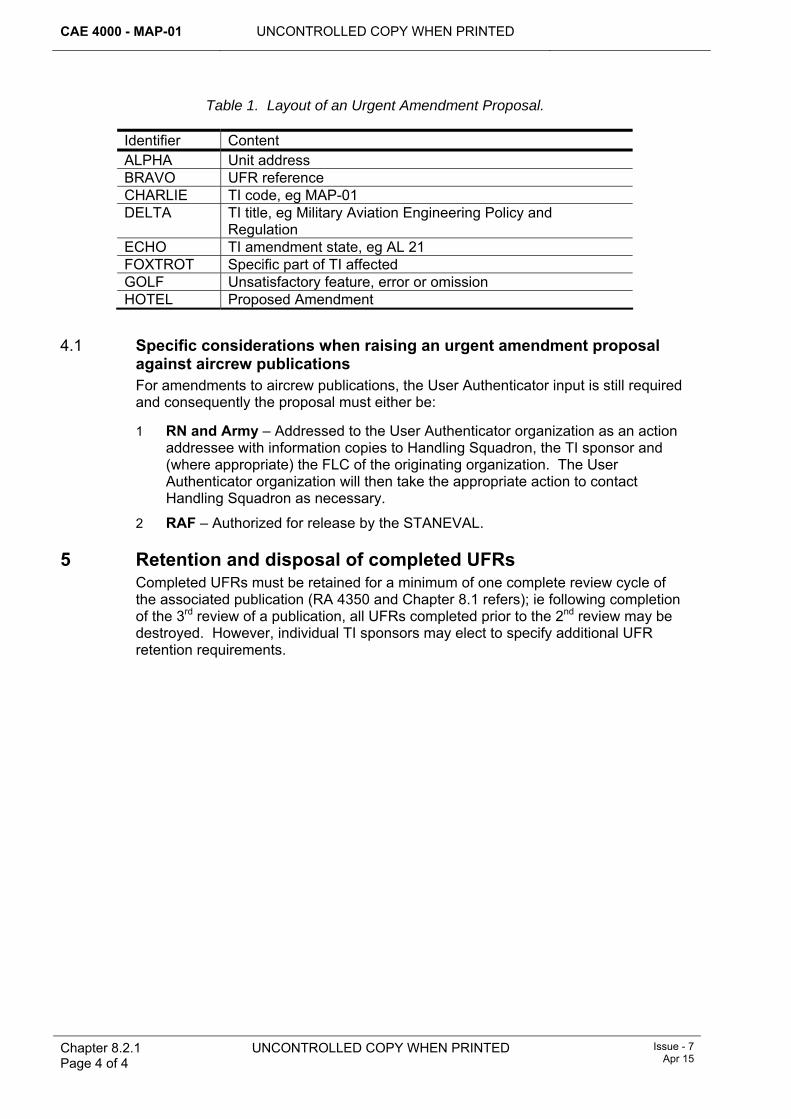
CAE 4000 - MAP-01 UNCONTROLLED COPY WHEN PRINTED
Chapter 8.2.1 Page 4 of 4
UNCONTROLLED COPY WHEN PRINTED Issue - 7 Apr 15
Table 1. Layout of an Urgent Amendment Proposal.
Identifier Content ALPHA Unit address BRAVO UFR reference CHARLIE TI code, eg MAP-01 DELTA TI title, eg Military Aviation Engineering Policy and
Regulation ECHO TI amendment state, eg AL 21 FOXTROT Specific part of TI affected GOLF Unsatisfactory feature, error or omission HOTEL Proposed Amendment
4.1 Specific considerations when raising an urgent amendment proposal
against aircrew publications For amendments to aircrew publications, the User Authenticator input is still required and consequently the proposal must either be:
1 RN and Army – Addressed to the User Authenticator organization as an action addressee with information copies to Handling Squadron, the TI sponsor and (where appropriate) the FLC of the originating organization. The User Authenticator organization will then take the appropriate action to contact Handling Squadron as necessary.
2 RAF – Authorized for release by the STANEVAL.
5 Retention and disposal of completed UFRs Completed UFRs must be retained for a minimum of one complete review cycle of the associated publication (RA 4350 and Chapter 8.1 refers); ie following completion of the 3rd review of a publication, all UFRs completed prior to the 2nd review may be destroyed. However, individual TI sponsors may elect to specify additional UFR retention requirements.
UNCONTROLLED COPY WHEN PRINTED CAE 4000 - MAP-01
Issue - 7 Apr 15
UNCONTROLLED COPY WHEN PRINTED Chapter 8.2.2 Page 1 of 8
Chapter 8.2.2
Amendments to Technical Information using the Advance Information Leaflet, the Service Amendment Leaflet or the Advance
Notification of Amendment
TABLE OF CONTENTS Paragraph
Page
1 General ............................................................................................................... 1 1.1 Introduction.......................................................................................................... 1 1.2 Applicability ......................................................................................................... 2 2 Regulatory Governance.................................................................................... 2 2.1 Regulatory Article cross-reference ...................................................................... 2 3 Amendment by Advance Information Leaflet (AIL) ........................................ 2 3.1 General................................................................................................................ 2 3.2 Responsibilities of the Technical Information (TI) sponsor.................................. 2 3.3 Responsibilities of the Publication Organization (PO)......................................... 2 3.4 Follow-up actions ................................................................................................ 3 4 Amendment by Service Amendment Leaflet (SAL)........................................ 3 4.1 General................................................................................................................ 3 4.2 Responsibilities of the TI sponsor ....................................................................... 3 4.3 Responsibilities of the PO ................................................................................... 4 5 Promulgation of an amendment ...................................................................... 4 6 Layout of AILs and SALs.................................................................................. 5 6.1 AIL terminating notes .......................................................................................... 5 6.2 SAL terminating notes ......................................................................................... 5 7 References ......................................................................................................... 6
LIST OF TABLES Table 1. Layout of an AIL or SAL..................................................................................................5
LIST OF FIGURES Figure 1. Layout of an AIL or SAL. ...............................................................................................7
1 General 1.1 Introduction
The Advance Information Leaflet (AIL), the Service Amendment Leaflet (SAL) and the Advance Notification of Amendment (ANA) provide methods by which the Services can amend their Technical Information (TI) more rapidly than by formal amendment, either in advance of formal Design Organization (DO) approval or when the amendment is a result of a Service Modification (SM). An AIL or ANA is used to promulgate advance information of a change to the publication, or master data set, and can be used as an authority to carry out local amendments to the publication, such as a handwritten amendment. A SAL is used to promulgate new information relating to an SM, which has not been cover-modified by the DO and cannot result in any changes to the publication, or master data set.
CAE 4000 - MAP-01 UNCONTROLLED COPY WHEN PRINTED
Chapter 8.2.2 Page 2 of 8
UNCONTROLLED COPY WHEN PRINTED Issue - 7 Apr 15
1.2 Applicability This chapter is applicable to all TI sponsors required to issue amendments to TI by either an AIL, SAL or ANA. ANA are only applicable to aircrew publicationsand are issued by Handling Squadron in accordance with Defence Aircrew Documentation Specifications (DADS) which should be regarded as the authoritative source of information relating to amendment of aircrew publications.
2 Regulatory Governance 2.1 Regulatory Article cross-reference
This chapter supports:
1 RA 4810(3).
3 Amendment by Advance Information Leaflet (AIL) 3.1 General
1 An AIL allows the TI sponsor to arrange for the issue of a temporary amendment to TI in advance of formal amendment action. An immediate notification process is at paragraph 5for urgent updates, which should then be followed up by a routine AIL. Formal agreement of the DO is not required, but should be gained when the DO has an input, (eg Topic 1, where the DO has produced the original information being amended). .
If an SM necessitates a rapid temporary TI amendment, a further, superseding, SAL should be issued as detailed in paragraph 4 rather than issuing an AIL.
The incorporation of an AIL must be recorded on the "Record of AIL Incorporation" sheet contained within the preliminary pages of the TI. Although an AIL is not a formal amendment, its content is binding and must be acted upon in place of the information that it replaces. An AIL is superseded by the issue of a formal amendment.
3.2 Responsibilities of the Technical Information (TI) sponsor The TI sponsor requesting the issue of an AIL is solely responsible for the content of the AIL. The master media AIL is to be submitted to the PO in the format shown at Figure 1 or in a format consistent with that used in the TI. The covering letter is to contain the following information, where applicable:
1 Precise details of the publication to which the AIL refers.
2 Details of any actions already taken, egany urgent updates already issued.
3 A statement to the effect that Logistic Information System (LIS) reference data is/is not affected and whether or not the relevant reference data management team has been tasked with assessing the impact of the AIL.
. The TI sponsor is responsible for reviewing all outstanding AILs to ensure that formal amendment action is undertaken. The review should be conducted at least every 24 months.
3.3 Responsibilities of the Publication Organization (PO) The PO is responsible for arranging the publication and distribution of the AIL through the normal TI publication and distribution procedures. When the TI includes data owned or controlled by a DO, the PO is to forward a copy of the AIL to the DO. If the request for issue of an AIL can be met by including the required amendment in an imminent schedule amendment, the PO must obtain the approval of the TI sponsor
UNCONTROLLED COPY WHEN PRINTED CAE 4000 - MAP-01
Issue - 7 Apr 15
UNCONTROLLED COPY WHEN PRINTED Chapter 8.2.2 Page 3 of 8
and DO for this course of action. If this is not acceptable to the TI sponsor, an AIL must be issued. The production of an AIL must be given priority during printing and distribution. The PO must notify the TI sponsor of the delivery date of the AIL to the distribution agency. To ease subsequent identification, if the AIL is issued against a paper publication, it should be printed on blue paper. The choice of paper colour shade should allow for photocopying of the document without loss of clarity of the information. If the AIL is issued against electronic data or data held on other media, the change must be notified in accordance with the appropriate standards, or TI-approved, procedures.
3.4 Follow-up actions Following the issue of an AIL, the PO is responsible for taking the actions required to issue an amendment to the TI concerned, cancelling the AIL.
4 Amendment by Service Amendment Leaflet (SAL) 4.1 General
The SAL replaces the Aircraft Branch Temporary Amendment Leaflet (ABTAL), RAFTAL and RNTAL for all future SMs. Extant ABTAL, RAFTAL and RNTAL need not be replaced by a SAL until they are reviewed or amended. A SAL must be issued to introduce TI relating to an SM that has not been made the subject of a Design cover modification. It may be re-issued because of an amendment proposal. The specific responsibilities for producing a new SM are at RA 5308. Whilst many SMs are subsequently replaced by cover modification(s), there are occasions where the Services will not pursue a Design cover modification: in these instances the SAL is to remain extant for the life of the SM. The incorporation of a SAL must be recorded on the "Record of SAL Incorporation" sheet contained within the preliminary pages of the TI. Although a SAL is not a formal amendment, its content is binding and must be acted upon when working with the equipment to which it refers. A SAL must be cancelled by instructions for its removal from theTAA/TI Sponsor:
1 As a result of the SM being subject to a Designer cover modification and its associated TI amendment.
2 Where the SM is no longer required.
The SAL must be issued as an insertion to the affected TI and is not to require permanent alteration or defacement of the TI by adhesion, ink annotation or other means.
4.2 Responsibilities of the TI sponsor In producing a SAL, the TI sponsor is required to consult all necessary agencies. This consultation process must include an assessment on the impact that the SAL may have on LIS reference data. If it is found that reference data will be affected, or the effect is not known, a request for further investigation must be raised and passed, with a copy of the SAL, to the LIS reference data management team. The TI sponsor requesting the issue of a SAL is solely responsible for the content of the SAL. The master media SAL must be submitted to the PO in the format shown at Figure 1 or in a format consistent with that used in the TI. The covering letter must contain the following information:
1 Precise details of the publication to which the SAL refers.
2 Details of any actions already taken, eg the media by which the SAL was issued.
CAE 4000 - MAP-01 UNCONTROLLED COPY WHEN PRINTED
Chapter 8.2.2 Page 4 of 8
UNCONTROLLED COPY WHEN PRINTED Issue - 7 Apr 15
3 A statement to the effect that LIS reference data is/is not affected and whether or not the relevant reference data management team has been tasked with assessing the impact of the SAL.
The TI sponsor must review all SALs annually. Where cover modification action is undertaken, the TI sponsor is responsible for the follow-up actions required to procure a Design cover modification leaflet or to cancel the SAL in conjunction with the PO.
4.3 Responsibilities of the PO The PO is responsible for arranging the publication and distribution of the SAL through the normal TI publication and distribution procedures. The SAL must be given priority during printing and distribution. The PO must notify the TI sponsor of the delivery date of the SAL to the distribution agency. To ease subsequent identification, if the SAL is issued against a paper publication, it should be printed on yellow paper. The choice of paper colour shade should allow for photocopying of the document without loss of clarity of the information. If the amendment is to electronic data or data held on other media, the change must be notified in accordance with the appropriate standards.
5 Promulgation of urgent amendments The TI sponsor may issue an AIL/SAL by the most expeditiousmeans available, when there is a perceived risk to personnel or equipment, or if it is considered that the routine AIL/SAL procedure is inappropriate.
The AIL/SAL must contain the following information:
1 Precise details of the publication affected.
2 Explicit instructions as to how to effect the required changes.
3 For AILs that necessitate the insertion of hand written text, either:
3.1 An exact copy of the text that will be issued as part of any forthcoming amendment action, or:
3.2 If the text may be subject to amendment post-DO, or other authority, validation, the best available text.
4 In cases where LIS reference data is affected, a statement to that effect must be included.
5 Details of any amendment action that will follow and a statement that the AIL/SAL is cancelled on receipt of the amendment action.
Table 1 gives the layout that must be used for all urgent submissions. Once the initial requirement to notify holders has been met, the TI sponsor must initiate formal amendment, AIL or SAL action as detailed elsewhere in this chapter. Urgent amendments must be superseded by an amendment, AIL or SAL within 6 months.
Note:
For signal use - When information such as a diagram or amendment to electronic TI is required to be transmitted, the TI sponsor is still required to send a signal notifying all organizations of the AIL or SAL and then forward that information by the most suitable means.
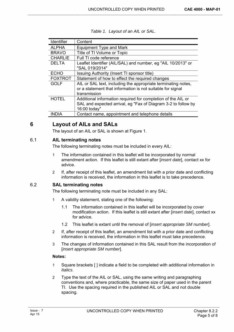
UNCONTROLLED COPY WHEN PRINTED CAE 4000 - MAP-01
Issue - 7 Apr 15
UNCONTROLLED COPY WHEN PRINTED Chapter 8.2.2 Page 5 of 8
Table 1. Layout of an AIL or SAL.
Identifier Content ALPHA Equipment Type and Mark BRAVO Title of TI Volume or Topic CHARLIE Full TI code reference DELTA Leaflet Identifier (AIL/SAL) and number, eg "AIL 10/2013" or
"SAL 019/2014" ECHO Issuing Authority (Insert TI sponsor title) FOXTROT Statement of how to effect the required changes GOLF AIL or SAL text, including the appropriate terminating notes,
or a statement that information is not suitable for signal transmission
HOTEL Additional information required for completion of the AIL or SAL and expected arrival, eg "Fax of Diagram 3-2 to follow by 16:00 today"
INDIA Contact name, appointment and telephone details
6 Layout of AILs and SALs The layout of an AIL or SAL is shown at Figure 1.
6.1 AIL terminating notes The following terminating notes must be included in every AIL:
1 The information contained in this leaflet will be incorporated by normal amendment action. If this leaflet is still extant after [insert date], contact xx for advice.
2 If, after receipt of this leaflet, an amendment list with a prior date and conflicting information is received, the information in this leaflet is to take precedence.
6.2 SAL terminating notes The following terminating note must be included in any SAL:
1 A validity statement, stating one of the following:
1.1 The information contained in this leaflet will be incorporated by cover modification action. If this leaflet is still extant after [insert date], contact xx for advice.
1.2 This leaflet is extant until the removal of [insert appropriate SM number].
2 If, after receipt of this leaflet, an amendment list with a prior date and conflicting information is received, the information in this leaflet must take precedence.
3 The changes of information contained in this SAL result from the incorporation of [insert appropriate SM number].
Notes:
1 Square brackets [ ] indicate a field to be completed with additional information in Italics.
2 Type the text of the AIL or SAL, using the same writing and paragraphing conventions and, where practicable, the same size of paper used in the parent TI. Use the spacing required in the published AIL or SAL and not double spacing.
CAE 4000 - MAP-01 UNCONTROLLED COPY WHEN PRINTED
Chapter 8.2.2 Page 6 of 8
UNCONTROLLED COPY WHEN PRINTED Issue - 7 Apr 15
3 To achieve a rapid issue, the draft AIL or SAL will not be referred elsewhere for checking or comment. The originator is therefore wholly responsible for the clarity, adequacy and accuracy of the draft. If a draft AIL is being prepared, inclusion of all the detail as and where described in this layout, and the use of capitals and bolding where, and only where, shown, will materially assist the PO concerned.
4 Position the terminating note(s) at the bottom of the page as shown, regardless of where the text ends.
7 References This chapter refers to the following publications:
1 Defence Aircrew Documentation Specifications (DADS); available on the Handling Squadron web site.
2 .
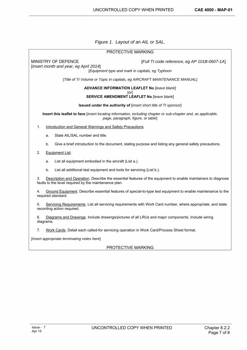
UNCONTROLLED COPY WHEN PRINTED CAE 4000 - MAP-01
Issue - 7 Apr 15
UNCONTROLLED COPY WHEN PRINTED Chapter 8.2.2 Page 7 of 8
Figure 1. Layout of an AIL or SAL.
PROTECTIVE MARKING
MINISTRY OF DEFENCE [Full TI code reference, eg AP 101B-0607-1A] [Insert month and year, eg April 2014]
[Equipment type and mark in capitals, eg Typhoon
[Title of TI Volume or Topic in capitals, eg AIRCRAFT MAINTENANCE MANUAL]
ADVANCE INFORMATION LEAFLET No [leave blank] [or]
SERVICE AMENDMENT LEAFLET No [leave blank]
Issued under the authority of [insert short title of TI sponsor]
Insert this leaflet to face [insert locating information, including chapter or sub-chapter and, as applicable, page, paragraph, figure, or table]
1. Introduction and General Warnings and Safety Precautions.
a. State AIL/SAL number and title. b. Give a brief introduction to the document, stating purpose and listing any general safety precautions.
2. Equipment List.
a. List all equipment embodied in the aircraft (List a.). b. List all additional test equipment and tools for servicing (List b.).
3. Description and Operation. Describe the essential features of the equipment to enable maintainers to diagnose faults to the level required by the maintenance plan. 4. Ground Equipment. Describe essential features of special-to-type test equipment to enable maintenance to the required standard. 5. Servicing Requirements. List all servicing requirements with Work Card number, where appropriate, and state recording action required. 6. Diagrams and Drawings. Include drawings/pictures of all LRUs and major components. Include wiring diagrams. 7. Work Cards. Detail each called-for servicing operation in Work Card/Process Sheet format.
[Insert appropriate terminating notes here]
PROTECTIVE MARKING

CAE 4000 - MAP-01 UNCONTROLLED COPY WHEN PRINTED
Chapter 8.2.2 Page 8 of 8
UNCONTROLLED COPY WHEN PRINTED Issue - 7 Apr 15
Intentionally Blank for Print Pagination
UNCONTROLLED COPY WHEN PRINTED
CAE 4000 - MAP-01
Issue - 7 Apr 15
UNCONTROLLED COPY WHEN PRINTED Chapter 8.4 Page 1 of 6
Chapter 8.4
Topic 2(N-A-R) – General Orders, Special Instructions and Modifications
TABLE OF CONTENTS Paragraph
Page
1 General ............................................................................................................... 1 1.1 Introduction.......................................................................................................... 1 1.2 Associated instructions........................................................................................ 1 1.3 Definitions............................................................................................................ 2 2 Regulatory Governance.................................................................................... 2 2.1 Regulatory Article Cross-reference ..................................................................... 2 2.2 Additional Information.......................................................................................... 2 3 Topic 2(N/A/R) – General Orders, Special Instructions and Modifications.. 2 4 Layout of Topic 2(N/A/R) .................................................................................. 2 4.1 Topic 2(N/A/R)1 – General Orders and Special Instructions............................... 3 4.2 Topic 2(N/A/R)2 – Service Modifications (SMs) .................................................. 3 4.3 Topic 2(N/A/R)3 – Service Engineered Aircraft Radio Installation Modifications
(SRIMs) (Obsolete) ............................................................................................. 3 4.4 Topic 2(N/A/R)4 – Special Trial Fits (STFs) (Obsolete) ...................................... 3 4.5 Additional Topic 2(N/A/R) sub-topics .................................................................. 4 5 Omnibus topics ................................................................................................. 4 6 Publication and amendment action................................................................. 4 7 Responsibilities................................................................................................. 4 7.1 Type Airworthiness Authority (TAA)/commodity Project Team (PT).................... 4 8 Reference ........................................................................................................... 5
LIST OF TABLES Table 1. MAP-01 Chapters that Require TAAs/commodity PTs to Include Information in the
Topic 2(N/A/R) Series. ......................................................................................................4
1 General 1.1 Introduction
The aircraft and/or equipment Topic 2 deals with Design Organization modifications. However, there are instances where TAAs and commodity PTs need to promulgate specific information relating to their aircraft and/or equipment. The Topic 2(N/A/R) series – General Orders, Special Instructions and Service Modifications, is a tri-Service publication, which provides the means for TAAs/commodity PTs to publish their aircraft and/or equipment-specific orders, special instructions and modifications. Additionally, the MAP-01 chapters listed in Table 1 require TAAs/commodity PTs to include specific information in the Topic 2(N/A/R).
1.2 Associated instructions This chapter is associated with the following instructions:
1 JAP 100C-20 – Preparation and Amendment of Maintenance Schedules.
2 Acquisition Operating Framework (AOF)
CAE 4000 - MAP-01 UNCONTROLLED COPY WHEN PRINTED
Chapter 8.4 Page 2 of 6
UNCONTROLLED COPY WHEN PRINTED Issue - 7 Apr 15
3 DAvP 70 – Specification for Air Technical Publications.
4 JSP(D) 543 – Defence Technical Documentation – Policy & Requirements.
1.3 Definitions The designators (N/A/R) denote the applicability of the publication with regard to each of the 3 services, where N is for the Royal Navy, A is for the Army and R is for the Royal Air Force. This identifies that the General Orders, Special Instructions and Modifications have been authorized for aircraft and/or equipment used by the respective Service. Thus a Topic 2(A/R) indicates that this Topic 2 is authorized for aircraft and/or equipments used by the Army and the RAF, whilst a Topic 2(A) indicates that the Topic 2 is authorized for aircraft and/or equipment used only by the Army.
2 Regulatory Governance 2.1 Regulatory Article Cross-reference
This chapter supports:
1 RA 4356.
2.2 Additional Information Nil.
3 Topic 2(N/A/R) – General Orders, Special Instructions and Modifications Where an aircraft type has more than one mark, TAAs may adopt single all-marks Topic 2(N/A/R) or produce a Topic 2(N/A/R) for each individual mark of aircraft. A suggested layout is contained in this chapter.
Commodity PTs must use the Topic 2(N/A/R) series as described in this chapter. However, where it is more cost-effective to do so, they may publish their General Orders, Special Instructions and Modifications in the relevant aircraft Topic 2(N/A/R), following agreement with the appropriate aircraft TAA.
FLCs, with the agreement of the relevant TAA and/or commodity PT, may publish aircraft and/or equipment-specific information within the relevant Topic 2(N/A/R).
4 Layout of Topic 2(N/A/R) The following paragraphs detail a suggested layout for the for the Topic 2(N/A/R) series of publications. The TAA / commodity PT may change this layout to meet specific requirements; however, it must contain the detail described in this chapter. The layout for each Topic 2(N/A/R) must be stated in the aircraft and/or equipment Support Policy Statement (SPS). The Topic 2(N/A/R) is sub-divided into the following sub-topics:
1 Topic 2(N/A/R)1 – General Orders and Special Instructions.
2 Topic 2(N/A/R)2 – Service Modifications (SM).
3 Topic 2(N/A/R)3 – Service Engineered Aircraft Radio Installation Modifications (SRIMs) (obsolete).
4 Topic 2(N/A/R)4 – Special Trial Fits (STF) (obsolete).
Topics 2(N/A/R)2, 3 and 4 need only be published for aircraft, equipment and omnibus ranges for which SMs, SRIMs or STFs have been issued.
UNCONTROLLED COPY WHEN PRINTED CAE 4000 - MAP-01
Issue - 7 Apr 15
UNCONTROLLED COPY WHEN PRINTED
Chapter 8.4 Page 3 of 6
4.1 Topic 2(N/A/R)1 – General Orders and Special Instructions The Topic 2(N/A/R)1 is divided into a minimum of 3 parts, each with its own index of individually numbered leaflets.
4.1.1 Part 1 – General Orders The first leaflet of Part 1 in the Topic 2(N/A/R)1 must be the SPS for the aircraft and/or equipment. The remaining leaflets must be numbered sequentially and contain those instructions required by the TAA.
4.1.2 Part 2 – Locally Manufactured Equipment (LME) Instructions dealing with LME unique to an aircraft, equipment or omnibus range must be contained in Part 2. Note: see RA 4809 and Chapter 6.3 for LME policy.
4.1.3 Part 3 – Special Instructions (Technical) Part 3 must be sub-divided into the following sections:
1 Special Technical Instructions.
2 Servicing Instructions.
3 Urgent Technical Instructions.
4 Routine Technical Instructions.
Each section must include an index that lists, by reference number and title, all instructions issued for the aircraft, equipment or omnibus range, with details of amendment, fleet/equipment range embodiment, supersession or cancellation, as appropriate. Copies of current instructions must be placed and held in the respective section. If copies of closed instructions are retained in these sections for record purposes, they must be annotated ‘CLOSED’ to identify their status.
The section indexes must be re-issued as necessary in order to keep to a minimum the number of manuscript entries generated by the issue, amendment and withdrawal of instructions.
4.2 Topic 2(N/A/R)2 – Service Modifications (SMs) The contents list of this sub-topic must be an index of all SMs raised for that aircraft, equipment or omnibus range, with details of amendment, fleet/equipment range embodiment, supersession and/or cancellation, as appropriate. Current SMs in course of fleet/equipment range embodiment must form the subsequent leaflets, with the leaflet numbers equating to the SM number.
4.3 Topic 2(N/A/R)3 – Service Engineered Aircraft Radio Installation Modifications (SRIMs) (Obsolete) Legacy SRIM leaflets were published in this sub-topic, together with an index of all published SRIMs, in a similar format to that for the Topic 2(N/A/R)2. Note that no new SRIMs must be developed, as the procedure has been superseded by the SM procedure; see RA 5308.
4.4 Topic 2(N/A/R)4 – Special Trial Fits (STFs) (Obsolete) The contents list to this sub-topic must list all legacy STFs issued for the aircraft or equipment type and include details of their amendment, removal and cancellation. If copies of cancelled STFs are retained in this section for record purposes, they must be annotated ‘cancelled’ to identify their status. Note that no new STFs must be
CAE 4000 - MAP-01 UNCONTROLLED COPY WHEN PRINTED
Chapter 8.4 Page 4 of 6
UNCONTROLLED COPY WHEN PRINTED Issue - 7 Apr 15
developed, as the procedure has been superseded by the SM procedure; see RA 5308.
4.5 Additional Topic 2(N/A/R) sub-topics A TAA /commodity PTs may decide that there is a requirement for additional sub-topics within its Topic 2(N/A/R) system. If they are used, the requirement must be published in the SPS. Each new sub-topic must have its own appropriately structured index and individually numbered leaflets.
5 Omnibus topics TAAs and/or commodity PTs will normally publish a discrete Topic 2(N/A/R); however, it may be more appropriate to publish an omnibus Topic 2(N/A/R) for a range of equipments when a discrete topic cannot be justified economically.
6 Publication and amendment action TAAs/commodity PTs must publish their own Topic 2(N/A/R). Amendment proposals must be forwarded to TAAs/commodity PTs on MOD F765.
7 Responsibilities 7.1 Type Airworthiness Authority (TAA)/commodity Project Team (PT)
TAAs and/or commodity PTs are responsible for:
1 The content, production and through-life management of their Topic 2(N/A/R) series.
2 Carrying out an annual review of the content of their Topic 2(N/A/R) series to ensure that the information contained is current and up-to-date.
Table 1. MAP-01 Chapters that Require TAAs/commodity PTs to Include Information in the Topic 2(N/A/R) Series.
Chapter Title Chapter 2.3 Engineering Aspects of Physical Security of Aircraft at Foreign and UK
Civilian Airfields Chapter 2.4 Royal Flights Chapter 2.5 Ground Handling of Aircraft (only glider Topic 2(N/A/R)s affected) Chapter 2.6 Fuelling Operations and AVPIN Replenishment for Aircraft on the Ground Chapter 2.8 Flight Servicing Chapter 2.9 Continuous Charge Chapter 2.11 Aircraft Displaying Abnormal Flying Characteristics Chapter 2.12 Embarked Aviation Policy Chapter 3.5 Decontamination of Aircraft After Spillage of Body Fluids Chapter 4.4 Aircraft Ground Engineers Chapter 4.5 Self-supervision Chapter 4.7.1 Authorization of Aircrew to carry Out Aircraft Maintenance Work Chapter 4.7.3 Operation of Air Transport Systems by Movements Personnel Chapter 5.1 Maintenance Policy – General Chapter 5.3.1 Lifing of Aerospace Components Chapter 5.3 Preventive Maintenance Chapter 5.4 Corrective Maintenance Chapter 5.6 Dehumidification of Aircraft
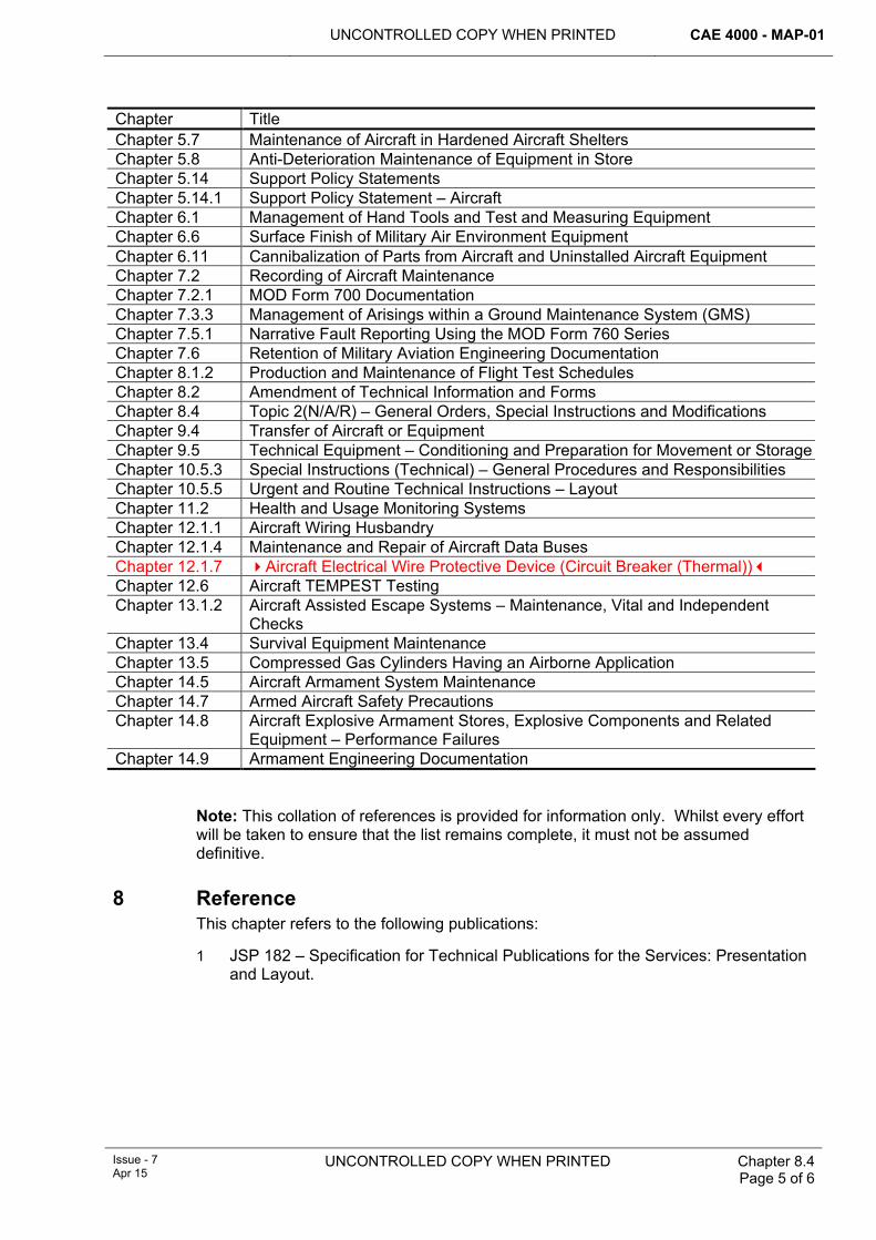
UNCONTROLLED COPY WHEN PRINTED CAE 4000 - MAP-01
Issue - 7 Apr 15
UNCONTROLLED COPY WHEN PRINTED
Chapter 8.4 Page 5 of 6
Chapter Title Chapter 5.7 Maintenance of Aircraft in Hardened Aircraft Shelters Chapter 5.8 Anti-Deterioration Maintenance of Equipment in Store Chapter 5.14 Support Policy Statements Chapter 5.14.1 Support Policy Statement – Aircraft Chapter 6.1 Management of Hand Tools and Test and Measuring Equipment Chapter 6.6 Surface Finish of Military Air Environment Equipment Chapter 6.11 Cannibalization of Parts from Aircraft and Uninstalled Aircraft Equipment Chapter 7.2 Recording of Aircraft Maintenance Chapter 7.2.1 MOD Form 700 Documentation Chapter 7.3.3 Management of Arisings within a Ground Maintenance System (GMS) Chapter 7.5.1 Narrative Fault Reporting Using the MOD Form 760 Series Chapter 7.6 Retention of Military Aviation Engineering Documentation Chapter 8.1.2 Production and Maintenance of Flight Test Schedules Chapter 8.2 Amendment of Technical Information and Forms Chapter 8.4 Topic 2(N/A/R) – General Orders, Special Instructions and Modifications Chapter 9.4 Transfer of Aircraft or Equipment Chapter 9.5 Technical Equipment – Conditioning and Preparation for Movement or StorageChapter 10.5.3 Special Instructions (Technical) – General Procedures and Responsibilities Chapter 10.5.5 Urgent and Routine Technical Instructions – Layout Chapter 11.2 Health and Usage Monitoring Systems Chapter 12.1.1 Aircraft Wiring Husbandry Chapter 12.1.4 Maintenance and Repair of Aircraft Data Buses Chapter 12.1.7 Aircraft Electrical Wire Protective Device (Circuit Breaker (Thermal)) Chapter 12.6 Aircraft TEMPEST Testing Chapter 13.1.2 Aircraft Assisted Escape Systems – Maintenance, Vital and Independent
Checks Chapter 13.4 Survival Equipment Maintenance Chapter 13.5 Compressed Gas Cylinders Having an Airborne Application Chapter 14.5 Aircraft Armament System Maintenance Chapter 14.7 Armed Aircraft Safety Precautions Chapter 14.8 Aircraft Explosive Armament Stores, Explosive Components and Related
Equipment – Performance Failures Chapter 14.9 Armament Engineering Documentation
Note: This collation of references is provided for information only. Whilst every effort will be taken to ensure that the list remains complete, it must not be assumed definitive.
8 Reference This chapter refers to the following publications:
1 JSP 182 – Specification for Technical Publications for the Services: Presentation and Layout.
CAE 4000 - MAP-01 UNCONTROLLED COPY WHEN PRINTED
Chapter 8.4 Page 6 of 6
UNCONTROLLED COPY WHEN PRINTED Issue - 7 Apr 15
Intentionally Blank for Print Pagination
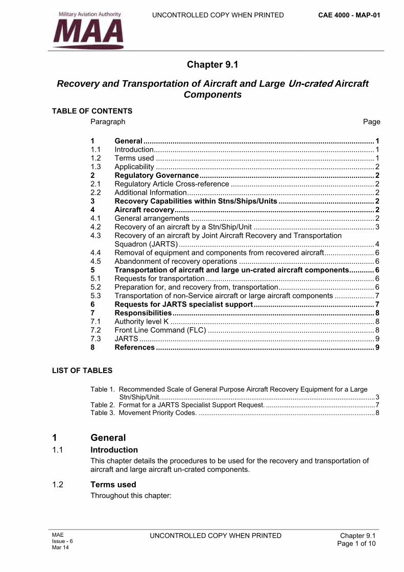
UNCONTROLLED COPY WHEN PRINTED CAE 4000 - MAP-01
MAE Issue - 6 Mar 14
UNCONTROLLED COPY WHEN PRINTED Chapter 9.1 Page 1 of 10
Chapter 9.1
Recovery and Transportation of Aircraft and Large Un-crated Aircraft Components
TABLE OF CONTENTS Paragraph
Page
1 General ............................................................................................................... 1 1.1 Introduction.......................................................................................................... 1 1.2 Terms used ......................................................................................................... 1 1.3 Applicability ......................................................................................................... 2 2 Regulatory Governance.................................................................................... 2 2.1 Regulatory Article Cross-reference ..................................................................... 2 2.2 Additional Information.......................................................................................... 2 3 Recovery Capabilities within Stns/Ships/Units .............................................. 2 4 Aircraft recovery................................................................................................ 2 4.1 General arrangements ........................................................................................ 2 4.2 Recovery of an aircraft by a Stn/Ship/Unit .......................................................... 3 4.3 Recovery of an aircraft by Joint Aircraft Recovery and Transportation
Squadron (JARTS) .............................................................................................. 4 4.4 Removal of equipment and components from recovered aircraft........................ 6 4.5 Abandonment of recovery operations ................................................................. 6 5 Transportation of aircraft and large un-crated aircraft components............ 6 5.1 Requests for transportation ................................................................................. 6 5.2 Preparation for, and recovery from, transportation.............................................. 6 5.3 Transportation of non-Service aircraft or large aircraft components ................... 7 6 Requests for JARTS specialist support.......................................................... 7 7 Responsibilities................................................................................................. 8 7.1 Authority level K .................................................................................................. 8 7.2 Front Line Command (FLC) ................................................................................ 8 7.3 JARTS................................................................................................................. 9 8 References ......................................................................................................... 9
LIST OF TABLES Table 1. Recommended Scale of General Purpose Aircraft Recovery Equipment for a Large
Stn/Ship/Unit...................................................................................................................3 Table 2. Format for a JARTS Specialist Support Request. ..........................................................7 Table 3. Movement Priority Codes. ..............................................................................................8
1 General 1.1 Introduction
This chapter details the procedures to be used for the recovery and transportation of aircraft and large aircraft un-crated components.
1.2 Terms used Throughout this chapter:
CAE 4000 - MAP-01 UNCONTROLLED COPY WHEN PRINTED
Chapter 9.1 Page 2 of 10
UNCONTROLLED COPY WHEN PRINTED MAE Issue - 6
Mar 14
1 ‘Aircraft transportation’ is the planned movement of un-crated aircraft and large un-crated sub-assemblies by road, sea, rail or air from one location to another.
2 ‘Aircraft recovery’ is the unscheduled requirement to move an unserviceable/crashed aircraft for subsequent repair or further investigation at another location.
1.3 Applicability This chapter applies to the recovery and transportation of UK military aircraft. In addition the Joint Aircraft Recovery and Transportation Squadron (JARTS) may, under special circumstances, be tasked with the recovery and transportation of civilian and foreign aircraft.
This chapter does not cover the transportation of crated aircraft or crated aircraft components, which is the responsibility of the Defence Support Chain Operations and Movements (DSCOM) in accordance with the arrangements detailed in JSP 327.
2 Regulatory Governance 2.1 Regulatory Article Cross-reference
This chapter supports:
1 Nil.
2.2 Additional Information This chapter does not support any Regulatory Article however the chapter details the agencies that control and support the recovery and transportation of aircraft and large un-crated aircraft components.
3 Recovery Capabilities within Stns/Ships/Units Stns/Ships/Units have varying aircraft recovery capabilities depending upon their single-Service requirements and operating environments. These capabilities must be used for the recovery and/or transportation of aircraft and large components when:
1 The task is within the resources of the Stn/Ship/Unit.
2 Personnel are suitably trained/authorized.
3 The appropriate procedure is documented in the aircraft’s technical information (TI).
Additionally, an individual holding authority level K may decide to undertake a recovery or transportation task if, for urgent operational reasons, it is not possible to wait for specialist assistance.
JARTS provides a specialist aircraft recovery and transportation service for rotary-wing aircraft, fixed-wing aircraft and large un-crated aircraft components. When a recovery or transportation task is beyond the capability of a Stn/Ship/Unit, the individual holding authority level K must request that JARTS be tasked to undertake the task in accordance with this chapter’s procedures.
4 Aircraft recovery 4.1 General arrangements
Whenever there is a requirement to recover an aircraft, the individual holding authority level K must assess whether the Stn/Ship/Unit has the capability to undertake the recovery task or whether specialist support is required from JARTS.
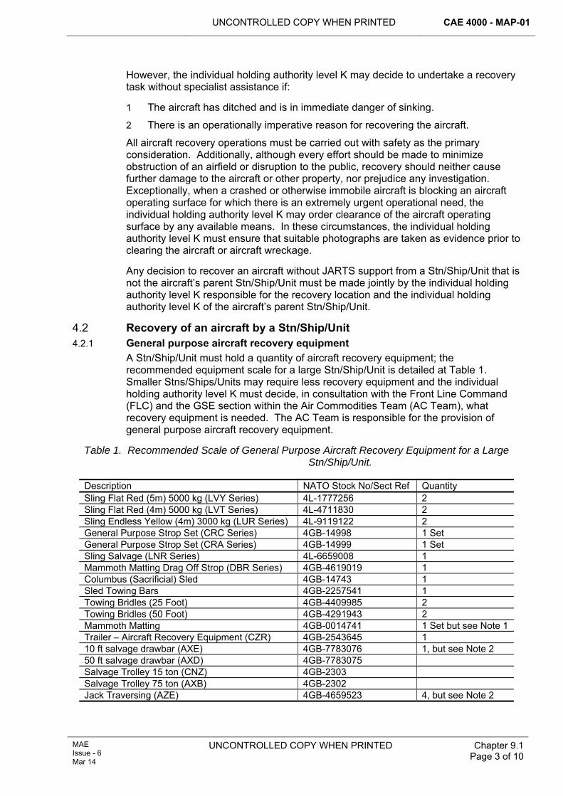
UNCONTROLLED COPY WHEN PRINTED CAE 4000 - MAP-01
MAE Issue - 6 Mar 14
UNCONTROLLED COPY WHEN PRINTED
Chapter 9.1 Page 3 of 10
However, the individual holding authority level K may decide to undertake a recovery task without specialist assistance if:
1 The aircraft has ditched and is in immediate danger of sinking.
2 There is an operationally imperative reason for recovering the aircraft.
All aircraft recovery operations must be carried out with safety as the primary consideration. Additionally, although every effort should be made to minimize obstruction of an airfield or disruption to the public, recovery should neither cause further damage to the aircraft or other property, nor prejudice any investigation. Exceptionally, when a crashed or otherwise immobile aircraft is blocking an aircraft operating surface for which there is an extremely urgent operational need, the individual holding authority level K may order clearance of the aircraft operating surface by any available means. In these circumstances, the individual holding authority level K must ensure that suitable photographs are taken as evidence prior to clearing the aircraft or aircraft wreckage.
Any decision to recover an aircraft without JARTS support from a Stn/Ship/Unit that is not the aircraft’s parent Stn/Ship/Unit must be made jointly by the individual holding authority level K responsible for the recovery location and the individual holding authority level K of the aircraft’s parent Stn/Ship/Unit.
4.2 Recovery of an aircraft by a Stn/Ship/Unit 4.2.1 General purpose aircraft recovery equipment
A Stn/Ship/Unit must hold a quantity of aircraft recovery equipment; the recommended equipment scale for a large Stn/Ship/Unit is detailed at Table 1. Smaller Stns/Ships/Units may require less recovery equipment and the individual holding authority level K must decide, in consultation with the Front Line Command (FLC) and the GSE section within the Air Commodities Team (AC Team), what recovery equipment is needed. The AC Team is responsible for the provision of general purpose aircraft recovery equipment.
Table 1. Recommended Scale of General Purpose Aircraft Recovery Equipment for a Large Stn/Ship/Unit.
Description NATO Stock No/Sect Ref Quantity Sling Flat Red (5m) 5000 kg (LVY Series) 4L-1777256 2 Sling Flat Red (4m) 5000 kg (LVT Series) 4L-4711830 2 Sling Endless Yellow (4m) 3000 kg (LUR Series) 4L-9119122 2 General Purpose Strop Set (CRC Series) 4GB-14998 1 Set General Purpose Strop Set (CRA Series) 4GB-14999 1 Set Sling Salvage (LNR Series) 4L-6659008 1 Mammoth Matting Drag Off Strop (DBR Series) 4GB-4619019 1 Columbus (Sacrificial) Sled 4GB-14743 1 Sled Towing Bars 4GB-2257541 1 Towing Bridles (25 Foot) 4GB-4409985 2 Towing Bridles (50 Foot) 4GB-4291943 2 Mammoth Matting 4GB-0014741 1 Set but see Note 1 Trailer – Aircraft Recovery Equipment (CZR) 4GB-2543645 1 10 ft salvage drawbar (AXE) 4GB-7783076 1, but see Note 2 50 ft salvage drawbar (AXD) 4GB-7783075 Salvage Trolley 15 ton (CNZ) 4GB-2303 Salvage Trolley 75 ton (AXB) 4GB-2302 Jack Traversing (AZE) 4GB-4659523 4, but see Note 2
CAE 4000 - MAP-01 UNCONTROLLED COPY WHEN PRINTED
Chapter 9.1 Page 4 of 10
UNCONTROLLED COPY WHEN PRINTED MAE Issue - 6
Mar 14
Notes:
1 Pre-stocked for logistic convenience.
2 Only for the following RAF Units – Akrotiri, Ascension, Brize Norton, Gibraltar, Lossiemouth, Mount Pleasant and Boscombe Down (custody of JARTS).
3 In addition, JARTS must hold air bag lifting equipment and lightweight matting.
4.2.2 Special-to-type aircraft recovery equipment Aircraft Project Teams (PT) are responsible for the provision of all special-to-type aircraft recovery equipment, but must agree its deployment and scaling with the appropriate FLC.
4.2.3 Reporting requirements Whenever a Stn/Ship/Unit carries out a recovery task and in doing so encounters new or unusual problems or other exceptional circumstances that warrant further staff action, the appropriate individual holding authority level K must forward a post-recovery task report to the FLC, the relevant Type Airworthiness Authority (TAA) and JARTS. The report must include the following:
1 A brief description of the occurrence that necessitated the recovery.
2 A summary of the recovery operation, including details of equipment used and its effectiveness.
3 Any recommendations, in terms of equipment or training that would facilitate any similar recovery tasks.
FLCs must co-ordinate all post-recovery task reports, investigate any shortcomings in equipment or training and take remedial action to address these shortcomings. Specialist departments (including the AC Team and JARTS) must advise on future equipment and training requirements as required.
4.3 Recovery of an aircraft by Joint Aircraft Recovery and Transportation Squadron (JARTS)
4.3.1 General arrangements Whenever the recovery of an aircraft is beyond the capabilities of a Stn/Ship/Unit, JARTS must carry out the recovery task. Requests for JARTS specialist support must be made in accordance with paragraph 6 however, if the aircraft has crashed, detailed Post-Crash Management procedures are contained in the Manual of Post Crash Management.
When the aircraft accident/incident is subject to a formal investigation, recovery actions must not be undertaken without the permission of the President of the Service Inquiry/Unit Inquiry or Accident Investigation Officer, with the following exceptions:
1 When there is an extremely urgent operational need to clear an aircraft operating surface as detailed in paragraph 4.1.
2 When the wreckage constitutes a significant or dangerous obstruction, in which case the Civil Police can order removal of the wreckage. Should this be the case the MOD Incident Officer must request that suitable photographs be taken as evidence and advise or assist in removing the wreckage to a suitable position.
4.3.2 Procedures for obtaining specialist assistance In addition to support provided by JARTS, other units can be tasked to supply specialist assistance outside JARTS’s area of expertise. These include the Royal Engineers, Tactical Communications Wing, the Salvage and Marine Operations
UNCONTROLLED COPY WHEN PRINTED CAE 4000 - MAP-01
MAE Issue - 6 Mar 14
UNCONTROLLED COPY WHEN PRINTED
Chapter 9.1 Page 5 of 10
(S&MO), Joint Air Delivery Test and Evaluation Unit (JADTEU), Joint Helicopter Support Unit, 5131 (BD) Sqn (for explosive ordnance disposal) and an Aircraft Assisted Escape System Investigation Team nominated by the Aircrew Escape & Survival Team. The procedures for obtaining further specialist assistance from external organizations are detailed in the Manual of Post Crash Management.
4.3.3 Recovery of USAF aircraft The USAF is responsible for the recovery of its own crashed or damaged aircraft but, under a USAF/RAF mutual assistance agreement, either Service may ask the other to assist with the recovery of its assets. However, the USAF has no UK-based maritime salvage capability and therefore the S&MO Team will undertake all USAF maritime salvage tasks within the UK. Requests for USAF assistance are to be channelled through HQ 3rd Air Force, USAF, RAF Mildenhall.
4.3.4 Recovery of military aircraft maintained by contractors When a contractor is responsible for the maintenance of military aircraft, the contract must specify the contractor’s responsibility for aircraft recovery. Generally a contractor would be required to undertake only simple recovery tasks, employing procedures documented in the aircraft’s TI. More complex recovery tasks could be included if considered necessary and appropriate. A contractor that is unable to meet its recovery obligations may seek assistance from JARTS through the contract manager. Whenever JARTS undertakes a recovery task that should have been undertaken under the terms of a maintenance contract, JARTS must provide full cost details to the contract manager for cost recovery action.
4.3.5 Other aircraft recoveries JARTS has limited responsibilities for the recovery of other aircraft as detailed below:
1 If a civilian aircraft crashes on MOD property, it must be treated in the same manner as a military aircraft, in accordance with the Manual of Post Crash Management, to meet the MOD’s health and safety responsibilities.
2 The Defence Science and Technology Laboratory (Dstl), QinetiQ or the Department of Transport (DoT) may ask JARTS to recover their aircraft. When recovering aircraft owned or regulated by any of these organizations, JARTS must proceed as if recovering a military aircraft.
3 The Chief Inspector of Accidents of the Air Accidents Investigation Branch (AAIB) may ask JARTS to recover a crashed civilian aircraft when the AAIB is investigating the crash. Such recovery tasks should normally be completed within JARTS’ resources, but if additional resources are required, it is the AAIB’s responsibility to provide them.
4 When an allied, non-USAF aircraft crashes or is forced to land in the UK, the allied armed Service concerned may request JARTS to recover the aircraft. On completion of the task, full details of all costs incurred (including repayment vouchers) must be forwarded to the A8 Finance Manager, RAF Wittering.
5 JARTS is responsible for the recovery of any non-allied or enemy military aircraft that crash in the UK. However, recovery of such aircraft is subject to the following conditions:
5.1 The aircraft must not be disturbed, other than to save life or fight fire, until recovery action is authorized by MOD Director Intelligence (Scientific and Technical) (DI(ST)) or his authorized deputy.
5.2 JARTS must direct all queries relating to the technical intelligence aspects of the recovery operation to MOD DI(ST).
CAE 4000 - MAP-01 UNCONTROLLED COPY WHEN PRINTED
Chapter 9.1 Page 6 of 10
UNCONTROLLED COPY WHEN PRINTED MAE Issue - 6
Mar 14
4.4 Removal of equipment and components from recovered aircraft Equipment and components must not be removed from an aircraft undergoing investigation except at the request of the investigating authority. If the investigating authority requires a component to be removed, the task must be undertaken by a competent tradesman approved by the President of the Service Inquiry/Unit Inquiry or Accident Investigation Officer. Once the investigating authority has released the aircraft back to the custodian/PT, subsequent removal of equipment and components will depend on the aircraft’s repair category as detailed below:
1 Removal of equipment and components from Category 3 or 4 aircraft must be carried out with authorization of the Continuing Airworthiness Management Organization (CAMO) in accordance with RA 4815 and Chapter 9.13.1.
2 Removal of equipment and components from Category 5 aircraft must only be carried out with the authority of the TAA.
Components removed from damaged aircraft must have their serviceability verified before being fitted to other aircraft. In particular, any components removed from crashed aircraft are to be conditioned Unserviceable R3/4 in accordance with RA 4809and Chapter 9.5 to ensure that they are subjected to detailed examination before any further use.
4.5 Abandonment of recovery operations When the investigating authority, in consultation with the appropriate FLC and PT, assesses that the recovery of a crashed aircraft, either on land or in the sea, is either impracticable or uneconomic, recovery operations must only be halted when all of the following conditions have been satisfied:
1 The crashed aircraft will not present an obstruction or continuing hazard.
2 All explosive armament stores and other dangerous equipment or substances have been removed or rendered harmless.
3 Undamaged items that cannot be removed have been broken up so that they cannot be recovered and used for their original purpose.
4 There are no outstanding security issues.
5 All necessary environmental protection measures have been taken and the Defence Land Agent is content for recovery work to cease.
When a recovery task has been abandoned, the recovery team must report details of the aircraft to the local Civil Police. If the wreckage is underwater, the S&MO Team must report the position of the abandoned wreckage to the appropriate Coastguard authorities.
5 Transportation of aircraft and large un-crated aircraft components
5.1 Requests for transportation When a transportation task is beyond its capabilities, a Stn/Ship/Unit must submit a request for transportation directly to JARTS with a copy to the appropriate PT and FLC in accordance with paragraph 6.
5.2 Preparation for, and recovery from, transportation JARTS is responsible only for transporting aircraft and large un-crated aircraft components and fitting any specialist transportation kit. The despatching Stn/Ship/Unit must prepare the aircraft or large un-crated aircraft component for
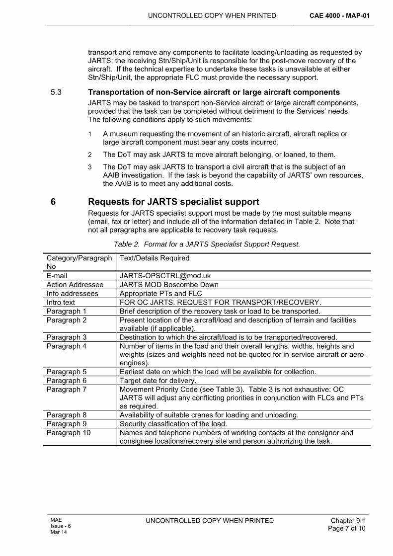
UNCONTROLLED COPY WHEN PRINTED CAE 4000 - MAP-01
MAE Issue - 6 Mar 14
UNCONTROLLED COPY WHEN PRINTED
Chapter 9.1 Page 7 of 10
transport and remove any components to facilitate loading/unloading as requested by JARTS; the receiving Stn/Ship/Unit is responsible for the post-move recovery of the aircraft. If the technical expertise to undertake these tasks is unavailable at either Stn/Ship/Unit, the appropriate FLC must provide the necessary support.
5.3 Transportation of non-Service aircraft or large aircraft components JARTS may be tasked to transport non-Service aircraft or large aircraft components, provided that the task can be completed without detriment to the Services’ needs. The following conditions apply to such movements:
1 A museum requesting the movement of an historic aircraft, aircraft replica or large aircraft component must bear any costs incurred.
2 The DoT may ask JARTS to move aircraft belonging, or loaned, to them.
3 The DoT may ask JARTS to transport a civil aircraft that is the subject of an AAIB investigation. If the task is beyond the capability of JARTS’ own resources, the AAIB is to meet any additional costs.
6 Requests for JARTS specialist support Requests for JARTS specialist support must be made by the most suitable means (email, fax or letter) and include all of the information detailed in Table 2. Note that not all paragraphs are applicable to recovery task requests.
Table 2. Format for a JARTS Specialist Support Request.
Category/Paragraph No
Text/Details Required
E-mail [email protected] Action Addressee JARTS MOD Boscombe Down Info addressees Appropriate PTs and FLC Intro text FOR OC JARTS. REQUEST FOR TRANSPORT/RECOVERY. Paragraph 1 Brief description of the recovery task or load to be transported. Paragraph 2 Present location of the aircraft/load and description of terrain and facilities
available (if applicable). Paragraph 3 Destination to which the aircraft/load is to be transported/recovered. Paragraph 4 Number of items in the load and their overall lengths, widths, heights and
weights (sizes and weights need not be quoted for in-service aircraft or aero-engines).
Paragraph 5 Earliest date on which the load will be available for collection. Paragraph 6 Target date for delivery. Paragraph 7 Movement Priority Code (see Table 3). Table 3 is not exhaustive: OC
JARTS will adjust any conflicting priorities in conjunction with FLCs and PTs as required.
Paragraph 8 Availability of suitable cranes for loading and unloading. Paragraph 9 Security classification of the load. Paragraph 10 Names and telephone numbers of working contacts at the consignor and
consignee locations/recovery site and person authorizing the task.
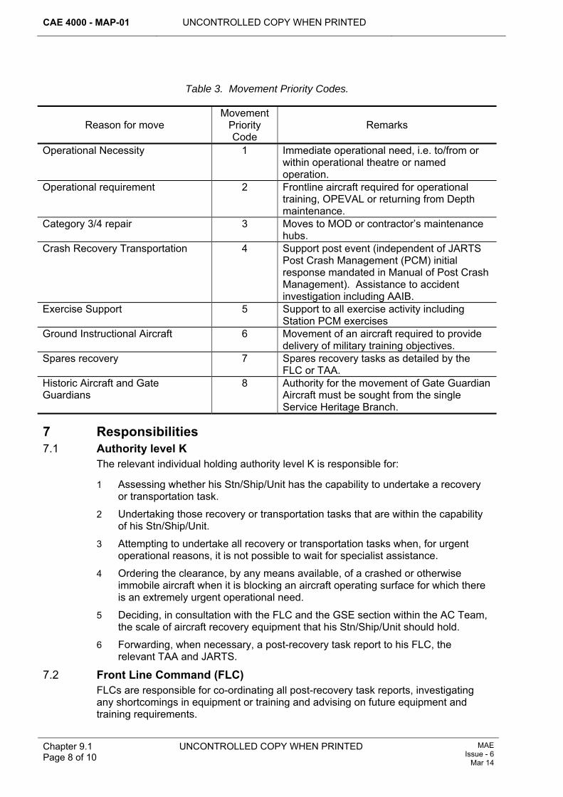
CAE 4000 - MAP-01 UNCONTROLLED COPY WHEN PRINTED
Chapter 9.1 Page 8 of 10
UNCONTROLLED COPY WHEN PRINTED MAE Issue - 6
Mar 14
Table 3. Movement Priority Codes.
Reason for move Movement
Priority Code
Remarks
Operational Necessity 1 Immediate operational need, i.e. to/from or within operational theatre or named operation.
Operational requirement 2 Frontline aircraft required for operational training, OPEVAL or returning from Depth maintenance.
Category 3/4 repair 3 Moves to MOD or contractor’s maintenance hubs.
Crash Recovery Transportation 4 Support post event (independent of JARTS Post Crash Management (PCM) initial response mandated in Manual of Post Crash Management). Assistance to accident investigation including AAIB.
Exercise Support 5 Support to all exercise activity including Station PCM exercises
Ground Instructional Aircraft 6 Movement of an aircraft required to provide delivery of military training objectives.
Spares recovery 7 Spares recovery tasks as detailed by the FLC or TAA.
Historic Aircraft and Gate Guardians
8 Authority for the movement of Gate Guardian Aircraft must be sought from the single Service Heritage Branch.
7 Responsibilities 7.1 Authority level K
The relevant individual holding authority level K is responsible for:
1 Assessing whether his Stn/Ship/Unit has the capability to undertake a recovery or transportation task.
2 Undertaking those recovery or transportation tasks that are within the capability of his Stn/Ship/Unit.
3 Attempting to undertake all recovery or transportation tasks when, for urgent operational reasons, it is not possible to wait for specialist assistance.
4 Ordering the clearance, by any means available, of a crashed or otherwise immobile aircraft when it is blocking an aircraft operating surface for which there is an extremely urgent operational need.
5 Deciding, in consultation with the FLC and the GSE section within the AC Team, the scale of aircraft recovery equipment that his Stn/Ship/Unit should hold.
6 Forwarding, when necessary, a post-recovery task report to his FLC, the relevant TAA and JARTS.
7.2 Front Line Command (FLC) FLCs are responsible for co-ordinating all post-recovery task reports, investigating any shortcomings in equipment or training and advising on future equipment and training requirements.
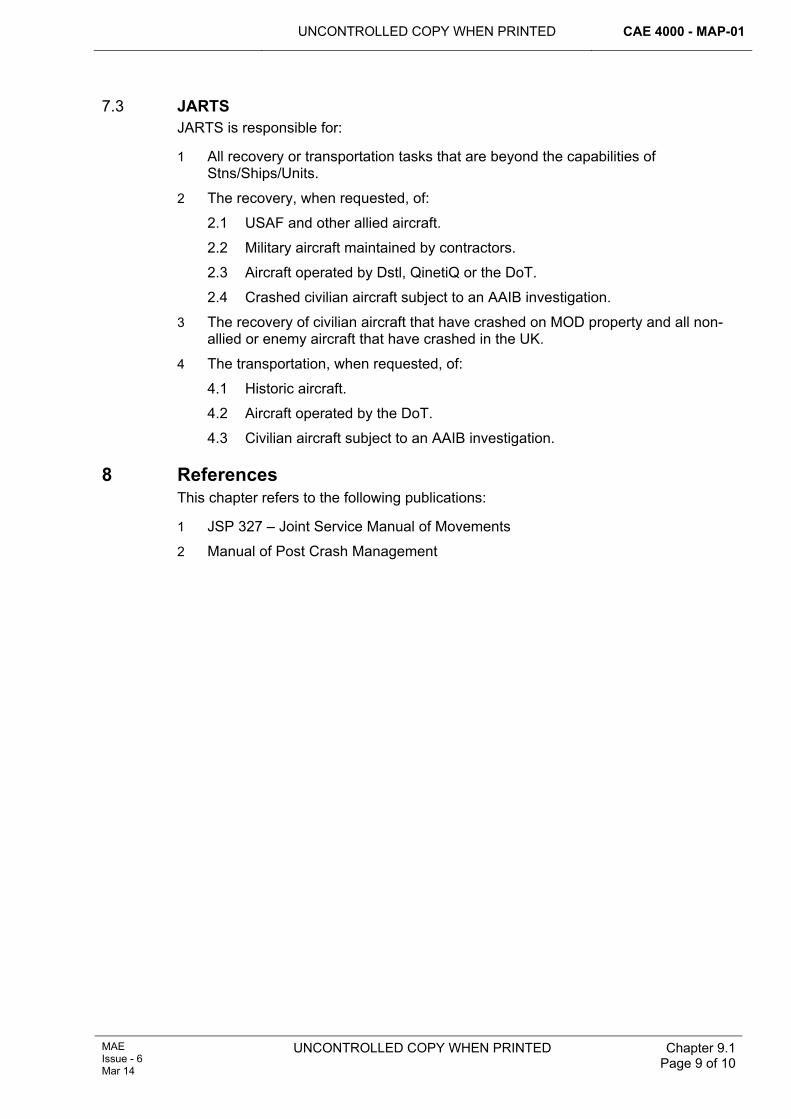
UNCONTROLLED COPY WHEN PRINTED CAE 4000 - MAP-01
MAE Issue - 6 Mar 14
UNCONTROLLED COPY WHEN PRINTED
Chapter 9.1 Page 9 of 10
7.3 JARTS JARTS is responsible for:
1 All recovery or transportation tasks that are beyond the capabilities of Stns/Ships/Units.
2 The recovery, when requested, of:
2.1 USAF and other allied aircraft.
2.2 Military aircraft maintained by contractors.
2.3 Aircraft operated by Dstl, QinetiQ or the DoT.
2.4 Crashed civilian aircraft subject to an AAIB investigation.
3 The recovery of civilian aircraft that have crashed on MOD property and all non-allied or enemy aircraft that have crashed in the UK.
4 The transportation, when requested, of:
4.1 Historic aircraft.
4.2 Aircraft operated by the DoT.
4.3 Civilian aircraft subject to an AAIB investigation.
8 References This chapter refers to the following publications:
1 JSP 327 – Joint Service Manual of Movements
2 Manual of Post Crash Management

CAE 4000 - MAP-01 UNCONTROLLED COPY WHEN PRINTED
Chapter 9.1 Page 10 of 10
UNCONTROLLED COPY WHEN PRINTED MAE Issue - 6
Mar 14
Intentionally Blank for Page Pagination
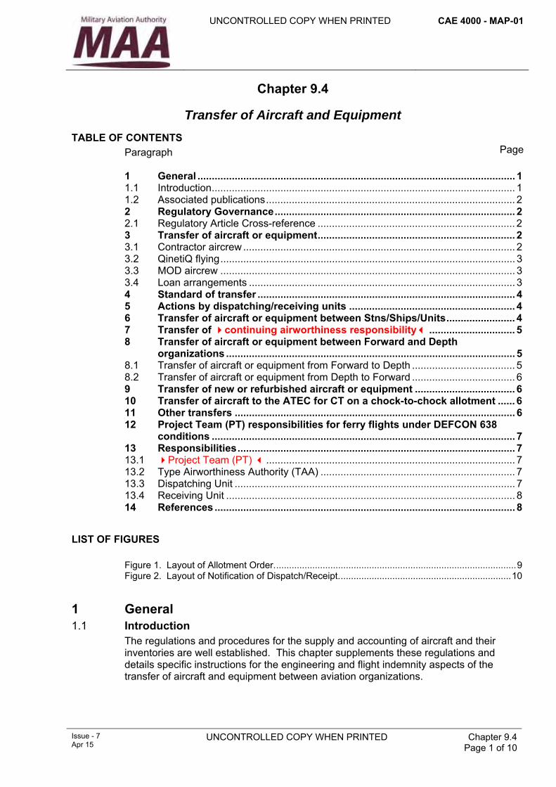
UNCONTROLLED COPY WHEN PRINTED CAE 4000 - MAP-01
Issue - 7 Apr 15
UNCONTROLLED COPY WHEN PRINTED Chapter 9.4 Page 1 of 10
Chapter 9.4
Transfer of Aircraft and Equipment
TABLE OF CONTENTS Paragraph
Page
1 General ............................................................................................................... 1 1.1 Introduction.......................................................................................................... 1 1.2 Associated publications....................................................................................... 2 2 Regulatory Governance.................................................................................... 2 2.1 Regulatory Article Cross-reference ..................................................................... 2 3 Transfer of aircraft or equipment..................................................................... 2 3.1 Contractor aircrew ............................................................................................... 2 3.2 QinetiQ flying....................................................................................................... 3 3.3 MOD aircrew ....................................................................................................... 3 3.4 Loan arrangements ............................................................................................. 3 4 Standard of transfer .......................................................................................... 4 5 Actions by dispatching/receiving units .......................................................... 4 6 Transfer of aircraft or equipment between Stns/Ships/Units........................ 4 7 Transfer of continuing airworthiness responsibility .............................. 5 8 Transfer of aircraft or equipment between Forward and Depth
organizations ..................................................................................................... 5 8.1 Transfer of aircraft or equipment from Forward to Depth .................................... 5 8.2 Transfer of aircraft or equipment from Depth to Forward .................................... 6 9 Transfer of new or refurbished aircraft or equipment ................................... 6 10 Transfer of aircraft to the ATEC for CT on a chock-to-chock allotment ...... 6 11 Other transfers .................................................................................................. 6 12 Project Team (PT) responsibilities for ferry flights under DEFCON 638
conditions .......................................................................................................... 7 13 Responsibilities................................................................................................. 7 13.1 Project Team (PT) ....................................................................................... 7 13.2 Type Airworthiness Authority (TAA) .................................................................... 7 13.3 Dispatching Unit .................................................................................................. 7 13.4 Receiving Unit ..................................................................................................... 8 14 References ......................................................................................................... 8
LIST OF FIGURES Figure 1. Layout of Allotment Order..............................................................................................9 Figure 2. Layout of Notification of Dispatch/Receipt...................................................................10
1 General 1.1 Introduction
The regulations and procedures for the supply and accounting of aircraft and their inventories are well established. This chapter supplements these regulations and details specific instructions for the engineering and flight indemnity aspects of the transfer of aircraft and equipment between aviation organizations.
CAE 4000 - MAP-01 UNCONTROLLED COPY WHEN PRINTED
Chapter 9.4 Page 2 of 10
UNCONTROLLED COPY WHEN PRINTED Issue - 7 Apr 15
1.2 Associated publications This chapter is associated with the following publications:
1 JSP 886 – The Defence Logistics Support Chain Manual.
2 AOF – Managing Quality – Flight Indemnity
2 Regulatory Governance 2.1 Regulatory Article Cross-reference
This chapter supports:
1 RA 4401.
3 Transfer of aircraft or equipment Aircraft or equipment are transferred when there is a change of inventory holder (custodian). Transfers must be notified by means of an allotment order, which ensures that transfers of responsibilities and specific conditions are clearly defined and understood. The allotment order is to follow the layout at Figure 1. The aircraft Project Team (PT) has overall responsibility for the management of aircraft transfers. However, responsibility for the management of the operational fleet may be devolved to the Front Line Commands (FLC) or equivalent. In addition, PTs may require reports on the transfer of other nominated equipment, such as ECUs: details of nominated equipments must be published in the relevant Topic 2(N/A/R)1. Allotment orders are to have dispatch and receipt notices, as detailed at Figure 2, issued by the dispatching/receiving organizations respectively. The general conditions of transfer must be detailed in the equipment Topic 2(N/A/R)1, but more specific conditions may be detailed in mid level orders or instructions. The dispatching organization is responsible for compliance with the conditions of transfer. Aircraft must be transferred by ferry flight where possible. All maintenance documents must be completed and transferred without delay and the appropriate aircraft tool tallies must be transferred with the aircraft MOD Form 700C. Where an aircraft or equipment is received in an unsatisfactory condition, a report must be forwarded to the allotting organization in accordance with RA 4815 and Chapter 15.1.1.
3.1 Contractor aircrew 3.1.1 Ferry flight – flight liability and indemnity
Where contractor aircrew, including Service pilots on loan/attached to the contractor, are required to ferry MOD aircraft between MOD organizations or from an MOD organization to a designated contractor’s site, it is essential that such contracts call up DEFCON 638 ‘flight indemnity and liability’ conditions and that these conditions are activated prior to the flight taking place, via the signing of a Flight Authorization Certificate (FAC) (Def Stan 05-100, Annex C), by the respective Project Team Leader (PTL) or delegated representative. In these instances the ferry flights must be regulated under the FLY 2000 Series of RAs.
Notes:
1 Any such ferry flight taking place without a valid FAC (Def Stan 05-100, Annex C) would be deemed to be an ‘Unauthorized flight’ and MOD flight indemnity would not be provided.
2 Ferry flights must only be authorized by the PTL or delegated representative, providing that the aircraft has not been modified outside the RTS and will not be flown outside the RTS.
UNCONTROLLED COPY WHEN PRINTED CAE 4000 - MAP-01
Issue - 7 Apr 15
UNCONTROLLED COPY WHEN PRINTED Chapter 9.4 Page 3 of 10
3.1.2 Period of Flight Authorization Certificate cover Subject to specific DEFCON 638 conditions, the FAC (Def Stan 05-100, Annex C) will remain valid for the period of the ferry flight. This would include cover for the onward completion of a ferry flight, following an unscheduled diversion, provided that any flight servicing or replenishment at the diversion airfield was completed by MOD personnel, including Service pilots on loan/attached to the contractor, who are specifically authorized to undertake flight servicing on type, in accordance with RA 4057 and Chapter 2.8.
Note:
If any of the above conditions are not met, an FAC (Def Stan 05-100, Annex A) will be required for the continuation ferry-flight. Therefore, to cover this event, DEFCON 638 conditions would need to be called up in the respective contract.
3.2 QinetiQ flying QinetiQ Ltd and the MOD work jointly under the Long Term Partnering Agreement (LTPA) to conduct aircraft, aircraft weapons systems and airborne systems Test & Evaluation (T&E). Whilst both QinetiQ and the MOD each provide specific resources and capabilities, certain approvals, eg MAA Oversight and Approvals Dep Hd 1 approval of an aircraft flight test centre, are valid only when the partnership is viewed as a whole. For regulatory purposes, this entity is referred to as the Aircraft Test and Evaluation Centre (ATEC). QinetiQ is responsible for aircraft maintenance, modification, design work and the preparation and approval of aircraft release documents. HQ Air Command is the Aircraft Operating Authority (AOA) for aircraft allotted to QinetiQ or the ATEC.
Notes:
1 With the exception noted below, all aircraft intended to be used for T&E purposes are to be allotted to QinetiQ Ltd.
2 The only exception to the above is when the ATEC require aircraft for Continuation Training (CT) on a chock-to-chock basis, or are tasked with delivery of an aircraft from and on behalf of FLC to QinetiQ. The aircraft can then be allotted to the ATEC under the 2000 Series of RAs and in this instance the aircraft must be maintained and operated within the RTS, ie with no QinetiQ or any other contractor involvement.
3.3 MOD aircrew Where MOD aircrew are used to ferry MOD aircraft that have been prepared for flight in accordance with Military Air Environment (MAE) rules and regulations by MOD personnel and remain within the RTS, flight indemnity is provided by the Secretary of State under 2000 Series of RAs conditions and FACs are not required.
Note:
Where MOD aircrew are either on loan or attached to a contractor, the conditions at paragraph 3.1.1 apply.
3.4 Loan arrangements Aircraft or equipment may be loaned for defined periods without the need for formal transfer, but with the permission of the allotting organization. The parent organization remains responsible for the engineering management of the aircraft or equipment. Where aircraft are loaned to a contractor, the MOD does not provide indemnity and the contractor is required to take out full all-risk insurance against any potential loss or liability.
CAE 4000 - MAP-01 UNCONTROLLED COPY WHEN PRINTED
Chapter 9.4 Page 4 of 10
UNCONTROLLED COPY WHEN PRINTED Issue - 7 Apr 15
Further guidance can be found in:
1 Def Stan 05-100.
2 Def Con 638.
3 2000 Series of RAs.
4 Standard of transfer The standard to which aircraft or equipment are prepared for transfer is to be determined by the (TAA) or delegated authority, in consultation with the Continuing Airworthiness Management Organization (CAMO). Consideration must be given to the following during the production of the standard of transfer:
1 Scheduled maintenance forecast.
2 Outstanding and embodied modifications.
3 Outstanding and completed Special Instructions (Technical).
4 Current MOD Form 703 and MOD Form 704 entries.
5 The remaining life of components.
6 Special fits and role equipment.
7 Military Airworthiness Review Certificate.
8 Certificate of Airworthiness (where applicable).
The equipment must be transferred in a serviceable condition unless a concession has been granted by the TAA or delegated authority.
5 Actions by dispatching/receiving units As a minimum the dispatching/receiving CAMO should ensure that the following actions are conducted by dispatching/receiving units as appropriate:
1 Notification of Dispatch/Receipt – The dispatch/receipt of aircraft or equipment must be notified by the dispatching and receiving organizations. The notification is to follow the layout at Figure 2.
2 Flight testing – Any requirement for flight testing must be detailed on the standard of transfer or statement of work; flight testing may be combined with the ferry flight.
3 Inventory check – Aircraft and equipment must be checked against the content of the aircraft and/or equipment inventory.
4 Documentation check – Hardcopy and electronic documentation must be examined for completeness and integrity, both prior to dispatch and on receipt. Any discrepancies must be reported in accordance with RA 4815 and Chapter 15.1.1.
5 Equipment survey – Aircraft or equipment must be examined to confirm compliance with the standards of transfer. Examinations may be supplemented by functional checks. Unsatisfactory conditions must be reported in accordance with RA 4815 and Chapter 15.1.1.
6 Transfer of aircraft or equipment between Stns/Ships/Units The transfer of aircraft or equipment between Stns/Ships/Units must comply with this chapter. Aircraft or equipment operating from ships remain allotted to the parent
UNCONTROLLED COPY WHEN PRINTED CAE 4000 - MAP-01
Issue - 7 Apr 15
UNCONTROLLED COPY WHEN PRINTED Chapter 9.4 Page 5 of 10
squadron; however, operational command is transferred to the Commanding Officer of the ship.
7 Transfer of continuing airworthiness responsibility When an aircraft is allotted between Delivery Duty Holders and/or Accountable Managers (Military Flying), the dispatching and receiving CAMOs should engage directly to agree the information required to underpin the required level of continuing airworthiness assurance. The receiving CAMO must ensure that sufficient information is available to enable the Duty Holder to be assured of continued safe operation. .
8 Transfer of aircraft or equipment between Forward and Depth organizations
8.1 Transfer of aircraft or equipment from Forward to Depth When an aircraft or equipment is to be transferred to a Depth organization for maintenance or storage, a Statement of Work (SOW) must be raised by the allotting organization in conjunction with the PT, CAMO, FLC and dispatching organization, as appropriate. The SOW will incorporate, as a minimum, the following information
1 Aircraft/equipment details:
1.1 Custodian.
1.2 Aircraft/equipment type/mark/serial number.
1.3 Current airframe hours/life used.
2 Transfer details:
2.1 Date task to commence.
2.2 Maintenance organization.
3 Maintenance requirements (examples):
3.1 Scheduled maintenance requirements.
3.2 Component replacements.
3.3 Modifications to be embodied, including those issued during the maintenance period.
3.4 Special Instructions (Technical) to be satisfied, including those issued during the maintenance period.
3.5 MOD Form 703, MOD Form 704 and variants, rectification, repairs and other corrective maintenance.
3.6 Surface finish.
3.7 Aircraft weigh.
3.8 Compass swing.
3.9 Flight testing requirements.
Note:
The Maintenance requirements should detail the relevant schedule or maintenance publications where applicable.
CAE 4000 - MAP-01 UNCONTROLLED COPY WHEN PRINTED
Chapter 9.4 Page 6 of 10
UNCONTROLLED COPY WHEN PRINTED Issue - 7 Apr 15
8.2 Transfer of aircraft or equipment from Depth to Forward The TAA in consultation with the CAMO must define the conditions required before transfer to the operational fleet. This may include:
1 A period of maintenance-free operation.
2 Accounting for out-of-use time in storage so that it is not debited against a maintenance cycle based on calendar time where a flying hour base co-exists.
3 Stopping and/or re-starting the maintenance clock.
4 Fitting Service-supplied role equipment, weapons, etc.
5 Embodying Special Order Only and Service modifications.
6 Updating any logistic information system (LIS).
Where compliance is not possible, the TAA may issue individual or general concessions that detail the limitations to be recorded in the aircraft or equipment documents and determine the appropriate remedial action.
9 Transfer of new or refurbished aircraft or equipment New or refurbished aircraft and equipment delivered to the MOD must be prepared to the standard dictated in the production contract. Where the production run is very long and the MOD's requirements change, consideration should be given to additional equipment fits, modifications and any other requirements to be met by the contractor before delivery. Concessions to the transfer standard are to be negotiated prior to delivery.
If the delivery must be direct to an operating unit rather than an intermediary maintenance facility, the contract must include any additional requirements to be met prior to delivery and/or any arrangements for them to be met at Service units. If the transfer standard is to be achieved by work at a Service unit, the appropriate DE&S PT must ensure that the necessary arrangements, including funding through the appropriate FLC if applicable, are put in place before the aircraft or equipment is/are delivered.
10 Transfer of aircraft to the ATEC for CT on a chock-to-chock allotment When approval for the allotment has been given by the PT using the allotment order shown at Figure1, paragraphs B & C should be left blank. This will allow the dispatching organization flexibility to locally manage their assets.
Note:
The above is only applicable for flights beginning and ending at the same location.
11 Other transfers Other transfers include the issue of Service aircraft to contractors for flying trials, transfers to other armed forces and transfers for display purposes. These aircraft or equipment transfers must be allotted as detailed in paragraph 3 and the allotting organization must specify the conditions under which the aircraft or equipment is transferred, to ensure that airworthiness and engineering integrity are maintained.
UNCONTROLLED COPY WHEN PRINTED CAE 4000 - MAP-01
Issue - 7 Apr 15
UNCONTROLLED COPY WHEN PRINTED Chapter 9.4 Page 7 of 10
12 Project Team (PT) responsibilities for ferry flights under DEFCON 638 conditions When a ferry flight is required using contractor aircrew and operating under DEFCON 638 conditions, the PT must:
1 Issue the allotment order, stating at paragraph L that the flight is subject to DEFCON 638 conditions and specifying which operating regulations apply, ie 2000 Series of RAs.
2 Arrange for the contractor to raise the required FAC (Def Stan 05-100, Annex 4C3), in triplicate, with part 1 completed and signed.
3 Confirm the submitted FAC details and ensure that the nominated pilot(s) is current on type and authorized by MAA Oversight and Approvals Dep Hd 1 (for flights regulated under 2000 Series of RAs).
4 Complete and sign part 2 of the FAC in triplicate and return originals (1 and 2) to the contractor, one of which will be held by the nominated pilot. The 3rd original must be retained by the PT.
13 Responsibilities 13.1 Project Team (PT)
The PT is responsible for:
1 The overall management of aircraft or equipment transfers.
2 Arranging for the issue of an FAC if required.
3 Defining the condition of an aircraft or item of equipment prior to its transfer to the relevant Forward organization.
4 Making appropriate arrangements for any in-service work that may need to be undertaken on new or refurbished aircraft or equipment.
13.2 Type Airworthiness Authority (TAA) The TAA is responsible for:
1 Publishing the Topic 2(N/A/R)1 general conditions of transfer and any associated reporting requirements.
2 Coordinating the production of the SOW when an aircraft or item of equipment is transferred to a Depth maintenance organization.
13.3 Dispatching Unit The dispatching unit is responsible for:
1 Issuing a dispatch notification.
2 Attaching a copy of the allotment order to the aircraft MoD Form 700C.
3 Detailing any flight testing requirements on the standard of transfer or SOW.
4 Checking the aircraft or equipment against the content of its inventory.
5 Checking the hardcopy and electronic documentation for completeness and integrity and reporting any discrepancies.
6 Examining the aircraft or equipment to confirm compliance with the standard of transfer.
CAE 4000 - MAP-01 UNCONTROLLED COPY WHEN PRINTED
Chapter 9.4 Page 8 of 10
UNCONTROLLED COPY WHEN PRINTED Issue - 7 Apr 15
13.4 Receiving Unit The receiving unit is responsible for:
1 Issuing a receipt notification.
2 Checking the hardcopy and electronic documentation for completeness and integrity and reporting any discrepancies.
3 Examining the aircraft or equipment to confirm compliance with the standard of transfer and reporting any discrepancies or other unsatisfactory conditions.
14 References This chapter refers to the following publications:
1 DEFCON 638 – Flights Liability and Indemnity.
2 Def Stan 05-100 – MOD Requirements for Certification of Aircraft for Authorized Flight and Ground Running.
3 Topic 2(N/A/R)1 – General Orders and Special Instructions.
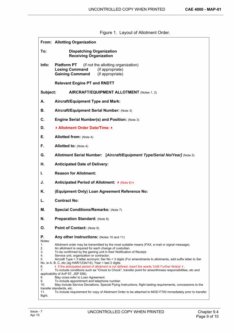
UNCONTROLLED COPY WHEN PRINTED CAE 4000 - MAP-01
Issue - 7 Apr 15
UNCONTROLLED COPY WHEN PRINTED Chapter 9.4 Page 9 of 10
Figure 1. Layout of Allotment Order.
From: Allotting Organization To: Dispatching Organization Receiving Organization Info: Platform PT (if not the allotting organization) Losing Command (if appropriate) Gaining Command (if appropriate) Relevant Engine PT and RNDTT Subject: AIRCRAFT/EQUIPMENT ALLOTMENT (Notes 1, 2) A. Aircraft/Equipment Type and Mark: B. Aircraft/Equipment Serial Number: (Note 3) C. Engine Serial Number(s) and Position: (Note 3) D. Allotment Order Date/Time: E. Allotted from: (Note 4) F. Allotted to: (Note 4) G. Allotment Serial Number: [Aircraft/Equipment Type/Serial No/Year] (Note 5) H. Anticipated Date of Delivery: I. Reason for Allotment: J. Anticipated Period of Allotment: (Note 6) K. (Equipment Only) Loan Agreement Reference No: L. Contract No: M. Special Conditions/Remarks: (Note 7) N. Preparation Standard: (Note 8) O. Point of Contact: (Note 9) P. Any other instructions: (Notes 10 and 11) Notes: 1. Allotment order may be transmitted by the most suitable means (FAX, e-mail or signal message). 2. An allotment is required for each change of custodian. 3. To be confirmed by the gaining unit in their Notification of Receipt. 4. Service unit, organization or contractor. 5. Aircraft Type = 3 letter acronym; Ser No = 3 digits (For amendments to allotments, add suffix letter to Ser No, ie A, B, C, etc (eg HAR/123A/14); Year = last 2 digits. 6. If the anticipated period of allotment is not defined, insert the words ‘Until Further Notice’. 7. To include conditions such as "Chock to Chock", transfer point for airworthiness responsibilities, etc and applicability of AvP 67, JSP 556). 8. May cross-refer to Loan Agreement. 9. To include appointment and telephone number. 10. May include Service Deviations, Special Flying Instructions, flight testing requirements, concessions to the transfer standards, etc. 11. To include requirement for copy of Allotment Order to be attached to MOD F700 immediately prior to transfer flight.
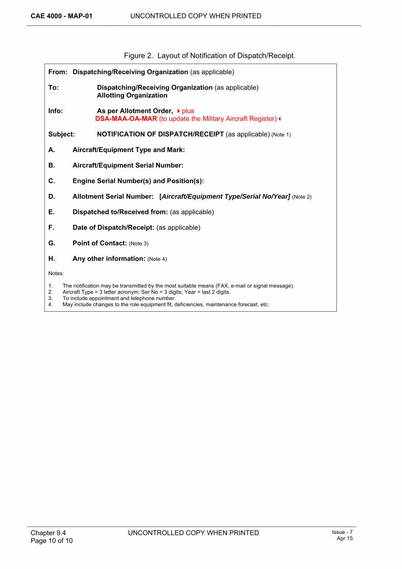
CAE 4000 - MAP-01 UNCONTROLLED COPY WHEN PRINTED
Chapter 9.4 Page 10 of 10
UNCONTROLLED COPY WHEN PRINTED Issue - 7 Apr 15
Figure 2. Layout of Notification of Dispatch/Receipt.
From: Dispatching/Receiving Organization (as applicable) To: Dispatching/Receiving Organization (as applicable) Allotting Organization Info: As per Allotment Order, plus DSA-MAA-OA-MAR (to update the Military Aircraft Register) Subject: NOTIFICATION OF DISPATCH/RECEIPT (as applicable) (Note 1) A. Aircraft/Equipment Type and Mark: B. Aircraft/Equipment Serial Number: C. Engine Serial Number(s) and Position(s): D. Allotment Serial Number: [Aircraft/Equipment Type/Serial No/Year] (Note 2) E. Dispatched to/Received from: (as applicable) F. Date of Dispatch/Receipt: (as applicable) G. Point of Contact: (Note 3) H. Any other information: (Note 4) Notes: 1. The notification may be transmitted by the most suitable means (FAX, e-mail or signal message). 2. Aircraft Type = 3 letter acronym; Ser No = 3 digits; Year = last 2 digits. 3. To include appointment and telephone number. 4. May include changes to the role equipment fit, deficiencies, maintenance forecast, etc.
UNCONTROLLED COPY WHEN PRINTED CAE 4000 - MAP-01
Issue - 7 Apr 15
UNCONTROLLED COPY WHEN PRINTED Chapter 9.5 Page 1 of 8
Chapter 9.5
Technical Equipment – Conditioning and Preparation for Movement or Storage
TABLE OF CONTENTS Paragraph
Page
1 General ............................................................................................................... 1 1.1 Introduction.......................................................................................................... 1 1.2 Materiel Accounting (MA) and logistics transformation ....................................... 2 2 Regulatory Governance.................................................................................... 2 2.1 Regulatory Article Cross-reference ..................................................................... 2 2.2 Additional information.......................................................................................... 2 3 Conditioning and preparation for movement or storage............................... 2 4 Terminology....................................................................................................... 2 4.1 Technical equipment ........................................................................................... 3 4.2 Conditioners ........................................................................................................ 3 4.3 Conditioning terms .............................................................................................. 3 5 Conditioning ...................................................................................................... 3 5.1 When conditioning must be undertaken .............................................................. 3 5.2 Conditioning exceptions ...................................................................................... 3 6 Authorization to condition technical equipment............................................ 4 7 Factors affecting conditioning decisions ....................................................... 4 7.1 Conditioning by Logistic Services (Log Svcs) ..................................................... 4 7.2 Conditioning by Logistics personnel............................................................. 4 7.3 Conditioning when detached from parent Stn/Ship/Unit...................................... 4 7.4 Faulty technical equipment.................................................................................. 5 7.5 Conditioning as Scrap ......................................................................................... 5 7.6 Inventory holders and the condition ‘Scrap’ ........................................................ 5 8 Preparation of conditioned technical equipment for movement or
storage ............................................................................................................... 5 8.1 Physical preparation............................................................................................ 5 8.2 Technical equipment labelling ............................................................................. 6 8.3 Technical equipment label completion ................................................................ 7 9 Responsibilities................................................................................................. 8 9.1 Type Airworthiness Authorities (TAAs)................................................................ 8 10 References ......................................................................................................... 8
1 General 1.1 Introduction
Conditioning is the determination of the serviceability state of technical equipment. Any item returned to the supply/logistics organization having been assessed and conditioned as serviceable may be re-issued to another user without further action to confirm serviceability. Any item returned to the supply/logistics organization having been assessed as unserviceable will enter a repair process that has been agreed between the item’s Project Team (PT) and the supply chain. Therefore it is essential that conditioning of technical equipment and preparing it for movement or storage is performed with a high degree of care and integrity. Conditioning an item of technical equipment requires an authorized person to determine and state whether the item is serviceable or not.
CAE 4000 - MAP-01 UNCONTROLLED COPY WHEN PRINTED
Chapter 9.5 Page 2 of 8
UNCONTROLLED COPY WHEN PRINTED
Issue - 7 Apr 15
1.2 Materiel Accounting (MA) and logistics transformation MA principles are defined in JSP 886 Vol 4 Pt 1. Fundamentally it is the process of maintaining records of the quantities, condition and configuration of items of materiel which have been received, held and issued, in such a way that the source, current location and description of the item can be determined. Each item of materiel has an MA Classification code. JSP 886 provides a descriptor for each of the following MA Classification codes:
1 Permanent (P).
2 Limited (L).
3 Consumable (C).
Prior to logistics transformation, these MA Classification codes were linked to repair categories (R2/R3/R4 and T3/T4): these reflected the 2nd/3rd/4th Line and Depth B/C/D repair strategy for the item, derived by Logistic Support Analysis and published in the aircraft or equipment Topic 5W (Summary of Component Repair Plans) or its equivalent.
However, logistics transformation within the Military Air Environment (MAE) has replaced 2nd/3rd/4th Line with Depth, which has no recognized sub-divisions. This has allowed MAE PTs to adopt Depth repair strategies that are optimized to their business arrangements and which may not fit the R2/R3/R4 and T3/T4 model. Notwithstanding this, the supply chain must provide pan-MOD support: to do this it requires that MAE PTs sustain the R2/R3/R4 and T3/T4 model pending full MOD-wide implementation of logistics transformation.
2 Regulatory Governance 2.1 Regulatory Article Cross-reference
This chapter supports:
1 RA 4809(1).
2.2 Additional information RA 4812(4) regulates the need for a ‘Certification of Component Release’ in order to release a component for use by another maintenance organization; Acceptable Means of Compliance to RA 4812(4) states that this requirement is satisfied by following the processes for conditioning components as detailed in this Chapter. In order to avoid confusion, the term ‘Certification of Component Release’ has not yet been introduced to the procedures below; rather, traditional terminology has continued to be used.
3 Conditioning and preparation for movement or storage In addition to the contents of this chapter, conditioners must comply with the maintenance policy of the technical equipment concerned, as specified in the equipment’s specific technical information and any other instructions issued by the appropriate TAA.
4 Terminology The following paragraphs identify the terminology to be used when conditioning technical equipment in accordance with the circumstances identified at paragraph 5.
UNCONTROLLED COPY WHEN PRINTED CAE 4000 - MAP-01
Issue - 7 Apr 15
UNCONTROLLED COPY WHEN PRINTED
Chapter 9.5 Page 3 of 8
4.1 Technical equipment Technical equipment must be interpreted as meaning all equipment associated with aircraft, aircraft-associated components and aircraft ground support equipment.
4.2 Conditioners Conditioners are personnel authorized to determine and annotate the relevant paperwork with the condition of an item of technical equipment.
4.3 Conditioning terms Conditioners must use the following conditioning terms:
1 Serviceable: technical equipment that is fit for immediate use and capable of performing its designed function (Serviceable equipment may be identified as either A1: Serviceable New or A2: Serviceable Used).
2 Unserviceable: until further notice (see paragraph 1.2), unserviceable technical equipment that is unfit for immediate use and incapable of performing its designed function, must be allocated the following conditioning terms:
2.1 R2, R3 and R4.
2.2 T3 and T4.
These terms are drawn from JSP 886 Vol 3 Part 15 - Supply Chain Transactions, Chapter 7, Figure 30 - Recognised Materiel Condition (MATCON) Codes. As noted at paragraph 1.2, PTs have developed repair strategies and support solutions that do not align with the historical and generic R2/R3/R4 and T3/T4 model. Consequently, PTs are to liaise with the supply chain and provide definitions of how the terms R2/R3/R4 and T3/T4 apply to their equipment. These definitions must be promulgated in the relevant Support Policy Statement (SPS) and must be used to compile the equipment’s Topic 5W (or equivalent).
3 Scrap: An item of P or L class technical equipment that is unfit for its designed use to the extent that it cannot be repaired economically.
5 Conditioning 5.1 When conditioning must be undertaken
Technical equipment must be conditioned:
1 Prior to transfer between maintenance organizations.
2 Prior to movement within the same maintenance organization from one work location to another for the purpose of further maintenance or reinstallation.
3 When the item is the subject of cannibalization and is transferred between Stn/Ship/Unit; see RA 4812 and Chapter 6.11.
4 Prior to return to the supply/logistic organization for whatever reason.
5.2 Conditioning exceptions Technical equipment conditioning need not be undertaken:
1 When serviceable equipment is removed from an aircraft for the sole purpose of routine replenishment, eg a Lox Converter. However, when the equipment is removed for replenishment, local procedures are to ensure that these items are segregated from similar equipment that has been conditioned. Should the serviceability of the equipment undergoing replenishment become suspect at any time, it is to be conditioned.
CAE 4000 - MAP-01 UNCONTROLLED COPY WHEN PRINTED
Chapter 9.5 Page 4 of 8
UNCONTROLLED COPY WHEN PRINTED
Issue - 7 Apr 15
2 If the equipment is subject to its own specialist documentation, eg Magnetic Debris Plugs on issue from, or return to, an Early Failure Detection Centre (EFDC).
3 If the equipment is the subject of cannibalization but the item is remaining on the same Stn/Ship/Unit; see RA 4812 and Chapter 6.11.
4 When equipment is received from industry as new or following repair and the packaging is un-broached. The accompanying MOD Form 640 or equivalent document, and, when applicable, a Certificate of Conformity, will be retained by Logistic Services (Log Svcs) at the point of initial receipt into the Joint Support Chain (JSC). Copies may be requested to provide confirmation that the item was serviceable when dispatched.
5 When equipment is received from industry as new or following repair and is in primary trade packaging, has a quality/serviceable stamp present and has an accompanying MOD Form 640 or equivalent document.
6 Authorization to condition technical equipment 1 Personnel required to condition technical equipment as Serviceable or
Unserviceable (R2/R3/R4 and T3/T4) inside trade boundary must hold authorization MAP-C481.
2 Personnel required to condition technical equipment as Serviceable or Unserviceable (R2/R3/R4 and T3/T4) outside trade boundary must hold authorization MAP-C482.
3 Personnel required to condition technical equipment as SCRAP inside trade boundary must hold authorization MAP-E483.
4 Personnel required to condition technical equipment as SCRAP outside trade boundary must hold authorization MAP-E484.
7 Factors affecting conditioning decisions 7.1 Conditioning by Logistic Services (Log Svcs)
In some cases, where an item of technical equipment is received at a Log Svcs site without an MOD F731, MOD F3910 or equivalent contractor’s label attached, the only means by which its identity and condition may be established would be to return it to the originator, if known, or to a user unit for further conditioning. To minimize unnecessary movement of equipment, appropriately authorized conditioners within a Log Svcs site may apply any of the defined conditioning terms to an item of equipment following test at the Log Svcs site to establish its identity and condition.
7.2 Conditioning by Logistics personnel In cases where a serviceable item sustains damage during transit which renders it unfit for use and it would be inefficient to continue on to its planned destination for technical conditioning, Logistics personnel may condition the item as Unserviceable if approved in appropriate single Service orders. The MOD F731 should be annotated as ‘Damaged in Transit’ and the item returned to the appropriate repair organization as determined by the appropriate PT or Front Line Command (FLC), who should also identify any requirement to initiate a Quality Occurrence Report (QOR) in accordance with JSP 886.
7.3 Conditioning when detached from parent Stn/Ship/Unit When detached from parent Stn/Ship/Unit to locations without appropriate repair facilities, Class P and L equipments beyond repair or servicing using local resources
UNCONTROLLED COPY WHEN PRINTED CAE 4000 - MAP-01
Issue - 7 Apr 15
UNCONTROLLED COPY WHEN PRINTED
Chapter 9.5 Page 5 of 8
must be conditioned Unserviceable (R2/R3/R4 and T3/T4) and returned to the appropriate repair organization as determined by the appropriate PT or FLC.
7.4 Faulty technical equipment If the item of technical equipment under consideration is the subject of Narrative Fault Reporting using the MOD F760 as detailed in Chapter 7.5.1, the condition ‘Scrap’ is not to be applied.
7.5 Conditioning as Scrap Unless authority is promulgated by the PT, the condition Scrap must not be applied to any Class P item. Class L items may only be scrapped when a repair capability does not exist as confirmed by the relevant PT.
However, items that have been destroyed, or which are impossible to reclaim or repair, may be scrapped locally by an individual holding authority level J. Items scrapped in these circumstances must not be those subject to ongoinginvestigation and must be made safe for disposal.
Items conditioned as Scrap should be damaged/deformed/dented/cut/distorted beyond repair/use to ensure they do not re-enter the supply chain and subsequently be used on aircraft or equipment.
7.6 Inventory holders and the condition ‘Scrap’ A conditioner who has been authorized to condition items of P and L technical equipment as ‘Scrap’ must not exercise that authorization in respect of any item he holds on inventory charge.
8 Preparation of conditioned technical equipment for movement or storage
8.1 Physical preparation The person conditioning an item of technical equipment must ensure that it is correctly prepared for subsequent movement and storage on unit. Engineering responsibility for such preparation includes:
1 Taking all packaging and documentary safety measures ordered for the protection of Service personnel and the public during subsequent handling and movement of the item.
2 Taking the initial packing measures required to assist in protecting the item against damage during movement or deterioration whilst in store, eg fitment of blanks to plugs, sockets and openings, fitment of protective shrouds and covers and removal of internal dry batteries.
3 Ensuring that the item is not deficient of any components other than when such deficiencies are the cause, or unavoidable result, of a fault recorded on the equipment label for an item that is unserviceable.
4 Ensuring that all accessories supplied as part of the item, eg connectors, adapters and test leads, are securely attached to, or packaged together with, the item.
5 If the item is one for which an engineering record card (ERC) is kept, see Chapter 5.3.1, and the item is being returned to the supply organization, enclosing the ERC in a protective cover and attaching it securely to the item unless a purpose-designed pocket is provided on or in the Special-to-Contents container.
CAE 4000 - MAP-01 UNCONTROLLED COPY WHEN PRINTED
Chapter 9.5 Page 6 of 8
UNCONTROLLED COPY WHEN PRINTED
Issue - 7 Apr 15
6 Completing and signing as the authorized conditioner the appropriate equipment and safety labels, attaching them securely to the item and providing duplicate labels for attachment to any external packaging.
7 Packing the item in a Special-to-Contents container or permanent storage and transit container, whenever such a container has been provisioned for the item and is specified for storage and transportation forward of the Stn/Ship/Unit supply organization, and ensuring that the duplicate MOD F731 and any safety labels required are securely attached to the exterior of the container.
8 If the item contains a Dangerous Engineering Substance (DES) that presents a hazard under normal handling, or if the item has been damaged or has had its protective covers removed thereby exposing a DES, sealing the item in a suitable container and fixing an appropriate hazard warning label to the container.
9 Where equipment is known to have a destination off the Stn/Ship/Unit, ensuring that any necessary packing, in addition to that specified in item 2 above, is applied to minimize the risk of transit damage or deterioration in store, prior to handing the item over to the supply organization. The MOD F731 is to be annotated:
‘Prepared For Movement Off Stn/Ship/Unit’
8.2 Technical equipment labelling The following labels must be used to show the condition of technical equipment:
1 MOD F731, Equipment Conditioning Label. Two labels must be raised; one for attachment to the item and the second label, protected by polythene, to be secured to the external packaging. For technical equipment of any class that is conditioned ‘Scrap’ and returned to the supply organization, see item 3 below.
2 MOD F760E, Faulty Equipment Label. This label must be used if the technical equipment is subject to MOD F760 action. Two labels must be raised; one for attachment to the item and the second label, protected by polythene, to be secured to the external packaging.
3 MOD F3910C, Scrap Label. This label must be used for technical equipment of any class that is conditioned ‘Scrap’ by an individual holding authorization MAP-E483 or MAP-E484 as appropriate and returned to the supply organization for disposal.
4 MOD Form 640, Advice and Inspection Note. This note will be found on equipment received from industry as new or following repair and provides confirmation that the item was serviceable when dispatched from the contractor’s premises and receipted into JSC and/or Log Svcs site. In some instances a contractor may issue several identical items to a Log Svcs site on one MOD Form 640. The Log Svcs site may issue single items from this consignment. Certified copies for each item are acceptable as confirmation that the item was serviceable when dispatched from the contractor’s premises.
5 MOD F3910, Serviceable Equipment Label for C Class items must be used and attached to equipment when issuing or returning any Serviceable (A1/A2) item(s) back into or from the supply organisation, with Batch, Date Packed & Manufactures details completed where possible.
Note:
The MOD F3910 is an equipment label only; it is not a conditioning label and may be signed by personnel not authorized to condition equipment.
UNCONTROLLED COPY WHEN PRINTED CAE 4000 - MAP-01
Issue - 7 Apr 15
UNCONTROLLED COPY WHEN PRINTED
Chapter 9.5 Page 7 of 8
8.3 Technical equipment label completion Conditioners must ensure that all information called for on the equipment or safety label has been correctly entered, including:
1 In the case of an item of equipment conditioned Unserviceable (R2/R3/R4 and T3/T4) using MOD F731 (see MOD Posters 301A and 301B):
1.1 Full details of the fault or other reason that caused the item to be withdrawn from use. Where appropriate, recommendations for further maintenance action must be provided.
1.2 The identity and stage of any test or maintenance schedule requirement that the item failed to meet.
1.3 A list of any components or parts that are deficient.
1.4 The life consumed.
1.5 Copies of relevant incident reports and any other information that will assist the maintenance organization to which the item is being sent to deal with the un-serviceability in the most economical and effective way.
1.6 If the item is subject to an Occurrence Report (see Chapter 7.5.3), the following annotation or stamp must be added in red:
“OR”
1.7 If the item is subject to a Quality Occurrence Report (see RA 4815 and Chapter 15.1.1), the following annotation or stamp must be added in red:
“QOR”
1.8 If the item is subject to F760 Investigation (see Chapter 7.5.1), the following annotation or stamp must be added in red:
“F760”
2 In the case of an item of equipment containing a DES (see JSP 515 and JSP 800 Vol 4b) that would not normally present a hazard to personnel handling the item in transit or storage, an endorsement on the relevant equipment conditioning label stating the name of the DES; eg:
‘Contains [insert name of DES, eg mercury, sulphuric acid, asbestos, compressed nitrogen]. NOTE: Hazard not present when handled under normal circumstances’
3 In the case of an item of equipment containing a DES that does present a hazard under normal handling, or if the item has been damaged or has had its protective covers removed thereby exposing a DES, an endorsement on the relevant equipment conditioning label as in item 2 above, but without the note.
4 In the case of an item of equipment requiring the application of safety measures before handling, other than those associated with a DES:
4.1 Identification of the hazard concerned.
4.2 Details of the safety precautions taken to make the item safe for handling on a Hazard Information Label, F/Pkg/822 or F/Pkg/823.
5 If there is insufficient space on an equipment label for the entry of all the information required, the information is to be entered on a sheet of paper that must be stapled to the reverse side of the label.
CAE 4000 - MAP-01 UNCONTROLLED COPY WHEN PRINTED
Chapter 9.5 Page 8 of 8
UNCONTROLLED COPY WHEN PRINTED
Issue - 7 Apr 15
6 Having ensured that the item has been correctly prepared for movement and storage as detailed in paragraph 8.1 and that the necessary information has been entered on the relevant equipment-conditioning label, the conditioner must complete the Conditioning and Safety Certificate.
7 Whenever a new equipment conditioning label is attached to an item of equipment, any previous equipment label must be removed and destroyed.
9 Responsibilities 9.1 Type Airworthiness Authorities (TAAs)
TAAs must:
1 Identify their equipment’s repair strategy in the SPS within the Topic 2(N/A/R)1. This strategy must define how the terms R2/R3/R4 and T3/T4 are to be applied to their equipment in order to meet the needs of the supply chain and in order to inform the equipment’s Topic 5W (or equivalent).
2 Ensure that the Topic 5W (or equivalent) reflects equipment repair arrangements and promulgates how the terms R2/R3/R4 and T3/T4 are to be applied to their equipment.
10 References This chapter refers to the following publications:
1 JSP 515 – Hazardous Stores Information System.
2 JSP 800 Vol 4b – Dangerous Goods by Road, Rail and Sea.
3 JSP 886 Vol 3 Part 15 - Supply Chain Transactions.
4 JSP 886 Vol 4 Part 1 – Fundamentals of Materiel Accounting.
5 Topic 2(N/A/R)1 – General Orders and Special Instructions.
6 Topic 5W – Summary of Component Repair Plans.
UNCONTROLLED COPY WHEN PRINTED CAE 4000 - MAP-01
Issue - 7 Apr 15
UNCONTROLLED COPY WHEN PRINTED Chapter 9.12 Page 1 of 8
Chapter 9.12
Expedient Repair
TABLE OF CONTENTS Paragraph
Page
1 General ............................................................................................................... 1 1.1 Introduction.......................................................................................................... 1 2 Regulatory Governance.................................................................................... 1 2.1 Regulatory article Cross-reference...................................................................... 1 3 General principles of ER................................................................................... 2 4 Authorization of an ER regime......................................................................... 2 4.1 Airworthiness considerations............................................................................... 2 4.2 Criteria for a FLC to authorize an ER regime ...................................................... 2 4.3 FLC authorization to invoke an ER regime.......................................................... 3 5 Implementation of ER ....................................................................................... 3 5.1 Local Engineering Commander (LEC) ................................................................ 3 5.2 ER Assessor (ERA) requirements....................................................................... 4 5.3 ER Operator (ERO) requirements ....................................................................... 5 6 Training and authorizations ............................................................................. 5 6.1 ERA..................................................................................................................... 5 6.2 ERO..................................................................................................................... 5 7 Documenting ER decisions.............................................................................. 5 8 Recovery ............................................................................................................ 5 9 Responsibilities................................................................................................. 6 9.1 Stns/Ships/Units .................................................................................................. 6 9.2 Front Line Command (FLC) ................................................................................ 6 9.3 Continuing Airworthiness Management Organization (CAMO) ........................... 6 9.4 TAA ..................................................................................................................... 6 9.5 MAA Cert S and ADS......................................................................................... 6 10 References ......................................................................................................... 7
1 General 1.1 Introduction
There may be occasions when, due to a lack of either time or resources and the need to meet an overriding operational requirement, it is necessary to undertake repairs (which may include repairs to structural, mechanical, electrical, avionic and weapon systems) to an aircraft that are outside the limits for normal peacetime operations detailed in the Aircraft Document Set (ADS). Such a repair, which generates a level of operational capability, potentially at the expense of a reduced level of airworthiness or longer-term aircraft structural and systems integrity, is termed an Expedient Repair (ER).
2 Regulatory Governance 2.1 Regulatory article Cross-reference
This chapter supports:
1 RA 4403.
CAE 4000 - MAP-01 UNCONTROLLED COPY WHEN PRINTED
Chapter 9.12 Page 2 of 8
UNCONTROLLED COPY WHEN PRINTED Issue - 7 Apr 15
3 General principles of ER ER is designed to restore operational capability by providing rapid repair solutions for military aircraft both in deployed and non-deployed environments. Depending on the operational imperative, local resources and aircraft suitability, ER can range from the application of Aircraft Battle Damage Repair (ABDR) techniques up to a fully restorative and permanent repair. However, formal recovery action must be carried out for all ER in accordance with paragraph 8. The fundamental principle of ER is that the repair solution must always aim to achieve the greatest degree of restoration within the constraints of time and available resources.
The two common links for all ER are:
1 An ER involves the application of a repair solution that is neither taken (wholly) from the ADS nor from a previous, fully restorative and permanent, repair solution produced by the Designer or 1710 Naval Air Squadron (1710 NAS) and hence may have airworthiness considerations.
2 The repair process, from damage assessment through repair scheme development to implementation of repair, is achieved in the most expeditious manner that resources, local conditions and operational constraints allow.
It follows that the need to undertake ER will be minimized if the ADS contains all authorized repair schemes. Type Airworthiness Authorities (TAA) must therefore ensure that their Topic 6 (Aircraft Repair Manual) or Structural Repair Manual (SRM) and Topic 6C (ABDR Manual) are regularly updated in accordance with RA 4350 and Chapter 8.1.
4 Authorization of an ER regime 4.1 Airworthiness considerations
The TAA retains responsibility for design airworthiness and the ADS; moreover, the TAA will not amend the Air System Safety Case to reflect the application of any ER.
Duty Holders are responsible for operating their aircraft fleet within the Release to Service documentation/criteria and for maintaining their aircraft fleet in accordance with the ADS authorized by the TAA. However, during operations, resources and lines of communication may become degraded, so generating a need to increase local responsibility for engineering decisions. Front Line Commands (FLCs) must assess operational situations and decide whether local engineering commanders are likely to need to undertake ER to support the operational commander’s requirements.
Local engineering commanders are responsible for the ER decisions that they make. These decisions must be commensurate with the authority granted them by the FLC and must reflect both the operational situation and their ER assessments. In addition, the local engineering commander must ensure that the local operational commander is fully aware of any potential reduction in airworthiness, and the associated risk, that an individual ER imposes on an aircraft.
4.2 Criteria for a FLC to authorize an ER regime The criteria that a FLC needs to consider before authorizing ER will depend on the operational circumstances and the level of support available. It follows that any decision to invoke ER must balance the airworthiness risk against the operational necessity. Consultation between the FLC and the appropriate TAAs, and other organizations such as 1710 NAS and Business Units within Defence Equipment &
UNCONTROLLED COPY WHEN PRINTED CAE 4000 - MAP-01
Issue - 7 Apr 15
UNCONTROLLED COPY WHEN PRINTED Chapter 9.12 Page 3 of 8
Support (DE&S), is necessary to maintain continuity and relevance. Factors affecting a decision on how and when to invoke ER include:
1 The alternative operational solutions that are available and consistent with the operational imperative.
2 The level of ER decision-making authority granted to the local engineering commander.
3 The lines of communication and levels of equipment support available, ie is there an accessible Main Operating Base or Logistic Support Site, or is the Sqn/Unit operating in isolation.
4 The availability and deployability of the following resources:
4.1 Technical information support (eg technical authority/design support).
4.2 Logistics support (eg spares, manufacturing or cannibalization options).
4.3 Ground support equipment (including tools and test equipment).
4.4 Personnel of the appropriate competence (including ER assessors, technicians and AD FS(Air) deployable repair teams).
4.5 Aircraft recovery assets (including 1710 NAS deployable aircraft recovery teams).
Note:
The FLC must monitor the operational situation to ensure that the criteria for invoking an ER regime remain valid.
4.3 FLC authorization to invoke an ER regime Under normal circumstances repairs must be carried out in accordance with:
1 The ADS.
2 Specific repair schemes prepared by the platform Designer or 1710 NAS.
Note:
The techniques contained in AP 101A-1500-0 and the Aircraft Topic 6C must not to be used unless specifically authorized by the TAA or ER has been authorized by the FLC.
To move to an ER regime, the appropriate Duty Holder must accept the increased airworthiness risk. During the transition to a period of increased operational activity, an FLC, unless it has already established its ER regime via a standing instruction, must state clearly the authority granted to local engineering commanders to invoke ER and define any associated restrictions via an engineering operation order or equivalent.
Where ER Assessors (ERAs) and ER Operators (EROs) are available to the local engineering commander, they must be authorized in accordance with FLC instructions.
5 Implementation of ER 5.1 Local Engineering Commander (LEC)
There will be circumstances where an aircraft returns from a sortie in which it has suffered damage not normally encountered or expected, which has degraded its operational effectiveness. As a consequence, if an ER regime has been authorized
CAE 4000 - MAP-01 UNCONTROLLED COPY WHEN PRINTED
Chapter 9.12 Page 4 of 8
UNCONTROLLED COPY WHEN PRINTED Issue - 7 Apr 15
by the FLC, the relevant LEC may decide that the damaged aircraft could be returned to flight by means of an ER. Therefore, the LEC must:
1 Confirm that an FLC-authorized ER regime is in place.
2 Task his ERA to assess the damage and formulate an ER in accordance with paragraph 5.2.
3 Balance the airworthiness/safety risk of implementing an ER with the competing operational necessity.
4 Carry out a risk analysis of the ramifications of implementing the proposed ER.
5 Consult the:
5.1 Local operational commander, where practicable, and confirm that the operational imperative justifies any potential reduction in airworthiness and the longer-term effect to structural and system integrity.
5.2 TAA where practicable.
5.3 Consult with/request assistance from any local Repair Support Unit (RSU) teams from 1710 NAS that may be deployed specifically for assistance in the ER role.
6 Authorize the ER.
7 Report full details of the ER to the FLC, the Continuing Airworthiness Management Organization (CAMO), and TAA when implemented, as ER schemes require approval/recovery by the relevant authority at the earliest opportunity; see paragraph 8.
5.2 ER Assessor (ERA) requirements The ERA must:
1 Assess damage to an aircraft's structure and systems to determine the degree of degradation on airworthiness and functionality.
2 Determine the aircraft repairability, based on an assessment of the impact to structural or systems integrity and/or safety-related functions of aircraft systems and immediate operational and resource constraints.
3 Independently scheme a structural or system repair using information, principles and techniques contained within the ADS, ABDR publications and generic repair manual and be able to communicate the repair scheme to the ERO, understanding their competence and resource limitations.
4 Produce an effective repair scheme and supervise its implementation to return the aircraft to an operationally capable state, potentially with a reduced level of airworthiness or long-term structural integrity.
5 Advise the LEC/Authorising Officer on the effect of ER proposal on long term structural and system integrity and potential limitations to operational capability post repair.
6 Determine when the repair of damage to structure and aircraft systems is outside the capabilities of the unit and implement the process of requesting assistance from external agencies such as 1710 NAS, the TAA or the Designer.
7 Understand the process for authorizing and reporting an ER.
8 Have a thorough working knowledge of the appropriate FLC ER instructions.
9 Supervise the ERO who is implementing the ER.
UNCONTROLLED COPY WHEN PRINTED CAE 4000 - MAP-01
Issue - 7 Apr 15
UNCONTROLLED COPY WHEN PRINTED Chapter 9.12 Page 5 of 8
Note:
The subsequent repair must be commensurate with the time and resources available for its application.
5.3 ER Operator (ERO) requirements The ERO must:
1 Carry out repairs to aircraft structure and systems in accordance with the ADS.
2 Carry out ER to structure and/or systems as directed and supervised by the ERA, utilizing specialist ABDR/ER tools and techniques where necessary.
3 Have either documented training or experience in the use of aircraft fasteners, fabrication and repair of structural components, and repair and replacement of system components.
6 Training and authorizations 6.1 ERA
Personnel required to be ERAs must have completed the relevant ERA training course (TBD) and must be granted authorization MAP-E442 by an individual holding authorization MAP-J443.
6.2 ERO Personnel required to be EROs must have completed the relevant ERO training course (TBD) (or trade training course which meets the requirements of the ERO as detailed in paragraph 5.3) and must be granted authorization MAP-C472 by an individual holding authorization MAP-J443.
7 Documenting ER decisions To maintain the airworthiness audit trail and to assist in formulating recovery plans, all ER measures must be documented. When the ER involves the recovery of structural integrity, including permanent repairs, this must be recorded in a database. Repairs that are fully restorative and permanent must be documented in accordance RA 4813 and Chapter 7.2. All other repairs that either fall short of this standard and require subsequent recovery, or impose limitations in terms of life and/or capability, must be recorded on MOD F703 or MOD F704 as appropriate.
Note:
The process for recording maintenance activities is detailed primarily in RA 4813 and Chapter 7.2 and supplemented in the relevant MAP chapter for specific maintenance activities.
8 Recovery The use of ER will require the TAA, in consultation with the CAMO, to determine any actions required to recover in full the structural integrity and system capability of the aircraft.
The level of recovery required will depend on the impact of the ER. As soon as it is practicable, an operational Sqn/Unit must forward to the TAA, via its FLC and CAMO, details of any ER measures taken on its aircraft. The TAA must then dictate, at the earliest opportunity and in accordance with RA 4812 and Chapter 5.4.2, any
CAE 4000 - MAP-01 UNCONTROLLED COPY WHEN PRINTED
Chapter 9.12 Page 6 of 8
UNCONTROLLED COPY WHEN PRINTED Issue - 7 Apr 15
necessary recovery action. In determining this action, advice may be sought from a Subject Matter Expert (SME) within MAA Cert S and ADS and 1710 NAS.
9 Responsibilities 9.1 Stns/Ships/Units
1 Stns/Ships/Units are responsible for ensuring that their FLC and CAMO are informed of all ERs that have been undertaken.
2 Ensuring that they have sufficient personnel trained and authorized to undertake ER assessment in accordance with FLC instructions.
9.2 Front Line Command (FLC) FLCs are responsible for:
1 Authorizing local engineering commanders to undertake ER as necessary.
2 Taking measures to provide for their anticipated ER requirement, including:
2.1 Ensuring that their Stns/Ships/Units have sufficient personnel trained and authorized to undertake ER assessment.
2.2 Ensuring that their Stns/Ships/Units carry out ER training (where applicable).
2.3 Ensuring that external agencies such as other FLCs are made aware of any resources that the FLC expects the agency to provide to generate its ER capability, including personnel (eg from 1710 NAS), spares, tools and repair materials.
3 Informing TAAs of those ERs undertaken on their platforms.
4 Terminating a previously authorized ER regime when circumstances permit.
9.3 Continuing Airworthiness Management Organization (CAMO) The CAMO is responsible for:
1 Monitoring the implementation of ER on the aircraft.
2 Managing the recovery of aircraft coming off an ER regime.
9.4 TAA The TAA is responsible for ensuring that:
1 The Topic 6 or SRM and Topic 6C are regularly updated. In particular:
1.1 ERs are reviewed and, if considered appropriate, published in the ADS as approved repairs in the Topic 6 so that they can be used in the future as normal repairs.
1.2 ERs developed from generic principles are considered for inclusion in the Topic 6C.
2 FLCs are advised at the earliest opportunity of any post-ER recovery actions.
9.5 MAA Cert S and ADS MAA Cert S and ADS is responsible for:
1 Acting as SME for AP 101A-1500-0.
2 Sponsoring ER training courses.
UNCONTROLLED COPY WHEN PRINTED CAE 4000 - MAP-01
Issue - 7 Apr 15
UNCONTROLLED COPY WHEN PRINTED Chapter 9.12 Page 7 of 8
3 Acting as SME to the Defence School of Aeronautical Engineering (DSAE) and FLCs on all ER matters, including the requirement to include ER awareness training in initial trade training.
4 Providing SME advice to the appropriate Equipment Capability Customer on the development of generic ER techniques for publication in AP 101A-1500-0 or platform Topic 6C or SRM.
5 Providing TAAs with specialist technical assistance in formulating recovery plans.
10 References This chapter makes reference to the following publications:
1 AP101A-1500-0 – Joint Service Aircraft Battle Damage Repair Manual.
2 SRM – Aircraft type-specific Structural Repair Manual.
3 Topic 6 – Aircraft type-specific Repair Manual.
4 Topic 6C – Aircraft type-specific ABDR Repair Manual.

CAE 4000 - MAP-01 UNCONTROLLED COPY WHEN PRINTED
Chapter 9.12 Page 8 of 8
UNCONTROLLED COPY WHEN PRINTED Issue - 7 Apr 15
Intentionally Blank for Print Pagination
UNCONTROLLED COPY WHEN PRINTED CAE 4000 - MAP-01
Issue - 7 Apr 15
UNCONTROLLED COPY WHEN PRINTED Chapter 9.13 Page 1 of 2
Chapter 9.13
Aircraft Repair
TABLE OF CONTENTS Paragraph
Page
1 General ............................................................................................................... 1 1.1 Introduction.......................................................................................................... 1 1.2 Terms used ......................................................................................................... 1 2 Regulatory Governance.................................................................................... 1 2.1 Regulatory Article Cross-reference ..................................................................... 1 3 Policy on aircraft repairs in the Military Air Environment (MAE).................. 1 4 Repair Organizations (ROs) ............................................................................. 1 5 RO functions and responsibilities ................................................................... 2 5.1 RO functions........................................................................................................ 2 5.2 RO responsibilities .............................................................................................. 2 6 USAF assistance in the UK .............................................................................. 2
1 General 1.1 Introduction
This chapter details the arrangements within the Military Air Environment (MAE) for repairing aircraft that are beyond the repair capabilities of the aircraft custodian or their Forward maintenance organization.
1.2 Terms used Throughout this chapter ‘aircraft custodian’ is the Ship/Station/Squadron/Unit/Flight to which the aircraft has been allotted by the aircraft type fleet manager.
2 Regulatory Governance 2.1 Regulatory Article Cross-reference
This chapter supports:
1 RA 4815(2).
3 Policy on aircraft repairs in the Military Air Environment (MAE) The MAE’s aircraft Repair Organization (RO) must be used to repair MAE aircraft that are beyond the repair capability of the aircraft custodian or their Forward maintenance organization.
4 Repair Organizations (ROs) Aircraft repair capability is provided by 2 ROs:
1 Fixed-wing aircraft repairs: 71(Inspection and Repair) Squadron (71(IR) Sqn), based at A4 Force Element, RAF Wittering.
2 Rotary-wing aircraft repairs: 1710 Naval Air Squadron (NAS); based at Her Majesty’s Naval Base, Portsmouth.
CAE 4000 - MAP-01 UNCONTROLLED COPY WHEN PRINTED
Chapter 9.13 Page 2 of 2
UNCONTROLLED COPY WHEN PRINTED
Issue - 7 Apr 15
5 RO functions and responsibilities 5.1 RO functions
The ROs are responsible for co-ordinating and controlling the following functions:
1 Within the boundaries of paragraph 2, repairing:
1.1 UK Military Aircraft (MA), including those on loan to QinetiQ and the Defence Science & Technology Laboratory (Dstl), in the UK and overseas.
1.2 Allied MA, other than USAF aircraft in the UK.
1.3 Non-allied foreign MA in the UK or on British military airfields overseas.
2 Considering and, when practicable, actioning requests from the appropriate authorities for assistance with repairing:
2.1 UK MA maintained by civilian contractors.
2.2 Aircraft owned by QinetiQ, Dstl, or the Department of Trade and Industry.
2.3 USAF aircraft in the UK.
3 In times of crisis; seeking direction on repair priorities from operational headquarters, central staffs or war headquarters.
4 During peacetime; determining repair priorities in accordance with timescales agreed in Joint Business Agreements (JBAs) between the ROs and relevant Front Line Commands (FLCs) and Project Teams (PTs).
5.2 RO responsibilities When tasked, the ROs are responsible for:
1 Assessing aircraft damage and recommending its categorization in accordance with Chapter 9.13.1.
2 Undertaking repairs to Category 3 (SER) & Category 4 (SER) fixed-wing aircraft (71(IR) Sqn).
3 Undertaking repairs to Category 3 (SER) & Category 4 (SER) rotary-wing aircraft (1710 NAS).
4 Assisting aircraft custodians with repairs to Category 2 aircraft as appropriate.
5 Undertaking structural repairs to aircraft components, when requested by PTs.
6 Approving repair instructions and providing general assembly drawings for fixed and rotary-wing aircraft.
7 Providing on-site advice to the Joint Aircraft Recovery and Transportation Squadron (JARTS) prior to salvage or transportation of crashed aircraft in order to determine that the structure is safe to move and that the recovery methods used will not cause further damage.
8 Providing technical data sheets on working practices and procedures (71(IR) Sqn only).
6 USAF assistance in the UK In principle, the USAF is responsible for all repair operations on USAF aircraft in the UK. However, it has been agreed between the USAF and the MOD that, in appropriate circumstances, each air force will render repair assistance to the other; see Chapter 9.13.1.
UNCONTROLLED COPY WHEN PRINTED CAE 4000 - MAP-01
Issue - 7 Apr 15
UNCONTROLLED COPY WHEN PRINTED Chapter 9.13.1 Page 1 of 14
Chapter 9.13.1
Assessment, Categorization and Repair of Aircraft and Aircraft Structural Components
TABLE OF CONTENTS Paragraph
Page
1 General ............................................................................................................... 2 1.1 Introduction.......................................................................................................... 2 1.2 Terms Used......................................................................................................... 2 2 Regulatory Governance.................................................................................... 2 2.1 Regulatory Article Cross-reference ..................................................................... 2 2.2 Additional Information.......................................................................................... 2 3 Responsibilities................................................................................................. 2 3.1 Aircraft custodian................................................................................................. 2 3.2 Nearest aviation unit............................................................................................ 3 3.3 Project Team (PT) ............................................................................................... 3 4 Assessment and categorization ...................................................................... 4 4.1 Assessment......................................................................................................... 4 4.2 Categorization ..................................................................................................... 4 5 Repair of aircraft................................................................................................ 6 5.1 General................................................................................................................ 6 5.2 Repair priorities ................................................................................................... 6 5.3 Recording of repair work ..................................................................................... 7 6 Authorizations ................................................................................................... 7 6.1 Authorizations to conduct repair work ................................................................. 7 6.2 1710 (NAS) Repair Manager and 71(IR) Sqn OC authorizations........................ 8 6.3 CO 1710 (NAS) and OC 42(ES) Wing authorizations ......................................... 8 7 Cannibalization.................................................................................................. 8 8 Allotment and disposal of Category 4 aircraft................................................ 8 8.1 Category 4 (FLY)................................................................................................. 8 8.2 Other Category 4 aircraft..................................................................................... 8 9 Special arrangements for Military Air Environment (MAE) aircraft / USAF
aircraft mutual assistance ................................................................................ 9 10 Repair of allied, non-USAF aircraft in the UK ................................................. 9 11 Repair of MAE aircraft abroad.......................................................................... 9 12 Message formats ............................................................................................. 10 13 Further Contact Information........................................................................... 10 14 References ....................................................................................................... 10
LIST OF TABLES Table 1. Repair Categories and Definitions. .................................................................................5 Table 2. Request for Assessment, Categorization and Repair...................................................11 Table 3. Confirmation of Categorization and Allocation of Repair..............................................12
CAE 4000 - MAP-01 UNCONTROLLED COPY WHEN PRINTED
Chapter 9.13.1 Page 2 of 14
UNCONTROLLED COPY WHEN PRINTED Issue - 7 Apr 15
1 General 1.1 Introduction
This chapter describes the responsibilities and procedures for the assessment, categorization and repair of aircraft that are beyond the owner Service’s Forward maintenance resources.
1.2 Terms Used Throughout this chapter the ‘aircraft custodian’ is the Ship/Stn/Sqn/Unit/Flt to which the aircraft has been allotted by the aircraft type Fleet Manager/Controller.
2 Regulatory Governance 2.1 Regulatory Article Cross-reference
This chapter supports:
1 RA 4815(2) .
2.2 Additional Information Where damage has resulted from an accident or incident, the originating unit must make the request for assessment and categorization as early as possible. Where damage has been sustained as a result of engineering reasons, the unit that discovers the fault must make the request. All requests must be made no later than 48 hours after the event.
3 Responsibilities The responsibilities of the Repair Organization (RO) are detailed at Chapter 9.13. The responsibilities of all other organizations involved in the process of requesting assistance or effecting repairs to aircraft are set out below.
3.1 Aircraft custodian The custodian of an aircraft that requires RO assistance with a repair has the following responsibilities:
3.1.1 Before repair 1 Requesting assessment and categorization from an RO.
2 Providing assistance to the RO carrying out the assessment and categorization of the aircraft, if requested.
3 Preparing the aircraft for repair, removing components and providing assistance as requested by the RO.
4 Implementing armament safety precautions.
5 Safeguarding classified equipment, storing any special airborne radio equipment and disposing of that equipment in accordance with instructions issued by the Front Line Command (FLC), where appropriate.
6 Taking appropriate measures to prevent deterioration of the aircraft condition, without causing further damage, eg fitting blanks, etc.
7 Undertaking preservation work that may be required on the aircraft, its systems and equipment.
8 Implementing any Engineering Orders and procedures necessary for the safety of the aircraft.
UNCONTROLLED COPY WHEN PRINTED CAE 4000 - MAP-01
Issue - 7 Apr 15
UNCONTROLLED COPY WHEN PRINTED Chapter 9.13.1 Page 3 of 14
9 Providing maintenance records as requested.
10 Notifying the RO if the aircraft is to be transferred to another unit before the repair is effected.
11 Arranging Non-Destructive Testing (NDT) resources, where appropriate.
12 Providing authorized personnel to undertake the work detailed if the nearest aviation unit does not have suitably qualified personnel.
3.1.2 During repair 1 Arranging for any work to be undertaken that may be required on any system
and sub-system in support of the repair.
2 Arranging NDT resources as required.
3 Re/defueling the aircraft as requested by the RO team or Depth maintenance organization undertaking the repair.
3.1.3 Post-repair recovery If no suitably qualified personnel are available at the aircraft location:
1 Arranging the replacement of removed equipment or components necessary for flight after repair.
2 Preparing, inspecting and certifying the aircraft for flight.
3 Conducting flight tests.
3.2 Nearest aviation unit The individual holding authority level K responsible for the Forward maintenance unit or embarked aviation unit nearest to the location of an aircraft requiring Category 3 or 4 damage repair must provide a site engineer of authority level J (authority level H when an authority level J is not embarked). Provided that suitably qualified personnel are available, the site engineer, in consultation with the President of the Service Inquiry (if appointed) and the aircraft custodian, is responsible for undertaking the work detailed at paragraph 3.1.1 on that aircraft. This work does not assume post-crash management. For post-crash management immediate actions, see the Manual of Aircraft Post-Crash Management.
When the aircraft is to be repaired at the nearest unit, or on site, and when the aircraft custodian does not provide a working party; the nearest aviation unit, in consultation with the aircraft custodian, via the FLC, is additionally responsible for undertaking the work detailed at sub-paragraphs 3.1.2 and 3.1.3 on that aircraft:
3.3 Project Team (PT) The PT is responsible for:
1 Advising the relevant RO if the unexpired life of an aircraft does not justify the expenditure of the estimated repair costs.
2 Advising the RO that all repair data must be forwarded to the PT.
3 Arranging for Category 3 (Depth) and Category 4 (WKS) repairs, as defined in Table 1, to be undertaken by a contractor.
4 Managing aircraft transfers; see RA 4401 and Chapter 9.4.
5 If necessary, deciding where the repair must be carried out.
CAE 4000 - MAP-01 UNCONTROLLED COPY WHEN PRINTED
Chapter 9.13.1 Page 4 of 14
UNCONTROLLED COPY WHEN PRINTED Issue - 7 Apr 15
4 Assessment and categorization 4.1 Assessment
Requests for assessment and categorization considered by the aircraft custodian as beyond their or their Forward maintenance organization capabilities must be made in accordance with
Table 2 by the fastest possible means, eg phone, fax, etc, supported by an e-mail message.
Upon receipt of a request for categorization, the RO concerned must co-ordinate and conduct an assessment.
4.2 Categorization ROs have the authority to award Category 1 to 5 (except for Category 5 (COMP), (GI) and (SCRAP) which are awarded by the PT; see Table 1 below for details), and to re-grade provisional categories as appropriate. The RO is responsible for confirming the category awarded and the repair priority by email message in accordance with the format shown in Table 3. A list of repair categories and their definitions is contained in Table 1.
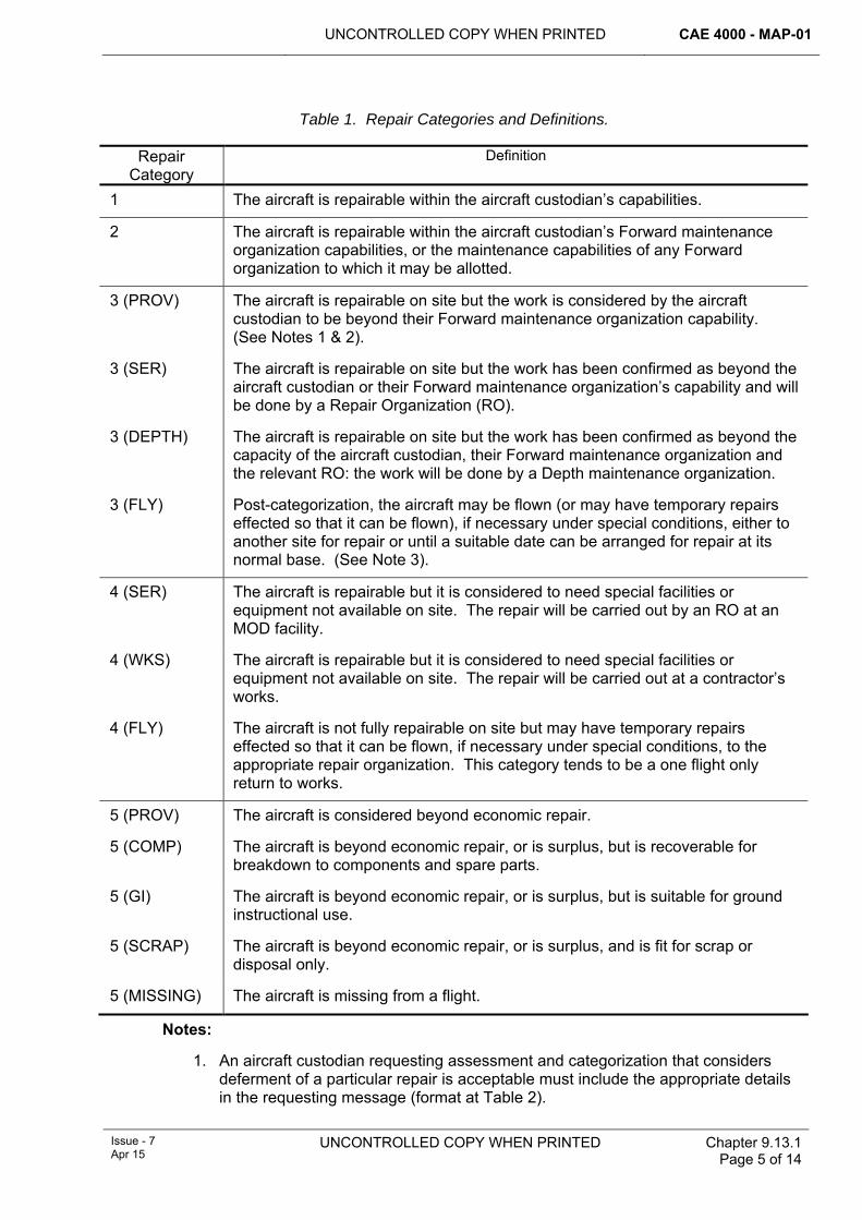
UNCONTROLLED COPY WHEN PRINTED CAE 4000 - MAP-01
Issue - 7 Apr 15
UNCONTROLLED COPY WHEN PRINTED Chapter 9.13.1 Page 5 of 14
Table 1. Repair Categories and Definitions.
Repair Category
Definition
1 The aircraft is repairable within the aircraft custodian’s capabilities.
2 The aircraft is repairable within the aircraft custodian’s Forward maintenance organization capabilities, or the maintenance capabilities of any Forward organization to which it may be allotted.
3 (PROV) The aircraft is repairable on site but the work is considered by the aircraft custodian to be beyond their Forward maintenance organization capability. (See Notes 1 & 2).
3 (SER) The aircraft is repairable on site but the work has been confirmed as beyond the aircraft custodian or their Forward maintenance organization’s capability and will be done by a Repair Organization (RO).
3 (DEPTH) The aircraft is repairable on site but the work has been confirmed as beyond the capacity of the aircraft custodian, their Forward maintenance organization and the relevant RO: the work will be done by a Depth maintenance organization.
3 (FLY) Post-categorization, the aircraft may be flown (or may have temporary repairs effected so that it can be flown), if necessary under special conditions, either to another site for repair or until a suitable date can be arranged for repair at its normal base. (See Note 3).
4 (SER) The aircraft is repairable but it is considered to need special facilities or equipment not available on site. The repair will be carried out by an RO at an MOD facility.
4 (WKS) The aircraft is repairable but it is considered to need special facilities or equipment not available on site. The repair will be carried out at a contractor’s works.
4 (FLY) The aircraft is not fully repairable on site but may have temporary repairs effected so that it can be flown, if necessary under special conditions, to the appropriate repair organization. This category tends to be a one flight only return to works.
5 (PROV) The aircraft is considered beyond economic repair.
5 (COMP) The aircraft is beyond economic repair, or is surplus, but is recoverable for breakdown to components and spare parts.
5 (GI) The aircraft is beyond economic repair, or is surplus, but is suitable for ground instructional use.
5 (SCRAP) The aircraft is beyond economic repair, or is surplus, and is fit for scrap or disposal only.
5 (MISSING) The aircraft is missing from a flight.
Notes:
1. An aircraft custodian requesting assessment and categorization that considers deferment of a particular repair is acceptable must include the appropriate details in the requesting message (format at Table 2).
CAE 4000 - MAP-01 UNCONTROLLED COPY WHEN PRINTED
Chapter 9.13.1 Page 6 of 14
UNCONTROLLED COPY WHEN PRINTED Issue - 7 Apr 15
2. When conducting the assessment of categorization, if further investigation or strip is required the RO will release a Confirmation of Categorization (Hold) message, deferring the categorization until the assessment has been completed and a Confirmation of Categorization message has been released.
3. The RO will recommend deferment by adding the qualifier '(FLY)' to the confirmed categorization 3, along with any associated limitations as part of the repair solution. All repair data for such repair tasks must be forwarded to the aircraft PT for information/action as appropriate. The aircraft custodian is to ensure that the deferment and any limitations detailed in the recommendation are recorded in aircraft Limitations Log (MOD F703) or Deferred Faults Log (MOD F704) entries. The applicable RO task number must be recorded in any such entry.
5 Repair of aircraft 5.1 General 5.1.1 Aircraft subject to inquiry
Service aircraft that are the subject of an inquiry must not be repaired unless authorized by the President of that Service Inquiry.
5.1.2 Repair information Repair of an aircraft must not be undertaken unless authorized repair drawings or instructions are available. If the necessary instructions are not contained in the aircraft Topic 6 (or equivalent air publication), an authorized repair scheme must be obtained as described in RA 4815 and Chapter 9.13.2, unless Expedient Repair has been authorized by the relevant FLC; see RA 4403 and Chapter 9.12.
5.1.3 RO repair progress Repair work must start as soon as repair resources are available and the requirements of paragraphs 5.1.1 and 5.1.2 have been met. The aircraft custodian, PT and FLC must be informed promptly by the RO of the estimated date of completion, progress and any delays.
5.1.4 RO handover On completion of the repair, the RO must raise a Task Completion Certificate, which must be used to certify acceptance of the aircraft by an individual holding authority level J or delegated representative of the aircraft custodian.
5.1.5 Quality management Quality management must be in accordance with RA 4700 and Chapter 15.1.
5.1.6 Depth repairs Once an aircraft has been confirmed Category 3 (DEPTH) or Category 4 (WKS) by the appropriate RO, the relevant PT must make arrangements for the repair.
5.2 Repair priorities 5.2.1 Grading
Category 3 and 4 tasks will be graded ‘Routine’ or ‘Urgent’ priority, as follows:
1 Initially, all tasks will be allocated the ‘Routine’ grading.
2 The ‘Urgent’ grading may be allocated to those tasks that must be completed in the shortest possible time for safety reasons or to meet essential operational
UNCONTROLLED COPY WHEN PRINTED CAE 4000 - MAP-01
Issue - 7 Apr 15
UNCONTROLLED COPY WHEN PRINTED Chapter 9.13.1 Page 7 of 14
requirements. Use of this grading must be authorized by the relevant FLC in consultation with the platform PT Leader.
3 Where there are conflicting requirements for tasks, the RO is to consult with PTs and FLCs as necessary.
4 The task must be manned as fully as possible during the repair and, for urgent tasks that relate to aircraft undergoing Category 3 repair only, the RO must consider double shifting if necessary. If double shifting can be achieved only at the expense of other tasks, this must be discussed between the aircraft custodian, PT, FLC and the RO.
5.3 Recording of repair work Repair work is to be recorded in accordance with Chapter 7.2. In addition details of Category 3 or 4 repairs must be entered onto Maintenance Work Orders (MWO) by the RO or Depth maintenance organization as appropriate. Suitable cross-reference to the worksheets or job cards must be made in the aircraft’s MOD Form 700 (or electronic aircraft maintenance recording system) by:
1 The RO in the case of an RO repair task.
2 The aircraft custodian in the case of a Depth maintenance organization repair task.
In the absence of specific structural integrity management guidance from the TAA in the Topic 2(N/A/R)1, completed MWOs relating to such repairs must be retained by the aircraft custodian from the date of completion of the repair until the next lowest frequency scheduled maintenance of the maintenance cycle plus 6 months. The RO may copy any repair documentation they wish to retain for management purposes. In the event of a Category 3 or 4 repair being undertaken on an assembly neither fitted nor allocated to an aircraft (eg tailplane undergoing repair in a maintenance bay), the completed MWOs relating to that repair must accompany the assembly and be retained with the archive documents of any aircraft on which the assembly is fitted. Where appropriate, details of the repair should be recorded on MOD F702 (Weight and Balance Data – Basic Weight and Moment), MOD F745 (Maintenance & Repair Record Card), MOD F735A (Component Record Card), or bespoke form as required in accordance with the platform Topic 2(N/A/R)1. For IS-based aircraft maintenance data recording systems, eg GOLDesp & LITS, the appropriate sanction or asset activity must be raised to record the repair.
6 Authorizations 6.1 Authorizations to conduct repair work
Aircraft repairs at Category 3 and above require additional quality control procedures to ensure a durable airworthy repair. However, the act of repair can be a self-supervised activity. The RO tradesmen required to carry out, supervise or stage check repairs at Category 3 or above must hold the appropriate authorizations as detailed below:
Personnel required to:
1 Carry out Category 3 and higher airframe structural repairs must:
1.1 Have completed advanced airframe repair training.
1.2 Be awarded authorization MAP-B487 by a holder of authorization MAP-J490.
2 Supervise Category 3 and higher airframe structural repairs must:
CAE 4000 - MAP-01 UNCONTROLLED COPY WHEN PRINTED
Chapter 9.13.1 Page 8 of 14
UNCONTROLLED COPY WHEN PRINTED Issue - 7 Apr 15
2.1 Have completed advanced airframe repair training.
2.2 Have gained a minimum of 9 months experience on Category 3 and higher airframe structural repairs.
2.3 Be awarded authorization MAP-C488 by a holder of authorization MAP-J490.
3 Carry out self-supervised stage checks of Category 3 and higher airframe structural repairs must:
3.1 Have completed advanced airframe repair training.
3.2 Have gained a minimum of 9 months experience on Category 3 and higher airframe structural repairs.
3.3 Have completed an administrative and engineering training package.
3.4 Be awarded authorization MAP-D489 by a holder of authorization MAP-J490.
6.2 1710 (NAS) Repair Manager and 71(IR) Sqn OC authorizations Personnel required to fill the 1710 (NAS) Repair Manager and 71(IR)Sqn OC appointments must:
1 Be a minimum of SO2 rank.
2 Hold DAOS authorization for RW or FW repair design.
3 Be awarded authorization MAP-J490 by the holder of authorization MAP-K491.
6.3 CO 1710 (NAS) and OC 42(ES) Wing authorizations Personnel appointed to be CO 1710 (NAS) and OC 42(ES) Wing must:
1 Be a minimum of SO1 rank.
2 Hold DAOS authorization for RW repair design (CO 1710 (NAS) only).
3 Hold authorization MAP-K491 by virtue of their appointment.
7 Cannibalization Components must not be cannibalized from Category 3 or 4 aircraft except to meet urgent operational needs. Such cannibalization must be authorized by the Continuing Airworthiness Management Organization (CAMO) of the relevant aircraft in accordance with RA 4812, RA 4947(1)b and Chapter 6.11.
8 Allotment and disposal of Category 4 aircraft When an aircraft is confirmed as requiring Category 4 repair, the aircraft PT concerned must make a formal allotment in accordance with RA 4401 and Chapter 9.4 as soon as repair facilities are available. Until an aircraft is allotted for repair, it is normally to remain at the unit at which it was categorized. On allotment, aircraft must be disposed of in accordance with paragraphs 7.1 and 7.2.
8.1 Category 4 (FLY) When an aircraft is confirmed as Category 4 (FLY), the aircraft custodian must arrange the transfer of the aircraft.
8.2 Other Category 4 aircraft The unit at which the aircraft was categorized must request the assistance of the Joint Aircraft Recovery and Transportation Squadron (JARTS) to transport the aircraft
UNCONTROLLED COPY WHEN PRINTED CAE 4000 - MAP-01
Issue - 7 Apr 15
UNCONTROLLED COPY WHEN PRINTED Chapter 9.13.1 Page 9 of 14
to the repair facility. The aircraft custodian or their Forward maintenance organization, as appropriate, must forward the aircraft’s maintenance documentation to the repair facility concerned when the aircraft is allotted; see RA 4401 and Chapter 9.4.
9 Special arrangements for Military Air Environment (MAE) aircraft / USAF aircraft mutual assistance A Memorandum of Understanding held by the Senior RAF Officer (S RAF O), HQ Third Air Force, USAF, RAF Mildenhall, details the arrangements that have been made between the MOD and the United States Department of Defence. When so requested, each may assist the other concerning the repair of aircraft that become casualties in the UK, although each organization remains responsible for assessing and categorizing its own aircraft.
A USAF mobile repair team will normally repair USAF aircraft that have sustained minor damage on site. However, when the aircraft is at an MOD unit, MOD personnel may undertake minor repairs within the unit’s capacity, at the request of the USAF. Similarly, the USAF will assist, on request, with minor repair to damaged MOD aircraft located at USAF bases in the UK.
Procedures for requesting assistance are as follows:
1 MOD units must make requests for USAF assistance to the appropriate RO.
2 The RO must forward all requests for USAF assistance to the S RAF O, HQ Third Air Force, USAF, RAF Mildenhall.
3 USAF requests for MOD assistance will be made to the S RAF O, HQ Third Air Force, USAF, RAF Mildenhall who will forward all requests to the appropriate RO.
10 Repair of allied, non-USAF aircraft in the UK An allied non-USAF Armed Service may request RO assistance with assessing, categorizing and repairing one of their aircraft in the UK. Where damage is assessed as Category 3 or worse, the RO must submit a report to their relevant FLC, who will determine, in consultation with the parent allied armed Service, whether the aircraft should be repaired and, if so, what procedure should be adopted. The FLC will issue disposal instructions accordingly.
On completion of any such repair work undertaken by an RO, full details of the task, supported by any applicable repayment vouchers, are to be forwarded through normal Service channels to the respective FLC to enable cost recovery action to be initiated.
11 Repair of MAE aircraft abroad When an MAE aircraft requires assessment, categorization and repair abroad, other than on a British military base, the request for assessment and categorization must follow the procedure detailed at paragraph 4. Responsibility for advising the British Military Attaché or Advisor to the country concerned rests with the aircraft custodian or their FLC. The Attaché or Advisor will, wherever possible, also arrange for:
1 Safeguarding valuable and/or secret equipment and storing special airborne radio equipments pending receipt of disposal instructions from the aircraft custodian.
CAE 4000 - MAP-01 UNCONTROLLED COPY WHEN PRINTED
Chapter 9.13.1 Page 10 of 14
UNCONTROLLED COPY WHEN PRINTED Issue - 7 Apr 15
2 Protecting the aircraft from deterioration.
3 Making safe and, when necessary, removing and storing ejection seats, conventional armament equipment, explosive and pyrotechnic stores.
4 Providing assistance to the relevant RO.
12 Message formats Requests for assessment, categorization and repair must be sent by the most suitable means, supported by an email message, and are to accord with the requirements stated in Table 2 and Table 3.
Note:
Dii(F) users may request an Aircraft Repair Assessment via the 71(R) Sqn MOSS site on the following URL: http://cui5-uk.diif.r.mil.uk/r/214/default.aspx
Dii(F) users may request an Aircraft Repair Assessment via the 1710 NAS ARTIMS (Aircraft Repair Task Information Management System) on the following URL: http://25.172.120.111/RepairTM/Client/
13 Further Contact Information 1 For fixed wing assessment and categorization requests, in addition to an email
message in accordance with Table 2, 71(IR) Sqn can be contacted via the following:
Email: [email protected]
Fax: 95351 7635 / 01780 417635
Duty Surveyor (24 hr cover): 07736 340092
Any request for categorization outside of normal working hours should be communicated to the Duty Surveyor by phone to ensure the most expedient response.
2 For rotary wing assessment and categorization requests, in addition to an email message in accordance with Table 2, 1710 NAS can be contacted via the following:
Email: [email protected]
Tel: 9380 22689 / 02392 722689
Fax: 9380 23247 / 02392 723247
1710NAS Duty Technical Senior Rate (24 hr cover): 07885623181
Any urgent request for categorization outside of normal work hours should be communicated to the Duty Technical SNCO by telephone to ensure the most expedient response, where necessary.
14 References This chapter refers to the following publications:
1 JSP 440 – The Defence Manual of Security
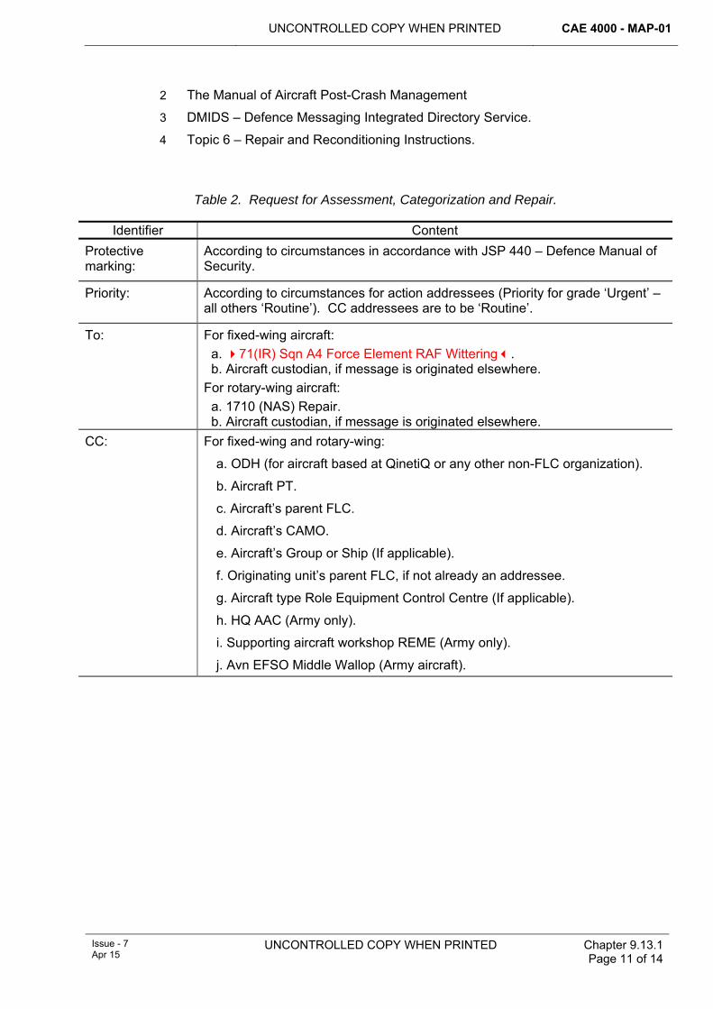
UNCONTROLLED COPY WHEN PRINTED CAE 4000 - MAP-01
Issue - 7 Apr 15
UNCONTROLLED COPY WHEN PRINTED Chapter 9.13.1 Page 11 of 14
2 The Manual of Aircraft Post-Crash Management
3 DMIDS – Defence Messaging Integrated Directory Service.
4 Topic 6 – Repair and Reconditioning Instructions.
Table 2. Request for Assessment, Categorization and Repair.
Identifier Content Protective marking:
According to circumstances in accordance with JSP 440 – Defence Manual of Security.
Priority: According to circumstances for action addressees (Priority for grade ‘Urgent’ – all others ‘Routine’). CC addressees are to be ‘Routine’.
To: For fixed-wing aircraft: a. 71(IR) Sqn A4 Force Element RAF Wittering. b. Aircraft custodian, if message is originated elsewhere. For rotary-wing aircraft: a. 1710 (NAS) Repair. b. Aircraft custodian, if message is originated elsewhere.
CC: For fixed-wing and rotary-wing:
a. ODH (for aircraft based at QinetiQ or any other non-FLC organization).
b. Aircraft PT.
c. Aircraft’s parent FLC.
d. Aircraft’s CAMO.
e. Aircraft’s Group or Ship (If applicable).
f. Originating unit’s parent FLC, if not already an addressee.
g. Aircraft type Role Equipment Control Centre (If applicable).
h. HQ AAC (Army only).
i. Supporting aircraft workshop REME (Army only).
j. Avn EFSO Middle Wallop (Army aircraft).
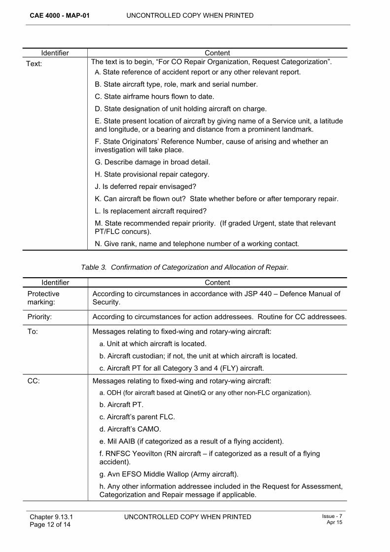
CAE 4000 - MAP-01 UNCONTROLLED COPY WHEN PRINTED
Chapter 9.13.1 Page 12 of 14
UNCONTROLLED COPY WHEN PRINTED Issue - 7 Apr 15
Identifier Content Text: The text is to begin, “For CO Repair Organization, Request Categorization”.
A. State reference of accident report or any other relevant report.
B. State aircraft type, role, mark and serial number.
C. State airframe hours flown to date.
D. State designation of unit holding aircraft on charge.
E. State present location of aircraft by giving name of a Service unit, a latitude and longitude, or a bearing and distance from a prominent landmark.
F. State Originators’ Reference Number, cause of arising and whether an investigation will take place.
G. Describe damage in broad detail.
H. State provisional repair category.
J. Is deferred repair envisaged?
K. Can aircraft be flown out? State whether before or after temporary repair.
L. Is replacement aircraft required?
M. State recommended repair priority. (If graded Urgent, state that relevant PT/FLC concurs).
N. Give rank, name and telephone number of a working contact.
Table 3. Confirmation of Categorization and Allocation of Repair.
Identifier Content Protective marking:
According to circumstances in accordance with JSP 440 – Defence Manual of Security.
Priority: According to circumstances for action addressees. Routine for CC addressees.
To: Messages relating to fixed-wing and rotary-wing aircraft:
a. Unit at which aircraft is located.
b. Aircraft custodian; if not, the unit at which aircraft is located.
c. Aircraft PT for all Category 3 and 4 (FLY) aircraft.
CC: Messages relating to fixed-wing and rotary-wing aircraft: a. ODH (for aircraft based at QinetiQ or any other non-FLC organization).
b. Aircraft PT.
c. Aircraft’s parent FLC.
d. Aircraft’s CAMO.
e. Mil AAIB (if categorized as a result of a flying accident).
f. RNFSC Yeovilton (RN aircraft – if categorized as a result of a flying accident).
g. Avn EFSO Middle Wallop (Army aircraft).
h. Any other information addressee included in the Request for Assessment, Categorization and Repair message if applicable.
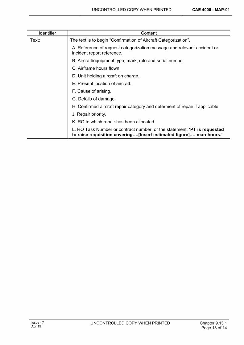
UNCONTROLLED COPY WHEN PRINTED CAE 4000 - MAP-01
Issue - 7 Apr 15
UNCONTROLLED COPY WHEN PRINTED Chapter 9.13.1 Page 13 of 14
Identifier Content Text: The text is to begin “Confirmation of Aircraft Categorization”.
A. Reference of request categorization message and relevant accident or incident report reference.
B. Aircraft/equipment type, mark, role and serial number.
C. Airframe hours flown.
D. Unit holding aircraft on charge.
E. Present location of aircraft.
F. Cause of arising.
G. Details of damage.
H. Confirmed aircraft repair category and deferment of repair if applicable.
J. Repair priority.
K. RO to which repair has been allocated.
L. RO Task Number or contract number, or the statement: ‘PT is requested to raise requisition covering….[Insert estimated figure].… man-hours.’

CAE 4000 - MAP-01 UNCONTROLLED COPY WHEN PRINTED
Chapter 9.13.1 Page 14 of 14
UNCONTROLLED COPY WHEN PRINTED Issue - 7 Apr 15
Intentionally Blank for Print Pagination
UNCONTROLLED COPY WHEN PRINTED CAE 4000 - MAP-01
Issue - 7 Apr 15
UNCONTROLLED COPY WHEN PRINTED Chapter 9.13.2 Page 1 of 14
Chapter 9.13.2
New Repair Instructions and Aerospace Equipment Design Requests
TABLE OF CONTENTS Paragraph
Page
1 General ............................................................................................................... 1 1.1 Introduction.......................................................................................................... 1 2 Regulatory Governance.................................................................................... 2 2.1 Regulatory Article Cross-reference ..................................................................... 2 3 Definitions.......................................................................................................... 2 4 Range and scope of authority.......................................................................... 2 4.1 Design Organization (DO) status ........................................................................ 2 4.2 Repair Organizations (ROs) ................................................................................ 3 5 Approval of repair instructions and design drawings ................................... 3 6 Requests by Stns/Ships/Units for repair instructions and aerospace
equipment designs............................................................................................ 3 6.1 Priority of request ................................................................................................ 4 6.2 Follow-up information .......................................................................................... 4 7 Action by Repair Organizations (ROs)/Type Airworthiness Authorities
(TAAs)................................................................................................................. 4 7.1 Incorporation of repair instructions in aircraft publications .................................. 4 8 Recording of repairs ......................................................................................... 4 9 General Assembly (GA) drawings for use during airframe repairs .............. 5 10 Damage reporting.............................................................................................. 5 10.1 Pictorial................................................................................................................ 5 10.2 Fasteners ............................................................................................................ 6 10.3 Corrosion and scoring ......................................................................................... 6 10.4 Heat damage....................................................................................................... 6 10.5 Adjacent repairs and modifications ..................................................................... 6 11 Message formats ............................................................................................... 6 12 References ......................................................................................................... 6
LIST OF TABLES Table 1. Request for Repair Instruction. .......................................................................................7 Table 2. Approval of Repair Instruction ........................................................................................9 Table 3. Request for New Aerospace Equipment Design. .........................................................11 Table 4. Upgrade of Repair Instruction Request. .......................................................................12 Table 5. Request for Drawings. ..................................................................................................13
1 General 1.1 Introduction
Repair instructions approved by a Type Airworthiness Authority (TAA) are normally found in the aircraft Topic 6 or equivalent documentation, Special Instructions (Technical) (SI(T)) or modification leaflets. However, meeting Urgent Operational Requirements (UORs) or urgent maintenance needs, catering for the introduction of new aerospace equipment or adopting GEMS suggestion scheme proposals may require formal design services that, if provided by the Design Organization (DO), may
CAE 4000 - MAP-01 UNCONTROLLED COPY WHEN PRINTED
Chapter 9.13.2 Page 2 of 14
UNCONTROLLED COPY WHEN PRINTED
Issue - 7 Apr 15
be prohibitively expensive or time-consuming. The aircraft Repair Organizations (ROs) (see Chapter 9.13) provide an alternative source for repair instructions and aerospace equipment design services. This chapter details the DO status of the ROs, the range and scope of repair and design services available from the ROs, initial points of contact, damage reporting, formats for requests for repair instructions and design services, priorities, priority upgrading and arrangements for obtaining General Assembly (GA) drawings.
2 Regulatory Governance 2.1 Regulatory Article Cross-reference
This chapter supports:
1 RA 4815(2).
3 Definitions A repair instruction or design request may include the following:
1 Repair scheme: Engineering drawings authorized by a DO or TAA for the repair of aircraft structure or components.
2 Production permit: Authorizes a divergence from an existing standard repair scheme, authorized and issued before production commences.
3 Raise-in-issue: The extended application of an existing repair scheme.
4 Concession: A divergence from an existing standard or repair scheme authorized during production.
5 Design drawings: Engineering drawings authorized by the relevant RO for the manufacture of aircraft structure, structural components or aerospace equipment.
4 Range and scope of authority 4.1 Design Organization (DO) status
DO status is granted to ROs as follows:
4.1.1 Aircraft and aircraft equipment The ROs may design, approve and amend aircraft repair instructions, subject to the organization meeting the following requirements:
1 Registration to ISO 9000:2000 or equivalent; see RA 4700 and Chapter 15.1.
2 Inclusion in the Design Approved Organization Scheme (DAOS), which also specifies the scope of the design approval.
4.1.2 Aerospace equipment The ROs may prepare and approve drawings, concessions, production permits and raises-in-issue of locally produced designs for:
1 Lifting tackle.
2 Ground Support Equipment.
3 Role equipment.
4 Aircraft mock-ups.
5 Jigs, fixtures and gauges.
UNCONTROLLED COPY WHEN PRINTED CAE 4000 - MAP-01
Issue - 7 Apr 15
UNCONTROLLED COPY WHEN PRINTED Chapter 9.13.2 Page 3 of 14
6 Mechanical test equipment.
4.1.3 Data sheets The ROs may prepare and approve technical data sheets covering standard working practices and procedures on aerospace equipment.
4.2 Repair Organizations (ROs) There are two ROs, as follows:
1 For fixed-wing aircraft: 71 Inspection and Repair Squadron (71(IR) Sqn), based at A4 Force Element, RAF Wittering. For aircraft structure, components and aerospace equipment, 71(IR) Sqn is authorized to:
1.1 Carry out the design, approval and amendment of aircraft repair instructions to all MOD aircraft.
1.2 Prepare and approve concessions and production permits against designs in the categories above that are produced by other DOs.
1.3 Prepare for approval by other DOs, the raise-in-issue of drawings produced by agencies external to 71(IR) Sqn.
1.4 Carry out design, approval and post-design services.
2 For rotary-wing aircraft: 1710 Naval Air Squadron (1710 NAS) based at Unicorn Building, HM Portsmouth Dockyard. For rotary-wing aircraft structure and structural components, 1710 NAS is authorized to design and approve repair schemes and concessions for structural damage, within the support policies authorized by aircraft/equipment Project Teams (PTs).
4.2.1 Internal procedures The ROs must publish local instructions to ensure that their internal procedures for the design, approval and amendment of aircraft repair instructions accord with the requirements of the ‘Application for Inclusion in the DAOS’ set out in the 5000 Series of RAs.
5 Approval of repair instructions and design drawings Repair instructions and design drawings may be approved by the DO, TAAs and ROs using the format at Table 2. Parts and drawings used in repair schemes are to be marked in accordance with RA 4809 and Chapter 6.3.
6 Requests by Stns/Ships/Units for repair instructions and aerospace equipment designs Requests for repair instructions must be made by e-mail or fax using the format at Table 1 and for aerospace equipment designs using the format at Table 3. All requests must specify an initial target date for completion of the task. The initial points of contact for any request for repair instructions not contained in a formal engineering instruction and aerospace equipment designs are as follows, unless the appropriate TAA has issued specific instructions:
1 For fixed-wing aircraft structure, structural components and all aspects of aerospace design services – the Repair and Design Authority (RDA), 71(IR) Sqn, A4 Force Element, RAF Wittering, Peterborough, Cambridgeshire, PE8 6HB.
2 For rotary-wing aircraft structure and structural components – 1710 NAS Repair Office, Unicorn Building PP88, Unicorn Road, Portsmouth, PO1 3GX.
CAE 4000 - MAP-01 UNCONTROLLED COPY WHEN PRINTED
Chapter 9.13.2 Page 4 of 14
UNCONTROLLED COPY WHEN PRINTED
Issue - 7 Apr 15
3 For non-structural items – the aircraft, equipment or system PT.
4 For aero-engines – as contained in:
4.1 AP 100E-01A Leaflet 100.4.2.
4.2 AP 100E-01A Leaflet 101.
4.3 The aircraft Topic 5A1, where AP 100E-01A is not available.
6.1 Priority of request Stns/Ships/Units must state the priority they wish to be allocated to the preparation of a repair instruction or design request, as follows:
1 Routine – for aircraft and equipment undergoing maintenance.
2 Urgent – for aircraft on the ground solely awaiting repair instructions.
If the target date cannot be met and there is a UOR or other urgent requirement, the task may be upgraded to ‘Urgent’ by the TAA, using the format at Table 4. In the event that there is an urgent requirement identified initially, an ‘Urgent’ priority task can be declared at the time of task initiation.
6.2 Follow-up information E-mail or fax requests must be followed up with full damage details. Follow-up information must be sent by appropriate means to the appropriate authority. For repair instructions to airframes or to structural components, the information detailed at paragraph 10 must be included.
7 Action by Repair Organizations (ROs)/Type Airworthiness Authorities (TAAs) The relevant RO must satisfy the request for a repair instruction by providing an existing instruction, a raise-in-issue, or by drafting and approving a new instruction or package of design services.
If a request for a repair instruction cannot be satisfied by one of these methods, the RO must request the TAA to task the appropriate DO with preparing the necessary instruction. Where prior arrangements exist between the RO, a TAA and the DO, local procedures must be followed when contacting the DO to ensure a timely response.
7.1 Incorporation of repair instructions in aircraft publications If the RO considers that an airframe repair instruction should be incorporated into the aircraft Topic 6 or equivalent publication, a recommendation must be made to the appropriate TAA. The TAA must consider the recommendation and take appropriate amendment action or inform the RO of the reasons why the repair instruction is not to be included.
8 Recording of repairs Recording of all repairs must be in accordance with RA 4813 and Chapter 7.1, taking into account maintenance and repair record cards, engineering record cards and basic weight and moment record cards.
UNCONTROLLED COPY WHEN PRINTED CAE 4000 - MAP-01
Issue - 7 Apr 15
UNCONTROLLED COPY WHEN PRINTED Chapter 9.13.2 Page 5 of 14
9 General Assembly (GA) drawings for use during airframe repairs In addition to holding copies of current repair instructions, the ROs hold some GA drawings. Stns/Ships/Units requiring copies of GA drawings may request them from the 71(IR) Sqn Technical Library or 1710 NAS by e-mail or fax, using the format at Table 5. If the RO does not hold a copy of the drawing, the RO will request a copy from the DO. Under current contract arrangements with DOs, there may be some delay, due to the maximum delivery date of the copies to the RO. If very urgent copies are requested, the reasons must be stated and the priority upgraded at the time of the request.
10 Damage reporting Repair instructions can be produced quickly and efficiently if correct and comprehensive details are provided to the RO. All requests for repair instructions must be accompanied by as much pictorial detail as possible; information on the possible cause is also useful. The following paragraphs expand upon the detail required.
10.1 Pictorial 10.1.1 Photographs
Photographs should include a rule against the structure to indicate the scale of the damage and must show:
1 Damage location in relation to the adjacent datum points, eg frames, stringers and brackets.
2 Close-ups of the damage, taken from as many angles as necessary to reveal the precise nature of the defect.
10.1.2 Rubbings and mouldings When access permits, a simple pencil rubbing on tracing paper, or a moulding of the damage, is often the most accurate means of presenting the information. The rubbing must include datum points; these are to be labelled on the rubbing. The rubbing must be large enough to cover the repair scheme area (including anticipated butt-strap, insert or reinforcing plate areas) and must show clearly all surrounding fastener positions, as these vary between aircraft.
10.1.3 Sketches Where limited access prevents a rubbing, a sketch of the area showing datum points must be made. Note the position of stringers, frames, skin joints, etc.
10.1.4 NDT reports Any NDT reports must be included.
10.1.5 Air Publication illustrations Copies of relevant Topic 3 and 6 illustrations, or equivalent, can be used to show overall areas containing the damaged items. The defective items must be highlighted.
10.1.6 Notes Include as much detail on materials as possible. Note fastener edge distance or, if easier to measure, material remaining, but always state what is being quoted.
CAE 4000 - MAP-01 UNCONTROLLED COPY WHEN PRINTED
Chapter 9.13.2 Page 6 of 14
UNCONTROLLED COPY WHEN PRINTED
Issue - 7 Apr 15
10.2 Fasteners If it is apparent that the repair to the damaged areas will preclude the use of original-build fasteners (eg solid rivets or high-shear pins), this must be indicated in the package. Consideration can then be given to designing the repair using more appropriate fasteners.
10.3 Corrosion and scoring Before requesting a repair instruction for corrosion or scoring damage, it may be necessary to blend out the damage; refer to the RDA, 71(IR) Sqn or 1710 NAS Repair Office before commencing blending. Details of the location and dimensions of the blend must be compiled using the methods described in paragraph 10.1. Whenever possible, NDT must be requested (see RA 4504 and Chapter 11.5) to provide a contour plot using the appropriate technique. In the absence of NDT methods, obtain a contour plot by using a straight edge and feeler gauges.
10.4 Heat damage The procedures to be adopted for heat damage to aircraft structure must be in accordance with the relevant aircraft Topic 6 or equivalent. Where no procedure is published, advice should be sought from the relevant aircraft PT.
10.5 Adjacent repairs and modifications In all instances, details of any repairs, modifications and other structural anomalies that are present in the vicinity of the damaged area must be supplied. In general, a minimum radius of 0.5m for small aircraft (eg training, fast jet or helicopter) and 1m for large aircraft (eg maritime patrol aircraft) should be considered around the extent of the damage.
11 Message formats Message formats, as detailed in Table 1, Table 2, Table 3, Table 4 or Table 5 are to be used as appropriate.
12 References This chapter refers to the following publications:
1 Aircraft Topic 3 – Parts Catalogue and Associated Information.
2 Aircraft Topic 5A1 – Master Maintenance Schedule.
3 Aircraft Topic 6 – Repair and Reconditioning Instructions.
4 AP 100E-01A – Maintenance, Lifing and Management of Aero-Engines, Their Components and Accessories.
5 5000 Series: Design and Modification Engineering Regulations (DME).
6 JSP 440 – The Defence Manual of Security
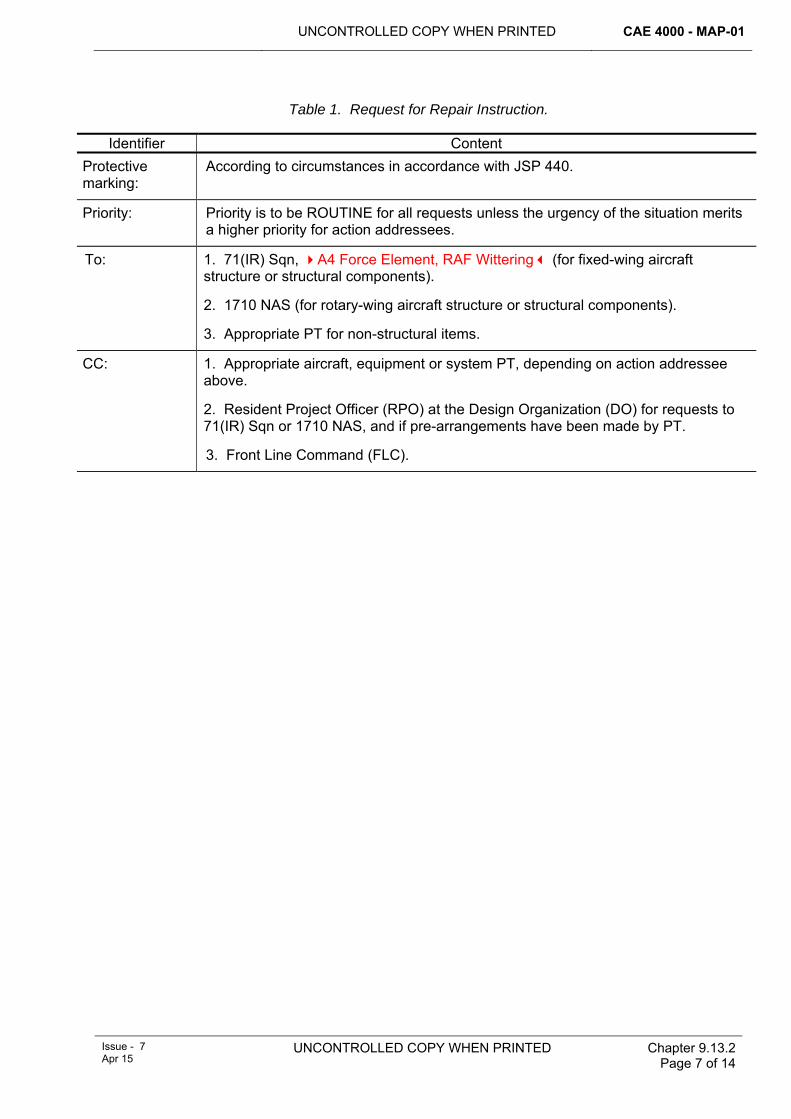
UNCONTROLLED COPY WHEN PRINTED CAE 4000 - MAP-01
Issue - 7 Apr 15
UNCONTROLLED COPY WHEN PRINTED Chapter 9.13.2 Page 7 of 14
Table 1. Request for Repair Instruction. Identifier Content
Protective marking:
According to circumstances in accordance with JSP 440.
Priority: Priority is to be ROUTINE for all requests unless the urgency of the situation merits a higher priority for action addressees.
To: 1. 71(IR) Sqn, A4 Force Element, RAF Wittering (for fixed-wing aircraft structure or structural components).
2. 1710 NAS (for rotary-wing aircraft structure or structural components).
3. Appropriate PT for non-structural items.
CC: 1. Appropriate aircraft, equipment or system PT, depending on action addressee above.
2. Resident Project Officer (RPO) at the Design Organization (DO) for requests to 71(IR) Sqn or 1710 NAS, and if pre-arrangements have been made by PT.
3. Front Line Command (FLC).
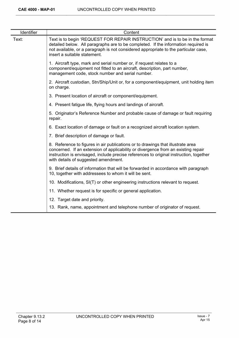
CAE 4000 - MAP-01 UNCONTROLLED COPY WHEN PRINTED
Chapter 9.13.2 Page 8 of 14
UNCONTROLLED COPY WHEN PRINTED
Issue - 7 Apr 15
Identifier Content Text: Text is to begin ‘REQUEST FOR REPAIR INSTRUCTION’ and is to be in the format
detailed below. All paragraphs are to be completed. If the information required is not available, or a paragraph is not considered appropriate to the particular case, insert a suitable statement.
1. Aircraft type, mark and serial number or, if request relates to a component/equipment not fitted to an aircraft, description, part number, management code, stock number and serial number.
2. Aircraft custodian, Stn/Ship/Unit or, for a component/equipment, unit holding item on charge.
3. Present location of aircraft or component/equipment.
4. Present fatigue life, flying hours and landings of aircraft.
5. Originator’s Reference Number and probable cause of damage or fault requiring repair.
6. Exact location of damage or fault on a recognized aircraft location system.
7. Brief description of damage or fault.
8. Reference to figures in air publications or to drawings that illustrate area concerned. If an extension of applicability or divergence from an existing repair instruction is envisaged, include precise references to original instruction, together with details of suggested amendment.
9. Brief details of information that will be forwarded in accordance with paragraph 10, together with addressees to whom it will be sent.
10. Modifications, SI(T) or other engineering instructions relevant to request.
11. Whether request is for specific or general application.
12. Target date and priority.
13. Rank, name, appointment and telephone number of originator of request.
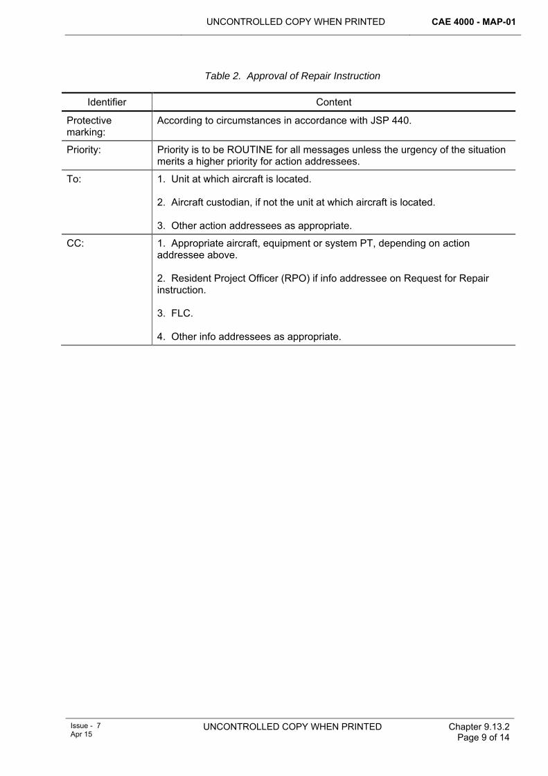
UNCONTROLLED COPY WHEN PRINTED CAE 4000 - MAP-01
Issue - 7 Apr 15
UNCONTROLLED COPY WHEN PRINTED Chapter 9.13.2 Page 9 of 14
Table 2. Approval of Repair Instruction
Identifier Content
Protective marking:
According to circumstances in accordance with JSP 440.
Priority: Priority is to be ROUTINE for all messages unless the urgency of the situation merits a higher priority for action addressees.
To: 1. Unit at which aircraft is located. 2. Aircraft custodian, if not the unit at which aircraft is located. 3. Other action addressees as appropriate.
CC: 1. Appropriate aircraft, equipment or system PT, depending on action addressee above. 2. Resident Project Officer (RPO) if info addressee on Request for Repair instruction. 3. FLC. 4. Other info addressees as appropriate.
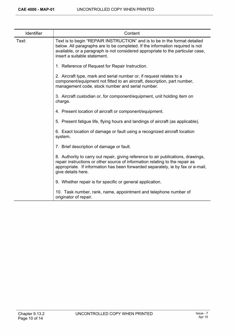
CAE 4000 - MAP-01 UNCONTROLLED COPY WHEN PRINTED
Chapter 9.13.2 Page 10 of 14
UNCONTROLLED COPY WHEN PRINTED
Issue - 7 Apr 15
Identifier Content
Text: Text is to begin “REPAIR INSTRUCTION” and is to be in the format detailed below. All paragraphs are to be completed. If the information required is not available, or a paragraph is not considered appropriate to the particular case, insert a suitable statement. 1. Reference of Request for Repair Instruction. 2. Aircraft type, mark and serial number or, if request relates to a component/equipment not fitted to an aircraft, description, part number, management code, stock number and serial number. 3. Aircraft custodian or, for component/equipment, unit holding item on charge. 4. Present location of aircraft or component/equipment. 5. Present fatigue life, flying hours and landings of aircraft (as applicable). 6. Exact location of damage or fault using a recognized aircraft location system. 7. Brief description of damage or fault. 8. Authority to carry out repair, giving reference to air publications, drawings, repair instructions or other source of information relating to the repair as appropriate. If information has been forwarded separately, ie by fax or e-mail, give details here. 9. Whether repair is for specific or general application. 10. Task number, rank, name, appointment and telephone number of originator of repair.
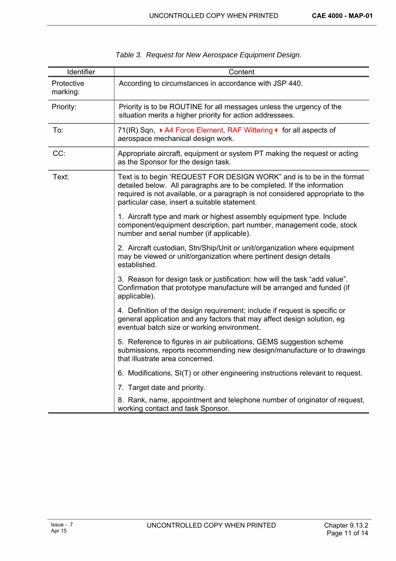
UNCONTROLLED COPY WHEN PRINTED CAE 4000 - MAP-01
Issue - 7 Apr 15
UNCONTROLLED COPY WHEN PRINTED Chapter 9.13.2 Page 11 of 14
Table 3. Request for New Aerospace Equipment Design.
Identifier Content Protective marking:
According to circumstances in accordance with JSP 440.
Priority: Priority is to be ROUTINE for all messages unless the urgency of the situation merits a higher priority for action addressees.
To: 71(IR) Sqn, A4 Force Element, RAF Wittering for all aspects of aerospace mechanical design work.
CC: Appropriate aircraft, equipment or system PT making the request or acting as the Sponsor for the design task.
Text: Text is to begin ‘REQUEST FOR DESIGN WORK” and is to be in the format detailed below. All paragraphs are to be completed. If the information required is not available, or a paragraph is not considered appropriate to the particular case, insert a suitable statement.
1. Aircraft type and mark or highest assembly equipment type. Include component/equipment description, part number, management code, stock number and serial number (if applicable).
2. Aircraft custodian, Stn/Ship/Unit or unit/organization where equipment may be viewed or unit/organization where pertinent design details established.
3. Reason for design task or justification: how will the task “add value”. Confirmation that prototype manufacture will be arranged and funded (if applicable).
4. Definition of the design requirement; include if request is specific or general application and any factors that may affect design solution, eg eventual batch size or working environment.
5. Reference to figures in air publications, GEMS suggestion scheme submissions, reports recommending new design/manufacture or to drawings that illustrate area concerned.
6. Modifications, SI(T) or other engineering instructions relevant to request.
7. Target date and priority.
8. Rank, name, appointment and telephone number of originator of request, working contact and task Sponsor.
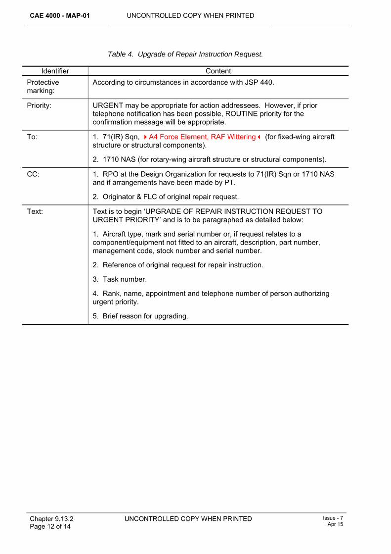
CAE 4000 - MAP-01 UNCONTROLLED COPY WHEN PRINTED
Chapter 9.13.2 Page 12 of 14
UNCONTROLLED COPY WHEN PRINTED
Issue - 7 Apr 15
Table 4. Upgrade of Repair Instruction Request.
Identifier Content Protective marking:
According to circumstances in accordance with JSP 440.
Priority: URGENT may be appropriate for action addressees. However, if prior telephone notification has been possible, ROUTINE priority for the confirmation message will be appropriate.
To: 1. 71(IR) Sqn, A4 Force Element, RAF Wittering (for fixed-wing aircraft structure or structural components).
2. 1710 NAS (for rotary-wing aircraft structure or structural components).
CC: 1. RPO at the Design Organization for requests to 71(IR) Sqn or 1710 NAS and if arrangements have been made by PT.
2. Originator & FLC of original repair request.
Text: Text is to begin ‘UPGRADE OF REPAIR INSTRUCTION REQUEST TO URGENT PRIORITY’ and is to be paragraphed as detailed below:
1. Aircraft type, mark and serial number or, if request relates to a component/equipment not fitted to an aircraft, description, part number, management code, stock number and serial number.
2. Reference of original request for repair instruction.
3. Task number.
4. Rank, name, appointment and telephone number of person authorizing urgent priority.
5. Brief reason for upgrading.
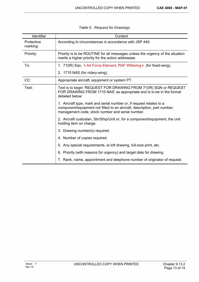
UNCONTROLLED COPY WHEN PRINTED CAE 4000 - MAP-01
Issue - 7 Apr 15
UNCONTROLLED COPY WHEN PRINTED Chapter 9.13.2 Page 13 of 14
Table 5. Request for Drawings.
Identifier Content Protective marking:
According to circumstances in accordance with JSP 440.
Priority: Priority is to be ROUTINE for all messages unless the urgency of the situation merits a higher priority for the action addressee.
To: 1. 71(IR) Sqn, A4 Force Element, RAF Wittering (for fixed-wing).
2. 1710 NAS (for rotary-wing).
CC: Appropriate aircraft, equipment or system PT.
Text: Text is to begin ‘REQUEST FOR DRAWING FROM 71(IR) SQN or REQUEST FOR DRAWING FROM 1710 NAS’ as appropriate and is to be in the format detailed below:
1. Aircraft type, mark and serial number or, if request relates to a component/equipment not fitted to an aircraft, description, part number, management code, stock number and serial number.
2. Aircraft custodian, Stn/Ship/Unit or, for a component/equipment, the unit holding item on charge.
3. Drawing number(s) required.
4. Number of copies required.
5. Any special requirements, ie loft drawing, full-size print, etc.
6. Priority (with reasons for urgency) and target date for drawing.
7. Rank, name, appointment and telephone number of originator of request.

CAE 4000 - MAP-01 UNCONTROLLED COPY WHEN PRINTED
Chapter 9.13.2 Page 14 of 14
UNCONTROLLED COPY WHEN PRINTED
Issue - 7 Apr 15
Intentionally Blank for Print Pagination
UNCONTROLLED COPY WHEN PRINTED CAE 4000 - MAP-01
Issue - 7 Apr 15
UNCONTROLLED COPY WHEN PRINTED Chapter 10.5.1 Page 1 of 6
Chapter 10.5.1
Special Instructions (Technical)
TABLE OF CONTENTS Paragraph
Page
1 ............................................................................................................... 1 General1.1 .......................................................................................................... 1 Introduction1.2 ......................................................................................................... 1 Applicability2 .................................................................................... 2 Regulatory Governance2.1 ................................................................................ 2 Regulatory Cross-reference2.2 .......................................................................................... 2 Additional Information3 ....................................................... 2 Format and promulgation of instructions3.1 ...................................................................................... 2 Categories of instruction3.2 .............................................................. 2 Layout and promulgation of instructions3.3 ................................................................. 3 Electronic maintenance data systems3.4 .......................................................................................................... 3 Distribution3.5
...................................................................................................... 3 Instructions affecting the Air System Safety Case and/or Release to Service (RTS)
3.6 ................ 3 Instructions affecting aircraft or equipment operation and/or handling3.7 ....................................................................................................... 3 Amendments4 ................................................................... 3 Through-life management of SI(T)4.1 ........................................................................................ 3 Retention and indexing4.2 ................................................................................. 4 Application and compliance4.3 ...................................................................................... 4 Follow-up arrangements4.4 ............................................................................................. 4 Active management4.5 ......................................................................................................... 4 Cancellation5 ............................................................................................................ 4 Enquiries6 ......................................................................................................... 5 References
1 General 1.1 Introduction
Special Instructions (Technical) (SI(T)) are temporary instructions, issued by, or on behalf of, the Type Airworthiness Authority (TAA) or commodity Project Team (PT), to undertake a work package to identify, monitor, repair or prevent the occurrence or re-occurrence of a potential fault. Prior to issuing an SI(T) the TAA in conjunction with the Release to Service Authority (RTSA) and Handling Squadron (HS) must assess its effects on the Air System Safety Case, RTS and handling and operation in accordance with RA 5405.
There are 4 types of SI(T):
1 Special Technical Instruction (STI).
2 Servicing Instruction (SI).
3 Urgent Technical Instruction (UTI).
4 Routine Technical Instruction (RTI).
1.2 Applicability This chapter, and its sub-chapters, are applicable to all units responsible for operation, maintenance or storage of aircraft and aircraft-related equipment as listed
CAE 4000 - MAP-01 UNCONTROLLED COPY WHEN PRINTED
Chapter 10.5.1 Page 2 of 6
UNCONTROLLED COPY WHEN PRINTED Issue - 7 Apr 15
at Chapter 10.5.2. This includes supply and storage units, aircraft and equipment on loan to QinetiQ and those undergoing maintenance and/or overhaul by contractors.
2 Regulatory Governance 2.1 Regulatory Cross-reference
This chapter supports:
1 RA 4457.
2.2 Additional Information When the TAA for a small fleet of civil-derived aircraft (eg Islander) considers that it is neither practicable nor cost-effective to convert Service Bulletins (SB) into STI/SI format, the SB may be issued under cover of an SI/STI. This also applies to civil-issued directives, assessed applicable by the Design Organization (DO), to Service aircraft. Exceptionally, the TAA may wish to issue the SB under cover of a UTI/RTI, particularly when there is an intention to vary significantly from the SB or there are significant safety/time/cost implications. The TAA responsibilities for issuing these instructions are covered in detail at Chapter 10.5.3. In all cases, an exemption to RA 4457 must be sought from Military Aviation Authority Regulations and Certification Head (MAA Reg & Cert Hd) in accordance with MAA03, before civil-issued instructions may be issued direct to units.
3 Format and promulgation of instructions 3.1 Categories of instruction
SI(T) are issued in specific equipment categories as listed in Chapter 10.5.2. Requests for new categories must be made using the RFC process in Chapter 0.3.
3.2 Layout and promulgation of instructions 3.2.1 SI/STI/UTI/RTI reference numbers
SI(T) reference number convention is shown in Chapters 10.5.4 and 10.5.5. However, multiple Platform/Equipment Sponsors, identified in Chapter 10.5.2, Table 1, may use a four element reference number to clearly identify the SI(T) PT and equipment and ensure that there is no reference number duplication by different equipment sponsors. For example: SI(T)/PT/Equipment/001.
3.2.2 SI/STI layout and promulgation The layout for an SI and an STI is at Chapter 10.5.4. TAAs/commodity PTs must approve the process for issuing SIs and STIs; RA 4350 and Chapter 8.1 refers. A TAA/commodity PT may issue an SI or STI by supplementary methods such as signal (where available), e-mail or fax, but in such instances they must ensure that the instruction is subsequently issued in the PT approved method. General procedures and responsibilities for SI and STI are given at Chapter 10.5.3.
3.2.3 UTI and RTI layout and promulgation The layout for a UTI and RTI is at Chapter 10.5.5. UTIs and RTIs may be promulgated by signal (where available), e-mail, fax, or in printed form.
3.2.4 Promulgation of instructions – electronic format All SI(T) may be transmitted in electronic format ie signal (where available), and email, using single-Service communications publications as guidance. When an SI(T) is issued in electronic format, the issuing TAA/commodity PT must mandate that all action addressees provide an acknowledgement of receipt. The
UNCONTROLLED COPY WHEN PRINTED CAE 4000 - MAP-01
Issue - 7 Apr 15
UNCONTROLLED COPY WHEN PRINTED Chapter 10.5.1 Page 3 of 6
acknowledgement returns must be collated and checked by the TAA/commodity PT to ensure that all addressees have received the Instruction.
3.3 Electronic maintenance data systems Where electronic maintenance data systems are employed (eg GOLDesp, LITS), TAAs/commodity PTs must ensure that SI(T) that they issue comply with the single-Service requirements for updating the appropriate electronic systems, both on initiation and cancellation.
3.4 Distribution TAAs/commodity PTs must maintain an up-to-date SI(T) distribution list that includes contractors, ie QinetiQ. The issuing TAA/commodity PT is responsible for distributing SI(T) to all affected organizations, including Front Line Commands (FLCs), Stns/Ships/Units, any related PTs and external agencies, as appropriate. This should be conducted through liaison with the relevant Continuing Airworthiness Management Organizations (CAMOs) to ensure that all end-users receive applicable SI(T)s: RA 4947(1)d refers. UTIs must be transmitted by signal for aircraft and equipment of any Service embarked in RN ships.
3.5 Instructions affecting the Air System Safety Case and/or Release to Service (RTS) When initiating an SI(T), TAAs/commodity PTs must engage the RTSA and other specialist organizations. This should allow the RTSA sufficient time to assess the proposal and agree what evidence, if any, is required to enable the RTSA to incorporate the SI(T) into the RTS and to update the Air System Safety Case. When considering the possible effect of an SI(T) on the Air System Safety Case, it is essential that the TAA/commodity PT considers both the fault or potential fault being addressed by the SI(T) and any effect that SI(T) compliance itself may consequently have (for example, an SI(T) that requires the frequent disturbance of a critical aircraft system may, in itself, introduce a Risk to Life).
3.6 Instructions affecting aircraft or equipment operation and/or handling TAAs must consult widely when considering aircraft or handling issues, involving single-Service experts and aircraft operating authorities as appropriate when framing MOD Form entries. OC HS is responsible for determining whether the Instruction affects the handling of the aircraft or equipment. OC HS is also responsible for determining the effect and/or limitations of the Instruction on the operation or handling of an aircraft or equipment and the wording that must be transcribed onto MOD F703A1 and MOD F703A2 for aircraft. (In all instances the draft Instruction must be copied to HS). Also specify any associated Special Flying Instruction.
3.7 Amendments Amendments that do not require the instruction to be re-satisfied are identified by the addition of a suffix letter to the original number. When amendments require the instruction to be re-satisfied, a superseding instruction must be issued using a new number. However, in the case of an SI, changes to the work content are permissible, providing re-satisfaction is not required before the next scheduled application.
4 Through-life management of SI(T) 4.1 Retention and indexing
TAAs/commodity PTs are responsible for:
1 Retaining an audit trail of all actions relating to SI(T).
CAE 4000 - MAP-01 UNCONTROLLED COPY WHEN PRINTED
Chapter 10.5.1 Page 4 of 6
UNCONTROLLED COPY WHEN PRINTED Issue - 7 Apr 15
2 Maintaining registers for all SI(T).
3 Issuing periodic summaries, at least every six months.
CAMOs are also to maintain registers of all SI(T) and periodic summaries issued.
4.2 Application and compliance Custodians of aircraft, flight simulators, synthetic trainers, ground instructional aircraft and ground training aids must ensure that SI(T)) are applied to relevant aircraft and equipment, timeframes are met and records are kept. For aircraft in storage, custodians must ensure that JAP100V-21 requirements are met. For calendar-based activities, the start date for compliance must be the instruction’s date of issue, unless stated otherwise in the SI(T). Requirements for reporting to the issuing authorities must be strictly applied. Operators must be briefed at the appropriate level if operation or handling of aircraft or equipment is affected.
4.3 Follow-up arrangements SI(T) are temporary instructions to invoke rapid action and are not intended to circumvent more formal action, such as modification or maintenance schedule amendment. The intended means of closure must be included in the ‘follow-up’ paragraph of the SI(T).
An SI(T) remains extant until:
1 Issue of a superseding SI(T).
2 Issue of an over-riding publication amendment or aircraft/equipment modification.
3 Fulfilment of purpose, when further application is not required.
4.4 Active management TAAs/commodity PTs must have a robust system in place to monitor and proactively manage SI(T) to ensure that they remain extant for the minimum practical period. SI(T) that remain extant beyond the periods specified below must feature in internal audit reporting to the relevant PT Leader. The longevity of an SI(T) is a standing entry on the Airworthiness Scorecard reported through the relevant Airworthiness Management Group Meetings.
1 UTI – 6 months from date of issue.
2 RTI – 12 months from date of issue.
3 STI/SI – 24 months from date of issue.
4.5 Cancellation An STI or SI is cancelled once the requirements have been satisfied or the instruction superseded. A UTI or RTI is automatically cancelled on expiry of any predetermined timescale or on supersession.
5 Enquiries All enquiries relating to the technical or administrative content of SI(T) should be made to the issuing TAA/commodity PT.
UNCONTROLLED COPY WHEN PRINTED CAE 4000 - MAP-01
Issue - 7 Apr 15
UNCONTROLLED COPY WHEN PRINTED Chapter 10.5.1 Page 5 of 6
6 References This chapter refers to the following publication:
1 RA 4350 - Through Life Management of Technical Information.
2 RA 4947 - Continuing Airworthiness Management - MRP Part M Sub Part G.
3 RA 5405 - Special Instructions (Technical).
4 JAP100V-21 – Aircraft Storage.
CAE 4000 - MAP-01 UNCONTROLLED COPY WHEN PRINTED
Chapter 10.5.1 Page 6 of 6
UNCONTROLLED COPY WHEN PRINTED Issue - 7 Apr 15
Intentionally Blank for Print Pagination
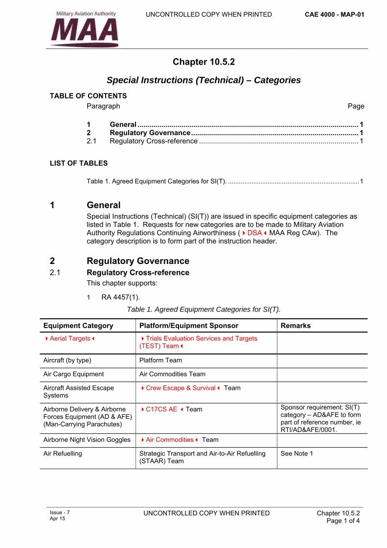
UNCONTROLLED COPY WHEN PRINTED
CAE 4000 - MAP-01
Issue - 7 Apr 15
UNCONTROLLED COPY WHEN PRINTED
Chapter 10.5.2 Page 1 of 4
Chapter 10.5.2
Special Instructions (Technical) – Categories
TABLE OF CONTENTS Paragraph
Page
1 General ............................................................................................................... 1 2 Regulatory Governance.................................................................................... 1 2.1 Regulatory Cross-reference ................................................................................ 1
LIST OF TABLES Table 1. Agreed Equipment Categories for SI(T). .........................................................................1
1 General Special Instructions (Technical) (SI(T)) are issued in specific equipment categories as listed in Table 1. Requests for new categories are to be made to Military Aviation Authority Regulations Continuing Airworthiness (DSAMAA Reg CAw). The category description is to form part of the instruction header.
2 Regulatory Governance 2.1 Regulatory Cross-reference
This chapter supports:
1 RA 4457(1).
Table 1. Agreed Equipment Categories for SI(T).
Equipment Category Platform/Equipment Sponsor Remarks
Aerial Targets Trials Evaluation Services and Targets (TEST) Team
Aircraft (by type) Platform Team
Air Cargo Equipment Air Commodities Team
Aircraft Assisted Escape Systems
Crew Escape & Survival Team
Airborne Delivery & Airborne Forces Equipment (AD & AFE) (Man-Carrying Parachutes)
C17CS AE Team Sponsor requirement: SI(T) category – AD&AFE to form part of reference number, ie RTI/AD&AFE/0001.
Airborne Night Vision Goggles Air Commodities Team
Air Refuelling Strategic Transport and Air-to-Air Refuelling (STAAR) Team
See Note 1
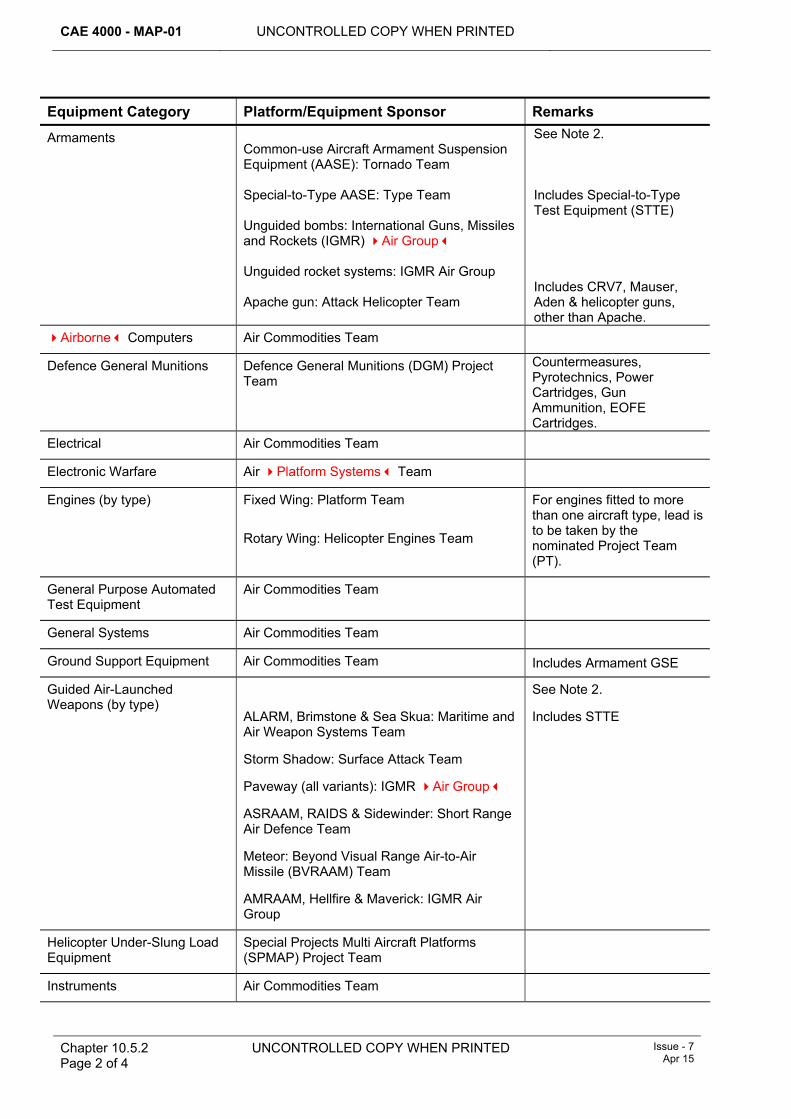
CAE 4000 - MAP-01 UNCONTROLLED COPY WHEN PRINTED
Chapter 10.5.2 Page 2 of 4
UNCONTROLLED COPY WHEN PRINTED Issue - 7 Apr 15
Equipment Category Platform/Equipment Sponsor Remarks
Armaments Common-use Aircraft Armament Suspension Equipment (AASE): Tornado Team Special-to-Type AASE: Type Team Unguided bombs: International Guns, Missiles and Rockets (IGMR) Air Group Unguided rocket systems: IGMR Air Group Apache gun: Attack Helicopter Team
See Note 2. Includes Special-to-Type Test Equipment (STTE) Includes CRV7, Mauser, Aden & helicopter guns, other than Apache.
Airborne Computers Air Commodities Team
Defence General Munitions Defence General Munitions (DGM) Project Team
Countermeasures, Pyrotechnics, Power Cartridges, Gun Ammunition, EOFE Cartridges.
Electrical Air Commodities Team
Electronic Warfare Air Platform Systems Team
Engines (by type) Fixed Wing: Platform Team Rotary Wing: Helicopter Engines Team
For engines fitted to more than one aircraft type, lead is to be taken by the nominated Project Team (PT).
General Purpose Automated Test Equipment
Air Commodities Team
General Systems Air Commodities Team
Ground Support Equipment Air Commodities Team Includes Armament GSE
Guided Air-Launched Weapons (by type)
ALARM, Brimstone & Sea Skua: Maritime and Air Weapon Systems Team
Storm Shadow: Surface Attack Team
Paveway (all variants): IGMR Air Group
ASRAAM, RAIDS & Sidewinder: Short Range Air Defence Team
Meteor: Beyond Visual Range Air-to-Air Missile (BVRAAM) Team
AMRAAM, Hellfire & Maverick: IGMR Air Group
See Note 2.
Includes STTE
Helicopter Under-Slung Load Equipment
Special Projects Multi Aircraft Platforms (SPMAP) Project Team
Instruments Air Commodities Team
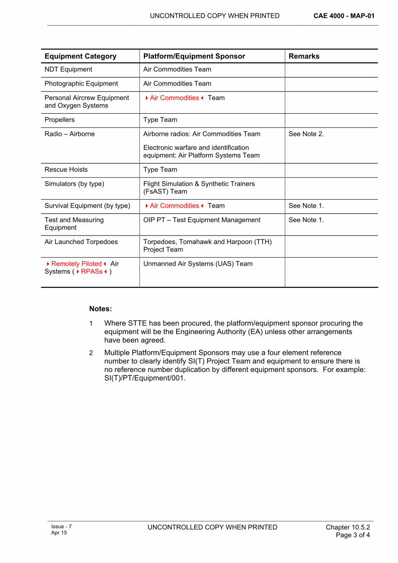
UNCONTROLLED COPY WHEN PRINTED CAE 4000 - MAP-01
Issue - 7 Apr 15
UNCONTROLLED COPY WHEN PRINTED
Chapter 10.5.2 Page 3 of 4
Equipment Category Platform/Equipment Sponsor Remarks
NDT Equipment Air Commodities Team
Photographic Equipment Air Commodities Team
Personal Aircrew Equipment and Oxygen Systems
Air Commodities Team
Propellers Type Team
Radio – Airborne Airborne radios: Air Commodities Team
Electronic warfare and identification equipment: Air Platform Systems Team
See Note 2.
Rescue Hoists Type Team
Simulators (by type) Flight Simulation & Synthetic Trainers (FsAST) Team
Survival Equipment (by type) Air Commodities Team See Note 1.
Test and Measuring Equipment
OIP PT – Test Equipment Management See Note 1.
Air Launched Torpedoes Torpedoes, Tomahawk and Harpoon (TTH) Project Team
Remotely Piloted Air Systems (RPASs)
Unmanned Air Systems (UAS) Team
Notes:
1 Where STTE has been procured, the platform/equipment sponsor procuring the equipment will be the Engineering Authority (EA) unless other arrangements have been agreed.
2 Multiple Platform/Equipment Sponsors may use a four element reference number to clearly identify SI(T) Project Team and equipment to ensure there is no reference number duplication by different equipment sponsors. For example: SI(T)/PT/Equipment/001.

CAE 4000 - MAP-01 UNCONTROLLED COPY WHEN PRINTED
Chapter 10.5.2 Page 4 of 4
UNCONTROLLED COPY WHEN PRINTED Issue - 7 Apr 15
Intentionally Blank for Page Pagination
UNCONTROLLED COPY WHEN PRINTED
CAE 4000 - MAP-01
Issue - 7 Apr 15
UNCONTROLLED COPY WHEN PRINTED
Chapter 10.5.3 Page 1 of 8
Chapter 10.5.3
Special Instructions (Technical) – General Procedures and Responsibilities
TABLE OF CONTENTS Paragraph
Page
1 General ............................................................................................................... 1 2 Regulatory Governance.................................................................................... 1 2.1 Regulatory Cross-reference ................................................................................ 1 3 Special Technical Instruction (STI) / Servicing Instruction (SI) system
outline................................................................................................................. 2 4 Responsibilities for STI/SI production ............................................................ 2 4.1 Design Organization (DO) responsibilities .......................................................... 2 4.2 Type Airworthiness Authority (TAA) / commodity Project Team (PT)
responsibilities..................................................................................................... 2 5 Urgent Technical Instruction/Routine Technical Instruction (UTI/RTI)
system outline ....................................................... Error! Bookmark not defined. 6 Responsibilities for SI(T) administration ........................................................ 6 6.1 Stns/Ships/Units .................................................................................................. 6 6.2 Continuing Airworthiness Management Organization (CAMO) ........................... 6 7 References ......................................................................................................... 6
LIST OF FIGURES Figure 1. STI/SI Production Procedure Flowchart. ........................................................ 7
1 General The Special Technical Instruction (STI), Servicing Instruction (SI), Urgent Technical Instruction (UTI) or Routine Technical Instruction (RTI) procedure should be invoked if rapid action is essential to identify, monitor, repair or prevent the occurrence or re-occurrence of a potential fault in an aircraft or equipment. These procedures are not to be used to circumvent more formal action, ie a UTI in lieu of an STI/SI or an STI/SI in lieu of a modification or maintenance schedule amendment. The UTI/RTI may be used to disseminate information of a technical-administrative or policy nature as detailed at Chapter 10.5.5, but is not to be used to amend MOD-administered publications; procedures for which are at RA 4810 and Chapter 8.2.
2 Regulatory Governance 2.1 Regulatory Cross-reference
This chapter supports:
1 RA 4457(1).
CAE 4000 - MAP-01 UNCONTROLLED COPY WHEN PRINTED
Chapter 10.5.3 Page 2 of 8
UNCONTROLLED COPY WHEN PRINTED Issue - 7 Apr 15
3 Special Technical Instruction (STI) / Servicing Instruction (SI) system outline An STI/SI can be initiated on the recommendation of the Design Organization (DO) or at the request of the Type Airworthiness Authority (TAA) or commodity Project Team (PT). The general outline of the procedure for producing an STI/SI is shown in the flowchart at Figure 1. An STI is only to be raised where remedial action is non-recurrent; an SI is raised for remedial action that is recurrent.
4 Responsibilities for STI/SI production 4.1 Design Organization (DO) responsibilities
The DO for the aircraft or equipment concerned is responsible for the following:
1 Preparing the draft STI/SI.
2 Alerting the TAA or commodity PT, if appropriate, and Non-Destructive Testing (NDT) staffs when there is a need for an NDT technique.
3 When contracted to do so, initiating modification, drawing amendment, AP amendment or other action to enable cancellation of the Instruction.
4 Where the DO is the issuing authority, giving technical approval, ensuring that:
4.1 TAA or commodity PT (as applicable) approval has been gained prior to issue.
4.2 The relevant approval(s) details have been entered into field 10 of the STI/SI layout – (Chapter 10.5.4 figure 1).
5 Preparing Instructions for printing and distribution.
4.2 Type Airworthiness Authority (TAA)/commodity Project Team (PT) responsibilities The TAA/commodity PT is responsible for the following:
1 Ensuring that draft instructions are suitable and achievable for the application for which they have been raised. This may require specialist staff involvement and/or a proof application on an aircraft or equipment concerned. In addition, unless the airworthiness risk precludes it, the appropriate CAMOs should be contacted in order to give advanced notification of the STI/SI, to ensure that the instruction can be complied with and that any impact on availability and operational capability is understood. The following should be considered as a minimum:
1.1 Availability of any spares required (including Fuels, Lubricants and Associated Products (FLAP)) and any specialist tooling.
1.2 The requirement for any specialist skills or training.
1.3 The potential impact on deployed operations and overseas exercises.
1.4 The potential impact on UK training and, when deemed necessary, the need to inform the Delivery Duty Holder (DDH) or Operating Duty Holder (ODH).
Note:
Draft instructions must be raised with the word DRAFT as a ‘centred’ header and footer to the document or with the word DRAFT embellished as a watermark on the document. The issuing TAA/commodity PT must ensure that concise
UNCONTROLLED COPY WHEN PRINTED CAE 4000 - MAP-01
Issue - 7 Apr 15
UNCONTROLLED COPY WHEN PRINTED Chapter 10.5.3 Page 3 of 8
instructions are supplied with the draft SI(T) emphasizing that the draft SI(T) is not to be acted upon until receipt of the authorized SI(T).
2 Where the Issuing Authority is the TAA/commodity PT, discussing technical approval with the DO.
3 Establishing a process to manage all STI/SIs that includes:
3.1 Maintaining a register of reference numbers to be allocated to Instructions, (if also the Issuing Authority).
3.2 Maintaining an index of STI/SI in the Topic 2(N/A/R)1.
3.3 Preparing Instructions for printing and distribution.
3.4 Ensuring that procedures are in place to cancel Instructions.
3.5 Conducting a periodic review of distribution lists, ensuring that all end users are included.
3.6 Conducting a periodic review – at least every six months, of all Instructions issued, extended or cancelled during the previous period. A summary of all occurrences during that period must be produced and distributed to all parties as appropriate.
3.7 Providing the relevant Airworthiness Management Group Meeting with summaries and periodic indexes for each category of STI/SI that remain extant beyond the specified periods as detailed in RA 4457 and Chapter 10.5.1.
4 Ensuring that the layout and content of the Instruction conforms to the requirements of this chapter and 10.5.4.
5 Ensuring that only a competent person with the appropriate level of authority from the TAA/commodity PT Leader (PTL) approves the release of the Instruction. In the case of an Instruction containing on-aircraft work, this should be a holder of an appropriate Letter of Airworthiness Authority (LoAA).
6 Where the TAA/commodity PT is the Issuing Authority, ensuring that the relevant approval(s) details have been entered into field 10 of the STI/SI layout; see Chapter 10.5.4 figure 1.
7 Where a Platform PT is the Engineering Authority for an equipment with multi-platform applicability and has a requirement to issue an STI/SI against this equipment, (using an SI(T) category which is sponsored by a commodity PT), the issuing Platform PT must request an SI(T) reference number from the appropriate commodity PT. The Platform PT will be responsible for producing and distributing the SI(T).
8 Initiating supersession of the Instruction by modification, drawing amendment, AP amendment or other appropriate action.
9 Ensuring that action is taken to initiate updating of single-Service information systems on generation and cessation of Instructions.
10 Ensuring that Domestic Management Code/Nation Code/Item Identification numbers quoted are accurate and verifying the availability of items required from stock.
11 Ensuring that the requirements and implications of applying the Instruction to equipment fitted to flight simulators and synthetic trainers, fatigue test specimens, not-in-use equipment and equipment in store are met.
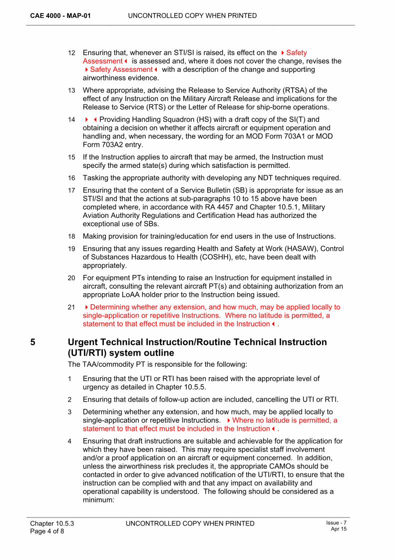
CAE 4000 - MAP-01 UNCONTROLLED COPY WHEN PRINTED
Chapter 10.5.3 Page 4 of 8
UNCONTROLLED COPY WHEN PRINTED Issue - 7 Apr 15
12 Ensuring that, whenever an STI/SI is raised, its effect on the Safety Assessment is assessed and, where it does not cover the change, revises the Safety Assessment with a description of the change and supporting airworthiness evidence.
13 Where appropriate, advising the Release to Service Authority (RTSA) of the effect of any Instruction on the Military Aircraft Release and implications for the Release to Service (RTS) or the Letter of Release for ship-borne operations.
14 Providing Handling Squadron (HS) with a draft copy of the SI(T) and obtaining a decision on whether it affects aircraft or equipment operation and handling and, when necessary, the wording for an MOD Form 703A1 or MOD Form 703A2 entry.
15 If the Instruction applies to aircraft that may be armed, the Instruction must specify the armed state(s) during which satisfaction is permitted.
16 Tasking the appropriate authority with developing any NDT techniques required.
17 Ensuring that the content of a Service Bulletin (SB) is appropriate for issue as an STI/SI and that the actions at sub-paragraphs 10 to 15 above have been completed where, in accordance with RA 4457 and Chapter 10.5.1, Military Aviation Authority Regulations and Certification Head has authorized the exceptional use of SBs.
18 Making provision for training/education for end users in the use of Instructions.
19 Ensuring that any issues regarding Health and Safety at Work (HASAW), Control of Substances Hazardous to Health (COSHH), etc, have been dealt with appropriately.
20 For equipment PTs intending to raise an Instruction for equipment installed in aircraft, consulting the relevant aircraft PT(s) and obtaining authorization from an appropriate LoAA holder prior to the Instruction being issued.
21 Determining whether any extension, and how much, may be applied locally to single-application or repetitive Instructions. Where no latitude is permitted, a statement to that effect must be included in the Instruction.
5 Urgent Technical Instruction/Routine Technical Instruction (UTI/RTI) system outline The TAA/commodity PT is responsible for the following:
1 Ensuring that the UTI or RTI has been raised with the appropriate level of urgency as detailed in Chapter 10.5.5.
2 Ensuring that details of follow-up action are included, cancelling the UTI or RTI.
3 Determining whether any extension, and how much, may be applied locally to single-application or repetitive Instructions. Where no latitude is permitted, a statement to that effect must be included in the Instruction.
4 Ensuring that draft instructions are suitable and achievable for the application for which they have been raised. This may require specialist staff involvement and/or a proof application on an aircraft or equipment concerned. In addition, unless the airworthiness risk precludes it, the appropriate CAMOs should be contacted in order to give advanced notification of the UTI/RTI, to ensure that the instruction can be complied with and that any impact on availability and operational capability is understood. The following should be considered as a minimum:
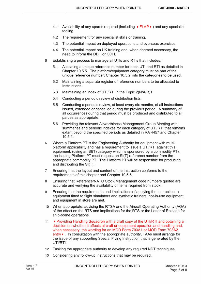
UNCONTROLLED COPY WHEN PRINTED CAE 4000 - MAP-01
Issue - 7 Apr 15
UNCONTROLLED COPY WHEN PRINTED Chapter 10.5.3 Page 5 of 8
4.1 Availability of any spares required (including FLAP) and any specialist tooling.
4.2 The requirement for any specialist skills or training.
4.3 The potential impact on deployed operations and overseas exercises.
4.4 The potential impact on UK training and, when deemed necessary, the need to inform the DDH or ODH.
5 Establishing a process to manage all UTIs and RTIs that includes:
5.1 Allocating a unique reference number for each UTI and RTI as detailed in Chapter 10.5.5. The platform/equipment category must be part of the unique reference number; Chapter 10.5.2 lists the categories to be used.
5.2 Maintaining a separate register of reference numbers to be allocated to Instructions.
5.3 Maintaining an index of UTI/RTI in the Topic 2(N/A/R)1.
5.4 Conducting a periodic review of distribution lists.
5.5 Conducting a periodic review, at least every six months, of all Instructions issued, extended or cancelled during the previous period. A summary of all occurrences during that period must be produced and distributed to all parties as appropriate.
5.6 Providing the relevant Airworthiness Management Group Meeting with summaries and periodic indexes for each category of UTI/RTI that remains extant beyond the specified periods as detailed in RA 4457 and Chapter 10.5.1.
6 Where a Platform PT is the Engineering Authority for equipment with multi-platform applicability and has a requirement to issue a UTI/RTI against this equipment, (using an SI(T) category which is sponsored by a commodity PT), the issuing Platform PT must request an SI(T) reference number from the appropriate commodity PT. The Platform PT will be responsible for producing and distributing the SI(T).
7 Ensuring that the layout and content of the Instruction conforms to the requirements of this chapter and Chapter 10.5.5.
8 Ensuring that Reference/NATO Stock/Management code numbers quoted are accurate and verifying the availability of items required from stock.
9 Ensuring that the requirements and implications of applying the Instruction to equipment fitted to flight simulators and synthetic trainers, not-in-use equipment and equipment in store are met.
10 When appropriate, advising the RTSA and the Aircraft Operating Authority (AOA) of the effect on the RTS and implications for the RTS or the Letter of Release for ship-borne operations.
11 Providing Handling Squadron with a draft copy of the UTI/RTI and obtaining a decision on whether it affects aircraft or equipment operation and handling and, when necessary, the wording for an MOD Form 703A1 or MOD Form 703A2 entry. In consultation with the appropriate authority, TAAs must arrange for the issue of any supporting Special Flying Instruction that is generated by the UTI/RTI.
12 Tasking the appropriate authority to develop any required NDT techniques.
13 Considering any follow-up Instructions that may be required.
CAE 4000 - MAP-01 UNCONTROLLED COPY WHEN PRINTED
Chapter 10.5.3 Page 6 of 8
UNCONTROLLED COPY WHEN PRINTED Issue - 7 Apr 15
14 Arranging for the distribution of Instructions to all end users and, where an SI(T) is issued by signal, ensuring that copies have been received by all action addressees in accordance with RA 4457 and Chapter 10.5.1.
15 Initiating supercession of the Instruction by modification, drawing amendment, AP amendment or other appropriate action.
16 Ensuring that, where appropriate, a follow-up Instruction is generated on cancellation of the UTI or RTI.
17 Ensuring that any issues regarding HASAW, COSHH, etc, have been dealt with appropriately.
18 For equipment PTs intending to raise an Instruction for equipment installed in aircraft, consulting the relevant aircraft PT(s) and obtaining authorization from an appropriate LoAA holder prior to the Instruction being issued.
6 Responsibilities for SI(T) administration 6.1 Stns/Ships/Units
Stns/Ships/Units, as required, must maintain registers of extant SI(T) and retain copies of PT generated 6-monthly summaries (see Paragraph 4.2 item 3.6 and Paragraph 5 item 5.5).
6.2 Continuing Airworthiness Management Organization (CAMO) In addition to their consultative role in the drafting of SI(T)s (see Paragraph 4.2 item 1 and Paragraph 5 item 4), and their role in ensuring that they are appropriately distributed to end users following issue (see RA 4947(1)d and MAP-01 Chapter 10.5.1), CAMOs have a responsibility to manage the compliance of instructions and ensure that appropriate records of extant SI(T)s, as detailed in Paragraph 6.1, are retained: RA 4947(1)d refers.
7 References This chapter refers to the following publication:
1 Topic 2(N/A/R)1 – General Orders and Special Instructions.
2 RA 4947 - Continuing Airworthiness Management - MRP Part M Sub Part G.
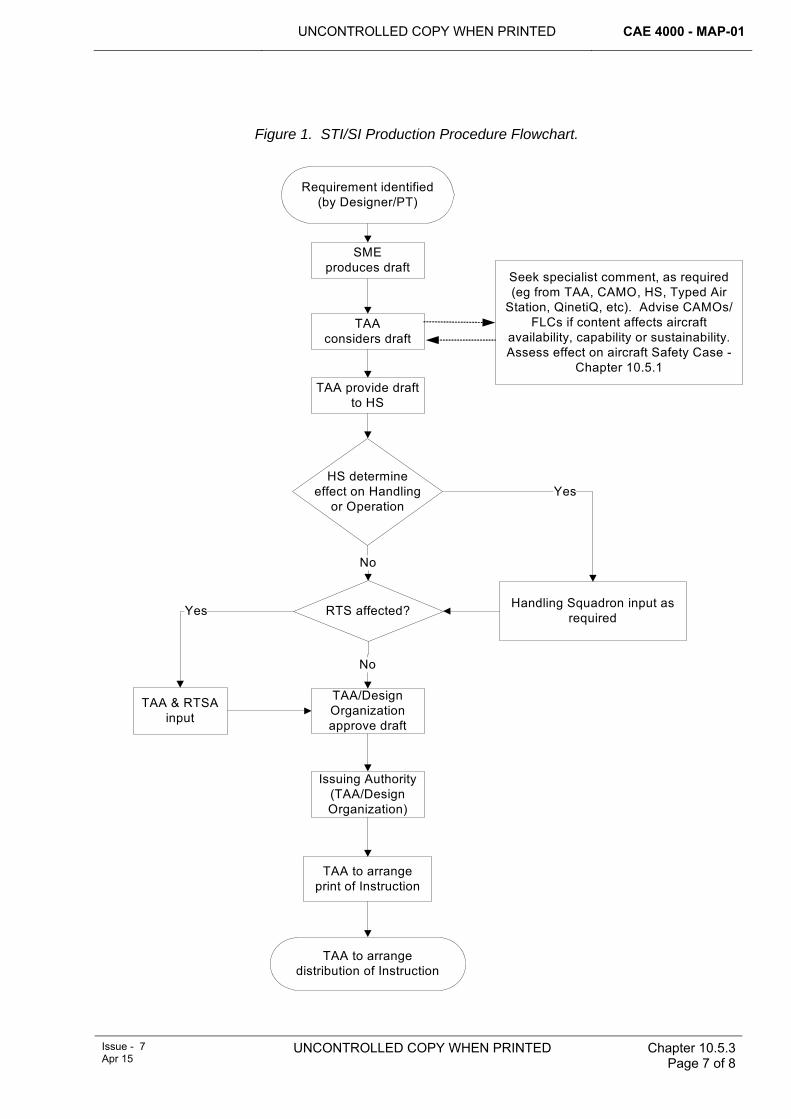
UNCONTROLLED COPY WHEN PRINTED CAE 4000 - MAP-01
Issue - 7 Apr 15
UNCONTROLLED COPY WHEN PRINTED Chapter 10.5.3 Page 7 of 8
Figure 1. STI/SI Production Procedure Flowchart.
Requirement identified (by Designer/PT)
SME produces draft
TAA considers draft
RTS affected?
TAA/Design Organization approve draft
Issuing Authority (TAA/Design Organization)
TAA to arrange
Seek specialist comment, as required (eg from TAA, CAMO, HS, Typed Air
Station, QinetiQ, etc). Advise CAMOs/FLCs if content affects aircraft
availability, capability or sustainability. Assess effect on aircraft Safety Case -
Chapter 10.5.1TAA provide draft
to HS
print of Instruction
TAA to arrangedistribution of Instruction
TAA & RTSA input
Handling Squadron input as required
No
No
Yes
HS determine effect on Handling
or Operation Yes

CAE 4000 - MAP-01 UNCONTROLLED COPY WHEN PRINTED
Chapter 10.5.3 Page 8 of 8
UNCONTROLLED COPY WHEN PRINTED Issue - 7 Apr 15
Intentionally Blank for Print Pagination
UNCONTROLLED COPY WHEN PRINTED CAE 4000 - MAP-01
Issue - 7 Apr 15
UNCONTROLLED COPY WHEN PRINTED Chapter 10.5.4 Page 1 of 6
Chapter 10.5.4
Special Technical Instructions and Servicing Instructions – Layout
TABLE OF CONTENTS Paragraph
Page
1 General ............................................................................................................... 1 1.1 Introduction.......................................................................................................... 1 2 Regulatory Governance.................................................................................... 1 2.1 Regulatory Cross-reference ................................................................................ 1 3 Layout and content .................................................................................... 1
LIST OF FIGURES Figure 1. Layout of an STI or SI.....................................................................................................1
1 General 1.1 Introduction
This chapter illustrates at Figure 1 the layout of Special Technical Instructions (STIs) and Servicing Instructions (SIs) produced in accordance with the regulations contained in Chapter 10.5.3.
2 Regulatory Governance 2.1 Regulatory Cross-reference
This chapter supports:
1 RA 4457(1).
3 Layout and content The layout and content of a SI or STI is to be completed as detailed in Figure 1. Originators must include all the stated paragraph numbering and paragraph headings. All content must be completed, except when a paragraph has no relevant content; then it must be annotated "Not Applicable" or as instructed in the detail for the paragraph heading.
Figure 1. Layout of an STI or SI
PROTECTIVE MARKING (unless Unclassified)
STI or SI/Category/Serial No
(followed by suffix letter for amendments)(eg STI/TOR/XXX)
Date of issue From: [Enter Publication Authority details] This Instruction is approved and issued for application to MOD materiel. Unless otherwise agreed, the use
CAE 4000 - MAP-01 UNCONTROLLED COPY WHEN PRINTED
Chapter 10.5.4 Page 2 of 6
UNCONTROLLED COPY WHEN PRINTED
Issue - 7 Apr 15
of this information for any other purpose is on the understanding that Her Majesty’s Government (HMG) will not be liable in any way whatever (including but without limitation negligence on the part of HMG, its servants or agents) in respect of injury to persons or loss or damage to property where the information is so used. Enquiries. All enquiries relating to the technical or administrative content of this SI(T) should be made to the issuing Project Team (PT). 1. TITLE The title must consist of 2 to 4 elements, viz:
a. Instruction reference number, eg STI/TOR/XXX (plus suffix letter, if amended version). b. A brief description of the fault, eg FIN ATTACHMENT – CRACKING. c. The Reference of any superseded Instruction, if applicable, in brackets, eg (Superseding – UTI/TOR/XXX (plus suffix letter, if amended version). d. Logistical Information System (LIS) reference, if applicable.
2. APPLICATION
a. Equipment In Use. State the application of the Instruction to in-use equipment, ie to which aircraft, aircraft mark, guided weapon, engine change unit or other equipment by description, mark, stores management code, reference number or NATO stock number and, where applicable, serial number. State in this paragraph any application of the Instruction to fly-away packs/priming equipment packs, flight simulators, synthetic trainers, fatigue test specimens, Ground Instructional Aircraft and ground training aids. Where the Instruction is being applied, or otherwise satisfied by modification action, to new production aircraft or equipment before delivery to the Service, the serial number of the first item so satisfied is also to be included in this paragraph. The PT is responsible for allocating new stores management codes, reference numbers or NATO stock numbers as required.
b. Equipment In Store. State the application of the Instruction to aircraft in storage and to not-in-use equipment (excluding fly away/priming equipment packs). The PT must discuss its contents with the relevant staffs responsible for aircraft in storage and for not-in-use equipment.
3. REASON FOR INSTRUCTION AND ASSOCIATED INFORMATION
a. Reason. Provide a brief summary of the circumstances that gave rise to the Instruction and state, in general terms, the examination, remedial and reporting actions required. b. Effect of Any Previous Instruction. State briefly any previous related Instruction, including UTI/RTIs, etc, and whether compliance with any has a bearing on the application of the Instruction being issued. c. References. Detail any necessary references; the following sequence must be used:
(1) Hazard and Maintenance Information (Safety and Maintenance Notes). Specify the Aircraft Publication (AP) and Topic number of the aircraft or equipment Hazard and Maintenance Information (Safety and Maintenance Notes) concerned. (2) Other Publications. List other relevant publications by AP and Topic number. (3) Drawings.
(a) Attached. Identify any drawing that is attached to the Instruction. Give precise location reference points and dimensions to work points within drawings. Drawings must be A3 (Landscape) or A4 in size, drawn in ink and must meet the requirements of JSP 181.
UNCONTROLLED COPY WHEN PRINTED CAE 4000 - MAP-01
Issue - 7 Apr 15
UNCONTROLLED COPY WHEN PRINTED
Chapter 10.5.4 Page 3 of 6
(b) Existing Contractor’s Drawings. List any applicable existing Contractor’s drawings. The appropriate PT must obtain Contractor’s drawings that will be required by units and liaise with the appropriate RPO to ensure that all necessary drawings will be available when required.
(c) Repair Scheme. Provide instructions to units on how to obtain relevant repair schemes.
(4) NDT Techniques. Include the identification numbers of any relevant NDT techniques. (5) Spares and Special Tools. Provide details of spares and special tools, listed by their supply management code and reference or NATO stock numbers. Include details of any special supply arrangements made – especially where the source is non-Service. The appropriate PT must verify all reference and stock numbers quoted and ensure that stocks are available to units before the Instruction is issued. (6) List of Hazardous Substances. List any substance, required by the Instruction, that is defined as being hazardous to health by Regulation 2 of the Control of Substances Hazardous to Health Regulations (1988), contained in the Health and Safety at Work Act 1974.
d. Structural Integrity. Identify any structural integrity implications of the Instruction. The PT concerned must identify any structurally significant items affected by the Instruction and list those elements of sub-paragraphs 4b and 5b (work required) that must be undertaken by qualified personnel. For RAF and Army aircraft and equipment, this must include identifying ‘Y’ or ‘tech’ coded items listed in the Topic 5A1, Master Maintenance List. Where there are no structural integrity implications, this sub-paragraph must state: ‘This Instruction has no structural integrity implications.’
4. TIMING AND WORK REQUIRED FOR EQUIPMENT IN USE
a. Timing. State the time limit in working days/calendar days, or conditions with a specified time limit, for initial application of the Instruction and, in the case of SIs, the repetition frequency. Where the work package is set out in parts, the relevant conditions and time limits for each part must be included. A statement is also to be included where deferment or compliance latitude is permitted at unit level and the authority level, in accordance with RA 4806 and Chapter 4.3, of who may authorize the deferment. When an SI(T) is aligned with an existing scheduled maintenance opportunity, the Instruction must state whether its compliance may be deferred in line with that scheduled maintenance or whether it must retain its own stated latitude. Where no latitude is permitted a statement to that effect is to be included in the SI(T). b. Work Required. State the examination and remedial action required for in-use equipment. Where there are no record or log cards for the affected assemblies or parts, there may be a requirement to mark the work area or part to indicate satisfaction of the Instruction prior to installation of the component or closure of the access to the work area. Include engineering preparation and recovery work, eg jacking, panel removal/replacement and any caveats relating to satisfaction on armed aircraft, if applicable. Use this sub-paragraph to define different work centres, in which case the work package must be set out in parts. c. Manhours. State the estimated manhours required to carry out the Instruction per aircraft or equipment, etc (incomplete hours must be expressed in decimals). For planning purposes, quote the manhours by trades and, where appropriate, include estimates of surface finish or adhesive drying times.
5. TIMING AND WORK REQUIRED FOR EQUIPMENT IN STORE
a. Timing. State the time limit for carrying out the Instruction. b. Work Required. State the examination and remedial action required on aircraft in storage
CAE 4000 - MAP-01 UNCONTROLLED COPY WHEN PRINTED
Chapter 10.5.4 Page 4 of 6
UNCONTROLLED COPY WHEN PRINTED
Issue - 7 Apr 15
and not-in-use equipment. The PT concerned must discuss its content with the relevant staffs responsible for aircraft in storage and for not-in-use equipment. The work package may cross-refer to sub-paragraph 4b above. If it is not possible to satisfy the Instruction on not-in-use equipment, this sub-paragraph must state ‘labelling action only’ and include any instructions for labelling stock so affected.
c. Manhours. State the estimated manhours for carrying out the Instruction per aircraft or equipment, etc, including unpacking and re-packing times (incomplete manhours must be expressed as decimals). The contractor concerned will advise on the manhours required to unpack and repack not-in-use equipment.
6. RECORDING The PT concerned must specify the maintenance forms and/or information systems
to be used for recording. However, the PT must include appropriate specific statements to identify non-standard requirements.
a. Equipment In Use. Provide instructions for recording, and certifying compliance with, the Instruction following satisfaction on equipment in use. In the case of SIs, include the additional recording necessary to ensure subsequent repeated application. b. Equipment In Store. Provide instructions for recording, and certifying compliance with, the Instruction following satisfaction on aircraft in store or on not-in-use equipment. Alternatively, where the requirement is for ‘labelling action only’ as described in sub-paragraph 5b above, include a statement on the endorsements to be made on the equipment record or log card.
7. REPORTING
a. Reporting of Faults Found. State whether advance reports of faults found are required: if so, whether by signal, e-mail, fax or letter and the addressees. For signals, include the SICs that will be used. MOD Form 760 fault reports raised in response to an Instruction must include the reference number of the appropriate Instruction. Where rejected items of equipment will be sent to a contractor, provide labelling and documentation instructions, including the authority and task number, or contract number, for movement of the equipment. b. Reporting of Satisfaction or Non-satisfaction of Instruction. Specify the report format (including SICs for signals) to be used for reporting satisfaction or non-satisfaction of the Instruction. Include addressees for the report.
8. FOLLOW-UP ACTION
a. Include instructions for disposal of any parts removed and controls for any lifed items introduced by the STI. b. Describe the follow-up action already initiated, or proposed, that will lead to supersession or cancellation of the Instruction, eg AP or schedule amendment, modification action or changes to contractor’s drawings.
9. SPECIAL REQUIREMENTS
a. Effect on Operation and/or Handling. Submit the draft SI(T) to Handling Squadron (HS) to determine the effect on operation and/or handling of the aircraft or equipment. HS are required to provide the statement on the effect on operation and/or handling and, if necessary, the wording to be entered on to the MOD Form 703A1 or MOD Form 703A2 for the aircraft. b. Generic Aircraft Release Procedure/Military Aircraft Release/Release To Service. State: ‘The GARP*/MAR*/RTS*/Letter of Release for shipborne operations is*/is not* affected’. * Delete as appropriate. c. Electro-magnetic Compatibility (EMC). State, ‘The EMC of the aircraft*/weapon*/ equipment* may be*/is not* affected’.
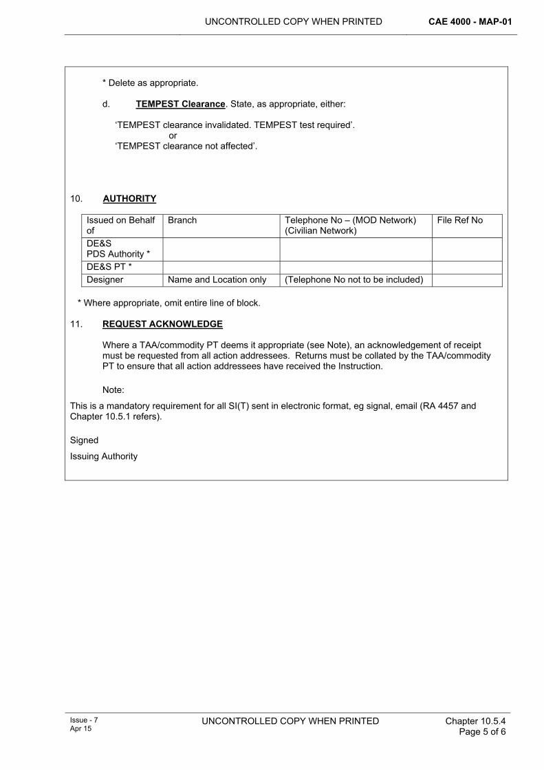
UNCONTROLLED COPY WHEN PRINTED CAE 4000 - MAP-01
Issue - 7 Apr 15
UNCONTROLLED COPY WHEN PRINTED
Chapter 10.5.4 Page 5 of 6
* Delete as appropriate. d. TEMPEST Clearance. State, as appropriate, either: ‘TEMPEST clearance invalidated. TEMPEST test required’. or ‘TEMPEST clearance not affected’.
10. AUTHORITY
Issued on Behalf of
Branch Telephone No – (MOD Network) (Civilian Network)
File Ref No
DE&S PDS Authority *
DE&S PT * Designer Name and Location only (Telephone No not to be included)
* Where appropriate, omit entire line of block. 11. REQUEST ACKNOWLEDGE
Where a TAA/commodity PT deems it appropriate (see Note), an acknowledgement of receipt must be requested from all action addressees. Returns must be collated by the TAA/commodity PT to ensure that all action addressees have received the Instruction. Note:
This is a mandatory requirement for all SI(T) sent in electronic format, eg signal, email (RA 4457 and Chapter 10.5.1 refers). Signed
Issuing Authority
CAE 4000 - MAP-01 UNCONTROLLED COPY WHEN PRINTED
Chapter 10.5.4 Page 6 of 6
UNCONTROLLED COPY WHEN PRINTED
Issue - 7 Apr 15
Intentionally Blank for Print Pagination
UNCONTROLLED COPY WHEN PRINTED
CAE 4000 - MAP-01
Issue - 7 Apr 15
UNCONTROLLED COPY WHEN PRINTED
Chapter 10.5.5 Page 1 of 6
Chapter 10.5.5
Urgent and Routine Technical Instructions – Layout
TABLE OF CONTENTS Paragraph
Page
1 General ............................................................................................................... 1 1.1 Introduction.......................................................................................................... 1 2 Regulatory Governance.................................................................................... 1 2.1 Regulatory Cross-reference ................................................................................ 1 3 Urgent Technical Instructions (UTIs) .............................................................. 1 4 Routine Technical Instructions (RTIs)............................................................. 2 5 Layout and Content........................................................................................... 2 6 Reference ........................................................................................................... 2
LIST OF FIGURES Figure 1. Layout of UTI and RTI. ...................................................................................................2
1 General 1.1 Introduction
A Type Airworthiness Authority (TAA) or commodity Project Team (PT) may wish to communicate issues of a technical nature to its customer base. Issues that warrant close Design Organization (DO) involvement and result in the issue of Special Technical Instructions (STIs) and Servicing Instructions (SIs) are covered in Chapter 10.5.3. All other matters, including technical administration, policy issues, fleet trawls, etc, and issues that may result in the issue of an STI/SI but need prior Service action, should be communicated through Service technical instructions. These technical instructions are categorized as either Urgent or Routine and are titled accordingly. TAAs/commodity PTs must ensure that records of Urgent Technical Instructions (UTIs) and Routine Technical Instructions (RTIs) are maintained in aircraft/equipment Topic 2(N/A/R)1.
2 Regulatory Governance 2.1 Regulatory Cross-reference
This chapter supports:
1 RA 4457(1).
3 Urgent Technical Instructions (UTIs) Issued by the relevant TAA/commodity PT, a UTI can be used to inform units of a potential fault, to audit the extent of a potential problem and, on occasion, to give instructions for remedial action, and to effect technical administration action. A UTI may be issued in response to an incident or Serious Fault Report (SFR) raised by an operating unit and may be of a recurrent or non-recurrent nature. UTIs are to be raised when DO input is not immediately required and remedial action is necessary within 14 days/25 flying hours.
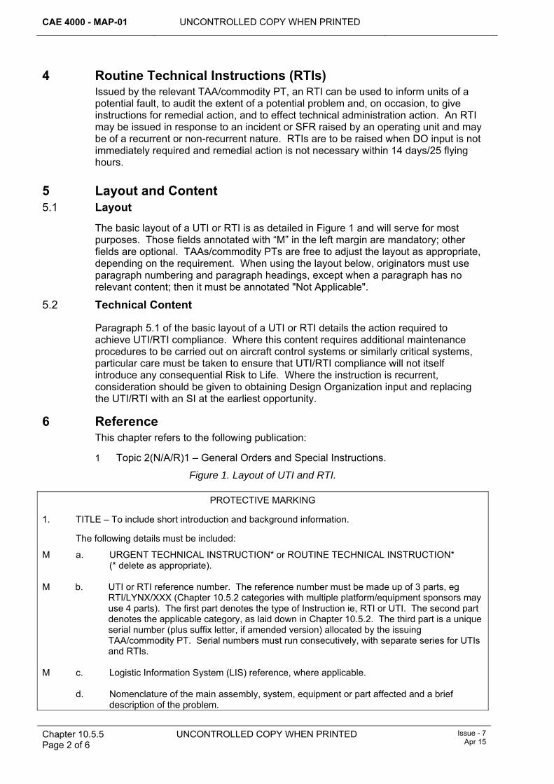
CAE 4000 - MAP-01 UNCONTROLLED COPY WHEN PRINTED
Chapter 10.5.5 Page 2 of 6
UNCONTROLLED COPY WHEN PRINTED Issue - 7 Apr 15
4 Routine Technical Instructions (RTIs) Issued by the relevant TAA/commodity PT, an RTI can be used to inform units of a potential fault, to audit the extent of a potential problem and, on occasion, to give instructions for remedial action, and to effect technical administration action. An RTI may be issued in response to an incident or SFR raised by an operating unit and may be of a recurrent or non-recurrent nature. RTIs are to be raised when DO input is not immediately required and remedial action is not necessary within 14 days/25 flying hours.
5 Layout and Content 5.1 Layout
The basic layout of a UTI or RTI is as detailed in Figure 1 and will serve for most purposes. Those fields annotated with “M” in the left margin are mandatory; other fields are optional. TAAs/commodity PTs are free to adjust the layout as appropriate, depending on the requirement. When using the layout below, originators must use paragraph numbering and paragraph headings, except when a paragraph has no relevant content; then it must be annotated "Not Applicable".
5.2 Technical Content
Paragraph 5.1 of the basic layout of a UTI or RTI details the action required to achieve UTI/RTI compliance. Where this content requires additional maintenance procedures to be carried out on aircraft control systems or similarly critical systems, particular care must be taken to ensure that UTI/RTI compliance will not itself introduce any consequential Risk to Life. Where the instruction is recurrent, consideration should be given to obtaining Design Organization input and replacing the UTI/RTI with an SI at the earliest opportunity.
6 Reference This chapter refers to the following publication:
1 Topic 2(N/A/R)1 – General Orders and Special Instructions.
Figure 1. Layout of UTI and RTI.
PROTECTIVE MARKING
1. TITLE – To include short introduction and background information.
The following details must be included:
M a. URGENT TECHNICAL INSTRUCTION* or ROUTINE TECHNICAL INSTRUCTION* (* delete as appropriate).
M b. UTI or RTI reference number. The reference number must be made up of 3 parts, eg RTI/LYNX/XXX (Chapter 10.5.2 categories with multiple platform/equipment sponsors may use 4 parts). The first part denotes the type of Instruction ie, RTI or UTI. The second part denotes the applicable category, as laid down in Chapter 10.5.2. The third part is a unique serial number (plus suffix letter, if amended version) allocated by the issuing TAA/commodity PT. Serial numbers must run consecutively, with separate series for UTIs and RTIs.
M c. Logistic Information System (LIS) reference, where applicable.
d. Nomenclature of the main assembly, system, equipment or part affected and a brief
description of the problem.
UNCONTROLLED COPY WHEN PRINTED CAE 4000 - MAP-01
Issue - 7 Apr 15
UNCONTROLLED COPY WHEN PRINTED Chapter 10.5.5 Page 3 of 6
e. Reference to any Serious Fault Signal, Air/Ground Incident Report or Special Flying
Instruction. f. Reference of any superseded Instruction.
2. APPLICATION
a. Equipment in Use. State the applicability of the Instruction to in-use equipment, including that fitted to flight simulators, synthetic trainers, Ground Instructional Aircraft and ground training aids, by description, mark, stores management code, ref no/NATO stock no and, where applicable, serial no.
b. Equipment in Store. State the applicability of the Instruction to equipment in store and not-
in-use equipment, including flyaway packs/priming equipment packs. 3. REASON
Summarize the circumstances leading to the requirement for a UTI/RTI, including a brief statement on any previous related Instructions.
Note:
TAAs/commodity PTs may use this paragraph to state their assessment of the associated risk, in terms of the hazard and likelihood, which the UTI/RTI seeks to address through its implementation.
4. REFERENCES
a. Hazard and Maintenance Information (Safety and Maintenance Notes) – hazardous substances. b. Other relevant publications. c. Drawings. d. Relevant repair schemes. e. NDT techniques. f. Spares and special tools.
5. ACTION REQUIRED
a. Investigation. Describe the investigation required, on both in-use and not-in-use equipment, to find the reported fault. Include reference to the Topic 1/3 where appropriate. State whether the investigation (and remedial work where applicable) may be carried out on armed aircraft and where this is the case, detail the permitted armament state and any additional measures required.
b. Remedial Work. Describe the immediate remedial work necessary. This may include
marking the UTI/RTI number on the equipment to denote compliance. c. Timescales. Detail the timeframe for compliance, together with any repetition frequency of
the action, where appropriate. Detail any latitudes or extensions that may be applied locally to the Instruction and the authority level, in accordance with RA 4806 and Chapter 4.3, of who may authorize the deferment. When a UTI or RTI is aligned with an existing scheduled maintenance opportunity, the Instruction must state whether its compliance may be deferred in line with that scheduled maintenance or whether it must retain its own stated latitude. Where no latitude is permitted a statement to that effect is to be included in the
CAE 4000 - MAP-01 UNCONTROLLED COPY WHEN PRINTED
Chapter 10.5.5 Page 4 of 6
UNCONTROLLED COPY WHEN PRINTED Issue - 7 Apr 15
SI(T).
Note:
Unless stated otherwise by the TAA/commodity PT the start date for compliance with calendar-based activities must be the date inserted at paragraph 10 of the Instruction (authority for issue).
d. Manhours. State the estimated manhours required to carry out the Instruction per aircraft or equipment, etc. (incomplete hours must be expressed in decimals). For planning purposes, quote the manhours by trades and, where appropriate, include estimates of surface finish or adhesive drying times.
6. RECORDING
The TAA/commodity PT concerned must specify the maintenance forms and/or information system to be used for recording. However, the TAA/commodity PT must include appropriate specific statements to identify non-standard requirements.
7. REPORTING
a. Reporting of Faults Found. State whether early reporting of faults found is required and, where necessary, by what means.
b. Reporting of Satisfaction or Non-satisfaction of Instructions. Give details of the report
format, including addressees, SICs and timings. M 8. FOLLOW-UP ACTION
Describe the method by which the Instruction will be cancelled, eg by AP or schedule amendment, modification action, fulfilment of purpose and further application not required, or by default when the timescale for its application has expired.
9. SPECIAL REQUIREMENTS
a. Effect on Operation and/or Handling. If the Instruction affects the handling of the aircraft or equipment, refer to DME 5000 Series Regulation. Also specify any associated Special Flying Instruction. When framing this sub-paragraph, consult the appropriate Subject Matter Experts and Second Customer staffs. Where there is no effect on operation or handling, state ‘Operation and handling are not affected’.
b. Generic Aircraft Release Process/Military Aircraft Release/Release To Service. State ‘The
GARP*/MAR*/RTS*/Letter of Release for shipborne operations is*/is not* affected’, as appropriate.
c. EMC. State ‘The EMC of the aircraft*/weapon*/equipment* may be*/is not* affected’, as
appropriate.
d. TEMPEST Clearance. State ‘TEMPEST clearance invalidated*/not affected*/test required*’, as appropriate.
* Delete as necessary
M 10. AUTHORITY FOR ISSUE
Include Branch, Appointment, Date and Tel No of the individual authorizing the instruction’s issue.
UNCONTROLLED COPY WHEN PRINTED CAE 4000 - MAP-01
Issue - 7 Apr 15
UNCONTROLLED COPY WHEN PRINTED Chapter 10.5.5 Page 5 of 6
11. REQUEST ACKNOWLEDGE
Where a TAA/commodity PT deems it appropriate (see Note), an acknowledgement of receipt must be requested from all action addressees. Returns must be collated by the TAA/commodity PT to ensure that all action addressees have received the Instruction. Note:
This is a mandatory requirement for all SI(T) sent in electronic format, eg signal, email (RA 4457 and Chapter 10.5.1 refers).
12. CONTACT INFORMATION
Provide TAA/commodity PT contact details as appropriate, eg out-of-hours contact telephone numbers.

CAE 4000 - MAP-01 UNCONTROLLED COPY WHEN PRINTED
Chapter 10.5.5 Page 6 of 6
UNCONTROLLED COPY WHEN PRINTED Issue - 7 Apr 15
Intentionally Blank for Print Pagination
UNCONTROLLED COPY WHEN PRINTED
CAE 4000 - MAP-01
MAE Issue - 6 Mar 14
UNCONTROLLED COPY WHEN PRINTED
Chapter 10.5.6 Page 1 of 6
Chapter 10.5.6
Aviation Local Technical Instructions
TABLE OF CONTENTS Paragraph
Page
1 General ............................................................................................................... 1 1.1 Introduction.......................................................................................................... 1 2 Regulatory Governance.................................................................................... 1 2.1 Regulatory Cross-reference ................................................................................ 1 2.2 Additional Information.......................................................................................... 1 3 Criteria for raising an ALTI ............................................................................... 1 4 ALTI validity ....................................................................................................... 3 5 Follow-up action................................................................................................ 3 6 Amendment of ALTIs ........................................................................................ 3 6.1 Minor amendment ............................................................................................... 3 6.2 Major amendment ............................................................................................... 4 7 Responsibilities................................................................................................. 4 7.1 Authority level K .................................................................................................. 4 7.2 Front Line Commands (FLCs)............................................................................. 4 7.3 Type Airworthiness Authority (TAA)/commodity Project Team (PT) ................ 4
LIST OF TABLES Table 1. Layout of an Aviation Local Technical Instruction............................................ 2
1 General 1.1 Introduction
An Aviation Local Technical Instruction (ALTI) enables the promulgation of a formal instruction, which satisfies an urgent local engineering requirement where high or mid-level directives are inadequate due to local operational or environmental circumstances.
2 Regulatory Governance 2.1 Regulatory Cross-reference
This Chapter supports:
1 RA 4462(1).
2 RA 4462(2).
2.2 Additional Information Nil.
3 Criteria for raising an ALTI Where, for local operational or environmental reasons, extant maintenance schedules, instructions, orders or procedures are inadequate, the relevant individual holding authorization MAP-K290, after consulting with the Front Line Command
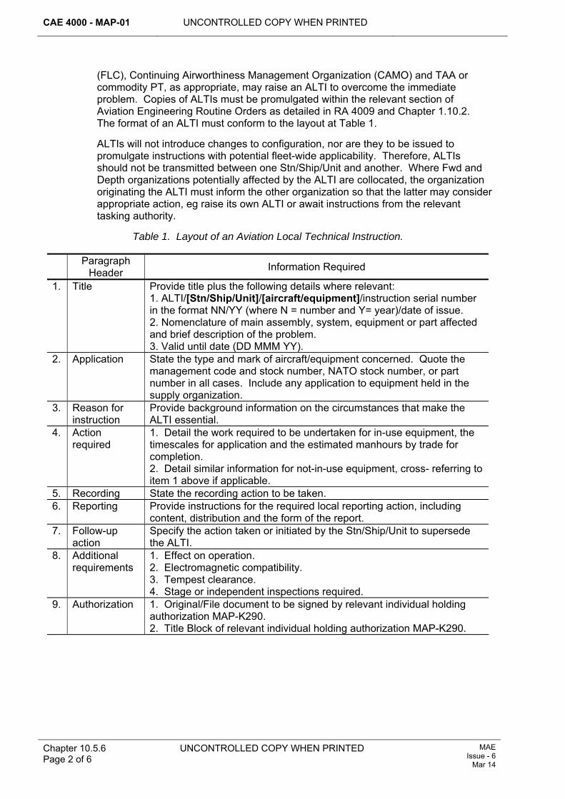
CAE 4000 - MAP-01 UNCONTROLLED COPY WHEN PRINTED
Chapter 10.5.6 Page 2 of 6
UNCONTROLLED COPY WHEN PRINTED MAE Issue - 6
Mar 14
(FLC), Continuing Airworthiness Management Organization (CAMO) and TAA or commodity PT, as appropriate, may raise an ALTI to overcome the immediate problem. Copies of ALTIs must be promulgated within the relevant section of Aviation Engineering Routine Orders as detailed in RA 4009 and Chapter 1.10.2. The format of an ALTI must conform to the layout at Table 1.
ALTIs will not introduce changes to configuration, nor are they to be issued to promulgate instructions with potential fleet-wide applicability. Therefore, ALTIs should not be transmitted between one Stn/Ship/Unit and another. Where Fwd and Depth organizations potentially affected by the ALTI are collocated, the organization originating the ALTI must inform the other organization so that the latter may consider appropriate action, eg raise its own ALTI or await instructions from the relevant tasking authority.
Table 1. Layout of an Aviation Local Technical Instruction.
Paragraph Header Information Required
1. Title Provide title plus the following details where relevant: 1. ALTI/[Stn/Ship/Unit]/[aircraft/equipment]/instruction serial number in the format NN/YY (where N = number and Y= year)/date of issue. 2. Nomenclature of main assembly, system, equipment or part affected and brief description of the problem. 3. Valid until date (DD MMM YY).
2. Application State the type and mark of aircraft/equipment concerned. Quote the management code and stock number, NATO stock number, or part number in all cases. Include any application to equipment held in the supply organization.
3. Reason for instruction
Provide background information on the circumstances that make the ALTI essential.
4. Action required
1. Detail the work required to be undertaken for in-use equipment, the timescales for application and the estimated manhours by trade for completion. 2. Detail similar information for not-in-use equipment, cross- referring to item 1 above if applicable.
5. Recording State the recording action to be taken. 6. Reporting Provide instructions for the required local reporting action, including
content, distribution and the form of the report. 7. Follow-up
action Specify the action taken or initiated by the Stn/Ship/Unit to supersede the ALTI.
8. Additional requirements
1. Effect on operation. 2. Electromagnetic compatibility. 3. Tempest clearance. 4. Stage or independent inspections required.
9. Authorization 1. Original/File document to be signed by relevant individual holding authorization MAP-K290. 2. Title Block of relevant individual holding authorization MAP-K290.
UNCONTROLLED COPY WHEN PRINTED CAE 4000 - MAP-01
MAE Issue - 6 Mar 14
UNCONTROLLED COPY WHEN PRINTED Chapter 10.5.6 Page 3 of 6
4 ALTI validity An ALTI is valid:
1 For the minimum period necessary, but is not to exceed 28 days from the date of issue.
2 At the location where it was issued and exceptionally, where the issuing Stn/Ship/Unit provides maintenance support for its own aircraft/equipment, at other locations.
3 An extension to the 28-day period may be granted by the FLC, following appropriate consultation with the CAMO and TAA or commodity PT, as required. Extensions should be kept to a minimum and are not to exceed 90 days validity from the original date of issue of the ALTI. This gives sufficient time for more appropriate action to be promulgated by the TAA/commodity PT, if required.
5 Follow-up action Following the issue of an ALTI, the individual holding authorization MAP-K290 who authorizes its release must ensure that:
1 Contact is made with the FLC or TAA/commodity PT, as appropriate, to request:
1.1 More appropriate remedial action (eg TAA/commodity PT-issued SI(T)), or:
1.2 Grant an extension to the validity of the ALTI.
2 Copies of the ALTI are distributed to relevant organizations from within the following list:
2.1 FLC.
2.2 CAMO.
2.3 TAA and/or commodity PT.
2.4 Typed Air Station.
3 Other supporting documentation is raised, eg:
3.1 Narrative Fault Report MOD F760 – RA 4814 and Chapter 7.5.1.
3.2 Unsatisfactory Feature Report MOD F765 – RA 4810 and Chapter 8.2.1.
Notes:
1 FLCs must inform the relevant TAA/commodity PT of any extension to an ALTI’s period of validity.
2 External copies of ALTIs must be distributed by the fastest practicable means and as soon as possible after initial issue.
6 Amendment of ALTIs 6.1 Minor amendment
If a minor amendment is required to an ALTI, it must be reissued with the amendment under the same serial number, supplemented with a suffix; eg reissue of 01/2003 would be numbered 01A/2003. The reissued ALTI must include the date of amendment and the date on which the original instruction was signed. Any extension to the validity of the amended ALTI must be calculated from the issue date of the original instruction.
CAE 4000 - MAP-01 UNCONTROLLED COPY WHEN PRINTED
Chapter 10.5.6 Page 4 of 6
UNCONTROLLED COPY WHEN PRINTED MAE Issue - 6
Mar 14
6.2 Major amendment A major amendment is defined as one that would significantly change the content of the ALTI. In this situation, the original ALTI must be cancelled by the relevant individual holding authorization MAP-K290, who must raise a completely new ALTI. This ALTI must have a separate serial number to that of the original one. Any extension to the validity of this ALTI must be calculated from the date of its issue, not that of the original ALTI.
7 Responsibilities 7.1 Authority level K
In addition to those responsibilities detailed at paragraphs 3 and 5, the relevant individual holding authorization MAP-K290 is also responsible for ensuring that a register of ALTIs is maintained.
7.2 Front Line Commands (FLCs) ALTIs originated by a Fwd organization must be controlled by the FLC responsible for the aircraft/equipment, who must consult with the issuing Stn/Ship/Unit, CAMOs and relevant TAAs and commodity PTs so that:
1 Where necessary, extensions to the validity of ALTIs are minimized.
2 Advice is issued to the relevant Stn/Ship/Unit, through the CAMO if appropriate, on forthcoming TAA/commodity PT action.
3 Adjustments may be made to logistic support.
4 Amendments may be initiated to FLC mid-level Aviation Engineering Policy.
5 Follow-up action is completed within appropriate timescales.
6 ALTIs are cancelled.
7.3 Type Airworthiness Authority (TAA)/commodity Project Team (PT) 7.3.1 Fwd-originated ALTIs
The TAA/commodity PT must:
1 Consult with the applicable FLCs, CAMOs and relevant Stn/Ship/Units.
2 Issue Service Instructions (Technical) (detailed in Chapter 10.5.3) or amendments to instructions or schedules as appropriate, upon receipt of follow-up documentation within the approved timescales.
3 Consider, in conjunction with the CAMO, the ALTI’s potential applicability at Depth organizations maintaining affected aircraft/equipment.
7.3.2 Depth-originated ALTIs ALTIs originated by a Depth organization must be controlled by the relevant platform PT who must consult with the issuing Stn/Ship/Unit so that:
1 Advice is issued to the relevant Stn/Ship/Unit, through the CAMO if appropriate, on forthcoming TAA action.
2 The ALTI’s potential applicability at Fwd organizations is considered in conjunction with the relevant FLC and CAMO.
3 Adjustments may be made to logistical support.
4 Where necessary, extensions to the validity of ALTIs are minimized.
5 Follow-up action is completed within appropriate timescales.
UNCONTROLLED COPY WHEN PRINTED CAE 4000 - MAP-01
MAE Issue - 6 Mar 14
UNCONTROLLED COPY WHEN PRINTED Chapter 10.5.6 Page 5 of 6
6 ALTIs are cancelled.

CAE 4000 - MAP-01 UNCONTROLLED COPY WHEN PRINTED
Chapter 10.5.6 Page 6 of 6
UNCONTROLLED COPY WHEN PRINTED MAE Issue - 6
Mar 14
Intentionally Blank for Print Pagination
UNCONTROLLED COPY WHEN PRINTED
CAE 4000 - MAP-01
Issue - 7 Apr 15
UNCONTROLLED COPY WHEN PRINTED
Chapter 11.2 Page 1 of 6
Chapter 11.2
Health and Usage Monitoring
TABLE OF CONTENTS Paragraph
Page
1 General ............................................................................................................... 1 1.1 Introduction.......................................................................................................... 1 1.2 Associated instructions........................................................................................ 2 1.3 Applicability ......................................................................................................... 2 2 Regulatory Governance.................................................................................... 2 2.1 Regulatory Cross-reference ................................................................................ 2 2.2 Additional Information.......................................................................................... 2 3 HUM support...................................................................................................... 2 3.1 Support levels...................................................................................................... 2 3.2 Health and usage data management .................................................................. 3 3.3 Cockpit Voice Recorder (CVR) and Flight Data Recorder (FDR) data................ 3 4 Responsibilities................................................................................................. 3 4.1 Station/Ship/Units................................................................................................ 3 4.2 Health and Usage Centres (HUCs) and HUMS Support Cells (HSCs) ............... 3 4.3 1710 Naval Air Squadron (1710 NAS) ................................................................ 3 4.4 Military Aviation Authority Certification Mechanical and Propulsion Systems
(MAA Cert MPS).................................................................................................. 4 4.5 Type Airworthiness Authorities (TAA) ................................................................. 4 4.6 HUMS section within the Lynx/Wildcat PT (Lynx-Wildcat-HUMSMgr) ......... 5 5 Interface with other data systems ................................................................... 5 6 Training of personnel involved in HUM........................................................... 5 7 Authorization of personnel involved in HUM.................................................. 5 8 References ......................................................................................................... 6
LIST OF TABLES Table 1. Minimum Authorization Requirements for Health and Usage Monitoring Systems
Data Activities................................................................................................................6
1 General 1.1 Introduction
The term Health and Usage Monitoring (HUM) encompasses a variety of techniques including operational load monitoring, vibration analysis, visual inspections, oil and wear debris analysis. The data obtained through such monitoring is used to preserve and enhance the airworthiness of the platform. Health and Usage Monitoring Systems (HUMS) have been developed to support condition-based maintenance by the acquisition of health and usage data from on–board sensors.
This chapter covers Acceptable Means of Compliance (AMC), Guidance Material (GM) and associated processes relating to the management of HUM data, responsibilities, interfaces with other data systems and authorizations. Instructions for the operation and data maintenance of specific installations will be detailed in the
CAE 4000 - MAP-01 UNCONTROLLED COPY WHEN PRINTED
Chapter 11.2 Page 2 of 6
UNCONTROLLED COPY WHEN PRINTED Issue - 7 Apr 15
appropriate Aircraft Maintenance Manual or Interactive Electronic Technical Publication.
Engine Health and Usage Monitoring Systems (EHUMS) are a sub-set of HUMS applied to the monitoring of aero-engines. Equipment Usage Condition Monitoring and Management Strategy (EUCAMS) is the MOD programme to develop and apply new technology and equipment to the monitoring of aero-engines and power train systems to realize improvements in airworthiness, availability and Whole Life Costs (WLC).
Cockpit Voice & Flight Data Recorders (CVR/FDR) are crash-protected devices used to record audio data and the general cockpit environment, together with pre-determined flight sensor data.
1.2 Associated instructions The following instructions are associated with this chapter:
1 RA 4501 and Chapter 11.3.
2 RA 4502 and Chapter 11.4.
1.3 Applicability This chapter is applicable to all units operating or maintaining HUMS-equipped fixed or rotary-wing aircraft, or managing HUM data.
2 Regulatory Governance 2.1 Regulatory Cross-reference
This chapter supports:
1 RA 4500(1).
2 RA 4500(2).
2.2 Additional Information HUMS will be supported by a Ground Support System (GSS), integrated with a Logistic Information System (LIS), thereby optimizing the use of available data, hardware and software.
3 HUM support 3.1 Support levels
Support for HUM is provided in 3 levels, as follows:
3.1.1 First level First-level support comprises all HUM activities that occur in direct support of aircraft operations.
3.1.2 Second level Specialist cells known as Health and Usage Centres (HUC) or HUMS Support Cells (HSC) provide second-level HUM support. These encompass the activities of Vibration Control Cells (VCC) and, in the RAF, Early Failure Detection Centres (EFDC).
3.1.3 Third level 1710 NAS provides the Depth support for HUM and provides advice as required to Forward operators, Type Airworthiness Authorities (TAAs) and Front Line Commands (FLCs).
UNCONTROLLED COPY WHEN PRINTED CAE 4000 - MAP-01
Issue - 7 Apr 15
UNCONTROLLED COPY WHEN PRINTED
Chapter 11.2 Page 3 of 6
3.2 Health and usage data management
The specific requirements for HUMS data management are as follows:
1 Data management procedures should be transparent to the method used for data transfer, as well as data storage and access requirements, and should take account of any limitations imposed by military operations or locations.
2 The IT requirements for HUMS must be communicated to, and compatible with, the respective Service IT organizations. These requirements should take into consideration the HUM data management architectures and procedures. The direct interchange of data between GSS and Service IT systems should be implemented where practicable.
3 All HUM data must be archived and retained to enable it to be made available for audit, trend analysis, retrospective analysis or airworthiness purposes as required. The establishment of the Minimum Data Set for archiving should be a high priority task during the introduction and maturity phase of the procurement of a HUMS.
3.3 Cockpit Voice Recorder (CVR) and Flight Data Recorder (FDR) data CVR data is only to be downloaded for the annual serviceability check or in exceptional circumstances as authorized by FLCs. Download must be via a separate transfer medium from HUMS data and must be handled in accordance with the procedures laid down in JSP 440 appropriate to the classification of the data held. The process of downloading FDR data and its linkage with HUMS data is platform-specific.
4 Responsibilities 4.1 Station/Ship/Units
Forward Units operating HUM equipment, or managing HUM data at first level, are responsible for providing the following information from HUMS data:
1 An aircraft serviceability statement based on HUM data.
2 A description of health and usage alerts including associated values and trend history.
3 A description of the recovery action required.
4.2 Health and Usage Centres (HUCs) and HUMS Support Cells (HSCs) HUCs and HSCs conduct initial analysis of HUM data, provide advice and technical support to front line units and are responsible for:
1 Responding to technical enquiries.
2 Managing and analysing HUM data and producing reports as required.
3 Maintaining liaison with the depth support to ensure coherent development of HUM.
4.3 1710 Naval Air Squadron (1710 NAS) 1710 NAS is the single point of focus for HUM, liaising with DE&S’s departments and the Military Aviation Authority Certification Mechanical and Propulsion Systems (MAA Cert MPS) propulsion specialist staff where appropriate.
CAE 4000 - MAP-01 UNCONTROLLED COPY WHEN PRINTED
Chapter 11.2 Page 4 of 6
UNCONTROLLED COPY WHEN PRINTED Issue - 7 Apr 15
1710 NAS conducts technical and management functions in support of HUM, including:
1 For Generic Helicopter HUMS (GenHHUMS), the practical implementation of software updates on behalf of the HUMS section within the Lynx/Wildcat Project Team (PT) (Lynx-Wildcat-HUMSMgr).
2 Management of HUM data and maintaining master databases where practical.
3 In-depth analysis of HUM information and related health and usage matters.
4 Providing advice on system specification and performance.
Additionally, 1710 NAS is responsible for:
1 Providing direct support to DE&S PTs on HUM procurement and development.
2 Providing advice on all aspects of HUM equipment, techniques and analysis methods and their resultant maintenance implications, including the provision of advice and assistance to user units, FLCs and TAAs on individual aircraft problems.
3 Establishing, maintaining and controlling the configuration of fleet-wide aircraft databases drawn from second level HUC/HSCs. From this data, providing functional guidance and delegating fleet-specific functions to HUCs/HSCs and optimizing parameter management across different aircraft fleets.
4 Making recommendations to TAAs on revised threshold levels and improved data acquisition to improve visibility of faults, usage and maintenance effectiveness.
5 Proposing and managing trials to evaluate new/improved equipment and techniques.
6 Providing advice and assistance to HUM working groups.
7 Assisting the MAA to formulate policies for HUM and data management.
4.4 Military Aviation Authority Certification Mechanical and Propulsion Systems (MAA Cert MPS) MAA Cert MPS is the subject matter expert (SME) for engine performance and integrity assurance and usage monitoring.
4.5 Type Airworthiness Authorities (TAA) TAAs are responsible for:
1 Specifying the extent of HUM activities on the equipments for which they are responsible.
2 The airworthiness of:
2.1 The HUM equipment.
2.2 The maintenance actions taken as a result of the information provided by HUM.
3 Assessing the need for the retrofit or enhancement of HUM equipment to their platforms or engine fleet through cost-benefit analysis and/or on flight safety grounds.
4 Monitoring HUMS performance and formally reviewing maintenance policy in conjunction with health and usage data analysis.
5 Promulgating procedures in the aircraft/aero-engine Topic 2(N/A/R)1.
UNCONTROLLED COPY WHEN PRINTED CAE 4000 - MAP-01
Issue - 7 Apr 15
UNCONTROLLED COPY WHEN PRINTED
Chapter 11.2 Page 5 of 6
6 Determining retention/disposal policy for their aircraft/aero-engine HUM data and publishing the resulting requirements within the aircraft/aero-engine Topic 2(N/A/R)1.
7 Managing software configuration changes for the monitoring equipment.
8 For platforms operating with HUMS other than GenHUMS, TAAs take on the responsibilities laid down in paragraph 4.6 below with respect to their own systems.
4.6 HUMS section within the Lynx/Wildcat PT (Lynx-Wildcat-HUMSMgr) Lynx-Wildcat-HUMSMgr is responsible for:
1 Co-ordinating and managing the support of Generic Helicopter HUMS (GenHHUMS).
2 Managing the development of GenHHUMS hardware and software on behalf of other platform TAAs.
3 Managing the support aspects of Post-Design Services (PDS) for all equipment within its responsibility.
4 Acting as the focal point for tri-Service GenHHUMS support matters, liaising with other platform TAAs as required.
5 The configuration control of all equipment within its sphere of responsibility.
6 The integrity, accuracy and application of GenHHUMS analysis tools and data.
7 Liaison with IT providers, other platform TAAs and Units to ensure that IT requirements are met in the most appropriate manner for all equipment within its responsibility.
5 Interface with other data systems Where a HUMS is required to interface with other data systems, the technical relationship must be governed by an Interface Control Document agreed by both system managers.
6 Training of personnel involved in HUM Personnel operating non-GenHHUMS aircraft must undertake such training as is deemed necessary in agreement between TAAs and the appropriate FLCs.
Personnel operating GenHHUMS aircraft must undertake appropriate training at agreed locations. For further details, contact the training organization appropriate to the aircraft type and mark.
Authorization to undertake HUMS operations does not negate previous requirements or qualifications to undertake operations such as Vibration Analysis using Section 4XV equipment.
7 Authorization of personnel involved in HUM Personnel operating HUM equipment must be trained in accordance with RA 4806 and Chapter 4.1 and authorized by an individual holding authorization MAP-J193, MAP-J194, or MAP-J195 in accordance with RA 4806 and Chapter 4.3. The authorization requirements for HUM data functions are shown at Table 1.
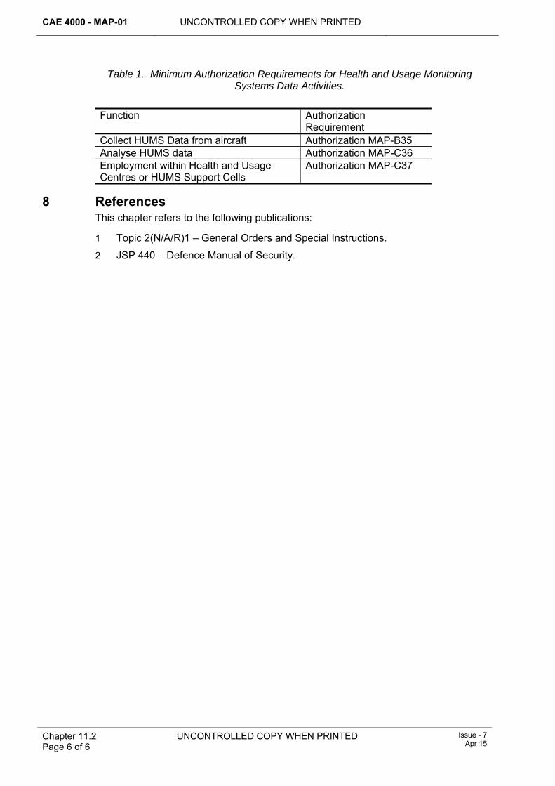
CAE 4000 - MAP-01 UNCONTROLLED COPY WHEN PRINTED
Chapter 11.2 Page 6 of 6
UNCONTROLLED COPY WHEN PRINTED Issue - 7 Apr 15
Table 1. Minimum Authorization Requirements for Health and Usage Monitoring Systems Data Activities.
Function Authorization
Requirement Collect HUMS Data from aircraft Authorization MAP-B35 Analyse HUMS data Authorization MAP-C36 Employment within Health and Usage Centres or HUMS Support Cells
Authorization MAP-C37
8 References This chapter refers to the following publications:
1 Topic 2(N/A/R)1 – General Orders and Special Instructions.
2 JSP 440 – Defence Manual of Security.
UNCONTROLLED COPY WHEN PRINTED CAE 4000 - MAP-01
Issue - 7 Apr 15
UNCONTROLLED COPY WHEN PRINTED Chapter 11.3 Page 1 of 6
Chapter 11.3
Vibration Control
TABLE OF CONTENTS Paragraph
Page
1 General ............................................................................................................... 1 1.1 Introduction.......................................................................................................... 1 1.2 Associated publications....................................................................................... 2 2 Regulatory Governance.................................................................................... 2 2.1 Regulatory Cross-reference ................................................................................ 2 2.2 Additional Information.......................................................................................... 2 3 VC organization responsibilities...................................................................... 3 3.1 Ships/Stns/Units .................................................................................................. 3 3.2 Vibration Control Cells (VCCs)............................................................................ 3 3.3 Health and Usage Centres (HUCs) ..................................................................... 3 3.4 1710 Naval Air Squadron (1710 NAS) ................................................................ 4 3.5 Type Airworthiness Authorities (TAAs)................................................................ 4 4 Vibration Equipment (VE) ................................................................................. 4 4.1 Air Commodities Team (AC Team) responsibilities............................................. 4 4.2 Platform Project Team (PT) responsibilities ........................................................ 5 4.3 Maintenance of VE (Section 4XV) assets ........................................................... 5 4.4 Maintenance of HUMS VE assets ....................................................................... 5 5 Manpower training and authorization ............................................................. 5 5.1 Training ............................................................................................................... 5 5.2 Authorizations (Section 4VX equipment)............................................................. 6 5.3 Authorizations (HUMS RTB function).................................................................. 6 6 Static balance equipment ................................................................................. 6 7 References ......................................................................................................... 6
LIST OF TABLES Table 1. Summary of VC training courses. ...................................................................................5
1 General Vibration induced by aerodynamic loads or structural resonance excited by rotating components, such as gas turbines, propellers and helicopter rotors, may induce high levels of stress in parts of the structure or transmission system. These stresses may lead to premature failure through fatigue, including increased secondary damage such as wear or higher incidence of electronic component failure.
The Design Organization (DO) for each aircraft/aero-engine type establishes a datum vibration level at or below which the vibration is judged to be structurally non-damaging. Military Aircraft (MA) must be maintained and operated so that vibration is always kept as low as possible below this datum.
1.1 Introduction Vibration Control (VC) is the engineering term given to the suppression of this vibration by analysis and rectification. It is used for helicopter Rotor Track and Balancing (RTB) and propeller balancing. In addition, it may assist the health
CAE 4000 - MAP-01 UNCONTROLLED COPY WHEN PRINTED
Chapter 11.3 Page 2 of 6
UNCONTROLLED COPY WHEN PRINTED
Issue - 7 Apr 15
monitoring of aircraft engines and other rotating equipment. All equipment used solely for monitoring and controlling vibration is termed Vibration Equipment (VE).
Vibration Analysis (VA) is the process of measuring, recording, and interpreting vibration data. This may lead to the introduction of corrective maintenance activities to reduce or eliminate the vibration. The extent of the corrective maintenance will be dependent on the outcome of the VA and will be detailed in the appropriate Aircraft Maintenance Manual (AMM).
Vibration Control Cells (VCCs), provide a co-ordinated organization for aircraft vibration control. Forward Support (Rotary Wing) (FS(RW)) provides the VCC function for Army Lynx (847 NAS is supported by RNAS Yeovilton VCC) and Gazelle aircraft, with 7 Air Assault Bn REME Flight Test Cell (FTC) at Wattisham airfield providing the same for Apache. The evolution of Health and Usage Monitoring Systems (HUMS) is incorporating VCCs into Health and Usage Centres (HUCs).
This chapter describes the Acceptable Means of Compliance (AMC), Guidance Material (GM) and associated processes, management structure, training and personnel qualifications required to use VC equipment and to interpret and manage VC data.
1.2 Associated publications This chapter is associated with the following publications:
1 AP 119A-20000-2(N/A/R)1 Part 1 Leaflet 009 – Support Policy Statement (SPS) for Vibration Analysis Equipment.
2 AP119A-20700-1 – VA Theory and Application.
3 AP 119A-20713-1 – RADS-AT(RN) General and Technical Information.
4 AP119A-20714-1 – Vibration Monitoring Equipment (VME).
5 AP119A-20714-2(R)1 – Vibration Monitoring Equipment.
6 AP119A-20715-1 – Chadwick Helmuth 8500C.
7 AP 119A-20720-1 – Rotortuner 5JS+ Operator’s Manual.
8 AP 119A-20721-1 – Avion USBF Manual.
9 Aircraft platform-specific Topic 5G1/Integrated Electronic Technical Publication (IETP) data module.
10 Relevant VA equipment Air Publication.
2 Regulatory Governance 2.1 Regulatory Cross-reference
This chapter supports:
1 RA 4501.
2.2 Additional Information Aircraft subject to VC must be monitored for vibration as promulgated in the aircraft Topic 5A1. The operation of VE and the application of VA techniques must be conducted by trained personnel and the resultant data managed by key Subject Matter Experts (SME). If the techniques cannot be applied because of operational or maintenance considerations, the techniques must be deferred using MOD F704.
UNCONTROLLED COPY WHEN PRINTED CAE 4000 - MAP-01
Issue - 7 Apr 15
UNCONTROLLED COPY WHEN PRINTED Chapter 11.3 Page 3 of 6
3 VC organization responsibilities 3.1 Ships/Stns/Units
Ships/Stns/Units are responsible for:
1 Gathering and maintaining VC data by applying VA techniques by aircraft type.
2 The expedient transmission of VC data to the appropriate VCC/FTC/HUC.
3 Obtaining vibration measurements:
3.1 After rectification work to reduce vibration, to confirm results.
3.2 After fitting a major assembly, as detailed in the appropriate work card or maintenance procedure.
3.3 At any time when VA would be of assistance to the user, eg after a heavy landing, blade strike or crew-reported vibration.
3.4 When recommended by VCCs/FTCs/HUCs.
4 Generating bids for VC equipment (Army only).
3.2 Vibration Control Cells (VCCs) Each VCC, under the direction of an individual holding authority level K, is responsible for:
1 Gathering, monitoring and maintaining vibration data by aircraft type, based on operating unit input.
2 Monitoring the effect of vibration-related maintenance and providing advice and assistance to operating units and local engineering command on VC issues.
3 Providing local training on VC techniques.
4 Coordinating/assisting with vibration-related trials and equipment bids.
5 Undertaking vibration measurements for units (RN Only).
6 Maintaining a register of technical personnel authorized to conduct VC activities.
7 Co-ordinating local VC training for technical personnel as required (not Army).
8 Ensuring that VC activity is covered within local quality management systems.
9 Providing input to the central vibration database managed by 1710 NAS.
Note:
If no Ship/Stn/Unit VCC exists, Sqns/Units must appoint an individual to fulfil the VCC roles at items 1, 2, 6, 8 and 9 as required, with the other elements being supplied by the most appropriate remote VCC.
3.3 Health and Usage Centres (HUCs) In addition to the roles for VCCs identified above, HUCs provide additional services specific to aircraft operating RTB within their HUMS system. The HUCs are additionally responsible for:
1 Maintaining HUMS Ground Station (HGS) database integrity and user accounts through routine database administration.
2 Maintaining data flow between all levels of HUMS operation.
CAE 4000 - MAP-01 UNCONTROLLED COPY WHEN PRINTED
Chapter 11.3 Page 4 of 6
UNCONTROLLED COPY WHEN PRINTED
Issue - 7 Apr 15
3.4 1710 Naval Air Squadron (1710 NAS) The 1710 NAS is the focal point for all aircraft condition monitoring associated activities. It provides depth support for vibration control, measurement and analysis. It is responsible for:
1 Providing expert technical advice on all aspects of vibration equipment, techniques and analysis methods in respect of aircraft vibration problems.
2 Conducting Resonant Frequency Response (RFR) testing of aircraft structures, components and modifications.
3 Sponsoring and supporting aircraft vibration trials to evaluate new or improved equipment and techniques.
4 Maintaining Helicopter Vibration Control Ground Station (HVCGS) databases for all non-HUMS Service helicopter types.
5 Providing functional guidance to VCCs/FTCs/HUCs to enhance their effectiveness.
6 Developing formal VC techniques and advising TAAs on vibration Regulation, AMC, GM and associated processes, including limit reviews and Topic 5G1/Interactive Electronic Technical Publication (IETP) amendments.
7 Developing and configuring HVCGS and RADS-AT(RN) script files and Rotortuner 5JS+ data cards.
8 Providing VCC support to Engine Test Houses and Vector Aerospace, Fleetlands.
9 Maintaining VE databases for all service aircraft.
10 Providing technical support and training for fixed-wing propeller balancing and engine vibration monitoring.
11 Providing technical support and training for RADS-AT(RN), CH8500, Rotortuner 5JS+, VME and USBF.
12 Accessing HUMS databases for the purposes of aircraft review and analysis as agreed with appropriate stakeholders.
13 Providing technical support for HUMS.
3.5 Type Airworthiness Authorities (TAAs) TAAs are responsible for:
1 Continually assessing VC methods to enhance supportability, maintainability or safety of the aircraft or equipment for which they are responsible via the aircraft or equipment maintenance schedules as required.
2 Tasking the 1710 NAS with developing VC techniques to support specific requirements.
4 Vibration Equipment (VE) 4.1 Air Commodities Team (AC Team) responsibilities
The AC Team Aircraft Integrity Monitoring Equipment (AIME)2 is responsible for through-life support of all VC equipment within the Section 4XV range, including funding future equipment and sponsoring all relevant VC training.
UNCONTROLLED COPY WHEN PRINTED CAE 4000 - MAP-01
Issue - 7 Apr 15
UNCONTROLLED COPY WHEN PRINTED Chapter 11.3 Page 5 of 6
4.2 Platform Project Team (PT) responsibilities Platform PTs are responsible for the procurement and through-life support of platform-specific HUMS systems including RTB equipment.
4.3 Maintenance of VE (Section 4XV) assets To ensure best use of VE assets, the following procedures must be applied:
1 All Section 4XV equipment must remain in date for calibration in accordance with individual Service procedures. All calibration must be conducted in accordance with AP100C-50 by the AIME Support Flight, MOD St Athan.
2 The VCC is the focal point for the supply, diagnosis, repair or calibration of Section 4XV equipment for the RN and RAF only. Army units must use extant supply procedures. If urgent replacement of Section 4XV equipment is necessary and VCC support is not available, normal stores routines apply.
3 Unserviceable equipment must be returned for repair to Drop Point 77, AIME Support Flight, MOD St Athan.
4.4 Maintenance of HUMS VE assets To ensure best results from HUMS RTB functionality, the following procedures must be applied:
1 The HUC must be the focal point for the supply, diagnosis and repair of all HGS.
2 1710 NAS must provide a hardware/software serviceability assessment prior to equipment being sent to depth for repair or rework.
3 1710 NAS must provide specialist database and operating system support to the HUC.
5 Manpower training and authorization 5.1 Training
All maintenance personnel conducting VC tasks must be trained in accordance with RA 4806 and Chapter 4.1. Personnel using Section 4XV equipment must be trained to a course/syllabus approved by 1710 NAS. Personnel using GenHUMS RTB must be trained to a course/syllabus approved by Sea King PT. Personnel using equipment for HUMS RTB systems must be trained to a course/syllabus approved by the appropriate platform PT.
Where operating Section 4XV equipment, RN and RAF personnel must have completed both Part A & B training prior to authorization as VA operator. A summary of VC training courses is shown at Table 1. Contractor or other civilian maintainers must have completed the relevant courses listed, or equivalent instruction.
Table 1. Summary of VC training courses.
Equipment Course Undertaken at SAMCO 73 (Pt A) 1710 NAS SAMCO (Pt B) 192/203/495SST or Station OJT
Parent Stn RADS-AT
Apache training 4ATIL Training School (Army)
Rotortuner 5JS+ Q-A-RTB (Pt A) 1710 NAS
CAE 4000 - MAP-01 UNCONTROLLED COPY WHEN PRINTED
Chapter 11.3 Page 6 of 6
UNCONTROLLED COPY WHEN PRINTED
Issue - 7 Apr 15
Operator OJT (Pt B) Parent Stn Vibration Measuring and Analysis Course
Arborfield (Army)
Q-A-VA(VME) (Pt A) 1710 NAS (Wyton) Vibration Monitoring Equipment VME operator OJT (Pt B) Parent Stn Chadwick Helmuth 8500C+
Q-A-BAL/PROP 1710 NAS (Wyton)
5.2 Authorizations (Section 4VX equipment)
Personnel required to operate VE (ie operating CH8500C+, VME or Army Rotortuner operators) must hold MAP-B300, MAP-B305 or MAP-D344 as appropriate. Personnel required to analyse/interpret RADS/Rotortuner VE data must hold either MAP-C40 or MAP-D345 authorization. All personnel required to operate or analyse/interpret data must have completed training, as detailed in paragraph 5.1 and RA 4150 and Chapter 4.1. Part B training for RAF and RN personnel must be undertaken within 6 months of completion of Part A training; otherwise the qualification will lapse.
Authorization must be granted by the relevant holder of MAP-J39 or MAP-J302 in accordance with RA 4806 and Chapter 4.3. These are specialist qualifications for RN and RAF personnel and continued authorization is subject to the holder undertaking an annual competency check that must be administered by VCC personnel. However, for Army personnel, it is not a specialist qualification, so any competency checks must be undertaken as directed by an individual holding authority level J.
5.3 Authorizations (HUMS RTB function) For authorization requirements pertaining to HUMS RTB, refer to RA 4500 and Chapter 11.2.
6 Static balance equipment 1710 NAS is the technical support organization for the Avion Universal Static Balance Facility (USBF) and the Virtual Master Static Balance Facility (VMSBF) held within the blade bay at appropriate operating bases. The AC Team is responsible for through-life support of this equipment.
Only fully trained personnel are authorized to operate this equipment and all training requirements must be notified through the 1710 NAS VHUMS
7 References This chapter refers to the following publications:
1 JSP 509: Volumes 1 to 10 - The Management of Test & Measurement Equipment.
2 Topic 5A1 – Master Maintenance Schedule.
3 Topic 5G1 – Vibration Analysis.
UNCONTROLLED COPY WHEN PRINTED CAE 4000 - MAP-01
MAE Issue - 6 Mar 14
UNCONTROLLED COPY WHEN PRINTED Chapter 11.4 Page 1 of 8
Chapter 11.4
Wear Debris Monitoring
TABLE OF CONTENTS Paragraph
Page
1 General ............................................................................................................... 1 1.1 Introduction.......................................................................................................... 1 1.2 WDM uses........................................................................................................... 2 2 Regulatory Governance.................................................................................... 2 2.1 Regulatory Cross-reference ................................................................................ 2 2.2 Additional Information.......................................................................................... 2 3 WDM methods ................................................................................................... 3 4 WDM programmes............................................................................................. 3 4.1 Spectrometric Oil Analysis Programme (SOAP) ................................................. 3 4.2 Magnetic detector plug (MDP) and filter debris assessment............................... 3 5 Responsibilities................................................................................................. 3 5.1 1710 NAS............................................................................................................ 3 5.2 RAF Early Failure Detection Centres (EFDCs) ................................................... 4 5.3 Stns/Ships/Units .................................................................................................. 4 5.4 Front Line Commands (FLCs)............................................................................. 5 5.5 Type Airworthiness Authority (TAA) .................................................................... 5 5.6 Air Commodities Team (AC Team) ..................................................................... 5 6 Procedures......................................................................................................... 5 6.1 Wear Debris Management System (WDMS)....................................................... 5 6.2 Sampling and distribution .................................................................................... 6 6.3 Sample analysis .................................................................................................. 7 6.4 Sample results and maintenance action reporting .............................................. 7 6.5 Stn/Ship/Unit rejections ....................................................................................... 7 7 RAF EFD training and establishments ............................................................ 8 8 References ......................................................................................................... 8
1 General 1.1 Introduction
Any components within an oil-wetted system that are in moving contact will generate small particles from the contact surfaces, mainly because of local loading between these surfaces. Excessive friction or abnormal loading of such components will increase the rate of particle generation and may change the nature of wear debris. It is therefore important to recognize the onset and significance of such changes in wear characteristics; such recognition forms the basis of effective Wear Debris Monitoring (WDM).
When correctly applied, monitoring the wear that is occurring in a system can give an assurance of the continued integrity of the monitored system. It achieves this by providing an early indication of abnormal wear, enabling the monitored assemblies to be removed before the onset of excessive damage that could ultimately lead to complete system failure. Apart from preserving the integrity of aircraft, such monitoring can reduce the costs of repair and replacement of sub-assemblies and components.
CAE 4000 - MAP-01 UNCONTROLLED COPY WHEN PRINTED
Chapter 11.4 Page 2 of 8
UNCONTROLLED COPY WHEN PRINTED MAE Issue - 6
Mar 14
This chapter states WDM Acceptable Means of Compliance, Guidance Material and associated processes, describes wear debris analysis techniques and defines the management structure and training requirements for organizations and personnel involved in the control and application of WDM programmes of UK military aircraft.
1710 NAS have developed and implemented the Wear Debris Monitoring System (WDMS) to bring together and resolve the different procedures used by the RN, Army and RAF wherever possible. Minor differences remain and are specifically described in the chapter. 1710 NASas Subject Matter Expert (SME) will continue to review and further converge policy wherever possible.
1.2 WDM uses WDM may be used:
1 To recognize the onset of excessive wear and prevent consequential secondary damage or catastrophic failure.
2 To sustain confidence in the mechanical integrity and performance of the mechanical system.
3 To assess all wear factors in order to optimize in-service life and determine the most cost-effective maintenance philosophy.
4 To diagnose faults to component level in order to reduce down time and repair costs.
5 To provide better knowledge of failure causes and thereby hasten corrective action.
6 To forecast more accurately the need for scheduled or unscheduled maintenance and thereby improve equipment availability.
7 As required by the relevant TAA as part of a specific investigation.
8 On any occasion that the operator/maintainer has doubts concerning the internal integrity of an oil–lubricated assembly.
2 Regulatory Governance 2.1 Regulatory Cross-reference
This chapter supports:
1 RA 4502(1).
2 RA 4502(2).
2.2 Additional Information Oil and wear debris samples must be taken on the following occasions:
1 For in-service assemblies, in accordance with frequencies and procedures required by relevant aircraft Topic 5A1 and Topic 1.
2 For new/repaired/reconditioned or disturbed assemblies, as detailed in relevant work cards or maintenance procedures.
3 In accordance with recommendations made by 1710 NAS the aircraft type-specific Early Failure Detection Centres (EFDCs) or other Depth support WDM service provider appointed by the TAA.
UNCONTROLLED COPY WHEN PRINTED CAE 4000 - MAP-01
MAE Issue - 6 Mar 14
UNCONTROLLED COPY WHEN PRINTED Chapter 11.4 Page 3 of 8
3 WDM methods Employing WDM techniques can assess the wear occurring in an enclosed oil-wetted system, such as an aircraft engine or transmission; these monitoring techniques include:
1 Spectrometric Oil Analysis (SOA).
2 Magnetic Detector Plug (MDP) and filter debris assessment.
4 WDM programmes A WDM programme for a specific platform and component type may utilize either or both of the techniques described in the following sub-paragraphs.
4.1 Spectrometric Oil Analysis Programme (SOAP) The presence of fine wear particles suspended in lubricating oil is conducive to detection using SOA. By trending the results against historical data and employing alert criteria, potentially significant changes in the monitored assembly’s wear condition can be determined. This can lead to appropriate maintenance actions being taken to address wear anomalies. Whilst SOA is sensitive to fine forms of wear, it is relatively insensitive to the presence of the products of other wear modes; for example, surface fatigue, which generates larger debris particles that are outside the range of SOAP detection.
4.2 Magnetic detector plug (MDP) and filter debris assessment WDM can also be achieved by means of the routine extraction, inspection and trending of debris collected by MDPs, chip detectors and oil filters. The debris collected is generally larger than that detectable by SOA. Visual assessment of such debris can be applied to determine increased or abnormal system operation.
Further analysis of debris to determine the material composition is required to allow the probable source and wear criticality to be more accurately assessed.
5 Responsibilities 5.1 1710 NAS
For all WDM activities, 1710 NAS has the following specific responsibilities:
1 Assessing the suitability of WDM elements of the platform Health and Usage Monitoring (HUM) programmes.
2 Acting as a focus for Stns/Ships/Units, CAMOs, FLCs and TAAs for any matter relating to the organization and application of WDM programmes applied to UK military aircraft.
3 Providing Depth support WDM programmes to a range of UK military aircraft and promulgating the results of wear debris samples back to the originator.
4 Providing support to all RAF Early Failure Detection Centres (EFDCs) in investigating wear anomalies.
5 Managing the production and amendment of AP 119A-20006-1.
6 Providing representation to the Aircraft Integrity Monitoring Equipment Committee (AIMEC) on Depth support WDM equipment requirements.
7 Overseeing the introduction into service of Depth support WDM equipment.
CAE 4000 - MAP-01 UNCONTROLLED COPY WHEN PRINTED
Chapter 11.4 Page 4 of 8
UNCONTROLLED COPY WHEN PRINTED MAE Issue - 6
Mar 14
8 Developing and reviewing WDM policies that reflect best practice and promote the role of WDM within the evolving policies being developed for HUM.
9 Providing on-site overview of services provided by 1710 NAS to FLCs.
10 Sponsoring the “Early Failure Detection Basic” course, CN1595, at DSAE Cosford.
Where TAAs meet their WDM requirements through contractorized Depth support arrangements, 1710 NAS will continue to provide WDM subject matter expertise to TAAs as required.
5.2 RAF Early Failure Detection Centres (EFDCs) EFDCs are responsible for providing support at Main Operating Base (MOB), Detached Operating Base (DOB) and deployments for:
1 Recording, analysing, and reporting on the WDM of aircraft propulsion and transmission system components on WDMS.
2 Identifying abnormal wear and submitting samples to 1710 NAS for further analysis and advice where necessary.
3 Advising aircraft operators and station engineering authorities on the serviceability state of monitored systems.
4 Ensuring the integrity and condition of MDPs.
5 Providing personnel for deployed operations.
6 Providing training, currency and authorization of Q-EFD-B Local Unit Establishment (LUE) personnel who are required to operate as EFDC on deployed operations.
7 Training LUE authority level C non-Q-EFD-B personnel to attain temporary award of authorization MAP-D242 to meet exceptional deployment requirements.
5.3 Stns/Ships/Units Stns/Ships/Units are responsible for:
1 The provision of suitably trained personnel and the extraction and submission to the relevant Depth support organizations of all samples taken as part of WDM programmes.
2 The full and correct completion of WDMS sample registration with each sample, or sample documentation if WDMS is not available.
3 The upkeep of the monitored assembly’s log card to record the submission of such samples and details of any maintenance actions resulting from the analysis of such samples and for carrying out that maintenance.
5.3.1 Authority level J The relevant individual holding authority level J is responsible for:
1 Initiating WDM scaling bids, including those for Priming Equipment Packs (RAF only).
2 Selecting personnel for training and submitting bids accordingly.
3 Identifying EFDC manpower requirements and advising HQ Air Command (HQ Air Cmd) (RAF only).
UNCONTROLLED COPY WHEN PRINTED CAE 4000 - MAP-01
MAE Issue - 6 Mar 14
UNCONTROLLED COPY WHEN PRINTED Chapter 11.4 Page 5 of 8
5.3.2 Authority level K The relevant individual holding authority level K is responsible for:
1 Authorizing the award of X annotations to TQA Q-EFD-B-qualified personnel when they are considered competent on aircraft type (RAF only) and awarding authorization MAP-D430.
2 Authorizing the use of locally trained operators to meet exceptional requirements.
5.4 Front Line Commands (FLCs) All FLCs are responsible for providing trained personnel that are available to conduct WDM measures and processes in the Forward environment.
HQ Air Cmd is responsible for identifying EFDC requirements on LUEs and in the Crisis Manpower Requirement (RAF only).
5.5 Type Airworthiness Authority (TAA) TAAs must:
1 Establish, in conjunction with 1710 NAS, and publish in their aircraft’s Support Policy Statement, an engineering support policy for WDM that clearly defines the role of WDM within the broader policy of Health and Usage Monitoring of their platform.
2 Implement WDM techniques and procedures at a frequency as advised by 1710 NAS for maintaining the platform’s airworthiness.
3 Sponsor development of those WDM techniques that best meet the airworthiness requirements of the platform.
Note:
Where TAAs meet their WDM requirements through contractorized Depth support arrangements, TAAs may still obtain advice from 1710 NAS, the in-service WDM SME.
5.6 Air Commodities Team (AC Team) Within the AC Team, AIME2 is responsible for procuring Section 4XP equipment and providing support management of WDM equipment including WDMS. AIME2 also administers the AIMEC.
6 Procedures 6.1 Wear Debris Management System (WDMS)
WDMS is a system for managing the submission, analysis and reporting of Wear Debris samples. This includes oil, magnetic debris probe and filter samples. Aircraft operators register samples onto the system via a WDMS web page and the sample can be tracked through its analysis and reporting stages. Sample results are available to operators and other interested parties via the web pages as soon as the analysis has been completed. The centralized database enables access to all WDA information from anywhere on the MoD intranet system. The system provides a standard way of submitting and reporting WDA information across all aircraft platforms. The information collected is used for reviewing aircraft engine and transmission systems with a view to monitoring fault trends and improving system reliability.
The WDMS web site is available at http://25.172.120.111/wdms/home/.
CAE 4000 - MAP-01 UNCONTROLLED COPY WHEN PRINTED
Chapter 11.4 Page 6 of 8
UNCONTROLLED COPY WHEN PRINTED MAE Issue - 6
Mar 14
The postal address for WDM is:
Wear Debris Section 1710 NAS , Unicorn Building, PP88, Unicorn Road, HM Navel Base, PORTSMOUTH. PO1 3GX
Advice on WDMS use, training and requests for new reports and amendments is available by contacting 1710 NAS.
6.2 Sampling and distribution 6.2.1 General
1 Stn/Ship/Unit aircraft engineering personnel are responsible for removing and replacing MDPs and filters and sampling lubricating systems, in accordance with the relevant aircraft Topic 1.
2 All sample submissions should be registered on WDMS and appropriate forms should be sent by the quickest possible means to 1710 NAS or local EFDC.
3 Samples are not to be retained or batched by the sampling Stn/Ship/Unit to accumulate a ‘cost-effective batch’ for posting.
4 Oil submitted as part of SOA programmes must be taken into sample bottles available for the purpose from stores and labelled with MOD F730 1710 NAS and MOD F730C.
5 All samples requiring posting to 1710 NAS or parent EFDC must be properly identified, labelled and packaged. To avoid damage/leakage in transit, envelopes or jiffy bags are not to be used for submitting oil samples.
6 Sampling Stns/Ships/Units must conduct a visual assessment of the debris and decide whether routine or urgent examination is required. Samples requiring urgent analysis (eg as part of an investigation of an operating anomaly) should be clearly marked ‘PRIORITY’ in red. The sample should also have the maintenance record “Unit Priority” raised on the sample registration screen on WDMS.
6.2.2 In-field preparation of MDP/filter samples Removal of debris from MDPs, following careful de-oiling, must be carried out using the relevant magnetic plug wipe card. For the RN, these wipe cards are available on demand from 1710 NAS. Army units must use MOD F369 and MOD F369A.
The process of removing debris from filters for subsequent examination will vary, dependent on filter element type. The surfaces of cleanable filters can be washed and debris collected using paper filters. Disposable elements cannot be sampled in this manner and the element should be submitted to 1710 NAS for examination.
6.2.3 RAF MDPs, filters, filter debris and oil samples must be forwarded to the Stn/Unit EFDC or 1710 NAS as applicable.
6.2.4 Samples submitted from outside the UK Samples that require processing by customs must be clearly marked as having no commercial value.
6.2.5 ‘Out of hours’ emergencies For ‘out of hours’ emergencies, advice may be obtained by telephoning 1710 NAS Duty Officer on 07787 154890. In such cases, callers should identify themselves and
UNCONTROLLED COPY WHEN PRINTED CAE 4000 - MAP-01
MAE Issue - 6 Mar 14
UNCONTROLLED COPY WHEN PRINTED Chapter 11.4 Page 7 of 8
provide a contact telephone number. The 1710 NAS Duty Officer will then either deal with the emergency or call in the appropriate specialist.
6.3 Sample analysis Samples received at 1710 NAS or an RAF EFDC must be processed in accordance with 1710 NAS procedures or AP 119A-20006-1 as appropriate. Diagnoses of wear conditions should take full account of the system’s operational and maintenance history.
A sample assessment outside 1710 NAS that leads to maintenance action, eg requires re-sample, increases the sampling requirement, or requires system oil drain and replenish, must be supported by debris material analysis by 1710 NAS.
6.4 Sample results and maintenance action reporting Note:
Notwithstanding the WDM support arrangements detailed in this Chapter, the responsibility for ensuring the continued integrity of the respective aircraft system remains with the relevant maintenance organization within the Stn/Ship/Unit, not 1710 NAS or an RAF EFDC. It is therefore incumbent on the maintenance organization to monitor progression of those samples for which results have not yet been received and to engage with 1710 NAS or RAF EFDC, as required.
6.4.1 Samples processed using WDMS All results for samples processed using the WDMS are available online via the WDMS website. This includes all satisfactory samples and those requiring a maintenance action.
6.4.2 Samples processed by 1710 NAS The results and recommended maintenance actions must be promulgated back to the originator by signal. Signal details are also available online on the WDMS web site. In cases where abnormal wear is identified, 1710 NAS will, where practicable, contact the relevant Stn/Ship/Unit and the TAA directly, prior to signal release.
6.4.3 Samples processed by RAF EFDC The results and recommended maintenance actions must be promulgated back to the originator by telephone, supported by an authorized RAF F7158 – EFDC report. If the assessment recommends a component rejection or the imposition of an operational limitation, the RAF Form 7158 must be countersigned by the responsible Engineering Officer.
6.5 Stn/Ship/Unit rejections Stns/Ships/Units may reject a component for EFD reasons; however, prior to receiving 1710 NAS confirmation, the sampling Stn/Ship/Unit, or EFDC, must adhere to the following procedure:
1 Submit the last Stn/Ship/Unit sample with a copy of any component EFD historical records (if held) to 1710 NAS for detailed analysis without delay, together with a short written report of any other supporting evidence, ie fluctuating or low oil pressure, noises, over-torque, over-temp or any other characteristics that may help determine the origin of the fault. Where appropriate, the filter/filter wash should also be submitted for analysis.
2 Quarantine the component pending result of 1710 NAS analysis and recommendation.
CAE 4000 - MAP-01 UNCONTROLLED COPY WHEN PRINTED
Chapter 11.4 Page 8 of 8
UNCONTROLLED COPY WHEN PRINTED MAE Issue - 6
Mar 14
3 Annotate details of the final analysis and recommendations on the MOD F731 label and on a copy of the report attached to the component.
4 When the above procedure has been completed, return rejected components into the supply chain.
Where WDM is carried out via contractorized Depth support arrangements, the TAA must specify equivalent Stn/Ship/Unit rejection procedures.
7 RAF EFD training and establishments All RAF EFD training must be carried out in accordance with RA 4150 and Chapter 4.1.
Training for EFDC operators to Trade Qualification Annotation (TQA) Q-EFD-B is conducted at RAF Cosford. Engineering Officers must be given theoretical awareness training as part of Engineering Officer Foundation Training.
The LUE of each EFDC will, depending on workload, normally consist of two persons, one to hold authorization MAP-C157 and one to hold authorization MAP-E158. An operator that has been awarded the TQA Q-EFD-B may also be awarded authorization MAP-D430.
EFD required for any deployed operations must be provided by EFDC personnel. Where there is a need to minimize deployed manpower, suitable posts must be identified on the LUE as Q-EFD-B posts and the incumbents’ currency maintained locally. Exceptionally, personnel able to hold maximum standard authorization level C and trained by a qualified EFD Operator may be awarded authorization MAP-D242, authorized locally by an individual holding authority level K, to be temporary operators and carry out EFD techniques on a specific aircraft type to meet an operational requirement.
8 References This chapter refers to the following publications and websites:
1 Topics 1 & 2 – Aircraft Maintenance Manuals.
2 AP 119A-20006-1 – RAF EFDC Manual.
3 Wear Debris Management System.
UNCONTROLLED COPY WHEN PRINTED CAE 4000 - MAP-01
MAE Issue - 5 Sep 13
UNCONTROLLED COPY WHEN PRINTED Chapter 11.4.2Page 1 of 8
Chapter 11.4.2
Hydraulic Oil Monitoring
TABLE OF CONTENTS
Paragraph Page
1 General............................................................................................................... 1 1.1 Introduction ....................................................................................................... 1 1.2 Associated publications................................................................................... 2 2 Regulatory Governance.................................................................................... 2 2.1 Regulatory Cross-reference ............................................................................. 2 2.2 Additional Information ...................................................................................... 2 2.3 Monitoring Requirements................................................................................. 2 2.4 Sampling Requirements ................................................................................... 3 3 Hydraulic monitoring support .......................................................................... 3 3.1 Support levels ................................................................................................... 3 4 Hydraulic monitoring methods......................................................................... 3 4.1 Aims ................................................................................................................... 3 4.2 Cleanliness monitoring .................................................................................... 3 4.3 Fluid condition monitoring............................................................................... 4 5 Hydraulic monitoring techniques..................................................................... 4 5.1 The CM20 particle counter ............................................................................... 4 5.2 Patch testing...................................................................................................... 4 5.3 Comparison testing .......................................................................................... 4 5.4 Laboratory/Early Failure Detection Cell (EFDC) assessment using ............ 4 HIAC™ particle counter ............................................................................................... 4 5.5 Chlorine monitoring .......................................................................................... 5 5.6 Water monitoring .............................................................................................. 5 5.7 Filter examination ............................................................................................. 5 6 Responsibilities................................................................................................. 5 6.1 EFDC .................................................................................................................. 5 6.2 Stn/Ship/Unit...................................................................................................... 6 6.3 Type Airworthiness Authority (TAA) ....................................................... 6 6.4 Air Commodities Team (AC Team) ......................................................... 6 6.5 1710 NAS .................................................................................................... 6 7 Procedures ........................................................................................................ 7 7.2 Distribution ........................................................................................................ 7 7.3 Sample analysis ................................................................................................ 7 7.4 Resultant maintenance actions ....................................................................... 7 7.5 Guidance for reducing system contamination level ...................................... 8 8 References......................................................................................................... 8
1 General 1.1 Introduction
Hydraulic system contamination control is an essential element of maintaining reliability. The function of contamination control is to maintain the fluid cleanliness of hydraulic systems at levels that promote continuous effective functioning. As contamination is an ever-present threat from sources both internal and external to the system, routine hydraulic monitoring of cleanliness levels is required.
UNCONTROLLED COPY WHEN PRINTEDCAE 4000 - MAP-01
Chapter 11.4.2 Page 2 of 8
UNCONTROLLED COPY WHEN PRINTED MAE Issue - 5
Sep 13
In addition to maintaining airworthiness, routine hydraulic monitoring can reduce the costs of repair and replacement of sub-assemblies and components.
This chapter reflects the significant differences in hydraulic monitoring practice and procedure that exist down to individual platform level. 1710 NAS, as the Subject Matter Expert (SME), is reviewing this chapter content on a continual basis, in concert with other hydraulic monitoring publications, in order to form a converged policy.
This chapter states the current Acceptable Means of Compliance, Guidance Material and associated processes for hydraulic monitoring and describes those hydraulic fluid monitoring techniques available.
1.2 Associated publications
This chapter is associated with the following publications:
1 AP 119A-20006-1 – RAF Early Failure Detection Cell Manual.
2 AP 119A-20911-13 - Hydraulic Oil Particle Counter Kits and Off-line Bottle Samplers for OM-15, OX-20 & OX-87.
3 AP 119F-0564-1 – Contamination Analysis Kit.
4 BR2000 (53)(2) Article 0204 – Hydraulic Engineering Practice.
2 Regulatory Governance 2.1 Regulatory Cross-reference
This chapter supports:
1 RA 4503(1).
2 RA 4503(2).
2.2 Additional Information
The applicable hydraulic monitoring technique(s) must be carried out at regular intervals as detailed in paragraph 2.4 to monitor the condition of the hydraulic fluid within all UK military aircraft. The AC Team must ensure that the monitoring requirements at paragraph 2.3.1 are implemented for Aerospace Ground Equipment (AGE).
2.3 Monitoring Requirements
2.3.1 Aerospace Ground Equipment (AGE)
NATO STANAG 3149 governs the maintenance of the cleanliness of hydraulic fluid dispensed from AGE. This standard requires that all hydraulic fluid ground replenishment and servicing rigs shall be capable of delivering fluid at or better than cleanliness level ISO 4406 class 15/10 (Def Stan 05-42, class 1300F, National Aeronautical Standard (NAS) class 5). Routine monitoring checks are required to ensure that this standard is maintained on deliveries to aircraft.
These checks should ideally be conducted using in-line CM20 instrumentation. In the absence of such equipment, the use of those techniques at paragraph 4.2 must be adopted.
2.3.2 Aircraft systems
Some aircraft operated by the MOD have target cleanliness levels for hydraulic systems that have been specified either by the Original Equipment Manufacturer (OEM) or the TAA. In the absence of such levels, operators should maintain a
UNCONTROLLED COPY WHEN PRINTED CAE 4000 - MAP-01
MAE Issue - 5 Sep 13
UNCONTROLLED COPY WHEN PRINTED Chapter 11.4.2Page 3 of 8
minimum cleanliness level at or better than ISO class 16/12 (Def Stan 05-42 class 2000F, NAS class 7). Guidance on the interpretation of cleanliness levels can be supplied by 1710 NAS or the relevant TAA. Cleanliness levels can be determined using one of the techniques described at paragraph 4.2. These checks should ideally be conducted using the instrumentation/techniques specified in paragraph 2.3.1. In the event of a major component failure or incident, a more detailed examination/analysis may be required and the techniques described at paragraph 5.3 may be utilized.
2.4 Sampling Requirements
Hydraulic samples must be taken on the following occasions:
1 When required in accordance with the relevant aircraft/equipment maintenance manual.
2 In the event of a system malfunction, operating anomaly or suspicion of particulate contamination.
3 As directed by 1710 NAS or Early Failure Detection Centres (EFDCs).
3 Hydraulic monitoring support 3.1 Support levels
Support for hydraulic monitoring is provided in three levels, as follows:
3.1.1 First level
First level support comprises all hydraulic monitoring activities that occur in direct support of aircraft operations.
3.1.2 Second level
EFDCs provide second level hydraulic monitoring support.
3.1.3 Third level
1710 NAS provides third level of support for hydraulic monitoring advice to first and second levels as required and advice to TAAs.
4 Hydraulic monitoring methods 4.1 Aims
Hydraulic monitoring may be used to:
1 Identify the onset of excessive wear that could result in component failure.
2 Check the filter efficiency of the system.
3 Monitor the cleanliness of the replenishment or servicing rig supply.
4 Diagnose system operating anomalies.
4.2 Cleanliness monitoring
The maintenance of hydraulic fluid cleanliness is an important assurance as to the correct functioning of the hydraulic system. Debris can be generated both internally through wear or corrosion; or introduced from external sources either during operation or as a result of system disturbance during repair or maintenance. The following methods can be utilized to ensure that fluid cleanliness meets required limits:
1 In-line CM20 analysis.
UNCONTROLLED COPY WHEN PRINTEDCAE 4000 - MAP-01
Chapter 11.4.2 Page 4 of 8
UNCONTROLLED COPY WHEN PRINTED MAE Issue - 5
Sep 13
2 Off-line CM20 bottle sampler analysis.
3 Patch/Compar testing.
4 Laboratory/EFDC assessment using an automatic particle counter such as a HIAC™.
4.3 Fluid condition monitoring
Other techniques can be utilized to assess the condition of hydraulic fluid. These include:
1 Chlorine contamination monitoring.
2 Water contamination monitoring.
3 Filter examination.
5 Hydraulic monitoring techniques 5.1 The CM20 particle counter
The CM20 particle counter has become the predominant method for conducting measurements of contamination levels in fluid systems. The equipment electronically counts the particles present within specific size ranges in a measured liquid sample. AP 119A-20911-13 contains details of this method.
5.1.1 In-line CM20 analysis
The CM20 particle counter, when connected to suitable adapters, can allow for in-line contamination measurements. This avoids the need to extract fluid samples from the system, avoids the possibility of cross-contamination and provides a more representative and real-time indication of the system cleanliness state.
5.1.2 Off-line CM20 bottle sampler analysis
If an in-line sampler is not available, the CM20, used in conjunction with a turret sampler, allows processing of hydraulic fluid samples by Depth maintenance organizations.
5.2 Patch testing
The Millipore patch uses a fluid sample that is drawn through a filter membrane to extract suspended contaminants. The membrane is then “washed” and the resultant patch of discoloration is assessed by comparison against a booklet of standard shaded patches. AP 119F-0564-1 covers this method in more detail. This method does not give an exact measurement of the cleanliness level of the fluid and is therefore considered to be subjective.
5.3 Comparison testing
The comparison slide method, adopted by the RN only, uses a fluid sample that is drawn through a filter membrane and a slide is then prepared as detailed in BR2000 (53)(2) Article 0204. Once prepared, this slide is compared against a set of master slides under a monocular microscope. This method does not give an exact measurement of the cleanliness level of the fluid and is therefore considered to be subjective.
5.4 Laboratory/Early Failure Detection Cell (EFDC) assessment using
HIAC™ particle counter
Both 1710 NAS and QinetiQ laboratories utilize HIAC™ particle counters for assessing hydraulic sample cleanliness. HIAC™ counters operate using a light obstruction principle, which allows the number and size of particles to be determined
MAE Issue - 5 Sep 13
UNCONTROLLED COPY WHEN PRINTED Chapter 11.4.2Page 5 of 8
UNCONTROLLED COPY WHEN PRINTED CAE 4000 - MAP-01
in a measured fluid sample. HIAC™ counters are very quick and reliable; however, they still require bottle samples, which increase the risk of cross-contamination.
5.5 Chlorine monitoring
Chlorine monitoring is conducted to determine the presence of chlorinated solvent residues that may have entered hydraulic components during repair and overhaul. When combined with water, such residues can produce hydrochloric acid that can in turn promote corrosion of hydraulic components. The Montreal Protocol banned the use of chlorinated solvents and consequently the likelihood of components being exposed to such materials is considered minimal. Should a problem be suspected, to allow detailed testing and analysis to be conducted, samples should be dispatched to:
QinetiQ Ltd, Cody Technology Park, Building 442, Ively Road, Farnborough, Hants, GU14 0LX
5.6 Water monitoring
Water content monitoring determinations can be conducted at 1710 NAS and QinetiQ, who both utilize instrumentation to allow an exact measure of the total water content to be assessed.
If a hydraulic fluid is grossly contaminated with water, this should be visually apparent as cloudiness within the sample. The CM20 particle counter will also count water droplets as particles and therefore alert the operator to the presence of a potential problem.
5.7 Filter examination
Filter examination can be used to investigate possible system contamination, particularly if the filter ‘tell-tale pop-up’ indicator has been activated. Filters should be submitted to 1710 NAS or the EFDC for examination. Removal and examination of debris collected by the filter can provide valuable evidence as to the nature and causes of contamination.
6 Responsibilities 6.1 EFDC
The EFDC is responsible for the day-to-day serviceability of CM20 and Millipore patch equipment. The EFDC is also responsible for assessing hydraulic fluid samples against the limits laid down in the relevant aircraft publications and for providing ‘GO/NO-GO’ recommendations as to the serviceability of hydraulic systems. Where an EFDC is deployed afloat, that EFDC must be used in the first instance, with any subsequent analysis, for example the identification of particulate, being sent to:
1710 NAS Unicorn Building Unicorn Road HM Naval Base Portsmouth PO1 3GX
Chapter 11.4.2 Page 6 of 8
UNCONTROLLED COPY WHEN PRINTED MAE Issue - 5
Sep 13
UNCONTROLLED COPY WHEN PRINTEDCAE 4000 - MAP-01
6.2 Stn/Ship/Unit
The Stn/Ship/Unit is responsible for:
1 Extracting and sending all hydraulic samples to the relevant second and third level service providers.
2 Fully and correctly completing any documentation accompanying such samples.
3 Ensuring that the monitored assembly’s engineering record card is maintained.
6.3 Type Airworthiness Authority (TAA)
TAAs must ensure that they:
1 Establish an engineering support policy, in conjunction with 1710 NAS, which clearly defines the role of hydraulic monitoring within the broader Regulation of Health and Usage Monitoring.
2 Determine, in conjunction with 1710 NAS, hydraulic monitoring techniques and procedures that are most appropriate for maintaining the platform’s airworthiness.
3 Establish and review, in conjunction with 1710 NAS, the application frequency of hydraulic monitoring techniques and publish the sampling methods and frequencies in the aircraft’s Technical Information.
6.4 Air Commodities Team (AC Team)
Within the AC Team, AIME2 is responsible for:
1 The procurement and through-life support of section 4XP equipment and providing through-life support management of CM20 equipment.
2 Establishing and reviewing, in conjunction with the OEM and 1710 NAS, the application frequency of hydraulic monitoring techniques on hydraulic rigs and publishing the sampling methods and frequencies in the equipment’s Technical Information.
6.5 1710 NAS
For all activities related to second and third level support for hydraulic monitoring, 1710 NAS has the following specific responsibilities:
1 Acting as a focus for each Stn/Ship/Unit, Front Line Commands and TAAs
for any matter relating to the organization and application of hydraulic monitoring programmes applied to UK military aircraft.
2 Providing third level hydraulic monitoring programmes for UK military aircraft and promulgating the analysis results of hydraulic samples back to originators.
3 Providing support to all EFDCs in investigating hydraulic system anomalies.
4 Managing the production and amendment of the EFDC manual for hydraulic monitoring.
5 Providing representation to the Aircraft Integrity Monitoring Equipment Committee on hydraulic monitoring equipment requirements in Depth maintenance organizations.
6 Overseeing the introduction into service of hydraulic monitoring equipment for MOD-supported Depth maintenance organizations.
MAE Issue - 5 Sep 13
UNCONTROLLED COPY WHEN PRINTED Chapter 11.4.2Page 7 of 8
UNCONTROLLED COPY WHEN PRINTED CAE 4000 - MAP-01
7 Procedures 7.1 Sampling
Stn/Ship/Unit aircraft engineering personnel are responsible for removing and replacing hydraulic system filters and sampling hydraulic systems in accordance with the Aircraft Maintenance Manual (AMM). All samples must be properly identified, labelled and packaged for distribution. Hydraulic samples are not to be dispatched in ‘Jiffy-bag’ envelopes under any circumstances.
7.1.1 RN and Army
Hydraulic samples must be taken in purpose-designed bottles that have been cleaned to avoid contamination of the sample. ‘Hypacks’ that contain such bottles can be demanded directly from 1710 NAS. All accompanying paperwork must be completed correctly and must include the sample source and the reason for submission. Filter elements should be sealed into plastic bags and then placed into sufficient packaging to ensure that fluid does not leak from the filter during transit.
7.1.2 RAF
Hydraulic samples must be taken in purpose-designed bottles that have been cleaned to avoid contamination of the sample. These bottles are available from EFDC.
7.2 Distribution
7.2.1 Army and RN
Once taken, all samples must be forwarded to 1710 NAS (RN and Army only), or any other Depth support unit equipped with CM20, Colour Patch or Compar equipment. Samples should be submitted by the quickest possible means and those samples requiring urgent analysis should be clearly marked ‘PRIORITY’ in red.
For ‘out of hours’ emergencies, advice may be obtained by telephoning 1710 NAS Duty Scientist (07787 154890), who will either deal with the emergency or call in the appropriate specialist.
7.2.2 RAF
Filters and hydraulic samples must be forwarded to the station EFDC or QinetiQ Pyestock via EFDC without delay.
7.3 Sample analysis
Samples received at 1710 NAS, QinetiQ or an EFDC must be processed in accordance with current procedures. Diagnoses of hydraulic system problems should take full account of the system’s operational and maintenance history.
7.4 Resultant maintenance actions
7.4.1 For RN and Army aircraft only
The results and recommended maintenance actions must be promulgated back to the originator by email, except where an EFDC is co-located, when an RAF F7158 EFDC report will be used. In cases where further information is required, or where abnormalities are identified, 1710 NAS will where practicable contact the relevant squadron or flight and the TAA directly, prior to an email response.
7.4.2 For RAF aircraft only
The results and recommended maintenance actions must be promulgated back to the originator by telephone, supported by an RAF F7158 EFDC report.
Chapter 11.4.2 Page 8 of 8
UNCONTROLLED COPY WHEN PRINTED MAE Issue - 5
Sep 13
UNCONTROLLED COPY WHEN PRINTEDCAE 4000 - MAP-01
7.5 Guidance for reducing system contamination level
After incidents of contamination a mandatory routine sample and system ‘clean-up’ will be required. The necessary procedures must be contained in the relevant platform AMM. In the absence of such instructions, the following general procedure must be used:
1 Completely drain the reservoir.
2 Remove any filter bowls and thoroughly clean with replenishment/servicing rig- supplied hydraulic fluid.
3 Refit filter bowls and original filter element into the system and replenish the system.
4 Operate the system for a minimum of 15 minutes, ensuring that all components within the system are functioned.
5 Shut down system and re-examine filter bowls. If visual contamination is still evident, repeat steps 1-5 inclusive.
6 When all visual signs of contamination have disappeared, fit new filter elements and return used filter elements to relevant testing authority, together with a new fluid sample taken either from a sample point or system reservoir upon conclusion of this decontamination process.
8 References This chapter refers to the following publications:
1 AP 119A-20911-13 - Hydraulic Oil Particle Counter Kits and Off-line Bottle
Samplers for OM-15, OX-20 & OX-87.
2 AP 119F-0564-1 – Hydraulic Fluid Contamination Analysis Patch Test Kit, Part No XX65 04700.
3 BR2000 (53)(2) Article 0204 – Hydraulic Engineering Practice.
4 Def Stan 05-42 – Particulate Contamination Classes for Fluids in Hydraulic Systems.
UNCONTROLLED COPY WHEN PRINTED CAE 4000 - MAP-01
Issue - 7 Apr 15
UNCONTROLLED COPY WHEN PRINTED Chapter 11.5 Page 1 of 8
This Chapter has been substantially re-written; for clarity no change marks are presented – please read chapter in entirety
Chapter 11.5
Non-Destructive Testing
TABLE OF CONTENTS Paragraph
Page
1 General ............................................................................................................... 1 1.1 Introduction.......................................................................................................... 1 2 Regulatory Governance.................................................................................... 2 2.1 Regulatory Article Cross-reference ..................................................................... 2 2.2 Additional Information Regulatory Governance................................................... 2 3 Delivery of MOD NDT Services ........................................................................ 2 4 NDT Work Instructions ..................................................................................... 3 4.1 Provisional WIs.................................................................................................... 3 4.2 Review of WIs ..................................................................................................... 3 5 Eligibility and Nomination for NDT Training and Employment ..................... 3 5.1 Eligibility for NDT L2............................................................................................ 3 5.2 Eligibility for NDT L1............................................................................................ 3 5.3 Nomination of NDT Personnel............................................................................. 4 6 Managers and Supervisors of NDT Personnel ............................................... 4 6.1 Appreciation Training .......................................................................................... 4 7 Training Requirements Authority .................................................................... 4 7.1 Initial Qualification & Authorization...................................................................... 4 7.2 Re-authorization .................................................................................................. 4 7.3 Exceptional Re-authorization .............................................................................. 4 8 Registration and Custody of Engineering Authorization Documentation ... 5 9 Use of RNDTT for Joint-Service Arrangements ............................................. 5 10 Contractor Maintenance Arrangements.......................................................... 5 11 Tasking............................................................................................................... 5 12 NDT Inspection Instructions ............................................................................ 5 12.1 Use of NDT Techniques by BS EN4179 Personnel ............................................ 5 12.2 Transitional Arrangements for Contract Personnel ............................................. 6 13 Responsibilities................................................................................................. 6 13.1 Station/Ship/Units................................................................................................ 6 13.2 Front Line Commands (FLC)............................................................................... 6 13.3 Type Airworthiness Authority (TAA) .................................................................... 7 13.4 Air Commodities Team (AC Team) ..................................................................... 7 13.5 Military Aviation Authority (MAA)......................................................................... 7 13.6 71(IR) Sqn ........................................................................................................... 7 13.7 1710 Naval Air Squadron (1710 NAS) ................................................................ 8 14 References ......................................................................................................... 8
1 General 1.1 Introduction
Non-Destructive Testing (NDT) is the generic term given to those inspection methods that permit the examination of materials, structures and components without causing
CAE 4000 - MAP-01 UNCONTROLLED COPY WHEN PRINTED
Chapter 11.5 Page 2 of 8
UNCONTROLLED COPY WHEN PRINTED
Issue - 7 Apr 15
any damage that may render the material, structure or component unfit for further use.
The NDT methods most widely used on military aircraft are those employing radiography, ultrasound, eddy current, magnetic particle and penetrant flaw detection. Other methods and techniques are also employed within the Military Aircraft Environment (MAE). These include enhanced visual inspection, ultrasonic thickness gauging, bond testing, percussion testing, conductivity testing and hardness testing.
An organization's NDT capability is dictated by the design materials, platform and equipment fatigue lifing and maintenance philosophies and operating constraints.
2 Regulatory Governance 2.1 Regulatory Article Cross-reference
This chapter supports:
1 RA 4504.
2 RA 4806(6).
3 RA 5720.
2.2 Additional Information Regulatory Governance NDT supports Structural Integrity (RA 5720) and Environmental Damage Prevention and Control (EDPC) (RA 4507) Regulation by inspection and monitoring of aircraft structure and components. In-service degradation is monitored to avoid premature failures and thus a loss of Structural Integrity.
The MOD must train, qualify and authorize its NDT personnel in accordance with the European aerospace industry NDT Standard: BS EN4179.
Compliance with BS EN4179 and the associated processes and procedures used within the MAE by the MOD are detailed in the NDT Management Instructions (MI) (JAP(D)100A-4179).
3 Delivery of MOD NDT Services The MOD deploys its NDT capability through the employment of full-time NDT specialist personnel and unit-based personnel who have specific NDT responsibilities within the scope of their regular duties.
NDT for engineering organizations using Contracted Support Solutions to provide NDT under contract is the responsibility of individual Project Teams (PTs), but may by exception be delivered by Regional NDT Teams (RNDTTs) only on prior agreement with the relevant Front Line Command (FLC). Full-time NDT specialists consisting of Level 3 (L3) and Level 2 (L2) personnel are also employed within the Fixed Wing (FW) and Rotary Wing (RW) NDT centres as Subject Matter Experts (SMEs), providing equipment support and developing Work Instructions (WIs).
L3 and L2 personnel shall be trained, qualified and authorized in methods required by their NDT duties. Unit based personnel must be qualified to Level 1 (L1 as defined in JAP(D)100A-4179), in a particular method or methods as required by their employment.
The functional head and technical leads for the MOD's NDT Organization are the Responsible Level 3s (RL3). There will be two posts, one for the RAF and one to represent the Navy/Army, appointed jointly by DACOS AE, HQ Navy Cmd and
UNCONTROLLED COPY WHEN PRINTED CAE 4000 - MAP-01
Issue - 7 Apr 15
UNCONTROLLED COPY WHEN PRINTED Chapter 11.5 Page 3 of 8
DACOS 38 Gp, HQ Air Cmd. One of these RL3s will represent MOD NDT on the UK National Aerospace NDT Board.
The delivery of specialist NDT services is managed by the following FLC Organizations:
FW NDT: 71 (Inspection and Repair) Squadron (71(IR) Sqn), A4 Force Element, RAF Wittering
RW NDT: 1710 Naval Air Squadron (1710 NAS), HMNB Portsmouth
Note:
Fixed-wing NDT is generally defined as that which applies to aircraft managed within the Combat Air and Air Support Operating Centres (OCs). Rotary-wing NDT is defined as that which applies to aircraft managed within the Helicopter OC. However, practicalities and efficiencies may require cross-boundary delivery.
4 NDT Work Instructions NDT inspections must be documented as Work Instructions (WIs) and promulgated in the aircraft and/or equipment Topic 5Gs or equivalent document under the authority of the appropriate Type Airworthiness Authority (TAA)/commodity PT.
4.1 Provisional WIs To satisfy an immediate or non enduring NDT inspection requirement, Provisional WIs can be devised by the appropriate personnel in accordance with JAP(D)100A-4179.
Note:
It is possible that some Provisional WIs will become formalised in the Topic 5G or equivalent publication if their use becomes a routine requirement.
4.2 Review of WIs In accordance with their responsibilities for ensuring Type Airworthiness (RA 4200 and Chapter 5.1), TAAs, supported by commodity PTs, Design Organizations (DO) and NDT SMEs where appropriate, must periodically review all current authorized NDT WIs contained in their aircraft’s Topic 5G or equivalent document for continuing applicability, validity and periodicity of application.
5 Eligibility and Nomination for NDT Training and Employment 5.1 Eligibility for NDT L2
Personnel selected for NDT L2 training and employment must be Senior Rates/SNCOs in the disciplines listed below:
1 RN – air engineering technicians of the mechanical trade.
2 Army – technicians of the aircraft trade.
3 RAF – trades listed in AP 3392 Volume 2 Leaflet 1553.
5.2 Eligibility for NDT L1 Those selected for the appropriate type of NDT L1 training are as follows:
1 RN – LAET of any air engineering trade.
2 Army – Class 1 Technician of the aircraft trade.
CAE 4000 - MAP-01 UNCONTROLLED COPY WHEN PRINTED
Chapter 11.5 Page 4 of 8
UNCONTROLLED COPY WHEN PRINTED
Issue - 7 Apr 15
3 RAF – SAC(T) (Q OPS)
5.3 Nomination of NDT Personnel Service Manning Controllers will nominate personnel for L2 training. L1 training must be co-ordinated by the respective FLCs to satisfy operational requirements.
The number of L1 qualified personnel on each unit must be commensurate with their NDT requirement. Units will maintain their qualified NDT establishment at an appropriate level to balance the flexibility of manpower utilisation against the need to maintain proficiency through the repeated application of the WIs.
6 Managers and Supervisors of NDT Personnel 6.1 Appreciation Training
Managers and supervisors with direct responsibility for full-time NDT personnel or engineering personnel in PTs responsible for the development and authorization of WIs must complete NDT appreciation training.
7 Training Requirements Authority The lead Training Requirements Authority (TRA) is HQ Air, Aircraft Support Capability Role Office (ASCRO), who shall liaise with respective single service TRA’s as necessary.
7.1 Initial Qualification & Authorization Personnel will become qualified on the successful completion of NDT training, consolidation and examinations appropriate to the level of NDT qualification being sought.
The relevant individual holding authorization MAP-J429 must authorize qualified NDT personnel to conduct NDT inspections on equipment for which they are responsible.
The relevant individual holding authorization MAP-J429 must authorize the NDT personnel, for the period of their employment conducting NDT duties, up to the maximum permissible for their level of qualification provided they meet the requirements of JAP(D)100A-4179.
7.2 Re-authorization Authorization must be withdrawn if an individual’s qualification becomes invalid. For specific circumstances see JAP(D)100A-4179. The relevant individual holding authorization MAP-J429 may re-authorize personnel once the lapsed qualification element/s has been reassessed and certified as being complete. Units will be advised, by an appropriate L3 from within the Organizations listed at paragraph 3 above, on the re-authorization action required.
7.3 Exceptional Re-authorization Under exceptional or operational requirements, the relevant individual holding authorization MAP-J45 may extend the validity of the authorization to meet the specific need. This must be notified in writing to the relevant FLC NDT Organization. Units will be advised on the re-authorization action required.
UNCONTROLLED COPY WHEN PRINTED CAE 4000 - MAP-01
Issue - 7 Apr 15
UNCONTROLLED COPY WHEN PRINTED Chapter 11.5 Page 5 of 8
8 Registration and Custody of Engineering Authorization Documentation NDT personnel engineering authorization documentation must be held in accordance with RA 4806 and Chapter 4.3.
9 Use of RNDTT for Joint-Service Arrangements In accordance with RA 4806 and Chapter 4.3, paragraph 3.4, L2s must be authorized by their relevant FLC NDT Organization to conduct WIs on Service aircraft.
L1s must be authorized to conduct NDT WIs on their unit aircraft or equipment. However, authorization MAP-J429 holders may authorize suitable personnel from other units with the same aircraft or equipment type to conduct NDT on their aircraft or equipment.
10 Contractor Maintenance Arrangements Where NDT services are provided by a contractor-run organization, approved under the RA4800 - RA4849 Series (MRP Pt 145), the Contractor must satisfy the requirements of BS EN4179 to the level of qualification required.
Organizations providing NDT that are BS EN4179 compliant retain full responsibility for their NDT personnel.
The responsibility for non-MOD NDT personnel provided by organizations that are not BS EN4179 compliant must fall under the MOD BS EN4179 functional management. Specific responsibility for the qualification of contractors’ personnel must be detailed within the contract.
11 Tasking Service Level Agreements (SLAs)/Joint Business Agreement (JBAs) between the FLCs and DE&S must detail the extent of the NDT agreed, local tasking procedures and review requirements.
Organizations requiring the use of NDT services or facilities must submit their requests in accordance with the tasking procedures detailed in Chapter 11.5.1.
Contractual agreements between the FLCs and DE&S must detail the extent of the NDT agreed, local tasking procedures and review requirements
12 NDT Inspection Instructions NDT inspection instructions referred to as NDT WIs under EN4179 were known as NDT Techniques under the previous internal MOD system. NDT Techniques will remain valid until an amendment is necessitated by changes to requirement, equipment or process. Once revised, the NDT inspection instruction will be reissued as an NDT WI.
12.1 Use of NDT Techniques by BS EN4179 Personnel For personnel qualified under BS EN4179:
1 L1 personnel will be permitted to conduct NDT Techniques designated for NDT Operators.
2 L2/L3 personnel will be permitted to conduct all NDT Techniques.
CAE 4000 - MAP-01 UNCONTROLLED COPY WHEN PRINTED
Chapter 11.5 Page 6 of 8
UNCONTROLLED COPY WHEN PRINTED
Issue - 7 Apr 15
12.2 Transitional Arrangements for Contract Personnel Contract personnel will be permitted to continue to perform NDT as required by the existing contractual arrangements. New and re-negotiated contracts must be arranged under the conditions of the policy stated at paragraph 11.
13 Responsibilities 13.1 Station/Ship/Units
The unit’s relevant individual holding authority Level J is responsible for:
1 The delivery of L1 NDT.
2 Ensuring that the L1s are given the opportunity to maintain their currency on the NDT WIs for which they have been qualified, and, ensuring they maintain their logbooks.
3 Requesting L1 proficiency assessments through RNDTTs.
4 Providing supporting services and equipment requested by the RNDTT.
5 Providing assistance to RNDTTs when required. The following applies:
5.1 Any assistant must be conversant with the equipment being tested, but need not be NDT qualified.
5.2 If the assistance required relates to a radiography task, such assistants must not be required to enter radiation controlled areas, but may be employed on duties involving supervision of a controlled area barrier. If, exceptionally, an assistant is required to enter a controlled area, they must be considered as an 'unclassified radiation worker' as defined in JSP 392.
5.3 The RNDTT member is responsible for supervising the work of the assistant.
5.4 The assistant must not sign maintenance documents relating to the NDT task.
6 Ensuring that the Unit Radiation Safety Officer is informed on each occasion that the RNDTT is tasked to carry out radiography on the Unit.
13.2 Front Line Commands (FLC) The relevant FLC sponsors are:
1 FW – HQ Air, 38 Gp, A4 Division, Aircraft Support Capability Role Office (ASCRO).
2 RW – Navy Command, CO 1710 NAS (who carries out the duty on behalf of JHC/Capability Directorate, Combat Service Support (CD CSS) for Army Aviation).
FLCs are responsible for:
1 Delivery of NDT in accordance with Contract Annexes.
2 The application of NDT policy within units under their command.
3 Provision of NDT SME support.
4 Provision of supervision and mentoring support to L1 personnel.
Additionally, the HQ Air ASCRO is the lead TRA for NDT training.
5 The delivery of NDT to Contracted Support Solution Units only as agreed (by
exception).
UNCONTROLLED COPY WHEN PRINTED CAE 4000 - MAP-01
Issue - 7 Apr 15
UNCONTROLLED COPY WHEN PRINTED Chapter 11.5 Page 7 of 8
13.3 Type Airworthiness Authority (TAA) TAAs are responsible for:
1 Setting the requirement for the use of NDT in conjunction with their DO and the FLCs.
2 Authorizing the use of WIs on their aircraft and equipment as required by the issue of appropriate maintenance instructions (eg SI(T)s). All NDT WIs must be published within the Topic 5G or equivalent publication.
Note:
Provisional NDT WIs may not require incorporation into Topic 5Gs or equivalent publications due to their limited applicability. Provisional NDT WIs will be held by the RNDTTs.
3 The delivery of NDT at Depth Support Units (unless agreed by exception with the relevant FLC) ensuring that NDT carried out under contract from non-MOD Organizations is compliant with BS EN4179.
4 Reviewing regularly the results of the application of WIs to ensure their ongoing validity and effectiveness, adjusting their application (eg frequency) as appropriate and cancelling their application when no longer required in accordance with paragraph 4.2. All WIs are to be reviewed on a minimum 2 year cycle.
5 Ensuring appropriate NDT data recorded within aircraft maintenance documentation is captured and retained to support WI reviews.
13.4 Air Commodities Team (AC Team) The AC Team is responsible for the acquisition and through-life support of NDT equipment, including equipment publications.
13.5 Military Aviation Authority (MAA) MAA Certification Structures and Aircraft Design Standards is responsible for setting NDT regulation and assuring compliance within the UK MAE.
13.6 71(IR) Sqn For aircraft and associated equipment within the Combat Air and Air Support OCs, 71(IR) Sqn is responsible for: 1 Providing NDT specialist advice to aircraft TAAs.
2 Providing SME input into NDT policy.
3 Providing support into current NDT research programmes.
4 Identifying future NDT research requirements.
5 Developing NDT WIs.
6 Evaluating emerging NDT methods.
7 Delivery of NDT.
8 When there is an FLC requirement for inter-Service NDT support, co-ordinating all necessary arrangements.
9 Providing a tri-Service NDT training and certification programme.
10 Representing Fixed Wing NDT interests in the MAE.
11 Representing FW interests for the acquisition of NDT equipment.
CAE 4000 - MAP-01 UNCONTROLLED COPY WHEN PRINTED
Chapter 11.5 Page 8 of 8
UNCONTROLLED COPY WHEN PRINTED
Issue - 7 Apr 15
13.7 1710 Naval Air Squadron (1710 NAS) For aircraft and associated equipment within the Helicopters OC, 1710 NAS is responsible for:
1 Providing NDT specialist advice to TAAs.
2 Providing SME input into NDT policy.
3 Providing support into current NDT research programmes.
4 Identifying future NDT research requirements.
5 Developing NDT WIs.
6 Evaluating emerging NDT methods.
7 Delivery of NDT.
8 When there is an FLC requirement for inter-Service NDT support, co-ordinating all necessary arrangements.
9 Representing JHC/CD CSS NDT interests in the MAE.
10 Representing RW interests for the acquisition of NDT equipment.
14 References This chapter refers to the following publications:
1 Aircraft Topic 5G – Non-Destructive Testing Schedule (or equivalent publication).
2 AP 3392 Volume 2 Leaflet 1553 – Volunteers for Employment on Non-Destructive Testing Duties.
3 JAP(D)100A-4179 – Non-Destructive Testing Management Instructions.
4 RA 4800 - RA4849 (MRP Pt 145) – Maintenance Approved Organization Scheme.
5 JSP 392 – Radiation Safety Handbook – Volume 1.
6 BS EN4179 - Aerospace series; Qualification and approval of personnel for non-destructive testing.
7 RA 5720 Structural Integrity Management
UNCONTROLLED COPY WHEN PRINTED CAE 4000 - MAP-01
Issue - 7 Apr 15
UNCONTROLLED COPY WHEN PRINTED Chapter 11.5.1 Page 1 of 2
Chapter 11.5.1
Non-Destructive Testing – Tasking Procedures
TABLE OF CONTENTS Paragraph
Page
1 General ............................................................................................................... 1 1.1 Introduction.......................................................................................................... 1 2 Regulatory Governance.................................................................................... 1 2.1 Regulatory Article Cross-reference ..................................................................... 1 3 Tasking............................................................................................................... 1 3.1 Task sponsors ..................................................................................................... 1 3.2 Tasking for NDT delivery..................................................................................... 2 3.3 Tasking for NDT support and capability .............................................................. 2 3.4 Task priorities ...................................................................................................... 2
1 General 1.1 Introduction
This chapter details the task sponsors who are authorized to task the Non-Destructive Testing (NDT) Organizations and describes the tasking procedures and task priorities.
The following NDT Organizations are responsible for providing NDT advice and assistance to any Task Sponsor:
1 Fixed-Wing NDT: 71 (Inspection and Repair) Squadron (71(IR) Sqn): part of A4 Force Element based at RAF Wittering.
2 Rotary-Wing NDT: 1710 Naval Air Squadron (1710 NAS): based at HMNB Portsmouth.
2 Regulatory Governance 2.1 Regulatory Article Cross-reference
This chapter supports:
1 RA 4504.
3 Tasking 3.1 Task sponsors
The following task sponsors are authorized to task the relevant NDT Organizations:
1 Forward organizations within Stns/Ships/Units – through Front Line Commands (FLCs) for support and capability tasks.
2 Depth organizations within Stns/Ships/Units – through the relevant platform Project Team (PT).
3 FLCs.
4 Defence Equipment and Support (DE&S) platform and commodity PTs.
CAE 4000 - MAP-01 UNCONTROLLED COPY WHEN PRINTED
Chapter 11.5.1 Page 2 of 2
UNCONTROLLED COPY WHEN PRINTED Issue - 7 Apr 15
3.2 Tasking for NDT delivery The following tasking procedures apply:
1 Regional NDT Teams (RNDTTs) must be given a minimum of 48 hours notice of a requirement for services, or in the timescales agreed. Requirements for the services of an RNDTT, including NDT Level 1(L1)/Level 1 Limited (L1Ltd) re-certification must be co-ordinated by the requesting units.
2 Fixed-wing NDT tasking requests, including all requests for NDT delivery to Force Elements in operational theatres, must be made via parent Stn/Ship/Unit Eng Ops or direct to the RNDTT as detailed by the Stn/Ship/Unit.
Note:
71(IR) Sqn provides all NDT delivery to Force Elements in operational theatres for fixed-wing, rotary-wing and equipment.
3 Rotary-wing NDT tasking requests must be made direct to the relevant RNDTT.
3.3 Tasking for NDT support and capability A request for NDT support, capability and training task may take the form of a letter, e-mail, or facsimile to the relevant NDT Organization, copied to the platform and commodity PT as applicable. The request must include the following information:
1 Details of task sponsor and working contact, including name, rank/grade, appointment and contact details.
2 Details of the problem and what action is required. Where exact details are not known at the time of tasking, the relevant NDT Organization will advise on what further information is required and when it will be made available.
3 Impact statement, to include operational, airworthiness and safety implications.
4 Any maintenance constraints that might be relevant.
5 The timescale and deadlines for the task.
In most cases, a telephone call prior to the issue of a formal task can prevent nugatory work and is the recommended initial approach. In the event of task data being incomplete, the relevant NDT Organization will advise the task sponsor of any task limitations that this might impose.
3.4 Task priorities The priority assigned to a task must be agreed between the task sponsor and the relevant NDT Organization.
UNCONTROLLED COPY WHEN PRINTED CAE 4000 - MAP-01
MAE Issue - 5 Sep 13
UNCONTROLLED COPY WHEN PRINTED Chapter 11.6 Page 1 of 10
Chapter 11.6
Aircraft Environmental Damage Prevention and Control
TABLE OF CONTENTS Paragraph
Page
1 General ............................................................................................................... 1 1.1 Introduction.......................................................................................................... 1 2 Regulatory Governance.................................................................................... 2 2.1 Regulatory Cross-reference ................................................................................ 2 2.2 Additional Information.......................................................................................... 2 3 EDPC Programmes ........................................................................................... 2 4 Timing of EDPC Programmes .......................................................................... 2 5 EDPC management activities........................................................................... 3 5.1 Prevention and control activities.......................................................................... 3 5.2 Management techniques ..................................................................................... 5 6 Resourcing EDPC.............................................................................................. 7 6.1 Forward organizations......................................................................................... 7 6.2 Depth organizations ............................................................................................ 7 7 Training of personnel........................................................................................ 7 7.1 Requirement for EDPC training........................................................................... 7 7.2 EDPC specialist training...................................................................................... 7 7.3 Training courses.................................................................................................. 8 8 Responsibilities................................................................................................. 8 8.1 Forward organizations......................................................................................... 8 8.2 Type Airworthiness Authority (TAA) ............................................................. 8 8.3 Air Commodities Team (AC Team) ..................................................................... 9 8.4 Defence Fuel and Food Services (DFFS) .................................................... 9 8.5 Medical and General Supplies Team (M&GS Team) .......................................... 9 8.6 Military Aviation Authority Certification Structures and Aircraft Design
Standards (MAA Cert S and ADS) ...................................................................... 9 8.7 1710 NAS..................................................................................................... 9 9 References ....................................................................................................... 10
1 General 1.1 Introduction
Environmental Damage (ED) is the term used to describe the physical degradation of material properties as a direct result of interaction with the climate or the environment. ED includes corrosion, erosion and the degradation of surface finish and composite material properties. The methods of minimizing the effects of ED on metallic and composite materials have commonality in that prevention relies heavily on the effective maintenance of protective systems such as coatings, tapes and corrosion-preventive compounds (CPCs).
Corrosion is the most significant form of ED to the metallic structure or systems, including component parts, of an aircraft. It can reduce static strength, initiate stress corrosion cracking, shorten fatigue lives and also detrimentally affect avionic and mechanical equipment. Through either extreme environments or adjacent systems, the strength of composite structural or system components can be adversely affected by excess heat and moisture uptake and can also suffer degradation by fuels, oils, lubricants and ultra-violet (UV) light if left unprotected.
CAE 4000 - MAP-01 UNCONTROLLED COPY WHEN PRINTED
Chapter 11.6 Page 2 of 10
UNCONTROLLED COPY WHEN PRINTED MAE Issue - 5
Sep 13
The severity and effects of ED increase with time and if it remains undetected and unchecked it will impair the structural and systems integrity of the aircraft. The costs of inspecting for ED, and the subsequent costs associated with ED recovery and repair, are significant drivers in terms of overall maintenance cost, structural and system airworthiness, capability and availability of aircraft.
Careful consideration during the design stage can reduce susceptibility to ED by avoiding design features that can precipitate its onset and by selecting corrosion-resistant materials with appropriate surface treatments. Furthermore, susceptibility to ED can also be reduced when the aircraft is in service by applying appropriate maintenance procedures and carefully selecting appropriate husbandry materials, dependent on the operating environment. However, ED will not be eliminated by such measures and efforts to manage these risks must continue throughout the life of aircraft.
2 Regulatory Governance 2.1 Regulatory Cross-reference
This chapter supports:
1 RA 4507(1).
2 RA 4507(2).
2.2 Additional Information The aim of an Environmental Damage Prevention and Control (EDPC) Programme is to manage the risk to airworthiness, capability, availability and costs arising from ED.
3 EDPC Programmes An EDPC Programme is a comprehensive and systematic approach to managing the risk from ED throughout the life of an aircraft. The TAA must establish an EDPC Programme that defines the requirements for preventing, controlling and managing ED within the fleet. It is not the intent of an EDPC Programme to establish rigid requirements for eliminating all ED problems, but to control the risks arising from ED at or below levels that do not jeopardize Type Airworthiness of an aircraft type by using ED Control Plans and the management activities detailed in this chapter, plus those detailed within Structural Examination Programmes (SEP) in RA 5720(3). TAAs must ensure that inspections of the structure, systems and components are incorporated within the Master Maintenance Schedule (MMS) at intervals appropriate to the susceptibility of individual components to ED and the risk to airworthiness. TAAs must also ensure that component maintenance requirements are addressed by equipment/commodity Project Team (PT) programmes.
4 Timing of EDPC Programmes An EDPC Programme is a through-life approach and therefore should be established early in the life cycle to ensure that an appropriate maintenance regime is implemented. For Project aircraft this must be no later than Introduction To Service (ITS). For in-service aircraft, TAAs must introduce EDPC programmes at the earliest opportunity in order to manage and minimize the risks from ED.
UNCONTROLLED COPY WHEN PRINTED CAE 4000 - MAP-01
MAE Issue - 5 Sep 13
UNCONTROLLED COPY WHEN PRINTED Chapter 11.6 Page 3 of 10
5 EDPC management activities 5.1 Prevention and control activities
TAAs, in conjunction with Designers/Design Organizations (DOs), must develop and implement appropriate EDPC activities relevant to the ED threat to the aircraft. TAAs, in consultation with the Continuing Airworthiness Management Organization (CAMO), must periodically review the effectiveness of these activities and any associated procedures within the Aircraft Document Set (ADS). Such activities are described below.
5.1.1 Corrosion prevention and control Corrosion prevention and control can be promoted by:
1 Use of good anti-corrosion design practices (see Def Stan 00-970, Part 1 Section 4.3). These can include appropriate material selection, surface treatment and protection, wet assembly and drainage routes when procuring an aircraft and subsequently when commissioning modifications and repairs in accordance with the appropriate design requirements.
2 Use of CPCs, otherwise known as Temporary Protectives. These are the collective name for a range of oils, greases, waxes and pastes that are designed for easy application and are used to enhance the corrosion resistance of bare and painted metal whilst being relatively easy to remove to allow further work or inspection. The use of CPCs on assemblies and mechanical moving components must be carefully considered since they may reduce friction of joints, resulting in loosening, or attract dust/dirt, which can subsequently restrict movement of these systems. Additionally, the properties (flow/stickiness) of some CPCs are temperature-dependent and thus the appropriateness/effectiveness of a CPC solution varies with operating environment. TAAs must consider and approve the selection and use of CPCs for specific applications on their aircraft.
3 Removal and neutralization of corrosive agents. This is a critical maintenance activity, as severe corrosion of metal and structurally significant damage to non-metallic materials and damage to protective coatings can be caused by environmental fluids such as sea water, waste water (toilet or galley systems) or the careless use or inadvertent spillage of corrosive fluids such as acids, alkalis, mercury and certain aircraft maintenance materials, e.g. paint stripper or hydraulic fluid. In such an event, recovery action must be taken in accordance with instructions contained within the appropriate ADS or AP 119A-0200-1/0202-1. In all cases of corrosive agent spillage, the TAA must ensure that structural and systems integrity is recovered.
Note:
In addition, where body fluids have been spilled, recovery action must accord with RA 4103 and Chapter 3.5.
4 Husbandry procedures, appropriate to the operating environment, such as:
4.1 Whenever practicable, aircraft should be stored in hangars or other suitable shelters to reduce environmental effects.
4.2 Aircraft washing (see also RA 4257 and Chapter 6.6). The purpose of aircraft washing is to remove corrosive contaminants and facilitate inspection of the structure. As a minimum, TAAs must require aircraft to be washed prior to each appropriate scheduled maintenance activity undertaken by a Depth maintenance organization, or when environmental
CAE 4000 - MAP-01 UNCONTROLLED COPY WHEN PRINTED
Chapter 11.6 Page 4 of 10
UNCONTROLLED COPY WHEN PRINTED MAE Issue - 5
Sep 13
or operational considerations dictate. Aircraft washing is a vital maintenance activity, which should only be deferred in response to urgent operational requirements. For littoral and low-level over-the-sea operations, where salt accretion can occur, TAAs and CAMOs should consider introducing post-sortie or even daily fresh-water washing. TAAs must approve the use of washing materials and equipment for use on their aircraft.
4.3 Keeping drain holes/paths/traps clear and open to prevent blockages, pooling of liquids and collection of solids (e.g. sand).
4.4 Zonal surveys to confirm the integrity of temporary and permanent protective systems and the efficacy of husbandry procedures.
4.5 Use of sealants and filleting compounds to prevent moisture and liquids penetrating the structure and system components.
4.6 Aircraft wiring husbandry as required by RA 4551 and Chapter 12.1.1.
5 TAAs must ensure that promulgated procedures, techniques, materials and equipment, such as for surface finish removal, do not undermine or deplete corrosion protection systems, thereby increasing the risk of the onset of corrosion.
5.1.2 Erosion prevention and control Erosion is the loss of material from aircraft components (e.g. leading edges, helicopter rotor blades) by the action of small particles such as grit, sand, stones, ice and water. This form of ED destroys component corrosion protection, introduces wear to mechanical and avionic systems, degrades optical quality and strength of transparencies, affects intake and airframe aerodynamics, may be a source of fatigue crack initiation and is a mechanism that has a significant impact on aircraft and component availability. The relative significance of ED varies with respect to the natural environment and the operating procedures for an aircraft. The impact of erosion may be significantly reduced by the effective use of tapes, abrasion-resistant or anti-erosion paints and suitable operating procedures to reduce the risk of erosion. Specific processes and materials used to protect and control against erosion must be approved by TAAs and detailed within the ADS.
5.1.3 Surface Finish Surface Finish (SF) systems, such as paints, protect the underlying substrate of structure and components from ED, as well as from accidental damage (AD), in three ways:
1 By providing a barrier, preventing mechanical damage of the substrate from the environment.
2 By separating water, oxygen and other corrosive contaminants from the substrate, thus preventing chemical damage.
3 Where the physical barrier fails to separate the environment and metal substrates (e.g. microscopic pre-existing flaws, damage, and permeability of the SF system), corrosion inhibitors contained within the paint limit corrosion of the substrate.
SF on military equipment also has additional functions such as adjusting the conspicuity and decontamination characteristics of the aircraft or equipment.
However SF materials are also subject to ED and have a finite useful life. The correct selection, application, maintenance and replacement of the SF (see RA 4257
UNCONTROLLED COPY WHEN PRINTED CAE 4000 - MAP-01
MAE Issue - 5 Sep 13
UNCONTROLLED COPY WHEN PRINTED Chapter 11.6 Page 5 of 10
and Chapter 6.6) of an aircraft and its equipment are essential to preserve materials from environmental attack.
When approved by the TAA, in-theatre repairs of SF systems may be achieved through the use of ‘Touch-up’ kits in accordance with AP 119A-0601-OA.
5.1.4 Composite material maintenance Composite materials are degraded by heat, moisture ingress and contact with fuels, oils and lubricants, plus exposure to UV light. The operational life of composite structure is directly related to the amount of ED and AD sustained in service. However, ED and AD of composites may not always be visible or detectable (see RA 4201 and Chapter 5.1.1). ED of composites may be limited by application of effective maintenance policies and by appropriate SF maintenance (see paragraph 5.1.3).
5.1.5 Dehumidification of aircraft Dehumidification, or Controlled Humidity Environment (CHE) (see RA 4208 and Chapter 5.6), is the process of reducing the Relative Humidity (RH) of the local environment surrounding structure or equipments to below 50% RH to minimize the rate of corrosion. At or below this level, materials are kept free from corrosion and mildew. If the RH is taken below 40% certain materials (e.g. sealants and seals) will dry out. It therefore follows that the ideal RH for in-service use is between 40% and 50%.
Within the context of this chapter, dehumidification or CHE may be exploited to reduce degradation of two significant groups of assets:
1 Components, systems, equipment and assets that can be containerized or packaged. These items are containerized in controlled humidity packages, which can be transported via the stores system either from manufacturer/supplier or re-work to Forward or return from Forward to Depth. Packaging, silica gel and effective storage/warehousing are standard means of minimizing the effect of the prevailing environment.
2 Large multi-system assemblies that cannot be containerized, e.g. aircraft. Dehumidification or CHE should be employed: 2.1 During storage of attrition/reserve assets (immediate, short, medium and
long term).
2.2 Where practicable during maintenance periods and during transport to/from theatre of operations by sea.
2.3 Where practicable on unit and in theatre. In such circumstances, CHE may be applied intermittently and/or to selective parts of the structure/system.
5.1.6 Storage of Aircraft Generic procedures for the preparation, maintenance and recovery of aircraft placed in short, medium and long-term storage are contained in JAP 100V-21. TAAs are responsible for promulgating type-specific procedures, including EDPC activities, within the appropriate Topic 5L, 5N, 5P & 5Q.
5.2 Management techniques 5.2.1 Capture of ED data
TAAs must establish a means of detecting and tracking trends in corrosion and other ED mechanism arisings across fleets by capturing and retaining relevant data that can support decision-making both for structures and systems integrity and through-life management. The means of data capture and retention may be by one, or a combination, of the following:
CAE 4000 - MAP-01 UNCONTROLLED COPY WHEN PRINTED
Chapter 11.6 Page 6 of 10
UNCONTROLLED COPY WHEN PRINTED MAE Issue - 5
Sep 13
1 Enhanced reporting (using ED keywords, such as corrosion and erosion, in engineering documentation fields).
2 MOD Form 704 Series documentation (typically MOD Form 704C supported by corrosion and other ED maps).
3 Unit or fleet databases.
To meet the requirements of an electronic Structural Configuration Control (SCC) database as described in RA 5720(3), TAAs must capture fleet-wide ED data to track the condition of individual aircraft where it is expected that the information will be of value in repair, structural and systems integrity, ageing aircraft audits and life extension assessments.
5.2.2 ED Control Plans TAAs must produce and maintain ED Control Plans for their aircraft. TAAs may decide it appropriate to have a separate plan to counter each ED mechanism. The ED Control Plan is a living document used by the TAA to highlight and manage current ED issues, proposed solutions and details of prevention and control initiatives, which should be retained for the life of the aircraft. It will also be used as a briefing document for all agencies involved in operating, maintaining and supporting the aircraft fleet and when planning for life extension and future procurement. The plan should be reviewed by the TAA, with input from the CAMO where required, at an appropriate Working Group and updated to reflect any changes in managing ED issues.
5.2.3 ED management and reporting TAAs should proactively manage EDPC Programme issues as appropriate to their aircraft and to establish auditable management processes to ensure that structural and system integrity is maintained throughout the service life of the aircraft. For their aircraft, TAAs must:
1 Collect, manage and interpret ED arising data.
2 Consider ED data reports in order to direct prevention and remedial programmes through:
2.1 Identifying new ED arisings.
2.2 Considering the significance and effect of ED arisings.
3 Control and direct progress on structural and systems ED issues through:
3.1 Review and update of ED Control Plans.
3.2 Implementation of controlled humidity procedures.
3.3 Review of SF systems and techniques.
3.4 Use of CPCs.
3.5 Review of Preventive and Corrective maintenance procedures.
3.6 Review of composite material maintenance issues.
3.7 Review selection and authorization of ‘exposure incident’ recovery husbandry materials.
3.8 Co-ordination of Forward and Depth ED reporting.
4 Monitor and adjust the effort expended at Forward and Depth to ensure ED prevention and remedial programmes are optimized to provide best value for money and aircraft operational capability and availability.
UNCONTROLLED COPY WHEN PRINTED CAE 4000 - MAP-01
MAE Issue - 5 Sep 13
UNCONTROLLED COPY WHEN PRINTED Chapter 11.6 Page 7 of 10
5 Review the collection, management and suitability of ED data to ensure suitability for:
5.1 Structure and systems lifing reviews.
5.2 Reporting requirements to higher-level management forums.
5.3 Type structural and systems airworthiness.
6 Establish and review the need for special-to-type EDPC training/Phase 2 and Phase 3 training.
5.2.4 EDPC forum TAAs must establish a forum to manage the activities addressed in paragraph 5.2.3. The forum may be a dedicated EDPC Working Group, or a secondary element of another Working Group as deemed appropriate by the TAA. The TAA must appoint a chair and decide the level of membership of the forum, which will be appropriate to the level of meeting within the PT airworthiness management structure. Membership should include representatives from the DO, Front Line Commands (FLCs), Forward and Depth EDPC focal points, CAMO, other key personnel from the Depth organization and Subject Matter Experts (SMEs) from 1710 NAS and Military Aviation Authority Certification Structures and Aircraft Design Standards (MAA Cert S and ADS). Additional advice, including representation and/or appropriate expertise from independent specialists, should also be considered. Issues addressed by the EDPC forum that are deemed significant must be raised to the next appropriate meeting (such as structural issues raised to the Structural Integrity Working Group (SIWG)) within the TAA management structure.
6 Resourcing EDPC EDPC is an integral part of routine aircraft maintenance and in normal circumstances there should be no requirement for tradesmen to be established exclusively for these duties. However, ED, in particular corrosion, is a threat to structural airworthiness and PTs must adequately resource EDPC activities.
6.1 Forward organizations PTs are responsible for putting arrangements in place with FLCs, who must identify EDPC posts for a Senior Rate/Senior NCO or civilian equivalent within the Forward organization for each Stn/Ship/Unit. These posts will act as focal points for all EDPC matters. Exceptionally, if a TAA considers a particular aircraft type to be seriously at risk from ED, full-time teams may be established by FLCs within Forward organizations to mitigate the ED threat.
6.2 Depth organizations TAAs are responsible for managing the ED threat to their aircraft type(s) and should consider the need for a focal point to act on all EDPC matters. PTs must ensure that EDPC is adequately resourced within their Depth support arrangements.
7 Training of personnel 7.1 Requirement for EDPC training
Tradesmen who are required to carry out EDPC maintenance must be trained to do so. Training must comply with the requirements of RA 4150 and Chapter 4.1.
7.2 EDPC specialist training TAAs should define the requirement for any EDPC maintenance activities based upon the perceived threat to airworthiness from ED to their aircraft type(s) and/or
CAE 4000 - MAP-01 UNCONTROLLED COPY WHEN PRINTED
Chapter 11.6 Page 8 of 10
UNCONTROLLED COPY WHEN PRINTED MAE Issue - 5
Sep 13
equipment. EDPC specialist training at Depth, to meet the TAA’s maintenance activity requirements, must be determined by the provider organization. Similar EDPC specialist training for personnel within the Forward organization must be determined by the respective FLC in consultation with the appropriate TAA.
7.3 Training courses Specific specialist training in aircraft EDPC is currently limited to those Senior Rate/Senior NCO or civilian equivalent, of the appropriate aircraft trade, appointed as a Stn/Ship/Unit EDPC focal point. Course CN3720 (Environmental Damage Prevention and Control Coordinator) is available for nominated Service, MOD civilian and Industry personnel at DSAE Cosford. Service Personnel successfully completing this course will be awarded Q-A-EDPC(A).
8 Responsibilities 8.1 Forward organizations
FLCs must ensure that:
1 The requisite level of EDPC training, in subjects such as corrosion prevention and control, maintenance of composite structures (where appropriate to type) and aircraft husbandry, is provided to engineering personnel prior to employment on aircraft work.
2 Where necessary, and in consultation with TAAs, Senior Rate/Senior NCO or civilian equivalent posts act as a focal point for all EDPC matters within Forward organizations at each Stn/Ship/Unit.
3 The EDPC capabilities of Stns/Ships/Units must be assessed through the appropriate audit process.
8.2 Type Airworthiness Authority (TAA) TAAs are responsible for:
1 Ensuring that Master Maintenance Schedules contain inspections and procedures defined at intervals that are appropriate to the operating environment and that meet the threat of ED to aircraft structures and components.
2 Ensuring that any component requirements within the EDPC Programme are addressed by the appropriate equipment/commodity PTs.
3 Ensuring that appropriate ED data capture systems are employed by Forward and Depth organizations.
4 Ensuring that EDPC is addressed by an appropriate WG.
5 Producing and maintaining ED Control Plans, as required, and ensuring their review at an appropriate WG.
6 Approving husbandry procedures, materials and equipment.
7 Defining the requirement for EDPC specialist training at Forward and Depth for their aircraft.
8 Determining the requirement for and, where appropriate, resourcing EDPC focal points.
9 Maintaining the level of awareness of ED issues across Forward and Depth organizations where collocated.
10 Ensuring that Depth support arrangements address the need to:
UNCONTROLLED COPY WHEN PRINTED CAE 4000 - MAP-01
MAE Issue - 5 Sep 13
UNCONTROLLED COPY WHEN PRINTED Chapter 11.6 Page 9 of 10
10.1 Carry out appropriate EDPC management techniques as specified by the TAA.
10.2 Maintain a single ED data capture system (see paragraph 5.2.1) as defined by the TAA.
10.3 Appoint an EDPC focal point within the Depth Organization.
10.4 Adequately train personnel in EDPC techniques.
10.5 Provide support to TAAs on EDPC at appropriate WGs.
8.3 Air Commodities Team (AC Team) The AC Team is responsible for the introduction, provision, efficiency and through-life support of equipment associated with aircraft washing, dehumidification, surface finish and supplementary protection systems. The AC Team is also responsible for the supply of aircraft paints.
8.4 Defence Fuel and Food Services (DFFS) The DFFS is responsible for the provision of generic temporary CPCs/Temporary Protectives and aircraft de-icing fluids.
8.5 Medical and General Supplies Team (M&GS Team) The M&GS Team is responsible for the provision of airfield/runway de-icing and anti-icing fluids and generic aircraft foam/gel washing fluids.
8.6 Military Aviation Authority Certification Structures and Aircraft Design Standards (MAA Cert S and ADS) MAA Cert S and ADS is responsible for:
1 Defining EDPC policy where ED has a direct effect on aircraft SI as defined in RA 5720(1).
2 Providing advice and guidance to the DE&S on inclusion of aircraft EDPC design requirements in Defence Standard 00-970.
3 Supporting DE&S PTs on EDPC at appropriate WGs.
4 Sponsoring the specialist EDPC focal point training - Course CN3720 (Environmental Damage Prevention and Control Coordinator).
5 Sponsoring the publication AP 119A-0200-1.
6 Co-ordinating the identification and definition of in-service pan-platform EDPC capability deficiencies and providing air vehicle engineering advice into MOD research programmes, ensuring the relevance and effective delivery of research work packages for implementation by the relevant TAAs.
8.7 1710 NAS The 1710 NAS is responsible for:
1 Providing specialist scientific and engineering advice and guidance on EDPC, assessment, investigations and analysis services to FLCs, Stn/Ship/Unit focal points and TAAs.
2 Supporting DE&S PTs on EDPC at appropriate WGs.
3 Sponsoring AP 119A-0202-1.
4 Identifying, evaluating and developing new EDPC technologies, methods, equipment and materials and making recommendations to TAAs and FLCs.
CAE 4000 - MAP-01 UNCONTROLLED COPY WHEN PRINTED
Chapter 11.6 Page 10 of 10
UNCONTROLLED COPY WHEN PRINTED MAE Issue - 5
Sep 13
5 Assisting in identifying and defining in-service pan-platform EDPC capability deficiencies and providing scientific advice into MOD research programmes, ensuring the relevance and effective delivery of research work packages for implementation by the relevant TAAs.
9 References This chapter refers to the following publications:
1 AP 119A-0200-1 – Corrosion Manual.
2 AP 119A-0202-1 – Aircraft Corrosion Control for Deployed Units.
3 AP 119A-0601-OA – Surface Finishing and Marking of Service Equipment.
4 JAP 100V-21 – Aircraft Storage.
5 Defence Standard 00-970 – Design and Airworthiness Requirements for Service Aircraft.
6 Topic 5L – Storage Maintenance List.
7 Topic 5N – Preparation for Storage Schedule.
8 Topic 5P – Maintenance During Storage Schedule.
9 Topic 5Q – Recovery from Storage Schedule.
UNCONTROLLED COPY WHEN PRINTED CAE 4000 - MAP-01
MAE Issue - 6 Mar 14
UNCONTROLLED COPY WHEN PRINTED Chapter 11.7 Page 1 of 4
Chapter 11.7
Submission of Materials for Destructive Testing
TABLE OF CONTENTS Paragraph
Page
1 General ............................................................................................................... 1 1.1 Introduction.......................................................................................................... 1 1.2 Applicability ......................................................................................................... 1 2 Regulatory Governance.................................................................................... 1 2.1 Regulatory Cross-reference ................................................................................ 1 2.2 Additional Information.......................................................................................... 2 3 Types of materials............................................................................................. 2 4 Samples of metallic materials for destructive testing ................................... 2 4.1 Verification, identification and traceability during local manufacturing ................ 2 4.2 Verification of mechanical properties after heat treatment .................................. 2 4.3 Welded aircraft materials..................................................................................... 2 5 Samples of non-metallic materials for destructive testing ........................... 2 5.1 Paint and other surface finishing materials ......................................................... 2 5.2 Composite materials............................................................................................ 2 5.3 Any other non-metallic materials ......................................................................... 2 6 Technical advice and support.......................................................................... 2 7 Packaging .......................................................................................................... 3 8 Reference ........................................................................................................... 3
1 General 1.1 Introduction
Samples of materials for use on aircraft or aircraft components may require verification testing to determine compliance with a technical specification, or to establish their physical properties or fitness for use. These will test the material to destruction or render it no longer fit for use. Dependent on the nature and/or urgency of the requirement for testing either Service or contracted laboratories may conduct these tests. This chapter details the materials, submission requirements and types of testing available.
1.2 Applicability This chapter is applicable to all materials with the following exceptions:
1 Fuels, oils and lubricants.
2 Spectrometric Oil Analysis Programme samples.
3 Gases.
4 Explosives and pyrotechnics.
2 Regulatory Governance 2.1 Regulatory Cross-reference
This chapter supports:
1 RA 4264.
CAE 4000 - MAP-01 UNCONTROLLED COPY WHEN PRINTED
Chapter 11.7 Page 2 of 4
UNCONTROLLED COPY WHEN PRINTED MAE Issue - 6
Mar 14
2 RA 4809(3).
2.2 Additional Information Nil.
3 Types of materials There are two types of materials that require destructive testing: metallic and non-metallic.
4 Samples of metallic materials for destructive testing 4.1 Verification, identification and traceability during local manufacturing
Aircraft metals within domestic management codes 30A, 30B and 30E that require verification, identification, or their traceability established during local manufacturing processes, must be submitted to the appropriate laboratory as directed by the Air Commodities Team (AC Team): the Engineering Authority (EA) for multi-aircraft use metals. For all other special-to-type aircraft metals, the EA within the provisioning PT should be approached for advice and submission details.
4.2 Verification of mechanical properties after heat treatment Samples of metallic materials requiring verification of mechanical properties after heat treatment in connection with the authorized local manufacture of aircraft parts must be submitted as required by RA 4809 and Chapter 6.3 and AP 119G-0002-1, and as directed by the AC Team.
4.3 Welded aircraft materials Test pieces of welded aircraft materials, required to establish the competency of welders, must be submitted as required by RA 4264 and Chapter 6.13.
5 Samples of non-metallic materials for destructive testing 5.1 Paint and other surface finishing materials
Paints and other surface finishing materials that require verification, identification or their traceability established during local manufacturing processes must be submitted to the appropriate laboratory as directed by the AC Team.
5.2 Composite materials Composite materials must be submitted to the appropriate laboratory as directed by 1710 NAS.
5.3 Any other non-metallic materials All other non-metallic materials not covered by paragraphs 5.1 and 5.2 that require verification, identification, or their traceability established during local manufacturing processes must be submitted to the appropriate laboratory as directed by the relevant issuing PT.
6 Technical advice and support Technical advice (including required dimensions for sample submissions) and support on destructive testing of metallic and non-metallic materials, except paints, may be obtained from 1710 NAS, who also offers advice on related Urgent Operational Requirements.
UNCONTROLLED COPY WHEN PRINTED CAE 4000 - MAP-01
MAE Issue - 6 Mar 14
UNCONTROLLED COPY WHEN PRINTED
Chapter 11.7 Page 3 of 4
7 Packaging Samples for destructive testing must be packaged in accordance with relevant supply procedures and/or instructions from the relevant PT/testing laboratory.
8 Reference This chapter refers to the following publication:
1 AP 119G-0002-1 – Heat Treatment of Aluminium Alloys.
CAE 4000 - MAP-01 UNCONTROLLED COPY WHEN PRINTED
Chapter 11.7 Page 4 of 4
UNCONTROLLED COPY WHEN PRINTED MAE Issue - 6
Mar 14
Intentionally Blank for Print Pagination
UNCONTROLLED COPY WHEN PRINTED
CAE 4000 - MAP-01
MAE Issue - 5 Sep 13
UNCONTROLLED COPY WHEN PRINTED
Chapter 11.8 Page 1 of 4
Chapter 11.8
Aircraft Domestic Water
TABLE OF CONTENTS Paragraph
Page
1 General ............................................................................................................... 1 1.1 Introduction.......................................................................................................... 1 1.2 Definitions............................................................................................................ 1 2 Regulatory Governance.................................................................................... 2 2.1 Regulatory Cross-reference ................................................................................ 2 2.2 Additional Information.......................................................................................... 2 3 Ground water tanks and transfer equipment.................................................. 2 4 Domestic water storage and supply equipment within the aircraft.............. 2 5 Portable drinking water flasks ......................................................................... 2 6 Sampling and random checks ......................................................................... 2 7 Maintenance of aircraft domestic water equipment....................................... 2 8 Authorizations ................................................................................................... 3 9 Responsibilities................................................................................................. 3 9.1 Organization that manages the ground water tank ............................................. 3 9.2 Personnel responsible for the uplift of domestic drinking water to the aircraft .... 3 9.3 Medical Officer (MO) responsibilities................................................................... 3 10 Reference ........................................................................................................... 3
1 General 1.1 Introduction
It is important that only water that is safe to drink (potable) is supplied to an aircraft domestic water storage or supply system. Potable water must be free both from disease-causing organisms (pathogens) and chemical contamination. It must therefore be drawn from an Aircraft Water Replenishment Point (AWRP). Even if the water at source is potable, it may become contaminated during transfer to the aircraft or in the aircraft domestic water storage or supply systems unless special precautions are taken.
1.2 Definitions For the purpose of this chapter:
1 Aircraft domestic water storage and supply equipment is defined as all equipment that comes into contact with the aircraft domestic water, from the AWRP to the ground water tanks and then to the aircraft, including any transfer equipment, such as pipes and connections. This also includes all aircraft parts that come into contact with the domestic water.
2 Ground water tanks are vehicle-borne or mobile water tanks that are of an approved design for the replenishment of aircraft domestic drinking water storage and supply systems.
3 An AWRP is an approved and tested potable water point or facility.
CAE 4000 - MAP-01 UNCONTROLLED COPY WHEN PRINTED
Chapter 11.8 Page 2 of 4
UNCONTROLLED COPY WHEN PRINTED MAE Issue - 5
Sep 13
2 Regulatory Governance 2.1 Regulatory Cross-reference
This chapter supports:
1 RA 4509.
2.2 Additional Information Water for use in an aircraft’s domestic water storage and supply system is only to be drawn from an AWRP and transferred to the aircraft using a ground water tank. The cleaning, sterilization and chlorination of the aircraft domestic water storage and supply equipment must be carried out in accordance with GAI 3006.
3 Ground water tanks and transfer equipment The cleansing and sterilization of ground water tanks and transfer equipment must be carried out daily, weekly and 6-monthly, in accordance with GAI 3006. Additionally, before water from a ground water tank is transferred to an aircraft, the water must undergo chloramination in accordance with GAI 3006.
4 Domestic water storage and supply equipment within the aircraft Domestic water storage and supply equipment within the aircraft must be cleansed and sterilized at maintenance periodicities as stated in the aircraft servicing schedule, in accordance with GAI 3006. The tanks must be drained as part of the after flight servicing and not refilled until the pre-departure routine.
5 Portable drinking water flasks The procedures for the care of portable drinking water flasks are not as stringent as for the aircraft drinking water, as long as they are filled from a designated drinking tap, but the flasks must be cleansed and sterilized after each use in accordance with GAI 3006.
6 Sampling and random checks The Stn/Ship/Unit Medical Officer (MO) must ensure that a trained medical representative takes samples from the AWRP and from the aircraft domestic water storage and supply system every 3 months. Samples must also to be taken when there is any doubt about the potability of the aircraft domestic water storage and supply system, in accordance with GAI 3006. MOs must carry out random checks of all procedures associated with aircraft drinking water equipment. The frequency of these checks must be decided and recorded by the MO after local conditions have been taken into account. The MO must hold previous check results. A tradesman holding MAP-C182 must supervise sampling.
Note:
To supplement medical staff the Stn/Ship/Unit MO must seek agreement from the relevant level K for aircraft tradesmen to take samples from the aircraft domestic water storage and supply system within the aircraft.
7 Maintenance of aircraft domestic water equipment Aircraft domestic water storage and supply equipment must be maintained in accordance with the relevant Technical Information and GAI 3006.
UNCONTROLLED COPY WHEN PRINTED CAE 4000 - MAP-01
MAE Issue - 5 Sep 13
UNCONTROLLED COPY WHEN PRINTED
Chapter 11.8 Page 3 of 4
Personnel detailed to replenish aircraft domestic water must not be co-employed on ‘dirty tasks’, e.g. toilet servicing. They must observe strict rules of hygiene. Personnel suffering from a gastrointestinal illness must not to be employed on water duties without prior approval of the MO.
8 Authorizations A tradesman holding MAP-C182 must ensure that uplifts of aircraft drinking water are made in accordance with the aircraft Technical Information and GAI 3006.
9 Responsibilities 9.1 Organization that manages the ground water tank
The organization that manages and controls the ground water tank is responsible for ensuring that the relevant checks and procedures are carried out in accordance with the equipment Technical Information and GAI 3006 prior to the ground water tank being filled.
9.2 Personnel responsible for the uplift of domestic drinking water to the aircraft An individual holding authority level C is responsible for ensuring that:
1 The uplift of aircraft domestic water is carried out in accordance with GAI 3006 and the equipment and/or aircraft Technical Information.
2 Samples are taken correctly from domestic water storage and supply equipment within the aircraft.
9.3 Medical Officer (MO) responsibilities The MO is responsible for ensuring that:
1 AWRP are approved and tested.
2 Sampling and random checks are carried out on the procedures and the aircraft domestic water storage and supply system.
10 Reference This chapter refers to the following publication:
1 General Administration Instruction (GAI) 3006 – Drinking Water Supplies for Aircraft.

CAE 4000 - MAP-01 UNCONTROLLED COPY WHEN PRINTED
Chapter 11.8 Page 4 of 4
UNCONTROLLED COPY WHEN PRINTED MAE Issue - 5
Sep 13
Intentionally Blank for Print Pagination
UNCONTROLLED COPY WHEN PRINTED
CAE 4000 - MAP-01
MAE Issue - 6 Mar 14
UNCONTROLLED COPY WHEN PRINTED
Chapter 11.9 Page 1 of 4
Chapter 11.9
Ground Running of Aero-Engines and Auxiliary Power Units
Table of contents Paragraph
Page
1 General................................................................................................................ 1 1.1 Introduction.......................................................................................................... 1 1.2 Applicability ......................................................................................................... 1 2 Regulatory Governance ...................................................................................... 1 2.1 Regulatory Cross-reference ................................................................................ 1 2.2 Additional Information.......................................................................................... 1 3 General procedures and precautions .................................................................. 2 4 Communications.................................................................................................. 3 5 Aero-engine and APU conditioning following ground running ............................. 3 6 References .......................................................................................................... 3
1 General 1.1 Introduction
There are occasions when aircraft services are required in order to carry out maintenance activities. Where ground support equipment (GSE) is not available or is unsuitable, aero-engines and auxiliary power units (APUs) may be used to provide these services. In addition, aero-engines and APUs may need to be started for diagnostic or testing purposes. This chapter states the general orders and procedures for ground running aero-engines and APUs for maintenance operations.
1.2 Applicability This chapter is applicable to the starting of aero-engines and APUs installed in aircraft, engine training facilities and uninstalled engine test facilities (UETFs) in order to carry out maintenance or to provide aircraft services. This chapter is not applicable to the starting of aero-engines and APUs in preparation for flight by authorized aircrew.
2 Regulatory Governance 2.1 Regulatory Cross-reference
This chapter supports:
1 RA 4510. 2.2 Additional Information
The ground run must be conducted in accordance with the appropriate procedure in the aircraft Topic 1. The ground run supervisor must ensure that all members of the ground running team are briefed on their responsibilities and the general procedures and precautions. The Type Airworthiness Authority (TAA) must promulgate, in the appropriate publications, whether data obtained from the test of an aero-engine or APU requires external validation prior to declaring the aero-engine or APU as serviceable.
CAE 4000 - MAP-01 UNCONTROLLED COPY WHEN PRINTED
Chapter 11.9 Page 2 of 4
UNCONTROLLED COPY WHEN PRINTED MAE Issue - 6
Mar 14
3 General procedures and precautions 1 All ground runs on installed and uninstalled aero-engines and APUs shall be
carried out by properly constituted ground running teams. 2 The ground running team supervisor must ensure that the general precautions
are complied with as far as reasonably possible and must ensure that the contents of this chapter are brought to the attention of all members of the ground running team as part of the safety briefing.
3 The use of aircrew to carry out ground runs is mandatory where there is a significant risk of inadvertent flight (i.e. rotors-running ground runs where the controls cannot be restricted).
4 For installed engines, the ground run must be conducted on an authorized site and, where possible, facing into wind. The aircraft and any GSE used must be adequately restrained against movement as detailed in the relevant equipment publications. This includes fitting undercarriage and other relevant ground locks.
5 For aero-engines in UETFs and engine training facilities, the engine must be correctly rigged in the test stand and all connections must be made in accordance with the appropriate schedule.
6 For ground runs in a hardened aircraft shelter (HAS), the front and rear doors must be fully open, the ventilation system must be fully on and all personnel must remain forward of the engine intakes unless they are in a cabin with an external air supply. Additional precautions on HAS operations are detailed in Chapter 5.7.
7 A loose article check must be carried out on the aircraft/engine and surrounding areas (including the contents of pockets). All tools and other materiel required for the ground run must be secured against movement.
8 The aircraft/engine must be properly prepared for ground running in accordance with the aircraft Topic 1. Where there are no instructions in the Topic 1, the ground run supervisor must ensure that: 8.1 The aircraft/engine is in a safe condition for the ground run by physically
checking the aircraft/engine and associated documentation. 8.2 Debris guards, deflectors and diagnostic/test equipment are fitted. 8.3 All doors, panels, cowlings and filler caps are closed, except where access
is required during the ground run. 8.4 Blade tethering gear, covers, blanks, plugs and locking devices are
removed and stowed, unless required for restraint or safety reasons. 8.5 Snow and ice is removed. 8.6 The aircraft assisted escape systems are prepared.
9 Adequate lighting must be provided for night-time ground runs. In particular, the danger areas, as defined in the Topic 1, must be illuminated where practicable.
10 All members of the ground running team and other personnel likely to be affected by the ground run must wear appropriate personal protective equipment.
11 When a propeller has to be turned by hand before starting an aero-engine, the aero-engine is always to be treated as potentially live and the ignition switches/magnetos should be selected off.
12 Fire extinguishers of the approved type must be available for immediate use. 13 To eliminate the risk of a potential collision hazard should the aircraft
inadvertently move forward, the area in front of the aircraft must be clear of all
UNCONTROLLED COPY WHEN PRINTED CAE 4000 - MAP-01
MAE Issue - 6 Mar 14
UNCONTROLLED COPY WHEN PRINTED
Chapter 11.9 Page 3 of 4
obstructions such as vehicles and ground support equipment. Additionally, the aircraft must be secured by use of aircraft main-wheel chocks.
14 Ground running of aero-engines must be recorded in the aircraft's MOD Form 700 in accordance with RA 4813 and Chapter 7.2.
4 Communications The system of marshalling signals published in STANAG 3117 will be the primary means of communication between ground running team members. This system should be supplemented by use of an intercom system wherever possible. The supervisor must ensure that communication is maintained between team members and, where necessary, other personnel in the vicinity of the ground run.
When required by local orders and ground running orders, the ground run supervisor must notify Air Traffic Control (ATC) of the impending ground run to facilitate rapid fire service response if required. Prior to starting the APU or aero-engine, communications must be established between the aircraft and ATC using the aircraft radio. If contact between the aircraft and ATC cannot be made prior to starting the APU or aero-engine, due to aircraft radio problems or lack of external electrical ground power, a readily available portable ground radio or landline must be used as an alternative method to establish communications between the ground running team and ATC.
5 Aero-engine and APU conditioning following ground running Where the ground run is carried out to determine the condition of an aero-engine or APU, the test data may require external validation. The TAA must state when external validation of test data is required.
6 References This chapter refers to the following publications:
1 STANAG 3117 FS (Edition 8) – Aircraft Marshalling Signals 2 Topic 1 – Aircraft Maintenance Manual.
CAE 4000 - MAP-01 UNCONTROLLED COPY WHEN PRINTED
Chapter 11.9 Page 4 of 4
UNCONTROLLED COPY WHEN PRINTED MAE Issue - 6
Mar 14
Intentionally Blank for Print Pagination
UNCONTROLLED COPY WHEN PRINTED CAE 4000 - MAP-01
MAE Issue - 5 Sep 13
UNCONTROLLED COPY WHEN PRINTED Chapter 11.9.1 Page 1 of 4
Chapter 11.9.1
Composition and Responsibilities of Installed Aero-Engine Running Teams
TABLE OF CONTENTS Paragraph
Page
1 General ............................................................................................................... 1 1.1 Introduction.......................................................................................................... 1 1.2 Application........................................................................................................... 1 2 Regulatory Governance.................................................................................... 1 2.1 Regulatory Cross-reference ................................................................................ 1 2.2 Additional Information.......................................................................................... 1 3 Composition and responsibilities of the running team ................................. 1 3.1 Supervisor ........................................................................................................... 2 3.2 Engine operator................................................................................................... 2 3.3 Safety man .......................................................................................................... 2 3.4 Other personnel................................................................................................... 3 4 Authorizations ................................................................................................... 3 5 Reference ........................................................................................................... 3
1 General 1.1 Introduction
The ground running of installed aero-engines and auxiliary power units (APUs) must be undertaken by tasked ground running teams. The purpose of this chapter is to detail the Acceptable Means of Compliance (AMC), Guidance Material (GM) and associated process on the composition and responsibilities of the ground running team.
1.2 Application This chapter is applicable to personnel required to ground run aero-engines and APUs that are installed in aircraft and engine training facilities.
The AMC, GM and associated processes on uninstalled engine test facilities is contained in Chapter 11.9.2.
2 Regulatory Governance 2.1 Regulatory Cross-reference
This chapter supports:
1 RA 4510.
2.2 Additional Information The ground running of installed aero-engines and APUs must be undertaken by tasked and properly composed ground running teams.
3 Composition and responsibilities of the running team The composition of the ground running team is dependent on the aircraft type and the ground run to be carried out. However, the person tasking the ground running team
CAE 4000 - MAP-01 UNCONTROLLED COPY WHEN PRINTED
Chapter 11.9.1 Page 2 of 4
UNCONTROLLED COPY WHEN PRINTED MAE Issue - 5
Sep 13
must ensure that the following appointments are filled and their responsibilities clearly established as detailed in the following paragraphs:
1 Supervisor.
2 Engine Operator.
3 Safety Man.
Other personnel may be appointed to meet the specific requirements of the ground run or to meet local conditions (e.g. observers, ground equipment operators, fire officers, etc). The responsibilities of the supervisor and engine operator or supervisor and safety man may be combined, except for helicopter engaged-rotors ground running, where the engine operator is a tradesman. However, the responsibilities of the engine operator and safety man are not to be combined.
3.1 Supervisor The responsibilities of the ground running team supervisor include:
1 Briefing the ground running team on the conduct of the ground run. The briefing must include:
1.1 The duties of running team members.
1.2 Safety precautions.
1.3 Hand signals.
1.4 Emergency procedures.
1.5 Any local orders.
2 Ensuring that the requirements of RA 4510 and Chapter 11.9 are met as far as possible.
3 Liaising with external agencies such as the fire services, air traffic control and the Bridge when embarked.
4 Ensuring that an occurrence report is raised in the event of a ground incident in accordance with RA 1410: in addition, following an engine fire or severe overheat, ensuring that the relevant Type Airworthiness Authority (TAA) is informed.
The supervisor of the ground run may also supervise the associated maintenance activities that require the ground running of aero-engines and APUs.
3.2 Engine operator The engine operator must be a pilot or an aircraft engineering tradesman authorized in accordance with Chapter 11.9.3. The responsibilities of the engine operator include starting, operating and stopping the engine(s) in accordance with the approved procedures.
Where assistance is required to operate systems, the engine operator is responsible for briefing the assistant(s).
3.3 Safety man The safety man must be a tradesman deemed competent by the supervisor to carry out the following duties and responsibilities:
1 Remain outside the aircraft during the ground run.
UNCONTROLLED COPY WHEN PRINTED CAE 4000 - MAP-01
MAE Issue - 5 Sep 13
UNCONTROLLED COPY WHEN PRINTED
Chapter 11.9.1 Page 3 of 4
2 Give clearance to the engine operator to start the aero-engine or APU after assessing that it is safe to do so.
3 Restrict access of personnel and vehicles in the vicinity of the aircraft while the ground run is in progress.
4 Instruct the engine operator to stop the aero-engine or APU if an emergency arises.
5 When necessary, discharge the approved fire extinguishers onto the aero-engine or APU, or into the aero-engine or APU compartment, in accordance with the Aircraft Maintenance Manual and the safety brief received from the supervisor.
3.4 Other personnel The responsibilities of other team members must be directed by the supervisor.
4 Authorizations Personnel required to:
1 Supervise a ground running team must hold authorization MAP–C57.
2 Undertake engine operator duties must hold authorization MAP–C60 and be trained and authorized in accordance with Chapter 11.9.3.
5 Reference This chapter refers to the following publication:
1 RA 1410 - Occurrence Reporting.

CAE 4000 - MAP-01 UNCONTROLLED COPY WHEN PRINTED
Chapter 11.9.1 Page 4 of 4
UNCONTROLLED COPY WHEN PRINTED MAE Issue - 5
Sep 13
Intentionally Blank for Print Pagination
UNCONTROLLED COPY WHEN PRINTED CAE 4000 - MAP-01
MAE Issue - 5 Sep 13
UNCONTROLLED COPY WHEN PRINTED Chapter 11.9.2 Page 1 of 4
Chapter 11.9.2
Composition and Responsibilities of Uninstalled Engine Test Facility Running Teams
TABLE OF CONTENTS Paragraph
Page
1 General ............................................................................................................... 1 1.1 Introduction.......................................................................................................... 1 2 Regulatory Governance.................................................................................... 1 2.1 Regulatory Cross-reference ................................................................................ 1 2.2 Additional Information.......................................................................................... 1 3 Composition and responsibilities of the running team ................................. 1 3.1 Supervisor ........................................................................................................... 2 3.2 Engine operator................................................................................................... 2 3.3 Engine test assistant ........................................................................................... 2 3.4 Other personnel................................................................................................... 2 4 Authorizations ................................................................................................... 2 5 References ......................................................................................................... 2
1 General 1.1 Introduction
The ground running of aero-engines and auxiliary power units (APUs) in uninstalled engine test facilities (UETF) must be undertaken by tasked ground running teams. The purpose of this chapter is to detail the Acceptable Means of Compliance, Guidance Material and associated processes on the composition and responsibilities of the ground running team.
2 Regulatory Governance 2.1 Regulatory Cross-reference
This chapter supports:
1 RA 4510.
2.2 Additional Information The ground running of aero-engines and APUs in a UETF must be undertaken by tasked and properly composed ground running teams.
3 Composition and responsibilities of the running team The composition of the ground running team is dependent on the engine type and test facility and will be determined by the Type Airworthiness Authority (TAA). The person tasking the ground running team must ensure that the following appointments are filled:
1 Supervisor.
2 Engine Operator.
3 Engine Test Assistant.
CAE 4000 - MAP-01 UNCONTROLLED COPY WHEN PRINTED
Chapter 11.9.2 Page 2 of 4
UNCONTROLLED COPY WHEN PRINTED MAE Issue - 5
Sep 13
Other personnel may be incorporated within the team to meet the specific requirements of the ground run or to meet local conditions (e.g. observers, ground equipment operators, fire officers, etc). The responsibilities of the engine operator and engine test assistant may be combined; however, the responsibilities of the supervisor and engine operator are not to be combined.
3.1 Supervisor The responsibilities of the supervisor include:
1 Briefing the ground running team on the conduct of the ground run. The briefing must include: the duties of ground running team members, safety precautions, hand signals, emergency procedures and any local orders.
2 Ensuring that the requirements of RA 4510 and Chapter 11.9 are met as far as possible.
3 Liaising with external agencies, such as the fire services, as necessary.
4 Ensuring that an occurrence report is raised in the event of a ground incident in accordance with the RA 1410: in addition, following an engine fire or severe overheat, ensuring that the relevant TAA is informed.
3.2 Engine operator The engine operator must be an aircraft engineering tradesman trained and authorized in accordance with Chapter 11.9.3. The responsibilities of the engine operator, which include starting, operating and stopping the engine(s) as directed by the supervisor, must be carried out in accordance with the approved procedures.
3.3 Engine test assistant The responsibilities of the engine test assistant include:
1 Recording test data as directed by the supervisor.
2 Informing the supervisor or engine operator of any abnormal indications or readings.
3 When necessary, discharging the approved fire extinguishers onto the aero-engine or APU, or into the aero-engine or APU compartment, in accordance with the aircraft Topic 1 and the safety brief received from the supervisor.
3.4 Other personnel The responsibilities of any other team members must be as directed by the supervisor.
4 Authorizations Personnel required to:
1 Carry out engine test assistant duties must hold authorization MAP–B315.
2 Supervise UETF ground runs must hold authorization MAP–C58 and have completed the relevant UETF training course.
3 Undertake engine operator duties must hold authorization MAP–C60 and be trained and authorized in accordance with Chapter 11.9.3.
5 References This chapter refers to the following publications:
UNCONTROLLED COPY WHEN PRINTED CAE 4000 - MAP-01
MAE Issue - 5 Sep 13
UNCONTROLLED COPY WHEN PRINTED
Chapter 11.9.2 Page 3 of 4
1 Topic 1 – Aircraft Maintenance Manual.
2 RA 1410 - Occurrence Reporting.

CAE 4000 - MAP-01 UNCONTROLLED COPY WHEN PRINTED
Chapter 11.9.2 Page 4 of 4
UNCONTROLLED COPY WHEN PRINTED MAE Issue - 5
Sep 13
Intentionally Blank for Print Pagination
UNCONTROLLED COPY WHEN PRINTED CAE 4000 - MAP-01
Issue - 7 Apr 15
UNCONTROLLED COPY WHEN PRINTED Chapter 11.9.3 Page 1 of 4
Chapter 11.9.3
Training and Authorization of Aero-Engine Operators
TABLE OF CONTENTS Paragraph
Page
1 General ............................................................................................................... 1 1.1 Introduction.......................................................................................................... 1 1.2 Applicability ......................................................................................................... 1 2 Regulatory Governance.................................................................................... 1 2.1 Regulatory Cross-reference ................................................................................ 1 2.2 Additional Information.......................................................................................... 1 3 Training and authorization of engine operators............................................. 2 3.1 Training ............................................................................................................... 2 3.2 Authorization ....................................................................................................... 2
1 General 1.1 Introduction
There are occasions when it is necessary for aircraft engineering tradesmen to carry out ground runs on aero-engines and auxiliary power units (APUs) installed in aircraft, engine training facilities and uninstalled engine test facilities (UETFs). These ground runs must be carried out by tasked ground running teams as detailed in RA 4510 and Chapter 11.9, at least one member of which must be an authorized engine operator. The purpose of this chapter is to detail the Acceptable Means of Compliance (AMC), Guidance Material (GM) and associated processes for the training and authorization of aircraft engineering tradesmen as engine operators.
1.2 Applicability This chapter applies to the ground running of all aero-engines or APUs installed in aircraft, engine training facilities or UETFs.
2 Regulatory Governance 2.1 Regulatory Cross-reference
This chapter supports:
1 RA 4510.
2.2 Additional Information Where it is necessary for aircraft engineering tradesmen to carry out the ground running of aero-engines and APUs, they must be trained and authorized to undertake the duties of an engine operator. The authorization must include the type and limitations of the ground run.
The number of authorized personnel at a Stn/Ship/Unit should be optimized to give flexibility whilst maintaining competency.
CAE 4000 - MAP-01 UNCONTROLLED COPY WHEN PRINTED
Chapter 11.9.3 Page 2 of 4
UNCONTROLLED COPY WHEN PRINTED Issue - 7 Apr 15
3 Training and authorization of engine operators 3.1 Training
Personnel required to be engine operators must have completed training on the specific aircraft/engine type that they will be required to operate. Training must comply with the requirements of RA 4150 and Chapter 4.1 and must include an assessment of competence by an authorized engineering tradesman, or by a QFI/QHI, maintenance test pilot or suitable pilot who is qualified as an aircraft commander and has been nominated by a QFI/QHI. The assessment must certify that the tradesman:
1 Understands the relevant procedures, appropriate areas of the Aircrew Manual and local orders concerning ground running.
2 Is competent to operate the engine within the limitations of their training.
3.1.1 Certificate of competence On completion of the assessment, a certificate of competence must be issued in accordance with RA 4806 and Chapter 4.1 and must clearly show (where applicable):
1 Aircraft/engine type and mark.
2 With or without rotors engaged (helicopters only).
3 Specific engines on multi-engine aircraft.
4 The limitations imposed by the ground run as defined by the Type Airworthiness Authority (TAA) and enhanced by local orders (eg APU only, both engines at flight idle with rotors engaged, reheat/no-reheat).
5 The frequency of grounds runs required to maintain currency.
Note: details of these ground runs must be recorded.
3.1.2 Occasions for assessment Engine operators must be assessed for competence to ground run:
1 After engine operator training and prior to being authorized.
2 At least every 12 months: a new certificate of competence must be issued in accordance with paragraph 3.1.1.
3 After any period where the engine operator loses currency: a new certificate of competence must be issued in accordance with paragraph 3.1.1.
3.2 Authorization Personnel required to:
1 Undertake engine operator duties must:
1.1 Hold authorization MAP–C60.
1.2 Have completed the relevant engine operator training.
1.3 Have been assessed as competent on the specific aircraft/engine type that they are required to operate.
2 Train engine operators must:
2.1 Hold authorization MAP–E349.
2.2 Be an authorized engine operator.
UNCONTROLLED COPY WHEN PRINTED CAE 4000 - MAP-01
Issue - 7 Apr 15
UNCONTROLLED COPY WHEN PRINTED
Chapter 11.9.3 Page 3 of 4
2.3 Have completed instructor training as required by single Service policy or local orders.
3 Assess Engine Operators and issue Certificates of Competence must:
3.1 Hold authorization MAP–E470.
3.2 Be an authorized engine operator.
Notes:
1 The complexity and scope of the ground run and trade competence of the tradesman may require a higher authority level.
2 Simulator staff that have completed the appropriate instructor training may conduct training, but final assessment of competency must be conducted in accordance with paragraph 3.1.

CAE 4000 - MAP-01 UNCONTROLLED COPY WHEN PRINTED
Chapter 11.9.3 Page 4 of 4
UNCONTROLLED COPY WHEN PRINTED Issue - 7 Apr 15
Intentionally Blank for Print Pagination
UNCONTROLLED COPY WHEN PRINTED CAE 4000 - MAP-01
MAE Issue - 5 Sep 13
UNCONTROLLED COPY WHEN PRINTED Chapter 11.10 Page 1 of 6
Chapter 11.10
Contaminated Breathing Oxygen
TABLE OF CONTENTS Paragraph
Page
1 General ............................................................................................................... 1 1.1 Introduction.......................................................................................................... 1 2 Regulatory Governance.................................................................................... 2 2.1 Regulatory Cross-reference ................................................................................ 2 2.2 Additional Information.......................................................................................... 2 2.3 Post-crash management ..................................................................................... 2 3 General procedures .......................................................................................... 2 3.1 Charging trolleys ................................................................................................. 2 3.2 Oxygen production units...................................................................................... 2 3.3 Contractor-supplied breathing oxygen ................................................................ 2 4 Contamination incident reporting.................................................................... 4 5 Responsibilities................................................................................................. 4 5.1 Stn/Ship/Unit responsibilities............................................................................... 4 5.2 Type Airworthiness Authority (TAA) ............................................................. 5 5.3 Air Commodities Team (AC Team) ..................................................................... 5 5.4 Defence Fuel and Food Services (DFFS) .................................................... 5 6 References ......................................................................................................... 5
LIST OF TABLES Table 1. Contaminated Breathing Oxygen Report........................................................................4
LIST OF FIGURES Figure 1. Procedure for Managing Contaminated Breathing Oxygen. .........................................3
1 General 1.1 Introduction
Defence Standard 68-284 details the specification for compressed breathing gases, including oxygen, for UK military aircraft. JSP 319 and Defence Standard 81-24 detail the identification and marking of transportable gas containers. The correct identification of gases before they are used in an aircraft system is essential. If there is any doubt as to the quality of a gas container’s contents, or if the container itself appears unserviceable, it should be replaced with a serviceable item. The relevant Safety Data Sheet is always to be read. Contamination of an aircraft’s breathing oxygen system due to the ingress of moisture or other foreign bodies can adversely affect aircrew efficiency and therefore poses a serious flight safety hazard. An unexplained odour emanating from breathing oxygen is a common method for identifying contamination of the system. Smells originating from rubber hoses or associated breathing oxygen system components can be ignored but a damp musty smell can indicate moisture contamination and needs to be addressed. Any other inexplicable odour can indicate contamination of the system, so needs to be
CAE 4000 - MAP-01 UNCONTROLLED COPY WHEN PRINTED
Chapter 11.10 Page 2 of 6
UNCONTROLLED COPY WHEN PRINTED MAE Issue - 5
Sep 13
investigated as a priority. As soon as contamination has been identified, it is imperative that the suspect aircraft breathing oxygen supply components and associated replenishment systems are quarantined. An investigation is then to be carried out to identify the source of the contamination and ascertain if any other aircraft are also affected, with appropriate action taken to eliminate an escalation of the flight safety hazard.
2 Regulatory Governance 2.1 Regulatory Cross-reference
This chapter supports:
1 RA 4514.
2.2 Additional Information Whenever breathing oxygen contamination is confirmed, all possible sources of contamination must be quarantined, which may include other aircraft and onboard generation systems, and a thorough investigation undertaken to prevent escalation.
2.3 Post-crash management Regulation, Acceptable Means of Compliance, Guidance Material and associated processes for reporting and investigating accidents and incidents to UK military aircraft is contained in RA 2425. Post-crash management procedures require that oxygen samples are taken from the dispensing equipment, bulk tanks or supply containers. Information on available sampling equipment is detailed within JSP 319.
3 General procedures When contamination of breathing oxygen is suspected in an aircraft system, the procedure at Figure 1 must be carried out.
When contamination of breathing oxygen is suspected in oxygen Ground Support Equipment (GSE), e.g. a charging trolley or production unit, the procedures laid down in the relevant equipment publication and JSP 319 must be followed.
3.1 Charging trolleys Where contamination of a charging trolley is confirmed, the relevant individual
holding authority level J must advise the operational commanders of all aircraft that have or may have been charged from the charging trolley.
3.2 Oxygen production units Whenever contamination of breathing oxygen is found at an oxygen production unit, the relevant individual holding authority level J at the Stn/Ship/Unit must ensure that all recipients supplied by that oxygen production unit are informed.
3.3 Contractor-supplied breathing oxygen Where it is suspected that contractor-supplied breathing oxygen is contaminated, the procedures detailed in JSP 319 must be followed. The gas containers are not to be purged.
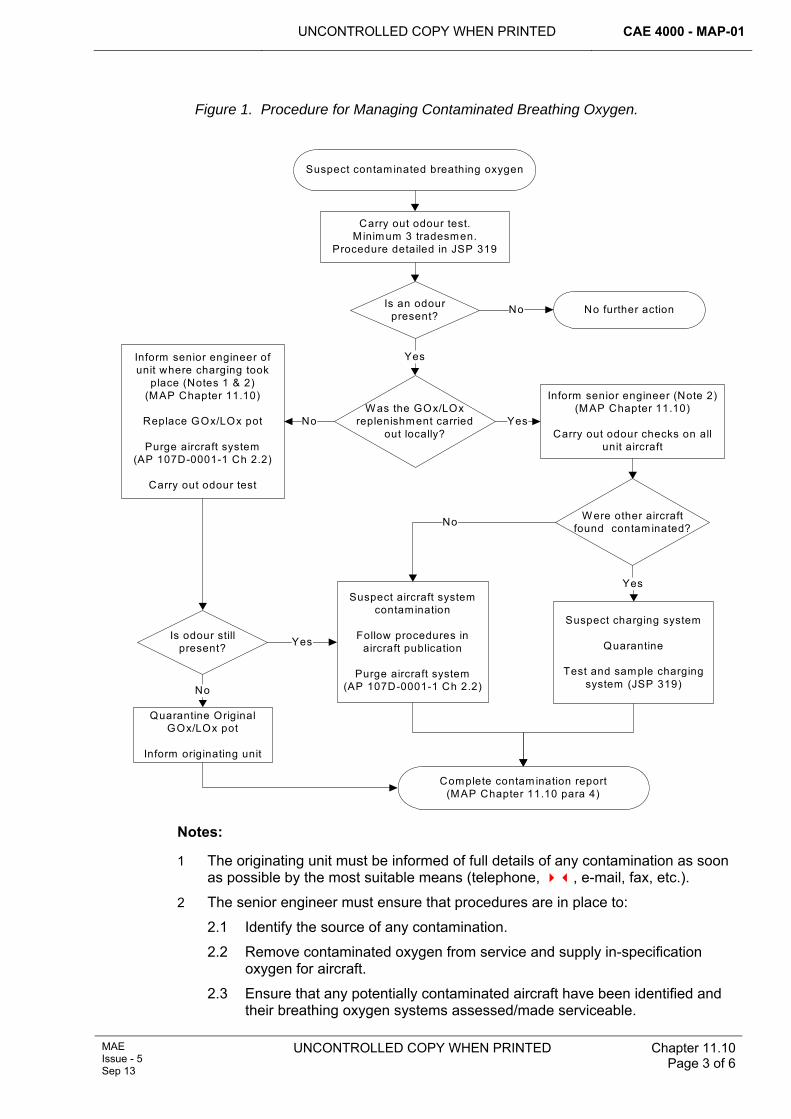
UNCONTROLLED COPY WHEN PRINTED CAE 4000 - MAP-01
MAE Issue - 5 Sep 13
UNCONTROLLED COPY WHEN PRINTED Chapter 11.10 Page 3 of 6
Figure 1. Procedure for Managing Contaminated Breathing Oxygen.
Suspect contaminated breathing oxygen
Is an odour present?
Yes
Carry out odour test.M inimum 3 tradesmen.
Procedure detailed in JSP 319
No further action
W as the GOx/LOx replenishment carried
out locally?
Complete contam ination report(MAP Chapter 11.10 para 4)
No
Is odour still present?
Quarantine Original GOx/LOx pot
Inform originating unit
No
Inform senior engineer of unit where charging took
place (Notes 1 & 2) (MAP Chapter 11.10)
Replace GOx/LOx pot
Purge aircraft system(AP 107D-0001-1 Ch 2.2)
Carry out odour test
Suspect aircraft system contamination
Follow procedures in aircraft publication
Purge aircraft system(AP 107D-0001-1 Ch 2.2)
Yes
Suspect charging system
Quarantine
Test and sample charging system (JSP 319)
No
Inform senior engineer (Note 2)(MAP Chapter 11.10)
Carry out odour checks on all unit aircraft
Yes
W ere other aircraft found contam inated?
Yes
No
Notes:
1 The originating unit must be informed of full details of any contamination as soon as possible by the most suitable means (telephone, , e-mail, fax, etc.).
2 The senior engineer must ensure that procedures are in place to:
2.1 Identify the source of any contamination.
2.2 Remove contaminated oxygen from service and supply in-specification oxygen for aircraft.
2.3 Ensure that any potentially contaminated aircraft have been identified and their breathing oxygen systems assessed/made serviceable.
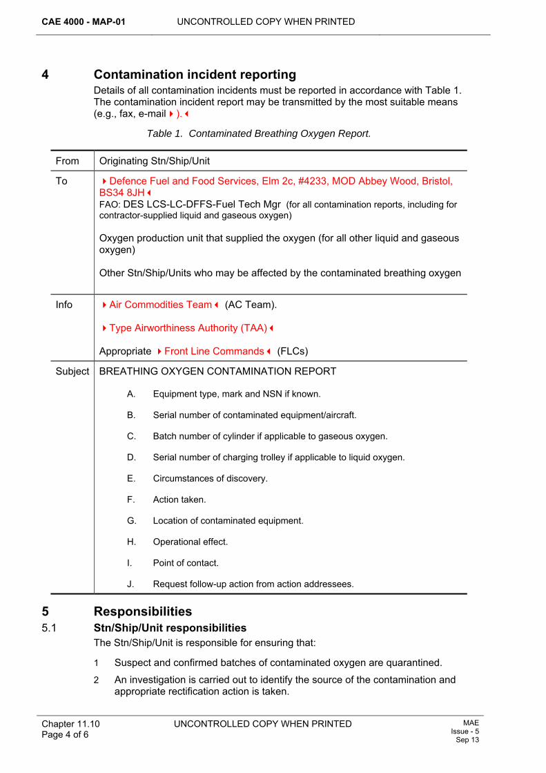
CAE 4000 - MAP-01 UNCONTROLLED COPY WHEN PRINTED
Chapter 11.10 Page 4 of 6
UNCONTROLLED COPY WHEN PRINTED MAE Issue - 5
Sep 13
4 Contamination incident reporting Details of all contamination incidents must be reported in accordance with Table 1. The contamination incident report may be transmitted by the most suitable means (e.g., fax, e-mail).
Table 1. Contaminated Breathing Oxygen Report.
From Originating Stn/Ship/Unit
To Defence Fuel and Food Services, Elm 2c, #4233, MOD Abbey Wood, Bristol, BS34 8JH FAO: DES LCS-LC-DFFS-Fuel Tech Mgr (for all contamination reports, including for contractor-supplied liquid and gaseous oxygen) Oxygen production unit that supplied the oxygen (for all other liquid and gaseous oxygen) Other Stn/Ship/Units who may be affected by the contaminated breathing oxygen
Info Air Commodities Team (AC Team). Type Airworthiness Authority (TAA) Appropriate Front Line Commands (FLCs)
Subject BREATHING OXYGEN CONTAMINATION REPORT
A. Equipment type, mark and NSN if known.
B. Serial number of contaminated equipment/aircraft.
C. Batch number of cylinder if applicable to gaseous oxygen.
D. Serial number of charging trolley if applicable to liquid oxygen.
E. Circumstances of discovery.
F. Action taken.
G. Location of contaminated equipment.
H. Operational effect.
I. Point of contact.
J. Request follow-up action from action addressees.
5 Responsibilities 5.1 Stn/Ship/Unit responsibilities
The Stn/Ship/Unit is responsible for ensuring that:
1 Suspect and confirmed batches of contaminated oxygen are quarantined.
2 An investigation is carried out to identify the source of the contamination and appropriate rectification action is taken.
UNCONTROLLED COPY WHEN PRINTED CAE 4000 - MAP-01
MAE Issue - 5 Sep 13
UNCONTROLLED COPY WHEN PRINTED Chapter 11.10 Page 5 of 6
3 All aircraft, which may have been contaminated, are identified. Follow the procedures in Figure 1.
4 Contamination of oxygen systems is reported in accordance with paragraph 4.
5.2 Type Airworthiness Authority (TAA) TAAs are responsible for:
1 Ensuring that breathing oxygen supplied to aircrew, or passengers, meets the required specification and that appropriate precautions and procedures are in place to prevent contamination occurring.
2 In the event of any suspected contamination, ensuring that there are procedures to test for the presence of contamination and, if confirmed, for the subsequent cleaning and purging of aircraft oxygen systems and for restoring a supply of in-specification gas.
These precautions and procedures must be published in the relevant technical information.
5.3 Air Commodities Team (AC Team) The AC Team is responsible for:
1 Through-life management of GSE (e.g. charging trolleys and oxygen production units) that provides oxygen for aircraft. This includes ensuring that the oxygen they contain meets the required specification and that appropriate precautions and procedures are in place to prevent contamination occurring.
2 In the event of any suspected contamination, ensuring that there are procedures to test for the presence of contamination and, if confirmed, for subsequent cleaning and purging of the equipment and for restoring a supply of in-specification gas.
These precautions and procedures must be published in the relevant equipment technical information.
5.4 Defence Fuel and Food Services (DFFS) DFFS are responsible for:
1 The acquisition of contractor-supplied liquid and gaseous oxygen and associated cylinders against the required specification.
2 MOD policy on the storage, handling and use of gases and associated containers. This policy is published in JSP 319.
6 References This chapter refers to the following publications:
1 JSP 319 – Safety Regulations for the Storage and Handling of LPG and IG.
2 RA 2425 - Aircraft Accidents, Forced Landings or Incidents.
3 Defence Standard 68-284 – Compressed Breathing Gasses for Aircraft, Diving and Marine Life-Support Applications.
4 Defence Standard 81-24 – Identification Marking of Transportable Containers, Compressed Gas.
5 AP 107D-0001-1 – General Information on Aircraft Oxygen Equipment.

CAE 4000 - MAP-01 UNCONTROLLED COPY WHEN PRINTED
Chapter 11.10 Page 6 of 6
UNCONTROLLED COPY WHEN PRINTED MAE Issue - 5
Sep 13
Intentionally Blank for Print Pagination
CAE 4000 - MAP-01
Issue - 7 Apr 15
UNCONTROLLED COPY WHEN PRINTED Chapter 11.11 Page 1 of 10
Chapter 11.11
Fuels, Lubricants, and Associated Products (FLAP) and Gases
TABLE OF CONTENTS Paragraph
Page
1 General ............................................................................................................... 1 1.1 Introduction.......................................................................................................... 1 1.2 Associated publications....................................................................................... 2 1.3 Definitions............................................................................................................ 2 2 Regulatory Governance.................................................................................... 2 2.1 Regulatory Cross-reference ................................................................................ 2 2.2 Additional Information.......................................................................................... 2 3 Standardization issues ..................................................................................... 3 3.1 Interoperability..................................................................................................... 3 3.2 Single fuels policy................................................................................................ 3 4 Governance........................................................................................................ 3 4.1 Introduction.......................................................................................................... 3 4.2 FLAAG................................................................................................................. 4 5 Product specifications...................................................................................... 4 6 FLAP and Gases selection during equipment acquisition............................ 4 7 Approval of product for use ............................................................................. 5 7.1 Approval authority ............................................................................................... 5 7.2 Promulgation of approved FLAP and gases........................................................ 5 8 Product obsolescence, rationalization and replacement .............................. 5 8.1 Introduction.......................................................................................................... 5 8.2 Evidence.............................................................................................................. 5 9 Operations, maintenance and logistics .......................................................... 6 9.1 Turbine engine fuel types, additives and blending .............................................. 6 9.2 F-24/Jet A with Additives..................................................................................... 6 9.3 Alternative/Non-conventional jet fuel................................................................... 7 9.4 Fuel contamination .............................................................................................. 7 9.5 Product packaging, colour and odour.................................................................. 8 10 Responsibilities................................................................................................. 8 10.1 Stn/Ship/Unit ....................................................................................................... 8 10.2 Project Team ....................................................................................................... 8 10.3 Technical Support ............................................................................................... 8 11 References ......................................................................................................... 9
LIST OF TABLES Table 1. Comparison of fuel types ................................................................................................6
1 General 1.1 Introduction
This chapter outlines the MOD policy on through-life use of Fuels, Lubricants and Associated Products (FLAP) and gases used in the Military Air Environment (MAE), specifically aircraft and aerospace ground equipment. This chapter does not cover
CAE 4000 - MAP-01
Chapter 11.11 Page 2 of 10
UNCONTROLLED COPY WHEN PRINTED Issue - 7 Apr 15
fuel and gas handling equipment or ship-borne fuel systems. JSP 317 covers fuel handling and safety; JSP 319 covers gas handling and safety; BR 3321 covers ship-borne aviation fuel systems. Def Stan 01-5 (Fuels, Lubricants and Associated Products) provides guidance on the characteristics and uses of FLAP (excluding gases).
1.2 Associated publications This chapter is associated with the following publications:
1 JSP 309 – UK MOD’s Fuels & Gases Environment and Safety Management.
2 JSP 317 – Joint Service Safety Regulations for the Storage and Handling of Fuels & Lubricants.
3 JSP 319 - Joint Service Regulations for the Storage, Handling and Use of Gases.
4 BR 767 - Naval Aviation Orders (Air Engineering).
5 BR 3321 - Aviation Fuel Systems in HM Ships.
6 Def Stan 68-284 - Compressed Breathing Gases for Aircraft, Diving and Marine Life-Support Applications.
7 Def Stan 58-96 - Pure Gases for Weapons Systems and Detector Cooling Applications.
1.3 Definitions The following definitions apply:
1 Standardized Products. Internationally agreed products used by NATO, Australia and New Zealand.
2 Standard Product. The product specified for routine use in support of a platform.
3 Acceptable Substitute. A product that may be used in place of a standard product for an extended period without further technical authority.
4 Emergency Substitute. Products that may be used in an emergency only, subject to technical authority, and may be subject to limitations in operation.
2 Regulatory Governance 2.1 Regulatory Cross-reference
This chapter supports:
1 RA 4515.
2.2 Additional Information The FLAP and gases used in the maintenance and operation of aircraft are required to perform in a severe operating environment under extremes of temperature, pressure and loading. Hence the responsibilities for the provision and use of FLAP and gases within the MAE must be clearly defined to ensure the safety and availability of platforms. FLAP and gases specified for use on a platform must be selected so as to minimize the logistics footprint and be capable of being sourced from a broad supplier base.
CAE 4000 - MAP-01
Issue - 7 Apr 15
UNCONTROLLED COPY WHEN PRINTED Chapter 11.11 Page 3 of 10
3 Standardization issues 3.1 Interoperability
The UK is bound by a number of international agreements to ensure interoperability of equipment with NATO and other allies. These include:
1 STANAG 1110 – Allowable Deterioration Limits for NATO Armed Forces Fuels, Lubricants and Associated Products.
2 STANAG 1135 – Interchangeability of Fuels, Lubricants and Associated Products Used by The Armed Forces of The North Atlantic Treaty Nations.
3 STANAG 1414 – Guidelines to Ensure that Contractors Design and Supply New Equipment Capable of Using Standardised Fuels, Lubricants and Associated Products.
4 STANAG 3747 – Guide Specifications (Minimum Quality Standards) for Aviation Turbine Fuels (F-34, F-35,F-40 and F-44).
5 STANAG 4362 – Fuels for Future Ground Equipments Using Compression Ignition or Turbine Engines.
6 STANAG 7036 - Fuels to be Introduced Into and Delivered by the NATO Pipeline System (NPS).
7 Gas related STANAGs, APs and studies included within the NATO Aircraft Gaseous Systems Panel (NATO GGSP).
8 JSP 886 Volume 6 Part 2: Accounting for Fuels, Lubricants and Gases.
The agreements mandate that MOD platforms shall use standardized products (NATO or Joint-Service equivalents) and only in exceptional circumstances should commercial or proprietary alternatives be used. In this situation the associated airworthiness risks are to be fully understood.
3.2 Single fuels policy The UK has adopted the Single Fuels Policy and under these terms, the standard battlefield fuel is AVTUR/FSII (F-34), and all land-based military air vehicles and equipment (ie STANAG 4362) are required to be capable of operating on this product.
4 Governance 4.1 Introduction
The MOD has a hierarchy of meetings to co-ordinate, review and manage the airworthiness and safety of military aircraft, their equipment and associated services. The MAA Executive Board (MEB) is the top level group, responsible for this activity and provides advice to the Secretary of State for Defence. Subordinate to the MEB is the Joint Air Safety Committee (JASC) which facilitates consultation and discussion with the aerospace industry on matters affecting airworthiness and safety of Military Aircraft, their equipment and associated services. Reporting to the JASC, the Type Airworthiness Advisory Group (TAAG) is charged with endorsing technical design and certification standards for military aircraft, and joint MOD/Industry processes and procedures so far as they impact upon airworthiness and safety. The TAAG is supported by a variety of specialist Sub Committees of which, the Fuels, Lubricants and Gases Airworthiness Advisory Group (FLAAG) is one.
CAE 4000 - MAP-01
Chapter 11.11 Page 4 of 10
UNCONTROLLED COPY WHEN PRINTED Issue - 7 Apr 15
4.2 FLAAG The FLAAG is chaired by DSA-MAA-Cert-MPS. Membership of the FLAAG is drawn from the MOD and UK aerospace industry. Representatives from other organizations and industrial groups may be added as judged necessary.
4.2.1 FLAAG Mission The mission of the FLAAG is to:
1 Exercise airworthiness governance over aviation fuel, lubricant and gas Defence Standards.
2 Consider and advise on the airworthiness impact of changes in aviation fuel, lubricant and gas policy, requirements, applications, safety and use.
3 Communicate emerging changes to aviation fuels, lubricants and gas policy and regulation to the wider aviation community.
4.2.2 Frequency of meetings Meetings are held twice per year, plus ad-hoc meetings and ex-committee business as required.
5 Product specifications In order to meet its obligations under the STANAGs, the MOD procures NATO Standardized Products ratified by a Def Stan, Mil Spec or Joint-Service Designation. This is notwithstanding the order of precedence prescribed by Def Stan, which places international standards (ISO) as the preferred means of specification. MOD FLAP procurement is by competitive tender. Hence more than one of the products qualified to the specification could be supplied and the specifications demand that mixing of brands within a specification is acceptable. Def Stan 01-5 provides a summary of the product specification, composition, characteristics, uses, alternatives and Stores References, as well as reference to the procurement process for each Def Stan specification.
6 FLAP and Gases selection during equipment acquisition The Acquisition Operating Framework (AOF) provides Project Teams (PTs) with a comprehensive means of ensuring that their project complies with logistic and operational policy. As part of the AOF, PTs must ensure that their requirement includes interoperability and reduction of logistics footprint through the use of standardized products. This does not preclude the employment of new technology or product formulation. Where the Original Equipment Manufacturer (OEM) proposes the use of products that are not currently available from within the MOD FLAP and Gases Inventory, or are commercially branded products, advice is to be sought in the first instance from the Defence Fuels and Food Services (DF&FS). When a PT is introducing new equipment that requires the use of FLAP and/or gases then the associated contract must stipulate the use of DefStan, MilSpec or Joint-Service Designation FLAP and gas specifications. This ensures appropriate evidence to use the multiple product brands (detailed within the respective Def Stan) is provided by the OEM to the PT in order for their use to be authorised. If this is not undertaken then the PT must provide such evidence. The requirement for standardization under STANAG 1414 is extant for multi-and international projects. Where compliance with the AOF cannot be achieved, DFFS SO1 Fuels should be informed.
CAE 4000 - MAP-01
Issue - 7 Apr 15
UNCONTROLLED COPY WHEN PRINTED Chapter 11.11 Page 5 of 10
7 Approval of product for use 7.1 Approval authority
The approval authority for the use of FLAP and gases on military registered aircraft is the appropriate Type Airworthiness Authority (TAA). In deciding whether to grant approval, the TAA should base the decision on technical and scientific advice which must be sought from the OEM, 1710 NAS or an alternative, competent body. For MRCOA, the products listed in the Type Certificate (TC) and approved maintenance schedule must be used. Except in the case of MRCOA aircraft, commercially branded products are only to be approved for use where it is confirmed that standard products would compromise airworthiness or maintainability as described below:
1 Airworthiness. The criterion to be used is whether the product could directly cause a system failure that would directly lead to the loss of the aircraft.
2 Maintainability. The criterion is whether the product will reduce the operational effectiveness of the platform.
7.2 Promulgation of approved FLAP and gases The approved FLAP and gases for use with an aircraft must be promulgated within the Aircraft Document Set (ADS). The Release To Service (RTS) promulgates the standardized FLAP (specifically fuels and engine oils) that must be used for normal replenishment activities.
7.2.1 Products used during maintenance The Technical Information (TI) associated with a specific aircraft, system or component specifies the standardized products to be used during maintenance activities. Where TI is commercially sourced, the PT must promulgate a list of equivalent standardized products approved for use.
8 Product obsolescence, rationalization and replacement 8.1 Introduction
Advances in material technology have improved the performance of FLAP and gas products over time. In many cases, replacement products have emerged offering a direct replacement with improved performance such that legacy products are no longer economic to produce. As a result, there is a need to avoid obsolescence and consolidate the FLAP and gases inventory to reduce costs. When replacement of a product is sought or proposed, the guiding principles are:
1 Miscibility. The proposed product must be miscible with the current standardized product(s).
2 Performance. The performance must be at least as good as the current standardized product(s).
3 Material Compatibility. The product must be no less compatible with the majority of common aerospace materials than the current standardized product(s).
8.2 Evidence Prior to approving replacement products, Project Engineers (PEs), TAAs or delegated staffs must satisfy themselves that appropriate scientific and operational evidence is available to assure that replacement products satisfy the guiding principles, especially regarding airworthiness and aircrew safety.
CAE 4000 - MAP-01
Chapter 11.11 Page 6 of 10
UNCONTROLLED COPY WHEN PRINTED Issue - 7 Apr 15
9 Operations, maintenance and logistics 9.1 Turbine engine fuel types, additives and blending
There are 3 principal types of turbine fuel: AVTUR, AVTAG and AVCAT, which differ in volatility (flash point). Typically, up to 4 additives are blended with these fuels, dependent upon specification to improve the product’s performance. The principal additives are: Fuel System Icing Inhibitor (FSII), Static Dissipater (SD), Lubricity Improver (LI) and Thermal Stability Improver (TSI). Table 1 outlines the additive content of each NATO fuel type and indicates potential alternative fuel types that can be used with TAA approval. Where bulk fuel is required to be blended with additives, this is only to be carried out using calibrated fuel blending equipment. Fuel is not to be blended using Risbridger pumps.
Table 1. Comparison of fuel types
JSD Title Def Stan FSII LI SD TSI Potential
Alternatives F-34 AVTUR/FSII 91-87 Yes Yes Yes JP-8 (1) F-35 AVTUR 91-91 Yes Jet A-1, Jet A(2),
TS-1(3) F-37 AVTUR/FSII or
TS-1 Mil-DTL-83133
Yes Yes Yes YesJP-8+100
F-40 AVTAG/FSII 91-88 Yes Yes Yes JP4, Jet B(4)
F-44 AVCAT/FSII 91-96 Yes Yes JP5
Notes:
1 The US has introduced lower FSII limits within its specification for JP-8 from 0.07% vol to 0.10% vol. This is outside of the limits specified within Def Stan 91-87. JP-8 may be an approved alternative fuel to F-34 on some platforms (Table 1 refers). However, TAAs should be aware of the potential lower FSII limits when considering use of JP-8 on their platforms and assess the consequences of its use accordingly.
2 Seek advice from TAA prior to use.
3 The Russian fuel TS-1 generally relates very closely to Jet A-1. However, when uplifted from Eastern European/Asian locations, it could contain additives that may not be approved for use and will need to be approved on a case-by-case basis. TS-1 uplifted from a US source will probably contain AL-41 (FSII) and AL-61 (LI), but again approval should be sought on a case-by-case basis.
4 Jet B is a commercially available (though very limited) fuel and is essentially F-40 without AL-41 or AL-61. It is recommended that frequent water drain checks are carried out when using Jet B.
9.2 F-24/Jet A with Additives JP-8 is prepared by the addition of 2 approved additives to a source of Jet A-1. However, the normal aviation fuel in the US civil market is Jet A. The US Defence Logistics Agency has identified that a significant cost saving can be made by procuring Jet A as opposed to Jet A-1. This principle has been accepted by the USAF and a programme of work is currently under way (2012) to prove this concept, with a number of US military airfields holding F-24/Jet A with Additives as their prime and in some cases only aviation fuel. There is an intent for USAF to transition
CAE 4000 - MAP-01
Issue - 7 Apr 15
UNCONTROLLED COPY WHEN PRINTED Chapter 11.11 Page 7 of 10
entirely to Jet A based fuel in the continental US by 2017. This change is currently planned for continental US only. F-34 (JP-8) shall remain as the standard battlefield fuel. It is intended that F-24 will be commonly known as Jet A with Additives and align with commercial practise. The major difference between Jet A and Jet A-1 is in the maximum freeze point of each fuel (-400C and -470C respectively). This may lead to Service impact if cold air is encountered during flight which may result in re-routing from the planned route. This may also have an effect on AAR operations if UK military aircraft are to receive fuel from US tankers. It should be noted that not all UK military aircraft are cleared to receive Jet A with Additives or Jet A within their RTS. As such, TAAs are advised to consider their platform RTS and any resulting clearance activity before conducting US operations and/or exercises.
9.3 Alternative/Non-conventional jet fuel Alternative/Non-conventional jet fuels are specific alternatives to jet fuels derived from crude oil (conventional) sources and are strictly governed by specifications such as Def Stan 91-91 and ASTM D7566. Currently, there are two types of alternative/non-conventional fuels that have been approved by these specification bodies. Synthetic fuel is a liquid fuel that is currently obtained primarily from coal or natural gas and is produced by a chemical process called Fischer-Tropsch conversion. Hydrogenated Esters of Fatty Acids (HEFA) are derived from the extraction of natural oils from plant (bio) materials which form a bio-crude which is further processed to form jet fuel. Alternative/Non-conventional fuels have the potential to replace fuels derived from crude oil so reducing reliance on crude oil and in some cases introducing a sustainable and potentially ‘green’ alternative. While some military aircraft are cleared for synthetic fuel use, the majority are presently not. In instances where Alternative/Non-conventional fuel clearance has not been obtained, the TAA should consider clearance activity so as to avoid interoperability issues in the future.
9.4 Fuel contamination The principal contamination threats for fuels are water, foreign particulates and microbiological organisms. All fuel types contain some dissolved water that may precipitate out as free water as the temperature falls. Whilst an aero-engine is generally protected from particulate damage by a filtration element, if free water is present, the formation of ice crystals at altitude could clog the filter element. Moreover, free water presents the ideal propagation conditions for microbiological organisms to develop, presenting a further risk of element clogging. The risk of free water developing is mitigated by the water and sediment checks mandated by JSP 317 and the ADS. The use of FSII, which absorbs free water, further reduces this risk. It is for this reason that FSII is specified as a standard additive for military fuels. If the FSII content is above 0.07% and below 0.2% at the point of issue to aircraft, it is acceptable for use. If it is outside of these limits, this should be reported to the relevant TAA; JSP 317 refers.
9.4.1 Fatty Acid Methyl Ester (FAME) The contamination of aviation fuel with FAME can arise due to the use of multi product-pipelines for fuel supply and distribution. In some countries, the widespread, mandatory introduction of aviation fuels with a bio-material content means that these pipelines are exposed to both automotive bio-diesels as well as to aviation fuel. FAME can adsorb onto the surface of the pipeline and later desorb, contaminating whatever fuel that follows, including aviation fuel. Current FAME limits are less than 5ppm (limit of detection).
CAE 4000 - MAP-01
Chapter 11.11 Page 8 of 10
UNCONTROLLED COPY WHEN PRINTED Issue - 7 Apr 15
9.4.2 Use of fuels without FSII Aircraft may be operated for short periods (up to a maximum of 14 consecutive calendar days) without FSII, provided that the normal fuel hygiene checks are carried out and that the aircraft subsequently operates on FSII fuels for an equivalent period of time. If requirements dictate, platforms may operate for periods in excess of 14 days under TAA concession, provided that a fuel-sampling regime is implemented to ensure that microbiological contamination is detected at the earliest opportunity; 1710 NAS and DSEA-FGSR-Sc must be consulted to ensure the most appropriate sampling regime is adopted.
9.5 Product packaging, colour and odour 9.5.1 Product packaging
FLAP is provided in appropriate packaging to meet storage requirements and is sized (volume or weight) according to typical use to preclude decanting and contamination. Gases are supplied by the MOD Contractor in compliant and transportable pressure receptacles of water capacity not exceeding 150 ltrs. Where the packaging is regarded as inadequate either in size or presentation, users must advise the DF&FS, via the PT, of the size and presentation most appropriate for users.
9.5.2 FLAP and gases product odour and colour The standardization process focuses on product performance against specification. Hence it must be expected that different suppliers’ products, whilst qualified to the same specification, may well differ in colour and odour. Where significant doubt exists as to the quality of the product (including gases - JSP 319 refers), the DF&FS should always be consulted in the first instance.
10 Responsibilities 10.1 Stn/Ship/Unit
The Stn/Ship/Unit is responsible for:
1 Conducting FLAP and gases storage and handling in accordance with JSP 317 / 319.
2 Advising the DF&FS, via the PT, of deficiencies in packaging or sizing.
3 Ensuring that tradesmen are aware that FLAP and gases meeting the same specification may have different colours and odours.
10.2 Project Team (PT) Platform PTs are responsible for:
1 Ensuring that FLAP and gases cleared for use on their platform are authorized via the Platform RTS and ADS.
2 Ensuring that advice is sought from the DF&FS if the OEM proposes the use of products that are not currently available from the MOD inventory or are commercially branded products.
10.3 Technical Support 10.3.1 Military Aviation Authority Certification Mechanical & Propulsion Systems
(MAA-Cert-MPS) MAA-Cert-MPS is responsible for:
1 Sponsoring RA 4515 and MAP-01 Chap 11.11.
CAE 4000 - MAP-01
Issue - 7 Apr 15
UNCONTROLLED COPY WHEN PRINTED Chapter 11.11 Page 9 of 10
2 Chairing the FLAAG and providing airworthiness governance over fuels, lubricants and gas standards.
10.3.2 1710 Naval Air Squadron (1710 NAS) The 1710 NAS is responsible for:
1 Assessing the requirement to modify existing, or develop new, specifications and reviewing operational requirements utilizing advances in lubricant and material technology.
2 Assisting PTs to select fuels and lubricants to optimize whole-life costs and minimize the aviation FLAP inventory through standardized products.
3 Providing specialist testing and in-service investigation of FLAP, including aviation fuel in the maritime environment.
4 Providing advice on in-service FLAP sampling, monitoring and investigations.
11 References This chapter refers to the following publications:
1 JSP 317 – Joint Service Safety Regulations for the Storage and Handling of Fuels & Lubricants.
2 JSP 319 - Joint Service Regulations for the Storage, Handling and Use of Gases.
3 STANAG 1110 – Allowable Deterioration Limits for NATO Armed Forces Fuels, Lubricants and Associated Products.
4 STANAG 1135 - Interchangeability of Fuels, Lubricants and Associated Products Used by the Armed Forces of the North Atlantic Treaty Nations.
5 STANAG 1414 - Guidelines to ensure that contractor’s design and supply equipment capable of using standardized fuels, lubricants and associated products.
6 STANAG 3747 – Guide Specifications (Minimum Quality Standards) for Aviation Turbine Fuels (F-34, F-35, F-40 and F-44).
7 STANAG 4362 - Fuels for future Ground Equipments using compression ignition or turbine engines.
8 STANAG 7036 - Fuels to be Introduced Into and Delivered by the NATO Pipeline System (NPS).
9 Def Stan 01-5 - Fuels, Lubricants and Associated Products (‘the Blue Book’).
10 Def Stan 68-284 - Compressed Breathing Gases for Aircraft, Diving and Marine Life Support Applications.
11 Def Stan 58-96 - Pure Gases for Weapon Systems and Detector Cooling Applications.
12 STANAG 3977 – Manual of Techniques of Sampling and Analysis of Gases and Liquefied Gases for Aircraft Servicing – AEP-6(F).
13 STANAG 7146 – Assignment of NATO Code Numbers to Gases Used in Aircraft Cross-Servicing.
14 JSP 886 Volume 6 Part 2: Accounting for Fuels, Lubricants and Gases.

CAE 4000 - MAP-01
Chapter 11.11 Page 10 of 10
UNCONTROLLED COPY WHEN PRINTED Issue - 7 Apr 15
Intentionally Blank for Print Pagination
UNCONTROLLED COPY WHEN PRINTED CAE 4000 - MAP-01
MAE Issue - 5 Sep 13
UNCONTROLLED COPY WHEN PRINTED Chapter 12.1 Page 1 of 2
Chapter 12.1
Electrical Wiring Interconnect System
TABLE OF CONTENTS Paragraph
Page
1 General ............................................................................................................... 1 1.1 Introduction.......................................................................................................... 1 1.2 Applicability ......................................................................................................... 1 2 Regulatory Governance.................................................................................... 1 2.1 Regulatory Cross-reference ................................................................................ 1 2.2 Additional information.......................................................................................... 2 3 Responsibilities................................................................................................. 2 3.1 Military Aviation Authority Certification Electronic Systems (MAA Cert
ES)................................................................................................................... 2 3.2 Air Commodities Team (AC Team) .............................................................. 2 3.3 Type Airworthiness Authorities (TAAs) ........................................................ 2
1 General 1.1 Introduction
The Electrical Wiring Interconnect System, (EWIS), is a major aircraft system that requires careful consideration to ensure it will perform adequately for the life of the aircraft.
This chapter details the Acceptable Means of Compliance (AMC), Guidance Material (GM) and associated processes required to ensure that the EWIS is maintained to an acceptable level. This acceptable level should be derived from the analysis of the following data; ‘as designed’ standard, ‘as built’ standard, ‘as maintained’ standard, the various operating environments and the ‘as required’ standard.
The associated processes are set out in the following sub-chapters to this document:
1 Aircraft Wiring Husbandry – see RA 4551 and Chapter 12.1.1.
2 Use of Crimped Splices in Aircraft EWIS – see RA 4552 and Chapter 12.1.2.
3 Aircraft Airframe Electrical Wiring – see RA 4553 and Chapter 12.1.3.
4 Maintenance and Repair of Aircraft Data Buses – see RA 4554 and Chapter 12.1.4.
5 Aircraft Fibre Optic Systems – see RA 4555 and Chapter 12.1.5.
6 Precision Termination Tooling and Process – See Chapter 12.1.6.
1.2 Applicability This chapter is applicable to the Military Air Environment, (MAE). The Sub-Chapters (12.1.1 to 12.1.6) to this document give more detailed regulatory requirements of an EWIS.
2 Regulatory Governance 2.1 Regulatory Cross-reference
This chapter supports:
CAE 4000 - MAP-01 UNCONTROLLED COPY WHEN PRINTED
Chapter 12.1 Page 2 of 2
UNCONTROLLED COPY WHEN PRINTED MAE Issue - 5
Sep 13
1 RA 4550(1).
2 RA 4550(2).
2.2 Additional information Nil.
3 Responsibilities 3.1 Military Aviation Authority Certification Electronic Systems (MAA Cert
ES). MAA Cert ES is responsible for defining and promulgating the Regulation, AMC, GM and associated processes on the Aircraft Electrical Wiring Interconnect System, (EWIS).
3.2 Air Commodities Team (AC Team) The AC Team is responsible for assisting MAA Cert ES in:
1 Defining and promulgating regulations on the support of aircraft EWIS and associated components for both future and in-service aircraft.
2 Advising on the relevant aspects of the formulation of aircraft requirements and commenting on aircraft specifications produced by DE&S.
3 Providing advice on methods that may be employed during aircraft design, manufacture, support and modification to promote high integrity and low cost of EWIS support.
4 Advising platform project teams on the specifications and subsequent modification and maintenance of their EWIS installations.
3.3 Type Airworthiness Authorities (TAAs) TAAs are responsible for:
1 Ensuring that the aircraft EWIS meets the requirements of this AMC, GM and associated processes, via agreed and defined standards. The standards will be applicable to new build aircraft and to modifications/upgrades of existing platforms.
2 Ensuring that suitable procedures and facilities exist for training all tradesmen involved in the support and husbandry of the EWIS.
UNCONTROLLED COPY WHEN PRINTED CAE 4000 - MAP-01
MAE Issue - 5 Sep 13
UNCONTROLLED COPY WHEN PRINTED Chapter 12.1.1 Page 1 of 4
Chapter 12.1.1
Aircraft Wiring Husbandry
TABLE OF CONTENTS Paragraph
Page
1 General ............................................................................................................... 1 1.1 Introduction.......................................................................................................... 1 1.2 Associated publications....................................................................................... 1 1.3 Applicability ......................................................................................................... 1 2 Regulatory Governance.................................................................................... 1 2.1 Regulator Cross-reference .................................................................................. 1 2.2 Additional Information.......................................................................................... 2 3 Responsibilities................................................................................................. 2 3.1 Military Aviation Authority Certification Electronic Systems (MAA Cert ES). 2 3.2 Air Commodities Team (AC Team) .............................................................. 2 3.3 Engineering tradesmen ....................................................................................... 2 3.4 Stns/Ships/Units .................................................................................................. 2 3.5 Type Airworthiness Authority (TAA) ............................................................. 3
1 General 1.1 Introduction
The majority of aircraft wiring in service is of thin wall construction and, as such, is vulnerable to mechanical damage. Additional factors that contribute to the premature ageing and deterioration of wire insulation are:
1 Contamination.
2 Mishandling through frequent bending.
3 Poor husbandry.
The purpose of this chapter is to introduce wiring husbandry Acceptable Means of Compliance (AMC), Guidance Material (GM) and associated processes for all aircraft wiring on all aircraft types and to define the responsibilities of personnel directly or indirectly involved in the maintenance of aircraft wiring.
1.2 Associated publications This chapter is associated with the following publications:
1 AP101A-0005-1 - Aircraft Wiring Practices and Standards.
1.3 Applicability These AMC, GM and associated process apply to all Service aircraft, aircraft equipment and personnel at all levels of maintenance.
2 Regulatory Governance 2.1 Regulator Cross-reference
This chapter supports:
CAE 4000 - MAP-01 UNCONTROLLED COPY WHEN PRINTED
Chapter 12.1.1 Page 2 of 4
UNCONTROLLED COPY WHEN PRINTED MAE Issue - 5
Sep 13
1 RA 4551.
2.2 Additional Information Aircraft wiring husbandry is a means of ensuring that the design life of aircraft wiring is achieved through a process of condition monitoring.
3 Responsibilities 3.1 Military Aviation Authority Certification Electronic Systems (MAA Cert
ES) MAA Cert ES is responsible for defining and promulgating the Regulation, AMC, GM and associated processes on aircraft wiring husbandry.
3.2 Air Commodities Team (AC Team) The AC Team is responsible on behalf of D Air Support for assisting MAA Cert ES in defining and promulgating the Regulation, AMC, GM and associated processes on the support of aircraft wiring husbandry.
3.3 Engineering tradesmen Whenever maintenance tasks are carried out on aircraft, the personnel involved, irrespective of trade discipline, must comply with the following procedures:
1 An unaided visual examination must be made, as far as possible, of any adjacent exposed cables or looms in the area of work. The examination is for insulation damage or contamination, insecurity of attachment or poor routeing.
2 Any insulation damage, contamination, insecurity or poor cable routeing found must be reported; a MOD Form 707 entry must be made and a cable examination carried out by a suitably qualified and experienced person.
3.4 Stns/Ships/Units Stns/Ships/Units,in conjunction with Continuing Airworthiness Management Organizations (CAMOs),are responsible for maintaining and monitoring all aspects of aircraft wiring husbandry. In particular, they must:
1 Ensure that an education campaign on aircraft wiring husbandry is maintained, which is directed towards all personnel involved in maintaining and handling aircraft wiring, including non-technical personnel. Consideration should be given to other disciplines that may have access to the aircraft.
2 Ensure that all tradesmen employed on the maintenance of aircraft wiring undergo formal familiarization training in aircraft wiring husbandry appropriate to their level of responsibility. Specimen training objectives can be obtained from AP 101A-0005-1. Guidance on the training syllabi should be obtained from the relevant aircraft PT.
3 Ensure that all relevant non-technical personnel are given suitable awareness training in the need for good aircraft wiring husbandry. In particular, personnel within the Logistics Organization should be briefed on the correct method of transportation of aircraft wire between the point of issue and the end user.
4 Ensure that no aircraft is returned from a Depth maintenance organization into service with any outstanding MOD F704 aircraft wiring husbandry entry, unless prior authorization from the TAA and/or CAMO has been granted.
CAE 4000 - MAP-01
MAE Issue - 5 Sep 13
UNCONTROLLED COPY WHEN PRINTED Chapter 12.1.1 Page 3 of 4
3.5 Type Airworthiness Authority (TAA) TAAsmust ensure that the aircraft Support Policy Statement includes specific details of its aircraft wiring husbandry requirements.
Consideration should be given to the introduction of:
1 Scheduled inspections carried out by suitable qualified and experienced tradesmen to check the condition of aircraft wiring.
2 Specific wiring husbandry training as part of aircraft type specific training and as part of a regular competency check for all engineering personnel.

CAE 4000 - MAP-01 UNCONTROLLED COPY WHEN PRINTED
Chapter 12.1.1 Page 4 of 4
UNCONTROLLED COPY WHEN PRINTED MAE Issue - 5
Sep 13
Intentionally Blank for Print Pagination
UNCONTROLLED COPY WHEN PRINTED CAE 4000 - MAP-01
MAE Issue - 5 Sep 13
UNCONTROLLED COPY WHEN PRINTED Chapter 12.1.2 Page 1 of 4
Chapter 12.1.2
Crimped Splice Repairs in Aircraft Electrical Wiring Interconnect Systems
TABLE OF CONTENTS Paragraph
Page
1 General ............................................................................................................... 1 1.1 Introduction.......................................................................................................... 1 2 Regulatory Governance.................................................................................... 1 2.1 Regulatory Cross-reference ................................................................................ 1 2.2 Additional Information.......................................................................................... 1 3 Crimped splice repairs...................................................................................... 1 3.1 General................................................................................................................ 1 3.2 Exclusions and conditions ................................................................................... 2 3.3 Permanent repairs............................................................................................... 2 3.4 Temporary repairs ............................................................................................... 3 4 Responsibilities................................................................................................. 3 4.1 Military Aviation Authority Certification Electronic Systems (MAA Cert ES)........ 3 4.2 Air Commodities Team (AC Team) .............................................................. 3 4.3 Type Airworthiness Authorities (TAAs) ........................................................ 3 5 Reference ........................................................................................................... 3
1 General 1.1 Introduction
This chapter details the conditions governing the use of in-line crimped splices for repairs in aircraft Electrical Wiring Interconnect System (EWIS) installations.
2 Regulatory Governance 2.1 Regulatory Cross-reference
This chapter supports:
1 RA 4552.
2.2 Additional Information The insertion of an environmentally sealed, in-line, crimped splice in an electrical wire or cable forming part of an aircraft EWIS installation is the accepted method of repair when replacement of the entire wire or cable is impracticable. Such repairs are, however, subject to specific restrictions and exclusions and some are permitted only as a temporary measure.
3 Crimped splice repairs 3.1 General
The definition of terms, repair procedures and installation precautions for the use of in-line splices are detailed in AP 113D-2008-1. The AP details low profile, environmentally sealed, in-line splices for use with wire sizes 26 (001) to 12 (030) AWG (ISO) and also details splices for wire sizes 10 (050) to 6 (140) AWG; however, these larger splices are not low profile. Providing both splice types are installed as
CAE 4000 - MAP-01 UNCONTROLLED COPY WHEN PRINTED
Chapter 12.1.2 Page 2 of 4
UNCONTROLLED COPY WHEN PRINTED MAE Issue - 5
Sep 13
directed in the AP, they may be considered permanent repairs, subject to the conditions of this chapter.
Non-environmentally sealed splices are only to be used for temporary repairs, unless approved by the platform Design Organization and relevant TAA.
3.2 Exclusions and conditions In addition to the specific repair instructions detailed in AP 113D-2008-1, the use of in-line crimped splices is subject to the following general exclusions and conditions (in all cases dissimilar metals are to be avoided):
1 An in-line crimped splice is not to be made in a curved wire or cable form that places undue stress on the splice: the natural lay of the wire or cable should not be impaired.
2 As far as is practicable, consideration should be given to existing splices in any one wire or cable in order to keep to number of repairs to a minimum.
3 The distance between splices in the same wire or cable should be as large as practicable. Splices are not to be used to salvage wire.
4 Splices are not to be made under clips or ties and the splice must be physically supported on each side.
5 Where multiple splices are required in close proximity to each other, their position should be staggered to avoid any increase in loom diameter. Wherever possible, splices should be positioned on the outside of a loom to allow subsequent identification and inspection.
6 Wires not marked with a circuit coding must be identified, adjacent to the splice, using printed marker sleeves of the appropriate material.
7 The supervisor must carry out stage inspections during the splicing process. 8 Wires and cables that have a specified Fire Resistance rating require special
consideration and are not to be repaired without the authority of the relevant TAA.
Repairs to co-axial, data bus or thermocouple cable may affect system performance; therefore, they should only be carried out as specified by the relevant TAA.
3.3 Permanent repairs 3.3.1 Where an in-line splice is deemed the most appropriate repair method, an
environmentally sealed variant is always to be used to affect a permanent repair to an aircraft wiring installation.
3.3.2 Wires or cables shall not be permanently repaired using a splice in the following areas or circuits unless authorized in-service by the TAA or a designer approved repair scheme:
1 Larger than size 6 AWG (ISO 140) or carries more than 250 volts RMS.
2 The connection between a bonded earth stud and earth terminal block.
3 In a designated fire zone within the aircraft.
4 In an area subject to flexing.
5 In fuel tanks.
6 In conduit or within 300 mm of conduit openings.
UNCONTROLLED COPY WHEN PRINTED CAE 4000 - MAP-01
MAE Issue - 5 Sep 13
UNCONTROLLED COPY WHEN PRINTED Chapter 12.1.2 Page 3 of 4
7 Within 300 mm of a termination device.
8 Part of the aircraft armament electrical installation or suspension equipment.
9 Subject to specific exclusion by the relevant TAA.
10 Cable, including data cables, which are designated critical components or are associated with critical components.
3.4 Temporary repairs A TAA may authorize a temporary repair using a low profile environmentally sealed crimped splice on items detailed at paragraph 3.3. In such cases, users must notify details of the intended repair to the platform Project Team and copy the information to the Air Commodities Team (AC Team). Once satisfied with the proposal, the TAA must provide authority for the repair (copy to the AC Team), giving:
1 Explicit instructions on the repair method.
2 Details of recording action to be taken.
3 The date or aircraft maintenance activity at which point the wire or cable must be restored to its pre-fault condition.
4 Responsibilities 4.1 Military Aviation Authority Certification Electronic Systems (MAA Cert
ES) MAA Cert ES is responsible for defining and promulgating this Acceptable Means of Compliance, Guidance Material and associated processes.
4.2 Air Commodities Team (AC Team) The AC Team is responsible on behalf of D Air Support for assisting MAA Cert ES in defining and promulgating the Regulation, AMC, GM and associated processes on the application of splices in the repair of EWIS.
4.3 Type Airworthiness Authorities (TAAs) TAAs must ensure that the aircraft Support Policy Statement includes specific details of any additional splice repair requirements or exclusions.
5 Reference This chapter refers to the following publication:
1 AP 113D-2008-1 – Crimp Splices for Electrical Cables – General and Technical Information.

CAE 4000 - MAP-01 UNCONTROLLED COPY WHEN PRINTED
Chapter 12.1.2 Page 4 of 4
UNCONTROLLED COPY WHEN PRINTED MAE Issue - 5
Sep 13
Intentionally Blank for Print Pagination
UNCONTROLLED COPY WHEN PRINTED CAE 4000 - MAP-01
MAE Issue - 5 Sep 13
UNCONTROLLED COPY WHEN PRINTED Chapter 12.1.3 Page 1 of 4
Chapter 12.1.3
Aircraft Electrical Wire
TABLE OF CONTENTS Paragraph
Page
1 General ............................................................................................................... 1 1.1 Introduction.......................................................................................................... 1 1.2 Associated Publications ............................................................................... 1 1.3 Applicability ......................................................................................................... 1 2 Regulatory Governance.................................................................................... 2 2.1 Regulatory Cross-reference ................................................................................ 2 2.2 Additional Information.......................................................................................... 2 3 Special application wire.................................................................................... 2 4 Procurement, update and modification of AEW............................................. 2 4.1 New aircraft ......................................................................................................... 2 4.2 Major update programmes .................................................................................. 2 4.3 In-Service modification and maintenance ........................................................... 2 5 Use of wire ......................................................................................................... 3 6 Responsibilities................................................................................................. 3 6.1 Military Aviation Authority Certification Electronic Systems (MAA Cert ES)........ 3 6.2 Air Commodities Team (AC Team) ..................................................................... 3 6.3 Type Airworthiness Authorities (TAAs) ........................................................ 3
1 General 1.1 Introduction
This chapter details the Acceptable Means of Compliance (AMC), Guidance Material (GM) and associated processes for Aircraft Electrical Wire (AEW) as utilised within the aircraft Electrical Wiring Interconnect System (EWIS). The AMC, GM and associated processes are designed to prevent the introduction of unsuitable wire types into Service aircraft during procurement, maintenance and modification.
1.2 Associated Publications This chapter is associated with the following publications:
1 AP101A-0005-1 Aircraft Wiring Practices and Standards
2 Defence Standard 61-12 Part 33 – Wires, Cords and Cables Electrical – Airframe Wires and Cables in the Temperature Categories of 135°C, 200°C and 260°C.
3 Defence Standard 00-970 – Design and Airworthiness Requirements for Service Aircraft.
1.3 Applicability This chapter is applicable to the Military Air Environment (MAE). Internal LRU wiring is not covered by this Regulation, AMC, GM and associated processes.
CAE 4000 - MAP-01 UNCONTROLLED COPY WHEN PRINTED
Chapter 12.1.3 Page 2 of 4
UNCONTROLLED COPY WHEN PRINTED MAE Issue - 5
Sep 13
2 Regulatory Governance 2.1 Regulatory Cross-reference
This chapter supports:
1 RA 4553(1).
2 RA 4553(2).
2.2 Additional Information Nil.
3 Special application wire The insulation of special application wire may contain an element of polyimide in its construction. Specifically, data bus cable that utilises pure polyimide insulation material may, exceptionally, be fitted to aircraft.
4 Procurement, update and modification of AEW Pure polyimide wire should not to be introduced, as AEW, into Service aircraft by procurement, modification or maintenance activity.
In order to ensure that the current, most suitable wire types are utilised and the D Air Support wire inventory is not increased without good cause, the Air Commodities Team (AC Team) must be kept informed of all wire choices.
4.1 New aircraft For national programmes, AEW should meet the requirements detailed in Defence Standard 00-970. Where the wire type proposed by a Design Organisation does not comply, then a proposed Alternative Acceptable Means of Compliance should be submitted to the MAA (in accordance with MAA03) detailing the delta between 00-970 and the proposed specification with full justification.
4.2 Major update programmes For all major aircraft update and modification programmes, paragraph 4.1 above applies.
4.3 In-Service modification and maintenance Current AEW of in-service aircraft may not comply with the latest requirements of Defence Standard 61-12 Part 33; in such cases, there is no requirement to retrospectively rewire aircraft. Only AEW authorized by the relevant TAA and complying with the Defence Standard, the aircraft build standard (see Note) or a DO approved replacement may be used for modification and/or maintenance of an aircraft EWIS.
Note:
When a DO approved replacement is to be used, authorization is to be obtained through submission of proposed Alternative Acceptable Means of Compliance to the MAA (in accordance with MAA03) to ensure any delta between the Defence Standard or the build standard is fully understood and justified. The AC Team are to be consulted for assistance as required and advised of final decisions. Where the aircraft build standard wire type is a pure polyimide, its continued use during maintenance activities must be approved by the TAA.
UNCONTROLLED COPY WHEN PRINTED CAE 4000 - MAP-01
MAE Issue - 5 Sep 13
UNCONTROLLED COPY WHEN PRINTED Chapter 12.1.3 Page 3 of 4
5 Use of wire The wire and cable types in the aircraft must comply with the following instructions:
1 General purpose – Wire and cable types with a specified minimum temperature rating of 135°C must be used.
2 High temperature – Wire and cable types with a specified minimum temperature rating of 260°C must be used in high temperature areas.
3 Severe Wind and Moisture-Prone (SWAMP) areas – Typical SWAMP areas include: undercarriage bays, flaps, slats airbrake and wing fold areas. The choice of wire type for use in these areas will require careful consideration due to the greater risk that may be posed by the environmental conditions.
4 Pylons and launchers – These are areas of high maintenance activity and are subject to demanding environmental conditions. Wire and cable types used in these areas therefore require a high degree of flexibility and external durability.
Note:
Further information governing the wire and cable types is contained in Defence Standard 00-970, Pt 1, Sect 6, Leaflet 14.
6 Responsibilities 6.1 Military Aviation Authority Certification Electronic Systems (MAA Cert
ES). MAA Cert ES is responsible for defining and promulgating the Regulation, AMC, GM and associated processes on AEW.
6.2 Air Commodities Team (AC Team) The AC Team is responsible, on behalf of D Air Support, for assisting MAA Cert ES in:
1 Defining and promulgating the Regulation, AMC, GM and associated processes on AEW, on behalf of D Air Support, on the support of AEW for both future and in-service aircraft.
2 Advising on the relevant aspects of the formulation of AEW requirements and commenting on aircraft specifications produced by the DE&S.
6.3 Type Airworthiness Authorities (TAAs) TAAs are responsible for:
1 Ensuring that the DO specifies and approves AEW that meets the requirements of this Regulation, AMC, GM and associated processes. Where a DO proposes the use of AEW that does not comply with the Regulation, AMC, GM and associated processes, then an Alternative Acceptable Means of Compliance proposal should be submitted to the MAA in accordance with MAA03. Advice should be sought from the AC Team as appropriate.
2 Ensuring that the DO is aware of the Services' concern about the integrity and cost of support of AEW.
3 Ensuring that the AEW used for the modification and maintenance of their aircraft meet the requirements of this Regulation, AMC and GM and that suitable
CAE 4000 - MAP-01 UNCONTROLLED COPY WHEN PRINTED
Chapter 12.1.3 Page 4 of 4
UNCONTROLLED COPY WHEN PRINTED MAE Issue - 5
Sep 13
procedures, training and facilities exist for the husbandry of electrical installations as appropriate.
UNCONTROLLED COPY WHEN PRINTED CAE 4000 - MAP-01
Issue - 7 Apr 15
UNCONTROLLED COPY WHEN PRINTED Chapter 12.1.4 Page 1 of 4
Chapter 12.1.4
Maintenance and Repair of Aircraft Data Buses
TABLE OF CONTENTS Paragraph
Page
1 General ............................................................................................................... 1 1.1 Introduction.......................................................................................................... 1 2 Regulatory Governance.................................................................................... 1 2.1 Regulatory Cross-reference ................................................................................ 1 2.2 Additional Information.......................................................................................... 1 3 Training of maintenance personnel................................................................. 1 4 Maintenance....................................................................................................... 2 4.1 Physical interference ........................................................................................... 2 4.2 Insertion loss ....................................................................................................... 2 4.3 Footprinting ......................................................................................................... 2 4.4 Test plan.............................................................................................................. 3 5 Repair ................................................................................................................. 3 6 Responsibilities................................................................................................. 3 6.1 Type Airworthiness Authority (TAA) .................................................................... 3 7 References ......................................................................................................... 3
1 General 1.1 Introduction
In order to manage the large amounts of data transferred between systems on aircraft, one or more Data Buses may be employed. The adoption of these Data Bus systems simplifies the integration of new aircraft systems and provides the added advantage of weight saving when compared with traditional wiring systems. Experience has shown that maintaining the integrity of an aircraft Data Bus is paramount in ensuring the correct operation of the systems connecting to it. This chapter details the mandatory procedures required for the maintenance and repair of aircraft Data Bus systems. Specific aspects for Fibre Optic transmission architectures should also be referred to as appropriate and are contained in chapter 12.1.5. Generic requirements for wiring husbandry are detailed in chapter 12.1.1.
2 Regulatory Governance 2.1 Regulatory Cross-reference
This Chapter Supports:
1 RA 4554.
2.2 Additional Information Disturbances of a Data Bus system refer to maintenance on the Data Bus cables, couplers and studs. Removing and refitting Line Replaceable Units (LRUs) associated with the Data Bus system does not require the aircraft to be re-footprinted.
3 Training of maintenance personnel Because of the importance of Data Buses to the operation of modern aircraft, maintenance staff at all levels must be aware of the consequences of disturbing them
CAE 4000 - MAP-01 UNCONTROLLED COPY WHEN PRINTED
Chapter 12.1.4 Page 2 of 4
UNCONTROLLED COPY WHEN PRINTED Issue - 7 Apr 15
and their related components. Type Airworthiness Authorities (TAAs) are therefore to ensure that suitable training is available for all personnel working on Data Bus systems and that training includes the use of specialist equipment, eg Precision Termination Tools.
4 Maintenance 4.1 Physical interference
Physical interference with the Data Bus, for example routine de-mating and re-mating of connectors, and inadvertent damage to cables, irrespective of severity and or introduction of an excessive bend radius, can result in degradation and possible failure. Additionally, any physical disturbance of the Data Bus will gradually degrade Data Bus integrity, as will the usual cyclic aircraft environmental changes (eg temperature, humidity and vibration) and also the ingress of aggressive fluids (eg hydraulic fluid or aircraft fuel). The deterioration and damage resulting from routine physical disturbance and cyclic changes will increase the electrical losses associated with the Data Bus. If not detected and corrected, such increases in electrical losses will eventually degrade the transmitted signal to a level that corrupts the signal waveform, thus causing errors.
4.2 Insertion loss Any single cable run will have an associated insertion loss, which attenuates the power of the transmitted signal. Insertion loss is measured in decibels (dB) of attenuation such that 0dB is equivalent to zero attenuation. The insertion loss of any single cable run will be dependent on:
1 The length of the cable run.
2 The characteristics of the stub couplers.
3 The frequency of the transmission signal.
Thus for any single cable run between 2 stubs there will be an insertion loss determined by the loss in each coupler and the length of the cable run. The nominal loss between 2 stubs (including cable losses) will be between 12 and 13dB.
4.3 Footprinting In order to monitor the integrity of Data Bus systems, they must be footprinted. The footprint process involves measuring the insertion losses between various points of the Data Bus system on each aircraft and recording the measurements on the appropriate documentation or Information System as directed by the TAA. Data Bus footprinting must be carried out on the following occasions:
1 On acceptance of a new aircraft into service.
2 At maintenance intervals as directed by the relevant TAA.
3 After any disturbance to Data Bus cables or components – refer to paragraph 4.1, (ie during aircraft modification or repair). The affected areas of the Data Bus system must be footprinted before removal and after refit to ensure their integrity.
4 After repair of a Data Bus cable run using in-line crimped splices, or when a Data Bus component (ie coupler or connector) is replaced.
On each of the above occasions, when an aircraft Data Bus system is footprinted, the latest test results must be recorded and compared with the original results obtained on acceptance of the aircraft into service. This will ascertain whether the insertion
UNCONTROLLED COPY WHEN PRINTED CAE 4000 - MAP-01
Issue - 7 Apr 15
UNCONTROLLED COPY WHEN PRINTED Chapter 12.1.4 Page 3 of 4
losses for any part of the Data Bus system are changing. If a change in insertion loss is observed, the difference between the current measurements and those obtained at initial acceptance into Service should be no greater than +/-1dB of the initial value. If the difference in measurements exceeds +/-1dB, a degradation problem exists and remedial action must be taken. If the reading obtained is within a tolerance of +/- 1dB, the Data Bus footprint must be annotated with the new measurement, leaving the original measurement visible for comparison purposes at a later date.
For aircraft that utilize an ‘integrated systems’ platform incorporating built-in fault reporting of the Data Bus system, eg the C17 aircraft, the TAA may decide that there is no benefit in carrying out a comprehensive footprinting process as detailed above. In such circumstances the TAA must detail within the aircraft Topic 2(N/A/R)1 the reasons for not following the footprinting procedures.
4.4 Test plan TAAs must provide a suitable test plan for fault-finding within specific aircraft topics for installed Mil Std 1553/Def Stan 00-18 (Part 2) Data Bus networks.
5 Repair Aircraft Data Buses may be repaired using environmentally sealed in-line crimped splices. The policy and regulations governing the use of crimped splices are detailed in RA 4552 (supported by MAP-01 Chapter 12.1.2) and AP 113D-2008-1, Chapter 3. However, for aircraft Data Bus systems the following additional conditions also apply:
1 There is no limit to the number of in-line crimped splices that can be used in a Data Bus cable run, as losses from the use of modern in-line splices are negligible. However, total losses must not vary by more than +/- 1dB from the figures obtained at initial acceptance into service.
2 After a Data Bus cable has been repaired using in-line crimped splices, the repaired Data Bus must be footprinted as detailed in paragraph 4.3 and the test result compared with the initial acceptance into service Data Bus map to verify the integrity of the repair.
6 Responsibilities 6.1 Type Airworthiness Authority (TAA)
The TAA must:
1 Set, and publish in the aircraft maintenance manual, the maintenance periodicity and footprinting requirements for aircraft Data Bus systems.
2 Provide a suitable test plan for Data Bus fault finding.
3 Ensure that appropriate Data Bus training is included in all pre-employment training courses.
7 References This chapter refers to the following publications and web sites:
1 AP 113D-2008-1 – Crimped Splices for Electrical Cables.
2 Topic 2(N/A/R)1 – General Orders and Special Instructions.
3 Def Stan 00-18 - Avionic Data Transmission Interface Systems - Part 2 - Serial, Time Division, Command/Response Multiplex Data Bus Standard (http://www.dstan.dii.r.mil.uk/standards/defstans/00/018/02000200.pdf)
CAE 4000 - MAP-01 UNCONTROLLED COPY WHEN PRINTED
Chapter 12.1.4 Page 4 of 4
UNCONTROLLED COPY WHEN PRINTED Issue - 7 Apr 15
Intentionally Blank for Print Pagination
UNCONTROLLED COPY WHEN PRINTED
CAE 4000 - MAP-01
Issue - 7 Apr 15
UNCONTROLLED COPY WHEN PRINTED
Chapter 12.1.5 Page 1 of 6
Chapter 12.1.5
Aircraft Fibre Optic Systems
TABLE OF CONTENTS Paragraph
Page
1 General ............................................................................................................... 1 1.1 Introduction.......................................................................................................... 1 2 Regulatory Governance.................................................................................... 2 2.1 Regulatory Cross-reference ................................................................................ 2 2.2 Additional Information.......................................................................................... 2 3 FO monitoring, maintenance and repair ......................................................... 2 3.1 Husbandry ........................................................................................................... 2 3.2 Inspection and cleaning....................................................................................... 2 3.3 Re-polishing of optical termini end face .............................................................. 2 3.4 Optical termini and connector replacement......................................................... 3 3.5 Pre-terminated jumper cable ............................................................................... 3 3.6 Temporary In-line splice (mechanical) ................................................................ 3 3.7 Post repair testing ............................................................................................... 3 3.8 Footprinting ......................................................................................................... 3 4 Safety.................................................................................................................. 3 4.1 Optical hazard ..................................................................................................... 4 4.2 Fibre hazard ........................................................................................................ 4 4.3 Chemical and adhesive hazard ........................................................................... 4 5 Training and authorization ............................................................................... 4 6 Responsibilities................................................................................................. 4 6.1 Military Aviation Authority Certification Electronic Systems (MAA Cert ES)........ 4 6.2 Air Commodities Team (AC Team) ..................................................................... 4 6.3 Type Airworthiness Authority (TAA) .................................................................... 5 6.4 Military Equipment Tool Solutions (METS) ................................................. 5 6.5 Operational Infrastructure Programme Project team (OIP PT) ........................... 5 6.6 Front Line Command (FLC) ................................................................................ 5 6.7 Stn/Ship/Unit ....................................................................................................... 5 7 References ......................................................................................................... 5
1 General 1.1 Introduction
Fibre Optic (FO) technology is the science involving transmission of light through transparent materials using total internal reflection. The optical fibre core is typically of a Silica construction, with the light source being provided by Light Emitting Diodes (LED) or Vertical Cavity Surface Emitting Lasers (VCSEL). Compared to conventional electrical systems, FO systems offer significant weight saving, greater bandwidth and intrinsic TEMPEST hardening. The purpose of this chapter is to identify the maintenance requirements and responsibilities associated with FO installations and equipment installed on military aircraft.
CAE 4000 - MAP-01 UNCONTROLLED COPY WHEN PRINTED
Chapter 12.1.5 Page 2 of 6
UNCONTROLLED COPY WHEN PRINTED Issue - 7 Apr 15
2 Regulatory Governance 2.1 Regulatory Cross-reference
This chapter supports:
1 RA 4555.
2.2 Additional Information Nil.
3 FO monitoring, maintenance and repair Type Airworthiness Authorities (TAAs) must address the need for a monitoring, maintenance and repair capability of their FO installation. The monitoring, maintenance and repair of FO systems can be time consuming, require specialist tools and also require a high degree of skill from trained maintenance personnel. Some repair activities may be better suited to the depth environment. The following maintenance and repair activities are to be considered by the TAA:
1 Husbandry.
2 Inspection and cleaning.
3 Re-polishing of optical termini end face.
4 Optical termini or connector replacement.
5 Pre-terminated jumper cable.
6 Temporary In-line splice (mechanical).
7 Post repair testing.
8 Foot-printing.
3.1 Husbandry Fibre optic cables, connectors and terminations are susceptible to damage due to incorrect handling, excessive bending and contamination. TAAs are to ensure that a FO husbandry campaign is in place that highlights the care required to preserve the quality and integrity of the FO installation.
3.2 Inspection and cleaning A procedure of inspection, cleaning and re-inspection of termini end faces is an essential practice to ensure that contamination does not degrade system performance. Various inspection tools and cleaning methods are available dependent on the connector and termini type. TAAs are to detail within their maintenance policy the inspection and cleaning procedures for their particular FO installation. Termini end faces are always to be inspected and cleaned as necessary prior to reconnection.
3.3 Re-polishing of optical termini end face If cleaning is unsuccessful the re-introduction of a suitable light path may be achieved by re-polishing of the optical contact end face. This can be achieved with the use of a portable, handheld polishing tool with pre-programmed polishing procedures to re-introduce the optimum end face polish and geometry of the termini. If re-polishing is unsuccessful then termini replacement will be required.
UNCONTROLLED COPY WHEN PRINTED CAE 4000 - MAP-01
Issue - 7 Apr 15
UNCONTROLLED COPY WHEN PRINTED
Chapter 12.1.5 Page 3 of 6
3.4 Optical termini and connector replacement Replacement and termination of an optical termini or connector (where the optical termini is an integral part of the FO connector) is possible where sufficient spare cable is available for re-termination. A suitable terminating process and specialist tools are also required. The terminating process consists of a ‘pot and polish’ technique where an epoxy adhesive is cured, using curing equipment, to retain the optical fibre within the optical contact. The fibre is then polished to achieve the required end face conformity.
3.5 Pre-terminated jumper cable The reinstatement of an optical link can be achieved by the substitution of a pre-terminated 'jumper' cable were full replacement of the original cable is impractical. This form of repair may be classed as temporary as the new jumper cable may not follow the same route or be installed to the same standard as the original installation. This type of repair is especially suited within an Expedient Repair (ER) environment; see Chapter 9.12 where the availability of specialist tooling is limited. A F704 entry is to be made pending a full repair.
3.6 Temporary In-line splice (mechanical) Mechanical in-line splices, suitable for Military Air Environment (MAE) applications, are being developed and may be suitable for in-line repairs of damaged optical links were cable replacement or the use of a jumper cable is impractical. This form of temporary repair may be authorized by the TAA and is especially suited within an ER environment; see Chapter 9.12 where the availability of specialist tooling is limited. A F704 entry is to be made pending a full repair.
3.7 Post repair testing Following any maintenance activity where a repair has been carried out the affected optical links shall be subjected to an Insertion Loss (IL) test. The losses are to be below the maximum allowable acceptable losses for the system.
Where a temporary repair has been carried out such as the use of a jumper cable or mechanical splice, regular tests are required to monitor the optical link performance until such time as a permanent repair is carried out.
3.8 Footprinting Foot-printing is an aid to through-life monitoring of a FO system and is a test philosophy that calls for an initial, or baseline, measurement of the individual optical links and associated interconnects, such as IL measurement. These readings are recorded and compared to subsequent measurements throughout the in-service life of the platform to determine performance capability and any system degradation.
4 Safety Personnel are to be aware of the following particular hazards associated with the maintenance of FO installations. Further information and guidance is available in AP 101A-0006-1, JSP 390, JSP 392 Leaflets 34 and 37 and JSP 375.
1 Optical hazard.
2 Fibre hazard.
3 Chemical and adhesive hazard.
CAE 4000 - MAP-01 UNCONTROLLED COPY WHEN PRINTED
Chapter 12.1.5 Page 4 of 6
UNCONTROLLED COPY WHEN PRINTED Issue - 7 Apr 15
4.1 Optical hazard Optical cables emit potentially hazardous light energy. Permanent or temporary eye damage may be caused by infrared, ultraviolet, high intensity visible and coherent light. Looking directly at the end of an optical fibre, whether terminated or not, is strictly prohibited when it is transmitting or propagating energy.
Visual inspection microscopes fitted with or without filters shall not used to examine the end face of a FO termination when it is transmitting or propagating energy. When using optical test equipment the operating instructions, particularly to eye safety, shall be followed.
Fault location or continuity equipment such as Visual Fault Locators (VFL) or Visual Continuity Tester (VCT) use high intensity light to check the integrity of an optical fibre. This light is typically based upon a class 2 laser therefore, at no time should the emitted beam be directly looked at when connected or disconnected to a fibre under test.
4.2 Fibre hazard Bare optical fibre and waste shards can cause puncture injury to skin and eyes. Particular care shall be taken when handling bare optical fibre with waste being kept to a minimum during the termination process. Waste shards and material is to be collected and disposed of in an appropriate sharps container.
4.3 Chemical and adhesive hazard Processes such as the cleaning and termination of optical fibre require the use of certain chemicals and adhesives that may be hazardous to health. Personnel are to follow all safety precautions in accordance with instructions and the relevant COSHH data sheets.
5 Training and authorization Only those personnel who are trained and authorized are to carry out maintenance to FO systems and components within the MAE. They are to have received formal FO training normally during Avionics trade training as well as platform/equipment type specific training and hold authorization MAP-B354. This authorization is to be granted by a holder of MAP-J355, see Chapter 0.7.
6 Responsibilities 6.1 Military Aviation Authority Certification Electronic Systems (MAA Cert
ES) MAA Cert ES is responsible for formulating and promulgating Tri-Service aircraft FO Regulation, Acceptable Means of Compliance (AMC), Guidance Material (GM) and associated processes.
6.2 Air Commodities Team (AC Team) The AC Team is responsible for:
1 Providing advice to Integrated Logistic Support Managers of MAE FO installations and equipment relating to new aircraft.
2 Advising TAAs on FO specifications for installation to existing aircraft.
3 Advising TAAs on modification and maintenance aspects of aircraft FO systems.
4 Advising TAAs on FO aspects to be included in aircraft Support Policy Statements (SPSs).
UNCONTROLLED COPY WHEN PRINTED CAE 4000 - MAP-01
Issue - 7 Apr 15
UNCONTROLLED COPY WHEN PRINTED
Chapter 12.1.5 Page 5 of 6
6.3 Type Airworthiness Authority (TAA) TAAs are responsible for:
1 Ensuring that the AC Team is informed of FO systems and components installed on their aircraft.
2 Liaising with the AC Team for practical advice on FO installation matters.
3 The maintenance policy for FO systems installed on their aircraft.
4 Ensuring that a FO husbandry campaign is in place that highlights the care required to preserve the quality and integrity of the FO installation.
6.4 Military Equipment Tool Solutions (METS) METS areresponsible for managing FO tooling.
6.5 Operational Infrastructure Programme Project team (OIP PT) The OIP PT is responsible for the provision of FO test equipment, in consultation with the relevant TAA.
6.6 Front Line Command (FLC) FLCs are responsible for ensuring that FO Regulation, AMC, GM and associated processes at Stns/Ships/Units under their technical command is applied correctly.
6.7 Stn/Ship/Unit The relevant holder of authority level J at a Stn/Ship/Unit must ensure that a competent individual is appointed to co-ordinate FO husbandry within the Stn/Ship/Unit.
7 References This chapter refers to the following publications:
1 JSP 375 – MOD Health & Safety Handbook.
2 JSP 390 – Ministry of Defence Military Laser Safety.
3 JSP 392 - Volume 2, Leaflet 34 Laser Safety.
4 JSP 392 - Volume 2, Leaflet 37 - Artificial Optical Radiation Safety.
5 AP 101A-0006-1 - Aircraft Fibre Optics: Standards and Practices.

CAE 4000 - MAP-01 UNCONTROLLED COPY WHEN PRINTED
Chapter 12.1.5 Page 6 of 6
UNCONTROLLED COPY WHEN PRINTED Issue - 7 Apr 15
Intentionally Blank for Print Pagination
CAE 4000 - MAP-01
MAE Issue - 6 Mar 14
UNCONTROLLED COPY WHEN PRINTED Chapter 12.1.6 Page 1 of 6
Chapter 12.1.6
Precision Termination Tooling and Process
TABLE OF CONTENTS Paragraph
Page
1 General ............................................................................................................... 1 1.1 Introduction.......................................................................................................... 1 1.2 Superseded instructions...................................................................................... 1 2 Regulatory Governance.................................................................................... 2 2.1 Regulatory Article Cross-reference ..................................................................... 2 2.2 Additional Information.......................................................................................... 2 3 Precision Termination Tooling (PTT) Maintenance........................................ 2 4 Precision Termination Process PTP Training ................................................ 2 5 Control of PTT Resources ................................................................................ 3 5.1 General................................................................................................................ 3 6 Responsibilities................................................................................................. 3 6.1 Military Aviation Authority Certification Electronic Systems (MAA Cert ES)........ 3 6.2 Air Commodities Team (AC Team) ..................................................................... 3 6.3 Operational Infrastructure Programme Project Team (OIP PT) .......................... 4 6.4 Units/MOBs ......................................................................................................... 4 6.5 Unit PTT Coordinator .......................................................................................... 4 7 Application for PTT Coordinator Course ........................................................ 5 8 Authorizations ................................................................................................... 5 9 References ......................................................................................................... 5
1 General 1.1 Introduction
This chapter details the conditions governing the control and use of Precision Termination Tooling (PTT) and the associated Precision Termination Process (PTP) in the Military Air Environment (MAE). PTP is a reliable, repeatable method of providing a uniform mechanical connection between a termination and an electrical conductor. PTT/PTP play a major role in the integrity of aircraft Electrical Wiring Interconnect System (EWIS) serviceability and therefore the control and management of PTT aligned with PTP awareness and continued improvement are essential to the maintenance of airworthiness.
This policy is restricted to the platform, associated LRUs, aero-engine, auxiliary power unit and role equipment. This policy does not apply to specialist fibre optic PTT/PTP.
1.2 Superseded instructions This chapter supersedes the following instruction:
1 AP120M-0612-1 Part 1 – Precision Termination Tooling Control, Maintenance and Testing.
CAE 4000 - MAP-01
Chapter 12.1.6 Page 2 of 6
UNCONTROLLED COPY WHEN PRINTED MAE Issue - 6
Mar 14
2 Regulatory Governance 2.1 Regulatory Article Cross-reference
This chapter supports:
Nil.
2.2 Additional Information This chapter does not support any Regulatory Article however the chapter does detail the agencies that control and support the use of Precision Termination Tooling.
3 Precision Termination Tooling (PTT) Maintenance All PTT (including wire strippers) that are or could be used within the MAE are subject to specific maintenance to ascertain serviceability as follows:
1 A before use inspection is to be carried out in accordance with the relevant worksheet detailed in AP120M-0612-1.
2 A servicing is to be carried out in accordance with the relevant worksheet detailed in AP120M-0612-1 on the following occasions:
2.1 Six monthly for in-use tools.
2.2 Removal from controlled store.
2.3 Prior to placing into controlled store.
2.4 Prior to issue of new tool (or tool transferred from another Unit).
3 GO/NO-GO gauges applicable to PTT are to be dimensionally checked annually in accordance with AP120M-0612-1.
4 If not available within AP120M-0612-1, worksheet advice should be sought from the OIP PT or applicable Type Airworthiness Authority (TAA).
Where PTT is utilized in a harsh environment, such as sand, dust and saltwater, an increase in maintenance frequency should be considered to maintain crimp tool integrity.
4 Precision Termination Process PTP Training All aircraft Tradesmen, who, in the normal course of their duties may be expected to
carry out PTP, are to undergo formal training on the common in use PTT pertaining to the platform or equipment on which they are employed, as follows:
1 Personnel are to complete training prior to or within three months of arrival on the unit/MOB.
2 Personnel are to complete revalidation training annually.
It is recommended that this training be carried out by the PTT co-ordinator. However, units may wish to subsume this training within their own ground schools or training facilities. The training is to be based on the type of PTT applicable to the platform or equipment on which they are employed. High level training objectives are detailed within AP101A-0005-1 and syllabus content assistance is available from the Air Commodities Team (AC Team).
Personnel who regularly use PTT (more than once daily for common items of PTT and weekly for the less common, i.e. hydraulic type) may have the authorization requirement for annual training extended to 24 months, at the discretion of the relevant individual holding authority level K.
CAE 4000 - MAP-01
MAE Issue - 6 Mar 14
UNCONTROLLED COPY WHEN PRINTED Chapter 12.1.6 Page 3 of 6
Personnel may have their authorization extended by up to six months for operational reasons at the discretion of the relevant individual holding authority level K.
Personnel who have not completed training, and been duly authorized, are not to conduct crimping on aircraft or aircraft equipment. Training is to be recorded, including extensions, as a local engineering authorization, in accordance with RA 4806 and Chapter 4.3.
5 Control of PTT Resources 5.1 General
It is recommended that in order to reduce the requirement for maintenance of PTT, the relevant individual holding authority level K should consider placing the control of all the unit's PTT resources under the control of a PTT Co-ordinator, as detailed in para 6.4, who should then carry out the following:
1 Negotiate with all PTT holders and withdraw all PTT that is infrequently used into storage.
2 Devise and implement a system, by which any section may withdraw, at any time, on temporary or permanent loan, any item of PTT for immediate use. A full range of the PTT that could be required by user sections should remain in the store available for immediate issue.
3 Maintain the serviceability of all PTT held in store and be responsible for ensuring that any tool removed from controlled store is subjected to a servicing prior to use.
4 Raise a Form 755C PTT Maintenance and Record card for each item of PTT to record servicing.
5 Review the PTT held in store and remove any that is considered surplus and place into a controlled store. PTT is to undergo a servicing prior to being placed into controlled store and will then not require any servicing whilst in storage.
6 Responsibilities 6.1 Military Aviation Authority Certification Electronic Systems (MAA Cert
ES) The responsibility for PTT policy is vested in MAA Cert ES. Their specific responsibility is the formulation and promulgation of policy and practice for PTT/PTP.
6.2 Air Commodities Team (AC Team) The ’Subject Matter Expert’ (SME), with responsibility for PTP is the AC Team. The executive branch is Avionics Repairables Branch (AvR) whose specific responsibilities are: 1 Provide SME support to the MAA Cert ES regarding the formulation and
promulgation of policy and practice for PTP.
2 Provide SME support to the Unit Coordinators regarding the PTP.
3 Sponsorship and engineering management of PTT training.
4 Ongoing maintenance and update of AP120M-0612-1.
5 Provide the opportunity for quality control sample testing.
6 Provide high level training objectives via AP101A-0005-1.
CAE 4000 - MAP-01
Chapter 12.1.6 Page 4 of 6
UNCONTROLLED COPY WHEN PRINTED MAE Issue - 6
Mar 14
6.3 Operational Infrastructure Programme Project Team (OIP PT) The responsibility for PTT is vested in the OIP PT. The executive branch is Military Equipment Tool Solutions (METS) whose specific responsibilities are: 1 Procurement and maintenance management, including technical support, of all
items of PTT.
2 The supply of PTT and management of repair contracts.
3 Informing the AC Team of new purchases of PTT and their accessories to enable updates to the AP120M-0612-1 to be carried out.
6.4 Units/MOBs The relevant individual holding authority level K at each unit/MOB is to appoint a PTT Co-ordinator who is normally to be a suitably experienced and qualified aircraft Avionics/Electrical tradesman or civilian equivalent holding authority level E. Where practicable the PTT Co-ordinator is to be both the controller and trainer for both PTT and PTP.
The PTT co-ordinator is to attend the PTT Co-ordinator Course as detailed in para 7 and the appointment is to be annotated on the Local Unit Establishment (LUE). Units should also consider the appointment of a deputy to act in the absence of the PTT Co-ordinator. It is recommended that the PTT Co-ordinators are considered for additional instructional technique training.
Out-Of-Area deployments which utilise a PTT Co-ordinator are, where practicable, to meet the qualification requirements. Where this is not possible due to roulement timescales or training availability, the minimum standard is to be the nomination of an aircraft Avionics/Electrical Tradesman holding authority level C.
The relevant individual holding authority level K is to oversee a system of training as detailed in para 3, for all aircraft Avionics/Electrical Tradesmen, who, in the normal course of their duties might be expected to carry out PTP.
6.5 Unit PTT Coordinator The PTT Coordinator is responsible to the relevant individual holding authority level K for the control of all PTT and where detailed the training of PTP. As the unit specialist, the Coordinator is to be the focal point for PTT. If the PTP or an item of PTT is suspect then the relevant authority is to be contacted for advice. Should a test sample be recommended, then it is to be constructed in accordance with AP120M-0612-1 and submitted to a test facility as directed by the AC Team. Additionally the PTT Co-ordinator is to:
1 Maintain a register/database of all PTT held on the unit, including their GO-NO-
GO gauges.
2 Liaise with the unit tool controller to ensure that the unit's system of serial numbering for PTT is correct in accordance with RA 4808 and Chapter 6.1 and all PTT is marked with the unit's identity code before being brought into use.
3 Maintain records to show that the scheduled maintenance of all PTT and annual dimensional checks of their GO-NO-GO gauges has been completed. If there is no other way to confirm tool serviceability and should the AC Team agree that a test sample is required, then it is to be constructed in accordance with AP120M-0612-1 and submitted to a test facility as directed.
CAE 4000 - MAP-01
MAE Issue - 6 Mar 14
UNCONTROLLED COPY WHEN PRINTED Chapter 12.1.6 Page 5 of 6
4 Control the maintenance of PTT by user sections and provide specialist advice on maintenance procedures.
5 Control the gauge annual dimensional checks in accordance with AP120M-0612-1.
6 Coordinate and progress the embodiment of modifications and the satisfaction of SIs, STIs, UTIs and RTIs pertaining to items of PTT.
7 Be the authorized conditioner of PTT in accordance with RA 4809 and Chapter 9.5.
8 Coordinate all supply support actions for PTT in accordance with Chapter 6.1.2, including routine demands and Low Value Purchase (LVP) action.
9 Inform the relevant tooling authority of LVP action to ensure that the tool is added to AP120M-0612-1.
10 Ensure that all PTT issued through supply or LVP action has equipment or platform project team approval.
7 Application for PTT Coordinator Course A course titled ‘Precision Termination Tooling Co-ordinators Course No-CN3016’ is held at the Civilian Technical Training School (CTTS) MoD Sealand. The course contains both elements of PTT control and PTP instructional training techniques. For RAF personnel this course leads to the accreditation of the qualification Q-A-PTT.
Nominations for course places are to be made via Units PTT Co-ordinator to SO3 Courses & External Training 3, 22 Trg Gp, Air Command, RAF High Wycombe. Course places are available to nominated PTT Co-ordinators and their deputies.
8 Authorizations Authorizations relating to PTT/PTP must be issued as local engineering authorizations.
9 References This chapter makes reference to the following publications:
1 AP120M-0612-1 – Precision Termination Tooling Control, Maintenance and Testing.
2 AP101A-0005-1 – Aircraft Wiring Standards and Practices (Aircraft Wiring Husbandry).
CAE 4000 - MAP-01
Chapter 12.1.6 Page 6 of 6
UNCONTROLLED COPY WHEN PRINTED MAE Issue - 6
Mar 14
Intentionally Blank for Print Pagination
UNCONTROLLED COPY WHEN PRINTED CAE 4000 - MAP-01
Issue - 7 Apr 15
UNCONTROLLED COPY WHEN PRINTED Chapter 12.2 Page 1 of 4
Chapter 12.2
Pitot Static Systems - Maintenance Responsibilities
TABLE OF CONTENTS Paragraph
Page
1 General ............................................................................................................... 1 1.1 Introduction.......................................................................................................... 1 2 Regulatory Governance.................................................................................... 1 2.1 Regulatory Cross-reference ................................................................................ 1 2.2 Additional Information.......................................................................................... 1 3 Maintenance Authorization .............................................................................. 1 4 Identifying the requirement for pitot static sense and leak tests ................. 2 5 Repetition of a pitot static sense and leak test .............................................. 2 5.1 Authorization ....................................................................................................... 2 6 Recording pitot static sense and leak tests ................................................... 2 6.1 Basic pitot static sense and leak tests................................................................. 2 6.2 Repetition of a pitot static sense and leak test .................................................... 3
1 General 1.1 Introduction
This chapter identifies the aircraft pitot static system’s maintenance activities that may be carried out by the specific trades throughout the 3 Services. After maintenance or disturbance, incorrect or badly made pipeline connections may cause false information to be fed to vital flight instruments and other systems. It is therefore essential that certain checks be done following any maintenance task associated with pitot and static systems. The basic test is a sense and leak test; however, following certain maintenance tasks, a repeat sense and leak check may also be required.
2 Regulatory Governance 2.1 Regulatory Cross-reference
This chapter supports
1 RA 4556(1).
2 RA 4556(2).
2.2 Additional Information The Type Airworthiness Authority (TAA) or the chain of command, in consultation with the Continuing Airworthiness Management Organization (CAMO) if appropriate, may mandate the requirement for the repetition of a sense and leak test.
3 Maintenance Authorization The installation, removal, operation and maintenance of drain traps and all rigid or flexible pipelines, pitot heads, static vents, and equipment items connected to the pipelines, including maintenance of pipeline mountings, securing devices and connectors is authorized for the following personnel:
CAE 4000 - MAP-01 UNCONTROLLED COPY WHEN PRINTED
Chapter 12.2 Page 2 of 4
UNCONTROLLED COPY WHEN PRINTED Issue - 7 Apr 15
1 RN – Avionic trade. Multi-traded AETs may be employed on pitot static system tasks under the supervision of an avionics trade supervisor.
2 Army – Avionic Technician.
3 RAF –A Tech(Av). AMMs may be employed on pitot static system tasks under the supervision of an avionics trade supervisor.
Note:
Personnel undertaking flight servicing tasks on pitot static systems may do so as part of their flight servicing authorization.
4 Identifying the requirement for pitot static sense and leak tests Although a TAA may mandate additional testing requirements, pitot static sense and leak tests are generally to be carried out on the following occasions:
1 Sense and leak tests should be carried out following the connection of any pitot or static pipeline to another item of equipment, including connection to another pipeline or other system element, and should test the whole aircraft system relating to the specific maintenance task.
2 A leak test is required, but no sense test, after the operation of opening and closing pitot and static drain traps.
3 No sense and leak test is required after opening and closing any hinged panel that carries pitot and/or static pipelines, so arranged as to accommodate movement of the panel without damage to the pipelines.
4 Except when opening and closing hinged panels as described above, a basic leak test must be carried out whenever pitot and/or static pipelines, or their connections, have been disturbed but not disconnected (eg whenever an instrument panel has been moved from, and returned to, its normal position without disconnection of any pitot or static pipelines to instruments mounted thereon).
5 Repetition of a pitot static sense and leak test When repetition of a pitot static sense and leak test is required, it must be carried out by personnel who have not been involved in either the supervisor function or taken part in the initial sense and leak test.
5.1 Authorization Personnel required to carry out repetition pitot static sense and leak tests must be of the trades listed at paragraph 3 and hold authorization MAP-E173.
6 Recording pitot static sense and leak tests 6.1 Basic pitot static sense and leak tests 6.1.1 Raising the requirement for a pitot static sense and leak test
Where a sense and leak test is listed as a specific activity within a maintenance procedure, or work card, and certified as an activity within that procedure, there is no requirement to separately record the test.
The supervisor of the work on the pitot static system is responsible for raising the requirement for a sense and leak test. He must raise the requirement, using the
UNCONTROLLED COPY WHEN PRINTED CAE 4000 - MAP-01
Issue - 7 Apr 15
UNCONTROLLED COPY WHEN PRINTED Chapter 12.2 Page 3 of 4
following wording in the Work Required column of the relevant Maintenance Work Order (MWO) (eg MOD Form 707):
‘Sense and Leak* Test required, in respect of work at ...[insert clear reference to the appropriate Sheet No and Line No]……………………………………………………………’
* Delete as appropriate
Where appropriate, the supervisor is also to raise the requirement for a repetition of the pitot static sense and leak test, as detailed above, raising the entry as detailed in paragraph 6.2.1.
6.1.2 Undertaking a pitot static sense and leak test The individual who does the sense and leak test must close the entry recording the requirement for the sense and leak test using the following wording in the Work Done column of the relevant MWO:
‘Sense and Leak* Test satisfactorily completed iaw ...[insert reference to appropriate aircraft AP or Topic]…………………………………………………’
* Delete as appropriate
6.2 Repetition of a pitot static sense and leak test 6.2.1 Raising the requirement for a repetition of a pitot static sense and leak test
Where the repetition of a sense and leak test is required, the supervisor of the maintenance task that necessitates the repetition of the test on the pitot static system is responsible for raising the requirement, using the following wording in the Work Required column of the relevant MWO:
'Repetition of the sense and leak test carried out at ...[insert clear reference to the appropriate Sheet No and Line No].……….…………………………………… required.'
6.2.2 Undertaking the repetition of a pitot static sense and leak test The individual who undertakes the repeat sense and leak test must close the entry that raised the requirement for the repeat sense and leak check, using the following wording in the Work Done column of the relevant MWO:
1 'Repetition of sense and leak test satisfactorily completed.'

CAE 4000 - MAP-01 UNCONTROLLED COPY WHEN PRINTED
Chapter 12.2 Page 4 of 4
UNCONTROLLED COPY WHEN PRINTED Issue - 7 Apr 15
Intentionally Blank for Print Pagination
UNCONTROLLED COPY WHEN PRINTED CAE 4000 - MAP-01
MAE Issue - 6 Mar 14
UNCONTROLLED COPY WHEN PRINTED Chapter 12.3 Page 1 of 4
Chapter 12.3
Electrostatic Discharge Sensitive Devices - Prevention of Damage by Static Electricity
TABLE OF CONTENTS
Paragraph
Page
1 General ............................................................................................................... 1 1.1 Introduction.......................................................................................................... 1 1.2 Terms used ......................................................................................................... 1 2 Regulatory Governance.................................................................................... 2 2.1 Regulatory Cross-reference ................................................................................ 2 2.2 Additional Information.......................................................................................... 2 3 Identification of ESDS devices......................................................................... 2 4 Procedure for handling ESDS devices and use of field service kit (FSK) ... 2 5 Electrostatic discharge (ESD) audit and auditor............................................ 2 5.1 Authorization of ESD auditor ............................................................................... 2 6 Responsibilities................................................................................................. 3 6.1 ESD auditor ......................................................................................................... 3 6.2 Equipment PT responsibilities ............................................................................. 3 7 Reference ........................................................................................................... 3
1 General 1.1 Introduction
Modern avionic equipment may contain many complex components that are susceptible to damage from an electrostatic discharge (ESD). These items are known as Electrostatic Discharge Sensitive (ESDS) devices. An ESD may cause either immediate failure or hidden damage, which may subsequently degrade performance, reduce reliability or shorten the device’s operational life. However, when ESDS devices are fitted in a fully assembled Line Replaceable Unit (LRU), other than through contact with exposed connectors, they are, usually, deemed to be protected by the equipment’s case.
Static electricity is generated by friction, or through the contact and/or separation of dissimilar or dielectric materials including the human body, which can result in the generation of electrostatic potentials to a charge of many thousands of volts. This voltage can then be discharged to earth via the ESDS device.
Damage to ESDS devices is easy to induce, difficult to detect and costly to rectify. Specific ESD and handling information dealing with each ESDS device is dealt with in the equipment Technical Information (TI).
1.2 Terms used For the purpose of this chapter, a Printed Circuit Board (PCB) is classed as an ESDS device.
CAE 4000 - MAP-01 UNCONTROLLED COPY WHEN PRINTED
Chapter 12.3 Page 2 of 4
UNCONTROLLED COPY WHEN PRINTED
MAE Issue - 6
Mar 14
2 Regulatory Governance 2.1 Regulatory Cross-reference
This chapter supports:
1 RA 4557.
2.2 Additional Information Nil.
3 Identification of ESDS devices Most manufacturers of electronic equipment that contains an ESDS device will make this evident by labelling their equipment. Where space does not allow the use of labels, manufacturers may use a yellow dot or, on PCBs, a yellow module extraction tab. If no identification is visible, refer to the equipment’s TI.
4 Procedure for handling ESDS devices and use of field service kit (FSK) An FSK is a portable ESD Protected Area (EPA) used for the safe handling of ESDS devices at Forward maintenance locations or when no other suitable EPA is available. Whenever an ESDS device will be handled using an FSK, the following precautions must be taken:
1 The equipment must be removed in accordance with relevant TI and placed on an FSK.
2 Before the PCB is handled, equal potential should be achieved by connecting the operator to the equipment by a wrist strap and clip contained in the FSK.
3 Avoid touching the exposed terminals on LRUs that contain, or are thought to contain, an ESDS device or PCB.
4 A suitable anti-static covering must protect any plugs or sockets removed.
5 PCBs must be placed in ESD protective packaging before being removed from the FSK.
These precautions apply to both serviceable and unserviceable equipment. Additional instructions for handling ESDS devices both at Forward and Depth maintenance locations are contained in AP 116A-0601-1.
5 Electrostatic discharge (ESD) audit and auditor Stns/Ships/Units that have EPAs or FSKs must ensure that an audit of their ESD equipment is carried out on a 6-monthly basis. An ESD auditor must carry out these audits.
5.1 Authorization of ESD auditor ESD auditors must have undergone appropriate training in accordance with RA 4150 and Chapter 4.1 and must hold authorization MAP-E266, awarded in accordance with RA 4806 and Chapter 4.3.
UNCONTROLLED COPY WHEN PRINTED CAE 4000 - MAP-01
MAE Issue - 6 Mar 14
UNCONTROLLED COPY WHEN PRINTED
Chapter 12.3 Page 3 of 4
6 Responsibilities 6.1 ESD auditor
The ESD auditor is responsible for:
1 Carrying out an audit of all ESD devices within their area of concern.
2 Maintaining a register of all EPAs and FSKs.
3 Ensuring that all EPAs and FSKs are maintained to the correct specifications and that the correct EPA and FSK practices are adhered to, in accordance with AP 116A-0601-1.
Detailed instructions and procedures for ESD device audits are contained in AP 116A-0601-1.
6.2 Equipment PT responsibilities Equipment PTs must ensure that:
1 The ESD vulnerability of their equipment is identified and stated in the TI dealing with the equipment; both positive and negative declarations are required.
2 Appropriate ESD warnings are included in the equipment’s TI.
7 Reference 1 This Chapter refers to AP 116A-0601-1 – Electrostatic Discharge Sensitive
Devices.

CAE 4000 - MAP-01 UNCONTROLLED COPY WHEN PRINTED
Chapter 12.3 Page 4 of 4
UNCONTROLLED COPY WHEN PRINTED
MAE Issue - 6
Mar 14
Intentionally Blank for Print Pagination
UNCONTROLLED COPY WHEN PRINTED CAE 4000 - MAP-01
MAE Issue - 6 Mar 14
UNCONTROLLED COPY WHEN PRINTED Chapter 12.6 Page 1 of 12
Chapter 12.6
Aircraft TEMPEST Testing
(Chapter completely revised at Issue 6: no amendments marked in chapter body)
TABLE OF CONTENTS Paragraph
Page
1 ............................................................................................................... 1 General1.1 .......................................................................................................... 1 Introduction1.2 ........................................................................................................ 2 Terms used:1.3 ......................................................................................................... 2 Applicability2 .................................................................................... 2 Regulatory Governance2.1 ................................................................................ 2 Regulatory Cross-reference2.2 .......................................................................................... 2 Additional Information3 ........................................... 3 Maintenance practices for TEMPEST equipment4 ................................................................................. 3 Aircraft TEMPEST testing4.1 ............................................................. 3 Occasions for aircraft TEMPEST testing4.2 ................................................................ 3 First-of-type aircraft TEMPEST testing4.3 ................................................................................. 4 In Service Test Plan (ISTP)4.4 .............................................................. 4 Requests for aircraft TEMPEST testing4.5 ........................................................................................ 4 TEMPEST test reports4.6 ....................................................................... 5 TEMPEST test failure procedures4.7 .............................................................................. 5 TEMPEST certification expiry4.8 ..................................................................... 5 Risk Balance Case (RBC) process5 .............................................................. 5 TEMPEST training and authorization5.1 ........................................................... 5 Engineering Branch and Trade Sponsors5.2 ................................................................................................ 6 Specialist training5.3 ...................................................................... 6 Authorization and self-supervision6 ................................................................................................. 7 Responsibilities6.1 ................................................................................ 7 Aircraft TEMPEST Authority6.2 .................................................................................................... 7 Technical Lead6.3 ................................................................................ 7 Front Line Command (FLC)6.4 ............................................................................................... 8 Project Team (PT)6.5 ....................................................................................................... 8 Stn/Ship/Unit7 .......................................................................... 9 TEMPEST quality audits (QA)8 ......................................................................................................... 9 References
LIST OF TABLES Table 1. Request for Aircraft TEMPEST Test...............................................................................9 Table 2. Abbreviated Aircraft TEMPEST Test Report. ...............................................................11
1 General 1.1 Introduction 1.1.1 General
This chapter describes aircraft TEMPEST Acceptable Means of Compliance (AMC), Guidance Material (GM) and associated processes and the approved procedures to be followed in the Military Air Environment (MAE) to ensure TEMPEST integrity of
CAE 4000 - MAP-01 UNCONTROLLED COPY WHEN PRINTED
Chapter 12.6 Page 2 of 12
UNCONTROLLED COPY WHEN PRINTED MAE Issue - 6
Mar 14
airborne Communications and Information Systems (CIS) that process Protectively Marked (PM) voice and/or data information. TEMPEST is not an acronym but it is an unclassified term used to describe the study of and measures to prevent unintentional radiation through space, along nearby conductors or by other unintended channels of compromising emanations. The unintentional transmission of PM information either coded or not, can be described as a TEMPEST hazard if important information, such as aircraft position, is inadvertently disclosed. The interceptability and the value of that information together with the number and physical installation of CIS in airborne platforms are used to designate TEMPEST risk. The TEMPEST risk is used to decide the requirements for TEMPEST testing a platform’s CIS in order to reduce the risk of TEMPEST hazards to acceptable levels. Thus, ensuring the TEMPEST security of a platform involves a balance between physical, personnel and technical security, good design, installation and maintenance of CIS equipment and procedural controls over its use. This chapter covers all of these factors, together with the organizations responsible for aircraft TEMPEST AMC, GM and associated processes and its articulation, including aircraft TEMPEST testing.
1.2 Terms used: 1 Compromising emanations (CE)
CE are unintentionally emitted voice or data-related or intelligence-bearing signals which, if intercepted and analysed, disclose PM information being transmitted, received, handled or otherwise processed by CIS.
2 Configuration change (CC) CC is brought about by the embodiment of any type of modification (including first embodiment of secure CIS Urgent Operational Requirements (UOR) and/or Service Modifications (SM), the satisfaction of a Special Instruction (Technical) (SI(T)), or a software version upgrade, eg in digital intercom systems. The temporary or permanent fitment of designated secure CIS role equipment, or the re-role of an aircraft to a secure CIS fit through the embodiment of a previously TEMPEST tested, risk-assessed and approved UOR or SM (including the RAF’s former Special Trial Fit), does not constitute a configuration change.
3 Significant disturbance (SD) An SD occurs when cables/looms carrying PM information or adjacent cables/ looms are repositioned, or re-routed or repaired. Certain Line Replaceable Units (LRUs) and their associated cables/looms, including secure CIS role equipment and LRUs in secure CIS UORs and SMs, may fit this definition; these LRUs must be listed in the aircraft Topic 2(N/A/R).
1.3 Applicability This chapter is applicable within the MAE to the maintenance of aircraft fitted with secure CIS that process PM information. This chapter is not applicable to ground-based mission support systems or facilities.
2 Regulatory Governance 2.1 Regulatory Cross-reference
This chapter supports:
1 RA 4558.
2.2 Additional Information AC/322-D(2007)0036 - INFOSEC Technical & Implementation Directive on Emission Security states that it is mandatory and binding that all equipment used to process
UNCONTROLLED COPY WHEN PRINTED CAE 4000 - MAP-01
MAE Issue - 6 Mar 14
UNCONTROLLED COPY WHEN PRINTED
Chapter 12.6 Page 3 of 12
NATO information classified NATO CONFIDENTIAL and above be TEMPEST tested. TEMPEST policy for CIS is set out in JSP 440 Part 8 Section 5 Chapter 6 that covers radiation security. The TEMPEST AMC, GM and associated processes for airborne CIS in this chapter is derived from the overarching national TEMPEST policy set by the Communications Electronic Security Group (CESG). CESG Good Practice Guide No. 14 states that tactical mobile equipment/systems and platforms that use radio transmitters as their primary means of communication to process PM information must be TEMPEST tested in accordance with NATO SDIP-27/1 TEMPEST Standard. Within the MAE, TEMPEST testing of fixed and rotary-wing aircraft fitted with secure CIS must be carried out in accordance with this chapter. The Regulation, AMC, GM and associated processes for aircraft Communications Security (COMSEC) material is covered in JSP 440 Part 8 Section 2 Chapter 3 and Chapter 12.7.
3 Maintenance practices for TEMPEST equipment All parts of CIS on aircraft, particularly secure CIS Line Replaceable Units (LRUs) and components manufactured and certified to meet TEMPEST build standards, ie SDIP-27/1 TEMPEST Standard, must be repaired, maintained and handled in such a way that the integrity of TEMPEST protection measures is not impaired or compromised. The effectiveness of these protection measures can easily be degraded by careless maintenance practices. Engineering maintenance personnel are therefore to pay particular attention, not only to the maintenance and correct fitment of LRUs, but also to the earthing, bonding and maintenance of cables/looms and cable screening.
4 Aircraft TEMPEST testing 4.1 Occasions for aircraft TEMPEST testing
Aircraft TEMPEST testing must be carried out on the following occasions:
1 Prior to the introduction into service of a new aircraft type containing, as part of the build standard, secure CIS that process PM information. This is termed first-of-type aircraft TEMPEST testing; see paragraph 4.2.
2 When secure CIS are installed in an aircraft already in-service but not previously fitted with a secure CIS capability. This is also termed first-of-type (FoT) aircraft TEMPEST testing.
3 When significant disturbance of aircraft systems occurs.
4 When detailed as a scheduled maintenance activity in the Topic 5A1.
5 As directed by the aircraft Project Team (PT) following consultation with the appropriate TEMPEST Testing Technical Lead.
4.2 First-of-type aircraft TEMPEST testing 4.2.1 New aircraft type requirement
For a new aircraft type, fitted with CIS that process PM information, but not yet accepted into service, FoT aircraft TEMPEST testing must be detailed in production contracts. FoT aircraft TEMPEST testing will be carried out in accordance with the NATO SDIP-27/1 TEMPEST Standard under the auspices of CESG or by a CESG-accredited organization. CESG may elect to witness the FoT testing. The purpose of FoT aircraft TEMPEST testing is to confirm the TEMPEST integrity and establish the TEMPEST profile of the aircraft type and its installed secure CIS.
CAE 4000 - MAP-01 UNCONTROLLED COPY WHEN PRINTED
Chapter 12.6 Page 4 of 12
UNCONTROLLED COPY WHEN PRINTED MAE Issue - 6
Mar 14
4.2.2 After first-of-type testing procedures After testing one aircraft, the TEMPEST profile is then to be confirmed by testing a second new aircraft in the same configuration. If aircraft production is carried out in batches and/or at different locations, the aircraft configuration may change between batches, so further FoT TEMPEST tests must be carried out on selected aircraft, normally the first in each batch, to confirm that the TEMPEST profile of the aircraft type and its secure CIS installation is being maintained. Any TEMPEST failures, or significant changes in the TEMPEST profile, must be investigated and resolved before the aircraft type enters service.
Note:
All remaining aircraft fitted with secure CIS in an aircraft fleet will be subject to TEMPEST testing as a scheduled maintenance activity, see paragraph 4.1, item 4.
4.2.3 First-of-type TEMPEST certification and security accreditation Prior to the undertaking of FoT Testing, the following documents must be produced:
1 TEMPEST Test Plan (TTP).
2 TEMPEST test instrumentation report.
If FoT aircraft TEMPEST testing confirms the TEMPEST integrity of the aircraft type and its installed secure CIS, CESG will approve the issue of TEMPEST certification to the Defence Security and Assurance Services (DSAS), the platform PT and the originator (if requested). The PT is responsible for producing an Accreditation Document Set and an Operational Security Management Plan (that embraces Security Operating Procedures) in order to gain security accreditation from the delegated accrediting organization in accordance with JSP 440 Part 8 Section 2 Chapter 3.
4.3 In Service Test Plan (ISTP) An ISTP must be produced for each aircraft type fitted with secure CIS that process PM information and each role where roles differ significantly within aircraft type. An ISTP is a ‘living’ document that takes account of all possible combinations of use of installed CIS; it is designed to provide a high degree of confidence in the TEMPEST integrity of the aircraft. These are compiled and maintained by the aircraft TEMPEST Technical Lead. The ISTP must be reviewed annually in order to take account of any changes in aircrew operating procedures or configuration changes.
4.4 Requests for aircraft TEMPEST testing Requests for aircraft TEMPEST testing will normally be originated by either an aircraft PT or the relevant aircraft engineering maintenance manager on Sqns/Units. Requests must be submitted direct to the appropriate Aircraft TEMPEST Testing Team (ATTT) in the format detailed in Table 1 – the form may be copied as required.
4.5 TEMPEST test reports 4.5.1 First-of-type testing
A full report, adapted as required from the format in SDIP-27/1 TEMPEST Standard detailing the TTP, test procedures and table of results, must be completed.
4.5.2 In Service Testing 4.5.2.1 Pass
When a successful aircraft In Service TEMPEST test has been carried out, an abbreviated TEMPEST test report, based on the format detailed in Table 2 (which
UNCONTROLLED COPY WHEN PRINTED CAE 4000 - MAP-01
MAE Issue - 6 Mar 14
UNCONTROLLED COPY WHEN PRINTED
Chapter 12.6 Page 5 of 12
may be copied and amended as required) must be completed and distributed within 10 working days to the originator of the initial request, with information copies to the Stn/Ship/Unit TEMPEST Control Officer (Air) (TCO(Air)) where appointed.
4.5.2.2 Fail A full report, adapted as required from the format in SDIP-27/1 TEMPEST Standard, detailing the TTP, test procedures and table of results, must be completed and distributed within 10 working days to the originator of the initial request and the appropriate platform Security Working Group.
4.6 TEMPEST test failure procedures A TEMPEST failure confirms there is a risk to information. The level and nature of this risk will be informed by the extent of the failure as defined within the TEMPEST test report. Whilst the TEMPEST test report will inform understanding of the risk to information, any aircraft with a TEMPEST test failure must be subject to a Risk Balance Case (RBC) approved by the MoD Senior Risk Officer (SIRO) prior to being operationally tasked (regardless of geographical location of that tasking), as described at paragraph 4.8. The affected platform CIS should not be used to process PM information and an appropriate Limitation Log entry must be raised on MOD Form 703. The Limitation Log entry may be couched in ‘procedural’ terms such that the affected CIS may be used only in tautly defined procedures and/or circumstances and/or configurations to process PM information. Ideally, such Limitation Log entries should be cleared at the earliest opportunity by corrective maintenance.TEMPEST training and authorization.
4.7 TEMPEST certification expiry The TEMPEST test periodicity may be increased by up to 25% by an Authority Level H holder. Extensions beyond 25% must be approved through the platform Project Team, who will consult the platform DSAS Accreditor. The lapsing of TEMPEST certification does not confirm that there is a risk to information (as per a TEMPEST failure). Lapsing does, however, reduce the level of assurance provided by the previous certification. Noting the reduced level of assurance, an assessment of the likely risk to information must be conducted by the relevant stakeholders prior to the aircraft being operationally tasked (regardless of geographical location of that tasking). If it is assessed that the operational tasking of the aircraft will present an information risk, and this risk is deemed to be outside of the risk appetite of the relevant Top Level Budget holder (TLB), a RBC should be raised and approved by the MoD SIRO in accordance with paragraph 4.8.
4.8 Risk Balance Case (RBC) process JSP 440 Supplement 12 outlines the procedures for presenting an information risk to the appropriate risk owner in the form of a RBC. In the event of a requirement being identified to raise an RBC for any information asset within the respective TLBs, the RBC must be staffed via the single service Warning and Reporting Point (WARP) and the Information Risk team for approval (via DSAS) by the respective 2* TLB SIRO prior to submission to the 2* MoD SIRO. Further detail on this process can be obtained from the Information Risk team.
5 TEMPEST training and authorization 5.1 Engineering Branch and Trade Sponsors
Engineering Branch and Trades Sponsors, as appropriate, must ensure that TEMPEST awareness training is included in initial engineering professional and trade training courses.
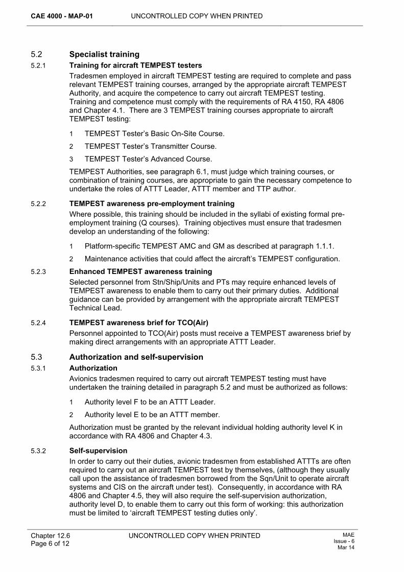
CAE 4000 - MAP-01 UNCONTROLLED COPY WHEN PRINTED
Chapter 12.6 Page 6 of 12
UNCONTROLLED COPY WHEN PRINTED MAE Issue - 6
Mar 14
5.2 Specialist training 5.2.1 Training for aircraft TEMPEST testers
Tradesmen employed in aircraft TEMPEST testing are required to complete and pass relevant TEMPEST training courses, arranged by the appropriate aircraft TEMPEST Authority, and acquire the competence to carry out aircraft TEMPEST testing. Training and competence must comply with the requirements of RA 4150, RA 4806 and Chapter 4.1. There are 3 TEMPEST training courses appropriate to aircraft TEMPEST testing:
1 TEMPEST Tester’s Basic On-Site Course.
2 TEMPEST Tester’s Transmitter Course.
3 TEMPEST Tester’s Advanced Course.
TEMPEST Authorities, see paragraph 6.1, must judge which training courses, or combination of training courses, are appropriate to gain the necessary competence to undertake the roles of ATTT Leader, ATTT member and TTP author.
5.2.2 TEMPEST awareness pre-employment training Where possible, this training should be included in the syllabi of existing formal pre-employment training (Q courses). Training objectives must ensure that tradesmen develop an understanding of the following:
1 Platform-specific TEMPEST AMC and GM as described at paragraph 1.1.1.
2 Maintenance activities that could affect the aircraft’s TEMPEST configuration.
5.2.3 Enhanced TEMPEST awareness training Selected personnel from Stn/Ship/Units and PTs may require enhanced levels of TEMPEST awareness to enable them to carry out their primary duties. Additional guidance can be provided by arrangement with the appropriate aircraft TEMPEST Technical Lead.
5.2.4 TEMPEST awareness brief for TCO(Air) Personnel appointed to TCO(Air) posts must receive a TEMPEST awareness brief by making direct arrangements with an appropriate ATTT Leader.
5.3 Authorization and self-supervision 5.3.1 Authorization
Avionics tradesmen required to carry out aircraft TEMPEST testing must have undertaken the training detailed in paragraph 5.2 and must be authorized as follows:
1 Authority level F to be an ATTT Leader.
2 Authority level E to be an ATTT member.
Authorization must be granted by the relevant individual holding authority level K in accordance with RA 4806 and Chapter 4.3.
5.3.2 Self-supervision In order to carry out their duties, avionic tradesmen from established ATTTs are often required to carry out an aircraft TEMPEST test by themselves, (although they usually call upon the assistance of tradesmen borrowed from the Sqn/Unit to operate aircraft systems and CIS on the aircraft under test). Consequently, in accordance with RA 4806 and Chapter 4.5, they will also require the self-supervision authorization, authority level D, to enable them to carry out this form of working: this authorization must be limited to ‘aircraft TEMPEST testing duties only’.
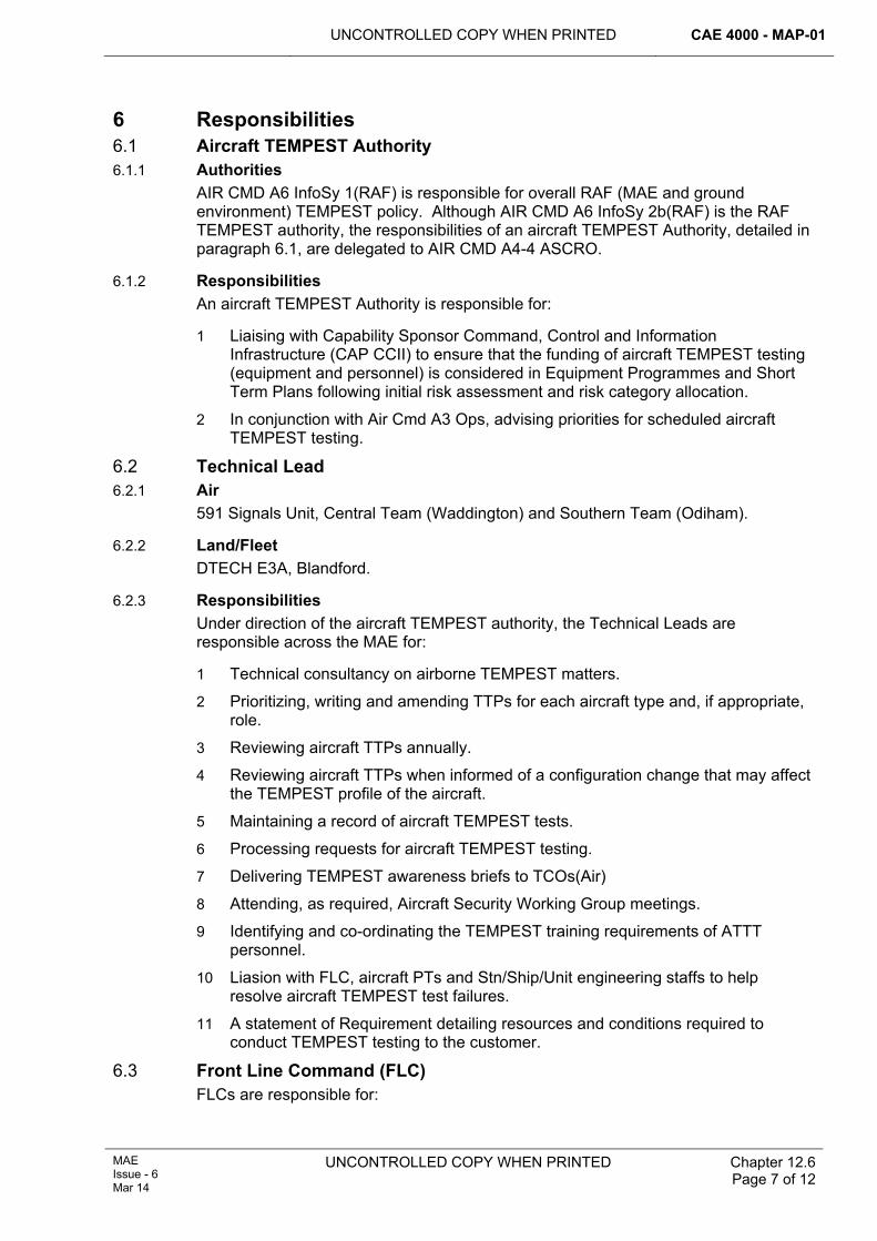
UNCONTROLLED COPY WHEN PRINTED CAE 4000 - MAP-01
MAE Issue - 6 Mar 14
UNCONTROLLED COPY WHEN PRINTED
Chapter 12.6 Page 7 of 12
6 Responsibilities 6.1 Aircraft TEMPEST Authority 6.1.1 Authorities
AIR CMD A6 InfoSy 1(RAF) is responsible for overall RAF (MAE and ground environment) TEMPEST policy. Although AIR CMD A6 InfoSy 2b(RAF) is the RAF TEMPEST authority, the responsibilities of an aircraft TEMPEST Authority, detailed in paragraph 6.1, are delegated to AIR CMD A4-4 ASCRO.
6.1.2 Responsibilities An aircraft TEMPEST Authority is responsible for:
1 Liaising with Capability Sponsor Command, Control and Information Infrastructure (CAP CCII) to ensure that the funding of aircraft TEMPEST testing (equipment and personnel) is considered in Equipment Programmes and Short Term Plans following initial risk assessment and risk category allocation.
2 In conjunction with Air Cmd A3 Ops, advising priorities for scheduled aircraft TEMPEST testing.
6.2 Technical Lead 6.2.1 Air
591 Signals Unit, Central Team (Waddington) and Southern Team (Odiham).
6.2.2 Land/Fleet DTECH E3A, Blandford.
6.2.3 Responsibilities Under direction of the aircraft TEMPEST authority, the Technical Leads are responsible across the MAE for:
1 Technical consultancy on airborne TEMPEST matters.
2 Prioritizing, writing and amending TTPs for each aircraft type and, if appropriate, role.
3 Reviewing aircraft TTPs annually.
4 Reviewing aircraft TTPs when informed of a configuration change that may affect the TEMPEST profile of the aircraft.
5 Maintaining a record of aircraft TEMPEST tests.
6 Processing requests for aircraft TEMPEST testing.
7 Delivering TEMPEST awareness briefs to TCOs(Air)
8 Attending, as required, Aircraft Security Working Group meetings.
9 Identifying and co-ordinating the TEMPEST training requirements of ATTT personnel.
10 Liasion with FLC, aircraft PTs and Stn/Ship/Unit engineering staffs to help resolve aircraft TEMPEST test failures.
11 A statement of Requirement detailing resources and conditions required to conduct TEMPEST testing to the customer.
6.3 Front Line Command (FLC) FLCs are responsible for:

CAE 4000 - MAP-01 UNCONTROLLED COPY WHEN PRINTED
Chapter 12.6 Page 8 of 12
UNCONTROLLED COPY WHEN PRINTED MAE Issue - 6
Mar 14
1 Liaising with TAAs and TEMPEST Authorities to ensure that sufficient resources, in terms of funding, established personnel, aircraft TEMPEST testing equipment and host Stn/Ship/Unit facilities, are provided to conduct aircraft TEMPEST testing.
2 Liaising, on behalf of Stns/Ships/Units, with the appropriate aircraft TEMPEST Authority to assist in resolving aircraft TEMPEST test failures.
3 Advising operational priorities if operational tasking conflicts with the need for scheduled aircraft TEMPEST testing.
6.4 Project Team (PT) 6.4.1 Aircraft PTs
For aircraft fitted with secure CIS that process PM information, aircraft PTs, through their Type Airworthiness Authority (TAA) where appropriate, are responsible ensuring that:
1 For initial FoT aircraft TEMPEST testing:
1.1 The requirement is detailed in production contracts.
1.2 Accreditation requirements are contracted for, progressed and maintained.
2 Resource levels, in terms of funding and support, for aircraft TEMPEST testing equipment, manpower and training are identified in the aircraft Through-Life Management Plan (TLMP).
3 In liaison with the appropriate aircraft TEMPEST Authority that:
3.1 TEMPEST risk assessments are completed for each aircraft role.
3.2 TTPs are written and reviewed regularly.
4 The aircraft document set contains:
4.1 In the Topic 1 and/or Topic 2, technical information on all secure CIS installations.
4.2 In the Topic 5A1, the periodicity of scheduled TEMPEST testing.
4.3 In the Topic 2(N/A/R), a reference to the TTP.
4.4 In the Topic 2(N/A/R), details of those LRUs, including cables/looms, the replacement, movement or re-routing of which constitute a significant disturbance.
5 The appropriate aircraft TEMPEST Technical Lead is informed of proposed and actual configuration changes that may or will affect the TEMPEST profile and the content of the TTP.
6 Requests for aircraft TEMPEST testing are submitted to the appropriate aircraft TEMPEST Authority in accordance with the format in Table 1.
7 Aircraft TEMPEST test failures are managed, as necessary, in conjunction with the platform Security Working Group or FLC as appropriate.
8 Platform-specific pre-employment training includes TEMPEST awareness training for all aircraft engineering tradesmen employed in maintaining systems that could affect an aircraft’s TEMPEST profile.
6.5 Stn/Ship/Unit 6.5.1 Parenting
A Stn/Ship/Unit should either host or provide parenting facilities to any ATTTs lodged on that Stn/Ship/Unit.
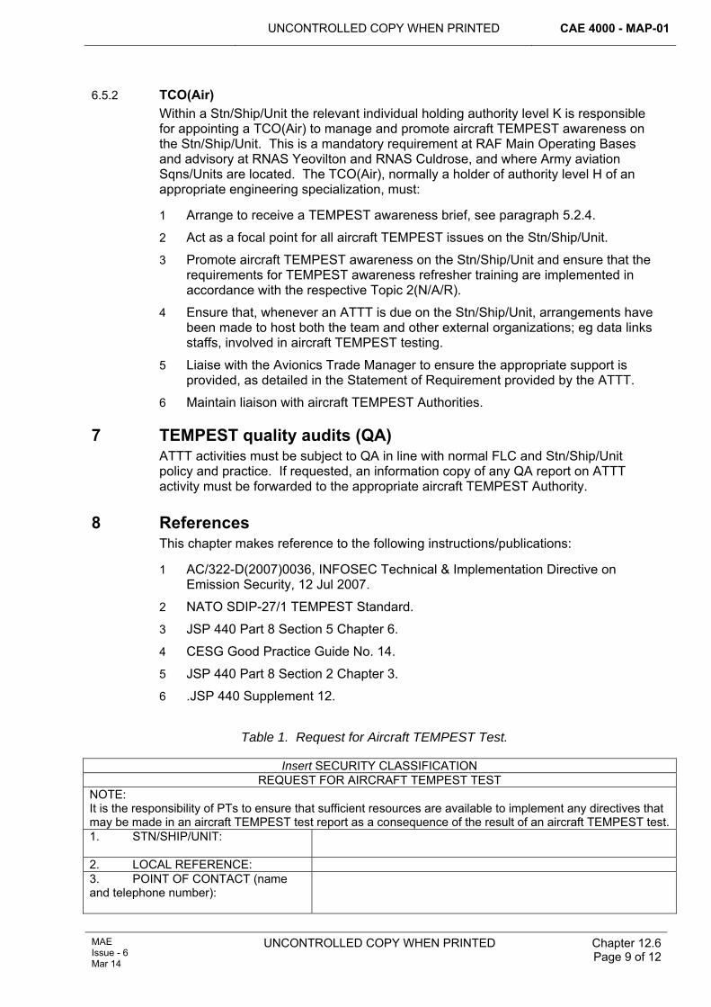
UNCONTROLLED COPY WHEN PRINTED CAE 4000 - MAP-01
MAE Issue - 6 Mar 14
UNCONTROLLED COPY WHEN PRINTED
Chapter 12.6 Page 9 of 12
6.5.2 TCO(Air) Within a Stn/Ship/Unit the relevant individual holding authority level K is responsible for appointing a TCO(Air) to manage and promote aircraft TEMPEST awareness on the Stn/Ship/Unit. This is a mandatory requirement at RAF Main Operating Bases and advisory at RNAS Yeovilton and RNAS Culdrose, and where Army aviation Sqns/Units are located. The TCO(Air), normally a holder of authority level H of an appropriate engineering specialization, must:
1 Arrange to receive a TEMPEST awareness brief, see paragraph 5.2.4.
2 Act as a focal point for all aircraft TEMPEST issues on the Stn/Ship/Unit.
3 Promote aircraft TEMPEST awareness on the Stn/Ship/Unit and ensure that the requirements for TEMPEST awareness refresher training are implemented in accordance with the respective Topic 2(N/A/R).
4 Ensure that, whenever an ATTT is due on the Stn/Ship/Unit, arrangements have been made to host both the team and other external organizations; eg data links staffs, involved in aircraft TEMPEST testing.
5 Liaise with the Avionics Trade Manager to ensure the appropriate support is provided, as detailed in the Statement of Requirement provided by the ATTT.
6 Maintain liaison with aircraft TEMPEST Authorities.
7 TEMPEST quality audits (QA) ATTT activities must be subject to QA in line with normal FLC and Stn/Ship/Unit policy and practice. If requested, an information copy of any QA report on ATTT activity must be forwarded to the appropriate aircraft TEMPEST Authority.
8 References This chapter makes reference to the following instructions/publications:
1 AC/322-D(2007)0036, INFOSEC Technical & Implementation Directive on Emission Security, 12 Jul 2007.
2 NATO SDIP-27/1 TEMPEST Standard.
3 JSP 440 Part 8 Section 5 Chapter 6.
4 CESG Good Practice Guide No. 14.
5 JSP 440 Part 8 Section 2 Chapter 3.
6 .JSP 440 Supplement 12.
Table 1. Request for Aircraft TEMPEST Test.
Insert SECURITY CLASSIFICATION REQUEST FOR AIRCRAFT TEMPEST TEST
NOTE: It is the responsibility of PTs to ensure that sufficient resources are available to implement any directives that may be made in an aircraft TEMPEST test report as a consequence of the result of an aircraft TEMPEST test.1. STN/SHIP/UNIT:
2. LOCAL REFERENCE: 3. POINT OF CONTACT (name and telephone number):
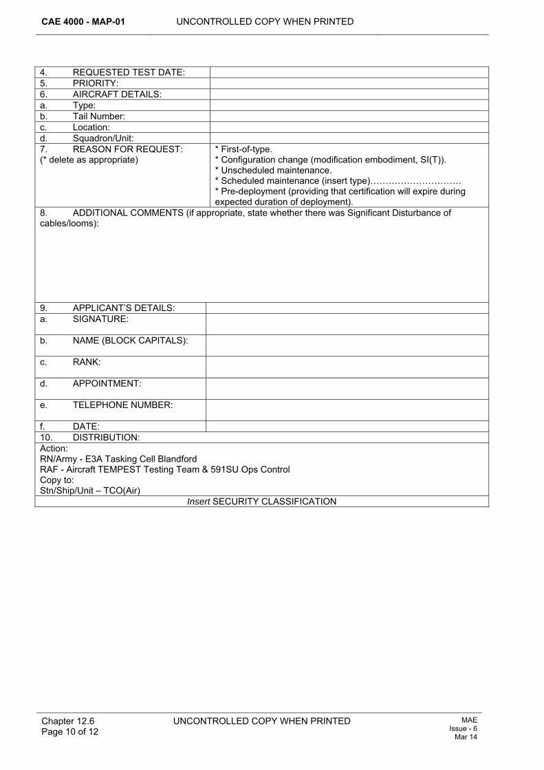
CAE 4000 - MAP-01 UNCONTROLLED COPY WHEN PRINTED
Chapter 12.6 Page 10 of 12
UNCONTROLLED COPY WHEN PRINTED MAE Issue - 6
Mar 14
4. REQUESTED TEST DATE: 5. PRIORITY: 6. AIRCRAFT DETAILS: a. Type: b. Tail Number: c. Location: d. Squadron/Unit: 7. REASON FOR REQUEST: (* delete as appropriate)
* First-of-type. * Configuration change (modification embodiment, SI(T)). * Unscheduled maintenance. * Scheduled maintenance (insert type)………………………… * Pre-deployment (providing that certification will expire during expected duration of deployment).
8. ADDITIONAL COMMENTS (if appropriate, state whether there was Significant Disturbance of cables/looms): 9. APPLICANT’S DETAILS: a. SIGNATURE:
b. NAME (BLOCK CAPITALS):
c. RANK:
d. APPOINTMENT:
e. TELEPHONE NUMBER:
f. DATE: 10. DISTRIBUTION: Action: RN/Army - E3A Tasking Cell Blandford RAF - Aircraft TEMPEST Testing Team & 591SU Ops Control Copy to: Stn/Ship/Unit – TCO(Air)
Insert SECURITY CLASSIFICATION
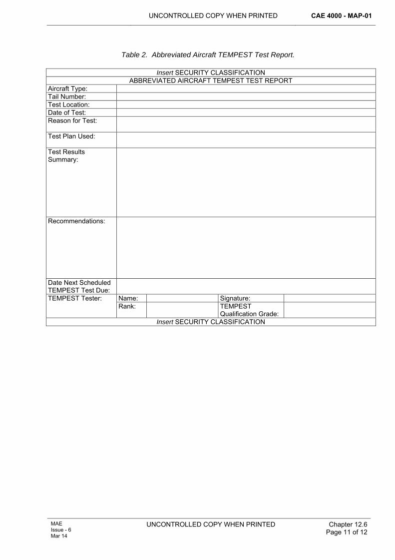
UNCONTROLLED COPY WHEN PRINTED CAE 4000 - MAP-01
MAE Issue - 6 Mar 14
UNCONTROLLED COPY WHEN PRINTED
Chapter 12.6 Page 11 of 12
Table 2. Abbreviated Aircraft TEMPEST Test Report.
Insert SECURITY CLASSIFICATION ABBREVIATED AIRCRAFT TEMPEST TEST REPORT
Aircraft Type: Tail Number: Test Location: Date of Test: Reason for Test:
Test Plan Used:
Test Results Summary:
Recommendations:
Date Next Scheduled TEMPEST Test Due:
Name: Signature: TEMPEST Tester: Rank: TEMPEST
Qualification Grade:
Insert SECURITY CLASSIFICATION
CAE 4000 - MAP-01 UNCONTROLLED COPY WHEN PRINTED
Chapter 12.6 Page 12 of 12
UNCONTROLLED COPY WHEN PRINTED MAE Issue - 6
Mar 14
Intentionally Blank for Print Pagination
UNCONTROLLED COPY WHEN PRINTED CAE 4000 - MAP-01
Issue - 7 Apr 15
UNCONTROLLED COPY WHEN PRINTED Chapter 12.7 Page 1 of 4
Chapter 12.7
Aircraft COMSEC Material
TABLE OF CONTENTS Paragraph
Page
1 General ............................................................................................................... 1 1.1 Introduction.......................................................................................................... 1 2 Regulatory Governance.................................................................................... 1 2.1 Regulatory Cross-reference ................................................................................ 1 3 Management procedures.................................................................................. 1 3.1 General................................................................................................................ 1 3.2 Security checks ................................................................................................... 2 3.3 Maintenance work recording ............................................................................... 2 3.4 Land-away........................................................................................................... 2 3.5 Transfer ............................................................................................................... 2 4 Authorization to load keymat ........................................................................... 2 5 Type Airworthiness Authority (TAA) Responsibilities................................... 2 6 References ......................................................................................................... 3
1 General 1.1 Introduction
Secure communications information systems and/or avionic systems containing COMSEC material are now routinely fitted in aircraft. This chapter provides guidance on the management of the associated cryptographic equipment installed in aircraft.
2 Regulatory Governance 2.1 Regulatory Cross-reference
This chapter supports:
1 RA 4559.
3 Management procedures 3.1 General
Procedures governing the management of COMSEC material are contained in JSP 490 (Defence Cryptosecurity Operating Instructions) and JSP 440. Essentially, the processes are as follows:
1 The Stn/Ship/Unit COMSEC Custodian is responsible for the registration and control of all COMSEC material. Additionally, the custodian is responsible both for the authorization of all personnel who use COMSEC material and the issue of orders detailing their responsibilities.
2 Authorized holders are issued their COMSEC material and relevant orders by the Stn/Ship/Unit COMSEC Custodian under signature and fulfil their duties as detailed.
CAE 4000 - MAP-01 UNCONTROLLED COPY WHEN PRINTED
Chapter 12.7 Page 2 of 4
UNCONTROLLED COPY WHEN PRINTED Issue - 7 Apr 15
3.2 Security checks The orders issued by the COMSEC Custodian detail all arrangements for storing, handling and managing cryptographic material held on charge and the frequency of required checks.
3.3 Maintenance work recording 3.3.1 Installation, removal or replacement of equipment
The installation, removal or replacement of an item of cryptographic equipment is a normal maintenance activity that must be recorded using the MOD Form 700 series documentation. The replacement of unserviceable or surplus cryptographic equipment must be effected through the Stn/Ship/Unit COMSEC Custodian.
3.3.2 Loading of keying material (keymat) In order for certain types of cryptographic equipment to function properly, it is essential that the correct keymat is loaded. Failure to load the correct keymat may result in systems being limited or unavailable. The loading of incorrect keymat is a serious breach of security and must be reported to the COMSEC custodian immediately. It is therefore imperative that a record is maintained onan appropriate MOD Form 700 series documentand aircrew are informed of the status of the cryptographic equipment systems on their aircraft.
3.4 Land-away Should an aircraft be required to land away from its normal operating base, the home base COMSEC Custodian must be provided with the exact details of any COMSEC material that may be carried on that aircraft and the anticipated period of the land-away, eg IFF Transponder MK12, Ser No 12875BA, fitted to aircraft No XZ247 is going to land away at Edinburgh Airport from 30/11/14 to 05/12/14. The COMSEC Custodian will detail any security requirements to be undertaken at the land-away base.
3.5 Transfer It is often necessary to transfer aircraft between Stns/Ships/Units. When this occurs, the home Stn/Ship/Unit COMSEC Custodian must be informed of the exact details of any cryptographic equipment that may be fitted to the transferring aircraft, as described at paragraph 3.4. The home Stn/Ship/Unit COMSEC Custodian will then carry out formal transfer accounting action with the receiving Stn/Ship/Unit COMSEC Custodian.
4 Authorization to load keymat As described at paragraph 3.3.2, the loading of keymat must be recorded in the aircraft MOD Form 700. Personnel holding authorization MAP-B26, awarded by a holder of authorization MAP-J252 in accordance with RA 4806 and Chapter 4.3, must load Keymat. To hold this authorization, personnel must be registered with the COMSEC Custodian as per paragraph 3.1, Security Clearance cleared and crypto-trained prior to authorization.
5 Type Airworthiness Authority (TAA) Responsibilities TAAs with cryptographic equipment fitted to their platform should consider the following, in addition to the normal requirements of through-life management:
1 Security accreditation – Before any cryptographic equipment system is allowed to process, store or forward information, it must be given security approval (accreditation) to permit its operation. Security should therefore be considered
UNCONTROLLED COPY WHEN PRINTED CAE 4000 - MAP-01
Issue - 7 Apr 15
UNCONTROLLED COPY WHEN PRINTED Chapter 12.7 Page 3 of 4
at the earliest stages of any procurement project. Guidance is contained in JSP 440 Volume 3 Chapter 13.
2 TEMPEST assessment – TEMPEST is the name given to the phenomenon of unintentional emanations from electromechanical and electronic data processing equipment being compromised. Installing cryptographic equipment on an aircraft could have a significant impact both on the aircraft’s security status and its TEMPEST profile. TEMPEST is therefore to be considered at the earliest stages of any procurement project. Guidance may be obtained from TEMPEST Authorities; see RA 4558 and Chapter 12.6.
6 References This Chapter refers to the following publications:
1 JSP 440 - Defence Manual of Security.
2 JSP 490 – Defence Cryptosecurity Operating Instructions.

CAE 4000 - MAP-01 UNCONTROLLED COPY WHEN PRINTED
Chapter 12.7 Page 4 of 4
UNCONTROLLED COPY WHEN PRINTED Issue - 7 Apr 15
Intentionally Blank for Print Pagination
UNCONTROLLED COPY WHEN PRINTED CAE 4000 - MAP-01
Issue - 7 Apr 15
UNCONTROLLED COPY WHEN PRINTED Chapter 12.9 Page 1 of 6
Chapter 12.9
Maintenance of Aircraft Compass Accuracy
TABLE OF CONTENTS Paragraph
Page
1 General ............................................................................................................... 1 1.1 Introduction.......................................................................................................... 1 1.2 Associated publications and instructions............................................................. 1 2 Regulatory Governance.................................................................................... 2 2.1 Regulatory Cross-reference ................................................................................ 2 3 Compass calibration ......................................................................................... 2 3.1 Compass bases................................................................................................... 2 3.2 Types of compass swing ..................................................................................... 2 3.3 Requirement for a compass swing ...................................................................... 3 3.4 Compass swing documentation .......................................................................... 3 3.5 Calibration and adjustment accuracy .................................................................. 4 3.6 Authority levels .................................................................................................... 4 4 Demagnetization of aircraft struck by lightning............................................. 4 4.1 Investigation ........................................................................................................ 4 4.2 Demagnetization ................................................................................................. 4 4.3 Post-demagnetization.......................................................................................... 4 5 Responsibilities................................................................................................. 5 5.1 Military Aviation Authority Certification Electronic Systems (MAA Cert ES)........ 5 5.2 Air Commodities Team (AC Team) ..................................................................... 5 5.3 Type Airworthiness Authority (TAA) .................................................................... 5 5.4 Front Line Commands (FLCs)............................................................................. 5 6 References ......................................................................................................... 5
1 General 1.1 Introduction
Many aircraft maintenance actions, including those not directly involving work on compass systems, may cause compass inaccuracies. This chapter describes the engineering responsibilities, procedures and equipment to be used to restore and maintain the accuracy of aircraft compass systems.
1.2 Associated publications and instructions This chapter is associated with the following instructions/publications:
1 AP 112B Series – Navigation Equipment.
2 AP 112T Series – Instrument Servicing and Test Equipment (Special Purpose).
3 AP 116G Series – Maritime Weapons.
4 AP 100L-01 – Avionic Procedures.
5 Relevant aircraft AP 101B or C, Topic 5.
CAE 4000 - MAP-01 UNCONTROLLED COPY WHEN PRINTED
Chapter 12.9 Page 2 of 6
UNCONTROLLED COPY WHEN PRINTED Issue - 7 Apr 15
2 Regulatory Governance 2.1 Regulatory Cross-reference
This chapter supports:
1 RA 4561.
3 Compass calibration 3.1 Compass bases
A compass base is a location used for the calibration of aircraft compasses and may be established as either Class 1 or Class 2. The two classes differ in their limits of permitted maximum deviation to be found anywhere within the base. Full details relating to compass bases can be found in the Manual of Aerodrome Design and Safeguarding (MADS), Chapter 5, Annex 5A.
The classifications of compass base and limitations are as follows:
1 Class 1 – The maximum permissible magnetic deviation is ±0.1° measured at 1.5m above the ground. Bases of this accuracy are normally required for carrying out refined swings. These bases should be surveyed every 5 years. A Class 1 base may be equipped with AC and DC power outlets as required.
2 Class 2 -- The maximum permissible magnetic deviation is ±0.25° measured at 1.5m above the ground. Bases of this accuracy are required for carrying out standard swings. These bases should be surveyed every 2 years. A Class 2 base will not necessarily be equipped with AC and DC power outlets.
3 Annually all bases should be checked by the responsible officer to ensure that markings and boundaries are clearly defined, that no work has been done which might affect their magnetic properties and to take into account any changes in magnetic variation.
4 QinetiQ, under the Long-Term Partnership Agreement (LTPA), is responsible for surveying compass bases for military aircraft world wide, where UK MOD has an interest.
3.2 Types of compass swing Full details of compass swings can be found in AP 3456 Volume 3 Chap 3-14. There are four types of compass swing: standard, refined, electrical and air. The standard and refined are the most commonly encountered.
1 Standard swing: Standard swings are carried out on aircraft whose compass systems are not used as an input to other navigation or weapon aiming systems. Standard swings can be carried out on either a Class 1 or Class 2 compass base and use eight headings during calibration.
2 Refined swing: Refined swings are carried out on aircraft whose compass systems are used to feed heading input to produce navigation or weapon aiming solutions. A refined swing is generally carried out on a Class 1 compass base; however, it is possible to carry out a refined swing on a Class 2 base using a special procedure involving the use of two Watts Datum Compasses. This procedure can be found in AP 3456 Volume 3 Chap 3-14 Annex B.
3 Electrical swing: Electrical swings are essentially the same as the refined swing except that, instead of physically moving the aircraft onto the appropriate headings, the headings are simulated by a Compass Calibrator.
UNCONTROLLED COPY WHEN PRINTED CAE 4000 - MAP-01
Issue - 7 Apr 15
UNCONTROLLED COPY WHEN PRINTED Chapter 12.9 Page 3 of 6
4 Air swing: Provided that an accurate datum (GPS, INS or AHRS) is available for determining heading whilst airborne, and the local values of magnetic variation are known, it is possible to swing an aircraft compass in the air; however, it is subject to limitations. This procedure can be found in AP 3456 Volume 3 Chap 3-14 Annex A. If a compass swing is required prior to a transit and recovery to base, an airborne swing may be an option and could provide sufficient data for a standard swing.
3.3 Requirement for a compass swing Other than in exceptional circumstances, a compass swing is not to be carried out during persistent rain or wind speeds greater than 15kts.
The accuracy of an aircraft compass system can be affected by changes in operating location, physical or electrical disturbances and changes to magnetic signature. Hence in addition to conducting compass swings as required in the maintenance schedule or when accuracy is in doubt, the Authority Level J should consider conducting one on the following occasions:
1 After a change of compass system components.
2 After an aircraft has passed through a severe electrical storm, or has been struck by lightning.
3 On transfer from one theatre of operations to another where latitude is changed and operating requirements necessitate that a high degree of compass accuracy must be assured.
4 Whenever a compass has been subjected to shock, eg after a heavy landing.
5 After an aircraft has been repaired or subjected to conditions likely to affect the compass system(s), for example:
5.1 On change of position, replacement, addition or permanent removal of any magnetic material.
5.2 After alteration to any electrical or electronic circuit in the vicinity of a direct reading compass or compass detector unit of a remote reading compass.
5.3 When the aircraft has been subjected to magnetic crack detection likely, in the opinion of the relevant individual holding authority level J, to result in permanent residual magnetism.
6 After an aircraft has been in long-term storage.
7 If it is considered likely that a specific freight load will cause magnetic influence and thereby affect compass readings.
Note:
As the above instructions cannot always be adhered to when aircraft are embarked or at dispersed sites, best endeavours must be made (such as checks against another aircraft or ship reference) to ensure that compass accuracy remains adequate for navigation and flight safety. Where accuracy is in doubt, an appropriate entry should be made in the Limitation Log (MOD F703) and a compass swing must be carried out at the first opportunity.
3.4 Compass swing documentation Compass swings must be raised, and their completion certified, in the appropriate Maintenance Work Order element of the MOD Form 700, in accordance with RA 4813 and Chapter 7.2.
CAE 4000 - MAP-01 UNCONTROLLED COPY WHEN PRINTED
Chapter 12.9 Page 4 of 6
UNCONTROLLED COPY WHEN PRINTED Issue - 7 Apr 15
Additionally, on completion of the swing, personnel (whether aircrew or an engineering tradesman) directly involved in the compass swing must update the relevant compass log (MOD Form 712A) and any necessary compass deviation/corrector cards and Logistics Information System (LIS).
3.5 Calibration and adjustment accuracy The degree of accuracy to which compass systems must be calibrated is detailed in the relevant aircraft maintenance manual.
3.6 Authority levels Supervision of aircraft compass adjustment may only be carried out by:
1 Aircrew holding authorization MAP-AM83, in accordance with RA 4806 and Chapter 4.7.1.
2 Avionics tradesmen holding authorization MAP-C116.
3 Sonar-trained technicians holding authorization MAP-C116.
4 Demagnetization of aircraft struck by lightning Aircraft compasses must be regarded as unreliable after an aircraft has been struck by lightning. The following sub-paragraphs outline the procedures to be followed to restore and maintain compass accuracy following a lightning strike. Full details and procedures can be found in AP 120M-0203-01.
4.1 Investigation Following a report of a lightning strike, a compass swing must be carried out prior to the next flight, where practicable. If this is not practicable, a suitable entry must be made in the aircraft MOD F703. A compass swing is then to be carried out at the earliest opportunity. If, during the investigation compass swing, a change of coefficient A, B or C appears to have occurred equal to or greater than 4 times the maximum acceptable residual coefficient for the aircraft, it must be assumed that the aircraft is magnetized.
4.2 Demagnetization AP 120M-0203-01A describes the standard equipment used for demagnetizing an aircraft and details the procedures to be followed. If all attempts to demagnetize an aircraft are unsuccessful, the relevant individual holding authority level J may apply to the relevant Front Line Command (FLC) for NDT Team assistance.
4.3 Post-demagnetization After demagnetization has been completed, the aircraft should be flown twice, performing figure-of-eight manoeuvres on each of the main compass headings to stabilize the magnetism. The deviations should be calculated during these flights to determine the effectiveness of the de-magnetization process. The aircraft compass should be re-swung two months after the de-magnetization to ensure that the aircraft is magnetically stable.
The following entry must be made in the aircraft’s MOD F703:
‘Aircraft demagnetized on …[insert date]. Changes in Compass Deviation may occur due to magnetic stabilization. A Maintenance Work Order entry must be made whenever compass errors are detected. A full Compass Swing must be undertaken on … [insert date + 2 Months]. RA 4561 and Chapter 12.9 refer.’
UNCONTROLLED COPY WHEN PRINTED CAE 4000 - MAP-01
Issue - 7 Apr 15
UNCONTROLLED COPY WHEN PRINTED Chapter 12.9 Page 5 of 6
If significant changes in deviation are detected during the check swing, the MOD F703 entry must be deferred for a further 28 days.
5 Responsibilities 5.1 Military Aviation Authority Certification Electronic Systems (MAA Cert
ES) MAA Cert ES for acting as a Subject Matter Expert (SME) for this Regulation and Acceptable Means of Compliance (AMC), Guidance Material (GM) and associated processes.
5.2 Air Commodities Team (AC Team) The AC Team is responsible for ensuring that:
1 SME advice is provided to all MOD users on any aspect of compass requirements.
2 Compass accuracy and calibration limits are detailed in the relevant Air Publications (APs).
3 The maintenance requirements of test facilities to support compass maintenance Regulation, AMC, GM and associated processes are determined and sponsored.
4 Test procedures to support compass maintenance Regulation, AMC, GM and associated processes are sponsored.
5.3 Type Airworthiness Authority (TAA) TAAs are responsible for ensuring that:
1 The type of compass swing to be carried out on each aircraft type is specified.
2 The aircraft Topic 1 contains the guidance necessary for units to carry out compass system maintenance on aircraft.
3 The maximum allowable residual deviations are identified and promulgated, in consultation with FLCs, in order to ensure that every compass meets the accuracy requirements laid down by the air staff.
5.4 Front Line Commands (FLCs) The FLCs, in consultation with the relevant TAA, are responsible for ensuring that demagnetizing equipment is controlled, distributed and transferred as necessary.
6 References This chapter refers to the following publications:
1 AP 120M-0203-1 – Demagnetizer Units.
2 AP 3456 Volume 3 – Flight Instruments and Avionics.
3 Manual of Aerodrome Design and Safeguarding (MADS).
4 Topic 1 – Aircraft Maintenance Manual.

CAE 4000 - MAP-01 UNCONTROLLED COPY WHEN PRINTED
Chapter 12.9 Page 6 of 6
UNCONTROLLED COPY WHEN PRINTED Issue - 7 Apr 15
Intentionally Blank for Print Pagination
UNCONTROLLED COPY WHEN PRINTED
CAE 4000 - MAP-01
Issue - 7 Apr 15
UNCONTROLLED COPY WHEN PRINTED
Chapter 13.1 Page 1 of 6
Chapter 13.1
Aircraft Assisted Escape Systems – Safety Precautions
TABLE OF CONTENTS Paragraph
Page
1 General ............................................................................................................... 1 1.1 Introduction.......................................................................................................... 1 1.2 Associated publication......................................................................................... 1 1.3 Applicability ......................................................................................................... 2 1.4 Terms used ......................................................................................................... 2 2 Regulatory Governance.................................................................................... 2 2.1 Regulatory Article Cross-reference ..................................................................... 2 3 Safety conditions .............................................................................................. 2 3.1 General................................................................................................................ 2 3.2 Safe for maintenance .......................................................................................... 2 3.3 Safe for parking ................................................................................................... 2 3.4 Safe condition...................................................................................................... 3 3.5 Flight condition .................................................................................................... 3 4 Responsibilities................................................................................................. 3 4.1 Maintenance supervisor ...................................................................................... 3 4.2 Personnel entering a cockpit ............................................................................... 3 5 Recording of AAES safety condition............................................................... 4 6 Movement of safety devices............................................................................. 4 6.1 Safe for maintenance to/from safe for parking .................................................... 4 6.2 Safe for parking or safe condition to/from flight condition ................................... 4 7 Training and authorization ............................................................................... 4 7.1 General safety training ........................................................................................ 4 7.2 Training and authorization in the movement of safety devices ........................... 5 8 References ......................................................................................................... 5
1 General 1.1 Introduction
Inadvertent operation of an Aircraft Assisted Escape System (AAES) or Crew Escape System (CES) has the potential to cause serious injury or death. The safety measures and devices employed to prevent such accidents are detailed in the safety and maintenance notes for each aircraft. This chapter sets out the general responsibilities for ensuring that AAES or CES safety devices are in a safe position when entering a cockpit, defines who may move safety devices and describes how such personnel are to be trained and authorized.
1.2 Associated publication This chapter is associated with the following publication:
1 AP 108A-0006-2(N/A/R)1 – Survival Equipment and Aircrew Equipment Assemblies Support Authority General Orders and Special Instructions (Technical).
CAE 4000 - MAP-01 UNCONTROLLED COPY WHEN PRINTED
Chapter 13.1 Page 2 of 6
UNCONTROLLED COPY WHEN PRINTED Issue - 7 Apr 15
1.3 Applicability This chapter is applicable to all organizations in the Military Air Environment (MAE) operating aircraft fitted with an AAES or CES.
1.4 Terms used For the purposes of this chapter the following terms have been adopted:
1 Unless otherwise stated, AAES includes both AAES and CES.
2 Cockpit is to be interpreted as meaning any aircraft cockpit or cabin in which an AAES is installed.
2 Regulatory Governance 2.1 Regulatory Article Cross-reference
This chapter supports:
1 RA 4600.
3 Safety conditions 3.1 General
Dependent upon the type of AAES, the associated safety devices may be in one of four conditions:
1 Safe for maintenance – see paragraph 3.2.
2 Safe for parking – see paragraph 3.3.
3 Safe condition – see paragraph 3.4.
4 Flight condition – see paragraph 3.5.
Type Airworthiness Authorities (TAAs), in conjunction Crew Escape Systems Team (CEST), must detail the position of safety devices, for the relevant safety conditions of the AAES, in the appropriate aircraft schedules and/or publications.
3.2 Safe for maintenance In the safe for maintenance condition, it is safe to carry out work on or around the AAES, provided that the safety instructions relevant to that particular aircraft type are complied with. The safe for maintenance condition must be established prior to and for the duration of:
1 Any prolonged period of aircraft unserviceability.
2 Any scheduled maintenance of an aircraft, other than flight servicing, where access to the cockpit is required.
3 Any maintenance activity that involves working in the vicinity of, or disturbing, the AAES.
4 Parking of the aircraft in an aircraft maintenance hangar, ashore or afloat. However, the aircraft may be left in the safe for parking condition, see paragraph 3.3, if it is being placed in an aircraft maintenance hangar for parking only.
3.3 Safe for parking The safe for parking condition is required at all times other than those listed in paragraphs 3.2, 3.4 and 3.5; this includes those periods, however brief, when a rapid crew change is being effected. In the safe for parking condition it is safe to enter the cockpit, provided that the safety instructions relevant to the particular aircraft type are
UNCONTROLLED COPY WHEN PRINTED CAE 4000 - MAP-01
Issue - 7 Apr 15
UNCONTROLLED COPY WHEN PRINTED
Chapter 13.1 Page 3 of 6
complied with. No maintenance, other than flight servicing, may be carried out on, or around, the AAES.
3.4 Safe condition On an AAES where there is no difference between the safe for parking and safe for maintenance conditions, the AAES must be in the safe condition at all times when the aircraft is not in the flight condition, including those periods, however brief, when a rapid crew change is being effected. In the safe condition it is safe to carry out work on, or around, the AAES, provided that the safety instructions relevant to the particular aircraft type are complied with.
3.5 Flight condition An AAES is deemed to be in the flight condition when all safety devices for the AAES have been removed. The AAES must only be placed into and out of the flight condition immediately before taxiing prior to take-off and following taxiing after landing, in accordance with paragraph 6.2. When operating from a Hardened Aircraft Shelter (HAS) or similar, local procedures must be defined to ensure that the AAES remains in a safe condition whilst under cover. Personnel must not enter or exit a cockpit should the AAES be in the flight condition, but are to carry out the actions detailed in paragraph 4.2.1.
4 Responsibilities 4.1 Maintenance supervisor
Whenever a maintenance task is to be undertaken, the supervisor of the task is responsible for the following, with respect to AAES:
1 Ensuring that the AAES is in a safe for parking, safe for maintenance or safe condition appropriate to the task being carried out, as detailed at paragraph 3.
2 When it is necessary to change the condition of the AAES to or from the safe for maintenance condition, tasking an appropriately authorized tradesman to place the safety devices in the correct position in accordance with paragraph 6.1.
3 When safety devices have been moved at item 2 above, ensuring that the fact has been recorded in accordance with paragraph 5.
4 Ensuring that all personnel tasked to work in or around the cockpit are trained on the position of the safety devices in accordance with paragraph 7.1. If this is not possible, the requirements of paragraph 4.2.2 are to be complied with.
4.2 Personnel entering a cockpit 4.2.1 Qualified personnel
Any person entering a cockpit or requiring to work on equipment installed in a cockpit must, before entering the cockpit, check visually that the AAES is in the appropriate condition for the task being carried out, as detailed in paragraph 3. If it is necessary to change the condition of the AAES to or from the safe for maintenance condition, they must inform the supervisor of the maintenance task, who must take the steps detailed at paragraph 4.1. If the person entering the cockpit discovers that the safety devices are not in a recognized safe condition, their position must not be adjusted, but personnel in the vicinity must be warned that a hazard exists and the person entering the cockpit must report the occurrence to an individual holding authorization MAP-C101 to supervise the movement of AAES safety devices. The individual holding authorization MAP-C101 must:
CAE 4000 - MAP-01 UNCONTROLLED COPY WHEN PRINTED
Chapter 13.1 Page 4 of 6
UNCONTROLLED COPY WHEN PRINTED Issue - 7 Apr 15
1 If possible, request the last known seat occupant to return to the aircraft and move the safety devices to the correct condition. Where this is not possible, they must task an appropriately authorized tradesman to place the safety devices into the correct position.
2 Report the incident to his superior for further investigation.
4.2.2 Unqualified personnel When a person not conversant with the position of safety devices is authorized to enter a cockpit, they must escorted by a suitably qualified individual who must ensure that:
1 The AAES is in an appropriate safety condition.
2 The AAES safety devices are not inadvertently disturbed.
5 Recording of AAES safety condition The movement of safety devices from or to the safe for maintenance condition is a maintenance task and must therefore be recorded in the appropriate section of the MOD Form 700C. The requirement to move the safety devices must be raised by the supervisor of the maintenance task. On an AAES where only the safe condition is used, no specific recording action is necessary, since this is the normal state of the AAES when the aircraft is on the ground.
6 Movement of safety devices 6.1 Safe for maintenance to/from safe for parking
The movement of safety devices to/from the safe for maintenance condition must only be carried out by an individual holding authorization MAP-B100 and supervised by an individual holding authorization MAP-C101 of the trades stated in Table 1. Normally, aircrew are permitted to move the safety devices of an AAES to and from the flight condition only. Exceptionally, when no authorized engineering officer or engineering tradesman is available, aircrew that have been awarded authorization MAP-AFS82 (Authority to Flight Service) in accordance with RA 4806 and Chapter 4.7.1 may be additionally authorized by an individual holding authorization MAP-J224 to move safety devices to and from the safe for maintenance condition.
6.2 Safe for parking or safe condition to/from flight condition The seat occupant for a planned flight is responsible for moving the safety devices to and from the flight condition, as required; maintenance personnel may assist. The responsible aircrew member is responsible for ensuring that the AAES safety devices are moved to and from the flight condition, as required, when non-aircrew personnel occupy the seat. Maintenance personnel may assist in this activity, but are required to give the Aircraft Commander verbal confirmation when this activity is complete.
7 Training and authorization 7.1 General safety training
Those tradesmen required to provide trade assistance and all personnel, including aircrew, who require access to a cockpit must receive training by a nominated individual holding authorization MAP-E103 to ensure that they are conversant with the safety devices, safety conditions and safety precautions appropriate to that AAES. The training policy for AAES is detailed in AP 109-0100-2(N/A/R)1, Part 4, Leaflet 001, which defines the periodicity of initial and subsequent retraining, and provides details of syllabus Operational Performance Statements (OPS) applicable to selected categories of personnel.
UNCONTROLLED COPY WHEN PRINTED CAE 4000 - MAP-01
Issue - 7 Apr 15
UNCONTROLLED COPY WHEN PRINTED
Chapter 13.1 Page 5 of 6
The relevant individual holding authority level J with responsibilities for aircraft fitted with AAES must ensure that suitable processes are in place for providing and recording AAES training.
7.2 Training and authorization in the movement of safety devices Personnel detailed in Table 1 may be authorized to undertake the movement of AAES safety devices and supervise such tasks as appropriate. Prior to being granted this authorization, and in addition to the requirements of paragraph 7.1, personnel must undergo training and examination of competence. Authority must be granted in accordance with RA 4806 and Chapter 4.3 by an individual holding authorization MAP-J105. Training must be conducted by nominated AAES instructors in accordance with a syllabus that complies with RA 4150 and Chapter 4.1, on the following occasions:
1 For OPS 1- On arrival at a Stn/Ship/Unit operating aircraft fitted with AAES and at six monthly intervals thereafter.
2 For OPS 2 to 4 - Following initial training; personnel are to be recertified at twelve monthly intervals.
3 Whenever the approved procedure for the movement of safety devices is amended or other significant changes are made to the AAES.
Table 1. Personnel Authorized to Undertake Movement of AAES Safety Devices to/from the Safe for Maintenance Condition.
RN Army 1 RAF
Authority level B AET Aircrew Weapons trade 2
Authority level C Avionics 3 Aircrew Weapons trade Notes:
1 At present there is no requirement for REME personnel to undertake the movement of AAES safety devices, as the only condition applicable for Army aircraft types is the safe condition and it is the responsibility of the aircrew to carry out the movement of safety devices to/from the safe condition.
2 An individual holding authorization MAP-J105 may allow a limited number of aircraft maintenance personnel of other trades to be trained and authorized to undertake this task under the supervision of an individual holding authorization MAP-C101.
3 An individual holding authorization MAP-J105 may allow a limited number of aircraft maintenance personnel of other trades to be trained and authorized to undertake this task.
On posting/drafting, personnel may be re-authorized as competent, if required by their new Stn/Ship/Unit, to carry out the movement of safety devices. Such re-authorization must only be carried out on condition that the aircraft and AAES types are the same as those in use on the previous Stn/Ship/Unit and those skills have been exercised in the preceding 12 months. Personnel will still require general safety training as detailed at paragraph 7.1.
8 References This chapter refers to the following publications:
1 JSP 482 – MOD Explosives Regulations.
CAE 4000 - MAP-01 UNCONTROLLED COPY WHEN PRINTED
Chapter 13.1 Page 6 of 6
UNCONTROLLED COPY WHEN PRINTED Issue - 7 Apr 15
2 AP 109A-0100-2(N/A/R)1 – General Orders and Special Instructions – Aircraft Assisted Escape Systems – Ejection Seats.
UNCONTROLLED COPY WHEN PRINTED CAE 4000 - MAP-01
1
Issue - 7 Apr 15
UNCONTROLLED COPY WHEN PRINTED Chapter 13.1.1 Page 1 of 2
Chapter 13.1.1
Aircraft Assisted Escape Systems – Maintenance Responsibilities
TABLE OF CONTENTS
Paragraph
Page
1 General ...............................................................................................................2 1.1 Introduction..........................................................................................................2 1.2 Associated publication.........................................................................................2 1.3 Applicability..........................................................................................................2 1.4 Terms used..........................................................................................................2 2 Regulatory Governance ....................................................................................3 2.1 Regulatory Article Cross-reference .....................................................................3 3 System responsibility .......................................................................................3 3.1 General................................................................................................................3 3.2 Survival Equipment..............................................................................................3 4 Training and authorization ...............................................................................3 4.1 Training................................................................................................................3 4.2 Authorization........................................................................................................3
1 General 1.1 Introduction
Maintenance carried out on/in the vicinity of an Aircraft Assisted Escape Systems (AAES) or Crew Escape Systems (CES) is potentially lethal and particular care is required to prevent the possibility of accidents. Additionally, several different trades may be involved in the maintenance of an AAES or CES and their component parts. This chapter identifies which trade has overall responsibility for the maintenance of an AAES or CES, in addition to defining the level of training and authorization required to carry out AAES maintenance.
1.2 Associated publication This chapter is associated with the following publication:
1 AP 109A-0100-2(N/A/R)1 – General Orders and Special Instructions – Aircraft Assisted Escape Systems – Ejection Seats.
1.3 Applicability This chapter is applicable to all maintenance organizations operating in the Military Air Environment (MAE) with responsibilities for the maintenance of installed and uninstalled AAES, CES and associated components.
1.4 Terms used For the purposes of this chapter the following terms are used:
1 AAES includes both AAES and CES.
2 ‘AAES trade’ represents the following single-Service trades:
2.1 RN: Avionics trade.
2.2 Army: Aircraft Technician.
2.3 RAF: Weapons trade.
UNCONTROLLED COPY WHEN PRINTED CAE 4000 - MAP-01
Issue - 7 Apr 15
UNCONTROLLED COPY WHEN PRINTED
Chapter 13.1.1 Page 2 of 2
2 Regulatory Governance 2.1 Regulatory Article Cross-reference
This chapter supports:
1 RA 4601.
3 System responsibility 3.1 General
Overall system responsibility for in-situ maintenance, removal or re-installation of AAES, or maintenance of a component part of such systems, is vested in the ‘AAES trade’. When required, other trades may be called upon to carry out maintenance to those elements of the AAES that fall outside the boundaries of the ‘AAES trade’, eg maintenance of the canopy installation. Where there is a requirement for another trade to undertake this maintenance, the relevant activity must be identified in the maintenance procedure. When more than one trade is engaged jointly on maintenance of an AAES, or on in-situ maintenance of a component part of such a system, an individual holding authorization MAP-C108 must be responsible for co-ordinating the work of all the tradesmen concerned so that safety of the system and its subsequent correct operation is not impaired.
3.2 Survival Equipment Notwithstanding paragraph 3.1 above, Survival Equipment tradesmen are responsible for providing specialist assistance as required and for the:
1 Scheduled maintenance of restraint harnesses, parachute assemblies and drogues, personal survival packs including automatic deployment units, all fabric parts of an ejection seat and all quick-release fittings that are attached to these items.
2 Maintenance, including scheduled maintenance, of the ‘man’ portion of personal equipment connectors and aircrew equipment assemblies.
4 Training and authorization 4.1 Training
All personnel, including aircrew, who require access to a cockpit must undergo training on the safety devices, safety conditions and safety precautions appropriate to that AAES in accordance with RA 4600 and Chapter 13.1. Tradesmen who are to undertake in-situ maintenance, removal or re-installation of an AAES, or maintenance of a component part of such systems, must undergo training that complies with the requirements of RA 4806(5) and Chapter 4.1. The syllabus must include all aspects of in-situ maintenance, removal and replacement procedures, and for AAES tradesmen must also include Maintenance, Vital and Independent checks as detailed in RA 4602 and Chapter 13.1.2. In-situ tasks of a minor nature within the SE trade boundary (such as stitching a replacement tie) may be conducted by trained and authorised SE tradesmen who must be fully overseen by suitable AAES tradesmen to ensure safety. An AAES supervisor must also confirm the requirement for any Independent check on completion.
4.2 Authorization Tradesmen holding authorizations MAP-B107 or MAP-C108 who are to be employed on in-situ maintenance, removal or re-installation of AAES, or maintenance of a component part of such systems, must be authorized by an appropriate individual holding authorization MAP-J110 in accordance with RA 4806 and Chapter 4.3.
UNCONTROLLED COPY WHEN PRINTED CAE 4000 - MAP-01
Issue - 7 Apr 15
UNCONTROLLED COPY WHEN PRINTED Chapter 13.1.2 Page 1 of 6
Chapter 13.1.2
Aircraft Assisted Escape Systems – Maintenance, Vital and Independent Checks
TABLE OF CONTENTS Paragraph
Page
1 General ............................................................................................................... 1 1.1 Introduction.......................................................................................................... 1 1.2 Associated publications....................................................................................... 1 1.3 Applicability ......................................................................................................... 2 1.4 Terms used ......................................................................................................... 2 2 Regulatory Governance.................................................................................... 2 2.1 Regulatory Article Cross-reference ..................................................................... 2 3 Checks on Aircraft Assisted Escape Systems (AAES).................................. 2 3.1 Maintenance checks............................................................................................ 2 3.2 Vital checks ......................................................................................................... 2 3.3 Independent checks ............................................................................................ 2 4 Recording of checks ......................................................................................... 2 4.1 Calling up the checks .......................................................................................... 2 4.2 Recording completion of the checks (Hard Copy)........................................ 3 4.3 Recording completion of the checks (Electronic) ......................................... 3 5 Personnel authorized to undertake checks on AAES.................................... 4 5.1 Maintenance checks............................................................................................ 4 5.2 Vital checks ......................................................................................................... 4 5.3 Independent checks ............................................................................................ 4 6 Training and authorization ............................................................................... 4 7 Responsibilities................................................................................................. 5 7.1 Type Airworthiness Authority (TAA) .................................................................... 5 8 References ......................................................................................................... 5
LIST OF TABLES Table 1. Trades that may be Authorized to Undertake Vital or Independent Checks of AAES....4
1 General 1.1 Introduction
It is imperative that Aircraft Assisted Escape Systems (AAES) and Crew Escape Systems (CES) function correctly when operated. To achieve this, their maintenance is subject to mandatory checks. This chapter details the types of check, the occasions when they are required, recording requirements and authorization to carry out such checks.
1.2 Associated publications This chapter is associated with the following publications:
1 AP 108A-0006-2(N/A/R)1 – Survival Equipment and Aircrew Equipment Assemblies Support Authority General Orders and Special Instructions (Technical).
CAE 4000 - MAP-01 UNCONTROLLED COPY WHEN PRINTED
Chapter 13.1.2 Page 2 of 6
UNCONTROLLED COPY WHEN PRINTED Issue - 7 Apr 15
2 AP 109A-0100-2(N/A/R)1 – General Orders and Special Instructions – Aircraft Assisted Escape Systems – Ejection Seats.
1.3 Applicability This chapter is applicable to all maintenance organizations operating in the Military Air Environment with responsibilities for the maintenance of installed and uninstalled AAES, CES and associated components.
1.4 Terms used For the purposes of this chapter, AAES includes both AAES and CES.
2 Regulatory Governance 2.1 Regulatory Article Cross-reference
This chapter supports:
1 RA 4602.
3 Checks on Aircraft Assisted Escape Systems (AAES) 3.1 Maintenance checks
Maintenance checks must be carried out whenever an AAES component undergoes any form of maintenance in a bay or as part of the bay activity in a licensed explosives area. Such checks are for correct assembly, locking and function to ensure the reliable operation of the AAES. These checks are carried out because they cannot be readily undertaken during or after installation or re-installation of the component in an aircraft. The relevant maintenance checks are detailed in the appropriate bay maintenance schedule.
3.2 Vital checks Vital checks must be carried out at defined stages during the process of installing or re-installing a component part of an AAES in an aircraft. Such checks are for correct assembly, routeing, locking and function to ensure the reliable operation of the AAES, which cannot be readily undertaken before installation or re-installation commences, or after it has been completed. Vital checks must be undertaken at the aircraft, or in a licensed explosives area associated with the aircraft maintenance activity. Details of each vital check are contained in the appropriate aircraft maintenance schedule or procedure.
3.3 Independent checks Independent checks must be made at the aircraft after installation or re-installation of a component part of an AAES. They provide final visual confirmation that all locking, routeing and installation processes have been carried out correctly. The detail of each independent check is contained in the appropriate aircraft maintenance schedule or procedure. They may be divided by sub-system, eg CES independent check, canopy system independent check and ejection seat independent check.
4 Recording of checks 4.1 Calling up the checks
The supervisor of a maintenance task is responsible for calling up any maintenance, vital or independent check required. They must do so by making a separate entry for each check required in the appropriate form in the MOD Form 707 series. Entries for
UNCONTROLLED COPY WHEN PRINTED CAE 4000 - MAP-01
Issue - 7 Apr 15
UNCONTROLLED COPY WHEN PRINTED Chapter 13.1.2 Page 3 of 6
independent checks are to be made when the system is first disturbed. All checks must be called up in the form:
‘[MAINTENANCE, VITAL or INDEPENDENT as applicable] CHECK REQUIRED AS DETAILED IN … [insert sufficient detail to enable the check to be positively identified]’
The number of checks called up must accord with the following:
1 All the maintenance checks applicable to a component part of an AAES must be made whenever the component has undergone any form of maintenance in a bay, or as part of the bay activity in a licensed explosives area.
2 All the vital checks applicable to a sub-system within an AAES must be made whenever a component part of that sub-system is in the process of being installed or re-installed in an aircraft.
3 All the independent checks applicable to an AAES sub-system must be made whenever a component part of that sub-system is installed or re-installed in an aircraft, or when any part of that sub-system is disturbed during a maintenance activity.
4.2 Recording completion of the checks (Hard Copy) Following satisfactory completion of the maintenance, vital, or independent check, the person who carried it out must enter the following statement in the ‘Work Done’ column of the MOD Form 707:
‘CERTIFIED [MAINTENANCE, VITAL or INDEPENDENT as applicable] CHECK SATISFACTORILY COMPLETED’
They must complete the relevant section of the MOD Form 707 by signing both the ‘Tradesman‘ and ‘Supervisor’ blocks. Maintenance, vital, or independent checks must be treated as self-supervised activities and the personnel carrying them out must be made aware that they assume the responsibilities for both the 1st and 2nd signature in accordance with RA 4806(5) and Chapter 4.3.2.
4.3 Recording completion of the checks (Electronic) If a Logistic Information System (LIS) is utilised (see MAP-01 Chap 7.3), the platform Topic 2(N/A/R)1 must define how the electronic equivalent of the MF 707 is completed. As a minimum standard, following satisfactory completion of a Maintenance, Vital or Independent check, the person who carried it out must enter the following statement in the ‘Work Done’ column of the MF 707 variant and sign for completion in accordance with the platform Topic 2(N/A/R)1 leaflet:
‘CERTIFIED [MAINTENANCE, VITAL or INDEPENDENT as applicable] CHECK SATISFACTORILY COMPLETED’
Maintenance, Vital or Independent checks must be treated as self-supervised activities and the personnel carrying them out must be made aware that they assume the responsibilities for both 1st and 2nd signature in accordance with RA 4806(5) and Chapter 4.3.2.
CAE 4000 - MAP-01 UNCONTROLLED COPY WHEN PRINTED
Chapter 13.1.2 Page 4 of 6
UNCONTROLLED COPY WHEN PRINTED Issue - 7 Apr 15
5 Personnel authorized to undertake checks on AAES 5.1 Maintenance checks
Maintenance checks must be undertaken by an individual holding authorization MAP-D262 as detailed in RA 4601 and Chapter 13.1.1. The authority level D who has supervised the task to which the maintenance check relates, may undertake the maintenance check. The 1st signature of the task to which the maintenance check relates must not carry out maintenance checks.
5.2 Vital checks Vital checks must be undertaken by an individual holding authorization MAP-D261 (or equivalent) as detailed in Table 1. Trades that may be Authorized to Undertake Vital or Independent Checks of AAES. The authority level D who has supervised the aircraft maintenance task to which the vital check relates, may undertake the vital check. The 1st signature of the task to which the vital check relates must not carry out vital checks.
5.3 Independent checks Independent checks must be undertaken by an individual holding authorization MAP-E260 (or equivalent) of the trade specified in Table 1. Trades that may be Authorized to Undertake Vital or Independent Checks of AAES., other than when the maintenance schedule or procedure specifies another trade.
An independent check must not be undertaken by:
1 Any tradesman who undertook or assisted in the aircraft or equipment maintenance task to which the independent check relates.
2 The supervisor of the aircraft maintenance task to which the independent check relates.
3 Any tradesman who undertook any of the earlier and related vital checks.
Table 1. Trades that may be Authorized to Undertake Vital or Independent Checks of AAES.
Service Trade RN Avionics
Army Aircraft RAF Eng Tech W
6 Training and authorization An individual holding authorization MAP-J259 (or equivalent) must authorize personnel who are required to undertake maintenance, vital or independent checks of AAES, before being employed on such duties. Selection of personnel must be limited to those who meet the authority level and trade requirements and have completed the relevant training in accordance with RA 4601 and Chapter 13.1.1. Authorization must be carried out in accordance with RA 4806 and Chapter 4.3. Following posting/drafting, personnel may be re-authorized as competent without further training, if required by their new Stn/Ship/Unit to carry out checks on AAES, provided that the aircraft and AAES types are the same as those in use on the previous Stn/Ship/Unit and those skills have been exercised in the preceding 12 months.
UNCONTROLLED COPY WHEN PRINTED CAE 4000 - MAP-01
Issue - 7 Apr 15
UNCONTROLLED COPY WHEN PRINTED Chapter 13.1.2 Page 5 of 6
7 Responsibilities 7.1 Type Airworthiness Authority (TAA)
The relevant TAA, in conjunction with the Aircrew Escape and Survival Project Team (AES PT) and the Crew Escape Systems Team (CEST) as applicable, must promulgate in the Topic 1 and/or Topic 2(N/A/R)1 the aircraft or component schedule or procedure detailing the vital and independent checks or maintenance checks, ensuring that the whole AAES and its component parts are covered.
8 References This chapter refers to the following publications:
1 Topic 1 – Aircraft Maintenance Manual or General and Technical Information.
2 Topic 2(N/A/R)1 – General Orders and Special Instructions.
CAE 4000 - MAP-01 UNCONTROLLED COPY WHEN PRINTED
Chapter 13.1.2 Page 6 of 6
UNCONTROLLED COPY WHEN PRINTED Issue - 7 Apr 15
Intentionally Blank for Print Pagination
UNCONTROLLED COPY WHEN PRINTED
CAE 4000 - MAP-01
MAE Issue - Initial Jul 11
UNCONTROLLED COPY WHEN PRINTED
Chapter 13.3 Page 1 of 4
Chapter 13.3
Lifing, Marking and Maintenance of Carbon Dioxide (CO2) Cylinders Used in Life Preservers
TABLE OF CONTENTS Paragraph
Page
1 General ............................................................................................................... 1 1.1 Introduction.......................................................................................................... 1 2 Regulatory Governance.................................................................................... 1 2.1 Regulatory Article Cross-reference ..................................................................... 1 2.2 Additional Information.......................................................................................... 1 3 Personnel ........................................................................................................... 1 4 Lifing................................................................................................................... 2 4.1 Rechargeable cylinders....................................................................................... 2 4.2 Disposable cylinders ........................................................................................... 2 5 Markings............................................................................................................. 2 5.1 Manufacturer’s markings ..................................................................................... 2 5.2 Stn/Ship/Unit markings........................................................................................ 2 6 Maintenance....................................................................................................... 2 6.1 Pre-installation examination ................................................................................ 2 6.2 Routine maintenance .......................................................................................... 2 7 Immersion in water............................................................................................ 3 7.1 Cylinders used for wet drills or parachutists’ wet descents ................................. 3 7.2 Cylinders segregated for SAR Winchmen/Winch Operator/Diver use ................ 3 8 References ......................................................................................................... 3
1 General 1.1 Introduction
Carbon dioxide (CO2) cylinders used in life preservers may be rechargeable or disposable. Manufacturers supply all cylinders in a charged condition.
2 Regulatory Governance 2.1 Regulatory Article Cross-reference
This chapter supports:
1 RA 4603.
2.2 Additional Information Nil.
3 Personnel To carry out maintenance and marking of CO2 cylinders used in life preservers personnel must be RAF/RN Survival Equipment tradesmen or RN AET ratings or civilian equivalent who have completed maintenance course TEM 23.
CAE 4000 - MAP-01 UNCONTROLLED COPY WHEN PRINTED
Chapter 13.3 Page 2 of 4
UNCONTROLLED COPY WHEN PRINTED
MAE Issue - Initial
Jul 11
4 Lifing 4.1 Rechargeable cylinders
Each rechargeable cylinder has an ultimate life of 10 years from the date stamped on its base; it has no reconditioning life. No extension to the ultimate life is permitted. A cylinder that has reached its ultimate life must be discharged and conditioned as “SCRAP”.
4.2 Disposable cylinders Disposable cylinders are lifed on condition only.
5 Markings 5.1 Manufacturer’s markings
In addition to stencilling identification markings on the side of a cylinder, the manufacturer stamps the following markings on the base of each cylinder:
1 The date of the manufacturer's pressure test; this is shown in the form '10/06' with the figure groups indicating the month and year respectively.
2 The uncharged weight in grams on a rechargeable cylinder, or the gross weight in grams on a disposable cylinder.
5.2 Stn/Ship/Unit markings Stns/Ships/Units must only apply the following additional markings to cylinders:
1 Cylinders must be annotated, using a suitable permanent black marker, with a unique Stn/Ship/Unit abbreviation (in accordance with Chapter 0.6) and serial number combination, e.g. ODI 17.
2 The cylinder must be marked as described in AP 108T-0406-1 if the replacement of a component part results in a change to the uncharged weight of a rechargeable cylinder.
3 Cylinders segregated for wet drills or parachutists’ wet descents must be marked on the side of each cylinder, using a suitable permanent black marker, with the legend 'WET DRILL ONLY' and the date of segregation (DoS), eg DoS 31/08/09.
Note:
Disposable cylinders used for wet drills or parachutists' wet descents are single-use only and do not require details of segregation or additional markings.
6 Maintenance 6.1 Pre-installation examination
Before installation, each cylinder must be:
1 Examined for corrosion or other damage as described in the relevant technical information.
2 Check weighed – rechargeable cylinders may be replenished, if necessary.
6.2 Routine maintenance Routine maintenance must be in accordance with the instructions for scheduled maintenance of the appropriate life preserver.
UNCONTROLLED COPY WHEN PRINTED CAE 4000 - MAP-01
MAE Issue - Initial Jul 11
UNCONTROLLED COPY WHEN PRINTED
Chapter 13.3 Page 3 of 4
7 Immersion in water A cylinder that has been immersed in water, other than as part of a leak test, wet drill, or parachutist’s wet descent, must be discharged and conditioned as “SCRAP”.
7.1 Cylinders used for wet drills or parachutists’ wet descents Stns/Ships/Units must segregate the minimum number of cylinders required for wet drills and parachutists' wet descents. Provided that cylinders continue to meet the serviceability requirements of the AP 108 series and do not reach their ultimate life, they may be used for wet drills or parachutists’ wet descents for a period of three years, measured from the date of segregation, after which they must be discharged and conditioned “SCRAP”.
7.2 Cylinders segregated for SAR Winchmen/Winch Operator/Diver use Cylinders segregated for use in SAR Winchmen/Winch Operator/Diver life preservers must be marked as per paragraph 5.2 with the additional legend “SAR ONLY”.
Provided that such cylinders continue to meet serviceability requirements and do not reach their ultimate fatigue life, they may be used for SAR operations for a period of three years measured from the date of segregation, after which they must be discharged and conditioned as “SCRAP”.
8 References This Chapter refers to the following publications:
1 AP 108T-0406-1 – Charging Rigs and Charging Instructions for Life Preserver CO2 Cylinders.
2 AP 108 series – Generic reference to Survival Equipment Technical Publications.

CAE 4000 - MAP-01 UNCONTROLLED COPY WHEN PRINTED
Chapter 13.3 Page 4 of 4
UNCONTROLLED COPY WHEN PRINTED End of Data Module
MAE Issue - Initial
Jul 11
Intentionally Blank for Print Pagination
UNCONTROLLED COPY WHEN PRINTED CAE 4000 - MAP-01
MAE Issue - 6 Mar 14
UNCONTROLLED COPY WHEN PRINTED Chapter 13.4 Page 1 of 4
Chapter 13.4
Survival Equipment Maintenance
Table of contents Paragraph
Page
1 General................................................................................................................ 1 1.1 Introduction.......................................................................................................... 1 1.2 Associated publications....................................................................................... 1 1.3 Terms used ......................................................................................................... 1 2 Regulatory Governance ...................................................................................... 1 2.1 Regulatory Article Cross-reference ..................................................................... 1 2.2 Additional Information.......................................................................................... 2 3 Personnel ............................................................................................................ 2 4 Maintenance of SE .............................................................................................. 2 4.1 General requirements.......................................................................................... 2 4.2 Maintenance by SE specialists............................................................................ 2 4.3 Maintenance by non-SE personnel ..................................................................... 2 5 SE used for aircrew SE drills............................................................................... 2 6 Training and authorization................................................................................... 2 7 References .......................................................................................................... 3
1 General 1.1 Introduction
Survival Equipment (SE) is the generic term used to describe the range of equipment used by aircrew and aircraft passengers as an aid to survival in the event of an aircraft accident or incident. Additionally, it includes certain equipment associated with supporting the life of personnel during normal aircraft operation. It includes all elements of SE, such as parachutes, life rafts, Aircrew Equipment Assemblies (AEA), anti-g suits, pressure breathing equipment, etc. It is important that this equipment is regularly maintained to ensure that it performs correctly in an emergency. This chapter details the maintenance requirements for SE.
1.2 Associated publications This chapter is associated with the following publications:
1 AP 100T-0100 – Qualifications for Fleet Air Arm Personnel. 2 AP 3456 – The Royal Air Force Manual, Flying. 3 BR 767 – Naval Aviation Orders.
1.3 Terms used Throughout this chapter, SE includes all elements of SE and AEA. For further information on the definition of SE and AEA, refer to AP 108A-0006-2(N/A/R)1.
2 Regulatory Governance 2.1 Regulatory Article Cross-reference
This chapter supports:
1 RA 4604.
CAE 4000 - MAP-01 UNCONTROLLED COPY WHEN PRINTED
Chapter 13.4 Page 2 of 4
UNCONTROLLED COPY WHEN PRINTED MAE Issue - 6
Mar 14
2.2 Additional Information Nil.
3 Personnel Maintenance of SE must be carried out as specified in the appropriate technical information and must only be undertaken by those personnel who are trained, qualified and authorized.
4 Maintenance of SE 4.1 General requirements
The general requirements for maintaining SE are promulgated in AP 108A-0006-2(N/A/R)1.
SE that is not permanently installed in an aircraft must be removed to approved stowages after flight. Stowages for such equipment must comply with the conditions detailed in the appropriate technical information.
4.2 Maintenance by SE specialists Personnel of the SE trades may be authorized to carry out maintenance on all types of SE for which they have been trained. When authorizing personnel of the SE trades, reference should be made to MAP Chapter 4.3 to identify the appropriate authority level that they may be granted. Authority must be granted in accordance with paragraph 6 of this chapter. Maintenance of SE in use by one Service by personnel of another Service is permitted without further training, providing that the equipment is common to both Services, as defined in AP 108A-0006-2(N/A/R)1. Where the SE is not common to the other Service, additional training must be complete.
4.3 Maintenance by non-SE personnel The deployment of aircraft flights gives rise to specific requirements for non-SE trade personnel to work, or supervise work, outside their normal trade boundaries. When this is necessary in support of SE maintenance, they must undertake appropriate cross training on the SE that they will be required to maintain. Authority must be granted in accordance with paragraph 6.
5 SE used for aircrew SE drills RA 2130 requires that aircrew undergo periodic ‘SE drills’ training. SE used for the conduct of aircrew SE drills must be clearly identified and maintained in accordance with AP 108A-0006-2(N/A/R)1.
6 Training and authorization Personnel who are to undertake the maintenance of SE must hold authorization MAP-B337, for 1st signature, authorization MAP-C338 for 2nd signature or authorization MAP-D339 for self-supervision and must undergo training on the equipment that they will be required to maintain. Training must comply with the requirements of RA 4150 and Chapter 4.1. Authorization must be granted by the appropriate individual holding authorization MAP-J340 in accordance with RA 4806 and Chapter 4.3.
UNCONTROLLED COPY WHEN PRINTED CAE 4000 - MAP-01
MAE Issue - 6 Mar 14
UNCONTROLLED COPY WHEN PRINTED Chapter 13.4 Page 3 of 4
7 References This chapter refers to the following publications:
1 AP 108A-0006-2(N/A/R)1 – Survival Equipment and Aircrew Equipment Assemblies General Orders and Special Instructions.
2 RA 2130 - Safety and Survival Drills.
CAE 4000 - MAP-01 UNCONTROLLED COPY WHEN PRINTED
Chapter 13.4 Page 4 of 4
UNCONTROLLED COPY WHEN PRINTED MAE Issue - 6
Mar 14
Intentionally Blank for Print Pagination
UNCONTROLLED COPY WHEN PRINTED CAE 4000 - MAP-01
MAE Issue - 6 Mar 14
UNCONTROLLED COPY WHEN PRINTED Chapter 13.5 Page 1 of 6
Chapter 13.5
Compressed Gas Cylinders Having an Airborne Application
Table of contents Paragraph
Page
1 General................................................................................................................ 1 1.1 Introduction.......................................................................................................... 1 1.2 Applicability ......................................................................................................... 1 2 Regulatory Governance ...................................................................................... 2 2.1 Regulatory Article Cross-reference ..................................................................... 2 2.2 Additional Information.......................................................................................... 2 3 Lifing.................................................................................................................... 2 3.1 Reconditioning life ............................................................................................... 2 3.2 Fatigue life........................................................................................................... 2 3.3 Lifing latitudes ..................................................................................................... 2 4 Cylinder markings................................................................................................ 3 4.1 Marking at initial charge of new cylinder ............................................................. 3 4.2 First charge after reconditioning.......................................................................... 3 4.3 Location and removal of markings ...................................................................... 3 5 Maintenance........................................................................................................ 3 5.1 Pre-installation examination ................................................................................ 3 5.2 Cylinder replacement .......................................................................................... 3 5.3 Cylinders used for drill purposes ......................................................................... 3 5.4 Immersion in water .............................................................................................. 4 5.5 Oxygen cylinders holding charge ........................................................................ 4 6 Project Team (PT) responsibilities ...................................................................... 4 7 References .......................................................................................................... 4
1 General 1.1 Introduction
Airborne gas cylinders (including bottles and spheres) are either a multi-platform item supported by the Air Commodities Team (AC Team), or a platform or equipment-specific item supported by the appropriate Type Airworthiness Authority (TAA) or equipment Project Team (PT). The purpose of this chapter is to detail the criteria for the use and management of compressed gas cylinders having an airborne application.
1.2 Applicability This chapter is applicable to compressed gas cylinders (including bottles and spheres) in the Military Air Environment (MAE), which have or may have an airborne application. It does not apply to:
1 Carbon dioxide cylinders used in life preservers described in RA 4603 and Chapter 13.3.
2 Pressurized components such as hydraulic accumulators, LOX containers or fire extinguisher bottles and spheres.
3 Cylinders constructed of non-metallic materials and having metallic inner liners.
CAE 4000 - MAP-01 UNCONTROLLED COPY WHEN PRINTED
Chapter 13.5 Page 2 of 6
UNCONTROLLED COPY WHEN PRINTED MAE Issue - 6
Mar 14
2 Regulatory Governance 2.1 Regulatory Article Cross-reference
This chapter supports:
1 RA 4605. 2.2 Additional Information
Nil.
3 Lifing All compressed gas cylinders are subject to a reconditioning life and many also have a fatigue life. Specific lifing information can be found in the following publications:
1 AP 107A-0101-2(N/A/R)1 – for cylinders whose Engineering Authority (EA) is within the AC Team. (An applicability table is included in AP 107A-0101-2(N/A/R)1 Chap 3.1.1.).
2 Relevant aircraft Topic 5A1 – for cylinders not supported by the AC Team. 3 Relevant equipment Topic 5K – for cylinders not supported by the AC Team. 4 Relevant equipment or platform Topic 2(N/A/R)1 – for cylinders not supported by
the AC Team. 3.1 Reconditioning life
The reconditioning life is that period after which a cylinder must be withdrawn from use and reconditioned before being certified as fit for further use. Reconditioning is undertaken by Cryogenic Services at Stafford or by industry.
Cylinders due for reconditioning must be categorized in accordance with RA 4809 and Chapter 9.5 and returned through normal supply channels.
3.2 Fatigue life The fatigue life of a cylinder is that period after which it must not be used.
Cylinders must be categorized in accordance with RA 4809 and Chapter 9.5 and then returned through normal supply channels for disposal. When the fatigue life of a cylinder is reached, the MOD F731 must be annotated:
‘LIFE EXPIRED’
3.3 Lifing latitudes Except where detailed in paragraph 3.3.1, the criteria for lifing detailed in RA 4204 and Chapter 5.3.1 must be followed.
3.3.1 Reconditioning lives Reconditioning lives may be extended as follows:
1 In accordance with AP 107A-0101-2(N/A/R)1 for cylinders whose EA is within the AC Team.
2 By the responsible aircraft or equipment PT for cylinders whose EA is not part of the AC Team.
A reconditioning life extension must not result in the fatigue life of the cylinder being exceeded. A cylinder that has had a reconditioning life extended must be marked with a yellow spot of approximately 25mm diameter adjacent to the cylinder neck; no date marking is required.
UNCONTROLLED COPY WHEN PRINTED CAE 4000 - MAP-01
MAE Issue - 6 Mar 14
UNCONTROLLED COPY WHEN PRINTED Chapter 13.5 Page 3 of 6
4 Cylinder markings The marking of cylinders must be carried out in accordance with Defence Standard 81-24. The actions that must be carried out by charging Stns/Ships/Units are extracted and detailed in this chapter.
Note:
Marking of United States Department of Trade (US DOT) standard cylinders is carried out in accordance with the Code of Federal Regulations.
4.1 Marking at initial charge of new cylinder The Stn/Ship/Unit first charging a new cylinder prior to putting it to its intended use, i.e. excluding any previous test or transit charge which is subsequently discharged, must mark the cylinder with the date of the initial charge using suitable white or black permanent pens or paint as follows:
'INIT CH …… [insert date in Year/Month/Day format, e.g. 2013/06/02]’ Note:
This is not required on US DOT standard cylinders, or cylinders identified by the appropriate PT as being lifed from test dates rather than charge dates.
4.2 First charge after reconditioning The Stn/Ship/Unit first charging a reconditioned cylinder prior to putting it to its intended use, excluding any previous test or transit charge which is subsequently discharged, must mark the cylinder with the date of this first charge using suitable white or black permanent pens or paint as follows:
'CH…… [insert date in form Year/Month/Day format, e.g. 2013/06/12]'
Note:
This is not required on US DOT standard cylinders, or cylinders identified by the appropriate PT as being lifed from test dates rather than charge dates.
4.3 Location and removal of markings Where practicable, the data legends or yellow spots must be positioned so that they are visible when the cylinder is installed. User Stns/Ships/Units must not remove data legends or coloured spots from cylinders.
5 Maintenance 5.1 Pre-installation examination
Cylinders must be examined externally for corrosion or other damage before installation.
5.2 Cylinder replacement Whenever a cylinder in a system is replaced, the other cylinders in that system may, for management purposes, be replaced at the same time.
5.3 Cylinders used for drill purposes Stns/Ships/Units must segregate the minimum number of cylinders required for drill purposes as defined in DAP 108A-0202-12.
CAE 4000 - MAP-01 UNCONTROLLED COPY WHEN PRINTED
Chapter 13.5 Page 4 of 6
UNCONTROLLED COPY WHEN PRINTED MAE Issue - 6
Mar 14
Providing they continue to meet the serviceability requirements of the DAP 108A-0202-12, cylinders may be used for drill purposes for a period of two years, after which they must be returned for reconditioning in accordance with paragraph 3.1.
5.3.1 Marking of cylinders used for drill purposes Cylinders used for drill purposes must be marked as detailed in AP 108A-0006-2(N/R)1; in addition, each cylinder must be marked on its side as follows:
‘DRILL ……[insert date of segregation in Year/Month/Day format, e.g. 2010/12/15]'
5.4 Immersion in water Cylinders that have been immersed in water as a result of operational use or drills (in accordance with paragraph 5.3) must be dried as soon as possible. Those immersed in salt water must first be washed in clean fresh water.
Cylinders immersed for any reason other than:
1 As part of a routine leak test. 2 Being partway through a 2-year period of use on wet life-raft drills. are to be categorized R3/4 and dispatched, using priority procedure, for reconditioning in accordance with RA 4809 and Chapter 9.5; in addition, the accompanying MOD Forms 731 must be annotated:
‘This cylinder has been immersed in water.’
5.5 Oxygen cylinders holding charge Because of the danger of moisture ingress, oxygen cylinders require a positive pressure (holding charge) to be maintained as specified in the applicable equipment AP. Should a cylinder become discharged below its documented holding charge, the procedures detailed in AP 107D-0001-1 Chap 2.2 Annex B are to be followed.
6 Project Team (PT) responsibilities A PT that is the EA for a cylinder is responsible for ensuring that:
1 Lifing details, including any permissible latitudes, are published in an appropriate publication.
2 Any specific marking or maintenance requirements are published in an appropriate publication.
7 References This chapter refers to the following instructions/publications:
1 AP 107A-0101-2(N/A/R)1 – AC Team Airborne Mechanical and Gaseous Components Engineering Authority General Orders and Special Instructions.
2 AP 107D-0001-1 – General Information - Aircraft Oxygen Equipment. 3 AP 108A-0006-2(N/A/R)1 - Survival Equipment and Aircrew Equipment
Assemblies Support Authority General Orders. 4 DAP 108A-0202-12 – Survival Equipment and Aircrew Equipment Assemblies
Drill Equipment. 5 Code of Federal Regulations. 6 Defence Standard 81-24 – Identification Marking of Transportable Containers,
Compressed Gas.
UNCONTROLLED COPY WHEN PRINTED CAE 4000 - MAP-01
MAE Issue - 6 Mar 14
UNCONTROLLED COPY WHEN PRINTED Chapter 13.5 Page 5 of 6
7 Topic 5A1 – Master Maintenance Schedule. 8 Topic 5K – Schedule of Component Lives.

CAE 4000 - MAP-01 UNCONTROLLED COPY WHEN PRINTED
Chapter 13.5 Page 6 of 6
UNCONTROLLED COPY WHEN PRINTED MAE Issue - 6
Mar 14
Intentionally Blank for Print Pagination
UNCONTROLLED COPY WHEN PRINTED CAE 4000 - MAP-01
MAE Issue - 6 Mar 14
UNCONTROLLED COPY WHEN PRINTED
Chapter 13.6 Page 1 of 2
Chapter 13.6
Ground Support Equipment
TABLE OF CONTENTS Paragraph
Page
1 General ............................................................................................................... 1 1.1 Introduction.......................................................................................................... 1 1.2 Applicability ......................................................................................................... 1 2 Regulatory Governance.................................................................................... 1 2.1 Regulatory Article Cross-reference ..................................................................... 1 2.2 Additional Information.......................................................................................... 1 3 Authorization ..................................................................................................... 1 4 Reference ........................................................................................................... 1
1 General 1.1 Introduction
The policy for the management and maintenance of Ground Support Equipment (GSE) is a vast subject that is covered in a dedicated publication. This chapter is a signpost to that publication.
1.2 Applicability This chapter is applicable to all Stns/Ships/Units in the Military Air Environment (MAE) that operate and/or maintain GSE.
2 Regulatory Governance 2.1 Regulatory Article Cross-reference
This chapter supports:
1 Nil
2.2 Additional Information This chapter does not support any Regulatory Article; however the chapter signposts the document detailing the Management of GSE.
3 Authorization Tradesmen required to manage and maintain GSE are to be authorized in accordance with RA 4806 and Chapter 4.3. JAP(D) 100E-10 Chapter 0.7 details authority levels for personnel conducting the management and maintenance of GSE.
4 Reference This chapter makes reference to the following publication:
1 JAP(D) 100E-10 – Management of Ground Support Equipment.
CAE 4000 - MAP-01
Chapter 13.6 Page 2 of 2
UNCONTROLLED COPY WHEN PRINTED End of Data Module
MAE Issue - 6
Mar 14
Intentionally Blank for Print Pagination
UNCONTROLLED COPY WHEN PRINTED CAE 4000 - MAP-01
Issue - 7 Apr 15
UNCONTROLLED COPY WHEN PRINTED Chapter 13.7 Page 1 of 6
Chapter 13.7
Aircraft Role Equipment – Maintenance, Modification and Control
TABLE OF CONTENTS Paragraph
Page
1 General ............................................................................................................... 1 1.1 Introduction.......................................................................................................... 1 1.2 Applicability ......................................................................................................... 1 2 Regulatory Governance.................................................................................... 1 2.1 Regulatory Article Cross-reference ..................................................................... 1 2.2 Additional Information.......................................................................................... 2 3 Categories of role equipment........................................................................... 2 3.1 Permanent-fit role equipment .............................................................................. 2 3.2 Temporary-fit role equipment .............................................................................. 2 3.3 Ready-use role equipment .................................................................................. 2 3.4 In-storage role equipment ................................................................................... 3 4 Maintenance of role equipment ....................................................................... 3 4.1 Maintenance policy.............................................................................................. 3 4.2 Uninstalled role equipment.................................................................................. 3 5 Modifications to role equipment ...................................................................... 3 6 Responsibilities for role equipment ................................................................ 3 6.1 Role equipment control centres and/or Stn/Ship/Unit ......................................... 3 6.2 Front Line Commands (FLC)............................................................................... 4 6.3 Project Team (PT) ............................................................................................... 4 7 Responsibilities for Aircraft Armament Suspension Equipment (AASE) .... 4 7.1 Tornado Team..................................................................................................... 4 7.2 Surface Attack (Medium) (SA(M)) Team ............................................................. 4 7.3 International Guns Missiles and Rockets (IGMR) Team ..................................... 5 7.4 Aircraft PTs.......................................................................................................... 5 8 References ......................................................................................................... 5
1 General 1.1 Introduction
Most aircraft in the Military Air Environment (MAE) are capable of performing a variety of roles. To enable this, each aircraft type may employ a suite of role equipment which, when installed, will permit operations in a required role to be carried out. This chapter defines the categories of role equipment and the procedures for its maintenance, modification and control.
1.2 Applicability This chapter is not applicable to role equipment and stores carried as cargo. Additionally, procedures for the modification, maintenance and control of Aerial Delivery Equipment (ADE) and Helicopter Underslung Load Equipment (HUSLE) are contained in AP 101P-0001-2(R)1 and AP 108G-0002-2(N/A/R)1 respectively.
2 Regulatory Governance 2.1 Regulatory Article Cross-reference
This chapter supports:
CAE 4000 - MAP-01 UNCONTROLLED COPY WHEN PRINTED
Chapter 13.7 Page 2 of 6
UNCONTROLLED COPY WHEN PRINTED Issue - 7 Apr 15
1 RA 4607(1).
2 RA 4607(2).
2.2 Additional Information The maintenance and modification of role equipment is to be carried out as directed by the relevant Project Team (PT). Role equipment is an Operational Fleet asset and as such the responsibility for operational control is vested in the Front Line Command (FLC). This responsibility may be delegated to role equipment control centres at a Stn/Ship/Unit that carry out the day-to-day management of role equipment on behalf of their FLC.
3 Categories of role equipment Role equipment is divided into the following categories:
1 Permanent-fit role equipment.
2 Temporary-fit role equipment.
3 Ready-use role equipment.
4 In-storage role equipment.
3.1 Permanent-fit role equipment Role equipment that forms part of the aircraft basic fit and/or aircraft inventory and is transferred with the aircraft is classed as permanent-fit role equipment. Under normal conditions it will only be removed from that aircraft for fault rectification, preventive maintenance or embodiment of modifications (including SI(T)s), or to facilitate other on-aircraft maintenance activities. Permanent-fit role equipment may be fitted to all Operating and Sustainment Fleet aircraft.
3.2 Temporary-fit role equipment Role equipment fitted to an aircraft on a temporary basis for a specific sortie or number of sorties in a particular role configuration is classed as temporary-fit role equipment and may include:
1 Special role equipment – Equipment that is procured in limited quantities to meet special operational commitments is classed as special role equipment. It is only held by Stns/Ships/Units whilst specifically authorized and may be transferred with an aircraft when authorized. The equipment is normally held by the relevant role equipment control awaiting issue and is to be returned to role equipment control on completion of the specific operation.
2 Squadron/flight role equipment – Equipment that is fitted by Stns/Ships/Units to meet specific common role requirements is classed as squadron/flight role equipment. It must not be transferred with the aircraft, but must be permanently held by Stns/Ships/Units in quantities determined by the FLC, in conjunction with the PT.
3.3 Ready-use role equipment Role equipment held forward of a station supply organization and which, subject only to a minimal pre-issue check, is otherwise ready for immediate aircraft use is classed as ready-use role equipment.
UNCONTROLLED COPY WHEN PRINTED CAE 4000 - MAP-01
Issue - 7 Apr 15
UNCONTROLLED COPY WHEN PRINTED
Chapter 13.7 Page 3 of 6
3.4 In-storage role equipment Role equipment held by the supply organization on a Stn/Ship/Unit as a long-term spare (including items not in current use but retained to meet contingencies) is classed as in-storage role equipment.
4 Maintenance of role equipment 4.1 Maintenance policy
Maintenance regimes must cover the maintenance activities for both installed and uninstalled role equipment, including any specific storage requirements. Aircraft Armament Suspension Equipment (AASE) general orders and special instructions are contained in AP 110G-0003-2(N/R)1 (AASE is defined in Chapter 14.5).
4.2 Uninstalled role equipment The following actions must be carried out, as a minimum, where no maintenance regime exists for uninstalled role equipment:
1 It must be vacuum-sealed in clear polythene, when possible.
2 It must be examined by appropriate engineering personnel for corrosion or deterioration at six-monthly intervals.
3 It must be examined, to determine its condition, before issue to a Forward organization. Where corrective maintenance is required, the principles of ‘Inspect and Repair As Necessary’ (IRAN) (see RA 4200 and Chapter 5.1) must be applied.
5 Modifications to role equipment Modification action must be taken, in accordance with RA 5313 when the requirement for a modification to role equipment has been identified. For configuration control purposes, modifications to role equipment should be identified using a unique identifying system, to reflect that the modification is applicable to the role equipment and not the aircraft.
6 Responsibilities for role equipment 6.1 Role equipment control centres and/or Stn/Ship/Unit
The relevant individual holding authority level J or authority level K of a Stn/Ship/Unit and/or role equipment control centre, if established, is responsible for:
1 Raising, retaining, compiling and maintaining associated engineering record cards and/or Information System (IS) data.
2 Correct storage of uninstalled equipment.
3 Ensuring that uninstalled equipment receives appropriate routine maintenance and 6-monthly inspections as detailed at paragraph 4.2.
4 Ensuring that spares and modification sets are demanded.
5 Ensuring that equipment modifications are embodied.
6 Ensuring that equipment is serviceable and complete when issued for installation.
7 Ensuring that equipment transferred to another organization is accompanied by the appropriate documentation.
Note:
CAE 4000 - MAP-01 UNCONTROLLED COPY WHEN PRINTED
Chapter 13.7 Page 4 of 6
UNCONTROLLED COPY WHEN PRINTED Issue - 7 Apr 15
For Army aviation these responsibilities are vested in the equipment holder.
6.2 Front Line Commands (FLC) Role equipment is an Operating Fleet asset and, as such, overall control of role equipment is vested in the FLC, who is responsible for:
1 Approving temporary increases to a Stn/Ship/Unit scale of role equipment.
2 Approving temporary loans of role equipment to other Commands.
3 Allocating priorities of temporary-fit role equipment to scales set by the PT.
4 Re-allocating priorities of short-supply role equipment between Stns/Ships/Units.
5 Reporting role equipment deficiencies to the appropriate PT. (This may be delegated to a role equipment control centre, but the FLC is to remain informed.)
6 Recommending alterations to role equipment scales.
6.3 Project Team (PT) Aircraft and commodity PTs, in consultation with the appropriate FLC, are responsible for:
1 Allocating scales for temporary-fit role equipment.
2 Arranging loans to other users to meet development trials.
3 Ensuring that sufficient stocks are maintained to meet established Required Operating Fleet scales.
4 Determining and promulgating the appropriate maintenance policy and procedures in conjunction with the relevant Type Airworthiness Authorities (TAAs).
Note:
The Hercules Tristar Team is responsible for some role equipment used on transport aircraft in supply-dropping operations.
7 Responsibilities for Aircraft Armament Suspension Equipment (AASE) In addition to the responsibilities listed at paragraphs 4 and 5, the following organizations have responsibilities for AASE.
7.1 Tornado Team The Tornado Team is responsible for formulating and promulgating maintenance policy for, and in-service management of, AASE as follows:
1 Sidewinder LAU-7 and BOL launchers.
2 Sky Flash and Tornado Eject Launchers.
3 All explosive release units, electro-mechanical release units, fuzing/arming units, carriers, missile eject launchers and single/multi-cell sonobuoy launchers.
4 Sponsoring type-related AP 110G-0003-2(N/R)1 publications for the above equipment.
7.2 Surface Attack (Medium) (SA(M)) Team The SA(M) Team is responsible for formulating and promulgating maintenance for, and in-service management of, AASE as follows:
UNCONTROLLED COPY WHEN PRINTED CAE 4000 - MAP-01
Issue - 7 Apr 15
UNCONTROLLED COPY WHEN PRINTED
Chapter 13.7 Page 5 of 6
1 Air Launched Anti-Radar Missile (ALARM) launcher and associated equipment.
2 Brimstone missile launcher and associated equipment.
7.3 International Guns Missiles and Rockets (IGMR) Team The IGMR Team is responsible for formulating and promulgating maintenance policy for, and in-service management of, AASE for Maverick launchers and associated equipment.
7.4 Aircraft PTs Aircraft PTs are responsible for:
1 Fuselage and wing pylons and associated adaptors, with the exception of common-user items, for which special arrangements will be made between the Aircraft PT and the team with equipment lead duty of care responsibility; eg Tornado Team for equipment at paragraph 7.1 item 3.
2 In respect of new AASE that is not for common use, sponsoring requirements and providing through-life support. For new common-user AASE, the team with equipment lead duty of care has this responsibility.
8 References This chapter refers to the following publications:
1 AP 108G-0002-2(N/A/R)1 - HUSLE General Orders and Special Instructions.
2 AP 101P-0001-2(R)1 – Airborne Forces Equipment – General Orders and Special Instructions.
3 AP 110G-0003-2(N/R)1 – General Orders, Special Tools, Equipment and Instructions – Aircraft Suspension Equipment.

CAE 4000 - MAP-01 UNCONTROLLED COPY WHEN PRINTED
Chapter 13.7 Page 6 of 6
UNCONTROLLED COPY WHEN PRINTED Issue - 7 Apr 15
Intentionally Blank for Print Pagination
UNCONTROLLED COPY WHEN PRINTED CAE 4000 - MAP-01
Issue - 7 Apr 15
UNCONTROLLED COPY WHEN PRINTED Chapter 14.1 Page 1 of 6
Chapter 14.1
Organizations Responsible for Ordnance, Munitions and Explosives Safety
TABLE OF CONTENTS Paragraph
Page
1 General ............................................................................................................... 1 1.1 Introduction.......................................................................................................... 1 1.2 Associated publication......................................................................................... 1 2 Regulatory Governance.................................................................................... 2 2.1 Regulatory Article Cross-reference ..................................................................... 2 2.2 Additional Information.......................................................................................... 2 3 Organizations responsible for Ordnance, Munitions and Explosives
(OME) safety ...................................................................................................... 2 3.1 Defence Ordnance Safety Regulator (DOSR)..................................................... 2 3.2 Defence Ordnance Safety Group (DOSG) .......................................................... 2 3.3 Chief Inspector of Explosives (MOD) (CIE(MOD)) .............................................. 3 3.4 The Explosives Storage and Transportation Committee (ESTC)........................ 3 3.5 Defence Land Ranges Safety Committee (DLRSC) ........................................... 3 3.6 Military Laser Safety Committee (MLSC) ............................................................ 3 3.7 Major Accidents Control Regulations Competent Authority (MACR CA) ............ 3 3.8 Inspectors of Explosives (IEs) ............................................................................. 3 3.9 Munitions Logistics Authority (MLA) .................................................................... 4 3.10 Military Aviation Authority (MAA)......................................................................... 4 3.11 Type Airworthiness Authority (TAA) responsibilities............................................ 4 3.12 Weapons Project Teams (PTs) and commodity PTs responsibilities.................. 4 3.13 Defence General Munitions (DGM) ..................................................................... 4 3.14 Crew Escape Systems Team (CEST) and Aircrew Escape and Survival PT
(AES PT) ............................................................................................................. 4 3.15 Sea Systems Group (SSG) ................................................................................. 5 4 References ......................................................................................................... 5
1 General 1.1 Introduction
This chapter provides a summary of the top-level organizations responsible for Ordnance, Munitions and Explosives (OME) safety in the MOD and those organizations responsible for providing OME support to the Military Air Environment (MAE).
1.2 Associated publication This chapter is associated with the following publication:
1 JSP 375 – MOD Health and Safety Handbook.
CAE 4000 - MAP-01 UNCONTROLLED COPY WHEN PRINTED
Chapter 14.1 Page 2 of 6
UNCONTROLLED COPY WHEN PRINTED Issue - 7 Apr 15
2 Regulatory Governance 2.1 Regulatory Article Cross-reference
This chapter supports:
1 RA 1350 - Air Launched Weapon Release.
2.2 Additional Information This chapter supports Regulatory Article 1350 - Air Launched Weapon Release (ALWR) and details the top-level agencies responsible for OME safety.
3 Organizations responsible for Ordnance, Munitions and Explosives (OME) safety
3.1 Defence Ordnance Safety Regulator (DOSR) The DOSR (part of the Defence Safety and Environment Authority (DSEA)) provides top-level direction of OME safety policy and ensures the continued effectiveness of the MOD’s OME Safety Management System (SMS). In addition, the DOSR advises the Secretary of State for Defence and other Ministers, normally through the auspices of the Defence Environment and Safety Committee (DESC), on OME matters. The DOSR Team Leader (TL) is appointed by the Permanent Under-Secretary of State (PUS) and his responsibilities are defined in a formal letter of delegation. DOSR will carry out safety audits at 2* level which will flow down to OME Project Teams (PTs).
3.2 Defence Ordnance Safety Group (DOSG) DOSG is a Support Group within the Weapons Operating Centre (WOC) in Defence Equipment and Support (DE&S). It is a pan-MOD organization which advises on matters relating to policy, strategy, policy implementation, performance measurement and support for OME safety. DOSR and DOSG have put in place a single OME SMS, which is consistent with the Secretary of State for Defence’s Health and Safety Policy. More detailed information relating to the MODs OME SMS is contained in JSP 520. DOSR and DOSG also develop OME safety policy and standards and provide support to a wide variety of customers by providing:
1 Support to PTs in their compilation and maintenance of Safety and Environmental Safety Assessments, throughout the Concept, Assessment, Demonstration, Manufacture, In-Service and Disposal (CADMID) cycle.
2 Impartial appraisal for safety, plus advice on the safety and suitability for service in UK Armed Forces, of OME and those parts of OME systems and other stores in which explosives are used.
3 Assessments for qualification of explosive compositions for military use.
4 Advice on matters affecting the safe use of weapons and other hazardous stores during military training.
5 The MOD focal point for NATO and international standardization, for testing, assessment and acceptance criteria relating to items 1 to 4 above and the safe use of ordnance during training and on ranges.
6 Endorsement, by an Ordnance Safety Review Panel (OSRP), of Safety and Environmental Safety Assessment Report and subsequent issue of Certificate of Safety OME (CSOME).
7 Secretariat functions for the DOSR.
UNCONTROLLED COPY WHEN PRINTED CAE 4000 - MAP-01
Issue - 7 Apr 15
UNCONTROLLED COPY WHEN PRINTED
Chapter 14.1 Page 3 of 6
3.3 Chief Inspector of Explosives (MOD) (CIE(MOD)) In his delegated role as CIE(MOD), the DOSR TL acts as the regulator for all MOD conventional explosives activities and is the authority for monitoring compliance with the published standards. In discharging his function, CIE(MOD) formally delegates authority for the issue of explosives licences to Inspectors of Explosives (IEs) in the MOD’s functional areas; see paragraph 3.8. Further information is given in JSPs 482 & 520.
3.4 The Explosives Storage and Transportation Committee (ESTC) The ESTC, which is answerable directly to PUS, is the lead authority within the MOD for explosive safety and licensing matters in storage, transport, processing and disposal, and classifies military explosives and associated packaging. It regulates MOD business by issuing Leaflets, Guidance Notes and Prescriptions, and is also the sponsor of JSP 482 and JSP 498. Additionally, the ESTC also makes recommendations on NATO principles, current and proposed explosives and other dangerous goods-related legislation, and also provides a centre of expertise on explosives safety matters to other Government Departments, principally the Health and Safety Executive.
DOSR TL, in his capacity as CIE(MOD), is chairman of the ESTC. A small core of Technical Advisors and several sub-committees, which make recommendations to the Main Committee, supports the ESTC. The Technical Advisors have no Terms of Reference per se, their duties being defined in Letters of Agreement. Further information can be found in JSP 482.
3.5 Defence Land Ranges Safety Committee (DLRSC) DOSR TL is chairman of the DLRSC, a standing tri-Service committee reporting through the DESC to the PUS on all aspects of safety on Defence land ranges. Through JSP 403, the DLRSC provides policy and direction for the safe use of Defence land ranges.
3.6 Military Laser Safety Committee (MLSC) DOSR TL is chairman of the MLSC, a standing tri-Service committee reporting through the DSEA to the DESC on all aspects of laser safety. The MLSC advises MOD departments on the technical and practical aspects of safety arising from direct and indirect hazards to people from laser and other optical devices. JSP 390 provides mandatory instructions for the UK armed services and MOD establishments.
3.7 Major Accidents Control Regulations Competent Authority (MACR CA) DOSR TL has delegated authority from PUS as the MACR CA. The MACR CA is empowered by PUS to discharge duties under MACR in the areas of regulation, assessment, inspection and accident investigation for those MOD establishments holding, or anticipating holding, any individual or aggregated quantities of named dangerous substances above qualifying thresholds. For MOD establishments these dangerous substances are mainly explosives and fuels.
3.8 Inspectors of Explosives (IEs) The IEs are embedded in the chains of command in the following functional areas:
1 RN Fleet Shore Establishments (IE(FE)) – SSG NAEXP.
2 Army (IE(Army)) – IE(A).
3 RAF (IE(RAF)) – DACOS A4 HQ Air Command.
4 Defence Equipment and Support (IE(DE&S)) – DOSG PR TL.
CAE 4000 - MAP-01 UNCONTROLLED COPY WHEN PRINTED
Chapter 14.1 Page 4 of 6
UNCONTROLLED COPY WHEN PRINTED Issue - 7 Apr 15
The IE’s issue Explosives Licences under personal delegated authority from, and to standards set by, CIE(MOD). The responsibilities of IE’s are detailed in JSP 482.
3.9 Munitions Logistics Authority (MLA) HMLA is responsible for ensuring that MLA policy supports the overarching Munitions Management Board (MMB) logistic and sustainability policy, and undertaking the duties of IE(DE&S). The MLA (MID Cell) is also the central repository for all MOD OME Occurrences & Fault information.
3.10 Military Aviation Authority (MAA) The MAA is responsible for sponsoring regulation relating to the safe air carriage, release and jettison of air weapons from military Air Systems (as defined in MAA02) in accordance with RA 1350 (ALWR). The MAA also sponsors regulation for aircraft Release to Service (RTS) Approval and RTS Upkeep in accordance with RA 1360 and RA 1370,which includes ALWR integration. DSAMAA ES4 ArmSys is the UK MOD point of contact for MIL STD 1760 which defines the mandatory, emerging, and needed standards to provide interoperability at key interfaces between the aircraft and air weapon systems.
3.11 Type Airworthiness Authority (TAA) responsibilities Equipment safety policy and advice for TAAs is given in 1000 Series of RAs. PT Leaders are required to describe the SMS and safety strategy for their project in a Safety Management Plan (SMP) in accordance with RA 1220. The TAA is responsible for the safety of all equipment fitted to his aircraft/Unmanned Air Vehicle/Air Launched Guided Weapon, including all OME, and for integration of weapon and commodity PT Safety and Environmental Safety Assessment Report (SEAR) and ALWR into the Air System Safety Case.
3.12 Weapons Project Teams (PTs) and commodity PTs responsibilities Weapon PT Leaders and commodity PT Leaders are required to describe the SMS and safety strategy for their project in an SMP in accordance with RA 1220. Weapon PT Leaders and commodity PT Leaders responsible for managing items of OME are required by Chief of Defence Materiel (CDM) to seek advice from DOSG on OME safety, produce a SECR and submit it, in accordance with JSP 520 to DOSG, OSRP for endorsement.
3.13 Defence General Munitions (DGM) The role of the DGM PT, which is a part of the WOC, is to manage all types of general munitions in service, with the exception of aircraft and some other guided weapons, ejection seats and associated equipment, aircraft bombs and torpedoes, and those items of OME managed by Weapons PTs. The DGM PTL, under delegation from DWeapons, is responsible for post-design services, modifications and rework of existing munitions and for new-to-service procurement, raising Safety Assessments, submitting Safety and Environmental Safety Assessments to the DOSG OSRP process and passing Safety Assessments to Platform/commodity PTs for integration.
3.14 Crew Escape Systems Team (CEST) and Aircrew Escape and Survival PT (AES PT) The CEST is responsible for the provision of cost-effective logistic support for all Aircraft Assisted Escape Systems (AAES) (including associated explosives) and the AES PT is responsible for related Survival Equipment. This support is detailed in specific business agreements with the Platform PTs. The CEST, under delegations from DG Combat Air ensures the safety of AAES and associated explosives, and is
UNCONTROLLED COPY WHEN PRINTED CAE 4000 - MAP-01
Issue - 7 Apr 15
UNCONTROLLED COPY WHEN PRINTED
Chapter 14.1 Page 5 of 6
responsible for repair, post-design service and modification for all elements of AAES, including raising Safety Assessments, submitting Safety and Environmental Safety Assessments to the OSRP process and passing Safety Assessments to TAAs for integration into the Air System Safety Case.
3.15 Sea Systems Group (SSG) The SSG approves Air Environment OME for carriage aboard HM Ships, Royal Fleet Auxiliaries and Ships Taken Up From Trade using Certificates of Safety for Shipborne Munitions (CSSMs) in accordance with JSP 430 and JSP 862. Only OME that has a CSSM may be carried aboard, and it is normally a pre-requisite of CSSM that the OME in question has a CSOME.
4 References This chapter refers to the following publications:
1 JSP 390 – Military Laser Safety.
2 JSP 403 – The Handbook of Defence Land Ranges Safety.
3 JSP 430 – MOD Ship Safety Management.
4 JSP 482 – MOD Explosives Regulations.
5 JSP 498 – MOD Major Accident Control Regulations (MACR).
6 JSP 520 – Ordnance, Munitions and Explosives Safety Management System.
7 JSP 862 – Parts 1 : MOD Maritime Explosive Regulations – Surface Ships .
8 RA 1220 - Project Airworthiness and Safety Regulations

CAE 4000 - MAP-01 UNCONTROLLED COPY WHEN PRINTED
Chapter 14.1 Page 6 of 6
UNCONTROLLED COPY WHEN PRINTED Issue - 7 Apr 15
Intentionally Blank for Print Pagination
UNCONTROLLED COPY WHEN PRINTED CAE 4000 - MAP-01
Issue - 7 Apr 15
UNCONTROLLED COPY WHEN PRINTED Chapter 14.1.1 Page 1 of 4
Chapter 14.1.1
General Responsibilities for Aircraft Weapon Systems and OME Safety
TABLE OF CONTENTS Paragraph
Page
1 General ............................................................................................................... 1 1.1 Introduction.......................................................................................................... 1 1.2 Associated publications....................................................................................... 1 2 Regulatory Governance.................................................................................... 1 2.1 Regulatory Article Cross-reference ..................................................................... 1 2.2 Additional Information.......................................................................................... 2 3 Responsibilities................................................................................................. 2 3.1 Type Airworthiness Authority (TAA) .................................................................... 2 3.2 Weapons Operating Centre (WOC) Project Teams (PTs) .................................. 2 3.3 Weapons Engineering Project Team (Wpns-Eng PT)......................................... 3 4 References ......................................................................................................... 3
1 General 1.1 Introduction
Defence Equipment and Support (DE&S), with advice from the Defence Ordnance Safety Group (DOSG), provides the requisite armament and ordnance, munitions and explosives (OME) safety management for all new and legacy OME projects. The Head of Weapons Engineering (Wpns-Eng Hd) maintains a watching brief on OME safety matters with respect to air launched weapons. The individual platform Type Airworthiness Authorities (TAAs) and Weapons Operating Centre (WOC) Project Teams (PTs) also have roles to play in respect of armament and weapons system assurance and advice and it is essential that there is formal dialogue between these organizations. This chapter outlines the responsibility of the Wpns-Eng PT, the TAA and the WOC PT for providing armament and OME advice or authorization/endorsement in respect of airworthiness and aircraft safety.
1.2 Associated publications This chapter is associated with the following publications:
1 JSP 862 – Parts 1: MOD Maritime Explosive Regulations – Surface Ships.
2 JSP 482 – MOD Explosives Regulations.
3 JSP 520 – The Ordnance, Munitions and Explosives Safety Management System.
2 Regulatory Governance 2.1 Regulatory Article Cross-reference
This chapter supports:
1 RA1350 - Air Launched Weapon Release.
CAE 4000 - MAP-01 UNCONTROLLED COPY WHEN PRINTED
Chapter 14.1.1 Page 2 of 4
UNCONTROLLED COPY WHEN PRINTED Issue - 7 Apr 15
2.2 Additional Information This chapter supports Regulatory Article 1350 - Air Launched Weapon Release and the chapter details the weapon system and OME responsibilities to the Chief of Defence Materiel (CDM).
3 Responsibilities 3.1 Type Airworthiness Authority (TAA)
To ensure the continuing airworthiness and safety of aircraft armament systems, air launched munitions and explosive armament stores/explosive components, the TAA provides:
1 In respect of In-service aircraft and equipment systems, advice and authorization for:
1.1 Aircraft armament system policy (including maintenance on armed aircraft, testing of aircraft armament systems and armament engineering documentation).
1.2 Aircraft weapon loading/unloading procedures (Topic 5A6), including trials and verification, consulting with the relevant Weapon PT as appropriate.
1.3 Aircraft OME performance failure processes, consulting with the relevant Weapon PT as appropriate.
2 Endorsement of the armament aspects of aircraft Service Modifications and enhancements.
3.2 Weapons Operating Centre (WOC) Project Teams (PTs) To ensure the continuing airworthiness and safety of aircraft armament systems, air launched munitions and explosive armament stores/explosive components, the individual Weapons PT provides:
1 In respect of In-service aircraft and equipment systems, advice and authorization for aircraft weapon preparation procedures (Topic 5A6) for weapons and explosives within the responsibility of the Weapons Operating Centre in DE&S.
2 The aircraft OME Safety Management System and Environmental Management System for those items of OME within a WOC PT remit, (including submission of Safety Assessments to DOSG Ordnance Safety Review Panel (OSRP) for endorsement and issue of a Certificate of Safety OME (CSOME), and implementing, where appropriate, DOSG limitations) and assisting integration of the relevant WOC PT Weapon Safety Assessments into Air System Safety Cases.
3 Endorsement of the armament and explosives Safety Assessments for Clearances with Limited Evidence (CLE), Service Deviations and Operational Emergency Clearances.
4 Advice to a TAA or equipment PT, via their Safety Panels, for weapon PT specific aircraft armament and OME safety matters.
5 Liaison with, and advice to, units within the Military Air Environment (MAE) on weapon PT specific aircraft armament safety and airworthiness matters.
6 Aircraft OME performance failure procedures.
CAE 4000 - MAP-01
Issue - 7 Apr 15
Chapter 14.1.1 Page 3 of 4
3.3 Weapons Engineering Project Team (Wpns-Eng PT) To ensure the continuing airworthiness and safety of aircraft armament systems, air launched munitions and explosive armament stores/explosive components, the Wpns-Eng PT, provides:
1 Advice to a platform aircraft or equipment PT, via their Safety Panels, for aircraft armament and OME safety matters.
2 Liaison with, and advice to, units within the MAE on aircraft armament safety and airworthiness matters.
3 A co-ordination function to ensure formalised system for the reporting of all weapons, armament and OME related technical and maintenance issues.
4 Advice on Aircraft Armament Systems (AAS) maintenance and testing, see Chapter 14.5.
5 Control for Pan Platform/Weapon System Armament Engineering documentation and publications, see Chapter 14.9.
4 References This chapter refers to the following publications:
1 Topic 5A6 – Armament Procedure Sheets (RN), Weapon Loading and Off-loading Procedures (Army/RAF).

CAE 4000 - MAP-01 UNCONTROLLED COPY WHEN PRINTED
Chapter 14.1.1 Page 4 of 4
UNCONTROLLED COPY WHEN PRINTED Issue - 7 Apr 15
Intentionally Blank for Print Pagination
UNCONTROLLED COPY WHEN PRINTED CAE 4000 - MAP-01
MAE Issue - 5 Sep 13
UNCONTROLLED COPY WHEN PRINTED Chapter 14.2 Page 1 of 4
Chapter 14.2
Weapon Preparation and Loading
TABLE OF CONTENTS Paragraph
Page
1 General ............................................................................................................... 1 1.1 Introduction.......................................................................................................... 1 1.2 Applicability ......................................................................................................... 1 1.3 Terms used ......................................................................................................... 2 2 Regulatory Governance.................................................................................... 2 2.1 Regulatory Article Cross-reference ..................................................................... 2 2.2 Additional Information.......................................................................................... 2 3 Requirement for weapon preparation and loading teams............................. 2 4 Composition of weapon preparation and loading teams .............................. 2 5 Training of personnel........................................................................................ 3 5.1 Training of weapon preparation and loading teams ............................................ 3 5.2 Competency checks ............................................................................................ 3 5.3 Training aircraft and rigs...................................................................................... 3 5.4 Training for warlike operations ............................................................................ 4 6 Authorization of personnel............................................................................... 4 6.1 Weapon preparation and loading teams ............................................................. 4 6.2 Training personnel............................................................................................... 4 7 Reference ........................................................................................................... 4
LIST OF TABLES Table 1. Tradesmen Able to Undertake Weapon Preparation and Loading.................................2
1 General 1.1 Introduction
Due to the significant risks associated with explosive armament stores, it is necessary to ensure that all personnel involved with the preparation, loading or unloading of such stores are trained and authorized. These personnel are required to have currency in the procedures for carrying out weapon preparation and loading/unloading tasks, including failure to release procedures, to ensure ongoing competency and immediate availability of trained personnel when required.
1.2 Applicability This chapter is not applicable to non-Military Air Environment (MAE) personnel responsible for RN and Army weapon preparation; in these circumstances, the non-MAE personnel will have undergone weapon preparation training and authorization in accordance with the regulations of their own Service and trade.
Additionally, these processes are not applicable to personnel of the Royal Logistic Corps (RLC) when providing assistance to the Army Air Corps (AAC) in the safe unloading of weapons that have failed to release. In this instance, personnel of the RLC will have been trained and authorized in accordance with RLC regulations.
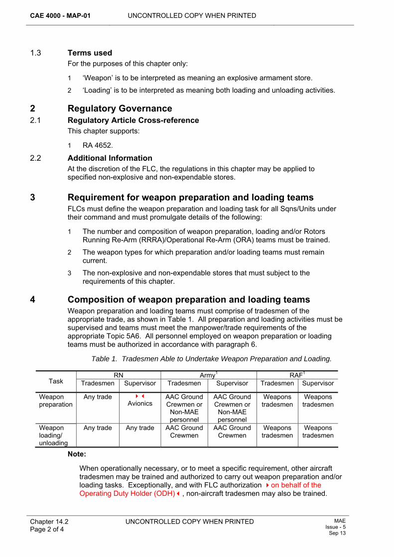
CAE 4000 - MAP-01 UNCONTROLLED COPY WHEN PRINTED
Chapter 14.2 Page 2 of 4
UNCONTROLLED COPY WHEN PRINTED MAE Issue - 5
Sep 13
1.3 Terms used For the purposes of this chapter only:
1 ‘Weapon’ is to be interpreted as meaning an explosive armament store.
2 ‘Loading’ is to be interpreted as meaning both loading and unloading activities.
2 Regulatory Governance 2.1 Regulatory Article Cross-reference
This chapter supports:
1 RA 4652.
2.2 Additional Information At the discretion of the FLC, the regulations in this chapter may be applied to specified non-explosive and non-expendable stores.
3 Requirement for weapon preparation and loading teams FLCs must define the weapon preparation and loading task for all Sqns/Units under their command and must promulgate details of the following:
1 The number and composition of weapon preparation, loading and/or Rotors Running Re-Arm (RRRA)/Operational Re-Arm (ORA) teams must be trained.
2 The weapon types for which preparation and/or loading teams must remain current.
3 The non-explosive and non-expendable stores that must subject to the requirements of this chapter.
4 Composition of weapon preparation and loading teams Weapon preparation and loading teams must comprise of tradesmen of the appropriate trade, as shown in Table 1. All preparation and loading activities must be supervised and teams must meet the manpower/trade requirements of the appropriate Topic 5A6. All personnel employed on weapon preparation or loading teams must be authorized in accordance with paragraph 6.
Table 1. Tradesmen Able to Undertake Weapon Preparation and Loading.
RN Army1 RAF1 Task Tradesmen Supervisor Tradesmen Supervisor Tradesmen Supervisor
Weapon preparation
Any trade Avionics
AAC Ground Crewmen or
Non-MAE personnel
AAC Ground Crewmen or
Non-MAE personnel
Weapons tradesmen
Weapons tradesmen
Weapon loading/ unloading
Any trade Any trade AAC Ground Crewmen
AAC Ground Crewmen
Weapons tradesmen
Weapons tradesmen
Note:
When operationally necessary, or to meet a specific requirement, other aircraft tradesmen may be trained and authorized to carry out weapon preparation and/or loading tasks. Exceptionally, and with FLC authorization on behalf of the Operating Duty Holder (ODH), non-aircraft tradesmen may also be trained.
UNCONTROLLED COPY WHEN PRINTED CAE 4000 - MAP-01
MAE Issue - 5 Sep 13
UNCONTROLLED COPY WHEN PRINTED
Chapter 14.2 Page 3 of 4
5 Training of personnel 5.1 Training of weapon preparation and loading teams
Training must comply with the requirements of Chapter 4.1. Training must be carried out by training instructors and must include relevant theoretical training on weapons, practice weapons, aircraft systems and safety aspects, prior to any practical training. Trainees must also satisfactorily answer a written examination on safety principles and procedures. This must be carried out to the satisfaction of a training examiner, who must certify that the tradesman is competent to act as a member of a weapon preparation and/or loading team.
5.2 Competency checks 5.2.1 Frequency
At least every 12 months, following completion of initial training, personnel must prepare and/or load the weapon types for which they are authorized. This must be carried out to the satisfaction of a training examiner, who must certify that the tradesman is competent to act as a member of a weapon preparation and/or loading team. However, the relevant individual holding authorization MAP-J93 may increase the frequency of these checks based on the following, non-exhaustive, list of examples:
1 The inexperience of newly qualified personnel.
2 Whenever personnel exhibit unsatisfactory performance or infringe safety rules during weapon preparation or loading activities. In these circumstances, the personnel concerned must receive further theoretical and practical training, as considered necessary.
3 Where it is considered that, due to the nature of the working environment, 12 months is too long an interval between checks.
4 Where the preparation and/or loading procedures have been subject to significant amendment.
5 When preparing for warlike operations, see paragraph 5.4.
RRRA/ORA - trained personnel must undertake one full RRRA/ORA, to the satisfaction of a training examiner, at least once every 12 months.
When weapons are being prepared or loaded on a regular basis, such as practice weapons used exclusively for aircrew training, FLCs may promulgate variations to the competency check regime. Preparation, loading and RRRA/ORA activities carried out during Stn/Ship/Unit exercises meet the competency check requirement, provided that a training examiner has witnessed the activity and subsequently certifies the tradesman as competent.
5.2.2 Recording A record must be maintained for each individual carrying out weapon preparation and/or loading, which must show the date of last competency check (including details of who performed the check), the date the next competency check is due and any other circumstances particular to the individual. Provided the individual has successfully passed the competency check, re-authorization by the individual holding authorization MAP-J93 is not required.
5.3 Training aircraft and rigs Whenever possible, weapon-loading training must be performed on fully serviceable aircraft. However, to avoid imposing unnecessarily severe restrictions on Stns/Ships/Units, the minimum acceptable standard of aircraft to be used must be
CAE 4000 - MAP-01 UNCONTROLLED COPY WHEN PRINTED
Chapter 14.2 Page 4 of 4
UNCONTROLLED COPY WHEN PRINTED MAE Issue - 5
Sep 13
one in which the relevant aircraft armament system is fully serviceable. FLCs, in conjunction with the Type Airworthiness Authority (TAA), may authorize the use of training aircraft or training rigs, provided that training can be safely and realistically carried out.
Weapons used to carry out training and competency checks must be fully representative. When using drill or training weapons, the procedures and precautions detailed in the Topic 5A6 must be followed as if a live weapon load were being carried out.
5.4 Training for warlike operations When preparing for warlike operations, FLCs and the individual holding authorization MAP-J93 must consider increasing the frequency of competency checks and providing in-theatre training assets in order to promote a higher level of proficiency than under normal peacetime conditions.
6 Authorization of personnel 6.1 Weapon preparation and loading teams
Personnel required to be a member of a weapon preparation must hold authorization MAP-B89. Personnel required to be a member of a weapon loading team must hold authorization MAP-B87. Personnel required to supervise a weapon preparation team must hold authorization MAP-C90. Personnel required to supervise a weapon loading team must hold authorization MAP-C88. The following requirements must be satisfied before personnel are authorized to be a member or supervisor of a weapon preparation and/or loading team:
1 Be of the appropriate trade as detailed in Table 1.
2 Successful completion of the training described in paragraph 5.1.
3 Competency in all tasks for which they are being authorized, to the satisfaction of a training examiner.
6.2 Training personnel Personnel who are to undertake the duties of training instructors or examiners must be authorized in accordance with paragraphs 6.2.1 and 6.2.2 respectively.
6.2.1 Instructors Personnel employed as instructors of weapon preparation and/or loading tasks must hold authorization MAP-C91. FLCs must identify:
1 Any additional ‘instructional technique’ qualifications that are required by the instructors.
2 The number of instructors that are required to hold these qualifications.
6.2.2 Examiners Personnel employed as examiners of weapon preparation and/or loading tasks must hold authorization MAP-E92 and be a minimum of a Senior Rating/SNCO. An examiner may be authorized as an instructor.
7 Reference This chapter refers to the following publication:
1 Topic 5A6 – Armament Procedure Sheets (RN), Weapon Loading and Off-loading Procedures (Army/RAF).
UNCONTROLLED COPY WHEN PRINTED CAE 4000 - MAP-01
MAE Issue - 5 Sep 13
UNCONTROLLED COPY WHEN PRINTED Chapter 14.3 Page 1 of 4
Chapter 14.3
Examination of In-use Pyrotechnics and Dangerous Goods Issued for use in Survival Equipment and on Airborne Platforms
TABLE OF CONTENTS Paragraph
Page
1 General ............................................................................................................... 1 1.1 Introduction.......................................................................................................... 1 1.2 Terms used ......................................................................................................... 1 1.3 Applicability ......................................................................................................... 2 2 Regulatory Governance.................................................................................... 2 2.1 Regulatory Article Cross-reference ..................................................................... 2 2.2 Additional Information.......................................................................................... 2 3 Examination of pyrotechnics and dangerous goods..................................... 2 3.1 Survival equipment.............................................................................................. 2 3.2 Airborne platforms ............................................................................................... 2 4 Recording requirements................................................................................... 3 5 Training and authorization ............................................................................... 3 5.1 Training ............................................................................................................... 3 5.2 Authorization ....................................................................................................... 3 6 Type Airworthiness Authority (TAA) Responsibilities ........................... 4 7 References ......................................................................................................... 4
1 General 1.1 Introduction
Environmentally suitable storages are normally used to ensure the long-term serviceability of not-in-use pyrotechnics and dangerous goods. All such storages and their contents are subjected to inspections in accordance with JSP 482. If the storage conditions are unsuitable, deterioration of the filling composition may occur and the designed performance of the pyrotechnics or dangerous goods may be degraded.
The environmental conditions to which in-use pyrotechnics and dangerous goods are subjected may cause them to deteriorate more rapidly than those stored in custom-designed storage areas. Additionally, some of the pyrotechnics and dangerous goods packed in survival equipment may not be readily available at the time of the inspections of explosives. Thus, special arrangements must be made for the examination of in-use pyrotechnics and dangerous goods issued for use in survival equipment and on airborne platforms. This chapter gives guidance on the recording requirements and details regulations for the examination of in-use pyrotechnics and dangerous goods.
1.2 Terms used For the purposes of this chapter, the following terms are used:
1 Dangerous goods refer to any article in use that contains non-explosive substances, but which is related by function to explosives.
2 Survival equipment includes all items of survival equipment and aircrew equipment assemblies fitted with pyrotechnics and/or dangerous goods.
CAE 4000 - MAP-01 UNCONTROLLED COPY WHEN PRINTED
Chapter 14.3 Page 2 of 4
UNCONTROLLED COPY WHEN PRINTED MAE Issue - 5
Sep 13
1.3 Applicability This chapter is only applicable to pyrotechnics and dangerous goods fitted in survival equipment and on airborne platforms.
For pyrotechnics or dangerous goods issued for emergency/immediate use in Air Traffic Control buildings/vehicles or Bird Control/Mountain Rescue vehicles, refer to AP 110E-1300-2(R)1, Part 2.
This chapter is not applicable to pyrotechnics and dangerous goods carried as cargo.
2 Regulatory Governance 2.1 Regulatory Article Cross-reference
This chapter supports:
1 RA 4653.
2.2 Additional Information During the examination of pyrotechnics and dangerous goods, the stripping of pyrotechnics and dangerous goods to expose explosive or pyrotechnic substances is strictly forbidden.
3 Examination of pyrotechnics and dangerous goods 3.1 Survival equipment 3.1.1 Initial issue
Prior to the initial issue of pyrotechnics and/or dangerous goods for use in survival equipment, they must to be examined by an individual holding authorization MAP-B341, authorized in accordance with paragraph 5.2, to ensure that they are fit for use. During the initial inspection each pyrotechnic must be marked with a serial number in accordance with AP 108A-0006-2(N/A/R)1. Completion of the examination must be recorded in accordance with paragraph 4 and recorded on the appropriate MOD Form 707 or MOD F715 series of documents.
When transferring pyrotechnics or dangerous goods between main equipments it is essential that all records held by the explosives storage area and the survival equipment section are amended to reflect the new location. The method of recording must be such that the complete installation history of each item is maintained.
3.1.2 Scheduled maintenance Pyrotechnics and dangerous goods installed in survival equipment must be examined during the scheduled maintenance of the equipment in which they are installed, as detailed in AP 108A-0006-2(N/A/R)1. Examinations must be conducted by an individual holding authorization MAP-B341. Pyrotechnics and dangerous goods which are visually inspected and considered to be unserviceable, or will be life-expired before the next scheduled maintenance becomes due, must be replaced with serviceable items. Unserviceable items must be disposed of in accordance with the instructions in JSP 886 Vol 13.
3.2 Airborne platforms Pyrotechnics and dangerous goods issued for emergency/immediate use on airborne platforms must be examined monthly by an individual holding authorization MAP-B341. As a minimum, the examination must consist of a visual inspection for damage and deterioration, and checks for explosive constraints limitations and any
UNCONTROLLED COPY WHEN PRINTED CAE 4000 - MAP-01
MAE Issue - 5 Sep 13
UNCONTROLLED COPY WHEN PRINTED Chapter 14.3 Page 3 of 4
applicable life criteria. Requirements for periodic examinations must be detailed in the aircraft Topic 2(N/A/R)1 and Topic 5A1, as appropriate.
4 Recording requirements Issues from unit stocks of pyrotechnics and dangerous goods covered by this chapter must be recorded in accordance with JSP 886 Vol 13. Historical records relating to the pyrotechnics and dangerous goods must be maintained in accordance with Chapter 14.9, using the MOD F715 series if applicable.
5 Training and authorization 5.1 Training
All weapons tradesmen may be authorized to carry out the examination of pyrotechnics and/or dangerous goods without the need for further formal training. RN and RAF Survival Equipment personnel required to undertake the examination of those pyrotechnics and/or dangerous goods specifically issued for use in survival equipment and on airborne platforms must be suitably qualified (RAF: Q-SE-PYRO) or the equivalent embedded in formal basic training. They must then receive local familiarization training on the items that they will be required to examine. All training must comply with the requirements of Chapter 4.1. Training must include, as a minimum, the following:
1 The safety precautions when working with explosive stores and explosive-operated devices.
2 The potential hazards of an inadvertent initiation and the appropriate fire precautions.
3 The identification and examination of the pyrotechnics or dangerous goods and those assemblies and components that require periodic inspection.
4 The completion of all relevant documentation and an awareness of all governing regulations and signature implications.
5 The procedures for the storage, transportation, handling, examination and control of pyrotechnics and dangerous goods used in survival equipment.
6 The requirement for installed pyrotechnics and dangerous goods to have sufficient life remaining until the next preventive maintenance activity and the procedures required for obtaining life extensions.
7 The fault reporting and explosives constraints procedures for pyrotechnics and dangerous goods.
8 The disposal of life-expired and unserviceable pyrotechnics and dangerous goods.
9 A demonstration of the operation of each item.
5.2 Authorization Tradesmen required to undertake the examination of in-use pyrotechnics and/or dangerous goods, issued for use in survival equipment and on airborne platforms, must hold authorization MAP-B341 and must be supervised by an individual holding authorization MAP-C342 who has undergone the same training. Authorizations must be granted by an individual holding authorization MAP-J343 in accordance with Chapter 4.3.
CAE 4000 - MAP-01 UNCONTROLLED COPY WHEN PRINTED
Chapter 14.3 Page 4 of 4
UNCONTROLLED COPY WHEN PRINTED MAE Issue - 5
Sep 13
6 Type Airworthiness Authority (TAA) Responsibilities For pyrotechnics or dangerous goods used in emergency, survival or aircrew equipments, the TAA must detail the requirement for periodic examinations in the aircraft Topic 2(N/A/R)1 and Topic 5A1.
7 References This chapter refers to the following publications:
1 AP 108A-0006-2(N/A/R)1 – Survival Equipment and Aircrew Equipment Assemblies Support Authority General Orders and Special Instructions (Technical).
2 AP 110E-1300-2(R)1 – Pyrotechnics General Orders – Special Instructions.
3 JSP 482 – MOD Explosives Regulations.
4 JSP 886 – The Defence Logistics Support Chain Manual.
5 Topic 2(N/A/R)1 – General Orders and Special Instructions.
6 Topic 5A1 – Master Maintenance Schedule.
UNCONTROLLED COPY WHEN PRINTED CAE 4000 - MAP-01
Issue - 7 Apr 15
UNCONTROLLED COPY WHEN PRINTED Chapter 14.4 Page 1 of 4
Chapter 14.4
Connecting Electro-Explosive Devices
TABLE OF CONTENTS Paragraph
Page
1 General ............................................................................................................... 1 1.1 Introduction.......................................................................................................... 1 1.2 Applicability ......................................................................................................... 1 1.3 Terms used ......................................................................................................... 1 2 Regulatory Governance.................................................................................... 2 2.1 Regulatory Article Cross-reference ..................................................................... 2 3 Connecting an EED ........................................................................................... 2 4 Determining requirements for No Volts Safety Test (NVST) ......................... 2 5 Authorization for NVST not being considered necessary............................. 2 6 Reference ........................................................................................................... 3
1 General 1.1 Introduction
An Electro-Explosive Device (EED) is an explosive or pyrotechnic device designed to be initiated by electrical means, which if inadvertently operated or initiated could cause extensive damage and loss of life. To protect the tradesman who is undertaking the connection of the EED to its Electrical Firing Circuit (EFC) and those personnel and materiel in the vicinity of this activity, it is necessary to carry out a test of the EFC, known as a No-Volts Safety Test (NVST). The purpose of this chapter is to specify the policy to be adopted for carrying out an NVST, prior to connecting an EED.
1.2 Applicability This chapter is applicable to both on and off-aircraft activities undertaken by organizations within the Military Air Environment (MAE) operating aircraft fitted with EEDs. Such devices may be associated with, or form part of, an explosive armament store or may be an explosive component in an aircraft or equipment system.
1.3 Terms used Throughout this chapter:
1 Connection of an EED to its EFC must be interpreted as also meaning any action that completes an EFC in which the EED is already installed.
2 ‘Schedule’ or ‘procedure concerned’ means the schedule or procedure that calls for, or controls, connection of an EED to its EFC.
3 NVST relates only to a safety test undertaken as a safety precaution prior to connecting an EED to its EFC and does not refer to no-volts testing performed for any other reason, eg as a form of ‘system test’: the term must not be used to describe such tests.
CAE 4000 - MAP-01 UNCONTROLLED COPY WHEN PRINTED
Chapter 14.4 Page 2 of 4
UNCONTROLLED COPY WHEN PRINTED Issue - 7 Apr 15
2 Regulatory Governance 2.1 Regulatory Article Cross-reference
This chapter supports:
1 RA 4654.
3 Connecting an EED The following procedures must be adhered to when connecting an EED to its EFC:
1 The NVST must be carried out under the same conditions as those determined for the connection of the EED to its EFC.
2 The NVST must be undertaken by the individual(s) who will personally connect the EED to its EFC. Additionally, the individual holding authorization MAP-C27 supervising the activity must ensure that all conditions detailed within the overall schedule or procedure concerned have been met prior to performing the NVST and that suitable measures have been taken to ensure that no change to the specified conditions occurs until the EED is connected to its EFC.
3 Once a satisfactory NVST has been carried out on an EFC, the EED must be connected to its EFC as soon as it is practicable to do so.
4 Determining requirements for No Volts Safety Test (NVST) For each system containing an EED, the respective Type Airworthiness Authority (TAA) must:
1 Determine, in conjunction with the appropriate Design Organization (DO), the conditions under which an NVST must be carried out. Should it be determined that there is no requirement to carry out an NVST, the procedures at paragraph 5 must be followed.
2 Determine, in conjunction with the appropriate DO, whether a system test is deemed necessary prior to connecting EEDs. Should a system test be required, it must be clearly separated from the NVST in the associated procedure.
3 Seek specialist advice from other agencies, eg Defence Ordnance Safety Group (DOSG), Defence Scientific and Technology Laboratory (Dstl), if appropriate.
4 Promulgate the overall schedule or procedure concerned.
5 Authorization for NVST not being considered necessary For situations where a TAA, in conjunction with the DO, considers that an NVST is not necessary, then either:
1 If it is considered that the design of the EFC meets the guidelines published in DEF STAN 07-85 and DEF STAN 59-114 and that the procedures being used fully ensure that isolation is achieved, the TAA must present a Safety Assessment to DOSG that an NVST is not necessary. If the DOSG accepts the Safety Assessment the TAA may stipulate that an NVST is not required.
2 If it is considered that inadvertent operation or initiation of the EED would present no risk to personnel or materiel, the TAA must present a risk assessment to the DOSG that an NVST is not necessary. If the DOSG accepts the risk assessment the TAA may stipulate that an NVST is not required.
UNCONTROLLED COPY WHEN PRINTED CAE 4000 - MAP-01
Issue - 7 Apr 15
UNCONTROLLED COPY WHEN PRINTED
Chapter 14.4 Page 3 of 4
6 Reference This chapter makes reference to the following publication:
1 DEF STAN 07-85 - Design Requirements for Weapons and Associated Systems.
2 DEF STAN 59-114 - Safety Principles for Electrical Circuits in Systems Incorporating Explosive Components

CAE 4000 - MAP-01 UNCONTROLLED COPY WHEN PRINTED
Chapter 14.4 Page 4 of 4
UNCONTROLLED COPY WHEN PRINTED Issue - 7 Apr 15
Intentionally Blank for Print Pagination
UNCONTROLLED COPY WHEN PRINTED CAE 4000 - MAP-01
Issue - 7 Apr 15
UNCONTROLLED COPY WHEN PRINTED Chapter 14.5 Page 1 of 6
Chapter 14.5
Aircraft Armament System Maintenance
Table of contents Paragraph
Page
1 General................................................................................................................ 1 1.1 Introduction.......................................................................................................... 1 1.2 Applicability ......................................................................................................... 1 2 Regulatory Governance ...................................................................................... 1 2.1 Regulatory Article Cross-reference ..................................................................... 1 2.2 Additional Information.......................................................................................... 2 3 AAS Testing ........................................................................................................ 2 3.1 Aircraft Armament Electrical Installation (AAEI) .................................................. 2 3.2 Aircraft Armament Suspension Equipment (AASE) ............................................ 2 3.3 Armament Role Change Harness (ARCH).......................................................... 3 4 Occasions when testing is not required............................................................... 3 5 Maintenance responsibilities, authorizations and training requirements ............. 3 5.1 Maintenance responsibilities ............................................................................... 3 5.2 Authorizations and training.................................................................................. 4 5.3 Further training .................................................................................................... 4 5.4 Training tests....................................................................................................... 4 6 Concessions........................................................................................................ 5 7 References .......................................................................................................... 5
List of tables Table 1. AAS Maintenance Responsibilities. ................................................................. 4
1 General 1.1 Introduction
In the interests of safety and reliability, the highest standards of maintenance are to be applied to Aircraft Armament Systems (AAS).
An AAS consists of the following:
1 Aircraft Armament Electrical Installation (AAEI). 2 Aircraft Armament Suspension Equipment (AASE). 3 Armament Role Change Harness (ARCH).
1.2 Applicability This chapter is applicable to all maintenance organizations that are responsible for the maintenance of AAS, AAS components or equipment.
2 Regulatory Governance 2.1 Regulatory Article Cross-reference
This chapter supports:
CAE 4000 - MAP-01 UNCONTROLLED COPY WHEN PRINTED
Chapter 14.5 Page 2 of 6
UNCONTROLLED COPY WHEN PRINTED Issue - 7 Apr 15
1 RA 4655.
2.2 Additional Information AAEIs that comprise a weapons databus utilize a Mil-Std-1760 Aircraft Stores Electrical Interconnection System for interfacing with ‘smart’ weapons or stores. A Mil-Std-1760 Aircraft Stores Electrical Interconnection System is to be maintained as part of the AAEI.
3 AAS Testing 3.1 Aircraft Armament Electrical Installation (AAEI)
An AAEI is an installation which comprises those systems that provide control, release, fuzing, firing, monitoring and related data transmission signals of weapons and stores, including counter-measure systems that contain explosives, carried by an aircraft. Unless defined otherwise in the aircraft Topic 1 or 2(N/A/R)1, the installation commences at, and includes, the supply fuses or circuit breakers providing electrical supply to the installation. If, however, the control, release, fuzing, firing, monitoring or related data transmission signals are generated by the aircraft main computer, or by other systems having wider functions than those of the AAEI, the installation commences at the interface connections of the line replaceable units generating the signals concerned. Irrespective of where it starts, the AAEI consists of all wiring and equipment making up its circuits to the point where the circuits terminate at the interfaces with the armament weapon suspension equipment, armament role change harness assemblies and weapons or stores.
An AAEI is a safety-critical system and a Type Airworthiness Authority (TAA), in consultation with the DES Wpns-Eng Project Team (PT), is responsible for the AAEI testing philosophy of their respective platform. AAEIs must be tested in accordance with the relevant Maintenance Procedure (MP) on the following occasions:
1 Every 6 months. 2 After the system has been disturbed. The MP carried out to test the AAEI must
fully confirm the serviceability of the disturbed components or cables. An AAS has been disturbed if any of the following activities occur: 2.1 An electrical connection to/from AAEI components or cables has been
disconnected or connected. 2.2 If, in the opinion of the supervisor, the physical displacement of AAEI
cables, or the fitment of securing devices, could have resulted in alteration or damage to the AAS.
3 Additionally, as directed by TAAs/commodity PTs in aircraft or equipment publications, modification leaflets or Special Instructions (Technical).
3.2 Aircraft Armament Suspension Equipment (AASE) AASE are those devices (eg, ejector release units (ERU), electro-mechanical release units (EMRU), fuzing/arming units, carriers, adapters, missile rail launchers, missile eject launchers and pylons) used for the carriage on, and release from, military aircraft (including helicopters) of the following stores:
1 Explosive armament stores, eg, missiles, rockets, bombs, bomb dispensers, gun pods, mines, torpedoes and Electronic Counter Measures (ECM) pods containing explosives.
2 Non-explosive stores, eg, fuel tanks, reconnaissance pods, baggage carriers or ECM pods not containing explosives.
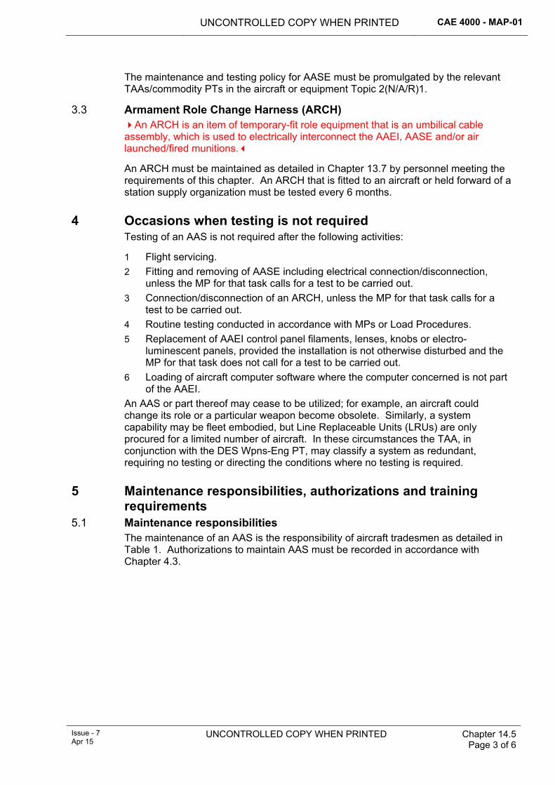
UNCONTROLLED COPY WHEN PRINTED CAE 4000 - MAP-01
Issue - 7 Apr 15
UNCONTROLLED COPY WHEN PRINTED Chapter 14.5 Page 3 of 6
The maintenance and testing policy for AASE must be promulgated by the relevant TAAs/commodity PTs in the aircraft or equipment Topic 2(N/A/R)1.
3.3 Armament Role Change Harness (ARCH) An ARCH is an item of temporary-fit role equipment that is an umbilical cable assembly, which is used to electrically interconnect the AAEI, AASE and/or air launched/fired munitions.
An ARCH must be maintained as detailed in Chapter 13.7 by personnel meeting the requirements of this chapter. An ARCH that is fitted to an aircraft or held forward of a station supply organization must be tested every 6 months.
4 Occasions when testing is not required Testing of an AAS is not required after the following activities:
1 Flight servicing. 2 Fitting and removing of AASE including electrical connection/disconnection,
unless the MP for that task calls for a test to be carried out. 3 Connection/disconnection of an ARCH, unless the MP for that task calls for a
test to be carried out. 4 Routine testing conducted in accordance with MPs or Load Procedures. 5 Replacement of AAEI control panel filaments, lenses, knobs or electro-
luminescent panels, provided the installation is not otherwise disturbed and the MP for that task does not call for a test to be carried out.
6 Loading of aircraft computer software where the computer concerned is not part of the AAEI.
An AAS or part thereof may cease to be utilized; for example, an aircraft could change its role or a particular weapon become obsolete. Similarly, a system capability may be fleet embodied, but Line Replaceable Units (LRUs) are only procured for a limited number of aircraft. In these circumstances the TAA, in conjunction with the DES Wpns-Eng PT, may classify a system as redundant, requiring no testing or directing the conditions where no testing is required.
5 Maintenance responsibilities, authorizations and training requirements
5.1 Maintenance responsibilities The maintenance of an AAS is the responsibility of aircraft tradesmen as detailed in Table 1. Authorizations to maintain AAS must be recorded in accordance with Chapter 4.3.
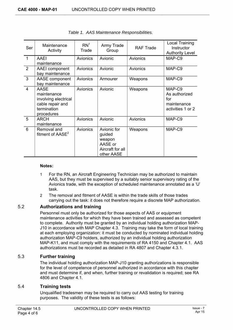
CAE 4000 - MAP-01 UNCONTROLLED COPY WHEN PRINTED
Chapter 14.5 Page 4 of 6
UNCONTROLLED COPY WHEN PRINTED Issue - 7 Apr 15
Table 1. AAS Maintenance Responsibilities.
Ser Maintenance Activity
RN1
Trade Army Trade
Group RAF Trade Local Training
Instructor Authority Level
1 AAEI maintenance
Avionics Avionic Avionics MAP-C9
2 AAEI component bay maintenance
Avionics Avionic Avionics MAP-C9
3 AASE component bay maintenance
Avionics Armourer Weapons MAP-C9
4 AASE maintenance involving electrical cable repair and termination procedures
Avionics Avionic Weapons MAP-C9 As authorized for maintenance activities 1 or 2
5 ARCH maintenance
Avionics Avionic Avionics MAP-C9
6 Removal and fitment of AASE2
Avionics Avionic for guided weapon AASE or Aircraft for all other AASE
Weapons MAP-C9
Notes:
1 For the RN, an Aircraft Engineering Technician may be authorized to maintain AAS, but they must be supervised by a suitably senior supervisory rating of the Avionics trade, with the exception of scheduled maintenance annotated as a ‘U’ task.
2 The removal and fitment of AASE is within the trade skills of those trades carrying out the task: it does not therefore require a discrete MAP authorization.
5.2 Authorizations and training Personnel must only be authorized for those aspects of AAS or equipment maintenance activities for which they have been trained and assessed as competent to complete. Authority must be granted by an individual holding authorization MAP-J10 in accordance with MAP Chapter 4.3. Training may take the form of local training at each employing organization: it must be conducted by nominated individual holding authorization MAP-C9 holders, authorized by an individual holding authorization MAP-K11, and must comply with the requirements of RA 4150 and Chapter 4.1. AAS authorizations must be recorded as detailed in RA 4807 and Chapter 4.3.1.
5.3 Further training The individual holding authorization MAP-J10 granting authorizations is responsible for the level of competence of personnel authorized in accordance with this chapter and must determine if, and when, further training or revalidation is required; see RA 4806 and Chapter 4.1.
5.4 Training tests Unqualified tradesmen may be required to carry out AAS testing for training purposes. The validity of these tests is as follows:
UNCONTROLLED COPY WHEN PRINTED CAE 4000 - MAP-01
Issue - 7 Apr 15
UNCONTROLLED COPY WHEN PRINTED Chapter 14.5 Page 5 of 6
1 If only one unqualified tradesman is involved and is directly supervised by an individual holding authorization MAP-C27 who is not otherwise involved in the test, the test may be considered a valid maintenance task.
2 If more than one unqualified tradesman is involved, the test must be considered as a training test. Training tests must be followed by a re-test conducted by authorized personnel.
Nominated local training instructors authorized to supervise those AAS maintenance activities must supervise all tests where personnel are undergoing training.
6 Concessions Requests for concessions to the maintenance activities detailed in this chapter must be made, with supporting evidence, to the applicable platform or equipment PT, which is to seek endorsement by the DES Wpns-Eng PTL. Permanent concessions to this chapter, endorsed by the DES Wpns-Eng PTL, must be authorized by the TAA and published in the Topic 2(N/A/R)1 and (if appropriate) in the Topic 5A1.
7 References This chapter makes reference to the following publications:
1 Topic 2(N/A/R)1 – General Orders and Special Instructions. 2 Topic 5A1 – Master Maintenance Schedule.

CAE 4000 - MAP-01 UNCONTROLLED COPY WHEN PRINTED
Chapter 14.5 Page 6 of 6
UNCONTROLLED COPY WHEN PRINTED Issue - 7 Apr 15
Intentionally Blank for Print Pagination
UNCONTROLLED COPY WHEN PRINTED CAE 4000 - MAP-01
MAE Issue - 5 Sep 13
UNCONTROLLED COPY WHEN PRINTED Chapter 14.6 Page 1 of 6
Chapter 14.6
Lifing of Explosives and Associated Ancillaries
TABLE OF CONTENTS Paragraph
Page
1 General ............................................................................................................... 1 1.1 Introduction.......................................................................................................... 1 1.2 Associated publications....................................................................................... 1 1.3 Terms used ......................................................................................................... 2 2 Regulatory Governance.................................................................................... 2 2.1 Regulatory Article Cross-reference ..................................................................... 2 2.2 Additional Information.......................................................................................... 2 3 Philosophy on lifing of explosives and associated ancillaries..................... 2 4 Initial determination of explosives lives ......................................................... 2 4.1 Justifying explosives lifing ................................................................................... 2 4.2 Approval of explosives maintenance policy......................................................... 3 4.3 Example of explosives lifing ................................................................................ 3 5 Promulgation of explosives lives .................................................................... 3 5.1 Changes to explosives lives ................................................................................ 4 6 Recording of life consumption ........................................................................ 4 6.1 Marking................................................................................................................ 4 6.2 Engineering Record Cards (ERC) ....................................................................... 4 6.3 Use and control of ERCs for explosives.............................................................. 4 7 Latitudes to explosives lives............................................................................ 5 7.1 Anticipation of explosives lives at Stn/Ship/Unit .................................................. 5 7.2 Extension of explosives lives by the Project Team (PT) ..................................... 5 7.3 Extension of explosives lives by the Front line Command (FLC) or
Stn/Ship/Unit ....................................................................................................... 5 7.4 Extension of maintenance lives........................................................................... 6 8 Disposal of life-expired explosives ................................................................. 6 9 References ......................................................................................................... 6
1 General 1.1 Introduction
Modern explosives are both costly and time-consuming to develop, and modify. It is therefore essential to optimize the maximum safe life of explosives to avoid early and expensive replacement or modification. Therefore, explosives and many of their associated ancillary items are subject to lifing procedures. The regulations governing lifing of explosives are both complex and specialist by nature, but are driven by the requirements of JSP 520, STANAG 4315 and AOP-46. This chapter seeks to regulate, in basic terms, the philosophy for lifing of explosives (including aerospace components that contain explosives) and associated ancillaries (such as suspension lugs) in the Military Air Environment (MAE). Should further advice be required, the Project Team (PT) for the explosive concerned should be approached. Further information regarding the lifing of aerosystem components can be found in MAP Chapter 5.3.1.
1.2 Associated publications This chapter is associated with the following publications:
CAE 4000 - MAP-01 UNCONTROLLED COPY WHEN PRINTED
Chapter 14.6 Page 2 of 6
UNCONTROLLED COPY WHEN PRINTED MAE Issue - 5
Sep 13
1 JSP 430 – MOD Ship Safety Management.
2 MAP-01 Chapter 14.1 – Organizations Responsible for Ordnance, Munitions and Explosives Safety.
1.3 Terms used Throughout this chapter the term life extension is used to refer to the increase of the life of an explosive beyond its previously assessed life. Additionally, definitions of the following terms are contained in MAP-01 Chapter 0.4:
1 Service Life.
2 Storage Life.
3 Operational Life.
4 Air Carriage Life.
5 Standby Life.
6 Disposal Life.
2 Regulatory Governance 2.1 Regulatory Article Cross-reference
This chapter supports:
1 RA 4656.
2.2 Additional Information The Service Life may include a Storage Life and/or an Operational Life.
3 Philosophy on lifing of explosives and associated ancillaries Explosive stores (including explosives in Aircraft Assisted Escape Systems (AAES)) and components containing explosive stores, and many non-explosive ancillaries such as suspension lugs, must be allocated a life, which is known as the Service Life.
4 Initial determination of explosives lives After identifying that an explosive/ancillary must be lifed, which is achieved wherever possible using whole life assessment planning as laid down in STANAG 4315 and AOP-46, and in consultation with the Defence Ordnance Safety Group (DOSG), PTs are to determine, for each manner of failure that merits allotment of a life, the most cost-effective activity (eg maintenance, reconditioning or disposal) which will minimize the occurrence of failures in that manner. Where an explosive/ancillary has more than one mode of failure, a different maintenance activity may be required for each mode, thus giving it a number of lives, eg bay maintenance life, reconditioning life and disposal life.
4.1 Justifying explosives lifing The assessment of explosives failure is carried out using data drawn, variously, from the Designer Safety and Suitability for Service (S3) trials, fault/performance reports, in-service surveillance, or from in-service experience; which determine that a failure will occur at a predictable stage within the maximum life envisaged for the explosive. Where, through lack of necessary data, a PT is unable to allot a life to an in-service or new explosive or ancillary in accordance with Designer/DOSG recommendations, the explosive/ancillary must be allotted a provisional storage, operational, maintenance, reconditioning or disposal life, as appropriate. The explosives
UNCONTROLLED COPY WHEN PRINTED CAE 4000 - MAP-01
MAE Issue - 5 Sep 13
UNCONTROLLED COPY WHEN PRINTED Chapter 14.6 Page 3 of 6
concerned must then be subject to a review of lifing measures or, if newly developed, to continued S3/qualification/testing in accordance with JSP 482 and/or JSP 520. The assessment of provisional lives may affect expenditure on initial provisioning and maintenance facilities. It is therefore desirable that any provisional lives allotted are the longest lives that can safely be permitted in the circumstances.
4.2 Approval of explosives maintenance policy The responsibility for approving the maintenance policy for explosives/explosive components/ancillaries is vested in the appropriate PT. Due to the costs involved in this exercise, the PT, when deciding the maintenance life of an explosive in a failure mode that is not critical, must be confident that the expected improvement in availability or in-service life support costs will outweigh other considerations.
4.3 Example of explosives lifing The following shows how an explosive item’s life may be determined:
1 The explosive item has a Service Life of 6 years, a Storage Life of 6 years and an Operational Life of 2 years. Therefore:
1.1 Service Life – The item will remain serviceable and safe for a maximum of 6 years calculated from the last day of the month of the year of filling.
1.2 Storage Life – The item will remain serviceable and safe in storage for a maximum of 6 years calculated from the last day of the month of the year of filling. The date calculated is not to exceed the Service Life.
1.3 Operational Life – The item may be installed in/loaded to a component/weapon/platform at any time during its Service/Storage Life. However, if for example the item is brought into use during the last 2 years of its Service/Storage Life, some of the Operational Life will be lost. The Operational Life is not to exceed the Service Life.
Note:
The prescribed lifing of an explosive in the MAE may vary if the item concerned is stored/operated in the Sea environment.
5 Promulgation of explosives lives The responsible PT must publish explosives lives in one (or more if appropriate) of the media listed below; however, if the explosive is contained within a platform component the Type Airworthiness Authority (TAA) must publish the life in the aircraft Topic 5A1 or equivalent publication:
1 The Component Life Register (CLR) and Component Replacement List of the relevant Topic 5A1 or equivalent publication (and, if appropriate Topic 5K (Schedule of Component Lives)) in accordance with the requirements of Chapter 8.1.1.
2 The appropriate Topic 2(N/A/R)1 or Ammunition and Explosive Regulations (A&ER) Pamphlet.
3 Section 2 of the Joint Service Munitions Control Register (JSMCR).
In the case of lifed explosives with a multi-user application, the PT must ensure that relevant platform/equipment PTs are advised of any lifing requirements.
Note:
CAE 4000 - MAP-01 UNCONTROLLED COPY WHEN PRINTED
Chapter 14.6 Page 4 of 6
UNCONTROLLED COPY WHEN PRINTED MAE Issue - 5
Sep 13
Promulgation of Service/Operational Life to RN Stns/Ships/Units is also carried out using a Defence Information Notice (DIN).
5.1 Changes to explosives lives The promulgation of amendments to/review of published explosives lives must be managed by the responsible PT. Stns/Ships/Units may be provided with advanced notification of the changes by issuing one (or more, if appropriate) of the following:
1 Routine Technical Instruction; see MAP-01 Chapter 10.5.3. Advanced notification may allow units to change and/or segregate explosives pending the receipt of formal amendment to the Topic 5A1. Advanced notification action is particularly important where component lifing details are contained electronically (eg LITS or GOLDesp) and the system affords PTs the ability to amend details centrally.
2 Advanced Information Leaflet to the appropriate Topic 2(N/A/R)1 or A&ER Pamphlet; see MAP-01 Chapter 8.2.2.
3 Amendment to the JSMCR.
In the case of lifed explosives with a multi-user application, the PT must ensure that relevant platform/equipment PTs are advised of any revised lifing requirements.
6 Recording of life consumption A record of life consumed must be maintained for every lifed explosive, component containing an explosive, or associated non-explosive ancillary.
6.1 Marking With certain exceptions, lifed explosives, when first opened for use (or in the case of AAES explosives, at the point of installation), must be marked in accordance with the instructions in the appropriate Topic 2(N/A/R)1 or Maintenance Procedure (eg with the life expiry date and the equipment/platform serial number) using a suitable or specified medium.
6.2 Engineering Record Cards (ERC) When an explosive, a component containing an explosive, or a non-explosive ancillary is introduced into service, the PT must determine whether the item requires an Engineering Record Card (ERC). The requirement for an ERC is normally determined during the logistic support analysis process. The PT must specify ERC requirements and promulgate them in the relevant section of the Topic 5A1 or the appropriate Topic 2(N/A/R)1 or A&ER Pamphlet. Instructions for the use of ERCs for explosives are in paragraph 6.3 (see also MAP-01 Chapter 14.9). Alternatively, a record of life consumed may be maintained, if appropriate, wholly by an electronic system (such as LITS) and a hard copy of the ERC printed when required.
6.3 Use and control of ERCs for explosives Unless otherwise stated in the Topic 2(N/A/R)1, user units must maintain the following minimum information on ERCs:
1 Domestic Management Code, Section Reference Number, NATO Stock Number or Ammunition Descriptive Asset Code and Nomenclature.
2 Maker/filler, lot number and date or Batch Key Identity (BKI).
3 Serial number (if appropriate).
4 Where fitted/installed/exposed.
5 Date fitted/installed/exposed.
UNCONTROLLED COPY WHEN PRINTED CAE 4000 - MAP-01
MAE Issue - 5 Sep 13
UNCONTROLLED COPY WHEN PRINTED Chapter 14.6 Page 5 of 6
6 Hours/sorties flown.
7 Date removed/repacked.
When an explosive/ancillary is removed from a platform/equipment for maintenance, the ERC must be completed with details of the removal, the life consumed, and the activity undertaken (eg periodic maintenance, component replacement, etc). If the explosive item/ancillary is sent to another Stn/Ship/Unit, the ERC must be attached to the MOD F731 and dispatched with the item.
7 Latitudes to explosives lives To facilitate maintenance planning and avoid unnecessary restrictions on system availability, some flexibility in the application of authorized lives to individual explosive items is essential. The latitudes permissible are detailed in paragraphs 7.1, 7.2, 7.3 and 7.4, though anticipation or extension of maintenance life may be limited or prohibited by the appropriate specialist regulations, the Front Line Command (FLC) or the responsible PT.
7.1 Anticipation of explosives lives at Stn/Ship/Unit An individual holding authorization MAP-J386 may authorize the anticipation of any explosive life expiry unless this action is prohibited in the Topic 2(N/A/R)1. Such anticipation has resource implications; therefore, when anticipating an explosive life expiry, every effort must be made to ensure that the action does not result in an MOD-wide shortage of the explosive item concerned. Stns/Ships/Units should therefore liaise with the responsible PT beforehand.
7.2 Extension of explosives lives by the Project Team (PT) The PT responsible for the item under consideration may, after considering all the relevant factors, authorize extensions to the Service/Operational Lives of explosives. This would normally be based on Designer/DOSG advice, but in certain circumstances (eg where operational capability may otherwise be adversely affected), a PT may authorize an extension to the Service/Operational lives of explosives without such recourse.
7.3 Extension of explosives lives by the Front line Command (FLC) or Stn/Ship/Unit The extension of an explosive’s Service/Storage or Operational Life at FLC or Stn/Ship/Unit level is prohibited regardless of whether it applies to either critical or non-critical failure modes. Requests for life extension must be made to the appropriate PT, providing the following information:
1 Aircraft/component type and number (CLR reference if applicable) and quantity involved.
2 Maker/filler, lot number and date or BKI.
3 Present life consumed.
4 Type of life due and extension required.
5 Reason for request.
6 Planned date of component change.
7 New expiry date if extension granted.
8 Other considerations that may affect its life, eg storage conditions in a sea environment.
CAE 4000 - MAP-01 UNCONTROLLED COPY WHEN PRINTED
Chapter 14.6 Page 6 of 6
UNCONTROLLED COPY WHEN PRINTED MAE Issue - 5
Sep 13
7.4 Extension of maintenance lives Provided extension is permitted in the Topic 2(N/A/R)1 extensions to maintenance lives may be authorized as follows:
1 An individual holding authorization MAP-K387 may authorize up to 10% on components with lives allotted to safeguard against critical failure modes.
2 An individual holding authorization MAP-K388 may authorize up to 25% on components with lives allotted to safeguard against non-critical failure modes.
Stns/Ships/Units wishing to extend maintenance beyond these limits must apply to the appropriate PT stating how much extension has already been granted. In consultation with the PT responsible for the explosive concerned, where appropriate, and after considering all the relevant factors, the PT may further extend the maintenance life beyond the 10%/25% detailed above.
Note:
Before extending a maintenance life, a check must be made to ensure that the extension granted does not compromise the Service/Operational Life of any explosive component fitted.
Critical and non-critical failure modes are described in MAP-01 Chapter 5.3.1.
8 Disposal of life-expired explosives Explosives that have completed their Service/Operational life are an important source of material for life extension trials/proof testing. Stns/Ships/Units therefore must not dispose of life-expired explosive/ancillary items without prior reference to the PT concerned where no instructions for disposal are detailed in the Topic 2(N/A/R)1. Pending receipt of disposal instructions, Stns/Ships/Units must store life-expired explosives under the same conditions as new stock.
9 References This chapter refers to the following publications:
1 Ammunition and Explosives Regulations.
2 JSP 482 – MOD Explosives Regulations.
3 JSP 520 – Ordnance Munitions and Explosives Safety Management.
4 STANAG 4315 – The Scientific Basis for the Whole Life Assessment of Munitions.
5 Joint Service Munitions Control Register.
6 Topic 2(N/A/R)1– General Orders and Special Instructions.
7 Topic 5A1 – Master Maintenance Schedule.
8 Topic 5K IS – Schedule of Component Lives.
9 AOP-46 – The Scientific Basis for the Whole Life Assessment of Munitions.
UNCONTROLLED COPY WHEN PRINTED
CAE 4000 - MAP-01
Issue - 7 Apr 15
UNCONTROLLED COPY WHEN PRINTED
Chapter 14.7 Page 1 of 12
Chapter 14.7
Armed Aircraft Safety Precautions
TABLE OF CONTENTS Paragraph
Page
1 General ............................................................................................................... 2 1.1 Introduction.......................................................................................................... 2 1.2 Associated publications....................................................................................... 2 1.3 Applicability ......................................................................................................... 2 2 Regulatory Governance.................................................................................... 2 2.1 Regulatory Article Cross-reference ..................................................................... 2 2.2 Additional Information.......................................................................................... 2 3 Load Procedures (LP) ....................................................................................... 3 4 Loading and unloading of aircraft ................................................................... 3 4.1 Aircraft weapon loading/unloading during Thunderstorm Level/Risk High
conditions ............................................................................................................ 3 4.2 Preparation of aircraft to fly with guns in the initially armed state ....................... 4 5 Parking of armed aircraft.................................................................................. 5 6 Warning notices ................................................................................................ 5 7 Safety devices ................................................................................................... 5 7.1 General requirements.......................................................................................... 5 7.2 Safe condition...................................................................................................... 5 7.3 Live condition ...................................................................................................... 6 8 Maintenance on armed aircraft ........................................................................ 6 8.1 General principles ............................................................................................... 6 8.2 Concurrent loading and maintenance ................................................................. 6 8.3 Instructions for maintenance on armed aircraft of a specific type ....................... 7 8.4 Electrical testing of armed aircraft ....................................................................... 7 8.5 Initially armed aircraft .......................................................................................... 7 8.6 Final or combat armed aircraft ............................................................................ 7 8.7 Armed aircraft in Hardened Aircraft Shelter (HAS) or readiness buildings.......... 8 8.8 Host Nation (HN) airfields overseas .................................................................... 8 9 Considerations when authorizing maintenance on armed aircraft .............. 8 9.1 Risk assessment ................................................................................................. 8 9.2 Additional safety precautions .............................................................................. 8 10 Housing of unarmed/armed aircraft ................................................................ 9 10.1 Unarmed aircraft housed for non-maintenance purposes ................................... 9 10.2 Unarmed aircraft housed for maintenance purposes .......................................... 9 10.3 Armed aircraft housed for non-maintenance purposes in a building that is not
a licensed Potential Explosion Site (PES) or other authorized readiness building .............................................................................................................. 10
10.4 Loading and unloading of armament explosive stores in hangars afloat .......... 11 11 Foreign military aircraft .................................................................................. 11 11.1 General.............................................................................................................. 11 11.2 Immediate action when the aircraft lands.......................................................... 11 11.3 Action when the aircraft is declared to be armed .............................................. 11 11.4 Action when the aircraft is declared to be unarmed .......................................... 12 12 Signal pistols ................................................................................................... 12 13 Use of electrical and electronic equipment .................................................. 12 14 Authorizations ................................................................................................. 12 15 References ....................................................................................................... 12
CAE 4000 - MAP-01 UNCONTROLLED COPY WHEN PRINTED
Chapter 14.7 Page 2 of 12
UNCONTROLLED COPY WHEN PRINTED Issue - 7 Apr 15
LIST OF TABLES Table 1. Thunderstorm Levels and Thunderstorm Risks. ..............................................................3
1 General 1.1 Introduction
The inadvertent release or firing of an aircraft's weapons or other weapon system mishap whilst an aircraft is on the ground could cause extensive damage and loss of life. Therefore, extreme caution is to be taken when an aircraft is armed or is in the process of being loaded or unloaded.
This chapter details the general safety precautions that must be applied to all aircraft, irrespective of type, whenever:
1 Explosive armament stores are being loaded on to, or unloaded from, an aircraft.
2 An armed aircraft is parked or housed.
3 A maintenance activity must be carried out on an armed aircraft.
4 An unarmed aircraft fitted with explosive components is housed.
All terms relating to armed aircraft and related safety precautions are defined in MAP-01 Chapter 0.4.
1.2 Associated publications This chapter is associated with the following publications:
1 BR 2924 – Radio Hazards in Naval Service.
2 JSP 375 – MOD Health and Safety Handbook.
3 JSP 482 – MOD Explosive Regulations.
1.3 Applicability This chapter is applicable to all organizations involved with the loading and unloading of explosive armament stores, the fitting and removal of explosive components and the ground activities associated with armed aircraft. Unless specifically stated otherwise, the precautions apply wherever the aircraft is parked.
Unless stated, this chapter does not apply to transport aircraft when explosive armament stores or explosive components are being carried as freight.
2 Regulatory Governance 2.1 Regulatory Article Cross-reference
This chapter supports:
1 RA 4657.
2.2 Additional Information The particular safety devices, drills and procedures employed to prevent accidents must be described in the Technical Information for each aircraft type and, where applicable, for the aircraft special-to-type armament equipment concerned.
UNCONTROLLED COPY WHEN PRINTED CAE 4000 - MAP-01
Issue - 7 Apr 15
UNCONTROLLED COPY WHEN PRINTED
Chapter 14.7 Page 3 of 12
3 Load Procedures (LP) Load Procedures (LPs) are issued as a part of the Topic 5A6 of the aircraft publication.
4 Loading and unloading of aircraft The loading and unloading of explosive armament stores from an aircraft must only be undertaken by personnel who have been authorized to act as a member of a weapon loading team in accordance with MAP-01 Chapter 14.2. The relevant individual holding authorization MAP-C88 in charge of the loading team must satisfy themselves that the aircraft and its armament system are safe, and that all relevant safety precautions have been observed, before they permit the loading or unloading of explosive armament stores to commence.
4.1 Aircraft weapon loading/unloading during Thunderstorm Level/Risk High conditions
4.1.1 General The imminence or probability of thunderstorms at, or developing at, specific locations is advised by notification of 'Thunderstorm Level'/'Thunderstorm Risk' (previously known as 'Lightning Risk'). A formal system must be in place whereby unit weapons and air movements staff are advised whenever a Thunderstorm Level/Risk High and Risk Moderate is declared by the responsible meteorological office.
4.1.2 Definitions The term ‘Thunderstorm Level’ is used only at locations at which there is a forecaster on duty and must be taken to indicate a very high degree of confidence in the forecast. Thunderstorm Level categories are detailed in Table 1.
The term ‘Thunderstorm Risk’ is used only in relation to locations without an on-site forecaster or resident forecaster on duty (eg remote sites). This forecast is necessarily less precise than the Thunderstorm Level. Thunderstorm Level and Risk categories, as defined in JSP 847, are reproduced in Table 1.
Table 1. Thunderstorm Levels and Thunderstorm Risks.
Category Thunderstorm Level Thunderstorm Risk High A thunderstorm is occurring or is
expected over the site in the immediate future (normally about 15 minutes).
Thunderstorms will develop/have developed in the area. The ‘will’ indicates a very high degree of confidence.
Moderate Thunderstorms are developing, or have been reported, within 40 km of the site, but are not expected to affect the site in the immediate future.
Thunderstorms may develop in the area. The ‘may’ indicates a degree of uncertainty but none the less implies that thunderstorm activity cannot be discounted entirely.
Low Thunderstorms are not occurring at the present time or are not expected.
Thunderstorms are not occurring at the present time or are not expected in the area.
Thunderstorm Risk High has a high degree of confidence in its prediction whereas Risk Moderate implies a degree of uncertainty and advises that thunderstorm activity cannot be discounted entirely. Should there be significant differences between the
CAE 4000 - MAP-01 UNCONTROLLED COPY WHEN PRINTED
Chapter 14.7 Page 4 of 12
UNCONTROLLED COPY WHEN PRINTED Issue - 7 Apr 15
perceived actual and forecast weather at a remote site, additional advice must be sought from the responsible met office.
4.1.3 Aircraft weapon loading/unloading 4.1.3.1 Aircraft in the open
When a Thunderstorm Level/Risk High is declared, or thunderstorm activity is apparent in the vicinity, all aircraft weapon loading/unloading in progress, including the return of explosives to their normal storage sites, must be completed as a priority. No further weapon loading/unloading must commence unless authorized in accordance with paragraph 4.1.4.
4.1.3.2 Aircraft in Hardened Aircraft Shelters (HAS), etc The loading/unloading of aircraft in a HAS, or other Readiness Building fitted with a Lightning Protection System, with main doors closed is exempted from any constraints imposed by Thunderstorm Level/Risk High conditions.
4.1.3.3 Transport Aircraft Where aircraft transporting explosives as freight are involved, the safety precautions published in JSP 800 Volume 4a – Dangerous Goods by Air, are to be observed.
4.1.4 Acceptance of Risk When requested by the relevant individual holding authorization MAP-J93, the local operational commander may, after taking account of the weather in the area both visually and aurally, and in consultation with the Met Officer, authorize the loading/unloading of aircraft in Thunderstorm Level/Risk High conditions. The decision to authorize must be based on the operational urgency of the task, balanced against the risks of continuing loading/unloading.
4.2 Preparation of aircraft to fly with guns in the initially armed state 4.2.1 General
Normally, if an aircraft that carries an installed gun is not flying on a gun-firing sortie, the gun(s) is/are to be unloaded. However there are occasions whenan aircraft may be required to fly with gun ammunition loaded but with the gun(s) in the initially armed state (ie electrically disconnected or similar inhibition). The gun(s) is/are to be flown only in the initially armed state when:
1. Ordered by the officer authorizing the flight who must ensure that the relevant Duty Holder is cognisant of, and accepts, any additional operating risk he holds; and
2. Such a configuration has been approved by the aircraft Type Airworthiness Authority (TAA).
Note:
Any maintenance conducted on an initially armed aircraft must remain in accordance with the procedures detailed in this chapter.
Crew-served aircraft weapons must be operated in accordance with platform-specific procedures.
4.2.2 Procedures for preparing aircraft to fly with guns in the initially armed state Where appropriate to the aircraft type, Type Airworthiness Authorities (TAAs) must publish specific procedures in the Topic 2(N/A/R)1 for flying aircraft with gun ammunition loaded but with the gun(s) inhibited from firing.
UNCONTROLLED COPY WHEN PRINTED CAE 4000 - MAP-01
Issue - 7 Apr 15
UNCONTROLLED COPY WHEN PRINTED
Chapter 14.7 Page 5 of 12
5 Parking of armed aircraft Armed aircraft and aircraft carrying United Nations (UN) Class 1 explosive freight must only be parked at locations that have been authorized in accordance with JSP 482 and JSP 862. In the case of weapons containing Electro-Explosive Devices (EED) that are known to be susceptible to Radio Hazards (RADHAZ), steps must be taken to maintain prescribed safety distances. When parked and during loading or unloading, the aircraft must be restrained by either chocks and/or lashings.
The movement of personnel and vehicles in the areas hazarded by aircraft directional weapons must be restricted to the minimum necessary for operational purposes. When necessary, the relevant individual holding authorization MAP-H49 is to determine whether additional restrictive methods must be used (eg safety men, barriers, warning lights, prohibitive notices) to prevent unauthorized personnel from approaching an armed aircraft.
Airborne Radio Installations (ARI), including Electronic Counter Measures and laser equipments, must not be operated within a licensed Hardened Aircraft Shelter (HAS) housing an armed aircraft, or otherwise containing explosive armament stores; except when authorized for the particular combination of aircraft, ARI and each explosive armament store concerned. For combinations of aircraft, ARIs and explosive armament stores not detailed, Front Line Commands (FLCs) must consult with the relevant TAAs and with the Weapons Engineering PT (Wpns-Eng PT).
6 Warning notices Appropriate warning notices must be displayed when armed aircraft and aircraft carrying UN Class 1 explosive freight are parked, as follows:
1 On flight lines or dispersals, notices must be displayed in, or on, and outside the aircraft.
2 At HASs or Quick Reaction Alert (QRA) accommodation, notices must be displayed in, or on, the aircraft and at vehicular and pedestrian entrances.
3 On flight decks, aircraft control column covers must be fitted and, where practicable, notices should be displayed in, or on, the aircraft.
7 Safety devices 7.1 General requirements
Details of the position of safety devices, applicable to the armament explosive store that may be loaded, for each aircraft armed state must be published in the Topic 5A6.
7.2 Safe condition All relevant safety devices must be set to the safe condition before the loading of explosive armament stores commences and must remain in that condition until final arming is undertaken, unless weapon LPs dictate otherwise.
When an aircraft lands with explosive armament stores still fitted, all relevant safety devices must be set to the safe condition as soon as it is safe to do so. The setting of safety devices to the safe condition after flight must be certified on the armament clearance certificate.
The Master Armament Safety Switch (MASS) in an aircraft must be operated only in accordance with instructions contained in the relevant aircraft maintenance schedules and aircrew flight reference cards. For those aircraft types that require a MASS key, the relevant TAA must determine whether the MASS key must be either:
CAE 4000 - MAP-01 UNCONTROLLED COPY WHEN PRINTED
Chapter 14.7 Page 6 of 12
UNCONTROLLED COPY WHEN PRINTED Issue - 7 Apr 15
1 Retained on the aircraft in an authorized stowage.
2 Retained off the aircraft and issued to maintenance personnel and aircrew as required.
7.3 Live condition The setting of safety devices to allow an initially armed aircraft to enter the finally armed state must be carried out in accordance with the relevant Topic 5A6, shortly before handover of the aircraft to the responsible aircrew member, or earlier as authorized by the relevant individual holding authorization MAP-H52.
Entry of an initially armed aircraft into the finally armed state must be certified on the final arming certificate.
The setting of further safety devices to the live condition to allow a finally armed aircraft to enter the combat armed state is the responsibility of the Aircraft Commander. When engineering tradesmen are required to assist in this process (see examples below), their actions must be controlled by the appropriate aircrew member and must be in accordance with an authorized aircrew drill.
In exceptional circumstances such as the lack of safe headings for aircraft fitted with forward firing weapons (FFW), the inability to meet prescribed Danger Areas for flare countermeasures (FCM), or at the request of a Host Nation (HN), it will be necessary to implement a modified arming procedure known as Operational Arming. This procedure permits an aircraft armed with FFW and/or FCM to taxi in the finally armed state to an authorized location with a safe heading, where authorized personnel can remove the FFW/FCM safety devices as detailed at MAP-01 Chapter 14.7.2.
8 Maintenance on armed aircraft 8.1 General principles
Explosive armament stores are normally to be removed from aircraft before any maintenance, other than flight servicing, is carried out.
Whilst maintenance activities are permitted on an armed aircraft commensurate with its armed state, the authority granted herein does not absolve those making the decision from their responsibility to assess the urgency of the requirement against the risk, which must be viewed against the wider context of the operational tempo. In reaching this decision, a risk assessment must be conducted as detailed at paragraph 9 and any additional safety precautions must be specified.
When an aircraft has entered the finally armed state, it must be reverted to the initially armed state, if applicable, before any maintenance activities are carried out. When a responsible aircrew member has accepted an aircraft, any maintenance activity must only be carried out with his consent as detailed at MAP-01 Chapter 5.4. Once the aircraft has been armed, maintenance activities must be limited to those detailed in the aircraft Topic 2(N/A/R)1 or authorized in accordance with these instructions.
8.2 Concurrent loading and maintenance The loading or unloading of explosive armament stores to an aircraft must not be undertaken concurrently with other maintenance of the aircraft, except when both loading/unloading and the other maintenance activity are authorized in the aircraft Operational Re-Arm (ORA) schedule and/or Topic 2(N/A/R)1.
When it is necessary to carry out concurrent maintenance and loading/unloading of explosive armament stores, effective communication must be established and maintained between all personnel involved to ensure that safety is not compromised.
UNCONTROLLED COPY WHEN PRINTED CAE 4000 - MAP-01
Issue - 7 Apr 15
UNCONTROLLED COPY WHEN PRINTED
Chapter 14.7 Page 7 of 12
8.3 Instructions for maintenance on armed aircraft of a specific type TAAs must publish in the Topic 2(N/A/R)1 a leaflet dealing specifically with maintenance on armed aircraft. The risk assessment process detailed in paragraph 9 must be followed when producing this leaflet. The content of the leaflet requires approval by the Wpns-Eng PT. The leaflet must contain the following:
1 Details of those maintenance activities that are permissible for each aircraft armed state.
2 Any general or specific safety precautions that must be taken when undertaking permissible maintenance.
3 Details of those maintenance activities that are prohibited irrespective of the aircraft armed state.
4 A proforma to record maintenance authorized on armed aircraft that is currently not permitted by the Topic 2(N/A/R)1.
8.4 Electrical testing of armed aircraft Electrical testing of the AAS, once the aircraft has been armed, must only take place if either of the following is met:
1 The electrical test forms part of an authorized LP.
2 The electrical test is part of a maintenance activity that has been authorized in accordance with the terms of this chapter.
A tradesman authorized to do so in accordance with MAP-01 Chapter 14.5 must carry out any such electrical test.
8.5 Initially armed aircraft The rectification of faults on initially armed aircraft must only be carried out if an unacceptable delay or mission abort would occur and when safety will not be compromised. The following maintenance on an initially armed aircraft may be undertaken:
1 Flight servicing, in accordance with MAP-01 Chapter 2.8 (including tasks detailed in the Supplementary Flight Servicing Register).
2 Maintenance activities as authorized by the TAA in conjunction with the Wpns-Eng PT, must be detailed in the aircraft Topic 2(N/A/R)1.
3 Other maintenance activities as authorized by the FLC concerned, seeking advice from the Wpns-Eng PT as appropriate. An FLC that authorizes such activities must include, in its authorizing instructions, details of the safety precautions to be taken. The exact nature of the maintenance and the level at which it must be authorized must be promulgated by the FLC.
4 Exceptionally, to meet an urgent operational need, other maintenance activities not permitted or prohibited in the Topic 2(N/A/R)1 leaflet detailed in paragraph 8.3 may be authorized by the relevant individual holding authorization MAP-H50. Where such maintenance has been authorized, the person authorizing such activities must carry out a risk assessment and specify the safety precautions that must be taken, as directed at paragraph 9. The proforma provided in the Topic 2(N/A/R)1 must be used to record his actions.
8.6 Final or combat armed aircraft Corrective maintenance on final armed or combat armed aircraft must only be carried out if an unacceptable delay or a mission abort would occur and when safety will not be compromised. No preventive maintenance of any sort must be undertaken on an
CAE 4000 - MAP-01 UNCONTROLLED COPY WHEN PRINTED
Chapter 14.7 Page 8 of 12
UNCONTROLLED COPY WHEN PRINTED Issue - 7 Apr 15
aircraft that is in the final armed or combat armed state unless the activity has been detailed and authorized in the aircraft Topic 2(N/A/R)1.
8.7 Armed aircraft in Hardened Aircraft Shelter (HAS) or readiness buildings The foregoing restrictions are equally applicable to the maintenance of aircraft in a licensed HAS and other readiness buildings. When a licensed HAS or other readiness building houses more than one aircraft, additional precautions are required to safeguard against the further hazards introduced by the necessity to work on aircraft in close proximity to each other, when one or more of the aircraft concerned is in an armed state. FLCs must assess the hazards involved and are to promulgate such additional regulations as are necessary to achieve a level of risk which is as low as reasonably practicable and commensurate with the operational task.
8.8 Host Nation (HN) airfields overseas When it is necessary to operate aircraft from HN airfields overseas, the relevant HN regulations must be compared with the equivalent Military Air Environment (MAE) regulations and the more stringent observed. Prior to any deployment, a review of the HN facilities must take place to ensure that the regulations governing the maintenance activities in the aircraft Topic 2(N/A/R)1 will not be subsequently infringed.
9 Considerations when authorizing maintenance on armed aircraft
9.1 Risk assessment The decision for the relevant individual holding authorization MAP-H50 to accept a request to work on armed aircraft must be based upon basic risk management techniques (ie the probability of an incident arising and the consequences should it occur). The factors to be considered include:
1 The likelihood of an incident occurring, and the outcome, if the aircraft were to remain loaded, balanced against the manpower and time to unload/load.
2 The operational pressures (eg imminence or importance of the next sortie).
3 The nature of the weapon load (eg forward-firing weapons, practice weapons, Hazard Division (HD)).
4 The risk (ie is the danger of an incident greater because of the unload/load than during the maintenance activity?).
5 The safety precautions detailed at paragraph 9.2.
9.2 Additional safety precautions The following safety precautions must be observed:
1 The relevant individual holding authorization MAP-H50 is to specify precisely the maintenance activity and the additional precautions required to reduce risk and enhance safety, to suit local conditions or comply with HN regulations. The following must be considered:
1.1 Safety implications and hazards associated with the armament explosive stores loaded, seeking advice from the senior armament tradesman as required.
1.2 Provision of additional fire and rescue facilities, especially if carrying out maintenance to the fuel system.
UNCONTROLLED COPY WHEN PRINTED CAE 4000 - MAP-01
Issue - 7 Apr 15
UNCONTROLLED COPY WHEN PRINTED
Chapter 14.7 Page 9 of 12
1.3 Enhancing supervision to ensure that the task is closely supervised to its completion.
1.4 The necessity for his direct involvement in the supervision of the task.
1.5 Provision of a safety briefing to all personnel who are to be involved with the maintenance activity.
1.6 Downloading the weapons if there is the likelihood of a prolonged period of activity within the danger areas.
2 Maintenance activities that require work in the vicinity of loaded directional weapons, including dispensers, must be kept to an absolute minimum commensurate with the operational requirement. Normally, before any maintenance activity takes place in the path of loaded directional weapons, that system, or part system, must revert to the ‘Initially Armed’ state, if applicable.
3 No relaxation of EMC/RADHAZ instruction is permitted. Should the risk assessment reveal EMC implications to the armament system, the aircraft must be downloaded before investigation commences. When carrying out functional checks of ARIs, or operating radiating test equipment, any restrictions detailed in paragraph 5 must be applied.
10 Housing of unarmed/armed aircraft 10.1 Unarmed aircraft housed for non-maintenance purposes
The following armament safety precautions apply to the housing in any building or hangar of unarmed aircraft for non-maintenance purposes.
1 Before housing an aircraft, all explosive components that are not fitted in an aircraft system, or held in an authorized aircraft stowage, and all explosive armament stores must be removed to an authorized explosives storage site. An authorized aircraft stowage is defined as a stowage that has been properly designed and approved for the sole purpose of storing the items concerned and which cannot be used for their operation, firing or release, whichever is applicable. Exceptions to this policy are as follows:
1.1 Signal distress day and night and pyrotechnics may remain in the aircraft, providing that they are held or contained in an authorized aircraft stowage and will continue to be so held or contained for the duration of the housing.
1.2 Sidewinder acquisition missiles may remain fitted.
1.3 When security of practice ammunition will not be at risk and if it is considered that the difficulty of off-loading the ammunition, coupled with the intended post-housing use of the aircraft, justifies such action, the relevant individual holding authorization MAP-K53 may permit the ammunition to remain in the aircraft’s containers for a period not exceeding 72 hours, providing that the ammunition feed is disconnected and all rounds forward of the break have been removed.
2 The distance of a housed aircraft from any hazardous Radio Frequency (RF) source must not be less than the minimum safety distance for the combination of RF source, aircraft type and mark and any explosive component or explosive armament store remaining in or loaded to the aircraft.
10.2 Unarmed aircraft housed for maintenance purposes The following armament safety precautions apply to the housing in any building or hangar of unarmed aircraft for maintenance purposes:
CAE 4000 - MAP-01 UNCONTROLLED COPY WHEN PRINTED
Chapter 14.7 Page 10 of 12
UNCONTROLLED COPY WHEN PRINTED Issue - 7 Apr 15
1 All the safety precautions detailed in paragraph 10.1 must be implemented.
2 All explosive components that are part of an aircraft system may remain fitted, or be fitted and removed, in accordance with the aircraft maintenance procedures, provided that the necessary safety precautions are obeyed. Uninstalled explosive components are to be stored in accordance with JSP 482 and JSP 862.
3 The aircraft PT must detail, in the Topic 2(N/A/R)1, the precautions to be taken prior to the housing of unarmed aircraft for maintenance purposes. If the FLC of the unit providing the housing requires additional armament safety precautions to be implemented, these must be detailed only after consultation with the appropriate TAA and, for visiting aircraft, the FLC of the aircraft concerned. The precautions must include the removal to an authorized explosives storage site of all explosive components in the aircraft, except when such removal would impose unacceptable penalties in relation to the nature, depth and duration of the maintenance work or cause unacceptable delay in returning the aircraft to use.
10.3 Armed aircraft housed for non-maintenance purposes in a building that is not a licensed Potential Explosion Site (PES) or other authorized readiness building Normally, armed aircraft must be housed only in a licensed PES. Units which have a predictable or foreseeable emergency requirement to house armed aircraft in a hangar or other building or area, which is not licensed for the purpose, must apply to the appropriate Inspector of Explosives (IE) for an explosives licence in accordance with JSP 482.
Exceptionally, and for periods not exceeding 48 hours, the relevant individual holding authorization MAP-K54 may authorize an armed aircraft to be housed for operational reasons in a building that is not a licensed PES, eg a maintenance hangar. The following armament safety precautions apply to such exceptional housing:
1 The aircraft must not be armed with any explosives of HD 1.1.
2 Explosive armament stores must not be loaded to, or unloaded from, the aircraft while it is housed.
3 The aircraft must remain in the initially armed state.
4 No maintenance activity of any sort is to take place in the building.
5 The distance of the housed aircraft from any hazardous RF source must not be less than the minimum safety distance for the combination of RF source, aircraft type and mark and explosive armament stores fitted in, or to, the aircraft, or contained in an authorized aircraft stowage.
6 A formal risk assessment must be made of the potential hazards to personnel, other aircraft and equipment, facilities and assets in the event of initiation of any explosive armament stores fitted in, or to, the aircraft. An information copy of this assessment must be forwarded to the IE who must assess the need for additional licensed PES at the Unit.
7 The FLC under whose authority this will be carried out must detail, in consultation where necessary with the appropriate TAA and additional FLCs, any additional armament safety precautions that must be implemented.
8 The precautions detailed at paragraphs 5 and 6 are to be implemented.
UNCONTROLLED COPY WHEN PRINTED CAE 4000 - MAP-01
Issue - 7 Apr 15
UNCONTROLLED COPY WHEN PRINTED
Chapter 14.7 Page 11 of 12
10.4 Loading and unloading of armament explosive stores in hangars afloat The regulations for the loading and unloading of explosive armament stores in hangars afloat, when it is essential to the conduct of operations, are detailed in JSP 862.
11 Foreign military aircraft 11.1 General
When a UK military aircraft lands, either by pre-arrangement or unexpectedly, at any location other than its parent Stn/Ship/Unit, there will be no difficulty in establishing whether the aircraft is armed or not and therefore that it is handled accordingly. However, if a foreign military aircraft lands at a Stn/Ship/Unit unexpectedly or without adequate prior arrangements having been made, difficulties may arise in establishing whether the aircraft is armed, due to unfamiliarity with the aircraft type and differences in language and terminology. In such cases, it is essential to take adequate precautions to ensure that accidents or incidents do not occur and, in principle, it must be assumed that the aircraft is armed until it has been determined that it is not.
Paragraphs 11.2, 11.3 and 11.4 describe the armament safety precautions that must be taken when any foreign military aircraft, regardless of its type or role, lands at a Stn/Ship/Unit and there is no, or insufficient, advance knowledge of its armament state.
11.2 Immediate action when the aircraft lands The aircraft must be parked on a safe heading in an area authorized for the parking of armed aircraft in accordance with paragraph 5. Personnel concerned with marshalling and chocking the aircraft, and with assisting the aircrew and any passengers to disembark, must act in accordance with normal procedures for handling armed aircraft. Before any other work is undertaken on the aircraft, the relevant individual holding authorization MAP-J357 must ascertain from the Aircraft Commander whether the aircraft is carrying any explosive armament stores other than:
1 Signal cartridges or pyrotechnics contained in authorized aircraft stowages.
2 Explosives being properly transported as freight.
11.3 Action when the aircraft is declared to be armed When the Aircraft Commander confirms that the aircraft is carrying explosive armament stores other than those described in paragraph 11.2, the aircraft must be handled as an armed aircraft in accordance with paragraph 5. If housing of the aircraft is a consideration, the terms of paragraph 10 must be observed.
In order to comply with the provisions of paragraph 8, no maintenance of the aircraft, including replenishment, may be undertaken unless the aircraft is in the initially armed state. It is the responsibility of the relevant individual holding authorization MAP-J357 to satisfy himself that the aircraft is in a state equivalent to, or safer than, the initially armed state before authorizing any maintenance to be undertaken. Unless the engineering personnel available have received appropriate cross-servicing training on the foreign military aircraft type concerned, he must request the Aircraft Commander to explain the safety measures which have been taken. Where such explanations refer to the setting of safety devices, the relevant individual holding authorization MAP-J357 is to confirm by visual examination that the measures described have been taken, providing the devices are readily accessible.
CAE 4000 - MAP-01 UNCONTROLLED COPY WHEN PRINTED
Chapter 14.7 Page 12 of 12
UNCONTROLLED COPY WHEN PRINTED Issue - 7 Apr 15
The relevant individual holding authorization MAP-J357 who, for any reason, cannot satisfy himself as to the safe state of the aircraft must request further information from the parent station of the aircraft or, if this is impracticable, must consult the relevant individual holding authorization MAP-K361 before seeking guidance from his FLC.
11.4 Action when the aircraft is declared to be unarmed When the Aircraft Commander states that the aircraft is not carrying any explosive armament stores other than those described in paragraph 11.2, the relevant individual holding authorization MAP-J357 must confirm, by visual inspection of the aircraft’s exterior and those internal areas which could be used for the carriage of explosive armament stores, that the statement is true.
If the Aircraft Commander is unable or unwilling to open for inspection any interior area which could be used for the carriage of explosive armament stores, the relevant individual holding authorization MAP-J357 must assume that the aircraft is in an armed condition and must apply the provisions of paragraph 11.3.
12 Signal pistols The responsible aircrew member is responsible for ensuring that signal pistols are unloaded prior to handing over the aircraft, after flight.
13 Use of electrical and electronic equipment Electrical and electronic equipment used in conjunction with armed aircraft must conform to the requirements of JSP 482 and Def Stan 59-411 and must be registered with the Explosive Storage and Transportation Committee where necessary.
14 Authorizations The authorizations MAP-H49, MAP-H52 or MAP-H50 are required to undertake the responsibilities detailed in paragraphs 5, 7.3 or 8.5 and 9 respectively. Authority must be granted by an appropriately authorized authority level K in accordance with MAP-01 Chapter 4.3.
The authorization MAP-J357 is required to undertake the responsibilities detailed in paragraphs 11.2, 11.3, and 11.4. Authority must be granted by an appropriately authorized authority level K in accordance with MAP-01 Chapter 4.3.
15 References This chapter refers to the following publications:
1 JSP 482 – MOD Explosives Regulations.
2 JSP 800 Vol 4a - Dangerous Goods by Air.
3 JSP 847 – Defence Meteorological Services Manual (DMSM)
4 JSP 862 – MOD Maritime Explosive Regulations – Surface Ships and Submarines.
5 Def Stan 59-411 – Electromagnetic Compatibility.
6 Aircraft type-specific Topic 2(N/A/R)1 – General Orders and Special Instructions.
7 Aircraft type-specific Topic 5A6 – Armament Procedure Sheets (RN), Weapon Loading and Off-loading Procedures (Army/RAF).
UNCONTROLLED COPY WHEN PRINTED CAE 4000 - MAP-01
Issue - 7 Apr 15
UNCONTROLLED COPY WHEN PRINTED Chapter 14.7.1 Page 1 of 2
Chapter 14.7.1
Chaff – Hazards Associated with Spillage
TABLE OF CONTENTS Paragraph
Page
1 General ............................................................................................................... 1 1.1 Introduction.......................................................................................................... 1 1.2 Applicability ......................................................................................................... 1 2 Regulatory Governance.................................................................................... 1 2.1 Regulatory Article Cross-reference ..................................................................... 1 2.2 Additional Information.......................................................................................... 1 3 Personal safety.................................................................................................. 1 4 Recovery of chaff .............................................................................................. 2 5 Disposal instructions........................................................................................ 2 6 First aid .............................................................................................................. 2 7 References ......................................................................................................... 2
1 General 1.1 Introduction
Chaff is used by UK military aircraft as a counter-measure to prevent unwanted detection by RADAR. It comprises silvery-grey fibres of various lengths, which are made up of a glass core coated with aluminium. Whilst there is no evidence of a serious health hazard to personnel, chaff is an irritant to the skin and respiratory system when concentrated in a small area. Therefore, any spillage must be dealt with immediately and in such a way as to minimize the potential hazard to personnel. A spillage is considered to have occurred whenever chaff is inadvertently exposed during transit, loading and unloading procedures or is released from a parked aircraft.
1.2 Applicability This chapter is applicable to all Stns/Ships/Units that operate, or may be required to handle, military aircraft fitted with a chaff dispenser system.
2 Regulatory Governance 2.1 Regulatory Article Cross-reference
This chapter supports:
1 Nil.
2.2 Additional Information This chapter does not support any Regulatory Article however this chapter details Health and Safety precautions associated with Chaff spillage.
3 Personal safety Personnel involved in the recovery of spilt chaff must be aware of the requirement for a risk assessment, in accordance with JSP 375, and are to wear appropriate personal protective equipment, identified in JSP 768, as follows:
1 Coveralls.
CAE 4000 - MAP-01 UNCONTROLLED COPY WHEN PRINTED
Chapter 14.7.1 Page 2 of 2
UNCONTROLLED COPY WHEN PRINTED Issue - 7 Apr 15
2 Industrial goggles.
3 Disposable, nuisance/odour, facemask.
4 Rubber gloves.
Personnel not involved in the operation must be excluded from the contaminated area.
4 Recovery of chaff Where practical, the affected area should be cleared using mechanical sweepers or vacuum cleaners. If this is not possible, the area must be swept clear by personnel using brooms. Spillage within hangars and hardened aircraft shelters must be contained by closing doors and shutting down ventilation systems.
5 Disposal instructions Chaff must be placed in plastic bags or paper sacks, which are to be sealed, clearly labelled and disposed of (ideally by incineration) in accordance with local procedures.
6 First aid In the event of personal contamination by chaff, the following first aid action must be taken:
1 Eyes – Irrigate the eyes thoroughly with water.
2 Mouth – Wash the mouth out thoroughly with water.
3 Skin – Rinse off any chaff deposits and then wash with soap and water.
4 Lungs – If chaff has been ingested into the lungs, obtain medical attention.
As soon as practicable, after receipt of first aid, affected person(s) are to obtain medical attention and report the occurrence in accordance with JSP375, Vol 2, Leaflet 14 - Accident/Incident Reporting and Investigation and RIDDOR 95.
7 References This chapter refers to the following publications:
1 JSP 375 – MOD Health & Safety Handbook
2 JSP 768 – Defence Clothing Catalogue
3 RIDDOR 95 – Reporting of Incidents, Diseases and Dangerous Occurrences Regulations 1995.
UNCONTROLLED COPY WHEN PRINTED
CAE 4000 - MAP-01
MAE Issue - Initial Jul 11
UNCONTROLLED COPY WHEN PRINTED
Chapter 14.7.2 Page 1 of 2
Chapter 14.7.2
Operational and End of Runway Arming
TABLE OF CONTENTS Paragraph
Page
1 General ............................................................................................................... 1 1.1 Introduction.......................................................................................................... 1 1.2 Associated publication......................................................................................... 1 1.3 Applicability ......................................................................................................... 1 2 Regulatory Governance.................................................................................... 1 2.1 Regulatory Article Cross-reference ..................................................................... 1 2.2 Additional Information.......................................................................................... 2 3 Implementation of Operational/End of Runway Arming................................ 2 3.1 General................................................................................................................ 2 3.2 Authority .............................................................................................................. 2 3.3 Implementation.................................................................................................... 2
1 General 1.1 Introduction
RA 4657 and Chapter 14.7 set out the general policy relating to aircraft arming procedures. However, in exceptional circumstances, such as the lack of safe headings for aircraft fitted with forward firing weapons (FFW), the inability to meet the prescribed Danger Areas for flares countermeasure (FCM), or at the request of a Host Nation (HN), it will be necessary to implement a modified arming procedure known as Operational Arming. In some instances, HNs may refer to this as End of Runway Arming.
The Operational Arming procedure will permit an aircraft armed with live FFW and/or FCM to taxi with FFW/FCM in the finally armed state to a suitable location where the aircraft can be halted on an acceptable safe heading so that authorized personnel can set the FFW/FCM safety devices to the live condition on behalf of the Aircraft Commander. This will allow a finally armed aircraft to enter the combat armed state.
The use of Operational Arming will be authorized via the Operating Duty Holder (ODH) who will only authorize implementation of Operational Arming procedures when no other arming options are available.
1.2 Associated publication This chapter is associated with the following publication:
1 JSP 482 – MOD Explosives Regulations.
1.3 Applicability This chapter is applicable to the Military Air Environment (MAE).
2 Regulatory Governance 2.1 Regulatory Article Cross-reference
This chapter supports:
CAE 4000 - MAP-01 UNCONTROLLED COPY WHEN PRINTED
Chapter 14.7.2 Page 2 of 2
UNCONTROLLED COPY WHEN PRINTED End of Data Module
MAE Issue - Initial
Jul 11
1 RA 4657.
2.2 Additional Information Nil.
3 Implementation of Operational/End of Runway Arming 3.1 General
Implementation of Operational/End of Runway Arming must only be authorized when operationally essential and no other arming options are available. Such authorization must take into consideration adjacent facilities put at risk and the maximum achievable safety traces. The use of barriers will be accepted in mitigating risk to inhabited and vital installations.
3.2 Authority Operational/End of Runway Arming may only be directed by the lead explosive licensing Command, as part of risk mitigation measures, or by HN procedures. Authority for Operational/End of Runway Arming is normally to be promulgated via an Operation Order.
3.3 Implementation When Operational/End of Runway Arming is authorized, the following measures must be implemented:
1 Standard Operational/End of Runway Arming procedures must be promulgated in Stn/Ship/Unit Aviation Engineering Standing Orders (AESOs). These procedures must specify the Operational Arming aircraft handling procedures that enable authorized personnel to set the safety devices to the live condition, on behalf of the Aircraft Commander, to allow a finally armed aircraft to enter the combat armed state. The actions of the engineering tradesmen must be in accordance with an authorized aircrew drill.
2 Area locations and safe headings must be used during Operational/End of Runway Arming and must be promulgated by the lead explosive licensing Command in the related Operation Order. Operational/End of Runway Arming must only be carried out at these designated locations/safe headings.
3 Operational/End of Runway Arming must only be undertaken by personnel trained and authorized to comply with the requirements of RA 4652 and Chapter 14.2.
4 Wherever possible, duplicate safety devices should be stowed in the aircraft prior to taxiing to avoid the need to open panels/stowages whilst engines are running. If duplicate safety devices are not available, safety devices removed during Operational/End of Runway Arming must be stowed in the aircraft in accordance with the aircraft handling procedures.
5 Once the MOD Form 700 has been co-ordinated and the Aircraft Commander has accepted the aircraft, there is no requirement for the subsequent movement of safety devices to be recorded in the aircraft MOD Form 700. Such subsequent movement constitutes remote combat arming actions on behalf of the Aircraft Commander.
UNCONTROLLED COPY WHEN PRINTED
CAE 4000 - MAP-01
MAE Issue - 5 Sep 13
UNCONTROLLED COPY WHEN PRINTED
Chapter 14.8 Page 1 of 4
Chapter 14.8
Aircraft Explosive Armament Stores, Explosive Components and Related Equipment – Performance Failures
TABLE OF CONTENTS Paragraph
Page
1 General ............................................................................................................... 1 1.1 Introduction.......................................................................................................... 1 1.2 Applicability ......................................................................................................... 2 2 Regulatory Governance.................................................................................... 2 2.1 Regulatory Article Cross-reference ..................................................................... 2 2.2 Additional information.......................................................................................... 2 3 Promulgation of procedures ............................................................................ 2 3.1 On-aircraft ........................................................................................................... 2 3.2 Off-aircraft ........................................................................................................... 2 3.3 Designer procedures ........................................................................................... 2 4 Approval of performance failure procedures ................................................. 3 5 Final disposal of explosive armament store/component or other store...... 3 6 Reporting ........................................................................................................... 3 7 References ......................................................................................................... 3
1 General 1.1 Introduction
A performance failure is the failure of an explosive armament store or explosive component, or of associated equipment, to function as designed. As stated in JSP 482, a system must be in place to report all performance failures and faults within mandated timescales. These reports must be submitted as quickly as possible to ensure that any incident can be quickly investigated and any corrective actions identified can be implemented rapidly.
For the purposes of this chapter, performance failures encompass:
1 Failures to Release or Launch: A failure to release (ie hang-up) or launch (i.e. misfire) occurs when any explosive armament store or other equipment is retained by an aircraft after the normal or emergency release sequence has been completed.
2 Irregular Release: An irregular release occurs when any explosive armament store or other equipment is released, launched or fired from an aircraft in a different manner than that selected by the aircrew. This includes premature or delayed releases/launches.
3 Failure to Function: A failure to function occurs when any explosive armament store or other equipment, after successful release/launch from an aircraft, fails to operate in accordance with the aircrew pre-release selections.
4 Irregular Functioning: Irregular functioning occurs when any explosive armament store is released, launched or fired correctly, but operates in a manner different to that selected or programmed during preparation or loading.
CAE 4000 - MAP-01 UNCONTROLLED COPY WHEN PRINTED
Chapter 14.8 Page 2 of 4
UNCONTROLLED COPY WHEN PRINTED MAE Issue - 5
Sep 13
This chapter details the procedure for dealing with an aircraft explosive armament store, an explosive component or other equipment performance failure on return from a sortie.
1.2 Applicability This chapter is applicable to all organizations responsible for the production of the Topic 5A6 and Topic 2(N/A/R)1 and any maintenance organization required to carry out the loading and unloading of aircraft explosive armament stores/components or other stores. This chapter does not apply to transport aircraft where the explosive armament stores or explosive components on board are being carried as freight.
2 Regulatory Governance 2.1 Regulatory Article Cross-reference
This chapter supports:
1 RA 4660.
2.2 Additional information Nil.
3 Promulgation of procedures 3.1 On-aircraft
The Topic 5A6 must stipulate how to assess the condition of remaining explosive armament and other stores, and how to unload aircraft. The procedures must conclude at the stage whereby the explosive armament store/component can be safely transported to the Explosive Storage Area (ESA) for further investigation and/or disposal as appropriate. The final operation in the Topic 5A6 must be a cross-reference to the explosive armament store/component or other store Topic 2(N/A/R)1 and aircraft Topic 2(N/A/R)1 for further investigative actions. The aircraft Topic 2(N/A/R)1 must contain the diagnostic procedures necessary to determine the cause of the performance failure.
Where no Topic 2(N/A/R)1 currently exists for the investigation of a performance failure, the engineering organization involved, as a minimum, must carry out a functional test of the aircraft system at fault. Items of the installation that are identified as suspect must be removed to an authorized workshop or test space for examination and testing as required. Advice must be sought from the aircraft PT if doubt exists concerning the investigation of a performance failure.
3.2 Off-aircraft The explosive armament store/component or other store Topic 2(N/A/R)1 must detail its complete performance failure procedure. This procedure must include Forward and Depth activities, detailing both the diagnostic procedures and actions necessary to determine the cause of the performance failure and the final disposal of the explosive armament store/component or other store. An abbreviated version of the procedure from the aircraft Topic 5A6 may be used.
3.3 Designer procedures The appropriate Designer for the equipment may publish a version of the performance failure procedure as a chapter within explosive armament store/component or other store publications that are not Service publications. The PT responsible for the explosive armament store/component or other store PT must ensure that Designer-endorsed recommendations regarding performance failure
UNCONTROLLED COPY WHEN PRINTED CAE 4000 - MAP-01
MAE Issue - 5 Sep 13
UNCONTROLLED COPY WHEN PRINTED
Chapter 14.8 Page 3 of 4
procedures are promulgated in the aircraft Topic 5A6, Topic 2(N/A/R)1 and the explosive armament store/component or other store Topic 2(N/A/R)1.
4 Approval of performance failure procedures The procedures detailed in paragraph 3 must be submitted for endorsement to the Weapons Engineering PT (Wpns-Eng PT) who must ensure that these procedures form a co-ordinated, investigative and safe approach to dealing with performance failures.
5 Final disposal of explosive armament store/component or other store Before final disposal is carried out, authority must be sought from the appropriate munitions PT. Procedures for the disposal of the explosive armament store/component or other store are detailed in the following publications:
1 JSP 364.
2 JSP 862, Part 1, Chapter 8
6 Reporting The reporting of performance failures and associated faults involving explosive armament stores or explosive components must be carried out in accordance with the following publications:
1 JSP 482 Chapter 25
2 .
3 MAP-01 Chapter 7.5.
7 References This chapter makes reference to the following publications:
1 JSP 364 - Joint Service Explosive Ordnance Disposal Manual
2 JSP 862 – MOD Maritime Explosive Regulations.
3 JSP 482 – Joint Service Explosives Regulations. 4 5
6 Topic 2(N/A/R)1 – General Orders and Special Instructions.
7 Topic 5A6 – Armament Procedure Sheets (RN), Weapon Loading and Off-loading Procedures (Army/RAF).

CAE 4000 - MAP-01 UNCONTROLLED COPY WHEN PRINTED
Chapter 14.8 Page 4 of 4
UNCONTROLLED COPY WHEN PRINTED MAE Issue - 5
Sep 13
Intentionally Blank for Print Pagination
UNCONTROLLED COPY WHEN PRINTED
CAE 4000 - MAP-01
MAE Issue - 6 Mar 14
UNCONTROLLED COPY WHEN PRINTED
Chapter 14.9 Page 1 of 4
Chapter 14.9
Armament Engineering Documentation
TABLE OF CONTENTS Paragraph
Page
1 General ............................................................................................................... 1 1.1 Introduction.......................................................................................................... 1 1.2 Applicability ......................................................................................................... 1 2 Regulatory Governance.................................................................................... 1 2.1 Regulatory Article Cross-reference ..................................................................... 1 2.2 Additional Information.......................................................................................... 2 3 Type Airworthiness Authority (TAA) responsibilities.................................... 2 4 General requirements for maintenance records ............................................ 2 4.1 Maintenance........................................................................................................ 2 4.2 Preparation and recovery .................................................................................... 2 4.3 Loading and unloading ........................................................................................ 2 5 Historical records.............................................................................................. 3 6 Transfer of records ........................................................................................... 3 6.1 Maintenance records........................................................................................... 3 6.2 Historical records................................................................................................. 3 7 Final disposal of records.................................................................................. 3 8 References ......................................................................................................... 3
1 General 1.1 Introduction
Armament engineering documentation is an essential aid to the effective and efficient management of armament equipment and stores and can be broadly categorized as follows:
1 Maintenance records – forms used to control and record the day-to-day maintenance and use of armament equipment and stores.
2 Historical records – forms used, where necessary, to provide long-term records of the maintenance, use and transfer between units of individual items.
1.2 Applicability This chapter is applicable to all personnel in the Military Air Environment (MAE) who have a responsibility for the maintenance and storage of explosive armament stores and/or explosive components, their preparation or recovery and the loading/unloading of these items to/from an aircraft.
This chapter is not applicable to armament ground support equipment; documentation for this is detailed in the appropriate publications listed at Chapter 0.8.
2 Regulatory Governance 2.1 Regulatory Article Cross-reference
This chapter supports:
1 RA 4813.
CAE 4000 - MAP-01 UNCONTROLLED COPY WHEN PRINTED
Chapter 14.9 Page 2 of 4
UNCONTROLLED COPY WHEN PRINTED MAE Issue - 6
Mar 14
2.2 Additional Information Nil.
3 Type Airworthiness Authority (TAA) responsibilities
TAAs with responsibilities for explosive armament stores, explosive components and Aircraft Armament Systems (AAS) must:
1 Determine the appropriate armament documentation requirements.
2 Publish the armament engineering documentation requirements in the appropriate Support Policy Statements (SPS) and/or Topic 2(N/A/R)1. This should include any mandatory requirements to retain historical records.
3 Maintain historical records for nuclear weapon systems.
Where possible, the aircraft Project Team (PT) must make maximum use of existing forms. However, when experience shows a change to existing armament engineering documentation to be essential, the aircraft PT concerned must take action in accordance with RA 4810 and Chapter 8.2 to implement the change.
4 General requirements for maintenance records 4.1 Maintenance
The maintenance of aircraft explosive armament stores, explosive components and AAS must be recorded in the appropriate MOD Form 707 series of documents.
4.2 Preparation and recovery The preparation and recovery of explosive armament stores must be recorded as detailed in the appropriate SPS and/or Topic 2(N/A/R)1. Where no current form is specified in the SPS and/or Topic 2(N/A/R)1, RAF F2946 – Weapon and Store Preparation and Recovery Log – must be used, except for Stormshadow, when RAF F2946A must be used.
4.3 Loading and unloading The loading and unloading of aircraft explosive armament stores must be recorded and certified, in accordance with their instructions to users, using the following forms as appropriate:
1 RAF Form 2947 – Aircraft Weapon Loading Log.
2 RAF Form 2947A – Aircraft Weapon Loading Log (Smart Weapons).
3 Relevant MOD Form 706.
4 Relevant MOD Form 705.
Once all appropriate documentation, as detailed above, for the loading/unloading of armament explosive stores to/from the aircraft has been completed, it signifies that:
1 When loading the aircraft:
1.1 The aircraft has been loaded as ordered.
1.2 The necessary safety precautions have been taken.
1.3 The load has been carried out correctly and in accordance with the Topic 5A6.
UNCONTROLLED COPY WHEN PRINTED CAE 4000 - MAP-01
MAE Issue - 6 Mar 14
UNCONTROLLED COPY WHEN PRINTED
Chapter 14.9 Page 3 of 4
1.4 The aircraft is finally armed and is ready for use, except for the removal of the safety devices or other action required by the aircrew, prior to take off, to make the aircraft combat armed.
1.5 All hand tools used during the loading activity have been accounted for.
2 When unloading the aircraft:
2.1 The explosive armament stores have been unloaded, or the aircraft made safe if stores have been expended, in accordance with the Topic 5A6.
2.2 The equipment is safe.
2.3 All appropriate safety precautions have been taken.
2.4 Flying hours (or other metrics if appropriate) have been recorded for the stores concerned.
2.5 All hand tools used during the unloading activity have been accounted for.
5 Historical records Historical records must be maintained as directed by the relevant PT. Retention Categories of forms are given in MAP-02 and their retention periods set out in MAP-01, Chapter 7.6. These records must be sufficient so as to record the storage, transfer, maintenance and usage of the explosive armament store or explosive component throughout its service life.
RAF only – historical records for aircraft explosive armament stores and explosive components must be kept on the following forms:
1 RAF Form 6577, Explosives Lot Number Record Card.
2 RAF Form 6578, Bin Stock Card.
3 RAF Form 6580, Component History and Maintenance Record.
4 RAF Form 6581, Aircraft/Explosives Record Card.
RAF Forms 6577 and 6578 must be used for all types of aircraft explosive armament stores and explosive components; RAF Forms 6580 and 6581 must be used only when required by the nature of the item concerned.
6 Transfer of records 6.1 Maintenance records
Maintenance records, except MOD F731, must not be transferred with equipment unless specific instructions to the contrary have been given.
6.2 Historical records Historical records must accompany the component to which they refer whenever those items are transferred, unless specific instructions to the contrary have been given.
7 Final disposal of records The final disposal of maintenance and historical records must be in accordance with the instructions printed on, or issued for, them.
8 References This chapter makes reference to the following publications:
CAE 4000 - MAP-01 UNCONTROLLED COPY WHEN PRINTED
Chapter 14.9 Page 4 of 4
UNCONTROLLED COPY WHEN PRINTED MAE Issue - 6
Mar 14
1 Topic 2(N/A/R)1 – General Orders and Special Instructions.
2 Topic 5A6 – Armament Procedure Sheets (RN), Weapon Loading and Off-loading Procedures (Army/RAF).
UNCONTROLLED COPY WHEN PRINTED CAE 4000 - MAP-01
MAE Issue - 5 Sep 13
UNCONTROLLED COPY WHEN PRINTED Chapter 15.1 Page 1 of 2
Chapter 15.1
Military Air Environment Quality Policy
TABLE OF CONTENTS Paragraph
Page
1 General ............................................................................................................... 1 1.1 Introduction.......................................................................................................... 1 1.2 Associated publications....................................................................................... 1 2 Regulatory Governance.................................................................................... 1 2.1 Regulatory Cross-reference ................................................................................ 1 2.2 Additional Information.......................................................................................... 2 3 Scope.................................................................................................................. 2
1 General 1.1 Introduction
Achieving optimal operational performance and maintaining air safety are paramount features of air environment engineering and logistics support activities. Therefore, the use of defined safe processes, practices and procedures, adequate supervision and high-calibre management are all essential elements of an integrated management system. Increased confidence is gained through a rigorous process of independent review and evaluation that verifies the continued adequacy and effectiveness of these essential control arrangements. This whole process ensures that air environment engineering and logistics standards and working practices are being maintained and adapted, thus ensuring that front-line forces are provided with consistent levels of high-quality support.
BS EN ISO 9001 provides a basis for the measurement and independent verification of the effectiveness of management systems, processes and work activities, against an internationally recognized standard. Furthermore, ISO 9001 identifies enhanced requirements for developing a customer-focused Quality Management System (QMS) and it gives additional guidance for those organizations wishing to pursue continual performance improvement.
The aim of this chapter is to further the tri-Service harmonization and convergence process by specifying a minimum QMS Acceptable Means of Compliance (AMC), Guidance Material (GM) and associated process requirements for the engineering and logistics elements of the air environment.
1.2 Associated publications This chapter is associated with the following publications:
1 AP 100C-10 – RAF Manual of Quality Assurance and Continual Improvement.
2 AP7400 - Continuing Airworthiness Engineering (Army).
3 BRd 763 – Fleet Aviation Quality Manual.
2 Regulatory Governance 2.1 Regulatory Cross-reference
This chapter supports:
CAE 4000 - MAP-01 UNCONTROLLED COPY WHEN PRINTED
Chapter 15.1 Page 2 of 2
UNCONTROLLED COPY WHEN PRINTED MAE Issue - 5
Sep 13
1 RA 4700.
2.2 Additional Information Nil.
3 Scope This Regulation, AMC, GM and associated processes apply to all engineering and logistics activities within the air environment that provide air engineering and logistics support to fixed and rotary wing aircraft, and to Unmanned Air Systems (UAS).
UNCONTROLLED COPY WHEN PRINTED CAE 4000 - MAP-01
Issue - 7 Apr 15
UNCONTROLLED COPY WHEN PRINTED Chapter 15.1.1 Page 1 of 6
Chapter 15.1.1
Quality Occurrence Reporting
TABLE OF CONTENTS Paragraph
Page
1 General ............................................................................................................... 1 1.1 Introduction.......................................................................................................... 1 1.2 Applicability ......................................................................................................... 1 2 Regulatory Governance.................................................................................... 1 2.1 Regulatory Cross-reference ................................................................................ 1 3 Conditions of use for the Quality Occurrence Report (QOR) system .......... 2 3.1 Perceived quality occurrences ............................................................................ 2 4 QOR process ..................................................................................................... 2 4.1 Quality occurrence reporting forms ..................................................................... 5 4.2 Actions on receipt of quality occurrence forms.................................................... 5 5 Associated documentation .............................................................................. 6
LIST OF FIGURES Figure 1. Quality Occurrence Reporting. ....................................................................... 3
1 General 1.1 Introduction
There are occasions when there is a requirement to report perceived quality occurrences in the condition of equipment, delivery of services, audit observations or potential improvements within the Military Air Environment (MAE). The Quality Occurrence Report (QOR) system provides a method of reporting and investigating these perceived quality occurrences throughout the MAE.
1.2 Applicability This chapter is applicable to the MAE (this includes all agencies such as QinetiQ, Dstl and contractors required to comply with this publication). Unless specified otherwise, the QOR is not to be used as a substitute for the fault reporting system (RA 4814 and Chapter 7.5), reporting unsatisfactory features of technical information (RA 4810 and Chapter 8.2.1), discrepancy reports, defective packaging reports or any other established reporting medium.
2 Regulatory Governance 2.1 Regulatory Cross-reference
This chapter supports:
1 RA 4815.
CAE 4000 - MAP-01 UNCONTROLLED COPY WHEN PRINTED
Chapter 15.1.1 Page 2 of 6
UNCONTROLLED COPY WHEN PRINTED Issue - 7 Apr 15
3 Conditions of use for the Quality Occurrence Report (QOR) system The QOR system must be used to report perceived quality occurrences that cannot be resolved using the following methods:
1 The fault reporting system detailed at RA 4814 and Chapter 7.5.
2 Reporting unsatisfactory features of technical information as detailed at RA 4810 and Chapter 8.2.1.
3 Materiel and supply chain discrepancy reporting (including packaging incorrect or inadequate) process detailed at JSP886.
Note:
Where one of the above reports is raised, it may still be appropriate to raise a QOR if the reported fault highlights a deficiency in the respective Quality Management System (QMS). In this instance, a copy of the original report raised should be attached to the QOR.
3.1 Perceived quality occurrences Perceived quality occurrences that cannot be resolved using the alternate methods listed in paragraph 3 may include:
1 When aviation materiel is received in an unsatisfactory condition resulting from:
1.1 Deviations from the transfer standards detailed by the Tasking Organization, eg Project Team (PT) or delegated organization.
1.2 Incomplete inventories.
1.3 Loose articles.
1.4 Incomplete or inaccurate documentation.
1.5 Faults not covered by the transfer standards but which should have been rectified before transfer.
1.6 Repairs or modifications by an on-site working party when the condition of an aircraft is unsatisfactory in relation to the particular work carried out.
2 Where it is suspected that the nature of the occurrence is attributable to a failure or weakness within a provider’s arrangements for quality.
3 Where there is a perceived quality shortfall in the provision of a service that may be attributable to the supplier’s/provider’s arrangements for quality.
4 As a result of an audit where further investigation is required to determine the root cause and initiate the appropriate corrective action.
Note:
Aviation materiel includes aircraft, aero-engines, modules, components, ground support equipment, documentation and associated equipment.
4 QOR process On those occasions when a QOR will be raised, the process detailed in Figure 1 should be followed.
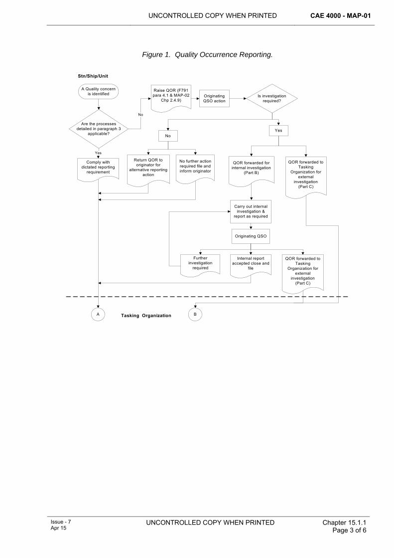
UNCONTROLLED COPY WHEN PRINTED CAE 4000 - MAP-01
Issue - 7 Apr 15
UNCONTROLLED COPY WHEN PRINTED Chapter 15.1.1 Page 3 of 6
Figure 1. Quality Occurrence Reporting.
A Quality concern is identified
Are the processes detailed in paragraph 3
applicable?
Comply with dictated reporting
requirement
Raise QOR (F791 para 4.1 & MAP-02
Chp 2.4.9)Originating QSO action
Is investigation required?
Yes
Return QOR to originator for
alternative reporting action
No further action required file and inform originator
QOR forwarded for internal investigation
(Part B)
QOR forwarded to Tasking
Organization for external
investigation(Part C)
No
Yes
Carry out internal investigation &
report as required
Originating QSO
Further investigation
required
Internal report accepted close and
file
QOR forwarded to Tasking
Organization for external
investigation(Part C)
Stn/Ship/Unit
No
A BTasking Organization
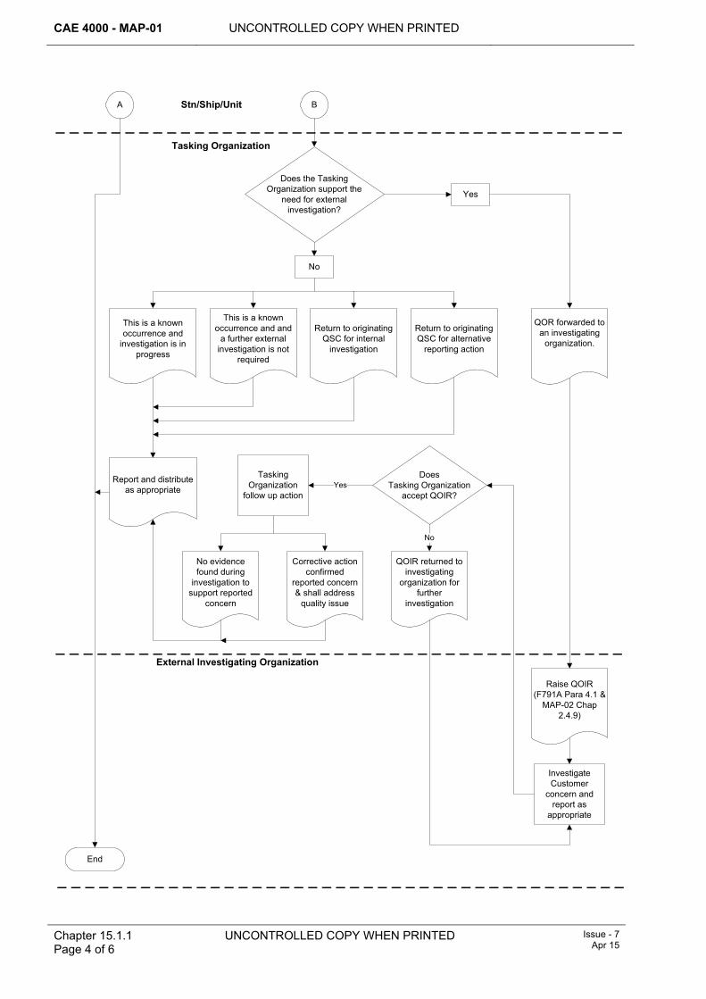
CAE 4000 - MAP-01 UNCONTROLLED COPY WHEN PRINTED
Does the Tasking Organization support the
need for external investigation?
No
This is a known occurrence and
investigation is in progress
This is a known occurrence and and
a further external investigation is not
required
Return to originating QSC for internal
investigation
Return to originating QSC for alternative
reporting action
Yes
Stn/Ship/Unit
External Investigating Organization
A B
Tasking Organization
End
QOR forwarded to an investigating
organization.
Report and distribute as appropriate
Raise QOIR (F791A Para 4.1 &
MAP-02 Chap 2.4.9)
Investigate Customer
concern and report as
appropriate
No evidence found during
investigation to support reported
concern
Tasking Organization
follow up action
Does Tasking Organization
accept QOIR?
Corrective action confirmed
reported concern & shall address
quality issue
QOIR returned to investigating
organization for further
investigation
No
Yes
Chapter 15.1.1 Page 4 of 6
UNCONTROLLED COPY WHEN PRINTED Issue - 7 Apr 15
UNCONTROLLED COPY WHEN PRINTED CAE 4000 - MAP-01
Issue - 7 Apr 15
UNCONTROLLED COPY WHEN PRINTED Chapter 15.1.1 Page 5 of 6
The Quality System Co-ordinator (QSC), or his nominated representative, at each Stn/Ship/Unit must be the focal point for registration, co-ordination and efficient progression of quality reports. To facilitate precise monitoring, the QSC must maintain separate registers for quality reports originating within the Stn/Ship/Unit and those received from external organizations. Quality report registers must be made available during both internal and external quality audits.
Where an omnibus quality report is raised to report a particular quality concern that is evident on a number of items of same-type equipment, it is only necessary to report one item. However, for statistical purposes, the number of items covered by the omnibus report must be used as the quality reporting tally.
4.1 Quality occurrence reporting forms The forms used for quality occurrence reporting are:
1 MOD F791 – Quality Occurrence Report (QOR).
2 MOD F791A – Quality Occurrence Investigation Report (QOIR).
The instructions for use can be found in MAP-02 Chapter 2.4.9. The forms are used to report a perceived quality occurrence and respective follow-up investigation, if required.
Each QOR must be allocated a unique reference number that complies with the following format:
QOR/ {organization} / {location} / {year} / {in-year counter}
The organization is the originator’s Stn/Ship/Unit, the location code is as detailed in Chapter 0.6 and the year and in-year counters are 4 and 3 figure identifiers. For example, the third QOR raised by 10 Sqn based at RAF Brize Norton in 2014 would be QOR/10/BZN/2014/003.
For QORs originated by Depth organizations, the organization is the originator’s business abbreviation and the location code must be the first half of the Postal Code related to the business location. As examples, the third QOR raised by BAE Systems working out of RAF Marham in 2014 would be QOR/BAESYSTEMS/PE33/2014/003 and the second QOR raised by the Tornado PT at RAF Marham in 2014 would be QOR/TOR/LE15/2014/002.
All subsequent documentation (including the QOIR) must quote this reference number.
4.2 Actions on receipt of quality occurrence forms 4.2.1 Receipt of a QOR from the originator or tasking organization
On receipt of a QOR, the Quality System Owner (QSO) or nominated representative must determine subsequent action, as appropriate; and reply to the originator within 7 working days.
4.2.2 Receipt of a QOR by an investigating organization The investigating organization must complete the required investigation within 28 working days of receiving the QOR and provide a report on MOD F791A (QOIR) to the QSC or nominated representative of the tasking organization.
Where the return of aviation materiel is required to aid the QOR investigation, the tasking organization must issue the call-forward/return instruction. The 28-day
CAE 4000 - MAP-01 UNCONTROLLED COPY WHEN PRINTED
Chapter 15.1.1 Page 6 of 6
UNCONTROLLED COPY WHEN PRINTED Issue - 7 Apr 15
investigation and reporting period will commence from the date of materiel receipt from the supply chain.
Note:
In any event where it is, or becomes, unlikely that the 28-day QOR investigation/reporting time-scale can be achieved; authority to delay the investigation must be sought from the tasking organization.
On occasions where the investigating organization is unable to confirm a reported concern, it is particularly important that the investigating organization provide as much information as possible, including that of any non-related deficiencies or faults that may have been discovered during the investigation. Such feedback gives the customer an improved understanding of the equipment and systems, and it will also serve to build customer confidence in the supplier’s arrangements for achieving quality.
4.2.3 Receipt of a QOIR by the tasking organization On receipt of the QOIR, the QSC or nominated representative must determine what action is required and complete part B of the QOIR within 7 working days.
5 Associated documentation There is no dedicated QOR labelling for aviation materiel. However, to assist in identification, tracking and retrieval of returned aviation materiel from the supply chain, the respective MOD Form 731 must include the following entry in the ‘Remarks’ box or the ‘Reasons for Removal’ box:
‘QOR [Reference Number]: Return to [Name of the investigating organization]’
UNCONTROLLED COPY WHEN PRINTED
CAE 4000 - MAP-01
MAE Issue - 6 Mar 14
UNCONTROLLED COPY WHEN PRINTED
Chapter 15.2 Page 1 of 4
Chapter 15.2
Quality Auditing
TABLE OF CONTENTS Paragraph
Page
1 General ............................................................................................................... 1 1.1 Introduction.......................................................................................................... 1 1.2 Associated publications....................................................................................... 1 1.3 Scope .................................................................................................................. 1 2 Regulatory Governance.................................................................................... 2 2.1 Regulatory Cross-reference ................................................................................ 2 2.2 Additional Information.......................................................................................... 2 3 Audit mechanism .............................................................................................. 2 4 Audit programmes ............................................................................................ 2 5 Audit preparation, constitution and reporting................................................ 3 5.1 Audit preparation ................................................................................................. 3 5.2 Audit constitution ................................................................................................. 3 5.3 Audit reporting ..................................................................................................... 3 5.4 Audit documentation............................................................................................ 4 6 Reference ........................................................................................................... 4
1 General 1.1 Introduction
Auditing is an essential part of any Quality Management System (QMS). It is used to provide feedback to management at all levels on the effectiveness of policies, plans, processes and documented procedures. In particular, quality audits:
1 Provide objective evidence of compliance with the standard or relevant documented procedures.
2 Evaluate the organization's effectiveness in terms of output, task and resources.
3 Identify levels of efficiency and subsequent areas for improvement.
4 Measure customer satisfaction both within an organization and at its boundaries.
1.2 Associated publications This chapter is associated with the following publications:
1 BS EN ISO 9001 – Quality Management Systems – Requirements.
2 ISO 19011 – Guidelines for quality and/or environmental management systems auditing.
1.3 Scope This Acceptable Means of Compliance, Guidance Material and associated processes applies to all Forward and Depth engineering and logistics activities within the Military Air Environment (MAE) that provide air engineering and logistics support to fixed and rotary wing aircraft and to Remotely Piloted Air Systems (RPAS).
CAE 4000 - MAP-01 UNCONTROLLED COPY WHEN PRINTED
Chapter 15.2 Page 2 of 4
UNCONTROLLED COPY WHEN PRINTED MAE Issue - 6
Mar 14
2 Regulatory Governance 2.1 Regulatory Cross-reference
This chapter supports:
1 RA 4815.
2.2 Additional Information These audits are only to be undertaken by personnel that are appropriately trained, qualified and authorized to conduct or participate in quality audits. All auditors must be competent and authorized to audit in accordance with their organizational requirements.
3 Audit mechanism The primary auditing mechanisms are External Quality Audits (EQA) and Internal Quality Audits (IQA); these are supported by Self Audits (SA). Risk-based surveillance audits may be undertaken within Depth organizations by Government Quality Assurance Representatives (GQARs) as tasked by the Project Team (PT).
1 EQAs are managed by Front Line Command (FLC) and audit Forward organizations. The PT may task FLCs to undertake an EQA in the non-contractor parts of Depth. EQAs are used to obtain confirmation of the continued effectiveness of a unit’s QMS. An EQA will normally be a wholly system-based audit; however, an element of compliance will be necessary to verify the effectiveness of IQA procedures. The EQA Team may comprise of representatives from all FLCs.
2 IQAs are managed at Stn/Ship/Unit level in order to ensure that units have an effective QMS. There will be a greater in-depth review of compliance during the audit in order to substantiate or verify issues highlighted during the system phase.
3 SAs are local (often down to sub-unit level) to determine compliance with procedures. SAs provide documentary evidence, which may be reviewed during EQA or IQA activity.
4 GQAR risk-based surveillance audits are as tasked by the PT on perceived contractual risks and are carried out within Depth organizations.
5 Partnering Audit Arrangements may be used within the MAE to enable FLCs to work with the GQAR organization, PT and Prime Contractor when auditing contractual quality requirements to support the MoD Forward/Depth construct. Guidance on Partnering Audit Arrangements is in the Acquisition Operating Framework (AOF).
4 Audit programmes Audit programmes must be generated by FLCs for EQAs and by the respective Stn/Ship/Unit for IQAs. Where possible, FLCs must plan and co-ordinate their respective EQA activity to ensure that all elements of the management system are reviewed, without omission, or unnecessary overlap or duplication. For example, specific elements of an Army unit ‘TECHEVAL’ would meet some of the requirements of an EQA.
Audits must be carried out as follows:
1 EQA – at least every 2 years.
UNCONTROLLED COPY WHEN PRINTED CAE 4000 - MAP-01
MAE Issue - 6 Mar 14
UNCONTROLLED COPY WHEN PRINTED
Chapter 15.2 Page 3 of 4
2 IQA – at least once within the Stn/Ship/Unit audit cycle.
3 GQAR and Partnering Audit Programmes – to be generated by the GQAR organization and related to risk-based tasking from the PT.
Note:
More frequent audits may be programmed at the discretion of Stn/Ship/Unit, FLC or PT, particularly where activities are considered to present a higher risk of nonconformity, or where nonconformity could present an airworthiness concern.
5 Audit preparation, constitution and reporting 5.1 Audit preparation
The Audit Team Leader (ATL) is responsible for planning and supervising the audit's activities. The preparation phase of an audit should comprise the following elements:
1 Selecting team member(s) (ensuring personnel are competent to undertake audits).
2 Establishing contact with a representative of the organization to be audited to arrange the date/times of audit, scope of audit and to confirm overall administrative arrangements.
3 Issuing written notice of audit (include decisions made during the initial contact).
4 Collating and researching audit criteria, including quality manuals, operating procedures, previous audit reports, Quality Occurrence Reports (QORs), etc, noting any themes or areas for attention.
5 Generating an audit plan. The plan should be formulated to minimize disruption to the normal working patterns.
5.2 Audit constitution The actual audit should comprise the following elements:
1 An opening meeting to brief line management on the scope and objectives of the audit. The meeting plays a key role in introducing the audit team members to line management and represents the first step in opening the channels of communication that are essential to the audit process.
2 The generation of Audit Records so that quality issues can be documented, addressed and resolved. EQAs, IQAs and SAs must be recorded on the MOD F792, MOD F792A and MOD F792B; all other audits may be recorded on the MOD F792, MOD F792A and MOD 792B or equivalent organizational form.
3 Regular line manager briefings on the progress of the audit to discuss and resolve, where possible, any areas of contention or concern. These are usually carried out daily.
4 Audit team briefings to ensure that the audit is proceeding to plan and allow the ATL to discuss any issues with individual team members.
5.3 Audit reporting Upon completion of the audit, the ATL must hold a closing meeting to present the overall audit findings to line management. A summary of the scope and objectives of the audit should be repeated for reference, together with confirmation of any areas or processes not audited as originally planned. All outstanding audit findings must be discussed; where non-conformances are identified a QOR (MOD F791) should be raised in accordance with RA 4815 and Chapter 15.1.1. There may be instances
CAE 4000 - MAP-01 UNCONTROLLED COPY WHEN PRINTED
Chapter 15.2 Page 4 of 4
UNCONTROLLED COPY WHEN PRINTED MAE Issue - 6
Mar 14
where it is considered a QOR is not required to record a non-conformance; however, all non-conformances should be recorded in the audit report.
The ATL must produce an Audit Report (MOD F792B) within 10 working days, summarizing the general findings and including details of any QORs or non-conformances raised. The report must be distributed as follows:
1 EQA: Distribution in accordance with FLC policy.
2 IQA: Distribution determined by the Quality System Coordinator (QSC).
3 GQAR: Distribution determined by the GQAR organization and tasking PT.
4 Partnering Audit Arrangement: Distribution as agreed in the Partnering Audit agreement.
The management for the area being audited is responsible for ensuring that all QORs and identified non-conformances are addressed and corrective actions are undertaken to eliminate the identified issues and their causes. Time scales must be agreed with the ATL.
To verify that all corrective actions are satisfactorily completed, the ATL shall conduct an audit follow-up.
5.4 Audit documentation Quality audit documentation must be retained and made available, as required, for review by the next higher auditing authority (EQA/IQA). Audit documentation retention periods must be specified by the auditing authority.
6 Reference This chapter makes reference to the following web site:
1 Guidance for a Partnering Audit Arrangement between Industry and the UK MOD within the Military Environment. (http://www.aof.dii.r.mil.uk/aofcontent/tactical/quality/content/assuringqual/partneringmae.htm)
UNCONTROLLED COPY WHEN PRINTED CAE 4000 - MAP-01
MAE Issue - 3 Jul 12
UNCONTROLLED COPY WHEN PRINTED End of Data Module
Chapter 16.1.2 Page 1 of 1
Chapter 16.1.2
Sustaining Structural Integrity
TABLE OF CONTENTS Paragraph
Page
1 ............................................................................................................... 1 General1.1 .......................................................................................................... 1 Introduction
1 General 1.1 Introduction
This chapter was transferred to RA 5720 during the MARDS rewrite. This Ghost Chapter is left in as a signpost for the reader.
Although the content of this Chapter has transferred, it retains the requirement for two related engineering authorizations; MAP-B473 and MAP-J432.