Embed Size (px)
Citation preview
http://pic.sagepub.com/Engineering Science
Engineers, Part C: Journal of Mechanical Proceedings of the Institution of Mechanical
http://pic.sagepub.com/content/215/1/65The online version of this article can be found at:
DOI: 10.1243/0954406011520526
215: 65 2001Proceedings of the Institution of Mechanical Engineers, Part C: Journal of Mechanical Engineering Science
H Ouyang and J E MottersheadOptimal suppression of parametric vibration in discs under rotating frictional loads
Published by:
http://www.sagepublications.com
On behalf of:
Institution of Mechanical Engineers
can be found at:Engineering ScienceProceedings of the Institution of Mechanical Engineers, Part C: Journal of MechanicalAdditional services and information for
http://pic.sagepub.com/cgi/alertsEmail Alerts:
http://pic.sagepub.com/subscriptionsSubscriptions:
http://www.sagepub.com/journalsReprints.navReprints:
http://www.sagepub.com/journalsPermissions.navPermissions:
http://pic.sagepub.com/content/215/1/65.refs.htmlCitations:
What is This?
- Jan 1, 2001Version of Record >>
at University of Liverpool on March 20, 2014pic.sagepub.comDownloaded from at University of Liverpool on March 20, 2014pic.sagepub.comDownloaded from
Optimal suppression of parametric vibration in discsunder rotating frictional loads
H Ouyang and J E Mottershead*
Department of Engineering, The University of Liverpool, UK
Abstract: This paper investigates the parametric resonances of a stationary disc excited by a rotating
frictional load and in¯ uenced by a series of mass± spring± damper systems with or without friction.
The genetic algorithm is used to ® nd out the right number of mass± spring± damper systems and their
optimal positions in order to reduce and even eliminate the dynamic instability caused by the rotating
friction as a follower force on the disc surface. It is found that, if these mass± spring± damper systemsinvolve no or low friction, they can reduce or suppress the dynamic instability of friction-induced
parametric resonances when correctly located, but they have, at best, no eŒect when the level of
friction is high.
Keywords: disc, parametric resonance, dynamic instability, stabilizer, dry friction, genetic algorithm
NOTATION
a; b inner and outer radii of the disc
c; f; k; m damping, friction force, stiŒness and mass
of the exciter respectively
cj; fj; kj; mj damping, friction force, stiŒness and mass
of the j th stabilizer respectively
D ¯ exural rigidity of the disc
D¤ Kelvin-type damping coe� cient of thedisc
E Young’ s modulus of the disc material
h thickness of the disc
i ¡1p
qkl…qrs† modal coordinate for k…r† nodal circles
and l…s† nodal diameters for the disc
r radial coordinate in the cylindrical
coordinate system
r0; rj initial radial positions of the exciter andthe jth stabilizer respectively
Rkl combination of Bessel functions to
represent the mode shape of the disc in the
radial direction
t time
w de¯ ection of the disc in the cylindrical
coordinate system
¯…¢† Dirac delta function
¯kl Kronecker delta
³ circumferential coordinate in the
cylindrical coordinate system
³j initial angular position of the jth
stabilizer
l characteristic exponent in exp…il½† whichdescribes the dynamic response of the disc
in the time domain
¸ Poisson’ s ratio of the disc material
¹ damping coe� cient of the disc …ˆ D¤=2D†» mass density of the disc
¼ detuning parameter
Âkl mode shape function for the transverse
vibration of the disc corresponding to qkl
!kl natural (circular) frequency
corresponding to qkl~« constant rotating speed of the disc (rad/s)
1 INTRODUCTION
There are many mechanical devices that involve a disc
and an auxiliary system in relative rotation, such as car
disc brakes, computer discs and circular saw blades.
There have also been many investigations into the
dynamic instability of such devices. Early researchincludes a stationary disc excited by a rotating load [1, 2]
or a spinning disc past a stationary load [3]. All these
studies pointed out that the system could become
unstable at some speci® c values of system parameters
(such as mass and stiŒness) and running conditions evenwhen friction between the two contacting components in
The MS was received on 24 June 1999 and was accepted after revisionfor publication on 10 February 2000.* Corresponding author: Department of Engineering, The University ofLiverpool, Brownlow Hill, Liverpool L69 3GH, UK.
65
C09099 ß IMechE 2001 Proc Instn Mech Engrs Vol 215 Part C at University of Liverpool on March 20, 2014pic.sagepub.comDownloaded from

relative rotation is absent. A spinning disc subjected to
stationary frictional load was studied by Ono et al. [4].The friction force modelled as a follower force made the
system more unstable. The transverse vibration of a
stationary disc excited by a rotating mass± spring± dam-
per system or a pad with dry friction can become
unstable under certain circumstances in the subcritical
range [5, 6]. It has been shown that the rotating frictionas a follower force is highly destabilizing. The rotating
mass is similarly destabilizing. A comprehensive survey
of friction-induced instabilities in discs can be found in
reference [7]. From previous experience on the analysis
of the dynamic instabilities of discs, it is very likely thatthe addition of one (or several) rotating mass± spring±
damper system can suppress excessive vibration when
used carefully.
The study and prevention of unstable vibration is
very important in industry. Excessive vibration cangenerate oŒensive noises and degrade the performance
of machinery. It causes major concern about the
reliability and quality of components. These practical
problems can be approximated as a rotating-load-on-
stationary-disc model or a stationary-load-on-rotating-
disc model. One way of eliminating the dynamicinstability as a result of parametric resonances in these
problems is to use stabilizers. The stabilizers are ide-
ally dampers but may contain mass and stiŒness and
even introduce friction in practice. This paper sets out
to ® nd the number of such stabilizers and their opti-mal positions so that best dynamic stability perfor-
mance can be achieved by using the genetic algorithm,
which has not been applied before to the stabilizer
optimization problem. It is found from numerical
simulations that low-friction stabilizers are very eŒec-tive in reducing vibration but high-friction stabilizers
are not.
2 FRICTION-INDUCED PARAMETRIC
RESONANCES OF THE DISC
A circular disc, modelled as a thin plate, excited by arotating mass± spring± damper system initially located at
…r; ³† ˆ …r0; 0†, and acted on by a series of rotating mass±
spring± damper systems initially located at …r; ³† ˆ…rj; ³j†, j ˆ 1; 2; . . . ; is shown in Fig. 1. The friction
between the mass± spring± damper systems and the disc ismodelled as a follower force [5]. The follower force
hypothesis means that the tangential friction force fol-
lows the deformed surface of the disc and changes its
direction when the disc vibrates. As a result, the follower
force has a transverse component when the disc deformsduring vibration. The equation of the transverse motion
of the whole system in a cylindrical coordinate system® xed to the disc centre is
»h@2w
@t2‡ D¤r4 _w ‡ Dr4w
ˆ ¡ 1
r¯…r ¡ r0†¯…³ ¡ ~« t†
£ m@
@t‡ ~«
@
@³
2
‡c@
@t‡ ~«
@
@³‡ k ¡ f
@
r@³w
¡ 1
rjˆ1
¯…r ¡ rj†̄ …³ ¡ ~« t ¡ ³j†
£ mj@
@t‡ ~«
@
@³
2
‡cj@
@t‡ ~«
@
@³‡ kj ¡ fj
@
r@³w
…1†
where the terms in the ® rst square bracket on the right-hand side of equation (1) represent the active force from
the exciter which can cause dynamic instability of the
disc. The terms in the second square bracket represent
the passive mechanisms, referred to as the stabilizers.
Though they could cause instability when wrongly used,
they are intended to stabilize the unstable vibrationcaused by the rotating friction load. Ideally, only a series
of dampers should be used to stabilize the vibrations. In
general, however, a damper may also involve some mass
and some stiŒness represented by a simple spring in this
article. Therefore, if the values of the additional massesand spring constants are ill chosen, or the positions of
these discrete mass± spring± damper systems are not
located in the right positions, they will not suppress the
unstable vibration and could well increase the instabil-
ity. As the dampers are also in contact with the discsurface, a certain amount of friction exists between the
Fig. 1 Circular disc with the exciter and the stabilizer
66 H OUYANG AND J E MOTTERSHEAD
Proc Instn Mech Engrs Vol 215 Part C C09099 ß IMechE 2001 at University of Liverpool on March 20, 2014pic.sagepub.comDownloaded from
dampers and the disc surface. This work ® rst determines
the regions of instability corresponding to diŒerentsystem parameters and running conditions and then
seeks to establish the `optimal positions’ of the stabi-
lizers so as to reduce the likelihood of dynamic
instability. The number of such stabilizers is also dis-
cussed.
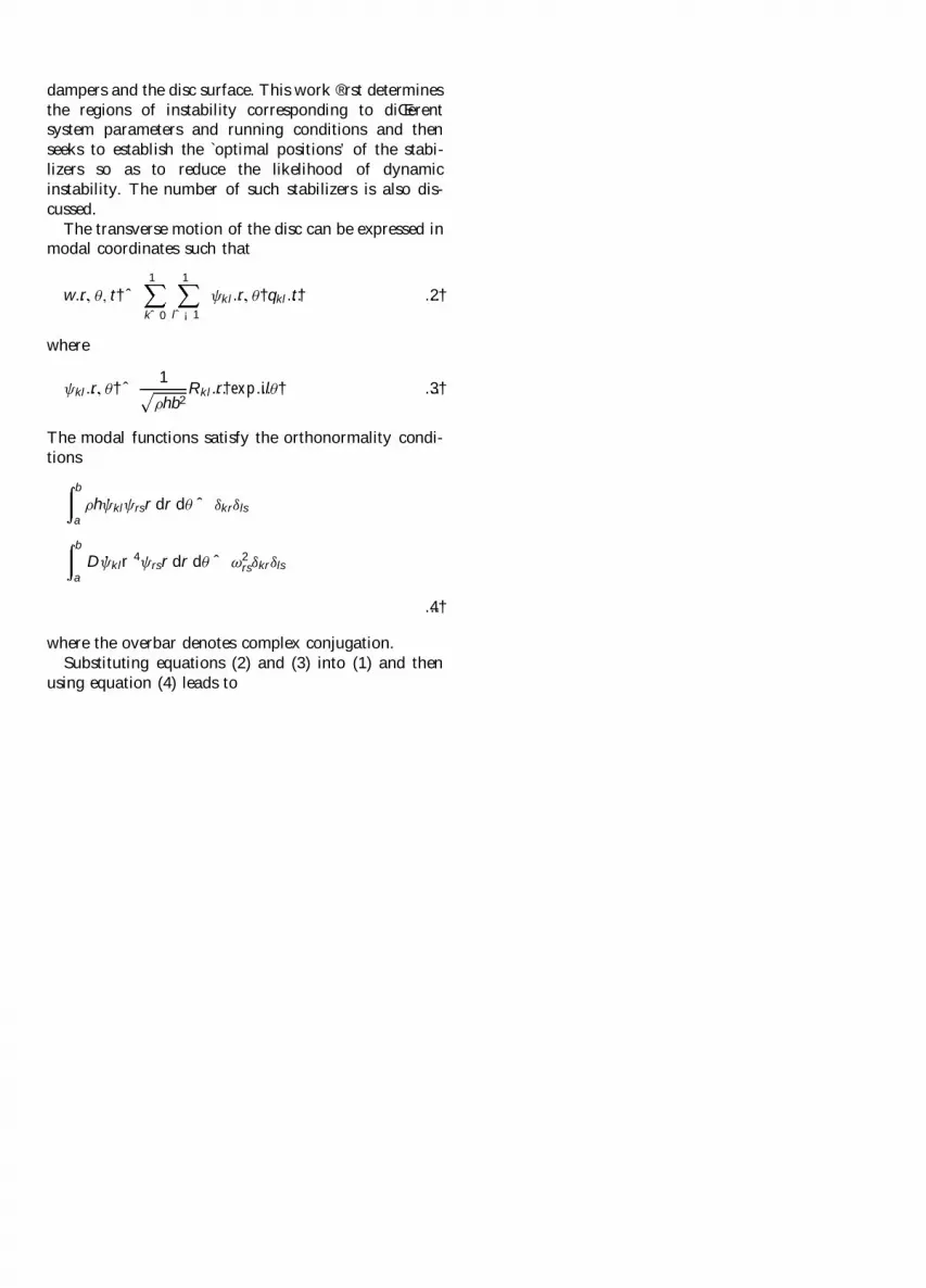
The transverse motion of the disc can be expressed inmodal coordinates such that
w…r; ³; t† ˆ1
kˆ0
1
lˆ¡1Âkl…r; ³†qkl…t† …2†
where
Âkl…r; ³† ˆ 1
»hb2Rkl…r†exp…il³† …3†
The modal functions satisfy the orthonormality condi-
tions
b
a
»h ·ÂklÂrsr dr d³ ˆ ¯kr¯ls
b
a
D ·Âklr4Ârsr dr d³ ˆ !2rs¯kr¯ls
…4†
where the overbar denotes complex conjugation.
Substituting equations (2) and (3) into (1) and then
using equation (4) leads to
�qkl ‡ 2¹!2kl _qkl ‡ !2
klqkl
ˆ ¡ 1
»hb2
1
rˆ0
1
sˆ¡1Rrs…r0†Rkl…r0†exp‰i…s ¡ l † ~« tŠ
£ m… �qrs‡i2s ~« _qrs ¡ s2 ~«2qrs† ‡ c… _qrs‡is ~« qrs†
‡ k ¡ isf
r0
qrs
¡ 1
»hb2j
1
rˆ0
1
sˆ¡1Rrs…rj†
£ Rkl…rj†exp‰i…s ¡ l †… ~« t ‡ ³j†Š
£ mj… �qrs‡i2s ~« _qrs ¡ s2 ~«2qrs† ‡ cj… _qrs‡is ~« qrs†
‡ kj ¡isfj
rjqrs …5†
Equation (5) is an in® nite system of Hill’ s equations.
Therefore, only an approximate solution may be found.
The dynamic behaviour of equation (5) is determined bythe system parameters and operating conditions. The
disc can be unstable at some particular values of the
system parameters and operating conditions in thesubcritical speed range because the rotating friction is
represented as a follower force. The instability thus
caused is also referred to as a parametric resonance since
it is caused by cyclical variation of the system para-
meters and not by an external applied load.
3 METHOD OF MULTIPLE SCALES
When any one of the parameters of the rotating mass±
spring± damper systems after scaling is very small, a
perturbation method may be used, which can reduce the
amount of computation that would be necessary by
using other methods such as the state-space method.
The method of multiple scales [8] is particularly suitablefor solving the above problem, and similar problems
[5, 9].
To use the method of multiple scales, the following
new variables are introduced so that a common small
parameter can be extracted from equation (5) which canthen be simpli® ed:
½ ˆ !crt; kl ˆ !kl
!cr; « ˆ
~«
!cr
…6†
where
!cr ˆ min!kl
l; k ˆ 0; 1; 2; . . . ; l ˆ 1; 2; . . . …7†
Substitution of equations (6) and (7) into equation (5)
yields
d2qkl
d½2‡ 2¹!cr
2kl
dqkl
d½‡ 2
klqkl
ˆ ¡1
rˆ0
1
sˆ¡1Rrs…r0†Rkl…r0†exp‰i…s ¡ l †«½Š
£ m
»hb2
d
d½‡ is«
2
qrs‡c
»hb2!cr
d
d½‡ is« qrs
‡k
»hb2!2cr
¡isf
r0»hb2!2cr
qrs
¡j
1
rˆ0
1
sˆ¡1Rrs…rj†Rkl…rj†exp‰i…s ¡ l †…«½ ‡ ³j†Š
£ mj
»hb2
d
d½‡ is«
2
qrs ‡ cj
»hb2!cr
d
d½‡ is« qrs
‡ kj
»hb2!2cr
¡ isfj
rj»hb2!2cr
qrs …8†
A small perturbation parameter, ", is introduced withthe purpose of scaling the system parameters in equation
OPTIMAL SUPPRESSION OF PARAMETRIC VIBRATION IN DISCS 67
C09099 ß IMechE 2001 Proc Instn Mech Engrs Vol 215 Part C at University of Liverpool on March 20, 2014pic.sagepub.comDownloaded from
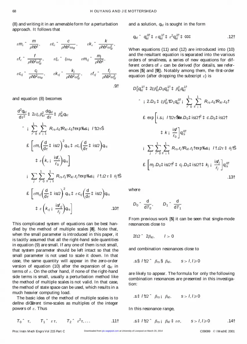
(8) and writing it in an amenable form for a perturbation
approach. It follows that
"m" ˆ m
»hb2; "c" ˆ c
»hb2!cr; "k" ˆ k
»hb2!2cr
;
"f" ˆ f
»hb2!2cr
; "¹" ˆ ¹!cr "m"j ˆ mj
»hb2;
"c"j ˆ cj
»hb2!cr; "k"j ˆ kj
»hb2!2cr
; "f"j ˆ fj
»hb2!2cr
…9†
and equation (8) becomes
d2qkl
d½2‡ 2"¹"
2kl
dqkl
d½‡ 2
klqkl
ˆ ¡1
rˆ0
1
sˆ¡1Rrs…r0†Rkl…r0†exp‰i…s ¡ l †«½Š
£ "m"d
d½‡ is«
2
qrs ‡ "c"d
d½‡ is« qrs
‡ " k" ¡ isf"
r0
qrs
¡j
1
rˆ0
1
sˆ¡1Rrs…rj†Rkl…rj†exp‰i…s ¡ l †…« ½ ‡ ³j†Š
£ "m"jd
d½‡ is«
2
qrs ‡ " c"jd
d½‡ is« qrs
‡ " k"j ¡isf"j
rjqrs …10†
This complicated system of equations can be best han-
dled by the method of multiple scales [8]. Note that,
when the small parameter is introduced in this paper, it
is tacitly assumed that all the right-hand side quantitiesin equation (9) are small. If any one of them is not small,
that system parameter should be left intact so that the
small parameter is not used to scale it down. In that
case, the same quantity will appear in the zero-order
version of equation (10) after the expansion of qkl interms of ". On the other hand, if none of the right-hand
side terms is small, usually a perturbation method like
the method of multiple scales is not valid. In that case,
the method of state space can be used, which results in a
much heavier computing load.
The basic idea of the method of multiple scales is tode® ne diŒerent time-scales as multiples of the integer
powers of ". Thus
T0 ˆ ½; T1 ˆ " ½; T2 ˆ "2½; . . . …11†
and a solution, qkl is sought in the form
qkl ˆ q…0†kl ‡ " q
…1†kl ‡ "2q
…2†kl ‡ ¢ ¢ ¢ …12†
When equations (11) and (12) are introduced into (10)and the resultant equation is separated into the various
orders of smallness, a series of new equations for dif-
ferent orders of " can be derived (for details, see refer-
ences [5] and [9]). Notably among them, the ® rst-order
equation (after dropping the subscript ") is
D20q
…1†kl ‡ 2¹ 2
klD0q…1†kl ‡ 2
klq…1†kl
ˆ ¡2…D0 ‡ ¹ 2kl†D1q
…0†kl ¡
1
rˆ0
1
sˆ¡1Rrs…r0†Rkl…r0†
£ exp i…s ¡ l †«½Š‰m…D0‡is«†2 ‡ c…D0‡is«†
‡ k ¡ isf
r0
q…0†rs
¡j
1
rˆ0
1
sˆ¡1Rrs…rj†Rkl…rj†exp‰i…s ¡ l †…«½ ‡ ³j†Š
£ mj…D0‡is«†2 ‡ cj…D0‡is«† ‡ kj ¡isfj
rjq…0†
rs
…13†
where
D0 ˆ d
dT0; D1 ˆ d
dT1
From previous work [5] it can be seen that single-mode
resonances close to
2l« ˆ 2 kl; l > 0
and combination resonances close to
…s § l †« ˆ rs § kl; s > l; l50
are likely to appear. The formula for only the following
combination resonances are presented in this investiga-tion:
…s ‡ l †« ˆ rs ¡ kl; s > l; l50
In this resonance range,
…s ‡ l †« ˆ rs ¡ kl ‡ "¼; s > l; l50 …14†
68 H OUYANG AND J E MOTTERSHEAD
Proc Instn Mech Engrs Vol 215 Part C C09099 ß IMechE 2001 at University of Liverpool on March 20, 2014pic.sagepub.comDownloaded from

and the equation for determining the characteristic
exponent l is
2 rs…l ‡ ¼† ¡ 2i¹ 3rs ¡ R2
rs…r0† ·D¡0rs ¡
j
R2rs…rj† ·D¡j
kl
£ 2 kll ¡ 2i¹ 3kl ¡ R2
kl…r0†D‡0kl ¡
j
R2kl…rj†D‡j
kl
¡ Rkl…r0†Rrs…r0† ·D¡0rs ‡
j
Rkl…rj†Rrs…rj† ·D¡jrs
£ exp‰¡i…s ‡ l †³jŠ
£ Rkl…r0†Rrs…r0†D‡0kl ‡
j
Rkl…rj†Rrs…rj†D‡jkl
£ exp‰i…s ‡ l †³jŠ ˆ 0 …15†
where
D‡0kl ˆ ¡m… kl ‡ l«†2 ‡ i‰c… kl ‡ l«† ¡ lf Š ‡ k
D¡0kl ˆ ¡m… kl ¡ l«†2 ¡ i‰c… kl ¡ l«† ‡ lf Š ‡ k
D‡jkl ˆ ¡mj… kl ‡ l«†2 ‡ i‰cj… kl ‡ l«† ¡ lfjŠ ‡ kj
D¡jkl ˆ ¡mj… kl ¡ l«†2 ¡ i‰cj… kl ¡ l«† ‡ lfjŠ ‡ kj
…16†
As mentioned before, diŒerent values of the system
parameters and operating conditions (parameter) bring
about diŒerent dynamic behaviour in terms of dynamic
stability. It is a common practice to show the areaswhere instability appears on a parameter plane, for
example, on a plane where the rotating speed of the disc
is the ordinate and the friction force is the abscissa.
When the areas of instability (referred to as regions of
instability) on each plane of every pair of system para-meter± operating conditions are obtained, a global pic-
ture of the dynamic stability in¯ uenced by all the system
parameters and operating conditions can be conceived.
The condition where a pair of l have purely real roots
de® nes the transition curves which divide the parameter
plane into regions of stability and regions of instability.The regions of instability have a characteristic wedge-
like appearance [5] in the parameter plane, the areas of
which can be characterized by their width "¼ at a pre-
scribed value of the system parameter (abscissa) con-
cerned. Therefore, the total width of all the regions ofinstability on a parameter plane, denoted by "¼, is a
measure of the degree of dynamic instability of the
whole system. Usually, the regions of instability on a
parameter plane overlap. In that case, "¼ is not the
simple sum of the width of each individual region ofinstability. Rather, it is the overall width of all the
combined regions of instability in that plane. Another
phenomenon should also be noted, namely that, whenthe width of an individual region of instability decreases,
the tip of this wedge-like region tends to move to the
right, resulting in a smaller area, i.e. reduced instability.
4 EFFECT OF THE STABILIZERS
Without the stabilizers, the regions of instability of thedisc excited by the rotating exciter can be quite large,
depending on the values of the system parameters and
operating conditions. Adding additional dampers alone
can reduce instability. Here, it is intended to investigate
how additional mass± spring± damper stabilizers aŒect
the dynamic instability and how instability can be
reduced by optimal positioning of these stabilizers. Thegenetic algorithm (GA) is suitable for this purpose.
The GA is a numerical search technique simulating
the process of natural evolution. A feasible solution is
represented by a binary string, which is analogous to achromosome in a biological system [10]. The genetic
algorithm works with a population of such strings.
Within an evolution cycle, there are three basic opera-
tions on these strings: reproduction, crossover and
mutation. A speci® c example will be used to demon-strate how it is used.
The surface of the annular disc is conceptually
discretized into 4 £ 32 small cells by a uniformly dis-
tributed mesh of diameters and circles, as illustrated in
Fig. 2. Another way of describing the conceptually dis-
cretized disc is that it consists of four concentric circles
(circles 1 to 4 from the inner radius to the outer radius)of cells. As there are 128 ˆ 27 cells altogether, each cell
can be represented by a 7-digit binary string. Suppose
three stabilizers are used, which are located at the cen-
tres of three of these cells. The three 7-digit strings,
which represent the three cells the stabilizers occupy, are
Fig. 2 Annular disc conceptually discretized into four circles
of cells
OPTIMAL SUPPRESSION OF PARAMETRIC VIBRATION IN DISCS 69
C09099 ß IMechE 2001 Proc Instn Mech Engrs Vol 215 Part C at University of Liverpool on March 20, 2014pic.sagepub.comDownloaded from
The intention is to study the regions of instability of the
disc under the in¯ uence of the exciter and the stabilizers
and then determine the optimal positions of the stabi-
lizers so as to have the smallest regions of instability, i.e.to minimize "¼. Here, a very brief description is given
of how the GA is used for this purpose.
Initially, choose randomly a number of 7-digit binary
strings and form a set of 21-digit binary strings in the
case of three stabilizers. Calculate "¼ for all possiblecombination resonances from equation (15) according
to the positions that every 21-digit binary string repre-
sents and add them together to get "¼. Those strings
resulting in small "¼ are deemed ® t for subsequent
reproduction:
1. Reproduction. This is a process where the ® t strings
are incorporated into the mating pool, in which the
number of appearances of the ® t strings is deter-
mined by the weighted roulette wheel rule [10].
2. Crossover. The strings deemed ® t for reproductionin the mating pool are randomly chosen to form
couples. Each couple exchanges part of their strings
to produce oŒspring.
3. Mutation. Mutation modi® es a small fraction of a
string, ¯ ipping 0 and 1 in that part of the string. Theauthors’ experience shows that, without mutation,
the search would usually converge to a local optimal
solution in a smaller part of the solution space,
which is spanned by the strings produced in previous
evolution cycles.
In a typical application there is a cost function which
characterizes the performance or the crucial attribute
(for example, the weight of an aircraft, the shortest route
to a destination and so on) of a system. The goal of
optimization is to minimize the cost function, "¼ inthis investigation. Those strings leading to small "¼are considered ® t and retained for reproduction. The ® t
parent strings tend to produce ® t and even ® tter oŒ-
spring strings. However, without mutation, the ® t parent
strings can only produce the ® ttest oŒspring stringwithin the solution space determined by the parent
strings. In so doing, only a local optimum is ensured
since the ® rst batch of parent strings is randomly chosen
and usually does not span the space that happens to
cover the global optimum. Therefore, mutation is
necessary to achieve a global optimum. On the other
hand, mutation and crossover may produce less ® t oŒ-
spring strings occasionally. An `orthodox’ genetic algo-rithm would not do anything about the problem since,
in the long run, un® t strings are sieved out and dis-
carded. However, computation with un® t strings takes
longer and slows down convergence to the global opti-
mum. As a result, most GA users tend to revise the pureGA to suit their need.
In this investigation, a record of poor strings pro-
duced in a previous cycle is kept and, if the poor strings
are reproduced in the next few cycles, they are discarded
and additional crossover and/or mutation operations
are performed to produce ® t strings. This record isconstantly updated. This is one of the many ideas
embraced in the so-called tabu search method [11].
Thus, a computation cycle (generation) consists of
reproduction, crossover and mutation. The reproduc-
tion is really a process of selection of ® t strings. Here,both the weighted roulette rule of an ’orthodox’ GA and
an empirical rule based on the knowledge gained about
the in¯ uence of the stabilizers are used in the selection.
The latter may be considered as a type of tabu search.
The outcome is a reduction in the number of compu-tation cycles, though each cycle becomes slightly more
complicated than when the knowledge about the speci® c
problem is not applied. Incidentally, the initial popula-
tion of the strings is also checked for ® tness. There are
other versions of the GA. When the knowledge about a
problem can be used to guide the search, a large savingcan be achieved. It is reported that, in one particular
application, the computation is reduced by 97 per cent
[12] using the GA combining speci® c knowledge about
the subject matter. Another example shows that the GA
can handle very complex optimization problems [13].The advantage of the GA over purely random search
techniques lies in its guidance from the evolution prin-
ciples. As ® tter oŒspring from the genetic algorithm
evolve, "¼ is reduced. In the end, a global minimum
of "¼ is found. If the GA is left on its own withoutintervention, the cost value would frequently ¯ uctuate,
though the general trend would be towards con-
vergence. Fluctuation of the cost value means extra
search eŒort.
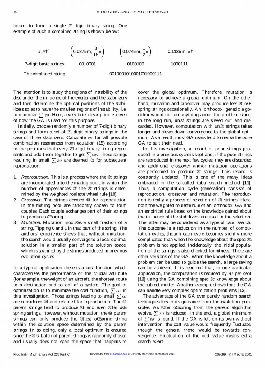
…r; ³† ˆ 0:0875m;3
16p 0:0745 m;
1
2p …0:1135 m; p†
7-digit basic strings 0010001 0100100 1000111
The combined string 0010001010001001000111
linked to form a single 21-digit binary string. One
example of such a combined string is shown below:
70 H OUYANG AND J E MOTTERSHEAD
Proc Instn Mech Engrs Vol 215 Part C C09099 ß IMechE 2001 at University of Liverpool on March 20, 2014pic.sagepub.comDownloaded from
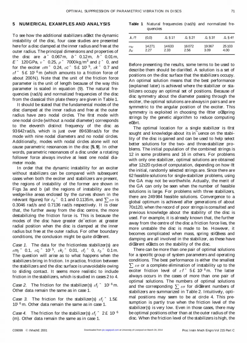
5 NUMERICAL EXAMPLES AND ANALYSIS
To see how the additional stabilizers aŒect the dynamic
instability of the disc, four case studies are presented
here for a disc clamped at the inner radius and free at the
outer radius. The principal dimensions and properties of
the disc are a ˆ 0:067 m, b ˆ 0:12 m, h ˆ 0:01 m,
E ˆ 120GPa, ¸ ˆ 0:25, » ˆ 7000 kg=m3 and ¹ ˆ 0, and
for the exciter "m ˆ 0:24, "c ˆ 5 £ 10¡5, "k ˆ 0:7 and
"f ˆ 5 £ 10¡6 m (which amounts to a friction force of
about 200 N). Note that the unit of the friction force
parameter is the unit of length because of the way this
parameter is scaled in equation (9). The natural fre-
quencies (rad/s) and normalized frequencies of the disc
from the classical thin plate theory are given in Table 1.
It should be stated that the fundamental modes of the
disc clamped at the inner radius and free at the outerradius have zero nodal circles. The ® rst mode with
one nodal circle (without a nodal diameter) corresponds
to the eleventh distinct frequency of the disc as
93 642 rad/s, which is just over 89 638 rad/s for the
mode with nine nodal diameters and no nodal circles.Additionally, modes with nodal circles alone will not
cause parametric resonances in the disc [5, 9]. In other
words, parametric resonances of a disc under a rotating
follower force always involve at least one nodal dia-
meter mode.In order that the dynamic instability for an exciter
without stabilizers can be compared with subsequent
cases when both the exciter and stabilizers are present,
the regions of instability of the former are shown in
Figs 3a and b (all the regions of instability are the
wedge-like areas enclosed by the curves shown in therelevant ® gures) for r0 ˆ 0:1 and 0.1135m, and "¼ is
0.3046 rad/s and 0.7136 rad/s respectively. It is clear
that, the further away from the disc centre, the more
destabilizing the friction force is. This is because the
modes of the disc have greater de¯ ection at greaterradial position when the disc is clamped at the inner
radius but free at the outer radius. For other boundary
conditions, the conclusion might be quite diŒerent.
Case 1. The data for the frictionless stabilizer(s) are
"mj ˆ 0:1, "cj ˆ 10¡5, "kj ˆ 0:01, "fj ˆ 0, r0 ˆ 0:1 m.The question will arise as to what happens when the
stabilizers bring in friction. In practice, friction between
the stabilizers and the disc surface is unavoidable owing
to sliding contact. It seems more realistic to include
friction in the stabilizers, which is studied in cases 2 to 4.
Case 2. The friction for the stabilizer(s) "fj ˆ 10¡6 m.
Other data remain the same as in case 1.
Case 3. The friction for the stabilizer(s) "fj ˆ 1:5£10¡6 m. Other data remain the same as in case 1.
Case 4. The friction for the stabilizer(s) "fj ˆ 2 £ 10¡6
(m). Other data remain the same as in case 1.
Before presenting the results, some terms to be used to
describe them should be clari® ed. A solution is a set of
positions on the disc surface that the stabilizers occupy.
An optimal solution means that the best performance
(explained later) is achieved where the stabilizer or sta-
bilizers occupy an optimal set of positions. Because ofdisc symmetry about the diameter passing through the
exciter, the optimal solutions are always in pairs and are
symmetric to the angular position of the exciter. This
symmetry is exploited in choosing the ® tter oŒspringstrings by the genetic algorithm to reduce computing
eŒort.
The optimal location for a single stabilizer is ® rst
sought and knowledge about its in¯ uence on the stabi-
lity of the disc is gained and can be used to help select
better solutions for the two- and three-stabilizer pro-blems. The initial population of the combined strings is
12 in some problems and 16 in others. For problems
with only one stabilizer, optimal solutions are obtained
after 12± 20 cycles of computation, depending on how ® t
the initial, randomly selected strings are. Since there are
62 feasible solutions for single-stabilizer problems, usingthe GA may not be worthwhile. Actually, the merit of
the GA can only be seen when the number of feasible
solutions is large. For problems with three stabilizers,
there are 249 984 feasible solutions. Convergence to aglobal optimum is achieved after generations of about
70± 120, when the record of poor strings is consulted and
previous knowledge about the stability of the disc is
used. For example, it is already known that, the further
away from the centre of the disc a friction force lies, the
more unstable the disc is made to be. However, itbecomes complicated when mass, spring stiŒness and
damping are all involved in the stabilizer, as these have
diŒerent eŒects on the stability of the disc.
There can be more than one pair of optimal solutions
for a speci® c group of system parameters and operating
conditions. The best performance is either the smallest
"¼ or a complete elimination of instability up to the
exciter friction level of " f ˆ 5 £ 10¡6 m. The latter
always occurs in the cases of more than one pair of
optimal solutions. The numbers of optimal solutionsand the corresponding "¼ for diŒerent numbers of
stabilizers are summarized in Table 2. Intuitively, opti-
mal positions may seem to be at circle 4. This pre-
sumption is partly true when the friction level of the
stabilizer(s) is very low. Even in those cases, there may
be optimal positions other than at the outer radius of thedisc. When the friction level of the stabilizers is high, the
Table 1 Natural frequencies (rad/s) and normalized fre-
quencies
…k; l† (0,0) …0; §1† …0; §2† …0; §3† …0; §4†
!kl 14 271 14 633 16 072 19 367 25 103 kl 2.27 2.33 2.56 3.09 4.00
OPTIMAL SUPPRESSION OF PARAMETRIC VIBRATION IN DISCS 71
C09099 ß IMechE 2001 Proc Instn Mech Engrs Vol 215 Part C at University of Liverpool on March 20, 2014pic.sagepub.comDownloaded from

optimal positions are at circle 1, where "¼ changes
very slightly compared with "¼ without the stabi-
lizers. The optimal positions for one stabilizer at dif-
ferent friction levels are given in Table 3.
Numerical results show that the numbers of optimalsolutions and the positions of them depend on the fric-
tion level of the stabilizers (when the friction level of the
exciter is ® xed at " f ˆ 5 £ 10¡6 m). When using one
frictionless stabilizer, there are three pairs of optimal
solutions, two of them on circle 4 and the third on circle3. Actually, one stabilizer on circle 4 is su� cient for this
purpose. At a low friction level of "fj ˆ 10¡6 m, optimal
solutions include only positions on circle 4. Case 3 yields
similar results as in case 2. However, as the friction level
of the stabilizers increases further, their stabilizing eŒect
diminishes. Since the further away from the disc centre
the more destabilizing the friction, at the higher friction
level of "fj ˆ 2 £ 10¡6 m in cases 4, the optimal positions
for the stabilizers are on circle 1 (close to the clamped
inner radius of the disc) and they are no longer eŒectivein curbing the vibration of the disc where they are close
to the inner radius.
Whenever the optimal positions are thought to be
located on circle 1 or 4, the search for optimal positions
of the stabilizers can be limited there. Then the searchspace is considerably smaller and the convergence is
much faster.
From Table 3 it can be seen that, at a low friction
level, it would nearly always be best to put stabilizers on
the outer radius of the disc, as in case 2. When the level
Fig. 3 Regions of instability without stabilizers: (a) r0 ˆ 0:1 m, "¼ ˆ 0:3046 rad/s; (b) r0 ˆ 0:1135m,
"¼ ˆ 0:7136 rad/s
72 H OUYANG AND J E MOTTERSHEAD
Proc Instn Mech Engrs Vol 215 Part C C09099 ß IMechE 2001 at University of Liverpool on March 20, 2014pic.sagepub.comDownloaded from

of friction is not very low, the situation becomes com-
plicated. This is because the friction of the stabilizers,
when located at the outer radius, has a larger destabi-
lizing eŒect than inside the disc surface, and the aggre-gate results of the stabilizing eŒect of dampers of the
stabilizers and the destabilizing eŒect of friction of the
stabilizers determine where the best places are to put
those stabilizers when friction is present. The implica-
tion is that the search for optimal positions of the sta-bilizers has to be conducted on the whole disc surface.
It can be noted that, if the stabilizers are frictionless,
the regions of instability are reduced wherever they are
except close to the clamped inner radius (though they
may not achieve best performance). Figure 4 shows sucha case … "¼ ˆ 0:2217 rad/s) when a single frictionless
stabilizer resides at …r1; ³1† ˆ …0:1135 m, 0). On the other
hand, if the stabilizers introduce friction and even if the
friction level is low, the regions of instability may be
increased when the stabilizers are wrongly located.Figure 5 illustrates one such example … "¼ ˆ
Fig. 4 Regions of instability with one frictionless stabilizer: r0 ˆ 0:1 m, "¼ ˆ 0:2217 rad/s
Table 2 Optimal solutions
Friction level (m) One stabilizer Two stabilizers Three stabilizers"fj ˆ 0 Three pairs of Many pairs of Many pairs of
optimal solutions optimal solutions optimal solutions"¼ ˆ 0 "¼ ˆ 0 "¼ ˆ 0
"fj ˆ 10¡6 Two pairs of Many pairs of Many pairs ofoptimal solutions optimal solutions optimal solutions
"¼ ˆ 0 "¼ ˆ 0 "¼ ˆ 0
"fj ˆ 1:5 £ 10¡6 One pair of Many pairs of Many pairs ofoptimal solutions optimal solutions optimal solutions
"¼ ˆ 0 "¼ ˆ 0 "¼ ˆ 0
"fj ˆ 2 £ 10¡6 One pair of One pair of One pair ofoptimal solutions optimal solutions optimal solutions
"¼ ˆ 0:3087rad/s "¼ ˆ 0:3100rad/s "¼ ˆ 0:3173rad/s
Table 3 Optimal positions for a single stabilizer
Optimal positions "fj ˆ 0 (m) "fj ˆ 10¡6 (m) "fj ˆ 1:5 £ 10¡6 (m)
…rj; ³j† (0.1135m, § 18 p† …0:1135m; § 1
8 p† (0.1135m § 18 p†
(0.1005m, § 18 p† (0.1135m, § 3
16 p†
(0.1135m, § 316 p†
OPTIMAL SUPPRESSION OF PARAMETRIC VIBRATION IN DISCS 73
C09099 ß IMechE 2001 Proc Instn Mech Engrs Vol 215 Part C at University of Liverpool on March 20, 2014pic.sagepub.comDownloaded from

0:5921 rad/s) when two stabilizers with friction of
"fj ˆ 10¡6 m reside at …rj; ³j† ˆ …0:1135 m, 14 p† and
(0.1135 m, 916 p†.
Finally, it should be stressed that the determination of
the regions of instability for each placement of stabi-
lizers takes time. Without using the GA, it would be very
time consuming to ® nd an optimal solution and it is
necessary to make do with a reasonably good solution (alocal minimum, for example). When the number of cells
increases, the advantage of the GA becomes even more
obvious.
From the above analysis it can be seen that adding
stabilizers on to the disc surface as a way of reducing the
instability should be done carefully. The level of friction
between the stabilizers and the disc will aŒect where theyshould be located and if they are an eŒective measure. If
wrongly added, they can destabilize rather than stabilize
the disc when friction is present.
The present work can be extended to friction-inducedparametric resonances of a disc with a negative friction±
velocity slope [14]. Other possible extensions are ® nding
optimal solutions of both the optimal positions and
optimal parameter values of the stabilizers, and even
controlling the dynamic behaviour of the disc. Ofcourse, both optimal positions of the stabilizers and
optimal values of the system parameters can be included
in the optimization process.
6 CONCLUSIONS
In this paper, the formulation of the multiple scales
method is presented for analysing the parametric
resonances of a disc excited by an exciter ofmass± spring± damper with friction and a series of mass±
spring± damper stabilizers with friction or without fric-
tion. The genetic algorithm is used to ® nd out the
optimal positions of the stabilizers in order to reduce oreven suppress the instability at diŒerent friction levels:
1. At low levels of friction the stabilizers are very
eŒective in reducing or even eliminating the dynamic
instability. One stabilizer at the outer radius of the
disc is usually su� cient.2. At higher friction levels the stabilizers are useless.
They increase the regions of instability when put
anywhere except close to the inner radius of the disc.
3. The optimal positions of the stabilizers are at the
outer radius on many occasions but can be else-where. When it is thought that the optimal positions
are at the outer radius, the search should be
conducted on the outer radius and the convergence
will be much faster.
ACKNOWLEDGEMENTS
This investigation is supported by the Engineering andPhysical Sciences Research Council (grants L00322 and
L91061), BBA Friction Limited and LucasVarity plc.
The authors are grateful to Dr Xiaojian Liu of the
University of Portsmouth for helpful discussion on the
genetic algorithm.
REFERENCES
1 Iwan, W. D. and Stahl, K. J. The response of an elastic disc
with a moving mass system. Trans. ASME, J. Appl. Mech.,
1973, 40, 445± 451.
Fig. 5 Region of instability with two stabilizers: "f1 ˆ "f2 ˆ 10¡6 m, r0 ˆ 0:1 m, "¼ ˆ 0:5921 rad/s
74 H OUYANG AND J E MOTTERSHEAD
Proc Instn Mech Engrs Vol 215 Part C C09099 ß IMechE 2001 at University of Liverpool on March 20, 2014pic.sagepub.comDownloaded from

2 Mote, C. D. Moving load stability of a circular plate on a
¯ oating central collar. J. Acoust. Soc. Am., 1977, 61(2),
439± 447.
3 Iwan, W. D. and Moeller, T. L. The stability of a spinning
disc with a transverse load system. Trans. ASME, J. Appl.
Mech., 1976, 43, 485± 490.
4 Ono, K., Chen, J.-S. and Bogy, D. B. Stability analysis for
the head± disc interface in a ¯ exible disc drive. Trans.
ASME, J. Appl. Mech., 1991, 58, 1005± 1014.
5 Chan, S. N., Mottershead, J. E. and Cartmell, M. P.
Parametric resonances at subcritical speeds in discs with
rotating frictional loads. Proc. Instn Mech. Engrs, Part C,
Journal of Mechanical Engineering Science, 1994, 208(C6),
417± 425.
6 Mottershead, J. E., Ouyang, H., Cartmell, M. P. and
Friswell, M. I. Parametric resonances in an annular disc,
with a rotating system of distributed mass and elasticity;
and the eŒects of friction and damping. Proc. R. Soc.
(Lond.) A, 1997, 453(1), 1± 19.
7 Mottershead, J. E. Vibration and friction-induced instabil-
ity in discs. Shock and Vibr. Dig., 1998, 30(1), 14± 31.
8 Nayfeh, A. H. and Mook, D. T. Nonlinear Oscillation, 1979
(Wiley-Interscience, New York).
9 Shen, I. Y. Response of a stationary damped circular plate
under a rotating slider bearing system. Trans. ASME, J.
Vibr. Acoust., 1993, 115, 65± 69.
10 Goldberg, E. D. Genetic Algorithms in Search, Optimisa-
tion, and Machine Learning, 1989 (Addison-Wesley).
11 Glover, F., Kelly, J. P. and Laguna, M. Genetic algorithms
and tabu search: hybrids for optimization. Computers and
Ops Res., 1995, 22(1), 111± 134.
12 Nair, P. B., Keane, A. J. and Shimpi, R. P. Combining
approximation concepts with genetic algorithms-based
structural optimisation. In Proceedings of 39th AIAA/ASME/ASCE/AHS/ASC Structures, Structural Dynamics
and Materials Conference, Long Beach, 1998, paper
AIAA-98-1912.
13 Liu, X., Begg, D. D. and Fishwick, R. J. Genetic approach
to optimal topology/controller design of adaptive
structures. Int. J. Numer. Meth. Engng, 1998, 41, 815±
830.
14 Ouyang, H., Mottershead, J. E., Cartmell, M. P. and
Friswell, M. I. Friction-induced parametric resonances in
discs: eŒect of a negative friction± velocity relationship. J.
Sound Vibr., 1998, 209(2), 251± 264.
OPTIMAL SUPPRESSION OF PARAMETRIC VIBRATION IN DISCS 75
C09099 ß IMechE 2001 Proc Instn Mech Engrs Vol 215 Part C at University of Liverpool on March 20, 2014pic.sagepub.comDownloaded from


