Embed Size (px)
Citation preview
Joining aluminium alloys with reduced
ductility by mechanical clinching
F. Lambiase1, A. Di Ilio and A. Paoletti,
Dept. of Industrial and Information Engineering and Economics, University of L’Aquila, v. G.
Gronchi 18, Nucleo Industriale di Pile, 67100 (AQ), Italy
Abstract
The joinability of aluminium alloy sheets with reduced ductility produced by mechanical clinching
is analysed. A modified tool set geometry was developed to reduce the localization and magnitude of
plastic strain. Sheets pre-heating was adopted to increase the material formability. Optical microscopy
and scanning electron microscopy were utilized to observe possible presence of cracks in clinched
connections and to perform dimensional analysis. Mechanical characterization tests comprising
micro-hardness test and single lap shear tests were conducted to evaluate the influence of the
processing conditions on joints strength.
Keywords: Joining, Clinching, Sheet metal, Formability, Warm deformation, Forming,
Aluminium
1 Corresponding author:
F. Lambiase
Monteluco di Roio, 67040 (AQ), Italy
Tel. N.: (+39) 0862 434343
Fax N.: (+39) 0862 434303
1. Introduction
The employment of materials with high strength to weight
ratio represents a key feature to improve the efficiency in the
transportations industries. In addition, in order to gain the best
performances from sub-assemblies, the joining technologies have
to be improved too. Aimed by such needs, several joining
processes based onto mechanical joining [1-3] have been recently
developed to produce high performing joints within a limited time.
Among these, self-pierce riveting [3-5] and mechanical clinching
are gaining considerable attention because they allow producing
joints with high static strength and fatigue life [6], and require
small processing time [7]. In addition, the employment of such
processes allow overcoming the main problems encountered
during welding process of dissimilar materials as well as materials
with poor weldability, such as aluminium alloys. Referring to
hybrid joints or materials difficult to weld, clinching process
offers additional advantages over conventional mechanical or
adhesive bonding processes, e.g. process cleanness, simplicity of
machines and absence of surface pre-treatments, low cost per joint
and easiness and robustness of the process. Because of these
advantages, clinching process has been extended to thick plates
[8] either to materials other than metals [9-12].
Static and dynamic strength of clinched connections have been
extensively investigated [13-18] as well as free [19] and forced
[20] vibration. The mechanical strength of clinched joints depends
on the interlock dimension between the sheets and the neck
thickness of punch-sided sheet [21].
The dimensions of the clinching tools represents a key aspect
to improve the mechanical strength of clinched connections. To
this end, Lee et al. [22,10] have proposed a method to design the
clinching tools based on the punch-die cavity volume. Since the
complex material flow during the process, such a model represents
a valid design tool especially at the early design phase, while non-
linear FE models should be preferred as a subsequent design step
[23,7,13,15]. The influence of process parameters on quality
criteria [24-26] is essential for the optimization of clinching tools
[27-29]. Once the quality parameters (mainly the interlock and the
neck thickness) are known, the mechanical strength of clinched
connections can be predicted by using analytical models in pull-
out tests [30]. FE models have been also extensively adopted for
this purpose and in the recent past, more complex models
involving material damage have been developed [31-33,29].
One of the main limitations in the employability of clinching
process is represented by the high localization of stress that may
result in occurrence of cracks in both punch-sided [34] and die-
sided [35] sheets. Therefore, materials with low ductility present
additional problems while joined by mechanical clinching with
round tools.
In the present study, the mechanical clinching of a material
with reduced formability is investigated using different
approaches including the adoption of a special designed punch,
the employment of dies with reduced die anvil depth and pre-
heating. The former approach is intended to reduce the high
localization of shear and tear stress in the zone surrounding the
punch corner, the adoption of shallow dies should reduce the
amount of plastic strain while the material pre-heating is aimed at
increasing the material formability.
Optical microscopy and Scanning Electron Microscopy (SEM)
were employed to verify possible occurrence of cracks as well as
perform dimensional characterization of clinched connections.
Mechanical characterization tests on single lap shear joints and
micro-hardness tests were used to compare the joints produced
under different processing conditions.
The main results show that the adoption of punches with
smoother fillet radius and preheating can notably improve the
joinability and the mechanical performances of the clinched joints.
On the other hand, although the adoption of shallow dies can
prevent crack development during the joining process, the
resulting joints exhibit poor mechanical behaviours due to a
reduced interlock.
2. Clinching Process
Clinching consists in producing a mechanical interlock
between two or more metal sheets by using a punch and a die.
During the process (especially in the offsetting phase), the punch
sided sheet in subjected to a severe thinning. In addition, a highly
localized strain is produced around the punch corner that may
result in local crack and even complete breakage of the sheet [34].
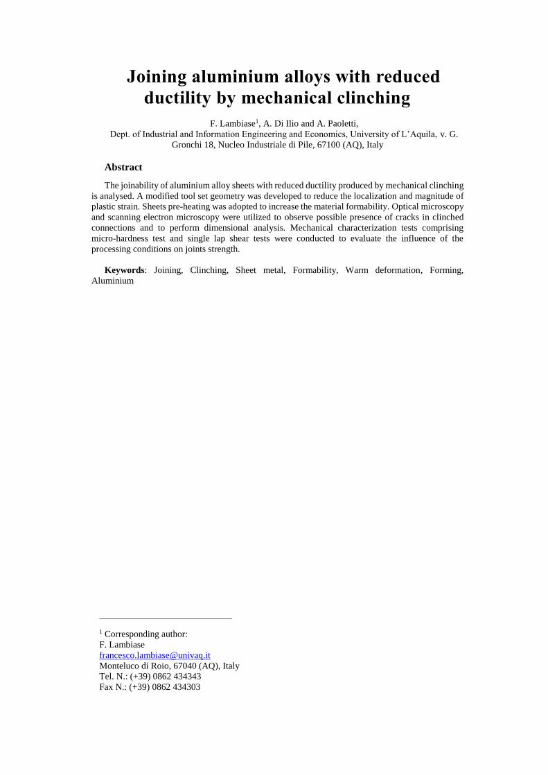
The mechanical strength of clinched connections depends on
both neck thickness, tn and the interlock ts: joints having small
values of neck thickness often fail by necking while joints with
small interlock are likely to fail by unbuttoning, as shown in Fig.
1.
Fig. 1 (a) Main geometrical parameters of clinched connections; (b) failure
modes of clinched connections.
Clinched connections on materials with reduced formability
may also produce cracks at the die-sided sheet [35] if the punch-
die cavity volume is not designed properly. Nevertheless, different
solutions can be adopted to join materials with reduced
formability by heating up the sheets before joining [36]. Warm
and hot forming processes resulting from the employment of a
heating source can both reduce the forming forces and increase the
formability of the sheets.

2. Materials and Methods
2.1. Methods for enhancing joinability
Mechanical clinching process involves a localized
deformation near the punch round corners, the magnitude of the
local strain often being larger than unity. Improper design of
clinching tools or reduced ductility of the sheets can lead to the
production of weak joints or even formation of cracks on the upper
sheet during the joining process.
In order to improve the joinability of such materials, the
influence of the following solutions on mechanical strength and
joints profile have been investigated:
reduction in the die anvil depth;
increase of material formability by pre-heating;
reduction of shear by changing the punch geometry;
2.2. Instrumented Clinching
AA6082 T6-alloy sheets of 1 mm in thickness have been
employed in this investigation. Tensile tests according to ASTM
E08 standards were conducted to measure the main mechanical
behaviours of the analysed material, summarized in Table 1, using
a universal testing machine by MTS model 322.31.
Table 1. Mechanical properties of AA6082T6 sheets
E
[GPa]
Rp0.2
[MPa]
Rm
[MPa]
Etot
[%]
Flow
Stress [MPa]
67.2 171 340 10.8 =
467.5 0.098
Clinched connections were produced using an experimental
apparatus mounted on the above-mentioned universal testing
machine MTS 322.31 with 25 kN full scale to measure the load
variation during the joining operation. The clinching process was
performed at a constant punch speed of 1 mm/s.
In the tests involving sheets pre-heating, convection heating
was used to heat up the sheets before the clinching operation. A
common industrial heater gun model Makita HG651CK was
employed. The schematic of the process involving the material
pre-heating is reported in Fig. 2.
Fig. 2 Schematic representation of clinching phases with preheating.
The process begins by pre-heating the upper sheet surface for
a prescribed time; thus, the heater gun is switched off and the
punch rapidly approaches (in 0.5 s) the upper sheet surface. Then
the punch further moves to produce the clinched joint and finally
the punch is retracted. A schematic representation of the
equipment used for preheating and clinching is depicted in Fig. 3.
Fig. 3 Schematic representation of the clinching equipment with preheating
adapter.
The temperature variation produced with different heating
times was measured by means of a thermo-camera model
ThermaCAM S65 HS by Flir Systems; herein, the exposed surface
was preventively covered by graphite powder to reduce the
reflectivity of the aluminium sheets.
To study the effect of the die anvil depth h, three different
extensible dies [37,38] were used (h = 0.6 mm, h = 0.8 mm and h
= 1.1 mm). In addition, two punches were used, as shown in Fig.
4: the former, designated as P1, is a common punch with a
cylindrical tool tip and a relatively sharp fillet radius of 0.1 mm;
the latter, P2, has a truncated cone shape with a smoother fillet
radius of 0.2 mm.
Fig. 4 Main dimensions of clinching tools.
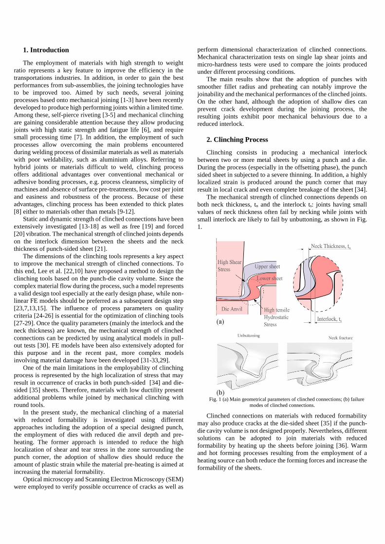
Single lap shear tests were carried out to evaluate the
mechanical properties of the clinched joints on sheets samples 60
× 20 mm2 as illustrated in Fig. 5. The samples were cut from a
unique sheet by CO2 laser. The mechanical tests of clinched joints
were performed on the previous mentioned MTS machine at a
constant velocity of 2 mm/min. For each testing conditions, three
repetitions were performed.
Fig. 5 Schematic representation of specimen used in single lap shear tests.
3. Results and discussion
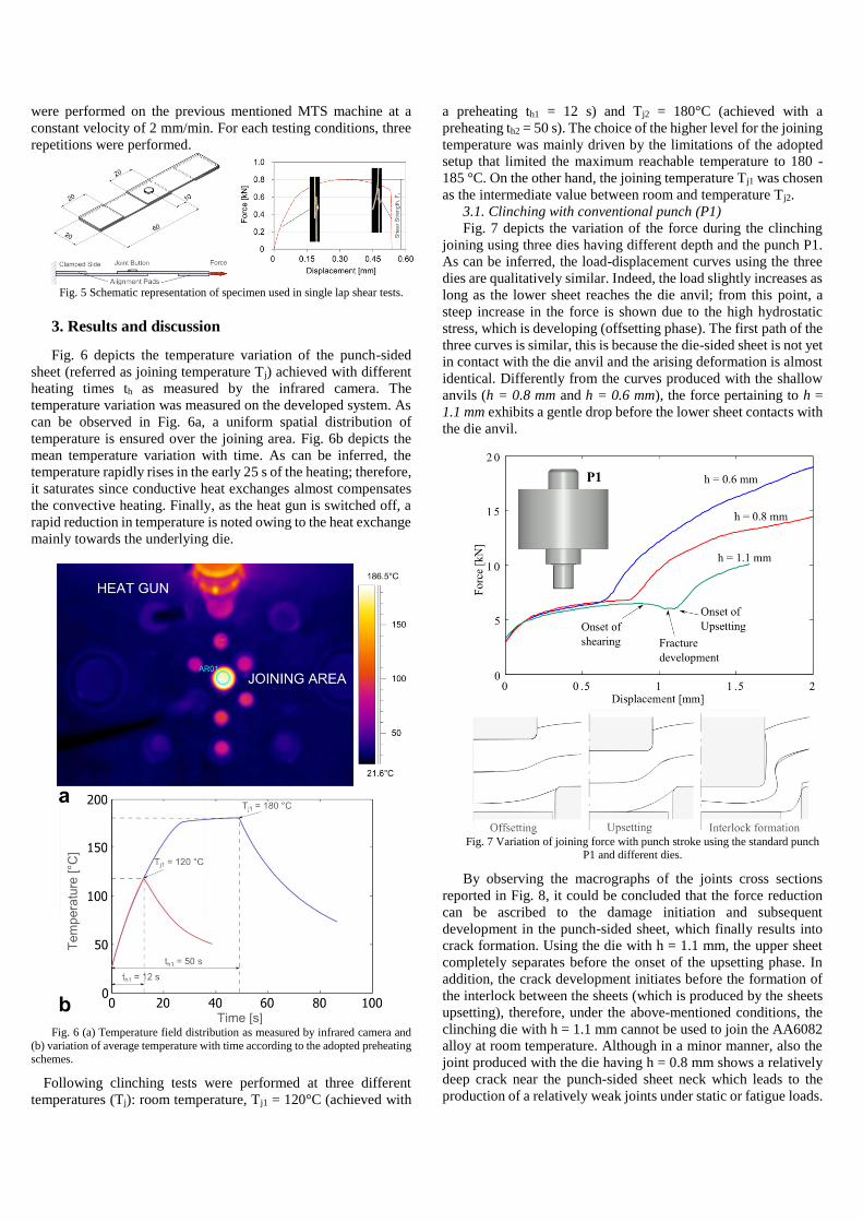
Fig. 6 depicts the temperature variation of the punch-sided
sheet (referred as joining temperature Tj) achieved with different
heating times th as measured by the infrared camera. The
temperature variation was measured on the developed system. As
can be observed in Fig. 6a, a uniform spatial distribution of
temperature is ensured over the joining area. Fig. 6b depicts the
mean temperature variation with time. As can be inferred, the
temperature rapidly rises in the early 25 s of the heating; therefore,
it saturates since conductive heat exchanges almost compensates
the convective heating. Finally, as the heat gun is switched off, a
rapid reduction in temperature is noted owing to the heat exchange
mainly towards the underlying die.
Fig. 6 (a) Temperature field distribution as measured by infrared camera and
(b) variation of average temperature with time according to the adopted preheating
schemes.
Following clinching tests were performed at three different
temperatures (Tj): room temperature, Tj1 = 120°C (achieved with
a preheating th1 = 12 s) and Tj2 = 180°C (achieved with a
preheating th2 = 50 s). The choice of the higher level for the joining
temperature was mainly driven by the limitations of the adopted
setup that limited the maximum reachable temperature to 180 -
185 °C. On the other hand, the joining temperature Tj1 was chosen
as the intermediate value between room and temperature Tj2.
3.1. Clinching with conventional punch (P1)
Fig. 7 depicts the variation of the force during the clinching
joining using three dies having different depth and the punch P1.
As can be inferred, the load-displacement curves using the three
dies are qualitatively similar. Indeed, the load slightly increases as
long as the lower sheet reaches the die anvil; from this point, a
steep increase in the force is shown due to the high hydrostatic
stress, which is developing (offsetting phase). The first path of the
three curves is similar, this is because the die-sided sheet is not yet
in contact with the die anvil and the arising deformation is almost
identical. Differently from the curves produced with the shallow
anvils (h = 0.8 mm and h = 0.6 mm), the force pertaining to h =
1.1 mm exhibits a gentle drop before the lower sheet contacts with
the die anvil.
Fig. 7 Variation of joining force with punch stroke using the standard punch
P1 and different dies.
By observing the macrographs of the joints cross sections
reported in Fig. 8, it could be concluded that the force reduction
can be ascribed to the damage initiation and subsequent
development in the punch-sided sheet, which finally results into
crack formation. Using the die with h = 1.1 mm, the upper sheet
completely separates before the onset of the upsetting phase. In
addition, the crack development initiates before the formation of
the interlock between the sheets (which is produced by the sheets
upsetting), therefore, under the above-mentioned conditions, the
clinching die with h = 1.1 mm cannot be used to join the AA6082
alloy at room temperature. Although in a minor manner, also the
joint produced with the die having h = 0.8 mm shows a relatively
deep crack near the punch-sided sheet neck which leads to the
production of a relatively weak joints under static or fatigue loads.

As a matter of facts, the only specimen that is exempt from cracks
is that produced with the shallowest die (h = 0.6 mm). However,
as it can be observed from Fig. 8, the adoption of such a die leads
to the formation of a very small interlock (ts = 0.03 mm), which
affects the joints strength.
Fig. 8 Cross sections of clinched connections produced with the punch P1 and different dies at room temperature.
Scanning electron microscopy was used to analyse the fracture
zone on the upper sheets. As can be inferred from Fig. 9a and 9b,
the upper sheet of the joint produced with the deeper die (h = 1.1
mm) exhibits a crack which originates from concentration of
deformation around the punch corner during the offsetting phase,
as reported by Abe et al. [34]. This crack stems from the relatively
high depth of the die anvil and the sharp corner radius of the
punch. As can be noted in Fig. 9d, the employment of dies with
deep die anvils (h = 1.1 mm) may result in crack development in
the die-sided sheet due to high positive hydrostatic stress. Indeed,
during the upsetting phase, the die sided sheet undergoes to a
severe radial spread leading to the development of high tensile
circumferential stresses which finally may cause radial cracks.
Similar conditions were observed in some experiments conducted
by Mucha in [2] and Abe et al. [35] while joining high strength
steel sheets. The adoption of shallower dies relieves the strain
around the punch corner; thus, it may prevent cracks formation in
the punch-sided sheet, as shown in Fig. 9c.
Fig. 9 SEM macrographs of clinched connections: punch-sided surface (punch
P1 die with h = 1.1 mm) (a) low magnifications, (b) high magnifications on the
crack zone, (c) punch sided surface (punch P1 with h = 0.6 mm) high magnification
on neck and (d) die sided surface (punch P1 with h = 1.1 mm) with low magnification.
3.2. Clinching with customized punch (P2)
In order to overcome the limitations encountered when using
the customized punch P1, a new punch, called P2, was used for
further tests. The new punch differed from the previous one by
with conical shape and a larger fillet radius R = 0.2 mm, which is
intended to spread the contact force arising at the punch-sheet
interface over a larger area.
Fig. 10 depicts the cross sections of the clinched joints realized
with the three types of die. Using the punch P2, the joints produced
with the die with h = 0.8 mm were free from cracks; however, the
joints produced with the deeper die (h = 1.1 mm) still showed a
thought crack, as shown in the macrograph in Fig. 10a both the
sheets exhibit a crack.
Fig. 10 (a) Macrograph of clinched connection produced with the punch P2
and the die with h = 1.1 mm (the lower sheet was metallized to better distinguish
between the sheets) (b) Protrusion of the die-sided sheet. (c-e) Cross sections of
clinched connections produced with different die depths h.

Fig. 11 Variation of joining force with punch stroke using the customized
punch P2 and different dies.
The variation of the force during clinch joining using the punch
P2 is reported in Fig. 11. The lack of the load drop before the
upsetting phase, as occurred with the punch P1, in the force-
displacement indicates a delay of crack initiation around the punch
corner after the offsetting phase owing to the smoother corner
radius of the punch P2.
The die with h = 0.6 mm is characterized by a minor punch-
die cavity-volume between the punch and the die which causes a
faster cavity volume fulfilment during the joining operation. In
addition, when such a die is used, a high thickness reduction at the
bottom is required to achieve the mechanical interlock between
the sheets. As a result, the adoption of the shallowest die (h = 0.6
mm) implies a major forming force as compared with deeper ones.
The main quality criteria (interlock and neck thickness) as well
as the shear strength of clinched connections produced using
different dies and pre-heating schemes (resulting in different
joining temperatures, Tj) are reported in Fig. 12.
The increase in the die depth results in an increase of interlock
ts and a slight reduction in the neck thickness tn, as shown in Fig.
12b and Fig. 12c, respectively. Actually, deeper dies involve a
major thinning effect on the sheets (especially during the
offsetting phase) which reduce the wall thickness of the punch-
sided sheet. On the other hand, the increase in the die depth
produces a higher material flow, which contributes to the
formation of a larger interlock. Indeed, when deeper dies are
employed, the wall thickness of the die-sided sheet is reduced
(during the offsetting phase) and the die-sided sheet exerts a minor
resistance to the spreading of the punch-sided sheet during the
upsetting phase which results in a larger interlock, as reported in
[25].
The employment of the most shallow die (with h = 0.6 mm)
produces relatively high values of neck thickness tn = 0.36 mm
and low values of interlock, ts = 0.045 (these values are the
average of tn and ts of joints produced at different temperatures,
Tj) leading to small values of the shear strength Fs = 0.32 kN.
Increasing the die depth h = 0.8 mm results in an increase in the
interlock ts = 0.13 mm and a slight decrease in the neck thickness
tn = 0.34 mm resulting in a significant improvement of the shear
strength of the joints Fs = 0.8 kN. Further increase in the die depth
h = 1.1 mm allows producing joints with higher strength Fs = 1.23
kN since the increase in the interlock ts = 0.22 mm; however, the
employment of such a die required the adoption of sheet pre-
heating since crack development at room temperature.
Fig. 12 Influence of joining temperature and die depth on (a) Shear strength
Fs, (b) interlock ts and (c) neck thickness tn of clinched connections (X-parameter
= 0.6 mm).
The depth of the die anvil also influences the joint failure mode,
namely pull-out, shear or a combination of them [30,39,13].
Indeed, the joints produced by means of the die with h = 1.1 mm
mainly failed by shearing mode, see fig 13a and b, due to the
higher interlock. Such failure mode is characterized by the
formation of a crack under the punch-sided sheet cap, which
progressively develops as the load increases up to the complete
separation of the cap from the sheet (fig. 13a). On the other hand,
joints produced with shallow dies are characterized by the pull out
failure mode. Herein, the interlock was much smaller than the
neck thickness and the punch-sided sheet is pulled away from the
joint causing a sudden drop in the load carrying ability.
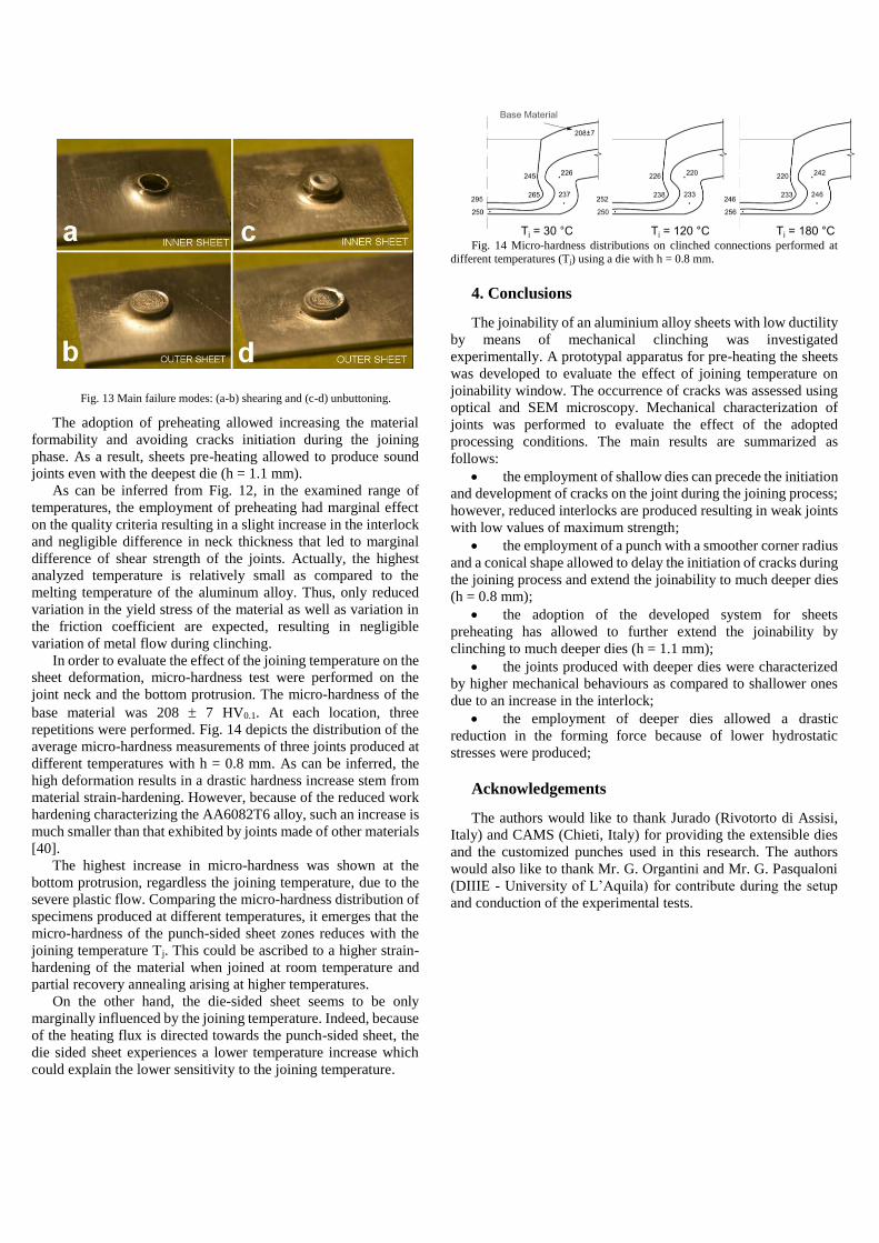
Fig. 13 Main failure modes: (a-b) shearing and (c-d) unbuttoning.
The adoption of preheating allowed increasing the material
formability and avoiding cracks initiation during the joining
phase. As a result, sheets pre-heating allowed to produce sound
joints even with the deepest die (h = 1.1 mm).
As can be inferred from Fig. 12, in the examined range of
temperatures, the employment of preheating had marginal effect
on the quality criteria resulting in a slight increase in the interlock
and negligible difference in neck thickness that led to marginal
difference of shear strength of the joints. Actually, the highest
analyzed temperature is relatively small as compared to the
melting temperature of the aluminum alloy. Thus, only reduced
variation in the yield stress of the material as well as variation in
the friction coefficient are expected, resulting in negligible
variation of metal flow during clinching.
In order to evaluate the effect of the joining temperature on the
sheet deformation, micro-hardness test were performed on the
joint neck and the bottom protrusion. The micro-hardness of the
base material was 208 7 HV0.1. At each location, three
repetitions were performed. Fig. 14 depicts the distribution of the
average micro-hardness measurements of three joints produced at
different temperatures with h = 0.8 mm. As can be inferred, the
high deformation results in a drastic hardness increase stem from
material strain-hardening. However, because of the reduced work
hardening characterizing the AA6082T6 alloy, such an increase is
much smaller than that exhibited by joints made of other materials
[40].
The highest increase in micro-hardness was shown at the
bottom protrusion, regardless the joining temperature, due to the
severe plastic flow. Comparing the micro-hardness distribution of
specimens produced at different temperatures, it emerges that the
micro-hardness of the punch-sided sheet zones reduces with the
joining temperature Tj. This could be ascribed to a higher strain-
hardening of the material when joined at room temperature and
partial recovery annealing arising at higher temperatures.
On the other hand, the die-sided sheet seems to be only
marginally influenced by the joining temperature. Indeed, because
of the heating flux is directed towards the punch-sided sheet, the
die sided sheet experiences a lower temperature increase which
could explain the lower sensitivity to the joining temperature.
Fig. 14 Micro-hardness distributions on clinched connections performed at
different temperatures (Tj) using a die with h = 0.8 mm.
4. Conclusions
The joinability of an aluminium alloy sheets with low ductility
by means of mechanical clinching was investigated
experimentally. A prototypal apparatus for pre-heating the sheets
was developed to evaluate the effect of joining temperature on
joinability window. The occurrence of cracks was assessed using
optical and SEM microscopy. Mechanical characterization of
joints was performed to evaluate the effect of the adopted
processing conditions. The main results are summarized as
follows:
the employment of shallow dies can precede the initiation
and development of cracks on the joint during the joining process;
however, reduced interlocks are produced resulting in weak joints
with low values of maximum strength;
the employment of a punch with a smoother corner radius
and a conical shape allowed to delay the initiation of cracks during
the joining process and extend the joinability to much deeper dies
(h = 0.8 mm);
the adoption of the developed system for sheets
preheating has allowed to further extend the joinability by
clinching to much deeper dies (h = 1.1 mm);
the joints produced with deeper dies were characterized
by higher mechanical behaviours as compared to shallower ones
due to an increase in the interlock;
the employment of deeper dies allowed a drastic
reduction in the forming force because of lower hydrostatic
stresses were produced;
Acknowledgements
The authors would like to thank Jurado (Rivotorto di Assisi,
Italy) and CAMS (Chieti, Italy) for providing the extensible dies
and the customized punches used in this research. The authors
would also like to thank Mr. G. Organtini and Mr. G. Pasqualoni
(DIIIE - University of L’Aquila) for contribute during the setup
and conduction of the experimental tests.

References
1. Mori K-i, Bay N, Fratini L, Micari F, Tekkaya AE (2013) Joining by plastic deformation. CIRP Annals - Manufacturing Technology. 2. Mucha J (2011) The analysis of lock forming mechanism in the clinching joint. Materials & Design 32 (10):4943-4954. 3. Mucha J (2013) The effect of material properties and joining process parameters on behavior of self-pierce riveting joints made with the solid rivet. Materials & Design 52:932-946. 4. Mori K, Abe Y, Kato T (2013) Self-pierce riveting of multiple steel and aluminium alloy sheets. Journal of Materials Processing Technology 214 (10):2002-2008. 5. He X, Gu F, Ball A (2011) Recent development in finite element analysis of self-piercing riveted joints. The International Journal of Advanced Manufacturing Technology 58 (5-8):643-649. 6. Li D, Han L, Thornton M, Shergold M, Williams G (2014) The influence of fatigue on the stiffness and remaining static strength of self-piercing riveted aluminium joints. Materials & Design 54:301-314. 7. He X (2010) Recent development in finite element analysis of clinched joints. The International Journal of Advanced Manufacturing Technology 48 (5-8):607-612. 8. Israel M (2014) The Suitability of Analytical and Numerical Methods for Developing Clinching Processes with Thick Sheet Metal. Advanced Materials Research 907:151-163. 9. Lüder S, Härtel S, Binotsch C, Awiszus B (2014) Influence of the moisture content on flat-clinch connection of wood materials and aluminium. Journal of Materials Processing Technology 214:2069-2074. 10. Lee C-J, Lee J-M, Ryu H-Y, Lee K-H, Kim B-M, Ko D-C (2014) Design of hole-clinching process for joining of dissimilar materials – Al6061-T4 alloy with DP780 steel, hot-pressed 22MnB5 steel, and carbon fiber reinforced plastic. Journal of Materials Processing Technology 214:2169-2178. 11. Gerstmann T, Awiszus B (2014) Recent developments in flat-clinching. Computational Materials Science 81:39-44. 12. Lambiase F, Di Ilio A (2015) Mechanical clinching of metal–polymer joints. Journal of Materials Processing Technology 215:12-19. 13. Coppieters S, Lava P, Hecke RV, Cooreman S, Sol H, Houtte PV, Debruyne D (2012) Numerical and experimental study of the multi-axial quasi-static strength of clinched connections. International Journal of Material Forming 6:437-451. 14. Kim H-K (2012) Fatigue Strength Evaluation of the Clinched Lap Joints of a Cold Rolled Mild Steel Sheet. Journal of Materials Engineering and Performance 22:294-299. 15. Mori K, Abe Y, Kato T (2012) Mechanism of superiority of fatigue strength for aluminium alloy sheets joined by mechanical clinching and self-pierce riveting. Journal of Materials Processing Technology 212:1900-1905.
16. Mucha J, Witkowski W (2013) The experimental analysis of the double joint type change effect on the joint destruction process in uniaxial shearing test. Thin-Walled Structures 66:39-49. 17. Mucha J, Witkowski W (2014) The clinching joints strength analysis in the aspects of changes in the forming technology and load conditions. Thin-Walled Structures 82:55-66. 18. He X, Zhao L, Yang H, Xing B, Wang Y, Deng C, Gu F, Ball A (2014) Investigations of strength and energy absorption of clinched joints. Computational Materials Science 94:58-65. 19. He XC, Zhen D, Yang HY, Feng GJ, Xing BY, Gu FS, Ball A (2014) Experimental free vibration analysis of clinched beams. Applied Mechanics and Materials, vol 467. 20. He XC, Liu FL, Cun HY, Yang HY, Xing BY, Zeng K (2014) Forced vibration measurements of clinched joints. Applied Mechanics and Materials, vol 556-562. 21. Varis J (2006) Ensuring the integrity in clinching process. Journal of Materials Processing Technology 174 (1-3):277-285. 22. Lee S-H, Lee C-J, Lee K-H, Lee J-M, Kim B-M, Ko D-C (2014) Influence of Tool Shape on Hole Clinching for Carbon Fiber-Reinforced Plastic and SPRC440. Advances in Mechanical Engineering 2014:1-12. 23. Coppieters S, Cooreman S, Sol H, Debruyne D (2007) Reproducing the experimental strength of clinched connections with finite element methods. Paper presented at the SEM Annual Conference & Exposition on Experimental and Applied Mechanics, 24. Gibmeier J, Rode N, Lin Peng R, Oden M, Scholtes B (2002) Residual stress in clinched joints of metals. Applied Physics A: Materials Science & Processing 74 (0):s1440-s1442. 25. Lambiase F (2013) Influence of process parameters in mechanical clinching with extensible dies. The International Journal of Advanced Manufacturing Technology 66 (9-12):2123-2131. 26. Lambiase F, Di Ilio A (2013) Finite Element Analysis of Material Flow in Mechanical Clinching with Extensible Dies. Journal of Materials Engineering and Performance 22 (6):1629-1636. 27. Oudjene M, Benayed L, Delameziere A, Batoz J (2009) Shape optimization of clinching tools using the response surface methodology with Moving Least-Square approximation. Journal of Materials Processing Technology 209 (1):289-296. 28. Lambiase F, Di Ilio A Optimization of clinching tools by means of integrated FE modeling and Artificial Intelligence Techniques. In: Procedia - CIRP, 2012. 29. Roux E, Bouchard PO (2013) Kriging metamodel global optimization of clinching joining processes accounting for ductile damage. Journal of Materials Processing Technology. 30. Lee C-J, Kim J-Y, Lee S-K, Ko D-C, Kim B-M (2010) Design of mechanical clinching tools for joining of aluminium alloy sheets. Materials & Design 31 (4):1854-1861. 31. Zhao SD, Xu F, Guo JH, Han XL (2014) Experimental and numerical research for the failure behavior of the clinched

joint using modified Rousselier model. Journal of Materials Processing Technology 214:2134-2145. 32. Xu F, Zhao SD, Han XL (2014) Use of a modified Gurson model for the failure behaviour of the clinched joint on Al6061 sheet. Fatigue & Fracture of Engineering Materials & Structures 37 (3):335-348. 33. Jiang T, Liu Z-X, Wang P-C (2014) Effect of aluminum pre-straining on strength of clinched galvanized SAE1004 steel-to-AA6111-T4 aluminum. Journal of Materials Processing Technology. 34. Abe Y, Kato T, Mori K-i, Nishino S (2014) Mechanical clinching of ultra-high strength steel sheets and strength of joints. Journal of Materials Processing Technology 214:2112-2118. 35. Abe Y, Mori K, Kato T (2012) Joining of high strength steel and aluminium alloy sheets by mechanical clinching with dies for control of metal flow. Journal of Materials Processing Technology 212 (4):884-889. 36. Neugebauer R, Kraus C, Dietrich S (2008) Advances in mechanical joining of magnesium. CIRP Annals - Manufacturing Technology 57 (1):283-286. 37. Lambiase F, Di Ilio A (2013) Optimization of the Clinching Tools by Means of Integrated FE Modeling and Artificial Intelligence Techniques. Procedia CIRP 12:163-168. 38. Lambiase F, Di Ilio A (2014) An experimental study on clinched joints realized with different dies. Thin-Walled Structures 85:71-80. 39. Coppieters S, Lava P, Baes S, Sol H, Van Houtte P, Debruyne D (2012) Analytical method to predict the pull-out strength of clinched connections. Thin-Walled Structures 52:42-52. 40. Mucha J, Kaščák Lu, Spišák E (2013) The Experimental Analysis of Forming and Strength of Clinch Riveting Sheet Metal Joint Made of Different Materials. Advances in Mechanical Engineering 2013:1-11.

List of Figure Captions
Fig. 1 (a) Main geometrical parameters of clinched
connections; (b) failure modes of clinched connections Fig. 2 Schematic representation of clinching phases with
preheating. Fig. 3 Schematic representation of the clinching equipment
with preheating adapter Fig. 4 Main dimensions of clinching tools Fig. 5 Schematic representation of specimen used in single lap
shear tests. Fig. 6 (a) Temperature field distribution as measured by
infrared camera and (b) variation of average temperature with
time according to the adopted preheating schemes. Fig. 7 Variation of joining force with punch stroke using the
standard punch P1 and different dies. Fig. 8 Cross sections of clinched connections produced with
the punch P1 and different dies. Fig. 9 SEM macrographs of clinched connections: punch-
sided surface (punch P1 die with h = 1.1 mm) (a) low
magnifications, (b) high magnifications on the crack zone, (c)
punch sided surface (punch P1 with h = 0.6 mm) high
magnification on neck and (d) die sided surface (punch P1 with
h = 1.1 mm) with low magnification. Fig. 10 (a) Macrograph of clinched connection produced with
the punch P2 and the die with h = 1.1 mm. (the lower sheet was
metallized to better distinguish between the sheets) (b)
Protrusion of the die-sided sheet. (c-e) Cross sections of clinched
connections produced with different die depths h. Fig. 11 Variation of joining force with punch stroke using the
customized punch P2 and different dies. Fig. 12 Influence of joining temperature and die depth on (a)
Shear strength Fs, (b) interlock ts and (c) neck thickness tn of
clinched connections (X-parameter = 0.6 mm). Fig. 13 Main failure modes: (a-b) shearing and (c-d)
unbuttoning. Fig. 14 Micro-hardness distributions on clinched connections
performed at different temperatures (Tj) using a die with h = 0.8
mm.
List of Table Captions
Table 1. Mechanical properties of AA6082T6 sheets


