Embed Size (px)
Citation preview
CRC Press is an imprint of theTaylor & Francis Group, an informa business
Boca Raton London New York
MechanicalFastening,Joining,and Assembly
MechanicalFastening,Joining,and Assembly James A. Speck
S e c o n d E d i t i o n
CRC PressTaylor & Francis Group6000 Broken Sound Parkway NW, Suite 300Boca Raton, FL 33487-2742
© 2015 by Taylor & Francis Group, LLCCRC Press is an imprint of Taylor & Francis Group, an Informa business
No claim to original U.S. Government worksVersion Date: 20140909
International Standard Book Number-13: 978-1-4822-7655-8 (eBook - PDF)
This book contains information obtained from authentic and highly regarded sources. Reasonable efforts have been made to publish reliable data and information, but the author and publisher cannot assume responsibility for the validity of all materials or the consequences of their use. The authors and publishers have attempted to trace the copyright holders of all material reproduced in this publication and apologize to copyright holders if permission to publish in this form has not been obtained. If any copyright material has not been acknowledged please write and let us know so we may rectify in any future reprint.
Except as permitted under U.S. Copyright Law, no part of this book may be reprinted, reproduced, transmit-ted, or utilized in any form by any electronic, mechanical, or other means, now known or hereafter invented, including photocopying, microfilming, and recording, or in any information storage or retrieval system, without written permission from the publishers.
For permission to photocopy or use material electronically from this work, please access www.copyright.com (http://www.copyright.com/) or contact the Copyright Clearance Center, Inc. (CCC), 222 Rosewood Drive, Danvers, MA 01923, 978-750-8400. CCC is a not-for-profit organization that provides licenses and registration for a variety of users. For organizations that have been granted a photocopy license by the CCC, a separate system of payment has been arranged.
Trademark Notice: Product or corporate names may be trademarks or registered trademarks, and are used only for identification and explanation without intent to infringe.
Visit the Taylor & Francis Web site athttp://www.taylorandfrancis.com
and the CRC Press Web site athttp://www.crcpress.com
iii
Contents
Preface to the Second Edition ...............................................................................ixPreface to the First Edition ....................................................................................xiAcknowledgments .............................................................................................. xiiiAuthor .....................................................................................................................xv
1 Fastener Functions and Assembly Testing ................................................11.1 The Fastener Design Role .....................................................................11.2 Analysis of a Simple Metal Assembly ................................................31.3 Fastening a More Complex Assembly.............................................. 131.4 Fastening Real-World Applications .................................................. 191.5 Fastener Statics ....................................................................................28Reference .........................................................................................................33
2 Fastener Types and Their Production .......................................................352.1 Tension Fasteners ................................................................................36
2.1.1 Pan Head .................................................................................362.1.2 Truss Head .............................................................................. 372.1.3 Hex Head ................................................................................ 392.1.4 Socket Screws .........................................................................402.1.5 Blind Rivets .............................................................................422.1.6 Some Dimensions for Blind Rivets ......................................422.1.7 Self-Clinching Studs ..............................................................432.1.8 Weld Studs ..............................................................................452.1.9 Grooved Pins ..........................................................................462.1.10 Split Knurl Drive Screws....................................................... 472.1.11 Type “U” Drive Screws ......................................................... 472.1.12 Self-Threading Screws ........................................................... 472.1.13 Locking Threads .................................................................... 492.1.14 Cold-Heading Manufacturing Process ............................... 492.1.15 Roll-Threading/Forming Process ........................................ 512.1.16 Heat Treating of Metal Fasteners ......................................... 522.1.17 Checking Fastener Hardness ...............................................552.1.18 Screw Machining ...................................................................562.1.19 Other Tension Fasteners ........................................................ 57
2.2 Compression Fasteners .......................................................................582.2.1 Set Screws ...............................................................................582.2.2 Washers ...................................................................................58
2.3 Shear Fasteners ....................................................................................602.4 Adhesives .............................................................................................602.5 Fastener Manufacturing Methods .................................................... 61
iv Contents
2.5.1 Roll-Threading and Other Screw-Threading Processes ................................................................................. 712.5.2 Some Additional Thoughts on Adhesives .......................... 732.5.3 Some Additional Thoughts on Welding ............................. 74
2.6 Fastener Dynamics ............................................................................. 74Reference ......................................................................................................... 76
3 Fastening and Joining Mechanics .............................................................773.1 Metal Joints ..........................................................................................77
3.1.1 Rigid Metal Joints .................................................................. 783.2 Nonmetal Joints ................................................................................... 93
3.2.1 Snap Fit Assembly ................................................................. 943.2.2 Adhesive Assembly ............................................................... 943.2.3 Blind Rivet Assembly ............................................................ 953.2.4 Self-Threading Screw Assembly .......................................... 953.2.5 Some Additional Thoughts .................................................. 97
3.3 Applications View of Fastener Functions ........................................ 983.4 Fastener Strength of Materials ........................................................ 103
3.4.1 Engineering Model Method ............................................... 107Reference ....................................................................................................... 113
4 Economic Factors in Fastener/Assembly Decisions ............................. 1154.1 Build Quantities ................................................................................ 117
4.1.1 Tools, Fixtures, and Equipment ......................................... 1204.1.2 Assembly Site ....................................................................... 1214.1.3 Assembly Documentation and Training .......................... 1214.1.4 Assembly Fastening Material Supply Channels ............. 122
4.2 Assembly Robustness ....................................................................... 1224.3 Legal Considerations and Constraints ........................................... 124
4.3.1 Consensus Standards .......................................................... 1264.3.2 Some Fastener Cases ........................................................... 126
4.3.2.1 Jet Engine Mounting Bolt .................................... 1264.3.2.2 Propeller Screw ..................................................... 1274.3.2.3 Motorcycle Disk Brake Rotor Screws ................ 1274.3.2.4 Fractured Valve Screws ....................................... 128
4.3.3 Bogus Bolting ....................................................................... 1284.4 Economic Factors in Fastener/Assembly Decisions ..................... 1334.5 Engineering Economics ................................................................... 138Suggested Reading ...................................................................................... 144
5 Assemblies under Dynamic Loading ..................................................... 1455.1 Mass Effects ....................................................................................... 149
5.1.1 Four-Bolt I.C. Engine Main Bearing Supports ................. 1495.1.2 Mass Effects of Oil Pan and Gasket Screws ..................... 1505.1.3 Testing for Dynamic Loading Applications .................... 153
vContents
5.2 Vibration ............................................................................................. 1545.3 Fatigue ................................................................................................ 1575.4 Some Additional Dynamic Tests .................................................... 158
5.4.1 Some Thoughts on Dynamic Loading .............................. 1605.5 Difference between Static and Dynamic Strength ....................... 1615.6 Fastener Chemistry ........................................................................... 164Reference ....................................................................................................... 165
6 Assembly Sites and Systems .................................................................... 1676.1 Accessibility ....................................................................................... 1676.2 Reusability Factors ............................................................................ 1696.3 Assembly Training ............................................................................ 1796.4 Degree of Automation ...................................................................... 1806.5 Automatic Assembly Machines ...................................................... 184
6.5.1 Station Tooling...................................................................... 1866.5.2 Ergonomics ........................................................................... 1876.5.3 Designed-In Flexibility........................................................ 1876.5.4 Seamless Handoff ................................................................ 1876.5.5 Setting Quantitative Targets .............................................. 187
6.6 Smart Machines and Robots ............................................................ 1876.7 A Renewed Look at Modern Assembly ......................................... 190
6.7.1 The Engineer and the Accountant ..................................... 1906.7.2 The Engineer and the Attorney ......................................... 191
6.8 Fastener Numerical Methods .......................................................... 1946.8.1 General Rules for Numerical Proficiency ......................... 1946.8.2 Numbering Systems ............................................................ 1956.8.3 Geometry .............................................................................. 1956.8.4 Algebra .................................................................................. 1956.8.5 Trigonometry ........................................................................ 1966.8.6 Statistics ................................................................................. 1966.8.7 Calculus—Differential and Integral ................................. 1976.8.8 Differential Equations ......................................................... 1976.8.9 Linear and Other Programming Techniques .................. 198
Reference ....................................................................................................... 198
7 Fastener Materials ...................................................................................... 1997.1 Steels ................................................................................................... 199
7.1.1 AISI 1010 ................................................................................2007.1.2 Response to Temperature: Annealing .............................. 201
7.1.2.1 Typical Fastener Application .............................. 2017.1.2.2 AISI 1018 ................................................................ 201
7.1.3 Response to Temperature: Carbonitriding and Tempering ............................................................................. 2027.1.3.1 Typical Application .............................................. 2027.1.3.2 AISI 1038 ................................................................ 202
vi Contents
7.1.4 Response to Temperature: Through or Neutral Hardening ............................................................................. 2037.1.4.1 AISI 4037 ................................................................ 203
7.1.5 Response to Temperature ................................................... 2037.1.5.1 AISI 4140 ................................................................ 2037.1.5.2 AISI 8640 ................................................................ 2047.1.5.3 AISI 52100 .............................................................. 2057.1.5.4 H-11 ......................................................................... 205
7.2 Stainless Steels ................................................................................... 2067.2.1 Type 302 HQ ......................................................................... 2067.2.2 Type 303 ................................................................................. 2077.2.3 Type 305 ................................................................................. 2087.2.4 Type 410 ................................................................................. 2087.2.5 Type 430 ................................................................................. 2097.2.6 17-4 PH ................................................................................... 2097.2.7 A 286 ...................................................................................... 210
7.3 Nonferrous Materials ....................................................................... 2117.3.1 Spectrographic Analysis ..................................................... 2117.3.2 Carbon Analysis ................................................................... 2127.3.3 Magnetic Screening ............................................................. 2127.3.4 Eddy Current Techniques ................................................... 2127.3.5 Brass Alloys .......................................................................... 2127.3.6 Aluminum Alloys ................................................................ 213
7.4 Other Fastener Materials .................................................................. 2147.4.1 Titanium ................................................................................ 2147.4.2 MP35N ................................................................................... 2147.4.3 Monel ..................................................................................... 2147.4.4 Hastelloy ............................................................................... 2147.4.5 AerMet 100 ............................................................................ 2157.4.6 Notes on Fastener Metallurgy ............................................ 2177.4.7 Brazing Alloys ...................................................................... 2177.4.8 Nonmetallic Fastener Materials ......................................... 217
7.5 Fastener Materials in Today’s Environment .................................. 2187.6 The Fastener Laboratory .................................................................. 2217.7 Electrical Theory and Fastening, Joining, and Assembly ........... 226Reference .......................................................................................................230
8 Environmental Factors and Corrosion ................................................... 2318.1 Corrosion of Fasteners and Assemblies ......................................... 2318.2 Corrosion Protection .........................................................................2358.3 Corrosion Testing .............................................................................. 2418.4 Some Thoughts on Sustainability ................................................... 2428.5 Application Engineering Project Management ............................ 2438.6 Thermodynamics .............................................................................. 245Suggested Reading ...................................................................................... 248
viiContents
9 Assembly Analysis ..................................................................................... 2499.1 Circular Areas ................................................................................... 249
9.1.1 Pins, Shoulders, Shear Areas .............................................. 2499.1.2 Hexagonal Area.................................................................... 2499.1.3 Circular Volume ...................................................................2509.1.4 Hexagonal Volume...............................................................2509.1.5 Volume of a More Complex Shape .................................... 251
9.1.5.1 Fastener Geometry ............................................... 2519.1.6 Calculate Part Weight, Individual, Per Hundred,
Per Thousand ........................................................................2549.1.7 Calculate Fastener Elastic Elongation ...............................2569.1.8 Calculate Upset Volume ...................................................... 2579.1.9 Find the Largest Head Diameter per Upset ..................... 2579.1.10 Calculating a Compound Fastener Shape ........................ 2599.1.11 Estimating Screw Slot Torque ............................................ 2599.1.12 Calculating Strip-to-Drive Ratios ...................................... 2609.1.13 Evaluating Drive Torque/Horsepower ............................. 2629.1.14 Calculating a Knurl Pitch ................................................... 2639.1.15 Finding a Screw Diameter from a Target Clamp Load ..........................................................................2649.1.16 Calculating Pin Shear Strengths ........................................264
9.1.16.1 Single Shear ........................................................... 2659.1.16.2 Double Shear ......................................................... 265
9.1.17 Calculating Torque–Tension Operating Charts ............... 2669.1.18 Estimating Assembly Efficiency ........................................ 266
9.2 Work from the Workshop ................................................................ 2689.2.1 Calculating Heading Upset Volumes and
Diameter Ratios .................................................................... 2709.3 D & D 100 ........................................................................................... 274References ..................................................................................................... 275
Appendix A: Fastening, Joining, and Assembly Glossary .......................277
Appendix B: Ingenious Fasteners and Assemblies ..................................... 281
Appendix C: Some Frequent Fastener Questions and Answers .............. 291
Appendix D: Article from American Fastener Journal .............................. 297
Appendix E: Some Additional Problem Solution Ideas and Summary Thoughts ...........................................................................................349

ix
Preface to the Second Edition
The second edition of Mechanical Fastening, Joining, and Assembly is presented as a guide and reference to all who engage in the mechanical arts. A decade and a half have passed since the preface to the first edition was written. This passage of time has affirmed many of the ideas expressed in that first edi-tion. Time has also witnessed the development of some interesting, and for our purposes, intellectually important, technical progress in the assembly of products and in the design, manufacturing, and installation of fastener products and procedures. Time has not been idle even during periods when worldwide economic engines were moving at less than full throttle.
Ranging from the interest children exhibit in building things with toys such as interlocking blocks, rods, and connecting components to the advanced and sometimes strident adult voices and viewpoints expressed in the media, in academic institutions, and in political and public discourse around the world, a panoramic view of the subject of fastening and its foundational tech-nologies, from the basics to the advanced is timely.
Research of technical education itself is undergoing at present a profound, and critically necessary, evaluation. And in the manufacture of products ranging from orthopedic hardware to aerospace, automotive, transporta-tion, and defense products, the need to assemble and fasten components efficiently, and well into functional products of value, continues. In fact, as I write, the early reemergence of a growing U.S. manufacturing base can be witnessed in shops and manufacturing plants in large cities and small towns. We are making things! Knowledge and ideas build best when started from a solid foundation. What appears to me to be coming into focus is that manufacturing is a significant component of a nation’s economy. From a strategic viewpoint, reliance on other industrialized economies for manufac-tured goods leads to dependence and potential weak points in an economy’s self-reliance, even in a globally connected economy with many of today’s economies. Manufacturing prowess provides strength and options not oth-erwise always available. A common issue I hear frequently in my business travels is the constraint of trained, young manufacturing employees. As those of us who are older reduce our hours of participation in manufacturing enterprises and begin to age and retire, a new workforce will be required. There is no doubt that this younger workforce has world-class computer and telecommunication skills. It is hoped that this will be matched by innovation in the expansion and growth of engineering skills to transform tomorrow’s ideas and raw materials into value-producing, lifestyle-enhancing fastened products. I am optimistic.
In Chapter 1 of this edition, I have expanded the fastened components pre-sented and reviewed. These are based on my experience in the field. At the
x Preface to the Second Edition
end of each chapter is a review of engineering fundamentals with a focus on their application in the fastener industry. The first chapter concludes with a section on fastener statics. Using free body diagrams and learning to read the forces in a fastener and assembly are key skills. In Chapter 2, we take a deeper look at the fastener manufacturing processes, especially those I was exposed to in my career, cold heading and roll threading. Fastener dynam-ics is added in Chapter 2 to focus our attention on forces in motion, such as a wind turbine hub turning in strong winds. In Chapter 3, we take a look at materials in fastening and add fastener strength of materials. Somewhere in my fastener application engineering career I started to think of statics, dynamics, and strength of materials as the big three. Each of these serve as a key to good fastener applications work. Chapter 4 expands our review of the economics of fastening and provides some tools for engineering economics. Too often, technical people tend to steer clear of economic and financial fac-tors. This does not have to be so. Neglecting economic and financial factors can lead to an over-reliance on technology to the detriment of the application and more importantly, the career advancement of the practitioner. Money is the life blood of an enterprise. In Chapter 4, we speak its language.
In Chapter 5, we examine the difference in static and dynamic strengths. These can sometimes present fastener application issues if not addressed properly. We also present some ideas with respect to chemistry in fastener work. Chapter 6 brings us a renewed look at modern assembly where the fundamentals still hold but with new constraints and concerns. Under the umbrella of numerical methods, we take an overview of the mathematical skills that provide the foundation of application engineering. Chapter 7 takes a look at fastener materials in this new century, provides some observations about the fastener laboratory, and discusses electrical theory. In Chapter 8, sustainability is focused along with some thoughts for application product management. A discussion of thermodynamics concludes Chapter 8 with material on energy systems and some new thought maps for application analysis. Chapter 9 provides the reader with a look at work from the fastener workshops that have been well received over the years and a look at a favor-ite application, D&D 100.
This second edition adds two new appendices. Appendix D presents, for the first time as a collection, some articles from the American Fastener Journal. Appendix E adds some concluding thoughts and application topics. I have learned that some tasks come more easily, some are more difficult, if not all. I realize that even the most accomplished writers make errors, which can survive through to the final published work. I have further learned that I am neither particularly accomplished in writing, nor adept at avoiding, editing out, and otherwise providing written proof to the reader of my lack of error-free composition. All such errors occurring in this edition are all my own. I request your sympathetic stance when finding all such lapses and request you to accept them, knowing that I am truly contrite.
xi
Preface to the First Edition
Mechanical Fastening, Joining, and Assembly is intended as a guide and refer-ence source for product designers, engineers, manufacturers, and students interested in a solid foundation in assembly and joining. A product is only as strong as its weakest link. For many products, the weakest area is at the joints where the components are assembled. Well-fastened assemblies result from good design, quality parts, and properly executed assembly procedures and production processes. Personnel having these responsibilities benefit from knowledge of mechanical assembly engineering and fastening technology. Observing the current generation of product designers and engineers, one cannot help but be awed by their grasp of electronics and computer-based designs and all of the associated skills. But also observable is a decline in attention directed toward mechanical technology as the newer electronics-based products gain favor.
This, in itself, is not cause for concern so long as the mechanical products and processes perform well. Mechanical proficiency, however, can decline with time unless studied and applied. With prolonged inattention to the fundamental mechanical technologies, including fastening and assembly work, progress in these other areas will show the detrimental effects and not advance at a pace and intensity that will do justice to the products that these newer technologies make possible.
Chapter 1 explains the fastening function in depth. In Chapters 2 through 4, you will learn the types of fastening approaches that can be used together with examples of what they cost and how they work. In Chapters 5 through 9, specific joining applications, including vibration, standard and special materials, and environmental factors are detailed, and useful reference charts are included for future use. The appendices serve as a useful refer-ence for fastening terms and concepts and give examples of the current generation of high-efficiency assemblies and fastening/joining trends for the future.
Fastener companies, the technical community and its engineering societ-ies, standards organizations, and academia all provide useful and valuable engineering knowledge on fasteners and fastening. But by their nature, they are more narrowly focused and/or constrained in scope by time and eco-nomic considerations. This book’s goal is to help bridge that gap.
Current and future generations of product designers, engineers, manu-facturers, and students should have access to a solid knowledge base of mechanical fastening, joining, and assembly information. The output of their creative efforts should yield the highest integrity, efficiency, and ana-lytical ability of fastening and joining.
xii Preface to the First Edition
Mechanical Fastening, Joining, and Assembly will enable readers with a start-ing interest in assembly technology as well as those with a more in-depth background in this field to gain a deeper understanding of fastener and fas-tening design and point the way to assembling more efficient and competi-tive products.
xiii
Acknowledgments
As I grow older, I increasingly realize the important roles that many of the people I have been fortunate to have had in my live have fulfilled, many with great distinction. First, mom and dad. We always had lots of books and read-ing materials, and they set a good example by reading them. An early steam engine I was given as a gift, I am sure at my dad’s behest, was a favored toy that I learned to operate, take apart to understand its operation, and then continually tinker with to make changes and what, to my childish eyes, were improvements. Second, my mom’s three brothers, my uncles, who each in their own way taught me important lessons about airplanes and jet engines, wood as a raw material and as a finished product, the requisite skills of mak-ing things work, and the marvels of electricity and electronics. More impor-tantly, I learned by their good examples, how a man can hone his individual craft and make his way successfully in this world. If I pass along any les-sons here, they would be “there is no such thing as can’t,” “a strong back helps but a strong mind is the key tool in your personal tool kit,” and “if you have a good mind and good hands, you’ll never go hungry.” Thanks guys, I hope I have “done good.” Many thanks to Mike McGuire, publisher/editor of American Fastener Journal, among many other accomplishments, both encour-aged and motivated me to write when he started his magazine. When I went looking for that graphics upgrade, he recommended Cyndi Daines who on this project was the epitome of both professional and clutch. To all of the people I have been honored to work with, from my first year as an appren-tice, through my most recent position as a regional manager for the Johnson Gage Company, you have my deepest gratitude.
A word of deep thanks is due to the good people of Taylor & Francis, start-ing with Jonathan Plant who got the project rolling, to Amber Donley who kept me “on the rails” during the start-up and well into the project, and to Jill Jurgensen who “came in during the late innings” when needed.
Last, at her acknowledged spot at the top of my list, my wife of over 30 years, Lillian, who was a rock-steady presence by my side during the first edition, along with our four wonderful children, Sarah, James, Holly, and Jason. She is now with us in spirit for this second edition. Lill always said I liked to do every-thing twice. So, “Hey you, here’s two … until we once more can say again once more, ‘Siamo, Tutti Qua’.”

xv
Author
James A. Speck, PE, worked as a regional manager of the Johnson Gage Company, Bloomfield, Connecticut, following an extensive career in the fastener industry. He has trained and served as a technical expert in the Department of Commerce’s National Voluntary Laboratory Accreditation program for fasteners and metals. Jim has presented numerous workshops and seminars on fastener fundamentals, fastener applications engineer-ing, and screw thread technology. Jim is also the author of numerous key publications. After completing an apprenticeship at the Philadelphia Naval Shipyard, Jim went on to receive BS (1971) in business administration from Drexel University, Philadelphia, Pennsylvania, and an MS (1974) in manage-ment from the Hartford Graduate Center, Hartford, Connecticut, and he is a licensed professional engineer in his home state of Connecticut.

1
1Fastener Functions and Assembly Testing
1.1 The Fastener Design Role
Fasteners are used in applications for strength, appearance, and reusability. Considering them in reverse order, reusability is often a consideration since many assemblies may need to be taken apart for maintenance, service, and repair. Even in some moderate-volume assemblies, it may be desirable by either some percentage of the target market or the product manufacturer, if not both, to have the ability at some time after manufacturing assembly to disassemble. Even for those products that have only a remote possibility of ever needing disassembly for service or repair, there is no way of know-ing which of them will need to be disassembled. If only one in a thousand products needs reusability in its fasteners, for whatever purpose, the reus-ability of the fastenings is a design requirement. Since knowing which 1% will require reusability is not possible during assembly, it is a requirement for all of the assemblies produced during the production run.
Fasteners play an appearance role in the market acceptance (or lack of acceptance) of their respective products. Although, when asked, many pur-chasers will state that economic or technical features of a product were a prime decision factor in purchasing, it cannot be refuted that style and appearance are much larger factors in what we choose to buy than many of us would care to admit.
Fastener appearance can function as a visible sign of robustness as in the exposed, high-strength fasteners in a piece of industrial machinery. In this manner, they can give visual assurance to customers and prospects of prod-uct strength, durability, and value. Conversely, fasteners can be designed “out of view,” a design trend that is popular now in consumer durable goods, especially automobiles and appliances. This well-tailored, sleek appearance makes a strong visual statement of thoughtful design, seamless assembly, and a general up-to-date, modern appearance. These two and numerous other fastener “looks” ebb and flow in popularity. But the assembly designer and manufacturer ignore them at their risk.
At the most basic level, fasteners are used because of their strength, espe-cially their holding strength in the assembly. As fasteners come “out of the
2 Mechanical Fastening, Joining, and Assembly
box,” they make available potential holding power. Holding power is the key element of fastener strength. Combined with appearance and reusability, holding ability is the mechanical foundation of all fasteners.
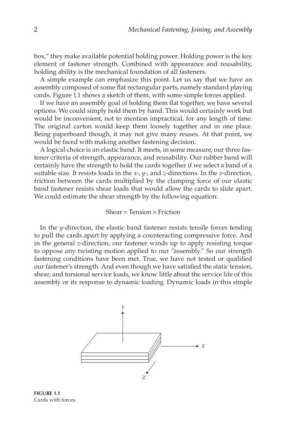
A simple example can emphasize this point. Let us say that we have an assembly composed of some flat rectangular parts, namely standard playing cards. Figure 1.1 shows a sketch of them, with some simple forces applied.
If we have an assembly goal of holding them flat together, we have several options. We could simply hold them by hand. This would certainly work but would be inconvenient, not to mention impractical, for any length of time. The original carton would keep them loosely together and in one place. Being paperboard though, it may not give many reuses. At that point, we would be faced with making another fastening decision.
A logical choice is an elastic band. It meets, in some measure, our three fas-tener criteria of strength, appearance, and reusability. Our rubber band will certainly have the strength to hold the cards together if we select a band of a suitable size. It resists loads in the x-, y-, and z-directions. In the x-direction, friction between the cards multiplied by the clamping force of our elastic band fastener resists shear loads that would allow the cards to slide apart. We could estimate the shear strength by the following equation:
Shear = Tension × Friction
In the y-direction, the elastic band fastener resists tensile forces tending to pull the cards apart by applying a counteracting compressive force. And in the general z-direction, our fastener winds up to apply resisting torque to oppose any twisting motion applied to our “assembly.” So our strength fastening conditions have been met. True, we have not tested or qualified our fastener’s strength. And even though we have satisfied the static tension, shear, and torsional service loads, we know little about the service life of this assembly or its response to dynamic loading. Dynamic loads in this simple
Y
X
Z
FIGURE 1.1Cards with forces.
3Fastener Functions and Assembly Testing
example, such as those resulting from a dropping of the card deck, would constitute a reasonable design consideration.
What about reusability? We have certainly satisfied this goal. We can install our fastener and also remove it many times. We can go through assemble and disassemble cycles repeatedly. No special tools are required, and our fastener is easy to access. We have scored well on reusability. We may lose some elasticity with time or ultraviolet light exposure. We could address this if they are service application factors.
How did we do regarding appearance? We have some latitude here. If we choose a utility quality rubber band fastener, it may not look particularly well assembled. But we could opt to carefully orient our application of the band as we put it on and choose one that only requires one wrap to hold fast. This would also increase assembly efficiency. We can even select a color to match the cards.
Obviously, this simple playing card and rubber band fastener example is oversimplified and far removed from most industrial and commercial fas-tening applications. Our hypothetical card assembly problem is useful in that it lets us look at strength, appearance, and reusability as factors to con-sider when designing and installing fasteners. Most of the assembly applica-tions we fasten are more demanding.
1.2 Analysis of a Simple Metal Assembly
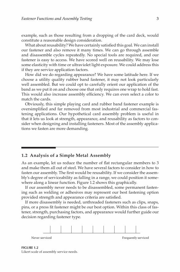
As an example, let us reduce the number of flat rectangular members to 3 and make them all out of steel. We have several factors to consider in how to fasten our assembly. The first would be reusability. If we consider the assem-bly’s degree of serviceability as falling in a range, we could position it some-where along a linear function. Figure 1.2 shows this graphically.
If our assembly never needs to be disassembled, some permanent fasten-ing such as welding or adhesives may represent our best fastening option provided strength and appearance criteria are satisfied.
If more disassembly is needed, unthreaded fasteners such as clips, snaps, pins, or a press fit fastener might be our best option. Within this class of fas-tener, strength, purchasing factors, and appearance would further guide our decision regarding fastener type.
Never serviced Frequently serviced
FIGURE 1.2 Likert scale of assembly service needs.
4 Mechanical Fastening, Joining, and Assembly
Going up the scale of disassembly, threaded fasteners along the lines of bolts, nuts, screws and tapped holes, self-threading screws, and self-drilling and self-tapping screws would be possible options, after which strength, purchasing factors, and assembly appearance factors can be factored into the decision of which fastener type to use.
At maximum reusability limits, quick acting fasteners such as quarter-turn fasteners, captive fastener assemblies, and similar fasteners are options.
Anywhere along the reusability range, from “never needs to be disassem-bled” to “frequently taken apart,” holding strength becomes the next signifi-cant factor. To determine the amount of fastener strength, or holding ability, to design into our assembly, we need to know the materials our assembly is constructed of. We also need to know the directions and sizes of service loads to which it will be subjected.
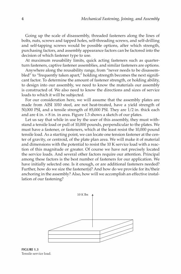
For our consideration here, we will assume that the assembly plates are made from AISI 1010 steel, are not heat-treated, have a yield strength of 50,000 PSI, and a tensile strength of 85,000 PSI. They are 1/2 in. thick each and are 4 in. × 8 in. in area. Figure 1.3 shows a sketch of our plates.
Let us say that while in use by the user of this assembly, they must with-stand a tensile load or pull of 10,000 pounds, perpendicular to the plates. We must have a fastener, or fasteners, which at the least resist the 10,000 pound tensile load. As a starting point, we can locate one tension fastener at the cen-ter of gravity, or centroid, of the plate plan area. We will make it of material and dimensions with the potential to resist the 10 K service load with a reac-tion of this magnitude or greater. Of course we have not precisely located the service loads. And several other factors require our attention. Principal among these factors is the best number of fasteners for our application. We have initially selected one. Is it enough, or are additional fasteners needed? Further, how do we size the fastener(s)? And how do we provide for its/their anchoring in the assembly? Also, how will we accomplish an effective instal-lation of our fastening?
10 K lbs
FIGURE 1.3Tensile service load.
5Fastener Functions and Assembly Testing
Let us look at the number of fasteners to use. In the application, we appear to have used reasonable mechanical judgment. One of our centrally located tension fasteners has a center of action that is only 2 and 4 in., respectively, from the edges of the clamped members. But without accurate informa-tion about the placement of the 10,000 pound service load and the assembly member’s reactions under service load conditions, we do not have sufficient information to reach an informed conclusion about the efficient number of fasteners required for optimal fastening.
Why not place one in each corner? Or one in each corner plus a center fas-tener for a total of five? This may not improve our assembly. First, adequate room for the fasteners means less room in the assembly for more functional, value-adding working room. The additional stresses from four or five fas-teners on the assembly members could cause unwanted distortions in the assembly. And equally important is the added cost of the additional fasteners raises the cost of assembling our product. And the fasteners, by themselves, represent only a fraction of the cost of the fasteners installed in the plates. Depending on the type of fastening selected and the method of anchoring it, the installation costs can represent a four times of the fastening purchasing cost. Put it another way, the total cost for a fastening can be made up of 20% fastener purchasing costs plus 80% fastener installation costs.
Total fastening costs = 20% Fastener purchasing cost + 80% Fastener installation cost
The purchasing costs represent the fasteners, their freight, handling, and disposal of packaging and material handling. Significant costs are also asso-ciated with the costs of physically handling the fasteners. Installation costs are made up of the work performed to prepare their site, work done to put them in the site, and costs associated with any tooling and fixtures used. It is very apparent from this that these can represent significant costs.
Clearly, there is a compelling motivation for any manufacturer to control these costs. Fastening efficiency requires the reduction of these costs to levels appropriate for the safety and structural integrity of the application.
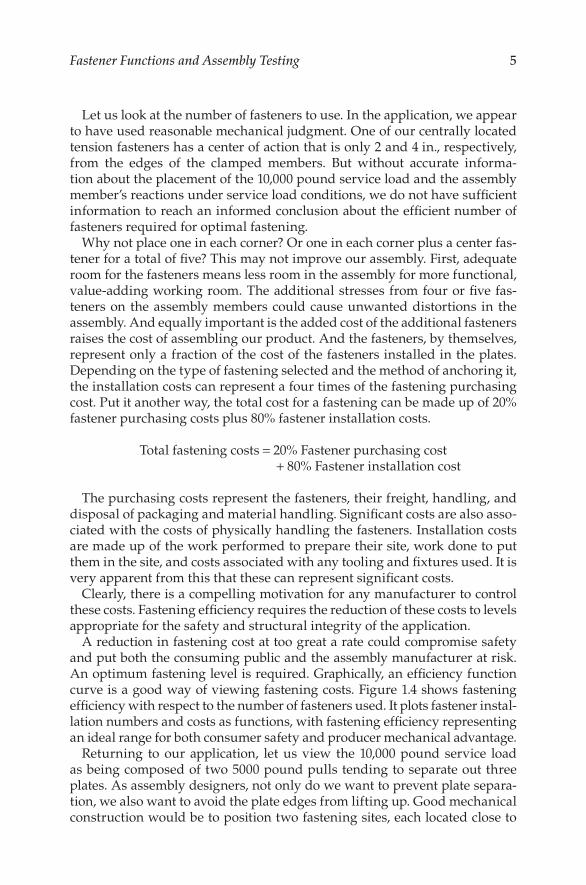
A reduction in fastening cost at too great a rate could compromise safety and put both the consuming public and the assembly manufacturer at risk. An optimum fastening level is required. Graphically, an efficiency function curve is a good way of viewing fastening costs. Figure 1.4 shows fastening efficiency with respect to the number of fasteners used. It plots fastener instal-lation numbers and costs as functions, with fastening efficiency representing an ideal range for both consumer safety and producer mechanical advantage.
Returning to our application, let us view the 10,000 pound service load as being composed of two 5000 pound pulls tending to separate out three plates. As assembly designers, not only do we want to prevent plate separa-tion, we also want to avoid the plate edges from lifting up. Good mechanical construction would be to position two fastening sites, each located close to
6 Mechanical Fastening, Joining, and Assembly
one of the service load points of action. The fastener clamp loads balance the service loads, preventing both plate separation and plate edge bending. Our assembly is in a condition of stable equilibrium.
But what if our confidence in the 10 K service load is less than 100%? Good mechanical judgment would call for us to provide additional clamping load to provide for any over-10 K pound service load peaks or spikes. A standard approach would be to provide for a design safety factor. This multiple will allow for unforeseen service load application to our assembly, with no assem-bly failure in the form of plate separation. Design safety factors represent a form of mechanical insurance. The size of the design factor, or insurance, should be chosen to be appropriate for the nature of the assembly and its intended market.
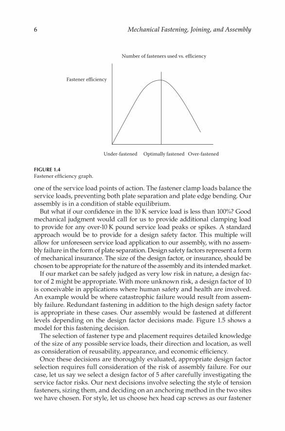
If our market can be safely judged as very low risk in nature, a design fac-tor of 2 might be appropriate. With more unknown risk, a design factor of 10 is conceivable in applications where human safety and health are involved. An example would be where catastrophic failure would result from assem-bly failure. Redundant fastening in addition to the high design safety factor is appropriate in these cases. Our assembly would be fastened at different levels depending on the design factor decisions made. Figure 1.5 shows a model for this fastening decision.
The selection of fastener type and placement requires detailed knowledge of the size of any possible service loads, their direction and location, as well as consideration of reusability, appearance, and economic efficiency.
Once these decisions are thoroughly evaluated, appropriate design factor selection requires full consideration of the risk of assembly failure. For our case, let us say we select a design factor of 5 after carefully investigating the service factor risks. Our next decisions involve selecting the style of tension fasteners, sizing them, and deciding on an anchoring method in the two sites we have chosen. For style, let us choose hex head cap screws as our fastener
Number of fasteners used vs. efficiency
Fastener efficiency
Under-fastened Optimally fastened Over-fastened
FIGURE 1.4Fastener efficiency graph.
7Fastener Functions and Assembly Testing
type. They are readily available. Tightening tools are common and fit the industrial style of our metal plates. Since they have machine screw threads, they are very reusable. An interesting observation is the nomenclature dif-ference between the bolts and screws. Although they are commonly used interchangeably, a bolt is used with a nut, and a screw, as normally used, is threaded directly into the assembly.
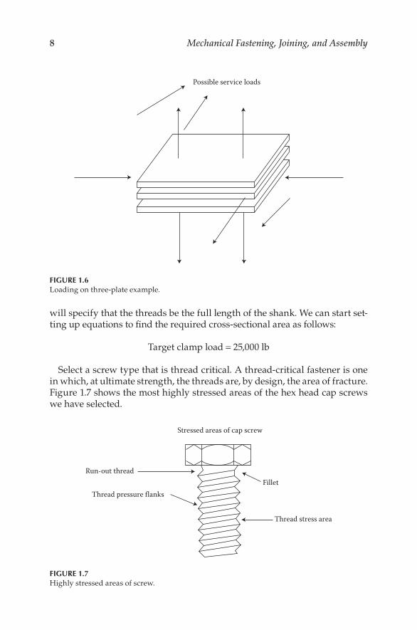
Since we want to keep our parts count down, we will use two machine screws. There are some technical advantages to using washers and nuts in this application—one among them is a longer grip length. This gives us lon-ger total elongation for a given preload. It also means that we will be apply-ing the clamp load over a larger bearing area giving a greater clamp-affected zone. This will give us lower bearing stresses. This is important if the fasten-ers are significantly harder than the assembly. We will forgo these advan-tages to reduce the parts count but will not lose sight of the trade-offs we have made to reduce fastener count. In an application, we would expect to thoroughly test our assembly using both laboratory and field work, possibly combined with computer simulation. Figure 1.6 shows other possible loads.
With a design safety factor of 5, a service load of 10,000 pounds, and two screws, each screw will need to be capable of carrying 25,000 pounds. This presupposes uniform loading. In actual practice, uniform loading is not always the case and in designing a fastening system, a nonuniform loading, and possible resulting bending stresses, should be added to our calculations.
To determine static fastener strength, we would need to know the fastener strength of material and cross-sectional area. To determine the critical area of our fasteners, we can rely on industry standards, which have been developed to help size cap screws for their intended service load. For our purposes, we will specify an SAE grade 8 material with 150,000 psi (lb/ft2) of tensile strength and 130,000 lb/in2 of yield strength. Our screws will be 1 1/2 in. long, and we
Cost of assembly failure Design factor
FIGURE 1.5Failure to design factor comparison.
8 Mechanical Fastening, Joining, and Assembly
will specify that the threads be the full length of the shank. We can start set-ting up equations to find the required cross-sectional area as follows:
Target clamp load = 25,000 lb
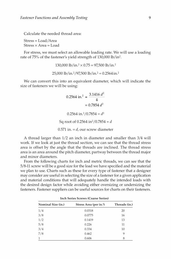
Select a screw type that is thread critical. A thread-critical fastener is one in which, at ultimate strength, the threads are, by design, the area of fracture. Figure 1.7 shows the most highly stressed areas of the hex head cap screws we have selected.
Possible service loads
FIGURE 1.6Loading on three-plate example.
Run-out thread
Stressed areas of cap screw
Fillet
Thread stress area
Thread pressure flanks
FIGURE 1.7Highly stressed areas of screw.
9Fastener Functions and Assembly Testing
Calculate the needed thread area:
Stress = Load/AreaStress × Area = Load
For stress, we must select an allowable loading rate. We will use a loading rate of 75% of the fastener’s yield strength of 130,000 lb/in2.
130,000 lb/in.2 × 0.75 = 97,500 lb/in.2
25,000 lb/in.2/97,500 lb/in.2 = 0.2564 in.2
We can convert this into an equivalent diameter, which will indicate the size of fasteners we will be using:
0.2564 in.3.1416
4= 0.7854
22
=d
d2
0.2564 in.2/0.7854 = d2
Sq root of 0.2564 in2/0.7854 = d
0.571 in. = d, our screw diameter
A thread larger than 1/2 an inch in diameter and smaller than 3/4 will work. If we look at just the thread section, we can see that the thread stress area is offset by the angle that the threads are inclined. The thread stress area is an area around the pitch diameter, partway between the thread major and minor diameters.
From the following charts for inch and metric threads, we can see that the 5/8-11 screw will be a good size for the load we have specified and the material we plan to use. Charts such as these for every type of fastener that a designer may consider are useful in selecting the size of a fastener for a given application and material conditions that will adequately handle the intended loads with the desired design factor while avoiding either oversizing or undersizing the fasteners. Fastener suppliers can be useful sources for charts on their fasteners.
Inch Series Screws (Coarse Series)
Nominal Size (in.) Stress Area (per in.2) Threads (in.)
1/4 0.0318 203/8 0.0775 161/2 0.1419 135/8 0.226 113/4 0.334 107/8 0.462 91 0.606 8
10 Mechanical Fastening, Joining, and Assembly
Metric Series Screws (Preferred Pitch)
Nominal Size Stress Area (mm2) Pitch
M5 14.20 0.8M8 36.60 1.25M10 58.00 1.50M12 84.30 1.75M16 157.00 2.0M20 245.00 2.5M24 353.00 3.0
We made a choice here regarding the threads per inch, or thread pitch if using the metric system. Both coarse and fine thread pitch series have ben-efits and drawbacks. A comparison shows the following facts.
Thread Pitch Selection
Coarse Pitch Fine Pitch
Benefits Fewer turns to tighten Larger stress areaEasier to start Slightly higher vibration resistance
Drawbacks Prone to loosening (from Reference 1)
Prone to hard starts
Using a very basic example, we have set a fastener design goal, quantified the service loads, selected a suitable design factor, and sized the fasteners. To complete the process, we should perform some application testing to assure and document our assembly design. If the assembly operation is to be repeti-tious, assembly materials and procedures should also be documented.
In testing, our goal should be to subject our assembly to test loads as simi-lar as possible to those it will work under in service. Since in this application, a 10 K tensile load is expected, composed of two 5 K components, we can use this loading for baseline testing.
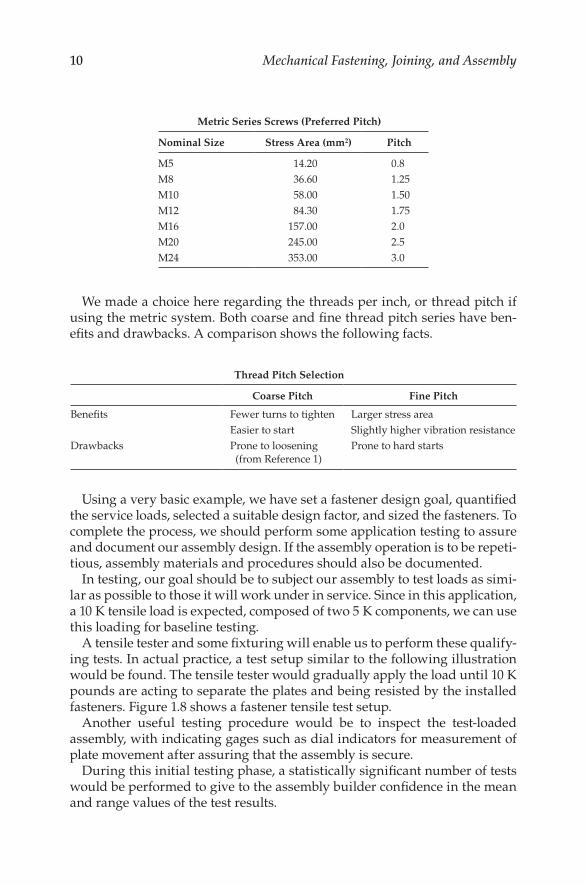
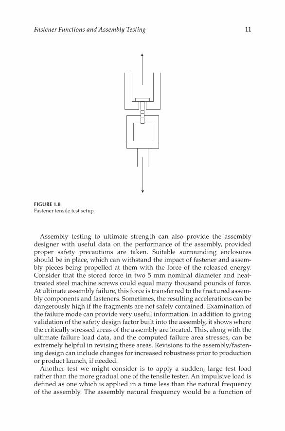
A tensile tester and some fixturing will enable us to perform these qualify-ing tests. In actual practice, a test setup similar to the following illustration would be found. The tensile tester would gradually apply the load until 10 K pounds are acting to separate the plates and being resisted by the installed fasteners. Figure 1.8 shows a fastener tensile test setup.
Another useful testing procedure would be to inspect the test-loaded assembly, with indicating gages such as dial indicators for measurement of plate movement after assuring that the assembly is secure.
During this initial testing phase, a statistically significant number of tests would be performed to give to the assembly builder confidence in the mean and range values of the test results.
11Fastener Functions and Assembly Testing
Assembly testing to ultimate strength can also provide the assembly designer with useful data on the performance of the assembly, provided proper safety precautions are taken. Suitable surrounding enclosures should be in place, which can withstand the impact of fastener and assem-bly pieces being propelled at them with the force of the released energy. Consider that the stored force in two 5 mm nominal diameter and heat-treated steel machine screws could equal many thousand pounds of force. At ultimate assembly failure, this force is transferred to the fractured assem-bly components and fasteners. Sometimes, the resulting accelerations can be dangerously high if the fragments are not safely contained. Examination of the failure mode can provide very useful information. In addition to giving validation of the safety design factor built into the assembly, it shows where the critically stressed areas of the assembly are located. This, along with the ultimate failure load data, and the computed failure area stresses, can be extremely helpful in revising these areas. Revisions to the assembly/fasten-ing design can include changes for increased robustness prior to production or product launch, if needed.
Another test we might consider is to apply a sudden, large test load rather than the more gradual one of the tensile tester. An impulsive load is defined as one which is applied in a time less than the natural frequency of the assembly. The assembly natural frequency would be a function of
FIGURE 1.8Fastener tensile test setup.
12 Mechanical Fastening, Joining, and Assembly
its assembled mass, found from its weight divided by a gravitational con-stant, its relative spring rates, and the assembly’s degrees of freedom. Our application has three steel plates with a weight of 4.5 lb each and a total of 13.5 lb. Our two hex head cap screws together weigh 0.2 lb. Our total assembly weight is 13.7 lb. If our natural frequency were about 0.7 cycles per second, we would want to be alert to assembly loading cycles around this frequency (2).
As a practical consideration, a commercial laboratory would be a good choice for performing impact-type work on the relatively small test iteration scale that a new assembly would entail.
With all of the test equipment used in assembly qualification and design evaluation, test procedures should be documented and the appropriate training should be in place. Measurement and test equipment should be on a calibration schedule with comparisons made to know standards trace-able to an established source, such as the National Institute of Standards and Technology (NIST) in Gaithersburg, Maryland. And test results should be recorded in a professional manner, and appropriate record maintenance kept for future reference.
If possible service for the assembly includes temperature-extreme envi-ronments or extended use in corrosive atmospheres, tests under these con-ditions are advisable. Laboratories for performing hot and cold tests, along with salt spray and humidity cabinet, or other corrosive atmosphere condi-tions exposure testing are available.
Other tests could include ones for vibration in several different modes to document the assembly’s ability to maintain a significant percentage of fas-tening force under the rugged conditions found in some applications.
If the service load is an alternating, defined-frequency-range environ-ment, typical of the loading conditions found in many prime movers such as internal combustion engines, fatigue life may be an important fastening design consideration. In alternating load applications, control of fastener preload, joint relaxation, and joint face embedment should be primary engi-neering factors.
Tests that we have conducted would include fatigue testing. In a fastener fatigue test, an alternating load is applied about a preestablished mean load, which is preloaded before starting the test. Using actual production assem-bly components and assembly fasteners in the fatigue test assures the closest replication to real-world service conditions.
However, using just the fasteners in test fixtures can be a valid fatigue test-ing procedure for periodic inspection and candidate vendor evaluation, or for competitive fastener design testing.
The fatigue tests are conducted to generate pairs of alternating service load and service load cycles. An advanced form of the fatigue test relies on driv-ing the test specimen into resonant frequency. This extreme form of alternate loading results in cascading loads at resonance, thereby reducing the time to complete testing.
13Fastener Functions and Assembly Testing
1.3 Fastening a More Complex Assembly
Many components that we are required to assemble present joining surfaces and service loads that are not as regular in either their geometry or engineer-ing mechanics. The fastening, joining, and assembly procedure decision to be made still must address the basic issues of assembled strength, assembly reusability, and assembled component appearance that form the basis for our fastening decisions in the prior, albeit simplified, example.
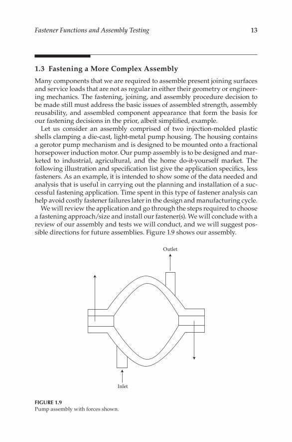
Let us consider an assembly comprised of two injection-molded plastic shells clamping a die-cast, light-metal pump housing. The housing contains a gerotor pump mechanism and is designed to be mounted onto a fractional horsepower induction motor. Our pump assembly is to be designed and mar-keted to industrial, agricultural, and the home do-it-yourself market. The following illustration and specification list give the application specifics, less fasteners. As an example, it is intended to show some of the data needed and analysis that is useful in carrying out the planning and installation of a suc-cessful fastening application. Time spent in this type of fastener analysis can help avoid costly fastener failures later in the design and manufacturing cycle.
We will review the application and go through the steps required to choose a fastening approach/size and install our fastener(s). We will conclude with a review of our assembly and tests we will conduct, and we will suggest pos-sible directions for future assemblies. Figure 1.9 shows our assembly.
Inlet
Outlet
FIGURE 1.9Pump assembly with forces shown.
14 Mechanical Fastening, Joining, and Assembly
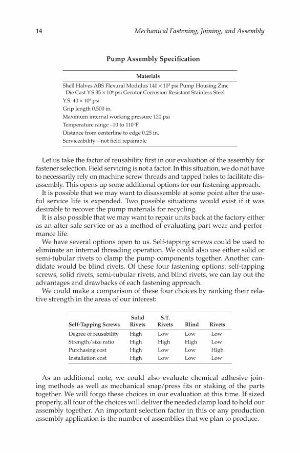
Pump Assembly Specification
Materials
Shell Halves ABS Flexural Modulus 140 × 103 psi Pump Housing Zinc Die Cast Y.S 35 × 106 psi Gerotor Corrosion Resistant Stainless Steel
Y.S. 40 × 106 psiGrip length 0.500 in.Maximum internal working pressure 120 psiTemperature range –10 to 110°FDistance from centerline to edge 0.25 in.Serviceability—not field repairable
Let us take the factor of reusability first in our evaluation of the assembly for fastener selection. Field servicing is not a factor. In this situation, we do not have to necessarily rely on machine screw threads and tapped holes to facilitate dis-assembly. This opens up some additional options for our fastening approach.
It is possible that we may want to disassemble at some point after the use-ful service life is expended. Two possible situations would exist if it was desirable to recover the pump materials for recycling.
It is also possible that we may want to repair units back at the factory either as an after-sale service or as a method of evaluating part wear and perfor-mance life.
We have several options open to us. Self-tapping screws could be used to eliminate an internal threading operation. We could also use either solid or semi-tubular rivets to clamp the pump components together. Another can-didate would be blind rivets. Of these four fastening options: self-tapping screws, solid rivets, semi-tubular rivets, and blind rivets, we can lay out the advantages and drawbacks of each fastening approach.
We could make a comparison of these four choices by ranking their rela-tive strength in the areas of our interest:
Self-Tapping ScrewsSolid Rivets
S.T. Rivets Blind Rivets
Degree of reusability High Low Low LowStrength/size ratio High High High LowPurchasing cost High Low Low HighInstallation cost High Low Low Low
As an additional note, we could also evaluate chemical adhesive join-ing methods as well as mechanical snap/press fits or staking of the parts together. We will forgo these choices in our evaluation at this time. If sized properly, all four of the choices will deliver the needed clamp load to hold our assembly together. An important selection factor in this or any production assembly application is the number of assemblies that we plan to produce.
15Fastener Functions and Assembly Testing
Realizing that exact prediction of future assembly build rates may be very difficult, it is still important to establish an estimate of the assembly build quantity. Build quantity will set the level of installation systems costs—the effort and the tooling, machinery, documentation, training, and inventory needed to get the assembly work done. And it is these costs that can repre-sent, as indicated earlier in this chapter, the major percentage of the assembly cost. Equally important is it fixes some of these costs for a long time into the assembly’s commercial future, if not for its entire life.
After evaluating our four choices, we will choose a semitubular rivet as best meeting our assembly’s design goals. Its strength can be sized and tested to deliver the holding power that our pump will require during its service life. While designed to be permanently joined in the field, semitubular rivets can be easily drilled out for some after-service work such as recycling, wear evaluation, or factory-authorized repair.
The appearance of our two assembled joints in the pump can be made of a material and plated or finished to give a range of esthetic looks as we require. By selecting a head style and riveting technique, we can match the semitubu-lar rivet’s shape to the pump housing’s geometry.
Sizing the rivet is our next step, which requires us to know the pump ser-vice loads that the rivets will be called on to oppose for the life of the assem-bly. From our data, we know that the internal pump pressure is 120 psi. Let us say that by calculating the internal area of the pump housing, we arrive at an internal working area of 7.5 in2. From the pressure and area, we estimate the primary service load as
Stress × Area = Service load120 lb/in2 × 7.5 in2 = 900 lb
We will need to clamp the assembly with a compressive force greater than 900 lb. In actual practice, we may want to use a pressure gage to confirm this internal pressure. Testing service loads is often good practice. It can often more than justify the setup and testing expenses involved. In some cases, loads not foreseen during assembly design can be brought to the designer’s attention. In a specific example, let us plan on a shear load from the internal torque of the gerotor pump mechanism. An accurate assessment of assembly service loads is a key factor in the efficient sizing of the fasteners specified. By knowing both the normal and extraordinary service loads of an assembly, coupled with a suitable design factor, we can have confidence in the strength, durability, and integrity of our fasteners. Often, prototype testing and com-puter simulation can be used to increase our understanding of service load-ing amplitudes, directions, and frequencies. Let us take a look at the rivets as they will be installed in the pump and at load. Figure 1.10 shows the assembly.
We will specify a semi-tubular rivet which has a shank diameter that can develop and hold a design factor multiple of 450 lb for each rivet. It will also be specified that the shank length is sufficient to grip our assembled stack of components with sufficient rivet body to rivet over into an acceptable joint.
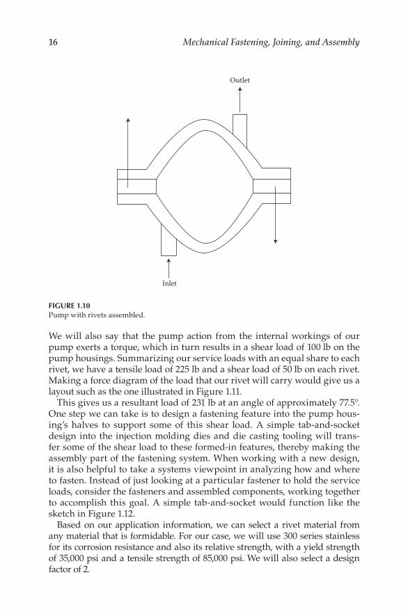
16 Mechanical Fastening, Joining, and Assembly
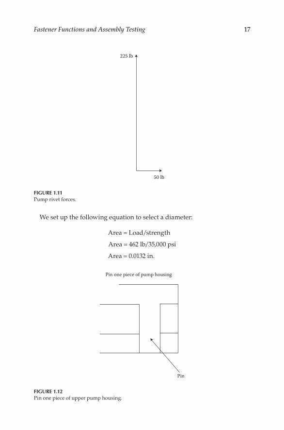
We will also say that the pump action from the internal workings of our pump exerts a torque, which in turn results in a shear load of 100 lb on the pump housings. Summarizing our service loads with an equal share to each rivet, we have a tensile load of 225 lb and a shear load of 50 lb on each rivet. Making a force diagram of the load that our rivet will carry would give us a layout such as the one illustrated in Figure 1.11.
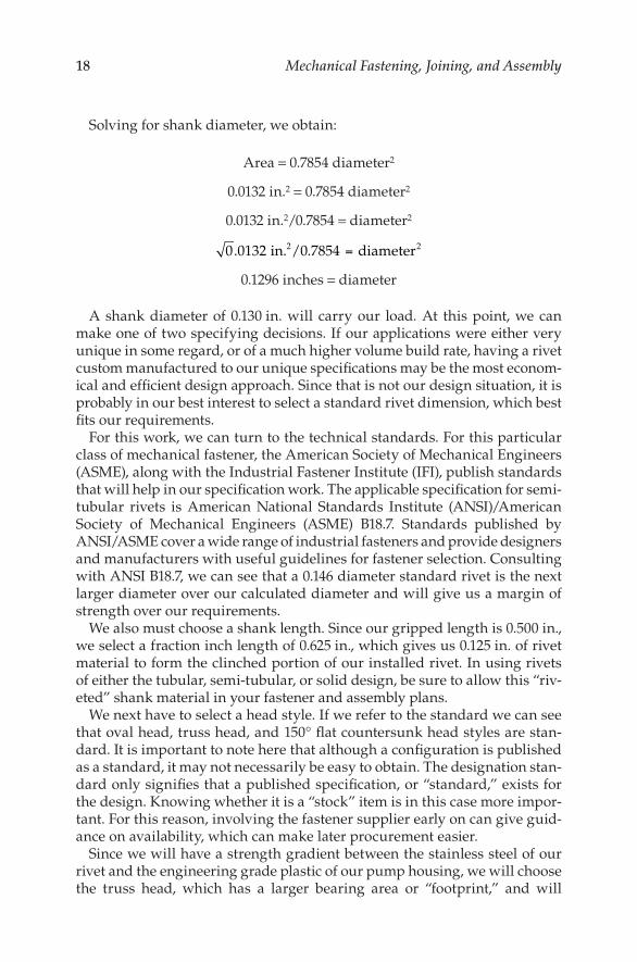
This gives us a resultant load of 231 lb at an angle of approximately 77.5°. One step we can take is to design a fastening feature into the pump hous-ing’s halves to support some of this shear load. A simple tab-and-socket design into the injection molding dies and die casting tooling will trans-fer some of the shear load to these formed-in features, thereby making the assembly part of the fastening system. When working with a new design, it is also helpful to take a systems viewpoint in analyzing how and where to fasten. Instead of just looking at a particular fastener to hold the service loads, consider the fasteners and assembled components, working together to accomplish this goal. A simple tab-and-socket would function like the sketch in Figure 1.12.
Based on our application information, we can select a rivet material from any material that is formidable. For our case, we will use 300 series stainless for its corrosion resistance and also its relative strength, with a yield strength of 35,000 psi and a tensile strength of 85,000 psi. We will also select a design factor of 2.
Inlet
Outlet
FIGURE 1.10Pump with rivets assembled.
17Fastener Functions and Assembly Testing
We set up the following equation to select a diameter:
Area = Load/strength
Area = 462 lb/35,000 psi
Area = 0.0132 in.
50 lb
225 lb
FIGURE 1.11Pump rivet forces.
Pin
Pin one piece of pump housing
FIGURE 1.12Pin one piece of upper pump housing.
18 Mechanical Fastening, Joining, and Assembly
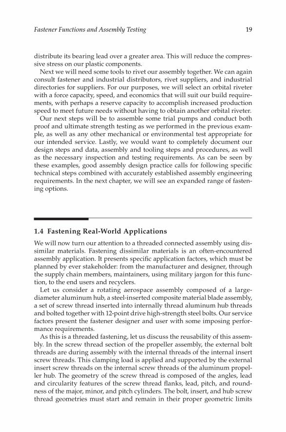
Solving for shank diameter, we obtain:
Area = 0.7854 diameter2
0.0132 in.2 = 0.7854 diameter2
0.0132 in.2/0.7854 = diameter2
0 0132 78542 2. . . in /0 diameter=
0.1296 inches = diameter
A shank diameter of 0.130 in. will carry our load. At this point, we can make one of two specifying decisions. If our applications were either very unique in some regard, or of a much higher volume build rate, having a rivet custom manufactured to our unique specifications may be the most econom-ical and efficient design approach. Since that is not our design situation, it is probably in our best interest to select a standard rivet dimension, which best fits our requirements.
For this work, we can turn to the technical standards. For this particular class of mechanical fastener, the American Society of Mechanical Engineers (ASME), along with the Industrial Fastener Institute (IFI), publish standards that will help in our specification work. The applicable specification for semi-tubular rivets is American National Standards Institute (ANSI)/American Society of Mechanical Engineers (ASME) B18.7. Standards published by ANSI/ASME cover a wide range of industrial fasteners and provide designers and manufacturers with useful guidelines for fastener selection. Consulting with ANSI B18.7, we can see that a 0.146 diameter standard rivet is the next larger diameter over our calculated diameter and will give us a margin of strength over our requirements.
We also must choose a shank length. Since our gripped length is 0.500 in., we select a fraction inch length of 0.625 in., which gives us 0.125 in. of rivet material to form the clinched portion of our installed rivet. In using rivets of either the tubular, semi-tubular, or solid design, be sure to allow this “riv-eted” shank material in your fastener and assembly plans.
We next have to select a head style. If we refer to the standard we can see that oval head, truss head, and 150° flat countersunk head styles are stan-dard. It is important to note here that although a configuration is published as a standard, it may not necessarily be easy to obtain. The designation stan-dard only signifies that a published specification, or “standard,” exists for the design. Knowing whether it is a “stock” item is in this case more impor-tant. For this reason, involving the fastener supplier early on can give guid-ance on availability, which can make later procurement easier.
Since we will have a strength gradient between the stainless steel of our rivet and the engineering grade plastic of our pump housing, we will choose the truss head, which has a larger bearing area or “footprint,” and will
19Fastener Functions and Assembly Testing
distribute its bearing lead over a greater area. This will reduce the compres-sive stress on our plastic components.
Next we will need some tools to rivet our assembly together. We can again consult fastener and industrial distributors, rivet suppliers, and industrial directories for suppliers. For our purposes, we will select an orbital riveter with a force capacity, speed, and economics that will suit our build require-ments, with perhaps a reserve capacity to accomplish increased production speed to meet future needs without having to obtain another orbital riveter.
Our next steps will be to assemble some trial pumps and conduct both proof and ultimate strength testing as we performed in the previous exam-ple, as well as any other mechanical or environmental test appropriate for our intended service. Lastly, we would want to completely document our design steps and data, assembly and tooling steps and procedures, as well as the necessary inspection and testing requirements. As can be seen by these examples, good assembly design practice calls for following specific technical steps combined with accurately established assembly engineering requirements. In the next chapter, we will see an expanded range of fasten-ing options.
1.4 Fastening Real-World Applications
We will now turn our attention to a threaded connected assembly using dis-similar materials. Fastening dissimilar materials is an often-encountered assembly application. It presents specific application factors, which must be planned by ever stakeholder: from the manufacturer and designer, through the supply chain members, maintainers, using military jargon for this func-tion, to the end users and recyclers.
Let us consider a rotating aerospace assembly composed of a large- diameter aluminum hub, a steel-inserted composite material blade assembly, a set of screw thread inserted into internally thread aluminum hub threads and bolted together with 12-point drive high-strength steel bolts. Our service factors present the fastener designer and user with some imposing perfor-mance requirements.
As this is a threaded fastening, let us discuss the reusability of this assem-bly. In the screw thread section of the propeller assembly, the external bolt threads are during assembly with the internal threads of the internal insert screw threads. This clamping load is applied and supported by the external insert screw threads on the internal screw threads of the aluminum propel-ler hub. The geometry of the screw thread is composed of the angles, lead and circularity features of the screw thread flanks, lead, pitch, and round-ness of the major, minor, and pitch cylinders. The bolt, insert, and hub screw thread geometries must start and remain in their proper geometric limits
20 Mechanical Fastening, Joining, and Assembly
if the screw threads are to allow good initial assembly and as importantly, subsequent removal and reassembly of the propeller during the engine and aircraft’s service life. The reusability will be required to adequately carry significant static and dynamic loads if reusability is to provide performance that all involved can consider as good reusability performance. What reus-ability performance measurement can be employed to measure this assem-bly’s reusability?
This is an important question. From a practical standpoint, most people would use a simple “If it works” reusability measurement criteria. If we are able to install, remove, and reinstall the propeller by screwing and unscrew-ing our bolts, we have a successful design. And for many users and appli-cations, this is satisfactory. That said, it does not enable us to quantify our reusability. It also does not provide sufficient guidance for measuring the degree of reusability: identifying existing or potential weaknesses in the assembly’s reusability. For continual improvement of reusability, with respect to both the total number of cycles available or the cost–benefits associated with fastening alternatives, numerical metrics are needed. Let us consider some of these.
Since we will be applying torque to the 12-point bolts to both install and remove the propeller, an index of torques might prove useful. One used in industry has been the prevailing on and prevailing off torques. For example, if we require 100 N m of tightening torque applied to the wrenching surfaces of the 12-point head torque to tighten the screw to its design preload target, the 100 N m can be the denominator of our index. We can record the loos-ening torque as the numerator of this index. In tightening the bolts, clamp-ing load is being developed in our assembly by bolt elongation, resisted by propeller compression. When the tightening torque is applied, work is being performed on our assembly “system”. A good analogy is pushing a block up an inclined plane. The inclined plane angle is the lead angle of the screw threads. If our bolt has M12 × 1 6 g screw threads, our lead is 1 mm and our lead angle is 1°, 42 min, 13 s.
During untightening, the block is coming back down the inclined plane, work is being performed by the system and the loosening torque is gener-ally lower. For this example, let us say 85 N m giving a reusability index of loosening and tightening torques of 85/100 N m, or 85%. A range of this reusability index would provide a quantitative measure for comparison and process improvement. If subsequent lots have increasing loosening torques, our system’s reusability has decreased. If we develop a new source whose components assemble with 100 N m tightening torque but loosen with only 75 N m, then we have changed the efficiency of our reusability. A customer need not apply as much loosening torque to remove the propeller. While not seeming to be significant, one assembly cycle, over the life of the system, or more to the point, over the life of a complete propeller assembly production run of large numbers and years of service, these efficiencies can add up to significant savings in maintainer effort, energy usage such as for compressed
21Fastener Functions and Assembly Testing
air, and electrical power and tool life. As an example in the opposite direc-tion, a screw-threaded component subject to galling in the threads may actu-ally “lock in” and require a higher torque to untightening, making this much less efficient.
Building on this index, let us add the factor of time. On the tightening side, we could compare quantitatively the initial tightening torque of 100 N m with the second, third, fourth, fifth, and so on. We might find decreases of 2%, perhaps more or less. Factors such as contacting surface smoothing, minor local permanent deformations from material yield, and other assem-bly component changes could be evaluated and understood. This phenome-non was often referred to as “bedding-in” of an assembly. We could also plot with torque and time graphical axis the shape and duration of the tightening torque. This would give us a tightening torque signature.
On the loosening side, we could perform a similar first to fifth (or more) loosening torque study and similarly a plot of loosening torque signature. The value to the reader is to know that these are available engineering tech-niques to provide a better understanding of an assembly’s reusability.
We could combine the result of all of these torque applications, namely assembly clamp load, to access reusability. It is reasonable to expect our assembly to have some decrease in clamp load, hopefully small in magni-tude, with repeated loading and loosening cycles due to localized perma-nent deformations of hub, insert propeller, and bolt. This “bedding-in” effect is one of the reasons for the frequently used maintenance instruction of peri-odic retightening of assembly fasteners. Reviewing our reusability factors, we can list tightening torque, loosening torque, service time, and clamp load. These are our important assembly factors to assess and understand reus-ability performance.
Next, we will turn our attention to the strength of this propeller assem-bly. A usual distinction can be to divide assembly strength into static and dynamic strength. We mentioned assembly clamp load in the previous para-graph. Clamping load, measured in Newtons or pounds measured in met-ric and inch system units, respectively, can be considered a static strength property of the assembly and is typically given the term preload. A useful measure of static strength is the ratio of the strength of the assembly as a unit compared with the material strength of the individual assembly members. Turning our attention to those, we can use the yield and ultimate tensile, compressive, and shear strength properties of the materials used for each assembly member.
As it is the prime fastening product in this assembly, let us evaluate the static strength of the 12-point bolts used. We can look at both the raw material certificates of the steel used to obtain the chemical and physical properties of the raw material, and we can similarly obtain the yield and tensile strength, elongation, and reduction in area and hardness of the bolts. Each individual bolt will have some small variation within specification of these proper-ties. Each should be depended upon to meet the specification minimums.
22 Mechanical Fastening, Joining, and Assembly
A good way to think of these strength properties is as hold power potential. For a 12-mm diameter bolt, it is reasonable to expect a yield strength in the 900 MPa range and an ultimate tensile strength of 1000 MPa. For the tensile shear area of an M12 × 1 6 g screw thread, this would give us an area of approximately 101 mm2 I obtained this estimate by finding the circular area of a diameter around the pitch diameter, which gives a useful approxima-tion for applications work. The precise thread stress area is often calculated by averaging the pitch and minor diameters, and I have considered it as a circular area inclined along the plane of the lead angle. In this application, the load at yield would be approximately 91,437.7 N, or 914 kN. For assembly design review purposes, we would make our design calculations based on a percentage of the 900 MPa yield strength. Up to 75% of bolt yield is one preload target sometimes used, depending on the assembly. Turning our attention to the strength of the composite propeller, its compressive strength will be a testable, known factor. Metallic inserts may be in place to reinforce bolt through holes and bearing areas. The aluminum hub will have yield, tensile, elongation, reduction in area, and hardness values. It is reasonable to expect this to be lower than the steel bolt. For this reason, high-strength screw thread inserts are installed in the internal hub threads. The inserts have strength properties, as evidenced by their chemical and physical raw material properties, and possible heat treatment and hardness values, that approach or exceed those of the mating bolt. Taken together, they provide a good assembly site to clamp the propeller to the hub with the bolts. We can measure the strength of the materials and then test the assembly as a unit to develop an index of the assembly and material strength. The index will give us a good ratio of fastener efficiency. Welds, for example, have joint strengths higher than the materials being welded. Reusability is understandably low. Our propeller assembly has good reusability. An index of 60–80% of the low-est static strength material, perhaps the aluminum hub, is within reason.
Finally, we offer an opinion about this assembly’s appearance factors. A good visual can be had by standing back, taking a good long look at the propeller assembly, and forming an opinion on how it looks. By what criteria do we judge appearance? Seeing numerous propeller assemblies could serve us well. As could continuing education and training in industrial design. If it were a consumer product, focus groups have proved both useful and quantifiable.
As a general observation, the composite material exudes a high-tech, advanced look. Our 12-point bolts are often found in aerospace as well as in high-performance and racing automobile applications. The aluminum can provide a bright, polished, and aerodynamic look. We could draw the subjec-tive opinion that on appearance criteria we would score well.
Turning our attention to dynamic strength, I would like to offer a real-life application as an example. The screw was a special socket head cap screw with a head that was machined to provide a barrel-shaped outer head sur-face, but a full bearing area. It was an inch system screw with material and
23Fastener Functions and Assembly Testing
mechanical properties very similar to our example above. My involvement as an employee of the manufacturer of the screw was to follow up on the fatigue failure of a bolt from a lot manufactured by my employer.
The screw, used in an aircraft, had broken during a flight. Fortunately, the aircraft landed safely with the remaining bolts still intact. As I recall, we were provided with the fracture threaded section, which was removed from the hub and sent by the propeller manufacturer as a corrective action. We discussed static strength earlier in this section. Dynamic strength, of which fatigue strength is an important one, was at play here. The fracture plane of the remaining threaded area presented the classic fracture planes of a fatigue failure.
Beach marks are so named as they appear like the surface of beach sand lifted by waves of an incoming tide. Metallurgical examination of the mate-rial showed it to be within print specifications. A dimension examination was performed from unused screws still remaining from the lot. No discrep-ancies could be found, yet the fatigue failure was obvious. The cause turned out to be the installation of the propeller on an engine that was supercharged and flying in a high-altitude, rugged terrain, greatly increasing the dynamic loading. The screw head fractured from too high an alternating service load, carrying past the screw and propeller assemblies endurance limit. A rede-sign of the screw increased the fatigue strength as measured by its endur-ance limit by increasing the fillet radius in both dimensions, reconfiguring the head’s outside diameter, and rolling the screw threads with unified “J” profile threads after heat treatment.
For our next application, we will review a class 5 threaded alloy steel stud threaded into an Inconel 718 valve body. The threaded stud serves to hold the valve bonnet onto the valve body. It needs to be reusable, but with the additional requirement that the stud-threaded end in the body must not be subject to loosening from the dynamic service loads of the valve open-ing and closing on high volumes of flowing fluid in the valve body. From a strength review of the stud, valve body, and valve bonnet assembly, the studs must be capable, when installed and tightened using high-strength nuts over engineered washers, of carrying substantial tension loads exerted by the fluid pressure in the valve.
Each stud’s material and geometry will retain the chemical and physical properties after heat treatment to meet its specification requirements. As a circular stud pattern installed around the valve body flange, they will, in combination, provide a design factor multiple of the maximum service loads anticipated for this assembly.
While the class 5 interference screw threads on one end of these valve body studs are relatively sophisticated, their appearance factors are about as straight forward as its gets. The studs are unseen except for the several turns, or thread and point length of the standard unified (UN) screw thread protruding past the top face of the nuts when installed or torqued to design preload.
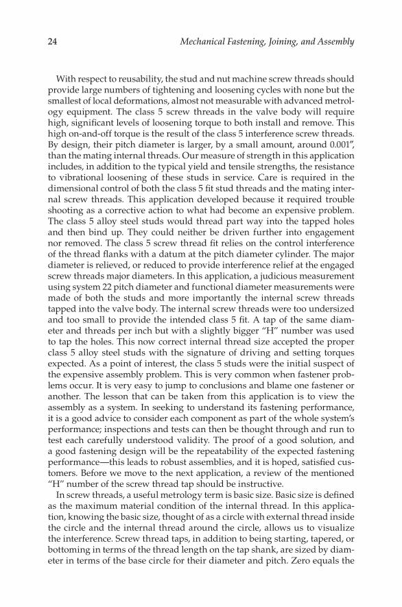
24 Mechanical Fastening, Joining, and Assembly
With respect to reusability, the stud and nut machine screw threads should provide large numbers of tightening and loosening cycles with none but the smallest of local deformations, almost not measurable with advanced metrol-ogy equipment. The class 5 screw threads in the valve body will require high, significant levels of loosening torque to both install and remove. This high on-and-off torque is the result of the class 5 interference screw threads. By design, their pitch diameter is larger, by a small amount, around 0.001″, than the mating internal threads. Our measure of strength in this application includes, in addition to the typical yield and tensile strengths, the resistance to vibrational loosening of these studs in service. Care is required in the dimensional control of both the class 5 fit stud threads and the mating inter-nal screw threads. This application developed because it required trouble shooting as a corrective action to what had become an expensive problem. The class 5 alloy steel studs would thread part way into the tapped holes and then bind up. They could neither be driven further into engagement nor removed. The class 5 screw thread fit relies on the control interference of the thread flanks with a datum at the pitch diameter cylinder. The major diameter is relieved, or reduced to provide interference relief at the engaged screw threads major diameters. In this application, a judicious measurement using system 22 pitch diameter and functional diameter measurements were made of both the studs and more importantly the internal screw threads tapped into the valve body. The internal screw threads were too undersized and too small to provide the intended class 5 fit. A tap of the same diam-eter and threads per inch but with a slightly bigger “H” number was used to tap the holes. This now correct internal thread size accepted the proper class 5 alloy steel studs with the signature of driving and setting torques expected. As a point of interest, the class 5 studs were the initial suspect of the expensive assembly problem. This is very common when fastener prob-lems occur. It is very easy to jump to conclusions and blame one fastener or another. The lesson that can be taken from this application is to view the assembly as a system. In seeking to understand its fastening performance, it is a good advice to consider each component as part of the whole system’s performance; inspections and tests can then be thought through and run to test each carefully understood validity. The proof of a good solution, and a good fastening design will be the repeatability of the expected fastening performance—this leads to robust assemblies, and it is hoped, satisfied cus-tomers. Before we move to the next application, a review of the mentioned “H” number of the screw thread tap should be instructive.
In screw threads, a useful metrology term is basic size. Basic size is defined as the maximum material condition of the internal thread. In this applica-tion, knowing the basic size, thought of as a circle with external thread inside the circle and the internal thread around the circle, allows us to visualize the interference. Screw thread taps, in addition to being starting, tapered, or bottoming in terms of the thread length on the tap shank, are sized by diam-eter in terms of the base circle for their diameter and pitch. Zero equals the
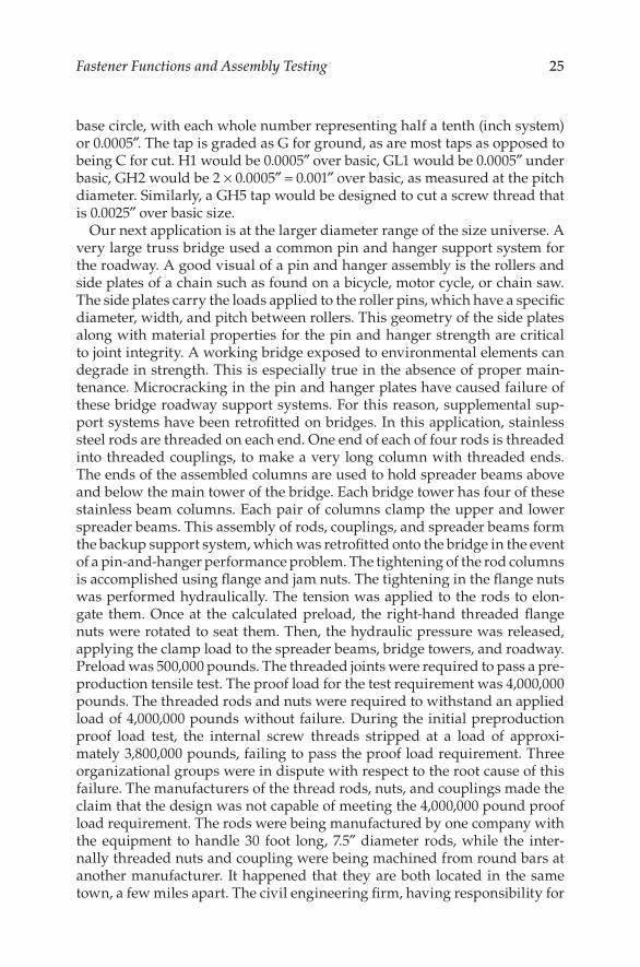
25Fastener Functions and Assembly Testing
base circle, with each whole number representing half a tenth (inch system) or 0.0005″. The tap is graded as G for ground, as are most taps as opposed to being C for cut. H1 would be 0.0005″ over basic, GL1 would be 0.0005″ under basic, GH2 would be 2 × 0.0005″ = 0.001″ over basic, as measured at the pitch diameter. Similarly, a GH5 tap would be designed to cut a screw thread that is 0.0025″ over basic size.
Our next application is at the larger diameter range of the size universe. A very large truss bridge used a common pin and hanger support system for the roadway. A good visual of a pin and hanger assembly is the rollers and side plates of a chain such as found on a bicycle, motor cycle, or chain saw. The side plates carry the loads applied to the roller pins, which have a specific diameter, width, and pitch between rollers. This geometry of the side plates along with material properties for the pin and hanger strength are critical to joint integrity. A working bridge exposed to environmental elements can degrade in strength. This is especially true in the absence of proper main-tenance. Microcracking in the pin and hanger plates have caused failure of these bridge roadway support systems. For this reason, supplemental sup-port systems have been retrofitted on bridges. In this application, stainless steel rods are threaded on each end. One end of each of four rods is threaded into threaded couplings, to make a very long column with threaded ends. The ends of the assembled columns are used to hold spreader beams above and below the main tower of the bridge. Each bridge tower has four of these stainless beam columns. Each pair of columns clamp the upper and lower spreader beams. This assembly of rods, couplings, and spreader beams form the backup support system, which was retrofitted onto the bridge in the event of a pin-and-hanger performance problem. The tightening of the rod columns is accomplished using flange and jam nuts. The tightening in the flange nuts was performed hydraulically. The tension was applied to the rods to elon-gate them. Once at the calculated preload, the right-hand threaded flange nuts were rotated to seat them. Then, the hydraulic pressure was released, applying the clamp load to the spreader beams, bridge towers, and roadway. Preload was 500,000 pounds. The threaded joints were required to pass a pre-production tensile test. The proof load for the test requirement was 4,000,000 pounds. The threaded rods and nuts were required to withstand an applied load of 4,000,000 pounds without failure. During the initial preproduction proof load test, the internal screw threads stripped at a load of approxi-mately 3,800,000 pounds, failing to pass the proof load requirement. Three organizational groups were in dispute with respect to the root cause of this failure. The manufacturers of the thread rods, nuts, and couplings made the claim that the design was not capable of meeting the 4,000,000 pound proof load requirement. The rods were being manufactured by one company with the equipment to handle 30 foot long, 7.5″ diameter rods, while the inter-nally threaded nuts and coupling were being machined from round bars at another manufacturer. It happened that they are both located in the same town, a few miles apart. The civil engineering firm, having responsibility for
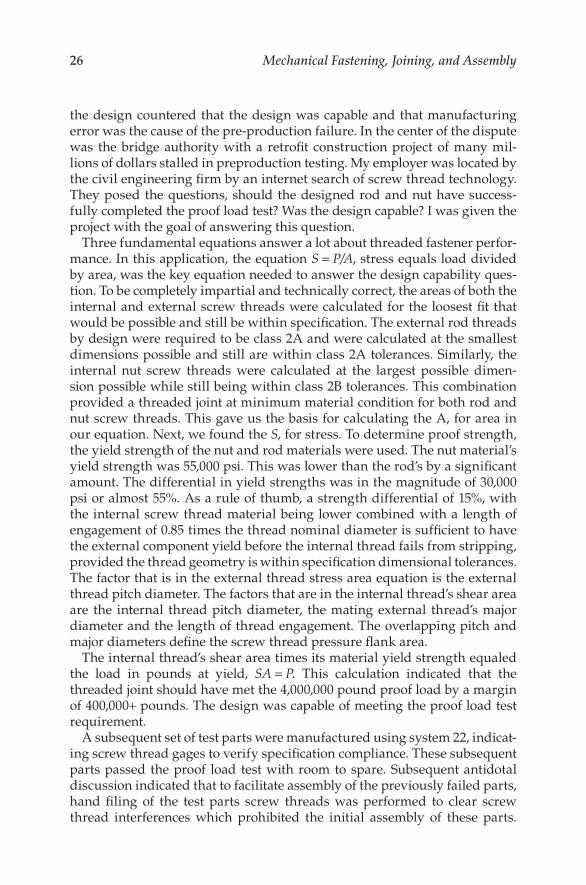
26 Mechanical Fastening, Joining, and Assembly
the design countered that the design was capable and that manufacturing error was the cause of the pre-production failure. In the center of the dispute was the bridge authority with a retrofit construction project of many mil-lions of dollars stalled in preproduction testing. My employer was located by the civil engineering firm by an internet search of screw thread technology. They posed the questions, should the designed rod and nut have success-fully completed the proof load test? Was the design capable? I was given the project with the goal of answering this question.
Three fundamental equations answer a lot about threaded fastener perfor-mance. In this application, the equation S = P/A, stress equals load divided by area, was the key equation needed to answer the design capability ques-tion. To be completely impartial and technically correct, the areas of both the internal and external screw threads were calculated for the loosest fit that would be possible and still be within specification. The external rod threads by design were required to be class 2A and were calculated at the smallest dimensions possible and still are within class 2A tolerances. Similarly, the internal nut screw threads were calculated at the largest possible dimen-sion possible while still being within class 2B tolerances. This combination provided a threaded joint at minimum material condition for both rod and nut screw threads. This gave us the basis for calculating the A, for area in our equation. Next, we found the S, for stress. To determine proof strength, the yield strength of the nut and rod materials were used. The nut material’s yield strength was 55,000 psi. This was lower than the rod’s by a significant amount. The differential in yield strengths was in the magnitude of 30,000 psi or almost 55%. As a rule of thumb, a strength differential of 15%, with the internal screw thread material being lower combined with a length of engagement of 0.85 times the thread nominal diameter is sufficient to have the external component yield before the internal thread fails from stripping, provided the thread geometry is within specification dimensional tolerances. The factor that is in the external thread stress area equation is the external thread pitch diameter. The factors that are in the internal thread’s shear area are the internal thread pitch diameter, the mating external thread’s major diameter and the length of thread engagement. The overlapping pitch and major diameters define the screw thread pressure flank area.
The internal thread’s shear area times its material yield strength equaled the load in pounds at yield, SA = P. This calculation indicated that the threaded joint should have met the 4,000,000 pound proof load by a margin of 400,000+ pounds. The design was capable of meeting the proof load test requirement.
A subsequent set of test parts were manufactured using system 22, indicat-ing screw thread gages to verify specification compliance. These subsequent parts passed the proof load test with room to spare. Subsequent antidotal discussion indicated that to facilitate assembly of the previously failed parts, hand filing of the test parts screw threads was performed to clear screw thread interferences which prohibited the initial assembly of these parts.
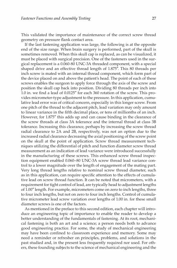
27Fastener Functions and Assembly Testing
This validated the importance of maintenance of the correct screw thread geometry on pressure flank contact area.
If the last fastening application was large, the following is at the opposite end of the size range. When brain surgery is performed, part of the skull is sometimes removed. When this skull cap is replaced, as can be visualized, it must be placed with surgical precision. One of the fasteners used in the sur-gical replacement is a 0.060-80 UNC-3A threaded component, with a special shaped drive and an effective thread length of 1.875″. This 80 threads per inch screw is mated with an internal thread component, which form part of the device placed on and above the patient’s head. The point of each of these screws enables the surgeon to apply force through the axis of the screw and position the skull cap back into position. Dividing 80 threads per inch into 1.0 in. we find a lead of 0.0125″ for each 360 rotation of the screw. This pro-vides micrometer-type adjustment to the pressure. In this application, cumu-lative lead error was of critical concern, especially in this longer screw. From one pitch of the thread to the adjacent pitch, lead variation may only amount to linear variance in the fifth decimal place, or tens of millionths of an inch. However, for 1.875″ this adds up and can cause binding in the clearance of the screw threads at class 3A tolerance and the internal thread at class 3B tolerance. Increasing this clearance, perhaps by increasing the screw thread radial clearance to 2A and 2B, respectively, was not an option due to the increased radial clearance decreasing the axial positioning of the screw point on the skull at the point of application. Screw thread measurement tech-niques utilizing the differential of pitch and function diameter screw thread measurement as an indication of lead variance were introduced successfully in the manufacturing of these screws. This enhanced screw thread inspec-tion equipment enabled 0.060–80 UNC-3A screw thread lead variance con-trol to a lower magnitude over the length of engagement of the mating part. Very long thread lengths relative to nominal screw thread diameter, such as in this application, can require specific attention to the effects of cumula-tive lead on screw thread function. It can be noted that micrometers, with a requirement for tight control of lead, are typically head to adjustment lengths of 1.00″ length. For example, micrometers come on zero to inch lengths, three to four inch lengths, but not on zero to four inch lengths. Control of cumula-tive micrometer lead screw variation over lengths of 1.00 in. for these small diameter screws is one of the factors.
As mentioned in the preface to this second edition, each chapter will intro-duce an engineering topic of importance to enable the reader to develop a better understanding of the fundamentals of fastening. At its root, mechani-cal fastening is both an art and a science; a person needs both to advance good engineering practice. For some, the study of mechanical engineering may have been confined to classroom experience and memory. Some may need a reminder or refresher on principles, problems, and solutions in the past studied and, in the present less frequently required nor used. For oth-ers, these founding subjects to the science of mechanical engineering and the
28 Mechanical Fastening, Joining, and Assembly
fastening arts will be perhaps new material. For both of these polar oppo-sites, and the continuum of technical understanding lying within, each of the nine chapters in this second edition of Mechanical Fastening will present a topic that will help with the science of understanding, presenting, and solv-ing joining and assembly problems. We will start with fastener statics.
1.5 Fastener Statics
As its name infers, statics deals with forces and reactions at rest. This rest is properly named equilibrium. Equilibrium is defined as a state of balance or equality between opposing forces. I have found this understanding of forces in balance to be at the core of being a good fastener application engineer. As proof, I have observed that fastener failures and assemblies providing less than satisfactory assembly performance are precipitated by forces out of balance. Consider the previously referenced propeller hub bolt and spe-cial socket cap screw application. By turbocharging the internal combustion engine, the application force was increased. The strength of the opposing and resisting socket cap screw force was not. These forces, which were in balance and equal on previous aircraft engines, lost the equality. The imbal-ance caused a fastener failure.
In the fundamentals of fastening, forces can be thought of as tension, com-pression, and shear. The forces are vectors having magnitude and directions. In SI units, the magnitudes are measured in Newtons and kilonewtons. In the inch system, pounds and tons of force are used. Vector directions in each system are measured in direction. These concepts of force vectors and fas-tener forces in equilibrium are important for a more complete understanding of fastener performance.
In the previous section, the bridge support application was presented com-posed of large-diameter stainless steel rods, couplings, spreader beams, and nuts. Working in that project, I studied as many texts and technical articles that I could locate on the subject of bridge engineering. One of the things that made an impression on me was the civil engineer’s ability to “read” a bridge. By that, it was meant that an engineer with a good technical understand-ing of bridge engineering could observe a bridge and read the direction and magnitude of the forces and reactions of a given bridge. It seemed to me that anyone wanting to become proficient in fastener engineering should simi-larly be capable of reading an assembly and discerning the forces, reactions, magnitudes, and directions of any given fastened assembly.
In fastener statics, the key point presented will be the concept of equilib-rium, vector mathematics, friction, bending, turning moments, and center of gravity. For each of these statics topics, we will offer specific fastener-related applications.
29Fastener Functions and Assembly Testing
The deck of playing cards in Figure 1.1 at the beginning of this chapter shows forces along the x-, y-, and z-coordinates. Forces that are drawn are being applied up, down, and sideways. The text presents the simple idea of fastening them with a rubber band. Let use that to define static equilib-rium. Of side forces in these three, tension, compression, or shear, directions can work to move the cards out of assembly either singly or in combina-tion. The rubber band can oppose any of these forces if it has the capabil-ity. If the applied forces are opposed by equal and opposite reactions, no motion occurs. The cards are secure and the assembly is said to be in static equilibrium.
The concept of static equilibrium is the key to understanding how fasten-ers and fastened assemblies perform. I find this concept of static equilibrium to be a key concept. Most people view an engineered assembly in everyday life and take for granted the forces and reaction present. We use our plumb-ing fixtures, drive our cars or use public transportation, ride elevators, and pick up mobile devices and can be oblivious to this balancing of forces that keeps things working, at static equilibrium.
Let us consider the static equilibrium of an assembly many orders of mag-nitude larger. A jet airplane sitting at the boarding ramp at an airport is supported by its landing gear, at equilibrium. On the wings of that aircraft are mounted jet engines of considerable weight. The force of gravity pull-ing these engines downward is proportional to the mass of the engine, the mass of the earth, and the distance between their centers of gravity. Indeed, these are the factors that mathematically define the force of gravity. Since we observe that the engines are in fact well attached and stationary as the plane rests before its next flight, reactions by the assembly are equal and opposite to the force of gravity as well as any other forces such as wind, fuel-ing, or other outside forces that may be applied. It is hoped that each of these nine chapters will not only provide knowledge of mechanical fastening, but also provide a good grounding or refresher on the fundamental engineering which provides its technical support. When you learn to read a bridge, or any mechanical assembly, evaluate the forces and reactions which compose or disturb its static equilibrium.
Turning our statics attention to vectors and vector mathematics. Whole engineering texts are available on the vector algebra and more advanced numerical techniques. For our statics overview, we have said that vectors have both magnitude and directions. What are the units of measure? In SI units, it is Newtons and kilonewtons. We will use Newtons (N) and for larger forces kilonewtons (kN). Force vectors can be added, subtracted, and resolved into rectangular components.
Let us consider a system at equilibrium, with a fastener clamp load of 4500 N, or 4.5 kN, being opposed by a 4.5 kN reaction from the assembly. If we add a +4.5 kN and a −4.5 kN to resolve our forces, we get zero, or equilibrium. If we pull on the assembly with an additional 1 kN, the reaction must increase, if the assembly is capable, or we will no longer have static equilibrium, and
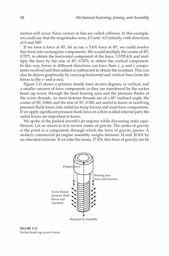
30 Mechanical Fastening, Joining, and Assembly
motion will occur. Force vectors in line are called collinear. In this example, we could say that the magnitudes were, 4.5 and −4.5 initially, with directions of 0 and 180°.
If we have a force at 45°, let us say a 5 kN force at 45°, we could resolve this force into rectangular components. We would multiply the cosine of 45°, 0.7071, to obtain the horizontal component of the force, 3.5355 kN and mul-tiply the force by the sine of 45°, 0.7071, to obtain the vertical component. In this way, forces in different directions can have their x, y, and z compo-nents resolved and then added or subtracted to obtain the resultant. This can also be drawn graphically by carrying horizontal and vertical lines from the forces to the x- and y-axis.
Figure 1.13 shows a primary tensile force at zero degrees, or vertical, and a smaller amount of force components as they are transferred by the socket head cap screw through the head bearing area and the pressure flanks of the screw threads. As most fastener threads are of a 60° inclined angle, the cosine of 30°, 0.866, and the sine of 30°, 0.500, are useful to know in resolving pressure flank forces into radial (or hoop forces) and axial force components. If we apply significant pressure flank force on a thin-walled internal part, the radial forces are important to know.
We spoke of the parked aircraft’s jet engines while discussing static equi-librium. Let us return to it to review center of gravity. The center of gravity is the point in a component, through which the force of gravity passes. A modern commercial jet engine assembly weighs between 14 and 20 kN by an educated estimate. If we take the mean, 17 kN, this force of gravity can be
Reaction by assembly
Screw threadpressure flankforces andreactions
Bearing areaforce and reaction
Primary force
FIGURE 1.13Socket head cap screw forces.
31Fastener Functions and Assembly Testing
thought of as passing through the center of gravity of the engine assembly. The center of gravity is a useful read of an assembly. For a symmetric part of uniform material density, such as a ball, or a cube, we can trace diago-nal lines from the corners or side midpoints and diameter lines through the spheres of these shapes, and know their internal point of line intersection to determine the location of the center of gravity.
Since we intuitively know that not all forces, including gravity, will always be applied this conveniently, statics provides the concept of turning, or bend-ing moments, and a related applied force, the couple. A turning moment is defined as a force which causes or tries to cause if resisted by an opposing moment to equilibrium, rotation. Turning moment has both a force and a direction of rotation. In mechanical fastening, the torque applies to tighten a thread fastener is a turning moment.
Turning moment is a force applied at some defined distance from the axis of rotation of the part to which the turning moment is applied. While we could use any torqued bolt, screw, or nut, we will use the socket screw previously used. A hex key inserted into the screw’s hex socket provides a wrench arm of some defined length. We will use 2.5 cm as our hex key’s long-arm length. Turning in the clockwise direction for a right-handed screw thread will seat the screw and pull on the hex key with a force of 90 N (2.5 cm is 2.5 m). The turning moment is 0.250 m × 90 N or 22.5 N m. Torque or turning moment is expressed as a force applied through a dis-tance. A sign of a working knowledge of engineering understanding is the proper use of terms.
When someone uses an expression of 20 pounds of torque, it shows a lack of this knowledge. A couple is a type of moment where the applied force is in the form of a pair of turning moments.
When you turn an automobile steering wheel with two hands, you are applying a couple. An example of a fastener couple would be a twin lead thread forming screw. The torque applied to drive the screw is a moment. The turning force at the point of the screw is a couple.
Friction is a statics concept, which is fundamental in the mechanics of screw thread function. Referring to the thread pressure flank vectors, these forces are the result of the clamping forces, developed axially in the shank of these fasteners, generated by the torque applied to the wrenching sur-face. All of these metal surfaces sliding against each other result in friction. Statics provides a mathematical tool to calculate the amount of friction in a fastening system. The statics term which is used is the Greek letter mu. The formula is applied force equals mu times the normal force. To demonstrate friction using statics, let us place a 5 kg steel block on a dry steel plate. The force holding the block on the plate is the force of gravity, 5 kg, through the center of gravity. This is the normal force.
The force required to move this right or left is mu times the normal force. Mu can be found experimentally by testing on any application and also can
32 Mechanical Fastening, Joining, and Assembly
be found as an estimate from standard published values of mu. At the high friction end of the range, mu, which is also referred to as the coefficient of friction, can approach unity, or a value of 1.0. At these high levels of fric-tion, much of the input Force (F) to overcome load (N) and start movement is needed to overcome friction. For example, with a coefficient of friction of 0.8, a force of 4 kg is required to overcome friction. Reducing the coefficient of friction to 0.4, or cutting it into half, reduces the force to start motion to 2.0 kg. Using the vector mechanics we introduced above, if we incline the surface 4–5°, we can use rectangular coordinates and the sine, cosine, and tangent functions to find the frictional forces at work on a block under grav-ity load on this inclined plan. This is useful for our work with fasteners using screw threads. Screw threads can be thought of as inclined planes wrapped around cylinders. If we unwrap a single lead screw thread, we will see an inclined plane. The angle of inclination is the lead angle, and the block is the thread flank clamping load. We can determine the lead angle by reference to thread specification tables and numerous handbooks. It can also be calculated by taking the arc tangent of the lead divided by 3.1416 times the pitch diameter.
The concept of static friction is very useful in thread fastener applica-tions. The input torque is converted into clamping load through the diam-eters of the fastener and requires the overcoming of friction to develop the load. The higher the various fastener surfaces coefficients of friction, the more torque that will be required to develop any given clamp load. In Figure 3.7 shows a graph plotting the torques to achieve a target clamp load in a specific threaded fastener with five different frictional coefficients.
The equations used, sum up mu for the fastener materials into an index, K, which can be thought of as the index of friction. In my practical experience, K values as low as 0.05 for super-lubricated parts up to K values approach-ing 0.35 are typically encountered in industrial fastening. It is conceivable that much high K values could be experienced in applications where the screw threads are exposed to service environments precipitating corrosion between mating fastener screw threads.
We will close our presentation of fastener statics with the concept of degrees of freedom. In engineering statics, components can be either fixed in location, such as a bolt, washers, and nuts clamped tightly through two ridged parts, or can be free to move. An example of freedom of movement would be the screw threads of the same bolt and nuts before tightening. Can the screw threads be moved up and down relative to each other? If so, that is two degrees of freedom. Are they side to side? Canted right to left? The degree of freedom is an important engineering consideration. Freedom of movement is a concept in the engineering section concluding this second edition of Chapter 2, fastener dynamics. As a final pointer on the use of stat-ics in fastener applications engineering, the use of simply drawn free body diagrams should be a tool in the kit of anyone seeking a better understand-ing of the fastener mechanics. In conjunction with the ability to “read” an
33Fastener Functions and Assembly Testing
assembly, the line drawing of vector with magnitude and direction of the forces and reactions in any given assembly of components is a skill that will serve the reader well. An example can be found in Figure 3.5b if the reader would care to skip ahead before returning to Chapter 2.
Reference
1. Speck, James A., P.E. 1995. Thread pitch’s influence on assembly speed, American Fastener Journal, Powell, OH, p. 52.

References
9 Chapter 9: Assembly Analysis
1. Jim Speck, P.E., American Fastener Journal, Collectedarticle problems and solutions.
2. SPEC Engineering, selected case problem work.


