Embed Size (px)
Citation preview

KI-NA-27186-EN
-N
The bridges are vital structures for the transport infrastructure; it is a fact that, in the last decades, composite bridges became a well-liked solution in many European countries as a cost-effective and aesthetic alternative to concrete bridges. Their competitiveness depends on several circumstances such as site conditions, local costs of material and staff and the contractor’s experience. Beside the classical solution, the new ones with efficient design and construction improve and consolidate the market position of the steel construction and steel producing industry.
The objective of this project was the construction of three composite bridges with integral abutments and/or innovative form of shear transmission – composite dowels. The targeted countries were: Germany, Romania and Poland.
Ahead the time schedule, the design and construction of the composite bridges using PRECOBEAM technology has been finished in Germany and Poland. On top of this, 5 other bridges using the same technology have been built in Poland and another one in Germany. This shows the high acceptance and trust in this innovative construction technique along practitioners and authorities and proves once more the economic and durable construction of this optimized bridge structure.
Summarizing the complete project beginning from the design process, (pre)fabrication of the different elements and finally the construction stage proved the general applicability of the technology. Compared to conventional design and construction techniques it turned out to be economic and competitive especially since the complete construction process could be finished within a very short time span.
Studies and reports
ISBN 978-92-79-47433-0
doi:10.2777/216745
EUR 27186
Dem
onstration of economical bridge solutions based on innovative com
posite dowels and integrated abutm
entsEU
Demonstration of economical bridge solutions based on
innovative composite dowels and integrated abutments
(ECOBRIDGE)
Research and Innovation EUR 27186 EN

EUROPEAN COMMISSION Directorate-General for Research and Innovation Directorate D — Key Enabling Technologies Unit D.4 — Coal and Steel
E-mail: [email protected] [email protected]
Contact: RFCS Publications
European Commission B-1049 Brussels
HOW TO OBTAIN EU PUBLICATIONS
Free publications: • one copy:
via EU Bookshop (http://bookshop.europa.eu);
• more than one copy or posters/maps: from the European Union’s representations (http://ec.europa.eu/represent_en.htm); from the delegations in non-EU countries (http://eeas.europa.eu/delegations/index_en.htm); by contacting the Europe Direct service (http://europa.eu/europedirect/index_en.htm) or calling 00 800 6 7 8 9 10 11 (freephone number from anywhere in the EU) (*). (*) The information given is free, as are most calls (though some operators, phone boxes or hotels may charge you).
Priced publications: • via EU Bookshop (http://bookshop.europa.eu).

European Commission
Research Fund for Coal and SteelDemonstration of economical bridge solutions
based on innovative composite dowels and integrated abutments
(ECOBRIDGE)
N. PopaArcelorMittal Belval & Differdange S.A
66, rue de Luxembourg, 4009 Esch-sur-Alzette, Luxembourg
D. Pak, N. SchilloRWTH Aachen University
Mies-van-der-Rohe-Str. 1, 52074 Aachen, Germany
G. SeidlSSF Ingenieure GmbH
Schönhauser Allee 149, 10435 Berlin, Germany
M. ScherpeTWT Sanierungsgesellschaft
Dorfstraße 10a, 04758 Cavertitz / Sörnewitz, Germany
R. BancilaUniversitatea “Politehnica”
Piata Victoriei nr. 2, 300006 Timisoara, Romania
E. PetzekSSF-RO Ltd
Str. T. Vladimirescu No. 12, 300195 Timisoara, Romania
W. LorencWrocław University of Technology
Wybrzeże Wyspiańskiego 27, 50370 Wrocław, Poland
K. Charszla, J. PiwońskiEuroprojekt Gdańsk Sp. Z o.o.
Nadwiślańska 55, 80680 Gdańsk, Poland
P. Arabczyk, P. BartoszewskiEnergopol – Szczecin Spółka Akcyjna
Św. Floriana 9/13, 706460 Szczecin, Poland
Grant Agreement RFSP-CT-2010-00024 1 July 2010 to 31 December 2013
Final report
Directorate-General for Research and Innovation
2015 EUR 27186 EN

LEGAL NOTICE
Neither the European Commission nor any person acting on behalf of the Commission is responsible for the use which might be made of the following information.
The views expressed in this publication are the sole responsibility of the authors and do not necessarily reflect the views of the European Commission.
More information on the European Union is available on the Internet (http://europa.eu). Cataloguing data can be found at the end of this publication. Luxembourg: Publications Office of the European Union, 2015 ISBN 978-92-79-47433-0 doi:10.2777/216745 © European Union, 2015 Reproduction is authorised provided the source is acknowledged. Printed in Luxembourg Printed on white chlorine-free PaPer
Europe Direct is a service to help you find answers to your questions about the European Union
Freephone number (*):00 800 6 7 8 9 10 11
(*) Certain mobile telephone operators do not allow access to 00 800 numbers or these calls may be billed.

Table of Contents
1 FINAL SUMMARY 5
2 SCIENTIFIC AND TECHNICAL DESCRIPTION OF THE RESULTS 7
2.1 OBJECTIVES OF THE PROJECT 7
2.2 DESCRIPTION OF ACTIVITIES AND DISCUSSION 7
2.2.1 Work Package 1 Demonstration of composite bridge with Precobeam girders in Germany 7
2.2.2 Work Package 2 Demonstration of composite bridge with integral abutments and/or Precobeam girders in Romania 17
2.2.3 Work Package 3 Demonstration of composite bridge with integral abutments and/or Precobeam girders in Poland 29
2.2.4 Work Package 4 Monitoring 44
2.3 CONCLUSIONS 81
2.3.1 Cost analysis of PE4 bridge 81 2.3.2 Life Cycle Analysis of PE4 Bridge 84 2.3.3 Lessons learned during the design and construction of the bridges 87 2.3.4 Final conclusions 90
2.4 EXPLOITATION AND IMPACT OF THE RESEARCH RESULTS 92
2.4.1 Actual applications 92 2.4.2 Technical and economic potential for the use of the results 95
3 LIST OF FIGURES 101
4 LIST OF TABLES 105
5 REFERENCES 107
3


1 FINAL SUMMARY
German ECOBRIDGE
The construction of German ECOBRIDGE was completed at the end 2011. The design office SSF has
identified a second project, has performed the design, applying the PRECOBEAM technology and convinced the bridge owner about the efficiency of this innovative solution. In the first quarter of 2012, a new ECOBRIDGE was built in Germany.
Summarizing the complete project beginning from the design process, (pre)fabrication of the different elements and finally the construction stage proved the general applicability of the technology. Compared to conventional design and construction techniques it turned out to be
economic and competitive especially since the complete construction process could be finished within a time span of 52 hours.
The high load bearings capacity, sufficient fatigue resistance and possible slenderness are the major characteristics of the innovative cross-section. The possibility to replace a bridge deck within less than 72 hours is a very important topic for railway bridges and certainly an important factor within the competition between different construction techniques.
Although this construction type requires high demands to very precise fabrication no major
problems occurred during construction progress. For that purpose it is certainly the most crucial objective to provide adequate tolerances between all constructional elements. A possible adjustment on the construction site is the most important topic and basic requirement for a successful project.
Romanian ECOBRIDGE
Due to difficult financial situation, DRDP was - in the last moment - in the impossibility to finance
the construction of the bridge identified in the frame of the ECOBRIDGE project. Therefore the Romanian team has identified a second project in order to respect the deliverable of their work package and the delays agreed on the Technical Annex. The new structure was more complex and therefore more representative. The consortium has requested to the European Commission the addition of a new beneficiary. The new company proposed as participant in the ECOBRIDGE program was: “SC CONSTRUCCIONES PROVIERA”. The design of the new bridge has been realized
by SSF-RO. The foundations have been realized and the steel beams have been rolled.
Unfortunately, due to financial issues, PROVIERA ceased its activity and the bridge was not
finished. The fabrication of beams has been stopped. Due to this issues and because the project was approaching its end, the consortium failed in delivering an ECOBRIDGE in Romania.
Polish ECOBRIDGE
The construction of the Polish ECOBRIDGE was completed in 2012. The Polish team has
successfully implemented the PRECOBEAM technology in 5 other bridges. This shows the high acceptance and trust in this innovative construction technique along practitioners and authorities and proves once more the economic and durable construction of this optimized bridge structure.
Bridge monitoring
Within the scope of the project, a concept was developed which allows for the measurement of train forces acting on the rail support points. The measurement results can be considered to be
sufficiently accurate both in compression and in tension. However, the system is quite sensitive to any kind of impact (e.g. vandalism), as the displacement transducers should not be moved. For the
monitoring campaign performed within the scope of this project, where a later inspection and repair of the system was possible, the principle has proved positive.
The strains in the external reinforcement were measured in mid-field as well as close to the bearings. This allowed for a separate measurement of strains due to global bending and local shear
forces. The underlying concept was already proved as successful in former research projects and will be deployed in future as well.
By employing the proven methodology of strain gauge application and protection, 95% of the strain gauges could be finally used for monitoring. However, at sensitive positions, back-up strain gauges should be applied. These additional gauges can be used for verification purposes as well.
It can be concluded, that there is a good correlation between calculated characteristic stresses and measured stresses. Together with the evaluation of results in the region of the hot-spot, this leads
5

to the conclusion that the given design concept and safe-sided design rules based on stress
concentration factors is applied correctly.
Workshop in Romania
The workshop was held on 3rd of October 2016 at Universitatea "Politehnica" Timisoara. The attendance was very good (over 90 persons). The participants were mainly structural engineers from design offices, steelwork companies, steel manufacturers and general contractors, as well as from the academic world. The participants have received USB keys with the new version of the
software ACOBRI, including the PRECOBEAM design method and the workshop presentations.
6

2 SCIENTIFIC AND TECHNICAL DESCRIPTION OF THE RESULTS
2.1 OBJECTIVES OF THE PROJECT
The European RFCS project ECOBRIDGE “Demonstration of ECOnomical BRIDGE solutions based on innovative composite dowels and integrated abutments” started in 2010 and has the principal objective to continue the research, demonstration projects and accompanying measures for the promotion of knowledge gained by the two pilot projects: INTAB - “Economic and Durable Design of Composite Bridges with Integral Abutments”, 2005 – 2008 and PRECOBEAM - “Prefabricated Enduring Composite Beams based on Innovative Shear Transmission”, 2006 – 2009.
The project had three partners working groups: one from Germany (Aachen University, SSF
Ingenieure AG, TWT Sanierungsgesellschaft), from Poland (Wroclaw University, Europrojekt Gdansk and Energopol Szczecin companies) and one from Romania (“Politehnica” University from Timisoara, SSF-RO s.r.l., D.R.D.P. Timisoara). ArcelorMittal coordinates the activities of all working groups.
The propose of this project was to design, construct and have a monitoring period for three composite bridges in Romania, Germany and Poland with integral abutments and / or composite
dowels - an innovative form of shear transmission. This is a possibility to apply the newest
techniques and developments in each participating country.
2.2 DESCRIPTION OF ACTIVITIES AND DISCUSSION
2.2.1 Work Package 1 Demonstration of composite bridge with Precobeam
girders in Germany
The objectives of WP1 were to identify a proper bridge site by considering socio-economic as well as technical points of view, to design according to German standard and to build a German ECOBRIDGE.
German ECOBRIDGE
The Simmerbach Bridge is part of the German railway network located in the Southwest of
Germany. The requirement was to replace two single span bridges both with a span of 12,75m that were in operation for more than 100 years. The old bridges were designed as steel-constructions with a conventional ballast substructure. One of the two bridges crosses the Simmerbach River
while the other one crosses a soil trail only. The bridges that had to be replaced are situated in a row so that the construction and replacement affects one among the two railway tracks only. On the opposite direction there are two bridges as well which were replaced about 30 years ago due to their bad condition at that time. They could be kept in operation and did not have to be either
repaired or replaced.
Figure 1 - Overview of the Simmerbach project for the German Railway Company DB
The existing abutments are made of brick which was the standard construction technology at that time. Detailed investigations of the abutments showed that the brick walls of the abutment and middle support were still in good condition and could be kept for further operation.
7
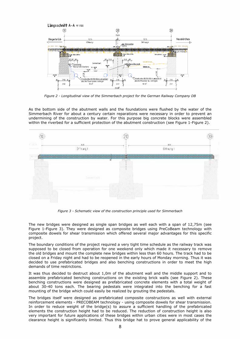
Figure 2 - Longitudinal view of the Simmerbach project for the German Railway Company DB
As the bottom side of the abutment walls and the foundations were flushed by the water of the
Simmerbach River for about a century certain reparations were necessary in order to prevent an undermining of the construction by water. For this purpose big concrete blocks were assembled
within the riverbed for a sufficient protection of the abutment construction (see Figure 1-Figure 2).
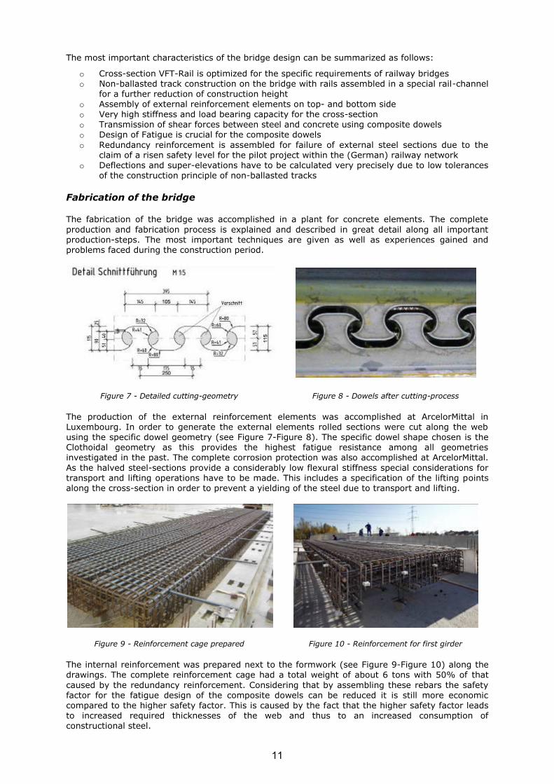
Figure 3 - Schematic view of the construction principle used for Simmerbach
The new bridges were designed as single span bridges as well each with a span of 12,75m (see Figure 1-Figure 3). They were designed as composite bridges using PreCoBeam technology with composite dowels for shear transmission which offered several major advantages for this specific project.
The boundary conditions of the project required a very tight time schedule as the railway track was supposed to be closed from operation for one weekend only which made it necessary to remove
the old bridges and mount the complete new bridges within less than 60 hours. The track had to be closed on a Friday night and had to be reopened in the early hours of Monday morning. Thus it was decided to use prefabricated bridges and also benching constructions in order to meet the high
demands of time restrictions.
It was thus decided to destruct about 1,0m of the abutment wall and the middle support and to assemble prefabricated benching constructions on the existing brick walls (see Figure 2). These benching constructions were designed as prefabricated concrete elements with a total weight of
about 30-40 tons each. The bearing pedestals were integrated into the benching for a fast mounting of the bridge which could easily be realized by grouting the pedestals.
The bridges itself were designed as prefabricated composite constructions as well with external reinforcement elements - PRECOBEAM technology - using composite dowels for shear transmission. In order to reduce weight of the bridge(s) to assure a sufficient handling of the prefabricated elements the construction height had to be reduced. The reduction of construction height is also very important for future applications of these bridges within urban cities were in most cases the
clearance height is significantly limited. Thus this bridge hat to prove general applicability of the
8

innovative cross-section for future projects within the (German) railway network. After optimization
the total weight of each bridge was 65 tons which could be handled by large mobile cranes.
The most important requirements and boundary condition are summarized as follows:
o Usage of innovative cross-section with reduced construction height and increased bearing capacities at the same time
o Interruption of railway traffic had to be limited to less than 60 hours o Usage of prefabricated bridge- and benching constructions for an accelerated construction
progress to stick to the very close time restrictions
Design and constructional details
The bridges were designed with external reinforcement elements and are connected to the concrete with composite dowels for the transmission of shear forces. The cross-section “VFT-Rail” (see Figure 4) was developed under special consideration of requirements from railway operation. For each railway track four external reinforcement elements are assembled on the top and bottom side of the cross-section. As there are external sections assembled within the compression zone a
considerably high degree of capacity utilization is given. The rails itself are arranged within a specific rail-channel in order to save construction height especially for urban applications with restrictive limitations of the clearance underneath the bridge. As the rails are mounted directly to
the construction concrete additional height for ballast substructures can be saved. By using the construction principle of non-ballasted tracks for this specific cross-section the overall height can be reduced significantly compared to conventional bridge solutions. By assembling the rails within
the rail-channel the constructional height between bottom edge of the cross-section and top-edge of the rail is favourably reduced. The application of non-ballasted tracks on the bridge requires special intersection constructions between the bridge and the railway embankment with ballast substructures.
Figure 4 - Application of VFT-Rail Cross-Sections using PreCoBeam technology
The overall construction height of the bridges is 66cm and the width is 265cm. As the span is
12,75m, a slenderness of l/19 results for the cross-section which can be considered reasonably ambitious for single span railway bridges (see Figure 5).
Figure 5 - VFT-Rail cross-section with 66cm construction height and external reinforcement
By assembling external reinforcement elements both on the bottom- and topside a considerably high stiffness of the cross-section is obtained for both Service (SLS) and Ultimate Limit State (ULS). Due to the PRECOBEAM principle the reduction of stiffness from cracking of concrete is very low compared to conventional concrete structures and in most cases is less than 12-15%. That way
9

a very stiff construction is assured with favourable characteristics for load bearing capacity and
limitation of deflections and rotation angles.
Figure 6 - Schematic reinforcement for the cross-section
The external reinforcement elements consist of halved rolled sections with the steel-grade S355 and a C 50/60 high quality concrete. The transmission of shear forces between concrete and external steel reinforcement is assured by composite dowels. These dowels used for this project
have a characteristic height of 115mm and a longitudinal pattern ex of 250mm (see Figure 7-Figure 8).
The longitudinal shear forces to be transmitted by the composite dowels are 215 KN/dowel for the
bottom steel sections and 180 KN/dowel for the topside external steel-sections. The dowel reinforcement was designed to two rebars ø14/25 assembled in each dowel-base (red) (see Figure 6). In order to increase the bearing capacity of the composite dowels a sufficient confinement reinforcement consisting of two rebars ø12/25 next to each steel-dowel is arranged (yellow). As this bridge is a pilot project for the German Railway Company a considerably high safety level was claimed. Therefore an additional internal reinforcement consisting of 30 rebars ø32 was arranged in order to assure the full bearing capacity of the cross-section in case of total failure of the external
reinforcement elements. For this redundancy reinforcement the safety level for load actions and materials had to be considered with =1,0.
The design for fatigue is the crucial design criteria for railway bridges using composite dowels for shear transmission. The dowels were classified as fatigue detail 125 under special consideration of stress concentration factors for both local dowel action and effects from global bending of the cross-section. The stress concentration factors were determined by extensive experimental and numerical studies to 1,45 for global bending and to 7,21 for local dowel action.
fglobal 1,45 Stress concentration factor for global bending
flokal 7,21 Stress concentration factor for local dowel action
The relevant stresses for the fatigue load state (FLS) can be calculated by using the following formula under consideration of the above mentioned stress concentration factors:
Dü
y
global
wy
y
lokalz
J
Mf
tJ
SVf
max
The partial safety factors for the FLS are considered to be MF=1,25 for cross-sections without a
sufficient redundancy reinforcement and MF=1,15 in case such a reinforcement is assembled. As
there is a redundancy reinforcement arranged within this cross-section the partial safety factor was set to MF=1,15. The crucial stresses in FLS for the dowel-base are 127,4 N/mm2 for the external
flexural tension reinforcement (bottom side). Under consideration of railway specific coefficients the relevant stress for fatigue in the dowel-base are calculated to 104,6 N/mm2.
ges x vorh. 104,6 N/mm2
As the bridge obtains the principle of non-ballasted tracks special considerations have to be made. First of all the rail-stresses have to be calculated and limited to certain levels. Further on the settlement of the embankment can cause stresses in the rails as well so that special investigations for the rail supports had to be made. The deflections and super-elevations of the bridge have to be calculated with great care because as the not ballast substructure provides no further possibilities to compensate differing deflections.
10
The most important characteristics of the bridge design can be summarized as follows:
o Cross-section VFT-Rail is optimized for the specific requirements of railway bridges o Non-ballasted track construction on the bridge with rails assembled in a special rail-channel
for a further reduction of construction height o Assembly of external reinforcement elements on top- and bottom side o Very high stiffness and load bearing capacity for the cross-section o Transmission of shear forces between steel and concrete using composite dowels o Design of Fatigue is crucial for the composite dowels
o Redundancy reinforcement is assembled for failure of external steel sections due to the claim of a risen safety level for the pilot project within the (German) railway network
o Deflections and super-elevations have to be calculated very precisely due to low tolerances of the construction principle of non-ballasted tracks
Fabrication of the bridge
The fabrication of the bridge was accomplished in a plant for concrete elements. The complete
production and fabrication process is explained and described in great detail along all important production-steps. The most important techniques are given as well as experiences gained and problems faced during the construction period.
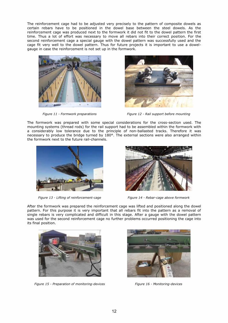
Figure 7 - Detailed cutting-geometry Figure 8 - Dowels after cutting-process
The production of the external reinforcement elements was accomplished at ArcelorMittal in Luxembourg. In order to generate the external elements rolled sections were cut along the web
using the specific dowel geometry (see Figure 7-Figure 8). The specific dowel shape chosen is the Clothoidal geometry as this provides the highest fatigue resistance among all geometries investigated in the past. The complete corrosion protection was also accomplished at ArcelorMittal.
As the halved steel-sections provide a considerably low flexural stiffness special considerations for transport and lifting operations have to be made. This includes a specification of the lifting points along the cross-section in order to prevent a yielding of the steel due to transport and lifting.
Figure 9 - Reinforcement cage prepared Figure 10 - Reinforcement for first girder
The internal reinforcement was prepared next to the formwork (see Figure 9-Figure 10) along the drawings. The complete reinforcement cage had a total weight of about 6 tons with 50% of that
caused by the redundancy reinforcement. Considering that by assembling these rebars the safety factor for the fatigue design of the composite dowels can be reduced it is still more economic compared to the higher safety factor. This is caused by the fact that the higher safety factor leads to increased required thicknesses of the web and thus to an increased consumption of constructional steel.
11
The reinforcement cage had to be adjusted very precisely to the pattern of composite dowels as
certain rebars have to be positioned in the dowel base between the steel dowels. As the reinforcement cage was produced next to the formwork it did not fit to the dowel pattern the first
time. Thus a lot of effort was necessary to move all rebars into their correct position. For the second reinforcement cage a special gauge with the dowel pattern was successfully used and the cage fit very well to the dowel pattern. Thus for future projects it is important to use a dowel-gauge in case the reinforcement is not set up in the formwork.
Figure 11 - Formwork preparations Figure 12 - Rail support before mounting
The formwork was prepared with some special considerations for the cross-section used. The
mounting systems (thread rods) for the rail support had to be assembled within the formwork with a considerably low tolerance due to the principle of non-ballasted tracks. Therefore it was necessary to produce the bridge turned by 180°. The external sections were also arranged within the formwork next to the future rail-channels.
Figure 13 - Lifting of reinforcement-cage Figure 14 - Rebar-cage above formwork
After the formwork was prepared the reinforcement cage was lifted and positioned along the dowel pattern. For this purpose it is very important that all rebars fit into the pattern as a removal of single rebars is very complicated and difficult in this stage. After a gauge with the dowel pattern was used for the second reinforcement cage no further problems occurred positioning the cage into its final position.
Figure 15 - Preparation of monitoring-devices Figure 16 - Monitoring-devices
12

As the Bridge is a pilot project for the German Railway Company comprehensive monitoring
devices were applied to the bridge (see Figure 15-Figure 16). Therefore all devices had to be applied before the external sections were lifted into the prepared formwork.
Figure 17 - Transport of external sections Figure 18 - Fixing of external sections
After the reinforcement cage was lifted into the formwork and properly positioned along the dowel
pattern the remaining external steel sections had to be assembled within the formwork (see Figure 17-Figure 18). As the construction principle of non-ballasted tracks is used only close tolerances for the geometry of the bridge especially for the location of the bearing construction are possible. Therefore the external sections on the bottom side –topside for formwork- were fixed together to assure the correct location of the bearings. This principle turned out to be very effective and sufficient without further problems occurring.
Figure 19 - Formwork prepared with all constructional elements before concreting
After the last external sections were lifted and positioned into the formwork and reinforcement finishing preparations for concreting were made (see Figure 19). For the first bridge it was decided
to lift up the topside section in the formwork by about 30mm in order to provide a sufficient concrete compacting without bubbles underneath the top flange. This procedure turned out to be very a bad solution because the upper section could only be pushed into the concrete using big forces. Thus for the second bridge the upper sections in the formwork were positioned exactly in their destined height. This solution turned out to be very effective because the compacting of the concrete worked very well.
13

Erection of the bridge
The erection of the bridge took place in October 2011 within a weekend interruption of rail traffic.
One of the major problems faced on the construction site was the opposite rail track that had to be kept in operation during the complete construction period and was only closed during night time. Thus the crane lifting the required prefabricated bridges elements and equipment was limited to the time schedule of the track in operation. This was considerably time consuming as the construction site could only be reached by swinging the loads across the track in operation. The
whole construction period was dominated by the time limitation and the necessity to reopen the track after less than 60 hours.
Figure 20 - Destruction of old abutment Figure 21 - Preparation of abutment
After the track was closed the partial destruction of the existing abutments started (see Figure 20-Figure 21). For that purpose about 1m of these existing abutments was removed in order to prepare the bearing area for the prefabricated benching constructions. These works took place
during the first night starting Friday evening until Saturday morning.
Figure 22 - Construction site first morning Figure 23 - Lifting of prefab-benching
After the destruction of the existing abutments was finished and bearing areas were prepared the prefabricated benching constructions were mounted (see Figure 22-Figure 23). These benching were supported on several points and put in the correct horizontal position by adjusting these support points. The remaining gap underneath the benching was afterwards casted with fluid grouting mortar. The placement of the benching constructions was scheduled until Saturday evening which could be kept as well.
After the benching constructions were placed and bearings mounted underneath the bridge
constructions the assembly of the bridge decks (see Figure 24-Figure 25) could start on Saturday evening after the last train passed the opposite track. Thereby an uninterrupted operation of the 550 tons mobile crane was possible. The lifting and mounting of the two bridges could be accomplished without any severe disruptions and was finished on Sunday morning.
As the possible tolerances for the adjustment of the bridges to the bearings were considerably low the mounting was a crucial milestone. It turned out that the efforts und special care undertaken during fabrication of the bridges was very valuable so that no problems occurred on the
construction site. In fact bearings, benching and bridges fit together very well.
14

Figure 24 - Lifting of pedestrian bridge Figure 25 - Bridge(s) after mounting
After the bearings of the bridges were grouted with mortar the pedestrian emergency bridges were placed on Sunday morning (see Figure 26-Figure 27). These works could be accomplished
considerably fast so that the backfilling of the abutments could also be finished as scheduled.
Figure 26 - Lifting of pedestrian bridge Figure 27 - Bridge(s) after mounting
After all bridge elements were mounted and the backfilling of the abutments was accomplished the rail mounting started on Sunday afternoon and could be finished by late Sunday evening. Mounting of the rails (see Figure 28) was another crucial point due to the non-ballasted track system. Thus inaccuracies resulting from fabrication and the construction process itself could lead to problems mounting the rails. It turned out that mounting of the rails could be accomplished without any problems due to sufficient tolerances. Thus the last critical step could also be taken successfully so that the new bridge could go into operation.
Figure 28 - Assembly of rails Figure 29 - Finished construction-progress
After 52 hours the construction process could be finished and the closed railway track could be reopened (see Figure 30-Figure 33). Only minor works were left to be done such as the grouting of the bearing construction for the pedestrian bridges and mounting of the handrails. Further on some
maintenance works had to be done for the brick walls of the abutments and the middle support.
15

These steps did not disturb the train operation so that the implementation of the new technology
and the innovative construction technique was successful under practical circumstances.
Figure 30 - Railway track in operation Figure 31 - Railway track in operation
In fact it was possible to implement this technology to the very challenging market of railway bridges. This can be considered especially ambitious as time limitations are very restrictive within this segment. It even turned out that the technology developed is economically and technically very competitive and thus an attractive innovation for further projects.
Figure 32 - Bridge in operation Figure 33 - Train on the bridge
In order to study the technology even deeper numerous monitoring devices (see Figure 34-Figure
35) were applied to the bridge and do now deliver valuable data for further research and evaluation of the bearing behaviour under operational loads.
Figure 34 - Monitoring devices Figure 35 - Monitoring in operation
16

2.2.2 Work Package 2 Demonstration of composite bridge with integral
abutments and/or Precobeam girders in Romania
Romanian ECOBRIDGE
The objectives of WP2 were to identify a proper bridge site by considering socio-economic as well as technical points of view, to design according to Romanian standard and to build a Romanian
ECOBRIDGE.
First, the Romanian team has chosen for the European project the bridge at Manarau. The existing bridge is deteriorated and has to be replaced. Two alternative solutions were designed, both composite girder bridges (Precobeam girder) with integral abutments, with a length of 8,175 and widths of 10,36 m and 10,08 m. Due to the lack of funds, the construction of the bridge was delayed.
The bridge at Francesti, situated in the south of Romania was the second proposal, made by the
project members from Romania, to be part of ECOBRIDGE. In this case the existing 75,00 m long bridge to be replaced, is a temporary structure used in present as a permanent solution. The technical situation is not appropriate, is unsafe and permits vehicles to circulate only in one direction. The new design includes a three-spanned integral bridge, each span having a length of 21,10 m, and a width of 5,20 m, with Precobeam girders superstructure. The construction started
in 2012 and until now the infrastructure was erected. The construction site is in standby, whilst the local authorities try to provide the necessary financial means to continue.
The third bridge included in the project is part of the A1 motorway and was finalized in at the end 2013. It is an one-spanned integral abutment bridge, with a length of 39,00 m and a width of 11,90 m. The superstructure is an innovative form of VFT – prefabricated composite beam. In November 2013 a load test was carried out.
This report presents the design of each of the two bridges included in the ECOBRIDGE project in Romania and the results concerning the behaviour of the third considered bridge.
The first proposed structure: bridge at Manarau
During service, the integrity of the existing bridge was influenced by many factors like the increase of the initial traffic volume, the existence of an inadequate maintenance process or a total lack of it. The effect of those factors on the existing structure can be pointed on the appearance of fatigue defects, inadequate deformations, corrosion, and behaviour due to traffic incorrect bearing conditions. All these aspects influenced the choice for the bridge at Manarau to be deconstructed
[7].
A composite girder bridge (PRECOBEAM girder) with integral abutments was designed according to the Romanian standard. The technical documentation was prepared including a static analysis of the new proposed structure. According to the contracting authorities’ requirements detailed plans within the scope of the project were started, using the available design guidance.
The bridge is situated on the National Highway DN 79A Km 60+627, near to the village Manărău in the Arad County. It was built in 1967 for the loading class 1 (truck convoys A13 and S60). The
general condition of the structure is bad; the maintenance is missing (Figure 36). The bridge belongs to the Regional Administrations of Roads and Bridges (DRDP). It does not correspond anymore to the present traffic necessities (trucks of 30 tons). The bridge has no footways and no borders. There is no safety parapet on the bridge, the traffic participants are in danger. No water discharging devices are on the bridge.
Table 1 - Technical information of the existing vs. the new bridge
The new structure The existing structure
Importance category (HG 766-97) C C
Category of construction (STAS 4273-83 art. 2.11)
3 3
Class load E (A30, V80) E (A13, V60)
Bridge length 8,175 m 9,85 m
Bridge width for the solution 1 10,36 m 9,00 m
17

Bridge width for the solution 2 10,08 m
Gradient’s bridge 0 % 0 %
Gradient in the cross section 2,5 % 2,5 %
Length of the bridge guardrail 32,2 m 0,0 m
Connection with embankments connection plates, back walls
back walls
Static structure frame structure with an opening
simply supported girder
Waterproofing waterproofing membrane with a protection layer
waterproofing membrane with a protection layer
Access ramps
rehabilitation on 2 x 20 m
and will be referred with road verges of 0,5 m;
-
Infrastructure indirect foundation direct foundation
Drain water from the bridge side ditch -
Figure 36 - General view of the bridge and access ramps
The total length of the bridge is 9,90 m and the width is 9,0 m. The present cross section consists of a reinforced concrete slab of C8/10, having a thickness of approx. 0,40 m (Figure 37). The carriageway, made out of asphalt concrete, presents cracks on extended areas. The infrastructure presents degradations, caused by waters. There is a geotechnical study based on geotechnical investigations, presenting the layers of the foundation ground. The bridge is situated in a seismic
zone; according to the Romanian Standards, no measures for anti-seismic protection have to be taken.
Figure 37 - Structure degradations
18

In conclusion, the present viability state of the structure is not satisfactory, which leads to the
necessity of replacement with a new structure. The highway bridge presents damages a result of actions, fatigue and creep. The replacement of the existing structure with the VFT-WIB® solution
(developed from the classical WIB composite structure) was proposed [7].
A classical WIB composite structure could be an adequate solution for the span and heights imposed for many existing structures, as well for the Manarau Bridge. Going further and taking into consideration also the need of a simple technology and a very short erection time, it leads to the necessity of a modular system with low costs. Using the high degree of prefabrication the
possibility of unexpected situations on site it reduced and lower costs are obtained. Simultaneously it offers execution simplicity. In Figure 38 some of the possible solutions are presented.
In this case the VFT-WIB® solution with based on the classical WIB composite structure and with some improvements was adopted (Figure 39).
Figure 38 - Durability of composite bridges
Figure 39 - General cross section: Solution 1 (a), Solution 2 (b)
Design aspects
With the help of the main dimensions and cross sections of the structural elements from the existing drawings and completed by the present situation on the site, a simple analysis of the
structure with the help of a FEM analyses was made. According to the results, the main girders subjected to current Romanian standards exceed the normal values. The conclusion was that the
19
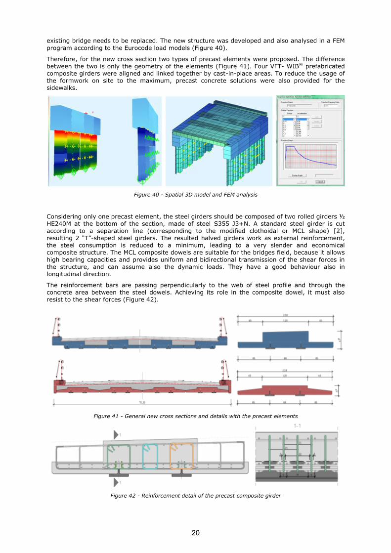
existing bridge needs to be replaced. The new structure was developed and also analysed in a FEM
program according to the Eurocode load models (Figure 40).
Therefore, for the new cross section two types of precast elements were proposed. The difference
between the two is only the geometry of the elements (Figure 41). Four VFT- WIB® prefabricated composite girders were aligned and linked together by cast-in-place areas. To reduce the usage of the formwork on site to the maximum, precast concrete solutions were also provided for the sidewalks.
Figure 40 - Spatial 3D model and FEM analysis
Considering only one precast element, the steel girders should be composed of two rolled girders ½ HE240M at the bottom of the section, made of steel S355 J3+N. A standard steel girder is cut according to a separation line (corresponding to the modified clothoidal or MCL shape) [2], resulting 2 “T”-shaped steel girders. The resulted halved girders work as external reinforcement, the steel consumption is reduced to a minimum, leading to a very slender and economical composite structure. The MCL composite dowels are suitable for the bridges field, because it allows
high bearing capacities and provides uniform and bidirectional transmission of the shear forces in the structure, and can assume also the dynamic loads. They have a good behaviour also in longitudinal direction.
The reinforcement bars are passing perpendicularly to the web of steel profile and through the concrete area between the steel dowels. Achieving its role in the composite dowel, it must also resist to the shear forces (Figure 42).
Figure 41 - General new cross sections and details with the precast elements
Figure 42 - Reinforcement detail of the precast composite girder
20
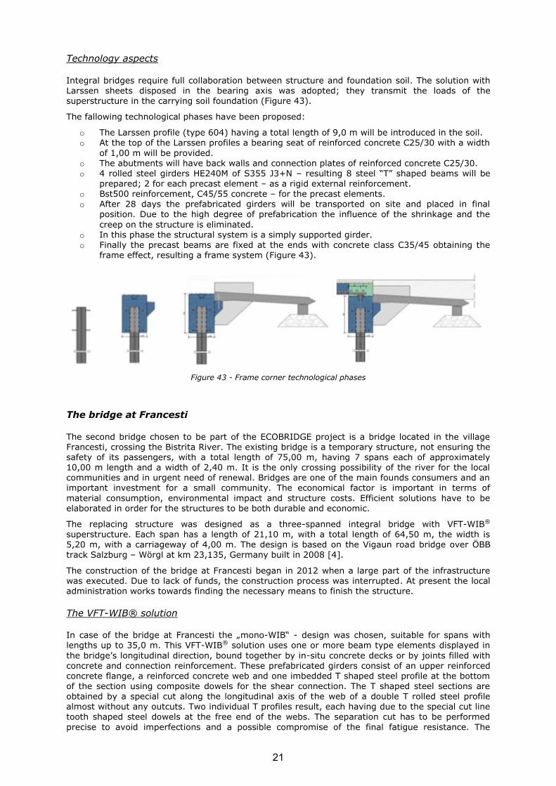
Technology aspects
Integral bridges require full collaboration between structure and foundation soil. The solution with
Larssen sheets disposed in the bearing axis was adopted; they transmit the loads of the superstructure in the carrying soil foundation (Figure 43).
The fallowing technological phases have been proposed:
o The Larssen profile (type 604) having a total length of 9,0 m will be introduced in the soil. o At the top of the Larssen profiles a bearing seat of reinforced concrete C25/30 with a width
of 1,00 m will be provided. o The abutments will have back walls and connection plates of reinforced concrete C25/30. o 4 rolled steel girders HE240M of S355 J3+N – resulting 8 steel “T” shaped beams will be
prepared; 2 for each precast element – as a rigid external reinforcement. o Bst500 reinforcement, C45/55 concrete – for the precast elements. o After 28 days the prefabricated girders will be transported on site and placed in final
position. Due to the high degree of prefabrication the influence of the shrinkage and the
creep on the structure is eliminated. o In this phase the structural system is a simply supported girder. o Finally the precast beams are fixed at the ends with concrete class C35/45 obtaining the
frame effect, resulting a frame system (Figure 43).
Figure 43 - Frame corner technological phases
The bridge at Francesti
The second bridge chosen to be part of the ECOBRIDGE project is a bridge located in the village Francesti, crossing the Bistrita River. The existing bridge is a temporary structure, not ensuring the safety of its passengers, with a total length of 75,00 m, having 7 spans each of approximately 10,00 m length and a width of 2,40 m. It is the only crossing possibility of the river for the local communities and in urgent need of renewal. Bridges are one of the main founds consumers and an important investment for a small community. The economical factor is important in terms of
material consumption, environmental impact and structure costs. Efficient solutions have to be elaborated in order for the structures to be both durable and economic.
The replacing structure was designed as a three-spanned integral bridge with VFT-WIB® superstructure. Each span has a length of 21,10 m, with a total length of 64,50 m, the width is 5,20 m, with a carriageway of 4,00 m. The design is based on the Vigaun road bridge over ÖBB track Salzburg – Wörgl at km 23,135, Germany built in 2008 [4].
The construction of the bridge at Francesti began in 2012 when a large part of the infrastructure was executed. Due to lack of funds, the construction process was interrupted. At present the local administration works towards finding the necessary means to finish the structure.
The VFT-WIB® solution
In case of the bridge at Francesti the „mono-WIB“ - design was chosen, suitable for spans with lengths up to 35,0 m. This VFT-WIB® solution uses one or more beam type elements displayed in
the bridge’s longitudinal direction, bound together by in-situ concrete decks or by joints filled with concrete and connection reinforcement. These prefabricated girders consist of an upper reinforced concrete flange, a reinforced concrete web and one imbedded T shaped steel profile at the bottom of the section using composite dowels for the shear connection. The T shaped steel sections are obtained by a special cut along the longitudinal axis of the web of a double T rolled steel profile almost without any outcuts. Two individual T profiles result, each having due to the special cut line tooth shaped steel dowels at the free end of the webs. The separation cut has to be performed
precise to avoid imperfections and a possible compromise of the final fatigue resistance. The
21

composite dowels represent the interaction between the steel dowels, through-going reinforcement
bars and enwrapping concrete.
For this bridge the fin or SA shape Figure 44 was chosen for the composite dowel strips (Figure
45a), which is designed to transfer the shear forces in only one direction. The dowel shape is not symmetric and the dowel orientation changes at the middle of each steel girder (Figure 45b).
Figure 44 - Cutting line types: fin (SA), puzzle (PZ), clothoidal (CL), modified clothoidal (MCL)
The composite dowel strip is located quite far from the neutral axis and the steel dowel not only gets local shear loads but also centric tension as a result of global bending moment and gets consequently higher fatigue loads due to global bending moments [4].
Figure 45 - SA or fin shaped steel dowels: The SA shape (a), Direction change of the composite dowels in the middle of the girder (b)
This construction method was chosen due to advantages such as durability, facile prefabrication possibilities, and material savings – especially regarding the steel use. High slenderness can be obtained be using frame type systems.
Design aspects
The cross section of the bridge (Figure 46b) aligns two mono-WIB girders bound together by a 20
cm thick concrete deck. The design of the prefabricated girders is shown in Figure 49a and are made each of one ½ HEM600 steel rolled profile of quality S460 ML, and of a upper concrete flange and a concrete web of C50/60 class. The concrete flange is 10…13 cm thick and ~2,60 m wide; the concrete web is 30,5 cm wide with a height of ~70 cm. For the entire three-spanned bridge with a total of six prefabricated mono-WIB girders only three rolled girders HEM600 were used.
Figure 46 - VFT-WIB – mono-WIB cross section (a), Superstructure cross section (b)
The ½ HEM600 and the steel dowels are obtained by cutting a regular HEM600 rolled profile according to a pre-established geometry (Figure 47) with the adequate technology in the factory. Only a low amount of outcuts result. Afterwards the girders are brought to the factory or on site under special conditions, where the dowel reinforcement, the binding reinforcement and the required carrying reinforcement are disposed (Figure 48). High class concrete is poured in
formwork and after hardening, the prefabricated girders are carried to the site. The prefabricated girders can also be produced on site, near the infrastructure.
22

Figure 47 - Execution details of the steel girders, geometry of the steel dowel
Figure 48 - Composite dowels – reinforcement details
The infrastructure and superstructure of the bridge are monolithically bound together by in situ concrete and connection reinforcement from the piers/ abutments, the VFT-WIB girders, the deck
and the frame nodes. The simple, rectangular shaped abutments are provided with relative small
back walls and transition slab. The elevations rest on foundation slabs with piles of 1,20 m in diameter. The bridge’s static system becomes a multi-span frame resulting an integral bridge.
Construction stages
The infrastructure consisting of piles, foundation plates and elevations is classically erected, but due to the regular, simple and slender shapes of each part is economical, easy and fast to build. The VFT-WIB girders are made either in the prefabrication workshop or in situ on small concrete
platforms. After the prefabricated mono-WIB girders are brought on site, they are lifted in their final position and fixed on top of the piers and/ or abutments (Figure 49a). Reinforcement bars are added at the frame nodes and on the deck, and linked to the connection reinforcement from the elevations and the prefabricated girders. After the concreting of the frame nodes an intermediary static frame system is created (Figure 49b) and the concrete deck can be poured (Figure 49c).
The integral building method implies the connection between all carrying elements. This is realized by outgoing reinforcement from every previously built/ added part. No props are needed during the
concrete casting and only lateral formworks for the in situ deck are used due to the “T” -shaped VFT-WIB sections. The weight of the bridge’s deck fresh concrete is taken over from the frame system: the two composite prefabricated girders, the frame nodes and the infrastructures. An optimal total superstructure height is obtained.
23

Figure 49 - Superstructure construction phases: laying of the VFT-WIB composite girders in their final position (a), frame node and end sections of the deck concreting (b), deck concreting (c)
The site
Early 2012 the construction of the bridge infrastructure began. The piles, the foundation slabs and the elevations were built.
An indirect foundation made of bored piles, with the concrete class C25/30 was adopted, suitable for integral bridges. One pile beneath each foundation plate includes 3 tubes for the sonic tests
(Figure 50). The piles are 8 m, 10 m and 12 m long according to the geotechnical necessities.
Figure 50 - Pile sections – reinforcement and tubes for the sonic test
In spring 2012 the concrete foundations of class C30/37 were poured. The outgoing reinforcement
ensures the connection to the infrastructure elevations (Figure 51).
Figure 51 - Foundation slab reinforcement plan (a), Site photo of the foundation slab reinforcement (b)
As a next step the elevations, abutments and piers were built (Figure 52, Figure 53, Figure 54). The concrete is of class C30/37. To ensure the connection to the superstructure, thus underlining the integral character of the structure, reinforcement bars reach out from the concrete joints.
a)
a)
24

Figure 52 - Abutment reinforcement plan
Figure 53 - Site photo of the abutment reinforcement (a), Site photo of the abutment (b)
Figure 54 - Pier reinforcement plan (a), Site photo of the pier (b)
The constructive details for the superstructure were designed. These include the formwork and reinforcement of the precast composite girders, the formwork and reinforcement from the cast-in-place concrete deck and the frame nodes reinforcement. The project also includes plans for auxiliary works. For example the river bank protection in area of the bridge was designed using gabions with terramesh modules. Also, the steel guardrail was chosen according to the traffic type and volume.
25

Conclusions
The mono-WIB is an economical solution, as it requires low steel consumption and the
prefabrication in the factory is facile. The steel profiles are obtained from regular rolled profiles without significant material loss, and their use is efficient acting as external reinforcement. The concrete amount is significantly reduced compared to the classic filler beam decks, but the self weight remains quite high and is therefore suited for spans smaller than 35,00 m, similar to the pre-stressed concrete beams [4]. Using T-shaped prefabricated beams only lateral reinforcement is
needed for the bridge deck concrete casting and the execution speed is increased. The integral structure requires a connection between the infrastructure and the superstructure and consequently supplementary reinforcement is used to strengthen the frame nodes. No bearings and no expansion joints are provided, assuring simultaneously facile maintenance and driving comfort.
Important delays (even if at that time the bridge in Francesti was an absolute premiere in Romania), due to missing financial possibilities postponed the realization of the bridge in Francesti.
Than the Romanian ECOBRIDGE team took the decision to analyze a new structure situated on the A1 motorway which fulfils all conditions of the initial ECOBRIDGE project.
Workshop in Romania
To promote this promising bridge type, the attention of designers, authorities and constructors needed to be attracted. Therefore, information has been provided in condensed form via a
workshop organized by UPT and SSF-RO. In order to ensure a good participation, the workshop was programmed together with the “8th – Danube Bridges Conference”, on the 3rd of October 2013 in Timisoara. A special session was dedicated to the presentation of the ECOBRIDGE program and to the results obtained in Germany, Poland and Romania.
The attendance was very good (over 90 persons). More than this, the organizers decided to publish the contributions presented at the workshop in a special volume, edited by a well known publishing house – Springer Verlag (Germany). The book is supported partially by own financial support.
26

Figure 55 – 8th Danube Bridges Conference poster
27
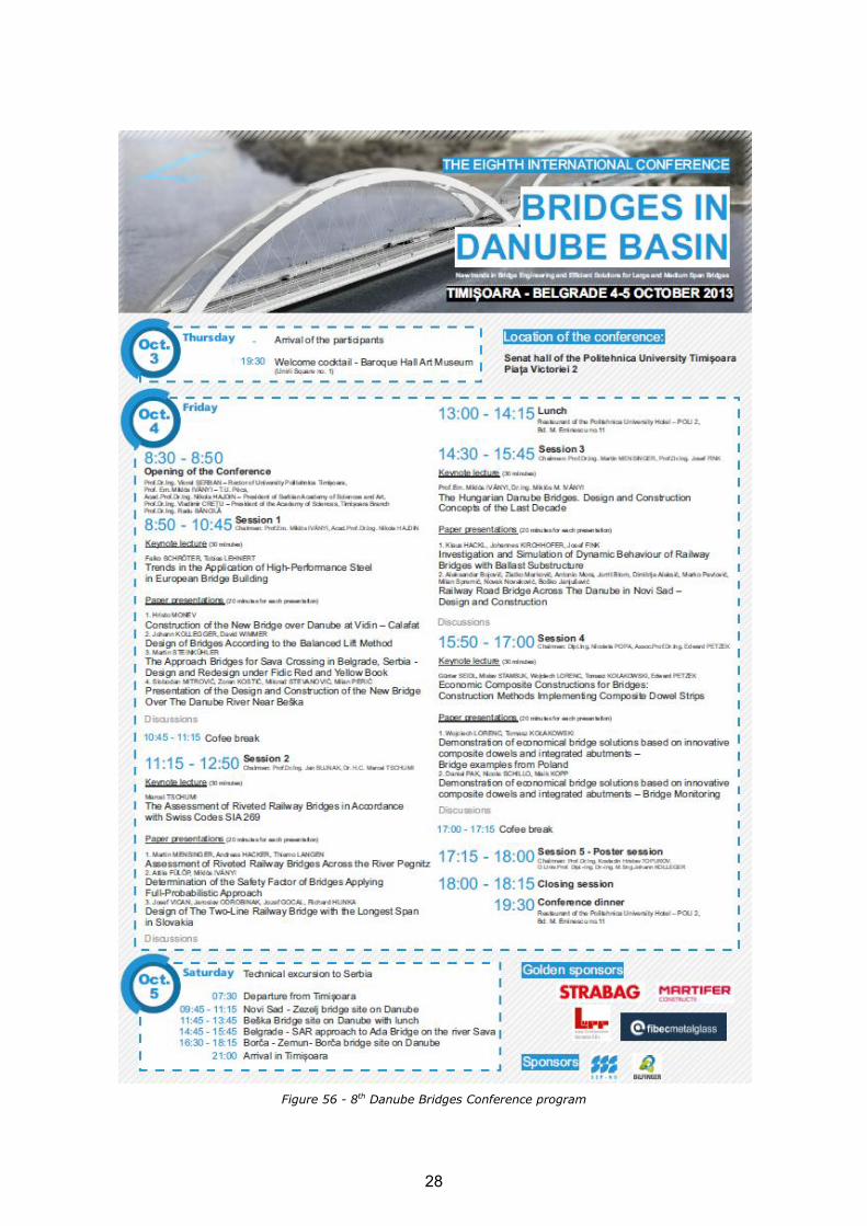
Figure 56 - 8th Danube Bridges Conference program
28

2.2.3 Work Package 3 Demonstration of composite bridge with integral
abutments and/or Precobeam girders in Poland
The objectives of WP3 were to identify a proper bridge site by considering socio-economic as well as technical points of view, to design according to Polish standard and to build a Polish ECOBRIDGE.
Polish ECOBRIDGE: PE4 project
The Polish consortium EPG+ENERG+PWr realized the innovative bridge project with integral abutments and composite dowels. It was decided to design and build the bridge in frame of contract „Design and build of express road no. 7 at Olsztynek – Nidzica sector (km 175+800 to km 203+600) with ring road of Olsztynek within national road no. 51 (km 109+500 to km 115+500)”, what was innovative approach at that time in Poland. This contract is realised in formula “design and build” what means that final price of realised structure is the main point – hence structures
must be economic. The owner was General Directorate of National Roads and Motorways (GDDKiA) – the governmental institution administrating net of main Polish roads and motorways. The works have been done by consortium that won the tender organised by GDDKiA: Sando Budownictwo Polska Sp. z o.o. (the lider), Construcciones Sanchez Dominguez-Sando S.A., Energopol Szczecin S.A., Wakoz Sp. z o.o., Europrojekt Gdańsk S.A. The value of entire contract was about 250 mln
euro. Localisation of contract is presented in Figure 57.
Figure 57 - Localisation of contract for design-and-build of sector of S7 road
In frame of these big contract two contractors, the partners in of Ecobridge project were responsible for design of road and bridges (EUROPROJEKT) and realisation of bridges
(ENERGOPOL). Together with third Polish partner of Ecobridge project (PWr) it was decided to design and build a bridge with innovative composite dowels and integral abutments. As EUROPROJEKT is a company with great experience with composite bridges with integral abutments, it was decided to implement integral bridge with composite dowels and realise it in VFTWIB technology, based on experience of SSF Ingenieure and PWr from PRECOBEAM RFCS project. The division of tasks was assumed: ENERGOPOL will build the bridge, EUROPROJEKT design a bridge
with support of PWr, PWr makes transfer of knowledge gained during PRECOBEAM towards EUROPROJEKT and supports consortium during entire project period. Moreover, PWr had to convince society of bridge engineers in Poland (owners’ representatives, universities, design offices) that new solution is justified and safe. This was done with support of EPG, and sometimes ENERG if needed, by extensive discussion at main Polish conferences and publicity in journals, what is presented in later part of report.
FE calculations have been done in EUROPROJEKT and PWr by the same software (SOFiSTiK) to
enable efficient cooperation and efficient cross-checking, what was very important as innovative structure was to be design and build without any significant support of Polish bridge design standards. As PWr was conducting tests concerning composite dowels that time (for another RFCS project), it was possible to support design by testing according to Eurocode 4 procedures.
It was a crucial point to pick one of many bridges to be design with innovative technology. As for time of beginning of contract the cyclic behaviour of composite dowels was not fully recognized yet, it was decided to implement the new solutions for crossing for animals over S7 road. It is to be
noted, that this kind of structures are the biggest bridge structures realised in frame of contract (hence many girders and large steel consumption) and the loads are almost two times higher (due to soil on structure) comparing to ordinary road bridges. On the basis of this investigation, the bridge named PE4 was picked for purposes of Ecobridge project (by the way this is Eco-bridge in fact – as this kind of structures are named like this in Poland). Localisation of the structure is
29

presented in Figure 58. The structure of the bridge had to be fit in architectural borders and formal
requirements – these boundaries were known as they were specification for the main tender (for design and build of sector of S7 road and bridges). Architectural visualisation of PE4 structure is
presented in Figure 59. The crucial point was, that it was assumed to build straight (in upper view) bridge – the solution with changing width of spans appeared (because of formal reasons) during project realisation and it resulted in much more effort at design stage because of different structure of individual girders).
Figure 58 - Localisation of PE4 structure
Figure 59 - Architectural visualisation of PE4 structure
Construction of the bridge
The specific and very interesting aspect of realisation of the bridge is that two independent superstructures (southern line and northern line) were constructed by different technologies:
o beams of southern line were supported at final position and casted, o beams of northern line were prefabricated (casted at ground level next to pillars) and then
shifted in final position.
Beams of southern line are marked with X and beams of northern line are marked with X’ – hence
for example spans A,B,C,D mean spans 1,2,3,4 of southern line and spans A’,B’,C’,D’ mean spans 1,2,3,4 of northern line.
Time schedule presenting construction of the bridge is presented (Table 2) and works done are presented in details (Table 3).
Table 2 - Time schedule presenting construction of the bridge (unit: month)
1 2 3 4 5 6 7 8 9 10 11 12 1 2 3 4 5 6 7 8 9 10 11 12 1 2 3 4 5 6 7
Groundworks
Piling
Foundations
Abutments, piers
Superstructure:
- VFT-WIB beams
- support crossbeams
- in-situ slab
Retaining walls
Cornice
Embankment
Finishing works
1 2PE-4
3
30

Table 3 - Specification of works that have been realised
Year Month
1 - First groundworks and other works associated with site preparation (energy supply, sanitary devices, storage yard, etc.)
- Land surveying of all support axis locations
2 - Reiforcement baskets ready for piles for axis 3 and 5
- Start of piling for support in axis 5
- Start of piling for support in axis 1 and 4
3 - Bearing capacity tests for particular completed piles for different support axises
- Continuation of piles realization for supports 3, 4 and 5
- Reinforcement baskets for foundations and supports site prefabrication
4 - Continuation of piles realization for supports 2, 3, 4 and 5
- Piles ready for supports 1, 2, 3, 4 and 5 - for these axises also ready preparation concrete layer under abutment/pier
5 - Reinforcement ready for foundations in axis 1 and 4, for axis 2 and 4 reinforcement for piers is in preparation process
6 - Formworks being constructed for foundations - ready for support axis 1, 2 and 4
7 - Concrete casted for reinforced foundations in axis 1, 2 and 4
- Formworks completed and concrete casted for foundations in axis 3 and 5
- Isolation layers completed for foundations
- Concrete casted for reinforced abutment wall in axis 5 (north side)
- Concrete casted for reinforced abutment wall in axis 1 (south side)
8 - Concrete casted for reinforced abutment wall in axis 1 (north side) and axis 5 (south side)
- Concrete casted for reinforced pier columns 1, 2, 7 in axis 2
- Concrete casted for reinforced pier columns 6, 8 in axis 2
9 - Concrete casted for reinforced pier columns 3, 4, 5 in axis 2; also for reinforced pier column 5 in axis 3
- Concrete casted for reinforced pier columns 4, 6, 7, 8 in axis 3; also for reinforced pier column 7 in axis 4
10 - Concrete casted for reinforced pier columns 1, 2 in axis 3; also for reinforced pier columns 4, 5, 6 in axis 4
- Concrete casted for reinforced pier columns 1, 2, 8 in axis 4; also for reinforced pier columns 3 in axis 3
- Concrete casted for reinforced pier columns 3 in axis 4
- Temporary supporting structure for VFT-WIB beams constructed in-place in spans 1-2 and 2-3 (south side)
11 - VFT-WIB steel beams placed on temporary supports in spans 1-2 and 2-3 (south side)
12 - Reinforcement and formworks for prefabricated concrete part of VFT-WIB beams completed
1
Construction works
1 - Concrete casted for prefabricated VFT-WIB beams A1-A7 and B1-B7
- Concrete casted for prefabricated VFT-WIB beams B1'-B7' in span 2-3
2 - Concrete casted for prefabricated VFT-WIB beams A1'-A7'
- Concrete casted for prefabricated VFT-WIB beams D1'-D7' in span 4-5
- Concrete casted for prefabricated VFT-WIB beams C1-C7 in span 3-4
- Concrete casted for prefabricated VFT-WIB beams C1'-C7' in span 3-4
- Concrete casted in frame corner including support crossbeam and in-situ 1st stage continuity slab in axis 1 (south side)
- Concrete casted for prefabricated VFT-WIB beams D1-D7 in span 4-5
3 - Concrete casted including support crossbeam and in-situ 1st stage continuity slab in axis 2 (south side)
- Concrete casted including support crossbeam and in-situ 1st stage continuity slab in axis 3 (south side)
- Starting prefabricated cornice elements completed
- Temporary supports constructed for VFT-WIB beams for spans 1-2, 2-3, 3-4, 4-5 (north side)
- Concrete casted including support crossbeam and in-situ 1st stage continuity slab in axis 4 (south side)
- Concrete casted in frame corner including support crossbeam and in-situ 1st stage continuity slab in axis 5 (south side)
- 28 prefabricated VFT-WIB beams transported to final bridge position (north side)
4 - Concrete casted including support crossbeam and in-situ 1st stage continuity slab in axis 3 (north side)
- Further prefabricated cornice elements completed
- Concrete casted including support crossbeam and in-situ 1st stage continuity slab in axis 2 and 4 (north side)
- Concrete casted in frame corner including support crossbeam and in-situ 1st stage continuity slab in axis 1 and 5 (north side)
5 - Further prefabricated cornice elements completed
- Concrete casted for final in-situ slab (south side)
- Concrete casted for final in-situ slab (north side)
- Corrosion protection works for concrete surfaces on abutments and piers
- Isolation layers completed for pier supports
6 - Isolation layers completed for abutment in axis 1
- Isolation layers completed for abutment in axis 5
- Isolation layers completed for in-situ superstructure slab
7 - Montage of prefabricated cornice elements on bridge both north and south sides
8 - Preparation for retaining wall, partially completed embankment
- Both abutment drainage systems installed
9 - Completion of horizontal parts of installed cornice elements
- Completion of retaining walls on axis 1 and 5, full embankments filled
12 - Individual cornice elements in axis 2, 3, 4
2
31

Preparation of construction site, works dedicated to soil transportation and construction of foundation piles have been done at first. After foundations, pillars and abutments were realised (typical construction types so not described herein) the consortium faced the problem concerning the assumed technology of realisation of superstructure.
According to principia of VFT-WIB method, prefabricated composite elements were initially assumed to be used for construction of superstructures. As presented in previous reports, very complicated geometry of the bridge resulted in very complicated geometry of prefabricated elements. Especially, prefabricated girders for spans 1 and 4 differ much, depending on their location in span. After many discussions the general contractor decided to build first line of bridge (the southern line) in its final position contrary to assumed prefabrication of composite elements at
level of ground next to the bridge. This way steel elements were supported the same way as it was initially designed (5 points along the girder) but using high towers typical for in-situ implementations. It was possible because no traffic under the bridge.
This way realisation of prefabricated elements took place in final position. Reinforcing works of
girders could be realised in parallel to fabrication of crossbeams. The welded connections of steel girders using additional steel plates assumed instead of screwed connection usually used for VFT confirmed to be good solution, as the problem of tolerances (studied in details at designed stage) really appeared. It was easy to handle by welding, but it could be a real problem by screws. Moreover, it was a big problem to realise the reinforcement of crossbeams (what was studied at design stage also) – due to aesthetics relatively small crossbeams and pillars were used. This way
1 - Cornice elements installed on retaining walls
- Preparations for corrosion protection works for VFT-WIB beams
2 - Masking shields completion
4 - Finished corrosion protection works for VFT-WIB beams
- Finished works with concrete corrosion protection for particular parts of the bridge
6 - Completion of soil cones near abutments
7 - Completion of scarp stairs
- Completion of the bridge
3
32
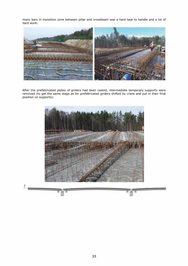
many bars in transition zone between pillar and crossbeam was a hard task to handle and a lot of
hard work:
After the prefabricated plates of girders had been casted, intermediate temporary supports were removed (to get the same stage as for prefabricated girders shifted by crane and put in their final position on supports):
33
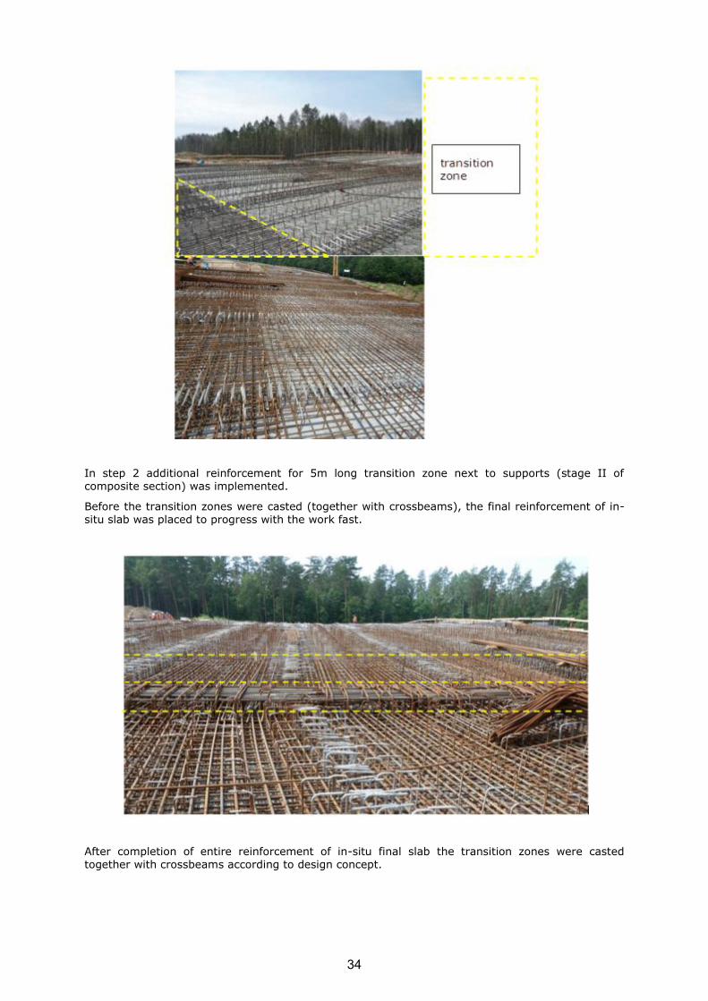
In step 2 additional reinforcement for 5m long transition zone next to supports (stage II of composite section) was implemented.
Before the transition zones were casted (together with crossbeams), the final reinforcement of in-situ slab was placed to progress with the work fast.
After completion of entire reinforcement of in-situ final slab the transition zones were casted together with crossbeams according to design concept.
34

This way step 3 was finished and it was only to cast the final plate (step 4).
In this point it is underlined, that second line of bridge was not realised after first is finally finished, but almost in parallel (see Table 3). During realisation of first line of the bridge first experiences
have been gained and discussion appeared concerning technology of realisation of second line of superstructure. Finally it was decided, that initially designed technology of realisation (prefabricated girders realised next to the bridge and then shifted by crane for final positions in spans) is possible even for such a complicated geometry of the girders. Prefabrication stands were set next to the bridge in few locations because number of girders to be produced was large. Girders for spans 2 and 3 were realised possibly close to their final locations (spans 2 and 3) and girders for spans 1 and 4 were realised behind abutments.
35

Girders have been realised and they were shifted by crane to their final positions on temporary supports next to pillars and abutments. Temporary supports were necessary to realise scaffolding for crossbeam proper way also.
36

37

The view from the bottom of the bridge (picture below) presents prefabricated girders of line 2 on
temporary supports and realised structure of line 1:
Finally reinforcement of girders and crossbeams was realised and realisation of superstructure could follow according to initially assumed design scheme:
o casting of crossbeam (and frame corners) together with additional 5m long transition zone next to supports (stage II of composite section)
o supports released o casting of final plate (stage III of composite section)
38
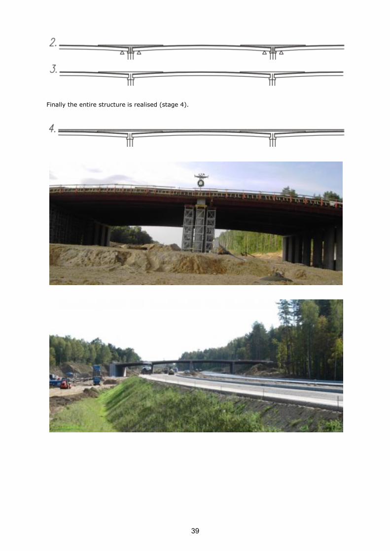
Finally the entire structure is realised (stage 4).
39

The next steps were to make embankments behind abutments, side concrete elements and soil on the superstructure.
40

Prefabricated elements of cornice:
41
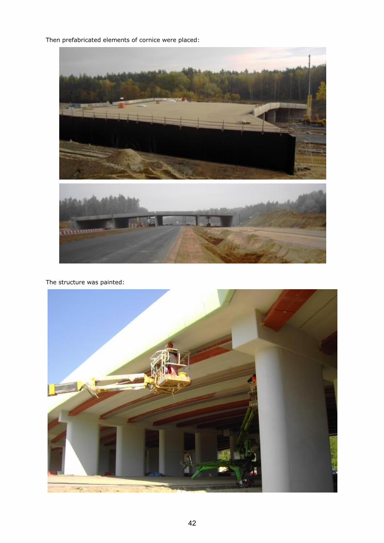
Then prefabricated elements of cornice were placed:
The structure was painted:
42

Then layer of soil was placed on superstructures:
43

Finally the bridge looks like this and the road under the bridge is in service:
2.2.4 Work Package 4 Monitoring
Monitoring of German bridge Simmerbach
In the course of railway track 3511 between Bingen and Saarbrücken (Germany), two existing steel troughs with ballast bed, which had reached their life-span, have been replaced by two VFT-Rail® girders with a span of 17.75 m each (Figure 61). The composite VFT-Rail® system is characterized by two characteristics: first, composite action between concrete and steel girders
(which act as external reinforcement) is ensured by means of composite dowels. These are cut out of an I-profile, see Figure 60, right. Second, the rail support points are directly fastened to the
composite girder (Figure 60, left).
Figure 60 - Transverse cross section (left) VFT-Rail® with rail support points directly fastened to the superstructure and composite dowel and longitudinal cross
section (right, depicting the clothoidal shape of the dowels)
44

Figure 61 - Longitudinal section railway crossing over the river “Simmerbach” with two VFT-Rail® girders, placed on toughened sub-structure
A detailed description of the railway bridge is given in [Seidl et al. 2012].
The rail operator made the following detailed long-term observation conditional as part of a special approval for the German market:
o measurement of strains in the steel girder caused by train crossings;
o measurement of forces acting on the rail support points; o measurement of settlement of the first sleeper behind the bridge, responsible for an
increase of tension and compression forces on the first four rail support points.
A detailed description of the measurements undertaken is given in this paper.
Design and construction
Both superstructures are designed as simply supported composite beams. Each single rail is placed
in a channel to increase the effective height of the cross section (Figure 60, left). Four halved steel profiles are placed at the bottom side of the bridge taking tension. The upper part of the structure is reinforced with four halved steel profiles as well. This additional external reinforcement is needed to carry compression forces, as the active concrete cross section is reduced by the channels, giving space for the rails. Composite action between steel girders and concrete is realized by composite dowels (geometry MCL250/115, [Seidl et al. 2012]). Shear reinforcement is placed in cut-outs between the steel dowels according to [ABZ 2013]. Due to concrete shrinkage, condition II builds
up over the concrete’s cross section. Therefore, for design purposes shear forces are assigned to the concrete, bending forces to the structural steel.
Figure 62 - Structure rail support point ECF [ThyssenKrupp 2006]
The elastic, adjustable rail support system Krupp ECF ([ThyssenKrupp 2006], 131-02) has been chosen to fasten the rails to the composite girder (Figure 62). Each rail support point is anchored by means of two threaded bolts which are embedded in the precast concrete. Lining plates are used to compensate vertical tolerances. Horizontal tolerances up to +/- 10mm are compensated by
means of eccentric insulating bushings.
45

The rail support points are placed in a regular pattern of a = 0.60 m. Next to the transition
between superstructure and backfilling (axis 20 and axis 30), an additional point is used to reduce the compressive forces in this region (Figure 63).
Figure 63 - Pattern of rail fasteners at the end of superstructure
The regular distance of 60 cm is continued on the ballast bed in front of the bridge. To ensure for small deformations under loading in that region, B90 sleepers are installed in front and behind the bridge structure. A possible maintenance replacement of the first four rail support points needs to be ensured, as the calculation of the tension forces acting on these fasteners is based on several assumptions such as time dependent ballast settlement in front of the bridge. Therefore the first four rail support points are fixed by means of stainless steel threaded bolts, screwed into friction welded stainless steel sleeves, anchored in the superstructure.
Aim of field measurements
The innovative aspects of the bridge structure are related to the composite dowel as well as the transition between ballast bed and directly fastened rail support points.
Therefore the following issues were investigated by means of field measurements:
o Confirmation of considerations underlying the design of the composite dowel, confirmation of correct application of rules based on stress concentration factors;
o Influence of settlement and deformation of ballast bed in front of the bridge on the forces acting on the rail support points.
Regarding the rail support points, threshold values were defined by the railway operator DB Netz AG which compliance had to be checked during monitoring.
Monitoring concept
Due to symmetric reasons, all measurement devices were applied at the VFT-Rail® girder between
axis 20 and axis 30 of the bridge structure only (Figure 61). For measurement of the strains in the composite dowel (Figure 60, right), strain gauges were applied and connected by wire during prefabrication of the elements in the workshop. Forces acting on the rail support points N° 1 and N° 4 were measured by means of two conventional ECF rail support points, equipped with special measurement devices. Furthermore relative settlement and lowering of the first B90 railway sleeper in front of the bridge was measured by means of two inductive displacement transducers.
The temperature distribution over the cross section was recorded permanently by three internal temperature gauges. These measurements were completed by deformation measurements of the superstructure.
Continuous measurements (C) were performed in combination with temporary measurements (T) to allow for a low-frequency recording of long term effects as well as a high-frequency recording of short term loading due to single train crossings. Temporary measurements were performed four times during a period of two years (summer and winter measurements to cover a large
temperature spectrum). In Table 4 the measurements are summarized.
46
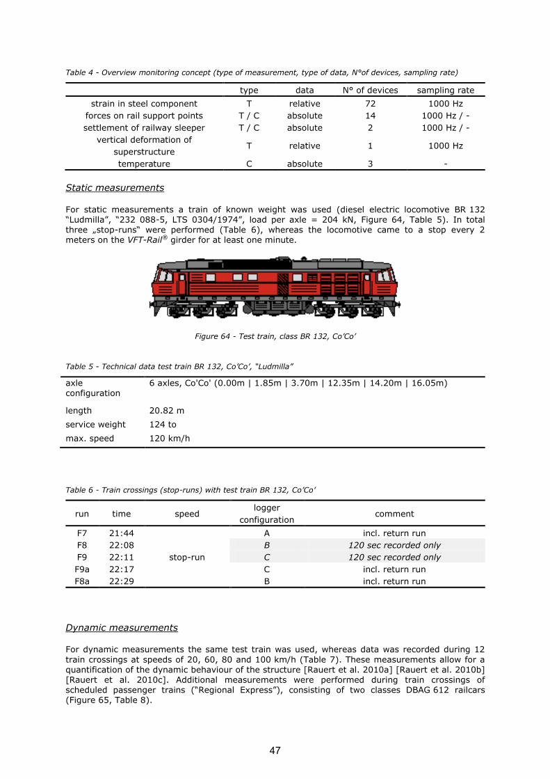
Table 4 - Overview monitoring concept (type of measurement, type of data, N°of devices, sampling rate)
type data N° of devices sampling rate
strain in steel component T relative 72 1000 Hz
forces on rail support points T / C absolute 14 1000 Hz / -
settlement of railway sleeper T / C absolute 2 1000 Hz / -
vertical deformation of
superstructure T relative 1 1000 Hz
temperature C absolute 3 -
Static measurements
For static measurements a train of known weight was used (diesel electric locomotive BR 132 “Ludmilla”, “232 088-5, LTS 0304/1974”, load per axle = 204 kN, Figure 64, Table 5). In total three „stop-runs“ were performed (Table 6), whereas the locomotive came to a stop every 2 meters on the VFT-Rail® girder for at least one minute.
Figure 64 - Test train, class BR 132, Co’Co’
Table 5 - Technical data test train BR 132, Co’Co’, “Ludmilla”
axle configuration
6 axles, Co'Co' (0.00m | 1.85m | 3.70m | 12.35m | 14.20m | 16.05m)
length 20.82 m
service weight 124 to
max. speed 120 km/h
Table 6 - Train crossings (stop-runs) with test train BR 132, Co’Co’
run time speed logger
configuration comment
F7 21:44
stop-run
A incl. return run
F8 22:08 B 120 sec recorded only
F9 22:11 C 120 sec recorded only
F9a 22:17 C incl. return run
F8a 22:29 B incl. return run
Dynamic measurements
For dynamic measurements the same test train was used, whereas data was recorded during 12
train crossings at speeds of 20, 60, 80 and 100 km/h (Table 7). These measurements allow for a quantification of the dynamic behaviour of the structure [Rauert et al. 2010a] [Rauert et al. 2010b] [Rauert et al. 2010c]. Additional measurements were performed during train crossings of scheduled passenger trains (“Regional Express”), consisting of two classes DBAG 612 railcars (Figure 65, Table 8).
47

Figure 65 - Railcar class DBAG 612, 2’B’+B’2’
Table 7 - Train crossings (dynamic) with test train BR 132, Co’Co’
run time speed logger
configuration comment
F1 18:28
20 km/h
A without displacement transducers (no
power)
F2 18:57 B without displacement transducers (no power)
F3 19:40 C -
F4 20:12
60 km/h
C
F5 20:41 B F6 21:14 A
F10 23:13 80 km/h
A - F11 23:41 B -
F12 00:08 C -
F13 - 100 km/h
C Not recorded F14 01:06 B - F15 01:35 A -
Table 8 - Train crossings (dynamic) with test train DBAG 612, 2’B’+B’2’
run time speed logger
configuration comment run
Ü1 18:17 - A - only strain gauges (ext. reinf.)
recorded
Ü2 19:06 - C RE 3341 only strain gauges (ext. reinf.)
recorded
Ü3 19:17 - C RB 13635 - Ü4 20:08 112 km/h C RE 3343 -
Ü5 20:20 87 km/h B RB 13637 only strain gauges (ext. reinf.)
recorded
Ü6 21:22 91 km/h A RB 13639 only strain gauges (ext. reinf.)
recorded
Owing to careful preparation and planning, the measurement campaign involving the measurement train BR 132, Co’Co’ could be finished after 7 hours. All preparations (arrangement and configuration of data loggers, connection and test of all measurement devices) were done in advance under regular traffic. For the test train measurements, the regular train service had not to be interrupted.
Rail support points
The forces acting on the rail support points as well as the stresses in the rails at both ends of the
superstructure were determined during the design process by project partner SSF by means of a structural analysis. These calculations were based on national railway codes “Ril 804 Module 5404” [DB 2011a] and “Ril 804 Module 5405” [DB 2011b] which were not compulsory.
Determination of design values
The theoretic values of rail stresses and forces acting on the single rail support points were determined by means of a framework model. This model consisted of the superstructure (layer 1) and the two single rails (layer 2). These rails were continuing with a length of LD = 0.5 * LT + 40 m = 46.58 m according to DIN Fachbericht 101, annex K.3.4 (4) [DIN FB 2009] adjacent to the superstructure in both directions.
48

The rails were coupled to the superstructure by horizontal and vertical springs, representing the
rail support points (Figure 63). The vertical spring stiffness of the rail support point was governed by the properties of the elastomer bearing (Figure 66), whereas the stiffness (22.5 kN/mm =
22,500 kN/m) was determined in advance by TU Munich (internal research report N° 1689a) for design purpose.
The horizontal creep resistance for the horizontal coupling springs was determined according to DIN Fachbericht 101, figure K.3 [DIN FB 2009], as the rails are fixed directly to the superstructure. For the load case “temperature difference” the values for an unloaded track (c = 18,000 kN/m per
single rail, yield value F = 9.0 kN/m) were used. For the load case “braking” the corresponding values for a loaded track (c = 36,000 kN/m per single rail, yield value F = 18.0 kN/m) were considered.
In the region of backfill the vertical spring stiffness was calculated by combining the spring stiffness of the rail support point and the spring stiffness of the elastic bedding (sleepers on ballast bed). For that case, a value of 0.10 N/mm2 was chosen according to [Eisenmann 2011], which resulted in a total spring stiffness of 14,300 kN/m for each single vertical spring.
Using the design rules provided by [DIN FB 2009], forces acting on the rail supports and stresses in the structure were calculated. These values were compared to the in-situ measurements.
The maximum stresses in the rail track at the abutments due to horizontal forces were determined
to be 37.1 N/mm2. This value by far did not exceed the limiting value of 92 N/mm2 as given by DIN FB 101, annex K.3.6 [DIN FB 2009].
The maximum stresses in the rails due to bending summed up to 170.6 N/mm2.
Forces acting on rail support points due to temperature loading were:
o max FZ =16.40 kN (at 1st rail support point on superstructure due to temperature induced vaulting)
o min FD =-4.60 kN (at 1st rail support point due to temperature induced flexion)
Forces acting on rail support point due to load scheme “Betriebszug type 5” were:
o max FZ =4.09 kN (at 4th rail support point)
o min FD =-65.5 kN (at 1st rail support point)
Forces acting on rail support point due to load scheme “test train BR 132” were:
o max FZ =4.0 kN(at 4th rail support point) o min FD =-36.3 kN (at 1. rail support point)
Alternatively a settlement of 3 mm was defined for the first springs on the backfill, which means
that the springs did not act for settlements not exceeding 3 mm (realistic settlement). This proceeding resulted in higher forces acting on the rail support points for load scheme “test train BR 132”:
o max FZ =6,79 kN (at 4th rail support point) o min FD =-51,90 kN (at 1st rail support point)
Measurement concept
Wheel loads are transferred from the rail track to the superstructure by ECF rail support points at regular intervals (Figure 63). The load transfer mechanism for vertical loads F had to be considered separately for compression and tension forces.
Compression forces are transferred from the rail through a ribbed base plate R and an elastic intermediate layer A into the superstructure (Figure 66).
The transfer of tension forces is realized by means of pre-stressed (stainless steel) threaded bolts
B which are screwed into friction welded stainless steel sleeves, anchored in the superstructure (Figure 66).
49

Figure 66 - Load bearing mechanism of rail support point ECF (principle, superelevated illustration), measurement equipment at rail support point ECF (principle)
As already mentioned, forces acting on the rail support point are not allowed to exceed limit values predefined by DB Netz AG. Within the scope of the bridge monitoring these vertical loads were measured separately for compression and tension forces, based on the corresponding load bearing
mechanism.
In the case of an external tensile loading F acting on the rail support point, the tension force is transferred from the ribbed base plate R through eccentric insulating bushings with collar E into two pre-stressed stainless steel threaded bolts (measurement bolt) B, anchored in the superstructure. The determination of these tensile forces was realized by a direct measurement of normal strain in the measurement bolts for which special strain gauges are glued into the bolts (Figure 66, D and Figure 67).
The threaded bolts are not pre-stressed against the ribbed base plate R but against the eccentric insulating bushings E. Hence a compression loading of the rail support point did not lead to a measurable decrease of preload force in the measurement bolts, as the pressure hull (caused by pre-stressing of the bolt) built up in the eccentric insulating bushings E were not decreased by a lowering of the ribbed base plate R (Figure 66, Figure 70). Therefore compression forces were determined by a measurement of the lowering of the ribbed base plate R combined with the known stiffness of the elastic intermediate layer. This approach is equivalent to the determination of
vertical spring stiffness for design purposes. The actual deformation of the ribbed base plate R was gauged by four inductive displacement transducers relatively to the slabbed track (Figure 66, I and Figure 67).
Figure 67 - Measurement devices for monitoring of forces acting on rail support points (1st, 2nd and 4th rail support point equipped)
Calibration of measurement equipment
In the first instance all measurement systems were calibrated at the Institute of Steel Construction of RWTH Aachen University in a phased process.
50

Figure 68 - Calibration of measurement bolts (here: measurement bolt S8), conversion of strain in measurement bolts into pre-tension force
Initially a linear calibration factor ktension,1 was determined. This factor was used for the conversion of measured elastic strains into equivalent bolt forces. Based on the concept of measurement bolt calibrations already successfully applied in the former research project RFCS HISTWIN [Feldmann
et al. 2011] [Veljkovic et al. 2010], the measurement bolts were loaded displacement-controlled in a two-column testing machine up to a maximum load of F=50 kN. The strains measured during testing were plotted against the corresponding jack forces (Figure 68) to derive a linear calibration factor ktension,1 for each individual bolt. These linear calibration factors are summarized in Figure 68 for all measurement bolts, representing the mean of a series of two measurements. They are used to determine the bold force (pre-tension force) for a given, measured strain.
In total, 8 measurement bolts were equipped and calibrated. 6 of those bolts were used in the
Simmerbach bridge (Figure 67), two of them were used for the calibration of the rail support point measurements.
In a second step a single rail support point was fixed to a concrete block using different grades of
pre-stressing and surcharged by a cyclic compression-tension force (Figure 69).
Figure 69 - Test set-up with measurement devices (unstressed measurement bolt S4 and displacement transducers W2, W4)
51

The concrete block was designed in accordance to the actual VFT-Rail® girder (concrete strength,
reinforcement, geometry). The measurement bolts were pre-stressed according to the tightening torque method whereas the final exact pre-stress was applied by means of the calibration factor
ktension,1, monitoring the strain in the bolts. The set of measurement bolts used for this cyclic test was not re-used in the final bridge structure.
Figure 70 - Mean lowering / deformation of the ribbed base plate depending on the force applied (20% pre-stress, 100% pre-stress)
The mean lowering of the ribbed base plate was measured by means of four displacement transducers and plotted against the jack force (Figure 70). In this way the vertical stiffness of the rail support point structure under compression was determined. Within the elastic region of the elastic intermediate layer this stiffness equals the stiffness determined by TU Munich (research report N 1689a) as well as the stiffness used for design (kpressure =22.5 kN/mm). However, due to
the non-linear force-deformation behaviour of the elastomer for compression forces > 45 kN, the secant stiffness (kpressure=29kN/mm) at F = 70 kN was used within the scope of the monitoring, leading to slightly conservative values for small deformations.
Figure 71 - Strain change in measurement bolt S2 depending on applied force (20% pre-stressed, 100% pre-stressed)
The change in strain measured in bolts is plotted against the jack force for different degrees of pre-
stress (Figure 71). Due to design and function of the rail support point, compressive loading does not lead to a measurable decrease of strain in the measurement bolts. The strain-force relation ktension,2 =0.36 [kN/(µm/m)] is valid for preloaded bolts only. Furthermore the linear relation is merely validated for tension forces Z<16 [kN]. A decrease of pre-stress results into a reduced
52

factor ktension,2,x%, whereas ktension,2 =0.36 [kN/(µm/m)] can be applied conservatively even for
measurement bolts with a low pre-stress (20%). For non-preloaded measurement bolts, ktension,1 (2 0,05274) may be applied (see Figure 72 and Figure 68).
Figure 72 - Bolt force function: measured strain s over jack force F at rail support point
The following factors result for the determination of the forces acting on the rail support point:
o Tension loading:
(100% pre-loaded bolts)
(non-preloaded bolts)
o Compressive loading:
The calibrated measurement bolts were installed during the construction of the rail tracks. The pre-
tension was applied according to the tightening torque method. The actual force in the bolts was determined based on the strain measured in the bolts.
Measurement results “rail support points”
Both the first and the fourth rail support point were monitored to verify the theoretically determined values of compression and tension forces acting on the system. On the one hand, strain changes in the measurement bolts were recorded to allow for a calculation of tensile forces acting on the rail support point. On the other hand the deformation of the ribbed base plate was measured to calculate the compressive force acting on the system. All short-term measurements
were performed at a frequency of 1000 Hz.
The mean values of static forces recorded during a stop-run of the test train are plotted over the position of the train on the bridge for rail support point 1 and 4 (Figure 73). These measured values correlate well with the characteristic calculated values. It can therefore be concluded that the design model chosen can be considered as sufficient.
A comparison of these results with the values recorded during “dynamic” train crossing at higher
speeds shows that in the case of the present structure the velocity of the train crossing the bridge
does not influence the forces acting on the rail support points. A dynamic amplification of forces could not be observed.
53

Figure 73 - Compression force / tension force acting on controlling rail support points 1 (left) and 4 (right), caused by static loading (test train)
Local stresses in external reinforcement
Determination of design values
The internal forces needed for the determination of stresses were determined by means of a framework model by project partner SSF. The section stiffness was calculated according to
elasticity theory for condition I (uncracked concrete, Figure 74, left) as well as for condition II (cracked concrete in tension zone, Figure 74, right). In the case of condition II, tension stiffening was disregarded (cracked concrete not contributing to stiffness, Young’s modulus of cracked concrete set to Ec =0). In the region of compression, concrete action was considered with non-reduced Young’s modulus. For the determination of the tension zone’s height, neutral axis zi,total = 38.4cm from condition I was considered without iteration. In both cases, next to external reinforcement, internal reinforcement (32 x Ø32) was taken into consideration as well. Especially in
condition II, the influence of this so-called redundancy reinforcement on the total stiffness of the cross section could not be disregarded.
Figure 74 - Cross section for condition I (left) and condition II (right), rail support point drawn in for illustration purposes only
Internal bending moments M, as well as internal shear force V was determined in the monitored
sections for different load positions of test train BR 132 (Figure 64). Therefore the loading of a single axle was applied step-wise to the framework model with a step-size of 1m, starting at axis 30 of the bridge. Based on these internal forces, normal stresses were calculated at the inner side of the upper and lower flanges, at the web as well as at the steel dowel (close to the stress hot-spot).
The stress calculation in the flanges as well as in the web was based on the global bending moment only. Amplification due to local stress concentration had not to be considered in this region, the
stress amplification factor fglobal was set to 1.0. The calculation of stresses in the region of the steel dowel was based on the global bending moment as well as on internal shear forces. There the stress amplification due to structural effects as well as local bending of the steel dowel (caused by internal shear forces) was considered by means of the stress amplification factors kf,G,CL and kf,L;CL.
54

Conservatively the stresses of both hot-spots were summed up [ABZ 2013] [P804] [Mensinger
2010].
D
y
Gf
wy
y
Lf zI
M
A
Nk
tI
SVk ,,
Measurement concept
Due to symmetry of the VFT-Rail® girder, the strain gauges were applied at the four left steel girders (2 top-girders, 2 bottom-girders, Figure 76) between axis 20 and axis 30 of the bridge structure only.
Figure 75 - Measurement sections at superstructure between axis 20 and axis 30
In axial direction, three measurement sections were defined. On the one hand the position of the
two sections close to the bearings (axis 20 and axis 30) had to be chosen in a way to allow for measurement of high shear forces in the composite section. On the other hand, local effects due to the load transfer into the bearings had to be minimized. Therefore the two outer sections were defined in a distance of about 1.85m to the bearing axis around the 7th and 8th steel dowel. The third measurement section was defined in mid-field around steel dowel 26 and steel dowel 27, as in this section the highest bending moments and deformations occurred (Figure 75).
Figure 76 - Position of strain gauges
Strain gauge application
The strain gauges were applied prior to casting in the workshop. In total 72 conventional steel strain gauges (R = 120 Ohm) were applied to the steel girder (Table 4). As all strain gauges were
covered by concrete, special care needed to be taken prior to casting regarding the protection of the gauges. Therefore all strain gauges were covered by a 2-component adhesive (PS-adhesive) after application of the signal wires. After hardening, this adhesive formed a stiff protective cover.
Finally a layer of permanent elastic cement (AK22) was applied, which minimized the risk of the gauges to be pulled off due to concrete pressure (Figure 77). Furthermore all signal wires were placed inside elastic ducts, placed in the radius of the steel profile and leading to axis 30 of the bridge structure. Due to these measures, only 4 out of 72 strain gauges did not work properly after casting, transportation and installation of the elements. Therefore this concept can be recommended for further measurement campaigns.
For identification of the strain gauges, all cables were marked with numeric clips at their particular
ends, whereas a need for further optimization has become evident during the project. If the cables
55
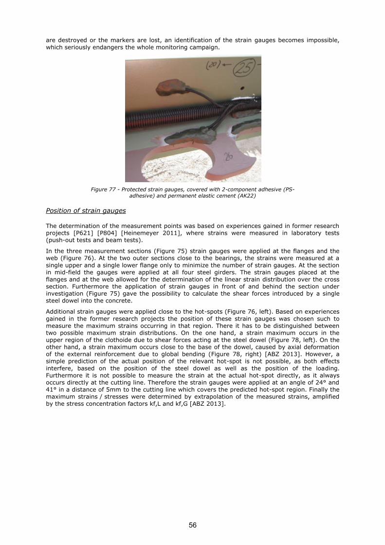
are destroyed or the markers are lost, an identification of the strain gauges becomes impossible,
which seriously endangers the whole monitoring campaign.
Figure 77 - Protected strain gauges, covered with 2-component adhesive (PS-adhesive) and permanent elastic cement (AK22)
Position of strain gauges
The determination of the measurement points was based on experiences gained in former research projects [P621] [P804] [Heinemeyer 2011], where strains were measured in laboratory tests (push-out tests and beam tests).
In the three measurement sections (Figure 75) strain gauges were applied at the flanges and the web (Figure 76). At the two outer sections close to the bearings, the strains were measured at a
single upper and a single lower flange only to minimize the number of strain gauges. At the section in mid-field the gauges were applied at all four steel girders. The strain gauges placed at the flanges and at the web allowed for the determination of the linear strain distribution over the cross section. Furthermore the application of strain gauges in front of and behind the section under investigation (Figure 75) gave the possibility to calculate the shear forces introduced by a single steel dowel into the concrete.
Additional strain gauges were applied close to the hot-spots (Figure 76, left). Based on experiences
gained in the former research projects the position of these strain gauges was chosen such to measure the maximum strains occurring in that region. There it has to be distinguished between two possible maximum strain distributions. On the one hand, a strain maximum occurs in the upper region of the clothoide due to shear forces acting at the steel dowel (Figure 78, left). On the other hand, a strain maximum occurs close to the base of the dowel, caused by axial deformation of the external reinforcement due to global bending (Figure 78, right) [ABZ 2013]. However, a simple prediction of the actual position of the relevant hot-spot is not possible, as both effects
interfere, based on the position of the steel dowel as well as the position of the loading. Furthermore it is not possible to measure the strain at the actual hot-spot directly, as it always occurs directly at the cutting line. Therefore the strain gauges were applied at an angle of 24° and 41° in a distance of 5mm to the cutting line which covers the predicted hot-spot region. Finally the maximum strains / stresses were determined by extrapolation of the measured strains, amplified by the stress concentration factors kf,L and kf,G [ABZ 2013].
56
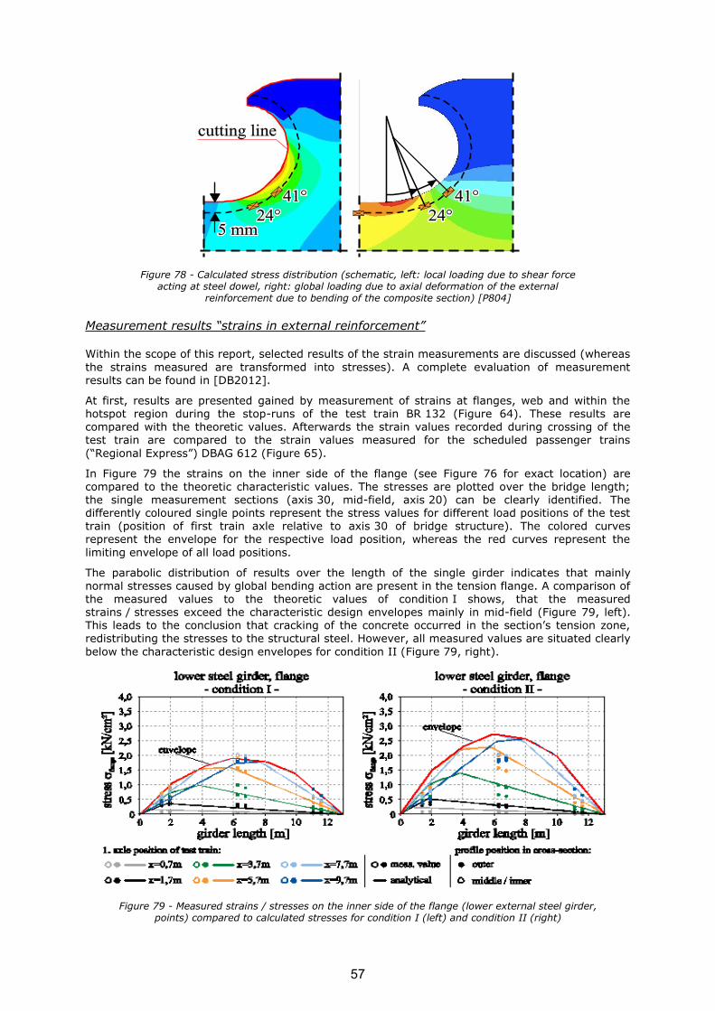
Figure 78 - Calculated stress distribution (schematic, left: local loading due to shear force acting at steel dowel, right: global loading due to axial deformation of the external
reinforcement due to bending of the composite section) [P804]
Measurement results “strains in external reinforcement”
Within the scope of this report, selected results of the strain measurements are discussed (whereas
the strains measured are transformed into stresses). A complete evaluation of measurement results can be found in [DB2012].
At first, results are presented gained by measurement of strains at flanges, web and within the hotspot region during the stop-runs of the test train BR 132 (Figure 64). These results are compared with the theoretic values. Afterwards the strain values recorded during crossing of the test train are compared to the strain values measured for the scheduled passenger trains
(“Regional Express”) DBAG 612 (Figure 65).
In Figure 79 the strains on the inner side of the flange (see Figure 76 for exact location) are compared to the theoretic characteristic values. The stresses are plotted over the bridge length; the single measurement sections (axis 30, mid-field, axis 20) can be clearly identified. The differently coloured single points represent the stress values for different load positions of the test train (position of first train axle relative to axis 30 of bridge structure). The colored curves represent the envelope for the respective load position, whereas the red curves represent the
limiting envelope of all load positions.
The parabolic distribution of results over the length of the single girder indicates that mainly normal stresses caused by global bending action are present in the tension flange. A comparison of the measured values to the theoretic values of condition I shows, that the measured strains / stresses exceed the characteristic design envelopes mainly in mid-field (Figure 79, left). This leads to the conclusion that cracking of the concrete occurred in the section’s tension zone, redistributing the stresses to the structural steel. However, all measured values are situated clearly
below the characteristic design envelopes for condition II (Figure 79, right).
Figure 79 - Measured strains / stresses on the inner side of the flange (lower external steel girder, points) compared to calculated stresses for condition I (left) and condition II (right)
57

The strains measured in the web are also distributed parabolically over the length of the girder
(Figure 80). This again leads to the conclusion that mainly normal stresses caused by global bending action are present in the tension flange. These stresses in the web are by 25% lower than
the corresponding stresses in the flange, which can be attributed (amongst others) to the smaller lever arm to the neutral axis. All values are increased compared to the theoretic values of condition I, which again shows that condition II governs and needs to be considered during design.
Figure 80 - Measured strains / stresses at web of lower external reinforcement, compared to calculated values for condition I (left) and condition II (right)
Stresses due to global bending of the composite girder and stresses caused by local bending of the steel dowel superimpose within the region of the so-called hot-spot at the foot of the dowel (Figure 81, Figure 78). Furthermore the stresses are increased due to geometric notch effects. Close to the bridge’s bearings (axis 20 and axis 30) normal stresses due to local bending of the steels dowels,
caused by shear forces to be distributed by the dowels, predominate. In mid-field, global bending still governs the stress state. However, as the stress-sums of global and local stress have to be taken into account, the hot-spots both at mid-field as well as at the bearings have to be investigated to find the critical cross-section. In the case given here, the critical stresses can be
found close to the bearings.
Figure 81 - Measured strains / stresses within the region of the hot-spot, lower external reinforcement, compared to calculated values for condition I (left) and condition II (right)
The results presented here show, that the maximum tension stress of about 2 kN/cm2 can be measured in mid-field in the region of the lower flanges. Therefore the stresses in this region (strain gauge S45 and strain gauge S46) induced by the test train (100 km/h) are compared to those caused by the scheduled regional train RE 3343 (120 km/h). The crossings lasted about 1 s
(BR 132) and about 2 s (RE 3343) respectively (Figure 82). The bogies are visible in both plots,
58

whereas the two central bogies of BR 132 merge due to the short distance between them (comp.
Figure 65). Furthermore the stresses caused by the regional train prove to be clearly smaller (about 0,87 kN/cm2) than the ones caused by the test train (Figure 82, left).
Figure 82 - Stresses in lower flange caused by crossing of test train (100 km/h, left) and regional train (120 km/h, right)
Furthermore the crossing of the regional train (BR 132) with 120 km/h is compared to a calculated quasi-static crossing. Therefore the estimated total weight of 58 t is distributed evenly to all axes, which results in axle loads of 72.5 kN. Based on the cross sectional values, the resulting moment distribution is transformed into theoretic stress curves for condition I (orange line) and condition II
(red line) (Figure 82). These theoretic values show a good correlation to the measured ones. The gliding mean value of both measured values (strain gauge S45 and strain gauge S46) is situated between the curves of condition I and condition II, which corresponds to the results discussed before. The small deviations in time between measured values and hand calculation results can be attributed to dynamic effects.
Monitoring of pilot bridge „Leuna“
A conventional single-span railway bridge crossing the K2174 (Maienweg) in Leuna (Germany), was replaced by a single-span integral abutment bridge.
Figure 83 - Longitudinal section railway crossing over K2174 (Maienweg) in Leuna
59

Design and construction
The bridge is designed as shallow founded integral abutment railway bridge with conventional
ballast bed. The two main girders, located on both sides of the bridge, are prefabricated composite beams.
The upper sides of these beams are reinforced with halved steel profiles as well. Composite action between the steel girders and the concrete is realized by composite dowels (geometry MCL250/115, [Seidl et al. 2012]). The bridge deck is cast in-situ, designed as composite slab. Here
composite action is realized by composite dowels as well (Figure 82), whereas these dowels are additionally loaded by transversal stresses.
Figure 84 - Cross section VFT-Rail with composite dowels and composite slab
The tension part of the corner moment is transmitted by conventional reinforcement. Furthermore
additional reinforcement is connected to the upper steel girder to avoid an uplift of the external reinforcement (Figure 85).
Figure 85 - Corner detail (northern abutment)
Aim of field measurements
The innovative aspects of the bridge structure are related to the composite dowel (girders and
slab) as well as transmission of corner moments.
Therefore the following aspects are investigated by means of field measurements:
o confirmation of considerations underlying the design of the composite dowel, confirmation of correct application of rules based on stress concentration factors;
o confirmation of considerations underlying the (conservative) design of the corner
reinforcement, to allow for a more economic design in the future;
Furthermore the earth pressure behind the integral abutments is measured.
60
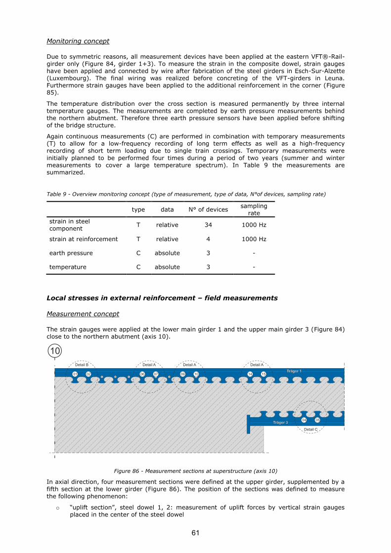
Monitoring concept
Due to symmetric reasons, all measurement devices have been applied at the eastern VFT®-Rail-
girder only (Figure 84, girder 1+3). To measure the strain in the composite dowel, strain gauges have been applied and connected by wire after fabrication of the steel girders in Esch-Sur-Alzette (Luxembourg). The final wiring was realized before concreting of the VFT-girders in Leuna. Furthermore strain gauges have been applied to the additional reinforcement in the corner (Figure 85).
The temperature distribution over the cross section is measured permanently by three internal temperature gauges. The measurements are completed by earth pressure measurements behind the northern abutment. Therefore three earth pressure sensors have been applied before shifting of the bridge structure.
Again continuous measurements (C) are performed in combination with temporary measurements (T) to allow for a low-frequency recording of long term effects as well as a high-frequency recording of short term loading due to single train crossings. Temporary measurements were
initially planned to be performed four times during a period of two years (summer and winter measurements to cover a large temperature spectrum). In Table 9 the measurements are summarized.
Table 9 - Overview monitoring concept (type of measurement, type of data, N°of devices, sampling rate)
type data N° of devices sampling
rate
strain in steel component
T relative 34 1000 Hz
strain at reinforcement T relative 4 1000 Hz
earth pressure C absolute 3 -
temperature C absolute 3 -
Local stresses in external reinforcement – field measurements
Measurement concept
The strain gauges were applied at the lower main girder 1 and the upper main girder 3 (Figure 84) close to the northern abutment (axis 10).
Figure 86 - Measurement sections at superstructure (axis 10)
In axial direction, four measurement sections were defined at the upper girder, supplemented by a
fifth section at the lower girder (Figure 86). The position of the sections was defined to measure the following phenomenon:
o “uplift section”, steel dowel 1, 2: measurement of uplift forces by vertical strain gauges placed in the center of the steel dowel
61

o “hot-spot section”, steel dowel 4, 5, 6, 7, 9, 10, 14, 15: measurement of hot-spot strains in
the steel dowel
Furthermore strain gauges were applied at a single cross-girder to determine the hot-spot stresses
under transverse tension (Figure 84).
Strain gauge application
The strain gauges were applied prior to casting in the workshop. In total 36 conventional steel strain gauges (R = 120 Ohm) were applied to the steel girders. For application and protection, the same methodology as used for the Simmerbach-bridge was applied.
For identification of the strain gauges, again all cables were marked with numeric clips at their particular ends.
Position of strain gauges
Again the determination of the measurement points was based on experiences gained in former
research projects [P621] [P804] [Heinemeyer 2011], where strains were measured in laboratory tests (push-out tests and beam tests).
In the “hot-spot” section, the strain gauges were again applied at the flanges and the web as described for the Simmerbach-bridge. The strain gauges placed at the flanges and at the web allowed for the determination of the linear strain distribution over the cross section. Furthermore the application of strain gauges in front of and behind the section under investigation gave the
possibility to calculate the shear forces introduced by a single steel dowel into the concrete. Additional strain gauges were applied close to the hot-spots. The positions were chosen in accordance to the considerations made for the Simmerbach-bridge.
Measurement results “strains in external reinforcement”
After shifting the bridge into its final position and before backfilling, the strain gauge measurement
wire strand was cut-off from unknown persons. In spite of the fact that the wires have been repaired, an allocation of the strain gauges was not possible according to the state of the art. Therefore RWTH started to perform tests in the lab on RWTH’s own costs to develop a method for identifying the cast-in strain gauges.
Figure 87 - Measurement wires Leuna, cut-off after installation
The method tested takes advantage of the fact, that even though strain gauges with a minimized sensitivity to temperature have been used (compensation for the thermal expansion), the effect of
thermal expansion is never compensated completely. Even though first results in laboratory were promising, the concept could not be adopted to the Leuna-bridge yet due to time constraints.
62
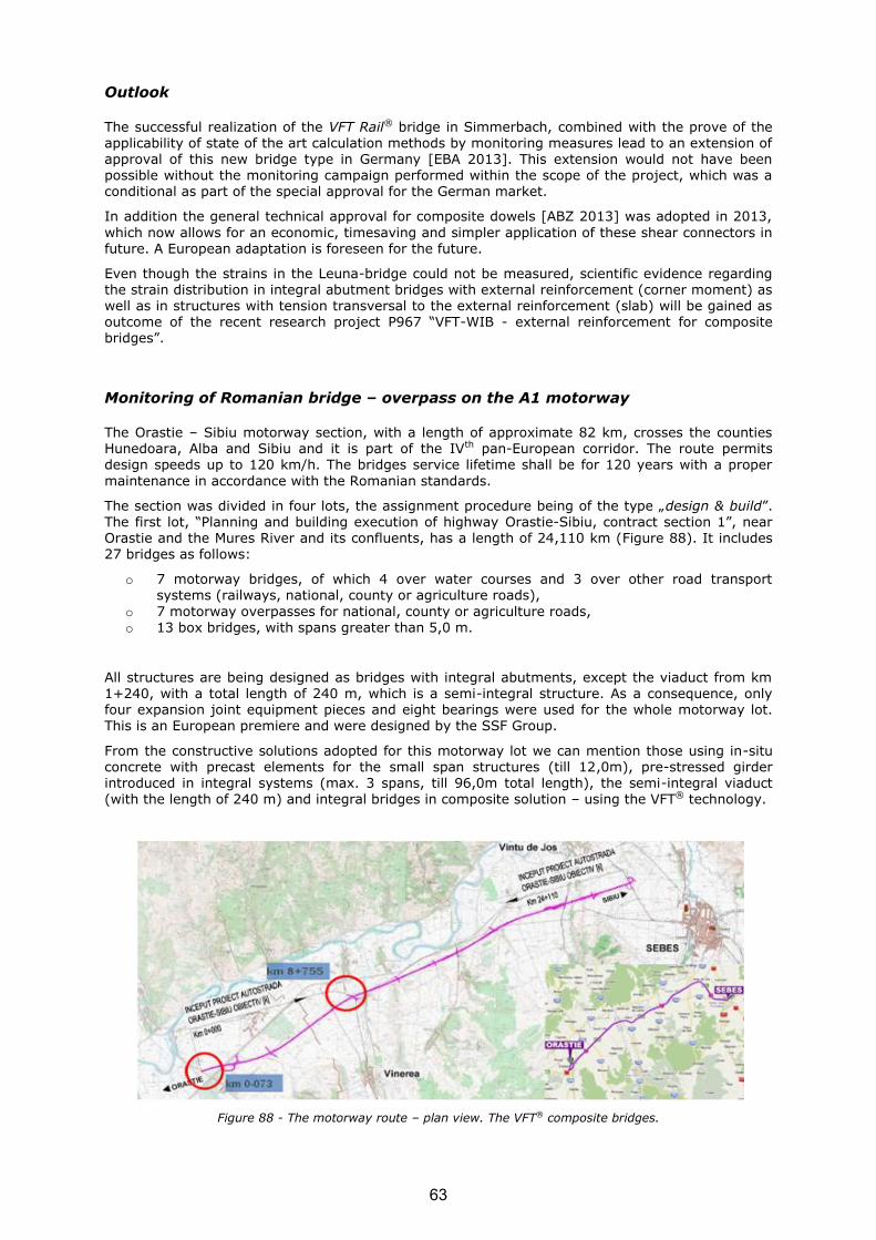
Outlook
The successful realization of the VFT Rail® bridge in Simmerbach, combined with the prove of the
applicability of state of the art calculation methods by monitoring measures lead to an extension of approval of this new bridge type in Germany [EBA 2013]. This extension would not have been possible without the monitoring campaign performed within the scope of the project, which was a conditional as part of the special approval for the German market.
In addition the general technical approval for composite dowels [ABZ 2013] was adopted in 2013,
which now allows for an economic, timesaving and simpler application of these shear connectors in future. A European adaptation is foreseen for the future.
Even though the strains in the Leuna-bridge could not be measured, scientific evidence regarding the strain distribution in integral abutment bridges with external reinforcement (corner moment) as well as in structures with tension transversal to the external reinforcement (slab) will be gained as outcome of the recent research project P967 “VFT-WIB - external reinforcement for composite bridges”.
Monitoring of Romanian bridge – overpass on the A1 motorway
The Orastie – Sibiu motorway section, with a length of approximate 82 km, crosses the counties Hunedoara, Alba and Sibiu and it is part of the IVth pan-European corridor. The route permits design speeds up to 120 km/h. The bridges service lifetime shall be for 120 years with a proper
maintenance in accordance with the Romanian standards.
The section was divided in four lots, the assignment procedure being of the type „design & build”. The first lot, “Planning and building execution of highway Orastie-Sibiu, contract section 1”, near Orastie and the Mures River and its confluents, has a length of 24,110 km (Figure 88). It includes 27 bridges as follows:
o 7 motorway bridges, of which 4 over water courses and 3 over other road transport systems (railways, national, county or agriculture roads),
o 7 motorway overpasses for national, county or agriculture roads, o 13 box bridges, with spans greater than 5,0 m.
All structures are being designed as bridges with integral abutments, except the viaduct from km
1+240, with a total length of 240 m, which is a semi-integral structure. As a consequence, only four expansion joint equipment pieces and eight bearings were used for the whole motorway lot. This is an European premiere and were designed by the SSF Group.
From the constructive solutions adopted for this motorway lot we can mention those using in-situ concrete with precast elements for the small span structures (till 12,0m), pre-stressed girder introduced in integral systems (max. 3 spans, till 96,0m total length), the semi-integral viaduct (with the length of 240 m) and integral bridges in composite solution – using the VFT® technology.
Figure 88 - The motorway route – plan view. The VFT® composite bridges.
63

The first bridge of the analyzed section is a new composite bridge in integral solution, using the
VFT® technology. It serves as overpass for the country road DJ705. The following ten structures are interesting and diversified. Here is located the second twin composite bridge from this lot at km
8+775 in intersection with the crowded national road DN7 (Figure 88).
Technical details of the applied solution
In case of the new VFT® the connection between steel and concrete is made through composite dowels and the upper steel flange is no more needed. If the elimination of the upper flanges of the
steel girders and the studs are considered, namely material consumption and welding workmanship, the efficiency of the designed solution can be observed. This theoretical concept was put in practice for the first time in Romania, as well being a world premiere; in case of the two overpasses from Orastie – Sibiu Motorway - lot 1. It represented an inspired alternative to the classical concrete bridges – particularly to those with pre-stressed girders on the cross section. Using the high degree of prefabrication, the VFT® girders reduce the possibility of unexpected situations on site and offer execution simplicity and by default obtaining lower costs. The reduced
weight of the prefabricated composite beams offers advantages both in the transportation as well as in the manipulation efforts and contributes to the success of modern composite bridges.
Both passages have only one span and are oblique (approximately 70°), integral structures and
they use four steel-concrete composite beams approximately 39 m long (Figure 89).
Figure 89 - Left: longitudinal section, Right: design model
Figure 90 - General cross section
The infrastructure is composed of four drilled piles for every axis – each being 10 m long, continuing with a foundation slab - 2,0 m wide and 1,20 m high - and one reinforced concrete
straight wall of 1,50 m depth and approximately 10,0 m height. Whilst the infrastructures are made, close to the final bridge position, four prefabricated steel girders are brought from the prefabrication plant and are fixed on temporary concrete supports, designed to take into account the precambering of the girder. On those temporary platforms the upper reinforced concrete flange of the precast girders begins to take shape with its variable thickness 10 cm ÷ 15 cm (Figure 91, Figure 92a). The concrete flange serves as a pressure zone, horizontal bracing during erection and
formwork for the in-situ slab.
64

Then, the finished composite beams – the VFT® girders are aligned on the infrastructure using a
crane of max 50,00 to. During the design stages and also during execution, special attention was paid to the reinforcement in the frame corners (Figure 92b). In accordance with the designed
technology, the pouring of the superstructure plate was made in two steps: first on the frame corners areas together with 4,5 m distance from the plate and only afterwards the works were continued on the remaining plate area - in the middle part of the superstructure. The superstructure plate is 20 cm ÷ 30 cm thick.
For more competitiveness, in the entire structure were used several concrete qualities, starting
from C20/25 concrete for the piles, C35/45 in the superstructure slab, till C45/55 concrete class for the upper reinforced concrete flange of the precast girders.
The last remaining work was the proper equipment of the structure: the waterproofing system, the pedestrian parapets, the guardrail protection and the translation slabs, earth filling with the corresponding degree of compaction and adequate materials, road structure (Figure 93).
Figure 91 - The formwork cross section of the Prefabricated Composite Girder VFT®
Figure 92- a) Reinforced cross section of the Prefabricated Composite Girder VFT®, b) Frame node reinforcement detail
Figure 93 - The final structure and its equipment.
a) b)
65

The welded steel girders from the prefabricated composite beams are made of S355 J2+N and
have variable height - 1200 mm in the field and 1500 mm at the supports. Two types of section were introduced: the middle part of the steel girder is composed only of a bottom flange and a web
with steel dowel cuttings on top and on the end zones, of each 6 meters, a slender U-shaped upper flange having a thickness of 12 mm was additionally introduced (Figure 94). The steel plates of the upper flange were cold bended and have the role to increase the number of the steel dowels in order to transfer the shear effect.
The composite dowels require a cutting geometry on the upper part of the steel (Figure 94, Figure
95) using a special form adapted to the requirements given by fatigue, reinforcement and concrete.
Figure 94 - The steel girder type sections; Steel girders in the workshop; the cutting line geometry of the composite dowels.
Figure 95 - The steel girder type sections; the end steel girders detail and the transition detail between the two types of section.
Figure 96 - Finished overpass
66

A very slender and aesthetic aspect was obtained for these overpasses and the solution allowed
considerable material savings. Practically, for both bridges a very good steel consumption of 130 kg/m2 was obtained.
Technical details of the load test project
A load test was carried out for one of the twin structures – the overpass at km 8+775. The test program was conceived according to the Romanian standard STAS 12504-86_DR 9 [9]. The test purpose was to obtain information about the structure behaviour subjected to present load
situations, to assess the viability of the initial design project.
According to the Romanian standard, the analysis of the following issues must be taken into account within a testing program:
o the resistance and the stability of the structure; o the superstructure’s elastic behaviour; o the state of deformations and displacements in characteristic points and sections; o functional behaviour;
o the overlapping of in-situ results with those obtained in the calculation design stage.
According to the national regulations it is compulsory to test all the new bridges which present
novelties from the point of view of the used material, the method of calculation and execution technologies. The tests will be performed under static and dynamic actions.
The entire testing process contains some well-established conditions, as follows:
o Several consecutive cycles of load schemas;
o In the static load case, the truck convoys entered and exited out the bridge with the maximum speed of 5 km/h. They stopped in the position specified in the load scheme;
o In case of dynamic loads, the convoys of motor vehicles circulate on the bridge with a constant speed;
o During the test the circulation on the bridge is closed; o To increase the impact on the tested structure, it is recommended to create artificial
unevenness of the way, by placing on the road wooden planks with the thickness of 4 cm,
width of 30 cm and length of 300 cm. The edges from the superior part of the wooden planks were flattened at 45°. Their positions on the bridge were established by the testing design;
o The testing actions included following information on the vehicles: the weight on the axle, position of the axles and of the front wheels in relation to the elements of the resistance structure of the bridge;
o For the dynamic testing of the bridge the speed of movement of the convoy must be
controlled and their dimensions, position and weight must be also known; o A visual observation of the bridge was also made.
According to the Romanian standard [9], the load test vehicles convoy must be similar to the A30 theoretical convoy, available on the market. Thus were used the MAN TGA 41.480 8X4 trucks, type BB - with four-axle. To be realistic, the trucks were loaded to the maximum weight of 40 t closer to the present traffic situation allowed on this national road (Figure 97, Figure 98). A number of two
static load schemas and four dynamic load schemas were provided, a total of maximum four MAN TGA trucks per schema being used.
67
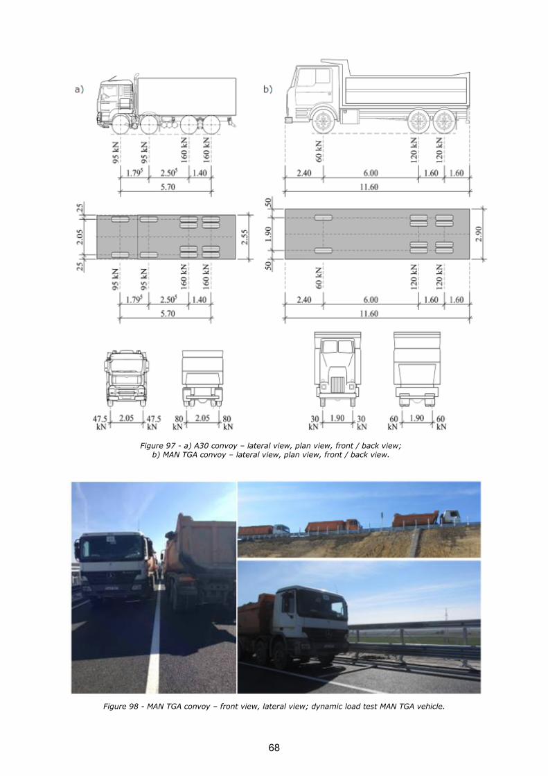
Figure 97 - a) A30 convoy – lateral view, plan view, front / back view; b) MAN TGA convoy – lateral view, plan view, front / back view.
Figure 98 - MAN TGA convoy – front view, lateral view; dynamic load test MAN TGA vehicle.
68

In order to obtain relevant results – the maximum stress and displacements in the structure six
different load schemas were established. The ratio between the measured values and the values obtained in the FEM analysis of the structure is defined in (1).
design
measured
stats
sE (1)
Where:
smeasured the stress obtained by measurements on the structure from the testing loads considered as statically applied,
sdesign the designed efforts, which are calculated on the structure.
For the dynamic test the dynamic coefficient was determined (2).
stat
din
masε
ε=Ψ (2)
Where:
εdin maximum specific deformation measured in a point, at the passing of the dynamic convoy with a certain speed,
εstat specific deformation measured in the same point where it has been measured εdin, from
the loading with the same convoy applied statically in the position in which εdin was produced.
Before starting the effective procedures, the following preparatory works were realized:
o The entire team of participants are present on the site: authorities, engineers, technicians; o Previously the load tests, the strain gauges, the cables and all the necessary equipment for
the test were prepared;
o All the measurement devices are verified a few days before; o Prior to the installation of the strain gauges, the surfaces from the steel beams were
prepared according to the usual procedure; o One day before the load test the strain gauges on the structure, indicated by the drawing
were installed, in accordance with the test project (Figure 99). It was considered to be important that the strain measurements are made in two different sections, for each steel beam: the first section is located near the frame corner, where two active strains on the
flanges and one passive strain on the neutral axis (Figure 100a, Figure 101a) are disposed and the second one is the middle cross section with one pair of strains – the active one on the bottom flange and the passive one in the neutral axis (Figure 100b, Figure 101b).
o The vehicles real weight on the axle was verified and then filled out in the prepared forms from the project;
o The axles and wheels positions will be marked properly on the bridge according to the
design drawings; o The equipment provided for the deformations measurements are installed and the required
topographic devices are prepared; o The weather conditions on the test load day must be taken into consideration by the
engineers (temperature, wind and precipitations);
69

Figure 99 - Installed strain gauges on the section of the bridge in the in-situ test day
Figure 100 - Installed strains on the section of the bridge; a) Cross section of the supports area; b) Cross section of the field.
Figure 101 - Installed strains on the section of the bridge; a) Cross section on the supports area; b) Cross section on the field.
a) b)
a) b)
70

The measuring devices were meant to be read in the following steps: prior to the loading, during the load schema and after each discharge. During the reading procedure of all the measurement
devices (stresses or displacements) the state of effort of the bridge structure was maintained constant. Before the testing the preliminary readings provided by the standard were performed: twice with approximately an hour ahead, respectively 15 minutes before the beginning of the testing. After the performance of each scheme of loading, as well as after each unloading, the measurement devices are read many times. The first reading is effectuated immediately after the
disposal of the testing actions on the bridge, respectively after unloading, than readings at equal intervals in time (of at least 5 minutes) are performed until the stabilization of the measured values, namely until the increasing of the values measured between two consecutive readings is under 15%.
The principle of the strain gauge chain used for the tests is presented in Figure 102. On the structure on which the loads F1…Fn act, the strain gauge is applied (glued) (TER – transducer with electrical resistance) and connected through the measuring cable with several conductors (1) to
the amplifier. The data acquisition is made with the help of the laptop connected to the amplifier through the interface (2).
Figure 102 - The principle of the strain gauge chain used for the probes.
Consequently the static schema of the bridge is a frame and the expansion joints were eliminated, it appeared as necessary and important to check the longitudinal displacements of the entire assembly. These measurements were provided by placing a displacement device – type W.A.1 on the back of one of the frame corners, before the disposal of the transition slab, the earth filling and the road structure. Using an extension, the W.A.1 cable was brought out to the outside surface of
the sidewalk of the bridge, where with the help of a reading device, the results could be recorded
and read off any time it was wanted (Figure 103). The measurements must be made at least once per season to obtain the displacement between extreme temperatures, especially winter-summer differences, as well as day-night differences. The monitoring has to be done at least one year, in order to obtain in the end a graphic with the movement differences of the structure.
71
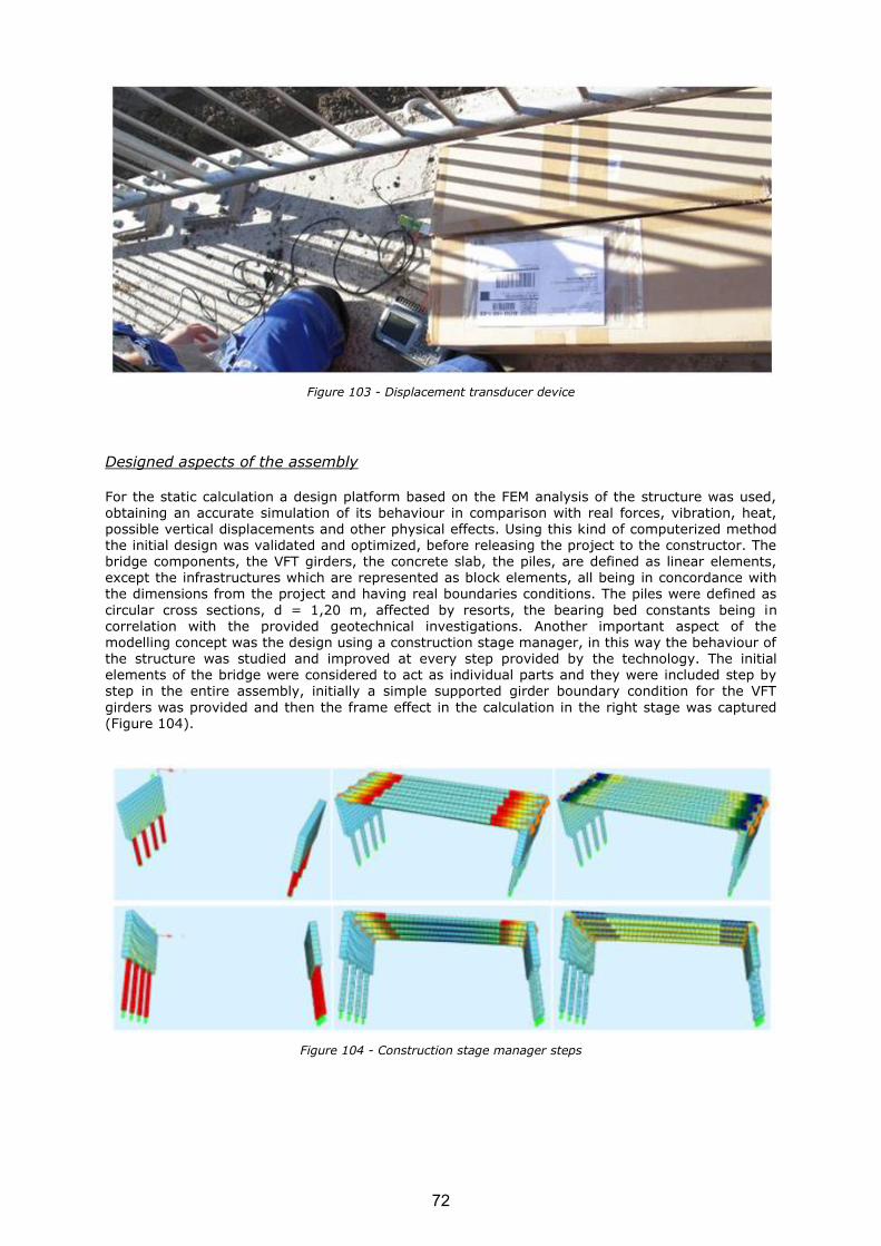
Figure 103 - Displacement transducer device
Designed aspects of the assembly
For the static calculation a design platform based on the FEM analysis of the structure was used, obtaining an accurate simulation of its behaviour in comparison with real forces, vibration, heat, possible vertical displacements and other physical effects. Using this kind of computerized method the initial design was validated and optimized, before releasing the project to the constructor. The bridge components, the VFT girders, the concrete slab, the piles, are defined as linear elements, except the infrastructures which are represented as block elements, all being in concordance with the dimensions from the project and having real boundaries conditions. The piles were defined as
circular cross sections, d = 1,20 m, affected by resorts, the bearing bed constants being in correlation with the provided geotechnical investigations. Another important aspect of the modelling concept was the design using a construction stage manager, in this way the behaviour of the structure was studied and improved at every step provided by the technology. The initial elements of the bridge were considered to act as individual parts and they were included step by step in the entire assembly, initially a simple supported girder boundary condition for the VFT
girders was provided and then the frame effect in the calculation in the right stage was captured (Figure 104).
Figure 104 - Construction stage manager steps
72

Figure 105 - a) Cross section of the supports area; b) Cross section of the field.
Figure 106 - Construction stages: a) Simple supported girder; b) Frame effect
On the structure thus defined two loads system were considered: the Eurocode tandem system and also the loads similar to those resulted from the testing convoys – the MAN TGA vehicles were
introduced (Table 10, Figure 107).
Concerning the static load test schemas, two cases – LC1, LC2 have been considered, each using four trucks. In the first situation the convoys were positioned in the middle of the span, being centred on the cross-section, in the second case the trucks were moved to the outside of the cross-section (Figure 108).
For the dynamic test a MAN TGA 8X4 truck type BB (equivalent to A30) was considered, which was running parallel to the highway axis with a speed of 30 km/h and then with a speed of 50 km/h. In
this case, four load schemas – LC1…4 were conceived.
The temperature variation, bearing settlements, all the self - weights including the pedestrian load were modelled on the structure, for the ultimate limit state and as well as for the service limit state.
a)
b)
73
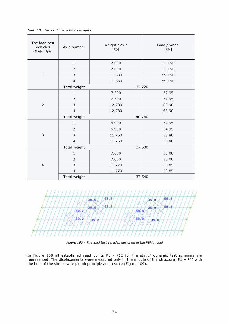
Table 10 - The load test vehicles weights
The load test vehicles
(MAN TGA)
Axle number Weight / axle
[to] Load / wheel
[kN]
1
1 7.030 35.150
2 7.030 35.150
3 11.830 59.150
4 11.830 59.150
Total weight 37.720
2
1 7.590 37.95
2 7.590 37.95
3 12.780 63.90
4 12.780 63.90
Total weight 40.740
3
1 6.990 34.95
2 6.990 34.95
3 11.760 58.80
4 11.760 58.80
Total weight 37.500
4
1 7.000 35.00
2 7.000 35.00
3 11.770 58.85
4 11.770 58.85
Total weight 37.540
Figure 107 - The load test vehicles designed in the FEM model
In Figure 108 all established read points P1 - P12 for the static/ dynamic test schemas are represented. The displacements were measured only in the middle of the structure (P1 – P4) with
the help of the simple wire plumb principle and a scale (Figure 109).
74

Figure 108 - The read points for the static / dynamic test schema, load schema 1 – LC1 and load schema 2 – LC2.
Figure 109 - Vertical displacement measuring principle
Data processing. Results
The results obtained during the bridge test were interpreted and compared with the model calculation values according to the methodology described by the norms.
The report between the ratio of the measured elastic deformation (fel) and the calculated ones (fteor) (Table 11, Figure 110) were corresponding to the criterion of similitude, the maximum values Ef stat in the middle of the span, the design characteristic loads being compared to the testing loads.
75

Table 11 - Maximum vertical displacements for load schema 1 – LC1 and load schema 2 – LC2
Load case
Section item
Recorded values Vertical displacement
unloaded structure
loaded structure
discharge structure
fel fteor ∆
1
P1 3305 3312 3306 7.00 7.90 1.13
P2 2718 2726 2719 8.00 9.00 1.13
P3 2115 2123 2117 8.00 9.00 1.13
P4 3493 3500 3494 7.00 7.80 1.11
2
P1 3306 3314 3306 8.00 9.00 1.13
P2 2719 2727 2719 8.00 9.50 1.19
P3 2117 2124 2118 7.00 8.50 1.21
P4 3495 3500 3495 5.00 6.00 1.20
Figure 110 - Vertical displacement diagrams – test load schema 1 – LC1 and load schema 2 – LC2
Table 12 - Results from test load schema 1 – LC1
Section item Smeasured
[N/mm²]
Sdesign
[N/mm²] Estat
P1_Test channel 9 23.52 23.80 0.99
P2_Test channel 10 27.30 27.13 1.01
P3_Test channel 11 28.54 27.22 1.05
P4_Test channel 12 22.72 23.16 0.98
P6_Test channel 1 27.72 28.84 0.96
P8_Test channel 2 35.09 38.28 0.92
P10_Test channel 3 36.09 38.73 0.93
P12_Test channel 4 27.68 26.98 1.03
P5_Test channel 5 -19.92 -19.72 1.01
P7_Test channel 6 -28.55 -32.70 0.87
P9_Test channel 7 -33.06 -32.93 1.00
P11_Test channel 8 -20.06 -20.80 0.96
LC1
76

Figure 111 - „smeasured” values from test load schema 1 – LC1
Figure 112 - „sdesign” values from test load schema 1 – LC1
beam 2
beam 1
beam 2
beam 1 beam
4
beam
1
beam 2 beam
3
77

Table 13 - Results from test load schema 2 – LC2
Section item Smeasured
[N/mm²]
Sdesign
[N/mm²] Estat
P1_Test channel 9 31.50 31.95 0.99
P2_Test channel 10 30.45 30.60 1.00
P3_Test channel 11 24.15 23.80 1.01
P4_Test channel 12 15.75 16.03 0.98
P6_Test channel 1 38.51 40.68 0.95
P8_Test channel 2 37.83 42.13 0.90
P10_Test channel 3 33.96 34.44 0.99
P12_Test channel 4 16.07 15.73 1.02
P5_Test channel 5 -29.44 -28.75 1.02
P7_Test channel 6 -29.85 -36.21 0.82
P9_Test channel 7 -26.16 -30.10 0.87
P11_Test channel 8 -14.32 -14.84 0.96
Figure 113 - „smeasured” values from test load schema 2 – LC2
beam
beam 4
beam
1
78
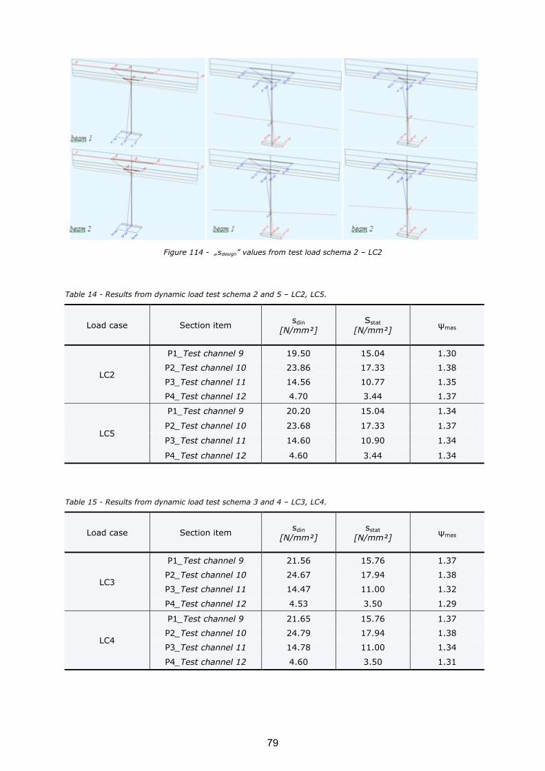
Figure 114 - „sdesign” values from test load schema 2 – LC2
Table 14 - Results from dynamic load test schema 2 and 5 – LC2, LC5.
Load case Section item sdin
[N/mm²] Sstat
[N/mm²] ψmas
LC2
P1_Test channel 9 19.50 15.04 1.30
P2_Test channel 10 23.86 17.33 1.38
P3_Test channel 11 14.56 10.77 1.35
P4_Test channel 12 4.70 3.44 1.37
LC5
P1_Test channel 9 20.20 15.04 1.34
P2_Test channel 10 23.68 17.33 1.37
P3_Test channel 11 14.60 10.90 1.34
P4_Test channel 12 4.60 3.44 1.34
Table 15 - Results from dynamic load test schema 3 and 4 – LC3, LC4.
Load case Section item sdin
[N/mm²] sstat
[N/mm²] ψmas
LC3
P1_Test channel 9 21.56 15.76 1.37
P2_Test channel 10 24.67 17.94 1.38
P3_Test channel 11 14.47 11.00 1.32
P4_Test channel 12 4.53 3.50 1.29
LC4
P1_Test channel 9 21.65 15.76 1.37
P2_Test channel 10 24.79 17.94 1.38
P3_Test channel 11 14.78 11.00 1.34
P4_Test channel 12 4.60 3.50 1.31
beam 2
beam 2
beam 1
79

Figure 115 - „sdin” values from test load schema 2 – LC2
Figure 116 - „sdin” values from test load schema 3 – LC3
Figure 117 - „sdin” values from test load schema 4 – LC4
80

Figure 118 - „sdin” values from test load schema 4 – LC5
Figure 119 - „sstat” values from dynamic test load schema 3, 4 – LC3,4 (v = 50 km/h) and load schema 2 – LC2,5 (v = 30 km/h)
The load test conclusion is that the structure has had a proper behaviour considering the following aspects:
o the bridge or its elements do not present important deformations, exceeding the elastic ones, or losing of stability;
o at a close inspection no cracks were observed; o flaws which could affect the functionality of the bridge did not appear; o displacements were within the limits recommended by the technical documentation;
o the unitary stresses in the areas with maximum stress are close to those resulted from the calculus.
2.3 CONCLUSIONS
2.3.1 Cost analysis of PE4 bridge
The price and material consumption analysis are presented with reference to meter squared of the
bridge for basic constructional materials used in PE4 Bridge: constructional steel with corrosion protection, reinforcement and concrete. It assumes unit prices to be used by contractors for cost calculation during design of the bridge. Take-off being the basis for calculations presented in tables below is enclosed as annex (in Polish).
81

Area of the bridge:
The price and material consumption data:
Beams Area [m2]
A1-A7 + A1'-A7' 878.9
B1-B7 + B1'-B7' 872.9
C1-C7 + C1'-C7' 872.9
D1-D7 + D1'-D7' 878.9
total: 3503.6
Item Construction steel [t]
VFT-WIB girder, type A 90.4
VFT-WIB girder, type B 108.0
VFT-WIB girder, type C 107.9
VFT-WIB girder, type D 90.7
total: [t] 396.9
unit price [PLN/t]: 7000
total cost [PLN]: 2778454
cost /m2 bridge [PLN/m
2]: 793.0
consumption [kg/m2] 113.3
Item Reinforcement steel [t]
abutment - axis 1 117.4
pier - axis 2 138.0
pier - axis 3 133.5
pier - axis 4 138.6
abutment - axis 5 109.4
in-situ concrete slab 150.7
prefabricated concrete VFT-WIB 164.1
cornice 24.1
total: [t] 975.8
unit price [PLN/t]: 3000
total cost [PLN]: 2927412
cost /m2 bridge [PLN/m
2]: 835.5
consumption [kg/m2] 278.5
Item Concrete [m3]
abutment - axis 1 699.2
pier - axis 2 269.6
pier - axis 3 248.2
pier - axis 4 269.1
abutment - axis 5 579.6
in-situ concrete slab 1154.0
prefabricated concrete VFT-WIB 547.4
cornice 221.0
total: [m3] 3988.1
unit price [PLN/m3]: 800
total cost [PLN]: 3190480
cost /m2 bridge [PLN/m
2]: 910.6
consumption [m3/m
2] 1.1
82

Finally after bridge is in service and final settlement of accounts of the contract with General Directorate of National Roads and Motorways is done, analysis of total costs dedicated to this bridge in frame of contract are delivered by Energopol:
In the previous research project, “PRECOBEAM: Prefabricated enduring composite beams based on innovative shear transmission” a comparison of a pre-stressed girder, a VFT (VFT® = Verbund-Fertigteil-Träger = prefabricated composite beam) and a Precobeam has been realized in order to prove that the new technology represents an economical solution.
Figure 120 - Dimensions of Preco-Beam girders for Vigaun-Bridge and of preliminary design for VFT and pre-stressed girders
Item cost /m2 [PLN/m
2]:
reinforcement steel 835.5
concrete 910.6
construction steel 793.0
total: 2539.2
Price PLN (netto)
1. Foundations, protection elements, isolations 3055286.00
2. Structure of the bridge 12053647.75
3. Drainage 429620.96
4. Other works dedicated to the bridge 961451.50
5. Construction camp 1787343.09
Total: 18287349.3
83

In comparison to the VFT girders high reduction of costs can be reached by less amount of steel. The steel of a PRECOBEAM is a little bit more expensive due to the cutting but the amount of steel can be reduced to 75 %. Especially the saving due to the shear connector using for the VFT girders has to be highlighted. Finally the transportation and placing of the girders at the construction site is
cheaper, as the PRECOBEAMs do not have to be fixed for the transportation.
For comparison of PRECOBEAM with pre-stress girders it can be seen that high reduction of costs can be reached regarding the prefabricated concrete. For the pre-stressed elements a width of 60 cm for the concrete web is necessary to have enough space to place the tendons. Thus the amount of concrete is much higher than for PRECOBEAMs which can be designed with a width of 30 cm. On the other hand this results in heavy pre-stressed girders with about 15 t more weight for each
girder. Due to the more lightweight girders of the Preco-Beam method the transport and placing is
cheaper here. Finally the high costs for the tendons can be saved.
2.3.2 Life Cycle Analysis of PE4 Bridge
The life cycle thinking is coming increasingly important in civil and bridge engineering. The importance of life cycle assessment and overall life cycle costs are a part of "lifelong adapted bridge" thinking. Lifelong sustainable bridges are going to be adapted in bridge designing in order to obtain more cost-efficient bridges.
Life Cycle analysis was performed using the software AMECO. The software is based on the principles of Life Cycle Assessment, i.e. compliant with ISO 14040 & 44, limited to the evaluation of
84

impacts well known by the target audience. For this project, only the environmental impact (GWP)
has been looked at. The operation stage is not included in the analysis.
Figure 121 - List of materials
Figure 122 - Transport parameters
85

Figure 123 - Global Warming potential
Material production is generally the life cycle phase leading to most impacts, followed by the maintenance & repair phase. As seen in Figure 123, production of reinforced concrete and structural steel are the main processes contributing to global impacts in the material production stage. Improvements in material design and use of recycled materials could therefore bring down
the overall emissions. The operation stage is not included in the analysis. Nevertheless, it is known, that the use of integral bridges significantly reduce operating costs due to the lack of maintenance actions concerning expansion joints. Moreover, the design of integral bridges requires less maintenance and therefore leads to less traffic disruption and reduced user costs.
In the end-of-life stage, it is assumed that the bridge is demolished and the materials are sorted in the same place before being sent to their final destination. Construction and demolition waste account for a large percentage of total solid waste. Different demolish strategies, material reuse or recycling scenarios are critical issues involved in the EOL stage. In this case study, the EOL phase takes account of the steel recycling and concrete crushing scenarios. The avoided burden from steel recycling is accounted in the initial material manufacture phase. The concrete are assumed to
be crushed into aggregates for roads sub-base filling material.
In order to better quantify the environmental impact of the bridge a comparative LCA study between at least two alternative designs should have been performed. Nevertheless, this study was not foreseen in the project. It is recognized that the structural design affects the life cycle scenarios and material quantities,
thus further influencing the final environmental impact. For instance, the steel enables the bridges to be designed with slender and thinner deck, plus the full recycling properties, the steel bridges options will probably show better environmental profile in several categories than the concrete design. Besides, the material manufacture phase is known as the most decisive phase through the life cycle in all designs, while the waste treatment scenarios in the EOL stage shows critical advantage in reducing the raw material consumption and the generation of the related
86

environmental impacts. Regarding the environmental performance in general, the contribution from
various structural components and life cycle scenarios are different in the targeted environmental impact category.
2.3.3 Lessons learned during the design and construction of the bridges
The experiences gained, problems faced and lessons learned during the fabrication of the first bridges can be summarized along the following aspects:
o Consideration of considerably low flexural stiffness of the external reinforcement elements
for transport and lifting operations o The rail supports have to be prepared within the formwork with great care due to reduced
tolerances o A fabrication of the bridge turned by 180° within the formwork turned out to be a very
effective and economic solution o Reinforcement cage should to be built either within the formwork or using a gauge with the
dowel pattern in order to assure an adaption und integration of the reinforcement to dowel
pattern of the external sections o External section should be fixed together in order to provide a sufficient positioning of the
bearing construction
o External sections on the upside in the formwork should be positioned in the final position and height by any means in order to prevent problems pushing it into the concrete ; a sufficient compacting of the concrete can be assured by the consistency
o Sufficient lifting points have to be arranged for big loads and also for turning the cross-section by 180° if concreted in the opposite direction
The realised bridge PE4 was very complicated and extraordinary structure. Consortium faced many problems but they were successfully overcome and valuable experience is gained for future.
Complicated steel structure and welding on site
Due to fan-shaped external spans we had to design very complicated steel structure, with variable sizes of dowels for individual beams, variable reinforcement system and so on.
It was a lot of effort at design stage. And due to tolerances we decided to use welding on site and to use additional plates between steel girders to connect them together. This was better solution than screws usually used if straight girders but it was a problem at construction site to weld because of lack of space (dense reinforcement of crossbeams).
87
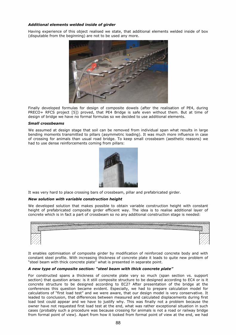
Additional elements welded inside of girder
Having experience of this object realised we state, that additional elements welded inside of box (disputable from the beginning) are not to be used any more.
Finally developed formulas for design of composite dowels (after the realisation of PE4, during
PRECO+ RFCS project [5]) proved, that PE4 Bridge is safe even without them. But at time of design of bridge we have no formal formulas so we decided to use additional elements.
Small crossbeams
We assumed at design stage that soil can be removed from individual span what results in large bending moments transmitted to pillars (asymmetric loading). It was much more influence in case of crossing for animals than usual road bridge. To keep small crossbeam (aesthetic reasons) we
had to use dense reinforcements coming from pillars:
It was very hard to place crossing bars of crossbeam, pillar and prefabricated girder.
New solution with variable construction height
We developed solution that makes possible to obtain variable construction height with constant height of prefabricated composite girder efficient way. The idea is to realise additional layer of concrete which is in fact a part of crossbeam so no any additional construction stage is needed:
It enables optimisation of composite girder by modification of reinforced concrete body and with
constant steel profile. With increasing thickness of concrete plate it leads to quite new problem of
“steel beam with thick concrete plate” what is presented in separate point.
A new type of composite section: “steel beam with thick concrete plate”
For constructed spans a thickness of concrete plate vary so much (span section vs. support section) that question arises: is it still composite structure to be designed according to EC4 or is it concrete structure to be designed according to EC2? After presentation of the bridge at the
conferences this question became evident. Especially, we had to prepare calculation model for calculations of “first load test” and we were aware, that our design model is very conservative. It leaded to conclusion, that differences between measured and calculated displacements during first load test could appear and we have to justify why. This was finally not a problem because the owner have not requested first load test at the end, what was rather exceptional situation in such cases (probably such a procedure was because crossing for animals is not a road or railway bridge from formal point of view). Apart from how it looked from formal point of view at the end, we had
88
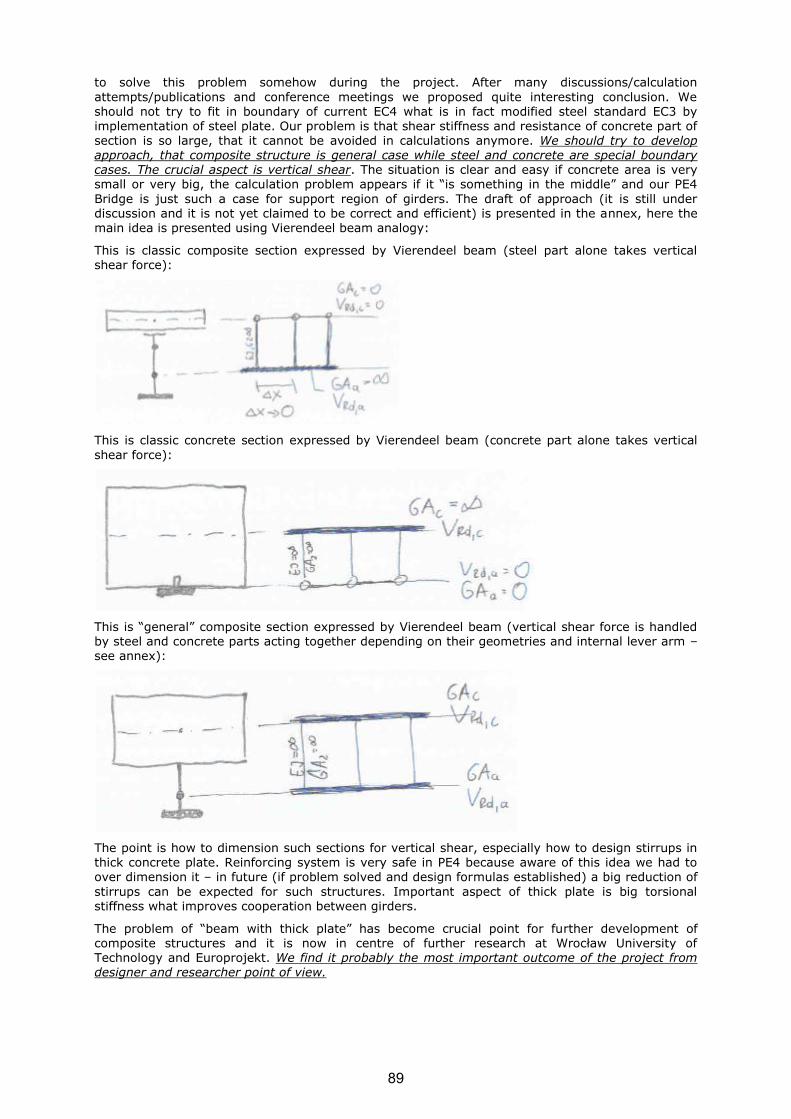
to solve this problem somehow during the project. After many discussions/calculation
attempts/publications and conference meetings we proposed quite interesting conclusion. We should not try to fit in boundary of current EC4 what is in fact modified steel standard EC3 by
implementation of steel plate. Our problem is that shear stiffness and resistance of concrete part of section is so large, that it cannot be avoided in calculations anymore. We should try to develop approach, that composite structure is general case while steel and concrete are special boundary cases. The crucial aspect is vertical shear. The situation is clear and easy if concrete area is very small or very big, the calculation problem appears if it “is something in the middle” and our PE4
Bridge is just such a case for support region of girders. The draft of approach (it is still under discussion and it is not yet claimed to be correct and efficient) is presented in the annex, here the main idea is presented using Vierendeel beam analogy:
This is classic composite section expressed by Vierendeel beam (steel part alone takes vertical shear force):
This is classic concrete section expressed by Vierendeel beam (concrete part alone takes vertical
shear force):
This is “general” composite section expressed by Vierendeel beam (vertical shear force is handled by steel and concrete parts acting together depending on their geometries and internal lever arm – see annex):
The point is how to dimension such sections for vertical shear, especially how to design stirrups in thick concrete plate. Reinforcing system is very safe in PE4 because aware of this idea we had to
over dimension it – in future (if problem solved and design formulas established) a big reduction of
stirrups can be expected for such structures. Important aspect of thick plate is big torsional stiffness what improves cooperation between girders.
The problem of “beam with thick plate” has become crucial point for further development of composite structures and it is now in centre of further research at Wrocław University of Technology and Europrojekt. We find it probably the most important outcome of the project from designer and researcher point of view.
89
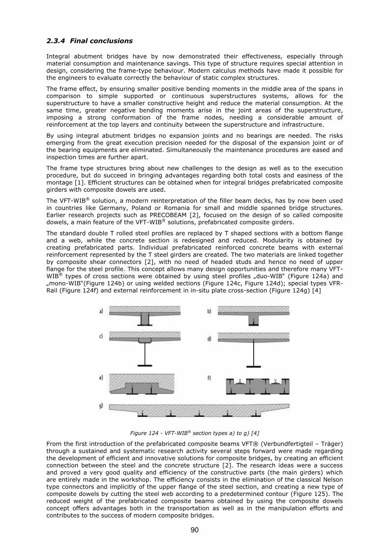
2.3.4 Final conclusions
Integral abutment bridges have by now demonstrated their effectiveness, especially through
material consumption and maintenance savings. This type of structure requires special attention in design, considering the frame-type behaviour. Modern calculus methods have made it possible for the engineers to evaluate correctly the behaviour of static complex structures.
The frame effect, by ensuring smaller positive bending moments in the middle area of the spans in comparison to simple supported or continuous superstructures systems, allows for the
superstructure to have a smaller constructive height and reduce the material consumption. At the same time, greater negative bending moments arise in the joint areas of the superstructure, imposing a strong conformation of the frame nodes, needing a considerable amount of reinforcement at the top layers and continuity between the superstructure and infrastructure.
By using integral abutment bridges no expansion joints and no bearings are needed. The risks emerging from the great execution precision needed for the disposal of the expansion joint or of the bearing equipments are eliminated. Simultaneously the maintenance procedures are eased and
inspection times are further apart.
The frame type structures bring about new challenges to the design as well as to the execution procedure, but do succeed in bringing advantages regarding both total costs and easiness of the
montage [1]. Efficient structures can be obtained when for integral bridges prefabricated composite girders with composite dowels are used.
The VFT-WIB® solution, a modern reinterpretation of the filler beam decks, has by now been used
in countries like Germany, Poland or Romania for small and middle spanned bridge structures. Earlier research projects such as PRECOBEAM [2], focused on the design of so called composite dowels, a main feature of the VFT-WIB® solutions, prefabricated composite girders.
The standard double T rolled steel profiles are replaced by T shaped sections with a bottom flange and a web, while the concrete section is redesigned and reduced. Modularity is obtained by creating prefabricated parts. Individual prefabricated reinforced concrete beams with external reinforcement represented by the T steel girders are created. The two materials are linked together
by composite shear connectors [2], with no need of headed studs and hence no need of upper flange for the steel profile. This concept allows many design opportunities and therefore many VFT-WIB® types of cross sections were obtained by using steel profiles „duo-WIB“ (Figure 124a) and „mono-WIB“(Figure 124b) or using welded sections (Figure 124c, Figure 124d); special types VFR-Rail (Figure 124f) and external reinforcement in in-situ plate cross-section (Figure 124g) [4]
Figure 124 - VFT-WIB® section types a) to g) [4]
From the first introduction of the prefabricated composite beams VFT® (Verbundfertigteil – Träger) through a sustained and systematic research activity several steps forward were made regarding
the development of efficient and innovative solutions for composite bridges, by creating an efficient connection between the steel and the concrete structure [2]. The research ideas were a success and proved a very good quality and efficiency of the constructive parts (the main girders) which are entirely made in the workshop. The efficiency consists in the elimination of the classical Nelson type connectors and implicitly of the upper flange of the steel section, and creating a new type of composite dowels by cutting the steel web according to a predetermined contour (Figure 125). The reduced weight of the prefabricated composite beams obtained by using the composite dowels
concept offers advantages both in the transportation as well as in the manipulation efforts and contributes to the success of modern composite bridges.
90

Figure 125 - VFT® solution for composite bridges [2]
The composite dowels are associating steel T-sections acting as tension member with a concrete top chord acting as compression member. Steel parts are generally obtained from rolled steel profiles that are longitudinally cut in two identical T-sections. The cut is performed with a special shape to allow the shear longitudinal transmission between steel and reinforced concrete [6] (Figure 126). Also a good accuracy of the cutting line is necessary because an imperfection in the geometry can compromise the final resistance to fatigue [7].
Figure 126 - Cutting line types: fin (SA), puzzle (PZ), clothoidal (CL), modified clothoidal (MCL) [8].
Going further by introducing these beams into framed load bearing systems such as integral
abutment bridges, it is possible to manufacture hybrid integral structures with concrete shafts and composite crossbeams that can easily absorb the high horizontal forces from impacts or earthquakes [2]. In case of an integral system, due to the absence of bearings and joints, the maintenance costs can be significantly decreased. Also the reduction of the number of construction stages on the site leads to a simple technology and a high quality assurance, during the building process. Those main advantages of the integral bridges turn out to become highly attractive to designers, constructors and road administrations.
The mono-WIB is an economical solution, as it requires low steel consumption and the
prefabrication in the factory is facile. The steel profiles are obtained from regular rolled profiles without significant material loss, and their use is efficient acting as external reinforcement. The concrete amount is significantly reduced compared to the classic filler beam decks, but the self weight remains quite high and is therefore suited for spans smaller than 35,00 m, similar to the pre-stressed concrete beams [4]. Using T-shaped prefabricated beams only lateral reinforcement is needed for the bridge deck concrete casting and the execution speed is increased. The integral
structure requires a connection between the infrastructure and the superstructure and consequently supplementary reinforcement is used to strengthen the frame nodes. No bearings and no expansion joints are provided, assuring simultaneously facile maintenance and driving comfort.
The project has benefited from the exchange of technical experience from the partners from different parts of Europe, from the transfer of information from the different construction fields with
different demands and from the high degree of cooperation and harmonization in the European steel and construction sector.
It was proven once more that, steel technologies lead to benefits at a social and sustainability level, as they are fast to construct, highly pre-fabricated, flexible and adaptable in use ,long life and recyclable. The efficient design and construction improves and consolidates the market position
of the steel construction and steel producing industry. Additionally the advanced forms of construction are contributing to savings in material and energy consumption for the structure
during production and maintenance.
The high degree of prefabrication helps to reduce the unintended manual works on-site leading to an upgrade of the working condition and quality of workmanship. Moreover the dangerous maintenance actions are largely reduced for bridges with integral abutments due to missing transition joints. Thus safer working conditions are achieved and remarkable saving in costs and down time are occurring for the lifetime of the bridge. All time savings in construction and maintenance result in large benefits of the bridge owners but also for the community as less
disturbance of the traffic will occur.
91

2.4 EXPLOITATION AND IMPACT OF THE RESEARCH RESULTS
2.4.1 Actual applications
InfraLeuna, Germany
The design office SSF has identified a second project, has performed the design, applying the PRECOBEAM technology and convinced the bridge owner about the efficiency of this innovative
solution. In the first quarter of 2012, a new ECOBRIDGE was built in Germany.
A conventional single-span railway bridge crossing the K2174 (Maienweg) in Leuna (Germany), was replaced by a single-span integral abutment bridge.
Figure 127 - Longitudinal section railway crossing over K2174 (Maienweg) in Leuna
The design and construction of the bridge w based on the following key features:
o the sub-structure is founded on a shallow foundation (footings) to allow for a construction
of the bridge besides the old bridge and a shifting / sliding of the complete structure into its
final position; o the superstructure is a partly prefabricated system completed by in-situ concrete,
consisting of VFT-Rail girders with a span of about 13.00 m (Figure 127).
Design and construction
The bridge is designed as shallow founded integral abutment railway bridge with conventional
ballast bed. The two main girders, located on both sides of the bridge, are prefabricated composite beams. The upper sides of these beams are reinforced with halved steel profiles as well. Composite action between the steel girders and the concrete is realized by composite dowels (geometry MCL250/115, 0).
The bridge deck is cast in-situ, designed as composite slab. Here composite action is realized by composite dowels (Figure 128), whereas these dowels are additionally loaded by transversal stresses.
Figure 128 - Cross section VFT-Rail with composite dowels and composite slab
The tension part of the corner moment is transmitted by conventional reinforcement. Furthermore additional reinforcement is connected to the upper steel girder to avoid an uplift of the external
reinforcement.
92

Figure 129 - Corner detail (northern abutment)
Figure 130 - Leuna Bridge: Principle
Figure 131 - Leuna Bridge: Cross section
93
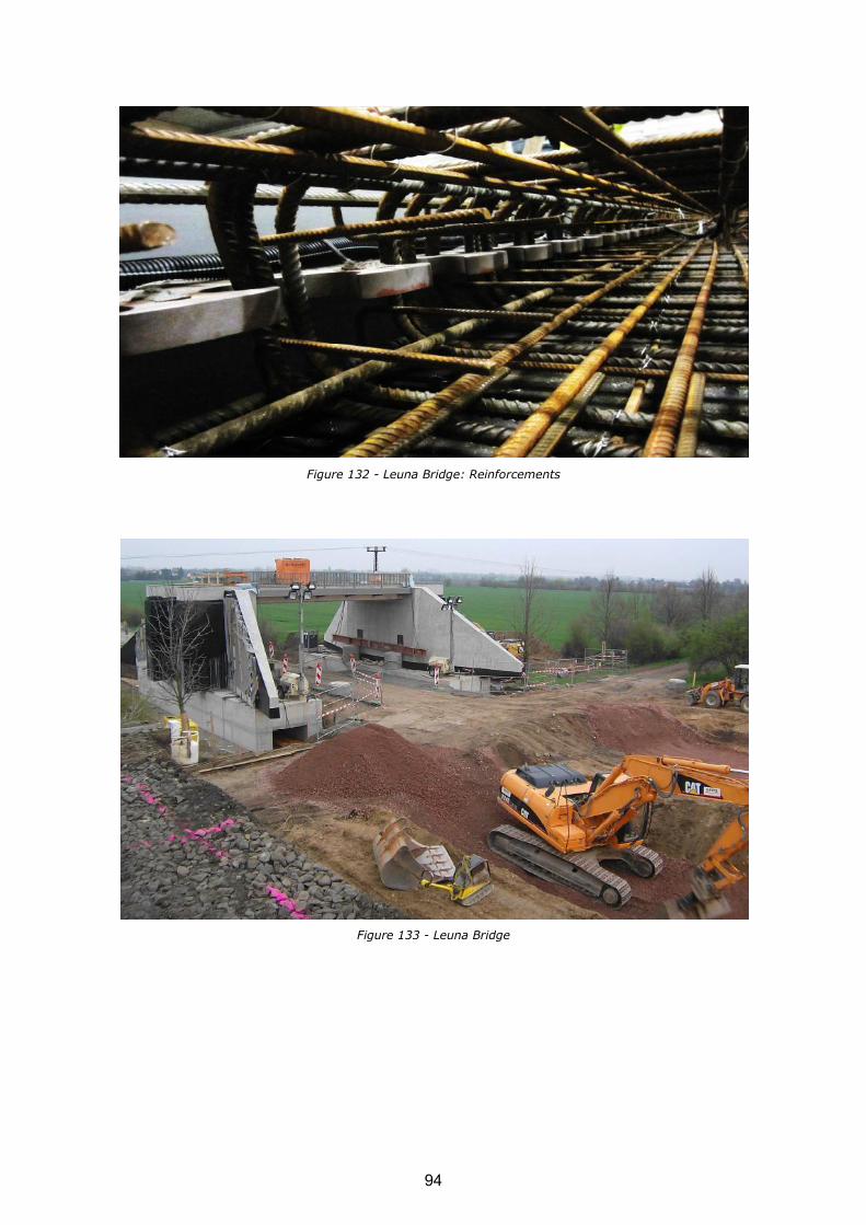
Figure 132 - Leuna Bridge: Reinforcements
Figure 133 - Leuna Bridge
94

2.4.2 Technical and economic potential for the use of the results
Patent filing
In 2011, SSF Ingenieure AG has applied for a patent, which was published on 21/03/2012.
Nevertheless, starting 19/03/2014 the patent application is deemed to be withdrawn.
95

A second patent, EP2218825 (A2) - Bridge for railways and girders and method for its manufacture
has been filled by SSF Ingenieure AG and is being now under revision.
96

Publications / conference presentations resulting from the project
The ideas used in design of Polish ECOBRIDGE PE4, design and construction process were
published extensively. All important media were concerned. Concerning bridge engineering, there are is special Polish journal “MOSTY” covering the bridges in Poland and the biggest conference on bridges is “Wrocławskie Dni Mostowe” held each year in Wrocław. There is journal “Inżynieria i Budownictwo” also, that is considered in Poland as high-rated one and treating about building engineering (bridges and buildings). The realization of PE4 as part of ECOBRIDGE project was
presented few times at conferences and in journals mentioned. Usually we preferred open discussion at the conference and after this we were invited by journals to publish the paper there. This way the topic of PE4 as part of ECOBRIDGE was well known in Polish society of bridge engineers. What is important to underline, we publish fresh information very fast, for example we presented construction of the bridge while it was really under construction and not waiting until it was finally finished. In following paragraphs there are papers presented with explanation what was discussed and why.
The idea of construction of frame by VFT-WIB method by new approach resulting with variable construction height (used finally in PE4) was presented and discussed at first. It was important to get general opinion of bridge society on bridge we want to build. The problem of definition of new composite section was highlighted:
o Kołakowski Tomasz, Kosecki Witold, Lorenc Wojciech, Rabiega Józef, Seidl
Günter: Prefabrykowane dźwigary zespolone stalowo-betonowe typu VFT-WIB do budowy
przęseł mostów drogowych i kolejowych. W: Prefabrykacja w mostownictwie : Wrocławskie Dni Mostowe : seminarium, Wrocław, 23-24 listopada 2010. Wrocław : Dolnośląskie Wydawnictwo Edukacyjne, 2010. s. 281-290.
o Kołakowski Tomasz, Kosecki Witold, Lorenc Wojciech, Rabiega Józef, Seidl Günter: Prefabrykowane dźwigary zespolone stalowo-betonowe VFT-WIB do budowy przęseł mostów drogowych i kolejowych. Inżynieria i Budownictwo. 2011, nr 7/8, s. 379-382.
Later on we published realization of PE4 bridge by three separate papers in journal “MOSTY”, first part treated about steel construction, the second one treated about prefabricated girders and the last treated about structure realized in general:
o Kołakowski Tomasz, Klimaszewski Paweł, Piwoński Jan, Lorenc Wojciech, Arabczyk Piotr: Przejście ekologiczne z dźwigarów VFT-WIB nad drogą S7. Cz. 1, Projekt i realizacja konstrukcji stalowej. Mosty (Katowice). 2011, nr 4, s. 24-26.
o Kołakowski Tomasz, Klimaszewski Paweł, Piwoński Jan, Lorenc Wojciech, Marcin
Konarzewski, Arabczyk Piotr: Przejście ekologiczne z dźwigarów VFT-WIB nad drogą S7.
Cz. 2, Projekt i realizacja prefabrykowanych belek zes[polonych. Mosty (Katowice). 2011, nr 5, s. 22-26.
o Kołakowski Tomasz, Klimaszewski Paweł, Piwoński Jan, Lorenc Wojciech, Marcin Konarzewski, Arabczyk Piotr: Przejście ekologiczne z dźwigarów VFT-WIB nad drogą S7. Cz. 3, Budowa obiektu mostowego. Mosty (Katowice). 2011, nr 5, s. 24-25.
In addition, we presented in “MOSTY” (with ArcelorMittal) that we implement new technology of construction of steel girders (finally used in PE4) and we applied special page that we realize ECOBRIDGE project:
97
98

We wrote about construction of PE4 as an example of modern structure by rolled section in
“Archiwum Instytutu Inżynierii Lądowej” which is connected to second Polish conference on bridges held nex to Poznań:
o Ochojski Wojciech, Klimaszewski Paweł, Rabiega Józef, Kożuch Maciej, Lorenc Wojciech: Współczesne obiekty mostowe o przęsłach zespolonych z dwuteowników walcowanych. Archiwum Instytutu Inżynierii Lądowej. 2012, nr 14, s. 185-191.
Finally we presented PE4 together with other bridges realised innovative way for purposes of construction of S7 fast road at the conference “Wrocławskie Dni Mostowe” and later on in
“Inżynieria i Budownictwo”:
o Arabczyk Piotr, Konarzewski Marcin, Żurych Roman, Klimaszewski Paweł, Kosecki Witold, Lorenc Wojciech, Ochojski Wojciech*: W: Aktualne realizacje mostowe: Wrocławskie Dni Mostowe : seminarium, Wrocław, 24-25 listopada 2011. Wrocław: Dolnośląskie Wydawnictwo Edukacyjne, 2011. s. 401-408.
o Arabczyk Piotr, Konarzewski Marcin, Żurych Roman, Klimaszewski Paweł, Kosecki Witold, Lorenc Wojciech, Ochojski Wojciech: Realizacje obiektów mostowych w ciągu
drogi S7 na odcinku Olsztynek-Nidzica. Inżynieria i Budownictwo. 2012, R. 68, nr 4, s. 221-224.
Having the bridge successfully constructed, we published experience abroad in German and in
English. We did this together with other project partners and this was in countries of our project partners (Germany and Romania):
o Seidl Günter, Stambuk Mislav, Lorenc Wojciech, Kołakowski Tomasz, Petzek
Edward: Wirtschaftliche Verbundbauweisen im Brückenbau - Bauweisen mit Verbunddübelleisten. Stahlbau. 2013, Jg 82, H. 7, s. 510-521.
o Seidl Günter, Stambuk Mislav, Lorenc Wojciech, Kołakowski Tomasz, Petzek Edward: Economic composite constructions for bridges: construction methods implementing composite dowel strips. W: The Eight International Conference "Bridges in Danube Basin": new trends in bridge engineering and efficient solutions for large and medium span bridges / Edward Petzek, Radu Băncilă (eds.). Wiesbaden: Springer Vieweg,
2013. s. 51-80.
Finally, setting the bridge on the background of the other structures realised by composite dowels we clearly identified the need of new approach for “steel beam with thick concrete plate” (and by the way the definition of composite structure) for calculation of vertical shear resistance of new type of composite sections, like the ones used for PE4 construction (this problem is now crucial point for further development of composite structures):
o Kożuch Maciej, Kołakowski Tomasz, Lorenc Wojciech, Petzek Edward, Rowiński
Sławomir, Seidl Günter: Problem definicji przekroju zespolonego stalowo -betonowego na tle stosowanych obecnie w mostownictwie rozwiązań konstrukcyjnych. W: Obiekty mostowe w infrastrukturze miejskiej: Wrocławskie Dni Mostowe : seminarium, Wrocław, 21-22 listopada 2013. Wrocław: Dolnośląskie Wydawnictwo Edukacyjne, 2011. s. 325-331.
This way results of this demonstration project ECOBRIDGE and experience gained during construction of the PE4 bridge have been widespread. Manuscripts published in Poland are enclosed
in annex (in such a sequence).
99


3 LIST OF FIGURES
Figure 1 - Overview of the Simmerbach project for the German Railway Company DB .................. 7
Figure 2 - Longitudinal view of the Simmerbach project for the German Railway Company DB ....... 8
Figure 3 - Schematic view of the construction principle used for Simmerbach .............................. 8
Figure 4 - Application of VFT-Rail Cross-Sections using PreCoBeam technology ............................ 9
Figure 5 - VFT-Rail cross-section with 66cm construction height and external reinforcement .......... 9
Figure 6 - Schematic reinforcement for the cross-section ........................................................ 10
Figure 7 - Detailed cutting-geometry .................................................................................... 11
Figure 8 - Dowels after cutting-process ................................................................................. 11
Figure 9 - Reinforcement cage prepared ................................................................................ 11
Figure 10 - Reinforcement for first girder .............................................................................. 11
Figure 11 - Formwork preparations ....................................................................................... 12
Figure 12 - Rail support before mounting .............................................................................. 12
Figure 13 - Lifting of reinforcement-cage ............................................................................... 12
Figure 14 - Rebar-cage above formwork ................................................................................ 12
Figure 15 - Preparation of monitoring-devices ........................................................................ 12
Figure 16 - Monitoring-devices ............................................................................................. 12
Figure 17 - Transport of external sections ............................................................................. 13
Figure 18 - Fixing of external sections ................................................................................... 13
Figure 19 - Formwork prepared with all constructional elements before concreting ..................... 13
Figure 20 - Destruction of old abutment ................................................................................ 14
Figure 21 - Preparation of abutment ..................................................................................... 14
Figure 22 - Construction site first morning ............................................................................. 14
Figure 23 - Lifting of prefab-benching ................................................................................... 14
Figure 24 - Lifting of pedestrian bridge.................................................................................. 15
Figure 25 - Bridge(s) after mounting .................................................................................... 15
Figure 26 - Lifting of pedestrian bridge.................................................................................. 15
Figure 27 - Bridge(s) after mounting .................................................................................... 15
Figure 28 - Assembly of rails ............................................................................................... 15
Figure 29 - Finished construction-progress ............................................................................ 15
Figure 30 - Railway track in operation ................................................................................... 16
Figure 31 - Railway track in operation ................................................................................... 16
Figure 32 - Bridge in operation ............................................................................................. 16
Figure 33 - Train on the bridge ............................................................................................ 16
Figure 34 - Monitoring devices ............................................................................................. 16
Figure 35 - Monitoring in operation ....................................................................................... 16
Figure 36 - General view of the bridge and access ramps ........................................................ 18
Figure 37 - Structure degradations ....................................................................................... 18
Figure 38 - Durability of composite bridges ............................................................................ 19
Figure 39 - General cross section: Solution 1 (a), Solution 2 (b) .............................................. 19
Figure 40 - Spatial 3D model and FEM analysis ...................................................................... 20
Figure 41 - General new cross sections and details with the precast elements ............................ 20
Figure 42 - Reinforcement detail of the precast composite girder.............................................. 20
101
Figure 43 - Frame corner technological phases ....................................................................... 21
Figure 44 - Cutting line types: fin (SA), puzzle (PZ), clothoidal (CL), modified clothoidal (MCL) .... 22
Figure 45 - SA or fin shaped steel dowels: The SA shape (a), Direction change of the composite dowels in the middle of the girder (b) .................................................................... 22
Figure 46 - VFT-WIB – mono-WIB cross section (a), Superstructure cross section (b) ................. 22
Figure 47 - Execution details of the steel girders, geometry of the steel dowel ........................... 23
Figure 48 - Composite dowels – reinforcement details ............................................................. 23
Figure 49 - Superstructure construction phases: laying of the VFT-WIB composite girders in
their final position (a), frame node and end sections of the deck concreting (b), deck concreting (c) .................................................................................................................... 24
Figure 50 - Pile sections – reinforcement and tubes for the sonic test ....................................... 24
Figure 51 - Foundation slab reinforcement plan (a), Site photo of the foundation slab reinforcement (b) ............................................................................................................... 24
Figure 52 - Abutment reinforcement plan .............................................................................. 25
Figure 53 - Site photo of the abutment reinforcement (a), Site photo of the abutment (b)........... 25
Figure 54 - Pier reinforcement plan (a), Site photo of the pier (b) ............................................ 25
Figure 55 – 8th Danube Bridges Conference poster ................................................................. 27
Figure 56 - 8th Danube Bridges Conference program ............................................................... 28
Figure 57 - Localisation of contract for design-and-build of sector of S7 road ............................. 29
Figure 58 - Localisation of PE4 structure ............................................................................... 30
Figure 59 - Architectural visualisation of PE4 structure ............................................................ 30
Figure 60 - Transverse cross section (left) VFT-Rail® with rail support points directly fastened to the superstructure and composite dowel and longitudinal cross section (right, depicting the clothoidal shape of the dowels) ............................................................................................ 44
Figure 61 - Longitudinal section railway crossing over the river “Simmerbach” with two VFT-Rail® girders, placed on toughened sub-structure .................................................................. 45
Figure 62 - Structure rail support point ECF [ThyssenKrupp 2006] ............................................ 45
Figure 63 - Pattern of rail fasteners at the end of superstructure .............................................. 46
Figure 64 - Test train, class BR 132, Co’Co’ ........................................................................... 47
Figure 65 - Railcar class DBAG 612, 2’B’+B’2’ ........................................................................ 48
Figure 66 - Load bearing mechanism of rail support point ECF (principle, superelevated illustration), measurement equipment at rail support point ECF (principle) ................................ 50
Figure 67 - Measurement devices for monitoring of forces acting on rail support points (1st, 2nd and 4th rail support point equipped) ...................................................................................... 50
Figure 68 - Calibration of measurement bolts (here: measurement bolt S8), conversion of
strain in measurement bolts into pre-tension force ................................................................. 51
Figure 69 - Test set-up with measurement devices (unstressed measurement bolt S4 and displacement transducers W2, W4) ....................................................................................... 51
Figure 70 - Mean lowering / deformation of the ribbed base plate depending on the force applied (20% pre-stress, 100% pre-stress) ........................................................................... 52
Figure 71 - Strain change in measurement bolt S2 depending on applied force (20% pre-
stressed, 100% pre-stressed) .............................................................................................. 52
Figure 72 - Bolt force function: measured strain s over jack force F at rail support point ......... 53
Figure 73 - Compression force / tension force acting on controlling rail support points 1 (left) and 4 (right), caused by static loading (test train) .................................................................. 54
Figure 74 - Cross section for condition I (left) and condition II (right), rail support point drawn in for illustration purposes only ............................................................................................ 54
Figure 75 - Measurement sections at superstructure between axis 20 and axis 30 ...................... 55
Figure 76 - Position of strain gauges ..................................................................................... 55
102
Figure 77 - Protected strain gauges, covered with 2-component adhesive (PS-adhesive) and
permanent elastic cement (AK22) ........................................................................................ 56
Figure 78 - Calculated stress distribution (schematic, left: local loading due to shear force
acting at steel dowel, right: global loading due to axial deformation of the external reinforcement due to bending of the composite section) [P804] ............................................... 57
Figure 79 - Measured strains / stresses on the inner side of the flange (lower external steel girder, points) compared to calculated stresses for condition I (left) and condition II (right) ........ 57
Figure 80 - Measured strains / stresses at web of lower external reinforcement, compared to
calculated values for condition I (left) and condition II (right) .................................................. 58
Figure 81 - Measured strains / stresses within the region of the hot-spot, lower external reinforcement, compared to calculated values for condition I (left) and condition II (right) .......... 58
Figure 82 - Stresses in lower flange caused by crossing of test train (100 km/h, left) and regional train (120 km/h, right) ........................................................................................... 59
Figure 83 - Longitudinal section railway crossing over K2174 (Maienweg) in Leuna ..................... 59
Figure 84 - Cross section VFT-Rail with composite dowels and composite slab ............................ 60
Figure 85 - Corner detail (northern abutment) ....................................................................... 60
Figure 86 - Measurement sections at superstructure (axis 10) ................................................. 61
Figure 87 - Measurement wires Leuna, cut-off after installation ................................................ 62
Figure 88 - The motorway route – plan view. The VFT® composite bridges. ............................... 63
Figure 89 - Left: longitudinal section, Right: design model....................................................... 64
Figure 90 - General cross section ......................................................................................... 64
Figure 91 - The formwork cross section of the Prefabricated Composite Girder VFT® ................... 65
Figure 92- a) Reinforced cross section of the Prefabricated Composite Girder VFT®, b) Frame node reinforcement detail .................................................................................................... 65
Figure 93 - The final structure and its equipment. .................................................................. 65
Figure 94 - The steel girder type sections; Steel girders in the workshop; the cutting line geometry of the composite dowels. ...................................................................................... 66
Figure 95 - The steel girder type sections; the end steel girders detail and the transition detail
between the two types of section. ........................................................................................ 66
Figure 96 - Finished overpass .............................................................................................. 66
Figure 97 - a) A30 convoy – lateral view, plan view, front / back view; b) MAN TGA convoy – lateral view, plan view, front / back view. .............................................................................. 68
Figure 98 - MAN TGA convoy – front view, lateral view; dynamic load test MAN TGA vehicle. ....... 68
Figure 99 - Installed strain gauges on the section of the bridge in the in-situ test day ................. 70
Figure 100 - Installed strains on the section of the bridge; a) Cross section of the supports
area; b) Cross section of the field. ........................................................................................ 70
Figure 101 - Installed strains on the section of the bridge; a) Cross section on the supports area; b) Cross section on the field. ....................................................................................... 70
Figure 102 - The principle of the strain gauge chain used for the probes. .................................. 71
Figure 103 - Displacement transducer device ......................................................................... 72
Figure 104 - Construction stage manager steps ...................................................................... 72
Figure 105 - a) Cross section of the supports area; b) Cross section of the field. ........................ 73
Figure 106 - Construction stages: a) Simple supported girder; b) Frame effect .......................... 73
Figure 107 - The load test vehicles designed in the FEM model................................................. 74
Figure 108 - The read points for the static / dynamic test schema, load schema 1 – LC1 and load schema 2 – LC2. ......................................................................................................... 75
Figure 109 - Vertical displacement measuring principle ........................................................... 75
Figure 110 - Vertical displacement diagrams – test load schema 1 – LC1 and load schema 2 –
LC2 .................................................................................................................................. 76
103

Figure 111 - „smeasured” values from test load schema 1 – LC1 ................................................. 77
Figure 112 - „sdesign” values from test load schema 1 – LC1..................................................... 77
Figure 113 - „smeasured” values from test load schema 2 – LC2 ................................................. 78
Figure 114 - „sdesign” values from test load schema 2 – LC2..................................................... 79
Figure 115 - „sdin” values from test load schema 2 – LC2 ........................................................ 80
Figure 116 - „sdin” values from test load schema 3 – LC3 ........................................................ 80
Figure 117 - „sdin” values from test load schema 4 – LC4 ........................................................ 80
Figure 118 - „sdin” values from test load schema 4 – LC5 ........................................................ 81
Figure 119 - „sstat” values from dynamic test load schema 3, 4 – LC3,4 (v = 50 km/h) and load schema 2 – LC2,5 (v = 30 km/h) .................................................................................. 81
Figure 120 - Dimensions of Preco-Beam girders for Vigaun-Bridge and of preliminary design for VFT and pre-stressed girders .......................................................................................... 83
Figure 121 - List of materials ............................................................................................... 85
Figure 122 - Transport parameters ....................................................................................... 85
Figure 123 - Global Warming potential .................................................................................. 86
Figure 124 - VFT-WIB® section types a) to g) [4] ................................................................... 90
Figure 125 - VFT® solution for composite bridges [2] ............................................................. 91
Figure 126 - Cutting line types: fin (SA), puzzle (PZ), clothoidal (CL), modified clothoidal (MCL) [8]. ......................................................................................................................... 91
Figure 127 - Longitudinal section railway crossing over K2174 (Maienweg) in Leuna ................... 92
Figure 128 - Cross section VFT-Rail with composite dowels and composite slab .......................... 92
Figure 129 - Corner detail (northern abutment) ..................................................................... 93
Figure 130 - Leuna Bridge: Principle ..................................................................................... 93
Figure 131 - Leuna Bridge: Cross section .............................................................................. 93
Figure 132 - Leuna Bridge: Reinforcements ........................................................................... 94
Figure 133 - Leuna Bridge ................................................................................................... 94
104

4 LIST OF TABLES
Table 1 - Technical information of the existing vs. the new bridge ............................................ 17
Table 2 - Time schedule presenting construction of the bridge (unit: month) ............................. 30
Table 3 - Specification of works that have been realised .......................................................... 31
Table 4 - Overview monitoring concept (type of measurement, type of data, N°of devices, sampling rate) ................................................................................................................... 47
Table 5 - Technical data test train BR 132, Co’Co’, “Ludmilla” .................................................. 47
Table 6 - Train crossings (stop-runs) with test train BR 132, Co’Co’ .......................................... 47
Table 7 - Train crossings (dynamic) with test train BR 132, Co’Co’ ............................................ 48
Table 8 - Train crossings (dynamic) with test train DBAG 612, 2’B’+B’2’ ................................... 48
Table 9 - Overview monitoring concept (type of measurement, type of data, N°of devices, sampling rate) ................................................................................................................... 61
Table 10 - The load test vehicles weights .............................................................................. 74
Table 11 - Maximum vertical displacements for load schema 1 – LC1 and load schema 2 – LC2 ... 76
Table 12 - Results from test load schema 1 – LC1 .................................................................. 76
Table 13 - Results from test load schema 2 – LC2 .................................................................. 78
Table 14 - Results from dynamic load test schema 2 and 5 – LC2, LC5. .................................... 79
Table 15 - Results from dynamic load test schema 3 and 4 – LC3, LC4. .................................... 79
105

5 REFERENCES
[ABZ 2013] Allgemeine Bauaufsichtliche Zulassung, Verbunddübelleisten, Z-26.4-56, Deutsches Institut für Bautechnik DIBt, Berlin, 2013.
[DB 2011a] DB Netz AG, „Bemessungsgrundlagen für die Festhaltekonstruktionen der Festen Fahrbahn auf Brücken,“ Ril804.5404, 2011.
[DB 2011b] DB Netz AG, „Nachweise an den Überbauenden bei Fester Fahrbahn,“ Ril 804 Modul 5405 (draft), 2011.
[DB 2012] Feldmann, M. Pak, D., Kopp, M., Schillo, N., Seidl, G., Hoyer, O., „Messbericht Simmerbach“, measurement report for DB Netz AG, Aachen 2012, not poblished.
[DIN FB 2009] DIN FB 101, Beuth Verlag GmbH, Berlin, 2009.
[EBA 2013] Eisenbahnbundesamt, „Erweiterung der Zulassung zur Betriebserprobung vom 06.12.2010 der Bauart VFT-Rail der SSF Ingenieure AG zur Verwendung in Strecken der Eisenbahn des Bundes mit zulässigen Geswchwindigkeiten bis 160 km/h“, Bonn, 2013.
[ECOBRIDGE] „ECOBRIDGE: Demonstration of economical bridge solutions based on innovative composite dowels and integrated abutements,“ Final Report RFSP-CT-2010-00024, Research Fund
for Coal and Steel, Brussels, not published yet.
[Eisenmann 2011] Eisenmann, J., „Gleislagebeständigkeit des Schotteroberbaus,“ Der Eisenbahningenieur, vol. 2, pp. 20-26, 2011.
[Feldmann et al. 2011] Feldmann, M., Naumes, J., Pak, D., „Zum Last-Verformungsverhalten von Schrauben in vorgespannten Ringflanschverbindungen mit überbrückten Klaffungen im Hinblick auf die Ermüdungsvorhersage,“ Stahlbau 80, pp. 21-29, 2011.
[Heinemeyer 2011] Heinemeyer, S., „Zum Trag- und Verformungsverhalten von Verbundträgern mit Puzzleleisten und ultrahochfestem Beton“, dissertation, Aachen, 2011.
[Mensinger 2010] Mensinger, M., „Gutachterliche Stellungnahme G 1008 Low Cost Bridge: Beurteilung der Konzepte zum Nachweis der statischen Tragfähigkeit und der Ermüdungssicherheit der Verdübelung der externen Bewehrung des neuartigen Brückentyps "Low Cost Bridge",“ Munich, 2010.
[P621] Feldmann, M., Hegger, J., Hechler, O., Rauscher, S., „P621 - Untersuchungen zum Trag- und Verformungsverhalten von Verbundmitteln unter ruhender und nichtruhender Belastung bei
Verwendung hochfester Werkstoffe,“ FOSTA - Forschungsvereinigung Stahlanwendung e. V.,
Düsseldorf, 2007.
[P804] Feldmann, M., Hegger, J., Gündel, M., Kopp, M., Gallwoszus, J., Heinemeyer, S., Seidl, G., Hoyer, O., „P804 - Neue Systeme für Stahlverbundbrücken – Verbundfertigteilträger aus hochfesten Werkstoffen und innovativen Verbundmitteln. VERBUND-DÜBEL-LEISTEN,“ FOSTA - Forschungsvereinigung Stahlanwendung e. V., Düsseldorf, not published yet.
[PRECOBEAM 2013] Seidl, G. et al., “PRECOBEAM: Prefabricated enduring composite beams based
on innovative shear transmission”, Final Report RFSR-CT-2006-00030, Research Fund for Coal and Steel, Brussels, 2013.
[Rauert et al. 2010a] Rauert, T., Bigelow, H., Hoffmeister, B., Feldmann, M., Patz, R., Lippert, P., „Zum Einfluss baulicher Randbedingungen auf das dynamische Verhalten von WIB-Eisenbahnbrücken, Teil I,“ Bautechnik 87, pp. 665–672, 2010
[Rauert et al. 2010b] Rauert, T., Bigelow, H., Hoffmeister, B., Feldmann, M., Patz, R., Lippert, P, „Zum Einfluss baulicher Randbedingungen auf das dynamische Verhalten von WIB-
Eisenbahnbrücken, Teil 2,“ Bautechnik 87, pp. 751–760, 2010.
[Rauert et al. 2010c] Rauert, T., Bigelow, H., Hoffmeister, B., Feldmann, M, „On the prediction of the interaction effect caused by continuous ballast on filler beam railway bridges by experimentally supported numerical studies,“ Engineering Structures, vol. 32, pp. 3981-3988, 2010.
[Seidl et al. 2012] Seidl, G., Mensinger, M., Koch, E., Hugle, F., „Projektbericht Eisenbahnüberführung Simmerbach - Pilotbrücke in VFT-Rail Bauweise mit externer Bewehrung,“
Stahlbau 81, pp. 100-107, 2012.
[ThyssenKrupp 2006] ThyssenKrupp GfT Gleistechnik, Oberbauhandbuch, Bochum, 2006.
[Veljkovic et al. 2010] Veljkovic, M., Feldmann, M., Naumes, J., Pak, D., Rebelo, C., Simões da Silva, L., „Friction connection in tubular towers for a wind turbine,“ Stahlbau 79, pp. 660-668, 2010.
107

[1] Pak, D, et al., “Economic and Durable Design of Composite Bridges with Integral Abutments –
Final Report RFSR-CT-2005-00041”, Brussels, RFCS publications, European Commission, 2009
[2] Seidl, G, et al., “Prefabricated enduring composite beams based on innovative shear
transmission - Final Report RFSR-CT-2006-00030”, s.l.: European Commission, 2011.
[3] RFCS research project, “ECOBRIDGE: Demonstration of economical bridge solutions based on innovative composite dowels and integrated abutment, Grant no. RFSP-CT-2010-00024”, 2010
[4] Seidl, G, et al., “Economic composite constructions for bridges: construction methods implementing composite dowel strips”, Timisoara, Springer Vieweg, ISBN 978-3-658-03713-0,
2013
[5] RFCS PRECO+ Composite Dowels in Bridges, D 767
[6] Barthellemy, J, Hechler, O, Lorenc, W, Seidl, G, Viefhues, E, “Premiers resultants du projet de recherché Europeen PreCoBeam de connexion par decoupe d’une tole”, Bulletin Ouvrqges d’Art du CTOA du Setra, n°3, 2009
[7] Seidl, G, Petzek, E, Băncilă, R, “Composite Dowels in Bridges - Efficient solution”, Timisoara, Trans Tech Publications, Advanced Materials Research Vol. 814, ISBN-13: 978-3-03785-848-6,
2013
[8] Berthellemy, J, Lorenc, W, Mensinger, M, Rauscher, S, Seidl, G, “Zum Tragverhalten von Verbunddübeln - Teil 1: Tragverhalten unter statischer Belastung”, Stahlbau 80, Heft 3 2011, 172-184, 2011
[9] Romanian Standard “STAS 12504-86, Validation date: 1986-11-01”
108

EUROPEAN COMMISSION Directorate-General for Research and Innovation Directorate D — Key Enabling Technologies Unit D.4 — Coal and Steel
E-mail: [email protected] [email protected]
Contact: RFCS Publications
European Commission B-1049 Brussels
HOW TO OBTAIN EU PUBLICATIONS
Free publications: • one copy:
via EU Bookshop (http://bookshop.europa.eu);
• more than one copy or posters/maps: from the European Union’s representations (http://ec.europa.eu/represent_en.htm); from the delegations in non-EU countries (http://eeas.europa.eu/delegations/index_en.htm); by contacting the Europe Direct service (http://europa.eu/europedirect/index_en.htm) or calling 00 800 6 7 8 9 10 11 (freephone number from anywhere in the EU) (*). (*) The information given is free, as are most calls (though some operators, phone boxes or hotels may charge you).
Priced publications: • via EU Bookshop (http://bookshop.europa.eu).

KI-NA-27186-EN
-N
The bridges are vital structures for the transport infrastructure; it is a fact that, in the last decades, composite bridges became a well-liked solution in many European countries as a cost-effective and aesthetic alternative to concrete bridges. Their competitiveness depends on several circumstances such as site conditions, local costs of material and staff and the contractor’s experience. Beside the classical solution, the new ones with efficient design and construction improve and consolidate the market position of the steel construction and steel producing industry.
The objective of this project was the construction of three composite bridges with integral abutments and/or innovative form of shear transmission – composite dowels. The targeted countries were: Germany, Romania and Poland.
Ahead the time schedule, the design and construction of the composite bridges using PRECOBEAM technology has been finished in Germany and Poland. On top of this, 5 other bridges using the same technology have been built in Poland and another one in Germany. This shows the high acceptance and trust in this innovative construction technique along practitioners and authorities and proves once more the economic and durable construction of this optimized bridge structure.
Summarizing the complete project beginning from the design process, (pre)fabrication of the different elements and finally the construction stage proved the general applicability of the technology. Compared to conventional design and construction techniques it turned out to be economic and competitive especially since the complete construction process could be finished within a very short time span.
Studies and reports
ISBN 978-92-79-47433-0
doi:10.2777/216745
EUR 27186
Dem
onstration of economical bridge solutions based on innovative com
posite dowels and integrated abutm
entsEU
Demonstration of economical bridge solutions based on
innovative composite dowels and integrated abutments
(ECOBRIDGE)
Research and Innovation EUR 27186 EN