Embed Size (px)
Citation preview

SASKATCHEWAN
TWIN-CITY TENDER
TENDER
INFORMATION
PACKAGE
TWO (2) TME
CUSTOM FIRE
PUMPERS
Twin-City Fire Department Pumper Tender - 2013 Page 2
TABLE OF CONTENTS
1.0 INVITATION TO TENDER ................................. Page 3
2.0 INSTRUCTION TO BIDDERS ................................. Page 4
BID FORM .......................................... Page 5
3.0 TERMS AND CONDITIONS .......................................... Page 7
4.0 PREPARTION OF TENDERS ................................. Page 8
5.0 SUBMISSION OF TENDERS ................................. Page 9
6.0 SHIPPING AND DELIVERY INSTRUCTIONS ............... Page 10
7.0 FORMATION OF CONTRACT ................................. Page 10
8.0 SUPPLEMENTARY CONDITIONS ........................ Page 11
9.0 VENDER EVALUATION ......... ................................. Page 14
10.0 TENDOR EVALUATION .......................................... Page 16
11.0 MANUFACTURER SPECIFICATIONS ........................ Page 20
12.0 CHASSIS SPECIFICATIONS ................................. Page 22
13.0 PUMP HOUSE SPECIFICATIONS ........................ Page 78
14.0 BODY SPECIFICATIONS ......... ................................. Page 94
15.0 OVERALL VEHICLE DIMENSIONS ........................ Page 109
16.0 OPTIONAL EQUIPMENT ......... ................................. Page 110

Twin-City Fire Department Pumper Tender - 2013 Page 3
1.0 INVITATION TO TENDER
The City of North Battleford and the City of Swift Current, hereinafter referred to
as “the Cities”, invite tenders for the provision of two (2) Top Mount Enclosed
(TME) Pumper Fire Apparatus. Tenders shall be submitted in duplicate and
must be marked “TWIN-CITY FIRE DEPARTMENT PUMPER TENDER” and
submitted on or before 2 pm CST, Thursday, August 1, 2013, to:
Jerry Hildebrandt
Manager of Purchasing
City of Swift Current
177 – 1st Avenue NE
Swift Current, Saskatchewan
S9H 2B1
Phone: 306-778-2713
Fax: 306-773-9386
Email: [email protected]
All tenders shall be opened at 2:05 pm, Thursday, August 1, 2013 and read
publicly in the office of the purchasing manager, 2074 South Service Road West,
Swift Current, SK. Bidders are invited to be present. Bidders of the successful
tender will be contacted and informed of their successful bid.
INSTRUCTIONS TO
BIDDERS
Twin-City Fire Department Pumper Tender - 2013 Page 4
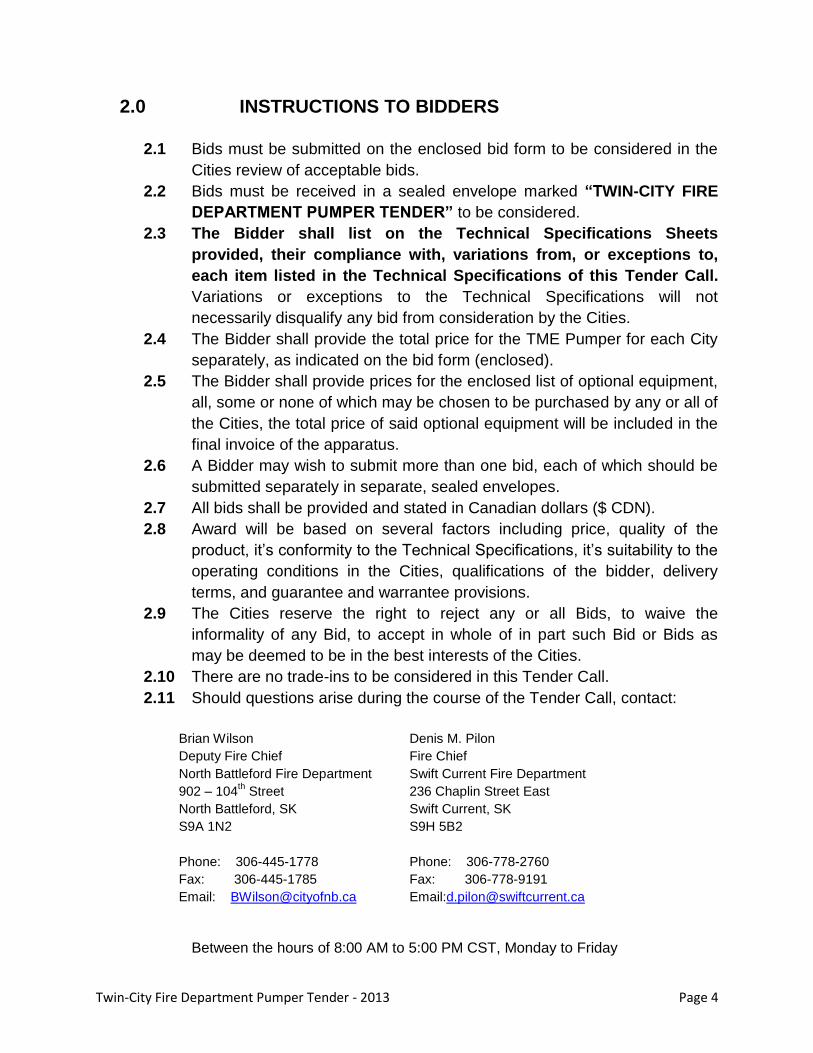
2.0 INSTRUCTIONS TO BIDDERS
2.1 Bids must be submitted on the enclosed bid form to be considered in the
Cities review of acceptable bids.
2.2 Bids must be received in a sealed envelope marked “TWIN-CITY FIRE
DEPARTMENT PUMPER TENDER” to be considered.
2.3 The Bidder shall list on the Technical Specifications Sheets
provided, their compliance with, variations from, or exceptions to,
each item listed in the Technical Specifications of this Tender Call.
Variations or exceptions to the Technical Specifications will not
necessarily disqualify any bid from consideration by the Cities.
2.4 The Bidder shall provide the total price for the TME Pumper for each City
separately, as indicated on the bid form (enclosed).
2.5 The Bidder shall provide prices for the enclosed list of optional equipment,
all, some or none of which may be chosen to be purchased by any or all of
the Cities, the total price of said optional equipment will be included in the
final invoice of the apparatus.
2.6 A Bidder may wish to submit more than one bid, each of which should be
submitted separately in separate, sealed envelopes.
2.7 All bids shall be provided and stated in Canadian dollars ($ CDN).
2.8 Award will be based on several factors including price, quality of the
product, it’s conformity to the Technical Specifications, it’s suitability to the
operating conditions in the Cities, qualifications of the bidder, delivery
terms, and guarantee and warrantee provisions.
2.9 The Cities reserve the right to reject any or all Bids, to waive the
informality of any Bid, to accept in whole of in part such Bid or Bids as
may be deemed to be in the best interests of the Cities.
2.10 There are no trade-ins to be considered in this Tender Call.
2.11 Should questions arise during the course of the Tender Call, contact:
Brian Wilson
Deputy Fire Chief
North Battleford Fire Department
902 – 104th Street
North Battleford, SK
S9A 1N2
Phone: 306-445-1778
Fax: 306-445-1785
Email: [email protected]
Denis M. Pilon
Fire Chief
Swift Current Fire Department
236 Chaplin Street East
Swift Current, SK
S9H 5B2
Phone: 306-778-2760
Fax: 306-778-9191
Email:[email protected]
Between the hours of 8:00 AM to 5:00 PM CST, Monday to Friday

Twin-City Fire Department Pumper Tender - 2013 Page 5
BID FORM
TWIN-CITY FIRE DEPARTMENT PUMPER TENDER
We ____________________________________________________________ (Company Name)
of _____________________________________________________________ (Business Address)
having examined the documents to this proposal and completed the Technical Specifications
submission form; hereby offer, in accordance with said specifications and standard instructions
to bidders, to enter into a contract to supply two (2) TME Pumper Fire Apparatus to the Cities of
North Battleford and Swift Current as follows:
Chassis Manufacturer ____________________________
Chassis Model ____________________________
Chassis Year Manufactured ____________________________
Engine Manufacturer ____________________________
Engine Model ____________________________
Engine Year ____________________________
Engine Horsepower ____________________________
Transmission Manufacturer ____________________________
Transmission Model ____________________________
Transmission Year ____________________________
Pump Manufacturer ____________________________
Pump Model ____________________________
PUMP ULC Rated Capacity ____________________________
North Battleford (Truck #1 )TOTAL $__________________
Swift Current (Truck #2) TOTAL $__________________
Tender must be quoted in Canadian Funds, which price does not include G.S.T. or P.S.T. or
disbursements. All prices given shall be effective for sixty (60) days from the date of closing the Call for
Tenders.
Twin-City Fire Department Pumper Tender - 2013 Page 6
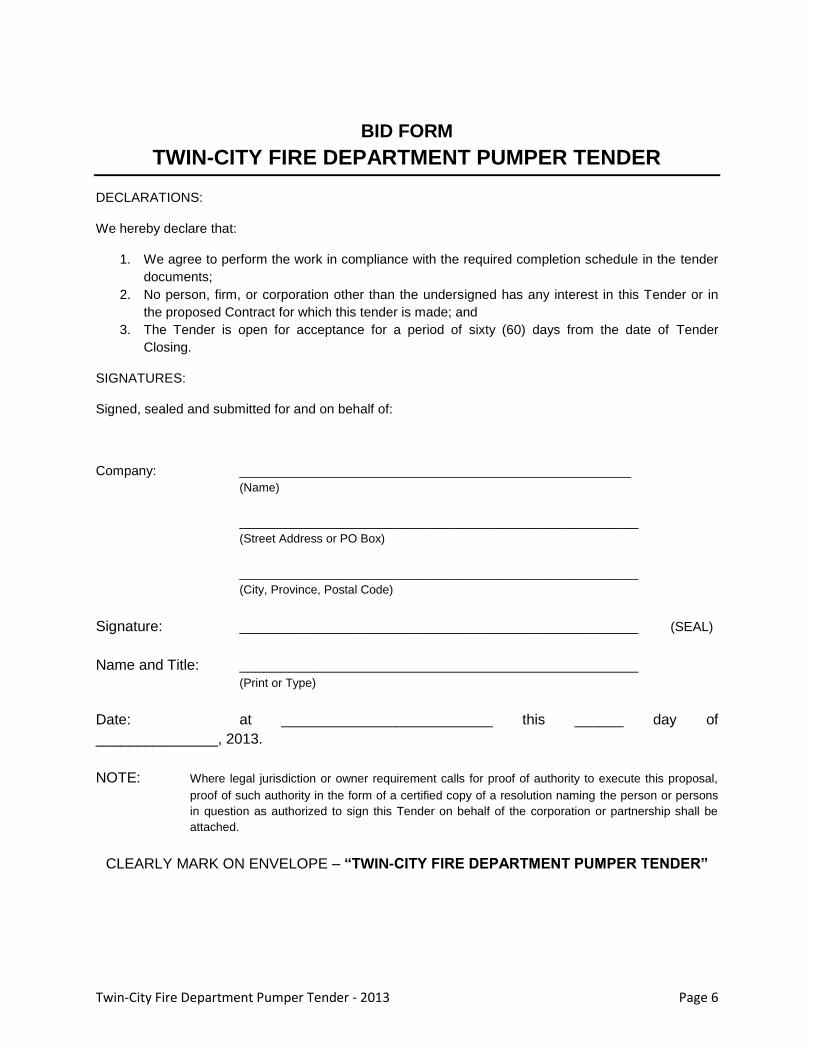
BID FORM
TWIN-CITY FIRE DEPARTMENT PUMPER TENDER
DECLARATIONS:
We hereby declare that:
1. We agree to perform the work in compliance with the required completion schedule in the tender
documents;
2. No person, firm, or corporation other than the undersigned has any interest in this Tender or in
the proposed Contract for which this tender is made; and
3. The Tender is open for acceptance for a period of sixty (60) days from the date of Tender
Closing.
SIGNATURES:
Signed, sealed and submitted for and on behalf of:
Company: _____________________________________________________
(Name)
______________________________________________________
(Street Address or PO Box)
______________________________________________________
(City, Province, Postal Code)
Signature: _________________________________________________ (SEAL)
Name and Title: _________________________________________________ (Print or Type)
Date: at __________________________ this ______ day of
_______________, 2013.
NOTE: Where legal jurisdiction or owner requirement calls for proof of authority to execute this proposal,
proof of such authority in the form of a certified copy of a resolution naming the person or persons
in question as authorized to sign this Tender on behalf of the corporation or partnership shall be
attached.
CLEARLY MARK ON ENVELOPE – “TWIN-CITY FIRE DEPARTMENT PUMPER TENDER”
Twin-City Fire Department Pumper Tender - 2013 Page 7
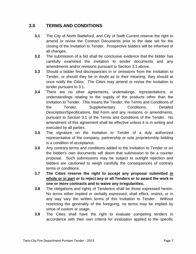
3.0 TERMS AND CONDITIONS
3.1 The City of North Battleford, and City of Swift Current reserve the right to
amend or revise the Contract Documents prior to the date set for the
closing of the Invitation to Tender. Prospective bidders will be informed of
all changes.
3.2 The submission of a bid shall be conclusive evidence that the bidder has
carefully examined the invitation to tender documents and any
amendments and/or revisions pursuant to Section 3.1 above.
3.3 Should a bidder find discrepancies in or omissions from the Invitation to
Tender, or should they be in doubt as to their meaning, they should at
once notify the Cities. The Cities may amend or revise the Invitation to
tender pursuant to 3.1.
3.4 There are no other agreements, undertakings, representations, or
understandings relating to the supply of the products other than the
Invitation to Tender. This means the Tender, the Terms and Conditions of
the Tender, Supplementary Conditions, Detailed
Description/Specifications, Bid Form and any revisions or amendments,
pursuant to Section 3.1 of the Terms and Conditions of the Tender. No
amendment of this agreement shall be effective unless it is in writing and
executed by all parties.
3.5 The signature on the Invitation to Tender of a duly authorized
representative of the company, partnership or sole proprietorship bidding
is a condition of acceptance.
3.6 Any contrary terms and conditions added to the Invitation to Tender or on
the bidder's own documents will deem that submission to be a counter
proposal. Such submissions may be subject to outright rejection and
bidders are cautioned to weigh carefully the consequences of contrary
terms or conditions.
3.7 The Cities reserve the right to accept any proposal submitted in
whole or in part or to reject any or all Tenders or to award the work in
one or more contracts and to waive any irregularities.
3.8 The obligations and rights of Tenderers shall be those expressed herein.
No terms either implied or verbally expressed, shall effect, restrict, or in
any way vary the written terms of this Invitation to Tender. Without
restricting the generality of the foregoing, no terms may be implied by
virtue of custom or usage.
3.9 The Cities shall have the right to evaluate competing tenders in
accordance with their own criteria for evaluation applied to the specific
Twin-City Fire Department Pumper Tender - 2013 Page 8
materials being tendered, whether or not such criteria has been expressly
related to bidders.
4.0 PREPARATION OF TENDERS
4.1 Each bidder shall specify, on the forms supplied by the Cities or duplicate of,
the price at which the bidder is offering to supply the items/service indicated.
The bidder shall type "YES" where indicated if the bidder offers to supply
the whole item/service.
4.2 If the bidder is meeting only a portion of the item, or is offering an alternative,
type "EXCEPTION" in the response section and explain the exception. Any
exception or variation in construction, performance or items of equipment,
between this (Purchaser's specification and Bidder's proposal) shall be
detailed and submitted on a separate sheet(s) along with the Bidder's
Proposal in bid sequence, and citing page number and paragraph.
4.3 If the bidder is not meeting the specifications or not providing the item, type
"NO" in the response column.
4.4 Minor exceptions from given dimensions which do not compromise quality or
performance will not be reason to eliminate bidder’s submission.
4.5 An exception will not eliminate the bidder from being successful as long as
there is an exception noted that can be evaluated.
4.6 Prices listed for the products shown should be net of tax and should not
include Goods and Services Tax or the Provincial Education and Health Tax.
4.7 Cartage – Truck #1, North Battleford – TME FIRE TRUCK – to be delivered
FOB City of North Battleford Fire Department, 902-104th Street, North
Battleford, Saskatchewan, unless otherwise specified.
Cartage – Truck #2, Swift Current – TME FIRE TRUCK – to be delivered
FOB Swift Current Fire Department, 236 Chaplin Street East, Swift Current,
Saskatchewan, unless otherwise specified.
4.8 All products and services must meet all current Provincial, Federal,
Municipal, CMVSS, etc. standards and if any defects are found all costs
involved to correct the problem will be borne by the quoting firm.
Twin-City Fire Department Pumper Tender - 2013 Page 9
5.0 SUBMISSION OF TENDER
5.1 Telecommunication bids will be accepted if received by closing of the
proposal. Bidder must immediately confirm the bids in writing. The Cities
assume no risk or responsibility whatsoever that any fax or email will be
received and shall not be liable to any tenderer if for any reason a fax or
email is not properly received.
5.2 A bidder may withdraw their tender provided a written withdrawal, signed by
a person authorized to sign tenders, is delivered to the address stated in
Section 1.0 before closing of the tender.
5.3 All tenders will be opened and read publicly in the office or place of address
stated in 1.0 shortly after the closing of the tender. Bidders are invited to be
present.
6.0 SHIPPING AND DELIVERY INSTRUCTIONS
6.1 Shipments to be made only on an order being placed by an authorized
staff member of each City. A local Purchase Order Number or Standing
Purchase Order Number will indicate the list of products or service
required, and will indicate the name and location of each City Department
to which the delivery is to be made.
6.2 Supplier to mail invoices in duplicate only to the address identified on the
Purchase Order. A packing slip outlining quantity and name of products
must be provided at the point and time of delivery.
6.3 The Goods and Services Tax is to be shown separately on all invoices.
Fire trucks are Provincial Sales Tax Exempt.
7.0 FORMATION OF CONTRACT
7.1 By submitting a bid, the bidder agrees that the price shall be open for
acceptance by each City for a period of 60 days after the date on which
the tenders are to be opened.
7.2 Each City may accept a tender by issuing their own Purchase Order
Number to the successful bidder and thereby establish a contract for the
supply and delivery of the product/service on the terms and conditions set
forth in the documents as specified in the Bid Form.
7.3 Failure to comply with the terms and conditions of the tender will result in
the successful bidder being notified of a breach of contract. The
successful bidder will be allowed ten (10) days to rectify this breach of
contract.
Twin-City Fire Department Pumper Tender - 2013 Page 10
7.4 Failure to rectify the breach of contract within the time specified in 8.3 may
result in the termination of the contract.
8.0 SUPPLEMENTARY CONDITIONS
8.1 Notwithstanding any other requirements, the apparatus shall meet the
requirements contained in the Canadian Motor Vehicle Safety Standards,
and applicable Provincial requirements. A copy of the company’s
Department of Transport Ministerial Authorization to use and apply the
National Safety Mark and a copy of the National Safety Mark shall
accompany the tender.
8.2 The apparatus shall be built and tested to the NFPA 1901, Standard for
Automotive Fire Apparatus, (Latest Edition), and all pertinent appendices.
The unit when delivered shall be listed and bear the label of the
Underwriter's Laboratories of Canada (ULC).
8.3 All items and materials used in the construction of the apparatus shall be
new and of products that resist corrosion and wear. The Design and
Construction of all elements of the vehicle and/or equipment shall be such
that the stresses imposed through normal use and normal shock loads at
maximum engine torque shall not cause rupture, permanent deformation
or undue wear on any of the elements.
8.4 The following print manuals shall be supplied at the time of delivery of the
apparatus to each of the Cities:
Two (2) operation/service/overhaul manuals for chassis.
Two (2) operation/service/overhaul manuals for the pump.
Two (2) operation/service/overhaul manuals for engine.
Two (2) operation/service/overhaul manuals for transmission.
Two (2) operation/service/overhaul manuals for 110-volt power
plant.
Two (2) complete manuals covering the special components.
Two (2) electric schematics specific to the engine and apparatus
body.
Two (2) complete wiring diagrams of the color coded wiring harness for the body.
Two (2) engineered as-built construction drawings showing all
installed equipment and information pertinent to the finished truck.
All/any manuals or information that is provided for accompanying
equipment.
Twin-City Fire Department Pumper Tender - 2013 Page 11
All documentation for miscellaneous components and accessories
such as the power plant, lighting etc. shall be neatly organized in a
three ring binder.
8.5 In addition to the print manuals listed in 9.4, two (2) CDs/DVDs containing electronic copies of the same manuals shall be supplied at the time of delivery. The CD manual(s) shall include a troubleshooting guide complete with recommended daily, weekly and annual maintenance procedures.
8.6 When not specifically listed, materials shall be of the best quality for the
purpose of commercial practice. Materials shall be free of all defects and
imperfections that might affect serviceability of the finished product.
8.7 Any exception or variation in construction, performance or items of
equipment, between this (Purchaser’s specification and Bidder’s tender)
shall be detailed and submitted on a separate sheet(s) along with the
Bidder’s Tender in bid sequence and citing page number and paragraph.
8.8 Drawings for approval and blueprints with all details therein must be
furnished with the bidder’s proposal.
8.9 Payment for the chassis will be due upon arrival of the chassis at the
manufacturing plant. Full payment will be made within 45 days after the
receiving City Fire Department has accepted delivery of their apparatus.
The Fire Department will accept delivery of the apparatus only after it has
been tested by the Department and found to be in good working order.
Keeping or storing the apparatus in any building owned or occupied by
any City during the test period will NOT constitute acceptance of delivery
of the apparatus.
8.10 The apparatus shall be delivered by the bidder within 365 calendar days,
or twelve months, from the date of award of contract, with all equipment
specified F.O.B.:
Truck #1, North Battleford – TME FIRE TRUCK – City of North
Battleford Fire Department, 902-104th Street, North Battleford,
Saskatchewan, unless otherwise specified.
Truck #2, Swift Current – TME FIRE TRUCK – Swift Current Fire
Department, 236 Chaplin Street East, Swift Current, Saskatchewan,
unless otherwise specified.
8.11 Bidder must submit a firm delivery time of said apparatus with his bid.
Quoting number of days after receipt of all components is unacceptable.
A deduction of $200.00 per day will be made for each day over and above
the quoted delivery date. The penalty will also apply if the unit is delivered
and rejected, until the unit is returned properly adjusted. The preceding
penalty may be waived at the discretion of the Chief of the receiving Fire
Department.
Twin-City Fire Department Pumper Tender - 2013 Page 12
8.12 The apparatus shall be delivered to each Fire Department by a fully
qualified technician for acceptance testing and training. The technician
shall present training to all four (4) platoons during their regular shifts so
as to not cause the Cities any overtime wage expenses.
8.13 The successful bidder shall be responsible for ALL EXPENSES incurred in
the delivery of the chassis from the chassis manufacturing plant to the
body manufacturing plant.
8.14 The successful bidder shall be responsible for ALL EXPENSES incurred in
the delivery of the completed unit from the manufacturer's plant to each
Fire Department.
8.15 The successful bidder shall be responsible for insurance for the drive from
the manufacturer's plant to each Fire Department
8.16 The overall size and weight of the finished apparatus is critical to each
Fire Department. The bidder shall list all compartment sizes, overall
length, width, height, wheelbase and fully loaded weight of the apparatus
with its bid.
8.17 The supplied chassis must include the Original Equipment Manufacturer’s
current heavy-duty components. The intent is to ensure the longevity,
reliability, safety and comfort for the anticipated life of the chassis and
apparatus.
8.18 Modifications to the chassis shall be permitted only if approved by the
Original Equipment Manufacturer. Failure to comply with this specification
shall be cause for immediate and absolute rejection of the apparatus by
the Cities.
8.19 All inquiries concerning the bid shall be directed to the persons listed in
Article 2.11.
8.20 The manufacturer shall supply a complete list of warranties that would
apply to this apparatus. The manufacturer shall state all warranty
arrangements and conditions, such as who is responsible for delivery of
the apparatus for warranty work. The warranty on the apparatus shall
include 100% replacement parts at no cost to the Cities and shall cover
the complete apparatus and all parts thereof against defects of
workmanship, construction and material for one (1) year from effective
date of acceptance and:
The body shall be warranted against structural defects for a period
of ten (10) years from acceptance.
The Apparatus manufacturer shall provide a 100% full 10-year paint
and lifetime corrosion perforation warranty. This warranty shall
cover paint peeling, cracking, blistering, and corrosion provided the
Twin-City Fire Department Pumper Tender - 2013 Page 13
vehicle is used in a normal and reasonable manner. UV fade shall
be covered for a minimum of 7 years.
The engine and transmission shall be warranted for a period of five
(5) years from acceptance.
The pump warranty shall be a minimum of two (2) years from
acceptance.
Booster tank shall have a lifetime warranty with field repair at the
customer’s location if ever required.
The chassis shall have a warranty for a minimum period of two (2)
years from the date of delivery to each receiving City.
8.21 Following acceptance of the trucks, the bidder shall conduct four quarterly
inspections at each apparatus location to correct, adjust and/or repair
defective parts and material. These inspections shall occur in the first
year at no cost to the Cities.
8.22 At the expense of the manufacturer(s), representatives from each of the
involved manufacturers (Chassis – Body) shall meet with representatives
from each Fire Department at the Swift Current Fire Department prior to
production of the apparatus (pre-construction meeting).
8.23 After delivery of the chassis and before construction of the apparatus, and
at the expense of the manufacturer, two representatives from each Fire
Department shall meet with factory representatives at the factory of the
successful bidder.
8.24 Prior to painting, and at the expense of the manufacturer, two
representatives of each Fire Department shall meet with factory
representatives at the factory of the successful bidder.
8.25 Prior to delivery, and at the expense of the manufacturer, two
representatives of each Fire Department shall meet with factory
representatives at the factory of the successful bidder.
8.26 Each inspection shall consist of all Cities being present at the same time
to inspect all apparatus during the same visit.
8.27 The construction shall be scheduled such that both trucks enter and leave
the assembly line in consecutive order so that all of the previous
inspections can be conducted concurrently.
8.28 It is the responsibility of the bidder to review all of the bidding
requirements. Failure of the bidder to be acquainted with this information
shall not relieve the bidder from any obligations of the bid requirements.
Twin-City Fire Department Pumper Tender - 2013 Page 14
9.0 VENDOR QUALIFICATIONS
9.1 The vendor shall carry general liability insurance in the amount of at least
$10,000,000. The insurance policy shall be issued by a broker and
underwritten by an insurance company authorized to conduct business in
Canada. A certificate of insurance shall accompany the vendors bid.
9.2 The vendor shall be certified by the Canadian Welding Bureau (CWB) or
American Welding Society (AWS) in the appropriate standards. A
certificate of proof of certification shall accompany the vendors bid.
9.3 The vendor shall ensure that all certification tests are conducted by a third
party accredited by the Standards Council of Canada to certify that they
are manufacturing apparatus in compliance with NFPA and/or ULC
requirements. A certificate verifying the third party is accredited shall
accompany the vendors bid.
9.4 The vendor shall have on staff, professional engineers with experience in
the design and construction of fire apparatus. These engineers shall have
expertise in vehicle electronics and electrical systems, pumps and
plumbing, vehicle structural design and testing, air brake systems, and
body design. Proof of membership in the Association of Professional
Engineers for the province in which the truck is being built shall
accompany the vendors bid.
9.5 The vendor shall be registered with Transport Canada with authorization
to affix a National Safety Mark at their manufacturing facility. Proof of the
authorization and a copy of the National Safety Mark shall accompany the
vendors bid.
9.6 The Vendor shall have a documented quality management system that
tracks the apparatus through all stages of construction from initial order to
the final delivery. Proof of a quality control program shall accompany the
vendors bid.
9.7 The vendor shall build apparatus in compliance with the Underwriters’
Laboratories of Canada (ULC). Documentation of the most recent
investigation by the ULC shall accompany the vendors bid. The finished
truck shall be ULC Listed in accordance with the most recent edition of
CAN/ULC-S515.
9.8 The vendor shall have been in the business of manufacturing similar
custom fire apparatus for a period of not less than ten (10) years. The
vendor shall provide a list of similar style trucks manufactured, along with
the contact information for the purchaser, during the previous 10 years.
9.9 The manufacturer shall perform all cutting of openings in panels by means
of laser cutting. This shall include openings for control levers, meters,
Twin-City Fire Department Pumper Tender - 2013 Page 15
lights, door handles, valves, inlets, and outlets. The type of cutting
machine used by the manufacturer shall included in the bid.
9.10 The vendor shall include with the bid a list of the proposed personnel who
will be assigned to the project. The list shall include their name, title, and
years of experience.
9.11 The vendor shall conduct a High Tech Drive Line Analysis to analyse the
performance of all drive lines. Proof of the ability to conduct these tests
shall accompany the vendors bid.
9.12 The vendor shall make available an audited financial statement which
indicates financial stability and the ability to manufacture the vehicle and
provide warranty and service over the life of the apparatus.
9.13 The vendor shall provide a “24 hour, 7 day per week” emergency parts
and service toll free telephone number. This phone number shall be listed
on a separate statement included in the bid package, along with the
contact name, business name, address, and phone number of the local
service agency, which will service the vehicle after being placed in service.
9.14 The service agency shall be capable of performing all required service
work and shall have at their disposal the ability to have any required
subcontracting work, such as engine, transmission, etc., work performed
on behalf of the apparatus manufacturer.
10.0 TENDER EVALUATION
10.1 The tenders shall be jointly evaluated by a team made up of two members
of each Fire Department and one member of the municipal purchasing
department from each of the Cities.
10.2 The evaluation will consist of two parts, product evaluation and vendor
evaluation.
10.3 The product evaluation shall evaluate the chassis and the body against
the specifications. This section will evaluate the design, features and
products offered by the bidder as well as any alternates offered by the
bidder. This section will also evaluate warrantees on various sections of
the apparatus and the quality of construction.
10.4 The vendor evaluation will qualify the vendor as acceptable to the Cities of
North Battleford and Swift Current to construct and supply the tendered
fire trucks. This section will evaluate time in business, quality control
programs, methodology, after market service and support, and
engineering.
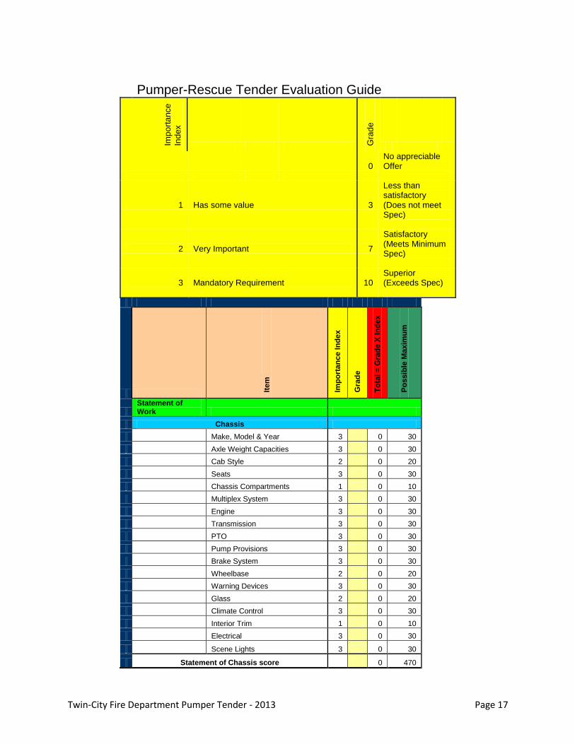
10.5 An evaluation matrix that will be used sets an importance index of 1 to 3
based on how important that item is to the Cities of North Battleford and
Twin-City Fire Department Pumper Tender - 2013 Page 16
Swift Current. Vendors are graded on each item with a score of 0, 3, 7, or
10 based on the quality of the information provided in their bid.
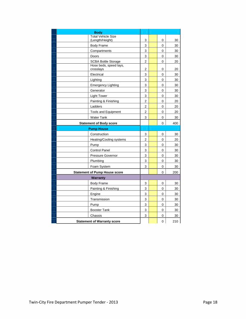
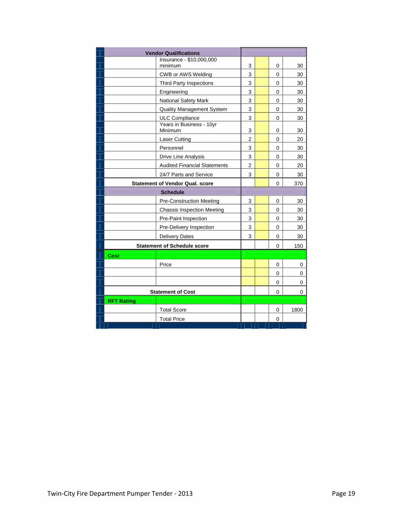
10.6 Below is the evaluation matrix:
Twin-City Fire Department Pumper Tender - 2013 Page 17
Pumper-Rescue Tender Evaluation Guide
Imp
ort
ance
Ind
ex
Gra
de
0
No appreciable Offer
1 Has some value 3
Less than satisfactory (Does not meet Spec)
2 Very Important 7
Satisfactory (Meets Minimum Spec)
3 Mandatory Requirement 10 Superior (Exceeds Spec)
Item
Imp
ort
an
ce In
de
x
Gra
de
To
tal
= G
rad
e X
In
de
x
Po
ssib
le M
axim
um
Statement of Work
Chassis
Make, Model & Year 3 0 30
Axle Weight Capacities 3 0 30
Cab Style 2 0 20
Seats 3 0 30
Chassis Compartments 1 0 10
Multiplex System 3 0 30
Engine 3 0 30
Transmission 3 0 30
PTO 3 0 30
Pump Provisions 3 0 30
Brake System 3 0 30
Wheelbase 2 0 20
Warning Devices 3 0 30
Glass 2 0 20
Climate Control 3 0 30
Interior Trim 1 0 10
Electrical 3 0 30
Scene Lights 3 0 30
Statement of Chassis score 0 470
Twin-City Fire Department Pumper Tender - 2013 Page 18
Body
Total Vehicle Size (Length/Height) 3 0 30
Body Frame 3 0 30
Compartments 3 0 30
Doors 3 0 30
SCBA Bottle Storage 2 0 20
Hose beds, speed lays, crosslays 2 0 20
Electrical 3 0 30
Lighting 3 0 30
Emergency Lighting 3 0 30
Generator 3 0 30
Light Tower 3 0 30
Painting & Finishing 2 0 20
Ladders 2 0 20
Tools and Equipment 2 0 20
Water Tank 3 0 30
Statement of Body score 0 400
Pump House
Construction 3 0 30
Heating/Cooling systems 2 0 20
Pump 3 0 30
Control Panel 3 0 30
Pressure Governor 3 0 30
Plumbing 3 0 30
Foam System 3 0 30
Statement of Pump House score 0 200
Warranty
Body Frame 3 0 30
Painting & Finishing 3 0 30
Engine 3 0 30
Transmission 3 0 30
Pump 3 0 30
Booster Tank 3 0 30
Chassis 3 0 30
Statement of Warranty score 0 210
Twin-City Fire Department Pumper Tender - 2013 Page 19
Vendor Qualifications
Insurance - $10,000,000 minimum 3 0 30
CWB or AWS Welding 3 0 30
Third Party Inspections 3 0 30
Engineering 3 0 30
National Safety Mark 3 0 30
Quality Management System 3 0 30
ULC Compliance 3 0 30
Years in Business - 10yr Minimum 3 0 30
Laser Cutting 2 0 20
Personnel 3 0 30
Drive Line Analysis 3 0 30
Audited Financial Statements 2 0 20
24/7 Parts and Service 3 0 30
Statement of Vendor Qual. score 0 370
Schedule
Pre-Construction Meeting 3 0 30
Chassis Inspection Meeting 3 0 30
Pre-Paint Inspection 3 0 30
Pre-Delivery Inspection 3 0 30
Delivery Dates 3 0 30
Statement of Schedule score 0 150
Cost
Price 0 0
0 0
0 0
Statement of Cost 0 0
RFT Rating
Total Score 0 1800
Total Price 0
DESCRIPTIONException
Yes No
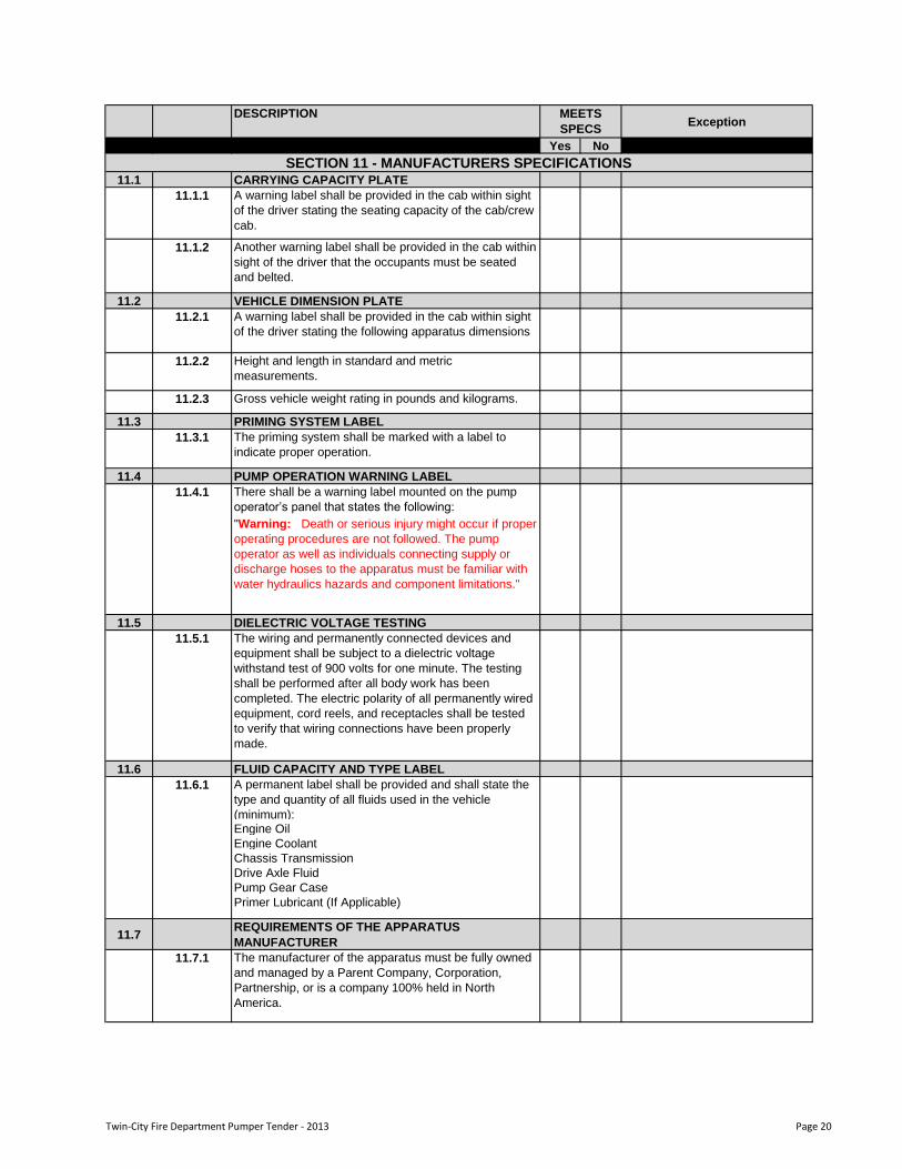
11.1 CARRYING CAPACITY PLATE
11.1.1 A warning label shall be provided in the cab within sight
of the driver stating the seating capacity of the cab/crew
cab.
11.1.2 Another warning label shall be provided in the cab within
sight of the driver that the occupants must be seated
and belted.
11.2 VEHICLE DIMENSION PLATE
11.2.1 A warning label shall be provided in the cab within sight
of the driver stating the following apparatus dimensions
11.2.2 Height and length in standard and metric
measurements.
11.2.3 Gross vehicle weight rating in pounds and kilograms.
11.3 PRIMING SYSTEM LABEL
11.3.1 The priming system shall be marked with a label to
indicate proper operation.
11.4 PUMP OPERATION WARNING LABEL
11.4.1 There shall be a warning label mounted on the pump
operator‟s panel that states the following:
"Warning: Death or serious injury might occur if proper
operating procedures are not followed. The pump
operator as well as individuals connecting supply or
discharge hoses to the apparatus must be familiar with
water hydraulics hazards and component limitations."
11.5 DIELECTRIC VOLTAGE TESTING
11.5.1 The wiring and permanently connected devices and
equipment shall be subject to a dielectric voltage
withstand test of 900 volts for one minute. The testing
shall be performed after all body work has been
completed. The electric polarity of all permanently wired
equipment, cord reels, and receptacles shall be tested
to verify that wiring connections have been properly
made.
11.6 FLUID CAPACITY AND TYPE LABEL
A permanent label shall be provided and shall state the
type and quantity of all fluids used in the vehicle
(minimum):Engine Oil
Engine Coolant
Chassis Transmission
Drive Axle Fluid
Pump Gear Case
Primer Lubricant (If Applicable)
11.7REQUIREMENTS OF THE APPARATUS
MANUFACTURER
11.7.1 The manufacturer of the apparatus must be fully owned
and managed by a Parent Company, Corporation,
Partnership, or is a company 100% held in North
America.
MEETS
SPECS
SECTION 11 - MANUFACTURERS SPECIFICATIONS
11.6.1
Twin-City Fire Department Pumper Tender - 2013 Page 20
DESCRIPTIONException
Yes No
MEETS
SPECS
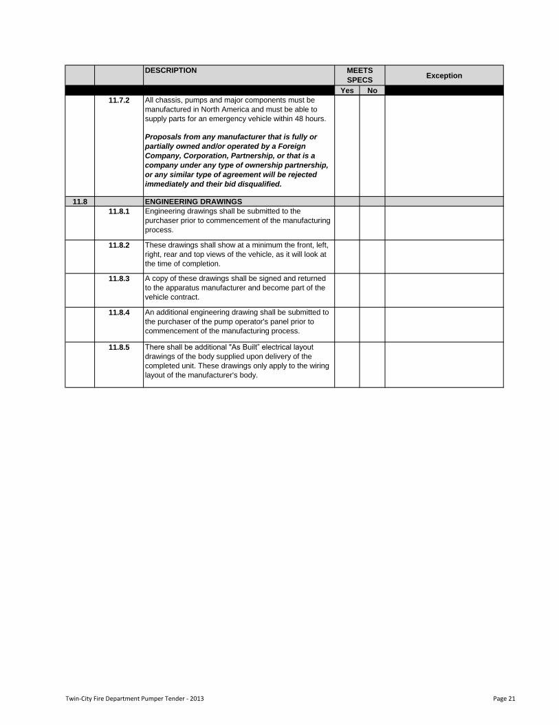
All chassis, pumps and major components must be
manufactured in North America and must be able to
supply parts for an emergency vehicle within 48 hours.
Proposals from any manufacturer that is fully or
partially owned and/or operated by a Foreign
Company, Corporation, Partnership, or that is a
company under any type of ownership partnership,
or any similar type of agreement will be rejected
immediately and their bid disqualified.
11.8 ENGINEERING DRAWINGS
11.8.1 Engineering drawings shall be submitted to the
purchaser prior to commencement of the manufacturing
process.
11.8.2 These drawings shall show at a minimum the front, left,
right, rear and top views of the vehicle, as it will look at
the time of completion.
11.8.3 A copy of these drawings shall be signed and returned
to the apparatus manufacturer and become part of the
vehicle contract.
11.8.4 An additional engineering drawing shall be submitted to
the purchaser of the pump operator's panel prior to
commencement of the manufacturing process.
11.8.5 There shall be additional "As Built” electrical layout
drawings of the body supplied upon delivery of the
completed unit. These drawings only apply to the wiring
layout of the manufacturer's body.
11.7.2
Twin-City Fire Department Pumper Tender - 2013 Page 21
DESCRIPTIONException
Yes No
MEETS
SPECS
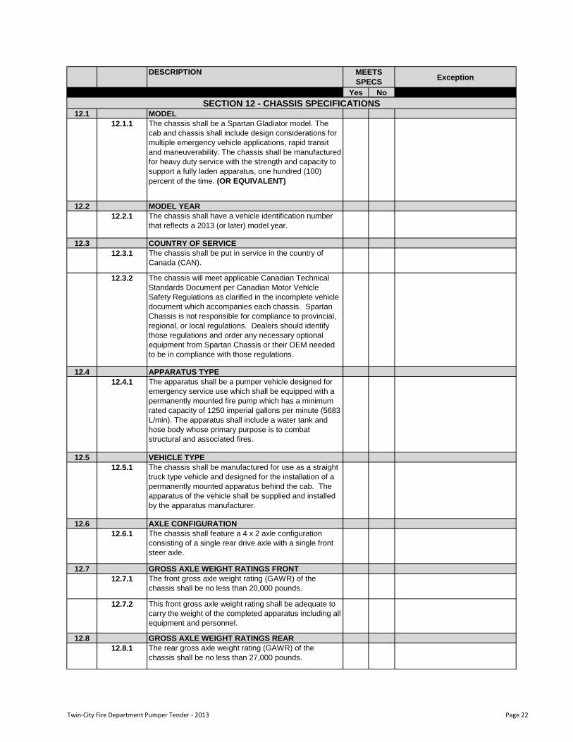
12.1 MODEL
12.1.1 The chassis shall be a Spartan Gladiator model. The
cab and chassis shall include design considerations for
multiple emergency vehicle applications, rapid transit
and maneuverability. The chassis shall be manufactured
for heavy duty service with the strength and capacity to
support a fully laden apparatus, one hundred (100)
percent of the time. (OR EQUIVALENT)
12.2 MODEL YEAR
12.2.1 The chassis shall have a vehicle identification number
that reflects a 2013 (or later) model year.
12.3 COUNTRY OF SERVICE
12.3.1 The chassis shall be put in service in the country of
Canada (CAN).
12.3.2 The chassis will meet applicable Canadian Technical
Standards Document per Canadian Motor Vehicle
Safety Regulations as clarified in the incomplete vehicle
document which accompanies each chassis. Spartan
Chassis is not responsible for compliance to provincial,
regional, or local regulations. Dealers should identify
those regulations and order any necessary optional
equipment from Spartan Chassis or their OEM needed
to be in compliance with those regulations.
12.4 APPARATUS TYPE
12.4.1 The apparatus shall be a pumper vehicle designed for
emergency service use which shall be equipped with a
permanently mounted fire pump which has a minimum
rated capacity of 1250 imperial gallons per minute (5683
L/min). The apparatus shall include a water tank and
hose body whose primary purpose is to combat
structural and associated fires.
12.5 VEHICLE TYPE
12.5.1 The chassis shall be manufactured for use as a straight
truck type vehicle and designed for the installation of a
permanently mounted apparatus behind the cab. The
apparatus of the vehicle shall be supplied and installed
by the apparatus manufacturer.
12.6 AXLE CONFIGURATION
12.6.1 The chassis shall feature a 4 x 2 axle configuration
consisting of a single rear drive axle with a single front
steer axle.
12.7 GROSS AXLE WEIGHT RATINGS FRONT
12.7.1 The front gross axle weight rating (GAWR) of the
chassis shall be no less than 20,000 pounds.
12.7.2 This front gross axle weight rating shall be adequate to
carry the weight of the completed apparatus including all
equipment and personnel.
12.8 GROSS AXLE WEIGHT RATINGS REAR
12.8.1 The rear gross axle weight rating (GAWR) of the
chassis shall be no less than 27,000 pounds.
SECTION 12 - CHASSIS SPECIFICATIONS
Twin-City Fire Department Pumper Tender - 2013 Page 22
DESCRIPTIONException
Yes No
MEETS
SPECS
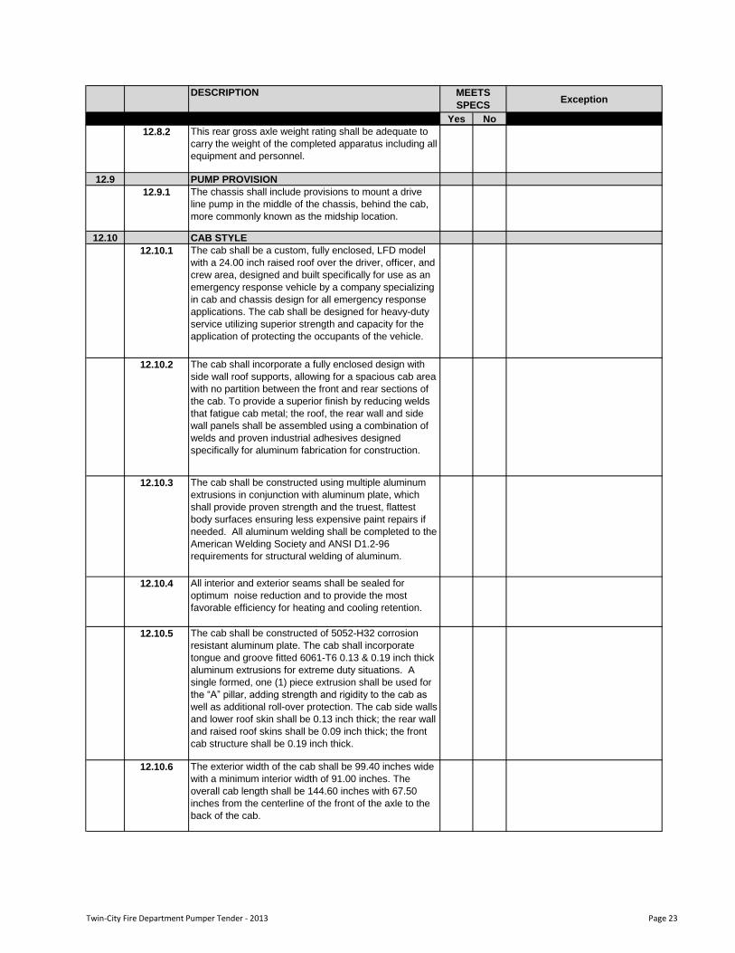
12.8.2 This rear gross axle weight rating shall be adequate to
carry the weight of the completed apparatus including all
equipment and personnel.
12.9 PUMP PROVISION
12.9.1 The chassis shall include provisions to mount a drive
line pump in the middle of the chassis, behind the cab,
more commonly known as the midship location.
12.10 CAB STYLE
12.10.1 The cab shall be a custom, fully enclosed, LFD model
with a 24.00 inch raised roof over the driver, officer, and
crew area, designed and built specifically for use as an
emergency response vehicle by a company specializing
in cab and chassis design for all emergency response
applications. The cab shall be designed for heavy-duty
service utilizing superior strength and capacity for the
application of protecting the occupants of the vehicle.
12.10.2 The cab shall incorporate a fully enclosed design with
side wall roof supports, allowing for a spacious cab area
with no partition between the front and rear sections of
the cab. To provide a superior finish by reducing welds
that fatigue cab metal; the roof, the rear wall and side
wall panels shall be assembled using a combination of
welds and proven industrial adhesives designed
specifically for aluminum fabrication for construction.
12.10.3 The cab shall be constructed using multiple aluminum
extrusions in conjunction with aluminum plate, which
shall provide proven strength and the truest, flattest
body surfaces ensuring less expensive paint repairs if
needed. All aluminum welding shall be completed to the
American Welding Society and ANSI D1.2-96
requirements for structural welding of aluminum.
12.10.4 All interior and exterior seams shall be sealed for
optimum noise reduction and to provide the most
favorable efficiency for heating and cooling retention.
12.10.5 The cab shall be constructed of 5052-H32 corrosion
resistant aluminum plate. The cab shall incorporate
tongue and groove fitted 6061-T6 0.13 & 0.19 inch thick
aluminum extrusions for extreme duty situations. A
single formed, one (1) piece extrusion shall be used for
the “A” pillar, adding strength and rigidity to the cab as
well as additional roll-over protection. The cab side walls
and lower roof skin shall be 0.13 inch thick; the rear wall
and raised roof skins shall be 0.09 inch thick; the front
cab structure shall be 0.19 inch thick.
12.10.6 The exterior width of the cab shall be 99.40 inches wide
with a minimum interior width of 91.00 inches. The
overall cab length shall be 144.60 inches with 67.50
inches from the centerline of the front of the axle to the
back of the cab.
Twin-City Fire Department Pumper Tender - 2013 Page 23
DESCRIPTIONException
Yes No
MEETS
SPECS
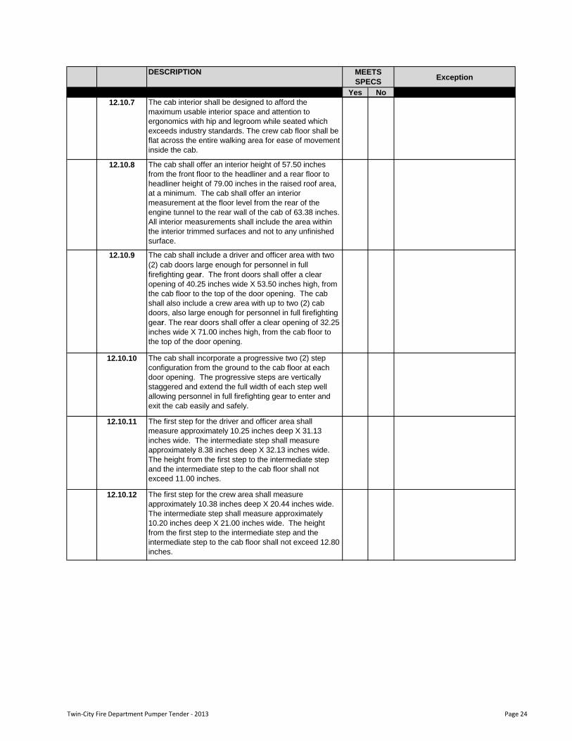
12.10.7 The cab interior shall be designed to afford the
maximum usable interior space and attention to
ergonomics with hip and legroom while seated which
exceeds industry standards. The crew cab floor shall be
flat across the entire walking area for ease of movement
inside the cab.
12.10.8 The cab shall offer an interior height of 57.50 inches
from the front floor to the headliner and a rear floor to
headliner height of 79.00 inches in the raised roof area,
at a minimum. The cab shall offer an interior
measurement at the floor level from the rear of the
engine tunnel to the rear wall of the cab of 63.38 inches.
All interior measurements shall include the area within
the interior trimmed surfaces and not to any unfinished
surface.
12.10.9 The cab shall include a driver and officer area with two
(2) cab doors large enough for personnel in full
firefighting gear. The front doors shall offer a clear
opening of 40.25 inches wide X 53.50 inches high, from
the cab floor to the top of the door opening. The cab
shall also include a crew area with up to two (2) cab
doors, also large enough for personnel in full firefighting
gear. The rear doors shall offer a clear opening of 32.25
inches wide X 71.00 inches high, from the cab floor to
the top of the door opening.
12.10.10 The cab shall incorporate a progressive two (2) step
configuration from the ground to the cab floor at each
door opening. The progressive steps are vertically
staggered and extend the full width of each step well
allowing personnel in full firefighting gear to enter and
exit the cab easily and safely.
12.10.11 The first step for the driver and officer area shall
measure approximately 10.25 inches deep X 31.13
inches wide. The intermediate step shall measure
approximately 8.38 inches deep X 32.13 inches wide.
The height from the first step to the intermediate step
and the intermediate step to the cab floor shall not
exceed 11.00 inches.
12.10.12 The first step for the crew area shall measure
approximately 10.38 inches deep X 20.44 inches wide.
The intermediate step shall measure approximately
10.20 inches deep X 21.00 inches wide. The height
from the first step to the intermediate step and the
intermediate step to the cab floor shall not exceed 12.80
inches.
Twin-City Fire Department Pumper Tender - 2013 Page 24
DESCRIPTIONException
Yes No
MEETS
SPECS
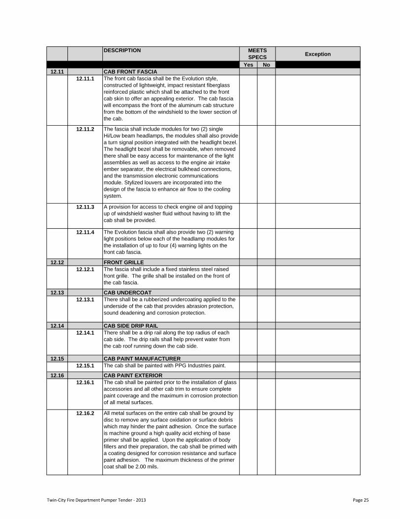
12.11 CAB FRONT FASCIA
12.11.1 The front cab fascia shall be the Evolution style,
constructed of lightweight, impact resistant fiberglass
reinforced plastic which shall be attached to the front
cab skin to offer an appealing exterior. The cab fascia
will encompass the front of the aluminum cab structure
from the bottom of the windshield to the lower section of
the cab.
12.11.2 The fascia shall include modules for two (2) single
Hi/Low beam headlamps, the modules shall also provide
a turn signal position integrated with the headlight bezel.
The headlight bezel shall be removable, when removed
there shall be easy access for maintenance of the light
assemblies as well as access to the engine air intake
ember separator, the electrical bulkhead connections,
and the transmission electronic communications
module. Stylized louvers are incorporated into the
design of the fascia to enhance air flow to the cooling
system.
12.11.3 A provision for access to check engine oil and topping
up of windshield washer fluid without having to lift the
cab shall be provided.
12.11.4 The Evolution fascia shall also provide two (2) warning
light positions below each of the headlamp modules for
the installation of up to four (4) warning lights on the
front cab fascia.
12.12 FRONT GRILLE
12.12.1 The fascia shall include a fixed stainless steel raised
front grille. The grille shall be installed on the front of
the cab fascia.
12.13 CAB UNDERCOAT
12.13.1 There shall be a rubberized undercoating applied to the
underside of the cab that provides abrasion protection,
sound deadening and corrosion protection.
12.14 CAB SIDE DRIP RAIL
12.14.1 There shall be a drip rail along the top radius of each
cab side. The drip rails shall help prevent water from
the cab roof running down the cab side.
12.15 CAB PAINT MANUFACTURER
12.15.1 The cab shall be painted with PPG Industries paint.
12.16 CAB PAINT EXTERIOR
12.16.1 The cab shall be painted prior to the installation of glass
accessories and all other cab trim to ensure complete
paint coverage and the maximum in corrosion protection
of all metal surfaces.
12.16.2 All metal surfaces on the entire cab shall be ground by
disc to remove any surface oxidation or surface debris
which may hinder the paint adhesion. Once the surface
is machine ground a high quality acid etching of base
primer shall be applied. Upon the application of body
fillers and their preparation, the cab shall be primed with
a coating designed for corrosion resistance and surface
paint adhesion. The maximum thickness of the primer
coat shall be 2.00 mils.
Twin-City Fire Department Pumper Tender - 2013 Page 25
DESCRIPTIONException
Yes No
MEETS
SPECS
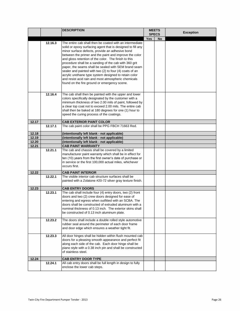
12.16.3 The entire cab shall then be coated with an intermediate
solid or epoxy surfacing agent that is designed to fill any
minor surface defects, provide an adhesive bond
between the primer and the paint and improve the color
and gloss retention of the color. The finish to this
procedure shall be a sanding of the cab with 360 grit
paper, the seams shall be sealed with SEM brand seam
sealer and painted with two (2) to four (4) coats of an
acrylic urethane type system designed to retain color
and resist acid rain and most atmospheric chemicals
found on the fire ground or emergency scene.
12.16.4 The cab shall then be painted with the upper and lower
colors specifically designated by the customer with a
minimum thickness of two 2.00 mils of paint, followed by
a clear top coat not to exceed 2.00 mils. The entire cab
shall then be baked at 180 degrees for one (1) hour to
speed the curing process of the coatings.
12.17 CAB EXTERIOR PAINT COLOR
12.17.1 The cab paint color shall be PPG FBCH 71663 Red.
12.18 (intentionally left blank - not applicable)
12.19 (intentionally left blank - not applicable)
12.20 (intentionally left blank - not applicable)
12.21 CAB PAINT WARRANTY
12.21.1 The cab and chassis shall be covered by a limited
manufacturer paint warranty which shall be in effect for
ten (10) years from the first owner‟s date of purchase or
in service or the first 100,000 actual miles, whichever
occurs first.
12.22 CAB PAINT INTERIOR
12.22.1 The visible interior cab structure surfaces shall be
painted with a Zolatone #20-72 silver gray texture finish.
12.23 CAB ENTRY DOORS
12.23.1 The cab shall include four (4) entry doors, two (2) front
doors and two (2) crew doors designed for ease of
entering and egress when outfitted with an SCBA. The
doors shall be constructed of extruded aluminum with a
nominal thickness of 0.13 inch. The exterior skins shall
be constructed of 0.13 inch aluminum plate.
12.23.2 The doors shall include a double rolled style automotive
rubber seal around the perimeter of each door frame
and door edge which ensures a weather tight fit.
12.23.3 All door hinges shall be hidden within flush mounted cab
doors for a pleasing smooth appearance and perfect fit
along each side of the cab. Each door hinge shall be
piano style with a 0.38 inch pin and shall be constructed
of stainless steel.
12.24 CAB ENTRY DOOR TYPE
12.24.1 All cab entry doors shall be full length in design to fully
enclose the lower cab steps.
Twin-City Fire Department Pumper Tender - 2013 Page 26
DESCRIPTIONException
Yes No
MEETS
SPECS
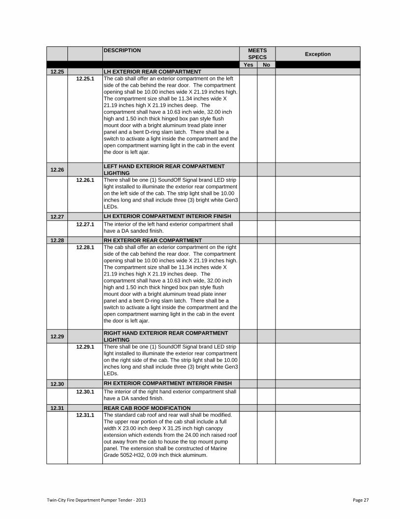
12.25 LH EXTERIOR REAR COMPARTMENT
12.25.1 The cab shall offer an exterior compartment on the left
side of the cab behind the rear door. The compartment
opening shall be 10.00 inches wide X 21.19 inches high.
The compartment size shall be 11.34 inches wide X
21.19 inches high X 21.19 inches deep. The
compartment shall have a 10.63 inch wide, 32.00 inch
high and 1.50 inch thick hinged box pan style flush
mount door with a bright aluminum tread plate inner
panel and a bent D-ring slam latch. There shall be a
switch to activate a light inside the compartment and the
open compartment warning light in the cab in the event
the door is left ajar.
12.26LEFT HAND EXTERIOR REAR COMPARTMENT
LIGHTING
12.26.1 There shall be one (1) SoundOff Signal brand LED strip
light installed to illuminate the exterior rear compartment
on the left side of the cab. The strip light shall be 10.00
inches long and shall include three (3) bright white Gen3
LEDs.
12.27 LH EXTERIOR COMPARTMENT INTERIOR FINISH
12.27.1 The interior of the left hand exterior compartment shall
have a DA sanded finish.
12.28 RH EXTERIOR REAR COMPARTMENT
12.28.1 The cab shall offer an exterior compartment on the right
side of the cab behind the rear door. The compartment
opening shall be 10.00 inches wide X 21.19 inches high.
The compartment size shall be 11.34 inches wide X
21.19 inches high X 21.19 inches deep. The
compartment shall have a 10.63 inch wide, 32.00 inch
high and 1.50 inch thick hinged box pan style flush
mount door with a bright aluminum tread plate inner
panel and a bent D-ring slam latch. There shall be a
switch to activate a light inside the compartment and the
open compartment warning light in the cab in the event
the door is left ajar.
12.29RIGHT HAND EXTERIOR REAR COMPARTMENT
LIGHTING
12.29.1 There shall be one (1) SoundOff Signal brand LED strip
light installed to illuminate the exterior rear compartment
on the right side of the cab. The strip light shall be 10.00
inches long and shall include three (3) bright white Gen3
LEDs.
12.30 RH EXTERIOR COMPARTMENT INTERIOR FINISH
12.30.1 The interior of the right hand exterior compartment shall
have a DA sanded finish.
12.31 REAR CAB ROOF MODIFICATION
12.31.1 The standard cab roof and rear wall shall be modified.
The upper rear portion of the cab shall include a full
width X 23.00 inch deep X 31.25 inch high canopy
extension which extends from the 24.00 inch raised roof
out away from the cab to house the top mount pump
panel. The extension shall be constructed of Marine
Grade 5052-H32, 0.09 inch thick aluminum.
Twin-City Fire Department Pumper Tender - 2013 Page 27
DESCRIPTIONException
Yes No
MEETS
SPECS
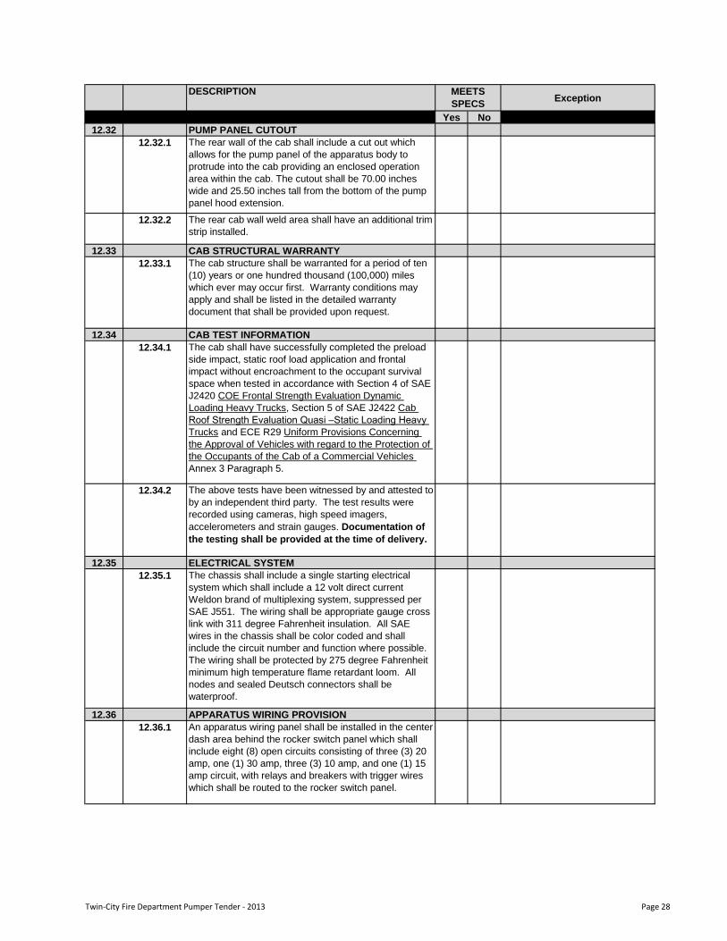
12.32 PUMP PANEL CUTOUT
12.32.1 The rear wall of the cab shall include a cut out which
allows for the pump panel of the apparatus body to
protrude into the cab providing an enclosed operation
area within the cab. The cutout shall be 70.00 inches
wide and 25.50 inches tall from the bottom of the pump
panel hood extension.
12.32.2 The rear cab wall weld area shall have an additional trim
strip installed.
12.33 CAB STRUCTURAL WARRANTY
12.33.1 The cab structure shall be warranted for a period of ten
(10) years or one hundred thousand (100,000) miles
which ever may occur first. Warranty conditions may
apply and shall be listed in the detailed warranty
document that shall be provided upon request.
12.34 CAB TEST INFORMATION
12.34.1 The cab shall have successfully completed the preload
side impact, static roof load application and frontal
impact without encroachment to the occupant survival
space when tested in accordance with Section 4 of SAE
J2420 COE Frontal Strength Evaluation Dynamic
Loading Heavy Trucks, Section 5 of SAE J2422 Cab
Roof Strength Evaluation Quasi –Static Loading Heavy
Trucks and ECE R29 Uniform Provisions Concerning
the Approval of Vehicles with regard to the Protection of
the Occupants of the Cab of a Commercial Vehicles
Annex 3 Paragraph 5.
12.34.2 The above tests have been witnessed by and attested to
by an independent third party. The test results were
recorded using cameras, high speed imagers,
accelerometers and strain gauges. Documentation of
the testing shall be provided at the time of delivery.
12.35 ELECTRICAL SYSTEM
12.35.1 The chassis shall include a single starting electrical
system which shall include a 12 volt direct current
Weldon brand of multiplexing system, suppressed per
SAE J551. The wiring shall be appropriate gauge cross
link with 311 degree Fahrenheit insulation. All SAE
wires in the chassis shall be color coded and shall
include the circuit number and function where possible.
The wiring shall be protected by 275 degree Fahrenheit
minimum high temperature flame retardant loom. All
nodes and sealed Deutsch connectors shall be
waterproof.
12.36 APPARATUS WIRING PROVISION
12.36.1 An apparatus wiring panel shall be installed in the center
dash area behind the rocker switch panel which shall
include eight (8) open circuits consisting of three (3) 20
amp, one (1) 30 amp, three (3) 10 amp, and one (1) 15
amp circuit, with relays and breakers with trigger wires
which shall be routed to the rocker switch panel.
Twin-City Fire Department Pumper Tender - 2013 Page 28
DESCRIPTIONException
Yes No
MEETS
SPECS
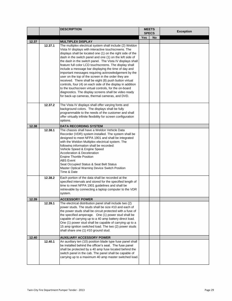
12.37 MULTIPLEX DISPLAY
12.37.1 The multiplex electrical system shall include (2) Weldon
Vista IV displays with interactive touchscreens. The
displays shall be located one (1) on the right side of the
dash in the switch panel and one (1) on the left side of
the dash in the switch panel. The Vista IV displays shall
feature full color LCD touchscreens. The display shall
include a message bar displaying the time of day and
important messages requiring acknowledgement by the
user on the top of the screen in the order they are
received. There shall be eight (8) push button virtual
controls, four (4) on each side of the display in addition
to the touchscreen virtual controls, for the on-board
diagnostics. The display screens shall be video ready
for back-up cameras, thermal cameras, and DVD.
12.37.2 The Vista IV displays shall offer varying fonts and
background colors. The displays shall be fully
programmable to the needs of the customer and shall
offer virtually infinite flexibility for screen configuration
options.
12.38 DATA RECORDING SYSTEM
The chassis shall have a Weldon Vehicle Data
Recorder (VDR) system installed. The system shall be
designed to meet NFPA 1901 and shall be integrated
with the Weldon Multiplex electrical system. The
following information shall be recorded:Vehicle Speed & Engine Speed
Acceleration & Deceleration
Engine Thorttle Position
ABS Event
Seat Occupied Status & Seat Belt Status
Master Optical Warning Device Switch Position
Time & Date
12.38.2 Each portion of the data shall be recorded at the
specified intervals and stored for the specified length of
time to meet NFPA 1901 guidelines and shall be
retrievable by connecting a laptop computer to the VDR
system.
12.39 ACCESSORY POWER
12.39.1 The electrical distribution panel shall include two (2)
power studs. The studs shall be size #10 and each of
the power studs shall be circuit protected with a fuse of
the specified amperage. One (1) power stud shall be
capable of carrying up to a 40 amp battery direct load.
One (1) power stud shall be capable of carrying up to a
15 amp ignition switched load. The two (2) power studs
shall share one (1) #10 ground stud.
12.40 AUXILIARY ACCESSORY POWER
12.40.1 An auxiliary ten (10) position blade type fuse panel shall
be installed behind the officer‟s seat. The fuse panel
shall be protected by a 40 amp fuse located behind the
switch panel in the cab. The panel shall be capable of
carrying up to a maximum 40 amp master switched load.
12.38.1
Twin-City Fire Department Pumper Tender - 2013 Page 29

DESCRIPTIONException
Yes No
MEETS
SPECS
12.41 EXTERIOR ELECTRICAL TERMINAL COATING
12.41.1 All terminals exposed to the elements will be sprayed
with a high visibility protective rubberized coating to
prevent corrosion.
12.42 CAB ENGINE TUNNEL
12.42.1 The cab interior shall include an integrated engine
tunnel constructed of 5052-H32 Marine Grade 0.19 of
an inch thick aluminum alloy plate. The tunnel shall be a
maximum of 46.50 inches wide X 29.00 inches high.
12.43 ENGINE
12.43.1 The chassis engine shall be a Cummins ISL9 engine.
The ISL9 engine shall be an in-line six (6) cylinder, four
cycle diesel powered engine. The engine shall offer a
rating of 450 horse power at 2100 RPM and shall be
governed at 2200 RPM. The torque rating shall feature
1250 foot pounds of torque at 1400 RPM with 543 cubic
inches (8.9 liter) of displacement.
12.43.2 The ISL9 engine shall feature a VGT™ Turbocharger, a
high pressure common rail fuel system, fully integrated
electronic controls with an electronic governor, and shall
be EPA certified to meet the 2010 emissions standards
using cooled exhaust gas recirculation and selective
catalytic reduction technology.
12.43.3 The engine shall include an engine mounted
combination full flow/by-pass oil filter with replaceable
spin on cartridge for use with the engine lubrication
system. The engine shall include Citgo brand Citgard
500, or equivalent SAE 15W40 CJ4 low ash engine oil
which shall be utilized for proper engine lubrication.
12.43.4 A wiring harness shall be supplied ending at the back of
the cab. The harness shall include a connector which
shall allow an optional harness for the pump panel. The
included circuits shall be provided for a tachometer, oil
pressure, engine temperature, hand throttle, high idle
and a PSG system. A circuit for J1939 data link shall
also be provided at the back of the cab.
12.44 DIESEL PARTICULATE FILTER CONTROLS
12.44.1 There shall be two (2) controls for the diesel particulate
filter. One (1) control shall be for regeneration and one
(1) control shall be for regeneration inhibit. The
regeneration inhibit switch shall include a guard.
12.45 ENGINE PROGRAMMING HIGH IDLE SPEED
12.45.1 The engine high idle control shall maintain the engine
idle at approximately 1250 RPM when engaged.
Twin-City Fire Department Pumper Tender - 2013 Page 30
DESCRIPTIONException
Yes No
MEETS
SPECS
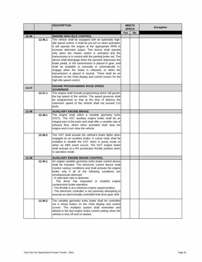
12.46 ENGINE HIGH IDLE CONTROL
12.46.1 The vehicle shall be equipped with an automatic high-
idle speed control. It shall be pre-set so when activated,
it will operate the engine at the appropriate RPM to
increase alternator output. This device shall operate
only when the master switch is activated and the
transmission is in neutral with the parking brake set. The
device shall disengage when the operator depresses the
brake pedal, or the transmission is placed in gear, and
shall be available to manually or automatically re-
engage when the brake is released, or when the
transmission is placed in neutral. There shall be an
indicator on the Vista display and control screen for the
high idle speed control.
12.47ENGINE PROGRAMMING ROAD SPEED
GOVERNOR
12.47.1 The engine shall include programming which will govern
the top speed of the vehicle. The speed governor shall
be programmed so that at the time of delivery the
maximum speed of the vehicle shall not exceed 112
km/h.
12.48 AUXILIARY ENGINE BRAKE
12.48.1 The engine shall utilize a variable geometry turbo
(VGT). The VGT auxiliary engine brake shall be an
integral part of the turbo and shall offer a variable rate of
exhaust flow, which when activated shall slow the
engine and in turn slow the vehicle.
12.48.2 The VGT shall actuate the vehicle‟s brake lights when
engaged as an auxiliary brake. A cutout relay shall be
installed to disable the VGT when in pump mode or
when an ABS event occurs. The VGT engine brake
shall activate at a 0% accelerator throttle position when
in operation mode.
12.49 AUXILIARY ENGINE BRAKE CONTROL
An engine variable geometry turbo brake control device
shall be included. The electronic control device shall
monitor various conditions and shall activate the engine
brake only if all of the following conditions are
simultaneously detected: - A valid gear ratio is detected.
- The driver has requested or enabled engine
compression brake operation.
- The throttle is at a minimum engine speed position.
- The electronic controller is not presently attempting to
execute an electronically controlled final drive gear shift.
12.49.2 The variable geometry turbo brake shall be controlled
via a virtual button on the Vista display and control
screen. The multiplex system shall remember and
default to the last engine brake control setting when the
vehicle is shut off and re-started.
12.49.1
Twin-City Fire Department Pumper Tender - 2013 Page 31
DESCRIPTIONException
Yes No
MEETS
SPECS
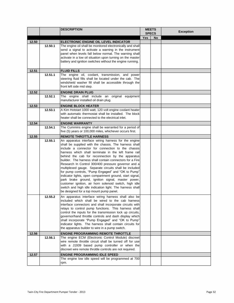
12.50 ELECTRONIC ENGINE OIL LEVEL INDICATOR
12.50.1 The engine oil shall be monitored electronically and shall
send a signal to activate a warning in the instrument
panel when levels fall below normal. The warning shall
activate in a low oil situation upon turning on the master
battery and ignition switches without the engine running.
12.51 FLUID FILLS
12.51.1 The engine oil, coolant, transmission, and power
steering fluid fills shall be located under the cab. The
windshield washer fill shall be accessible through the
front left side mid step.
12.52 ENGINE DRAIN PLUG
12.52.1 The engine shall include an original equipment
manufacturer installed oil drain plug.
12.53 ENGINE BLOCK HEATER
12.53.1 A Kim Hotstart 1000 watt, 120 volt engine coolant heater
with automatic thermostat shall be installed. The block
heater shall be connected to the electrical inlet.
12.54 ENGINE WARRANTY
12.54.1 The Cummins engine shall be warranted for a period of
five (5) years or 100,000 miles, whichever occurs first.
12.55 REMOTE THROTTLE HARNESS
12.55.1 An apparatus interface wiring harness for the engine
shall be supplied with the chassis. The harness shall
include a connector for connection to the chassis
harness which shall terminate in the left frame rail
behind the cab for reconnection by the apparatus
builder. The harness shall contain connectors for a Fire
Research In Control 300/400 pressure governor and a
multiplexed gauge. Separate circuits shall be included
for pump controls, “Pump Engaged” and “OK to Pump”
indicator lights, open compartment ground, start signal,
park brake ground, ignition signal, master power,
customer ignition, air horn solenoid switch, high idle
switch and high idle indication light. The harness shall
be designed for a top mount pump panel.
12.55.2 An apparatus interface wiring harness shall also be
included which shall be wired to the cab harness
interface connectors and shall incorporate circuits with
relays to control pump functions. This harness shall
control the inputs for the transmission lock up circuits,
governor/hand throttle controls and dash display which
shall incorporate “Pump Engaged” and “OK to Pump”
indicator lights. The harness shall contain circuits for
the apparatus builder to wire in a pump switch.
12.56 ENGINE PROGRAMMING REMOTE THROTTLE
12.56.1 The engine ECM (Electronic Control Module) discreet
wire remote throttle circuit shall be turned off for use
with a J1939 based pump controller or when the
discreet wire remote throttle controls are not required.
12.57 ENGINE PROGRAMMING IDLE SPEED
The engine low idle speed will be programmed at 700
rpm.
Twin-City Fire Department Pumper Tender - 2013 Page 32
DESCRIPTIONException
Yes No
MEETS
SPECS
12.58 ENGINE FAN DRIVE
12.58.1 The engine cooling system fan shall incorporate a
thermostatically controlled, Horton clutched type fan
drive.
12.58.2 When the clutched fan is disengaged it shall facilitate
improved vehicle performance, cab heating in cold
climates, and fuel economy. The fan clutch design shall
be fail safe so that if the clutch drive fails the fan shall
engage to prevent engine overheating due to the fan
clutch failure.
12.59 ENGINE COOLING SYSTEM
12.59.1 There shall be a heavy-duty aluminum cooling system
designed to meet the demands of the emergency
response industry. The cooling system shall have the
capacity to keep the engine properly cooled under all
conditions of road and pumping operations. The cooling
system shall be designed and tested to meet or exceed
the requirements specified by the engine and
transmission manufacturer and all EPA requirements.
The complete cooling system shall be mounted to
isolate the entire system from vibration or stress. The
individual cores of the cooling system shall be mounted
in a manner to allow expansion and contraction at
various rates without inducing stress into the adjoining
cores.
12.59.2 The cooling system shall utilize a charge air cooler to
radiator serial flow package that provides the maximum
cooling capacity for the specified engine as well as
serviceability. The main components shall include a
surge tank, an air to air charge air cooler bolted to the
front of the radiator, recirculation shields, a shroud, a
fan, and required tubing.
12.59.3 The radiator shall be a down-flow design constructed
with aluminum cores, plastic end tanks, and a steel
frame. The radiator shall be equipped with a drain cock
to drain the coolant for serviceability.
12.59.4 The cooling system shall include a one piece injection
molded polymer eleven (11) blade fan with a fiberglass
fan shroud.
12.59.5 The cooling system shall be equipped with a surge tank
that is capable of removing entrained air from the
system. The surge tank shall be equipped with a low
coolant probe and sight glass to monitor the level of the
coolant. The surge tank shall have a dual seal cap that
meets the engine manufacturer's pressure
requirements, and allows for expansion and recovery of
coolant into a separate integral expansion chamber.
12.59.6 All radiator tubes shall be formed from aluminized steel
tubing. Recirculation shields shall be installed where
required to prevent heated air from reentering the
cooling package and affecting performance.
12.59.7 The charge air cooler shall be a cross-flow design
constructed completely of aluminum with cast tanks. All
charge air cooler tubes shall be formed from aluminized
steel tubing and installed with silicone hump hoses and
stainless steel “constant torque” style clamps meeting
the engine manufacturer‟s requirements.
Twin-City Fire Department Pumper Tender - 2013 Page 33
DESCRIPTIONException
Yes No
MEETS
SPECS
12.60 ENGINE COOLING SYSTEM PROTECTION
12.60.1 The engine cooling system shall include a recirculation
shield designed to act as a light duty skid plate below
the radiator to provide additional protection for the
engine cooling system from light impacts, stones, and
road debris.
12.61 ENGINE COOLANT
12.61.1 The cooling package shall include Extended Life
Coolant (ELC). The use of ELC provides longer
intervals between coolant changes over standard
coolants providing improved performance. The coolant
shall contain a 55/45 mix of ethylene glycol and de-
ionized water to keep the coolant from freezing to a
temperature of -40 degrees Fahrenheit.
12.61.2 Proposals offering supplemental coolant additives
(SCA) shall not be considered, as this is part of the
extended life coolant makeup.
12.62 ENGINE COOLANT FILTER
12.62.1 An engine coolant filter with a shut-off valve for the inlet
and outlet shall be installed on the chassis. The location
of the filter shall allow for easy maintenance.
12.62.2 Proposals offering engines equipped with coolant filters
shall be supplied with standard non-chemical type
particulate filters.
12.63 ELECTRONIC COOLANT LEVEL INDICATOR
12.63.1 The instrument panel shall feature a low engine coolant
indicator light which shall be located in the center of the
instrument panel. An audible tone alarm shall also be
provided to warn of a low coolant incident.
12.64 ENGINE PUMP HEAT EXCHANGER
12.64.1 A single bundle type coolant to water heat exchanger
shall be installed between the engine and the radiator.
The heat exchanger shall be designed to prohibit water
from the pump from coming in contact with the engine
coolant. This shall allow the use of water from the
discharge side of the pump to assist in cooling the
engine.
12.65 COOLANT HOSES
12.65.1 The cooling system hoses shall be silicone heater hose
with rubber hoses in the cab interior. The radiator hoses
shall be formed silicone coolant hoses with formed
aluminized steel tubing. All heater hose, silicone coolant
hose, and tubing shall be secured with stainless steel
constant torque band clamps.
12.66 ENGINE COOLANT OVERFLOW BOTTLE
12.66.1 A remote engine coolant overflow bottle shall be
provided in the case of over filling the coolant system.
The overflow bottle shall capture the expansion fluid or
overfill rather than allow the fluid to drain on the ground.
The overflow bottle provided on the cooling system shall
only be a catch bottle and shall not return excess
coolant back into the surge tank.
Twin-City Fire Department Pumper Tender - 2013 Page 34
DESCRIPTIONException
Yes No
MEETS
SPECS
12.67 ENGINE AIR INTAKE
12.67.1 The engine air intake system shall include an ember
separator air intake filter which shall be located in the
front of the cab behind the right hand side fascia. This
filter shall protect the downstream air filter from embers
using a combination of unique flat and crimped metal
screens constructed into a corrosion resistant steel
frame. This multilayered screen shall be designed to
trap embers or allow them to burn out before passing
through the pack, while creating only minimal air flow
restriction through the system. Periodic cleaning or
replacement of the screen shall be all that is required
after installation.
12.67.2 The engine shall also include an air intake filter which
shall be bolted to the frame and located under the front
of the cab on the right hand side. The dry type filter shall
ensure dust and debris safely contained inside the
disposable housing, eliminating the chance of
contaminating the air intake system during air filter
service via a leak-tight seal.
12.67.3 The air flow distribution and dust loading shall be
uniform throughout the high-performance filter cone
pack, which shall result in pressure differential for
improved horsepower and fuel economy. The air intake
shall be mounted within easy access via a hinged panel
behind the right hand side headlight module. The air
intake system shall include a restriction indicator light in
the warning light cluster on the instrument panel, which
shall activate when the air cleaner element requires
replacement.
12.68 ENGINE EXHAUST SYSTEM
12.68.1 The exhaust system shall include a diesel particulate
filter (DPF), a diesel oxidation catalyst, and a selective
catalytic reduction (SCR) catalyst to meet current EPA
standards. The selective catalytic reduction catalyst
utilizes a diesel exhaust fluid solution consisting of urea
and purified water to convert NOx into nitrogen, water,
and trace amounts of carbon dioxide. The solution shall
be injected into the system through the decomposition
tube between the DPF and SCR.
12.68.2 The system shall utilize 0.07 inch thick stainless steel
exhaust tubing between the engine turbo and the DPF.
Zero leak clamps seal all system joints between the
turbo and DPF.
12.68.3 The DPF, the decomposition tube, and the SCR canister
through the end of the tailpipe shall be connected with
zero leak clamps. The discharge shall terminate
horizontally on the right side of the vehicle ahead of the
rear tires.
12.68.4 The exhaust system shall be mounted below the frame
in the outboard position with the SCR canister in line
rearward of the DPF. The exhaust system canisters
shall be mounted using T-shaped drop down angle
brackets.
Twin-City Fire Department Pumper Tender - 2013 Page 35
DESCRIPTIONException
Yes No
MEETS
SPECS
12.69 DIESEL EXHAUST FLUID (DEF) TANK
12.69.1 The exhaust system shall include a molded cross linked
polyethylene tank for Diesel Exhaust Fluid (DEF). The
tank shall have a capacity of six (6) usable gallons and
shall be mounted on the left hand side of the chassis
frame behind the batteries below the frame.
12.69.2 The DEF tank shall be designed with capacity for
expansion in case of fluid freezing. Engine coolant,
which shall be thermostatically controlled, shall be run
through lines in the tank to help prevent the DEF from
freezing and to provide a means of thawing the fluid if it
should become frozen.
12.69.3 The tank fill tube shall be routed under the rear of the
cab with the fill neck and splash guard accessible in the
top rear step.
12.70 ENGINE EXHAUST ACCESSORIES
12.70.1 An exhaust temperature mitigation device shall be
shipped loose for installation by the body manufacturer
on the vehicle. The temperature mitigation device shall
lower the temperature of the exhaust by combining
ambient air with the exhaust gasses at the exhaust
outlet.
12.71 ENGINE EXHAUST WRAP
12.71.1 The exhaust tubing between the engine turbo and the
diesel particulate filter (DPF) shall be wrapped with a
thermal cover in order to retain the necessary heat for
DPF regeneration. The exhaust wrap shall also help
protect surrounding components from radiant heat which
can be transferred from the exhaust.
12.72 TRANSMISSION
12.72.1 The drive train shall include an Allison Gen IV-E model
EVS 3000 torque converting, automatic transmission
which shall include electronic controls. The
transmission shall feature two (2) 10-bolt PTO pads
located on the converter housing.
12.72.2 The transmission shall include two (2) internal oil filters
and Castrol TranSynd™ synthetic TES 295
transmission fluid which shall be utilized in the
lubrication of the EVS transmission. An electronic oil
level sensor shall be included with the readout located in
the shift selector.
12.72.3 The Gen IV-E transmission shall include prognostic
diagnostic capabilities. These capabilities shall include
the monitoring of the fluid life, filter change indication,
and transmission clutch maintenance.
The transmission gear ratios shall be:
1st 3.49:1
2nd 1.86:1
3rd 1.41:1
4th 1.00:1
5th 0.75:1
6th 0.65:1 (if applicable)
Rev 5.03:1
12.72.4
Twin-City Fire Department Pumper Tender - 2013 Page 36
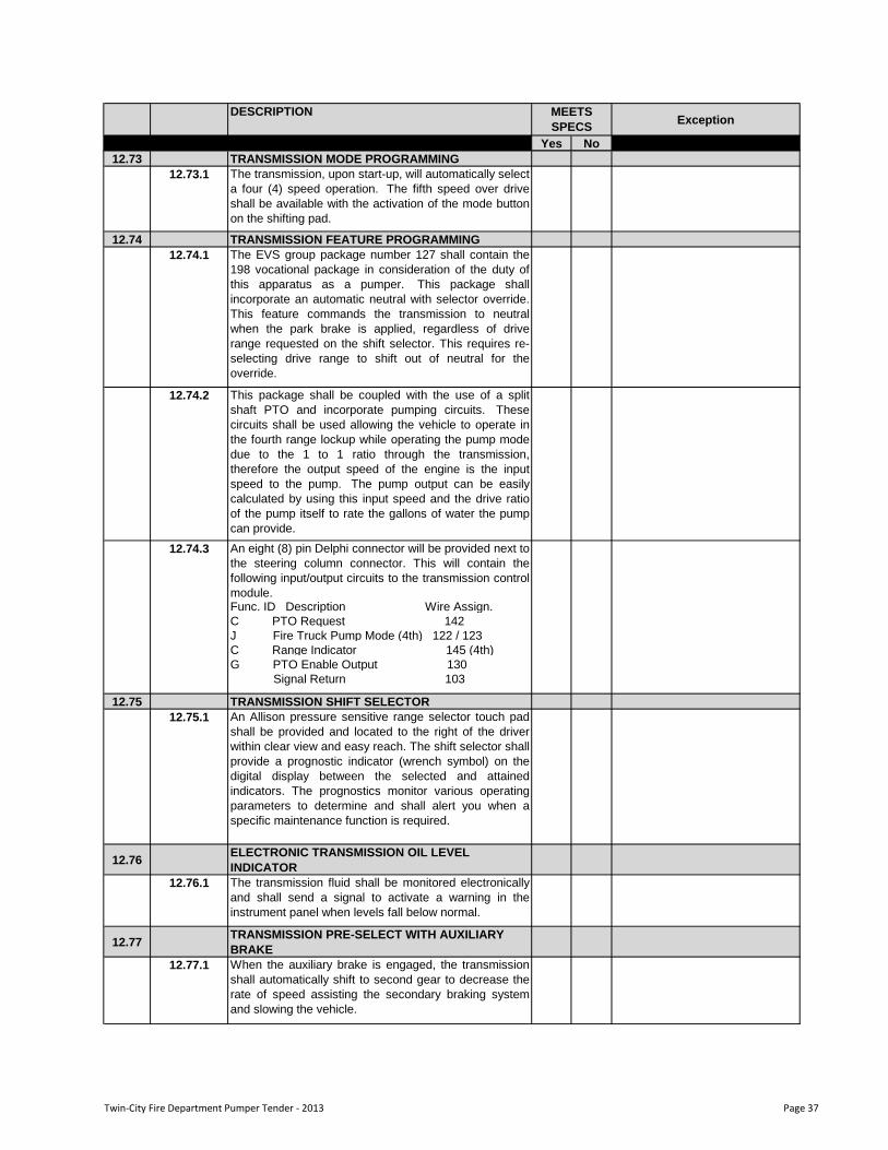
DESCRIPTIONException
Yes No
MEETS
SPECS
12.73 TRANSMISSION MODE PROGRAMMING
12.73.1 The transmission, upon start-up, will automatically select
a four (4) speed operation. The fifth speed over drive
shall be available with the activation of the mode button
on the shifting pad.
12.74 TRANSMISSION FEATURE PROGRAMMING
12.74.1 The EVS group package number 127 shall contain the
198 vocational package in consideration of the duty of
this apparatus as a pumper. This package shall
incorporate an automatic neutral with selector override.
This feature commands the transmission to neutral
when the park brake is applied, regardless of drive
range requested on the shift selector. This requires re-
selecting drive range to shift out of neutral for the
override.
12.74.2 This package shall be coupled with the use of a split
shaft PTO and incorporate pumping circuits. These
circuits shall be used allowing the vehicle to operate in
the fourth range lockup while operating the pump mode
due to the 1 to 1 ratio through the transmission,
therefore the output speed of the engine is the input
speed to the pump. The pump output can be easily
calculated by using this input speed and the drive ratio
of the pump itself to rate the gallons of water the pump
can provide.
An eight (8) pin Delphi connector will be provided next to
the steering column connector. This will contain the
following input/output circuits to the transmission control
module.Func. ID Description Wire Assign.
C PTO Request 142
J Fire Truck Pump Mode (4th) 122 / 123
C Range Indicator 145 (4th)
G PTO Enable Output 130
Signal Return 103
12.75 TRANSMISSION SHIFT SELECTOR
12.75.1 An Allison pressure sensitive range selector touch pad
shall be provided and located to the right of the driver
within clear view and easy reach. The shift selector shall
provide a prognostic indicator (wrench symbol) on the
digital display between the selected and attained
indicators. The prognostics monitor various operating
parameters to determine and shall alert you when a
specific maintenance function is required.
12.76ELECTRONIC TRANSMISSION OIL LEVEL
INDICATOR
12.76.1 The transmission fluid shall be monitored electronically
and shall send a signal to activate a warning in the
instrument panel when levels fall below normal.
12.77TRANSMISSION PRE-SELECT WITH AUXILIARY
BRAKE
12.77.1 When the auxiliary brake is engaged, the transmission
shall automatically shift to second gear to decrease the
rate of speed assisting the secondary braking system
and slowing the vehicle.
12.74.3
Twin-City Fire Department Pumper Tender - 2013 Page 37
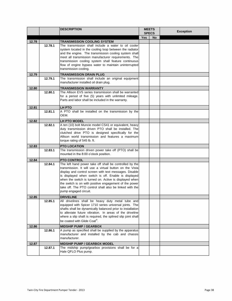
DESCRIPTIONException
Yes No
MEETS
SPECS
12.78 TRANSMISSION COOLING SYSTEM
12.78.1 The transmission shall include a water to oil cooler
system located in the cooling loop between the radiator
and the engine. The transmission cooling system shall
meet all transmission manufacturer requirements. The
transmission cooling system shall feature continuous
flow of engine bypass water to maintain uninterrupted
transmission cooling.
12.79 TRANSMISSION DRAIN PLUG
12.79.1 The transmission shall include an original equipment
manufacturer installed oil drain plug.
12.80 TRANSMISSION WARRANTY
12.80.1 The Allison EVS series transmission shall be warranted
for a period of five (5) years with unlimited mileage.
Parts and labor shall be included in the warranty.
12.81 LH PTO
12.81.1 A PTO shall be installed on the transmission by the
OEM.
12.82 LH PTO MODEL
12.82.1 A ten (10) bolt Muncie model CS41 or equivalent, heavy
duty transmission driven PTO shall be installed. The
clutched drive PTO is designed specifically for the
Allison world transmission and features a maximum
torque rating of 545 lb. ft.
12.83 PTO LOCATION
12.83.1 The transmission driven power take off (PTO) shall be
mounted in the 8:00 o‟clock position.
12.84 PTO CONTROL
12.84.1 The left hand power take off shall be controlled by the
transmission. It will use a virtual button on the Vista
display and control screen with text messages. Disable
is displayed when switch is off. Enable is displayed
when the switch is turned on. Active is displayed when
the switch is on with positive engagement of the power
take off. The PTO control shall also be linked with the
pump engaged circuit.
12.85 DRIVELINE
12.85.1 All drivelines shall be heavy duty metal tube and
equipped with Spicer 1710 series universal joints. The
shafts shall be dynamically balanced prior to installation
to alleviate future vibration. In areas of the driveline
where a slip shaft is required, the splined slip joint shall
be coated with Glide Coat®.
12.86 MIDSHIP PUMP / GEARBOX
12.86.1 A pump as specified shall be supplied by the apparatus
manufacturer and installed by the cab and chassis
manufacturer.
12.87 MIDSHIP PUMP / GEARBOX MODEL
12.87.1 The midship pump/gearbox provisions shall be for a
Hale QFLO Plus pump.
Twin-City Fire Department Pumper Tender - 2013 Page 38
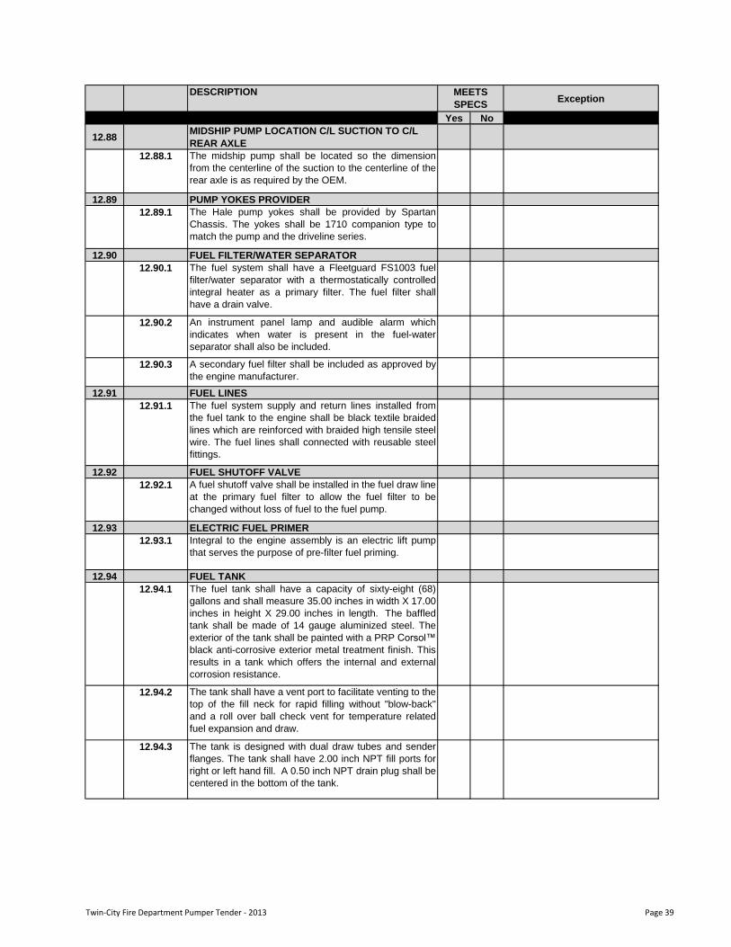
DESCRIPTIONException
Yes No
MEETS
SPECS
12.88MIDSHIP PUMP LOCATION C/L SUCTION TO C/L
REAR AXLE
12.88.1 The midship pump shall be located so the dimension
from the centerline of the suction to the centerline of the
rear axle is as required by the OEM.
12.89 PUMP YOKES PROVIDER
12.89.1 The Hale pump yokes shall be provided by Spartan
Chassis. The yokes shall be 1710 companion type to
match the pump and the driveline series.
12.90 FUEL FILTER/WATER SEPARATOR
12.90.1 The fuel system shall have a Fleetguard FS1003 fuel
filter/water separator with a thermostatically controlled
integral heater as a primary filter. The fuel filter shall
have a drain valve.
12.90.2 An instrument panel lamp and audible alarm which
indicates when water is present in the fuel-water
separator shall also be included.
12.90.3 A secondary fuel filter shall be included as approved by
the engine manufacturer.
12.91 FUEL LINES
12.91.1 The fuel system supply and return lines installed from
the fuel tank to the engine shall be black textile braided
lines which are reinforced with braided high tensile steel
wire. The fuel lines shall connected with reusable steel
fittings.
12.92 FUEL SHUTOFF VALVE
12.92.1 A fuel shutoff valve shall be installed in the fuel draw line
at the primary fuel filter to allow the fuel filter to be
changed without loss of fuel to the fuel pump.
12.93 ELECTRIC FUEL PRIMER
12.93.1 Integral to the engine assembly is an electric lift pump
that serves the purpose of pre-filter fuel priming.
12.94 FUEL TANK
12.94.1 The fuel tank shall have a capacity of sixty-eight (68)
gallons and shall measure 35.00 inches in width X 17.00
inches in height X 29.00 inches in length. The baffled
tank shall be made of 14 gauge aluminized steel. The
exterior of the tank shall be painted with a PRP Corsol™
black anti-corrosive exterior metal treatment finish. This
results in a tank which offers the internal and external
corrosion resistance.
12.94.2 The tank shall have a vent port to facilitate venting to the
top of the fill neck for rapid filling without "blow-back"
and a roll over ball check vent for temperature related
fuel expansion and draw.
12.94.3 The tank is designed with dual draw tubes and sender
flanges. The tank shall have 2.00 inch NPT fill ports for
right or left hand fill. A 0.50 inch NPT drain plug shall be
centered in the bottom of the tank.
Twin-City Fire Department Pumper Tender - 2013 Page 39
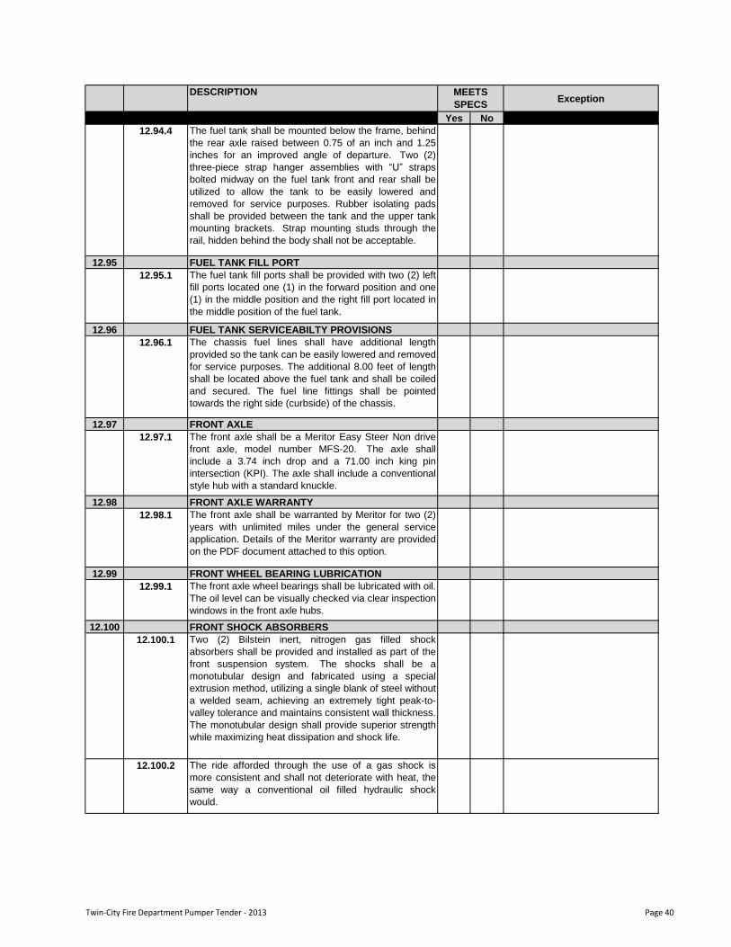
DESCRIPTIONException
Yes No
MEETS
SPECS
12.94.4 The fuel tank shall be mounted below the frame, behind
the rear axle raised between 0.75 of an inch and 1.25
inches for an improved angle of departure. Two (2)
three-piece strap hanger assemblies with “U” straps
bolted midway on the fuel tank front and rear shall be
utilized to allow the tank to be easily lowered and
removed for service purposes. Rubber isolating pads
shall be provided between the tank and the upper tank
mounting brackets. Strap mounting studs through the
rail, hidden behind the body shall not be acceptable.
12.95 FUEL TANK FILL PORT
12.95.1 The fuel tank fill ports shall be provided with two (2) left
fill ports located one (1) in the forward position and one
(1) in the middle position and the right fill port located in
the middle position of the fuel tank.
12.96 FUEL TANK SERVICEABILTY PROVISIONS
12.96.1 The chassis fuel lines shall have additional length
provided so the tank can be easily lowered and removed
for service purposes. The additional 8.00 feet of length
shall be located above the fuel tank and shall be coiled
and secured. The fuel line fittings shall be pointed
towards the right side (curbside) of the chassis.
12.97 FRONT AXLE
12.97.1 The front axle shall be a Meritor Easy Steer Non drive
front axle, model number MFS-20. The axle shall
include a 3.74 inch drop and a 71.00 inch king pin
intersection (KPI). The axle shall include a conventional
style hub with a standard knuckle.
12.98 FRONT AXLE WARRANTY
12.98.1 The front axle shall be warranted by Meritor for two (2)
years with unlimited miles under the general service
application. Details of the Meritor warranty are provided
on the PDF document attached to this option.
12.99 FRONT WHEEL BEARING LUBRICATION
12.99.1 The front axle wheel bearings shall be lubricated with oil.
The oil level can be visually checked via clear inspection
windows in the front axle hubs.
12.100 FRONT SHOCK ABSORBERS
12.100.1 Two (2) Bilstein inert, nitrogen gas filled shock
absorbers shall be provided and installed as part of the
front suspension system. The shocks shall be a
monotubular design and fabricated using a special
extrusion method, utilizing a single blank of steel without
a welded seam, achieving an extremely tight peak-to-
valley tolerance and maintains consistent wall thickness.
The monotubular design shall provide superior strength
while maximizing heat dissipation and shock life.
12.100.2 The ride afforded through the use of a gas shock is
more consistent and shall not deteriorate with heat, the
same way a conventional oil filled hydraulic shock
would.
Twin-City Fire Department Pumper Tender - 2013 Page 40
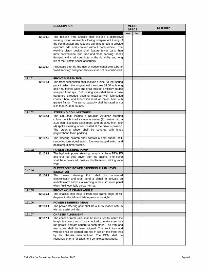
DESCRIPTIONException
Yes No
MEETS
SPECS
12.100.3 The Bilstein front shocks shall include a digressive
working piston assembly allowing independent tuning of
the compression and rebound damping forces to provide
optimum ride and comfort without compromise. The
working piston design shall feature fewer parts than
most conventional twin tube and “road sensing” shock
designs and shall contribute to the durability and long
life of the Bilstein shock absorbers.
12.100.4 Proposals offering the use of conventional twin tube or
“road sensing” designed shocks shall not be considered.
12.101 FRONT SUSPENSION
12.101.1 The front suspension shall include a nine (9) leaf spring
pack in which the longest leaf measures 54.00 inch long
and 4.00 inches wide and shall include a military double
wrapped front eye. Both spring eyes shall have a case
hardened threaded bushing installed with lubrication
counter bore and lubrication land off cross bore with
grease fitting. The spring capacity shall be rated at not
less than 20,000 pounds.
12.102 STEERING COLUMN/ WHEEL
12.102.1 The cab shall include a Douglas Autotech steering
column which shall include a seven (7) position tilt, a
2.25 inch telescopic adjustment, and an 18.00 inch, four
(4) spoke steering wheel located at the driver‟s position.
The steering wheel shall be covered with black
polyurethane foam padding.
12.102.2 The steering column shall contain a horn button, self-
canceling turn signal switch, four-way hazard switch and
headlamp dimmer switch.
12.103 POWER STEERING PUMP
12.103.1 The hydraulic power steering pump shall be a TRW PS
and shall be gear driven from the engine. The pump
shall be a balanced, positive displacement, sliding vane
type.
12.104ELECTRONIC POWER STEERING FLUID LEVEL
INDICATOR
12.104.1 The power steering fluid shall be monitored
electronically and shall send a signal to activate an
audible alarm and visual warning in the instrument panel
when fluid level falls below normal.
12.105 FRONT AXLE CRAMP ANGLE
12.105.1 The chassis shall have a front axle cramp angle of 48-
degrees to the left and 44-degrees to the right.
12.106 POWER STEERING GEAR
12.106.1 The power steering gear shall be a TRW model TAS 85
with an assist cylinder.
12.107 CHASSIS ALIGNMENT
12.107.1 The chassis frame rails shall be measured to insure the
length is correct and cross checked to make sure they
run parallel and are square to each other. The front and
rear axles shall be laser aligned. The front tires and
wheels shall be aligned and toe-in set on the front tires
by the chassis manufacturer. The OEM shall be
responsible for a full alignment completed post build.
Twin-City Fire Department Pumper Tender - 2013 Page 41
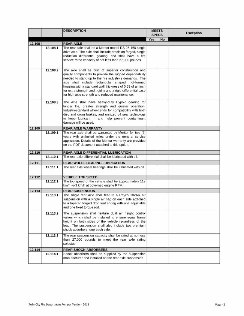
DESCRIPTIONException
Yes No
MEETS
SPECS
12.108 REAR AXLE
12.108.1 The rear axle shall be a Meritor model RS-25-160 single
drive axle. The axle shall include precision forged, single
reduction differential gearing, and shall have a fire
service rated capacity of not less than 27,000 pounds.
12.108.2 The axle shall be built of superior construction and
quality components to provide the rugged dependability
needed to stand up to the fire industry‟s demands. The
axle shall include rectangular shaped, hot-formed
housing with a standard wall thickness of 0.63 of an inch
for extra strength and rigidity and a rigid differential case
for high axle strength and reduced maintenance.
12.108.3 The axle shall have heavy-duty Hypoid gearing for
longer life, greater strength and quieter operation.
Industry-standard wheel ends for compatibility with both
disc and drum brakes, and unitized oil seal technology
to keep lubricant in and help prevent contaminant
damage will be used.
12.109 REAR AXLE WARRANTY
12.109.1 The rear axle shall be warranted by Meritor for two (2)
years with unlimited miles under the general service
application. Details of the Meritor warranty are provided
on the PDF document attached to this option.
12.110 REAR AXLE DIFFERENTIAL LUBRICATION
12.110.1 The rear axle differential shall be lubricated with oil.
12.111 REAR WHEEL BEARING LUBRICATION
12.111.1 The rear axle wheel bearings shall be lubricated with oil.
12.112 VEHICLE TOP SPEED
12.112.1 The top speed of the vehicle shall be approximately 112
km/h +/-3 km/h at governed engine RPM.
12.113 REAR SUSPENSION
12.113.1 The single rear axle shall feature a Reyco 102AR air
suspension with a single air bag on each side attached
to a tapered forged drop leaf spring with one adjustable
and one fixed torque rod.
12.113.2 The suspension shall feature dual air height control
valves which shall be installed to ensure equal frame
height on both sides of the vehicle regardless of the
load. The suspension shall also include two premium
shock absorbers, one each side.
12.113.3 The rear suspension capacity shall be rated at not less
than 27,000 pounds to meet the rear axle rating
selected.
12.114 REAR SHOCK ABSORBERS
12.114.1 Shock absorbers shall be supplied by the suspension
manufacturer and installed on the rear axle suspension.
Twin-City Fire Department Pumper Tender - 2013 Page 42
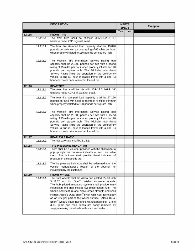
DESCRIPTIONException
Yes No
MEETS
SPECS
12.115 FRONT TIRE
12.115.1 The front tires shall be Michelin 385/65R22.5 “L”
tubeless radial XFE regional tread.
12.115.2 The front tire stamped load capacity shall be 19,840
pounds per axle with a speed rating of 65 miles per hour
when properly inflated to 130 pounds per square inch.
12.115.3 The Michelin Tire Intermittent Service Rating load
capacity shall be 20,000 pounds per axle with a speed
rating of 75 miles per hour when properly inflated to 120
pounds per square inch. The Michelin Intermittent
Service Rating limits the operation of the emergency
vehicle to one (1) hour of loaded travel with a one (1)
hour cool down prior to another loaded run.
12.116 REAR TIRE
12.116.1 The rear tires shall be Michelin 12R-22.5 16PR "H"
tubeless radial XDN2 all-weather tread.
12.116.2 The rear tire stamped load capacity shall be 27,120
pounds per axle with a speed rating of 75 miles per hour
when properly inflated to 120 pounds per square inch.
12.116.3 The Michelin Tire Intermittent Service Rating load
capacity shall be 28,880 pounds per axle with a speed
rating of 75 miles per hour when properly inflated to 120
pounds per square inch. The Michelin Intermittent
Service Rating limits the operation of the emergency
vehicle to one (1) hour of loaded travel with a one (1)
hour cool down prior to another loaded run.
12.117 REAR AXLE RATIO
12.117.1 The rear axle ratio shall be 5.13:1.
12.118 TIRE PRESSURE INDICATOR
12.118.1 There shall be a voucher provided with the chassis for a
pop up style tire pressure indicator at each tire valve
stem. The indicator shall provide visual indication of
pressure in the specific tire.
12.118.2 The tire pressure indicators shall be redeemed upon the
vehicle manufacturer‟s receipt of the voucher for
installation by the customer.
12.119 FRONT WHEEL
12.119.1 The front wheels shall be Alcoa hub piloted, 22.50 inch
X 12.25 inch LvL One™ polished aluminum wheels.
The hub piloted mounting system shall provide easy
installation and shall include two-piece flange nuts. The
wheels shall feature one-piece forged strength and shall
include Alcoa‟s Dura-Bright®
finish with XBR technology
as an integral part of the wheel surface. Alcoa Dura-
Bright®
wheels keep their shine without polishing. Brake
dust, grime and road debris are easily removed by
simply cleaning the wheels with soap and water.
Twin-City Fire Department Pumper Tender - 2013 Page 43
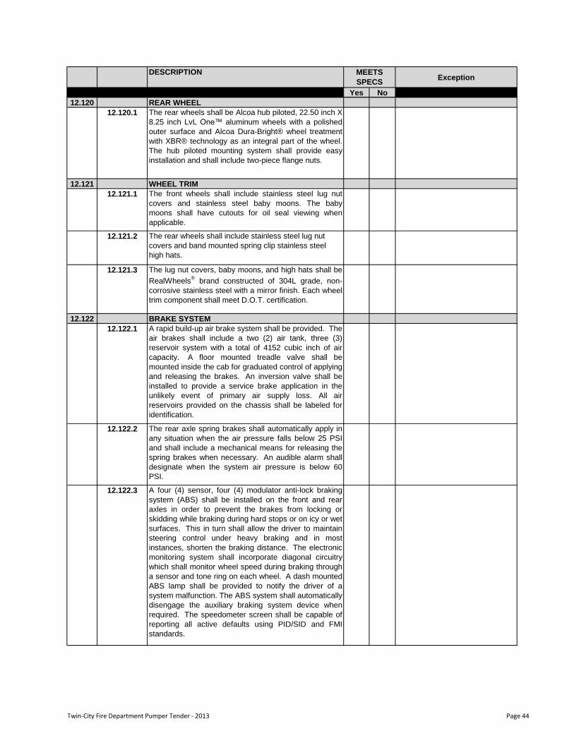
DESCRIPTIONException
Yes No
MEETS
SPECS
12.120 REAR WHEEL
12.120.1 The rear wheels shall be Alcoa hub piloted, 22.50 inch X
8.25 inch LvL One™ aluminum wheels with a polished
outer surface and Alcoa Dura-Bright® wheel treatment
with XBR® technology as an integral part of the wheel.
The hub piloted mounting system shall provide easy
installation and shall include two-piece flange nuts.
12.121 WHEEL TRIM
12.121.1 The front wheels shall include stainless steel lug nut
covers and stainless steel baby moons. The baby
moons shall have cutouts for oil seal viewing when
applicable.
12.121.2 The rear wheels shall include stainless steel lug nut
covers and band mounted spring clip stainless steel
high hats.
12.121.3 The lug nut covers, baby moons, and high hats shall be
RealWheels®
brand constructed of 304L grade, non-
corrosive stainless steel with a mirror finish. Each wheel
trim component shall meet D.O.T. certification.
12.122 BRAKE SYSTEM
12.122.1 A rapid build-up air brake system shall be provided. The
air brakes shall include a two (2) air tank, three (3)
reservoir system with a total of 4152 cubic inch of air
capacity. A floor mounted treadle valve shall be
mounted inside the cab for graduated control of applying
and releasing the brakes. An inversion valve shall be
installed to provide a service brake application in the
unlikely event of primary air supply loss. All air
reservoirs provided on the chassis shall be labeled for
identification.
12.122.2 The rear axle spring brakes shall automatically apply in
any situation when the air pressure falls below 25 PSI
and shall include a mechanical means for releasing the
spring brakes when necessary. An audible alarm shall
designate when the system air pressure is below 60
PSI.
12.122.3 A four (4) sensor, four (4) modulator anti-lock braking
system (ABS) shall be installed on the front and rear
axles in order to prevent the brakes from locking or
skidding while braking during hard stops or on icy or wet
surfaces. This in turn shall allow the driver to maintain
steering control under heavy braking and in most
instances, shorten the braking distance. The electronic
monitoring system shall incorporate diagonal circuitry
which shall monitor wheel speed during braking through
a sensor and tone ring on each wheel. A dash mounted
ABS lamp shall be provided to notify the driver of a
system malfunction. The ABS system shall automatically
disengage the auxiliary braking system device when
required. The speedometer screen shall be capable of
reporting all active defaults using PID/SID and FMI
standards.
Twin-City Fire Department Pumper Tender - 2013 Page 44
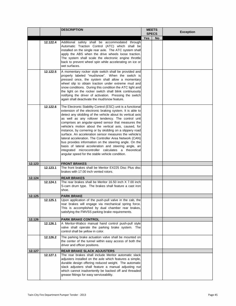
DESCRIPTIONException
Yes No
MEETS
SPECS
12.122.4 Additional safety shall be accommodated through
Automatic Traction Control (ATC) which shall be
installed on the single rear axle. The ATC system shall
apply the ABS when the drive wheels loose traction.
The system shall scale the electronic engine throttle
back to prevent wheel spin while accelerating on ice or
wet surfaces.
12.122.5 A momentary rocker style switch shall be provided and
properly labeled “mud/snow”. When the switch is
pressed once, the system shall allow a momentary
wheel slip to obtain traction under extreme mud and
snow conditions. During this condition the ATC light and
the light on the rocker switch shall blink continuously
notifying the driver of activation. Pressing the switch
again shall deactivate the mud/snow feature.
12.122.6 The Electronic Stability Control (ESC) unit is a functional
extension of the electronic braking system. It is able to
detect any skidding of the vehicle about its vertical axis
as well as any rollover tendency. The control unit
comprises an angular-speed sensor that measures the
vehicle‟s motion about the vertical axis, caused, for
instance, by cornering or by skidding on a slippery road
surface. An acceleration sensor measures the vehicle‟s
lateral acceleration. The Controller Area Network (CAN)
bus provides information on the steering angle. On the
basis of lateral acceleration and steering angle, an
integrated microcontroller calculates a theoretical
angular speed for the stable vehicle condition.
12.123 FRONT BRAKES
12.123.1 The front brakes shall be Meritor EX225 Disc Plus disc
brakes with 17.00 inch vented rotors.
12.124 REAR BRAKES
12.124.1 The rear brakes shall be Meritor 16.50 inch X 7.00 inch
S-cam drum type. The brakes shall feature a cast iron
shoe.
12.125 PARK BRAKE
12.125.1 Upon application of the push-pull valve in the cab, the
rear brakes will engage via mechanical spring force.
This is accomplished by dual chamber rear brakes,
satisfying the FMVSS parking brake requirements.
12.126 PARK BRAKE CONTROL
12.126.1 A Meritor-Wabco manual hand control push-pull style
valve shall operate the parking brake system. The
control shall be yellow in color.
12.126.2 The parking brake actuation valve shall be mounted on
the center of the tunnel within easy access of both the
driver and officer positions.
12.127 REAR BRAKE SLACK ADJUSTERS
12.127.1 The rear brakes shall include Meritor automatic slack
adjusters installed on the axle which features a simple,
durable design offering reduced weight. The automatic
slack adjusters shall feature a manual adjusting nut
which cannot inadvertently be backed off and threaded
grease fittings for easy serviceability.
Twin-City Fire Department Pumper Tender - 2013 Page 45
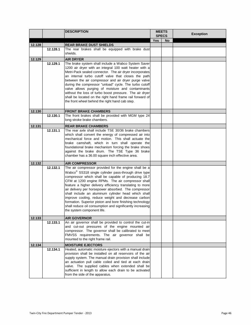
DESCRIPTIONException
Yes No
MEETS
SPECS
12.128 REAR BRAKE DUST SHIELDS
12.128.1 The rear brakes shall be equipped with brake dust
shields.
12.129 AIR DRYER
12.129.1 The brake system shall include a Wabco System Saver
1200 air dryer with an integral 100 watt heater with a
Metri-Pack sealed connector. The air dryer incorporates
an internal turbo cutoff valve that closes the path
between the air compressor and air dryer purge valve
during the compressor "unload" cycle. The turbo cutoff
valve allows purging of moisture and contaminants
without the loss of turbo boost pressure. The air dryer
shall be located on the right hand frame rail forward of
the front wheel behind the right hand cab step.
12.130 FRONT BRAKE CHAMBERS
12.130.1 The front brakes shall be provided with MGM type 24
long stroke brake chambers.
12.131 REAR BRAKE CHAMBERS
12.131.1 The rear axle shall include TSE 30/36 brake chambers
which shall convert the energy of compressed air into
mechanical force and motion. This shall actuate the
brake camshaft, which in turn shall operate the
foundational brake mechanism forcing the brake shoes
against the brake drum. The TSE Type 36 brake
chamber has a 36.00 square inch effective area.
12.132 AIR COMPRESSOR
12.132.1 The air compressor provided for the engine shall be a
Wabco®
SS318 single cylinder pass-through drive type
compressor which shall be capable of producing 18.7
CFM at 1200 engine RPMs. The air compressor shall
feature a higher delivery efficiency translating to more
air delivery per horsepower absorbed. The compressor
shall include an aluminum cylinder head which shall
improve cooling, reduce weight and decrease carbon
formation. Superior piston and bore finishing technology
shall reduce oil consumption and significantly increasing
the system component life.
12.133 AIR GOVERNOR
12.133.1 An air governor shall be provided to control the cut-in
and cut-out pressures of the engine mounted air
compressor. The governor shall be calibrated to meet
FMVSS requirements. The air governor shall be
mounted to the right frame rail.
12.134 MOISTURE EJECTORS
12.134.1 Heated, automatic moisture ejectors with a manual drain
provision shall be installed on all reservoirs of the air
supply system. The manual drain provision shall include
an actuation pull cable coiled and tied at each drain
valve. The supplied cables when extended shall be
sufficient in length to allow each drain to be activated
from the side of the apparatus.
Twin-City Fire Department Pumper Tender - 2013 Page 46
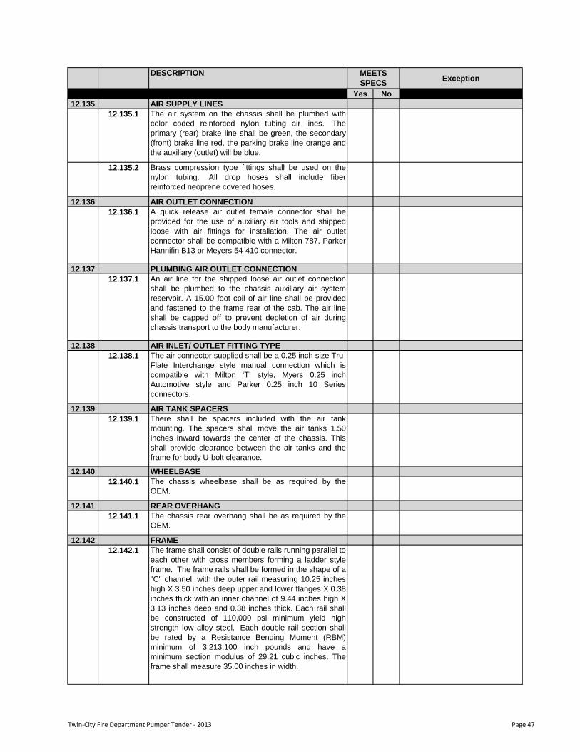
DESCRIPTIONException
Yes No
MEETS
SPECS
12.135 AIR SUPPLY LINES
12.135.1 The air system on the chassis shall be plumbed with
color coded reinforced nylon tubing air lines. The
primary (rear) brake line shall be green, the secondary
(front) brake line red, the parking brake line orange and
the auxiliary (outlet) will be blue.
12.135.2 Brass compression type fittings shall be used on the
nylon tubing. All drop hoses shall include fiber
reinforced neoprene covered hoses.
12.136 AIR OUTLET CONNECTION
12.136.1 A quick release air outlet female connector shall be
provided for the use of auxiliary air tools and shipped
loose with air fittings for installation. The air outlet
connector shall be compatible with a Milton 787, Parker
Hannifin B13 or Meyers 54-410 connector.
12.137 PLUMBING AIR OUTLET CONNECTION
12.137.1 An air line for the shipped loose air outlet connection
shall be plumbed to the chassis auxiliary air system
reservoir. A 15.00 foot coil of air line shall be provided
and fastened to the frame rear of the cab. The air line
shall be capped off to prevent depletion of air during
chassis transport to the body manufacturer.
12.138 AIR INLET/ OUTLET FITTING TYPE
12.138.1 The air connector supplied shall be a 0.25 inch size Tru-
Flate Interchange style manual connection which is
compatible with Milton „T‟ style, Myers 0.25 inch
Automotive style and Parker 0.25 inch 10 Series
connectors.
12.139 AIR TANK SPACERS
12.139.1 There shall be spacers included with the air tank
mounting. The spacers shall move the air tanks 1.50
inches inward towards the center of the chassis. This
shall provide clearance between the air tanks and the
frame for body U-bolt clearance.
12.140 WHEELBASE
12.140.1 The chassis wheelbase shall be as required by the
OEM.
12.141 REAR OVERHANG
12.141.1 The chassis rear overhang shall be as required by the
OEM.
12.142 FRAME
12.142.1 The frame shall consist of double rails running parallel to
each other with cross members forming a ladder style
frame. The frame rails shall be formed in the shape of a
"C" channel, with the outer rail measuring 10.25 inches
high X 3.50 inches deep upper and lower flanges X 0.38
inches thick with an inner channel of 9.44 inches high X
3.13 inches deep and 0.38 inches thick. Each rail shall
be constructed of 110,000 psi minimum yield high
strength low alloy steel. Each double rail section shall
be rated by a Resistance Bending Moment (RBM)
minimum of 3,213,100 inch pounds and have a
minimum section modulus of 29.21 cubic inches. The
frame shall measure 35.00 inches in width.
Twin-City Fire Department Pumper Tender - 2013 Page 47
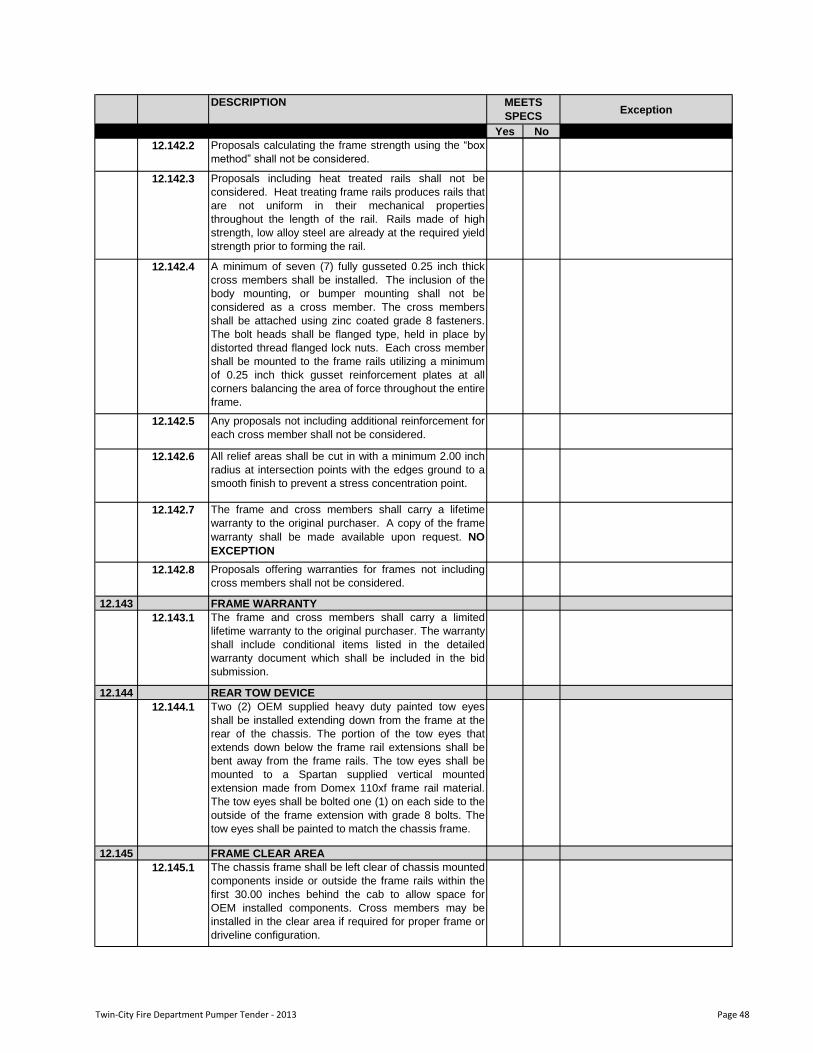
DESCRIPTIONException
Yes No
MEETS
SPECS
12.142.2 Proposals calculating the frame strength using the “box
method” shall not be considered.
12.142.3 Proposals including heat treated rails shall not be
considered. Heat treating frame rails produces rails that
are not uniform in their mechanical properties
throughout the length of the rail. Rails made of high
strength, low alloy steel are already at the required yield
strength prior to forming the rail.
12.142.4 A minimum of seven (7) fully gusseted 0.25 inch thick
cross members shall be installed. The inclusion of the
body mounting, or bumper mounting shall not be
considered as a cross member. The cross members
shall be attached using zinc coated grade 8 fasteners.
The bolt heads shall be flanged type, held in place by
distorted thread flanged lock nuts. Each cross member
shall be mounted to the frame rails utilizing a minimum
of 0.25 inch thick gusset reinforcement plates at all
corners balancing the area of force throughout the entire
frame.
12.142.5 Any proposals not including additional reinforcement for
each cross member shall not be considered.
12.142.6 All relief areas shall be cut in with a minimum 2.00 inch
radius at intersection points with the edges ground to a
smooth finish to prevent a stress concentration point.
12.142.7 The frame and cross members shall carry a lifetime
warranty to the original purchaser. A copy of the frame
warranty shall be made available upon request. NO
EXCEPTION
12.142.8 Proposals offering warranties for frames not including
cross members shall not be considered.
12.143 FRAME WARRANTY
12.143.1 The frame and cross members shall carry a limited
lifetime warranty to the original purchaser. The warranty
shall include conditional items listed in the detailed
warranty document which shall be included in the bid
submission.
12.144 REAR TOW DEVICE
12.144.1 Two (2) OEM supplied heavy duty painted tow eyes
shall be installed extending down from the frame at the
rear of the chassis. The portion of the tow eyes that
extends down below the frame rail extensions shall be
bent away from the frame rails. The tow eyes shall be
mounted to a Spartan supplied vertical mounted
extension made from Domex 110xf frame rail material.
The tow eyes shall be bolted one (1) on each side to the
outside of the frame extension with grade 8 bolts. The
tow eyes shall be painted to match the chassis frame.
12.145 FRAME CLEAR AREA
12.145.1 The chassis frame shall be left clear of chassis mounted
components inside or outside the frame rails within the
first 30.00 inches behind the cab to allow space for
OEM installed components. Cross members may be
installed in the clear area if required for proper frame or
driveline configuration.
Twin-City Fire Department Pumper Tender - 2013 Page 48
DESCRIPTIONException
Yes No
MEETS
SPECS
12.146 FRAME PAINT
12.146.1 The frame shall be powder coated black prior to any
attachment of components.
12.146.2 All powder coatings, primers and paint shall be
compatible with all metals, pretreatments and primers
used. The cross hatch adhesion test per ASTM D3359
shall not have a fail of more than ten (10) squares. The
pencil hardness test per ASTM D3363 shall have a final
post-curved pencil hardness of H-2H. The direct impact
resistance test per ASTM D2794 shall have an impact
resistance of 120.00 inches per pound at 2 mils.
12.146.3 Any proposals offering painted frame with variations
from the above process shall not be accepted. The film
thickness of vendor supplied parts shall also be
sufficient to meet the performance standards as stated
above.
12.147 FRONT BUMPER
12.147.1 A one piece, two (2) rib wrap-around style, polished
stainless steel front bumper shall be provided. The
material shall be 10 gauge 304 stainless steel, 12" high
and 104.50 inches wide.
12.148 FRONT BUMPER EXTENSION LENGTH
12.148.1 The front bumper shall be extended approximately 18.00
inches ahead of the cab.
12.149 FRONT BUMPER EXTENSION FRAME WIDTH
12.149.1 The front bumper extension frame shall feature an
overall width of 48.25 inches.
12.150 FRONT BUMPER APRON
12.150.1 The 18.00 inch extended front bumper shall include an
apron constructed of 0.19 inch thick embossed
aluminum tread plate.
12.150.2 The apron shall be installed between the bumper and
the front face of the cab affixed using stainless steel
bolts attaching the apron to the top bumper flange.
12.151 FRONT BUMPER COMPARTMENT CENTER
12.151.1 The front bumper shall include a compartment in the
bumper apron located in the center between the frame
rails which may be used as a hose well. The
compartment shall be constructed of 0.13 inch 5052-
H32 grade aluminum and shall include drain holes in the
bottom corners to allow excess moisture to escape. The
compartment shall include a cover constructed of 0.19
inch thick bright embossed aluminum tread plate.
12.152FRONT BUMPER COMPARTMENT COVER
HARDWARE
12.152.1 The front bumper compartment cover shall include gas
cylinder stays which shall hold the cover open. The
cover shall held in the closed position via a D-ring style
latch.
12.153 AIR HORN
12.153.1 The chassis shall include two (2) Grover brand Stutter
Tone air horns which shall measure 24.50 inches long
with a 6.00 inch round flare. The air horns shall be
trumpet style with a chrome finish.
Twin-City Fire Department Pumper Tender - 2013 Page 49
DESCRIPTIONException
Yes No
MEETS
SPECS
12.154 AIR HORN LOCATION
12.154.1 The two (2) air horns shall be located on the front
bumper face outboard of the frame rails with one (1) on
the right side and one (1) on the left side in the inboard
positions.
12.155 AIR HORN RESEVOIR
12.155.1 One (1) air reservoir, with a 1200 cubic inch capacity,
shall be installed on the chassis to act as a supply tank
for operating air horns. The reservoir shall be isolated
with a 90 PSI pressure protection valve on the reservoir
supply side to prevent depletion of the air to the air
brake system.
12.156 ELECTRONIC SIREN SPEAKER
12.156.1 The bumper shall include two (2) Cast Products Inc.
model SA2401, 100 watt speakers which shall be recess
mounted within the bumper fascia. Each speaker shall
measure 7.50 inches tall X 7.50 inches wide X 4.20
inches deep. Each speaker shall include a flat mounting
flange which shall be polished aluminum.
12.157 ELECTRONIC SIREN SPEAKER LOCATION
12.157.1 The two (2) electronic siren speakers shall be located
on the front bumper face outboard of the frame rails with
one (1) on the right side and one (1) on the left side in
the outboard positions.
12.158 FRONT BUMPER TOE EYES
12.158.1 The bumper shall include two (2) chrome plated tow
eyes shall be installed through the front bumper. The
eyes shall be fabricated from 0.75 inch thick #1020
ASTM-A36 hot rolled steel. The inside diameter of the
eye shall be 2.00 inches and include a chamfered edge.
12.159 FRONT LICENSE PROVISION
12.159.1 The bumper shall include mounting holes to allow for a
license plate to be installed by the OEM or end user.
12.160 CAB TILT SYSTEM
12.160.1 The entire cab shall be capable of tilting approximately
45-degrees to allow for easy maintenance of the engine
and transmission. The cab tilt pump assembly shall be
located on the right side of the chassis above the battery
box.
12.160.2 The electric-over-hydraulic lift system shall include an
ignition interlock and red cab lock down indicator lamp
on the tilt control which shall illuminate when holding the
“Down” button to indicate safe road operation.
12.160.3 It shall be necessary to activate the master battery
switch and set the parking brake in order to tilt the
cab. As a third precaution the ignition switch must be
turned off to complete the cab tilt interlock safety circuit.
12.160.4 Two (2) spring-loaded hydraulic hold down hooks
located outboard of the frame shall be installed to hold
the cab securely to the frame. Once the hold-down
hooks are set in place, it shall take the application of
pressure from the hydraulic cab tilt lift pump to release
the hooks.
Twin-City Fire Department Pumper Tender - 2013 Page 50
DESCRIPTIONException
Yes No
MEETS
SPECS
12.160.5 Two (2) cab tilt cylinders shall be provided with velocity
fuses in each cylinder port. The cab tilt pivots shall be
1.90 inch ball and be anchored to frame brackets with
1.25 inch diameter studs.
12.160.6 A steel safety channel assembly shall be installed on the
right side cab lift cylinder to prevent accidental cab
lowering. The safety channel assembly shall fall over
the lift cylinder when the cab is in the fully tilted position.
A cable release system shall also be provided to retract
the safety channel assembly from the lift cylinder to
allow the lowering of the cab.
12.161 CAB TILT AUXILIARY PUMP
12.161.1 A manual cab tilt pump module shall be attached to the
cab tilt pump housing.
12.162 CAB TILT LIMIT SWITCH
12.162.1 A cab tilt limit switch shall be installed. The switch will
effectively limit the travel of the cab when being tilted.
The final adjustment of the switch shall be performed by
the apparatus manufacturer to prevent damage to the
cab or any bumper mounted option mounted in the cab
tilt arc.
12.163 CAB TILT CONTROL RECEPTACLE
12.163.1 The cab tilt control cable shall include a receptacle
which shall be temporarily located on the right hand
chassis rail rear of the cab to provide a place to plug in
the cab tilt remote control pendant. The tilt pump shall
include 8.00 feet of cable with a six (6) pin Deutsch
receptacle with a cap.12.163.2 The remote control pendant shall include 20.00 feet of
cable with a mating Deutsch connector. The remote
control pendant shall be shipped loose with the chassis.
12.164 CAB TILT LOCK DOWN INDICATOR
12.164.1 The cab dash shall include a message located within the
dual air pressure gauge which shall alert the driver when
the cab is unlocked and ajar. The alert message shall
cease to be displayed when the cab is in the fully
lowered position and the hold down hooks are secured
and locked to the cab mounts.
12.164.2 In addition to the alert message an audible alarm shall
sound when the cab is unlocked and ajar and the
parking brake is released.
12.165 CAB WINDSHIELD
12.165.1 The cab windshield shall have a surface area of
2969.88 square inches and be of a two (2) piece
wraparound design for maximum visibility.
12.165.2 The glass utilized for the windshield shall include
standard automotive tint. The left and right windshield
shall be fully interchangeable thereby minimizing
stocking and replacement costs.
12.165.3 Each windshield shall be installed using black self
locking window rubber.
Twin-City Fire Department Pumper Tender - 2013 Page 51
DESCRIPTIONException
Yes No
MEETS
SPECS
12.166 GLASS FRONT DOOR
12.166.1 The front cab doors shall include a window which is
27.00 inches in width X 26.00 inches in height. These
windows shall have the capability to roll down
completely into the door housing. This shall be
accomplished manually utilizing a crank style handle on
the inside of the door. A reinforced window regulator
assembly shall be provided for severe duty use.
12.166.2 There shall be an irregular shaped fixed window which
shall measure 2.50 inches wide at the top, 8.00 inches
wide at the bottom X 26.00 inches in height, more
commonly known as “cozy glass” ahead of the front
door roll down windows.
12.166.3 The windows shall be mounted within the frame of the
front doors trimmed with a black anodized ring on the
exterior.
12.167 GLASS TINT FRONT DOOR
12.167.1 The windows located in the left and right front doors
shall have a standard green automotive tint which shall
allow seventy-five percent (75%) light transmittance.
12.168 GLASS REAR DOOR RH
12.168.1 The rear right hand side door shall include a window
which is 27.00 inches in width X 26.00 inches in height.
This window shall roll up and down manually utilizing a
crank style handle on the inside of the door. A reinforced
window regulator assembly shall be provided for severe
duty use.
12.169 GLASS TINT REAR DOOR RH
12.169.1 The window located in the right hand side rear door shall
include a standard green automotive tint which shall
allow seventy-five percent (75%) light transmittance.
12.170 GLASS REAR DOOR LH
12.170.1 The rear left hand side door shall include a window
which is 27.00 inches in width X 26.00 inches in height.
This window shall roll up and down manually utilizing a
crank style handle on the inside of the door. A reinforced
window regulator assembly shall be provided for severe
duty use.
12.171 GLASS TINT REAR DOOR LH
12.171.1 The window located in the left hand side rear door shall
include a standard green automotive tint which shall
allow seventy-five percent (75%) light transmittance.
12.172 GLASS SIDE MID RH
12.172.1 The cab shall include a window on the right side behind
the front and ahead of the crew door which shall
measure 16.00 inches wide X 26.00 inches high. This
window shall be fixed within this space and shall be
rectangular in shape. The window shall be mounted
using self locking window rubber. The glass utilized for
this window shall include a green automotive tint unless
otherwise noted.
Twin-City Fire Department Pumper Tender - 2013 Page 52
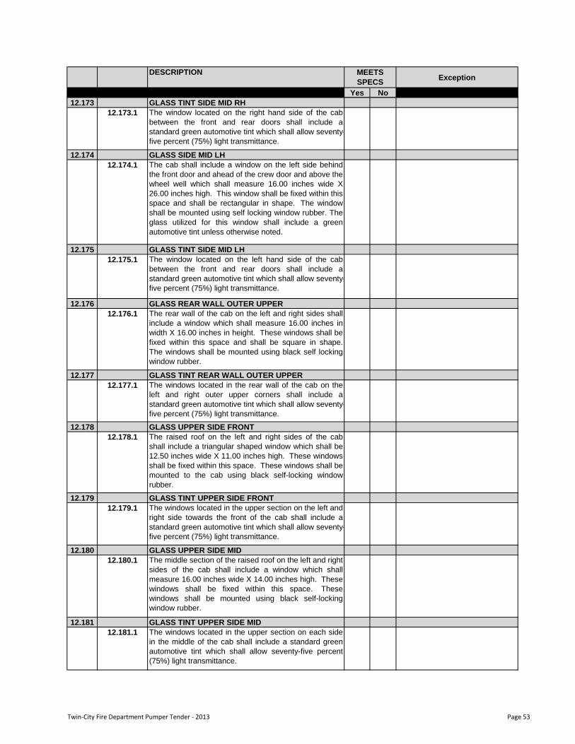
DESCRIPTIONException
Yes No
MEETS
SPECS
12.173 GLASS TINT SIDE MID RH
12.173.1 The window located on the right hand side of the cab
between the front and rear doors shall include a
standard green automotive tint which shall allow seventy-
five percent (75%) light transmittance.
12.174 GLASS SIDE MID LH
12.174.1 The cab shall include a window on the left side behind
the front door and ahead of the crew door and above the
wheel well which shall measure 16.00 inches wide X
26.00 inches high. This window shall be fixed within this
space and shall be rectangular in shape. The window
shall be mounted using self locking window rubber. The
glass utilized for this window shall include a green
automotive tint unless otherwise noted.
12.175 GLASS TINT SIDE MID LH
12.175.1 The window located on the left hand side of the cab
between the front and rear doors shall include a
standard green automotive tint which shall allow seventy-
five percent (75%) light transmittance.
12.176 GLASS REAR WALL OUTER UPPER
12.176.1 The rear wall of the cab on the left and right sides shall
include a window which shall measure 16.00 inches in
width X 16.00 inches in height. These windows shall be
fixed within this space and shall be square in shape.
The windows shall be mounted using black self locking
window rubber.
12.177 GLASS TINT REAR WALL OUTER UPPER
12.177.1 The windows located in the rear wall of the cab on the
left and right outer upper corners shall include a
standard green automotive tint which shall allow seventy-
five percent (75%) light transmittance.
12.178 GLASS UPPER SIDE FRONT
12.178.1 The raised roof on the left and right sides of the cab
shall include a triangular shaped window which shall be
12.50 inches wide X 11.00 inches high. These windows
shall be fixed within this space. These windows shall be
mounted to the cab using black self-locking window
rubber.
12.179 GLASS TINT UPPER SIDE FRONT
12.179.1 The windows located in the upper section on the left and
right side towards the front of the cab shall include a
standard green automotive tint which shall allow seventy-
five percent (75%) light transmittance.
12.180 GLASS UPPER SIDE MID
12.180.1 The middle section of the raised roof on the left and right
sides of the cab shall include a window which shall
measure 16.00 inches wide X 14.00 inches high. These
windows shall be fixed within this space. These
windows shall be mounted using black self-locking
window rubber.
12.181 GLASS TINT UPPER SIDE MID
12.181.1 The windows located in the upper section on each side
in the middle of the cab shall include a standard green
automotive tint which shall allow seventy-five percent
(75%) light transmittance.
Twin-City Fire Department Pumper Tender - 2013 Page 53
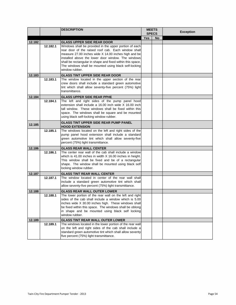
DESCRIPTIONException
Yes No
MEETS
SPECS
12.182 GLASS UPPER SIDE REAR DOOR
12.182.1 Windows shall be provided in the upper portion of each
rear door of the raised roof cab. Each window shall
measure 27.00 inches wide X 14.00 inches high and be
installed above the lower door window. The windows
shall be rectangular in shape and fixed within this space.
The windows shall be mounted using black self-locking
window rubber.
12.183 GLASS TINT UPPER SIDE REAR DOOR
12.183.1 The window located in the upper section of the rear
crew doors shall include a standard green automotive
tint which shall allow seventy-five percent (75%) light
transmittance.
12.184 GLASS UPPER SIDE REAR PPHE
12.184.1 The left and right sides of the pump panel hood
extension shall include a 16.00 inch wide X 16.00 inch
tall window. These windows shall be fixed within this
space. The windows shall be square and be mounted
using black self-locking window rubber.
12.185GLASS TINT UPPER SIDE REAR PUMP PANEL
HOOD EXTENSION
12.185.1 The windows located on the left and right sides of the
pump panel hood extension shall include a standard
green automotive tint which shall allow seventy-five
percent (75%) light transmittance.
12.186 GLASS REAR WALL CENTER
12.186.1 The center rear wall of the cab shall include a window
which is 41.00 inches in width X 16.00 inches in height.
This window shall be fixed and be of a rectangular
shape. The window shall be mounted using black self
locking window rubber.
12.187 GLASS TINT REAR WALL CENTER
12.187.1 The window located in center of the rear wall shall
include a standard green automotive tint which shall
allow seventy-five percent (75%) light transmittance.
12.188 GLASS REAR WALL OUTER LOWER
12.188.1 The lower portion of the rear wall on the left and right
sides of the cab shall include a window which is 5.00
inches wide X 30.00 inches high. These windows shall
be fixed within this space. The windows shall be oblong
in shape and be mounted using black self locking
window rubber.
12.189 GLASS TINT REAR WALL OUTER LOWER
12.189.1 The windows located in the lower portion of the rear wall
on the left and right sides of the cab shall include a
standard green automotive tint which shall allow seventy-
five percent (75%) light transmittance.
Twin-City Fire Department Pumper Tender - 2013 Page 54
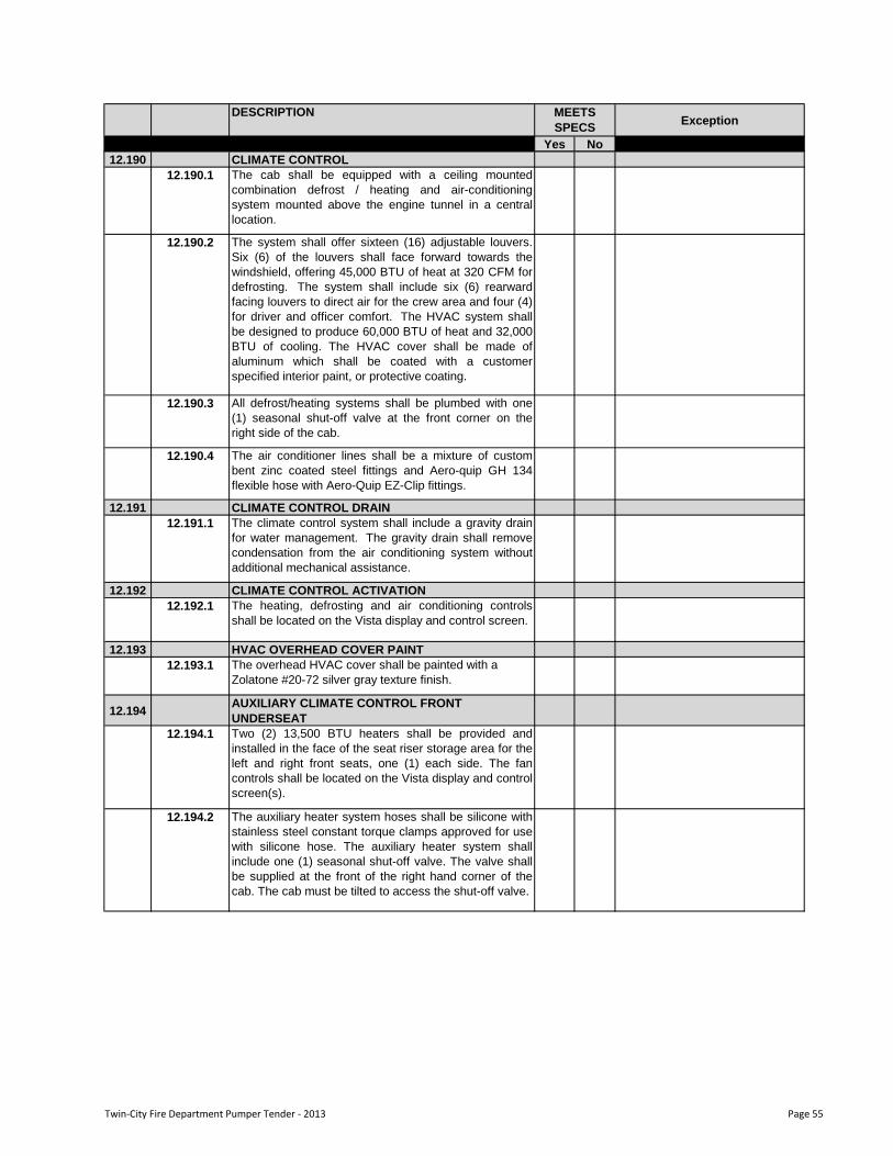
DESCRIPTIONException
Yes No
MEETS
SPECS
12.190 CLIMATE CONTROL
12.190.1 The cab shall be equipped with a ceiling mounted
combination defrost / heating and air-conditioning
system mounted above the engine tunnel in a central
location.
12.190.2 The system shall offer sixteen (16) adjustable louvers.
Six (6) of the louvers shall face forward towards the
windshield, offering 45,000 BTU of heat at 320 CFM for
defrosting. The system shall include six (6) rearward
facing louvers to direct air for the crew area and four (4)
for driver and officer comfort. The HVAC system shall
be designed to produce 60,000 BTU of heat and 32,000
BTU of cooling. The HVAC cover shall be made of
aluminum which shall be coated with a customer
specified interior paint, or protective coating.
12.190.3 All defrost/heating systems shall be plumbed with one
(1) seasonal shut-off valve at the front corner on the
right side of the cab.
12.190.4 The air conditioner lines shall be a mixture of custom
bent zinc coated steel fittings and Aero-quip GH 134
flexible hose with Aero-Quip EZ-Clip fittings.
12.191 CLIMATE CONTROL DRAIN
12.191.1 The climate control system shall include a gravity drain
for water management. The gravity drain shall remove
condensation from the air conditioning system without
additional mechanical assistance.
12.192 CLIMATE CONTROL ACTIVATION
12.192.1 The heating, defrosting and air conditioning controls
shall be located on the Vista display and control screen.
12.193 HVAC OVERHEAD COVER PAINT
12.193.1 The overhead HVAC cover shall be painted with a
Zolatone #20-72 silver gray texture finish.
12.194AUXILIARY CLIMATE CONTROL FRONT
UNDERSEAT
12.194.1 Two (2) 13,500 BTU heaters shall be provided and
installed in the face of the seat riser storage area for the
left and right front seats, one (1) each side. The fan
controls shall be located on the Vista display and control
screen(s).
12.194.2 The auxiliary heater system hoses shall be silicone with
stainless steel constant torque clamps approved for use
with silicone hose. The auxiliary heater system shall
include one (1) seasonal shut-off valve. The valve shall
be supplied at the front of the right hand corner of the
cab. The cab must be tilted to access the shut-off valve.
Twin-City Fire Department Pumper Tender - 2013 Page 55
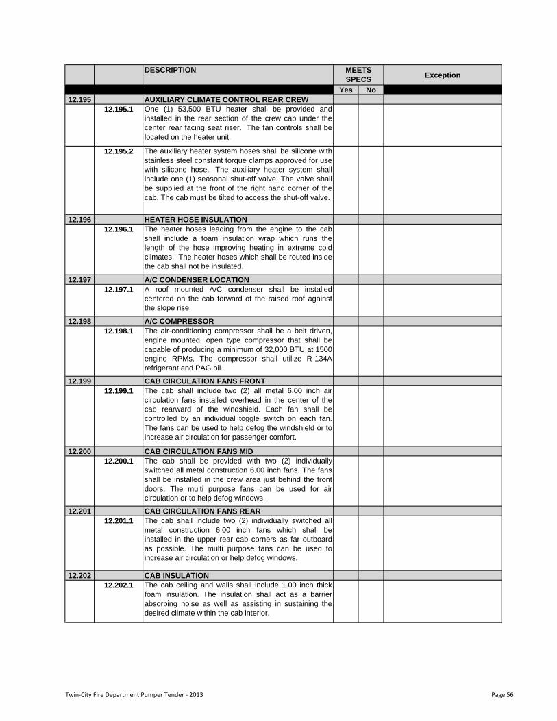
DESCRIPTIONException
Yes No
MEETS
SPECS
12.195 AUXILIARY CLIMATE CONTROL REAR CREW
12.195.1 One (1) 53,500 BTU heater shall be provided and
installed in the rear section of the crew cab under the
center rear facing seat riser. The fan controls shall be
located on the heater unit.
12.195.2 The auxiliary heater system hoses shall be silicone with
stainless steel constant torque clamps approved for use
with silicone hose. The auxiliary heater system shall
include one (1) seasonal shut-off valve. The valve shall
be supplied at the front of the right hand corner of the
cab. The cab must be tilted to access the shut-off valve.
12.196 HEATER HOSE INSULATION
12.196.1 The heater hoses leading from the engine to the cab
shall include a foam insulation wrap which runs the
length of the hose improving heating in extreme cold
climates. The heater hoses which shall be routed inside
the cab shall not be insulated.
12.197 A/C CONDENSER LOCATION
12.197.1 A roof mounted A/C condenser shall be installed
centered on the cab forward of the raised roof against
the slope rise.
12.198 A/C COMPRESSOR
12.198.1 The air-conditioning compressor shall be a belt driven,
engine mounted, open type compressor that shall be
capable of producing a minimum of 32,000 BTU at 1500
engine RPMs. The compressor shall utilize R-134A
refrigerant and PAG oil.
12.199 CAB CIRCULATION FANS FRONT
12.199.1 The cab shall include two (2) all metal 6.00 inch air
circulation fans installed overhead in the center of the
cab rearward of the windshield. Each fan shall be
controlled by an individual toggle switch on each fan.
The fans can be used to help defog the windshield or to
increase air circulation for passenger comfort.
12.200 CAB CIRCULATION FANS MID
12.200.1 The cab shall be provided with two (2) individually
switched all metal construction 6.00 inch fans. The fans
shall be installed in the crew area just behind the front
doors. The multi purpose fans can be used for air
circulation or to help defog windows.
12.201 CAB CIRCULATION FANS REAR
12.201.1 The cab shall include two (2) individually switched all
metal construction 6.00 inch fans which shall be
installed in the upper rear cab corners as far outboard
as possible. The multi purpose fans can be used to
increase air circulation or help defog windows.
12.202 CAB INSULATION
12.202.1 The cab ceiling and walls shall include 1.00 inch thick
foam insulation. The insulation shall act as a barrier
absorbing noise as well as assisting in sustaining the
desired climate within the cab interior.
Twin-City Fire Department Pumper Tender - 2013 Page 56
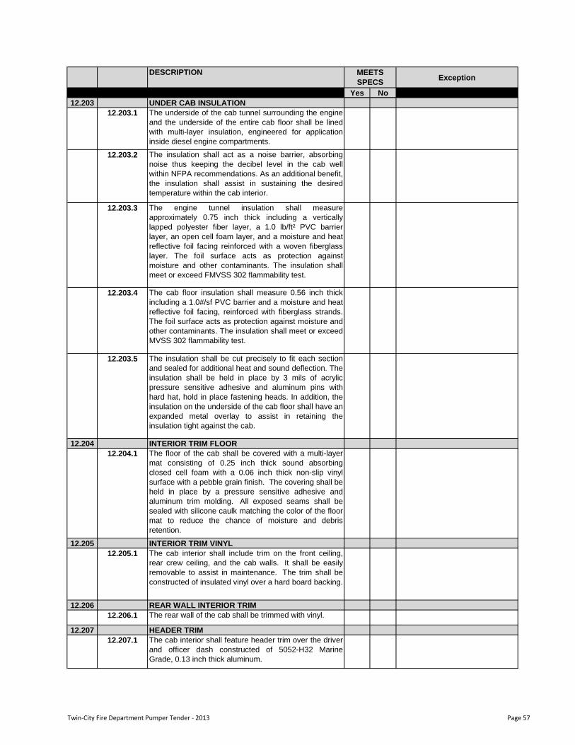
DESCRIPTIONException
Yes No
MEETS
SPECS
12.203 UNDER CAB INSULATION
12.203.1 The underside of the cab tunnel surrounding the engine
and the underside of the entire cab floor shall be lined
with multi-layer insulation, engineered for application
inside diesel engine compartments.
12.203.2 The insulation shall act as a noise barrier, absorbing
noise thus keeping the decibel level in the cab well
within NFPA recommendations. As an additional benefit,
the insulation shall assist in sustaining the desired
temperature within the cab interior.
12.203.3 The engine tunnel insulation shall measure
approximately 0.75 inch thick including a vertically
lapped polyester fiber layer, a 1.0 lb/ft² PVC barrier
layer, an open cell foam layer, and a moisture and heat
reflective foil facing reinforced with a woven fiberglass
layer. The foil surface acts as protection against
moisture and other contaminants. The insulation shall
meet or exceed FMVSS 302 flammability test.
12.203.4 The cab floor insulation shall measure 0.56 inch thick
including a 1.0#/sf PVC barrier and a moisture and heat
reflective foil facing, reinforced with fiberglass strands.
The foil surface acts as protection against moisture and
other contaminants. The insulation shall meet or exceed
MVSS 302 flammability test.
12.203.5 The insulation shall be cut precisely to fit each section
and sealed for additional heat and sound deflection. The
insulation shall be held in place by 3 mils of acrylic
pressure sensitive adhesive and aluminum pins with
hard hat, hold in place fastening heads. In addition, the
insulation on the underside of the cab floor shall have an
expanded metal overlay to assist in retaining the
insulation tight against the cab.
12.204 INTERIOR TRIM FLOOR
12.204.1 The floor of the cab shall be covered with a multi-layer
mat consisting of 0.25 inch thick sound absorbing
closed cell foam with a 0.06 inch thick non-slip vinyl
surface with a pebble grain finish. The covering shall be
held in place by a pressure sensitive adhesive and
aluminum trim molding. All exposed seams shall be
sealed with silicone caulk matching the color of the floor
mat to reduce the chance of moisture and debris
retention.
12.205 INTERIOR TRIM VINYL
12.205.1 The cab interior shall include trim on the front ceiling,
rear crew ceiling, and the cab walls. It shall be easily
removable to assist in maintenance. The trim shall be
constructed of insulated vinyl over a hard board backing.
12.206 REAR WALL INTERIOR TRIM
12.206.1 The rear wall of the cab shall be trimmed with vinyl.
12.207 HEADER TRIM
12.207.1 The cab interior shall feature header trim over the driver
and officer dash constructed of 5052-H32 Marine
Grade, 0.13 inch thick aluminum.
Twin-City Fire Department Pumper Tender - 2013 Page 57
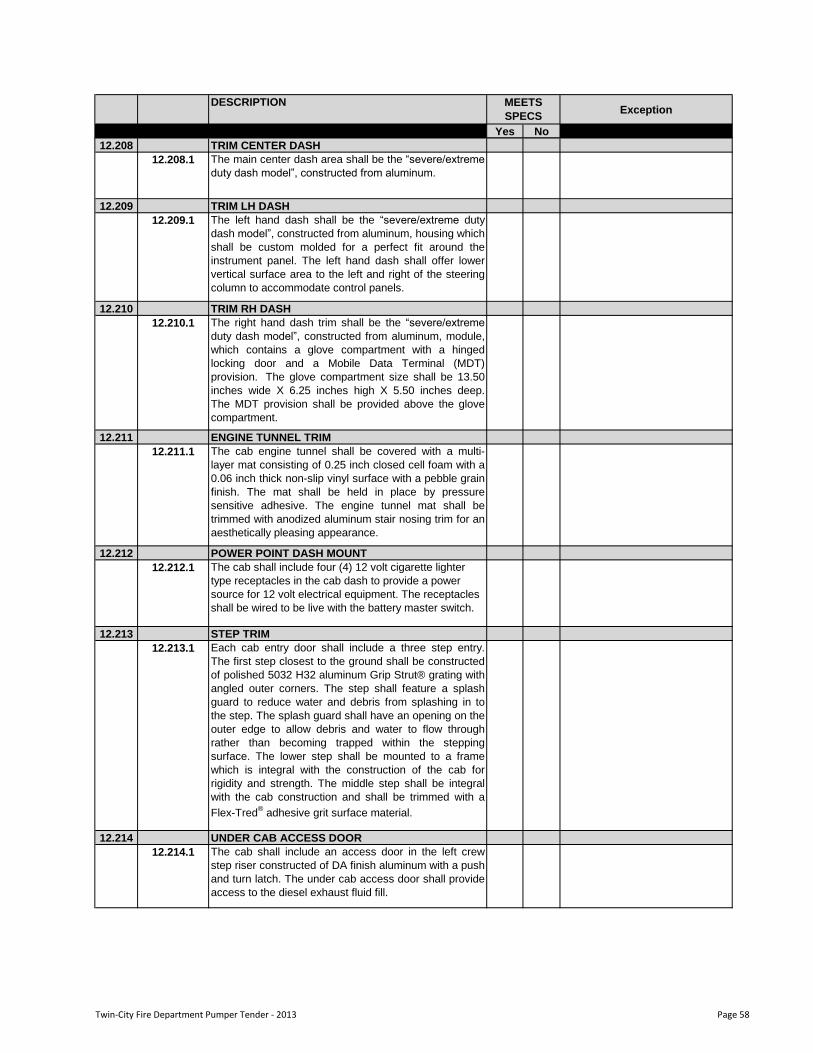
DESCRIPTIONException
Yes No
MEETS
SPECS
12.208 TRIM CENTER DASH
12.208.1 The main center dash area shall be the “severe/extreme
duty dash model”, constructed from aluminum.
12.209 TRIM LH DASH
12.209.1 The left hand dash shall be the “severe/extreme duty
dash model”, constructed from aluminum, housing which
shall be custom molded for a perfect fit around the
instrument panel. The left hand dash shall offer lower
vertical surface area to the left and right of the steering
column to accommodate control panels.
12.210 TRIM RH DASH
12.210.1 The right hand dash trim shall be the “severe/extreme
duty dash model”, constructed from aluminum, module,
which contains a glove compartment with a hinged
locking door and a Mobile Data Terminal (MDT)
provision. The glove compartment size shall be 13.50
inches wide X 6.25 inches high X 5.50 inches deep.
The MDT provision shall be provided above the glove
compartment.
12.211 ENGINE TUNNEL TRIM
12.211.1 The cab engine tunnel shall be covered with a multi-
layer mat consisting of 0.25 inch closed cell foam with a
0.06 inch thick non-slip vinyl surface with a pebble grain
finish. The mat shall be held in place by pressure
sensitive adhesive. The engine tunnel mat shall be
trimmed with anodized aluminum stair nosing trim for an
aesthetically pleasing appearance.
12.212 POWER POINT DASH MOUNT
12.212.1 The cab shall include four (4) 12 volt cigarette lighter
type receptacles in the cab dash to provide a power
source for 12 volt electrical equipment. The receptacles
shall be wired to be live with the battery master switch.
12.213 STEP TRIM
12.213.1 Each cab entry door shall include a three step entry.
The first step closest to the ground shall be constructed
of polished 5032 H32 aluminum Grip Strut® grating with
angled outer corners. The step shall feature a splash
guard to reduce water and debris from splashing in to
the step. The splash guard shall have an opening on the
outer edge to allow debris and water to flow through
rather than becoming trapped within the stepping
surface. The lower step shall be mounted to a frame
which is integral with the construction of the cab for
rigidity and strength. The middle step shall be integral
with the cab construction and shall be trimmed with a
Flex-Tred® adhesive grit surface material.
12.214 UNDER CAB ACCESS DOOR
12.214.1 The cab shall include an access door in the left crew
step riser constructed of DA finish aluminum with a push
and turn latch. The under cab access door shall provide
access to the diesel exhaust fluid fill.
Twin-City Fire Department Pumper Tender - 2013 Page 58
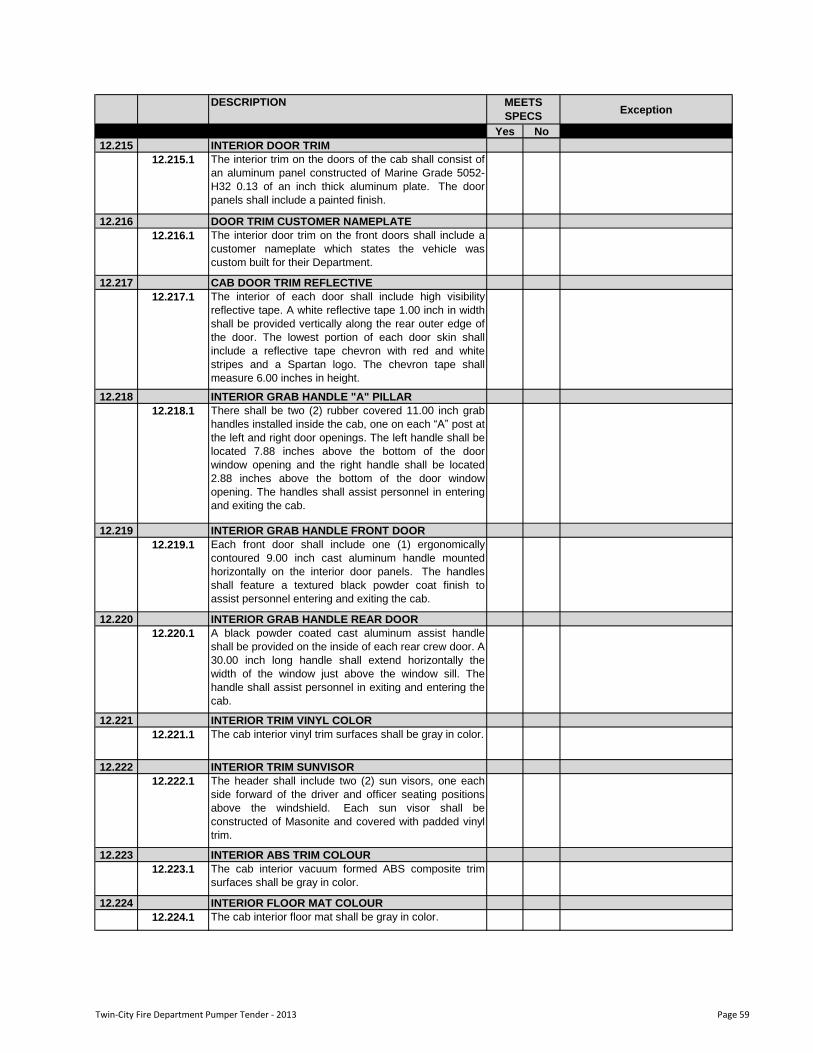
DESCRIPTIONException
Yes No
MEETS
SPECS
12.215 INTERIOR DOOR TRIM
12.215.1 The interior trim on the doors of the cab shall consist of
an aluminum panel constructed of Marine Grade 5052-
H32 0.13 of an inch thick aluminum plate. The door
panels shall include a painted finish.
12.216 DOOR TRIM CUSTOMER NAMEPLATE
12.216.1 The interior door trim on the front doors shall include a
customer nameplate which states the vehicle was
custom built for their Department.
12.217 CAB DOOR TRIM REFLECTIVE
12.217.1 The interior of each door shall include high visibility
reflective tape. A white reflective tape 1.00 inch in width
shall be provided vertically along the rear outer edge of
the door. The lowest portion of each door skin shall
include a reflective tape chevron with red and white
stripes and a Spartan logo. The chevron tape shall
measure 6.00 inches in height.
12.218 INTERIOR GRAB HANDLE "A" PILLAR
12.218.1 There shall be two (2) rubber covered 11.00 inch grab
handles installed inside the cab, one on each “A” post at
the left and right door openings. The left handle shall be
located 7.88 inches above the bottom of the door
window opening and the right handle shall be located
2.88 inches above the bottom of the door window
opening. The handles shall assist personnel in entering
and exiting the cab.
12.219 INTERIOR GRAB HANDLE FRONT DOOR
12.219.1 Each front door shall include one (1) ergonomically
contoured 9.00 inch cast aluminum handle mounted
horizontally on the interior door panels. The handles
shall feature a textured black powder coat finish to
assist personnel entering and exiting the cab.
12.220 INTERIOR GRAB HANDLE REAR DOOR
12.220.1 A black powder coated cast aluminum assist handle
shall be provided on the inside of each rear crew door. A
30.00 inch long handle shall extend horizontally the
width of the window just above the window sill. The
handle shall assist personnel in exiting and entering the
cab.
12.221 INTERIOR TRIM VINYL COLOR
12.221.1 The cab interior vinyl trim surfaces shall be gray in color.
12.222 INTERIOR TRIM SUNVISOR
12.222.1 The header shall include two (2) sun visors, one each
side forward of the driver and officer seating positions
above the windshield. Each sun visor shall be
constructed of Masonite and covered with padded vinyl
trim.
12.223 INTERIOR ABS TRIM COLOUR
12.223.1 The cab interior vacuum formed ABS composite trim
surfaces shall be gray in color.
12.224 INTERIOR FLOOR MAT COLOUR
12.224.1 The cab interior floor mat shall be gray in color.
Twin-City Fire Department Pumper Tender - 2013 Page 59
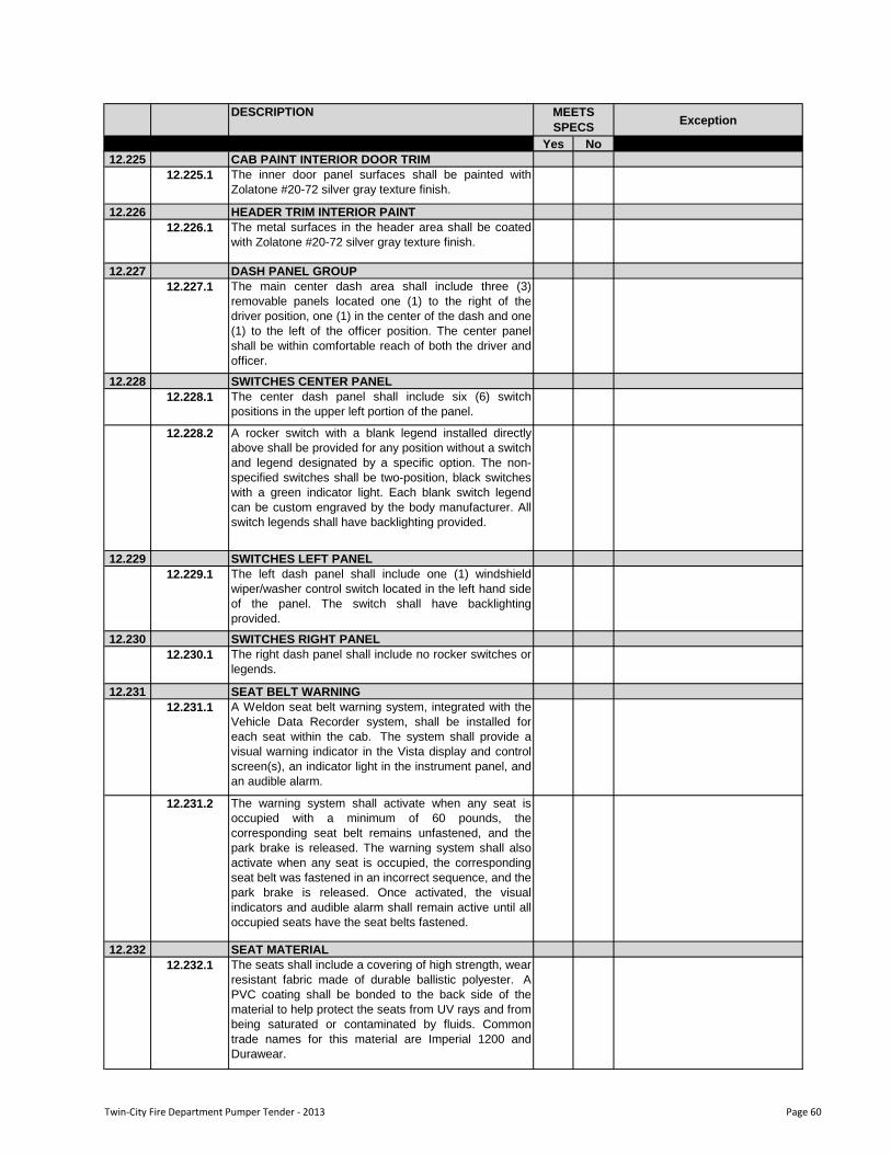
DESCRIPTIONException
Yes No
MEETS
SPECS
12.225 CAB PAINT INTERIOR DOOR TRIM
12.225.1 The inner door panel surfaces shall be painted with
Zolatone #20-72 silver gray texture finish.
12.226 HEADER TRIM INTERIOR PAINT
12.226.1 The metal surfaces in the header area shall be coated
with Zolatone #20-72 silver gray texture finish.
12.227 DASH PANEL GROUP
12.227.1 The main center dash area shall include three (3)
removable panels located one (1) to the right of the
driver position, one (1) in the center of the dash and one
(1) to the left of the officer position. The center panel
shall be within comfortable reach of both the driver and
officer.
12.228 SWITCHES CENTER PANEL
12.228.1 The center dash panel shall include six (6) switch
positions in the upper left portion of the panel.
12.228.2 A rocker switch with a blank legend installed directly
above shall be provided for any position without a switch
and legend designated by a specific option. The non-
specified switches shall be two-position, black switches
with a green indicator light. Each blank switch legend
can be custom engraved by the body manufacturer. All
switch legends shall have backlighting provided.
12.229 SWITCHES LEFT PANEL
12.229.1 The left dash panel shall include one (1) windshield
wiper/washer control switch located in the left hand side
of the panel. The switch shall have backlighting
provided.
12.230 SWITCHES RIGHT PANEL
12.230.1 The right dash panel shall include no rocker switches or
legends.
12.231 SEAT BELT WARNING
12.231.1 A Weldon seat belt warning system, integrated with the
Vehicle Data Recorder system, shall be installed for
each seat within the cab. The system shall provide a
visual warning indicator in the Vista display and control
screen(s), an indicator light in the instrument panel, and
an audible alarm.
12.231.2 The warning system shall activate when any seat is
occupied with a minimum of 60 pounds, the
corresponding seat belt remains unfastened, and the
park brake is released. The warning system shall also
activate when any seat is occupied, the corresponding
seat belt was fastened in an incorrect sequence, and the
park brake is released. Once activated, the visual
indicators and audible alarm shall remain active until all
occupied seats have the seat belts fastened.
12.232 SEAT MATERIAL
12.232.1 The seats shall include a covering of high strength, wear
resistant fabric made of durable ballistic polyester. A
PVC coating shall be bonded to the back side of the
material to help protect the seats from UV rays and from
being saturated or contaminated by fluids. Common
trade names for this material are Imperial 1200 and
Durawear.
Twin-City Fire Department Pumper Tender - 2013 Page 60
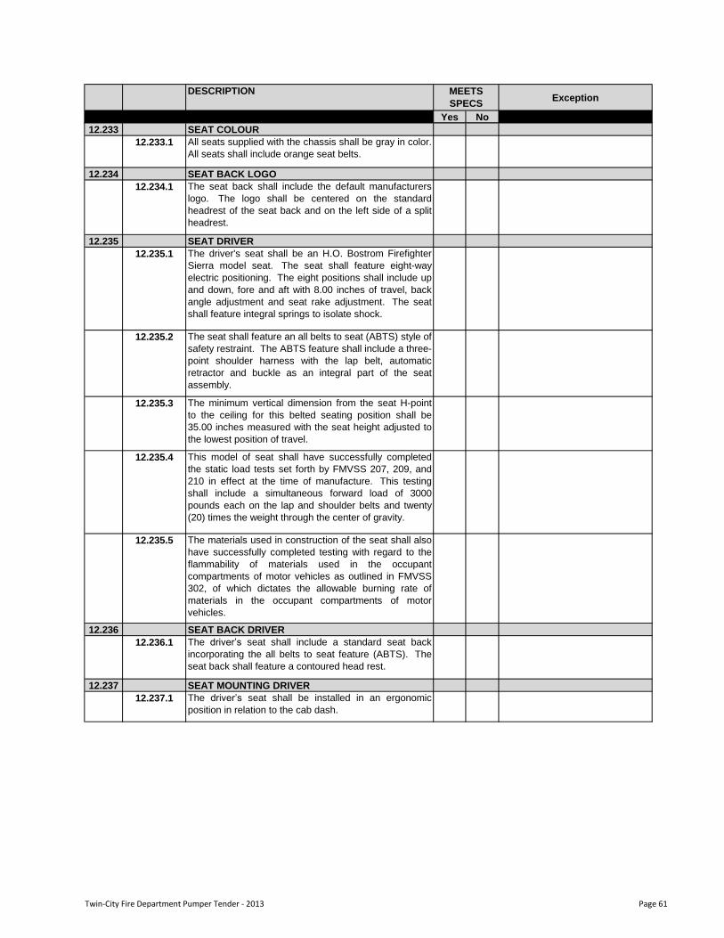
DESCRIPTIONException
Yes No
MEETS
SPECS
12.233 SEAT COLOUR
12.233.1 All seats supplied with the chassis shall be gray in color.
All seats shall include orange seat belts.
12.234 SEAT BACK LOGO
12.234.1 The seat back shall include the default manufacturers
logo. The logo shall be centered on the standard
headrest of the seat back and on the left side of a split
headrest.
12.235 SEAT DRIVER
12.235.1 The driver's seat shall be an H.O. Bostrom Firefighter
Sierra model seat. The seat shall feature eight-way
electric positioning. The eight positions shall include up
and down, fore and aft with 8.00 inches of travel, back
angle adjustment and seat rake adjustment. The seat
shall feature integral springs to isolate shock.
12.235.2 The seat shall feature an all belts to seat (ABTS) style of
safety restraint. The ABTS feature shall include a three-
point shoulder harness with the lap belt, automatic
retractor and buckle as an integral part of the seat
assembly.
12.235.3 The minimum vertical dimension from the seat H-point
to the ceiling for this belted seating position shall be
35.00 inches measured with the seat height adjusted to
the lowest position of travel.
12.235.4 This model of seat shall have successfully completed
the static load tests set forth by FMVSS 207, 209, and
210 in effect at the time of manufacture. This testing
shall include a simultaneous forward load of 3000
pounds each on the lap and shoulder belts and twenty
(20) times the weight through the center of gravity.
12.235.5 The materials used in construction of the seat shall also
have successfully completed testing with regard to the
flammability of materials used in the occupant
compartments of motor vehicles as outlined in FMVSS
302, of which dictates the allowable burning rate of
materials in the occupant compartments of motor
vehicles.
12.236 SEAT BACK DRIVER
12.236.1 The driver‟s seat shall include a standard seat back
incorporating the all belts to seat feature (ABTS). The
seat back shall feature a contoured head rest.
12.237 SEAT MOUNTING DRIVER
12.237.1 The driver‟s seat shall be installed in an ergonomic
position in relation to the cab dash.
Twin-City Fire Department Pumper Tender - 2013 Page 61
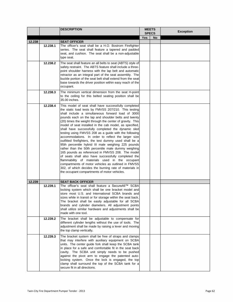
DESCRIPTIONException
Yes No
MEETS
SPECS
12.238 SEAT OFFICER
12.238.1 The officer's seat shall be a H.O. Bostrom Firefighter
series. The seat shall feature a tapered and padded
seat, and cushion. The seat shall be a non-adjustable
type seat.
12.238.2 The seat shall feature an all belts to seat (ABTS) style of
safety restraint. The ABTS feature shall include a three-
point shoulder harness with the lap belt and automatic
retractor as an integral part of the seat assembly. The
buckle portion of the seat belt shall extend from the seat
base towards the driver position within easy reach of the
occupant.
12.238.3 The minimum vertical dimension from the seat H-point
to the ceiling for this belted seating position shall be
35.00 inches.
12.238.4 This model of seat shall have successfully completed
the static load tests by FMVSS 207/210. This testing
shall include a simultaneous forward load of 3000
pounds each on the lap and shoulder belts and twenty
(20) times the weight through the center of gravity. This
model of seat installed in the cab model, as specified,
shall have successfully completed the dynamic sled
testing using FMVSS 208 as a guide with the following
accommodations. In order to reflect the larger size
outfitted firefighters, the test dummy used shall be a
95th percentile hybrid III male weighing 225 pounds
rather than the 50th percentile male dummy weighing
165 pounds as referenced in FMVSS 208. The model
of seats shall also have successfully completed the
flammability of materials used in the occupant
compartments of motor vehicles as outlined in FMVSS
302, of which decides the burning rate of materials in
the occupant compartments of motor vehicles.
12.239 SEAT BACK OFFICER
12.239.1 The officer‟s seat shall feature a SecureAll™ SCBA
locking system which shall be one bracket model and
store most U.S. and International SCBA brands and
sizes while in transit or for storage within the seat back.
The bracket shall be easily adjustable for all SCBA
brands and cylinder diameters. All adjustment points
shall utilize similar hardware and adjustments shall be
made with one tool.
12.239.2 The bracket shall be adjustable to compensate for
different cylinder lengths without the use of tools. The
adjustment shall be made by raising a lever and moving
the top clamp vertically.
12.239.3 The bracket system shall be free of straps and clamps
that may interfere with auxiliary equipment on SCBA
units. The center guide fork shall keep the SCBA tank
in place for a safe and comfortable fit in the seat back
cavity. The SCBA unit simply needs to be pushed
against the pivot arm to engage the patented auto-
locking system. Once the lock is engaged, the top
clamp shall surround the top of the SCBA tank for a
secure fit in all directions.
Twin-City Fire Department Pumper Tender - 2013 Page 62
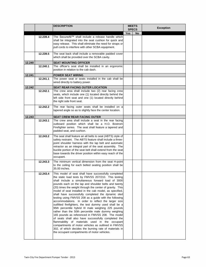
DESCRIPTIONException
Yes No
MEETS
SPECS
12.239.4 The SecureAll™ shall include a release handle which
shall be integrated into the seat cushion for quick and
easy release. This shall eliminate the need for straps or
pull cords to interfere with other SCBA equipment.
12.239.5 The seat back shall include a removable padded cover
which shall be provided over the SCBA cavity.
12.240 SEAT MOUNTING OFFICER
12.240.1 The officer‟s seat shall be installed in an ergonomic
position in relation to the cab dash.
12.241 POWER SEAT WIRING
12.241.1 The power seat or seats installed in the cab shall be
wired directly to battery power.
12.242 SEAT REAR FACING OUTER LOCATION
12.242.1 The crew area shall include two (2) rear facing crew
seats, which include one (1) located directly behind the
left side front seat and one (1) located directly behind
the right side front seat.
12.242.2 The rear facing outer seats shall be installed on a
tapered angle so as to slightly face the center location.
12.243 SEAT CREW REAR FACING OUTER
12.243.1 The crew area shall include a seat in the rear facing
outboard position which shall be a H.O. Bostrom
Firefighter series. The seat shall feature a tapered and
padded seat, and cushion.
12.243.2 The seat shall feature an all belts to seat (ABTS) style of
safety restraint. The ABTS feature shall include a three-
point shoulder harness with the lap belt and automatic
retractor as an integral part of the seat assembly. The
buckle portion of the seat belt shall extend from the seat
base towards the driver position within easy reach of the
occupant.
12.243.3 The minimum vertical dimension from the seat H-point
to the ceiling for each belted seating position shall be
35.00 inches.
12.243.4 This model of seat shall have successfully completed
the static load tests by FMVSS 207/210. This testing
shall include a simultaneous forward load of 3000
pounds each on the lap and shoulder belts and twenty
(20) times the weight through the center of gravity. This
model of seat installed in the cab model, as specified,
shall have successfully completed the dynamic sled
testing using FMVSS 208 as a guide with the following
accommodations. In order to reflect the larger size
outfitted firefighters, the test dummy used shall be a
95th percentile hybrid III male weighing 225 pounds
rather than the 50th percentile male dummy weighing
165 pounds as referenced in FMVSS 208. The model
of seats shall also have successfully completed the
flammability of materials used in the occupant
compartments of motor vehicles as outlined in FMVSS
302, of which decides the burning rate of materials in
the occupant compartments of motor vehicles.
Twin-City Fire Department Pumper Tender - 2013 Page 63
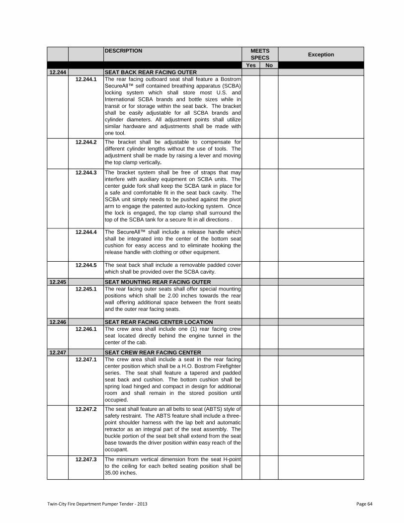
DESCRIPTIONException
Yes No
MEETS
SPECS
12.244 SEAT BACK REAR FACING OUTER
12.244.1 The rear facing outboard seat shall feature a Bostrom
SecureAll™ self contained breathing apparatus (SCBA)
locking system which shall store most U.S. and
International SCBA brands and bottle sizes while in
transit or for storage within the seat back. The bracket
shall be easily adjustable for all SCBA brands and
cylinder diameters. All adjustment points shall utilize
similar hardware and adjustments shall be made with
one tool.
12.244.2 The bracket shall be adjustable to compensate for
different cylinder lengths without the use of tools. The
adjustment shall be made by raising a lever and moving
the top clamp vertically.
12.244.3 The bracket system shall be free of straps that may
interfere with auxiliary equipment on SCBA units. The
center guide fork shall keep the SCBA tank in place for
a safe and comfortable fit in the seat back cavity. The
SCBA unit simply needs to be pushed against the pivot
arm to engage the patented auto-locking system. Once
the lock is engaged, the top clamp shall surround the
top of the SCBA tank for a secure fit in all directions .
12.244.4 The SecureAll™ shall include a release handle which
shall be integrated into the center of the bottom seat
cushion for easy access and to eliminate hooking the
release handle with clothing or other equipment.
12.244.5 The seat back shall include a removable padded cover
which shall be provided over the SCBA cavity.
12.245 SEAT MOUNTING REAR FACING OUTER
12.245.1 The rear facing outer seats shall offer special mounting
positions which shall be 2.00 inches towards the rear
wall offering additional space between the front seats
and the outer rear facing seats.
12.246 SEAT REAR FACING CENTER LOCATION
12.246.1 The crew area shall include one (1) rear facing crew
seat located directly behind the engine tunnel in the
center of the cab.
12.247 SEAT CREW REAR FACING CENTER
12.247.1 The crew area shall include a seat in the rear facing
center position which shall be a H.O. Bostrom Firefighter
series. The seat shall feature a tapered and padded
seat back and cushion. The bottom cushion shall be
spring load hinged and compact in design for additional
room and shall remain in the stored position until
occupied.
12.247.2 The seat shall feature an all belts to seat (ABTS) style of
safety restraint. The ABTS feature shall include a three-
point shoulder harness with the lap belt and automatic
retractor as an integral part of the seat assembly. The
buckle portion of the seat belt shall extend from the seat
base towards the driver position within easy reach of the
occupant.
12.247.3 The minimum vertical dimension from the seat H-point
to the ceiling for each belted seating position shall be
35.00 inches.
Twin-City Fire Department Pumper Tender - 2013 Page 64
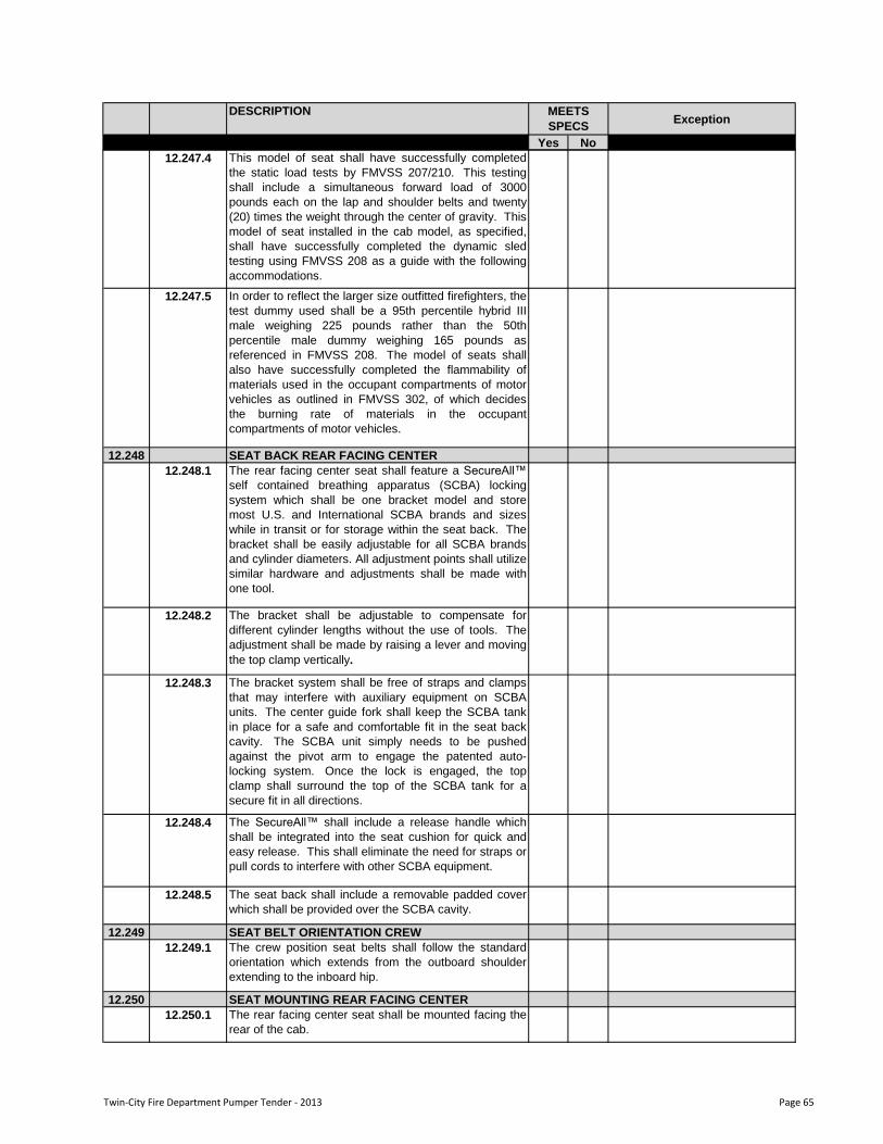
DESCRIPTIONException
Yes No
MEETS
SPECS
12.247.4 This model of seat shall have successfully completed
the static load tests by FMVSS 207/210. This testing
shall include a simultaneous forward load of 3000
pounds each on the lap and shoulder belts and twenty
(20) times the weight through the center of gravity. This
model of seat installed in the cab model, as specified,
shall have successfully completed the dynamic sled
testing using FMVSS 208 as a guide with the following
accommodations.
12.247.5 In order to reflect the larger size outfitted firefighters, the
test dummy used shall be a 95th percentile hybrid III
male weighing 225 pounds rather than the 50th
percentile male dummy weighing 165 pounds as
referenced in FMVSS 208. The model of seats shall
also have successfully completed the flammability of
materials used in the occupant compartments of motor
vehicles as outlined in FMVSS 302, of which decides
the burning rate of materials in the occupant
compartments of motor vehicles.
12.248 SEAT BACK REAR FACING CENTER
12.248.1 The rear facing center seat shall feature a SecureAll™
self contained breathing apparatus (SCBA) locking
system which shall be one bracket model and store
most U.S. and International SCBA brands and sizes
while in transit or for storage within the seat back. The
bracket shall be easily adjustable for all SCBA brands
and cylinder diameters. All adjustment points shall utilize
similar hardware and adjustments shall be made with
one tool.
12.248.2 The bracket shall be adjustable to compensate for
different cylinder lengths without the use of tools. The
adjustment shall be made by raising a lever and moving
the top clamp vertically.
12.248.3 The bracket system shall be free of straps and clamps
that may interfere with auxiliary equipment on SCBA
units. The center guide fork shall keep the SCBA tank
in place for a safe and comfortable fit in the seat back
cavity. The SCBA unit simply needs to be pushed
against the pivot arm to engage the patented auto-
locking system. Once the lock is engaged, the top
clamp shall surround the top of the SCBA tank for a
secure fit in all directions.
12.248.4 The SecureAll™ shall include a release handle which
shall be integrated into the seat cushion for quick and
easy release. This shall eliminate the need for straps or
pull cords to interfere with other SCBA equipment.
12.248.5 The seat back shall include a removable padded cover
which shall be provided over the SCBA cavity.
12.249 SEAT BELT ORIENTATION CREW
12.249.1 The crew position seat belts shall follow the standard
orientation which extends from the outboard shoulder
extending to the inboard hip.
12.250 SEAT MOUNTING REAR FACING CENTER
12.250.1 The rear facing center seat shall be mounted facing the
rear of the cab.
Twin-City Fire Department Pumper Tender - 2013 Page 65
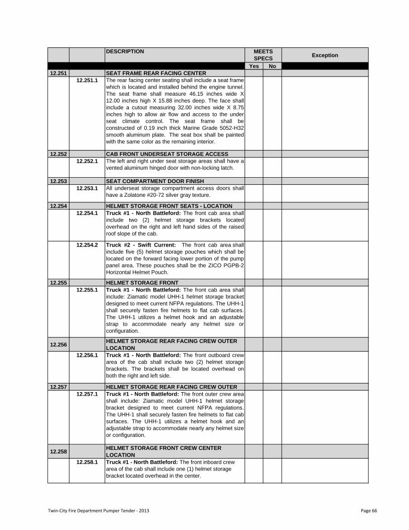
DESCRIPTIONException
Yes No
MEETS
SPECS
12.251 SEAT FRAME REAR FACING CENTER
12.251.1 The rear facing center seating shall include a seat frame
which is located and installed behind the engine tunnel.
The seat frame shall measure 46.15 inches wide X
12.00 inches high X 15.88 inches deep. The face shall
include a cutout measuring 32.00 inches wide X 8.75
inches high to allow air flow and access to the under
seat climate control. The seat frame shall be
constructed of 0.19 inch thick Marine Grade 5052-H32
smooth aluminum plate. The seat box shall be painted
with the same color as the remaining interior.
12.252 CAB FRONT UNDERSEAT STORAGE ACCESS
12.252.1 The left and right under seat storage areas shall have a
vented aluminum hinged door with non-locking latch.
12.253 SEAT COMPARTMENT DOOR FINISH
12.253.1 All underseat storage compartment access doors shall
have a Zolatone #20-72 silver gray texture.
12.254 HELMET STORAGE FRONT SEATS - LOCATION
12.254.1 Truck #1 - North Battleford: The front cab area shall
include two (2) helmet storage brackets located
overhead on the right and left hand sides of the raised
roof slope of the cab.
12.254.2 Truck #2 - Swift Current: The front cab area shall
include five (5) helmet storage pouches which shall be
located on the forward facing lower portion of the pump
panel area. These pouches shall be the ZICO PGPB-2
Horizontal Helmet Pouch.
12.255 HELMET STORAGE FRONT
12.255.1 Truck #1 - North Battleford: The front cab area shall
include: Ziamatic model UHH-1 helmet storage bracket
designed to meet current NFPA regulations. The UHH-1
shall securely fasten fire helmets to flat cab surfaces.
The UHH-1 utilizes a helmet hook and an adjustable
strap to accommodate nearly any helmet size or
configuration.
12.256HELMET STORAGE REAR FACING CREW OUTER
LOCATION
12.256.1 Truck #1 - North Battleford: The front outboard crew
area of the cab shall include two (2) helmet storage
brackets. The brackets shall be located overhead on
both the right and left side.
12.257 HELMET STORAGE REAR FACING CREW OUTER
12.257.1 Truck #1 - North Battleford: The front outer crew area
shall include: Ziamatic model UHH-1 helmet storage
bracket designed to meet current NFPA regulations.
The UHH-1 shall securely fasten fire helmets to flat cab
surfaces. The UHH-1 utilizes a helmet hook and an
adjustable strap to accommodate nearly any helmet size
or configuration.
12.258HELMET STORAGE FRONT CREW CENTER
LOCATION
12.258.1 Truck #1 - North Battleford: The front inboard crew
area of the cab shall include one (1) helmet storage
bracket located overhead in the center.
Twin-City Fire Department Pumper Tender - 2013 Page 66
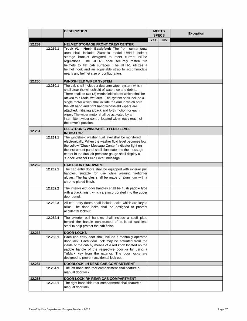
DESCRIPTIONException
Yes No
MEETS
SPECS
12.259 HELMET STORAGE FRONT CREW CENTER
12.259.1 Truck #1 - North Battleford: The front center crew
area shall include: Ziamatic model UHH-1 helmet
storage bracket designed to meet current NFPA
regulations. The UHH-1 shall securely fasten fire
helmets to flat cab surfaces. The UHH-1 utilizes a
helmet hook and an adjustable strap to accommodate
nearly any helmet size or configuration.
12.260 WINDSHIELD WIPER SYSTEM
12.260.1 The cab shall include a dual arm wiper system which
shall clear the windshield of water, ice and debris.
There shall be two (2) windshield wipers which shall be
affixed to a radial wet arm. The system shall include a
single motor which shall initiate the arm in which both
the left hand and right hand windshield wipers are
attached, initiating a back and forth motion for each
wiper. The wiper motor shall be activated by an
intermittent wiper control located within easy reach of
the driver‟s position.
12.261ELECTRONIC WINDSHIELD FLUID LEVEL
INDICATOR
12.261.1 The windshield washer fluid level shall be monitored
electronically. When the washer fluid level becomes low
the yellow “Check Message Center” indicator light on
the instrument panel shall illuminate and the message
center in the dual air pressure gauge shall display a
“Check Washer Fluid Level” message.
12.262 CAB DOOR HARDWARE
12.262.1 The cab entry doors shall be equipped with exterior pull
handles, suitable for use while wearing firefighter
gloves. The handles shall be made of aluminum with a
chrome plated finish.
12.262.2 The interior exit door handles shall be flush paddle type
with a black finish, which are incorporated into the upper
door panel.
12.262.3 All cab entry doors shall include locks which are keyed
alike. The door locks shall be designed to prevent
accidental lockout.
12.262.4 The exterior pull handles shall include a scuff plate
behind the handle constructed of polished stainless
steel to help protect the cab finish.
12.263 DOOR LOCKS
12.263.1 Each cab entry door shall include a manually operated
door lock. Each door lock may be actuated from the
inside of the cab by means of a red knob located on the
paddle handle of the respective door or by using a
TriMark key from the exterior. The door locks are
designed to prevent accidental lock out.
12.264 DOORLOCK LH REAR CAB COMPARTMENT
12.264.1 The left hand side rear compartment shall feature a
manual door lock.
12.265 DOOR LOCK RH REAR CAB COMPARTMENT
12.265.1 The right hand side rear compartment shall feature a
manual door lock.
Twin-City Fire Department Pumper Tender - 2013 Page 67
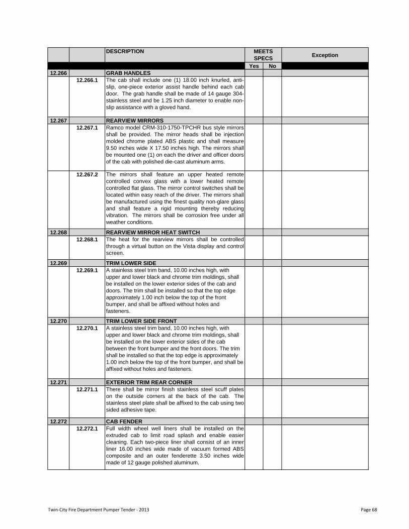
DESCRIPTIONException
Yes No
MEETS
SPECS
12.266 GRAB HANDLES
12.266.1 The cab shall include one (1) 18.00 inch knurled, anti-
slip, one-piece exterior assist handle behind each cab
door. The grab handle shall be made of 14 gauge 304-
stainless steel and be 1.25 inch diameter to enable non-
slip assistance with a gloved hand.
12.267 REARVIEW MIRRORS
12.267.1 Ramco model CRM-310-1750-TPCHR bus style mirrors
shall be provided. The mirror heads shall be injection
molded chrome plated ABS plastic and shall measure
9.50 inches wide X 17.50 inches high. The mirrors shall
be mounted one (1) on each the driver and officer doors
of the cab with polished die-cast aluminum arms.
12.267.2 The mirrors shall feature an upper heated remote
controlled convex glass with a lower heated remote
controlled flat glass. The mirror control switches shall be
located within easy reach of the driver. The mirrors shall
be manufactured using the finest quality non-glare glass
and shall feature a rigid mounting thereby reducing
vibration. The mirrors shall be corrosion free under all
weather conditions.
12.268 REARVIEW MIRROR HEAT SWITCH
12.268.1 The heat for the rearview mirrors shall be controlled
through a virtual button on the Vista display and control
screen.
12.269 TRIM LOWER SIDE
12.269.1 A stainless steel trim band, 10.00 inches high, with
upper and lower black and chrome trim moldings, shall
be installed on the lower exterior sides of the cab and
doors. The trim shall be installed so that the top edge
approximately 1.00 inch below the top of the front
bumper, and shall be affixed without holes and
fasteners.
12.270 TRIM LOWER SIDE FRONT
12.270.1 A stainless steel trim band, 10.00 inches high, with
upper and lower black and chrome trim moldings, shall
be installed on the lower exterior sides of the cab
between the front bumper and the front doors. The trim
shall be installed so that the top edge is approximately
1.00 inch below the top of the front bumper, and shall be
affixed without holes and fasteners.
12.271 EXTERIOR TRIM REAR CORNER
12.271.1 There shall be mirror finish stainless steel scuff plates
on the outside corners at the back of the cab. The
stainless steel plate shall be affixed to the cab using two
sided adhesive tape.
12.272 CAB FENDER
12.272.1 Full width wheel well liners shall be installed on the
extruded cab to limit road splash and enable easier
cleaning. Each two-piece liner shall consist of an inner
liner 16.00 inches wide made of vacuum formed ABS
composite and an outer fenderette 3.50 inches wide
made of 12 gauge polished aluminum.
Twin-City Fire Department Pumper Tender - 2013 Page 68
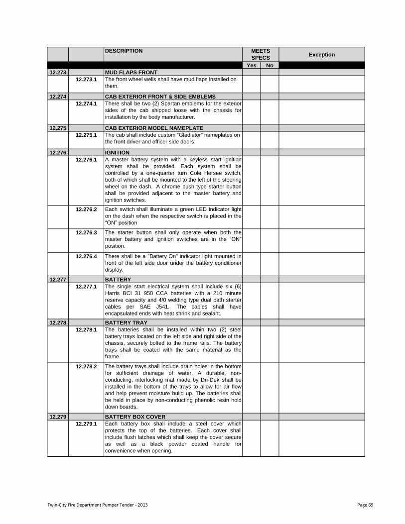
DESCRIPTIONException
Yes No
MEETS
SPECS
12.273 MUD FLAPS FRONT
12.273.1 The front wheel wells shall have mud flaps installed on
them.
12.274 CAB EXTERIOR FRONT & SIDE EMBLEMS
12.274.1 There shall be two (2) Spartan emblems for the exterior
sides of the cab shipped loose with the chassis for
installation by the body manufacturer.
12.275 CAB EXTERIOR MODEL NAMEPLATE
12.275.1 The cab shall include custom “Gladiator” nameplates on
the front driver and officer side doors.
12.276 IGNITION
12.276.1 A master battery system with a keyless start ignition
system shall be provided. Each system shall be
controlled by a one-quarter turn Cole Hersee switch,
both of which shall be mounted to the left of the steering
wheel on the dash. A chrome push type starter button
shall be provided adjacent to the master battery and
ignition switches.
12.276.2 Each switch shall illuminate a green LED indicator light
on the dash when the respective switch is placed in the
“ON” position
12.276.3 The starter button shall only operate when both the
master battery and ignition switches are in the “ON”
position.
12.276.4 There shall be a "Battery On" indicator light mounted in
front of the left side door under the battery conditioner
display.
12.277 BATTERY
12.277.1 The single start electrical system shall include six (6)
Harris BCI 31 950 CCA batteries with a 210 minute
reserve capacity and 4/0 welding type dual path starter
cables per SAE J541. The cables shall have
encapsulated ends with heat shrink and sealant.
12.278 BATTERY TRAY
12.278.1 The batteries shall be installed within two (2) steel
battery trays located on the left side and right side of the
chassis, securely bolted to the frame rails. The battery
trays shall be coated with the same material as the
frame.
12.278.2 The battery trays shall include drain holes in the bottom
for sufficient drainage of water. A durable, non-
conducting, interlocking mat made by Dri-Dek shall be
installed in the bottom of the trays to allow for air flow
and help prevent moisture build up. The batteries shall
be held in place by non-conducting phenolic resin hold
down boards.
12.279 BATTERY BOX COVER
12.279.1 Each battery box shall include a steel cover which
protects the top of the batteries. Each cover shall
include flush latches which shall keep the cover secure
as well as a black powder coated handle for
convenience when opening.
Twin-City Fire Department Pumper Tender - 2013 Page 69
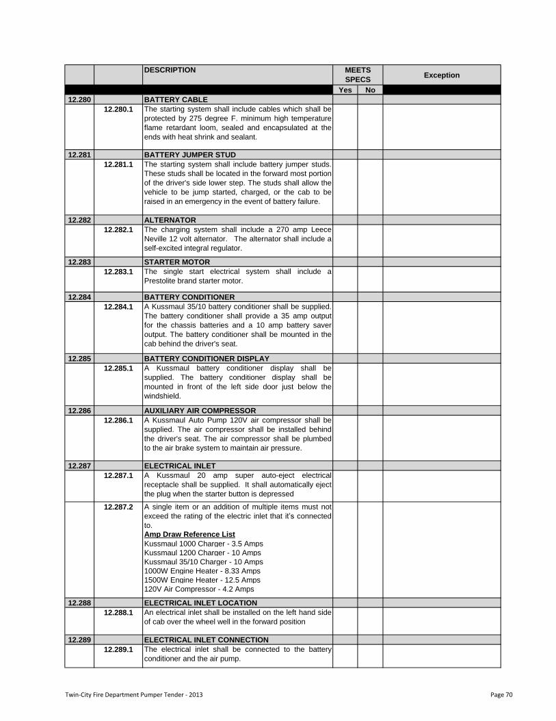
DESCRIPTIONException
Yes No
MEETS
SPECS
12.280 BATTERY CABLE
12.280.1 The starting system shall include cables which shall be
protected by 275 degree F. minimum high temperature
flame retardant loom, sealed and encapsulated at the
ends with heat shrink and sealant.
12.281 BATTERY JUMPER STUD
12.281.1 The starting system shall include battery jumper studs.
These studs shall be located in the forward most portion
of the driver's side lower step. The studs shall allow the
vehicle to be jump started, charged, or the cab to be
raised in an emergency in the event of battery failure.
12.282 ALTERNATOR
12.282.1 The charging system shall include a 270 amp Leece
Neville 12 volt alternator. The alternator shall include a
self-excited integral regulator.
12.283 STARTER MOTOR
12.283.1 The single start electrical system shall include a
Prestolite brand starter motor.
12.284 BATTERY CONDITIONER
12.284.1 A Kussmaul 35/10 battery conditioner shall be supplied.
The battery conditioner shall provide a 35 amp output
for the chassis batteries and a 10 amp battery saver
output. The battery conditioner shall be mounted in the
cab behind the driver's seat.
12.285 BATTERY CONDITIONER DISPLAY
12.285.1 A Kussmaul battery conditioner display shall be
supplied. The battery conditioner display shall be
mounted in front of the left side door just below the
windshield.
12.286 AUXILIARY AIR COMPRESSOR
12.286.1 A Kussmaul Auto Pump 120V air compressor shall be
supplied. The air compressor shall be installed behind
the driver's seat. The air compressor shall be plumbed
to the air brake system to maintain air pressure.
12.287 ELECTRICAL INLET
12.287.1 A Kussmaul 20 amp super auto-eject electrical
receptacle shall be supplied. It shall automatically eject
the plug when the starter button is depressed
A single item or an addition of multiple items must not
exceed the rating of the electric inlet that it‟s connected
to.
Amp Draw Reference List
Kussmaul 1000 Charger - 3.5 Amps
Kussmaul 1200 Charger - 10 Amps
Kussmaul 35/10 Charger - 10 Amps
1000W Engine Heater - 8.33 Amps
1500W Engine Heater - 12.5 Amps
120V Air Compressor - 4.2 Amps
12.288 ELECTRICAL INLET LOCATION
12.288.1 An electrical inlet shall be installed on the left hand side
of cab over the wheel well in the forward position
12.289 ELECTRICAL INLET CONNECTION
12.289.1 The electrical inlet shall be connected to the battery
conditioner and the air pump.
12.287.2
Twin-City Fire Department Pumper Tender - 2013 Page 70
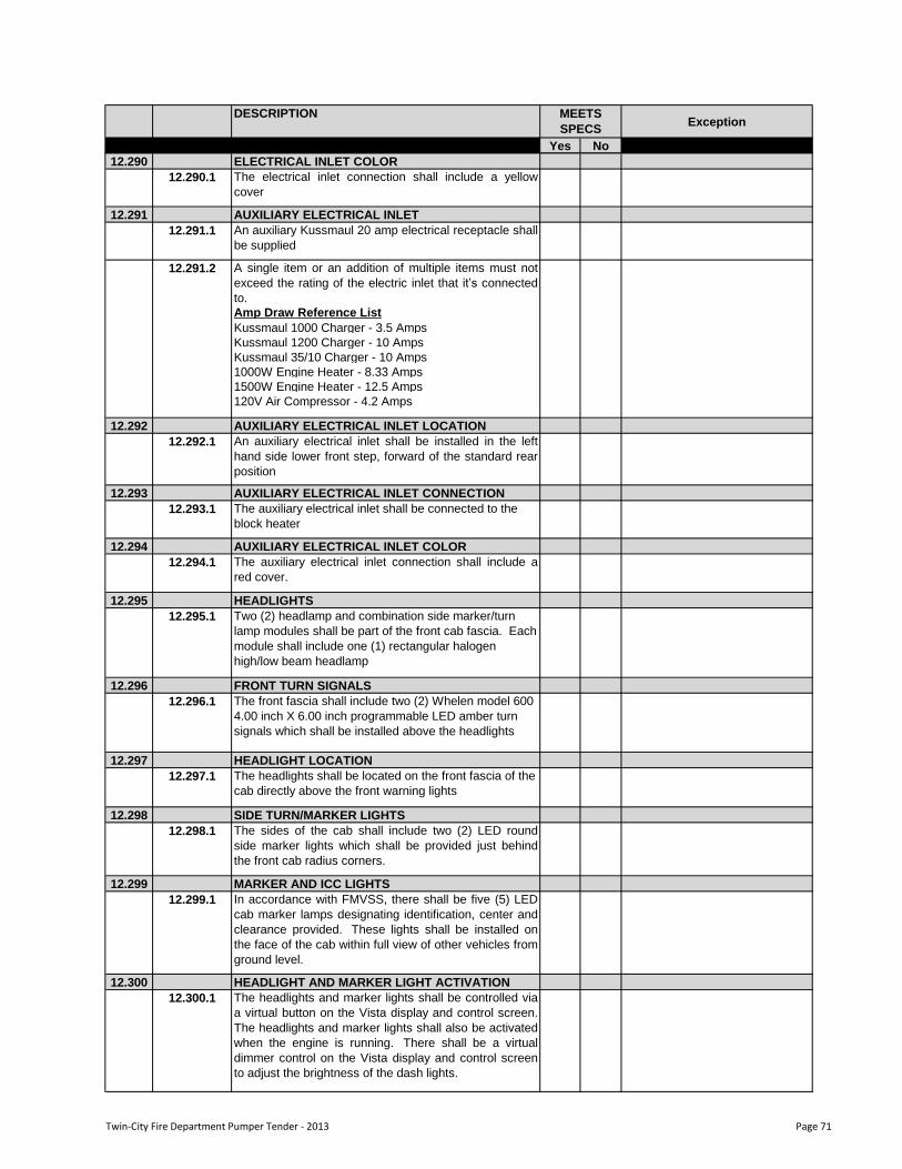
DESCRIPTIONException
Yes No
MEETS
SPECS
12.290 ELECTRICAL INLET COLOR
12.290.1 The electrical inlet connection shall include a yellow
cover
12.291 AUXILIARY ELECTRICAL INLET
12.291.1 An auxiliary Kussmaul 20 amp electrical receptacle shall
be supplied
A single item or an addition of multiple items must not
exceed the rating of the electric inlet that it‟s connected
to.
Amp Draw Reference List
Kussmaul 1000 Charger - 3.5 Amps
Kussmaul 1200 Charger - 10 Amps
Kussmaul 35/10 Charger - 10 Amps
1000W Engine Heater - 8.33 Amps
1500W Engine Heater - 12.5 Amps
120V Air Compressor - 4.2 Amps
12.292 AUXILIARY ELECTRICAL INLET LOCATION
12.292.1 An auxiliary electrical inlet shall be installed in the left
hand side lower front step, forward of the standard rear
position
12.293 AUXILIARY ELECTRICAL INLET CONNECTION
12.293.1 The auxiliary electrical inlet shall be connected to the
block heater
12.294 AUXILIARY ELECTRICAL INLET COLOR
12.294.1 The auxiliary electrical inlet connection shall include a
red cover.
12.295 HEADLIGHTS
12.295.1 Two (2) headlamp and combination side marker/turn
lamp modules shall be part of the front cab fascia. Each
module shall include one (1) rectangular halogen
high/low beam headlamp
12.296 FRONT TURN SIGNALS
12.296.1 The front fascia shall include two (2) Whelen model 600
4.00 inch X 6.00 inch programmable LED amber turn
signals which shall be installed above the headlights
12.297 HEADLIGHT LOCATION
12.297.1 The headlights shall be located on the front fascia of the
cab directly above the front warning lights
12.298 SIDE TURN/MARKER LIGHTS
12.298.1 The sides of the cab shall include two (2) LED round
side marker lights which shall be provided just behind
the front cab radius corners.
12.299 MARKER AND ICC LIGHTS
12.299.1 In accordance with FMVSS, there shall be five (5) LED
cab marker lamps designating identification, center and
clearance provided. These lights shall be installed on
the face of the cab within full view of other vehicles from
ground level.
12.300 HEADLIGHT AND MARKER LIGHT ACTIVATION
12.300.1 The headlights and marker lights shall be controlled via
a virtual button on the Vista display and control screen.
The headlights and marker lights shall also be activated
when the engine is running. There shall be a virtual
dimmer control on the Vista display and control screen
to adjust the brightness of the dash lights.
12.291.2
Twin-City Fire Department Pumper Tender - 2013 Page 71
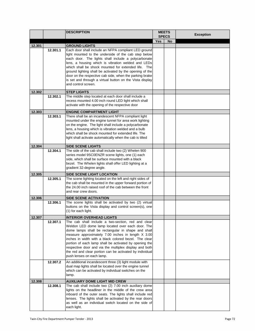
DESCRIPTIONException
Yes No
MEETS
SPECS
12.301 GROUND LIGHTS
12.301.1 Each door shall include an NFPA compliant LED ground
light mounted to the underside of the cab step below
each door. The lights shall include a polycarbonate
lens, a housing which is vibration welded and LEDs
which shall be shock mounted for extended life. The
ground lighting shall be activated by the opening of the
door on the respective cab side, when the parking brake
is set and through a virtual button on the Vista display
and control screen.
12.302 STEP LIGHTS
12.302.1 The middle step located at each door shall include a
recess mounted 4.00 inch round LED light which shall
activate with the opening of the respective door
12.303 ENGINE COMPARTMENT LIGHT
12.303.1 There shall be an incandescent NFPA compliant light
mounted under the engine tunnel for area work lighting
on the engine. The light shall include a polycarbonate
lens, a housing which is vibration welded and a bulb
which shall be shock mounted for extended life. The
light shall activate automatically when the cab is tilted
12.304 SIDE SCENE LIGHTS
12.304.1 The side of the cab shall include two (2) Whelen 900
series model 9SC0ENZR scene lights, one (1) each
side, which shall be surface mounted with a black
bezel. The Whelen lights shall offer LED lighting at a
gradient 32-degree angle.
12.305 SIDE SCENE LIGHT LOCATION
12.305.1 The scene lighting located on the left and right sides of
the cab shall be mounted in the upper forward portion of
the 24.00 inch raised roof of the cab between the front
and rear crew doors.
12.306 SIDE SCENE ACTIVATION
12.306.1 The scene lights shall be activated by two (2) virtual
buttons on the Vista display and control screen(s), one
(1) for each light.
12.307 INTERIOR OVERHEAD LIGHTS
12.307.1 The cab shall include a two-section, red and clear
Weldon LED dome lamp located over each door. The
dome lamps shall be rectangular in shape and shall
measure approximately 7.00 inches in length X 3.00
inches in width with a black colored bezel. The clear
portion of each lamp shall be activated by opening the
respective door and via the multiplex display and both
the red and clear portion can be activated by individual
push lenses on each lamp.
12.307.2 An additional incandescent three (3) light module with
dual map lights shall be located over the engine tunnel
which can be activated by individual switches on the
lamp.
12.308 AUXILIARY DOME LIGHT MID CREW
12.308.1 The cab shall include two (2) 7.00 inch auxiliary dome
lights on the headliner in the middle of the crew area
inboard of the outer seats. The lights shall include red
lenses. The lights shall be activated by the rear doors
as well as an individual switch located on the side of
each light.
Twin-City Fire Department Pumper Tender - 2013 Page 72
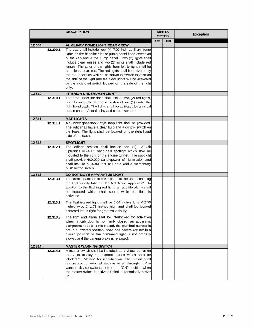
DESCRIPTIONException
Yes No
MEETS
SPECS
12.309 AUXILIARY DOME LIGHT REAR CREW
12.309.1 The cab shall include four (4) 7.00 inch auxiliary dome
lights on the headliner in the pump panel hood extension
of the cab above the pump panel. Two (2) lights shall
include clear lenses and two (2) lights shall include red
lenses. The color of the lights from left to right shall be
red, clear, clear, red. The red lights shall be activated by
the rear doors as well as an individual switch located on
the side of the light and the clear lights will be activated
by the individual switch located on the side of the light
only.
12.310 INTERIOR UNDERDASH LIGHT
12.310.1 The area under the dash shall include two (2) red lights,
one (1) under the left hand dash and one (1) under the
right hand dash. The lights shall be activated by a virtual
button on the Vista display and control screen.
12.311 MAP LIGHTS
12.311.1 A Sunnex gooseneck style map light shall be provided.
The light shall have a clear bulb and a control switch on
the base. The light shall be located on the right hand
side of the dash.
12.312 SPOTLIGHT
12.312.1 The officer position shall include one (1) 12 volt
Optronics KB-4003 hand-held spotlight which shall be
mounted to the right of the engine tunnel. The spotlight
shall provide 400,000 candlepower of illumination and
shall include a 10.00 foot coil cord and a momentary
push button switch.
12.313 DO NOT MOVE APPARATUS LIGHT
12.313.1 The front headliner of the cab shall include a flashing
red light clearly labeled "Do Not Move Apparatus". In
addition to the flashing red light, an audible alarm shall
be included which shall sound while the light is
activated.
12.313.2 The flashing red light shall be 6.00 inches long X 2.50
inches wide X 1.75 inches high and shall be located
centered left to right for greatest visibility.
12.313.3 The light and alarm shall be interlocked for activation
when: a cab door is not firmly closed, an apparatus
compartment door is not closed, the plumbed monitor is
not in a lowered position, hose bed covers are not in a
closed position or the command light is not properly
stowed and the parking brake is released.
12.314 MASTER WARNING SWITCH
12.314.1 A master switch shall be included, as a virtual button on
the Vista display and control screen which shall be
labeled “E Master” for identification. The button shall
feature control over all devices wired through it. Any
warning device switches left in the “ON” position when
the master switch is activated shall automatically power
up.
Twin-City Fire Department Pumper Tender - 2013 Page 73
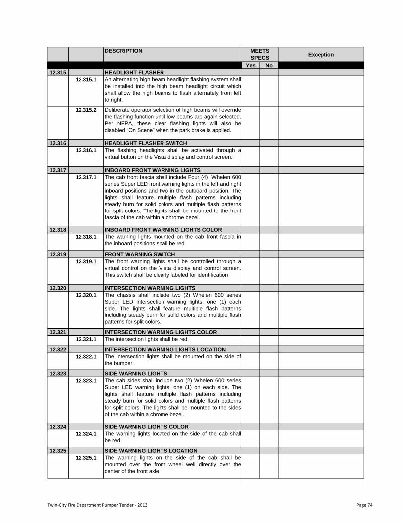
DESCRIPTIONException
Yes No
MEETS
SPECS
12.315 HEADLIGHT FLASHER
12.315.1 An alternating high beam headlight flashing system shall
be installed into the high beam headlight circuit which
shall allow the high beams to flash alternately from left
to right.
12.315.2 Deliberate operator selection of high beams will override
the flashing function until low beams are again selected.
Per NFPA, these clear flashing lights will also be
disabled “On Scene” when the park brake is applied.
12.316 HEADLIGHT FLASHER SWITCH
12.316.1 The flashing headlights shall be activated through a
virtual button on the Vista display and control screen.
12.317 INBOARD FRONT WARNING LIGHTS
12.317.1 The cab front fascia shall include Four (4) Whelen 600
series Super LED front warning lights in the left and right
inboard positions and two in the outboard position. The
lights shall feature multiple flash patterns including
steady burn for solid colors and multiple flash patterns
for split colors. The lights shall be mounted to the front
fascia of the cab within a chrome bezel.
12.318 INBOARD FRONT WARNING LIGHTS COLOR
12.318.1 The warning lights mounted on the cab front fascia in
the inboard positions shall be red.
12.319 FRONT WARNING SWITCH
12.319.1 The front warning lights shall be controlled through a
virtual control on the Vista display and control screen.
This switch shall be clearly labeled for identification
12.320 INTERSECTION WARNING LIGHTS
12.320.1 The chassis shall include two (2) Whelen 600 series
Super LED intersection warning lights, one (1) each
side. The lights shall feature multiple flash patterns
including steady burn for solid colors and multiple flash
patterns for split colors.
12.321 INTERSECTION WARNING LIGHTS COLOR
12.321.1 The intersection lights shall be red.
12.322 INTERSECTION WARNING LIGHTS LOCATION
12.322.1 The intersection lights shall be mounted on the side of
the bumper.
12.323 SIDE WARNING LIGHTS
12.323.1 The cab sides shall include two (2) Whelen 600 series
Super LED warning lights, one (1) on each side. The
lights shall feature multiple flash patterns including
steady burn for solid colors and multiple flash patterns
for split colors. The lights shall be mounted to the sides
of the cab within a chrome bezel.
12.324 SIDE WARNING LIGHTS COLOR
12.324.1 The warning lights located on the side of the cab shall
be red.
12.325 SIDE WARNING LIGHTS LOCATION
12.325.1 The warning lights on the side of the cab shall be
mounted over the front wheel well directly over the
center of the front axle.
Twin-City Fire Department Pumper Tender - 2013 Page 74
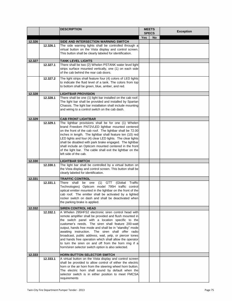
DESCRIPTIONException
Yes No
MEETS
SPECS
12.326 SIDE AND INTERSECTION WARNING SWITCH
12.326.1 The side warning lights shall be controlled through a
virtual button on the Vista display and control screen.
This button shall be clearly labeled for identification.
12.327 TANK LEVEL LIGHTS
12.327.1 There shall be two (2) Whelen PSTANK water level light
strips surface mounted vertically, one (1) on each side
of the cab behind the rear cab doors.
12.327.2 The light strips shall feature four (4) colors of LED lights
to indicate the fluid level of a tank. The colors from top
to bottom shall be green, blue, amber, and red.
12.328 LIGHTBAR PROVISION
12.328.1 There shall be one (1) light bar installed on the cab roof.
The light bar shall be provided and installed by Spartan
Chassis. The light bar installation shall include mounting
and wiring to a control switch on the cab dash.
12.329 CAB FRONT LIGHTBAR
12.329.1 The lightbar provisions shall be for one (1) Whelen
brand Freedom FN72VLED lightbar mounted centered
on the front of the cab roof. The lightbar shall be 72.00
inches in length. The lightbar shall feature ten (10) red
LED lights and four (4) clear LED lights. The clear lights
shall be disabled with park brake engaged. The lightbar
shall include an Opticom mounted centered in the front
of the light bar. The cable shall exit the lightbar on the
left side of the cab.
12.330 LIGHTBAR SWITCH
12.330.1 The light bar shall be controlled by a virtual button on
the Vista display and control screen. This button shall be
clearly labeled for identification.
12.331 TRAFFIC CONTROL
12.331.1 There shall be one (1) GTT (Global Traffic
Technologies) Opticom model 795H traffic control
optical emitter mounted in the lightbar on the front of the
cab roof. The emitter shall be activated by a lighted
rocker switch on dash and shall be deactivated when
the parking brake is applied.
12.332 SIREN CONTROL HEAD
12.332.1 A Whelen 295HFS2 electronic siren control head with
remote amplifier shall be provided and flush mounted in
the switch panel with a location specific to the
customer‟s needs. The siren shall feature 200-watt
output, hands free mode and shall be in “standby” mode
awaiting instruction. The siren shall offer radio
broadcast, public address, wail, yelp, or piercer tones
and hands free operation which shall allow the operator
to turn the siren on and off from the horn ring if a
horn/siren selector switch option is also selected.
12.333 HORN BUTTON SELECTOR SWITCH
12.333.1 A virtual button on the Vista display and control screen
shall be provided to allow control of either the electric
horn or the air horn from the steering wheel horn button.
The electric horn shall sound by default when the
selector switch is in either position to meet FMCSA
requirements
Twin-City Fire Department Pumper Tender - 2013 Page 75
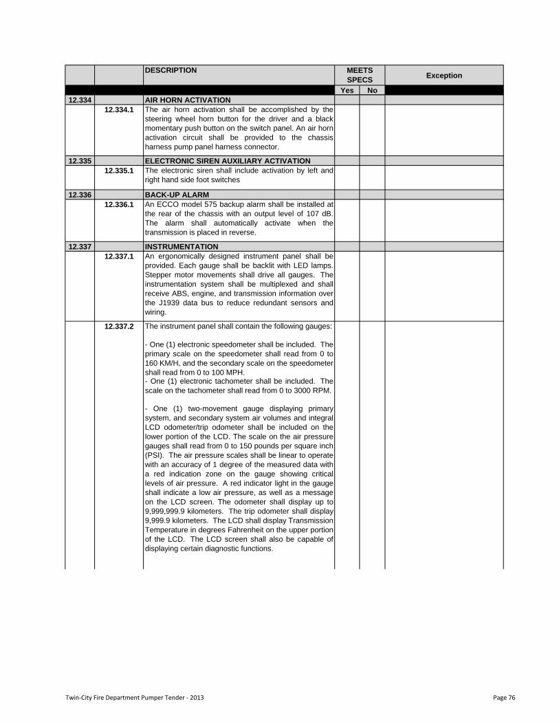
DESCRIPTIONException
Yes No
MEETS
SPECS
12.334 AIR HORN ACTIVATION
12.334.1 The air horn activation shall be accomplished by the
steering wheel horn button for the driver and a black
momentary push button on the switch panel. An air horn
activation circuit shall be provided to the chassis
harness pump panel harness connector.
12.335 ELECTRONIC SIREN AUXILIARY ACTIVATION
12.335.1 The electronic siren shall include activation by left and
right hand side foot switches
12.336 BACK-UP ALARM
12.336.1 An ECCO model 575 backup alarm shall be installed at
the rear of the chassis with an output level of 107 dB.
The alarm shall automatically activate when the
transmission is placed in reverse.
12.337 INSTRUMENTATION
12.337.1 An ergonomically designed instrument panel shall be
provided. Each gauge shall be backlit with LED lamps.
Stepper motor movements shall drive all gauges. The
instrumentation system shall be multiplexed and shall
receive ABS, engine, and transmission information over
the J1939 data bus to reduce redundant sensors and
wiring.
The instrument panel shall contain the following gauges:
- One (1) electronic speedometer shall be included. The
primary scale on the speedometer shall read from 0 to
160 KM/H, and the secondary scale on the speedometer
shall read from 0 to 100 MPH.- One (1) electronic tachometer shall be included. The
scale on the tachometer shall read from 0 to 3000 RPM.
- One (1) two-movement gauge displaying primary
system, and secondary system air volumes and integral
LCD odometer/trip odometer shall be included on the
lower portion of the LCD. The scale on the air pressure
gauges shall read from 0 to 150 pounds per square inch
(PSI). The air pressure scales shall be linear to operate
with an accuracy of 1 degree of the measured data with
a red indication zone on the gauge showing critical
levels of air pressure. A red indicator light in the gauge
shall indicate a low air pressure, as well as a message
on the LCD screen. The odometer shall display up to
9,999,999.9 kilometers. The trip odometer shall display
9,999.9 kilometers. The LCD shall display Transmission
Temperature in degrees Fahrenheit on the upper portion
of the LCD. The LCD screen shall also be capable of
displaying certain diagnostic functions.
12.337.2
Twin-City Fire Department Pumper Tender - 2013 Page 76
DESCRIPTIONException
Yes No
MEETS
SPECS
- One (1) four-movement gauge displaying engine oil
pressure, coolant temperature, fuel level, voltmeter, and
an indicator bar displaying Diesel Exhaust Fluid (DEF)
LED bar shall be included. The scale on the engine oil
pressure gauge shall read from 0 to 120 pounds per
square inch (PSI). The engine oil pressure scale shall
be linear to operate with an accuracy of 1 degree of the
measured data. A red indicator light in the gauge shall
indicate a low engine oil pressure, as well as a message
on the LCD screen. The scale on the coolant
temperature gauge shall read from 100 to 250 degrees
Fahrenheit (F).
12.337.7 The coolant temperature scale shall be linear to operate
with an accuracy of 1 degree of the measured data with
a red indication zone on the gauge showing critical
levels of air pressure. A red indicator light in the gauge
shall indicate high coolant temperature, as well as a
message on the LCD screen. The scale on the fuel
level gauge shall read from empty to full as a
percentage of fuel remaining. An amber indicator light
shall indicate low fuel at 25% tank level. The scale on
the voltmeter shall read from 10 to 16 volts with a red
indication zone on the gauge showing critical levels of
battery voltage. A red indicator light shall indicate high
or low system voltage, as well as a message on the
LCD screen. The scale on the DEF LED bar will consist
of four (4) LEDs displaying levels in increments of 25%
of useable DEF in green. Upon decreasing levels, the
indicator bar will change colors to notify the driver of
decreasing levels of DEF and action will be required.
An amber indicator light shall indichall be equipped with
an electronic control suitable for installation on the pump
p
12.337.8 The instrument panel shall include a light bar that will
contain the following LED indicator lights:
RED LAMPS:
* Low Primary Air Pressure (located in gauge)
* Low Secondary air Pressure (located in gauge)
* Stop Engine-indicates critical engine fault
* Air Filter Restricted-indicates excessive engine air
intake restriction
* Park Brake-indicates parking brake is set
* Seat Belt Indicator-indicates when a seat is occupied
and corresponding seat belt remains unfastened
* Volts-indicates high or low system voltage (located in
gauge)
* Low Oil Pressure-indicates low engine oil pressure
(located in gauge)
* High Coolant Temperature-indicates excessive engine
coolant temperature (located in gauge)
* DEF Level Bar-DEF level is at critically low level
(located in gauge)
12.337.2
Twin-City Fire Department Pumper Tender - 2013 Page 77
DESCRIPTIONException
Yes No
MEETS
SPECS
AMBER LAMPS:
* MIL-indicates an engine emission control system fault
* Check Engine-indicates engine fault
* Check Trans-indicates transmission fault
* High Transmission Temperature-indicates excessive
transmission oil temperature
* ABS-indicates anti-lock brake system fault
* Wait to Start-indicates active engine air preheat cycle
* HEST-indicates a high exhaust system temperature
* Water in Fuel-indicates presence of water in fuel filter
* DPF -indicates a restriction of the diesel particulate
filter
* Regen Inhibit-indicates regeneration has been
postponed due to user interaction
* Range Inhibit-indicates a transmission operation is
prevented and requested shift request maynot occur
* SRS-indicates a problem in the RollTek supplemental
restraint system
* Low Fuel-indicates low fuel, (located in gauge)
* DEF-indicates a low level of DEF fluid (located in
gauge)
* DEF Level Bar-DEF level is at a low level (located in
gauge)
GREEN LAMPS:
* Left and Right turn signal indicators
* ATC-indicates low wheel traction for automatic traction
control equipped vehicles, also indicates mud/snow
mode is active for ATC system* High Idle-indicates engine high idle is active
* Cruise Control-indicates cruise control is active
* OK to Pump-indicates the pump engage conditions
have been met
* Pump Engaged-indicates the pump is currently in use
* Auxiliary Brake-indicates secondary braking device is
active
* DEF Level Bar-indicates useable levels of DEF: 25%,
50%, 75%, 100% (located in gauge)
BLUE LAMPS:
* High Beam Indicator
CONSTANT AUDIBLE ALARMS FROM GAUGE
PACKAGE:
* High Trans Temp
* High or Low Voltage
* Seatbelt
* Check Engine
* Check Transmission
* Stop Engine
* Low Air Pressure
* Fuel Low
* Water in Fuel
* ESC
* High Coolant Temperature
* Low Engine Oil Pressure
* Low Coolant Level
* Low DEF Level
Twin-City Fire Department Pumper Tender - 2013 Page 78
DESCRIPTIONException
Yes No
MEETS
SPECS
OSCILLATING AUDIBLE ALARMS FROM GAUGE
PACKAGE:
* Air Filter
* Extended Left and Right Turn remaining on
* Cab Ajar
* Door Ajar
* Low Oil Level
BACKLIGHTING COLOR:
The instrumentation gauges and the switch panel
legends shall be backlit using red LED backlighting.
12.338 CAMERA
12.338.1 An Audiovox Voyager heavy duty rearview camera
system shall be supplied. One (1) box shaped camera
shall be shipped loose for OEM installation in the body
to afford the driver a clear view to the rear of the vehicle,
a second box shaped camera shall be supplied above
the front door on the officer side of the cab and a third
box shaped camera on the driver side above the front
door.
12.338.2 The cameras shall be wired to two (2) Weldon single
Vista displays located, one (1) on the driver dash and
one (1) on the officer dash. The rear camera display
shall activate when the vehicle‟s transmission is placed
in reverse. The side camera display shall activate when
the respective side turn signal is activated. The camera
system display can also be activated through the Vista
display panel.
12.339 COMMUNICATION ANTENNA
12.339.1 An antenna base, for use with an NMO type antenna,
shall be mounted on the right hand front corner of the
cab roof so not to interfere with light bars or other roof
mounted equipment installed by Spartan Chassis. The
antenna base shall be an Antenex model MABVT8
made for either a 0.38 inch or 0.75 inch receiving hole in
the antenna and shall include 17.00 foot of RG58 A/U
cable with no connector at the radio end of the cable.
The antenna base design provides the most corrosion
resistance and best power transfer available from a high
temper all brass construction and gold plated contact
design. The antenna base shall be provided by Spartan.
12.340 COMMUNICATION ANTENNA CABLE ROUTING
12.340.1 The antenna cable shall be routed from the antenna
base mounted on the roof to the area inside the center
rocker switch console
12.341 AUXILIARY COMMUNICATION ANTENNA
12.341.1 An auxiliary antenna base, for use with an NMO type
antenna, shall be installed on the cab. The antenna
base shall be an Antenex model MABVT8 and shall
include 17.00 foot of RG58 A/U cable with no connector
at the radio end of the cable. The antenna shall be
mounted on the left hand front corner of the cab roof so
not to interfere with light bars or other roof mounted
equipment installed by Spartan Chassis. The antenna
base shall be provided by Spartan.
Twin-City Fire Department Pumper Tender - 2013 Page 79
DESCRIPTIONException
Yes No
MEETS
SPECS
12.342AUXILIARY COMMUNICATION ANTENNA CABLE
ROUTING
12.342.1 The auxiliary antenna cable shall be routed from the
antenna basemounted on the roof to the area inside the
center rocker switch console.
12.343 CAB EXTERIOR PROTECTION
12.343.1 The cab face shall have a removable plastic film
installed over the painted surfaces to protect the paint
finish during transport to the body manufacturer.
12.344 FIRE EXTINGUISHER
12.344.1 A five (5) pound D.O.T approved fire extinguisher with
ABC rating shall be shipped loose with the cab.
12.345 DOOR KEYS
12.345.1 The cab and chassis shall include a total of four (4) door
keys for the manual door locks.
12.346 WARRANTY
12.346.1 The chassis manufacturer shall provide a limited parts
and labor warranty to the original purchaser of the
custom built cab and chassis for a period of twenty-four
(24) months, or the first 36,000 miles, whichever occurs
first. The warranty period shall commence on the date
the vehicle is accepted by the end user. The warranty
shall include conditional items listed in the detailed
warranty document which shall be provided with the
tender documents.
Twin-City Fire Department Pumper Tender - 2013 Page 80
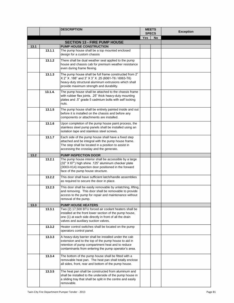
DESCRIPTIONException
Yes No
MEETS
SPECS
13.1 PUMP HOUSE CONSTRUCTION
13.1.1 The pump house shall be a top mounted enclosed
design for a custom chassis
13.1.2 There shall be dual weather seal applied to the pump
house and chassis cab for premium weather resistance
even during frame flexing.
13.1.3 The pump house shall be full frame constructed from 2”
X 2” X .188” and 3” X 3” X .25 (6061-T6 / 6063-T6)
heavy-duty structural aluminum extrusions which shall
provide maximum strength and durability.
13.1.4. The pump house shall be attached to the chassis frame
with rubber flex joints, .25” thick heavy-duty mounting
plates and .5” grade 5 cadmium bolts with self locking
nuts.
13.1.5 The pump house shall be entirely painted inside and out
before it is installed on the chassis and before any
components or attachments are installed.
13.1.6 Upon completion of the pump house paint process, the
stainless steel pump panels shall be installed using an
isolation tape and stainless steel screws.
13.1.7 Each side of the pump house shall have a fixed step
attached and be integral with the pump house frame.
The step shall be located in a position to assist in
accessing the crosslay and the generato.
13.2 PUMP INSPECTION DOOR
13.2.1 The pump house interior shall be accessible by a large
(32” X 67”) high shine .125” aluminum checker plate
(3003-H14) inspection door positioned in the forward
face of the pump house structure.
13.2.2 This door shall have sufficient latch/handle assemblies
as required to secure the door in place.
13.2.3 This door shall be easily removable by unlatching, lifting,
and removing. This door shall be removable to provide
access to the pump for repair and maintenance without
removal of the pump.
13.3 PUMP HOUSE HEATERS
13.3.1 Two (2) 17,500 BTU forced air coolant heaters shall be
installed at the front lower section of the pump house,
one (1) at each side directly in front of all the drain
valves and auxiliary suction valves.
13.3.2 Heater control switches shall be located on the pump
operators control panel.
13.3.3 A heavy-duty barrier shall be installed under the cab
extension and to the top of the pump house to aid in
retention of pump compartment heat and to reduce
contaminants from entering the pump operator‟s area.
13.3.4 The bottom of the pump house shall be fitted with a
removable heat pan. The heat pan shall totally enclose
all sides, front, rear and bottom of the pump house.
13.3.5 The heat pan shall be constructed from aluminum and
shall be installed to the underside of the pump house in
a sliding tray that shall be split in the centre and easily
removable.
SECTION 13 - FIRE PUMP HOUSE
Twin-City Fire Department Pumper Tender - 2013 Page 81
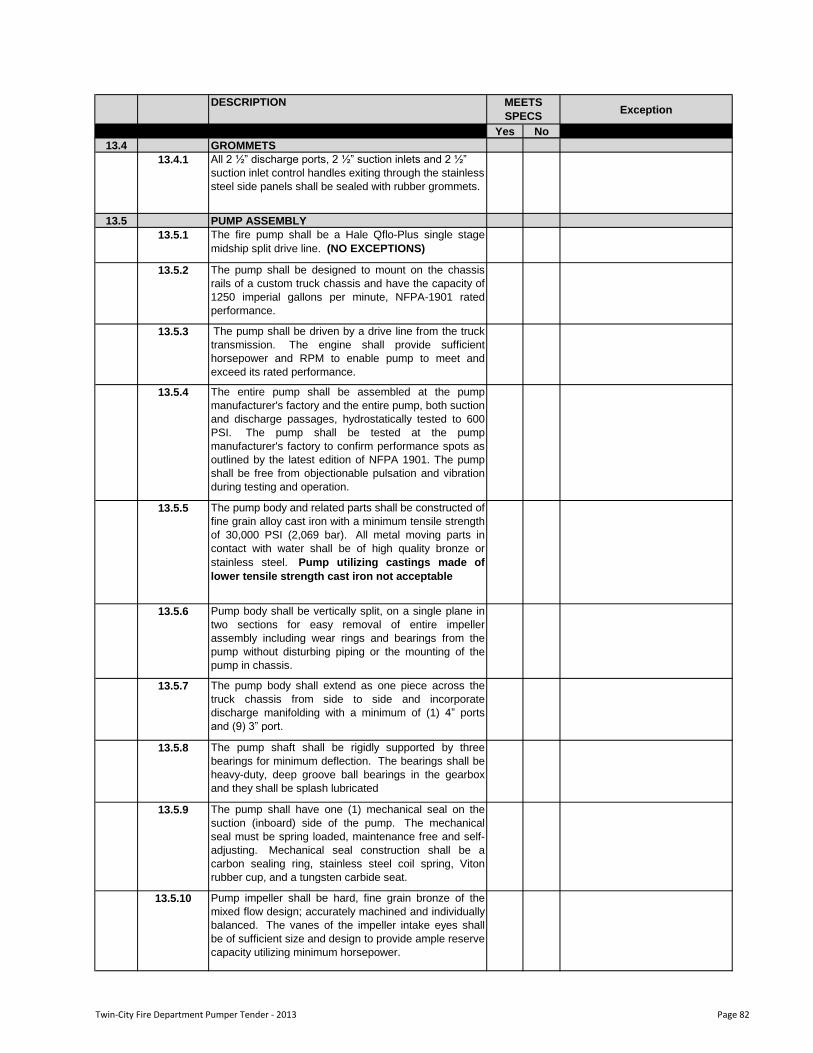
DESCRIPTIONException
Yes No
MEETS
SPECS
13.4 GROMMETS
13.4.1 All 2 ½” discharge ports, 2 ½” suction inlets and 2 ½”
suction inlet control handles exiting through the stainless
steel side panels shall be sealed with rubber grommets.
13.5 PUMP ASSEMBLY
13.5.1 The fire pump shall be a Hale Qflo-Plus single stage
midship split drive line. (NO EXCEPTIONS)
13.5.2 The pump shall be designed to mount on the chassis
rails of a custom truck chassis and have the capacity of
1250 imperial gallons per minute, NFPA-1901 rated
performance.
13.5.3 The pump shall be driven by a drive line from the truck
transmission. The engine shall provide sufficient
horsepower and RPM to enable pump to meet and
exceed its rated performance.
13.5.4 The entire pump shall be assembled at the pump
manufacturer's factory and the entire pump, both suction
and discharge passages, hydrostatically tested to 600
PSI. The pump shall be tested at the pump
manufacturer's factory to confirm performance spots as
outlined by the latest edition of NFPA 1901. The pump
shall be free from objectionable pulsation and vibration
during testing and operation.
13.5.5 The pump body and related parts shall be constructed of
fine grain alloy cast iron with a minimum tensile strength
of 30,000 PSI (2,069 bar). All metal moving parts in
contact with water shall be of high quality bronze or
stainless steel. Pump utilizing castings made of
lower tensile strength cast iron not acceptable
13.5.6 Pump body shall be vertically split, on a single plane in
two sections for easy removal of entire impeller
assembly including wear rings and bearings from the
pump without disturbing piping or the mounting of the
pump in chassis.
13.5.7 The pump body shall extend as one piece across the
truck chassis from side to side and incorporate
discharge manifolding with a minimum of (1) 4” ports
and (9) 3” port.
13.5.8 The pump shaft shall be rigidly supported by three
bearings for minimum deflection. The bearings shall be
heavy-duty, deep groove ball bearings in the gearbox
and they shall be splash lubricated
13.5.9 The pump shall have one (1) mechanical seal on the
suction (inboard) side of the pump. The mechanical
seal must be spring loaded, maintenance free and self-
adjusting. Mechanical seal construction shall be a
carbon sealing ring, stainless steel coil spring, Viton
rubber cup, and a tungsten carbide seat.
13.5.10 Pump impeller shall be hard, fine grain bronze of the
mixed flow design; accurately machined and individually
balanced. The vanes of the impeller intake eyes shall
be of sufficient size and design to provide ample reserve
capacity utilizing minimum horsepower.
Twin-City Fire Department Pumper Tender - 2013 Page 82
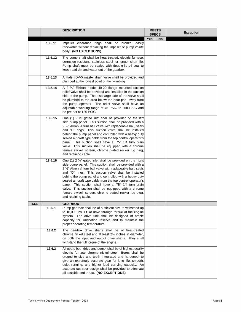
DESCRIPTIONException
Yes No
MEETS
SPECS
13.5.11 Impeller clearance rings shall be bronze, easily
renewable without replacing the impeller or pump volute
body. (NO EXCEPTIONS)
13.5.12 The pump shaft shall be heat treated, electric furnace,
corrosion resistant, stainless steel for longer shaft life.
Pump shaft must be sealed with double-lip oil seal to
keep road dirt and water out of the gearbox
13.5.13 A Hale #DV-5 master drain valve shall be provided and
plumbed at the lowest point of the plumbing
13.5.14 A 2 ½” Elkhart model 40-20 flange mounted suction
relief valve shall be provided and installed in the suction
side of the pump. The discharge side of the valve shall
be plumbed to the area below the heat pan, away from
the pump operator. The relief valve shall have an
adjustable working range of 75 PSIG to 250 PSIG and
be pre-set at 125 PSIG.
13.5.15 One (1) 2 ½” gated inlet shall be provided on the left
side pump panel. This suction shall be provided with a
2 ½” Akron ¼ turn ball valve with replaceable ball, seals
and “O” rings. This suction valve shall be installed
behind the pump panel and controlled with a heavy duty
sealed air craft type cable from the top control operator's
panel. This suction shall have a .75" 1/4 turn drain
valve. This suction shall be equipped with a chrome
female swivel, screen, chrome plated rocker lug plug,
and retaining cable.
13.5.16 One (1) 2 ½” gated inlet shall be provided on the right
side pump panel. This suction shall be provided with a
2 ½” Akron ¼ turn ball valve with replaceable ball, seals
and “O” rings. This suction valve shall be installed
behind the pump panel and controlled with a heavy duty
sealed air craft type cable from the top control operator's
panel. This suction shall have a .75" 1/4 turn drain
valve. This suction shall be equipped with a chrome
female swivel, screen, chrome plated rocker lug plug,
and retaining cable.
13.6 GEARBOX
13.6.1 Pump gearbox shall be of sufficient size to withstand up
to 16,000 lbs. Ft. of drive through torque of the engine
system. The drive unit shall be designed of ample
capacity for lubrication reserve and to maintain the
proper operating temperature.
13.6.2 The gearbox drive shafts shall be of heat-treated
chrome nickel steel and at least 2¾ inches in diameter,
on both the input and output drive shafts. They shall
withstand the full torque of the engine.
13.6.3 All gears both drive and pump, shall be of highest quality
electric furnace chrome nickel steel. Bores shall be
ground to size and teeth integrated and hardened, to
give an extremely accurate gear for long life, smooth,
quiet running, and higher load carrying capacity. An
accurate cut spur design shall be provided to eliminate
all possible end thrust. (NO EXCEPTIONS)
Twin-City Fire Department Pumper Tender - 2013 Page 83

DESCRIPTIONException
Yes No
MEETS
SPECS
13.6.4 The pump ratio shall be selected by the apparatus
manufacturer to give maximum performance with the
engine and transmission selected.
13.6.5 The gearbox shall be equipped with an air powered,
power shift. The shifting mechanism shall be heat
treated, hard anodized aluminum power cylinder, with
stainless steel shaft. An in-cab control for rapid shift
shall be provided that locks in road or pump.
13.6.6 Three green warning lights shall be provided to indicate
to the operator when the truck has completed the shift
from “Road” to “Pump” position. Two green lights to be
located in the truck driving compartment and one green
light on the operator‟s panel adjacent to the throttle
control. All light to have appropriate
identification/instruction plates.
13.7 PRIMING PUMP
13.7.1 The priming pump shall be a positive displacement, oil-
less rotary vane electric motor driven pump conforming
to the requirements of NFPA 1901. The pump body
shall be manufactured of heat treated anodized
aluminum for wear and corrosion resistance.
13.7.2 The pump shall be capable of producing a minimum 24
Hg vacuum at 2000 feet above sea level.
13.7.3 The electric motor shall be 12 VDC or 24 VDC, Matched
to the Chassis voltage, totally enclosed unit.
13.7.4 The priming pump shall not require lubrication.
13.7.5 The priming pump shall be operated by a single push-
pull control valve mounted on the pump operator panel.
The control valve shall be all bronze construction.
13.8 ANODES
13.8.1 Three zinc consumable anodes shall be installed on the
pump - one on each suction tube and one on the
discharge.
13.9 MASTER INTAKE VALVE
13.9.1 There shall be two (2) master intake valves, one
mounted on each side of the pump.
13.9.2 The inlet valves shall be a full flow butterfly valve
designed to mount on the fire pump between the suction
tube extension and suction tube behind the pump
compartment panel. The valve shall not interfere with
other suction or discharge openings on the fire pump or
with operator controls when properly mounted.
13.9.3 The entire valve shall be manufactured and tested at the
pump manufacturer‟s factory
13.9.4 When the valve is installed in the fire pump suction, the
fire pump shall be capable of achieving an NFPA/ULC
test rating of 1500 US GPM through a single 6 inch NST
suction hose. When two valves are installed on the fire
pump, the pump shall be capable of achieving an
NFPA/ULC test rating of 2000 US GPM using dual 6
inch NST suction hose.
Twin-City Fire Department Pumper Tender - 2013 Page 84
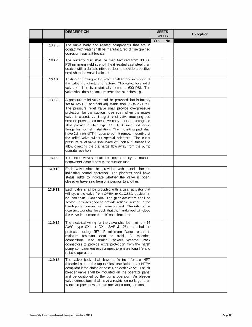
DESCRIPTIONException
Yes No
MEETS
SPECS
13.9.5 The valve body and related components that are in
contact with water shall be manufactured of fine grained
corrosion resistant bronze.
13.9.6 The butterfly disc shall be manufactured from 80,000
PSI minimum yield strength heat treated cast steel then
coated with a durable nitrile rubber to provide a positive
seal when the valve is closed
13.9.7 Testing and rating of the valve shall be accomplished at
the valve manufacturer‟s factory. The valve, less relief
valve, shall be hydrostatically tested to 600 PSI. The
valve shall then be vacuum tested to 26 inches Hg.
13.9.8 A pressure relief valve shall be provided that is factory
set to 125 PSI and field adjustable from 75 to 250 PSI.
The pressure relief valve shall provide overpressure
protection for the suction hose even when the intake
valve is closed. An integral relief valve mounting pad
shall be provided on the valve body. This mounting pad
shall provide a Hale type 115 4-3/8 inch Bolt circle
flange for normal installation. The mounting pad shall
have 2½ inch NPT threads to permit remote mounting of
the relief valve without special adapters. The outlet
pressure relief valve shall have 2½ inch NPT threads to
allow directing the discharge flow away from the pump
operator position
13.9.9 The inlet valves shall be operated by a manual
handwheel located next to the suction tube.
13.9.10 Each valve shall be provided with panel placards
indicating control operation. The placards shall have
status lights to indicate whether the valve is open,
closed or traversing from one position to another.
13.9.11 Each valve shall be provided with a gear actuator that
will cycle the valve from OPEN to CLOSED position in
no less than 3 seconds. The gear actuators shall be
sealed units designed to provide reliable service in the
harsh pump compartment environment. The ratio of the
gear actuator shall be such that the handwheel will close
the valve in no more than 10 complete turns
13.9.12 The electrical wiring for the valve shall be minimum 14
AWG, type SXL or GXL (SAE J1128) and shall be
protected using 257o
F minimum flame retardant,
moisture resistant loom or braid. All electrical
connections used sealed Packard Weather Pack
connectors to provide extra protection from the harsh
pump compartment environment to ensure long life and
reliable operation.
13.9.13 The valve body shall have a ¾ inch female NPT
threaded port on the top to allow installation of an NFPA
compliant large diameter hose air bleeder valve. The air
bleeder valve shall be mounted on the operator panel
and be controlled by the pump operator. Air bleeder
valve connections shall have a restriction no larger than
¾ inch to prevent water hammer when filling the hose.
Twin-City Fire Department Pumper Tender - 2013 Page 85
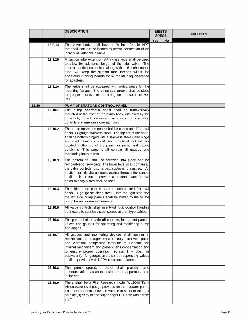
DESCRIPTIONException
Yes No
MEETS
SPECS
13.9.14 The valve body shall have a ¼ inch female NPT
threaded port on the bottom to permit connection of an
individual water drain valve.
13.9.15 A suction tube extension 7¼ inches wide shall be used
to allow for additional length of the inlet valve. The
shorter suction extension, along with a 6 inch suction
tube, will keep the suction tube threads within the
apparatus running boards while maintaining clearance
for adapters.
13.9.16 The valve shall be equipped with o-ring seals for the
mounting flanges. The o-ring seal groove shall be sized
for proper squeeze of the o-ring for pressures of 600
PSI.
13.10 PUMP OPERATORS CONTROL PANEL
13.10.1 The pump operator‟s panel shall be transversally
mounted at the front of the pump body, enclosed by the
crew cab, provide convenient access to the operating
controls and maximize operator vision
13.10.2 The pump operator‟s panel shall be constructed from #4
finish, 14 gauge stainless steel. The top tier of the panel
shall be bottom hinged with a stainless steel piano hinge
and shall have two (2) lift and turn twist lock latches
located at the top of the panel for pump and gauge
servicing. This panel shall contain all gauges and
monitoring instruments
13.10.3 The bottom tier shall be screwed into place and be
removable for servicing. The lower level shall contain all
the valve controls, discharges, suctions, drains, etc. All
suction and discharge ports exiting through the panels
shall be laser cut to provide a smooth exact fit. No
cover overlay plates shall be used.
13.10.4 The side pump panels shall be constructed from #4
finish, 14 gauge stainless steel. Both the right side and
the left side pump panels shall be bolted to the to the
pump house for ease of removal.
13.10.5 All valve controls shall use twist lock control handles
connected to stainless steel sealed aircraft type cables.
13.10.6 The panel shall provide all controls, instrument panels,
valves and gauges for operating and monitoring pump
and engine
13.10.7 All gauges and monitoring devices shall register in
Metric values. Gauges shall be fully filled with pulse
and vibration dampening Interlube to lubricate the
internal mechanism and prevent lens condensation and
to ensure proper operation. (Class 1 – Span or
equivalent). All gauges and their corresponding valves
shall be provided with NFPA color coded labels.
13.10.8 The pump operator‟s panel shall provide radio
communications as an extension of the apparatus radio
in the cab.
13.10.9 There shall be a Fire Research model WL2000 Tank
Vision water level gauge provided on the operator panel.
The indicator shall show the volume of water in the tank
on nine (9) easy to see super bright LEDs viewable from
180o.
Twin-City Fire Department Pumper Tender - 2013 Page 86
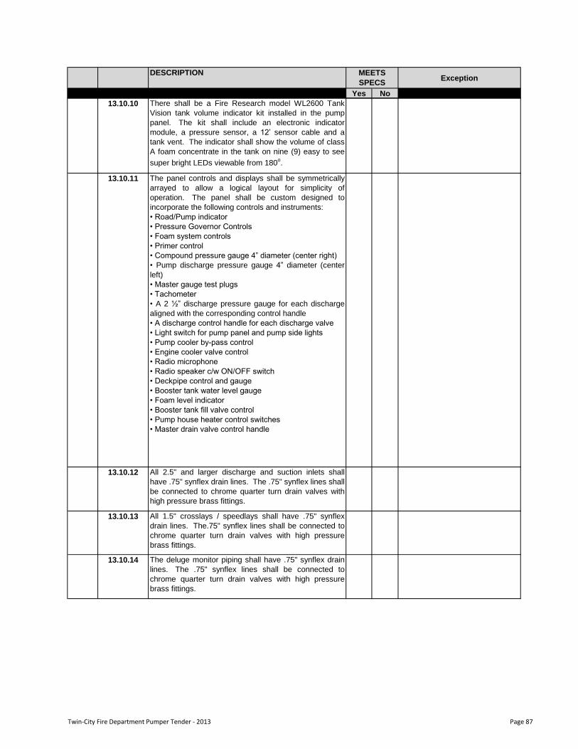
DESCRIPTIONException
Yes No
MEETS
SPECS
13.10.10 There shall be a Fire Research model WL2600 Tank
Vision tank volume indicator kit installed in the pump
panel. The kit shall include an electronic indicator
module, a pressure sensor, a 12‟ sensor cable and a
tank vent. The indicator shall show the volume of class
A foam concentrate in the tank on nine (9) easy to see
super bright LEDs viewable from 180o.
13.10.12 All 2.5" and larger discharge and suction inlets shall
have .75" synflex drain lines. The .75" synflex lines shall
be connected to chrome quarter turn drain valves with
high pressure brass fittings.
13.10.13 All 1.5" crosslays / speedlays shall have .75" synflex
drain lines. The.75" synflex lines shall be connected to
chrome quarter turn drain valves with high pressure
brass fittings.
13.10.14 The deluge monitor piping shall have .75" synflex drain
lines. The .75" synflex lines shall be connected to
chrome quarter turn drain valves with high pressure
brass fittings.
The panel controls and displays shall be symmetrically
arrayed to allow a logical layout for simplicity of
operation. The panel shall be custom designed to
incorporate the following controls and instruments:
• Road/Pump indicator
• Pressure Governor Controls
• Foam system controls
• Primer control
• Compound pressure gauge 4” diameter (center right)
• Pump discharge pressure gauge 4” diameter (center
left)
• Master gauge test plugs
• Tachometer
• A 2 ½” discharge pressure gauge for each discharge
aligned with the corresponding control handle
• A discharge control handle for each discharge valve
• Light switch for pump panel and pump side lights
• Pump cooler by-pass control
• Engine cooler valve control
• Radio microphone
• Radio speaker c/w ON/OFF switch
• Deckpipe control and gauge
• Booster tank water level gauge
• Foam level indicator
• Booster tank fill valve control
• Pump house heater control switches
• Master drain valve control handle
13.10.11
Twin-City Fire Department Pumper Tender - 2013 Page 87
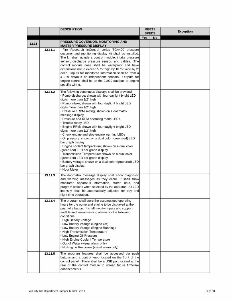
DESCRIPTIONException
Yes No
MEETS
SPECS
13.11 PRESSURE GOVERNOR, MONITORING AND
MASTER PRESSURE DISPLAY
13.11.1 Fire Research InControl series TGA400 pressure
governor and monitoring display kit shall be installed.
The kit shall include a control module, intake pressure
sensor, discharge pressure sensor, and cables. The
control module case shall be waterproof and have
dimensions not to exceed 5 ½” high by 10 ½” wide by 2”
deep. Inputs for monitored information shall be from a
J1939 databus or independent sensors. Outputs for
engine control shall be on the J1939 databus or engine
specific wiring.
13.11.2 The following continuous displays shall be provided:
• Pump discharge; shown with four daylight bright LED
digits more than 1/2" high
• Pump Intake; shown with four daylight bright LED
digits more than 1/2" high
• Pressure / RPM setting; shown on a dot matrix
message display
• Pressure and RPM operating mode LEDs
• Throttle ready LED
• Engine RPM; shown with four daylight bright LED
digits more than 1/2" high
• Check engine and stop engine warning LEDs
• Oil pressure; shown on a dual color (green/red) LED
bar graph display
• Engine coolant temperature; shown on a dual color
(green/red) LED bar graph display
• Transmission Temperature: shown on a dual color
(green/red) LED bar graph display
• Battery voltage; shown on a dual color (green/red) LED
bar graph display.
• Hour Meter
13.11.3 The dot-matrix message display shall show diagnostic
and warning messages as they occur. It shall show
monitored apparatus information, stored data, and
program options when selected by the operator. All LED
intensity shall be automatically adjusted for day and
night time operation.
13.11.4 The program shall store the accumulated operating
hours for the pump and engine to be displayed at the
push of a button. It shall monitor inputs and support
audible and visual warning alarms for the following
conditions:
• High Battery Voltage
• Low Battery Voltage (Engine Off)
• Low Battery Voltage (Engine Running)
• High Transmission Temperature
• Low Engine Oil Pressure
• High Engine Coolant Temperature
• Out of Water (visual alarm only)
• No Engine Response (visual alarm only)
13.11.5 The program features shall be accessed via push
buttons and a control knob located on the front of the
control panel. There shall be a USB port located at the
rear of the control module to upload future firmware
enhancements.
Twin-City Fire Department Pumper Tender - 2013 Page 88
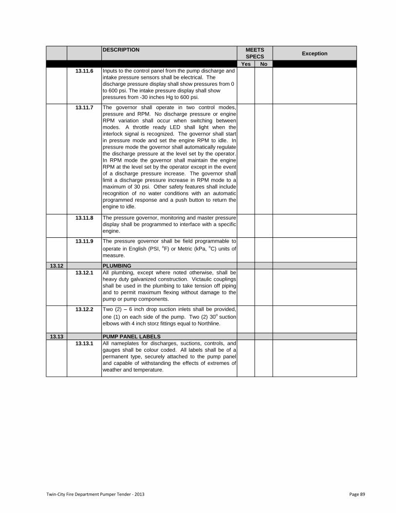
DESCRIPTIONException
Yes No
MEETS
SPECS
13.11.6 Inputs to the control panel from the pump discharge and
intake pressure sensors shall be electrical. The
discharge pressure display shall show pressures from 0
to 600 psi. The intake pressure display shall show
pressures from -30 inches Hg to 600 psi.
13.11.7 The governor shall operate in two control modes,
pressure and RPM. No discharge pressure or engine
RPM variation shall occur when switching between
modes. A throttle ready LED shall light when the
interlock signal is recognized. The governor shall start
in pressure mode and set the engine RPM to idle. In
pressure mode the governor shall automatically regulate
the discharge pressure at the level set by the operator.
In RPM mode the governor shall maintain the engine
RPM at the level set by the operator except in the event
of a discharge pressure increase. The governor shall
limit a discharge pressure increase in RPM mode to a
maximum of 30 psi. Other safety features shall include
recognition of no water conditions with an automatic
programmed response and a push button to return the
engine to idle.
13.11.8 The pressure governor, monitoring and master pressure
display shall be programmed to interface with a specific
engine.
13.11.9 The pressure governor shall be field programmable to
operate in English (PSI,oF) or Metric (kPa,
oC) units of
measure.
13.12 PLUMBING
13.12.1 All plumbing, except where noted otherwise, shall be
heavy duty galvanized construction. Victaulic couplings
shall be used in the plumbing to take tension off piping
and to permit maximum flexing without damage to the
pump or pump components.
13.12.2 Two (2) – 6 inch drop suction inlets shall be provided,
one (1) on each side of the pump. Two (2) 30o
suction
elbows with 4 inch storz fittings equal to Northline.
13.13 PUMP PANEL LABELS
13.13.1 All nameplates for discharges, suctions, controls, and
gauges shall be colour coded. All labels shall be of a
permanent type, securely attached to the pump panel
and capable of withstanding the effects of extremes of
weather and temperature.
Twin-City Fire Department Pumper Tender - 2013 Page 89
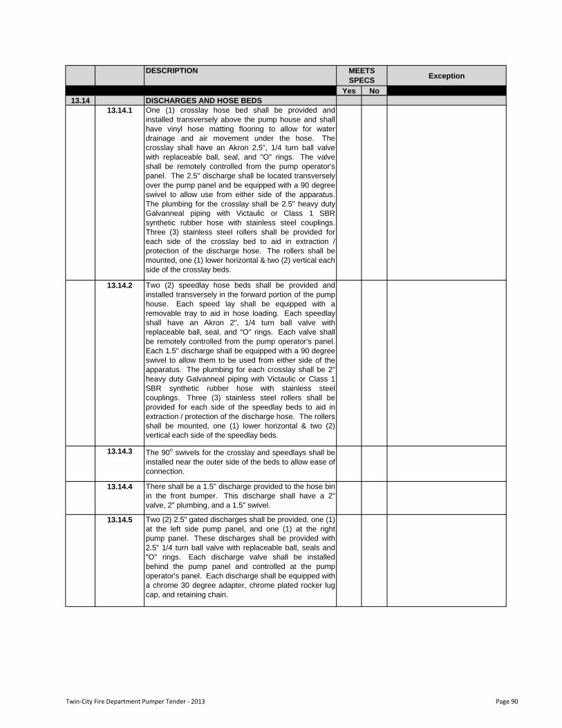
DESCRIPTIONException
Yes No
MEETS
SPECS
13.14 DISCHARGES AND HOSE BEDS
13.14.1 One (1) crosslay hose bed shall be provided and
installed transversely above the pump house and shall
have vinyl hose matting flooring to allow for water
drainage and air movement under the hose. The
crosslay shall have an Akron 2.5", 1/4 turn ball valve
with replaceable ball, seal, and "O" rings. The valve
shall be remotely controlled from the pump operator's
panel. The 2.5" discharge shall be located transversely
over the pump panel and be equipped with a 90 degree
swivel to allow use from either side of the apparatus.
The plumbing for the crosslay shall be 2.5" heavy duty
Galvanneal piping with Victaulic or Class 1 SBR
synthetic rubber hose with stainless steel couplings.
Three (3) stainless steel rollers shall be provided for
each side of the crosslay bed to aid in extraction /
protection of the discharge hose. The rollers shall be
mounted, one (1) lower horizontal & two (2) vertical each
side of the crosslay beds.
13.14.2 Two (2) speedlay hose beds shall be provided and
installed transversely in the forward portion of the pump
house. Each speed lay shall be equipped with a
removable tray to aid in hose loading. Each speedlay
shall have an Akron 2", 1/4 turn ball valve with
replaceable ball, seal, and "O" rings. Each valve shall
be remotely controlled from the pump operator's panel.
Each 1.5" discharge shall be equipped with a 90 degree
swivel to allow them to be used from either side of the
apparatus. The plumbing for each crosslay shall be 2"
heavy duty Galvanneal piping with Victaulic or Class 1
SBR synthetic rubber hose with stainless steel
couplings. Three (3) stainless steel rollers shall be
provided for each side of the speedlay beds to aid in
extraction / protection of the discharge hose. The rollers
shall be mounted, one (1) lower horizontal & two (2)
vertical each side of the speedlay beds.
13.14.3 The 90o
swivels for the crosslay and speedlays shall be
installed near the outer side of the beds to allow ease of
connection.
13.14.4 There shall be a 1.5" discharge provided to the hose bin
in the front bumper. This discharge shall have a 2"
valve, 2" plumbing, and a 1.5" swivel.
13.14.5 Two (2) 2.5" gated discharges shall be provided, one (1)
at the left side pump panel, and one (1) at the right
pump panel. These discharges shall be provided with
2.5" 1/4 turn ball valve with replaceable ball, seals and
"O" rings. Each discharge valve shall be installed
behind the pump panel and controlled at the pump
operator's panel. Each discharge shall be equipped with
a chrome 30 degree adapter, chrome plated rocker lug
cap, and retaining chain.
Twin-City Fire Department Pumper Tender - 2013 Page 90
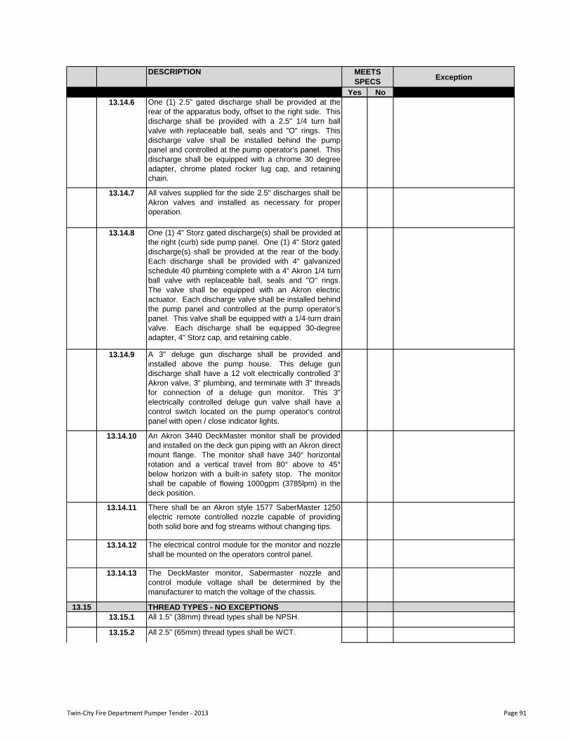
DESCRIPTIONException
Yes No
MEETS
SPECS
13.14.6 One (1) 2.5" gated discharge shall be provided at the
rear of the apparatus body, offset to the right side. This
discharge shall be provided with a 2.5" 1/4 turn ball
valve with replaceable ball, seals and "O" rings. This
discharge valve shall be installed behind the pump
panel and controlled at the pump operator's panel. This
discharge shall be equipped with a chrome 30 degree
adapter, chrome plated rocker lug cap, and retaining
chain.
13.14.7 All valves supplied for the side 2.5" discharges shall be
Akron valves and installed as necessary for proper
operation.
13.14.8 One (1) 4" Storz gated discharge(s) shall be provided at
the right (curb) side pump panel. One (1) 4" Storz gated
discharge(s) shall be provided at the rear of the body.
Each discharge shall be provided with 4" galvanized
schedule 40 plumbing complete with a 4" Akron 1/4 turn
ball valve with replaceable ball, seals and "O" rings.
The valve shall be equipped with an Akron electric
actuator. Each discharge valve shall be installed behind
the pump panel and controlled at the pump operator's
panel. This valve shall be equipped with a 1/4-turn drain
valve. Each discharge shall be equipped 30-degree
adapter, 4" Storz cap, and retaining cable.
13.14.9 A 3" deluge gun discharge shall be provided and
installed above the pump house. This deluge gun
discharge shall have a 12 volt electrically controlled 3"
Akron valve, 3" plumbing, and terminate with 3" threads
for connection of a deluge gun monitor. This 3"
electrically controlled deluge gun valve shall have a
control switch located on the pump operator's control
panel with open / close indicator lights.
13.14.10 An Akron 3440 DeckMaster monitor shall be provided
and installed on the deck gun piping with an Akron direct
mount flange. The monitor shall have 340° horizontal
rotation and a vertical travel from 80° above to 45°
below horizon with a built-in safety stop. The monitor
shall be capable of flowing 1000gpm (3785lpm) in the
deck position.
13.14.11 There shall be an Akron style 1577 SaberMaster 1250
electric remote controlled nozzle capable of providing
both solid bore and fog streams without changing tips.
13.14.12 The electrical control module for the monitor and nozzle
shall be mounted on the operators control panel.
13.14.13 The DeckMaster monitor, Sabermaster nozzle and
control module voltage shall be determined by the
manufacturer to match the voltage of the chassis.
13.15 THREAD TYPES - NO EXCEPTIONS
13.15.1 All 1.5" (38mm) thread types shall be NPSH.
13.15.2 All 2.5" (65mm) thread types shall be WCT.
Twin-City Fire Department Pumper Tender - 2013 Page 91
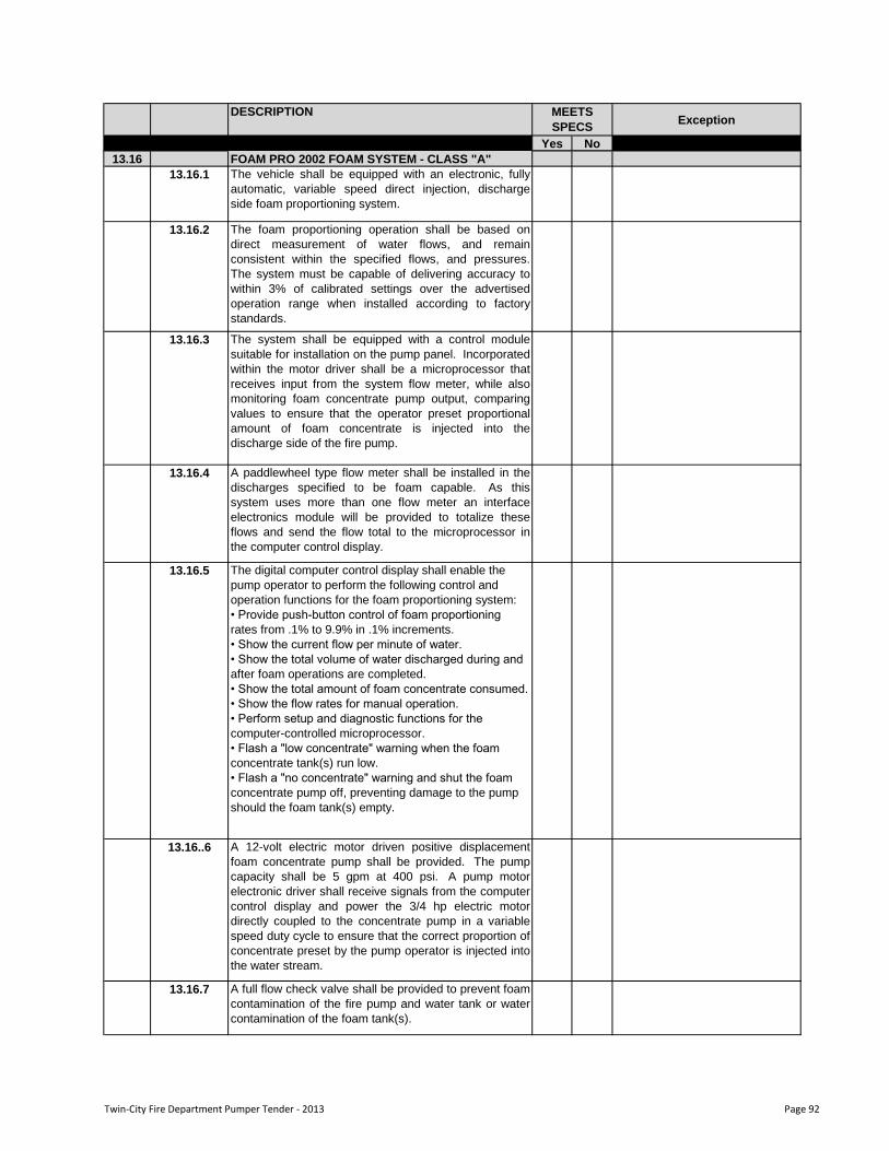
DESCRIPTIONException
Yes No
MEETS
SPECS
13.16 FOAM PRO 2002 FOAM SYSTEM - CLASS "A"
13.16.1 The vehicle shall be equipped with an electronic, fully
automatic, variable speed direct injection, discharge
side foam proportioning system.
13.16.2 The foam proportioning operation shall be based on
direct measurement of water flows, and remain
consistent within the specified flows, and pressures.
The system must be capable of delivering accuracy to
within 3% of calibrated settings over the advertised
operation range when installed according to factory
standards.
13.16.3 The system shall be equipped with a control module
suitable for installation on the pump panel. Incorporated
within the motor driver shall be a microprocessor that
receives input from the system flow meter, while also
monitoring foam concentrate pump output, comparing
values to ensure that the operator preset proportional
amount of foam concentrate is injected into the
discharge side of the fire pump.
13.16.4 A paddlewheel type flow meter shall be installed in the
discharges specified to be foam capable. As this
system uses more than one flow meter an interface
electronics module will be provided to totalize these
flows and send the flow total to the microprocessor in
the computer control display.
13.16.5 The digital computer control display shall enable the
pump operator to perform the following control and
operation functions for the foam proportioning system:
• Provide push-button control of foam proportioning
rates from .1% to 9.9% in .1% increments.
• Show the current flow per minute of water.
• Show the total volume of water discharged during and
after foam operations are completed.
• Show the total amount of foam concentrate consumed.
• Show the flow rates for manual operation.
• Perform setup and diagnostic functions for the
computer-controlled microprocessor.
• Flash a "low concentrate" warning when the foam
concentrate tank(s) run low.
• Flash a "no concentrate" warning and shut the foam
concentrate pump off, preventing damage to the pump
should the foam tank(s) empty.
13.16..6 A 12-volt electric motor driven positive displacement
foam concentrate pump shall be provided. The pump
capacity shall be 5 gpm at 400 psi. A pump motor
electronic driver shall receive signals from the computer
control display and power the 3/4 hp electric motor
directly coupled to the concentrate pump in a variable
speed duty cycle to ensure that the correct proportion of
concentrate preset by the pump operator is injected into
the water stream.
13.16.7 A full flow check valve shall be provided to prevent foam
contamination of the fire pump and water tank or water
contamination of the foam tank(s).
Twin-City Fire Department Pumper Tender - 2013 Page 92
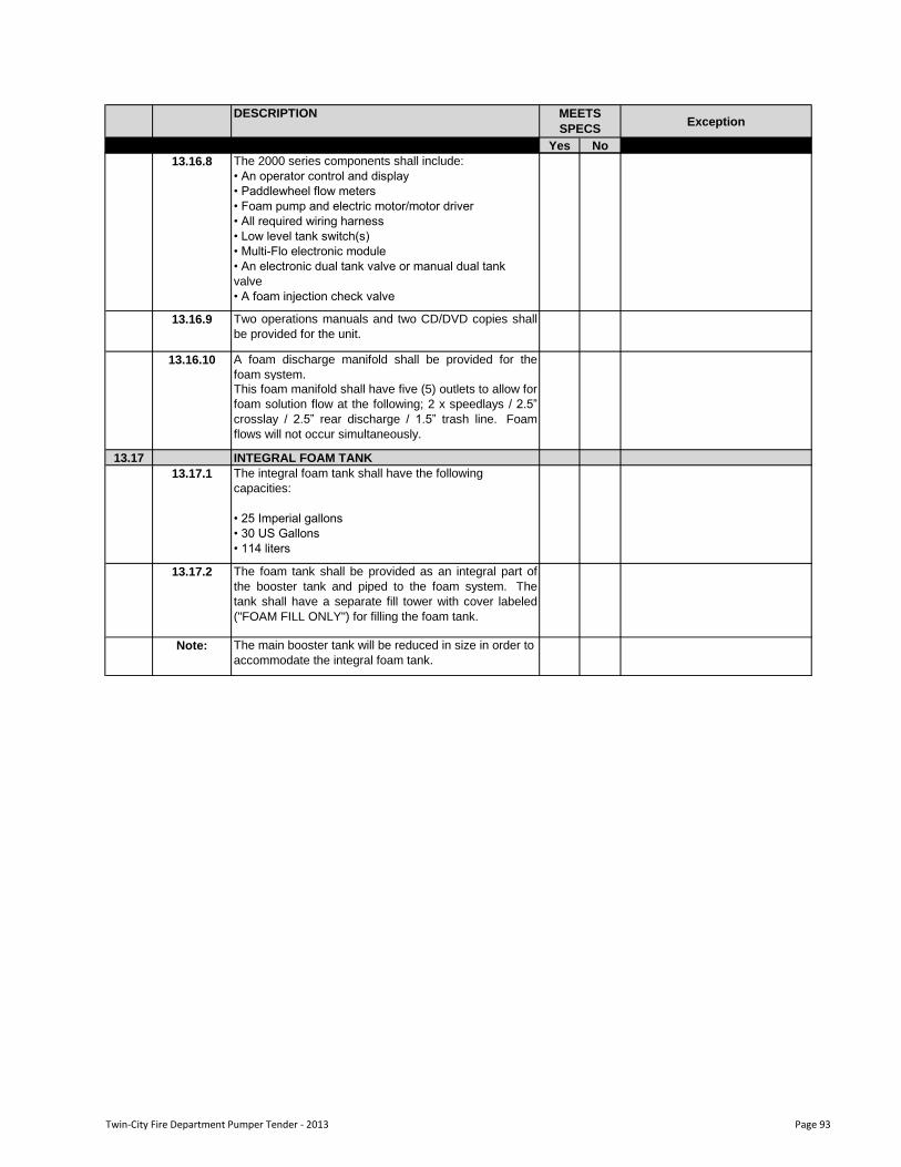
DESCRIPTIONException
Yes No
MEETS
SPECS
13.16.8 The 2000 series components shall include:
• An operator control and display
• Paddlewheel flow meters
• Foam pump and electric motor/motor driver
• All required wiring harness
• Low level tank switch(s)
• Multi-Flo electronic module
• An electronic dual tank valve or manual dual tank
valve
• A foam injection check valve
13.16.9 Two operations manuals and two CD/DVD copies shall
be provided for the unit.
A foam discharge manifold shall be provided for the
foam system.
This foam manifold shall have five (5) outlets to allow for
foam solution flow at the following; 2 x speedlays / 2.5”
crosslay / 2.5” rear discharge / 1.5” trash line. Foam
flows will not occur simultaneously.
13.17 INTEGRAL FOAM TANK
13.17.1 The integral foam tank shall have the following
capacities:
• 25 Imperial gallons
• 30 US Gallons
• 114 liters
13.17.2 The foam tank shall be provided as an integral part of
the booster tank and piped to the foam system. The
tank shall have a separate fill tower with cover labeled
("FOAM FILL ONLY") for filling the foam tank.
Note: The main booster tank will be reduced in size in order to
accommodate the integral foam tank.
13.16.10
Twin-City Fire Department Pumper Tender - 2013 Page 93
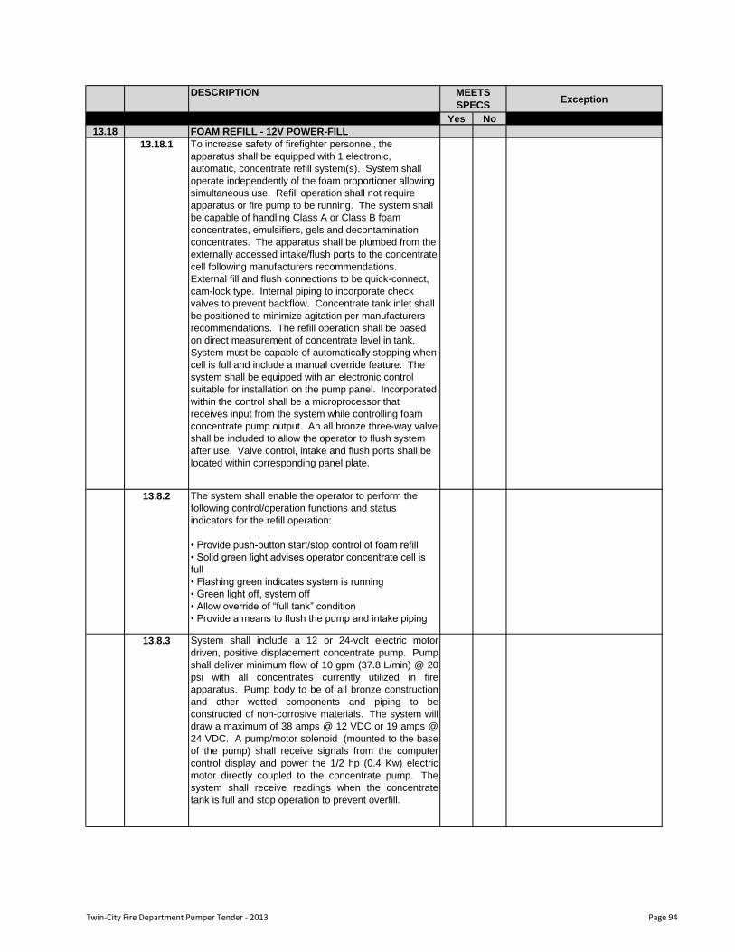
DESCRIPTIONException
Yes No
MEETS
SPECS
13.18 FOAM REFILL - 12V POWER-FILL
13.8.2 The system shall enable the operator to perform the
following control/operation functions and status
indicators for the refill operation:
• Provide push-button start/stop control of foam refill
• Solid green light advises operator concentrate cell is
full
• Flashing green indicates system is running
• Green light off, system off
• Allow override of “full tank” condition
• Provide a means to flush the pump and intake piping
13.8.3 System shall include a 12 or 24-volt electric motor
driven, positive displacement concentrate pump. Pump
shall deliver minimum flow of 10 gpm (37.8 L/min) @ 20
psi with all concentrates currently utilized in fire
apparatus. Pump body to be of all bronze construction
and other wetted components and piping to be
constructed of non-corrosive materials. The system will
draw a maximum of 38 amps @ 12 VDC or 19 amps @
24 VDC. A pump/motor solenoid (mounted to the base
of the pump) shall receive signals from the computer
control display and power the 1/2 hp (0.4 Kw) electric
motor directly coupled to the concentrate pump. The
system shall receive readings when the concentrate
tank is full and stop operation to prevent overfill.
To increase safety of firefighter personnel, the
apparatus shall be equipped with 1 electronic,
automatic, concentrate refill system(s). System shall
operate independently of the foam proportioner allowing
simultaneous use. Refill operation shall not require
apparatus or fire pump to be running. The system shall
be capable of handling Class A or Class B foam
concentrates, emulsifiers, gels and decontamination
concentrates. The apparatus shall be plumbed from the
externally accessed intake/flush ports to the concentrate
cell following manufacturers recommendations.
External fill and flush connections to be quick-connect,
cam-lock type. Internal piping to incorporate check
valves to prevent backflow. Concentrate tank inlet shall
be positioned to minimize agitation per manufacturers
recommendations. The refill operation shall be based
on direct measurement of concentrate level in tank.
System must be capable of automatically stopping when
cell is full and include a manual override feature. The
system shall be equipped with an electronic control
suitable for installation on the pump panel. Incorporated
within the control shall be a microprocessor that
receives input from the system while controlling foam
concentrate pump output. An all bronze three-way valve
shall be included to allow the operator to flush system
after use. Valve control, intake and flush ports shall be
located within corresponding panel plate.
13.18.1
Twin-City Fire Department Pumper Tender - 2013 Page 94
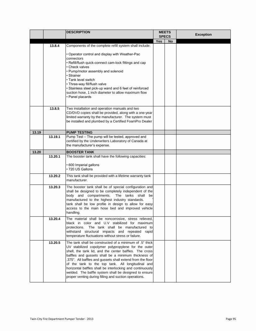
DESCRIPTIONException
Yes No
MEETS
SPECS
13.8.4 Components of the complete refill system shall include:
• Operator control and display with Weather-Pac
connectors
• Refill/flush quick-connect cam-lock fittings and cap
• Check valves
• Pump/motor assembly and solenoid
• Strainer
• Tank level switch
• Three-way fill/flush valve
• Stainless steel pick-up wand and 6 feet of reinforced
suction hose, 1 inch diameter to allow maximum flow
• Panel placards
13.8.5 Two installation and operation manuals and two
CD/DVD copies shall be provided, along with a one-year
limited warranty by the manufacturer. The system must
be installed and plumbed by a Certified FoamPro Dealer
13.19 PUMP TESTING
13.19.1 Pump Test – The pump will be tested, approved and
certified by the Underwriters Laboratory of Canada at
the manufacturer‟s expense.
13.20 BOOSTER TANK
13.20.1 The booster tank shall have the following capacities:
• 600 Imperial gallons
• 720 US Gallons
13.20.2 This tank shall be provided with a lifetime warranty tank
manufacturer.
13.20.3 The booster tank shall be of special configuration and
shall be designed to be completely independent of the
body and compartments. The tanks shall be
manufactured to the highest industry standards. The
tank shall be low profile in design to allow for easy
access to the main hose bed and improved vehicle
handling.
13.20.4 The material shall be noncorrosive, stress relieved,
black in color and U.V stabilized for maximum
protections. The tank shall be manufactured to
withstand structural impacts and repeated rapid
temperature fluctuations without stress or failure.
13.20.5 The tank shall be constructed of a minimum of .5" thick
UV stabilized copolymer polypropylene for the outer
shell, the tank lid, and the center baffles. The cross
baffles and gussets shall be a minimum thickness of
.375". All baffles and gussets shall extend from the floor
of the tank to the top tank. All longitudinal and
horizontal baffles shall be interlocking and continuously
welded. The baffle system shall be designed to ensure
proper venting during filling and suction operations.
Twin-City Fire Department Pumper Tender - 2013 Page 95
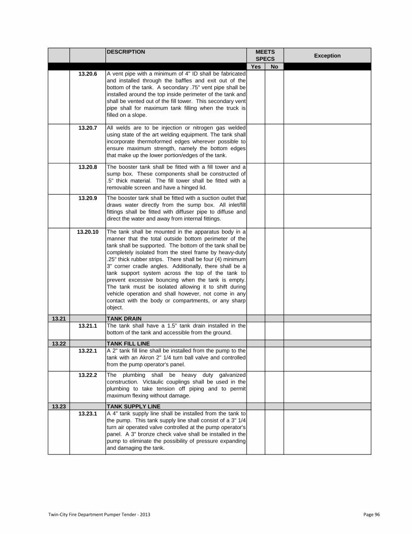
DESCRIPTIONException
Yes No
MEETS
SPECS
13.20.6 A vent pipe with a minimum of 4" ID shall be fabricated
and installed through the baffles and exit out of the
bottom of the tank. A secondary .75" vent pipe shall be
installed around the top inside perimeter of the tank and
shall be vented out of the fill tower. This secondary vent
pipe shall for maximum tank filling when the truck is
filled on a slope.
13.20.7 All welds are to be injection or nitrogen gas welded
using state of the art welding equipment. The tank shall
incorporate thermoformed edges wherever possible to
ensure maximum strength, namely the bottom edges
that make up the lower portion/edges of the tank.
13.20.8 The booster tank shall be fitted with a fill tower and a
sump box. These components shall be constructed of
.5" thick material. The fill tower shall be fitted with a
removable screen and have a hinged lid.
13.20.9 The booster tank shall be fitted with a suction outlet that
draws water directly from the sump box. All inlet/fill
fittings shall be fitted with diffuser pipe to diffuse and
direct the water and away from internal fittings.
13.20.10 The tank shall be mounted in the apparatus body in a
manner that the total outside bottom perimeter of the
tank shall be supported. The bottom of the tank shall be
completely isolated from the steel frame by heavy-duty
.25" thick rubber strips. There shall be four (4) minimum
3" corner cradle angles. Additionally, there shall be a
tank support system across the top of the tank to
prevent excessive bouncing when the tank is empty.
The tank must be isolated allowing it to shift during
vehicle operation and shall however, not come in any
contact with the body or compartments, or any sharp
object.
13.21 TANK DRAIN
13.21.1 The tank shall have a 1.5" tank drain installed in the
bottom of the tank and accessible from the ground.
13.22 TANK FILL LINE
13.22.1 A 2" tank fill line shall be installed from the pump to the
tank with an Akron 2" 1/4 turn ball valve and controlled
from the pump operator's panel.
13.22.2 The plumbing shall be heavy duty galvanized
construction. Victaulic couplings shall be used in the
plumbing to take tension off piping and to permit
maximum flexing without damage.
13.23 TANK SUPPLY LINE
13.23.1 A 4" tank supply line shall be installed from the tank to
the pump. This tank supply line shall consist of a 3" 1/4
turn air operated valve controlled at the pump operator's
panel. A 3" bronze check valve shall be installed in the
pump to eliminate the possibility of pressure expanding
and damaging the tank.
Twin-City Fire Department Pumper Tender - 2013 Page 96
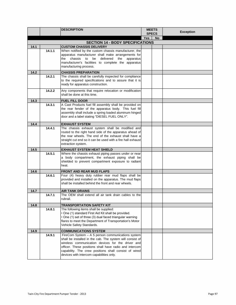
DESCRIPTIONException
Yes No
MEETS
SPECS
14.1 CUSTOM CHASSIS DELIVERY
14.1.1 When notified by the custom chassis manufacturer, the
apparatus manufacturer shall make arrangements for
the chassis to be delivered the apparatus
manufacturer's facilities to complete the apparatus
manufacturing process.
14.2 CHASSIS PREPARATION
14.2.1 The chassis shall be carefully inspected for compliance
to the required specifications and to assure that it is
ready for apparatus construction.
14.2.2 Any components that require relocation or modification
shall be done at this time.
14.3 FUEL FILL DOOR
14.3.1 A Cast Products fuel fill assembly shall be provided on
the rear fender of the apparatus body. This fuel fill
assembly shall include a spring loaded aluminum hinged
door and a label stating "DIESEL FUEL ONLY".
14.4 EXHAUST SYSTEM
14.4.1 The chassis exhaust system shall be modified and
routed to the right hand side of the apparatus ahead of
the rear wheels. The end of the exhaust shall have a
straight cut end so it can be used with a fire hall exhaust
extraction system.
14.5 EXHAUST SYSTEM HEAT SHIELD
14.5.1 Where the chassis exhaust piping passes under or near
a body compartment, the exhaust piping shall be
shielded to prevent compartment exposure to radiant
heat.
14.6 FRONT AND REAR MUD FLAPS
14.6.1 Four (4) heavy duty rubber rear mud flaps shall be
provided and installed on the apparatus. The mud flaps
shall be installed behind the front and rear wheels.
14.7 AIR TANK DRAINS
14.7.1 The OEM shall extend all air tank drain cables to the
rubrail.
14.8 TRANSPORTATION SAFETY KIT
14.8.1 The following items shall be supplied:
• One (1) standard First Aid Kit shall be provided.
• One (1) set of three (3) dual faced triangular warning
flares to meet the Department of Transportation's Motor
Vehicle Safety Standards.
14.9 COMMUNICATIONS SYSTEM
14.9.1 FireCom System – A 5 person communications system
shall be installed in the cab. The system will consist of
wireless communication devices for the driver and
officer. These positions shall have radio and intercom
capability. The crew positions shall consist of wired
devices with intercom capabilities only.
SECTION 14 - BODY SPECIFICATIONS
Twin-City Fire Department Pumper Tender - 2013 Page 97
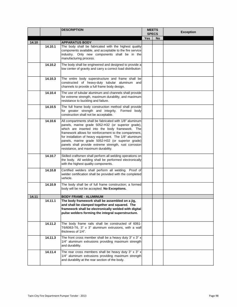
DESCRIPTIONException
Yes No
MEETS
SPECS
14.10 APPARATUS BODY
14.10.1 The body shall be fabricated with the highest quality
components available, and acceptable to the fire service
industry. Only new components shall be in the
manufacturing process.
14.10.2 The body shall be engineered and designed to provide a
low center of gravity and carry a correct load distribution
14.10.3 The entire body superstructure and frame shall be
constructed of heavy-duty tubular aluminum and
channels to provide a full frame body design.
14.10.4 The use of tubular aluminum and channels shall provide
for extreme strength, maximum durability, and maximum
resistance to buckling and failure.
14.10.5 The full frame body construction method shall provide
for greater strength and integrity. Formed body
construction shall not be acceptable.
14.10.6 All compartments shall be fabricated with 1/8" aluminum
panels, marine grade 5052-H32 (or superior grade),
which are inserted into the body framework. The
framework allows for reinforcement to the compartment,
for installation of heavy equipment. The 1/8" aluminum
panels, marine grade 5052-H32 (or superior grade)
panels shall provide extreme strength, rust corrosion
resistance, and maximum durability.
14.10.7 Skilled craftsmen shall perform all welding operations on
the body. All welding shall be performed electronically
with the highest quality components.
14.10.8 Certified welders shall perform all welding. Proof of
welder certification shall be provided with the completed
vehicle.
14.10.9 The body shall be of full frame construction; a formed
body will be not be accepted. No Exceptions.
14.11 BODY FRAME - ALUMINUM
14.11.1 The body framework shall be assembled on a jig,
and shall be clamped together and squared. The
framework shall be electronically welded with digital
pulse welders forming the integral superstructure.
14.11.2 The body frame rails shall be constructed of 6061-
T6/6063-T6, 3" x 3" aluminum extrusions, with a wall
thickness of 1/4".
14.11.3 The front cross member shall be a heavy duty 3" x 3" x
1/4" aluminum extrusions providing maximum strength
and durability.
14.11.4 The rear cross members shall be heavy duty 3" x 3" x
1/4" aluminum extrusions providing maximum strength
and durability at the rear section of the body.
Twin-City Fire Department Pumper Tender - 2013 Page 98
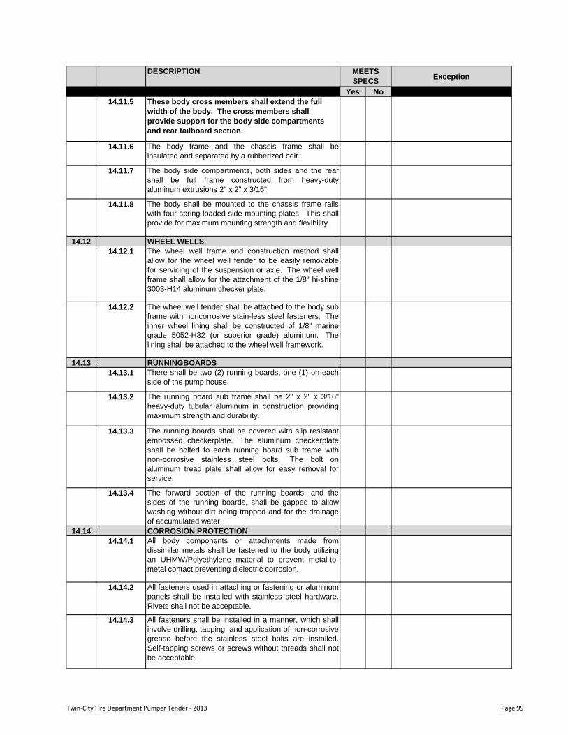
DESCRIPTIONException
Yes No
MEETS
SPECS
14.11.5 These body cross members shall extend the full
width of the body. The cross members shall
provide support for the body side compartments
and rear tailboard section.
14.11.6 The body frame and the chassis frame shall be
insulated and separated by a rubberized belt.
14.11.7 The body side compartments, both sides and the rear
shall be full frame constructed from heavy-duty
aluminum extrusions 2" x 2" x 3/16".
14.11.8 The body shall be mounted to the chassis frame rails
with four spring loaded side mounting plates. This shall
provide for maximum mounting strength and flexibility
14.12 WHEEL WELLS
14.12.1 The wheel well frame and construction method shall
allow for the wheel well fender to be easily removable
for servicing of the suspension or axle. The wheel well
frame shall allow for the attachment of the 1/8" hi-shine
3003-H14 aluminum checker plate.
14.12.2 The wheel well fender shall be attached to the body sub
frame with noncorrosive stain-less steel fasteners. The
inner wheel lining shall be constructed of 1/8" marine
grade 5052-H32 (or superior grade) aluminum. The
lining shall be attached to the wheel well framework.
14.13 RUNNINGBOARDS
14.13.1 There shall be two (2) running boards, one (1) on each
side of the pump house.
14.13.2 The running board sub frame shall be 2" x 2" x 3/16"
heavy-duty tubular aluminum in construction providing
maximum strength and durability.
14.13.3 The running boards shall be covered with slip resistant
embossed checkerplate. The aluminum checkerplate
shall be bolted to each running board sub frame with
non-corrosive stainless steel bolts. The bolt on
aluminum tread plate shall allow for easy removal for
service.
14.13.4 The forward section of the running boards, and the
sides of the running boards, shall be gapped to allow
washing without dirt being trapped and for the drainage
of accumulated water.
14.14 CORROSION PROTECTION
14.14.1 All body components or attachments made from
dissimilar metals shall be fastened to the body utilizing
an UHMW/Polyethylene material to prevent metal-to-
metal contact preventing dielectric corrosion.
14.14.2 All fasteners used in attaching or fastening or aluminum
panels shall be installed with stainless steel hardware.
Rivets shall not be acceptable.
14.14.3 All fasteners shall be installed in a manner, which shall
involve drilling, tapping, and application of non-corrosive
grease before the stainless steel bolts are installed.
Self-tapping screws or screws without threads shall not
be acceptable.
Twin-City Fire Department Pumper Tender - 2013 Page 99
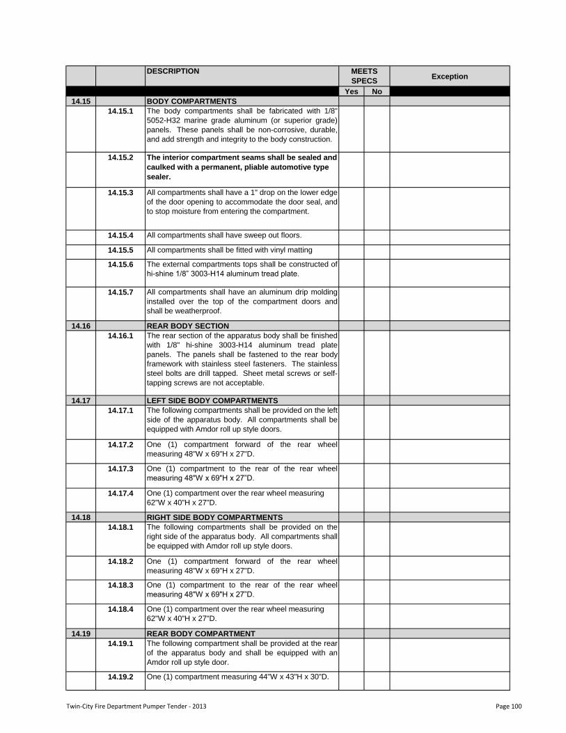
DESCRIPTIONException
Yes No
MEETS
SPECS
14.15 BODY COMPARTMENTS
14.15.1 The body compartments shall be fabricated with 1/8"
5052-H32 marine grade aluminum (or superior grade)
panels. These panels shall be non-corrosive, durable,
and add strength and integrity to the body construction.
14.15.2 The interior compartment seams shall be sealed and
caulked with a permanent, pliable automotive type
sealer.
14.15.3 All compartments shall have a 1" drop on the lower edge
of the door opening to accommodate the door seal, and
to stop moisture from entering the compartment.
14.15.4 All compartments shall have sweep out floors.
14.15.5 All compartments shall be fitted with vinyl matting
14.15.6 The external compartments tops shall be constructed of
hi-shine 1/8” 3003-H14 aluminum tread plate.
14.15.7 All compartments shall have an aluminum drip molding
installed over the top of the compartment doors and
shall be weatherproof.
14.16 REAR BODY SECTION
14.16.1 The rear section of the apparatus body shall be finished
with 1/8" hi-shine 3003-H14 aluminum tread plate
panels. The panels shall be fastened to the rear body
framework with stainless steel fasteners. The stainless
steel bolts are drill tapped. Sheet metal screws or self-
tapping screws are not acceptable.
14.17 LEFT SIDE BODY COMPARTMENTS
14.17.1 The following compartments shall be provided on the left
side of the apparatus body. All compartments shall be
equipped with Amdor roll up style doors.
14.17.2 One (1) compartment forward of the rear wheel
measuring 48"W x 69"H x 27"D.
14.17.3 One (1) compartment to the rear of the rear wheel
measuring 48"W x 69"H x 27”D.
14.17.4 One (1) compartment over the rear wheel measuring
62"W x 40"H x 27"D.
14.18 RIGHT SIDE BODY COMPARTMENTS
14.18.1 The following compartments shall be provided on the
right side of the apparatus body. All compartments shall
be equipped with Amdor roll up style doors.
14.18.2 One (1) compartment forward of the rear wheel
measuring 48"W x 69"H x 27"D.
14.18.3 One (1) compartment to the rear of the rear wheel
measuring 48"W x 69"H x 27”D.
14.18.4 One (1) compartment over the rear wheel measuring
62"W x 40"H x 27"D.
14.19 REAR BODY COMPARTMENT
14.19.1 The following compartment shall be provided at the rear
of the apparatus body and shall be equipped with an
Amdor roll up style door.
14.19.2 One (1) compartment measuring 44"W x 43"H x 30"D.
Twin-City Fire Department Pumper Tender - 2013 Page 100
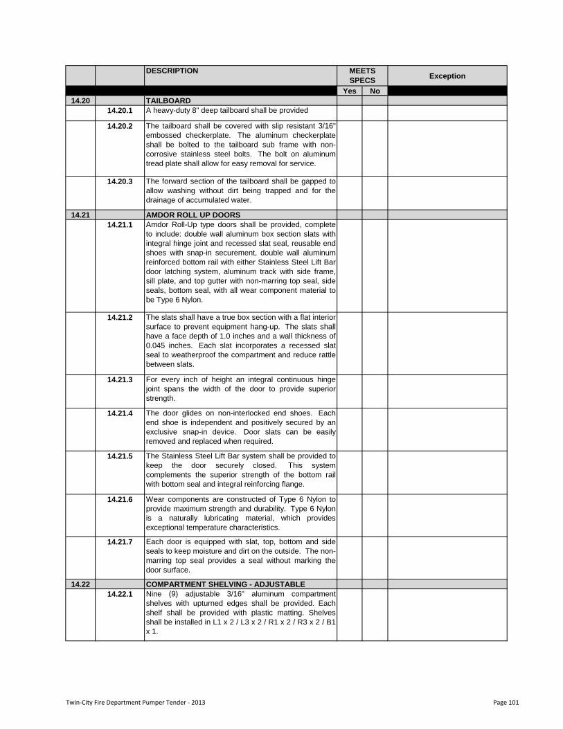
DESCRIPTIONException
Yes No
MEETS
SPECS
14.20 TAILBOARD
14.20.1 A heavy-duty 8" deep tailboard shall be provided
14.20.2 The tailboard shall be covered with slip resistant 3/16"
embossed checkerplate. The aluminum checkerplate
shall be bolted to the tailboard sub frame with non-
corrosive stainless steel bolts. The bolt on aluminum
tread plate shall allow for easy removal for service.
14.20.3 The forward section of the tailboard shall be gapped to
allow washing without dirt being trapped and for the
drainage of accumulated water.
14.21 AMDOR ROLL UP DOORS
14.21.1 Amdor Roll-Up type doors shall be provided, complete
to include: double wall aluminum box section slats with
integral hinge joint and recessed slat seal, reusable end
shoes with snap-in securement, double wall aluminum
reinforced bottom rail with either Stainless Steel Lift Bar
door latching system, aluminum track with side frame,
sill plate, and top gutter with non-marring top seal, side
seals, bottom seal, with all wear component material to
be Type 6 Nylon.
14.21.2 The slats shall have a true box section with a flat interior
surface to prevent equipment hang-up. The slats shall
have a face depth of 1.0 inches and a wall thickness of
0.045 inches. Each slat incorporates a recessed slat
seal to weatherproof the compartment and reduce rattle
between slats.
14.21.3 For every inch of height an integral continuous hinge
joint spans the width of the door to provide superior
strength.
14.21.4 The door glides on non-interlocked end shoes. Each
end shoe is independent and positively secured by an
exclusive snap-in device. Door slats can be easily
removed and replaced when required.
14.21.5 The Stainless Steel Lift Bar system shall be provided to
keep the door securely closed. This system
complements the superior strength of the bottom rail
with bottom seal and integral reinforcing flange.
14.21.6 Wear components are constructed of Type 6 Nylon to
provide maximum strength and durability. Type 6 Nylon
is a naturally lubricating material, which provides
exceptional temperature characteristics.
14.21.7 Each door is equipped with slat, top, bottom and side
seals to keep moisture and dirt on the outside. The non-
marring top seal provides a seal without marking the
door surface.
14.22 COMPARTMENT SHELVING - ADJUSTABLE
14.22.1 Nine (9) adjustable 3/16" aluminum compartment
shelves with upturned edges shall be provided. Each
shelf shall be provided with plastic matting. Shelves
shall be installed in L1 x 2 / L3 x 2 / R1 x 2 / R3 x 2 / B1
x 1.
Twin-City Fire Department Pumper Tender - 2013 Page 101
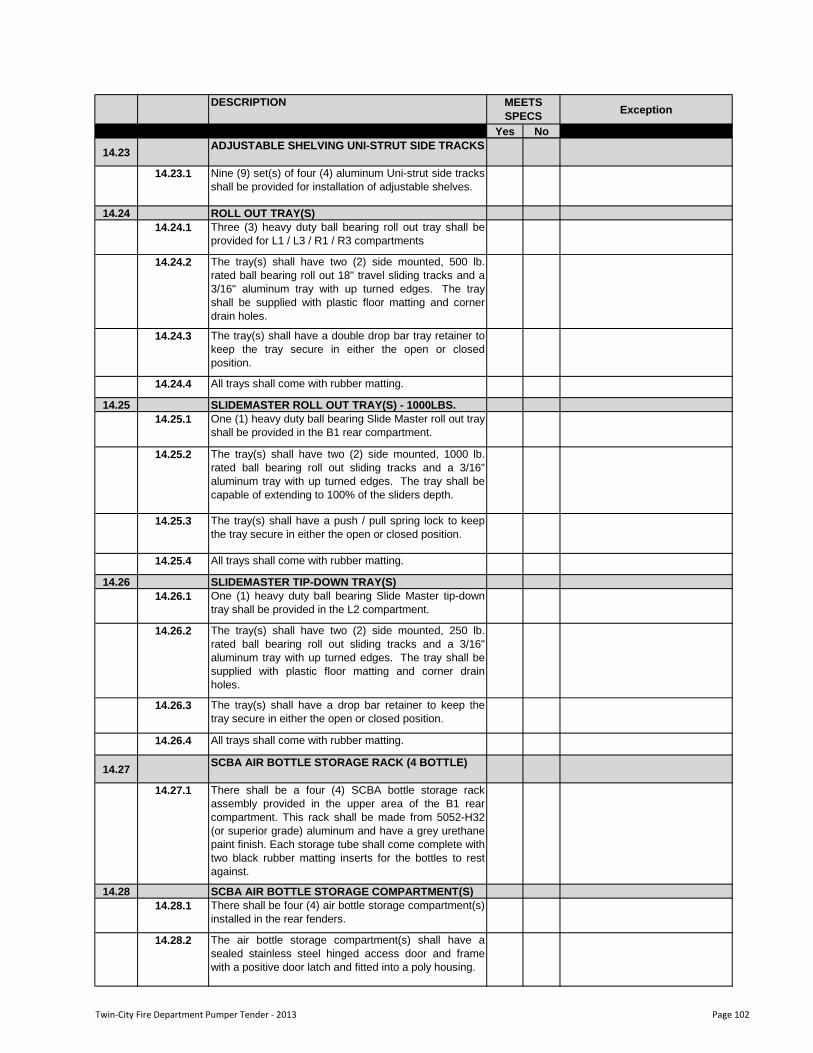
DESCRIPTIONException
Yes No
MEETS
SPECS
14.23 ADJUSTABLE SHELVING UNI-STRUT SIDE TRACKS
14.23.1 Nine (9) set(s) of four (4) aluminum Uni-strut side tracks
shall be provided for installation of adjustable shelves.
14.24 ROLL OUT TRAY(S)
14.24.1 Three (3) heavy duty ball bearing roll out tray shall be
provided for L1 / L3 / R1 / R3 compartments
14.24.2 The tray(s) shall have two (2) side mounted, 500 lb.
rated ball bearing roll out 18" travel sliding tracks and a
3/16" aluminum tray with up turned edges. The tray
shall be supplied with plastic floor matting and corner
drain holes.
14.24.3 The tray(s) shall have a double drop bar tray retainer to
keep the tray secure in either the open or closed
position.
14.24.4 All trays shall come with rubber matting.
14.25 SLIDEMASTER ROLL OUT TRAY(S) - 1000LBS.
14.25.1 One (1) heavy duty ball bearing Slide Master roll out tray
shall be provided in the B1 rear compartment.
14.25.2 The tray(s) shall have two (2) side mounted, 1000 lb.
rated ball bearing roll out sliding tracks and a 3/16"
aluminum tray with up turned edges. The tray shall be
capable of extending to 100% of the sliders depth.
14.25.3 The tray(s) shall have a push / pull spring lock to keep
the tray secure in either the open or closed position.
14.25.4 All trays shall come with rubber matting.
14.26 SLIDEMASTER TIP-DOWN TRAY(S)
14.26.1 One (1) heavy duty ball bearing Slide Master tip-down
tray shall be provided in the L2 compartment.
14.26.2 The tray(s) shall have two (2) side mounted, 250 lb.
rated ball bearing roll out sliding tracks and a 3/16"
aluminum tray with up turned edges. The tray shall be
supplied with plastic floor matting and corner drain
holes.
14.26.3 The tray(s) shall have a drop bar retainer to keep the
tray secure in either the open or closed position.
14.26.4 All trays shall come with rubber matting.
14.27 SCBA AIR BOTTLE STORAGE RACK (4 BOTTLE)
14.27.1 There shall be a four (4) SCBA bottle storage rack
assembly provided in the upper area of the B1 rear
compartment. This rack shall be made from 5052-H32
(or superior grade) aluminum and have a grey urethane
paint finish. Each storage tube shall come complete with
two black rubber matting inserts for the bottles to rest
against.
14.28 SCBA AIR BOTTLE STORAGE COMPARTMENT(S)
14.28.1 There shall be four (4) air bottle storage compartment(s)
installed in the rear fenders.
14.28.2 The air bottle storage compartment(s) shall have a
sealed stainless steel hinged access door and frame
with a positive door latch and fitted into a poly housing.
Twin-City Fire Department Pumper Tender - 2013 Page 102
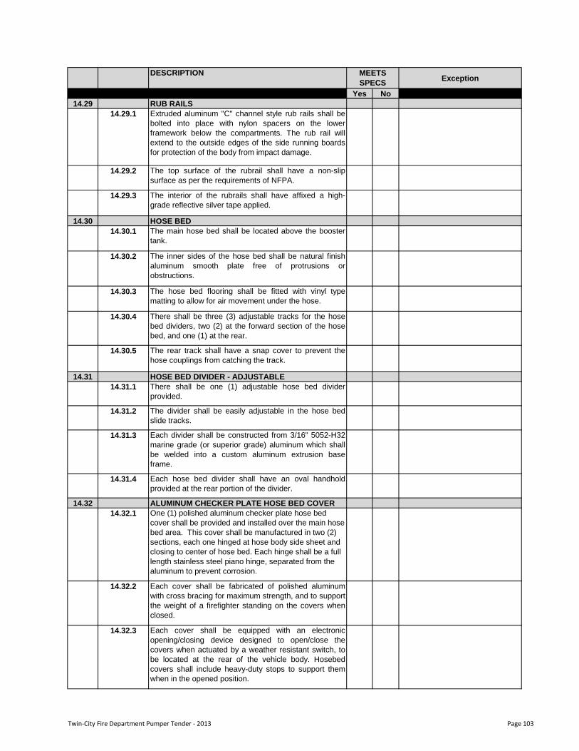
DESCRIPTIONException
Yes No
MEETS
SPECS
14.29 RUB RAILS
14.29.1 Extruded aluminum "C" channel style rub rails shall be
bolted into place with nylon spacers on the lower
framework below the compartments. The rub rail will
extend to the outside edges of the side running boards
for protection of the body from impact damage.
14.29.2 The top surface of the rubrail shall have a non-slip
surface as per the requirements of NFPA.
14.29.3 The interior of the rubrails shall have affixed a high-
grade reflective silver tape applied.
14.30 HOSE BED
14.30.1 The main hose bed shall be located above the booster
tank.
14.30.2 The inner sides of the hose bed shall be natural finish
aluminum smooth plate free of protrusions or
obstructions.
14.30.3 The hose bed flooring shall be fitted with vinyl type
matting to allow for air movement under the hose.
14.30.4 There shall be three (3) adjustable tracks for the hose
bed dividers, two (2) at the forward section of the hose
bed, and one (1) at the rear.
14.30.5 The rear track shall have a snap cover to prevent the
hose couplings from catching the track.
14.31 HOSE BED DIVIDER - ADJUSTABLE
14.31.1 There shall be one (1) adjustable hose bed divider
provided.
14.31.2 The divider shall be easily adjustable in the hose bed
slide tracks.
14.31.3 Each divider shall be constructed from 3/16" 5052-H32
marine grade (or superior grade) aluminum which shall
be welded into a custom aluminum extrusion base
frame.
14.31.4 Each hose bed divider shall have an oval handhold
provided at the rear portion of the divider.
14.32 ALUMINUM CHECKER PLATE HOSE BED COVER
14.32.1 One (1) polished aluminum checker plate hose bed
cover shall be provided and installed over the main hose
bed area. This cover shall be manufactured in two (2)
sections, each one hinged at hose body side sheet and
closing to center of hose bed. Each hinge shall be a full
length stainless steel piano hinge, separated from the
aluminum to prevent corrosion.
14.32.2 Each cover shall be fabricated of polished aluminum
with cross bracing for maximum strength, and to support
the weight of a firefighter standing on the covers when
closed.
14.32.3 Each cover shall be equipped with an electronic
opening/closing device designed to open/close the
covers when actuated by a weather resistant switch, to
be located at the rear of the vehicle body. Hosebed
covers shall include heavy-duty stops to support them
when in the opened position.
Twin-City Fire Department Pumper Tender - 2013 Page 103
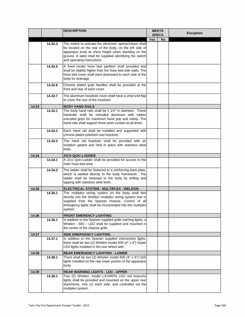
DESCRIPTIONException
Yes No
MEETS
SPECS
14.32.4 The switch to activate the electronic opener/closer shall
be located on the rear of the body, on the left side of
apparatus body at chest height when standing on the
ground. A label shall be supplied identifying the switch
and operating instructions.
14.32.5 A fixed center hose bed partition shall provided and
shall be slightly higher than the hose bed side walls. The
hose bed cover shall slant downward to each side of the
body for drainage.
14.32.6 Chrome plated grab handles shall be provided at the
front and rear of each cover.
14.32.7 The aluminum hosebed cover shall have a vinyl end flap
to cover the rear of the hosebed
14.33 BODY HAND RAILS
14.33.1 The body hand rails shall be 1 1/4" in diameter. These
handrails shall be extruded aluminum with rubber
extruded grips for maximum hand grip and safety. The
hand rails shall support three point contact at all times.
14.33.2 Each hand rail shall be installed and supported with
chrome plated polished cast brackets.
14.33.3 The hand rail brackets shall be provided with an
isolation gasket and held in place with stainless steel
bolts.
14.34 ZICO QUIC-LADDER
14.34.1 A Zico Quic-Ladder shall be provided for access to the
main hose bed area
14.34.2 The ladder shall be fastened to a reinforcing back plate,
which is welded directly to the body framework. The
ladder shall be fastened to the body by drilling and
tapping with stainless steel bolts.
14.35 ELECTRICAL SYSTEM - MULTIPLEX - WELDON
14.35.1 The multiplex wiring system on the body shall tied
directly into the Weldon multiplex wiring system that is
supplied from the Spartan chassis. Control of all
emergency lights shall be incorporated into the multiplex
system.
14.36 FRONT EMERENCY LIGHTING
14.36.1 In addition to the Spartan supplied grille warning lights, a
Whelen - 600 – LED shall be supplied and mounted in
the center of the chassis grille.
14.37 SIDE EMERGENCY LIGHTING
14.37.1 In addition to the Spartan supplied intersection lights,
there shall be two (2) Whelen model 600 (4" x 6") Super
LED lights installed in the rear wheel well.
14.38 REAR EMERGENCY LIGHTING - LOWER
14.38.1 There shall be two (2) Whelen model 600 (4" x 6") LED
lights installed on the rear lower portion of the apparatus
body.
14.39 REAR WARNING LIGHTS - LED - UPPER
14.39.1 Two (2) Whelen, model L31HRFN LED red beacons
lights shall be provided and mounted on the upper rear
stanchions, one (1) each side, and controlled via the
multiplex system.
Twin-City Fire Department Pumper Tender - 2013 Page 104
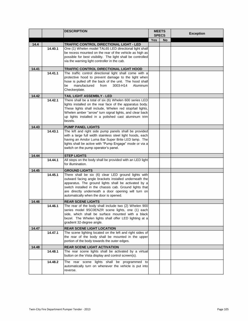
DESCRIPTIONException
Yes No
MEETS
SPECS
14.4 TRAFFIC CONTROL DIRECTIONAL LIGHT - LED
14.40.1 One (1) Whelen model TAL65 LED directional light shall
be recess mounted on the rear of the vehicle as high as
possible for best visibility. The light shall be controlled
via the warning light controller in the cab.
14.41 TRAFFIC CONTROL DIRECTIONAL LIGHT HOOD
14.41.1 The traffic control directional light shall come with a
protective hood to prevent damage to the light when
hose is pulled off the back of the unit. The hood shall
be manufactured from 3003-H14 Aluminum
Checkerplate.
14.42 TAIL LIGHT ASSEMBLY - LED
14.42.1 There shall be a total of six (6) Whelen 600 series LED
lights installed on the rear face of the apparatus body.
These lights shall include, Whelen red stop/tail lights,
Whelen amber "arrow" turn signal lights, and clear back
up lights installed in a polished cast aluminum trim
bezels.
14.43 PUMP PANEL LIGHTS
14.43.1 The left and right side pump panels shall be provided
with a large full width stainless steel light hoods, each
having an Amdor Luma Bar Super Brite LED lamp. The
lights shall be active with “Pump Engage” mode or via a
switch on the pump operator‟s panel.
14.44 STEP LIGHTS
14.44.1 All steps on the body shall be provided with an LED light
for illumination.
14.45 GROUND LIGHTS
14.45.1 There shall be six (6) clear LED ground lights with
outward facing angle brackets installed underneath the
apparatus. The ground lights shall be activated by a
switch installed in the chassis cab. Ground lights that
are directly underneath a door opening will turn on
automatically when the door is opened.
14.46 REAR SCENE LIGHTS
14.46.1 The rear of the body shall include two (2) Whelen 900
series model 9SC0ENZR scene lights, one (1) each
side, which shall be surface mounted with a black
bezel. The Whelen lights shall offer LED lighting at a
gradient 32-degree angle.
14.47 REAR SCENE LIGHT LOCATION
14.47.1 The scene lighting located on the left and right sides of
the rear of the body shall be mounted in the upper
portion of the body towards the outer edges.
14.48 REAR SCENE LIGHT ACTIVATION
14.48.1 The rear scene lights shall be activated by a virtual
button on the Vista display and control screen(s).
14.48.2 The rear scene lights shall be programmed to
automatically turn on whenever the vehicle is put into
reverse.
Twin-City Fire Department Pumper Tender - 2013 Page 105
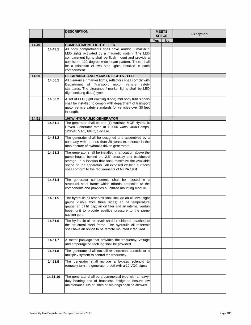
DESCRIPTIONException
Yes No
MEETS
SPECS
14.49 COMPARTMENT LIGHTS - LED
14.49.1 All body compartments shall have Amdor LumaBar™
LED lights activated by a magnetic switch. The LED
compartment lights shall be flush mount and provide a
consistent 120 degree wide beam pattern. There shall
be a minimum of two strip lights installed in each
compartment.
14.50 CLEARANCE AND MARKER LIGHTS - LED
14.50.1 All clearance / marker lights, reflectors shall comply with
Department of Transport motor vehicle safety
standards. The clearance / marker lights shall be LED
(light emitting diode) type.
14.50.2 A set of LED (light emitting diode) mid body turn signals
shall be installed to comply with department of transport
motor vehicle safety standards for vehicles over 30 feet
in length.
14.51 10KW HYDRAULIC GENERATOR
14.51.1 The generator shall be one (1) Harrison MCR Hydraulic
Driven Generator rated at 10,000 watts, 40/80 amps,
120/240 VAC, 60Hz, 1-phase.
14.51.2 The generator shall be designed and assembled by a
company with no less than 20 years experience in the
manufacture of hydraulic driven generators.
14.51.3 The generator shall be installed in a location above the
pump house, behind the 2.5" crosslay and backboard
storage, in a location that shall maximize the available
space on the apparatus. All exposed walking surfaces
shall conform to the requirements of NFPA 1901.
14.51.4 The generator components shall be housed in a
structural steel frame which affords protection to the
components and provides a unitized mounting module.
14.51.5 The hydraulic oil reservoir shall include an oil level sight
gauge visible from three sides; an oil temperature
gauge; an oil fill cap; an oil filter and an internal venturi
boost unit to provide positive pressure to the pump
suction port.
14.51.6 The hydraulic oil reservoir shall be shipped attached to
the structural steel frame. The hydraulic oil reservoir
shall have an option to be remote mounted if required.
14.51.7 A meter package that provides the frequency, voltage
and amperage of each leg shall be provided.
14.51.8 The generator shall not utilize electronic controls or a
multiplex system to control the frequency.
14.51.9 The generator shall include a bypass solenoid to
remotely turn the generator on/off with a 12 VDC signal.
14.51.10 The generator shall be a commercial type with a heavy-
duty bearing and of brushless design to ensure low
maintenance. No brushes or slip rings shall be allowed.
Twin-City Fire Department Pumper Tender - 2013 Page 106
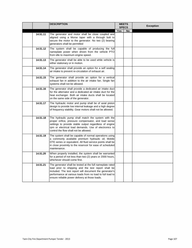
DESCRIPTIONException
Yes No
MEETS
SPECS
14.51.11 The generator and motor shall be close coupled and
aligned using a Morse taper with a through bolt to
secure the motor to the generator. No two (2) bearing
generators shall be permitted
14.51.12 The system shall be capable of producing the full
nameplate power when driven from the vehicle PTO
from idle to maximum engine speed.
14.51.13 The generator shall be able to be used while vehicle is
either stationary or in motion.
14.51.14 The generator shall provide an option for a self sealing
air intake to prevent re-circulation of exhaust air.
14.51.15 The generator shall provide an option for a vertical
exhaust fan in addition to the air intake fan. Single fan
systems shall not be allowed.
14.51.16 The generator shall provide a dedicated air intake duct
for the alternator and a dedicated air intake duct for the
heat exchanger. Both air intake ducts shall be located
on the same side of the generator.
14.51.17 The hydraulic motor and pump shall be of axial piston
design to provide low internal leakage and a high degree
of frequency stability. Gear motors shall not be allowed.
14.51.18 The hydraulic pump shall match the system with the
proper orifice, pressure compensator, and load sense
settings to provide stable output regardless of engine
rpm or electrical load demands. Use of electronics to
control the flow shall not be allowed.
14.51.19 The system shall be capable of normal operations using
a commonly available premium hydraulic oil; Mobile
DTE series or equivalent. All fluid service points shall be
in close proximity to the reservoir for ease of scheduled
maintenance.
14.51.20 When properly installed, the system shall be warranted
for a period of not less than two (2) years or 2000 hours,
whichever should come first.
14.51.21 The generator shall be tested at the full nameplate rated
load prior to shipping and the test report shall be
included. The test report will document the generator's
performance at various loads from no load to full load to
ensure reliable power delivery at those loads.
Twin-City Fire Department Pumper Tender - 2013 Page 107
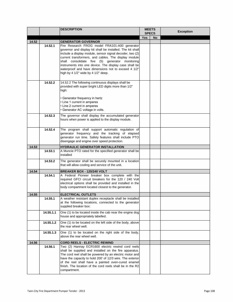
DESCRIPTIONException
Yes No
MEETS
SPECS
14.52 GENERATOR GOVERNOR
14.52.1 Fire Research FROG model FRA101-A00 generator
governor and display kit shall be installed. The kit shall
include a display module, sensor signal decoder, two (2)
current transformers, and cables. The display module
shall consolidate five (5) generator monitoring
instruments into one device. The display case shall be
waterproof and have dimensions not to exceed 4 1/2"
high by 4 1/2" wide by 4 1/2" deep.
14.52.2 14.52.2 The following continuous displays shall be
provided with super bright LED digits more than 1/2"
high:
• Generator frequency in hertz
• Line 1 current in amperes
• Line 2 current in amperes
• Generator AC voltage in volts.
14.52.3 The governor shall display the accumulated generator
hours when power is applied to the display module.
14.52.4 The program shall support automatic regulation of
generator frequency and the tracking of elapsed
generator run time. Safety features shall include PTO
disengage and engine over speed protection.
14.53 HYDRAULIC GENERATOR INSTALLATION
14.53.1 A Muncie PTO rated for the specified generator shall be
installed
14.53.2 The generator shall be securely mounted in a location
that will allow cooling and service of the unit.
14.54 BREAKER BOX - 120/240 VOLT
14.54.1 A Federal Pioneer breaker box complete with the
required GFCI circuit breakers for the 120 / 240 Volt
electrical options shall be provided and installed in the
body compartment located closest to the generator.
14.55 ELECTRICAL OUTLETS
14.55.1 A weather resistant duplex receptacle shall be installed
at the following locations, connected to the generator
supplied breaker box:
14.55.1.1 One (1) to be located inside the cab near the engine dog
house and appropriately labelled.
14.55.1.2 One (1) to be located on the left side of the body, above
the rear wheel well.
14.55.1.3 One (1) to be located on the right side of the body,
above the rear wheel well.
14.56 CORD REELS - ELECTRIC REWIND
14.56.1 Two (2) Hannay ECR1600 electric rewind cord reels
shall be supplied and installed on the fire apparatus.
The cord reel shall be powered by an electric motor and
have the capacity to hold 200' of 12/3 wire. The exterior
of the reel shall have a painted oven-cured enamel
finish. The location of the cord reels shall be in the R2
compartment.
Twin-City Fire Department Pumper Tender - 2013 Page 108
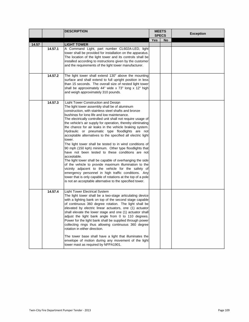
DESCRIPTIONException
Yes No
MEETS
SPECS
14.57 LIGHT TOWER
14.57.1 A Command Light, part number CL602A-LED, light
tower shall be provided for installation on the apparatus.
The location of the light tower and its controls shall be
installed according to instructions given by the customer
and the requirements of the light tower manufacturer.
14.57.2 The light tower shall extend 130" above the mounting
surface and shall extend to full upright position in less
than 15 seconds. The overall size of nested light tower
shall be approximately 44" wide x 73" long x 12" high
and weigh approximately 310 pounds.
Light Tower Construction and Design
The light tower assembly shall be of aluminum
construction, with stainless steel shafts and bronze
bushings for long life and low maintenance.The electrically controlled unit shall not require usage of
the vehicle's air supply for operation, thereby eliminating
the chance for air leaks in the vehicle braking system.
Hydraulic or pneumatic type floodlights are not
acceptable alternatives to the specified all electric light
tower.
The light tower shall be tested to in wind conditions of
90 mph (150 kph) minimum. Other type floodlights that
have not been tested to these conditions are not
acceptable.The light tower shall be capable of overhanging the side
of the vehicle to provide maximum illumination to the
vicinity adjacent to the vehicle for the safety of
emergency personnel in high traffic conditions. Any
tower that is only capable of rotations at the top of a pole
is not an acceptable alternative to the specified tower.
Light Tower Electrical System
The light tower shall be a two-stage articulating device
with a lighting bank on top of the second stage capable
of continuous 360 degree rotation. The light shall be
elevated by electric linear actuators, one (1) actuator
shall elevate the lower stage and one (1) actuator shall
adjust the light bank angle from 0 to 110 degrees.
Power for the light bank shall be supplied through power
collecting rings thus allowing continuous 360 degree
rotation in either direction.
The tower base shall have a light that illuminates the
envelope of motion during any movement of the light
tower mast as required by NFPA1901.
14.57.3
14.57.4
Twin-City Fire Department Pumper Tender - 2013 Page 109
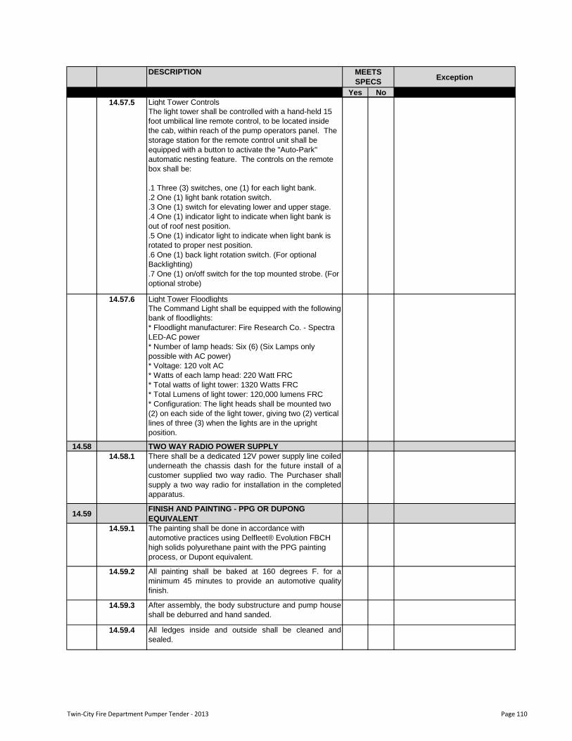
DESCRIPTIONException
Yes No
MEETS
SPECS
Light Tower Controls
The light tower shall be controlled with a hand-held 15
foot umbilical line remote control, to be located inside
the cab, within reach of the pump operators panel. The
storage station for the remote control unit shall be
equipped with a button to activate the "Auto-Park"
automatic nesting feature. The controls on the remote
box shall be:
.1 Three (3) switches, one (1) for each light bank.
.2 One (1) light bank rotation switch.
.3 One (1) switch for elevating lower and upper stage.
.4 One (1) indicator light to indicate when light bank is
out of roof nest position.
.5 One (1) indicator light to indicate when light bank is
rotated to proper nest position.
.6 One (1) back light rotation switch. (For optional
Backlighting)
.7 One (1) on/off switch for the top mounted strobe. (For
optional strobe)
Light Tower Floodlights
The Command Light shall be equipped with the following
bank of floodlights:
* Floodlight manufacturer: Fire Research Co. - Spectra
LED-AC power
* Number of lamp heads: Six (6) (Six Lamps only
possible with AC power)
* Voltage: 120 volt AC
* Watts of each lamp head: 220 Watt FRC
* Total watts of light tower: 1320 Watts FRC
* Total Lumens of light tower: 120,000 lumens FRC
* Configuration: The light heads shall be mounted two
(2) on each side of the light tower, giving two (2) vertical
lines of three (3) when the lights are in the upright
position.
14.58 TWO WAY RADIO POWER SUPPLY
14.58.1 There shall be a dedicated 12V power supply line coiled
underneath the chassis dash for the future install of a
customer supplied two way radio. The Purchaser shall
supply a two way radio for installation in the completed
apparatus.
14.59 FINISH AND PAINTING - PPG OR DUPONG
EQUIVALENT
14.59.1 The painting shall be done in accordance with
automotive practices using Delfleet® Evolution FBCH
high solids polyurethane paint with the PPG painting
process, or Dupont equivalent.
14.59.2 All painting shall be baked at 160 degrees F. for a
minimum 45 minutes to provide an automotive quality
finish.
14.59.3 After assembly, the body substructure and pump house
shall be deburred and hand sanded.
14.59.4 All ledges inside and outside shall be cleaned and
sealed.
14.57.6
14.57.5
Twin-City Fire Department Pumper Tender - 2013 Page 110
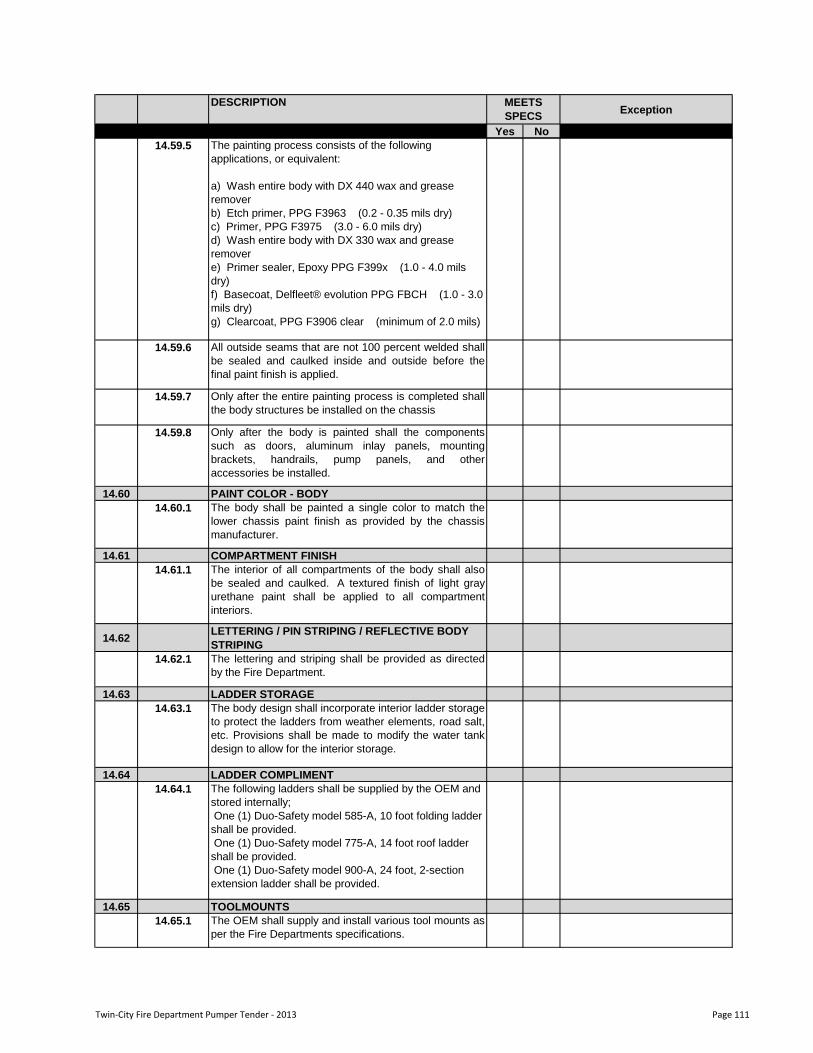
DESCRIPTIONException
Yes No
MEETS
SPECS
14.59.5 The painting process consists of the following
applications, or equivalent:
a) Wash entire body with DX 440 wax and grease
remover
b) Etch primer, PPG F3963 (0.2 - 0.35 mils dry)
c) Primer, PPG F3975 (3.0 - 6.0 mils dry)
d) Wash entire body with DX 330 wax and grease
remover
e) Primer sealer, Epoxy PPG F399x (1.0 - 4.0 mils
dry)
f) Basecoat, Delfleet® evolution PPG FBCH (1.0 - 3.0
mils dry)
g) Clearcoat, PPG F3906 clear (minimum of 2.0 mils)
14.59.6 All outside seams that are not 100 percent welded shall
be sealed and caulked inside and outside before the
final paint finish is applied.
14.59.7 Only after the entire painting process is completed shall
the body structures be installed on the chassis
14.59.8 Only after the body is painted shall the components
such as doors, aluminum inlay panels, mounting
brackets, handrails, pump panels, and other
accessories be installed.
14.60 PAINT COLOR - BODY
14.60.1 The body shall be painted a single color to match the
lower chassis paint finish as provided by the chassis
manufacturer.
14.61 COMPARTMENT FINISH
14.61.1 The interior of all compartments of the body shall also
be sealed and caulked. A textured finish of light gray
urethane paint shall be applied to all compartment
interiors.
14.62 LETTERING / PIN STRIPING / REFLECTIVE BODY
STRIPING
14.62.1 The lettering and striping shall be provided as directed
by the Fire Department.
14.63 LADDER STORAGE
14.63.1 The body design shall incorporate interior ladder storage
to protect the ladders from weather elements, road salt,
etc. Provisions shall be made to modify the water tank
design to allow for the interior storage.
14.64 LADDER COMPLIMENT
14.64.1 The following ladders shall be supplied by the OEM and
stored internally;
One (1) Duo-Safety model 585-A, 10 foot folding ladder
shall be provided.
One (1) Duo-Safety model 775-A, 14 foot roof ladder
shall be provided.
One (1) Duo-Safety model 900-A, 24 foot, 2-section
extension ladder shall be provided.
14.65 TOOLMOUNTS
14.65.1 The OEM shall supply and install various tool mounts as
per the Fire Departments specifications.
Twin-City Fire Department Pumper Tender - 2013 Page 111
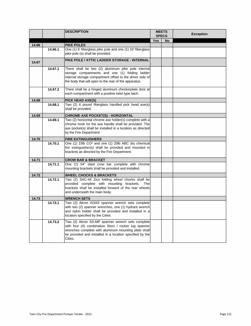
DESCRIPTIONException
Yes No
MEETS
SPECS
14.66 PIKE POLES
14.66.1 One (1) 6' fiberglass pike pole and one (1) 10' fiberglass
pike pole (s) shall be provided.
14.67 PIKE POLE / ATTIC LADDER STORAGE - INTERNAL
14.67.1 There shall be two (2) aluminum pike pole internal
storage compartments and one (1) folding ladder
internal storage compartment offset to the driver side of
the body that will open to the rear of the apparatus.
14.67.2 There shall be a hinged aluminum checkerplate door at
each compartment with a positive twist type latch.
14.68 PICK HEAD AXE(S)
14.68.1 Two (2) 6 pound fiberglass handled pick head axe(s)
shall be provided.
14.69 CHROME AXE POCKET(S) - HORIZONTAL
14.69.1 Two (2) horizontal chrome axe holder(s) complete with a
chrome hook for the axe handle shall be provided. The
axe pocket(s) shall be installed in a location as directed
by the Fire Department.
14.70 FIRE EXTINGUISHERS
14.70.1 One (1) 15lb CO² and one (1) 20lb ABC dry chemical
fire extinguisher(s) shall be provided and mounted in
brackets as directed by the Fire Department.
14.71 CROW BAR & BRACKET
14.71.1 One (1) 54" steel crow bar complete with chrome
mounting brackets shall be provided and installed.
14.72 WHEEL CHOCKS & BRACKETS
14.72.1 Two (2) SAC-44 Zico folding wheel chocks shall be
provided complete with mounting brackets. The
brackets shall be installed forward of the rear wheels
and underneath the main body.
14.73 WRENCH SETS
14.73.1 Two (2) Akron #2443 spanner wrench sets complete
with two (2) spanner wrenches, one (1) hydrant wrench
and nylon holder shall be provided and installed in a
location specified by the Cities.
14.73.2 Two (2) Akron SS-MP spanner wrench sets complete
with four (4) combination Storz / rocker lug spanner
wrenches complete with aluminum mounting plate shall
be provided and installed in a location specified by the
Cities.
Twin-City Fire Department Pumper Tender - 2013 Page 112
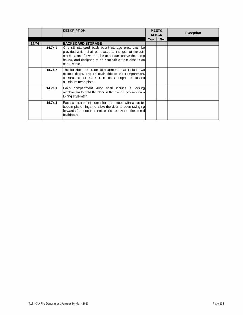
DESCRIPTIONException
Yes No
MEETS
SPECS
14.74 BACKBOARD STORAGE
14.74.1 One (1) standard back board storage area shall be
provided which shall be located to the rear of the 2.5"
crosslay, and forward of the generator, above the pump
house, and designed to be accessible from either side
of the vehicle.
14.74.2 The backboard storage compartment shall include two
access doors, one on each side of the compartment,
constructed of 0.19 inch thick bright embossed
aluminum tread plate.
14.74.3 Each compartment door shall include a locking
mechanism to hold the door in the closed position via a
D-ring style latch.
14.74.4 Each compartment door shall be hinged with a top-to-
bottom piano hinge, to allow the door to open swinging
forwards far enough to not restrict removal of the stored
backboard.
Twin-City Fire Department Pumper Tender - 2013 Page 113
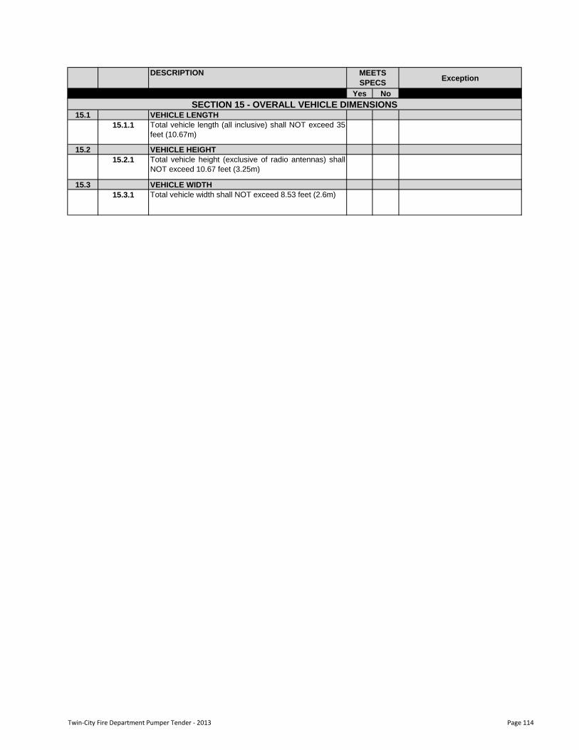
DESCRIPTIONException
Yes No
MEETS
SPECS
15.1 VEHICLE LENGTH
15.1.1 Total vehicle length (all inclusive) shall NOT exceed 35
feet (10.67m)
15.2 VEHICLE HEIGHT
15.2.1 Total vehicle height (exclusive of radio antennas) shall
NOT exceed 10.67 feet (3.25m)
15.3 VEHICLE WIDTH
15.3.1 Total vehicle width shall NOT exceed 8.53 feet (2.6m)
SECTION 15 - OVERALL VEHICLE DIMENSIONS
Twin-City Fire Department Pumper Tender - 2013 Page 114
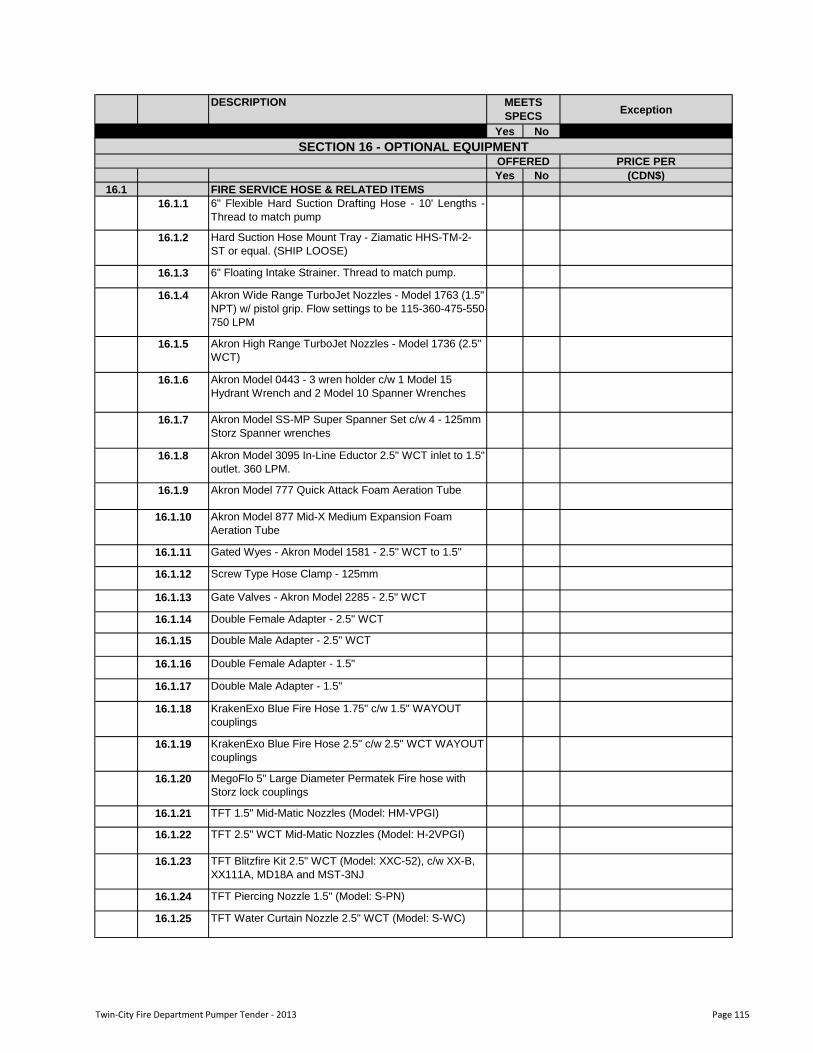
DESCRIPTIONException
Yes No
MEETS
SPECS
PRICE PER
Yes No (CDN$)
16.1 FIRE SERVICE HOSE & RELATED ITEMS
16.1.1 6" Flexible Hard Suction Drafting Hose - 10' Lengths -
Thread to match pump
16.1.2 Hard Suction Hose Mount Tray - Ziamatic HHS-TM-2-
ST or equal. (SHIP LOOSE)
16.1.3 6" Floating Intake Strainer. Thread to match pump.
16.1.4 Akron Wide Range TurboJet Nozzles - Model 1763 (1.5"
NPT) w/ pistol grip. Flow settings to be 115-360-475-550-
750 LPM
16.1.5 Akron High Range TurboJet Nozzles - Model 1736 (2.5"
WCT)
16.1.6 Akron Model 0443 - 3 wren holder c/w 1 Model 15
Hydrant Wrench and 2 Model 10 Spanner Wrenches
16.1.7 Akron Model SS-MP Super Spanner Set c/w 4 - 125mm
Storz Spanner wrenches
16.1.8 Akron Model 3095 In-Line Eductor 2.5" WCT inlet to 1.5"
outlet. 360 LPM.
16.1.9 Akron Model 777 Quick Attack Foam Aeration Tube
16.1.10 Akron Model 877 Mid-X Medium Expansion Foam
Aeration Tube
16.1.11 Gated Wyes - Akron Model 1581 - 2.5" WCT to 1.5"
16.1.12 Screw Type Hose Clamp - 125mm
16.1.13 Gate Valves - Akron Model 2285 - 2.5" WCT
16.1.14 Double Female Adapter - 2.5" WCT
16.1.15 Double Male Adapter - 2.5" WCT
16.1.16 Double Female Adapter - 1.5"
16.1.17 Double Male Adapter - 1.5"
16.1.18 KrakenExo Blue Fire Hose 1.75" c/w 1.5" WAYOUT
couplings
16.1.19 KrakenExo Blue Fire Hose 2.5" c/w 2.5" WCT WAYOUT
couplings
16.1.20 MegoFlo 5" Large Diameter Permatek Fire hose with
Storz lock couplings
16.1.21 TFT 1.5" Mid-Matic Nozzles (Model: HM-VPGI)
16.1.22 TFT 2.5" WCT Mid-Matic Nozzles (Model: H-2VPGI)
16.1.23 TFT Blitzfire Kit 2.5" WCT (Model: XXC-52), c/w XX-B,
XX111A, MD18A and MST-3NJ
16.1.24 TFT Piercing Nozzle 1.5" (Model: S-PN)
16.1.25 TFT Water Curtain Nozzle 2.5" WCT (Model: S-WC)
SECTION 16 - OPTIONAL EQUIPMENTOFFERED
Twin-City Fire Department Pumper Tender - 2013 Page 115

DESCRIPTIONException
Yes No
MEETS
SPECS
16.1.26 TFT In-Line Foam Eductor 2.5" WCT inlet to 1.5" outlet.
360 LPM.
16.1.27 TFT Gated Wyes 2.5" WCT inlet to 2x 1.5" outlets.
16.1.28 TFT Gated Wyes 4" Storz Inlet to 2x 2.5" WCT outlets
16.1.29 50' FC Conquest Fire Hose 1.75" c/w 1.5" couplings
16.1.30 50' FC Conquest Dbl Jkt Hose 2.5" WCT
16.1.31 50' Angus Hi Combat II Hose 1.75" c/w 1.5" couplings
16.1.32 50' Angus Hi Combat II Hose 2.5" WCT
16.1.33 50' Angus Hi-Vol Rubber 4" Supply Hose c/w storz
couplings
Twin-City Fire Department Pumper Tender - 2013 Page 116
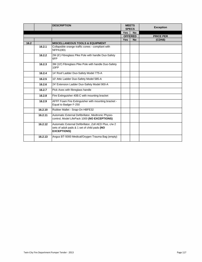
DESCRIPTIONException
Yes No
MEETS
SPECS
PRICE PER
Yes No (CDN$)
16.2 MISCELLANEOUS TOOLS & EQUIPMENT
16.2.1 Collapsible orange traffic cones - compliant with
NFPA1901
16.2.2 2M (6') Fibreglass Pike Pole with handle Duo-Safety
6FP
16.2.3 3M (10') Fibreglass Pike Pole with handle Duo-Safety
10FP
16.2.4 14' Roof Ladder Duo-Safety Model 775-A
16.2.5 10' Attic Ladder Duo-Safety Model 585-A
16.2.6 24' Extension Ladder Duo-Safety Model 900-A
16.2.7 Pick Axes with fibreglass handle
16.2.8 Fire Extinguisher 40B:C with mounting bracket
16.2.9 AFFF Foam Fire Extinguisher with mounting bracket -
Equal to Badger F-250
16.2.10 Rubber Mallet - Snap-On HBFE32
16.2.11 Automatic External Defibrillator, Medtronic Physio-
control, Model LifePack 1000 (NO EXCEPTIONS)
16.2.12 Automatic External Defibrillator, Zoll AED Plus, c/w 2
sets of adult pads & 1 set of child pads (NO
EXCEPTIONS)
16.2.13 Angus BT-5000 Medical/Oxygen Trauma Bag (empty)
OFFERED
Twin-City Fire Department Pumper Tender - 2013 Page 117