Embed Size (px)
Citation preview

181M. Keating, The Simple Art of SoC Design: Closing the Gap between RTL and ESL, DOI 10.1007/978-1-4419-8586-6, © Synopsys, Inc. 2011
This chapter summarizes the design and coding guidelines from previous chapters. It also provides some guidelines for coding datapaths using signed data types.
General
Guideline: Designs and coding should be kept as simple as possible, consistent with the objectives of the design. The best measure of simplicity/complexity is the size of the state space of the design.
Guideline: Locality. Related information should be located together in the code.
Guideline: File Size. Source code file should be no more than 5 pages (about 300 lines).
Guideline: Rule of Seven. Any design or part of a design should consist of at most seven to nine objects.
State Machines
Guideline: There should be at most one state machine per module.
Guideline: All sequential code (registers that do any computation) should be in a state machine. Registers that simply buffer a signal do not need to be in a state machine.
Guideline: A state machine should be coded as a sequential process (always_ff). Auxiliary always_comb combinational processes can be used to drive combina-tional outputs if required.
Appendix AGuidelines
Because of the possibility of human or mechanical error, neither the author, Synopsys, Inc., norany of its affiliates, including but not limited to Springer Science+Business Media, LLC guarantees the accuracy, adequacy or completeness of any information contained herein. In no event shall the authors, Synopsys, Inc. or their affiliates be liable for any damages in connection with the information provided herein. Full disclaimer available at: p. v of Frontmatter.

182 Appendix A
Guideline: A state machine with more than 7 to 9 states should be coded hierarchi-cally. Any single sub-state-machine should have at most 7to 9 states.
Processes
Guideline: Use the SystemVerilog constructs always_ff and always_comb rather than always@. These constructs remove the ambiguity inherent in always@, where we can accidently code a latch when we intend a flip-flop.
Combinational Code
Guideline: Combinational code should be coded as functions.
Guideline: Functions in RTL should be coded as automatic to avoid synthesis/simulation mismatches.
Guideline: Where practical, the function should be written with arguments that include all the signals needed by the function. But if the number of arguments gets large, this makes the code much harder to read; in this case, the function can be writ-ten without arguments and the function code can refer to global signals directly.
Hint: Debugging with automatic functions: When using a waveform viewer to debug code written using functions, we need to be a bit careful. Normal combina-tional code (always_comb blocks) are updated on the waveform viewer whenever an input changes. Functions are updated only when they are called. But with a little experience, debugging with functions becomes quite straight-forward.
Data Structures
Guideline: Use structs to assemble signals into data structures.
Guideline: Use enumerated types.
Guideline: Avoid reg and wire.
Guideline: Use bit and logic only as components of a struct.
Interfaces
Guideline: Design interfaces that isolate the two modules they connect. The FIFO is a great example of an interface that isolates the timing between two modules.

183Appendix A
Guideline: Use the interface or struct constructs rather than individual signals. (See Appendix D for a discussion of the interface construct.)
Guideline: Limit the number of interfaces of a module to 7-9.
Guideline: Design the interface to consist of a command word and a data word, rather than random wires.
Guideline: Use enumerated types to define the valid values of the command word.
Coding
Guideline: use “if (a)” instead of “if (a == 1)”
Partitioning
Guideline: Any module that has significant computation should be in a module that uses a single clock and a single reset. This facilitates analysis, since only one clock domain needs to be analyzed at a time.
Guideline: Any module with multiple clocks should consist only of the logic nec-essary for crossing the two clock domains. This facilitates analysis of the clock domain crossing logic. This logic can be quite tricky, so isolating it in a very small module can make analysis much easier.
Guideline: Modules that contain logic (and synchronizers) for crossing clock domains should be named with a prefix such as SYNC to indicate the special role of the module. Using such a prefix helps implementation engineers identify critical clock-crossing paths in synthesis reports and dynamic netlist simulations.
Guidelines for Datapath Synthesis
The following guidelines are excerpted from a set of datapath guidelines; the full set can be found online [28].
These guidelines were originally developed to guide designers on how to get the best quality of results (QOR) from synthesis. But what they really amount to is this: to get the best results, do NOT try to out-guess the synthesis tool by doing manual pre-synthesis (like converting a multiply to a shift and add). Write the code in the most general fashion (that is, leave it as a multiply) and let the synthesis tool do the optimizations.
This general approach fits in with the observations made earlier in the book. Considering the complexity of design, and the strength and maturity of the synthe-sis tools, we need to code for readability by human beings. The tools are smart enough to convert this user-friendly code into an optimal gate netlist.

184 Appendix A
The guidelines below have been re-written slightly from the versions on the solvenet website, in order to emphasize how they improve the readability of code and to comply with the other guidelines in this book.
Note: to keep the following examples simple, we use assign statements. In real code, we would expect the datapath arithmetic to be larger and more complex and to be written in a function.
Note: A lot of these recommendations concern signed arithmetic. Signed arith-metic was added in Verilog2001 and can be a bit tricky. Hopefully the guidelines below will help designers to avoid problems.
Signed Arithmetic
• Rule: Use type ’signed’ (Verilog 2001, SystemVerilog) for signed/2’s comple-ment arithmetic (that is, do not emulate signed arithmetic using unsigned oper-ands/operations). Also, do not use the ’integer’ type except for constant values.
• Rationale: Simpler, cleaner code and provides better QOR.• Example: Signed multiplication.
Not Recommended Recommended
input [7:0] a, b;output [15:0] z;
// a, b sign-extended to width of z
assign z = {{8{a[7]}}, a[7:0]} * {{8{b[7]}}, b[7:0]};
// -> unsigned 16x16= 16 bit multiply
input signed [7:0] a, b; output signed [15:0] z;
assign z = a * b;
// -> signed 8x8=16 bit multiplyinput [7:0] a, b; output [15:0] z; // emulate signed a, b
assign z = (a[6:0] - (a[7]<<7)) * (b[6:0] - (b[7]<<7));
// -> two subtract + unsigned //16x16=16 bit multiply
input [7:0] a, b; output [15:0] z; wire signed [15:0] z_sgn;
assign z_sgn = $signed(a) * $signed(b); assign z = $unsigned (z_sgn);
// -> signed 8x8= 16 bit multiply
Sign-/Zero-extension
• Rule: Do not manually sign-/zero-extend operands if possible. By using the appropriate unsigned/signed types, correct extension is done automatically.

185Appendix A
• Rationale: Simpler, cleaner code and better QoR because synthesis can more easily/reliably detect extended operands for optimal implementation.
• Example:
Mixed Unsigned/Signed Expression
• Rule: Do not mix unsigned and signed types in one expression.• Rationale: Unexpected behavior / functional incorrectness because Verilog
interprets the entire expression as unsigned if one operand is unsigned.• Example: Multiplication of unsigned operand with signed operand
Recommended
input signed [7:0] a, b; output signed [8:0] z; // a, b implicitly sign-extended assign z = a + b;
Functionally incorrect Functionally correct
input [7:0] a; input signed [7:0] b; output signed [15:0] z; // expression becomes unsigned assign z = a * b;
// -> unsigned multiply
input [7:0] a; input signed [7:0] b; output signed [15:0] z; // zero-extended, cast to signed (add ‘0’ // as sign bit) assign z = $signed ({1’b0, a}) * b;
// -> signed multiply input signed [7:0] a; output signed [11:0] z; // constant is unsigned
assign z = a * 4’b1011;
// -> unsigned multiply
input signed [7:0] a; output signed [15:0] z1, z2; // cast constant into signedassign z1 = a * $signed (4’b1011);
// mark constant as signedassign z2 = a * 4’sb1011; // -> signed multiply
186 Appendix A
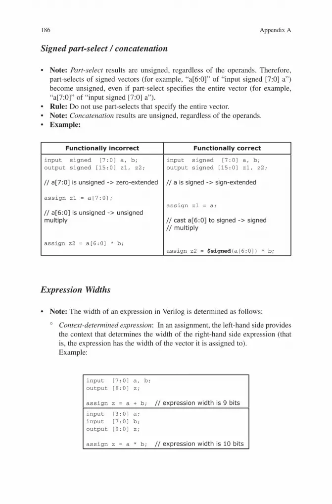
Signed part-select / concatenation
• Note: Part-select results are unsigned, regardless of the operands. Therefore, part-selects of signed vectors (for example, “a[6:0]” of “input signed [7:0] a”) become unsigned, even if part-select specifies the entire vector (for example, “a[7:0]” of “input signed [7:0] a”).
• Rule: Do not use part-selects that specify the entire vector.• Note: Concatenation results are unsigned, regardless of the operands.• Example:
Expression Widths
• Note: The width of an expression in Verilog is determined as follows:
° Context-determined expression: In an assignment, the left-hand side provides the context that determines the width of the right-hand side expression (that is, the expression has the width of the vector it is assigned to).Example:
Functionally incorrect Functionally correct
input signed [7:0] a, b; output signed [15:0] z1, z2;
// a[7:0] is unsigned -> zero-extended assign z1 = a[7:0]; // a[6:0] is unsigned -> unsigned multiply
assign z2 = a[6:0] * b;
input signed [7:0] a, b; output signed [15:0] z1, z2; // a is signed -> sign-extended
assign z1 = a; // cast a[6:0] to signed -> signed// multiply
assign z2 = $signed(a[6:0]) * b;
input [7:0] a, b; output [8:0] z;
assign z = a + b; // expression width is 9 bits
input [3:0] a; input [7:0] b; output [9:0] z;
assign z = a * b; // expression width is 10 bits

187Appendix A
° Special cases: Some expressions are not self-determined even though they seem to be. Then the expression takes the width of the higher-level context (for example, the left-hand side of an assignment).Example: Concatenation expression
Cluster Datapath Portions
• Rule: Cluster related datapath portions in the RTL code into a single combina-tional block. Do not separate them into different blocks. In particular,
° Self-determined expression: Expressions without context (for example, expressions in parentheses) determine their width from the operand widths. For arithmetic operations, the width of a self-determined expression is the width of the widest operand.Example:
Unintended behavior Intended behavior
input signed [3:0] a; input signed [7:0] b; output [11:0] z; // product width is 8 bits (not 12!) assign z = $unsigned(a * b); // -> 4x8=8 bit multiply
input signed [3:0] a; input signed [7:0] b; output [11:0] z; wire signed [11:0] z_sgn; // product width is 12 bits
assign z_sgn = a * b; assign z = $unsigned(z_sgn);// -> 4x8=12 bit multiply
input [7:0] a, b, c, d; output z; assign z = (a + b) > (c * d); // -> 8+8=8 bit add + 8x8=8 bit// multiply + 8>8=1 bit compare
input [7:0] a, b, c, d; output z; wire [8:0] s; wire [15:0] p; assign s = a + b;// -> 8+8=9 bit add assign p = c * d; // -> 8x8=16 bit // multiply assign z = s > p; // -> 9>16=1 bit // compare
input [15:0] a, b; output [31:0] z; assign z = {a[15:8] * b[15:8], a[ 7:0] * b[ 7:0]};
// -> two 8x8=8 bit multiplies,// bits z[31:16] are 0
input [15:0] a, b; output [31:0] z; wire [15:0] zh, zl; assign zh = a[15:8] * b[15:8]; assign zl = a[ 7:0] * b[ 7:0]; assign z = {zh, zl};
// -> two 8x8=16 bit multiplies

188 Appendix A
Keep related datapath portions within ° one single hierarchical component. Do not distribute them into different levels or subcomponents of your design hierarchy.Do ◦ not place registers between related datapath portions. If registers are required inside a datapath block to meet QoR requirements, use retiming to move the registers to the optimal requirements, use retiming to move the registers to the optimal location after the entire datapath block has been implemented (see [28] for more details).
• Rationale: Simpler, cleaner code and better QoR because bigger datapath blocks can be extracted and synthesized.
Component Instantiation
• Rule: Do not instantiate arithmetic DesignWare components if possible (for example, for explicitly forcing carry-save format on intermediate results). Write arithmetic expressions in RTL instead.
• Rationale: Simpler, higher level code. Better QoR can be obtained by exploiting the full potential of datapath extraction and synthesis.
• Example: Multiply-accumulate unit
Bad QoR Good QoR
input [7:0] a, b; input [15:0] c0, c1; output [15:0] z0, z1; wire [17:0] p0, p1; wire [15:0] s00, s01, s10, s11; // shared multiply with explicit carry-
// save output DW02_multp #(8, 8, 18) mult ( .a(a), .b(b), .tc(1’b0), .out0(p0), .out1(p1)); // add with explicit carry-save output DW01_csa #(16) csa0 ( .a(p0[15:0]), .b(p1[15:0]), .c(c0), .ci(1’b0), .sum(s00), .carry(s01)); DW01_csa #(16) csa1 ( .a(p0[15:0]), .b(p1[15:0]), .c(c1), .ci(1’b0), .sum(s10), .carry(s11)); // carry-save to binary conversion (final adder) DW01_add #(16) add0 ( .A(s00), .B(s01), .CI(1’b0), .SUM(z0)); DW01_add #(16) add1 ( .A(s10), .B(s11), .CI(1’b0), .SUM(z1));
input [7:0] a, b; input [15:0] c0, c1; output [15:0] z0, z1; // single datapath with: // - automatic sharing of
// multiplier // - implicit usage of carry-
// save internally
assign z0 = a * b + c0; assign z1 = a * b + c1;
189Appendix A
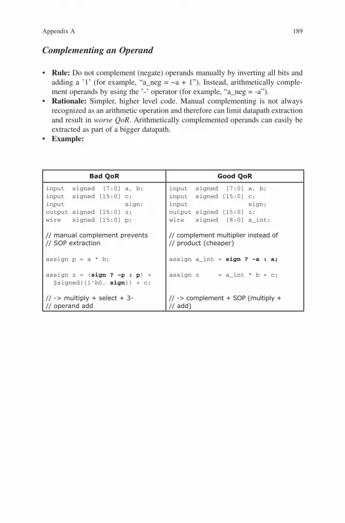
Complementing an Operand
• Rule: Do not complement (negate) operands manually by inverting all bits and adding a ’1’ (for example, “a_neg = ~a + 1”). Instead, arithmetically comple-ment operands by using the ’-’ operator (for example, “a_neg = -a”).
• Rationale: Simpler, higher level code. Manual complementing is not always recognized as an arithmetic operation and therefore can limit datapath extraction and result in worse QoR. Arithmetically complemented operands can easily be extracted as part of a bigger datapath.
• Example:
Bad QoR Good QoR
input signed [7:0] a, b; input signed [15:0] c; input sign; output signed [15:0] z; wire signed [15:0] p; // manual complement prevents // SOP extraction
assign p = a * b; assign z = (sign ? ~p : p) + $signed({1’b0, sign}) + c;
// -> multiply + select + 3-// operand add
input signed [7:0] a, b; input signed [15:0] c; input sign; output signed [15:0] z; wire signed [8:0] a_int; // complement multiplier instead of// product (cheaper) assign a_int = sign ? -a : a; assign z = a_int * b + c;
// -> complement + SOP (multiply + // add)

191
This chapter contains more complete versions of some of the sample code mentioned in the text.
State Machine Example
Simple Hierarchical State Machine in synthesizable SystemVerilog
This example shows how to code a hierarchical finite state machine in synthesiz-able SystemVerilog using tasks. Please see the notes following the code.
Appendix BExamples
module foo ( input bit clk, resetn, pkt_avail, pkt_out_fifo_full, input bit [31:0] data_in, output bit [15:0] data_out, output bit in_pkt_pop) ;
struct packed { bit [7:0] destination ; bit [7:0] payload ; } input_packet ;
enum { IDLE, GET_PKT, SEND_PKT} tx_state ; enum { GP_READ, GP_DONE } get_pkt_state ; enum { SP_DESTINATION, SP_PAYLOAD, SP_DONE } send_pkt_state;
M. Keating, The Simple Art of SoC Design: Closing the Gap between RTL and ESL, DOI 10.1007/978-1-4419-8586-6, © Synopsys, Inc. 2011
Because of the possibility of human or mechanical error, neither the author, Synopsys, Inc., norany of its affiliates, including but not limited to Springer Science+Business Media, LLC guarantees the accuracy, adequacy or completeness of any information contained herein. In no event shall the authors, Synopsys, Inc. or their affiliates be liable for any damages in connection with the information provided herein. Full disclaimer available at: pg. v of Frontmatter.

192 Appendix B
always @ (posedge clk or negedge resetn) begin if (! resetn)begin in_pkt_pop <= 0; data_out <= 0; tx_state <= IDLE; get_pkt_state <= GP_READ; send_pkt_state <= SP_DESTINATION; end else begin case (tx_state) IDLE : if (pkt_avail) tx_state <= GET_PKT ; GET_PKT : begin get_pkt () ; if (get_pkt_state == GP_DONE) tx_state <= SEND_PKT ; end SEND_PKT : begin send_pkt () ; if (send_pkt_state == SP_DONE) tx_state <= IDLE ; end endcase endend
// ---------- get_pkt sub state machine -------------
task get_pkt() ; case (get_pkt_state) GP_READ : begin input_packet.destination <= data_in[31:16] ; input_packet.payload <= data_in[15:0] ; in_pkt_pop <= 1 ; get_pkt_state <= GP_DONE ; end GP_DONE : begin in_pkt_pop <= 0 ; get_pkt_state <= GP_READ ; end endcase endtask
// ------------ main state machine -----------------
193Appendix B
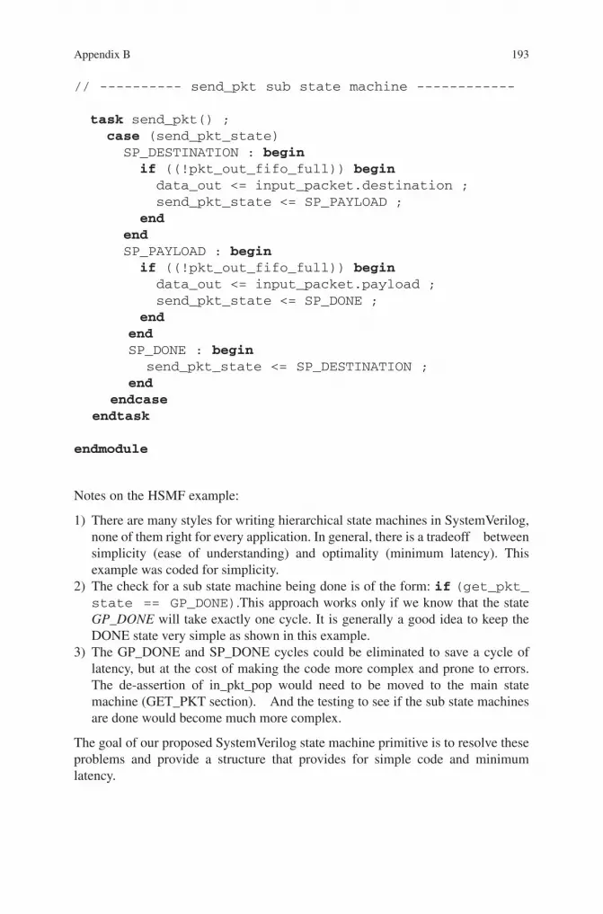
Notes on the HSMF example:
1) There are many styles for writing hierarchical state machines in SystemVerilog, none of them right for every application. In general, there is a tradeoff between simplicity (ease of understanding) and optimality (minimum latency). This example was coded for simplicity.
2) The check for a sub state machine being done is of the form: if (get_pkt_state == GP_DONE).This approach works only if we know that the state GP_DONE will take exactly one cycle. It is generally a good idea to keep the DONE state very simple as shown in this example.
3) The GP_DONE and SP_DONE cycles could be eliminated to save a cycle of latency, but at the cost of making the code more complex and prone to errors. The de-assertion of in_pkt_pop would need to be moved to the main state machine (GET_PKT section). And the testing to see if the sub state machines are done would become much more complex.
The goal of our proposed SystemVerilog state machine primitive is to resolve these problems and provide a structure that provides for simple code and minimum latency.
// ---------- send_pkt sub state machine ------------
task send_pkt() ; case (send_pkt_state) SP_DESTINATION : begin if ((!pkt_out_fifo_full)) begin data_out <= input_packet.destination ; send_pkt_state <= SP_PAYLOAD ; end end SP_PAYLOAD : begin if ((!pkt_out_fifo_full)) begin data_out <= input_packet.payload ; send_pkt_state <= SP_DONE ; end end SP_DONE : begin send_pkt_state <= SP_DESTINATION ; end endcase endtask
endmodule
194 Appendix B
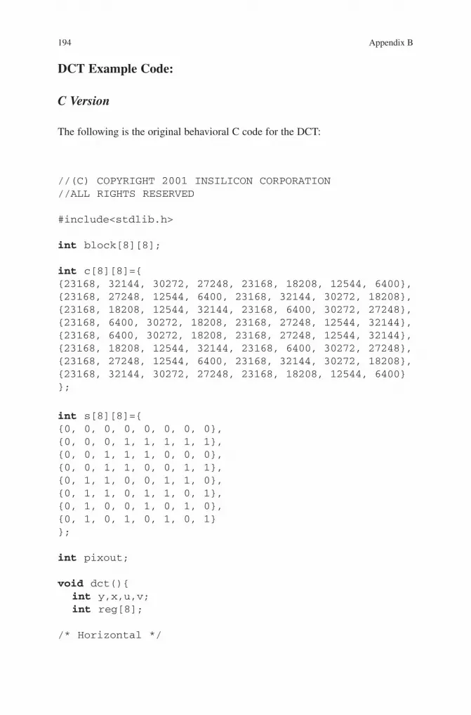
DCT Example Code:
C Version
The following is the original behavioral C code for the DCT:
//(C) COPYRIGHT 2001 INSILICON CORPORATION//ALL RIGHTS RESERVED
#include<stdlib.h>
int block[8][8];
int c[8][8]={{23168, 32144, 30272, 27248, 23168, 18208, 12544, 6400},{23168, 27248, 12544, 6400, 23168, 32144, 30272, 18208},{23168, 18208, 12544, 32144, 23168, 6400, 30272, 27248},{23168, 6400, 30272, 18208, 23168, 27248, 12544, 32144},{23168, 6400, 30272, 18208, 23168, 27248, 12544, 32144},{23168, 18208, 12544, 32144, 23168, 6400, 30272, 27248},{23168, 27248, 12544, 6400, 23168, 32144, 30272, 18208},{23168, 32144, 30272, 27248, 23168, 18208, 12544, 6400}};
int s[8][8]={{0, 0, 0, 0, 0, 0, 0, 0},{0, 0, 0, 1, 1, 1, 1, 1},{0, 0, 1, 1, 1, 0, 0, 0},{0, 0, 1, 1, 0, 0, 1, 1},{0, 1, 1, 0, 0, 1, 1, 0},{0, 1, 1, 0, 1, 1, 0, 1},{0, 1, 0, 0, 1, 0, 1, 0},{0, 1, 0, 1, 0, 1, 0, 1}};
int pixout;
void dct(){ int y,x,u,v; int reg[8];
/* Horizontal */
195Appendix B
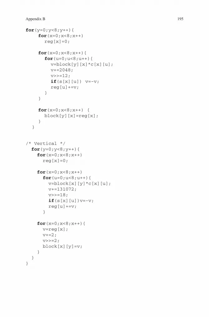
for(y=0;y<8;y++){ for(x=0;x<8;x++) reg[x]=0; for(x=0;x<8;x++){ for(u=0;u<8;u++){ v=block[y][x]*c[x][u]; v+=2048; v>>=12; if(s[x][u]) v=-v; reg[u]+=v; } }
for(x=0;x<8;x++) { block[y][x]=reg[x]; } }
/* Vertical */ for(y=0;y<8;y++){ for(x=0;x<8;x++) reg[x]=0;
for(x=0;x<8;x++) for(u=0;u<8;u++){ v=block[x][y]*c[x][u]; v+=131072; v>>=18; if(s[x][u])v=-v; reg[u]+=v; } for(x=0;x<8;x++){ v=reg[x]; v+=2; v>>=2; block[x][y]=v; } }}
196 Appendix B
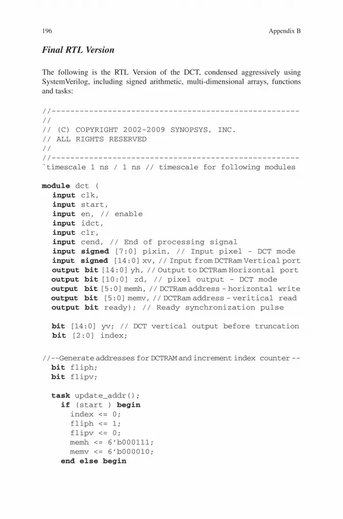
Final RTL Version
The following is the RTL Version of the DCT, condensed aggressively using SystemVerilog, including signed arithmetic, multi-dimensional arrays, functions and tasks:
//-----------------------------------------------------//// (C) COPYRIGHT 2002-2009 SYNOPSYS, INC.// ALL RIGHTS RESERVED////-----------------------------------------------------`timescale 1 ns / 1 ns // timescale for following modules
module dct ( input clk, input start, input en, // enable input idct, input clr, input cend, // End of processing signal input signed [7:0] pixin, // Input pixel - DCT mode input signed [14:0] xv, // Input from DCTRam Vertical port output bit [14:0] yh, // Output to DCTRam Horizontal port output bit [10:0] zd, // pixel output - DCT mode output bit [5:0] memh, // DCTRam address - horizontal write output bit [5:0] memv, // DCTRam address - veritical read output bit ready); // Ready synchronization pulse
bit [14:0] yv; // DCT vertical output before truncation bit [2:0] index;
//--Generate addresses for DCTRAM and increment index counter -- bit fliph; bit flipv;
task update_addr(); if (start ) begin index <= 0; fliph <= 1; flipv <= 0; memh <= 6’b000111; memv <= 6’b000010; end else begin

197Appendix B
index <= index + 1; memh <= incr_addr (fliph, memh); memv <= incr_addr (flipv, memv); if (memh == 6’b111111) fliph <= ~fliph; if (memv == 6’b111111) flipv <= ~flipv; end endtask
function automatic bit [5:0] incr_addr (bit flip, bit[5:0] addr); bit [5:0] addr_rev;
if (!flip) incr_addr = addr + 1; else begin addr_rev = {addr[2:0], addr[5:3]}; addr_rev++; incr_addr = {addr_rev[2:0], addr_rev[5:3]}; end endfunction
//--------------- calculate sign ---------------------function automatic bit [7:0] get_sgn (); bit [7:0] sgn; sgn[0] = 0; case (index) 3’b 000: sgn[7:1] = 7’b 0000000; 3’b 001: sgn[7:1] = 7’b 1111100; 3’b 010: sgn[7:1] = 7’b 0001110; 3’b 011: sgn[7:1] = 7’b 1100110; 3’b 100: sgn[7:1] = 7’b 0110011; 3’b 101: sgn[7:1] = 7’b 1011011; 3’b 110: sgn[7:1] = 7’b 0101001; 3’b 111: sgn[7:1] = 7’b 1010101; endcase get_sgn = sgn;endfunction
//-------- declarations for pixel processing -------- typedef bit [16:0] bit17; typedef bit [15:0] bit16; typedef bit [14:0] bit15; typedef bit [12:0] bit13; typedef bit [10:0] bit11;
198 Appendix B
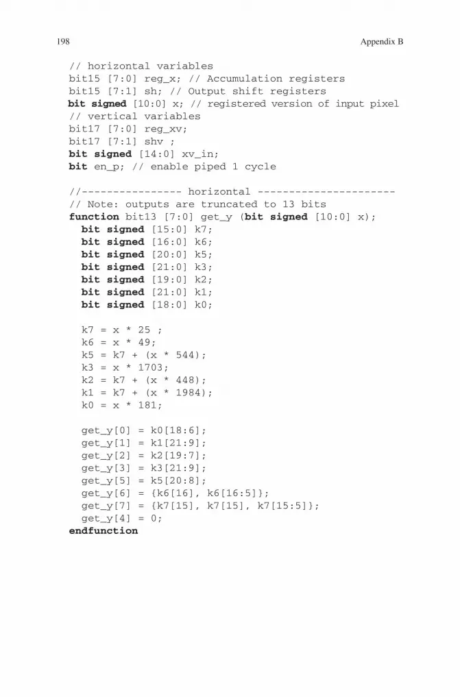
// horizontal variables bit15 [7:0] reg_x; // Accumulation registers bit15 [7:1] sh; // Output shift registers bit signed [10:0] x; // registered version of input pixel // vertical variables bit17 [7:0] reg_xv; bit17 [7:1] shv ; bit signed [14:0] xv_in; bit en_p; // enable piped 1 cycle
//---------------- horizontal ---------------------- // Note: outputs are truncated to 13 bits function bit13 [7:0] get_y (bit signed [10:0] x); bit signed [15:0] k7; bit signed [16:0] k6; bit signed [20:0] k5; bit signed [21:0] k3; bit signed [19:0] k2; bit signed [21:0] k1; bit signed [18:0] k0;
k7 = x * 25 ; k6 = x * 49; k5 = k7 + (x * 544); k3 = x * 1703; k2 = k7 + (x * 448); k1 = k7 + (x * 1984); k0 = x * 181;
get_y[0] = k0[18:6]; get_y[1] = k1[21:9]; get_y[2] = k2[19:7]; get_y[3] = k3[21:9]; get_y[5] = k5[20:8]; get_y[6] = {k6[16], k6[16:5]}; get_y[7] = {k7[15], k7[15], k7[15:5]}; get_y[4] = 0; endfunction

199Appendix B
//----------- Map the vector for accumulation --------
function bit13 [7:0] get_crossh ( bit13 [7:0] y); case (index) 3’d0: get_crossh[7:0] = { y[7],y[6],y[5],y[0],y[3],
y[2],y[1],y[0]}; 3’d1: get_crossh[7:0] = { y[5],y[2],y[1],y[0],y[7],
y[6],y[3],y[0]}; 3’d2: get_crossh[7:0] = { y[3],y[2],y[7],y[0],y[1],
y[6],y[5],y[0]}; 3’d3: get_crossh[7:0] = { y[1],y[6],y[3],y[0],y[5],
y[2],y[7],y[0]}; 3’d4: get_crossh[7:0] = { y[1],y[6],y[3],y[0],y[5],
y[2],y[7],y[0]}; 3’d5: get_crossh[7:0] = { y[3],y[2],y[7],y[0],y[1],
y[6],y[5],y[0]}; 3’d6: get_crossh[7:0] = { y[5],y[2],y[1],y[0],y[7],
y[6],y[3],y[0]}; 3’d7: get_crossh[7:0] = { y[7],y[6],y[5],y[0],y[3],
y[2],y[1],y[0]}; endcaseendfunction
//---------------- Accumulate -----------------------function bit15 [7:0] get_reg_x (bit signed [10:0] x); bit15 [7:0] tmp; bit13 bx[7:0]; bit16 b[7:0]; bit13 [7:0] sel; bit [7:0] sgn;
sel = get_crossh (get_y(x));
sgn = get_sgn();
for (int i=0;i<8;i++) bx[i] = sgn[i] ? ~sel[i] : sel[i]; for (int i=0;i<8;i++) b[i] = {bx[i][12],bx[i][12],
bx[i][12],bx[i]};
if (index == 0) for (int i=0;i<8;i++) tmp[i] = b[i] [15:1] + b[i][0]; else for (int i=0;i<8;i++) tmp[i] = reg_x[i] + b[i] [15:1] + b[i][0]; get_reg_x = tmp;
endfunction

200 Appendix B
task update_sr(); reg_x <= get_reg_x(x); if (index == 0) for (int i=1;i<8;i++) sh[i]<= reg_x[i]; else for (int i=1;i<7;i++) sh[i]<= sh[i+1];endtask
//------------------ vertical ------------------------// Note: outputs are truncated to 16 bitsfunction bit16 [7:0] get_y_vert (bit signed [14:0] x); bit signed [19:0] k7; bit signed [20:0] k6; bit signed [24:0] k5; bit signed [25:0] k3; bit signed [23:0] k2; bit signed [25:0] k1; bit signed [22:0] k0;
k7 = x * 25 ; k6 = x * 49; k5 = k7 + (x * 544); k3 = x * 1703; k2 = k7 + (x * 448); k1 = k7 + (x * 1984); k0 = x * 181;
get_y_vert = 0; get_y_vert[0] = {k0[22], k0[22], k0[22], k0[22:10]}; get_y_vert[1] = {k1[25], k1[25], k1[25], k1[25:13]}; get_y_vert[2] = {k2[23], k2[23], k2[23], k2[23:11]}; get_y_vert[3] = {k3[25], k3[25], k3[25], k3[25:13]}; get_y_vert[5] = {k5[24], k5[24], k5[24], k5[24:12]}; get_y_vert[6] = {k6[20], k6[20], k6[20], k6[20],k6[20:9]}; get_y_vert[7] = {k7[19], k7[19], k7[19], k7[19], k7[19], k7[19:9]};endfunction
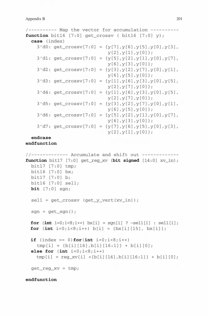
201Appendix B
/---------- Map the vector for accumulation ----------function bit16 [7:0] get_crossv ( bit16 [7:0] y); case (index) 3’d0: get_crossv[7:0] = { y[7],y[6],y[5],y[0],y[3],
y[2],y[1],y[0]}; 3’d1: get_crossv[7:0] = { y[5],y[2],y[1],y[0],y[7],
y[6],y[3],y[0]}; 3’d2: get_crossv[7:0] = { y[3],y[2],y[7],y[0],y[1],
y[6],y[5],y[0]}; 3’d3: get_crossv[7:0] = { y[1],y[6],y[3],y[0],y[5],
y[2],y[7],y[0]}; 3’d4: get_crossv[7:0] = { y[1],y[6],y[3],y[0],y[5],
y[2],y[7],y[0]}; 3’d5: get_crossv[7:0] = { y[3],y[2],y[7],y[0],y[1],
y[6],y[5],y[0]}; 3’d6: get_crossv[7:0] = { y[5],y[2],y[1],y[0],y[7],
y[6],y[3],y[0]}; 3’d7: get_crossv[7:0] = { y[7],y[6],y[5],y[0],y[3],
y[2],y[1],y[0]}; endcaseendfunction
//------------- Accumulate and shift out -------------function bit17 [7:0] get_reg_xv (bit signed [14:0] xv_in); bit17 [7:0] tmp; bit16 [7:0] bx; bit17 [7:0] b; bit16 [7:0] sel1; bit [7:0] sgn;
sel1 = get_crossv (get_y_vert(xv_in));
sgn = get_sgn();
for (int i=0;i<8;i++) bx[i] = sgn[i] ? ~sel1[i] : sel1[i]; for (int i=0;i<8;i++) b[i] = {bx[i][15], bx[i]}; if (index == 0)for(int i=0;i<8;i++) tmp[i] = {b[i][16],b[i][16:1]} + b[i][0]; else for (int i=0;i<8;i++) tmp[i] = reg_xv[i] +{b[i][16],b[i][16:1]} + b[i][0];
get_reg_xv = tmp;
endfunction

202 Appendix B
DCT Using Proposed SystemVerilog Extensions
This version is very close to the original C version, but becomes synthesizable with the use of the proposed SystemVerilog extensions. Note that the constant-handling optimizations from the RTL are not used, and that all variables are integers. This is just to keep the code as simple as possible, and allow focus on the SystemVerilog extensions. The constant-handling optimizations could certainly be added to this code; it would just make the code a bit larger.
task update_srv (); reg_xv <= get_reg_xv (xv_in); if (index == 0) for (int i=1;i<8;i++) shv[i]<= reg_xv[i]; else for (int i=1;i<7;i++) shv[i] <= shv[i+1];endtask
//--------------------- MAIN -------------------------task main (); x <= {~pixin[7], (~pixin[7]), pixin[6:0], 2’b 00}; en_p <= en; if (en) update_addr(); if (en_p) update_sr(); xv_in <= xv; if (en) update_srv();endtask
always_comb if (index == 0) yh = reg_x[0]; else yh = sh[1];
always_comb begin if (index == 0) yv = (reg_xv[0]+ 2) >>> 2; else yv = (shv[1]+ 2) >>> 2; zd = yv[10:0];end
always_ff @(posedge clk) main();
endmodule
//-----------------------------------------------------//// (C) COPYRIGHT 2002-2009 SYNOPSYS, INC.// ALL RIGHTS RESERVED////

203Appendix B
//-----------------------------------------------------module dct_top ( input bit clk, resetn, input bit run, input bit mem_read_rdy, input int pixin, output int pixout);
$clock posedge (clk);
int c[8][8]=’{ ‘{23168, 32144, 30272, 27248, 23168, 18208, 12544, 6400 }, ‘{23168, 27248, 12544, 6400, 23168, 32144, 30272, 18208}, ‘{23168, 18208, 12544, 32144, 23168, 6400, 30272, 27248}, ‘{23168, 6400, 30272, 18208, 23168, 27248, 12544, 32144}, ‘{23168, 6400, 30272, 18208, 23168, 27248, 12544, 32144}, ‘{23168, 18208, 12544, 32144, 23168, 6400, 30272, 27248}, ‘{23168, 27248, 12544, 6400, 23168, 32144, 30272, 18208}, ‘{23168, 32144, 30272, 27248, 23168, 18208, 12544, 6400 } };
int s[8][8]=’{ ‘{0, 0, 0, 0, 0, 0, 0, 0}, ‘{0, 0, 0, 1, 1, 1, 1, 1}, ‘{0, 0, 1, 1, 1, 0, 0, 0}, ‘{0, 0, 1, 1, 0, 0, 1, 1}, ‘{0, 1, 1, 0, 0, 1, 1, 0}, ‘{0, 1, 1, 0, 1, 1, 0, 1}, ‘{0, 1, 0, 0, 1, 0, 1, 0}, ‘{0, 1, 0, 1, 0, 1, 0, 1} };
int v_pixin; int tmp_x[8]; int reg_x[8]; int tmp_y[8]; int reg_y[8]; int mem[8][8];
//------------------ top (main) ------------------state_machine dct(); begin if (run) horizontal_dct(); endstate_machine

204 Appendix B
//-------------- horizontal processing ---------------state_machine horizontal_dct(); done = 0; while (run) begin for (state_var y=0;y<8;y++) begin for(state_var x=0;x<8;x++) begin for(int u=0;u<8;u++) begin v=pixin*c[x][u]; v+=2048; v>>>12; if(s[x][u]) v=-v; if (x ==0) reg_x[u]<=v; else if (x < 7) reg_x[u]<=reg_x[u]+v; else tmp_x[u] <= reg_x[u] + v; end end fork mem_write(y); join_none // can’t fork again until complete end end done = 1;endstate_machine
//------------- write scratchpad memory ---------------state_machine mem_write(int y); bit_ff flip; for(state_var x=0;x<8;x++) begin if (!flip) mem[y][x]<=tmp_x[x]; else mem[x][y]<=tmp_x[x]; if ((y == 7) && (x == 0) fork mem_read(); join_none if ((y == 7) && (x == 7) flip <= ~flip; endendstate_machine
//--------------- read scratchpad memory --------------state_machine mem_read(); bit_ff flip = 0; bit_ff v_pixin_available = 0; for (state_var y=0;y<8;y++) begin for(state_var x=0;x<8;x++) begin if (!flip) v_pixin <= mem[y][x];
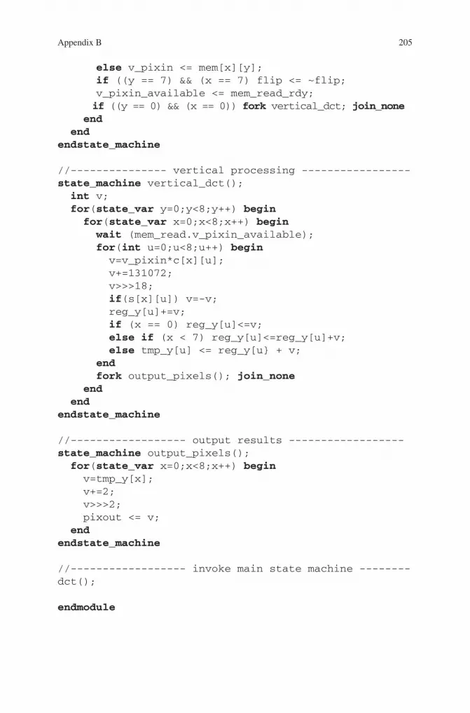
205Appendix B
else v_pixin <= mem[x][y]; if ((y == 7) && (x == 7) flip <= ~flip; v_pixin_available <= mem_read_rdy; if ((y == 0) && (x == 0)) fork vertical_dct; join_none end endendstate_machine
//--------------- vertical processing -----------------state_machine vertical_dct(); int v; for(state_var y=0;y<8;y++) begin for(state_var x=0;x<8;x++) begin wait (mem_read.v_pixin_available); for(int u=0;u<8;u++) begin v=v_pixin*c[x][u]; v+=131072; v>>>18; if(s[x][u]) v=-v; reg_y[u]+=v; if (x == 0) reg_y[u]<=v; else if (x < 7) reg_y[u]<=reg_y[u]+v; else tmp_y[u] <= reg_y[u} + v; end fork output_pixels(); join_none end endendstate_machine
//------------------ output results ------------------state_machine output_pixels(); for(state_var x=0;x<8;x++) begin v=tmp_y[x]; v+=2; v>>>2; pixout <= v; endendstate_machine
//------------------ invoke main state machine --------dct();
endmodule

207
This appendix includes preliminary specifications for some proposed extensions to the synthesizable subset of SystemVerilog. The first section addresses the issue of data types in SystemVerilog. The second section describes a hierarchical state machine construct.
Data Types in System Verilog
Overview
The most basic objects of digital design are:
The flip-flop•The combinational gate•The latch•The special signals clock and reset•
None of these types are explicitly supported by SystemVerilog. The supported data types of bit, logic, reg and wire do not exactly map onto the design primitives listed above.
SystemVerilog introduced always_ff, always_comb, and always_latch to enable designers to specify exactly how assignments in these processes should be inter-preted. Quoting from the LRM:
Appendix CPreliminary Specification for Extensions to SystemVerilog
M. Keating, The Simple Art of SoC Design: Closing the Gap between RTL and ESL, DOI 10.1007/978-1-4419-8586-6, © Synopsys, Inc. 2011
Because of the possibility of human or mechanical error, neither the author, Synopsys, Inc., norany of its affiliates, including but not limited to Springer Science+Business Media, LLC guarantees the accuracy, adequacy or completeness of any information contained herein. In no event shall the authors, Synopsys, Inc. or their affiliates be liable for any damages in connection with the information provided herein. Full disclaimer available at: pg. v of Frontmatter.
208 Appendix C
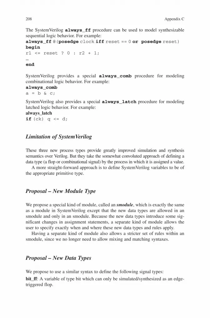
The SystemVerilog always_ff procedure can be used to model synthesizable sequential logic behavior. For example:always_ff @(posedge clock iff reset == 0 or posedge reset) beginr1 <= reset ? 0 : r2 + 1;…end
SystemVerilog provides a special always_comb procedure for modeling combinational logic behavior. For example:always_comba = b & c;
SystemVerilog also provides a special always_latch procedure for modeling latched logic behavior. For example:always_latchif (ck) q <= d;
Limitation of SystemVerilog
These three new process types provide greatly improved simulation and synthesis semantics over Verilog. But they take the somewhat convoluted approach of defining a data type (a flop or combinational signal) by the process in which it is assigned a value.
A more straight-forward approach is to define SystemVerilog variables to be of the appropriate primitive type.
Proposal – New Module Type
We propose a special kind of module, called an smodule, which is exactly the same as a module in SystemVerilog except that the new data types are allowed in an smodule and only in an smodule. Because the new data types introduce some sig-nificant changes in assignment statements, a separate kind of module allows the user to specify exactly when and where these new data types and rules apply.
Having a separate kind of module also allows a stricter set of rules within an smodule, since we no longer need to allow mixing and matching syntaxes.
Proposal – New Data Types
We propose to use a similar syntax to define the following signal types:
bit_ff: A variable of type bit which can only be simulated/synthesized as an edge-triggered flop.

209Appendix C
bit_comb: A variable of type bit which can only be simulated/synthesized as a combinational variable.
bit_latch: A variable of type bit which can only be simulated/synthesized as an level sensitive latch.
Similarly, we define logic_ff, logic_comb, and logic_latch as equivalent variables of type logic.
For types bit_ff, bit_latch, logic_ff, and logic_latch we allow initialization values to indicate the reset value of the variable. For example:
bit_ff [31:0] foo = 32’b0;
In addition, we provide for the specification of a default clock and a default reset to be used in a module.
$clock posedge clk specifies that the posedge of signal clk is the default clock for all flops and latches in this module.
$reset async negedge reset_n specifies that the signal reset_n is the default reset for all flops and latches in this module, that reset is asynchronous and occurs on the negedge of the signal reset_n.
$reset sync !reset_n specifies that the signal reset_n is the default reset for all flops and latches in this module, that reset is synchronous and occurs when the signal reset_n is low.
Usage
For the purpose of this section, we refer to bit_ff, bit_comb, bit_latch, logic_ff, logic_comb, logic_latch as extended bit/logic types.
The extended bit/logic types can be used only in an smodule. They can be used anywhere bit/logic can be used. That is, any object than can be declared to be of type bit (or logic) in a normal module can be declared to be an extended bit(or logic) type in an smodule. But the distinction between extended bit/logic types and normal bit/logic types becomes meaningful only when the variable appears on the left hand side of an assignment. That is, the compiler treats extended bit/logic data types exactly like normal bit/logic types except when they appear on the left hand side of an assignment operator.
Sequential and Combinational Processes
Explicit processes are not allowed in smodules. That is, no kind of always state-ment or assign statement is allowed. Since we have the extended data types, always_ff and always_comb are not required to disambiguate what an assignment means in terms of behavior and hardware structures that will be synthesized.

210 Appendix C
Operators
It will be an error if:
1. A variable of type bit_ff, bit_latch, logic_ff or logic_latch is on the left hand side of any assignment operator except the non-blocking assignment operator (<=).
2. A variable of type bit_comb or logic_comb is on the left hand side of any assign-ment operator except the blocking assignment operator (=).
Assignments Outside of Processes
In smodules, an assignment to an extended bit/logic type implies the appropriate process.For example:
smodule foo (input bit [7:0] a,b );
bit_comb [7:0] bar;
bar = a && b;
endmodule
Is the equivalent of:
module foo (input bit [7:0] a,b );bit [7:0] bar;
always_comb bar = a && b;
endmodule
Sequential Assignments:
For implied sequential processes, it is necessary to know the clock, reset signal, and reset value. These are provided by $clock, $reset, and variable initialization.For example:
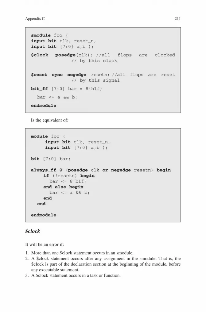
211Appendix C
Is the equivalent of:
smodule foo (input bit clk, reset_n,input bit [7:0] a,b );
$clock posedge(clk); //all flops are clocked // by this clock
$reset sync negedge resetn; //all flops are reset // by this signal
bit_ff [7:0] bar = 8’h1f;
bar <= a && b;
endmodule
module foo ( input bit clk, reset_n, input bit [7:0] a,b );
bit [7:0] bar;
always_ff @ (posedge clk or negedge resetn) begin if (!resetn) begin bar <= 8’b1f; end else begin bar <= a && b; end end
endmodule
$clock
It will be an error if:
1. More than one $clock statement occurs in an smodule. 2. A $clock statement occurs after any assignment in the smodule. That is, the
$clock is part of the declaration section at the beginning of the module, before any executable statement.
3. A $clock statement occurs in a task or function.
212 Appendix C
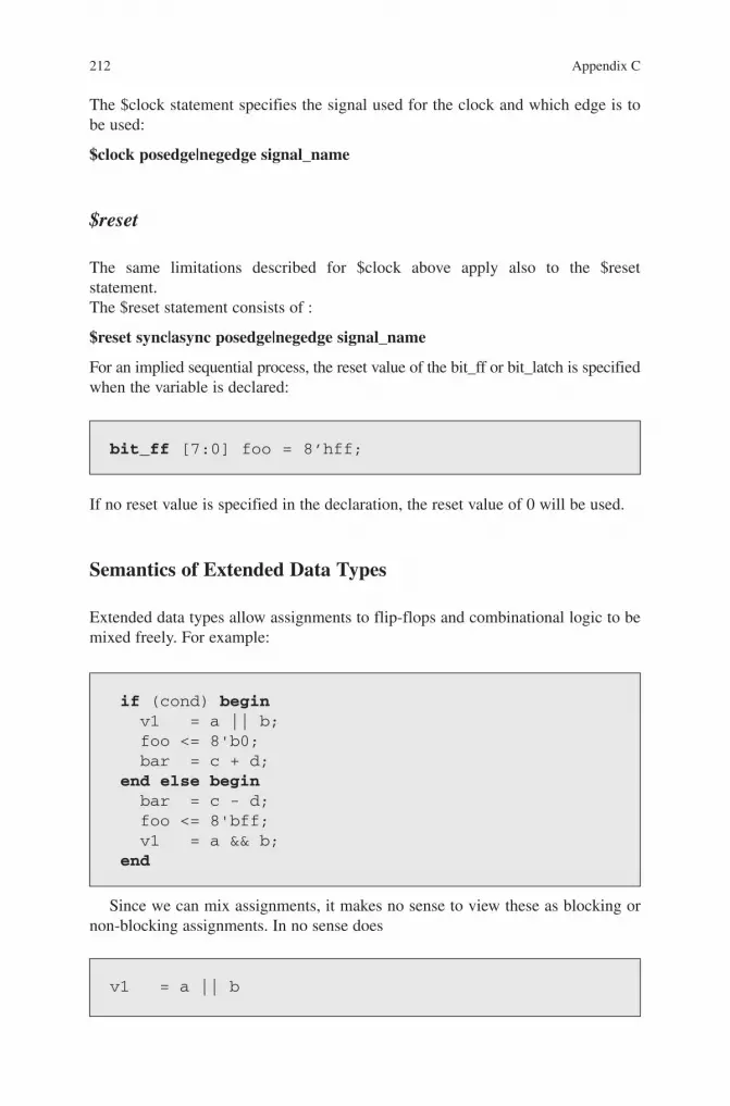
The $clock statement specifies the signal used for the clock and which edge is to be used:
$clock posedge|negedge signal_name
$reset
The same limitations described for $clock above apply also to the $reset statement.The $reset statement consists of :
$reset sync|async posedge|negedge signal_name
For an implied sequential process, the reset value of the bit_ff or bit_latch is specified when the variable is declared:
bit_ff [7:0] foo = 8’hff;
if (cond) begin v1 = a || b; foo <= 8'b0; bar = c + d; end else begin bar = c - d; foo <= 8'bff; v1 = a && b; end
v1 = a || b
If no reset value is specified in the declaration, the reset value of 0 will be used.
Semantics of Extended Data Types
Extended data types allow assignments to flip-flops and combinational logic to be mixed freely. For example:
Since we can mix assignments, it makes no sense to view these as blocking or non-blocking assignments. In no sense does

213Appendix C
block
foo <= 8'b0 or bar = c + d.
always_ff @ (posedge clk or negedge resetn) begin if (!resetn) begin foo <= (reset_value_of_foo); end else begin if (cond) begin foo <= 8'b0; end else begin foo <= 8'bff; end endend
always_comb begin if (cond) begin v1 = a || b; end else begin v1 = a && b; endend
always_comb begin if (cond) begin bar = c + d; end else begin bar = c - d; endend
if (cond) foo <= 8'b0; else foo <= 8'bff;
if (cond) v1 = a || b; else v1 = a && b;
if (cond) bar = c + d; else begin bar = c - d;
Instead, we think of combinational assignments as occurring immediately, and sequential assignments occurring at the next clock. Thus the above code is equiva-lent to:
Or, in our more succinct extended data types:
214 Appendix C
Tasks
A standalone invocation of a task is considered an implied sequential process. So:
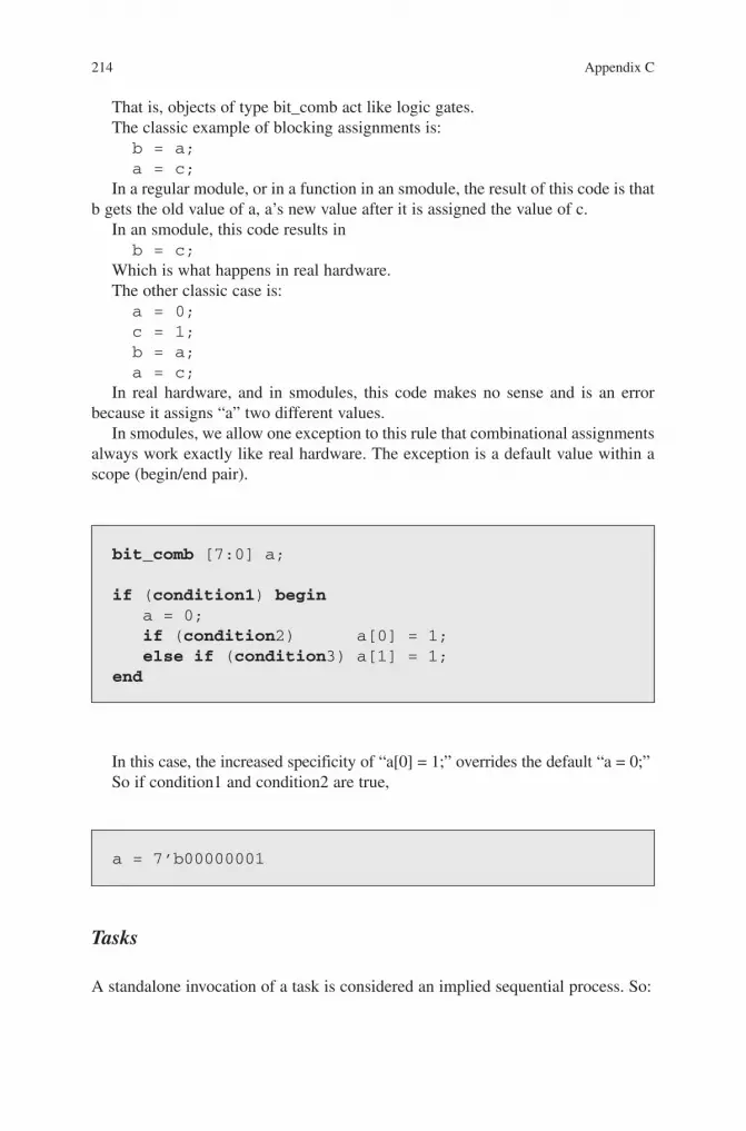
bit_comb [7:0] a;
if (condition1) begin a = 0; if (condition2) a[0] = 1; else if (condition3) a[1] = 1;end
That is, objects of type bit_comb act like logic gates.The classic example of blocking assignments is:b = a;a = c;
In a regular module, or in a function in an smodule, the result of this code is that b gets the old value of a, a’s new value after it is assigned the value of c.
In an smodule, this code results inb = c;
Which is what happens in real hardware.The other classic case is:a = 0;c = 1;b = a;a = c;
In real hardware, and in smodules, this code makes no sense and is an error because it assigns “a” two different values.
In smodules, we allow one exception to this rule that combinational assignments always work exactly like real hardware. The exception is a default value within a scope (begin/end pair).
a = 7’b00000001
In this case, the increased specificity of “a[0] = 1;” overrides the default “a = 0;”So if condition1 and condition2 are true,

215Appendix C
smodule foo (input bit clk, reset_n,);
$clock posedge(clk);$reset sync negedge resetn;
task bar(); a <= b + c;endtask ;
bar ();
endmodule
module foo (input bit clk, reset_n);
task bar(); a <= b + c;endtask ;
always_ff @ (posedge clk) begin bar (); end endmodule
Is the equivalent of:
Functions
The behavior and rule governing functions are not changed.
Structure in SModules
One advantage of explicit processes like always_ff is that they allow a scope to be defined where local variables can be declared and related statements grouped together. This kind of mechanism for localizing information and hiding it from the rest of the code is important for writing good code.
216 Appendix C
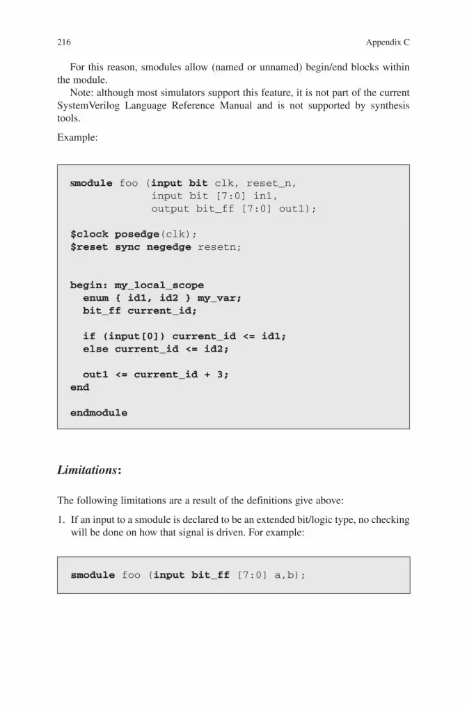
For this reason, smodules allow (named or unnamed) begin/end blocks within the module.
Note: although most simulators support this feature, it is not part of the current SystemVerilog Language Reference Manual and is not supported by synthesis tools.
Example:
smodule foo (input bit clk, reset_n, input bit [7:0] in1, output bit_ff [7:0] out1);
$clock posedge(clk);$reset sync negedge resetn;
begin: my_local_scope enum { id1, id2 } my_var; bit_ff current_id; if (input[0]) current_id <= id1; else current_id <= id2;
out1 <= current_id + 3;end
endmodule
Limitations:
The following limitations are a result of the definitions give above:
1. If an input to a smodule is declared to be an extended bit/logic type, no checking will be done on how that signal is driven. For example:
smodule foo (input bit_ff [7:0] a,b);

217Appendix C
The fact that a and b are defined as bit_ff has no effect – we don’t check that the module driving these inputs drives them from a flip-flop. (Note – this could be an interesting check in the future).
2. If a function is declared as type bit_ff, it is the same as declaring it as bit, since a function/task can never be the left hand side of an assignment.
Examples
Reference for Examples
The following (legal SystemVerilog) code serves as a reference for the following examples which use extended data types.
module foo ( input bit clk, resetn, input bit data_valid, input bit [31:0] data_in, output bit [35:0] output_data , output bit hdr_dword_push );
always_ff @ (posedge clk or negedge resetn) begin if (!resetn) begin output_data <= 36’h0; end else begin output_data <= data_in; end end
always_comb hdr_dword_push = data_valid;
endmodule
218 Appendix C
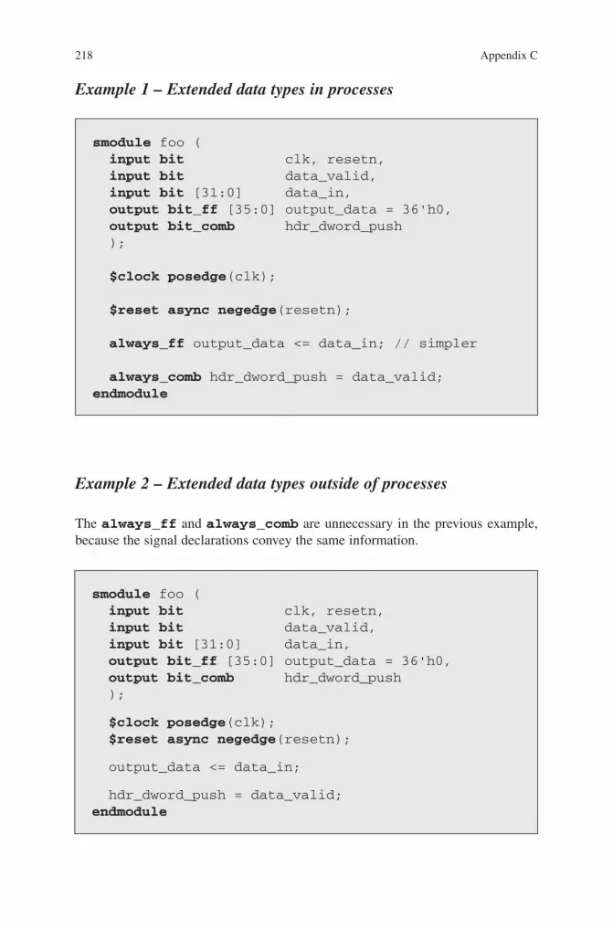
Example 1 – Extended data types in processes
smodule foo ( input bit clk, resetn, input bit data_valid, input bit [31:0] data_in, output bit_ff [35:0] output_data = 36'h0, output bit_comb hdr_dword_push );
$clock posedge(clk);
$reset async negedge(resetn);
always_ff output_data <= data_in; // simpler
always_comb hdr_dword_push = data_valid; endmodule
Example 2 – Extended data types outside of processes
The always_ff and always_comb are unnecessary in the previous example, because the signal declarations convey the same information.
smodule foo ( input bit clk, resetn, input bit data_valid, input bit [31:0] data_in, output bit_ff [35:0] output_data = 36'h0, output bit_comb hdr_dword_push );
$clock posedge(clk); $reset async negedge(resetn);
output_data <= data_in;
hdr_dword_push = data_valid;endmodule

219Appendix C
Example 3 - A slightly more complex example
smodule foo ( input bit clk, resetn, input bit data_valid, input bit [31:0] data_in, output bit_ff [35:0] output_data = 36'h0, output bit_comb hdr_dword_push );
$clock posedge(clk); $reset async negedge(resetn);
if (data_valid) output_data <= data_in; else for (int i=0; i<8; i++) output_data <= i;
hdr_dword_push = data_valid; endmodule
Hierarchical State Machine Primitive
Overview
The state machine is the most important element in control code. Today engineers code state machines in many different styles. This limits the optimizations synthesis can do and the analysis that verification tools can do. It also leads to state machines that are more complex and difficult for humans to understand. Although about 5-10% of RTL designers have used hierarchical state machines, the difficulty in cod-ing them limits the adoption of this very effective tool for structuring control code.
The proposed hierarchical state machine (HSM) mechanism is similar to a func-tion or a task, in that it is a scope. This allows local variables and types to be defined. Like functions and tasks, state machines can call other state machines, leading to hierarchical state machines.
Fundamental Characteristics of a State Machine
1. A state machine is a fully static object. State is persistent and (can be declared to be) local to the state machine.
2. State is a primitive design concept, so the state machine is not a function or task, although it can be coded using functions and tasks.

220 Appendix C
3. State is a property of a module – a module is in exactly one state at any time during operation.
4. State transitions are synchronous events. All state transitions in a given state machine occur on the same edge (pos or neg) of the same clock.
5. In a given state, both synchronous and combinational outputs are driven to new values. The synchronous events occur on the same edge (pos or neg) of the same clock as the state transitions.
6. The state machine primitive must support hierarchical state machines.
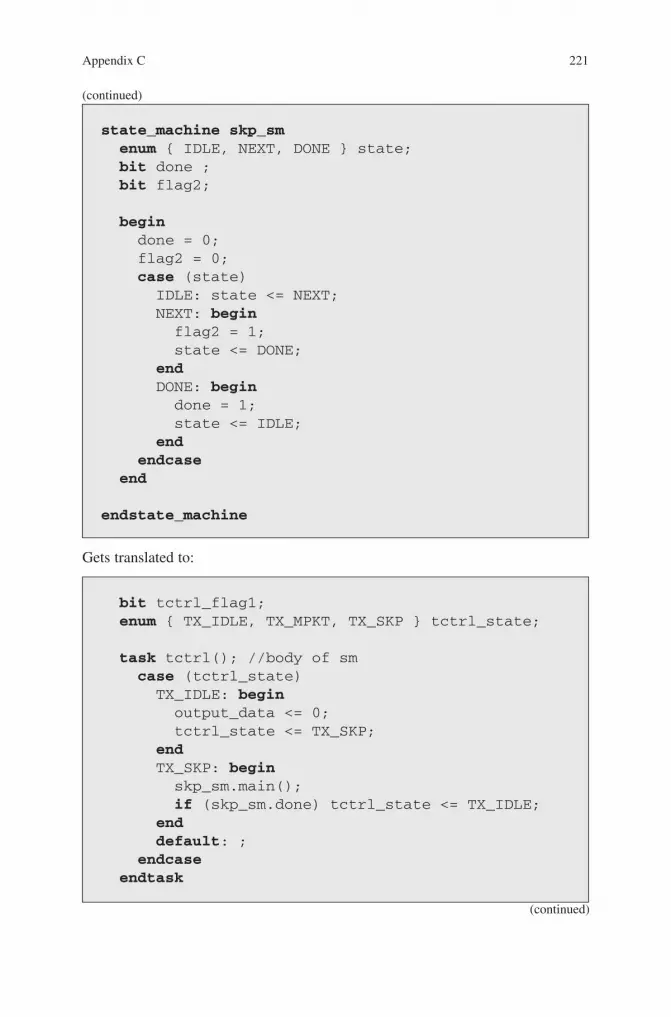
Translation Example – Simple State Machine
The features of the state machine primitive are described in Chapter 11. Here we give an example of a very simple state machine and how it might be translated into legal SystemVerilog. The following state machine:
state_machine tctrl(); bit flag1; state_type { TX_IDLE, TX_MPKT, TX_SKP } state; begin flag1 = 0; case (state) TX_IDLE: begin output_data <= 0; state <= TX_SKP; end TX_SKP: begin flag1 = 1; skp_sm(); if (skp_sm.done) state <= TX_IDLE; end default: ; endcase endendstate_machine
(continued)
221Appendix C
Gets translated to:
bit tctrl_flag1; enum { TX_IDLE, TX_MPKT, TX_SKP } tctrl_state;
task tctrl(); //body of sm case (tctrl_state) TX_IDLE: begin output_data <= 0; tctrl_state <= TX_SKP; end TX_SKP: begin skp_sm.main(); if (skp_sm.done) tctrl_state <= TX_IDLE; end default: ; endcase endtask
(continued)
state_machine skp_sm enum { IDLE, NEXT, DONE } state; bit done ; bit flag2; begin done = 0; flag2 = 0; case (state) IDLE: state <= NEXT; NEXT: begin flag2 = 1; state <= DONE; end DONE: begin done = 1; state <= IDLE; end endcase end
endstate_machine
(continued)

222 Appendix C
always_comb if (tctrl_state == TX_SKP) tctrl_flag1 = 1; else tctrl_flag1 = 0;
always @(posedge clk) tctrl();
enum {SKP_IDLE,SKP_NEXT,SKP_DONE} skp_sm_state; bit skp_done ; bit skp_flag2;
task skp_sm(); case (skp_sm_state) SKP_IDLE: skp_sm_state <= SKP_NEXT; SKP_NEXT: skp_sm_state <= SKP_DONE; SKP_DONE: skp_sm_state <= SKP_IDLE; endcase endtask
always_comb if (skp_sm_state == SKP_NEXT) skp_flag2 = 1; else skp_flag2 = 0;
always_comb if (skp_sm_state == SKP_DONE) skp_done = 1; else skp_done = 0;
(continued)

223
This chapter describes some additional high-level constructs in SystemVerilog and their potential role in raising the level of abstraction in design.
Interfaces
The interface construct in SystemVerilog can be a useful tool in creating more structured code. The interface construct is described in detail in [15] and [16].
The idea behind interfaces is that we can go beyond grouping interface signals together – which is easily and efficiently done using structs. With interfaces, we can move some functionality, especially functionality that is communication-dependent, from the module into an interface.
Appendix DMore on High Level SystemVerilog
Figure D-1 Using the interface construct to encapsulate the memory and FIFO read/write tasks.
M. Keating, The Simple Art of SoC Design: Closing the Gap between RTL and ESL, DOI 10.1007/978-1-4419-8586-6, © Synopsys, Inc. 2011
Because of the possibility of human or mechanical error, neither the author, Synopsys, Inc., norany of its affiliates, including but not limited to Springer Science+Business Media, LLC guarantees the accuracy, adequacy or completeness of any information contained herein. In no event shall the authors, Synopsys, Inc. or their affiliates be liable for any damages in connection with the information provided herein. Full disclaimer available at: pg. v of Frontmatter.

224 Appendix D
Figure D-1 illustrates this idea. Imagine we are in the early stages of a design, and we don’t yet know if we are going to interface to a memory or a FIFO. We can use a SystemVerilog interface to encapsulate the read and write functions. We can then code the module using generalized read and write functions, which call func-tions (tasks) in the interface. Now we can change our minds about whether to use a FIFO or memory, and we need only change the code in the interface. The module itself remains unchanged.
This approach has proven very useful in writing test benches and behavioral code. With the current synthesizable subset, however, it is not possible to put sequential code in the interface block. This means that if the read or write takes multiple clock cycles, it is not really possible to isolate this behavior in the inter-face. This is another case where, hopefully, the synthesizable subset of SystemVerilog will be extended.
Parameters of Type Type
Another interesting high-level capability of SystemVerilog is the parameter of type type. Here we can specify the type of an object via a parameter. As in the case of the interface, this construct allows us to defer decisions. For instance, if we are not sure whether an interface is going to be a DMA interface or a register read-write interface, we can use parameters of type type to defer the decision but carry on with writing the rest of the code.
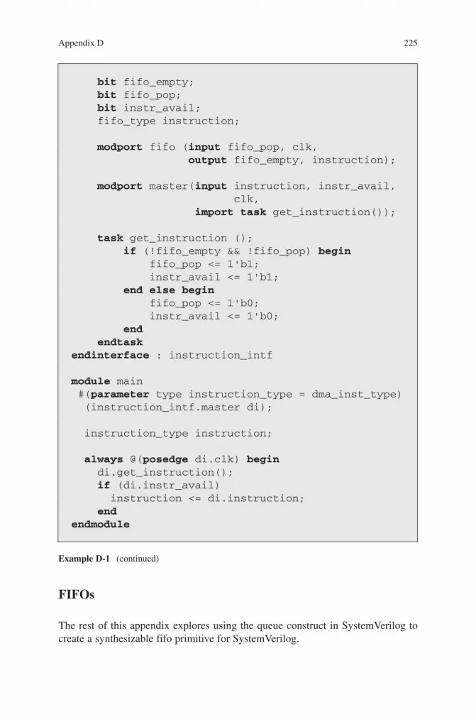
Example D-1 shows a (very simple) example of using parameters of type type.Example D1: Parameters of type type are synthesizable in the Synopsys synthesis tools.
typedef enum bit {READ, WRITE} rw_type;
typedef struct packed{ bit [14:0] target_addr; bit [7:0] length;} dma_inst_type ;
typedef struct packed { rw_type read_write; bit [14:0] addr; bit [15:0] data; } rw_instr_type;
interface automatic instruction_intf #(parameter type fifo_type = dma_inst_type) (input clk);
(continued)
225Appendix D
FIFOs
The rest of this appendix explores using the queue construct in SystemVerilog to create a synthesizable fifo primitive for SystemVerilog.
bit fifo_empty; bit fifo_pop; bit instr_avail; fifo_type instruction;
modport fifo (input fifo_pop, clk, output fifo_empty, instruction);
modport master(input instruction, instr_avail, clk, import task get_instruction());
task get_instruction (); if (!fifo_empty && !fifo_pop) begin fifo_pop <= 1'b1; instr_avail <= 1'b1; end else begin fifo_pop <= 1'b0; instr_avail <= 1'b0; end endtaskendinterface : instruction_intf
module main #(parameter type instruction_type = dma_inst_type) (instruction_intf.master di);
instruction_type instruction;
always @(posedge di.clk) begin di.get_instruction(); if (di.instr_avail) instruction <= di.instruction; endendmodule
Example D-1 (continued)
226 Appendix D
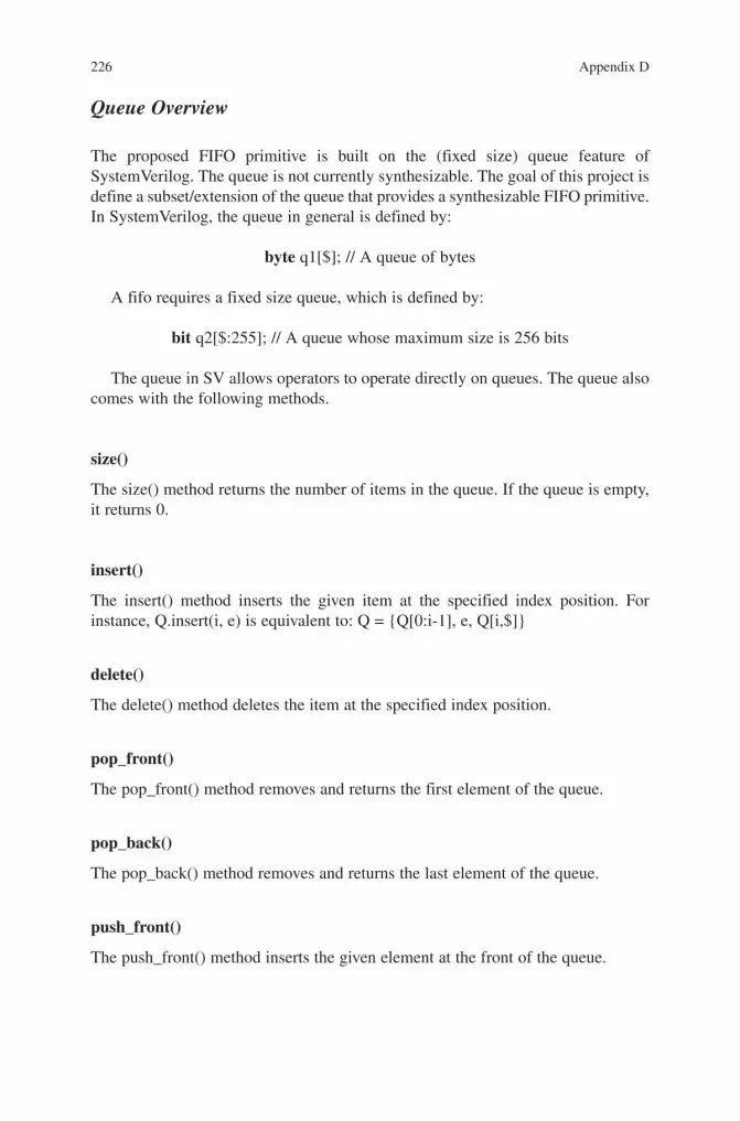
Queue Overview
The proposed FIFO primitive is built on the (fixed size) queue feature of SystemVerilog. The queue is not currently synthesizable. The goal of this project is define a subset/extension of the queue that provides a synthesizable FIFO primitive. In SystemVerilog, the queue in general is defined by:
byte q1[$]; // A queue of bytes
A fifo requires a fixed size queue, which is defined by:
bit q2[$:255]; // A queue whose maximum size is 256 bits
The queue in SV allows operators to operate directly on queues. The queue also comes with the following methods.
size()
The size() method returns the number of items in the queue. If the queue is empty, it returns 0.
insert()
The insert() method inserts the given item at the specified index position. For instance, Q.insert(i, e) is equivalent to: Q = {Q[0:i-1], e, Q[i,$]}
delete()
The delete() method deletes the item at the specified index position.
pop_front()
The pop_front() method removes and returns the first element of the queue.
pop_back()
The pop_back() method removes and returns the last element of the queue.
push_front()
The push_front() method inserts the given element at the front of the queue.
227Appendix D
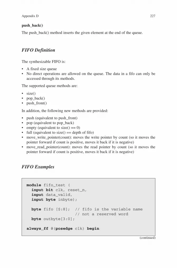
push_back()
The push_back() method inserts the given element at the end of the queue.
FIFO Definition
The synthesizable FIFO is:
A fixed size queue•No direct operations are allowed on the queue. The data in a fifo can only be •accessed through its methods.
The supported queue methods are:
size()•pop_back()•push_front()•
In addition, the following new methods are provided:
push (equivalent to push_front)•pop (equivalent to pop_back)•empty (equivalent to size() == 0)•full (equivalent to size() == depth of fifo)•move_write_pointer(count): moves the write pointer by count (so it moves the •pointer forward if count is positive, moves it back if it is negative)move_read_pointer(count): moves the read pointer by count (so it moves the •pointer forward if count is positive, moves it back if it is negative)
FIFO Examples
module fifo_test ( input bit clk, reset_n, input data_valid, input byte inbyte);
byte fifo [$:8]; // fifo is the variable name // not a reserved word byte outbyte[3:0];
always_ff @(posedge clk) begin
(continued)

228 Appendix D
Example D-2 shows the use of a bounded queue as a fifo. This is completely legal SystemVerilog code – it simulates correctly. But it is not currently synthesizable.Example D-3 shows how to use a queue as a fifo in the case where it is read and written by two different modules.
module fifo_test ( input bit clk, reset_n, input data_valid, input byte inbyte);
byte fifo [$:8];
fifo_writer U_fifo_writer(.*); fifo_reader U_fifo_reader(.*);endmodule
module fifo_writer ( input bit clk, reset_n, input data_valid, input byte inbyte);
always_ff @(posedge clk) begin if (data_valid &&(fifo_test.fifo.size < 8)) fifo_test.fifo.push_front(inbyte);
(continued)
Example D-2 (continued)
if (data_valid && (fifo.size < 8)) fifo.push_front(inbyte);end
always_ff @(posedge clk) begin if (fifo.size > 4) for (int i = 0; i < 4; i++) outbyte[i] <= fifo.pop_back();endendmodule

229Appendix D
Example D-4 shows a queue used as a fifo with the fifo in the interface.
interface fifo_interface (); byte fifo [$:8];
modport master (import full, push); modport slave (import empty, half_full, pop);
function empty (); empty = (fifo.size() == 0); endfunction
function full (); full = (fifo.size() == 8); endfunction
task push (byte inbyte); fifo.push_front(inbyte); endtask
function byte pop (); pop = fifo.pop_back(); endfunction
(continued)
Example D-3 (continued)
endendmodule
module fifo_reader ( input bit clk, reset_n, input data_valid, input byte inbyte);
byte outbyte[3:0];
always_ff @(posedge clk) begin if (fifo_test.fifo.size > 4) for (int i = 0; i < 4; i++) outbyte[i] <= fifo_test.fifo.pop_back(); endendmodule

230 Appendix D
Example D-4 (continued)
function half_full (); half_full = (fifo.size() >= 4); endfunctionendinterface : fifo_interface
module fifo_writer ( input bit clk, reset_n, input data_valid, input byte inbyte, fifo_interface.master fifo);
always_ff @(posedge clk) if (data_valid && !fifo.full())fifo.push(inbyte);
endmodule
module fifo_reader ( input bit clk, reset_n, input data_valid, input byte inbyte, fifo_interface.slave fifo);
byte outbyte;
always_ff @(posedge clk) if (fifo.half_full())outbyte <= fifo.pop();
endmodule
module fifo_test ( input bit clk, reset_n, input data_valid, input byte inbyte);
fifo_interface fifo();
fifo_writer U_fifo_writer(.*); fifo_reader U_fifo_reader(.*);
endmodule

231
[1] Miller, G. A. (1956). “The magical number seven, plus or minus two: Some limits on our capacity for processing information”. Psychological Review 63 (2): 81–97.
[2] Lorenz, Edward N. “Deterministic Nonperiodic Flow”. Journal of the Atmospheric Sciences 20 (2): 130–141 (March 1963). Note: In spite of the title listed above, the effect has long been referred to as the butterfly affect. According to Lorenz, when he failed to provide a title for a talk he was to present at the 139th meeting of the American Association for the Advancement of Science in 1972, Philip Merilees concocted Does the flap of a butterfly’s wings in Brazil set off a tornado in Texas? as the title.
[3a] Miller, J. and Page, S. Complex Adaptive Systems: An Introduction to Computational Models of Social Life (Princeton Studies in Complexity) Princeton University Press March 5, 2007
[3b] Bar_Yam, Y., Minai, A. Unifying Themes in Complex Systems: Proceedings of the Second International Conference on Complex Systems
[4a] http://www.sei.cmu.edu/library/abstracts/news-at-sei/wattsnew20043.cfm [4b] Humphrey, W. A Discipline for Software Engineering. Addison Wesley, 1995. [4c] http://weblogs.java.net/blog/2006/03/10/economics-quality [5] McConnell, S. Code Complete: A Practical Handbook of Software Construction Microsoft
Press; 2nd edition (June 9, 2004) [6a] http://www.eetimes.com/design/automotive-design/4004785/Leveraging-system-models-
for-RTL-functional-verification [6b] http://ieeexplore.ieee.org/stamp/stamp.jsp?arnumber=01200580 [7] Jones,C. Applied Software Measurement: Global Analysis of Productivity and Quality by
Capers Jones McGraw-Hill Osborne Media; 3 edition (April 11, 2008) [8] Sutherland, S. et al. SystemVerilog for Design Second Edition: A Guide to Using
SystemVerilog for Hardware Design and Modeling [Hardcover]Springer; 2nd edition (July 20, 2006)
[9] Keating, M. and Bricaud, P. Reuse Methodology Manual for System-on-a-Chip Designs Springer; 3rd edition (September 11, 2007)
[10] Harel, D. and Politi, M. Modeling Reactive Systems With Statecharts : The Statemate Approach McGraw-Hill Companies (October 8, 1998)
[11] Samek, M. Practical Statecharts in C/C++ CMPBooks 2008 [12] Hennessy, J. and Patterson, D. Computer Architecture: A Quantitative Approach, 3rd
Edition Morgan Kaufmann (May 31, 2002) [13] Fowler, M. and Parsons, R. Domain-Specific Languages Martin Fowler (Author)
Addison-Wesley Professional; (October 4, 2010) [14] Dijkstra, E. “Go To Statement Considered Harmful” (PDF). Communications of the ACM
11 (3): 147–148 (March 1968). [15] Jones, C. Applied Software Measurement: Global Analysis of Productivity and Quality
McGraw-Hill Osborne Media; 3 edition (April 11, 2008) [16a] A. Koelbl, R. Jacoby, H. Jain, C. Pixley, “Solver Technology for System-level to RTL
Equivalence Checking”, Proceedings of DATE 2009, Munich, Germany
References

232 References
[16b] A. Koelbl, J.Burch, C. Pixley, “Memory Modeling in ESL-RTL Equivalence Checking, Proceedings of DAC 2007, San Diego, CA.
[16c] Alfred Koelbl, C.Pixley, “Constructing Efficient Formal Models from High-Level Descriptions Using Symbolic Simulation”, Intl. J. of Parallel Programming, Volume 33, Number 6, December 2005, pp. 645–666
[17] McCabe, T. “A Complexity Measure” IEEE Transactions on Software Engineering Vol. 2, No. 4, p. 308 (1976) (http://www.literateprogramming.com/mccabe.pdf)
[18] Sutherland, S. et al., SystemVerilog for Design, Second Edition. Springer, 2006. [19] Spear, C. SystemVerilog for Verification, Second Edition. Springer, 2008. [20] http://www.arm.com/products/system-ip/amba/amba-open-specifications.php [21] http://www.ocpip.org/home.php [22] Philippe Coussy, Daniel D. Gajski, Michael Meredith, Andres Takach, “An Introduction to
High-Level Synthesis,” IEEE Design and Test, July/August 2009 [23] Marı´a Carmen Molina, Rafael Ruiz-Sautua, Alberto Del Barrio, and Jose´ Manuel
Mendı´as, “Subword Switching Activity Minimization to Optimize Dynamic Power pCon-sumption”, IEEE Design and Test, July/August 2009
[24] http://www.ghs.com/products/doublecheck.html [25] http://csse.usc.edu/csse/research/COCOMOII/cocomo_main.html [26] Boehm, B. Software Engineering Economics, Prentice Hall (November 1, 1981) [27] Jones, C. Estimating Software Costs: Bringing Realism to Estimating, McGraw-Hill
Osborne Media; 2 edition (April 19, 2007) [28] https://solvnet.synopsys.com/retrieve/015771.html

233
AAbstraction, 11, 13, 20, 23, 25–28, 63, 100, 104,
139–153, 168, 175, 177, 178, 223
CCode coverage, 74, 75, 79, 80, 82–87Complexity, 4, 5, 8, 13, 19, 20, 26–45, 55, 58,
63, 67, 69, 89–107, 109, 110, 115, 118, 121, 123–137, 139, 149, 155, 170, 171, 177–179, 180, 181, 183
Complex system, 1, 3, 4, 8, 9, 17, 64, 130, 133, 152, 180
Concurrency, 15, 17–19, 22, 120, 143, 177Control dominated design, 12, 27–45, 97,
105–107, 118, 144, 145, 153
DDatapath dominated design, 89–107Deep state space, 58–59, 76–77Domain specific languages, 146, 149–153, 169
EEmergent behavior, 9
FFinite state machine, 35, 41, 47, 48, 65, 69,
151, 153, 155, 191Function, 2, 5, 15–17, 20, 21, 28, 29, 38–40,
44, 48, 63, 72, 74, 78–86, 93–102, 104–107, 118, 123, 124, 126, 129–133, 136, 137, 139, 144, 147, 148, 150, 161, 169, 170, 172–177, 179, 182, 184–186, 196–201, 211, 214, 215, 217, 219, 223, 224, 229, 230
HHierarchical state machine, 22, 28, 41,
44, 47–54, 64–65, 67, 69, 155, 160, 177, 178, 191–193, 207, 219–222
High level synthesis, 105, 136, 140–147, 153, 166, 168, 178
IIntellectual property (IP), 3–5, 7, 12,
13, 123, 124, 126–127, 129, 133, 135–137, 139, 173–177, 179
Interface(s), 3, 15, 28, 56, 93, 109, 123, 145, 169, 175, 182–183, 223–224
IP. See Intellectual property (IP)
LLine coverage, 76, 77, 79, 83–85
RRule of seven, 6–7, 22, 24, 47, 130, 134, 181
SShallow state space, 58–59, 76, 77, 123SoC, Software driver, 128–129, 133State machine, 17, 28, 47–54, 58,
71, 95, 119, 140, 155, 177, 181–182, 191, 207
State space, 17–19, 28, 55–69, 73, 109, 123, 155, 181
Syntactic fluff, 16–17, 19, 28, 32–34, 44, 145, 146, 152
SystemC, 136, 140, 142, 144–147, 177
Index

234 Index
SystemVerilog, 20, 23–25, 28, 40, 41, 43, 48, 50, 54, 62, 92, 103–107, 115, 118, 146–153, 155–170, 172, 182, 184, 191–193, 196, 202–205, 207–230
TTasks, 2, 4, 16, 48, 50, 52, 72, 73, 97–98, 100,
102, 104, 106, 107, 115, 150, 152, 160, 161, 170, 191, 196, 211, 214–215, 217, 219, 223, 224
Transaction(s), 44, 61, 120, 121, 124, 126–129, 131–135, 151, 153, 174, 177
VVerification, 1, 29, 71–87, 106, 117–118, 123,
139, 169, 172, 219 Verilog, 2, 28, 29, 33–35, 63, 91, 104–106,
115, 140, 144, 146, 147, 149, 150, 160, 172, 184–186, 207–212
Virtual platform, 129, 146