Embed Size (px)
Citation preview
REPUBLIC OF INDONESIA
MINISTRY OF PUBLIC WORKS AND HOUSING
DIRECTORATE GENERAL OF HIGHWAYS
GENERAL SPECIFICATIONS
FOR FREEWAYS AND TOLL ROADS
AUGUST 2020

GS - i
TABLE OF CONTENT
GENERAL SPECIFICATIONS FOR FREEWAYS AND TOLL ROADS
DIVISION 1
GENERAL
CLAUSE PAGE
S1.01 Abbreviations .......................................................................................... GS1-1
S1.02 Materials .................................................................................................. GS1-1
S1.03 Storage of Materials ................................................................................. GS1-2
S1.04 Royalties ................................................................................................... GS1-3
S1.05 Right-of-Way ........................................................................................... GS1-3
S1.06 Working Area and Maintenance of Adjacent Roads and Bridges ............ GS1-3
S1.07 Site for Detours, Equipment, and Other Uses ......................................... GS1-3
S1.08 Living Quarters, Sheds, and Stores ......................................................... GS1-4
S1.09 The Project Site Office and Facilities ..................................................... GS1-4
S1.10 Laboratory ............................................................................................... GS1-4
S1.11 Setting-Out and Staking .......................................................................... GS1-5
S1.12 Notice of Operations ................................................................................. GS1-7
S1.13 Occupational Health and Safety ............................................................... GS1-7
S1.14 Temporary Road Works .......................................................................... GS1-21
S1.15 Temporary Traffic Ramps ....................................................................... GS1-22
S1.16 Traffic Control .......................................................................................... GS1-22
S1.17 Number of Lanes for Traffic Control ...................................................... GS1-28
S1.18 Extraordinary Traffic ............................................................................... GS1-28
S1.19 Traffic Management and Safety ............................................................... GS1-28
S1.20 Mobilization ............................................................................................. GS1-30
S1.21 Half-Width Construction ......................................................................... GS1-31
S1.22 Filling in Holes and Trenches ................................................................... GS1-31
S1.23 Location and Protection of Utilities ......................................................... GS1-32
S1.24 Project Information Signs ........................................................................ GS1-32
S1.25 Maintenance of Existing Drainage .......................................................... GS1-32
S1.26 Working In and Dealing With, Existing Water Flows ............................. GS1-33
S1.27 Contractors Responsibility for Work ........................................................ GS1-34
S1.28 Standards of Workmanship ...................................................................... GS1-34
S1.29 Protection of Works from the Weather .................................................... GS1-34
S1.30 Units of Measurement .............................................................................. GS1-34
S1.31 Day Work ................................................................................................. GS1-34
S1.32 Templates and Straightedges .................................................................... GS1-34
S1.33 Orders to Foreman ................................................................................... GS1-35
S1.34 Work and Material included the Contract Prices...................................... GS1-35
S1.35 Workshop ................................................................................................. GS1-36
S1.36 Drawings ................................................................................................... GS1-36
S1.37 Fire Prevention ......................................................................................... GS1-36
S1.38 Irrigation Works ....................................................................................... GS1-36
GS - ii
S1.39 Environmental Safeguards ........................................................................ GS1-37
S1.40 Quality Management ................................................................................ GS1-51
S1.41 Deduction of Monthly Payment due to the Incident and/or Omission .... GS1-62
Attachment 1.10 List of Laboratory Equipment for soils, Bituminous.. GS1-65
and Concrete Testing
Attachment 1.39 Environmental Management and Monitoring Plan .... GS1-71
(RKPPL)
Attachment 1.40 Checklist of Duty of Quality Control Manager .......... GS1-85
(QCM) and the Output Indicator
DIVISION 2
SITE CLEARING
S2.01 Site Clearing ............................................................................................. GS2-1
DIVISION 3
DEMOLITION
S3.01 Demolition ................................................................................................ GS3-1
DIVISION 4
ROAD EARTHWORK AND GEOSYNTHETICS WORK
S4.01 Scope ........................................................................................................ GS4-1
S4.02 General...................................................................................................... GS4-1
S4.03 Common Excavation, Soft Rock Excavation, Excavation of Existing ... GS4-6
Granular Pavement, Excavation of Existing Cement Concrete Pavement
S4.04 Rock Excavation ....................................................................................... GS4-8
S4.05 Borrow Material ....................................................................................... GS4-10
S4.06 Formation of Embankment and Areas of Fill ........................................... GS4-12
S4.07 Waste ........................................................................................................ GS4-18
S4.08 Areas of Special Fill ................................................................................. GS4-19
S4.09 Granular Backfill ...................................................................................... GS4-21
S4.10 Permeable Backfill ................................................................................... GS4-22
S4.11 Vertical Horizontal Sand Drain ................................................................ GS4-23
S4.12 Geotextile Sheet ........................................................................................ GS4-25
S4.13 Prefabricated Vertical Drain (PVD) ......................................................... GS4-35
S4.14 Geotechnical Instrumentation ................................................................... GS4-42
GS - iii
DIVISION 5
STRUCTURE EXCAVATION
S5.01 Structure Excavation................................................................................. GS5-1
DIVISION 6
DRAINAGE
S6.01 Scope ........................................................................................................ GS6-1
S6.02 General...................................................................................................... GS6-1
S6.03 Sequence of Work .................................................................................... GS6-1
S6.04 Box Culverts and Pumping/Dewatering ................................................... GS6-2
S6.05 Drainage Pipes .......................................................................................... GS6-2
S6.06 U-Ditch, Concrete Ditch, Inlets, Outlet, Headwalls and Joint Boxes, etc GS6-5
S6.07 Porous Drainage ...................................................................................... GS6-9
DIVISION 7
SUBGRADE
S7.01 Subgrade Preparation ................................................................................ GS7-1
DIVISION 8
AGGREGATE BASE AND CEMENT TREATED BASE
S8.01 Aggregate Base ......................................................................................... GS8-1
S8.02 Cement Treated Base ................................................................................ GS8-7
DIVISION 9
PAVEMENTS
S9.01 Bituminous Pavements - General ............................................................. GS9-1
S9.02 Scarify Pavement ...................................................................................... GS9-8
S9.03 Patching of Existing Pavements .............................................................. GS9-9
S9.04 Bituminous Prime Coat ............................................................................ GS9-11
S9.05 Bituminous Tack Coat .............................................................................. GS9-12
S9.06 Seal Coat ................................................................................................... GS9-14
S9.07 Asphalt Concrete. ..................................................................................... GS9-17
S9.08 Concrete Pavement ................................................................................... GS9-31
S9.09 Wet Lean Concrete ................................................................................... GS9-50
Attachment 9.07.A Marshall Modification for Large Aggregate ............ GS9-55
(> 1” &< 2”)
GS - iv
DIVISION 10
CONCRETE STRUCTURES
S10.01 Concrete and High Performance Concrete ............................................... GS10-1
S10.02 Reinforcing Steel Bars .............................................................................. GS10-41
S10.03 Prestressed Concrete ................................................................................. GS10-46
S10.04 Precast Concrete Beam ............................................................................. GS10-62
S10.05 Pretensioned Concrete Piling ................................................................... GS10-64
S10.06 Steel Piling ................................................................................................ GS10-73
S10.07 Cast-In-Place Concrete Pilling ................................................................. GS10-79
S10.08 Test Drilling .............................................................................................. GS10-83
S10.09 Bridge Railing and Chainlink Fence and Stair Handrail.....…………….. GS10-85
S10.10 Bridge Expansion Joint ............................................................................. GS10-87
S10.11 Bridge Bearings ........................................................................................ GS10-95
S10.12 Other Incidental Bridge Facilities ............................................................ GS10-101
S10.13 Prestressed Concrete Corrugated Sheet Pile ............................................. GS10-102
DIVISION 11
STRUCTURAL STEEL WORK
S11.01 Bridge Steel Work ................................................................................... GS11-1
DIVISION 12
MISCELLANEOUS
S12.01 Sodding ..................................................................................................... GS12-1
S12.02 Stone Masonry for Retaining Walls ......................................................... GS12-4
S12.03 Slope Protection ........................................................................................ GS12-7
S12.04 Cement Mortar .......................................................................................... GS12-9
S12.05 Mortar Rubble .......................................................................................... GS12-10
S12.06 Guardrail and Fence.................................................................................. GS12-11
S12.07 Traffic Signs (Warning and Regulatory Signs) ........................................ GS12-14
S12.08 Traffic Guide and Prohibition Signs (Traffic Guide Signs) ..................... GS12-16
S12.09 Road Markings ......................................................................................... GS12-17
S12.10 Delineators ................................................................................................ GS12-19
S12.11 Dwarf Stone Walls ................................................................................... GS12-20
S12.12 Concrete Curb ........................................................................................... GS12-21
S12.13 Interlocking Concrete Paving ................................................................... GS12-23
S12.14 Staircases .................................................................................................. GS12-26
S12.15 Concrete Barrier ....................................................................................... GS12-27
S12.16 Bus Stop Shelter ....................................................................................... GS12-31
S12.17 Landscaping Works .................................................................................. GS12-32
S12.18 GSrface Treatment of Steel ...................................................................... GS12-37
S12.19 Guide Post, Kilometers Post and ROW Post ............................................ GS12-40
S12.20 ROW Fence .............................................................................................. GS12-41
GS - v
S12.21 Escape Lane .............................................................................................. GS12-43
S12.22 Shotcrete ................................................................................................... GS12-44
S12.23 Bridge Deck Loading Test ........................................................................ GS12-54
DIVISION 13
LIGHTING, TRAFFIC SIGNALS AND ELECTRICAL WORKS
S13.01 Lighting, Traffic Signals and Electrical Works ........................................ GS13-1
S13.02 Civil Works for Electrical Items ............................................................... GS13-32
S13.03 Drainage Pump ........................................................................................ GS13-35
S13.04 Generator for Drainage Pump with Electric Panel ................................... GS13-36
DIVISION 14
TOLL PLAZAS
S14.01 Toll Plaza Works ...................................................................................... GS14-1
DIVISION 15
RELOCATION OF EXISTING UTILITIES AND SERVICES
S15.01 Relocation of Existing Utilities and Services ........................................... GS15-1
DIVISION 16
TOLL OFFICE AND FACILITIES
S16.01 General...................................................................................................... GS16-1
S16.02 Site Works ................................................................................................ GS16-1
S16.03 Building Work .......................................................................................... GS16-5
S16.04 Facilities Work ......................................................................................... GS16-32
S16.05 Measurement and Payment ....................................................................... GS16-47
DIVISION 17
DAYWORK
S17.01 General...................................................................................................... GS17-1
S17.02 Materials and Equipment .......................................................................... GS17-1
S17.03 Execution of Daywork .............................................................................. GS17-2
S17.04 MeaGSrement and Payment ..................................................................... GS17-3

GS - vi
Toll Road Project – General Specifications
Division 1 – General
GS1 - 1
DIVISION 1 GENERAL
S1.01 Abbreviations
In addition to the definitions stated in the General Conditions of Contract, the
following abbreviations are used in the General Specifications and Bill of
Quantities and they shall be interpreted as follows:
C.B.R - California bearing ratio
cm - Centimeter(s)
Cov.Pl. - Cover plate
cu.m or m3 - Cubic meter(s)
Dia. or Ø - Diameter
Diaph. - Diaphragm
Drg. or Dwg - Drawing
Ea - Each
Guss. - Gusset
Hp - Horsepower(s)
Kg - Kilogram(s)
L.M. or m - Linear meter(s)
lt - Liter(s)
Max. - Maximum
Min. - Minimum
mm. - Millimeter(s)
No. - Number
P.C. - Prestressed Concrete
R.C. - Reinforced Concrete
Rp. - Rupiah(s) of the Republic of Indonesia
Sht. - Sheet
Spl. - Splice
sq. cm or cm2 - Square centimeter(s)
sq. m or m2 - Square meter(s)
T or ton - Metric tonne
W or Wt - Weight
S1.02 Materials
S1.02 (1) Unless otherwise specifically provided in this Contract, all items incorporated in
the completed work, such as plant, materials and other Clauses, are to be new and
the most suitable grade for the purpose intended. Unless otherwise specifically
provided in this Contract, reference to any plant, material, article, or patented
process, by trade name, make, or catalogue number, shall be considered as
establishing a standard or quality and shall not be construed as limiting
competition, and the Contractor may, at his option, use any plant, material, goods,
or process which, in evaluation of the Engineer, is equal to that named. Unless
otherwise specified or instructed, all proprietary materials shall be used in
accordance with the Manufacturer's instructions.
Toll Road Project – General Specifications
Division 1 – General
GS1 - 2
S1.02 (2) The Contractor, before placing any order for materials or manufactured goods o
be incorporated in the Permanent Works, shall submit for approval a complete
description of such items, the names of firms from whom the Contractor to obtain
them, and a list of such of the items that proposes the firms should supply. The
Contractor shall submit samples and certificates for approval of the Engineer.
S1.02 (3) The Contractor shall make all arrangements for locating, selecting and processing
natural materials in accordance with these Specifications and shall submit for
approval full information regarding the proposed location of the material source
at least 30 days in advance of commencement of working the material. The
Engineer's approval of a source does not imply that all the material in that source
is approved. Locations of material sources that may be used and identified and
specified in Drawings are the information only. The Contractor shall determine
for himself the amount of equipment and work required to produce a material
meeting the Specifications. It shall be understood that it is not feasible to ascertain
from samples the exact limits for an entire deposit and that variations shall be
considered as usual and are to be expected. The Engineer may order procurement
of material from any portion of a deposit and may reject portions of the deposit
as unacceptable
S1.02 (4) In the case of bituminous materials, cement and other manufactured material the
manufacturer’s test certificates are required to be submitted to the Engineer for
his initial approval. The Engineer shall give his approval in writing to the
Contractor for ordering. All materials that are delivered to the site shall be tested
as specified under the supervision of or as directed by the Engineer.
S1.02 (5) If the quality of the material delivered to site does not conform to the quality
previously inspected or tested, the offending material shall be rejected, and shall
be removed from the site within 48 hours unless agreed otherwise with the
Engineer.
S1.03 Storage of Materials
S1.03 (1) Materials shall be stored so as to ensure preservation of their specified quality
and fitness for the work. They shall be placed on a hard, clean surface and, when
required, they shall be placed under cover. Stored materials shall be located so
as to facilitate prompt inspection. Private property shall not be used for storage
purposes without written permission of the owner and lessee and payment to
them, if necessary.
S1.03 (2) The stockpile site shall be prepared by clearing and leveling as directed by the
Engineer.
S1.03 (3) The center of all aggregate stockpile areas shall be raised and sloped to the sides
as required so as to provide proper drainage of excess moisture. The material
shall be stored in such manner as to prevent segregation and coning and to ensure
proper gradation and moisture content. Coarse aggregate storage piles shall be
lifted up and removed in layers not exceeding one meter. The height of such
stockpiles shall be limited to five meters.
Toll Road Project – General Specifications
Division 1 – General
GS1 - 3
S1.03 (4) Site means the places where the Permanent Works are to be executed including
storage and working areas and to which Plant and Materials are to be delivered,
and any other places as may be specified in the Contract as forming part of the
Site.
S1.04 Royalties
The Contractor shall be responsible for all compensation and royalties due in
respect of quarried materials. No separate payment will be made for the
compensation of royalties, but all such costs shall be included in the applicable
unit price and total of the Bill of Quantities.
S1.05 Right-of-Way
The right-of-way is the land to be acquired for and devoted to the Road. The
right-of-way widths shown on the Drawings are approximate only, the effective
width to be established by the Engineer.
S1.06 Working Area and Maintenance of Adjacent Roads and Bridges
The Contractor shall make all arrangements, inclusive of payment, if necessary,
for the use of any land required for working areas outside the right-of-way, and
the Employer will not accept any liability in connection with the use of such land.
Any exceptions to this will be given in the Special Specifications or at the time
of Bidding.
Existing public roads and bridges adjacent to the project which are use by the
Contractor in the course of his transport and haulage operations in performing the
Works, including existing bridges strengthened by the Contractor, temporary
bridges constructed by the Contractor and quarry access roads subjected to
additional heavy loading as a result of the Contractor’s activities, shall be fully
maintained by the Contractor at his own expense throughout the duration of the
Works and shall be left in a condition of serviceability, quality and amenity such
is no worse than before the Contractor’s operations were commenced. Temporary
bridges constructed by Contractor shall not be removed by the Contractor at the
completion of the Works.
Any incident and/or negligence due to the failing of implementation of the
maintenance of adjacent roads and bridges as specified in this Clause S1.06, the
deduction of payment shall be applied as described in Clause S1.41 of these
Specifications.
S1.07 Site for Detours, Equipment, and Other Uses
The Contractor shall select, arrange for, and if necessary pay for the use of sites
for detours, for all central mixing equipments for concrete and bituminous
materials, for the storage of equipment, for his own office buildings, housing, or
other uses necessary for the execution of the Work.
Toll Road Project – General Specifications
Division 1 – General
GS1 - 4
Before any land belonging to the Government or to a private land-owner is used
for any purposes in connection with the execution of the Work, the Engineer's
approval shall be obtained.
If any utility for water, electricity, drainage, etc., passing through the temporary
site will be affected by the Works, the Contractor at his own expense, shall
provide a satisfactory alternative in full working order to the satisfaction of the
owner of the utility and the Engineer, before the cutting or removal of the existing
utility.
On completion of the Contract, or earlier if so directed by the Engineer, all
Equipment and any other encumbrances shall be removed, the site properly
cleaned, all damage made good, and, if necessary, the land-owner paid for the
use of the land.
S1.08 Living Quarters, Sheds, and Stores
The Contractor shall supply, equip and maintain for the Contract period all his
own living accommodation, sheds and stores necessary for the execution of the
Work, and shall make his own arrangements, subject to the approval of the
Engineers, with the owner of any land required and, if necessary, pay for its use.
The furnishing and maintenance of living quarters, sheds, and stores shall be paid
for as provided in Clause S1.20 "Mobilization". Such payment covers the
utilization but not the ownership of the living quarters, sheds, and stores which
will remain the property of the Contractor at the completion of the Contract.
S1.09 Offices and Field Facilities
S1.09 (1) The Contractor shall provide and maintain for the duration of the Contract, all
their own accommodations, barracks and stores required for the execution of the
Works, and shall carry out his own arrangement with the owner of the land to be
occupied, to the satisfaction of the Engineer, and if necessary, to pay for the land
use.
S1.09 (2) The supply, equipping and maintenance of items described in this Clause shall
be paid for as provided in Clause S1.20 "Mobilization". Such payment covers the
utilization but not the ownership of the offices and fields facilities which will
remain the property of the Contractor at the completion of the Contract.
S1.10 Laboratory
The Contractor shall supply, equip and maintain for the duration of the Contract,
an approved fixed or mobile laboratory with facilities, furniture, equipment,
personnel, apparatus, and installations for the quality control and workmanship
testing as required in this Contract. Generally, Contractor shall be responsible
to carry out all instructions and coordination of the Quality Control Manager
under the supervision of the Engineer.
The laboratory shall be equipped with all the necessary apparatus and materials
for the performance of all the standard tests required by the Specifications.
Toll Road Project – General Specifications
Division 1 – General
GS1 - 5
Group 1.
Testing, in opinion of the Engineer, not routine testing which able to be carried
out in the approved external accredited laboratories.
Group 2.
All other apparatus and materials necessary for tests required under this Contract
shall be supplied by the Contractor and installed in the laboratory. Not later than
30 days after the Commencement Date, the Contractor shall submit for the
Engineer's approval, a list of all equipment to be procured and details of suppliers.
All equipment used for testing shall be of standard type and approved by the
Engineer and properly housed by the Contractor. An adequate supply of water
and electric power shall be provided at all times.
Indonesian National Standard (SNI) shall be used for the procedure of testing and
requirements of Works. In all cases, the Contractor may use the relevant or
equivalent SNIs specified in these Specifications. The contractor shall use the
recent edition of SNIs or other relevant standards as the replacements or directed
of the Engineer.
Every designation of AASHTO Test and Material in these Specifications refers
to "AASHTO Specifications for Highways Material and Methods of Sampling
and Testing" and shall refer to the latest revision of the Specification at the time
of project bidding, except where otherwise nominated.
In any case where material or workmanship is specified by one of the above tests,
and alternative test methods are allowed, the method used to determine
compliance with this Specification will be at the absolute discretion of the
Engineer. The Engineer's decision will be final and claims on the basis of the
Engineer's selection of a particular allowable test method will be rejected.
Other than the laboratory prescribed in this Clause, a field laboratory shall be
provided by the Contractor with an area not less than 108 square meters at the
location designated by the Engineer in order that the Engineer can monitor the
material used for bituminous pavements and operations of bituminous mixing
Equipments, as provided in DIVISION 9 of these Specifications.
The furnishing and maintenance of laboratories including staffing, water, electric
facilities, equipment, apparatus and materials and all other expenses shall be
provided on a rental basis and will be paid for as provided in Clause S1.20.
However, the Engineer may, during the Time for Completion, order the
Contractor to add laboratory equipment as necessary without any change to the
lump sum price for Mobilization. Such payment covers the utilization but not the
ownership of the equipment, apparatus and installation of the laboratory building
which will remain the property of the Contractor at the completion of the
Contract.
S1.11 Setting-Out and Staking
S1.11 (1) The Contractor shall set construction stakes establishing lines and grades in
accordance with the Drawings and shall secure the approval of the Engineer
before commencing with the work of construction. The Engineer will, if he
deems it necessary, revise the line and grade and require the Contractor to adjust
Toll Road Project – General Specifications
Division 1 – General
GS1 - 6
the stakes accordingly. The Contractor shall give the Engineer not less than
forty-eight hours notice of his intention to stake out or establish levels for any
part of the work in order that arrangements may be made for checking. The
Contractor shall measure the staking out and the Engineer will check the
measurement. The approved measurement will be the basis of payments.
S1.11 (2) The Contractor shall, as a requirement of the Contract and without extra charge,
furnish for the exclusive use of the Engineer all necessary instruments,
appliances, surveyor personnel and labor, and any material that the Engineer may
require for checking the setting out or for any other relevant work to be done.
Such survey personnel and equipment shall include but not necessarily be limited
to:
(a) 2 Surveyors
6 Surveyors’ laborers
(b) Survey equipments:
3 sets of Surveying Equipment as listed below or equal approved by the
Engineer:
- Receiver GPS (Global Positioning System) L1/L2
- GPS L1/L2 RTK (Real Time Kinematic) Receiver
- Electronic total station which can read a minimum of one (1) second,
accuracy ≤ five (5) second, produced after year of two years before
Contract signed, and has calibration certificate that is still effective
when used.
- Auto / Digital Level
- Aluminum Tripod (Flat Head)
- Program Card, including software and data cable
- Min 1 MB SRAM
- Card reader/Writer Model Card
- Single prism set
- Pole Tripod Type PPS
- Telescopic Prism Pole with nivo
- Three (4) sets walky-talky
- 2 steel measuring tapes 50m long;
- 2 steel measuring rods (4m);
- Survey stakes as required; and
- Miscellaneous tools and consumables as required in surveying
Such survey equipment will be utilized by the Engineer and will be repaired or
replaced by the Contractor as required by the Engineer, however the equipment
will remain the property of the Contractor at the completion of the Contract.
The Contractor shall at his own expense make any additional surveys and
measurements that are required for the construction of the work such as slope
stakes, temporary grade stakes, and bridge and culvert layout, offset line, etc.
The Contractor shall be responsible for the accuracy of all surveys or
measurements made by his employees.
Any marks made by the Engineer or the Contractor shall be carefully preserved
and, if disturbed or destroyed, shall be immediately replaced by the Contractor at
Toll Road Project – General Specifications
Division 1 – General
GS1 - 7
his own expense and to the satisfaction of the Engineer. No work shall be carried
out in any section until the necessary setting out in that section has been approved
by the Engineer.
S1.11.(3) The Contractor shall stake out in accordance with the Drawings prior to the
commencement of any work. Measurement of the cross section shall be within
an interval of 25 meter or less in accordance with the filed requirement.
After clearing and grubbing, the Contractor shall re-measure the cross section to
obtain the recent field condition
S1.11 (4) The Contractor shall submit to the Engineer one set of hard copies, together with
soft copies, of the cross-sections as required by Clause S4.02. The Engineer will
endorse one copy with his approval or his revision thereof, and return it to the
Contractor.
The Contractor shall resubmit as above for approval any cross-sections that the
Engineer may require to be revised.
The Contractor's cross-sections shall be drawn on standard format with scales
and layout as approved by the Engineer. When they have been finally approved
the Contractor shall give the soft copy and three printout to the Engineer.
The drawings of cross-sections shall have a title block and be of a size stipulated
by the Engineer.
S1.11 (5) The cost of complying with this Clause shall be considered to be included in the
Bid Prices for pay items under the Contract.
S1.12 Notice of Operations
S1.12 (1) The Contractor, when required by the Engineer, shall supply in writing full
information regarding the locations in which the materials are being obtained and
in which the work is being prepared.
S1.12 (2) No permanent work shall be undertaken without the Engineer's approval. Full
and complete notice in writing shall be given to the Engineer sufficiently in
advance of the time of the operation for him to be able to make such arrangements
as he may deem necessary for its inspection.
S1.13 Occupational Health and Safety
S1.13 (1) General
Description
(a) This Clause involves the provisions of occupational health and safety
management during construction for any person in the job site related to
the hauling of raw materials, the use of heavy equipment, the production
process and the environment around the job site.
(b) OHS management involves the preparation of means for preventing
occupational accidents and protection of occupational health during
construction as well as the preparation of competent personnel and the
Toll Road Project – General Specifications
Division 1 – General
GS1 - 8
OHS organization in accordance with the level of risk determined by the
Engineer.
(c) Contractor shall comply with the provisions of OHS management
specified in the Minister Regulation of Public Works and Housing
No.21/PRT/M/2019 or Amendments (if any) regarding the Guidelines for
the Occupational Safety and Health Management System (SMKK) for
Construction in Public Works and Housing Sector, and the Guidelines of
Implementation of OHS (K3) for Road and Bridge Construction
No.004/BM/2006, and other related regulations.
(d) The contractor shall provide the OHS manual in the form of Pictures and
Practical Instructions on each type of work which that easily understood
by any worker in the Site.
(e) All facilities and other means provided by the Contractor under this
Clause, however they will remain the property of the Contractor at the
completion of the Contract.
S1.13 (2) Health and Safety Management System
(a) The Contractor shall prepare, implement, and maintain continuously the
procedures for hazard identification, risk assessment and control in
accordance with the Health and Safety Plan which approved by the
Engineer as described in Clause S1.20 Mobilization.
(b) The Contractor shall provide the Occupational Health and Safety with
OHS Plan for implementing the OHS in all stages of construction.
(c) The Contractor shall presentate the OHS Plan at the pre construction
meeting for the approval and signed by the Engineer in accordance with
Minister Regulation of Public Works and Housing No.21/PRT/M/2019 or
Amendments (if any) concerning Guidelines of Health and Safety
Management System in the Public Works Sector.
(d) The Contractor shall provide at least a Middle Expert of OHS (Ahli
Madya K3) with experience of minimum 3 years or a Senior Expert of
OHS (Ahli Utama K3), a Junior Expert of OHS (Ahli Muda K3) with
experience of minimum 3 years or Middle Expert of OHS (Ahli Madya
K3), an Officer of OHS (Petugas K3) for the package with high, middle
and low potential risk, respectively. The risk level of OHS will be
determined by the Employer Representative.
(e) Works with high level risk such as welding, confined space, lockout/
tagout, excavation, working at height, electrical work, shall require a
specific permit, requested by the Contractor approved by the Engineer
(f) An Expert of OHS is a person who has a certificate of training and
competence from the authorities with evidence of work experience in the
OHS for construction for the Public Works and Housing. Officer of OHS
is an officer in a Contractor’s organization who has been trained the OHS
for Construction for the Public Works and Housing. Application
requirements of OHS Expert and OHS Officer shall refer to the Minister
Toll Road Project – General Specifications
Division 1 – General
GS1 - 9
Regulation of Public Works and Housing No.21/PRT/M/2019 or the
Amendments (if any).
(g) The Contractor shall prepare an Advisory Committee of OHS (P2K3) if:
(i) manage the Works with employees more 100 persons or a contract
amount of more than IDR.100,000,000,000 (one hundred billion
rupiah) or in accordance with applicable regulations.
(ii) manage the Works with employees less than 100 persons, but uses
the materials, processes and installations that has a high risk of
explosion, fire, poisoning and radioactive radiation.
OHS Facilitator Committee (P2K3) is an assistant board in headquarter
and job site which is the cooperation between employers (Contractor) and
workers to develop mutual understanding and effective participation in
the implementation of occupational health and safety. The team of P2K3
consists of Chairman, Secretary and Members. Secretary of P2K3 is the
principle of the Contractor’s organization.
(h) The Contractor shall provide at least each 3 month a routine report of
P2K3’s activities to the Local Manpower Office and a copy to be
delivered to the Engineer.
(i) The Contractor shall carry out an internal audit of OHS for construction
in the Public Works Sector.
(j) The Contractor together with the Engineer conduct a periodic inspection
of OHS for Construction weekly and/or monthly basis.
(k) The Contractor shall immediately carry out the necessary corrective
actions to the discrepancies found at the inspection of OHS for
Construction. The inspection report shall be submitted by the Contractor
to the Engineer.
(l) The Contractor shall carry out a review to OHS Plan for Construction (in
the part which really needs to be reviewed) continuously during the
implementation of construction work in progress.
S1.13 (3) OHS for Field Offices and Facilities
(a) Washing Facilities
The Contractor shall provide adequate washing facilities and in
accordance with the work being carried out for all construction workers.
Washing facilities including the provision of hot water and cleaning
agents for the following conditions:
(i) If workers are at risk of exposure to contamination of skin caused
by toxic substances, substances that cause infection and irritation
or other sensitive substances.
(ii) If workers handle the skin material which difficultly washed with
the cold water.
(iii) If workers have to clean their whole bodies.
Toll Road Project – General Specifications
Division 1 – General
GS1 - 10
(iv) If workers are exposed to excessive heat or cold conditions, or
working in unusually wet conditions, causing the workers have to
clean their whole body, then the Contractor shall provide a
number of showers.
(v) For normal conditions, the Contractor shall provide the showers
for bath at least one for every 15 peoples.
(b) Sanitation Facilities
(i) The Contractor shall provide adequate toilet both for man and
woman for women who employed inside or around the working
areas and the bins with enough capacity.
(ii) If the Contractor employs more than 30 workers, the minimum
requirements are 1 toilet with 1 closet
(iii) If the Contractor employs women, toilet facilities shall be
equipped with napkin disposal facilities.
(iv) Toilets of man and woman shall be separated with a full height
wall. Toilets shall be easily accessible, have an enough lighting
and ventilation, and protected from the weather. If the toilet is
located outside, it shall be provided with a walking path and
adequate lighting along the path. Toilets shall be made and placed
in a such manner so that they are able to keep the privacy of people
who use them and shall be made of a material which is easily
cleaned.
(v) The Contractor may provide one toilet if the number of man and
woman less than 10 peoples; toilet completely closed; have the
key; available napkin disposal facilities; there are no urinals in the
toilet.
(vi) In all cases, the toilet shall provide clean water with the fairly and
smoothly discharge, plumbing system that separates water and
sewage and disposal through drainage channels with a good
sanitation.
(c) Water
The Contractor shall provide enough supply of drinking water for all
workers with the following requirements:
(i) The drinking water shall be easily accessible by all employees and
clearly labeled as drinking water.
(ii) Containers for drinking water shall conform to the applicable
health standards.
(iii) If the water to be stored in a container, the container shall be clean;
protected from any contamination and heat; shall be emptied and
filled with the drinking water from the sources that conform to the
health standards.
Toll Road Project – General Specifications
Division 1 – General
GS1 - 11
(d) First Aid Kit for Accident (P3K)
(i) First aid kit shall be available in all vehicles use construction
activities and in the Site. First aid kit box shall consist of a
standard content as specified in Regulation of the Minister of
Manpower and Transmigration of the Republic of Indonesia No.
PER.15/MEN/VIII/2008 or the modifications (if any) for First Aid
for Accident at the Job Site.
(ii) A first aid team which consists of the trained persons shall be
ready in the Job Site and responsible to first aid for accidents.
(e) Accommodation for Foods and Clothes
(i) Sufficient accommodation for workers shall be provided by the
Contractor such as a room for eating, rest, and protection from the
weather.
(ii) The changing room shall have a clean floor, equipped with tables
and chairs, and other furniture to ensure the availability of a meal
break and protection from the weather.
(iii) The trash bins for food waste shall be provided separately from
the trach bins of organic, non organic, and hazardous and toxic
waste, they shall be periodically emptied and cleaned.
(iv) The changing room for workers and the locker of each worker for
unused clothes during working hours shall be provided.
(f) Illumination
(i) Illumination shall be provided in throughout the job sites,
including in the room, roads, access, stairs and alleys. All
illumintion shall be able to be turned on when any person goes
through or utilize.
(ii) Additional illumination shall be provided for the detailed work,
dangerous processes, or when using the machine.
(iii) Sufficient emergency lighting shall also be provided
(g) Maintenance Facility
The Contractor shall ensure that the implementation of maintenance
facilities to be provided in a clean and hygienic condition, and they able
to be conveniently accessed by workers.
(h) Ventilation
(i) All job sites shall have a clean air flow.
(ii) In the working areas which are very dusty such a concrete cutting,
the use of hazardous chemicals such as adhesives, and in other
conditions, the Contractor shall provide a breathing protective
equipment such as respirators and eye protective.
Toll Road Project – General Specifications
Division 1 – General
GS1 - 12
S1.13 (4) The Requirements for Working in High Places
(a) Working in high places shall be carried out by workers who have a
knowledge, experience and resources required to complete the work
safely.
(b) Safety to work in high places can use one or more of the following
protections: guardrails, safety net, individual fall arrest system.
(c) Safety around the working areas:
(i) Guardrails in work areas shall be provided along the edge of
working floor or open working areas in accordance with the Sub-
clause S1.13 (4) (d) of this Specification.
(ii) If the work floor or working area is placed in public roads and if
the hazard of struck down materials or others to the road users,
then the working floor or working area shall be exempted for the
access or the safety net shall be installed.
(d) Guardrails for Job Site
If the guardrails to be used around the building, or openings in the roof,
floor, or lift void, then the guardrails shall conform following
requirements:
(i) The height shall be 900 - 1100 mm from the working areas;
(ii) Having a mid-rail.
(iii) Having the toe board if the hazard of falling tools or materials
from the roof or working places.
(e) Safety Net
(i) Workers who install the safety net shall be protected from fall
hazards. It is recommended to use a special vehicle (mobile work
platforms) when installing the safety net. However, if this
mechanical moveable equipment is not available, the worker who
installed the safety net shall be protected with safety harness
which tied to the safety line or the scaffolding shall be used.
(ii) Safety net shall be installed as close as possible to the inner side
of work area.
(iii) Safety net shall be installed with sufficient clearance from the
surface of floor or existing ground so that if the workers fall on
the net, they will not be touch to the surface of floor or existing
ground.
f) Individual Fall Arrest System
(i) Individual fall arrest system including inertia reel system, safety
harness and static line. Workers who use these tools shall be
priorly trained.
(ii) Safety belt shall not be used for roofing work.
Toll Road Project – General Specifications
Division 1 – General
GS1 - 13
(iii) Workers who use the safety harness shall not allowed to work
individually. Workers who fall and hanging on the safety harness
shall be saved not more than 20 minutes after falling.
(iv) Care shall be taken to anchors point of static line, inertia reel,
and/or safety net.
(g) Ladder
If the ladder to be used, then the Contractor shall:
(i) Select the type of ladder in accordance with the work to be carried
out.
(ii) Arrange the training to use the ladders.
(iii) Tying the top and bottom of stairs to prevent accidents due to
shifting of the ladder.
(iv) Place the ladder as close as possible to the job.
(vi) If the ladder is used to climb to upper working area, ensure that
the ladder shall be at least 1m above the working area.
(h) Scaffolding
(i) Scaffolding with height of more than 5 m from the existing surface
is able to be carried out by personnel who have competence as a
scaffolder.
(ii) All scaffolding shall be inspected by a competent person before
utilizing, at least each week during utilization, after the bad
weather or other disorders that able to affect the stability, if the
scaffold not used in the long term. The inspection shall be
recorded, including the damage that rectified during inspection.
The records shall be signed by the person who carry out the
inspection.
(iii) The person who conduct the inspection shall ensure that:
- Sufficient access to the bedding floor of scaffolding.
- All components of pole to be placed on the strong foundation
and equipped with a base plate. If necessary, use a wood base
or other means to prevent pole shift and/or depression.
- Scaffolding which to be strongly tied to the building/structure
so able to prevent the scaffolding collapse and keep the
sufficient strong tying.
- If some tyings have been moved since the scaffolding
installed, the additional tying or other means to replace shall
be provided.
- Scaffolding has been braced sufficiently to ensure the stiffness
and stability.
- Pole, rod, bracing, or strut is not yet moved.
Toll Road Project – General Specifications
Division 1 – General
GS1 - 14
- The work floor boards have been installed correctly, the board
shall be clean of defects and have good order.
- The board of working floor shall be properly fastened to
prevent the shifting.
- The guardrails and toe board is available on each side where a
person can fall.
- If the scaffold is designed and built to bear the load of
material, ensure that the load shall be evenly distributed.
- The barrier or warning ia available to prevent the use of the
incomplete scaffolding.
S1.13 (5) Electrical
(a) Power Supply
Portable electric tools that able to be used in moist condition is just the
tools that meet the following requirements:
(i) Having isolated supply from the grounding with voltage of inter-
conductor no more than 230 volts.
(ii) Having a monitored earth circuit where the power supply to the
equipment will automatically disconnect if a damage on the
grounding occurred.
(iii) The tool has a double insulation.
(iv) Having a power supply connected to grounding such that the
voltage to grounding shall not more than 55 volts AC; or
(v) Having a gauge of residual current.
(b) Temporary Supply Switchboard
The entire supply switchboards to be used at job sites shall become a main
concern and shall be:
(i) If they placed outdoors, they shall be made in such a way so they
are not be disturbed by the weather.
(ii) Equipped with doors and locks. Doors shall be designed and
attached in such a way that it will not damage the flexible cable
connected to panel and shall be able to protect the switch from
mechanical damage. The door shall be marked: PLEASE
ALWAYS CLOSED.
(iii) Having insulated slot at the bottom.
(iv) To be attached on permanent wall or structure designed for this.
(v) If attached, ensure that they are attached with bolts.
(c) Inspection Equipment
All electrical equipments and tools shall be inspected before use for the
first time and thereafter at least every three months. All electrical
Toll Road Project – General Specifications
Division 1 – General
GS1 - 15
equipments and tools shall have the identification mark which inform the
last inspection date and the date of next inspection.
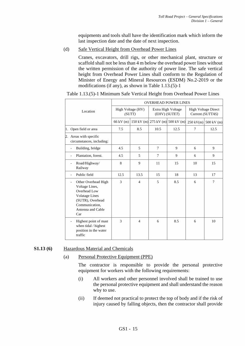
(d) Safe Vertical Height from Overhead Power Lines
Cranes, excavators, drill rigs, or other mechanical plant, structure or
scaffold shall not be less than 4 m below the overhead power lines without
the written permission of the authority of power line. The safe vertical
height from Overhead Power Lines shall conform to the Regulation of
Minister of Energy and Mineral Resources (ESDM) No.2-2019 or the
modifications (if any), as shown in Table 1.13.(5)-1
Table 1.13.(5)-1 Minimum Safe Vertical Height from Overhead Power Lines
Location
OVERHEAD POWER LINES
High Voltage (HV)
(SUTT)
Extra High Voltage
(EHV) (SUTET)
High Voltage Direct
Current (SUTTAS)
66 kV (m) 150 kV (m) 275 kV (m) 500 kV (m) 250 kV(m) 500 kV (m)
1. Open field or area 7.5 8.5 10.5 12.5 7 12.5
2. Areas with specific
circumstances, including:
- Building, bridge 4.5 5 7 9 6 9
- Plantation, forest. 4.5 5 7 9 6 9
- Road/Highway/
Railway
8 9 11 15 10 15
- Public field 12.5 13.5 15 18 13 17
- Other Overhead High
Voltage Lines,
Overhead Low
Volatage Lines
(SUTR), Overhead
Communication,
Antenna and Cable
Car
3 4 5 8.5 6 7
- Highest point of mast
when tidal / highest
position in the water
traffic
3 4 6 8.5 6 10
S1.13 (6) Hazardous Material and Chemicals
(a) Personal Protective Equipment (PPE)
The contractor is responsible to provide the personal protective
equipment for workers with the following requirements:
(i) All workers and other personnel involved shall be trained to use
the personal protective equipment and shall understand the reason
why to use.
(ii) If deemed not practical to protect the top of body and if the risk of
injury caused by falling objects, then the contractor shall provide
Toll Road Project – General Specifications
Division 1 – General
GS1 - 16
the protective helmet and all personnel involved in the field shall
use.
(iii) Eye protection shall be used if there is a possibility of eye damage
due to welding work, or of flake material such as pieces of sawing
wood, or fragments of concrete.
(iv) Shoes to be used shall be able to protect the feet of workers. Use
the shoes with metal tip on the toes.
(v) Protective noise shall be used if the noise level is high.
(vi) Gloves will be required on some jobs.
(vii) Respiratory protection should be provided to workers exposed to
hazardous material such as asbestos, chemical fumes and dust.
(b) Danger of Skin
(i) Each employee shall report if getting the skin problems, especially
in the hands due to the use of hazardous materials.
(ii) Hands and eyes of workers shall be protected against contact with
cement. Keep in contact with cement to a minimum. The use of
protective creams can reduce the risk of skin damage.
(iii) Wherever possible, protective clothing shall be used during
working. This clothing including long sleeves, gloves and
protective shoes.
(iv) The Contractor shall provide facilities for washing the body and
change clothes as specified in Sub-clause S1.13 (3).
(v) Respiratory protective equipment shall be used during concrete
curing process where dust commence be formed.
(c) Use of Chemicals
(i) The Contractor shall have procedures that arrange the method for
handling properly hazardous chemicals or substances, method for
storage, method for waste disposal.
(ii) All chemicals shall be stored in their original containers in a safe
place and well ventilated.
(iii) All workers shall be trained when dealing with chemicals or
hazardous substances including emergency measures that need to
be carried out in case of problems.
(iv) The Contractor which uses hazardous material for road and/or
bridge work shall prepare a management document, including the
collection, transportation, storage, use, and/or processing of such
materials, and submitted to the Ministry of Environment and
Forestry (LHK) or Regional Environmental Agency (BLHD)
(v) List of toxic and hazardous which can be used, prohibited, or
limited use refer to Appendix I and II of Government Regulation
No.101-2014 or the modifications (if any) about Management of
Toxic and Hazardous Materials.
Toll Road Project – General Specifications
Division 1 – General
GS1 - 17
(d) Cutting and Welding with High Pressure Gas
(i) The contractor shall pay attention to potential hazards as follows:
- A fire due to leakage of fuel (propane, acetylene), usually the
damage of hoses or hoses connection.
- The explosion of tube due to oxygen leakage from hoses or
welding cutting torch.
- Sucking noxious fumes from welding operations.
- Fires of the flammable materials around the welding area.
(ii) Tube Handling
- The tube shall not be rolled in the existing ground or handled
roughly. If possible, use the trolley and binding tube with
chain.
- The tube shall not be placed free standing alone to prevent the
collapse of tube.
- The tube shall be left alone for a while when positioned up
before use
- The tube and manifold valves shall be closed when not used
according to the procedures
(iii) Storage of Tube and Accessories
- All hoses and cutting accessories shall be removed when work
is finished and stored away from the tubes.
- Tubes shall be stored in a position away from combustible
materials and sources of ignition.
- Storage of empty cylinders shall separate from fully filled
tubes.
- In storage, oxygen shall be separated from fuel gas and
flammable materials and liquids at least 7 meters or have
noncombustible barrier of five-foot-height.
- Fire extinguishers shall not be closer than 8 meters, but not
more than 50 meters away from where the fuel gas is stored.
- The tube shall be kept away from heat sources
(iv) Equipment
- Only hoses that meets the standards that can be used. Hoses
shall be inspected every day to check for potential damage.
- The hose shall be as short as possible. If the hose shall be
connected due to damaged parts, hose coupler and hose
clamps shall be used.
- If a leak occurs and can not be stopped, the tube shall be
moved to a safe place with open air and immediately contact
the supplier.
Toll Road Project – General Specifications
Division 1 – General
GS1 - 18
- Oxygen hoses shall have a different color with the hoses for
fuel gas lines (oxygen - green; fuel - red).
- To ensure the flashback holder is mounted on the both
regulator (oxygen and fuel line) or in the inlet torch line.
(v) Fire Extinguishers and Personal Protective Equipment
- Flammable materials shall be removed from the working area
and sufficient fire extinguishers shall be provided by the
Contractor.
- Workers shall use the eye protection and protective clothing
to protect against fire, leather gloves, long-sleeved, helmets,
and other protective equipment.
S1.13 (7) Use of Machinary Equipments
(a) General
The entire machinery equipments shall be equipped with the use and
safety manuals with a copy which easily accessed by the operator or
superintendent.
(b) Automatic or Portabel Nailer and Stapler
If the Contractor uses the automatic or portable nailer or stapler, the
following safety requirements shall be met:
(i) This equipment shall not be directed to a person, even it has a
safety device.
(ii) Trigger of nailer or stapler shall not be suppressed unless the tip
of equipment is directed to a secure object surface.
(iii) Special attention shall be paid if nailing at the edge location of an
object.
(iv) If the power of automatic nailer or stapler is pneumatic power, it
is not allowed to use a harmful and flammable gases.
(v) The damaged equipment shall not be used.
(vi) The proper hearing and eye protection shall be used when using
these equipments.
c) Portable Power Tools
(i) Chainsaws, concrete mixer, reinforcing steel cutting tools and
other motorized tools shall always be equipped with a safety
device.
(ii) The Contractor shall comply with the following safety
requirements:
- Each operator shall be trained to use the tools mentioned
above.
- To use only the proper tools and methods for each type of
work carried out.
Toll Road Project – General Specifications
Division 1 – General
GS1 - 19
- Damaged tool or machine shall not be used.
- The sharpness of cutlery shall be maintained.
- The hearing and eye protection shall be used whe using these
tools.
- The area around the tool or machine shall be clean.
- Extension wires shall be placed in such a way to avoid damage
of tools and materials.
- Additional illumination shall be provided when using the tool
or machine.
d) Hoist for Lifting Person and Material
(i) Hoist Lift for person and material shall be carried out by a proper
person.
(ii) The operator shall be a trained and having a specific permission
to operate the equipment.
(iii) Hoist lift shall be on a firm foundation and tied to the building or
structure.
(iv) The access for operator and maintenance personnel shall be safe.
(v) Basket lift shall have a minimum height of 2 m, with fully sides
and solid doors or covered by a weaving wire with minimum
diameter of 3 mm and maximum aperture of 9 mm. Basket lift
shall be covered with a roof, at least made of wooden planks or
plywood with a minimum thickness of 18 mm.
(vi) Basket height shall be minimum of 2 m and have a secure key.
The solid door shall have a transparent panel.
(vii) The distance from the existing ground to the basket floor shall not
be more than 50 mm.
(viii) Basket lift shall have an electro-mechanical locking mechanism
which can only be opened from the basket and can only be opened
when the basket touches the existing ground and can prevent the
lift move when the basket is being opened.
(ix) Lifting shall be controlled from the basket inside.
(x) All parts of metal shall be connected to the grounding system.
(xi) Lifesaver shall be available to stop the basket if it falls or moves
too fast.
(xii) Description of manufacture, model and load capacity shall be
attached in the basket.
(xiii) A mechanism for emergencies shall be available to exclude those
who are stuck in the basket.
(xiv) An emergency alarm shall be provided in the basket.
(xv) If possible, a means of communication between the operator and
the working personnel to be provided.
Toll Road Project – General Specifications
Division 1 – General
GS1 - 20
(e) Crane and Lifting Equipment
(i) It is not allowed to move or lift goods/material with a risk of
physical disorder to the workers if they do not use the lift.
(ii) The moving or lifting of goods/material with a difference
elevation of more than 5 m and weight more than 500 kg shall use
crane, excavator or forklift.
(iii) Operation of lifting and transportation equipment shall be carried
out by an operator of lifting and transportation who have OHS
License and shall refer to the guidance book in accordance with
their type and qualifications. The competency requirements of
operator of lifting and transportation shall refer to Regulation of
Minister of Manpower No.8 Year 2020 concerning the Lift and
Transportation Equipment.
(iv) Operator assistants shall be trained to give the signals to the
operator and tie the load properly and know the capacity of crane
lifting.
(v) Loading, uploading and liftup with a lifting equipment shall be
arranged with uniform codes that are truly understood.
(vi) If more than one worker working on lifting equipment, the
operator shall work based on a signal from one appointed person
only.
(vii) Prior to the implementation, the load has been determined by the
operator that can be lifted.
(viii) Fiber rope shall be checked before use and during the use to lift
the rope shall be checked as frequent as possible and at least once
3 months.
(ix) Steel ropes shall be checked at the time of first installation and
every day by the operator and at least once a week by a qualified
person for Lift and Transportation from the Manufacture.
(x) Steel ropes shall be prohibited to be used if they are broken, worn
or rusty wires based on the standard of requirements
(xi) Crane shall stand on a firm foundation.
(xii) Requirements for the use and property of lifting equipment shall
refer to Regulation of Minister of Manpower No.8 Year 2020 or
amendments (if any) concerning Lift and Transportation
Equipment, and other related regulations.
(xiii) All cranes shall be equipped with safety devices that can
automatically give a clear warning sign, if the lifting capacity
exceeds that permitted.
(xiv) Crane shall be inspected weekly and inspected thoroughly every
12 months by a qualified person. Inspection results shall be
recorded.
Toll Road Project – General Specifications
Division 1 – General
GS1 - 21
(xv) The lifting gear shall be in good condition and has been
thoroughly inspected.
(xvi) Control devices (levers, switches, etc.) shall be thoroughly
inspected.
(xvii) Sufficient space shall be provided for the safe lifting.
(xviii) Any jib crane with a capacity of more than 1 ton shall have a safe
load indicator that checked every week.
(xix) Hook shall be equipped with a latch.
S1.13 (8) Measurement and Payment
(a) Payments to be made for the Contractor shall include all costs for
Occupational Health and Safety (K3) including all costs for Construction
OHS Experts on the high and moderate risk project and Construction
OHS Officer for small risk project.
(b) Occupational health and safety work shall be paid on a lump sum basis
for the pay item listed below, which to be paid in installments on a
monthly basis, proportionally based on the accepted progress of work.
This amount shall be as full compensation for the supply of all materials,
equipment, labour, methods and all other costs deemed necessary or usual
to proper completion of the work prescribed in this Clause.
(c) Notwithstanding to the provisions of General and Special Conditions of
the Contract, the Engineer who represent the Employer’s Representative
will notice to the Contractor if the Contractor deviate from the
requirements of Clause S1.13 Occupational Health and Safety by the first
and second warnings. If the second warning is not responded, then the
Engineer who represent the Employer’s Representative will suspend the
Works in accordance with Minister Regulation of Public Works and
Housing No.21/PRT/M/2019 or Amendments (if any) and for any event
and/or omission due to non-implementation of the requirements of Clause
S1.13, the deduction of payment will be applied as described in Clause
S1.41 of these Specifications. All costs incurred due to the suspension
shall be the responsibility of the Contractor.
Pay Item No. and Name Unit of Measurement
1.13 Occupational Health and Safety Lump Sum
S1.14 Temporary Road Works
S1.14 (1) The Contractor shall furnish, maintain, and remove on completion of the work
for which they are required, all temporary roads and road works such as sleeper
tracks and staging over roads, access and service roads, temporary crossings or
bridges over streams or unstable ground, and shall make them suitable in every
respect for carrying Constructional Equipment required for the work, for
providing access for traffic for himself or others, or for any other purpose. Such
temporary road works shall be constructed to the satisfaction of the Engineer, but
Toll Road Project – General Specifications
Division 1 – General
GS1 - 22
the Contractor shall nevertheless be responsible for any damage done to or caused
by such temporary road works.
S1.14 (2) Before constructing temporary road works, the Contractor shall make all
necessary arrangements, including payment if required, with the public
authorities or landowners concerned, for the use of the land and he shall obtain
the approval of the Engineer. Such approval will be dependent on the Engineer
being satisfied with the Contractor's proposals for items such as signing, lighting
and riding quality of the temporary road together with the proposed maintenance
arrangements. Such approval will not, however, relieve the Contractor of his
responsibilities under the Contract. Upon completion of the works the
Contractor shall clean up and restore the land to the satisfaction of the Engineer.
S1.14 (3) The Contractor, when required by the Engineer, shall submit for the Engineer's
approval drawings giving full details of temporary roads. Such details shall
include alignment, profile, pavement construction, signing, lighting and the
duration of the temporary road.
S1.14 (4) The Contractor shall make all arrangements necessary to permit the passage
along the road section relating to this Contract of the Constructional Equipment,
materials and employees belonging to other Contractors engaged in the
construction of contiguous stretches of road. For this purpose the Contractor
and the contractors concerned in the construction of the stretches contiguous to
those through which they shall pass shall, when necessary and with at least 15
days' notice, request the Engineer for permission to pass and submit a schedule
for such passage. After the Engineer has granted such permission and approved
the schedule submitted, both the Contractors permitting the passage and those
requesting it shall undertake to observe the schedule approved by the Engineer
for the passage along the site without having any right to extra payment in
consequence of the restrictions on passage or the necessary temporary suspension
of works due to the aforesaid schedule.
S1.14 (5) Payment for Temporary Road Works will be as provided in Clause S1.19 "Traffic
Management and Safety".
S1.15 Temporary Traffic Ramps
S1.15 (1) General
To provide access to the Works, the Contractor shall construct, maintain and
demolish the completed temporary access roads, including the temporary bridges,
to provide the installation, equipment and vehicles which required for the Works.
The temporary road and/or bridge shall be constructed and accepted by the
Engineer. However, Contractor shall be responsible for any deterioration of the
temporary work.
The design of temporary bridge shall be prepared by the Contractor and submitted
to the Engineer for his approval. However, this approval shall not relieve the
Contractor from his responsibility under the Contract.
Toll Road Project – General Specifications
Division 1 – General
GS1 - 23
In cases where it is necessary or required by the Engineer, the Contractor shall
construct and maintain temporary traffic ramps, and furnish all the labour and
materials required therefor.
S1.15 (2) Layout
The general layout, dimensions and construction requirements shall be as shown
in the approved shop Drawings or as directed by the Engineer.
S1.15 (3) Payment
Payment for temporary traffic ramps will be as provided in Clause S1.19 "Traffic
Management and Safety".
S1.16 Traffic Control
S1.16 (1) General
In order to facilitate traffic through or around the Works, or wherever ordered by
the Engineer, the Contractor shall erect and maintain at prescribed points on the
work and at the approaches to the work, traffic signs, lights, flares, barricades,
rubber cones with traffic lamps and other facilities as indicated in the Drawings
or required by the Engineer for the direction and control of traffic.
Where required, or where directed by the Engineer, the Contractor shall furnish
and station competent flagmen whose sole duties shall consist of directing the
movement of traffic through or around the work.
In addition to the requirements, the Contractor shall furnish and erect, within or
in the vicinity of the project area, such warning and guide signs as may be ordered
by the Engineer.
In order to minimize disruption to traffic flows the Contractor shall enclose the
Site with temporary fence to provide a visual barrier between his work and
adjacent traffic. The temporary fence shall be of 2.0 m height as indicated in the
Drawings and the movement of men, materials and Equipment into and out of the
barriered area shall be controlled by flagmen.
For high speed roads and toll roads, details not shown in the Drawings shall be
in conformity with all the applicable standards, Specifications and regulations of
the agencies concerned such as "Petunjuk Teknis Pemeliharaan Jalan Tol dan
Jalan Penghubung (PTP)" under Peraturan Menteri Pekerjaan Umum, Nomor
02/PRT/M/2007.
It should be noted that the construction work will take place in one of the busiest
traffic corridors in Indonesia and the Contractor should thoroughly acquaint
himself with existing traffic conditions and understand the importance of
maintaining traffic safety and the avoidance of excessive traffic delay.
The Contractor shall co-operate with the pertinent agencies regarding traffic
control and all details will be subject to the Engineer's approval.
Temporary Traffic Control as Traffic Safety Superintendent, Labour and
Flagman, Traffic Sign as described in Table 1.16-1
The contractor shall estimate the required quantity of each type of purposes by
the methods of work and requirements of the Contract Documents. The quantity
Toll Road Project – General Specifications
Division 1 – General
GS1 - 24
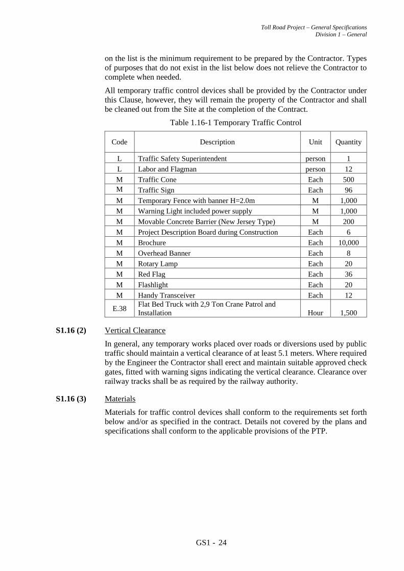
on the list is the minimum requirement to be prepared by the Contractor. Types
of purposes that do not exist in the list below does not relieve the Contractor to
complete when needed.
All temporary traffic control devices shall be provided by the Contractor under
this Clause, however, they will remain the property of the Contractor and shall
be cleaned out from the Site at the completion of the Contract.
Table 1.16-1 Temporary Traffic Control
Code Description Unit Quantity
L Traffic Safety Superintendent person 1
L Labor and Flagman person 12
M Traffic Cone Each 500
M Traffic Sign Each 96
M Temporary Fence with banner H=2.0m M 1,000
M Warning Light included power supply M 1,000
M Movable Concrete Barrier (New Jersey Type) M 200
M Project Description Board during Construction Each 6
M Brochure Each 10,000
M Overhead Banner Each 8
M Rotary Lamp Each 20
M Red Flag Each 36
M Flashlight Each 20
M Handy Transceiver Each 12
E.38 Flat Bed Truck with 2,9 Ton Crane Patrol and
Installation Hour 1,500
S1.16 (2) Vertical Clearance
In general, any temporary works placed over roads or diversions used by public
traffic should maintain a vertical clearance of at least 5.1 meters. Where required
by the Engineer the Contractor shall erect and maintain suitable approved check
gates, fitted with warning signs indicating the vertical clearance. Clearance over
railway tracks shall be as required by the railway authority.
S1.16 (3) Materials
Materials for traffic control devices shall conform to the requirements set forth
below and/or as specified in the contract. Details not covered by the plans and
specifications shall conform to the applicable provisions of the PTP.
Toll Road Project – General Specifications
Division 1 – General
GS1 - 25
(a) Retro-reflective Material
Unless otherwise specified in the contract, sign panels, barricades, cones,
vertical panels, and flagman paddles shall have retro-reflective sheeting
meeting the minimum requirements for retro-reflective material, Clauses
S12.07 and S12.08 of the General Specifications.
(b) Sign Panels
Sign panels shall conform to Clauses S12.07 and S12.08 of the General
Specifications and shall be orange with black legend unless otherwise
specified in the contract or required in the PTP.
(c) Sign Posts
Sign posts shall be fabricated from untreated soft wood, metal, or other
materials acceptable to the Engineer. Signs shall be capable of remaining
in position during normal traffic flow and wind conditions.
(d) Barricades
Barricades shall be constructed of wood, metal, plastic or concrete, e.g.
New Jersey type.
(e) Cones
Cones shall be a minimum of 75 cm in height with a broadened base and
shall be capable of withstanding impact without damage to the cones or
vehicles. All cones shall be orange/white colored and highly visible both
in daylight and darkness. Cones shall be capable of remaining bright and
in position during normal traffic flow and wind conditions in the area
where they are used. Lamps for cones shall be in accordance with PTP.
(f) Temporary Fence
Temporary fence shall be fabricated in panels with painted steel
framework, galvanized metal panels and cover by banner which shows
the perspective of the project and green plant as approved by the
Engineer. The panel face towards the traffic shall be painted.
(g) Vertical Panels
Vertical panels other than for temporary fence shall be constructed of
wood, metal or plastic.
(h) Warning Lights (flashing or steady)
Warning lights shall be installed in accordance with the minimum
requirements of the PTP.
(i) Flagmen and Pilot Car Operators
Flagmen and pilot car operators shall be physically and mentally
qualified, trained in their duties, efficient, and courteous. Each flagman
on duty shall be identified with appropriate and distinctive apparel,
including orange retro-reflective vest and hat, and shall be equipped with
a highly visible, retro-reflective "Stop/Slow" hand sign. Flags will not be
permitted unless approved by the Engineer.
Pilot cars shall be identified with an appropriate informative sign mounted
on the rear thereof and with a rotating amber beacon and shall be operated
at proper speeds. Strobe light beacons will not be permitted.
Toll Road Project – General Specifications
Division 1 – General
GS1 - 26
S1.16 (4) Construction Requirements
(a) General
The Contractor shall keep the entire length of the project in such condition
that traffic will be accommodated safely. Traffic control devices and
services shall be provided and maintained both inside and outside the
project limits as needed to facilitate traffic guidance.
The Contractor shall prepare and submit for approval by the Engineer,
traffic control plans for handling traffic. Such plans shall be based on the
Contractor's Method Statements for Traffic Management as required by
the Instructions to Bidders, modified or revised as required by the
Engineer, and shall comply with the requirements of these specifications.
Prior to the start of construction operations, the Contractor shall erect such
signs, barricades, and other traffic control devices as may be required by
the plans and specifications or directed by the Engineer. Traffic control
devices shall be operated only when they are needed and only those
devices that apply to conditions actually in existence shall be operable.
Temporary fence shall be placed to provide a visual barrier between the
work area and adjacent traffic or buildings and at locations directed by
the Engineer.
Any devices provided under this Clause that are lost, stolen, destroyed, or
deemed unacceptable while their use is required on the project shall be
replaced by the Contractor without additional compensation.
During nonworking hours and following completion of a particular
construction operation, all warning signs, except those necessary for the
safety of the public, shall be removed or entirely covered with either metal
or plywood sheeting so that the sign panel will not be visible.
Retro-reflective sheeting on signs, barricades, and other devices shall be
kept clean. Stretches, rips, and tears in the sheeting shall be promptly
corrected by the Contractor. Retro-reflective sheeting shall have a
maintained retro-reflection.\
Night time operations shall be illuminated by a lighting system approved
by the Engineer. The lighting system shall be positioned and operated to
preclude glare to the approaching traveling public. Incandescent lights
will not be permitted.
(b) Removal of Existing Marking
All conflicting construction striping and other pavement markings shall
be removed to the fullest extent possible by sand blasting or other
approved method that does not materially damage the surface or texture
of the pavement. The removal pattern shall be in an uneven shape that
does not perpetuate the outline of the removed markings by using
diagonal strokes and including some surrounding surface area. Damage
to the surface shall be repaired at the Contractor's expense by methods
acceptable to the Engineer. Accumulations of sand or other material that
might constitute a traffic hazard shall be removed. Upon completion,
Toll Road Project – General Specifications
Division 1 – General
GS1 - 27
sandblasted areas on bituminous surfaces shall be lightly coated with a
coal tar emulsion or approved equal.
(c) Traffic Safety Superintendent
The Contractor shall have a competent Traffic Safety Superintendent who
shall be responsible for the Contractor's maintenance of traffic operations.
The Traffic Safety Superintendent shall have previous experience in
supervising traffic management and safety through highway construction
work areas.
The Contractor's Traffic Safety Superintendent’s duties shall include the
following:
(i) Understand the requirements of the current PTP, the contract
drawings and specifications and the approved traffic control
plans.
(ii) Routinely inspect the condition and position of traffic control
devices in use on the project and assure that they are in proper
working order, clean, visible, and conform to the plans and
specifications.
(iii) Review and anticipate appropriate traffic control device needs,
advise the Engineer thereof, and assure the devices determined to
be necessary for safe and efficient traffic movement are obtained
and placed.
(iv) Coordinate maintenance of traffic operations with the Engineer.
(v) Review work areas, storage of equipment, and handling and
storage of materials to traffic safety.
(vi) Hold Contractor's traffic safety meeting with the prime
Contractor's and Subcontractor's superintendents and foremen
prior to beginning construction, and periodic meetings thereafter
as deemed necessary or as directed by the Engineer. The Engineer
shall be provided the opportunity to attend these meetings.
(d) Limitation of Operations
The Contractor's operations shall be limited as follows for roadways open
to public traffic:
(i) Construction operations shall not be performed during the hours
of darkness unless authorized by the Engineer.
(ii) The Contractor's equipment shall be operated in the direction of
traffic, where practical.
(iii) Private vehicles belonging to the Contractor's employees shall not
be parked along the roadway but shall be parked in areas approved
by Engineer or off the right-of-way.
(iv) The Contractor shall provide approved equipment for two-way
radio communications between flagmen when they are not in plain
view of each other and shall make such equipment available to the
Engineer for use as may be necessary.
Toll Road Project – General Specifications
Division 1 – General
GS1 - 28
(v) Prior to switching traffic to a completed lane, the Contractor shall
have the following:
- Adequate personnel and equipment to remove and set up all
traffic control devices as approved by the Engineer.
- Acceptable two-way radio communication network other than
citizen band units.
- Paving and related equipment removed off the travel lane.
(vi) The Contractor shall schedule operations to minimize potential
traffic backups. The Engineer may suspend the performance of the
work, either in whole or in part, should an inordinate traffic delay
occur during a construction operation.
(vii) The Contractor shall obtain all the permits and/or approval
required for his operation mentioned above from the Police and
any other authorities concerned.
S1.16 (5) Basis of Payment
Payment for this Clause of traffic control will be as provided in General
Specifications Clause S1.19 “Traffic Management and Safety” and shall be
deemed full compensation for complying with the requirements of and
performing the work presented in this Clause
S1.17 Number of Lanes for Traffic Control
The existing number of traffic lanes on roads at the project site shall be
maintained at all times during the work and if diversions are provided these shall
be of the same traffic capacity as the original road. Notwithstanding the above,
the Engineer may give approval to reductions in traffic capacity if the Contractor
can show that these will not cause excessive delay to traffic. If such approval is
given, the Engineer may specify the hours during the day when the reduction in
capacity may be applied and it should be anticipated that these hours may not
include the peak period for the traffic movement under consideration.
The Contractor shall cooperate with the pertinent agencies regarding traffic
control and all details will be subject to the Engineer's approval.
The cost of complying with this Clause shall be deemed to have been included in
Pay Item 1.19 "Traffic Management and Safety".
S1.18 Extraordinary Traffic
The Contractor shall observe the requirements of General Conditions of Contract
and is responsible for carrying out any necessary investigations and the obtaining
of approvals, licenses, escorts and any other necessary facilities in order to enable
extraordinary traffic to be moved on the roads in the project area.
Any expenses arising out of this requirement shall be deemed to have been
included in the lump sum payment for "Traffic Management and Safety"
described in Clause S1.19.
Toll Road Project – General Specifications
Division 1 – General
GS1 - 29
S1.19 Traffic Management and Safety
Contractors shall follow the requirements as specified in the Minister of Public
Works Regulation No.2/PRT/M/2007 ”Petunjuk Teknis Pemeliharaan Jalan Tol
dan Jalan Penghubung” so that during the construction it is not dangerous and
safe for road users and do not interfere the smooth of running traffic. Design and
installation of temporary road marking markers shall refer to the Minister of
Transportation Regulation No. PM 67 of 2018 or changes thereof (if any)
regarding road markings
The Contractor shall keep open to traffic existing roads during the performance
of the Works, provided that when approved by the Engineer the Contractor may
bypass traffic over a detour. The Contractor shall at all times keep roads and
footpaths, affected by his operations, in good condition, free from soil and
material spillage, and shall carry out repair and reinstatement work, including
asphalt pavement repair, as directed by the Engineer.
The Contractor shall take necessary care at all times during the execution of the
works to ensure the existing convenience and safety of residents along and
adjacent to the road, and any public highway or port facility that may be affected
by the Works. Street lighting shall be relocated as necessary to maintain the
same standard of lighting during the course of the works until new lighting
facilities are brought into operation.
To protect works, ensure public safety and facilitate traffic flow into and around
the working location, the Contractor shall install and maintain traffic signs,
barriers and other facilities at each site, where the execution of the work affect
road users/traffic. All barrier signs including reflective stripes or other instrument
shall be visible in the dark. The Contractor shall also provide and place the officer
to direct and control the traffic flow into and around the works, in the locations
where the execution of the work will affect the traffic flow. When the road surface
is not fully completed and to be opened to traffic, the Contractor shall provide
pre marking and temporary traffic signs or other road furniture required to ensure
the safety of the road user.
The Contractor shall prevent congestion and accidents during transport of
material to set the speed and implement the approved operating schedule.
All temporary road works and traffic control installations provided by the
Contractor on adjacent or feeder roads to the site of works shall at all times during
the Time for Completion be maintained in a safe and serviceable condition to the
requirements and satisfaction of the Engineer, to ensure the safety of other traffic
and of the public using the road.
Payment to the Contractor under Pay Item 1.19 shall be deemed to include the
cost to the Contractor of meeting his obligations under this Clause together with
such other items as are expressly stated in the General or Special Specifications
as for being included payment in this Clause. Such payment covers the utilization
but not the ownership of any facilities and means to support the traffic
management and safety which will remain the property of the Contractor at the
completion of the Contract.
Toll Road Project – General Specifications
Division 1 – General
GS1 - 30
Any incident and/or negligence due to the failing of implementation of the
requirements in this Clause S1.19, the deduction of payment shall be applied as
described in Clause S1.41 of these Specifications.
Payment of this sum will be made in three instalments, as follows:
- 25% (twenty-five percent) with the first Monthly Certificate after the
main equipments for traffic management and safety delivered on Site and
approved by the Engineer;
- 50% (fifty percent) with the Monthly Certificates in instalments
proportional to the progress of work executed; and
- 25% (twenty-five percent) with the Final Certificate after clearing and
demobilizing complete.
Pay Item No. and Name Unit of Measurement
1.19 Traffic Management and Safety Lump Sum
S1.20 Mobilization
S1.20 (1) When the Bill of Quantities contains an item for "Mobilization", the following
are understood to be paid for:
(a) Transport of Construction Equipment, on the basis of the list of
Construction Equipment submitted with the Bid, from the port of
unloading in Indonesia to the sites where they are to be used on the road
under Construction, and their installation;
(b) The construction of offices, housing, workshops, stores, etc.;
(c) The supply, installation and maintenance of vehicles, living quarters,
offices, laboratories, workshops, stores, communications, facilities, etc.;
and
(d) Such other items as are expressly stated in the General or Special
Specifications as being included in "Mobilization".
S1.20 (2) The Contractor may, always subject to the authorization of the Engineer, at any
time during the works, make any alterations, reductions and/or improvements to
the Construction Equipment and installations.
Payment is also intended to cover the dismantling of the work site by the
Contractor, with the removal of all the installations, Constructional Equipment
and equipment, so that the site is restored to the state it was in before the
installations, Equipment and equipment were placed there.
S1.20 (3) Within seven (7) days after the Noice to Proceed, the Contractor shall prepare,
submit and obtain the Employer's approval of a Mobilization Programme. The
mobilization shall be completed within a period of 90 days from the
Commencement Date except for the completion of the office, laboratory and
housing shall be completed within a period of 45 days from the Commencement
Date.
If some plants or equipments or instruments to be requested by the Employer at
the end of the works, these may be handed over against payment to be agreed by
Toll Road Project – General Specifications
Division 1 – General
GS1 - 31
the both parties. In that case, a reduction to the cost of demobilization shall be
agreed by the both parties, and this reduction will govern on the date of hand
over.
Mobilization of main equipments and personals could be carried out in stages
based on the mobilization schedule approved by the Engineer. This staging
mobilization shall be amended in the Addendum.
.S1.20 (4) Payments under this Clause will be made in four installments for each Pay Item
as follows:
- 30% (thirty percent) on completion of the office, laboratory, housing and
other facilities for the Contractor;
- 50% (fifty percent) on completion of mobilization and acceptance by the
Engineer;
- 20% (twenty percent) on completion of demobilization and acceptance by
the Engineer.
In the event that the Contractor does not complete mobilization in accordance
with either of the two limits specified in Sub-clause S1.20 (3), the amount to be
certified by the Engineer for payment will be the full percentage installments of
the Lump Sum price for Mobilization less an amount of 1 (one percent) of the
value of the installment for each day’s delay in completion up to a maximum of
50 (fifty) days.
Pay Item No. and Name Unit of Measurement
1.20 Mobilization Lump Sum
S1.21 Half-Width Construction
S1.21 (1) Where, in the opinion of the Engineer, a detour is not feasible, construction on
existing public roads shall be undertaken only over half of the full width of the
roadway. The length of such half-width construction shall be kept as short as
possible.
S1.21 (2) Where half-width construction is necessary, work on culverts commenced in the
dry season shall be completed and the embankment adjacent to them shall be
reinstated so that at least half the full width shall be available for use by the public
throughout the next rainy season.
S1.21 (3) Where single-lane traffic becomes necessary over a particular length of the works
or over the approaches thereto, the Contractor, in maintaining through traffic,
shall provide a single lane at least three and a half meters wide on the roadway
or embankment to be kept open to traffic.
The Contractor shall so conduct his operations as to offer the least possible
obstruction, inconvenience, and delay to traffic and shall be responsible for the
adequate control of the traffic using such lengths of single lane.
Toll Road Project – General Specifications
Division 1 – General
GS1 - 32
S1.22 Filling in Holes and Trenches
The Contractor, upon completion of any part of the work, shall immediately, at
his own expense, fill up all holes and trenches, or carry out the work to them as
required by the Engineer, that he may have dug or excavated and are no longer
required for the project, and he shall clear away all rubbish and material that is
no longer required for the execution of the work.
S1.23 Location and Protection of Utilities
The utility survey results given in the drawings or in any other documents are
intended only for the reference and guidance.
Before commencing construction work the Contractor shall undertake a survey,
e.g. by making test pits, to establish the detailed location of all utilities to be
affected by the Works. Survey results shall be recorded in plan form to the
satisfaction of the Engineer and surface pegs fixed on the site to indicate the
location of all underground utilities. These pegs shall remain for the duration of
the contract.
Where works of either a temporary or permanent nature are to be undertaken by
the Contractor in the vicinity of utilities, the Contractor shall adopt appropriate
construction methods, provide adequate protective devices and take
precautionary measures, without additional payment, in order to avoid damage to
the utilities. Any damage to utilities caused directly or indirectly by the
Contractor's work will be considered the Contractor's responsibility.
When during construction, there is a plan for installing the new utilities, the
Contractor shall report this plan to the Engineer and the Employer. The Employer
will coordinate with the employer of utilities.
The requirements of this Clause shall be met without additional payment and all
costs thereof shall be included in the various items of the Bill of Quantities under
the Contract.
S1.24 Project Information Signs
The Contractor shall within the mobilization period erect project information
signs at all major roads crossing or joining the project area and at the beginning
and end of the contract. The size of the project information signs and the message
thereon shall be determined by the Employer and the Engineer. Payment for
information signs and their proper maintenance during the entire construction
period shall be considered as included in the lump sum payment as provided in
Clause S1.20 - Mobilization.
S1.25 Maintenance of Existing Drainage
The Contractor shall maintain the existing drainage entering, crossing or
affecting the works.
Toll Road Project – General Specifications
Division 1 – General
GS1 - 33
This shall include where required by the Engineer the cleaning of all existing
channels, ditches and pipes upstream and down-stream to an extent of 100 m
beyond the construction limits and the right-of-way.
These requirements shall be met without additional payment and all costs thereof
shall be included in the various items of the Bill of Quantities under the Contract.
However, should the maintenance work necessitate, in the opinion of the
Engineer, repair, remedial or reconstruction work to the existing drainage, except
where such work is due to damage caused by the Contractor, the Engineer will
instruct the extent of such work required and the Contractor will be entitled to
payment in accordance with the Contract.
S1.26 Working In and Dealing With, Existing Water Flows
S1.26 (1) The Contractor shall take all necessary measures to remove water from the area
of his work when, in the opinion of the Engineer, this is necessary for the
protection of completed work or to allow satisfactory execution of work in
progress.
S1.26 (2) If an excavation or riverbed dredging can be avoided for the execution of proper
work, the Contractor, after the work is completed, shall backfill all such
excavations up to the original surface or river bed with materials approved by the
Engineer.
S1.26 (3) Where the stabilization of the embankment or other permanent work will obstruct
unavoidably all or part of the existing waterways, the drains shall be removed to
ensure that the flow is not blocked by work at normal flow heights.
S1.26 (4) The removal of the such waterways shall maintain the bed slope of the existing
waterways and should be placed in such a way which not cause destructive
scouring both on the work and on adjacent property
S1.26 (5) The Contractor shall make measurements and cross sections drawing of the
waterways to be removed and provide detailed markings for the work required.
The Engineer could revise the Contractor's proposal before a transfer work
begins.
S1.26 (6) Except for the extra payment detailed in Division 5 of these Specifications
(Structure Excavation), all costs resulting from the Contractor's compliance with
(1) above will be deemed to be included in this Pay Item.
Such payment is understood to include for the following :
(a) All expenses involved in providing temporary dams, pumps, cofferdams,
temporary realignment of the flow, or any other methods approved by the
Engineer.
(b) All expenses resulting from the Contractor's observance of all rules and
regulations of appropriate authorities regarding the interference or
maintenance of flow in the appropriate canals, water courses, channels or
pipes.
S1.26 (7) Payment from such lump sum will be considered to be full compensation for all
expenses involved in the work and the Contractor's estimate will be assumed to

Toll Road Project – General Specifications
Division 1 – General
GS1 - 34
be based on a thorough study of the work involved and be deemed to cover the
cost of working in any season of the year and for working in flow of both storm
water and foul sewage.
S1.26 (8) Payment of the lump sum will be made in such instalments as the Engineer
considers reasonable and will be based on the total amount of such work in the
Contract.
Pay Item No. and Name Unit of Measurement
1.26 Working in and Dealing with, Lump Sum
Existing Water Flows
S1.27 Contractors Responsibility for Work
Where the approval of the Engineer is required under these Specifications, such
approval shall not relieve the Contractor of his duties or responsibilities under the
Contract.
S1.28 Standards of Workmanship
All workmanship shall be the best of its particular kind, and shall be carried out
to the satisfaction of the Engineer.
S1.29 Protection of Works from the Weather
The Contractor shall, at his own expense, carefully protect all work and materials
from damage by the weather.
S1.30 Units of Measurement
All units of measurement used in these Specifications and in the priced Bill of
Quantities are according to the standard metric measurement (or unit mks-meter,
kilogram, second) except specified otherwise.
S1.31 Day Works
If, in the opinion of the Engineer, it is necessary or desirable to execute any
additional or substituted work or furnish any Labour, services or materials
regarded as being on a Day work basis after a written order of the Engineer, the
Contractor shall therefore be paid for such work and supply according to the
priced Bill of Quantities.
The measurements shall be taken jointly and recorded and agreed at the time such
work is executed or such material furnished. The Contractors measurements will
not otherwise be recognized by the Engineer.
The Engineer shall always have full access to the Contractors time records, and
may check daily with the Contractors timekeeper, or otherwise, the time taken
for executing any Day work, but the fact of his agreeing upon any time shall in
no way bind the Engineer to value the work other than by measurement and
Toll Road Project – General Specifications
Division 1 – General
GS1 - 35
comparing unit costs of the same work done under this contract. Details for Day
Work are given in Division 17.
S1.32 Templates and Straightedges
S1.32 (1) Sufficient metal templates shall be furnished by the Contractor and used by the
Contractor or the Engineer to check the finished surface of the pavement
structure. These templates shall be submitted to the Engineer for his approval.
The templates used to control the work shall be maintained at all times in a
condition to produce the correct cross-sectional profile and shall be checked at
intervals and, if necessary, repaired or adjusted as directed by the Engineer.
S1.32 (2) The Contractor shall furnish sufficient straightedges, three meters long, to check
the surface of the pavement.
S1.32 (3) The furnishing of templates and straightedges will not be paid for directly, but all
costs shall be included in the Bid Prices for Pay Items under the Contract.
S 1.33 Orders to Foreman
Whenever the Contractor or his authorized representative is not present on any
part of the work where the Engineer may decide to give orders or directions, such
orders or directions shall be received and obeyed by the foreman or other person
who is in charge of the particular work concerned. All foreman shall be proficient
in Indonesia language, or the Contractor shall provide interpreters to the
satisfaction of the Engineer as to their number and proficiency in Indonesia
language.
S1.34 Work and Material included in the Contract Prices
S1.34 (1) The work to be performed and the material to be furnished under the various
Clauses of these Specifications, or shown on the Drawings, or the supplementary
or explanatory drawings, or ordered by the Engineer for all Labour, materials,
Construction Plant, organization of work, profits, royalties, taxes, custody of
completed works, payment to third parties for land or the use of land, or for
damage to property, incidental work where herein specified for the proper
completion of the Works; temporary drainage to protect the Works during
construction, haulage, tools, explosives and material for blasting, placing of
material where herein specified or where directed, sheeting, shoring, staging,
centering and supports, usual for the proper performance of the work are not paid
for separately.
S1.34 (2) In case where the basis of payment Clause or part of any Clause in these
Specifications relating to any pay item requires that the Contract Price covers and
be compensation for certain work or material essential to the item, this same work
or material shall not be measured or paid for under any other item that may appear
elsewhere in these Specifications.
S1.34 (3) The Contractor shall construct the Works to the details given in the Contract
Drawings, and the directions of the Engineer under a predominantly unit price
Toll Road Project – General Specifications
Division 1 – General
GS1 - 36
system. Payment to the Contractor shall be made for the actual measured
quantities of Contract Pay Items performed in accordance with the relevant
Divisions of these Specifications concerning measurement and payment.
Payment shall also be made on the basis of the measurement and payment
provisions of the lump sums for Clause S1.13 Occupactional Health and Safety,
Clause S.1.19 Management Tarffic and Safety, Clause S1.20 Mobilization,
Clause 1.26 Working In and Dealing With, Existing Water Flows, Clause S1.39
Environmental Safeguard, Clause S1.40 Quality Management, and the part of
Clause S16.01 Toll Office and Facilities as well as for Works instructed on
Division 17 Day Works.
S1.35 Workshop
The Contractor shall have on the Site a suitable workshop, adequately equipped
and provided with electric power, to allow for repairs on the equipment employed
to carry out the Works. He shall also provide a warehouse for the equipment spare
parts, mainly for the parts that frequently fail or are difficult to procure.
The workshop shall be managed by a chief foreman qualified for mechanical
repairs, with an adequate labour force. The furnishing of the Workshop, including
all equipment and facilities, shall be paid for as provided in Clause S1.19.
S1.36 Drawings
The Drawings of this project are issued and made part of these Specifications and
the Contract Documents. It shall be anticipated that minor revisions of alignment
location, section and details may be made during the work. The Contractor shall
perform the work in accordance with the intent of the Drawings and
Specifications and shall take no advantage of any error or omission in the
Drawings or discrepancy between the Drawings and these Specifications. The
Engineer will make such corrections and interpretations deemed necessary for
the fulfillment of these Specifications and Drawings. Where dimensions on the
Drawings are given or can be computed, scaled measurements shall not be used
except when approved by the Engineer. Any deviation from the Drawings due to
field conditions not anticipated will be determined by the Engineer and
authorized in writing.
S1.37 Fire Prevention
The Contractor shall take adequate fire prevention measures during the carrying
out of his operation ad in his camps, stores and workshop areas. He shall provide
and maintain throughout the Contract period adequate firefighting equipment in
all camps, offices, stores and workshop as provided for in Clause S1.20.
S1.38 Irrigation Works
The Contractor shall not interrupt or interfere with the flow of irrigation waters
without making prior arrangements with and obtaining the agreement of the
irrigation authorities. The Contractor shall allow in his program for the
Toll Road Project – General Specifications
Division 1 – General
GS1 - 37
construction of those works which might interfere with the flow of irrigation
waters to be carried out at such times as will cause the least disturbance to
irrigation operation.
S1.39 Environmental Safeguards
S.1.39 (1) General
(a) This Clause covers the provision of environmental countermeasures and
actions that are needed to perform any civil works required under the
Contract. In most cases the Clauses have been extracted from other
Clauses of these Specifications and are included here to ensure awareness
and compliance.
(b) The Contractor shall take all reasonable steps to protect the environment
(both on and off the Site, access road, including base camp and other
installations under the control of the Contractor) and to limit damage and
disturbance to people and property resulting from pollution, noise and
other results of his operations. The Contractor should also ensure that
transportation, quarrying activities and all other activities are undertaken
in an environmentally acceptable manner.
(c) As a means of minimizing environmental disturbance to all nearby
communities all construction and transportation activities shall be
confined to the hours of operation as defined in the Conditions of
Contract, unless otherwise approved by the Engineer.
(d) Prior to implementation of the Contract commences, if excluded in the
document category of Environmental Impact Assessment (EIA, Ind:
AMDAL) or Environmental Management Effort / Environmental
Monitoring Effort (Ind : UKL/UPL), Environmental Evaluation
Document (Ind: DELH - Dokumen Evaluasi Lingkungan Hidup) atau
Environmental Management Document (Ind: DPLH - Dokumen
Pengelolaan Lingkungan Hidup), the Employer Representative will
notice the Contractor the obligation to carry out environmental
management in accordance with the provisions of these Specifications
and to fulfill the provisions as regulated in the environmental regulations
/ legislation in the field of roads, local regulations and other relevant laws
and regulations and based on the approval of the relevant environmental
agencies.
(e) Before the commencement date, if the activities plan is included in the
EIA or UKL-UPL or DELH or DPLH mandatory category, the Employer
Representative shall notice in writing to the Contractor to comply with
and implement the environmental management and monitoring plan
stated in the Environmental Document, Decree of Environmental
Feasibility (SKKLH – Surat Keputusan Kelayakan Lingkungan Hidup)
and/or the available Environmental Permit (Izin Lingkungan). The
Contractor shall prepare himself all Environmental Permit requirements
related to his activities in all activity locations such as quarry, AMP
(Asphalt Mixing Plant), CBP (Concrete Batching Plant) and base camp,
as required, and attach a copy of the environmental permit in the Pre
Toll Road Project – General Specifications
Division 1 – General
GS1 - 38
Construction Meeting (PCM) and Implementation Report RKPPL. The
form of RKPPL as shown in Attachment 1.39 to this Specification
(f) The Contractor shall prepare a Management and Monitoring
Environmental Plan (RKPPL) based on Environmental Documents,
Decree of Environmental Feasibility (SKKLH – Surat Keputusan
Kelayakan Lingkungan Hidup) and/or Environmental Permit (Izin
Lingkungan) that have been available during the Pre-Construction
Meeting (PCM) to be discussed together with the Employer and Engineer.
RKPPL form as in the Appendix 1.39 of this specification shall describe
the initial field condition, the potential impact of work activities and the
environmental management plan of any changes to the initial field
condition.
(g) Based on the RKPPL, the Engineer shall monitor in accordance with the
period specified in the Environmental Document, SKKLH, and/or
Environmental Permit of any location of field activities, AMP or CBP
location, quarry sites, and basecamp location including access roads
related to the environmental management.
(h) The Contractor shall carry out the sampling in accordance with the
provisions in the Environmental Document, SKKLH, and/or the
Environmental Permit. If the sampling requirements are not regulated in
the Environmental Document, SKKLH and/or the Environmental Permit,
the Contractor shall carry out the sampling of water, ambient air, and
noise and/or vibration.
(i) The point of sampling location shall represent the existence of activities
around the location of activities, sampling can be taken 3 to 6 points for
road and/or bridge work which are included in the activities required to
have the Environmental Documents (AMDAL or UKL-UPL or DELH or
DPLH), or determined by authorized environmental agencies. Sampling
shall be taken at the time before construction, during construction, and
after construction to be completed.
(j) The criteria for sampling locations shall follow the provisions specified
in Environmental Documents, SKKLH, and/or Environmental Permits.
The sampling points generally represent the existence of activities around
the location of activities including settlements, public facilities (schools,
health centres, markets, hospitals), water sources, surface water (rivers,
lakes), which adjacent and/or crossing activities, quarries, cultivation
activities (forest, rice fields, plantations etc.) and basecamp locations.
(k) By the instruction or the delegation of authorities from the Employer, the
Engineer shall prepare the reports on the implementation of
Environmental Management Plans (RKL) and Environmental Monitoring
Plans (RPL) as specified in the Environmental Documents which at the
level of AMDAL or DELH, or reporting on the implementation of
Environmental Management Efforts (UKL) and Environmental
Monitoring Efforts (UPL) as specified in the level of UKL-UPL or DPLH,
and/or Environmental Feasibility Decree (SKKLH), and/or
Environmental Permit to be addressed by the Employer to the
environmental agency in accordance with the period specified in the
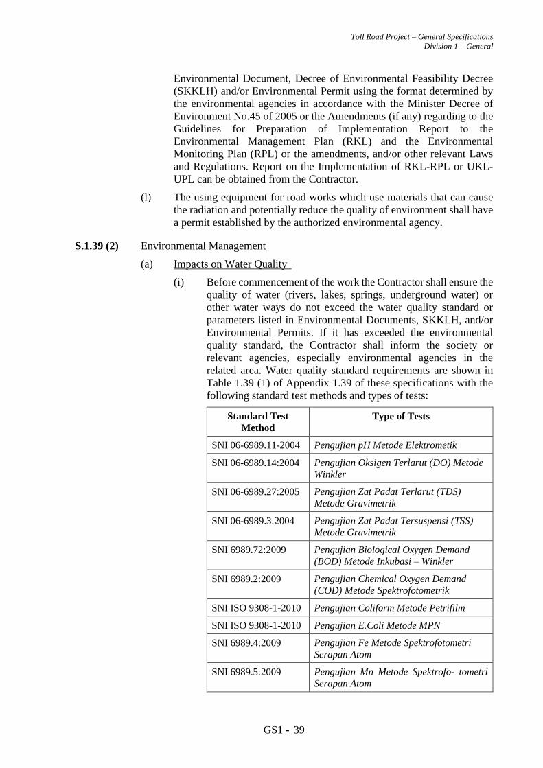
Toll Road Project – General Specifications
Division 1 – General
GS1 - 39
Environmental Document, Decree of Environmental Feasibility Decree
(SKKLH) and/or Environmental Permit using the format determined by
the environmental agencies in accordance with the Minister Decree of
Environment No.45 of 2005 or the Amendments (if any) regarding to the
Guidelines for Preparation of Implementation Report to the
Environmental Management Plan (RKL) and the Environmental
Monitoring Plan (RPL) or the amendments, and/or other relevant Laws
and Regulations. Report on the Implementation of RKL-RPL or UKL-
UPL can be obtained from the Contractor.
(l) The using equipment for road works which use materials that can cause
the radiation and potentially reduce the quality of environment shall have
a permit established by the authorized environmental agency.
S.1.39 (2) Environmental Management
(a) Impacts on Water Quality
(i) Before commencement of the work the Contractor shall ensure the
quality of water (rivers, lakes, springs, underground water) or
other water ways do not exceed the water quality standard or
parameters listed in Environmental Documents, SKKLH, and/or
Environmental Permits. If it has exceeded the environmental
quality standard, the Contractor shall inform the society or
relevant agencies, especially environmental agencies in the
related area. Water quality standard requirements are shown in
Table 1.39 (1) of Appendix 1.39 of these specifications with the
following standard test methods and types of tests:
Standard Test
Method
Type of Tests
SNI 06-6989.11-2004 Pengujian pH Metode Elektrometik
SNI 06-6989.14:2004 Pengujian Oksigen Terlarut (DO) Metode
Winkler
SNI 06-6989.27:2005 Pengujian Zat Padat Terlarut (TDS)
Metode Gravimetrik
SNI 06-6989.3:2004 Pengujian Zat Padat Tersuspensi (TSS)
Metode Gravimetrik
SNI 6989.72:2009 Pengujian Biological Oxygen Demand
(BOD) Metode Inkubasi – Winkler
SNI 6989.2:2009 Pengujian Chemical Oxygen Demand
(COD) Metode Spektrofotometrik
SNI ISO 9308-1-2010 Pengujian Coliform Metode Petrifilm
SNI ISO 9308-1-2010 Pengujian E.Coli Metode MPN
SNI 6989.4:2009 Pengujian Fe Metode Spektrofotometri
Serapan Atom
SNI 6989.5:2009 Pengujian Mn Metode Spektrofo- tometri
Serapan Atom
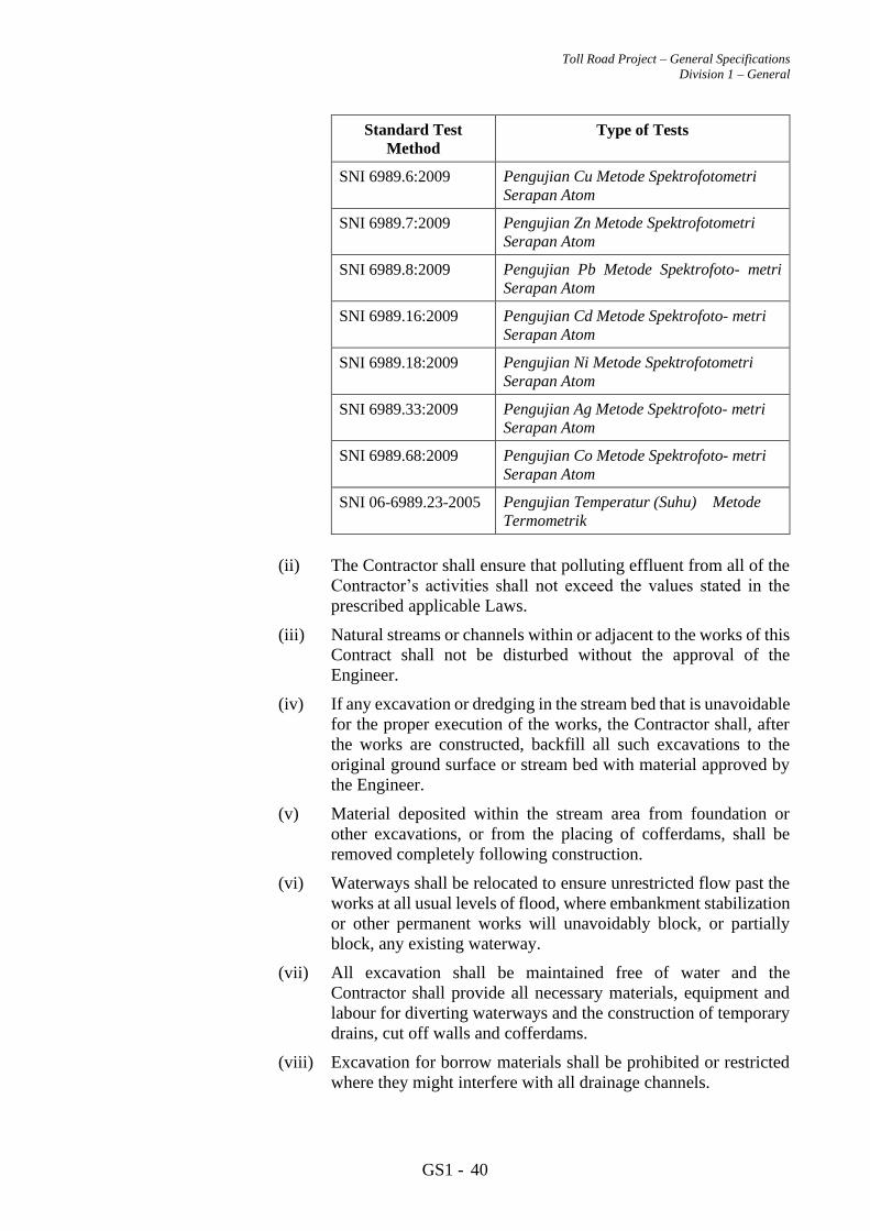
Toll Road Project – General Specifications
Division 1 – General
GS1 - 40
Standard Test
Method
Type of Tests
SNI 6989.6:2009 Pengujian Cu Metode Spektrofotometri
Serapan Atom
SNI 6989.7:2009 Pengujian Zn Metode Spektrofotometri
Serapan Atom
SNI 6989.8:2009 Pengujian Pb Metode Spektrofoto- metri
Serapan Atom
SNI 6989.16:2009 Pengujian Cd Metode Spektrofoto- metri
Serapan Atom
SNI 6989.18:2009 Pengujian Ni Metode Spektrofotometri
Serapan Atom
SNI 6989.33:2009 Pengujian Ag Metode Spektrofoto- metri
Serapan Atom
SNI 6989.68:2009 Pengujian Co Metode Spektrofoto- metri
Serapan Atom
SNI 06-6989.23-2005 Pengujian Temperatur (Suhu) Metode
Termometrik
(ii) The Contractor shall ensure that polluting effluent from all of the
Contractor’s activities shall not exceed the values stated in the
prescribed applicable Laws.
(iii) Natural streams or channels within or adjacent to the works of this
Contract shall not be disturbed without the approval of the
Engineer.
(iv) If any excavation or dredging in the stream bed that is unavoidable
for the proper execution of the works, the Contractor shall, after
the works are constructed, backfill all such excavations to the
original ground surface or stream bed with material approved by
the Engineer.
(v) Material deposited within the stream area from foundation or
other excavations, or from the placing of cofferdams, shall be
removed completely following construction.
(vi) Waterways shall be relocated to ensure unrestricted flow past the
works at all usual levels of flood, where embankment stabilization
or other permanent works will unavoidably block, or partially
block, any existing waterway.
(vii) All excavation shall be maintained free of water and the
Contractor shall provide all necessary materials, equipment and
labour for diverting waterways and the construction of temporary
drains, cut off walls and cofferdams.
(viii) Excavation for borrow materials shall be prohibited or restricted
where they might interfere with all drainage channels.
Toll Road Project – General Specifications
Division 1 – General
GS1 - 41
(ix) In the excavation of potentially mixed with surface water i.e. rain
water, waste water, the other water which will pollute the
surrounding road surface, the Contractor shall prepare an
excavation method plan including disposal and sewer muddy
water plan, and shall be approved by the Engineer prior to carrying
out the excavation work.
(x) Any damaging liquid or solid contaminant, such as hydraulic or
lubricating oils, dropped or spilled upon any portion of the site
work and adjacent environment, base camp, or haul route shall be
cleaned up immediately by the Contactor in order to avoid
contamination of water and soil. The Engineer shall approve the
completion of the clean up.
(xi) Washing of contractor’s vehicles and equipment shall only be
permitted in specially designated and equipped areas and shall not
be permitted in any existing water courses.
(xii) The waste water from the washing material process shall be
treated before discharging into the river or other sewer waste drain
in accordance with the waste water management to meet water
quality standard, if it cannot meet the standards required the
specific water treatment shall be carried out.
(b) Impacts on Air Quality
(i) The Contractor shall ensure that emissions from all the
Contractor’s activities including transportation activities shall not
exceed the values stated in the applicable Laws.
(ii) The asphalt mixing plant, concrete batching plant, stone crusher
and any other static construction equipment shall be installed in
area as distant as possible from housing and other sensitive areas
(forest area, disaster-prone area, residential area, sustainable food
agricultural land area (LP2B)), to ensure minimal disturbance and
complaint from any member of the local community. The location
shall be approved by the Engineer.
(iii) The Contractor shall have an Environmental License issued by the
authorized officer for asphalt mixing plant (AMP) and concrete
batching plant (CBP) before operated. The asphalt mixing plant
(AMP) shall be provided with a complete dust collector, i.e. dry
cyclone and wet cyclone or filter tube system to ensure no air
pollution in the atmosphere. If either of these systems is
damaged or not functioning the equipment shall not be operated.
The stone crusher shall be ensured will not pollute the air.
(iv) Trucks shall be sealed, and all covers shall be securely fastened.
(v) The Contractor shall maintain at the work site adequate supplies
of water for the moisture control during all placing and
compacting operations, and shall also remove excess material
from all existing roadways and the location shall not potentially
cause dusty and these shall be approved by the Engineer.
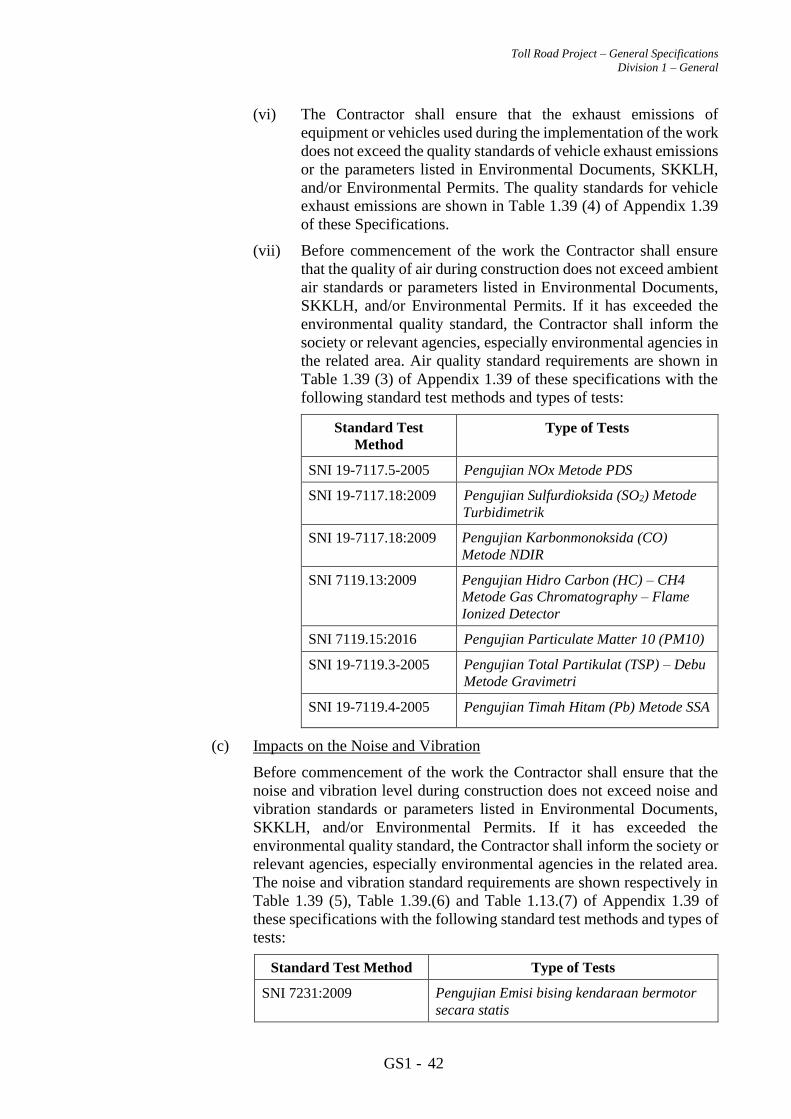
Toll Road Project – General Specifications
Division 1 – General
GS1 - 42
(vi) The Contractor shall ensure that the exhaust emissions of
equipment or vehicles used during the implementation of the work
does not exceed the quality standards of vehicle exhaust emissions
or the parameters listed in Environmental Documents, SKKLH,
and/or Environmental Permits. The quality standards for vehicle
exhaust emissions are shown in Table 1.39 (4) of Appendix 1.39
of these Specifications.
(vii) Before commencement of the work the Contractor shall ensure
that the quality of air during construction does not exceed ambient
air standards or parameters listed in Environmental Documents,
SKKLH, and/or Environmental Permits. If it has exceeded the
environmental quality standard, the Contractor shall inform the
society or relevant agencies, especially environmental agencies in
the related area. Air quality standard requirements are shown in
Table 1.39 (3) of Appendix 1.39 of these specifications with the
following standard test methods and types of tests:
Standard Test
Method
Type of Tests
SNI 19-7117.5-2005 Pengujian NOx Metode PDS
SNI 19-7117.18:2009 Pengujian Sulfurdioksida (SO2) Metode
Turbidimetrik
SNI 19-7117.18:2009 Pengujian Karbonmonoksida (CO)
Metode NDIR
SNI 7119.13:2009 Pengujian Hidro Carbon (HC) – CH4
Metode Gas Chromatography – Flame
Ionized Detector
SNI 7119.15:2016 Pengujian Particulate Matter 10 (PM10)
SNI 19-7119.3-2005 Pengujian Total Partikulat (TSP) – Debu
Metode Gravimetri
SNI 19-7119.4-2005 Pengujian Timah Hitam (Pb) Metode SSA
(c) Impacts on the Noise and Vibration
Before commencement of the work the Contractor shall ensure that the
noise and vibration level during construction does not exceed noise and
vibration standards or parameters listed in Environmental Documents,
SKKLH, and/or Environmental Permits. If it has exceeded the
environmental quality standard, the Contractor shall inform the society or
relevant agencies, especially environmental agencies in the related area.
The noise and vibration standard requirements are shown respectively in
Table 1.39 (5), Table 1.39.(6) and Table 1.13.(7) of Appendix 1.39 of
these specifications with the following standard test methods and types of
tests:
Standard Test Method Type of Tests
SNI 7231:2009 Pengujian Emisi bising kendaraan bermotor
secara statis
Toll Road Project – General Specifications
Division 1 – General
GS1 - 43
(d) Impacts on Traffic, Adjoining Properties, and Utilities
(i) The provision given in Clause S1.19, regarding Traffic
Management and Safety, shall apply.
(ii) Trenching or other excavation across the roadway shall be carried
out using half width construction so that the road is maintained
open to traffic at all times.
(iii) The Contractor shall be responsible for all the consequences of
traffic and shall prohibit such traffic when necessary by the
provision of a detour or by half width construction.
(iv) All the works shall be carried out with the least inconvenience to
traffic and at least one traffic lane shall be kept open at all times.
(v) At all times during the performance of the Works, the Contractor
shall ensure that the pavement, shoulders and adjacent areas
within the right-of-way shall be maintained free of construction
material, debris or other such loose objects that may obstruct or
endanger the free and safe passage of traffic. The Works shall also
be maintained free of any unauthorized parking or street trading
activity except in areas designated for such purposes.
(vi) The Contractor shall be responsible for obtaining any existing
information on the existence and location of existing underground
utilities and for obtaining and paying when required for any
necessary permits or other authorization for their diversion or
temporary cessation.
(vii) The Contractor shall be responsible for the care and protection of
any existing serviceable underground piping, cables, conduit, or
other subsurface lines or structures that may be encountered and
for repairing any damage caused to them by his operations.
(viii) All potholes in sealed pavements and holes in the finished Work
made by density testing or otherwise shall be reinstated as soon as
possible after damaged layers have been cut back, in order to
avoid obstruction or hazards to traffic.
(ix) At all times during the time for completion the contractor shall
maintain vehicular and pedestrian access to all houses,
commercial, industrial and all other uses. Temporary accesses
shall be provided where construction will close permanent access
for any period of over 16 hours and all affected owners and
community members shall be notified at least 24 hours in advance
of any impact on accesses.
(e) Human Health and Safety
(i) Provisions given in Clause S1.13 shall govern
(ii) The Contractor shall: (i) comply with all applicable safety
regulations; (ii) take care for the safety of all persons entitled to
be on the Site and prepare the Occupational Health and Safety
Management System (SMK3); and (iii) provide any Temporary
Toll Road Project – General Specifications
Division 1 – General
GS1 - 44
Works (including roadways, footways, guards and fences) which
may be necessary, because of the execution of the Works, for the
use and protection of the public and of owners and occupiers of
adjacent land. The preparation of the Occupational Health and
Safety Management System Plan shall refer to the Government
Regulation No.50-2012 concerning The Implementation of
Occupational Safety and Health Management System or the
modifications (if any).
(iii) The Contractor shall at all times take all reasonable precautions to
maintain the health and safety of the Contractor’s Personnel and
shall appoint an accident prevention officer at the Site, responsible
for maintaining safety and protection against accidents.
(iv) The Contractor shall at all times take necessary actions to protect
the health and well being of the Contractor’s Personnel employed
on the Site by ensuring that all parts of the worksite are regularly
kept clean and sanitary.
(v) All gears, pulleys, chains, sprockets, and other dangerous moving
parts of Mixing Plants shall be thoroughly guarded and protected.
(vi) Adequate sanitary waste control facilities shall be provided for all
project staff and workers and waste shall be collected regularly
and disposed of in accordance with applicable laws.
(f) Impact on Flora and Fauna
(i) The cutting of trees shall be carried out only when absolutely
necessary for widening either the carriageway or the shoulders or
for the clear zone and will be specifically defined and agreed by
all parties during the field investigation. Every tree felled should
be replaced by two semi mature trees of the same or similar
species. No new tree planting should take place within the clear
zone. Tree planting shall be in accordance with Clause S.12.17 of
the Specifications.
(ii) The Contractor shall limit the movement of his employees, the
location of Base Camps, AMP etc and equipment within the
sensitive environmental areas, such as the forest areas disaster-
prone area, residential area, sustainable food agricultural land area
(LP2B) and all other officially protected sensitive areas so as to
minimize damage to natural vegetation and shall endeavor to
avoid any damage to land. No Base Camp, AMP, CBP, equipment
or vehicle parking or storage area will be allowed outside the
ROW where the road passes through an officially protected
sensitive area.
(g) Impacts on Soil
(i) The Contractor shall ensure that pollutant discharge from the
Contractor’s activities shall not exceed the values stated in the
prescribed applicable Laws.
Toll Road Project – General Specifications
Division 1 – General
GS1 - 45
(ii) In order to avoid land sliding and erosion during excavation for
borrow materials, the edge of a borrow pit shall be not closer than
2 meters from the toe of the embankment or 10 meters from the
top of any cutting.
(h) Disposal of Waste
(i) The disposal of all solid and liquid waste from construction
activities should only take place in accordance with Sub-clause
S4.07 (2), and the requirements and permissions of responsible
institution at Province or Kabupaten/Kota.
(ii) When any material is to be disposed of outside the Site, the
Contractor shall obtain a written permit from the property owner
on whose property the disposal is to made, which permit shall
designate the disposal location and shall be submitted to the
Engineer together with a request for approval to proceed.
(iii) When material is disposed of as provided above and the disposal
location is visible from a highway, the Contractor shall dispose of
the material in a neat and uniform manner to the satisfaction of the
Engineer.
(i) Hazardous and Toxic Waste (LB3).
(i) Management of hazardous and toxic waste (LB3) resulting from
construction activities (eg used oil, used/contaminated B3, cloth
rags, used lamps, used batteries, used/contaminated B3 residual
packaging and so on) shall be in accordance with the provisions
and permits related to waste management of LB3.
(ii) Hazardous and toxic waste which generated during construction
activities shall be stored in Temporary Storage with specifications
that meet that the licensing requirements related to applicable LB3
and issued by the authorized environmental agency
(j) Impact in Protected Sensitive Area.
The following provisions in sensitive areas shall govern:
(i) Especially for the implementation activities of roads and/or
bridges which within the protected sensitive areas, the Engineer
will coordinate with relevant relevant government agency in order
to obtain the required information such as the existing presence,
habitat, species and corridors of wildlife. When implementation,
the core zone/ corridor of wildlife shall be avoided.
(ii) For all quarries and other sources of material (owned by the
Contractor or other parties), the Contractor shall submit to the
Engineer a plan of hauling route which explains the route travelled
by hauling material from the sources of material.
(iii) The Contractor shall have an approval letter from the relevant
government agency that the locations and activities of material
sources and the route of hauling will not disturb the environment
Toll Road Project – General Specifications
Division 1 – General
GS1 - 46
and local community and accepted in accordance with applicable
laws and regulations.
(iv) All borrow pits and quarries shall be licensed and have full legal
authorization from the local government
(v) The extraction of any construction materials shall not be allowed
in any National Park or other officially protected sensitive area
(vi) The contractor shall ensure that the Base Camp is operated in
accordance with good environmental practice and that adverse
environmental impacts are kept to an absolute minimum and in
accordance with this section, and that the local community is not
disturbed by any of the activities of the Base Camp.
(vii) In compliance with sustainable development practice, all timber
materials for sheet piles, bearing piles, and mini timber piles, shall
be purchased from a certified dealer (not from illegal logging).
Surat Keterangan Sahnya Hasil Hutan (SKSHH, letter indicating
source from legal forest production) operates a certificate of its
legal nature be attached to the purchase document shall be
submitted to the Engineer.
(viii) All part of the Site shall be reinstated to their original conditions
prior to the commencement date of works.
S1.39 (3) Implementation of Required Environmental Documents
The Contractor shall comply to any recommendations that has been incorporated
in the environment documents (Environmental Impact Analysis (AMDAL) or
Environmental Management Efforts - Environment Monitoring Efforts (UKL-
UPL) or Environmental Evaluation Document (DELH) or Environmental
Management Document (DPLH)), Environmental Feasibility Decree (SKKLH)
and/or Environmental Permit. The Employer shall make the Environmental
Documents, Environmental Feasibility Decree, and/or Environmental Permit
available to the Contractor and Engineer as an information or reference for the
implementation of environmental safeguards. General overview of the potential
impact on the environment as a result of road and bridge work activities that may
occur at each stage of activities, shall be submitted by the Contractor to the
Engineer if the potential impact is not specified in the Environmental
Documents, Environmental Feasibility Decree (SKKLH) and/or Environmental
Permit, and the Contractor shall carry out an impact reduction effort with the
approval of the Engineer. The stage of activities shall include the following:
(a) Pre-Construction Stage
(i) Preliminary survey, impact on the perception and unrest of
community.
(ii) The dissemination of activities planned, to be carried out in order
to provide the information and collect the feedback from the
community. The dissemination of activities planned activities has
an impact to the perception and unrest of community.
Toll Road Project – General Specifications
Division 1 – General
GS1 - 47
(iii) Land acquisition shall involve the survey of land use, land area
and estimated land price associated with the required
compensation of the land acquisition.
b) Construction Stage
(i) Mobilization, the impact of traffic disruption, air pollution and
deterioration of access road.
(ii) Construction which have an impact on the location of works,
material source material (quarry) including the access roads and
Base Camp.
At each of these locations, monitoring to the environmental impact related
with activity locations either directly or indirectly shall be carried out,
including the activity locations of the access road.
(c) Post-Construction Stage
(i) The operation of road will have an impact of dust pollution by
traffic, congestion and traffic accidents as well as the changes of
uncontrolled land use.
(ii) Maintenance of road, will have an impact of traffic disruption.
While hypothetical significant impacts classification in accordance with the
disturbed environmental component groups as follows:
(a) Reduction of Environmental Quality includes:
(i) The change in land use;
(ii) The loss of flora and fauna;
(iii) Disruption of the flow of surface water;
(iv) Reduction of air quality;
(v) Increase of noise and vibration;
(vi) Disruption of aquatic biota;
(vii) Hazardous and toxic waste;
(viii) Declining water quality (rivers, lakes, springs, underground
water);
(ix) Soil pollution.
(b) Disruption of Society includes:
(i) The loss of assets;
(ii) Disruption of traffic;
(iii) The loss of livelihood;
(iv) Attitudes and Negative Perception of Society;
(v) The emergence of public unrest;
(vi) Missing / disruption of public / social facilities;
Toll Road Project – General Specifications
Division 1 – General
GS1 - 48
(c) Disruption of Infrastructure includes:
(i) Disruption of utilities;
(ii) Disruption of accessibility;
(iii) Road damage.
S1.39 (4) Monthly Report
(1) Type of Reports
(a) The report consists of the internal report in the form of the
Implementation Report of Management and Monitoring Environmental
Plan (RKPPL) and external report in the form of the Implementation
Report of the Environmental Management Plan (RKL) and
Environmental Monitoring Plan (RPL) or Implementation Report of
Environmental Management Efforts (UKL) and Environmental
Monitoring Efforts (UPL).
(b) The implementation report of RKPPL shall be submitted by the
Contractor to the Engineer
(c) Implementation Report of RKL-RPL as listed in the EIA or DELH
document and Implementation Report of UKL-UPL as listed in UKL-
UPL or DPLH document, SKKLH and/or Environmental Permits shall be
submitted by the Contractor to the Employer through the Engineer and
then addressed to the Environmental Authority.
(d) The internal report’s method and forms are applied in accordance with
those listed in these Specifications and the external report’s method and
form which addressed to environmental agencies shall follow the laws
and regulations determined by the Environmental Authority in
accordance with the Minister Decree of Environment of the Republic of
Indonesia No.45 of 2005 or the Amendment (if any) regarding Guidelines
for the Preparation of Implementation Report of Environmental
Management Plan (RKL) and the Environmental Monitoring Plan (RPL)
and/or other relevant laws and regulations.
(2) Submittal
Draft Environmental Management and Monitoring Plan (RKPPL) by the
Contractor shall be submitted at the time of the Pre-Construction Meeting (PCM)
and to be discussed and approved by the Employer and Engineer. Then the
approved RKPPL will be used to carry out the monitoring on the progress and
treatment required in environmental management for each month. Environmental
Management and Monitoring Plan (RKPPL) form included in Appendix 1.39 of
this Specifications.
In the preparation of RKPPL, the Contractor shall conform the following
conditions:
(a) RKPPL shall be prepared in accordance with this specification and scope
of works under the Contract.
(b) RKPPL shall be equipped with adequate supporting documentation and
complete and substantially according to the activity location, potential
Toll Road Project – General Specifications
Division 1 – General
GS1 - 49
impact and treatment required to the environmental management as
supporting data to certify the payment within the time specified in
accordance with the relevant Clause of the General Conditions of
Contract and this specification.
(c) A copy of RKPPL including the supporting data shall be submitted to the
Employer and Engineer. It will be used as guidance for monitoring of
environmental management in the implementation activities of each
month
(d) The draft implementation report of RKL-RPL or UKL-UPL shall be
submitted by the Contractor to the Engineer at least two (2) weeks before
latest date of reporting as specified in the Environmental Feasibility
Decree (SKKLH) and/or Environmental Permit for the approval from the
Employer as the holder of Environmental Permit. Implementation report
which approved by the Employer as the holder of Environmental Permit
will be addressed to the Environmental Authority.
(3) Timing
(a) Internal report (RKPPL) shall be carried by monthly basis and the
external report (implementation report of RKL-RPL or UKL-UPL) to the
Environmental Authority shall be carried out every 6 months or in
accordance with the period stated in the Environmental Document,
SKKLH and/or Permit Environment.
(b) Each Monthly Report of the Environmental Management and Monitoring
Plan (RKPPL) shall be dated on the last day of calendar month
collectively as the backup data of Monthly Statement as stipulated in the
General Conditions of Contract.
S1.39 (5) Method of Measurement
(a) Work that is measured for payment according to this pay item is the work
carried out directly and instructed by the Engineer based on the
recommendations listed in the Environmental Document, SKKLH and/or
Environmental Permit, for sampling and testing of water quality, ambient
air quality, noise and/or vibration as specified in Sub-clause S1.39.(2) of
these Specifications.
(b) For planting trees will be paid separately in another Division of this
Specification.
(c) The cost of work as instructed in Sub-clause S1.39.(3) (Implementation
of Required Environmental Documents) and S1.39.(4) (Monthly Reports)
shall be included in the unit rate of all pay items as specified in the
Contract, where the price shall be full compensation for the furnishing all
materials, labour, equipment and other costs required for environmental
management.
(d) For the measurement of payment for tests of water quality of groundwater
and surface water, ambient air quality, noise and/or vibration, all
provisions of the quality standard shall be met (mandatory if the activities
around the Site have not changed or the same as specified in the
environmental document), if the results do not meet the requirements/
Toll Road Project – General Specifications
Division 1 – General
GS1 - 50
provisions on environmental quality standards, so the work shall not be
paid for the tests required for the environmental safeguard.
(e) Sampling shall be carried out before construction, during construction,
and after construction completed.
S1.39 (5) Basis for Payment
This work shall be paid for at the basis of the number of tests for the Pay Items
listed below. which price and payment shall be full compensation for furnishing
all materials, equipment, labour, methods, tests and other costs, including tools
and reporting costs which is a recommendation of quality standard measurement
for the environmental safeguards. During the construction period, the Engineer
may instruct the Contractor to carry out environmental management in
accordance with the provisions of the local government and the Laws. The tests
are carried out before, during and after construction at the same location is
considered as 3 times,
If the pay items are is not listed in the priced Bill of Quantities, then there is no
separate payment will be made for the payment of environmental safeguard
executed in accordance with this Division of these Specifications, the cost for this
work shall be included in the Unit Rate of all other Pay Items included in the
Contract, which prices shall be full compensation for furnishing all materials,
labor, equipment, tools and other expenses necessary for environmental
management.
If the Contractor fails to carry out the work of environmental safeguards, the
Supervisory Consultant without freeing the Contractor of the responsibility, will
be entitled to carry out such work as is deemed necessary and charge all the repair
costs to the Contractor, in which the value of the fee will be deducted from any
payment certificate paid or will be paid to the Contractor under the Contract.
Service users will be responsible in setting the jobs that need to be repaired and
prepare a cost estimate.
Any incident and/or negligence due to the failing of implementation of the
requirements in this Clause S1.39, the deduction of payment shall be applied as
described in Clause S1.41 of these Specifications.
Pay Item No. Description Unit of Measurement
1.39.(1a) Test of pH Each
1.39.(1b) Test of Dissolved Oxygen (DO) Each
1.39.(1c) Test of Dissolved Solid (TDS) Each
1.39.(1d) Test of Suspended Solids (TSS) Each
1.39.(1e) Test of Biological Oxygen Demand (BOD) Each
1.39.(1f) Test of Chemical Oxygen Demand (COD) Each
1.39.(1g) Test of Coliform Each
1.39.(1h) Test of E.Coli Each
1.39.(1i) Destruction Testing of Cu, Pb, Cd, Ni, Each
Fe, Zn, Ag, Co, Mn
Toll Road Project – General Specifications
Division 1 – General
GS1 - 51
1.39.(1j) Test of Temperature Each
1.39.(1k) Other Parameter Test of Water Quality…. Each
1.39.(2a) Test of Environmental Vibration for Each
Comfort and Health
1.39.(2b) Test of Vibration Level of Motored Each
Vehicles
1.39.(2c) Other Test of Noise and /or Vibration … Each
1.39.(3a) Test of NOx Each
1.39.(3b) Test of Sulphur Dioxide (SO2) Each
1.39.(3c) Test of Carbon Dioxide (CO2) Each
1.39.(3d) Test of Hydro Carbon (HC) - CH4 Each
1.39.(3e) Test of Total Suspended Particulate Each
(TSP) – Dust
1.39.(3f) Test of Lead (Pb) Each
1.39.(3g) Other Parameter Test of Air Emissions Each
and Ambient ……….
S1.40 Quality Management
S1.40 (1) General
The Works shall be undertaken through a quality management process, utilizing
Employer, Engineer, Contractor and third-party resources, as necessary.
The Employer accepts the following definitions associated with Quality
Management:
Quality Control (QC): The process of checking specific product or service
results to determine if they comply with relevant quality standards, correct
errors and substandard quality, and identifying ways to eliminate causes of
unsatisfactory product or service performance. The process of inspection and
approval/ rejection of product quality or performance of specific services is
carried out by the Quality Control Manager (QCM) provided by the
Contractor to internally control and ensure the quality of construction works
which carried out by the representative of Contractor (General
Superintendent/GS) in accordance with the provisions specified in the
Specifications. The report of QC results from QCM to be submitted to the
Contractor with a copy to the Engineer.
Quality Assurance (QA): The process of evaluating standard procedures and
work instructions for overall product or service, which are evaluated by
Engineer, to ensure that the quality of works carried out by the Contractor
are able to be accepted or rejected as a basis for payment approval of the
works which conform to the contract requirements.
The quality management program has two key components as follows:
Quality Control – the Contractor’s responsibility
Toll Road Project – General Specifications
Division 1 – General
GS1 - 52
Quality Assurance – the Engineer’s responsibility under the Engineer’s
Quality Assurance Plan
Each component of the program shall address materials, processes,
workmanship, products, and documentation which specified in Quality Control
Plan (QCM). QCM is prepared and then presented by the Contractor when pre-
construction meeting (PCM) which consists of:
1. Scope of works.
2. Organization Chart of the Contractor, including the task and
responsibility
3. Detailed Construction Schedule per component of works.
4. Detailed Procedure of Construction
5. Detailed Standard Procedure of Job Instruction and Checklist
6. Form of Product
7. List of Superintendents
The Contractor shall provide unrestricted access to all Quality Control operations
and documentation produced by or on behalf of the Contractor and shall allow
the Engineer full access at any time.
The Engineer will review the Contractor’s performance of the Work and
determine the acceptability of the Work based on the Engineer’s Quality
Assurance results and, where deemed appropriate by the Engineer, supplemented
by the Contractor’s Quality Control results.
Work failing to meet the Conditions of the Contract shall be considered
Unacceptable Work.
The Engineer may consider all Work from the last acceptable Quality Assurance
testing as Unacceptable Work. The Contractor shall not be entitled to payment
for Work that lacks the appropriate Quality Control documentation, verified by
the QC Manager, as required by the Contract.
The Contractor shall implement a well-coordinated approach to all operations
related to the Work and will organize its team and operations in keeping with the
goal of doing things right the first time.
S1.40 (2) Quality Control Plan (QC Plan)
(a) QC Plan General Requirements
As a part of the Contractor’s Quality Assurance required the General
Conditions, the Contractor shall be responsible for all Quality Control
during the performance of the Work. QC work includes monitoring,
inspecting and testing the means, methods, materials, workmanship,
processes and products of all aspects of the Work as necessary to ensure
conformance with the Contract.
The Contractor shall prepare a Quality Control Plan (QC Plan) in
accordance with the Contract provisions and shall submit the complete
QC Plan to the Engineer a minimum of two weeks in advance of
commencement of any element of Work covered by the plan.

Toll Road Project – General Specifications
Division 1 – General
GS1 - 53
The QC Plan shall be structured around the ISO 9001:2015 / SNI ISO
9001:2015 program (although ISO registration is not required), and
clearly demonstrate the Contractor’s understanding and commitment to
ISO’s seven principles of quality management:
Customer focused
Leadership
Engagement of people
Process approach
Improvement
Evidence-based decision making
Relationship Management
The QC Plan shall also include sections detailing the Contractor’s
methodology associated with each of the relevant sections of ISO
9001:2015 / SNI ISO 9001:2015 as follows (No.1 to No.3 are not
specified below):
4. Context of the Organization
4.1 Understanding the organization and its context
4.2 Understanding the needs and expectations of interested parties
4.3 Determining the scope of the quality management system
4.4 Quality management system and its processes
5. Leadership
5.1 Leadership and commitment
5.2 Policy
5.3 Organizational roles, responsibilities and authorities
6. Planning
6.1 Actions to address risks and opportunities
6.2 Quality objectives and planning to achieve them
6.3 Planning of changes
7. Support
7.1 Resources
7.2 Competence
7.3 Awareness
7.4 Communication
7.5 Documented information
8. Operation
8.1 Operational planning and control
8.2 Requirements for products and services
8.3 Design and development of products and services
8.4 Control of externally provided products and services
8.5 Production and service provision
8.6 Release of products and services
8.7 Control of nonconforming outputs
9. Performance Evaluation
9.1 Monitoring, measurement, analysis and evaluation
9.2 Internal audit
9.3 Management review
Toll Road Project – General Specifications
Division 1 – General
GS1 - 54
10. Improvement
10.1 General
10.2 Nonconformity and corrective action
10.3 Continual improvement
No Work shall be undertaken on any element of Work (including pay
items and temporary Work, or submittals for review) for which there are
QC Plan submission requirements until the Engineer has accepted the
base portion of the QC Plan and the specific details for that element of
Work.
The QC Plan shall cover the Work in its entirety, including without
limitation all materials the Contractor and Subcontractors are supplying,
and all items and phases of construction on the Project.
The Quality Assurance Plan (QA Plan) shall cover the whole of Work,
including without limitation to all materials supplied by the Contractor
and Sub-Contractor, and all types and stages of activities.
The plan may be operated wholly or in part by a qualified Subcontractor
or an independent agency/organization. However, the plan’s
administration (including conformance with the plan and its
modifications) and the quality of the Work remain the responsibility of
the Contractor.
The Contractor’s QC program and the Work shall be undertaken in
accordance with the QC Plan and shall be well managed, with testing
results representative of actual operations. Results will be reported
accurately and in a timely manner.
The Contractor shall also ensure that all workers are familiar with the
Quality Control Plans, its goals, and their role under it, as well as with the
Contract specifications associated with the Work they are to undertake.
(b) QC Plan Quality Control Staff and Equipment Submission Requirements
In accordance with Clause S1.09 and S1.10 of these Specifications, and
the General Conditions of Contract, the Contractor shall provide all
resources and take all actions necessary to ensure:
(i) Provision of sufficient inspection or testing staff, with adequate
equipment and technical support to perform all Quality Control
functions in an accurate and timely manner.
(ii) That QC staff perform only inspections and tests for which they
are qualified
(iii) All testing equipment is calibrated, properly maintained, and in
good operating condition.
(iv) All testing and inspection is performed in accordance with
appropriate standards of the Contract.
(v) Submission to the Engineer, within twenty-four (24) hours, of
daily reports for all tests and inspections that indicate non-
conformance of the material being tested.
Toll Road Project – General Specifications
Division 1 – General
GS1 - 55
(vi) Production, within forty-eight (48) hours, of daily reports for all
tests and inspections that indicate conformance of the material
being tested and the availability of back-up documentation to
substantiate test results when required.
(vii) Organization, compilation and submission of all project QC
documentation within 14 days of issuance of the Completion
Certificate.
The Contractor shall designate one person as the Quality Control Manager
(QC Manager) who shall be responsible for the implementation of the QC
Plan. The QC Manager shall be a qualified Professional Engineer,
Certified Engineering Technician, or Applied Science Technologist, or
other person with knowledge, skills and abilities acceptable to the
Engineer.
The QC Manager shall be at arms length from the productivity part of the
Contractor’s organization and specifically shall not be the Project
Manager or the Project Superintendent.
The Engineer recognizes the Contractor’s Project Manager and
Superintendent as the personnel responsible for making the product meet
the contractual requirements, but the QC Manager’s duties include being
responsible to measure conformance and to ensure that quality is not
compromised by production pressures.
The QC Manager, or a designated replacement acceptable to the Engineer
empowered and able to perform all of the QC Manager’s relevant duties,
shall remain on Site at all times the Contractor is performing Work which
shall be tested or inspected in-process, and shall be readily accessible and
able to return when off- Site.
The QC Plan will include the following information:
the name of the QC Manager and qualifications establishing a proven
capability to provide the specific services required for the Project;
the name of QC testing agencies and their proven capability to provide
the specific services required for the Project;
a listing of QC staff (including names, qualifications and relevant
experience) and their assigned roles and work scheduling in
performing QC duties;
a list of testing equipment to be used for the Work.
The QC Plan shall include an organizational chart showing details of the
flow of information, holding points as listed in Sub-clause S1.40.(4)
below, rectification of deficiencies and other relationships and
responsibilities necessary to assure Project quality requirements are met.
The QC Plan should describe how the QC staff are allocated to Project
requirements, the tasks assigned to each, and how their work will be
coordinated.
Without limitation, the Contractor’s QC Manager shall, with the output
indicators and checklist as shown in Appendix 1.40:

Toll Road Project – General Specifications
Division 1 – General
GS1 - 56
implement the Contractor’s QC Plan;
be responsible for measuring conformance with all aspects of the
contract quality;
stop work when materials, product, processes or submittals are
deficient;
develop inspection and testing plans for each element of Work;
ensure all surveys, tests, technical audits, etc. shall use GPS
instruments for their exact coordinates (latitude-longitude).
develop acceptance/non-acceptance reports and quality control
checklists for each element of Work in sufficient detail to gauge
conformance with all significant contractual requirements;
ensure the requirements for quality management (including an
overview of how the QC Plan operates, the worker’s role in it,
contractual specifications for the Work, and work procedures) are
known to, understood by, and adhered to by all workers on the Site;
ensure that all QC checklists are signed-off by competent and
responsible parties as close to the actual work as appropriate to the
nature of the Work (e.g. by the actual worker or a foreman for most
work; by a Professional Engineer for false work erection; etc.)
review, sign, and be responsible for all reports (materials and testing
results);
consult with Engineer regarding materials and testing issues;
receive notification by Engineer re deficiencies and ensure re-testing
or rejection;
provide weekly and monthly summary reports on testing and
inspection results;
initiate the non-conformance process when materials or product do
not meet the required specifications and, inform the Engineer of such
nonconformance;
consult with the Contractor Representative and initiate corrective
action on non-conformance;
respond to each Non-Conformance Report (NCR) issued by the
Engineer within the time specified in the NCR;
schedule testing and inspection services in coordination with the
Contractor’s superintendent and foremen;
monitor QC testing and inspection procedures including those of the
Subcontractors;
work directly with the Engineer on matters related to QC;
ensure required approvals and permits from the Engineer and others
are obtained as and when required;
Toll Road Project – General Specifications
Division 1 – General
GS1 - 57
verify that all testing equipment is properly maintained and kept in
good working order;
keep an organized filing system to ensure that quality records are
easily accessible so that auditors can obtain necessary information;
review issued for construction drawings, calculations, and shop
drawings and ensure that all concerned Contractor staff have current
versions of documents applicable to their part of the Work;
notify the Engineer of any changes in survey layout, location, line,
grade, etc., for approval;
notify the Contractor principles of any issues that compromise the
integrity or function of the Quality Management System, and
provide an auditable trail for survey computations to the Engineer.
(c) QC Plan Submission Requirements
(i) Full Submission
Unless otherwise specified in the Special Provisions, the
Contractor’s QC plan shall provide details of the means, methods,
and frequencies of Quality Control measures for all elements of
Work in the Contract
(ii) Partial Submission
On projects considered by the Engineer to be of low complexity
and/or risk, and only where explicitly invoked by the Special
Provisions, the Engineer will accept a partial QC Plan submission.
Notwithstanding any such reduced submission requirements, the
Contractor remains responsible for QC for all aspects of the Work.
The Contractor’s partial QC Plan submission to the Engineer is
only required to address the details of the following types of
Work:
Traffic Management and Safety
Survey/layout
Materials incorporated into the Work (concrete barrier,
culverts, filter cloth, etc.)
Compaction (sub-grade, embankments, granular aggregates,
culvert backfill, etc.)
Aggregate gradation
Plus any other elements identified in the Special Provisions as
a submission requirement.
The Contractor shall initiate such other Quality Control
procedures as are necessary for ensuring the production of a
quality product and may include them in the Quality Control Plan
submission.
Toll Road Project – General Specifications
Division 1 – General
GS1 - 58
(iii) For Both Full and Partial Submissions
The initial QC Plan shall be submitted to the Engineer a minimum
of seven (7) days in advance of the Project Pre-construction
Meeting (PCM) and shall provide details of all elements of Work
anticipated to be undertaken within the Contractor’s first thirty
(30) days on Site.
Detailed submissions for the balance of the Work shall be received
a minimum of fourteen (14) days prior to the anticipated first day
of Work on each element covered by the submission.
The initial submission, as well as any subsequent submission or
revision, shall be accompanied by the Contractor’s QC checklist
for Quality Management, verifying that the submission meets all
relevant contractual requirements.
Improved procedures may be introduced after the start of work as
necessary as amendments to the Quality Control Plan. All
amendments require the written acceptance of the Engineer.
The type and frequency of QC tests shall be established by the
Contractor and shall be in conformance with the requirements of
the Contract, including the minimum frequencies specified in the
Special Provisions and/or Standard Specifications (for those listed
items applicable to the Work), and the current acceptable practice
of the industry.
When materials or equipment are specified by the Specifications
the Contractor shall obtain from suppliers or manufacturers
independent test reports, or test certificates stating that the
materials or equipment meet or exceed specified requirements.
The Contractor shall provide back-up documentation of actual
testing results upon request by the Engineer.
S1.40 (3) Quality Assurance Plan
The Engineer will prepare and implement a Quality Assurance Plan, based in part
on the effectiveness and reliability of the Contractor’s Quality Control Plan. The
Engineer may also undertake random and systematic inspections of the Work and
of the Contractor’s QC documentation.
The purpose of the QA Plan and inspectional activities is to ensure that payment
is made only for acceptable works in place and may be based on a limited amount
of sampling and testing, in accordance with ASTM D3665-12(2017) or SNI 03-
6868-2002.
The Engineer will monitor the Contractor’s operations and the Quality Control
program to assure that standards are being met and to assess what payments have
been earned under the terms of the Contract.
Any instances of Unacceptable Work discovered will result in a Non-
Conformance Report (NCR) being issued to the Contractor.
The QA program activities will not relieve the Contractor of Quality Control
responsibilities under the terms of the Contract.
Toll Road Project – General Specifications
Division 1 – General
GS1 - 59
The frequency of QA inspection and testing will generally be approximately zero
to ten percent (0 – 10%) of the frequencies undertaken by the Contractor in its
QC Plan and will initially be set at a level commensurate with the Engineer’s
confidence in the anticipated effectiveness of the Contractor’s QC program.
The Engineer may increase or decrease the frequency of QA inspection and
testing during the course of the Work, based in part on the actual effectiveness of
the Contractor’s QC Plan.
S1.40 (4) Holding Points
The Contractor shall notify the Engineer, and the Engineer or his delegate shall
inspect and approve the following work stages, but not limited, before covering
up.
(a) Setting out
(b) Ground level
(c) Pile tests
(d) Bridge foundation excavation
(e) Steel reinforcement and formwork before concrete casting
(f) Acceptance of a concrete mix design to be used according to the type of
concrete (normal concrete, SCC, mass concrete) and the structure.
(g) Erection of super structure and their bearing systems.
(h) Top of subgrade
(i) Top of compacted Base B
(j) Top of compacted Base A inclusive of proof rolling, impact hammer or
another test nominated by the Engineer.
(k) Existing asphalt preparation for overlay
(l) Each asphalt layers
(m) Soil stabilization, drainage layer, lean concrete, and portland cement
concrete pavement
(o) Pipe culverts, drainage structures
(p) Subgrade drains, bleeder drain and permeable fill
(q) Underground utilities
The Engineer may nominate other activities for which inspection is required and
may also nominate any test which is to be provided before giving approval for
covering up. For each of the above-mentioned stages and activities, the Engineer
and Contractor shall agree the procedure, place and time for giving of notice to
inspect. The contractor shall not be bound to delay work if the Engineer’s or
Engineer’s Assistant is not present at the agreed time, provided notice has been
correctly given, and provided all other applicable requirements have been met.
Toll Road Project – General Specifications
Division 1 – General
GS1 - 60
S1.40 (5) Tests on Completion
In accordance with the General Conditions of Contract, the Contractor shall
submit as-built documents including as-built drawings and QC documentations
before the date of Tests on Completion.
Tests on Completion shall include:
An evaluation of all as-built documents which show that all completed works
are comply with the work requirements and all Non-Conformance Reports
(NCRs) are resolved.
Submission of written Engineer’s instructions and/or approval where the as-
built documents depart from the work requirements.
Checking on the overall performance of the final works completed showing
compliance with the Employer’s overall requirements or the intention of the
design/drawings, e.g. dimensions, levels, functions such as pavement surface
roughness, water flows, etc.
Minimum random sampling for testing if required by the Engineer.
The Engineer will evaluate the Engineer’s QA documentations supplemented
with Contractor’s Documents to ensure that all completed works comply with the
work requirements and all Non-Conformance Reports (NCRs) are resolved.
Tests on Completion shall assure the readiness of the Works to be taken over by
the Employer for public use.
S1.40 (6) Quality Audit
As a part of the overall project management, the Employer may have one or more
auditors on the Project, supplementing the work of the Engineer Quality
Assurance staff. When utilized, the auditor(s) will report to the Employer and
provide a systematic and independent assessment of whether or not the materials
and Project activities and related results comply with the Contract, the
Contractor’s Quality Control Plan, and the Engineer’s Quality Assurance Plan.
These auditors may be Employer employees or other persons appointed by the
Employer which have not otherwise been involved with the Work.
The objective of Quality Auditing is to have an independent opinion on both
Quality Control and Quality Assurance activities and be proactive in avoiding or
reducing quality related issues by requiring the process of conformance
verification to be systematic.
The auditor(s) will be allowed unrestricted access to the Site and all activities
therein, to all testing and documentation of the work done by the Engineer,
Contractor and their agents and suppliers.
S1.40 (7) Non-Conformance Reports (NCRs)
The Contractor shall and the Engineer may review the Work to determine
conformance with the contractual requirements. Non-conformances found shall
be dealt with as follows.
Toll Road Project – General Specifications
Division 1 – General
GS1 - 61
(a) Contractor’s Internal NCR
Should the Contractor’s QC reporting indicate that the Work is not in
conformance, the QC Manager shall issue in internal Non-Conformance
Report (NCR) to the Contractor, with a copy to the Engineer, including a
response time.
The Contractor shall then respond to the QC Manager, with a copy to the
Engineer, with respect to the NCR, within the specified time, with
proposed resolutions and corrective actions. The Contractor and/or the
QC Manager may consult with the Engineer on the resolutions but is not
required to do so.
Payment for a Quality Management will not be affected by internal NCRs,
as long as the issue is diligently pursued and resolved.
Payment for the Work itself may be withheld until the NCR issue is
resolved.
(b) Engineer-Issued NCR
Should the Engineer’s QA reporting indicate that the Work is not in
conformance, the Engineer will issue to the Contractor a NCR, including
a response time.
The Contractor shall then respond to that NCR, within the specified time,
with proposed resolutions and corrective actions.
The Engineer will accept or reject the proposed resolution and corrective
action proposal.
Assurance testing and inspection will be performed to determine if the
corrective action has provided an acceptable product. Acceptance and
rejection will continue until the Engineer determines that a quality
product has been achieved.
A portion of the payment for a Quality Management may be withheld
until the NCR issue is resolved or may be withheld permanently.
Payment for the Work itself may be withheld until the NCR issue is
resolved.
(c) Opportunity for Improvement
Should the QA review indicate that the Work is not in conformance, but
the variance is deemed minor by the Engineer, the Engineer may issue an
Opportunity for Improvement (OFI) report.
The Contractor is encouraged to review the findings and undertake such
modifications to the QC Plan and the work procedures as necessary to
address the issue.
An OFI will not affect payment for Quality Management or for the Work
itself.
S1.40 (8) Appeal
If the Contractor disputes the validity of a finding in an NCR, the Contractor may
file an appeal with the Engineer. The Engineer and the Contractor Representative
Toll Road Project – General Specifications
Division 1 – General
GS1 - 62
will use all reasonable efforts to refine the area of dispute and to resolve the
determination of conformance with the Contract.
If the Engineer and the Contractor Representative cannot come to a mutually
agreeable resolution, the Work that is the subject of the Non-Conformance Report
shall be re-evaluated by an independent third-party, selected by the Engineer in
consultation with the Contractor, at a test frequency equivalent to twice that
specified in the Contract or to such other frequency as may be mutually agreed
between the Engineer and the Contractor.
If the appeal testing confirms the non-conformance determination, all appeal
testing costs will be borne by the Contractor. If the appeal testing shows that the
Work did in fact meet the requirements of the Contract, all appeal testing costs
will be borne by the Engineer
S1.40 (9) Payment
The Lump Sum Price bid for Quality Management shall be full compensation for
all costs of all personnel salaries and operational activities resulting from the
Quality Management requirements set out in the Contract.
Payment will be made on a monthly basis prorated for the percentage of the total
Work completed as determined by the Engineer, subject to the Contractor being
totally compliant with the requirements of this Division and with its own Quality
Control Plan
The Engineer shall reduce the total Lump Sum payable by the value of any quality
management work required but not satisfactorily undertaken during the Time for
Completion. The foregoing determinations will be made in the sole discretion of
the Engineer. In addition, notwithstanding the provisions required in the Clause
S1.41 of these Specifications the Engineer may deduct the amount from each
Monthly Statement prepared, due to the failing to implementation of the Quality
Management activities required in this Clause S.1.40 for the related month.
Inspection or testing by the Engineer will be at the Engineer’s cost. However, re-
inspection or retesting by the Engineer for repaired deficient details shall be at
the Contractor’s cost.
Work that is deemed unacceptable will not be eligible for payment from the
applicable Item for that Work.
The Completion Certificate will not be issued if there are any unresolved Non-
Conformance Reports.
Pay Item No. and Name Unit of Measurement
1.40 Quality Management Lump Sum
S1.41 Deduction of Monthly Payment due to the Incident and/or Omission
The meaning of incident in this Specification is an unplanned/unwanted
/uncontrolled/ unexpected event which able to cause any kind of loss.
The meaning of omission in this Specification is a mistake, carelessness,
negligence to carry out the works in accordance with the requirements.

Toll Road Project – General Specifications
Division 1 – General
GS1 - 63
Notwithstanding the provisions of the Contract Conditions, the Engineer will
impose the sanctions by deduction of one (1) of the Contract Price or a maximum
of Rp.500,000,000 (five hundred million rupiahs) whichever is lesser, if any
incident and/or omission occurs as the result of no action with the following
activities: S1.06 Working Area and Maintenance of Adjacent Roads and Bridges;
S1.13 Occupational Health and Safety; S1.19 Traffic Management and Safety;
S1.39 Environmental Safeguards; S1.40 Quality Management; which cause the
losses.

Toll Road Project – General Specifications
Division 1 – General
GS1 - 64
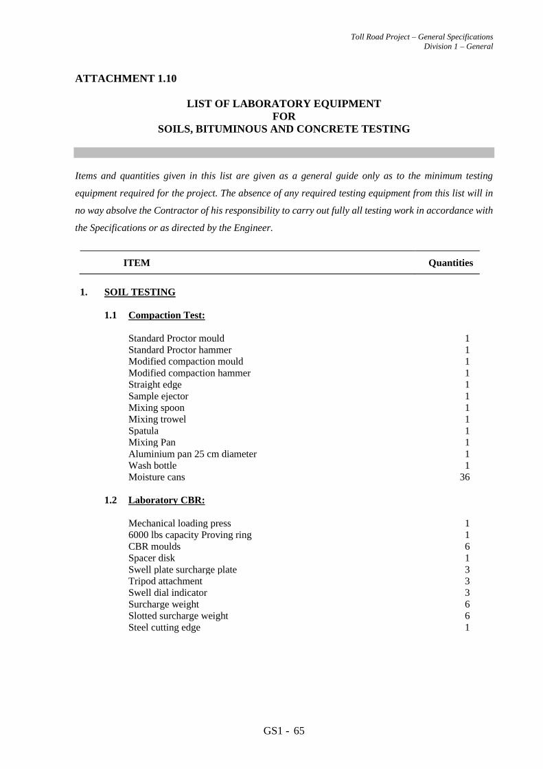
Toll Road Project – General Specifications
Division 1 – General
GS1 - 65
ATTACHMENT 1.10
LIST OF LABORATORY EQUIPMENT
FOR
SOILS, BITUMINOUS AND CONCRETE TESTING
Items and quantities given in this list are given as a general guide only as to the minimum testing
equipment required for the project. The absence of any required testing equipment from this list will in
no way absolve the Contractor of his responsibility to carry out fully all testing work in accordance with
the Specifications or as directed by the Engineer.
ITEM Quantities
1. SOIL TESTING
1.1 Compaction Test:
Standard Proctor mould 1
Standard Proctor hammer 1
Modified compaction mould 1
Modified compaction hammer 1
Straight edge 1
Sample ejector 1
Mixing spoon 1
Mixing trowel 1
Spatula 1
Mixing Pan 1
Aluminium pan 25 cm diameter 1
Wash bottle 1
Moisture cans 36
1.2 Laboratory CBR:
Mechanical loading press 1
6000 lbs capacity Proving ring 1
CBR moulds 6
Spacer disk 1
Swell plate surcharge plate 3
Tripod attachment 3
Swell dial indicator 3
Surcharge weight 6
Slotted surcharge weight 6
Steel cutting edge 1
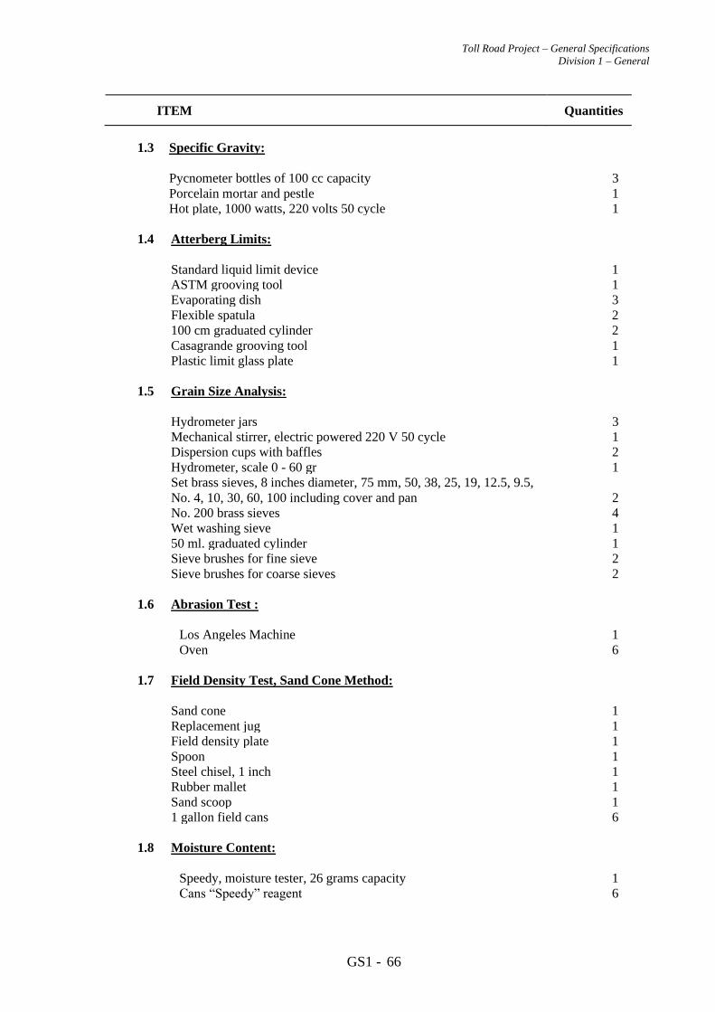
Toll Road Project – General Specifications
Division 1 – General
GS1 - 66
ITEM Quantities
1.3 Specific Gravity:
Pycnometer bottles of 100 cc capacity 3
Porcelain mortar and pestle 1
Hot plate, 1000 watts, 220 volts 50 cycle 1
1.4 Atterberg Limits:
Standard liquid limit device 1
ASTM grooving tool 1
Evaporating dish 3
Flexible spatula 2
100 cm graduated cylinder 2
Casagrande grooving tool 1
Plastic limit glass plate 1
1.5 Grain Size Analysis:
Hydrometer jars 3
Mechanical stirrer, electric powered 220 V 50 cycle 1
Dispersion cups with baffles 2
Hydrometer, scale 0 - 60 gr 1
Set brass sieves, 8 inches diameter, 75 mm, 50, 38, 25, 19, 12.5, 9.5,
No. 4, 10, 30, 60, 100 including cover and pan
2
No. 200 brass sieves 4
Wet washing sieve 1
50 ml. graduated cylinder 1
Sieve brushes for fine sieve 2
Sieve brushes for coarse sieves 2
1.6 Abrasion Test :
Los Angeles Machine 1
Oven 6
1.7 Field Density Test, Sand Cone Method:
Sand cone 1
Replacement jug 1
Field density plate 1
Spoon 1
Steel chisel, 1 inch 1
Rubber mallet 1
Sand scoop 1
1 gallon field cans 6
1.8 Moisture Content:
Speedy, moisture tester, 26 grams capacity 1
Cans “Speedy” reagent 6
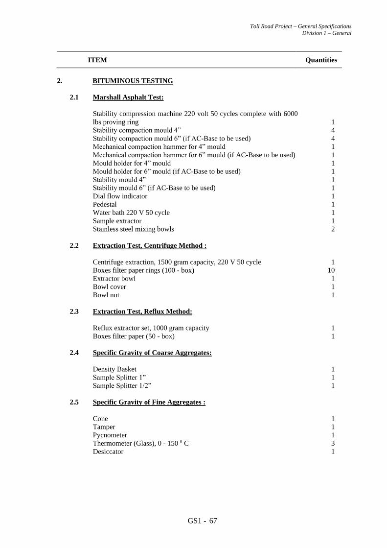
Toll Road Project – General Specifications
Division 1 – General
GS1 - 67
ITEM Quantities
2. BITUMINOUS TESTING
2.1 Marshall Asphalt Test:
Stability compression machine 220 volt 50 cycles complete with 6000
lbs proving ring
1
Stability compaction mould 4” 4
Stability compaction mould 6” (if AC-Base to be used) 4
Mechanical compaction hammer for 4” mould 1
Mechanical compaction hammer for 6” mould (if AC-Base to be used) 1
Mould holder for 4” mould 1
Mould holder for 6” mould (if AC-Base to be used) 1
Stability mould 4” 1
Stability mould 6” (if AC-Base to be used) 1
Dial flow indicator 1
Pedestal 1
Water bath 220 V 50 cycle 1
Sample extractor 1
Stainless steel mixing bowls 2
2.2 Extraction Test, Centrifuge Method :
Centrifuge extraction, 1500 gram capacity, 220 V 50 cycle 1
Boxes filter paper rings (100 - box) 10
Extractor bowl 1
Bowl cover 1
Bowl nut 1
2.3 Extraction Test, Reflux Method:
Reflux extractor set, 1000 gram capacity 1
Boxes filter paper (50 - box) 1
2.4 Specific Gravity of Coarse Aggregates:
Density Basket 1
Sample Splitter 1” 1
Sample Splitter 1/2” 1
2.5 Specific Gravity of Fine Aggregates :
Cone 1
Tamper 1
Pycnometer 1
Thermometer (Glass), 0 - 150 0 C 3
Desiccator 1
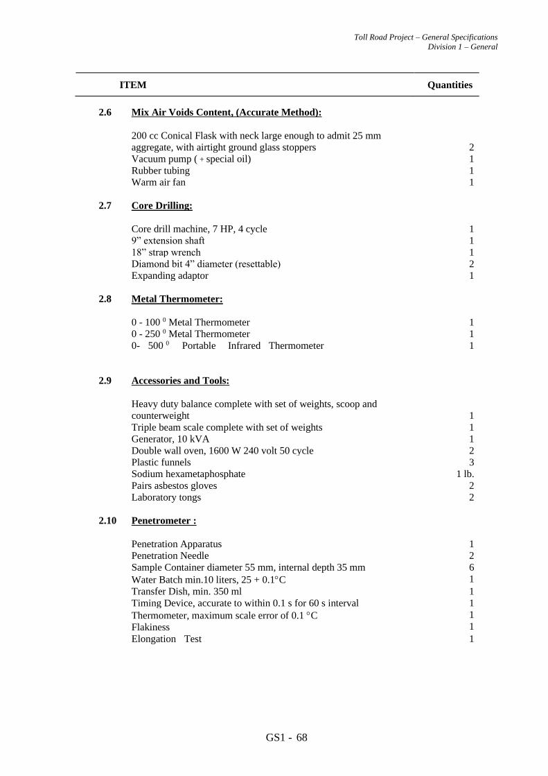
Toll Road Project – General Specifications
Division 1 – General
GS1 - 68
ITEM Quantities
2.6 Mix Air Voids Content, (Accurate Method):
200 cc Conical Flask with neck large enough to admit 25 mm
aggregate, with airtight ground glass stoppers
2
Vacuum pump ( + special oil) 1
Rubber tubing 1
Warm air fan 1
2.7 Core Drilling:
Core drill machine, 7 HP, 4 cycle 1
9” extension shaft 1
18” strap wrench 1
Diamond bit 4” diameter (resettable) 2
Expanding adaptor 1
2.8 Metal Thermometer:
0 - 100 0 Metal Thermometer 1
0 - 250 0 Metal Thermometer 1
0- 500 0 Portable Infrared Thermometer 1
2.9 Accessories and Tools:
Heavy duty balance complete with set of weights, scoop and
counterweight
1
Triple beam scale complete with set of weights 1
Generator, 10 kVA 1
Double wall oven, 1600 W 240 volt 50 cycle 2
Plastic funnels 3
Sodium hexametaphosphate 1 lb.
Pairs asbestos gloves 2
Laboratory tongs 2
2.10 Penetrometer :
Penetration Apparatus 1
Penetration Needle 2
Sample Container diameter 55 mm, internal depth 35 mm 6
Water Batch min.10 liters, 25 + 0.1C 1
Transfer Dish, min. 350 ml 1
Timing Device, accurate to within 0.1 s for 60 s interval 1
Thermometer, maximum scale error of 0.1 C
Flakiness
1
1
Elongation Test 1
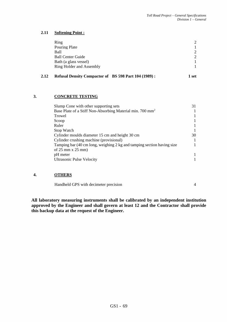
Toll Road Project – General Specifications
Division 1 – General
GS1 - 69
2.11 Softening Point :
Ring 2
Pouring Plate 1
Ball 2
Ball Center Guide 2
Bath (a glass vessel) 1
Ring Holder and Assembly 1
2.12 Refusal Density Compactor of BS 598 Part 104 (1989) : 1 set
3. CONCRETE TESTING
Slump Cone with other supporting sets 31
Base Plate of a Stiff Non-Absorbing Material min. 700 mm2
Trowel
1
1
Scoop
Ruler
Stop Watch
1
1
1
Cylinder moulds diameter 15 cm and height 30 cm 30
Cylinder crushing machine (provisional) 1
Tamping bar (40 cm long, weighing 2 kg and tamping section having size
of 25 mm x 25 mm)
1
pH meter 1
Ultrasonic Pulse Velocity 1
4. OTHERS
Handheld GPS with decimeter precision 4
All laboratory measuring instruments shall be calibrated by an independent institution
approved by the Engineer and shall govern at least 12 and the Contractor shall provide
this backup data at the request of the Engineer.

Toll Road Project – General Specifications
Division 1 – General
GS1 - 70

Toll Road Project – General Specifications
Division 1 – General
GS1 - 71
APPENDIX 1.39:
ENVIRONMENTAL MANAGEMENT AND MONITORING PLAN (RKPPL)
The systematic of Environmental Management and Monitoring Plan (RKPPL) are as follows:
(1) The front cover contains the title of EMMP (RKPPL) for the project and location of Works.
(2) Validation Sheet containing the parties involved in environmental management of this activity
which includes, made by the Contractor, checked by Engineer and approved by the Employer
representative as the initiator.
(3) Chapter I Introduction: The objectives of EMMP, project location, project data, technical
activities data, and organization chart of Contractor.
(4) Chapter II Initial Environmental Baseline: contains the environmental baseline at the location
where the activities are described in a table on each typical of road section and accompanied
with the photos of existing condition.
(5) Chapter III: Environmental Management Work Plan: contains the environmental management
plan for each activity on road section including the potential impacts.
(6) Chapter IV: Environmental Monitoring Work Plan: contains the monitoring plan for
environmental management to be carried out.
(7) Attachments which involve:
(a) Environmental Permit
(b) Map of Base Camp and Quarry.
(c) Permits related to the quarry, concrete batching plant, AMP and/or Stone Crusher.
Form of EMMP (RKPPL) Documents involve:
• Cover of EMMP (RKPPL)
• Validation Sheet of EMMP (RKPPL)
• Project Data
1 Project Name :
2 Project Location :
3 Project Length :
4 Budget Sources :
5 Employer :
6 Project Manager :
7 Engineer :
8 Contractor :
9 Contractor’s Address :
10 Contract Number :
11 Contract Signing Date :
12 Accepted Contract Amount :
13 Time for Completion :
14 Commencement Date :
15 Defect Notification Period :
• Technical Data
Sample of Technical Data
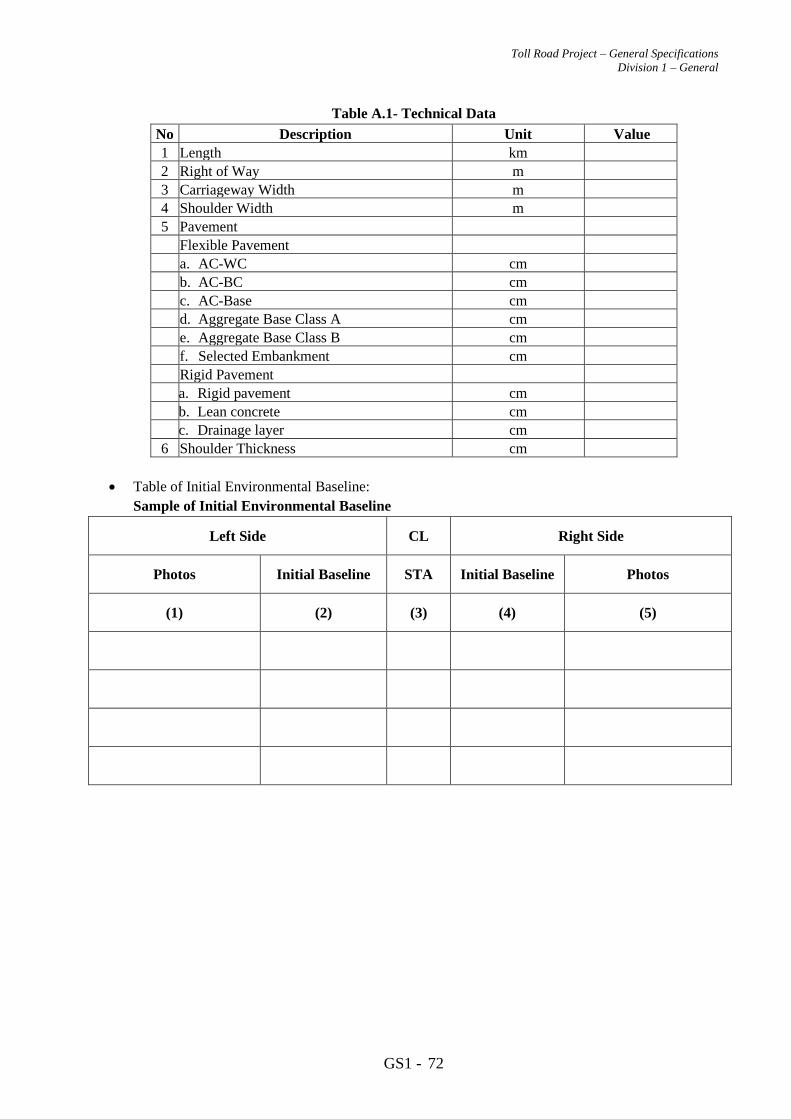
Toll Road Project – General Specifications
Division 1 – General
GS1 - 72
Table A.1- Technical Data
No Description Unit Value
1 Length km
2 Right of Way m
3 Carriageway Width m
4 Shoulder Width m
5 Pavement
Flexible Pavement
a. AC-WC cm
b. AC-BC cm
c. AC-Base cm
d. Aggregate Base Class A cm
e. Aggregate Base Class B cm
f. Selected Embankment cm
Rigid Pavement
a. Rigid pavement cm
b. Lean concrete cm
c. Drainage layer cm
6 Shoulder Thickness cm
• Table of Initial Environmental Baseline:
Sample of Initial Environmental Baseline
Left Side CL Right Side
Photos Initial Baseline STA Initial Baseline Photos
(1) (2) (3) (4) (5)
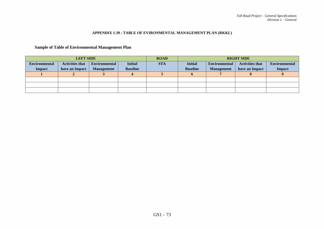
Toll Road Project – General Specifications
Division 1 – General
GS1 - 73
APPENDIX 1.39 : TABLE OF EVIRONMENTAL MANAGEMENT PLAN (RKKL)
Sample of Table of Environmental Management Plan
LEFT SIDE ROAD RIGHT SIDE
Environmental
Impact
Activities that
have an Impact
Environmental
Management
Initial
Baseline
STA Initial
Baseline
Environmental
Management
Activities that
have an Impact
Environmental
Impact
1 2 3 4 5 6 7 8 9
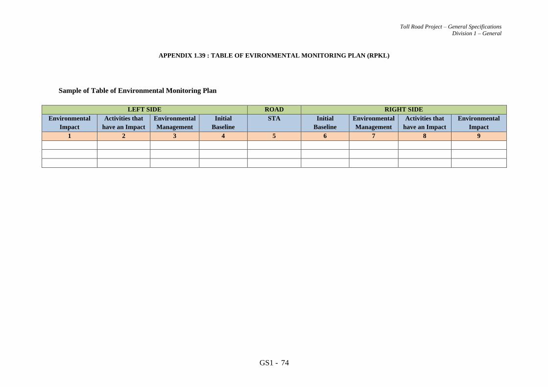
Toll Road Project – General Specifications
Division 1 – General
GS1 - 74
APPENDIX 1.39 : TABLE OF EVIRONMENTAL MONITORING PLAN (RPKL)
Sample of Table of Environmental Monitoring Plan
LEFT SIDE ROAD RIGHT SIDE
Environmental
Impact
Activities that
have an Impact
Environmental
Management
Initial
Baseline
STA Initial
Baseline
Environmental
Management
Activities that
have an Impact
Environmental
Impact
1 2 3 4 5 6 7 8 9
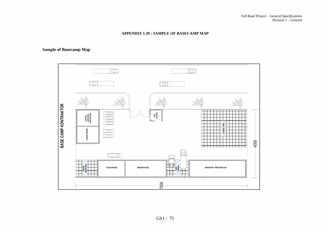
Toll Road Project – General Specifications
Division 1 – General
GS1 - 75
KA
NTO
R
LAP
AN
GA
N
KO
NTR
AK
TOR
LAB
OR
ATO
RIU
M
GUDANG BENGKEL BARAK PEKERJA
4000
7500
WA
TER
RE
SE
RV
OIR
CA
STI
NG
YA
RD
PO
S
SA
TPA
M
BB
M
TAN
KE
R
BA
SE
CA
MP
KO
NTR
AK
TOR
APPENDIX 1.39 : SAMPLE OF BASECAMP MAP
Sample of Basecamp Map
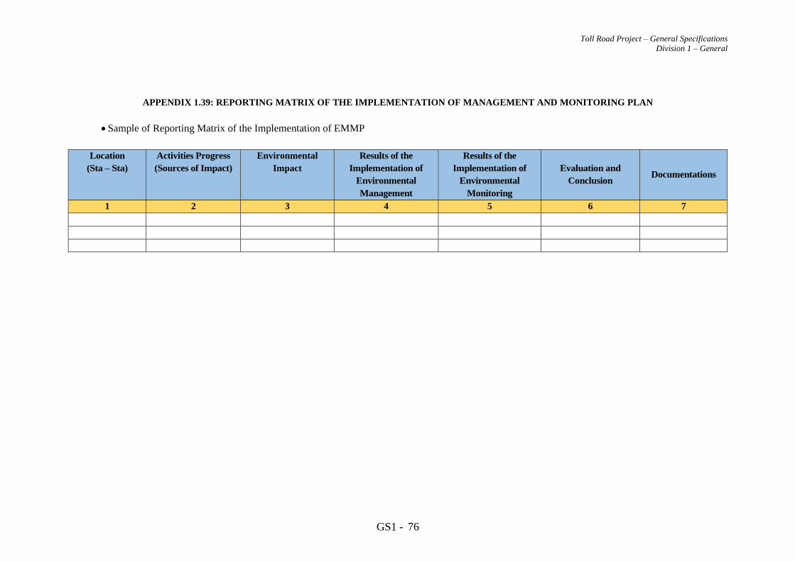
Toll Road Project – General Specifications
Division 1 – General
GS1 - 76
APPENDIX 1.39: REPORTING MATRIX OF THE IMPLEMENTATION OF MANAGEMENT AND MONITORING PLAN
• Sample of Reporting Matrix of the Implementation of EMMP
Location
(Sta – Sta)
Activities Progress
(Sources of Impact)
Environmental
Impact
Results of the
Implementation of
Environmental
Management
Results of the
Implementation of
Environmental
Monitoring
Evaluation and
Conclusion Documentations
1 2 3 4 5 6 7
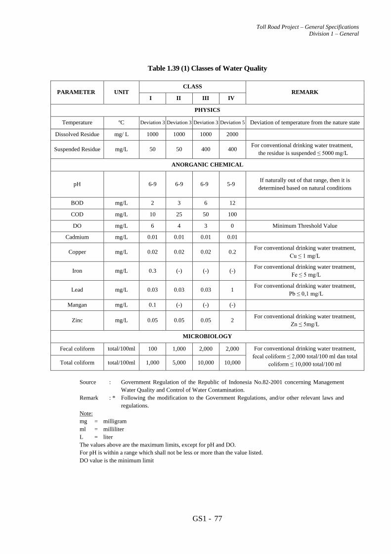
Toll Road Project – General Specifications
Division 1 – General
GS1 - 77
Table 1.39 (1) Classes of Water Quality
PARAMETER UNIT CLASS
REMARK I I II III IV
PHYSICS
Temperature ºC Deviation 3 Deviation 3 Deviation 3 Deviation 5 Deviation of temperature from the nature state
Dissolved Residue mg/ L 1000 1000 1000 2000
Suspended Residue mg/L 50 50 400 400 For conventional drinking water treatment,
the residue is suspended ≤ 5000 mg/L
ANORGANIC CHEMICAL
pH 6-9 6-9 6-9 5-9 If naturally out of that range, then it is
determined based on natural conditions
BOD mg/L 2 3 6 12
COD mg/L 10 25 50 100
DO mg/L 6 4 3 0 Minimum Threshold Value
Cadmium mg/L 0.01 0.01 0.01 0.01
Copper mg/L 0.02 0.02 0.02 0.2 For conventional drinking water treatment,
Cu ≤ 1 mg/L
Iron mg/L 0.3 (-) (-) (-) For conventional drinking water treatment,
Fe ≤ 5 mg/L
Lead mg/L 0.03 0.03 0.03 1 For conventional drinking water treatment,
Pb ≤ 0,1 mg/L
Mangan mg/L 0.1 (-) (-) (-)
Zinc mg/L 0.05 0.05 0.05 2 For conventional drinking water treatment,
Zn ≤ 5mg/L
MICROBIOLOGY
Fecal coliform total/100ml 100 1,000 2,000 2,000 For conventional drinking water treatment,
fecal coliform ≤ 2,000 total/100 ml dan total
coliform ≤ 10,000 total/100 ml Total coliform total/100ml 1,000 5,000 10,000 10,000
Source : Government Regulation of the Republic of Indonesia No.82-2001 concerning Management
Water Quality and Control of Water Contamination.
Remark : * Following the modification to the Government Regulations, and/or other relevant laws and
regulations.
Note:
mg = milligram
ml = milliliter
L = liter
The values above are the maximum limits, except for pH and DO.
For pH is within a range which shall not be less or more than the value listed.
DO value is the minimum limit
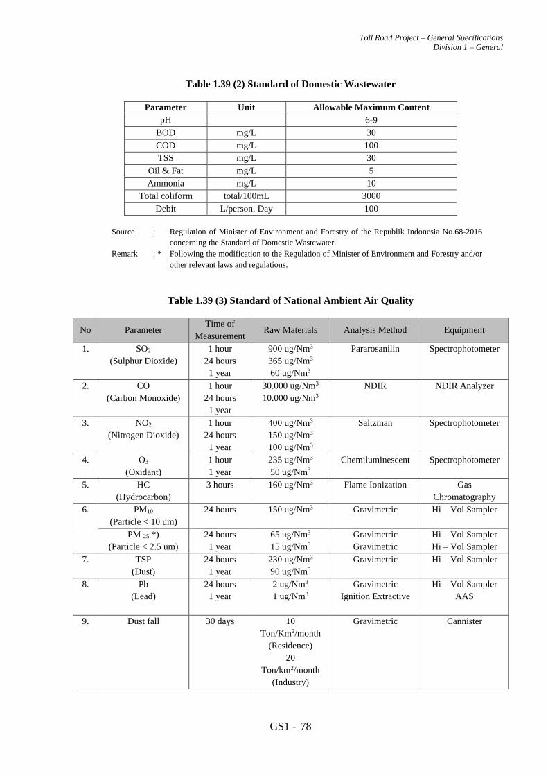
Toll Road Project – General Specifications
Division 1 – General
GS1 - 78
Table 1.39 (2) Standard of Domestic Wastewater
Parameter Unit Allowable Maximum Content
pH 6-9
BOD mg/L 30
COD mg/L 100
TSS mg/L 30
Oil & Fat mg/L 5
Ammonia mg/L 10
Total coliform total/100mL 3000
Debit L/person. Day 100
Source : Regulation of Minister of Environment and Forestry of the Republik Indonesia No.68-2016
concerning the Standard of Domestic Wastewater.
Remark : * Following the modification to the Regulation of Minister of Environment and Forestry and/or
other relevant laws and regulations.
Table 1.39 (3) Standard of National Ambient Air Quality
No Parameter Time of
Measurement Raw Materials Analysis Method Equipment
1. SO2
(Sulphur Dioxide)
1 hour
24 hours
1 year
900 ug/Nm3
365 ug/Nm3
60 ug/Nm3
Pararosanilin Spectrophotometer
2. CO
(Carbon Monoxide)
1 hour
24 hours
1 year
30.000 ug/Nm3
10.000 ug/Nm3
NDIR NDIR Analyzer
3. NO2
(Nitrogen Dioxide)
1 hour
24 hours
1 year
400 ug/Nm3
150 ug/Nm3
100 ug/Nm3
Saltzman Spectrophotometer
4. O3
(Oxidant)
1 hour
1 year
235 ug/Nm3
50 ug/Nm3
Chemiluminescent Spectrophotometer
5. HC
(Hydrocarbon)
3 hours 160 ug/Nm3
Flame Ionization Gas
Chromatography
6. PM10
(Particle < 10 um)
24 hours 150 ug/Nm3
Gravimetric Hi – Vol Sampler
PM 25 *)
(Particle < 2.5 um)
24 hours
1 year
65 ug/Nm3
15 ug/Nm3
Gravimetric
Gravimetric
Hi – Vol Sampler
Hi – Vol Sampler
7. TSP
(Dust)
24 hours
1 year
230 ug/Nm3
90 ug/Nm3
Gravimetric Hi – Vol Sampler
8. Pb
(Lead)
24 hours
1 year
2 ug/Nm3
1 ug/Nm3
Gravimetric
Ignition Extractive
Hi – Vol Sampler
AAS
9. Dust fall
30 days 10
Ton/Km2/month
(Residence)
20
Ton/km2/month
(Industry)
Gravimetric Cannister
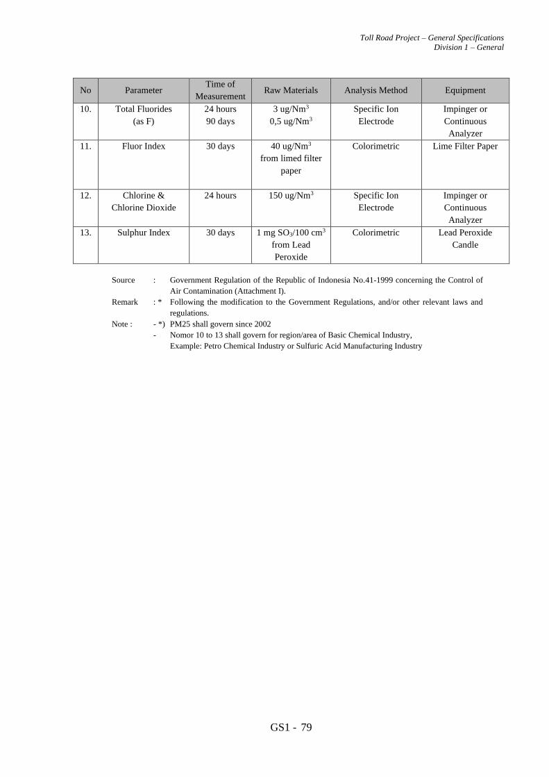
Toll Road Project – General Specifications
Division 1 – General
GS1 - 79
No Parameter Time of
Measurement Raw Materials Analysis Method Equipment
10. Total Fluorides
(as F)
24 hours
90 days
3 ug/Nm3
0,5 ug/Nm3
Specific Ion
Electrode
Impinger or
Continuous
Analyzer
11. Fluor Index 30 days 40 ug/Nm3
from limed filter
paper
Colorimetric Lime Filter Paper
12. Chlorine &
Chlorine Dioxide
24 hours 150 ug/Nm3
Specific Ion
Electrode
Impinger or
Continuous
Analyzer
13. Sulphur Index 30 days 1 mg SO3/100 cm3
from Lead
Peroxide
Colorimetric Lead Peroxide
Candle
Source : Government Regulation of the Republic of Indonesia No.41-1999 concerning the Control of
Air Contamination (Attachment I).
Remark : * Following the modification to the Government Regulations, and/or other relevant laws and
regulations.
Note : - *) PM25 shall govern since 2002
- Nomor 10 to 13 shall govern for region/area of Basic Chemical Industry,
Example: Petro Chemical Industry or Sulfuric Acid Manufacturing Industry
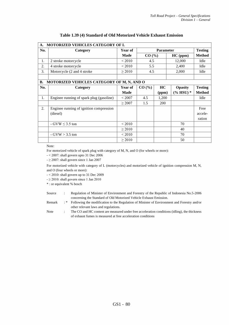
Toll Road Project – General Specifications
Division 1 – General
GS1 - 80
Table 1.39 (4) Standard of Old Motorized Vehicle Exhaust Emission
A. MOTORIZED VEHICLES CATEGORY OF L
No. Category Year of
Made
Parameter Testing
Method CO (%) HC (ppm)
1. 2 stroke motorcycle < 2010 4.5 12,000 Idle
2. 4 stroke motorcycle < 2010 5.5 2,400 Idle
3. Motorcycle (2 and 4 stroke ≥ 2010 4.5 2,000 Idle
B. MOTORIZED VEHICLES CATEGORY OF M, N, AND O
No. Category Year of
Made
CO (%) HC
(ppm)
Opasity
(% HSU) *
Testing
Method
1. Enginee running of spark plug (gasoline) < 2007 4.5 1,200 Idle
≥ 2007 1.5 200
2. Enginee running of ignition compression
(diesel)
Free
accele-
ration
- GVW ≤ 3.5 ton < 2010 70
≥ 2010 40
- GVW > 3.5 ton < 2010 70
≥ 2010 50
Note:
For motorized vehicle of spark plug with category of M, N, and O (for wheels or more):
- < 2007: shall govern upto 31 Dec 2006
- ≥ 2007: shall govern since 1 Jan 2007
For motorized vehicle with category of L (motorcycles) and motorized vehicle of ignition compression M, N,
and O (four wheels or more):
- < 2010: shall govern up to 31 Dec 2009
- ≥ 2010: shall govern since 1 Jan 2010
* : or equivalent % bosch
Source : Regulation of Minister of Environment and Forestry of the Republic of Indonesia No.5-2006
concerning the Standard of Old Motorized Vehicle Exhaust Emission.
Remark : * Following the modification to the Regulation of Minister of Environment and Forestry and/or
other relevant laws and regulations.
Note : The CO and HC content are measured under free acceleration conditions (idling), the thickness
of exhaust fumes is measured at free acceleration conditions
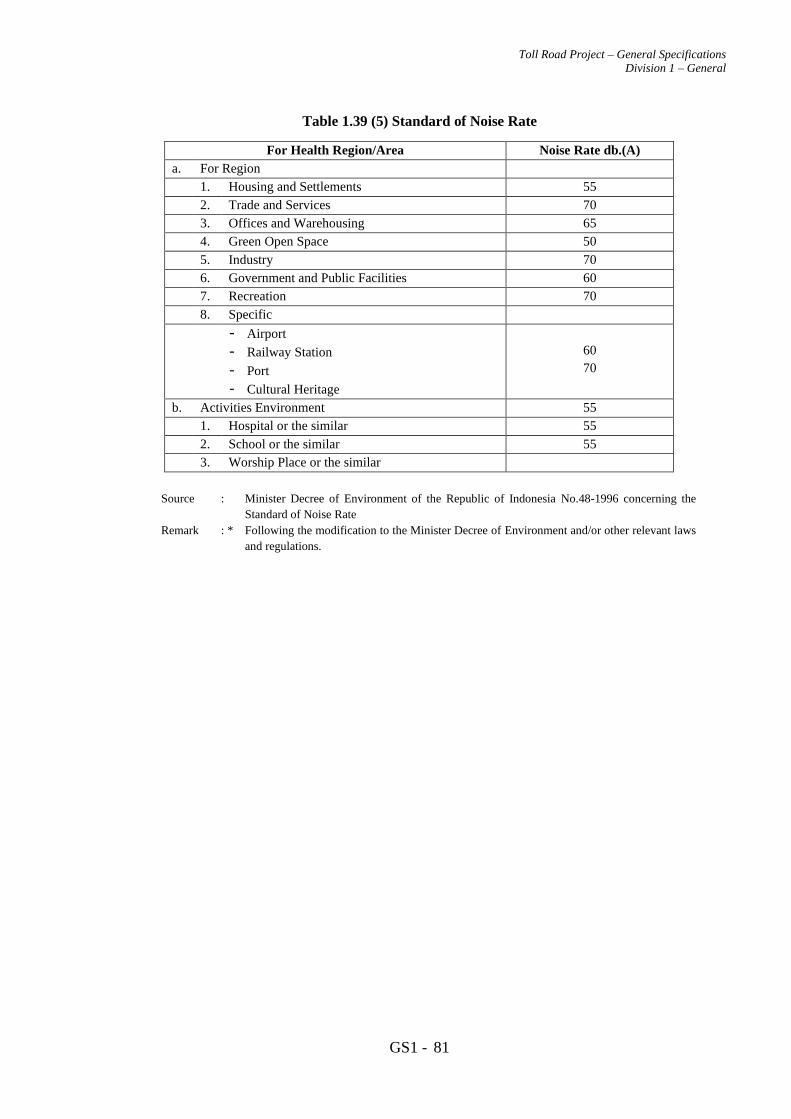
Toll Road Project – General Specifications
Division 1 – General
GS1 - 81
Table 1.39 (5) Standard of Noise Rate
Source : Minister Decree of Environment of the Republic of Indonesia No.48-1996 concerning the
Standard of Noise Rate
Remark : * Following the modification to the Minister Decree of Environment and/or other relevant laws
and regulations.
For Health Region/Area Noise Rate db.(A)
a. For Region
1. Housing and Settlements 55
2. Trade and Services 70
3. Offices and Warehousing 65
4. Green Open Space 50
5. Industry 70
6. Government and Public Facilities 60
7. Recreation 70
8. Specific
- Airport
- Railway Station
- Port
- Cultural Heritage
60
70
b. Activities Environment 55
1. Hospital or the similar 55
2. School or the similar 55
3. Worship Place or the similar
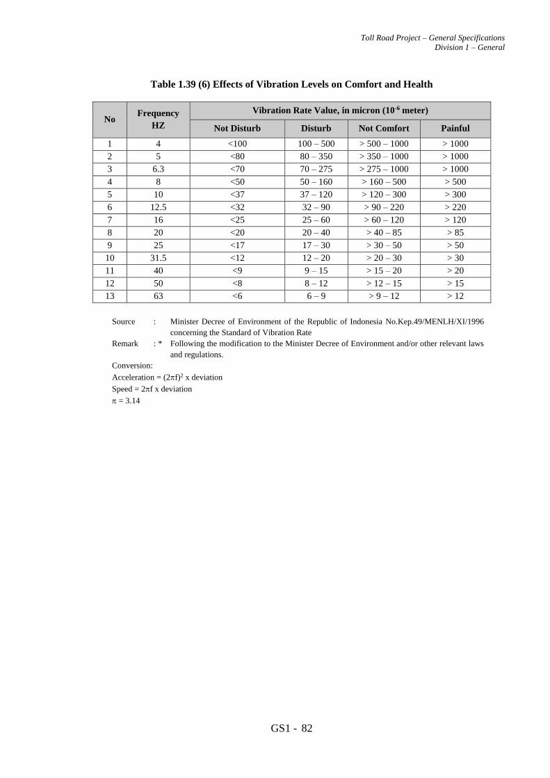
Toll Road Project – General Specifications
Division 1 – General
GS1 - 82
Table 1.39 (6) Effects of Vibration Levels on Comfort and Health
No Frequency
HZ
Vibration Rate Value, in micron (10-6 meter)
Not Disturb Disturb Not Comfort Painful
1 4 <100 100 – 500 > 500 – 1000 > 1000
2 5 <80 80 – 350 > 350 – 1000 > 1000
3 6.3 <70 70 – 275 > 275 – 1000 > 1000
4 8 <50 50 – 160 > 160 – 500 > 500
5 10 <37 37 – 120 > 120 – 300 > 300
6 12.5 <32 32 – 90 > 90 – 220 > 220
7 16 <25 25 – 60 > 60 – 120 > 120
8 20 <20 20 – 40 > 40 – 85 > 85
9 25 <17 17 – 30 > 30 – 50 > 50
10 31.5 <12 12 – 20 > 20 – 30 > 30
11 40 <9 9 – 15 > 15 – 20 > 20
12 50 <8 8 – 12 > 12 – 15 > 15
13 63 <6 6 – 9 > 9 – 12 > 12
Source : Minister Decree of Environment of the Republic of Indonesia No.Kep.49/MENLH/XI/1996
concerning the Standard of Vibration Rate
Remark : * Following the modification to the Minister Decree of Environment and/or other relevant laws
and regulations.
Conversion:
Acceleration = (2f)2 x deviation
Speed = 2f x deviation
= 3.14
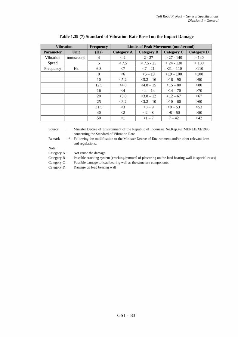
Toll Road Project – General Specifications
Division 1 – General
GS1 - 83
Table 1.39 (7) Standard of Vibration Rate Based on the Impact Damage
Vibration Frequency Limits of Peak Movement (mm/second)
Parameter Unit (Hz) Category A Category B Category C Category D
Vibration
Speed
mm/second 4 < 2 2 - 27 > 27 - 140 > 140
5 < 7.5 < 7.5 - 25 > 24 - 130 > 130
Frequency Hz 6.3 <7 <7 – 21 >21 – 110 >110
8 <6 <6 – 19 >19 – 100 >100
10 <5.2 <5.2 – 16 >16 – 90 >90
12.5 <4.8 <4.8 – 15 >15 – 80 >80
16 <4 <4 – 14 >14 – 70 >70
20 <3.8 <3.8 – 12 >12 – 67 >67
25 <3.2 <3.2 – 10 >10 – 60 >60
31.5 <3 <3 – 9 >9 – 53 >53
40 <2 <2 – 8 >8 – 50 >50
50 <1 <1 – 7 7 – 42 >42
Source : Minister Decree of Environment of the Republic of Indonesia No.Kep.49/ MENLH/XI/1996
concerning the Standard of Vibration Rate
Remark : * Following the modification to the Minister Decree of Environment and/or other relevant laws
and regulations.
Note:
Category A : Not cause the damage.
Category B : Possible cracking system (cracking/removal of plastering on the load bearing wall in special cases)
Category C : Possible damage to load bearing wall as the structure components.
Category D : Damage on load bearing wall

Toll Road Project – General Specifications
Division 1 – General
GS1 - 84
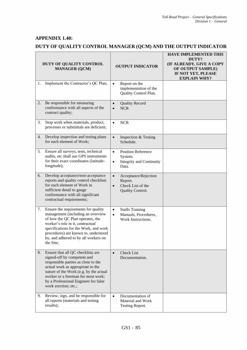
Toll Road Project – General Specifications
Division 1 – General
GS1 - 85
APPENDIX 1.40:
DUTY OF QUALITY CONTROL MANAGER (QCM) AND THE OUTPUT INDICATOR
DUTY OF QUALITY CONTROL
MANAGER (QCM) OUTPUT INDICATOR
HAVE IMPLEMENTED THIS
DUTY?
(IF ALREADY, GIVE A COPY
OF OUTPUT SAMPLE)
IF NOT YET, PLEASE
EXPLAIN WHY?
1. Implement the Contractor’s QC Plan;
• Report on the
implementation of the
Quality Control Plan.
2. Be responsible for measuring
conformance with all aspects of the
contract quality;
• Quality Record
• NCR
3. Stop work when materials, product,
processes or submittals are deficient;
• NCR
4. Develop inspection and testing plans
for each element of Work;
• Inspection & Testing
Schedule.
5. Ensure all surveys, tests, technical
audits, etc shall use GPS instruments
for their exact coordinates (latitude-
longitude);
• Position Reference
System.
• Integrity and Continuity
Data.
6. Develop acceptance/non-acceptance
reports and quality control checklists
for each element of Work in
sufficient detail to gauge
conformance with all significant
contractual requirements;
• Acceptance/Rejection
Report.
• Check List of the
Quality Control.
7. Ensure the requirements for quality
management (including an overview
of how the QC Plan operates, the
worker’s role in it, contractual
specifications for the Work, and work
procedures) are known to, understood
by, and adhered to by all workers on
the Site;
• Staffs Training
• Manuals, Procedures,
Work Instructions.
8. Ensure that all QC checklists are
signed-off by competent and
responsible parties as close to the
actual work as appropriate to the
nature of the Work (e.g. by the actual
worker or a foreman for most work;
by a Professional Engineer for false
work erection; etc.;
• Check List
Documentation.
9. Review, sign, and be responsible for
all reports (materials and testing
results);
• Documentation of
Material and Work
Testing Report.
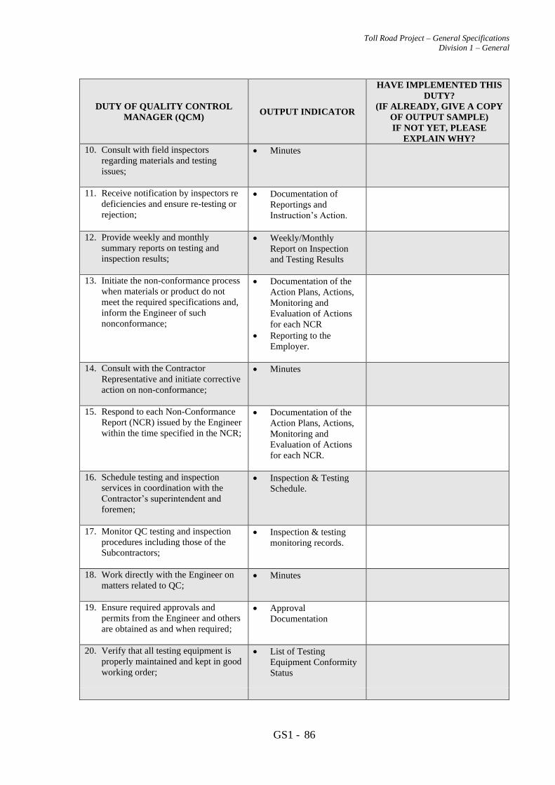
Toll Road Project – General Specifications
Division 1 – General
GS1 - 86
DUTY OF QUALITY CONTROL
MANAGER (QCM) OUTPUT INDICATOR
HAVE IMPLEMENTED THIS
DUTY?
(IF ALREADY, GIVE A COPY
OF OUTPUT SAMPLE)
IF NOT YET, PLEASE
EXPLAIN WHY?
10. Consult with field inspectors
regarding materials and testing
issues;
• Minutes
11. Receive notification by inspectors re
deficiencies and ensure re-testing or
rejection;
• Documentation of
Reportings and
Instruction’s Action.
12. Provide weekly and monthly
summary reports on testing and
inspection results;
• Weekly/Monthly
Report on Inspection
and Testing Results
13. Initiate the non-conformance process
when materials or product do not
meet the required specifications and,
inform the Engineer of such
nonconformance;
• Documentation of the
Action Plans, Actions,
Monitoring and
Evaluation of Actions
for each NCR
• Reporting to the
Employer.
14. Consult with the Contractor
Representative and initiate corrective
action on non-conformance;
• Minutes
15. Respond to each Non-Conformance
Report (NCR) issued by the Engineer
within the time specified in the NCR;
• Documentation of the
Action Plans, Actions,
Monitoring and
Evaluation of Actions
for each NCR.
16. Schedule testing and inspection
services in coordination with the
Contractor’s superintendent and
foremen;
• Inspection & Testing
Schedule.
17. Monitor QC testing and inspection
procedures including those of the
Subcontractors;
• Inspection & testing
monitoring records.
18. Work directly with the Engineer on
matters related to QC;
• Minutes
19. Ensure required approvals and
permits from the Engineer and others
are obtained as and when required;
• Approval
Documentation
20. Verify that all testing equipment is
properly maintained and kept in good
working order;
• List of Testing
Equipment Conformity
Status
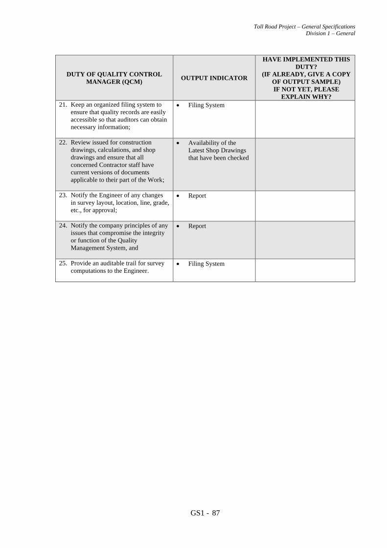
Toll Road Project – General Specifications
Division 1 – General
GS1 - 87
DUTY OF QUALITY CONTROL
MANAGER (QCM) OUTPUT INDICATOR
HAVE IMPLEMENTED THIS
DUTY?
(IF ALREADY, GIVE A COPY
OF OUTPUT SAMPLE)
IF NOT YET, PLEASE
EXPLAIN WHY?
21. Keep an organized filing system to
ensure that quality records are easily
accessible so that auditors can obtain
necessary information;
• Filing System
22. Review issued for construction
drawings, calculations, and shop
drawings and ensure that all
concerned Contractor staff have
current versions of documents
applicable to their part of the Work;
• Availability of the
Latest Shop Drawings
that have been checked
23. Notify the Engineer of any changes
in survey layout, location, line, grade,
etc., for approval;
• Report
24. Notify the company principles of any
issues that compromise the integrity
or function of the Quality
Management System, and
• Report
25. Provide an auditable trail for survey
computations to the Engineer.
• Filing System

Toll Road Project – General Specifications
Division 1 – General
GS1 - 88
Toll Road Project – General Specifications
Division 2 – Site Clearing
GS2 - 1
DIVISION 2 SITE CLEARING
S2.01 Site Clearing
S2.01 (1) Description
The Clearing and grubbing shall consist of clearing of all trees less than 15 cm in
diameter, downed timber, snags, bush, other vegetation, rubbish, and all other
objectionable material, and shall include grubbing stumps, roots, and disposing of
all spoil material resulting from the clearing and grubbing in accordance with
these Specifications or as directed by the Engineer. It shall also include the
removal and disposal of structures that obtrude, encroach upon, or otherwise
obstruct the Works except where otherwise provided for in these Specifications
or ordered by the Engineer.
Selected tree removal shall consist of the removal of all trees shown on the
Drawings or designated by the Engineer measuring 15 cm or more in diameter at
a point measured one meter above the ground surface. The work shall consist of
not only the removal and disposal to the satisfaction of the Engineer of the
individual tree but the stump and roots as well.
This work shall also include the preservation from injury or defacement of all
vegetation and objects designated to remain.
S2.01 (2) Construction Requirements
(a) General
The Engineer will establish the limits of work and designate all trees,
shrubs, plants and other things to remain. The Contractor shall preserve
all items designated to remain.
(b) Clearing and Grubbing and Tree Removal
All surface objects and all trees, down timber, rotten wood, stumps, roots,
snags, brush, other vegetation, rubbish, and other protruding obstructions,
not designated to remain, shall be cleared and/or grubbed, including
disposal as required.
In areas under roadway embankments, from which top soil or unsuitable
materials are to be removed or which are designated to be compacted, all
stumps and roots shall be thoroughly removed.
In roadway cut areas, all stumps and roots shall be thoroughly removed.
Clearing and grubbing of pits, channel changes, and ditches will be
required only to the depth necessitated by the excavation within those
areas.
Voids left after removal of roots shall be filled with suitable compacted
material in accordance with Clause S.4.06.
Toll Road Project – General Specifications
Division 2 – Site Clearing
GS2 - 2
(c) Topsoil Stripping
In areas under roadway embankments or where designated by the
Engineer, the Contractor shall remove the topsoil and dispose of it as
directed by the Engineer.
In general, the removal of topsoil shall include only the removal of soil
which is fertile enough to encourage or sustain a growth of vegetation with
maximum of 30 cm.
Removal of topsoil over any designated area shall be executed to the depth
as directed by the Engineer, and the topsoil shall be kept separate from
other excavated material.
When the topsoil will be used for dressing of the slopes of the embankment
or other areas as directed by the Engineer or as indicated on the Drawings,
the work of topsoil stripping will be deemed to include stockpiling the
topsoil when necessary and removing therefrom and the placing and
spreading of the topsoil in areas designated by the Engineer. After
spreading, the topsoil shall be raked to form a smooth surface free from
weeds, roots, sods and large stones.
(d) Protection of Areas Designated to Remain
In areas designated by the Engineer, the Contractor will be responsible for
the protection and routine maintenance of existing shrubs, trees and
grassed areas. On completion of the Works these areas will be returned
to the Employer in the same condition as before and any damage due
directly or indirectly to the Contractor's operations shall be made good at
his own expense.
S2.01 (3) Disposal of Cleared Material
The Contractor shall have the right to use unsaleable timber (or saleable timber
when permission is granted in writing by the appropriate Government agency or
authority) for his own purposes in connection with the Contract always provided
that he has ascertained and complied with the requirements of the appropriate
Government agency or authority.
Saleable timber shall be neatly stored in an approved accessible place within or
near the right-of-way as directed and shall be trimmed and stacked in accordance
with the requirements of the appropriate Government agency.
All other timber, except timber to be used, and all brush, stumps, roots, logs, and
other refuse from the clearing and grubbing operation shall be disposed of at
locations provided by the Contractor.
The roadway and adjacent areas shall be left with a neat and finished appearance.
No accumulation of debris shall remain on or adjacent to the right-of-way.
S2.01 (4) Method of Measurement
Clearing and grubbing, topsoil stripping and protection of designated areas, will
together be considered as Site Clearing, and will be paid for by the square meter.
Toll Road Project – General Specifications
Division 2 – Site Clearing
GS2 - 3
Tree cutting and protection to the selected tree to be considered as Removal of
Existing Tree and shall be paid for by each. Tree removal and protection of trees
designated to remain in place will be considered as Removal of Existing Trees
more than 15 cm in diameter at a point measured one meter above the ground
surface and will be paid for by number. The work of Site Clearing and Tree
Removal for disposal sites, material sites, imported borrow pit sites, haul roads
and all temporary construction shall not be paid for when such sites are outside
the areas designated for clearing and grubbing and the Contractor is permitted to
exercise his own option as to whether he elects to use such disposal sites or borrow
pit sites.
S2.01 (5) Basis of Payment
The work measured as provided above shall be paid for as undermentioned. The
payment shall be full compensation for furnishing all labor, materials, tools,
equipment and incidentals necessary to do the work and for doing all the Site
Clearance and Tree Removal in the designated areas as specified in these
Specifications and as directed by the Engineer including if necessary, removal and
disposal of the resulting material.
Pay Item No. and Name Unit of Measurement
2.01 (1) Site Clearing Square Meter
2.01 (2) Removal of Existing Tree dia. >15 – 30 cm Each
2.01 (3) Removal of Existing Tree dia. >30 – 50 cm Each
2.01 (4) Removal of Existing Tree dia. >50 – 75 cm Each
2.01 (5) Removal of Existing Tree dia. >75 cm Each

Toll Road Project – General Specifications
Division 2 – Site Clearing
GS2 - 4
Toll Road Project – General Specifications
Division 3 – Demolition
GS3 - 1
DIVISION 3 DEMOLITION
S3.01 Demolition
S3.01 (1) Description
This work shall consist of the removal, wholly or in part and satisfactory disposal
of blocks of masonry of an individual size greater than 1 cubic meter, of all
buildings, hedges, fences, structures, curbs, and any other obstructions which are
not designated or permitted to remain, except for the obstructions to be removed
and disposed of under other items in the Contract Documents. It shall also consist
of the salvaging of designated materials and backfilling the resulting trenches,
holes and pits.
In general, when the materials are not required by the Employer and they shall be
removed by the Contractor as instructed by the Engineer, such materials should
be disposed of at the disposal area itself, in accordance with the provisions of
Clause S4.07 of Specifications.
S3.01 (2) Work Requirements
(a) General
The Contractor shall perform the above work, within and adjacent to the
roadway, on the right-of-way, as shown on the Drawings or as directed by
the Engineer. The Engineer may instruct that materials recovered from
demolition shall remain the property of the Employer unless specifically
provided otherwise in the Contract Documents. All designated saleable
material shall be removed, without unnecessary damage, in sections or
pieces which may be readily transported, and shall be stored by the
Contractor at specified places on the project as directed by the Engineer.
Basements or cavities left by structure removal shall be filled with
acceptable material to the level of the surrounding ground and, if within
the prism of construction, shall be compacted in accordance with Clause
S4.06.
Performance of these works under the Contract shall include salvage of
materials removed, their custody, preservation, storage on the right-of-
way or any other places as may be designated by the Engineer or the
Employer, or disposal as provided herein.
(b) Removal of Bridges, Culverts, and other Structures
Bridges, culverts and other drainage structures in use by traffic shall not
be removed until satisfactory arrangements have been made to
accommodate traffic.
Unless otherwise directed, the substructures of existing water structures
shall be removed down to the natural stream bottom and those parts
outside of a stream shall be removed to the extent necessary to avoid
influence on new works.
Toll Road Project – General Specifications
Division 3 – Demolition
GS3 - 2
Where portions of the existing structures lie wholly or in part within the
limits for a new structure, they shall be removed as necessary to
accommodate the construction of the proposed structure. Where only a
section of the existing structure is to be demolished, the Contractor shall
execute this work in such a way as to avoid damage to the section
designated to remain. All details of the Contractor's proposed working
method shall be submitted to the Engineer for approval.
Steel bridges and wood bridges, when specified by the Engineer to be
salvaged, shall be carefully dismantled without damage. Steel components
shall be match marked, unless such match marking is waived by the
Engineer. All salvaged material shall be stored as requested by the
Engineer.
Unless waived in writing by the Engineer, all concrete removed that is of
suitable size for riprap and not needed for such use on the Project, shall
be stockpiled at locations designated by the Engineer, for use by the
Employer.
(c) Removal of Curbs
Existing curbs designated for removal, including their bases, shall be
broken into pieces and shall be removed and stockpiled at designated
locations on the site for use of the Employer, or shall be otherwise
disposed of as directed by the Engineer.
Removal of existing curbs shall be undertaken in such a manner as to
avoid damage to existing pavements and curbs which are designated to
remain.
(d) Removal of Traffic Signs
When directed, traffic signs including steel frames shall be carefully
dismantled, removed and stored where directed by the Engineer.
Concrete foundations shall be broken into pieces removed and stockpiled
at designated locations on the site for use of the Employer or shall be
otherwise disposed of as directed by the Engineer.
(e) Removal of Guardrail
Guardrail including block piece shall be carefully dismantled and the
condition of material shall be remained as before. Bolts and nuts shall be
opened with a key to remain intact. If the bolt or nut has been in the
welding, welding former shall be chiseled or grinded in order not to
damage the guardrail or other parts. Demolition of the welding pieces on
the guardrail, block piece or post is not permitted unless the bolt or nut if
the existing was welded.
(f) Demolition of Housing
House including all fence and yard shall be demolished until level to the
surrounding ground level. Demolition includes foundations shall be
accompanied by refill and recompaction with soil. Certain parts of the
house that shall be carefully demolished to maintain its integrity in
accordance with the direction of the Engineer.
Toll Road Project – General Specifications
Division 3 – Demolition
GS3 - 3
.. S3.01 (3) Method of Measurement
The quantities to be paid for according to these Specifications or as directed by
the Engineer, shall be cubic meter or square meter or linear meter depending upon
the nature of structure and obstructions demolished acceptably within the limits
as directed by the Engineer. Demolition of housing will be measured for payment
in square meter per story.
Demolition required for the Permanent Works will be measured for payment,
while demolition for haul roads, borrow areas and all the Temporary Works will
not be measured for payment.
S3.01 (4) Basis of Payment
The work measured as provided above shall be paid as undermentioned. The
payment shall be full compensation for furnishing all labor, materials, tools,
equipment, and incidentals necessary to do the work and for doing all the
demolition in the designated locations or areas as specified in these
Specifications, including backfilling if necessary. The unit price for any work
under this Clause will be deemed to include any precautions or special working
methods necessary to avoid damage to abutting material designated to remain.
Any such damage shall be rectified by the Contractor at his own expense. All
work shall be as directed by the Engineer including the removal and disposal of
all the resulting material.
Pay Item No. and Name Unit of Measurement
3.01 (1a) Demolition of Stone Masonry or Brick Cubic Meter
3.01 (1b) Demolition of Structural Concrete Cubic Meter
3.01 (1c) Demolition of Prestressed Concrete Cubic Meter
3.01 (2) Demolition of Curb Linear Meter
3.01 (3) Demolition of Traffic Sign Each
3.01 (4) Demolition of Guardrail/Railing/Chain Link Linear Meter
3.01 (5) Demolition of Housing Square Meter

Toll Road Project – General Specifications
Division 3 – Demolition
GS3 - 4
Toll Road Project – General Specifications
Division 4 – Road Earthwork
GS4 - 1
DIVISION 4 ROAD EARTHWORK AND GEOSYNTHETICS WORK
S4.01 Scope
Road earthwork shall consist of all necessary work for the excavation and placing
or disposal of earth or rock or other material from or to the roadway or adjacent
thereto, for construction of waterways, ditches, laybys and bridge approaches, for
the removal of unsuitable material, the removal of landslides, all in accordance
with the lines, grades, cross-sections shown on the Drawings or as established by
the Engineer. Structure excavation shall not be included in Division 4, but in
Division 5 "Structure Excavation".
S4.02 General
S4.02 (1) Soil Information
Any information of the properties of the soil that may be shown on the Drawings
or obtained by the Contractor as a result of discussion with the Engineer shall
alone not be considered as a sufficient basis for the Contractor's Bid Prices.
The Contractor is responsible for his interpretation of information supplied by the
Employer and shall visit the Site and possible Borrow Pits. Prior to start the
earthwork, the Contractor shall ascertain the nature of the soil, its quantity,
locations, and suitability to meet the specified requirements.
S4.02 (2) Classes of the Work
This work will be divided into the following classes, which are hereinafter
described in detail under separate headings:
(a) Common Excavation; Soft Rock Excavation, Rock Excavation;
Excavation on Existing Granular Pavement and Excavation on Existing
Cement Concrete Pavement;
(b) Borrow Material;
(c) Formation of Embankment and Areas of Fill;
(d) Waste;
(e) Areas of Special Fill;
(f) Granular Backfill;
(g) Permeable Backfill.
(h) Vertical Sand Drain and Horizontal Sand Drain.
(i) Geotextiles
(j) Prefabricated Vertical Drain (PVD)
(k) Geotechnical Instruments
All road earthworks shall be carried out in accordance with the Specifications for
the classes as named above, and the specifications for other work items involved,
Toll Road Project – General Specifications
Division 4 – Road Earthwork
GS4 - 2
and in conformity with the lines, grades, sections and dimensions, shown on the
Drawings or required by the Engineer.
S4.02 (3) Horizontal and Vertical Alignment
The Engineer will supply the Contractor with the locations of the Points of
Intersection of Tangents and Grade lines. The Drawings will indicate the
properties of horizontal and vertical curves, together with the rates of super
elevation where required. The Contractor shall prepare cross-sections based
upon the above properties, secure the Engineer's approval of his cross-sections
and stake out before proceeding with construction. If, in the opinion of the
Engineer, any modification of the line or grade is advisable, either before or after
stake-out, the Engineer will issue detailed instructions to the Contractor for such
modifications and the Contractor shall revise the stake-out for further approval.
These requirements shall be met without additional payment and all costs thereof
shall be included in the Bid Prices for pay items under the Contract.
Horizontal alignment tolerances for road earthwork shall not exceed 20 mm
tolerance.
S4.02 (4) Quantities
The quantities of the various classes of excavation and embankment includes the
unlined ditches, to be measured for payment under the Contract will be based on
the lines shown on the approved profiles and cross-sections or as instructed by
the Engineer. The Engineer may decide the angle of the slope of cut and fill or
the formation of benches in the slopes as the work proceeds on the basis of his
evaluation of the soil characteristics.
The cross-sections will form the basis of the earthwork’s calculations, but they
will be supplemented by such site measurements as are necessary to accurately
determine the quantity for each pay item. The actual lines of the cut and fill as
made shall be duly measured and recorded by the Contractor. The Engineer will
check these records and will approve the measurements, if correct, as a basis of
payment. Excavation and fill in excess of the approved cross-section will not be
paid for.
Suitable excavated material surplus to the requirements of Division 5 (Structure
Excavation) of these Specifications, shall be considered as available for
incorporation in fill areas, and should be stockpiled if not required at the time of
excavation.
Excess excavation shall be back-filled, as directed by the Engineer, with sub-base
or other suitable material without extra payment.
S4.02 (5) Method of Measurement
The quantities of earthwork to be paid for shall be the number of cubic meters of
material measured and computed by calculations incorporating the average end-
area method, except where the error may exceed plus or minus five percent as
compared with the prismoidal formula, in which case the Engineer will authorize
the use of the more accurate method. However, the Contractor shall request such
authority before he submits his quantities for approval. Quantities measured on
Toll Road Project – General Specifications
Division 4 – Road Earthwork
GS4 - 3
the average end-area basis, once they have been submitted and approved, shall
not be subject to review for the purpose of applying a more accurate method.
S4.02 (6) Removal of Existing Obstructions
The Bid Prices for the classes of excavation shall include the cost of removal of
all material, regardless of its nature, encountered within the approved limits for
excavation, including the removal and disposal, as required by the Engineer, of
sections of existing brick, stone, concrete or masonry, and rock boulders
encountered during earthwork.
Only boulders or bricks of masonry of individual size greater than 1 cubic meter,
will be paid for under the respective pay item from Division 3 of these
specifications.
S4.02 (7) Removal or Diversion of Water
Removal or Diversion of Water will be paid for in accordance with Clause S1.26
of these Specifications and no additional payment will be made for this work
under this Division 4.
The Contractor shall provide necessary facilities for dewatering, and for draining
or diverting water-courses when necessary for the execution and protection of the
work or where required by the Engineer.
The Contractor shall provide such temporary or permanent drainage outlet ditches
as may be necessary to affect proper drainage before rain is to be expected.
Payment will only be made for the permanent work.
S4.02 (8) Use and Disposal of Excavated Material
All surplus suitable material excavated within the limit and scope of the project
shall, unless provision is expressly made to the contrary in these Specifications,
be used in the most effective manner for the formation of the embankment. Any
material surplus to these requirements, or any material declared in writing by the
Engineer to be unsuitable, shall be disposed of by the Contractor outside the right-
of-way or as directed by the Engineer in accordance with the provisions of these
Specifications, and shall be considered as Waste, which shall be subject to the
provisions of Clause S4.07.
S4.02 (9) Ditches
The Contractor shall construct channels, side and interception ditches, inlet and
outlet ditches as shown on the Drawings or where ordered by the Engineer,
whether for temporary or permanent drainage. In order to keep water away from
the embankment, sub grade, sub-base, and/or base during construction, the
Contractor shall at all times ensure adequate drainage is operative before work is
begun on the embankment and pavement structure. He shall clean and trim all
such drainage ditches from time to time so that there may be a free flow of water
throughout the whole Time for Completion and Defect Notification Period.
Damage to the work due to soaking water caused by inadequate drainage shall be
repaired at the Contractor's expense. Ditches shall first be trimmed short of the
approved cross-sections, and final trimming, including the repair of any damage
Toll Road Project – General Specifications
Division 4 – Road Earthwork
GS4 - 4
that may have been done during the construction work, shall be carried out after
the completion of the construction work and shall be a condition for final approval
and acceptance.
Irrigation of areas on which earthworks are to be executed shall have been halted
at least two months in advance of the construction. All surface water shall be
drained off and temporary and permanent ditches constructed in good time to
allow the area to dry out.
S4.02 (10) Relocation of Stream Channels
Where indicated on the Drawings or where required by the Engineer, the
Contractor shall take cross-sections of existing stream channels and, in
collaboration with the Engineer, mark them with details of the excavation
required for the relocation of the stream channel. The Contractor shall also take
levels to allow the profile levels of box culverts and their extensions to be
accurately fixed by the Engineer. Work shall not proceed without approval of
the marked cross-sections by the Engineer. The work of stream-channel
excavation shall be considered as Common Excavation and paid for at the
Contract unit prices for this item, subject to the provisions of Clause S4.03.
S4.02 (11) Loose Earth or Rock, Landslides, Benches, Flattening of Slopes
Loose earth or loose rock shall be removed from slopes when required by the
Engineer. The Engineer may also order the removal of material resulting from
landslides, the construction of benches in or above the cut slopes, or, where in his
opinion the slope, after cutting, shows signs of instability, the flattening of the
slope.
Performance of this work under the contract is not payable directly but shall be
considered as a subsidiary obligation of the Contractor covered under the unit rate
for Common Excavation or Borrow Material.
S4.02 (12) Filling Existing Watercourses
Where watercourses have to be diverted from sites of embankments or other
works, the original channels shall be cleared of all vegetable growths and soft
deposits and carefully filled with suitable materials deposited and compacted as
specified in Clause S4.06.
S4.02 (13) Cut and Fill at Sliding Areas
Excavation at the sliding area, in addition to follow the procedures specified in
the General Specifications, the material shall be removed or dumped outside the
landslide area. The excavation material shall be directly put into the truck and
placed in a location approved by the Engineer.
Embankment material shall be immediately placed in the location of the road, and
stock piling on the road is not allowed to be carried out. This material shall be
immediately leveled in accordance with loose thickness allowed for compaction.
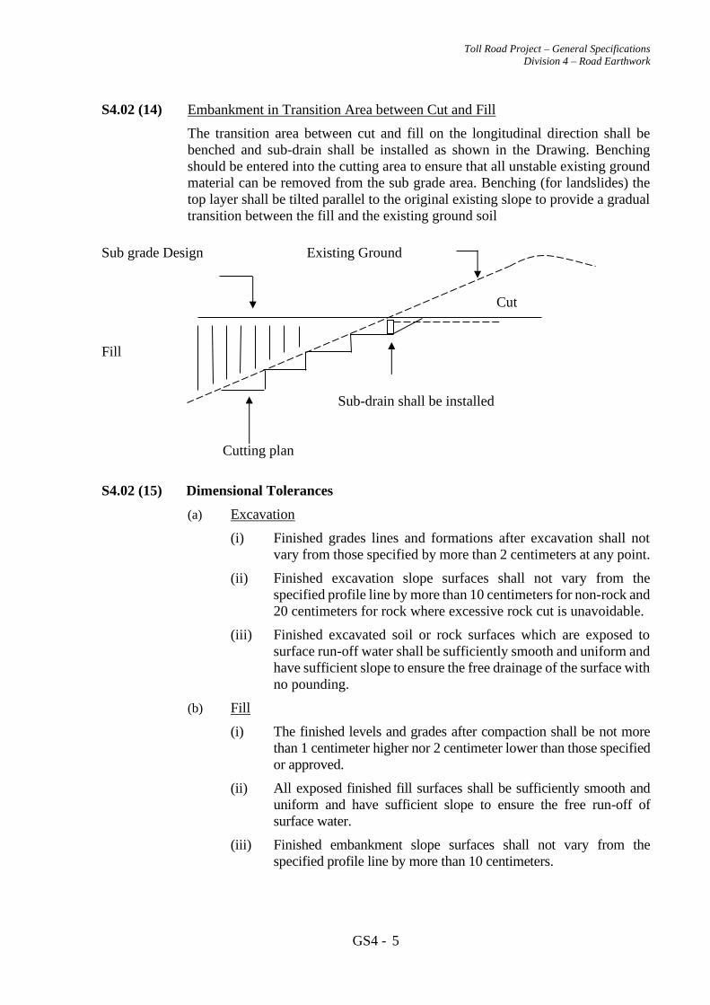
Toll Road Project – General Specifications
Division 4 – Road Earthwork
GS4 - 5
S4.02 (14) Embankment in Transition Area between Cut and Fill
The transition area between cut and fill on the longitudinal direction shall be
benched and sub-drain shall be installed as shown in the Drawing. Benching
should be entered into the cutting area to ensure that all unstable existing ground
material can be removed from the sub grade area. Benching (for landslides) the
top layer shall be tilted parallel to the original existing slope to provide a gradual
transition between the fill and the existing ground soil
Sub grade Design Existing Ground
Cut
Fill
Sub-drain shall be installed
Cutting plan
S4.02 (15) Dimensional Tolerances
(a) Excavation
(i) Finished grades lines and formations after excavation shall not
vary from those specified by more than 2 centimeters at any point.
(ii) Finished excavation slope surfaces shall not vary from the
specified profile line by more than 10 centimeters for non-rock and
20 centimeters for rock where excessive rock cut is unavoidable.
(iii) Finished excavated soil or rock surfaces which are exposed to
surface run-off water shall be sufficiently smooth and uniform and
have sufficient slope to ensure the free drainage of the surface with
no pounding.
(b) Fill
(i) The finished levels and grades after compaction shall be not more
than 1 centimeter higher nor 2 centimeter lower than those specified
or approved.
(ii) All exposed finished fill surfaces shall be sufficiently smooth and
uniform and have sufficient slope to ensure the free run-off of
surface water.
(iii) Finished embankment slope surfaces shall not vary from the
specified profile line by more than 10 centimeters.
Toll Road Project – General Specifications
Division 4 – Road Earthwork
GS4 - 6
S4.02 (16) Weather Limitation
Fill shall not be placed, spread or compacted while rain is falling, and no compaction
shall be carried out after rain or otherwise when the moisture content of the material
falls outside the range specified in Sub-clause S4.06.(3).(e). All uncompacted fill
surfaces shall be scarified and compacted sufficiently to maintaince the moisture
content and shall be covered with plastic or tarpauline sheets at the end of daily
working time as well as the rain will fall.
S4.03 Common Excavation, Soft Rock Excavation, Excavation of Existing
Granular Pavement, Excavation of Existing Cement Concrete Pavement
S4.03 (1) Description
Common Excavation shall consist of all excavation within the limits of the right-
of-way which is not classified as soft rock excavation, rock excavation, structure
excavation, borrow excavation, excavation on existing asphalt pavement,
granular pavement excavation, and concrete pavement excavation, the removal,
handling and proper utilization or disposal of all excavated materials and shaping
of excavation and preparation of exposed surface of excavation for the entire
length of the roadway and approaches, in accordance with these Specifications
and the lines, levels, grades, dimensions and cross-sections shown on the
Drawings and as required by the Engineer.
Soft Rock Excavation shall include excavations on conglomerate or soft/
weathered rock which have a uniaxial compressive strength of 0.6 – 12.5 MPa in
accordance with ASTM D7012-14e1 or SNI 2825:2008.
Excavation of existing Granular Pavement includes excavations on existing
granular pavements and disposal of unused granular pavement as shown in the
Drawings or as directed by the Engineer.
Excavation of existing Cement Concrete Pavement includes excavation on
existing cement concrete pavement and disposal of unused cement concrete
pavement as shown in the Drawings or as directed by the Engineer.
S4.03 (2) Applicable Provisions
The applicable provisions of Clause S4.02 shall be read into and become part of
this Clause S4.03 "Common Excavation".
S4.03 (3) Execution of the works
Excavation shall be carried out according to the grade, line, and elevation
specified in the Drawings or as directed by the Engineer and shall involve the
disposal of all materials in any kind that were found, including soil, stone, brick,
concrete, masonry and old pavement materials, which do not used for permanent
works.
S4.03 (4) Use of Excavated Material
Suitable material excavated under this Clause shall be incorporated in the
permanent works in accordance with Clause S4.06, or excavated material shall,
Toll Road Project – General Specifications
Division 4 – Road Earthwork
GS4 - 7
if directed by the Engineer, be considered as Waste and dealt with in accordance
with Clause S4.07.
S4.03 (5) Removal and Disposal of Unsuitable Material
When so directed in writing by the Engineer, the Contractor shall remove material
unsuitable for use in the embankment and shall dispose of it as provided in Clause
S4.07.
Where the excavation reveals a combination of suitable and unsuitable materials
the Contractor shall unless otherwise agreed by the Engineer, carry out the
excavation in such a manner that the suitable materials are excavated separately
for use in the Works without contamination by the unsuitable materials.
When unsuitable material below sub-grade level in cut or below embankment
foundation level is ordered to be removed, the soil left in place after the removal
of the unsuitable material shall be compacted, to a depth of 20 cm, to a density of
100 percent of the maximum dry density determined according to AASHTO T99-
15 or SNI 1742:2008. Payment for such compaction shall be included in the unit
rate for Common Excavation.
S4.03 (6) Method of Measurement
The quantity to be paid for shall be the number of cubic meters of material
acceptably excavated as hereinbefore prescribed. The material shall be measured
in the original position in the natural ground after Site Clearing (Division 2) and
Demolition (Division 3).
The volume of material excavated for temporary diversion roads constructed by
the Contractor that fall outside the width affected by the excavation of the road
will not be measured for direct payment, since this work is covered by the price
tendered for the provisions of Clause S.1.19 " Traffic Management and Safety".
The measurement shall include the unavoidable over breakage due to slides when
not attributable to carelessness of the Contractor.
S4.03 (7) Basis of Payment
When the Engineer orders the use of material obtained from Common Excavation
for the execution of other works (such as stone masonry or aggregates for
pavement or concrete) the Common Excavation shall not be paid for separately
but shall be considered as a subsidiary obligation of the Contractor covered under
the unit rates paid for the other works in which the material is employed.
The quantity of Common Excavation measured as specified above shall be paid
for at the Contract unit price per cubic meter listed in the Bill of Quantities. The
price and payment shall be full compensation for all work involved in performing
excavation including excavating, removal, haulage, placing and compaction or
satisfactory disposal of roadway excavation, for shaping and completion of all
surfaces and for furnishing all labor, materials, tools, equipment and incidentals
to complete the work as shown on the Drawings and as specified in these
Specifications and as directed by the Engineer.
Toll Road Project – General Specifications
Division 4 – Road Earthwork
GS4 - 8
Pay Item No. and Name Unit of Measurement
4.03 (1) Common Excavation for Embankment Cubic Meter
4.03 (2) Common Excavation for Filling Material Cubic Meter
in Median
4.03 (3) Common Excavation as Waste Material Cubic Meter
4.03 (4) Soft Rock Excavation for Embankment Cubic Meter
4.03 (5) Soft Rock Excavation as Waste Material Cubic Meter
4.03 (6) Excavation on Existing Granular Pavement Cubic Meter
4.03 (7) Excavation on Existing Cement Concrete Cubic Meter
Pavement
S4.04 Rock Excavation
S4.04 (1) Description
Rock excavation shall consist of the excavation of boulders which have an
uniaxial compressive strength of more than 12.5 MPa in accordance with ASTM
D7012-14e1 or SNI 2825:2008 with l cubic meter in volume or greater and all
rock or other hard material which, in the opinion of the Engineer, it is not practical
to excavate without drilling and blasting. It is not including material which, in the
opinion of Engineer, can be loosened by a single tine hydraulic ripper drawn by
a tractor unit with a minimum weight of 15 tons and a net horsepower rating of
180 HP
S4.04 (2) Applicable Provisions
The applicable provisions of Clause S4.02 shall be read into and become part of
this Clause.
S4.04 (3) Explosives
(a) The Contractor shall provide suitable buildings or warehouses in
appropriate positions for the storage of explosives, which shall be stored
in the manner and quantity approved of by the Engineer. Such storage
places shall be accessible only to authorized personnel. They shall be
properly marked, and all doors or accesses there to shall be provided with
secure locks and all necessary means of preventing access by
unauthorized persons.
(b) The Contractor shall be responsible for the prevention of any unauthorized
issue or improper use of any explosives. The handling of explosives shall
be entrusted only to experienced and responsible men, shall be to the
satisfaction of the Engineer, and in conformity with the statutory
regulations.
(c) All drilling and blasting shall be done in such a manner as to bring the
excavation as close as possible to the required grade lines, and to disturb
as little as possible the material to be left in place. Blasting by means of
drill holes, tunnels or any other similar methods shall be performed at the
Toll Road Project – General Specifications
Division 4 – Road Earthwork
GS4 - 9
entire risk and responsibility of the Contractor, who shall have no claim
to payment for any extra work occasioned by breakage outside the
approved or revised cross sections.
(c) The greatest care shall be taken by the Contractor during all blasting
operations to ensure that no injury be done to persons or damage to
property or the finished work. Shots shall be properly loaded and capped,
and only appropriate charges shall be used in each hole. A register of all
explosives used, showing locations and amounts, shall be kept by the
Contractor for checking by the Engineer.
(e) Where directed by the Engineer, the Contractor shall provide heavy mesh
blasting mats for protection of persons, property and the Works during the
excavation. If found necessary, blasting shall be restricted to times
prescribed by the Engineer.
(f) The Engineer may prohibit blasting and order the rock to be excavated by
other means, if, in his opinion, it would be dangerous to persons or
adjacent structures, or is being carried out in a reckless manner. If traffic
on the road has to be interrupted, the Contractor shall obtain approval of
his schedule for such interruption from the proper authorities and shall
satisfy the Engineer that he has obtained it.
S4.04 (4) Subgrade Level in Rock Cut
Rock cut for the roadway shall be excavated to the sub grade levels shown on the
drawings and provided in Sub-clause S4.02 (3) and S7.01 (2).
S4.04 (5) Method of Measurement
The quantities to be paid for shall be the number of cubic meters of material
acceptably excavated as herein before prescribed. The material shall be measured
in the original position in the existing ground after the operation of clearing and
grubbing, demolition and common excavation and excavation profile plan.
S4.04 (6) Basis of Payment
Rock Excavation, including work defined as Rock Excavation in Clause S4.04
and elsewhere in these Specifications, shall be paid for separately only in the
following cases:
- when the material resulting from the Rock Excavation is declared in
writing by the Engineer to be unsuitable for use for embankment in the
project;
- when the material resulting from the Rock Excavation is surplus to the
amount required for the construction of embankment, provided, however,
it is not material rendered surplus by reason of the Contractors having
opened borrow pits solely for his own convenience as provided in Sub-
clause S4.05 (4).
- where the Engineer orders the use of material obtained from Rock
Excavation for the execution of other works (such as stone masonry or
aggregates for pavement or concrete) the Rock Excavation shall not be
Toll Road Project – General Specifications
Division 4 – Road Earthwork
GS4 - 10
paid for separately but shall be considered as a subsidiary obligation of
the Contractor covered under the Contract Price paid for the other works
in which the material is employed.
The quantities, determined as provided above, whatever the haulage distance of
the excavated material shall be paid for at the Contract Price per unit of
measurement for the Pay Item listed below, which price and payment shall be full
compensation for all the costs indicated in Sub-clause S1.34 (1), and all other
costs necessary or usual for the proper completion of the work prescribed in this
Clause.
Pay Item No. and Name Unit of Measurement
4.04 Rock Excavation Cubic Meter
S4.05 Borrow Material
S4.05 (1) Description
This work shall consist of the clearing and stripping of borrow pits, the excavating
and hauling spreading and compacting of materials obtained from approved
sources for constructing embankment, subgrade and other parts of the work as
required by the Contract or by the Engineer.
S4.05 (2) Applicable Provisions
The applicable provisions of Clause S4.02 shall be read into and become part of
this Clause.
S4.05 (3) Materials
Borrow material shall be selected to meet the requirements and conditions of the
particular fill or embankment for which it is to be used. Materials shall be free
from detrimental quantities of organic material such as leaves, grass, roots and
sewage.
Common Borrow Materials will also be selected preferentially to exclude the use
of highly plastic clay soils, classified as A-7 by AASHTO specification M145-
91(2012) or SNI 03-6797-2002 or as CH on the Unified or Casagrande Soil
Classification System. Where the use of highly plastic soils cannot reasonably be
avoided, such material shall be used only in the bottom portion of embankments
or in backfill not required to possess good bearing or shear strength, but not in the
subgrade unless it is possible to obtain the minimum design CBR value required
when compacted as specified in Sub-clause S7.01.(2).(c). Highly expansive soils
having an Activity Value greater than 1.25, or a degree of expansion classified by
AASHTO T258-81(2013) or SNI 03-6795-2002 as “Very High” or “Extra High”,
shall not be used as embankment fill material. The Activity Value shall be
measured as the ratio Plasticity Index (AASHTO T90-15 or SNI 1966:2008) /
Percent Clay Sizes (AASHTO T89-13 or SNI 1967:2008).
Selected Borrow Material to be used in locations or for purposes where these
materials have been specified or otherwise approved in writing by the Engineer,
it shall consist of soil or rock material, when tested in accordance with AASHTO
Toll Road Project – General Specifications
Division 4 – Road Earthwork
GS4 - 11
T193-13 or SNI 1744:2012 have a CBR value of at least 10% (ten percent) after
four days soaking when compacted to 100% of the maximum dry density as
determined according to AASHTO T99-15 or SNI 1742:2008.
S4.05 (4) Use of Borrow Pits
Borrow material shall be obtained from approved private sources. Permission to
open borrow pits, including advice as to suitability, shall first be obtained in
writing from the Engineer. Nevertheless, the total amount of surplus material
from excavation under Divisions 4 and 5 of these Specifications, after deduction
of the material declared unsuitable by the Engineer, shall be considered to be
available for use in the embankment, and any borrow material resulting from the
Contractor having used pit borrow in place of surplus material shall not be
measured for payment under these Specifications.
The distance of borrow pits from the work site shall not be grounds for extra
payment or revision of the Contract Price.
Where suitable material for embankments is available adjacent to the
embankment the Engineer may order the excavation of drainage channels wider
and deeper than normally required in which case such excavation will be
measured and included in cross-sections as Common Excavation.
S4.05 (5) Placing and Compaction
Suitable borrow material shall be incorporated in the permanent works in
accordance with the requirements of Clause S4.06.
S4.05 (6) Payment to Others
The consent of the landowner and tenant for the digging and taking of material
for borrow shall be secured by the Contractor, who shall, if required, pay for such
concession. The pit shall be left in a condition acceptable to the owner and to
the Engineer.
Any fees payable for permission to cut or haul the borrow material shall be at the
Contractor's expense and shall be deemed to be included in the unit price for this
pay item.
S4.05 (7) Method of Measurement
The quantity of borrow material to be measured and paid for shall be the balance
of the earthworks remaining after applying to the volume of embankment the
quantity of all suitable material excavated within the site. The volume of
embankment to be measured will be the net volume, after Site Clearing, of
required and accepted embankment, actually constructed and completed to the
lines, grades, and cross-sections shown on the Drawings and as directed by the
Engineer. To calculate the balance of the earthworks it shall be assumed that the
shrinkage factor for all suitable material excavated within the site is 0.90. This
factor is fixed for all such material and claims on the basis of a variation to this
factor will be rejected. No allowance will be made for shrinkage in the borrow
material between cutting at the borrow pit and incorporation in the permanent
work.
Toll Road Project – General Specifications
Division 4 – Road Earthwork
GS4 - 12
If the borrow material to be constructed where significant consolidation of the
original ground is anticipated, the borrow material will be measured for payment
by the installation of settlement plates and rods which shall be placed and
surveyed jointly by the Engineer and Contractor. The borrow material quantities
may then be determined on the basis of ground levels after settlement finished. If
documented settlement records have not been properly maintained, measurement
shall be based on original ground levels before settlement.
S4.05 (8) Basis of Payment
This work measured as provided above shall be paid for at the unit rate listed
below, which price and payment shall be full compensation for the cost of
searching for and finding borrow pits, for acquiring the right to occupy the sites
and extract materials, for the cost of any negotiation right of access, for the cost
of establishing and maintaining access, for any fees, licenses, or royalties in
connection with borrow pits, for clearing grubbing sloping draining and cleaning
up of pits, for furnishing excavating hauling placing and compacting material
from borrow pits and for providing all labor, equipment, tools and incidentals
necessary to the works.
Pay Item No. and Name Unit of Measurement
4.05 (1) Common Borrow Material Cubic Meter
4.05 (2) Selected Borrow Material Cubic Meter
S4.06 Formation of Embankment and Areas of Fill
S4.06 (1) Description
This work shall consist of the construction of embankment and backfill not
specified elsewhere by furnishing, placing, compacting and shaping suitable
material of acceptable quality obtained from approved sources in accordance with
these Specifications, and to the lines, levels, grades, dimensions and cross-
sections shown on the Drawings and as required by the Engineer.
S4.06 (2) Sources and Use of Material
Material for embankment shall consist of suitable material approved by the
Engineer, excavated under any other Clause of this Specification. Borrow
material, however, shall only be used under the provisions of Sub-clause
S4.05.(5). Surplus or suitable material shall be disposed of as provided in Sub-
clause S4.02.(8) and Clause S4.07.
S4.06 (3) Construction
(a) Compaction of Foundation of Embankment
When ordered by the Engineer, the Contractor shall excavate turf, decayed
vegetable matter, or other unsuitable matter to such depth as the Engineer
may require. This work shall be considered as Site Clearing or Common
Excavation and paid for as provided in Clause S2.01 or S4.03.
Toll Road Project – General Specifications
Division 4 – Road Earthwork
GS4 - 13
Before beginning the construction of Embankment, the Contractor shall
fill all holes, etc. within all the areas which have been cleared and grubbed,
and such areas shall be suitably leveled at the level resulting after the
removal of the topsoil. Fill material shall be approved by the Engineer.
This work shall not be paid for directly, but shall be considered a
subsidiary obligation of the Contractor covered by the Contract price for
item 2.01.
Before the construction of the embankment is begun, the Engineer may
order the compaction of the cleared surface or that resulting after removal
of the topsoil, in which case the density after compaction shall conform to
the requirements of Sub-clause S4.06 (3) (d).
(b) Placing and Compaction
(i) Material for embankment, obtained and approved as provided
above, shall be placed in horizontal layers of uniform thickness
over a width determined by the Engineer and in conformity with
the lines, grades, sections, and dimensions shown on the
Drawings. The layer of loose material other than rock shall be
not more than 20 cm thick, unless the compacting equipment used
is capable of compacting a depth greater than 20 cm to a uniform
density through the full depth which is acceptable to the Engineer,
in which case the Contractor may place and compact the material
other than rock, in layers of thickness approved by the Engineer.
After adjustment of the moisture content to that required obtaining
maximum density, the loose material shall be compacted to the
required density.
(ii) If the material deposited as fill subsequently reaches a condition
such that it cannot be compacted in accordance with the
requirements of the Contract, the Contractor shall at his own
expense either:
(1) make good by removing the material either to tip or
elsewhere until it is in a suitable physical condition for re-
use and replace it with suitable material; or
(2) make good the material by mechanical or chemical means;
or
(3) cease work in the material until its physical condition is
again such that it can be compacted as described in the
Contract.
(iii) Where embankments are located on hillsides, or where new fill is
to be compacted against existing embankments or where fill is
constructed on half width at a time, the original slope of the
hillside, of the old or of the first half width fill, shall be cut into a
distance sufficient to accommodate the width of the compacting
equipment as the new fill is placed in horizontal layers, and this
material cut shall be incorporated and compacted with the new fill.
Toll Road Project – General Specifications
Division 4 – Road Earthwork
GS4 - 14
In the measurement of the work no allowance will be made for the
volumes of material cut from the hillside or from the old or from
the first half width fill to accommodate the compacting equipment,
but will be calculated only on the net volume of fill placed against
the original hillside, the old embankment or the first half width fill.
(iv) To avoid interference with the construction of bridge abutments,
wing walls and box culverts, the Contractor shall, at points to be
determined by the Engineer, suspend work on embankment
forming the approaches to any such structure until such time as the
construction of the latter is sufficiently advanced to permit the
completion of the approaches without the risk of interference or
damage to the bridge works. The cost of suspension of work shall
be included in the Contract unit price for "Common Excavation",
and "Borrow Material".
(v) Material for embankment at points inaccessible to normal
compacting equipment shall be placed in horizontal layers of loose
material not more than 10 cm thick and thoroughly compacted by
the use of mechanical hammers.
(vi) In carrying embankments up to or over culverts and where
required in the Contract up to or over bridges, the Contractor shall
bring the embankments up equally on both sides. If conditions
require placing backfill or embankment appreciably higher on one
side than on the opposite side, the additional material on the higher
side shall not be placed until permission shall have been given by
the Engineer and preferably not until the structure has been in
place 14 days, and tests made by the laboratory under the
supervision of the Engineer establish that the structure has attained
sufficient strength to withstand any pressure created by the
methods used and materials placed without damage or strain
beyond a safe factor.
Where special materials for filling adjacent to structures are
described in the Contract, filling may proceed over widths less
than the full width of the embankment and in steps not exceeding
the depth of one layer above the adjoining area of fill.
In rock fill embankments the materials shall be carefully packed
for such distance from the structure as is described in the Contract.
Special care shall be taken to prevent any wedging action against
the structure and all slopes bounding or within the areas to be filled
shall be benched or serrated to prevent wedge action. The placing
of embankment and the benching of slopes shall continue in such
a manner that at all times there shall be a horizontal berm of
thoroughly compacted material for a distance at least equal to the
height of the abutment or wall to be backfilled against except in so
far as undisturbed material intrudes upon the areas.
(vii) on certain embankment lengths surcharge material will be required to induce settlement/consolidation to the existing grade level being
Toll Road Project – General Specifications
Division 4 – Road Earthwork
GS4 - 15
overlaid with embankment. This may be common fill and / or concrete blocks and / or any acceptable alternative proposal made by the Contractor and will be dependent on the site conditions at the time of fill operations and as agreed with and / or directed by the Engineer.
(c) Compaction Trials
Before starting the formation of the embankment, the Contractor shall
construct trial lengths for compacting as directed by the Engineer. The
soils used in the trials shall be those encountered along the roadway and
the compacting equipment shall be the same equipment that the
Contractor will use for the main work accepted by the Engineer.
The object of these trials will be to determine the optimum moisture
content and the relationship between the number of passes of compacting
equipment and density obtained for the soil types under trial. No separate
payment will be made for this work, which will be regarded as a
subsidiary obligation of the Contractor covered under the other Clauses of
this Specification.
(d) Required Density
The required densities to which embankment layers shall be compacted
are as follows:
(i) Layers more than 30 cm below subgrade level shall be compacted
to 95 percent of the maximum dry density determined according
to AASHTO T99-15 or SNI 1742:2008. For all soils, except rock
fill materials, containing more than 10 percent oversize material
retained on a 19.0 mm (¾ inch) sieve, the maximum dry density
thus obtained shall be adjusted for such oversize material as
directed by the Engineer. Subsequent layers shall not be placed
and compacted unless the previous layer has been properly
compacted and accepted by the Engineer.
(ii) Layers 30 cm or less below subgrade level shall be compacted to
100 percent of the maximum dry density determined according to
AASHTO T99-15 or SNI 1742:2008.
(e) Moisture Content
Embankment material that does not contain sufficient moisture to obtain
the required compaction shall be given additional moisture by means of
approved sprinklers and mixing. Material containing more than the
amount of moisture necessary to obtain the required compaction may not,
without approval of the Engineer, be incorporated in the embankment
until it has been sufficiently dried out. The drying of wet material may
be expedited only by methods approved by the Engineer.
The compaction of the embankment shall be carried out at the optimum
moisture content. In forming the embankment, the Contractor shall take
steps to ensure that the work can be drained free of rain-water, and he shall
make due allowance in the height and width of the work for swelling or
shrinkage.
Toll Road Project – General Specifications
Division 4 – Road Earthwork
GS4 - 16
(f) Rock Fill
No rock fill shall be placed until after the Contractor has discussed his
proposals for the work of cut and fill with the Engineer and secured the
latter's approval. In order to provide a suitable grade level, material for
covering the rock fill shall be reserved from the excavation of cut.
Should such material be available and not be so reserved by the
Contractor, so that borrow material has to be used for forming the grade
level, such borrow shall be supplied and placed without extra payment to
the Contractor.
Rock fill shall be placed in loose layers not to exceed 60 cm in thickness
and compacted as herein provided. The top of this fill shall be not less
than 20 cm below the required finished subgrade, and the interstices shall
be thoroughly filled with clean small spalls, shale, gravel or similar
approved material and thoroughly compacted to the satisfaction of the
Engineer.
Rock in fill shall be considered as rock only when the earth or other finer
material, when uniformly distributed throughout the mass, is considerably
less than sufficient to fill the voids so that the rock particles shall be in
intimate contact and not separated by earth or similar materials.
Otherwise, the fill material shall be handled and considered as earth fill to
be placed and compacted as specified in Clause S4.06.
Where rock is to be incorporated in fill or portions of fill, composed
largely of earth friable material, the rock shall be reduced to a maximum
size not exceeding 75 percent of the thickness of the layer being placed.
A sufficient cover of earth over rock fill shall be used to produce a uniform
grade level.
(g) Mixed Material in Fill
When materials of widely divergent characteristics, such as clay and chalk
or sand, drawn from different sources, are to be used in the embankment,
they shall be deposited in alternate layers over the full width of the
embankment to depth approved by the Engineer.
When material used for fill is of variable quality, the Contractor shall
schedule and execute his works so that the material designated as better
quality by the Engineer, is used in the upper layers of the fill.
Rock, clay or other material shall be broken up, and no accumulation of
lumps or boulders at the toe of the embankment will be permitted.
(h) Leveling of Existing Embankment
Before fill is placed and compacted on an existing roadway, the existing
embankment and/or pavement may be leveled by cutting, rooting, or
scarifying with approved mechanical means to a level to be determined
by the Engineer. The earth, old asphalt, or other material obtained as a
result of this operation will be declared by the Engineer to be either
suitable or unsuitable for use in the embankment. In the first case it shall
be used in the adjacent embankment as directed by the Engineer, subject
Toll Road Project – General Specifications
Division 4 – Road Earthwork
GS4 - 17
to the provisions in Clause S4.03 "Common Excavation". In the second
case the material shall be disposed of as provided in Clause S4.07
"Waste".
(i) Finishing Roadbed
(i) Final Grade Level - When an embankment requires the addition of
material to a depth of not more than 30 cm to bring it up to the
required grade level, the top of the embankment shall be
thoroughly scarified and re-compacted before the additional
material is placed.
The final grade level, to the profile indicated and adjusted for
super elevation where required, shall conform to the provisions of
Sub-clause S4.02 (3) of these Specifications, and to the tolerances
given in the Special Specifications. Prior to adding any material
to raise the level of any low spots, the existing surface shall be
scarified.
(ii) Slopes - Side slopes shall be neatly trimmed to the lines and slopes
shown on the Drawings as directed by the Engineer, and finished
work shall be left in a neat and acceptable condition. In order to
achieve uniform slope density with the entire embankment, when
carrying out compaction layers the Contractor exceeds the width
of the embankment width which at the end of compaction the outer
edge is neatly cut according to the requested slope line. Thickness
and lack of slope not justified resulting from the patching of the
slope.
(iii) Stability - The Contractor shall be responsible for the stability of
all embankments and shall replace any portions that have been
damaged or displaced due, in the opinion of the Engineer, to
carelessness or neglect on the part of the Contractor, or to such
natural causes as storms. The Contractor will not be responsible
for damage caused by unavoidable movements of the natural
ground upon which the embankment is made. During
construction the roadway shall be kept shaped to drain at all times.
When unsuitable material has been placed in the embankment by
the Contractor, he shall remove it and replace it using suitable
material, and without extra payment there for.
S4.06 (4) Method of Measurement
The performance of the work above shall be covered by the Contract Prices of the
appropriate pay items under which the fill material is obtained and the work of
this Clause S4.06 shall not be measured for direct payment.
S4.06 (5) Basis of Payment
Performance of this work under the Contract is not payable directly but shall be
considered as a subsidiary obligation of the Contractor covered under the Contract
Prices for performance of work under Clause S4.03 "Common Excavation",
Toll Road Project – General Specifications
Division 4 – Road Earthwork
GS4 - 18
Clause S4.05 “Borrow Material", Division 5 of these Specifications and Division
6 of these Specifications.
S4.06 (6) With regards to surcharge material and/or concrete block surcharge and/or whatever acceptable proposal from the Contractor with regards to method of surcharge in S4.06 (3).(b), it shall be deemed to be included in the earthwork rates, covering for removal as well as initial placing with all that details.
S4.07 Waste
S4.07 (1) Description
This item shall consist of excavating, ripping, loading, hauling and spreading in
waste areas, soil material designated as waste.
S4.07 (2) Waste Material
Material shall be known as "Waste" in the following cases:
(a) When the material resulting from the excavation made for the construction
of the road is declared in writing by the Engineer to be unsuitable for use
in the embankment or other work.
Normally, highly organic clays and silts, peat, soil containing large
amounts of roots, grass and other vegetable matter, domestic or industrial
waste, are to be unsuitable. Materials that are soft or unsuitable merely
because they are too wet or dry are not to be classified as unsuitable unless
otherwise directed by the Engineer.
(b) When the material resulting from the excavation made for the construction
of the road is surplus to the amount required for the construction of the
embankment, provided, however, it is not material rendered surplus by
reason of the Contractor having opened borrow pits solely for his own
convenience as provided in Clause S4.04 of these Specifications.
The material proposed for wasting shall not be wasted until approved or
directed in writing by the Engineer after guided by the Employer. If the
material is not wasted, then the Employer shall provide the storage
locations.
S4.07 (3) Work Requirements
Unsuitable material shall be excavated below sub grade level in cut and below
embankment foundation level to the depth shown on the Drawings or directed by
the Engineer. Where unsuitable material is excavated below the normal sub
grade level or below embankment foundation or for benching under
embankments, the excavation shall be back filled with material and in a manner
that conforms to Clause S4.06.
Waste shall be removed and disposed of in waste areas provided by the Contractor
in such manner as to present a neat appearance and not to obstruct drainage to any
highway nor to cause injury to highway works or property. If it becomes
necessary for the Contractor to locate or relocate any waste areas, they shall be
approved by the Engineer prior to spreading any waste.
Toll Road Project – General Specifications
Division 4 – Road Earthwork
GS4 - 19
Waste areas shall be left in a smooth, neat and drainable condition, as directed by
the Engineer, and all waste material shall be placed in such manner that adjacent
property will not be damaged or endangered.
Soil slopes shall not be steeper than 2:1, unless otherwise directed by the
Engineer.
Performance of this work shall not be paid for under this Clause but shall be
considered as a subsidiary obligation of the Contractor covered under the unit
rates of the appropriate pay item for excavation.
S4.08 Areas of Special Fill
S4.08 (1) Description
The work under this item shall consist of supplying and placing free-draining
granular material under water in swampy areas or filling in areas where there are
deep beds of unsuitable material and full depth removal is not possible.
The Backfill for reinforced earth wall construction will also satisfy this Clause of
the Specification, but in addition, the backfill material will satisfy the
requirements of the specialist contractor and be subject to the approval of the
Engineer. The backfill material shall not comprise pit-run river gravel, unless
screened and crushed to give a 20 mm maximum size. A granular, crushed rock-
based course material, or well graded natural gravelly sand, or similar material,
is recommended.
Swampy areas are understood to be those areas where the embankment is to be
constructed across low ground permanently or seasonally under a level of water
or subject to the action of water that, in the opinion of the Engineer, given the
topography of the area, cannot be drained and dried out with the methods
envisaged in these Specifications.
S4.08 (2) Applicable Provisions
The applicable provisions of Clauses S4.02 and S4.06 shall be read into and
become part of this Clause.
S4.08 (3) Construction
Before carrying out the work described in this Clause, all work under Sub-clauses
S2.01 (2) (b), S4.02 (12) and S4.03 (4), shall be completed to the satisfaction of
the Engineer.
The filling shall be executed to a height not less than 50 cm above existing ground
level or not less than 50 cm above the water level at that time, with material
coming from common excavation, borrow material or free-draining material as
specified below.
Free draining material:
Free draining material, on swampy area, and for situations where spreading in
saturated or flood conditions cannot be avoided, shall be rock, sand or gravel or
other clean grained material with a maximum Plasticity Index of 6% (six percent).
Toll Road Project – General Specifications
Division 4 – Road Earthwork
GS4 - 20
The material used shall be approved beforehand by the Engineer.
The selected material shall be placed in conformity with the elevation and cross-
sections shown on the Drawings or ordered by the Engineer, and in any case in
such a way that:
(a) After compaction and proof rolling, it is not less than 50 cm above the
water level at that time; and/or
(b) A support grade is formed for the construction, if required, of an
embankment in accordance with Clause S4.06, up to the elevation of the
sub grade.
For this purpose, the selected material shall be placed according to the profiles
shown on the Drawings or ordered by the Engineer, with suitable equipment and
if necessary by dumping successive loads in a uniformly distributed layer of a
thickness not greater than necessary to support the hauling equipment while
placing subsequent layers. Material placed outside the profiles indicated will be
not measured for payment.
Compaction shall begin on the material in accordance with the Engineer's
instructions and shall be executed with suitable equipment. Losses of elevation
due to settling of the embankment shall be compensated, either by laying the loose
material up to elevations higher than those indicated, or by adding other material
during compaction.
Compaction shall continue until the Engineer has ascertained that settlement of
the top grade has ceased and that it no longer shows deformation under rollers or
site equipment.
On completion of the work as described in this Clause, filling shall continue in
accordance with Clause S4.06.
S4.08 (4) Method of Measurement
The material placed and compacted under this Clause will be calculated in cubic
meters measured in the trucks before unloading. For each truckload of material
supplied at the place of loading, the Contractor shall deliver to the Engineer or
his representative present at the unloading a numbered note, duly signed by both
parties, showing the registration number of the truck and the volume of the
material transported in it then be determined on the basis of aggregated quantity
of material supplied, as measured and recorded by the Engineer, after the material
has been leveled in the truck body according to a horizontal plane parallel to the
edges of the sides of the truck.
Each day details of each note with the registration number of the truck and the
load transported shall be entered in a special register kept by the Engineer. The
material supplied will be measured after it has been leveled in the truck body
according to a horizontal plane parallel to the edges of the sides of the truck; no
other method of measurement will be allowed.
S4.08 (5) Basis of Payment
The quantities, determined as provided above, shall be paid for at the Contract
unit price for the pay items as listed below. The prices and payment shall be full
Toll Road Project – General Specifications
Division 4 – Road Earthwork
GS4 - 21
compensation for all costs including furnishing, hauling, placing and for all
materials, labor, tools, equipment and incidentals necessary to complete the works
as described in this Clause.
Pay Item No. and Name Unit of Measurement
4.08 Free-Draining Material Cubic Meter
S4.09 Granular Backfill
S4.09 (1) Description
This item shall consist of furnishing, placing and compacting granular backfill
adjacent to structures. The area in which this material is to be placed is the
"Influence Zone" of certain structures and this will be shown on the Drawings.
S4.09 (2) Material
The material shall be well graded crushed or uncrushed gravel, stone, rock fill or
natural sand or a well-mixed combination of any of these. Grading requirements
for the material are as follows:
Maximum size : 10 cm
Passing 4.75 mm sieve : 25% to 90%
Passing 0.075 mm sieve : 0% to 10%
Plasticity Index : 10 max.
S4.09 (3) Construction
The granular backfill shall be placed in layers not exceeding 15 cm and
compacted to a density of 95% of the maximum dry density determined according
to AASHTO T180-15 or SNI 1743:2008.
S4.09 (4) Method of Measurement
The quantity of granular backfill to be measured and paid for will be the number
of cubic meters of suitable material supplied and compacted to the Engineer's
satisfaction and in accordance with this Specification. This material is required
to be placed when filling within the influence zone of certain structures and any
material placed outside the specified zone will not be measured for payment.
Any existing material within the influence zone which is removed because of the
Contractor's method of working shall be replaced by granular backfill at the
Contractor's expense. Where excavation within the influence zone is instructed
under any Clause of these Specifications, then the backfilling will be carried out
with granular backfill and the work will be measured for payment under this
Clause.
S4.09 (5) Basis of Payment
The accepted quantities of granular backfill, measured as provided above, will be
paid for at the Contract unit price for the pay item as below. The price and
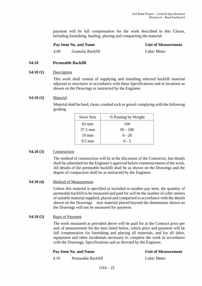
Toll Road Project – General Specifications
Division 4 – Road Earthwork
GS4 - 22
payment will be full compensation for the work described in this Clause,
including furnishing, hauling, placing and compacting the material.
Pay Item No. and Name Unit of Measurement
4.09 Granular Backfill Cubic Meter
S4.10 Permeable Backfill
S4.10 (1) Description
This work shall consist of supplying and installing selected backfill material
adjacent to structures in accordance with these Specifications and in locations as
shown on the Drawings or instructed by the Engineer.
S4.10 (2) Material
Material shall be hard, clean, crushed rock or gravel complying with the following
grading.
Sieve Size % Passing by Weight
63 mm
37.5 mm
19 mm
9.5 mm
100
85 - 100
0 - 20
0 - 5
S4.10 (3) Construction
The method of construction will be at the discretion of the Contractor, but details
shall be submitted for the Engineer's approval before commencement of the work.
All details of the permeable backfill shall be as shown on the Drawings and the
degree of compaction shall be as instructed by the Engineer.
S4.10 (4) Method of Measurement
Unless this material is specified as included in another pay item, the quantity of
permeable backfill to be measured and paid for will be the number of cubic meters
of suitable material supplied, placed and compacted in accordance with the details
shown on the Drawings. Any material placed beyond the dimensions shown on
the Drawings will not be measured for payment.
S4.10 (5) Basis of Payment
The work measured as provided above will be paid for at the Contract price per
unit of measurement for the item listed below, which price and payment will be
full compensation for furnishing and placing all materials, and for all labor,
equipment and other incidentals necessary to complete the work in accordance
with the Drawings, Specifications and as directed by the Engineer.
Pay Item No. and Name Unit of Measurement
4.10 Permeable Backfill Cubic Meter
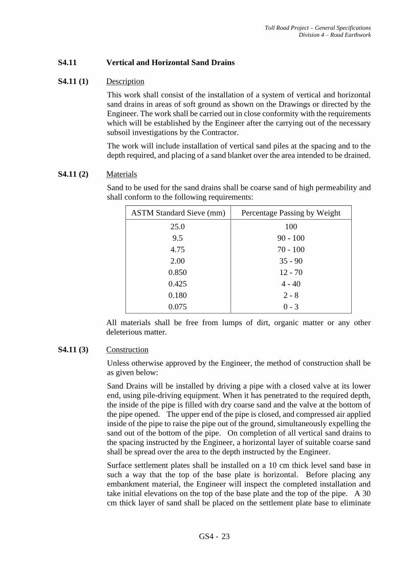
Toll Road Project – General Specifications
Division 4 – Road Earthwork
GS4 - 23
S4.11 Vertical and Horizontal Sand Drains
S4.11 (1) Description
This work shall consist of the installation of a system of vertical and horizontal
sand drains in areas of soft ground as shown on the Drawings or directed by the
Engineer. The work shall be carried out in close conformity with the requirements
which will be established by the Engineer after the carrying out of the necessary
subsoil investigations by the Contractor.
The work will include installation of vertical sand piles at the spacing and to the
depth required, and placing of a sand blanket over the area intended to be drained.
S4.11 (2) Materials
Sand to be used for the sand drains shall be coarse sand of high permeability and
shall conform to the following requirements:
ASTM Standard Sieve (mm) Percentage Passing by Weight
25.0
9.5
4.75
2.00
0.850
0.425
0.180
0.075
100
90 - 100
70 - 100
35 - 90
12 - 70
4 - 40
2 - 8
0 - 3
All materials shall be free from lumps of dirt, organic matter or any other
deleterious matter.
S4.11 (3) Construction
Unless otherwise approved by the Engineer, the method of construction shall be
as given below:
Sand Drains will be installed by driving a pipe with a closed valve at its lower
end, using pile-driving equipment. When it has penetrated to the required depth,
the inside of the pipe is filled with dry coarse sand and the valve at the bottom of
the pipe opened. The upper end of the pipe is closed, and compressed air applied
inside of the pipe to raise the pipe out of the ground, simultaneously expelling the
sand out of the bottom of the pipe. On completion of all vertical sand drains to
the spacing instructed by the Engineer, a horizontal layer of suitable coarse sand
shall be spread over the area to the depth instructed by the Engineer.
Surface settlement plates shall be installed on a 10 cm thick level sand base in
such a way that the top of the base plate is horizontal. Before placing any
embankment material, the Engineer will inspect the completed installation and
take initial elevations on the top of the base plate and the top of the pipe. A 30
cm thick layer of sand shall be placed on the settlement plate base to eliminate
Toll Road Project – General Specifications
Division 4 – Road Earthwork
GS4 - 24
bedding errors. As embankment construction advances the pipes shall be
extended as shown on the Drawings.
The work shall also include the installation and maintenance of other settlement
monitoring and measuring devices as required by the Engineer.
During settlement of sand drains an additional 1 m width of sand 1 m deep may
be instructed by the Engineer to be placed at the toe of the sand embankment to
be later removed after settlement is complete.
S4.11 (4) Method of Measurement
Vertical sand drains will be measured by the linear meter for the diameter as given
in the Pay Item Name.
The quantity of horizontal sand drain will be measured by cubic meters as one
pay item, irrespective of the depth of sand instructed by the Engineer.
The work of installing and maintaining the settlement monitoring devices will not
be measured directly for payment but will be deemed to be included in the
Contract unit price for the vertical sand drains.
Any work on boring, sampling and testing will be measured and paid for under
Clause S10.08 of these General Specifications but any special laboratory testing
required will be the Contractors responsibility and any additional costs will be
deemed to be included in the Contract unit price for the vertical sand drains.
S4.11 (5) Basis of Payment
The quantities, determined as provided above, shall be paid for at the Contract
unit price per linear or cubic meter for the pay items as listed below. The prices
and payment shall be full compensation for all costs including hauling materials,
placing sand piles and sand blanket, and for all materials labor, tools, equipment
and incidentals necessary to complete the works as described in this Clause.
Pay Item No. and Name Unit of Measurement
4.11(1) Vertical Sand Drains Linear Meter
(40 cm diameter)
4.11(2) Horizontal Sand Drain Cubic Meter
Toll Road Project – General Specifications
Division 4 – Road Earthwork
GS4 - 25
S4.12 Geotextile Sheet
S4.12 (1) General
(a) Description
(i) This specification is the specification of the geotextile filter
material for subsurface drainage, separator, and stabilizer.
(ii) This specification sets forth a set of physical, mechanical and
endurance properties then shall be met. or exceeded.
(iii) These specifications are intended to ensure the quality and
performance of the geotextile is good for use on applications as
specified in Sub-clause S4.12 (1) (a) (i).
(iv) This specification is based on geotextile survivability from
installation stresses
(b) Terms and Definitions
(i) Minimum Average Roll Value (MARV):
A manufacturing quality control tool used to allow manufacturers
to establish published values such that the user/purchaser will have
a 97.7 percent confidence that the property in question will meet
published values. For normally distributed data. MARV is
calculated as the typical value minus two standard deviations from
documented quality control test results for a defined population
from one specific test method associated with one specific
property.
(ii) Minimum value
The lowest sample value from documented manufacturing quality
control test results for a defined population from one test method
associated with one specific property
(iii) Maximum Value
The highest sample value from documented manufacturing quality
control test results for a defined population from one lest method
associated with one specific property.
(iv) Permittivity
Volumetric flow rate of water per unit area per unit cross section
of pressure on laminar flow conditions, in the direction normal
(perpendicular) to the plane of the geotextile.
(v) The size of pores Geotextile (Apparent Opening Size, AOS)
A trait that gives an indication of approximate largest particle that
would effectively pass through the geotextile.
(vi) Ultraviolet Stability
Ultraviolet Stability is a measure of tensile strength reduction (in
percentage) against exposure to ultraviolet light. The percentage
Toll Road Project – General Specifications
Division 4 – Road Earthwork
GS4 - 26
decrease in tensile strength were obtained by comparing the tensile
strength of five test samples after being exposed by ultraviolet
light over a certain period in the xenon-arc device of tensile test
samples are not exposed to ultraviolet light.
S4.12 (2) Material
(a) Physical Requirements
Fiber (fiber) is used to create geotextiles and rope (thread) which is used
to connect the geotextile by stitching, should consist of a long chain
synthetic polymer composed of at least 95% by weight of polyolefin or
polyesters. Fiber and the rope should be formed into a stable network such
that the filament (fiber basis), or strands of fiber (yarn) to maintain
stability relative to other dimensions, including Selvage (the edge of a
sheet of woven geotextile parallel to the longitudinal direction geotextile).
Geotextiles used for subsurface drainage, separation, stabilization, and
permanent erosion control Applications shall conform to the physical
requirements as specified in Table 4.12.(1).
All property values, with the exception of apparent opening size (AOS),
in these specifications represent minimum average roll values (MARV) in
the weakest principal direction (i.e. average test results of any roll in a lot
sampled for conformance or quality assurance testing shall meet or exceed
the minimum values provided herein). Values for AOS represent
maximum average roll values.
(b) Geotextile Requirements
(i) General
(1) Table 4.12 (1) gives the properties of strength for the three
classes of geotextiles. Geotextile shall conform to the
values listed in Table 4.12.(1), Table 4.12.(2), Table
4.12.(3), Table 4.12.(4) or Table 4.12.(5) in accordance
with their use.
(2) All the values in Table 4.12.(1) shows the value Scrolls
Average Minimum (Minimum Average Roll Value, Marv)
in the main direction of the weakest. Geotextile properties
required for each class depends on the elongation of
geotextiles. If required the connection seam (sewn seams),
then the strong connection that is determined based on
ASTM D4632/D4632M-15a or SNI 4417:2017 shall be
equal to or more than 90% strong grab (grab strength) are
required.
1. .
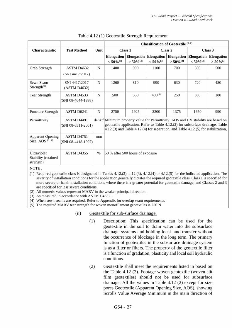
Toll Road Project – General Specifications
Division 4 – Road Earthwork
GS4 - 27
Table 4.12 (1) Geotextile Strength Requirement
Classification of Geotextile (1, 2)
Characteristic Test Method Unit Class 1 Class 2 Class 3
Elongation
< 50%(3)
Elongation
> 50%(3)
Elongation
< 50%(3)
Elongation
> 50%(3)
Elongation
< 50%(3)
Elongation
> 50%(3)
Grab Strength ASTM D4632 N 1400 900 1100 700 800 500
(SNI 4417:2017)
Sewn Seam
Strength(4)
SNI 4417:2017
(ASTM D4632)
N 1260 810 990 630 720 450
Tear Strength ASTM D4533
(SNI 08-4644-1998)
N 500 350 400(5) 250 300 180
Puncture Strength ASTM D6241 N 2750 1925 2200 1375 1650 990
Permittivity ASTM D4491
(SNI 08-6511-2001)
detik-1 Minimum property value for Permittivity. AOS and UV stability are based on
geotextile application. Refer to Table 4.12.(2) for subsurface drainage, Table
4.12.(3) and Table 4.12.(4) for separation, and Table 4.12.(5) for stabilization,
Apparent Opening
Size, AOS (3, 4)
ASTM D4751
(SNI 08-4418-1997)
mm
Ultraviolet
Stability (retained
strength)
ASTM D4355 % 50 % after 500 hours of exposure
NOTE :
(1) Required geotextile class is designated in Tables 4.12.(2), 4.12.(3), 4.12.(4) or 4.12.(5) for the indicated application. The
severity of installation conditions for the application generally dictates the required geotextile class. Class 1 is specified for
more severe or harsh installation conditions where there is a greater potential for geotextile damage, and Classes 2 and 3
are specified for less severe conditions.
(2) All numeric values represent MARV in the weaker principal direction.
(3) As measured in accordance with ASTM D4632.
(4) When sewn seams are required. Refer to Appendix for overlap seam requirements.
(5) The required MARV tear strength for woven monofilament geotextiles is 250 N.
(ii) Geotextile for sub-surface drainage.
(1) Description: This specification can be used for the
geotextile in the soil to drain water into the subsurface
drainage systems and holding local land transfer without
the occurrence of blockage in the long term. The primary
function of geotextiles in the subsurface drainage system
is as a filter or filters. The property of the geotextile filter
is a function of gradation, plasticity and local soil hydraulic
conditions.
(2) Geotextile shall meet the requirements listed in based on
the Table 4.12 (2). Footage woven geotextile (woven slit
film geotextiles) should not be used for subsurface
drainage. All the values in Table 4.12 (2) except for size
pores Geotextile (Apparent Opening Size, AOS), showing
Scrolls Value Average Minimum in the main direction of
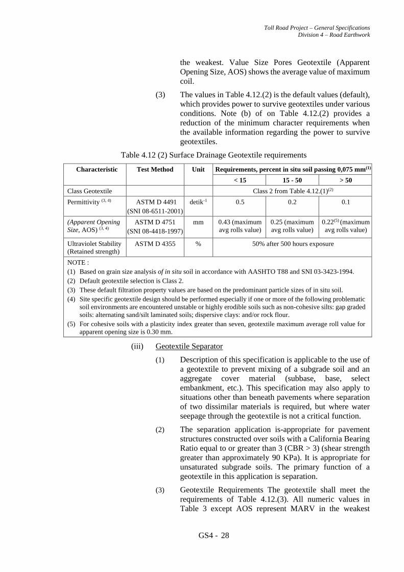
Toll Road Project – General Specifications
Division 4 – Road Earthwork
GS4 - 28
the weakest. Value Size Pores Geotextile (Apparent
Opening Size, AOS) shows the average value of maximum
coil.
(3) The values in Table 4.12.(2) is the default values (default),
which provides power to survive geotextiles under various
conditions. Note (b) of on Table 4.12.(2) provides a
reduction of the minimum character requirements when
the available information regarding the power to survive
geotextiles.
Table 4.12 (2) Surface Drainage Geotextile requirements
Characteristic Test Method Unit Requirements, percent in situ soil passing 0,075 mm(1)
< 15 15 - 50 > 50
Class Geotextile Class 2 from Table 4.12.(1)(2)
Permittivity (3, 4) ASTM D 4491
(SNI 08-6511-2001)
detik-1 0.5 0.2 0.1
(Apparent Opening
Size, AOS) (3, 4)
ASTM D 4751
(SNI 08-4418-1997)
mm 0.43 (maximum
avg rolls value)
0.25 (maximum
avg rolls value)
0.22(5) (maximum
avg rolls value)
Ultraviolet Stability
(Retained strength)
ASTM D 4355 % 50% after 500 hours exposure
NOTE :
(1) Based on grain size analysis of in situ soil in accordance with AASHTO T88 and SNI 03-3423-1994.
(2) Default geotextile selection is Class 2.
(3) These default filtration property values are based on the predominant particle sizes of in situ soil.
(4) Site specific geotextile design should be performed especially if one or more of the following problematic
soil environments are encountered unstable or highly erodible soils such as non-cohesive silts: gap graded
soils: alternating sand/silt laminated soils; dispersive clays: and/or rock flour.
(5) For cohesive soils with a plasticity index greater than seven, geotextile maximum average roll value for
apparent opening size is 0.30 mm.
(iii) Geotextile Separator
(1) Description of this specification is applicable to the use of
a geotextile to prevent mixing of a subgrade soil and an
aggregate cover material (subbase, base, select
embankment, etc.). This specification may also apply to
situations other than beneath pavements where separation
of two dissimilar materials is required, but where water
seepage through the geotextile is not a critical function.
(2) The separation application is-appropriate for pavement
structures constructed over soils with a California Bearing
Ratio equal to or greater than 3 (CBR > 3) (shear strength
greater than approximately 90 KPa). It is appropriate for
unsaturated subgrade soils. The primary function of a
geotextile in this application is separation.
(3) Geotextile Requirements The geotextile shall meet the
requirements of Table 4.12.(3). All numeric values in
Table 3 except AOS represent MARV in the weakest
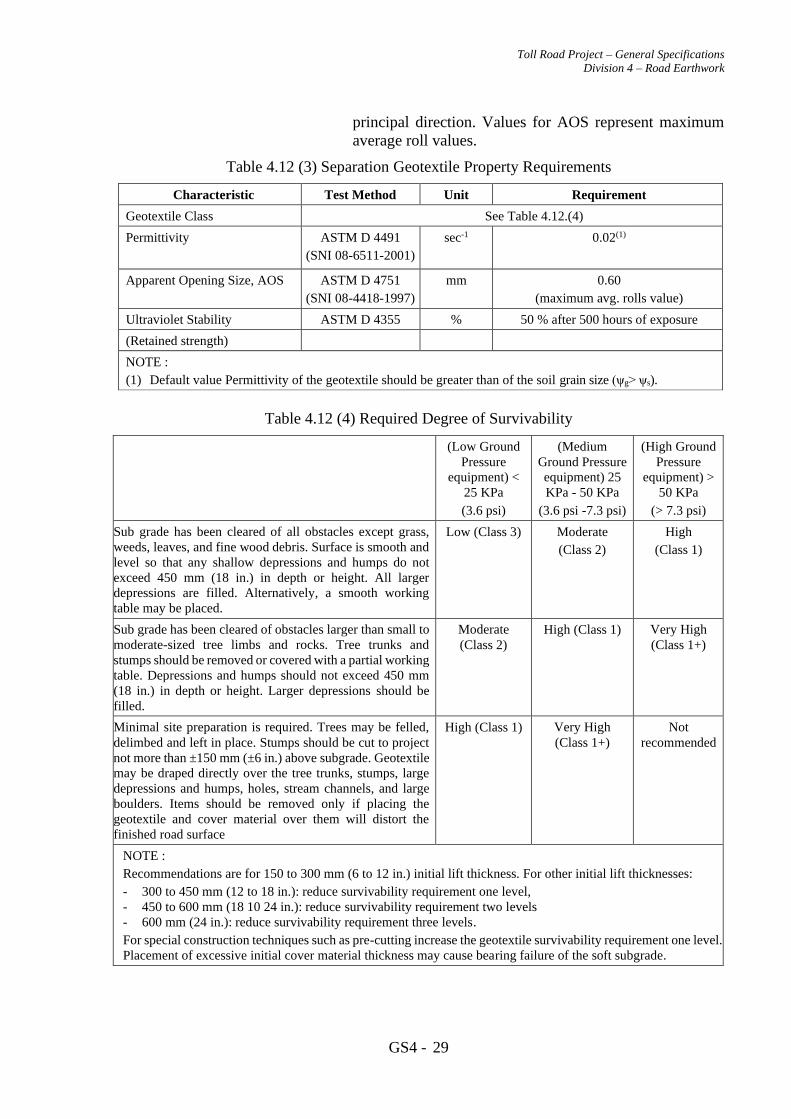
Toll Road Project – General Specifications
Division 4 – Road Earthwork
GS4 - 29
principal direction. Values for AOS represent maximum
average roll values.
Table 4.12 (3) Separation Geotextile Property Requirements
Characteristic Test Method Unit Requirement
Geotextile Class See Table 4.12.(4)
Permittivity ASTM D 4491
(SNI 08-6511-2001)
sec-1 0.02(1)
Apparent Opening Size, AOS ASTM D 4751
(SNI 08-4418-1997)
mm 0.60
(maximum avg. rolls value)
Ultraviolet Stability ASTM D 4355 % 50 % after 500 hours of exposure
(Retained strength)
NOTE :
(1) Default value Permittivity of the geotextile should be greater than of the soil grain size (ψg> ψs).
Table 4.12 (4) Required Degree of Survivability
(Low Ground
Pressure
equipment) <
25 KPa
(3.6 psi)
(Medium
Ground Pressure
equipment) 25
KPa - 50 KPa
(3.6 psi -7.3 psi)
(High Ground
Pressure
equipment) >
50 KPa
(> 7.3 psi)
Sub grade has been cleared of all obstacles except grass,
weeds, leaves, and fine wood debris. Surface is smooth and
level so that any shallow depressions and humps do not
exceed 450 mm (18 in.) in depth or height. All larger
depressions are filled. Alternatively, a smooth working
table may be placed.
Low (Class 3) Moderate
(Class 2)
High
(Class 1)
Sub grade has been cleared of obstacles larger than small to
moderate-sized tree limbs and rocks. Tree trunks and
stumps should be removed or covered with a partial working
table. Depressions and humps should not exceed 450 mm
(18 in.) in depth or height. Larger depressions should be
filled.
Moderate
(Class 2)
High (Class 1) Very High
(Class 1+)
Minimal site preparation is required. Trees may be felled,
delimbed and left in place. Stumps should be cut to project
not more than ±150 mm (±6 in.) above subgrade. Geotextile
may be draped directly over the tree trunks, stumps, large
depressions and humps, holes, stream channels, and large
boulders. Items should be removed only if placing the
geotextile and cover material over them will distort the
finished road surface
High (Class 1) Very High
(Class 1+)
Not
recommended
NOTE :
Recommendations are for 150 to 300 mm (6 to 12 in.) initial lift thickness. For other initial lift thicknesses:
- 300 to 450 mm (12 to 18 in.): reduce survivability requirement one level,
- 450 to 600 mm (18 10 24 in.): reduce survivability requirement two levels
- 600 mm (24 in.): reduce survivability requirement three levels.
For special construction techniques such as pre-cutting increase the geotextile survivability requirement one level.
Placement of excessive initial cover material thickness may cause bearing failure of the soft subgrade.
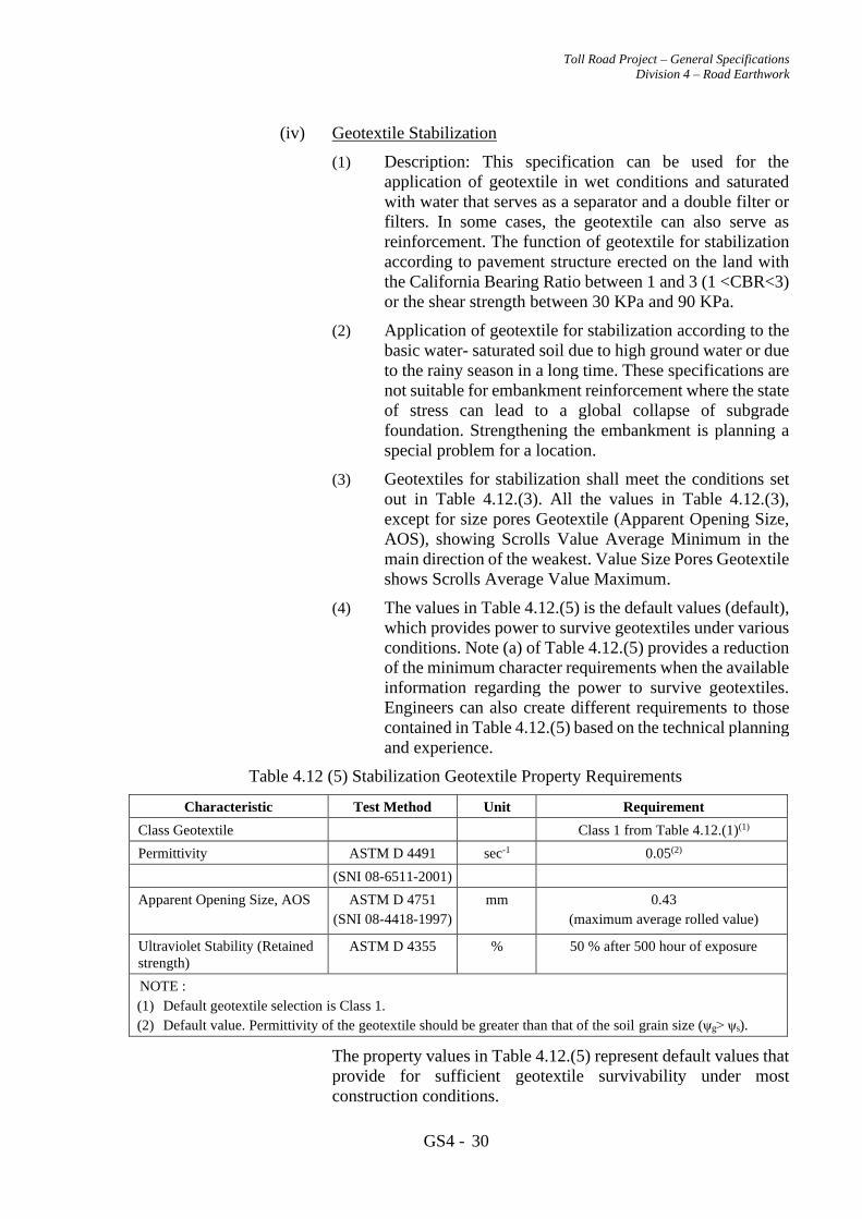
Toll Road Project – General Specifications
Division 4 – Road Earthwork
GS4 - 30
(iv) Geotextile Stabilization
(1) Description: This specification can be used for the
application of geotextile in wet conditions and saturated
with water that serves as a separator and a double filter or
filters. In some cases, the geotextile can also serve as
reinforcement. The function of geotextile for stabilization
according to pavement structure erected on the land with
the California Bearing Ratio between 1 and 3 (1 <CBR<3)
or the shear strength between 30 KPa and 90 KPa.
(2) Application of geotextile for stabilization according to the
basic water- saturated soil due to high ground water or due
to the rainy season in a long time. These specifications are
not suitable for embankment reinforcement where the state
of stress can lead to a global collapse of subgrade
foundation. Strengthening the embankment is planning a
special problem for a location.
(3) Geotextiles for stabilization shall meet the conditions set
out in Table 4.12.(3). All the values in Table 4.12.(3),
except for size pores Geotextile (Apparent Opening Size,
AOS), showing Scrolls Value Average Minimum in the
main direction of the weakest. Value Size Pores Geotextile
shows Scrolls Average Value Maximum.
(4) The values in Table 4.12.(5) is the default values (default),
which provides power to survive geotextiles under various
conditions. Note (a) of Table 4.12.(5) provides a reduction
of the minimum character requirements when the available
information regarding the power to survive geotextiles.
Engineers can also create different requirements to those
contained in Table 4.12.(5) based on the technical planning
and experience.
Table 4.12 (5) Stabilization Geotextile Property Requirements
Characteristic Test Method Unit Requirement
Class Geotextile Class 1 from Table 4.12.(1)(1)
Permittivity ASTM D 4491 sec-1 0.05(2)
(SNI 08-6511-2001)
Apparent Opening Size, AOS ASTM D 4751
(SNI 08-4418-1997)
mm 0.43
(maximum average rolled value)
Ultraviolet Stability (Retained
strength)
ASTM D 4355 % 50 % after 500 hour of exposure
NOTE :
(1) Default geotextile selection is Class 1.
(2) Default value. Permittivity of the geotextile should be greater than that of the soil grain size (ψg> ψs).
The property values in Table 4.12.(5) represent default values that
provide for sufficient geotextile survivability under most
construction conditions.
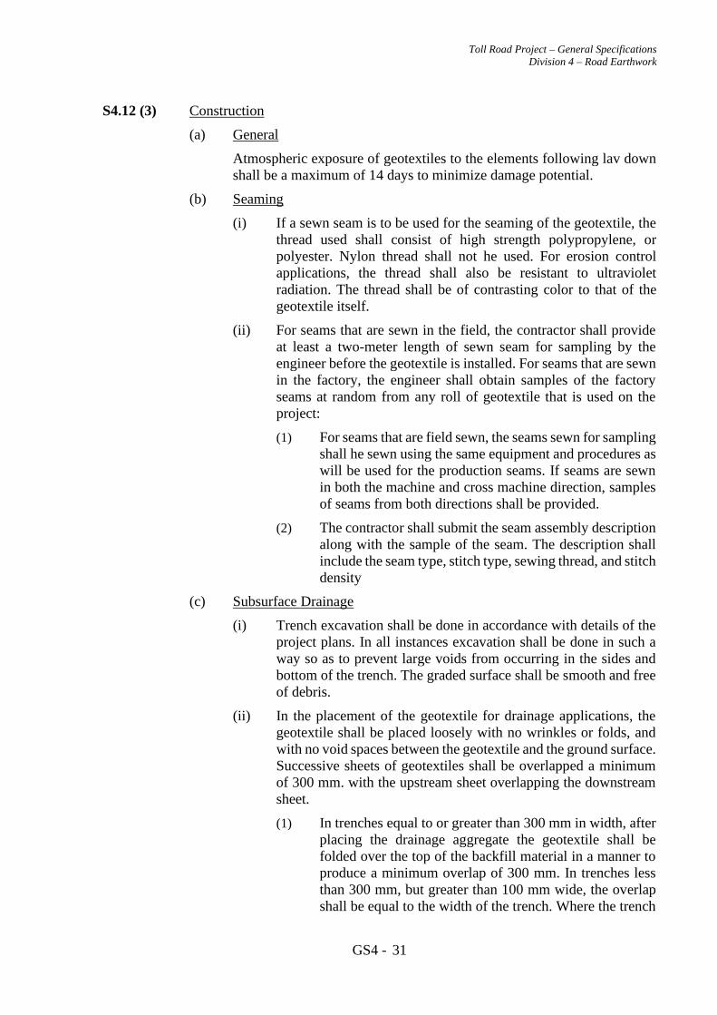
Toll Road Project – General Specifications
Division 4 – Road Earthwork
GS4 - 31
S4.12 (3) Construction
(a) General
Atmospheric exposure of geotextiles to the elements following lav down
shall be a maximum of 14 days to minimize damage potential.
(b) Seaming
(i) If a sewn seam is to be used for the seaming of the geotextile, the
thread used shall consist of high strength polypropylene, or
polyester. Nylon thread shall not he used. For erosion control
applications, the thread shall also be resistant to ultraviolet
radiation. The thread shall be of contrasting color to that of the
geotextile itself.
(ii) For seams that are sewn in the field, the contractor shall provide
at least a two-meter length of sewn seam for sampling by the
engineer before the geotextile is installed. For seams that are sewn
in the factory, the engineer shall obtain samples of the factory
seams at random from any roll of geotextile that is used on the
project:
(1) For seams that are field sewn, the seams sewn for sampling
shall he sewn using the same equipment and procedures as
will be used for the production seams. If seams are sewn
in both the machine and cross machine direction, samples
of seams from both directions shall be provided.
(2) The contractor shall submit the seam assembly description
along with the sample of the seam. The description shall
include the seam type, stitch type, sewing thread, and stitch
density
(c) Subsurface Drainage
(i) Trench excavation shall be done in accordance with details of the
project plans. In all instances excavation shall be done in such a
way so as to prevent large voids from occurring in the sides and
bottom of the trench. The graded surface shall be smooth and free
of debris.
(ii) In the placement of the geotextile for drainage applications, the
geotextile shall be placed loosely with no wrinkles or folds, and
with no void spaces between the geotextile and the ground surface.
Successive sheets of geotextiles shall be overlapped a minimum
of 300 mm. with the upstream sheet overlapping the downstream
sheet.
(1) In trenches equal to or greater than 300 mm in width, after
placing the drainage aggregate the geotextile shall be
folded over the top of the backfill material in a manner to
produce a minimum overlap of 300 mm. In trenches less
than 300 mm, but greater than 100 mm wide, the overlap
shall be equal to the width of the trench. Where the trench
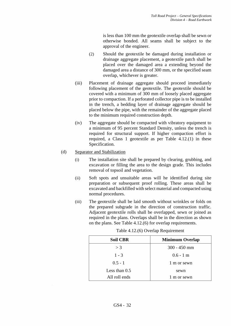
Toll Road Project – General Specifications
Division 4 – Road Earthwork
GS4 - 32
is less than 100 mm the geotextile overlap shall be sewn or
otherwise bonded. All seams shall be subject to the
approval of the engineer.
(2) Should the geotextile be damaged during installation or
drainage aggregate placement, a geotextile patch shall be
placed over the damaged area a extending beyond the
damaged area a distance of 300 mm, or the specified seam
overlap, whichever is greater.
(iii) Placement of drainage aggregate should proceed immediately
following placement of the geotextile. The geotextile should be
covered with a minimum of 300 mm of loosely placed aggregate
prior to compaction. If a perforated collector pipe is to be installed
in the trench, a bedding layer of drainage aggregate should be
placed below the pipe, with the remainder of the aggregate placed
to the minimum required construction depth.
(iv) The aggregate should be compacted with vibratory equipment to
a minimum of 95 percent Standard Density, unless the trench is
required for structural support. If higher compaction effort is
required, a Class 1 geotextile as per Table 4.12.(1) in these
Specification.
(d) Separator and Stabilization
(i) The installation site shall be prepared by clearing, grubbing, and
excavation or filling the area to the design grade. This includes
removal of topsoil and vegetation.
(ii) Soft spots and unsuitable areas will he identified during site
preparation or subsequent proof rolling. These areas shall be
excavated and backfilled with select material and compacted using
normal procedures.
(iii) The geotextile shall be laid smooth without wrinkles or folds on
the prepared subgrade in the direction of construction traffic.
Adjacent geotextile rolls shall be overlapped, sewn or joined as
required in the plans. Overlaps shall be in the direction as shown
on the plans. See Table 4.12.(6) for overlap requirements.
Table 4.12.(6) Overlap Requirement
Soil CBR Minimum Overlap
> 3 300 - 450 mm
1 - 3 0.6 - 1 m
0.5 - 1 1 m or sewn
Less than 0.5 sewn
All roll ends 1 m or sewn
c)
Toll Road Project – General Specifications
Division 4 – Road Earthwork
GS4 - 33
(iv) On curves, the geotextile may be folded or cut to conform to the
curves. The fold or overlap shall be in the direction of construction
and held in place by pins, staples, or piles of fill or rock.
(v) Prior to covering, the geotextile shall be inspected to ensure that
the geotextile has not been damaged (i.e., holes, tears, rips) during
installation. The inspection shall be done by the Engineer or the
Engineer's designated representative. It is recommended that the
designated representative be a certified inspector. Damaged
geotextiles as identified by the Engineer shall be repaired
immediately. Cover the damaged area with a geotextile patch that
extends an amount equal to the required overlap beyond the
damaged area.
(vi) The sub base shall be placed by end dumping onto the geotextile
from the edge of the geotextile over previously placed subbase
aggregate. Construction vehicles shall not be allowed directly on
the geotextile. The sub base shall be placed such that at least the
minimum specified lift thickness shall be between the geotextile
and equipment tires or tracks at all times. Turning of vehicles shall
not be permitted on the first lift above the geotextile.
(vii) Any ruts occurring during construction shall the Contractor filled
with additional sub base material, and compacted to the specified
density.
(viii) If placement of the backfill material causes damage to the
geotextile the damaged area shall be repaired as previously
described in Sub-clause 4.12 (3) (c). The placement procedures
shall then be modified to eliminate further damage from taking
place (i.e. increase initial lift thickness, decrease equipment loads,
etc.). In stabilization applications, the use of vibratory compaction
equipment is not recommended with the initial lift of subbase
material, as it may cause damage to the geotextile
S4.12 (4) Quality Control
(a) Certification
(i) The Contractor shall provide to the Engineer a certificate stating
the name of the manufacturer, product name, and style number,
chemical composition of the filaments or yarns, and other
pertinent information to fully describe the geotextile.
(ii) The manufacturer is responsible for establishing and maintaining
a quality control program to assure compliance with the
requirements of the specification Documentation describing the
quality control program shall be made available upon request.
(iii) The manufacturer s certificate shall state that the furnished
geotextile meets MARV requirements of the specification as
evaluated under the manufacturer s quality control program. A
person having legal authority to bind the manufacturer shall attest
to the certificate.
Toll Road Project – General Specifications
Division 4 – Road Earthwork
GS4 - 34
(iv) Either mislabeling or misrepresentation of 'materials shall be
reason to reject those geotextile products.
(b) Sampling, Testing and Acceptance
(i) Geotextiles shall be subject to sampling and testing to verily
conformance with this specification. Sampling shall be in
accordance with the most current ASTM D4354-12 in the chapter
entitled "Procedure for Sampling for Purchaser's Specification
Conformance Testing" or refer to the ISO 9868-1990 or SNI 08-
4419-1997, using the section tilled. Procedure for Sampling for
Purchaser s Specification Conformance Testing. In the absence of
purchaser s testing, verification may be based on manufacturer s
certifications as a result of testing by the manufacturer of quality
assurance samples obtained using the procedure for Sampling for
Manufacturer s Quality Assurance (MQA) Testing. A lot size shall
be considered to be the shipment quantity of the given product, or
a truck load of the given product, whichever is smaller.
(ii) Testing shall be performed in accordance with the methods
referenced in this specification for indicated application. The
number of specimens to test per sample is specified by each test
method. Geotextile product acceptance shall be based on ASTM
D4759-11(2018) "Practice for determining the specification
conformance of Geo-synthetics" Product acceptance is
determined by comparing the average test results of all specimens
within a given sample.
(c) Shipment and Storage
(i) Geotextiles labeling, shipment, and storage shall follow ASTM
D4873/D4873M-17. Product labels shall clearly show the
manufacturer or supplier name, style name, and roll number. Bach
shipping document shall include a notation certifying that the
material is in accordance with the manufacturer s certificate.
(ii) Each geotextile roll shall be wrapped with a material that will
protect the geotextile, including the ends of the roll, from damage
due to shipment, water, sunlight, and contaminants. The
protective wrapping shall be maintained during periods of
shipment and storage.
(iii) During storage, geotextile rolls shall be elevated off the ground
and adequately covered to protect them from the following: site
construction damage, precipitation, extended ultraviolet radiation
including sunlight, chemicals that are strong acids or strong bases,
flames including welding sparks, temperatures in excess of 71°C.
and any other environmental condition that may damage the
physical property values of the geotextile.
Toll Road Project – General Specifications
Division 4 – Road Earthwork
GS4 - 35
S4.12 (5) Method and Measurement
(a) The geotextile shall be measured by the number of square metres
computed from the payment lines shown on the plans or from payment
lines established in writing by the Engineer. This Excludes seam overlaps,
but shall include geotextile used in crest and toe of slope treatments.
(i) Slope preparation, excavation and backfill, bedding, and cover material
are separate pay items.
S4.12 (6) Basic of Payment
The quantities, determined as provided above, shall be paid for at the Contract
unit price per square meter for the pay items as listed below. The prices and
payment shall be full compensation for all costs including hauling materials,
horizontal sand blanket, and geotextile separator, placing temporary dike if
directed, and for all materials, labor, tools, equipment and incidentals necessary
to complete the works as described in this Clause.
Pay Item No. and Name Unit of Measurement
4.12 (1) Geotextile for Subsurface Drainage Square Meter
(Class 2)
4.12 (2) Geotextile for Separator (Class 1) Square Meter
4.12 (3) Geotextile for Separator (Class 2) Square Meter
4.12 (4) Geotextile for Separator (Class 3) Square Meter
4.12 (5) Geotextile for Stabilization (Class 1) Square Meter
S.4.13 Prefabricated Vertical Drain (PVD)
S.4.13 (1) Desciption
This work consists of the installation of Prefabrication Vertical Drains (PVD) in
accordance with the details shown in the Drawings and with the requirements of
these Specifications. The drains shall consist of a band-shaped plastic core
enclosed in a suitable jacket material or other shape or configuration approved by
the Engineer. They shall be spaced and arranged as shown in the Drawings or as
otherwise directed by the Engineer.
S.4.13 (2) Material
(a) General
(i) The PVD shall be manufactured of new materials and shall consist
of a core enclosed in or integrated with a jacket. The jacket shall
allow free passage of pore water to the core without loss of soil
material or piping. The core shall provide continuous vertical
drainage.
(ii) The drain shall be band-shaped with an aspect ratio (width devided
by thickness) not exceeding 50.
Toll Road Project – General Specifications
Division 4 – Road Earthwork
GS4 - 36
(b) Jacket
(i) The jacket shall be a synthetic non-woven geotextile, capable of
resisting all bending, punching and tensile forces imposed during
installation and during the design life of the drain.
(ii) The jacket material shall not be subject to localized damage (e.g.,
punching through the filter bys sand/gravel particles).
(iii) The jacket material shall be sufficiently rigid to withstand lateral
earth pressures due to embedment and surcharges so that the
vertical flow capacity through the core will not be adversely
affected. The jacket material shall be sufficiently flexible to bend
smoothly during installation and induced consolidation settlement
without damage. Jacket material shall not undergo cracking and
peeling during installation of the drain
(iv) The jacket material shall meet the following requirements:
Table 4.13.1 Jacket Material Requirement
Properties Test Method Requirement
Grab strength SNI 4417:2017
(ASTM D4632)
min. 356 N
Puncture Strength SNI 8058:2014
(ASTM D4833)
min. 220 N
Bursting strength ASTM D 3786 min. 896 KPa
Tear Strength SNI 08-4644-1998
(ASTM D4533)
min. 111 N
Apparent Opening Size, O95 SNI 08-4418-1997
(ASTM D 4751)
As shown in Drawing
Permittivity SNI 08-6511-2001
(ASTM D 4491)
As shown in Drawing
Note:
(1) All values in Table 4.13.1, except Apparent Opening Size (AOS), indicate
the minimum average roll value in the weakest major direction. The
Geotextile Pore Size Value shows the maximum average roll value.
(2) Jacket material shall be tested in saturated and dry conditions, taken from
the lowest value
(c) Core
The core shall be a black three-dimensional polyester filament core
structure fabrication to promote drainage along the axis of the vertical
drain.
(d) Assembled Drain
(i) The assembled drain shall be resistant against wet rot, mildew,
bacterial action, insects, salts in solution in the groundwater, acids,
alkalis, solvents, and any other significant ingredients in the site
groundwater.
Toll Road Project – General Specifications
Division 4 – Road Earthwork
GS4 - 37
(ii) One single type of assembled drain shall be used on the project
unless otherwise specified or approved by the Engineer.
(iii) PVD materials shall be labeled or tagged in such a manner that the
information for sample identification and other quality control
purposes can be read from the label. As a minimum, each roll shall
be identified by the manufacturer as to lot or control numbers,
individual roll number, date of manufacture, manufacturer and
product identification of the jacket and core.
(iv) During shipment and storage, the drain shall be wrapped in heavy
paper, burlap or similar heavy-duty protective covering. The
drains shall be protected from sunlight, mud, dirt, dust, debris and
other detrimental substances during shipping and on-site storage.
(v) All material which is damage during shipment, unloading, storage,
or handling and/or which does not meet the minimum
requirements of the drain material shall be rejected by the
Engineer. No payment of any kind shall be made for rejected
material.
(vi) PVD shall have a minimum equivalent diameter of 2 inches using
the following definition of equivalent diameter:
dw = (a+b)/2,
where:
dw = diameter of a circular drain equivalent to the band shaped
drain
a = width of the band shaped drain
b = thickness of the band shaped drain
S.4.13 (3) Quality Control and Testing
(a) The actual vertical drain to be used shall be at the option of the contractor
subject to the approval of the Engineer.
(b) The Contractor shall indicate the proposed source of the materials prior to
delivery to site as specified in Sub-clause S1.02 (4). The contractor shall
also submit samples and Manufacturer's certificates to verify the physical,
mechanical and hydraulic properties of the drain to be used for Engineer's
approval.
(c) Prior to installation and at the discretion of the Engineer, individual test
sample shall be cut from at least one roll selected at random to represent
each batch or every 100,000 meters, whichever is lesser. Individual
sample shall be no less than 3 meters in length and shall be full width.
Samples submitted for tests shall indicate the linear meters of drain and
manufacturer's identifications represented by the sample.
(d) Should any individual sample selected at random fail to meet the
specification, then that roll shall be rejected and two additional samples
shall be taken at random from two other rolls representing the same batch
on 100,000 meters. If either of these two additional samples fail to comply
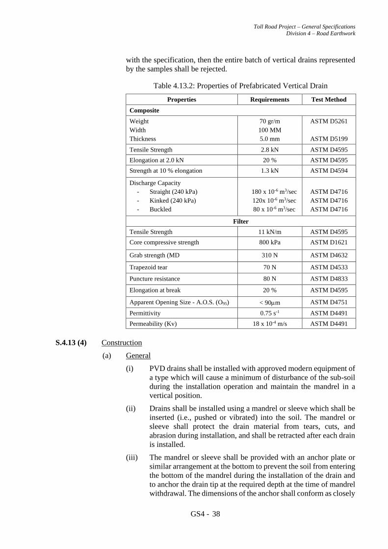
Toll Road Project – General Specifications
Division 4 – Road Earthwork
GS4 - 38
with the specification, then the entire batch of vertical drains represented
by the samples shall be rejected.
Table 4.13.2: Properties of Prefabricated Vertical Drain
Properties Requirements Test Method
Composite
Weight
Width
Thickness
70 gr/m
100 MM
5.0 mm
ASTM D5261
ASTM D5199
Tensile Strength 2.8 kN ASTM D4595
Elongation at 2.0 kN 20 % ASTM D4595
Strength at 10 % elongation 1.3 kN ASTM D4594
Discharge Capacity
- Straight (240 kPa)
- Kinked (240 kPa)
- Buckled
180 x 10-6 m3/sec
120x 10-6 m3/sec
80 x 10-6 m3/sec
ASTM D4716
ASTM D4716
ASTM D4716
Filter
Tensile Strength 11 kN/m ASTM D4595
Core compressive strength 800 kPa ASTM D1621
Grab strength (MD 310 N ASTM D4632
Trapezoid tear 70 N ASTM D4533
Puncture resistance 80 N ASTM D4833
Elongation at break 20 % ASTM D4595
Apparent Opening Size - A.O.S. (O95) < 90m ASTM D4751
Permittivity 0.75 s-1 ASTM D4491
Permeability (Kv) 18 x 10-4 m/s ASTM D4491
S.4.13 (4) Construction
(a) General
(i) PVD drains shall be installed with approved modern equipment of
a type which will cause a minimum of disturbance of the sub-soil
during the installation operation and maintain the mandrel in a
vertical position.
(ii) Drains shall be installed using a mandrel or sleeve which shall be
inserted (i.e., pushed or vibrated) into the soil. The mandrel or
sleeve shall protect the drain material from tears, cuts, and
abrasion during installation, and shall be retracted after each drain
is installed.
(iii) The mandrel or sleeve shall be provided with an anchor plate or
similar arrangement at the bottom to prevent the soil from entering
the bottom of the mandrel during the installation of the drain and
to anchor the drain tip at the required depth at the time of mandrel
withdrawal. The dimensions of the anchor shall conform as closely
Toll Road Project – General Specifications
Division 4 – Road Earthwork
GS4 - 39
as possible to the dimensions of the mandrel so as to minimize soil
disturbance. The Engineer shall determine the acceptability of the
anchorage system and produce.
(b) Installation Procedures
(i) Two weeks prior to the beginning of trial installation, the
Contractor shall submit full details on the materials, equipment,
sequence and method proposed for PVD Drain installation to the
Engineer for review and approval. Approval by the Engineer of
installation sequence and methods shall not relieve the Contractor
of its responsibility to install drains in accordance with the plans
and specifications.
(ii) Prior to the installation of production PVD drains, the Contractor
shall demonstrate that its equipment, methods, and materials
produce a satisfactory.
Installation in accordance with these specifications. For this the
Contractor will be required to install 5 trial totaling approximately
50 linear meters at locations designated by the Engineer.
(iii) Approval by the Engineer of the method or equipment used to
install the trial drains shall not constitute, necessarily, acceptance
of the method for the remainder of the project. If, at any time, the
Engineer considers that the method of installation does not
produce satisfactory pv drains, the Contractor shall alter his
method and/or equipment as necessary to comply with these
specifications.
(c) Installation
(i) PVD shall be located, numbered and staked out by the Contractor
using a baseline and benchmark as shown in the Drawings. The
Contractor shall take all reasonable precautions to preserve the
stakes and is responsible for any necessary re-staking. The as-
installed location of the PVD shall not vary by more than 150 mm
from the plan locations designated on the drawings.
(ii) PVD that are more than 150 mm from design plan location or are
damaged or improperly installed, will be rejected and abandoned
in place.
(iii) PVD shall be installed from the working surface to the depth
shown on the drawings, or to such depth as directed by the
Engineer. The Engineer may vary the depths, spacing, or the
number of drains to be installed, and may revise the plan limits for
this work as necessary.
(iv) During PVD installation, the Contractor shall provide the
Engineer with suitable means of determining the depth of the
advancing drain at any given time and the length (to nearest 50
mm) quantity of pv drain installed at each location.
Toll Road Project – General Specifications
Division 4 – Road Earthwork
GS4 - 40
(v) Equipment for installing PVD shall be plumbed prior to installing
each drain and shall not deviate from the vertical more than 50 mm
in 3 meters during installation of any drain.
(vi) PVD shall be installed using a continuous push using static weight
or vibration.
(vii) Installation techniques requiring driving will not be permitted.
Jetting techniques will be permitted only after receiving written
approval from the Engineer.
(viii) The installation shall be performed, without any damage to the
drain during advancement or retraction of the mandrel. In no case
will alternate raising or lowering of the mandrel during
advancement be permitted. Raising of the mandrel will only be
permitted after completion of a drain installation.
(ix) The completed PVD shall be cut off neatly 300 mm above the
working grade, or as otherwise specified on the contract drawings.
(x) The Contractor shall observe precautions necessary for protection
of any field instrumentation devices. The Contractor shall replace,
at his own expenses, any instrumentation equipment that has been
damaged or become unreliable as a result of his operations prior
to continuing with drain installation or order construction
activities.
(d) Preaugering/Obstructions
(i) The Contractor shall be responsible for penetrating any overlying
material as necessary to install the drains.
(ii) Where obstruction is encountered below the working surface
which cannot be penetrated by the drain installation equipment,
the Contractor shall complete the drain from the elevation of the
working surface to the obstruction and notify the Engineer prior to
installing any more drains. At the direction of the Engineer and
under his review, the Contractor shall attempt to install anew drain
within 600 mm horizontally from the obstructed drain. A
maximum of two attempts shall be made as directed by the
Engineer. If the drain still cannot be installed to the design tip
elevation, the drain location shall be abandoned and the
installation equipment shall be moved to the next location, or other
action shall be taken as directed by the Engineer.
(iii) If permitted by the Engineer, the Contractor may use augering,
spudding, or other methods to loosen the soil and clear
obstructions, providing the augering does not penetrate more than
600 mm into the underlaying compressible soil.
(iv) Where obstructions are encountered, the following procedure shall
be implemented in the listed sequence:
Toll Road Project – General Specifications
Division 4 – Road Earthwork
GS4 - 41
(1) The Contractor shall immediately notify the Engineer prior
to completing the drain and prior to installing any other
drains.
(2) The Contractor shall attempt to install drains adjacent to
the obstructed location. Based upon the results of these
installations and at the direction of the Engineer and under
his review, the Contractor shall:
attempt to install an offset drain within 600 mm
horizontally of the obstructed drain, or
implement obstruction clearance procedures and install
the drain at the design location.
Obstruction clearance procedures shall be used only as
directed by the Engineer.
(e) Splicing
(i) Splicing of prefabricated vertical drain material shall be done by
stapling in a workmanlike manner and so as to insure structural
and hydraulic continuity of the drain.
(ii) A maximum of 1 splice per drain installed will be permitted,
without specific permission from the Engineer.
(iii) The jacket and core shall be overlapped a minimum of 150 mm at
any splice.
S.4.13 (5) Method of Measurement
(a) Vertical drains shall be measured by the linear meter. The length of PVD
to be paid for shall be the distance the installation mandrel tip penetrates
below the working grade plus the required cut off length above the
working grade. Payment will not be made for drains which are not
anchored to the required depth.
(b) PVD placed in excess of the length designated on the contract drawings
shall not be paid for unless the additional length was authorized by the
Engineer in writing prior to or during the drain installation.
S.4.13 (6) Basis of Payment
The quantities, measured as provided above, shall be paid for at the Contract price
per linear meter, which price and payment shall be full compensation for
furnishing and installing all materials including all supervision, equipment, crew,
survey stake out of drain locations, other equipment and materials as necessary to
properly execute the work.
Pay Item No. and Name Unit of Measurement
4.13 Prefabricated Vertical Drain (PVD) Linear Meter
Toll Road Project – General Specifications
Division 4 – Road Earthwork
GS4 - 42
S4.14 Geotechnical Instrumentation
S4.14 (1) General
(a) Description
(i) This specification is intended to explain and control the
requirements for using Instrumentation on embankment work on
soft soil, slope stabilization, Prefabricated Vertical Drain (PVD)
work and Preloading Systems
(ii) The scope of work of this specification includes: the supply,
installation, monitoring and analysis of data which shall comply
with the regulations and standards stated in this Specification
(iii) The instrumentation referred to in this specification includes
instruments to monitor vertical settlement, horizontal movements,
and pore pressures which shall be installed and adjusted as shown
in Drawing.
(iv) These specifications are intended to ensure good quality and
performance
(b) Reference Standard
Standar Nasional Indonesia (SNI)
SNI 3404:2008 : Tata cara pemasangan inklinometer dan
pemantauan pergerakan horisontal tanah
SNI 03-3431-1994 : Tata cara pemantauan gerakan horizontal
batuan dan bangunan dengan alat inklinometer
SNI 03-3442-1994 : Tata cara pengukuran tekanan air pori tanah
dengan pisometer pipa terbuka Casagrande
SNI 03-3443-1994 : Tata cara pemantauan tekanan air pori dengan
pisometer pipa terbuka casagrande
SNI 03-3452-1994 : Tata cara pemasangan pisometer pneumatik
SNI 03-3453-1994 : Tata cara pemantauan tekanan air pori dengan
alat pisometer penumatik
SNI 3454:2008 : Tata cara pemasangan instrumen magnetis dan
pemantauan pergerakan vertikal tanah.
SNI 6461:2012 : Tata cara pemasangan dan pembacaan
pisometer kawat vibrasi
Pt T-08-2002-B : Panduan geoteknik 1 : Proses pembentukan dan
sifat-sifat dasar tanah lunak
Pt T-09-2002-B : Panduan geoteknik 2 : Penyelidikan tanah lunak
desain dan pekerjaan lapangan
Pt M-01-2002-B : Panduan geoteknik 3 : Pengujian tanah lunak
pengujian laboratorium
Pt T-10-2002-B : Panduan geoteknik 4 : Desain dan konstruksi
ASTM
ASTM D6230-13 : Standard Test Method for Monitoring Ground
Movement Using Probe-Type Inclinometers
Toll Road Project – General Specifications
Division 4 – Road Earthwork
GS4 - 43
ASTM D6598-19 : Standard Guide for Installing and Operating
Settlement Platforms for Monitoring Vertical
Deformations
(c) Terms and Definition
(i) Settlement Plate, Settlement Probe, Settlement Sensor
Instruments used to measure vertical settlement of embankment or existing ground.
(ii) Piezometer
Instruments used to measure water pore pressure. Water pore
pressure can indicate instability in embankment and evaluate the
progress of the consolidation process.
(iii) Inclinometer
Instruments used to measure horizontal movement and monitor the
stability of the embankment.
S4.14 (2) Material
(a) Physical Instrument Requirements
(i) The instrument for monitoring the vertical settlement used shall
comply with the requirements set forth in ASTM D6598-19.
(ii) (Instruments to monitor horizontal movements used shall be in
accordance with the requirements SNI 3404: 2008.
(iii) Instruments to measure pore pressures used shall comply with the
requirements in SNI 03-3442-1994 or SNI 03-3453-1994 or SNI
6461:2012.
(b) Instrumentation Requirements
(i) The instrument to be installed shall be instrumentation which has
been approved by the Engineer
(ii) All requirements for types and models of instruments used shall
obtain approval from the Engineer
(iii) All instruments shall be able to function in accordance with the
requirements specified in these Specifications.
S4.14 (3) Implementation
(a) Installation
Installation of instrumentation shall follow:
(i) All instruments shall be installed in accordance with the Drawings
before loading or embankment started.
(ii) Schedule, description of the layout plan shall be prepared and
implemented appropriately according to Drawings and records
shall be made if there are deviations from the original plan.
(iii) The inclinometer should be planted to hard soil.
Toll Road Project – General Specifications
Division 4 – Road Earthwork
GS4 - 44
(iv) All instruments shall be marked with serial numbers.
(v) During the installation, a record shall be made and when
completed, the installation note shall be made into a report, which
will be the definite factual information about the instrumentation.
(b) Protection
During the installation and implementation of the embankment, all
instruments installed shall be protected against vehicle traffic and heavy
equipment. After completion of installation and backfilling, the
instrument shall be protected with a protective device which is not easily
damaged or stolen, to ensure that all instruments are not damaged and
work well.
Special safety precautions shall be taken for instruments that are mounted
until they are protruding on the ground surface that can be damaged by
construction activities. Inclinometer casings and settlement probes require
a barrier to protect it and shall be clearly marked or painted to warn
construction equipment operators.
To avoid theft and vandalism, all terminals shall be buried and made not
stand out because the protective box that is striking invites damage.
All vertical pipes shall be given a lid/cover to prevent the entry of dirt into
the pipe.
(c) Embankment record
Embankments are carried out in layer by layer 20 cm thick. The initial
speed is 60 cm / week. Progress of the embankment shall be recorded ie
the start date of the embankment and the finish date for each layer.
Embankment is controlled by the instrument. The Contractor’s consultant
who evaluates the results of the monitoring will determine whether the
speed of embankment above needs to be reduced or may be accelerated.
Since the embankment is not possible to settle uniformly, recording the
thickness of the overlay layer is not sufficient to determine the height of
the embankment that has been carried out. Each time the plate is
measured, the height of the measurement point above the embankment
shall also be recorded.
(d) Settlement Plate
The height of the base plate and the end of the rod should be recorded as
a preliminary reading. The initial height of the tip of the stem shall be
revised when the rod is extended. Decreasing plate readings are carried
out at the completion of each pile layer or taken weekly or every 3 days if
necessary.
A settlement plate shall be installed before the embankment is carried out
and so that the plates do not move when they are buried, the bottom plates
shall be leveled with sand. The most common problem is in areas of
flooding or paddy fields where a very soft layer of mud covers the surface
of the soil which will swell out from under the plate and give the
appearance of an early decline.
Toll Road Project – General Specifications
Division 4 – Road Earthwork
GS4 - 45
Data shall be plotted and reviewed as soon as it is obtained. If the values
change quickly, the frequency of readings shall be increased. If the values
are not consistent with the previous set of readings, the measurement shall
be repeated.
(e) Embankment Measurement
(i) Marking Surface Settlement
A settlement marker is the simplest and cheapest instrument for
measuring a decline. These markers consist of wooden, steel or
concrete pegs placed on the finished embankment surface.
Measurements with this technique only measure the total
settlement in embankment after completion of construction,
including the settlement in the lower layer and the embankment
itself. Settlement is measured by measuring the height of a fixed-
point peg which is a reference datum.
(ii) Settlement Plate
A settlement plate consists of a rod welded on a 60 cm x 60 cm
square steel plate placed at the bottom of the embankment.
Settlement is measured by measuring the height of a fixed point
peg which is the datum reference.
(iii) Measuring Water Pore Pressure
Pore pressures can provide an indication of instability in the
embankment and are also important for evaluating the progress of
consolidation. The type of piezometer selected shall meet the
following requirements:
- Shall be able to accurately record pore pressures in the soil
- The piezometer shall cause minimal disturbance to the original
soil
- Piezometers shall react quickly to changes in pore pressure
conditions
- The piezometer shall be strong, reliable and stable for long
periods of time
- A piezometer can be recorded continuously or alternately if
required
S4.14 (4) Method of Measurement
The measurement basis is determined based on the functioning of each
instrumentation which has been installed according to Drawing. Each
instrumentation shall be able to function as: an instrument for monitoring changes
in pore water values, settlement vertically and monitoring horizontal movements
for the stability of the embankment.
Toll Road Project – General Specifications
Division 4 – Road Earthwork
GS4 - 46
S4.14 (5) Basis of Payment
The instrument used to complete this work, as described in the Clause above shall
be measured and paid for each point for instruments for monitoring pore pressure,
vertical settlement and horizontal movement. This unit price and payment is full
compensation for the rental price of monitoring instruments, consumables,
installation work, labor supply, monitoring services, data collection and analysis,
and reporting.
Payments will be made in two stages:
(a) 50% when instruments and consumables are installed;
(b) 50% when monitoring reports are received and approved by the Engineer.
Pay Item No. and Name Unit of Measurement
4.14 (1) Water Pore Pressure Monitoring Each
4.14 (2) Vertical Settlement Monitoring Each
4.14 (3) Horizontal Moving Monitoring Each
Toll Road Project – General Specifications
Division 5 – Structure Excavation
GS5 - 1
DIVISION 5 STRUCTURE EXCAVATION
S5.01 Structure Excavation
S5.01 (1) Definition
Structure Excavation shall consist of excavation in earth, within the limits of the
work as specified herein or as shown on the Drawings, that is made for structures.
Any excavation which can be defined under any other Clause of this Specification
shall not be considered to be Structure Excavation.
Structure Excavation shall be limited to excavation for the foundation of bridges
or concrete retaining walls, box culverts, wing walls and other structures, unless
otherwise noted in these Specifications. It shall include backfilling with suitable
material accepted by the Engineer; incorporating surplus material in the fill areas
as described in Clause S4.06; all necessary of sheeting, shoring, preparation of
working area or cofferdam and the demolition, disposing of waste material, and
all necessary materials and equipment for keeping the excavation free of surface
run-off and groundwater. Removal of free-surface water shall not be paid for
under this Clause but will be considered to be covered by Clause S1.26 of these
Specifications.
S5.01 (2) Classification
Structure Excavation shall be classified for measurement and payment as :
(a) structure excavation in earth;
(b) structure excavation executed at a depth greater than 20 cm below the
constant level to which the groundwater naturally rises in a foundation pit;
(c) blinding stone for structure foundation.
S5.01 (3) Groundwater
(a) Whenever groundwater is encountered during structure excavation, the
Contractor shall take such measures as are described in Sub-clause
S5.01.(3).(c), to ensure that the excavation and footing are kept free of
water.
(b) When the excavation is taking place in or directly adjacent to free-surface
water, this will not be considered as groundwater and will be deemed to
be covered by the Contractor's obligations under Clause S1.26 of these
Specifications and therefore not measured for additional payment under
this Division 5. The decision as to whether water is free-surface water or
groundwater will be at the absolute discretion of the Engineer. Where
water can be kept out of the excavation by the use of a non-closed
cofferdam, the water will generally not be considered to be groundwater.
(c) Suitable and practically watertight cofferdams shall be used wherever
water bearing strata are encountered above the elevation of the bottom of
the excavation. Upon request, the Contractor shall submit drawings
Toll Road Project – General Specifications
Division 5 – Structure Excavation
GS5 - 2
showing his proposed method of cofferdam construction to the Engineer
for his approval.
Cofferdams or cribs for foundation construction shall, in general, be
carried out well below the bottoms of the footings and shall be well braced
and as nearly water-tight as practicable. In general, the interior
dimensions of cofferdams shall be such as to give sufficient clearance for
the construction of forms and the inspection of their exteriors, and to
permit pumping outside of the forms. Cofferdams or cribs which are
tilted or moved laterally during the process of sinking shall be righted or
enlarged so as to provide the necessary clearance.
When conditions are encountered which, as determined by the Engineer,
render it impractical to dewater the foundation before placing the footing,
the Engineer may require the construction of a concrete foundation seal
of such dimensions as he may consider necessary, and such seal shall be
placed as shown on the Drawings or as directed by the Engineer. The
foundation shall then be dewatered and the footing placed. When
weighted cribs are employed and the weight is utilized to overcome
partially the hydrostatic pressure acting against the bottom of the
foundation seal, special anchorages such as dowels or keys shall be
provided to transfer the entire weight of the crib to the foundation seal.
When a foundation seal is placed under water, the cofferdam shall be
vented or ported at low water level as directed.
Cofferdams shall be constructed so as to protect concrete against damage
from sudden rising of the water and to prevent damage to the foundation
by erosion. No timber or bracing shall be left in cofferdams or cribs,
without the approval of the Engineer.
Any pumping that may be permitted from the interior of any foundation
enclosure shall be done in such a manner as to preclude the possibility of
any portion of the concrete materials being carried away. Any pumping
required during the placing of concrete, or for a period of at least 24 hours
thereafter, shall be done from a suitable pump located outside the concrete
forms. Pumping to dewater shall not be commenced until the seal has set
sufficiently to withstand the hydrostatic pressure.
Unless otherwise provided, cofferdam or cribs, with all sheeting and
bracing involved therewith, shall be removed by the Contractor after the
completion of the substructure. Removal shall be effected in such a
manner as not to disturb or damage any finished work.
(d) Preservation of Channel
Unless otherwise permitted, no excavation shall be made outside of
caissons, cribs, cofferdams, or sheet piling and the natural stream bed
adjacent to the structure shall not be disturbed without the approval of the
Engineer. If any excavation or dredging is made at the site of the structure
before caissons, cribs, or cofferdams are sunk in place, the Contractor
shall, after the foundation base is in place, backfill all such excavations to
the original ground surface or stream bed with material satisfactory to the
Engineer. Material deposited within the stream area from foundation or
Toll Road Project – General Specifications
Division 5 – Structure Excavation
GS5 - 3
other excavation or from the filling of cofferdams shall be removed and
the stream area freed from obstruction.
S5.01 (4) Excavation
Prior to starting excavation operations in any area, the Contractor shall:
(a) take steps on his own initiative to regulate the natural drainage of the
water flowing on the surface of the ground, to prevent flooding of
excavations.
(b) ensure that all necessary Site Clearance and Demolition in that area has
been performed in accordance with these Specifications.
(c) notify the Engineer sufficiently in advance of the beginning of any
excavation so that cross-sectional elevations and measurements can be
taken of the undisturbed ground. The existing ground adjacent to the
structures shall not be disturbed without the permission of the Engineer.
Trenches or foundation pits for structures or structure footings shall be of
sufficient size to permit the placing of structures or structure footings of the full
width and length shown. The sides of trenches or pits shall be adequately
supported, as approved by the Engineer, at all times. The elevations of the
bottoms of footings as shown on the Drawings shall be considered as approximate
only and the Engineer may order, in writing, such changes in dimensions or
elevations of footings as may be deemed necessary to secure a satisfactory
foundation.
Boulders, logs, and any other unsuitable material encountered in excavation shall
be removed from the site and shall not be used for backfilling purposes.
After each excavation is completed, the Contractor shall notify the Engineer to
that effect, and no footing or bedding material shall be placed until the Engineer
has approved the depth of excavation and the character of the foundation material.
All rock or other hard foundation material shall be cleaned of all loose material
and cut to a firm surface, either level, stepped or serrated as directed by the
Engineer. All seams or crevices shall be cleaned out and grouted. All loose and
disintegrated rock and thin strata shall be removed.
When the footing is to rest on material other than rock, excavation to final grade
shall not be made until just before the footing is to be placed. When the
foundation material is soft or mucky or otherwise unsuitable, in the opinion of
the Engineer, the Contractor shall remove the unsuitable material and replace it
with granular backfill, as specified in Clause S4.08. This foundation fill shall be
placed and properly compacted in 15 cm layers up to the foundation elevation at
the density required by the Engineer.
If, in the opinion of the Engineer, the foundation material is unsuitable solely
because of the Contractor's failure to fulfill his obligations under Clause S1.26 or
S5.01 (3), then the Contractor shall either:
(a) carry out at his own expense the removal and replacement described
above; or
Toll Road Project – General Specifications
Division 5 – Structure Excavation
GS5 - 4
(b) suspend works in that excavation until such time as the foundation
material becomes suitable.
When foundation piles are used, the excavation of each pit shall be completed
before the piles are driven and any placing of blinding stone shall be done after
the piles are driven. However if for any reason it is impossible to drive the piles
after excavation, piles shall be driven from the natural ground level, as directed
by the Engineer. Surplus length of piles in this case will not be measured for
payment.
After both the driving and the excavation are completed, all loose and displaced
material shall be removed, leaving a smooth, solid bed to receive the footing.
All excavated material, so far as suitable, shall be utilized as backfill or
embankment, or shall be removed from the site if surplus to requirements.
Where a box culvert is to be located in embankment the Engineer may instruct
that the excavation shall be performed after the embankment has been constructed
to the proposed subgrade level and compacted sufficiently.
Necessary support shall be constructed so as to protect the current structure which
will be above or side of the excavation. Excavation under railway shall include
support with suitable foundation for the railway as shown in the drawings to
secure the current railway transportation. All details of excavation under railway
shall be approved by the Engineer before commencement of the work.
Structure excavation shall be made so that any adverse effect on the existing or
adjacent roads or facilities shall be avoided or kept at minimum by use of sheet-
piling and/or or other suitable measures.
S5.01 (5) Blinding Stone
Blinding stone for use as a foundation for structures shall be provided as shown
on the Drawings or instructed by the Engineer.
The main component of the blinding stone shall be approved cobble-stone or
crushed rock, of the maximum size compatible with the thickness of blinding
stone as shown on the Drawings. The minimum height of any stone as placed
shall be 7 cm. Stone shall be closely packed by hand placing, to the dimensions
shown on the Drawings, and then thoroughly rammed by mechanical rammer.
Smaller stone pieces of minimum size 3 mm shall then be placed between the
larger stones and the upper surface brought up to the finished level shown on the
Drawings or instructed by the Engineer. The complete surface shall then be
thoroughly compacted to the satisfaction of the Engineer using a mechanical
rammer or vibrating roller.
The Contractor may propose an alternative to the above process, based on the use
of graded, crushed stone of maximum size less than 5 cm. The Engineer's
acceptance of this alternative and the maximum thickness to be laid in one layer
will be dependent on the proposed compacting plant and its suitability for the
restricted working area available.
Toll Road Project – General Specifications
Division 5 – Structure Excavation
GS5 - 5
S5.01 (6) Backfill and Embankments for Structure
On completion of the structure, excavated areas if not to be backfilled in
accordance with Clause S4.09 or S4.10, shall be backfilled with approved
material to the level of the finished ground surface. Unless otherwise approved
by the Engineer, all backfill shall be carried out in accordance with the
requirements of Clause S4.06 of these Specifications.
All material surplus to the requirement of this Clause shall be utilized for the
formation of areas of fill or shall, if instructed by the Engineer, be considered as
waste and treated in accordance with Clause S4.07.
S5.01 (7) Method of Measurement
Structure Excavation and Blinding Stone will not be measured for payment under
any item in which the Basis of Payment states that such work is included in the
pay item.
Additional payment for structure excavation underwater will not be made unless
the Engineer is satisfied that the water is groundwater. Payment for dealing with
free-surface water will be in accordance with Clause S1.26 of these
Specifications.
The quantity of structure excavation to be paid for shall be the number of cubic
meters of material measured in its original position and shall be computed as
follows.
The volume of earth or rock to be measured for structure excavation shall consist
of a prismoidal bounded by the following planes:
(a) upper plane; the horizontal plane reproducing the perimeter of the base of
the structural member and passing through the lowest point of the natural
ground or excavated ground along the perimeter; above which plane
excavation shall be considered as common excavation and shall be
measured and paid for accordingly;
(b) lower plane; the horizontal plane at the base of the foundation; which will
be taken as the lower surface of the structural concrete, leveling concrete
or blinding stone as shown on the Drawings or instructed by the Engineer;
(c) the vertical planes coinciding with the perimeter of the base of the
structural member. Any additional width of excavation necessary for the
installation of blinding stone or class E leveling concrete or structural
concrete exceeding area of lower plane or method of construction which
requires a larger space will not be measured for payment and the cost of
this excavation will be deemed to be included in the unit price for the
measured quantity as described above.
Except as described previously in Sub-clause S5.01.(4) of these Specifications
measurement for structure excavation shall not include material removal below
the footing grade and beyond the specified limits of the excavation to compensate
for anticipated swell or as a result of effective swell during pile driving or
additional material resulting from slides, slips, cave-ins, silting or filling whether
due to the action of the elements or to the operations by the Contractor.
Toll Road Project – General Specifications
Division 5 – Structure Excavation
GS5 - 6
Where the Engineer orders the excavation after the embankment has been placed,
this extra excavation in the embankment will be measured for payment as
structure excavation as otherwise provided in these Specifications.
Structure excavation under railway shall include all temporary works such as
support for the existing railway and temporary bridges, rails, and etc. as shown in
the drawings to secure current transportation with suitable foundation. It also
includes all the monitoring works of the existing railway to prevent the accident
and failure of railway network.
The volume of structure excavation where groundwater is present will be
measured for additional payment, only where the excavation is executed to a
depth greater than 20 cm below the constant level to which the water rises in the
foundation pit.
The volume of Blinding Stone measured for payment will be the number of cubic
meters of stone completed in accordance with these Specifications and calculated
using the dimensions shown on the drawings or instructed by the Engineer.
S5.01 (8) Basis of Payment
The quantities, determined as provided above shall be paid for at the Contract
Price per unit of measurement, respectively, for each of the particular pay items
listed below that is shown in the Bill of Quantities, which prices and payment
shall be full compensation for all costs necessary or usual for the proper
completion of the work described in this Division 5.
Pay Item No. and Name Unit of Measurement
5.01 (1) Structure Excavation >0 – 2 meter depth Cubic Meter
5.01 (2) Structure Excavation >2 – 4 meter depth Cubic Meter
5.01 (3) Structure Excavation >4 – 6 meter depth Cubic Meter
5.01 (4) Addition to the prices of Items Nos.5.01 (1) Cubic Meter
through 5.01 (3) for Structure Excavation
where water is present
5.01 (5) Addition to the prices of Items Nos.5.01 (1) Cubic Meter
through 5.01 (3) for Excavation in Rock
5.01 (6) Blinding Stone Cubic Meter
Toll Road Project – General Specifications
Division 6 – Drainage
GS6 - 1
DIVISION 6 DRAINAGE
S6.01 Scope
This work shall consist of the construction of drainage pipes, culverts, U-ditches,
and other drainage facilities in accordance with these Specifications and the
specifications for other work items involved, all in conformity with the lines,
grades and dimensions instructed by the Engineer.
The applicable provisions of Clause S1.26 shall be read into and become part of
this Clause. The cost of working in or dealing with all ground water encountered
in executing the work of this Division will be deemed to be included in the unit
price for the pay item being installed or constructed.
The Engineer reserves the right to inspect and test all precast concrete items before
their delivery to the site and at any time prior to and during laying.
S6.02 General
The types and characteristics of the drainage pipes and other drainage structures
shown on the Drawings and their estimated total quantities entered in the Bill of
Quantities are not to be taken as final. To assist the Engineer in his review of the
contract drawings, the Contractor will undertake a survey of the site to determine
the location, pipe or channel size, invert level and estimated discharge of all storm
water or foul sewer flows entering the Site. On the basis of the results of this
survey the final types, lines, characteristics and quantities will be decided by the
Engineer, who will inform the Contractor of them in writing in due time in
relation to the approved schedule of work submitted by the Contractor.
Responsibility for accurately locating all existing flows will rest with the
Contractor and the cost of this survey will be deemed to be included in the various
pay items of this Division.
S6.03 Sequence of Work
The Contractor shall provide the construction schedule of drainage works such
that the discharge of runoff from rain or other sources, both during and after
construction, is properly provided for. To avoid damage to works in course of
construction the Contractor shall provide adequate means of protection, including
all necessary temporary outlet ditches, dams, or diversion channels. Culverts or
other drainage works for the discharge of runoff water either during or after
construction shall not be built until adequate facilities for the inflow and outflow
of the water have been completed, and they shall be kept clear of all obstructions
that might impede the flow of water. All culverts, ditches and other drainage
works shall be fully operative before work is begun on the construction of
subgrade, sub-base or shoulders. These requirements shall be met without
additional payment and all costs thereof shall be included in Pay Item 1.26.
Toll Road Project – General Specifications
Division 6 – Drainage
GS6 - 2
S6.04 Box Culverts and Pumping/Dewatering
S6.04 (1) Box Culverts
Box culverts and associated wing walls will be measured and paid for on the
basis of individual pay items described elsewhere in these Specifications. The
relevant provisions of Clauses S6.01, S6.02 and S6.03 will be deemed to be
applicable to all work on box culverts, except that groundwater encountered
during structure excavation for box culverts will be measured and paid for under
Pay Item 5.01 (4).
The work shall consist of reinforced concrete box culverts furnished and installed
in accordance with the relevant Clauses of this Specification in conformity with
the lines, levels, grades and dimensions shown on the Drawings or instructed by
the Engineer.
S6.04 (2) Pumping/dewatering
The submersible pumps to be used should be suitable for clear and waste water
and sewage-type waste with sludge containing solids and fibrous material. The
pumps should be with automatic coupling system for below-ground level wet
installation. The pumps should also be suitable for horizontal or vertical dry
installation. The permanent seals and temperature monitoring and early warning
system are also required to indicate whenever inspection is required, ensuring
longer durability along with low service costs and maintenance requirements.
The Contractor shall propose for the Engineer’s approval all the details including
the above for such pumping/dewatering arrangement prior to the start of the
related activities for approval of the Engineer.
The cost associated with the above operation shall be deemed to be included,
unless otherwise provided elsewhere in the Contract, in the unit rates/prices
provided for the other pay items included in the Bill of Quantities.
S6.05 Drainage Pipes
S6.05 (1) Description
The work shall consist of reinforced concrete drainage pipes furnished and
installed in accordance with these Specifications and in conformity with the lines,
levels and other details decided by the Engineer as a result of the Contractor's
survey mentioned in Clause S6.02. The relevant requirements of Clauses S6.02,
and S6.03 shall be read into and considered part of this Clause.
S6.05 (2) Material
All concrete and reinforcement shall comply with the relevant requirements of
Division 10 of these Specifications. Pipe details shall be as shown on the
Drawings and the Contractor shall submit for the Engineer's approval, full details
of his proposed arrangements for the manufacture, curing and handling of
reinforced concrete pipes. Formwork used in the manufacture shall be steel and
of rigid construction.
Toll Road Project – General Specifications
Division 6 – Drainage
GS6 - 3
S6.05 (3) Construction
(a) Excavation
Prior to starting excavation, the Contractor shall take all necessary
measures to keep the excavation free from free-surface water or surface
water run-off.
In areas of fill, filling shall be completed to a depth of one pipe diameter
above the top of the pipe, before excavation begins. All excavation shall
be carried out so as to minimize damage to existing surfaces.
The sides of pits and trenches shall be adequately supported at all times.
Except where otherwise described in the Contract, they shall not be
battered. The supports shall be left in pits or trenches only where described
in the Contract. Excavated material not required for backfilling shall be
dealt with in accordance with Division 4 of these Specifications.
Soft soil in the bottom of drainage excavation shall be removed and the
resulting void immediately backfilled with Granular Backfill to Clause
S4.09. When the Engineer instructs this additional treatment, it will be
paid for under the relevant Clauses of this Specification. Where the
Engineer considers that soft spots are due to the contractor's failure to
fulfill his obligations under any Clause of these Specifications then the
Contractor shall, at his own expense, undertake the additional excavation
and replacement with Granular Backfill to the satisfaction of the Engineer.
Any suitable material below the level of the concrete pipe bed which is
removed unnecessarily shall be replaced at the Contractor's expense with
Granular Backfill in accordance with Clause S4.09 of these
Specifications.
(b) Bedding, Laying and Surrounding of Pipes
All pipes shall be laid, using cradles if necessary, to the true line and level
as directed by the Engineer. Joints shall be sealed with cement mortar of
1 PC: 2 sand, except where otherwise specified, so that water will not leak.
The inside of the joint shall be wiped and finished smooth and the outside
shall be protected for two days or as otherwise directed by the Engineer
to prevent cracking.
If the joint between the pipe culverts is equipped with a rubber or other
seal as shown in the Drawings, the seal prepared by the manufacturer shall
be installed between the bell and spigot, and accepted by the Engineer. All
seals shall be circular or profile and in accordance with ASTM C443-
12(2017). Bitumen type seal shall not be used.
After the Engineer has checked and approved the pipes and joints, the
Contractor will complete the concrete bedding and encasing or
surrounding as instructed by the Engineer. Concrete shall be thoroughly
compacted below and around the pipe to the dimensions shown on the
Drawings, but special care should be taken to avoid dislodging the pipes
or damaging the joints.
Toll Road Project – General Specifications
Division 6 – Drainage
GS6 - 4
(c) Backfilling and Reinstatement
Backfilling shall not commence until in the opinion of the Engineer, the
concrete has achieved sufficient strength. Backfilling shall be carried out
in accordance with the requirements of Clause S4.06, except that the
maximum thickness of loose material shall not exceed 15 cm. Where
insufficient suitable material is available from any particular pipe
excavation, surplus material from any other excavation shall be used. On
completion of backfilling, the area excavated shall be reinstated to its
original condition, but the Engineer may waive or modify this requirement
if the area is to be overlaid or reconstructed under other Clauses of this
Contract.
S6.05 (4) Method of Measurement
The quantity of reinforced concrete drainage pipe to be paid for, shall be the
number of linear meters measured along the center-line of the pipe, between the
inside faces of the headwalls, catch-basins or manholes, as installed in accordance
with these Specifications and the Engineer's instructions.
Pipes will be measured and paid for according to the pipe diameter and the method
of bedding or surrounding. Type A pipe will have concrete bed and surrounding,
and Type B pipe will have full concrete encased. All details shall be as shown
on the drawings.
S6.05 (5) Basis of Payment
Drainage pipes, measured as provided above shall be paid for at the Contract unit
price per linear meter for the particular pipe size and bedding type as specified
below. The price and payment will be full compensation for furnishing, hauling
and installing the pipe including cradles if necessary, jointing, concrete
foundation or surround, reinforcement, excavation to any depth and backfilling,
maintaining the excavation free of groundwater, breaking in to any existing
manholes or channels to form a connection, and for all labor, tools, equipment
and incidentals necessary to complete the work as described in this Specification.
If the Engineer instructs that the area of excavation should be completely or
partially reinstated, this will be measured and paid for under the other Clauses of
this Specification. Any extra costs resulting from working on small areas will
be deemed to be included in the other Pay Items.
Pay Item No. and Name Unit of Measurement
6.05 (1) Unreinforced Concrete Pipe 40 cm Linear Meter
6.05 (2) RC Spun Pipe Type A 40 cm Linear Meter
6.05 (3) RC Spun Pipe Type B 40 cm Linear Meter
6.05 (4) RC Spun Pipe Type A 60 cm Linear Meter
6.05 (5) RC Spun Pipe Type B 60 cm Linear Meter
6.05 (6) RC Spun Pipe Type A 80 cm Linear Meter
6.05 (7) RC Spun Pipe Type B 80 cm Linear Meter
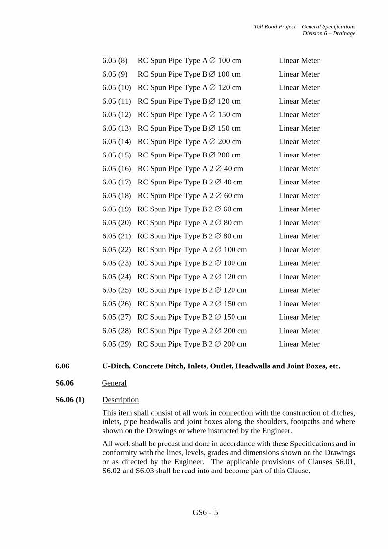
Toll Road Project – General Specifications
Division 6 – Drainage
GS6 - 5
6.05 (8) RC Spun Pipe Type A 100 cm Linear Meter
6.05 (9) RC Spun Pipe Type B 100 cm Linear Meter
6.05 (10) RC Spun Pipe Type A 120 cm Linear Meter
6.05 (11) RC Spun Pipe Type B 120 cm Linear Meter
6.05 (12) RC Spun Pipe Type A 150 cm Linear Meter
6.05 (13) RC Spun Pipe Type B 150 cm Linear Meter
6.05 (14) RC Spun Pipe Type A 200 cm Linear Meter
6.05 (15) RC Spun Pipe Type B 200 cm Linear Meter
6.05 (16) RC Spun Pipe Type A 2 40 cm Linear Meter
6.05 (17) RC Spun Pipe Type B 2 40 cm Linear Meter
6.05 (18) RC Spun Pipe Type A 2 60 cm Linear Meter
6.05 (19) RC Spun Pipe Type B 2 60 cm Linear Meter
6.05 (20) RC Spun Pipe Type A 2 80 cm Linear Meter
6.05 (21) RC Spun Pipe Type B 2 80 cm Linear Meter
6.05 (22) RC Spun Pipe Type A 2 100 cm Linear Meter
6.05 (23) RC Spun Pipe Type B 2 100 cm Linear Meter
6.05 (24) RC Spun Pipe Type A 2 120 cm Linear Meter
6.05 (25) RC Spun Pipe Type B 2 120 cm Linear Meter
6.05 (26) RC Spun Pipe Type A 2 150 cm Linear Meter
6.05 (27) RC Spun Pipe Type B 2 150 cm Linear Meter
6.05 (28) RC Spun Pipe Type A 2 200 cm Linear Meter
6.05 (29) RC Spun Pipe Type B 2 200 cm Linear Meter
6.06 U-Ditch, Concrete Ditch, Inlets, Outlet, Headwalls and Joint Boxes, etc.
S6.06 General
S6.06 (1) Description
This item shall consist of all work in connection with the construction of ditches,
inlets, pipe headwalls and joint boxes along the shoulders, footpaths and where
shown on the Drawings or where instructed by the Engineer.
All work shall be precast and done in accordance with these Specifications and in
conformity with the lines, levels, grades and dimensions shown on the Drawings
or as directed by the Engineer. The applicable provisions of Clauses S6.01,
S6.02 and S6.03 shall be read into and become part of this Clause.
Toll Road Project – General Specifications
Division 6 – Drainage
GS6 - 6
S6.06 (2) Materials
Materials shall be as shown on the Drawings and shall comply with the relevant
Clauses of this Specification. Information about units which require
reinforcement will be shown on the drawings.
Grating steel materials shall conform to the requirements of JIS G3101: Rolled
Steel for General Structures - SS400 or ASTM A36/A36M-14 or SNI 6764:2016
and shall be galvanized unless otherwise specified, in accordance with the
requirements of Clause S12.18 of these Specifications.
S6.06 (3) Construction
(a) Excavation
Excavation shall be performed in accordance with the requirements of
Division 5, "Structure Excavation" of these Specifications and the
relevant requirements of Clause S6.05.
(b) Foundation
The foundation shall be prepared in accordance with Sub-clause S5.01 (5).
When Class E concrete is shown on the Drawings or instructed by the
Engineer, this shall be in accordance with Clause S10.01 of these
Specifications.
(c) Layout
All work on U-ditches or concrete ditches, inlets, pipe headwalls and joint
boxes shall be carefully set out and constructed with due recognition being
taken of the fact that the upper surfaces shall be incorporated exactly into
curbs, footpaths, etc. The Engineer may reject any item of work under
this Clause when the upper surfaces do not meet the tolerances for curb
and footpath given elsewhere in these Specifications.
Bottom surface of ditches shall be smoothly and neatly finished. Where
the Engineer considers that any ditch, inlet or catch basin is likely to carry
foul sewage, he may instruct that the 150 mm sand trap as shown on the
Drawings be deleted and replaced by benching formed in Class D
concrete. All details regarding the shape of benching and method of
construction shall be in accordance with the Engineer's instructions.
Unless otherwise specified, joints of precast blocks shall be carefully
constructed using cement mortar of 1-part cement and 2 part sand so as to
prevent leakage. Hook of U-ditches or concrete ditches along steep
slopes shall be constructed so as to effectively resist sliding, by excavating
soil to the shape of the hook and placing the concrete without disturbing
the surrounding soil.
Cast-in-place concrete for waterways, drainage ditches, joint boxes,
manholes, pipe headwalls, inlet and outlet of waterways, shall be
constructed according to the requirements of Clause S10.01 and S10.02
of these Specifications. These structures shall be exactly as shown on the
Drawings and as directed by the Engineer. The top portions of catch
basins or inlets on which covers are to be placed shall be set exactly, and
carefully and smoothly finished.
Toll Road Project – General Specifications
Division 6 – Drainage
GS6 - 7
To ensure uniformity in the horizontal and vertical alignment of the curb,
the Engineer may instruct that work on the upper sections of inlets, catch
basins and U-ditches or concrete ditches be deferred and carried out
immediately before or during work on the adjacent curb. Any additional
expense incurred in complying with this instruction will be deemed to be
already included in the unit price for this work.
(d) Backfill and Reinstatement
Backfill shall be performed in accordance with the requirements of Clause
S5.01 of these Specifications. Backfill shall be carefully made so as to
obtain a bearing capacity equal to the adjacent subgrade. In compacting
subbase or base course in contact with drainage structures, rammers or
small compactors shall be used and care taken to prevent damage to the
adjacent structures. Backfill shall be carefully constructed so as to
prevent erosion by overflow of drain water or rain.
On completion of backfilling, the area excavated shall be reinstated to its
original condition, but the Engineer may waive or modify this requirement
if the area is to be overlaid or reconstructed under other Clauses of this
Contract.
S6.06 (4) Method of Measurement
The quantities of ditches, catch basins, inlets, pipe headwalls and joint boxes
completed and accepted in accordance with the Drawings, these Specifications
and as directed by the Engineer, will be measured as follows:
(a) The quantities of each type of ditch to be paid for will be the number of
linear meters measured along the centerline of the completed ditch. The
length will be measured to the outside face of any inlet or catch basin. In
locations where P.C. piles are shown on the Drawings under any U-ditch
or concrete ditch type the measurement and payment will be made under
the appropriate pay item in Division 10.
(b) The quantities of catch basins, manholes, inlet or outlet of waterway, pipe
headwalls and joint boxes to be paid for, will be the respective number for
each structure furnished and installed, complete in place and accepted in
accordance with the Drawings and the Engineer's instructions. The
measurement for the pipe headwalls will be deemed to include the
mortared rubble apron as detailed on the Drawings and no additional
measurement will be made for this apron.
(c) The measurement for ditches, inlets and catch basins will be independent
of the depth and the unit price will be deemed to cover any depth within
the range shown on the Drawings. Where U-ditches are formed with
vertical walls of different heights, the combined height of walls will be
compared with the combined height of walls on standard U-ditches as
shown on the Drawings, when determining the compliance with this
method of measurement. No additional measurement will be made for
joints between inlets or catch basins and ditches or drainage pipes. Any
additional expense involved in forming joints or junctions between
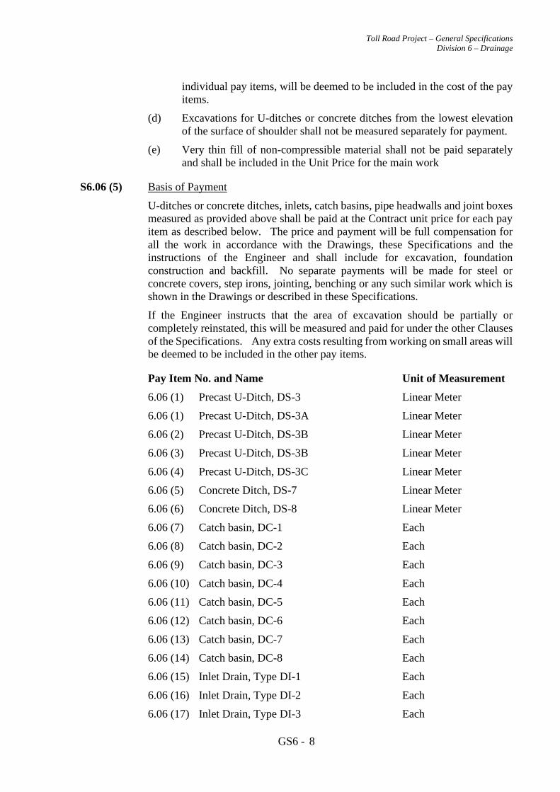
Toll Road Project – General Specifications
Division 6 – Drainage
GS6 - 8
individual pay items, will be deemed to be included in the cost of the pay
items.
(d) Excavations for U-ditches or concrete ditches from the lowest elevation
of the surface of shoulder shall not be measured separately for payment.
(e) Very thin fill of non-compressible material shall not be paid separately
and shall be included in the Unit Price for the main work
S6.06 (5) Basis of Payment
U-ditches or concrete ditches, inlets, catch basins, pipe headwalls and joint boxes
measured as provided above shall be paid at the Contract unit price for each pay
item as described below. The price and payment will be full compensation for
all the work in accordance with the Drawings, these Specifications and the
instructions of the Engineer and shall include for excavation, foundation
construction and backfill. No separate payments will be made for steel or
concrete covers, step irons, jointing, benching or any such similar work which is
shown in the Drawings or described in these Specifications.
If the Engineer instructs that the area of excavation should be partially or
completely reinstated, this will be measured and paid for under the other Clauses
of the Specifications. Any extra costs resulting from working on small areas will
be deemed to be included in the other pay items.
Pay Item No. and Name Unit of Measurement
6.06 (1) Precast U-Ditch, DS-3 Linear Meter
6.06 (1) Precast U-Ditch, DS-3A Linear Meter
6.06 (2) Precast U-Ditch, DS-3B Linear Meter
6.06 (3) Precast U-Ditch, DS-3B Linear Meter
6.06 (4) Precast U-Ditch, DS-3C Linear Meter
6.06 (5) Concrete Ditch, DS-7 Linear Meter
6.06 (6) Concrete Ditch, DS-8 Linear Meter
6.06 (7) Catch basin, DC-1 Each
6.06 (8) Catch basin, DC-2 Each
6.06 (9) Catch basin, DC-3 Each
6.06 (10) Catch basin, DC-4 Each
6.06 (11) Catch basin, DC-5 Each
6.06 (12) Catch basin, DC-6 Each
6.06 (13) Catch basin, DC-7 Each
6.06 (14) Catch basin, DC-8 Each
6.06 (15) Inlet Drain, Type DI-1 Each
6.06 (16) Inlet Drain, Type DI-2 Each
6.06 (17) Inlet Drain, Type DI-3 Each
Toll Road Project – General Specifications
Division 6 – Drainage
GS6 - 9
6.06 (18) Inlet Drain, Type DI-4 Each
6.06 (19) Inlet Drain, Type DI-5 Each
6.06 (20) Outlet Drain, Type DO-1 Each
6.06 (21) Outlet Drain, Type DO-2 Each
6.06 (22) Outlet Drain, Type DO-3 Each
6.06 (23) Outlet Drain, Type DO-4 each
6.06 (24) Outlet Drain, Type DO-5 Each
S6.07 Porous Drainage
S6.07 (1) General
(a) Description
(i) This work shall consist of winning, hauling, placing and
compacting porous drainage materials required for the bedding of
concrete drains or pipes or for subsurface drainage purposes or to
prevent the washout or scour of soil fines by groundwater seepage.
The work also includes the supply and placing of porous pipes
(drain type) and soil filter fabrics where these materials are called
for.
(ii) These materials are to be used against the rear faces of abutments,
wing walls retaining walls, rip rap and gabion walls, and in the
construction of pavement subsurface drains, concrete lined drains,
culverts, sand blankets and chimney drain, for stabilization works,
weep hole pockets, slope toe filters and other similar works, in
accordance with these Specifications or as directed by the
Engineer.
(b) Dimensional Tolerances
(i) Finished profiles for porous drainage granular fill shall not vary
from the specified or approved profiles by more than 2 cm.
(ii) Finished levels and grades for pipe and concrete drain bedding
material shall not vary from those specified or approved by more
than 1 cm.
(iii) Dimensional tolerances for the shape, diameter, and length and
wall thickness of porous pipes shall be as specified in AASHTO
178M/M178-17. The maximum gap between the ends of butt
jointed porous pipes when laid shall be 5 mm.
(iv) The minimum fall in drains constructed using porous pipe, shall
be 1: 1000.
(v) Foundation surfaces for porous drainage used in drainage blankets
shall be smooth and regular with a uniform fall that will prevent
ponding. The minimum grade for such surfaces shall be 1 : 200.
Toll Road Project – General Specifications
Division 6 – Drainage
GS6 - 10
(c) Submittals
(i) At least 21 days prior to the proposed date of placing any materials,
representative samples shall be submitted to the Engineer.
(ii) In the case of porous drainage or filter material, at least one 50 kg
sample of each material proposed to be used shall be submitted
together with 5 kg samples of the materials that will be upstream
and downstream of water seeping through the porous drainage.
The results of wash grading tests (AASHTO T11-05(2013) or SNI
ASTM C117:2012) shall also be supplied for each sample
submitted.
(iii) Samples of porous pipe or filter mesh proposed to be used shall be
submitted together with the manufacturer's specifications and
proof-test data.
(iv) The Contractor shall notify the Engineer in writing when the
placing is complete and before the work is concealed by any other
material or work. The notification of completion shall be
accompanied by the results of density tests as specified in Sub-
clause S6.07.(3).(a).(iii) and by survey records verifying that the
dimensional tolerances given in Sub-clause S6.07.(1).(b) are met.
(d) Work Scheduling
(i) Clean granular porous drainage material shall be placed only
immediately prior to the placing of the overlaying materials.
(ii) Granular Porous Drainage material in vertical slot drains in new
embankment shall be placed in horizontal layers at the same time
as the other embankment fill layers are laid.
S6.07 (2) Materials
(a) Porous Drainage or Filter Material
(i) Granular porous drainage or filter material shall be hard, durable
and clean. It shall be free from organic material, clay balls and
other deleterious substances, laterite or concretionary materials
shall not be used.
(ii) The required particle grading of the material will depend on its
intended function in the works and on the characteristics in the
materials that will be upstream and downstream of water seeping
through it, and also on the materials available. The grading
required in each case will be as directed by the Engineer, whose
assessment shall include ensuring that “Piping” (washing-out of
fines) cannot occur from the upstream material into the porous
backfill or from the porous backfill into the downstream material,
in accordance with the following criteria :
(1) D15 (filter)
-------------- < 5
D85 (soil)
Toll Road Project – General Specifications
Division 6 – Drainage
GS6 - 11
(2) D15 (filter)
4 < -------------- < 20
D15 (soil)
(3) D50 (filter)
-------------- < 25
D50 (soil)
where D15, D50 and D85 are the particle sizes from the grading
curve at 15 %, 50 % and 85 %, respectively, finer by weight. The
term “filter” refers to the coarser protecting material; the term “soil”
refers to the finer material being protected from piping.
(iii) Porous backfill and filter materials shall carry seepage water
without piping from embankment clay to 30 cm diameter rip rap
which generally to be protected by a gravel, the gravel by a sand
and the sand by a fine silty sand or plastic filter mesh.
(iv) In the case where there is no granular material downstream of the
porous drainage material but rather weep holes or pipe
perforations, selection and approval of the porous drainage
material shall be based on the following criteria:
(1) D85 (backfill) > 0.2 x D (hole)
and
(2) D50 (backfill) > 0.04 x D (hole)
where D85 and D50 are as defined in this Sub-clause in (b) above
and D (hole) is the inside diameter of the weep hole or pipe
perforation.
(v) Any sized porous drainage may be safely used downstream of a
plastic filter mesh. For example, in the case of pavement
subsurface drains, the porous backfill may be coarse uniform
cobbles if the trench sides are protected with the suitable plastic
filter mesh, but generally shall be a fine sand, if there is no plastic
filter mesh. Under no circumstances shall coconut palm fiber (Ind:
ijuk) be used as a substitute for a specified plastic mesh.
(b) Bedding Material for Pipes and Concrete Drains
Granular material for use as bedding material shall be sand, sandy gravel
or crushed rock and shall conform to the following requirements.
(i) Maximum Particle Size
(AASHTO T88-13 or SNI
3423:2008)
: 20 mm or less, but at least twice
the maximum clear gap in any
open jointed pipe
(ii) Passing No. 200 Sieve
(AASHTO T11-05(2013) or
SNI ASTM C117:2012)
: 15% maximum
(iii) Plasticity Index : 6 maximum
Toll Road Project – General Specifications
Division 6 – Drainage
GS6 - 12
(iv) Liquid Limit
(AASHTO T89-13 or SNI
1967:2008)
: 25 maximum
The material shall be well graded rather than uniform.
(c) Plastic Filter Mesh
Plastic filter mesh shall be a propriety woven synthetic geotextile fabric
approved by the Engineer. Selection of the mesh opening size (MOS) for
filter fabric shall be based on the particle size distribution curve for the
soil upstream of the filter fabric in accordance with whichever is the
smaller of:
(i) D85 (backfill) > 5 x D85 (soil)
and
(ii) D50 (backfill) > 25 x D50 (soil)
where, D85 and D50 are as defined in Sub-clause 6.07 (2).(a).(ii) above.
(d) Porous Pipes and Weep Hole Pipes
(i) Porous pipes for subsurface drainage shall be porous concrete or
perforated PVC or corrugated perforated polyethylene drain type
of approximately 100 mm inside diameter and comply with
AASHTO M176M/M176-17, AASHTO M278-15 and ASTM
F758-14(2019), and AASHTO M252-09(2012) respectively or
other specification approved by the Engineer.
(ii) Pipes to be placed through concrete or mortared walls or linings
as weep holes shall be 50 mm inside diameter and shall be of any
material approved by the Engineer which is strong enough to resist
being deformed during construction and setting of the mortar or
concrete.
(e) Mortar
Mortar used for locking pipe joints shall be Cement Mortar in accordance
with Clause S12.04 of these Specifications.
S6.07 (3) Placing Porous Drainage Material
(a) Placing Porous Drainage Material for Filter
(i) Before Porous Backfill shall be placed on any area, all unsuitable
too soft or too hard material shall have been replaced in
accordance with Sub-clause S4.03.(4) and S4.03.(1) of these
Specifications.
(ii) Placing of Porous Backfill around pipes or drains or behind
structures shall be performed systematically and as soon as
possible following placing of the pipes or structure. A minimum
period of 14 days before backfilling, however, should be allowed
following the mortaring of pipe joints or the placing of structures.
Toll Road Project – General Specifications
Division 6 – Drainage
GS6 - 13
(iii) The Porous Backfill shall be thoroughly compacted in layers not
exceeding 15 cm compacted thickness to a density in excess of
95 % of the maximum dry density determined according to
AASHTO T99-15 or SNI 1742:2008. Any approved method of
compaction may be used which achieves the required density.
(iv) The adequacy of compaction shall be monitored by density tests
in accordance with AASHTO T176-08(2013) or SNI 03-4428-
1997, and if the tests show insufficient density has been obtained
the Contractor shall apply additional compaction or otherwise
remedy the work as directed by the Engineer. The frequency and
position of testing shall be as directed by the Engineer
(v) Thin drainage blankets (less than 20 cm thick) of Porous Backfill
which are to be covered with earth fill shall be only nominally
compacted before the first layer of earth fill is placed on top. The
earth fill layer shall then be heavily compact until the underlying
layer of Porous Backfill has attained the specified density.
(vi) Until it is covered by other materials, Porous Drainage material
shall be careful protected from disturbance by traffic or feet.
Temporary wooden planks shall be laid over sand blankets to
allow the passage of workmen and the first layer of over the porous
material shall be carefully spread by hand methods to avoid co-
mingling of the two materials,
(vii) Care shall be taken to ensure minimum contamination of the
Porous Backfill material with the adjacent soil or fill, and where,
in the opinion of the Engineer this is occurring, or is likely to occur,
a form shall be used to separate the two materials during placing.
The form shall be 3 mm thick steel sheet or similar and shall be
gradually lifted as the backfilling work proceeds. The form shall
be completely removed from the completed fill.
(b) Placing Bedding Material
(i) Trenches or foundation pits for pipe culverts, concrete drains,
subsurface drains or other works requiring a bedding layer shall be
excavated in accordance with Division 4 of these Specifications
and a firm bed of uniform compaction prepared to the required
grade less the required thickness of bedding material.
(ii) The thickness of the bedding for pipes shall be not less than 10 %
of the diameter of the pipe nor less than 50 mm for any works,
(iii) Pipe bedding shall be shaped (using a semi-circular template of
the same diameter as outside diameter of the pipe) to fit the
underside of the pipe, so that it provides uniform support. When
bell and spigot pipe is used, recesses shall also be dug to
accommodate the bells.
(c) Placing Plastic Filter Mesh
Plastic filter mesh shall be installed in accordance with the procedures
recommended by the manufacturer and as directed by the Engineer.
Toll Road Project – General Specifications
Division 6 – Drainage
GS6 - 14
(d) Placing Porous Pipes
(i) Beds for porous pipes shall be prepared as above but using Porous
Backfill as specified in Sub-clause S6.07.(2).(a) rather than
Bedding Material as specified in Sub-clause S6.07.(2).(b)
(ii) The porous pipes shall be placed on the prepared bed and carefully
positioned with respect to both alignment and grade. The pipes
shall be butt jointed with a 1 to 5 mm gap left between pipes. The
joints shall be wrapped with an approved filter fabric which will
allow passage of water but not the porous backfill material. The
upper half of each joint shall be further protected with a strip of
tarred paper or similar non-perishable sheeting material. Each
joint shall be locked in place, but not sealed, using a small amount
of cement mortar on either side.
(iii) After the pipes have been laid, inspected and approved, porous
backfill material shall be placed and compacted as specified in
Sub-clause S6.07.(2).(a) above.
(e) Construction of Weep holes
(i) Where weep holes are required to be formed through a wall or
other construction without the permanent incorporation in the
works of a pipe or other forms the method of forming the weep
holes shall be subject to the approval of the Engineer.
(ii) All non-durable forms shall be removed on completion of the
structure
(iii) Weep holes shall be formed horizontally unless otherwise directed
by the Engineer.
(iv) Pipes that are to be encased in concrete as weep holes, or as forms
for weep holes, shall be held or braced rigidly during the concrete
placement.
(v) Unless otherwise specified or directed by the Engineer, weep holes
shall be spaced horizontally and vertically at intervals no greater
than 2 meters and 1 meter respectively.
(vi) Where filter pockets are required to be formed at the back of weep
holes the filter material shall extend into the bedding or backfill
for a distance of at least 30 centimeters from the end of the hole in
all directions, unless otherwise specified or directed by the
Engineer.
S6.07 (4) Method of Measurement
(a) Measurement of Porous Drainage Material or Filter Material
(i) Fill shall only be classified and measured as Porous Backfill or
Filter Material when used in locations or for purposes where
Porous Backfill or Bedding or Filter Material of Filter Pockets or
Drainage Blanket have been specified or otherwise approved in
writing by the Engineer, and when the material has been accepted
Toll Road Project – General Specifications
Division 6 – Drainage
GS6 - 15
by the Engineer as being suitable as Porous Drainage in terms of
the relevant provisions of this Clause.
(ii) The quantity of Porous Backfill to be measured for payment shall
be the number of cubic meter of the compacted material required
to fill the specified or approved lines. Any material placed in
excess of the approved theoretical volume shall be regarded as
either Common Fill or Selected Fill, as directed by the Engineer,
and shall not be measured under this Division irrespective of its
material qualities.
(iii) All approved porous backfill used and accepted on the Contract,
and which qualifies for measurement as above, shall be measured
and paid for under this Clause.
(b) Measurement of Plastic Filter Mesh
The quantity of Plastic Filter Mesh to be measured for payment shall be
the number of square meters of approved fabric actually installed in the
works and accepted in place and to be paid Pay Item 4.12.(1) Geotextile
for Subsurface Drainage (Class 2).
(c) Measurement of Porous Pipes
The quantity of Porous Pipe to be measured for payment shall be the
number of linear meters of approved pipe actually installed in the works
and accepted in place. No deduction in the measured length will be made
for the gaps at the pipe joints.
(d) Weep Holes, Tarred Paper and Cement Mortar
Pipe used for forming weep holes, tarred paper or other sheeting used to
wrap pipes and cement mortar used to seal joints between the pipe will
not be measured for payment, the cost of these materials being deemed to
be included in the bid price for Subsurface Drainage Works.
(e) Excavation for Porous Drainage Material, Filter Material
Except for Rock Excavation, no separate measurement for payment will
be made for excavation for filling work, the cost of this work being
deemed incidental to carry out the Porous Backfill or Filter Material and
included in the prices bid for the various construction materials used.
(f) Excavation for Subsurface Drainage Works
The quantity of excavation for Subsurface Drainage Works shall be
measured for payment in accordance with Division 4, Road Earthwork.
S6.07 (5) Basis of Payment
The work measured as provided above shall be paid for at the Contract Unit Price
for the Pay Items listed below and included in the Bill of Quantities, which prices
and payment shall be full compensation for all labor, material, equipment and
incidentals required to complete satisfactorily the work prescribed in this Clause.
Pay Item No. and Name Unit of Measurement
6.07.(1) Porous Drainage or Filter Material Cubic Meter

Toll Road Project – General Specifications
Division 6 – Drainage
GS6 - 16
6.07 (2a) Perforated Pipe for Subsurface Drainage Linear Meter
Works, Dia.4 inch
6.07 (2b) Perforated Pipe for Subsurface Drainage Linear Meter
Works, Dia.5 inch
6.07 (2c) Perforated Pipe for Subsurface Drainage Linear Meter
Works, Dia.6 inch
6.07 (2d) Perforated Pipe for Subsurface Drainage Linear Meter
Works, Dia.8 inch
Toll Road Project – General Specifications
Division 7 – Subgrade
GS7 - 1
DIVISION 7 SUBGRADE
S7.01 Subgrade Preparation
S7.01 (1) Description
The subgrade shall be that part of the work which is prepared for the sub-base or,
if there is no sub-base, the base of the pavement. It shall extend to the full width
of the roadbed including the shoulders and spot widening or such limited areas as
shown on the Drawings or as instructed by the Engineer.
For the purpose of payment, no differentiation is made between sub grade in cut
or fills areas.
Work on subgrade preparation shall only be carried out immediately prior to
laying the sub-base.
S7.01 (2) Construction
(a) Templates and Straightedges
The Contractor shall provide and use straightedges to check the accuracy
of the work and to ensure adherence to the requirements of these
Specifications.
When a 3 meter straightedge is laid on the surface parallel to and
perpendicular to the center line, variation of compacted the surface sub
grade from the lower edge of the straightedge shall not exceed 12 mm
over 3 m.
(b) Prior Works
Culverts, drain pipes and any other minor structures below the subgrade
level, including fully compacted backfill shall be completed before work
is begun on the subgrade. Ditches, drains, outlets for drainage, and
headwalls for culverts shall be in such operative condition as to ensure
prompt and effective drainage and to avoid damage to the subgrade by
surface water.
Any subgrade areas failing to meet the planned elevation due to settlement
or any other cause, or which have become damaged since completion of
earthwork, shall be removed, material replaced or added, recompacted and
finished to the specified lines, grades and cross-sections as directed by the
Engineer.
No work shall be started on the preparation of the subgrade before the
prior works herein described have been approved by the Engineer.
(c) Degree of Compaction
All material down to a depth of 30 centimeters below the subgrade level
shall be compacted to at least 100 percent of the maximum dry density as
determined according to AASHTO T99-15 or SNI 1742:2008 within
moisture content of - 3% to +1% of the optimum moisture content in
laboratory testing.
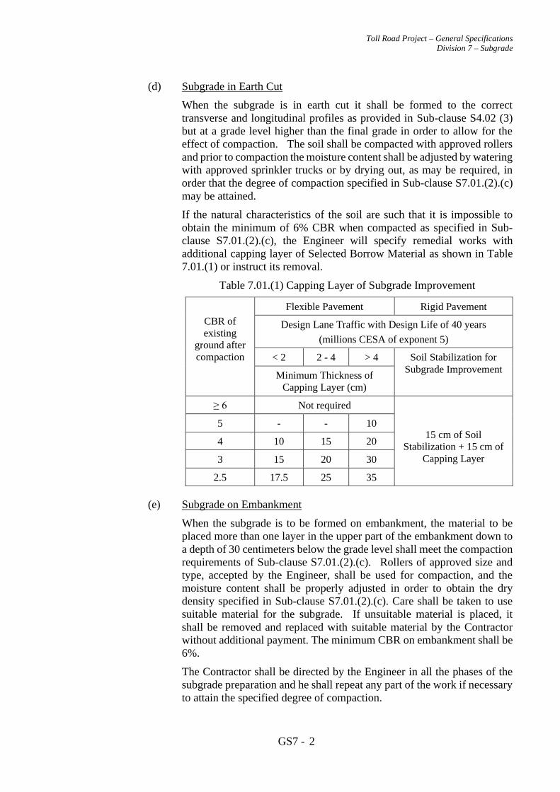
Toll Road Project – General Specifications
Division 7 – Subgrade
GS7 - 2
(d) Subgrade in Earth Cut
When the subgrade is in earth cut it shall be formed to the correct
transverse and longitudinal profiles as provided in Sub-clause S4.02 (3)
but at a grade level higher than the final grade in order to allow for the
effect of compaction. The soil shall be compacted with approved rollers
and prior to compaction the moisture content shall be adjusted by watering
with approved sprinkler trucks or by drying out, as may be required, in
order that the degree of compaction specified in Sub-clause S7.01.(2).(c)
may be attained.
If the natural characteristics of the soil are such that it is impossible to
obtain the minimum of 6% CBR when compacted as specified in Sub-
clause S7.01.(2).(c), the Engineer will specify remedial works with
additional capping layer of Selected Borrow Material as shown in Table
7.01.(1) or instruct its removal.
Table 7.01.(1) Capping Layer of Subgrade Improvement
CBR of
existing
ground after
compaction
Flexible Pavement Rigid Pavement
Design Lane Traffic with Design Life of 40 years
(millions CESA of exponent 5)
< 2 2 - 4 > 4 Soil Stabilization for
Subgrade Improvement Minimum Thickness of
Capping Layer (cm)
≥ 6 Not required
15 cm of Soil
Stabilization + 15 cm of
Capping Layer
5 - - 10
4 10 15 20
3 15 20 30
2.5 17.5 25 35
(e) Subgrade on Embankment
When the subgrade is to be formed on embankment, the material to be
placed more than one layer in the upper part of the embankment down to
a depth of 30 centimeters below the grade level shall meet the compaction
requirements of Sub-clause S7.01.(2).(c). Rollers of approved size and
type, accepted by the Engineer, shall be used for compaction, and the
moisture content shall be properly adjusted in order to obtain the dry
density specified in Sub-clause S7.01.(2).(c). Care shall be taken to use
suitable material for the subgrade. If unsuitable material is placed, it
shall be removed and replaced with suitable material by the Contractor
without additional payment. The minimum CBR on embankment shall be
6%.
The Contractor shall be directed by the Engineer in all the phases of the
subgrade preparation and he shall repeat any part of the work if necessary
to attain the specified degree of compaction.
Toll Road Project – General Specifications
Division 7 – Subgrade
GS7 - 3
(f) Protection of Completed Work
Any part of the subgrade that has been completed shall be protected
against drying out and cracking and any damage resulting from default of
the Contractor shall be repaired as directed by the Engineer without
additional payment.
(g) Traffic and Repairs
The Contractor shall be responsible for all the consequences of traffic
being admitted to the subgrade, and he may prohibit such traffic if he has
provided a detour or is operating half-width construction. He shall repair
any ruts or ridges occasioned by his own traffic or that of others by
reshaping and compacting with rollers of the size and type necessary for
such repair. The Contractor shall arrange for subgrade preparation and
sub-base or base placing to follow each other closely.
The subgrade, when prepared too soon in relation to the laying of the sub-
base, is liable to deteriorate, and in such case the Contractor shall repair,
re-roll, or compact the subgrade as may be necessary to restore it to the
state specified herein, without additional payment.
(h) Tolerances
(i) Final elevation after compaction shall not be more than 1 cm or less
than 2 cm as required or approved
(ii) The entire final surface shall be fine and flat and shall have proper
slope to ensure free flow of water surface.
S7.01 (3) Method of Measurement
The quantities to be paid for shall be the number of square meters of subgrade in
cut or in fill, prepared as hereinbefore prescribed, tested and accepted. The area
to be measured for payment will be limited to the sub-grade below sub-base or
under the lean concrete on rigid pavement in areas of new pavement construction.
Areas to be sodded or laid with interlocking concrete paving will not be measured
for payment under this Division.
S7.01 (4) Basis of Payment
The quantities, determined as provided in Sub-clause S7.01.(3) shall be paid for
at the pay item listed below. This payment shall be full compensation for
furnishing all labor, equipment and material necessary to complete the work
including scarifying, reworking, wetting or drying, compacting, proof rolling,
shaping and finishing, maintenance and other incidental items of work prescribed
in this Division.
Pay Item No. and Name Unit of Measurement
7.01 Subgrade Preparation Square Meter

Toll Road Project – General Specifications
Division 7 – Subgrade
GS7 - 4
Toll Road Project – General Specifications
Division 8 – Aggregate Base and Cement Treated Base
GS8 - 1
DIVISION 8 AGGREGATE BASE AND CEMENT TREATED BASE
S8.01 Aggregate Base
S8.01 (1) General
(a) Description
This work shall consist of supplying and placing of untreated crushed
stone materials between the subgrade and the concrete slab or bituminous
base course, in accordance with these Specifications and in conformity
with the lines, grades, thickness and typical cross-sections shown on the
plans or established by the Engineer.
(b) Dimensional Tolerances
(i) Dimensional tolerances for the prepared sub-grade and sub-base
shall be in accordance with Sub-clauses S7.01 (2) (h) and S8.01
(3) (e) respectively.
(ii) The average thickness of Cement Treated Base shall not less than
1 cm of the design thickness as shown in the Drawings.
(iii) The finished surface of Cement Treated Base shall conform
reasonably closely to the design grade and shall be not less than
one centimeter below the design level at any point.
(iv) The finished surface of Cement Treated Base shall deviate by no
more than 2 cm from a 3-meter-long straight edge placed on the
surface parallel to the road center line or from a template placed
transversely.
(v) The Contractor should note that poor surface shape of Cement
Treated Base will lead to greater asphalt quantities being required
in the overlay to meet the specified asphalt surface smoothness
tolerances. Since Hot Asphalt Mixtures are paid for on the basis of
design nominal dimensions rather than by weight, such additional
asphalt quantities will represent a loss to the Contractor. The
smoothest possible finish to the Cement Treated Base will
therefore give the Contractor the best economic solution and also
produce the best road.
S8.01 (2) Materials
(a) Material Sources
Aggregate Base and Drainage Layer material shall be selected from an
source approved by the Engineer and stored in accordance with Clause
S.1.03 “Storage of Materials” of these Specifications.
(b) Aggregate Base and Drainage Layer
The three different qualities in this Clause are specified as Aggregate Base
Class A, Aggregate Base Class B and Drainage Layer. Generally,
Aggregate Base Class A is base course quality for use in the layers
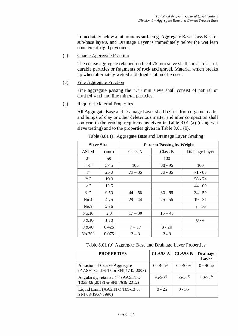
Toll Road Project – General Specifications
Division 8 – Aggregate Base and Cement Treated Base
GS8 - 2
immediately below a bituminous surfacing, Aggregate Base Class B is for
sub-base layers, and Drainage Layer is immediately below the wet lean
concrete of rigid pavement.
(c) Coarse Aggregate Fraction
The coarse aggregate retained on the 4.75 mm sieve shall consist of hard,
durable particles or fragments of rock and gravel. Material which breaks
up when alternately wetted and dried shall not be used.
(d) Fine Aggregate Fraction
Fine aggregate passing the 4.75 mm sieve shall consist of natural or
crushed sand and fine mineral particles.
(e) Required Material Properties
All Aggregate Base and Drainage Layer shall be free from organic matter
and lumps of clay or other deleterious matter and after compaction shall
conform to the grading requirements given in Table 8.01 (a) (using wet
sieve testing) and to the properties given in Table 8.01 (b).
Table 8.01 (a) Aggregate Base and Drainage Layer Grading
Sieve Size Percent Passing by Weight
ASTM (mm) Class A Class B Drainage Layer
2” 50 100
1 ½” 37.5 100 88 - 95 100
1” 25.0 79 – 85 70 - 85 71 - 87
¾” 19.0 58 - 74
½” 12.5 44 - 60
⅜” 9.50 44 – 58 30 - 65 34 - 50
No.4 4.75 29 – 44 25 - 55 19 - 31
No.8 2.36 8 - 16
No.10 2.0 17 – 30 15 – 40
No.16 1.18 0 - 4
No.40 0.425 7 – 17 8 - 20
No.200 0.075 2 – 8 2 - 8
Table 8.01 (b) Aggregate Base and Drainage Layer Properties
PROPERTIES CLASS A CLASS B Drainage
Layer
Abrasion of Coarse Aggregate
(AASHTO T96-15 or SNI 1742:2008)
0 - 40 % 0 - 40 % 0 - 40 %
Angularity, retained ⅜” (AASHTO
T335-09(2013) or SNI 7619:2012)
95/901) 55/502) 80/753)
Liquid Limit (AASHTO T89-13 or
SNI 03-1967-1990)
0 - 25 0 - 35
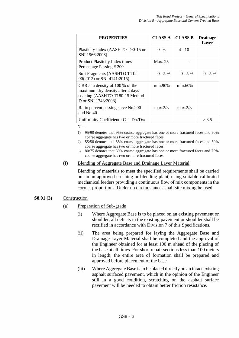
Toll Road Project – General Specifications
Division 8 – Aggregate Base and Cement Treated Base
GS8 - 3
PROPERTIES CLASS A CLASS B Drainage
Layer
Plasticity Index (AASHTO T90-15 or
SNI 1966:2008)
0 - 6 4 - 10
Product Plasticity Index times
Percentage Passing # 200
Max. 25 -
Soft Fragments (AASHTO T112-
00(2012) or SNI 4141:2015)
0 - 5 % 0 - 5 % 0 - 5 %
CBR at a density of 100 % of the
maximum dry density after 4 days
soaking (AASHTO T180-15 Method
D or SNI 1743:2008)
min.90% min.60%
Ratio percent passing sieve No.200
and No.40
max.2/3 max.2/3
Uniformity Coefficient : Cu = D60/D10 > 3.5
Note:
1) 95/90 denotes that 95% coarse aggregate has one or more fractured faces and 90%
coarse aggregate has two or more fractured faces.
2) 55/50 denotes that 55% coarse aggregate has one or more fractured faces and 50%
coarse aggregate has two or more fractured faces.
3) 80/75 denotes that 80% coarse aggregate has one or more fractured faces and 75%
coarse aggregate has two or more fractured faces
(f) Blending of Aggregate Base and Drainage Layer Material
Blending of materials to meet the specified requirements shall be carried
out in an approved crushing or blending plant, using suitable calibrated
mechanical feeders providing a continuous flow of mix components in the
correct proportions. Under no circumstances shall site mixing be used.
S8.01 (3) Construction
(a) Preparation of Sub-grade
(i) Where Aggregate Base is to be placed on an existing pavement or
shoulder, all defects in the existing pavement or shoulder shall be
rectified in accordance with Division 7 of this Specifications.
(ii) The area being prepared for laying the Aggregate Base and
Drainage Layer Material shall be completed and the approval of
the Engineer obtained for at least 100 m ahead of the placing of
the base at all times. For short repair sections less than 100 meters
in length, the entire area of formation shall be prepared and
approved before placement of the base.
(iii) Where Aggregate Base is to be placed directly on an intact existing
asphalt surfaced pavement, which in the opinion of the Engineer
still in a good condition, scratching on the asphalt surface
pavement will be needed to obtain better friction resistance.
Toll Road Project – General Specifications
Division 8 – Aggregate Base and Cement Treated Base
GS8 - 4
(b) Spreading
(i) Aggregate Base and Drainage Layer shall be delivered to the road
bed as a uniform mix and shall be spread at a moisture content
within the range specified in Sub-clause 8.01.(3).(c). The moisture
in the material shall be uniformly distributed throughout.
(ii) Each layer shall be spread in one operation at a uniform rate which
will produce the required compacted thickness within the specified
tolerances. Where more than one layer is to be placed the layers
are to be as nearly equal in thickness as possible.
(iii) Aggregate Base and Drainage Layer shall be spread and shaped by
any approved method which does not cause segregation of the fine
and coarse aggregate particles. Segregated material shall be
corrected or removed and replaced with graded material..
(iv) Aggregate Base shall be spread at least with an aggregate spreader.
Specifically, Aggregate Base Class A shall be spread with paver
to obtain a uniform thickness and evenness, and prevention of
segregation.
(iv) The minimum dense layer thickness for any construction layer
shall be twice the aggregate base maximum particle size. The
maximum loose layer thickness shall not exceed 20 cm, except use
special equipment approved by Engineer.
(v) Thickness Tolerances of compacted Base Course shall not exceed
10% and shall not less than 5% of design thickness accordance
with Drawings
(vi) Aggregate Base shall not be placed, spread or compacted while
rain is falling, and no compaction shall be carried out immediately
after rain or otherwise when the moisture content of the material
falls outside the range specified in Sub-clause S8.01. (3). (c)) (iii).
(vii) When a 3-meter straightedge is laid on the surface parallel to and
perpendicular to the center line, variation of the surface aggregate
base and drainage layer course from the lower edge of the
straightedge shall not exceed 8 mm over 3 m.
(c) Compaction
(i) Immediately following final mixing and shaping, each layer shall
be thoroughly compacted with suitable and adequate compaction
equipment approved by the Engineer to a density of at least 100 %
of the maximum modified dry density as determined by AASHTO
T180-15, Method D or SNI 1743:2008. Compaction of the
Drainage Layer shall be carried out about six passing with a
vibratory roller of 10 tons or as instructed by the Engineer.
(ii) The Engineer may direct that pneumatic tired rollers be used for
the final surface compaction, if static steel wheeled rollers are
considered likely to cause excessive breakdown or degradation of
the aggregate base.
Toll Road Project – General Specifications
Division 8 – Aggregate Base and Cement Treated Base
GS8 - 5
(iii) Compaction shall be carried out only when the moisture content
of the material is within the range of 3% less than optimum
moisture content to 1% more than optimum moisture content,
where the optimum moisture content is defined by the maximum
modified dry density determined by AASHTO T180-15, Method
D or SNI 1743:2008.
(iv) Rolling operations shall begin along the edges and progress
gradually towards the center, in a longitudinal direction. On super-
elevated sections rolling shall begin at the low side and progress
towards the high side. The rolling operation shall continue until all
roller marks are eliminated and the layer is uniformly compacted.
(v) Material along curbs, walls, and at other places not accessible to
the roller shall be compacted using approved mechanical tampers
or compactors.
(d) Testing
(i) The amount of supporting test data required for initial approval of
the quality of the material will be as directed by the Engineer but
will include all the tests specified in Sub-clause 8.01.(2)(e) on at
least three representative samples from the proposed material
source, selected to represent the range of material quality likely to
be obtained from the source.
(ii) Following approval of the quality of a proposed Aggregate Base
and Drainage Layer material, the full range of material quality
tests performed will be repeated subsequently, at the discretion of
the Engineer, in the event of observed changes in the material or
in its source or to its method of production.
(iii) A program of routine material quality control testing will be
carried out to control variability of the material being brought on
site. The extent of the testing shall be directed by the Engineer but
for every 1000 cubic meters of material produced the testing shall
include no less than five (5) plasticity index tests, five (5) particle
grading tests, and one (1) maximum dry density determined using
AASHTO T180-15, Method D or SNI 1743:2008. CBR tests shall
be carried out from time to time as directed by the Engineer.
(iv) The density and moisture content of the compacted aggregate base
material shall be routinely determined using AASHTO T191-14
or SNI 2828:2011 and/or Light Weight Deflectometer (LWD)
determined using ASTM E2583-07(2015) or Pd 03-2016-B which
equipped with a relationship between deflection and density, if
approved by the Engineer. The test shall be made to the full depth
of the layer at locations directed by the Engineer, but not more
than 200 m apart.
(e) Dimension and Elevation Tolerance
(i) Final surface layer Aggregate Base and Drainage Layer shall
comply with Table 8.01.(c) with the following tolerances:
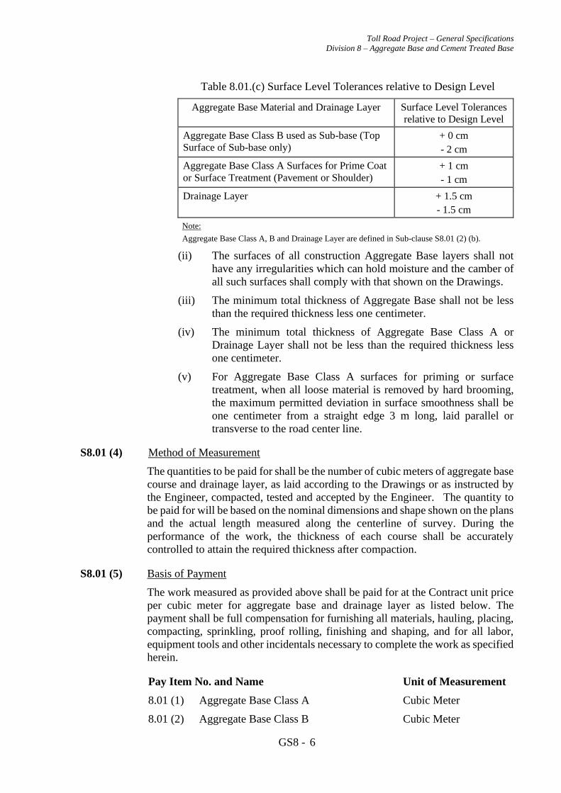
Toll Road Project – General Specifications
Division 8 – Aggregate Base and Cement Treated Base
GS8 - 6
Table 8.01.(c) Surface Level Tolerances relative to Design Level
Aggregate Base Material and Drainage Layer Surface Level Tolerances
relative to Design Level
Aggregate Base Class B used as Sub-base (Top
Surface of Sub-base only)
+ 0 cm
- 2 cm
Aggregate Base Class A Surfaces for Prime Coat
or Surface Treatment (Pavement or Shoulder)
+ 1 cm
- 1 cm
Drainage Layer + 1.5 cm
- 1.5 cm
Note:
Aggregate Base Class A, B and Drainage Layer are defined in Sub-clause S8.01 (2) (b).
(ii) The surfaces of all construction Aggregate Base layers shall not
have any irregularities which can hold moisture and the camber of
all such surfaces shall comply with that shown on the Drawings.
(iii) The minimum total thickness of Aggregate Base shall not be less
than the required thickness less one centimeter.
(iv) The minimum total thickness of Aggregate Base Class A or
Drainage Layer shall not be less than the required thickness less
one centimeter.
(v) For Aggregate Base Class A surfaces for priming or surface
treatment, when all loose material is removed by hard brooming,
the maximum permitted deviation in surface smoothness shall be
one centimeter from a straight edge 3 m long, laid parallel or
transverse to the road center line.
S8.01 (4) Method of Measurement
The quantities to be paid for shall be the number of cubic meters of aggregate base
course and drainage layer, as laid according to the Drawings or as instructed by
the Engineer, compacted, tested and accepted by the Engineer. The quantity to
be paid for will be based on the nominal dimensions and shape shown on the plans
and the actual length measured along the centerline of survey. During the
performance of the work, the thickness of each course shall be accurately
controlled to attain the required thickness after compaction.
S8.01 (5) Basis of Payment
The work measured as provided above shall be paid for at the Contract unit price
per cubic meter for aggregate base and drainage layer as listed below. The
payment shall be full compensation for furnishing all materials, hauling, placing,
compacting, sprinkling, proof rolling, finishing and shaping, and for all labor,
equipment tools and other incidentals necessary to complete the work as specified
herein.
Pay Item No. and Name Unit of Measurement
8.01 (1) Aggregate Base Class A Cubic Meter
8.01 (2) Aggregate Base Class B Cubic Meter
Toll Road Project – General Specifications
Division 8 – Aggregate Base and Cement Treated Base
GS8 - 7
8.01 (3) Drainage Layer Cubic Meter
S8.02 Cement Treated Base
S8.02 (1) Description
This work shall consist of providing a cement treated base course on a previously
prepared surface including the supplying, mixing, hauling, spreading, shaping,
compacting, curing and finishing of the material, all in accordance with the
requirements of these Specifications and in conformity with the dimensions and
typical cross sections shown on the Drawings and to the lines and grades
established by the Engineer.
S8.02 (2) Materials
(a) Portland Cement
The cement to be used for Cement Treated Base shall be Ordinary
Portland Cement Type I complying with the requirements of AASHTO
M85-15 or SNI 15-2049-2004 or PPC (Portland Pozzolan Cement)
complying with the requirements of ASTM C595/C595M-18 or SNI
0302: 2014 is able to be used if permitted in writing by the Engineer.
The Engineer may call for quality tests on each consignment of cement on
arrival on site, and also at any time after it has been stored on site prior to
use, to ascertain if the cement has deteriorated in any manner during
transit or storage. No cement will be allowed to be used until it has been
accepted by the Engineer.
All cement to be used in the Works shall be stored on site in accordance
with the provisions of Clause S10.01.(1).(e) of these Specifications, and
shall be inventoried on arrival under supervision of the Engineer. The
inventory records shall be signed in confirmation of their correctness by
both the Contractor and the Engineer. The amount of cement placed in the
Preliminary Field Trials or in the Works shall also be recorded in detail
and no cement shall be placed except when the Engineer or his
representative is on site to supervise and record the laying. Both the
Contractor and the Engineer will sign the daily record showing the amount
of cement actually placed in the Works.
(b) Water
The requirements of Sub-clause S10.01.(2).(d) shall govern
(c) Aggregate
The aggregate material shall be Aggregate Base Class A in accordance
with the provisions of Sub-clause S8.02.(2) of these Specifications.
S8.03 (3) Mixes
(a) General Composition of the Mixture
The Cement Treated Base mixture shall be comprised of approved
aggregate, cement and moisture. The cement content to be used shall be
Toll Road Project – General Specifications
Division 8 – Aggregate Base and Cement Treated Base
GS8 - 8
fixed by the Engineer on the basis of laboratory test data and Preliminary
Field Trials.
(b) Laboratory Mix Design
The contractor shall carry out the mix design to determine:
(i) The unconfined compressive strength.
(ii) The minimum cement content.
(iii) The optimum moisture content, and
(iv) The maximum dry density.
(c) Characteristic of the Cement Treated Base
Determination of Laboratory density shall be determined in accordance
AASHTO T180-15 or SNI 1743: 2008 method D by substituting the
particle of aggregate above 19 mm (¾"). Furthermore, the proportion of
aggregates, water and cement for compressive strength testing is based on
the test results of mixture with maximum dry density and optimum
moisture content.
The strength of the mixture is based on the compressive strength at 7 days
of cylinder specimens with diameter of 150 mm and height of 300 mm
height at 7 days, 45 – 55 kg/cm2.
Cylinder specimens using materials prepared in accordance with
AASHTO T180-15 or SNI 1743: 2008 method D, to be compacted in 5
layers, each layer to be compacted with 145 blows (see the note below)
with a hammer weight of 4.5 kg and falling height of 45 cm. Furthermore,
the compressive strength test of cylindrical specimens shall be in
accordance with ASTM C873/C873M-15 or SNI 1974: 2011.
Note:
(1) Compaction of 145 blows in each layer based on the calculation of the volume ratio
of cylinder (diameter of 15 cm and height of 30 cm) and the mold (diameter of 152
mm and height of 116 mm) multiplied by 56 blows.
(2) Estimate of cement content of Cement Treated Base is 3-5%. The required cement
content shall be determined based on the results of the job mix design.
(3) During the implementation of Cement treated Base, a minimum of 4 cylinder
specimens shall be provided for testing.
S8.02 (4) Construction
(a) Surface Preparation
Aggregate Base Class B as sub-base preparation work shall be carried out
in accordance with this Clause and the provisions of Clause S8.01 of these
Specifications to the grades, lines and dimensions shown on the Drawings
or directed by the Engineer.
On completion of compaction and before commencing the next operation,
the surface of the sub-base shall comply with the surface to tolerances
specified in Sub-clause S8.01.(3).(e) of the Specifications.
Prior to laying each section of Cement Treated Base, the prepared
compacted sub-base shall be cleaned of all dust and other deleterious
Toll Road Project – General Specifications
Division 8 – Aggregate Base and Cement Treated Base
GS8 - 9
materials by air jesting or other approved means, and shall be moistened
if necessary, as directed by the Engineer.
(b) Spreading of Cement
The cement shall be uniformly spread at a controlled mass by area rate
(kg/m2) across the pavement. The rate of spreading shall be such as to
provide the specified cement content in the compacted material. The
spreader shall be equipped with gates to allow variable widths of cements
to be deposited onto the pavement surface. The spreader hopper shall be
equipped with load cells or other means to permit accurate measurement
of cement usage. Unless otherwise approved by the Engineer the cement
shall be spread in two passes over each point on the pavement.
The contractor shall record the area of spread, tonnage of cement used for
each cement distribution run, and shall take tray samples at least once per
day in the presence of the Engineer.
The construction tolerance for the cement spread rate shall not exceed
10% of the Design Mix value.
Once the cement has been spread, the only traffic that may travel over the
area to be mixed, shall be construction plant employed for the work.
Cement shall not be spread when the wind speed exceeds 25 km/hour, if
rain is imminent or if the cement is likely to be affected by surface water
flows. Cement shall not be spread unless the mixer is ready to work. All
cement that has been spread shall be incorporated into the pavement as
soon as possible after spreading and not later than the same day as it is
spread. Mixed material that is left overnight without compaction shall be
removed or shall be reworked to the satisfaction of the Engineer and fresh
cement shall be added sufficient to achieve a UCS for 7 days of 45 - 55
kg/cm2 in accordance with AASHTO T22-14 or SNI 1974:2011.
(c) Mixing
The total specified quantity of cement required for the full depth of the
treatment shall be uniformly spread over the surface to be treated prior to
the mixing process, or incorporated in the pavement by an approved
controlled mechanical feed in one operation in a manner satisfactory to
the Engineer. No equipment except that used in spreading and mixing will
be allowed to pass over the freshly spread cement until mixing operations
are complete.
Water shall be added during the mixing process by means of a controlled
pressure feed distributor located inside the mixing chamber. The moisture
content shall be uniformly distributed through the pavement material and
shall be within the range approved by the Engineer to ensure that full
compaction can be achieved.
The mixing equipment shall be so operated that the mixed depth of CTB
shall be to the full design depth of the stabilized layer. Mixing shall be by
a self-propelled rotary mixer or reclaimer/mixer having a mixing width of
not less than 1.8 meters and a mixing depth of at least 300 mm. Mixing
Toll Road Project – General Specifications
Division 8 – Aggregate Base and Cement Treated Base
GS8 - 10
by other equipment including graders, profilers, rotary hoes and other
agricultural type implements shall not be approved.
Two passes of the mixer shall be provided to obtain an even mixture of
the cement throughout the pavement depth.
Mixing shall proceed in lanes working generally from the low to the high
side of the pavement, with sufficient overlap to ensure uniformity and
without intervening lanes of unmixed material. The stabilized layer shall
be 0.5 meters wider than the pavement seal on each side of the pavement
(d) Moisture Content
The moisture content of the material immediately after mixing shall be
80% to 110% of the moisture content specified by the Engineer and not
greater than the optimum moisture content. If no value has been specified
by the Engineer, the moisture content shall be 70% to 100% of the
laboratory optimum.
(e) Compaction
Compaction of the material in the pavement shall commence and shall
complete within 30 minutes and 60 minutes of the cement first coming in
contact with the soil respectively.
The compaction achieved, as determined by tests of the insitu material,
shall not be less than 98% of the maximum dry density.
Compaction shall be by a vibratory sheep foot roller having a minimum
static mass as shown below and a preferred pad height of at least 125mm.
Dense Thickness of CTB
(cm)
Static Weight of Vibratory Sheep Foot Roller
Minimum (ton)
≤ 20 13
25 19
30 25
(f) Curing
The mixed CTB shall be protected from moisture loss for a period of 4
days or until a further pavement layer is applied. Curing may be attained
by:
(i) keeping the pavement continuously damp by means of water spray
(ii) tack coat application in accordance with Clause S9.05
Specifications of within 24 hours of the finishing operations
S8.02 (5) Field Quality Control and Testing
(a) General
The Contractor shall provide a site laboratory and all necessary equipment
to carry out compaction control testing. Testing procedures and
frequency for Mix Design and quality control inclusive cement addition,
shape, depth, moisture content, surface tolerances and other shall be
included in the contractors Quality Plan.
Toll Road Project – General Specifications
Division 8 – Aggregate Base and Cement Treated Base
GS8 - 11
(b) Spread Rate
The cement spread rate shall be verified at least twice per day, or as
directed or approved by the Engineer.
(c) Depth
The depth of mixture shall be verified by measuring the depth of “cutting”
adjacent to an existing pavement material in at least two locations within
the lot and measured to the nearest 5 mm. The construction tolerance for
the mixed and compacted depth shall be ± 20 mm.
(d) Density
The density of mixture shall be verified by testing in at least two locations
per day in accordance with AASHTO T191-14 or SNI 2828:2011 (by the
sand cone method). For layers deeper than 200 mm there shall be two tests
for each location comprising the top 200 mm and the bottom 150 mm.
(e) Other Tests
There shall be at least two Unconfined Compressive Strength (UCS) and
moisture content tests per day. There shall be no separate payment for
tests.
(f) Acceptance/Rejection Criteria
Where the cement addition, compaction, shape or mixture depth does not
meet the specified requirements, at the discreation of the Engineer, this
work may be accepted without any payment, accepted by strengthening
with overlay, or the Contractor shall rework of the affected area.
S8.02 (6) Method of Measurement
The quantity of CTB to be measured for payment shall be the number of cubic
meters of required work completed and accepted work based on the specified plan
dimensions and the accepted average thickness. The average thickness (higher or
lower than design thickness as shown in the Drawings) shall not be less than the
design thickness.
S8.01.(7) Basis of Payment
The quantities of cement treated base, determined as provided above, shall be
paid for at the Contract Price per unit of measurement, for the Pay Items shown
below and in the Bill of Quantities. The rates shall include for all materials,
labour, plant, tools, testing and other work incidental to satisfactory completion
of the work.
Pay Item No. and Name Unit of Measurement
8.02 Cement Treated Base Cubic Meter

Toll Road Project – General Specifications
Division 8 – Aggregate Base and Cement Treated Base
GS8 - 12
Toll Road Project – General Specifications
Division 9 – Pavements
GS9 - 1
DIVISION 9 PAVEMENTS
S9.01 Bituminous Pavements - General
S9.01 (1) Description
The work described in this clause covers the treatment and repair of existing
bituminous pavements together with the supplying and laying of new construction
to form the completed pavements as shown on the Drawings and as instructed by
the Engineer.
The extent and treatment of existing pavement to be incorporated in the new
works will be instructed by the Engineer following a survey of cross-sections
prepared by the Contractor. The Contractor shall cooperate in the survey and
will be required to prepare additional cross-sections or levels to supplement those
used in the earthworks calculations and provide experienced staff to assist the
Engineer in his work.
S9.01 (2) Equipment
Unless specified elsewhere or approved by the Engineer, equipment used in the
work for bituminous pavements shall comply with the following specifications.
(a) Bitumen Distributor
The distributor shall be self-powered and have pneumatic tires of such
width and number that the load produced on the road surface shall not
exceed 100 kilograms per centimeter of tire width. It shall be so
designed, equipped, maintained, and operated that bituminous materials
at even heat may be applied uniformly on variable width of surface up to
5 meters at readily determined and controlled rates of from 0.2 to 9.0 liter
per square meter with uniform pressure, and with an allowable variation
from any specified rate not to exceed 0.1 liter per square meter.
Distributor equipment shall include an instrument for measuring the speed
of travel accurately at low speeds, the rate of flow of asphaltic material
through nozzles, the temperature of the contents of the tank, and the
pressure. These instruments shall be so located that the operator can
easily read them whilst operating the distributor.
The distributor shall be equipped with a separate power unit for the pump,
and full circulation spray bars which shall be adjustable laterally and
vertically. The spray bars on the distributor shall be controlled by a man
riding at the rear of the distributor in such a position that the operation of
all sprays is in his full view. The distributor shall incorporate one or
more hand operated lances, but these shall only be used in areas
inaccessible to the main spray bars.
(b) Bitumen Heater
This shall be of the oil jacket type or else incorporate an automatic agitator
to prevent local overheating of the material. The heater should
incorporate a thermometer.
Toll Road Project – General Specifications
Division 9 – Pavements
GS9 - 2
(c) Bituminous Mixing Plant (Asphalt Mixing Plant)
The Bituminous Mixing Plant shall:
(i) has a valid operation certificate from Ministry of Public Work and
Housing, and calibration certificate from - Metrology Office for
the asphalt, aggregate and filler scales, which appointed by the
Engineer. If the opinion of the Engineer, Asphalt Mixing Plant or
scales are in bad condition, the Asphalt Mixing Plant or scales
shall be recalibrated even the certificate is not yet expire;
(ii) be a batch mix plant and shall have a capacity sufficient to supply
the finisher on the road continuously when spreading the asphaltic
mix at normal speed and required thickness;
(iii) be so designed, coordinated and operated as to produce a mixture
within the job mix formula (JMF) tolerances;
(iv) be installed in an area approved by the Engineer which is
sufficiently far from residential areas to minimize disturbance and
complaints from local people;
(v) be provided with a dust collector, comprising dry cyclone and wet
cyclone system or bag house to ensure that emissions remain
below required levels. If one of these systems is damaged or not
functioning, the mixing plant shall not be operated;
(vi) have a minimum single pug mill capacity of 800 kg (as origin
manufacture) and equipped with the weighing computerized
system;
(vii) if used for the manufacture of modified asphalt mixes shall be
equipped with automated thermostatic temperature controls
capable of maintaining a mix temperature of 175ºC. If used the gas
fuel heater (dryer) shall be equipped with a temperature control
device (regulator) to maintain temperature constantly;
(viii) if used for the manufacture of AC-Base, have not fewer than five
cold feed bins and for other bituminous mix use minimum four
cold bins;
(ix) be of a well proven design, equipped with all necessary features;
(x) fuel used to heat the aggregate and asphalt shall be high speed
diesel oil with maximum specific gravity of 860 kg/m3 or kerosene
or LNG (Liquefied Natural Gas) or coal gas. The coal used in the
gasification process shall be min.5.500 K.Cal/kg;
(xi) aggregate supplied from hot bin or dryer shall not contain of soot
and or not burned oil residual; and
(xii) the overall operating system shall be computerized, starting from
the cold bin, hot bin control, mixing time, mixing weighing up to
production control and digital recording of each quantity of each
material until hot mix is produced.
Toll Road Project – General Specifications
Division 9 – Pavements
GS9 - 3
(d) Bituminous Storage Tank
Tanks for storage of bituminous binder shall be equipped for heating the
binder under effective and positive control at all times to a temperature
within the range specified. The heating shall be accomplished by steam
coils, electricity, or other means such that no flame shall come in contact
with the heating tank. Each tank shall be fitted with a thermometer located
so that the tank temperature can be easily read. A valve shall be positioned
in the outlet pipe from each tank for sampling.
The circulating system for the bituminous binder shall be of adequate size
to ensure proper and continuous circulation during the entire operating
period. Suitable means shall be provided, either by steam jackets or other
insulation, for maintaining the specified temperature of the bituminous
binder throughout the circulation system.
The total storage of the tanks shall be not less than the quantity required
for two days production. At least two equal capacity tanks shall be
provided. The tanks shall be so connected to the circulatory system that
each tank can be separately isolated without interference to the circulation
of bituminous binder to the mixer.
(e) Hot Bin Screen:
Hot bin screen sizes shall be provided in accordance with that are
appropriate for the asphalt mixtures required for the project. (Refer to
Table 9.07(3))
(f) Control of Mixing Time:
The plant shall be equipped with a positive means to govern the time of
mixing. Once agreed, this shall not be change without the Engineer’s
written approval.
(g) Weighing Bridge and Weighing House:
A weighing bridge and weighing house shall be provided for the weighing
of trucks loaded with material ready for delivery to Site. The scales shall
comply with the requirements for Plant Scales described above.
(h) Filler Storage and Handling:
A filler silo or weatherproof filler storage shed and elevator, and weigh
batch filler delivery system shall be provided
(i) Safety Requirements:
(i) Adequate and safe stairways to the mixer platform and guarded
ladders to other plant units shall be placed at all points required for
accessibility to all plant operations. Accessibility to the top of
truck bodies shall be provided by means of a platform or other
suitable device to enable the Engineer to obtain sampling and
mixture temperature data. To facilitate handling scale calibration
equipment, sampling equipment, etc, a hoist or pulley system shall
be provided to raise or lower the equipment from the ground to
platform or vice versa. All gears, pulleys, chains, sprockets, and
other dangerous moving parts shall be thoroughly guarded and
Toll Road Project – General Specifications
Division 9 – Pavements
GS9 - 4
protected.
(ii) Ample and unobstructed passage shall be maintained at all times
in and around the truck loading space. This space shall be kept free
from drippings from the mixing platform.
(j) Hauling Equipment
(i) Trucks for hauling bituminous mixture shall have tight, clean and
smooth metal beds that have been sprayed with a minimum
amount of soapy water, or lime solution to prevent the mixture
from adhering to the beds. Use of diesel fuel or other petroleum
products for this purpose shall not be allowed. Each load shall be
covered with canvas or other suitable material of adequate size as
to protect the mixture from the weather and the oxidation process.
The truck rear body overhang sand tail gate shall be so arranged
that the whole of the asphalt mixture can be discharged to the
asphalt paver hopper without interfering with the smooth
operation of the asphalt paver and while the truck remains engaged
with the asphalt finisher. Trucks fitted with oversize bodies shall
not be permitted. Overloading of asphalt trucks shall not be
permitted.
(ii) Any truck causing excessive segregation of material, or that shows
oil leaks in detrimental amounts, that causes undue delays, or that
the Engineer’s deems to be unsatisfactory shall, upon direction of
the Engineer, be removed from the work until such defects have
been corrected.
(iii) The mixture shall be delivered on the road at the specified
temperature, truck beds shall be insulated, and all covers shall be
securely fastened.
(iv) There shall be sufficient trucks hauling asphalt and they shall be
so organized as to ensure that the pavers can operate continuously,
at the approved speed.
(v) Paving on any section of the works shall not begin until there are
at least three trucks waiting to unload into the pavers. The paver
operating speed is low enough that the number of trucks in use for
haulage of asphalt, on each day, can keep the pavers moving
continuously. If this is impossible to achieve, the Engineer shall
only allow the pavers to restart, after a stoppage, when there are at
least three asphalt trucks waiting to unload. This is normal good
practice and no delays to paving caused by the Contractor’s failure
to maintain an adequate supply of mix material to the pavers shall
be accepted as a cause for any claim for extra payment or time.
(k) Spreading Finishing Equipment
(i) The equipment for spreading and finishing shall be approved
mechanical, self-powered pavers, capable of spreading and
finishing the mixture true to the line, grade, and cross section
required.
Toll Road Project – General Specifications
Division 9 – Pavements
GS9 - 5
(ii) The pavers shall be equipped with hoppers and distributing screws
of the reversing type to place the mixture evenly in front of
adjustable screeds. They shall be equipped with quick and efficient
steering devices and shall have reverse as well as forward gears.
The hoppers shall have wings that can be folded in at the end of
each truck load of asphalt to prevent retention of cooled material.
(iii) The pavers shall be equipped with electronic and/or mechanical
level control devices such as leveling beams, line and joint
matching shoes and cross fall devices, when necessary to maintain
the trueness of grade and to form the edges of the pavement to true
lines without the use of stationary side forms. A spirit level cross
fall device shall be mandatory. Other level control device
requirements may be nominated in the Instructions to Bidders for
each contract.
(iv) Pavers shall be equipped with a screed, of either the tamping or
vibrating type, and devices for heating the screed to the
temperature required for the laying of the mixture without pulling
or marring.
(v) The term “screed” refers to the standard floating mechanism
connected by side arms, to pivot points mounted on the paver
tractor unit forward of the rear wheels and designed to produce a
level, even, smooth textured surface without tearing, shoving or
gouging.
(vi) If, during construction, it is found that the spreading and finishing
equipment in operation leaves tracks, indented areas, segregation
or other objectionable irregularities that cannot satisfactorily
corrected by modification to the operating procedures, the use of
such equipment shall be discontinued and other satisfactory
spreading and finishing equipment shall be provided by the
Contractor.
(l) Compacting Equipment
(i) With each paver, at least two tandem steel wheeled rollers and one
pneumatic tired roller shall be required. At least one additional
pneumatic tired roller shall be provided for each 40 ton per hour
of production capacity or part thereof exceeding 40 ton per hour.
All rollers shall be self-propelled.
(ii) Pneumatic tired rollers shall be of an approved type having not
less than nine wheels with smooth tread compaction tires of equal
size and construction capable of operating at an inflation pressure
of 6 - 6.5 kg per square centimeter (85 - 90 pounds per square inch)
with the same ply of tires. Wheels shall be equally spaced along
both axle lines and arranged so that tires on one axle line track
midway between those on the other axle with an overlap. Each tire
shall be kept inflated to the specified operating pressure such that
the pressure difference between any two tires shall not exceed 0.35
kg per square centimeter (5 pounds per square inch). Means shall
Toll Road Project – General Specifications
Division 9 – Pavements
GS9 - 6
be provided for checking and adjusting the tire pressures on the
job at all times. For each size and type of tire used the Contractor
shall supply to the Engineer charts or tabulations showing the
relationship between wheel load, inflation pressure, tire contact
pressure, width and area. Each roller shall be equipped with means
of adjusting its total weight by ballasting so that the load per wheel
width can be varied from 300 - 600 kilograms per 0.1 meter. In
operation the tire inflation pressure and the wheel load shall be
adjusted, as required by the Engineer, to meet the requirements of
each particular application. In general, the compaction of any
course with a pneumatic tired roller shall be accomplished with
contact pressures as high as the material will support.
(iii) Self-propelled steel wheeled rollers may be of two types:
(a) Tandem static rollers
(b) Twin drum vibratory rollers
(iv) Static rollers shall have a minimum static weight of not less than
8 tons. Twin drum vibratory rollers shall have a static weight of
not less than 6 tons. The rollers shall be free of flat areas, dents,
openings or projections which will mar the surface of the
pavement.
(v) In the laying trial, for approval of the Job Mix Formula (JMF), the
Contractor will have demonstrated to the Engineer’s satisfaction
the combination of roller types he shall use to compact each
mixture satisfactory. He shall continue to keep available and use
the approved combination of rollers for each mixture. No
alteration shall be allowed unless the Contractor proves to the
Engineer that the new combination of rollers he proposes to use is
at least as effective as that already approved.
(m) Other Equipment’s
All necessary field equipment shall be provided including but not limited
to:
- Petrol driven vibrating plate.
- Vibratory Roller, 600 Kg.
- Straight edge 4 meters
- Thermometer (dial type) 300 °C (minimum three units).
- Compressor and jack hammers
- Water pass mounted on 4 meters straight edge and adjustable to
read 3% or other cross falls and super-elevations of 0% - 6%,
- Diamond or fiber power saw
- Rotary broom
- Calibrated asphalt depth gauge
- Tire pressure gauge
Toll Road Project – General Specifications
Division 9 – Pavements
GS9 - 7
S9.01 (3) General Requirement
Unless specified elsewhere or approved by the Engineer, all work utilizing new
bituminous material shall comply with the following for the purposes of
construction and measurement.
(a) Weather
Bituminous material shall not be laid in rain or in foggy weather and the
surface being covered shall be clean and dry. Bituminous plant mix shall
not be placed when weather conditions prevent the proper handling or
finishing of the material.
(b) Protection of Existing Work
Constructional plant used on pavements under construction shall be
suitable in relation to the material, condition and thickness of the courses
it traverses so that damage is not caused to the sub-grade or the pavement
courses already constructed. Bituminous material shall be kept clean and
uncontaminated for so long as it remains uncovered by succeeding layers
or surface treatment. The only traffic permitted access to bituminous
material shall be that engaged in laying and compacting the next course.
At his own risk, the Contractor may allow traffic to use the AC Binder
Course or AC Base Course but this will be subject to the Engineer's
approval and he may require the Contractor at his own expense, to seal or
otherwise protect the binder course. Should any bituminous material
become contaminated, the Contractor shall make good by cleaning it to
the satisfaction of the Engineer and if this proves impractical, he shall
remove and replace the layer at his own expense.
Before undertaking any bituminous spraying, the surfaces of structures,
curbs, trees, etc., adjacent to the areas being treated shall be protected in
such a manner as to prevent their being spattered or marred.
(c) Layers of Bituminous Courses
A bituminous pavement shall be laid so that the compacted thickness of
each layer does not exceed 2.5 times the minimum nominal thickness as
required in Sub-clause S9.07.(3).(h). Where any course of material
exceeds this thickness, it shall be laid in 2 or more layers of equal
thickness.
(d) Measurement
When payment is made by weight for any pay item this will be calculated
by using load delivery tickets for material incorporated in the permanent
works in accordance with the Drawings and these Specifications. The
weight of bituminous material shall be evidenced by machine stamped
load delivery tickets which shall identify the hauling unit (truck) for which
it was issued, together with the time of issue. The accuracy of the scales
shall be checked before the start of the works and in every subsequent
month the actual date of checking is to be chosen randomly.
Toll Road Project – General Specifications
Division 9 – Pavements
GS9 - 8
For purpose of checking, each truck will bear an identification number
painted on the sides of the truck, of such size as to be easily read by the
Engineer's representatives or checkers.
Payment will only be made for material incorporated in the permanent
works in accordance with the detailed drawings and the Engineer's
instructions. The Contractor should schedule and carry out his work in
such a way as to eliminate waste. The Engineer will deduct from the
certified weight-tickets for any material laid outside the dimensions
shown on the drawings or otherwise wasted due to the Contractor's
method of working.
(e) Overlay
When the contract covers for the overlay of existing pavement, any
regulating or levelling required shall be carried out using the material
determined in the Drawing or instructed by Engineer. All remedial
works to the pavement shall be executed before commencement of
overlay operations.
(f) Finished Work Samples
Plant-Mix: The Contractor shall cut full depth samples as directed, from
the finished course, for testing by the Engineer. Samples shall be neatly
cut by a saw, core drill, or other approved equipment.
Each sample shall be one slab of at least 15 cm by 15 cm, or a number of
cores, each with a minimum 10 cm diameter totaling at least 230 cubic
cm. At least one, but not more than three samples shall be taken for each
full day's operations. The Contractor shall supply and finish new
material to backfill voids left by sampling. Extra samples will be taken
whenever a substantial change has been approved and made in the job-
mix formula, or when the Engineer directs that more samples be taken.
Bituminous Spray: To check the rate of bituminous material actually
applied, sheets of building paper 50 cm by 50 cm previously weighed shall
be laid on the surface to be treated and weighed again after application of
the coat. The Contractor will supply the material for this check and will
re-spray the areas from which the paper is lifted.
Based on the results of the above checks and subsequent laboratory
analysis, the Engineer may instruct the removal and replacement at the
Contractor's expense, of any material which does not fully comply with
these Specifications. The Engineer may also instruct an additional coat of
material or removal of excess material and/or may reduce the quantity of
material approved for payment.
S9.02 Scarify Pavement
S9.02 (1) Description
This work shall consist of the removal of the upper layer or layers of an existing
asphalt pavement with or without cold milling machine where this is necessary to
allow resurfacing or to allow formation of a joint between existing and new work.
Toll Road Project – General Specifications
Division 9 – Pavements
GS9 - 9
Scarifying necessary solely because of the Contractor's method of working will
not be measured for payment.
S9.02 (2) Construction
The work shall be done by machine or by hand in such a manner that the area
scarified does not exceed that instructed by the Engineer. Any damage to asphalt
or curb designated by the Engineer to remain will be made good to the Engineer's
satisfaction at the Contractor's own expense. All material removed shall be
stockpiled on the site for use of the Employer, or otherwise disposed of as directed
by the Engineer.
S9.02 (3) Method of Measurement
The quantity measured for payment will be the number of square meters of
existing asphalt scarified in accordance with the Engineer's instructions. Where
the Engineer orders the removal of more than one layer in separate operations,
each layer removed will be measured and paid for separately. Where the
Engineer instructs that the full depth of existing asphalt shall be removed, the
work shall conform to the requirements of Clause S9.02 of these Specifications
for removal, measurement and payment.
S9.02 (4) Basis of Payment
The work measured as provided above shall be paid for at the Contract price per
unit of measurement for the pay item below. The Contract unit price will be full
compensation for furnishing all labor, tools, equipment and incidentals necessary
to do the work as directed by the Engineer, including removal and disposal of all
the resulting material.
Pay Item No. and Name Unit of Measurement
9.02 (1) Scarify existing Asphalt Pavement Square Meter
with Cold Milling Machine
9.02 (2) Scarify existing Asphalt Pavement Square Meter
without Cold Milling Machine
S9.03 Patching of Existing Pavements
S9.03 (1) Description
This work will consist of removal and replacement of damaged existing pavement
in localized areas. The Engineer will designate the areas of pavement to be so
treated and all work shall be carried out as specified below and will be paid for
on the basis of the number of square meters so treated.
S9.03 (2) Material
All material and work furnished under this pay item shall comply with the
requirements of the following Clauses and all compaction equipment may be
varied to suit the size of the area being treated:
Toll Road Project – General Specifications
Division 9 – Pavements
GS9 - 10
- Subgrade preparation : Clause S7.01
- Aggregate base : Clause S8.01
- Scarify existing asphalt pavement : Clause S9.02
- Prime : Clause S9.04
- Tack coat : Clause S9.05
- Asphalt concrete : Clause S9.07
- Asphalt cement : Clause S9.07
S9.03 (3) Construction
The area to be treated shall be marked on the surface, and the existing pavement
and sub-grade removed to a depth of 50 cm. Pavement to remain shall be cut to
form a vertical face and the edges of the excavation shall be straight and in neat
lines. After preparation of the subgrade in accordance with Sub-clause
S7.01.(2).(d), 30 cm of the aggregate base as used for new construction shall be
laid in accordance with Clause S8.01. The aggregate base shall then be primed
in accordance with Clause S9.04 and 20 cm of asphalt concrete base course laid
in 2 equal layers, in accordance with Clause S9.07. Bituminous material in the
existing pavement which will about with the new base course shall be tack coated
in accordance with Clause S9.05 or else lightly brushed with hot asphalt cement.
The finished level of the patched area shall be carefully formed to leave a smooth
surface level with the adjacent existing pavement.
S9.03 (4) Method of Measurement
The quantities to be paid for under this Clause will be the number of square meters
of existing pavement removed and replaced in accordance with this specification
and the Engineer's instructions. The maximum area of a single patch treated
under this Clause will be 40 square meters. When any single area exceeds this
quantity, it will be dealt with on the basis of the other individual pay items in this
specification for the purpose of measurement and payment.
Any pavement damaged by the Contractor's work under other Clauses of the
Specification shall be replaced in accordance with the requirements of this Clause
but will not be measured for payment and replacement will be at the Contractor's
own expense.
S9.03 (5) Basis of Payment
The accepted quantity of pavement replaced as determined above, will be paid
for at the Contract price per square meter, for the pay item as shown below. Such
price and payment will be considered as full compensation for the work of this
Clause, including any special working methods due to the restricted area being
repaired.
Pay Item No. and Name Unit of Measurement
9.03 Patching of Existing Pavements Square Meter
Toll Road Project – General Specifications
Division 9 – Pavements
GS9 - 11
S9.04 Bituminous Prime Coat
S9.04 (1) Description
This work shall consist of furnishing and applying bituminous material to a
previously prepared unbound base surface in accordance with these Specifications
and to the width shown on the typical cross sections or instructed by the Engineer.
S9.04 (2) Material
(a) Bituminous Material
Bituminous material shall be of type and grade called for in the Drawings
and shall conform to the requirements of the specifications listed below.
Medium-curing cut back asphalt : AASHTO M82-75(2012) or SNI
4799:2008
Medium setting emulsion asphalt : AASHTO M140-13 or SNI 6832:
2011 and or M208-01(2013) or SNI
4798:2011
Slow setting emulsion asphalt : AASHTO M140-13 or SNI 6832:
2011 and or M208-01(2013) or SNI
4798:2011
The grade (with temperatures of application in degrees C shall be MC-30
(40C ± 10C).
(b) Blotter Material
Blotter material shall be approved clean, dry sand or stone screenings free
from any cohesive material. It shall contain no organic matter.
S9.04 (3) Construction
(a) Weather Limitations
Prime coat shall be applied only with the approval of the Engineer who
will specify the grade to be used. The surface to be treated shall be dry
or slightly damp. Spraying prime coat shall not be applied when strong
winds or rain.
(b) Equipment
The equipment shall meet the requirements of Sub-clause S9.01 (2).
(c) Preparation of Surface
Immediately before applying the bituminous material all loose dirt and
other objectionable material shall be removed from the surface with a
power broom and/or blower as required. If the Engineer so orders, the
surface shall be lightly bladed and rolled immediately prior to the
application of bituminous material, in which case brooming or blowing
will not be required. When so ordered by the Engineer a light application
of water shall be made just before the application of bituminous material.
The area to be treated shall be approved by the Engineer prior to
application.
Toll Road Project – General Specifications
Division 9 – Pavements
GS9 - 12
(d) Application of Bituminous Material
Bituminous material shall be applied to the width of the section to be
primed by means of a bitumen distributor in a uniform, continuous spread.
The rate of application will usually be in the range of 0.4 to 1.3 kg/sq.m.
and the Engineer will determine the rate and material grade to be used for
each material being covered. Care shall be taken that the application of
bituminous material at the junction of spreads is not in excess of the
specified amount. Excess bituminous material shall be sponged from the
surface. Skipped areas or deficiencies shall be corrected. Building
paper shall be placed over the end of the previous applications and the
joining application shall start on the building paper. Building paper used
shall be removed and satisfactorily disposed of.
(e) Application of Blotter Material
In order to minimize possible damage by rain before the surface has
completely dried, the Engineer may instruct that blotter material should
be spread to cover any wet bituminous material. Blotter material shall be
spread so that no wheels or tracks will travel on uncovered wet bituminous
material.
(f) General
The relevant requirements of Clause S9.01 shall be read into and
considered part of this Clause.
S9.04 (4) Method of Measurement
The quantity of prime coat to be paid for shall be the number of kilograms of
bituminous material, laid in accordance with this Specification and the Engineer's
instructions.
S9.04 (5) Basis of Payment
The accepted quantities of prime coat, determined as provided above, will be paid
for at the Contract price per kilogram for bituminous material which price and
payment will be full compensation for the work of this Clause.
Blotter material will not be payable directly but shall be considered as a subsidiary
obligation of the Contractor covered under the Contract price for this Clause.
Pay Item No. and Name Unit of Measurement
9.04 Bituminous Prime Coat Kilogram
S9.05 Bituminous Tack Coat
S9.05 (1) Description
This work shall consist of preparing and treating an existing bituminous or bound
surface with bituminous material in accordance with these Specifications and in
conformity with the details shown on the Drawings or instructed by the Engineer.
Toll Road Project – General Specifications
Division 9 – Pavements
GS9 - 13
S9.05 (2) Materials
Bituminous material shall conform to the requirements of the specification listed
below.
Rapid-curing cut back asphalt : AASHTO M81-92(2012) or SNI 4800:
2011
Rapid-setting emulsion asphalt : AASHTO M140-13 or SNI 6832: 2011 and
or M208-01(2013) or SNI 4798:2011
The grade (with temperatures of application in degrees C) shall be RC-250 (70 ±
10 degrees).
S9.05 (3) Construction
(a) Equipment
The equipment shall meet the requirements of Sub-clause S9.01 (2).
(b) Preparation of Surface to be treated
The existing surface shall be patched and cleaned and shall be free of
irregularities to provide a reasonably smooth and uniform surface to
receive the treatment. Unstable, corrugated or damaged areas shall be
removed and replaced or repaired as instructed by the Engineer. The
edges of existing pavements, which are to be adjacent to new pavement,
shall be cleaned to permit the adhesion of bituminous materials. The area
to be treated shall be cleaned by a power broom and/or blower and
approved by the Engineer.
(c) Application of Bituminous Material
The bituminous material shall be uniformly applied with a pressure
distributor within the 1 hours preceding placement of the covering course.
The Engineer will specify the rate of the application which will usually be
in the range of 0.15 to 0.5 kg/sq.m.
Care shall be taken that the application of bituminous material at the
junction of spreads is not in excess of the specified amount. Excess
bituminous material shall be sponged from the surface. Skipped areas or
deficiencies shall be corrected.
The surface shall be allowed to dry until it is in a proper condition of
tackiness to receive the covering course. Tack coat shall be applied only
in advance of covering course placement as is necessary to obtain this
proper condition of tackiness. Until the covering course is placed, the
Contractor shall protect the tack coat from damage.
(d) General
The relevant requirements of Clause S9.01 shall be read into and
considered part of this Clause.
Toll Road Project – General Specifications
Division 9 – Pavements
GS9 - 14
S9.05 (4) Method of Measurement
The quantity of tack coat to be paid for shall be the number of kilograms of
bituminous material, laid in accordance with this Specification and the Engineer's
instructions.
S9.05 (5) Basis of Payment
The accepted quantities of tack coat, determined as provided above, will be paid
for at the Contract unit price per kilogram for bituminous material complete in
place, which price and payment will be full compensation for the work of this
Clause.
Pay Item No. and Name Unit of Measurement
9.05 Bituminous Tack Coat Kilogram
S9.06 Seal Coat
S9.06 (1) Description
This work shall consist of an application of bituminous material with an
application of cover coat material in accordance with these Specifications in
conformity with the lines shown on the Drawings or established by the Engineer.
S9.06 (2) Materials
(a) Bituminous Material
Bituminous material shall conform to the requirements of the following
specification.
Rapid-curing cut back asphalt : AASHTO M81-92(2012) or SNI
4800:2011
Rapid-setting emulsion asphalt : AASHTO M140-13 or SNI 6832:
2011 and or M208-01(2013) or SNI
4798:2011
The grade of cut back asphalt shall be RC-250 with application
temperature of 70 ± 10C or that directed by the Engineer.
(b) Cover Coat Material
Cover coat material shall be crushed stone, or crushed gravel and shall
meet the requirements for surface course material in Sub-clause
S9.07.(2).(b). When crushed gravel is used, not less than 50 percent by
weight of the particles retained on the No. 4 sieve shall have at least one
fractured face. Aggregates shall meet the gradation requirements of the
following table.
Toll Road Project – General Specifications
Division 9 – Pavements
GS9 - 15
Sieve Designation (mm) Percentage Passing by Weight
9.5
4.75
2.36
0.075
100
85 - 100
0 - 40
0 – 5
(c) The approximate amounts of materials per square meter for seal coats
shall be as follows:
Bituminous material (residue) ........ 0.87 – 1.00 lt. per sq.m.
Cover aggregate............................... 7.8 – 8.6 kg per sq.m.
The exact spread rates will be instructed by the Engineer.
S9.06 (3) Construction
(a) Weather Limitations
Seal coat shall be applied only when the surface to be treated is dry or
slightly damp, when the temperature of the road surface is 21 degrees
Celsius or more.
(b) Equipment
The equipment shall meet the requirements of Sub-clause S9.01 (2).
(c) Preparation of Surface
Seal coating operations shall not be started until the surface is thoroughly
compacted by Pneumatic Tired Roller. Bituminous material shall not be
spread until the surface has been cleaned as required, and the section to
be sealed has been approved by Engineer.
(d) Applying Bituminous Material
Bituminous material shall be applied by means of a pressure distributor in
a uniform, continuous spread over the section to be treated and within the
temperature range specified. The quantity of bituminous material to be
used per square meter shall be as directed. If the texture of the surface is
such that bituminous material penetrates too rapidly, a preliminary
application of from 0.2 to 0.5 liter per square meter of surface may be
required. A strip of building paper, at least 100 cm in width and with a
length equal to that of the spray bar of the distributor plus 30 cm, shall be
used at the beginning of each spread. If the cut-off is not positive, the
use of paper may be required at the end of each spread. The paper shall
be removed and disposed of in a satisfactory manner. The distributor
shall be moving forward at proper application speed at the time the spray
bar is opened. Any skipped areas or deficiencies shall be corrected.
Junction of spreads shall be carefully made to assure a smooth riding
surface. The length of bituminous material shall not be in excess of that
which approved spreading equipment can immediately cover with
approved material.
Toll Road Project – General Specifications
Division 9 – Pavements
GS9 - 16
The spread of bituminous material shall not be more than 15 cm wider
than the width covered by the cover coat material from the spreading
device. Under no circumstances shall operations proceed in such manner
that bituminous material will be allowed to chill, set up, or otherwise
impair retention of the cover coat.
The distributor, when not spreading, shall be parked so that the spray bar
or mechanism will not drip bituminous materials on the surface of the
travelled way.
(e) Application of Cover Coat Material
Immediately following the application of the bituminous material, cover
coat for seal shall be spread in quantities as designated. Spreading shall
be accomplished in such a manner that the tires of the approved aggregate
spreader at no time contact the uncovered and newly applied bituminous
material.
If directed, the cover coat material shall be moistened with water to
eliminate or reduce the dust coating of the aggregate. Moistening shall
be done the day before the use of the aggregate.
Immediately after the cover coat material is spread, any deficient areas
shall be covered by additional material. Initial rolling shall begin
immediately behind the spreader and shall consist of one complete
coverage with a power roller. Pneumatic tired roller shall begin
immediately after completion of the initial rolling and shall be completed
the same day the bituminous material and cover coat materials are applied.
After the application of the cover coat material, the surface shall be lightly
broomed or otherwise maintained as directed for a period of 4 days or as
directed. Maintenance of the surface shall include the distribution of
cover coat material over the surface to absorb any free bituminous
material and to cover any area deficient in cover coat material. The
maintenance shall be conducted so as not to displace embedded material.
Excess material shall be swept from the entire surface by means of rotary
brooms. The surface shall be swept at the time determined by the
Engineer. The Contractor shall furnish a pilot car and driver to conduct
traffic over completed seal coat at a maximum speed of 10 kilometers per
hour for the first 24 hours after cover aggregate is applied, if so directed
by the Engineer.
S9.06 (4) Method of Measurement
Seal coat will be measured by the square meter. No measurement or payment will
be made of areas "sealed" outside the limits shown on the plans or ordered by the
Engineer. No measurement or payment will be made for material used in excess
of those specified by the Engineer nor shall they form the basis of a claim for
additional payment.
Toll Road Project – General Specifications
Division 9 – Pavements
GS9 - 17
S9.06 (5) Basis of Payment
The accepted quantities of seal coat determined as provided above, will be paid
for at the Contract price per square meter which price and payment will be full
compensation for the work of this Clause and for any specified spread rates within
the ranges given in Sub-clause S9.06 (1).
Pay Item No. and Name Unit of Measurement
9.06 Seal Coat Square Meter
S9.07 Asphalt Concrete
S9.07 (1) Description
(a) This work shall consist of aggregate, filler added, anti-stripping agent and
bituminous material mixed in a central plant and spread and compacted
on a prepared surface in accordance with these Specifications and in close
conformity with the lines, grades, thicknesses and typical cross sections
shown on the Drawings or established by the Engineer
.(b) Type of hot bituminous mixture shall be as determined on this Clause or
as directed by Engineer. Asphalt mixtures to be used for pavement works
are Asphalt Concrete Base (AC-Base), Asphalt Concrete Binder Course
(AC-BC) and Asphalt Concrete Wearing Course (AC-WC)
(c) The relevant sections of Sub-clause S9.01 (2) and S9.01 (3) shall be read
into and considered as part of this Clause.
S9.07 (2) Material
(a) Composition of Mixtures
The bituminous material shall be composed of a mixture of aggregate,
filler added, asphalt cement and anti-stripping agent and/or modifier.
The several aggregate fractions shall be sized, uniformly graded and
combined in such proportions that the resulting composite blend meets the
job-mix formula and the following index of retained strength as
determined in accordance with SNI 06-2489-1991 (AASHTO T245-15)
for AC-WC and AC-BC and RSNI M-06-2004 (ASTM D5581-
07a(2013)) for AC-Base.
In calculating the void characteristics of the mixture the Contractor shall
allow for the asphalt absorbed by the aggregate and use the effective
specific gravity of aggregate and the maximum specific gravity of the
loose paving mixture (SNI 03-6893-2002 or AASHTO T209-12).
Some fractions of aggregate and filler added for the asphalt mixture shall
be batched and mixed with a proper proportion to obtain the grading
required in Table 9.07 (1).
The properties of asphalt mixture are specified in Table 9.07 (2).

Toll Road Project – General Specifications
Division 9 – Pavements
GS9 - 18
Table 9.07 (1) Aggregate Grading Requirements
Sieve Designation Percentage Passing by Weight
(mm) AC-Base AC-BC AC-WC
37.5
25.0
19.0
12.5
9.5
4.75
2.36
1.18
0.600
0.300
0.150
0.075
100
90 - 100
76 - 90
60 - 78
52 - 71
35 - 54
23 - 41
13 - 30
10 - 22
6 - 15
4 - 10
3 - 7
-
100
90 - 100
75 - 90
66 - 82
46 - 64
30 - 49
18 - 38
12 - 28
7 - 20
5 - 13
4 - 8
-
-
100
90 - 100
77 - 90
53 - 69
33 - 53
21 - 40
14 - 30
9 - 22
6 - 15
4 - 9
Table 9.07 (2) Hot Asphaltic Mixture Property Requirements
Mix Property AC-WC AC-BC AC-Base
Number of blows per Face 75 112(1)
Ratio particle passing #200 – effective
bitumen content
Min 1.0
Max 1.4
VIM (%)(3) Min 3.0
Max 5.0
VMA (%) Min 15 14 13
Void Filled with Bitumen (VFB) % Min 65
Marshall Stability (kg) Min 1000 2250(1)
Max - -
Marshall Flow (mm) Min 2.0 3.0(1)
Max 4.0 6.0(1)
Retained Marshall Stability after 24
hours soaking, 60°C (%)(4)
Min 90
Voids in Mix at Refusal Density (%)(2) Min 2
Note:
(1) Marshall Modification see Appendix 9.07.A.
(2) A vibratory hammer is preferred for Refusal Density compaction. The number of blows
per face shall be 600 for diameter 6 inches and 400 for diameter 4 inches.
(3) The Effective specific gravity of aggregate shall be calculated from the Maximum
Specific Gravity of Mix (Gmm test) SNI 03-6893-2002 or AASHTO T209-12.
(4) The Engineer may require or approve AASHTO T283-14 as an alternative test without
freeze thaw conditioning of -18 ± 3ºC.
Before stockpiling aggregate, the Contractor shall submit a proposed job-
mix formula in writing, for use by the Engineer in setting the job-mix to
Toll Road Project – General Specifications
Division 9 – Pavements
GS9 - 19
be used with the proposed materials. The formula submitted shall propose
definite single values for:
- The percentage of aggregate passing each specified sieve
- The percentage of bituminous material to be added, on the total
aggregate basis
- The temperature of the mixture leaving the mixer
- The temperature of the mixture delivered on the road
- The grade of bituminous material
Values shall be proposed within the limits specified for the particular type
of bituminous concrete called for. The Engineer will determine a job-
mix formula with single values for the above-mentioned and so notify the
Contractor in writing.
The mixture furnished by the Contractor shall conform to this job-mix
formula, within the following range of tolerances and within the grading
ranges of Table 9.07 (2).
Aggregate equal to the 2.36 mm and larger sieve ............... ± 5 percent
Aggregate passing the 2.36 mm and
retained the 0.150 mm sieve ................................................ ± 3 percent
Aggregate passing the 0.150 mm and
retained the 0.075 mm sieve ................................................ ± 2 percent
Aggregate passing the 0.075 mm sieve.............................. .± 1 percent
Bituminous material .......................................................... ± 0.3 percent
Temperature leaving the mixer ....................................... ± 10 degrees C
When unsatisfactory results make it necessary, the Engineer may ask a
new job-mix formula and so notify the Contractor in writing. Should a
change in sources of material be proposed, a new job-mix formula will be
established before the new material is used.
The plant mixed material will be tested after blending or mixing at the
plant or prior to final incorporation in the work.
The limits set by the Job Mix Formula and the Job Mix Tolerances
represent boundaries will guide the Contractor to product the mixtures
within the limits of job grading. The Engineer may accept job grading
beyond the permissible tolerance provided that the asphaltic mixture
meets all the requirements required in Table 9.07.(2).
(b) Coarse Aggregate
The coarse aggregate (retained on the 4.75 mm sieve) shall consist of
clean tough, durable fragments free from an excess of flat, elongated, soft
or disintegrated pieces and free from stone coated with dirt or other
objectionable material.
Toll Road Project – General Specifications
Division 9 – Pavements
GS9 - 20
The percentage of wear when tested according to AASHTO T96-02(2015)
or SNI 2417:2008 not more than 30 for 500 revolutions and 6 for 100
revolutions.
The sodium sulfate soundness loss shall not exceed 12 percent and the
magnesium sulfate soundness loss shall not exceed 18 percent. All to be
tested according to AASHTO T104-99(2011) or SNI 3407:2008.
The coating and stripping tested according to AASHTO T182-84(2002)
or SNI 2439:2011 is not less than 95%.
When crushed gravel is used, coarse aggregate angularity is defined as the
percent by weight of aggregate larger than 4.75 mm with one or more
fractured faces, tested according to AASHTO T335-09(2013) or SNI
7619:2012, at least 95/90 (means 95% of coarse aggregate has one
fractured face or more and 90% of coarse aggregate has two or more
fractured face).
The flat and elongated particles tested according to ASTM D4791-10 or
RSNI T-01-2005 (caliper ratio 1:5) or SNI 8287:2016 is not more than
10%.
The mineral particle passing No.200 sieve tested according to AASHTO
T11-05(2013) or SNI ASTMC117:2012 is not more than 1%.
Coarse aggregate fraction shall consist crushed stone or crushed gravel
and shall be provided in the nominal single size. Individual coarse
aggregate fractions shall be stockpiled separately and shall be fed into the
mixing plant using separate cold bin feeds with the following nominal
sizes:
Table 9.07 (3) Coarse Aggregate Cold Feed Stockpile Nominal Sizes
Mix Type Minimum coarse aggregate cold feed nominal sizes required (mm)
5 - 10 10 - 14 14 - 22 22 - 30
AC-WC yes yes
AC-BC yes yes yes
AC-Base yes yes yes yes
(c) Fine Aggregate
Fine aggregate, from each source, shall consist of natural sand or crushed
stone screening and consists of materials passing 4.75 mm size (No.4).
Each source and type of fine aggregate shall be stock-piled separately.
Natural sand used in asphaltic concrete mixtures shall not exceed 15% of
total mix by weight.
The fine aggregate shall be composed of clean, tough particles, free from
clay, or other objectionable material. Stone screenings shall be produced
from stone meeting the quality requirements of Sub-clause S9.07.(2).
To obtain a fine aggregate that meets the above requirements:
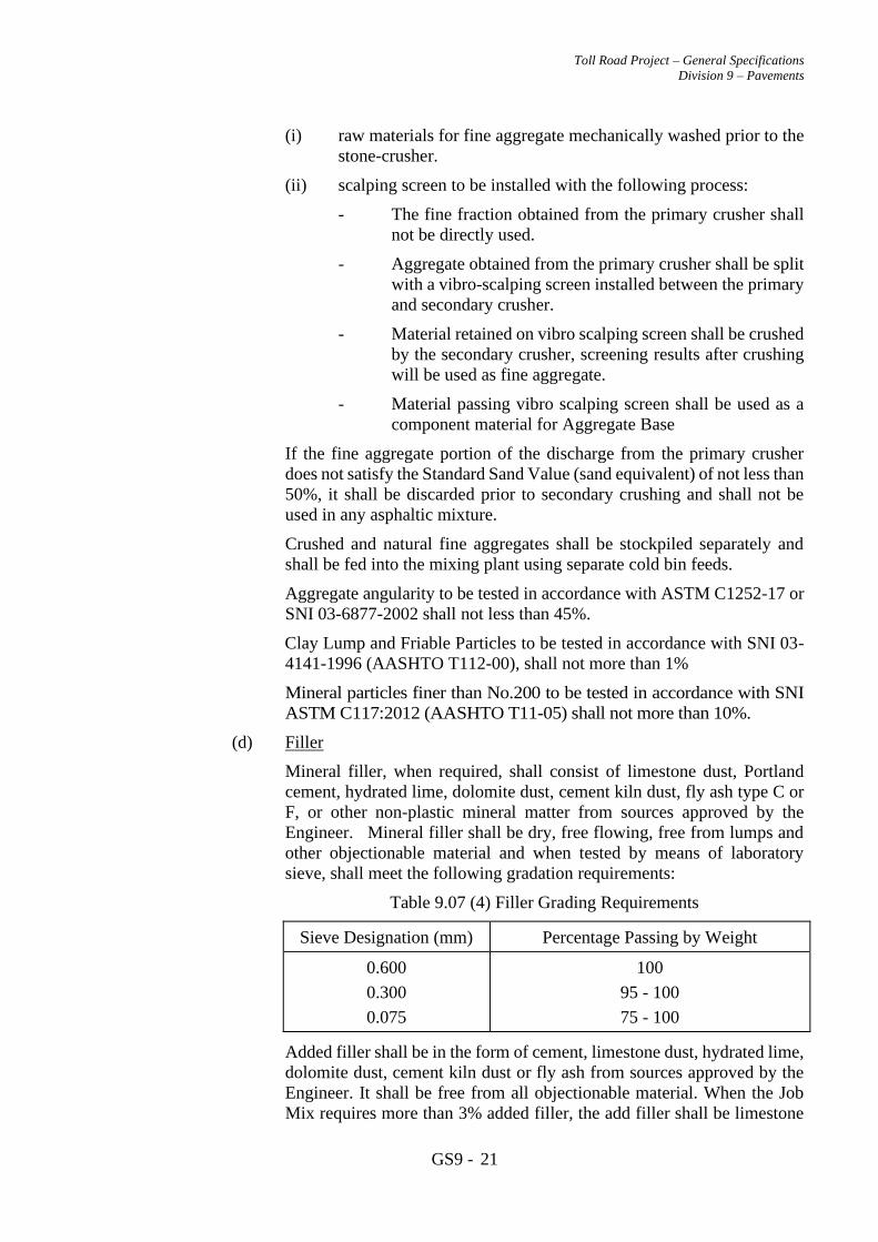
Toll Road Project – General Specifications
Division 9 – Pavements
GS9 - 21
(i) raw materials for fine aggregate mechanically washed prior to the
stone-crusher.
(ii) scalping screen to be installed with the following process:
- The fine fraction obtained from the primary crusher shall
not be directly used.
- Aggregate obtained from the primary crusher shall be split
with a vibro-scalping screen installed between the primary
and secondary crusher.
- Material retained on vibro scalping screen shall be crushed
by the secondary crusher, screening results after crushing
will be used as fine aggregate.
- Material passing vibro scalping screen shall be used as a
component material for Aggregate Base
If the fine aggregate portion of the discharge from the primary crusher
does not satisfy the Standard Sand Value (sand equivalent) of not less than
50%, it shall be discarded prior to secondary crushing and shall not be
used in any asphaltic mixture.
Crushed and natural fine aggregates shall be stockpiled separately and
shall be fed into the mixing plant using separate cold bin feeds.
Aggregate angularity to be tested in accordance with ASTM C1252-17 or
SNI 03-6877-2002 shall not less than 45%.
Clay Lump and Friable Particles to be tested in accordance with SNI 03-
4141-1996 (AASHTO T112-00), shall not more than 1%
Mineral particles finer than No.200 to be tested in accordance with SNI
ASTM C117:2012 (AASHTO T11-05) shall not more than 10%.
(d) Filler
Mineral filler, when required, shall consist of limestone dust, Portland
cement, hydrated lime, dolomite dust, cement kiln dust, fly ash type C or
F, or other non-plastic mineral matter from sources approved by the
Engineer. Mineral filler shall be dry, free flowing, free from lumps and
other objectionable material and when tested by means of laboratory
sieve, shall meet the following gradation requirements:
Table 9.07 (4) Filler Grading Requirements
Sieve Designation (mm) Percentage Passing by Weight
0.600
0.300
0.075
100
95 - 100
75 - 100
Added filler shall be in the form of cement, limestone dust, hydrated lime,
dolomite dust, cement kiln dust or fly ash from sources approved by the
Engineer. It shall be free from all objectionable material. When the Job
Mix requires more than 3% added filler, the add filler shall be limestone
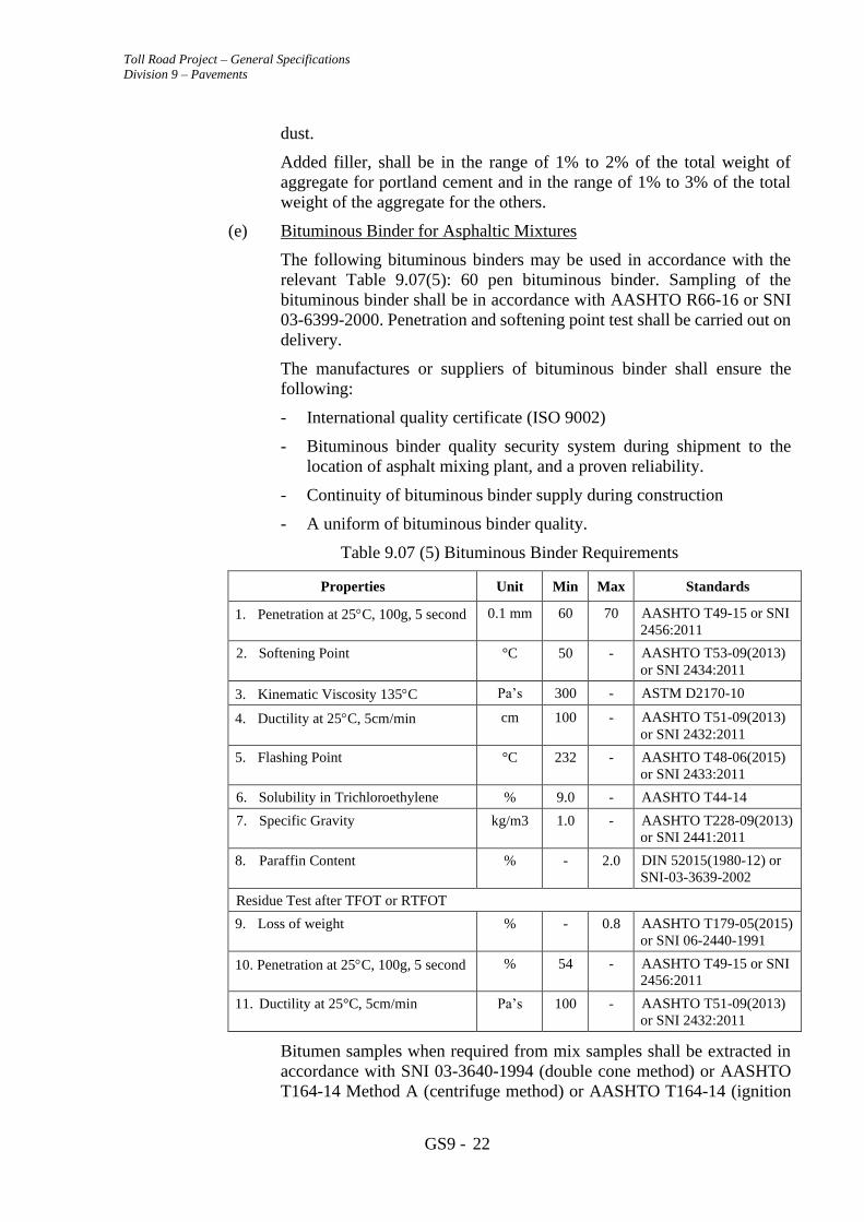
Toll Road Project – General Specifications
Division 9 – Pavements
GS9 - 22
dust.
Added filler, shall be in the range of 1% to 2% of the total weight of
aggregate for portland cement and in the range of 1% to 3% of the total
weight of the aggregate for the others.
(e) Bituminous Binder for Asphaltic Mixtures
The following bituminous binders may be used in accordance with the
relevant Table 9.07(5): 60 pen bituminous binder. Sampling of the
bituminous binder shall be in accordance with AASHTO R66-16 or SNI
03-6399-2000. Penetration and softening point test shall be carried out on
delivery.
The manufactures or suppliers of bituminous binder shall ensure the
following:
- International quality certificate (ISO 9002)
- Bituminous binder quality security system during shipment to the
location of asphalt mixing plant, and a proven reliability.
- Continuity of bituminous binder supply during construction
- A uniform of bituminous binder quality.
Table 9.07 (5) Bituminous Binder Requirements
Properties Unit Min Max Standards
1. Penetration at 25C, 100g, 5 second 0.1 mm 60 70 AASHTO T49-15 or SNI
2456:2011
2. Softening Point °C 50 - AASHTO T53-09(2013)
or SNI 2434:2011
3. Kinematic Viscosity 135C Pa’s 300 - ASTM D2170-10
4. Ductility at 25C, 5cm/min cm 100 - AASHTO T51-09(2013)
or SNI 2432:2011
5. Flashing Point °C 232 - AASHTO T48-06(2015)
or SNI 2433:2011
6. Solubility in Trichloroethylene % 9.0 - AASHTO T44-14
7. Specific Gravity kg/m3 1.0 - AASHTO T228-09(2013)
or SNI 2441:2011
8. Paraffin Content % - 2.0 DIN 52015(1980-12) or
SNI-03-3639-2002
Residue Test after TFOT or RTFOT
9. Loss of weight % - 0.8 AASHTO T179-05(2015)
or SNI 06-2440-1991
10. Penetration at 25C, 100g, 5 second % 54 - AASHTO T49-15 or SNI
2456:2011
11. Ductility at 25°C, 5cm/min Pa’s 100 - AASHTO T51-09(2013)
or SNI 2432:2011
Bitumen samples when required from mix samples shall be extracted in
accordance with SNI 03-3640-1994 (double cone method) or AASHTO
T164-14 Method A (centrifuge method) or AASHTO T164-14 (ignition
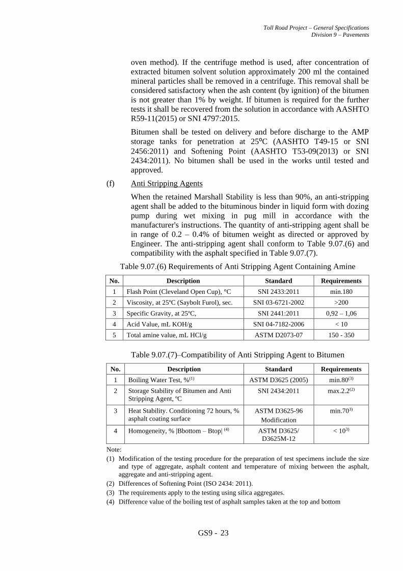
Toll Road Project – General Specifications
Division 9 – Pavements
GS9 - 23
oven method). If the centrifuge method is used, after concentration of
extracted bitumen solvent solution approximately 200 ml the contained
mineral particles shall be removed in a centrifuge. This removal shall be
considered satisfactory when the ash content (by ignition) of the bitumen
is not greater than 1% by weight. If bitumen is required for the further
tests it shall be recovered from the solution in accordance with AASHTO
R59-11(2015) or SNI 4797:2015.
Bitumen shall be tested on delivery and before discharge to the AMP
storage tanks for penetration at 25⁰C (AASHTO T49-15 or SNI
2456:2011) and Softening Point (AASHTO T53-09(2013) or SNI
2434:2011). No bitumen shall be used in the works until tested and
approved.
(f) Anti Stripping Agents
When the retained Marshall Stability is less than 90%, an anti-stripping
agent shall be added to the bituminous binder in liquid form with dozing
pump during wet mixing in pug mill in accordance with the
manufacturer's instructions. The quantity of anti-stripping agent shall be
in range of 0.2 – 0.4% of bitumen weight as directed or approved by
Engineer. The anti-stripping agent shall conform to Table 9.07.(6) and
compatibility with the asphalt specified in Table 9.07.(7).
Table 9.07.(6) Requirements of Anti Stripping Agent Containing Amine
No. Description Standard Requirements
1 Flash Point (Cleveland Open Cup), °C SNI 2433:2011 min.180
2 Viscosity, at 25ºC (Saybolt Furol), sec. SNI 03-6721-2002 >200
3 Specific Gravity, at 25ºC, SNI 2441:2011 0,92 – 1,06
4 Acid Value, mL KOH/g SNI 04-7182-2006 < 10
5 Total amine value, mL HCl/g ASTM D2073-07 150 - 350
Table 9.07.(7)–Compatibility of Anti Stripping Agent to Bitumen
No. Description Standard Requirements
1 Boiling Water Test, %(1) ASTM D3625 (2005) min.80(3)
2 Storage Stability of Bitumen and Anti
Stripping Agent, ºC
SNI 2434:2011 max.2.2(2)
3 Heat Stability. Conditioning 72 hours, %
asphalt coating surface
ASTM D3625-96
Modification
min.703)
4 Homogeneity, % |Bbottom – Btop| (4) ASTM D3625/
D3625M-12
< 103)
Note:
(1) Modification of the testing procedure for the preparation of test specimens include the size
and type of aggregate, asphalt content and temperature of mixing between the asphalt,
aggregate and anti-stripping agent.
(2) Differences of Softening Point (ISO 2434: 2011).
(3) The requirements apply to the testing using silica aggregates.
(4) Difference value of the boiling test of asphalt samples taken at the top and bottom
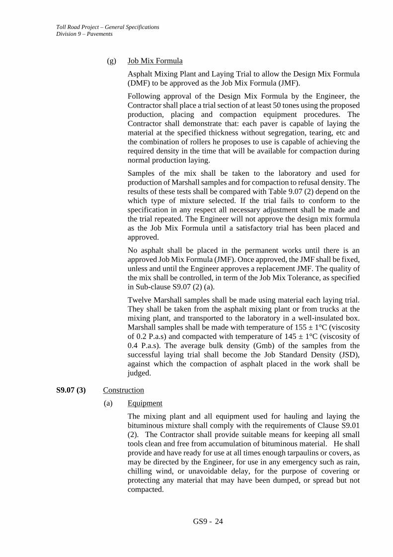
Toll Road Project – General Specifications
Division 9 – Pavements
GS9 - 24
(g) Job Mix Formula
Asphalt Mixing Plant and Laying Trial to allow the Design Mix Formula
(DMF) to be approved as the Job Mix Formula (JMF).
Following approval of the Design Mix Formula by the Engineer, the
Contractor shall place a trial section of at least 50 tones using the proposed
production, placing and compaction equipment procedures. The
Contractor shall demonstrate that: each paver is capable of laying the
material at the specified thickness without segregation, tearing, etc and
the combination of rollers he proposes to use is capable of achieving the
required density in the time that will be available for compaction during
normal production laying.
Samples of the mix shall be taken to the laboratory and used for
production of Marshall samples and for compaction to refusal density. The
results of these tests shall be compared with Table 9.07 (2) depend on the
which type of mixture selected. If the trial fails to conform to the
specification in any respect all necessary adjustment shall be made and
the trial repeated. The Engineer will not approve the design mix formula
as the Job Mix Formula until a satisfactory trial has been placed and
approved.
No asphalt shall be placed in the permanent works until there is an
approved Job Mix Formula (JMF). Once approved, the JMF shall be fixed,
unless and until the Engineer approves a replacement JMF. The quality of
the mix shall be controlled, in term of the Job Mix Tolerance, as specified
in Sub-clause S9.07 (2) (a).
Twelve Marshall samples shall be made using material each laying trial.
They shall be taken from the asphalt mixing plant or from trucks at the
mixing plant, and transported to the laboratory in a well-insulated box.
Marshall samples shall be made with temperature of 155 ± 1°C (viscosity
of 0.2 P.a.s) and compacted with temperature of 145 ± 1°C (viscosity of
0.4 P.a.s). The average bulk density (Gmb) of the samples from the
successful laying trial shall become the Job Standard Density (JSD),
against which the compaction of asphalt placed in the work shall be
judged.
S9.07 (3) Construction
(a) Equipment
The mixing plant and all equipment used for hauling and laying the
bituminous mixture shall comply with the requirements of Clause S9.01
(2). The Contractor shall provide suitable means for keeping all small
tools clean and free from accumulation of bituminous material. He shall
provide and have ready for use at all times enough tarpaulins or covers, as
may be directed by the Engineer, for use in any emergency such as rain,
chilling wind, or unavoidable delay, for the purpose of covering or
protecting any material that may have been dumped, or spread but not
compacted.
Toll Road Project – General Specifications
Division 9 – Pavements
GS9 - 25
(b) Preparation of Bituminous Material
The bituminous material shall be heated to the specified temperature in a
manner that will avoid local overheating and provide a continuous supply
of the bituminous material to the mixer at a uniform temperature at all
times. The maximum temperature of asphalt cement delivered to the
mixer shall not be more than 5 degrees Celsius above the temperature as
specified in (c) hereof for aggregate. Asphalt cement shall not be used
while it is foaming nor shall it be heated above 175 degrees Celsius at any
time.
(c) Preparation of Aggregates
The aggregates for the mixture shall be dried and heated to the required
temperature. Flames used for drying and heating shall be properly
adjusted to avoid damage to the aggregate and to avoid soot on the
aggregate. Immediately after heating and drying, the aggregates shall be
screened into three or more fractions as specified and conveyed into
separate compartments ready for batching and mixing with bituminous
material. When asphalt cement is used, the temperature of the aggregates
as introduced into the mixer, including the tolerance permitted by the job-
mix formula, shall not exceed that at which the asphalt cement has a Say
bolt Furol viscosity of 100 seconds, determined by AASHTO T72-
10(2019) or SNI 7729:2011. It shall not be lower than is required to
obtain complete coating and uniform distribution of the aggregate
particles and to provide a mixture of satisfactory workability.
(d) Mixing
The dried aggregate shall be combined in the mixer in the amount of each
fraction of aggregates required to meet the job-mix formula. The
bituminous material and anti-stripping agent shall be measured or gauged
and introduced into the mixer in the amount specified by the job-mix
formula.
After the required amounts of aggregate, bituminous material and anti-
stripping agent have been introduced into the mixer, unless otherwise
specified, the materials shall be mixed until a complete and uniform
coating of the particles and a thorough distribution of the bituminous
material throughout the aggregate is secured. Mixing time shall be
determined by using the procedure in accordance with AASHTO T195-
11(2015) (generally the dry and wet mix are approximately 10 and 35
seconds or more, respectively). Total mixing time will be determined by
the Engineer for each plant and for each type of aggregate used.
For plant mix bituminous pavement, the mixture shall be produced as
closely as practicable to the lowest temperature that will produce a
workable mix within the specified temperature range.
(e) Transporting, Spreading and Finishing
The mixture shall be transported from the mixing plant to the point of use
in vehicles conforming to the requirements of Sub-clause S9.01 (2). No
loads shall be sent out so late in the day as to prevent completion of the
Toll Road Project – General Specifications
Division 9 – Pavements
GS9 - 26
spreading and compaction of the mixture during daylight hours unless
with the Engineers approval and satisfactory illumination is provided.
Each vehicle shall be weighed after each loading at the mixer and a record
shall be kept of the gross weight, tare, net weight, and time of day of each
load operation. The mixture temperature shall be unloaded to asphalt
paver with the minimum 130oC and while the break down rolling
minimum 125oC.
The mixture shall be laid upon an approved surface, spread and struck off
to the grade and elevation established. Bituminous pavers shall be used
to distribute the mixture either over the entire width or over such partial
width as may be practical.
The longitudinal joint in one layer shall offset that in the layer
immediately below by approximately 15 cm; however, the joint in the top
layer shall be at the center line of the pavement if the roadway comprises
two lanes in width, or at lane lines if the roadway is more than 2 lanes in
width, unless otherwise directed.
On areas where irregularities or unavoidable obstacles make the use of
mechanical spread and finishing equipment impracticable, the mixture
shall be spread out, and raked by hand tools until the specified thickness.
If the continuity of concrete asphalt mixture production can be maintained
and is considered practical, the paver shall be used in a row (lined up) to
lay out the surface course on adjacent lanes.
The Contractor shall carry out such tests as are necessary to determine the
uncompacted thickness of mixture to be laid for compaction to conform
to the required finished depths. The uncompacted material immediately
behind the paver shall then be measured at frequent intervals and
adjustments made to ensure conformity with the nominal thickness.
(f) Compaction
After the bituminous mixture has been spread, struck off and surface
irregularities adjusted, it shall be thoroughly and uniformly compacted by
rolling. The specific gravity of the consolidated mixture, as determined
by AASHTO T166-13 or SNI 03-6757-2002 shall be not less than 98
percent of the Job Standard Density (JSD) as defined in Sub-clause S9.07
(3) (k).
The Contractor shall be deemed to have complied with his obligation to
thoroughly compact the asphalt mixture if the density of the compacted
layer is equal to or greater than the value given in Table 9.07 (8). If the
ratio of the minimum and maximum densities determined in the first set
of cores representing any individual area being measured for payment is
greater than 1.08, the cores shall be discarded and a new set shall be taken.
The surface shall be rolled when the mixture is in the proper condition and
when the rolling does not cause undue displacement, cracking or shoving.
The number, weight and type of rollers furnished shall be sufficient to
obtain the required compaction while the mixture is in a workable
Toll Road Project – General Specifications
Division 9 – Pavements
GS9 - 27
condition. The sequence of rolling operations and the selection of roller
types shall provide the specified pavement density.
Table 9.07 (8) Density Requirements
Specified
Density (%
of JSD)
Number of
Tests per
Sample
Minimum
Mean Density
(% of JSD)
Minimum Value of
Each Single Test
(% of JSD)
98 3 - 4 98.1 95
5 98.3 94.9
> 6 98.5 94.8
The surface shall be rolled when the mixture is in the proper condition and
when the rolling does not cause undue displacement, cracking or shoving.
The number, weight and type of rollers furnished shall be sufficient to
obtain the required compaction while the mixture is in a workable
condition. The sequence of rolling operations and the selection of roller
types shall provide the specified pavement density.
The compaction shall be three step operations as:
1. Break Down Rolling
2. Intermediate Rolling
3. Finishing Rolling
Unless otherwise directed, rolling shall begin at the sides and proceed
longitudinally parallel to the road center line, each trip overlapping one-
half the roller width, gradually progressing to the crown of the road.
When paving in echelon or abutting a previously placed lane, the
longitudinal joint should be rolled first followed by the regular rolling
procedure. On super elevated curves the rolling shall begin at the low side
and progress to the high side by overlapping of longitudinal trips parallel
to the center line.
Rollers shall move at a slow but uniform speed with the drive roll or
wheels nearest the paver. Rolling shall be continued until all roller marks
are eliminated and at least the minimum density indicated above has been
attained. Care shall be exercised in rolling not to displace the line and
grade of the edges of the bituminous mixture.
To prevent adhesion of the mixture to the rollers, the wheels shall be kept
properly moistened with water or water mixed with very small quantities
of detergent or other approved material. Excess liquid will not be
permitted. Along forms, headers, walls and other places not accessible
to the rollers, the mixture shall be thoroughly compacted with hot hand
tampers, smoothing irons or with mechanical tampers. On depressed
areas, a trench roller may be used or cleated compression strips may be
used under the roller to transmit compression to the depressed area.
Toll Road Project – General Specifications
Division 9 – Pavements
GS9 - 28
Any mixture that becomes loose and broke, mixed with dirt, or is in any
way defective shall be removed and replaced with fresh hot mixture,
which shall be compacted to conform to the surrounding area. Any area
showing an excess or deficiency of bituminous material shall be removed
and replaced. No traffic shall be permitted on the final course in less than
12 hours after completion unless authorized by the Engineer.
(g) Joint, Trimming Edges and Clean-up
Placing of the bituminous paving shall be as continuous as possible.
Rollers shall not pass over the unprotected end of a freshly laid mixture
unless authorized by the Engineer. Transverse joints shall be formed by
cutting back on the previous run to expose the full depth of the course.
Where pavers are not used in echelon to place the wearing course in
adjacent lanes and where the edges of the previously laid wearing course
are, in the opinion of the Engineer, in such condition that the quality of
the completed joint will be affected, longitudinal joints shall be trimmed
to a vertical face and to a neat line.
The exposed edges of the completed mat shall be cut off true to the
required lines. Material trimmed from the edges and any other discarded
or rejected bituminous mixture shall be removed from the roadway and
disposed of by the Contractor as instructed by the Engineer. When
directed by the Engineer, a brush coat of bituminous material shall be used
on contact surfaces of joints just before additional mixture is placed
against the previously rolled material.
(h) Layer Thicknesses and Surface Tolerance
The variation of the surface from the testing edge of a straightedge
between any two contacts with the surface shall not exceed the allowable
tolerances. For base course and binder course, the test for conformity
shall be made immediately after initial rolling and variation shall be
corrected by removing or adding materials as may be necessary. Rolling
shall then be continued as specified. Removal or addition of material to
the surface course will not be permitted after rolling has commenced.
Work on surface course shall be carefully controlled to ensure that
material as laid will conform to the allowable tolerance.
The thickness of each asphalt layer shall be monitored by pavement cores
taken by the Contractor under the supervision of the Engineer. The
spacing and location of the cores shall be as directed by the Engineer but
there shall be at least two cores taken transversely per traffic lane per
cross-section investigated. The longitudinal spacing of cross sections
investigated shall be no greater than 100 m per lane and shall be at least 2
cores taken randomly in any cross section
The “actual thickness” of Asphaltic Mixture placed over any given section
of the works, defined as the average thickness of all cores (either more or
less than the thicknesses as shown in the Drawings) taken in that section,
shall be conform to the tolerance given below:
- Asphaltic Concrete - Wearing Course : - 3.0 mm
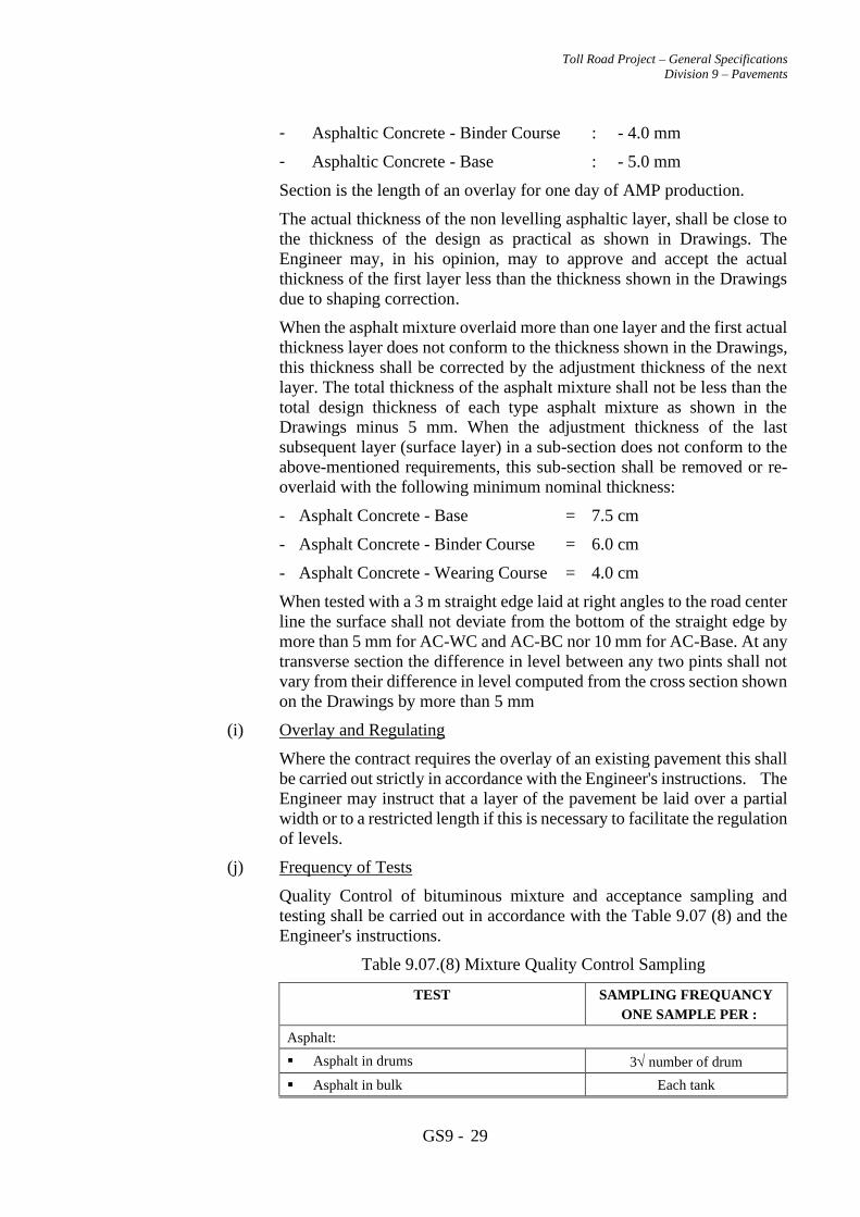
Toll Road Project – General Specifications
Division 9 – Pavements
GS9 - 29
- Asphaltic Concrete - Binder Course : - 4.0 mm
- Asphaltic Concrete - Base : - 5.0 mm
Section is the length of an overlay for one day of AMP production.
The actual thickness of the non levelling asphaltic layer, shall be close to
the thickness of the design as practical as shown in Drawings. The
Engineer may, in his opinion, may to approve and accept the actual
thickness of the first layer less than the thickness shown in the Drawings
due to shaping correction.
When the asphalt mixture overlaid more than one layer and the first actual
thickness layer does not conform to the thickness shown in the Drawings,
this thickness shall be corrected by the adjustment thickness of the next
layer. The total thickness of the asphalt mixture shall not be less than the
total design thickness of each type asphalt mixture as shown in the
Drawings minus 5 mm. When the adjustment thickness of the last
subsequent layer (surface layer) in a sub-section does not conform to the
above-mentioned requirements, this sub-section shall be removed or re-
overlaid with the following minimum nominal thickness:
- Asphalt Concrete - Base = 7.5 cm
- Asphalt Concrete - Binder Course = 6.0 cm
- Asphalt Concrete - Wearing Course = 4.0 cm
When tested with a 3 m straight edge laid at right angles to the road center
line the surface shall not deviate from the bottom of the straight edge by
more than 5 mm for AC-WC and AC-BC nor 10 mm for AC-Base. At any
transverse section the difference in level between any two pints shall not
vary from their difference in level computed from the cross section shown
on the Drawings by more than 5 mm
(i) Overlay and Regulating
Where the contract requires the overlay of an existing pavement this shall
be carried out strictly in accordance with the Engineer's instructions. The
Engineer may instruct that a layer of the pavement be laid over a partial
width or to a restricted length if this is necessary to facilitate the regulation
of levels.
(j) Frequency of Tests
Quality Control of bituminous mixture and acceptance sampling and
testing shall be carried out in accordance with the Table 9.07 (8) and the
Engineer's instructions.
Table 9.07.(8) Mixture Quality Control Sampling
TEST SAMPLING FREQUANCY
ONE SAMPLE PER :
Asphalt:
Asphalt in drums 3 number of drum
Asphalt in bulk Each tank
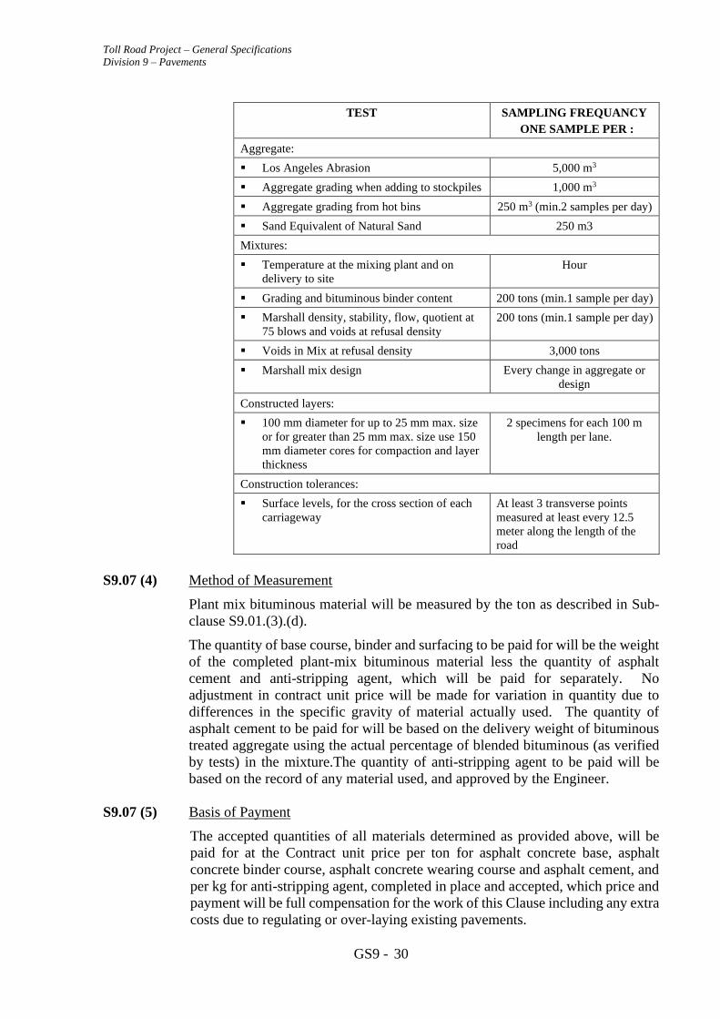
Toll Road Project – General Specifications
Division 9 – Pavements
GS9 - 30
TEST SAMPLING FREQUANCY
ONE SAMPLE PER :
Aggregate:
Los Angeles Abrasion 5,000 m3
Aggregate grading when adding to stockpiles 1,000 m3
Aggregate grading from hot bins 250 m3 (min.2 samples per day)
Sand Equivalent of Natural Sand 250 m3
Mixtures:
Temperature at the mixing plant and on
delivery to site
Hour
Grading and bituminous binder content 200 tons (min.1 sample per day)
Marshall density, stability, flow, quotient at
75 blows and voids at refusal density
200 tons (min.1 sample per day)
Voids in Mix at refusal density 3,000 tons
Marshall mix design Every change in aggregate or
design
Constructed layers:
100 mm diameter for up to 25 mm max. size
or for greater than 25 mm max. size use 150
mm diameter cores for compaction and layer
thickness
2 specimens for each 100 m
length per lane.
Construction tolerances:
Surface levels, for the cross section of each
carriageway
At least 3 transverse points
measured at least every 12.5
meter along the length of the
road
S9.07 (4) Method of Measurement
Plant mix bituminous material will be measured by the ton as described in Sub-
clause S9.01.(3).(d).
The quantity of base course, binder and surfacing to be paid for will be the weight
of the completed plant-mix bituminous material less the quantity of asphalt
cement and anti-stripping agent, which will be paid for separately. No
adjustment in contract unit price will be made for variation in quantity due to
differences in the specific gravity of material actually used. The quantity of
asphalt cement to be paid for will be based on the delivery weight of bituminous
treated aggregate using the actual percentage of blended bituminous (as verified
by tests) in the mixture.The quantity of anti-stripping agent to be paid will be
based on the record of any material used, and approved by the Engineer.
S9.07 (5) Basis of Payment
The accepted quantities of all materials determined as provided above, will be
paid for at the Contract unit price per ton for asphalt concrete base, asphalt
concrete binder course, asphalt concrete wearing course and asphalt cement, and
per kg for anti-stripping agent, completed in place and accepted, which price and
payment will be full compensation for the work of this Clause including any extra
costs due to regulating or over-laying existing pavements.
Toll Road Project – General Specifications
Division 9 – Pavements
GS9 - 31
Pay Item No. and Name Unit of Measurement
9.07 (1) Asphalt Concrete - Base ton
9.07 (2) Asphalt Concrete - Binder Course ton
9.07 (3) Asphalt Concrete - Wearing Course ton
9.07 (4) Asphalt Cement Pen 60/70 ton
9.07 (5) Anti Stripping Agent kg
S9.08 Cement Concrete Pavement
S9.08 (1) Description
This work shall consist of constructing a Portland cement concrete pavement,
constructed in accordance with the thickness and typical cross sections shown on
the Drawings or as instructed by the Engineer.
S9.08 (2) Applicable Provisions
The applicable provisions of Clauses S10.01 and S10.02 shall be read into and
become part of this Clause S9.08 "Concrete Pavement".
S9.08 (3) Materials
(a) Pavement Quality Concrete (P.Q.C.)
The constituent materials for P.Q.C. shall comply with Clause S10.01 of
the General Specifications except that Coarse Aggregate shall be crushed
stone.
(b) Reinforcing Steel and Dowel Bar
Reinforcing steel and dowel bar shall be in accordance with Clause S10.02
of these Specifications and such further details as are shown on the
Drawings.
(c) Joint Filler
Poured filler for joints shall conform to the requirements of ASTM
D6690-15 or SNI 03-4814-1998
Preformed fillers for joints shall conform to the requirements of AASHTO
M33-99(2012), AASHTO M153-06(2011) or SNI 03-4432-1997,
AASHTO M213-01(2015) or SNI 03-4815-1998, and ASTM D2628-
91(2016), as specified on the Drawings or by the Engineer and shall be
punched to admit dowels where called for on the Drawings. The filler
for each joint shall be furnished in a single piece for the depth and width
required for the joint unless otherwise authorized by the Engineer. When
the use of more than one piece is authorized for a joint, the abutting ends
shall be fastened securely, and held accurately to shape, by stapling or
other positive fastening satisfactory to the Engineer.
Toll Road Project – General Specifications
Division 9 – Pavements
GS9 - 32
(d) Slip Sheet Membrane
Membrane for waterproof underlay below the slab shall be polythene
sheeting 125 microns thick or as instructed by the Engineer. When an
overlap of underlay materials is necessary this shall be at least 300 mm.
(e) Curing Materials
Curing materials shall conform to the following requirements as specified
or other materials satisfactory to the Engineer:
Liquid Membrane - Forming ASTM C309-19 or
Compounds for Curing Concrete - SNI ASTM C309:2012
Type 2 white pigmented
(f) Concrete
(i) Components of the Mix
The approval of mix proportions shall be made on the basis of trial
mixes developed by the Contractor in accordance with Clause
S10.01 of these Specifications.
The cement content per cubic meter of solid concrete shall not less
than the content of trial mix approved. The using of very high
cement content shall be undesirable and the Contractor shall
provide the mix design with the most economical proportion that
meets all the requirements.
The coarse and fine aggregate shall be as specified in Clause
S10.01 of the General Specifications. In determining the coarse
aggregate/fine aggregate ratio the fine aggregate proportion shall
be kept to a minimum. However, at least 40% aggregate (by
weight) in the concrete mix shall be the fine aggregate which
defined as aggregate passing 4.75 mm sieve. The combined
aggregate shall not contain the particle finer than 0.075 mm more
than 2% except the Pozolan material. Once the appropriate total
grading has been determined and approved, it shall be varied only
with the permission of the Engineer.
The Contractor is allowed a choice of coarse aggregate up to a
maximum size of 40 mm providing that suitable workability for
the plant being used can be achieved and the surface regularity
required maintained. The Engineer at his discretion, may order a
change in the size of the Contractor's choice of coarse aggregate.
Fly ash may be used by maximum of 25% of the portland cement
weight for the Ordinary Portland Cement (OPC) Type I or III only
and may not be used for Pozolan Portland Cement (PPC)
The use of plasticizers or water reducing agents shall not be
permitted except with the written permission of the Engineer.
Accelerating admixtures and those containing calcium chloride
shall not be used.
Chemical additives shall be in accordance with AASHTO
M194M/M194-13 or SNI 03-2495-1991. Additional materials
Toll Road Project – General Specifications
Division 9 – Pavements
GS9 - 33
containing calcium chloride, calcium format, and try ethanolamine
shall not be used.
The following conditions shall be met:
(1) For the combination of two or more additives, the
compatibility of additives shall be specified in the
manufacture’s certificate.
(2) For the mixture with fly ash of less than 50 kg/m3, the
contribution of total alkali (expressed as Na2O equivalent)
of all additives used in the mixture shall not more than 0.20
kg/m3.
Super plasticizer/high range water reducer can be used on the
written approval of the Engineer.
(ii) Concrete Strength
The minimum trial mix and site working (production control)
flexural strength shall not be less than 4.7 MPa and 4.5 MPa
respectively at 28 days when tested by the third point method in
accordance with AASHTO T97-14 or SNI 4431:2011. Especially,
Fast Track Cement Concrete Pavement 8 or 24 hours shall be
obtained according to their ages and shall not be less than the
requirements as above mentioned in 8 or 24 hours.
The minimum compressive strength value for production may be
amended based on a comparison of flexural and compressive
strengths achieved for a series of not less than 16, 8 compressive
and 8 flexural strength tests of the approved mix design.
Amendment of the minimum Compressive Strength values above
mentioned shall be subject to the instruction or approval of the
Engineer.
(iii) Sampling of Concrete
Concrete will be sampled each 50 cubic meters for slip form and
30 cubic meter for fixed form, two pairs of beam test specimens
shall be printed for flexural testing of non-fast track cement
concrete pavement, the first pair for 7 days and the other pair at 28
days, and a pair only for fast track cement concrete pavement, both
for 8 hours and 24 hours.
If the site working flexural strength less than 90% of minimum
requirement as specified in Sub-clause S9.08.(3).(f).(ii), sampling
of minimum 4 cores shall be carried out for the compressive
strength test. If the compressive strength results meet the
compressive strength of the same concrete mixtures which used
for flexural strength test, the concrete will be accepted for the
payment.
(iv) Consistence for PCC Pavement
Consistence of the concrete shall be determined by measuring the
slump in accordance with AASHTO T119-13 or SNI 1972:2008.
Toll Road Project – General Specifications
Division 9 – Pavements
GS9 - 34
The Contractor shall nominate a slump for each concrete mix
within the ranges:
- 20 – 50 mm for concrete to be slipform
- 50 – 75 mm for concrete to be placed manually (fixed-form)
The ratio of free water to cement for surface dry of aggregate shall
be determined based on the requirements to obtain the strength and
durability of concrete. The free cement water ratio shall be listed
in the document of concrete mix design approved by the Engineer.
The tolerance permitted relative to the Contractor’s nominated
slump for any concrete mix shall be +/- 13 mm. Care shall be taken
to ensure that a consistent method of test is adopted to minimizes
random variations in the test result.
(v) Uniformity of Concrete Mix
Concrete mixture properties shall conform to the following table:
Concrete Uniformity Parameters
Test
Requirement,
Expressed as Maximum
Permissible Difference
in Results of Tests of
Samples Taken from
Two Locations in the
Concrete Batch
Weight per cubic meter calculated to an air free
basis (kg/m3)
16
Air content, volume % of concrete 1
Slump (mm) 25
Coarse Aggregate Content, portion by weight of
each sample retained on No.4 (4.75 mm) sieve, %
6
Unit Weight of air free mortar (not less than 3
cylinders will be molded and tested from each of
the samples) based on average for all comparative
samples tested, %
1.6
Average compressive strength at 7 days for each
sample, based on average strength of all
comparative test specimens, %
7.5
(vi) Cement Concrete Pavement for Early Traffic Opening
(1) Portland Cement
Ordinary Portland Cement (OPC) Type I generally to be
used for all cement concrete pavement.
Ordinary Portland Cement (OPC) Type III to be used for
cement concrete pavement which to be opened for traffic
of 8 hours after casting and shall be strictly under control
by an Expert. Due to the low durability consideration, the
Toll Road Project – General Specifications
Division 9 – Pavements
GS9 - 35
fast track cement concrete pavement of 8 hours to be
recommended only for reinstatement of the damaged
section.
(2) Admixture
The admixture may be used fast track cement concrete
pavement are Water Reducer Retarder (Type D).
Accelerator (Type C) may be used for fast track cement
concrete pavement of 8 hours and shall be strictly under
control by an Expert. Due to the low durability
consideration, the using of accelerator for fast track cement
concrete pavement of 8 hours is recommended only for
reinstatement of the damaged section. If urgent required,
the using of Super-Plasticizer Type F to reduce the water/
cement ratio is permitted
S9.08 (4) Equipment
(a) General
Equipment shall conform to the requirements of Sub-clause S10.01.(3) of
these Specifications. The capacity of the concrete batching plant shall be
able to achieve the requirement of the slipform concrete paver so that the
device keeps on moving without any stopping as a consequence of delay
with the supply of fresh concrete. A dump truck can be used to deliver
mixed concrete with low slump.
(b) Slipform Concrete Paver.
The slipform concrete paver machine shall be designed as a unit that has
functions of spreading, leveling, compacting and smoothening, and shall
also be capable of being directed and adjusted to the required elevation as
it moves forward.
The type of machine shall be a slipform paver type with minimum width
of 4.0 m and shall have 4 (four) crawler tracks, complete with steering
sensors, level control sensors in the front and at the back on both sides,
and slope sensors where all sensors are computerized controlled and
automatically operated.
This equipment shall be generally equipped by:
- Auger that can uniformly `spread out and distribute the concrete
mixture into full width of paving slab.
- A Screed that can control and adjust the concrete filling into the
mold.
- Vibrator with sufficient capacity to guarantee all uniform
compaction and consolidation of the concrete mixture and
placement into width of mold. The vibrator shall have an operation
frequency ranging from 160 – 200 Hertz and shall be flexible in
order to be able to work even if it touches the reinforcement.
Toll Road Project – General Specifications
Division 9 – Pavements
GS9 - 36
- The mold (slipform pan / finishing pan) pavement forming shall
be designed by high quality steel and the form shall be guaranteed
so that the formed concrete will not be dragged along and will
produce the compact concrete.
- Super smoother / float pan finisher – smooth finishing, leveling
the final pavement surface and move oscillating move.
- Tie bar inserter inserts tie bar automatically into longitudinal joints
in a certain space.
The equipment can be equipped by dowel inserter to insert dowel
automatically into concrete pavement which is in processing of spreading
and compacting to the required space interval and parallel to machine
movement.
(c) If the pavement location is narrow or irregular and it is impossible for
slipform concrete paver to operate, after approval of Engineer the
following equipment can be used:
(i) Spreading and Finishing Machines
Spreading machines shall be designed so as to reduce to the
minimum segregation of the mixed concrete. Finishing machines
shall be equipped with at least two oscillating type transverse
screeds or other comparable means of striking off concrete as
required by Sub-clause S9.08.(6).
(ii) Vibrators
Vibrators, for full width vibration of concrete paving slabs, may
be either the surface pan type or the internal type with either
immersed tube or multiple spuds. They may be attached to the
spreader or the finishing machine, or may be mounted on a
separate carriage. They shall not come in contact with the joint,
load transfer devices, subgrade, or side forms. The frequency of
the surface vibrators shall not be less than 3,500 impulses per
minute (58 Hz) and the frequency of the internal type shall not be
less than 5,000 impulses per minute (83 Hz) for tube vibrators and
not less than 7,000 impulses per minute (117 Hz) for spud
vibrators.
When spud type internal vibrators, either hand operated or
attached to spreaders or finishing machines, are used adjacent to
forms, they shall have a frequency of not less than 3,500 impulses
per minute (58 Hz).
(c) Concrete Saw
When saw joints are elected or specified, the Contractor shall provide
sawing equipment adequate in number of units and power to complete the
sawing with a water-cooled diamond edge saw blade or an abrasive wheel
to the required dimensions and at the required rate. The Contractor shall
provide at least one standby saw in good working order. An ample
supply of saw blades shall be maintained at the site of the work at all times
Toll Road Project – General Specifications
Division 9 – Pavements
GS9 - 37
during sawing operations. The Contractor shall provide adequate artificial
lighting facilities for night sawing. All of these equipments shall be on the
job both before and continuously during concrete placement.
(e) Forms
Straight side forms shall be made of metal having a thickness of not less
than 5 mm and shall be furnished in sections not less than 3.0 m in length.
Forms shall have a depth at least equal to the prescribed edge thickness of
the pavement without horizontal joint, and a base width equal to not less
than the depth of the forms. Flexible or curved forms of proper radius shall
be used for curves of 30.0 m radius or less. Flexible or curved forms
shall be of a design acceptable to the Engineer. Forms shall be provided
with adequate devices for secure setting so that when in place they will
withstand, without visible spring or settlement, the impact and vibration
of the consolidating and finishing equipment. Flange braces shall extend
outward on the base not less than ⅔ the height of the form. Forms with
battered top surfaces, and bent, twisted, or broken forms shall be removed
from the work. Repaired forms shall not be used until inspected and
approved. The top face of the form shall not vary from a true plane more
than 3 mm in 3.0 m and the upstanding leg shall not vary more than 6 mm.
The forms shall contain provisions for locking the ends of abutting form
sections together tightly, and for secure setting.
S9.08 (5) Joints
Joints shall be constructed of the type and dimensions, and at the locations
required by the Drawings. All joints shall be protected from the intrusion of
injurious foreign material until sealed.
(a) Longitudinal Joints
Deformed steel tie bars of specified length, size, spacing and material shall
be placed perpendicular to the longitudinal joints by approved mechanical
equipment or rigidly secured by chairs or other approved supports to
prevent displacement. Tie bars shall not be painted or coated with asphalt
or other material or enclosed in tubes or sleeves except for future
extension joint. When shown on the Drawings and when adjacent lanes
of pavement are constructed separately, steel side forms shall be used
which will form a keyway along the construction joint. Tie bars, except
those made of rail steel, may be bent at right angles against the form of
the first lane constructed and straightened into final position before the
concrete of the adjacent lane is placed or in lieu of bent tie bars, approved
two-piece connectors may be used.
Longitudinal formed joints shall consist of a groove extending downward
from, and normal to, the surface of the pavement. These joints shall be
affected or formed by an approved mechanically or manually operated
device to the dimensions and line indicated on the Drawings and while the
concrete is in a plastic state. The groove shall be filled with either a
premoulded strip or poured material as required.
Toll Road Project – General Specifications
Division 9 – Pavements
GS9 - 38
The longitudinal center joint shall be installed so that its ends are in
contact with the transverse joints, if any.
Longitudinal sawn joints shall be cut by means of approved concrete saws
to the depth, width and line shown on the Drawings. Suitable guidelines
or devices shall be used to assure cutting the longitudinal joint on the true
line as shown on the Drawings. The longitudinal joint shall be sawn
before the end of the curing period or shortly thereafter and before any
equipment or vehicles are allowed on the pavement. The sawn area shall
be thoroughly cleaned and, if required, the joint shall immediately be
filled with sealer.
Longitudinal permanent insert type joints shall be formed by placing a
continuous strip of plastic material which will not react adversely with the
chemical constituents of the concrete. The insert strip shall be of
sufficient width to form a weakened plane to the depth required by the
Drawings. Weakened plane type joints shall not be sawn. The insert strip
thickness shall not be less than 0.5 mm and shall be inserted with a
mechanical device that places the material in a continuous strip. Splices
will be permitted provided they are effective in maintaining the continuity
of the insert strip. The top edge of the insert strip shall be positioned
below the finished surface as shown in the Drawings.
The insert strip shall not be deformed from a vertical position during
installation or in subsequent finishing operations performed on the
concrete. The alignment of the finished joint shall be uniformly parallel
with the centerline of the pavement and shall be free from excessive local
irregularities in alignment. The mechanical installation device shall
vibrate the concrete during the insertion of the strip in such a manner as
to cause the disturbed concrete to return evenly along the edges of the strip
without segregation or developing voids.
(b) Transverse Expansion Joints
The expansion joint filler shall be continuous from form to form, shaped
to the subgrade and to the keyway along the form. Preformed joint filler
shall be furnished in lengths equal to the pavement width or equal to the
width of one lane. Damaged or repaired joint filler shall not be used unless
approved by the Engineer.
The expansion joint filler shall be held in a vertical position. An approved
installing bar, or other device, shall be used if required to secure
preformed expansion joint filler at the proper grade and alignment during
placing and finishing of the concrete. Finished joints shall not deviate
more than 5 mm in the horizontal alignment from a straight line. If joint
fillers are assembled in sections, there shall be no offsets between adjacent
units. No plugs of concrete shall be permitted anywhere within the
expansion space.
Toll Road Project – General Specifications
Division 9 – Pavements
GS9 - 39
(c) Transverse Contraction Joints
Transverse contraction joints shall consist of planes of weakness created
by forming or cutting grooves in the surface of the pavement and, when
shown on the Drawings, shall include load transfer assemblies.
(i) Transverse strip contraction joints - These joints shall be formed
by installing a parting strip to be left in place as shown on the
Drawings.
(ii) Formed grooves - These grooves shall be made by depressing an
approved tool or device into the plastic concrete. The tool or
device shall remain in place at least until the concrete has attained
its initial set and shall then be removed without disturbing the
adjacent concrete, unless the device is designed to remain in the
joint.
(iii) Sawn contraction joints - These joints shall be created by sawing
grooves in the surface of the pavement of the width, depth, and at
the spacing and lines shown on the Drawings, with an approved
concrete saw. After each joint is sawn, the saw cut and adjacent
concrete surface shall be thoroughly cleaned.
Sawing of the joints shall commence as soon as the concrete has
hardened sufficiently to permit sawing without excessive raveling,
and generally not less than 4 hours but in no case more than 10
hours after the final compaction of the concrete. All joints shall be
sawn before uncontrolled shrinkage cracking takes place. If
necessary, the sawing operations shall be carried on both during
the day and night, regardless of weather conditions. The sawing
of any joint shall be omitted if a crack occurs at or near the joint
location prior to the time of sawing. Sawing shall be discontinued
when a crack develops ahead of the saw. If extreme conditions
exist which make it impractical to prevent erratic cracking by early
sawing, the contraction joint groove shall be formed prior to initial
set of concrete as provided above. In general, all joints should be
sawn in sequence.
(iv) Transverse formed contraction joints - These joints shall comply
with the requirements of sub-clause (a) above for the longitudinal
formed joint.
(v) Transverse construction joints - Transverse construction joints
shall be constructed when there is an interruption of more than 30
minutes in the concreting operations. No transverse joint shall be
constructed within 1.8 m of an expansion joint, contraction joint,
or plane of weakness. If sufficient concrete has not been mixed at
the time of interruption to form a slab at least 1.8 m long, the
excess concrete back to the last preceding joint shall be removed
and disposed of as directed.
Toll Road Project – General Specifications
Division 9 – Pavements
GS9 - 40
(d) Load Transfer Devices
Dowels, when used, shall be held in position parallel to the surface and
center line of the slab by a metal device that is left in the pavement.
Dowel ends shall be carefully sawn to provide a smooth regular surface.
The portion of each dowel lubricated as shown on the Drawings shall be
thoroughly coated with approved bituminous material or an approved
lubricant, to prevent the concrete from binding to that portion of the
dowel. A dowel cap or sleeve approved by the Engineer shall be furnished
for dowel bar used with the expansion joints as shown in the Drawings.
The caps or sleeves shall fit the dowel bar tightly and the closed end shall
be water-tight.
In lieu of using dowel assemblies at contraction joints, dowel bars may be
placed in the full thickness of pavement by a mechanical device approved
by the Engineer.
Prior to placing concrete, the alignment tolerance of individual dowels at
any locations as measured in the dowel assembly will be ± 2 mm for two
thirds of dowels within a joint, ± 4 mm for one third, and ± 2 mm for the
adjacent horizontal or vertical dowels. During pouring the concrete, the
position of dowels shall be ensured no any movement.
(e) Sealing Joints
Joints shall be sealed as soon after completion of the curing period as
feasible and before the pavement is opened to traffic, including the
Contractor's equipment. Just prior to sealing, each joint shall be
thoroughly cleaned of all foreign material, including membrane curing
compound and the joint faces shall be clean and surface dry when the seal
is applied.
The sealing material shall be applied to each joint opening to conform to
the details shown on the Drawings or as directed by the Engineer.
If a sealing material of preformed filler type (elastomeric compression
joint sealant) is used, a hot air blower compressor shall be used, to asssist
the acceleration process of developing preformed filler when the location
is wet (after rain). The length of preformed filler shall be at least 4 (four)
meters per-roll, and the joint of preformed filler shall be really tight, in
order to ensure no gap available.
Material for seal applied hot shall be stirred during heating so that
localized overheating does not occur. The pouring shall be done in such
a manner that the material will not be spilled on the exposed surfaces of
the concrete. Any excess material on the surface of the concrete
pavement shall be removed immediately and the pavement surface
cleaned. The use of sand or similar material as a cover for the seal will
not be permitted.
Toll Road Project – General Specifications
Division 9 – Pavements
GS9 - 41
S9.08 (6) Construction without Slipform
(a) General
The construction without slipform work shall be carried out only in areas
where the slipform paver cannot be used due to irregular pavement forms.
Before commencing work on the concrete slab, all work on the sub-base,
ducts, and adjacent curb shall be completed to the satisfaction of the
Engineer.
Except for areas falling within the scope of and laid in accordance with
Sub-clause S9.08.(6).(f) all concrete shall be distributed uniformly,
compacted and finished by machines.
(b) Form Setting
Forms shall be set sufficiently in advance of the point where concrete is
being placed to permit the performance and approval of all operations
required within and adjacent to the form lines. Forms shall be staked into
place with no less than 3 pins for each 3.0 m section. A pin shall be placed
at each side of every joint. Form sections shall be tightly locked, free
from play or movement in any direction. The forms shall not deviate from
true line by more than 5 mm at any point. Forms shall be so set that they
will withstand without visible spring or settlement, the impact and
vibration of the consolidating and finishing equipment. Forms shall be
cleaned and coated with a form release agent or oiled prior to the placing
of concrete.
The alignment and grade elevation of the forms shall be checked and
corrections made by the Contractor immediately before placing the
concrete. When any form has been disturbed or any grade has become
unstable, the form shall be reset and rechecked.
(c) Placing Concrete
The concrete shall be spread with a thickness such that a removal or
rework is avoided Unless truck mixers, truck agitators, or non-agitating
hauling equipment are equipped with means for discharge of concrete
without segregation of the materials, the concrete shall be unloaded into
an approved spreading device and mechanically spread on the grade in
such manner as to prevent segregation of the materials. Placing shall be
continuous between transverse joints without the use of intermediate
bulkheads. Necessary hand spreading shall be done with shovels, not
rakes. Workmen shall not walk in the freshly mixed concrete with boots
or shoes coated with earth or foreign substances.
Where concrete is to be placed adjoining a previously constructed lane of
pavement and mechanical equipment will be operated upon the existing
lane of pavement, that lane shall have attained at least 90% of the strength
specified for 28 days concrete. If only finishing equipment is carried on
the existing lane, paving in adjoining lanes may be permitted after 3 days.
Concrete shall be thoroughly consolidated against and along the faces of
all forms and along the full length and on both sides of all joint assemblies,
Toll Road Project – General Specifications
Division 9 – Pavements
GS9 - 42
by means of vibrators inserted in the concrete. Vibrators shall not be
permitted to come in contact with a joint assembly, the grade, or a side
form. In no case shall the vibrator be operated longer than 5 seconds in
any one location.
Concrete shall be deposited as near to expansion and contraction joints as
possible without disturbing them but shall not be dumped from the
discharge bucket or hopper onto a joint assembly unless the hopper is well
centered on the joint assembly.
Should any concrete materials fall on or be worked into the surface of a
completed slab, they shall be removed immediately by approved methods.
(d) Placement of Reinforcement
Following the placing of the concrete, it shall be struck off to conform to
the cross section shown on the Drawings. When reinforced concrete
pavement is placed in two layers, the bottom layer shall be struck off and
consolidated to such length and depth that the sheet of fabric or bar mat
may be laid full length on the concrete in its final position without further
manipulation. The reinforcement shall then be placed directly upon the
concrete, after which the top layer of the concrete shall be placed. Any
portion of the bottom layer of concrete which has been placed more than
30 minutes without being covered with the top layer shall be removed and
replaced with freshly mixed concrete at the Contractor's expense. When
reinforced concrete is placed in one layer, the reinforcement may be
firmly positioned in advance of concrete placement or it may be placed at
the depth shown on the Drawings in the plastic concrete, after spreading,
by mechanical or vibratory means.
At joints between mats of steel fabric reinforcement the first wire of one
mat shall lie within the complete mesh of the previous mat and the overlap
shall be not less than 450 mm.
Reinforcing steel shall be free from dirt, oil, paint, grease, mill scale, and
loose or thick rust which could impair bond of the steel with the concrete.
(e) Machine Finishing
The concrete shall be distributed or spread as soon as placed and shall be
struck off, vibrated and screed up by an approved finishing machine. The
machine shall pass each area of pavement as many times and at such
intervals as necessary to give the proper consolidation and to leave a
surface of uniform texture. Excessive operation over a given area shall
be avoided. The tops of the forms shall be kept clean and the travel of
the machine on the forms shall be maintained true without lift, wobbling,
or other vibration tending to affect the precision finish.
During the first pass of the finishing machine a uniform ridge of concrete
shall be maintained ahead of the front screed for its entire length.
(f) Hand Finishing
Where slabs are so small or irregular, or with the permission of the
Engineer when the Site is so restricted or limited as to make the use of the
Toll Road Project – General Specifications
Division 9 – Pavements
GS9 - 43
methods specified in sub-clause (e) impracticable, concrete shall be
evenly distributed and spread by hand without pre-compaction or
segregation.
Concrete to be compacted by a vibrating beam shall be struck off at such
a level that the surface level after all entrapped air has been removed by
compaction is above that of the side forms. The concrete shall be
compacted by a steel or steel-shod hardwood compacting beam not less
than 75 mm wide, 225 mm deep with an energy input of not less than 250
W per meter width of slab, the beam being lifted and moved forward by
increments not exceeding the beam width. Alternatively, a vibrating twin
beam compactor of equivalent power may be used. When compacting
layers of concrete exceeding 200 mm in depth, or when directed by the
Engineer sufficient additional internal vibration shall be provided over the
whole width of the slab to produce full compaction. After every 1.5 m
length of slab has been compacted the vibrating beam shall be taken back
1.5 m and then drawn slowly forward whilst vibrating over the compacted
surface to provide a smooth finish.
The surface shall then be regulated by at least two passes of a scraping
straight-edge with blade length not less than 1.8 m. If the surface is torn
extensively by the straight-edge, owing to irregularities in the surface, a
further pass of the vibrating beam shall be made, followed by a further
pass of the scraping straight-edge.
When laying reinforced concrete two-layer construction shall be used.
The first layer shall be spread, struck off and compacted to a level so that
the reinforcement when placed shall have the required depth of cover.
Immediately after placing the reinforcement the top layer of concrete shall
be laid and finished.
(g) Floating
After the concrete has been struck off and consolidated, it shall be further
smoothed, trued, and consolidated by means of a float, using one of the
following methods as specified or permitted.
(i) Hand method - A hand-operated longitudinal float not less than
3.5 m in length and 150 mm in width, properly stiffened to prevent
flexibility and warping shall be used. The longitudinal float,
operated from foot bridges resting on the side forms and spanning
but not touching the concrete, shall be worked with a sawing
motion, while held in a floating position parallel to the road centre
line, and passing gradually from one side of the pavement to the
other. Movement ahead along the center line of the pavement shall
be in successive advances of not more than one-half the length of
the float. Any excess water or fluid material shall be wasted over
the side forms on each pass.
(ii) Mechanical method - The mechanical float shall be of a design
approved by the Engineer and shall be in good working condition.
The float shall be accurately adjusted to the required crown and
Toll Road Project – General Specifications
Division 9 – Pavements
GS9 - 44
coordinated with the adjustments of the transverse finishing
machine.
As an alternative to the mechanical float above, the Contractor
may use a machine composed of a cutting and smoothing float or
floats, suspended from and guided by a rigid frame. The frame
shall be carried by four or more visible wheels riding on, and
constantly in contact with, the side forms.
If necessary, following one of the preceding methods of floating,
long-handled floats having blades not less than 1.5 m in length and
150 mm in width may be used to smooth and fill in open-textured
areas in the pavement. Long-handled floats shall not be used to
float the entire surface of the pavement in lieu of, or
supplementing, one of the preceding methods of floating. When
strike-off and consolidation are done by the hand method and the
crown of the pavement will not permit the use of the longitudinal
float, the surface shall be floated transversely by means of the
long-handled float. Care shall be taken not to work the crown out
of the pavement during the operation. After floating, any excess
water and residue shall be removed from the surface of the
pavement by a straightedge 3.0 m or more in length. Successive
drags shall be lapped one-half the length of the blade.
(h) Surface Correction
After the floating has been completed and the excess water removed, but
while the concrete is still plastic, depressions shall be immediately filled
with freshly mixed concrete, struck off, consolidated, and refinished. High
areas shall be cut down and refinished. Special attention shall be given
to assure that the surface across joints meets the requirements for
smoothness. Surface corrections shall continue until the entire surface is
found to be free from observable departures and the slab conforms to the
required grade and cross section.
The variation of the surface from the testing edge of a straightedge
between any two contacts with the surface shall not exceed the allowable
tolerance specified in Sub-clause S9.08 (6) (l).
(i) Edging
As soon as the concrete has been struck off and consolidated, the edges of
slabs along the forms and at the joints shall be carefully finished with an
edging tool to form a smooth rounded surface of the required radius which
unless shown otherwise on the Drawings shall be 12 mm.
(j) Surface Finish
After the completion of joints and edging and before the application of
curing compound the surface of the concrete pavement shall be brushed
in a direction aspect of the center line of the pavement.
A brushed finish shall be formed with a wire broom not less than 450 mm
wide. The broom shall have two rows of tufts made from 100mm long 32-
gauge wire with 20mm between the centers of each tuft. The two rows of
Toll Road Project – General Specifications
Division 9 – Pavements
GS9 - 45
tufts shall be offset in a zigzag arrangement maintaining the 25 mm center
to center spacing with the second row of tufts offset by 12.5 mm from the
first row. Each tuft shall have 14 wires which shall be replaced if the
shortest wire length wears down to less than 90mm in length. Average
texture depth shall not be less than 3 mm. Manual or mechanical grooving
tool, which has a rake rods of 3 mm thick and distance between 15 to 20
mm, approved by the Engineer.
(k) Level Survey
Within 24 hours of placing, the Contractor shall survey the surface levels
for conformity of the layer surface and thickness.
The level at any point on top of the layer for Lean Concrete Sub-base shall
not vary by more than 10 mm below or 10 mm above the design level (-
10 mm, +10 mm)
(l) Surface Test
As soon as the concrete has hardened sufficiently, the pavement surface
shall be tested with a 3.0 m straight edge. Areas showing high spots of
more than 3 mm but not exceeding 12.5 mm in 3.0 m shall be marked and
immediately ground down with an approved grinding tool to an elevation
where the area or spot will not show surface deviations in excess of 3 mm
when tested with a 3.0 m straight-edge. Where the departure from correct
cross section exceeds 12.5 mm, the pavement shall be removed and
replaced by and at the expense of the Contractor.
Any area or section so removed shall be neither less than 3.0 m in length
nor less than the full width of the lane involved. When it is necessary to
remove and replace a section of pavement, any remaining portion of the
slab adjacent to the joints that is less than 3.0 m in length, shall also be
removed and replaced.
The surface roughness of completed cement concrete pavement shall
conform to the requirement of Minister Regulation of Public Works
No.16/PRT/M/2014 or the addendum (if any) when to be tested with the
NAASRA-meter in accordance with SNI 03-3426-1994.
(m) Curing
The exposed surfaces of concrete pavement shall be cured immediately
after the surface finish brushing by treating with an approved curing
compound which shall be mechanically sprayed on to the surface at a rate
of 0.22 - 0.27 liter/m2, or at a rate recommended by the manufacturer,
using a fine spray. For the sides of slip-formed slab or where the side
forms are removed and for small areas where a mechanical distributor
cannot be used, the compound shall be sprayed by hand lance at the rate
of 0.27 - 0.36 liter/m2 or at a rate recommended by the manufacturer.
Any groove over a joint shall be protected from the entry of curing
compound.
Immediately after the finishing operations have been completed and as
soon as marring of the concrete will not occur, the entire surface of the
newly placed concrete shall be covered and cured in accordance with one
Toll Road Project – General Specifications
Division 9 – Pavements
GS9 - 46
of the methods specified in Sub-clause S10.01.(4).(g). Failure to provide
sufficient cover or lack of water to adequately take care of both curing and
other requirements shall be cause for immediate suspension of concreting
operations.
(n) Removal of Forms
Unless otherwise provided, forms shall not be removed from freshly
placed concrete until it has set for at least 12 hours. Forms shall be
removed carefully so as to avoid damage to the pavement. After the forms
have been removed, the sides of the slab shall be cured as required in (l)
above.
Minor areas of honeycomb shall be cleaned, wetted, and neatly patched
with stiff mortar in the proportions of 1-part cement to 2 parts fine
aggregate. Patching shall not be carried out until the honeycomb areas
have been inspected and method of patching approved by the Engineer.
Major honeycombed areas will be considered as defective work and shall
be removed and replaced. Any area or section so removed shall not be
less than 2.5 m in length nor less than full width of the lane involved.
When it is necessary to remove and replace a section of pavement, any
remaining portion of the slab adjacent to the joints that is less than 3.0 m
in length shall also be removed and replaced.
S9.08 (7) Construction with Slipform
(a) Setting of string line
A string line that serves as the main guide for line and grade shall be set
along the pavement production plan. The string line shall be set at the
proper position (elevation and coordinate) to provide the final thickness,
line and grade of pavement and shall be set with a measuring instrument.
(b) Bedding of track
Track - working path for the crawler track shall be prepared along the
production plan and with a flat, tough and stable surface to support the
crawler track. The crawler track shall not be depression in order to ensure
the track moves forward stably.
(c) Continuity
A slipform paver shall be operated continuously without stopping. This
paver will be operated when the fresh concrete supplied to the Site is
enough to ensure that the paver will operate continuously without stopping
due to shortage or delay supply.
Continuity of spreading - compaction shall be strictly maintained
continuously without stopping. Discontinuation of spreading - compaction
shall be stopped if the paver suddenly has a technical trouble such as
breaking down or the production completed according to the production
plan on that day.
The requirements of Sub-clause S9.08 (6) (a), (j), (k), (l) shall govern for apply
the using of slipform paver.
Toll Road Project – General Specifications
Division 9 – Pavements
GS9 - 47
S9.08 (8) Trial Lengths
The Contractor shall demonstrate the plant, equipment and method of
construction by laying an initial trial length not less than 30 m long at a location
provided by the Contractor outside the permanent works. Subsequent trial lengths
may be instructed by the Engineer if any aspect of the initial trial proves
unsatisfactory.
Following approval by the Engineer of the initial trial a comprehensive trial
length at least 150 m and not more than 300 m long shall be carried out within the
permanent works. This comprehensive trial shall demonstrate all aspects of the
work and shall include each type of joint to be used in the Works.
The Contractor shall submit to the Engineer at least one month prior to the date
proposed for the initial trial length, a detailed description of the plant, equipment
and method of construction. No development of the plant shall be permitted
either during this trial length or when pavement concrete is being laid in the
permanent works.
The Contractor shall not continue with the laying of pavement quality concrete in
the permanent works until approval to a comprehensive trial has been given or
permission has been given by the Engineer to proceed with another
comprehensive trial.
For the comprehensive trial to be acceptable, the length of pavement shall
conform, without remedial works, to the Specification.
If the comprehensive trial length does not conform to the Specification the
Contractor shall construct another trial length. Trial lengths which do not
conform to the Specification shall be removed unless the Engineer permits
otherwise.
Trial length outside the permanent works may not be required where the amount
of concrete pavement work is limited, such as at Toll Plaza areas only.
Determination of non-requirement of the trial length will be solely decided by the
Engineer.
S9.08 (9) Protection of Pavement
The Contractor shall protect the pavement and its appurtenances against both
public traffic and traffic caused by his own employees and agents. This shall
include watchmen to direct traffic and the erection and maintenance of warning
signs, lights, pavement bridges, or crossovers, etc.
Any damage to the pavement, occurring prior to final acceptance, shall be
repaired or the pavement replaced, as directed by the Engineer.
S9.08 (10) Opening to Traffic
The Engineer will decide when the pavement shall be opened to traffic. The
pavement will not be opened to traffic until test specimens molded and cured in
accordance with SNI 4810:2013 or AASHTO T23-14 have attained not less than
90% of the minimum flexural strength at 28 days given in Table 10-1-1 of the
Specifications when tested by the third point method. If such tests are not
conducted, the pavement shall not be opened to traffic until 14 days after the
Toll Road Project – General Specifications
Division 9 – Pavements
GS9 - 48
concrete was placed. Prior to opening to traffic, the pavement shall be cleaned,
and joint sealing completed.
S9.08 (11) Tolerance in Pavement Thickness
Actual concrete pavement thickness will normally be determined by the
difference in values from the level surveys carried out before and after the rigid
pavement is placed. In the event of any area of concrete thickness discrepancy
being revealed by the two-level surveys, the Engineer may request that cores be
drilled to determine the actual concrete thickness in these areas. In the event that
coring is required, the thickness of the pavement in these areas will be determined
by average caliper measurement of cores tested in accordance with AASHTO T
148-15(2019) or SNI 03-6969-2003.
In calculating the average thickness of the pavement, measurements which are in
excess of the specified thickness by more than 5 mm will be considered as the
specified thickness plus 5 mm,
Areas found deficient in thickness by more than 12.5 mm shall be evaluated by
the Engineer, and if in his determination the deficient areas warrant removal, they
shall be removed and replaced with concrete of the thickness shown on the
Drawings.
S9.08 (12) Method of Measurement
The quantity to be paid for under this item will be the number of square meters of
concrete pavement completed and accepted as measured complete in place in the
permanent works. The width for measurement will be the width of the pavement
shown on the typical cross section of the plans, additional areas such as ramps and
toll plazas where called for, or as otherwise directed in writing by the Engineer.
The length will be measured by the Engineer. The length will be measured along
the center line of each roadway.
Joints and reinforcing steel required for the work of this Clause will not be
measured for separate payment.
The initial trial length placed outside the permanent works shall not be measured
for payment.
S9.08 (13) Basis of Payment
(a) General
The accepted quantities of concrete pavement determined as provided
above will be paid for at the contract unit price per square meter which
price and payment will be full compensation for furnishing and placing
all materials, including, but not limited to, class P concrete, reinforcing
steel, forms, dowels, tie bars and joint materials, carrying out trial lengths,
taking cores for price adjustment, and all other material, labor, equipment
and incidentals necessary to complete the work as shown on the Drawings.
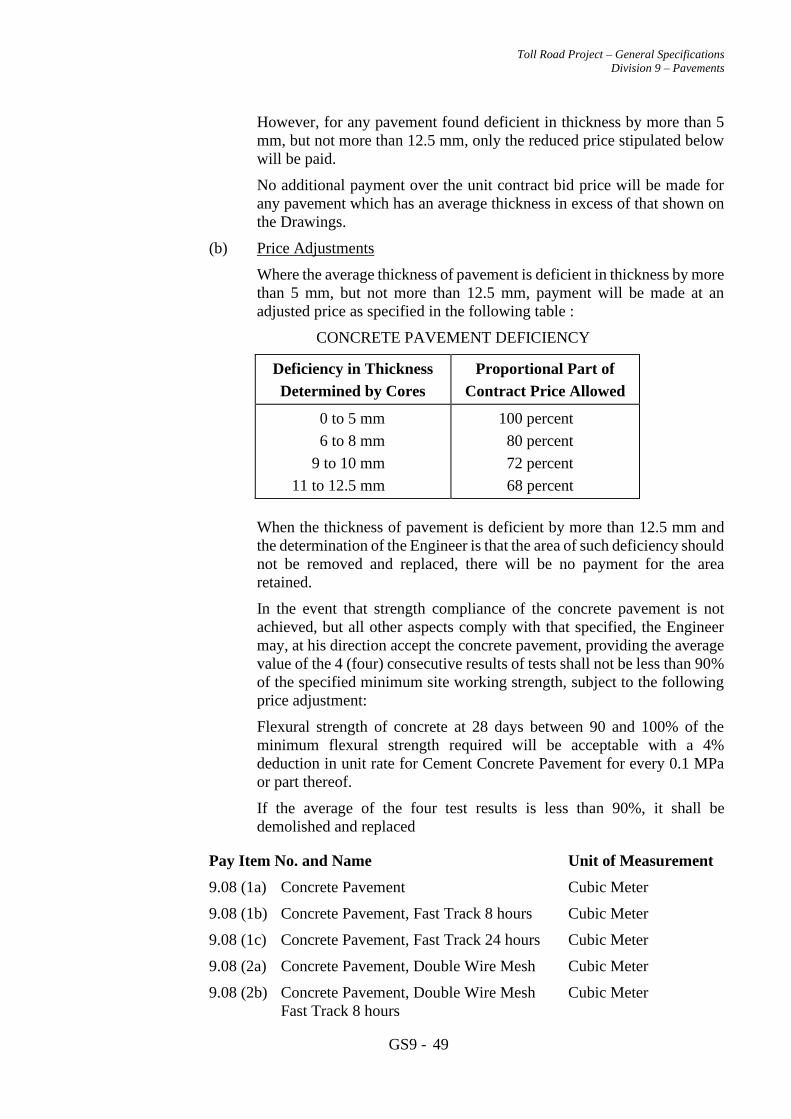
Toll Road Project – General Specifications
Division 9 – Pavements
GS9 - 49
However, for any pavement found deficient in thickness by more than 5
mm, but not more than 12.5 mm, only the reduced price stipulated below
will be paid.
No additional payment over the unit contract bid price will be made for
any pavement which has an average thickness in excess of that shown on
the Drawings.
(b) Price Adjustments
Where the average thickness of pavement is deficient in thickness by more
than 5 mm, but not more than 12.5 mm, payment will be made at an
adjusted price as specified in the following table :
CONCRETE PAVEMENT DEFICIENCY
Deficiency in Thickness
Determined by Cores
Proportional Part of
Contract Price Allowed
0 to 5 mm
6 to 8 mm
9 to 10 mm
11 to 12.5 mm
100 percent
80 percent
72 percent
68 percent
When the thickness of pavement is deficient by more than 12.5 mm and
the determination of the Engineer is that the area of such deficiency should
not be removed and replaced, there will be no payment for the area
retained.
In the event that strength compliance of the concrete pavement is not
achieved, but all other aspects comply with that specified, the Engineer
may, at his direction accept the concrete pavement, providing the average
value of the 4 (four) consecutive results of tests shall not be less than 90%
of the specified minimum site working strength, subject to the following
price adjustment:
Flexural strength of concrete at 28 days between 90 and 100% of the
minimum flexural strength required will be acceptable with a 4%
deduction in unit rate for Cement Concrete Pavement for every 0.1 MPa
or part thereof.
If the average of the four test results is less than 90%, it shall be
demolished and replaced
Pay Item No. and Name Unit of Measurement
9.08 (1a) Concrete Pavement Cubic Meter
9.08 (1b) Concrete Pavement, Fast Track 8 hours Cubic Meter
9.08 (1c) Concrete Pavement, Fast Track 24 hours Cubic Meter
9.08 (2a) Concrete Pavement, Double Wire Mesh Cubic Meter
9.08 (2b) Concrete Pavement, Double Wire Mesh Cubic Meter
Fast Track 8 hours
Toll Road Project – General Specifications
Division 9 – Pavements
GS9 - 50
9.08 (2c) Concrete Pavement, Double Wire Mesh Cubic Meter
Fast Track 24 hours
9.08 (3a) Concrete Pavement, Single Wire Mesh Cubic Meter
9.08 (3b) Concrete Pavement, Single Wire Mesh Cubic Meter
Fast Track 8 hours
9.08 (3c) Concrete Pavement, Single Wire Mesh Cubic Meter
Fast Track 24 hours
S9.09 Wet Lean Concrete
S9.09 (1) Description
The work shall consist of furnishing all labor, equipment, supplies and materials,
and of performing all operations in connection with construction of levelling
course and pavement widening works with wet lean concrete including
underlying course preparation, importing and preparation of aggregates, batching,
mixing, transporting, placing, consolidating, finishing, curing, maintenance and
other incidental operations pertaining to the construction. All work shall be done
in strict accordance with the plans and drawings, specifications, and as directed
by the Engineer.
S9.09 (2) Underlying Course
Where wet lean concrete is specified for leveling course, prior to construction the
underlying course shall be cleaned of dirt, mud, loose stone or other foreign matter
and inspected by the Engineer to ensure compaction, finish and surface
smoothness. Any areas failing to comply with the applicable specification
requirements shall be removed, repaired or reconstructed as directed by the
Engineer. No direct payment will be made for this removal, repair, or
reconstruction provided that the Contractor is held responsible therefor.
S9.09 (3) Sand Bedding
Where wet lean concrete is specified for pavement widening work, the lean
concrete shall be laid on a prepared leveled bed comprising 4 cm of natural sand
except other specified in the Drawings. Any natural sand with the bulk of its
mass being retained on a No.200 mesh sieve and its mortar fraction being non-
plastic may be used. The sand at suitable moisture content shall be spread on the
prepared approved sub-grade and leveled. The leveled bed shall be compacted
with the largest roller that can be utilized in the excavation to refusal. Prior to
placing wet lean concrete the sand bed shall be dampened with water.
S9.09 (4) Materials
The aggregates, cement and water shall conform to the requirements of Sub-
clause S10.01 (2) of these Specifications. The maximum aggregate size, subject
to the Engineer's approval, shall be selected by the Contractor with regard to the
specific application of wet lean concrete.
Toll Road Project – General Specifications
Division 9 – Pavements
GS9 - 51
S9.09 (5) Mix Proportions
The ratio mass of cement to aggregate in the saturated surface dry condition shall
be sufficient to achieve the crushing strength requirements of this Clause, and to
provide a satisfactory consistency of mixing.
S9.09 (6) Formwork
Wet lean concrete for leveling course shall be placed between cut-off screeding
forms of steel or timber set true to grade and elevation.
S9.09 (7) Joints
Longitudinal joints shall be offset by at least 20 cm from the longitudinal joint of
the concrete pavement to be superimposed.
Transverse construction joints shall be formed at the end of each day's work and
shall form a true transverse vertical surface.
S9.09 (8) Mixing, Transportation, Laying and Consolidation
Wet lean concrete shall be mixed, transported, placed, spread and compacted in
accordance with the requirements of Sub-clauses S10.01 (3) and S10.01 (4).
S9.09 (9) Finishing
After consolidation and screeding to the correct plane and elevation the wet lean
concrete shall be floated to a smooth finish the surface being free from depressions
or projections and areas of open texture. The surface shall then be regulated by at
least two passes of a scraping straightedge with a blade not less than 1.8 m.
S9.09 (10) Curing
Wet lean concrete shall immediately on completion of finishing be cured for a
period of not less than 7 days. Curing of the surface shall be achieved by one of
the following methods:
(a) Covering until the next pavement layer is laid with impermeable plastic
sheeting, adequately secured from being blown off the surface and with
the joints overlapped at least 300 mm and set to prohibit egress of moisture.
(b) The entire surface sprayed uniformly with white pigmented curing
compound.
(c) Continual mist spraying covering the entire surface and maintaining a
permanently moist condition for the full duration of the curing period.
Intermittent wet curing will not be accepted.
S9.09 (11) Testing for Strength
Compressive strength test cylinders, 15 cm diameter by 30 cm high shall be
prepared from the wet lean concrete delivered to site.
One cylinder shall be prepared representing each 50 linear meter of wet lean
concrete being laid and not less than three (3) cylinders shall be prepared from
each day's work.
Toll Road Project – General Specifications
Division 9 – Pavements
GS9 - 52
S9.09 (12) Crushing Strength Requirements
The average crushing strength at 28 days of each group of specimens representing
each day's work of 80 – 110 kg/cm2.
If the average crushing strength of more than one group of any five consecutive
groups falls below 80 kg/cm2, the cement content shall be increased to such a
value as may be approved by the Engineer, until it can be shown by the results
that satisfactory material can be achieved with different mix proportions.
S9.09 (13) Cause for Rejection
Provided the crushing strength requirements are followed, low crushing strength
values will not be cause for rejection.
All loose, segregated or otherwise defective areas, along with areas not complying
with the surface smoothness requirements, which cannot be corrected by grinding,
shall be delimited by the Engineer. The material shall be broken out to the full
thickness of layer, removed and replaced with freshly mixed material complying
to the Specification. Surface patching will not be permitted.
S9.09 (14) Surface Smoothness
Wet lean concrete shall be shaped and finished to the lines, grades, and cross
sections as shown on the plans and drawings. The finished surface shall not
deviate more than 1 cm from the planned elevation.
Lean Concrete Sub-base shall have a cross-fall equal to the design cross-fall with
tolerance of ± 0.3 %.
S9.09 (15) Maintenance
Neither equipment nor traffic, including construction vehicles, will be allowed on
the finished surface during the initial 7 day's curing period.
After the curing period such equipment and vehicles required for the continuation
of works will be permitted to traffic on the wet lean concrete.
Wet lean concrete shall be maintained in a proper condition prior to placing the
next pavement layer. Any damage from any cause whatsoever shall be repaired
by replacement of the area in question at the expense of the Contractor.
S9.09 (16) Method of Measurement
Wet lean concrete for leveling course to be paid for will be the number of square
meters of leveling course, completed and accepted in accordance with the plans,
drawings, and specifications and as directed by the Engineer.
Sand bedding will not be measured separately.
In computing all quantities, the dimensions used shall be those shown on the
Drawings or ordered in writing by the Engineer. No pay allowance shall be made
for any increased cement content or for variations in layer thickness where
minimum thickness is specified.
Toll Road Project – General Specifications
Division 9 – Pavements
GS9 - 53
S9.09 (17) Basis of Payment
The accepted quantities of wet lean concrete and sand bedding, determined as
provided above, will be paid for at the Contract unit price for the item shown
below. This payment shall be full compensation for furnishing all labor,
equipment and materials necessary to complete the work, including underlying
course preparation, sand bedding, mixing, preparation, transporting, laying,
consolidation, finishing, curing, maintenance and all other incidental items of
work in accordance with the plans, drawings, specifications, and as directed by
the Engineer.
Pay Item No. and Name Unit of Measurement
9.09 Wet Lean Concrete (t = 10 cm) Square Meter

Toll Road Project – General Specifications
Division 9 – Pavements
GS9 - 54
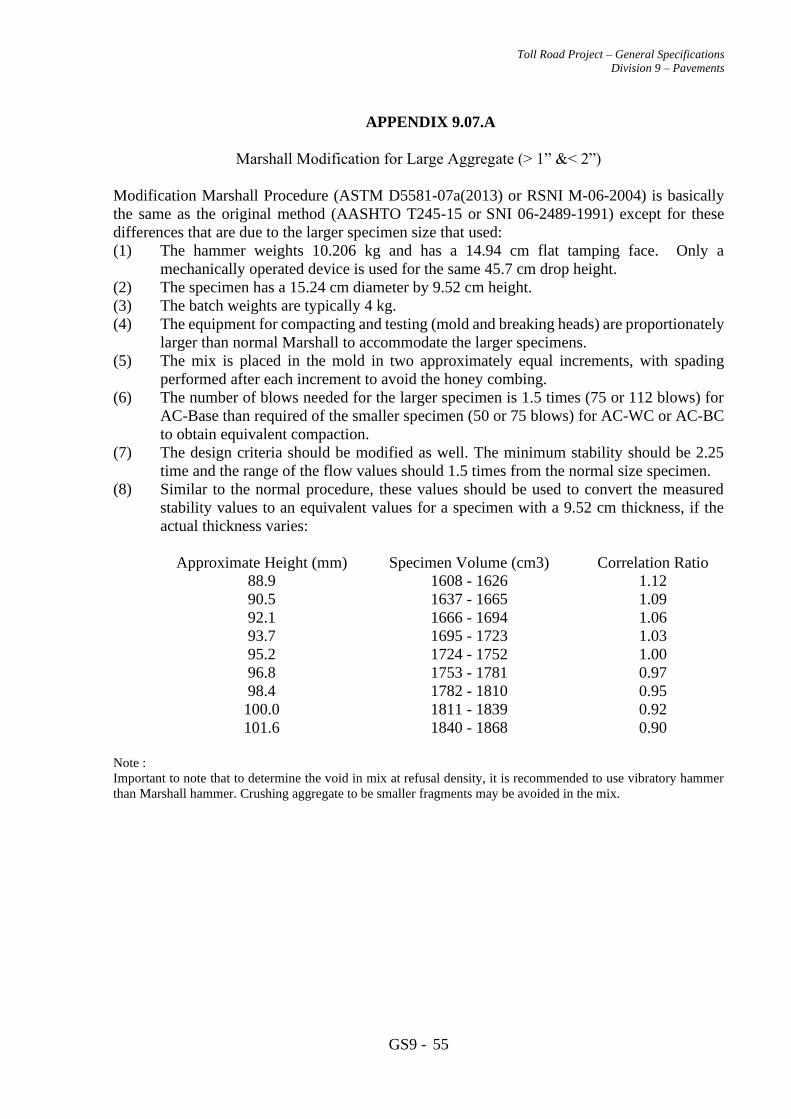
Toll Road Project – General Specifications
Division 9 – Pavements
GS9 - 55
APPENDIX 9.07.A
Marshall Modification for Large Aggregate (> 1” &< 2”)
Modification Marshall Procedure (ASTM D5581-07a(2013) or RSNI M-06-2004) is basically
the same as the original method (AASHTO T245-15 or SNI 06-2489-1991) except for these
differences that are due to the larger specimen size that used:
(1) The hammer weights 10.206 kg and has a 14.94 cm flat tamping face. Only a
mechanically operated device is used for the same 45.7 cm drop height.
(2) The specimen has a 15.24 cm diameter by 9.52 cm height.
(3) The batch weights are typically 4 kg.
(4) The equipment for compacting and testing (mold and breaking heads) are proportionately
larger than normal Marshall to accommodate the larger specimens.
(5) The mix is placed in the mold in two approximately equal increments, with spading
performed after each increment to avoid the honey combing.
(6) The number of blows needed for the larger specimen is 1.5 times (75 or 112 blows) for
AC-Base than required of the smaller specimen (50 or 75 blows) for AC-WC or AC-BC
to obtain equivalent compaction.
(7) The design criteria should be modified as well. The minimum stability should be 2.25
time and the range of the flow values should 1.5 times from the normal size specimen.
(8) Similar to the normal procedure, these values should be used to convert the measured
stability values to an equivalent values for a specimen with a 9.52 cm thickness, if the
actual thickness varies:
Approximate Height (mm) Specimen Volume (cm3) Correlation Ratio
88.9 1608 - 1626 1.12
90.5 1637 - 1665 1.09
92.1 1666 - 1694 1.06
93.7 1695 - 1723 1.03
95.2 1724 - 1752 1.00
96.8 1753 - 1781 0.97
98.4 1782 - 1810 0.95
100.0 1811 - 1839 0.92
101.6 1840 - 1868 0.90
Note :
Important to note that to determine the void in mix at refusal density, it is recommended to use vibratory hammer
than Marshall hammer. Crushing aggregate to be smaller fragments may be avoided in the mix.

Toll Road Project – General Specifications
Division 9 – Pavements
GS9 - 56
Toll Road Project – General Specifications
Division 10 – Concrete Structures
S10 - 1
DIVISION 10 CONCRETE STRUCTURES
S10.01 Concrete and High Performance Concrete
S10.01 (1) Description
(a) Scope
This work shall consist of the general items pertaining to the required class
or classes of concrete: reinforced and unreinforced concrete; self
compacting concrete (SCC); mass concrete; prestressed concrete; precast
concrete; and concrete for composite steel structures, constructed in
accordance with these Specifications and the lines, levels, grades and
dimensions shown on the Drawings, and as required by the Engineer.
Cement concrete shall consist of a mixture of portland cement or
equivalent hydraulic cement, water, coarse and fine aggregates, with or
without additives forming solid mass
High-performance concrete is the concrete meeting special combinations
of performance and uniformity requirements that cannot always be
achieved routinely using conventional constituents and normal mixing,
placing, and curing practices. The performance requirements involve the
placement and compaction without segregation, early strength, toughness,
volume stability, service life such as self compacting concrete (SCC).
Mass concrete is any volume of concrete with the smallest dimensions
equal to or greater than one meter or the structural components with a
smallest dimension of less than one meter, but it has a potential to produce
a peak temperature exceeding the permitted limits. These specific
dimensions will require that measures be taken to cope with the generation
of heat from hydration of the cement and attendant volume change to
minimize cracking. The one characteristic that distinguishes mass
concrete from other concrete work is thermal behavior.
This work shall also include the preparing working areas for casting
concrete, furnishing the curing, working floors and maintaining
foundation such as pumping or other measures to keep the foundation dry.
(b) Concrete Classes and their Use
The use of each class of concrete shall be as follows unless otherwise
shown on the Drawings or directed by the Engineer:
Strength Class Use of Each Class of Concrete
AA (fc’ 50 MPa) - Segmental precast prestressed concrete U-girders
- Segmental prestressed concrete U-girders
- Preccast/Segmental prestressed concrete I-girders
- Prestressed concrete spun piles
A - 1 (fc’ 40 MPa) - Precast prestressed concrete box girders
- Precast prestressed concrete I-girders
Toll Road Project – General Specifications
Division 10 – Concrete Structures
S10 - 2
- Precast prestressed concrete U-girders
- Prestressed concrete box girders
- Precast prestressed concrete hollow slab units
A - 2 (fc’ 35 MPa) - Prestressed concrete cantilevered pier heads and
columns
- Prestressed concrete portal pier
- Prestressed concrete hollow slabs
- Precast Cross Beams
B - 1 (fc’ 30 MPa) - Reinforced concrete slab bridges
- Reinforced concrete deck slabs
- Diaphragms of prestressed concrete I- girder and
U-girderbridges
- Reinforced concrete hollow slab
- Concrete barriers
- Pipe culverts
- Reinforced concrete for pier columns and heads
- Stairs and pier for pedestrian bridges
- Reinforced Concrete Piled slabs
- Curb (reinforcing and plain)
B - 2 (fc’ 30 MPa) - Cast-in-place reinforced concrete piles
- Reinforced concrete piles
C (fc’ 20 MPa) - Wall piers
- Abutments, footing of piers, retaining walls
- Approach slabs
- Stairs on embankment and foundations of street
lighting poles
- Box culverts (including wing walls)
- RC frames and encasement of pipe culverts
- Planting boxes
- Precast plates for slabs
- Stairs of pedestrian bridge
- Piers of pedestrian bridge
- U-ditches or concrete ditches
D (fc’ 15 MPa) - Gravity type retaining walls
- Concrete footpaths
Toll Road Project – General Specifications
Division 10 – Concrete Structures
S10 - 3
- Head walls, cradles of pipe culverts
E (fc’ 10 MPa) - Leveling concrete, backfill concrete in masonry
structures, and as specified on the Drawings
P (fs 4.5 MPa) - Cement Concrete Pavement.
(c) Tolerances
(i) Dimensional Tolerances:
Overall length up to 6 m ± 5 mm
Overall length over 6 m ± 15 mm
Length of beams, deck slabs, columns walls,
or between abutments - 0 and +10 mm
(ii) Shape Tolerances:
Square (difference in diagonal lengths) 10 mm
Straightness or Bow (deviation from
intended line) for lengths up to 3 m 12 mm
Straightness or Bow for lengths 3 m to 6 m 15 mm
Straightness or Bow for lengths greater 20 mm
than 6 m
(iii) Position Tolerances (from reference point):
Plan position of precast columns ± 10 mm
Plan position of horizontal surfaces ± 10 mm
Plan position of vertical surfaces ± 10 mm
(iv) Vertical Alignment Tolerance:
Plumb alignment for columns and walls ± 10 mm
(v) Level/Elevations Tolerances:
Top of blinding concrete under foundations ± 10 mm
Top of blinding concrete under approach
slabs ± 10 mm
Top of columns, abutments and transverse
beams ± 10 mm
(vi) Horizontal Alignments Tolerance:
10 mm in 4 m horizontal length
(vii) Tolerances for Concrete cover over Reinforcing Steel:
Concrete cover up to 3 cm. - 0 and + 5 mm
Concrete cover of >3 cm - 5 cm - 0 and + 10 mm
Concrete cover of >5 cm - 10 cm ± 10 mm
Toll Road Project – General Specifications
Division 10 – Concrete Structures
S10 - 4
(d) Submittals
(i) The Contractor shall submit samples of all materials he intends to
use together with test data confirming that all material properties
as specified in Sub-clause S10.01 (2) of these Specifications are
met.
(ii) The Contractor shall submit a mix design for each concrete class
to be used before the start of concrete placement, complete with
the test results of materials and concrete trial mix in the laboratory
based on the compressive strength results generally within ages of
7 and 28 days, and an additional age of 56 days for mass concrete
unless otherwise specified for other ages by the Engineer.
(iii) Especially for Mass Concrete
Before commencement of the mass concrete work, the Contractor
shall submit a temperature control plan together with the design
calculation for the approval of the Engineer. The design is in the
form of concrete mix design, method and duration of curing with
the following equipments:
(1) Thermal Control with Insulation Walls
When the insulation walls are used to maintain temperature
differences, the material used shall have a heat holding
level of 2 - 4 hour-foot2/BTU.
1 BTU (BTU: British Thermal Unit) is defined as the
amount of heat rquired to raise the temperature for one
pound (about 454 grams) of water by 1-degree Fahrenheit.
143 BTU is required to melt 1 pound of ice.
(2) Temperature Sensor Tool
The temperature sensor used is a thermistor type or the
others. The sensor shall be able to show temperatures in
the range of 10 - 95°C or within the required range with a
reading accuracy of 0.5°C. Temperature sensor tool shall
be calibrated.
(iii) The Contractor shall submit the detailed drawings for all scaffolds
to be used and shall obtain approval from the Engineer before any
scaffolding installment commenced.
(iv) The Contractor shall notify the Engineer in writing at least 24
hours prior to the starting date plan of mixing or placement of any
concrete classes, as required under Sub-clause S10.01 (4) below.
(e) Storage and Protection of Cement
For storage of cement the Contractor shall provide a weatherproof shed
that is airtight and has a raised wooden floor which is covered with
polyethylene sheeting. At all times stacks of cement bags shall be kept
covered with an envelope of polyethylene sheeting.
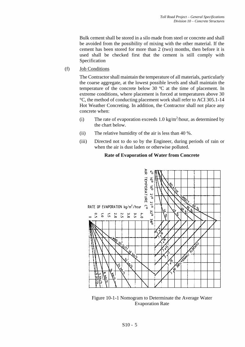
Toll Road Project – General Specifications
Division 10 – Concrete Structures
S10 - 5
Bulk cement shall be stored in a silo made from steel or concrete and shall
be avoided from the possibility of mixing with the other material. If the
cement has been stored for more than 2 (two) months, then before it is
used shall be checked first that the cement is still comply with
Specification
(f) Job Conditions
The Contractor shall maintain the temperature of all materials, particularly
the coarse aggregate, at the lowest possible levels and shall maintain the
temperature of the concrete below 30 ºC at the time of placement. In
extreme conditions, where placement is forced at temperatures above 30
°C, the method of conducting placement work shall refer to ACI 305.1-14
Hot Weather Concreting. In addition, the Contractor shall not place any
concrete when:
(i) The rate of evaporation exceeds 1.0 kg/m2/hour, as determined by
the chart below.
(ii) The relative humidity of the air is less than 40 %.
(iii) Directed not to do so by the Engineer, during periods of rain or
when the air is dust laden or otherwise polluted.
Rate of Evaporation of Water from Concrete
Figure 10-1-1 Nomogram to Determinate the Average Water
Evaporation Rate
Toll Road Project – General Specifications
Division 10 – Concrete Structures
S10 - 6
Note:
The estimated temperature of concrete is determined by the following empirical formula:
Concrete temperature = 0.1 PC temperature + 0.3 water temperature + 0.6 aggregate temperature
(coarse and fine).
(g) Rectification of Unsatisfactory Concrete Work
(i) Rectification of concrete work which does not meet the tolerance
criteria specified in Sub-clause S10.01.(1).(c), or which does not
have a satisfactory surface finish, or which does not meet the mix
property requirements specified in Sub-clause S10.01.(3).(a), shall
be as directed by the Engineer and may include:
(1) Changes in the mix proportions for the remainder of the
work.
(2) Additional curing on those portions of the structure
represented by the test specimens which failed.
(3) Strengthening or complete removal and replacement of
those portions of the work which he deems to be
unsatisfactory.
(ii) In the event of a dispute regarding the quality of the concrete work
or any doubt regarding the adequacy of the available test data, the
Engineer may direct the Contractor to carry out additional testing
to ensure that a fair judgement of the work quality can be made.
Such additional testing shall be at the Contractor's own expense.
(iii) Rectification of cracked or displaced concrete work due to
negligence of the Contractor is the responsibility of the Contractor
and shall be carried out at his own expense. The Contractor shall
not be responsible for the damages caused by natural disasters
which is not able be avoided, provided that the damaged work has
been completed and accepted and declared by the Engineer in
writing.
(iv) Rectification of concrete works which do not meet the
requirements as specified in Sub-clauses S10.01.(5).(c).(ix) and
S10.01.(5).(c).(x) may include the demolition and replacing all
concrete.
(h) Supply of Ready Mix Concrete
Concrete supplied as Ready Mix by an outside supplier shall comply with
the requirements of ASTM C94/C94M-09 – Standard Specification for
Ready Mix Concrete. Unless otherwise noted in the bid documents the
“purchaser” described within ASTM C94/C94M-09 shall be the
Contractor. The General Conditions of Contract and the requirements of
Clause S10.01 of the Specifications take precedence over ASTM
C94/C94M-09. The contractor shall not thereby be relieved of any of his
duties under the Contract
Toll Road Project – General Specifications
Division 10 – Concrete Structures
S10 - 7
S10.01 (2) Materials
(a) General
All materials to be furnished and used that are not covered in this Clause
shall conform to the requirements stipulated in other applicable Clauses.
(b) Cement
(i) The cement used for Concrete Work shall be Portland cement
conforming to SNI 2049:2015 (AASHTO M85-15) type I, II, III,
IV and V.
(ii) Unless otherwise permitted by the Engineer, the product of only
one mill of any one brand type of Portland Cement shall be used
on the project. If this is permitted, the Kontraktor shall re-submit
the concrete mix design according to the type and mill of cement
used.
(c) Additives
The Contractor shall submit samples of any additives. The Contractor
requests to use to the Engineer at least 28 days prior to the date of
commencement of construction of the particular structure or portion of
structure on which he intends to use such admixtures. The use of any kind
of additives for any purpose shall be based on the laboratory test results
where the results shall be in accordance with the requirements and
approved by the Engineer.
Additives to be used to improve the performance of concrete can be
chemical, mineral or waste products in the form of pozzolan powder as a
filler in the concrete mix.
i) Chemical
Admixtures in the form of chemicals added to concrete in an
amount not more than 5% by weight of cement during the mixing
process or during the additional mixing in concrete. The admixture
shall conform to the requirements specified in ASTM C494/
C494M-17 or SNI 03-2495-1991. Admixtures shall not contain
chlorides, nitrates, sulphates or sulphides.
For the purpose of performance improvement of the fresh
concrete, the admixture can be used for the purposes of :
improving the workability of concrete mix without adding water;
reducing the water used in the concrete mix without reducing
workability; acceleration ofthe cement hydration binding or
concrete hardening; deceleration of the cement hydration binding
or concrete hardening; improving the workability of concrete
pumping; deceleration of the slump loss; reducing theshrinkage of
concrete or providing a little expansion for concrete; reducing the
possibility of bleeding; reducing the possibility of segregation.
For the purpose of performance improvement after the concrete
hardening, the admixture can be used for the purposes of:
increasing the strength of concrete (indirectly); increasing the
Toll Road Project – General Specifications
Division 10 – Concrete Structures
S10 - 8
strength of the young concrete; reducing or slowing the hydration
heat in concrete hardening process, especially for concrete with
high early strength; improving the workability of concrete casting
in the water or in the sea; improving the long-term durability of
concrete; improving water-tightness of concrete (reducing the
permeability of concrete); controlling the expansion of concrete
due to alkali-aggregate reaction; increase of the bonding between
new and old concrete; improving the adhesion between concrete
and reinforcing steel; increase of the concrete resistance to
abrasion and impact.
Viscocity Modifying Admixture (VMA) may be used to reduce
the segregation and sensitivity of the mixture to variations in other
components, especially water content, usually used for self-
compacting concrete (SCC) when the powder content as described
in Sub-clause S10.01.(2).(h) in the mixture is not enough.
ii) Mineral
The additives in the form of mineral or waste material can be in
the form of fly ash class F or pozzolan which conforms to ASTM
C618-17a or SNI 2460:2014, slag cement or ground granulated
blast furnace slag which conforms to ASTM C989/C989M-18 or
SNI 6385:2016, micro silica or silica fume.
(d) Water
Water used in mixing, curing, or other designated applications shall be
clean and free from harmful matter such as oil, salt, acid, alkali, sugar, or
organic materials. Water shall be tested in accordance with and shall meet
the requirements of ASTM C1602/C1602M-12 or SNI 7974:2016. Water
known to be of potable quality may be used without being tested. When
the proposed water quality is doubtful and the testing as above mentioned
could not be carried out, comparison testing shall be carried out by using
the cement mortar with the proposed water and with the distillated or
drinking water. The proposed water could be used when the compressive
strength at 7 days and 28 days of cement mortar with the proposed water
is at least 90 % of cement mortar with the distillated or drinking water at
the same curing period.
(e) Aggregate Grading Requirements
(i) The coarse and fine aggregate gradations shall conform to the
requirements given in Table 10-1-1 Aggregate Grading Require-
ments. Aggregates do not conform to these grading requirements
shall not necessarily be rejected if the Contractor can demonstrate
that the concrete mixture conforms to the mix property
requirements specified in Sub-clauses S10.01.(1).(d) and
S10.01.(3).(a) of the Specifications.
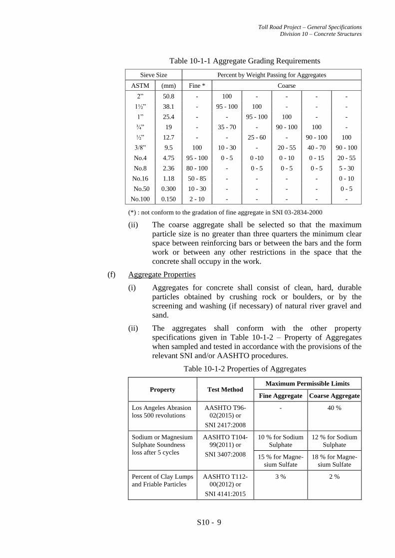
Toll Road Project – General Specifications
Division 10 – Concrete Structures
S10 - 9
Table 10-1-1 Aggregate Grading Requirements
Sieve Size Percent by Weight Passing for Aggregates
ASTM (mm) Fine * Coarse
2” 50.8 - 100 - - - -
1½” 38.1 - 95 - 100 100 - - -
1” 25.4 - - 95 - 100 100 - -
¾” 19 - 35 - 70 - 90 - 100 100 -
½” 12.7 - - 25 - 60 - 90 - 100 100
3/8” 9.5 100 10 - 30 - 20 - 55 40 - 70 90 - 100
No.4 4.75 95 - 100 0 - 5 0 -10 0 - 10 0 - 15 20 - 55
No.8 2.36 80 - 100 - 0 - 5 0 - 5 0 - 5 5 - 30
No.16 1.18 50 - 85 - - - - 0 - 10
No.50 0.300 10 - 30 - - - - 0 - 5
No.100 0.150 2 - 10 - - - - -
(*) : not conform to the gradation of fine aggregate in SNI 03-2834-2000
(ii) The coarse aggregate shall be selected so that the maximum
particle size is no greater than three quarters the minimum clear
space between reinforcing bars or between the bars and the form
work or between any other restrictions in the space that the
concrete shall occupy in the work.
(f) Aggregate Properties
(i) Aggregates for concrete shall consist of clean, hard, durable
particles obtained by crushing rock or boulders, or by the
screening and washing (if necessary) of natural river gravel and
sand.
(ii) The aggregates shall conform with the other property
specifications given in Table 10-1-2 – Property of Aggregates
when sampled and tested in accordance with the provisions of the
relevant SNI and/or AASHTO procedures.
Table 10-1-2 Properties of Aggregates
Property Test Method Maximum Permissible Limits
Fine Aggregate Coarse Aggregate
Los Angeles Abrasion
loss 500 revolutions
AASHTO T96-
02(2015) or
SNI 2417:2008
- 40 %
Sodium or Magnesium
Sulphate Soundness
loss after 5 cycles
AASHTO T104-
99(2011) or
SNI 3407:2008
10 % for Sodium
Sulphate
12 % for Sodium
Sulphate
15 % for Magne-
sium Sulfate
18 % for Magne-
sium Sulfate
Percent of Clay Lumps
and Friable Particles
AASHTO T112-
00(2012) or
SNI 4141:2015
3 % 2 %
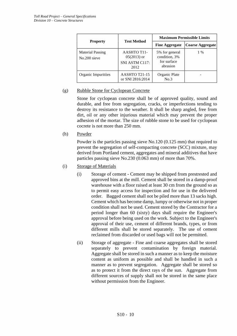
Toll Road Project – General Specifications
Division 10 – Concrete Structures
S10 - 10
Property Test Method Maximum Permissible Limits
Fine Aggregate Coarse Aggregate
Material Passing
No.200 sieve
AASHTO T11-
05(2013) or
SNI ASTM C117:
2012
5% for general
condition, 3%
for surface
abrasion
1 %
Organic Impuritiies AASHTO T21-15
or SNI 2816:2014
Organic Plate
No.3
-
(g) Rubble Stone for Cyclopean Concrete
Stone for cyclopean concrete shall be of approved quality, sound and
durable, and free from segregation, cracks, or imperfections tending to
destroy its resistance to the weather. It shall be sharp angled, free from
dirt, oil or any other injurious material which may prevent the proper
adhesion of the mortar. The size of rubble stone to be used for cyclopean
cocrete is not more than 250 mm.
(h) Powder
Powder is the particles passing sieve No.120 (0.125 mm) that required to
prevent the segregation of self-compacting concrete (SCC) mixture, may
derived from Portland cement, aggregates and mineral additives that have
particles passing sieve No.230 (0.063 mm) of more than 70%.
(i) Storage of Materials
(i) Storage of cement - Cement may be shipped from prestrested and
approved bins at the mill. Cement shall be stored in a damp-proof
warehouse with a floor raised at least 30 cm from the ground so as
to permit easy access for inspection and for use in the delivered
order. Bagged cement shall not be piled more than 13 sacks high.
Cement which has become damp, lumpy or otherwise not in proper
condition shall not be used. Cement stored by the Contractor for a
period longer than 60 (sixty) days shall require the Engineer's
approval before being used on the work. Subject to the Engineer's
approval of their use, cement of different brands, types, or from
different mills shall be stored separately. The use of cement
reclaimed from discarded or used bags will not be permitted.
(ii) Storage of aggregate - Fine and coarse aggregates shall be stored
separately to prevent contamination by foreign material.
Aggregate shall be stored in such a manner as to keep the moisture
content as uniform as possible and shall be handled in such a
manner as to prevent segregation. Aggregate shall be stored so
as to protect it from the direct rays of the sun. Aggregate from
different sources of supply shall not be stored in the same place
without permission from the Engineer.
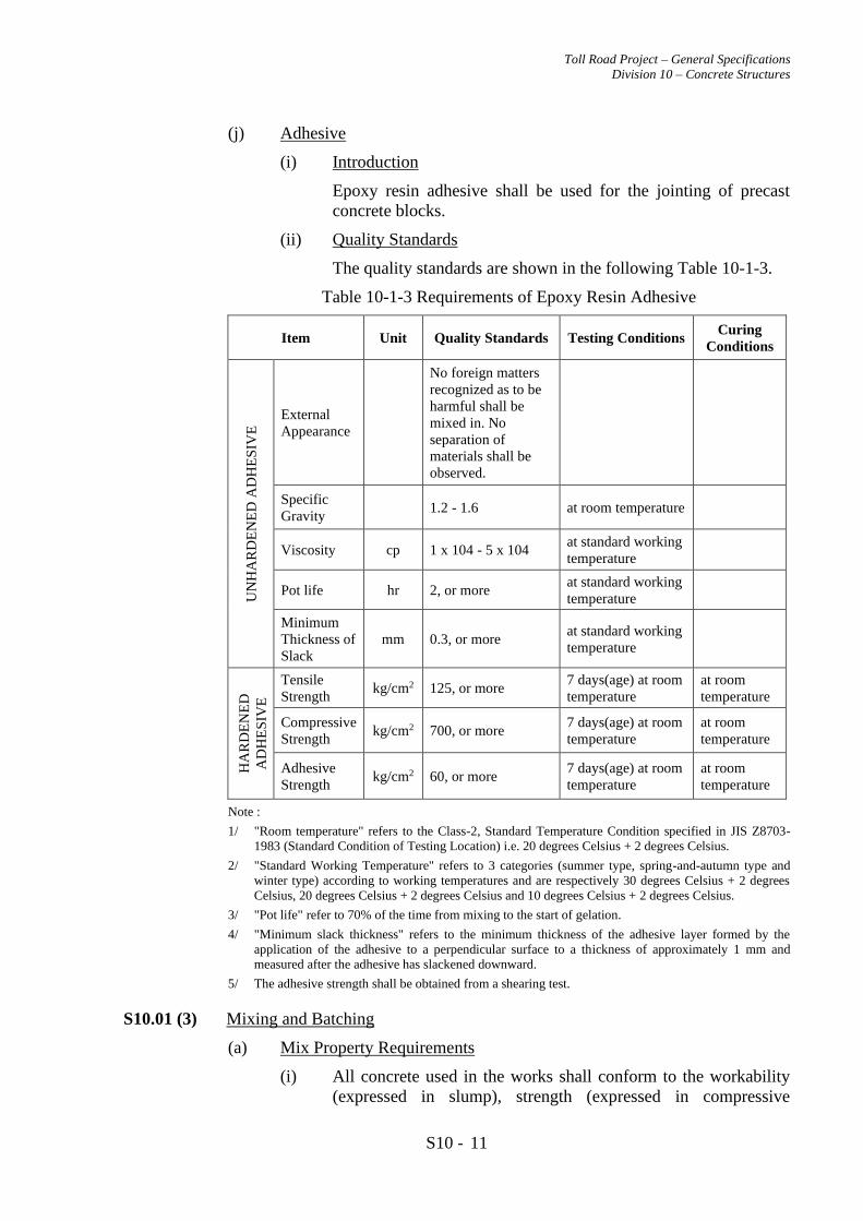
Toll Road Project – General Specifications
Division 10 – Concrete Structures
S10 - 11
(j) Adhesive
(i) Introduction
Epoxy resin adhesive shall be used for the jointing of precast
concrete blocks.
(ii) Quality Standards
The quality standards are shown in the following Table 10-1-3.
Table 10-1-3 Requirements of Epoxy Resin Adhesive
Item Unit Quality Standards Testing Conditions Curing
Conditions
UN
HA
RD
EN
ED
AD
HE
SIV
E External
Appearance
No foreign matters
recognized as to be
harmful shall be
mixed in. No
separation of
materials shall be
observed.
Specific
Gravity 1.2 - 1.6 at room temperature
Viscosity cp 1 x 10⁴ - 5 x 10⁴ at standard working
temperature
Pot life hr 2, or more at standard working
temperature
Minimum
Thickness of
Slack
mm 0.3, or more at standard working
temperature
HA
RD
EN
ED
AD
HE
SIV
E
Tensile
Strength kg/cm2 125, or more
7 days(age) at room
temperature
at room
temperature
Compressive
Strength kg/cm2 700, or more
7 days(age) at room
temperature
at room
temperature
Adhesive
Strength kg/cm2 60, or more
7 days(age) at room
temperature
at room
temperature
Note :
1/ "Room temperature" refers to the Class-2, Standard Temperature Condition specified in JIS Z8703-
1983 (Standard Condition of Testing Location) i.e. 20 degrees Celsius + 2 degrees Celsius.
2/ "Standard Working Temperature" refers to 3 categories (summer type, spring-and-autumn type and
winter type) according to working temperatures and are respectively 30 degrees Celsius + 2 degrees
Celsius, 20 degrees Celsius + 2 degrees Celsius and 10 degrees Celsius + 2 degrees Celsius.
3/ "Pot life" refer to 70% of the time from mixing to the start of gelation.
4/ "Minimum slack thickness" refers to the minimum thickness of the adhesive layer formed by the
application of the adhesive to a perpendicular surface to a thickness of approximately 1 mm and
measured after the adhesive has slackened downward.
5/ The adhesive strength shall be obtained from a shearing test.
S10.01 (3) Mixing and Batching
(a) Mix Property Requirements
(i) All concrete used in the works shall conform to the workability
(expressed in slump), strength (expressed in compressive
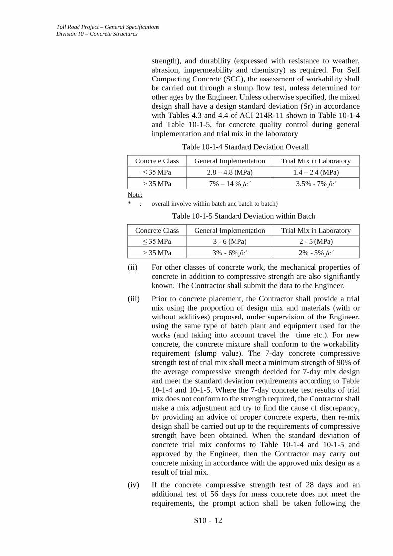
Toll Road Project – General Specifications
Division 10 – Concrete Structures
S10 - 12
strength), and durability (expressed with resistance to weather,
abrasion, impermeability and chemistry) as required. For Self
Compacting Concrete (SCC), the assessment of workability shall
be carried out through a slump flow test, unless determined for
other ages by the Engineer. Unless otherwise specified, the mixed
design shall have a design standard deviation (Sr) in accordance
with Tables 4.3 and 4.4 of ACI 214R-11 shown in Table 10-1-4
and Table 10-1-5, for concrete quality control during general
implementation and trial mix in the laboratory
Table 10-1-4 Standard Deviation Overall
Concrete Class General Implementation Trial Mix in Laboratory
≤ 35 MPa 2.8 – 4.8 (MPa) 1.4 – 2.4 (MPa)
> 35 MPa 7% – 14 % fc’ 3.5% - 7% fc’
Note:
* : overall involve within batch and batch to batch)
Table 10-1-5 Standard Deviation within Batch
Concrete Class General Implementation Trial Mix in Laboratory
≤ 35 MPa 3 - 6 (MPa) 2 - 5 (MPa)
> 35 MPa 3% - 6% fc’ 2% - 5% fc’
(ii) For other classes of concrete work, the mechanical properties of
concrete in addition to compressive strength are also signifiantly
known. The Contractor shall submit the data to the Engineer.
(iii) Prior to concrete placement, the Contractor shall provide a trial
mix using the proportion of design mix and materials (with or
without additives) proposed, under supervision of the Engineer,
using the same type of batch plant and equipment used for the
works (and taking into account travel the time etc.). For new
concrete, the concrete mixture shall conform to the workability
requirement (slump value). The 7-day concrete compressive
strength test of trial mix shall meet a minimum strength of 90% of
the average compressive strength decided for 7-day mix design
and meet the standard deviation requirements according to Table
10-1-4 and 10-1-5. Where the 7-day concrete test results of trial
mix does not conform to the strength required, the Contractor shall
make a mix adjustment and try to find the cause of discrepancy,
by providing an advice of proper concrete experts, then re-mix
design shall be carried out up to the requirements of compressive
strength have been obtained. When the standard deviation of
concrete trial mix conforms to Table 10-1-4 and 10-1-5 and
approved by the Engineer, then the Contractor may carry out
concrete mixing in accordance with the approved mix design as a
result of trial mix.
(iv) If the concrete compressive strength test of 28 days and an
additional test of 56 days for mass concrete does not meet the
requirements, the prompt action shall be taken following the
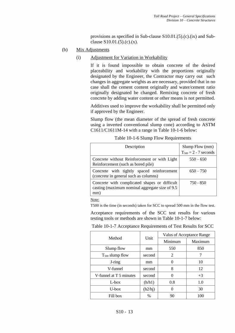
Toll Road Project – General Specifications
Division 10 – Concrete Structures
S10 - 13
provisions as specified in Sub-clause S10.01.(5).(c).(ix) and Sub-
clause S10.01.(5).(c).(x).
(b) Mix Adjustments
(i) Adjustment for Variation in Workability
If it is found impossible to obtain concrete of the desired
placeability and workability with the proportions originally
designated by the Engineer, the Contractor may carry out such
changes in aggregate weights as are necessary, provided that in no
case shall the cement content originally and water/cement ratio
originally designated be changed. Remixing concrete of fresh
concrete by adding water content or other means is not permitted.
Additives used to improve the workability shall be permitted only
if approved by the Engineer.
Slump flow (the mean diameter of the spread of fresh concrete
using a inverted conventional slump cone) according to ASTM
C1611/C1611M-14 with a range in Table 10-1-6 below:
Table 10-1-6 Slump Flow Requirements
Description Slump Flow (mm)
T500 = 2 - 7 seconds
Concrete without Reinforcement or with Light
Reinforcement (such as bored pile)
550 – 650
Concrete with tightly spaced reinforcement
(concrete in general such as columns)
650 – 750
Concrete with complicated shapes or difficult
casting (maximum nominal aggregate size of 9.5
mm)
750 - 850
Note:
T500 is the time (in seconds) taken for SCC to spread 500 mm in the flow test.
Acceptance requirements of the SCC test results for various
testing tools or methods are shown in Table 10-1-7 below:
Table 10-1-7 Acceptance Requirements of Test Results for SCC
Method Unit Valus of Acceptance Range
Minimum Maximum
Slump flow mm 550 850
T500 slump flow second 2 7
J-ring mm 0 10
V-funnel second 8 12
V-funnel at T 5 minutes second 0 +3
L-box (h/h1) 0.8 1.0
U-box (h2/hj) 0 30
Fill box % 90 100
Toll Road Project – General Specifications
Division 10 – Concrete Structures
S10 - 14
(ii) Adjustment for Strength
If the concrete at an earlier age before 28 days produces a
compressive strength below the target strength, the Contractor
shall not be permitted to further cast the concrete until the cause
of low strength is certainly known and until the proper actions
have been taken to ensure that the concrete production will meet
the requirements specified in these Specifications.
If the concrete does not come up to the specified strength, as the
approval of Engineer the cement content may be increased
provided that it does not exceed the maximum cement content
limit due to heat hydration considerations (AASHTO LRFD
Bridge Construction Specification 8.4.3 Maximum Cementitious
593 kilograms/m3 for High Performance Concrete). The other
alternative may be carried out by using the plasticizer to improve
the workability of concrete mix without adding water content.
(iii) Adjustment for New Materials
No change in the source or character of the materials shall be made
without due notice to the Engineer and no new materials shall be
used until the Engineer has accepted such materials and has
designated new proportions based on tests or trial mixes as
provided herein. Should the changes due to the new materials
require an increase in the amount of cement, no additional
payment shall be made to the Contractor for the cost of such
additional cement.
(iv) Adjustment for Admixtures
If the admixtures need to be added and originally mix design
without admixtures, then the implementation shall be carried out
in accordance with Sub-clause S10.01.(2).(c).(i) and the approval
from the Engineer required.
(c) Proportions and Batch Weights
(i) For concrete class fc’ > 20 MPa, all components of concrete
materials shall be measured by weight. For concrete class fc’ < 20
MPa, measurement to be allowed by volume according to ACI
304R-00 or SNI 03-3976-1995. When cement used in bag, the
quantity of batching shall be such that the quantity of cement used
is equivalent to rounded number of cement bag. The aggregate
shall be measured by weight separately. The weight of batch shall
not exceed the capacity of mixer.
(ii) Batching of aggregate and water shall be carried out on the basis
of saturated surface dry aggregate. The surface dry saturated
aggregate may be carried out by spraying the aggregate stockpile
to be used with water at least 12 (twelve) hours before batching. If
the aggregate is not in a saturated surface dry condition, then the
batching correction of water and aggregate shall be carried out
using the data of aggregate water absorption for water and the
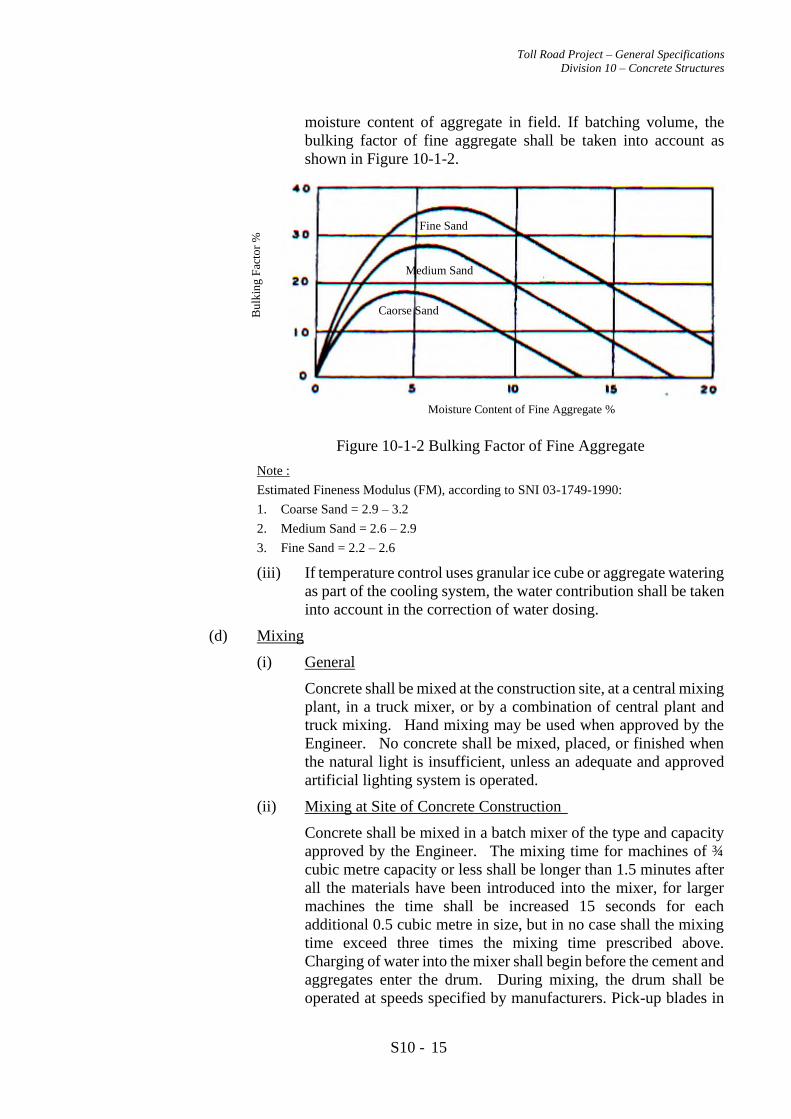
Toll Road Project – General Specifications
Division 10 – Concrete Structures
S10 - 15
moisture content of aggregate in field. If batching volume, the
bulking factor of fine aggregate shall be taken into account as
shown in Figure 10-1-2.
Figure 10-1-2 Bulking Factor of Fine Aggregate
Note :
Estimated Fineness Modulus (FM), according to SNI 03-1749-1990:
1. Coarse Sand = 2.9 – 3.2
2. Medium Sand = 2.6 – 2.9
3. Fine Sand = 2.2 – 2.6
(iii) If temperature control uses granular ice cube or aggregate watering
as part of the cooling system, the water contribution shall be taken
into account in the correction of water dosing.
(d) Mixing
(i) General
Concrete shall be mixed at the construction site, at a central mixing
plant, in a truck mixer, or by a combination of central plant and
truck mixing. Hand mixing may be used when approved by the
Engineer. No concrete shall be mixed, placed, or finished when
the natural light is insufficient, unless an adequate and approved
artificial lighting system is operated.
(ii) Mixing at Site of Concrete Construction
Concrete shall be mixed in a batch mixer of the type and capacity
approved by the Engineer. The mixing time for machines of ¾
cubic metre capacity or less shall be longer than 1.5 minutes after
all the materials have been introduced into the mixer, for larger
machines the time shall be increased 15 seconds for each
additional 0.5 cubic metre in size, but in no case shall the mixing
time exceed three times the mixing time prescribed above.
Charging of water into the mixer shall begin before the cement and
aggregates enter the drum. During mixing, the drum shall be
operated at speeds specified by manufacturers. Pick-up blades in
Bu
lkin
g F
acto
r %
Moisture Content of Fine Aggregate %
Caorse Sand
Kasar
Medium Sand
Sandedang
Fine Sand
Halus
Toll Road Project – General Specifications
Division 10 – Concrete Structures
S10 - 16
the drum of the mixer which are worn down 2 cm or more at any
part shall be replaced.
The volume of a batch shall not exceed the manufacturer's rated
capacity of the mixer without written permission of the Engineer.
No mixer whose rated capacity is less than a one-bag batch shall
be used.
Concrete shall be mixed only in such quantities as are required for
immediate use, and concrete which is not of the required
consistency at the time of placement shall not be used.
Re-tempering of concrete will not be permitted. Entire content of
the mixer shall be removed from the drum before materials for the
next batch are placed therein. Upon cessation of mixing for a
considerable length of time, the mixer shall be cleaned thoroughly.
Upon resumption of mixing, the first batch of concrete materials
placed in the mixer shall contain sufficient sand, cement and water
to coat the inside surface of the drum without diminishing the
required content of the mix.
(iii) Central Plant Mixing
When mixed at a central plant, the mixer and methods used shall
be in accordance with the requirements of Sub-clause
S10.01.(3).(c). Mixed concrete shall be transported from the
central mixing plant to the site of work in agitator or non-agitator
trucks approved by the Engineer.
Unless otherwise permitted in writing by the Engineer, agitator
trucks shall be equipped with water-tight, revolving drum, and
shall be capable of transporting and discharging concrete without
segregation. The agitation speed of the drum shall be between 2
and 6 revolutions per minute. The volume of mixed concrete
permitted in the drum shall not exceed the manufacturer's rating
nor exceed 70% of the gross volume of the drum. Upon approval
of the Engineer, truck mixers may be used in lieu of agitator trucks
for transportation of central plant mixed concrete. Gross volume
of agitator bodies, expressed in cubic metre, shall be as determined
by the mixer manufacturer. The interval between introduction of
water into mixer drum and final discharge time shall be as
determined by the Engineer. During this interval the mixture shall
be agitated continuously.
Bodies of non-agitator trucks shall be smooth and water-tight.
Covers shall be provided when needed for protection against
rainfall. The non-agitator trucks shall deliver concrete to the work
site in a thoroughly mixed and uniform mass. Uniformity shall be
deemed satisfactory if samples from the one-quarter and three-
quarter points of the load do not differ more than 2.5 cm in slump.
Placing of concrete shall be completed within 30 minutes after
introduction of mixing water into the cement and aggregates or if
admixture is used at a time to be determined by the Engineer.
Toll Road Project – General Specifications
Division 10 – Concrete Structures
S10 - 17
(iv) Truck Mixing
Concrete may be mixed in truck mixers of approved design.
Truck mixing shall be in accordance with the following
provisions. The truck mixer shall be either a closed, water-tight,
revolving drum or an open-top revolving-blade or paddle type. It
shall combine all ingredients into a thoroughly mixed and uniform
mass, and shall discharge the concrete with satisfactory
uniformity. A maximum difference of 2.5 cm between slumps of
samples from the one-quarter and three-quarter points of the
discharge load shall be deemed satisfactory.
Mixing speed for revolving drum type mixers shall not be less than
4 revolutions per minute of the drum nor greater than a speed
resulting in a peripheral velocity of the drum of 1 metre per
second. For the open-top type mixer, mixing speed shall be
between 4 and 16 revolutions per minute of the mixing blades or
paddles. Agitation speed for both the revolving-drum and
revolving blade type mixers shall be between 2 and 6 revolutions
per minute of the drum or mixing blades or paddles.
The capacities of truck mixer shall be in accordance with the
manufacturer's ratings except that they shall not exceed the
limitation herein. Standard for normal rated capacity, expressed
as percentage of the gross volume of the drum, shall not be more
than 50% for truck mixing and 70% for agitating.
The concrete shall be delivered to the site of the work and
discharge shall be completed within 45 minutes after the
introduction of the mixing water into cement and aggregates or if
admixture is used at a time to be determined by the Engineer.
When the concrete is mixed in a truck mixer, the mixing operation
shall begin within 30 minutes after the cement has been mixed
with the aggregates. Except when intended for use exclusively as
agitators, truck mixers shall be provided with a water measuring
device which will measure accurately the quantity of water for
each batch. The delivered amount of water shall be within plus
or minus 1% of the indicated amount when the tank, if mounted
on the truck mixer, is satisfactorily and practically level.
(v) Hand Mixing
Hand mixing will not be permitted, except in case of emergency,
without written permission from the Engineer. For non-structural
concrete (fc’ ≤ 15 MPa), when permitted, it shall be performed
only on water-tight mixing platforms made of metal, etc.
Concrete shall be turned and returned on the platform at least six
times and until all particles of the coarse aggregate are covered
thoroughly with mortar and the mixture is uniform.
Toll Road Project – General Specifications
Division 10 – Concrete Structures
S10 - 18
S10.01 (4) Construction
(a) General
The Contractor shall maintain an adequate number of trained and
experienced superintendents and foremen at the site to supervise and
control the work. All construction, other than the concrete, shall conform
to the requirements prescribed in other clauses for the several items of
work entering the complete structure.
(b) Foundation
Preparation of foundations shall conform to the details as shown on the
Drawings in accordance with the requirements of Clause S5.01. The
elevations of the bottoms of footings as shown on the Drawings are
approximate only and the Engineer may order further excavation as
necessary to obtain satisfactory foundations.
Foundations to be prepared with concrete leveling class E or on rock shall
be excavated with a tolerance of 0 - 5 cm. Any excessive exvacation shall
be filled with material of the upper layer, and not to be filled with
excavated materials.
Pile foundations shall be constructed in accordance with the provisions set
out in the other relevant Clauses and as shown on the Drawings.
(c) Falsework
Falsework shall be built on foundations of sufficient strength to carry the
loads without appreciable settlement. Falsework that cannot be founded
on solid footings shall be supported by ample falsework piling provided
at the Contractor's expense.
Before constructing falsework the Contractor shall submit detailed
drawings and, if required, design calculations of proposed falsework for
approval by the Engineer, but such approval shall not relieve the
Contractor of any of his responsibilities under the Contract for the
successful completion of the structure.
In falsework, deflection factor shall be considered in accordance with the
Shop Drawings prepared by the Contractor and approved by the Engineer.
(d) Formwork
Before concrete is placed the Engineer shall inspect all formwork and
falsework and no concrete shall be placed until the Engineer has inspected
and approved such formwork and falsework. Such approval shall not
relieve the Contractor of any of his responsibilities under the Contract for
the successful completion of the structure.
Internal formwork for hollow slab shall be made of plywood, thin metal
plate or other materials. These materials shall have strength sufficient to
resist the pressure of fresh concrete and the buoyancy.
Type and structure of joint and cover for the cylindrical form shall be tight
to prevent any leakage of concrete and shall be approved by the Engineer.
Nominal diameter of cylindrical forms shall be the outer diameter, or the
Toll Road Project – General Specifications
Division 10 – Concrete Structures
S10 - 19
outer diameter of projecting portion in case of thin metal plate having
projection. The height of the projection shall be less than 10 mm.
Internal forms shall be fixed in the correct position such that they will not
displace or deform during placing concrete. U-shape bolts shall be used
to fix the internal forms and the method of supporting and fixing the
internal forms shall be approved by the Engineer. Care shall be taken to
ensure that U-shape bolts and other items can resist the buoyancy of the
formwork.
In formwork, deflection factor shall be considered in accordance with the
Shop Drawings prepared by the Contractor and approved by the Engineer.
Shapes, types, material and strengthening type in the fabrication of false
work and formwork as described above, are subject to that positions,
vertically and the dimensions of the type of concrete works not exceed the
allowable tolerance than as specified in Sub-clause S10.01.(1).(c).
(e) Reinforcement
The Engineer shall inspect and approve all reinforcement in place in
accordance with the requirements of Clause S10.02, before concrete is
placed. An experienced steel fixer shall be present while all concrete is
placed to ensure that no reinforcement becomes displaced during placing
and if it does to reposition reinforcement before placing continues.
(f) Placing Concrete
(i) General - All concrete shall be placed within the time specified in
Sub-clause S10.01 (3) (f). Concrete shall be placed in such a
manner as to avoid segregation and the displacement of
reinforcing bars and shall be spread in horizontal layers where
practicable. Concrete shall be placed where necessary inside forms
by hand shovels and in no instance shall vibrators be so
manipulated to transport concrete inside formwork. Care shall be
taken to prevent mortar from spattering forms and reinforcing steel
and from drying ahead of the final covering with concrete. When
spattering has occurred the forms and steel shall be cleaned with
wire brushes or scrapers before concrete is placed around steel or
in forms which have been spattered.
Troughs, pipes, or short chutes used as aids in placing concrete
shall be positioned in such a manner that segregation of the
concrete will not occur. All chutes, troughs, and pipes shall be
kept clean and free from coating of hardened concrete or mortar.
Concrete shall not be dropped freely over a vertical distance of
more than 1.5 meters.
Concrete shall be placed continuously throughout each section of
the structure or between indicated joints if shown on the Drawings
or as directed by the Engineer.
If in an emergency it is necessary to stop placing concrete before
a section is completed, bulkheads shall be placed as the Engineer
Toll Road Project – General Specifications
Division 10 – Concrete Structures
S10 - 20
may direct and the resulting joint shall be deemed a construction
joint, and treated as specified herein below.
(ii) Concrete columns - Concrete in columns or bents shall be placed
in one continuous operation unless shown on the Drawings or
permitted by the Engineer.
(iii) Concrete slab and girder spans - Slabs and girders having spans of
10 meters or less shall be placed in one continuous operation
unless otherwise stated on the Drawings. Concrete preferably
shall be deposited by beginning at the centre of the span working
from the centre toward the ends.
Concrete in slab spans shall be placed in one continuous operation
and in one layer for each span, unless otherwise stated on the
Drawings.
Concrete in girders spanning more than 10 meters may be placed
in two operations, the first operation being the placing of concrete
in the girder stems to the bottom of the slab haunches or the bottom
of the slab whichever is applicable. A period of at least 24 hours
shall elapse between the completion of placing concrete in the
girder and the commencement of placing concrete in slab.
The construction procedure for the concrete deck slab on steel box
girders shall be so arranged as to eliminate excessive stress in new
or recently placed concrete.
Immediately before placing concrete, the top surface of the
previously placed concrete shall be hammered with a sharp hand
tool until the aggregate is exposed and cleaned. The Contractor
shall check all falsework for shrinkage and settlement, and shall
tighten all wedges to ensure minimum deflection of all formwork.
(iv) Walls, piers, etc. - Where walls, piers, columns, struts, posts and
other such structural members allow horizontal construction
joints, concrete shall not be placed on top of other concrete which
has not been allowed to set for 12 hours or more.
Work shall not be discontinued within 45 centimeters of the top of
any face, unless provision has been made for a coping less than 45
centimeters thick, in which case, if permitted by the Engineer, the
construction joint may be made at the underside of the coping.
(v) Culverts - The slabs of box culverts shall be placed for their full
depth in one mass or layer and allowed to set not less than 12 hours
before any additional work is done on them.
Before concrete is placed in sidewalls, bottom slabs shall be
cleaned of all shavings, sticks, sawdust and other extraneous
material.
The Contractor shall submit to the Engineer for approval his
proposals for pouring culvert walls before commencing culvert
construction. Concrete shall not be placed in layers more than
Toll Road Project – General Specifications
Division 10 – Concrete Structures
S10 - 21
one meter high relative to the concrete already placed.
Deposition shall proceed in a systematic manner.
(vi) Depositing concrete underwater - Concrete shall not be deposited
in water except with the approval of the Engineer and with his
immediate supervision, and by the method described in this
paragraph.
To prevent segregation, the concrete shall be carefully placed in a
compact mass in its final position by means of a tremie tube or
pipe, or a closed bottom-dump bucket, or by other means, and shall
not be disturbed after being deposited. Special care shall be
exercised to maintain still water at the point of deposit. Concrete
shall not be placed in running water. The method of depositing
concrete shall be so regulated as to produce approximately
horizontal surfaces.
Concrete seals shall be placed in one continuous operation.
When a tremie tube or pipe is used, it shall consist of a tube or pipe
not less than 25 centimeters in diameter, constructed in sections
having flanged couplings fitted with gaskets.
The means of supporting the tremie shall be such as to permit free
movement of the discharge end over the entire top of the concrete
and permit its being lowered rapidly when necessary to choke off
or retard the flow.
The tremie shall be filled by a method that will prevent washing
of the concrete. The discharge end shall be completely submerged
in concrete at all times and the tremie shall contain sufficient
concrete to prevent any water entry.
When concrete is placed with a bottom-dump bucket, the bucket
shall have a capacity of not less than 1.20 cubic meters and shall
be equipped with loose-fitting top covers. The bottom door shall
open freely downward and outward when tripped. The bucket shall
be completely filled and be lowered gradually and carefully until
it rests on the surface upon which the concrete is to be deposited.
It shall then be raised very slowly during the discharge travel, the
intent being to maintain, as nearly as possible, still water at the
point of discharge and to avoid agitating the mixture.
Dewatering shall proceed only when the concrete seal is
considered strong enough to withstand any pressures to be exerted
upon it. This time will be decided by the Engineer. All laitance
or other unsatisfactory material shall be removed from the exposed
surface by scraping, jetting, chipping or other means which will
not unduly injure the seal.
(vii) Construction joints - Construction joints shall be located where
shown on the Drawings or permitted or instructed by the Engineer.
Construction joints shall be perpendicular to the principal lines of
stress and in general shall be located at points of minimum shear.
Toll Road Project – General Specifications
Division 10 – Concrete Structures
S10 - 22
At horizontal construction joints, details shall be as approved by
the Engineer. Before placing fresh concrete, the surfaces of
construction joints shall be sandblasted or washed and scrubbed
with a wire brush to expose clean aggregate, drenched with water
until saturated, and kept saturated until the new concrete is placed.
Immediately prior to placing new concrete the forms shall be
drawn tight against the concrete already in place. Concrete in
substructures shall be placed in such a manner that all horizontal
construction joints will be truly horizontal.
Where vertical construction joints are necessary, reinforcing bars
shall extend across the joint in such a manner as to make the
structure monolithic. Special care shall be taken to avoid
construction joints through panelled wing walls or other large
surfaces which are to have an architectural finish.
Necessary dowel, load-transfer devices, and bonding devices shall
be placed as shown on the Drawings or directed by the Engineer.
(viii) Expansion joints - Expansion joints shall be asphaltic joint filler,
20 mm thick, and shall be located and formed as required on the
Drawings. Asphaltic joint filler shall be measured and paid for as
provided at Pay Item 10.01 (21).
Cut-off plate for water stops used for the expansion joints shall be
flexible PVC to SNI 06-0162-1987 and SNI 06-0178-1987 or
according to ASTM D2665-14 with basic materials made of virgin
PVC compounds that meet the 12454 class according to ASTM
D1784-11 and shall be placed in accordance with the Drawings.
The water stops shall be held firmly in place to prevent
displacement during concreting. If after placing concrete water
stops are materially out of position or shape, the surrounding
concrete shall be removed, the water stop reset, and the concrete
replaced, all at the Contractor's expense.
Water stop shall be furnished full length for each straight portion
of the joint, without field splices. Water stop shall be cut and
spliced at changes in direction as may be necessary to avoid
buckling or distortion. All field splices shall be performed by
heat sealing the adjacent surfaces in accordance with the
manufacturer's recommendations to form continuous watertight
joints.
Water stop shall be measured and paid for as provided at Pay Item
10.01 (20).
(ix) Open joints - Open joints shall be constructed where shown on the
Drawings by insertion and subsequent removal of a wooden strip,
metal plate, or other approved material. The insertion and
removal of the template shall be accomplished without chipping
or breaking the corners of the concrete. Reinforcement shall not
extend across an open joint unless so specified on the Drawings.
Toll Road Project – General Specifications
Division 10 – Concrete Structures
S10 - 23
(x) Steel joints - The plates, or other structural shapes shall be
accurately shaped at the shop to conform to the section of the
concrete floor. The fabrication and painting shall conform to the
requirements of the specifications covering those items. When
called for on the Drawings or in the Specifications, the material
shall be galvanized in lieu of painting. Care shall be taken to
ensure that the surface in the finished plane is true and free of
warping. Positive methods shall be employed in placing the
joints to keep them in correct position during the placing of the
concrete. The opening at expansion joints shall be that
designated on the Drawings at normal temperature, and care shall
be taken to avoid impairment of the clearance in any manner.
(xi) Anchor bolts - All necessary anchor bolts in piers or abutments
shall be accurately set in holes formed while the concrete is being
placed. Holes may be formed by inserting in the fresh concrete
oiled wooden plugs, metal pipe sleeves, or other approved devices,
and withdrawing them after the concrete has partially set. Holes
so formed shall be at least 10 cm in diameter. Bolts shall be set
accurately and fixed with grout completely filling the holes. The
grout shall be non-shrink mortar of a type approved by the
Engineer.
Anchor bolts used in connection with expansion shoes, rollers, and
rockers shall be located with due regard to the temperature at the
time of erection. Care shall be taken that full and free movement
of the superstructure at the moveable bearings is not restricted by
improper setting or adjustment of bearings or anchor bolt and nuts.
(xii) Shoes and bearing plates - Bridge seat bearing areas shall
preferably be finished high and ground to level required. Shoes
and bearing plates shall be set as provided in Clause S10.11.
(xiii) Drainage holes and weep holes - Drainage holes and weep holes
shall be constructed in the manner and at the locations indicated
on the Drawings or required by the Engineer. Ports or vents for
equalizing hydrostatic pressure shall be placed below low water.
Forms for weep holes through concrete shall be PVC pipe.
Exposed surfaces of weep drain pipe shall be flush with the
concrete.
(xiv) Pipe, conduits, and ducts - Pipes, conduits, and ducts that are to be
encased in concrete shall be installed by the Contractor before the
concrete is placed. Unless otherwise indicated, pipe embedded in
concrete shall be standard, light weight, non-corrosive pipes. Pipes
shall be held or braced rigidly during concrete placement in order
to prevent their displacement.
(xv) Piers and abutments - No superstructure load shall be placed upon
finished bents, piers, or abutments until the Engineer so directs,
but the minimum time allowed for the hardening of concrete in the
Toll Road Project – General Specifications
Division 10 – Concrete Structures
S10 - 24
substructure before any load of the superstructure is placed
thereon shall be 7 days when normal Portland cement is used.
(g) Control Temperature of Mass Concrete
(i) Control of Material Composition
Control of material composition to produce the maximum concrete
temperature required shall be proven by the measuring the
temperature of test object (mock up) with a minimum size in
accordance with the structural elements to be carried out.
(ii) Mechanical Cooling System
If the Contractor chooses to use a mechanical cooling system, it
shall be planned according to the temperature control plan with the
following requirements:
- The mechanical cooling system shall be located inside of
concrete elements and when the concrete has reached the
required age, the joint in surface to the cooling pipe shall be
discharged to a depth of 10 cm from the surface.
- Formwork shall be planned so that the opening does not
interfere the monitoring of cooling system and temperature.
- The cooling pipes shall not break or sag during concrete
casting and shall be guaranteed to be protected from
movement. Broken cooling pipes shall be replaced
immediately.
- Mechanical cooling systems shall be tested at 30 psi for 30
minutes to ensure no leak before concrete casting.
- Cooling circulation shall be carried out when casting
commences, and after the cooling process completes the
cooling pipe shall be immediately grouted with a grouting
mixture without shrinkage in accordance with ASTM C1107-
17 for 0.0 percent shrinkage and ASTM C-827-16 for 0.0 - 4.0
percent change. Grouting shall be carried out in accordance
with the manufacturer's recommendations.
- After opening the joint in surface to the cooling pipe, the hole
shall be patched with mortar.
(iii) Temperature Monitoring and Recording System
Temperature monitoring and recording systems shall consist of
temperature sensors which connected to a data collection system
and it is able to print, save and download data to a computer. The
temperature sensor shall be placed so that the maximum
temperature difference of concrete can be observed. At least, the
concrete temperature shall be observed at the hottest location
based on the computation or at the center of mass, and minimum
2 outer walls or at a depth of 50 mm from the outer surface and
approved by the Engineer.
Toll Road Project – General Specifications
Division 10 – Concrete Structures
S10 - 25
(iv) Temperature Readings
Temperature readings shall be automatically recorded every hour
or faster. A set of backup sensors shall be installed closed to the
main sensor. Backup sensors shall be able to be recorded, but
recording is not necessary if the main sensor is working properly.
The temperature reading can be stopped if the difference
temperature between the concrete with the average daily air
temperature is less than the allowable temperature difference for
three consecutive days and there is no casting mass concrete of
adjacent to this concrete. Data shall be printed and submitted to
the Engineer every day.
(v) Sensor Protection
The method of compacting mass concrete shall be able to protect
the temperature monitoring and reading system. The cable of
temperature sensor which installed in the concrete shall be
protected from any movement. The length of cable shall be as
short as possible. The edges of the temperature sensor shall not be
in contact with the formwork or reinforcement.
(vi) Tool Failure
If the tool for temperature monitoring and recording system is
damage during the implementation of mass concrete, the
Contractor shall immediately carry out the repairs in accordance
with the Temperature Control Plan. Failure to meet temperature
monitoring requirements will cause the rejection of concrete work.
(vii) Allowable Temperature (includes the acceptance criteria)
Mass concrete works shall meet the following acceptance criteria
and temperature requirements:
- The maximum allowable temperature is 71°C;
- The allowable temperature difference is not more than 21°C,
unless it can be proven by an analysis that the concrete
structure is able to accommodate temperature differences
greater than 21°C.
(viii) Failure to Meet Temperature Requirements
If the Contractor fails to meet the maximum temperature
requirements as required in Sub-clause S10.01 (6) (h) of these
Specifications, the related concrete element shall be rejected.
Rejected concrete shall be removed at the expense of the
Contractor. The Contractor shall modify the Temperature Control
Plan and planning computation to resolve the problem and submit
the revised Temperature Control Plan.
(ix) Grace Period
The Contractor will be given of the 15 days to review the revised
Temperature Control Plan. Concrete casting shall not be carried
out before the Engineer approves the revised Temperature Control
Toll Road Project – General Specifications
Division 10 – Concrete Structures
S10 - 26
Plan. There is no additional or extra for any rejection of structural
elements or correction of Temperature Control Plan.
(h) Consolidation
(i) Concrete shall be consolidated with approved internal or external
mechanical vibrators. When required, and when approved by the
Engineer, vibrating shall be supplemented by hand rod with
suitable tools to assure proper and adequate consolidation.
Vibrators shall not be used to transport concrete from point to
point inside the forms.
(ii) Care shall be taken during consolidation to ensure that all corners
and spaces between and around reinforcing bars are properly filled
without displacement of the reinforcing cage and that all voids and
air bubbles are filled with concrete.
(iii) Vibration shall be limited to the time necessary to produce
satisfactory consolidation without causing segregation of
aggregates.
(iv) External mechanical vibrators shall be capable of producing at
least 5000 cycles per minute with an effective weight of 0.25 kg,
and able to be located on the form work so as to produce even
vibrations.
(v) Internal mechanical vibrators shall be of the pulsating type and
shall be capable of producing at least 5000 cycles per minute when
used in concrete that has a slump of 2.5 cm or less, with vibrated
radius area shall not be less than 45 cm.
(vi) Each internal vibrator shall be inserted into the wet concrete
vertically so that it penetrates to the bottom of the freshly placed
concrete and provides consolidation throughout the full depth of
the section. The vibrator shall then be withdrawn slowly and
inserted again at an adjacent position no more then 45 cm away.
Vibrators shall not remain for more than 30 seconds in one
location, shall not be used to move concrete to adjacent locations
and shall not be allowed to touch the reinforcing.
(vii) The minimum number of internal mechanical vibrators shall be as
shown on the following Table 10-1-8.
Table 10-1-8 Minimum Number of Internal Mechanical Vibrator
Concreting Speed (m3/hour) Vibrator Number
4
8
12
16
20
2
3
4
5
6
(viii) A more detailed requirement of vibrator head diameter (mm),
recommended frequency (Hz), average amplitude (mm), vibrating
Toll Road Project – General Specifications
Division 10 – Concrete Structures
S10 - 27
radius (mm), casting speed (m3/hour/ vibrator) and the guidance
of implementation can be adopted from Table 5.1 ACI Committee
Report : Guide for Consolidation of Concrete 309R-05 ACI
Manual of Concrete Practice - 2006 Part.2.
(i) Curing Concrete
Immediately after forms have been removed and finishing completed, all
concrete shall be cured by one of the following methods. The Engineer
will specify the concrete surface which may be cured by either method.
(i) Water method - The entire exposed surfaces other than slabs shall
be protected from the sun and the whole structure shall be covered
with wet burlap, cotton mats, or other suitable fabric for a period
of at least seven days. These materials shall be kept thoroughly
wet for the entire curing period. Curbs, walls, and other surfaces
requiring a rubbed finish may have the covering temporarily
removed for finishing, but the covering shall be restored as soon
as possible. All concrete slabs shall be covered as soon as
possible with sand, earth or other suitable material and kept
thoroughly wet for at least seven days. This covering material
shall not be cleared from the surface of the concrete slabs for a
period of twenty one days.
If wood forms are allowed to remain in place during the curing
period, they shall be kept moist at all times to prevent them from
shrinking.
(ii) Membrane - forming curing compound - All surfaces shall be
given the required surface finish prior to application of the curing
compound. During the finishing period, the concrete shall be
protected by the water method of curing.
Membrane curing compound shall be applied after the removal of
forms, or after the disappearance of surface water. It shall be
sprayed on the concrete surface in one or more coats at the rate
instructed by the manufacturer.
Should the membrane seal be broken or damaged before the
expiration of the curing period, the damaged area shall be
immediately repaired by the application of additional membrane
material.
The Contractor's proposals for the use of liquid membrane curing
compound and the locations shall be subject to the approval of the
Engineer.
Curing of mass concrete is carried out by taking into account the initial
setting time of cement. Immediately after initial setting time passed, the
curing of casting mass concrete shall be carried out by spraying the curing
compounds to retain heat that conforms to ASTM C309:2012 or SNI
ASTM C309: 2012. Curing membrane which has a function as a cover
shall have a heat resistance rate of 0.5 hour-foot2/BTU.
Toll Road Project – General Specifications
Division 10 – Concrete Structures
S10 - 28
First curing of mass concrete using a curing coumpounds to be carried out
after the initial setting time passed. The other curings may be carried out
after application of the curing compounds complete. The difference
temperature between the air and the concrete surface temperature shall not
more than 11°C.
(j) Steam Curing
(i) Steam curing may be used to get high early strength. Additive
material shall not be permitted unless otherwise approved by the
Engineer.
(ii) Steam curing shall be applied continuously until the concrete
reaches 70 % of its 28-day design strength. Steam curing shall
follow the requirements below:
- Steam pressure shall not exceed atmospheric pressure
- The temperature shall not exceed 38 C within 2 hours after
concreting, and may gradually increase to 65 C, with a
maximum rate of increase of 14 C/hour.
- The temperature difference between two locations on the
steamer shall not exceed 5.5 C.
- The rate of temperature decrease during the cooling down
period shall not exceed 11 C/hour.
- The concrete temperature at the time of removal from the
steamer shall not differ by more than 11 C from the air
temperature.
- During steam curing, the steamer shall always be in a saturated
condition.
- After finishing steam curing, each part of the structure shall be
kept wet for 4 days.
(iii) The Contractor shall ensure that the equipment is in good working
condition and the temperature in the steamer can be adjusted in
accordance with the above requirements and variations in the
weather.
(iv) The steam pipe shall be located, and the beam protected such that
steam will not be directly sprayed on the concrete, as this may
cause temperature differences between adjacent concrete parts.
(k) Removal of Formwork and Falsework
(i) Time of removal - Formwork and falsework shall not be removed
without the approval of the Engineer. The Engineer's approval
shall not relieve the Contractor of responsibility for the safety of
the work. Blocks and bracing shall be removed at the same time
as the forms and in no case shall any portion of the wood forms be
left in the concrete.
Toll Road Project – General Specifications
Division 10 – Concrete Structures
S10 - 29
Falsework removal for continuous or cantilevered structures shall
be as directed by the Engineer or shall be such that the structure is
gradually subjected to its working stress.
When the time for removal of forms and supports is determined
based on concrete strength tests, such removal shall not begin until
the concrete has attained the percentage of the specified design
strength shown in the table below.
If field operations are not controlled by compressive strength tests,
the time shown below for removal of forms and supports shall be
used as a minimum:
Table 10-1-9 Minimum Days for Removal of Forms and Supports
Standard
Concrete
Early
Strength
Concrete
Percentage
Design
Strength
Centering under girders,
beams, frames or arches
Floor slabs
Walls
Columns
Side of beams and all
other vertical surfaces
14 days
14 days
1 day
2 days
1 day
7 days
7 days
12 hours
1 day
12 hours
80%
70%
-
-
-
In continuous structures, falsework shall not be released in any
span until the first and second adjoining spans on each side have
reached the strength specified herein or in the special provisions.
When cast-in-place post tensioned bridges are constructed,
falsework shall remain in place until all post tensioning has been
accomplished.
Falsework under all spans of continuous structures shall be
completely released before concrete is placed in railings and
bridge parapets.
Forms and falsework shall not be released from under concrete
without first determining if the concrete has gained adequate
strength without regard to the time element. In the absence of
strength determinations, the forms and falsework are to remain in
place until removal is permitted by the Engineer.
The forms for footings constructed within cofferdams or cribs may
be left in place when, in the opinion of the Engineer, their removal
would endanger the safety of the cofferdam or crib, and when the
forms so left intact will not be exposed to view in the finished
structure. All other forms shall be removed whether above or
below the ground line or water level.
All formwork shall be removed from the cells of concrete box
girders within which utilities are required, and all formwork
except that necessary to support the deck slab shall be removed
from the remaining cells of the box girder.
Toll Road Project – General Specifications
Division 10 – Concrete Structures
S10 - 30
To facilitate finishing, forms used on ornamental work, railings,
parapets, and exposed vertical surfaces shall be removed at least
12 but not more than 48 hours later depending upon weather
conditions.
In order to determine the condition of concrete in columns, forms
to columns shall always be removed before releasing supports
from beneath beams and girders.
Falsework supporting the deck of rigid frame structures shall not
be removed until fill has been placed behind the vertical legs.
(ii) Patching - Immediately following removal of the forms all
projecting wires or metal devices that have been used for holding
the forms in place shall be removed or cut back at least 2.5 cm
beneath the surface of the concrete. Fins or runs of mortar and all
irregularities caused by form joints shall be removed. Small
holes, depressions, and voids that show on the concrete shall be
filled with cement mortar mixed in the same proportions as that
used in the body of the work, except without coarse aggregate.
The surface of this mortar shall be floated with a wooden float
before initial set takes place. It shall be uniform in colour with
the surrounding concrete and neat and workmanlike in
appearance.
(iii) Cause for rejection - Excessive honeycombing shall be sufficient
cause for rejection of portions of the structure containing this
honeycombing. The Contractor, on receipt of written orders from
the Engineer, shall remove and rebuild such portions of the
structure at his own expense.
(l) Finishing Concrete
All concrete surfaces exposed in the completed work shall comply with
the requirements of (iii) Ordinary finish except where otherwise shown or
specified.
(i) Concrete decks - Immediately after placing concrete, concrete
decks shall be struck off with templates to provide proper
transverse sections and shall be hand finished smooth to the
concrete levels. Finish shall be slightly but uniformly roughened
by brooming. The finished surface shall not vary more than 10
millimeters from a 4 meter straightedge placed parallel to the
centreline of the roadway and 10 millimeters from a transverse
template cut to the true cross section of the roadway.
(ii) Curb and footpath surface - Exposed faces of curbs and footpath
shall be finished true to lines and grades. The curb surface shall
be wood floated to a smooth but non-slippery finish. Footpath
surfaces shall be slightly but uniformly roughened by brooming
across the direction of travel. Flatteness of surfaces as measured
using a 3 meter straightedge laid on the top or face of the curb or
Toll Road Project – General Specifications
Division 10 – Concrete Structures
S10 - 31
on the surface of gutters shall not vary more than 3 mm from the
edge of the straightedge, except at grade changes or curves
(iii) Ordinary finish - An ordinary finish is defined as the finish left on
a surface after the removal of the forms when all holes left by form
ties have been filled, and any minor surface defects have been
repaired. The surface shall be true and even, free from
depressions or projections and of reasonably uniform colour.
Repaired surfaces, the appearance of which is not satisfactory,
shall be "rubbed" as specified in Item (iv) Rubbed finish.
The concrete in bridge seats, caps, and tops of walls shall be struck
off with a straightedge and floated to true grade. Unless shown
on the Drawings the use of mortar topping for concrete surfaces
will not be permitted.
(iv) Rubbed finish - After the removal of forms the rubbing of concrete
shall be started as soon as its condition will permit. Immediately
before starting this work the concrete shall be kept thoroughly
saturated with water. Sufficient time shall have elapsed before
the wetting down to allow the mortar used in patching to set
thoroughly. Surfaces to be finished shall be rubbed with a
medium coarse carborundum stone, using a small amount of
mortar on its face. The mortar shall be composed of cement and
fine sand mixed in the same proportions as those used in the
concrete being finished. Rubbing shall be continued until all
form marks, projections and irregularities have been removed, all
voids filled, and a uniform surface has been obtained. The paste
produced by this rubbing shall be left in place. After all concrete
above the surface being treated has been cast, the final finish shall
be obtained by rubbing with a fine carborundum stone and water.
This rubbing shall be continued until the entire surface is of a
smooth texture and uniform colour.
After the final rubbing has been completed and the surface has
dried, it shall be rubbed with burlap to remove loose particles and
laitance. The final surface shall be free from all unsound patches,
paste, powder and objectionable marks.
On the concrete surface either the exposed surface or the covered
surface that flatteness tolerances allowed are as follows:
(1) Flatteness of covered vertical surfaces:
- Tolerance for offset at form joint ..… 3 mm
- Tolerance on flatness ………………. 5 mm over 2 m
(2) Flatteness of exposed vertical surfaces :
- Tolerance for joint offset …..……… 0 mm
- Tolerance on flatteness …..………. 5 mm over 2 m
(v) Backfill and road fills - All spaces which have been excavated and
the volumes of which are not occupied by the concrete structure
Toll Road Project – General Specifications
Division 10 – Concrete Structures
S10 - 32
shall be backfilled and compacted with acceptable material in
accordance with the provisions of Division 5 of these
Specifications.
If there is likelihood of water accumulating behind any wall, the
backfill shall not be placed until after the retaining, diaphragm, or
spandrel walls are 28 days old. No fill shall be placed over arches
and slabs until the concrete is 28 days old or until test specimens
indicate the concrete has attained the required 28-day strength.
(vi) Loadings - Traffic or heavy construction equipment shall not be
allowed on reinforced concrete structures until 28 days have
elapsed from the last placing of concrete except as noted below.
If it is proposed to use the structure at an earlier date, extra test
specimens shall be cast. The structure may be used when tests of
these specimens show that the concrete has attained its specified
28-day strength.
(m) Adhesive
(i) Construction Method
(1) Smoothing Treatment of Jointing Surface
The block surface to which adhesive is to be applied shall
be wire brushed till smooth, removing any sheath ends that
may be projecting beyond the jointing surface.
(2) Dust Removal and Degreasing
After treating the jointing surface to a smooth and flat
surface, dust and dirt shall be removed using compressed
air or other means. If any form of releasing agent or
grease has been deposited, the surface shall be degreased
using an organic solvent.
(3) Drying of Bond Surface
After separating the form from the PC block, the surface
shall be covered with a sheet cover, etc., as protection
against rainwater, in order to maintain the bonded blocks
in a dried condition. If bonding work shall be performed
when the PC blocks to be bonded are in a wet condition,
forced drying by means of a torch lamp, gas burner, etc.,
shall be performed.
(ii) Application of Adhesive
(1) Mixing and Stirring
On completion of surface treatment, the base agent and
hardener shall be mixed according to the specified mix
proportion and thoroughly stirred.
(2) Application Method
The adhesive is to be applied thoroughly to both bonding
surfaces using a rubber, or metallic spatula. The optimum
Toll Road Project – General Specifications
Division 10 – Concrete Structures
S10 - 33
coat thickness for each concrete surface is about 1 mm and
the adhesive should ooze out beyond the joints when the
blocks are jointed and prestressing is introduced.
(3) Jointing
The air temperature during block jointing should
preferably be in the range from 5 - 35 degrees celsius and
work should proceed so that the first prestressing should
be completed at least within the adhesive's pot life time.
Since with the introduction of prestressing, the adhesive
will ooze out beyond the joints, and at the same time, will
be pushed inside the sheath, it is advisable to leave an
uncoated area of 10 - 20 mm around the sheath.
Satisfactory results can be obtained also by covering the
sheath holes by means of gum tape, etc.
(4) Curing
For at least 24 hours after bonding, the jointed section
should be protected against rainwater or excessive impact.
(n) Cyclopean Concrete
Cyclopean concrete shall consist of Class fc’ 15 MPa containing large
embedded stones. The stones shall be carefully placed and shall not be
dropped into place. They shall be cast to avoid damage to the forms or to
the partially set adjacent masonry. Stones shall be washed and saturated
with water before placing. Total volume of stone shall not be greater than
1/3 of total volume of cyclopean concrete.
For retaining walls or piers greater than 60 cm thickness, stone having a
maximum size of 25 cm may be used. Each stone shall be surrounded by
at least 15 cm of concrete and no stone shall be closer than 30 cm to any
top surface nor closer than 15 cm to any coping
(o) Cleaning Up
Upon completion of structure and before final acceptance, the Contractor
shall remove all falsework, falsework piling, etc., down to 1.0 meter
below the finished ground line. Excavated, or useless materials, rubbish,
etc. shall be removed from the site and the site shall be left in a neat and
presentable condition satisfactory to the Engineer.
(p) Storage of precast concrete units.
Precast concrete unit shall be stored or stacked on site after removal from
forms so that no distortion or bending of the units shall occur. Where units
are stacked on the ground, the surface of the ground shall be level and be
of such hard material that no softening of the soil, or settlement of the
stack, will occur when the ground becomes wet. Two timber bearers (of
minimum section 50 mm by 100 mm) will be placed on the ground and
be firmly seated and made level and parallel before any precast units are
placed on them. Timber pallets may be used instead of the two bearers
with the approval of the Engineer.
Toll Road Project – General Specifications
Division 10 – Concrete Structures
S10 - 34
Care will be taken to avoid any damage to the precast concrete units
during handling and storage. Any units which are damaged shall be
rejected and removed from the site of works.
S10.01 (5) Field Quality Control
(a) Accepted Materials
The accepted materials (water, cement, aggregates and additives required)
shall be checked by the Engineer by examining written evidence
indicating that the materials conform to the requirements of Sub-clause
S10.01 (2).
If the quantity materials required are sufficient by continuous shipment,
then as the engineer direction, for aggregate coarse and fine aggregate the
Contractor shall carry out a periodic testing during construction with a
maximum interval of 1000 m3 for gradation and a maximum of 5000 m3
for abrasion test, and for the cement with maximum interval of 300 ton
each for delivery. But if in the opinion of the Engineer there is an
indication of quality change or the nature of material used, the Contractor
shall promptly carry out the additional tests before the material to be used.
(b) Testing for Workability
One slump test or more as directed by the Engineer, shall be carried out
on every batch of concrete produced, and the test shall not be deemed to
have been carried out unless witnessed by the Engineer or his
representative.
If the concrete mixture does not conform to the proposed workability, it
shall not be used for the work, unless in some cases, the Engineer approves
their limited use and the quality of concrete remains maintained.
Workability and textures shall be such that the concrete may be placed for
the work without forming hollow spaces or gaps or retention of air or
water bubbles, and when the formwork to be removed the surface results
shall be flat, smooth and dense.
(c) Compressive Strength Testing
(i) The Contractor shall obtain a number of compressive strength test
results from the concrete works carried out. Each result is the
average of a pair compressive strength of the specimens in one set
specimens (1 set = 3 test specimens), the different of a pair results
shall not more than 5% for each age, for each compressive strength
required and for each type of structural component placed
separately for each day placement.
(ii) For the purpose of concrete compressive tests, the Contractor shall
provide a cylindrical specimen with a diameter of 150 mm and a
height of 300 mm and shall be cured in accordance with AASHTO
T23-14 or SNI 4810:2013. The test specimen shall be prepared
and taken together from the concrete to be placed, and then cured
in accordance with the curing in the laboratory.
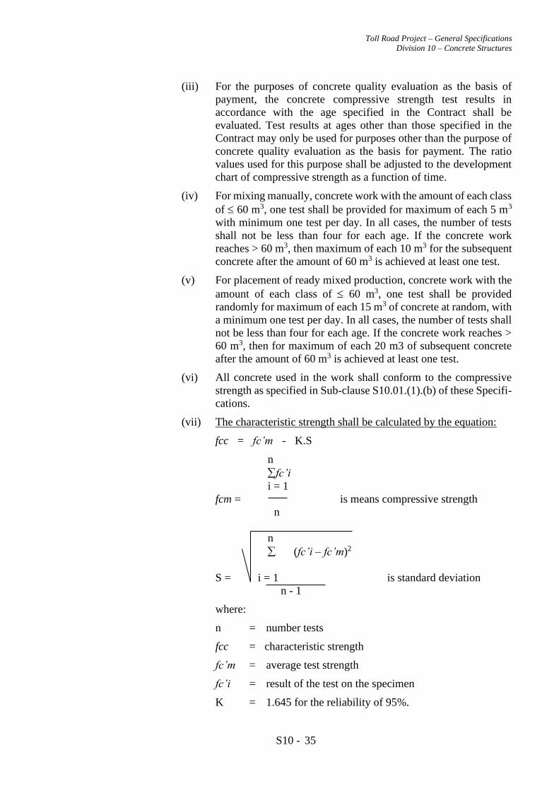
Toll Road Project – General Specifications
Division 10 – Concrete Structures
S10 - 35
(iii) For the purposes of concrete quality evaluation as the basis of
payment, the concrete compressive strength test results in
accordance with the age specified in the Contract shall be
evaluated. Test results at ages other than those specified in the
Contract may only be used for purposes other than the purpose of
concrete quality evaluation as the basis for payment. The ratio
values used for this purpose shall be adjusted to the development
chart of compressive strength as a function of time.
(iv) For mixing manually, concrete work with the amount of each class
of 60 m3, one test shall be provided for maximum of each 5 m3
with minimum one test per day. In all cases, the number of tests
shall not be less than four for each age. If the concrete work
reaches > 60 m3, then maximum of each 10 m3 for the subsequent
concrete after the amount of 60 m3 is achieved at least one test.
(v) For placement of ready mixed production, concrete work with the
amount of each class of 60 m3, one test shall be provided
randomly for maximum of each 15 m3 of concrete at random, with
a minimum one test per day. In all cases, the number of tests shall
not be less than four for each age. If the concrete work reaches >
60 m3, then for maximum of each 20 m3 of subsequent concrete
after the amount of 60 m3 is achieved at least one test.
(vi) All concrete used in the work shall conform to the compressive
strength as specified in Sub-clause S10.01.(1).(b) of these Specifi-
cations.
(vii) The characteristic strength shall be calculated by the equation:
fcc = fc’m - K.S
n
fc’i
i = 1
fcm = is means compressive strength
n
n
(fc’i – fc’m)2
S = i = 1 is standard deviation
n - 1
where:
n = number tests
fcc = characteristic strength
fc’m = average test strength
fc’i = result of the test on the specimen
K = 1.645 for the reliability of 95%.
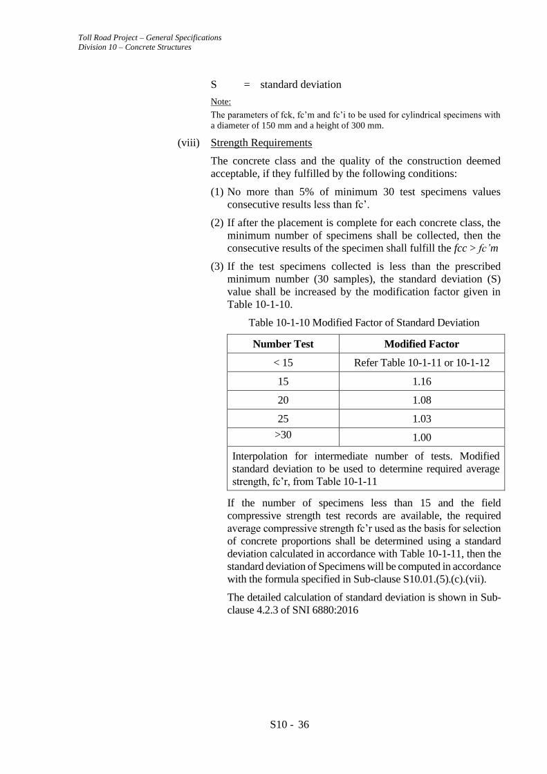
Toll Road Project – General Specifications
Division 10 – Concrete Structures
S10 - 36
S = standard deviation
Note:
The parameters of fck, fc’m and fc’i to be used for cylindrical specimens with
a diameter of 150 mm and a height of 300 mm.
(viii) Strength Requirements
The concrete class and the quality of the construction deemed
acceptable, if they fulfilled by the following conditions:
(1) No more than 5% of minimum 30 test specimens values
consecutive results less than fc’.
(2) If after the placement is complete for each concrete class, the
minimum number of specimens shall be collected, then the
consecutive results of the specimen shall fulfill the fcc > fc’m
(3) If the test specimens collected is less than the prescribed
minimum number (30 samples), the standard deviation (S)
value shall be increased by the modification factor given in
Table 10-1-10.
Table 10-1-10 Modified Factor of Standard Deviation
Number Test Modified Factor
< 15 Refer Table 10-1-11 or 10-1-12
15 1.16
20 1.08
25 1.03
>30 1.00
Interpolation for intermediate number of tests. Modified
standard deviation to be used to determine required average
strength, fc’r, from Table 10-1-11
If the number of specimens less than 15 and the field
compressive strength test records are available, the required
average compressive strength fc’r used as the basis for selection
of concrete proportions shall be determined using a standard
deviation calculated in accordance with Table 10-1-11, then the
standard deviation of Specimens will be computed in accordance
with the formula specified in Sub-clause S10.01.(5).(c).(vii).
The detailed calculation of standard deviation is shown in Sub-
clause 4.2.3 of SNI 6880:2016
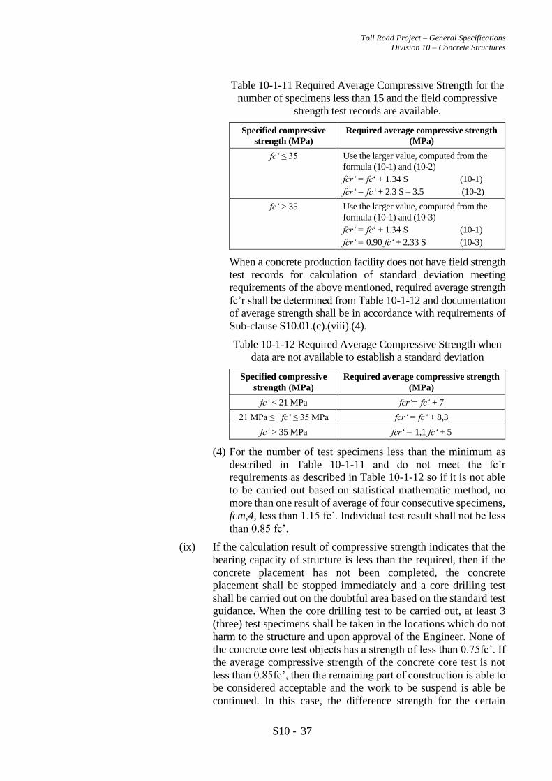
Toll Road Project – General Specifications
Division 10 – Concrete Structures
S10 - 37
Table 10-1-11 Required Average Compressive Strength for the
number of specimens less than 15 and the field compressive
strength test records are available.
Specified compressive
strength (MPa)
Required average compressive strength
(MPa)
fc‘ ≤ 35 Use the larger value, computed from the
formula (10-1) and (10-2)
fcr‘ = fc‘ + 1.34 S (10-1)
fcr‘ = fc‘ + 2.3 S – 3.5 (10-2)
fc‘ > 35 Use the larger value, computed from the
formula (10-1) and (10-3)
fcr‘ = fc‘ + 1.34 S (10-1)
fcr‘ = 0.90 fc‘ + 2.33 S (10-3)
When a concrete production facility does not have field strength
test records for calculation of standard deviation meeting
requirements of the above mentioned, required average strength
fc’r shall be determined from Table 10-1-12 and documentation
of average strength shall be in accordance with requirements of
Sub-clause S10.01.(c).(viii).(4).
Table 10-1-12 Required Average Compressive Strength when
data are not available to establish a standard deviation
Specified compressive
strength (MPa)
Required average compressive strength
(MPa)
fc‘ < 21 MPa fcr‘= fc‘ + 7
21 MPa ≤ fc‘ ≤ 35 MPa fcr‘ = fc‘ + 8,3
fc‘ > 35 MPa fcr‘ = 1,1 fc‘ + 5
(4) For the number of test specimens less than the minimum as
described in Table 10-1-11 and do not meet the fc’r
requirements as described in Table 10-1-12 so if it is not able
to be carried out based on statistical mathematic method, no
more than one result of average of four consecutive specimens,
fcm,4, less than 1.15 fc’. Individual test result shall not be less
than 0.85 fc’.
(ix) If the calculation result of compressive strength indicates that the
bearing capacity of structure is less than the required, then if the
concrete placement has not been completed, the concrete
placement shall be stopped immediately and a core drilling test
shall be carried out on the doubtful area based on the standard test
guidance. When the core drilling test to be carried out, at least 3
(three) test specimens shall be taken in the locations which do not
harm to the structure and upon approval of the Engineer. None of
the concrete core test objects has a strength of less than 0.75fc’. If
the average compressive strength of the concrete core test is not
less than 0.85fc’, then the remaining part of construction is able to
be considered acceptable and the work to be suspend is able be
continued. In this case, the difference strength for the certain
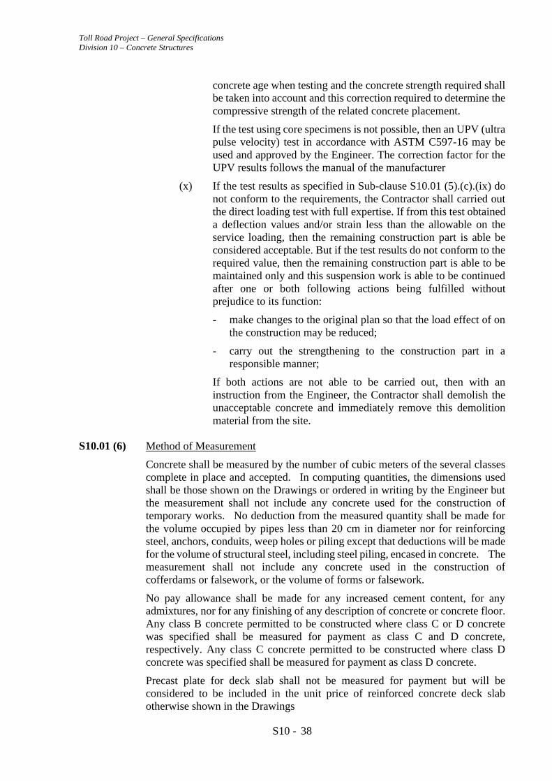
Toll Road Project – General Specifications
Division 10 – Concrete Structures
S10 - 38
concrete age when testing and the concrete strength required shall
be taken into account and this correction required to determine the
compressive strength of the related concrete placement.
If the test using core specimens is not possible, then an UPV (ultra
pulse velocity) test in accordance with ASTM C597-16 may be
used and approved by the Engineer. The correction factor for the
UPV results follows the manual of the manufacturer
(x) If the test results as specified in Sub-clause S10.01 (5).(c).(ix) do
not conform to the requirements, the Contractor shall carried out
the direct loading test with full expertise. If from this test obtained
a deflection values and/or strain less than the allowable on the
service loading, then the remaining construction part is able be
considered acceptable. But if the test results do not conform to the
required value, then the remaining construction part is able to be
maintained only and this suspension work is able to be continued
after one or both following actions being fulfilled without
prejudice to its function:
- make changes to the original plan so that the load effect of on
the construction may be reduced;
- carry out the strengthening to the construction part in a
responsible manner;
If both actions are not able to be carried out, then with an
instruction from the Engineer, the Contractor shall demolish the
unacceptable concrete and immediately remove this demolition
material from the site.
S10.01 (6) Method of Measurement
Concrete shall be measured by the number of cubic meters of the several classes
complete in place and accepted. In computing quantities, the dimensions used
shall be those shown on the Drawings or ordered in writing by the Engineer but
the measurement shall not include any concrete used for the construction of
temporary works. No deduction from the measured quantity shall be made for
the volume occupied by pipes less than 20 cm in diameter nor for reinforcing
steel, anchors, conduits, weep holes or piling except that deductions will be made
for the volume of structural steel, including steel piling, encased in concrete. The
measurement shall not include any concrete used in the construction of
cofferdams or falsework, or the volume of forms or falsework.
No pay allowance shall be made for any increased cement content, for any
admixtures, nor for any finishing of any description of concrete or concrete floor.
Any class B concrete permitted to be constructed where class C or D concrete
was specified shall be measured for payment as class C and D concrete,
respectively. Any class C concrete permitted to be constructed where class D
concrete was specified shall be measured for payment as class D concrete.
Precast plate for deck slab shall not be measured for payment but will be
considered to be included in the unit price of reinforced concrete deck slab
otherwise shown in the Drawings
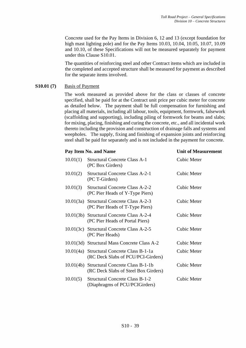
Toll Road Project – General Specifications
Division 10 – Concrete Structures
S10 - 39
Concrete used for the Pay Items in Division 6, 12 and 13 (except foundation for
high mast lighting pole) and for the Pay Items 10.03, 10.04, 10.05, 10.07, 10.09
and 10.10, of these Specifications will not be measured separately for payment
under this Clause S10.01.
The quantities of reinforcing steel and other Contract items which are included in
the completed and accepted structure shall be measured for payment as described
for the separate items involved.
S10.01 (7) Basis of Payment
The work measured as provided above for the class or classes of concrete
specified, shall be paid for at the Contract unit price per cubic meter for concrete
as detailed below. The payment shall be full compensation for furnishing and
placing all materials, including all labour, tools, equipment, formwork, falsework
(scaffolding and supporting), including piling of formwork for beams and slabs;
for mixing, placing, finishing and curing the concrete, etc., and all incidental work
thereto including the provision and construction of drainage falls and systems and
weepholes. The supply, fixing and finishing of expansion joints and reinforcing
steel shall be paid for separately and is not included in the payment for concrete.
Pay Item No. and Name Unit of Measurement
10.01(1) Structural Concrete Class A-1 Cubic Meter
(PC Box Girders)
10.01(2) Structural Concrete Class A-2-1 Cubic Meter
(PC T-Girders)
10.01(3) Structural Concrete Class A-2-2 Cubic Meter
(PC Pier Heads of Y-Type Piers)
10.01(3a) Structural Concrete Class A-2-3 Cubic Meter
(PC Pier Heads of T-Type Piers)
10.01(3b) Structural Concrete Class A-2-4 Cubic Meter
(PC Pier Heads of Portal Piers)
10.01(3c) Structural Concrete Class A-2-5 Cubic Meter
(PC Pier Heads)
10.01(3d) Structural Mass Concrete Class A-2 Cubic Meter
10.01(4a) Structural Concrete Class B-1-1a Cubic Meter
(RC Deck Slabs of PCU/PCI-Girders)
10.01(4b) Structural Concrete Class B-1-1b Cubic Meter
(RC Deck Slabs of Steel Box Girders)
10.01(5) Structural Concrete Class B-1-2 Cubic Meter
(Diaphragms of PCU/PCIGirders)
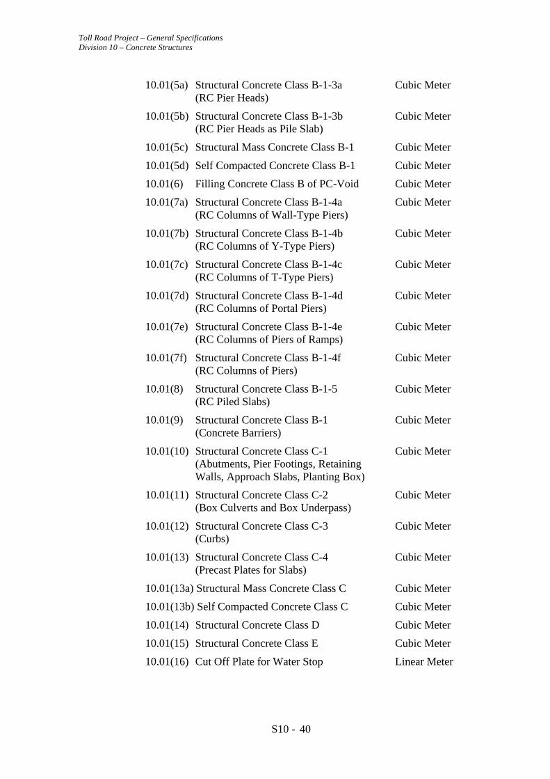
Toll Road Project – General Specifications
Division 10 – Concrete Structures
S10 - 40
10.01(5a) Structural Concrete Class B-1-3a Cubic Meter
(RC Pier Heads)
10.01(5b) Structural Concrete Class B-1-3b Cubic Meter
(RC Pier Heads as Pile Slab)
10.01(5c) Structural Mass Concrete Class B-1 Cubic Meter
10.01(5d) Self Compacted Concrete Class B-1 Cubic Meter
10.01(6) Filling Concrete Class B of PC-Void Cubic Meter
10.01(7a) Structural Concrete Class B-1-4a Cubic Meter
(RC Columns of Wall-Type Piers)
10.01(7b) Structural Concrete Class B-1-4b Cubic Meter
(RC Columns of Y-Type Piers)
10.01(7c) Structural Concrete Class B-1-4c Cubic Meter
(RC Columns of T-Type Piers)
10.01(7d) Structural Concrete Class B-1-4d Cubic Meter
(RC Columns of Portal Piers)
10.01(7e) Structural Concrete Class B-1-4e Cubic Meter
(RC Columns of Piers of Ramps)
10.01(7f) Structural Concrete Class B-1-4f Cubic Meter
(RC Columns of Piers)
10.01(8) Structural Concrete Class B-1-5 Cubic Meter
(RC Piled Slabs)
10.01(9) Structural Concrete Class B-1 Cubic Meter
(Concrete Barriers)
10.01(10) Structural Concrete Class C-1 Cubic Meter
(Abutments, Pier Footings, Retaining
Walls, Approach Slabs, Planting Box)
10.01(11) Structural Concrete Class C-2 Cubic Meter
(Box Culverts and Box Underpass)
10.01(12) Structural Concrete Class C-3 Cubic Meter
(Curbs)
10.01(13) Structural Concrete Class C-4 Cubic Meter
(Precast Plates for Slabs)
10.01(13a) Structural Mass Concrete Class C Cubic Meter
10.01(13b) Self Compacted Concrete Class C Cubic Meter
10.01(14) Structural Concrete Class D Cubic Meter
10.01(15) Structural Concrete Class E Cubic Meter
10.01(16) Cut Off Plate for Water Stop Linear Meter
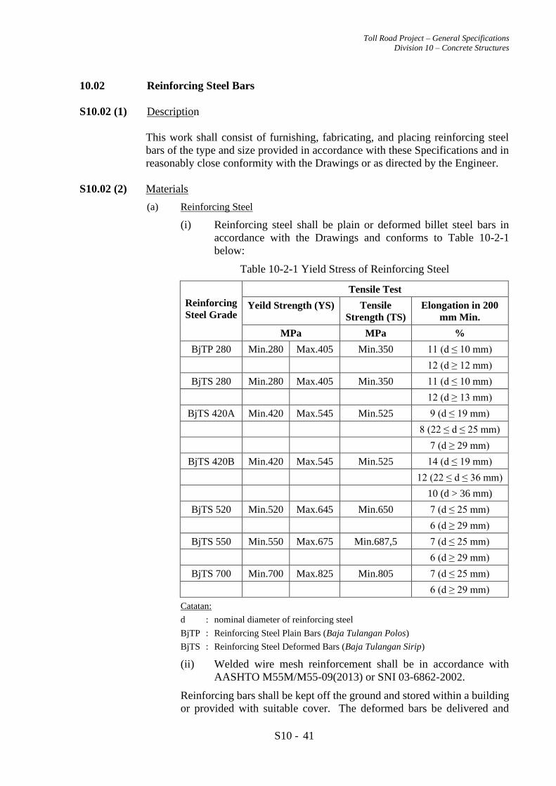
Toll Road Project – General Specifications
Division 10 – Concrete Structures
S10 - 41
10.02 Reinforcing Steel Bars
S10.02 (1) Description
This work shall consist of furnishing, fabricating, and placing reinforcing steel
bars of the type and size provided in accordance with these Specifications and in
reasonably close conformity with the Drawings or as directed by the Engineer.
S10.02 (2) Materials
(a) Reinforcing Steel
(i) Reinforcing steel shall be plain or deformed billet steel bars in
accordance with the Drawings and conforms to Table 10-2-1
below:
Table 10-2-1 Yield Stress of Reinforcing Steel
Reinforcing
Steel Grade
Tensile Test
Yeild Strength (YS) Tensile
Strength (TS)
Elongation in 200
mm Min.
MPa MPa %
BjTP 280 Min.280 Max.405 Min.350 11 (d ≤ 10 mm)
12 (d ≥ 12 mm)
BjTS 280 Min.280 Max.405 Min.350 11 (d ≤ 10 mm)
12 (d ≥ 13 mm)
BjTS 420A Min.420 Max.545 Min.525 9 (d ≤ 19 mm)
8 (22 ≤ d ≤ 25 mm)
7 (d ≥ 29 mm)
BjTS 420B Min.420 Max.545 Min.525 14 (d ≤ 19 mm)
12 (22 ≤ d ≤ 36 mm)
10 (d > 36 mm)
BjTS 520 Min.520 Max.645 Min.650 7 (d ≤ 25 mm)
6 (d ≥ 29 mm)
BjTS 550 Min.550 Max.675 Min.687,5 7 (d ≤ 25 mm)
6 (d ≥ 29 mm)
BjTS 700 Min.700 Max.825 Min.805 7 (d ≤ 25 mm)
6 (d ≥ 29 mm)
Catatan:
d : nominal diameter of reinforcing steel
BjTP : Reinforcing Steel Plain Bars (Baja Tulangan Polos)
BjTS : Reinforcing Steel Deformed Bars (Baja Tulangan Sirip)
(ii) Welded wire mesh reinforcement shall be in accordance with
AASHTO M55M/M55-09(2013) or SNI 03-6862-2002.
Reinforcing bars shall be kept off the ground and stored within a building
or provided with suitable cover. The deformed bars be delivered and
Toll Road Project – General Specifications
Division 10 – Concrete Structures
S10 - 42
maintained straight or bent in a shape as shown in Drawings. They shall
not be bent and then straightened or bent twice at the same point of
deformed bar.
(b) Support for Reinforcement
Supports for reinforcement shall be formed from lightweight wire bar or
precuts concrete blocks of Class fc’ 20 MPa concrete as specified in
Clause S10.01 of these Specifications, unless otherwise directed by the
Engineer. Wood, bricks, stone or other materials shall not be used as
supports.
(c) Ties for Reinforcement
Tie wire for fastening reinforcement shall be annealed steel wire
conforming to AASHTO M32M/M32-09(2013) or SNI 03-07-6401-2000.
S10.02 (3) Construction
(a) Fabrication
(i) Reinforcing bars shall be accurately formed to the shapes and
dimensions indicated in the design, and shall be fabricated in a
manner that will not injure the material. When bending failed,
reinforcement bars shall not be repeated bending without the
approval of the Engineer.
(ii) Unless otherwise permitted, all reinforcing bars requiring bending
shall be bent cold. When reinforcing bars are bent by heating, the
entire operation shall be approved by the Engineer. Should the
Engineer approve the application of heat for field bending
reinforcing bars, precautions shall be taken to assure that the
physical properties of the steel will not be materially altered.
(iii) Reinforcing bars that cannot be straightened by means of
fabrication shall not be used. Bars partially embedded in concrete
shall not be bent except as shown on the Drawings or otherwise
permitted.
(iv) Qualified men shall be employed for cutting and bending, and
proper appliances shall be provided for such work.
(v) If it is necessary for the Engineer to ascertain the quality of
reinforcing bars, the Contractor shall test reinforcing bars, at his
own expense, by means as directed by the Engineer.
(b) Placing
(i) Reinforcing bars before being positioned shall be cleaned and free
from rust, dirt, mud and loose scale and from paint, oil, or any
other foreign substance that destroys or reduces the bond.
(ii) Reinforcing bars shall be accurately placed in proper position so
that they will be firmly held during placing concrete. Reinforcing
bars for erecting shall be used when needed.
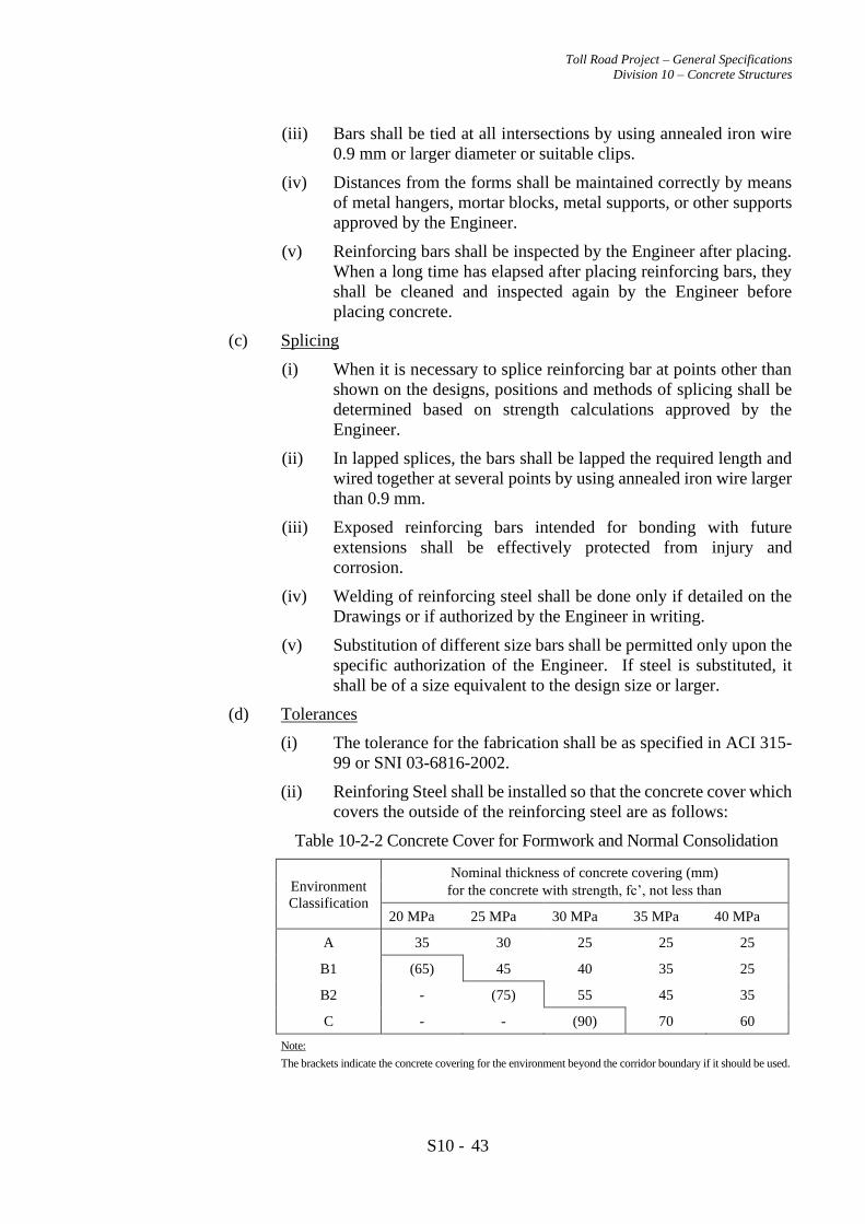
Toll Road Project – General Specifications
Division 10 – Concrete Structures
S10 - 43
(iii) Bars shall be tied at all intersections by using annealed iron wire
0.9 mm or larger diameter or suitable clips.
(iv) Distances from the forms shall be maintained correctly by means
of metal hangers, mortar blocks, metal supports, or other supports
approved by the Engineer.
(v) Reinforcing bars shall be inspected by the Engineer after placing.
When a long time has elapsed after placing reinforcing bars, they
shall be cleaned and inspected again by the Engineer before
placing concrete.
(c) Splicing
(i) When it is necessary to splice reinforcing bar at points other than
shown on the designs, positions and methods of splicing shall be
determined based on strength calculations approved by the
Engineer.
(ii) In lapped splices, the bars shall be lapped the required length and
wired together at several points by using annealed iron wire larger
than 0.9 mm.
(iii) Exposed reinforcing bars intended for bonding with future
extensions shall be effectively protected from injury and
corrosion.
(iv) Welding of reinforcing steel shall be done only if detailed on the
Drawings or if authorized by the Engineer in writing.
(v) Substitution of different size bars shall be permitted only upon the
specific authorization of the Engineer. If steel is substituted, it
shall be of a size equivalent to the design size or larger.
(d) Tolerances
(i) The tolerance for the fabrication shall be as specified in ACI 315-
99 or SNI 03-6816-2002.
(ii) Reinforing Steel shall be installed so that the concrete cover which
covers the outside of the reinforcing steel are as follows:
Table 10-2-2 Concrete Cover for Formwork and Normal Consolidation
Environment
Classification
Nominal thickness of concrete covering (mm)
for the concrete with strength, fc’, not less than
20 MPa 25 MPa 30 MPa 35 MPa 40 MPa
A 35 30 25 25 25
B1 (65) 45 40 35 25
B2 - (75) 55 45 35
C - - (90) 70 60
Note:
The brackets indicate the concrete covering for the environment beyond the corridor boundary if it should be used.
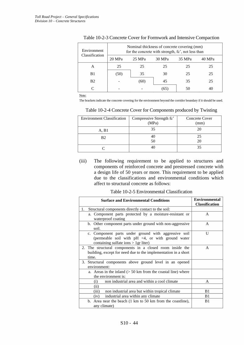
Toll Road Project – General Specifications
Division 10 – Concrete Structures
S10 - 44
Table 10-2-3 Concrete Cover for Formwork and Intensive Compaction
Environment
Classification
Nominal thickness of concrete covering (mm)
for the concrete with strength, fc’, not less than
20 MPa 25 MPa 30 MPa 35 MPa 40 MPa
A 25 25 25 25 25
B1 (50) 35 30 25 25
B2 - (60) 45 35 25
C - - (65) 50 40
Note:
The brackets indicate the concrete covering for the environment beyond the corridor boundary if it should be used.
Table 10-2-4 Concrete Cover for Components produced by Twisting
Environment Classification Compressive Strength fc’
(MPa)
Concrete Cover
(mm)
A, B1 35 20
B2 40
50
25
20
C 40 35
(iii) The following requirement to be applied to structures and
components of reinforced concrete and prestressed concrete with
a design life of 50 years or more. This requirement to be applied
due to the classifications and environmental conditions which
affect to structural concrete as follows:
Table 10-2-5 Environmental Classification
Surface and Environmental Conditions Environmental
Classification
1. Structural components directly contact to the soil:
a. Component parts protected by a moisture-resistant or
waterproof coating
A
b. Other component parts under ground with non-aggressive
soil.
A
c. Component parts under ground with aggressive soil
(permeable soil with pH <4, or with ground water
containing sulfate ions > 1gr liter)
U
2. The structural components in a closed room inside the
building, except for need due to the implementation in a short
time.
A
3. Structural components above ground level in an opened
environment:
a. Areas in the inland (> 50 km from the coastal line) where
the environment is:
(i) non industrial area and within a cool climate A
(ii)
(iii) non industrial area but within tropical climate B1
(iv) industrial area within any climate B1
b. Area near the beach (1 km to 50 km from the coastline),
any climate)
B1
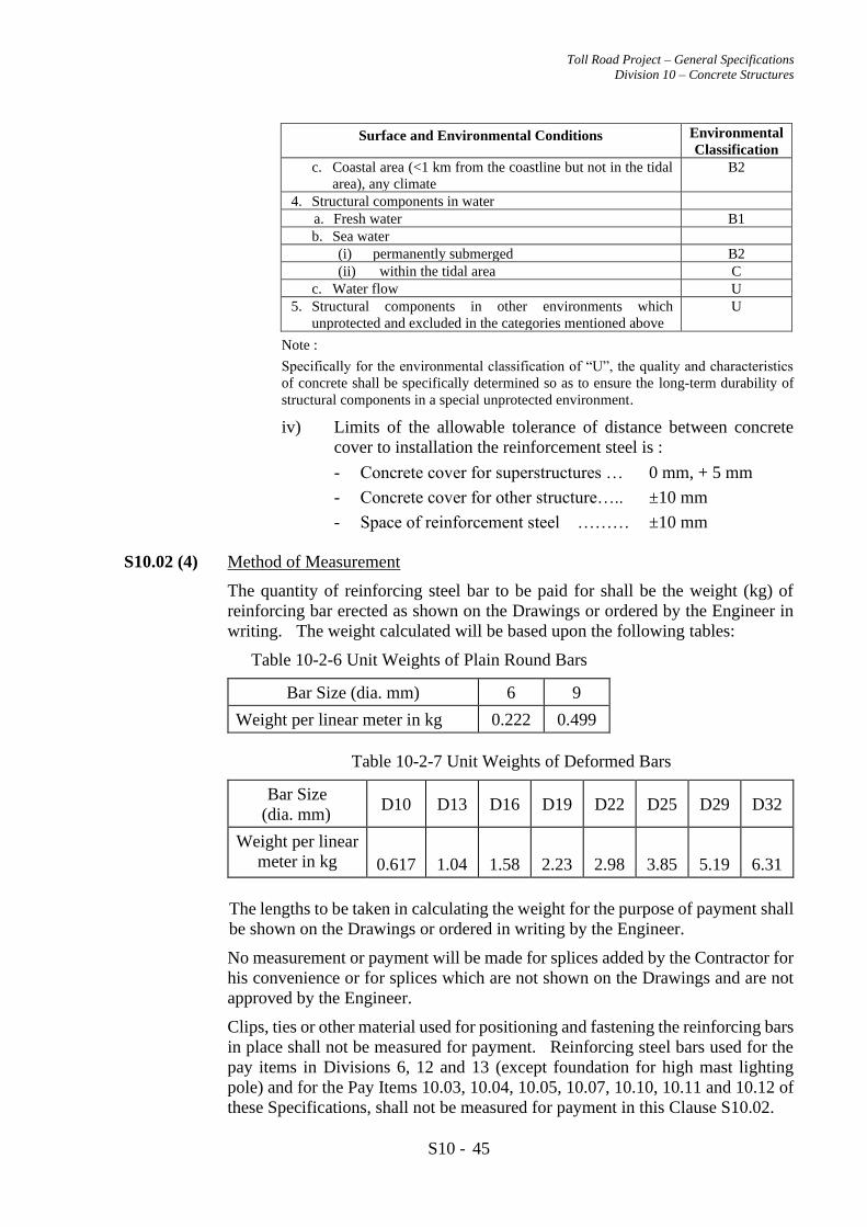
Toll Road Project – General Specifications
Division 10 – Concrete Structures
S10 - 45
Surface and Environmental Conditions Environmental
Classification
c. Coastal area (<1 km from the coastline but not in the tidal
area), any climate
B2
4. Structural components in water
a. Fresh water B1
b. Sea water
(i) permanently submerged B2
(ii) within the tidal area C
c. Water flow U
5. Structural components in other environments which
unprotected and excluded in the categories mentioned above
U
Note :
Specifically for the environmental classification of “U”, the quality and characteristics
of concrete shall be specifically determined so as to ensure the long-term durability of
structural components in a special unprotected environment.
iv) Limits of the allowable tolerance of distance between concrete
cover to installation the reinforcement steel is :
- Concrete cover for superstructures … 0 mm, + 5 mm
- Concrete cover for other structure….. ±10 mm
- Space of reinforcement steel ……… ±10 mm
S10.02 (4) Method of Measurement
The quantity of reinforcing steel bar to be paid for shall be the weight (kg) of
reinforcing bar erected as shown on the Drawings or ordered by the Engineer in
writing. The weight calculated will be based upon the following tables:
Table 10-2-6 Unit Weights of Plain Round Bars
Bar Size (dia. mm) 6 9
Weight per linear meter in kg 0.222 0.499
Table 10-2-7 Unit Weights of Deformed Bars
Bar Size
(dia. mm) D10 D13 D16 D19 D22 D25 D29 D32
Weight per linear
meter in kg
0.617
1.04
1.58
2.23
2.98
3.85
5.19
6.31
The lengths to be taken in calculating the weight for the purpose of payment shall
be shown on the Drawings or ordered in writing by the Engineer.
No measurement or payment will be made for splices added by the Contractor for
his convenience or for splices which are not shown on the Drawings and are not
approved by the Engineer.
Clips, ties or other material used for positioning and fastening the reinforcing bars
in place shall not be measured for payment. Reinforcing steel bars used for the
pay items in Divisions 6, 12 and 13 (except foundation for high mast lighting
pole) and for the Pay Items 10.03, 10.04, 10.05, 10.07, 10.10, 10.11 and 10.12 of
these Specifications, shall not be measured for payment in this Clause S10.02.
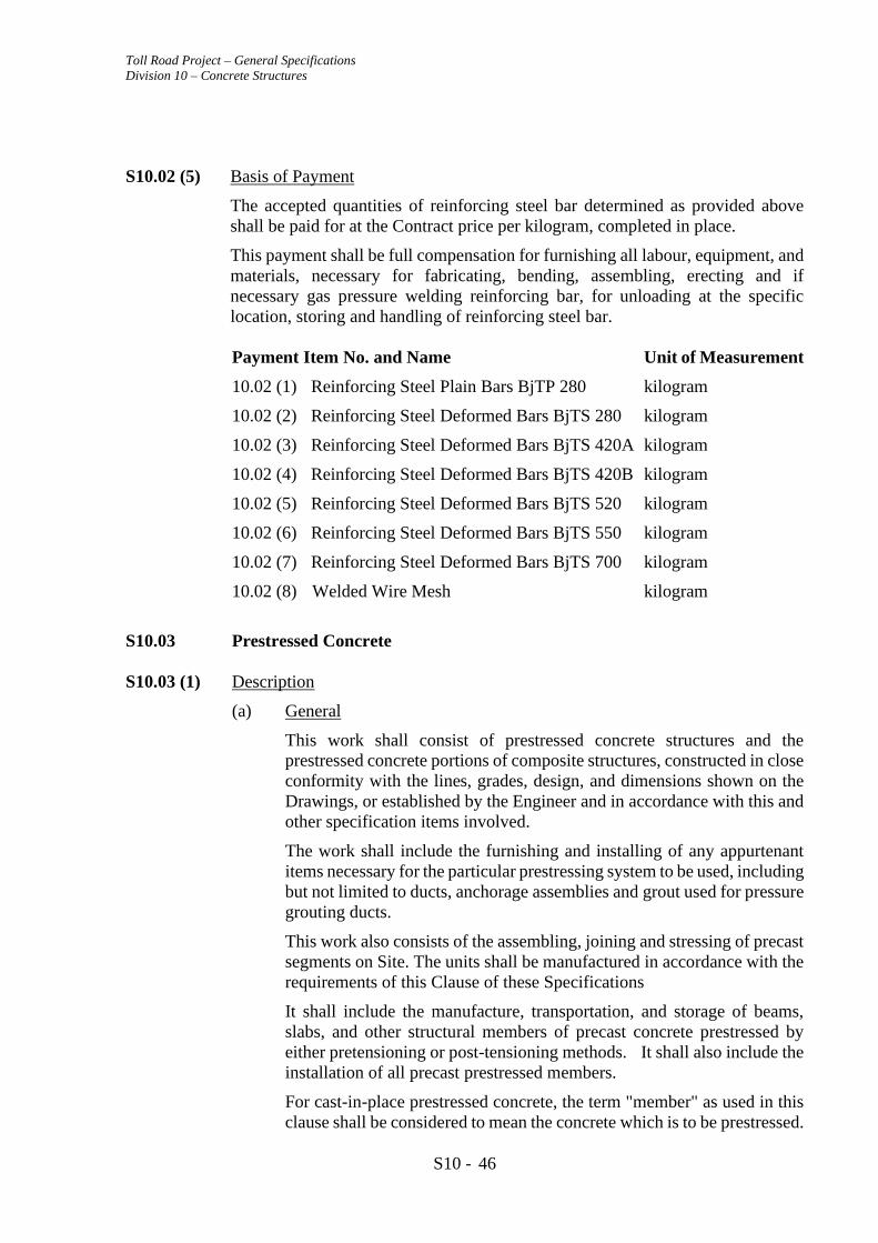
Toll Road Project – General Specifications
Division 10 – Concrete Structures
S10 - 46
S10.02 (5) Basis of Payment
The accepted quantities of reinforcing steel bar determined as provided above
shall be paid for at the Contract price per kilogram, completed in place.
This payment shall be full compensation for furnishing all labour, equipment, and
materials, necessary for fabricating, bending, assembling, erecting and if
necessary gas pressure welding reinforcing bar, for unloading at the specific
location, storing and handling of reinforcing steel bar.
Payment Item No. and Name Unit of Measurement
10.02 (1) Reinforcing Steel Plain Bars BjTP 280 kilogram
10.02 (2) Reinforcing Steel Deformed Bars BjTS 280 kilogram
10.02 (3) Reinforcing Steel Deformed Bars BjTS 420A kilogram
10.02 (4) Reinforcing Steel Deformed Bars BjTS 420B kilogram
10.02 (5) Reinforcing Steel Deformed Bars BjTS 520 kilogram
10.02 (6) Reinforcing Steel Deformed Bars BjTS 550 kilogram
10.02 (7) Reinforcing Steel Deformed Bars BjTS 700 kilogram
10.02 (8) Welded Wire Mesh kilogram
S10.03 Prestressed Concrete
S10.03 (1) Description
(a) General
This work shall consist of prestressed concrete structures and the
prestressed concrete portions of composite structures, constructed in close
conformity with the lines, grades, design, and dimensions shown on the
Drawings, or established by the Engineer and in accordance with this and
other specification items involved.
The work shall include the furnishing and installing of any appurtenant
items necessary for the particular prestressing system to be used, including
but not limited to ducts, anchorage assemblies and grout used for pressure
grouting ducts.
This work also consists of the assembling, joining and stressing of precast
segments on Site. The units shall be manufactured in accordance with the
requirements of this Clause of these Specifications
It shall include the manufacture, transportation, and storage of beams,
slabs, and other structural members of precast concrete prestressed by
either pretensioning or post-tensioning methods. It shall also include the
installation of all precast prestressed members.
For cast-in-place prestressed concrete, the term "member" as used in this
clause shall be considered to mean the concrete which is to be prestressed.
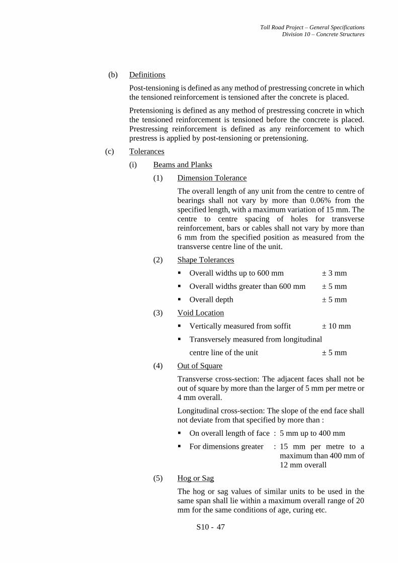
Toll Road Project – General Specifications
Division 10 – Concrete Structures
S10 - 47
(b) Definitions
Post-tensioning is defined as any method of prestressing concrete in which
the tensioned reinforcement is tensioned after the concrete is placed.
Pretensioning is defined as any method of prestressing concrete in which
the tensioned reinforcement is tensioned before the concrete is placed.
Prestressing reinforcement is defined as any reinforcement to which
prestress is applied by post-tensioning or pretensioning.
(c) Tolerances
(i) Beams and Planks
(1) Dimension Tolerance
The overall length of any unit from the centre to centre of
bearings shall not vary by more than 0.06% from the
specified length, with a maximum variation of 15 mm. The
centre to centre spacing of holes for transverse
reinforcement, bars or cables shall not vary by more than
6 mm from the specified position as measured from the
transverse centre line of the unit.
(2) Shape Tolerances
Overall widths up to 600 mm ± 3 mm
Overall widths greater than 600 mm ± 5 mm
Overall depth ± 5 mm
(3) Void Location
Vertically measured from soffit ± 10 mm
Transversely measured from longitudinal
centre line of the unit ± 5 mm
(4) Out of Square
Transverse cross-section: The adjacent faces shall not be
out of square by more than the larger of 5 mm per metre or
4 mm overall.
Longitudinal cross-section: The slope of the end face shall
not deviate from that specified by more than :
On overall length of face : 5 mm up to 400 mm
For dimensions greater : 15 mm per metre to a
maximum than 400 mm of
12 mm overall
(5) Hog or Sag
The hog or sag values of similar units to be used in the
same span shall lie within a maximum overall range of 20
mm for the same conditions of age, curing etc.
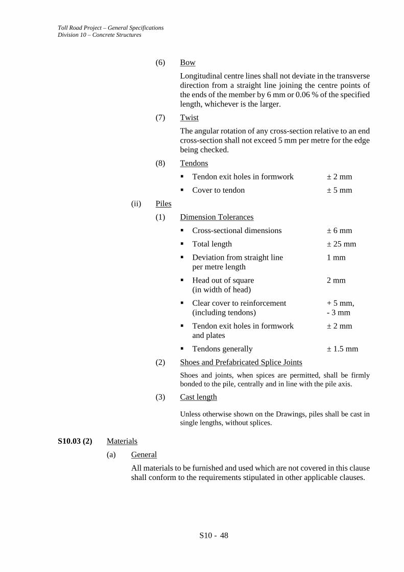
Toll Road Project – General Specifications
Division 10 – Concrete Structures
S10 - 48
(6) Bow
Longitudinal centre lines shall not deviate in the transverse
direction from a straight line joining the centre points of
the ends of the member by 6 mm or 0.06 % of the specified
length, whichever is the larger.
(7) Twist
The angular rotation of any cross-section relative to an end
cross-section shall not exceed 5 mm per metre for the edge
being checked.
(8) Tendons
Tendon exit holes in formwork ± 2 mm
Cover to tendon ± 5 mm
(ii) Piles
(1) Dimension Tolerances
Cross-sectional dimensions ± 6 mm
Total length ± 25 mm
Deviation from straight line 1 mm
per metre length
Head out of square 2 mm
(in width of head)
Clear cover to reinforcement + 5 mm,
(including tendons) - 3 mm
Tendon exit holes in formwork ± 2 mm
and plates
Tendons generally ± 1.5 mm
(2) Shoes and Prefabricated Splice Joints
Shoes and joints, when spices are permitted, shall be firmly
bonded to the pile, centrally and in line with the pile axis.
(3) Cast length
Unless otherwise shown on the Drawings, piles shall be cast in
single lengths, without splices.
S10.03 (2) Materials
(a) General
All materials to be furnished and used which are not covered in this clause
shall conform to the requirements stipulated in other applicable clauses.
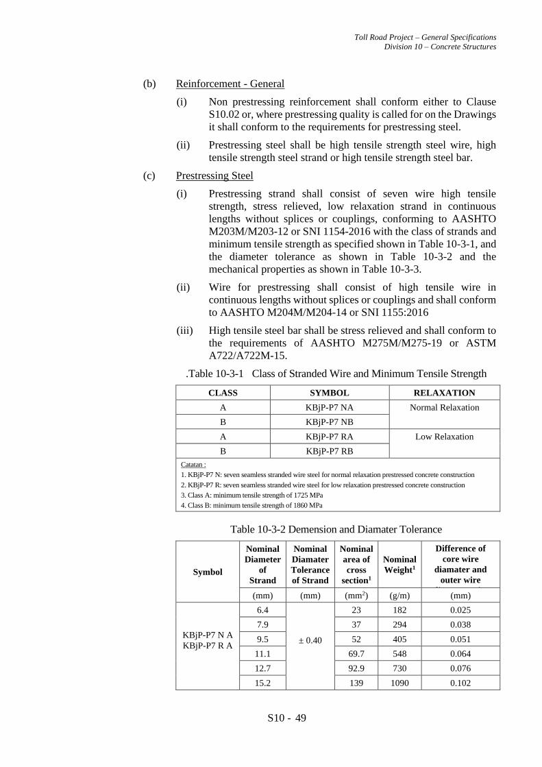
Toll Road Project – General Specifications
Division 10 – Concrete Structures
S10 - 49
(b) Reinforcement - General
(i) Non prestressing reinforcement shall conform either to Clause
S10.02 or, where prestressing quality is called for on the Drawings
it shall conform to the requirements for prestressing steel.
(ii) Prestressing steel shall be high tensile strength steel wire, high
tensile strength steel strand or high tensile strength steel bar.
(c) Prestressing Steel
(i) Prestressing strand shall consist of seven wire high tensile
strength, stress relieved, low relaxation strand in continuous
lengths without splices or couplings, conforming to AASHTO
M203M/M203-12 or SNI 1154-2016 with the class of strands and
minimum tensile strength as specified shown in Table 10-3-1, and
the diameter tolerance as shown in Table 10-3-2 and the
mechanical properties as shown in Table 10-3-3.
(ii) Wire for prestressing shall consist of high tensile wire in
continuous lengths without splices or couplings and shall conform
to AASHTO M204M/M204-14 or SNI 1155:2016
(iii) High tensile steel bar shall be stress relieved and shall conform to
the requirements of AASHTO M275M/M275-19 or ASTM
A722/A722M-15.
.Table 10-3-1 Class of Stranded Wire and Minimum Tensile Strength
CLASS SYMBOL RELAXATION
A KBjP-P7 NA Normal Relaxation
B KBjP-P7 NB
A KBjP-P7 RA Low Relaxation
B KBjP-P7 RB
Catatan :
1. KBjP-P7 N: seven seamless stranded wire steel for normal relaxation prestressed concrete construction
2. KBjP-P7 R: seven seamless stranded wire steel for low relaxation prestressed concrete construction
3. Class A: minimum tensile strength of 1725 MPa
4. Class B: minimum tensile strength of 1860 MPa
Table 10-3-2 Demension and Diamater Tolerance
Symbol
Nominal
Diameter
of
Strand
Nominal
Diamater
Tolerance
of Strand
Nominal
area of
cross
section1
Nominal
Weight1
Difference of
core wire
diamater and
outer wire
diameter min. (mm) (mm) (mm2) (g/m) (mm)
KBjP-P7 N A
KBjP-P7 R A
6.4
± 0.40
23 182 0.025
7.9 37 294 0.038
9.5 52 405 0.051
11.1 69.7 548 0.064
12.7 92.9 730 0.076
15.2 139 1090 0.102
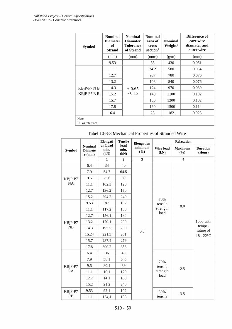
Toll Road Project – General Specifications
Division 10 – Concrete Structures
S10 - 50
Symbol
Nominal
Diameter
of
Strand
Nominal
Diamater
Tolerance
of Strand
Nominal
area of
cross
section1
Nominal
Weight1
Difference of
core wire
diamater and
outer wire
diameter min. (mm) (mm) (mm2) (g/m) (mm)
9.53 55 430 0.051
KBjP-P7 N B
KBjP-P7 R B
11.1
+ 0.65
- 0.15
74.2 580 0.064
12.7 987 780 0.076
13.2 108 840 0.076
14.3 124 970 0.089
15.2 140 1100 0.102
15.7 150 1200 0.102
17.8 190 1500 0.114
6.4 23 182 0.025
Note: 1 : as reference
Tabel 10-3-3 Mechanical Properties of Stranded Wire
Symbol
Nominal
Diamete
r (mm)
Elongati
on Load
min.
(kN)
Tensile
load
min.
(kN)
Elongation
minimum
(%)
Relaxation
Wire load
(kN)
Maximum
(%)
Duration
(Hour)
1 2 3 4
KBjP-P7
NA
6.4 34 40
3.5
70%
tensile
strength
load
8.0
1000 with
tempe-
rature of
18 - 22°C
7.9 54.7 64.5
9.5 75.6 89
11.1 102.3 120
12.7 136.2 160
15.2 204.2 240
KBjP-P7
NB
9.53 87 102
11.1 117.2 138
12.7 156.1 184
13.2 170.1 200
14.3 195.5 230
15.24 221.5 261
15.7 237.4 279
17.8 300.2 353
KBjP-P7
RA
6.4 36 40
70%
tensile
strength
load
2.5
7.9 58.1 6.,5
9.5 80.1 89
11.1 10.1 120
12.7 14.1 160
15.2 21.2 240
KBjP-P7
RB
9.53 92.1 102 80%
tensile 3.5
11.1 124,1 138
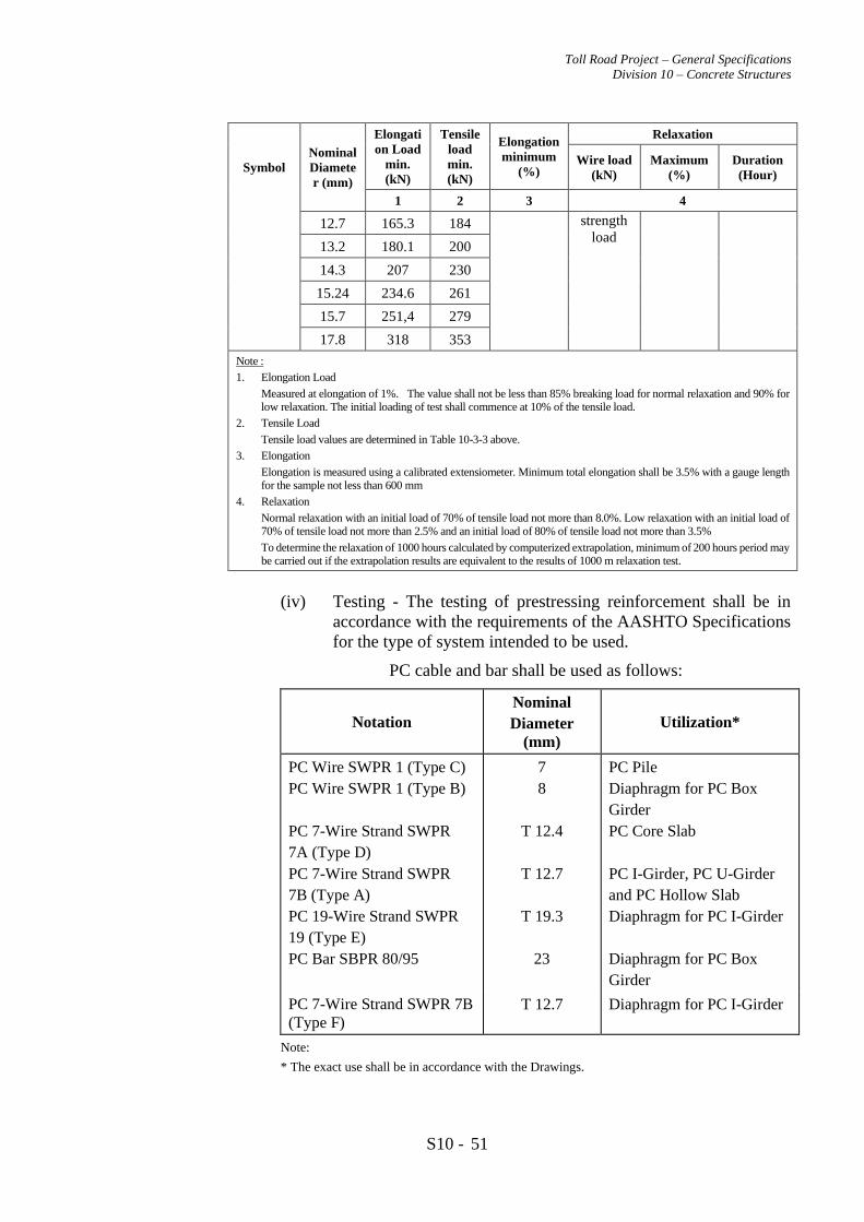
Toll Road Project – General Specifications
Division 10 – Concrete Structures
S10 - 51
Symbol
Nominal
Diamete
r (mm)
Elongati
on Load
min.
(kN)
Tensile
load
min.
(kN)
Elongation
minimum
(%)
Relaxation
Wire load
(kN)
Maximum
(%)
Duration
(Hour)
1 2 3 4
12.7 165.3 184 strength
load 13.2 180.1 200
14.3 207 230
15.24 234.6 261
15.7 251,4 279
17.8 318 353
Note :
1. Elongation Load
Measured at elongation of 1%. The value shall not be less than 85% breaking load for normal relaxation and 90% for low relaxation. The initial loading of test shall commence at 10% of the tensile load.
2. Tensile Load
Tensile load values are determined in Table 10-3-3 above.
3. Elongation
Elongation is measured using a calibrated extensiometer. Minimum total elongation shall be 3.5% with a gauge length for the sample not less than 600 mm
4. Relaxation
Normal relaxation with an initial load of 70% of tensile load not more than 8.0%. Low relaxation with an initial load of 70% of tensile load not more than 2.5% and an initial load of 80% of tensile load not more than 3.5%
To determine the relaxation of 1000 hours calculated by computerized extrapolation, minimum of 200 hours period may be carried out if the extrapolation results are equivalent to the results of 1000 m relaxation test.
(iv) Testing - The testing of prestressing reinforcement shall be in
accordance with the requirements of the AASHTO Specifications
for the type of system intended to be used.
PC cable and bar shall be used as follows:
Notation
Nominal
Diameter
(mm)
Utilization*
PC Wire SWPR 1 (Type C)
PC Wire SWPR 1 (Type B)
PC 7-Wire Strand SWPR
7A (Type D)
PC 7-Wire Strand SWPR
7B (Type A)
PC 19-Wire Strand SWPR
19 (Type E)
PC Bar SBPR 80/95
7
8
T 12.4
T 12.7
T 19.3
23
PC Pile
Diaphragm for PC Box
Girder
PC Core Slab
PC I-Girder, PC U-Girder
and PC Hollow Slab
Diaphragm for PC I-Girder
Diaphragm for PC Box
Girder
PC 7-Wire Strand SWPR 7B
(Type F)
T 12.7 Diaphragm for PC I-Girder
Note:
* The exact use shall be in accordance with the Drawings.
Toll Road Project – General Specifications
Division 10 – Concrete Structures
S10 - 52
(d) Anchorages
All post-tensioned prestressing steel shall be secured at the ends by means
of approved permanent type anchoring devices.
All anchorage devices for post-tensioning shall be capable of holding the
prestressing steel at a load producing a stress of not less than 95 percent
of the guaranteed minimum tensile strength of the prestressing steel.
(e) Ducts
All ducts shall be metallic and shall be mortar-tight. Ducts shall be strong
enough to maintain their shape under working stresses, and where
grouting is specified, air and grout holes shall be provided with pipes or
other devices so that the injection of grout will completely fill all void
spaces within the entire length of the duct.
(f) Grout
Grout shall consist of Portland cement, water, and an expansive admixture
plus retarder as approved by the Engineer. Water shall be potable. No
admixtures containing chlorides or nitrates shall be used.
The Contractor shall submit the proportion of mixing for approval of the
Engineer.
Water shall be first added to the mixer followed by cement and admixture.
The grout shall be mixed in mechanical mixing equipment of a type that
will produce uniform and thoroughly mixed grout. Retempering of grout
will not be permitted. Grout shall be continuously agitated until it is
pumped.
(g) Concrete
Concrete shall conform to the requirements of Class A-1, A-2 or Class
AA concrete of Clause S10.01 of this Specification and to the
requirements specified below unless otherwise stated in the Drawings.
The Contractor shall develop his own mix designs which shall be
submitted to the Engineer for approval.
The maximum size of aggregate for use in the manufacture of prestressed
concrete shall be 2 centimeters.
S10.03 (3) Construction
(a) General
The Contractor shall provide a Technician skilled in the use of the system
of prestressing to be used, who shall supervise the work and give the
Engineer such assistance as the Engineer may consider necessary.
The Contractor shall provide all equipment necessary for the construction
and the prestressing. Prestressing shall be done with approved jacking
equipment. If hydraulic jacks are used they shall be equipped with
accurately reading pressure gauges. The combination of jack and gauge
shall be calibrated and a graph or table showing the calibration shall be
furnished to the Engineer. Should other types of jacks be used, calibrated

Toll Road Project – General Specifications
Division 10 – Concrete Structures
S10 - 53
proving rings or other devices shall be furnished so that the jacking forces
may be accurately known.
All of the applicable requirements of Sub-clause S10.01.(4) "Construc-
tion" shall be complied with, except as may be modified in this Sub-
clause. Prestressed concrete shall be formed, stressed, placed, cured, and
protected at shops, manufacturing plants, and locations approved by the
Engineer, where the fabrication of such members may be properly
inspected and controlled.
The position/ lay out of the tendons in the Prestressed Concrete either the
vertical or horizontal direction allowable tolerance ± 6 mm
(b) Plan of Operation
The Contractor shall, if required, prepare, check and submit to the
Engineer complete detailed Working Drawings or Schedules showing:
(i) Contractor's alternative designs if the submission of alternatives is
approved;
(ii) Contractor's details of proposed manufacture and construction;
(iii) Sequence of operations proposed; and
(iv) Dimensions and complete descriptions of all devices, joints,
bearings, and anchorages not specified or detailed in the Contract
Documents.
Concrete shall not be cast prior to the Engineer's approval of the
Contractor's Drawings, if any, of concrete mixtures, of formwork, of
method of application of prestressing forces, of methods of placing, of
curing, of protecting, of handling and of erecting members. Any
alternative to the design in the Contract Documents shall be subject to the
Engineer's approval before manufacture or construction.
The Contractor shall inform the Engineer not less than 3 days in advance
of the probable date of commencement of manufacture and the dates when
tensioning of steel, casting of units and transfer of stress will be
undertaken for the first time.
(c) Placing Steel
All steel units shall be accurately placed in the position shown on the
Drawings and rigidly held during placing and setting of the concrete.
Distance from the forms shall be maintained by stays, blocks, ties,
hangers, or other approved support. Blocks for holding units from
contact with the forms shall be precast mortar blocks of approved shape
and dimensions. Layers of units shall be separated by mortar blocks or
other equally suitable devices. Wooden blocks shall not be used.
(d) Pretensioning Method
The prestressing elements shall be accurately held in position and stressed
by jacks. Stressing shall be applied to produce the stresses required in
the wires or strands immediately after the anchorage as shown on the
Drawings or as directed by the Engineer. Suitable allowances shall be
Toll Road Project – General Specifications
Division 10 – Concrete Structures
S10 - 54
made for friction in the jacks and for slip and yield in the grips or
anchorages.
A record shall be kept of the jacking forces and the elongations produced
thereby and the minimum age in hours of the concrete in the line at the
time the tendons were released.
Several units may be cast in one continuous line and stressed at one time,
in which case sufficient space shall be left between ends of units to permit
access for cutting after the concrete has attained the required strength.
No bond stress shall be transferred to the concrete, nor shall end anchors
be released, until the concrete has attained a compressive strength not less
than 85% of the specified 28-day strength as shown by standard specimens
made and cured identically with the members. The elements shall be cut
or released in such an order that eccentricity of prestress will be a
minimum.
(e) Curing
Steam curing process may be used as an alternative to water curing. The
casting bed for any unit cured with steam shall be completely enclosed to
prevent steam escaping and exclude outside atmosphere. Two to four
hours after placing concrete and after the concrete has undergone initial
set, the first application of steam shall be made. If retarding admixtures
have been used, the delay before application of the steam shall be
increased to four to six hours. Water curing methods shall be used from
the time the concrete is placed until steam is first applied.
The steam shall be at 100% relative humidity to prevent loss of moisture
and to provide moisture for proper hydration of the cement. Application
of the steam shall not be directly on the concrete. During the application
of the steam, the ambient air temperature shall increase at a rate not to
exceed 22 degrees celsius per hour until the maximum temperature is
reached and shall be held until the concrete has reached the desired
strength. In discontinuing the steam application, the ambient air
temperature shall not decrease at a rate to exceed 22 degrees celsius per
hour until a temperature has been reached 10 degrees celsius above the
temperature of the air to which the concrete will be exposed. The
maximum curing temperature shall be from 60 degrees celsius to 67
degrees celsius.
If the Contractor elects to cure by any other special method, the method
and details shall be subject to the approval of the Engineer.
Except as specified or otherwise approved, curing shall comply with the
requirements in Clause S10.01.
(f) Post-tensioning Method
Tensioning of the prestressing reinforcement shall not be commenced
until tests on concrete cylinders, manufactured of the same concrete of the
particular member to be prestressed has attained compressive strength
indicated in the Drawings or directed by the Engineer.
Toll Road Project – General Specifications
Division 10 – Concrete Structures
S10 - 55
After all concrete has attained the required strength, the prestressing
reinforcement shall be stressed by means of jacks to the desired tension
and the stress transferred to the end anchorage.
Cast in place concrete shall not be post-tensioned until at least 10 days
after the last concrete has been placed in the member to be post-tensioned
and until the compressive strength of said placed concrete has reached the
strength specified for the concrete at the time of stressing.
All side and inside forms for girders shall be removed before post-
tensioning. The falsework under the bottom slab supporting the
superstructure shall not be released until a minimum of 48 hours have
elapsed neither after grouting of the post-tension tendons nor until all
other conditions of the specifications have been met. The supporting
falsework shall be constructed in such a manner that the superstructure
will be free to lift off the falsework and shorten during post-tensioning.
The tensioning process shall be so conducted that the tension being
applied and the elongation of the prestressing elements may be measured
at all times.
A record shall be kept of gauge pressures and elongation at all times and
submitted to the Engineer for his approval.
The load from the anchoring device shall be distributed to the concrete by
means of approved devices that will effectively distribute the load to the
concrete.
Where the end of a post-tensioned assembly will not be covered by
concrete, the anchoring devices shall be recessed so that the ends of the
prestressing steel and all parts of the anchoring devices will be at least 50
mm inside of the end surface of the members, unless a greater embedment
is shown on the plans. Following post-tenioning, the recesses shall be
filled with concrete, and finished as shown in the Drawings.
(g) Bonding Steel
Post-tensioned steel shall be bonded to the concrete. All prestressing
steel to be bonded to the concrete shall be free of dirt, loose rust, grease
or other deleterious substances.
Prestressing steel shall be bonded to the concrete by filling the void space
between the duct and the tendon with grout. All ducts shall be clean and
free of deleterious materials that would impair bonding of the grout or
interfere with grouting procedures.
All grout shall pass through a screen with 1.20 mm maximum clear
openings prior to being introduced into the grout pump.
Grout injection pipes shall be fitted with positive mechanical shutoff
valves. Vents and ejection pipes shall be fitted with valves, caps, or other
devices capable of withstanding the pumping pressure. Valves and caps
shall not be removed or opened until the grout has set.
Toll Road Project – General Specifications
Division 10 – Concrete Structures
S10 - 56
(h) Handling, Transport and Storage
Precast prestressed concrete shall not be moved from the casting position
until the concrete has attained a compressive strength of 85% of the
specified 28-day strength, nor transported until it has developed a strength
of 90% of the specified 28-day strength.
Extreme care shall be exercised in handling and moving precast
prestressed concrete members. Precast girders and slabs shall be
transported in an upright position, shock shall be avoided and the points
of support and directions of the reactions with respect to the member shall
be approximately the same during transporting and storage as when the
member is in its final position. If the Contractor deems it expedient to
transport or store precast prestressed units in other than this position, it
shall be done at his own risk after notifying the Engineer of his intention
to do so. Any unit considered by the Engineer to have become
substandard shall be rejected and replaced at the Contractor's expense by
an acceptable unit.
(i) Marking of Precast Prestressed Members
Each precast prestressed member is to be uniquely and permanently
marked so as to show its type, date of casting and reinforcement.
(j) Testing of Precast Prestressed Members
When directed by the Engineer one or more beams shall be subjected to a
loading test. The Contractor shall obtain the prior approval of the
Engineer to the detailed arrangements for the testing. A beam which is
to undergo testing shall be supported at its design points of bearing and
the upward deflection due to the prestressing force measured relative to a
line joining these points. Equal loads shall then be applied at the third
points in ten equal increments, the total being sustained for 5 minutes.
The beam shall then be unloaded.
The midspan deflection relative to the reference line shall be measured for
each increment of load. The load deflection curve plotted from these
values shall show no appreciable variation from a straight line. The
Drawings shall show, or the Engineer shall direct, the loads to be applied
and the corresponding deflections which shall not be exceeded.
Any beam which fails to satisfy the Engineer under the prescribed test
shall be rejected and all other beams cast in the same line as the rejected
beam shall also be rejected unless tested at the Contractor's expense and
found satisfactory.
The Contractor shall supply to the Engineer record sheets of the tests
showing date of test, the loads, deflections, and load deflection curves,
calculated values of "E" and the strength of the concrete at release as
indicated by the relevant cube or cylinder test results.
The tests are to be carried out on units selected by and in the presence of
the Engineer after he has agreed to the method of testing and form of
records. The cost of such tests and records shall be included in the unit
prices.
Toll Road Project – General Specifications
Division 10 – Concrete Structures
S10 - 57
(k) Post Tensioned Segmental Construction
(i) Assembly of Precast Segments
Handling of precast units for segmental construction during
placing operations shall be in accordance with the requirements of
Sub-clause S10.03 (3) (h).
The Contractor shall submit details of the falsework design and
the method of erection and assembly to the Engineer for his
approval at least four weeks prior to the proposed date for
commencing assembly of the segments.
Segments shall be assembled on falsework or on bearers at ground
level. The Contractor shall design the supporting system to carry
all the loads that may be applied to it, and shall incorporate
provision for adjusting the position of each segment during
assembly.
The unit shall be assembled with minimum misalignment of ducts
and outside surfaces and shall be within the tolerances given in
Sub-clause S10.01.(1).(c).
(ii) Joint Concrete
Concrete for joints and associated diaphragms or other infill
concrete involved in the assembly of segments for post-tensioned
construction shall comply with the requirements of Clause S10.01
of this Specification except where modified below.
Unless otherwise approved by the Engineer the effective maximum
size shall be 10 mm.
Joint concrete shall be subject to the same strength requirements
prior to stressing as given in Sub-clause S10.03 (2) (g) of this
Specification.
Concrete materials shall be carefully selected and proportioned to
produce joint concrete of the specified strength and of a similar
colour to that of the segments. If requested by the Engineer, the
Contractor shall supply cured samples of the proposed joint
concrete for colour comparison.
Joint concrete between segments shall be placed in forms which
shall conform to the shape, lines and dimensions required in the
finished work. Forms shall be rigid, watertight, and braced and
tied together so that they will maintain position and shape during
placing of concrete. The fit of the forms against the segments shall
be such that a completely watertight joint, flush with adjacent
surfaces is obtained. Forms shall be such that a Class 2 surface
finish (the “default” for any architectural finish where the concrete
is left exposed) in accordance with AS 3610.1:2018 can be
produced.
Toll Road Project – General Specifications
Division 10 – Concrete Structures
S10 - 58
Where necessary, temporary openings shall be provided in the
formwork to enable the adequate placing and compaction of
concrete especially around and underneath ducting and anchorages.
The joints between segments shall be completely filled with
compacted concrete of a strength as shown on the Drawings.
Surfaces against which concrete is to be placed shall be scabbed to
a dense hard surface. Just prior to placing concrete, these surfaces
shall be cleaned to remove all dirt and other foreign matter.
Joint concrete shall be placed in the presence of the Engineer and
any joint concrete placed during his absence or not placed to his
satisfaction shall be broken out by the Contractor and made good at
no extra cost to the Employer.
Care shall be taken during placing and compaction of concrete to
avoid damage to the ducting. Vibrators shall not come into direct
contact with the ducting. If the ducting is damaged during
concreting the whole or a portion of the concrete cast may be
rejected by the Engineer.
After placing the concrete, the top surface of the joint shall be
screeded flush with the tops of the adjacent segments and covered
to prevent premature drying. Joint concrete shall be cured by one
or more of the methods specified in Sub-clause S10.03 (3) (e) of
this Specification for a minimum period of 7 days.
(iii) Concreting of Anchorage Recesses
Concreting of anchorage recesses of the post tensioned segmental
member shall be carried out as shown on the Drawings and in
accordance with the requirements of these Specifications.
(iv) Damage to Units
In the event of any unit, which has been manufactured or accepted
by the Contractor, sustaining damage such as cracking, spalling or
deformation of projecting reinforcement, the unit shall be set aside
until it has been inspected by the Engineer, who will decide
whether it shall be rejected and removed from the site of the works,
or repaired by the Contractor.
The cost of such repairs, or the removal of rejected units, and all
costs of replacing these units at the site of the works shall be borne
by the Contractor.
(l) Erection of Prestressed Units
(i) Acceptance of Units
If units are manufactured off site the Contractor shall check these
for quality and condition upon taking delivery and shall
immediately report in writing to the Engineer any defect or
deficiency. The Contractor is responsible for all damage to the
units occurring after he accepts delivery thereof.
Toll Road Project – General Specifications
Division 10 – Concrete Structures
S10 - 59
(ii) Seating for Units
(1) Unit placed on Neoprene Pads or Elastomeric Bearings.
Where the units are to be placed on neoprene pads or
elastomeric bearings the pads shall be located as shown on
the Drawings and shall be retained in position by gluing to
the concrete bearing surface with an approved contact
adhesive, in order to prevent dislodgment of the pads
during unit placing.
(2) Units Bedded on Mortar.
Where the Drawings show that the units are to be bedded
on cement mortar, a mortar seating strip shall be prepared
on the substructure immediately before erection of the
prestressed units. The mortar shall be made of a 1 : 3
mixture of Portland cement and fine sand plus an approved
bonding agent; mixed to give widths shown on the
Drawings and approximately 10 mm thick, and shall
provide an even seating strip is laid the prestressed units
shall be seated on the prepared substructure in the position
indicated on the Drawings. Any excess mortar shall be
struck off.
(iii) Positioning Units
All holding down bolts and holes for transverse reinforcement, etc.
shall be carefully aligned during placement of the units. Bars shall
be placed through holes for transverse reinforcement as erection
proceeds, in order to ensure the correct alignment of the holes.
S10.03 (4) Method of Measurement
The quantity of prestressed concrete I-girders and U-girders to be measured for
payment shall be the actual number of precast prestressed concrete structural
members, furnished, erected in place, completed and accepted. Each member
shall include the concrete, reinforcement and prestressing steel, and other such
material contained within or attached to the beam or slab unit.
Prestressed cast-in-place concrete members will be paid for on the basis of the
number of cubic meters of concrete, the weight (kg) of reinforcing steel and the
weight (kg) of prestressing steel, respectively. For concrete reference is made to
Clause S10.01 and for reinforcing steel reference is made to Clause S10.02.
Prestressing steel used in Pay Item of these Specifications will not be measured
separately for payment in this Clause S10.03.
Concrete plates to be measured for payment are paid shall be the number of square
meters in accordance with the Drawings.
S10.03 (5) Basis of Payment
The work measured as provided above, shall be paid for at the Contract unit price
for any item listed below which appears in the Bid Schedule. The prices and
payment shall be full compensation for furnishing and placing all materials
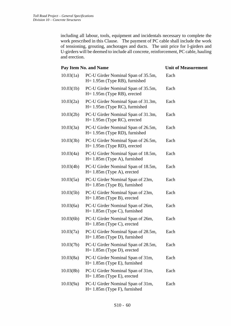
Toll Road Project – General Specifications
Division 10 – Concrete Structures
S10 - 60
including all labour, tools, equipment and incidentals necessary to complete the
work prescribed in this Clause. The payment of PC cable shall include the work
of tensioning, grouting, anchorages and ducts. The unit price for I-girders and
U-girders will be deemed to include all concrete, reinforcement, PC cable, hauling
and erection.
Pay Item No. and Name Unit of Measurement
10.03(1a) PC-U Girder Nominal Span of 35.5m, Each
H= 1.95m (Type RB), furnished
10.03(1b) PC-U Girder Nominal Span of 35.5m, Each
H= 1.95m (Type RB), erected
10.03(2a) PC-U Girder Nominal Span of 31.3m, Each
H= 1.95m (Type RC), furmished
10.03(2b) PC-U Girder Nominal Span of 31.3m, Each
H= 1.95m (Type RC), erected
10.03(3a) PC-U Girder Nominal Span of 26.5m, Each
H= 1.95m (Type RD), furnished
10.03(3b) PC-U Girder Nominal Span of 26.5m, Each
H= 1.95m (Type RD), erected
10.03(4a) PC-U Girder Nominal Span of 18.5m, Each
H= 1.85m (Type A), furnished
10.03(4b) PC-U Girder Nominal Span of 18.5m, Each
H= 1.85m (Type A), erected
10.03(5a) PC-U Girder Nominal Span of 23m, Each
H= 1.85m (Type B), furnished
10.03(5b) PC-U Girder Nominal Span of 23m, Each
H= 1.85m (Type B), erected
10.03(6a) PC-U Girder Nominal Span of 26m, Each
H= 1.85m (Type C), furnished
10.03(6b) PC-U Girder Nominal Span of 26m, Each
H= 1.85m (Type C), erected
10.03(7a) PC-U Girder Nominal Span of 28.5m, Each
H= 1.85m (Type D), furnished
10.03(7b) PC-U Girder Nominal Span of 28.5m, Each
H= 1.85m (Type D), erected
10.03(8a) PC-U Girder Nominal Span of 31m, Each
H= 1.85m (Type E), furnished
10.03(8b) PC-U Girder Nominal Span of 31m, Each
H= 1.85m (Type E), erected
10.03(9a) PC-U Girder Nominal Span of 31m, Each
H= 1.85m (Type F), furnished
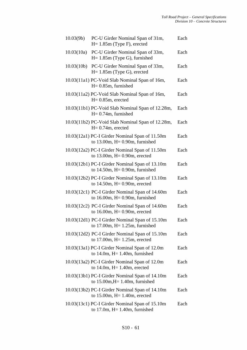
Toll Road Project – General Specifications
Division 10 – Concrete Structures
S10 - 61
10.03(9b) PC-U Girder Nominal Span of 31m, Each
H= 1.85m (Type F), erected
10.03(10a) PC-U Girder Nominal Span of 33m, Each
H= 1.85m (Type G), furnished
10.03(10b) PC-U Girder Nominal Span of 33m, Each
H= 1.85m (Type G), erected
10.03(11a1) PC-Void Slab Nominal Span of 16m, Each
H= 0.85m, furnished
10.03(11a2) PC-Void Slab Nominal Span of 16m, Each
H= 0.85m, erected
10.03(11b1) PC-Void Slab Nominal Span of 12.28m, Each
H= 0.74m, furnished
10.03(11b2) PC-Void Slab Nominal Span of 12.28m, Each
H= 0.74m, erected
10.03(12a1) PC-I Girder Nominal Span of 11.50m Each
to 13.00m, H= 0.90m, furnished
10.03(12a2) PC-I Girder Nominal Span of 11.50m Each
to 13.00m, H= 0.90m, erected
10.03(12b1) PC-I Girder Nominal Span of 13.10m Each
to 14.50m, H= 0.90m, furnished
10.03(12b2) PC-I Girder Nominal Span of 13.10m Each
to 14.50m, H= 0.90m, erected
10.03(12c1) PC-I Girder Nominal Span of 14.60m Each
to 16.00m, H= 0.90m, furnished
10.03(12c2) PC-I Girder Nominal Span of 14.60m Each
to 16.00m, H= 0.90m, erected
10.03(12d1) PC-I Girder Nominal Span of 15.10m Each
to 17.00m, H= 1.25m, furnished
10.03(12d2) PC-I Girder Nominal Span of 15.10m Each
to 17.00m, H= 1.25m, erected
10.03(13a1) PC-I Girder Nominal Span of 12.0m Each
to 14.0m, H= 1.40m, furnished
10.03(13a2) PC-I Girder Nominal Span of 12.0m Each
to 14.0m, H= 1.40m, erected
10.03(13b1) PC-I Girder Nominal Span of 14.10m Each
to 15.00m,H= 1.40m, furnished
10.03(13b2) PC-I Girder Nominal Span of 14.10m Each
to 15.00m, H= 1.40m, erected
10.03(13c1) PC-I Girder Nominal Span of 15.10m Each
to 17.0m, H= 1.40m, furnished
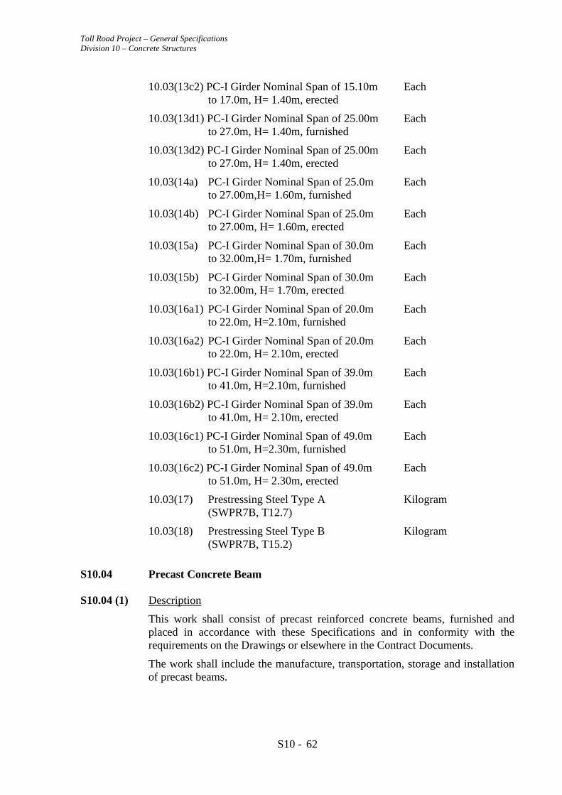
Toll Road Project – General Specifications
Division 10 – Concrete Structures
S10 - 62
10.03(13c2) PC-I Girder Nominal Span of 15.10m Each
to 17.0m, H= 1.40m, erected
10.03(13d1) PC-I Girder Nominal Span of 25.00m Each
to 27.0m, H= 1.40m, furnished
10.03(13d2) PC-I Girder Nominal Span of 25.00m Each
to 27.0m, H= 1.40m, erected
10.03(14a) PC-I Girder Nominal Span of 25.0m Each
to 27.00m,H= 1.60m, furnished
10.03(14b) PC-I Girder Nominal Span of 25.0m Each
to 27.00m, H= 1.60m, erected
10.03(15a) PC-I Girder Nominal Span of 30.0m Each
to 32.00m,H= 1.70m, furnished
10.03(15b) PC-I Girder Nominal Span of 30.0m Each
to 32.00m, H= 1.70m, erected
10.03(16a1) PC-I Girder Nominal Span of 20.0m Each
to 22.0m, H=2.10m, furnished
10.03(16a2) PC-I Girder Nominal Span of 20.0m Each
to 22.0m, H= 2.10m, erected
10.03(16b1) PC-I Girder Nominal Span of 39.0m Each
to 41.0m, H=2.10m, furnished
10.03(16b2) PC-I Girder Nominal Span of 39.0m Each
to 41.0m, H= 2.10m, erected
10.03(16c1) PC-I Girder Nominal Span of 49.0m Each
to 51.0m, H=2.30m, furnished
10.03(16c2) PC-I Girder Nominal Span of 49.0m Each
to 51.0m, H= 2.30m, erected
10.03(17) Prestressing Steel Type A Kilogram
(SWPR7B, T12.7)
10.03(18) Prestressing Steel Type B Kilogram
(SWPR7B, T15.2)
S10.04 Precast Concrete Beam
S10.04 (1) Description
This work shall consist of precast reinforced concrete beams, furnished and
placed in accordance with these Specifications and in conformity with the
requirements on the Drawings or elsewhere in the Contract Documents.
The work shall include the manufacture, transportation, storage and installation
of precast beams.
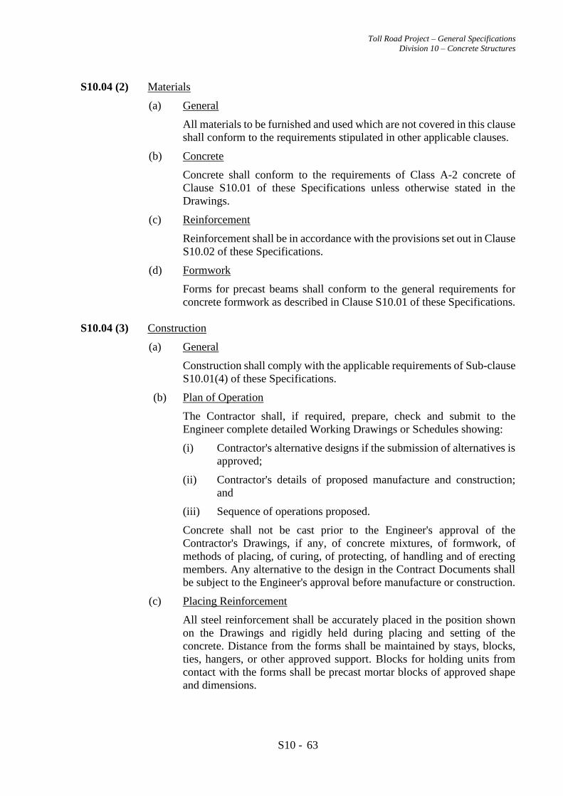
Toll Road Project – General Specifications
Division 10 – Concrete Structures
S10 - 63
S10.04 (2) Materials
(a) General
All materials to be furnished and used which are not covered in this clause
shall conform to the requirements stipulated in other applicable clauses.
(b) Concrete
Concrete shall conform to the requirements of Class A-2 concrete of
Clause S10.01 of these Specifications unless otherwise stated in the
Drawings.
(c) Reinforcement
Reinforcement shall be in accordance with the provisions set out in Clause
S10.02 of these Specifications.
(d) Formwork
Forms for precast beams shall conform to the general requirements for
concrete formwork as described in Clause S10.01 of these Specifications.
S10.04 (3) Construction
(a) General
Construction shall comply with the applicable requirements of Sub-clause
S10.01(4) of these Specifications.
(b) Plan of Operation
The Contractor shall, if required, prepare, check and submit to the
Engineer complete detailed Working Drawings or Schedules showing:
(i) Contractor's alternative designs if the submission of alternatives is
approved;
(ii) Contractor's details of proposed manufacture and construction;
and
(iii) Sequence of operations proposed.
Concrete shall not be cast prior to the Engineer's approval of the
Contractor's Drawings, if any, of concrete mixtures, of formwork, of
methods of placing, of curing, of protecting, of handling and of erecting
members. Any alternative to the design in the Contract Documents shall
be subject to the Engineer's approval before manufacture or construction.
(c) Placing Reinforcement
All steel reinforcement shall be accurately placed in the position shown
on the Drawings and rigidly held during placing and setting of the
concrete. Distance from the forms shall be maintained by stays, blocks,
ties, hangers, or other approved support. Blocks for holding units from
contact with the forms shall be precast mortar blocks of approved shape
and dimensions.
Toll Road Project – General Specifications
Division 10 – Concrete Structures
S10 - 64
(d) Casting
The beams shall be cast in a horizontal position. Special care shall be
taken to place the concrete so as to produce a beam free from any air
pockets, honeycomb or other defect. Concrete shall be placed
continuously and shall be compacted by vibrating or by other means
satisfactory to the Engineer.
(e) Handling, Transport and Storage
Precast reinforced concrete beams shall not be moved from the casting
position until the concrete has attained a compressive strength of 85% of
the specified 28-day strength, nor transported until it has developed
strength of 90% of the specified 28-day strength.
Extreme care shall be exercised in handling and moving precast concrete
beams. Precast beams shall be transported in an upright position, shock
shall be avoided and the points of support and directions of the reactions
with respect to the member shall be approximately the same during
transporting and storage as when the member is in its final position. If the
Contractor deems it expedient to transport or store precast beam unit in
other than this position, it shall be done at his own risk after notifying the
Engineer of his intention to do so. Any unit considered by the Engineer to
have become substrandard shall be rejected and replaced at the
Contractor's expense by an acceptable unit.
(f) Marking of Precast Beams
Each precast beam unit is to be uniquely and permanently marked
including its date of casting.
S10.04 (4) Method of Measurements
The quantity of reinforced concrete beams to be measured for payment shall be
the actual number of precast concrete beams, installed in place, completed and
accepted. Each beam shall include the concrete, reinforcement steel, and other
such material contained within or attached to the beam unit.
S10.04 (5) Basis of Payment
The work measured as provided above shall be paid for at the Contract unit price
for each type of precast reinforced concrete beam listed below.
The price and payment shall be full compensation for furnishing and placing all
materials including concrete and reinforcement, for casting and for hauling,
storage and erection of the beams including all labour, tools, equipment and
incidentals necessary to complete the work as shown on the drawings and
prescribed in this Clause.
S10.05 Pretensioned Concrete Piling and Precast Reinforced Concrete Piling
S10.05 (1) Description
This work shall consist of pretensioned spun concrete piling and pretensioned
precast concrete piling as well as precast reinforced concrete piling, furnished and
Toll Road Project – General Specifications
Division 10 – Concrete Structures
S10 - 65
driven in accordance with these Specifications and in reasonably close conformity
with the requirements on the Drawings or elsewhere in the Contract Documents.
S10.05 (2) Materials
(a) General
Pretensioned concrete piles shall be constructed in accordance with the
details shown on the Drawings and to the requirements of ACI 318-14.
Pretensioned spun concrete piles shall also comply with the requirement
of JIS A5335-1987 Type A and Type B, pretensioned spun concrete piles.
The applicable provisions of Clause S10.01 and S10.03 shall be read into
and become part of this Clause.
(b) Concrete
Pretensioned concrete piles and precast reinforced concrete piles shall be
Class AA and Class B2 respectively, in accordance with the provisions of
Clause S10.01 of these Specifications.
(c) Reinforcement
Reinforcement shall comply with the provisions of Clause S10.02 of these
Specifications and shall be positioned as shown on the Drawings.
(d) Prestressing Steel
High tensile steel prestressing wire shall conform to the requirements of
AASHTO M203M/M203-12 or SNI 1154-2016.
(e) Certificate
Prior to furnishing pretensioned concrete and precast reinforced concrete
piles the Contractor shall submit to the Engineer for approval a certificate
by the manufacturer certifying that the piles comply with the specification
requirements.
S10.05 (3) Construction
(a) Preparation for Driving
(i) Caps - The heads of all concrete piles, when the nature of the
driving is such as to unduly injure them, shall be protected by caps
of approved design having a suitable cushion next to the pile head
and fitting into a casting which in turn supports a timber shock
block. No pile head will be held so firmly that the slightrotation
of the pile normally occurring while the pile is being driven will
be prevented.
(ii) Joints - Joints of pretensioned concrete and precast reinforced
concrete piles shall be carefully constructed in accordance with the
Drawings or the instruction of the Engineer. Welding shall be
made in accordance with the requirements specified in JIS
A7201:2009 (Standard Practice for Execution of Spun Concrete
Piles).
Toll Road Project – General Specifications
Division 10 – Concrete Structures
S10 - 66
All welded joints shall be protected with an anti corrosion paint.
The anti corrosion paint and thickness required shall conform to
ISO 12944-6:2018 or SNI ISO 12944-6-2012 and SE Menteri
PUPR No.26/SE/M/2015 Pedoman Perlindungan Komponen Baja
Jembatan dengan Cara Pengecatan.
(iii) Pile shoes - Shoe bases shall consist of steel plate as shown on the
Drawings.
(b) Handling, Pitching and Driving
(i) General - When raising or transporting piles the Contractor shall
provide slings and other equipment necessary to prevent any
appreciable bending of the pile.
The main setting out for the piles is to be completed prior to
commencement of driving. Secondary or individual pile setting
out is to be completed and agreed not less than 8 hours prior to
commencing work on the piles concerned. All main setting out
points, lines and stations are to be maintained safe and undisturbed
until the work is complete.
Piles shall be pitched accurately in the positions and driven to the
lines shown on the Drawings or fixed by the Engineer. Piles
deflected from the vertical or proper line shall, where ordered by
the Engineer, be withdrawn and repitched until the proper line is
obtained.
No forcible method of correction of the position or line of any pile
will be permitted. Any pile damaged by reason of improper
driving or driven out of its proper location or driven below the
elevation fixed by the Drawings or by the Engineer, shall be
corrected at the Contractor's expense by one of the following
methods approved by the Engineer for the pile in question :
- The pile shall be withdrawn and replaced by a new and if
necessary longer pile. Any holes from which piles are
withdrawn shall be packed with approved non-plastic material
before redriving takes place; or
- A second pile shall be driven adjacent to the defective pile.
All piles pushed up by the driving of adjacent piles or by any other
cause shall be driven again.
(ii) Batter piles - Batter piles shall be driven accurately to the batter
shown on the Drawings. The pile frame employed for the driving
of the batter piles shall have leads capable of adjustment to the
required angle. When piles have to be driven below the level of
the bottom of the leads, extension leads shall be provided except
where the use of a follower is specifically permitted by the
Engineer.
(iii) Driving equipment - Before any piling work is commenced the
Contractor shall submit to the Engineer full details of the pile
Toll Road Project – General Specifications
Division 10 – Concrete Structures
S10 - 67
driving equipment and the method of carrying out the work he
intends to use. All piles shall be provided with caps for driving
as specified in Item (a) (i) above. For special types of piling,
driving head mandrels, or other devices in accordance with these
requirements shall be provided so that piles may be driven without
damage.
Piles shall be driven with steam, air or diesel hammers, a
combination of hammers with water jets or gravity hammers.
When diesel hammers are used, they shall be calibrated by a load
test if necessary.
The plant and equipment furnished for steam and air hammers
shall have sufficient capacity to maintain, under working
conditions, the pressure in the manner specified by the
manufacturer. The boiler or tank shall be equipped with an
accurate pressure gauge, and another gauge shall be supplied at the
hammer intake.
When gravity hammers are used for driving concrete piles, the
drop of the hammer shall not exceed 2.5 meters and the hammer
shall have a weight of not less than half the weight of the pile.
The fall shall be regulated so as to prevent injury to the pile.
(iv) Driving - Piles shall be supported in line and position with leads
while being driven. Pile drive leads shall be constructed so as to
afford freedom of movement of the hammer, and they shall be held
firmly in position to ensure rigid lateral support to the pile during
driving. Except where piles are driven through water, the leads
shall be of sufficient length to make the use of a follower
unnecessary and shall be so designed as to permit the proper
placing of batter piles. If the condition at the site requires the
necessity of a follower, the Contractor shall not use it without
approval of the Engineer.
When water jets are considered by the Engineer to be necessary,
the number of jets and the nozzle volume and pressure shall be
sufficient to erode freely the material adjacent to the piling. The
plant shall have at all times a pressure of at least seven (7)
kilogrammes per square centimeter at two (2) centimeter jet
nozzles. Before the required penetration is reached, the jets shall
be shut off and the piles driven by hammer to final penetration.
A detailed accurate record of the driving of all piles shall be kept
by the Engineer and the Contractor shall give every assistance to
the Engineer to help him keep this record which will include the
following: pile numbers, positions, types, sizes, actual lengths,
dates driven, lengths in footings, penetration under final blows of
the hammer, striking energy of the hammer, lengths extended,
length cut off, and final pay lengths.
No piles shall be driven near freshly placed concrete.
Toll Road Project – General Specifications
Division 10 – Concrete Structures
S10 - 68
(v) Bearing values - Piles shall be driven to a bearing value of not less
than that shown on the Drawings. The Engineer will specify the
penetration and the Contractor shall drive the piles to the
penetration specified, but if the Engineer is not satisfied that the
desired bearing value has been attained the Contractor shall carry
on driving until such desired bearing value is attained.
(vi) Cut off and extension - Piles shall be cut off at such elevation that
they will extend into the cap or footing as indicated on the
Drawings.
The extended length of a pile shall be sufficient to reach the
elevation of the bottom of the cap and shall be of the same section
as the pile itself or as shown on the Drawings. After piles have
been lengthened driving shall not be resumed until the approval of
the Engineer has been given.
Unless otherwise specified, pile cut-off length shall become the
property of the Contractor and shall be disposed of beyond
Government property limits and outside the limit of view from the
roadway to the satisfaction of the Engineer.
(vii) Connection with footing - All piles shall be connected to footings
as shown on the Drawings or directed by the Engineer.
(c) Test Piles
The Engineer may order the execution of test piles as he may consider
necessary to ascertain the type of the foundation or the length of pile for
the project. The Contractor shall furnish and execute test piling at the
locations designated by the Engineer.
The lengths of the piles shown on the Drawings are based on information
obtained from previous site investigations. However, piles of different
lengths may be required and as ordered by the Engineer.
Before pile lengths are finally settled, the Contractor shall construct to the
lengths shown on the Drawings such test piles as may be found necessary
and these piles shall be driven in the positions specified by the Engineer
who shall be notified in advance of the driving. The Contractor shall
furnish the Engineer daily with a detailed record of the driving of test piles
throughout the full depth of driving.
After attaining the approved set, driving shall be continued until the
Engineer directs that it shall cease. Driving of test piles beyond the point
at which the approved set is obtained will be called for to demonstrate that
driving resistance continues to increase. The Contractor shall then
furnish the remainder of the piles in the structure. In determining the
lengths of piles the Contractor shall base his list on the lengths assumed
to remain in the completed structure.
Test piles shall be used as foundation piles, only on the written agreement
of the Engineer.
Toll Road Project – General Specifications
Division 10 – Concrete Structures
S10 - 69
The Contractor at his own expense may increase the lengths to provide for
fresh heading and or such lengths as may be necessary to suit his method
of operation.
(d) Test Loading
The static and dynamic load tests shall be made by the methods approved
by the Engineer. The Contractor shall submit to the Engineer for approval
detailed drawings of the loading apparatus he intends to use.
(i) Static Load Test
The apparatus of static load tests shall be so constructed as to allow
the various increments of the load to be placed gradually without
causing vibration to the test piles.
If the approved method requires the use of tension (anchor) piles,
such tension piles shall be of the same type and diameter as the
permanent piles and shall be executed in the location of permanent
piles. Pipe and shell piles whose walls are not of adequate strength
to sustain the test loading when empty shall have the required
reinforcement and concrete placed before loading. Loads for the
load tests shall not be applied until the concrete has attained a
minimum compressive strength of 95 percent of the design 28 day
compressive strength. If he so elects, the Contractor may use high
early strength cement, type III, in the concrete of the load test piles
and the tension piles.
Suitable approved apparatus for determining accurately the load
on the piles and the settlement of the piles under each increment
of load shall be supplied by the Contractor.
The apparatus shall have a working capacity of three times the
design load shown on the Drawings for the pile being tested.
Reference points for measuring pile settlement shall be
sufficiently removed from the test pile to preclude all possibility
of disturbance. All pile load settlement shall be measured by
adequate devices, such as gauges, and shall be checked by means
of an Engineer's level.
Increments of deflection shall be read just after each load
increment is applied and at 15 minute intervals thereafter. The safe
allowable load shall be considered as 50% of the load which, after
48 hours of continuous application, has caused not more than 6.5
mm of permanent settlement, measured at the top of the pile. The
test load shall be twice the design load shown on the Drawings.
The first increment of load to be applied to the test pile shall be
the pile design load. The load on the pile shall be increased to
twice the design load by applying additional loads in three equal
increments. A minimum period of 2 hours shall intervene between
the application of each increment, except that no increment shall
be added until a settlement of less than 0.12 mm is observed in a
15 minute interval under the previously applied increment. If there
Toll Road Project – General Specifications
Division 10 – Concrete Structures
S10 - 70
is a question as to whether the test pile will support the test load,
the load increments shall be reduced by 50 percent, at the direction
of the Engineer, in order that a more closely controlled failure
curve may be plotted. The full test load shall remain on the test
pile not less than 48 hours. The full test load shall then be removed
and the permanent settlement read. When requested by the
Engineer, loading shall then continue beyond the double design
load in 10 ton increments until the pile fails or the capacity of the
loading apparatus is reached, whichever is the lesser. The pile may
be considered to have failed when the total settlement under load
exceeds 2.5 cm or the permanent settlement exceeds 6.5 mm.
After the completion of loading tests, the load used shall be
removed and the piles, including tension piles, shall be utilized in
the structure if found by the Engineer to be satisfactory for such
use. Test piles not loaded shall be utilized similarly. If any pile,
after serving its purpose as a test or tension pile, is found
unsatisfactory for utilization in the structure, it shall be removed if
so ordered by the Engineer or shall be cut off below the ground
line or footings, whichever is applicable.
(ii) Dynamic Load Test
Dynamic Load Test shall be in accordance with ASTM D4945-17
Standard Test Method for High-Strain Dynamic Testing of Pile.
The dynamic load test covers the procedure for testing vertical or
batter piles individually to determine the force and velocity
response of the pile to an impact force applied axially by pile
driving hammer to the top of pile. This is applicable to deep
foundation piles.
This method is used to provide data on strain or force and
acceleration, velocity or displacement of a pile under impact force.
The data will be used to estimate the bearing capacity, pile
integrity, as well as hammer performance, pile stresses, and soil
dynamic characteristics.
The apparatus for applying impact force is pile driving hammer or
similar device which is capable of generating a net measurable pile
penetration, or an estimated mobilized static resistance in the
bearing stratum.
The apparatus for obtaining dynamic measurement shall consist of
force or strain transducers and velocity or displacement
transducers. The first transducers shall be capable of
independently measuring strain and acceleration versus time at a
specific location along the pile axis during the impact event. The
second transducers shall be placed at equal radial distances on the
diametrically opposite side of the pile to where the first
transducers were placed. Both of the transducers shall be placed
securely so that they do not slip. Velocity data shall be obtained
with the second transducers or accelerometers provided the signal
can be processed by integration in the apparatus for reducing data.
Toll Road Project – General Specifications
Division 10 – Concrete Structures
S10 - 71
The accelerometers shall have a minimum of two accelerometers
with a resonant frequency above 7500 Hz.
The signals from the transducers during the impact event shall be
transmitted to the apparatus for recording, reducing and displaying
data to allow determination of the force and velocity versus time.
It may be desirable to also determine the acceleration and
displacement of the pile head, and the energy transfer to the pile.
This apparatus shall include an oscilloscope or oscillograph for
displaying the force and velocity traces, a tape recorder or
equivalent for obtaining a record for future analysis, and a means
to reduce data. The apparatus shall have the capability of making
internal calibration check of strain, acceleration, and time scales.
No error shall exceed 2% of the maximum signal expected.
The number and location of the piles to be submitted to static or
dynamic load testing shall be decided by the Engineer. This
number, for piles over 600 mm in diameter, shall be not less than
one and not more than three for each bridge. For piles up to and
including 600 mm in diameter it shall be not less than one for every
30 piles.
(iii) Reporting
A report shall be prepared by the Contractor on each load test. This
report shall include the following documents:
Plan of the foundation;
Stratification of the soil;
Calibrating curve of the gauges;
Drawing of the jack diameter of the piston;
Graph of the test, having for abscissa the loads (tons) and for
ordinates the settlements in fractions of mm;
Tables showing, as a function of the times (date and hour), the
readings of the gauge in atmospheres, the loads in tons, the
settlements and average of the settlement.
When the safe bearing capacity of any pile is found by test to be
less than the design load, longer piles or additional piles shall be
installed as directed by the Engineer.
(e) Dynamic Formula for Estimating Pile Capacity
The pile load capacity of driven piles may be estimated using the
following dynamic formula (Hiley). The Contractor may propose another
formula for the Engineer’s approval.
efWH W + n2Wp
Pu = ------------------------ X -------------
S + (C1 + C2 + C3)/2 W + P
Toll Road Project – General Specifications
Division 10 – Concrete Structures
S10 - 72
Where :
Pu : ultimate load capacity (ton)
Pa : permissible load capacity (ton)
ef : hammer efficiency
ef = 1.00 for diesel hammer
ef = 0.75 for drop hammer actuated by rope and friction winch
W : weight of hammer or ram (ton)
Wp : weight of pile (ton)
n : coefficient of restitution
n = 0.25 for concrete pile
H : drop of hammer (m)
H = 2H’ for diesel hammer (H’ : drop of ram)
S : pile penetration for last blow, or “set” (m)
C1 : temporary compression allowance for pile head and cap (m)
C2 : temporary compression allowance for elastic deformation of pile
shaft (m)
C3 : temporary compression allowance for quake of ground (m)
N : safety factor
Value of C1 + C2 + C3 shall be measured during driving.
S10.05 (4) Method of Measurement
(a) Piles Furnished
The unit of measurement for payment for furnishing pretensioned
concrete and precast reinforced concrete piles shall be the linear meters,
measured from the toe of pile to the cut off of pile, in compliance with the
Engineer's instructions and the material requirements of these
Specifications and stockpiled in good condition at the site of the work by
the Contractor, and accepted by the Engineer. No allowance will be
made for the length of piles furnished by the Contractor to replace piles
previously accepted by the Engineer that are subsequently lost or those
that are damaged prior to completion of the Contract while in stockpile,
or during handling or driving, and are ordered by the Engineer to be
removed from the site of the work or disposed of otherwise. No payment
for the lengths cut off or the undriven of furnished piles.
(b) Piles Driven
The quantities of driven pretensioned concrete and precast reinforced
concrete piles to be paid for shall be the number of linear meters of piles
actually driven and accepted. The pay lengths of the satisfactorily driven
piles shall be measured from the tip to the cut-off or the piles totally
penetrated in groundor from the toe of pile to the ground level for the piles
partly penetrated in ground. Lengths cut-off will not be measured for
payment.
(c) Piles Executed in Water Stream
Measurement for additional payment for piles constructed under water
shall be calculated by linear metre. No additional payment will be made
if the depth of water is less than 50 cm. The additional payment will be
Toll Road Project – General Specifications
Division 10 – Concrete Structures
S10 - 73
based on the linear metre measurement of the depth of water, based on the
elevation difference between the river bed and normal water level for each
individual pile.
(d) Test Piles
The quantities of test piles as provided in Sub-clause S10.05 (3) (c) to be
paid for shall be the linear meters of test piles completed and accepted,
whether they are executed inside or outside the foundation.
S10.05 (5) Basis of Payment
The work measured as provided above shall be paid for at the Contract unit price
per linear meter for the particular pay items listed below. The rate shall
constitute full compensation for all materials including prestressing,
reinforcement and shoes, equipment, hardware, furnishing, jointing, driving,
jetting, welding (extending), painting, testing, coupling, cutting-off, concrete
filling for spun piles, reinforcement for connection with footing and all related
tools, rigs, cranes, boilers, hammers, jets, labour and other incidental equipment
and work.
Pile connection with footing, including reinforcement bars and including concrete filling for spun piles, will not be measured separately and is deemed to be included in the cost of pile driving.
Payment for test piles, completed and accepted, shall be made as the linear meter
of test piles for furnishing and driving a test pile of the size specified. When test
piles are incorporated in the foundation connection with footing is included and
no additional payment shall be made for the pile so utilized other than as for test
pile.
No payment shall be made for unauthorized, defective, unsound or
unsatisfactorily driven piles or for any costs incurred by the Contractor for such
piles.
Pay Item No. and Name Unit of Measurement
10.05 (1) Pretensioned Spun Concrete Pile, Linear Meter
Furnished, D = 80cm
10.05 (2) Pretensioned Spun Concrete Pile, Linear Meter
Driven, D = 80cm
10.05 (3) Pretensioned Spun Concrete Pile Test Linear Meter
Furnished and Driven, D = 80cm
10.05 (4) Pretensioned Spun Concrete Pile, Linear Meter
Furnished, D = 60cm
10.05 (5) Pretensioned Spun Concrete Pile, Linear Meter
Driven, D = 60cm
10.05 (6) Pretensioned Spun Concrete Pile Test Linear Meter
Furnished and Driven, D = 60cm
10.05 (7) Pretensioned Spun Concrete Pile, Linear Meter
Furnished, D = 50cm
Toll Road Project – General Specifications
Division 10 – Concrete Structures
S10 - 74
10.05 (8) Pretensioned Spun Concrete Pile, Linear Meter
Driven, D = 50cm
10.05 (9) Pretensioned Spun Concrete Test Pile, Linear Meter
Furnished and Driven, D = 50cm
10.05 (10) Additional Price to Prices No.10.05.(2), Linear Meter
No.10.05.(5) and No.10.05.(8) when the
Pile is executed in the Water Stream,
10.05 (11) Static Loading Test for Pretensioned Each
Spun Concrete Pile D = 50 - 60cm
10.05 (12) Static Loading Test for Pretensioned Each
Spun Concrete Pile D = 80cm
10.05 (13) Dynamic Loading Test for Pretensioned Each
Spun Concrete Pile D = 50 - 60cm
10.05 (14) Dynamic Loading Test for Pretensioned Each
Spun Concrete Pile D = 80cm
10.05 (15) Precast Reinforced Concrete Pile Each
30cm x 30cm, furnished
10.05 (16) Precast Reinforced Concrete Pile Each
30cm x 30cm, driven
10.05 (17) Precast Reinforced Concrete Pile Each
20cm x 20cm, furnished
10.05 (18) Precast Reinforced Concrete Pile Each
20cm x 20cm, driven
S10.06 Steel Piling
S10.06 (1) Description
This work shall consist of steel piling for structure foundations furnished and
driven in accordance with these Specifications and in reasonably close conformity
with the Drawings at the penetration or depth ordered by the Engineer. When
the Engineer judges that pile foundation is not necessary, based on the result of
Test Drilling specified in Clause S10.08 or the result of Test Piling, Contractor
shall change the footing design as directed by the Engineer.
When the steel pipe pile to be used and to be filled with concrete, the concrete
shall be selft compacted concrete (SCC) with minimum strength of fc '30 MPa
and filled up to a minimum depth of 8 meters under existing ground or as shown
in the Drawings. The sand to be filled into the steel pipe pile shall be clean and
does not contain the corrosive materials such as sea sand.
S10.06 (2) Materials
Steel pile shall be shop-fabricated and shall have the type, weight, quality and
dimensions specified ASTM A500/A500M - 18 (Steel Pipe Grade B), or as shown
on the Drawings.
Toll Road Project – General Specifications
Division 10 – Concrete Structures
S10 - 75
Prior to furnishing steel piles the Contractor shall submit to the Engineer for
approval a certificate by the manufacturer certifying that the piles comply with
the specification requirements.
S10.06 (3) Construction
(a) Preparation for Driving
(i) Caps - The heads of all steel piles, when the nature of the driving
is such as to unduly injure them, shall be protected by caps of
approved design having a suitable cushion next to the pile head
and fitting into a casting which in turn supports a timber shock
block. No pile head will be held so firmly that the slight rotation
of the pile normally occurring while the pile is being driven will
be prevented.
(ii) Joints of steel pile - Joints of steel pile shall be carefully
constructed in accordance with the Drawings, or the instruction of
the Engineer. When joints which are not specified on the
Drawings are to be constructed, the Contractor shall obtain the
approval of the Engineer and employ electric arc welding
throughout the butt joint. Welding shall be made in accordance
with requirements specified in JIS A7201:2009 (Standard Practice
for Execution of Spun Concrete Piles).
(iii) Pile shoes - Shoe bases where used shall consist of steel plate as
shown on the Drawings.
(iv) Protection Against Corrosion - Where there is a possibility of
corrosion of steel piles, the lengths or sections liable to corrosion
shall be protected by painting with an approved protective coating
and/or shall be installed with a thicker metal section when the rate
of corrosion can be reasonably accurately estimated. Generally, all
exposed lengths of steel pile, and any lengths installed in disturbed
ground above the minimum water table shall be protected against
corrosion.
If the steel piles to be located in watery areas (rivers), these piles
shall be protected with an anti corrosion paint at least 1.5 meters
above the highest flood water level and 0.5 meters below the
lowest water level, and if the steel piles to be located in the tidal
area, these piles shall be protected with an anti corrosion paint at
least 1.5 meters above the highest tidel level and 0.5 meters below
the lowest tidel level. The anti corrosion paint and thickness
required shall conform to ISO 12944-6:2018 or SNI ISO 12944-
6-2012 and SE Menteri PUPR No.26/SE/M/2015 Pedoman
Perlindungan Komponen Baja Jembatan dengan Cara Pengecatan.
(b) Handling, Pitching and Driving
(i) General - When raising or transporting steel pipe piles the
Contractor shall provide slings and other equipment necessary to
prevent any appreciable bending of the pile. No steel pile shall
be lifted otherwise than by slinging from the lifting holes, the
Toll Road Project – General Specifications
Division 10 – Concrete Structures
S10 - 76
positions of which shall be as directed or approved by the
Engineer.
The main setting out for the piles is to be completed prior to
commencement of driving. Secondary or individual pile setting
out is to be completed and agreed not less than 8 hours prior to
commencing work on the piles concerned. All main setting out
points, lines and stations are to be maintained safe and undisturbed
until the work is complete.
Piles shall be pitched accurately in the positions and driven to the
lines shown on the Drawings or fixed by the Engineer. Piles
deflected from the vertical or proper line shall, where ordered by
the Engineer, be withdrawn and repitched until the proper line is
obtained.
No forcible method of correction of the position or line of any pile
will be permitted. Any pile damaged by reason of improper
driving or driven out of its proper location or driven below the
elevation fixed by the Drawings or by the Engineer, shall be
corrected at the Contractor's expense by one of the following
methods approved by the Engineer for the pile in question :
- The pile shall be withdrawn and redriven or replaced by a new
pile as decided by the Engineer. Any holes from which piles
are withdrawn shall be packed with approved non-plastic
material before redriving takes place; or
- A second pile shall be driven adjacent to the defective pile.
All piles pushed up by the driving of adjacent piles or by any other
cause shall be driven again.
(ii) Battered piles - Battered piles shall be driven accurately to the
batter shown on the Drawings. The pile frame employed for the
driving of the batter piles shall have leads capable of adjustment
to the required angle. When piles have to be driven below the
level of the bottom of the leads, extension leads shall be provided
except where the use of a follower is specifically permitted by the
Engineer.
(iii) Driving equipment - Before any piling work is commenced the
Contractor shall submit to the Engineer full details of the pile
driving equipment and the method of carrying out the work he
intends to use. All piles shall be provided with caps for driving
as specified in Item (a) (i) above. For special types of piling,
driving head mandrels, or other devices in accordance with these
requirements shall be provided so that piles may be driven without
damage.
Shoes shall be provided as shown on the Drawings. Piles shall be
driven with steam, air or diesel hammers, a combination of
hammers with water jets or gravity hammers. When diesel
Toll Road Project – General Specifications
Division 10 – Concrete Structures
S10 - 77
hammers are used, they shall be calibrated by a load test if
necessary.
The plant and equipment furnished for steam and air hammers
shall have sufficient capacity to maintain, under working
conditions, the pressure in the manner specified by the
manufacturer. The boiler or tank shall be equipped with an
accurate pressure gauge, and another gauge shall be supplied at the
hammer intake.
(iv) Driving - Piles shall be supported in line and position with leads
while being driven. Pile drive leads shall be constructed so as to
afford freedom of movement of the hammer, and they shall be held
firmly in position to ensure rigid lateral support to the pile during
driving. Except where piles are driven through water, the leads
shall be of sufficient length to make the use of a follower
unnecessary, and shall be so designed as to permit the proper
placing of batter piles. If the condition at the site requires the
necessity of a follower, the Contractor shall not use it without
approval of the Engineer.
When water jets are considered by the Engineer to be necessary,
the number of jets and the nozzle volume and pressure shall be
sufficient to erode freely the material adjacent to the piling. The
plant shall have at all times a pressure of at least 7 kilogrammes
per square centimeter at two (2) centimeter jet nozzles. Before
the required penetration is reached, the jets shall be shut off and
the piles driven by hammer to final penetration.
A detailed accurate record of the driving of all piles shall be kept
by the Engineer and the Contractor shall give every assistance to
the Engineer to help him keep this record which will include the
following: pile numbers, positions, types, sizes, actual lengths,
dates driven, lengths in footings, penetration under final blows of
the hammer, striking energy of the hammer, lengths extended,
lengths cut off, and final pay lengths.
No pile shall be driven near freshly placed concrete.
(v) Bearing values - Piles shall be driven to a bearing value of not less
than that shown on the Drawings. The Engineer will specify the
penetration and the Contractor shall drive the piles to the
penetration specified, but if the Engineer is not satisfied that the
desired bearing value has been attained the Contractor shall carry
on driving until such desired bearing value is attained.
(vi) Cut off and extension - Steel pipe piles shall be cut off at such
elevation that they will extend into the cap or footing as indicated
on the Drawings.
The extended length of a pile shall be sufficient to reach the
elevation of the bottom of the cap and shall be of the same section
as the pile itself or as shown on the Drawings. After piles have
Toll Road Project – General Specifications
Division 10 – Concrete Structures
S10 - 78
been lengthened driving shall not be resumed until the approval of
the Engineer has been given.
If so required and directed by the Engineer pile cut-off lengths, of
1.0 meter or more, shall be utilized as extension piles or otherwise.
The preparation of such cut-off pile lengths shall be undertaken by
the Contractor without additional payment or claim.
In compliance with this Clause all pile cut-off lengths shall be
salvaged and safely stored and protected by the Contractor. On
completion of the Works any unused pile cut-off lengths will
become the property of the Contractor and shall be disposed of
beyond Government property limits and outside the limit of view
from the roadway to the satisfaction of the Engineer.
(vii) Connection with footing - All piles shall be connected to footings
using reinforcing bars and steel plate, as shown on the Drawing or
directed by the Engineer.
(c) Test Piles
The Engineer may order the execution of test piles as he may consider
necessary to ascertain the type of the foundation or the length of pile for
the project. The Contractor shall furnish and execute test piling at the
locations designated by the Engineer.
The lengths of the piles shown on the Drawings are based on information
obtained from previous site investigations. However, piles of different
lengths may be required and as ordered by the Engineer.
Before pile lengths are finally settled, the Contractor shall construct to the
lengths shown on the Drawings such test piles as may be found necessary
and these piles shall be driven in the positions specified by the Engineer
who shall be notified in advance of the driving. The Contractor shall
furnish the Engineer daily with a detailed record of the driving of test piles
throughout the full depth of driving.
After attaining the approved set, driving shall be continued until the
Engineer directs that it shall cease. Driving of test piles beyond the point
at which the approved set is obtained will be called for to demonstrate that
driving resistance continues to increase. The Contractor shall then
furnish the remainder of the piles in the structure. In determining the
lengths of piles the Contractor shall base his list on the lengths assumed
to remain in the completed structure.
Test piles shall be used as foundation piles, only on the written agreement
of the Engineer.
The Contractor at his own expense may increase the lengths to provide for
fresh heading and or such lengths as may be necessary to suit his method
of operation.
Toll Road Project – General Specifications
Division 10 – Concrete Structures
S10 - 79
S10.06 (4) Method of Measurement
(a) Piles Furnished
The unit of measurement for payment for furnishing steel piles shall be
the weight (tonne), measured from the toe of pile to the under-side of pile
cap, including plates, jointing steel and cap reinforcement, furnished in
compliance with the material requirements of these Specifications and as
directed by the Engineer. No payment for the lengths cut off or the
undriven of furnished piles.
(b) Piles Driven
The quantities of driven steel piles to be paid for shall be the number of
linear meters of piles actually driven and accepted. The length of
individual piles shall be measured from the toe of pile to the under-side of
pile cap for the piles totally penetrated in ground, or from the toe of pile
to the ground level for the piles partly penetrated in ground.
(c) Test Piles
Test piles will be measured and paid for in accordance with (a) and (b)
above, and the quantities given in the Bid Schedule will be based on the
assumption that test piles can subsequently be incorporated into the
permanent works.
S10.06 (5) Basis of Payment
The work measured as provided above shall be paid for at the Contract price per
unit of measurement for the pay items listed below. The payment shall include
full compensation for furnishing and driving the piles including materials for
completion of the pile and for all labor, tools, equipment, hauling, handling,
jetting, jointing, cutting and all other incidental works connected therewith.
Pay Item No. and Name Unit of Measurement
10.06 (1) Steel Pile, Furnished., D = 50cm Tonne
10.06 (2) Steel Pile, Driven, D = 50cm Linear Meter
10.06 (3) Steel Pile, Furnished. D = 60cm Tonne
10.06 (4) Steel Pile, Driven, D = 60cm Linear Meter
10.06 (5) Steel Pile, Furnished. D = 80cm Tonne
10.06 (6) Steel Pile, Driven, D = 80cm Linear Meter
10.06 (7) Additional Price to Prices No.10.06 (2), Linear Meter
No.10.06.(4) and No.10.06 (6) and when
the Pile is executed in the Water Stream
Toll Road Project – General Specifications
Division 10 – Concrete Structures
S10 - 80
S10.07 Cast-in-place Concrete Piling
S10.07 (1) Description
The work shall consist of cast-in-place concrete piles constructed by the reverse
circulation drill method in accordance with these Specifications and with the
requirements shown on the Drawings. Loading test is also included and required
to determine beraring capacity of bored pile foundation.
S10.07 (2) Materials
Cast-in-place concrete piles shall be constructed, in accordance with the details
shown on the Drawings, of concrete Class B-2 Self Compacted Concrete (SCC),
mixed and placed in accordance with the provisions of Clause S10.01 of these
Specifications.
Reinforcement shall comply with the provisions of Clause S10.02 of these
Specifications.
S10.07 (3) Construction
(a) Drilled holes
All holes for concrete piles cast in drilled holes shall be drilled to the tips
of piles. The length of piles shall be instructed by the Engineer. The
drilling machine shall be such that the hole can be maintained exactly
vertical during drilling operations.
Completed piles and existing structures very close to the drilling area shall
be protected from the influence of piling and the Contractor's proposals
for this shall be submitted to, and approved by, the Engineer before the
start of piling.
Drilled holes shall be protected from collapse by a water surcharge, by
providing a steel casing (i.e. stand casing pipe). The stand casing pipe
shall be rigid and project at least 50 cm above ground level.
The water level of the inside of the drilled hole shall be always kept
approximately 2 m higher than the natural ground water level. Water
supplied from a municipal water supply system or a river is allowed for
this purpose.
All loose material existing at the bottom of the hole after drilling
operations have been completed shall be removed by air lift or suction
pump before placing concrete.
(b) Bentonite
The bentonite material shall be sourced from approved international
brands or from equivalent material such as polymer, which shall be
considered if there is influence of salt water from the seaside.
The bentonite shall be mixed in high turbulence mixers and pumped into
storage silos or clean bentonite tank/pool built on site.
Slurry shall be pumped through 4" diameter steel pipes from and to the
excavation.
Toll Road Project – General Specifications
Division 10 – Concrete Structures
S10 - 81
Used bentonite will be passed through descending sieves and stored for
re-used.
Unsuitable bentonite slurry shall be stored separately and transported off
site in slurry tankers and dumped in an approved area.
A mud testing laboratory shall be provided on site and shall contain the
following apparatus and result of test shall be approved by the Engineer:
- 1 baroid filter press (free water test);
- 1 mud balance (density test);
- 1 marsh cone (viscosity test);
- 1 sand screen set (sand content test);
- Apparatus for measuring pH.
(c) Soil Disposal
Soil waste from the drilled hole which is dumped beside the rig during
drilling workshall be transported away from the site immediately to
prevent obstructing the drillingprogress. The spoil shall be loaded into
dump trucks with an excavator or loader andshall be carried to stockpile
area inside the site and then transported out of project siteto an approved
waste disposal area
(d) Reinforcement
Reinforcement shall be positioned as shown on the Drawings. The
connecting portions of main bars with hoops shall generally be welded by
arc fillet welding.
During the placing of the reinforcement in the hole, the verticality and
position of the reinforcement shall be carefully controlled to prevent
collapse of the drilled hole or damage to the walls.
(e) Casting
Concrete shall be placed in one continuous operation from tip to cut-off
elevation by tremie tubes and shall be carried out in such a manner as to
avoid segregation. The tip of the tremie shall generally be 2 m lower than
the fresh concrete surface.
The Contractor at his own expense shall initially cast an additional length
of pile above the finished level of the top of the pile and subsequently
remove any defective concrete to ensure satisfactory bonding of the pile
head to the footing structure.
(f) Reporting
The Contractor shall furnish the Engineer daily with a detailed record of
the construction of piles.
Toll Road Project – General Specifications
Division 10 – Concrete Structures
S10 - 82
(g) Static Loading Test Piles
The Engineer may instruct the load testing of cast-in-place concrete piles.
Details of the loading test are given in the Special Specification.
The Engineer may instruct the load testing of cast-in-place concrete piles.
Details of the loading test are given in as directed by the Engineer and in
accordance with the requirements of maximum loading which is 150 % of
service load.
(h) Dynamic Loading Testing Pile
For the Dynamic loading test a proper weight of hammer shall
requiredmakingsufficient energy to mobilize the soil element around the
pile. As the method of testing, the minimal proper hammer weight shall
be minimum 1 % of the expected ultimate bearing capacity. The standard
test method shall be accordance with the requirement of ASTM D4945-
17 “Standard Test Method for High-Strain Dynamic Testing of Piles”.
(i) Non-destructive checking
The Contractor may be requested to check all drilled holes by ultrasonic
measurement before installation of reinforcement, and the details of such
checking shall be approved by the Engineer.
(i) Measurement Monitor of Drilling Hole
The Contractor shall check all drilled holes by ultrasonic
measurement before installation of the reinforcement bar, and the
details of such method shall be approved by the Engineer. The
monitor shall be check for the vertical drilling holes and the direct
recording shall be in four directions (X-X' and Y-Y'). This work
shall include in pay item 10.07 (1) and (2).
(ii) Pile Integrity Testing (PIT)
The Contractor shall test all concrete piles by Pile Integrity Testing
(PIT) after casting of concrete, which is a non-destructive integrity
test method for foundation piles. It is a “Low Strain” Method
(since it requires the impact of only a small hand-held hammer).
The evaluation of PIT records is conducted either according to the
pulseecho (or Sonic Echo – a time domain analysis) or the
transient response (frequency domain analysis) procedure. The
standard test method shall be accordance with the requirement of
ASTM D5882-16 “Standard Test Method for Low -Strain
Integrity Testing of Piles”, and shall include in pay item 10.07 (1)
and (2).
(iii) Ultrasonic Measurement monitor of concrete pile
The Contractor may be requested to monitor concrete piles used
installed pipe in the pile by ultrasonic measurement monitor after
casting of concrete, and the result of such monitoring shall be
approved by the Engineer and may instruct the location of the
testing of cast-in-place concrete piles. The hole of pile for the
Toll Road Project – General Specifications
Division 10 – Concrete Structures
S10 - 83
ultrasonic equipment installation shall pour the suitable material
after result of the ultrasonic test record.
Specification of ultrasonic measurement monitor shall be
approved the Engineer and shall pay item 10.07 (4).
S10.07 (4) Method of Measurement
(a) Cast-in-place Concrete Piles
The quantity of cast-in-place concrete piles to be paid for will be the actual
number of linear meters of piles cast and left in place in the completed and
accepted work.
Measurement will be made from the point of the tip of the pile to the
bottom of the footing. Portions of piles cast deeper than required through
over-drilling procedures will not be measured for payment.
(b) Static Loading Test Piles
The quantities of static loading test piles to be paid for will be the actual
number of piles installed and tested as instructed by the Engineer
Measurement of test piles will
(c) Dynamic Loading Test Piles
The quantities of dynamic loading test piles to be paid for will be the
actual number of tested as instructed by the Engineer. The pile installation
will be excluded in this pay item.
(d) Ultrasonic Measurement Monitor of Concrete Pile
The quantities of ultrasonic measurement monitor of concrete pile to be
paid for will be the actual number of tested as instructed by the Engineer.
The pile installation will be excluded in this pay item.
S10.07 (5) Basis of Payment
The work measured as provided above shall be paid for at the Contract price per
unit of measurement for the pay items listed below.
The payment for cast-in-place pile shall be full compensation for construction of
the piles including protection of existing piles and structures, all materials for
completion of the pile and for all labour, tools, equipment, hauling, handling,
jetting, jointing, cutting and all other incidental works connected therewith.
Payment for each test pile shall be full compensation for all labour, equipment,
material, including temporary piles, required to install the test pile and carry out
the loading test in a manner as approved by the Engineer. When test piles are
incorporated in the foundation no additional payment shall be made for the pile
so utilized other than as for test pile.
Pay Item No. and Name Unit of Measurement
10.07 (1) Cast-in-Place RC Pile D=80cm Linear Meter
with Ultrasonic Monitoring
Toll Road Project – General Specifications
Division 10 – Concrete Structures
S10 - 84
10.07 (1a) Cast-in-Place RC Pile D=100cm Linear Meter
with Ultrasonic Monitoring
10.07 (2) Cast-in-Place RC Pile D=80cm Linear Meter
including Static Loading Test
10.07 (2a) Cast-in-Place RC Pile D=100cm Linear Meter
including Static Loading Test
10.07 (3) Dynamic Loading Test for Cast-in-Place Each
RC Pile D=80cm
10.07 (3a) Dynamic Loading Test for Cast-in-Place Each
RC Pile D=100cm
10.07 (4) Ultrasonic Measurement Monitor for Each
Cast-in-Place RC Pile D=80cm
10.07 (4a) Ultrasonic Measurement Monitor for Each
Cast-in-Place RC Pile D=100cm
10.07 (5) Cast-in-Place RC Pile D=120cm, Linear Meter
with Ultrasonic Monitoring
10.07 (6) Cast-in-Place RC Pile D=120cm, Linear Meter
including Static LoadingTest
10.07 (7) Dynamic Loading Test for Cast-in-Place Each
RC Pile D=120cm
10.07 (8) Ultrasonic Measurement Monitor for Each
Cast-in-Place RC Pile D=120cm
10.07 (9) Additional Price to Prices No.10.07.(1), Linear Meter
No.10.07.(1a), No.10.07.(2), No.10.07.(2a),
No.10.07.(5) and No.10.07.(6) when the
Pile is executed in the Water Stream
S10.08 Test Drilling
S10.08 (1) Description
This work shall consist of test drilling for the investigation of sites on which any
structure foundation is to be provided.
S10.08 (2) Test Bores
(a) General
When testing is required the Contractor shall take several test bores at
each structure site to get the exact soil profile or as otherwise directed by
the Engineer. Where rock is outcropping on the surface the Engineer
may dispense with test bores.
(b) Depth of Bores
The test bores shall be taken down to the bearing stratum and into it
sufficiently to prove its continuity. Generally, this will be five meters.
Toll Road Project – General Specifications
Division 10 – Concrete Structures
S10 - 85
When bearing stratum has not been reached within 50 meters of the
surface, the test bore may be stopped after the approval of the Engineer.
(c) Method of Boring
The Contractor may use rotary wash drilling. Basement rock shall be
continuously core drilled.
(d) Tests Required on All Holes
Standard penetration tests shall be taken at two (2) meter intervals or at
each change of strata whichever is lesser. The static ground water level
shall be recorded for each hole. In rock core drilling the full core shall
be recovered and stored in core boxes for inspection by the Engineer.
(e) Logging of the Bores
If so requested by the Engineer, the Contractor shall supply on the
working day following completion of the bore the following information:
(i) Structure name
(ii) Bore position and code number
(iii) Reduced level of top of the bore
(iv) Date and time of boring
(v) Diameter of bore
(vi) Type of plant used
(vii) Depth to which bore was cased
(viii) Depth to base of each stratum from the surface
(ix) Description of strata
(x) Depth and results of tests
(xi) Static water level
(xii) Remarks
All descriptions and classifications of soils shall be in accordance with
"Procedures for Testing Soils, ASTM".
(f) Further Tests that may be Required
The Engineer may call for more elaborate testing than described above at
any structure site if he finds that the information is not adequate.
When instructed by the Engineer, undisturbed core samples shall be taken
in cohesive soil strata.
The sampling cylinder is to be sealed and used for transport of the core
from site to testing laboratory. All laboratory testing will be the
responsibility of the Contractor.
S10.08 (3) Method of Measurement
The test drilling will be measured for payment purposes as lengths of hole drilled
no matter what materials are encountered.
Toll Road Project – General Specifications
Division 10 – Concrete Structures
S10 - 86
S10.08 (4) Basis of Payment
Payment will be made on the quantities as measured above and at the rates shown
in the Bid Schedule. The payment shall include full compensation for all drilling,
casing, if necessary, penetration test and split-barrel sampling, recording and
presenting the results and storing the samples until their disposal is approved by
the Engineer.
Pay Item No. and Name Unit of Measurement
10.08 Test Drilling Linear Meter
S10.09 Bridge Railing and Chainlink Fence and Stair Handrail
S10.09 (1) Description
This work shall consist of furnishing, fabricating and erecting steel pipe railings,
aluminium railings and chainlink fences for bridges, RC frames and incidental
structures, all as indicated on the Drawings and required by these Specifications
and as directed by the Engineer.
S10.09 (2) Materials
(a) Materials shall conform to the requirements of :
JIS G 3101 : Rolled Steel for General Structures
(ASTM A36/A36M-19)
JIS G 3452 : Carbon Steel Pipes for Ordinary Piping
(ASTM A53/A53M-18)
JIS G 3444 : Carbon Steel Tubes for General structural
(ASTM A500/A500M-18) Purposes
JIS G 3466 : Carbon Steel Square Pipes for General
Structural Purposes
JIS G 3532 : Low Carbon Steel Wires
(ASTM A82/A82M-07)
JIS G 3552 : Chainlink Wire Netting
(ASTM A392-11a(2017))
JIS H 4040 : Aluminium and Aluminium Alloy Rods,
Bars, Wires
JIS G 4303 : Stainless Steel Bars
(b) Mortar and grout shall conform to the provisions of Clause S12.04 of these
Specifications.
(c) All steel railing, chainlink fencing, and fittings shall be galvanised unless
otherwise specified, in accordance with the requirements of Clause
S12.18 of these Specifications. All aluminium alloy shall be coated in
accordance with the Specifications of JIS H8601:1999. Galvanised areas
damaged by welding or other site works shall be cleaned and given 3 coats
of approved zinc based paint, to the satisfaction of the Engineer.
Toll Road Project – General Specifications
Division 10 – Concrete Structures
S10 - 87
(d) Where painting is required, it shall be in accordance with the requirements
of Clause S12.18 of these Specifications.
S10.09 (3) Construction
(a) Pipe railings, fittings and incidental parts shall be carefully handled and
stored on blocking, racks or platforms so as not to be in contact with the
ground and shall be protected from corrosion. Materials shall be kept
free from dirt, oil, grease and other foreign matter. Surfaces to be painted
shall be carefully protected both in the shop and in the field. Threads
shall be carefully protected from damage.
(b) Railings and fences shall be carefully constructed true to line and grade as
shown on the Drawings, and no construction shall be commenced before
the inspection and approval by the Engineer and before all centres,
supports, and falsework or staging of bridge superstructure have been
removed.
(c) The component parts of pipe railings shall be connected with threaded
screws unless otherwise specified on the Drawings. Fitting for railings
on slopes shall be levelled to fit the required grades. Screw thread fittings
shall be coated with red lead and oil, and the threads shall engage for a
minimum length of 2 centimeters. Expansion shall be provided by
omitting threads on one side of fittings at designated posts. Where the
rails are continuous through two or more posts threads may be omitted
between the rails and the fitting, but the rail shall be pinned at each post.
Where welding of component parts is permitted, the details shall be in
accordance with the Drawings or as approved by the Engineer.
(d) The Contractor shall provide for the erection of pipe railing by suitable
fabrication in the shop. Where railing is fitted between concrete posts,
provision shall be made to allow the installation of same.
Railing and fence shall be fabricated and erected as indicated on the
Drawings, and rails shall be parallel to the grade of the road. Posts shall
be set truly vertical unless otherwise instructed by the Engineer.
All exposed surfaces shall be thoroughly cleaned in an approved manner
as a final operation under this project.
(e) The Contractor shall furnish for the approval of the Engineer working
drawings for the particular type of railing and fence to be installed.
S10.09 (4) Method of Measurement
The quantities of metal railing and chainlink fence to be paid for shall be the
number of linear meters of railings or chain-link fence satisfactorily completed
and accepted in accordance with the Drawings, these Specifications, and as
directed by the Engineer.
Toll Road Project – General Specifications
Division 10 – Concrete Structures
S10 - 88
S10.09 (5) Basis of Payment
The work measured as provided above shall be paid for at the Contract unit price
per linear meter of railings and chainlink fence. The price and payment shall be
full compensation for furnishing all railings, chainlink wire netting, posts and
fittings including delivery, erection and finishing, and for all labour, equipment,
tools and incidentals necessary for the completion of the work.
Pay Item No. and Name Unit of Measurement
10.09 (1) Bridge Railing linear meter
10.09 (2) Stair Handrail H = 1.5m linear meter
10.09 (3) Chainlink Fence, H = 2.6m linear meter
S10.10 Bridge Expansion Joints
S10.10 (1) Description
This work shall consist of furnishing, fabricating and erecting expansion joint at
slab, deck slab concrete of bridge and RC bridge, wihich made of metal or
elastomer or asphaltic type and each of filler and sealer for structure connection
either longitudinalor traversal as indicated on the Drawings and required by these
Specifications and as directed by the Engineer.
S10.10 (2) Submittals
A sample of any expansion joint material that the Contractor proposes to use in
the work, together with a statement as to its source and test data giving its
properties shall be submitted to the Engineer and approved by him before
furnishing the joints.
Before furnishing the joints the Contractor shall submit to the Engineer for
approval a certificate by the manufacturer certifying that the joints comply with
the specification requirements.
S10.10 (3) Expansion Joint Types
(a) Surface Rubber joint with Load - supporting Type (Type A)
Surface Rubber joint with Load-supporting type (Type A) shall be for
movable joints (30mm) for short span concrete bridges (PC-U, PC-I,
Hollow slab, etc).
(b) Adhesive Sealant Joint (Type B)
Adhesive Sealant type joints (Type B) shall be for fixed joints (20mm) for
short span concrete bridges (PC-U, PC-I, Hollow slab, etc) and Piled slab.
(c) Steel Finger Joint (Type C)
Steel Finger Joint (Type C) shall be for expansion joint of steel box
girders. The expansion amount of each type shall be 60mm in Type C-1,
175mm in Type C-2 and 220mm in type C-3.
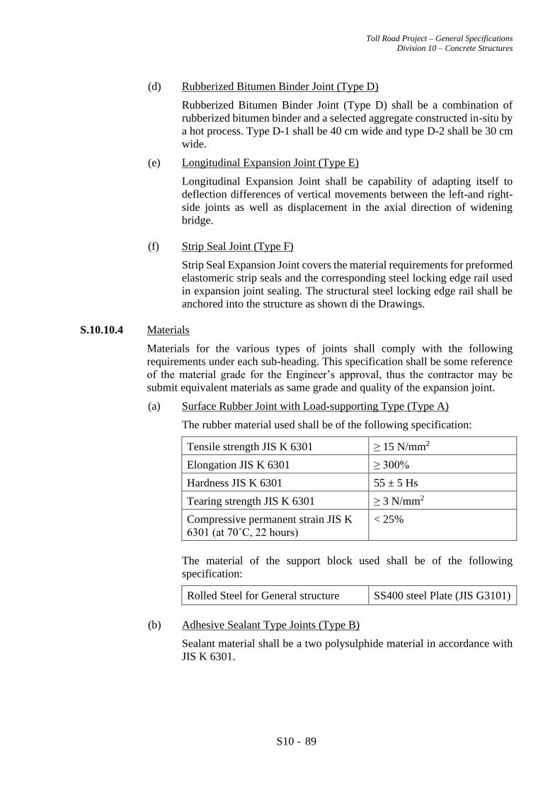
Toll Road Project – General Specifications
Division 10 – Concrete Structures
S10 - 89
(d) Rubberized Bitumen Binder Joint (Type D)
Rubberized Bitumen Binder Joint (Type D) shall be a combination of
rubberized bitumen binder and a selected aggregate constructed in-situ by
a hot process. Type D-1 shall be 40 cm wide and type D-2 shall be 30 cm
wide.
(e) Longitudinal Expansion Joint (Type E)
Longitudinal Expansion Joint shall be capability of adapting itself to
deflection differences of vertical movements between the left-and right-
side joints as well as displacement in the axial direction of widening
bridge.
(f) Strip Seal Joint (Type F)
Strip Seal Expansion Joint covers the material requirements for preformed
elastomeric strip seals and the corresponding steel locking edge rail used
in expansion joint sealing. The structural steel locking edge rail shall be
anchored into the structure as shown di the Drawings.
S.10.10.4 Materials
Materials for the various types of joints shall comply with the following
requirements under each sub-heading. This specification shall be some reference
of the material grade for the Engineer’s approval, thus the contractor may be
submit equivalent materials as same grade and quality of the expansion joint.
(a) Surface Rubber Joint with Load-supporting Type (Type A)
The rubber material used shall be of the following specification:
Tensile strength JIS K 6301 ≥ 15 N/mm2
Elongation JIS K 6301 ≥ 300%
Hardness JIS K 6301 55 ± 5 Hs
Tearing strength JIS K 6301 ≥ 3 N/mm2
Compressive permanent strain JIS K
6301 (at 70˚C, 22 hours)
< 25%
The material of the support block used shall be of the following
specification:
Rolled Steel for General structure SS400 steel Plate (JIS G3101)
(b) Adhesive Sealant Type Joints (Type B)
Sealant material shall be a two polysulphide material in accordance with
JIS K 6301.
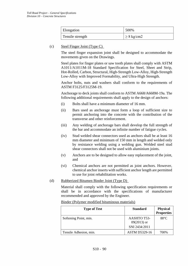
Toll Road Project – General Specifications
Division 10 – Concrete Structures
S10 - 90
Elongation 500%
Tensile strength ≥ 8 kg/cm2
(c) Steel Finger Joint (Type C)
The steel finger expansion joint shall be designed to accommodate the
movements given on the Drawings.
Steel plates for finger plates or saw tooth plates shall comply with ASTM
A1011/A1011M-18 Standard Specification for Steel, Sheet and Strip,
Hot-Rolled, Carbon, Structural, High-Strength Low-Alloy, High-Strength
Low-Alloy with Improved Formability, and Ultra-High Strength.
Anchor bolts, nuts and washers shall conform to the requirements of
ASTM F3125/F3125M-19.
Anchorage to deck joints shall conform to ASTM A668/A668M-19a. The
following additional requirements shall apply to the design of anchors:
(i) Bolts shall have a minimum diameter of 16 mm.
(ii) Bars used as anchorage must form a loop of sufficient size to
permit anchoring into the concrete with the contribution of the
transverse and other reinforcement.
(iii) Any welding of anchorage bars shall develop the full strength of
the bar and accommodate an infinite number of fatigue cycles.
(iv) Stud welded shear connectors used as anchors shall be at least 16
mm diameter and minimum of 150 mm in length and welded only
by resistance welding using a welding gun. Welded steel stud
shear connectors shall not be used with aluminium joints.
(v) Anchors are to be designed to allow easy replacement of the joint,
and
(vi) Chemical anchors are not permitted as joint anchors. However,
chemical anchor inserts with sufficient anchor length are permitted
to use for joint rehabilitation works.
(d) Rubberized Bitumen Binder Joint (Type D)
Material shall comply with the following specification requirements or
shall be in accordance with the specifications of manufacturer
recommended and approved by the Engineer.
Binder (Polymer modified bituminous materials)
Type of Test Standard Physical
Properties
Softening Point, min. AASHTO T53-
09(2013) or
SNI 2434:2011
88°C
Tensile Adhesion, min. ASTM D5329-16 700%
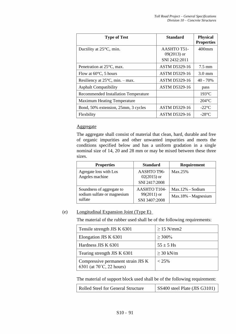
Toll Road Project – General Specifications
Division 10 – Concrete Structures
S10 - 91
Type of Test Standard Physical
Properties
Ductility at 25°C, min. AASHTO T51-
09(2013) or
SNI 2432:2011
400mm
Penetration at 25°C, max. ASTM D5329-16 7.5 mm
Flow at 60°C, 5 hours ASTM D5329-16 3.0 mm
Resiliency at 25°C, min. – max. ASTM D5329-16 40 - 70%
Asphalt Compatibility ASTM D5329-16 pass
Recommended Installation Temperature 193°C
Maximum Heating Temperature 204°C
Bond, 50% extension, 25mm, 3 cycles ASTM D5329-16 -22°C
Flexbility ASTM D5329-16 -28°C
Aggregate
The aggregate shall consist of material that clean, hard, durable and free
of organic impurities and other unwanted impurities and meets the
conditions specified below and has a uniform gradation in a single
nominal size of 14, 20 and 28 mm or may be mixed between these three
sizes.
Properties Standard Requirement
Agregate loss with Los
Angeles machine
AASHTO T96-
02(2015) or
SNI 2417:2008
Max.25%
Soundness of aggregate to
sodium sulfate or magnesium
sulfate
AASHTO T104-
99(2011) or
SNI 3407:2008
Max.12% - Sodium
Max.18% - Magnesium
(e) Longitudinal Expansion Joint (Type E)
The material of the rubber used shall be of the following requirements:
Tensile strength JIS K 6301 ≥ 15 N/mm2
Elongation JIS K 6301 ≥ 300%
Hardness JIS K 6301 55 ± 5 Hs
Tearing strength JIS K 6301 ≥ 30 kN/m
Compressive permanent strain JIS K
6301 (at 70˚C, 22 hours)
< 25%
The material of support block used shall be of the following requirement:
Rolled Steel for General Structure SS400 steel Plate (JIS G3101)
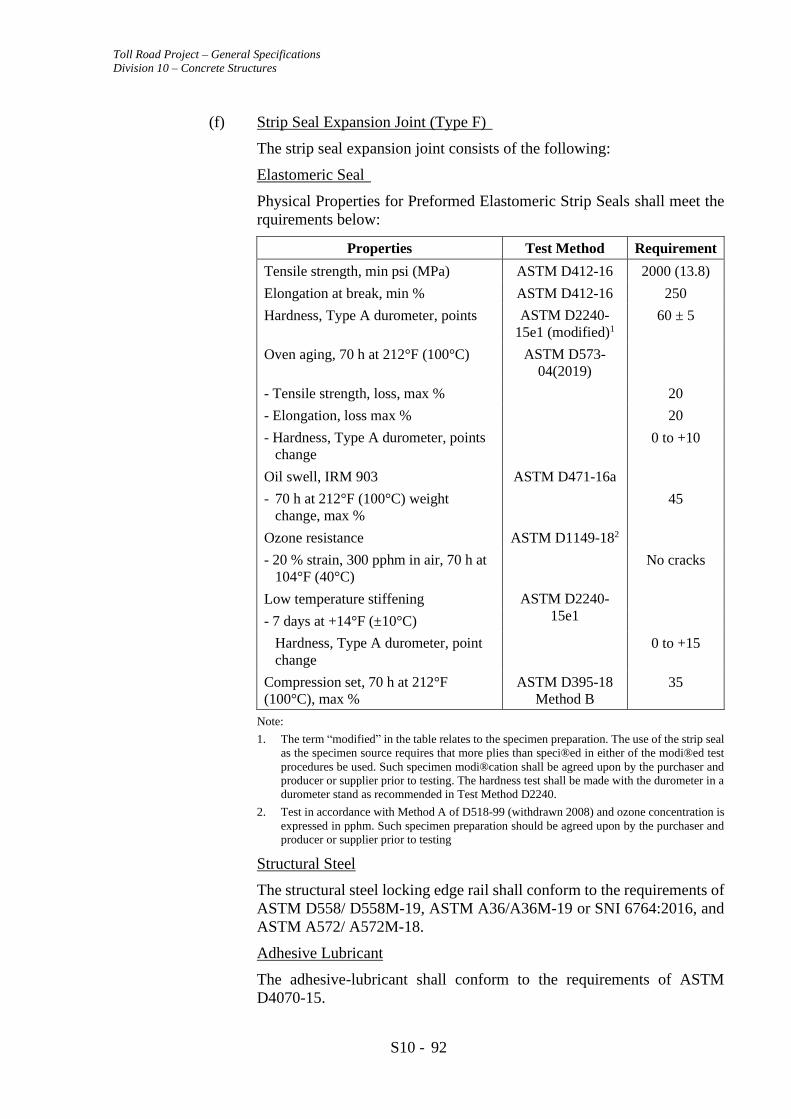
Toll Road Project – General Specifications
Division 10 – Concrete Structures
S10 - 92
(f) Strip Seal Expansion Joint (Type F)
The strip seal expansion joint consists of the following:
Elastomeric Seal
Physical Properties for Preformed Elastomeric Strip Seals shall meet the
rquirements below:
Properties Test Method Requirement
Tensile strength, min psi (MPa) ASTM D412-16 2000 (13.8)
Elongation at break, min % ASTM D412-16 250
Hardness, Type A durometer, points ASTM D2240-
15e1 (modified)1
60 ± 5
Oven aging, 70 h at 212°F (100°C) ASTM D573-
04(2019)
- Tensile strength, loss, max % 20
- Elongation, loss max % 20
- Hardness, Type A durometer, points
change
0 to +10
Oil swell, IRM 903 ASTM D471-16a
- 70 h at 212°F (100°C) weight
change, max %
45
Ozone resistance ASTM D1149-182
- 20 % strain, 300 pphm in air, 70 h at
104°F (40°C)
No cracks
Low temperature stiffening ASTM D2240-
15e1
- 7 days at +14°F (±10°C)
Hardness, Type A durometer, point
change
0 to +15
Compression set, 70 h at 212°F
(100°C), max %
ASTM D395-18
Method B
35
Note:
1. The term “modified” in the table relates to the specimen preparation. The use of the strip seal
as the specimen source requires that more plies than speci®ed in either of the modi®ed test
procedures be used. Such specimen modi®cation shall be agreed upon by the purchaser and
producer or supplier prior to testing. The hardness test shall be made with the durometer in a
durometer stand as recommended in Test Method D2240.
2. Test in accordance with Method A of D518-99 (withdrawn 2008) and ozone concentration is
expressed in pphm. Such specimen preparation should be agreed upon by the purchaser and
producer or supplier prior to testing
Structural Steel
The structural steel locking edge rail shall conform to the requirements of
ASTM D558/ D558M-19, ASTM A36/A36M-19 or SNI 6764:2016, and
ASTM A572/ A572M-18.
Adhesive Lubricant
The adhesive-lubricant shall conform to the requirements of ASTM
D4070-15.
Toll Road Project – General Specifications
Division 10 – Concrete Structures
S10 - 93
S10.10 (5) Construction
(a) Storage and Preparation
Expansion joint material delivered to the bridge site shall be stored under
cover on platforms above the surface of the ground.
It shall be protected at all times from damage, and when placed it shall be
free from dirt, oil, grease or other foreign substance. Premoulded
material shall be used in as large pieces as possible. The material shall
be cut to a clean, true edge with a sharp tool. Rough or ragged edges will
not be permitted. Jointing of adjacent pieces shall be in accordance with
the manufacturer's instructions.
(b) Installation of Rubber Type Joints
(i) General - Expansion joints shall be shaped to the section, and of a
type of material as shown on the Drawings or approved by the
Engineer. The size of the gap shall be compatible with the mean
bridge temperature at the time of installation. This temperature
shall be determined in accordance with arrangements agreed with
the Engineer.
The position of all bolts cast into concrete and all holes shall be
accurately determined from templates. The mixing, application
and curing of all proprietary materials shall comply with the
manufacturer's requirements.
All joints shall be constructed according to physical details shown
on the Drawings or as directed by the Engineer, and strictly in
accordance with the manufacturer's recommendations.
(ii) Placing of epoxy mortar - Placing of epoxy mortar for joint type
A and B shall be executed in 2 (two) stages. Bottom-layer mortar
shall be placed after a primer (epoxy binder) has been applied to
the slab surface and side section of the pavement and the mortar
compacted by means of a vibrator machine to a thickness of 2.0
cm from the pavement level. The top-layer of mortar shall be
placed after embedding the Fibre Reinforced Plastic. The top layer
shall be compacted with a vibrator to level with the surface
pavement. Rough finishing shall be carried out with a wooden
trowel and final finishing with a metallic trowel.
(iii) Prevention of damage - During the placing and hardening of
concrete or mortar under expansion joint components, relative
movement shall be prevented between them and the supports to
which they are being fixed.
When one half of the joint is being set, the other half shall be
completely free from longitudinal restraint. In particular where
strongbacks or templates are used to locate the two sides of a joint
they shall not be fixed simultaneously to both sides. Screw
threads shall be kept clean and free from rust.
Toll Road Project – General Specifications
Division 10 – Concrete Structures
S10 - 94
Ramps shall be provided and maintained to protect all expansion
joints from vehicular loading. Vehicles shall cross the joints only
by means of the ramps until the Engineer permits their removal.
(iv) Time of installation - Setting of expansion joints shall be done
after pavement works on the bridge are finished.
(c) Installation of Rubberized Bitumen Binder Type Joints
Installation shall be carried out complying with the following
requirements, or strictly in accordance with the manufacturer's
instructions.
(i) Time of Installation - Installation of expansion joints shall be
carried out after pavement works on the structure are finished.
(ii) Marking out - The joint shall be marked out to the width shown in
the Drawings or such other width as directed by the Engineer.
(iii) Excavation - The asphalt shall be cut full depth and broken out
carefully by hand or plane to the structure slab ensuring that the
slab concrete is not damaged.
(iv) Cleaning - The entire joint shall be thoroughly cleaned and dried
using a hot compressed air lance immediately prior to filling. All
loose debris shall be removed from the expansion gap.
(v) Caulking - The expansion gap shall be caulked with a tarred hemp
in such a way as to allow 25 mm of binder in the expansion gap
between the top of the arris and the finished level of the caulking
yarn.
(vi) Tanking - The joint shall be coated with a layer of hot binder
immediately after caulking and cleaning.
(vii) Plating - The joint gap shall be covered with an aluminium strip
according to the width and the condition of the gap.
(viii) Material Preparation
- Aggregate - The aggregate shall be dried, cleaned and heated
in a drum mixer by means of hot compressed air. The
aggregate shall be heated to a temperature of ± 150 degrees
Celsius and all visible signs of dust shall be removed.
- Binder - The binder shall be heated by means of a sealant pre-
heater to a temperature of 170 - 190 degrees Celsius.
(ix) Material Installation - Layers of hot stone not less than 20 and not
more than 40 mm thick shall be placed in the trench and
immediately flooded with hot binder. Each layer shall be raked to
ensure that the stone is fully coated and voids filled. This process
shall stop approximately 25 mm from the top of the excavation for
application of the final surface layer.
(x) Surface Layer - Hot pre-mixed prepared material shall be
transferred to the joint and spread to a slight overfill.
Toll Road Project – General Specifications
Division 10 – Concrete Structures
S10 - 95
(xi) Compaction - The material shall be compacted as soon as possible
after filling using a vibrator plate or roller which shall be pre-
wetted. At least 3 passes shall be carried out to bring the joint to
the existing road surface.
(xii) Screeding/Finishing Work - The surface of the joint and the
surrounding road shall be dried and cleaned with a hot compressed
air lance prior to the final screeding. Immediately thereafter a
single hot binder layer shall be applied to fill all surface voids.
S10.10 (6) Method of Measurement
The quantities to be paid for shall be the actual number of linear meters of
expansion joints completed in place in accordance with the Drawings.
Sealant and back up form of foamed polystyrene or similar material used in
adjacent curbs and parapet walls will not be measured separately for payment.
S10.10 (7) Basis of Payment
The quantities, measured as specified above, shall be paid for at the Contract price
per unit of measurement, respectively, for each of the particular pay items listed
below, which price and payment shall constitute full compensation for all cutting
and excavation of pavement, formation of construction joint with existing
concrete and for all labour and equipment, furnishing of materials including
epoxy concrete, epoxy mortar, fibre reinforced plastic, reinforcement, concrete,
binder and aggregate, fabricating, transporting, painting, setting expansion joints,
and for other incidentals. Payment for expansion joints will be deemed to
include the cost of sealant used in adjacent works and parapets.
Pay Item No. and Name Unit of Measurement
10.10 (1) Expansion Joint Type A (Surface Rubber Linear Meter
Joint with Load - supporting Type)
10.10 (2) Expansion Joint Type B (Adhesive Linear Meter
Sealant Joint)
10.10 (3) Expansion Joint Type C-1 (Steel Finger
60 mm) Linear Meter
10.10 (3a) Expansion Joint Type C-1 (Steel Finger
20 mm) Linear Meter
10.10 (3b) Expansion Joint Type C-1 (Steel Finger
50 mm) Linear Meter
10.10 (4) Expansion Joint Type C-2 (Steel Finger Linear Meter
Joint 175 mm)
10.10 (5) Expansion Joint Type C-3 (Steel Finger Linear Meter
Joint 220 mm)
10.10 (6a) Expansion Joint Type D-1 (Rubberized Linear Meter
Bitumen Binder Type 40 cm)
Toll Road Project – General Specifications
Division 10 – Concrete Structures
S10 - 96
10.10 (6b) Expansion Joint Type D-2 (Rubberized Linear Meter
Bitumen Binder Type 30 cm)
10.10 (6c) Expansion Joint Type D-3 (Rubberized Linear Meter
Bitumen Binder Type 50 cm)
10.10 (6d) Expansion Joint Type D-4 (Rubberized Linear Meter
Bitumen Binder Type 15 cm)
10.10 (7) Expansion Joint Type E (Longitudinal Linear Meter
Expansion Joint)
10.10 (8) Expansion Joint Type F (Strip Seal Joint) Linear Meter
S10.11 Bridge Bearings
S10.11 (1) Description
This work shall consist of furnishing and installing bearing shoes and bearing
pads for bridge superstructure, piled slab and extended pile structure and rubber
sheet for RC frame and approach slab.
S10.11 (2) Materials
(a) Bearing Shoes
Material for bearing shoes of general type shall conform to the following:
JIS G 3101 : Rolled Steel for General Structure SS 400
JIS G 5101 : Carbon Steel Castings - SC 450
JIS G 5102 : High Strength Brass Castings-HBsC3
The Contractor shall have the Engineer's approval prior to furnishing
bearing shoes.
(b) Bearing Pads
Elastomeric bearing pads shall conform to AASHTO M251-06(2011).
Bearing pads shall consist of alternative laminations of elastomer and
metal bonded together, and shall conform to the following design
requirements:
Durometer Hardness : 53
Bearing stress : 5.0 – 10.0 N/mm2
Shearing Modulus : 0.69 N/mm2
Bulk Modulus : 2000 N/mm2
The elastomer portion of the elastomeric compound will be a 100 percent
virgin chloroprene meeting the requirements of Column B of Table 10-
11-1, which shall be referred to unless in conflict with AASHTO M251-
06(2011).
Laminates shall be rolled mild steel sheets embedded by a minimum of
3.2 mm of elastomer.
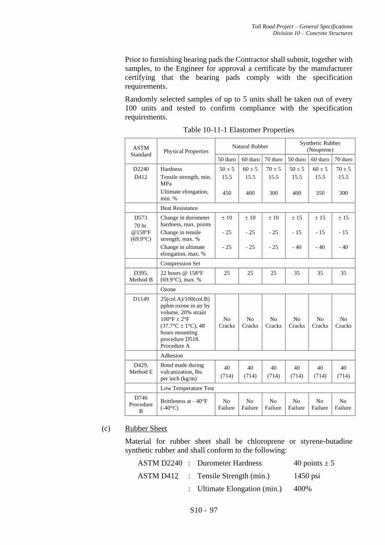
Toll Road Project – General Specifications
Division 10 – Concrete Structures
S10 - 97
Prior to furnishing bearing pads the Contractor shall submit, together with
samples, to the Engineer for approval a certificate by the manufacturer
certifying that the bearing pads comply with the specification
requirements.
Randomly selected samples of up to 5 units shall be taken out of every
100 units and tested to confirm compliance with the specification
requirements.
Table 10-11-1 Elastomer Properties
ASTM
Standard Physical Properties
Natural Rubber Synthetic Rubber
(Neoprene)
50 duro 60 duro 70 duro 50 duro 60 duro 70 duro
D2240
D412
Hardness
Tensile strength, min.
MPa
Ultimate elongation,
min. %
50 ± 5
15.5
450
60 ± 5
15.5
400
70 ± 5
15.5
300
50 ± 5
15.5
400
60 ± 5
15.5
350
70 ± 5
15.5
300
Heat Resistance
D573
70 hr.
@158°F
(69.9°C)
Change in durometer
hardness, max. points
Change in tensile
strength, max. %
Change in ultimate
elongation, max. %
± 10
- 25
- 25
± 10
- 25
- 25
± 10
- 25
- 25
± 15
- 15
- 40
± 15
- 15
- 40
± 15
- 15
- 40
Compression Set
D395,
Method B
22 hours @ 158°F
(69.9°C), max. %
25 25 25 35 35 35
Ozone
D1149 25(col.A)/100(col.B)
pphm ozone in air by
volume, 20% strain
100°F ± 2°F
(37.7°C ± 1°C), 48
hours mounting
procedure D518.
Procedure A
No
Cracks
No
Cracks
No
Cracks
No
Cracks
No
Cracks
No
Cracks
Adhesion
D429,
Method E
Bond made during
vulcanization, lbs.
per inch (kg/m)
40
(714)
40
(714)
40
(714)
40
(714)
40
(714)
40
(714)
Low Temperature Test
D746
Procedure
B
Brittleness at - 40°F
(-40°C)
No
Failure
No
Failure
No
Failure
No
Failure
No
Failure
No
Failure
(c) Rubber Sheet
Material for rubber sheet shall be chloroprene or styrene-butadine
synthetic rubber and shall conform to the following:
ASTM D2240 : Durometer Hardness 40 points ± 5
ASTM D412 : Tensile Strength (min.) 1450 psi
: Ultimate Elongation (min.) 400%
Toll Road Project – General Specifications
Division 10 – Concrete Structures
S10 - 98
Prior to furnishing rubber sheet the Contractor shall submit to the
Engineer for approval a certificate by the manufacturer certifying that the
rubber sheet complies with the specification requirements.
(d) Anchor Bar
Anchor bar shall be made from steel JIS G3101 Grade SS400 or
equivalent
S10.11 (3) Construction
(a) Bearing Shoes
(i) Bearing shoes shall be accurately set in the specified position. The
shoes shall be set before construction of superstructure members
unless otherwise approved by the Engineer. This setting work shall
be carefully done with non-shrink mortar so that the bottom of
bearing shoes will adhere tightly to the top of the pier or abutment.
(ii) Placing anchor bolts - Reference is made to Sub-clause S10.01 (4)
(f) (xi).
(b) Bearing Pads
The bearing pads shall be installed in the appropriate setting as directed
by the Engineer or shown on the Drawings.
When they are set on thin beds of cement mortar, the mortar shall be cured
and allowed to develop sufficient strength before the beams are erected.
The bearing pads shall be maintained in their correct position during the
placing of the beams. After the beam has been completed, each bearing
and the area around it shall be left clean.
(c) Rubber Sheet
The rubber sheet shall be set at the Mesnager hinge (concrete hinge) of
continuous slab bridges at the end of RC frames and at the approach slabs
as shown on the Drawings or directed by the Engineer.
S10.11 (4) Method of Measurement
(a) Bearing Shoes
The quantities of bearing shoes shall be measured by the number of each
type completed in place and accepted.
The classification of bearing shoes shall be as follows:
Type Design Load (P)
Type A; 125 ton (Movable Bearing)
Type B; 150 ton (Movable Bearing)
Type C; 175 ton (Movable Bearing)
Type D; 275 ton (Movable Bearing)
Type E; 450 ton (Movable Bearing)
Type F; 450 ton (Fixed Bearing)
Type G; 162 ton (Movable Bearing)
Type H; 175 ton (Fixed Bearing)
Toll Road Project – General Specifications
Division 10 – Concrete Structures
S10 - 99
Type I; 200 ton (Movable Bearing)
Type J; 300 ton (Movable Bearing)
Type K; 300 ton (Fixed Bearing)
Type L; 350 ton (Fixed Bearing)
(b) Rubber Sheet
The quantities of rubber sheet shall be measured by the number or linear
meters completed in place and accepted.
(c) Bearing Pads
The quantities of bearing pads shall be measured by the number of each
type completed in place in accordance with the Drawings.
The classification of bearing pads shall be as follows:
Type Design Load Allowable Shear Deformation
Type A;
Type B;
Type C;
Type D;
Type E;
Type F;
Type G;
Type H;
Type I;
Type J;
Type K-1;
Type K-2;
60 tons
70 tons
70 tons
85 tons
110 tons
70 tons
95 tons
110 tons
150 tons
125 tons
35 tons
35 tons
20 mm
20 mm
22 mm
22 mm
22 mm
25 mm
25 mm
25 mm
25 mm
29 mm
15 mm
15 mm
(d) Anchor Bar
The quantities of anchor bar shall be measured for payment based on the
weight of the anchor bar excluding the accessories, payment for wich is
included with the anchor bar.
S10.11 (5) Basis of Payment
The work measured as provided above will be paid for at the Contract unit price
respectively. The payment shall consist of full compensation for furnishing,
fabricating, transporting, painting, random sample testing and placing all
materials including all labour, tools, equipment, and incidentals necessary to
complete the work prescribed. Details of necessary accessories are shown on the
Drawings, and includes anchor bar and cap, and reinforcement, etc.
Pay Item No. and Name Unit of Measurement
10.11(1) Elastomeric Bearing Pad Each
460 x 550 x 75 (Mov.)
10.11(2) Elastomeric Bearing Pad Each
450 x 520 x 75 (Mov.)
10.11(3) Elastomeric Bearing Pad Each
420 x 500 x 75 (Mov.)

Toll Road Project – General Specifications
Division 10 – Concrete Structures
S10 - 100
10.11(4a) Elastomeric Bearing Pad Each
400 x 450 x 75 (Mov.)
10.11(4b) Elastomeric Bearing Pad Each
450 x 450 x 76 (Mov.)
10.11(5a) Elastomeric Bearing Pad Each
450 x 450 x 76 (Fix)
10.11(5b) Elastomeric Bearing Pad Each
460 x 550 x 49 (Fix)
10.11(6) Elastomeric Bearing Pad Each
450 x 520 x 49 (Fix)
10.11(7) Elastomeric Bearing Pad Each
420 x 500 x 49 (Fix)
10.11(8) Elastomeric Bearing Pad Each
400 x 450 x 49 (Fix)
10.11(8a) Elastomeric Bearing Pad Each
300 x 350 x 39 (Mov.) (for RCI-Girder )
10.11(8b) Elastomeric Bearing Pad Each
300 x 350 x 26 (Fix) (for RCI-Girder)
10.11(9) Elastomeric Bearing Pad Each
450 x 550 x 83 (Mov.)
10.11(10a) Elastomeric Bearing Pad Each
600 x 600 x 83 (Mov.)
10.11(10b) Elastomeric Bearing Pad Each
600 x 600 x 83 (Fix.)
10.11(11) Elastomeric Bearing Pad Each
400 x 450 x 83 (Mov.)
10.11(12) Elastomeric Bearing Pad Each
700 x 750 x 48 (Fix)
10.11(13) Elastomeric Bearing Pad Each
850 x 850 x 52 (Fix)
10.11(14) Elastomeric Bearing Pad Each
650 x 650 x 52 (Fix)
10.11(15) Elastomeric Bearing Pad Each
300 x 350 x 36 (Mov.)
10.11(16) Elastomeric Bearing Pad Each
350 x 400 x 40 (Mov.)
10.11(17) Elastomeric Bearing Pad Each
450 x 500 x 60 (Mov.)
10.11(18) Elastomeric Bearing Pad Each
300 x 350 x 36 (Fix.)
Toll Road Project – General Specifications
Division 10 – Concrete Structures
S10 - 101
10.11(19) Elastomeric Bearing Pad Each
350 x 400 x 40 (Fix.)
10.11(20) Elastomeric Bearing Pad Each
450 x 500 x 60 (Fix.)
10.11(21) Elastomeric Bearing Pad Each
350 x 400 x 52 (Mov.)
10.11(22) Elastomeric Bearing Pad Each
350 x 400 x 52 (Fix.)
10.11(22a) Elastomeric Bearing Pad Each
450 x 400 x 52 (Mov.)
10.11(22b) Elastomeric Bearing Pad Each
450 x 400 x 52 (Fix.)
10.11(23) Elastomeric Bearing Pad Each
for PC Void 100 x 500 x 29 (Fix)
10.11(24) Elastomeric Bearing Pad Each
for PC Void 100 x 500 x 38(Move)
10.11(25) Rubber Bearing Sheet 200 x 200 x 20 Each
10.11(26a) Rubber Bearing Sheet 200x20 Linear Meter
10.11(26b) Rubber Bearing Sheet 250x25 Linear Meter
10.11(27) Anchor Bar with Accessories Kg
10.11(28) Elastomeric Bearing Shoe for Each
Steel Girder 7,400kN (Fix)
10.11(29) Elastomeric Bearing Shoe for Each
Steel Girder 8,800kN (Fix)
10.11(30) Elastomeric Bearing Shoe for Each
Steel Girder 7,200kN (Fix)
10.11(31) Elastomeric Bearing Shoe for Each
Steel Girder 8,200kN (Fix)
10.11(32) Elastomeric Bearing Shoe for Each
Steel Girder 4,200kN (Move)
10.11(33) Elastomeric Bearing Shoe for Each
Steel Girder 4,200kN (Fix)
10.11(34) Elastomeric Bearing Shoe for Each
Steel Girder 4,000kN (Move)
10.11(35) Elastomeric Bearing Shoe for Each
Steel Girder 4,000kN (Fix)
10.11(36) Elastomeric Bearing Shoe for Each
Steel Girder 3,800kN (Move)
10.11(37) Elastomeric Bearing Shoe for Each
Steel Girder 3,800kN (Fix)
Toll Road Project – General Specifications
Division 10 – Concrete Structures
S10 - 102
10.11(38) Elastomeric Bearing Shoe for Each
Steel Girder 3,400kN (Fix)
10.11(39) Elastomeric Bearing Shoe for Each
Steel Girder 1,800kN (Mov.)
10.11(40) Elastomeric Bearing Shoe for Each
Steel Girder 2,000kN (Move)
10.11(41) Elastomeric Bearing Shoe for Each
Steel Girder 1,800kN (Fix)
10.11(42) Elastomeric Bearing Shoe for Each
Steel Girder 4,700kN (Fix)
10.11(43) Elastomeric Bearing Shoe for Each
Steel Girder 4,700kN (Mov.)
10.11(44) Pot Bearing ,1900/220/80 kN Each
S10.12 Other Incidental Bridge Facilities
S10.12 (1) Description
This work shall consist of the furnishing and installation of drainage facilities and
pull boxes for bridges, RC frames and other incidental bridge facilities. All work
shall be done in strict accordance with the Drawings and these Specifications and
as directed by the Engineer.
S10.12 (2) Material
(a) Drain pipe material shall conform to the requirements of SNI 06-0162-
1987 and SNI 06-0178-1987 or comply to ASTM D2665-14 with basic
material of virgin PVC compounds which conform to Class 12454 as
specified in ASTM D1784-11. Deck drain material shall conform to the
requirements of JIS G 5101 (Carbon Steel Castings), JIS G 5501 (Grey
Iron Castings), and JIS G 3101 (Rolled Steel for General Structures:
SS41). Cast metal deck drain material shall be painted three coats tar
epoxy resin paint, each coat thickness 80 µm, and support brackets and
other accessories shall be galvanised, all in accordance with Clause
S12.18 of these Specifications.
(b) Pull box material shall conform to the requirements of JIS G 3101 (Rolled
Steel for General Structures: SS41) and shall be galvanised in accordance
with Clause S12.18 of these Specifications.
S10.12 (3) Construction
(a) Drainage Facilities
(i) Drain pipes, catch basin and deck drains that are to be encased in
concrete shall be installed by the Contractor as indicated on the
Drawings.
Toll Road Project – General Specifications
Division 10 – Concrete Structures
S10 - 103
(ii) Drain pipes shall be fixed as indicated on the Drawings or as
directed by the Engineer.
(b) Pull Box
Pull boxes and conduit for lighting in bridge parapets shall be installed as
indicated on the Drawings, or directed by the Engineer, before the
concrete is placed. After concrete hardens it shall be checked that pull
boxes can open freely.
(c) Name Plate
The type and the material of name plate shall conform to the requirements
as directed by the Engineer.
S10.12 (4) Method of Measurement
The quantities of drain pipe to be paid for will be the number of linear meters
measured along the central lines of pipe runs and no extra measurement will be
made for bends or junction pieces.
The quantities of deck drain to be paid for shall be measured by the number of
each type, completed in place and accepted.
The quantities of name plate to be paid for shall be by the number of each
furnished, installed and accepted as directed by the Engineer.
Pull boxes and conduits for electrical work will be measured and paid for under
Division 13 of these Specifications.
S10.12 (5) Basis of Payment
The quantities, measured as specified above, will be paid for at the Contract unit
price per linear meter of drain pipes and per number of deck drains and name
plates.
Drain pipe shall be 20 cm and 15 cm diameter. Payment for drain pipe and deck
drain will be deemed to include for all fittings and supports necessary to install
the drains in accordance with the details shown on the Drawings.
The prices and payment for the above items shall be considered full compensation
for labour, tools and equipment, furnishing of materials, fabricating, transporting,
and setting of each item and all other incidental works connected therewith.
Pay Item No. and Name Unit of Measurement
10.12(1) Drain Pipe D=20cm Linear Meter
with Fitting and Supports
10.12(2) Drain Pipe D=15cm Linear Meter
with Fitting and Supports
10.12(3) Deck Drain Type 1 with Accessories Each
10.12(4) Deck Drain Type 2 with Accessories Each
Toll Road Project – General Specifications
Division 10 – Concrete Structures
S10 - 104
S10.13 Prestressed Concrete Corrugated Sheet Pile
S10.13 (1) Description
This work shall consist of Prestressed Concrete Corrugated Sheet Pile furnished
and driven in accordance with this Specifications and in reasonably close
conformity to the Drawings.
S10.13 (2) Material
(a) General
Prestressed concrete corrugated sheet piles shall be constructed in
accordance with the details shown on the Drawings and to the
requirements of JIS A 5326, Prestressed Concrete Sheet Pile.
The applicable provisions of Clause S10.03 shall be read into and become
part of this Clause.
(b) Concrete
Concrete shall comply with the provisions of Clause S10.01 of these
Specifications and as shown in the Drawings.
(c) Reinforcement
Reinforcement shall comply with the provisions of Clause S10.02 of these
Specifications and shall be positioned as shown on the Drawings.
(d) Prestressing Steel
High tensile steel prestressing wire shall conform to the requirements of
JIS G 3536 Class SWPR 1 135/155.
(e) Certificate
The Contractor shall submit a certificated by the manufacturer to the
Engineer for approval prior to furnishing pretensioned corrugated
concrete sheet pile.
(f) Tie Rod
Reinforcement bar which conforms the requirements of SNI 2052:2017
or AASHTO M31M/M31-19, minimum grade BjTS 420a, D32 shall be
used as Tie Rods.
Coating - Tie rods shall be coated by epoxy zinc rich anti-corrosion primer
which conforms the requirements of BS4652 – specification for metallic
zinc-rich priming paint or BS5493 – Code of practice for protective
coating of iron and steel structures against corrosion.
S10.13 (3) Construction
(a) Preparation for Driving (in case of Water jet type)
(i) The Contractor shall install guide frame for PC Sheet Piles.The
usual method of guide frame installation is to provide two
horizontal runs of steel section secured at adequate convenient
intervals. The structure of guide frame shall be of adequate
proportion to ensure that PC Sheet Piles are rigidly support during
Toll Road Project – General Specifications
Division 10 – Concrete Structures
S10 - 105
driving.
(ii) Connect the top of jetting pipe (which is installed inside the PC
Sheet Pile) with the delivery hoses of water jet, insure that pipes
& nozzle in good condition.
(iii) The PC Sheet Piles (which has been connected to the water jet
cutter) is lifted and slotted in it’s position. Hold the pile tip at about
25 cm above driving ditch/ground. Then secure the pile by using
lever block.
(iv) Start water jet cutter machine, check the water pressure at certain
level.
(v) Connect vibro hammer on the upper part of the PC Sheet Pile,
check grip pressure, activate vibro then drive.Check vertically and
longitudinal alignment during driving by lead or theodolite.
(vi) Driving will be terminated when the top of the PC Sheet Pile
reaches the design level. (the water jet cutter shall be stopped at
0.5~1m before reaching final level of the PC Sheet Pile).
(vii) Release the vibro hammer and disconnect the delivery hoses of
water jet cutter from the jetting pipes in the PC Sheet Pile, Start all
over again.
(b) Handling, Pitching and Driving
(i) General – When raising or transporting sheet piles the Contractor
shall provide slings and other equipment necessary to prevent any
appreciable bending of the pile.
The main setting out for the piles is to be completed prior to
commencement of driving. Secondary or individual pile setting
out is to be completed and agreed not less than 8 hours prior to
commencing work on the pile concerned. All main setting out
points, lines and stations are to be maintained safe and undisturbed
until the work is complete.
Sheet piles shall be pitched accurately in the positions and driven
to the lines shown on the Drawings or fixed by the Enginner. Sheet
piles deflected from vertical or proper line shall, where ordered by
the Engineer, be withdrawn and repatched until the proper line is
obtained.
No forcible method of correction of the position or line of any pile
will be permitted. Any pile damaged by reason of improper driving
or driven out of its proper location or driven below the elevation
fixed by the Drawing or by the Engineer, shall be corrected at the
contractor’s expense by one of the following methods approved
by the Engineer for the pile in question:
(c) Water Supply
(i) PC Corrugated Sheet Pile shall drive using water jet to open soil
beneath pile tip and to avoid friction against PC Sheet Pile, so that
PC Sheet Pile not compacting the soil and penetration will be
Toll Road Project – General Specifications
Division 10 – Concrete Structures
S10 - 106
easier.
(ii) In hard soil, water jet will break out particle or soften soil to let PC
Sheet Pile hammered the layer.
(iii) Mud and fine particle will flow out from PC Sheet Pile side due to
vibration (pumping action of vibro hammer). Water consumption
at about 20 ~ 30 m3/day according to soil condition.
(iv) To accommodate mud, fine particle and waste-water, driving ditch
shall be constructed accordingly.
(v) Mud and waste-water may not higher than guide frame.
(vi) Water pressure (low/high) 70~150 Kg/cm2.
(vii) The Contractor may not cut off the sheet piles less than that shown
on the Drawings. The Engineer will specify the soil condition and
the Contractor shall drive the all length of sheet piles.
(d) Tie Rod
Tie rods shall be coated by the epoxy zinc rich anti-corrosion primer. The
coating material shall be applied to the tie rods in sufficient thickness
without pin holes or other defects. If any doubt exists about having
achieved an unbroken coating, a second application should be made as
soon as possible the first coating is fully dry. Forced ventilation in
confined areas shall be provided during application and curing.
S10.13 (4) Method of Measurement
(a) Sheet Piles Furnished
The unit of measurement for payment for furnishing pretensioned
concrete sheet piles shall be the linear metres, furnished in compliance
with the Engineer’s instructions and the material requirements of these
specification and stockpiled in good condition at the site of the work by
the Contractor, and accepted by the Engineer. No allowance will be made
for the length of sheet pile furnished by the Contractor to replace pile
previously accepted by the Engineer that are subsequently lost or those
that are damaged prior to completion of the Contract while in the
stockpile, or during handling or driving, and are ordered by the Engineer
to be removed from the site of the work or disposed of otherwise.
All Sheet Pile surface that will be exposed to the air shall be covered by
the Aluminium Composite Panel. The details shall be approved by the
Engineer before orders are given to the suppliers or manufacturers.
In areas with tie rods, Sheet Piles shall be manufactured with anchor holes
to tie up the sheet piles with the tie rods. The details are shown in the
drawings.
Capping beam concrete and reinforcements will be measured and paid for
under the other pay items in this specification.
(b) Piles Driven
The quantities of driven pretensioned concrete sheet piles to be paid for
Toll Road Project – General Specifications
Division 10 – Concrete Structures
S10 - 107
shall be the number of linear metres of piles actually driven and accepted.
The pay lengths of the satisfactorily driven piles shall be measured from
the tip to the ground surface. Total length of sheet pile will not be
measured for payment.
S10.13 (5) Basis of Payment
The work measured as provided above shall be paid for at the Contract unit
price per linear metre for the particular pay items listed below. The rate shall
constitute full compensation for all materials including prestressing,
reinforcement and high pressure pipes, water jet equipments, hardware,
furnishing, driving, guide beam, support frames, jetting, welding and all related
tools, rigs, cranes, bolts, hammers, jets, labour and other incidental equipment and
work
Tie rods are measured and shall be paid for at the contract unit price per kg for
the particular pay items listed below. The rate shall constitute full compensation
for all materials including epoxy zinc rich anti corrosion primer, materials to tie
the tie rods up to the sheet pile that is shown on the drawings, covering mortal of
tie rods ends, and any other necessary materials in the relevant drawings,
necessary equipments, labours, and works until the requested setting is fully
completed.
No payment shall be made for unauthorized, defective, unsound or
unsatisfactorily driven piles or for any costs incurred by the Contractor for such
piles.
Pay Item No. and Name Unit of Measurement
10.13 (1) Prestressed Concrete Corrugated Linear Meter
Sheet Pile W 325A, furnished
10.13 (2) Prestressed Concrete Corrugated Linear Meter
Sheet pile W 325A, driven

Toll Road Project – General Specifications
Division 10 – Concrete Structures
S10 - 108
Toll Road Project – General Specifications
Division 11 – Structural Steel Work
GS11 - 1
DIVISION 11 STRUCTURAL STEEL WORK
S11.01 Bridge Steel Work
S11.01 (1) General
(a) Description
This work consists of steel structures and the steel portions of composite
structures, constructed in close conformity to the lines, grades and
dimensions shown on the Drawings or established by the Engineer. It shall
cover completely new construction and the widening and repair of
existing structures. The work shall include the furnishing, fabricating,
erecting, galvanizing or painting of structural metal as required in these
Specifications or as shown on the Drawings. Structural metals shall
include structural steel, rivets, welding, special and alloy steels, metallic
electrodes and steel forgings and castings. This work shall also include
any incidental metal construction not otherwise provided for, all in
accordance with these Specifications and with the Drawings.
(b) Reference Standards
Standar Nasional Indonesia (SNI) :
SNI ASTM A325:2012 : Spesifikasi baut baja hasil perlakuan
panas dengan kuat tarik minimum 830
MPa (ASTM A325M-04, IDT).
SNI 07-0722-1989 : Baja canai panas untuk konstruksi umum
SNI 07-3015-1992 : Baja canai panas untuk konstruksi dengan
pengelasan.
SNI 6764:2016 : Spesifikasi baja karbon struktural (ASTM
A36/A36M-12, IDT).
SNI 8458:2017 : Metode uji pengencangan baut mutu
tinggi.
SE No.14/SE/M/2015 : Pedoman Pemasangan Baut Jembatan.
AASHTO:
AASHTO M111M/M111-15 : Zinc (Hot-Dip Galvanized) Coatings on
Iron and Steel Products.
AASHTO M169-15 : Steel Bars, Carbon, Cold Finished,
Standard Quality
AASHTO M270M/M270-15 : Carbon and High-strength Low-Alloy
Structural Steel Shapes, Plates, and Bars
and Quenched-and-Tempered Alloy
Structural Steel Plates for Bridges.
ASTM:
ASTM A307-14e1 : Standard Specification for Carbon Steel
Bolts, Studs, and Threaded Rod 60,000
PSI Tensile Strength
Toll Road Project – General Specifications
Division 11 – Structural Steel Work
GS11 - 2
ASTM F3125/F3125M-15a : Standard Specification for High Strength
Structural Bolts, Steel and Alloy Steel,
Heat Treated, 120 ksi (830 MPa) and 150
ksi (1040 MPa) Minimum Tensile
Strength, Inch and Metric Dimensions.
American Welding Society (AWS):
AWS D1.1/D1.1M:2015 : Structural Welding Code – Steel
AWS D1.5M/D1.5:2015 : Bridge Welding Code.
If not otherwise indicated on the Drawings, the fabrication and erection of
the steel superstructure shall conform to the requirements of AASHTO's
Standard Specifications for Highway Bridges and AWS D1.1/D1.1M:
2015, Structural Welding Code, and Standard Specifications for
Construction of Roads and Bridges on Federal Highway Projects, FP-14
(2014), Division 550, Section 555, PP 436 - 452.
In case of conflict between the above referenced specifications and this
Specification, this Specification shall govern.
(c) Testing and Inspection
(i) Inspection Authority
The Employer has the right to appoint an Inspection Authority to
inspect, examine and test materials, workmanship and
performance of any part of the works at the manufacturer's works
or the site of fabrication. The Inspection Authority will be selected
by the Employer but all fees and expenses for this work will be
paid by the Contractor and will be deemed to be included in the
unit prices for this work. Should the Employer decide to waive
his right to appoint an Inspection Authority this will be notified at
the time of bidding.
The Inspection Authority shall take instructions from the Engineer
and his representatives and shall submit monthly reports to the
Engineer. The Inspection Authority will certify that all works up
to the stage of fabrication shop painting after trial assemblage,
have been carried out in accordance with these specifications and
the approved shop Drawings. Certain authority of the Engineer
will be delegated to the Inspection Authority, for the purpose of
quality control and testing. The limits of this Authority will be
notified to the Contractor in writing when the Inspection Authority
is appointed.
The Inspection Authority's certificates shall not relieve the
Contractor of any of his obligations under the contract.
(ii) Inspection by the Contractor
Irrespective of the appointment of an Inspection Authority, the
Contractor shall himself inspect or have inspected all materials,
shop work and field work to determine that the requirements of the
Toll Road Project – General Specifications
Division 11 – Structural Steel Work
GS11 - 3
Drawings and Specifications are met and that the Works are
carried out in a first-class and workmanlike manner.
The Contractor shall provide the necessary assistants, labor,
materials, electricity, fuel, stores, apparatus and instruments and
any other materials required to ensure that all testing and
inspection by the Engineer or the Inspection Authority can be
carried out efficiently.
(d) Submittals
(i) Overall Schedule
Before any technical submittals are made, the Contractor shall
submit his proposed schedule for all shop drawing submissions,
materials submissions, and fabrication processes. In this
schedule, the Contractor shall allow the Engineer 4 weeks from
receipt of any submittal or resubmittal, for his review.
(ii) Approval of the Engineer
The Contractor shall not proceed with any purchase or fabrication
of materials until the relevant shop drawings have been approved
by the Engineer.
(iii) Materials
Prior to the use of any materials, the Contractor shall submit for
the Engineer's approval, 2 copies of the Manufacture's certificates
for:
- bolts, nuts, washers, and filler for welding.
- mill test certificates for structural steel. These shall include
the names and locations of steel mills, analysis of chemical and
physical properties, and shall be properly correlated to the
various grades of structural steel to be used in the project.
(iv) Welding Plan
The Contractor shall not proceed with any welding until the
Engineer has approved his Welding Plan which shall include the
following.
- All information on welding procedures, equipment, additives
and preheating during the welding operations.
- Details of non-destructive testing methods to be used for
specific typical joints.
- Precautions with regard to welding shrinkage.
- Possible treatment of completed welds by grinding with
indication of grinding direction, etc.
- Procedures and program of welding sequence (for each
component and for welding components together). After
approval of this submittal, welding procedures and sequences
shall be followed without deviation.
Toll Road Project – General Specifications
Division 11 – Structural Steel Work
GS11 - 4
The Engineer will require confirmation as to the suitability of the
details contained in the welding plan, by tests as prescribed in the
AWS "Standard Qualification Procedure".
(v) Painting Plan
The Contractor shall in ample time before the commencement of
the surface treatment, prepare and submit for approval a detailed
program relating to the execution of the works, in the workshop,
at the site, etc., as well as the methods used, and a time schedule
for the individual treatments. The program shall be subject to
approval by the Engineer.
(vi) Erection Plan
Prior to the start of Fabrication, the Contractor shall submit for the
Engineer's approval a full description of his proposed erection
method including:
- sequence of erection
- use of temporary or permanent stanchions, beams and bracing
- connection details
- erection camber diagrams to show the vertical position of the
structure at each stage of the erection process
- design calculation to cover the various stages in the erection
process
- type of equipment to be used during erection.
The Engineer's approval of the above details will not relieve the
Contractor of his contractual obligations or of his responsibility
for providing proper methods, equipment, workmanship and
safety precautions.
(vii) Painting Certification
The Contractor shall submit to the Engineer, 2 copies of
certification stating that requirements pertaining to preprint
cleaning and painting of steel have been performed in accordance
with the specifications.
(viii) Connection Records
The Contractor shall maintain records of shop welding procedures,
welders employed with date of qualification and identification
symbol. Records shall also be maintained of all bolts tested and
the corresponding torque values if torque control is used. These
records shall be freely available for the use of the Inspection
Authority and shall be submitted to the Engineer on completion of
all shop fabrication work.
(ix) As-built Drawings
Within 4 weeks of completion of the related works, the Contractor
shall submit 1 softcopy and 2 prints of the as-built drawings.
Toll Road Project – General Specifications
Division 11 – Structural Steel Work
GS11 - 5
These drawings shall include details of actual camber achieved,
details of temporary bracings left in the works, etc.
(e) Matters to be considered by the Contractor
In this preparation of shop drawings and in all his fabrication works the
Contractor shall give careful consideration to the following:
(i) the need for trial assemblage at the fabrication shop
(ii) problems on the weight and size of elements for transportation
between fabrication yard and the construction site
(iii) temperature variation between the fabrication yard and the site
temperature of 28 degrees Centigrade, assumed for the purposes
of the Drawing
(iv) the need for certain dimensions of structural steel work to be
verified by measurement at site
(v) the prohibition of the use of site welding except for fixtures.
(f) Storage and Protection of Materials
Steel work, at both the fabrication yard and at site, shall be stacked on
blocks, racks or platforms so as not to be in contact with the ground and
in a manner approved by the Engineer. When steelwork is stacked several
levels high, supports for all levels shall be in line. Materials shall be
protected from corrosion and other damage and shall be kept free of dirt,
oil, greases and other foreign matter. Surfaces to be painted shall be
carefully protected both at the fabrication shop and in the field. Threads
to fixings shall be protected from damage.
S11.01 (2) Material and Workmanship
(a) Materials
(i) Structural Steel
Unless otherwise shown on the Drawings structural carbon steel
for riveted, bolted or welded construction shall conform to the
requirements of SNI 6764:2016 or ASTM A36/A36M-14.
Structural steel shall have a minimum strength as specified in
Table 11.01 (1).
Table 11.01 (1) Minimum Strength Requirements of Structural Steel
Grade Yield Stress Tensile Strength
Minimum (MPa)
Grade 250 250 400
Grade 345 345 450
Grade 485 485 585
Grade 690 Plate Thickness ≤ 63.5 mm 690 760
Plate Thickness > 63.5 mm 620 690
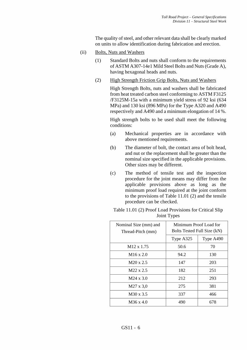
Toll Road Project – General Specifications
Division 11 – Structural Steel Work
GS11 - 6
The quality of steel, and other relevant data shall be clearly marked
on units to allow identification during fabrication and erection.
(ii) Bolts, Nuts and Washers
(1) Standard Bolts and nuts shall conform to the requirements
of ASTM A307-14e1 Mild Steel Bolts and Nuts (Grade A),
having hexagonal heads and nuts.
(2) High Strength Friction Grip Bolts, Nuts and Washers
High Strength Bolts, nuts and washers shall be fabricated
from heat treated carbon steel conforming to ASTM F3125
/F3125M-15a with a minimum yield stress of 92 ksi (634
MPa) and 130 ksi (896 MPa) for the Type A320 and A490
respectively and A490 and a minimum elongation of 14 %.
High strength bolts to be used shall meet the following
conditions:
(a) Mechanical properties are in accordance with
above mentioned requirements.
(b) The diameter of bolt, the contact area of bolt head,
and nut or the replacement shall be greater than the
nominal size specified in the applicable provisions.
Other sizes may be different.
(c) The method of tensile test and the inspection
procedure for the joint means may differ from the
applicable provisions above as long as the
minimum proof load required at the joint conform
to the provisions of Table 11.01 (2) and the tensile
procedure can be checked.
Table 11.01 (2) Proof Load Provisions for Critical Slip
Joint Types
Nominal Size (mm) and
Thread-Pitch (mm)
Minimum Proof Load for
Bolts Tested Full Size (kN)
Type A325 Type A490
M12 x 1.75 50.6 70
M16 x 2.0 94.2 130
M20 x 2.5 147 203
M22 x 2.5 182 251
M24 x 3.0 212 293
M27 x 3,0 275 381
M30 x 3.5 337 466
M36 x 4.0 490 678
Toll Road Project – General Specifications
Division 11 – Structural Steel Work
GS11 - 7
Note:
M12 x 1.75 is a bolt with a diameter of 12 mm (including thread) and
pitch is a movement of 1 rotation of 360° bolt of 1.75 mm.
The other quality standard of bolts may be used if the
manufacturer can provide data of proof load and the
minimum tensile strength.
The torque wrench against the minimum tensile load of the
bolt using a gauge shall be calibrated.
The use of torque wrench method shall be carried out
carefully and needs more detailed attentions. Calibration
of torque wrench in the Site shall be carried out every day
or:
- When a lot of components (bolt, nut and washer) is
replaced;
- When a lot of components (bolt, nut and washer) is re-
lubricated;
- When there are significant differences on the surface
of bolts, thread, nuts or washers;
- When replacement the torque wrench or the main
component of torque wrench to be changed
(lubricated).
Bolt tightening may be carried using the bridge erection
guidelines.
(3) Bolts and nuts shall be marked for identification in
accordance with ASTM F3125/F3125M-15a. Sizes of
bolts shall be as indicated on the Drawings.
(iii) Welded Shear Connector Studs
Welded shear connector studs shall conform to the requirements
of AASHTO M169-15 Cold Finished Carbon Steel Bars and
Shafting, and be cold drawn bar, grade 1015, 1018 or 1020, either
semi-killed or fully killed.
(iv) Welding Consumables:
Welding consumables used in the metal-arc welding of grades of
steel complying with the requirements of SNI 03-6764-2002 or
ASTM A36/A36M-14 shall conform to Structural Welding code
AWS D1.1-81/D1.1M:2015.
If the base metal is not included in the group of ASTM steel
covered by Table 4.1.1 of AWS D1.1-81/D1.1M:2015, then the
properties of the welding metal used for filler material shall
correspond to the properties of the base metal used for the parts to
be welded. The Contractor shall in this respect submit his
proposal for the Engineer's approval.
All materials to be used for welding shall be of a recognized
manufacture, and the Contractor shall when requested by the
Toll Road Project – General Specifications
Division 11 – Structural Steel Work
GS11 - 8
Engineer furnish manufacturer's certification that the electrodes
and other products used for welding meet the requirement of the
specifications.
(v) Materials used in painting of steel structures shall be as shown on
the Drawings or specified elsewhere and shall conform to the
requirements of the following specifications.
JIS K 5400 Testing Methods for Organic Coatings
JIS K 5421 Boiled Oil and Boiled Linseed Oil
JIS K 5516 Ready Mixed Paint
JIS K 5492 Aluminum Paint
JIS K 5621 Anticorrosive Paint for General Use
JIS K 5622 Red-Lead Anticorrosive Paint
JIS K 5623 Lead Suboxide Anticorrosive Paint (Class 1)
JIS K 5624 Basic Lead Chromate Anticorrosive Paint (Class 1)
JIS K 5625 Lead Cyanamide Anticorrosive Paint (Class 1)
JIS K 5626 Zinc Dust Anticorrosive Paint
JIS K 5627 Zinc Chromate Anticorrosive Paint
JIS K 5628 Red-Lead Zinc Chromate Anticorrosive Paint
JIS K 5633 Etching Primer (Class 2)
JIS K 5664 Tar-Epoxy Resin Paint
Where paints are specified that do not comply with any of the
above specifications, they shall be supplied only by recognized
manufacturers, and samples and technical data shall be submitted
to the Engineer for his approval. In any paint system (viz. primer,
undercoats, intermediate coat and finishing coats) each coat of
paint shall be compatible with the other, and to ensure this, all
paint shall be obtained from the same approved manufacturer with
a guarantee of compatibility.
(b) Workmanship
Except as otherwise denoted herein or on the drawings, all work shall be
executed in accordance with the relevant clauses of the specification given
in Sub-clause S11.01 (1) (b).
The Contractor shall be responsible for any damage caused to other
components of the structure including the substructures, by his operations
for the duration of this Contract. In particular, the Contractor shall take
all necessary precautions to minimize concrete splash onto completed
steel work or rust staining of concrete due to erected steel-work. He shall
clean and/or repair all stains and other damage to completed work, before
acceptance.
(c) Tolerances
The Contractor shall, through appropriate planning and continuous
measurements in the workshop and at the erection site, ensure that the
tolerances given shall be strictly observed. The Engineer will require any
specific working procedure changed in case such procedure appears not
to afford sufficient security against exceeding the tolerances. The
Toll Road Project – General Specifications
Division 11 – Structural Steel Work
GS11 - 9
dimensional tolerance limits shall be in accordance with AWS
D1.1/D1.1M:2015 with the following additional requirements:
(i) Hole Diameter
(1) Hole in main member : + 1.2 mm, - 0.4 mm
(2) Hole in secondary member : + 1.8 mm, - 0.4 mm
(b) Hole Alignment
(1) Main member, shop positioned : 0.4 mm
(2) Secondary member, field positioned : 0.6 mm
(c) Girders
Camber - deviation from specified camber ± 0.2 mm per metre
length beam or ± 6 mm vehicle is less.
Lateral deviation from straight line between centers of bearings
0.1 mm per meter length of beam to a maximum of 3 mm.
Lateral deviation between center line of web and center line of
flange in built up girders 3 mm maximum.
Combined warpage and tilt of flange of welded beams or girders
shall be determined by measuring the offset at toe of flange from
a line normal to the plane of the web through the intersection
center line of web with the outside surface of the flange plate. This
offset shall not exceed 1/200 of total width of flange or 3 mm
whichever is greater.
Out of flatness or seats or bases:
(1) To be set on grout : 3.0 mm, max.
(2) To be set on steel, hard masonry, : - 0.25 mm, max.
or lead
The maximum deviation from specified depth for welded beam
and girders, measured at the web center line, shall be as follows:
(1) For depths up to 900 mm : ± 3 mm
(2) For depths over 900 mm to : ± 5 mm
inclusive 1.8 meters
(3) For depths over 1.80 m : - 5 mm, + 8 mm
(d) Struts
Maximum deviation form straightness, including that of individual
flanges in either direction: length/1000 or 3 mm whichever is the
greater.
(e) Machined Surfaces
Machined bearing surfaces shall be machined within a deviation
of 0.25 mm for surfaces that can be inscribed within a square of
side 0.5 m.
Toll Road Project – General Specifications
Division 11 – Structural Steel Work
GS11 - 10
The Contractor is fully responsible for the calculation and provision of the
necessary camber in the preassembled elements to obtain the correct
levels in the completed bridge, duly considering the applied erection
procedure and the sequence in the installation of the various dead load
components.
The roadway load levels given on the Drawings - or defined by the given
inclination and curvature - are the required roadway load levels to top of
asphalt surfacing in bridge axis of the completed bridge, when loaded only
with the dead loads of the installed and completed structure. In fixing the
geometry of the superstructure, the Contractor shall make compensation
for the difference between workshop temperature and the temperature of
the bridge in normal position (280 Celsius).
S11.01 (3) Construction
(a) Fabrication
(i) Templates and Measurements
The Contractor shall supply all templates, jigs and other
appliances necessary to ensure the accuracy of the work.
(ii) Straightening
Before any work is done on them, all plates shall be checked for
flatness and all bars and sections checked for straightness and
freedom from twist. Any corrective action shall be taken so that
when assembled, adjacent surfaces shall be in close contact
throughout. The methods adopted for the work above shall be
such as not to damage, mark or impair the strength of the material.
(iii) Cutting
Marking shall be performed accurately and elaborately using full
size rules and templates. Prior to marking, the dimensions and
grade of materials shall be checked.
Through-going plates in the box girder including longitudinal rib
shall be so oriented that the direction of rolling shall follow the
longitudinal direction of the bridge. For built-up sections the
direction of rolling of the individual components shall follow the
axis of the section.
Cutting shall be done automatically. Hand cutting may be used
exceptionally, in connection with the erection, if approved by the
Engineer. In such cases the joint edges shall receive a finishing
treatment, with planning and grinding tools.
Cutting by shearing machine may be used for plates not exceeding
10 mm in thickness provided that the plate edge be fully enclosed
in a weld.
Oxygen cutting may be used provided a smooth and regular
surface free from cracks and notches is secured and provided that
Toll Road Project – General Specifications
Division 11 – Structural Steel Work
GS11 - 11
the roughness of oxygen cut-surfaces shall be no greater than 50S
according to JIS B 0601 by the use of a mechanical guide.
All cut plate edges that will not be welded shall be ground to
planeness and all edges of plates and sections that will not be
welded shall be rounded to the appropriate radius for painting.
(iv) Holing
Holes for bolts shall be drilled. Punching of holes shall not be
permitted. If not otherwise indicated on the drawings, the
diameter of bolt holes shall be 2.5 mm larger than the nominal
diameter of bolts. All holes for field connection of girder, except
stringer and bracket, shall be sub drilled 1.5 mm smaller and
during shop assembly reamed 2.5 mm larger than the nominal
diameter of the bolts.
(v) Bending
Bending of plate may be machined by cold processes, provided
that the bending inner radius is at least 15 times the thickness of
the plate.
(vi) Welding (Execution)
All welding shall be planned and executed using the most suitable
materials and working methods for the particular purpose. Site
welding will only be permitted for fixtures and details of any
fixture welding proposed by the Contractor shall be clearly
identified on the shop drawings and referred to in the
accompanying submittal letter.
Welding requirements shall in all respects conform to the
following sections of AWS D1.1/D1.1M:2015: Section 2, Design
of Welded Connections; Section 3, Workmanship; Section 4,
Technique; Section 5, Qualification; Section 6, Inspection; and
Section 9, Design of New Bridges.
All welding shall be executed by skilled, experienced welders
holding valid welder examination qualifications based on the
qualification tests specified in part C of Section 5 of AWS
D1.1/D1.1M:2015 or similar internationally recognized
qualification tests. A welder shall be qualified for each process
used.
Prior to commencement of any welding, the joint shall be carefully
freed from rust, scale, slag, and burrs. Where two welds for
structural reasons have to cross each other, the former has to be
ground flush. Where a flush surface is required, the excess weld
metal shall be ground.
During the assembly work, the components shall be held in
position and supported in such a manner that no unfavorable
inherent stresses or deformation shall develop. Drilling of holes
Toll Road Project – General Specifications
Division 11 – Structural Steel Work
GS11 - 12
for temporary assembly for welding purposes shall not be
accepted.
Minimum preheating and interphases temperature shall comply
with the welding procedure in question and shall be approved by
the Engineer.
(vii) Welding (Tolerances)
The members to be connected by welding shall be so prepared that
they fit exactly together, without being forced into position.
The tolerances concerning gap between parts to be welded,
eccentricity and departure from theoretical alignment, dimensions
of the cross section of groove welded joints, etc. shall conform to
Section 3.3, Assembly, of AWS D1.1/D1.1M:2015, except that the
gap between parts to be joined by fillet welds shall not exceed 1
mm for fillet welds connecting flange to web in box girder and 5
mm for all other fillet welds. Tolerances of weld profiles shall
correspond to section 3.6 of AWS D1.1/D1.1M:2015.
(viii) Welding Procedure Qualification Tests
The Contractor shall perform test welds of the layers type of
welding to be applied in the structure, according to a program to
be agreed upon with the Engineer. The quality of the test welds
shall be approved by the Engineer prior to execution of the
welding work in question. The test welding shall be made from
working positions corresponding to the actual working positions
during construction.
(ix) Welding Inspection
The Contractor shall prepare a detailed program for control of
welds in consultation with the Engineer and the established
program shall not be deviated from without the Engineer's consent.
The Contractor's control program shall assure satisfactory
inspection in the workshops to fulfill the stipulations laid down in
Section 9.25 of AWS D1.1/D1.1M:2015. The Contractor's
control shall be performed at his own expense and shall
correspond to the following schedule:
(1) Preparation for Welding
- Visual inspection of edge preparation
- Visual inspection of surface conditions for cracks, gaps
and other items that may cause any defect of welding.
(2) Visual Inspection before and after Welding
- All welds shall be visually inspected in accordance
with Section 9.25.1 of AWS D1.1/D1.1M:2015.
Toll Road Project – General Specifications
Division 11 – Structural Steel Work
GS11 - 13
(3) Non-destructive Testing of Welds
- Welds that are subject to radiographic or magnetic
particle testing in addition to visual inspection, shall be
unacceptable if the radiographic or magnetic particle
testing show any of the types of discontinuities given
in AWS D1.1/D1.1M:2015, Section 9.25.2.
- Welds that are subject to ultrasonic testing, in addition
to visual inspection, are acceptable if they meet the
requirements of table 9.25.3 in AWS D1.1-81/D1.1M:
2015. Welds that are subject to liquid penetration
testing, in addition to visual inspection, shall be
evaluated on the basis of the requirements for visual
inspection.
4) Scope of Non-destructive Testing of Weld
- Fillet welds shall be tested by the most suitable of
either the magnetic particle test or the liquid
penetration.
- Groove welds shall be tested by the most suitable of
either the radiographic test or the ultrasonic test.
- The method of non-destructive testing for a specific
weld shall be elaborated in consultation with the
Engineer.
The minimum extent of the testing (control) shall be as
follows:
Box girder plate
Transverse butt weld in top and bottom flange plate:
Welds subject to tensile stress
And reversal stress = 100%
Weld subject to compressive stress = 25%
Transverse butt weld in web plate = 50%
(The major part of the control to be performed in the
tension zone)
Longitudinal fillet weld:
Top and bottom flange to web = 25%
Longitudinal rib to top and bottom flange = 10%
Horizontal stiffener to web = 10%
Diaphragm
All end weld = 25%
Fillet weld = 10%
Other
Other welds not mentioned above = 10%
Toll Road Project – General Specifications
Division 11 – Structural Steel Work
GS11 - 14
The above figures are the minimum extent of testing and
the Engineer may require additional tests if these are
considered necessary to ensure compliance with the
specifications.
(x) Stud Welding
After the studs have been welded to the beams a visual inspection
shall be made and each stud shall be given a light blow with a
hammer. Any stud which does not have a complete end weld,
which does not emit a ringing sound when given a light blow with
a hammer, which has been repaired by welding, or which has less
than normal height due to welding, shall be forged with a hammer
and bent 15 degrees from the correct axis of installation, and in the
case of a defective or repaired weld, the stud shall be bent 15
degrees in the direction that will place that defective portion of the
weld in the greatest tension. Studs that crack either in the weld or
in the shank shall be replaced.
The Contractor is obliged to show the exact extent of the control
on the shop drawings to be approved by the Engineer. Two sets
of reports describing the inspection and comprising all the results
have to be handed over to the Engineer concurrently with the
execution of the inspection. The Contractor shall execute, at his
own expense, the repair of unsatisfactory welds, and the repaired
welds shall be tested anew on the Contractor's account.
(xi) Bolted Connection
Contact surfaces in bolted joints shall not be painted. When
assembled in the field, the rust on joint surfaces, including those
adjacent to bolt head, nut and washer, shall be removed by wire
brushing. The separation between fraying surfaces of bolted
connections shall be not greater than 1 mm. If the separation is
between 1 mm and 3 mm, the surface shall be tapered to eliminate
the separation. Over 3 mm separation shall be filled with filler
plate as required.
Each bolt shall be tightened to provide, when all bolts in the joint
are tight, the minimum bolt tension shown in the following Table
11.01 (2).
High strength bolts shall not be reused. Retightening previously
tightened bolts which may have been loosened by the tightening
of adjacent bolts shall not be considered reuse.
All high strength bolts shall be tightened by properly calibrated
wrenches and their setting shall be such as to induce a bolt tension
10% in excess of the above value. These wrenches shall be
calibrated at least once each working day by tightening in a device
of the diameter of each bolt to be installed. Power wrenches shall
be adjusted to stall or cut-out at the selected tension. If manual
torque wrenches are used the torque indication corresponding to
the calibrating tension shall be noted and used in the installation
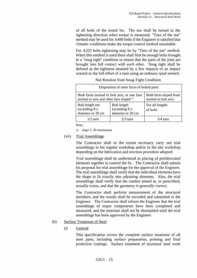
Toll Road Project – General Specifications
Division 11 – Structural Steel Work
GS11 - 15
of all bolts of the tested lot. The nut shall be turned in the
tightening direction when torque is measured. "Turn of the nut"
method may be used for A490 bolts if the Engineer is satisfied that
climatic conditions make the torque control method unsuitable.
For A325 bolts tightening may be by "Turn of the nut" method.
When this method is used there shall first be enough bolts brought
to a "snug tight" condition to ensure that the parts of the joint are
brought into full contact with each other. Snug tight shall be
defined as the tightness attained by a few impacts of an impact
wrench or the full effort of a man using an ordinary spud wrench.
Nut Rotation from Snug-Tight Condition
Disposition of outer faces of bolted parts
Both faces normal to bolt axis, or one face
normal to axis and other face sloped 1)
Both faces sloped from
normal to bolt axis
Bolt length not
exceeding 8 x
diameter or 20 cm
Bolt length
exceeding 8 x
diameter or 20 cm
For all lengths
of bolts
1/2 turn 2/3 turn 3/4 turn
Note:
1) slope 1: 20 maximums
(xii) Trial Assemblage
The Contractor shall to the extent necessary carry out trial
assemblage in his regular workshop and/or in the site workshop
depending on the fabrication and erection procedure adopted.
Trial assemblage shall be understood as placing of prefabricated
elements together to control the fit. The Contractor shall submit
his proposal for trial assemblage for the approval of the Engineer.
The trial assemblage shall verify that the individual elements have
the shape to fit exactly into adjoining elements. Also, the trial
assemblage shall verify that the camber aimed at, or prescribed,
actually exists, and that the geometry is generally correct.
The Contractor shall perform measurement of the structural
members, and the results shall be recorded and submitted to the
Engineer. The Contractor shall inform the Engineer that the trial
assemblage of major components have been completed and
measured, and the structure shall not be dismantled until the trial
assemblage has been approved by the Engineer.
(b) Surface Treatment of Steel
(i) General
This specification covers the complete surface treatment of all
steel parts, including surface preparation, priming and final
protective coatings. Surface treatment of structural steel work
Toll Road Project – General Specifications
Division 11 – Structural Steel Work
GS11 - 16
shall be considered in six classes as shown on the drawings and as
described below :
System I : Generally, all external steel work which will be
exposed to the atmospheric conditions.
System II : Concealed surfaces not liable to wetting or
exposure to the atmosphere.
System III : Generally, all steel work to be encased, or in
contact, with concrete.
System IV : Internal surfaces including box girders.
System V : Bolted joint.
System VI : Particular areas which are difficult to repaint
during maintenance works.
(ii) Surface Preparation
Before the application of any paint, the surfaces to be treated shall
be thoroughly cleaned and freed from all scale, loose paint, rust
and other deleterious matters. Oil and grease shall be removed
from the surface by washing with solvents or with a detergent
solution before any blast cleaning operation. If any traces of oil
or grease remain after blasting, they shall be removed by solvent
cleaning and the area blasted back.
All welding areas shall be given special attention for removal of
weld flux slag, weld metal splatter, weld head oxides, weld flux
fumes, slivers and other foreign objects before blasting. If
deemed necessary by the Engineer acid washing and subsequent
washing with clean water shall be used.
Any rough welding seams have to be ground and shall be inspected
and approved by the Engineer before application of the coatings.
All structural steel which will be painted shall be cleaned by blast
cleaning in accordance with SSPC-SP 10 Near-White Blast
cleaning. Mill scale, rust and foreign matter shall be removed to
the extent that the only traces remaining are light stains in the form
of spots or stripes. Finally, the surface is cleaned with a vacuum
cleaner or clean, dry compressed air.
The blast cleaning shall produce a surface roughness complying
with the one specified by the paint manufacturer for the primer
concerned. If cleaned surfaces rust or are contaminated with
foreign material before painting is accomplished, they shall be
recleaned by the Contractor at his expense.
(iii) Painting Materials
All materials shall comply with the requirements of Sub-clause
S11.01 (2) (a) (v). The colors of all paint coats will be as
instructed by the Engineer.
Toll Road Project – General Specifications
Division 11 – Structural Steel Work
GS11 - 17
(iv) Painting
The execution of the painting works shall be carried out in the
most perfect and workmanship manner by experienced labor to the
satisfaction of the Engineer. Furthermore, the application of the
paints shall be carried out in accordance with the manufacturer's
recommendations.
Planning and execution of the painting work shall be in conformity
with the supplier's specifications in respect to minimum and
maximum intervals between the application of the individual
coats.
If a coating material requires the addition of a curing agent, the pot
life under application conditions shall be clearly stated on the
container label, and this pot life shall not be exceeded. When the
pot life limit is reached, the spray equipment shall be emptied,
remaining material discarded, the equipment cleaned and new
material prepared.
Each coat shall be applied uniformly over the entire surface.
Skips, runs, sags and drips shall be avoided. When these occur,
they shall be brushed out immediately or the material shall be
removed and the surface recoated. Each coat shall be allowed to
dry for the time specified by the manufacturer or as directed by the
Engineer before application of any succeeding coat.
The surface shall be completely dry, and its temperature should be
at least 5 degrees Celsius above the dew point. Paint should only
be applied in suitable weather conditions and any fresh paint
damaged by weather shall be repaired or replaced at the
Contractor's expense. Measure shall be taken to prevent dust or
other extraneous matter from adhering to wet paint.
Brushes, when used, shall have sufficient body and length of
bristle to spread the paint in a uniform film. Paint shall be evenly
spread and thoroughly brushed out. On all surfaces which are
inaccessible for painting by regular means, the paint shall be
applied by sheepskin daubers, bottle brushes, or by any other
means approved by the Engineer. Rollers, when used, shall be of
a type which do not leave a stippled texture in the paint film.
A water trap acceptable to the Engineer shall be furnished and
installed on all equipment used in spray painting. Mechanical
mixers shall be used to mix paint. Prior to applying, the paint
shall be mixed a sufficient length of time to thoroughly mix the
pigment and vehicle together and shall be kept thoroughly mixed
during its application. The dry film thickness of the paint will be
measured in place with a calibrated magnetic film thickness gauge.
The thickness of each application shall be limited to that specified
in the Paint Systems.
Toll Road Project – General Specifications
Division 11 – Structural Steel Work
GS11 - 18
(v) Film Thickness
The specified film thicknesses for coating materials shall be
strictly observed and shall be checked with appropriate film
thickness gauges furnished by the Contractor. The Contractor
shall calibrate the gauges for the thickness range to be checked.
Calibration shall generally be carried out on a ground and polished
steel plate of a quality corresponding to the structural steel to be
coated.
The dry film thickness shown on the painting systems are the
minimum according to the specification SSPC-PA2, Measurement
of Dry Paint Thickness with Magnetic Gauges.
When dry film thickness is less than specified, additional coats
shall be applied as required at no additional cost to the Employer.
Particular attention shall be paid to the film thickness on edges,
welding, etc.
(vi) Protection of Paintwork
The Contractor shall provide protective measures as necessary to
prevent damage to the work and to other property or persons from
all cleaning and painting operations. Paint or paint stains which
result in an unsightly appearance on surfaces not designated to be
painted shall be removed or obliterated by the Contractor at his
expense. All painted surfaces that in the opinion of the Engineer
are marred or damaged in any way, shall be repaired by the
Contractor, at his expense, with materials and to a condition equal
to that of the coating specified herein. The Contractor's proposal
for retreatment of areas damaged by flame cutting and welding
operations should be clearly stated in the detailed painting plan
submitted in accordance with Sub-clause S11.01 (1) (d) (v).
Upon completion of al painting operations and of any other work
that would cause dust, grease, or other foreign materials to be
deposited upon the painted surfaces, the painted surfaces shall be
thoroughly cleaned. At the time of opening structures to public
traffic, the painting shall be completed, and the surfaces shall be
undamaged and clean.
(vii) Types of Surface Treatment
The treatment of the various areas of structural steel shall be in
accordance with Sub-clause S11.01 (3) (b) one of the six treatment
systems (I to VI) as shown on the attached table. The application
of each system of surface treatment within the structure shall be as
shown on the Drawings.
The attached table is prepared on the assumption that the painting
sequence is as follows:
Mill shop - shot blasting and etching primer
Toll Road Project – General Specifications
Division 11 – Structural Steel Work
GS11 - 19
Fabrication shop - painting to be after satisfactory
completion of trial assemblage.
Site - painting to be after final erection.
Where the Contractor requests permission to deviate from the
above sequence, this shall be clearly stated in the detailed painting
plan submitted in accordance with Sub-clause S11.01 (1) (d) (v).
The areas for HSFG bolts shall be protected by masking at the time
of the fabrication shop undercoats. Immediately prior to final
erection, any rust in the joint area shall be removed by power wire
brushing to a standard equivalent to SSPC-SP 3.
(c) Transport Handling and Storage
Before shop assembling is dismantled, all adjacent sections shall be
marked with paint or grooved. The Contractor shall submit to the
Engineer drawings of the finished structure showing all part and match
marks.
The methods of transporting and handing shall be subject to the approval
of the Engineer. Special care shall be taken in the packing, methods of
supporting, lifting during handling and transporting of structural steel
work which is shop assembled before delivery, to ensure protection from
damage.
Immediately following delivery to the site, the Contractor shall check the
material and bring immediately to the notice of the Engineer or his
representative any damage or defects therein. He shall also report in
writing to the Engineer any such damage or defects, and give his proposals
for the rectification or replacement or damaged sections.
Material to be stored shall be placed on skids above the ground and shall
be kept clean and properly drained. Girders and beams shall be placed
upright and shored. Long members shall be supported on skids placed
near enough together to prevent injury from deflection.
Any structural steel materials (whether painted or unpainted) shipped to
the site by sea transport, and positioned on board in such a way as to come
into contact with salt water spray, shall be thoroughly washed with clean
fresh water, using pressure hoses and stiff bristle brushes, prior to erection
or application of finish coats of paint.
(d) Field Erection
The position of field splices as shown on the Drawings is for information
only and the Contractor is free to propose alternative procedures
providing, they comply with all the relevant requirements of these
specifications. The preparation of the calculations and detailed design to
support the proposed alternative shall be at the Contractor's responsibility
and cost.
The Contractor will provide setting drawings, templates, and directions
for the installation of anchor bolts or other items to be embedded in
concrete.
Toll Road Project – General Specifications
Division 11 – Structural Steel Work
GS11 - 20
During erection, the parts shall be accurately assembled as shown on the
approved Shop Drawings and any match marks shall be followed. The
material shall be carefully handled so that no parts will be bent, broken or
otherwise damaged. Hammering which will injure or distort the
members shall not be done. Bearing surfaces and surfaces to be in
permanent contact shall be cleaned before the members are assembled.
Splices and field connections shall have one half of the holes filled with
bolts and cylindrical erection pins (half bolts and half pins) before bolting
with high-strength bolts. Fitting-up bolts shall be of the same nominal
diameter as the high-strength bolts, and cylindrical erection pins shall be
1 mm larger.
The correction of minor misfits involving harmless amounts of reaming,
cutting and chipping will be considered a legitimate part of the erection.
However, any error in the shop fabrication or deformation resulting from
handling and transportation which prevents the proper assembling and
fitting up of parts by the moderate use of drift pins or by a moderate
amount of reaming and slight chipping or cutting, shall be reported
immediately to the Engineer and his approval of the method of correction
obtained. The correction shall be made in his presence. The Contractor
shall be responsible for all misfits, errors and injuries and shall make the
necessary corrections and replacements.
The straightening of plates, angles, other shapes and built-up members,
when permitted by the Engineer, shall be done by methods that will not
produce fracture or other injury. Distorted members shall be straightened
by mechanical means or, if approved by the Engineer, by the careful
planned and supervised application of a limited amount of localized heat,
each application subject to the approval of the Engineer.
S11.01 (4) Method of Measurement
The quantity of structural steel measured for payment shall be the number of
kilograms complete in place and accepted in the works. For computing the
nominal weight of rolled or cast steel, the material shall be assumed to have a
density of 7,850 kilograms per cubic meter. The weights of other metals shall be
as indicated on the Drawings or as approved by the Engineer. In particular, there
will be no separate measurement or payment for trial assemblage, transportation
and shop or field painting.
The computed weight of material shall be the nominal weight of finished
steelwork comprising plates, rolled section, shear connectors, stiffeners, cleats,
packs, splices plates, and all fittings, without allowance for rolling margin and
other permissible deviations from standard weights or nominal dimensions, and
excluding the weights of welds, fillets, bolts, nuts, washers, rived heads and
protective coatings. No deduction shall be made for notches, bolt holes and rivet
holes etc which are less than 0.03 square metres in area.
Reinforced concrete for the deck slab, expansion joints, bridge bearings, bridge
railings, deck drains, electrical works and traffic signs will be measured and paid
for under the other pay items in this specification.
.
Toll Road Project – General Specifications
Division 11 – Structural Steel Work
GS11 - 21
S11.01 (5) Basis of Payment
The quantities of structural steelwork determined as provided above, shall be paid
for at the price per unit of measurement for the Pay Item listed below and shown
in the Bill of Quantities. Such price and payment shall be deemed full
compensation for supplying, fabricating and erecting the materials, including all
labor, equipment, tools, testing and other incidentals necessary or usual for the
satisfactory completion of the work prescribed in this Clause.
Pay Item No. and Name Unit of Measurement
11.01 (1) Continuous Steel Box Girders, furnished ton
11.01 (2) Continuous Steel Box Girders, erection ton
11.01 (3) Simple Steel Box Girders, furnished ton
11.01 (4) Simple Steel Box Girders, erection ton
11.01 (5) Continuous Steel Box Girders with ton
Steel Deck, furnished
11.01 (6) Continuous Steel Box Girders with ton
Steel Deck, erection

Toll Road Project – General Specifications
Division 11 – Structural Steel Work
GS11 - 22
Toll Road Project – General Specifications
Division 12 – Miscellaneous
S12 - 1
DIVISION 12 MISCELLANEOUS
S12.01 Sodding
S12.01 (1) Description
This work shall consist of furnishing grass sods as required and planting them to
give a healthy, stable covering of grass which will maintain its growth in any
weather and prevent erosion of the material in which it is planted.
S12.01 (2) Material
(a) The species of grass may be Polytrias amaura (rumput embun). It shall
be rapid spreading, free of disease and noxious weeds and shall be deep
rooted. The Contractor shall notify the Engineer not less than 3 days
before cutting of sods begins. The source of sods will be approved by
the Engineer before cutting and delivery to the Project.
Sods shall be planted with their root system substantially undamaged and
cut into blocks with moist earth in which they have grown. Sods shall be
laid within 5 days of cutting. Sod blocks shall be hauled and stored in
such manner that they will be protected from direct sun rays, provided
with air circulation, and prevented against drying.
(b) The species of Vetiver Grass System used for slope stabilization and
retaining the surface water erosion is species of Vetiveria zizanioides or
otherwise known as vetiver grass, hereinafter called Vetiver System (VS).
VS has a stiff, long and narrow leaf with width of no more than 8mm,
grow upright with height of 1.5 m to 2.5 m after 2 years old, formed big
clumps, smooth surface leaf, slender edge, pointed, meeting, and erect
along the flower stalk. It has a longitudinal root which able to be more
than 2m length at 1 year old.
(c) Fertilizer shall be approved mixtures of plant nutrients.
S12.01 (3) Construction
(a) Non Vertiver Grass System
Grass sodding shall not take place until tree planting in the area has been
completed.
Surfaces on which sod blocks are to be placed shall be scarified and
shaped after removing debris, gravel and weeds. All stones of more than
3 cm diameter shall be removed. The surface below the sods shall be made
up as necessary with good quality topsoil so as to ensure that the sod and
topsoil together form a finished thickness of not less than 20 cm consisting
of 5 cm humus and 15 cm existing soil as shown on the Drawings. Every
square meter of soil shall be implanted with lime or other approved
materials approximately 3 gram to a depth of 20 cm and a final layer of
topsoil 10 cm thick placed on top. The purpose of the lime is to neutralize
any existing sour condition of the soil. The Contractor shall be responsible
for ensuring a healthy growth in sodded areas and necessary fertilizer used
Toll Road Project – General Specifications
Division 12 – Miscellaneous
GS12 - 2
before or after sodding will be at the Contractor's own expense. Urea or
NPK fertilizer shall be used.
Sod blocks shall be placed so as to cover 50% of the surface by forming
sod strips at the interval of 30 cm (this will be called "Strip Sodding"), or
to cover entire surfaces (which shall be called "Solid Sodding"), as noted
in the Drawings or directed by the Engineer. In strip sodding joints shall
be staggered to form a broken bond. Joints between adjacent sod blocks
shall not exceed 0.5 cm. Sod blocks shall be placed in smooth finish and
compacted by a roller of 100 kg weight or by tamper plate. Sand shall be
spread over the grass sods already laid and into the joints and the whole
area shall be watered twice daily until the grass has taken firm root.
Sufficient bamboo stakes shall be used to prevent the sod blocks slipping
when sodding is provided on slopes.
For at least six months after completion of sodding, the Contractor shall
maintain watering and other incidental operations. Sodded areas will be
subject to special checks, 2 and 12 months after they have been laid. Any
areas in which sods are not maintaining a healthy growth shall be
refurnished and resodded by the Contractor at his own expense.
The Contractor will be responsible for cutting and keeping clean any
sodded areas until completion of the Defect Notification Period.
(b) Vertiver Grass System
(i) Preparation
- Fine grade all areas to be sodded to a uniform surface and
loosen the surface materials.
- Make up the surface with top soil so that the sod and top soil
form a finished thickness of 15 cm.
- After surface preparation, spread fertilizer uniformly over all
surfaces which are to be sodded, at a rate of 4 kg per 100 square
meters. Incorporate fertilizer into such surfaces by raking,
dishing or harrowing. Apply fertilizer not more than 48 hours
before the grass is to be placed.
- Sods shall be cut with their root system substantially intact and
taken when the earth is moist or has been artificially watered.
Sods should be stacked on pallets in layers together with as
much moisture as possible, protected from sun and wind and
watered every 4 hours. They should be laid within 2 days of
cutting.
(ii) Application
- Prepare the points of the planting hole location by marking
with wooden stick/rod of 50 cm which is designed with a
distance of not more than 2 m.
- If in the opinion of the Engineer, the slope to be stabilized is a
critical or steep slope of more than 1: 1.5, then slip No.2 above
mentioned able to be planted first on the ground in a polybag,
Toll Road Project – General Specifications
Division 12 – Miscellaneous
S12 - 3
then placed lined up on the critical soil until the slip age of 1.5
- 2 months. Then the polybag to be removed before the slip to
be planted at the right time/ time of planting.
- Procedure of removing the polybags shall be in accordance
with VS Planting Guidance.
- Diameter of polybags shall be approximately 10 cm with a
height of approximately 15cm, then filled in sequential sandy
soil up to one-third of the volume, the fertilizer approximately
20 grams, and filled the again with soil up to full.
(iii) Watering
- At least 3 months after VS has been planted, the surface
ground shall be watered at regular intervals in accordance with
current weather conditions or as directed by the Engineer. The
amount of water sprayed shall be such as that the surface
ground which just planted with VS will not erode, drift or
otherwise damage. Water sprinkling shall be approximately 5-
10 liters/m2/day in the afternoon every day until the first 2
weeks after planting. Then it shall be sprayed every 2 days for
the second 2 weeks. Finally sprayed 2 times a week until the
age of 3 months of planting. All with water needs of
approximately 5-10 liters/m2/day. In the dry season, due to the
type of sandy soil, and the steep of slope, the water needs shall
be increased by up to 10 liters/m2/day or more in accordance
with the instructions of the Engineer.
- The land shall be cleaned out from weed plants, shrubs, weeds.
Cleaning should be used Atrazine herbicide or the like as a
precaution, and do not use glyphosate as it may interfere with
the survival of VS.
- Water sprinkling on slip into polybags is recommended less
than slip that is planted freely as directed by the Engineer in
order to maintain the stability of slope/critical slopes.
(iv) Maintenance
- After 3 months VS able to grow without routine watering
except trimming to maintain a height of about 30 cm from the
existing ground surface at least once a month.
S12.01 (4) Method of Measurement
The quantities of sodding to be paid for shall be the number of square meters of
treated surface measured on the slope including unsodded areas between strip
sods, completed and accepted in accordance with the Drawings, Specifications
and as directed by the Engineer.
S12.01 (5) Basis of Payment
The quantities, determined as provided above, shall be paid for at the Contract
price per unit of measurement for the pay items listed below, which price and
Toll Road Project – General Specifications
Division 12 – Miscellaneous
GS12 - 4
payment shall be full compensation for furnishing all materials, labor, equipment,
tools including preparation of surface, sodding, protection and maintenance, and
other incidentals to complete the work in accordance with the Drawings and
Specifications, and as directed by the Engineer.
Pay Item No. and Name Unit of Measurement
12.01 (1) Solid Sodding Square Meter
12.01 (2) Strip Sodding Square Meter
12.01 (3) Vetiver Grass System Square Meter
S12.02 Stone Masonry for Retaining Walls
S12.02 (1) Description
This work shall consist of stone masonry in retaining walls for both cut and
embankment sections, in minor structures, and in other places where called for on
the Drawings or ordered in writing by the Engineer. The stone masonry shall be
constructed on the prepared foundation bed in accordance with these
Specifications and the specifications for other work items involved and in
conformity with lines, grades, sections, and dimensions shown on the Drawings
or required by the Engineer.
S12.02 (2) Material
(a) Stone
The stone shall be sound, have sufficient strength, no seams, shall be of
good quality, and shall be resistant to weathering. Quality of stone shall
be approved by the Engineer prior to use. The stone shall be of the strength
specified on the Drawings, and shall be flat, wedge or convex shaped.
The base surface shall be not less than 1/16 of the front surface, and the
shorter length of the base surface shall be more than 1/10 of the longer
length. The standard number of stones per square meter shall be 14.
However, if directed by the Engineer the number may differ from that
specified.
(b) Mortar
Mortar shall be in accordance with Clause S12.04 "Cement Mortar".
(c) Concrete
Class D concrete for footings and class E for backing shall be in
accordance with the requirements of Division 10 of these Specifications.
(d) Filter Backfill
Permeable backfill shall be in accordance with Clause S4.10 of these
Specifications.
Toll Road Project – General Specifications
Division 12 – Miscellaneous
S12 - 5
S12.02 (3) Construction
(a) Excavation
Excavation shall be in strict accordance with the cross-sections, grades
and lines shown on the Drawings after staking has been inspected and
approved by the Engineer. When the excavation method and dimensions
are not specified, the method shall be selected by the Contractor and
approved by the Engineer. Excavation and backfill shall be made in
accordance with the requirements of Division 5 of these Specifications.
(b) Foundation
Prior to placing the foundation, the soil shall be thoroughly compacted by
mechanical or hand ramming. Blinding stone foundation in accordance
with Sub-clause S5.01 (5) shall then be placed and compacted as shown
on the Drawings. A footing of Class E concrete shall then be formed to
the dimensions shown on the Drawings.
(c) Backfill and Backing Concrete
Permeable backfill shall be provided as shown in the Drawings,
Specifications or as directed by the Engineer. Class E concrete shall be
placed and compacted on the permeable backfill material with
consideration being given to the need to provide expansion joints and
weep holes as directed elsewhere in this clause. Backfill material and
Class E concrete shall be provided in advance of the stonework only to
such height as can be adequately compacted.
(d) Placing
Placing of stone masonry shall not begin until the finishing stakes set
according to the design have been inspected and approved by the
Engineer. Stones shall be washed with water before placing. A mortar
bed shall be spread on the sides of adjacent stones before the next stone is
laid. The thickness of the mortar shall be the minimum necessary to
ensure that there is no direct contact between stones. Stones shall be
thoroughly hammered into place and any stone whose face is deviating
more than 20 mm from the true face or more than 30 mm from the face of
the adjacent stone, shall immediately be made good by lifting and
relaying. Face joints between stones shall be flush-pointed as work
proceeds.
(e) Weep holes
Walls of stone masonry shall be provided with weep holes. Unless
otherwise shown on the Drawings or directed by the Engineer, the weep
holes shall be spaced not more than 2 meters center to center and shall be
50 mm in diameter.
(f) Coping
Coping shall be as shown on the Drawings. Where copings are not
determined, the upper surfaces of masonry shall be mortared and finished
smooth by wooden float.
Toll Road Project – General Specifications
Division 12 – Miscellaneous
GS12 - 6
(g) Joints
Expansion joints shall be formed at a maximum spacing of 20 meters.
Joints shall be 30 mm in width and shall extend through the complete wall
including the footing and backing concrete. Stones used for joint
forming shall be selected so as to form a clean vertical joint of the
dimensions specified above.
(h) Finishing
Appearance of stone masonry should be outer carving in between two
stone surfaces, and no additional payment for this work and already
included in the Pay Item 12.02.(1).
(i) Curing
In hot or dry weather, the masonry shall be satisfactorily protected from
the sun and shall be kept wet for a period of at least three days after
completion.
S12.02 (4) Method of Measurement
The quantities to be paid for shall be the number of square meters for Type A and
B of stone masonry laid in accordance with this Specification, and cubic meters
for Type C. In computing the quantity for payment, the dimensions used shall
be those shown on the Drawings or ordered in writing by the Engineer. No
deductions shall be made for weep holes, drain pipes, or other openings of less
than 0.10 square meters in area and no increase will be allowed for the concrete
footing. Any coping provided shall be included in the measurement as though it
were stone masonry.
Stone masonry type A shall be used in embankment sections and type B in cut
sections, and type C as directed by the Engineer.
S12.02 (5) Basis of Payment
The quantities determined as provided above, shall be paid for at the contract price
per unit of measurement for the pay items as listed below.
All excavation and backfilling for these pay items will be deemed to be covered
by and paid for under the work described in Division 5 of these Specifications.
Any extra expense due to excavation, or due to provision of foundations or of
special backfill will be considered to be included in the unit price for these pay
items.
The contract unit price shall be full compensation for furnishing and placing all
materials including concrete footing and coping and all other necessary work as
specified for the proper completion of all the work as described in this Clause.
Pay Item No. and Name Unit of Measurement
12.02 (1) Stone Masonry Type A Square Meter
12.02 (2) Stone Masonry Type B Square Meter
12.02 (3) Stone Masonry Type C Cubic Meter
Toll Road Project – General Specifications
Division 12 – Miscellaneous
S12 - 7
S12.03 Slope Protection
S12.03(1) Description
This work shall consist of dry-stone riprap and concrete blocks for slope
protection furnished and constructed in accordance with these Specifications and
in conformity with the lines, grades and dimensions shown on the Drawings or
required by the Engineer. The concrete block slope protection shall be installed at
bridge abutments.
S12.03 (2) Materials
Stone for riprap shall consist of field stone or unhewn quarry stone as nearly
rectangular in section as is practical. The stone shall be sound, tough, durable,
dense, resistant to the action of air and water, and suitable in all respects for the
purpose intended. Adobe blocks shall not be used for riprap work.
Stone pieces for protecting slopes shall range in weight from a minimum of 2 kg
to a maximum of 20 kg with not less than 60 percent of the stones weighing more
than 12 kg.
Grout for grouted rip rap shall be mortar with compressive strength at least 5 MPa
as specified in Clause S12.04 of these Specifications
Concrete blocks shall be solid plain rectangular blocks. Representative sample
blocks shall be submitted to the Engineer for approval before orders are given to
the suppliers or manufacturers.
S12.03 (3) Construction
(a) Preparation
Slope surface on which slope protection is to be placed shall be compacted
and properly smoothed after removing all vegetation.
Placing slope protection shall not begin until the finishing stakes are set
according to the Drawings and have been inspected and approved by the
Engineer.
(b) Placing
(i) Riprap Slope Protection
Stone placed below the water line shall be distributed and
compacted so that the thickness of riprap is not less than that
specified. Stone placed above the water line shall be placed by
hand. It shall be laid with close, broken joints and shall be firmly
bedded into the slope and against the adjoining stones. The stones
shall be laid perpendicular to the slope with ends in contact.
Smaller stones shall be first laid on the slope and larger stones
shall be used as surface cover. The riprap shall be thoroughly
compacted as construction progresses and the finished surface
shall present an even, tight surface. Interstices between stones
shall be chinked with spalls firmly rammed into place.
Toll Road Project – General Specifications
Division 12 – Miscellaneous
GS12 - 8
Unless otherwise provided, riprap shall be at least 60 cm in
thickness, measured perpendicular to the slope. The surface of
riprap placed above the water line shall not vary from the
theoretical surface by more than 8 cm at any point.
(ii) Grouted Rip Rap Slope Protection
Stones shall be thoroughly clean and saturated with water before
being placed. Grout material shall be applied to the previously
placed stone against which a new stone is to be placed. Stones shall
be firmly bedded into the slope and tamped into close contact with
adjacent stones to form the required thickness of rip rap.
The interstices between stones may be partly filled with spills or
small stones after which all remaining voids shall be solidly filled
with concrete and neatly pointed to within not more than 10
millimeters of the surface of the stones.
Weep holes shall be constructed as directed by the Engineer.
The work shall be kept shaded and damp for not less than 3 days
after completion
(iii) Concrete Block Slope Protection
The concrete blocks shall be placed on a bed of Class E concrete
and sand. The blocks shall be thoroughly tamped into the sand to
produce an even surface. Joints between blocks shall be filled
with mortar. The finished surface shall be such that it will not
exceed more than 6 mm from the testing edge between any two
contacts of a 3-meter straight edge applied anywhere on the paved
area. Blocks shall be neatly cut as necessary to completely fill the
area to be covered.
In hot or dry weather, the paved area shall be satisfactorily
protected from the sun and shall be kept wet for a period of at least
three days after completion.
S12.03 (4) Method of Measurement
The quantities to be paid for shall be the number of square meters of dry riprap or
grouted riprap or concrete blocks measured in place and incorporated in the
completed work in accordance with the Contract. In computing the quantity for
payment of slope protection the height shall be measured along the slope surface
and no measurement will be made for the toe key to dry riprap or grouted riprap.
In computing the quantity for concrete block slope protection no measurement
will be made for the concrete edge key or the concrete and blinding stone footing.
Only accepted work will be measured for payment and the computation of the
quantity thereof will be based on the area within the limiting dimensions designed
on the Drawings or ordered by the Engineer.
S12.03 (5) Basis of Payment
The quantities, determined as provided above, shall be paid for at the Contract
price per unit of measurement for the items listed below, which price and payment
Toll Road Project – General Specifications
Division 12 – Miscellaneous
S12 - 9
shall be full compensation for furnishing and placing all materials, labor,
equipment, tools including preparation of slope bed, foundations and other
incidentals to complete the work in accordance with the Drawings and
Specifications, and as directed by the Engineer.
Pay Item No. and Name Unit of Measurement
12.03 (1) Dry Riprap Slope Protection Square Meter
12.03 (2) Grouted Riprap Square Meter
12.03 (3) Concrete Block Slope Protection Square Meter
S12.04 Cement Mortar
S12.04 (1) Description
(a) General
This work shall consist of preparing and furnishing mortar in accordance
with these Specifications, for masonry and for any other incidental work.
(b) Composition
Unless otherwise instructed by the Engineer, masonry mortar shall be
composed of one part Portland cement and five parts fine aggregate by
volume to which hydrated lime may be added in an amount equal to 10
percent of the cement by weight.
S12.04 (2) Materials
(a) Cement shall conform to the requirements of AASHTO M85-15 or SNI
2049:2015.
(b) Fine aggregate shall conform to the requirements of SNI 03-6820-2002 or
AASHTO M45-15.
(c) Hydrated lime shall meet the requirements for residue, popping and
pitting, and water retention shown for Type N Lime in ASTM C207-18.
(d) Water shall conform to the requirements of Sub-clause S10.01.(2).(d) of
these Specifications
Unless directed otherwise by the Engineer, masonry mortar shall have a
compressive strength of at least 5 MPa at 28 days. Hydrated lime may be added
in an amount equal to 10 percent of the cement by weight
S12.04 (3) Construction
(a) All the materials except water shall be mixed in an approved mortar mixer
until the mixture assumes a uniform color, after which water shall be
added and the mixing continued. Mortar shall be mixed only in those
quantities required for immediate use. Mortar that is not used within 45
minutes after water has been added shall be discarded in an approved
manner.
Toll Road Project – General Specifications
Division 12 – Miscellaneous
GS12 - 10
(b) Surface shall be cleaned of any clay, or materials other unused and fully
saturated before the mortar used.
(c) When used finishing surface, the mortar thickness minimum 15 mm and
surface should be clean and shall be leveled up to get a smooth and flat
surface.
S12.04 (4) Method of Measurement
Cement mortar shall not be measured for direct payment.
S12.04 (5) Basis of Payment
Performance of this work shall not be paid for separately but shall be a subsidiary
obligation of the Contractor for which full payment is made in the payment of
Contract prices for the work items in which it is called for or required.
S12.05 Mortared Rubble
S12.05 (1) Description
This work shall consist of open ditches lined with mortared rubble furnished and
constructed in accordance with these Specifications and in conformity with lines,
grades, and dimensions shown on the Drawings or required by the Engineer.
S12.05 (2) Materials
(a) Stone shall consist of field stone or rough unhewn quarry stone, as nearly
rectangular in section as is practical. The stone shall be sound, tough,
durable, dense, resistant to the action of air and water, and suitable in all
respects for the purpose intended.
Quality and dimensions of stone shall be approved by the Engineer prior
to use. Unless otherwise provided by the Drawings or Specifications, all
stone shall be more than 0.008 cu. m in volume.
(b) Mortar shall conform to the requirements of Clause S12.04.
S12.05 (3) Construction
Earthworks shall be completed, and the foundation tamped prior to placing the
class E foundation concrete. Stone shall be securely placed by hand, and voids
shall be avoided. The face surfaces of all stones shall form a smooth regular
surface conforming to the shape of the ditch. No stone surface shall extend more
than one and a half centimeter above or below the general level of the ditch.
All voids between stones shall be filled and flushed with mortar but the face
surface of the stone shall be left exposed. Mortar shall be placed from bottom to
top and the surface swept with a stiff broom. The surface shall be cured as
specified in Division 10 for a period of at least three days.
Copings shall be as shown on the Drawings. Where copings are not called for
the upper surface of the mortared rubble shall be mortared and finished smooth
by wooden float.
Toll Road Project – General Specifications
Division 12 – Miscellaneous
S12 - 11
S12.05 (4) Method of Measurement
The quantities to be paid for shall be the number of linear meters of open ditches
lined with mortared rubble or cubic meters of inlet and outlet with mortared rubble
measured, as indicated on the Drawings, completed and accepted. In computing
the length for payment the dimensions used will be those determined by the
payment lines or payment areas shown on the Drawings or ordered by the
Engineer. Any coping provided shall be included in the measurement as though
it were mortared rubble. Where the Engineer instructs special joint or edge
details of a thickness greater than the standard shown on the Drawings, this will
be measured by volume and converted to an equivalent length of the standard
thickness for the purpose of payment. Excavations for mortared rubble ditches
from the lowest elevation of the surface of shoulder shall not be measured
separately for payment.
S12.05 (5) Basis of Payment
The quantities, determined as provided above, shall be paid for at the Contract
price per unit of measurement for the pay item listed below, which price and
payment shall be full compensation for furnishing all labor, equipment and
materials necessary for the proper completion of the work prescribed in this
clause.
Pay Item No. and Name Unit of Measurement
12.05 (1) Mortared Rubble DS-2 Linear Meter
12.05 (2) Mortared Rubble DS-4 Linear Meter
12.05 (3) Mortared Rubble DS-5 Linear Meter
12.05 (4) Mortared Rubble DS-5 with Subdrain Linear Meter
12.05 (5) Mortared Rubble D-6 Linear Meter
12.05 (6) Mortared Rubble DV-10 Linear Meter
12.05 (7) Mortared Rubble for Inlet and Outlet Cubic Meter
12.06 Guardrail and Fence
S12.06 (1) Description
This work shall consist of furnishing and installing the specified type of railing at
locations indicated on the Drawings or as directed by the Engineer. The work
shall include all required posts, rails, fixtures and fastenings, beams and
attachments as well as aligning, fabricating, erecting and painting of guardrail or
fence, if required, and all the process necessary to complete the work as described
in the Drawings and this Specification.
S12.06 (2) Materials
(a) Materials shall conform to the relevant requirements of :
JIS G 3101/ (ASTM A36/A36M-19):
Rolled Steel for General Structures
Toll Road Project – General Specifications
Division 12 – Miscellaneous
GS12 - 12
JIS G 3452/ (ASTM A53/A53M-18):
Carbon Steel Pipes for Ordinary Piping
JIS G 3444/ (ASTM A500/A500M-18):
Carbon Steel Tubes for General Structures Purposes
JIS G 3466/ (ASTM A511/A511M - 16):
Carbon Steel Square Pipes for General Structures Purposes
JIS G 3532/ (ASTM A82/A82M-07) :
Low Carbon Steel Wires
JIS G 3552/ (ASTM A392-11a(2017)):
Chain-link Wire Netting
Corrugated sheet steel beams for vehicle guardrail shall conform to
AASHTO M180-18 Class A, Type 1.
(b) All steel railing and fittings shall be galvanized unless otherwise specified,
in accordance with the requirements of Clause S12.18 of these
Specifications. Where painting is required it shall also be in accordance
with the requirements of Clause S12.18.
(c) All other materials shall be in accordance with the relevant clauses of this
Specification or as specified on the Drawings.
S12.06 (3) Construction
General
(a) Pipe, railing, fittings and incidental parts shall be carefully handled and
stored on blocking, racks or platforms so as not to be in contact with the
ground and shall be protected from corrosion. Materials shall be kept
free from dirt, oil, grease and other foreign matter. Threads shall be
carefully protected from damage.
(b) Guardrail shall be constructed to the lines and grades, and in the exact
positions shown on the Drawings or as directed by the Engineer.
(c) Steel shall not be heated or welded in the field unless with the prior written
approval of the Engineer. Field operation of drilling holes or cutting steel
shall be carefully conducted so as to prevent damage to steel.
(d) Posts shall be firmly set after digging holes by means of auger or post
driving machine or other equipment approved by the Engineer. When
handwork is required, care shall be exercised not to damage existing
pavement. When posts are to be set in concrete or masonry, all details of
preformed openings and the method of fixing the post therein shall be as
shown on the Drawings.
Post holes in soil shall be backfilled using material approved by the
Engineer or concrete according to the details on the Drawings. Backfill
material shall be thoroughly compacted to the same degree of compaction
as the adjacent soil. The surface surrounding the fixed pole shall be
reinstated to its original condition to the satisfaction of the Engineer.
Toll Road Project – General Specifications
Division 12 – Miscellaneous
S12 - 13
(e) The component parts of pipe railings shall be connected with threaded
screws unless otherwise specified on the Drawings. Fitting of railings on
slopes shall be leveled to fit the required grades. Screw thread fittings
shall be coated with red lead and oil.
Expansion shall be provided by omitting screws on one side of fittings at
designated posts. Where the rails are continuous through two or more
posts screws may be omitted between the rails and the fitting.
Barbed wire and chain-link netting shall be securely fixed to steel posts
with suitable metal fittings including steel connecting plates at joints of
steel angles, at corners and at ends of fence bolted as required, materials
and workmanship to be approved by the Engineer.
Gates shall be supplied and fixed all in accordance with the drawings
including hinges, locks, bolts and keepers and other ironmongery
required, materials and workmanship to be approved by the Engineer.
Barbed wire shall be securely fixed to steel posts with suitable metal
fittings, materials and workmanship to be approved by the Engineer.
S12.06 (4) Method of Measurement
The quantities to be paid for shall be the number of linear meters of each type of
guardrail or fence, completed and accepted in accordance with the Drawings,
Specifications, and as directed by the Engineer. Vehicle Guardrail Type C will
be use on Diverging nose, for protection pier of bridge and approach of bridge
and unit of completed measurement to be paid for shall be the number of linear
meters.
S12.06 (5) Basis of Payment
The work measured as provided above shall be paid for at the Contract unit price
for each type of guardrail or fence as designated below. The price and payment
shall be full compensation for furnishing and installing all materials, including
labor, equipment, tools and all incidentals necessary to complete the work as
shown on the Drawings and described in this Specification.
Pay Item No. and Name Unit of Measurement
12.06 (1) Vehicle Guardrail Type A Linear Meter
12.06 (2) Vehicle Guardrail Type B Linear Meter
12.06 (3) Vehicle Guardrail Type C Linear Meter
12.06 (4) Separator Fence (Concrete Panel) Type-A Linear Meter
12.06 (5) Separator Fence (Spine Wire) Type-B Linear Meter
12.06 (6) Fence Gate Type-A Each
12.06 (7) Fence Gate Type-B Each
12.06 (8) Moveable Fence Type-A Each
12.06 (9) Moveable Fence Type-B Each
Toll Road Project – General Specifications
Division 12 – Miscellaneous
GS12 - 14
12.06 (10) BRC Fence Linear Meter
12.06 (11) Guard Rail End Section Each
12.06 (12) Chain-link Fence Linear Meter
S12.07 Traffic Signs (Warning and Regulatory Signs)
S12.07 (1) Description
This work shall consist of furnishing, fabricating, hauling, and establishing the
specified types of traffic signs at locations indicated on the Drawings or as
directed by the Engineer and as required by the Ministry of Transportation
Regulation No. PM -13/2014 or the modifications (if any)
S12.07 (2) Materials
(a) Materials shall conform to the requirements noted in the Drawings.
Steel and aluminum materials shall be of durable quality and shall be
approved by the Engineer.
Material for poles shall comply with the requirements of ASTM
A53/A53M-12.
Nut, Bolts, U-Bolt, washer, clamps and others to be used for tightening
sign boards shall be steel bolts, fully galvanized, and free from
deformation and bending and shall conform to the requirement of
AASHTO M232M/M232-19.
(b) Aluminum plates shall be degreased, etched, neutralized and processed
prior to use as traffic sign boards, and shall conform to the requirement of
ASTM B209-14 or AASHTO M290-96(2013), with the minimum
thickness 2 mm.
Reflective sheeting shall conform to the requirements of AASHTO M268-
15(2019) or ASTM D4956-17 and the color shall be as shown on the
Drawings and shall include a precoated adhesive on the back capable of
forming a durable bond, by vacuum or roller method, to aluminum plates.
(c) Steel plate type for traffic sign is steel for general structure as
requirements of ASTM A36/A36M-19 or SNI 6764:2016 and galvanized
as per the requirements AASHTO M111M/M111-19 or JIS H 8641.
(d) Steel poles for traffic signs shall either be processed for rust prevention
by phosphatic membrane or zinc galvanizing, or if approved by the
Engineer, by means of a rust prevention painting process. Rust prevention
paint and galvanizing shall conform to Clause S12.18 of these
Specifications and all details of materials and painting shall be approved
in advance by the Engineer.
(e) The quality of the concrete to be used for the foundation as shown in
Drawing and shall comply with the provisions of Division 10 of this
Specification.
Toll Road Project – General Specifications
Division 12 – Miscellaneous
S12 - 15
S12.07 (3) Construction
(a) The type and location of traffic signs shall conform to the Drawings and
the instructions of the Engineer. Traffic sign locations shall be
established in the presence of the Engineer.
(b) Poles shall be set on a foundation as shown on the Drawings after digging
holes by means of auger or other equipment approved by the Engineer.
When handwork is required, care shall be exercised not to damage
existing pavement.
(c) Poles shall be supported as necessary until the concrete has achieved
sufficient strength and the hole shall then be backfilled and thoroughly
compacted with suitable material to the satisfaction of the Engineer. The
adjacent surface shall be restored to its original condition as directed by
the Engineer.
(d) When traffic signs are to be installed on an existing road extreme care
shall be exercised to prevent obstruction of traffic. Any damaged portion
shall be repaired to its original condition immediately after installation.
(e) Traffic signs shall be carefully handled so as not to cause damage, and the
Contractor shall repair or replace signs at his own expense in the event of
damage.
S12.07 (4) Method of Measurement
The quantities to be paid for shall be the actual number of permanent traffic sign
poles furnished, placed and accepted in accordance with the Drawings, and as
directed by the Engineer.
S12.07 (5) Basis of Payment
The work measured as provided above shall be paid for at the Contract unit price
for each type of traffic sign pole listed below.
The prices and payment shall be full compensation for furnishing and placing all
materials including sign or signs as necessary, for all materials, for foundations,
for all excavation, backfill and reinstatement, including labour, equipment, tools
and incidentals necessary to complete the work as shown on the Drawings or
described herein.
Pay Item No. and Name Unit of Measurement
12.07 (1) Regulatory and warning signs type A-1 Each
12.07 (2) Regulatory and warning signs type A-2 Each
12.07 (3) Regulatory and warning signs type B-1 Each
12.07 (4) Regulatory and warning signs type B-2 Each
12.07 (5) Regulatory and warning signs type C-1 Each
12.07 (6) Regulatory and warning signs type C-2 Each
12.07 (7) Regulatory and warning signs type D Each
Toll Road Project – General Specifications
Division 12 – Miscellaneous
GS12 - 16
12.07 (7a) Regulatory and warning signs type D-2 Each
S12.08 Traffic Guide and Prohibition Signs (Traffic Guide Signs)
S12.08 (1) Description
This work shall consist of furnishing, fabricating, hauling and installing the
specified types of traffic guide signs at locations indicated on the Drawings or as
directed by the Engineer and as required by the Ministry of Transportation
Regulation No. PM 13/2014 or the modifications (if any).
S12.08 (2) Materials
(a) Unless otherwise noted in these Specifications, all materials shall conform
to the requirements given on the Drawings.
(b) The specification for steel and aluminums products and for reflective
sheeting as given in Clause S12.07 of these Specifications shall also be
applied to traffic guide signs.
All materials for this work shall be approved by the Engineer before orders are
given to the suppliers or manufacturers.
S12.08 (3) Construction
(a) The type, location and placement of signs shall be in accordance with
Drawing or instructed by the Engineer. Setting and fixing the location
shall be supervised by the Engineer.
(b) All details given in Clause S12.07 regarding the fabrication and
installation of signs and poles shall also be applied to traffic guide signs.
Foundation details shall be as shown on the Drawings.
(c) Guide signs and light units shall be carefully handled so as to avoid
damage, and the Contractor shall repair or replace these at his own
expense in the event of any damage.
S12.08 (4) Method of Measurement
The quantities to be paid for shall be the actual number of permanent traffic sign
poles furnished, placed and accepted in accordance with the Drawings, and as
directed by the Engineer.
S12.08 (5) Basis of Payment
The work measured as provided above shall be paid for at the Contract unit price
for each type of traffic guide sign as listed below.
The prices and payment shall be full compensation for furnishing and placing all
materials including signs lettered in accordance with the Engineer's instructions,
pole(s), jointing, for all sundry materials, for foundations, for all excavation,
backfill and reinstatement, including labor, equipment, tools and incidentals
necessary to complete the work.
Toll Road Project – General Specifications
Division 12 – Miscellaneous
S12 - 17
Pay Item No. and Name Unit of Measurement
12.08 (1) Guide Sign Type A-1 Each
12.08 (2) Guide Sign Type A-2 Each
12.08 (3) Guide Sign Type A-3 Each
12.08 (4) Guide Sign Type A-4 Each
12.08 (5) Guide Sign Type A-5 Each
12.08 (6) Guide Sign Type A-6 Each
12.08 (7) Guide Sign Type A-7 Each
12.08 (8) Guide Sign Type B-1 Each
12.08 (9) Guide Sign Type B-2 Each
12.08 (10) Guide Sign Type C-1 Each
12.08 (11) Guide Sign Type C-2 Each
12.08 (12) Guide Sign Type D-1 Each
12.08 (13) Guide Sign Type D-2 Each
S12.09 Road Markings
S12.09 (1) Description
This work shall consist of furnishing and applying Type A, Type B and Rumble
Strip painted road markings on the finished paved area in accordance with these
Specifications, at the locations and of the dimensions shown on the Drawings, or
as directed by the Engineer.
S12.09 (2) Materials
(a) Type A material shall be white and yellow thermoplastic material (solid
form) incorporating glass beads and conforming with AASHTO M249-
12(2016) or SNI 06-4826-1998.
(b) Type B material shall be white and yellow ready-mixed traffic paint
conforming with AASHTO M248-91(2012) or SNI 06-4825-1998.
(c) Glass beads applied to the surface of both Class A and Class B and
Rumble Strip material shall conform to AASHTO M247-13 or SNI 15-
4839-1998 (Type 2).
S12.09 (3) Construction
(a) Existing lines and markings to be removed will be designated by the
Engineer and shall be removed by grit-blasting or other approved method
causing minimum damage to the road surface.
(b) The surface area to be marked shall be clean, dry and free from loose
particles. Setting out and location of all markings shall be approved by
the Engineer before work begins. Except where approved by the
Toll Road Project – General Specifications
Division 12 – Miscellaneous
GS12 - 18
Engineer, all markings shall be laid by self-propelled machines equipped
with cut-off valves and nozzles capable of forming clean and sharp edged
lines and markings, of the specified thickness.
(c) Type A material shall be laid by screed to the dimensions shown on the
Drawings and agreed by the Engineer. The finished thickness of the
material shall be at least 3 mm exclusive of the glass beads described in
(e) below. Preparation and application of the material shall be in
accordance with the manufacturer's instructions or as agreed by the
Engineer. On concrete surfaces the Contractor shall first apply a tack
coat of a type compatible with the thermoplastic material.
(d) Type B material shall be laid by spray type machine equipped with a
mechanical agitator. Each nozzle shall be equipped with suitable
guidelines consisting of metallic shrouds or air blasts, and with a
satisfactory cut-off valve capable of applying broken or skip lines
automatically. Spread rate shall be not less than 40 liters/ 100 m2. In areas
where machine laying is impossible, the Engineer may give approval to
brush application.
(e) Glass beads shall be applied to the surface of Class A and Class B
markings immediately after they have been laid. Unless otherwise
approved by the Engineer, all glass beads shall be applied by pressure or
spray application at a rate not less than 450 gm/m2.
(f) All road markings shall be protected from traffic as instructed by the
Engineer. All markings shall present a clean cut, uniform and
workmanlike appearance and the surface shall be free from streaks and
cracks. All markings which do not have a uniform satisfactory
appearance by day and night shall be corrected by the Contractor at his
own expense.
(g) The thickness of the rumble strip shall be 12.5 mm ± 0.5 mm with some
applications of thermoplastic material.
S12.09 (4) Method of Measurement
The quantities of road marking and rumble strip to be paid for will be the number
of square meters of the relevant material applied to the surface, completed and
accepted in accordance with the Drawings, these Specifications, and as directed
by the Engineer. For the purposes of measurement each type of material for road
marking will be divided into two categories as follows:
General Application - Centre lines, edge lines, lane markings and other
work which is basically parallel to the centerline of
carriageway or ramp.
Special Application - Arrows, pedestrian markings, striping and other
work which is transverse or sharply angled to the
direction of traffic flow.
Toll Road Project – General Specifications
Division 12 – Miscellaneous
S12 - 19
S12.09 (5) Basis of Payment
The quantities, measured as provided above, will be paid for at the Contract unit
price per square meter of traffic marking and Rumble Strip for each category of
work as listed below.
The price and payment shall constitute full compensation for furnishing all
materials, labor and equipment and for fulfilling all the work as described in this
clause.
Pay Item No. and Name Unit of Measurement
12.09 (1) Road Marking Type A (General Application) Square Meter
12.09 (2) Road Marking Type A (Special Application) Square Meter
12.09 (3) Road Marking Type B (General Application) Square Meter
12.09 (4) Rumble Strip Square Meter
S12.10 Delineators
S12.10 (1) Description
This work shall consist of furnishing and installing the specified type of
delineators at the locations indicated on the Drawings or as directed by the
Engineer.
The work shall include all required posts, fixtures, fastenings and attachments as
well as aligning and installing, and all the process necessary to complete the work.
S12.10 (2) Materials
The manufacturer and model type of all delineators shall be approved by the
Engineer before any order is placed for their supply as specified in Sub-clause
S1.02.(4) of these Specifications. All details of delineators shall conform to the
relevant JIS or AASHTO standards.
Delineator Type A : Reflective disc fixed to steel post placed in the ground.
Delineator Type B : Reflective disc on guardrail post or bridge railing.
Delineator Type C : Reflective road stud fixed to the face of the curb.
S12.10 (3) Construction
Delineators shall be exactly installed in accordance with the Drawings and the
instructions given by the Engineer. All metal parts of delineators shall be fully
galvanized. Reflector color shall be as directed by the Engineer.
S12.10 (4) Method of Measurement
The quantities to be paid for shall be the actual number of delineators furnished,
installed and accepted in accordance with the Drawings, and as directed by the
Engineer.
Toll Road Project – General Specifications
Division 12 – Miscellaneous
GS12 - 20
S12.10 (5) Basis of Payment
The work measured as provided above shall be paid for at the Contract unit price
for each type of delineator as listed below. The prices and payment shall be full
compensation for furnishing and installing delineators, including labor,
equipment, tools and all incidentals necessary to complete the work.
Pay Item No. and Name Unit of Measurement
12.10 (1) Delineator Type A Each
12.10 (2) Delineator Type B Each
12.10 (3) Delineator Type C Each
S12.11 Dwarf Stone Walls
S12.11 (1) Description
This work shall consist of stone masonry in small retaining walls where shown on
the Drawings or instructed by the Engineer. The walls shall be constructed on the
prepared foundation as shown on the Drawings. There shall be only one pay item
for this work although the Drawings may detail different types for the purposes
of construction.
S12.11 (2) Materials
Materials shall be in accordance with sub-clause S12.02 (2), except that backfill
to Clause S4.09 will not be required.
S12.11 (3) Construction
Excavation shall be in accordance with the cross-sections, grades and lines shown
on the Drawings after staking has been inspected and approved by the Engineer.
Excavation and backfill shall be made in accordance with the requirements of
Division 5 of these Specifications.
The foundation shall be as shown on the Drawings. All other details of
construction shall comply with the relevant Sub-clauses of paragraphs (d) to (h)
of Sub-clause S12.02 (3).
S12.11 (4) Method of Measurement
The quantities to be paid for shall be the number of square meters of stone
masonry laid in accordance with this Specification. In computing the quantity
for payment, the dimensions used shall be those shown on the Drawings or
ordered in writing by the Engineer. No deductions shall be made for weep holes,
drain pipe, or other openings of less than 0.10 square meter in area, and no
increase will be allowed for the concrete or stone foundation. Coping will be
included in the measurement as though it were stone.
S12.11 (5) Basis of Payment
The quantities determined as provided above, shall be paid for at the Contract
prices per unit of measurement for the pay item listed below.
Toll Road Project – General Specifications
Division 12 – Miscellaneous
S12 - 21
All excavation and backfilling for this pay item will be deemed to be covered by
and paid for under the work described in Division 5 of these Specifications. Any
extra expense due to excavation or due to provision of the foundation will be
deemed to be included in the unit price for this pay item. The Contract unit price
will be full compensation for furnishing and placing all materials including
foundation and coping and all other necessary works as specified for the proper
completion of all the work described in this Clause.
Pay Item No. and Name Unit of Measurement
12.11 Dwarf Stone Walls Square Meter
S12.12 Concrete Curb
S12.12 (1) Description
This work shall consist of the construction of concrete curb of the various shapes
and at the locations as shown on the Drawings or instructed by the Engineer.
S12.12 (2) Materials
Curbs may be cast-in-place or precast. The concrete for reinforced or precast
curbs shall be Class B, for non- reinforced cast-in-place curbs Class B, and any
base or foundation shall be of concrete Class E or blinding stone as shown on the
Drawings. All concrete shall meet the requirements of Clause S10.01 of the
Specifications.
Preformed expansion joint fillers for curb joints shall consist of a bituminous
mastic composition, formed and encased between two layers of bituminous felt,
all in conformity with AASHTO M33-99(2012).
S12.12 (3) Construction Requirements
The construction requirements shall conform to Clause S10.01 for concrete
structures. Maximum joint spacing shall be 10 m. Before placing the exposed
section of the curb all lines and levels shall be checked by the Engineer. Any
junction between the concrete base and the Class B concrete shall be prepared and
treated as a construction joint in accordance with Clause S10.01 of these
Specifications.
When at driveway entrance crossings or for other reasons, a transition section of
curb is indicated on the Drawings or ordered by the Engineer, the Contractor shall
furnish concrete curbs with the required modification.
Precast curbs shall be cast in mortar-tight metal molds sufficiently rigid to prevent
any deformation of the curb. The precast curbs shall be removed from the molds
as soon as practicable and shall be kept damp for a period of at least 7 days.
During this period, they shall be protected from the sun and wind. Any curbs
that show cracking or soft or damaged corners or surfaces shall be rejected.
Curbs shall be carefully handled, transported and off-loaded so as to avoid
damage. Any curbs which become chipped, marred or cracked before or during
placing shall be rejected.
Toll Road Project – General Specifications
Division 12 – Miscellaneous
GS12 - 22
Bedding and joint mortar for precast curbs shall comply with the requirements of
Clause S12.04.
Precast curb units shall not be more than 80 cm long. Special units shall be cast
for radii of less than 5.0 m.
Curb construction shall be properly carried out. The tops and faces of all curbs
are measured with a straight-edge to check the 6 mm in 3 meter tolerance. All
curb that does not meet the straight-edge requirement is removed and replaced.
On completion of curb the Contractor shall backfill and tidy up the work to the
satisfaction of the Engineer.
The precast curbs shall be painted to surface of concrete based on local
government specification. The contractor shall submit specification of painting
material to the Engineer
S12.12 (4) Method of Measurement
Concrete curb of the types as shown on the Drawings will be measured by the
linear meter along the face of the curb.
No additional allowance will be made for curbs constructed on curves. No
deduction in length will be made for drainage structures installed in the curb
section, but payment for these structures will be deemed to be full compensation
for finishing the structures to the same standard and tolerance as the adjacent curb
and for providing expansion joints between the units and the adjacent curbs.
Reinforced concrete curbs provided as an integral part of non- drainage structures
will not be measured for payment under this clause but will be dealt with under
Division 10 of these Specifications.
S12.12 (5) Basis of Payment
The accepted quantities of concrete curbs determined as provided above, will be
paid for at the contract unit price per linear meter of curbing completed in place.
This price and payment shall be full compensation for the work on the types of
curb as shown in the Drawings, including excavation in any material, provision
of base of foundation, expansion joint material, bedding, jointing of precast curbs,
backfill and disposal of all surplus material, and all other materials, labor or
equipment necessary to complete the work.
Pay Item No. and Name Unit of Measurement
12.12 (1) Concrete Curb Type A Linear Meter
12.12 (2) Concrete Curb Type B Linear Meter
12.12 (3) Concrete Curb Type C Linear Meter
12.12 (4) Concrete Curb Type D Linear Meter
Toll Road Project – General Specifications
Division 12 – Miscellaneous
S12 - 23
S12.13 Interlocking Concrete Paving
S12.13 (1) Description
This work shall consist of the furnishing and laying of interlocking concrete
blocks to the lines, grades and locations shown on the Drawings or instructed by
the Engineer.
S12.13 (2) Materials
(a) Aggregate for Production of Inter-block
(i) Coarse aggregate shall have an abrasion loss less than 30% for
thickness of 8 and 10 cm and 40% for thickness of 6 cm the when
tested with the Los Angeles Abrasion Method.
(ii) The silt content of the sand shall be less than 3% passing a 0.075
mm sieve opening.
(iii) The mix design of the concrete mixture for inter-block shall
contain 30 - 40% of coarse aggregate (5 - 10 mm).
(b) Production of Inter-block
(i) Batching Plant
The inter-blocks shall be produced in a plant equipped with a
batching plant where raw materials can be batched by weight and
the moisture content of the mix can be controlled automatically.
(ii) Quality Control
The plant shall have its own laboratory to control the quality of the
products of each shift, including but not limited to the following:
- Compressive test
- Abrasion resistance
(c) Inter-block
The shape, thickness, strength, quality, etc. shall conform to the following
specifications:
(i) Shape
General shapes of inter-block shall be submitted to the Engineer
for approval before orders are given to the suppliers or
manufacturers.
(ii) Thickness
The following minimum thickness shall apply: 6 cm for sidewalk
for pedestrian; 8 cm for medium/heavy traffic of passenger car,
pick- up, bus and truck; 10 cm for super heavy traffic including
crane, loader, etc.
(iii) Dimension Tolerances
Dimension tolerances shall be 2 mm for length and width, and 3
mm for thickness.
Toll Road Project – General Specifications
Division 12 – Miscellaneous
GS12 - 24
(iv) Compressive Strength
When tested in accordance with ASTM C140-12, the compressive
strength average shall be not less than 490 kg/cm2 and the crushing
strength of any individual block shall be not less than 400 kg/cm2.
The inter-block for sidewalk shall have a minimum compressive
strength of 250 kg/cm2.
(v) Abrasion Resistance
Inter-block shall be durable and resistant to climate and wear,
when tested in accordance with Procedure C of ASTM C770-19
shall have a minimum abrasion index of 1.5 for thickness of 8 and
10 cm and 1,2 for thickness of 6 cm, or in accordance with SNI
03-0028-1987 shall have an abrasion resistance of average 0.90
mm/minutes and minimum 0.103 mm/minutes for thickness of 8
and 10 cm and average 0.130 mm/minutes and minimum 0.149
for thickness of 6 cm.
(v) Sampling for Test
Randomly selected samples of 5 units for a compression test and
5 units for an abrasion test shall be taken out of every 10,000 units
or out of every delivery lot, whichever is the least.
(d) Sand Bedding
The sand for inter-block bedding shall be concrete sand, which shall be
clean, dry and of moisture content approximately 4 - 8%.
(e) Filler Sand
Filler sand shall be finer than 1.18 mm (passing No.16) and shall contain
approximately 10% silt material.
S12.13 (3) Construction Requirements
(a) Base Course
(i) The base course shall be strong and stable, with a minimum CBR
value of 90%.
(ii) The base course surface shall be crowned in the middle, and shall
have a cross fall of 2 - 2.50% or as shown in the Drawings.
(iii) The base course surface shall be firm to avoid bedding sand from
entering the space between inter-blocks.
(b) Spreading of Sand Bedding
(i) Bedding sand shall be dry, spread loose 20% thicker than
compacted design thickness shown on drawings.
(ii) Using a straightedge, bedding sand shall be leveled to follow the
designed road surface. Before and after being leveled, bedding
sand shall not be compacted. Where previously prepared bedding
is compacted unintentionally, that portion shall be made loose and
leveled again.
Toll Road Project – General Specifications
Division 12 – Miscellaneous
S12 - 25
(c) Placing of Inter-block
(i) Inter-block shall be placed above the leveled bedding sand.
(ii) Placing of inter-block shall start from the edge of the curbs
following the design pattern.
(iii) The space between inter-blocks shall be 2 - 4 mm to accommodate
insertion of filler sand, shall be straight and controlled by string
lines and straightedges.
(iv) Damaged inter-block shall be rejected and shall not be placed.
(d) Compaction
(i) After one day placement is completed, inter-block shall be
compacted with a vibrating plate compactor of specification as
follows :
- Plate area 0.35 - 0.50 sq.m
- Centrifugal force 16 - 20 KN
- Frequency 75 - 100 Hz
- No. of passes 3 - 4 passes
(ii) Compaction shall be carefully carried out near curbs to avoid
disturbing or damaging the curbs.
(iii) Inter-block damaged by this initial compaction shall be replaced
by new blocks.
(iv) After initial compaction is completed, filler sand shall then be
spread and swept to fill the spaces between inter-blocks.
(v) Final compaction using the same vibrating plate compactor shall
comprise 3 - 4 passes.
(vi) Inter-block for heavy traffic shall also be compacted by a tire roller
(TR) of 10 - 14 tons capacity for 8 - 10 passes, following
compaction by vibrating plate compactor.
(e) Maintenance
For several weeks or as directed by the Engineer after the inter-block road
is opened to traffic, maintenance is required by refilling the spaces
between inter-blocks with filler sand. Ideally, refilling sand shall be
continued before interlocking of inter-block takes place.
S12.13 (4) Method of Measurement
Interlocking paving will be measured by the square meter of paved area complete
in place and accepted.
S12.13 (5) Basis of Payment
The quantities determined as provided above will be paid for at the contract price
per unit of measurement, which price and payment will be full compensation for
ground preparation, supply of inter-block, the sand bedding, the installation,
Toll Road Project – General Specifications
Division 12 – Miscellaneous
GS12 - 26
tamping or vibrating of the paving, and for all other incidentals necessary to
complete the work as shown on the Drawings.
Pay Item No. and Name Unit of Measurement
12.13 Interlocking Concrete Paving Square Meter
S12.14 Staircases
S12.14 (1) Description
This work shall consist of constructing reinforced concrete staircases on the
roadway embankment in accordance with the details shown on the Drawings or
as instructed by the Engineer.
S12.14 (2) Applicable Provisions
The applicable provisions of Clauses S5.01, S10.01 and S10.02 shall be read into
and become part of this Clause S12.14.
S12.14 (3) Materials
(a) Concrete
Concrete shall conform to the requirements of Clause S10.01 of these
Specifications. Reinforced concrete stairs shall be Class C concrete.
Leveling concrete shall be Class E concrete.
(b) Reinforcing Steel
Reinforcing steel shall be in accordance with Clause S10.02 of these
Specifications.
(c) Blinding Stone
Blinding stone shall be in accordance with sub-clause S5.01 (5) of these
Specifications.
S12.14 (4) Construction
Construction shall be in accordance with the requirements of sub-clause S10.01
(4) of these Specifications. Slope surface on which staircases are to be constructed
shall be excavated to the required levels, compacted and properly smoothed.
Construction of the staircase shall not begin until survey stakes are set according
to the Drawings and have been inspected and approved by the Engineer.
S12.14 (5) Method of Measurement
The quantity to be paid for shall be the number of linear meters of staircase
measured in place. The length to be measured shall be the length of landings and
the length of stairway measured up the slope.
Toll Road Project – General Specifications
Division 12 – Miscellaneous
S12 - 27
S12.14 (6) Basis of Payment
The quantity, determined as provided above, shall be paid at the Contract price
per unit of measurement for the item listed below, which price and payment shall
be full compensation for furnishing and placing all materials, labor, equipment,
tools including preparation of slope bed, blinding stone, leveling concrete and
other incidentals to complete the work in accordance with the Drawings and
Specifications, and as directed by the Engineer.
Pay Item No. and Name Unit of Measurement
12.14 Staircase Linear Meter
S12.15 Concrete Barrier
S12.15 (1) Description
This work shall consist of concrete barrier, constructed and erected in close
conformity with the dimensions, lines, grades design shown on the Drawings or
established by the Engineer in accordance with this and other specification items
involved. It shall include the manufacture, transportation, and storage of precast
concrete units and railing members.
S12.15 (2) Materials
(a) General
All materials to be furnished and used which are not covered in this clause
shall conform to the requirements stipulated in other applicable Clauses.
(b) Reinforcement
Reinforcement steel bars shall conform to Clause S10.02 of the General
Specifications.
(c) Concrete
Concrete shall conform to the requirements of Class B-1 concrete as in
Clause S10.01 of the General Specifications and to the requirements
specified below unless otherwise stated in the Drawings. The Contractor
shall develop his own mix designs in compliance with Clause S10.01 of
the General Specifications.
(d) Grout
Grout shall consist of Portland cement, potable water and retarder
admixture approved by the Engineer. No admixture containing chlorides
or nitrates shall be used. The Contractor shall submit the proportions of
mixing for approval of the Engineer.
The grout shall be mixed by mechanical mixing equipment of a type that
will produce uniform and thoroughly mixed grout. Water shall be first
added to the mixer followed by cement and admixture.
Toll Road Project – General Specifications
Division 12 – Miscellaneous
GS12 - 28
(e) Railing
Railing shall conform to the requirements of Clause S10.09 of the General
Specifications and as shown on the Drawings.
(f) Expansion Joint Filler
Expansion joint filler shall conform to the requirement of AASHTO M33-
99(2012).
S12.15 (3) Equipment and Tools
Equipment and tools necessary for handling materials and performing the work
shall be satisfactory to the Engineer as to design, capacity, mechanical condition
and shall be at the site of the work before work is started.
If any equipment as used by the Contractor proves inadequate to obtain the results
prescribed, such equipment shall be improved, or other satisfactory equipment
substituted or added at the direction of the Engineer.
(a) Concrete Batching Plant and Equipment
Concrete batching plant and equipment, concrete mixers, vibrators, tools
and transportation shall conform to Clause S10.01 of the General
Specifications.
(b) Forms
Forms shall be made of metal conforming to the shape, lines and
dimensions of the members shown on the Drawings and be in accordance
with the requirements of Clause S10.01 of the General Specifications.
The number of forms to be provided by the Contractor shall be adequate
for the casting schedule which shall be submitted by the Contractor for
the Engineer's agreement and approval. In the event that the rate of
casting cannot maintain the approved schedule output, the Contractor
shall provide additional forms, in such numbers as may be directed by the
Engineer. Forms that deteriorate from reuse shall be replaced by the
Contractor with new forms if so directed by the Engineer. Unless
otherwise approved by the Engineer the form shall be so designed that the
concrete barrier is cast in an inverted position.
S12.15 (4) Construction
(a) Pre-casting
Concrete barrier shall be constructed using precast members
manufactured in a casting yard of sufficient size, provided by the
Contractor. The Contractor shall provide a casting yard superintendent
having the necessary technical expertise and experience to supervise the
work on a full time basis.
The Contractor shall prepare, check and submit to the Engineer complete
Shop Drawings and Schedules, showing:
(i) Details of the various precast units to be manufactured;
Toll Road Project – General Specifications
Division 12 – Miscellaneous
S12 - 29
(ii) Contractor's alternative designs if the submission of alternatives is
approved;
(iii) Details of forms;
(iv) Contractors details of proposed manufacture and construction;
(v) Sequence of operations proposed; and
(vi) Production schedule in relation to Construction Schedule and
Time for Completion.
The Contractor shall not cast concrete prior to the Engineer's approval of
the Contractor's Drawings and Schedules, the concrete mixture,
formwork, sequence of operations, and method of placing, curing,
protecting, handling and erecting members. Any alternative to the design
in the Contract Documents shall be subject to the Engineer's approval
before manufacture or construction.
After all stipulated necessary approvals have been given the Contractor
shall inform the Engineer, not less than 3 (three) working days in advance,
of the probable date of commencement of manufacture.
(b) Form Setting
Forms shall be erected, set, braced and supported in a manner satisfactory
to the Engineer with the inverted base of the form truly level both
longitudinally and transversely.
(c) Placing Steel
All reinforcing steel shall be accurately placed in the position shown on
the Drawings and rigidly held during placing and setting of concrete.
Distances from the forms shall be maintained by stay blocks, ties, hangers,
or other approved support. The use of precast mortar blocks for holding
units from contact with the forms is deprecated, and approval for their use
will only be given if their design and dimensions are such that the contact
area with the forms is minimal. The use of wooden blocks is prohibited.
(d) Placing Concrete
Concrete shall be placed in accordance with the requirements of Clause
S10.01 of the General Specifications.
(e) Finishing Concrete
Immediately after placing concrete the upper exposed surface shall be
struck off true to the forms and hand finished using wooden floats. On
completion of floating all units cast shall be checked by means of a
straight edge to ensure that no high spots exist.
(f) Curing Concrete
Curing shall commence immediately on finishing operations and shall
comply with the requirement of Clause S10.01 and/or Clause S10.03 of
the General Specifications. Water curing shall be continuous for at least
7 days.
Toll Road Project – General Specifications
Division 12 – Miscellaneous
GS12 - 30
(g) Form Removal
Forms shall not be removed until at least 24 hours after finishing of the
concrete.
(h) Surface Finish
Immediately after form removal, unless otherwise approved by the
Engineer, the units cast shall be given a Rubbed finish in accordance with
Clause S10.01 of the General Specifications.
(i) Storage of Units
Units shall not be moved until the concrete has attained at least 70% of
the specified minimum compressive strength. Units shall be stored clear
of the ground. Stacking of units shall be permitted providing it is limited
to double stacking but no concrete to concrete contact shall be permitted.
S12.15 (5) Erecting
(a) Equipment
Units shall be double slung from a gantry or crane of adequate capacity to
facilitate ease of handling and correct positioning. Lifting devices shall
not damage or mark the concrete barrier.
(b) Bedding
Cement grout bedding shall be spread to the thickness shown on the
Drawings. The spreading of grout shall not be made far in advance of
barrier placing as the grout shall still be plastic at the time of placing the
barrier unit. Grout squeezed out from under the barrier shall be removed.
(c) Alignment
The barrier shall be erected to the correct alignment following and
providing the correct smooth curvature.
(d) Railing
Railing shall be installed and constructed in accordance with Clause
S10.09 of the General Specifications.
S12.15 (6) Method of Measurement
The quantity of concrete barrier to be measured for payment shall be the actual
number of linear meters of precast concrete members and metal railing installed
in place, completed and adopted. Special units of non-standard dimensions shall
be measured in the length.
Transition blocks, lean concrete foundation and infill concrete foundation and
infill concrete between the barrier and curb shall not be measured for payment the
work being considered a subsidiary obligation of the Contractor under this Clause.
S12.15 (7) Basis of Payment
The work measured as provided above shall be paid for at the Contract unit price
for the items listed below which appear in the Bid Schedule. The prices and
Toll Road Project – General Specifications
Division 12 – Miscellaneous
S12 - 31
payment shall be full compensation for furnishing and placing all materials
including all tools, equipment and incidentals necessary to complete the work
prescribed in this Clause.
Pay Item No. and Name Unit of Measurement
12.15 (1) Concrete Barrier Type A Linear Meter
12.15 (2) Concrete Barrier Type B Linear Meter
12.15 (3) Concrete Barrier and Planter Box Cubic Meter
S12.16 Bus Stop Shelter
S12.16 (1) Description
This work shall consist of furnishing and installing bus stop shelters at locations
shown on the Drawings or instructed by the Engineer.
S12.16 (2) Materials
All materials shall be as shown on the Drawings or equivalent as approved by the
Engineer. Shop drawings and details of materials sources shall be approved by
the Engineer before procurement of materials.
All materials for the electrical work shall be approved by the Engineer before
orders are given to the suppliers or manufacturers.
S12.16 (3) Construction
All details of construction shall be in accordance with the approved shop drawings
and the relevant clauses of the Specifications.
S12.16 (4) Method of Measurement
The quantities to be paid for will be the actual number of Bus Stop Shelters
furnished and installed in accordance with the Drawings and the Engineer's
instructions.
S12.16 (5) Basis of Payment
The work measured as provided above will be paid for at the Contract unit price
for each Bus Stop Shelter. The prices and payment will be full compensation for
furnishing and installing the Bus Stop Shelter, including labor, equipment,
materials and all incidentals necessary to complete the work as shown on the
Drawings.
Pay Item No. and Name Unit of Measurement
12.16 Bus Stop Shelter Each
Toll Road Project – General Specifications
Division 12 – Miscellaneous
GS12 - 32
S12.17 Landscaping Works
S12.17 (1) Description
This work shall consist of the provision and planting of trees and shrubs and their
cultivation according to the specifications and their positioning as detailed on the
Drawings and the furnishing or constructing of concrete, brick or block planting
boxes at the locations shown on the Drawings or as instructed by the Engineer.
The Contractor shall give attention to the preparatory measures required before
planting is carried out, such as levels of soil; slope of ground; and topsoil
requirements including turning over and leveling the soil.
S12.17 (2) References
All work such as planting of shrubs, trees, and the cultivation of vegetation to
cover the bare soil, shall be executed in accordance with specifications and current
standards for such work. The Contractor shall acquaint himself with the
regulations and requirements of the local government authority, Dinas
Pertamanan, and shall carry out the work accordingly.
S12.17 (3) Materials
Plants used shall consist of trees and shrubs/bushes as detailed on the Drawings.
Supports and protection for trees shall be of wood/bamboo. Binding or ties shall
be made of natural raffia. Fertilizer shall be as detailed in these specifications.
Concrete for planting boxes shall be in accordance with the requirements of
Division 10 of these General Specifications.
Bricks and blocks shall be of local product best quality approved by the Engineer.
The bricks/blocks shall have clean surfaces, sharp edges, uniform in dimensions
and without cracks.
S12.17 (4) Preparation
After the soil is cleaned of debris from the construction works the topsoil shall be
prepared for planting.
To prevent any standing water occurring a slope of 0.3 %o (three thousandths)
shall be made in the direction of flow indicated by the Engineer.
All top soil for the areas of cultivation shall consist of a soil mixture of 5 cm
humus and 10 cm existing soil.
These layers shall be executed after the ground to be prepared is clear of debris
resulting from the construction works and clear of other growths or weeds.
The use of weed killers for destroying weeds etc. shall not be permitted.
The preparation of the soil forms the final stage in the soil workings. At this stage
the condition and compactness of the soil shall be good, there being no further
changes occurring to the heights and contours desired.
Toll Road Project – General Specifications
Division 12 – Miscellaneous
S12 - 33
S12.17 (5) Provision of Plants
Before the plants are finally planted in position on the site they shall first be put
in a location to be indicated by the Engineer. Permission to execute the planting
on site will be given by the Engineer to the Contractor before planting is
commenced.
The plants shall comply with the following requirements:
- Height of trees shall be between 2.0 m and 3.0 m.
- Height of shrubs shall be not less than 60 cm.
- When dispatching trees to the site the trees shall be tied to support posts or
similar in order that the trees are not damaged, similarly the leaves may be
trimmed to reduce evaporation.
- Plants shall be free of disease, infestation and shall have good healthy
branches.
S12.17 (6) Planting
Execution of the landscaping can be commenced:
- When all the construction and civil works in the area are completed.
- When the Contractor has received permission in writing from the Engineer.
Holes to be planted shall be enriched with a mixture of soil and fertilizers, and
shall be cleared of debris and stones. Each plant shall be held somewhat above
the bottom of the hole to receive it, then soil added gradually to the hole and
around the roots, tamping the soil to the required compaction. After the roots of
the plant have spread, its trunk shall be slowly pulled out to ascertain that the
surrounding soil is compact enough to support its roots, and so promote healthy
growth.
In promoting cultivation, care of the topsoil around the plants requires that the top
soil is cleaned up around the planted area.
S12.17 (7) Trees and Shrubs
Trees and shrubs shall be planted before grass sodding is placed but after the
ground has been leveled and prepared.
(a) Locations of trees shall first be ascertained, with reference to staking out
posts, in accordance with the specifications or detail drawings and as
approved by the Engineer.
(b) Planting shall be in accordance with details in the drawings.
(c) Holes dug for planting shall be as follows:
- for trees : 80 x 80 cm to a depth of 80 cm
- for shrubs : 60 x 60 cm to a depth of 40 cm
(d) To protect soil fertility and plant growth the Contractor shall complete the
tree planting not more than 1 week after the holes for the trees have been
dug, in order to avoid acid condition of the soil.
Toll Road Project – General Specifications
Division 12 – Miscellaneous
GS12 - 34
(e) The mixture of soil for filling in holes for planting shall consist of red soil
and stable manure or of a quality similar to compost (compost is soil
containing vegetation that has already undergone a process of
decomposition).
The mixture of soil for filling shall be comparable to:
- soil for planting (pH7) 75%
- stable manure 25%
(f) The soil mixture shall be free of stones greater than 4 cm in size. This
mixture shall be put into the holes evenly to a depth of 15 cm, with another
5 cm around the tree roots.
(g) Sufficient watering shall be carried out at every stage of planting. To avoid
the possibility of water flowing away to another level when watering, the
height of the top soil around trees and shrubs shall be made 4 cm lower
than the surrounding level.
(h) Each tree shall be protected by support posts. Such support posts (wooden
or bamboo) shall be given a coating of creosote or its equivalent so that
they do not quickly decay. Posts shall be 1.8 m in length of which 60 cm
shall be buried in the soil.
(i) Trees shall be watered until they are growing healthily up to the end of
the Defect Notification Period, the watering to be carried out in the
mornings between 6 AM to 10 AM and in the afternoons from 3 PM until
completed.
S12.17 (8) Planting Boxes
Type 1 planting boxes shall be pre-cast concrete comprising a group of 4
cylindrical containers as shown on the Drawings.
Type 2 planting boxes shall be brick or block as shown on the Drawings. Exposed
brickwork/block work shall be of best quality, true to line, with even joints.
Palm fiber and broken bricks to promote drainage, and soil for planting in the
boxes shall be as shown on the Drawings.
S12.17 (9) Cleaning Up
During and after the work of planting and other works the Contractor shall
continue to clean up all refuse or debris caused by landscaping activities over the
pavements and/or the drains and channels for the duration of the Period of
Warranty. The Contractor shall transport the remaining materials left over and
other rubbish away from the site as early as possible when the landscaping
activities are completed.
S12.17 (10) Nursing
Any weeds which grow after the landscaping work is completed shall be pulled
up and removed. The use of chemical weed killer is not permitted.
The prevention of disease or infestation is to be dealt with by twice weekly
applications of Curacron 500 EC and/or Bazola 80 WP or the equivalent product
Toll Road Project – General Specifications
Division 12 – Miscellaneous
S12 - 35
Watering shall be carried out twice daily, mornings and afternoons until growth
is fully established and thereafter to maintain healthy growth until the completion
of the Defect Notification Period.
Applications of fertilizers, commencing 2 weeks after planting, are to be made
twice monthly using "NPK" fertilizers for all trees and shrubs.
For any and all omissions by the Contractor during the period of nursing which
causes damage or death to the plant life, the Contractor will be required to replace
the dead plants as quickly as possible, at the latest 3 days after the request for
replacement is issued.
S12.17 (11) Method of Measurement
The quantities to be paid for shall be the number of trees and plants satisfactorily
planted and nurtured in accordance with the Drawings, these Specifications and
the Engineer's instructions.
Payment will be made for each type of planting box furnished and placed or
constructed and accepted in accordance with the Drawings, and as directed by the
Engineer.
S12.17 (12) Basis of Payment
The work measured as provided above will be paid for at the Contract Unit Prices
for each type of tree, shrub and planting box listed below.
The prices and payment shall be full compensation for complying with local
government authority requirements, for furnishing, planting and nurturing the
trees and shrubs, and for furnishing and placing all materials, for foundations, for
all excavation, backfill and reinstatement for planting boxes, and all labour,
material, tools, equipment and incidentals necessary to complete the work
Pay Item No. and Name Unit of Measurement
12.17 (1) Shrub-Planting for Plantation Box Type 1 Each
12.17 (2) Shrub-Planting for Plantation Box Type 2 Each
12.17 (3) Nyamplung (Calophylum Inophyllum) Each
12.17 (4) Ketapang (Terminallia Cattapa) Each
12.17 (5) Bungur (Largerslroemia Indica) Each
12.17 (6) Bintaro (Cerbera Oddlam) Each
12.17 (7) Waru Laut (Hibiscus Tillaceus) Each
12.17 (8) Mahoni (Swietania Mahagoni) Each
12.17 (9) Akasia Daun Lebar Each
12.17 (10) Biola Cantik Each
12.17 (11) Butterfly Each
12.17 (12) Dadap Merah (Erythrina Oristagal) Each
12.17 (13) Kelapa Sawit (Elais Guineensis) Each
Toll Road Project – General Specifications
Division 12 – Miscellaneous
GS12 - 36
12.17 (14) Trembesi (Samanea Saman) Each
12.17 (15) Jati Mas (Tectona grandis) Each
12.17 (16) Anggrek Tanah (Spathoglottis plicata BI) Each
12.17 (17) Api Kuning (Peltophorum pterocarpum) Each
12.17 (18) Bakung Air Mancur (Hymenocallis littoralis) Each
12.17 (19) Bogenvil (Bougainvillea hybrida) Each
12.17 (20) Flamboyan (Delonix regia) Each
12.17 (21) Hujan Mas (Casia glauca) Each
12.17 (22) Iris (Neomarica longofolia) Each
12.17 (23) Jambu Air (Syzigium aquae) Each
12.17 (24) Jatropa (Jatropha pandurifolia) Each
12.17 (25) Kaca Piring (Gardenia augusta) Each
12.17 (26) Kamboja Kuning (Plumeria acuminata) Each
12.17 (27) Kamboja Merah (Plumeria rubra) Each
12.17 (28) Kana (Canna hybrida) Each
12.17 (29) Karet Munding Belang Each
(Ficus elastica variegata)
12.17 (30) Kecrutan (Spathodea campanulata) Each
12.17 (31) Kembang Merak (Caesalpinia pulcherrima) Each
12.17 (32) Kembang Sepatu (Hibiscus rosa sinesis) Each
12.17 (33) Mangga (Mangifera indica) Each
12.17 (34) Oleander (Nerrium oleander) Each
12.17 (35) Pagoda (Plumeria pudica) Each
12.17 (36) Palem Bambu (Chamaedorea seifrizii) Each
12.17 (37) Palem Putri (Veitchia merilli) Each
12.17 (38) Palem Weregu (Rhapis excelsa) Each
12.17 (39) Pangkas Kuning (Duranta sp) Each
12.17 (40) Pucuk Merah (Syzigium oleana) Each
12.17 (41) Rambutan (Nephelium lappaceum) Each
12.17 (42) Sukun (Artocarpus altilis) Each
12.17 (43) Tabebuya Pink (Tabebuia rosea) Each
12.17 (44) Wali Songo (Schefflera sp) Each
12.17 (45) Plant's Pot Each
Toll Road Project – General Specifications
Division 12 – Miscellaneous
S12 - 37
S12.18 Surface Treatment of Steel
S12.18 (1) General
This specification covers the surface treatment of all steel parts, including surface
preparation and galvanizing or painting in accordance with the specifications and
drawings or as required by the Engineer.
S12.18 (2) Materials
(a) Materials used for painting steel shall be as shown on the Drawings or
specified elsewhere and shall conform to the requirements of the
following specifications:
JIS K 5400 Testing Methods for Organic Coatings
JIS K 5421 Boiled Oil and Boiled Linseed Oil
JIS K 5516 Ready Mixed Paint
JIS K 5492 Aluminum Paint
JIS K 5621 Anticorrosive Paint for General Use
JIS K 5622 Red-Lead Anticorrosive Paint
JIS K 5623 Lead Sub oxide Anticorrosive Paint (Class 1)
JIS K 5624 Basic Lead Chromate Anticorrosive Paint (Class 1)
JIS K 5625 Lead Cyanamid Anticorrosive Paint (Class 1)
JIS K 5626 Zinc Dust Anticorrosive Paint
JIS K 5627 Zinc Chromate Anticorrosive Paint
JIS K 5628 Red-Lead Zinc Chromate Anticorrosive Paint
JIS K 5633 Etching Primer (Class 2)
JIS K 5664 Tar-Epoxy Resin Paint
Where paints are specified that do not comply with any of the above
specifications, they shall be supplied only by recognized manufacturers,
and samples and technical data shall be submitted to the Engineer for his
approval. In any paint system (viz. primer, undercoats, intermediate coat
and finishing coats) each coat of paint shall be compatible with the other,
and to ensure this, all paint shall be obtained from the same approved
manufacturer with a guarantee of compatibility.
(b) Galvanizing shall in general conform to the requirements of AASHTO
M111M/M111-19 or JIS H 8641 class 3-55C and JIS H 0401. Material
thinner than 3.2 mm may be galvanized before fabrication in conformance
with the requirements of ASTM A525-93. Galvanizing of iron and steel
hardware and nuts and bolts shall conform to the specifications of
AASHTO M232M/M232-19 or equal.
S12.18 (3) Work Requirements
(a) Surface Preparation
Before the application of any paint or galvanizing, the surface to be treated
shall be thoroughly cleaned and freed from all scale, rust and other
deleterious matters. Oil and grease shall be removed from the surface by
washing with solvents or with a detergent solution before any blast
Toll Road Project – General Specifications
Division 12 – Miscellaneous
GS12 - 38
cleaning operation. If any traces of oil or grease remain after blasting,
they shall be removed by solvent cleaning and the area reblasted.
If cleaned surfaces rust or are contaminated with foreign material before
painting or galvanizing is accomplished, they shall be reclined.
All welding areas shall be given special attention for removal of weld flux
slag, weld metal splatter, weld head oxides, weld flux fumes, slivers and
other foreign objects. Any rough welding seams are to be ground
smooth.
(b) Painting
The execution of the painting works shall be carried out in a neat and
workmanlike manner by experienced labor to the satisfaction of the
Engineer. Furthermore, the application of the paints shall be carried out
in accordance with the manufacturer's recommendations.
Planning and execution of the painting work shall be in conformity with
the manufacturer's specifications in respect to minimum and maximum
intervals between the applications of the individual coats.
If a coating material requires the addition of a curing agent, the pot life
under application conditions shall be clearly stated on the container label,
and this pot life shall not be exceeded. When the pot life limit is reached,
spray equipment shall be emptied, remaining material discarded, the
equipment cleaned and new material prepared.
Each coat shall be applied uniformly over the entire surface. Skips, runs,
sags and drips shall be avoided. When these occur, they shall be brushed
out immediately or the material shall be allowed to dry for the time
specified by the manufacturer or as directed by the Engineer before
application of any succeeding coat.
The surface shall be completely dry, and its temperature shall be at least
5 degrees C above the dew point. Paint shall only be applied in suitable
weather conditions and any fresh paint damaged by weather shall be
repaired or replaced at the Contractor's expense. Measures shall be taken
to prevent dust or other extraneous matter from adhering to wet paint.
Brushes, when used, shall have sufficient body and length of bristle to
spread the paint in a uniform film. Paint shall be evenly spread and
thoroughly brushed out. On all surfaces which are inaccessible for
painting by regular means, the paint shall be applied by sheepskin daubers,
bottle brushes, or by any other means approved by the Engineer. Rollers,
when used, shall be of a type which does not leave a stippled texture in
the paint film.
A water trap acceptable to the Engineer shall be furnished and installed
on all equipment used in spray painting. Prior to applying, the paint shall
be mixed a sufficient length of time to thoroughly mix the pigment and
vehicle together, and shall be kept thoroughly mixed during its
application.
Toll Road Project – General Specifications
Division 12 – Miscellaneous
S12 - 39
The dry film thickness of the paint will be measured in place with a
calibrated magnetic film thickness gauge. The thickness of each
application shall be as specified.
When dry film thickness is less than that specified, additional coats shall
be applied as required at no additional cost to the Employer. Particular
attention shall be paid to the film thickness on edges, welding, etc.
Number of coats, type of paint and dry film thickness of the paint shall be
as follows unless otherwise specified or noted on the Drawings.
Number
of
Coats
Type of Paint
Minimum Film
Thickness per
Coat (micron)
Two
One
One
One
Lead Suboxide (JIS K 5623)
or
Basic Lead Chromate (JIS K 5624)
or
Lead Cyanamide (JIS K 5625)
Phenol M10 (or equivalent)
Chlorinated Rubber Intermediate Coat
Chlorinated Rubber Top Coat
35
45
35
30
Succeeding applications of paint shall be of such shade as to contrast with
the paint being covered. Paint color shall be approved by the Engineer
prior to commencing the work.
(c) Protection of Paintwork
The Contractor shall provide protective measures as necessary to prevent
damage to the work and to other property or persons from all cleaning and
painting operations. Paint or paint stains which result in an unsightly
appearance on surfaces not designated to be painted shall be removed or
obliterated by the Contractor at his expense. All painted surfaces that in
the opinion of the Engineer are marred or damaged in any way, shall be
repaired by the Contractor, at his expense, with materials and to a
condition equal to that of the coating specified herein.
(d) Galvanizing
Except for pre-galvanized standard pipe, galvanizing of material 3.2 mm
thick or thicker shall be performed after fabrication into the largest
practical sections.
All welded areas shall be thoroughly cleaned prior to galvanizing to
remove all slag or other material that would interfere with the adherence
of the zinc. When it is necessary to straighten any sections after
galvanizing, such work shall be performed without damage to the zinc
coating.
Toll Road Project – General Specifications
Division 12 – Miscellaneous
GS12 - 40
Galvanizing surfaces that are abraded or damaged at any time after the
application of the zinc coating shall be repaired by thoroughly wire
brushing the damaged areas and removing all loose and cracked coating,
after which the cleaned areas shall be painted with three applications of
zinc anticorrosive paint as approved by the Engineer.
S12.18 (4) Method of Measurement
Painting and galvanizing will not be measured for direct payment.
S12.18 (5) Basis of Payment
Performance of this work shall not be paid for separately, but shall be a subsidiary
obligation of the Contractor for which full payment is made in the payment of
Contract prices for the work items in which it is called for or required.
S12.19 Guide Post, Kilometers Post and ROW Post
S12.19 (1) Description
This work shall consist of the supply and installation of guide post type, ROW
post and kilometer post markers specific to the location in the Drawing or by the
Engineer.
This work shall consist furnish of the pole, the reflector board, adjustment,
manufacture and installation of foundation and all the processes needed to
complete the work.
S12.19 (2) Material
(a) Guide post pole conform of the steel pipe or steel profiles according with
of Clause S12.07.
Reflector boards consist of aluminum plate with a minimum thickness 2
mm and coated with reflective sheeting type of "high intensity grade" in
accordance with of Clause S12.07 and S12.08. The size of the reflector
board conforms to the requirements in the Drawings.
Color of reflector board shall conform to the requirements noted in the
Drawings as red, white or yellow.
(b) ROW post shall conform of square reinforced concrete according with of
requirements noted in the Drawings. Concrete shall be concrete Class D
according with Clause S10.01 and Reinforcing steel bars used type BJTP
280
(c) Kilometer post pole conform of the steel pipe and panel material shall be
fulfill of the Clause S12.07.
S12.19 (3) Construction
Reflector boards installed on the pole post with bolts or rivets and carried out as
fabrication. Pole of guidepost planted directly on a concrete foundation with the
size according to Drawing. A foundation excavated hole shall be backfill and
Toll Road Project – General Specifications
Division 12 – Miscellaneous
S12 - 41
compacted so that the density of at least equal to the density of the surrounding
soil
The distance of between guidepost shall be in accordance with the Drawing or as
required by the Engineer.
The number and location of the ROW Post as instructed by the Engineer. All poles
shall be set precisely at the location and height required and, in this way, to ensure
the poles is maintained in place with strong, especially during setting time of each
concrete
Distance of placement kilometers post shall be in accordance with the Drawing
or instruction by Engineer.
S12.19 (4) Method of Measurement
The number will be paid as number of guide post, ROW post and kilometer post
for furnishing and placing and accepted accordance with Drawing and required
by Engineer.
S12.19 (5) Basis of Payment
The work measured as provided above will be paid for at the Contract unit price
for each type of work listed below. The prices and payment shall be full
compensation for furnishing and placing guide post, ROW Post, Kilometer Post
including labor, equipment, tools and incidentals necessary to complete the work.
Pay Item No. and Name Unit of Measurement
12.19 (1) Guide Post, Type A Each
12.19 (2) Guide Post, Type B Each
12.19 (2a) Guide Post, Type C Each
12.19 (3) ROW Post, Type A Each
12.19 (4) ROW Post, Type B Each
12.19 (5) Kilometer Post Each
S12.20 ROW Fence
S12.20 (1) Description
This work shall consist of furnishing and installing all the material of fence, lane
preparation for these fences will be done at locations accordance with the
Drawings.
S12.20 (2) Material
ROW fence consist pre-cast concrete panel fence, barbed wire and BRC. Material
to be use as below:
- Foundation : Concrete Class C for ROW Fence type 1.
- Foundation : Concrete Class D for ROW Fence type 2 and type 3
Toll Road Project – General Specifications
Division 12 – Miscellaneous
GS12 - 42
- Column : Precast Concrete Class C with reinforced accordance
Drawing (type 1, 2).
- Panel/Concrete plate : Precast Concrete class C with reinforced accordance
Drawing (type 1).
- Iron Elbow : L-40-40 (ROW type 1)
- Barbed Wire
- BRC fence
Other provisions that have not been defined in this specification shall refer to the
Drawings.
S12.20 (3) Construction
(a) Preparation of the fence that made should be done carefully, with a true
measure of the street and to the building in accordance with Drawing.
(b) Prior to the implementation of this work, the Contractor is required to
make Shop Drawing to get the approval of the Engineer.
(c) Mistakenness that may occur later after the fence is already installed and
the Contractor cannot be proved to have the approval of the Engineer will
be the responsibility of the Contractor.
(d) The execution of this fence, one way or another in accordance with Clause
iron work and concrete work section of this specification.
(e) Welding work and painting shall be in accordance with the related Clauses
in this specification.
S12.20 (4) Method of Measurement
The quantity to be measured for payment shall be the actual number of linear
meters of ROW fence (concrete panel) and ROW fence (barbed wire) installed in
place, completed and approved by Engineer. For quantity for payment, length of
fence already included of foundation, concrete panel, concrete column barbed
wire and iron elbow that approved by Engineer.
S12.20 (5) Basis of Payment
The work measured as provided above will be paid for at the Contract unit price
for each type of work listed below. The prices and payment shall be full
compensation for make of foundation, column, concrete panel, barbed wire and
including labor, equipment, tools and incidentals necessary to complete the work
in this Clause.
Pay Item No. and Name Unit of Measurement
12.20 (1) ROW fence, Type 1 (Concrete Panel) Linear Meter
12.20 (2) ROW fence, Type 2 (Barbed Wire) Linear Meter
12.20 (3) ROW Fence, Type 3 (BRC) Linear Meter
Toll Road Project – General Specifications
Division 12 – Miscellaneous
S12 - 43
S12.21 Escape Lanes
S12.21 (1) Description
This work shall consist of furnishing all the material for escape lane, preparation
will be done at locations accordance with the Drawings.
S12.21 (2) Material
All material and work done in these pay item shall be in accordance with the
Clauses in this Specification.
- Sub grade preparation (Subgrade) - Clause S7.01
- Aggregate base course (Subbase) - Clause S8.01
- Prime Coat - Clause S9.04
- Asphalt Concrete Base - Clause S9.07
- Sand - Clause S9.09 (3)
- Concrete Class C - Clause S10.01
- Stone Masonry - Clause S12.02
- Bumper
Other provisions that have not been defined in this specification shall refer to the
Drawings.
S12.21 (3) Construction
(a) Preparation of the Escape Lane should be done carefully, with a true
measure of the street and to the building in accordance with Drawing.
(b) Prior to the implementation of this work, the Contractor is required to
make Shop Drawing to get the approval of the Engineer.
(c) Mistakenness that may occur later after the fence is already installed and
the Contractor cannot be proved to have the approval of the Engineer will
be the responsibility of the Contractor.
S12.21 (4) Basis of Payment
Material, labor and equipment necessary to complete this work in this Clause shall
be paid with lump sum payment for escape lane where the amount will be
regarded as full payment for the construction, equipment and also includes
purposes incidental to complete the work as specified in the Drawings and in this
specification, as well as instructions by Engineer.
Pay Item No. and Name Unit of Measurement
12.21 Escape Lane Lump Sum
Toll Road Project – General Specifications
Division 12 – Miscellaneous
GS12 - 44
S12.22 Shotcrete
S12.22 (1) General
(a) Description
This work shall consist of providing all the materials and labuor required
for placing shotcrete as a slope protection, installing drainage material,
connecting pipe, weep holes, and horizontal drains (if required), opened
drain, and reinforcing steel as shown in the Drawings.
Shotcrete may be applied one or more layers to surfaces using a dry or wet
mix method. The wet mix concrete method consists of portland cement
and aggregate premixed with water before the pump pushes the mixture
though the hose. Additional compressed air is added at the nozzle to
increase the velocity of the mixture.
This work includes the stripping and cleaning on old surface of hardened
shotcrete in the joint before placing the new shotcrete.
If the mixing is wet method, all materials shall be thoroughly mixed,
flowed into the nozzle and pushed at high pressure to the surface which
prepared in advance. In the mixing is dry method, cement and aggregate
are mixed and then put into a silo, then pushed together with water into
the nozzle with a high pressure.
(b) Submittal
Prior to commencement the Work, the Contractor shall provide the
Engineer with the following:
(i) Experience of the NOZZLEMAN as the nozzle operator.
(ii) Method for placing the shotcrete and arrangements to maintain the
stable slope and thickness proposed.
(iii) Mix Design of shotcrete which includes:
- Type of Portland Cement
- Source and gradation of aggregates
- Manufacture and references of the proposed admixture
- Compressice strength results of 3 and 28 days
(iv) Strip drain material data
(v) Reinforcing steel data
The Engineer will accept or reject this submittal within 10 days after
receiving the proposal. Before the approval to be given, the Contractor
shall not allow to deliver the material the the site and to commence the
work. Suspension of work may be carried out by the Engineer if the
qualification of personnel proposed does not meet the requirements and
the Contractor shall fully responsible for any additional costs as a result
of the disqualification without any additional of Time for Completion.
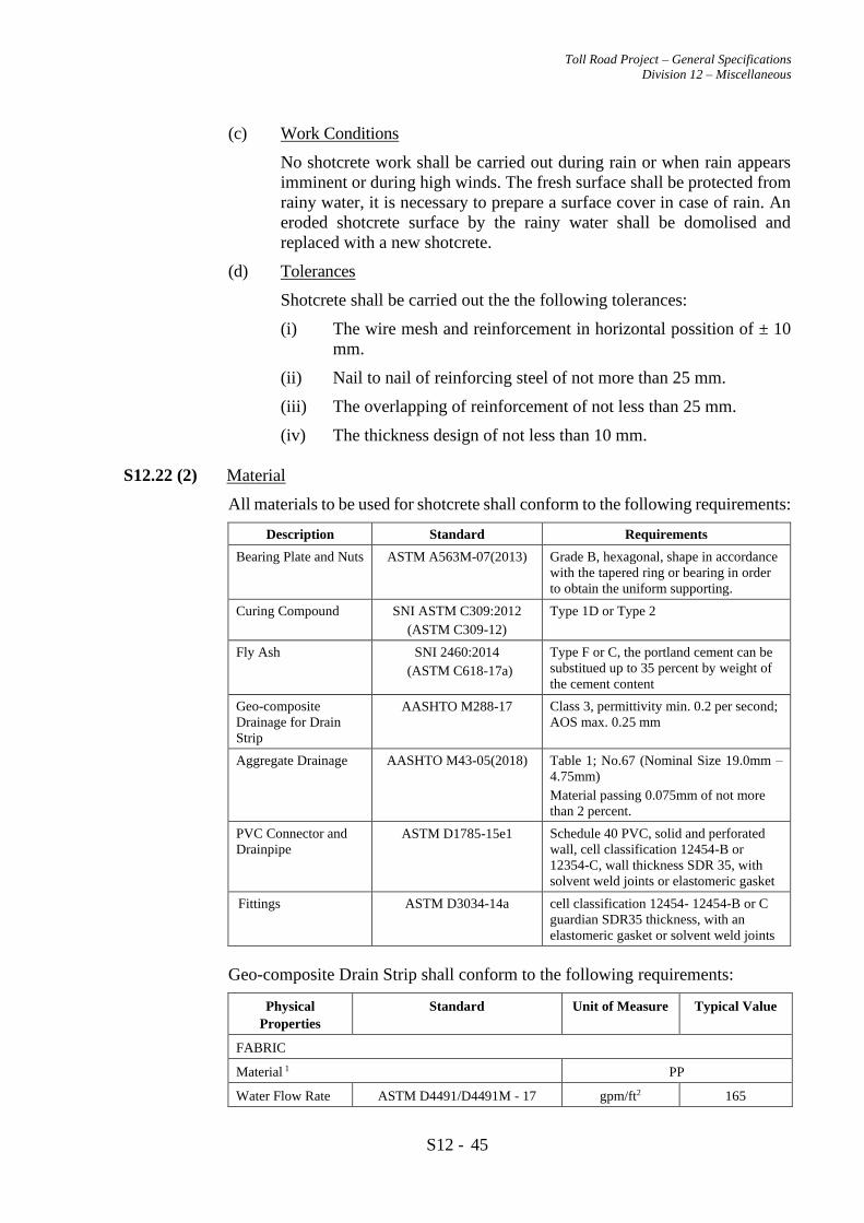
Toll Road Project – General Specifications
Division 12 – Miscellaneous
S12 - 45
(c) Work Conditions
No shotcrete work shall be carried out during rain or when rain appears
imminent or during high winds. The fresh surface shall be protected from
rainy water, it is necessary to prepare a surface cover in case of rain. An
eroded shotcrete surface by the rainy water shall be domolised and
replaced with a new shotcrete.
(d) Tolerances
Shotcrete shall be carried out the the following tolerances:
(i) The wire mesh and reinforcement in horizontal possition of ± 10
mm.
(ii) Nail to nail of reinforcing steel of not more than 25 mm.
(iii) The overlapping of reinforcement of not less than 25 mm.
(iv) The thickness design of not less than 10 mm.
S12.22 (2) Material
All materials to be used for shotcrete shall conform to the following requirements:
Description Standard Requirements
Bearing Plate and Nuts
ASTM A563M-07(2013) Grade B, hexagonal, shape in accordance
with the tapered ring or bearing in order
to obtain the uniform supporting.
Curing Compound SNI ASTM C309:2012
(ASTM C309-12)
Type 1D or Type 2
Fly Ash
SNI 2460:2014
(ASTM C618-17a)
Type F or C, the portland cement can be
substitued up to 35 percent by weight of
the cement content
Geo-composite
Drainage for Drain
Strip
AASHTO M288-17 Class 3, permittivity min. 0.2 per second;
AOS max. 0.25 mm
Aggregate Drainage
AASHTO M43-05(2018)
Table 1; No.67 (Nominal Size 19.0mm –
4.75mm)
Material passing 0.075mm of not more
than 2 percent.
PVC Connector and
Drainpipe
ASTM D1785-15e1 Schedule 40 PVC, solid and perforated
wall, cell classification 12454-B or
12354-C, wall thickness SDR 35, with
solvent weld joints or elastomeric gasket
Fittings
ASTM D3034-14a cell classification 12454- 12454-B or C
guardian SDR35 thickness, with an
elastomeric gasket or solvent weld joints
Geo-composite Drain Strip shall conform to the following requirements:
Physical
Properties
Standard Unit of Measure Typical Value
FABRIC
Material 1 PP
Water Flow Rate ASTM D4491/D4491M - 17 gpm/ft2 165
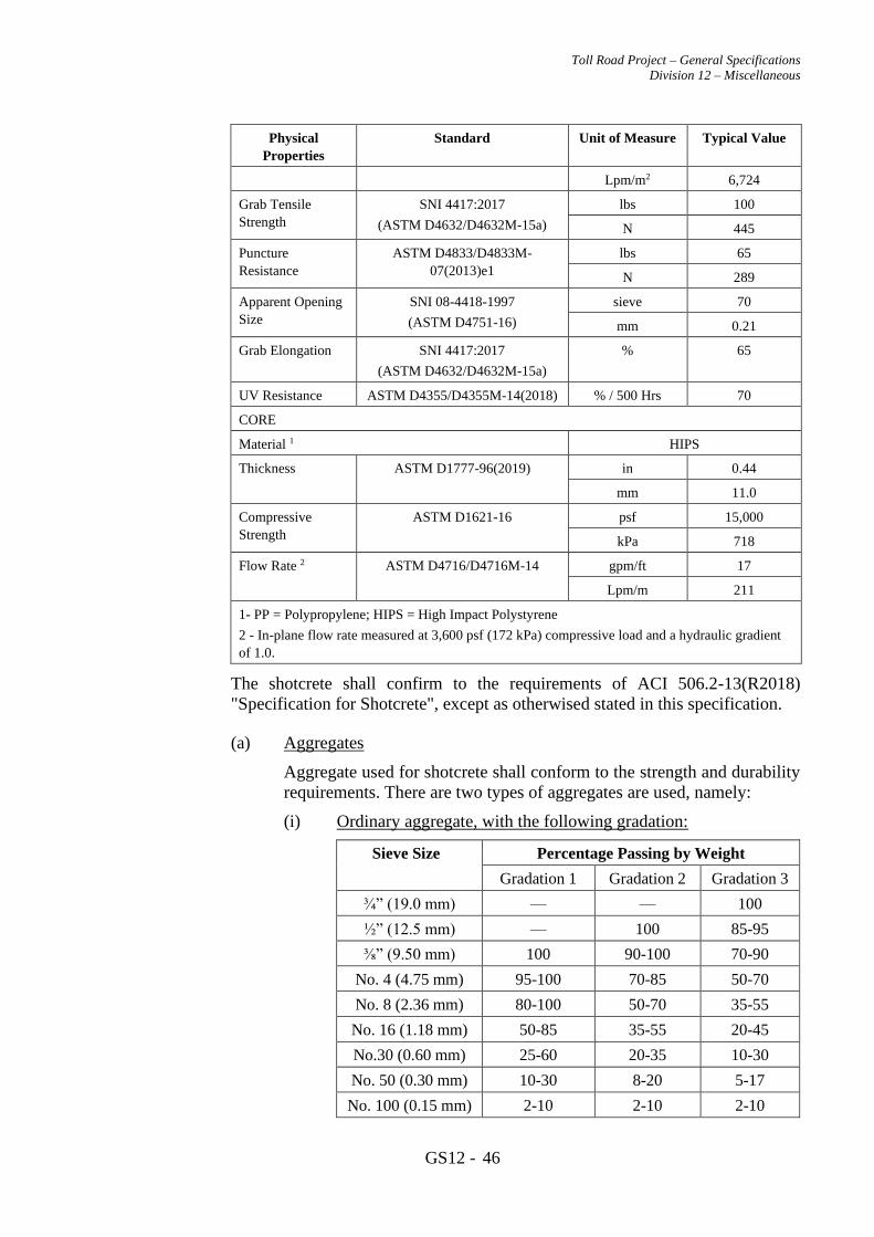
Toll Road Project – General Specifications
Division 12 – Miscellaneous
GS12 - 46
Physical
Properties
Standard Unit of Measure Typical Value
Lpm/m2 6,724
Grab Tensile
Strength
SNI 4417:2017
(ASTM D4632/D4632M-15a)
lbs 100
N 445
Puncture
Resistance
ASTM D4833/D4833M-
07(2013)e1
lbs 65
N 289
Apparent Opening
Size
SNI 08-4418-1997
(ASTM D4751-16)
sieve 70
mm 0.21
Grab Elongation SNI 4417:2017
(ASTM D4632/D4632M-15a)
% 65
UV Resistance ASTM D4355/D4355M-14(2018) % / 500 Hrs 70
CORE
Material 1 HIPS
Thickness ASTM D1777-96(2019) in 0.44
mm 11.0
Compressive
Strength
ASTM D1621-16 psf 15,000
kPa 718
Flow Rate 2 ASTM D4716/D4716M-14 gpm/ft 17
Lpm/m 211
1- PP = Polypropylene; HIPS = High Impact Polystyrene
2 - In-plane flow rate measured at 3,600 psf (172 kPa) compressive load and a hydraulic gradient
of 1.0.
The shotcrete shall confirm to the requirements of ACI 506.2-13(R2018)
"Specification for Shotcrete", except as otherwised stated in this specification.
(a) Aggregates
Aggregate used for shotcrete shall conform to the strength and durability
requirements. There are two types of aggregates are used, namely:
(i) Ordinary aggregate, with the following gradation:
Sieve Size Percentage Passing by Weight
Gradation 1 Gradation 2 Gradation 3
¾” (19.0 mm) — — 100
½” (12.5 mm) — 100 85-95
⅜” (9.50 mm) 100 90-100 70-90
No. 4 (4.75 mm) 95-100 70-85 50-70
No. 8 (2.36 mm) 80-100 50-70 35-55
No. 16 (1.18 mm) 50-85 35-55 20-45
No.30 (0.60 mm) 25-60 20-35 10-30
No. 50 (0.30 mm) 10-30 8-20 5-17
No. 100 (0.15 mm) 2-10 2-10 2-10
Toll Road Project – General Specifications
Division 12 – Miscellaneous
S12 - 47
Gradation 1 to be used for fine graded shotcrete, gradation 2 and 3 to be
used for coarse graded shotcrete.
(ii) Lightweight aggregate, as specified in the AASHTO M195-
11(2019).
(b) Reinforcing Steel
Reinforcement is required when the shotcrete has a function as structure
to support the loading. Reinforcement to be used in form of welded wire
mesh or reinforcing bar, either plain or deformed. For the proper
implementation, reinforcing steel shall have a diameter of 10 - 16 mm and
the galvanized wire mesh shall have a size of 5 mm X 150 mm X 150 mm.
Materials to be used shall be delivered, stored, and handled properly to
avoid contamination, segregation, corrosion, or damage. Liquid material
shall be stored properly to avoid the evaporation.
All geocomposite materials shall be rolled up and wrapped and stored in
such a way that protect them from mud, dirt, dust, soil and cement. The
coverage shall not be opened until the geo-composite will be installed.
This material shall not be directly exposed to ultraviolet light during
storage. Each roll of geocomposit in shipment shall be labeled as an
identification of production.
S12.22 (3) Mixing
(a) Mix Design
Contractor shall not commence the shotcrete work without Engineer’s
written approval of the mix design and method of construction.
(i) Proportions of Mixture and the Using of Admixture
The mixture shall be proportioned such as that the material can be
flowed using a pump provided for this work, with a bonding
material (portland cement) at least 390 kg/m3 and water-cement
ratio of less than 0.45. Admixture shall not be used without a prior
approval from the Engineer. Admixture to be added into the
mixture with the stirring speed as recommended by the
manufacturer. Accelerators (if used) shall be compatible with the
portland cement used, not corrosive to steel, and other negative
impacts such as cracks and excessive shrinkage. The content of
chloride ions is allowed of maximum 0.10% when tested in
accordance with AASHTO T260-97(2016).
(ii) Air Content
Air content is required for wet mixture. Air content in the mixture
shall be in the range of 7 - 10% when tested in accordance with
AASHTO T152-19. Air content limitation is not required for the
dry mix.
(iii) Strength and Durability Requirements
The compressive strength of shotcrete for 3 days shall have a
minimum strength of 14 MPa and for 28 days 28 MPa. Average
Toll Road Project – General Specifications
Division 12 – Miscellaneous
GS12 - 48
compressive strength of a set of 3 specimens (cores) taken from
the preconstruction panel test or from the shotcrete wall shall be
equal to or more than 85% of the compressive strength required,
with each test specimen is not less than 75% of the compressive
strength required in accordance with ACI 506.2-13(R2018).
Boiled absorption of shotcrete for 7 days shall not exceed 8.0% in
accordance with ASTM C642-13 "Standard Test Methodfor
Density, Absorption and voids in hardened concrete".
(b) Mixing of Shotcrete
Aggregate and cement shall be mixed with a ratio of weight or volume as
specified in AASHTO M241M/M241:2013(R2017) "Standard
Specification for concrete Made by Volumetrie Batching and Continuous
Mixing". Mixing equipment shall be able to mix throroughly with the
proper amount to maintain the continuous supply of materials. When the
ready-mix concrete to be used for shotcrete, it shall be in accordance with
AASHTO M157-13(2017). Shotcrete concrete shall be made, delivered,
to be placed within 90 minutes. The use of admixture may extend the
placement of more than 90 minutes, but it shall be approved by the
Engineer.
Shotcrete materials produced by a manufacture may be provided for mixing in
the site. The materials shall be in accordance with the section of this
specification. Placement time of shotcrete shall be in accordance with the
recommendations of the manufacturer.
S12.22 (4) Construction
(a) Surface Preparation
The slope surface or area for the shotcrete shall be cleaned out from loose
material, mud, splashes of cement, or other materials which is able to
cause bonding of shotcrete loose. To prevent of the spraying the edges and
adjacent shall be protected. During excavation and cleaning the surface, it
shall be avoided of soil loose, cracks, or damage. Surface of loose and
damaged soil shall be cleaned out to a depth which sufficient to provide
the shotcrete foundation. Material which causes the shotcrete apart when
spraying shall be cleaned out. To turn the flow of water when detected to
protect the shotcrete from the damage by the flow.
(b) Drainage Preparation on Slope
Installing and protecting all drainage components as shown in the
Drawings or requested by the Engineer in situ are required to match with
the Drawings or as requested by the Engineer in situ to accomodate the
field conditions. Drainage network shall include the drain strip made of
nonwoven geotextile, PVC pipe for the weep holes as shown in the
Drawings or the approved by the Engineer in accordance with the field
conditions. All components shall be installed before the shotcrete placed.
When the sub-drainage networks are found during excavation and is not
shown in the Drawings, they shall be treated and discharged separately,
and not combined with new drainage network and they shall be carried
Toll Road Project – General Specifications
Division 12 – Miscellaneous
S12 - 49
out before placing any shotcrete. The costs expended for such work are
taken into account as an additional cost.
Strip drain shall be installed in the middle of two nail points as shown in
the Drawings. The strip drain shall have a minimum thickness of 100 mm
and a minimum width of 300 mm with geocomposite component on the
ground. Strip drain shall be placed and maintained in such a way that the
shotcrete does not enter into the strip drain. Strip drain to be made
continously, when the joint to be used, the strip drain shall have a
minimum overlapping of 30 cm in order to prevent interruption of water
flow.
PVC pipe shall be in accordance with the Drawings to drain out the water
from strip drain. A special connector from manufacturer shall be used
between two strips drain to the pipe or a direct wrapped connection to
prevent intrusion of shotcrete shall be applied. This connection shall be
carried out by making a hole with the larger diamater than the pipe of strip
drains behind the plastic part and does not penetrate the geotextile. The
end of pipe shall be wrapped with the geotextile to prevent the migration
of fine particles into the pipeline. The end of pipe which connected to the
strip drain shall be protected and wrapped to prevent the shotcrete enter
in this section. Wheepholes made of PVC pipe shall be installed in
accordance with the Drawings to drain the water out from the wall. At the
end of pipe shall be closed temporarily during the placement of shotcrete
in order to prevent the clogged.
(c) Installation of Wire Mesh
Wire mesh with dimension of 5 mm X 150 mm X 150 mm is the
reinforcement of shotcrete, installed with spikes which planted on sloping
ground with a concrete decking under the reinforcement so that it does not
contact with the surface of soil. At least The quality of concrete decking
at least equal to concrete shotcrete. With the contribution of wire mesh, it
is expected that the shotcrete is a stronger cover of slope and reduce or
eliminate the possibility of cracks.
(d) Shotcrete Surface
(i) Shotcrete Thickness Setting
For the unloading shotcrete or structures with limited load, the
thickness is 75 mm both interior and exterior. The thickness of the
shotcrete shall be ensured to meet the minimum requirements as
shown in the Drawings by using the tools such as string, thickness
regulator sticks or other tools that can be accepted by the Engineer.
The tools shall be installed perpendicular to the plane so that the
minimum thickness can be achieved and the alignment of the
shotcrete surface in accordance with the Drawings. The maximum
distance tool shall be equal to the distance between the nails. When
the string used as a tool it shall be ensured that the string are
securely attached, straight, and placed in such manner to allow re-
tightening. The string shall be removed after completion placing
of shotcrete
Toll Road Project – General Specifications
Division 12 – Miscellaneous
GS12 - 50
(ii) Placing or Spraying of Shotcrete
Shotcrete placementshall be carried out from the bottom up to
prevent excessive rebound. The nozzle shall be pointed repeatly at
a distance of 60-100 cm in order to obtain the thickness design and
keep to perpendicular to the working plane so that the rebound
effect to be minimized and the maximum density obtained.
Reinforcement shall be ensured to be clean and shotcrete to be
placed behind the reinforcement in order to prevent the occurance
of voids or empty sandbag. Use the spray pipe to clean out the
rebound and excessive placing of shotcrete. The hardened rebound
and excessive shotcrete shall be cleaned out before the placement
of next shotcrete, cleaning shall be carried out by using the proper
manner. When the shotcrete to be used to fill part of the drill holes
that are close to the surface, pointing the nozzle into the hole until
fully charged.
When the pattern of shotcrete vertically or horizontally for the
strengthening section shows obviuosly the lack of shotcrete
covering or improper nozzle ponting, the shotcrete work shall be
suspended, and the Contractor shall investigate thoroughly before
continuing the work. Shotcrete placement procedure shal be
improved by adjusting the nozzle distance and the direction of
spraying to ensure the proper thickness of shotcrete cover on the
reinforcing steel, and to ensure the proper water content of the
mixtire or the other things. Adjustment of the water content in wet
mixing shall be approved by the Engineer.
The spraying pipe used for cleaning the rebound shall have the
clean, dry pressurized air flow, free from any lubricated oil in
order to obtain proper speed and continuous operation of the
equipment. Shotcrete equipment shall be able to tenasport the
mixture accurately, uniformly and continuously through a
transport hose. The thickness of shotcrete placing, nozzle pointing,
air pressure, and speed of shotcrete placing shall be controlled to
prevent uneven shotcrete, piling or excessive wet, which makes
shotcrete flow down.
(e) Surface Rectification
The rectification of shotcrete surface which not tidy but meet the strength
requirement shall be carried out with the following:
(i) brushing the surface with a steel brush for cleaning of loose
material, rebound, excessive spray or shiny surface before the
shotcrete hardening.
(ii) If the shotcrete has hardened, the surface preparation shall be post-
poned for at least 24 hours, then the surface shall be prepared with
sand blast or pressurized water spraying to remove all loose
materials, rebound, excessive hardened spray or a shiny surface,
or any other material that may cause a weak bonding with the new
concrete.
Toll Road Project – General Specifications
Division 12 – Miscellaneous
S12 - 51
(f) Defect of Shotcrete
Engineer may decide to accept or reject the work of shotcrete. The
shotcrete which does not conform to the specifications shall be rejected,
either at the time of construction, test results, or after completion of work.
Defects on the shotcrete surface shall be rectified immediately after the
placement of shotcrete. All parts of shotcrete which are segregation,
honeycombe or empty sandbag shall be cleaned out. Shotcrete which has
been placed and does not meet the requirement of the compressive
strength will be recfified as the direction of the Engineer. Rectifiaction
that possibly carried out is the placement of additional shotcrete, or
demolition and replacing of new shotcrete with costs fully borne by the
Contractor.
(g) Joints
Shotcrete joint shall be quite rough, clean and hard with a taper shape.
Prior to placing a new shotcrete, the joint shall be cleaned and moistened.
If shotcrete is used to cover the space above the top of the nail holes, then
the jointing shall pay attention to the things above.
(h) Curing
Shotcrete has been placed sahll be kept moist for at least 7 days after
placing with a method to ensure the shotcrete surface in wet conditions.
Curing commenced 1 hour after shotcrete placing, but if the air
temperature is over 27°Celsius, the curing shall be commenced
immediately after shtcrete placing.
Proper curing shall be carrie out with the following requirements:
(i) Curing with water. The supply of water shall be arranged so that
the shotcrete surface always be in wet condition and the surface
shall be kept in such manner that no erosion by water flow.
Irregular wetting where the shotcrete is in wet and dry condition
during the curing period shall not be allowed.
(ii) Curing with membrane. Curing compound shall not be applied on
the surface which will be overlaid with a new shotcrete unless the
surface is cleaned out using the sand blast. Curing compound
membrane shall be sprayed on the surface as soon as the initial
hardening of shotcrete with the rate of not more than 2.5 liters/m2
S12.22 (5) Quality Control
The manufacture of pre-construction panel test and cores sampling on the
constructed walls, both shall be carried out. Implementation of the panel test and
core sampling shall be carried out by experienced personnel and supervised by
the Engineer. Contractor shall provide equipment, materials, and personnel
required to obtain the cores to be tested, panel test box, and curing required in
situ. Shotcrete compressive strength for 28 days shall be a basis of final
acceptance.
Shotcrete material supply shall not be carried out prior to the initial approval of
the mix design and nozzlemen, and shotcerete work will be commenced when the
Toll Road Project – General Specifications
Division 12 – Miscellaneous
GS12 - 52
required compressive strength has been achieved. Shotcrete work may be
suspended if the test result does not meet the compressive strength required.
Contractor shall carrie out this procedure. The entire costs required to obtain the
compressive strength required shall be borne by the Contractor.
Pre-construction Panel Test. Each nozzleman who has no certification shall carry
out at least two pre-construction panel test for each mixture to be used and any
spraying position that will be found in this work. Preconstruction panel test shall
be carried out before commencing the work using the same tools, materials, mix
proportions, and the procedure to be used in the work.
The workers involved in this work shall have an experience to carry out this work,
especially the Nozzleman and his assistants as the key workers in the shotcrete
operation. Nozzleman who has a skill certificate in the shotcrete or equivalent is
preferred, therefore they can produce a dense shotcrete and meet the requirements
of compressive strength. The manufacture of pre-construction panel test and
taking core samples by core drilling shall be carried out in accordance ACI 506.2-
13(R2018) and AASHTO T24M/T24-15 or "Test Method for Obtaining and
Testing Cores drilled and sawed Beams of Concrete".
Initial qualification of nozzleman shall be carried out with the skill certification
owned and conduct pre-construction panel testing. Testing shall be carried out
using the same tools, materials, mix proportions, and the procedure to be used
during construction. Initial qualification of Nozzleman is based on visual
inspection of the density of shotcrete, structure space, and requirements of
compressive strength for 3 days and 28 days from the core of preconstruction
panel test taken. Loading of preconstruction panel test and core-making shall be
conducted in accordance with ACI 506.2-13(R2018) and AASHTO T24M/T24-
15, unless otherwise specified. Nozzleman without certificate may be permitted
to do the work if based on the compressive strength results of the pre-construction
panel test for 3 days meet the requirements, the continued for compressive
strength results for 28 days meet the requirements and the work is satisfactory
peformanced.
Preconstruction panel test shall be made with a minimum size of 750 mm x 750
mm and thickness of 100 mm. Spraying shall be carried out with a slope of 45°
to release the rebound. A preconstruction panel test shall include the reinforcing
steel as shown in the Drawings. Drill test shall be carried out from this panel test
which show the reinforcing steel in accordance with ACI 506.2 which equal to
the drill test of grade 2 or better. Other preconstruction panel test shall be prepared
without reinforcing steel, then the core shall be taken to test the absorption and
compressive strength.
Production Panel Test. Preparation of panel test at least once, nine (9) drill holes
with diameter of 75 mm were taken from the shotcrete wall for each area of 500
m2. Preparation of panel test shall be carried out simultaneously with the work in
progress by the time as determined by the Engineer. Production panel test to be
prepared shall have a minimum thickness of 100 mm and dimensions of 450 mm
x 450 mm.
Sampling, Curing and Testing. Immediately after spraying the mixture, the panel
test shall be kept moist by covering or wrap it with a sheet of material that meets
the requirements in SNI ASTM C309:2012 or ASTM C309-12 "Liquid
Toll Road Project – General Specifications
Division 12 – Miscellaneous
S12 - 53
Membrane forming Compound for Curing Concrete" until it has been brought
into the laboratory or testing sample has been carried out. Panel test shall not be
immersed into the water. Panel test also shall not be interrupted during the first
24 hours after the spraying mix. Samples shall be provided in 3 drill with a
diameter of 75 mm from each pre-construction panel test with installed
reinforcement for the purpose of determining the grade. For the purpose’s
absorption and compressive strength, preconstruction panel test without
reinforcement shall be provided in 9 Specimens with a diameter of 75 mm.
Contractor may choose to carry out the core drill testing in situ or brought to
another place for that purpose. Drill test shall be taken at a distance of 150 mm
from the outer edge of the panel test. For compressive strength testing, the core
drill results shall be cut at both ends in order to obtain the specimen with a height
of 75 mm. The both ends of core drill to be tested for absorption shall not be cut.
If the Contractor chooses to take the drill results from the panel test taken from
the walls of shotcrete in situ, then location will be determined by the Engineer.
Each specimen shall be marked properly in order to distinguish between the
specimen taken from preconstruction or during construction. If the specimen is
taken during the construction, the test specimen shall be marked on the part of
wall that represented. Immeditaely the drill results to be wrapped with wet
material or other material that meets the requirements of SNI ASTM C309:2012
(ASTM C309-12) and then put them in a sealed plastic bag. Within 48 hours, the
drill results shall be immediately delivered to the designated laboratory. The
compressive strength and absorption test will be conducted by the Engineer.
During transportation up to testing, the specimen shall be placed in a moisty room.
When the height of the test specimen is less than twice of diameter, a correction
factor from AASHTO T24M/T24-15 shall be applied to obtain the compressive
strength results of specimens. The compressive strength of 3 specimens shall be
tested for 3 days, and three other specimens for 28 days in accordance with
AASHTO T24M/T24-15. The absorption of the next 3 specimens again shall be
tested for 7 days in accordance with ASTM C642-13.
The hole of drill test in the wall shall be filled with the unexpanded mortar after
the hole has been cleaned out. This hole shall not be filled by using shotcrete
material.
S12.22 (6) Method of Measurement
Shotcrete shall be calculated from the surface area in square meter for the
shotcrete with the related thickness has been completed and accepted. The net
area is calculated from the outside plain surface as shown in the Drawings.
Addtional measurement and payment shall be not made for the additional
shotcrete required to cover the cavity caused by the incorrect excavation,
excessive or unplanned excavation, or workmanship which is not accordance with
a allowable tolerance. The payment shall include shotcrete, admixture,
reinforcing steel, wire mesh, panel test, and sampling, testing and reporting in
accordance with the design and this Specification. The quantity to be measured
shall be the area as shown in the Drawings or as approved by the Engineer.
Toll Road Project – General Specifications
Division 12 – Miscellaneous
GS12 - 54
S12.22 (7) Basis of Payment
The quantity of work to be measured as above mentioned will be paid according
to the contract price per square meter with the acceptable thickness. The payment
to be made shall include the supply of all equipments, materials, labour, and tools
to complete the work in accordance with the design and specification, including
the other work to obtain the alignment and thickness design of shotcrete. All
materials shall include strip drains, pipe for weep holes, catch basin, geotextiles,
and all accessories for the completion of the work will not be paid separately.
Pay Item No. and Name Unit of Measurement
12.22 Shotcrete Square Meter
S12.23 Bridge Deck Loading Test
S12.23 (1) General
(a) Description
Bridge deck load testing is carried out with the following purposes:
(1) To know the level of bridge safety.
(2) To determine the level of structure safety to the service load.
(3) To determine the initial condition of bridge using based on the
stiffness of bridge which obtained from the natural frequency
value of the bridge.
(b) Reference Standards
Standar Nasional Indonesia (SNI):
SNI 1725:2016 : Pembebanan untuk Jembatan
RSNI T-12-2004 : Perencanaan Struktur Beton untuk Jembatan
RSNI T-03-2005 : Perencanaan Struktur Baja untuk Jembatan
(c) Submittals
(i) Technical Preparation
Some matters that need to be carried out in the technical
preparation, such as:
(1) Collecting drawings and design documents.
(2) Communication (discussion) with the designer which
bridge to be tested as well as superintendent to obtain the
information regarding the condition of design and bridge
construction in order to predict easier the bridge’s
behavior.
(3) Implementing the examination on Drawings and design
documents regarding structural analysis and bridge
modeling.
Toll Road Project – General Specifications
Division 12 – Miscellaneous
S12 - 55
Prior to commencement the test on site, it is required to exanimate
the bridge design, including the Drawings and design data as well
as the As Built Drawings and post construction data. Based on
these two documents, a view will be able to obtained regarding the
condition of bridge when designed and constructed, therefore the
current condition of the bridge will can able to be predicted based
on the desk study result, whether there is any change from design
to construction stage.
(ii) Administrative Preparation
Administrative preparation includes the completion of
correspondence and approval of testing location. This approval
process involves Toll Road Regulatory Agency (BPJT), Local
Public Works Office, Local Transport Office, and Local Police.
The types of correspondence that need to be prepared are:
(1) Permit for Implementation of Testing
Permit for testing this is given an appendix as of a
technical proposal for testing plan. Permit for
Implementation of Testing is addressed to:
(a) Toll Road Regulatory Agency (BPJT)
(b) The National Road Construction Agency.
(c) Provincial Public Works Office for Provincial
Road.
(d) Region/Municipal Public Works for Region/
Municipal Road.
(2) Request of Engagement for Implementation of Testing
(a) Police for Toll and National Road.
(b) Provincial Transportation Office and Regional
Police for Provincial Road.
(c) Region/Municipal Transportation Office and
Resort Police for Region/Municipal Road.
When these permits have been approved, then bridge deck
load testing will be carried out.
S12.23 (2) Equipment
Any tool to be used shall be ensured that it shall be in a good condition and has
been calibrated and ready for use.
(a) Main Equipment
(i) Visual Test Equipment
Main equipment to be required on visual test implementation
except the inspection form, the detailed bridge condition to be
determined based on the type bridge, steel or concrete structure
bridge, such as:
Toll Road Project – General Specifications
Division 12 – Miscellaneous
GS12 - 56
(1) Steel Structure Bridge:
(a) Crack Detection Microscoupe/Crack Meter
(b) Torgue Wrench
(c) Total Station
(d) Waterpass
(2) Concrete Structure Bridge:
(a) UPV (Ultrasonic Pulse Velocity)
(b) Hammer Test
(c) Crack Detection Microscoupe/Crack Meter
(d) Total Station
(e) Waterpass
(ii) Static Load Testing Equipment
Main Equipment required for the implementation of static load
testing are:
(1) Strain Gauge
Strain gauge has it’s characteristic for steel and concrete
structure, therefore, for static load testing for steel bridge,
steel strain gauge shall be used, while for concrete
structure, concrete strain gauge shall be used.
(2) Logger Static data
(3) Switch Box (if required)
(4) Total Station
(5) Testing Truck
(iii) Dynamic Load Testing Equipment
Main equipment required for implementation of dynamic load
testing are:
(1) Blastmate or 3 dimension Accelerometer
(2) Logger Dynamic Data
(3) Switch Box (if required)
(4) Testing Beam
(5) Testing Truck
(b) Supporting Tools for Implementation of Testing
Supporting tools for implementation of testing, such as:
(i) Climbing tools (to install sensor, etc)
(ii) Cloth Uniform
(iii) Safety Hat
Toll Road Project – General Specifications
Division 12 – Miscellaneous
S12 - 57
(iv) Handy Talky
(v) Spray Paint
(vi) Hammer + Nail (as required)
(vii) Thin Plastik (rain protection)
(viii) Double Tape
(ix) Scissor
(x) Digital Camera
(xi) Handycam
(xii) Walking Measure
(c) Occupational Safety Tools
Occupational safety tools required and shall be prepared to prevent
unexpected event during preparation and implementation of load testing.
Some of the safety tools required are as follows:
(i) Safety hat, for protecting the head from falling or bumping of hard
material during preparation and implementation of load testing.
(ii) Safety shoes, preventing the slip due to slippery or protecting the
leg from hard material falling or others.
(iii) Gloves, required for doing the works related with hard material,
such as opening or fastening bolt or others.
(iv) Safety Belt, protecting the body from falling hazard, particularly
when the installation of sensor tool
(v) Full body harness, for working at height more than 1.24 meter,
useful to protect the body from falling hazard, particularly when
the installation of sensor tool.
S12.23 (3) Execution
(a) Requirements for Bridge Deck Load Testing
For Bridge deck load testing, some issues need to be paid attention,
include:
(i) Testing shall provide information about the condition of stress and
deformation of the main part of bridge structure.
(ii) Testing shall reflect load capacity of structure
Capacity is a synthetic index of physical mechanics of structure,
including strength, stiffness, stability, response, dynamic and
others. Of course, this will be different for the different structural
system. Therefore, based on the basis of previous structural
analysis, proper method shall be adopted on testing to evaluate
structural load capacity.
(iii) Testing load shall not impact on structural damage
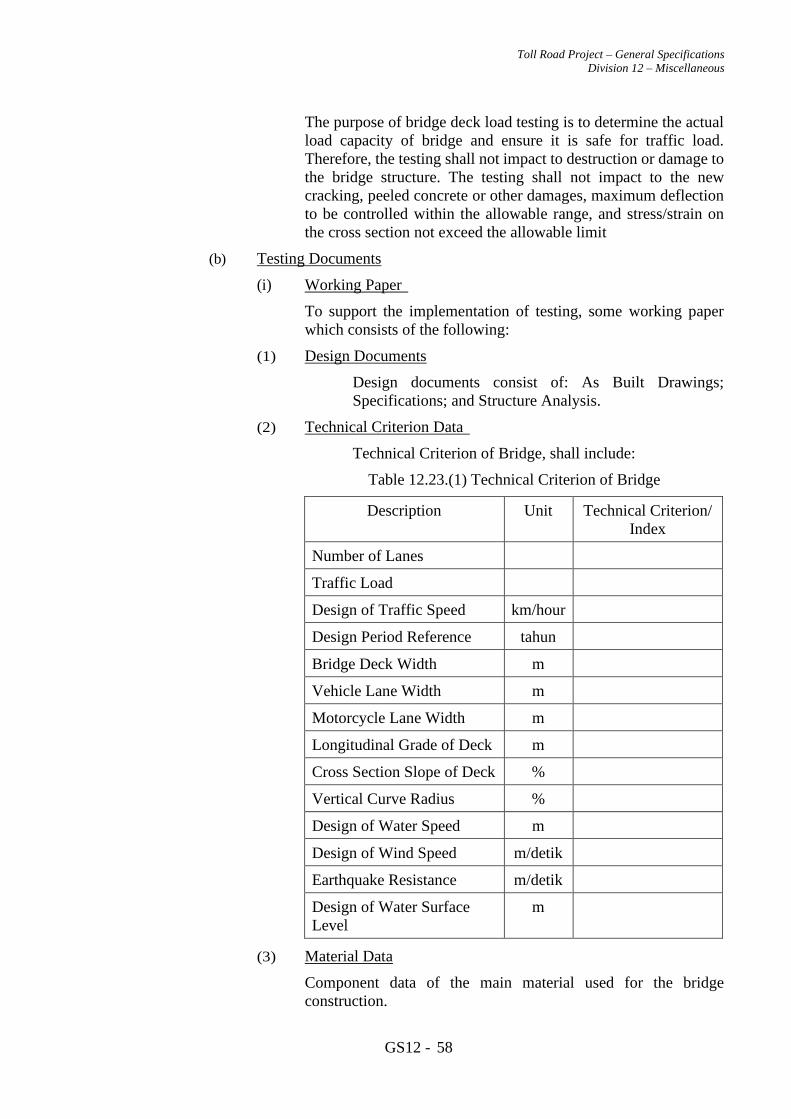
Toll Road Project – General Specifications
Division 12 – Miscellaneous
GS12 - 58
The purpose of bridge deck load testing is to determine the actual
load capacity of bridge and ensure it is safe for traffic load.
Therefore, the testing shall not impact to destruction or damage to
the bridge structure. The testing shall not impact to the new
cracking, peeled concrete or other damages, maximum deflection
to be controlled within the allowable range, and stress/strain on
the cross section not exceed the allowable limit
(b) Testing Documents
(i) Working Paper
To support the implementation of testing, some working paper
which consists of the following:
(1) Design Documents
Design documents consist of: As Built Drawings;
Specifications; and Structure Analysis.
(2) Technical Criterion Data
Technical Criterion of Bridge, shall include:
Table 12.23.(1) Technical Criterion of Bridge
Description Unit Technical Criterion/
Index
Number of Lanes
Traffic Load
Design of Traffic Speed km/hour
Design Period Reference tahun
Bridge Deck Width m
Vehicle Lane Width m
Motorcycle Lane Width m
Longitudinal Grade of Deck m
Cross Section Slope of Deck %
Vertical Curve Radius %
Design of Water Speed m
Design of Wind Speed m/detik
Earthquake Resistance m/detik
Design of Water Surface
Level
m
(3) Material Data
Component data of the main material used for the bridge
construction.
Toll Road Project – General Specifications
Division 12 – Miscellaneous
S12 - 59
(ii) Testing Form
As a reference on testing implementation on site, some forms
required to be used as a tool to record testing result as well as to
provide a view regarding the testing procedure and the results.
Testing form used can be taken from BMS. Forms to be that used
are as follows:
(1) Inspection Form of Detailed Bridge Condition (Visual)
Inspection Form of Detailed Bridge Condition (Visual)
consists of:
(a) Bridge identity includes: number; name and location of bridge
(b) Date of inspection and identity of inspector
(c) Element required to be tested
(d) Types of action required to be carried out
(e) Documentation photo of the bridge
(f) List of damaged elements
(g) Evaluation of the elements
(h) Notes and Drawings
(2) Testing Form of Static Loading
Testing Form of Static Loading consists of:
(a) Bridge identity includes: number; name and
location of bridge
(b) Date of inspection and identity of inspector.
(c) Information of total and location of load used
applied (as table and drawing)
(d) Information of the total and location of sensor used
(as table and drawing)
(e) Record of the deflection observation
(3) Testing Form of Dynamic Loading
Testing Form of Dynamic Loading consists of:
(a) Bridge identity includes: number, name and
location of bridge
(b) Date of inspection and identity of inspector.
(c) Sketch of position for vibration recording tool
(d) Record issues that shall be noted during
implementation of testing
Toll Road Project – General Specifications
Division 12 – Miscellaneous
GS12 - 60
(iii) Testing Proposal
Testing proposal consists of the following:
(1) The purpose and objective of testing
(2) Metode used
(3) Procedure of testing
(4) Human resources and equipment requirement
(5) Analysis of modelling result
(6) Expected result
(c) Field Testing
(i) Visual Inspection
Visual inspection requires a trained expert who able to detect
abnormal issues which may occur on the structure and able to
differentiate types of damage and their causes. For example, the
expert shall be able to differentiate types of crack that may occur
on concrete structure.
Procedure to be carried out on visual inspection:
(1) Inspect the general condition of bridge
Detail inspection by recording the damages or the main
deviation on elements of bridge structures.
(2) Check the crack with the UPV and crack measuring tools
for concrete bridge.
Crack inspection is required to determine accurate and
complete data regarding current crack condition therefore
a conclusion can be determined regarding how far the
current crack can influence the structure as well as to
understand or indicate the cause of crack.
Tool that can be used to examine the depth of crack is
PUNDIT (Portable Unit Non Destructive Indicator Tester)
or Ultrasonic Pulse Velocity (UPV) and for the width of
crack can be examined using crack meter with an
additional magnifying glass to measure occurred crack. To
differentiate types of crack as well as their causes, an
intensive investigation regarding the crack pattern is
required. Based on the investigation, early prediction
regarding the cause of crack can be obtained.
From the testing using UPV and crack measuring tool, the
data of depth, length and width of the crack can be
determined, as well as the presence of void or honeycomb
on the concrete. Elements of bridge that are examined
(possibility of cracks) are the structural parts and made of
concrete, such as abutment, pier, girder deck plate of the
bridge.
Toll Road Project – General Specifications
Division 12 – Miscellaneous
S12 - 61
(3) Cary out a more accurate regarding the concrete
compressive strength.
Based on the visual inspection, the result can be put in a
proposal of load testing which include the determination
of total load and model testing where all damages (if any)
on bridge have been considered.
(ii) Static Load Testing
(1) Criterion of load that can be applied on structure:
(a) Total of static load applied shall be calculated in
such manner in order to not cause the damage to
the structural element of bridge. In some cases, the
maximum of load that can be applied shall not
exceed 50% of Uniformly Distributed Load
(UDL).
(b) Total of load shall be distributed to some load
points, therefore this loading can represent the
actual traffic load.
(c) Load shall be applied in stages, starting from the
loading position which gives a minimum effect.
(d) Load shall be applied symmetrical.
(e) From the first loading stage to the next loading
stage shall have a sufficient duration for structure
to response the applied load. This can be observed
from whether the bridge still provides an additional
deflection or not.
(2) Testing Procedures:
(a) Preparation:
(1) Planning Preparation (in office)
Calculation of total load and truck
configuration to be used:
Total of load that will be used depends on
the load planning that will be implemented,
by keeping the principle that the testing
shall be a non-destructive test, therefore the
determination of total load used is as much
as possible but it shall not impact to the
bridge and still provide the required data.
(2) Planning Preparation (in situ)
(a) After initial planning and site
investigation, arrange testing items
if required.
(b) Mark loading position on the bridge
Toll Road Project – General Specifications
Division 12 – Miscellaneous
GS12 - 62
deck in accordance with the testing
points and reference marks
predetermined
(c) Sensor Installation
Strain Gauge shall be is placed on
the point that will have highest
stress. The location is adjusted with
the modelling result that has been
carried out by a bridge expert.
(d) Set the tool: logger static data and
switch box if the total of sensor
exceed the capacity of logger data.
(e) Check the sensor condition and tool
whether ready to be used and no
disruption
(f) Connect the instrument and the tool,
check whether each system has
worked after electrified
(g) Put the Total Station on the location
that can cover all cross section of
the bridge.
(h) Preparation of Testing Truck
Truck that will be used as a load on
the testing shall be prepared
previously in accordance with the
total of load planned and the
availability on the testing location.
Truck that will be used shall be
recorded for the configuration and
total load, therefore the weighting
shall be carried out prior to testing
Scale used to determine the truck
loading has to be calibrated in order
to obtain the accurate load
(i) Check the Fasten Bolt
For the steel bridge testing, ensure
all bolts are installed with good and
fastened condition in accordance
with the fastened torque
(j) Determine loading time in
accordance with site condition and
weather
Toll Road Project – General Specifications
Division 12 – Miscellaneous
S12 - 63
(b) Testing Implementation
Loading dan Un-loading Test
(i) Ensuring that all equipment in good
condition, particularly the strain gauge.
(ii) Record initial condition by pushing the
button of logger static data, therefore the
initial sensor data will be read.
(iii) Reading the total station for all observed
location (TS-0) when the truck just arrived,
and when the truck totally stopped.
(iv) Placing the truck on the mid of span
according to the initial plan by staging up
to the entire trucks are placed on the bridge
and all data are read in each stage.
(v) Loading scheme:
Loading shall be carried out by staging to
observe behavior of bridge when tested and
post tested. Static loading scheme is as
follows:
(1) Loading :
- Stage 1 no truck
- Stage 2, trucks used are 4 which
are located on left and right
edge of the bridge span
respectively
- Continuing each stage until the
truck reach the mid of span or
maximum load planned
- The deflection of each stage
shall be recorded and shall be
coordinated to a Structure
Expert to obtain the next
instruction.
(2) Un-loading :
- Unloading Stage 1, trucks
occupy half span of bridge
- Unloading Stage 2, trucks used
are eliminated by 2 and all
trucks in front move backward
for (10 + length of truck) m.
- Repeating until all trucks on
bridge have been moved.
Toll Road Project – General Specifications
Division 12 – Miscellaneous
GS12 - 64
During testing, structure
displacement as well as the strain of
structural elements in the critical
locations shall be measured using
variety of techniques and
measurement tools.
Generally, displacement can be
considered a measure of structural
stiffness, while strain is a measure
of material structural capacity.
Structural displacement due to
static loading can be measured on
horizontal and vertical direction,
however vertical direction is
generally specified as deflection of
structural element, measured in
each case, using dial gauge (strain
gauge), calibrated Linear Variable
Differential Transformer (LVDT),
evenness measurement or other
measuring methods.
Measured results of displacement,
majority are deflection, are
compared to the calculated results
according to standard loading,
design load and correspond to
vehicle used for testing
(iii) Dynamic Load Testing
Dynamic load on a road bridge can be carried out using the
following loading:
- a normal traffic,
- vehicle or test machine,
- sudden release of displacement by producing a load related
to structure,
- producing sinusoidal excitation wave,
- energy input tool,
- braking of vehicle or a machine on the bridge,
- impact produced by a vehicle that go through a standard
bar (on road case).
Bridge vibration inspection is carried out to know whether the
bridge vibration behavior still meet the criterion of bridge
behavior or not. Vibration criterion on the bridge includes stiffness
criteria, service capacity criteria, load capacity criteria, and
damping criteria. Vibration testing is carried out by using moving
Toll Road Project – General Specifications
Division 12 – Miscellaneous
S12 - 65
load or heavy traffic load. The measurement of bridge vibration is
carried out by using vibrocorder that produces a vibration record
on a film paper with a sensor of transducer that located on mid
span.
This testing provides information regarding some dynamic
characteristics that generally selected from the bridge. During the
dynamic testing, the following parameter indicates dynamic
behavior of a bridge that generally measured.:
- natural frequency,
- mode shape,
- damping factor.
In general, the method of dynamic load testing using vibration
recording sensor tool is as follows:
- Prepare sensor to obtain vibration on horizontal direction
(in this case, Wireless Structural Testing System (STS-
WiFi) to be used),
- Place sensor on the top of the pier/base of bridge,
- Place vibration recording device the safe location and free
from distraction,
- Calibrate vibration recording device to obtain a good
record.
- Pass the vehicle (testing truck) on a wooden beam with
particular dimension (according to plan)
- Record the vibration.
(iv) Management and Safety Testing
During all processes of testing implementation, testing personnel
shall take a control of site condition to manage the loading. This
will impact to good testing, other than safety to personnel, tools
and supplies, and the bridge. There are some components shall be
paid attention, as below:
(1) Load Control
Loading area and internal force per each part shall be
gradually increased from the lower level to higher level,
step by step to comply with the load testing specified.
Unloading shall be ready to be carried out for any time.
(2) Location of the Measurement Point
Measurement points shall be measured and calculated
during all load test processes. All data shall be has
collected and analyzed to determine the testing status any
time. If the actual measurement value is so far below the
calculated value, then the loading shall be stopped
Toll Road Project – General Specifications
Division 12 – Miscellaneous
GS12 - 66
temporarily to search the reason why, then to determine
when the testing to be continued.
(3) Observation on Loading Process
A person shall be assigned to observe structural weak
points to examine if there is any cracking, damage,
abnormal voice, abnormal vibration, etc, on the load
testing. If an abnormality occure, then it shall be reported
immediately to take a relevant measurement and action.
(4) Criteria to stop the Loading
Loading shall be stopped if the following conditions
occure:
- The stress on measurement point achieves or exceeds the
control value that calculated using elastic theory according
to design standard.
- Displacement/deflection of measurement point exceeds
the allowable limit.
- The deflection distribution which actually measured on the
girder throughout the bridge is really different with the
calculated value, or the deformation which actually
measured is so far above the calculated value.
- Other damages that will impact to the load capacity or the
service level of bridge.
To ensure security as well as easiness of testing
implementation, and to prevent the accident, then the
following requirements shall be strictly implemented on
the testing, such as:
- To establish the awareness regarding safety, increase
vigilance and avoid the accident occupational.
- Key point of construction shall be arranged with protection
and lighting facilities, testing staffs shall wear helmet and
safety belt.
- During testing, take care the safety and water protection
for equipment and tools.
- Testing staffs shall understand the site instructions.
- Unauthorized persons are prohibited to enter testing area.
To prevent the damage on the data recording in situ, some
matters need to be ensured, such as:
- Ensure that when testing is commenced, consent from
local government has been obtained with allowable time
for testing as planned.
- Ensure that the time for testing implementation on site is
accordance with the plan which has been agreed in order
Toll Road Project – General Specifications
Division 12 – Miscellaneous
S12 - 67
that all preparations can be ripened by all parties who
involve in the testing implementation
- Prepare all equipment and tools are ready to withstand to
all kinds of weather, such as hot weather or rain. Provide
cover if the equipment does not withstand to weather by
maintaining the performace to keep it running well.
S12.23 (4) Method of Measurement
The Bridge Deck Load Testing shall be measured by the number of testing carried
out, completed as well as the report accepted.
S12.23 (5) Basis of Payment
Quantity of Bridge Deck Load Testing will be determined as provided above,
shall be paid for at the Unit Price for the Pay Item and using the unit of
measurement shown below and in the Bill of Quantities.
Pay Item No. and Name Unit of Measurement
12.23 Bridge Deck Load Testing Each

Toll Road Project – General Specifications
Division 12 – Miscellaneous
GS12 - 68
Toll Road Project – General Specifications
Division 13 – Lightings, Traffic Signals & Electrical Works
GS13 - 1
DIVISION 13 LIGHTINGS, TRAFFIC SIGNALS AND ELECTRICAL WORKS
S13.01 Lighting, Traffic Signals and Electrical Works
S13.01 (1) General
(a) This work shall consist of furnishing and installing all materials and
equipment necessary to complete in place traffic signals, highway
lighting, and other electrical systems, and the modification of such
existing systems when so specified, all in accordance with the Drawings,
these Specifications, or as instructed by the Engineer. Unless otherwise
noted, civil engineering works necessary for the work of this Clause
S13.01 shall be executed and paid for under Clause S13.02 of this
Specification.
(b) The location of signals, controllers, poles and appurtenances shown on the
Drawings are approximate and the exact location will be established by
the Engineer in the field.
(c) The electrical works for Guide Signs shall be executed in accordance with
this Clause and Clause S13.02. Payment under this Clause for Guide
Sign cables will terminate at the junction board in the hand hole of the
pole.
S13.01 (2) Scope of Work
The scope of work shall cover the supply, delivery to site, erection, test and
commissioning of all material and equipment in connection with the Electrical
Installation to the extent described and shown on the Drawings and includes but
is not necessarily limited to :
(a) Preparation and submission of Shop Drawings
(b) Submission of detailed Material Supply Lists
(c) All work associated with the removal of sections of the existing systems
and the incorporation of the remaining sections in the permanent works.
(d) Site measurements of ambient brightness of natural daylight at tunnel or
underpass sections to assist the Engineer in his review of the lighting
details shown on the Drawings.
(e) All other electrical equipment and services needed to complete operation
facilities in accordance with the pertinent electric codes and local
regulations for Electrical Installation, included all permits required from
Electrical Authority to operate properly.
Toll Road Project – General Specifications
Division 13 – Lightings, Traffic Signals & Electrical Works
GS13 - 2
S13.01 (3) Quality Assurance
(a) For fabrication, installation, and testing of the work described in this
Clause, the Contractor shall use only thoroughly trained and experienced
personnel who are completely familiar with the requirements for this work
and with the installation recommendations of the manufacturers of the
specified items.
(i) In acceptance or rejection of the installed electrical system, no
allowance will be made for lack of skill on the part of installers.
(ii) Installers shall hold the relevant valid certificates complying with
PLN and local Regulations.
(b) All work shall comply with the Drawings and this Specification, in
addition to complying with the following codes and regulations:
(i) Requirements of the local unit of PLN exploitation and local
government agencies;
(ii) PUIL, SPLN and Local Electricity authority standards.
S13.01 (4) Drawings and Documents
(a) The Contractor shall refer to all relevant drawings to ascertain for himself
the location and routes of all other utility services so as to maintain
adequate clearance between electrical and other services. The supplied
Drawings are to indicate generally the arrangement of the work. The
Contractor is therefore required to provide working drawings showing the
exact routes of all underground or overhead cables and ducts, the exact
run of all conduits and trunking, the location of manholes, draw-in and
junction boxes, the number and size of wires in each conduit or trunking,
the final connection arrangements at street lighting panels, the detail of
ducts and the method of fixing street lighting panels for the approval of
the Engineer before commencing any portion of the Works. All such
shopdrawings shall be submitted in duplicate and within the periods
stipulated below:
(i) Details of ducts and method of fixing street lighting panels and
cable entry into buildings: Shop drawings shall be submitted
within two months of handing over the site to the Contractor.
(ii) All other shop drawings shall be submitted within a period of one
month from the date of approval of the street lighting panels by
the Engineer.
(iii) Should however the Contractor be obliged to install electrical
conduits prior to this period then he shall submit the relevant shop
drawings at least four weeks prior to the proposed date for
commencement of the work.
(iv) The Contractor shall submit a program indicating the dates on
which concreting in different sections will take place, together
with the submission of the shop drawings.
Toll Road Project – General Specifications
Division 13 – Lightings, Traffic Signals & Electrical Works
GS13 - 3
(b) On completion of testing, the Contractor shall make "as built" drawings
of plans and circuit diagrams, which clearly indicate any modifications
which have been made to the original design drawings.
(c) Upon completion of the work, and as a condition of its acceptance, the
Contractor shall supply to the Engineer three copies of a Manual for the
maintenance and operation of all electrical installations and a parts list
sufficient for the ordering of parts.
S13.01 (5) Standards and Regulations
(a) The work covered by this Contract shall be carried out in accordance with
the regulations issued by the local Electricity Authority and with the
applicable standards and codes of any of the following:
ASA : American Standards Association
ASTM : American Society for Testing Materials
CIE : Commission Internationale de l’Elclairege (International
Commission of Illumination)
DIN : German Industry Standard (Deutsche Industrie Normen)
EN : European Standards
IEC : International Electrotechnical Commission
IEE : Institute of Electrical Engineers
IEA : International Electrical Association
JEC : Japanese Electrical Committee
JIS : Japanese Industrial Standard
LMK : Lembaga Masalah Kelistrikan
NEC : National Electrical Code (U.S.A)
NECA : National Electrical Contractors "Standard of Installation"
(U.S.A)
NEMA : National Electrical Manufacturers Association (U.S.A)
PLN : Indonesia Government Electric Company
PUIL : Peraturan Umum Instalasi Listrik
SPLN : Standar Perusahaan Listrik Negara
UL : Underwriters Laboratories, Inc.
(b) Before commencing the works, the Contractor shall carefully examine his
works at all of the Regulations issued by the local Electricity Authority
and selected materials and method of installation shall be in accordance
with these Regulations.
S13.01 (6) Lighting Units
A. For non-LED
(a) General
Lighting units as shown on the Drawings shall consist of lighting lanterns
(lanterns), lamps, electrical control ballasts (ballasts), and mounting
accessories.
The Contractor shall submit for approval, detailed street lighting panel
diagrams for each type of lantern he proposes to install. Furthermore,
calculations shall be submitted showing the horizontal illuminance in lux
Toll Road Project – General Specifications
Division 13 – Lightings, Traffic Signals & Electrical Works
GS13 - 4
at roadway level and the luminance distribution in candela per sq.m for
every 2 m in roadway direction and every 1.2 m across the roadway.
(b) Street Lighting Units (Pole Mounted)
Lamps for expressway lighting system shall be 250 watts high-pressure
sodium type and for the arterial roads lamps shall be 250 watts high
pressure sodium type.
All lanterns shall be of the type shown on the Drawings or equivalent as
approved by the Engineer.
(c) Lighting Units for Under Bridges or Inside Tunnels
Lighting units fixed to the ceiling/wall under Bridges or inside Tunnels
(Box Culverts) shall have 150 watts low-pressure sodium type lamps.
The layout of tunnel lighting units shown on the Drawings is based on the
estimated ambient brightness of natural daylight at the tunnel entrance.
On completion of the box culvert and substantial pavement works, the
Contractor shall undertake site measurements to check the actual ambient
brightness. Based on these results, the Engineer may revise the layout of
lighting units as shown on the Drawings.
Lanterns shall be surface mounted type with symmetrical light
distribution and of the type shown on the Drawings or equivalent as
approved by the Engineer.
(d) High Mast Lighting Units
The lanterns shall be floodlight type and shall be mounted on a high mast
carrying 1000 watts mercury or high pressure sodium lamps. The lantern
shall comprise three main parts; a low-pressure die-cast aluminum
housing; a toughened front glass, attached to the housing by two hinges
and four clips of stainless steel; and a hot dip galvanized mounting
bracket. The lantern shall be fitted with an asymmetrical optical system
of special design, made of high purity aluminum which has been
chemically polished and anodized.
The lantern shall incorporate a splash and dustproof type sealing between
the housing and the glass front cover. All exposed metal parts shall be
made of non-corrosive materials. In its basic mounting position with the
glass front cover in an absolute horizontal position the flood-light shall
keep all distributed light below the horizontal plane, providing a cut-off
light distribution with perfect glare limitation in accordance with C.I.E.
recommendations. (C.I.E.: Commission International de l' Eclairage).
(e) Toll Plaza Lighting Units (Pole Mounted)
The lanterns shall be horizontal burning type with semi-cut-off light
distribution and shall be of the type shown on the Drawings or equivalent
as approved by the Engineer. Lamps shall be high-pressure mercury
type.
Toll Road Project – General Specifications
Division 13 – Lightings, Traffic Signals & Electrical Works
GS13 - 5
(f) Ballasts for Low Pressure Sodium Lamp
Ballasts for low pressure sodium lamps shall be designated to properly
operate the lamps of the wattage as designated in the Drawings.
Ballasts shall have the electrical characteristics of the high power factor
type with voltage ratings as noted on the Drawings. The ballasts shall be
remotely mounted and shall be set on the junction board located in the
handhole of the lighting pole.
Each ballast shall have a name plate permanently attached to the case,
listing all electrical data.
(g) Ballasts for High Pressure Sodium Lamp
Ballasts for high pressure sodium lamps shall be designated to properly
operate the lamps of the wattage as designated in the Drawings. All
ballasts shall be drip-proof, canned, and polyester-filled and shall be
equipped with terminal blocks for the electrical connections.
Instructions for making the electrical connection shall be printed clearly
on the can of the ballast.
The power factor of a lamp combination shall have a higher value than
0.85 and shall be achieved by connecting parallel capacitors with
sufficient capacitance across the mains. The capacitors used for the
purpose shall be suitable to operate at a normal voltage of at least 220 V
50 Hz.
(h) Ballasts for High-Pressure Mercury Lamp
Ballasts for high-pressure mercury lamps shall be designated to properly
operate the lamps of the wattage as detailed in the Drawings. All ballasts
shall be drip-proof nylon encapsulated orthocyclically wound, units of
low power loss and rugged mechanical and electrical construction. The
ballasts shall be equipped with terminal blocks for electrical connections.
Instructions of the electrical connection shall have a name plate
permanently attached to the case listing all electrical data.
(i) The Lanterns for Public Street Lighting
(i) General
(1) Luminaire is a tool that distribute, filter or change the
transmitted light from the lamp, consisting of all the parts
needed to support, install and protect the lamp, including
electrical circuit in it to be connected to the mains.
(2) Luminaire and its components are made of corrosion-
resistant material and vibration and are made of materials
of high pressure die cast aluminum and shall be evidenced
by a brochure or catalog from the factory.
(ii) Classification
Classification luminaire shall be meet the criteria for protection
against dust, solid objects, humidity and water on the luminaire
(IP) and the coefficient of utilization of at least 60%.
Toll Road Project – General Specifications
Division 13 – Lightings, Traffic Signals & Electrical Works
GS13 - 6
(1) Lantern / optical Minimum: IP 65
(2) The minimum gear control room: IP 43
(iii) The Lantern and cover
(1) In the lantern there is a light bulb, fitting, reflector and
cover are equipped with silicon gasket from a tropical
climate resistant and securely fastened in position.
(2) The locking clamp lamp cover shall be opened easily
without using tools.
(3) Lamp cover made of borosilicate or tempered glass.
(4) Electrical components chamber cover is made of high
pressure die cast aluminum.
(iv) Optic Reflector
(1) The reflector is made of anodized aluminum or all-glass
with high purity and can give the effect of light reflection,
resulting in a minimum luminaire light efficiency of 60%.
(2) In the optical space should be no air circulation and
reflectors shall meet the room lights (full reflector)
B. FOR LED (Light-Emitting Diode)
(a) LED Standard
Standard to be used as follows:
• EN61347-1 : General standard and safety.
• EN62384 : DC/AC supply, electronic control gear module LED
• EN61347-2-13 : DC/AC condition supply, electronic control gear
module LED
Standard test LED
• IEC 60598-2-3: Certification Body Test (CB Test)
• IEC 3130125: Electro Magnetic Compatibility (EMC Test)
(b) Certification
Prior to request to Engineer, Contractor shall perform the following
certificates:
• Certificate LM80 (Lumen Depreciation Test) of LED used
• Certificate type IEC 60598
• Certificate of Vibration Test
• Certificate of Electro Magnetic Compatibility (EMC Test)
• Certificate of Salt spray test
• Certificate of ISO from the Manufacture.
• Certificate of Laboratory of Test.
Toll Road Project – General Specifications
Division 13 – Lightings, Traffic Signals & Electrical Works
GS13 - 7
(c) Lantern
• The lantern shall be made from the full die cast Aluminum.
• For optimal heat dissipation strength and ease of operation, the driver
and LED module shall be in the same lantern set (complete set)
• The LED module chamber glass cover shall be made of tempered glass
of silicon material which guarantees a minimum protection index of
IP66.
(d) Optic
The following optical requirements shall be met:
• Luminaires for 120 watt LEDs shall have a minimum light flux output
(13000 Lumen +/- 5%) with maximum power consumption (120 Watt
+/- 5%), and an 80 watt LED luminaire shall have a minimum light
flux output (Lumen 8000 + / - 5%) with maximum power consumption
(80 Watt +/- 5%).
• For the optimum efficiency of LED light spread the lens used shall
have multi-layer technology in order the light distribution can still be
maintained in the event of a failure on one of the LED chips on the
module.
• The lens and LED module board shall have the following
characteristics: ultraviolet protection in order the lens does not change
color and the LED module board is bright white to obtain high
reflectance.
(e) Protection index and impact resistance index
To guarantee durability and performance, the following requirements
shall be met:
• For street lighting: Luminaires shall have a minimum protection index
of IP66 and an Impact Resistance Index IK08
• For under bridge lighting or in tunnels: Luminaires shall have an IP
65 Protection Indicator and IK07 Impact Resistance Index.
• Installation of silicone gaskets shall be without using adhesive
chemicals.
(f) Heat release technology
To ensure perfect heat release and maintain optimal luminaire system
durability, the following requirements shall be met:
• The lantern shall have a special design which allows perfect meeting
between the back of the LED module board and the inside surface of
the lantern.
• The LED module board is installed in the lantern by using a high
conductance material and it is not permitted to use silicone glue as an
adhesive LED module board.
Toll Road Project – General Specifications
Division 13 – Lightings, Traffic Signals & Electrical Works
GS13 - 8
(g) Driver LED
The following requirement of LED driver shall be met:
• The LED driver used in the luminaire shall have a working voltage of
220V-240VAC, 50Hz with a minimum efficiency of 0.9.
• The LED driver shall have a dimming feature for energy savings,
where the dimming system can also be used with a 1-10V DC system.
• The LED driver shall also have a feature to be programmed into
staging dimming.
(h) Chip Modul LED
To guarantee the quality and performance of LEDs, the Luminaires
proposed by the Contractor shall have LED chips from manufacturers
which meet the standards and certifications mentioned above.
(i) Color Renderation (Ra), Color Temperature, Efficiency and Lumen
efficacy
• LEDs on luminaires shall have a Color Render Index (Ra) of minimum
CRI (70 +/- 10%)
• Color temperature 4000K-6500K
• Efficiency of LED lights ≥ 95% with Power Factor (PF): 0.9501
• Efficacy of LED lights ≥ 100 Lumen / Watt
(j) Protection against overvoltage
Luminaires shall have a protection system which is able to protect all
electrical components from overvoltage, such as lightning strikes. The
protection system on this luminaire consists of at least 2 stages of
protection,
• Stage 1 for Driver LED protection.
• Stage 2 for LED module protection.
• Protection value: minimum 10kV.
(k) Installation
The following luminaire installation shall be met:
• Luminaires shall be able to accommodate horizontal mounting on the
ornament handlebar (48 - 60) mm.
• Luminaires shall have a Certificate of Origin from the manufacturer.
(l) Upgrade / Module Change
The luminaire used shall have a design and system that allows upgrading
/ replacing LED modules without having to replace the luminaire.
Toll Road Project – General Specifications
Division 13 – Lightings, Traffic Signals & Electrical Works
GS13 - 9
(m) Maintenance
The LED module compartment and components shall be accessible by
opening the luminaire glass without tools.
(n) Guarantee Period
The entire luminaire system shall have a minimum service life of 50,000
hours at an ambient temperature of 35o°C with a 3-year warranty period
issued officially by the manufacturer
(o) Lighting Unit
The Road and Tunnel Lighting Unit are 120 watt and 70 watt respectively.
(p) Illumination
Illumination in accordance with SNI 7391: 2008: average E = 15 - 20 lux,
uniformity = 0.14 - 0.20
S13.01 (7) Lighting Panels
(a) General
The lighting panels shall be included as feeders of the power source fed
to the circuits of the street and tunnel lighting, traffic signals and the guide
signs. The panels shall be as shown on the Drawings or equivalent as
approved by the Engineer.
The panels shall be ventilated and shall be substantial, free-standing
structures on a concrete foundation a minimum of 40 cm above ground
level.
Panel house roofs shall be double pitched, the apex being central to the
panel.
The panel and door shall be made from fully-finished steel sheet not less
than 3.2 millimeters in thickness with the necessary steel frames. The
welding for all outside joints shall be smooth finished. The panel shall
have a bottom design that will permit tack welding to channels that shall
be set on the raised concrete foundation as shown on the Drawings.
The panel shall be completely assembled and wired at the factory. Main
and small wiring shall be easily accessible for maintenance and
inspection, and small wiring shall be effectively isolated from the main
wiring. The wiring diagram, engraved or etched on an aluminum plate,
shall be permanently fixed to the inner door of the panel.
Each panel shall have one or more nameplates for identification.
Nameplates shall be made of laminated plastic with white characters to
show through a black top layer when cut or engraved.
The panel Type-SS shall be made for LVMDP (Low Voltage Main
Distribution Panel). The panel Types MB1 and MB2 shall be made for
Lighting Panel. Dimension and content of the panels are as shown on the
drawings.
Toll Road Project – General Specifications
Division 13 – Lightings, Traffic Signals & Electrical Works
GS13 - 10
Panel housings shall be fitted with a PLN master lock.
(b) Components of Lighting Panels
All lighting panels shall be as shown on the Drawings. The components
shall be designed for 3-phase 4-wire, 50 Hertz operation at 380/220 volts.
The components shall be in accordance with the following items:
(i) Circuit Breakers
The circuit breakers shall be molded case, air break type, rated for
600-volt A.C. service. The circuit breakers shall have 3-poles
unless otherwise noted.
The circuit breakers shall provide inverse time tripping for
overloads and instantaneous action and overload ten times the
normal rating.
The circuit breakers shall be arc resisting contact type and be
provided with trip-free lever handles and arc quenchers.
The circuit breakers' interrupting capacity shall be 16,000 amperes
based on JIS C8370 standard duty cycles, except that breakers
larger than 225 amperes shall have 25,000 amperes interrupting
capacity, or as approved by the Engineer.
The breakers for the main power feeders shall be provided with
auxiliary contact that will close when the breaker is closed and 380
volts shunt trip coil. They shall be wired to prevent either breaker
being closed while the other is closed.
(ii) Control Equipment
Multiple lighting circuits shall be controlled by combination of
timer switches and remote-control relay which shall be installed in
the panel of lighting pole type A, B, C and D
(iii) Timer Switch/Photo Censor
Timer switch units shall have two control elements, one of which
shall be for "on" control at evening/darkness and "off" at early
morning/bright, and the other which shall be for reduced current
control at midnight for saving energy, all as shown on the
Drawings. Timer switch shall be operated on 220 volts, 50 Hz
Timer installation for basic lighting is 100 % on at 06.00 PM and
06,00 AM, while for lighting less than 100 % the dimming ballast/
electromagnet/ inductive ballast is to be used and can reduce
power and electric consumption minimum 30 % which installed in
the lantern, and setting of lamp lighting as follows:
(1) 100 % on at 06.00 PM -10.00PM with timer switch
(2) 100 % on (energy saved 30 %) at 10.00 PM-06.00 AM with
dimming ballast
(3) 50% on (energy saved 80 %) at 02.00 AM-06.00 AM with
combination of dimming ballast and timer switch system
Toll Road Project – General Specifications
Division 13 – Lightings, Traffic Signals & Electrical Works
GS13 - 11
(iv) Control Equipment for Tunnel Lighting
Additional control equipment for tunnel lighting panels comprises
auto controller and photo sensor. The former is to be attached to
the tunnel lighting panel and the latter is to be installed at the
entrance of the tunnel.
The auto controller shall be a panel mounted type provided with a
built-in timer switch, display lamps, power switch and change-
over switches for automatic or manual control. Power source
requirement shall be AC 1 phase 220 V + 10% 50 Hz and 40 VA
at maximum.
Setting of timers for basic lighting shall be 100% turn on between
06:00 hours and 24:00 hours and 50% turn on between 24:00 hours
and 06:00 hours.
The timer switch shall have an emergency driving device for 48
hours or more when the incoming power source fails.
The entrance zone lighting which shall be controlled by the photo
sensor shall be arranged in two sets as follows:
- First set of entrance zone lights turns on at 5,000 lux of outside
illuminance;
- First set of entrance zone lights turns off at 2,500 lux of outside
illuminance;
- Second set of entrance zone lights turns on at 10,000 lux of
outside illuminance;
- Second set of entrance zone lights turns off at 5,000 lux of
outside illuminance.
The photo sensor shall consist of a light receiving window and
cadmium sulphate detecting device and relay unit.
S13.01 (8) Poles and Masts
(a) Lighting Poles
Lighting poles shall be galvanized steel, in accordance with the details
shown on the Drawings, as outlined herein and in accordance with the
requirements of Clause S12.18 of these Specifications.
The height of lighting poles Type-A1 single arm shall be 13m and height
of the lighting poles TypeB-1 double arms shall be 12m and stand on the
median.
The Contractor may propose the use of spun prestressed concrete lighting
poles as an alternative to the galvanized steel poles for the Engineer’s
approval construction drawings of the lighting poles, method of handling
and transportation, erection and details how the poles are fixed in the
ground. All relevant Clauses for steel lighting poles shall be applicable to
spun prestressed concrete poles.
Toll Road Project – General Specifications
Division 13 – Lightings, Traffic Signals & Electrical Works
GS13 - 12
All materials shall be in natural color and shall not be painted or coated
with any other material. All pole items and all hardware shall be
galvanized steel. Scratches, marks, dents or other damages to poles and
fittings will be cause for rejection. Any marks or stains resulting from
wrapping materials shall be removed.
All poles and arms shall be individually spiral wrapped and, in addition,
shall be packed for shipping in groups with suitable form fitting wood
dunnage between all poles and completely around each group at a
minimum of 4 locations, and held with suitable metal strapping. Arms
shall be wrapped, packed and shipped to the job site with a minimum of
reloading between points of origin and destination. Packing not in
conformance with this provision shall be cause for rejection of poles
and/or arms. All loading and unloading of poles and arms shall be under
the supervision of the manufacturer and/or Contractor. All miscellaneous
pole line hardware required to complete the project shall be standard
material manufactured for pole line construction. All metal parts shall be
hot dip galvanized. All poles supplied shall be of the anchor base type
and shall have a cast steel anchor base fitted over the shaft and secured
with two circumferential welds.
The hand hole and cover plate for the terminal connection shall be 2.0
meters above ground level. Identification plates shall be attached to each
lighting pole.
(b) Lighting poles for Floodlight
All requirements accent lighting poles together with requirements for
lighting poles for street lighting.
(c) High Masts
(i) The masts shall be made of steel folded in conical sections,
automatically welded in one longitudinal seam. The sections
shall be telescopic jointed or by means of bolts. If bolted joints
are used, flanges shall not disturb the aesthetics of the silhouette
of the mast and should preferably be positioned inside the mast.
The steel parts of the mast shall be hot dip galvanized over their
entire surface in accordance with the requirements of Clause
S11.11 of these Specifications. After installation of the mast, all
exposed anchor bolts and securing nuts on the foundation shall be
given one coat of an approved bituminous paint. All scratches and
other damage of the finish occurring during transport or
installation works shall be thoroughly cleaned and touched up.
(ii) The masts shall be bolted on a reinforced concrete foundation by
means of steel bolts and nuts of adequate diameter and quantity.
The foundation shall be made of concrete and rolled steel bars in
accordance with the applicable requirements of Division 10.
The Contractor shall submit for the Engineer's approval,
construction drawings of the foundations and calculations
showing that the foundation and the anchor bolts will not move.
Anchor bolts shall conform to the specifications of JIS B1180 and
Toll Road Project – General Specifications
Division 13 – Lightings, Traffic Signals & Electrical Works
GS13 - 13
B 1181 or equal, and each shall be provided with 2 nuts and 2
washers. Anchor bolts, nuts and washers shall be galvanized over
their entire surface in accordance with the requirements of Clause
S12.18 of these Specifications.
(iii) The masts shall have a lockable access door at ground level.
(iv) The lamp accessories such as fuses, ballasts, ignitors and
capacitors shall be mounted on a suitable frame and installed
inside the mast at ground level. Provisions shall be made that no
moisture, either from condensation or from entering rain water,
will drip on the lamp accessories. Rising cables from the
accessories to the lamps shall be bunched and fixed in the mast.
Near the accessory frame inside the mast an earth terminal of at
least M10 diameter shall be provided, directly welded to the mast.
At the top of the mast a head frame shall be provided suitable to
receive the lighting fittings in quantities and directions as shown
on the drawings.
(v) The mast shall have a harmonious silhouette and the Contractor
shall submit for approval, full information on the shape and
detailed dimensions of the proposed masts.
(vi) Before manufacturing the masts, the Contractor shall provide
calculations and obtain the Engineer's approval for detailed
construction drawings of the mast. The calculations shall cover
the complete structure, including head frame and lanterns, and
shall show that:
- No parts of the assembly are submitted to stresses above
acceptable limits;
- The deflection caused by dynamic forces does not exceed
acceptable limits; and
- Calculation is in accordance with JIL-1001- 1962.
(JIL: Japan Lighting Fixtures and Equipment Industry
Association)
(vii) The height of masts shall be 30 meters.
(d) Foundations
Concrete for foundations for lighting poles and pedestals of cabinets shall
be of class C or as shown on the Drawings. All details of concrete and
reinforcement for foundations shall conform to the applicable
requirements of Division 10.
For pole tower (high mast), the Contractor shall submit a picture of the
foundation and its calculation, the Engineer for approval. Anchor bolts
shall comply with JIS B1180 and B1181 or equivalent, and each shall be
equipped with two nuts and two rings. Anchor bolts, nuts and rings shall
be galvanized in accordance with the provisions of Clause S11.01 of this
specification.
Toll Road Project – General Specifications
Division 13 – Lightings, Traffic Signals & Electrical Works
GS13 - 14
(e) Mobile Equipment for Floodlight Masts
(i) Mobile equipment shall consist of head frame assembly, mobile
floodlight carriage, hoisting device, and electrical equipment.
(ii) Each mast will be provided with a mechanism which shall have
three locks at the top of the structure capable of supporting a
mobile floodlight suspension, etc., when the raising cables are
slack. Head frame assemblies shall be fitted at the top of the mast,
and one carriage for supporting a maximum of six floodlights shall
be provided.
(iii) Each mast structure shall be complete with three hoisting cables,
a six-conductor minimum 10 mm2 electrical cable, circuit breaker
box and hoist with removable common drive. The electrical cable
shall be disconnected from the circuit breaker box and securely
attached to the lowering cable when the floodlights are lowered.
The electric cables shall be split within the flood-light carriage
with a 5 ampere in-line fuse installed in each floodlight ballast
supply line.
(iv) The head frame assembly shall be covered by a removable cover
and the carriage ring shall be supplied in semi-circles to facilitate
shipping, mounting or dismounting after the High Mast pole has
been erected. The ring shall be supplied with means of
supporting six floodlights equally spaced around the ring, and a
plug to match the six pole socket outlet in the base shall be
installed in the main power feeder for testing purposes when the
ring is in the lower position.
(v) Guides shall be provided on the head frame sleeve, to ensure
correct alignment of the carriage to the locking mechanism in the
raised position. Rollers shall be provided on the inside of the
carriage to aid in the final alignment of the carriage in the raising
operation. The carriage shall be equipped with indicating flags to
confirm that the carriage is in the fully locked position. This flag
shall be clearly discernible from ground level.
The locking mechanisms shall be located at a maximum of 120
degrees to each other on the head frame assembly and shall be able
to support the carriage, lanterns and ballast in the fully locked
position. The hoisting cables shall not be under tension when the
carriage is in the raised and locked position.
(vi) A winch shall be provided in the base of each mast shaft, for
raising and lowering the carriage by means of flexible steel
hoisting cables. The winch shall be of the worm and gear type,
having a gear ratio that will allow easy raising and lowering and
prevent the free fall of the carriage in the event of an accidental
release of the winch handle. A winch handle shall be provided
for hand operation of the winch in an emergency.
(vii) A hinged door cover shall be provided over the access opening in
the mast shaft. The opening shall be of sufficient size to permit
Toll Road Project – General Specifications
Division 13 – Lightings, Traffic Signals & Electrical Works
GS13 - 15
the removal from the shaft of the equipment installed therein, for
replacement or maintenance. The door shall be provided with
facilities for padlocking. The access opening shall be suitably
reinforced to ensure that there is no weakening of the structure in
this area, also it shall be ensured that the reinforcing is such that it
does not interfere with the operation or access to equipment
required therein.
(viii) In addition to the cable hoist, the masts shall be provided with a
grounding stud and nuts, and a code gauge epoxy-painted steel
sheet metal box containing:
(1) One three-pole, 20 ampere molded case circuit breaker
(interrupting capacity of 30,000 amperes at 460 volts) for
the area lighting luminaires.
(2) One single-pole, 15 amperes as in the above for the
security lighting luminaire.
(3) One single-pole, 15 ampere circuit breakers, as in the
above, for the lowering device drive outlet.
(4) One six-pole matching plug and socket outlet for the six-
conductor hanging cable.
(5) One neutral connecting strip to which the neutral circuit
from the street lighting panels shown on the drawings and
the mast socket outlets shall be connected.
One single phase socket 265-volt outlet compatible with the
lowering device drive plug shall be connected to the circuit
breaker in (iii) above.
The removable lowering and raising device drive motor (one only
supplied) shall include a torque rated clutch with shaft connection
for the lowering device drive. Mounting and bracing for the drive
motor shall be provided. A water tight connection and control
box shall be supplied with the drive motor which shall contain:
- One reversing motor starter with cable and plug to match the
socket outlet in the circuit breaker box, plus a six meter length
of control cable complete with a water tight reversing push
button station. The latter will allow the operator to stand back
out of the possible danger zone during the "raising" and
"lowering" of the luminaire mounting ring.
- Before placing an order for the motor, the Contractor shall
submit the characteristics of the motor to be used to the
Engineer to obtain his approval.
Toll Road Project – General Specifications
Division 13 – Lightings, Traffic Signals & Electrical Works
GS13 - 16
S13.01 (9) Cable, Grounding, Splices and Conduit
(a) Wiring for Lighting
All cables to be used for roadway lighting shall be of the type and size
shown on the Drawings. Cables shall be pulled into a pole through pipes
prepared in the foundation of the pole and shall be connected to the
terminals in the terminal box installed in the pole.
All poles shall include an approved miniature circuit breaker rated at IP-
10 amperes, 240 volts, installed in the base of each pole and accessible
through the handhole of the pole. The fuse shall protect both pole cables
and electrical control ballasts.
Cables installed in the pole shall have two conductors of 2.5 mm as
prescribed in "Cable and Wire" herein. Cables shall be adequately
attached to the lantern so that lantern terminals shall be free from carrying
their weights.
Roadway lighting cables shall be four (4) core through to the last pole.
(b) Cable and Wire
All cables shall be suitable for operation at the specified voltage in open,
duct or conduit, under the condition of the maximum conductor operating
temperature which at rated current shall be less than 70 degrees C.
Cable colors shall comply with Indonesian color code standards.
Cables shall be delivered to the Site on substantial non- returnable wooden
drums, each bearing a securely fixed label stating gross weight, serial
number, length of cable and other description.
Covers shall be provided around the periphery of the drum in order to
protect the cable in transit and the inner cable end shall be adequately
protected by a metal guard or other approved means. Both ends of the
cable shall be sealed by a suitable method to prevent the entrance of
moisture.
All cables inside of the lighting pole shall have two conductors per lantern.
Cables shall be 600 volts, grade "Polyvinyl Chloride Insulated and
Sheathed Cable (NYY)" or shall be of the type approved by the Engineer.
All cables for the roadway lighting system to be installed underground
shall be PVC insulated, Galvanized Flat Steel wire armoring, and PVC
sheeting type NYFGbY or equal approved by the Engineer. Conductors
shall have a minimum cross-sectional area of 10 mm2 for use in
underground installations. Cable type shall Indonesian National Standard
(S01.01) and the type specified.
All cables to be used shall be tested and approved by Lembaga Masalah
Kelistrikan (LMK) or PLN prior to the Engineer's approval.
The cable Type-1 shall be 4 cores by 2.5 mm2.
The cable Type-2 shall be 4 cores by 10 mm2.
The cable Type-3 shall be 4 cores by 16 mm2.
Toll Road Project – General Specifications
Division 13 – Lightings, Traffic Signals & Electrical Works
GS13 - 17
The cable Type-4 shall be 4 cores by 25 mm2.
The cable Type-5 shall be 4 cores by 70 mm2.
(c) Grounding
Conduit, steel poles and cabinets shall be made mechanically and
electrically secure to form a continuous system and shall be effectively
grounded. Bonding and grounding jumpers shall be copper wire of the
same cross-sectional area for all systems.
Bonding jumpers shall be used in all non-metallic boxes. Metallic boxes
shall employ hubs of double lock nuts and bushes. The bonding of all
conduits, lighting poles and panels to form a continuous ground system
shall be in accordance with applicable code standards. If directed by the
Engineer each lighting pole shall be individually grounded.
Size of grounding wire shall be minimum 6 mm2 Bare Copper Conductor
(BCC) or as approved by the Engineer.
Ground rods shall be copper 10 dia. x 1,500 millimeter minimum, depth
1.2 meter below finished grade and thermo-welded or connected using
connection hardware to the 6 mm2 grounding wire.
The Contractor shall investigate each site and measure the grounding
resistance of the sites. After taking the data, the Contractor shall obtain
the Engineer's approval before installation.
The grounding resistance shall be 5 ohms or less, or as approved by the
Engineer.
Types of cable grounding shall be as follows:
- Cable Type-6 shall be BCC 10 mm2.
- Cable Type-7 shall be BCC 16 mm2.
- Cable Type-8 shall be BCC 25 mm2.
Details of all grounding points shall be submitted to the Engineer for
approval.
(d) Electrical Splice Materials
Splices and taps shall be made with pressure type solderless connectors to
securely joint the wires both mechanically and electrically.
An epoxy resin, cast type insulation shall be formed in clear plastic molds.
The material used shall be compatible with the insulation specified in the
Contract Drawings or these Specifications. Materials to be used for the
work shall conform to the requirements of JIS C2804, C2805 and C2806,
or shall have the quality approved by the Engineer.
Insulating tape when specified for use in splice formation shall conform
to JIS C2336.
Unfused quick-disconnect connectors such as In-line connectors or Tee
connectors shall be of quality approved by the Engineer.
Toll Road Project – General Specifications
Division 13 – Lightings, Traffic Signals & Electrical Works
GS13 - 18
(e) Conduit Pipe
Conduit to be installed below ground, above ground or on the surface of
structures shall be steel. Cable pipes installed below ground are termed as
ducts and are dealt with in Clause S13.02.
Exterior and interior surfaces of all steel conduits shall be uniformly and
adequately zinc-coated by a hot-dip galvanizing process.
Conduit to be embedded in concrete shall be PVC in accordance with the
requirements of JIS C8430 or ”AZ” type
(f) Cable Trays
All details regarding material and installation of cable trays shall be as
shown on the Drawings.
(g) Pull Box
Material pull box shall comply with condition of JIS G3101. Pull box
is installed in underpass, overpass or tunnel which requires lighting, and
its function is as a place for connecting cable to the lighting pole.
S13.01.(10) Lightning Protection Systems
(a) General
This Clause includes the supply, testing and repair during the maintenance
of a complete flashing lights system according to Specifications including
obtaining the permission from the competent authority.
Scope of work:
(i) Supply and installation of the entire installation material according
to the Drawing.
(ii) Supply and installation flashing lights Spitzen supporting pole.
(iii) Testing system
(b) Standardization
Standard and regulation applicable in this work, among others :
SNI : Standard Nasional Indonesia
PUIPP : Peraturan Umum Instalasi Penangkal Petir
PUIL : Peraturan Umum Instalasi Listrik tahun 2000
Others : Fabricator recommendation
(c) Material Requirements
Materials used in the lightning protection system shall be in good
condition and in accordance with requirement of and approved by the
Engineer.
List of material, catalogs and shop drawings shall be submitted to the
Engineer prior to installation. Material or equipment that does not comply
with these specifications will be rejected.
Toll Road Project – General Specifications
Division 13 – Lightings, Traffic Signals & Electrical Works
GS13 - 19
Lightning protection system used is: System Electrostatic non-radioactive
The components used are as follows:
(i) Head Electrodes (Spitzen):
Head of special electrodes for non-radioactive or electrostatic
system that can create field ionization in the surrounding area
(ionizer dissipation system).
(ii) Conductor:
That is vertical conductor (down conductor) which electrically
connects between the head of protector and the grounding
electrode.
This protector shall guarantee that it can safely transfer lightning
energy from air terminal to the ground safely.
For electrostatic system, special types of lighting cable protection
Bare Copper is applied
(iii) Grounding System:
Grounding terminal located in the control tanks are equipped with
a grounding electrode. Control tanks required for periodic testing
of soil resistance
(iv) Electrode Grounding:
Electrode Grounding, made of Copper Rod galvanized with a
diameter of no less than 1inch and 6 meters length and should be
put into the ground vertically and measuring a maximum of 3 1
Ohm grounding resistant
(d) Work Requirements
The manner of installing lightning protection system shall comply with
the instructions and manufacturer's specifications.
Lightning rod mounted on the roof of a building by means of bolts or
clamps haunted. Installation shall be sufficiently strong to support the
mechanical forces when lightning strike.
Conductor holder/clamp should be made of the same material with the
conductor to prevent electrolysis if exposed to water.
Connections:
The required connectors should ensure good contact and are not easily
separated. Connectors are as possible to reduce losses due to thin
connection
Mechanical protector:
Down Conductor shall be protected against mechanical damage to the
type of high impact PVC pipe.
Toll Road Project – General Specifications
Division 13 – Lightings, Traffic Signals & Electrical Works
GS13 - 20
(e) Testing and Commissioning
To determine whether or not a lightning protection system is installed, it
shall be held to the installation and testing of the grounding system
Testing should be done:
(i) Grounding Resistant Test
Resistant value of earth is by using standard methods.
(ii) Continuity Test.
(f) Sample
The Contractor shall submit samples of materials to be used / installed,
the minimum conductor and a grounding electrode requested in
requirements.
All costs associated with the delivery and return of these examples is
responsibility of the Contractor
(g) Checking
Lightning protection system shall be checked by the Engineer to ensure
compliance with this Specification.
All parts of this plant shall be inspected by the Engineer before closed or
covered. Any parts which are not in accordance with the terms of the
Specification and Drawings shall be replaced immediately, without any
additional charge to the Engineer.
(h) Permit Letter
(i) The Contractor shall have permit letter from PLN class C for
installation this lightning protection.
(ii) The Contractor/Subcontractor shall be experienced in the
installation of flashing lights, evidenced by providing a list of
projects that have been undertaken.
(i) Material List
For all of the material to be used, the Contractor shall fill material list as:
brand, type, and class complete with brochures/catalogs that are attached
prior to commence the works and submitted to the Engineer. This table
lists are preferred material for components in the form of goods
production.
S13.01 (11) Traffic Control Light
Each unit traffic control light shall consist of complete electrical mechanism for
controlling traffic operations, include:
a) Electrical Panel PLN
As a source of electrical power for the operation of the control panel lights
traffic control and traffic lights. Electricity grid panel mounted on a
concrete foundation, panels made of 3.2 mm thick steel plate and painted
Toll Road Project – General Specifications
Division 13 – Lightings, Traffic Signals & Electrical Works
GS13 - 21
anti-rust, details and dimensions of the foundation panel and electrical
panel in accordance with the Drawings.
b) Control Panel for Traffic Light
Control Panel for traffic lights serves to regulate the operation of traffic
lights automatically and equipped for manual operation (operated by the
operator).
The control panel mounted on a concrete foundation, panels made of 3.2
mm steel plate and painted with anti-rust paint.
c) Traffic Light Pole
Traffic light poles octagonal shaped, made of thick steel plate with 3.2
mm protected with hot dip galvanized. Detail and dimension foundation
traffic lights and traffic lights pole is referred to the Drawing, and or under
instruction of the Engineer.
d) Traffic Control Light
Traffic control lights should be a halogen type, and the pedestrian light
control shall be contained symbols/images "the man walks” or writing
symbols in accordance with the Drawing. Pillar of light traffic control
should be painted with colors as the requirement in Drawing. The type
and capacity control unit (controller) details, the provision and installation
of traffic lights should be in accordance with the regulation of Ministry of
Transportation. and shall be in accordance with the instructions of the
Engineer.
The relevant requirement for the installation of street lighting is also
effective for the installation of traffic control lights.
Details of flashing light shall be in accordance with Drawing, Sample of
materials to be used shall firstly be approved by the Engineer before
ordering.
Flashing Light Specification:
No. DESCRIPTION REQUIREMENTS
1 Appearance Warning Light Standing
2 Voltage 180 – 240 VAC
3 Light Traffic Signal: 40/60/70 Watt (2 Aspect, LED
10 Watt/Aspect)
4 Lantern Material from Box Aluminum
5 Lens Yellow – Yellow: 2 Aspect diameter 20 cm
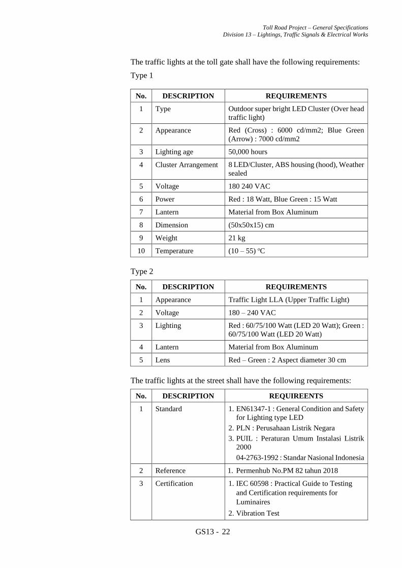
Toll Road Project – General Specifications
Division 13 – Lightings, Traffic Signals & Electrical Works
GS13 - 22
The traffic lights at the toll gate shall have the following requirements:
Type 1
No. DESCRIPTION REQUIREMENTS
1 Type Outdoor super bright LED Cluster (Over head
traffic light)
2 Appearance Red (Cross) : 6000 cd/mm2; Blue Green
(Arrow) : 7000 cd/mm2
3 Lighting age 50,000 hours
4 Cluster Arrangement 8 LED/Cluster, ABS housing (hood), Weather
sealed
5 Voltage 180 240 VAC
6 Power Red : 18 Watt, Blue Green : 15 Watt
7 Lantern Material from Box Aluminum
8 Dimension (50x50x15) cm
9 Weight 21 kg
10 Temperature (10 – 55) oC
Type 2
No. DESCRIPTION REQUIREMENTS
1 Appearance Traffic Light LLA (Upper Traffic Light)
2 Voltage 180 – 240 VAC
3 Lighting Red : 60/75/100 Watt (LED 20 Watt); Green :
60/75/100 Watt (LED 20 Watt)
4 Lantern Material from Box Aluminum
5 Lens Red – Green : 2 Aspect diameter 30 cm
The traffic lights at the street shall have the following requirements:
No. DESCRIPTION REQUIREENTS
1 Standard 1. EN61347-1 : General Condition and Safety
for Lighting type LED
2. PLN : Perusahaan Listrik Negara
3. PUIL : Peraturan Umum Instalasi Listrik
2000
04-2763-1992 : Standar Nasional Indonesia
2 Reference 1. Permenhub No.PM 82 tahun 2018
3 Certification 1. IEC 60598 : Practical Guide to Testing
and Certification requirements for
Luminaires
2. Vibration Test
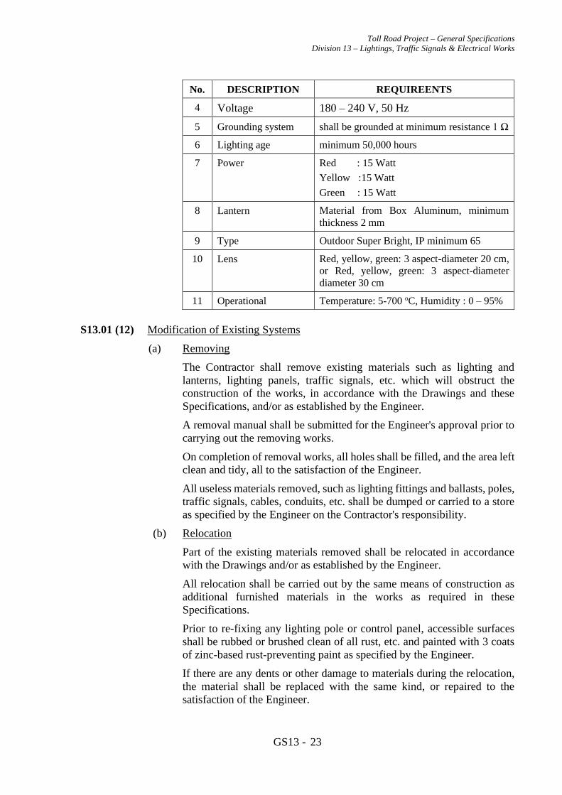
Toll Road Project – General Specifications
Division 13 – Lightings, Traffic Signals & Electrical Works
GS13 - 23
No. DESCRIPTION REQUIREENTS
4 Voltage 180 – 240 V, 50 Hz
5 Grounding system shall be grounded at minimum resistance 1 Ω
6 Lighting age minimum 50,000 hours
7 Power Red : 15 Watt
Yellow :15 Watt
Green : 15 Watt
8 Lantern Material from Box Aluminum, minimum
thickness 2 mm
9 Type Outdoor Super Bright, IP minimum 65
10 Lens Red, yellow, green: 3 aspect-diameter 20 cm,
or Red, yellow, green: 3 aspect-diameter
diameter 30 cm
11 Operational Temperature: 5-700 oC, Humidity : 0 – 95%
S13.01 (12) Modification of Existing Systems
(a) Removing
The Contractor shall remove existing materials such as lighting and
lanterns, lighting panels, traffic signals, etc. which will obstruct the
construction of the works, in accordance with the Drawings and these
Specifications, and/or as established by the Engineer.
A removal manual shall be submitted for the Engineer's approval prior to
carrying out the removing works.
On completion of removal works, all holes shall be filled, and the area left
clean and tidy, all to the satisfaction of the Engineer.
All useless materials removed, such as lighting fittings and ballasts, poles,
traffic signals, cables, conduits, etc. shall be dumped or carried to a store
as specified by the Engineer on the Contractor's responsibility.
(b) Relocation
Part of the existing materials removed shall be relocated in accordance
with the Drawings and/or as established by the Engineer.
All relocation shall be carried out by the same means of construction as
additional furnished materials in the works as required in these
Specifications.
Prior to re-fixing any lighting pole or control panel, accessible surfaces
shall be rubbed or brushed clean of all rust, etc. and painted with 3 coats
of zinc-based rust-preventing paint as specified by the Engineer.
If there are any dents or other damage to materials during the relocation,
the material shall be replaced with the same kind, or repaired to the
satisfaction of the Engineer.
Toll Road Project – General Specifications
Division 13 – Lightings, Traffic Signals & Electrical Works
GS13 - 24
S13.01 (13) Construction
(a) General
All workmanship shall be complete and in accordance with the latest
accepted standards of the industry, as determined by the Engineer.
Installation of duct, construction of manholes, and excavation for cable or
duct track, shall be in accordance with Clause S13.02.
(b) Excavating and Backfilling
The excavation and backfilling required for the installation of
foundations, poles and other appliances shall be performed in accordance
with the requirements of Clause S13.02, but will not be measured for
payment. The cost of such extra work will be deemed to be included in
the unit price of the pay item being installed or removed.
(c) Foundations
Foundations shall be constructed of Portland cement concrete Class C,
unless otherwise noted on the Drawings and all details shall meet the
applicable requirements of Division 10 of the Specifications. The bottom
of concrete foundations shall rest on firm ground.
Foundations shall be poured in one pour where practicable. The exposed
portions shall be formed to present a neat appearance. The footing shown
on the Drawings shall be extended if conditions require additional depth,
and such additional work, if ordered by the Engineer, will be paid for
under the applicable provision of Division 5 of these Specifications.
Forms shall be true to line and grade. Tops of footings for poles, except
special foundations, shall be finished to ground line or sidewalk grade,
unless otherwise noted on the Drawings or directed by the Engineer.
Forms shall be rigid and securely braced in place. Conduit ends and
anchor bolts shall be placed in proper position and to proper height and
shall be held in place by means of a template until concrete sets.
Plumbing of poles shall be accomplished by adjusting leveling nuts.
Shims or other similar devices for plumbing or raking will not be
permitted.
Both forms and ground which will be in contact with the concrete shall be
thoroughly moistened before placing concrete. Forms shall not be
removed until the concrete has set at least 3 days.
A "rubbed surface finish" shall be applied to exposed surfaces of concrete
in accordance with the requirements of Clause S10.01.
Where obstructions prevent construction of planned foundations, the
Contractor shall construct an effective foundation, satisfactory to the
Engineer.
(d) Conduit
Installation of conduit shall be performed in accordance with these
Specifications and in reasonably close conformity with the locations as
specified in the Drawings or as directed by the Engineer.
Toll Road Project – General Specifications
Division 13 – Lightings, Traffic Signals & Electrical Works
GS13 - 25
The size of conduit used shall be as shown on the Drawings. Conduits
smaller than 25 mm electrical trade size shall not be used, unless otherwise
specified. It shall be the option of the Contractor, at his own expense, to
use larger size conduit if desired, and where larger size conduit is used, it
shall be for the entire length of the run from outlet to outlet. No reducing
couplings will be permitted.
The ends of all conduits shall be well reamed to remove burrs and rough
edges. Field cuts shall be made square and true so that the ends will butt
or come together for the full circumference thereof. Slip joints or
running threads will not be permitted for coupling conduit. When a
standard coupling cannot be used, an approved threaded union coupling
shall be used. The threads of all steel conduit shall be well painted with
a good quality of lead or rust-preventative paint before couplings are made
up. All steel couplings shall be screwed up until the ends of the conduits
are brought together, so that a good electrical connection will be made
throughout the entire length of the conduit run. Where coating on steel
conduit has been damaged in handling or installing, such places shall be
thoroughly painted with rust-preventative paint.
All conduit ends shall be threaded and capped with standard conduit
couplings capped with conduit push pennies until wiring is started.
When couplings and push pennies are removed the threaded ends shall be
provided with approved conduit bushings. The use of any plugs, even
though temporary, in lieu of the aforementioned conduit couplings and
push pennies is expressly prohibited.
Conduit stubs from bases shall extend at least 15 cm from the face of
foundations and at least 80 cm below the top of foundations.
Conduit bends, except factory bends, shall have a radius of not less than
six times the inside diameter of the conduit. Where factory bends are not
used, conduit shall be bent, using an approved conduit bending tool
employing correctly sized dies, without crimping or flattening, using the
longest radius practicable. All PVC conduit bends shall be performed.
Conduit terminating in poles or pedestals shall extend approximately 15
cm above the foundation vertically and shall be sloped towards the
handhole opening.
Conduit entering through the bottom of a pull box shall be located near
the end walls to leave the major portion of the box clear. At all outlets,
conduit shall enter from the direction of the run, terminate 15 to 20 cm
below the pull box lid and within 9 cm of the box wall nearest its entry
location.
Suitable markers shall be set at the ends of conduits which are covered so
that they may be easily located.
A galvanized pull wire shall be installed in all conduits which are to
receive future conductors. At least 60 cm of pull wire shall be doubled
back into the conduit at each termination.
Toll Road Project – General Specifications
Division 13 – Lightings, Traffic Signals & Electrical Works
GS13 - 26
Conduit of utility box shall cooperate to electric cables, telecom cables
and water supply pipes located at grade beside of foot pass. This U-ditch
with cover structure made by precast concrete product. The material shall
be in accordance with Sub-clause S6.06 (2) of these Specifications
(e) Pull Boxes
Pull boxes shall be installed at the locations shown on the Drawings, and
at such additional points as ordered by the Engineer. The Contractor may
install, at his own expense, such additional boxes as may be desired to
facilitate the work.
(f) Wire
Wiring shall conform to appropriate code requirements. Wiring within
cabinets, manholes, etc. shall be neatly arranged and within cabinets shall
be laced.
Powdered soapstone, talc, or lubricant shall be used in placing conductors
in conduit.
Splicing in conductors will be permitted only at manholes, transformer
leads, in pole bases, or at control equipment.
Sufficient signal light conductors shall be provided to perform the
functional operation of the signal systems as shown. Spare conductors
shall be provided when noted on the Drawings.
(g) Service
Service points are located within or close to the Site, normally, but not
necessarily always, at the PLN sub-station transformer house nearest the
project main lighting panel designated on the drawings.
Unless otherwise noted on the Drawings, each service point shall include
a meter base installed in accordance with serving utility requirements, a
three-wire service breaker of size noted on the Drawings, the necessary
conduit risers and grounding assembly.
In general, all multiple lighting will be 220 volts, 50 Hz as noted on the
Drawings.
The Contractor shall prepare all drawings required and all necessary
documentation for the application for the service connection which shall
be submitted to the Engineer. The Engineer shall then, upon request of
the Contractor, make arrangements with the serving utility to complete the
service connections.
The serving utility connection costs, and consumption of electrical energy
to the date of completion, to be paid by the Contractor, payments are
included in the unit price unless otherwise provided in the Contract
(h) Field Test
Prior to completion of the work, the Contractor shall cause the following
tests to be made on all traffic signal and lighting circuits, in the presence
of the Engineer.
Toll Road Project – General Specifications
Division 13 – Lightings, Traffic Signals & Electrical Works
GS13 - 27
(i) Test for continuity of each circuit.
(ii) Test for grounds in each circuit.
(iii) A megger test on each circuit between the conductor and ground
with all switch boards, panel boards, fuse holders, switches, socket
outlets and over current devices in place and all readings recorded.
The Contractor shall furnish the Engineer with three copies of the
test results identifying observed readings with their respective
circuits. The insulation resistance between conductor and ground
shall be not less than 8 megohms.
Any change in the above stated minimum readings shall be
approved by the Engineer. Such approval shall be in writing,
following written application by the Contractor.
(iv) A functional test in which it is demonstrated that each and every
part of the system functions as specified or intended herein.
Any fault in any material or in any part of the installation revealed
by these tests shall be replaced or repaired by the Contractor in a
manner approved by the Engineer, and the same test shall be
repeated until no fault appears.
(i) Painting
All painting required shall be in conformance with applicable portions of
Clause S12.18 of these Specifications.
If the enclosure of any electrical equipment (less signal heads) located
above ground does not have an exterior surface of either aluminum or
galvanizing, then it shall be finished with two coats of an approved zinc
based paint, plus such finishing coat as the Engineer may direct.
Controller cabinets shall be finished in accordance with the above
requirements for electrical equipment.
Galvanized steel or aluminum lighting poles and lighting lanterns shall
not be painted.
(j) Lighting Poles
Lighting poles shall be handled in loading, unloading and erecting in such
a manner that they will not be damaged. Any parts that are damaged due
to the Contractor's operations shall be repaired or replaced at the
Contractor's expense, to the satisfaction of the Engineer.
Lighting poles shall not be erected on concrete foundations until
foundations have set at least 72 hours, and shall be raked sufficiently to
be plumb after all load has been placed, or as otherwise directed by the
Engineer.
(k) Control Equipment
Where specifically detailed on the Drawings, for service locations where
two or more lighting circuits are operated from one time switch control
device, the relays, service breakers and any other necessary control
equipment shall be grouped together and installed in a suitable rain-tight
Toll Road Project – General Specifications
Division 13 – Lightings, Traffic Signals & Electrical Works
GS13 - 28
enclosure of a sufficient size to accommodate all of the equipment
installed therein.
Each electrical control ballast assembly shall be protected by moulded
circuit breakers.
(l) Signal Controllers
All control cabinets and control equipment shall be factory wired ready
for operation. Field work shall be limited to placing cabinets and
equipment and connecting field wiring to field terminal strips.
(m) Signal Heads
All signal heads shall be installed as shown on the Drawings. Signal
heads shall not be installed at any intersection until all other signal
equipment, including the controller, is in place and ready for operation at
that intersection, except that the signal heads may be mounted if the faces
are covered.
(n) "As-Built" Drawings
Upon completion of the work, the Contractor shall submit "As-Built" or
corrected drawings, or any data therefor as required by the Engineer,
showing in detail all construction changes, especially location and depth
of conduit and completed schematic circuit diagram.
The drawings shall be on sheets conforming to the standard contract
Drawings. Corrected drawings shall be made on full sized sheets and not
on reduced size prints.
(o) Guarantee
The Contractor shall furnish to the Employer any guarantee or warranty
required as a normal trade practice in connection with the purchase of any
materials or items used in the construction of the illumination or traffic
signal system or systems included in this Contract.
S13.01 (14) Method of Measurement
The quantity of each item paid for under this Clause will be the number of linear
meters or individual items as detailed below which are furnished and installed in
accordance with this specification, the Drawings and the instructions of the
Engineer.
Ducts, manholes and excavation for cable or ducts will be measured for payment
under Clause S13.02 of these Specifications.
Cable within each pole or traffic signal will not be measured for payment but will
be considered to be included in the unit price for the pay item being installed.
Measurement of external cable will be taken to the junction board located within
the handhole of the pole or to the first junction within the control panel.
Cables in the pole or lamp and connecting cables to the poles and panels as well
as the connection to the power to PLN will not be measured and paid for but is
considered to be in the Unit Price for pay item install work.
Toll Road Project – General Specifications
Division 13 – Lightings, Traffic Signals & Electrical Works
GS13 - 29
S13.01 (15) Basis of Payment
The quantity measured as provided above, shall be paid at the Contract unit price
for each pay item as described below. The price and payment will be full
compensation for all the work shown on the Drawings or described in these
Specifications. The scope of work included in each pole item shall be as shown
on the Drawings or as described in these Specifications.
The work of high mast lighting shall include furnishing, assembly and erection of
the mast, mast head, lanterns, wiring, electrical control gear, base plate and anchor
bolts for the mast. One removable lowering and raising device drive motor unit
shall be furnished and payment shall be full compensation for furnishing the drive
motor and all its mounting and control equipment. Detailed drawings for the pile
foundation and pile cap will be supplied by the Engineer and this work will be
measured and paid for under Division 10 of the Specifications.
The payment for tunnel lighting panel shall include furnishing and installing the
remotely sited photo sensor.
The payment for bus stop shelters lighting shall include furnishing and installing
the MCB box and all electrical items after this box.
The payment for cable shall be full compensation for the furnishing, laying or
pulling, and jointing cable, but excavation, protection and backfilling will be paid
for under Clause S13.02 of these Specification
Payment for installation, relocation or removal of any pole or panel shall be
deemed to include any excavation, demolition, backfilling and all materials
necessary for the provision of a base as shown on the Drawings or described in
these Specifications.
The payment for utility box shall be full compensation for all the works, precast
concrete U-ditch with cover, the furnishing, laying, for excavation, sand base,
protections and backfilling. But installation of utilities will not include this pay
item.
Pay Item No. and Name Unit of Measurement
13.01 STREET LIGHTING
13.01(1) Lighting (include Grounding), Cable and
Auxiliary Materials
13.01(1).1 Street Lighting, Height 13 m, Type A (1 x 120
Watt), LED, Dimming System type
Each
13.01(1).1a Street Lighting, Height 13 m, Type A (1 x 150
Watt), HPS, Dimming System type
Each
13.01(1).2 Street Lighting, Height 13 m, Type B (2 x 120
Watt), LED, Dimming System type
Each
13.01(1).2a Street Lighting, Height 13 m, Type B (2 x 150
Watt), HPS, Dimming System type
Each
13.01(1).3 Street Lighting, Height 13 m, Type A (1 x 250
Watt), HPS, Dimming System type
Each
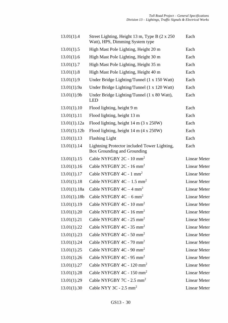
Toll Road Project – General Specifications
Division 13 – Lightings, Traffic Signals & Electrical Works
GS13 - 30
13.01(1).4 Street Lighting, Height 13 m, Type B (2 x 250
Watt), HPS, Dimming System type
Each
13.01(1).5 High Mast Pole Lighting, Height 20 m Each
13.01(1).6 High Mast Pole Lighting, Height 30 m Each
13.01(1).7 High Mast Pole Lighting, Height 35 m Each
13.01(1).8 High Mast Pole Lighting, Height 40 m Each
13.01(1).9 Under Bridge Lighting/Tunnel (1 x 150 Watt) Each
13.01(1).9a Under Bridge Lighting/Tunnel (1 x 120 Watt) Each
13.01(1).9b Under Bridge Lighting/Tunnel (1 x 80 Watt),
LED
Each
13.01(1).10 Flood lighting, height 9 m Each
13.01(1).11 Flood lighting, height 13 m Each
13.01(1).12a Flood lighting, height 14 m (3 x 250W) Each
13.01(1).12b Flood lighting, height 14 m (4 x 250W) Each
13.01(1).13 Flashing Light Each
13.01(1).14 Lightning Protector included Tower Lighting,
Box Grounding and Grounding
Each
13.01(1).15 Cable NYFGBY 2C - 10 mm2 Linear Meter
13.01(1).16 Cable NYFGBY 2C - 16 mm2 Linear Meter
13.01(1).17 Cable NYFGBY 4C - 1 mm2 Linear Meter
13.01(1).18 Cable NYFGBY 4C – 1.5 mm2 Linear Meter
13.01(1).18a Cable NYFGBY 4C – 4 mm2 Linear Meter
13.01(1).18b Cable NYFGBY 4C – 6 mm2 Linear Meter
13.01(1).19 Cable NYFGBY 4C - 10 mm2 Linear Meter
13.01(1).20 Cable NYFGBY 4C - 16 mm2 Linear Meter
13.01(1).21 Cable NYFGBY 4C - 25 mm2 Linear Meter
13.01(1).22 Cable NYFGBY 4C - 35 mm2 Linear Meter
13.01(1).23 Cable NYFGBY 4C - 50 mm2 Linear Meter
13.01(1).24 Cable NYFGBY 4C - 70 mm2 Linear Meter
13.01(1).25 Cable NYFGBY 4C - 90 mm2 Linear Meter
13.01(1).26 Cable NYFGBY 4C - 95 mm2 Linear Meter
13.01(1).27 Cable NYFGBY 4C - 120 mm2 Linear Meter
13.01(1).28 Cable NYFGBY 4C - 150 mm2 Linear Meter
13.01(1).29 Cable NYFGBY 7C - 2.5 mm2 Linear Meter
13.01(1).30 Cable NYY 3C - 2.5 mm2 Linear Meter
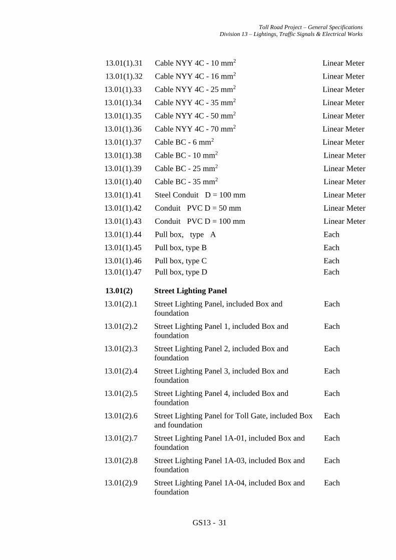
Toll Road Project – General Specifications
Division 13 – Lightings, Traffic Signals & Electrical Works
GS13 - 31
13.01(1).31 Cable NYY 4C - 10 mm2 Linear Meter
13.01(1).32 Cable NYY 4C - 16 mm2 Linear Meter
13.01(1).33 Cable NYY 4C - 25 mm2 Linear Meter
13.01(1).34 Cable NYY 4C - 35 mm2 Linear Meter
13.01(1).35 Cable NYY 4C - 50 mm2 Linear Meter
13.01(1).36 Cable NYY 4C - 70 mm2 Linear Meter
13.01(1).37 Cable BC - 6 mm2 Linear Meter
13.01(1).38 Cable BC - 10 mm2 Linear Meter
13.01(1).39 Cable BC - 25 mm2 Linear Meter
13.01(1).40 Cable BC - 35 mm2 Linear Meter
13.01(1).41 Steel Conduit D = 100 mm Linear Meter
13.01(1).42 Conduit PVC D = 50 mm Linear Meter
13.01(1).43 Conduit PVC D = 100 mm Linear Meter
13.01(1).44 Pull box, type A Each
13.01(1).45 Pull box, type B Each
13.01(1).46 Pull box, type C Each
13.01(1).47 Pull box, type D Each
13.01(2) Street Lighting Panel
13.01(2).1 Street Lighting Panel, included Box and
foundation
Each
13.01(2).2 Street Lighting Panel 1, included Box and
foundation
Each
13.01(2).3 Street Lighting Panel 2, included Box and
foundation
Each
13.01(2).4 Street Lighting Panel 3, included Box and
foundation
Each
13.01(2).5 Street Lighting Panel 4, included Box and
foundation
Each
13.01(2).6 Street Lighting Panel for Toll Gate, included Box
and foundation
Each
13.01(2).7 Street Lighting Panel 1A-01, included Box and
foundation
Each
13.01(2).8 Street Lighting Panel 1A-03, included Box and
foundation
Each
13.01(2).9 Street Lighting Panel 1A-04, included Box and
foundation
Each
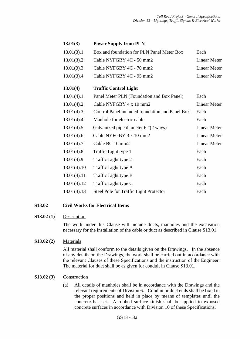
Toll Road Project – General Specifications
Division 13 – Lightings, Traffic Signals & Electrical Works
GS13 - 32
13.01(3) Power Supply from PLN
13.01(3).1 Box and foundation for PLN Panel Meter Box Each
13.01(3).2 Cable NYFGBY 4C - 50 mm2 Linear Meter
13.01(3).3 Cable NYFGBY 4C - 70 mm2 Linear Meter
13.01(3).4 Cable NYFGBY 4C - 95 mm2 Linear Meter
13.01(4) Traffic Control Light
13.01(4).1 Panel Meter PLN (Foundation and Box Panel) Each
13.01(4).2 Cable NYFGBY 4 x 10 mm2 Linear Meter
13.01(4).3 Control Panel included foundation and Panel Box Each
13.01(4).4 Manhole for electric cable Each
13.01(4).5 Galvanized pipe diameter 6 “(2 ways) Linear Meter
13.01(4).6 Cable NYFGBY 3 x 10 mm2 Linear Meter
13.01(4).7 Cable BC 10 mm2 Linear Meter
13.01(4).8 Traffic Light type 1 Each
13.01(4).9 Traffic Light type 2 Each
13.01(4).10 Traffic Light type A Each
13.01(4).11 Traffic Light type B Each
13.01(4).12 Traffic Light type C Each
13.01(4).13 Steel Pole for Traffic Light Protector Each
S13.02 Civil Works for Electrical Items
S13.02 (1) Description
The work under this Clause will include ducts, manholes and the excavation
necessary for the installation of the cable or duct as described in Clause S13.01.
S13.02 (2) Materials
All material shall conform to the details given on the Drawings. In the absence
of any details on the Drawings, the work shall be carried out in accordance with
the relevant Clauses of these Specifications and the instruction of the Engineer.
The material for duct shall be as given for conduit in Clause S13.01.
S13.02 (3) Construction
(a) All details of manholes shall be in accordance with the Drawings and the
relevant requirements of Division 6. Conduit or duct ends shall be fixed in
the proper positions and held in place by means of templates until the
concrete has set. A rubbed surface finish shall be applied to exposed
concrete surfaces in accordance with Division 10 of these Specifications.
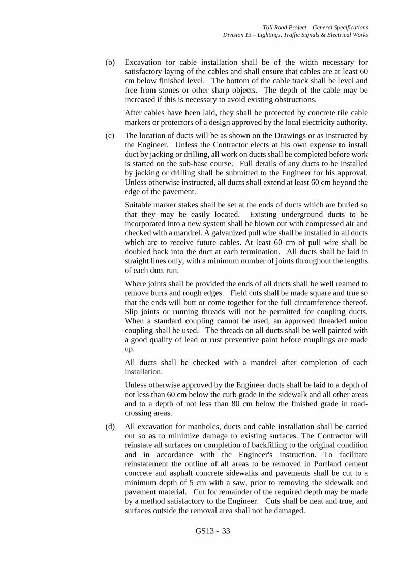
Toll Road Project – General Specifications
Division 13 – Lightings, Traffic Signals & Electrical Works
GS13 - 33
(b) Excavation for cable installation shall be of the width necessary for
satisfactory laying of the cables and shall ensure that cables are at least 60
cm below finished level. The bottom of the cable track shall be level and
free from stones or other sharp objects. The depth of the cable may be
increased if this is necessary to avoid existing obstructions.
After cables have been laid, they shall be protected by concrete tile cable
markers or protectors of a design approved by the local electricity authority.
(c) The location of ducts will be as shown on the Drawings or as instructed by
the Engineer. Unless the Contractor elects at his own expense to install
duct by jacking or drilling, all work on ducts shall be completed before work
is started on the sub-base course. Full details of any ducts to be installed
by jacking or drilling shall be submitted to the Engineer for his approval.
Unless otherwise instructed, all ducts shall extend at least 60 cm beyond the
edge of the pavement.
Suitable marker stakes shall be set at the ends of ducts which are buried so
that they may be easily located. Existing underground ducts to be
incorporated into a new system shall be blown out with compressed air and
checked with a mandrel. A galvanized pull wire shall be installed in all ducts
which are to receive future cables. At least 60 cm of pull wire shall be
doubled back into the duct at each termination. All ducts shall be laid in
straight lines only, with a minimum number of joints throughout the lengths
of each duct run.
Where joints shall be provided the ends of all ducts shall be well reamed to
remove burrs and rough edges. Field cuts shall be made square and true so
that the ends will butt or come together for the full circumference thereof.
Slip joints or running threads will not be permitted for coupling ducts.
When a standard coupling cannot be used, an approved threaded union
coupling shall be used. The threads on all ducts shall be well painted with
a good quality of lead or rust preventive paint before couplings are made
up.
All ducts shall be checked with a mandrel after completion of each
installation.
Unless otherwise approved by the Engineer ducts shall be laid to a depth of
not less than 60 cm below the curb grade in the sidewalk and all other areas
and to a depth of not less than 80 cm below the finished grade in road-
crossing areas.
(d) All excavation for manholes, ducts and cable installation shall be carried
out so as to minimize damage to existing surfaces. The Contractor will
reinstate all surfaces on completion of backfilling to the original condition
and in accordance with the Engineer's instruction. To facilitate
reinstatement the outline of all areas to be removed in Portland cement
concrete and asphalt concrete sidewalks and pavements shall be cut to a
minimum depth of 5 cm with a saw, prior to removing the sidewalk and
pavement material. Cut for remainder of the required depth may be made
by a method satisfactory to the Engineer. Cuts shall be neat and true, and
surfaces outside the removal area shall not be damaged.
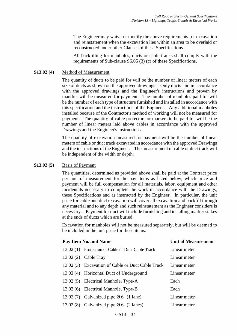
Toll Road Project – General Specifications
Division 13 – Lightings, Traffic Signals & Electrical Works
GS13 - 34
The Engineer may waive or modify the above requirements for excavation
and reinstatement when the excavation lies within an area to be overlaid or
reconstructed under other Clauses of these Specifications.
All backfilling for manholes, ducts or cable tracks shall comply with the
requirements of Sub-clause S6.05 (3) (c) of these Specifications.
S13.02 (4) Method of Measurement
The quantity of ducts to be paid for will be the number of linear meters of each
size of ducts as shown on the approved drawings. Only ducts laid in accordance
with the approved drawings and the Engineer's instructions and proven by
mandrel will be measured for payment. The number of manholes paid for will
be the number of each type of structure furnished and installed in accordance with
this specification and the instructions of the Engineer. Any additional manholes
installed because of the Contractor's method of working will not be measured for
payment. The quantity of cable protectors or markers to be paid for will be the
number of linear meters laid above cables in accordance with the approved
Drawings and the Engineer's instructions.
The quantity of excavation measured for payment will be the number of linear
meters of cable or duct track excavated in accordance with the approved Drawings
and the instructions of the Engineer. The measurement of cable or duct track will
be independent of the width or depth.
S13.02 (5) Basis of Payment
The quantities, determined as provided above shall be paid at the Contract price
per unit of measurement for the pay items as listed below, which price and
payment will be full compensation for all materials, labor, equipment and other
incidentals necessary to complete the work in accordance with the Drawings,
these Specifications and as instructed by the Engineer. In particular, the unit
price for cable and duct excavation will cover all excavation and backfill through
any material and to any depth and such reinstatement as the Engineer considers is
necessary. Payment for duct will include furnishing and installing marker stakes
at the ends of ducts which are buried.
Excavation for manholes will not be measured separately, but will be deemed to
be included in the unit price for these items.
Pay Item No. and Name Unit of Measurement
13.02 (1) Protection of Cable or Duct Cable Track Linear meter
13.02 (2) Cable Tray Linear meter
13.02 (3) Excavation of Cable or Duct Cable Track Linear meter
13.02 (4) Horizontal Duct of Underground Linear meter
13.02 (5) Electrical Manhole, Type-A Each
13.02 (6) Electrical Manhole, Type-B Each
13.02 (7) Galvanized pipe Ø 6" (1 lane) Linear meter
13.02 (8) Galvanized pipe Ø 6" (2 lanes) Linear meter

Toll Road Project – General Specifications
Division 13 – Lightings, Traffic Signals & Electrical Works
GS13 - 35
13.02 (9) Galvanized pipe Ø 4" Linear meter
13.02 (10) Iron steel protection Linear meter
13.02 (11) PVC pipe Ø 6" Linear meter
13.02 (12) PVC pipe Ø 4" Linear meter
13.02 (13) Utilities pipe, Type-1 Linear meter
13.02 (14) Utilities pipe, Type-2 Linear meter
13.02 (15) Utilities pipe, Type-3 Linear meter
S13.03 Drainage Pump
S13.03 (1) Description
This work shall consist of furnishing and installing control room of drainage
pump at locations shown on the Drawings or instructed by the Engineer.
S13.03 (2) Materials
All materials shall be as shown on the Drawings or equivalent as approved by the
Engineer. Working drawings and details of materials sources shall be approved
by the Engineer before procurement of materials.
All materials for the electrical work shall be approved by the Engineer before
orders are given to the suppliers or manufacturers.
The pump shall have the capacity to pump up 110 liter/s (0.11 m3/s) vertically
from the reservoir under the road surface to catch basin on the level of frontage
road.
S13.03 (3) Construction
All details of construction shall be in accordance with the approved working
drawings and the relevant Clauses of the Specifications.
S13.03 (4) Method of Measurement
The quantities to be paid for will be the actual number of Drainage Pumps
furnished and installed in accordance with the Drawings and the Engineer's
instructions.
S13.03 (5) Basis of Payment
The work measured as provided above will be paid for at the Contract unit price
for each Drainage Pump. The prices and payment will be full compensation for
furnishing and installing the Drainage Pumps, including pipe from pump to catch
basin above, supporting materials for pipes, foundation for the pump and all other
material necessary for sufficient drainage system, labor, equipment, and all
incidentals necessary to complete the work as shown on the Drawings.
Pay Item No. and Name Unit of Measurement
13.03 Drainage Pump Each
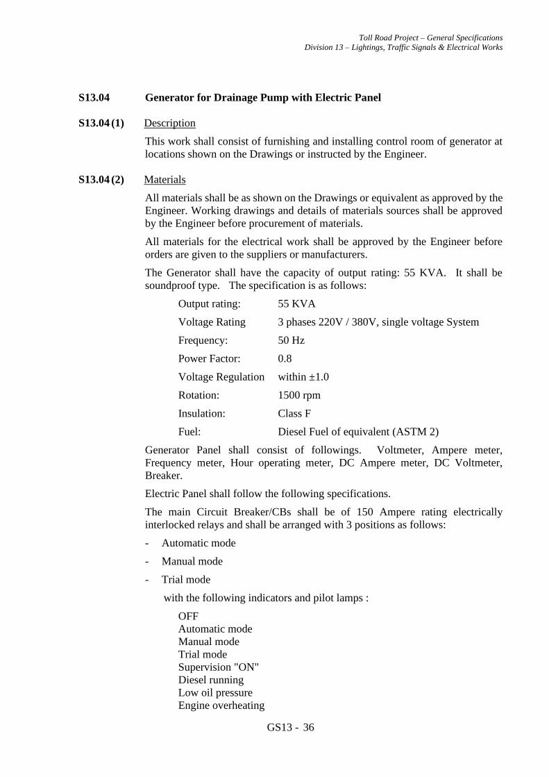
Toll Road Project – General Specifications
Division 13 – Lightings, Traffic Signals & Electrical Works
GS13 - 36
S13.04 Generator for Drainage Pump with Electric Panel
S13.04 (1) Description
This work shall consist of furnishing and installing control room of generator at
locations shown on the Drawings or instructed by the Engineer.
S13.04 (2) Materials
All materials shall be as shown on the Drawings or equivalent as approved by the
Engineer. Working drawings and details of materials sources shall be approved
by the Engineer before procurement of materials.
All materials for the electrical work shall be approved by the Engineer before
orders are given to the suppliers or manufacturers.
The Generator shall have the capacity of output rating: 55 KVA. It shall be
soundproof type. The specification is as follows:
Output rating: 55 KVA
Voltage Rating 3 phases 220V / 380V, single voltage System
Frequency: 50 Hz
Power Factor: 0.8
Voltage Regulation within ±1.0
Rotation: 1500 rpm
Insulation: Class F
Fuel: Diesel Fuel of equivalent (ASTM 2)
Generator Panel shall consist of followings. Voltmeter, Ampere meter,
Frequency meter, Hour operating meter, DC Ampere meter, DC Voltmeter,
Breaker.
Electric Panel shall follow the following specifications.
The main Circuit Breaker/CBs shall be of 150 Ampere rating electrically
interlocked relays and shall be arranged with 3 positions as follows:
- Automatic mode
- Manual mode
- Trial mode
with the following indicators and pilot lamps :
OFF
Automatic mode
Manual mode
Trial mode
Supervision "ON"
Diesel running
Low oil pressure
Engine overheating

Toll Road Project – General Specifications
Division 13 – Lightings, Traffic Signals & Electrical Works
GS13 - 37
Main source CB on
Generator CB on
Start fails
Start
Manual start
Manual stop
Block
Reset
Test
The panel shall also be equipped with an emergency stop and horn automatically
activated in case of emergency.
S13.04 (3) Construction
All details of construction shall be in accordance with the approved working
drawings and the relevant Clauses of the Specifications.
S13.04 (4) Method of Measurement
The quantities to be paid for will be the actual number of control rooms furnished
and installed in accordance with the Drawings and the Engineer's instructions.
S13.04 (5) Basis of Payment
The work measured as provided above will be paid for at the Contract unit price
for each Generator with electric panel. The prices and payment will be full
compensation for furnishing and installing the Generator including generator
panel, electric panel, support and foundation, and all other material necessary for
sufficient drainage system in emergency as well as normal condition, labor,
equipment, and all incidentals necessary to complete the work as shown on the
Drawings.
Pay Item No. and Name Unit of Measurement
13.04 Generator for Drainage Pump Each

Toll Road Project – General Specifications
Division 13 – Lightings, Traffic Signals & Electrical Works
GS13 - 38
Toll Road Project – General Specifications
Division 14 – Toll Plazas
GS14 - 1
DIVISION 14 TOLL PLAZAS
S14.01 Toll Plaza Works
S14.01 (1) General
This work consists of the construction of Toll Plazas and the furnishing and
installation of Toll Plaza facilities, all in accordance with the Drawings, these
Specifications, or as instructed by the Engineer.
S14.01 (2) Scope of Works
The scope of works can basically be divided into two parts, as follows :
(a) Construction of the Toll Plaza consisting of Toll Gate Island, Toll Gate
Roofing, Foundation for Toll Gate Roofing, Generator House, Electrical
Manhole and Septic Tank.
(b) Furnishing and installation of all materials and equipment to complete the
Toll Plaza facilities such as Lighting Installation, Lightning Protection,
Intercom, Alarm System, Public Address, CCTV, Traffic Lights, Fresh
Air Supply, Guide Signs, Sanitary Work, Plumbing, Generator and AMF,
Toll Booths, Flower Pots and Collection Furniture.
The above works shall be executed as described and shown on the Drawings and
shall include but not necessarily be limited to :
(a) Preparation and submission of Shop Drawings;
(b) Submission of detailed Material Supply List; and
(c) All other electrical equipment and services shall be completed and
operated in accordance with the pertinent electrical code and local
regulations for Electrical Installations.
S14.01 (3) Quality Assurance
(a) For the construction of Toll Plaza as described in Sub-clause
S14.01.(2).(a), the codes and regulations governing the execution of civil
engineering works as referred to in the various Clauses of the General and
Special Specifications shall be applied together with the relevant Clauses
of this Division 14.
(b) For the Toll Facilities works as grouped in Sub-clause S14.01.(2).(b) refer
to Sub-clauses S.13.01.(3).(a) and S.13.01.(3).(b) of these General
Specifications together with the relevant Sub-clauses of this Division 14.
S14.01 (4) Drawings and Documents
(a) Since the supplied drawings are to indicate generally the arrangement of
the work, the Contractor shall refer to all relevant drawings to ascertain
for himself the location and routes of all other utility services so as to
maintain adequate clearances between electrical and other services. The
Contractor is therefore required to provide working drawings in duplicate
Toll Road Project – General Specifications
Division 14 – Toll Plazas
GS14 - 2
showing the exact routes of all underground or overhead cables and ducts,
the exact run of all conduits and trunking, the location of manholes, draw-
in and junction boxes, the number and size of wires in each conduit or
trunking, the final connection arrangements at distribution boards, the
detail of ducts and the method of fixing Main and Sub- main Distribution
Boards for the portion of the Works. The contractor shall submit a
programme indicating the dates on which concreting in different sections
will take place, together with the submission of the working drawings.
(b) On completion of testing, the Contractor shall make "as- built" drawings
of plans and circuit diagrams, which clearly indicate any modifications
made to the original design.
(c) Upon completion of the work, and as a condition of its acceptance, the
Contractor shall supply to the Engineer three copies of a Manual for the
maintenance and operation of all electrical installations and a parts list
sufficient for the ordering of parts.
S14.01 (5) Standards
(a) The works in Sub-clause S14.01 (2) (b) covered by this contract shall be
carried out in accordance with the regulations issued by the local
Electricity Authority and with the applicable standards and codes of any
of the following :
AIEE : American Institute of Electrical Engineers
ASA : American Standards Association
ASTM : American Society for Testing Materials
DIN : German Industry Standards (Deutsche Industrie Normen)
IEA : International Electrical Association
JEA : Japanese Electrical Association
JIS : Japanese Industrial Standards
NEC : National Electrical Code (USA)
NECA : National Electrical Contractors "Standards of Installation"
(USA)
NEMA : National Electrical Manufacturers Association (USA)
PLN : Indonesian Government Electrical Company
SII : Indonesia Industry Standard (Standar Industri Indonesia)
SNI : Indonesia National Standard (Standar Nasional Indonesia)
UL : Underwriters Laboratories, Inc.
(b) Before submitting his Bid, the Contractor must carefully examine all of
the Regulations issued by the local electricity authority at his own expense
and selected materials and method of installation shall be in accordance
with these Regulations. The Contractor shall inform himself fully of the
local authority regulations, DLLAJR, PLN, PDAM, PT. TELKOM, PT.
PGN and appreciate all relevant rules and regulations before the
submission of bids.
S14.01 (6) Materials
The materials required for the Construction of works referred to in Sub-clause
S14.01 (2) (a) shall follow the relevant Sub-clauses referred to before.
Toll Road Project – General Specifications
Division 14 – Toll Plazas
GS14 - 3
For materials required for provision and installation of Toll facilities the following
shall be fulfilled.
(a) Lighting Units
(i) Lighting units as shown on the Drawings shall consist of fixtures,
lamps, ballasts, starters and mounting accessories.
Lamps of LED 100 watt daylight type shall be used. Fixtures
placed outdoors on the ceiling of the Toll Plaza roof shall be of the
recessed type.
(ii) Electrical Panels
Unless indicated otherwise in the Drawings, the panels shall be
generally indoor type panels made of steel plate or special plastic
material available in the market under well known brand names.
Sufficient space shall be provided to facilitate the easy
maintenance and inspection of small wire sizes.
Panels shall be supplied with individual wiring diagram
permanently affixed to the inner side of the panel door.
(iii) Panel Components
The components shall be designed for 3-phase, 4 wire, 50 Hz
operation at 380/220 volts. The circuit breakers shall be moulded
case, air break type, rated for 460 - volt AC service. The circuit
breakers interrupting capacity shall be 15,000 amperes and based
on JIS C8370 standard duty cycles, except that breakers larger than
225 amperes shall have 25,000 amperes interrupting capacity, or
as approved by the Engineer.
(iv) Cable, Wire, Grounding and Electrical Splice Materials
All cable, wire, grounding and electrical splice materials shall
comply with the requirements of Sub-clauses S.13.01.(9).(b),
S.13.01.(9).(c) and S.13.01.(9).(d) of these General Specifications,
and all requirements specified therein shall be applicable.
(v) In-line Connectors
A copper pin and copper receptacle each of at least 90%
conductivity shall be crimped to the cable.
The receptacle shall establish constant pressure with the pin by the
use of a copper beryllium sleeve spring and shall be equipped with
a disposable mounting pin.
The pin shall be of at least half-hard material and the crimping
portion shall be fully annealed while the rest of the pin is
maintained in its original state of hardness.
The socket shall be fully annealed. Both the copper pin and
socket shall have a centrally located recessed locking area adapted
to be fitted and retained by the rubber housings. The pin and
socket shall lock together so the connection will be maintained
Toll Road Project – General Specifications
Division 14 – Toll Plazas
GS14 - 4
when a minimum force of 10 kg tension pull is applied to the
attached cables.
Plugs and socket housing shall each be made of water resisting,
synthetic rubber capable of burial in the ground or of installation
in sunlight. Each housing shall provide a water-seal around the
cable, have an interior arrangement to suit and retain the copper
pin or receptacle and shall have a water-seal between the two
housings at the point of disconnection.
Each housing socket shall be provided with a through internal vent
filled with a predetermined amount of silicon insulating compound
which upon assembly of the housing to the conductor element, will
force air through the vent rendering the entire interior of the
connector body void free.
(vi) Tee Connectors
Each connector shall contain three terminal lugs, a bolt and stop
nut. Each lug shall have a mounting hole for bolt and nut. Tap
housings and a tee housings shall be made of water-resisting
synthetic rubber capable of burial in the ground or installation in
sunlight. The tap housing shall have a water-seal around the
cable and between itself and the tee housing at the point of
connection. The tee housing shall have a water-seal for the tap
housing. Each kit shall be supplied with sufficient silicone
compound to lubricate the rubber housing for easy assembly.
(vii) Conduit
Conduit installed below ground shall be steel. Exterior and
interior surfaces of all steel conduit shall be uniformly and
adequately zinc-coated by hot-dip galvanizing process.
Conduit embedded in concrete shall be PVC in accordance with
the requirements of JIS C8430.
(b) Lightning Protection
Air-terminals shall be of conventional copper type as indicated in the
Drawings.
BC conductors shall be fixed by a bracket at each 50 cm length and rubber
sealants shall be applied to all holes to avoid leakage. The maximum
ground resistance shall be less than or equal to 1(one) ohm.
(c) Alarm System
A control unit shall be placed at the road safety patrol room. A strobe
light of yellow colour shall be fixed to the ceiling of the Toll Booth as
indicated in the Drawings.
All Toll Booths shall be equipped with push buttons for quick and easy
operation.
A siren shall be placed near the strobe light as shown on the Drawings.
Toll Road Project – General Specifications
Division 14 – Toll Plazas
GS14 - 5
(d) Public Address System
All Toll Booths shall be equipped with a microphone of condenser type
with chime attached. The frequency response shall be 50 Hz to 20 KHz,
output impedance 600 ohm and balance of uni-directional pickup pattern.
The speakers shall be of horn type of frequency response 280 Hz to 12,500
Hz and shall have an Output Sound Pressure as follows :
Input 1 watt, 1 meter : 104 dB
Input 15 watt, 1 meter : 116 dB
Input Rating 15 watt with impedance 8 ohm.
The Pre-Amplifier, separated from the Power Amplifier, shall have 1
input module for both microphone and chime having the following
characteristics:
Power Output Mixer : 0 dB / 600 ohm
Frequency Response : 40 Hz to 16 KHz for 1 dB
Total Harmonic Distortion : Less than 0.5%
Indicator : LED
Power Output Amplifier : 100 watt
Specification for the Power Amplifier shall be :
Power Output : 100 watt
Total Harmonic Distortion : Less than 1% at 40 Hz to 16 KHz
Controls : 1 Volume Control
1 Power ON / OFF switch
2 Priority inputs paralleled
Specifications for the Volume Control shall be :
Type : Auto Transformer
Power Rating : in accordance with the horn speaker
Attenuation/Step : 3 dB / 6 dB
Total Attenuation : 36 dB
Insertion Loss : 0.6 dB
All wiring used in this system shall be NYAHY 2 x 1.5 mm2.
All equipment shall be grounded.
(e) CCTV
A camera equipped with a remote control lens and camera adjustment
shall be placed at each Toll Booth located so that the CCTV operator can
monitor the situation on the 21" UHDTV monitors placed in the road
safety patrol room.
Toll Road Project – General Specifications
Division 14 – Toll Plazas
GS14 - 6
(f) Traffic Signals
As indicated in the Drawings, the location of the traffic control lights shall
be 1 set overhead each lane entrance 30 cm diameter and 1 set on 20 cm
diameter pole painted green. Each set shall consist of 2 LED lamps - 1
green and 1 red which shall be operated from the Toll Booth.
(g) Fresh Air Supply
Not required
h) Air Conditioning
Air conditioning shall be provided only for all personnel booths as
follows:
(1) Toll Booth (Short Type)
Air conditioning for short type booth shall be installed as shown
on the drawings.
For 4 booths, also utilized for 3 booths, the capacity shall be
15,000 BTU and for 2 booths the capacity shall be 9,000 BTU.
Voltage shall be 220 V.
(2) Toll Booth (Long Type)
Air conditioning for long type booth shall be split unit type.
Capacity of each unit shall be 8,000 BTU. Voltage shall be 220 V.
The air conditioning units shall be installed in the positions
directed by the Engineer.
(i) Air Curtain
Air curtain shall be installed at all short type toll booths. The unit shall be
installed above the operator's/personnel’s window to provide an air
curtain at the window and shall have the following characteristics:
Length : 90 cm
Air Velocity : Dual speed control
Hi = 9.0 m/s, Lo = 8.0 m/s
Voltage : 220 V
Frequency : 50 Hz
Weight : Not more than 15 kg
(j) Intercom System
The system shall comprise a key telephone unit with desk type telephone
sets with branches as indicated in the Drawings. Armored cables shall be
0.8 mm2 diameter of manufacture complying with SPLN. For conduits
PVC type Az shall be used.
(k) Guide Signs
The relevant requirements of Clauses S12.07 and S12.08 shall be
applicable for the guide signs.
Toll Road Project – General Specifications
Division 14 – Toll Plazas
GS14 - 7
(l) Sanitary Installation
Floor drains shall be stainless steel, 50 mm diameter and equipped with a
siphon.
Water closets shall be of reputable manufacture equipped with the
required fittings.
Excavation for and construction of septic tank shall comply with the code
and regulations for civil engineering works.
(m) Plumbing
Piping for the plumbing system shall be PVC according to JIS K6742 type
VIP.
The water pump shall be a jet pump type 250 watt single phase 220 volt,
with the following characteristics :
Capacity : 60 Lt. per minute
Section head : 30 m
Pressure head : 30 m
Total head : 60 m
(n) Connection to Water Supply Authority PAM/PDAM
The plumbing system shall be connected to the main piped water supply
of PAM/PDAM or from water tank storage if no PAM/PDAM available.
The connection point will be determined by the Engineer.
The cost of the water connection will be as determined by the Public
Water Authority and will be charged to the Contractor.
(o) Emergency Standby Generator
The emergency standby generator set shall be of the following
specifications:
(i) Generator 100 KVA
(1) Diesel Engine
Rating : 150 HP or as shown in the Drawings
Rpm : 1500
Stroke : 4
Water cooled, electrically started, skid mounted and
equipped with vibration dampers.
(2) Fuel System
500 l daily tank on a steel structure 3 m high to enable fuel
supply by gravity.
3000 l fuel tank on a concrete base, connected to the daily
tank with transfer pump, electrical and manual type.
Toll Road Project – General Specifications
Division 14 – Toll Plazas
GS14 - 8
Fuel line connection through a set of filters, pre and fine
filters, an injection pump and fine adjustment screw.
(3) Lubrication System
Lubrication oil pump
Filtered cooling radiator
Pressure gauge
Oil change pump (manual)
- Air Intake
Filtered intake turbo charger system
- Exhaust System
Insulated exhaust manifold with residential type
silencer
- Cooling System
Water cooling system equipped with circulator pump,
radiator and fan
- Engine Monitor System
The engine monitor system will protect the engine
from:
• low oil pressure
• over speeding
• coolant deficiency
and shall be equipped with an emergency shut down
button
- Manuals
Manuals to be supplied are:
• operation manual
• repair manual
• spare parts manual with a 2000 hours
recommended spare part list
(4) Generator Set
Output rating : 100 KVA continuous rating
Voltage rating : 3 phase, 220 V / 380 V AC
Frequency : 50 Hz
Rpm : 1500
Power factor : 0.8
Isolation : Class F
Toll Road Project – General Specifications
Division 14 – Toll Plazas
GS14 - 9
Standard : VDE IP-23
Voltage regulation shall be automatic and the generator
shall be a brushless 3 phase synchronous type with damper
windings.
(ii) Generator 30 KVA
(1) Diesel Engine
Rating : 55 HP
Rpm : 1500
Water cooled, electrically started with a 24-volt battery of
50 AH and equipped with a 500 Lt. fuel tank.
(2) The Generator Set
Output rating : 30 KVA
Voltage rating : 3 phase, 220 V / 380 V
Frequency : 50 Hz
Rotation : 1500 rpm
Power factor : 0.8
Isolation : F Class; IP - 23 (VDE)
The generator shall be brushless, three phase synchronous
type with damper windings revolving field, self-excited,
self-regulated.
(iii) Generator Panel
The generator panel shall be of free standing type made of 3.2 mm
steel plate and steel frame, painted with an anti-rust layer as the first
coat and heat treated grey color finished layer.
The panel shall contain the following:
- Voltmeter : Scale from 0 - 500 V
Direct measurement, moving iron type,
rectangular shape 100 mm x 100 mm,
connected with a selector switch with
suitable contacts for 3x phase to neutral,
3x phase to phase and an OFF position.
- Ampere meter : Scale 0 - 100 A
One for each phase, moving iron type,
rectangular shape 100 mm x 100 mm,
operated with the aid of current
transformers.
- Frequency meter : Vibration type with accuracy error
less than 0.3%, rectangular shape 100
mm x 100 mm.
Toll Road Project – General Specifications
Division 14 – Toll Plazas
GS14 - 10
- Hour operating
meter : Rectangular shape 50 mm x 50 mm.
- DC Ampere meter : Scale 0-50 A, moving iron type
rectangular shape 100 mm x 100 mm.
- DC Voltmeter : Scale 0-50 V, moving coil type,
rectangular shape 100 mm x 100 mm.
The main MCCB shall be a 3 pole 200 A breaker for the 100 KVA
generator and 100 A for the 30 KVA generator.
The panel shall be placed on a foundation as shown on the
Drawings.
(iv) Automatic Mains Failure (AMF) Panel
The main CBs shall be of 150 Ampere rating electrically
interlocked relays and shall be arranged with 3 positions as
follows:
- Automatic mode
- Manual mode
- Trial mode
with the following indicators and pilot lamps:
OFF
Automatic mode
Manual mode
Trial mode
Supervision "ON"
Diesel running
Low oil pressure
Engine overheating
Main source CB on
Generator CB on
Start fails
Start
Manual start
Manual stop
Block
Reset
Test
The panel shall also be equipped with an emergency stop and horn
automatically activated in case of emergency.
The panel shall be of free standing type, made of 3.2 mm steel
plate and steel frame, painted with an anti-rust layer as the first
coat and heat treated grey colour finished layer.
Toll Road Project – General Specifications
Division 14 – Toll Plazas
GS14 - 11
(p) Fire Extinguishers
Multipurpose dry chemical type fire extinguishers shall be of the type for
use against A, B or C types of fire with spray which is not injurious to
operator, not of poisonous, unhealthy, corrosive or electrically conductive
materials.
The extinguisher shall be of 4.5 kg weight, shall be placed upright and
shall not be shaken before use. The active life of the extinguisher shall
be not less than two years and shall have a range of 3.0 m.
(q) Steel Structure
The structure shall be of steel with plate conforming to JIS G 3101 or
ASTM A36/A36M-14 or SNI 6764:2016 standards.
The welding electrodes shall be of steel electrode type Eutectic Rod
Unimatic 6,000 (AC-DC) with tensile strength of 68,000 psi or equivalent.
Bolts and nuts shall conform to ASTM A36/A36M-14 for black bolts and
F3125/F3125M-15a or SNI ASTM A325:2012 for HSB type.
(r) Wood
All wood used in the project structures shall be straight, old and dry and
in accordance with SNI 7973:2013.
(s) Mosaic Tiles
The dimensions of the tiles shall be 10 cm x 20 cm originating from a
local well known manufacturer. The colour and texture will be
determined by the Engineer.
(t) Aluminum
Aluminum profiles shall comply with the following specification:
Anodize thickness : 20 - 20 microns
Breaking limit : 22 kg / mm2
Elasticity limit : 0.078 inch (without damaged)
0.056 inch (with damaged)
Profile thickness : minimum 1.5 mm
Other accessories shall be aluminum.
All glass shall be 5 mm thick, with edge protected by vinyl gasket.
The specification for door keys is as follows:
Office : Kend or equivalent
Toilet : Alpha 6,000, p.11 WC or equivalent
Toll Booth : Cisa 44210 or equivalent
(u) Ceiling
Super deck type C thickness 0.3 mm or equivalent shall be used for the
ceiling of the Toll Plaza roof.
Toll Road Project – General Specifications
Division 14 – Toll Plazas
GS14 - 12
(v) Roof and Fascia
Roof material shall be as follows:
- Office type LT 7 SWG 22
- Toll Booth Type L 7 SWG 22
The fascia material shall be Super deck type B (height of corrugation 15
mm) thickness 0.7 mm or equivalent of brown color.
S14.01 (7) Construction
(a) General
All workmanship shall be completed in accordance with the latest
accepted standards of the industry as determined by the Engineer.
(b) Conduit
Installation of conduit shall be performed in accordance with these
Specifications and in reasonably close conformity with the location as
specified in the Drawings or as directed by the Engineer.
The size of conduit shall be as shown on the Drawings. Conduits smaller
than 25 mm shall not be used, unless otherwise specified. It shall be the
option of the Contractor, at his own expense, to use larger size conduit if
desired and where larger size conduit is used, it shall be for the entire
length of the run from outlet to outlet. No reducing couplings will be
permitted.
Ends of conduit shall be well reamed to remove burrs and rough edges.
Field cuts shall be made square and true so that ends will butt or come
together for the full circumference.
Slip joints or running threads will not be permitted for coupling conduit.
When a standard coupling cannot be used, an approved threaded union
coupling shall be used. The threads on all-steel conduit shall be painted
with good quality lead or rust-preventive paint before couplings are made
up. All steel couplings shall be screwed up until the ends of the conduits
are brought together, so that a good electrical connection will be made
throughout the entire length of the conduit run. Where coating on conduit
has been damaged in handling or installing, such places shall be
thoroughly painted with rust-preventive paint.
All conduit ends shall be threaded and capped with standard conduit
couplings capped with conduit push pennies until wiring is started.
When couplings and push pennies are removed, the threaded ends shall
be provided with approved conduit bushings. The use of any plugs, even
temporary in lieu of the aforementioned conduit couplings and push
pennies is expressly prohibited.
Conduit stubs from bases shall extend at least 15 cm from the face of
foundations and at least 80 cm below the top of foundations.
Conduit bends, except factory bends, shall have a radius of not less than
6 times the inside diameter of the conduit. When factory bends are not
Toll Road Project – General Specifications
Division 14 – Toll Plazas
GS14 - 13
used, conduit shall be bent using an approved conduit bending tool
employing correctly sized dies, without crimping or flattening, using the
longest radius practicable.
Galvanized pull wire shall be installed in all conduits which are to receive
future conductors. At least 60 cm of pull wire shall be doubled back into
the conduit at each termination.
(c) Pull Boxes
Pull boxes shall be installed at the locations shown on the Drawings, and
at such additional points as ordered by the Engineer. The Contractor may
install, at its own expense, such additional boxes as may be desired to
facilitate the work.
(d) Wire
Wiring shall conform to appropriate code requirements. Wiring within
cabinets, manholes, etc. shall be neatly arranged and within cabinets shall
be laced.
Powdered soapstone, talc, or lubricants shall be used in placing
conductors in conduit.
Splicing in conductors will be permitted only at manholes, transformer
leads, in pole bases, or at control equipment.
(e) Steel Profiles
Steel profiles shall be free of rust and backed up by the required quality
certificates. All welding work shall be done by qualified welders and
preferably by welders with qualifications as stipulated in JIS 2.3801.
All steel surfaces shall first be zinc-chromate primed twice before the final
layers are applied.
Prior to painting, all surfaces shall be cleaned and sand blasted if required.
(f) Aluminum Works
Aluminum sheets shall be fixed by using screws, interlocking profile or
rivets.
Aluminum frame in contact with cement or other materials, which might
damage the anodizing shall first be protected by grease and wrapped in
paper or caulking.
(g) Water Closets
Before installing water closets, a 3 cm thick oak wood base shall be placed
and the water closet then screwed on by bronze screws.
(h) The Generator-Set Testing Procedure
After the generator-set has been completely installed, the following
testing procedure shall be followed:
(i) Generator
With the use of an artificial loading device, the loading steps shall
be :
Toll Road Project – General Specifications
Division 14 – Toll Plazas
GS14 - 14
No load 60 minutes
25% full load 15 minutes
50% full load 15 minutes
100% full load 60 minutes
110% full load 15 minutes
(ii) AMF (Automatic Mains Failure)
Having reached 25% generating load level the AMF shall be tested
against:
(1) Functioning of the standing relays, such as automatic
mode, manual start, etc.
(2) Interchange of power sources.
The testing procedure shall be repeated prior to first and final
hand-over for 100% loading.
(i) Field Tests
Prior to completion of the work, the Contractor shall cause the following
tests to be made on all traffic signals and lighting circuits, in the presence
of the Engineer.
(i) Tests for continuity of each circuit.
(ii) Tests for grounds in each circuit.
(iii) A megger test on each circuit between the conductor and ground
with all switch boards, panel boards, fuse holders, switches,
receptacles and over current devices in place and all reading
recorded. The Contractor shall furnish the Engineer with three
copies of the test results identifying observed readings with their
respective circuits. The insulation resistance between conductors
and grounds shall be not less then 8 mega-ohms.
Any change in the above stated minimum reading shall be
approved by the Engineer which approval shall be in writing,
following written application by the Contractor.
(iv) A functional test in which it is demonstrated that each and every
part of the system functions as specified or intended herein.
Any fault in any material or in any part of the installation revealed
by these tests shall be replaced or repaired by the Contractor in a
manner approved by the Engineer, and the same test shall be
repeated until no fault appears.
(j) Painting
All painting required shall be in conformance with applicable portions of
Clause S12.18 of these Specifications.
If the enclosure of any electrical equipment (less signal heads) located
above ground does not have an exterior surface of either aluminum or
Toll Road Project – General Specifications
Division 14 – Toll Plazas
GS14 - 15
galvanizing, then it shall be finished with two coats of an approved zinc
based paint, plus such finishing coat as the Engineer may direct.
Controller cabinets shall be finished in accordance with the above
requirements for electrical equipment.
(k) Panels
All control cabinets and control equipment shall be factory wired ready
for operation. Field work shall be limited to placing cabinets and
equipment and connection of field wiring to field terminal strips.
(l) "As-Built" Drawings
Upon completion of the work, the Contractor shall submit "As-Built" or
corrected drawings, or any data therefor as required by the Engineer,
showing in detail all construction changes, especially location and depth
of conduit and complete schematic circuit diagrams.
The drawings shall be on sheets conforming to the standard contract
Drawings. Corrected drawings shall be made on full sized sheets and not
on reduced size prints.
(m) Guarantee
The Contractor shall furnish the Employer with any guarantee or warranty
required as a normal trade practice in connection with the purchase of any
materials or items used in the construction of the illumination or traffic
signal system or systems included in this Contract.
S14.01 (8) Method of Measurement
The quantity of each item paid for under this Clause will be the number of
individual items as detailed below which are furnished and installed in accordance
with this Specification, the Drawings and the instructions of the Engineer. Supply
and installation of electrical cable and connection to existing or new generator
system will not be measured separately and is deemed to be included in the item
for electrical installation.
S14.01 (9) Basis of Payment
The quantity measured as provided above, shall be paid at the Contract unit price
for each pay item as described below. The price and payment will be full
compensation for all the work shown on the Drawings or described in these
Specifications.
Pay Item No. and Name Unit of Measurement
14.01 (1) Toll Island Type. A (standard) Each
14.01 (2) Toll Island Type. B Each
(standard with holes for stairs)
14.01 (3) Toll Island Type. C (for long booth type- Each
security and chief toll collector booth)
Toll Road Project – General Specifications
Division 14 – Toll Plazas
GS14 - 16
14.01 (4) Toll Island Type. D (for long booth type- Each
water closet booth)
14.01 (5) Toll Island Type. E (for reversible booth) Each
14.01 (6) Toll Island Type. F (for outer side of gate) Each
14.02 (1) Short Booth for Standard Type Each
14.02 (1a) Short Booth for Automatic Type (GTO) Each
14.02 (2) Long Booth for security and Each
chief toll collector
14.02 (3) Long Booth with Water Closet Each
14.03 (1) Roof of the Toll Gate for 2 Islands Each
14.03 (2) Roof of the Toll Gate for 3 Islands Each
14.03 (3) Roof of the Toll Gate for 4 Islands Each
14.03 (4) Roof of the Toll Gate for 5 Islands Each
14.03 (5) Roof of the Toll Gate for 6 Islands Each
14.03 (6) Roof of the Toll Gate for 7 Islands Each
14.03 (7) Roof of the Toll Gate for 8 Islands Each
14.03 (8) Roof of the Toll Gate for 9 Islands Each
14.04 (1) Movable Generator Set 100 KVA Each
(sound proof trailer)
14.04 (2) Movable Generator Set 50 KVA Each
(sound proof trailer)
14.04 (3) Movable Generator Set 30 KVA Each
(sound proof trailer)
Toll Road Project – General Specifications
Division 15 – Relocation of Existing Utilities and Services
GS15 - 1
DIVISION 15 RELOCATION OF EXISTING UTILITIES AND SERVICES
S15.01 Relocation of Existing Utilities and Services
S15.01 (1) General
(a) This work consists of the relocation of existing underground service
conduits, cables, lighting, electric power poles, telephone poles and traffic
signal poles, together with all associated fittings, as necessary for the
proper and smooth execution of the road works, as shown on the Drawings
or as directed by the Engineer.
(b) The Provisional Sum which is included in this Clause is to cover the
contingency allowance for possible price increases such as : (a) the work
to be executed and, (b) plant, materials or services to be purchased by the
Contractor, from a nominated Subcontractor as specified in Sub-clause
13.5 of the Conditions of Contract (if GCC of FIDIC applied) or Particular
Conditions of Contract. The use of any Provisional Sum shall be subject
to approval of the Engineer with the agreement from the Employer.
Representative
S15.01 (2) Measurement and Payment
As indicated above, all costs associated with the Provisional Sum as specified in
Sub-clause 13.5 of the Conditions of Contract (if GCC of FIDIC applied) or
Particular Conditions of Contract will be paid under this Division.
Pay Item No. and Name Unit of Measurement
15.01 Relocation of Existing Utilities Provisional Sum

Toll Road Project – General Specifications
Division 15 – Relocation of Existing Utilities and Services
GS15 - 2
Toll Road Project – General Specifications
Division 16 – Toll Office and Facilities
GS16 - 1
DIVISION 16 TOLL OFFICE AND FACILITIES
S16.01 General
Division 16 of these Specifications refers only to the area designated on the
drawings as the Toll Office and Facilities area.
Unless specified to the contrary within this Division 16 the requirements of the
General Specifications, the Special Specifications and any Addenda thereto
shall apply.
S16.02 Site Works
S16.02 (1) Scope of Works
(a) General
The following scope of works as stated do not limit the extent of the works
which are fully defined in the entire Specifications and Drawings but
merely provide a preliminary overall description.
(b) Description of Works
The work to be executed consists of the following:
- Grading and preparation of existing ground or embankment as
necessary under and around the Toll Office and Facilities Area
- Construction of Roads and Parking Lot
- Construction of Drainages around the Buildings
- Construction of Drainage Trenches, Culverts and Grates
- Excavation of Road-Side Drain
- Construction of Flower Boxes
- Landscaping i.e. planting, grass, flowers or shrubs, etc.
- Fence.
(c) Site Location
The site location is shown on the Drawings.
S16.02 (2) Site Clearing, Demolition, Excavation and Filling
(a) Specification Requirements
Site Clearing, Demolition, Excavation, Geotextile Sheet and Filling will
be carried out in accordance with the requirements of Division 2 "Site
Clearing", Division 3 "Demolition" and Division 4 "Road Earthwork" of
these Specifications.
Excavation and Backfilling for structures, drainage, pipes, etc. shall be
carried out in accordance with the requirements of Division 5 "Structure
Excavation" of these Specifications.
Toll Road Project – General Specifications
Division 16 – Toll Office and Facilities
GS16 - 2
(b) Method of Measurement
The quantities to be paid for shall be measured in accordance with the
respective provisions of Division 2, Division 3 and Division 4 of these
Specifications.
(c) Basis of Payment
The work measured as provided above shall be paid for in accordance with
the provisions of Division 2, Division 3 and Division 4 of these
Specifications.
Performance of excavation and backfilling for structures, drainage, pipes,
etc. is not paid directly but shall be considered as a subsidiary obligation
of the Contractor covered under the Pay Items in Sub-clause S16.03 (6)
for performance of the respective works.
S16.02 (3) Masonry Works
(a) Cement
Cement for masonry works shall be of the same quality as the cement
specified for concrete works, Sub-clause S16.02 (2).
(b) Sand
Sand for masonry works shall conform to the requirements of AASHTO
M45-15 or SNI 03-6820-2002
(c) Water
Water used for masonry works shall be clean, free from harmful matters
or impurities that will affect the bonding actions of the cement.
(d) Mortar Types
(i) Composition
The following mortar mixes shall be used as and where instructed
on the drawings or in these specifications as follows : 1 part
Portland Cement (1 PC): 5 parts sand (5 sand).
(ii) Mixing
Mortar shall be mixed in an approved mixer or by hand on a clean
hard surface. Each batch shall be proportioned by volume,
accurately measured and thoroughly mixed with the minimum
amount of water to uniform consistency and workability.
Mortar shall not be mixed until needed. Any unused mortar
mixed for a period of one (1) hour shall be discarded. Stiffened
mortar shall not be re- tempered with water and shall be discarded.
(e) Stone Masonry
(i) Material
The stone shall be of the best quality locally available materials,
sound, clean, free from cracks and other defects affecting the
Toll Road Project – General Specifications
Division 16 – Toll Office and Facilities
GS16 - 3
quality. Either broken rock or river stone are acceptable.
Maximum diameter size of stone is 15 cm.
(ii) Mortar
All stone masonry shall be executed with mortar type according to
Sub-clause S16.02.(3).(d) and jointed with 1 PC : 5 sand.
(iii) Execution
The stone masonry structures shall be set out and built to the
respective dimensions and heights required to comply with the
drawings.
(iv) Protection
Stone masonry structures in the course of erection which are
exposed to the weather shall be protected during periods of heavy
rain by covering with suitable materials.
(v) Curing
The stone masonry shall be kept damp with water for a minimum
period of 7 days after erection.
(v) Brick Masonry for Trenches/Gutters
The brick masonry shall be executed with mortar 1 PC : 5 sand, all
joints shall be raked to 1/2 cm depth. All broken/damaged bricks
shall not be used.
S16.02 (4) Roads and Car Parks
(a) General
The whole of the roadworks shall be constructed in accordance with the
drawings. All road paving shall have a curb lining of curb Type A in
accordance with Clause S12.12.
(b) Sub-grade
Description and construction of sub-grade preparation shall comply with
the requirements of Clause S7.01 of these Specifications.
(c) Aggregate Base
Aggregate Base Class A Layer as required in Division 8 with a thickness
of shown in Drawing, well compacted, placed at the top of the sub-grade
as wide as the road (carriageway and shoulder), and all topsoil shall be
completely removed from the sub-grade.
(d) Bituminous Pavement
(i) General
Bituminous pavement shall comply with the requirements of
Clause S9.01 of these Specifications.
Toll Road Project – General Specifications
Division 16 – Toll Office and Facilities
GS16 - 4
(ii) Bituminous Prime Coat
Bituminous prime coat description, material and construction shall
comply with the requirements of Clause S9.04 of these
Specifications.
(iii) Bituminous Layer
The asphalt layer consisting of AC-WC with a thickness of 4 cm
and AC-BC with thickness of 6 cm, material and construction shall
comply with the requirements of Clause S9.07 of these
Specifications.
(e) Final Surface of Carriageway
The final surface of the carriageway shall be measured and comply with
the requirement of Sub-clause S9.07.(3).(h) of these Specifications.
The surface shall be evenly textured and show no lean or flat areas and
shall not have any low or flat spots where water will collect, and no
surfacing work shall be executed in wet weather.
S16.02 (5) Drainage Trenches and Culverts
(a) Excavation for Road-Side Drains
Excavation for road-side drains shall be straight lines and to the correct
depth and gradients as indicated on the drawings. The drain bottoms
shall be of sufficient width to allow adequate working space.
Excavated material shall not be deposited within 50 cm of the edge of the
trench and the side of the excavations shall be supported by planking and
strutting if necessary, to ensure the proper and speedy execution of the
work.
In case that the excavations as being made are deeper than necessary, they
shall be filled to the proper level with an efficient means of effecting
consolidation.
All excess soil from the excavation shall be removed from site as directed
by the Engineer.
(b) Excavation for Culverts and Drainage Trenches
All preparatory works and excavations shall be executed in accordance
with Sub-clause (a) of this Clause.
(c) Concrete Open Drains
Construction of concrete open drains shall be in accordance with the
Specifications, dimensions and details shown in the Drawings. Such
drains shall be formed of half round open concrete pipes set in concrete
surround around buildings etc. and entirely in reinforced concrete
construction where shown on the Drawings.
(d) Concrete Pipe Culverts
Excavation for the culverts shall be in trench, the width of which shall be
at least 0.50 m greater than the outside diameter of the pipes. The concrete
Toll Road Project – General Specifications
Division 16 – Toll Office and Facilities
GS16 - 5
pipe culverts shall be constructed to the specified dimensions, lines and
levels, complete with beds, and where directed, suitable wing-walls, head
walls, aprons and sump pits all as specified and as shown in the drawings.
Compacted sand beds shall be at least 0.10 m thick and 0.20 m. wider than
the outside diameter of the pipes.
Brick masonry collars 10 cm thick (mortar 1 PC: 3 sand.) shall be made
at each pipe joint.
Stone masonry wing-walls, head walls, aprons and sump pits in thickness
according to the drawings shall be provided to the pipe culverts where
directed. Where no head-wall is provided haunching or surrounds shall
be terminated flush with the ends of the pipes. All stone masonry shall be
made with mortar 1 PC: 3 sand.
Pipes shall be accurately laid along the center of the bed, properly butt-
jointed and mortared to prevent ingress of grout or of backfill material.
The steel grate in the sump pit shall be made according to the detailed
drawings.
Backfill shall be evenly spread and thoroughly compacted in layers. No
traffic over the concrete pipe culverts shall be permitted for at least 7 days
after completion of all concrete pours.
(e) Brick Masonry Drainage Trenches/Gutters and Flower Boxes/Planters
The brick masonry trenches/boxes shall be constructed in accordance with
Sub-clause S16.01 (3) (f) and the Drawings. Compacted sand beds shall
be at least 0.10 m thick and 0.20 m wider than the outside dimensions of
the bottom. Backfill shall be evenly spread and thoroughly compacted in
layers.
(f) Reinforced Concrete Trenches
The concrete quality shall be Class C and the steel reinforcement Grade
40 or BJTP 280 (mild steel), and shall comply with the requirements for
concrete works, Sub-clause S16.03 (2).
S16.02 (6) Landscaping
Landscaping work shall be carried out, measured and paid in accordance with
Clause S12.17 of these Specifications.
S16.03 Building Work
S16.03 (1) Scope of Works
(a) General
The scope of works is as follows hereafter. Such descriptions do not limit
the extent of the works which are fully defined in the total Specifications
and Drawings but merely provide a preliminary overall description.
Toll Road Project – General Specifications
Division 16 – Toll Office and Facilities
GS16 - 6
(b) Description of Work
The work to be executed consists of the construction of:
• Toll Office
• Staff Housing
• Security House
• Genset House
• Pump House
• Water Tower
• Ground Water Tank
• Covered Walkway
(c) Site Location
Site location is shown on the Drawings.
S16.03 (2) Concrete Works
(a) Material
Materials for concrete works shall meet the requirements of Division 10
and related ones.
(b) Final Surface of Concrete Cement
The final concrete surface for structural work as specified or shown in the
Drawings will be achieved with the use of good quality references. The
rough surface plastered will not be accepted.
(c) Anchors for Walling
At all vertical connections of concrete columns with walls, the Contractor
shall provide 8 mm diameter rod steel bars, 40 cm long, bent at one end
and cast into the concrete and the other end of 25 cm length for later
connections with walls. The anchors shall be located at distances of 50
cm., 150 cm., 250 cm., etc. measured from the top of the reinforced
concrete tie beam of the foundation or equivalent point.
(d) Sleeves, Openings and Blocks
The Contractor shall locate and install all sleeves, openings, hardwood
nailing of fixing blocks, anchors etc. required for the crossing of pipes,
fixing of frames or other joinery items, etc. Incorrectly placed devices
shall be removed if so directed by the Engineer and other provisions shall
be made to achieve the required purpose.
(e) Tolerances
(i) Tolerances for Rough Formed Concrete
The positions of members shall be accurate within 1 cm. but this
tolerance shall not be cumulative. Sizes of members shall be
accurate to within -0.3 and + 0.5 cm.
Toll Road Project – General Specifications
Division 16 – Toll Office and Facilities
GS16 - 7
(ii) Tolerances for Fair Face Concrete
Tolerance for fair face concrete shall be 0.6 cm for position of
members and within O and 0.3 cm for sizes of member. Moreover
the displacement of shuttering boards at joints shall not be greater
than 0.1 cm, and the displacement from straightness of the
members shall be within 1/1000, but this tolerance shall not be
cumulative.
(f) Concrete Cover to Steel
The requirements of concrete cover to reinforcing steel as specified in
Clause S10.03 shall govern.
(g) Precast Concrete
The covers of manholes shall be made of precast concrete, reinforced with
bars dia. 8 mm x 15 cm in both directions. The size and shape of these
precast concrete covers are indicated in the Drawings.
(h) Lintels (Latel Beam)
Lintels (latel beam) over doors and similar openings up to a maximum
clear span of 2 meters supporting brickwork and without any additional
loading shall be constructed as follows:
• for hair brick walls 13 cm x 20 cm
• for one brick walls 22 cm x 25 cm
Lintels shall be in concrete (reinforced with 4 x 10 mm diameter mild steel
bars (up to 1 meter span) and with 6 mm diameter mild steel for stirrups
at 15 cm centers. Ends of lintels shall be built 20 cm into brickwork.
(i) Expansion Joints
Expansion joints shall be so constructed that any necessary movement
may occur with the minimum resistance at joints. Reinforcement shall not
extend across expansion joints and the break between the two sections
shall be complete.
Premolded joint filler shall be of the thickness noted, shall conform to the
requirements of AASHTO M33-99(2012), and shall be used within the
expansion joints and construction joints as shown on the drawings.
S16.03 (3) Brick Wall and Stone Masonry Works
(a) Material
Material shall be as specified in Division 10 of these Specifications.
(b) Mortar Type:
• 1 part of PC: 3 parts of sand for masonry with waterproofed mortar.
• 1 part of PC: 5 parts of sand and 1 part of PC: 3 parts of sand for
masonry with ordinary mortar.
Toll Road Project – General Specifications
Division 16 – Toll Office and Facilities
GS16 - 8
(c) Bricks and Stone Masonry
(i) Bricks
Bricks to be used will be of local product best quality approved by
the Engineer and have a thickness of 10 cm (Half Brick). The
bricks shall have plane and clean surfaces, sharp edges, uniform
in dimensions and without cracks.
(ii) Stone Masonry
Stone to be used will be of local product best quality, solid, clean,
free of cracks and other defects that affect quality and approved
by the Engineer. Either rock fragments or river rock will be
accepted.
(d) Execution
Walling shall be set out and built to the respective dimensions, thicknesses
and heights required to comply with the Drawings. No part of the work
shall be carried up more than 1 meter above another at any one time,
before filling the corners, intersections and wall ends with reinforcement
and grout.
(e) Corners, Intersections and Wall Ends
In accordance with the recommendations and directions given by the
manufacturer, all corners, intersections and wall ends shall be executed as
intermediate columns. For this purpose the corners, intersections and wall
ends shall be filled with 2 vertical steel bars diameter 10 mm and grout of
1 part PC to 2 parts of sand and 3 parts fine gravel.
(f) Intermediate Columns and Bond Beam
Larger wall surfaces shall be strengthened with intermediate columns and
bond beam which divide the surface in bays of maximum 12 m2. The
intermediate columns shall be formed by filling the holes with 2 vertical
steel bars diameter 10 mm and grout as specified for the intersections.
(g) Raking of Joint
All joints shall be raked at least 0.5 cm to provide a good bond for the
plaster work.
S16.03 (4) Carpentry, Joinery and Hardware
(a) Timber
(i) Quality
All timber shall be of the best quality for the kind specified and
shall be free from sap wood, shakes, large loose or dead knots,
wavey edges, borers and other serious defects. All timber shall be
kiln dried.
(ii) Moisture Content
The moisture content of the timber used for internal finish
carpentry and joinery shall be less than 15%, and less than 20%

Toll Road Project – General Specifications
Division 16 – Toll Office and Facilities
GS16 - 9
for timber used for structures. Said moisture contents are specified
for the materials delivered to the site, and the moisture content
shall be maintained until the building is finished.
(iii) Kinds of Timber
The following kinds of timber shall be used for the construction
and items of work listed hereafter.
-------------------------------------------------------------------------
Kind of Timber U s e
-------------------------------------------------------------------------
- Kamper Samarinda - Purlins
ex Kalimantan - Rafters
Dryobalanops Aromatica - Roof battens
Grade A - Roof planks
Durability Class II
Strength Class II
Unit Weight 0.75 min.
as stated in PKKI
- Kamper Samarinda - Unexposed ceiling
Grade 5 hangers
Durability Class III - Unexposed roof planks
Strength Class II timber and all timber
Unit Weight, 0.75 min roof trusses
as stated in PKKI - Wood fascias and ridge pieces
of roof
- Door and window frames
- Door and window blades
- Partition frames
- Timber louvres
- Exposed wood framing of
ceiling
- Wood slats ceiling
- Wood base
- All solid wood of
furniture
- Wood steps, wood railing
- Wood framing of sun screens
- Teak (solid teakwood) - Timber beads/laths for:
natural finish quality. * fixing of glazing
* lining of joints of wall
panels
* furniture
---------------------------------------------------------------------------
All timber shall be stored in a shaded place protected against rain
and direct sunlight.
Toll Road Project – General Specifications
Division 16 – Toll Office and Facilities
GS16 - 10
(iv) Testing
All kiln-dried timber for structural use shall be strictly inspected
through:
(1) a visual check as directed by PKKI-1961 (Indonesia
Timber Construction Code).
(2) the use of moisture content apparatus to measure the
moisture degree of each piece of timber.
(3) the use of a machine stress reted timber MSR "Panter L12"
(non destructive test) to measure the stiffness value.
(4) the use of a destructive test for verification of MSR
Ratings.
(5) points (2), (3), and (4) as stated above shall be executed
under the supervision of an approved timber laboratory.
Other timber shall be strictly inspected through points (1) and (2)
as stated above.
(b) Dimensions
Unwrought timber shall be full to the dimensions stated except that
occasional light variation in sawing is permissible. Wrought timber is to
be planed, drilled or otherwise machined or worked at the correct sizes
and as shown on the drawings. Only a maximum tolerance of 3 mm in
size is allowed.
(c) Exposed Faces
All timber that is to be exposed on the finished surface or joinery work
shall be wrought on the appropriate faces, to the satisfaction of the
Engineer. All exposed faces of timber shall be planed and smoothed by
fine sanding until a smooth surface is obtained.
(d) Knots
Surface for painting may contain sound or tight knots on one side if their
average diameter does not exceed 4 cm and does not occupy more than
half the width of the surfaces. In surfaces to be natural finished, only
small, sound and tight knots will be accepted.
(e) Plywood
Plywood shall be manufactured by a firm which is a member of "Assosiasi
Panil Kayu Indonesia" (APKINDO) and shall conform to the following:
- All plywood shall be Type I Standard Indonesia exterior grade
with water resistant glue.
- Thickness of single layer of veneer shall not be less than 1.0 mm.
The lamina shall be superimposed in layers with fibers crossing at
right angles in successive layers. The number of layers shall be 3,
5, 7, etc.
Toll Road Project – General Specifications
Division 16 – Toll Office and Facilities
GS16 - 11
- All exposed plywood with a natural finish shall have a face of
decorative sliced veneer, preferably teak, but other suitable kinds
of decorative timber will also be acceptable, as long as it is
consistently used and approved by the Engineer.
- All exposed plywood for transparent finish shall be of equal and
uniform color and grain; where grain character or color variations
are noticeable, panels shall be selected and arranged on each wall
for best match of adjacent panels.
(f) Shrinkage
The arrangement, jointing and fixing of all joinery shall be such that
shrinkage in any part and in any direction shall not impair the strength and
appearance of the finished work and shall not cause damage to contiguous
materials.
(g) Fabrication
The Contractor shall perform all necessary mortising tenoning, grooving,
matching, tonguing, housing, rebating and all other works necessary for
correct jointing. He shall also provide all metal plates, screws, nails and
other fixings that may be necessary for the proper construction of all
framings, lining, etc. and for their support and fixing in the buildings.
(h) Partitions
(i) Material
Partitions made of timber shall be constructed in several rooms at
floor plan level. Teak plywood shall be used for the panels.
(ii) Execution
The construction and dimensions shall be according to the
drawings and accurately executed. The solid frame shall be
framed together with tenon and mortise joints and half lap joints
at the crossing in such a manner as to secure rigidity throughout
the frame. The joints shall be secured with timber wedges and
timber glue and not with timber pins. Frames adjoining concrete
structural columns shall be fixed with galvanized screws and
fisher or ramset of the specified diameter.
Teak overlay plywood panels shall be applied to the wood frames
by adhesive. Panels will be firmly pressed into place and pressure
of panel alignment will be maintained until adhesive has set.
(i) Doors, Windows, and Frames
(i) Doors
Flush doors shall be semi-solid cored and shall be covered on both
sides with teakwood and formica and one face with glass. The
doors shall be manufactured exactly to the dimensions and
detailing given on the relevant drawings. Tenon and mortise joints
shall be secured by using wedges and not timber pins.
Toll Road Project – General Specifications
Division 16 – Toll Office and Facilities
GS16 - 12
(ii) Windows
Timber windows shall be framed together with fitting tenon and
mortise joints secured with timber wedges and not with timber
pins. Glazing rebates and beads shall be straight and true to form.
(iii) Frames
The solid frames shall be framed together with tenon and mortise
joints in such a manner as to secure rigidity and soundness
throughout the frame.
The frames shall be provided with timber as shown on the
drawings. Frames adjoining concrete structure columns shall be
fixed with timber wedges or ramset. All vertical surfaces
adjoining walls or columns shall be provided with a mortar groove.
The tenon and mortise joints shall be secured with timber wedges
and not with timber pins.
(iv) Finish
The doors, windows and frames shall be truly square and flat. The
surface exposed to view shall be true, smooth, free from machine
marks and finished for varnishing. The surfaces coming into
contact with mortar or masonry and all joints shall be painted two
coats of red lead of best quality approved by the Engineer.
(v) Fitting and Hanging Doors and Windows
Each door and window shall be accurately fitted to each frame,
with suitable allowance for finishing by painting and possible
swelling and shrinking.
Hardware shall be fitted accurately at the positions shown on the
drawings.
The clearance at the lock and hanging stiles at the top rail shall not
exceed 2.5 mm. The clearance at the bottom shall not exceed 3
mm. All sharp edges shall be rounded.
(j) Protection of Joinery
Joinery shall not be brought on to the site until it is required for building-
on or fixing-in. Material for joinery which is to be fabricated shall not be
brought prematurely to the site, nor shall joinery works be assembled until
the building has progressed sufficiently to receive such works. If stored,
the materials and assembled units are to be protected from the weather.
Facilities are to be given to the Engineer to inspect all works in progress
in shops and on site.
The Contractor shall further provide all temporary doors and closing-in of
all openings necessary for the protection of the joinery works during
progress. He shall provide and maintain any boxing or other temporary
coverings required for the protection of dressed or finished joinery,
projections, moldings, steps or the like that might be damaged during the
progress of the work.
Toll Road Project – General Specifications
Division 16 – Toll Office and Facilities
GS16 - 13
(k) Fixed-in Joinery
Where joinery works are to be fixed-in after the surrounding building
frame is completed, the Contractor shall ensure that the necessary fixings
are incorporated in the frame.
Vertical junctions between frames and buildings carcases shall be filled
solid with mortar but a clearance shall be maintained at the head. Joinery
shall not be fixed in position until carcasing of the floor, walls and ceilings
is completed.
(l) Blocks and Grounds
All necessary blocks and grounds are to be provided and fixed for fitting
water closets or other cisterns, also for towel rails, hooks, etc.
(m) Repairing Defective Work
All doors and windows shall operate freely, but not loosely, without
sticking and with all hardware properly adjusted and functioning. Should
any shrinkage or warping occur or any other defect appear in the joinery
and carpentry work before the end of the defects liability period, such
defective works shall be taken down and renewed to the Engineer's
satisfaction and any work disturbed in consequence shall be made good at
the Contractor's expense.
(n) Cleaning
All shavings cut ends and other timber waste are to be cleared out from
all parts of the building from time to time and at completion of the works.
All waste and rubbish shall be removed or destroyed.
(o) Builders Hardware
(i) General
Based on the hardware requirements indicated in the final
hardware schedule, each item of hardware shall be furnished for
use on doors, windows, and frames for proper installation and
function. The Contractor shall submit a sample of each device to
the Engineer before ordering.
(ii) Materials
- Hinges, pivots bolts, spring loaded bolts and casement
adjusters shall be “Simonwerk”, “Schwarte”, "Henderson" or
equal approved best quality.
- Weather stripping shall be "Super Seal Kleenex Ind. Ltd." or
equal approved.
- Lock-cases shall be “Griff”. Nemef”, “Bostinco” or equal
approved best quality.
- Cylinders, shall be “DOM”, “Griff” or equal approved best
quality.
Toll Road Project – General Specifications
Division 16 – Toll Office and Facilities
GS16 - 14
- Handles, back plates, door pulls, pull bars and push plates,
escutcheons, panic exit devices shall be “Griff”, FSB” or equal
approved best quality.
- Door closers, floor hinges and closers, door straps shall be
“ESB”, “Geze” or equal approved.
- Finish shall match adjacent hardware.
- Sliding door devices shall be "Henderson", “Griff” or equal
approved.
- The Contractor shall provide a key control system including
labels, tags, card index, as recommended by the system
manufacturer.
(iii) Installation
- Each hardware item shall be installed in compliance with the
manufacturer's instructions and recommendations. Wherever
cutting and fitting is required to install hardware onto or into
surfaces which are later to be painted or finished, each item
shall be completely installed and then removed and stored in a
secure place during the finish application. After completion of
the finishes, each item shall be reinstalled. Surface-mounted
items shall not be installed until finishes have been completed
on the substrate.
- Units shall be set level, plumb and true to line and location.
The attachment substrate shall be adjusted and reinforced as
necessary for proper installation and operation.
- Units which are not factory prepared for anchorage fasteners
shall be drilled and countersunk.
- Threshold and floor covers shall be cut and fitted to profile of
door frames, with mitered corners and hairline joints.
Openings for spindles, bolts and similar items shall be cut
smooth.
- Thresholds shall be screwed to substrate with stainless steel
screws of the proper type for permanent anchorage.
- Each operating item of hardware shall be adjusted and checked
to ensure proper operation or functioning of every unit.
(iv) Description of Hardware
For the purpose of establishing a basis of quality, the key system,
door pulls, pull bars and push plates, escutcheons, panic exit
devices specified in the Schedule of Hardware listed hereafter are
based upon hardware as manufactured by “Bostinco”. The
specifying of hardware by a manufacturer's name and type number
shall not be considered as being proprietary but rather as
establishing a basis for quality comparison only.
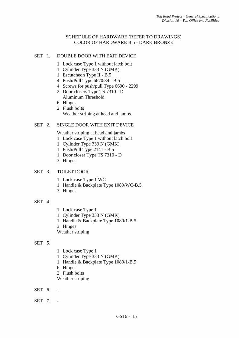
Toll Road Project – General Specifications
Division 16 – Toll Office and Facilities
GS16 - 15
SCHEDULE OF HARDWARE (REFER TO DRAWINGS)
COLOR OF HARDWARE B.5 - DARK BRONZE
SET 1. DOUBLE DOOR WITH EXIT DEVICE
1 Lock case Type 1 without latch bolt
1 Cylinder Type 333 N (GMK)
1 Escutcheon Type II - B.5
4 Push/Pull Type 6670.34 - B.5
4 Screws for push/pull Type 6690 - 2299
2 Door closers Type TS 7310 - D
Aluminum Threshold
6 Hinges
2 Flush bolts
Weather striping at head and jambs.
SET 2. SINGLE DOOR WITH EXIT DEVICE
Weather striping at head and jambs
1 Lock case Type 1 without latch bolt
1 Cylinder Type 333 N (GMK)
1 Push/Pull Type 2141 - B.5
1 Door closer Type TS 7310 - D
3 Hinges
SET 3. TOILET DOOR
1 Lock case Type 1 WC
1 Handle & Backplate Type 1080/WC-B.5
3 Hinges
SET 4.
1 Lock case Type 1
1 Cylinder Type 333 N (GMK)
1 Handle & Backplate Type 1080/1-B.5
3 Hinges
Weather striping
SET 5.
1 Lock case Type 1
1 Cylinder Type 333 N (GMK)
1 Handle & Backplate Type 1080/1-B.5
6 Hinges
2 Flush bolts
Weather striping
SET 6. -
SET 7. -
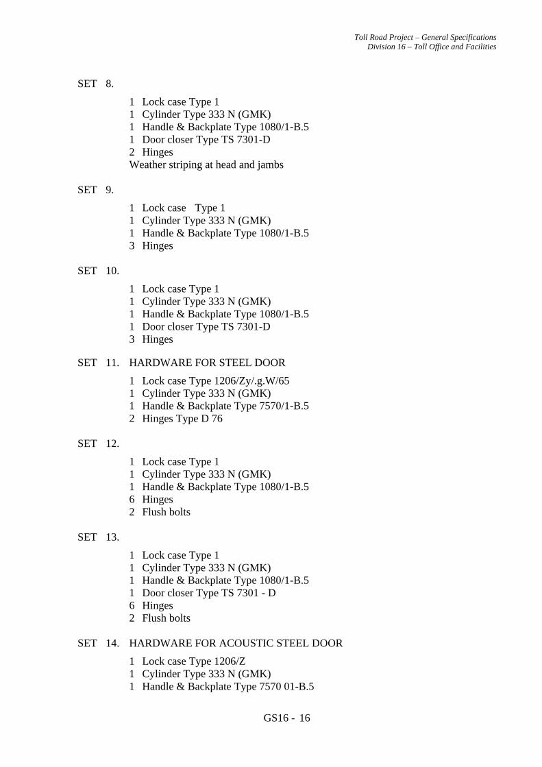
Toll Road Project – General Specifications
Division 16 – Toll Office and Facilities
GS16 - 16
SET 8.
1 Lock case Type 1
1 Cylinder Type 333 N (GMK)
1 Handle & Backplate Type 1080/1-B.5
1 Door closer Type TS 7301-D
2 Hinges
Weather striping at head and jambs
SET 9.
1 Lock case Type 1
1 Cylinder Type 333 N (GMK)
1 Handle & Backplate Type 1080/1-B.5
3 Hinges
SET 10.
1 Lock case Type 1
1 Cylinder Type 333 N (GMK)
1 Handle & Backplate Type 1080/1-B.5
1 Door closer Type TS 7301-D
3 Hinges
SET 11. HARDWARE FOR STEEL DOOR
1 Lock case Type 1206/Zy/.g.W/65
1 Cylinder Type 333 N (GMK)
1 Handle & Backplate Type 7570/1-B.5
2 Hinges Type D 76
SET 12.
1 Lock case Type 1
1 Cylinder Type 333 N (GMK)
1 Handle & Backplate Type 1080/1-B.5
6 Hinges
2 Flush bolts
SET 13.
1 Lock case Type 1
1 Cylinder Type 333 N (GMK)
1 Handle & Backplate Type 1080/1-B.5
1 Door closer Type TS 7301 - D
6 Hinges
2 Flush bolts
SET 14. HARDWARE FOR ACOUSTIC STEEL DOOR
1 Lock case Type 1206/Z
1 Cylinder Type 333 N (GMK)
1 Handle & Backplate Type 7570 01-B.5
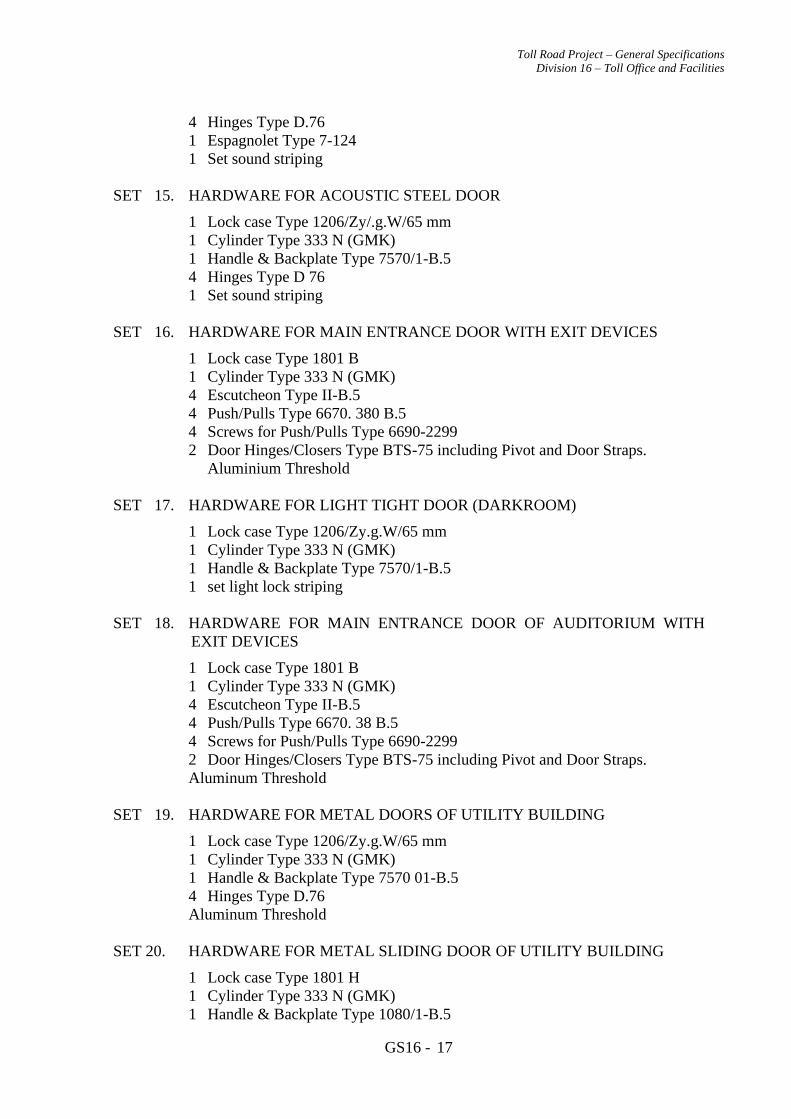
Toll Road Project – General Specifications
Division 16 – Toll Office and Facilities
GS16 - 17
4 Hinges Type D.76
1 Espagnolet Type 7-124
1 Set sound striping
SET 15. HARDWARE FOR ACOUSTIC STEEL DOOR
1 Lock case Type 1206/Zy/.g.W/65 mm
1 Cylinder Type 333 N (GMK)
1 Handle & Backplate Type 7570/1-B.5
4 Hinges Type D 76
1 Set sound striping
SET 16. HARDWARE FOR MAIN ENTRANCE DOOR WITH EXIT DEVICES
1 Lock case Type 1801 B
1 Cylinder Type 333 N (GMK)
4 Escutcheon Type II-B.5
4 Push/Pulls Type 6670. 380 B.5
4 Screws for Push/Pulls Type 6690-2299
2 Door Hinges/Closers Type BTS-75 including Pivot and Door Straps.
Aluminium Threshold
SET 17. HARDWARE FOR LIGHT TIGHT DOOR (DARKROOM)
1 Lock case Type 1206/Zy.g.W/65 mm
1 Cylinder Type 333 N (GMK)
1 Handle & Backplate Type 7570/1-B.5
1 set light lock striping
SET 18. HARDWARE FOR MAIN ENTRANCE DOOR OF AUDITORIUM WITH
EXIT DEVICES
1 Lock case Type 1801 B
1 Cylinder Type 333 N (GMK)
4 Escutcheon Type II-B.5
4 Push/Pulls Type 6670. 38 B.5
4 Screws for Push/Pulls Type 6690-2299
2 Door Hinges/Closers Type BTS-75 including Pivot and Door Straps.
Aluminum Threshold
SET 19. HARDWARE FOR METAL DOORS OF UTILITY BUILDING
1 Lock case Type 1206/Zy.g.W/65 mm
1 Cylinder Type 333 N (GMK)
1 Handle & Backplate Type 7570 01-B.5
4 Hinges Type D.76
Aluminum Threshold
SET 20. HARDWARE FOR METAL SLIDING DOOR OF UTILITY BUILDING
1 Lock case Type 1801 H
1 Cylinder Type 333 N (GMK)
1 Handle & Backplate Type 1080/1-B.5
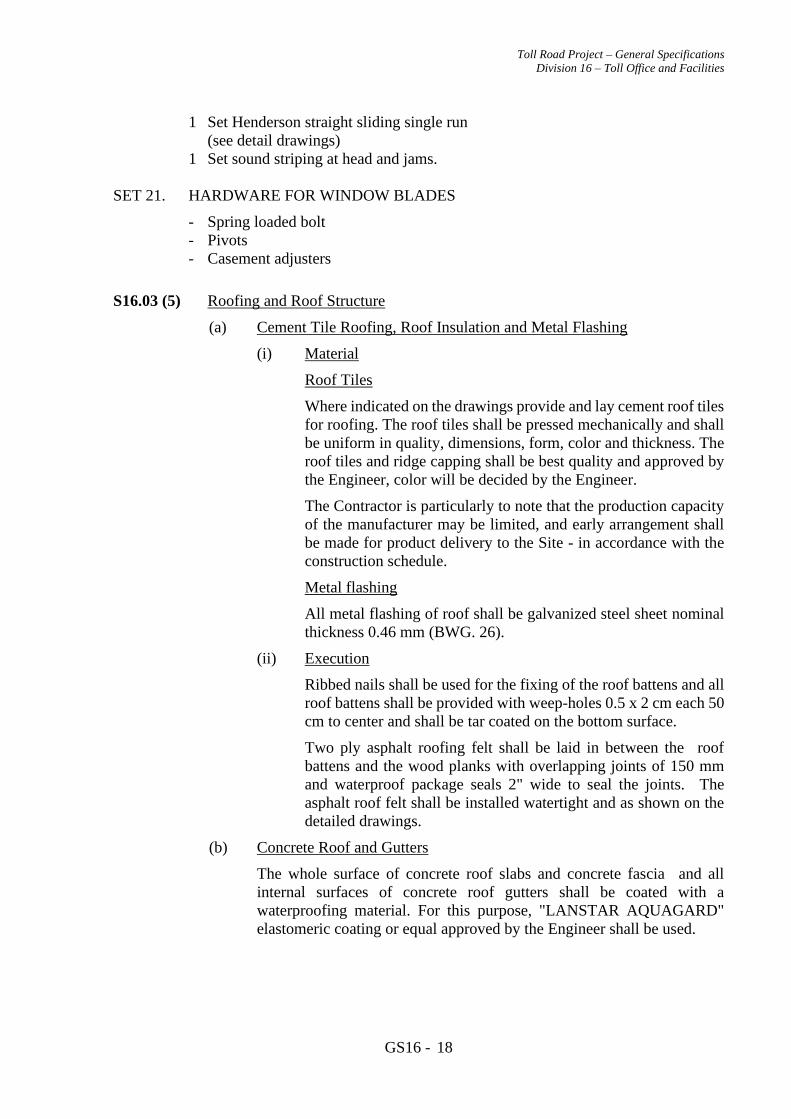
Toll Road Project – General Specifications
Division 16 – Toll Office and Facilities
GS16 - 18
1 Set Henderson straight sliding single run
(see detail drawings)
1 Set sound striping at head and jams.
SET 21. HARDWARE FOR WINDOW BLADES
- Spring loaded bolt
- Pivots
- Casement adjusters
S16.03 (5) Roofing and Roof Structure
(a) Cement Tile Roofing, Roof Insulation and Metal Flashing
(i) Material
Roof Tiles
Where indicated on the drawings provide and lay cement roof tiles
for roofing. The roof tiles shall be pressed mechanically and shall
be uniform in quality, dimensions, form, color and thickness. The
roof tiles and ridge capping shall be best quality and approved by
the Engineer, color will be decided by the Engineer.
The Contractor is particularly to note that the production capacity
of the manufacturer may be limited, and early arrangement shall
be made for product delivery to the Site - in accordance with the
construction schedule.
Metal flashing
All metal flashing of roof shall be galvanized steel sheet nominal
thickness 0.46 mm (BWG. 26).
(ii) Execution
Ribbed nails shall be used for the fixing of the roof battens and all
roof battens shall be provided with weep-holes 0.5 x 2 cm each 50
cm to center and shall be tar coated on the bottom surface.
Two ply asphalt roofing felt shall be laid in between the roof
battens and the wood planks with overlapping joints of 150 mm
and waterproof package seals 2" wide to seal the joints. The
asphalt roof felt shall be installed watertight and as shown on the
detailed drawings.
(b) Concrete Roof and Gutters
The whole surface of concrete roof slabs and concrete fascia and all
internal surfaces of concrete roof gutters shall be coated with a
waterproofing material. For this purpose, "LANSTAR AQUAGARD"
elastomeric coating or equal approved by the Engineer shall be used.
Toll Road Project – General Specifications
Division 16 – Toll Office and Facilities
GS16 - 19
(c) Roof Structure
(i) Timber Roof Structure
Timber trusses shall be constructed as shown on the drawings,
assembled on the ground in true rigid form ready for erection. All
joints and connections shall be executed according to the details
on the drawings and shall be fastened with black steel bolts of the
specified diameter.
All jointing shall be executed in a workmanlike manner and tie
bolts shall be carefully fixed in holes of a diameter of the bolt.
Nuts shall be tightly screwed home. Trusses shall be fixed to the
concrete tie beam either by means of steel plate/angle as specified
on the drawings and where necessary wedged up or down to ensure
tight and secure fixing or by means of metal brackets as shown on
the detailed drawings of the trusses.
(ii) Purlins etc.
Purlins, rafters, wind braces, battens, plank, shall all be of the
dimensions shown on the general and detailed drawings. Each
member shall be securely fixed according to the detailed drawings.
(iii) Inspection of Roofing
Completed roof construction shall not be left unprotected longer
than absolutely necessary. Before commencement of the fixing
of the roof finish the roof, construction shall be inspected by the
Engineer to ensure that the structure is not warped and that purlins
and laths are straight and at the correct distance.
(iv) Finishing
The bars of the roof structure purlins and wood planks that are to
be exposed shall be wrought and planed until a smooth surface is
obtained and will be finished with a natural finishing. See Sub-
clause S16.02 (8) Painting.
(v) Steel Roof Structure
The roof structure for the office shall be made of steel.
Steel work shall be executed in accordance with the information
contained in the drawings, complete with support, means of
fixings and connection. Materials used for steelwork shall meet
the quality of ASTM A36-14 or SNI 6719:2015, ASTM
A572/A572M-18 minimum yield strength 25 kg/mm2, tensile
strength 40-52 kg/mm2, shall be obtained from recognized and
approved suppliers, shall be free from excessive corrosion and the
sections and sheets shall be not bent or otherwise deformed.
The exact sections, shapes, thicknesses, sizes, weight, and details
of construction indicated in the Drawings shall be supplied,
however, the Contractor, because of his stock or shop practices
may suggest changes to the Engineer to be considered for
approval.
Toll Road Project – General Specifications
Division 16 – Toll Office and Facilities
GS16 - 20
(1) Connection
- Welding
Welding shall be arc welding, executed with all
possible care. The deposited weld metal shall be free
from slag deposit and other faults impairing the
strength and connection and when exposed shall be
ground smooth. The surface of the welds shall have a
uniform and consistent contour and regular
appearance. Welds showing any signs of defects shall
be cut and rewelded at the Contractor's expense.
- Bolts and nuts
Bolts and nuts shall be of mild steel as required in Sub-
clause S11.01.(2).(a).(ii).(1) of these Specifications.
They shall be to the sizes indicated on the drawings.
(2) Protection
- Painting
Mill scale and surface corrosion shall be removed until
the surface has obtained a regular metallic appearance.
Immediately after this treatment the steelwork shall be
coated with two coats of 30 - 36 micron of metal primer
chromate as specified in Sub-clause S16.02 (8).
If these coats should be damaged during transport,
stacking or erection they shall be repaired without
delay.
(3) Finishing
The exposed steel roof structure shall be finished with
gloss paint in accordance with the requirements of Sub-
clause S16.02 (8).
S16.03 (6) Floor Finishing
(a) General
Tiles are to be laid as indicated on the Drawings and as described
hereafter. Samples are to be submitted for each type for final review and
approval of quality, color, pattern and texture.
(b) Finishing layer mortar for Floor
Finishing layer mortar for Floor are as follows: the mixing proportion
shall be 1-part cement and 3 parts of fine aggregate. The thickness shall
be determined by calculating the difference of the level of the floor finish
and the reinforced concrete slab. Water shall be kept to a minimum but
shall be sufficient to allow adequate compaction.
All cables, pipe work etc, shall be placed and inspected before
commencing the screeds.
Toll Road Project – General Specifications
Division 16 – Toll Office and Facilities
GS16 - 21
Mortar layer shall be laid in bays of monolithic construction not to exceed
30 m2. Mortar layer shall be cured for 3 to 7 days and protected from
wear or other damage until the laying of the floor finish.
No moisture sensitive floor finish shall be laid until a reliable moisture
test shows that the screed is sufficiently dry to receive the covering.
Defective mortar layer shall be cut out and made good in such time as to
allow a sufficient interval for drying out prior to the scheduled laying of
the finished floor coverings.
The surface of the mortar layer shall be flat.
(c) Terrazzo Tile with Copper Joints
(i) Material
Materials for terrazzo flooring tile will be first class grade local
product, approved by the Engineer. Minimum compressive
strength of finished terrazzo tile shall be 40 kg/cm2.
(ii) Execution
After the mortar layer are dried out (see sub Sub-clause (b) copper
joints shall be laid following an equilateral triangle pattern as
indicated on the drawings. The thickness of the joints shall be 2
mm. The joints shall be laid in a straight line.
The terrazzo tile shall be applied with a wood skimming float and
traversed with a floating rule to a true and even surface. The
average thickness of the tile shall be 2.5 cm.
Polishing of the surface shall be performed accurately by a
polishing machine until a smooth and even surface is obtained to
the satisfaction of the Engineer. Polishing shall be carried out at a
minimum of 7 days after the tile work is finished.
The terrazzo tile work and polishing shall be executed by the
manufacturer. Workmanship shall be of the best quality and
performed only by skilled workmen. The Contractor shall be
responsible for the appearance and quality of the finished work.
Terrazzo tile flooring that is not executed to the satisfaction of the
Engineer shall be repaired as soon as possible.
(d) Exposed Concrete Floor
Exposed concrete floor refers to flooring with a cement mortar as the
finishing layer on a concrete slab.
(i) Execution
Cement mortar as the finishing layer or exposed floor will be
executed for :
- Pedestrian malls, etc.
Cement mortar shall be laid in bays or patterns as indicated in the
drawings.
Toll Road Project – General Specifications
Division 16 – Toll Office and Facilities
GS16 - 22
(e) Portland Cement Tile
(i) Material
Ribbed P.C. tile 20 x 20 cm with a minimum thickness of 2 cm
shall be best quality local product approved by the Engineer.
(ii) Execution
Finishing mortar layer see sub Sub-clause (b).
After the mortar layer are dried out the tiles shall be laid in a bed
of semi dry mortar. The thickness of mortar depends on the
finished floor levels shown on the drawings.
Mortar for joints shall be a mixing of water and Portland cement.
The joints shall be straight lines of even width.
Immediately after the laying of the tiles the floor shall be cleaned
off with sawdust. The P.C. tiles shall be hand polished to obtain a
good finish.
(f) Ceramics and Mosaics Tile
(i) Material
Ceramics and mosaics tile shall be best quality local product
approved by the Engineer.
(ii) Execution
Screeds to receive finishers see sub Sub-clause (b).
After the mortar are dried out the tiles shall be laid in a bed of semi
dry mortar. The thickness of mortar depends on the finished floor
levels shown on the drawings.
Mortar for joints shall be a mixing of water and Portland cement.
The joints shall be straight lines of even width.
Workmanship shall be of the best quality and performed only by
skilled workmen. The Contractor shall be responsible for the
appearance and quality of the finished work.
Ceramics and mosaics tile floating that is not executed to the
satisfaction of the Engineer shall be repaired as soon as possible.
Dimensions for ceramics tile shall be 10 x 20 cm or as shown on
the Drawings.
S16.03 (7) Wall Finish
(a) Plasterwork
(i) Materials
Portland cement, sand and water shall be in accordance with the
requirements of Sub-clause S16.02 (2).
Toll Road Project – General Specifications
Division 16 – Toll Office and Facilities
GS16 - 23
(ii) Mortar Composition
Mortar composition shall be 1 part of Portland cement to 5 parts
of sand for concrete block masonry. For other surfaces the
composition shall be 1-part PC to 4 parts of sand, and for
waterproof mortar 1 part of PC to 2 parts of sand.
The mortar shall be mixed as described in Sub-clause S16.02 (3)
and shall be thoroughly mixed dry before adding water.
(iii) Preparation of Surface
Adequate drying-out time shall be allowed for concrete block
walls and concrete surface. All piping, conduits, etc, shall be
previously set in the correct location.
Joints in concrete block walling shall be raked out as specified in
Sub-clause S16.02 (3). Concrete surface shall be roughened by
hacking or bush hammering and shall be free of grease or oil
patches. Dirt and all lose materials shall be thoroughly brushed
down with stiff brushes. Low spots and areas shall be dubbed out
and sufficient time shall be allowed for the dubbing out to dry
before the first plastering coat is applied. To prevent premature
drying out of the plaster, prepared surface shall be soaked with
water.
The underside of exposed concrete beams and floor slabs shall not
be plastered.
(iv) Execution
The average thickness of plaster shall be 1.5 cm and minimum
thickness 1 cm. A finish is to be obtained that is acceptable to the
Engineer.
Mortar shall be formed to serve as guides to bring the work to an
even surface. The plaster shall be applied with a wood skimming
float and traversed with a floating rule to a true and even surface.
The plaster shall be kept damp for at least 7 days after its
application. Moistening shall begin as soon as plaster has hardened
sufficiently to avoid damage. The plaster shall be protected from
uneven and excessive evaporation during hot, dry weather.
(b) Wall Tiling
(i) Preparation and Inspection
The Contractor shall not start wall tiling until all plumbing pipes,
conduits, grounds, anchors, etc. have been installed and approved.
The Contractor shall inspect surfaces before tiling. If there are
any defects or bad condition the Contractor shall repair these
before commencing the tiling work.
Toll Road Project – General Specifications
Division 16 – Toll Office and Facilities
GS16 - 24
(ii) Material
Tiles shall be white glazed ceramic tiles of best quality approved
by the Engineer with a nominal dimensions of 11 cm x 11 cm or
as shown in the Drawings. The tiles shall be uniform in dimension,
colour, glaze and thickness. Tiles with defect surfaces shall not
be used.
(iii) Mortar
- Mortar for bedding shall be 1 part of Portland cement to 3 parts
of sand
- Mortar for joints shall be a mixing of white cement and water.
(iv) Cutting of Tiles
Cut edges of glazed ceramic tiles shall be smoothed with a
carborundum stone.
(v) Execution
Before placing, the white glazed wall tiles shall be soaked in
advance in clean water till they are damp, but not dripping wet.
The mortar for bedding shall be placed on a prepared plane surface
which has been thoroughly cleaned and wetted. The tiling shall
be true, straight and plumb, with joints in a straight line and of an
even width of 3 mm.
(vi) Fixing of Wall Tiles with Adhesive
Wall tiles may be applied to a rendering coat by means of an
approved adhesive on a cement base which has been levelled up
and smoothed. The Contractor shall adhere strictly to all
instructions given by the manufacturer of the adhesive.
The requirements for the tiling, the width and the pointing of the
joints shall be as specified in the previous Sub-clause (v)
"Execution".
(vii) Scope of Work
White glazed ceramic tiles shall be laid as lining of toilet walls,
and as indicated on the drawings.
S16.03 (8) Glazing and Painting
(a) Glazing
(i) Materials
Glass used for the building shall be clear glass 6 mm thick best
quality approved by the Engineer. A silicone rubber compound
shall be used for back puttying of glazing to timber frames. Only
compounds which are known (proven) to be fully compatible with
surfaces contacted shall be used.
Toll Road Project – General Specifications
Division 16 – Toll Office and Facilities
GS16 - 25
(ii) Execution
- Clean the timber framing members to receive glass
immediately before glazing.
- The timber framing shall be primed and painted one coat
before glazing.
- The Contractor shall be responsible for correct glass size for
each opening within the tolerance and necessary dimensions
established.
- Watertight and airtight installation of each piece of glass is
required. Each piece of glass shall withstand normal
temperature changes, wind loading, impact loading without
failure of any kind.
- Glazing compound shall be used to ensure complete bond of
sealant to glass and timber framing or beads.
- Timber beads shall be fixed with brass screws.
- Remove and replace glass which is broken, chipped cracked,
abraded or damaged in other ways during the construction
period, including natural causes, accidents and vandalism.
- Wash and polish glass on both faces not more than 4 days prior
to Employer's acceptance of the work.
(b) Painting
(i) Materials, General Requirements
All paint material and primers shall be obtained from approved
suppliers.
For the purpose of establishing a basis of quality, the paints
specified herein are based upon paints as manufactured by ICI.
The specifying of paints by a manufacturer's name and series
number shall not be construed as being proprietary but rather as
establishing a basis for quality comparison only.
Paints to be used shall be as follows or equal
- ICI Vinyl Acrylic Emulsion A.921
- ICI Weather shield Exterior Wall Finish
- ICI Synthetic Super Gloss A. 365
- ICI Teak Oil A.101-110
- ICI Timber Glow Clear Finish A.291-Satin
- ICI Clear Varnish A.105-49010
Note: ICI = PT. ICI Indonesia or equal approved.
- Materials shall be delivered to the site in the manufacturer's
sealed containers bearing the manufacturer's label identifying
Toll Road Project – General Specifications
Division 16 – Toll Office and Facilities
GS16 - 26
type and grade of contents. No paint stored longer than the
manufacturer's specified shelf life shall be used.
- Paint shall be mixed and applied in compliance with the
manufacturer's directions. Paint shall be thoroughly stirred
until the ingredients therein are completely intermixed and, if
necessary shall be strained prior to being applied.
- Under no circumstances will the addition of driers or other
materials be permitted, unless such additions are
recommended or required by the manufacturer of the paint.
- White wash material shall be of "kapur pemutih/kapur sirih"
of good quality (specified in N17) free from impure material.
Three coats or more shall be applied until an even white wash
finish is obtained to the satisfaction of the Engineer.
(ii) Materials, Specific Requirements
a. Transparent Finish (Pigmented) Woodwork
a.1
First Coat
Second Coat
:
:
1 Coat of wood primer
2 Coats of varnish
A.105-49010
.
.
.
Door, window &
partition frames
Exterior door &
window blades
Timber louvres
a.2
First Coat
Second Coat
:
:
1 Coat of wood primer
2 Coats of timber
glow clear finish
A.291-Satan
.
.
.
.
.
.
.
Wood staircase
wood handrailing
Exposed wood
framing of ceiling
Wood slats ceiling
Wood base
Exposed wood struc-
tures, trusses,
purlins, etc.
Exposed roof planks
Furniture
a.3
3 Coats of Teak Oil
.
Interior door
blades, teak
plywood
b. Gloss Finish Surface Type
b.1
First Coat
Second Coat
:
:
1 Coat of wood primer
2 Coats of Synthetic
Super Gloss A.365
.
Wood Fascia
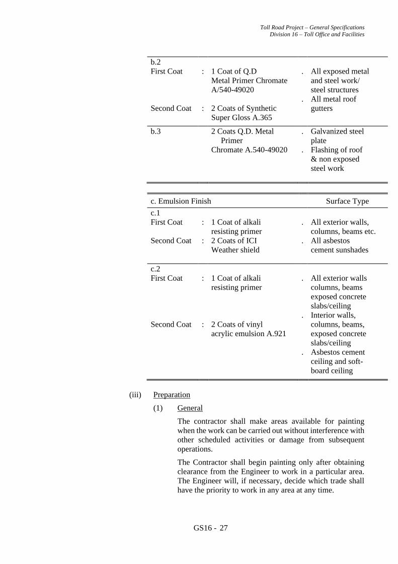
Toll Road Project – General Specifications
Division 16 – Toll Office and Facilities
GS16 - 27
b.2
First Coat
Second Coat
:
:
1 Coat of Q.D
Metal Primer Chromate
A/540-49020
2 Coats of Synthetic
Super Gloss A.365
.
.
All exposed metal
and steel work/
steel structures
All metal roof
gutters
b.3 2 Coats Q.D. Metal
Primer
Chromate A.540-49020
.
.
Galvanized steel
plate
Flashing of roof
& non exposed
steel work
c. Emulsion Finish Surface Type
c.1
First Coat
Second Coat
:
:
1 Coat of alkali
resisting primer
2 Coats of ICI
Weather shield
.
.
All exterior walls,
columns, beams etc.
All asbestos
cement sunshades
c.2
First Coat
:
1 Coat of alkali
resisting primer
.
.
All exterior walls
columns, beams
exposed concrete
slabs/ceiling
Interior walls,
Second Coat : 2 Coats of vinyl
acrylic emulsion A.921
.
columns, beams,
exposed concrete
slabs/ceiling
Asbestos cement
ceiling and soft-
board ceiling
(iii) Preparation
(1) General
The contractor shall make areas available for painting
when the work can be carried out without interference with
other scheduled activities or damage from subsequent
operations.
The Contractor shall begin painting only after obtaining
clearance from the Engineer to work in a particular area.
The Engineer will, if necessary, decide which trade shall
have the priority to work in any area at any time.
Toll Road Project – General Specifications
Division 16 – Toll Office and Facilities
GS16 - 28
Unless otherwise specifically recommended or required by
the manufacturer's instructions for satisfactory use of
special coating, the surface to be painted shall be dry when
the work is performed. No paint or coating shall be
applied over dust or other non-adhering matter nor over
grease, oil or other matter which is incompatible with or
may adversely affect the bond of the paint or coating to be
applied. The general requirements of this paragraph shall
apply to all surfaces including shop primed and factory
painted items. All shop primed or painted items and all
previously applied field coats shall be cleaned of any oil,
grease or other incompatible matter by an appropriate
surface preparation before applying the next coating.
(2) Preparation of Woodwork
- Alkaline cleaning as required to remove any grease, oil
or wax. Remove alkali with water-soaked wipers and
dry thoroughly.
- Smooth surface by fine sanding.
- Blunt sharp edges with grinder.
- Seal knots and pitch streaks with shellac.
- Fill holes, cracks, etc. with a latex base caulking
compound and when hardened, sand smooth.
(3) Preparation of Steel Work
All surfaces to be painted shall be cleaned of all rust, scale,
welding contaminants, grease, oil or other foreign matter
by solvent cleaning and hand cleaning or power tool
cleaning. All weld spatter and sharp edges and points
shop primed steelwork shall be inspected. Heat damaged
primer and unsatisfactory priming shall be removed,
cleaned off, wire brushed, rubbed down and primed
immediately as specified.
Strict precautions shall be taken to prevent introduction of
rust, scale, dirt or other products of cleaning into working
parts of adjacent machinery or equipment, adjacent
processes or products or areas of paint.
Remove all oil, waste, oxides and other surface
contaminants or coatings by scrubbing with Rustoleum
surface-etch or equal approved, rinse clean with fresh
water and dry thoroughly. Only quick drier metal primer
chromate shall be used as primer.
(4) Preparation of Plaster Work
Plaster shall be allowed the maximum time possible for
drying out. All defective plaster or cement rendering shall
be cut out and made good to the satisfaction of the
Toll Road Project – General Specifications
Division 16 – Toll Office and Facilities
GS16 - 29
Engineer. The manufacturer's recommendations regarding
neutralizing the surface before treatment of the surface
with alkali resisting primer coating shall be complied with.
(iv) Application
(1) Conditions for Painting
- No painting shall be done when windblown dust or
debris may contaminate the work.
- Interior painting areas shall be isolated as required to
prevent dust circulation. Temporary enclosures shall
be provided by the Contractor where isolation cannot
be affected by closing of existing doors.
- No solvent drying or catalyst curing coating shall be
applied when the relative humidity is higher than 80%.
- No paint shall be applied to wet surface, unless so
specified.
The Contractor shall examine the surface to be painted or
coated and shall notify the Engineer of any detectable
defects or unsatisfactory surface conditions not correctable
by surface preparation. If in doubt regarding compatibility
of previously painted surfaces with specified paints, the
Contractor shall make a patch test before proceeding with
field painting. Application of the first field coat of paint
or coating shall be upon representation by the Contractor
that the surface, including shop priming or painting, is
suitable to receive his field painting.
Where portions or surfaces of structural steel will be
inaccessible after installation of other materials, such
portions or surfaces shall be painted before installation of
such materials.
The manufacturer's recommendations for re-coat time for
the conditions under which painting is performed shall be
strictly followed.
All paint materials shall be used strictly in accordance with
the manufacturer's instruction.
(v) Clean Up
Before final acceptance of the work, the Contractor shall remove
all paint spots or stains caused by his work, from floors, walls,
hardware, fixtures and similar items, leaving all surfaces in a clean
and acceptable condition. All glass shall be cleaned of all paint
and putty deposits.
Toll Road Project – General Specifications
Division 16 – Toll Office and Facilities
GS16 - 30
S16.03 (9) Ceiling
(a) Panel Ceiling
(i) Material
Kamper class I (wood) shall be used for ceiling structure and the
ceiling shall not be asbestos cement plate.
(ii) Construction and Execution
The panels 0.5 cm thick with wood framing 3 x 4 cm are to be
supported by a wood frame 3 x 5 cm which is screwed to a frame
3 x 7 cm. The joining between the bars of the frame shall be
executed with trimming joints. The underside of the hangers
shall be planned to obtain a smooth surface.
(iii) Before fixing the ceiling, the Contractor shall inspect whether the
underside of all hangers is plane and at a suitable height.
(iv) Finishing
The exposed parts of the wood frame on the corner shall be painted
in accordance with Sub-clause S16.02 (8).
(v) Location
Panel ceilings shall be installed as indicated in the drawings.
S16.03 (10) Metal Railing
(a) Material
All parts of the railing, including posts are to be made of steel dia. 25 mm
and 50 mm.
(b) Execution
For some parts of the balcony the railing shall be fitted to the steel framing
along the building facade. The posts of the railing of the concrete
staircase shall be fitted to the concrete straircase slab with four bolts.
(i) Connections
- Welding
See Sub-clause S16.02 (5)
- Bolts and Nuts
See Sub-clause S16.02 (5)
(ii) Finishing
The railing shall be painted in accordance with the requirements
of Sub-clause S16.02 (8).
Toll Road Project – General Specifications
Division 16 – Toll Office and Facilities
GS16 - 31
S16.03 (11) Rainwater Drain Pipe
(a) Material
All rainwater drain pipes or down pipes shall be P.V.C. diameter 15 cm
(dia. 6"). Roof drains shall be cast iron.
(b) Execution
The drain pipes shall be constructed according to the detailed drawings.
S16.03 (12) Softboard Wall Finish
(a) Material
Softboard sheet 1.20 m x 2.40 m with a thickness of 1.2 cm best quality
approved by the Engineer shall be used for the panels. Joints lath shall be
teak (jati) 1.5 x 5 cm. The softboard panel shall be covered with fabric.
(b) Execution
Lathwork for fitting the softboard panels shall be made of Kamper (wood)
3 cm x 5 cm with a grid of 60 cm x 120 cm. The lathwork shall be fitted
to the unplaster concrete block wall with screws and fisher 40 cm c.t.c.
The softboard shall be fitted from the upper side of the wooden base to
entrance door level (+ 3 m).
The upper side of the softboard wall finish shall be horizontal. The upper
side shall be covered with a teak lath 1.5/2.5 cm x 6.5 cm (trapezium cross
section). The softboard panels shall be nailed to the lath work at a
distance of 40 cm c.t.c. with 1" nails. The vertical joints shall be covered
with teak lath 1.5 cm x 5 cm. The horizontal joints shall not be covered.
The execution shall be carried out in accordance with the detail drawing.
Above the softboard wall finish the concrete block wall shall be plastered.
(c) Finishing
The teak joint laths and upper side laths shall be finished with clear
varnish in accordance with the requirements of Sub-clause S16.02 (8).
S16.03 (13) Soil Treatment and Termite Proofing
(a) Scope
The work shall include furnishing labor and material and performing all
operations necessary in soil treatment in strict accordance with the
specifications.
(b) Due to existing laws and regulations limiting the licensing of companies
engaged in the practice of Termite Control and Prevention Operations and
due to the necessity of using specialized knowledge, the license of the sub-
contractor shall be submitted to the Engineer for approval.
(c) Application rates shall be determined by the use of a power sprayer, with
calibrated flowmeter attachment to provide the required rate and
uniformity of application. Any other method shall be approved by the
Engineer.
Toll Road Project – General Specifications
Division 16 – Toll Office and Facilities
GS16 - 32
(d) The chemical applied to soil areas to be treated shall be lambda
cyhalothrin with concentration applied as the manufacturer’s instruction.
(e) Prior to pouring of concrete floor slab for slabs on the ground and on fill,
and prior to backfilling around the outside perimeter, along with interior
foundation walls, and around critical areas soil treatment and termite
proofing shall be applied as herein specified.
(i) Overall treatment shall be applied over the entire surface under the
floor slab, entrance platforms, pedestrian malls, paved open
terrace, steps and around outside perimeter of building 1.0 m wide,
at a rate (liter per square meter) as the manufacturer’s instruction.
In critical areas such as around openings for utility pipes, conduit,
ducts and floor drains, application shall be at rate (liter per square
meter, generally 1,5 times of non critical areas) as the
manufacturer’s instruction.
(ii) Treatment shall be applied along both sides of foundation of
columns and walls and shear walls at a rate (liter per square meter,
generally equal with the above mentioned critical areas) as the
manufacturer’s instruction. Application shall be 1/3 of the
emulsion applied near the level of the top of footings before
backfilling; 1/3 after half of the backfill is placed; and then the
remainder.
(f) The soil treatment and termite proofing operations shall be guaranteed by
the sub-contractor for a period of five (5) years from the date of treatment
as a condition for the final acceptance of the work. The Contractor shall
hand over the pest control operator's certificate of warranty to the Engineer
which guarantees among other items, the required concentration, rate and
method of application complying in every aspect with the requirements
contained herein. Any evidence of infestation within the guarantee period
will require treatment without cost to the owner.
S16.04 Facilities Work
S16.04 (1) Plumbing and Fire Fighting Systems
(a) General
This clause covers furnishing and installing plumbing and fire fighting
equipment and materials as specified herein and indicated in the drawings.
The complete installation shall be inspected and tested and all work
required to place the system in satisfactory operating condition shall be
performed.
If the water supply from the PAM is inaccessible or the existing water
supply does not have sufficient capacity, the Contractor shall assume that
additonal water supply to be required and the Contractor shall provide the
wells with the pumps required. The contractor shall discuss this case with
the appropriate relevan agencies and include for all work that needed to
provide a constant and sufficient water supply. For "adequate supply" with
a normal discharge level of necessity shall be added to the discharge rate
Toll Road Project – General Specifications
Division 16 – Toll Office and Facilities
GS16 - 33
of fire suppression pump for two hours. Supply and storage capacity shall
be taken account as needed.
(b) Plumbing and Fire Fighting Installation Regulations
The plumbing and firefighting installation work shall be carried out in
compliance with:
- Pedoman Plumbing Indonesia 1979
- National Fire Protection Association (NFPA)
- Fire Offices Committee (F.O.C)
- Regulation by other authorized authorities
The plumbing and firefighting installation work shall be performed by a
sub-contractor registered and possessing a valid permit from PAM and
experienced in installing similar systems. A list of installation references
shall be submitted to the Engineer. The Contractor shall be responsible for
all negotiations with the relevant institutions and for obtaining and paying
all permits and fees.
(c) Scope of Work for Plumbing and Fire Fighting
The extent of work required under this clause covers furnishing,
installation and testing of all equipment, materials and related items
necessary to complete the plumbing and firefighting system and fulfill all
requirements as indicated on the design drawings and described in this
specification.
(i) Scope of plumbing works in general is as follows :
- Furnishing and installing Sanitary Fixtures
- Furnishing and installing Clean Water System
- Furnishing and installing Sanitation System e.g. sewage
piping, waste water piping and vent piping, septic tank.
- Preparation and finishing of plumbing system.
(ii) Scope of fire fighting works in general is as follows:
- Furnishing and installing Fire Fighting Piping System
including Pumps and Hydrant Boxes
- Furnishing and installing Siamese Connections
- Furnishing and installing Portable Fire Extinguishers
(iii) Detailed scope of plumbing works shall include but not be limited
to the following items :
- Lavatory fixtures:
* Water closets
* Urinals
* Wash basins
* Sink basins
Toll Road Project – General Specifications
Division 16 – Toll Office and Facilities
GS16 - 34
* Taps
* Floor drains
* Floor clean outs
* Mirrors
* Soap liquid dispensers
- Clean water system:
* Furnishing and installing clean water system from the
existing pipe line to underground water reservoir complete
with all take-off points.
* Furnishing and installing packaged booster pump system,
clean water piping system complete with accessories from
ground reservoir to all take-off points.
- Sanitation System:
* Construction of a septic tank or furnishing and installing
connection to the local exhaust system if available and
permitted.
* Furnishing and installing of waste water piping, sewage
piping from lavatories, showers, WC, urinals, floor drains
and kitchen sinks to septic tank. The septic tank system
shall be separate for the sewage from the toilet and others
in order to the biological reaction in the septic tank will be
effective and not disturbed by soap or other impact.
* Furnishing and installing vent piping for plumbing system
to roof.
- Preparation and Finishing of Plumbing System:
The preparation and finishing of plumbing system shall
include:
* Supply and installation of sleeves and openings on floor,
beam and wall to provide holes for pipe work.
* Supply and installation of pipe hangers and supports.
* Soil excavation and backfill for buried piping installation
* Leak test, flushing and cleaning.
* Coating for all steel pipes and buried piping underground.
* Painting for all steel piping which is above ground
including steel support, hanger and all steel material.
* Concrete blocks for piping as required.
(iv) Detailed scope of firefighting works shall include but not be
limited to the following:
- Furnishing and installing electrical driven fire pump, electrical
driven jockey pump and gasoline engine driven fire pump,
Toll Road Project – General Specifications
Division 16 – Toll Office and Facilities
GS16 - 35
complete with pressure tanks, accessories, starter panels,
power and control cables and all related items necessary.
- Furnishing and installing hydrant boxes and siamese
connection.
- Furnishing and installing piping system for fire fighting
systems.
- Furnishing and installing portable fire extinguishers.
(d) Standard of Materials
All materials shall be brand new and of good quality based on local
standard as well as international standards ASA. Contractor shall be
fully responsible regarding qualities of materials to be used. Before
installing all materials the Engineer's approval shall be obtained.
(e) Substitution of Materials
(i) Material, equipment or fixtures which are not in accordance with
the specifications may only be used after written approval from
the Engineer. All costs due to testing these materials, equipment
or fixtures shall be at the Contractor's expense.
(ii) If required, testing of materials, equipment or fixtures shall be
carried out by institutes approved by the Engineer. These tests
shall be carried out conforming to local standard procedures. If
there are no standard procedures, the Engineer may determine the
testing procedures to be used.
(iii) Each standard length of pipe fitting, fixture and equipment to be
used shall have a clear manufacturer's mark on it. Materials
without this mark shall be replaced.
(f) Material Specification
(i) Sanitary Fixtures
All sanitary fixtures shall be of "K.I.A. Ceramics Indonesia" or
equal approved, color will be decided by the Engineer.
(1) W.C. western style shall be type DUTA T.S. or equal
approved, supply valve, outlet seal & fixing screws.
(2) W.C. squatting type shall be type RAPI E. or equal
approved, chromium plated angle valve, flush pipe and
coupling, outlet seal and fixing screws.
(3) Urinals shall be type PANDA or equal approved.
Each urinal shall be provided with chromium plated flush
valve, and fabricated perforated pipe spray nozzle, all in
chromium.
(4) Washbasins shall be type SUSAN or equal approved
Toll Road Project – General Specifications
Division 16 – Toll Office and Facilities
GS16 - 36
Each washbasin shall be provided with chromium plated
tap, chromium plate waste fitting and "P" trap, back
hangers, dynabolts fasteners etc.
(5) Taps shall be type SINKTAP Y 100 or equal approved
(6) Floor drains shall be conventional type with grill and cover
made of stainless steel or chromium plated brass.
(7) Floor clean-outs shall be made of stainless steel or
chromium plated brass with cover and frame of same
material.
(8) Paper roll holders shall be type VIDI/BIMA or equal
approved and are required for each W.C.
(9) Placenta shall be type SHINTA or equal approved, required
for each wash basin.
(ii) Sanitary System
(1) The following materials shall be used for sewage, waste
water and vent piping systems:
- Pipes shall be PVC Pralon or Rucika brand class D or
equal approved with glued joints.
- Pipe fittings shall be PVC injection molding fittings of
the same brand as pipes.
- Bends in main pipes shall be long radius bends and for
branches in the main pipe 45oY and 45o bends shall be
used.
- Glue shall be in accordance with the PVC pipe
manufacturer's recommendations.
(2) All pipes, fittings, valves, equipment and accessories shall
be original products from the factory.
(iii) Fire Fighting System
(a) Fire hydrant pumping system shall consist of :
- One electric driven jockey pump Fairbank Morse,
Ingersol Rand or approved equivalent c/w NUG motor,
coupling, base plate etc.
- One electric driven fire pump Fairbank Morse,
Ingersol Rand or approved equivalent c/w NUG motor,
coupling, base plate etc. capacity 600 L/M, Head 50 m.
- One 500 lt pressure tank c/w pressure gauge & cock,
hand hole, drain etc. on test pressure of 15 kg/cm2.
Two pressure switches FANAL type FG 10 or equal
approved.
- One pump control panel PCP 1.
Toll Road Project – General Specifications
Division 16 – Toll Office and Facilities
GS16 - 37
- One lot electrical wiring from PCP 1 to pumps and
control.
- One 500 lt priming tank c/w all accessories.
- One gasoline fire pump Fairbank Morse or equal
approved with gasoline driven Perkins or equal
approved c/w all accessories.
(2) Indoor hydrant boxes type A shall mainly comprise as
follows:
Metal casing complete with doors wall thickness 1.5 mm,
hinges, handles, louvers, fixed type hose reel dia. 100 and
hydrant valve diameter 12".
(3) Indoor hydrant type B shall mainly comprise as follows:
Metal casing complete with doors wall thickness 1.5 mm,
hinges, handles, louvers, canvas hose diameter 1.5" length
200 feet, complete with nozzle, valve and rack, etc.
(4) Firefighting piping system shall be galvanized iron pipe
ASTM A53/53M-18 Schedule 40 (welded type) and 300
lbs. screwed fittings for pipe size up to 2" and for larger
than 2" black steel pipe BS 1387 medium class with
welding fitting and shall be primed and painted minimum
twice. Valves larger than 3" shall be Cast Iron Valve 150
psi flanged type.
(5) Portable fire extinguisher shall be type BCF, capacity 5
lbs. ABRO brand or equal approved.
(g) Joint Specification
(i) Galvanized Pipes and Fittings
(1) Joints between pipes and fittings shall be threaded.
(2) Length of thread on pipes shall be at least 3/4 the diameter
of the pipe.
(3) All threaded joints shall use seal tape.
(4) For cutting pipes a suitable pipe cutter device shall be used.
(5) All ends of pipes shall be reamed.
(6) For piping system up to 2.5" after every valve a union shall
be used, and for pipes larger than 3" flanges shall be used.
(7) In piping system, union or flanges shall be used at
minimum every 60 m.
(8) All pipes shall be cleaned properly before installing.
(ii) P.V.C. Pipes and Fittings
(1) Pipes and fittings shall be joined by PVC glue as
recommended by the PVC pipe manufacturer. Before
Toll Road Project – General Specifications
Division 16 – Toll Office and Facilities
GS16 - 38
gluing the joint shall be cleaned properly with cleaning
fluid.
(2) Joints between pipes and fittings shall be carried out
properly using special pressing device. For cutting pipes a
suitable cutting device shall be used to achieve straight
ends of pipe after cutting.
(iii) Couplings
Coupling shall be used for the following joints:
• Joints between fire hoses.
• Joints between fire hose, nozzle and valve.
For all these joints "machine coupling" shall be used.
(iv) Gasket Joints
To achieve water tight joints gaskets shall be used for the
following sanitary equipment joints:
• Between lavatory faucet and supply valve
• Between flush valve and urinal
• Between supply valve and closet floater
• For waste fittings and syphon
(h) Installation Specification
(i) All pipes shall be installed straight and parallel to walls and/or
floor.
(ii) Bends of 90o and 45o shall be used.
(iii) Before pipes are installed supports shall be correctly installed.
(iv) Before installing, supports shall be painted with Zinc chromate
primer.
(v) All installation works shall be correctly carried out.
(vi) All pipes shall be properly supported.
(vii) During installing, open pipe ends shall be covered with caps or
plugs.
(viii) Pipes and fittings shall be free from stresses caused by improper
fixing.
(ix) Before installing the Engineer's approval shall be obtained for all
installation through, or connected to, building construction.
(x) The Contractor shall provide sleeves for all piping going through
walls, floors, concrete slabs, etc.
(xi) Before being buried in the ground piping shall be painted with
flintcote, minimum three coats.
(xii) Sewage piping shall have a 0.5 - 1% slope.
Toll Road Project – General Specifications
Division 16 – Toll Office and Facilities
GS16 - 39
(xiii) Waste water piping shall have a 1 - 2% slope.
(xiv) PVC pipes buried in the ground shall be laid on a sand underlayer
of 10 cm minimum thickness.
(xv) Septic tank construction shall be carried out by a Contractor
experienced in such work.
(i) Sleeves and Supports
(i) General
(1) The subcontractor shall furnish all required sleeves and
supports and is fully responsible for installing at the correct
locations.
Installing sleeves and supports on building parts which will
be poured with concrete shall be carried out by the
Contractor.
(2) Piping shall not run through columns, column bases and
beams without written approval from the Engineer.
(ii) Sleeves
(1) Sleeves for pipes passing through concrete shall be
correctly placed before concrete is poured.
(2) Sleeves shall have an internal diameter at least 2" larger
than the outside diameter of the pipe including insulation.
(3) Sleeves passing through walls etc, shall be of cast iron or
steel pipe.
(4) Sleeves passing through waterproofed building parts shall
be of "flashing sleeves" type.
(5) Contractor shall fill space between outside of pipe or
insulation and inside of sleeves with gasket or "caulk" for
waterproofing.
(iii) Supports
(1) All fixture and sanitary equipment shall be supported and
fixed properly at the correct locations.
(2) All "inserts" in concrete slabs or walls shall be correctly
fixed.
(3) Bolts passing through walls or floors shall be provided
with a steel plate for holding the bolt on the other side of
the wall or floor.
(4) All exposed bolts, nuts, screws and washers shall be
chromium or nickel-plated type.
(j) Hangers
(i) All pipes shall be clamped and fastened with hangers, supports and
fastenings of suitable size and strength.
Toll Road Project – General Specifications
Division 16 – Toll Office and Facilities
GS16 - 40
(ii) Horizontal piping shall be supported on adjustable steel hangers at
maximum spacing 3.0 m.
(iii) The Contractor shall submit to the Engineer samples of hangers
and supports for approval. Perforated strip, wire, or the like will
not be permitted to be used for hangers.
(iv) Hangers and supports shall be fastened to concrete construction by
using "inserts" or "ramset" bolts before concrete is poured.
(v) Vertical pipes shall be clamped. Distance between clamps shall be
less than the floor height.
(k) Underground Pipes
(i) Underground pipes shall be set to the correct depth and slope.
(ii) Piping shall be laid in trenches on a 10 cm underlayer of sand for
stability.
(iii) Pipes for clean water and pipes for waste water or sewage shall not
be laid in the same trench.
(iv) After installing piping in a trench and after checking by the
Engineer the trench shall be cleaned and backfilled with sand or
with an approved material.
(v) All underground piping shall be adequately supported to prevent
sagging or breaking before and after back filling.
(l) Testing
(i) Testing of Cold-Water Pipes
After all piping is installed leakage test of the whole system shall
be carried out to ensure satisfactory performance. The piping
system will be tested uninterrupted for 2 hours, hydrostatic test
pressure 10 kg/cm2, maximum acceptable drop in pressure 5%.
The Contractor shall repair all leakages/damages without extra
cost.
(ii) Fire Fighting Pipe Tests
After all pipes are installed leakage test of the whole system shall
be carried out to ensure satisfactory performance. The piping
system will be tested uninterrupted for 2 hours, hydrostatic test
pressure 20 kg/cm2, maximum acceptable drop in pressure 5%.
The Contractor shall repair all leakages/damages without extra
cost.
(iii) Sanitation Pipe Tests
After all pipes are installed, leakage test of the whole system shall
be carried out to ensure satisfactory performance. The piping
system will be tested uninterrupted for 2 hours, hydrostatic test
pressure 2 kg/cm2, maximum acceptable drop in pressure 5%.
Toll Road Project – General Specifications
Division 16 – Toll Office and Facilities
GS16 - 41
The Contractor shall repair all leakages/damages without extra
cost.
(iv) Rinsing
After all tests for leakages are completed the whole piping system
shall be rinsed by turning on the water distribution system and
opening all the tap points with maximum pressure of 2 kg/cm2.
(v) Distribution Test
After all tests for leakages and rinsing are completed the system
shall be tested for distribution by turning on the whole system at
once. This test shall be repeated for 6 days, each day 6 hours
uninterrupted without causing any damage.
The Contractor shall repair all damages after these tests without
extra cost.
(vi) Disinfection
(1) The contractor shall rinse and disinfect the whole water
installation before handing it over to the Employer.
(2) Disinfection shall be carried out by chlorinating the piping
system, with an approved method. Chlorine 500 p.p.m.
(part per million).
(3) After 16 hours the whole piping system shall be rinsed with
clean water diluted with chlorine solution to a maximum
of 0.2 p.p.m.
(4) Within these 16 hours of disinfection process the taps shall
be opened and closed several times.
S16.04 (2) Fire Fighting Alarm Installation
(a) General
This clause covers furnishing and installing fire alarm equipment and
materials as specified herein and indicated in the Drawings. The
completed installation shall be inspected and tested, and all work required
to place the system in satisfactory operating condition shall be performed.
(b) Fire Alarm Installation Codes
The fire alarm system installation work shall be carried out in compliance
with:
- FUIL Regulations
- National Fire Protection Association (N.F.P.A)
- Fire Office Committee (F.O.C.)
- Regulations by other authorized authorities
The fire alarm system installation work shall be performed by a Contractor
experienced in installing similar systems. A list of installation references
shall be submitted to the Engineer.
Toll Road Project – General Specifications
Division 16 – Toll Office and Facilities
GS16 - 42
(c) Scope of the Fire Alarm System Installation
The Contractor shall furnish, install, test and submit in good condition and
ready for use, materials and equipment for the Fire Alarm System in
compliance with the technical regulations and drawings.
(d) Equipment
The Fire Alarm System is to warn of a fire at an early stage and to give a
warning alarm, automatically, with a detector, or manually with a push
button.
The Fire Alarm System network is designed to centralize the whole
detector and manual push button network at a junction box in the corridor
of each floor and from this junction box to the Control Panel.
This Control Panel will receive a signal automatically or manually and
will give a visible signal and an audible signal.
Equipment for the system shall include but not be limited to the following:
- Thermal Detector: Fixed temperature detector, Rate of temperature
rise detector
- Ionization Smoke Detector
- Optical Smoke Detector
- Alarm Horn (Bell)
- Control Panel
All the Fire Alarm equipment shall be approved by the Engineer and shall
comply with the following requirements:
(i) Thermal Detector
The detector shall be a combination of "rate of rise" with a
"temperature detector" and a "fixed" temperature detector".
Technical Specification:
• Frequency Test : Can be used repeatedly
• Operation Voltage : 20 V DC
• Quiescent Current : Less than 1000 u.A
• Alarm Current : Max: 100 mA
(ii) Ionization Smoke Detector
The detector shall fulfill the following requirements:
• Frequency Test : Can be used repeatedly
• Operation Voltage : 20 V DC
• Quiescent Current : Less than 100 mA.
Mounting plate and terminal base shall be the same as for the
thermal detector.
Toll Road Project – General Specifications
Division 16 – Toll Office and Facilities
GS16 - 43
(iii) Optical Smoke Detector
The detector used shall fulfill the following requirements:
• Frequency Test : Can be used repeatedly
• Operation Voltage : 20 V DC
• Alarm Current : Max 100 mA.
• Permissible Ambient temperature : -30oC - + 60o C
(iv) Manual Push Button
Surface mounted with breakable glass.
(v) Alarm Horn
Surface mounted with the following technical requirements:
• Rust free construction
• Operating Voltage : 18 to 36 DC
• Current consumption : Max. 60mA
• Package Consumption : 2 VA
• Horn Sound Level : 95 dB
(vi) Control Panel
The Control Panel shall consist of a Power Module, Control
Module, Zone Module and Delay Module. Control Panel shall
have a door with framed glass.
(1) Power Module
The Power Module shall have the following facilities:
- An emergency power supply unit to stand in
automatically when the electricity power of 220 V/50
Hz drops out.
- An electrical preventor (fuse, mini circuit breaker etc.).
- A sign lamp ON for the Main Power, internal voltage
system (remote control/signaling), battery charge.
- Give signals when:
* Main Power is ON
* Fault in power supply
(2) Control Module
The Control Module shall have the following facilities:
- Lamp Sign for:
* Horn off
* Reset
* Test
Toll Road Project – General Specifications
Division 16 – Toll Office and Facilities
GS16 - 44
* Lamp Test
* Fault Signal General
* Signal for Alarm Condition
* Signal for "Zone Off"
- An output such as:
* Visible/audible alarm
* Visible/audible fault alarm
* Signal Test (Visible)
* Optical Signal "Zone Off"
- Facility to shut off all AC Package Units when fire
breaks out, (cable control supplied/ installed by the
Fire Alarm Contractor to AC Panels).
(vii) Conduit
• For conduits installed in concrete, steel ducts a minimum
diameter 3/4" or as directed by the Engineer shall be used.
• For built up conduits, above ceiling, PVC pipes complete with
accessories in compliance with PUIL regulations shall be used.
All cables for the Fire Alarm System shall use conduits.
(viii) C a b l e s
- Cables for Main Power Supply of each piece of equipment in
the system shall be NYM 3 x 2.5 mm2.
- For circuit between detector and manual push button cable
shall be NYA diameter 1.5 mm2.
- For Alarm Horn circuit cable shall be NYM 2.5 mm2.
- Cables shall be Kabelmetal, or Kabelindo or equal approved.
(e) Equipment Installation
(i) Location of detectors and other equipment will be determined by
the Engineer.
(ii) Manual Push Button shall be installed at 1.5 m height from the
floor.
(iii) Alarm Horn shall be installed approximately 0.5 m below ceiling
level.
(iv) Approximately 0.6 m around the Detector shall be free from any
obstacle.
Toll Road Project – General Specifications
Division 16 – Toll Office and Facilities
GS16 - 45
S16.04 (3) Closed Circuit Television and Sound System
(a) General
This clause covers furnishing and installing closed circuit television
equipment and paging system and materials as specified herein and
indicated in the Drawing. The completed installations shall be inspected
and tested, and all work required to place the systems in satisfactory
operating condition shall be performed.
(b) Sound System Installation Regulations
The sound system installation work shall be carried out in compliance
with:
- FUIL
- AVE
- Instructions issued by the equipment manufacturers
- Regulations by other authorized authorities
The sound system installation work shall be performed by a Contractor
experienced in similar installation work. A list of installation references
shall be submitted to the Engineer.
(c) Scope of the Closed-Circuit Television
The Contractor shall furnish install and submit in good condition and
ready for use the following closed-circuit television installation.
(i) Supply and install cable from transmitter to each camera in the toll
booth and every designated room.
(ii) Supply and install cable from transmitter to television monitors,
lens control and pan & tilt control.
(d) Operation Conditions
All Closed-Circuit Television installation appliances shall operate in a
good condition at an ambient temperature of 35o C and a RH 70% or 35o
C and a RH 80%.
(e) Material and Installation Condition
(i) Closed Circuit Television Cables type RG-150 and RG-590 brand
Kabelmetal, Kabelindo or equal approved shall be used.
(ii) All Closed-Circuit Television Installation cable shall use conduits
except cables to be installed in floor ducts. For conduits installed
in concrete, GIP pipes with a minimal diameter 3/4" shall be used
or as prescribed by the Engineer. For conduits to be installed above
ceiling, PVC pipes shall be used with accessories. For all cable
joints, boxes with covers shall be used. Closed Circuit Television
cable routes shall be separated from other cable systems.
(f) Installing System
(i) All wiring shall be grouped, cable or wiring shall be tied firmly,
clamped as tied bundled of cable.
Toll Road Project – General Specifications
Division 16 – Toll Office and Facilities
GS16 - 46
(ii) All cables shall be clearly marked and direction shown.
(iii) Contractor shall assign an expert to install and to supervise the
installation/equipment and to assure good functioning of the
installation.
(iv) Installing the Closed-Circuit Television and the testing shall be
carried out in compliance with regulations and other authorities.
(g) Closed Circuit Television
(i) Camera with lenses 8 mm
(ii) Television monitor
(iii) Lens Control
(iv) Transmitter
The Closed-Circuit Television shall be Javelin or TOA or equal approved.
S16.04 (4) Air Conditioning Installation
(a) General
This clause covers furnishing and installing air conditioning equipment
and material as specified herein or indicated in the drawings.
The completed installation shall be inspected and tested and all work
required to place the system in satisfactory operating condition shall be
performed.
(b) Air Conditioning Installation
The Air Conditioning installation work shall be carried out in compliance
with the following regulations:
- FULL
- ASHRAE, ARI, NFPA
- ASTM. ASME
- SMACNA
- The regulations of relevant authorities.
The air conditioning installation work shall be performed by a sub-
contractor experienced in similar installations. References shall be
submitted to the Engineer.
(c) Air Conditioning Scheme
The Contractor shall prepare an air conditioning scheme, complete with
calculations and drawings showing unit locations, to provide the room
conditions in (d) below and submit to the Engineer for approval.
(d) Room Conditions
(i) Required room conditions are as follows:
Temperature Relative Humidity
74o ± 2o F 50% + 5%
Toll Road Project – General Specifications
Division 16 – Toll Office and Facilities
GS16 - 47
(ii) Noise level in occupied spaces caused by the air conditioning
installation shall not exceed 150 NR-35.
(e) Scope of Work
Work includes furnishing of all labor, material and equipment and service
necessary and required for the complete and proper installation of all air
conditioning work to achieve the room conditions in (d) above.
S16.05 Measurement and Payment
S16.05 (1) Method of Measurement
The quantity of each pay item paid for under Division 16 will be the number of
individual items as detailed below which are furnished and installed in accordance
with this Specification, the Drawings and the instructions of the Engineer.
S16.05 (2) Basis of Payment
The work for “road, parking lot, drainage system, sanitary, fence and landscape
for toll plaza and office”, “electrical installation”, and “plumbing and fire
extinguishing system, as provided above shall be paid for on the basis of a lump
sum respectively, and the other pay items shall be paid at the unit price for each
pay item as described below. Such payment shall be full compensation for all the
work shown on the Drawings or described in these Specifications and shall
include excavation and backfilling for foundations, drainage, etc., preparation of
subgrade for road and parking lot, and all other material necessary as well as
labour, equipment, and all incidentals necessary to complete the work as shown
on the Drawings.
Pay Item No. and Name Unit of Measurement
16.01 Toll Office and Facilities
16.01 (1)
Road, parking lot, drainage system, sanitary,
fence and landscape for Toll Plaza and
Office
Lump Sum
16.01 (2a) Toll Gate Branch Office Each
16.01 (2b) Toll House Each
16.01 (2c) Toll Gate Office Each
16.01 (2d) Main Toll Gate Office Each
16.01 (3a) Guard and Security House Each
16.01 (3b) Highway Patrol Office Each
16.01 (4) Staff Housing, Type 54 Each
16.01 (5) Mosque Each
16.01 (6) Pump House, Type A Each
16.01 (7) Generator Set House Each

Toll Road Project – General Specifications
Division 16 – Toll Office and Facilities
GS16 - 48
16.01 (8) Water Tower and Supply Type A (8000 liter) Each
16.01 (9) Underground water Reservoir Each
16.01 (9a) Road Environment and Vehicle Parking Each
16.01 (10) Electrical Installation Lump Sum
16.01 (11) Plumbing and Fire Extinguishing System Lump Sum
16.01 (12) . Fire alarm system Each
16.01 (13) Air Condition Each
16.01 (14) Intercom System for Office Type A Each
Toll Road Project – General Specifications
Division 17 – Daywork
GS17 - 1
DIVISION 17 DAYWORK
S17.01 General
S17.01 (1) Description
This work shall consist of additional work items directed and/or approved by the
Engineer that were not originally envisaged during design, or allowed for in the
quantity schedule for Divisions 1 to 16 inclusive, but which have become
apparent during construction as being necessary for the satisfactory execution and
completion of the project. The operations carried out under Daywork may be of
any kind whatsoever as directed or authorized by the Engineer, and may include
additional drainage works, excavation, filling, stabilization, testing, demolition,
restitution of existing pavement, construction of overlays, structures, utility
protection or diversion or any other works.
S17.01 (2) Submittals
The Contractor shall, before ordering any materials which are not available in
Contract, submit to the Engineer quotations for such material for his prior
approval, and subsequent to ordering the material, shall furnish to the Engineer
such receipts or other evidence as may be necessary to verify the amounts paid.
The Contractor shall submit at the end of each working day a written record of
the hours for labor and plant and the quantities of all materials used on a Daywork
basis and shall obtain the Engineer's signature on this record certifying his
agreement with the items and quantities claimed.
The Contractor shall submit a Daywork Claim, in accordance with Sub-clause
S17.03 (3) below.
S17.02 Materials and Equipment
S17.02 (1) Materials
All materials used on a Daywork basis shall meet the quality and performance
provisions given in the relevant Divisions of these Specifications. For materials
not specified in detail elsewhere in these Specifications, material quality shall be
as directed or approved by the Engineer.
S17.02 (2) Equipment
All equipment used on a Daywork basis shall meet the provisions of the relevant
Divisions of these Specifications and shall be approved for use by the Engineer
before work is commenced.
Toll Road Project – General Specifications
Division 17 – Daywork
GS17 - 2
S17.03 Execution of Daywork
S17.03 (1) Daywork Authorization
Daywork may be either requested in writing by the Contractor or instructed by
the Engineer. In either case, the work shall not be commenced until the issue by
the Engineer of a written Daywork Authorization, and if necessary, a signed
Variation.
For work to be executed for which Daywork Unit Prices are already established
in the priced Bill of Quantities, this authorization will describe scope and
description of works required with attachments of drawings to define the details
of the work, and shall designate the method of determining for setting the final
price of the Work ordered.
For work to be executed for which new or additional Daywork Unit Prices have
to prior approval, this authorization shall also be cross referenced to, and he
accompanied by Addendum (variation) included the new or additional unit price
which is approved.
The Engineer will sign and date the Daywork Authorization as authorization for
the Contractor to proceed with the work.
S17.03 (2) Performance of Work Executed on a Daywork Basis
Daywork operations shall be carried out in accordance with the provisions of the
relevant Divisions of these Specifications governing the placement and finishing
of materials, the testing, quality and maintenance of the work and rectification of
any unsatisfactory work. In the case of work required to be carried out on a
Daywork basis which is not specified elsewhere in the Specifications, the work
shall be performed as directed and approved by the Engineer.
S17.03 (3) Daywork Claims
Upon completion of each instruction for work executed on a Daywork basis, the
Contractor shall prepare an itemized payment claim for the labor, plant and
material costs incurred by him in carrying out the Daywork, and he shall include
this Daywork Claim, together with all supporting data, in his next application for
interim payment by Monthly Certificate. The supporting data for the Daywork
Claim shall include all of the daily records approved by the Engineer plus any
additional information requested by the Engineer such as:
• A copy of the Engineer's Daywork Authorization.
• A summary of the dates and times work was performed, and by whom.
• A summary of hours worked, for all labor.
• A summary of hours used for all Construction Plant.
• Where applicable, invoices and receipts for any materials, products or
services used in the Works as directed by Addendum (Variation)
The Engineer will check and certify the Contractor's Daywork Claim as part of
the application for Monthly Certificate Payment in accordance with the relevant
Sub-clauses of the Conditions of Contract concerning certification and payment.
Toll Road Project – General Specifications
Division 17 – Daywork
GS17 - 3
S17.04 Measurement and Payment
S17.04 (1) Measurement and Payment for Labor
Measurement of labor for payment under Daywork shall be made for the actual
certified hours worked at the unit Prices for the various categories of labor entered
in the Bill of Quantities, which price and payment shall constitute full
compensation for the following costs:
The laborer’s wages, taxes, bonuses, insurances, holiday pay, housing, welfare
facilities, medical expenses, other entitled allowances and all other charges
provided for in “Manpower Regulations in Indonesia: Guidance for Foreign
Investors” (Labor Legislation Republic of Indonesia), published by the juridical
Bureau, Ministry of Manpower.
• The use and maintenance of hand tools.
• The cost of transportation to and from the site of the work to be executed.
• All associated administration and accounting costs, supervision excluding
foreman, and all other incidentals and overheads necessary to mobilize the
labor at the site of the Works.
• Profit.
S17.04 (2) Measurement and Payment for Construction Plant
Measurement of plant for payment under Daywork, whether hired or owned by
the Contractor, shall be made for the actual certified hours worked by the plant at
the unit prices for the various categories of plant entered in the Bill of Quantities,
which prices and payment shall constitute full compensation for the following
costs:
• Drivers, operators and attendants, which shall include all the costs indicated
in Sub-clause 17.04 (1) above for labor.
• Fuels and consumables.
• Overhauls, repairs and replacements.
• Idling and travelling time on site.
• Establishment charges, site and head office accounting costs and all other
overheads.
• Cost of haulage to and from site.
S17.04 (3) Measurement for Materials
The quantity of Daywork to be measured for payment shall be the quantities of
materials actually incorporated in the Daywork: as verified by suppliers’ invoices
and the approved daily work records.
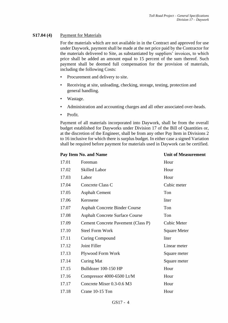
Toll Road Project – General Specifications
Division 17 – Daywork
GS17 - 4
S17.04 (4) Payment for Materials
For the materials which are not available in in the Contract and approved for use
under Daywork, payment shall be made at the net price paid by the Contractor for
the materials delivered to Site, as substantiated by suppliers’ invoices, to which
price shall be added an amount equal to 15 percent of the sum thereof. Such
payment shall be deemed full compensation for the provision of materials,
including the following Costs:
• Procurement and delivery to site.
• Receiving at site, unloading, checking, storage, testing, protection and
general handling.
• Wastage.
• Administration and accounting charges and all other associated over-heads.
• Profit.
Payment of all materials incorporated into Daywork, shall be from the overall
budget established for Dayworks under Division 17 of the Bill of Quantities or,
at the discretion of the Engineer, shall be from any other Pay Item in Divisions 2
to 16 inclusive for which there is surplus budget. In either case a signed Variation
shall be required before payment for materials used in Daywork can be certified.
Pay Item No. and Name Unit of Measurement
17.01 Foreman Hour
17.02 Skilled Labor Hour
17.03 Labor Hour
17.04 Concrete Class C Cubic meter
17.05 Asphalt Cement Ton
17.06 Kerosene liter
17.07 Asphalt Concrete Binder Course Ton
17.08 Asphalt Concrete Surface Course Ton
17.09 Cement Concrete Pavement (Class P) Cubic Meter
17.10 Steel Form Work Square Meter
17.11 Curing Compound liter
17.12 Joint Filler Linear meter
17.13 Plywood Form Work Square meter
17.14 Curing Mat Square meter
17.15 Bulldozer 100-150 HP Hour
17.16 Compressor 4000-6500 Lt/M Hour
17.17 Concrete Mixer 0.3-0.6 M3 Hour
17.18 Crane 10-15 Ton Hour
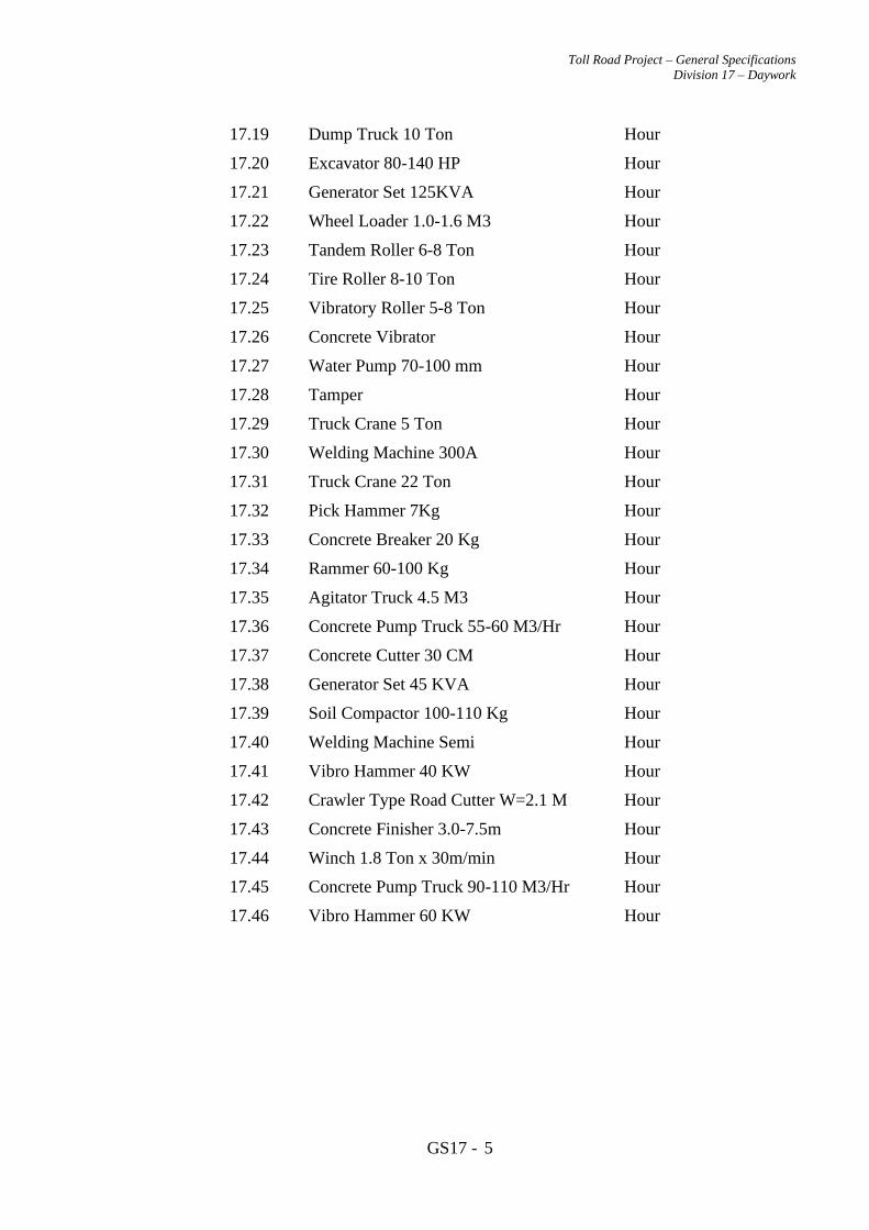
Toll Road Project – General Specifications
Division 17 – Daywork
GS17 - 5
17.19 Dump Truck 10 Ton Hour
17.20 Excavator 80-140 HP Hour
17.21 Generator Set 125KVA Hour
17.22 Wheel Loader 1.0-1.6 M3 Hour
17.23 Tandem Roller 6-8 Ton Hour
17.24 Tire Roller 8-10 Ton Hour
17.25 Vibratory Roller 5-8 Ton Hour
17.26 Concrete Vibrator Hour
17.27 Water Pump 70-100 mm Hour
17.28 Tamper Hour
17.29 Truck Crane 5 Ton Hour
17.30 Welding Machine 300A Hour
17.31 Truck Crane 22 Ton Hour
17.32 Pick Hammer 7Kg Hour
17.33 Concrete Breaker 20 Kg Hour
17.34 Rammer 60-100 Kg Hour
17.35 Agitator Truck 4.5 M3 Hour
17.36 Concrete Pump Truck 55-60 M3/Hr Hour
17.37 Concrete Cutter 30 CM Hour
17.38 Generator Set 45 KVA Hour
17.39 Soil Compactor 100-110 Kg Hour
17.40 Welding Machine Semi Hour
17.41 Vibro Hammer 40 KW Hour
17.42 Crawler Type Road Cutter W=2.1 M Hour
17.43 Concrete Finisher 3.0-7.5m Hour
17.44 Winch 1.8 Ton x 30m/min Hour
17.45 Concrete Pump Truck 90-110 M3/Hr Hour
17.46 Vibro Hammer 60 KW Hour

Toll Road Project – General Specifications
Division 17 – Daywork
GS17 - 6