Embed Size (px)
Citation preview
GENERALSPECIFICATIONSAND STANDARDDETAIL PLATES FOR STREET AND UTILITYCONSTRUCTION
2018
CITY OF NORTH ST. PAUL
2400 MARGARET STREET
NORTH ST. PAUL, MN 55109
651.747.2400
GENERAL SPECIFICATIONS AND CERTIFICATION STANDARD DETAIL PLATES FOR STREET AND UTILITY CONSTRUCTION CITY OF NORTH ST. PAUL, MN DECEMBER 2018
CERTIFICATION
I hereby certify that this plan, specification, or report was prepared by me or under my direct supervision and that I am a duly licensed professional engineer under the laws of the State of Minnesota.
Morgan Dawley, PE
Date: December 2018 Lic. No. 44178
GENERAL SPECIFICATIONS AND TABLE OF CONTENTS STANDARD DETAIL PLATES FOR STREET AND UTILITY CONSTRUCTION CITY OF NORTH ST. PAUL, MN DECEMBER 2018
TABLE OF CONTENTS CERTIFICATION TABLE OF CONTENTS STANDARD GENERAL CONDITIONS OF THE CONSTRUCTION CONTRACT (EJCDC C-700, 2013 EDITION) SUPPLEMENTARY CONDITIONS* SPECIFICATIONS DIVISION 1 – GENERAL REQUIREMENTS DIVISION 2 – SPECIFICATIONS APPENDIX A CEAM STANDARD SPECIFICATIONS (2013 EDITION) APPENDIX B CITY OF NORTH ST. PAUL STANDARD DETAIL PLATES APPENDIX C AWWA C153 COMPACT FITTING WEIGHTS APPENDIX D DISINFECTING WATER MAINS (AWWA C651)
* This document is a MODIFIED version of EJCDC® C-800, Copyright © 2013 by the National Society of Professional Engineers, American Society of Civil Engineers, and American Council of Engineering Companies, or is based in part on excerpts from EJCDC documents. Those portions of the text that originated in published EJCDC documents remain subject to the copyright.
EJCDC® C-700, Standard General Conditions of the Construction Contract. Copyright © 2013 National Society of Professional Engineers, American Council of Engineering Companies,
and American Society of Civil Engineers. All rights reserved.
This document has important legal consequences; consultation with an attorney is encouraged with respect to its use or modification. This document should be adapted to the particular circumstances of the contemplated Project and the controlling Laws and Regulations.
STANDARD GENERAL CONDITIONS OF THE CONSTRUCTION CONTRACT
EJCDC® C-700, Standard General Conditions of the Construction Contract. Copyright © 2013 National Society of Professional Engineers, American Council of Engineering Companies,
and American Society of Civil Engineers. All rights reserved.
These General Conditions have been prepared for use with the Agreement Between Owner and Contractor for Construction Contract (EJCDC® C-520, Stipulated Sum, or C-525, Cost-Plus, 2013 Editions). Their provisions are interrelated and a change in one may necessitate a change in the other.
To prepare supplementary conditions that are coordinated with the General Conditions, use EJCDC’s Guide to the Preparation of Supplementary Conditions (EJCDC® C-800, 2013 Edition). The full EJCDC Construction series of documents is discussed in the Commentary on the 2013 EJCDC Construction Documents (EJCDC® C-001, 2013 Edition).
Copyright © 2013:
National Society of Professional Engineers
1420 King Street, Alexandria, VA 22314-2794
(703) 684-2882
www.nspe.org
American Council of Engineering Companies
1015 15th Street N.W., Washington, DC 20005
(202) 347-7474
www.acec.org
American Society of Civil Engineers
1801 Alexander Bell Drive, Reston, VA 20191-4400
(800) 548-2723
www.asce.org
The copyright for this document is owned jointly by the three sponsoring organizations listed above. The National Society of Professional Engineers is the Copyright Administrator for the EJCDC documents; please direct all inquiries regarding EJCDC copyrights to NSPE.
NOTE: EJCDC publications may be purchased at www.ejcdc.org, or from any of the sponsoring organizations above.
EJCDC® C-700, Standard General Conditions of the Construction Contract. Copyright © 2013 National Society of Professional Engineers, American Council of Engineering Companies,
and American Society of Civil Engineers. All rights reserved. Page i
STANDARD GENERAL CONDITIONS OF THE CONSTRUCTION CONTRACT
TABLE OF CONTENTS
Page Article 1 – Definitions and Terminology ......................................................................................... 1
1.01 Defined Terms ........................................................................................................................ 1
1.02 Terminology ........................................................................................................................... 5
Article 2 – Preliminary Matters ....................................................................................................... 6
2.01 Delivery of Bonds and Evidence of Insurance ........................................................................ 6
2.02 Copies of Documents ............................................................................................................. 6
2.03 Before Starting Construction ................................................................................................. 6
2.04 Preconstruction Conference; Designation of Authorized Representatives ........................... 7
2.05 Initial Acceptance of Schedules ............................................................................................. 7
2.06 Electronic Transmittals ........................................................................................................... 7
Article 3 – Documents: Intent, Requirements, Reuse .................................................................... 8
3.01 Intent ...................................................................................................................................... 8
3.02 Reference Standards .............................................................................................................. 8
3.03 Reporting and Resolving Discrepancies ................................................................................. 8
3.04 Requirements of the Contract Documents ............................................................................ 9
3.05 Reuse of Documents ............................................................................................................ 10
Article 4 – Commencement and Progress of the Work ................................................................ 10
4.01 Commencement of Contract Times; Notice to Proceed ...................................................... 10
4.02 Starting the Work ................................................................................................................. 10
4.03 Reference Points .................................................................................................................. 10
4.04 Progress Schedule ................................................................................................................ 10
4.05 Delays in Contractor’s Progress ........................................................................................... 11
Article 5 – Availability of Lands; Subsurface and Physical Conditions; Hazardous Environmental Conditions ..................................................................................................................................... 12
5.01 Availability of Lands ............................................................................................................. 12
5.02 Use of Site and Other Areas ................................................................................................. 12
5.03 Subsurface and Physical Conditions ..................................................................................... 13
5.04 Differing Subsurface or Physical Conditions ........................................................................ 14
5.05 Underground Facilities ......................................................................................................... 15
EJCDC® C-700, Standard General Conditions of the Construction Contract. Copyright © 2013 National Society of Professional Engineers, American Council of Engineering Companies,
and American Society of Civil Engineers. All rights reserved. Page ii
5.06 Hazardous Environmental Conditions at Site ...................................................................... 17
Article 6 – Bonds and Insurance ................................................................................................... 19
6.01 Performance, Payment, and Other Bonds ........................................................................... 19
6.02 Insurance—General Provisions ............................................................................................ 19
6.03 Contractor’s Insurance ......................................................................................................... 20
6.04 Owner’s Liability Insurance .................................................................................................. 23
6.05 Property Insurance ............................................................................................................... 23
6.06 Waiver of Rights ................................................................................................................... 25
6.07 Receipt and Application of Property Insurance Proceeds ................................................... 25
Article 7 – Contractor’s Responsibilities ....................................................................................... 26
7.01 Supervision and Superintendence ....................................................................................... 26
7.02 Labor; Working Hours .......................................................................................................... 26
7.03 Services, Materials, and Equipment ..................................................................................... 26
7.04 “Or Equals” ........................................................................................................................... 27
7.05 Substitutes ........................................................................................................................... 28
7.06 Concerning Subcontractors, Suppliers, and Others ............................................................. 29
7.07 Patent Fees and Royalties .................................................................................................... 31
7.08 Permits ................................................................................................................................. 31
7.09 Taxes .................................................................................................................................... 32
7.10 Laws and Regulations ........................................................................................................... 32
7.11 Record Documents ............................................................................................................... 32
7.12 Safety and Protection ........................................................................................................... 32
7.13 Safety Representative .......................................................................................................... 33
7.14 Hazard Communication Programs ....................................................................................... 33
7.15 Emergencies ......................................................................................................................... 34
7.16 Shop Drawings, Samples, and Other Submittals .................................................................. 34
7.17 Contractor’s General Warranty and Guarantee................................................................... 36
7.18 Indemnification .................................................................................................................... 37
7.19 Delegation of Professional Design Services ......................................................................... 37
Article 8 – Other Work at the Site ................................................................................................ 38
8.01 Other Work .......................................................................................................................... 38
8.02 Coordination ........................................................................................................................ 39
8.03 Legal Relationships ............................................................................................................... 39
EJCDC® C-700, Standard General Conditions of the Construction Contract. Copyright © 2013 National Society of Professional Engineers, American Council of Engineering Companies,
and American Society of Civil Engineers. All rights reserved. Page iii
Article 9 – Owner’s Responsibilities .............................................................................................. 40
9.01 Communications to Contractor ............................................................................................ 40
9.02 Replacement of Engineer ..................................................................................................... 40
9.03 Furnish Data ......................................................................................................................... 40
9.04 Pay When Due ...................................................................................................................... 40
9.05 Lands and Easements; Reports, Tests, and Drawings .......................................................... 40
9.06 Insurance .............................................................................................................................. 40
9.07 Change Orders ...................................................................................................................... 40
9.08 Inspections, Tests, and Approvals ........................................................................................ 41
9.09 Limitations on Owner’s Responsibilities .............................................................................. 41
9.10 Undisclosed Hazardous Environmental Condition ............................................................... 41
9.11 Evidence of Financial Arrangements .................................................................................... 41
9.12 Safety Programs ................................................................................................................... 41
Article 10 – Engineer’s Status During Construction ...................................................................... 41
10.01 Owner’s Representative ....................................................................................................... 41
10.02 Visits to Site .......................................................................................................................... 41
10.03 Project Representative ......................................................................................................... 42
10.04 Rejecting Defective Work ..................................................................................................... 42
10.05 Shop Drawings, Change Orders and Payments .................................................................... 42
10.06 Determinations for Unit Price Work .................................................................................... 42
10.07 Decisions on Requirements of Contract Documents and Acceptability of Work ................ 42
10.08 Limitations on Engineer’s Authority and Responsibilities .................................................... 42
10.09 Compliance with Safety Program ......................................................................................... 43
Article 11 – Amending the Contract Documents; Changes in the Work ...................................... 43
11.01 Amending and Supplementing Contract Documents .......................................................... 43
11.02 Owner-Authorized Changes in the Work ............................................................................. 44
11.03 Unauthorized Changes in the Work ..................................................................................... 44
11.04 Change of Contract Price ..................................................................................................... 44
11.05 Change of Contract Times .................................................................................................... 45
11.06 Change Proposals ................................................................................................................. 45
11.07 Execution of Change Orders ................................................................................................. 46
11.08 Notification to Surety ........................................................................................................... 47
Article 12 – Claims ......................................................................................................................... 47
EJCDC® C-700, Standard General Conditions of the Construction Contract. Copyright © 2013 National Society of Professional Engineers, American Council of Engineering Companies,
and American Society of Civil Engineers. All rights reserved. Page iv
12.01 Claims ................................................................................................................................... 47
Article 13 – Cost of the Work; Allowances; Unit Price Work ........................................................ 48
13.01 Cost of the Work .................................................................................................................. 48
13.02 Allowances ........................................................................................................................... 50
13.03 Unit Price Work .................................................................................................................... 51
Article 14 – Tests and Inspections; Correction, Removal or Acceptance of Defective Work ....... 52
14.01 Access to Work ..................................................................................................................... 52
14.02 Tests, Inspections, and Approvals ........................................................................................ 52
14.03 Defective Work..................................................................................................................... 53
14.04 Acceptance of Defective Work ............................................................................................. 53
14.05 Uncovering Work ................................................................................................................. 53
14.06 Owner May Stop the Work .................................................................................................. 54
14.07 Owner May Correct Defective Work .................................................................................... 54
Article 15 – Payments to Contractor; Set-Offs; Completion; Correction Period .......................... 55
15.01 Progress Payments ............................................................................................................... 55
15.02 Contractor’s Warranty of Title ............................................................................................. 58
15.03 Substantial Completion ........................................................................................................ 58
15.04 Partial Use or Occupancy ..................................................................................................... 59
15.05 Final Inspection .................................................................................................................... 59
15.06 Final Payment ....................................................................................................................... 59
15.07 Waiver of Claims .................................................................................................................. 61
15.08 Correction Period ................................................................................................................. 61
Article 16 – Suspension of Work and Termination ....................................................................... 62
16.01 Owner May Suspend Work .................................................................................................. 62
16.02 Owner May Terminate for Cause ......................................................................................... 62
16.03 Owner May Terminate For Convenience ............................................................................. 63
16.04 Contractor May Stop Work or Terminate ............................................................................ 63
Article 17 – Final Resolution of Disputes ...................................................................................... 64
17.01 Methods and Procedures ..................................................................................................... 64
Article 18 – Miscellaneous ............................................................................................................ 64
18.01 Giving Notice ........................................................................................................................ 64
18.02 Computation of Times .......................................................................................................... 64
18.03 Cumulative Remedies .......................................................................................................... 64
EJCDC® C-700, Standard General Conditions of the Construction Contract. Copyright © 2013 National Society of Professional Engineers, American Council of Engineering Companies,
and American Society of Civil Engineers. All rights reserved. Page v
18.04 Limitation of Damages ......................................................................................................... 65
18.05 No Waiver ............................................................................................................................ 65
18.06 Survival of Obligations ......................................................................................................... 65
18.07 Controlling Law .................................................................................................................... 65
18.08 Headings ............................................................................................................................... 65
EJCDC® C-700, Standard General Conditions of the Construction Contract. Copyright © 2013 National Society of Professional Engineers, American Council of Engineering Companies,
and American Society of Civil Engineers. All rights reserved. Page 1 of 65
ARTICLE 1 – DEFINITIONS AND TERMINOLOGY
1.01 Defined Terms
A. Wherever used in the Bidding Requirements or Contract Documents, a term printed with initial capital letters, including the term’s singular and plural forms, will have the meaning indicated in the definitions below. In addition to terms specifically defined, terms with initial capital letters in the Contract Documents include references to identified articles and paragraphs, and the titles of other documents or forms.
1. Addenda—Written or graphic instruments issued prior to the opening of Bids which clarify, correct, or change the Bidding Requirements or the proposed Contract Documents.
2. Agreement—The written instrument, executed by Owner and Contractor, that sets forth the Contract Price and Contract Times, identifies the parties and the Engineer, and designates the specific items that are Contract Documents.
3. Application for Payment—The form acceptable to Engineer which is to be used by Contractor during the course of the Work in requesting progress or final payments and which is to be accompanied by such supporting documentation as is required by the Contract Documents.
4. Bid—The offer of a Bidder submitted on the prescribed form setting forth the prices for the Work to be performed.
5. Bidder—An individual or entity that submits a Bid to Owner.
6. Bidding Documents—The Bidding Requirements, the proposed Contract Documents, and all Addenda.
7. Bidding Requirements—The advertisement or invitation to bid, Instructions to Bidders, Bid Bond or other Bid security, if any, the Bid Form, and the Bid with any attachments.
8. Change Order—A document which is signed by Contractor and Owner and authorizes an addition, deletion, or revision in the Work or an adjustment in the Contract Price or the Contract Times, or other revision to the Contract, issued on or after the Effective Date of the Contract.
9. Change Proposal—A written request by Contractor, duly submitted in compliance with the procedural requirements set forth herein, seeking an adjustment in Contract Price or Contract Times, or both; contesting an initial decision by Engineer concerning the requirements of the Contract Documents or the acceptability of Work under the Contract Documents; challenging a set-off against payments due; or seeking other relief with respect to the terms of the Contract.
10. Claim—(a) A demand or assertion by Owner directly to Contractor, duly submitted in compliance with the procedural requirements set forth herein: seeking an adjustment of Contract Price or Contract Times, or both; contesting an initial decision by Engineer concerning the requirements of the Contract Documents or the acceptability of Work under the Contract Documents; contesting Engineer’s decision regarding a Change Proposal; seeking resolution of a contractual issue that Engineer has declined to address; or seeking other relief with respect to the terms of the Contract; or (b) a demand or assertion by Contractor directly to Owner, duly submitted in compliance with the procedural requirements set forth herein, contesting Engineer’s decision regarding a Change Proposal; or seeking resolution of a contractual issue that Engineer
EJCDC® C-700, Standard General Conditions of the Construction Contract. Copyright © 2013 National Society of Professional Engineers, American Council of Engineering Companies,
and American Society of Civil Engineers. All rights reserved. Page 2 of 65
has declined to address. A demand for money or services by a third party is not a Claim.
11. Constituent of Concern—Asbestos, petroleum, radioactive materials, polychlorinated biphenyls (PCBs), hazardous waste, and any substance, product, waste, or other material of any nature whatsoever that is or becomes listed, regulated, or addressed pursuant to (a) the Comprehensive Environmental Response, Compensation and Liability Act, 42 U.S.C. §§9601 et seq. (“CERCLA”); (b) the Hazardous Materials Transportation Act, 49 U.S.C. §§5501 et seq.; (c) the Resource Conservation and Recovery Act, 42 U.S.C. §§6901 et seq. (“RCRA”); (d) the Toxic Substances Control Act, 15 U.S.C. §§2601 et seq.; (e) the Clean Water Act, 33 U.S.C. §§1251 et seq.; (f) the Clean Air Act, 42 U.S.C. §§7401 et seq.; or (g) any other federal, state, or local statute, law, rule, regulation, ordinance, resolution, code, order, or decree regulating, relating to, or imposing liability or standards of conduct concerning, any hazardous, toxic, or dangerous waste, substance, or material.
12. Contract—The entire and integrated written contract between the Owner and Contractor concerning the Work.
13. Contract Documents—Those items so designated in the Agreement, and which together comprise the Contract.
14. Contract Price—The money that Owner has agreed to pay Contractor for completion of the Work in accordance with the Contract Documents. .
15. Contract Times—The number of days or the dates by which Contractor shall: (a) achieve Milestones, if any; (b) achieve Substantial Completion; and (c) complete the Work.
16. Contractor—The individual or entity with which Owner has contracted for performance of the Work.
17. Cost of the Work—See Paragraph 13.01 for definition.
18. Drawings—The part of the Contract that graphically shows the scope, extent, and character of the Work to be performed by Contractor.
19. Effective Date of the Contract—The date, indicated in the Agreement, on which the Contract becomes effective.
20. Engineer—The individual or entity named as such in the Agreement.
21. Field Order—A written order issued by Engineer which requires minor changes in the Work but does not change the Contract Price or the Contract Times.
22. Hazardous Environmental Condition—The presence at the Site of Constituents of Concern in such quantities or circumstances that may present a danger to persons or property exposed thereto. The presence at the Site of materials that are necessary for the execution of the Work, or that are to be incorporated in the Work, and that are controlled and contained pursuant to industry practices, Laws and Regulations, and the requirements of the Contract, does not establish a Hazardous Environmental Condition.
23. Laws and Regulations; Laws or Regulations—Any and all applicable laws, statutes, rules, regulations, ordinances, codes, and orders of any and all governmental bodies, agencies, authorities, and courts having jurisdiction.
EJCDC® C-700, Standard General Conditions of the Construction Contract. Copyright © 2013 National Society of Professional Engineers, American Council of Engineering Companies,
and American Society of Civil Engineers. All rights reserved. Page 3 of 65
24. Liens—Charges, security interests, or encumbrances upon Contract-related funds, real property, or personal property.
25. Milestone—A principal event in the performance of the Work that the Contract requires Contractor to achieve by an intermediate completion date or by a time prior to Substantial Completion of all the Work.
26. Notice of Award—The written notice by Owner to a Bidder of Owner’s acceptance of the Bid.
27. Notice to Proceed—A written notice by Owner to Contractor fixing the date on which the Contract Times will commence to run and on which Contractor shall start to perform the Work.
28. Owner—The individual or entity with which Contractor has contracted regarding the Work, and which has agreed to pay Contractor for the performance of the Work, pursuant to the terms of the Contract.
29. Progress Schedule—A schedule, prepared and maintained by Contractor, describing the sequence and duration of the activities comprising the Contractor’s plan to accomplish the Work within the Contract Times.
30. Project—The total undertaking to be accomplished for Owner by engineers, contractors, and others, including planning, study, design, construction, testing, commissioning, and start-up, and of which the Work to be performed under the Contract Documents is a part.
31. Project Manual—The written documents prepared for, or made available for, procuring and constructing the Work, including but not limited to the Bidding Documents or other construction procurement documents, geotechnical and existing conditions information, the Agreement, bond forms, General Conditions, Supplementary Conditions, and Specifications. The contents of the Project Manual may be bound in one or more volumes.
32. Resident Project Representative—The authorized representative of Engineer assigned to assist Engineer at the Site. As used herein, the term Resident Project Representative or “RPR” includes any assistants or field staff of Resident Project Representative.
33. Samples—Physical examples of materials, equipment, or workmanship that are representative of some portion of the Work and that establish the standards by which such portion of the Work will be judged.
34. Schedule of Submittals—A schedule, prepared and maintained by Contractor, of required submittals and the time requirements for Engineer’s review of the submittals and the performance of related construction activities.
35. Schedule of Values—A schedule, prepared and maintained by Contractor, allocating portions of the Contract Price to various portions of the Work and used as the basis for reviewing Contractor’s Applications for Payment.
36. Shop Drawings—All drawings, diagrams, illustrations, schedules, and other data or information that are specifically prepared or assembled by or for Contractor and submitted by Contractor to illustrate some portion of the Work. Shop Drawings, whether approved or not, are not Drawings and are not Contract Documents.
EJCDC® C-700, Standard General Conditions of the Construction Contract. Copyright © 2013 National Society of Professional Engineers, American Council of Engineering Companies,
and American Society of Civil Engineers. All rights reserved. Page 4 of 65
37. Site—Lands or areas indicated in the Contract Documents as being furnished by Owner upon which the Work is to be performed, including rights-of-way and easements, and such other lands furnished by Owner which are designated for the use of Contractor.
38. Specifications—The part of the Contract that consists of written requirements for materials, equipment, systems, standards, and workmanship as applied to the Work, and certain administrative requirements and procedural matters applicable to the Work.
39. Subcontractor—An individual or entity having a direct contract with Contractor or with any other Subcontractor for the performance of a part of the Work.
40. Substantial Completion—The time at which the Work (or a specified part thereof) has progressed to the point where, in the opinion of Engineer, the Work (or a specified part thereof) is sufficiently complete, in accordance with the Contract Documents, so that the Work (or a specified part thereof) can be utilized for the purposes for which it is intended. The terms “substantially complete” and “substantially completed” as applied to all or part of the Work refer to Substantial Completion thereof.
41. Successful Bidder—The Bidder whose Bid the Owner accepts, and to which the Owner makes an award of contract, subject to stated conditions.
42. Supplementary Conditions—The part of the Contract that amends or supplements these General Conditions.
43. Supplier—A manufacturer, fabricator, supplier, distributor, materialman, or vendor having a direct contract with Contractor or with any Subcontractor to furnish materials or equipment to be incorporated in the Work by Contractor or a Subcontractor.
44. Technical Data—Those items expressly identified as Technical Data in the Supplementary Conditions, with respect to either (a) subsurface conditions at the Site, or physical conditions relating to existing surface or subsurface structures at the Site (except Underground Facilities) or (b) Hazardous Environmental Conditions at the Site. If no such express identifications of Technical Data have been made with respect to conditions at the Site, then the data contained in boring logs, recorded measurements of subsurface water levels, laboratory test results, and other factual, objective information regarding conditions at the Site that are set forth in any geotechnical or environmental report prepared for the Project and made available to Contractor are hereby defined as Technical Data with respect to conditions at the Site under Paragraphs 5.03, 5.04, and 5.06.
45. Underground Facilities—All underground pipelines, conduits, ducts, cables, wires, manholes, vaults, tanks, tunnels, or other such facilities or attachments, and any encasements containing such facilities, including but not limited to those that convey electricity, gases, steam, liquid petroleum products, telephone or other communications, fiber optic transmissions, cable television, water, wastewater, storm water, other liquids or chemicals, or traffic or other control systems.
46. Unit Price Work—Work to be paid for on the basis of unit prices.
47. Work—The entire construction or the various separately identifiable parts thereof required to be provided under the Contract Documents. Work includes and is the result of performing or providing all labor, services, and documentation necessary to produce such construction; furnishing, installing, and incorporating all materials and equipment into such construction; and may include related services such as testing, start-up, and commissioning, all as required by the Contract Documents.
EJCDC® C-700, Standard General Conditions of the Construction Contract. Copyright © 2013 National Society of Professional Engineers, American Council of Engineering Companies,
and American Society of Civil Engineers. All rights reserved. Page 5 of 65
48. Work Change Directive—A written directive to Contractor issued on or after the Effective Date of the Contract, signed by Owner and recommended by Engineer, ordering an addition, deletion, or revision in the Work.
1.02 Terminology
A. The words and terms discussed in the following paragraphs are not defined but, when used in the Bidding Requirements or Contract Documents, have the indicated meaning.
B. Intent of Certain Terms or Adjectives:
1. The Contract Documents include the terms “as allowed,” “as approved,” “as ordered,” “as directed” or terms of like effect or import to authorize an exercise of professional judgment by Engineer. In addition, the adjectives “reasonable,” “suitable,” “acceptable,” “proper,” “satisfactory,” or adjectives of like effect or import are used to describe an action or determination of Engineer as to the Work. It is intended that such exercise of professional judgment, action, or determination will be solely to evaluate, in general, the Work for compliance with the information in the Contract Documents and with the design concept of the Project as a functioning whole as shown or indicated in the Contract Documents (unless there is a specific statement indicating otherwise). The use of any such term or adjective is not intended to and shall not be effective to assign to Engineer any duty or authority to supervise or direct the performance of the Work, or any duty or authority to undertake responsibility contrary to the provisions of Article 10 or any other provision of the Contract Documents.
C. Day:
1. The word “day” means a calendar day of 24 hours measured from midnight to the next midnight.
D. Defective:
1. The word “defective,” when modifying the word “Work,” refers to Work that is unsatisfactory, faulty, or deficient in that it:
a. does not conform to the Contract Documents; or
b. does not meet the requirements of any applicable inspection, reference standard, test, or approval referred to in the Contract Documents; or
c. has been damaged prior to Engineer’s recommendation of final payment (unless responsibility for the protection thereof has been assumed by Owner at Substantial Completion in accordance with Paragraph 15.03 or 15.04).
E. Furnish, Install, Perform, Provide:
1. The word “furnish,” when used in connection with services, materials, or equipment, shall mean to supply and deliver said services, materials, or equipment to the Site (or some other specified location) ready for use or installation and in usable or operable condition.
2. The word “install,” when used in connection with services, materials, or equipment, shall mean to put into use or place in final position said services, materials, or equipment complete and ready for intended use.
EJCDC® C-700, Standard General Conditions of the Construction Contract. Copyright © 2013 National Society of Professional Engineers, American Council of Engineering Companies,
and American Society of Civil Engineers. All rights reserved. Page 6 of 65
3. The words “perform” or “provide,” when used in connection with services, materials, or equipment, shall mean to furnish and install said services, materials, or equipment complete and ready for intended use.
4. If the Contract Documents establish an obligation of Contractor with respect to specific services, materials, or equipment, but do not expressly use any of the four words “furnish,” “install,” “perform,” or “provide,” then Contractor shall furnish and install said services, materials, or equipment complete and ready for intended use.
F. Unless stated otherwise in the Contract Documents, words or phrases that have a well-known technical or construction industry or trade meaning are used in the Contract Documents in accordance with such recognized meaning.
ARTICLE 2 – PRELIMINARY MATTERS
2.01 Delivery of Bonds and Evidence of Insurance
A. Bonds: When Contractor delivers the executed counterparts of the Agreement to Owner, Contractor shall also deliver to Owner such bonds as Contractor may be required to furnish.
B. Evidence of Contractor’s Insurance: When Contractor delivers the executed counterparts of the Agreement to Owner, Contractor shall also deliver to Owner, with copies to each named insured and additional insured (as identified in the Supplementary Conditions or elsewhere in the Contract), the certificates and other evidence of insurance required to be provided by Contractor in accordance with Article 6.
C. Evidence of Owner’s Insurance: After receipt of the executed counterparts of the Agreement and all required bonds and insurance documentation, Owner shall promptly deliver to Contractor, with copies to each named insured and additional insured (as identified in the Supplementary Conditions or otherwise), the certificates and other evidence of insurance required to be provided by Owner under Article 6.
2.02 Copies of Documents
A. Owner shall furnish to Contractor four printed copies of the Contract (including one fully executed counterpart of the Agreement), and one copy in electronic portable document format (PDF). Additional printed copies will be furnished upon request at the cost of reproduction.
B. Owner shall maintain and safeguard at least one original printed record version of the Contract, including Drawings and Specifications signed and sealed by Engineer and other design professionals. Owner shall make such original printed record version of the Contract available to Contractor for review. Owner may delegate the responsibilities under this provision to Engineer.
2.03 Before Starting Construction
A. Preliminary Schedules: Within 10 days after the Effective Date of the Contract (or as otherwise specifically required by the Contract Documents), Contractor shall submit to Engineer for timely review:
1. a preliminary Progress Schedule indicating the times (numbers of days or dates) for starting and completing the various stages of the Work, including any Milestones specified in the Contract;
2. a preliminary Schedule of Submittals; and
EJCDC® C-700, Standard General Conditions of the Construction Contract. Copyright © 2013 National Society of Professional Engineers, American Council of Engineering Companies,
and American Society of Civil Engineers. All rights reserved. Page 7 of 65
3. a preliminary Schedule of Values for all of the Work which includes quantities and prices of items which when added together equal the Contract Price and subdivides the Work into component parts in sufficient detail to serve as the basis for progress payments during performance of the Work. Such prices will include an appropriate amount of overhead and profit applicable to each item of Work.
2.04 Preconstruction Conference; Designation of Authorized Representatives
A. Before any Work at the Site is started, a conference attended by Owner, Contractor, Engineer, and others as appropriate will be held to establish a working understanding among the parties as to the Work and to discuss the schedules referred to in Paragraph 2.03.A, procedures for handling Shop Drawings, Samples, and other submittals, processing Applications for Payment, electronic or digital transmittals, and maintaining required records.
B. At this conference Owner and Contractor each shall designate, in writing, a specific individual to act as its authorized representative with respect to the services and responsibilities under the Contract. Such individuals shall have the authority to transmit and receive information, render decisions relative to the Contract, and otherwise act on behalf of each respective party.
2.05 Initial Acceptance of Schedules
A. At least 10 days before submission of the first Application for Payment a conference, attended by Contractor, Engineer, and others as appropriate, will be held to review for acceptability to Engineer as provided below the schedules submitted in accordance with Paragraph 2.03.A. Contractor shall have an additional 10 days to make corrections and adjustments and to complete and resubmit the schedules. No progress payment shall be made to Contractor until acceptable schedules are submitted to Engineer.
1. The Progress Schedule will be acceptable to Engineer if it provides an orderly progression of the Work to completion within the Contract Times. Such acceptance will not impose on Engineer responsibility for the Progress Schedule, for sequencing, scheduling, or progress of the Work, nor interfere with or relieve Contractor from Contractor’s full responsibility therefor.
2. Contractor’s Schedule of Submittals will be acceptable to Engineer if it provides a workable arrangement for reviewing and processing the required submittals.
3. Contractor’s Schedule of Values will be acceptable to Engineer as to form and substance if it provides a reasonable allocation of the Contract Price to the component parts of the Work.
2.06 Electronic Transmittals
A. Except as otherwise stated elsewhere in the Contract, the Owner, Engineer, and Contractor may transmit, and shall accept, Project-related correspondence, text, data, documents, drawings, information, and graphics, including but not limited to Shop Drawings and other submittals, in electronic media or digital format, either directly, or through access to a secure Project website.
B. If the Contract does not establish protocols for electronic or digital transmittals, then Owner, Engineer, and Contractor shall jointly develop such protocols.
C. When transmitting items in electronic media or digital format, the transmitting party makes no representations as to long term compatibility, usability, or readability of the items resulting from the recipient’s use of software application packages, operating systems, or
EJCDC® C-700, Standard General Conditions of the Construction Contract. Copyright © 2013 National Society of Professional Engineers, American Council of Engineering Companies,
and American Society of Civil Engineers. All rights reserved. Page 8 of 65
computer hardware differing from those used in the drafting or transmittal of the items, or from those established in applicable transmittal protocols.
ARTICLE 3 – DOCUMENTS: INTENT, REQUIREMENTS, REUSE
3.01 Intent
A. The Contract Documents are complementary; what is required by one is as binding as if required by all.
B. It is the intent of the Contract Documents to describe a functionally complete project (or part thereof) to be constructed in accordance with the Contract Documents.
C. Unless otherwise stated in the Contract Documents, if there is a discrepancy between the electronic or digital versions of the Contract Documents (including any printed copies derived from such electronic or digital versions) and the printed record version, the printed record version shall govern.
D. The Contract supersedes prior negotiations, representations, and agreements, whether written or oral.
E. Engineer will issue clarifications and interpretations of the Contract Documents as provided herein.
3.02 Reference Standards
A. Standards Specifications, Codes, Laws and Regulations
1. Reference in the Contract Documents to standard specifications, manuals, reference standards, or codes of any technical society, organization, or association, or to Laws or Regulations, whether such reference be specific or by implication, shall mean the standard specification, manual, reference standard, code, or Laws or Regulations in effect at the time of opening of Bids (or on the Effective Date of the Contract if there were no Bids), except as may be otherwise specifically stated in the Contract Documents.
2. No provision of any such standard specification, manual, reference standard, or code, or any instruction of a Supplier, shall be effective to change the duties or responsibilities of Owner, Contractor, or Engineer, or any of their subcontractors, consultants, agents, or employees, from those set forth in the part of the Contract Documents prepared by or for Engineer. No such provision or instruction shall be effective to assign to Owner, Engineer, or any of their officers, directors, members, partners, employees, agents, consultants, or subcontractors, any duty or authority to supervise or direct the performance of the Work or any duty or authority to undertake responsibility inconsistent with the provisions of the part of the Contract Documents prepared by or for Engineer.
3.03 Reporting and Resolving Discrepancies
A. Reporting Discrepancies:
1. Contractor’s Verification of Figures and Field Measurements: Before undertaking each part of the Work, Contractor shall carefully study the Contract Documents, and check and verify pertinent figures and dimensions therein, particularly with respect to applicable field measurements. Contractor shall promptly report in writing to Engineer any conflict, error, ambiguity, or discrepancy that Contractor discovers, or has actual knowledge of, and shall not proceed with any Work affected thereby until the conflict,
EJCDC® C-700, Standard General Conditions of the Construction Contract. Copyright © 2013 National Society of Professional Engineers, American Council of Engineering Companies,
and American Society of Civil Engineers. All rights reserved. Page 9 of 65
error, ambiguity, or discrepancy is resolved, by a clarification or interpretation by Engineer, or by an amendment or supplement to the Contract Documents issued pursuant to Paragraph 11.01.
2. Contractor’s Review of Contract Documents: If, before or during the performance of the Work, Contractor discovers any conflict, error, ambiguity, or discrepancy within the Contract Documents, or between the Contract Documents and (a) any applicable Law or Regulation, (b) actual field conditions, (c) any standard specification, manual, reference standard, or code, or (d) any instruction of any Supplier, then Contractor shall promptly report it to Engineer in writing. Contractor shall not proceed with the Work affected thereby (except in an emergency as required by Paragraph 7.15) until the conflict, error, ambiguity, or discrepancy is resolved, by a clarification or interpretation by Engineer, or by an amendment or supplement to the Contract Documents issued pursuant to Paragraph 11.01.
3. Contractor shall not be liable to Owner or Engineer for failure to report any conflict, error, ambiguity, or discrepancy in the Contract Documents unless Contractor had actual knowledge thereof.
B. Resolving Discrepancies:
1. Except as may be otherwise specifically stated in the Contract Documents, the provisions of the part of the Contract Documents prepared by or for Engineer shall take precedence in resolving any conflict, error, ambiguity, or discrepancy between such provisions of the Contract Documents and:
a. the provisions of any standard specification, manual, reference standard, or code, or the instruction of any Supplier (whether or not specifically incorporated by reference as a Contract Document); or
b. the provisions of any Laws or Regulations applicable to the performance of the Work (unless such an interpretation of the provisions of the Contract Documents would result in violation of such Law or Regulation).
3.04 Requirements of the Contract Documents
A. During the performance of the Work and until final payment, Contractor and Owner shall submit to the Engineer all matters in question concerning the requirements of the Contract Documents (sometimes referred to as requests for information or interpretation—RFIs), or relating to the acceptability of the Work under the Contract Documents, as soon as possible after such matters arise. Engineer will be the initial interpreter of the requirements of the Contract Documents, and judge of the acceptability of the Work thereunder.
B. Engineer will, with reasonable promptness, render a written clarification, interpretation, or decision on the issue submitted, or initiate an amendment or supplement to the Contract Documents. Engineer’s written clarification, interpretation, or decision will be final and binding on Contractor, unless it appeals by submitting a Change Proposal, and on Owner, unless it appeals by filing a Claim.
C. If a submitted matter in question concerns terms and conditions of the Contract Documents that do not involve (1) the performance or acceptability of the Work under the Contract Documents, (2) the design (as set forth in the Drawings, Specifications, or otherwise), or (3) other engineering or technical matters, then Engineer will promptly give written notice to Owner and Contractor that Engineer is unable to provide a decision or interpretation. If Owner and Contractor are unable to agree on resolution of such a matter in question, either party may pursue resolution as provided in Article 12.
EJCDC® C-700, Standard General Conditions of the Construction Contract. Copyright © 2013 National Society of Professional Engineers, American Council of Engineering Companies,
and American Society of Civil Engineers. All rights reserved. Page 10 of 65
3.05 Reuse of Documents
A. Contractor and its Subcontractors and Suppliers shall not:
1. have or acquire any title to or ownership rights in any of the Drawings, Specifications, or other documents (or copies of any thereof) prepared by or bearing the seal of Engineer or its consultants, including electronic media editions, or reuse any such Drawings, Specifications, other documents, or copies thereof on extensions of the Project or any other project without written consent of Owner and Engineer and specific written verification or adaptation by Engineer; or
2. have or acquire any title or ownership rights in any other Contract Documents, reuse any such Contract Documents for any purpose without Owner’s express written consent, or violate any copyrights pertaining to such Contract Documents.
B. The prohibitions of this Paragraph 3.05 will survive final payment, or termination of the Contract. Nothing herein shall preclude Contractor from retaining copies of the Contract Documents for record purposes.
ARTICLE 4 – COMMENCEMENT AND PROGRESS OF THE WORK
4.01 Commencement of Contract Times; Notice to Proceed
A. The Contract Times will commence to run on the thirtieth day after the Effective Date of the Contract or, if a Notice to Proceed is given, on the day indicated in the Notice to Proceed. A Notice to Proceed may be given at any time within 30 days after the Effective Date of the Contract. In no event will the Contract Times commence to run later than the sixtieth day after the day of Bid opening or the thirtieth day after the Effective Date of the Contract, whichever date is earlier.
4.02 Starting the Work
A. Contractor shall start to perform the Work on the date when the Contract Times commence to run. No Work shall be done at the Site prior to such date.
4.03 Reference Points
A. Owner shall provide engineering surveys to establish reference points for construction which in Engineer’s judgment are necessary to enable Contractor to proceed with the Work. Contractor shall be responsible for laying out the Work, shall protect and preserve the established reference points and property monuments, and shall make no changes or relocations without the prior written approval of Owner. Contractor shall report to Engineer whenever any reference point or property monument is lost or destroyed or requires relocation because of necessary changes in grades or locations, and shall be responsible for the accurate replacement or relocation of such reference points or property monuments by professionally qualified personnel.
4.04 Progress Schedule
A. Contractor shall adhere to the Progress Schedule established in accordance with Paragraph 2.05 as it may be adjusted from time to time as provided below.
1. Contractor shall submit to Engineer for acceptance (to the extent indicated in Paragraph 2.05) proposed adjustments in the Progress Schedule that will not result in changing the Contract Times.
EJCDC® C-700, Standard General Conditions of the Construction Contract. Copyright © 2013 National Society of Professional Engineers, American Council of Engineering Companies,
and American Society of Civil Engineers. All rights reserved. Page 11 of 65
2. Proposed adjustments in the Progress Schedule that will change the Contract Times shall be submitted in accordance with the requirements of Article 11.
B. Contractor shall carry on the Work and adhere to the Progress Schedule during all disputes or disagreements with Owner. No Work shall be delayed or postponed pending resolution of any disputes or disagreements, or during any appeal process, except as permitted by Paragraph 16.04, or as Owner and Contractor may otherwise agree in writing.
4.05 Delays in Contractor’s Progress
A. If Owner, Engineer, or anyone for whom Owner is responsible, delays, disrupts, or interferes with the performance or progress of the Work, then Contractor shall be entitled to an equitable adjustment in the Contract Times and Contract Price. Contractor’s entitlement to an adjustment of the Contract Times is conditioned on such adjustment being essential to Contractor’s ability to complete the Work within the Contract Times.
B. Contractor shall not be entitled to an adjustment in Contract Price or Contract Times for delay, disruption, or interference caused by or within the control of Contractor. Delay, disruption, and interference attributable to and within the control of a Subcontractor or Supplier shall be deemed to be within the control of Contractor.
C. If Contractor’s performance or progress is delayed, disrupted, or interfered with by unanticipated causes not the fault of and beyond the control of Owner, Contractor, and those for which they are responsible, then Contractor shall be entitled to an equitable adjustment in Contract Times. Contractor’s entitlement to an adjustment of the Contract Times is conditioned on such adjustment being essential to Contractor’s ability to complete the Work within the Contract Times. Such an adjustment shall be Contractor’s sole and exclusive remedy for the delays, disruption, and interference described in this paragraph. Causes of delay, disruption, or interference that may give rise to an adjustment in Contract Times under this paragraph include but are not limited to the following:
1. severe and unavoidable natural catastrophes such as fires, floods, epidemics, and earthquakes;
2. abnormal weather conditions;
3. acts or failures to act of utility owners (other than those performing other work at or adjacent to the Site by arrangement with the Owner, as contemplated in Article 8); and
4. acts of war or terrorism.
D. Delays, disruption, and interference to the performance or progress of the Work resulting from the existence of a differing subsurface or physical condition, an Underground Facility that was not shown or indicated by the Contract Documents, or not shown or indicated with reasonable accuracy, and those resulting from Hazardous Environmental Conditions, are governed by Article 5.
E. Paragraph 8.03 governs delays, disruption, and interference to the performance or progress of the Work resulting from the performance of certain other work at or adjacent to the Site.
F. Contractor shall not be entitled to an adjustment in Contract Price or Contract Times for any delay, disruption, or interference if such delay is concurrent with a delay, disruption, or interference caused by or within the control of Contractor.
EJCDC® C-700, Standard General Conditions of the Construction Contract. Copyright © 2013 National Society of Professional Engineers, American Council of Engineering Companies,
and American Society of Civil Engineers. All rights reserved. Page 12 of 65
G. Contractor must submit any Change Proposal seeking an adjustment in Contract Price or Contract Times under this paragraph within 30 days of the commencement of the delaying, disrupting, or interfering event.
ARTICLE 5 – AVAILABILITY OF LANDS; SUBSURFACE AND PHYSICAL CONDITIONS; HAZARDOUS ENVIRONMENTAL CONDITIONS
5.01 Availability of Lands
A. Owner shall furnish the Site. Owner shall notify Contractor of any encumbrances or restrictions not of general application but specifically related to use of the Site with which Contractor must comply in performing the Work.
B. Upon reasonable written request, Owner shall furnish Contractor with a current statement of record legal title and legal description of the lands upon which permanent improvements are to be made and Owner’s interest therein as necessary for giving notice of or filing a mechanic’s or construction lien against such lands in accordance with applicable Laws and Regulations.
C. Contractor shall provide for all additional lands and access thereto that may be required for temporary construction facilities or storage of materials and equipment.
5.02 Use of Site and Other Areas
A. Limitation on Use of Site and Other Areas:
1. Contractor shall confine construction equipment, temporary construction facilities, the storage of materials and equipment, and the operations of workers to the Site, adjacent areas that Contractor has arranged to use through construction easements or otherwise, and other adjacent areas permitted by Laws and Regulations, and shall not unreasonably encumber the Site and such other adjacent areas with construction equipment or other materials or equipment. Contractor shall assume full responsibility for (a) damage to the Site; (b) damage to any such other adjacent areas used for Contractor’s operations; (c) damage to any other adjacent land or areas; and (d) for injuries and losses sustained by the owners or occupants of any such land or areas; provided that such damage or injuries result from the performance of the Work or from other actions or conduct of the Contractor or those for which Contractor is responsible.
2. If a damage or injury claim is made by the owner or occupant of any such land or area because of the performance of the Work, or because of other actions or conduct of the Contractor or those for which Contractor is responsible, Contractor shall (a) take immediate corrective or remedial action as required by Paragraph 7.12, or otherwise; (b) promptly attempt to settle the claim as to all parties through negotiations with such owner or occupant, or otherwise resolve the claim by arbitration or other dispute resolution proceeding, or at law; and (c) to the fullest extent permitted by Laws and Regulations, indemnify and hold harmless Owner and Engineer, and the officers, directors, members, partners, employees, agents, consultants and subcontractors of each and any of them from and against any such claim, and against all costs, losses, and damages (including but not limited to all fees and charges of engineers, architects, attorneys, and other professionals and all court or arbitration or other dispute resolution costs) arising out of or relating to any claim or action, legal or equitable, brought by any such owner or occupant against Owner, Engineer, or any other party indemnified hereunder to the extent caused directly or indirectly, in whole or in part
EJCDC® C-700, Standard General Conditions of the Construction Contract. Copyright © 2013 National Society of Professional Engineers, American Council of Engineering Companies,
and American Society of Civil Engineers. All rights reserved. Page 13 of 65
by, or based upon, Contractor’s performance of the Work, or because of other actions or conduct of the Contractor or those for which Contractor is responsible.
B. Removal of Debris During Performance of the Work: During the progress of the Work the Contractor shall keep the Site and other adjacent areas free from accumulations of waste materials, rubbish, and other debris. Removal and disposal of such waste materials, rubbish, and other debris shall conform to applicable Laws and Regulations.
C. Cleaning: Prior to Substantial Completion of the Work Contractor shall clean the Site and the Work and make it ready for utilization by Owner. At the completion of the Work Contractor shall remove from the Site and adjacent areas all tools, appliances, construction equipment and machinery, and surplus materials and shall restore to original condition all property not designated for alteration by the Contract Documents.
D. Loading of Structures: Contractor shall not load nor permit any part of any structure to be loaded in any manner that will endanger the structure, nor shall Contractor subject any part of the Work or adjacent structures or land to stresses or pressures that will endanger them.
5.03 Subsurface and Physical Conditions
A. Reports and Drawings: The Supplementary Conditions identify:
1. those reports known to Owner of explorations and tests of subsurface conditions at or adjacent to the Site;
2. those drawings known to Owner of physical conditions relating to existing surface or subsurface structures at the Site (except Underground Facilities); and
3. Technical Data contained in such reports and drawings.
B. Reliance by Contractor on Technical Data Authorized: Contractor may rely upon the accuracy of the Technical Data expressly identified in the Supplementary Conditions with respect to such reports and drawings, but such reports and drawings are not Contract Documents. If no such express identification has been made, then Contractor may rely upon the accuracy of the Technical Data (as defined in Article 1) contained in any geotechnical or environmental report prepared for the Project and made available to Contractor. Except for such reliance on Technical Data, Contractor may not rely upon or make any claim against Owner or Engineer, or any of their officers, directors, members, partners, employees, agents, consultants, or subcontractors, with respect to:
1. the completeness of such reports and drawings for Contractor’s purposes, including, but not limited to, any aspects of the means, methods, techniques, sequences, and procedures of construction to be employed by Contractor, and safety precautions and programs incident thereto; or
2. other data, interpretations, opinions, and information contained in such reports or shown or indicated in such drawings; or
3. any Contractor interpretation of or conclusion drawn from any Technical Data or any such other data, interpretations, opinions, or information.
EJCDC® C-700, Standard General Conditions of the Construction Contract. Copyright © 2013 National Society of Professional Engineers, American Council of Engineering Companies,
and American Society of Civil Engineers. All rights reserved. Page 14 of 65
5.04 Differing Subsurface or Physical Conditions
A. Notice by Contractor: If Contractor believes that any subsurface or physical condition that is uncovered or revealed at the Site either:
1. is of such a nature as to establish that any Technical Data on which Contractor is entitled to rely as provided in Paragraph 5.03 is materially inaccurate; or
2. is of such a nature as to require a change in the Drawings or Specifications; or
3. differs materially from that shown or indicated in the Contract Documents; or
4. is of an unusual nature, and differs materially from conditions ordinarily encountered and generally recognized as inherent in work of the character provided for in the Contract Documents;
then Contractor shall, promptly after becoming aware thereof and before further disturbing the subsurface or physical conditions or performing any Work in connection therewith (except in an emergency as required by Paragraph 7.15), notify Owner and Engineer in writing about such condition. Contractor shall not further disturb such condition or perform any Work in connection therewith (except with respect to an emergency) until receipt of a written statement permitting Contractor to do so.
B. Engineer’s Review: After receipt of written notice as required by the preceding paragraph, Engineer will promptly review the subsurface or physical condition in question; determine the necessity of Owner’s obtaining additional exploration or tests with respect to the condition; conclude whether the condition falls within any one or more of the differing site condition categories in Paragraph 5.04.A above; obtain any pertinent cost or schedule information from Contractor; prepare recommendations to Owner regarding the Contractor’s resumption of Work in connection with the subsurface or physical condition in question and the need for any change in the Drawings or Specifications; and advise Owner in writing of Engineer’s findings, conclusions, and recommendations.
C. Owner’s Statement to Contractor Regarding Site Condition: After receipt of Engineer’s written findings, conclusions, and recommendations, Owner shall issue a written statement to Contractor (with a copy to Engineer) regarding the subsurface or physical condition in question, addressing the resumption of Work in connection with such condition, indicating whether any change in the Drawings or Specifications will be made, and adopting or rejecting Engineer’s written findings, conclusions, and recommendations, in whole or in part.
D. Possible Price and Times Adjustments:
1. Contractor shall be entitled to an equitable adjustment in Contract Price or Contract Times, or both, to the extent that the existence of a differing subsurface or physical condition, or any related delay, disruption, or interference, causes an increase or decrease in Contractor’s cost of, or time required for, performance of the Work; subject, however, to the following:
a. such condition must fall within any one or more of the categories described in Paragraph 5.04.A;
b. with respect to Work that is paid for on a unit price basis, any adjustment in Contract Price will be subject to the provisions of Paragraph 13.03; and,
EJCDC® C-700, Standard General Conditions of the Construction Contract. Copyright © 2013 National Society of Professional Engineers, American Council of Engineering Companies,
and American Society of Civil Engineers. All rights reserved. Page 15 of 65
c. Contractor’s entitlement to an adjustment of the Contract Times is conditioned on such adjustment being essential to Contractor’s ability to complete the Work within the Contract Times.
2. Contractor shall not be entitled to any adjustment in the Contract Price or Contract Times with respect to a subsurface or physical condition if:
a. Contractor knew of the existence of such condition at the time Contractor made a commitment to Owner with respect to Contract Price and Contract Times by the submission of a Bid or becoming bound under a negotiated contract, or otherwise; or
b. the existence of such condition reasonably could have been discovered or revealed as a result of any examination, investigation, exploration, test, or study of the Site and contiguous areas expressly required by the Bidding Requirements or Contract Documents to be conducted by or for Contractor prior to Contractor’s making such commitment; or
c. Contractor failed to give the written notice as required by Paragraph 5.04.A.
3. If Owner and Contractor agree regarding Contractor’s entitlement to and the amount or extent of any adjustment in the Contract Price or Contract Times, or both, then any such adjustment shall be set forth in a Change Order.
4. Contractor may submit a Change Proposal regarding its entitlement to or the amount or extent of any adjustment in the Contract Price or Contract Times, or both, no later than 30 days after Owner’s issuance of the Owner’s written statement to Contractor regarding the subsurface or physical condition in question.
5.05 Underground Facilities
A. Contractor’s Responsibilities: The information and data shown or indicated in the Contract Documents with respect to existing Underground Facilities at or adjacent to the Site is based on information and data furnished to Owner or Engineer by the owners of such Underground Facilities, including Owner, or by others. Unless it is otherwise expressly provided in the Supplementary Conditions:
1. Owner and Engineer do not warrant or guarantee the accuracy or completeness of any such information or data provided by others; and
2. the cost of all of the following will be included in the Contract Price, and Contractor shall have full responsibility for:
a. reviewing and checking all information and data regarding existing Underground Facilities at the Site;
b. locating all Underground Facilities shown or indicated in the Contract Documents as being at the Site;
c. coordination of the Work with the owners (including Owner) of such Underground Facilities, during construction; and
d. the safety and protection of all existing Underground Facilities at the Site, and repairing any damage thereto resulting from the Work.
B. Notice by Contractor: If Contractor believes that an Underground Facility that is uncovered or revealed at the Site was not shown or indicated in the Contract Documents, or was not shown or indicated with reasonable accuracy, then Contractor shall, promptly after
EJCDC® C-700, Standard General Conditions of the Construction Contract. Copyright © 2013 National Society of Professional Engineers, American Council of Engineering Companies,
and American Society of Civil Engineers. All rights reserved. Page 16 of 65
becoming aware thereof and before further disturbing conditions affected thereby or performing any Work in connection therewith (except in an emergency as required by Paragraph 7.15), identify the owner of such Underground Facility and give written notice to that owner and to Owner and Engineer.
C. Engineer’s Review: Engineer will promptly review the Underground Facility and conclude whether such Underground Facility was not shown or indicated in the Contract Documents, or was not shown or indicated with reasonable accuracy; obtain any pertinent cost or schedule information from Contractor; prepare recommendations to Owner regarding the Contractor’s resumption of Work in connection with the Underground Facility in question; determine the extent, if any, to which a change is required in the Drawings or Specifications to reflect and document the consequences of the existence or location of the Underground Facility; and advise Owner in writing of Engineer’s findings, conclusions, and recommendations. During such time, Contractor shall be responsible for the safety and protection of such Underground Facility.
D. Owner’s Statement to Contractor Regarding Underground Facility: After receipt of Engineer’s written findings, conclusions, and recommendations, Owner shall issue a written statement to Contractor (with a copy to Engineer) regarding the Underground Facility in question, addressing the resumption of Work in connection with such Underground Facility, indicating whether any change in the Drawings or Specifications will be made, and adopting or rejecting Engineer’s written findings, conclusions, and recommendations in whole or in part.
E. Possible Price and Times Adjustments:
1. Contractor shall be entitled to an equitable adjustment in the Contract Price or Contract Times, or both, to the extent that any existing Underground Facility at the Site that was not shown or indicated in the Contract Documents, or was not shown or indicated with reasonable accuracy, or any related delay, disruption, or interference, causes an increase or decrease in Contractor’s cost of, or time required for, performance of the Work; subject, however, to the following:
a. Contractor did not know of and could not reasonably have been expected to be aware of or to have anticipated the existence or actual location of the Underground Facility in question;
b. With respect to Work that is paid for on a unit price basis, any adjustment in Contract Price will be subject to the provisions of Paragraph 13.03;
c. Contractor’s entitlement to an adjustment of the Contract Times is conditioned on such adjustment being essential to Contractor’s ability to complete the Work within the Contract Times; and
d. Contractor gave the notice required in Paragraph 5.05.B.
2. If Owner and Contractor agree regarding Contractor’s entitlement to and the amount or extent of any adjustment in the Contract Price or Contract Times, or both, then any such adjustment shall be set forth in a Change Order.
3. Contractor may submit a Change Proposal regarding its entitlement to or the amount or extent of any adjustment in the Contract Price or Contract Times, or both, no later than 30 days after Owner’s issuance of the Owner’s written statement to Contractor regarding the Underground Facility in question.
EJCDC® C-700, Standard General Conditions of the Construction Contract. Copyright © 2013 National Society of Professional Engineers, American Council of Engineering Companies,
and American Society of Civil Engineers. All rights reserved. Page 17 of 65
5.06 Hazardous Environmental Conditions at Site
A. Reports and Drawings: The Supplementary Conditions identify:
1. those reports and drawings known to Owner relating to Hazardous Environmental Conditions that have been identified at or adjacent to the Site; and
2. Technical Data contained in such reports and drawings.
B. Reliance by Contractor on Technical Data Authorized: Contractor may rely upon the accuracy of the Technical Data expressly identified in the Supplementary Conditions with respect to such reports and drawings, but such reports and drawings are not Contract Documents. If no such express identification has been made, then Contractor may rely on the accuracy of the Technical Data (as defined in Article 1) contained in any geotechnical or environmental report prepared for the Project and made available to Contractor. Except for such reliance on Technical Data, Contractor may not rely upon or make any claim against Owner or Engineer, or any of their officers, directors, members, partners, employees, agents, consultants, or subcontractors with respect to:
1. the completeness of such reports and drawings for Contractor’s purposes, including, but not limited to, any aspects of the means, methods, techniques, sequences and procedures of construction to be employed by Contractor and safety precautions and programs incident thereto; or
2. other data, interpretations, opinions and information contained in such reports or shown or indicated in such drawings; or
3. any Contractor interpretation of or conclusion drawn from any Technical Data or any such other data, interpretations, opinions or information.
C. Contractor shall not be responsible for removing or remediating any Hazardous Environmental Condition encountered, uncovered, or revealed at the Site unless such removal or remediation is expressly identified in the Contract Documents to be within the scope of the Work.
D. Contractor shall be responsible for controlling, containing, and duly removing all Constituents of Concern brought to the Site by Contractor, Subcontractors, Suppliers, or anyone else for whom Contractor is responsible, and for any associated costs; and for the costs of removing and remediating any Hazardous Environmental Condition created by the presence of any such Constituents of Concern.
E. If Contractor encounters, uncovers, or reveals a Hazardous Environmental Condition whose removal or remediation is not expressly identified in the Contract Documents as being within the scope of the Work, or if Contractor or anyone for whom Contractor is responsible creates a Hazardous Environmental Condition, then Contractor shall immediately: (1) secure or otherwise isolate such condition; (2) stop all Work in connection with such condition and in any area affected thereby (except in an emergency as required by Paragraph 7.15); and (3) notify Owner and Engineer (and promptly thereafter confirm such notice in writing). Owner shall promptly consult with Engineer concerning the necessity for Owner to retain a qualified expert to evaluate such condition or take corrective action, if any. Promptly after consulting with Engineer, Owner shall take such actions as are necessary to permit Owner to timely obtain required permits and provide Contractor the written notice required by Paragraph 5.06.F. If Contractor or anyone for whom Contractor is responsible created the Hazardous Environmental Condition in question, then Owner may remove and remediate the Hazardous Environmental Condition, and impose a set-off against payments to account for the associated costs.
EJCDC® C-700, Standard General Conditions of the Construction Contract. Copyright © 2013 National Society of Professional Engineers, American Council of Engineering Companies,
and American Society of Civil Engineers. All rights reserved. Page 18 of 65
F. Contractor shall not resume Work in connection with such Hazardous Environmental Condition or in any affected area until after Owner has obtained any required permits related thereto, and delivered written notice to Contractor either (1) specifying that such condition and any affected area is or has been rendered safe for the resumption of Work, or (2) specifying any special conditions under which such Work may be resumed safely.
G. If Owner and Contractor cannot agree as to entitlement to or on the amount or extent, if any, of any adjustment in Contract Price or Contract Times, or both, as a result of such Work stoppage or such special conditions under which Work is agreed to be resumed by Contractor, then within 30 days of Owner’s written notice regarding the resumption of Work, Contractor may submit a Change Proposal, or Owner may impose a set-off.
H. If after receipt of such written notice Contractor does not agree to resume such Work based on a reasonable belief it is unsafe, or does not agree to resume such Work under such special conditions, then Owner may order the portion of the Work that is in the area affected by such condition to be deleted from the Work, following the contractual change procedures in Article 11. Owner may have such deleted portion of the Work performed by Owner’s own forces or others in accordance with Article 8.
I. To the fullest extent permitted by Laws and Regulations, Owner shall indemnify and hold harmless Contractor, Subcontractors, and Engineer, and the officers, directors, members, partners, employees, agents, consultants, and subcontractors of each and any of them from and against all claims, costs, losses, and damages (including but not limited to all fees and charges of engineers, architects, attorneys, and other professionals and all court or arbitration or other dispute resolution costs) arising out of or relating to a Hazardous Environmental Condition, provided that such Hazardous Environmental Condition (1) was not shown or indicated in the Drawings, Specifications, or other Contract Documents, identified as Technical Data entitled to limited reliance pursuant to Paragraph 5.06.B, or identified in the Contract Documents to be included within the scope of the Work, and (2) was not created by Contractor or by anyone for whom Contractor is responsible. Nothing in this Paragraph 5.06.H shall obligate Owner to indemnify any individual or entity from and against the consequences of that individual’s or entity’s own negligence.
J. To the fullest extent permitted by Laws and Regulations, Contractor shall indemnify and hold harmless Owner and Engineer, and the officers, directors, members, partners, employees, agents, consultants, and subcontractors of each and any of them from and against all claims, costs, losses, and damages (including but not limited to all fees and charges of engineers, architects, attorneys, and other professionals and all court or arbitration or other dispute resolution costs) arising out of or relating to the failure to control, contain, or remove a Constituent of Concern brought to the Site by Contractor or by anyone for whom Contractor is responsible, or to a Hazardous Environmental Condition created by Contractor or by anyone for whom Contractor is responsible. Nothing in this Paragraph 5.06.J shall obligate Contractor to indemnify any individual or entity from and against the consequences of that individual’s or entity’s own negligence.
K. The provisions of Paragraphs 5.03, 5.04, and 5.05 do not apply to the presence of Constituents of Concern or to a Hazardous Environmental Condition uncovered or revealed at the Site.
EJCDC® C-700, Standard General Conditions of the Construction Contract. Copyright © 2013 National Society of Professional Engineers, American Council of Engineering Companies,
and American Society of Civil Engineers. All rights reserved. Page 19 of 65
ARTICLE 6 – BONDS AND INSURANCE
6.01 Performance, Payment, and Other Bonds
A. Contractor shall furnish a performance bond and a payment bond, each in an amount at least equal to the Contract Price, as security for the faithful performance and payment of all of Contractor’s obligations under the Contract. These bonds shall remain in effect until one year after the date when final payment becomes due or until completion of the correction period specified in Paragraph 15.08, whichever is later, except as provided otherwise by Laws or Regulations, the Supplementary Conditions, or other specific provisions of the Contract. Contractor shall also furnish such other bonds as are required by the Supplementary Conditions or other specific provisions of the Contract.
B. All bonds shall be in the form prescribed by the Contract except as provided otherwise by Laws or Regulations, and shall be executed by such sureties as are named in “Companies Holding Certificates of Authority as Acceptable Sureties on Federal Bonds and as Acceptable Reinsuring Companies” as published in Circular 570 (as amended and supplemented) by the Financial Management Service, Surety Bond Branch, U.S. Department of the Treasury. A bond signed by an agent or attorney-in-fact must be accompanied by a certified copy of that individual’s authority to bind the surety. The evidence of authority shall show that it is effective on the date the agent or attorney-in-fact signed the accompanying bond.
C. Contractor shall obtain the required bonds from surety companies that are duly licensed or authorized in the jurisdiction in which the Project is located to issue bonds in the required amounts.
D. If the surety on a bond furnished by Contractor is declared bankrupt or becomes insolvent, or its right to do business is terminated in any state or jurisdiction where any part of the Project is located, or the surety ceases to meet the requirements above, then Contractor shall promptly notify Owner and Engineer and shall, within 20 days after the event giving rise to such notification, provide another bond and surety, both of which shall comply with the bond and surety requirements above.
E. If Contractor has failed to obtain a required bond, Owner may exclude the Contractor from the Site and exercise Owner’s termination rights under Article 16.
F. Upon request, Owner shall provide a copy of the payment bond to any Subcontractor, Supplier, or other person or entity claiming to have furnished labor or materials used in the performance of the Work.
6.02 Insurance—General Provisions
A. Owner and Contractor shall obtain and maintain insurance as required in this Article and in the Supplementary Conditions.
B. All insurance required by the Contract to be purchased and maintained by Owner or Contractor shall be obtained from insurance companies that are duly licensed or authorized, in the state or jurisdiction in which the Project is located, to issue insurance policies for the required limits and coverages. Unless a different standard is indicated in the Supplementary Conditions, all companies that provide insurance policies required under this Contract shall have an A.M. Best rating of A-VII or better.
C. Contractor shall deliver to Owner, with copies to each named insured and additional insured (as identified in this Article, in the Supplementary Conditions, or elsewhere in the Contract), certificates of insurance establishing that Contractor has obtained and is
EJCDC® C-700, Standard General Conditions of the Construction Contract. Copyright © 2013 National Society of Professional Engineers, American Council of Engineering Companies,
and American Society of Civil Engineers. All rights reserved. Page 20 of 65
maintaining the policies, coverages, and endorsements required by the Contract. Upon request by Owner or any other insured, Contractor shall also furnish other evidence of such required insurance, including but not limited to copies of policies and endorsements, and documentation of applicable self-insured retentions and deductibles. Contractor may block out (redact) any confidential premium or pricing information contained in any policy or endorsement furnished under this provision.
D. Owner shall deliver to Contractor, with copies to each named insured and additional insured (as identified in this Article, the Supplementary Conditions, or elsewhere in the Contract), certificates of insurance establishing that Owner has obtained and is maintaining the policies, coverages, and endorsements required of Owner by the Contract (if any). Upon request by Contractor or any other insured, Owner shall also provide other evidence of such required insurance (if any), including but not limited to copies of policies and endorsements, and documentation of applicable self-insured retentions and deductibles. Owner may block out (redact) any confidential premium or pricing information contained in any policy or endorsement furnished under this provision.
E. Failure of Owner or Contractor to demand such certificates or other evidence of the other party’s full compliance with these insurance requirements, or failure of Owner or Contractor to identify a deficiency in compliance from the evidence provided, shall not be construed as a waiver of the other party’s obligation to obtain and maintain such insurance.
F. If either party does not purchase or maintain all of the insurance required of such party by the Contract, such party shall notify the other party in writing of such failure to purchase prior to the start of the Work, or of such failure to maintain prior to any change in the required coverage.
G. If Contractor has failed to obtain and maintain required insurance, Owner may exclude the Contractor from the Site, impose an appropriate set-off against payment, and exercise Owner’s termination rights under Article 16.
H. Without prejudice to any other right or remedy, if a party has failed to obtain required insurance, the other party may elect to obtain equivalent insurance to protect such other party’s interests at the expense of the party who was required to provide such coverage, and the Contract Price shall be adjusted accordingly.
I. Owner does not represent that insurance coverage and limits established in this Contract necessarily will be adequate to protect Contractor or Contractor’s interests.
J. The insurance and insurance limits required herein shall not be deemed as a limitation on Contractor’s liability under the indemnities granted to Owner and other individuals and entities in the Contract.
6.03 Contractor’s Insurance
A. Workers’ Compensation: Contractor shall purchase and maintain workers’ compensation and employer’s liability insurance for:
1. claims under workers’ compensation, disability benefits, and other similar employee benefit acts.
2. United States Longshoreman and Harbor Workers’ Compensation Act and Jones Act coverage (if applicable).
3. claims for damages because of bodily injury, occupational sickness or disease, or death of Contractor’s employees (by stop-gap endorsement in monopolist worker’s compensation states).
EJCDC® C-700, Standard General Conditions of the Construction Contract. Copyright © 2013 National Society of Professional Engineers, American Council of Engineering Companies,
and American Society of Civil Engineers. All rights reserved. Page 21 of 65
4. Foreign voluntary worker compensation (if applicable).
B. Commercial General Liability—Claims Covered: Contractor shall purchase and maintain commercial general liability insurance, covering all operations by or on behalf of Contractor, on an occurrence basis, against:
1. claims for damages because of bodily injury, sickness or disease, or death of any person other than Contractor’s employees.
2. claims for damages insured by reasonably available personal injury liability coverage.
3. claims for damages, other than to the Work itself, because of injury to or destruction of tangible property wherever located, including loss of use resulting therefrom.
C. Commercial General Liability—Form and Content: Contractor’s commercial liability policy shall be written on a 1996 (or later) ISO commercial general liability form (occurrence form) and include the following coverages and endorsements:
1. Products and completed operations coverage:
a. Such insurance shall be maintained for three years after final payment.
b. Contractor shall furnish Owner and each other additional insured (as identified in the Supplementary Conditions or elsewhere in the Contract) evidence of continuation of such insurance at final payment and three years thereafter.
2. Blanket contractual liability coverage, to the extent permitted by law, including but not limited to coverage of Contractor’s contractual indemnity obligations in Paragraph 7.18.
3. Broad form property damage coverage.
4. Severability of interest.
5. Underground, explosion, and collapse coverage.
6. Personal injury coverage.
7. Additional insured endorsements that include both ongoing operations and products and completed operations coverage through ISO Endorsements CG 20 10 10 01 and CG 20 37 10 01 (together); or CG 20 10 07 04 and CG 20 37 07 04 (together); or their equivalent.
8. For design professional additional insureds, ISO Endorsement CG 20 32 07 04, “Additional Insured—Engineers, Architects or Surveyors Not Engaged by the Named Insured” or its equivalent.
D. Automobile liability: Contractor shall purchase and maintain automobile liability insurance against claims for damages because of bodily injury or death of any person or property damage arising out of the ownership, maintenance, or use of any motor vehicle. The automobile liability policy shall be written on an occurrence basis.
E. Umbrella or excess liability: Contractor shall purchase and maintain umbrella or excess liability insurance written over the underlying employer’s liability, commercial general liability, and automobile liability insurance described in the paragraphs above. Subject to industry-standard exclusions, the coverage afforded shall follow form as to each and every one of the underlying policies.
F. Contractor’s pollution liability insurance: Contractor shall purchase and maintain a policy covering third-party injury and property damage claims, including clean-up costs, as a result
EJCDC® C-700, Standard General Conditions of the Construction Contract. Copyright © 2013 National Society of Professional Engineers, American Council of Engineering Companies,
and American Society of Civil Engineers. All rights reserved. Page 22 of 65
of pollution conditions arising from Contractor’s operations and completed operations. This insurance shall be maintained for no less than three years after final completion.
G. Additional insureds: The Contractor’s commercial general liability, automobile liability, umbrella or excess, and pollution liability policies shall include and list as additional insureds Owner and Engineer, and any individuals or entities identified in the Supplementary Conditions; include coverage for the respective officers, directors, members, partners, employees, agents, consultants, and subcontractors of each and any of all such additional insureds; and the insurance afforded to these additional insureds shall provide primary coverage for all claims covered thereby (including as applicable those arising from both ongoing and completed operations) on a non-contributory basis. Contractor shall obtain all necessary endorsements to support these requirements.
H. Contractor’s professional liability insurance: If Contractor will provide or furnish professional services under this Contract, through a delegation of professional design services or otherwise, then Contractor shall be responsible for purchasing and maintaining applicable professional liability insurance. This insurance shall provide protection against claims arising out of performance of professional design or related services, and caused by a negligent error, omission, or act for which the insured party is legally liable. It shall be maintained throughout the duration of the Contract and for a minimum of two years after Substantial Completion. If such professional design services are performed by a Subcontractor, and not by Contractor itself, then the requirements of this paragraph may be satisfied through the purchasing and maintenance of such insurance by such Subcontractor.
I. General provisions: The policies of insurance required by this Paragraph 6.03 shall:
1. include at least the specific coverages provided in this Article.
2. be written for not less than the limits of liability provided in this Article and in the Supplementary Conditions, or required by Laws or Regulations, whichever is greater.
3. contain a provision or endorsement that the coverage afforded will not be canceled, materially changed, or renewal refused until at least 10 days prior written notice has been given to Contractor. Within three days of receipt of any such written notice, Contractor shall provide a copy of the notice to Owner, Engineer, and each other insured under the policy.
4. remain in effect at least until final payment (and longer if expressly required in this Article) and at all times thereafter when Contractor may be correcting, removing, or replacing defective Work as a warranty or correction obligation, or otherwise, or returning to the Site to conduct other tasks arising from the Contract Documents.
5. be appropriate for the Work being performed and provide protection from claims that may arise out of or result from Contractor’s performance of the Work and Contractor’s other obligations under the Contract Documents, whether it is to be performed by Contractor, any Subcontractor or Supplier, or by anyone directly or indirectly employed by any of them to perform any of the Work, or by anyone for whose acts any of them may be liable.
J. The coverage requirements for specific policies of insurance must be met by such policies, and not by reference to excess or umbrella insurance provided in other policies.
EJCDC® C-700, Standard General Conditions of the Construction Contract. Copyright © 2013 National Society of Professional Engineers, American Council of Engineering Companies,
and American Society of Civil Engineers. All rights reserved. Page 23 of 65
6.04 Owner’s Liability Insurance
A. In addition to the insurance required to be provided by Contractor under Paragraph 6.03, Owner, at Owner’s option, may purchase and maintain at Owner’s expense Owner’s own liability insurance as will protect Owner against claims which may arise from operations under the Contract Documents.
B. Owner’s liability policies, if any, operate separately and independently from policies required to be provided by Contractor, and Contractor cannot rely upon Owner’s liability policies for any of Contractor’s obligations to the Owner, Engineer, or third parties.
6.05 Property Insurance
A. Builder’s Risk: Unless otherwise provided in the Supplementary Conditions, Contractor shall purchase and maintain builder’s risk insurance upon the Work on a completed value basis, in the amount of the full insurable replacement cost thereof (subject to such deductible amounts as may be provided in the Supplementary Conditions or required by Laws and Regulations). This insurance shall:
1. include the Owner and Contractor as named insureds, and all Subcontractors, and any individuals or entities required by the Supplementary Conditions to be insured under such builder’s risk policy, as insureds or named insureds. For purposes of the remainder of this Paragraph 6.05, Paragraphs 6.06 and 6.07, and any corresponding Supplementary Conditions, the parties required to be insured shall collectively be referred to as “insureds.”
2. be written on a builder’s risk “all risk” policy form that shall at least include insurance for physical loss or damage to the Work, temporary buildings, falsework, and materials and equipment in transit, and shall insure against at least the following perils or causes of loss: fire; lightning; windstorm; riot; civil commotion; terrorism; vehicle impact; aircraft; smoke; theft; vandalism and malicious mischief; mechanical breakdown, boiler explosion, and artificially generated electric current; earthquake; volcanic activity, and other earth movement; flood; collapse; explosion; debris removal; demolition occasioned by enforcement of Laws and Regulations; water damage (other than that caused by flood); and such other perils or causes of loss as may be specifically required by the Supplementary Conditions. If insurance against mechanical breakdown, boiler explosion, and artificially generated electric current; earthquake; volcanic activity, and other earth movement; or flood, are not commercially available under builder’s risk policies, by endorsement or otherwise, such insurance may be provided through other insurance policies acceptable to Owner and Contractor.
3. cover, as insured property, at least the following: (a) the Work and all materials, supplies, machinery, apparatus, equipment, fixtures, and other property of a similar nature that are to be incorporated into or used in the preparation, fabrication, construction, erection, or completion of the Work, including Owner-furnished or assigned property; (b) spare parts inventory required within the scope of the Contract; and (c) temporary works which are not intended to form part of the permanent constructed Work but which are intended to provide working access to the Site, or to the Work under construction, or which are intended to provide temporary support for the Work under construction, including scaffolding, form work, fences, shoring, falsework, and temporary structures.
4. cover expenses incurred in the repair or replacement of any insured property (including but not limited to fees and charges of engineers and architects).
EJCDC® C-700, Standard General Conditions of the Construction Contract. Copyright © 2013 National Society of Professional Engineers, American Council of Engineering Companies,
and American Society of Civil Engineers. All rights reserved. Page 24 of 65
5. extend to cover damage or loss to insured property while in temporary storage at the Site or in a storage location outside the Site (but not including property stored at the premises of a manufacturer or Supplier).
6. extend to cover damage or loss to insured property while in transit.
7. allow for partial occupation or use of the Work by Owner, such that those portions of the Work that are not yet occupied or used by Owner shall remain covered by the builder’s risk insurance.
8. allow for the waiver of the insurer’s subrogation rights, as set forth below.
9. provide primary coverage for all losses and damages caused by the perils or causes of loss covered.
10. not include a co-insurance clause.
11. include an exception for ensuing losses from physical damage or loss with respect to any defective workmanship, design, or materials exclusions.
12. include performance/hot testing and start-up.
13. be maintained in effect, subject to the provisions herein regarding Substantial Completion and partial occupancy or use of the Work by Owner, until the Work is complete.
B. Notice of Cancellation or Change: All the policies of insurance (and the certificates or other evidence thereof) required to be purchased and maintained in accordance with this Paragraph 6.05 will contain a provision or endorsement that the coverage afforded will not be canceled or materially changed or renewal refused until at least 10 days prior written notice has been given to the purchasing policyholder. Within three days of receipt of any such written notice, the purchasing policyholder shall provide a copy of the notice to each other insured.
C. Deductibles: The purchaser of any required builder’s risk or property insurance shall pay for costs not covered because of the application of a policy deductible.
D. Partial Occupancy or Use by Owner: If Owner will occupy or use a portion or portions of the Work prior to Substantial Completion of all the Work as provided in Paragraph 15.04, then Owner (directly, if it is the purchaser of the builder’s risk policy, or through Contractor) will provide notice of such occupancy or use to the builder’s risk insurer. The builder’s risk insurance shall not be canceled or permitted to lapse on account of any such partial use or occupancy; rather, those portions of the Work that are occupied or used by Owner may come off the builder’s risk policy, while those portions of the Work not yet occupied or used by Owner shall remain covered by the builder’s risk insurance.
E. Additional Insurance: If Contractor elects to obtain other special insurance to be included in or supplement the builder’s risk or property insurance policies provided under this Paragraph 6.05, it may do so at Contractor’s expense.
F. Insurance of Other Property: If the express insurance provisions of the Contract do not require or address the insurance of a property item or interest, such as tools, construction equipment, or other personal property owned by Contractor, a Subcontractor, or an employee of Contractor or a Subcontractor, then the entity or individual owning such property item will be responsible for deciding whether to insure it, and if so in what amount.
EJCDC® C-700, Standard General Conditions of the Construction Contract. Copyright © 2013 National Society of Professional Engineers, American Council of Engineering Companies,
and American Society of Civil Engineers. All rights reserved. Page 25 of 65
6.06 Waiver of Rights
A. All policies purchased in accordance with Paragraph 6.05, expressly including the builder’s risk policy, shall contain provisions to the effect that in the event of payment of any loss or damage the insurers will have no rights of recovery against any insureds thereunder, or against Engineer or its consultants, or their officers, directors, members, partners, employees, agents, consultants, or subcontractors. Owner and Contractor waive all rights against each other and the respective officers, directors, members, partners, employees, agents, consultants, and subcontractors of each and any of them, for all losses and damages caused by, arising out of, or resulting from any of the perils or causes of loss covered by such policies and any other property insurance applicable to the Work; and, in addition, waive all such rights against Engineer, its consultants, all Subcontractors, all individuals or entities identified in the Supplementary Conditions as insureds, and the officers, directors, members, partners, employees, agents, consultants, and subcontractors of each and any of them, under such policies for losses and damages so caused. None of the above waivers shall extend to the rights that any party making such waiver may have to the proceeds of insurance held by Owner or Contractor as trustee or fiduciary, or otherwise payable under any policy so issued.
B. Owner waives all rights against Contractor, Subcontractors, and Engineer, and the officers, directors, members, partners, employees, agents, consultants and subcontractors of each and any of them, for:
1. loss due to business interruption, loss of use, or other consequential loss extending beyond direct physical loss or damage to Owner’s property or the Work caused by, arising out of, or resulting from fire or other perils whether or not insured by Owner; and
2. loss or damage to the completed Project or part thereof caused by, arising out of, or resulting from fire or other insured peril or cause of loss covered by any property insurance maintained on the completed Project or part thereof by Owner during partial occupancy or use pursuant to Paragraph 15.04, after Substantial Completion pursuant to Paragraph 15.03, or after final payment pursuant to Paragraph 15.06.
C. Any insurance policy maintained by Owner covering any loss, damage or consequential loss referred to in Paragraph 6.06.B shall contain provisions to the effect that in the event of payment of any such loss, damage, or consequential loss, the insurers will have no rights of recovery against Contractor, Subcontractors, or Engineer, or the officers, directors, members, partners, employees, agents, consultants, or subcontractors of each and any of them.
D. Contractor shall be responsible for assuring that the agreement under which a Subcontractor performs a portion of the Work contains provisions whereby the Subcontractor waives all rights against Owner, Contractor, all individuals or entities identified in the Supplementary Conditions as insureds, the Engineer and its consultants, and the officers, directors, members, partners, employees, agents, consultants, and subcontractors of each and any of them, for all losses and damages caused by, arising out of, relating to, or resulting from any of the perils or causes of loss covered by builder’s risk insurance and any other property insurance applicable to the Work.
6.07 Receipt and Application of Property Insurance Proceeds
A. Any insured loss under the builder’s risk and other policies of insurance required by Paragraph 6.05 will be adjusted and settled with the named insured that purchased the
EJCDC® C-700, Standard General Conditions of the Construction Contract. Copyright © 2013 National Society of Professional Engineers, American Council of Engineering Companies,
and American Society of Civil Engineers. All rights reserved. Page 26 of 65
policy. Such named insured shall act as fiduciary for the other insureds, and give notice to such other insureds that adjustment and settlement of a claim is in progress. Any other insured may state its position regarding a claim for insured loss in writing within 15 days after notice of such claim.
B. Proceeds for such insured losses may be made payable by the insurer either jointly to multiple insureds, or to the named insured that purchased the policy in its own right and as fiduciary for other insureds, subject to the requirements of any applicable mortgage clause. A named insured receiving insurance proceeds under the builder’s risk and other policies of insurance required by Paragraph 6.05 shall distribute such proceeds in accordance with such agreement as the parties in interest may reach, or as otherwise required under the dispute resolution provisions of this Contract or applicable Laws and Regulations.
C. If no other special agreement is reached, the damaged Work shall be repaired or replaced, the money so received applied on account thereof, and the Work and the cost thereof covered by Change Order, if needed.
ARTICLE 7 – CONTRACTOR’S RESPONSIBILITIES
7.01 Supervision and Superintendence
A. Contractor shall supervise, inspect, and direct the Work competently and efficiently, devoting such attention thereto and applying such skills and expertise as may be necessary to perform the Work in accordance with the Contract Documents. Contractor shall be solely responsible for the means, methods, techniques, sequences, and procedures of construction.
B. At all times during the progress of the Work, Contractor shall assign a competent resident superintendent who shall not be replaced without written notice to Owner and Engineer except under extraordinary circumstances.
7.02 Labor; Working Hours
A. Contractor shall provide competent, suitably qualified personnel to survey and lay out the Work and perform construction as required by the Contract Documents. Contractor shall at all times maintain good discipline and order at the Site.
B. Except as otherwise required for the safety or protection of persons or the Work or property at the Site or adjacent thereto, and except as otherwise stated in the Contract Documents, all Work at the Site shall be performed during regular working hours, Monday through Friday. Contractor will not perform Work on a Saturday, Sunday, or any legal holiday. Contractor may perform Work outside regular working hours or on Saturdays, Sundays, or legal holidays only with Owner’s written consent, which will not be unreasonably withheld.
7.03 Services, Materials, and Equipment
A. Unless otherwise specified in the Contract Documents, Contractor shall provide and assume full responsibility for all services, materials, equipment, labor, transportation, construction equipment and machinery, tools, appliances, fuel, power, light, heat, telephone, water, sanitary facilities, temporary facilities, and all other facilities and incidentals necessary for the performance, testing, start up, and completion of the Work, whether or not such items are specifically called for in the Contract Documents.
B. All materials and equipment incorporated into the Work shall be of good quality and new, except as otherwise provided in the Contract Documents. All special warranties and
EJCDC® C-700, Standard General Conditions of the Construction Contract. Copyright © 2013 National Society of Professional Engineers, American Council of Engineering Companies,
and American Society of Civil Engineers. All rights reserved. Page 27 of 65
guarantees required by the Specifications shall expressly run to the benefit of Owner. If required by Engineer, Contractor shall furnish satisfactory evidence (including reports of required tests) as to the source, kind, and quality of materials and equipment.
C. All materials and equipment shall be stored, applied, installed, connected, erected, protected, used, cleaned, and conditioned in accordance with instructions of the applicable Supplier, except as otherwise may be provided in the Contract Documents.
7.04 “Or Equals”
A. Whenever an item of material or equipment is specified or described in the Contract Documents by using the name of a proprietary item or the name of a particular Supplier, the Contract Price has been based upon Contractor furnishing such item as specified. The specification or description of such an item is intended to establish the type, function, appearance, and quality required. Unless the specification or description contains or is followed by words reading that no like, equivalent, or “or equal” item is permitted, Contractor may request that Engineer authorize the use of other items of material or equipment, or items from other proposed suppliers under the circumstances described below.
1. If Engineer in its sole discretion determines that an item of material or equipment proposed by Contractor is functionally equal to that named and sufficiently similar so that no change in related Work will be required, Engineer shall deem it an “or equal” item. For the purposes of this paragraph, a proposed item of material or equipment will be considered functionally equal to an item so named if:
a. in the exercise of reasonable judgment Engineer determines that:
1) it is at least equal in materials of construction, quality, durability, appearance, strength, and design characteristics;
2) it will reliably perform at least equally well the function and achieve the results imposed by the design concept of the completed Project as a functioning whole;
3) it has a proven record of performance and availability of responsive service; and
4) it is not objectionable to Owner.
b. Contractor certifies that, if approved and incorporated into the Work:
1) there will be no increase in cost to the Owner or increase in Contract Times; and
2) it will conform substantially to the detailed requirements of the item named in the Contract Documents.
B. Contractor’s Expense: Contractor shall provide all data in support of any proposed “or equal” item at Contractor’s expense.
C. Engineer’s Evaluation and Determination: Engineer will be allowed a reasonable time to evaluate each “or-equal” request. Engineer may require Contractor to furnish additional data about the proposed “or-equal” item. Engineer will be the sole judge of acceptability. No “or-equal” item will be ordered, furnished, installed, or utilized until Engineer’s review is complete and Engineer determines that the proposed item is an “or-equal”, which will be evidenced by an approved Shop Drawing or other written communication. Engineer will advise Contractor in writing of any negative determination.
EJCDC® C-700, Standard General Conditions of the Construction Contract. Copyright © 2013 National Society of Professional Engineers, American Council of Engineering Companies,
and American Society of Civil Engineers. All rights reserved. Page 28 of 65
D. Effect of Engineer’s Determination: Neither approval nor denial of an “or-equal” request shall result in any change in Contract Price. The Engineer’s denial of an “or-equal” request shall be final and binding, and may not be reversed through an appeal under any provision of the Contract Documents.
E. Treatment as a Substitution Request: If Engineer determines that an item of material or equipment proposed by Contractor does not qualify as an “or-equal” item, Contractor may request that Engineer considered the proposed item as a substitute pursuant to Paragraph 7.05.
7.05 Substitutes
A. Unless the specification or description of an item of material or equipment required to be furnished under the Contract Documents contains or is followed by words reading that no substitution is permitted, Contractor may request that Engineer authorize the use of other items of material or equipment under the circumstances described below. To the extent possible such requests shall be made before commencement of related construction at the Site.
1. Contractor shall submit sufficient information as provided below to allow Engineer to determine if the item of material or equipment proposed is functionally equivalent to that named and an acceptable substitute therefor. Engineer will not accept requests for review of proposed substitute items of material or equipment from anyone other than Contractor.
2. The requirements for review by Engineer will be as set forth in Paragraph 7.05.B, as supplemented by the Specifications, and as Engineer may decide is appropriate under the circumstances.
3. Contractor shall make written application to Engineer for review of a proposed substitute item of material or equipment that Contractor seeks to furnish or use. The application:
a. shall certify that the proposed substitute item will:
1) perform adequately the functions and achieve the results called for by the general design,
2) be similar in substance to that specified, and
3) be suited to the same use as that specified.
b. will state:
1) the extent, if any, to which the use of the proposed substitute item will necessitate a change in Contract Times,
2) whether use of the proposed substitute item in the Work will require a change in any of the Contract Documents (or in the provisions of any other direct contract with Owner for other work on the Project) to adapt the design to the proposed substitute item, and
3) whether incorporation or use of the proposed substitute item in connection with the Work is subject to payment of any license fee or royalty.
c. will identify:
1) all variations of the proposed substitute item from that specified, and
EJCDC® C-700, Standard General Conditions of the Construction Contract. Copyright © 2013 National Society of Professional Engineers, American Council of Engineering Companies,
and American Society of Civil Engineers. All rights reserved. Page 29 of 65
2) available engineering, sales, maintenance, repair, and replacement services.
d. shall contain an itemized estimate of all costs or credits that will result directly or indirectly from use of such substitute item, including but not limited to changes in Contract Price, shared savings, costs of redesign, and claims of other contractors affected by any resulting change.
B. Engineer’s Evaluation and Determination: Engineer will be allowed a reasonable time to evaluate each substitute request, and to obtain comments and direction from Owner. Engineer may require Contractor to furnish additional data about the proposed substitute item. Engineer will be the sole judge of acceptability. No substitute will be ordered, furnished, installed, or utilized until Engineer’s review is complete and Engineer determines that the proposed item is an acceptable substitute. Engineer’s determination will be evidenced by a Field Order or a proposed Change Order accounting for the substitution itself and all related impacts, including changes in Contract Price or Contract Times. Engineer will advise Contractor in writing of any negative determination.
C. Special Guarantee: Owner may require Contractor to furnish at Contractor’s expense a special performance guarantee or other surety with respect to any substitute.
D. Reimbursement of Engineer’s Cost: Engineer will record Engineer’s costs in evaluating a substitute proposed or submitted by Contractor. Whether or not Engineer approves a substitute so proposed or submitted by Contractor, Contractor shall reimburse Owner for the reasonable charges of Engineer for evaluating each such proposed substitute. Contractor shall also reimburse Owner for the reasonable charges of Engineer for making changes in the Contract Documents (or in the provisions of any other direct contract with Owner) resulting from the acceptance of each proposed substitute.
E. Contractor’s Expense: Contractor shall provide all data in support of any proposed substitute at Contractor’s expense.
F. Effect of Engineer’s Determination: If Engineer approves the substitution request, Contractor shall execute the proposed Change Order and proceed with the substitution. The Engineer’s denial of a substitution request shall be final and binding, and may not be reversed through an appeal under any provision of the Contract Documents. Contractor may challenge the scope of reimbursement costs imposed under Paragraph 7.05.D, by timely submittal of a Change Proposal.
7.06 Concerning Subcontractors, Suppliers, and Others
A. Contractor may retain Subcontractors and Suppliers for the performance of parts of the Work. Such Subcontractors and Suppliers must be acceptable to Owner.
B. Contractor shall retain specific Subcontractors, Suppliers, or other individuals or entities for the performance of designated parts of the Work if required by the Contract to do so.
C. Subsequent to the submittal of Contractor’s Bid or final negotiation of the terms of the Contract, Owner may not require Contractor to retain any Subcontractor, Supplier, or other individual or entity to furnish or perform any of the Work against which Contractor has reasonable objection.
D. Prior to entry into any binding subcontract or purchase order, Contractor shall submit to Owner the identity of the proposed Subcontractor or Supplier (unless Owner has already deemed such proposed Subcontractor or Supplier acceptable, during the bidding process or otherwise). Such proposed Subcontractor or Supplier shall be deemed acceptable to Owner unless Owner raises a substantive, reasonable objection within five days.
EJCDC® C-700, Standard General Conditions of the Construction Contract. Copyright © 2013 National Society of Professional Engineers, American Council of Engineering Companies,
and American Society of Civil Engineers. All rights reserved. Page 30 of 65
E. Owner may require the replacement of any Subcontractor, Supplier, or other individual or entity retained by Contractor to perform any part of the Work. Owner also may require Contractor to retain specific replacements; provided, however, that Owner may not require a replacement to which Contractor has a reasonable objection. If Contractor has submitted the identity of certain Subcontractors, Suppliers, or other individuals or entities for acceptance by Owner, and Owner has accepted it (either in writing or by failing to make written objection thereto), then Owner may subsequently revoke the acceptance of any such Subcontractor, Supplier, or other individual or entity so identified solely on the basis of substantive, reasonable objection after due investigation. Contractor shall submit an acceptable replacement for the rejected Subcontractor, Supplier, or other individual or entity.
F. If Owner requires the replacement of any Subcontractor, Supplier, or other individual or entity retained by Contractor to perform any part of the Work, then Contractor shall be entitled to an adjustment in Contract Price or Contract Times, or both, with respect to the replacement; and Contractor shall initiate a Change Proposal for such adjustment within 30 days of Owner’s requirement of replacement.
G. No acceptance by Owner of any such Subcontractor, Supplier, or other individual or entity, whether initially or as a replacement, shall constitute a waiver of the right of Owner to the completion of the Work in accordance with the Contract Documents.
H. On a monthly basis Contractor shall submit to Engineer a complete list of all Subcontractors and Suppliers having a direct contract with Contractor, and of all other Subcontractors and Suppliers known to Contractor at the time of submittal.
I. Contractor shall be fully responsible to Owner and Engineer for all acts and omissions of the Subcontractors, Suppliers, and other individuals or entities performing or furnishing any of the Work just as Contractor is responsible for Contractor’s own acts and omissions.
J. Contractor shall be solely responsible for scheduling and coordinating the work of Subcontractors, Suppliers, and all other individuals or entities performing or furnishing any of the Work.
K. Contractor shall restrict all Subcontractors, Suppliers, and such other individuals or entities performing or furnishing any of the Work from communicating with Engineer or Owner, except through Contractor or in case of an emergency, or as otherwise expressly allowed herein.
L. The divisions and sections of the Specifications and the identifications of any Drawings shall not control Contractor in dividing the Work among Subcontractors or Suppliers or delineating the Work to be performed by any specific trade.
M. All Work performed for Contractor by a Subcontractor or Supplier shall be pursuant to an appropriate contractual agreement that specifically binds the Subcontractor or Supplier to the applicable terms and conditions of the Contract Documents for the benefit of Owner and Engineer.
N. Owner may furnish to any Subcontractor or Supplier, to the extent practicable, information about amounts paid to Contractor on account of Work performed for Contractor by the particular Subcontractor or Supplier.
EJCDC® C-700, Standard General Conditions of the Construction Contract. Copyright © 2013 National Society of Professional Engineers, American Council of Engineering Companies,
and American Society of Civil Engineers. All rights reserved. Page 31 of 65
O. Nothing in the Contract Documents:
1. shall create for the benefit of any such Subcontractor, Supplier, or other individual or entity any contractual relationship between Owner or Engineer and any such Subcontractor, Supplier, or other individual or entity; nor
2. shall create any obligation on the part of Owner or Engineer to pay or to see to the payment of any money due any such Subcontractor, Supplier, or other individual or entity except as may otherwise be required by Laws and Regulations.
7.07 Patent Fees and Royalties
A. Contractor shall pay all license fees and royalties and assume all costs incident to the use in the performance of the Work or the incorporation in the Work of any invention, design, process, product, or device which is the subject of patent rights or copyrights held by others. If a particular invention, design, process, product, or device is specified in the Contract Documents for use in the performance of the Work and if, to the actual knowledge of Owner or Engineer, its use is subject to patent rights or copyrights calling for the payment of any license fee or royalty to others, the existence of such rights shall be disclosed by Owner in the Contract Documents.
B. To the fullest extent permitted by Laws and Regulations, Owner shall indemnify and hold harmless Contractor, and its officers, directors, members, partners, employees, agents, consultants, and subcontractors from and against all claims, costs, losses, and damages (including but not limited to all fees and charges of engineers, architects, attorneys, and other professionals, and all court or arbitration or other dispute resolution costs) arising out of or relating to any infringement of patent rights or copyrights incident to the use in the performance of the Work or resulting from the incorporation in the Work of any invention, design, process, product, or device specified in the Contract Documents, but not identified as being subject to payment of any license fee or royalty to others required by patent rights or copyrights.
C. To the fullest extent permitted by Laws and Regulations, Contractor shall indemnify and hold harmless Owner and Engineer, and the officers, directors, members, partners, employees, agents, consultants and subcontractors of each and any of them from and against all claims, costs, losses, and damages (including but not limited to all fees and charges of engineers, architects, attorneys, and other professionals and all court or arbitration or other dispute resolution costs) arising out of or relating to any infringement of patent rights or copyrights incident to the use in the performance of the Work or resulting from the incorporation in the Work of any invention, design, process, product, or device not specified in the Contract Documents.
7.08 Permits
A. Unless otherwise provided in the Contract Documents, Contractor shall obtain and pay for all construction permits and licenses. Owner shall assist Contractor, when necessary, in obtaining such permits and licenses. Contractor shall pay all governmental charges and inspection fees necessary for the prosecution of the Work which are applicable at the time of the submission of Contractor’s Bid (or when Contractor became bound under a negotiated contract). Owner shall pay all charges of utility owners for connections for providing permanent service to the Work

EJCDC® C-700, Standard General Conditions of the Construction Contract. Copyright © 2013 National Society of Professional Engineers, American Council of Engineering Companies,
and American Society of Civil Engineers. All rights reserved. Page 32 of 65
7.09 Taxes
A. Contractor shall pay all sales, consumer, use, and other similar taxes required to be paid by Contractor in accordance with the Laws and Regulations of the place of the Project which are applicable during the performance of the Work.
7.10 Laws and Regulations
A. Contractor shall give all notices required by and shall comply with all Laws and Regulations applicable to the performance of the Work. Except where otherwise expressly required by applicable Laws and Regulations, neither Owner nor Engineer shall be responsible for monitoring Contractor’s compliance with any Laws or Regulations.
B. If Contractor performs any Work or takes any other action knowing or having reason to know that it is contrary to Laws or Regulations, Contractor shall bear all resulting costs and losses, and shall indemnify and hold harmless Owner and Engineer, and the officers, directors, members, partners, employees, agents, consultants, and subcontractors of each and any of them from and against all claims, costs, losses, and damages (including but not limited to all fees and charges of engineers, architects, attorneys, and other professionals and all court or arbitration or other dispute resolution costs) arising out of or relating to such Work or other action. It shall not be Contractor’s responsibility to make certain that the Work described in the Contract Documents is in accordance with Laws and Regulations, but this shall not relieve Contractor of Contractor’s obligations under Paragraph 3.03.
C. Owner or Contractor may give notice to the other party of any changes after the submission of Contractor’s Bid (or after the date when Contractor became bound under a negotiated contract) in Laws or Regulations having an effect on the cost or time of performance of the Work, including but not limited to changes in Laws or Regulations having an effect on procuring permits and on sales, use, value-added, consumption, and other similar taxes. If Owner and Contractor are unable to agree on entitlement to or on the amount or extent, if any, of any adjustment in Contract Price or Contract Times resulting from such changes, then within 30 days of such notice Contractor may submit a Change Proposal, or Owner may initiate a Claim.
7.11 Record Documents
A. Contractor shall maintain in a safe place at the Site one printed record copy of all Drawings, Specifications, Addenda, Change Orders, Work Change Directives, Field Orders, written interpretations and clarifications, and approved Shop Drawings. Contractor shall keep such record documents in good order and annotate them to show changes made during construction. These record documents, together with all approved Samples, will be available to Engineer for reference. Upon completion of the Work, Contractor shall deliver these record documents to Engineer.
7.12 Safety and Protection
A. Contractor shall be solely responsible for initiating, maintaining, and supervising all safety precautions and programs in connection with the Work. Such responsibility does not relieve Subcontractors of their responsibility for the safety of persons or property in the performance of their work, nor for compliance with applicable safety Laws and Regulations. Contractor shall take all necessary precautions for the safety of, and shall provide the necessary protection to prevent damage, injury, or loss to:
1. all persons on the Site or who may be affected by the Work;
EJCDC® C-700, Standard General Conditions of the Construction Contract. Copyright © 2013 National Society of Professional Engineers, American Council of Engineering Companies,
and American Society of Civil Engineers. All rights reserved. Page 33 of 65
2. all the Work and materials and equipment to be incorporated therein, whether in storage on or off the Site; and
3. other property at the Site or adjacent thereto, including trees, shrubs, lawns, walks, pavements, roadways, structures, other work in progress, utilities, and Underground Facilities not designated for removal, relocation, or replacement in the course of construction.
B. Contractor shall comply with all applicable Laws and Regulations relating to the safety of persons or property, or to the protection of persons or property from damage, injury, or loss; and shall erect and maintain all necessary safeguards for such safety and protection. Contractor shall notify Owner; the owners of adjacent property, Underground Facilities, and other utilities; and other contractors and utility owners performing work at or adjacent to the Site, when prosecution of the Work may affect them, and shall cooperate with them in the protection, removal, relocation, and replacement of their property or work in progress.
C. Contractor shall comply with the applicable requirements of Owner’s safety programs, if any. The Supplementary Conditions identify any Owner’s safety programs that are applicable to the Work.
D. Contractor shall inform Owner and Engineer of the specific requirements of Contractor’s safety program with which Owner’s and Engineer’s employees and representatives must comply while at the Site.
E. All damage, injury, or loss to any property referred to in Paragraph 7.12.A.2 or 7.12.A.3 caused, directly or indirectly, in whole or in part, by Contractor, any Subcontractor, Supplier, or any other individual or entity directly or indirectly employed by any of them to perform any of the Work, or anyone for whose acts any of them may be liable, shall be remedied by Contractor at its expense (except damage or loss attributable to the fault of Drawings or Specifications or to the acts or omissions of Owner or Engineer or anyone employed by any of them, or anyone for whose acts any of them may be liable, and not attributable, directly or indirectly, in whole or in part, to the fault or negligence of Contractor or any Subcontractor, Supplier, or other individual or entity directly or indirectly employed by any of them).
F. Contractor’s duties and responsibilities for safety and protection shall continue until such time as all the Work is completed and Engineer has issued a notice to Owner and Contractor in accordance with Paragraph 15.06.B that the Work is acceptable (except as otherwise expressly provided in connection with Substantial Completion).
G. Contractor’s duties and responsibilities for safety and protection shall resume whenever Contractor or any Subcontractor or Supplier returns to the Site to fulfill warranty or correction obligations, or to conduct other tasks arising from the Contract Documents.
7.13 Safety Representative
A. Contractor shall designate a qualified and experienced safety representative at the Site whose duties and responsibilities shall be the prevention of accidents and the maintaining and supervising of safety precautions and programs.
7.14 Hazard Communication Programs
A. Contractor shall be responsible for coordinating any exchange of material safety data sheets or other hazard communication information required to be made available to or
EJCDC® C-700, Standard General Conditions of the Construction Contract. Copyright © 2013 National Society of Professional Engineers, American Council of Engineering Companies,
and American Society of Civil Engineers. All rights reserved. Page 34 of 65
exchanged between or among employers at the Site in accordance with Laws or Regulations.
7.15 Emergencies
A. In emergencies affecting the safety or protection of persons or the Work or property at the Site or adjacent thereto, Contractor is obligated to act to prevent threatened damage, injury, or loss. Contractor shall give Engineer prompt written notice if Contractor believes that any significant changes in the Work or variations from the Contract Documents have been caused thereby or are required as a result thereof. If Engineer determines that a change in the Contract Documents is required because of the action taken by Contractor in response to such an emergency, a Work Change Directive or Change Order will be issued.
7.16 Shop Drawings, Samples, and Other Submittals
A. Shop Drawing and Sample Submittal Requirements:
1. Before submitting a Shop Drawing or Sample, Contractor shall have:
a. reviewed and coordinated the Shop Drawing or Sample with other Shop Drawings and Samples and with the requirements of the Work and the Contract Documents;
b. determined and verified all field measurements, quantities, dimensions, specified performance and design criteria, installation requirements, materials, catalog numbers, and similar information with respect thereto;
c. determined and verified the suitability of all materials and equipment offered with respect to the indicated application, fabrication, shipping, handling, storage, assembly, and installation pertaining to the performance of the Work; and
d. determined and verified all information relative to Contractor’s responsibilities for means, methods, techniques, sequences, and procedures of construction, and safety precautions and programs incident thereto.
2. Each submittal shall bear a stamp or specific written certification that Contractor has satisfied Contractor’s obligations under the Contract Documents with respect to Contractor’s review of that submittal, and that Contractor approves the submittal.
3. With each submittal, Contractor shall give Engineer specific written notice of any variations that the Shop Drawing or Sample may have from the requirements of the Contract Documents. This notice shall be set forth in a written communication separate from the Shop Drawings or Sample submittal; and, in addition, in the case of Shop Drawings by a specific notation made on each Shop Drawing submitted to Engineer for review and approval of each such variation.
B. Submittal Procedures for Shop Drawings and Samples: Contractor shall submit Shop Drawings and Samples to Engineer for review and approval in accordance with the accepted Schedule of Submittals. Each submittal will be identified as Engineer may require.
1. Shop Drawings:
a. Contractor shall submit the number of copies required in the Specifications.
b. Data shown on the Shop Drawings will be complete with respect to quantities, dimensions, specified performance and design criteria, materials, and similar data to show Engineer the services, materials, and equipment Contractor proposes to
EJCDC® C-700, Standard General Conditions of the Construction Contract. Copyright © 2013 National Society of Professional Engineers, American Council of Engineering Companies,
and American Society of Civil Engineers. All rights reserved. Page 35 of 65
provide and to enable Engineer to review the information for the limited purposes required by Paragraph 7.16.D.
2. Samples:
a. Contractor shall submit the number of Samples required in the Specifications.
b. Contractor shall clearly identify each Sample as to material, Supplier, pertinent data such as catalog numbers, the use for which intended and other data as Engineer may require to enable Engineer to review the submittal for the limited purposes required by Paragraph 7.16.D.
3. Where a Shop Drawing or Sample is required by the Contract Documents or the Schedule of Submittals, any related Work performed prior to Engineer’s review and approval of the pertinent submittal will be at the sole expense and responsibility of Contractor.
C. Other Submittals: Contractor shall submit other submittals to Engineer in accordance with the accepted Schedule of Submittals, and pursuant to the applicable terms of the Specifications.
D. Engineer’s Review:
1. Engineer will provide timely review of Shop Drawings and Samples in accordance with the Schedule of Submittals acceptable to Engineer. Engineer’s review and approval will be only to determine if the items covered by the submittals will, after installation or incorporation in the Work, conform to the information given in the Contract Documents and be compatible with the design concept of the completed Project as a functioning whole as indicated by the Contract Documents.
2. Engineer’s review and approval will not extend to means, methods, techniques, sequences, or procedures of construction or to safety precautions or programs incident thereto.
3. Engineer’s review and approval of a separate item as such will not indicate approval of the assembly in which the item functions.
4. Engineer’s review and approval of a Shop Drawing or Sample shall not relieve Contractor from responsibility for any variation from the requirements of the Contract Documents unless Contractor has complied with the requirements of Paragraph 7.16.A.3 and Engineer has given written approval of each such variation by specific written notation thereof incorporated in or accompanying the Shop Drawing or Sample. Engineer will document any such approved variation from the requirements of the Contract Documents in a Field Order.
5. Engineer’s review and approval of a Shop Drawing or Sample shall not relieve Contractor from responsibility for complying with the requirements of Paragraph 7.16.A and B.
6. Engineer’s review and approval of a Shop Drawing or Sample, or of a variation from the requirements of the Contract Documents, shall not, under any circumstances, change the Contract Times or Contract Price, unless such changes are included in a Change Order.
7. Neither Engineer’s receipt, review, acceptance or approval of a Shop Drawing, Sample, or other submittal shall result in such item becoming a Contract Document.
EJCDC® C-700, Standard General Conditions of the Construction Contract. Copyright © 2013 National Society of Professional Engineers, American Council of Engineering Companies,
and American Society of Civil Engineers. All rights reserved. Page 36 of 65
8. Contractor shall perform the Work in compliance with the requirements and commitments set forth in approved Shop Drawings and Samples, subject to the provisions of Paragraph 7.16.D.4.
E. Resubmittal Procedures:
1. Contractor shall make corrections required by Engineer and shall return the required number of corrected copies of Shop Drawings and submit, as required, new Samples for review and approval. Contractor shall direct specific attention in writing to revisions other than the corrections called for by Engineer on previous submittals.
2. Contractor shall furnish required submittals with sufficient information and accuracy to obtain required approval of an item with no more than three submittals. Engineer will record Engineer’s time for reviewing a fourth or subsequent submittal of a Shop Drawings, sample, or other item requiring approval, and Contractor shall be responsible for Engineer’s charges to Owner for such time. Owner may impose a set-off against payments due to Contractor to secure reimbursement for such charges.
3. If Contractor requests a change of a previously approved submittal item, Contractor shall be responsible for Engineer’s charges to Owner for its review time, and Owner may impose a set-off against payments due to Contractor to secure reimbursement for such charges, unless the need for such change is beyond the control of Contractor.
7.17 Contractor’s General Warranty and Guarantee
A. Contractor warrants and guarantees to Owner that all Work will be in accordance with the Contract Documents and will not be defective. Engineer and its officers, directors, members, partners, employees, agents, consultants, and subcontractors shall be entitled to rely on Contractor’s warranty and guarantee.
B. Contractor’s warranty and guarantee hereunder excludes defects or damage caused by:
1. abuse, modification, or improper maintenance or operation by persons other than Contractor, Subcontractors, Suppliers, or any other individual or entity for whom Contractor is responsible; or
2. normal wear and tear under normal usage.
C. Contractor’s obligation to perform and complete the Work in accordance with the Contract Documents shall be absolute. None of the following will constitute an acceptance of Work that is not in accordance with the Contract Documents or a release of Contractor’s obligation to perform the Work in accordance with the Contract Documents:
1. observations by Engineer;
2. recommendation by Engineer or payment by Owner of any progress or final payment;
3. the issuance of a certificate of Substantial Completion by Engineer or any payment related thereto by Owner;
4. use or occupancy of the Work or any part thereof by Owner;
5. any review and approval of a Shop Drawing or Sample submittal;
6. the issuance of a notice of acceptability by Engineer;
7. any inspection, test, or approval by others; or
8. any correction of defective Work by Owner.
EJCDC® C-700, Standard General Conditions of the Construction Contract. Copyright © 2013 National Society of Professional Engineers, American Council of Engineering Companies,
and American Society of Civil Engineers. All rights reserved. Page 37 of 65
D. If the Contract requires the Contractor to accept the assignment of a contract entered into by Owner, then the specific warranties, guarantees, and correction obligations contained in the assigned contract shall govern with respect to Contractor’s performance obligations to Owner for the Work described in the assigned contract.
7.18 Indemnification
A. To the fullest extent permitted by Laws and Regulations, and in addition to any other obligations of Contractor under the Contract or otherwise, Contractor shall indemnify and hold harmless Owner and Engineer, and the officers, directors, members, partners, employees, agents, consultants and subcontractors of each and any of them from and against all claims, costs, losses, and damages (including but not limited to all fees and charges of engineers, architects, attorneys, and other professionals and all court or arbitration or other dispute resolution costs) arising out of or relating to the performance of the Work, provided that any such claim, cost, loss, or damage is attributable to bodily injury, sickness, disease, or death, or to injury to or destruction of tangible property (other than the Work itself), including the loss of use resulting therefrom but only to the extent caused by any negligent act or omission of Contractor, any Subcontractor, any Supplier, or any individual or entity directly or indirectly employed by any of them to perform any of the Work or anyone for whose acts any of them may be liable.
B. In any and all claims against Owner or Engineer or any of their officers, directors, members, partners, employees, agents, consultants, or subcontractors by any employee (or the survivor or personal representative of such employee) of Contractor, any Subcontractor, any Supplier, or any individual or entity directly or indirectly employed by any of them to perform any of the Work, or anyone for whose acts any of them may be liable, the indemnification obligation under Paragraph 7.18.A shall not be limited in any way by any limitation on the amount or type of damages, compensation, or benefits payable by or for Contractor or any such Subcontractor, Supplier, or other individual or entity under workers’ compensation acts, disability benefit acts, or other employee benefit acts.
C. The indemnification obligations of Contractor under Paragraph 7.18.A shall not extend to the liability of Engineer and Engineer’s officers, directors, members, partners, employees, agents, consultants and subcontractors arising out of:
1. the preparation or approval of, or the failure to prepare or approve maps, Drawings, opinions, reports, surveys, Change Orders, designs, or Specifications; or
2. giving directions or instructions, or failing to give them, if that is the primary cause of the injury or damage.
7.19 Delegation of Professional Design Services
A. Contractor will not be required to provide professional design services unless such services are specifically required by the Contract Documents for a portion of the Work or unless such services are required to carry out Contractor’s responsibilities for construction means, methods, techniques, sequences and procedures. Contractor shall not be required to provide professional services in violation of applicable Laws and Regulations.
B. If professional design services or certifications by a design professional related to systems, materials, or equipment are specifically required of Contractor by the Contract Documents, Owner and Engineer will specify all performance and design criteria that such services must satisfy. Contractor shall cause such services or certifications to be provided by a properly licensed professional, whose signature and seal shall appear on all drawings, calculations, specifications, certifications, and other submittals prepared by such professional. Shop
EJCDC® C-700, Standard General Conditions of the Construction Contract. Copyright © 2013 National Society of Professional Engineers, American Council of Engineering Companies,
and American Society of Civil Engineers. All rights reserved. Page 38 of 65
Drawings and other submittals related to the Work designed or certified by such professional, if prepared by others, shall bear such professional’s written approval when submitted to Engineer.
C. Owner and Engineer shall be entitled to rely upon the adequacy, accuracy, and completeness of the services, certifications, or approvals performed by such design professionals, provided Owner and Engineer have specified to Contractor all performance and design criteria that such services must satisfy.
D. Pursuant to this paragraph, Engineer’s review and approval of design calculations and design drawings will be only for the limited purpose of checking for conformance with performance and design criteria given and the design concept expressed in the Contract Documents. Engineer’s review and approval of Shop Drawings and other submittals (except design calculations and design drawings) will be only for the purpose stated in Paragraph 7.16.D.1.
E. Contractor shall not be responsible for the adequacy of the performance or design criteria specified by Owner or Engineer.
ARTICLE 8 – OTHER WORK AT THE SITE
8.01 Other Work
A. In addition to and apart from the Work under the Contract Documents, the Owner may perform other work at or adjacent to the Site. Such other work may be performed by Owner’s employees, or through contracts between the Owner and third parties. Owner may also arrange to have third-party utility owners perform work on their utilities and facilities at or adjacent to the Site.
B. If Owner performs other work at or adjacent to the Site with Owner’s employees, or through contracts for such other work, then Owner shall give Contractor written notice thereof prior to starting any such other work. If Owner has advance information regarding the start of any utility work at or adjacent to the Site, Owner shall provide such information to Contractor.
C. Contractor shall afford each other contractor that performs such other work, each utility owner performing other work, and Owner, if Owner is performing other work with Owner’s employees, proper and safe access to the Site, and provide a reasonable opportunity for the introduction and storage of materials and equipment and the execution of such other work. Contractor shall do all cutting, fitting, and patching of the Work that may be required to properly connect or otherwise make its several parts come together and properly integrate with such other work. Contractor shall not endanger any work of others by cutting, excavating, or otherwise altering such work; provided, however, that Contractor may cut or alter others' work with the written consent of Engineer and the others whose work will be affected.
D. If the proper execution or results of any part of Contractor’s Work depends upon work performed by others under this Article 8, Contractor shall inspect such other work and promptly report to Engineer in writing any delays, defects, or deficiencies in such other work that render it unavailable or unsuitable for the proper execution and results of Contractor’s Work. Contractor’s failure to so report will constitute an acceptance of such other work as fit and proper for integration with Contractor’s Work except for latent defects and deficiencies in such other work.
EJCDC® C-700, Standard General Conditions of the Construction Contract. Copyright © 2013 National Society of Professional Engineers, American Council of Engineering Companies,
and American Society of Civil Engineers. All rights reserved. Page 39 of 65
8.02 Coordination
A. If Owner intends to contract with others for the performance of other work at or adjacent to the Site, to perform other work at or adjacent to the Site with Owner’s employees, or to arrange to have utility owners perform work at or adjacent to the Site, the following will be set forth in the Supplementary Conditions or provided to Contractor prior to the start of any such other work:
1. the identity of the individual or entity that will have authority and responsibility for coordination of the activities among the various contractors;
2. an itemization of the specific matters to be covered by such authority and responsibility; and
3. the extent of such authority and responsibilities.
B. Unless otherwise provided in the Supplementary Conditions, Owner shall have sole authority and responsibility for such coordination.
8.03 Legal Relationships
A. If, in the course of performing other work at or adjacent to the Site for Owner, the Owner’s employees, any other contractor working for Owner, or any utility owner causes damage to the Work or to the property of Contractor or its Subcontractors, or delays, disrupts, interferes with, or increases the scope or cost of the performance of the Work, through actions or inaction, then Contractor shall be entitled to an equitable adjustment in the Contract Price or the Contract Times, or both. Contractor must submit any Change Proposal seeking an equitable adjustment in the Contract Price or the Contract Times under this paragraph within 30 days of the damaging, delaying, disrupting, or interfering event. The entitlement to, and extent of, any such equitable adjustment shall take into account information (if any) regarding such other work that was provided to Contractor in the Contract Documents prior to the submittal of the Bid or the final negotiation of the terms of the Contract. When applicable, any such equitable adjustment in Contract Price shall be conditioned on Contractor assigning to Owner all Contractor’s rights against such other contractor or utility owner with respect to the damage, delay, disruption, or interference that is the subject of the adjustment. Contractor’s entitlement to an adjustment of the Contract Times is conditioned on such adjustment being essential to Contractor’s ability to complete the Work within the Contract Times.
B. Contractor shall take reasonable and customary measures to avoid damaging, delaying, disrupting, or interfering with the work of Owner, any other contractor, or any utility owner performing other work at or adjacent to the Site. If Contractor fails to take such measures and as a result damages, delays, disrupts, or interferes with the work of any such other contractor or utility owner, then Owner may impose a set-off against payments due to Contractor, and assign to such other contractor or utility owner the Owner’s contractual rights against Contractor with respect to the breach of the obligations set forth in this paragraph.
C. When Owner is performing other work at or adjacent to the Site with Owner’s employees, Contractor shall be liable to Owner for damage to such other work, and for the reasonable direct delay, disruption, and interference costs incurred by Owner as a result of Contractor’s failure to take reasonable and customary measures with respect to Owner’s other work. In response to such damage, delay, disruption, or interference, Owner may impose a set-off against payments due to Contractor.
EJCDC® C-700, Standard General Conditions of the Construction Contract. Copyright © 2013 National Society of Professional Engineers, American Council of Engineering Companies,
and American Society of Civil Engineers. All rights reserved. Page 40 of 65
D. If Contractor damages, delays, disrupts, or interferes with the work of any other contractor, or any utility owner performing other work at or adjacent to the Site, through Contractor’s failure to take reasonable and customary measures to avoid such impacts, or if any claim arising out of Contractor’s actions, inactions, or negligence in performance of the Work at or adjacent to the Site is made by any such other contractor or utility owner against Contractor, Owner, or Engineer, then Contractor shall (1) promptly attempt to settle the claim as to all parties through negotiations with such other contractor or utility owner, or otherwise resolve the claim by arbitration or other dispute resolution proceeding or at law, and (2) indemnify and hold harmless Owner and Engineer, and the officers, directors, members, partners, employees, agents, consultants and subcontractors of each and any of them from and against any such claims, and against all costs, losses, and damages (including but not limited to all fees and charges of engineers, architects, attorneys, and other professionals and all court or arbitration or other dispute resolution costs) arising out of or relating to such damage, delay, disruption, or interference.
ARTICLE 9 – OWNER’S RESPONSIBILITIES
9.01 Communications to Contractor
A. Except as otherwise provided in these General Conditions, Owner shall issue all communications to Contractor through Engineer.
9.02 Replacement of Engineer
A. Owner may at its discretion appoint an engineer to replace Engineer, provided Contractor makes no reasonable objection to the replacement engineer. The replacement engineer’s status under the Contract Documents shall be that of the former Engineer.
9.03 Furnish Data
A. Owner shall promptly furnish the data required of Owner under the Contract Documents.
9.04 Pay When Due
A. Owner shall make payments to Contractor when they are due as provided in the Agreement.
9.05 Lands and Easements; Reports, Tests, and Drawings
A. Owner’s duties with respect to providing lands and easements are set forth in Paragraph 5.01.
B. Owner’s duties with respect to providing engineering surveys to establish reference points are set forth in Paragraph 4.03.
C. Article 5 refers to Owner’s identifying and making available to Contractor copies of reports of explorations and tests of conditions at the Site, and drawings of physical conditions relating to existing surface or subsurface structures at the Site.
9.06 Insurance
A. Owner’s responsibilities, if any, with respect to purchasing and maintaining liability and property insurance are set forth in Article 6.
9.07 Change Orders
A. Owner’s responsibilities with respect to Change Orders are set forth in Article 11.
EJCDC® C-700, Standard General Conditions of the Construction Contract. Copyright © 2013 National Society of Professional Engineers, American Council of Engineering Companies,
and American Society of Civil Engineers. All rights reserved. Page 41 of 65
9.08 Inspections, Tests, and Approvals
A. Owner’s responsibility with respect to certain inspections, tests, and approvals is set forth in Paragraph 14.02.B.
9.09 Limitations on Owner’s Responsibilities
A. The Owner shall not supervise, direct, or have control or authority over, nor be responsible for, Contractor’s means, methods, techniques, sequences, or procedures of construction, or the safety precautions and programs incident thereto, or for any failure of Contractor to comply with Laws and Regulations applicable to the performance of the Work. Owner will not be responsible for Contractor’s failure to perform the Work in accordance with the Contract Documents.
9.10 Undisclosed Hazardous Environmental Condition
A. Owner’s responsibility in respect to an undisclosed Hazardous Environmental Condition is set forth in Paragraph 5.06.
9.11 Evidence of Financial Arrangements
A. Upon request of Contractor, Owner shall furnish Contractor reasonable evidence that financial arrangements have been made to satisfy Owner’s obligations under the Contract Documents (including obligations under proposed changes in the Work).
9.12 Safety Programs
A. While at the Site, Owner’s employees and representatives shall comply with the specific applicable requirements of Contractor’s safety programs of which Owner has been informed.
B. Owner shall furnish copies of any applicable Owner safety programs to Contractor.
ARTICLE 10 – ENGINEER’S STATUS DURING CONSTRUCTION
10.01 Owner’s Representative
A. Engineer will be Owner’s representative during the construction period. The duties and responsibilities and the limitations of authority of Engineer as Owner’s representative during construction are set forth in the Contract.
10.02 Visits to Site
A. Engineer will make visits to the Site at intervals appropriate to the various stages of construction as Engineer deems necessary in order to observe as an experienced and qualified design professional the progress that has been made and the quality of the various aspects of Contractor’s executed Work. Based on information obtained during such visits and observations, Engineer, for the benefit of Owner, will determine, in general, if the Work is proceeding in accordance with the Contract Documents. Engineer will not be required to make exhaustive or continuous inspections on the Site to check the quality or quantity of the Work. Engineer’s efforts will be directed toward providing for Owner a greater degree of confidence that the completed Work will conform generally to the Contract Documents. On the basis of such visits and observations, Engineer will keep Owner informed of the progress of the Work and will endeavor to guard Owner against defective Work.
B. Engineer’s visits and observations are subject to all the limitations on Engineer’s authority and responsibility set forth in Paragraph 10.08. Particularly, but without limitation, during
EJCDC® C-700, Standard General Conditions of the Construction Contract. Copyright © 2013 National Society of Professional Engineers, American Council of Engineering Companies,
and American Society of Civil Engineers. All rights reserved. Page 42 of 65
or as a result of Engineer’s visits or observations of Contractor’s Work, Engineer will not supervise, direct, control, or have authority over or be responsible for Contractor’s means, methods, techniques, sequences, or procedures of construction, or the safety precautions and programs incident thereto, or for any failure of Contractor to comply with Laws and Regulations applicable to the performance of the Work.
10.03 Project Representative
A. If Owner and Engineer have agreed that Engineer will furnish a Resident Project Representative to represent Engineer at the Site and assist Engineer in observing the progress and quality of the Work, then the authority and responsibilities of any such Resident Project Representative will be as provided in the Supplementary Conditions, and limitations on the responsibilities thereof will be as provided in Paragraph 10.08. If Owner designates another representative or agent to represent Owner at the Site who is not Engineer’s consultant, agent, or employee, the responsibilities and authority and limitations thereon of such other individual or entity will be as provided in the Supplementary Conditions.
10.04 Rejecting Defective Work
A. Engineer has the authority to reject Work in accordance with Article 14.
10.05 Shop Drawings, Change Orders and Payments
A. Engineer’s authority, and limitations thereof, as to Shop Drawings and Samples, are set forth in Paragraph 7.16.
B. Engineer’s authority, and limitations thereof, as to design calculations and design drawings submitted in response to a delegation of professional design services, if any, are set forth in Paragraph 7.19.
C. Engineer’s authority as to Change Orders is set forth in Article 11.
D. Engineer’s authority as to Applications for Payment is set forth in Article 15.
10.06 Determinations for Unit Price Work
A. Engineer will determine the actual quantities and classifications of Unit Price Work performed by Contractor as set forth in Paragraph 13.03.
10.07 Decisions on Requirements of Contract Documents and Acceptability of Work
A. Engineer will render decisions regarding the requirements of the Contract Documents, and judge the acceptability of the Work, pursuant to the specific procedures set forth herein for initial interpretations, Change Proposals, and acceptance of the Work. In rendering such decisions and judgments, Engineer will not show partiality to Owner or Contractor, and will not be liable to Owner, Contractor, or others in connection with any proceedings, interpretations, decisions, or judgments conducted or rendered in good faith.
10.08 Limitations on Engineer’s Authority and Responsibilities
A. Neither Engineer’s authority or responsibility under this Article 10 or under any other provision of the Contract, nor any decision made by Engineer in good faith either to exercise or not exercise such authority or responsibility or the undertaking, exercise, or performance of any authority or responsibility by Engineer, shall create, impose, or give rise to any duty in contract, tort, or otherwise owed by Engineer to Contractor, any Subcontractor, any Supplier, any other individual or entity, or to any surety for or employee or agent of any of them.
EJCDC® C-700, Standard General Conditions of the Construction Contract. Copyright © 2013 National Society of Professional Engineers, American Council of Engineering Companies,
and American Society of Civil Engineers. All rights reserved. Page 43 of 65
B. Engineer will not supervise, direct, control, or have authority over or be responsible for Contractor’s means, methods, techniques, sequences, or procedures of construction, or the safety precautions and programs incident thereto, or for any failure of Contractor to comply with Laws and Regulations applicable to the performance of the Work. Engineer will not be responsible for Contractor’s failure to perform the Work in accordance with the Contract Documents.
C. Engineer will not be responsible for the acts or omissions of Contractor or of any Subcontractor, any Supplier, or of any other individual or entity performing any of the Work.
D. Engineer’s review of the final Application for Payment and accompanying documentation and all maintenance and operating instructions, schedules, guarantees, bonds, certificates of inspection, tests and approvals, and other documentation required to be delivered by Paragraph 15.06.A will only be to determine generally that their content complies with the requirements of, and in the case of certificates of inspections, tests, and approvals, that the results certified indicate compliance with the Contract Documents.
E. The limitations upon authority and responsibility set forth in this Paragraph 10.08 shall also apply to the Resident Project Representative, if any.
10.09 Compliance with Safety Program
A. While at the Site, Engineer’s employees and representatives will comply with the specific applicable requirements of Owner’s and Contractor’s safety programs (if any) of which Engineer has been informed.
ARTICLE 11 – AMENDING THE CONTRACT DOCUMENTS; CHANGES IN THE WORK
11.01 Amending and Supplementing Contract Documents
A. The Contract Documents may be amended or supplemented by a Change Order, a Work Change Directive, or a Field Order.
1. Change Orders:
a. If an amendment or supplement to the Contract Documents includes a change in the Contract Price or the Contract Times, such amendment or supplement must be set forth in a Change Order. A Change Order also may be used to establish amendments and supplements of the Contract Documents that do not affect the Contract Price or Contract Times.
b. Owner and Contractor may amend those terms and conditions of the Contract Documents that do not involve (1) the performance or acceptability of the Work, (2) the design (as set forth in the Drawings, Specifications, or otherwise), or (3) other engineering or technical matters, without the recommendation of the Engineer. Such an amendment shall be set forth in a Change Order.
2. Work Change Directives: A Work Change Directive will not change the Contract Price or the Contract Times but is evidence that the parties expect that the modification ordered or documented by a Work Change Directive will be incorporated in a subsequently issued Change Order, following negotiations by the parties as to the Work Change Directive’s effect, if any, on the Contract Price and Contract Times; or, if negotiations are unsuccessful, by a determination under the terms of the Contract Documents governing adjustments, expressly including Paragraph 11.04 regarding change of Contract Price. Contractor must submit any Change Proposal seeking an
EJCDC® C-700, Standard General Conditions of the Construction Contract. Copyright © 2013 National Society of Professional Engineers, American Council of Engineering Companies,
and American Society of Civil Engineers. All rights reserved. Page 44 of 65
adjustment of the Contract Price or the Contract Times, or both, no later than 30 days after the completion of the Work set out in the Work Change Directive. Owner must submit any Claim seeking an adjustment of the Contract Price or the Contract Times, or both, no later than 60 days after issuance of the Work Change Directive.
3. Field Orders: Engineer may authorize minor changes in the Work if the changes do not involve an adjustment in the Contract Price or the Contract Times and are compatible with the design concept of the completed Project as a functioning whole as indicated by the Contract Documents. Such changes will be accomplished by a Field Order and will be binding on Owner and also on Contractor, which shall perform the Work involved promptly. If Contractor believes that a Field Order justifies an adjustment in the Contract Price or Contract Times, or both, then before proceeding with the Work at issue, Contractor shall submit a Change Proposal as provided herein.
11.02 Owner-Authorized Changes in the Work
A. Without invalidating the Contract and without notice to any surety, Owner may, at any time or from time to time, order additions, deletions, or revisions in the Work. Such changes shall be supported by Engineer’s recommendation, to the extent the change involves the design (as set forth in the Drawings, Specifications, or otherwise), or other engineering or technical matters. Such changes may be accomplished by a Change Order, if Owner and Contractor have agreed as to the effect, if any, of the changes on Contract Times or Contract Price; or by a Work Change Directive. Upon receipt of any such document, Contractor shall promptly proceed with the Work involved; or, in the case of a deletion in the Work, promptly cease construction activities with respect to such deleted Work. Added or revised Work shall be performed under the applicable conditions of the Contract Documents. Nothing in this paragraph shall obligate Contractor to undertake work that Contractor reasonably concludes cannot be performed in a manner consistent with Contractor’s safety obligations under the Contract Documents or Laws and Regulations.
11.03 Unauthorized Changes in the Work
A. Contractor shall not be entitled to an increase in the Contract Price or an extension of the Contract Times with respect to any work performed that is not required by the Contract Documents, as amended, modified, or supplemented, except in the case of an emergency as provided in Paragraph 7.15 or in the case of uncovering Work as provided in Paragraph 14.05.
11.04 Change of Contract Price
A. The Contract Price may only be changed by a Change Order. Any Change Proposal for an adjustment in the Contract Price shall comply with the provisions of Paragraph 11.06. Any Claim for an adjustment of Contract Price shall comply with the provisions of Article 12.
B. An adjustment in the Contract Price will be determined as follows:
1. where the Work involved is covered by unit prices contained in the Contract Documents, then by application of such unit prices to the quantities of the items involved (subject to the provisions of Paragraph 13.03); or
2. where the Work involved is not covered by unit prices contained in the Contract Documents, then by a mutually agreed lump sum (which may include an allowance for overhead and profit not necessarily in accordance with Paragraph 11.04.C.2); or
3. where the Work involved is not covered by unit prices contained in the Contract Documents and the parties do not reach mutual agreement to a lump sum, then on
EJCDC® C-700, Standard General Conditions of the Construction Contract. Copyright © 2013 National Society of Professional Engineers, American Council of Engineering Companies,
and American Society of Civil Engineers. All rights reserved. Page 45 of 65
the basis of the Cost of the Work (determined as provided in Paragraph 13.01) plus a Contractor’s fee for overhead and profit (determined as provided in Paragraph 11.04.C).
C. Contractor’s Fee: When applicable, the Contractor’s fee for overhead and profit shall be determined as follows:
1. a mutually acceptable fixed fee; or
2. if a fixed fee is not agreed upon, then a fee based on the following percentages of the various portions of the Cost of the Work:
a. for costs incurred under Paragraphs 13.01.B.1 and 13.01.B.2, the Contractor’s fee shall be 15 percent;
b. for costs incurred under Paragraph 13.01.B.3, the Contractor’s fee shall be five percent;
c. where one or more tiers of subcontracts are on the basis of Cost of the Work plus a fee and no fixed fee is agreed upon, the intent of Paragraphs 11.01.C.2.a and 11.01.C.2.b is that the Contractor’s fee shall be based on: (1) a fee of 15 percent of the costs incurred under Paragraphs 13.01.A.1 and 13.01.A.2 by the Subcontractor that actually performs the Work, at whatever tier, and (2) with respect to Contractor itself and to any Subcontractors of a tier higher than that of the Subcontractor that actually performs the Work, a fee of five percent of the amount (fee plus underlying costs incurred) attributable to the next lower tier Subcontractor; provided, however, that for any such subcontracted work the maximum total fee to be paid by Owner shall be no greater than 27 percent of the costs incurred by the Subcontractor that actually performs the work;
d. no fee shall be payable on the basis of costs itemized under Paragraphs 13.01.B.4, 13.01.B.5, and 13.01.C;
e. the amount of credit to be allowed by Contractor to Owner for any change which results in a net decrease in cost will be the amount of the actual net decrease in cost plus a deduction in Contractor’s fee by an amount equal to five percent of such net decrease; and
f. when both additions and credits are involved in any one change, the adjustment in Contractor’s fee shall be computed on the basis of the net change in accordance with Paragraphs 11.04.C.2.a through 11.04.C.2.e, inclusive.
11.05 Change of Contract Times
A. The Contract Times may only be changed by a Change Order. Any Change Proposal for an adjustment in the Contract Times shall comply with the provisions of Paragraph 11.06. Any Claim for an adjustment in the Contract Times shall comply with the provisions of Article 12.
B. An adjustment of the Contract Times shall be subject to the limitations set forth in Paragraph 4.05, concerning delays in Contractor’s progress.
11.06 Change Proposals
A. Contractor shall submit a Change Proposal to Engineer to request an adjustment in the Contract Times or Contract Price; appeal an initial decision by Engineer concerning the requirements of the Contract Documents or relating to the acceptability of the Work under the Contract Documents; contest a set-off against payment due; or seek other relief under
EJCDC® C-700, Standard General Conditions of the Construction Contract. Copyright © 2013 National Society of Professional Engineers, American Council of Engineering Companies,
and American Society of Civil Engineers. All rights reserved. Page 46 of 65
the Contract. The Change Proposal shall specify any proposed change in Contract Times or Contract Price, or both, or other proposed relief, and explain the reason for the proposed change, with citations to any governing or applicable provisions of the Contract Documents.
1. Procedures: Contractor shall submit each Change Proposal to Engineer promptly (but in no event later than 30 days) after the start of the event giving rise thereto, or after such initial decision. The Contractor shall submit supporting data, including the proposed change in Contract Price or Contract Time (if any), to the Engineer and Owner within 15 days after the submittal of the Change Proposal. The supporting data shall be accompanied by a written statement that the supporting data are accurate and complete, and that any requested time or price adjustment is the entire adjustment to which Contractor believes it is entitled as a result of said event. Engineer will advise Owner regarding the Change Proposal, and consider any comments or response from Owner regarding the Change Proposal.
2. Engineer’s Action: Engineer will review each Change Proposal and, within 30 days after receipt of the Contractor’s supporting data, either deny the Change Proposal in whole, approve it in whole, or deny it in part and approve it in part. Such actions shall be in writing, with a copy provided to Owner and Contractor. If Engineer does not take action on the Change Proposal within 30 days, then either Owner or Contractor may at any time thereafter submit a letter to the other party indicating that as a result of Engineer’s inaction the Change Proposal is deemed denied, thereby commencing the time for appeal of the denial under Article 12.
3. Binding Decision: Engineer’s decision will be final and binding upon Owner and Contractor, unless Owner or Contractor appeals the decision by filing a Claim under Article 12.
B. Resolution of Certain Change Proposals: If the Change Proposal does not involve the design (as set forth in the Drawings, Specifications, or otherwise), the acceptability of the Work, or other engineering or technical matters, then Engineer will notify the parties that the Engineer is unable to resolve the Change Proposal. For purposes of further resolution of such a Change Proposal, such notice shall be deemed a denial, and Contractor may choose to seek resolution under the terms of Article 12.
11.07 Execution of Change Orders
A. Owner and Contractor shall execute appropriate Change Orders covering:
1. changes in the Contract Price or Contract Times which are agreed to by the parties, including any undisputed sum or amount of time for Work actually performed in accordance with a Work Change Directive;
2. changes in Contract Price resulting from an Owner set-off, unless Contractor has duly contested such set-off;
3. changes in the Work which are: (a) ordered by Owner pursuant to Paragraph 11.02, (b) required because of Owner’s acceptance of defective Work under Paragraph 14.04 or Owner’s correction of defective Work under Paragraph 14.07, or (c) agreed to by the parties, subject to the need for Engineer’s recommendation if the change in the Work involves the design (as set forth in the Drawings, Specifications, or otherwise), or other engineering or technical matters; and
4. changes in the Contract Price or Contract Times, or other changes, which embody the substance of any final and binding results under Paragraph 11.06, or Article 12.
EJCDC® C-700, Standard General Conditions of the Construction Contract. Copyright © 2013 National Society of Professional Engineers, American Council of Engineering Companies,
and American Society of Civil Engineers. All rights reserved. Page 47 of 65
B. If Owner or Contractor refuses to execute a Change Order that is required to be executed under the terms of this Paragraph 11.07, it shall be deemed to be of full force and effect, as if fully executed.
11.08 Notification to Surety
A. If the provisions of any bond require notice to be given to a surety of any change affecting the general scope of the Work or the provisions of the Contract Documents (including, but not limited to, Contract Price or Contract Times), the giving of any such notice will be Contractor’s responsibility. The amount of each applicable bond will be adjusted to reflect the effect of any such change.
ARTICLE 12 – CLAIMS
12.01 Claims
A. Claims Process: The following disputes between Owner and Contractor shall be submitted to the Claims process set forth in this Article:
1. Appeals by Owner or Contractor of Engineer’s decisions regarding Change Proposals;
2. Owner demands for adjustments in the Contract Price or Contract Times, or other relief under the Contract Documents; and
3. Disputes that Engineer has been unable to address because they do not involve the design (as set forth in the Drawings, Specifications, or otherwise), the acceptability of the Work, or other engineering or technical matters.
B. Submittal of Claim: The party submitting a Claim shall deliver it directly to the other party to the Contract promptly (but in no event later than 30 days) after the start of the event giving rise thereto; in the case of appeals regarding Change Proposals within 30 days of the decision under appeal. The party submitting the Claim shall also furnish a copy to the Engineer, for its information only. The responsibility to substantiate a Claim shall rest with the party making the Claim. In the case of a Claim by Contractor seeking an increase in the Contract Times or Contract Price, or both, Contractor shall certify that the Claim is made in good faith, that the supporting data are accurate and complete, and that to the best of Contractor’s knowledge and belief the amount of time or money requested accurately reflects the full amount to which Contractor is entitled.
C. Review and Resolution: The party receiving a Claim shall review it thoroughly, giving full consideration to its merits. The two parties shall seek to resolve the Claim through the exchange of information and direct negotiations. The parties may extend the time for resolving the Claim by mutual agreement. All actions taken on a Claim shall be stated in writing and submitted to the other party, with a copy to Engineer.
D. Mediation:
1. At any time after initiation of a Claim, Owner and Contractor may mutually agree to mediation of the underlying dispute. The agreement to mediate shall stay the Claim submittal and response process.
2. If Owner and Contractor agree to mediation, then after 60 days from such agreement, either Owner or Contractor may unilaterally terminate the mediation process, and the Claim submittal and decision process shall resume as of the date of the termination. If the mediation proceeds but is unsuccessful in resolving the dispute, the Claim
EJCDC® C-700, Standard General Conditions of the Construction Contract. Copyright © 2013 National Society of Professional Engineers, American Council of Engineering Companies,
and American Society of Civil Engineers. All rights reserved. Page 48 of 65
submittal and decision process shall resume as of the date of the conclusion of the mediation, as determined by the mediator.
3. Owner and Contractor shall each pay one-half of the mediator’s fees and costs.
E. Partial Approval: If the party receiving a Claim approves the Claim in part and denies it in part, such action shall be final and binding unless within 30 days of such action the other party invokes the procedure set forth in Article 17 for final resolution of disputes.
F. Denial of Claim: If efforts to resolve a Claim are not successful, the party receiving the Claim may deny it by giving written notice of denial to the other party. If the receiving party does not take action on the Claim within 90 days, then either Owner or Contractor may at any time thereafter submit a letter to the other party indicating that as a result of the inaction, the Claim is deemed denied, thereby commencing the time for appeal of the denial. A denial of the Claim shall be final and binding unless within 30 days of the denial the other party invokes the procedure set forth in Article 17 for the final resolution of disputes.
G. Final and Binding Results: If the parties reach a mutual agreement regarding a Claim, whether through approval of the Claim, direct negotiations, mediation, or otherwise; or if a Claim is approved in part and denied in part, or denied in full, and such actions become final and binding; then the results of the agreement or action on the Claim shall be incorporated in a Change Order to the extent they affect the Contract, including the Work, the Contract Times, or the Contract Price.
ARTICLE 13 – COST OF THE WORK; ALLOWANCES; UNIT PRICE WORK
13.01 Cost of the Work
A. Purposes for Determination of Cost of the Work: The term Cost of the Work means the sum of all costs necessary for the proper performance of the Work at issue, as further defined below. The provisions of this Paragraph 13.01 are used for two distinct purposes:
1. To determine Cost of the Work when Cost of the Work is a component of the Contract Price, under cost-plus-fee, time-and-materials, or other cost-based terms; or
2. To determine the value of a Change Order, Change Proposal, Claim, set-off, or other adjustment in Contract Price. When the value of any such adjustment is determined on the basis of Cost of the Work, Contractor is entitled only to those additional or incremental costs required because of the change in the Work or because of the event giving rise to the adjustment.
B. Costs Included: Except as otherwise may be agreed to in writing by Owner, costs included in the Cost of the Work shall be in amounts no higher than those prevailing in the locality of the Project, shall not include any of the costs itemized in Paragraph 13.01.C, and shall include only the following items:
1. Payroll costs for employees in the direct employ of Contractor in the performance of the Work under schedules of job classifications agreed upon by Owner and Contractor. Such employees shall include, without limitation, superintendents, foremen, and other personnel employed full time on the Work. Payroll costs for employees not employed full time on the Work shall be apportioned on the basis of their time spent on the Work. Payroll costs shall include, but not be limited to, salaries and wages plus the cost of fringe benefits, which shall include social security contributions, unemployment, excise, and payroll taxes, workers’ compensation, health and retirement benefits, bonuses, sick leave, and vacation and holiday pay applicable
EJCDC® C-700, Standard General Conditions of the Construction Contract. Copyright © 2013 National Society of Professional Engineers, American Council of Engineering Companies,
and American Society of Civil Engineers. All rights reserved. Page 49 of 65
thereto. The expenses of performing Work outside of regular working hours, on Saturday, Sunday, or legal holidays, shall be included in the above to the extent authorized by Owner.
2. Cost of all materials and equipment furnished and incorporated in the Work, including costs of transportation and storage thereof, and Suppliers’ field services required in connection therewith. All cash discounts shall accrue to Contractor unless Owner deposits funds with Contractor with which to make payments, in which case the cash discounts shall accrue to Owner. All trade discounts, rebates, and refunds and returns from sale of surplus materials and equipment shall accrue to Owner, and Contractor shall make provisions so that they may be obtained.
3. Payments made by Contractor to Subcontractors for Work performed by Subcontractors. If required by Owner, Contractor shall obtain competitive bids from subcontractors acceptable to Owner and Contractor and shall deliver such bids to Owner, who will then determine, with the advice of Engineer, which bids, if any, will be acceptable. If any subcontract provides that the Subcontractor is to be paid on the basis of Cost of the Work plus a fee, the Subcontractor’s Cost of the Work and fee shall be determined in the same manner as Contractor’s Cost of the Work and fee as provided in this Paragraph 13.01.
4. Costs of special consultants (including but not limited to engineers, architects, testing laboratories, surveyors, attorneys, and accountants) employed for services specifically related to the Work.
5. Supplemental costs including the following:
a. The proportion of necessary transportation, travel, and subsistence expenses of Contractor’s employees incurred in discharge of duties connected with the Work.
b. Cost, including transportation and maintenance, of all materials, supplies, equipment, machinery, appliances, office, and temporary facilities at the Site, and hand tools not owned by the workers, which are consumed in the performance of the Work, and cost, less market value, of such items used but not consumed which remain the property of Contractor.
c. Rentals of all construction equipment and machinery, and the parts thereof, whether rented from Contractor or others in accordance with rental agreements approved by Owner with the advice of Engineer, and the costs of transportation, loading, unloading, assembly, dismantling, and removal thereof. All such costs shall be in accordance with the terms of said rental agreements. The rental of any such equipment, machinery, or parts shall cease when the use thereof is no longer necessary for the Work.
d. Sales, consumer, use, and other similar taxes related to the Work, and for which Contractor is liable, as imposed by Laws and Regulations.
e. Deposits lost for causes other than negligence of Contractor, any Subcontractor, or anyone directly or indirectly employed by any of them or for whose acts any of them may be liable, and royalty payments and fees for permits and licenses.
f. Losses and damages (and related expenses) caused by damage to the Work, not compensated by insurance or otherwise, sustained by Contractor in connection with the performance of the Work (except losses and damages within the deductible amounts of property insurance established in accordance with Paragraph 6.05), provided such losses and damages have resulted from causes
EJCDC® C-700, Standard General Conditions of the Construction Contract. Copyright © 2013 National Society of Professional Engineers, American Council of Engineering Companies,
and American Society of Civil Engineers. All rights reserved. Page 50 of 65
other than the negligence of Contractor, any Subcontractor, or anyone directly or indirectly employed by any of them or for whose acts any of them may be liable. Such losses shall include settlements made with the written consent and approval of Owner. No such losses, damages, and expenses shall be included in the Cost of the Work for the purpose of determining Contractor’s fee.
g. The cost of utilities, fuel, and sanitary facilities at the Site.
h. Minor expenses such as communication service at the Site, express and courier services, and similar petty cash items in connection with the Work.
i. The costs of premiums for all bonds and insurance that Contractor is required by the Contract Documents to purchase and maintain.
C. Costs Excluded: The term Cost of the Work shall not include any of the following items:
1. Payroll costs and other compensation of Contractor’s officers, executives, principals (of partnerships and sole proprietorships), general managers, safety managers, engineers, architects, estimators, attorneys, auditors, accountants, purchasing and contracting agents, expediters, timekeepers, clerks, and other personnel employed by Contractor, whether at the Site or in Contractor’s principal or branch office for general administration of the Work and not specifically included in the agreed upon schedule of job classifications referred to in Paragraph 13.01.B.1 or specifically covered by Paragraph 13.01.B.4. The payroll costs and other compensation excluded here are to be considered administrative costs covered by the Contractor’s fee.
2. Expenses of Contractor’s principal and branch offices other than Contractor’s office at the Site.
3. Any part of Contractor’s capital expenses, including interest on Contractor’s capital employed for the Work and charges against Contractor for delinquent payments.
4. Costs due to the negligence of Contractor, any Subcontractor, or anyone directly or indirectly employed by any of them or for whose acts any of them may be liable, including but not limited to, the correction of defective Work, disposal of materials or equipment wrongly supplied, and making good any damage to property.
5. Other overhead or general expense costs of any kind and the costs of any item not specifically and expressly included in Paragraph 13.01.B.
D. Contractor’s Fee: When the Work as a whole is performed on the basis of cost-plus, Contractor’s fee shall be determined as set forth in the Agreement. When the value of any Work covered by a Change Order, Change Proposal, Claim, set-off, or other adjustment in Contract Price is determined on the basis of Cost of the Work, Contractor’s fee shall be determined as set forth in Paragraph 11.04.C.
E. Documentation: Whenever the Cost of the Work for any purpose is to be determined pursuant to this Article 13, Contractor will establish and maintain records thereof in accordance with generally accepted accounting practices and submit in a form acceptable to Engineer an itemized cost breakdown together with supporting data.
13.02 Allowances
A. It is understood that Contractor has included in the Contract Price all allowances so named in the Contract Documents and shall cause the Work so covered to be performed for such sums and by such persons or entities as may be acceptable to Owner and Engineer.
EJCDC® C-700, Standard General Conditions of the Construction Contract. Copyright © 2013 National Society of Professional Engineers, American Council of Engineering Companies,
and American Society of Civil Engineers. All rights reserved. Page 51 of 65
B. Cash Allowances: Contractor agrees that:
1. the cash allowances include the cost to Contractor (less any applicable trade discounts) of materials and equipment required by the allowances to be delivered at the Site, and all applicable taxes; and
2. Contractor’s costs for unloading and handling on the Site, labor, installation, overhead, profit, and other expenses contemplated for the cash allowances have been included in the Contract Price and not in the allowances, and no demand for additional payment on account of any of the foregoing will be valid.
C. Contingency Allowance: Contractor agrees that a contingency allowance, if any, is for the sole use of Owner to cover unanticipated costs.
D. Prior to final payment, an appropriate Change Order will be issued as recommended by Engineer to reflect actual amounts due Contractor on account of Work covered by allowances, and the Contract Price shall be correspondingly adjusted.
13.03 Unit Price Work
A. Where the Contract Documents provide that all or part of the Work is to be Unit Price Work, initially the Contract Price will be deemed to include for all Unit Price Work an amount equal to the sum of the unit price for each separately identified item of Unit Price Work times the estimated quantity of each item as indicated in the Agreement.
B. The estimated quantities of items of Unit Price Work are not guaranteed and are solely for the purpose of comparison of Bids and determining an initial Contract Price. Payments to Contractor for Unit Price Work will be based on actual quantities.
C. Each unit price will be deemed to include an amount considered by Contractor to be adequate to cover Contractor’s overhead and profit for each separately identified item.
D. Engineer will determine the actual quantities and classifications of Unit Price Work performed by Contractor. Engineer will review with Contractor the Engineer’s preliminary determinations on such matters before rendering a written decision thereon (by recommendation of an Application for Payment or otherwise). Engineer’s written decision thereon will be final and binding (except as modified by Engineer to reflect changed factual conditions or more accurate data) upon Owner and Contractor, subject to the provisions of the following paragraph.
E. Within 30 days of Engineer’s written decision under the preceding paragraph, Contractor may submit a Change Proposal, or Owner may file a Claim, seeking an adjustment in the Contract Price if:
1. the quantity of any item of Unit Price Work performed by Contractor differs materially and significantly from the estimated quantity of such item indicated in the Agreement;
2. there is no corresponding adjustment with respect to any other item of Work; and
3. Contractor believes that it is entitled to an increase in Contract Price as a result of having incurred additional expense or Owner believes that Owner is entitled to a decrease in Contract Price, and the parties are unable to agree as to the amount of any such increase or decrease.
EJCDC® C-700, Standard General Conditions of the Construction Contract. Copyright © 2013 National Society of Professional Engineers, American Council of Engineering Companies,
and American Society of Civil Engineers. All rights reserved. Page 52 of 65
ARTICLE 14 – TESTS AND INSPECTIONS; CORRECTION, REMOVAL OR ACCEPTANCE OF DEFECTIVE WORK
14.01 Access to Work
A. Owner, Engineer, their consultants and other representatives and personnel of Owner, independent testing laboratories, and authorities having jurisdiction will have access to the Site and the Work at reasonable times for their observation, inspection, and testing. Contractor shall provide them proper and safe conditions for such access and advise them of Contractor’s safety procedures and programs so that they may comply therewith as applicable.
14.02 Tests, Inspections, and Approvals
A. Contractor shall give Engineer timely notice of readiness of the Work (or specific parts thereof) for all required inspections and tests, and shall cooperate with inspection and testing personnel to facilitate required inspections and tests.
B. Owner shall retain and pay for the services of an independent inspector, testing laboratory, or other qualified individual or entity to perform all inspections and tests expressly required by the Contract Documents to be furnished and paid for by Owner, except that costs incurred in connection with tests or inspections of covered Work shall be governed by the provisions of Paragraph 14.05.
C. If Laws or Regulations of any public body having jurisdiction require any Work (or part thereof) specifically to be inspected, tested, or approved by an employee or other representative of such public body, Contractor shall assume full responsibility for arranging and obtaining such inspections, tests, or approvals, pay all costs in connection therewith, and furnish Engineer the required certificates of inspection or approval.
D. Contractor shall be responsible for arranging, obtaining, and paying for all inspections and tests required:
1. by the Contract Documents, unless the Contract Documents expressly allocate responsibility for a specific inspection or test to Owner;
2. to attain Owner’s and Engineer’s acceptance of materials or equipment to be incorporated in the Work;
3. by manufacturers of equipment furnished under the Contract Documents;
4. for testing, adjusting, and balancing of mechanical, electrical, and other equipment to be incorporated into the Work; and
5. for acceptance of materials, mix designs, or equipment submitted for approval prior to Contractor’s purchase thereof for incorporation in the Work.
Such inspections and tests shall be performed by independent inspectors, testing laboratories, or other qualified individuals or entities acceptable to Owner and Engineer.
E. If the Contract Documents require the Work (or part thereof) to be approved by Owner, Engineer, or another designated individual or entity, then Contractor shall assume full responsibility for arranging and obtaining such approvals.
F. If any Work (or the work of others) that is to be inspected, tested, or approved is covered by Contractor without written concurrence of Engineer, Contractor shall, if requested by Engineer, uncover such Work for observation. Such uncovering shall be at Contractor’s expense unless Contractor had given Engineer timely notice of Contractor’s intention to
EJCDC® C-700, Standard General Conditions of the Construction Contract. Copyright © 2013 National Society of Professional Engineers, American Council of Engineering Companies,
and American Society of Civil Engineers. All rights reserved. Page 53 of 65
cover the same and Engineer had not acted with reasonable promptness in response to such notice.
14.03 Defective Work
A. Contractor’s Obligation: It is Contractor’s obligation to assure that the Work is not defective.
B. Engineer’s Authority: Engineer has the authority to determine whether Work is defective, and to reject defective Work.
C. Notice of Defects: Prompt notice of all defective Work of which Owner or Engineer has actual knowledge will be given to Contractor.
D. Correction, or Removal and Replacement: Promptly after receipt of written notice of defective Work, Contractor shall correct all such defective Work, whether or not fabricated, installed, or completed, or, if Engineer has rejected the defective Work, remove it from the Project and replace it with Work that is not defective.
E. Preservation of Warranties: When correcting defective Work, Contractor shall take no action that would void or otherwise impair Owner’s special warranty and guarantee, if any, on said Work.
F. Costs and Damages: In addition to its correction, removal, and replacement obligations with respect to defective Work, Contractor shall pay all claims, costs, losses, and damages arising out of or relating to defective Work, including but not limited to the cost of the inspection, testing, correction, removal, replacement, or reconstruction of such defective Work, fines levied against Owner by governmental authorities because the Work is defective, and the costs of repair or replacement of work of others resulting from defective Work. Prior to final payment, if Owner and Contractor are unable to agree as to the measure of such claims, costs, losses, and damages resulting from defective Work, then Owner may impose a reasonable set-off against payments due under Article 15.
14.04 Acceptance of Defective Work
A. If, instead of requiring correction or removal and replacement of defective Work, Owner prefers to accept it, Owner may do so (subject, if such acceptance occurs prior to final payment, to Engineer’s confirmation that such acceptance is in general accord with the design intent and applicable engineering principles, and will not endanger public safety). Contractor shall pay all claims, costs, losses, and damages attributable to Owner’s evaluation of and determination to accept such defective Work (such costs to be approved by Engineer as to reasonableness), and for the diminished value of the Work to the extent not otherwise paid by Contractor. If any such acceptance occurs prior to final payment, the necessary revisions in the Contract Documents with respect to the Work shall be incorporated in a Change Order. If the parties are unable to agree as to the decrease in the Contract Price, reflecting the diminished value of Work so accepted, then Owner may impose a reasonable set-off against payments due under Article 15. If the acceptance of defective Work occurs after final payment, Contractor shall pay an appropriate amount to Owner.
14.05 Uncovering Work
A. Engineer has the authority to require special inspection or testing of the Work, whether or not the Work is fabricated, installed, or completed.
EJCDC® C-700, Standard General Conditions of the Construction Contract. Copyright © 2013 National Society of Professional Engineers, American Council of Engineering Companies,
and American Society of Civil Engineers. All rights reserved. Page 54 of 65
B. If any Work is covered contrary to the written request of Engineer, then Contractor shall, if requested by Engineer, uncover such Work for Engineer’s observation, and then replace the covering, all at Contractor’s expense.
C. If Engineer considers it necessary or advisable that covered Work be observed by Engineer or inspected or tested by others, then Contractor, at Engineer’s request, shall uncover, expose, or otherwise make available for observation, inspection, or testing as Engineer may require, that portion of the Work in question, and provide all necessary labor, material, and equipment.
1. If it is found that the uncovered Work is defective, Contractor shall be responsible for all claims, costs, losses, and damages arising out of or relating to such uncovering, exposure, observation, inspection, and testing, and of satisfactory replacement or reconstruction (including but not limited to all costs of repair or replacement of work of others); and pending Contractor’s full discharge of this responsibility the Owner shall be entitled to impose a reasonable set-off against payments due under Article 15.
2. If the uncovered Work is not found to be defective, Contractor shall be allowed an increase in the Contract Price or an extension of the Contract Times, or both, directly attributable to such uncovering, exposure, observation, inspection, testing, replacement, and reconstruction. If the parties are unable to agree as to the amount or extent thereof, then Contractor may submit a Change Proposal within 30 days of the determination that the Work is not defective.
14.06 Owner May Stop the Work
A. If the Work is defective, or Contractor fails to supply sufficient skilled workers or suitable materials or equipment, or fails to perform the Work in such a way that the completed Work will conform to the Contract Documents, then Owner may order Contractor to stop the Work, or any portion thereof, until the cause for such order has been eliminated; however, this right of Owner to stop the Work shall not give rise to any duty on the part of Owner to exercise this right for the benefit of Contractor, any Subcontractor, any Supplier, any other individual or entity, or any surety for, or employee or agent of any of them.
14.07 Owner May Correct Defective Work
A. If Contractor fails within a reasonable time after written notice from Engineer to correct defective Work, or to remove and replace rejected Work as required by Engineer, or if Contractor fails to perform the Work in accordance with the Contract Documents, or if Contractor fails to comply with any other provision of the Contract Documents, then Owner may, after seven days written notice to Contractor, correct or remedy any such deficiency.
B. In exercising the rights and remedies under this Paragraph 14.07, Owner shall proceed expeditiously. In connection with such corrective or remedial action, Owner may exclude Contractor from all or part of the Site, take possession of all or part of the Work and suspend Contractor’s services related thereto, and incorporate in the Work all materials and equipment stored at the Site or for which Owner has paid Contractor but which are stored elsewhere. Contractor shall allow Owner, Owner’s representatives, agents and employees, Owner’s other contractors, and Engineer and Engineer’s consultants access to the Site to enable Owner to exercise the rights and remedies under this paragraph.
C. All claims, costs, losses, and damages incurred or sustained by Owner in exercising the rights and remedies under this Paragraph 14.07 will be charged against Contractor as set-offs against payments due under Article 15. Such claims, costs, losses and damages will
EJCDC® C-700, Standard General Conditions of the Construction Contract. Copyright © 2013 National Society of Professional Engineers, American Council of Engineering Companies,
and American Society of Civil Engineers. All rights reserved. Page 55 of 65
include but not be limited to all costs of repair, or replacement of work of others destroyed or damaged by correction, removal, or replacement of Contractor’s defective Work.
D. Contractor shall not be allowed an extension of the Contract Times because of any delay in the performance of the Work attributable to the exercise by Owner of Owner’s rights and remedies under this Paragraph 14.07.
ARTICLE 15 – PAYMENTS TO CONTRACTOR; SET-OFFS; COMPLETION; CORRECTION PERIOD
15.01 Progress Payments
A. Basis for Progress Payments: The Schedule of Values established as provided in Article 2 will serve as the basis for progress payments and will be incorporated into a form of Application for Payment acceptable to Engineer. Progress payments on account of Unit Price Work will be based on the number of units completed during the pay period, as determined under the provisions of Paragraph 13.03. Progress payments for cost-based Work will be based on Cost of the Work completed by Contractor during the pay period.
B. Applications for Payments:
1. At least 20 days before the date established in the Agreement for each progress payment (but not more often than once a month), Contractor shall submit to Engineer for review an Application for Payment filled out and signed by Contractor covering the Work completed as of the date of the Application and accompanied by such supporting documentation as is required by the Contract Documents. If payment is requested on the basis of materials and equipment not incorporated in the Work but delivered and suitably stored at the Site or at another location agreed to in writing, the Application for Payment shall also be accompanied by a bill of sale, invoice, or other documentation warranting that Owner has received the materials and equipment free and clear of all Liens, and evidence that the materials and equipment are covered by appropriate property insurance, a warehouse bond, or other arrangements to protect Owner’s interest therein, all of which must be satisfactory to Owner.
2. Beginning with the second Application for Payment, each Application shall include an affidavit of Contractor stating that all previous progress payments received on account of the Work have been applied on account to discharge Contractor’s legitimate obligations associated with prior Applications for Payment.
3. The amount of retainage with respect to progress payments will be as stipulated in the Agreement.
C. Review of Applications:
1. Engineer will, within 10 days after receipt of each Application for Payment, including each resubmittal, either indicate in writing a recommendation of payment and present the Application to Owner, or return the Application to Contractor indicating in writing Engineer’s reasons for refusing to recommend payment. In the latter case, Contractor may make the necessary corrections and resubmit the Application.
2. Engineer’s recommendation of any payment requested in an Application for Payment will constitute a representation by Engineer to Owner, based on Engineer’s observations of the executed Work as an experienced and qualified design professional, and on Engineer’s review of the Application for Payment and the accompanying data and schedules, that to the best of Engineer’s knowledge, information and belief:
EJCDC® C-700, Standard General Conditions of the Construction Contract. Copyright © 2013 National Society of Professional Engineers, American Council of Engineering Companies,
and American Society of Civil Engineers. All rights reserved. Page 56 of 65
a. the Work has progressed to the point indicated;
b. the quality of the Work is generally in accordance with the Contract Documents (subject to an evaluation of the Work as a functioning whole prior to or upon Substantial Completion, the results of any subsequent tests called for in the Contract Documents, a final determination of quantities and classifications for Unit Price Work under Paragraph 13.03, and any other qualifications stated in the recommendation); and
c. the conditions precedent to Contractor’s being entitled to such payment appear to have been fulfilled in so far as it is Engineer’s responsibility to observe the Work.
3. By recommending any such payment Engineer will not thereby be deemed to have represented that:
a. inspections made to check the quality or the quantity of the Work as it has been performed have been exhaustive, extended to every aspect of the Work in progress, or involved detailed inspections of the Work beyond the responsibilities specifically assigned to Engineer in the Contract; or
b. there may not be other matters or issues between the parties that might entitle Contractor to be paid additionally by Owner or entitle Owner to withhold payment to Contractor.
4. Neither Engineer’s review of Contractor’s Work for the purposes of recommending payments nor Engineer’s recommendation of any payment, including final payment, will impose responsibility on Engineer:
a. to supervise, direct, or control the Work, or
b. for the means, methods, techniques, sequences, or procedures of construction, or the safety precautions and programs incident thereto, or
c. for Contractor’s failure to comply with Laws and Regulations applicable to Contractor’s performance of the Work, or
d. to make any examination to ascertain how or for what purposes Contractor has used the money paid on account of the Contract Price, or
e. to determine that title to any of the Work, materials, or equipment has passed to Owner free and clear of any Liens.
5. Engineer may refuse to recommend the whole or any part of any payment if, in Engineer’s opinion, it would be incorrect to make the representations to Owner stated in Paragraph 15.01.C.2.
6. Engineer will recommend reductions in payment (set-offs) necessary in Engineer’s opinion to protect Owner from loss because:
a. the Work is defective, requiring correction or replacement;
b. the Contract Price has been reduced by Change Orders;
c. Owner has been required to correct defective Work in accordance with Paragraph 14.07, or has accepted defective Work pursuant to Paragraph 14.04;
d. Owner has been required to remove or remediate a Hazardous Environmental Condition for which Contractor is responsible; or
EJCDC® C-700, Standard General Conditions of the Construction Contract. Copyright © 2013 National Society of Professional Engineers, American Council of Engineering Companies,
and American Society of Civil Engineers. All rights reserved. Page 57 of 65
e. Engineer has actual knowledge of the occurrence of any of the events that would constitute a default by Contractor and therefore justify termination for cause under the Contract Documents.
D. Payment Becomes Due:
1. Ten days after presentation of the Application for Payment to Owner with Engineer’s recommendation, the amount recommended (subject to any Owner set-offs) will become due, and when due will be paid by Owner to Contractor.
E. Reductions in Payment by Owner:
1. In addition to any reductions in payment (set-offs) recommended by Engineer, Owner is entitled to impose a set-off against payment based on any of the following:
a. claims have been made against Owner on account of Contractor’s conduct in the performance or furnishing of the Work, or Owner has incurred costs, losses, or damages on account of Contractor’s conduct in the performance or furnishing of the Work, including but not limited to claims, costs, losses, or damages from workplace injuries, adjacent property damage, non-compliance with Laws and Regulations, and patent infringement;
b. Contractor has failed to take reasonable and customary measures to avoid damage, delay, disruption, and interference with other work at or adjacent to the Site;
c. Contractor has failed to provide and maintain required bonds or insurance;
d. Owner has been required to remove or remediate a Hazardous Environmental Condition for which Contractor is responsible;
e. Owner has incurred extra charges or engineering costs related to submittal reviews, evaluations of proposed substitutes, tests and inspections, or return visits to manufacturing or assembly facilities;
f. the Work is defective, requiring correction or replacement;
g. Owner has been required to correct defective Work in accordance with Paragraph 14.07, or has accepted defective Work pursuant to Paragraph 14.04;
h. the Contract Price has been reduced by Change Orders;
i. an event that would constitute a default by Contractor and therefore justify a termination for cause has occurred;
j. liquidated damages have accrued as a result of Contractor’s failure to achieve Milestones, Substantial Completion, or final completion of the Work;
k. Liens have been filed in connection with the Work, except where Contractor has delivered a specific bond satisfactory to Owner to secure the satisfaction and discharge of such Liens;
l. there are other items entitling Owner to a set off against the amount recommended.
2. If Owner imposes any set-off against payment, whether based on its own knowledge or on the written recommendations of Engineer, Owner will give Contractor immediate written notice (with a copy to Engineer) stating the reasons for such action and the specific amount of the reduction, and promptly pay Contractor any amount
EJCDC® C-700, Standard General Conditions of the Construction Contract. Copyright © 2013 National Society of Professional Engineers, American Council of Engineering Companies,
and American Society of Civil Engineers. All rights reserved. Page 58 of 65
remaining after deduction of the amount so withheld. Owner shall promptly pay Contractor the amount so withheld, or any adjustment thereto agreed to by Owner and Contractor, if Contractor remedies the reasons for such action. The reduction imposed shall be binding on Contractor unless it duly submits a Change Proposal contesting the reduction.
3. Upon a subsequent determination that Owner’s refusal of payment was not justified, the amount wrongfully withheld shall be treated as an amount due as determined by Paragraph 15.01.C.1 and subject to interest as provided in the Agreement.
15.02 Contractor’s Warranty of Title
A. Contractor warrants and guarantees that title to all Work, materials, and equipment furnished under the Contract will pass to Owner free and clear of (1) all Liens and other title defects, and (2) all patent, licensing, copyright, or royalty obligations, no later than seven days after the time of payment by Owner.
15.03 Substantial Completion
A. When Contractor considers the entire Work ready for its intended use Contractor shall notify Owner and Engineer in writing that the entire Work is substantially complete and request that Engineer issue a certificate of Substantial Completion. Contractor shall at the same time submit to Owner and Engineer an initial draft of punch list items to be completed or corrected before final payment.
B. Promptly after Contractor’s notification, Owner, Contractor, and Engineer shall make an inspection of the Work to determine the status of completion. If Engineer does not consider the Work substantially complete, Engineer will notify Contractor in writing giving the reasons therefor.
C. If Engineer considers the Work substantially complete, Engineer will deliver to Owner a preliminary certificate of Substantial Completion which shall fix the date of Substantial Completion. Engineer shall attach to the certificate a punch list of items to be completed or corrected before final payment. Owner shall have seven days after receipt of the preliminary certificate during which to make written objection to Engineer as to any provisions of the certificate or attached punch list. If, after considering the objections to the provisions of the preliminary certificate, Engineer concludes that the Work is not substantially complete, Engineer will, within 14 days after submission of the preliminary certificate to Owner, notify Contractor in writing that the Work is not substantially complete, stating the reasons therefor. If Owner does not object to the provisions of the certificate, or if despite consideration of Owner’s objections Engineer concludes that the Work is substantially complete, then Engineer will, within said 14 days, execute and deliver to Owner and Contractor a final certificate of Substantial Completion (with a revised punch list of items to be completed or corrected) reflecting such changes from the preliminary certificate as Engineer believes justified after consideration of any objections from Owner.
D. At the time of receipt of the preliminary certificate of Substantial Completion, Owner and Contractor will confer regarding Owner’s use or occupancy of the Work following Substantial Completion, review the builder’s risk insurance policy with respect to the end of the builder’s risk coverage, and confirm the transition to coverage of the Work under a permanent property insurance policy held by Owner. Unless Owner and Contractor agree otherwise in writing, Owner shall bear responsibility for security, operation, protection of the Work, property insurance, maintenance, heat, and utilities upon Owner’s use or occupancy of the Work.
EJCDC® C-700, Standard General Conditions of the Construction Contract. Copyright © 2013 National Society of Professional Engineers, American Council of Engineering Companies,
and American Society of Civil Engineers. All rights reserved. Page 59 of 65
E. After Substantial Completion the Contractor shall promptly begin work on the punch list of items to be completed or corrected prior to final payment. In appropriate cases Contractor may submit monthly Applications for Payment for completed punch list items, following the progress payment procedures set forth above.
F. Owner shall have the right to exclude Contractor from the Site after the date of Substantial Completion subject to allowing Contractor reasonable access to remove its property and complete or correct items on the punch list.
15.04 Partial Use or Occupancy
A. Prior to Substantial Completion of all the Work, Owner may use or occupy any substantially completed part of the Work which has specifically been identified in the Contract Documents, or which Owner, Engineer, and Contractor agree constitutes a separately functioning and usable part of the Work that can be used by Owner for its intended purpose without significant interference with Contractor’s performance of the remainder of the Work, subject to the following conditions:
1. At any time Owner may request in writing that Contractor permit Owner to use or occupy any such part of the Work that Owner believes to be substantially complete. If and when Contractor agrees that such part of the Work is substantially complete, Contractor, Owner, and Engineer will follow the procedures of Paragraph 15.03.A through E for that part of the Work.
2. At any time Contractor may notify Owner and Engineer in writing that Contractor considers any such part of the Work substantially complete and request Engineer to issue a certificate of Substantial Completion for that part of the Work.
3. Within a reasonable time after either such request, Owner, Contractor, and Engineer shall make an inspection of that part of the Work to determine its status of completion. If Engineer does not consider that part of the Work to be substantially complete, Engineer will notify Owner and Contractor in writing giving the reasons therefor. If Engineer considers that part of the Work to be substantially complete, the provisions of Paragraph 15.03 will apply with respect to certification of Substantial Completion of that part of the Work and the division of responsibility in respect thereof and access thereto.
4. No use or occupancy or separate operation of part of the Work may occur prior to compliance with the requirements of Paragraph 6.05 regarding builder’s risk or other property insurance.
15.05 Final Inspection
A. Upon written notice from Contractor that the entire Work or an agreed portion thereof is complete, Engineer will promptly make a final inspection with Owner and Contractor and will notify Contractor in writing of all particulars in which this inspection reveals that the Work, or agreed portion thereof, is incomplete or defective. Contractor shall immediately take such measures as are necessary to complete such Work or remedy such deficiencies.
15.06 Final Payment
A. Application for Payment:
1. After Contractor has, in the opinion of Engineer, satisfactorily completed all corrections identified during the final inspection and has delivered, in accordance with the Contract Documents, all maintenance and operating instructions, schedules, guarantees, bonds, certificates or other evidence of insurance, certificates of
EJCDC® C-700, Standard General Conditions of the Construction Contract. Copyright © 2013 National Society of Professional Engineers, American Council of Engineering Companies,
and American Society of Civil Engineers. All rights reserved. Page 60 of 65
inspection, annotated record documents (as provided in Paragraph 7.11), and other documents, Contractor may make application for final payment.
2. The final Application for Payment shall be accompanied (except as previously delivered) by:
a. all documentation called for in the Contract Documents;
b. consent of the surety, if any, to final payment;
c. satisfactory evidence that all title issues have been resolved such that title to all Work, materials, and equipment has passed to Owner free and clear of any Liens or other title defects, or will so pass upon final payment.
d. a list of all disputes that Contractor believes are unsettled; and
e. complete and legally effective releases or waivers (satisfactory to Owner) of all Lien rights arising out of the Work, and of Liens filed in connection with the Work.
3. In lieu of the releases or waivers of Liens specified in Paragraph 15.06.A.2 and as approved by Owner, Contractor may furnish receipts or releases in full and an affidavit of Contractor that: (a) the releases and receipts include all labor, services, material, and equipment for which a Lien could be filed; and (b) all payrolls, material and equipment bills, and other indebtedness connected with the Work for which Owner might in any way be responsible, or which might in any way result in liens or other burdens on Owner's property, have been paid or otherwise satisfied. If any Subcontractor or Supplier fails to furnish such a release or receipt in full, Contractor may furnish a bond or other collateral satisfactory to Owner to indemnify Owner against any Lien, or Owner at its option may issue joint checks payable to Contractor and specified Subcontractors and Suppliers.
B. Engineer’s Review of Application and Acceptance:
1. If, on the basis of Engineer’s observation of the Work during construction and final inspection, and Engineer’s review of the final Application for Payment and accompanying documentation as required by the Contract Documents, Engineer is satisfied that the Work has been completed and Contractor’s other obligations under the Contract have been fulfilled, Engineer will, within ten days after receipt of the final Application for Payment, indicate in writing Engineer’s recommendation of final payment and present the Application for Payment to Owner for payment. Such recommendation shall account for any set-offs against payment that are necessary in Engineer’s opinion to protect Owner from loss for the reasons stated above with respect to progress payments. At the same time Engineer will also give written notice to Owner and Contractor that the Work is acceptable, subject to the provisions of Paragraph 15.07. Otherwise, Engineer will return the Application for Payment to Contractor, indicating in writing the reasons for refusing to recommend final payment, in which case Contractor shall make the necessary corrections and resubmit the Application for Payment.
C. Completion of Work: The Work is complete (subject to surviving obligations) when it is ready for final payment as established by the Engineer’s written recommendation of final payment.
D. Payment Becomes Due: Thirty days after the presentation to Owner of the final Application for Payment and accompanying documentation, the amount recommended by Engineer (less any further sum Owner is entitled to set off against Engineer’s recommendation,
EJCDC® C-700, Standard General Conditions of the Construction Contract. Copyright © 2013 National Society of Professional Engineers, American Council of Engineering Companies,
and American Society of Civil Engineers. All rights reserved. Page 61 of 65
including but not limited to set-offs for liquidated damages and set-offs allowed under the provisions above with respect to progress payments) will become due and shall be paid by Owner to Contractor.
15.07 Waiver of Claims
A. The making of final payment will not constitute a waiver by Owner of claims or rights against Contractor. Owner expressly reserves claims and rights arising from unsettled Liens, from defective Work appearing after final inspection pursuant to Paragraph 15.05, from Contractor’s failure to comply with the Contract Documents or the terms of any special guarantees specified therein, from outstanding Claims by Owner, or from Contractor’s continuing obligations under the Contract Documents.
B. The acceptance of final payment by Contractor will constitute a waiver by Contractor of all claims and rights against Owner other than those pending matters that have been duly submitted or appealed under the provisions of Article 17.
15.08 Correction Period
A. If within one year after the date of Substantial Completion (or such longer period of time as may be prescribed by the terms of any applicable special guarantee required by the Contract Documents, or by any specific provision of the Contract Documents), any Work is found to be defective, or if the repair of any damages to the Site, adjacent areas that Contractor has arranged to use through construction easements or otherwise, and other adjacent areas used by Contractor as permitted by Laws and Regulations, is found to be defective, then Contractor shall promptly, without cost to Owner and in accordance with Owner’s written instructions:
1. correct the defective repairs to the Site or such other adjacent areas;
2. correct such defective Work;
3. if the defective Work has been rejected by Owner, remove it from the Project and replace it with Work that is not defective, and
4. satisfactorily correct or repair or remove and replace any damage to other Work, to the work of others, or to other land or areas resulting therefrom.
B. If Contractor does not promptly comply with the terms of Owner’s written instructions, or in an emergency where delay would cause serious risk of loss or damage, Owner may have the defective Work corrected or repaired or may have the rejected Work removed and replaced. Contractor shall pay all claims, costs, losses, and damages (including but not limited to all fees and charges of engineers, architects, attorneys, and other professionals and all court or arbitration or other dispute resolution costs) arising out of or relating to such correction or repair or such removal and replacement (including but not limited to all costs of repair or replacement of work of others).
C. In special circumstances where a particular item of equipment is placed in continuous service before Substantial Completion of all the Work, the correction period for that item may start to run from an earlier date if so provided in the Specifications.
D. Where defective Work (and damage to other Work resulting therefrom) has been corrected or removed and replaced under this paragraph, the correction period hereunder with respect to such Work will be extended for an additional period of one year after such correction or removal and replacement has been satisfactorily completed.
EJCDC® C-700, Standard General Conditions of the Construction Contract. Copyright © 2013 National Society of Professional Engineers, American Council of Engineering Companies,
and American Society of Civil Engineers. All rights reserved. Page 62 of 65
E. Contractor’s obligations under this paragraph are in addition to all other obligations and warranties. The provisions of this paragraph shall not be construed as a substitute for, or a waiver of, the provisions of any applicable statute of limitation or repose.
ARTICLE 16 – SUSPENSION OF WORK AND TERMINATION
16.01 Owner May Suspend Work
A. At any time and without cause, Owner may suspend the Work or any portion thereof for a period of not more than 90 consecutive days by written notice to Contractor and Engineer. Such notice will fix the date on which Work will be resumed. Contractor shall resume the Work on the date so fixed. Contractor shall be entitled to an adjustment in the Contract Price or an extension of the Contract Times, or both, directly attributable to any such suspension. Any Change Proposal seeking such adjustments shall be submitted no later than 30 days after the date fixed for resumption of Work.
16.02 Owner May Terminate for Cause
A. The occurrence of any one or more of the following events will constitute a default by Contractor and justify termination for cause:
1. Contractor’s persistent failure to perform the Work in accordance with the Contract Documents (including, but not limited to, failure to supply sufficient skilled workers or suitable materials or equipment or failure to adhere to the Progress Schedule);
2. Failure of Contractor to perform or otherwise to comply with a material term of the Contract Documents;
3. Contractor’s disregard of Laws or Regulations of any public body having jurisdiction; or
4. Contractor’s repeated disregard of the authority of Owner or Engineer.
B. If one or more of the events identified in Paragraph 16.02.A occurs, then after giving Contractor (and any surety) ten days written notice that Owner is considering a declaration that Contractor is in default and termination of the contract, Owner may proceed to:
1. declare Contractor to be in default, and give Contractor (and any surety) notice that the Contract is terminated; and
2. enforce the rights available to Owner under any applicable performance bond.
C. Subject to the terms and operation of any applicable performance bond, if Owner has terminated the Contract for cause, Owner may exclude Contractor from the Site, take possession of the Work, incorporate in the Work all materials and equipment stored at the Site or for which Owner has paid Contractor but which are stored elsewhere, and complete the Work as Owner may deem expedient.
D. Owner may not proceed with termination of the Contract under Paragraph 16.02.B if Contractor within seven days of receipt of notice of intent to terminate begins to correct its failure to perform and proceeds diligently to cure such failure.
E. If Owner proceeds as provided in Paragraph 16.02.B, Contractor shall not be entitled to receive any further payment until the Work is completed. If the unpaid balance of the Contract Price exceeds the cost to complete the Work, including all related claims, costs, losses, and damages (including but not limited to all fees and charges of engineers, architects, attorneys, and other professionals) sustained by Owner, such excess will be paid to Contractor. If the cost to complete the Work including such related claims, costs, losses,
EJCDC® C-700, Standard General Conditions of the Construction Contract. Copyright © 2013 National Society of Professional Engineers, American Council of Engineering Companies,
and American Society of Civil Engineers. All rights reserved. Page 63 of 65
and damages exceeds such unpaid balance, Contractor shall pay the difference to Owner. Such claims, costs, losses, and damages incurred by Owner will be reviewed by Engineer as to their reasonableness and, when so approved by Engineer, incorporated in a Change Order. When exercising any rights or remedies under this paragraph, Owner shall not be required to obtain the lowest price for the Work performed.
F. Where Contractor’s services have been so terminated by Owner, the termination will not affect any rights or remedies of Owner against Contractor then existing or which may thereafter accrue, or any rights or remedies of Owner against Contractor or any surety under any payment bond or performance bond. Any retention or payment of money due Contractor by Owner will not release Contractor from liability.
G. If and to the extent that Contractor has provided a performance bond under the provisions of Paragraph 6.01.A, the provisions of that bond shall govern over any inconsistent provisions of Paragraphs 16.02.B and 16.02.D.
16.03 Owner May Terminate For Convenience
A. Upon seven days written notice to Contractor and Engineer, Owner may, without cause and without prejudice to any other right or remedy of Owner, terminate the Contract. In such case, Contractor shall be paid for (without duplication of any items):
1. completed and acceptable Work executed in accordance with the Contract Documents prior to the effective date of termination, including fair and reasonable sums for overhead and profit on such Work;
2. expenses sustained prior to the effective date of termination in performing services and furnishing labor, materials, or equipment as required by the Contract Documents in connection with uncompleted Work, plus fair and reasonable sums for overhead and profit on such expenses; and
3. other reasonable expenses directly attributable to termination, including costs incurred to prepare a termination for convenience cost proposal.
B. Contractor shall not be paid on account of loss of anticipated overhead, profits, or revenue, or other economic loss arising out of or resulting from such termination.
16.04 Contractor May Stop Work or Terminate
A. If, through no act or fault of Contractor, (1) the Work is suspended for more than 90 consecutive days by Owner or under an order of court or other public authority, or (2) Engineer fails to act on any Application for Payment within 30 days after it is submitted, or (3) Owner fails for 30 days to pay Contractor any sum finally determined to be due, then Contractor may, upon seven days written notice to Owner and Engineer, and provided Owner or Engineer do not remedy such suspension or failure within that time, terminate the contract and recover from Owner payment on the same terms as provided in Paragraph 16.03.
B. In lieu of terminating the Contract and without prejudice to any other right or remedy, if Engineer has failed to act on an Application for Payment within 30 days after it is submitted, or Owner has failed for 30 days to pay Contractor any sum finally determined to be due, Contractor may, seven days after written notice to Owner and Engineer, stop the Work until payment is made of all such amounts due Contractor, including interest thereon. The provisions of this paragraph are not intended to preclude Contractor from submitting a Change Proposal for an adjustment in Contract Price or Contract Times or otherwise for
EJCDC® C-700, Standard General Conditions of the Construction Contract. Copyright © 2013 National Society of Professional Engineers, American Council of Engineering Companies,
and American Society of Civil Engineers. All rights reserved. Page 64 of 65
expenses or damage directly attributable to Contractor’s stopping the Work as permitted by this paragraph.
ARTICLE 17 – FINAL RESOLUTION OF DISPUTES
17.01 Methods and Procedures
A. Disputes Subject to Final Resolution: The following disputed matters are subject to final resolution under the provisions of this Article:
1. A timely appeal of an approval in part and denial in part of a Claim, or of a denial in full; and
2. Disputes between Owner and Contractor concerning the Work or obligations under the Contract Documents, and arising after final payment has been made.
B. Final Resolution of Disputes: For any dispute subject to resolution under this Article, Owner or Contractor may:
1. elect in writing to invoke the dispute resolution process provided for in the Supplementary Conditions; or
2. agree with the other party to submit the dispute to another dispute resolution process; or
3. if no dispute resolution process is provided for in the Supplementary Conditions or mutually agreed to, give written notice to the other party of the intent to submit the dispute to a court of competent jurisdiction.
ARTICLE 18 – MISCELLANEOUS
18.01 Giving Notice
A. Whenever any provision of the Contract Documents requires the giving of written notice, it will be deemed to have been validly given if:
1. delivered in person, by a commercial courier service or otherwise, to the individual or to a member of the firm or to an officer of the corporation for which it is intended; or
2. delivered at or sent by registered or certified mail, postage prepaid, to the last business address known to the sender of the notice.
18.02 Computation of Times
A. When any period of time is referred to in the Contract by days, it will be computed to exclude the first and include the last day of such period. If the last day of any such period falls on a Saturday or Sunday or on a day made a legal holiday by the law of the applicable jurisdiction, such day will be omitted from the computation.
18.03 Cumulative Remedies
A. The duties and obligations imposed by these General Conditions and the rights and remedies available hereunder to the parties hereto are in addition to, and are not to be construed in any way as a limitation of, any rights and remedies available to any or all of them which are otherwise imposed or available by Laws or Regulations, by special warranty or guarantee, or by other provisions of the Contract. The provisions of this paragraph will be as effective as if repeated specifically in the Contract Documents in connection with each particular duty, obligation, right, and remedy to which they apply.
EJCDC® C-700, Standard General Conditions of the Construction Contract. Copyright © 2013 National Society of Professional Engineers, American Council of Engineering Companies,
and American Society of Civil Engineers. All rights reserved. Page 65 of 65
18.04 Limitation of Damages
A. With respect to any and all Change Proposals, Claims, disputes subject to final resolution, and other matters at issue, neither Owner nor Engineer, nor any of their officers, directors, members, partners, employees, agents, consultants, or subcontractors, shall be liable to Contractor for any claims, costs, losses, or damages sustained by Contractor on or in connection with any other project or anticipated project.
18.05 No Waiver
A. A party’s non-enforcement of any provision shall not constitute a waiver of that provision, nor shall it affect the enforceability of that provision or of the remainder of this Contract.
18.06 Survival of Obligations
A. All representations, indemnifications, warranties, and guarantees made in, required by, or given in accordance with the Contract, as well as all continuing obligations indicated in the Contract, will survive final payment, completion, and acceptance of the Work or termination or completion of the Contract or termination of the services of Contractor.
18.07 Controlling Law
A. This Contract is to be governed by the law of the state in which the Project is located.
18.08 Headings
A. Article and paragraph headings are inserted for convenience only and do not constitute parts of these General Conditions.
SUPPLEMENTARY CONDITIONS
GENERAL SPECIFICATIONS AND SUPPLEMENTARY CONDITIONS STANDARD DETAIL PLATES FOR STREET AND UTILITY CONSTRUCTION CITY OF NORTH ST. PAUL, MN DECEMBER 2018
INTRODUCTION ........................................................................................................................................... 1
ARTICLE 1 DEFINITIONS AND TERMINOLOGY ................................................................................... 1
ARTICLE 2 PRELIMINARY MATTERS ................................................................................................... 1
ARTICLE 3 DOCUMENTS: INTENT, REQUIREMENTS, REUSE .......................................................... 2
ARTICLE 4 COMMENCEMENT AND PROGRESS OF THE WORK ..................................................... 3
ARTICLE 5 AVAILABILITY OF LANDS; SUBSURFACE AND PHYSICAL CONDITIONS; HAZARDOUS ENVIRONMENTAL CONDITIONS ............................................................... 3
ARTICLE 6 BONDS AND INSURANCE .................................................................................................. 4
ARTICLE 7 CONTRACTOR’S RESPONSIBILITIES ............................................................................... 6
ARTICLE 8 OTHER WORK AT THE SITE .............................................................................................. 8
ARTICLE 9 OWNER’S RESPONSIBILITIES ........................................................................................... 8
ARTICLE 10 ENGINEER’S STATUS DURING CONSTRUCTION ........................................................... 8
ARTICLE 11 AMENDING THE CONTRACT DOCUMENTS; CHANGES IN THE WORK ........................ 9
ARTICLE 12 CLAIMS ................................................................................................................................ 9
ARTICLE 13 COST OF THE WORK; ALLOWANCES; UNIT PRICE WORK ........................................... 9
ARTICLE 14 TESTS AND INSPECTIONS; CORRECTION, REMOVAL OR ACCPETANCE OF DEFECTIVE WORK ........................................................................................................... 10
ARTICLE 15 PAYMENTS TO CONTRACTOR; SET-OFFS; COMPLETION; CORRECTION PERIOD 10
ARTICLE 17 FINAL RESOLUTION OF DISPUTES ................................................................................ 12
SUPPLEMENTARY CONDITIONS
GENERAL SPECIFICATIONS AND SUPPLEMENTARY CONDITIONS STANDARD DETAIL PLATES FOR STREET AND UTILITY CONSTRUCTION CITY OF NORTH ST. PAUL, MN DECEMBER 2018 PAGE 1
INTRODUCTION These Supplementary Conditions amend or supplement the Standard General Conditions of the Construction Contract, EJCDC C-700 (2013 Edition). All provisions, which are not so amended or supplemented, remain in full force and effect. The terms used in these Supplementary Conditions have the meanings assigned to them in the General Conditions. Additional terms used in these Supplementary Conditions have the meanings stated below, which are applicable to both the singular and plural thereof. The address system used in these Supplementary Conditions is the same as the address system used in the General Conditions, with the prefix “SC” added thereto. ARTICLE 1 DEFINITIONS AND TERMINOLOGY SC 1.01 Defined Terms The definitions in Paragraph 1.01.A are modified and/or supplemented as follows:
Engineer – The Engineer shall mean the City Engineer of the City of North St. Paul or the Engineer representing the Owner on the project.
Owner – The Owner shall mean the City of North St. Paul, 2400 Margaret Street, North St. Paul, MN 55109.
Add to the list of definitions in Paragraph 1.01.A by inserting the following as numbered items in their proper alphabetical positions:
Department – The Department shall mean the City of North St. Paul.
Observer – The Observer shall mean the individual or entity by with whom the Owner and Engineer is represented in the observation and construction of the project.
ARTICLE 2 PRELIMINARY MATTERS SC 2.03 Before Starting Construction Delete Paragraph 2.03.A in its entirety and insert the following in its place:
A. Within ten (10) days after the Effective Date of the Agreement (or as otherwise specifically required by the Contract Documents) and before the preconstruction conference, the Contractor shall submit to Engineer the following for timely review:
1. Project Schedule: A Progress Schedule indicating the order in which the Contractor
proposes to perform the various stages of the Work, the dates on which the Contractor will start the various features thereof, and the contemplated dates for completing the same. This schedule shall be in the form of a bar chart of a suitable scale to indicate appropriately the percentage of work scheduled and completed by weekly schedules. The lack of a schedule shall be cause for withholding of progress payments and could result in a work stoppage. If the work is stopped, no credit of working days or payment of down time will be provided.
GENERAL SPECIFICATIONS AND SUPPLEMENTARY CONDITIONS STANDARD DETAIL PLATES FOR STREET AND UTILITY CONSTRUCTION CITY OF NORTH ST. PAUL, MN DECEMBER 2018 PAGE 2
The Contractor shall not deviate from this schedule, once approved, without the written permission of the Engineer. The Progress Schedule will be acceptable to the Engineer if it provides an orderly progression of the Work to completion within any specified milestones and the Contract Times. Such acceptance will not impose on the Engineer’s responsibility for the Progress Schedule, for sequencing, scheduling or progress of the Work nor interfere with or relieve the Contractor from the Contractor’s full responsibility therefore.
2. Schedule of Submittals: The schedule of submittals will be acceptable to the Engineer if it provides a workable arrangement for reviewing and processing the required submittals.
Add the following new paragraph immediately following Paragraph 2.03.A:
B. Engineer's acceptance of the progress schedule and schedule of submittals shall not relieve Contractor from responsibility for deviations from drawings or specifications unless the Contractor has, in writing, called the Engineer's attention to such deviations at the time of submission, nor shall it relieve the Contractor from the responsibility for errors of any sort in the progress schedule and schedule of submittals. No Work shall commence until the schedules have been accepted by the Engineer.
SC 2.04 Preconstruction Conference; Designation of Authorized Representatives Delete Paragraph 2.04.A in its entirety and insert the following in its place:
A. Before any Work at the Site is started, the Engineer shall arrange a preconstruction conference for purposes of establishing a working understanding among the parties as to the Work and to discuss the schedules referred to in Paragraph 2.03.A, the list of subcontractors and suppliers, procedures for handling Shop Drawings, samples, and other submittals, processing Applications for Payment, electronic or digital transmittals, and maintaining required records.
Delete Paragraph 2.04.B in its entirety and insert the following in its place:
B. Representatives of the Engineer, Owner, Contractor, utility companies, and other parties involved in the project shall be present at the preconstruction conference. The Contractor's project superintendent and foreman will be present at this meeting. The Contractor's project superintendent shall be familiar with all phases of the Work to be executed and shall oversee the Work during its progress. The project superintendent shall represent the Contractor in the Contractor’s absence, and communications and directions given to the project superintendent shall be as binding as if given to the Contractor.
SC 2.05 Initial Acceptance of Schedules Delete Paragraph 2.05 in its entirety. ARTICLE 3 DOCUMENTS: INTENT, REQUIREMENTS, REUSE SC 3.02 Reference Standards Add the following new paragraph immediately after Paragraph 3.02.A:
B. The Work shall be performed in accordance with: 1. the Project Manual;
GENERAL SPECIFICATIONS AND SUPPLEMENTARY CONDITIONS STANDARD DETAIL PLATES FOR STREET AND UTILITY CONSTRUCTION CITY OF NORTH ST. PAUL, MN DECEMBER 2018 PAGE 3
2. the City of North St. Paul General Specifications and Standard Detail Plates for Street and Utility Construction dated December 2018;
a. All Contractor representatives and/or subcontractors shall maintain a copy of the
City’s General Specifications on-site when performing work under this Contract.
3. the 2018 Edition of the Minnesota Department of Transportation (MnDOT) Standard Specifications for Construction; and
4. the City Engineers Association of Minnesota (CEAM) Standard Specifications dated 2013.
ARTICLE 4 COMMENCEMENT AND PROGRESS OF THE WORK SC 4.04 Progress Schedule Amend the first sentence of Paragraph 4.04.A to read as follows:
Contractor shall adhere to the Progress Schedule submitted in accordance with Paragraph 2.03 as it may be adjusted from time to time as provided below.
Amend the first sentence of Paragraph 4.04.A.1 to read as follows:
Contractor shall submit to Engineer for acceptance proposed adjustment in the Progress Schedule that will not result in changing the Contract Times.
ARTICLE 5 AVAILABILITY OF LANDS; SUBSURFACE AND PHYSICAL CONDITIONS; HAZARDOUS ENVIRONMENTAL CONDITIONS SC 5.01 Availability of Lands Add the following language at the end of Paragraph 5.01.A:
If the Contractor believes that there has been delay by Owner in furnishing lands, rights-of-way, or easements, Contractor’s sole remedy shall be an extension of Contract Time, for which the Contractor may make a claim therefore as provided in Article 12.
SC 5.03 Subsurface and Physical Conditions Add the following new paragraph immediately after Paragraph 5.03.B:
C. Any reports of exploration and tests of subsurface conditions, or drawings of physical conditions relating to existing surface or subsurface structures at or adjacent to the Site (except underground facilities) known to the Owner are included with the Bidding Documents for reference only.
Notwithstanding Paragraphs 5.03.A and 5.03.B, under no circumstances may the Contractor rely upon the accuracy of the “technical data” contained in reports of explorations or tests of the amounts, elevations, or locations of subsurface groundwater.
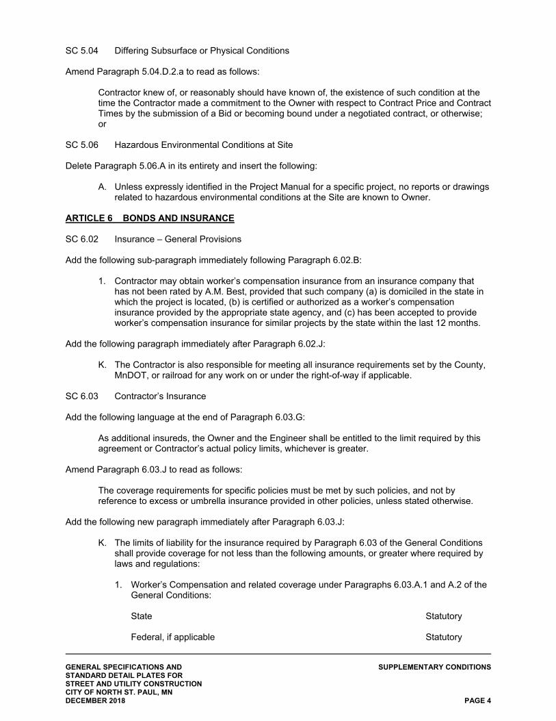
GENERAL SPECIFICATIONS AND SUPPLEMENTARY CONDITIONS STANDARD DETAIL PLATES FOR STREET AND UTILITY CONSTRUCTION CITY OF NORTH ST. PAUL, MN DECEMBER 2018 PAGE 4
SC 5.04 Differing Subsurface or Physical Conditions Amend Paragraph 5.04.D.2.a to read as follows:
Contractor knew of, or reasonably should have known of, the existence of such condition at the time the Contractor made a commitment to the Owner with respect to Contract Price and Contract Times by the submission of a Bid or becoming bound under a negotiated contract, or otherwise; or
SC 5.06 Hazardous Environmental Conditions at Site Delete Paragraph 5.06.A in its entirety and insert the following:
A. Unless expressly identified in the Project Manual for a specific project, no reports or drawings related to hazardous environmental conditions at the Site are known to Owner.
ARTICLE 6 BONDS AND INSURANCE SC 6.02 Insurance – General Provisions
Add the following sub-paragraph immediately following Paragraph 6.02.B:
1. Contractor may obtain worker’s compensation insurance from an insurance company that has not been rated by A.M. Best, provided that such company (a) is domiciled in the state in which the project is located, (b) is certified or authorized as a worker’s compensation insurance provided by the appropriate state agency, and (c) has been accepted to provide worker’s compensation insurance for similar projects by the state within the last 12 months.
Add the following paragraph immediately after Paragraph 6.02.J:
K. The Contractor is also responsible for meeting all insurance requirements set by the County, MnDOT, or railroad for any work on or under the right-of-way if applicable.
SC 6.03 Contractor’s Insurance Add the following language at the end of Paragraph 6.03.G:
As additional insureds, the Owner and the Engineer shall be entitled to the limit required by this agreement or Contractor’s actual policy limits, whichever is greater.
Amend Paragraph 6.03.J to read as follows:
The coverage requirements for specific policies must be met by such policies, and not by reference to excess or umbrella insurance provided in other policies, unless stated otherwise.
Add the following new paragraph immediately after Paragraph 6.03.J:
K. The limits of liability for the insurance required by Paragraph 6.03 of the General Conditions shall provide coverage for not less than the following amounts, or greater where required by laws and regulations:
1. Worker’s Compensation and related coverage under Paragraphs 6.03.A.1 and A.2 of the
General Conditions:
State Statutory Federal, if applicable Statutory
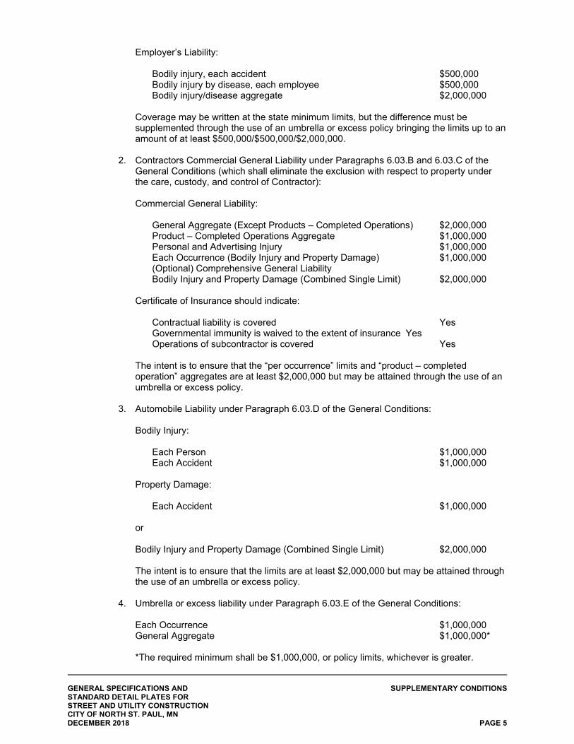
GENERAL SPECIFICATIONS AND SUPPLEMENTARY CONDITIONS STANDARD DETAIL PLATES FOR STREET AND UTILITY CONSTRUCTION CITY OF NORTH ST. PAUL, MN DECEMBER 2018 PAGE 5
Employer’s Liability:
Bodily injury, each accident $500,000 Bodily injury by disease, each employee $500,000 Bodily injury/disease aggregate $2,000,000
Coverage may be written at the state minimum limits, but the difference must be supplemented through the use of an umbrella or excess policy bringing the limits up to an amount of at least $500,000/$500,000/$2,000,000.
2. Contractors Commercial General Liability under Paragraphs 6.03.B and 6.03.C of the
General Conditions (which shall eliminate the exclusion with respect to property under the care, custody, and control of Contractor):
Commercial General Liability:
General Aggregate (Except Products – Completed Operations) $2,000,000 Product – Completed Operations Aggregate $1,000,000 Personal and Advertising Injury $1,000,000 Each Occurrence (Bodily Injury and Property Damage) $1,000,000 (Optional) Comprehensive General Liability Bodily Injury and Property Damage (Combined Single Limit) $2,000,000
Certificate of Insurance should indicate: Contractual liability is covered Yes Governmental immunity is waived to the extent of insurance Yes Operations of subcontractor is covered Yes
The intent is to ensure that the “per occurrence” limits and “product – completed operation” aggregates are at least $2,000,000 but may be attained through the use of an umbrella or excess policy.
3. Automobile Liability under Paragraph 6.03.D of the General Conditions:
Bodily Injury: Each Person $1,000,000 Each Accident $1,000,000 Property Damage: Each Accident $1,000,000 or Bodily Injury and Property Damage (Combined Single Limit) $2,000,000 The intent is to ensure that the limits are at least $2,000,000 but may be attained through
the use of an umbrella or excess policy.
4. Umbrella or excess liability under Paragraph 6.03.E of the General Conditions: Each Occurrence $1,000,000 General Aggregate $1,000,000* *The required minimum shall be $1,000,000, or policy limits, whichever is greater.
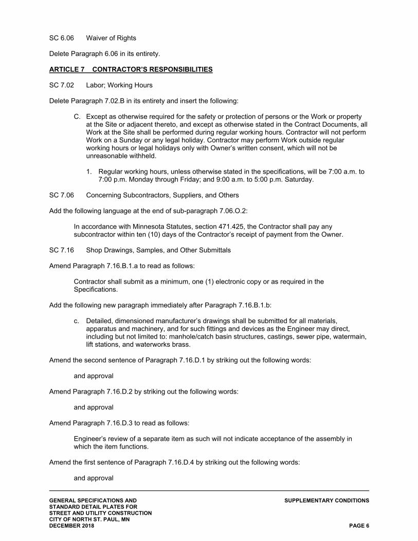
GENERAL SPECIFICATIONS AND SUPPLEMENTARY CONDITIONS STANDARD DETAIL PLATES FOR STREET AND UTILITY CONSTRUCTION CITY OF NORTH ST. PAUL, MN DECEMBER 2018 PAGE 6
SC 6.06 Waiver of Rights Delete Paragraph 6.06 in its entirety. ARTICLE 7 CONTRACTOR’S RESPONSIBILITIES SC 7.02 Labor; Working Hours Delete Paragraph 7.02.B in its entirety and insert the following:
C. Except as otherwise required for the safety or protection of persons or the Work or property at the Site or adjacent thereto, and except as otherwise stated in the Contract Documents, all Work at the Site shall be performed during regular working hours. Contractor will not perform Work on a Sunday or any legal holiday. Contractor may perform Work outside regular working hours or legal holidays only with Owner’s written consent, which will not be unreasonable withheld.
1. Regular working hours, unless otherwise stated in the specifications, will be 7:00 a.m. to
7:00 p.m. Monday through Friday; and 9:00 a.m. to 5:00 p.m. Saturday.
SC 7.06 Concerning Subcontractors, Suppliers, and Others Add the following language at the end of sub-paragraph 7.06.O.2:
In accordance with Minnesota Statutes, section 471.425, the Contractor shall pay any subcontractor within ten (10) days of the Contractor’s receipt of payment from the Owner.
SC 7.16 Shop Drawings, Samples, and Other Submittals Amend Paragraph 7.16.B.1.a to read as follows:
Contractor shall submit as a minimum, one (1) electronic copy or as required in the Specifications.
Add the following new paragraph immediately after Paragraph 7.16.B.1.b:
c. Detailed, dimensioned manufacturer’s drawings shall be submitted for all materials, apparatus and machinery, and for such fittings and devices as the Engineer may direct, including but not limited to: manhole/catch basin structures, castings, sewer pipe, watermain, lift stations, and waterworks brass.
Amend the second sentence of Paragraph 7.16.D.1 by striking out the following words: and approval Amend Paragraph 7.16.D.2 by striking out the following words: and approval Amend Paragraph 7.16.D.3 to read as follows:
Engineer’s review of a separate item as such will not indicate acceptance of the assembly in which the item functions.
Amend the first sentence of Paragraph 7.16.D.4 by striking out the following words: and approval
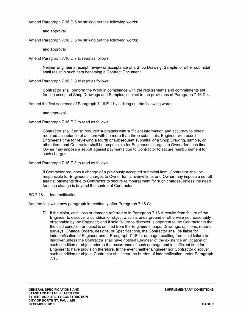
GENERAL SPECIFICATIONS AND SUPPLEMENTARY CONDITIONS STANDARD DETAIL PLATES FOR STREET AND UTILITY CONSTRUCTION CITY OF NORTH ST. PAUL, MN DECEMBER 2018 PAGE 7
Amend Paragraph 7.16.D.5 by striking out the following words: and approval Amend Paragraph 7.16.D.6 by striking out the following words: and approval Amend Paragraph 7.16.D.7 to read as follows:
Neither Engineer’s receipt, review or acceptance of a Shop Drawing, Sample, or other submittal shall result in such item becoming a Contract Document.
Amend Paragraph 7.16.D.8 to read as follows:
Contractor shall perform the Work in compliance with the requirements and commitments set forth in accepted Shop Drawings and Samples, subject to the provisions of Paragraph 7.16.D.4.
Amend the first sentence of Paragraph 7.16.E.1 by striking out the following words: and approval Amend Paragraph 7.16.E.2 to read as follows:
Contractor shall furnish required submittals with sufficient information and accuracy to obtain required acceptance of an item with no more than three submittals. Engineer will record Engineer’s time for reviewing a fourth or subsequent submittal of a Shop Drawing, sample, or other item, and Contractor shall be responsible for Engineer’s charges to Owner for such time. Owner may impose a set-off against payments due to Contractor to secure reimbursement for such charges.
Amend Paragraph 7.16.E.3 to read as follows:
If Contractor requests a change of a previously accepted submittal item, Contractor shall be responsible for Engineer’s charges to Owner for its review time, and Owner may impose a set-off against payments due to Contractor to secure reimbursement for such charges, unless the need for such change is beyond the control of Contractor.
SC 7.18 Indemnification Add the following new paragraph immediately after Paragraph 7.16.C:
D. If the claim, cost, loss or damage referred to in Paragraph 7.18.A results from failure of the Engineer to discover a condition or object which is underground or otherwise not reasonably observable by the Engineer; and if said failure to discover is apparent to the Contractor in that the said condition or object is omitted from the Engineer’s maps, Drawings, opinions, reports, surveys, Change Orders, designs, or Specifications, the Contractor shall be liable for indemnification of Engineer under Paragraph 7.18 for damage resulting from said failure to discover unless the Contractor shall have notified Engineer of the existence an location of such condition or object prior to the occurrence of such damage and in sufficient time for Engineer to have provision therefore. In the event neither Engineer nor Contractor discover such condition or object, Contractor shall bear the burden of indemnification under Paragraph 7.18.
GENERAL SPECIFICATIONS AND SUPPLEMENTARY CONDITIONS STANDARD DETAIL PLATES FOR STREET AND UTILITY CONSTRUCTION CITY OF NORTH ST. PAUL, MN DECEMBER 2018 PAGE 8
ARTICLE 8 OTHER WORK AT THE SITE SC 8.01 Other Work Add the following language at the end of Paragraph 8.01.C:
Contractor shall cooperate with all parties to facilitate the prompt completion of all contracts for work at or adjacent to the Site.
SC 8.02 Coordination Add the following new paragraphs immediately following Paragraph 8.02.B:
C. Contractor is hereby advised that the following work may be performed at or adjacent to the Site by others during the Contract Time:
1. The individual lot owners or their agents may be site grading and/or constructing
buildings on the lots adjacent to the proposed streets. 2. Private utility companies may be installing and/or relocating underground facilities.
D. If Owner performs work for the Contractor, the Contractor must pay Owner for such work with
no deduction in Contract amount.
ARTICLE 9 OWNER’S RESPONSIBILITIES SC 9.11 Evidence of Financial Arrangements
Delete Paragraph 9.11 in its entirety. ARTICLE 10 ENGINEER’S STATUS DURING CONSTRUCTION SC 10.02 Visits to Site Add the following new paragraph immediately following Paragraph 10.02.B:
C. Throughout the construction phase, regular weekly meetings will be held by the Engineer on site to review progress and to discuss items necessary for an orderly completion of the project. The weekly construction meetings shall include the Owner, Engineer, and Contractor. Contractor’s representative must be able to make decisions for the Contractor pertaining to the project. All project conflicts shall be brought to these meetings, including requests for additional payment. Meeting minutes will be provided to all participants as a record of the meeting.
SC 10.08 Limitations on Engineer’s Authority and Responsibilities
Add the following sub-paragraph immediately following Paragraph 10.08.A:
1. Insofar as the subject matter of any pertinent claim, dispute, or other matter falls within the realm of the technical expertise of Engineer, Engineer shall not render any decision on any claims, disputes, or other matters the subject matter of which, at Engineer's sole discretion, requires legal, rather than technical interpretation.
GENERAL SPECIFICATIONS AND SUPPLEMENTARY CONDITIONS STANDARD DETAIL PLATES FOR STREET AND UTILITY CONSTRUCTION CITY OF NORTH ST. PAUL, MN DECEMBER 2018 PAGE 9
Add the following new paragraph immediately following Paragraph 10.08.E:
F. Paragraphs 10.08.A through 10.08.E pertain to the Engineer’s responsibilities to the Contractor and its subcontractors, suppliers, and other agents. Nothing in these paragraphs shall be construed to limit the Engineer’s responsibilities to the Owner, if any, under the Engineer’s contract with the Owner.
ARTICLE 11 AMENDING THE CONTRACT DOCUMENTS; CHANGES IN THE WORK SC 11.03 Unauthorized Changes in the Work Add the following new paragraphs immediately following Paragraph 11.03.A:
B. Except as specifically authorized in writing by the Engineer at the time additional work is done beyond the original scope of the Contract Documents, the Contractor shall make no claims for additional compensation. The Contractor’s plea of ignorance of foreseeable conditions which will create difficulties or hindrances in the execution of the Work will not be acceptable to the Owner as an excuse for any failure of the Contractor to fulfill the requirements of the Contract Documents and shall not be a basis for the Contractor’s claim for additional compensation.
C. Any discrepancies in or conflicts between the items described in these Contract Documents
must be submitted in writing to the Engineer for adjustment prior to proceeding with the Work as any claims for additional compensation to achieve compliance with the requirements of those items will not be allowed or considered.
SC 11.06 Change Proposals Amend the first sentence of Paragraph 11.06.A.1 to read as follows:
Procedures: Contractor shall submit each Change Proposal to Engineer promptly (but in no event later than seven (7) days) after the start of the event giving rise thereto, or after such initial decision.
ARTICLE 12 CLAIMS SC 12.01 Claims Amend the first sentence of Paragraph 12.01.B to read as follows:
The party submitting a claim shall deliver it directly to the other party to the Contract and the Engineer promptly (but in no event later than ten (10) days) after the start of the event giving rise thereto; in the case of appeals regarding Change Proposals within ten (10) days of the decision under appeal.
ARTICLE 13 COST OF THE WORK; ALLOWANCES; UNIT PRICE WORK SC 13.01 Cost of the Work Delete sub-paragraph 13.01.B.5.f in its entirety.
GENERAL SPECIFICATIONS AND SUPPLEMENTARY CONDITIONS STANDARD DETAIL PLATES FOR STREET AND UTILITY CONSTRUCTION CITY OF NORTH ST. PAUL, MN DECEMBER 2018 PAGE 10
SC 13.03 Unit Price Work Delete Paragraph 13.03.E in its entirety and insert the following:
There will be no adjustment in unit price for increased or decreased quantities. In addition, the Owner reserves the right to reduce certain quantities or delete certain items from each section of the bids as the Owner sees fit, either before or after the Award of Contract. There will be no additional compensation due to remobilization of equipment as necessary to complete punch list items or other items not completed by the Contractor. There will be no additional compensation due to restocking charges for materials not used on the project.
ARTICLE 14 TESTS AND INSPECTIONS; CORRECTION, REMOVAL OR ACCPETANCE OF DEFECTIVE WORK SC 14.02 Tests, Inspections, and Approvals Add the following sub-paragraphs immediately following Paragraph 14.02.A:
1. The Contractor shall provide a minimum 48-hour notice to the Observer for any testing that must be observed or accomplished by someone other than the Contractor’s personnel. All final tests and inspections shall be performed under the observation of the Observer.
2. Signed copies of all reports on tests shall be sent at once to the Owner, Engineer, and
Contractor. Inspection and testing shall in no way relieve the Contractor or supplier from the responsibility of furnishing materials and workmanship in accordance with the Plans and Specifications.
ARTICLE 15 PAYMENTS TO CONTRACTOR; SET-OFFS; COMPLETION; CORRECTION PERIOD SC 15.01 Progress Payments Amend the first sentence of Paragraph 15.01.A to read as follows:
Basis for Progress Payments: The Bid will serve as the basis for progress payments and will be incorporated into a form of Application for Payment acceptable to Engineer.
Delete Sub-paragraph 15.01.B.3 in its entirety and insert the following:
3. The amount of retainage with respect to progress payments will be as follows:
Minnesota Contractors 5% Exempt Non-Minnesota Contractors 5% Non-Exempt Non-Minnesota Contractors 5% + 8%* = 13% *State Surety Deposit
Non-Minnesota Contractors are advised to file Form SDE with the Minnesota Department of Revenue to determine their exemption status. No reduction in retainage will be allowed until final acceptance of entire project, unless approved by the Engineer.
GENERAL SPECIFICATIONS AND SUPPLEMENTARY CONDITIONS STANDARD DETAIL PLATES FOR STREET AND UTILITY CONSTRUCTION CITY OF NORTH ST. PAUL, MN DECEMBER 2018 PAGE 11
Delete Sub-paragraph 15.01.D.1 in its entirety and insert the following:
1. Thirty (30) days after presentation of the Application for Payment to Owner with Engineer's recommendation, the amount recommended (subject to any Owner set-offs) will become due, and when due will be paid by Owner to Contractor, unless extenuating circumstances exist which would preclude such payment by Owner to Contractor. If such extenuating circumstances exist, then payment shall be made within 45 days after Owner receives presentation of the Application for Payment.
SC 15.05 Final Inspection Add the following language at the end of the second sentence of Paragraph 15.05.A:
If, after such measures are taken, subsequent inspections by the Engineer reveal that any of the previously identified construction items remain incomplete or defective, the Engineer will again notify the Contractor in writing of the remaining construction items. All costs associated with any subsequent inspections in which said remaining particulars are revealed, will be documented by the Engineer and paid by the Contractor to the Owner.
SC 15.06 Final Payment Add a new paragraph immediately following Paragraph 15.06.A.3:
4. Before final application for payment is made for the work, the Contractor must make satisfactory showing of compliance with MINN. STAT. 290.92, which requires the withholding of state income taxes for wages paid to employees on this project. Receipt by the Engineer of a certificate of Compliance from the Commissioner of Taxation to the Owner will satisfy this requirement. The Contractor is advised that before such certificate can be issued, the Contractor must first place on file with the Commissioner of Taxation an affidavit that the Contractor has complied with the provisions of MINN. STAT. 290.92. The required affidavit form will be supplied by the Commissioner of Taxation, Centennial Building, St. Paul, Minnesota, on request.
Final payment will not be made until the Contractor shall have filed with the Engineer
evidence in the form of an affidavit or such other evidence as may be required that all claims against him by reason of the Contract have been fully paid or satisfactorily secured. This shall be in the form of IC134 forms, paid-in-full final lien waivers from the Contractor, subcontractors, and major suppliers, and a Consent of Surety shall precede or accompany the final application for payment. In case such evidence is not furnished, the Owner may retain out of any monies due said Contractor sums sufficient to cover all lienable claims unpaid. In addition, a two (2) year maintenance bond is required from the Contractor. Said maintenance bond is to be dated to begin the date the City Council formally accepts the project.
GENERAL SPECIFICATIONS AND SUPPLEMENTARY CONDITIONS STANDARD DETAIL PLATES FOR STREET AND UTILITY CONSTRUCTION CITY OF NORTH ST. PAUL, MN DECEMBER 2018 PAGE 12
SC 15.08 Correction Period Delete Paragraph 15.08.A in its entirety and insert the following:
A. If within two (2) years after the date of final acceptance by the Owner (or such longer period of time as may be prescribed by Laws or Regulations, by the terms of any applicable special guarantee required by the Contract Documents, or by any specific provision of the Contract Documents), any Work is found to be defective, or if the repair of any damages to the Site, adjacent areas that Contractor has arranged to use through construction easements or otherwise, and other adjacent areas used by Contractor as permitted by Laws and Regulations, is found to be defective, the Contractor shall promptly, without cost to the Owner and in accordance with the Owner’s written instructions:
1. correct the defective repairs to the Site or such other adjacent areas;
2. correct such defective Work; 3. if the defective Work has been rejected by Owner, remove it from the project and
replace it with Work that is not defective, and 4. satisfactorily correct or repair or remove and replace any damage to other Work, to
the work of others, or to other land or areas resulting therefrom.
With regards to any surface concrete work, including but not limited to sidewalks, curb, gutter, and driveway aprons within the project area, the Contractor shall assume full responsibility for any warranty work unless written approval is provided by the Owner releasing the Contractor from the responsibility for damages. The intent of this provision is to release the Contractor from accepting monetary losses for destruction of concrete sidewalk, curb, gutter, and driveway aprons due to damages and circumstances out of the control of the Contractor. At no point during the two (2) year warranty period shall this relieve the Contractor’s responsibility for correction of the defective work as stated in the preceding paragraph, or as caused by poor construction and defective materials on the concrete sidewalk, curb, gutter, and driveway aprons within the project area. The Owner or Engineer shall make the final determination of what material is defective within the project area at any point within the two (2) year warranty period.
ARTICLE 17 FINAL RESOLUTION OF DISPUTES SC 17.01 Methods and Procedures Delete Paragraphs 17.01.A and 17.01.B in their entirety and insert the following:
A. In an effort to resolve any conflicts that arise during the design or construction of the project or following the completion of the project, the Contractor and the Engineer agree that all disputes between them arising out of or relating to this agreement shall be resolved, if possible, at the lowest possible staff level. If the dispute cannot be resolved between the Contractor and the Engineer staff, the presidents of the respective firms will meet to attempt to resolve the dispute(s). If resolution is not achieved, the dispute shall be submitted to non-binding mediation.
GENERAL SPECIFICATIONS AND SUPPLEMENTARY CONDITIONS STANDARD DETAIL PLATES FOR STREET AND UTILITY CONSTRUCTION CITY OF NORTH ST. PAUL, MN DECEMBER 2018 PAGE 13
B. The rights and remedies available to the Contractor shall be limited to breach of Contract, and no other cause of action, including, without limitation, negligence, misrepresentation or other tort theory. The Owner or Contractor may assert any such breach of contract claim in any court of competent jurisdiction. Neither the Owner nor the Contractor shall be entitled to a jury trial in any such action. The right and remedies to the Owner hereunder shall be in addition to and shall not be constructed in any way as a limitation of any rights and remedies available to the Owner, which is otherwise available by law or contract, by special warranty or guarantee, or by other provision of the Contract Documents. The provision of this paragraph shall be as effective as if repeated specifically in the Contract Documents in connection with each particular duty, obligation, right and remedy to which it may apply. All representations, warranties and guarantees made in the Contract Documents shall survive final payment, termination, or completion of this agreement.
Add the following new paragraph immediately following Paragraph 17.01.B:
C. No waiver or failure to enforce any part or provision of the Contract Documents, including but not limited to the change order process, shall be deemed to be waiver by the Owner of any subsequent default or breach of the same or any other part of provision contained herein, or right to enforce the same or any other part or provision contained herein.
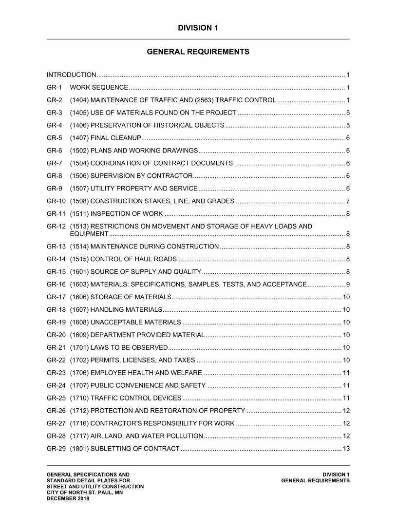
DIVISION 1
GENERAL REQUIREMENTS
GENERAL SPECIFICATIONS AND DIVISION 1 STANDARD DETAIL PLATES FOR GENERAL REQUIREMENTS STREET AND UTILITY CONSTRUCTION CITY OF NORTH ST. PAUL, MN DECEMBER 2018
INTRODUCTION ........................................................................................................................................... 1
GR-1 WORK SEQUENCE ......................................................................................................................... 1
GR-2 (1404) MAINTENANCE OF TRAFFIC AND (2563) TRAFFIC CONTROL ...................................... 1
GR-3 (1405) USE OF MATERIALS FOUND ON THE PROJECT ............................................................ 5
GR-4 (1406) PRESERVATION OF HISTORICAL OBJECTS ................................................................... 5
GR-5 (1407) FINAL CLEANUP.................................................................................................................. 6
GR-6 (1502) PLANS AND WORKING DRAWINGS .................................................................................. 6
GR-7 (1504) COORDINATION OF CONTRACT DOCUMENTS .............................................................. 6
GR-8 (1506) SUPERVISION BY CONTRACTOR ..................................................................................... 6
GR-9 (1507) UTILITY PROPERTY AND SERVICE .................................................................................. 6
GR-10 (1508) CONSTRUCTION STAKES, LINE, AND GRADES ............................................................. 7
GR-11 (1511) INSPECTION OF WORK ..................................................................................................... 8
GR-12 (1513) RESTRICTIONS ON MOVEMENT AND STORAGE OF HEAVY LOADS AND EQUIPMENT .................................................................................................................................... 8
GR-13 (1514) MAINTENANCE DURING CONSTRUCTION ...................................................................... 8
GR-14 (1515) CONTROL OF HAUL ROADS .............................................................................................. 8
GR-15 (1601) SOURCE OF SUPPLY AND QUALITY ................................................................................ 8
GR-16 (1603) MATERIALS: SPECIFICATIONS, SAMPLES, TESTS, AND ACCEPTANCE ..................... 9
GR-17 (1606) STORAGE OF MATERIALS ............................................................................................... 10
GR-18 (1607) HANDLING MATERIALS .................................................................................................... 10
GR-19 (1608) UNACCEPTABLE MATERIALS ......................................................................................... 10
GR-20 (1609) DEPARTMENT PROVIDED MATERIAL ............................................................................ 10
GR-21 (1701) LAWS TO BE OBSERVED ................................................................................................. 10
GR-22 (1702) PERMITS, LICENSES, AND TAXES ................................................................................. 10
GR-23 (1706) EMPLOYEE HEALTH AND WELFARE ............................................................................. 11
GR-24 (1707) PUBLIC CONVENIENCE AND SAFETY ........................................................................... 11
GR-25 (1710) TRAFFIC CONTROL DEVICES ......................................................................................... 11
GR-26 (1712) PROTECTION AND RESTORATION OF PROPERTY ..................................................... 12
GR-27 (1716) CONTRACTOR’S RESPONSIBILITY FOR WORK ........................................................... 12
GR-28 (1717) AIR, LAND, AND WATER POLLUTION ............................................................................. 12
GR-29 (1801) SUBLETTING OF CONTRACT .......................................................................................... 13
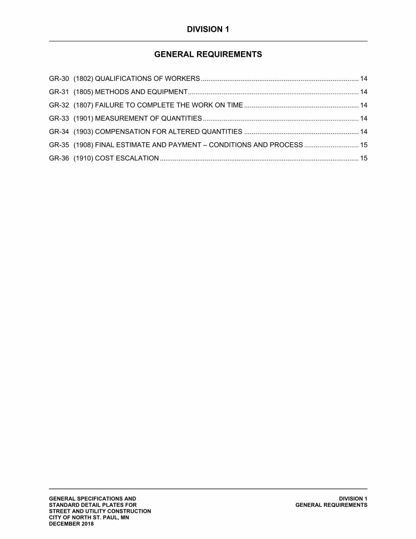
DIVISION 1
GENERAL REQUIREMENTS
GENERAL SPECIFICATIONS AND DIVISION 1 STANDARD DETAIL PLATES FOR GENERAL REQUIREMENTS STREET AND UTILITY CONSTRUCTION CITY OF NORTH ST. PAUL, MN DECEMBER 2018
GR-30 (1802) QUALIFICATIONS OF WORKERS .................................................................................... 14
GR-31 (1805) METHODS AND EQUIPMENT ........................................................................................... 14
GR-32 (1807) FAILURE TO COMPLETE THE WORK ON TIME ............................................................. 14
GR-33 (1901) MEASUREMENT OF QUANTITIES ................................................................................... 14
GR-34 (1903) COMPENSATION FOR ALTERED QUANTITIES ............................................................. 14
GR-35 (1908) FINAL ESTIMATE AND PAYMENT – CONDITIONS AND PROCESS ............................. 15
GR-36 (1910) COST ESCALATION .......................................................................................................... 15
DIVISION 1
GENERAL REQUIREMENTS
GENERAL SPECIFICATIONS AND DIVISION 1 STANDARD DETAIL PLATES FOR GENERAL REQUIREMENTS STREET AND UTILITY CONSTRUCTION CITY OF NORTH ST. PAUL, MN DECEMBER 2018 PAGE 1
INTRODUCTION These General Requirements amend or supplement Division I of the Minnesota Department of Transportation (MnDOT) Standard Specifications for Construction (2018 Edition). With the exclusion of Definitions and Terms, Bidding Requirements and Conditions, and Bidding Requirements and Covenants, unless specifically stated, provisions of MnDOT Division I which are not amended or supplemented shall not apply to this Contract. GR-1 WORK SEQUENCE The Contractor shall:
1. Perform his work in such a manner as to cause the least interference with adjoining property owners and the general public.
2. For each phase of the project, construct work in a sequence that will allow the utility work to
follow immediately upon the removal of the bituminous pavement and concrete curb and gutter. Subgrade excavation, subgrade preparation, and placement of aggregate base shall be completed within two (2) weeks of the completion of any utility work. Curb and gutter placement, final aggregate base placement, and the first lift of bituminous pavement shall be placed within two (2) weeks of initial aggregate base placement. All restoration work within the boulevard area shall be completed within two (2) weeks of paving the bituminous base course.
3. Limit the area under construction at any given time to minimize the impacts to adjoining
properties and limit the duration that activities will disturb residents on each street.
4. Limit the area under construction to the area(s) indicated on the staging plan, unless approved by the Engineer. Under construction is defined as the time period from bituminous removal to placement of aggregate base.
5. All proposed haul roads must be approved by the Engineer. The Contractor cannot utilize newly
paved streets as haul roads. Any damage to existing streets due to unapproved construction use will be repaired at the Contractor’s expense.
6. Concrete curb and gutter and bituminous paving crews shall be mobilized to the project whenever a minimum of one (1) working day, but not more than two (2) working days, are satisfactorily prepared for their respective work.
GR-2 (1404) MAINTENANCE OF TRAFFIC AND (2563) TRAFFIC CONTROL The provisions of MnDOT 1404 are modified and/or supplemented with the following: All traffic control devices shall conform and be installed in accordance to:
- the “Minnesota Manual on Uniform Traffic Control Devices” (MN MUTCD); - Part 6, “Field Manual for Temporary Traffic Control Zone Layouts” (Field Manual); - the Speed Limits in Work Zone Guidelines; - the Minnesota Flagging Handbook; - the MnDOT Standard Signs and Markings Manual;
And the provisions of MnDOT 1404 and 1710, the Plans, and the Project Manual.
GENERAL SPECIFICATIONS AND DIVISION 1 STANDARD DETAIL PLATES FOR GENERAL REQUIREMENTS STREET AND UTILITY CONSTRUCTION CITY OF NORTH ST. PAUL, MN DECEMBER 2018 PAGE 2
The Contractor shall furnish, install, maintain, and remove all traffic control devices required to provide safe movement of vehicular traffic through the Project during the life of the Contract from the start of Contract operations through the completion thereof. This shall include construction signs with special messages in accordance with MnDOT 2564 as directed by the Engineer. The Engineer will have the right to modify the requirements for traffic control as deemed necessary, due to existing field conditions.
Traffic control devices include, but are not limited to, barricades, warning signs, trailers, flashers, cones, and drums, as required, and sufficient barricade ballasts to maintain barricade stability. Work performed within MnDOT or County right-of-way may require additional traffic control, including but not limited to flagging operations, concrete jersey barriers, lane delineation, and advanced notice signage. The Contractor will be responsible for providing all traffic control required by MnDOT or the County.
Traffic Control
A. The Contractor shall submit the proposed traffic control layout and project staging plan to the Engineer, for acceptance, at least 14 days prior to the start of construction. This plan shall include, at a minimum:
phasing of utility construction to allow a means of ingress/egress from each of the
reconstructed areas at all times; 48-hour advance notice shall be provided to the Engineer prior to restricting access to
any street or property; and all roads shall be re-opened to traffic at the end of each work day.
B. At least 24 hours prior to placement, all traffic control devices shall be available on the Project for
inspection by the Engineer. The Contractor shall modify the proposed traffic control layout and/or devices as deemed necessary by the Engineer.
C. The Contractor shall notify Engineer in writing at least seventy-two (72) hours prior to the start of any construction operation that will necessitate lane closure or internal traffic control signing.
D. The Contractor shall be responsible for the immediate repair or replacement of all traffic control
devices that become damaged, moved or destroyed, of all lights that cease to function properly, and of all barricade ballasts that are damaged, destroyed, or otherwise fail to stabilize the barricades. The Contractor shall provide sufficient surveillance of all traffic control devices at least once every 24 hours. The Contractor shall furnish the Engineer names, addresses and phone numbers of at least three individuals responsible for the placement and maintenance of traffic control devices. These individuals shall be “on call” 24 hours per day, seven days per week during the times any traffic control devices, furnished and installed by the Contractor, are in place. The Contractor shall submit required information to the Engineer at the Pre-construction Conference
E. The Contractor shall inspect, on a daily basis, all traffic control devices, which the Contractor has
furnished and installed, and verify that the devices are placed in accordance with the traffic control plan and/or the MN MUTCD. Any discrepancy between the placement and the required placement shall be immediately corrected.
The Contractor shall be required to respond immediately to any call from the Engineer concerning any request for improving or correcting traffic control devices.
GENERAL SPECIFICATIONS AND DIVISION 1 STANDARD DETAIL PLATES FOR GENERAL REQUIREMENTS STREET AND UTILITY CONSTRUCTION CITY OF NORTH ST. PAUL, MN DECEMBER 2018 PAGE 3
The Contractor is required to meet the traffic control device quality standards as determined in the Field Manual. The Contractor shall immediately replace traffic control devices that are deemed unacceptable. Signs that are dirty and result in a noticeable loss of reflectivity at night are also considered unacceptable and shall be cleaned or replaced. The Contractor shall be required to respond immediately to any call from the Engineer concerning the notification of unacceptable traffic control devices.
F. If, at any time, the Contractor fails to, in a timely manner, properly furnish, install, maintain or remove any of the required traffic control devices, the Owner reserves the right to correct the deficiency at the Contractor’s expense.
General Requirements
A. All portable sign assemblies shall be perpendicular to the ground. No roll-up signs will be allowed unless authorized by the Engineer. No traffic control device (signs, channelizing devices, arrow boards, etc.) shall be weighted so they become hazardous to motorists and workers.
When signs will remain in the same location for more than 30 consecutive days the signs shall be post mounted. This would not include portable signs that are set up and taken down at the beginning and end of each work shift.
B. When signs are installed, they shall be mounted as detailed in the MN MUTCD. When signs are
removed, the sign posts and stub posts shall also be removed from the Right-of-Way within two (2) weeks.
C. All temporary rigid signs shall be fabricated with an approved retroreflective sheeting material of the appropriate color and be listed under the Approved/Qualified Products List (APL/QPL) for either “Sheeting for Rigid Temporary Work Zone Signs, Delineators, and Markers (Type IX and XI)” or “Sheeting for Rigid Permanent Signs, Delineators, and Markers (Type IX and XI)”. In place signs that still apply during temporary operations need no change in sign sheeting.
The sheeting materials APL/QPL, including the retroreflective sheeting types, is located at http://www.dot.state.mn.us/products/signing/sheeting.html.
D. In Place Signing: All in place signs and delineators that interfere with the Contractor’s normal
operations shall be relocated outside of the work area or removed by the Contractor at the direction of the Engineer. Signs that are removed and will be reused are to be stored in such a manner as to protect the sign from scratching, fading, or other harmful effects until said signs are reinstalled. Upon completion of work at each sign location, or at the direction of the Engineer, the signs shall be replaced as near to their original locations as possible or to a location designated by the Engineer. Signs and structures damaged by the Contractor shall be replaced at the Contractor’s expense.
The reinstalled sign posts shall be plumb, and the sign panels shall be level. The minimum mounting height shall be seven feet above the elevation of the traveled roadway. The minimum embedment length of the stub posts shall be 3.5 feet. The spice between the stub post and the riser post shall be a minimum of 12 inches.
E. The Contractor shall provide protective devices necessary to protect traffic from excavations,
drop-offs, falling objects, splatter or other hazards that may exist during construction This work shall be incidental. The Contractor will not be allowed to suspend material, equipment, tools and personnel over traffic unless a lane closure is established. Lane closures required for protection of traffic from excavations, suspended materials, equipment, tools, and personnel are incidental.
F. The Contractor will not be permitted to park vehicles or construction equipment in a location that obstructs any traffic control device. The parking of workers’ private vehicles will not be allowed within the Project limits unless so approved by the Engineer.
GENERAL SPECIFICATIONS AND DIVISION 1 STANDARD DETAIL PLATES FOR GENERAL REQUIREMENTS STREET AND UTILITY CONSTRUCTION CITY OF NORTH ST. PAUL, MN DECEMBER 2018 PAGE 4
G. The Contractor will not be allowed to store materials or equipment within 30 feet of through traffic unless approved by the Engineer. If materials or equipment must be stored within 30 feet of through traffic, the Contractor shall provide Type B channelizers, barricades or barriers, placed near the object to warn and protect traffic.
H. High-Visibility Apparel: All workers within the right of way who are exposed to either traffic or to construction equipment shall wear reflectorized high-visibility safety apparel. All high visibility apparel must be worn in the manner for which it was designed. All apparel worn on the torso must be closed in the front to provide contiguous 360-degree visibility. High-visibility safety apparel means personal protective safety clothing that is intended to provide conspicuity during both daytime and nighttime usage and meets the minimum performance ANSI/ISEA 107-2004 (or ANSI/ISEA 107-2010) Performance Class 2 requirements. ANSI/ISEA 107-2015 Type R, Performance Class 2 is also acceptable. This information can be found in the publication entitled “American National Standard for High-Visibility Safety Apparel and Accessories.” Additional requirements for flaggers and nighttime/low light conditions: ANSI/ISEA 107-2004 (or ANSI/ISEA 107-2010) Performance Class 3 requirements. ANSI/ISEA 107-2015 Type R, performance Class 3 is also acceptable. The Class 3 requirements shall be met by wearing a Class 2 or Class 3 vest, shirt, or jacket, as well as Class E pants. Clothing shall have an attached original label indicating the Performance Class. Retro-reflective headgear shall also be required.
Vehicle Warning Lights All Contractors, subcontractors’ and suppliers’ mobile equipment, operating with the limits of the Project with potential exposure to passing traffic, including roads that are open to local traffic only shall be equipped with operable warning lights that meet the appropriate requirements of the SAE Specifications.J845 and J595. This also includes any vehicle that enters the traveled roadway at any time. Lights shall be mounted so that at least one light is visible at all times from a height of 3.5 feet and from a 60-foot radius about the equipment. In order to meet the 360 degrees at 60-foot radius requirements, supplemental lighting may be used. All supplemental lights must be SAE Class 1 certified. Warning lights shall also be operating and visible when a vehicle decelerates to enter a construction work zone and again when a vehicle leaves the work zone and enters the traveled traffic lane. Providing warning lights for mobile equipment shall be incidental. Maintenance and Staging of Traffic Control The Contractor shall furnish, install, and maintain “ROAD WORK AHEAD” signs in advance of the construction limits and on all intersecting roads and streets as directed by the Engineer. Construction signing and barricades shall be furnished, installed, and maintained at all job site entrances throughout the project. All signs that are not consistent with traffic operations shall be covered as required by the Engineer. Street names and address numbers shall be maintained by temporary installations as required by the Engineer to maintain the 911 emergency system. As each road is completed, and on or before the date of opening, the Contractor shall install the final signing and pavement markings required to safely open that road to traffic.
GENERAL SPECIFICATIONS AND DIVISION 1 STANDARD DETAIL PLATES FOR GENERAL REQUIREMENTS STREET AND UTILITY CONSTRUCTION CITY OF NORTH ST. PAUL, MN DECEMBER 2018 PAGE 5
Access to Properties The Contractor shall maintain access to all areas for residential and commercial traffic and emergency vehicles at all times. The Contractor shall maintain residential driveway accesses during construction at all times unless utilities are being installed directly in front of said access. If a driveway access must be closed, the Contractor shall notify the residents a minimum of twenty-four (24) hours in advance of the time the access will be unavailable. In the event that an access Is temporarily closed, the Contractor shall install the proper traffic control to barricade the access at no additional cost to the Owner. The Contractor shall salvage aggregate or recycled bituminous from the project, or haul approved granular material to the project site, at no additional cost to the Owner for use in ramping the driveways to maintain access. The Contractor shall accommodate special access needs of the residents (medical needs, working the night shift, etc.) and provide access to driveways and roadways as required. If access is determined to be unsuitable for individual residences by the Engineer, the Contractor shall make the necessary improvements to reestablish an acceptable access to the property. Measurement and Payment No measurement will be made of the various items that constitute Traffic Control, but all such work shall be construed to be included in the lump sum payment under Item 2563.601 (Traffic Control) according to the following schedule:
(1) When five percent (5%) of the Contract amount is earned, fifty percent (50%) of the amount bid for traffic control will be paid.
(2) When ten percent (10%), or more, of the Contract amount is earned, and additional twenty percent (20%) of the amount bid for traffic control will be paid.
(3) When fifty percent (50%), or more, of the Contract amount is earned, an additional twenty percent (20%) of the amount bid for traffic control will be paid.
(4) The remaining five percent (5%) of the amount bid for traffic control will be paid when all work has been completed and accepted.
In Items 1-4 above, the Contract amount shall be the total value of all Contract Items including the Traffic Control item, but the percentage earned in each case shall be exclusive of the Traffic Control item. The lump sum payment shall be compensation in full for all costs of furnishing, installing, maintaining, and removing the individual traffic control devices, except for items as specifically listed in the Bid form. If no bid item for traffic control is provided, traffic control is considered incidental to the Contract. GR-3 (1405) USE OF MATERIALS FOUND ON THE PROJECT The provisions of MnDOT 1405 shall apply. GR-4 (1406) PRESERVATION OF HISTORICAL OBJECTS The provisions of MnDOT 1406 shall apply.
GENERAL SPECIFICATIONS AND DIVISION 1 STANDARD DETAIL PLATES FOR GENERAL REQUIREMENTS STREET AND UTILITY CONSTRUCTION CITY OF NORTH ST. PAUL, MN DECEMBER 2018 PAGE 6
GR-5 (1407) FINAL CLEANUP The provisions of MnDOT 1407 are modified and/or supplemented with the following: During the progress of the work, the area affected shall be kept clean and free of all rubbish and surplus materials. All unnecessary construction equipment shall be removed from the site and all damage repaired so that the public and adjacent property owners are inconvenienced as little as possible. Where materials or debris have washed, flowed into, or have been placed in water courses, ditches, gutters, drains, catch basins, or elsewhere as a result of the Contractor’s operations, such material or debris shall be removed and satisfactorily disposed of during progress of work. All ditches, channels, drains, etc. shall be kept in a clean and neat condition. On or before the completion of work, the Contractor shall, unless otherwise directed in writing, remove all temporary works, tools and machinery, other construction equipment, or stockpiles placed by the Contractor. The Contractor shall remove all rubbish from any grounds which the Contractor occupied and shall leave all the premises and adjacent properties affected by the operation in a neat and restored condition satisfactory to the Engineer. Street sweeping (with a pickup broom) will be required periodically. Any material deposited on streets adjacent to the project from construction or hauling operations shall be cleaned as directed by the Engineer. If the Contractor fails to clear adjacent roadways within 24 hours of notification, the Engineer shall arrange to have the roadways cleaned by the City and bill the Contractor $500.00 per occurrence. The $500.00 fee for street sweeping will be deducted from project retainage for each occurrence. GR-6 (1502) PLANS AND WORKING DRAWINGS The provisions of MnDOT 1502 are modified and/or supplemented with the following: Drawings provided by the Owner will include the information, as applicable to the project, in accordance with MnDOT 1502. The Owner’s Standard Plates, MnDOT’s Standard Plates, and MnDOT’s Standard Plans may provide supplemental information. GR-7 (1504) COORDINATION OF CONTRACT DOCUMENTS The provisions of MnDOT 1504 shall apply. GR-8 (1506) SUPERVISION BY CONTRACTOR The provisions of MnDOT 1506 shall apply. GR-9 (1507) UTILITY PROPERTY AND SERVICE The provisions of MnDOT 1507 are modified and/or supplemented with the following: The plans show only known underground utilities, public and private, and the locations are approximate. No assurance is given that additional underground facilities do not exist. The utilities are classified as “Level D” unless the plans specifically state otherwise. This utility quality level was determined according to the guidelines of CI/ASCE38-02, entitled “Standard Guidelines for the Collection and Depiction of Existing Subsurface Data”. State law requires the Contractor to contact Gopher State One Call (811) for utility locations before doing any underground excavation. The Contractor is responsible for ascertaining the actual location of underground utilities.
GENERAL SPECIFICATIONS AND DIVISION 1 STANDARD DETAIL PLATES FOR GENERAL REQUIREMENTS STREET AND UTILITY CONSTRUCTION CITY OF NORTH ST. PAUL, MN DECEMBER 2018 PAGE 7
All bidders are responsible for contacting the affected utilities prior to submitting a bid to determine the extent of their facilities within the project area and the scope and anticipated schedule of any facility relocation, removal, or adjustment. The following utility owners have existing facilities that may be affected by the Work: Prior to commencing construction, the Contractor shall check all existing manholes, catch basins, gate valve boxes, stop boxes, culverts, and storm sewer lines in the construction zones to determine their condition. Failure to report deficiencies in writing, and have such deficiencies acknowledged in writing by the Engineer, will be cause for any required repairs and/or cleaning to be charged to this Contractor. The Contractor shall coordinate activities with the activities of all utility owners present within the project limits. This includes delays associated with scheduling conflicts, fees charges by utility owners for construction services, and all time necessary to communicate and work with utility owners within the project limits. The location, protection, maintenance and/or repair, if damaged, of all in-place utilities shall be the responsibility of the Contractor. Where construction operations require the interruption of service of a utility, the Contractor shall notify the utility at least 48 hours before the interruption and shall advise the utility of the probable time when the service will be restored. GR-10 (1508) CONSTRUCTION STAKES, LINE, AND GRADES MnDOT 1508 is deleted in its entirety and replaced with the following: 1508 CONSTRUCTION STAKES, LINE AND GRADES
The Engineer will provide horizontal and vertical control construction stakes to allow the Contractor to construct the improvements as follows:
A. Offset stakes placed at 25-foot intervals for the first 100 feet out of each manhole, then 100-foot intervals thereafter for sanitary or storm sewer, with a cut sheet indicating horizontal and vertical distances from the stake to the pipe invert.
B. Offset stakes placed at 50-foot intervals, including changes in direction and
appurtenances for watermain construction.
C. Curb and Gutter: Three (3) foot offset stakes placed at 25-foot intervals with a cut sheet indicating a cut/fill to the proposed top of curb.
D. Reference hubs (bluetops) at approximately 100-foot intervals at a measured distance
either side of centerline, including cut or fill instructions for subgrade and/or gravel base.
It shall be the Contractor's total responsibility to accurately construct the improvements in accordance with the construction stakes. Construction stakes will not be placed by the Owner until a written request is received from the Contractor giving the Engineer 48 hours' notice, describing where and when he wants the construction stakes placed for the next week's construction. The stakes will be set only one (1) time and it will be the responsibility of the Contractor to preserve the stakes.
The Engineer shall have the right to order the Contractor to have construction stakes replaced if the Engineer determines that a significant number of stakes have been destroyed.
GENERAL SPECIFICATIONS AND DIVISION 1 STANDARD DETAIL PLATES FOR GENERAL REQUIREMENTS STREET AND UTILITY CONSTRUCTION CITY OF NORTH ST. PAUL, MN DECEMBER 2018 PAGE 8
The replacement of any construction stakes will be done by the Engineer at the Contractor's expense and for which the Contractor will be billed.
The Contractor shall be responsible for replacement of all property or section corners removed by the Contractor. The Owner will mark all property corners and section corners the Owner is aware of prior to construction. The Contractor shall notify the Engineer of any property corner, whether the Owner has marked them or not, which the Contractor may disturb in sufficient time to allow the Engineer to establish ties to the corner. The replacement of property or section corners shall be by the Owner at the Contractor's expense and for which the Contractor will be billed.
No additional compensation shall be allowed the Contractor for any claims of crews being held up
because of lack of line and grade stakes. GR-11 (1511) INSPECTION OF WORK The provisions of MnDOT 1511 are modified and/or supplemented with the following: Any person representing Federal or State agencies, the Engineer, or Owner shall have the right-of-entry to inspect the Work being performed by the Contractor. If the case warrants, the Contractor shall provide proper facilities for such access and inspection. The Contractor shall notify the Engineer anytime he anticipates working on this project. No work will be allowed without notifying the Engineer a minimum of 24 hours beforehand. GR-12 (1513) RESTRICTIONS ON MOVEMENT AND STORAGE OF HEAVY LOADS AND EQUIPMENT The provisions of MnDOT 1513 are modified and/or supplemented with the following: The Contractor shall limit the roadways utilized for delivery of equipment and for hauling operations. Hauling operations will not be permitted to take place on residential roadways except for the roadway segment under construction. The Contractor shall provide and use only rubber tire dozers, front end loaders, and other necessary equipment on all work where street pavements or portions of pavements are undisturbed for the protection of the pavements or in such locations as the Engineer may direct. No compensation will be allowed to the Contractor for replacement of damaged utilities and resurfacing or replacing damaged pavements. GR-13 (1514) MAINTENANCE DURING CONSTRUCTION The provisions of MnDOT 1514 shall apply. GR-14 (1515) CONTROL OF HAUL ROADS The provisions of MnDOT 1515 shall apply. GR-15 (1601) SOURCE OF SUPPLY AND QUALITY The provisions of MnDOT 1601 shall apply.
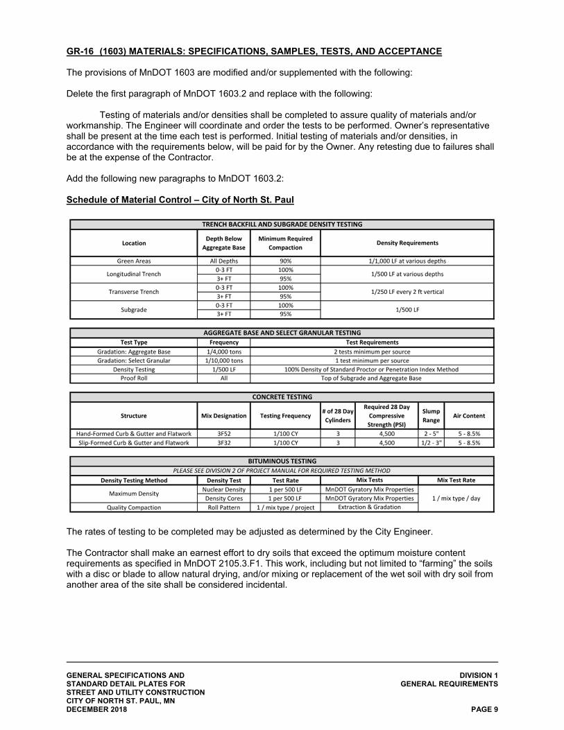
GENERAL SPECIFICATIONS AND DIVISION 1 STANDARD DETAIL PLATES FOR GENERAL REQUIREMENTS STREET AND UTILITY CONSTRUCTION CITY OF NORTH ST. PAUL, MN DECEMBER 2018 PAGE 9
GR-16 (1603) MATERIALS: SPECIFICATIONS, SAMPLES, TESTS, AND ACCEPTANCE The provisions of MnDOT 1603 are modified and/or supplemented with the following: Delete the first paragraph of MnDOT 1603.2 and replace with the following:
Testing of materials and/or densities shall be completed to assure quality of materials and/or workmanship. The Engineer will coordinate and order the tests to be performed. Owner’s representative shall be present at the time each test is performed. Initial testing of materials and/or densities, in accordance with the requirements below, will be paid for by the Owner. Any retesting due to failures shall be at the expense of the Contractor. Add the following new paragraphs to MnDOT 1603.2: Schedule of Material Control – City of North St. Paul
The rates of testing to be completed may be adjusted as determined by the City Engineer. The Contractor shall make an earnest effort to dry soils that exceed the optimum moisture content requirements as specified in MnDOT 2105.3.F1. This work, including but not limited to “farming” the soils with a disc or blade to allow natural drying, and/or mixing or replacement of the wet soil with dry soil from another area of the site shall be considered incidental.
GENERAL SPECIFICATIONS AND DIVISION 1 STANDARD DETAIL PLATES FOR GENERAL REQUIREMENTS STREET AND UTILITY CONSTRUCTION CITY OF NORTH ST. PAUL, MN DECEMBER 2018 PAGE 10
GR-17 (1606) STORAGE OF MATERIALS The provisions of MnDOT 1606 are modified and/or supplemented with the following: Any disturbed area shall be cleaned up and fully restored to the pre-existing condition prior to closing out this project. The Contractor shall be required to install protective fencing and silt fence around the storage area. The protection, cleanup, and restoration of the project storage area shall be the Contractor’s responsibility; no compensation will be made for this work. Materials cannot be stockpiled within the Project Limits for use on other projects. If the Contractor elects to crush excavated materials within the Project Limits, the quantity of crushed material will be limited to only that material found within the Project Limits, unless approved in writing by the Engineer. The Contractor will not be allowed to remove crushed material from the Project Limits, unless approved in writing by the Engineer. GR-18 (1607) HANDLING MATERIALS The provisions of MnDOT 1607 shall apply. GR-19 (1608) UNACCEPTABLE MATERIALS The provisions of MnDOT 1608 shall apply. GR-20 (1609) DEPARTMENT PROVIDED MATERIAL The provisions of MnDOT 1609 shall apply. GR-21 (1701) LAWS TO BE OBSERVED The provisions of MnDOT 1701 are modified and/or supplemented with the following: Delete MnDOT 1701.2 and replace with the following: The Owner intends to provide a workplace free of violence, threats of violence, harassment, and discrimination. The Owner has zero tolerance for violence in the workplace. Contractors shall maintain a workplace free of violence, harassment, and discrimination. The Contractor shall immediately remove from the Project any employee of the Contractor or a Subcontractor in violation of these requirements. The Contractor shall not discriminate against prospective employees because of age, race, color, sex, creed, religion, nationality, or disability. Delete MnDOT 1701.3 in its entirety. GR-22 (1702) PERMITS, LICENSES, AND TAXES The provisions of MnDOT 1702 are modified and/or supplemented with the following: In the event the Owner is fined by the Minnesota pollution Control Agency, the Environmental Protection Agency, the Minnesota Department of Health, or other such authority, as a result of the Contractor’s actions or lack of actions, the Owner will deduct from payment due the Contractor corresponding amounts to cover the cost of such fines, including the costs of related Engineering and legal fees.
GENERAL SPECIFICATIONS AND DIVISION 1 STANDARD DETAIL PLATES FOR GENERAL REQUIREMENTS STREET AND UTILITY CONSTRUCTION CITY OF NORTH ST. PAUL, MN DECEMBER 2018 PAGE 11
GR-23 (1706) EMPLOYEE HEALTH AND WELFARE The provisions of MnDOT 1706 are modified and/or supplemented with the following: The Contractor, at their own expense, shall provide and maintain temporary toilet facilities at the site during the construction period sufficient for the scheduled workforce. The Contractor and Engineer shall agree to the location of the temporary toiled facilities. Areas of special concern include, but are not limited to, excavation stability protection, fall protection, protection from overhead hazards, vehicle backup protection, confined space safety, blasting operations, and personal safety devices. The Contractor must not use motor vehicle equipment that has an obstructed rear view unless the vehicle has a reverse alarm that is audible above the surrounding noise level; or an observer signals to the operator that it is safe to revers. GR-24 (1707) PUBLIC CONVENIENCE AND SAFETY The provisions of MnDOT 1707 are modified and/or supplemented with the following: The Contractor shall comply with local and state ordinances on noise abatement. All equipment shall have effective mufflers on engine exhaust systems. The Contractor shall be required to accommodate garbage collection while the project is under construction. Coordination shall include contact with the garbage companies service the area and maintaining access to the individual residences. If the Contractor fails to accommodate garbage collection, the Contractor shall contract independently to have the garbage removed at no cost to the Owner. The Contractor shall be required to accommodate mail service while the project is under construction. Notify the local Postmaster two weeks prior to any disruption of service. Installation of sanitary sewer and watermain improvements may disrupt the operation of existing utility systems. The Contractor shall be responsible for providing and maintaining temporary service until the new utilities are installed, tested and available for connections. The Contractor will submit a plan to the Engineer for temporary sewer and water service prior to disconnection of service. Maintenance of service will be considered incidental to the project with no separate measurement or payment made for this work unless a specific Bid item is provided. he Contractor shall provide any barricades, fences or other means of protection necessary to properly execute the work and adequately protect his employees, employees of the Owner, employees of the Engineer, and members of the public according to federal, state, and local regulators. All utility trenches shall be backfilled at the end of each working day to the satisfaction of the Engineer. The Contractor shall immediately call “911” if a gas utility line is struck or damaged. All labor and materials necessary to comply with these provisions are incidental, and no payment shall be made. GR-25 (1710) TRAFFIC CONTROL DEVICES The provisions of MnDOT 1710 shall apply.
GENERAL SPECIFICATIONS AND DIVISION 1 STANDARD DETAIL PLATES FOR GENERAL REQUIREMENTS STREET AND UTILITY CONSTRUCTION CITY OF NORTH ST. PAUL, MN DECEMBER 2018 PAGE 12
GR-26 (1712) PROTECTION AND RESTORATION OF PROPERTY The provisions of MnDOT 1712 are modified and/or supplemented with the following: The Contractor shall protect, and/or remove and reinstall all fences, street signs, retaining walls, and other items required to construct the proposed improvements. Work associated with protecting, and/or removing and reinstalling fences, street signs, lawn irrigation systems, and other items shall be considered incidental to the project unless specific bid items are included. The Contractor shall take whatever steps necessary to protect adjoining properties and structures from hazards due to performance of the work. The Contractor is responsible for any and all damage to properties and structures that occur as a result of the Contractor’s operations. The street and utility construction may occur in close proximity to a number of existing structures. The Contractor shall use shoring or other means as necessary to ensure that those structures are protected during construction. Existing residences may not be of modern construction and are thus sensitive to vibrating equipment. The Contractor shall take care when utilizing vibratory equipment to avoid damage to adjoining structures. Damage to structures resulting from the use of vibratory equipment are the responsibility of the Contractor. In the event of a complaint or perceived problem, a seismograph will be required to be provided at the Contractor’s expense. All labor and materials necessary to comply with the provisions of this section are incidental, and no payment shall be made. GR-27 (1716) CONTRACTOR’S RESPONSIBILITY FOR WORK The provisions of MnDOT 1716 are modified and/or supplemented with the following: The Contractor shall guarantee and maintain the stability of all work, equipment and materials for a period of two (2) years from date of final payment. This Contractor shall provide as part of the Contractor Security a separate two (2) year maintenance bond to be dated to begin the date the City Council formally accepts the project. The provisions of this paragraph shall not be construed as restricting Contractor's liability for breach of contract by reason of non-conformance with the specification for defects or faulty workmanship. GR-28 (1717) AIR, LAND, AND WATER POLLUTION Pollution of natural resources of air, land, and water by operations under this Contract shall be prevented, controlled, and abated in accordance with the rules, regulations, and standards adopted and established by the Minnesota Pollution Control Agency (MPCA) and MnDOT 1717. The provisions of MnDOT 1717 are modified and/or supplemented with the following:
1717.1 GENERAL D Air Protection
The Contractor shall be responsible for dust control unless a specific Bid item has been provided.
A dust control plan is required, including but not limited to the following dust control measures:
1. Minimize period of exposed or graded areas. 2. Spray construction areas and haul roads with water or calcium chloride. 3. Minimize use of vehicles on unpaved surfaces.
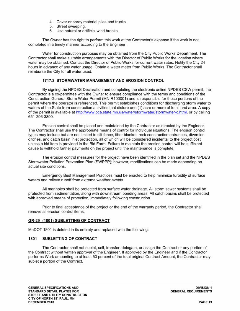
GENERAL SPECIFICATIONS AND DIVISION 1 STANDARD DETAIL PLATES FOR GENERAL REQUIREMENTS STREET AND UTILITY CONSTRUCTION CITY OF NORTH ST. PAUL, MN DECEMBER 2018 PAGE 13
4. Cover or spray material piles and trucks. 5. Street sweeping. 6. Use natural or artificial wind breaks.
The Owner has the right to perform this work at the Contractor’s expense if the work is not
completed in a timely manner according to the Engineer.
Water for construction purposes may be obtained from the City Public Works Department. The Contractor shall make suitable arrangements with the Director of Public Works for the location where water may be obtained. Contact the Director of Public Works for current water rates. Notify the City 24 hours in advance of any water usage. Obtain a water meter from Public Works. The Contractor shall reimburse the City for all water used. 1717.2 STORMWATER MANAGEMENT AND EROSION CONTROL By signing the NPDES Declaration and completing the electronic online NPDES CSW permit, the Contractor is a co-permittee with the Owner to ensure compliance with the terms and conditions of the Construction General Storm Water Permit (MN R100001) and is responsible for those portions of the permit where the operator is referenced. This permit establishes conditions for discharging storm water to waters of the State from construction activities that disturb one (1) acre or more of total land area. A copy of the permit is available at http://www.pca.state.mn.us/water/stormwater/stormwater-c.html, or by calling 651-296-3890.
Erosion control shall be placed and maintained by the Contractor as directed by the Engineer. The Contractor shall use the appropriate means of control for individual situations. The erosion control types may include but are not limited to silt fence, fiber blanket, rock construction entrances, diversion ditches, and catch basin inlet protection, all of which will be considered incidental to the project cost unless a bid item is provided in the Bid Form. Failure to maintain the erosion control will be sufficient cause to withhold further payments on the project until the maintenance is complete.
The erosion control measures for the project have been identified in the plan set and the NPDES Stormwater Pollution Prevention Plan (SWPPP); however, modifications can be made depending on actual site conditions.
Emergency Best Management Practices must be enacted to help minimize turbidity of surface waters and relieve runoff from extreme weather events.
All manholes shall be protected from surface water drainage. All storm sewer systems shall be protected from sedimentation, along with downstream ponding areas. All catch basins shall be protected with approved means of protection, immediately following construction.
Prior to final acceptance of the project or the end of the warranty period, the Contractor shall remove all erosion control items.
GR-29 (1801) SUBLETTING OF CONTRACT MnDOT 1801 is deleted in its entirety and replaced with the following: 1801 SUBLETTING OF CONTRACT The Contractor shall not sublet, sell, transfer, delegate, or assign the Contract or any portion of the Contract without written approval of the Engineer. If approved by the Engineer and if the Contractor performs Work amounting to at least 50 percent of the total original Contract Amount, the Contractor may sublet a portion of the Contract.
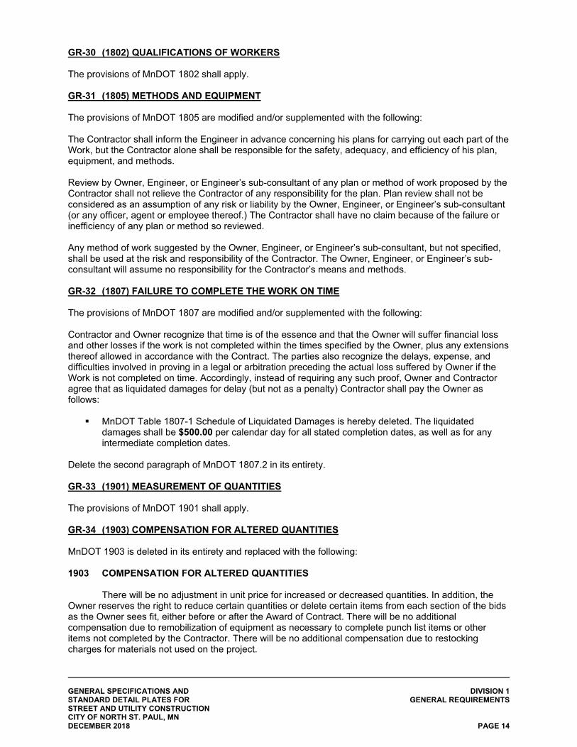
GENERAL SPECIFICATIONS AND DIVISION 1 STANDARD DETAIL PLATES FOR GENERAL REQUIREMENTS STREET AND UTILITY CONSTRUCTION CITY OF NORTH ST. PAUL, MN DECEMBER 2018 PAGE 14
GR-30 (1802) QUALIFICATIONS OF WORKERS The provisions of MnDOT 1802 shall apply. GR-31 (1805) METHODS AND EQUIPMENT The provisions of MnDOT 1805 are modified and/or supplemented with the following: The Contractor shall inform the Engineer in advance concerning his plans for carrying out each part of the Work, but the Contractor alone shall be responsible for the safety, adequacy, and efficiency of his plan, equipment, and methods. Review by Owner, Engineer, or Engineer’s sub-consultant of any plan or method of work proposed by the Contractor shall not relieve the Contractor of any responsibility for the plan. Plan review shall not be considered as an assumption of any risk or liability by the Owner, Engineer, or Engineer’s sub-consultant (or any officer, agent or employee thereof.) The Contractor shall have no claim because of the failure or inefficiency of any plan or method so reviewed. Any method of work suggested by the Owner, Engineer, or Engineer’s sub-consultant, but not specified, shall be used at the risk and responsibility of the Contractor. The Owner, Engineer, or Engineer’s sub-consultant will assume no responsibility for the Contractor’s means and methods.
GR-32 (1807) FAILURE TO COMPLETE THE WORK ON TIME The provisions of MnDOT 1807 are modified and/or supplemented with the following: Contractor and Owner recognize that time is of the essence and that the Owner will suffer financial loss and other losses if the work is not completed within the times specified by the Owner, plus any extensions thereof allowed in accordance with the Contract. The parties also recognize the delays, expense, and difficulties involved in proving in a legal or arbitration preceding the actual loss suffered by Owner if the Work is not completed on time. Accordingly, instead of requiring any such proof, Owner and Contractor agree that as liquidated damages for delay (but not as a penalty) Contractor shall pay the Owner as follows:
MnDOT Table 1807-1 Schedule of Liquidated Damages is hereby deleted. The liquidated damages shall be $500.00 per calendar day for all stated completion dates, as well as for any intermediate completion dates.
Delete the second paragraph of MnDOT 1807.2 in its entirety. GR-33 (1901) MEASUREMENT OF QUANTITIES The provisions of MnDOT 1901 shall apply. GR-34 (1903) COMPENSATION FOR ALTERED QUANTITIES MnDOT 1903 is deleted in its entirety and replaced with the following: 1903 COMPENSATION FOR ALTERED QUANTITIES There will be no adjustment in unit price for increased or decreased quantities. In addition, the Owner reserves the right to reduce certain quantities or delete certain items from each section of the bids as the Owner sees fit, either before or after the Award of Contract. There will be no additional compensation due to remobilization of equipment as necessary to complete punch list items or other items not completed by the Contractor. There will be no additional compensation due to restocking charges for materials not used on the project.
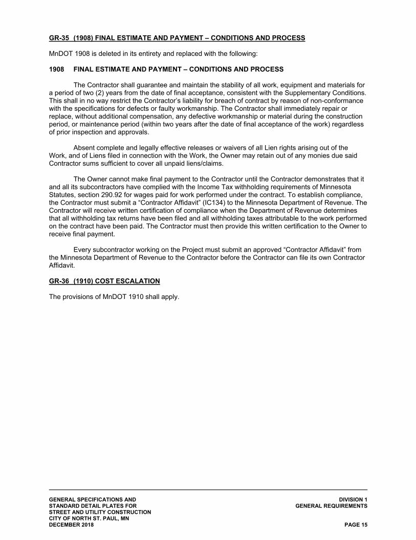
GENERAL SPECIFICATIONS AND DIVISION 1 STANDARD DETAIL PLATES FOR GENERAL REQUIREMENTS STREET AND UTILITY CONSTRUCTION CITY OF NORTH ST. PAUL, MN DECEMBER 2018 PAGE 15
GR-35 (1908) FINAL ESTIMATE AND PAYMENT – CONDITIONS AND PROCESS MnDOT 1908 is deleted in its entirety and replaced with the following: 1908 FINAL ESTIMATE AND PAYMENT – CONDITIONS AND PROCESS The Contractor shall guarantee and maintain the stability of all work, equipment and materials for a period of two (2) years from the date of final acceptance, consistent with the Supplementary Conditions. This shall in no way restrict the Contractor’s liability for breach of contract by reason of non-conformance with the specifications for defects or faulty workmanship. The Contractor shall immediately repair or replace, without additional compensation, any defective workmanship or material during the construction period, or maintenance period (within two years after the date of final acceptance of the work) regardless of prior inspection and approvals. Absent complete and legally effective releases or waivers of all Lien rights arising out of the Work, and of Liens filed in connection with the Work, the Owner may retain out of any monies due said Contractor sums sufficient to cover all unpaid liens/claims.
The Owner cannot make final payment to the Contractor until the Contractor demonstrates that it and all its subcontractors have complied with the Income Tax withholding requirements of Minnesota Statutes, section 290.92 for wages paid for work performed under the contract. To establish compliance, the Contractor must submit a “Contractor Affidavit” (IC134) to the Minnesota Department of Revenue. The Contractor will receive written certification of compliance when the Department of Revenue determines that all withholding tax returns have been filed and all withholding taxes attributable to the work performed on the contract have been paid. The Contractor must then provide this written certification to the Owner to receive final payment.
Every subcontractor working on the Project must submit an approved “Contractor Affidavit” from
the Minnesota Department of Revenue to the Contractor before the Contractor can file its own Contractor Affidavit. GR-36 (1910) COST ESCALATION The provisions of MnDOT 1910 shall apply.
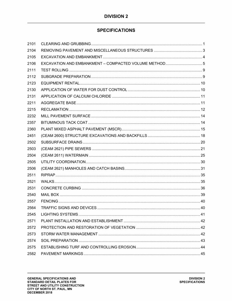
DIVISION 2
SPECIFICATIONS
GENERAL SPECIFICATIONS AND DIVISION 2 STANDARD DETAIL PLATES FOR SPECIFICATIONS STREET AND UTILITY CONSTRUCTION CITY OF NORTH ST. PAUL, MN DECEMBER 2018
2101 CLEARING AND GRUBBING .......................................................................................................... 1
2104 REMOVING PAVEMENT AND MISCELLANEOUS STRUCTURES .............................................. 3
2105 EXCAVATION AND EMBANKMENT ............................................................................................... 4
2106 EXCAVATION AND EMBANKMENT – COMPACTED VOLUME METHOD ................................... 5
2111 TEST ROLLING ............................................................................................................................... 9
2112 SUBGRADE PREPARATION .......................................................................................................... 9
2123 EQUIPMENT RENTAL ................................................................................................................... 10
2130 APPLICATION OF WATER FOR DUST CONTROL ..................................................................... 10
2131 APPLICATION OF CALCIUM CHLORIDE .................................................................................... 11
2211 AGGREGATE BASE ...................................................................................................................... 11
2215 RECLAMATION ............................................................................................................................. 12
2232 MILL PAVEMENT SURFACE ........................................................................................................ 14
2357 BITUMINOUS TACK COAT ........................................................................................................... 14
2360 PLANT MIXED ASPHALT PAVEMENT (MSCR) ........................................................................... 15
2451 (CEAM 2600) STRUCTURE EXCAVATIONS AND BACKFILLS .................................................. 18
2502 SUBSURFACE DRAINS ................................................................................................................ 20
2503 (CEAM 2621) PIPE SEWERS ....................................................................................................... 21
2504 (CEAM 2611) WATERMAIN .......................................................................................................... 25
2505 UTILITY COORDINATION ............................................................................................................. 30
2506 (CEAM 2621) MANHOLES AND CATCH BASINS ........................................................................ 31
2511 RIPRAP .......................................................................................................................................... 35
2521 WALKS ........................................................................................................................................... 35
2531 CONCRETE CURBING ................................................................................................................. 36
2540 MAIL BOX ...................................................................................................................................... 39
2557 FENCING ....................................................................................................................................... 40
2564 TRAFFIC SIGNS AND DEVICES .................................................................................................. 40
2545 LIGHTING SYSTEMS .................................................................................................................... 41
2571 PLANT INSTALLATION AND ESTABLISHMENT ......................................................................... 42
2572 PROTECTION AND RESTORATION OF VEGETATION ............................................................. 42
2573 STORM WATER MANAGEMENT ................................................................................................. 42
2574 SOIL PREPARATION .................................................................................................................... 43
2575 ESTABLISHING TURF AND CONTROLLING EROSION ............................................................. 44
2582 PAVEMENT MARKINGS ............................................................................................................... 45
DIVISION 2
SPECIFICATIONS
GENERAL SPECIFICATIONS AND DIVISION 2 STANDARD DETAIL PLATES FOR SPECIFICATIONS STREET AND UTILITY CONSTRUCTION CITY OF NORTH ST. PAUL, MN DECEMBER 2018 PAGE 1
2101 CLEARING AND GRUBBING The provisions of MnDOT 2101 are modified and/or supplemented as follows: 2101.1 DESCRIPTION Delete Paragraph 2101.1 in its entirety and replace with the following:
This work consists of removing and disposing of the trees, brush, stumps, roots, and other plant life, including dead and decayed matter, within the construction area designated for removal by the contract or as directed by the Engineer.
2101.3 CONSTRUCTION REQUIREMENTS The Contractor shall assume multiple mobilizations for this work.
All or part of this Project is located in a county which has been placed under an Emerald Ash Borer Quarantine by the Minnesota Department of Agriculture (MDA). Contractor may contact MDA at 1-888-545-6684 or visit the Emerald Ash Borer website http://www.mda.state.mn.us/plants/pestmanagement/eab.aspx to find more information. The Contractor must comply with the following requirements, with no direct compensation made. The Contractor will not:
(1) Offer any part of an Ash tree (Fraxinus spp.) from a quarantined area to any
industry or individual without an Emerald Ash Borer Compliance Agreement with MDA; or
(2) Make available any part of an ash tree or any non-coniferous (hardwood) species with bark from the quarantined area for use as firewood; or
(3) Transport any part of an ash trees, in any form, outside of a quarantined county without complying with an Emerald Ash Borer Compliance Agreement with MDA; or
(4) Transport any part of ash trees, in any form, outside the state of MN without obtaining the United States Department of Agriculture’s and the MDA’s joint approval of the Emerald Ash Borer Compliance Agreement.
The Contractor will:
(1) Dispose of ash trees according to the Emerald Ash Borer Compliance
Agreement; and (2) Use the ash wood chips within the construction limits for erosion control,
construction exit pads, or other project related needs.
C Grubbing Operations
All depressions resulting from grubbing operations shall be filled and compacted within seven (7) days (incidental).
D Disposal Limitations No disposal of debris shall be allowed on-site unless authorized by the Engineer.
GENERAL SPECIFICATIONS AND DIVISION 2 STANDARD DETAIL PLATES FOR SPECIFICATIONS STREET AND UTILITY CONSTRUCTION CITY OF NORTH ST. PAUL, MN DECEMBER 2018 PAGE 2
Written verification of disposal location (dumping receipts, etc.) is required and shall be provide to the Engineer.
2101.4 METHOD OF MEASUREMENT MnDOT 2104.4 is deleted and replaced with the following: The Engineer will measure clearing and grubbing by area, lump sum, or individual unit as
required by the contract. The Engineer will measure tree diameter by measuring 4.5 feet above the ground or by measuring the diameter of the tree stump after removal.
A Qualifying Trees and Stumps The Engineer will only measure trees for payment having a diameter greater than 3 inches at a
point measured 4.5 feet above the ground. The Engineer will only measure stumps for payment having a diameter greater than 3 inches
when measured at the point of cutoff. The Engineer will not measure for the removal of stumps and brush with a diameter equal to or
less than 3 inches at the pint of cutoff. B Area Basis If the contract specifies the unit as an acre, the Engineer will determine quantities by measuring,
to the nearest 0.05 acre, all areas cleared, and all areas grubbed within the limits as shown on the plans or staked by the Engineer. The Engineer will make all measurements horizontally to points 10 feet outside the trunks of qualifying trees or stumps on the perimeter of the area being measured. The Engineer will measure separate areas less than 0.05 acre as 0.05 acre.
If isolated trees or stumps require removal outside the areas designated for clearing or grubbing
by the acre, and no unit price is provided in the contract for clearing and grubbing individual trees or stumps, the Department will pay based on the following:
(1) The Engineer will consider each isolated qualifying tree less than 40 inches in diameter
when measured at a point 2 feet above the ground surface, and each isolated qualifying stump measuring less than 40 inches at the point of cutoff as 0.05 acre.
(2) The Engineer will consider each isolated tree or stump at least 40 inches in diameter when measured at the points described in (1) above as 0.1 acre.
C Individual Unit Basis When the contract specifies “tree” as the unit, the Engineer will count the number of qualifying
trees cleared and the number of qualifying stumps grubbed to determine the quantity. D Lump Sum Basis The Engineer will not measure an individual area, tree, or stump if the contract specifies clearing
and grubbing as a lump sum item.
GENERAL SPECIFICATIONS AND DIVISION 2 STANDARD DETAIL PLATES FOR SPECIFICATIONS STREET AND UTILITY CONSTRUCTION CITY OF NORTH ST. PAUL, MN DECEMBER 2018 PAGE 3
2104 REMOVING PAVEMENT AND MISCELLANEOUS STRUCTURES The provisions of MnDOT 2104 are modified and/or supplemented as follows:
2104.3 CONSTRUCTION REQUIREMENTS B Salvage Operations
Add the following new paragraph to MnDOT 2104.3.B:
B.1 Haul Salvaged Materials Salvaged materials, not required for installation elsewhere under this Contract, shall be loaded
and hauled to the designated storage area(s) and deposited thereat in a manner satisfactory to the Engineer.
C Removal Operations
Removals made by sawing, shall result in a neat, straight line, or a square edge. The use of
wedges driven into the saw cut to break off the portion to be removed will not be permitted.
Add the following new paragraphs to MnDOT 2104.3.C: C.7 Concrete Curb and Gutter
All concrete curb and gutter scheduled for removal and marked by the Engineer in the field shall
first be saw cut, using a wet saw and then removed. The Contractor shall be responsible for protecting all curb and gutter within the project that is to
remain in place. Any damage to existing curb and gutter shall be the responsibility of the Contractor and shall be repaired or replaced as directed by the Engineer with no additional compensation thereto.
C.8 Pipe Removal
Removal of storm sewer pipe and culvert, as noted in the plans, shall be in manner and at the
stage of construction so that drainage will be maintained.
D.1 Disposal Plan Material and debris removed from the project site shall be disposed of at approved landfills or property under the direct control of the Contractor, in accordance with State and local rules and regulations. Add the following new paragraph to MnDOT 2104.3:
F Abandon Operations Sanitary sewer, storm sewer, and/or watermain pipe that are to be abandoned shall be filled with
a granular or other approved material and capped watertight. Filling and capping of the abandoned pipe shall be included in the unit price for abandonment.
Manhole structures that are to be abandoned shall first have the cone section removed (to a
depth specified by the engineer) (incidental) and then filled with granular or other approved material to the top of the barrel section. The remainder of the backfilling shall consist of the native soils. Abandoning a manhole is not allowed unless specifically called for in the plans. Castings shall be removed and disposed of by the Contractor.
GENERAL SPECIFICATIONS AND DIVISION 2 STANDARD DETAIL PLATES FOR SPECIFICATIONS STREET AND UTILITY CONSTRUCTION CITY OF NORTH ST. PAUL, MN DECEMBER 2018 PAGE 4
2104.5 BASIS OF PAYMENT Delete the last sentence of the second paragraph and replace with the following: Saw cutting for necessary for the removal of sidewalks or concrete curb and gutter shall be considered incidental with no direct compensation made. Measurement and payment for the removal and disposal of materials will be made only for those Items of removal work specifically included for payment as such in the Bid Form and as listed in the Plans, with the following exception:
(1) If the Bid Form does not include bid items for the removal of signs, mailboxes, posts, etc. the removal, care of, and replacement of signs, mailboxes, posts, etc. shall be done at the Contractor’s expense without any direct compensation therefore.
All costs of hauling salvaged materials shall be included in the cost of salvaging the material. All abandoned pipe will be measured by the length of pipe sealed and abandoned as specified. Payment at the Contract bid price per linear foot shall be payment in full for all costs involved.
2105 EXCAVATION AND EMBANKMENT The provisions of MnDOT 2105 are modified and/or supplemented as follows:
2105.1 DESCRIPTION No modifications to the definitions provided in MnDOT 2105.1.A have been made.
Add the following paragraph to MnDOT 2105.1:
B Dewatering The Contractor shall, at his expense, provide groundwater excavation dewatering as necessary to
allow for construction on a stable foundation. The work potentially involves the drawdown of the water table (using wells or other means), placement of temporary barriers, or other satisfactory types of water control to allow for construction and to protect the improvements. Dewatering operations are controlled by permit from the DNR or other agencies. Dewatering operations must be in accordance with the MnDOT 2573. Rerouting surface water is not considered dewatering and is incidental.
The Contractor is responsible for application for any necessary permits and compliance with all
conditions of permits. The Contractor shall also be responsible for noise control during dewatering as directed by the Engineer.
The Contractor shall make his own determination as to the extent of the groundwater on
the project prior to bidding. No additional compensation will be made for a higher than expected groundwater table or any compliance requirements from regulatory agencies.
Dewatering systems will be necessary to maintain the groundwater table a minimum of two feet
(2’) below the excavation invert. Dewatering systems and excavations must remain inside construction limits. A dewatering operation that significantly disrupts private property usage in advance of actual
construction operations shall not be permitted. Any additional costs related to utility work or project disturbance and restoration caused by the dewatering operation shall be incidental.
GENERAL SPECIFICATIONS AND DIVISION 2 STANDARD DETAIL PLATES FOR SPECIFICATIONS STREET AND UTILITY CONSTRUCTION CITY OF NORTH ST. PAUL, MN DECEMBER 2018 PAGE 5
For all utility work, granular foundation material may be used in conjunction with or in lieu of dewatering. Any use of granular foundation material or other material to maintain a dry trench or improve the pipe foundation shall be considered incidental to dewatering or pipe installation unless specified otherwise.
B.1 Dewatering Plan Prior to starting the project, the Contractor shall submit a complete dewatering plan for the entire
project to the Engineer for informational purposes only. Special precautions shall be taken adjacent to structures, so dewatering does not create any structural damage.
The dewatering system plan: (1) must show in plan and profile view the proposed dewatering operations; and (2) include a Contractor’s estimate regarding the time required from start of dewatering to a soil
condition such that successful construction can occur.
If wells or headers are to be placed below existing surface elevations, the plan shall include measures proposed, including trenching an backfill of dewatering components, to minimize disruption to and impact on areas abutting the project.
2106 EXCAVATION AND EMBANKMENT – COMPACTED VOLUME METHOD The provisions of MnDOT 2106 are modified and/or supplemented as follows:
2106.1 DESCRIPTION No modifications to the definitions provided in MnDOT 2106.1.A have been made except
for A.6, Select Grading Material.
Delete MnDOT 2106.1.A.6 and replace with the following: A.6 Select Grading Material Select grading materials are all mineral soils found in the Triaxial Chart in the Grading and Base Manual, excluding: organic soils per MnDOT 2106.1.A.10, marl, and silt. Silt is defined as soils containing 80% or more silt-sized particles as determined by MnDOT Laboratory manual procedure 1302. Select Grading Material may contain up to 100% recycled materials composed of recycled concrete, asphalt, or glass meeting the following:
no more than 10% glass, no more than 75% concrete, and with a bitumen content of 3.5% or less.
2106.2 MATERIALS
Delete MnDOT 2106.2.A.1 and replace with the following:
A.1 Common Excavation Excavation not classified in any other category, except that MnDOT 2106.2.A.7, “Topsoil
Excavation” is included with common excavation.
GENERAL SPECIFICATIONS AND DIVISION 2 STANDARD DETAIL PLATES FOR SPECIFICATIONS STREET AND UTILITY CONSTRUCTION CITY OF NORTH ST. PAUL, MN DECEMBER 2018 PAGE 6
Delete MnDOT 2106.2.A.2 and replace with the following: A.2 Subgrade Excavation All excavation in the road core below the grading grade, exclusive of rock, muck, channel and pond, or rock channel excavation.
A.5 Channel and Pond Excavation MnDOT 2106.2.A.7, “Topsoil Excavation” is included with channel and pond excavation.
2106.3 CONSTRUCTION REQUIREMENTS
Management of the excavated materials on the site is the Contractor’s responsibility. All suitable material shall be utilized for roadway construction. Excess material shall become property of the Contractor.
A General Where connection to an in-place roadway is made: at the termini of new road construction, cut
vertically to the bottom of in place surfacing. Then, cut back within the construction limits at a 1(V):20(H) taper to the bottom of the recommended subgrade excavation.
Before beginning the embankment and excavation operations, topsoil shall be stripped and
stockpiled for re-spreading upon the graded area. Mining of materials for removal from the project area and replacement with less desirable
materials by the Contractor shall not be permitted. Add the following language at the end of the last paragraph: Excess granular material from grading operations shall be used first in areas where the subgrade is low, as backfill behind the curb, or other areas as approved by the Engineer. Excavated material that is unsuitable for embankment shall be placed in locations as directed by the Engineer. No unsuitable material may be placed under roadway surfaces, sidewalks or pathways. All excess material shall be disposed of by the Contractor at no additional cost to the Owner.
Delete MnDOT 2106.3.B in its entirety and replace with the following: B Contractor Quality Control (QC) Testing, Aggregate Certification, and Moisture Requirements B.1 Contractor Quality Control (QC) Testing Perform Contractor QC testing as required in the Schedule of Materials Control. Correct areas represented by failing QC or Quality Assurance (QA) tests. Submit test results to the Engineer within one business day. B.2 Aggregate Certification Certify granular materials on Form G&B-104 and attach any required tests. Material placed without certification is unauthorized work.
GENERAL SPECIFICATIONS AND DIVISION 2 STANDARD DETAIL PLATES FOR SPECIFICATIONS STREET AND UTILITY CONSTRUCTION CITY OF NORTH ST. PAUL, MN DECEMBER 2018 PAGE 7
B.3 Moisture Control Meet the moisture content requirements listed in Table 2016-2.
Table 2106-2 Moisture Content Requirements
Compaction Requirement Relative Moisture Content Requirement * Minimum of 100% maximum density 65% - 102% Minimum of 95% maximum density 65% - 115% Quality Compaction 65% - 102% Penetration Index Method ≥ 65% *As determined on Form G&B-105
Correct moisture content in areas represented by failing moisture tests. Note that optimum moisture content determination tests and moisture tests during compaction are required for all compaction requirements, including quality compaction, LWD, penetration index, and specified density. The Owner’s proctor test results are used to determine optimum moisture determination.
D Excavating Operations Subgrade excavations shall be performed for the removal of any unstable or unsuitable materials
which may be encountered. Such excavations shall be backfilled with suitable excess material generated from the common excavation, common embankment material, or granular embankment material as directed by the Engineer. If the Contractor proceeds without the approval of the Engineer, all work and material required for restoration of the roadbed to the proposed grade shall be at the Contractor’s expense.
Delete MnDOT 2106.3.G in its entirety and replace with the following: G Agency Quality Assurance (QA) Test according to the Schedule of Materials Control. G.1 Material Testing Sample granular materials from the road core after spreading, but before compaction. Select crushing, aggregate quality, and bitumen samples using the random sampling method in the Grading and Base manual; additional samples and tests may be taken to delineate visually indicated material failures. Select gradation samples from locations that are at risk of not meeting the specification requirements. G.2 Compaction Testing Test for compaction using:
Quality compaction, and specified density or the LWD method for materials not meeting the requirements of Table 3.149-1, 1 Granular Material, or
Quality compaction, and specified density or granular penetration index or the LWD method for materials meeting the requirements of Table 3149-1, 1 Granular Material.
Test for compaction in areas with the greatest rutting or deflection, and near structures, and in an
area at least 1 foot from an unconfined edge. After Contractor correction of areas represented by a failing test, perform additional tests in areas with the greatest rutting or deflection.
GENERAL SPECIFICATIONS AND DIVISION 2 STANDARD DETAIL PLATES FOR SPECIFICATIONS STREET AND UTILITY CONSTRUCTION CITY OF NORTH ST. PAUL, MN DECEMBER 2018 PAGE 8
For granular materials with less than 6% passing the #200 sieve, the Engineer may elect to only use the Quality Compaction method, MnDOT 2106.3.F.2.
Use the specified density method for virgin materials only. The following method may be used in lieu of point testing (penetration index, specified density, or
LWD) for material meeting Table 3149-1, 2 Select Granular Material, when the material thickness is 18 inches or less and when not adjacent to Structures (per MnDOT 1103.)
The Engineer may elect, with the concurrence of the Contractor, to have the Contractor test roll
per MnDOT 2111, material meeting the requirements of Table 3149-1, 2 Select Granular Material, in lieu of point compaction testing. If this method is elected, the Contractor is required to first place 3 inches of base on top of the material meeting Table 3149-1, 2 Select Granular Material, prior to test rolling. For areas failing test rolling, the Contractor is required to remove the base and recompact the material meeting Table 3149-1, 2 Select Granular Material, then place the base back, and re-test roll. There is no additional compensation to the Contractor, if this method is selected. Additionally, the material meeting Table 3149-1, 2 Select Granular Material, is not accepted, until acceptable test rolling has occurred.
G.3 Moisture Testing Optimum moisture content determination tests and moisture tests during compaction are required
for all compaction requirements, including quality compaction, LWD, penetration index, and specified density.
H Finishing Operations Topsoil borrow, in accordance with MnDOT 2574, shall be used only when specifically authorized
by the Engineer. It shall only be used when there is not sufficient in place topsoil to restore the disturbed area. A minimum of 6 inches of topsoil shall be provided in all areas requiring topsoil, unless specified otherwise. This work shall not be substituted for the work required of the Contractor to salvage and replace existing topsoil. All topsoil shall be free of all sticks, rocks/stones, and debris. Topsoil shall be of a consistency acceptable to the Engineer.
Excess topsoil may be disposed of outside the road core as directed by the Engineer. 2106.4 METHOD OF MEASUREMENT
A representative of the Owner, Engineer and Contractor shall be present during the measurement of the work for payment.
2106.5 BASIS OF PAYMENT
The Contractor shall be responsible for arranging, obtaining, and paying for all inspections and tests required as Quality Control (QC). The Owner shall be responsible for all inspections and tests required as Quality Assurance (QA). Add the following new paragraph to MnDOT 2106.5C: C1 Select Granular Embankment Select granular embankment shall be used only as directed by the Engineer.
GENERAL SPECIFICATIONS AND DIVISION 2 STANDARD DETAIL PLATES FOR SPECIFICATIONS STREET AND UTILITY CONSTRUCTION CITY OF NORTH ST. PAUL, MN DECEMBER 2018 PAGE 9
Add the following new paragraphs to MnDOT 2106.5D:
D5 Common Excavation
Payment shall be at the unit price bid per cubic yard as an excavated volume and shall be compensation in full for excavation (including salvaging and stockpiling topsoil), preparing the excavation and embankment areas, loading, hauling, placing and compacting fill, stockpiling materials, spreading topsoil, and disposal of material as required. Payment for Common Excavation shall not include the volume of items paid for separately as removals (e.g. curb, bituminous pavement, concrete pavement, reclaimed material). Potholing to locate existing utilities may be required. All labor and materials use for potholing will be incidental. D6 Subgrade Excavation Payment shall be made at the unit price bid per cubic yard as an excavated volume, and shall be compensation in full for excavation, hauling, stockpiling, and embankment or disposal of unsuitable materials. This work shall also include the replacement and compaction of suitable material within the excavated area unless it is directed by the Engineer that embankment material be used to replace the excavated material volume. 2111 TEST ROLLING The provisions of MnDOT 2111 are modified and/or supplemented as follows:
2111.3 CONSTRUCTION REQUIREMENTS A.1 General A representative of the Owner, Engineer and Contractor shall be present during test rolling. Surfaces to be test rolled include the following: the finished subgrade and/or the granular borrow
and the aggregate base. For full depth reclamation, the reclaimed material shall be test rolled prior to placement of the
bituminous base course. If it rains after a test roll has been performed and the test roll has been accepted, the Contractor,
at the discretion of the Owner and Engineer, will be required to perform an additional test roll prior to commencing with construction at no additional compensation.
B Acceptance Requirements Acceptance of the test roll does not constitute acceptance of the roadway and does not relieve
the Contractor of warranty issues.
2112 SUBGRADE PREPARATION The provisions of MnDOT 2112 are modified and/or supplemented as follows: 2112.1 DESCRIPTION This work also consists of shaping and compacting the subgrade after the completion of the utility work and prior to the placement of the next material layer.
GENERAL SPECIFICATIONS AND DIVISION 2 STANDARD DETAIL PLATES FOR SPECIFICATIONS STREET AND UTILITY CONSTRUCTION CITY OF NORTH ST. PAUL, MN DECEMBER 2018 PAGE 10
2112.3 CONSTRUCTION REQUIREMENTS A General Maintain drainage for surface water to avoid unnecessary saturation of the subgrade.
2123 EQUIPMENT RENTAL The provisions of MnDOT 2123 are modified and/or supplemented as follows:
2123.3 SPECIFIC REQUIREMENTS
Add the following new paragraph to 2123.3: O Street Sweeper with Pickup Broom Throughout construction, constructed streets and roadways adjacent to the project shall be swept
and cleaned as directed by the Engineer, and shall be in conformance with the NPDES permit. The Engineer may require additional sweeping of roads to ensure safety for the general public, protect the environment, uphold local requirements, or as otherwise directed. Material that is tracked off the project site shall be swept within twenty-four (24) hours.
Removal of dirt and debris shall be accomplished with self-propelled street sweeping equipment
with a pick-up broom and a sufficient size for the purpose intended, to the satisfaction of the Engineer. All materials shall be collected and retained within the sweeping equipment as they are swept. Disposal of the swept material shall be in accordance with MnDOT 2104.3.D. 2123.5 BASIS OF PAYMENT Add the following new paragraph to 2123.5: A Street Sweeper with Pickup Broom Payment will only be made for hours of time required to maintain cleaned roadways for the traveling public, as approved by the Engineer. No payment shall be made for sweeping that is normally required to construction the project, including, but not limited to, removal of bituminous millings, sweeping between bituminous lifts, and sweeping prior to placement of pavement markings. No payment will be made for sweeping done by “kickoff brooms.” 2130 APPLICATION OF WATER FOR DUST CONTROL The provisions of MnDOT 2130 are modified and/or supplemented as follows:
2130.2 MATERIALS Water for construction purposes may be obtained from the Owner. The Owner may charge for
construction water and the Contractor shall understand and be familiar with the fees charged for water. The Contractor shall pay any fee accrued for construction water directly to the Owner. Water shall not be taken from ponds, wetlands, or any other surface water sources.
GENERAL SPECIFICATIONS AND DIVISION 2 STANDARD DETAIL PLATES FOR SPECIFICATIONS STREET AND UTILITY CONSTRUCTION CITY OF NORTH ST. PAUL, MN DECEMBER 2018 PAGE 11
2131 APPLICATION OF CALCIUM CHLORIDE The provisions of MnDOT 2131 are modified and/or supplemented as follows: 2131.1 DESCRIPTION Calcium chloride solution, as applied as dust control shall be used at the discretion of the Engineer. It is anticipated that water will be used for dust control at the discretion of the Engineer where the application of calcium chloride is not feasible. 2131.4 METHOD OF MEASUREMENT No separate measurement of water used with dry calcium chloride to form a calcium chloride solution shall be made. 2131.5 BASIS OF PAYMENT Delete the first sentence of MnDOT 2131.5 and replace with the following: Payment for the application of calcium chloride for dust control shall be by the gallon and shall include all labor, materials and equipment required. Water required for the dilution and application of calcium chloride shall be incidental to the calcium chloride solution. 2211 AGGREGATE BASE The provisions of MnDOT 2211 are modified and/or supplemented as follows:
2211.2 MATERIALS Aggregate base shall be 100% crushed quarry rock (limestone or dolostone) Class 5, as specified
in MnDOT 3138.2.B, or recycled aggregate mixtures in accordance with MnDOT 3138.2.C
The Contractor may substitute reclamation material (reclaimed bituminous and aggregate) for class 3, 4, 5, or 6, if used for base, subbase, stabilizing aggregate, or fine aggregate bedding. Gradation must meet the requirements in Table 3138-6 and all other requirements of MnDOT 3138.
Table 3138-6 Reclamation Material Permitted as a Substitute for Class 3, 4, 5, or 6
Total Percent Passing Sieve Size Class 3 Class 4 Class 5 Class 6
3” * 100 100 100 100 3/4” --- --- 70 – 100 70 – 100 3/8” --- --- 45 – 90 45 – 85 #4 35 – 100 35 – 100 35 – 80 35 – 70
#10 20 – 100 20 – 100 20 – 65 20 – 55 #40 5 – 50 5 – 35 10 – 35 10 – 30 #200 0 – 10.0 0 – 10.0 0 – 10.0 0 – 7.0
*Note for bedding within 2 feet of plastic pipe the requirement is 100% passing the 1” sieve.
GENERAL SPECIFICATIONS AND DIVISION 2 STANDARD DETAIL PLATES FOR SPECIFICATIONS STREET AND UTILITY CONSTRUCTION CITY OF NORTH ST. PAUL, MN DECEMBER 2018 PAGE 12
2211.3 CONSTRUCTION REQUIREMENTS
Delete MnDOT 2211.3.B in its entirety, and replace with the following: B Contractor Quality Control (QC) Testing
If required by the Schedule of Materials Control, perform Contractor QC testing and submit results and all required forms to the Engineer within one business day.
Certify materials on Form G&B-104 and attach any required aggregate test results. Correct base, which fails either QC or Quality Assurance (QA) testing Correct failing material
before placing the next lift. C Placing and Compacting The Contractor shall install the aggregate base immediately, no more than twenty-four (24) hours
after completion and approval of the Grading Grade. If placement of the aggregate base is done more than twenty-four (24) hours after the initial test roll, a second test roll shall be required and paid for by the Contractor. The Contractor shall be responsible to maintain the aggregate base until completion of bituminous surfacing with no direct payment therefore. Additional aggregate base required due to erosion, washouts, trench settlements or other similar causes shall be replaced by the Contractor without additional compensation therefore. Add the following new paragraph to MnDOT 2211.4.D: D4 Moisture Testing Test for the moisture content in areas that appear least likely to meet specifications. Note that moisture tests during compaction are required for all compaction requirements, including quality compaction, LWD, penetration index, and specified density.
2211.5 BASIS OF PAYMENT The Contractor shall be responsible for arranging, obtaining, and paying for all inspections and
tests required as Quality Control (QC). The Owner shall be responsible for all inspections and tests required as Quality Assurance (QA). Add the following language at the end of the first paragraph: No claim may be made for aggregate not finished or placed. Original load tickets from a certified scale shall be provided to the Observer by the end of each day’s haul. 2215 RECLAMATION Topic A – All Reclamation shall apply. Topic B – Full Depth Reclamation (FDR) shall apply.
2215.1 DESCRIPTION
B Description – Full Depth Reclamation (FDR) Pulverizing and blending shall be accomplished in a single operation in place.
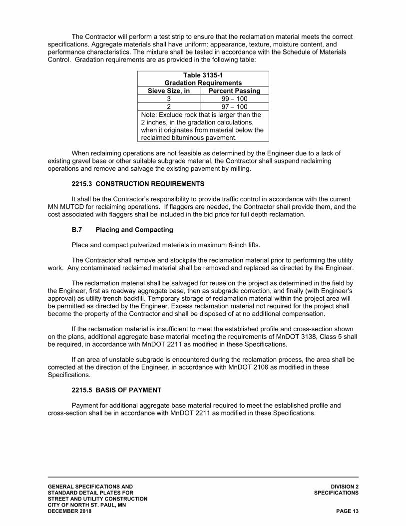
GENERAL SPECIFICATIONS AND DIVISION 2 STANDARD DETAIL PLATES FOR SPECIFICATIONS STREET AND UTILITY CONSTRUCTION CITY OF NORTH ST. PAUL, MN DECEMBER 2018 PAGE 13
The Contractor will perform a test strip to ensure that the reclamation material meets the correct specifications. Aggregate materials shall have uniform: appearance, texture, moisture content, and performance characteristics. The mixture shall be tested in accordance with the Schedule of Materials Control. Gradation requirements are as provided in the following table:
Table 3135-1
Gradation Requirements Sieve Size, in Percent Passing
3 99 – 100 2 97 – 100
Note: Exclude rock that is larger than the 2 inches, in the gradation calculations, when it originates from material below the reclaimed bituminous pavement.
When reclaiming operations are not feasible as determined by the Engineer due to a lack of
existing gravel base or other suitable subgrade material, the Contractor shall suspend reclaiming operations and remove and salvage the existing pavement by milling.
2215.3 CONSTRUCTION REQUIREMENTS It shall be the Contractor’s responsibility to provide traffic control in accordance with the current
MN MUTCD for reclaiming operations. If flaggers are needed, the Contractor shall provide them, and the cost associated with flaggers shall be included in the bid price for full depth reclamation.
B.7 Placing and Compacting Place and compact pulverized materials in maximum 6-inch lifts. The Contractor shall remove and stockpile the reclamation material prior to performing the utility
work. Any contaminated reclaimed material shall be removed and replaced as directed by the Engineer. The reclamation material shall be salvaged for reuse on the project as determined in the field by
the Engineer, first as roadway aggregate base, then as subgrade correction, and finally (with Engineer’s approval) as utility trench backfill. Temporary storage of reclamation material within the project area will be permitted as directed by the Engineer. Excess reclamation material not required for the project shall become the property of the Contractor and shall be disposed of at no additional compensation.
If the reclamation material is insufficient to meet the established profile and cross-section shown
on the plans, additional aggregate base material meeting the requirements of MnDOT 3138, Class 5 shall be required, in accordance with MnDOT 2211 as modified in these Specifications.
If an area of unstable subgrade is encountered during the reclamation process, the area shall be
corrected at the direction of the Engineer, in accordance with MnDOT 2106 as modified in these Specifications.
2215.5 BASIS OF PAYMENT Payment for additional aggregate base material required to meet the established profile and
cross-section shall be in accordance with MnDOT 2211 as modified in these Specifications.
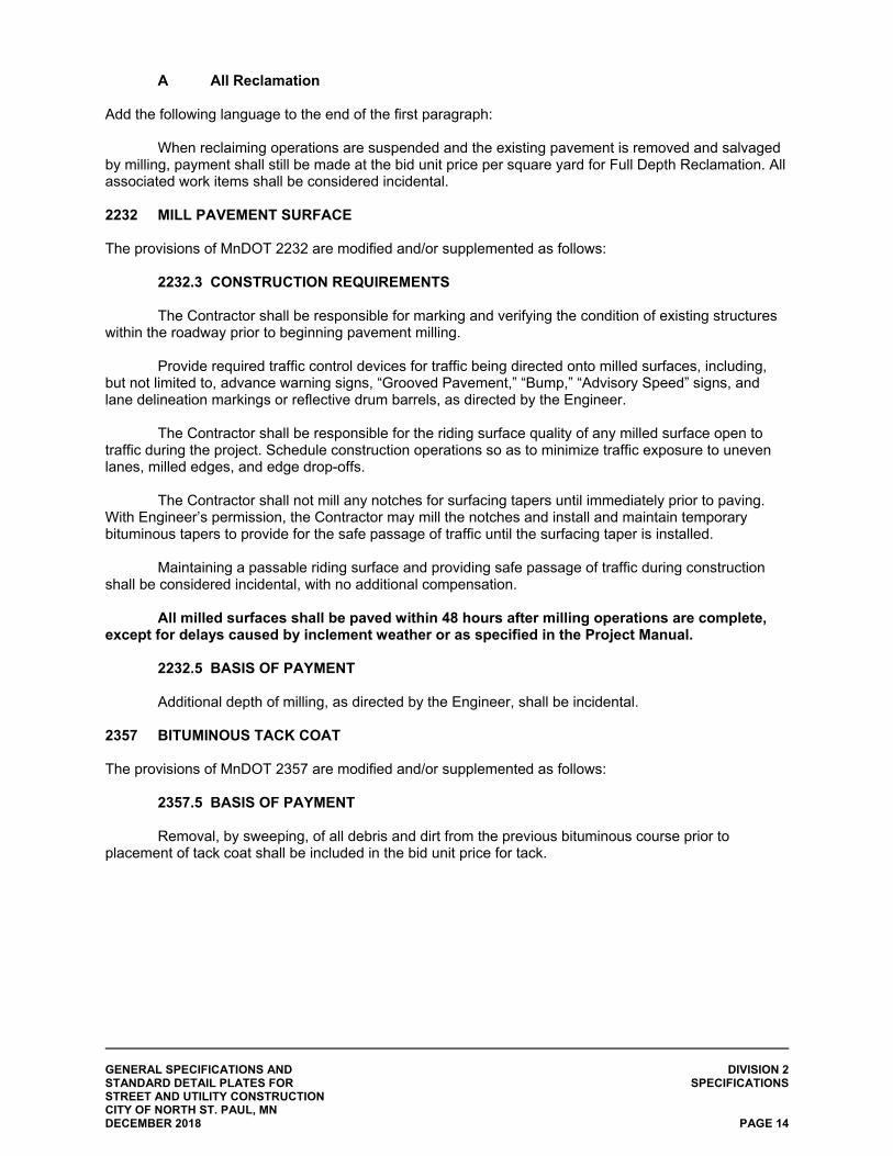
GENERAL SPECIFICATIONS AND DIVISION 2 STANDARD DETAIL PLATES FOR SPECIFICATIONS STREET AND UTILITY CONSTRUCTION CITY OF NORTH ST. PAUL, MN DECEMBER 2018 PAGE 14
A All Reclamation
Add the following language to the end of the first paragraph:
When reclaiming operations are suspended and the existing pavement is removed and salvaged by milling, payment shall still be made at the bid unit price per square yard for Full Depth Reclamation. All associated work items shall be considered incidental.
2232 MILL PAVEMENT SURFACE The provisions of MnDOT 2232 are modified and/or supplemented as follows:
2232.3 CONSTRUCTION REQUIREMENTS The Contractor shall be responsible for marking and verifying the condition of existing structures
within the roadway prior to beginning pavement milling. Provide required traffic control devices for traffic being directed onto milled surfaces, including,
but not limited to, advance warning signs, “Grooved Pavement,” “Bump,” “Advisory Speed” signs, and lane delineation markings or reflective drum barrels, as directed by the Engineer.
The Contractor shall be responsible for the riding surface quality of any milled surface open to
traffic during the project. Schedule construction operations so as to minimize traffic exposure to uneven lanes, milled edges, and edge drop-offs.
The Contractor shall not mill any notches for surfacing tapers until immediately prior to paving.
With Engineer’s permission, the Contractor may mill the notches and install and maintain temporary bituminous tapers to provide for the safe passage of traffic until the surfacing taper is installed.
Maintaining a passable riding surface and providing safe passage of traffic during construction
shall be considered incidental, with no additional compensation. All milled surfaces shall be paved within 48 hours after milling operations are complete,
except for delays caused by inclement weather or as specified in the Project Manual. 2232.5 BASIS OF PAYMENT
Additional depth of milling, as directed by the Engineer, shall be incidental.
2357 BITUMINOUS TACK COAT The provisions of MnDOT 2357 are modified and/or supplemented as follows:
2357.5 BASIS OF PAYMENT Removal, by sweeping, of all debris and dirt from the previous bituminous course prior to
placement of tack coat shall be included in the bid unit price for tack.
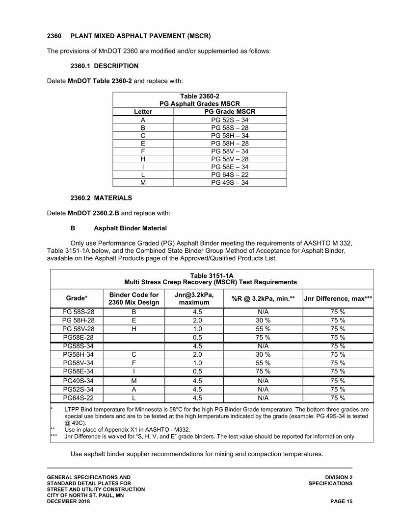
GENERAL SPECIFICATIONS AND DIVISION 2 STANDARD DETAIL PLATES FOR SPECIFICATIONS STREET AND UTILITY CONSTRUCTION CITY OF NORTH ST. PAUL, MN DECEMBER 2018 PAGE 15
2360 PLANT MIXED ASPHALT PAVEMENT (MSCR) The provisions of MnDOT 2360 are modified and/or supplemented as follows:
2360.1 DESCRIPTION
Delete MnDOT Table 2360-2 and replace with:
Table 2360-2 PG Asphalt Grades MSCR
Letter PG Grade MSCR A PG 52S – 34 B PG 58S – 28 C PG 58H – 34 E PG 58H – 28 F PG 58V – 34 H PG 58V – 28 I PG 58E – 34 L PG 64S – 22 M PG 49S – 34
2360.2 MATERIALS
Delete MnDOT 2360.2.B and replace with:
B Asphalt Binder Material
Only use Performance Graded (PG) Asphalt Binder meeting the requirements of AASHTO M 332, Table 3151-1A below, and the Combined State Binder Group Method of Acceptance for Asphalt Binder, available on the Asphalt Products page of the Approved/Qualified Products List.
Table 3151-1A Multi Stress Creep Recovery (MSCR) Test Requirements
Grade* Binder Code for 2360 Mix Design
[email protected], maximum
%R @ 3.2kPa, min.** Jnr Difference, max***
PG 58S-28 B 4.5 N/A 75 % PG 58H-28 E 2.0 30 % 75 % PG 58V-28 H 1.0 55 % 75 % PG58E-28 0.5 75 % 75 % PG58S-34 4.5 N/A 75 % PG58H-34 C 2.0 30 % 75 % PG58V-34 F 1.0 55 % 75 % PG58E-34 I 0.5 75 % 75 %
PG49S-34 M 4.5 N/A 75 % PG52S-34 A 4.5 N/A 75 % PG64S-22 L 4.5 N/A 75 %
* LTPP Bind temperature for Minnesota is 58°C for the high PG Binder Grade temperature. The bottom three grades are special use binders and are to be tested at the high temperature indicated by the grade (example: PG 49S-34 is tested @ 49C).
** Use in place of Appendix X1 in AASHTO - M332. *** Jnr Difference is waived for “S, H, V, and E” grade binders. The test value should be reported for information only.
Use asphalt binder supplier recommendations for mixing and compaction temperatures.
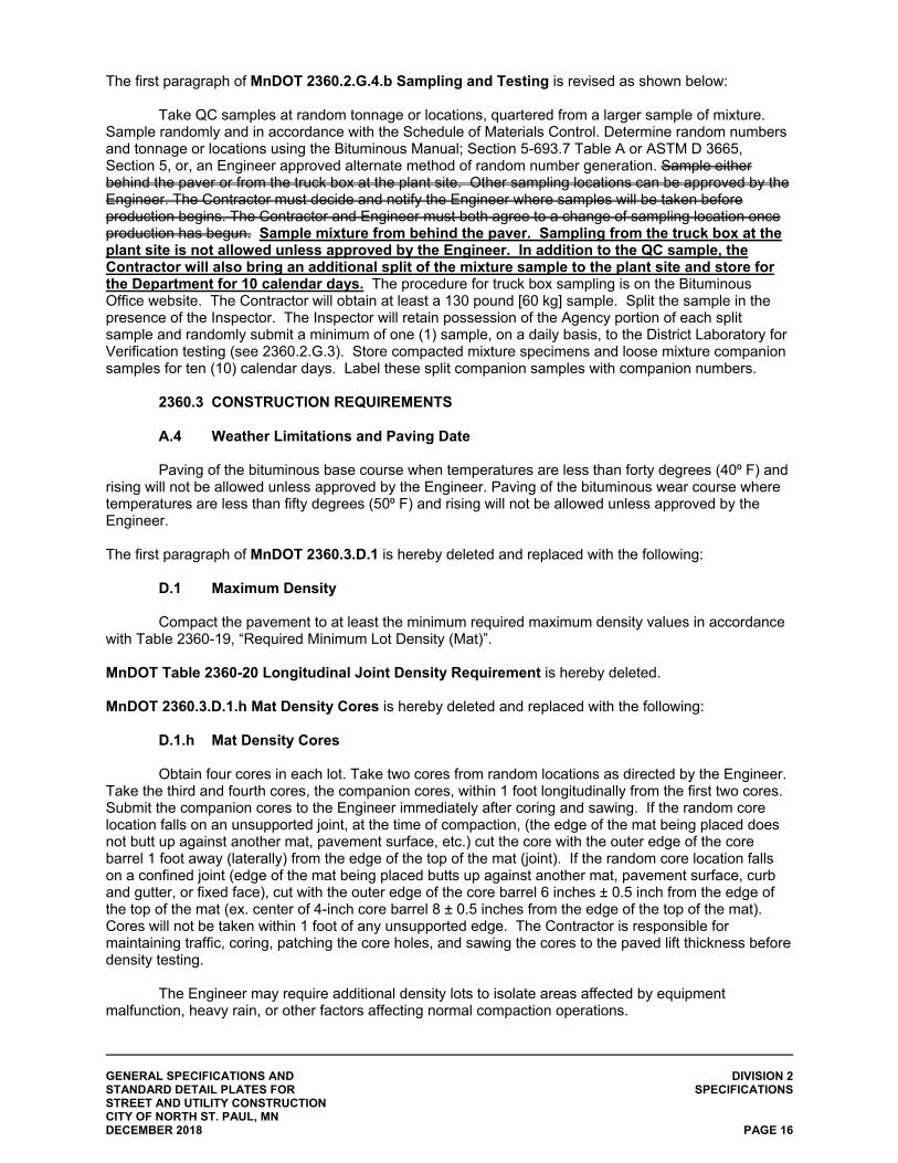
GENERAL SPECIFICATIONS AND DIVISION 2 STANDARD DETAIL PLATES FOR SPECIFICATIONS STREET AND UTILITY CONSTRUCTION CITY OF NORTH ST. PAUL, MN DECEMBER 2018 PAGE 16
The first paragraph of MnDOT 2360.2.G.4.b Sampling and Testing is revised as shown below:
Take QC samples at random tonnage or locations, quartered from a larger sample of mixture. Sample randomly and in accordance with the Schedule of Materials Control. Determine random numbers and tonnage or locations using the Bituminous Manual; Section 5-693.7 Table A or ASTM D 3665, Section 5, or, an Engineer approved alternate method of random number generation. Sample either behind the paver or from the truck box at the plant site. Other sampling locations can be approved by the Engineer. The Contractor must decide and notify the Engineer where samples will be taken before production begins. The Contractor and Engineer must both agree to a change of sampling location once production has begun. Sample mixture from behind the paver. Sampling from the truck box at the plant site is not allowed unless approved by the Engineer. In addition to the QC sample, the Contractor will also bring an additional split of the mixture sample to the plant site and store for the Department for 10 calendar days. The procedure for truck box sampling is on the Bituminous Office website. The Contractor will obtain at least a 130 pound [60 kg] sample. Split the sample in the presence of the Inspector. The Inspector will retain possession of the Agency portion of each split sample and randomly submit a minimum of one (1) sample, on a daily basis, to the District Laboratory for Verification testing (see 2360.2.G.3). Store compacted mixture specimens and loose mixture companion samples for ten (10) calendar days. Label these split companion samples with companion numbers.
2360.3 CONSTRUCTION REQUIREMENTS
A.4 Weather Limitations and Paving Date Paving of the bituminous base course when temperatures are less than forty degrees (40⁰ F) and rising will not be allowed unless approved by the Engineer. Paving of the bituminous wear course where temperatures are less than fifty degrees (50⁰ F) and rising will not be allowed unless approved by the Engineer. The first paragraph of MnDOT 2360.3.D.1 is hereby deleted and replaced with the following:
D.1 Maximum Density
Compact the pavement to at least the minimum required maximum density values in accordance with Table 2360-19, “Required Minimum Lot Density (Mat)”.
MnDOT Table 2360-20 Longitudinal Joint Density Requirement is hereby deleted.
MnDOT 2360.3.D.1.h Mat Density Cores is hereby deleted and replaced with the following:
D.1.h Mat Density Cores
Obtain four cores in each lot. Take two cores from random locations as directed by the Engineer. Take the third and fourth cores, the companion cores, within 1 foot longitudinally from the first two cores. Submit the companion cores to the Engineer immediately after coring and sawing. If the random core location falls on an unsupported joint, at the time of compaction, (the edge of the mat being placed does not butt up against another mat, pavement surface, etc.) cut the core with the outer edge of the core barrel 1 foot away (laterally) from the edge of the top of the mat (joint). If the random core location falls on a confined joint (edge of the mat being placed butts up against another mat, pavement surface, curb and gutter, or fixed face), cut with the outer edge of the core barrel 6 inches ± 0.5 inch from the edge of the top of the mat (ex. center of 4-inch core barrel 8 ± 0.5 inches from the edge of the top of the mat). Cores will not be taken within 1 foot of any unsupported edge. The Contractor is responsible for maintaining traffic, coring, patching the core holes, and sawing the cores to the paved lift thickness before density testing.
The Engineer may require additional density lots to isolate areas affected by equipment malfunction, heavy rain, or other factors affecting normal compaction operations.
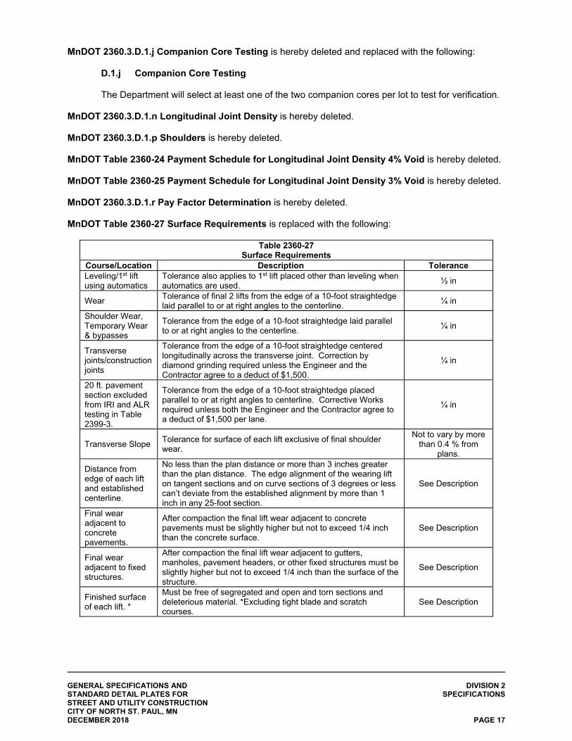
GENERAL SPECIFICATIONS AND DIVISION 2 STANDARD DETAIL PLATES FOR SPECIFICATIONS STREET AND UTILITY CONSTRUCTION CITY OF NORTH ST. PAUL, MN DECEMBER 2018 PAGE 17
MnDOT 2360.3.D.1.j Companion Core Testing is hereby deleted and replaced with the following:
D.1.j Companion Core Testing
The Department will select at least one of the two companion cores per lot to test for verification.
MnDOT 2360.3.D.1.n Longitudinal Joint Density is hereby deleted. MnDOT 2360.3.D.1.p Shoulders is hereby deleted. MnDOT Table 2360-24 Payment Schedule for Longitudinal Joint Density 4% Void is hereby deleted. MnDOT Table 2360-25 Payment Schedule for Longitudinal Joint Density 3% Void is hereby deleted. MnDOT 2360.3.D.1.r Pay Factor Determination is hereby deleted. MnDOT Table 2360-27 Surface Requirements is replaced with the following:
Table 2360-27 Surface Requirements
Course/Location Description Tolerance Leveling/1st lift using automatics
Tolerance also applies to 1st lift placed other than leveling when automatics are used.
½ in
Wear Tolerance of final 2 lifts from the edge of a 10-foot straightedge laid parallel to or at right angles to the centerline.
¼ in
Shoulder Wear, Temporary Wear & bypasses
Tolerance from the edge of a 10-foot straightedge laid parallel to or at right angles to the centerline.
¼ in
Transverse joints/construction joints
Tolerance from the edge of a 10-foot straightedge centered longitudinally across the transverse joint. Correction by diamond grinding required unless the Engineer and the Contractor agree to a deduct of $1,500.
¼ in
20 ft. pavement section excluded from IRI and ALR testing in Table 2399-3.
Tolerance from the edge of a 10-foot straightedge placed parallel to or at right angles to centerline. Corrective Works required unless both the Engineer and the Contractor agree to a deduct of $1,500 per lane.
¼ in
Transverse Slope Tolerance for surface of each lift exclusive of final shoulder wear.
Not to vary by more than 0.4 % from
plans.
Distance from edge of each lift and established centerline.
No less than the plan distance or more than 3 inches greater than the plan distance. The edge alignment of the wearing lift on tangent sections and on curve sections of 3 degrees or less can’t deviate from the established alignment by more than 1 inch in any 25-foot section.
See Description
Final wear adjacent to concrete pavements.
After compaction the final lift wear adjacent to concrete pavements must be slightly higher but not to exceed 1/4 inch than the concrete surface.
See Description
Final wear adjacent to fixed structures.
After compaction the final lift wear adjacent to gutters, manholes, pavement headers, or other fixed structures must be slightly higher but not to exceed 1/4 inch than the surface of the structure.
See Description
Finished surface of each lift. *
Must be free of segregated and open and torn sections and deleterious material. *Excluding tight blade and scratch courses.
See Description
GENERAL SPECIFICATIONS AND DIVISION 2 STANDARD DETAIL PLATES FOR SPECIFICATIONS STREET AND UTILITY CONSTRUCTION CITY OF NORTH ST. PAUL, MN DECEMBER 2018 PAGE 18
2360.5 BASIS OF PAYMENT Payment shall be at the bid unit price per square yard of each thickness of bituminous pavement for walks/paths, and shall include all excavation, grading, aggregate base (see 2521 Walks), placement of granular borrow as required, materials, labor and equipment required to complete the walk/path in-place in accordance with the Plan. Surface tolerances will be verified prior to payment. 2451 (CEAM 2600) STRUCTURE EXCAVATIONS AND BACKFILLS The provisions of MnDOT 2451 shall apply, in addition to the provisions of CEAM 2600, Trench Excavation and Backfill/Surface Restoration, which are modified and/or supplemented as follows:
2451.2 (CEAM 2600.2) MATERIALS The provisions of CEAM 2600.2 are modified and/or supplemented as follows:
A.1 Granular Material Gradation Classifications Bedding and encasement materials, unless noted otherwise, shall meet the requirements of
MnDOT 3149.2.B.1 except that 100% by weight shall pass the one-inch (1”) sieve.
Add the following new paragraph to CEAM 2600.2: D Tracer Wire Tracer wire for use with all thermoplastic pipe installations shall be #12 AWG Copper Clad Steel, High Strength, with minimum 450 lb. break load and a minimum 30 mil HDPE insulation thickness for direct bury. Insulation shall be color coated per APWA Uniform Color Code for the utility being marked.
Connectors shall be 3-2ay lockable connectors and mainline to lateral lug connectors specifically
manufactured for use in underground tracer wire installation. Connectors shall be dielectric silicon filled to seal out moisture and corrosion. Non-locking friction fit, twist on, or taped connectors are prohibited.
Tracer wire termination points shall include an approved tracer wire grade level or in-ground
access box specifically manufactured for this purpose. Access boxes shall contain a minimum of two (2) feet of excess/slack wire after meeting final elevation. The access box shall be appropriately color coded and identified with “SEWER” or “WATER” cast into the cap. Access boxes must include a manually interruptible conductive/connective link between the terminal(s) for the tracer wire connection and for the grounding anode wire connection.
Tracer wire must be properly grounded at all dead ends and stubs. Use a drive-in magnesium
grounding anode rod with a minimum of 20 feet of #12 red HDPE insulated copper clad steel wire connected to anode (1.5 lb. minimum) specifically manufactured for this purpose, and buried at the same elevation as the utility. Install grounding anode in a direction 180 degrees opposite of the tracer wire, at the maximum possible distance.
2451.3 (CEAM 2600.3) CONSTRUCTION REQUIREMENTS
The provisions of CEAM 2600.3 are modified and/or supplemented as follows:
E Pipeline Backfilling Operations If insufficient suitable materials are available to complete backfilling, excess suitable materials
from other areas of the project may be used to complete the work, as directed by the Engineer.
GENERAL SPECIFICATIONS AND DIVISION 2 STANDARD DETAIL PLATES FOR SPECIFICATIONS STREET AND UTILITY CONSTRUCTION CITY OF NORTH ST. PAUL, MN DECEMBER 2018 PAGE 19
Granular foundation, bedding, and encasement materials shall be placed around all pipe within areas of rock excavation.
Backfilling above the encasement zone shall comply with the general requirements specified in
2600.3.E and the following: 1) Backfill within the roadbed or building pad areas shall be placed in accordance with
MnDOT 2105.3.E and shall be compacted to Specified Density Requirements in accordance with MnDOT 2105.3.F.1.
2) Backfill not within the roadbed or building pad areas shall be compacted to ninety-five percent (95%) of maximum density (MnDOT Standard Proctor).
3) Maximum backfill lift thicknesses may be increased or decreased by authority and at the discretion of the Engineer in consideration of material type, material disposition, or the demonstrated capability of compaction equipment.
4) The Engineer shall have full authority to suspend backfill operations until the preceding lift of backfill has been determined by the Engineer to be fully compacted and a passing compaction test has been taken. No additional compensation for lost time shall be made if backfill operations are suspended by the Engineer for the purposes of determining adequate trench backfill compaction.
Add the following new paragraph to CEAM 2600.3: H Tracer Wire Installation Install tracer wire in such a manner that allows proper access for connection of line tracing equipment, proper locating of wire without loss or deterioration of low frequency (512Hz) signal for distances in excess of 1000 linear feet, and without distortion of signal caused by multiple wires being installed in close proximity to one another.
1) Install tracer wire as a continuous wire, except where using approved connectors. No looping or coiling of wire is allowed.
2) Repair any damage occurring during installation immediately by removing the damaged wire and installing a new section of wire with approved connectors.
3) Tracer wire shall be installed at the bottom half of the pipe and secured (taped/tied) at five (5) foot intervals.
4) Tracer wire must be properly grounded. 5) Mainline tracer wire shall not be connected to existing conductive pipes. Treat as a mainline
dead-end. 6) Service lateral tracer wires shall be a single wire, connected to the mainline trace wire using
a mainline to lateral lug connector. No cutting/splicing of the mainline wire is allowed. 7) When an existing tracer wire is encountered on an existing utility that is being extended or
tied into, the new tracer wire and existing tracer wire shall be connecting using an approved splice connector, and shall be properly grounded at the splice location.
Tracer wire installation shall be in accordance with the Minnesota Rural Water Association
Standard Details, available online: https://www.mrwa.com/PDF/TracerWireSpecGuideFinalweb7.pdf.
H.1 Testing All new tracer wire installations shall be located using typical low frequency (512 Hz) line tracing
equipment, witnessed by the Contractor, Engineer, and facility owner as applicable, prior to acceptance. Continuity testing in lieu of actual line tracing shall not be accepted. Verification shall be performed upon completion of rough grading and again prior to final
acceptance of the project.
GENERAL SPECIFICATIONS AND DIVISION 2 STANDARD DETAIL PLATES FOR SPECIFICATIONS STREET AND UTILITY CONSTRUCTION CITY OF NORTH ST. PAUL, MN DECEMBER 2018 PAGE 20
2451.5 (CEAM 2600.5) BASIS OF PAYMENT The provisions of CEAM 2600.5 are supplemented with the following:
Furnishing and placing of granular materials for foundation, bedding, cover or backfill placement as specified in connection with pipe or structure items shall be incidental to the pipe or structure item without any direct compensation being made. 2502 SUBSURFACE DRAINS The provisions of MnDOT 2502 are modified and/or supplemented as follows:
2502.1 DESCRIPTION The location and alignment of the subsurface drains and outlets are shown in a general manner
on the Plans. Modifications to the proposed alignment may be made by the Engineer in the field to ensure that the drain properly collects groundwater and infiltration water that may accumulate in the bottom of granular base material.
Perforated corrugated thermoplastic (TP) pipe, 6-inch diameter or perforated corrugated PE pipe,
6-inch diameter, shall be installed in accordance with the requirements for subcut drains, (MnDOT 2502.3.F) except that perforated pipe drains shall be bedded on coarse filter aggregate (MnDOT3149.2.H). Trenches shall also be backfilled with coarse filter aggregate.
2502.2 MATERIALS
Delete MnDOT 2502.2.A1 and replace with the following: A1 Thermoplastic (TP) Provide thermoplastic pipe and fittings (for use as pipe sewers or subsurface drains) meeting the requirements of the Contract. If pipe is not specified in the Contract, use pipe meeting the applicable application, i.e. use perforated pipe for drainage application and unperforated pipe for outlet into ditch, etc.
(1) AASHTM M278, Class PS 46, Polyvinyl Chloride (PVC) Pipe (perforated and unperforated), (2) Blank (3) ASTM D3034, Type PSM PVC Sewer Pipe, SDR 35, (unperforated only), (4) ASTM F758, Smooth-Wall PVC, Type PS 46 (perforated and unperforated), or (5) ASTM F949, PVC Corrugated Sewer Pipe (perforated and unperforated). (6) ASTM D17885, Schedule 40 pipe (perforated & unperforated as applicable) with one of the
following designs. a. Perforated: Slotted with maximum slot width of 1/16 inch and minimum slot area of
1.5 in2/linear foot for pipe 4 inches in diameter and greater than 1.0 in2/linear foot for pipe less than 4 inches in diameter.
b. Perforated: Circular holes with two to four rows of holes. Hole diameter = 3/16 inch – 3/8 inch, and minimum area of holes 1.5 in2/linear foot for pipe 4 inches in diameter and greater and 1.0 in2/linear foot for pipe less than 4 inches in diameter.
c. Unperforated. If perforated pipe is specified, provide pipe with perforations in accordance with the applicable
specification. Unless otherwise specified in the applicable specifications, plans, or special provisions, the Contractor may choose the joint type. Submit to the Engineer a manufacturer’s Certificate of Compliance with each pipe shipment.
GENERAL SPECIFICATIONS AND DIVISION 2 STANDARD DETAIL PLATES FOR SPECIFICATIONS STREET AND UTILITY CONSTRUCTION CITY OF NORTH ST. PAUL, MN DECEMBER 2018 PAGE 21
2502.3 CONSTRUCTION REQUIREMENTS D Drain Outlets Perforated pipe drain, installed as shown on the plans or as directed by the Engineer, shall outlet
via a connection to a storm drainage structure or to a ditch via a discharge pipe and headwall. D.2 Discharge Pipe
Connect the 6-inch subsurface drain to the 6-inch x 12-inch straight length of TP discharge pipe with a TP connector.
2502.4 METHOD OF MEASUREMENT A Subsurface Drains Connection of pipe drains to storm drainage structures and terminal points shall be incidental to
the construction of the subsurface drain. 2502.5 BASIS OF PAYMENT
Delete MnDOT 2502.5 in its entirety and replace with the following: The contract unit prices for subsurface drains and outlets of each size, type, kind, and strength class include the cost of providing and installing the item as shown on the plans. Payment for perforated TP pipe drain at the Bid unit price per linear foot shall be full compensation for fabric wrapped pipe, furnished and installed as specified, filter aggregate backfill and compaction, end caps, connection of the pipe drain into the drainage structures, and all other associated work and materials required to install the perforated pipe drains as detailed, specified, and as directed by the Engineer. All excess material shall be disposed of by the Contractor at no additional cost to the Owner.
2503 (CEAM 2621) PIPE SEWERS The provisions of MnDOT 2503 shall apply, in addition to the provisions of CEAM 2621, Sanitary Sewer and Storm Sewer Installation, which are modified and/or supplemented as follows:
2503.2 (CEAM 2621.2) MATERIALS
The provisions of CEAM 2621.2 are modified and/or supplemented with the following:
A.3 Reinforced Concrete Pipe and Fittings Reinforced gasketed concrete pipe and fittings with a rubber O-ring shall conform to the
requirements of MnDOT 3236 for the type, size and strength class specified. Manufacturers of reinforced concrete pipe may produce an alternate “offset joint” on the spigot
end of the pipe. This type of offset joint is to be used with the profile or pre-lubricated pipe seal systems. See MnDOT Standard Plate 3006.
GENERAL SPECIFICATIONS AND DIVISION 2 STANDARD DETAIL PLATES FOR SPECIFICATIONS STREET AND UTILITY CONSTRUCTION CITY OF NORTH ST. PAUL, MN DECEMBER 2018 PAGE 22
A.5 Polyvinyl Chloride Pipe and Fittings Sanitary sewer polyvinyl chloride (PVC) pipe and fittings shall conform to the CEAM
requirements. Polyvinyl Chloride Pipe used for storm sewer installations shall conform to the requirements outlined in MnDOT 2503. In accordance with MnDOT 3248, submit a manufacturer’s Certificate of Compliance with each pipe shipment including date manufactured, nominal and actual inside pipe diameters.
A.8 Corrugated Polyethylene Pipe In accordance with MnDOT 3247, submit a manufacturer’s Certificate of Compliance with each
pipe shipment including date manufactured, nominal and actual inside pipe diameters. Delete CEAM 2621.2.A.11 and replace with the following:
A.11 Polypropylene Pipe Provide corrugated polypropylene (PP) dual-wall pipe with couplings and fittings meeting the requirements of the following:
1) AASHTO M33 dual wall Type “S” pipe, and 2) Section 12 of the AASHTO LRFD Bridge Design Specifications, and 3) Gasketed integral bell and spigot joint meeting the requirements of ASTM F2881, for
respective diameters, and 4) Water tight joints that meet a 10.8 psi laboratory test per ASTM D3212 with a gasket that
meets the requirements of ASTM F477, and 5) Protect polypropylene compounds from ultraviolet (UV) degradation with UV stabilizers or
carbon black meeting the requirements and testing in AASHTO M33 and ASTM D3895.
Provide laboratory certification that the pipe connection for each size of pipe meets or exceeds these requirements. Submit shop drawings of each pipe coupler and any additional mechanical connections required by the plans. Mitered end sections are not to be constructed of polypropylene. Provide polypropylene (PP) pipe and fittings manufactured from high-density polypropylene (PP) virgin compounds. Clean, reworked PP materials from the manufacturer’s own production may be used if the pipe fittings produced meet the requirements of this section. Store and handle polypropylene (PP) pipe as recommended by the manufacturer. Provide pipe manufactured no more than six months prior to installation. Do not use damaged pipe. Polypropylene (PP) pipe is considered to be plastic pipe and must be installed according to MnDOT 2501.3.C.4 and must pass deflection testing for acceptance. Submit a manufacturer’s Certificate of Compliance with each pipe shipment including the date manufactured, nominal and actual inside pipe diameters.
Polypropylene (PP) manufacturing facilities are required to participate and be in compliance with AASHTO’s National Transportation Product Evaluation Program (NTPEP) for producers of AASHTO M330 polypropylene (PP) pipe. The Engineer confirms the plant where the pipe is manufactured is in compliant status by checking the NTPEP website, a link is provided through the Approved Products List.
GENERAL SPECIFICATIONS AND DIVISION 2 STANDARD DETAIL PLATES FOR SPECIFICATIONS STREET AND UTILITY CONSTRUCTION CITY OF NORTH ST. PAUL, MN DECEMBER 2018 PAGE 23
Delete CEAM 2621.2.A.12 and replace with the following: A.12 Tracer Wire for Non-conductive Pipe Tracer wire for use with all thermoplastic pipe installations shall be #12 AWG Copper Clad Steel, High Strength, with minimum 450 lb. break load and a minimum 30 mil HDPE insulation thickness for direct bury, in accordance with CEAM 2600 an das modified in these specifications. Add the following new paragraph to MnDOT 2503.2: E Steel Casing Pipe The casing pipe shall be welded steel pipe (new material) conforming to ASTM Designation A252 Grade 2 or ASTM Designation A139 Grade B, with a minimum yield strength of 35,000 psi. The wall thickness (in inches) shall be as shown on the plans.
2503.3 (CEAM 2621.3) CONSTRUCTION REQUIREMENTS The provisions of CEAM 2621.3 are modified and/or supplemented with the following:
The Engineer shall receive notice twenty-four (24) hours in advance for testing of sewers.
When the Contractor uses laser beam control for grade and alignment, the Contractor shall check into the grade stakes provided. Any discrepancies found between the laser beam elevation and grade stake elevation, or the line and grade shown on the plans, shall be immediately brought to the Engineer’s attention before continuing pipe installation. Failure to check into grade stakes provided or to notify the Engineer of discrepancies shall put the full responsibility on the Contractor for any removal and reinstallation of pipe necessary to conform to the line and grade as shown in the Drawings.
A.2 Pipe Laying Operations Dewatering to maintain pipe trenches free of water shall be considered incidental, unless a bid
item has been included for Dewatering. Install pipe to the alignment, grade, and location as shown in the drawings and/or staked in the
field. No deviation from the drawings and/or staked alignment, grade, or location is allowed. A.4 Bulkheading Open Pipe Ends
Mark end of sewer stubs with a wooden four-inch by four-inch (4” x 4”) marker. The marker shall
extend adjacent to the plug and to a depth six inches (6”) below and shall extend two feet (2’) above the ground line. The marker shall be continuous without any breaks and shall be vertical or plumb. Add the following new paragraph to CEAM 2621.3.A: A.5 Tracer Wire for Non-conductive Pipe In accordance with CEAM 2600 and as modified in these specifications, install mainline tracer wire and properly connect all service lateral tracer wires, to ensure full tracing/locating capabilities from a single connection point. Lay mainline tracer wire continuously, bypassing around the outside of manholes/structures on the North or East side.
Terminate tracer wire on water service laterals at an approved trace wire access box located directly above the service lateral at the right of way.
GENERAL SPECIFICATIONS AND DIVISION 2 STANDARD DETAIL PLATES FOR SPECIFICATIONS STREET AND UTILITY CONSTRUCTION CITY OF NORTH ST. PAUL, MN DECEMBER 2018 PAGE 24
Where the storm sewer system includes service laterals for connection of private drains and/or drain tile, tracer wire shall be installed on the service laterals as for sanitary sewer services. Add the following new paragraph to CEAM 2621.3.A: A.6 Steel Casing Pipe Where required and shown on the plans, steel casing pipes (both jacked and non-jacked) shall be placed to allow for the construction of sanitary sewer, watermain, and storm sewer beneath roads and other surface improvements in accordance with the requirements of CEAM 2600.3.C, Trenchless Pipe Installation.
F Deflection Test Deflection testing of plastic pipe shall be performed in accordance with MnDOT 2503.3.C.4. G Televising
All new sanitary sewer main shall be jetted clean and televised after the services are installed, as
applicable, and prior to wear course paving. Televising should include panning the camera up to the sanitary sewer wyes and service lines so that it is visible. The Contractor shall supply two (2) videos and two (2) detailed reports within fifteen (15) days of the televising being complete. One (1) set shall be supplied to the Engineer and one (1) set to Owner. A digital copy of the report shall also be delivered to the Owner.
Prior to placement of wear course paving, the Engineer must review all sewer televising reports
and conclude there are no subsurface deficiencies requiring excavation to correct.
The Contractor will be responsible for television inspection of the sanitary sewer after it has been constructed. The Owner reserves the right to view these television inspection records prior to final project acceptance and at any time within the warranty period. Add the following new paragraph to CEAM 2621.3:
H Sanitary Sewer By-Pass Pumping The Contractor shall furnish, install, maintain, and remove temporary pumps, pipes, automatic
controls, and related appurtenances to allow continuous operation of sanitary sewer facilities whenever necessary to ensure service will be maintained during construction. Sanitary sewer facilities shall include, but are not limited to gravity sanitary sewer main, sanitary sewer force mains, sanitary sewer services, sanitary sewer lift stations, and/or sanitary sewer grinder pumps.
Sanitary sewer pipe sizes are shown on the Plans. The Contractor shall be responsible for
verifying all sanitary sewer pipe sizes and locations within the project limits to determine the most appropriate manner to provide sanitary sewer bypass pumping.
The Contractor shall submit copies of the proposed pumping, piping, and control systems for
sanitary sewer bypass pumping to the Engineer a minimum of seven (7) days in advance of installing the sanitary sewer bypass pumping system.
The Contractor shall have one (1) standby pump available on-site for each pumping location to
use in the event of a pump failure. The standby pump shall be adequately sized to handle the rates of sanitary sewer flow being bypasses.
GENERAL SPECIFICATIONS AND DIVISION 2 STANDARD DETAIL PLATES FOR SPECIFICATIONS STREET AND UTILITY CONSTRUCTION CITY OF NORTH ST. PAUL, MN DECEMBER 2018 PAGE 25
2503.4 (CEAM 2621.4) METHOD OF MEASUREMENT The provisions of CEAM 2621.4 are modified and/or supplemented with the following: Add the following new paragraph to CEAM 2621.4: I Steel Casing Pipe Each diameter of steel casing pipe will be measured by linear foot of casing pipe installed.
2503.5 (CEAM 2621.5) BASIS OF PAYMENT
The provisions of CEAM 2621.5 are modified and/or supplemented with the following: Sewer connections shall be paid per each connection of new sewer to existing sewer. All necessary labor, materials, and work required to make the connection shall be included in the price per each as provided in the Bid Form. Payment for steel casing pipe shall be at the bid unit price per linear foot and shall be compensation in full for all costs including concrete bulkheads, filling with sand, grouting outside the casing pipe, and any dewatering required, as specified in the plan. Payment for the carrier pipe passing through the casing pipe will be paid separately for the size and type of pipe specified. 2504 (CEAM 2611) WATERMAIN The provisions of CEAM 2611, Standard Specifications for Watermain and Service Line Installation are modified and/or supplemented as follows:
2504.2 (CEAM 2611.2) MATERIALS
The provisions of CEAM 2611.2 are modified and/or supplemented as follows:
All watermain materials, including but not limited to ductile iron pipe and fittings, hydrants, valve boxes, gate valves, and retainer glands and bolts shall be manufactured and produced in the United States.
A.1 Ductile Iron Pipe and Ductile Iron and Gray Iron Fittings Ductile iron pipe shall be mechanical joint, Class 50 for twelve inch (12”) and larger diameter, and
Class 52 for ten inch (10”) and smaller diameter.
All fittings for watermain shall be mechanical joint, Class 350, Ductile Iron Compact Fittings in accordance with AWWA C153. Fittings shall be furnished with fusion bonded epoxy external coating in accordance with AWWA C50 and C116, 6-8 mil nominal thickness.
All nuts and bolts shall be stainless steel or Cor-Blue t-head bolts. All tie rod restraints and
corresponding nuts shall be coated with an approved rust-proofing material. A.2 Polyvinyl Chloride (PVC) Pressure Pipe and Fittings All PVC watermain pipe shall conform to AWWA C900 (DR 18). Tracer wire shall be laid with all
PVC watermain. All fittings for watermain shall be mechanical joint, Class 350, Ductile Iron Compact Fittings in
accordance with AWWA C153. Fittings shall be furnished with fusion bonded epoxy external coating and/or interior lining in accordance with AWWA C550 and C116, 6-8 mil nominal thickness.
GENERAL SPECIFICATIONS AND DIVISION 2 STANDARD DETAIL PLATES FOR SPECIFICATIONS STREET AND UTILITY CONSTRUCTION CITY OF NORTH ST. PAUL, MN DECEMBER 2018 PAGE 26
B Fire Hydrants All fire hydrants shall conform to Owner and CEAM requirements. Fire hydrants shall be American Flow Control Model WB67-250 Pacer Fire Hydrant as
manufactured by the Waterous Company. All hydrant lead piping (hydrant assembly) shall be ductile iron pipe with polyethylene
encasement in accordance with AWWA C105. The hydrant assembly is defined as all elements from the tee at the main to and including the hydrant.
C.1 Valve Housings
Valve boxes shall be screw-type with a drop lid cover marked with “Water.” Box to be adjustable
a minimum of six inches (6”) up and down from the specified depth of pipe bury. C.2 Gate Valves All gate valves shall conform to Owner and CEAM requirements. Gate valves shall be resilient-seated gate valves conforming to the requirements of AWWA C509
as manufacture by Clow Corporation or equal. All gate valves require a bonnet adapter. C.3 Butterfly Valves All butterfly valves shall conform to Owner and CEAM requirements D Water Service Pipe and Fittings
Corporation stops shall conform to Owner and CEAM requirements. Water service taps made
directly to PVC or PE watermain pipe shall require stainless steel saddles. Saddles shall be included in the cost of the corporation stop.
Curb stops shall conform to Owner and CEAM requirements. Service stops shall be for copper
service pipe inlet and outlet, without a drain, and shall include HDPE to copper transition fittings. Curb boxes shall conform to Owner and CEAM requirements. No additional compensation will be
paid for any adjustments required to match final grade elevations. Where curb boxes are placed in concrete or bituminous pavement, a meter box cover, Ford Model A1, eight-inch (8”) cover shall be installed at no additional compensation.
Flared end couplings shall be Ford C22 of the size required. Compression joint couplings will not
be accepted. F Mechanical Joint Restraints All restraints shall be fusion bonded epoxy coated on the inside and outside according to
ANSI/AWWA C550 and C116/A21.16. All bolts and fasteners are to be stainless steel or Cor-Blue t-head bolts.
Retainer glands shall be ductile iron designed to withstand the same pressures as the watermain
pipe and fittings. Retainer glands shall be by American, US Pipe or Mega-Lug type and shall be used at all changes in direction and at all fittings and valves in addition to reaction blocking. This shall be considered included in the cost of the watermain pipe.
GENERAL SPECIFICATIONS AND DIVISION 2 STANDARD DETAIL PLATES FOR SPECIFICATIONS STREET AND UTILITY CONSTRUCTION CITY OF NORTH ST. PAUL, MN DECEMBER 2018 PAGE 27
Delete CEAM 2611.2.I and replace with the following: I Tracer Wire for Non-Conductive Pipe Tracer wire for use with all thermoplastic pipe installations shall be #12 AWG Copper Clad Steel, High Strength, with minimum 450 lb. break load and a minimum 30 mil HDPE insulation thickness for direct bury, in accordance with CEAM 2600 and as modified in these specifications. Add the following new paragraphs to CEAM 2611.2:
J Polystyrene Insulation Insulation board shall be rigid expanded polystyrene, conforming to the material requirements of
MnDOT 3760. Placement of insulation shall be in accordance with the requirements of CEAM 2600.3.D and the Standard Detail Plates.
L Steel Casing Pipe
The casing pipe shall be welded steel pipe (new material) conforming to ASTM Designation A252 Grade 2 or ASTM Designation A139 Grade B, with a minimum yield strength of 35,000 psi. The wall thickness (in inches) shall be as shown on the plans.
2504.3 (CEAM 2611.3) CONSTRUCTION REQUIREMENTS
The provisions of CEAM 2611.3 are modified and/or supplemented with the following:
Dewatering to maintain pipe trenches free of water shall be considered incidental.
Notify the Engineer and the Owner at least seventy-two (72) hours prior to connecting to existing watermain. All residents who will be affected by shutting off water service shall be given a minimum of twenty-four (24) hour notice in writing as to when, and for how long, service will be interrupted. Temporary water shutoffs shall not exceed four (4) hours in duration and shall only occur between the hours of 9:00 a.m. and 3:00 p.m. Monday through Friday, unless otherwise specified in the Contract. The Contractor shall at all times coordinate work with the Engineer and the Owner.
During the installation of the new watermain, service shall be maintained to all properties. It may
be necessary to maintain temporary pipes on the surface with connections to outside hose bibs. The temporary connections must be made according to Department of Health standards and approved by the Engineer. New watermain installations shall be coordinated so that no home or business is on temporary water service for more than fourteen (14) days unless prior arrangements have been made. The Contractor shall be responsible for any improvements to homes or businesses necessary to facilitate the temporary water connections. Delete CEAM 2611.3.B.4 in its entirety and replace with the following: B.4 Tracer Wire for Non-conductive Pipe In accordance with CEAM 2600 and as modified in these specifications, install mainline tracer wire and properly connect all service lateral tracer wires, to ensure full tracing/locating capabilities from a single connection point. Lay mainline tracer wire continuously, bypassing around the outside of valves and fittings on the North or East side.
All conductive and non-conductive service lines shall include tracer wire. Terminate tracer wire on water service laterals at an approved trace wire access box located directly above the service lateral at the right of way.
GENERAL SPECIFICATIONS AND DIVISION 2 STANDARD DETAIL PLATES FOR SPECIFICATIONS STREET AND UTILITY CONSTRUCTION CITY OF NORTH ST. PAUL, MN DECEMBER 2018 PAGE 28
Add the following new paragraphs to CEAM 2611.3.D:
D.1 Adjust Gate Valve & Box
The final surface elevation of the valve box shall be one-half inch (1/2“) below the adjacent pavement surface elevation and at-grade in turf areas unless noted otherwise.
Valve boxes shall be adjusted to meet either interim or final grades. Raise all valve boxes to base
course grade prior to base course paving. Multiple adjustments, with the use of metal adjustment rings, will be required when multiple lifts of base course are specified and if there will be more than 48 hours between paving of lifts.
Valve box adjustments with the use of metal adjustment rings shall be made to final grade prior to wear course paving. Wear course paving must be completed within 48 hours after adjusting structures to final grade, including overlay projects. During the interim, the Contractor shall place traffic cones or other traffic barricades on the adjusted structures (incidental). Metal adjustment riser rings shall be either cast iron or ductile iron as manufactured by Neenah Foundry, Ess Brothers and Sons, Inc., or Engineer approved equal. The riser ring installation shall be as per manufacturer’s recommendations. Valve boxes shall be set to have 6-inches of adjustment up and down from finished grade. Adjustment of gate valves should include additional riser sections as needed to meet the above requirements. Delete CEAM 2611.3.F and replace with the following:
F Electrical Conductivity Test
The Engineer shall receive at least twenty-four (24) hours’ notice for all testing. All new tracer wire installations shall be located using typical low frequency (512 Hz) line tracing
equipment, witnessed by the Contractor, Engineer, and facility owner as applicable, prior to acceptance. Continuity testing in lieu of actual line tracing shall not be accepted. Verification shall be performed upon completion of rough grading and again prior to final
acceptance of the project. G Hydrostatic Testing of Watermains The Engineer shall receive at least twenty-four (24) hours’ notice for all testing. The Contractor
shall perform all testing in the presence of the Engineer in the field. Service pipes may be tested at the time of the foregoing test, if installed, at the Contractor’s
option; however, testing of service pipes may be completed as a separate operation from main testing. Service pipe testing, if done separately, shall be done with the corporation stop open.
GENERAL SPECIFICATIONS AND DIVISION 2 STANDARD DETAIL PLATES FOR SPECIFICATIONS STREET AND UTILITY CONSTRUCTION CITY OF NORTH ST. PAUL, MN DECEMBER 2018 PAGE 29
Add the following new paragraph to CEAM 2611.3:
I Irrigation System Repair The Engineer shall attempt to field verify any existing irrigation systems in the project area prior to
construction. The Engineer shall notify the Contractor of such known systems. The Contractor shall avoid or minimize disturbance to existing irrigation systems during construction. Homeowners must be notified by the Contractor of any disturbances or disruptions of existing systems. Existing private irrigation systems (of all types and designs) impacted by construction are to be repaired and/or replaced. New components used in the repair/replacement shall be consistent with existing system components. The existing system and its components shall be salvaged and reinstalled where possible. Add the following new paragraph to CEAM 2611.3.A: J Steel Casing Pipe Where required and shown on the plans, steel casing pipes (both jacked and non-jacked) shall be placed to allow for the construction of sanitary sewer, watermain, and storm sewer beneath roads and other surface improvements in accordance with the requirements of CEAM 2600.3.C, Trenchless Pipe Installation. 2504.4 (CEAM 2611.4) METHOD OF MEASUREMENT The provisions of CEAM 2611.4 are modified and/or supplemented with the following: Add the following new paragraph to CEAM 2611.4: D.1 Adjust Gate Valve & Box
Measurement by each valve box, for adjustment shall be for existing valve boxes that are adjusted in preparation for bituminous wear course placement or curb and gutter placement. Initial valve box placement after base course construction, installation of valve boxes, or installation of any valve boxes in areas outside of the bituminous roadway surface shall be considered included with the gate valve pay item. H Ductile and Gray Iron Fittings Ductile Iron compact fittings (AWWA C-153) shall be measured by the pound. (See Appendix for Fitting Weights table.) Add the following new paragraph to CEAM 2611.4: K Insulation
Insulation shall be measured on a square yard basis installed to the specified thickness, and shall include all materials, equipment, and labor required for placement. Add the following new paragraph to CEAM 2621.4: L Steel Casing Pipe Each diameter of steel casing pipe will be measured by linear foot of casing pipe installed.
GENERAL SPECIFICATIONS AND DIVISION 2 STANDARD DETAIL PLATES FOR SPECIFICATIONS STREET AND UTILITY CONSTRUCTION CITY OF NORTH ST. PAUL, MN DECEMBER 2018 PAGE 30
2504.5 (CEAM 2611.5) BASIS OF PAYMENT
All gate valves that are not located within the surfaced right-of-way shall be marked with marker signs in accordance with the Standard Detail Plates. Payment for the marker sign shall be included in the bid unit price for the structure requiring the marker sign.
Irrigation System Repair: Payment at the bid unit price per each sprinkler system repair shall include all labor and materials required to satisfactorily repair each existing irrigation system impacted by construction, including but not limited to salvaging, repairing, or replacing the system and/or its components. If the Contractor damages an existing system unnecessarily or is otherwise negligent, the Owner reserves the right to require payment of the resulting excessive repair costs by the Contractor.
Steel Casing Pipe: Payment for steel casing pipe shall be at the bid unit price per linear foot and shall be compensation in full for all costs including concrete bulkheads, filling with sand, grouting outside the casing pipe, and any dewatering required, as specified in the plan. Payment for the carrier pipe passing through the casing pipe will be paid separately for the size and type of pipe specified.
2505 UTILITY COORDINATION
2505.1 DESCRIPTION The Contractor shall coordinate his activities with the activities of all utility (natural gas, power,
phone, etc.) owners present within the project limits. Coordination will include any delays associated with scheduling conflicts, fees charged by utility owners for construction services, and all time necessary to communicate and work with utility owners within the project limits.
The plans show only known underground utilities (including public utilities) and the locations are
approximate. No assurance is given that additional underground facilities do not exist. The Contractor shall make his/her own investigation to determine to what extent existing utilities shall affect his work.
In the event a private or public utility is to be relocated by Others, the Contractor shall coordinate
their work directly with the private or public utility. For projects where a utility coordination meeting was held during the project design phase, any
plans for relocations or improvements known to the Owner are included in the Project Manual. 2505.4 METHOD OF MEASUREMENT No measurement will be made of the various items that constitute Utility Coordination. 2505.5 BASIS OF PAYMENT Payment shall be made at the lump sum unit price bid and shall be compensation in full for all
labor, equipment, and materials necessary to complete the work as specified. Payment will be made at 50% upon installation and approval of the utility improvements (sanitary sewer, watermain, storm sewer). The remaining 50% payment will be made upon completion and approval of all curb and gutter.
If no bid item is included for utility coordination, all such work shall be considered incidental to the
project, with no additional compensation.
GENERAL SPECIFICATIONS AND DIVISION 2 STANDARD DETAIL PLATES FOR SPECIFICATIONS STREET AND UTILITY CONSTRUCTION CITY OF NORTH ST. PAUL, MN DECEMBER 2018 PAGE 31
2506 (CEAM 2621) MANHOLES AND CATCH BASINS
The provisions of MnDOT 2506 shall apply, in addition to the provisions of CEAM 2621, Sanitary Sewer and Storm Sewer Installation, which are modified and/or supplemented as follows:
2506.2 (CEAM 2621.2) MATERIALS
The provisions of CEAM 2621.2 are modified and/or supplemented with the following:
B Metal Sewer Castings Metal Sewer Castings shall conform to the Standard Detail Plates. All castings shall be Class
35B or better, in accordance with MnDOT 3321. The words "SANITARY SEWER" or "STORM SEWER" shall be cast on top of each manhole cover in two-inch (2”) letters as applicable.
Except as directed in the plans, all castings shall be in accordance with the following: 1) Type B618 and D412 concrete curb and gutter: storm sewer casting shall be Neenah
R3067-V or approved equal. Catch basins in the project area may require a low profile casting to construct while allowing for minimum adjustment rings. No additional payment will be made for supplemented low profile castings.
2) Surmountable concrete curb and gutter: drive-over castings will be installed per the
Standard Detail Plates in front of all driveways and walks, or as directed by the Engineer. No additional payment will be made for supplemented driveover castings.
C Precast Concrete Manhole and Catch Basin Sections Adjusting rings manufactured from high density polyethylene (HDPE) are approved as an alternate to concrete adjusting rings. HDPE adjusting rings shall be sealed with the product recommended by the manufacturer. Delete CEAM 2621.2C.3 and replace with the following:
3) Sanitary sewer inlet and outlet pipes shall be joined to the manhole with a watertight joint consisting of a rubber boot with a non-magnetic, corrosion resistant steel coupling band or equal.
Supplement CEAM 2621.2C with the following:
7) The base of sanitary manholes shall be cast integral with the bottom section of the
manholes unless noted otherwise. Add the following new paragraph to CEAM 2621.2:
F Chimney Seal F.1 External Chimney Seal The adjusting rings and castings of each sanitary sewer manhole located within the project area
shall be sealed with external chimney seal, Infi-Shield or approved equal, meeting the material and installation requirements of the manufacturer. The seal shall be made of EPDM rubber with a minimum thickness of sixty-five (65) mils. Each unit shall have a two-inch (2”) wide mastic strip on the top and bottom edges of the rubber wrap. The mastic shall be non-hardening butyl rubber sealant, with a minimum thickness of 250 mils.
GENERAL SPECIFICATIONS AND DIVISION 2 STANDARD DETAIL PLATES FOR SPECIFICATIONS STREET AND UTILITY CONSTRUCTION CITY OF NORTH ST. PAUL, MN DECEMBER 2018 PAGE 32
F.2 Internal Chimney Seal Internal chimney seals shall be Infi-Shield or approved equal, meeting the material and installation requirements of the manufacturer. The seal shall be made of high-quality rubber compound with a minimum thickness of 3/16 inches. The sealing system shall incorporate the use of an expansion band with no welded attachments, 16 gauge 304 stainless steel, to permanently hold the seal in place. Each unit shall have a two-inch (2”) wide mastic strip on the top and bottom edges of the rubber wrap. The mastic shall be non-hardening butyl rubber sealant, with a minimum thickness of 250 mils.
2506.3 (CEAM 2621.3) CONSTRUCTION REQUIREMENTS
The provisions of CEAM 2621.3 are modified and/or supplemented with the following: B Appurtenance Installations
It is the Contractor’s responsibility to verify the type and quantity of casting assemblies prior to ordering materials.
The final surface elevation of the frame or ring casting shall be one-half inch (1/2“) below the
adjacent pavement surface elevation and at-grade in turf areas unless noted otherwise. Frame and ring castings when installed in curbing shall be encased in a minimum of four inches
(4”) thick concrete around the outside of the adjustment rings. Rim elevations shall be set to correspond with the depressed curb as detailed in the Plans.
Add the following new paragraph to CEAM 2621.3.B:
B1 Chimney Seal
All chimney seal installation shall be performed in accordance with the manufacturer’s
recommendations. The Contractor shall be required to perform the installation of the first chimney seal in the presence of the Engineer to verify that the installation is acceptable and in accordance with the manufacturer’s recommendations. Add the following new paragraph to CEAM 2621.3.B: B2 Adjust Frame and Ring Casting Manhole and catch basin castings shall be adjusted to meet either interim or final grades. Raise all castings to base course grade prior to base course paving. Multiple adjustments, with the use of metal adjustment rings, will be required when multiple lifts of base course are specified and if there will be more than 48 hours between paving of lifts.
Casting adjustments with the use of metal adjustment rings shall be made to final grade prior to wear course paving. Wear course paving must be completed within 48 hours after adjusting structures to final grade, including overlay projects. During the interim, the Contractor shall place traffic cones or other traffic barricades on the adjusted structures (incidental). Metal adjustment riser rings shall be either cast iron or ductile iron as manufactured by Neenah Foundry, Ess Brothers and Sons, Inc., or Engineer approved equal. The riser ring installation shall be as per manufacturer’s recommendations.
D Manhole and Catch Basin Structures At least two (2) and not more than five (5) standard precast concrete or high-density polyethylene
adjusting rings shall be placed immediately below the casting assembly.
GENERAL SPECIFICATIONS AND DIVISION 2 STANDARD DETAIL PLATES FOR SPECIFICATIONS STREET AND UTILITY CONSTRUCTION CITY OF NORTH ST. PAUL, MN DECEMBER 2018 PAGE 33
The maximum or minimum height of adjusting rings do not apply to the adjustment of existing manholes and catch basins. However, the adjustment of existing structures shall be to the satisfaction of the Engineer. In no case shall additional compensation be made for adjusting rings and mortar exceeding 12 inches in height for existing structures.
For shallow drainage structures, the Contractor may furnish precast structures with additional
depth as necessary for pre-casting, not to exceed a maximum of two feet (2’) deeper than the plan design build. The additional depth of manhole shall be filled with grout to match elevations of proposed pipe inverts.
Steps shall be aligned over the downstream side of the manhole and be: One inch plus or minus (1"±) horizontal alignment One inch plus or minus (1"±) vertical alignment with sixteen-inch (16") spacing Catch basins under curb and gutter shall be installed to an alignment deviation of less than two-
tenths foot (0.20') with the top slab centered over the base. Deviations greater than two-tenths foot (0.20') shall be corrected by the Contractor by moving the base to its proper location. All grade stakes involved must be saved by the Contractor. If a catch basin location must be adjusted and the grade stake shows the Contractor to be in error or the grade stake has been destroyed, the Contractor must make the correction at their expense.
All manholes must be protected or covered with plates, castings, or other approved materials at
all times during construction to prevent sediment from entering the system. Sanitary manholes shall be covered to also prevent rainwater from entering the sanitary sewer system. This is included in the construction of the structure.
When installing a new structure within an existing pipe network, the Contractor shall verify the
structure location, invert elevation and line of any existing opening to ensure the installation of the proposed sewer facility can be constructed according to the plan requirements. The Contractor shall immediately inform the Engineer of any deviation from the plan requirements necessitated by existing conditions. The Contractor shall ensure that upon completion of the connection that the area of the connection be water tight. The Contractor shall ensure smooth even flow from the newly connected pipe to the invert of the existing structure.
2506.4 (CEAM 2621.4) METHOD OF MEASUREMENT The provisions of CEAM 2506.4 are modified and/or supplemented with the following:
Delete CEAM Paragraph 2621.4.B and replace with the following: B Manholes Manholes will be measured by length in accordance with MnDOT 2506.4.A unless noted otherwise. Where manholes are measured by length, the casting assembly will be measured separately by each, in accordance with MnDOT 2506.4.C Delete CEAM Paragraph 2621.4.C and replace with the following: C Catch Basins Drainage structures of each design designation will be measured in accordance with MnDOT 2506.4.A unless noted otherwise.
In accordance with MnDOT 2506.4.C, where drainage structures are measured by length, the casting assembly will be measured separately by each. No separate measurement for casting assemblies will be made where drainage structures are measured as a unit.
GENERAL SPECIFICATIONS AND DIVISION 2 STANDARD DETAIL PLATES FOR SPECIFICATIONS STREET AND UTILITY CONSTRUCTION CITY OF NORTH ST. PAUL, MN DECEMBER 2018 PAGE 34
Add the following new paragraph to CEAM 2621.4: I Adjust Frame and Ring Casting
Measurement by each casting, for adjustment of frame and ring castings shall be for existing castings that are adjusted in preparation for bituminous wear course placement or curb and gutter placement. Initial casting placement after base course construction, installation of new castings on catch basins or structures, or installation of any castings in areas outside of the bituminous roadway surface shall be considered included with the casting and/or manhole structure pay item.
2506.5 (CEAM 2621.5) BASIS OF PAYMENT
The provisions of CEAM 2621.5 are modified and/or supplemented with the following: All manholes, drainage structures and storm sewer aprons that are not located within the surfaced right-of-way shall be marked with marker signs in accordance with the Standard Detail Plates. Payment for the marker sign shall be included in the bid unit price for the structure requiring the marker sign. Add the following new paragraphs to CEAM 2621.5: A Casting Assembly Payment for both sanitary sewer and storm sewer castings shall be made under the casting assembly pay item. This item shall include furnishing, installing, and adjusting each new casting assembly and be compensation in full for all materials, labor, and equipment required to set the furnished and install castings on new or existing structures to the required elevation for new pavement surface, including multiple adjustments to suit pavement lifts. A1 Adjust Frame and Ring Casting Payment at the bid unit price shall be made for each casting adjusting, including sanitary sewer manhole castings, storm sewer manhole castings, and catch basin castings. Payment shall be in full for all labor, material and equipment required to adjust and reset the structure to the final elevation. Interim adjustments, including multiple riser rings, shall be included within this item. No measurement or payment shall be made for casting adjustment for new or reconstructed structures, including multiple adjustments to suit blacktop lifts. B Chimney Seal Chimney seals shall be considered incidental unless a separate pay item has been included on the Bid Form. C Construct Sanitary Manhole The bid unit price for construct sanitary manhole by linear foot, shall be compensation in full for all materials, labor, equipment, casting adjustments, excavation, and backfilling necessary to install the manhole. A separate bid item shall be provided for the casting assembly. D Construct Drainage Structure The bid unit price for construct drainage structure by each, shall be compensation in full for all materials, labor, equipment, casting, casting adjustments, base slab, excavation, and backfilling to install the catch basin. The casting assembly shall be considered included with the drainage structure.
GENERAL SPECIFICATIONS AND DIVISION 2 STANDARD DETAIL PLATES FOR SPECIFICATIONS STREET AND UTILITY CONSTRUCTION CITY OF NORTH ST. PAUL, MN DECEMBER 2018 PAGE 35
The bid unit price for construct drainage structure by linear foot of each structure design and size, shall be compensation in full for all materials, labor, equipment, casting adjustments, base slab, excavation, and backfilling to install the drainage structure. A separate bid item shall be provided for the casting assembly. No separate payment shall be made for connecting new storm sewer to a new drainage structure.
2511 RIPRAP
The provisions of MnDOT 2511 are modified and/or supplemented with the following:
2511.3 CONSTRUCTION REQUIREMENTS A General For 21-inch diameter and larger pipe, grouted riprap will be required in accordance with the
Standard Detail Plates, or as directed by the Engineer. When grouted riprap is required, riprap shall be hand placed.
2511.4 METHOD OF MEASUREMENT
Delete MnDOT 2511.4.B in its entirety and replace with the following:
B Filter Materials No separate measurement shall be made for filter material/geotextile fabric. Filter materials and
geotextile fabric shall be considered included with the installation of the riprap. 2511.5 BASIS OF PAYMENT The bid unit price for riprap of each type and class includes the cost of providing the materials,
excavating, and preparing the foundations, placing the riprap stone, and providing and placing the filter materials and grout as required by the contract.
2521 WALKS
The provisions of MnDOT 2521 are modified and/or supplemented with the following:
2521.3 CONSTRUCTION REQUIREMENTS E Granular Materials Base for concrete walk shall meet the requirements of MnDOT 3149.2.B.1, Granular Material,
except that one hundred percent (100%) of the material shall pass a one and one-half inch (1 ½”) sieve. Existing on-site materials may be used if approved by the Engineer.
Base for bituminous walk shall be aggregate base, class 5 in accordance with MnDOT 3138. If
allowed by the Engineer, crushed concrete meeting the requirements of MnDOT 3149.2.B.1 with one hundred percent (100%) passing a one and one-half inch (1 ½”) sieve may be used.
GENERAL SPECIFICATIONS AND DIVISION 2 STANDARD DETAIL PLATES FOR SPECIFICATIONS STREET AND UTILITY CONSTRUCTION CITY OF NORTH ST. PAUL, MN DECEMBER 2018 PAGE 36
2521.3 CONSTRUCTION REQUIREMENTS Where private utilities are to be installed within the public right of way and drainage and utility
easements, and are on the same side as the walk, the private utility work shall be coordinated with all applicable private utility companies such that all construction of private utilities will be completed prior to construction of the walk. The Contractor shall be responsible for coordination with the private utilities, Engineer, and Owner to ensure that the private utilities are constructed prior to the walk. The Contractor shall give a minimum of two (2) weeks notification to private utilities for the estimated completion date of curb, gutter, grading, and erosion control stabilization. No additional compensation from the Owner shall be provided to the Contractor for any claims of crews being delayed because of scheduling issues with private utility companies resulting from inadequate notification of curb, gutter, grading, and erosion control completion dates.
Signing for “Walk Closed” during reconstruction or repair of walks/trails shall be considered
incidental with no additional compensation. Placement of signs shall be at the beginning and end of each block segment, or as directed by the Engineer.
D Placing and Finishing Concrete Each concrete batch shall be tested (by an approved testing laboratory) for air content prior to
placement. Any batch not meeting the air requirements will be rejected. The Owner shall bear the initial cost of the testing. If, however, sections of the walk fail, and retesting is required, the cost of this additional testing shall be at the Contractor’s expense.
Slipform machine placement will be allowed in accordance with MnDOT 2531.3.D. D.3 Workmanship and Quality When the compressive strength of the concrete test cylinders is less than the specified strength
at the twenty-eight (28) day test break, the Owner will decide whether or not the defective concrete must be removed and replaced on a case by case basis. The removal and replacement costs shall be the responsibility of the Contractor. If the Owner decides to allow the concrete to be left in place, the Contractor shall receive no compensation for that section that is determined to b of deficient strength.
2521.5 BASIS OF PAYMENT
Payment for concrete walk at the bid unit price per square foot is full compensation for all cost to providing concrete walk to the specified lines, grade and minimum thickness specified in the Plans, including but not limited to: excavation, grading, granular material, forming, joint filler material, furnishing and placing concrete, compaction, curing and protecting the completed work from damage.
Payment for bituminous shall be in accordance with MnDOT 2360 as modified by these
Specifications.
2531 CONCRETE CURBING
The provisions of MnDOT 2531 are modified and/or supplemented with the following: 2531.1 DESCRIPTION
This work also consists of furnishing and installing Truncated Dome Systems (detectable warning
surfaces) at pedestrian curb ramps in compliance with the Public Rights-of-Way Accessibility Guidelines (PROWAG). Truncated domes shall provide a visual contrast to the concrete ramp of either dark on light or light on dark. This work shall be performed in accordance with the applicable MnDOT Standard Specifications, Special Provisions, and the details in the Plan.
GENERAL SPECIFICATIONS AND DIVISION 2 STANDARD DETAIL PLATES FOR SPECIFICATIONS STREET AND UTILITY CONSTRUCTION CITY OF NORTH ST. PAUL, MN DECEMBER 2018 PAGE 37
Concrete curb and gutter, design B618 shall be installed at all intersection radii and at catch basins in accordance with the Standard Detail Plates and the details in the Plan.
2531.3 CONSTRUCTION REQUIREMENTS C Placing and Finishing Concrete Each concrete batch shall be tested (by an approved testing laboratory) for air content prior to
placement. Any batch not meeting the air requirements will be rejected. The Owner shall bear the initial cost of the testing. If, however, sections of the walk fail, and retesting is required, the cost of this additional testing shall be at the Contractor’s expense.
For concrete curb and gutter, including curb fill-ins, mechanical vibration of the concrete will be
required to produce a smooth curb face. For concrete driveway pavement, a power concrete screed shall be used on all concrete driveway
pavement. Roller screeds will not be allowed. Place a “W” and/or “S” Stamp (in accordance with the Standard Details Plates) on the face of
curb where curb and gutter crosses at water and/or sanitary service. D Slipform Machine Placement Where existing driveways are being protected, or do not need to be removed, the Contractor shall
hand pour the concrete curb along these driveways. No additional compensation will be granted the Contractor for this work.
G Concrete Curing and Protection Protect the work from traffic during the curing period. Adequate signage, barricades, and
appropriate deterrents shall be placed to prohibit traffic from damaging the work. Any concrete damaged due to traffic shall be corrected at the Contractor’s expense.
H Backfill Construction Backfilling of the curb and gutter shall be completed within 48-hours after the curing period (three
to seven days as determined by the Engineer) and prior to bituminous surfacing of the roadway. Only topsoil shall be placed within four inches (4”) of the finished grade. I Workmanship and Finish When the compressive strength of the concrete test cylinders is less than the specified strength
at the twenty-eight (28) day test break, the Owner will decide whether or not the defective concrete must be removed and replaced on a case by case basis. The removal and replacement costs shall be the responsibility of the Contractor. If the Owner decides to allow the concrete to be left in place, the Contractor shall receive no compensation for that section that is determined to b of deficient strength.
Unacceptable work shall be removed and replaced with acceptable work as ordered by the
Engineer.
GENERAL SPECIFICATIONS AND DIVISION 2 STANDARD DETAIL PLATES FOR SPECIFICATIONS STREET AND UTILITY CONSTRUCTION CITY OF NORTH ST. PAUL, MN DECEMBER 2018 PAGE 38
Add the following new paragraph to MnDOT 2531.3: J Truncated Domes The Contractor, with approval of the Engineer, shall select a truncated dome product from the approved products list at http://www.dot.state.mn.us/products/miscmaterials/truncateddomes.html. The truncated domes shall be placed in concrete and shall be pressed firmly into the concrete to the point that concrete fills the vent holes on the truncated dome plates. No cutting of truncated domes will be allowed unless approved by the Engineer. No more than one cut dome per pedestrian ramp is allowed and any cut sections used shall not be less than 2 square feet of surface area. All cut edges shall be ground to a smooth surface leaving no sharp edges or burrs. If using coated colored truncated domes, they shall not be cut. Any swelling of the concrete that occurs around the truncated domes must be screeded off and the surrounding concrete shall be finished flush with the truncated dome plate edge. The finished installation of the truncated domes plates and the ramp surface plan shall have no surface deviations over 3/16 inches. To ensure that the truncated domes are well seated in concrete, the Contractor should provide a 3-inch minimum border around the edges of the truncated domes. The Contractor will be allowed to interchange 9-foot 5-inch and 10-foot radial truncated domes when either is called for in the Plan. If the Contractor does make a substitution, the Contractor will be required to modify the curb line radius to match the truncated domes and meet the detectable edge requirements shown on MnDOT Standard Plan No. 5-297.250. The Contractor will be allowed to adjust plan locations of zero-inch height curb up to 6 inches laterally to make field fit adjustments for radial truncated domes placement. 2531.4 METHOD OF MEASUREMENT A Length Concrete valley gutter shall be measured per linear foot installed as measured through the flow line. No separate measurement shall be taken for any apron space necessary to connect the valley gutter to the adjacent curb and gutter. B Area Square or rectangular truncated dome area will be measured by square foot. Radial truncated domes will be measured along the long chord and multiplied by two feet to compute square footage. 2531.5 BASIS OF PAYMENT Payment for concrete curb and gutter shall include all necessary excavation, joints, protective coating, and mechanically tamped backfill, curb drop work and B618 curb and gutter work at intersection radii and at catch basins. Payment shall be limited to eighty-percent (80%) of the actual footage installed until all curbing has been backfilled and topsoil placed. Stamping of service locations shall be considered incidental to the curb and gutter. Aggregate base material required beneath concrete driveway pavement shall be considered included in the cost of the concrete driveway pavement. Payment for truncated domes will be made at the bid unit price per square foot, which shall be compensation in full for furnishing and installing truncated domes.
GENERAL SPECIFICATIONS AND DIVISION 2 STANDARD DETAIL PLATES FOR SPECIFICATIONS STREET AND UTILITY CONSTRUCTION CITY OF NORTH ST. PAUL, MN DECEMBER 2018 PAGE 39
2540 MAIL BOX 2540.1 DESCRIPTION The provisions herein shall be applicable to all labor, materials, and equipment associated with
managing and maintaining mail service for the duration of the project as herein. 2540.2 MATERIALS When new mail boxes or standards are required, the design (size, color, material, etc.) of the mail
box and standard shall be approved by the Owner prior to installation. 2540.3 CONSTRUCTION REQUIREMENTS The Contractor shall be required to carefully remove each existing mail box and standard as
necessary for construction (including any attached distribution box and/or sign). The mail box and standard shall be delivered to the homeowner for storage during construction. During construction, the Contractor shall furnish temporary mail boxes for all residents at an accessible location for interim mail delivery as approved by the Postmaster. Each box shall be clearly labeled and mounted on a stable standard. Upon completion of construction, the Contractor shall be required to reinstall the original box and standard as directed by the Engineer.
Temporarily relocate the mail boxes in collaboration with the Engineer and the Post Office. If the existing mail box or standard is in such a condition that removal and reinstallation is not
feasible, the homeowner shall be provided a new mail box or standard for installation by the Contractor as directed by the Engineer. The design (size, color, material, etc.) of new mail boxes and standards shall be approved by the Owner and the Post Office prior to installation. The Contractor may request to be relieved of their responsibility for reinstallation by the Engineer, and notification of such relief of responsibility shall only be granted in writing from the Engineer.
In rural areas when addresses are removed with mail boxes, or in any situation when temporary
addresses are required, the Contractor shall provide reflective address labels visible for emergency vehicles.
If a concrete base existed prior to construction, a new concrete base shall be installed for the mail
box support. The bid item for new mail box support shall include the placement of concrete at the support base.
2540.4 METHOD OF MEASUREMENT A Temporary Mail Box Measurement for temporary mail box shall be per each temporary mail box furnished and
installed. B Mail Box Measurement for mail box shall be per each new mail box furnished and installed, as directed by
the Engineer. C Mail Box Support Measurement for mail box support shall be per each new mail box support furnished and
installed, as directed by the Engineer.
GENERAL SPECIFICATIONS AND DIVISION 2 STANDARD DETAIL PLATES FOR SPECIFICATIONS STREET AND UTILITY CONSTRUCTION CITY OF NORTH ST. PAUL, MN DECEMBER 2018 PAGE 40
2540.5 BASIS OF PAYMENT Payment shall be at the bid unit price per each temporary mail box. This shall include the salvage
of existing mail box and standard, coordination of temporary mail delivery with the Postmaster, reinstallation of salvaged mail box and standard, and removal of temporary mail boxes as specified.
Payment shall be at the bid unit price per each mail box. This shall include furnishing and
installing a new mail box, as directed by the Engineer. Disposal of the existing mail box which was unsuitable for reinstallation shall be at the Contractor’s expense.
Payment shall be at the bid unit price per each mail box support. This shall include furnishing and
installing a new mail box support, as directed by the Engineer. Disposal of the existing mail box support which was unsuitable for reinstallation shall be at the Contractor’s expense.
2557 FENCING
The provisions of MnDOT 2557 are modified and/or supplemented with the following:
2557.4 METHOD OFMEASUREMENT
Add the following new paragraph to MnDOT 2557.4:
F Repair Dog Fence Measurement will be made of each underground fencing system (per parcel, lot or address) that
is to be repaired. Additional compensation shall not be made for repairing the same underground fencing system on multiple occasions or at multiple locations on the same parcel, lot or address. If an underground fencing system is damaged causing the need for repair, repairs beyond the initial repair to that same system will be incidental. Use only an approved epoxy splice kit for underground wire repair. If damage occurs more than once along the property’s street frontage, the entire front footage adjacent to the curb shall be replaced.
Compensation will not be made for damage to underground fencing systems that have been
identified on the plans or in the field by the Engineer. It is the Contractor’s responsibility to protect fencing systems previously identified at no additional compensation.
2557.5 BASIS OF PAYMENT
Add the following new paragraphs to MnDOT 2557.5:
A Repair Dog Fence
Payment for Repair Dog Fence shall be compensation in full for all labor, materials, and equipment necessary to complete the specified work for the identified parcel, regardless of the number of locations or occasions that the identified system requires repair.
2564 TRAFFIC SIGNS AND DEVICES
The provisions of MnDOT 2564 are modified and/or supplemented with the following:
2564.3 CONSTRUCTION REQUIREMENTS
A General Unless designated otherwise, or directed by the Engineer, all existing sign panels removed shall
be salvaged and delivered to the Owner.
GENERAL SPECIFICATIONS AND DIVISION 2 STANDARD DETAIL PLATES FOR SPECIFICATIONS STREET AND UTILITY CONSTRUCTION CITY OF NORTH ST. PAUL, MN DECEMBER 2018 PAGE 41
Submit all street name signs to the Owner for review following the preconstruction conference and prior to ordering materials.
2564.5 BASIS OF PAYMENT
Add the following new paragraphs to MnDOT 2564.5:
A Sign Panel Type Special
The bid unit price for each Sign Panel Type Special (street name sign) shall include the cost of providing and installing the sign panels, the sign post, brackets, and all mounting hardware necessary for sign panel attachment. Each installation of Sign Panel Type Special shall include two (2) blades of each street name (four blades total). Multiple sign panels may be installed on the same sign post as directed by the Engineer.
B Install Salvaged Sign The bid unit price for each salvaged sign to be reinstalled shall include the cost of re-installing the
salvaged sign panels on a new sign post, using new brackets and mounting hardware. Multiple sign panels may be installed on the same sign post as directed by the Engineer. 2545 LIGHTING SYSTEMS The provisions of MnDOT 2545 are modified and/or supplemented with the following:
2545.1 DESCRIPTION A General This work shall also include the installation of non-metallic conduit (NMC) utility crossings for
private utility companies. 2545.3 CONSTRUCTION REQUIREMENTS D Conduit, Fittings, and Junction Box Installation In new developments, the private utility companies are asked to provide the non-metallic conduit
(NMC) for installation and copies of location maps for the Contractor and Engineer at the preconstruction conference. Conduit depths typically do not exceed three (3) feet to five (5) feet in depth. Utility crossings are not always shown on the Plan but will be coordinated in the field with the private utility companies. The Contractor shall install the NMC before the concrete curb is installed.
2545.4 METHOD OF MEASUREMENT B.4 Conduit
For installation of the NMC as provided by the private utility companies, the Engineer will measure the excavation length in linear feet for each crossing location. Where multiple conduits are bundled at a crossing, the excavation length will be measured along the longest conduit at the same crossing location.
2545.5 BASIS OF PAYMENT Payment at the bid unit price per linear foot shall be compensation in full for all labor, excavation,
compaction and restoration required to complete the installation of the NMC for private utility crossings.
GENERAL SPECIFICATIONS AND DIVISION 2 STANDARD DETAIL PLATES FOR SPECIFICATIONS STREET AND UTILITY CONSTRUCTION CITY OF NORTH ST. PAUL, MN DECEMBER 2018 PAGE 42
2571 PLANT INSTALLATION AND ESTABLISHMENT The provisions of MnDOT 2571 are modified and/or supplemented with the following:
2571.3 CONSTRUCTION REQUIREMENTS D.2 Weed Control and Soil Cultivation Topsoil, soil conditions, humus and fertilizer shall be included to assure good plant growth.
Delete MnDOT 2571.3.K.1 in its entirety and replace with the following:
K.1 Establishment Period A Plant Establishment Period (PEP) of two calendar years, coinciding with the two-year
guarantee period of the Contract, shall begin with the date of final acceptance by the Owner. 2572 PROTECTION AND RESTORATION OF VEGETATION The provisions of MnDOT 2572 are modified and/or supplemented with the following:
2572.3 CONSTRUCTION REQUIREMENTS A Protecting and Preserving Any trees or shrubs not designated for removal shall be fully protected by the Contractor during
construction. Any trees or shrubs removed or damaged by the Contractor, which were not designated for removal, will be replaced at the Contractor’s expense.
A.7 Pruning All pruning of trees, in accordance with MnDOT 2571.3.E.1, must be approved by the Engineer. 2572.5 BASIS OF PAYMENT
All work under this section shall be considered incidental to the contract with no additional
compensation allowed unless provided for in the Bid Form.
2573 STORM WATER MANAGEMENT The provisions of MnDOT 2573 are modified and/or supplemented with the following:
2573.1 DESCRIPTION The Contractor will be required to comply with NPDES General Storm Water Permit regulations to
prevent erodible materials from leaving the site, even if such permit is not required due to the project scope, size or location.
2573.2 MATERIALS BMP devices shall be a MnDOT approved product. The Contractor shall verify with the Engineer
prior to installation that the proposed BMP device is suitable for prevention of soil and sediment erosion in the field.
GENERAL SPECIFICATIONS AND DIVISION 2 STANDARD DETAIL PLATES FOR SPECIFICATIONS STREET AND UTILITY CONSTRUCTION CITY OF NORTH ST. PAUL, MN DECEMBER 2018 PAGE 43
2573.3 CONSTRUCTION REQUIREMENTS The Contractor shall be responsible for the maintenance of all-temporary erosion and sediment
control measures. These measures shall be repaired, replaced, or supplemented as set forth in the NPDES General Storm Water Permit.
If the Contractor fails to provide maintenance of the temporary erosion and sediment control
measures as set forth in the NPDES permit requirements, the Engineer shall have the authority under the terms of this contract to hire the work done and deduct the costs incurred from the amounts due to the Contractor.
The Contractor shall be assessed liquidated damages of two hundred dollars ($200) per day for
each specified area for which the Contractor has not installed or repaired erosion and sediment control devices (including sod) within forty-eight (48) hours after receiving written notice.
2573.5 BASIS OF PAYMENT The payment shall be limited to fifty percent (50%) of the actual quantities installed until fifty
percent (50%) of the Contract, including any Change Orders, has been completed. At that point in time, payment shall be increased, but limited to eighty percent (80%) of the actual quantities installed until all temporary erosion control measures have been removed from the project site. 2574 SOIL PREPARATION The provisions of MnDOT 2574 are modified and/or supplemented with the following:
2574.2 MATERIALS C Fertilizer Fertilizer shall be a zero (0) phosphorus, commercial grade fertilizer, or as specified in the Project
Manual. 2574.3 CONSTRUCTION REQUIREMENTS C Topsoil The Contractor is cautioned to salvage all available suitable topsoil from the project site for
spreading on areas to be restored. The topsoil shall be free from roots, stick, chunks of miscellaneous debris, rocks larger than one
inch (1”), and garbage. Topsoil placement shall be approved by the Engineer prior to installation. 2574.4 METHOD OF MEASUREMENT E Topsoil Borrow Topsoil borrow shall be imported only at the direction of the Engineer. Load tickets will be
required for payment.
GENERAL SPECIFICATIONS AND DIVISION 2 STANDARD DETAIL PLATES FOR SPECIFICATIONS STREET AND UTILITY CONSTRUCTION CITY OF NORTH ST. PAUL, MN DECEMBER 2018 PAGE 44
2575 ESTABLISHING TURF AND CONTROLLING EROSION The provisions of MnDOT 2575 are modified and/or supplemented with the following:
2575.1 DESCRIPTION All disturbed areas within the project shall be either seeded or sodded to an equal or better
condition to that which was in place prior to construction and as directed by the Engineer. All exposed areas of the site shall receive seed and mulch, sod or erosion control blanket within two (2) weeks after final grade on slopes flatter than 3:1 and one (1) week on slopes steeper than 3:1. Restoration may include areas outside of the construction limits as determined by the Engineer. If bituminous base is placed, the final turf establishment shall be installed within two (2) weeks of bituminous placement (unless impeded by fences, walls, or other specialty construction items).
All areas adjacent to the roadway disturbed by construction shall be excavated to a depth as
specified to allow for placement of topsoil. The Contractor shall import topsoil as necessary to provide for a minimum depth of topsoil specified. All rock, Class 5, debris, and excess concrete shall be removed from the area behind the curb to the satisfaction of the Engineer prior to the placement of topsoil. The Contractor shall cut a clean, square edge and install sod or seed in areas as directed by the Engineer.
2575.2 MATERIALS A Seed Seed mixture shall be MnDOT Seed Mixture 25-151 at a rate of one-hundred twenty pounds per
acre (120 lbs/acre) or as specified in the Project Manual. Temporary seeding may be required to satisfy the requirements of the NPDES or watershed
permits based on the Contractor’s schedule. C Sod Sod shall meet the requirements of MnDOT 3878.2.D. The sod type shall be a Kentucky
bluegrass blend, highland stock, densely rooted and locally grown. 2575.3 CONSTRUCTION REQUIREMENTS
A General
Permanent turf establishment shall commence within seven (7) days after finish grading has been completed, unless the NPDES permit requirements specify a more stringent timeline.
F Placing Sod Sod shall be placed within two (2) weeks) following the completion of the curb construction. In
some instances, this may be prior to the completion of work by private utility companies. In areas where there will be sidewalk construction, two strips of sod shall be placed behind the back of curb until the sidewalk work is completed. The entire boulevard area must receive sod within two (2) weeks following sidewalk construction and the completion of private utility work. If additional sod is required to repair damage caused by the private utility companies, it shall be paid for at the unit bid price. No additional compensation will be allowed for the additional mobilization required to complete the work as specified.
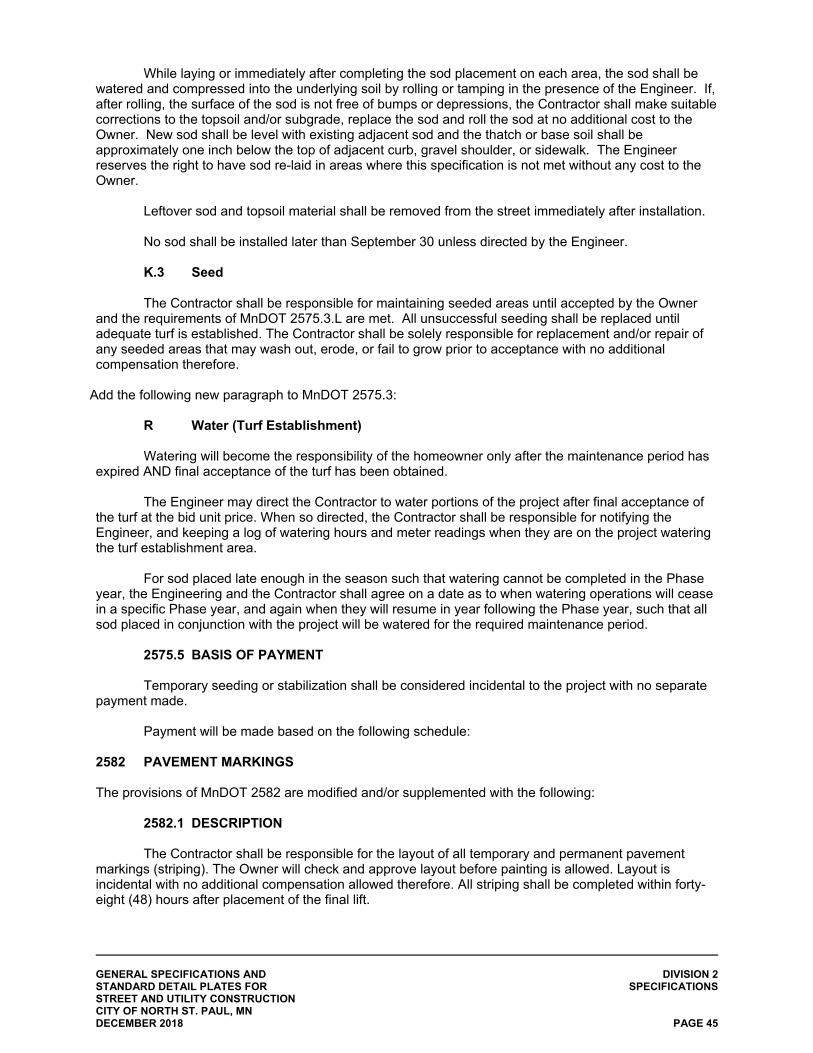
GENERAL SPECIFICATIONS AND DIVISION 2 STANDARD DETAIL PLATES FOR SPECIFICATIONS STREET AND UTILITY CONSTRUCTION CITY OF NORTH ST. PAUL, MN DECEMBER 2018 PAGE 45
While laying or immediately after completing the sod placement on each area, the sod shall be watered and compressed into the underlying soil by rolling or tamping in the presence of the Engineer. If, after rolling, the surface of the sod is not free of bumps or depressions, the Contractor shall make suitable corrections to the topsoil and/or subgrade, replace the sod and roll the sod at no additional cost to the Owner. New sod shall be level with existing adjacent sod and the thatch or base soil shall be approximately one inch below the top of adjacent curb, gravel shoulder, or sidewalk. The Engineer reserves the right to have sod re-laid in areas where this specification is not met without any cost to the Owner.
Leftover sod and topsoil material shall be removed from the street immediately after installation. No sod shall be installed later than September 30 unless directed by the Engineer. K.3 Seed
The Contractor shall be responsible for maintaining seeded areas until accepted by the Owner and the requirements of MnDOT 2575.3.L are met. All unsuccessful seeding shall be replaced until adequate turf is established. The Contractor shall be solely responsible for replacement and/or repair of any seeded areas that may wash out, erode, or fail to grow prior to acceptance with no additional compensation therefore.
Add the following new paragraph to MnDOT 2575.3:
R Water (Turf Establishment) Watering will become the responsibility of the homeowner only after the maintenance period has
expired AND final acceptance of the turf has been obtained. The Engineer may direct the Contractor to water portions of the project after final acceptance of
the turf at the bid unit price. When so directed, the Contractor shall be responsible for notifying the Engineer, and keeping a log of watering hours and meter readings when they are on the project watering the turf establishment area.
For sod placed late enough in the season such that watering cannot be completed in the Phase
year, the Engineering and the Contractor shall agree on a date as to when watering operations will cease in a specific Phase year, and again when they will resume in year following the Phase year, such that all sod placed in conjunction with the project will be watered for the required maintenance period.
2575.5 BASIS OF PAYMENT Temporary seeding or stabilization shall be considered incidental to the project with no separate
payment made. Payment will be made based on the following schedule:
2582 PAVEMENT MARKINGS The provisions of MnDOT 2582 are modified and/or supplemented with the following:
2582.1 DESCRIPTION The Contractor shall be responsible for the layout of all temporary and permanent pavement
markings (striping). The Owner will check and approve layout before painting is allowed. Layout is incidental with no additional compensation allowed therefore. All striping shall be completed within forty-eight (48) hours after placement of the final lift.

GENERAL SPECIFICATIONS AND APPENDIX A STANDARD DETAIL PLATES FOR STREET AND UTILITY CONSTRUCTION CITY OF NORTH ST. PAUL, MN DECEMBER 2018
APPENDIX A
CEAM STANDARD SPECIFICATIONS (2013 EDITION)

CITY ENGINEERS ASSOCIATION OF MINNESOTA
STANDARD SPECIFICATIONS
2600 Trench Excavation and Backfill/Surface Restoration
2611 Watermain and Service Line Installation
2621 Sanitary Sewer and Storm Sewer Installation
2631-CIPPS Sewer Pipe Rehabilitation - Cured In Place Pipe Systems
2641 – Pipeline Rehabilitation - Pipe Bursting Method
2013 Edition
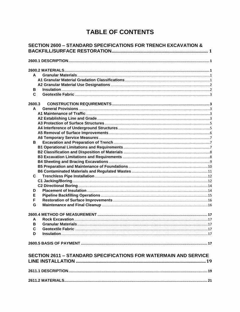
TABLE OF CONTENTS
SECTION 2600 – STANDARD SPECIFICATIONS FOR TRENCH EXCAVATION &
BACKFILL/SURFACE RESTORATION ......................................................................................... 1
2600.1 DESCRIPTION ........................................................................................................................................ 1
2600.2 MATERIALS............................................................................................................................................ 1 A Granular Materials ...................................................................................................................................... 1
A1 Granular Material Gradation Classifications ...................................................................................... 1 A2 Granular Material Use Designations .................................................................................................... 2
B Insulation ...................................................................................................................................................... 2 C Geotextile Fabric ........................................................................................................................................ 3
2600.3 CONSTRUCTION REQUIREMENTS .............................................................................................. 3 A General Provisions .................................................................................................................................... 3
A1 Maintenance of Traffic ............................................................................................................................. 3 A2 Establishing Line and Grade .................................................................................................................. 3 A3 Protection of Surface Structures .......................................................................................................... 5 A4 Interference of Underground Structures............................................................................................. 5 A5 Removal of Surface Improvements ...................................................................................................... 6 A6 Temporary Service Measures ................................................................................................................ 7
B Excavation and Preparation of Trench ................................................................................................. 7 B1 Operational Limitations and Requirements ....................................................................................... 7 B2 Classification and Disposition of Materials ....................................................................................... 8 B3 Excavation Limitations and Requirements ........................................................................................ 8 B4 Sheeting and Bracing Excavations ...................................................................................................... 9 B5 Preparation and Maintenance of Foundations ................................................................................ 10 B6 Contaminated Materials and Regulated Wastes ............................................................................. 11
C Trenchless Pipe Installation .................................................................................................................. 12 C1 Jacking/Boring ......................................................................................................................................... 12 C2 Directional Boring ................................................................................................................................... 14
D Placement of Insulation .......................................................................................................................... 14 E Pipeline Backfilling Operations ............................................................................................................ 15 F Restoration of Surface Improvements ................................................................................................ 16 G Maintenance and Final Cleanup ........................................................................................................... 16
2600.4 METHOD OF MEASUREMENT .......................................................................................................... 17 A Rock Excavation ....................................................................................................................................... 17 B Granular Materials .................................................................................................................................... 17 C Geotextile Fabric ...................................................................................................................................... 17 D Insulation .................................................................................................................................................... 17
2600.5 BASIS OF PAYMENT .......................................................................................................................... 17
SECTION 2611 – STANDARD SPECIFICATIONS FOR WATERMAIN AND SERVICE
LINE INSTALLATION ........................................................................................................................ 19
2611.1 DESCRIPTION ...................................................................................................................................... 19
2611.2 MATERIALS.......................................................................................................................................... 21
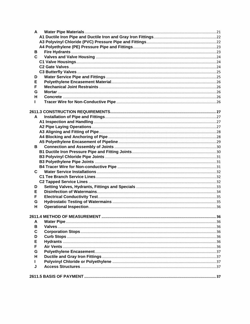
A Water Pipe Materials ................................................................................................................................ 21 A1 Ductile Iron Pipe and Ductile Iron and Gray Iron Fittings............................................................. 22 A3 Polyvinyl Chloride (PVC) Pressure Pipe and Fittings .................................................................... 22 A4 Polyethylene (PE) Pressure Pipe and Fittings ................................................................................. 23
B Fire Hydrants ............................................................................................................................................. 23 C Valves and Valve Housing ..................................................................................................................... 24
C1 Valve Housings ........................................................................................................................................ 24 C2 Gate Valves ............................................................................................................................................... 24 C3 Butterfly Valves ....................................................................................................................................... 25
D Water Service Pipe and Fittings ........................................................................................................... 25 E Polyethylene Encasement Material ...................................................................................................... 26 F Mechanical Joint Restraints .................................................................................................................. 26 G Mortar .......................................................................................................................................................... 26 H Concrete ..................................................................................................................................................... 26 I Tracer Wire for Non-Conductive Pipe ................................................................................................. 26
2611.3 CONSTRUCTION REQUIREMENTS.................................................................................................. 27 A Installation of Pipe and Fittings ............................................................................................................ 27
A1 Inspection and Handling ....................................................................................................................... 27 A2 Pipe Laying Operations ......................................................................................................................... 27 A3 Aligning and Fitting of Pipe .................................................................................................................. 28 A4 Blocking and Anchoring of Pipe ......................................................................................................... 28 A5 Polyethylene Encasement of Pipeline ............................................................................................... 29
B Connection and Assembly of Joints ................................................................................................... 30 B1 Ductile Iron Pressure Pipe and Fitting Joints .................................................................................. 30 B3 Polyvinyl Chloride Pipe Joints ............................................................................................................ 31 B3 Polyethylene Pipe Joints ...................................................................................................................... 31 B4 Tracer Wire for Non-conductive Pipe ................................................................................................ 31
C Water Service Installations .................................................................................................................... 32 C1 Tee Branch Service Lines ..................................................................................................................... 32 C2 Tapped Service Lines ............................................................................................................................ 32
D Setting Valves, Hydrants, Fittings and Specials .............................................................................. 33 E Disinfection of Watermains.................................................................................................................... 34 F Electrical Conductivity Test ................................................................................................................... 35 G Hydrostatic Testing of Watermains ..................................................................................................... 35 H Operational Inspection ............................................................................................................................ 36
2611.4 METHOD OF MEASUREMENT .......................................................................................................... 36 A Water Pipe .................................................................................................................................................. 36 B Valves .......................................................................................................................................................... 36 C Corporation Stops .................................................................................................................................... 36 D Curb Stops ................................................................................................................................................. 36 E Hydrants ..................................................................................................................................................... 36 F Air Vents ..................................................................................................................................................... 36 G Polyethylene Encasement ...................................................................................................................... 37 H Ductile and Gray Iron Fittings ............................................................................................................... 37 I Polyvinyl Chloride or Polyethylene ..................................................................................................... 37 J Access Structures .................................................................................................................................... 37
2611.5 BASIS OF PAYMENT .......................................................................................................................... 37
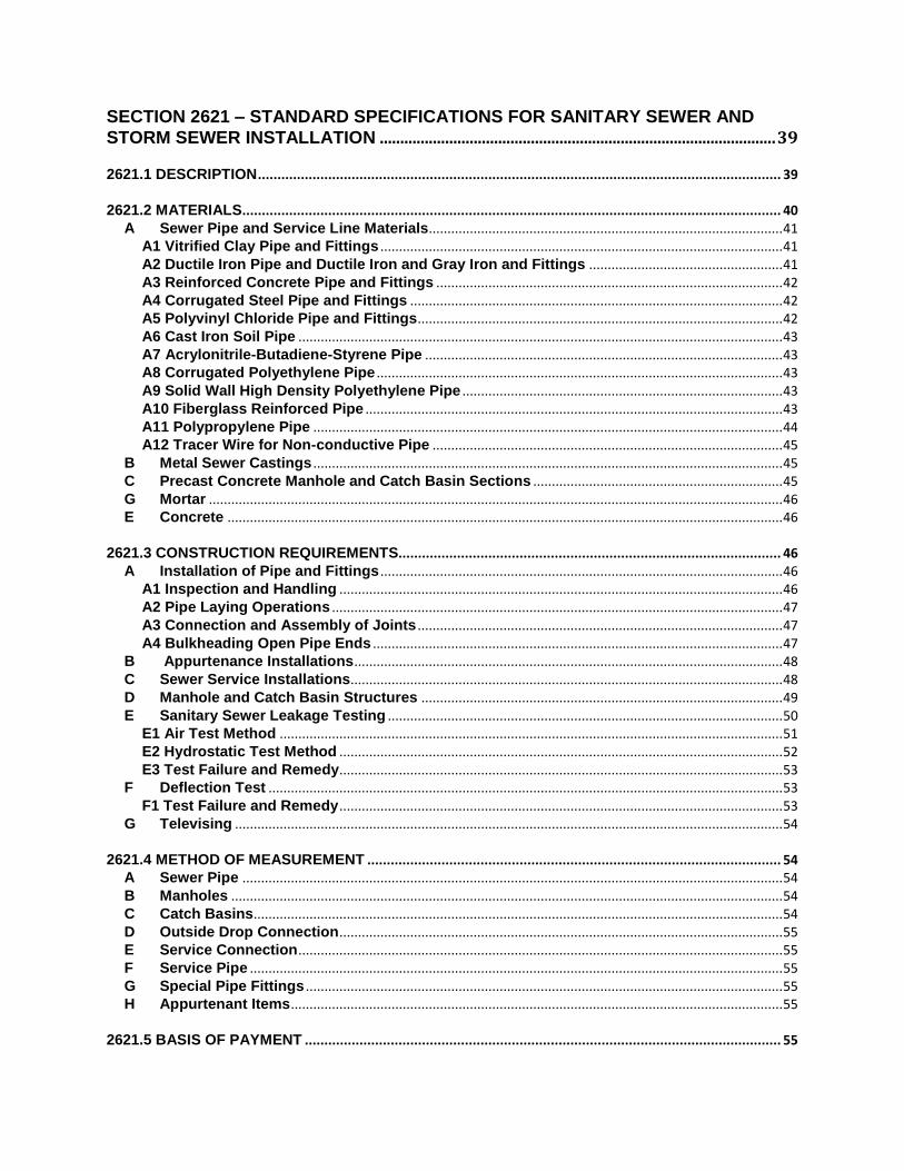
SECTION 2621 – STANDARD SPECIFICATIONS FOR SANITARY SEWER AND
STORM SEWER INSTALLATION ................................................................................................. 39
2621.1 DESCRIPTION ...................................................................................................................................... 39
2621.2 MATERIALS.......................................................................................................................................... 40 A Sewer Pipe and Service Line Materials............................................................................................... 41
A1 Vitrified Clay Pipe and Fittings ............................................................................................................ 41 A2 Ductile Iron Pipe and Ductile Iron and Gray Iron and Fittings .................................................... 41 A3 Reinforced Concrete Pipe and Fittings ............................................................................................. 42 A4 Corrugated Steel Pipe and Fittings .................................................................................................... 42 A5 Polyvinyl Chloride Pipe and Fittings.................................................................................................. 42 A6 Cast Iron Soil Pipe .................................................................................................................................. 43 A7 Acrylonitrile-Butadiene-Styrene Pipe ................................................................................................ 43 A8 Corrugated Polyethylene Pipe ............................................................................................................. 43 A9 Solid Wall High Density Polyethylene Pipe ...................................................................................... 43 A10 Fiberglass Reinforced Pipe ................................................................................................................ 43 A11 Polypropylene Pipe .............................................................................................................................. 44 A12 Tracer Wire for Non-conductive Pipe .............................................................................................. 45
B Metal Sewer Castings .............................................................................................................................. 45 C Precast Concrete Manhole and Catch Basin Sections ................................................................... 45 G Mortar .......................................................................................................................................................... 46 E Concrete ..................................................................................................................................................... 46
2621.3 CONSTRUCTION REQUIREMENTS.................................................................................................. 46 A Installation of Pipe and Fittings ............................................................................................................ 46
A1 Inspection and Handling ....................................................................................................................... 46 A2 Pipe Laying Operations ......................................................................................................................... 47 A3 Connection and Assembly of Joints .................................................................................................. 47 A4 Bulkheading Open Pipe Ends .............................................................................................................. 47
B Appurtenance Installations ................................................................................................................... 48 C Sewer Service Installations.................................................................................................................... 48 D Manhole and Catch Basin Structures ................................................................................................. 49 E Sanitary Sewer Leakage Testing .......................................................................................................... 50
E1 Air Test Method ....................................................................................................................................... 51 E2 Hydrostatic Test Method ....................................................................................................................... 52 E3 Test Failure and Remedy....................................................................................................................... 53
F Deflection Test .......................................................................................................................................... 53 F1 Test Failure and Remedy ....................................................................................................................... 53
G Televising ................................................................................................................................................... 54
2621.4 METHOD OF MEASUREMENT .......................................................................................................... 54 A Sewer Pipe ................................................................................................................................................. 54 B Manholes .................................................................................................................................................... 54 C Catch Basins.............................................................................................................................................. 54 D Outside Drop Connection ....................................................................................................................... 55 E Service Connection .................................................................................................................................. 55 F Service Pipe ............................................................................................................................................... 55 G Special Pipe Fittings ................................................................................................................................ 55 H Appurtenant Items .................................................................................................................................... 55
2621.5 BASIS OF PAYMENT .......................................................................................................................... 55
SECTION 2631 CIPPS – STANDARD SPECIFICATIONS FOR SANITARY SEWER AND STORM SEWER PIPE REHABILITATION WITH CURED IN-PLACE PIPE
SYSTEMS (CIPPS).............................................................................................................................. 57
2631.1 CIPPS DESCRIPTION ......................................................................................................................... 57 A General ........................................................................................................................................................ 57 B Qualifications ............................................................................................................................................ 58
B1 Manufactured Products and Installation ........................................................................................... 58
2631.2 CIPPS MATERIALS ............................................................................................................................. 59 A General ........................................................................................................................................................ 59
A1 CIPPS Fabric Tube .................................................................................................................................. 59 A2 CIPPS Structural Requirements .......................................................................................................... 61 A3 Material Testing Requirements ........................................................................................................... 62
2631.3 CIPPS CONSTRUCTION REQUIREMENTS ..................................................................................... 62 A Installation of CIPPS ................................................................................................................................ 62
A1 Access ....................................................................................................................................................... 62 A2 Water Usage ............................................................................................................................................. 62 A3 Cleaning of Sewer Lines ....................................................................................................................... 63 A4 Bypassing Wastewater .......................................................................................................................... 63 A5 Inspection of Pipelines .......................................................................................................................... 63 A6 Line Obstructions ................................................................................................................................... 63 A7 Public Notification .................................................................................................................................. 64 A8 Liner Installation...................................................................................................................................... 64 A9 Resin Impregnation ................................................................................................................................ 65 A10 Cool Down .............................................................................................................................................. 65 A11 Finishing Operations ........................................................................................................................... 65 A12 Manhole Connections .......................................................................................................................... 65 A13 Reconnections of Existing Services ................................................................................................ 66 A14 CIPP Short-Liner ................................................................................................................................... 66
B TESTING AND INSPECTION .................................................................................................................. 66 B1 Testing ....................................................................................................................................................... 66 B2 Inspection ................................................................................................................................................. 67 B3 Televising .................................................................................................................................................. 67
2631.4 CIPPS METHOD OF MEASUREMENT .............................................................................................. 67
2631.5 CIPPS BASIS OF PAYMENT .............................................................................................................. 68
SECTION 2641 – STANDARD SPECIFICATIONS FOR PIPELINE REHABILITATION
BY PIPE BURSTING .......................................................................................................................... 69
2641.1 DESCRIPTION ...................................................................................................................................... 69 A General ........................................................................................................................................................ 69
2641.2 QUALIFICATIONS ............................................................................................................................... 69
2641.3 MATERIALS.......................................................................................................................................... 69
2641.4 SUBMITTALS ....................................................................................................................................... 70
2641.5 DELIVERY, STORAGE, AND HANDLING ........................................................................................ 70
2641.6 LICENSE AGREEMENTS ................................................................................................................... 70
2641.7 CONSTRUCTION REQUIREMENTS.................................................................................................. 70
2641.8 TESTING AND INSPECTION .............................................................................................................. 72
2641.9 METHOD OF MEASUREMENT .......................................................................................................... 73
2641.10 BASIS OF PAYMENT ........................................................................................................................ 73
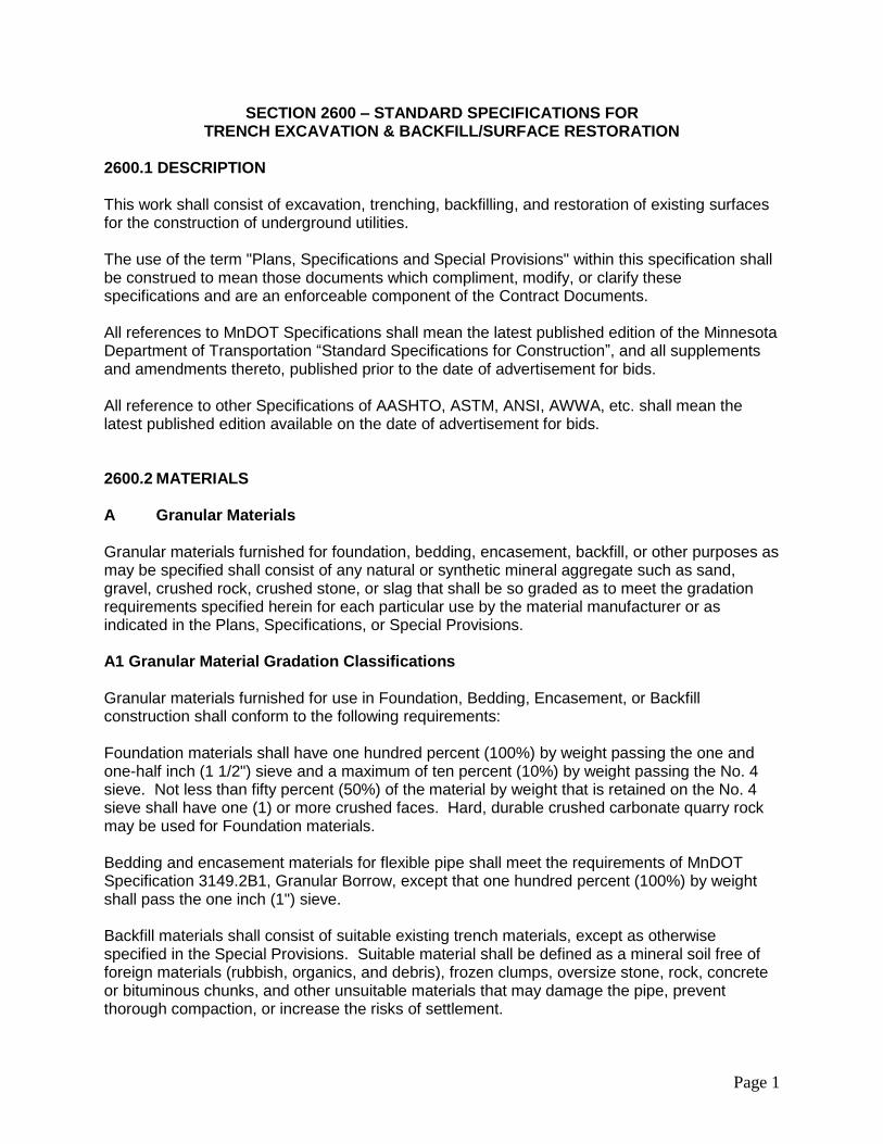
Page 1
SECTION 2600 – STANDARD SPECIFICATIONS FOR TRENCH EXCAVATION & BACKFILL/SURFACE RESTORATION
2600.1 DESCRIPTION This work shall consist of excavation, trenching, backfilling, and restoration of existing surfaces for the construction of underground utilities. The use of the term "Plans, Specifications and Special Provisions" within this specification shall be construed to mean those documents which compliment, modify, or clarify these specifications and are an enforceable component of the Contract Documents. All references to MnDOT Specifications shall mean the latest published edition of the Minnesota Department of Transportation “Standard Specifications for Construction”, and all supplements and amendments thereto, published prior to the date of advertisement for bids. All reference to other Specifications of AASHTO, ASTM, ANSI, AWWA, etc. shall mean the latest published edition available on the date of advertisement for bids. 2600.2 MATERIALS A Granular Materials
Granular materials furnished for foundation, bedding, encasement, backfill, or other purposes as may be specified shall consist of any natural or synthetic mineral aggregate such as sand, gravel, crushed rock, crushed stone, or slag that shall be so graded as to meet the gradation requirements specified herein for each particular use by the material manufacturer or as indicated in the Plans, Specifications, or Special Provisions. A1 Granular Material Gradation Classifications Granular materials furnished for use in Foundation, Bedding, Encasement, or Backfill construction shall conform to the following requirements: Foundation materials shall have one hundred percent (100%) by weight passing the one and one-half inch (1 1/2") sieve and a maximum of ten percent (10%) by weight passing the No. 4 sieve. Not less than fifty percent (50%) of the material by weight that is retained on the No. 4 sieve shall have one (1) or more crushed faces. Hard, durable crushed carbonate quarry rock may be used for Foundation materials. Bedding and encasement materials for flexible pipe shall meet the requirements of MnDOT Specification 3149.2B1, Granular Borrow, except that one hundred percent (100%) by weight shall pass the one inch (1") sieve. Backfill materials shall consist of suitable existing trench materials, except as otherwise specified in the Special Provisions. Suitable material shall be defined as a mineral soil free of foreign materials (rubbish, organics, and debris), frozen clumps, oversize stone, rock, concrete or bituminous chunks, and other unsuitable materials that may damage the pipe, prevent thorough compaction, or increase the risks of settlement.
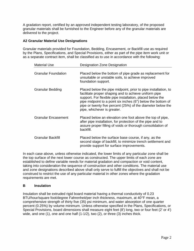
Page 2
A gradation report, certified by an approved independent testing laboratory, of the proposed granular materials shall be furnished to the Engineer before any of the granular materials are delivered to the project. A2 Granular Material Use Designations Granular materials provided for Foundation, Bedding, Encasement, or Backfill use as required by the Plans, Specifications, and Special Provisions, either as part of the pipe item work unit or as a separate contract item, shall be classified as to use in accordance with the following:
Material Use Designation Zone Designation
Granular Foundation Placed below the bottom of pipe grade as replacement for
unsuitable or unstable soils, to achieve improved foundation support.
Granular Bedding Placed below the pipe midpoint, prior to pipe installation, to
facilitate proper shaping and to achieve uniform pipe support. For flexible pipe installation, placed below the pipe midpoint to a point six inches (6") below the bottom of pipe or twenty five percent (25%) of the diameter below the pipe, whichever is greater.
Granular Encasement Placed below an elevation one foot above the top of pipe,
after pipe installation, for protection of the pipe and to assure proper filling of voids or thorough consolidation of backfill.
Granular Backfill Placed below the surface base course, if any, as the
second stage of backfill, to minimize trench settlement and provide support for surface improvements.
In each case above, unless otherwise indicated, the lower limits of any particular zone shall be the top surface of the next lower course as constructed. The upper limits of each zone are established to define variable needs for material gradation and compaction or void content, taking into consideration the sequence of construction and other conditions. The material use and zone designations described above shall only serve to fulfill the objectives and shall not be construed to restrict the use of any particular material in other zones where the gradation requirements are met. B Insulation Insulation shall be extruded rigid board material having a thermal conductivity of 0.23 BTU/hour/square foot/degree Fahrenheit/per inch thickness, maximum, at 40°F mean, a comprehensive strength of thirty five (35) psi minimum, and water absorption of one quarter percent (0.25%) by volume minimum. Unless otherwise specified in the Plans, Specifications, or Special Provisions, board dimensions shall measure eight feet (8') long, two or four feet (2' or 4') wide, and one (1), one and one half (1-1/2), two (2), or three (3) inches thick.
Page 3
C Geotextile Fabric Geotextile fabric shall meet the requirements of MnDOT Specification 3733 and be used as required by the Plans, Specifications, and Special Provisions. 2600.3 CONSTRUCTION REQUIREMENTS A General Provisions A1 Maintenance of Traffic Whenever work interferes with the flow of traffic along a roadway, the Contractor shall provide traffic control signing and public safety in accordance with the provisions Minnesota Manual on of Uniform Traffic Control Devices (current edition and any amendments), MnDOT Specifications 1404 and 1710, and the Special Provisions. Neither road closures nor detours shall be permitted unless specified in the Special Provisions or authorized by the Engineer. Where road closures or detours are permitted by the Engineer, the Engineer shall determine the appropriate agencies, boards, or departments the Contractor must notify prior to taking the action and the proper advance notice to be provided to each body. Compliance with this requirement shall not be construed to relieve the Contractor from the responsibility of notifying agencies or institutions whose services may be predicated upon a roadway being opened to traffic or whose services would be hindered if a roadway is closed to traffic. Such agencies or institutions shall include, but not be limited to, the police department, the fire department, municipal bus service, school bus service, and ambulance service, mail delivery, and waste hauler services. The Contractor shall keep the required agencies informed of changing traffic patterns and detour situations. A2 Establishing Line and Grade The primary line and grade will be established by the Engineer. For trench installation, line and grade stakes will be set parallel to the proposed pipeline at an appropriate offset therefrom as will best serve the Contractor's operations wherever practical. For tunnel installation, line and grade stakes will be set directly above the proposed pipeline setting. The Contractor shall arrange operations to avoid unnecessary interference with the establishment of the primary line and grade stakes and shall render whatever assistance may be required by the Engineer in accomplishing the staking. The Contractor shall be responsible for preservation of the primary stakes and, if negligent in providing necessary protection, shall bear the full cost of any re-staking. The Contractor shall be solely responsible for the correct transfer of the primary line and grade to all working points and for construction of the work to the prescribed lines and grades as established by the Engineer. Unless otherwise specified in the Plans, Specifications, and Special Provisions the watermain shall generally be placed with the minimum specified cover. However, a greater depth may be required to avoid conflicts with other utilities and obstructions. Installation of watermain and services to a depth deeper than specified shall be considered incidental with no additional compensation allowed therefore.
Page 4
The existing grade shown on the plans is approximate. Modification of the pipe location or differences in existing elevation shall not be cause for additional compensation. In areas where direct conflicts arise between watermain and water services, with storm sewer, sanitary sewer, sanitary sewer services, sewer forcemains, septic tanks, or subsoil treatment systems, the following shall apply: Watermain and services located near sewer forcemains:
A minimum of ten feet (10') of separation, measured horizontally between the outer surfaces of the pipes is required.
If ten feet (10') of separation cannot be provided, an approved additional measure of containment must be provided for either the watermain or the sewer forcemain.
Watermain and services located near septic tanks, or subsoil treatment systems:
A minimum of ten feet (10') measured horizontally between the outer surfaces of the watermain, tank and subsoil treatment system is required.
Watermain and services located near gravity sanitary and storm sewers:
A minimum of ten feet (10') measured horizontally between the outer surfaces of the pipes is required.
In locations where local conditions prevent the required separation indicated above (due to the presence of rock, buildings, other significant obstructions), the watermain may be laid closer to gravity sewer if one (1) of the following conditions is met:
The bottom of the watermain is laid at least eighteen inches (18") above the top of the sewer on a separate shelf; or
The sewer is constructed of materials and with joints that are equivalent to watermain standards of construction and is pressure tested to assure water tightness prior to backfilling.
Watermain and services crossing gravity sanitary and storm sewers:
A minimum vertical separation of eighteen inches (18") must be provided between the outer surfaces of the pipes, with preference that the watermain cross above the sewer, wherever possible. One full length of water pipe shall be located so both joints will be as far from the sewer as possible.
Watermain above-water crossings: The pipe shall be adequately supported and anchored, protected from vandalism, damage and freezing, and accessible for repair or replacement.
Page 5
Watermain underwater crossings: A minimum cover of five feet (5') shall be provided over the pipe unless otherwise approved by the Department of Health. When crossing water courses which are greater than fifteen feet (15') in width, the following shall be provided: 1. The pipe shall be of special construction, having flexible, restrained or welded watertight
joints 2. Valves shall be provided at both ends of water crossings so that the section can be isolated
for testing or repair; the valves shall be easily accessible, and not subject to flooding 3. Permanent taps or other provisions to allow insertion of a small meter to determine leakage
and obtain water samples on each side of the valve closest to the supply source. A3 Protection of Surface Structures All surface structures and features located outside the permissible excavation limits for underground installations, together with those within the construction areas which are indicated in the Plans as being saved, shall be properly protected against damage and shall not be disturbed or removed without approval of the Engineer. Within the construction limits, as indicated on the plans or as directed by the Engineer, the removal of improvements such as pavement, curb, curb & gutter, walks, turf, etc., shall be subject to equivalent acceptable replacement after completion of underground work, with all expense of removal and replacement being borne by the Contractor to the extent that separate compensation is not specifically provided for in the Contract. Obstructions such as street signs, guard posts, small culverts, mailboxes, and other items of prefabricated construction may be temporarily removed during construction provided that essential service is maintained in a relocated setting as approved by the Engineer and that nonessential items are properly stored for the duration of construction. Upon completion of the underground work, all such items shall be replaced in their proper setting at the sole expense of the Contractor to the extent that separate compensation is not specifically provided for in the Contract. The Contractor shall be responsible for protection of existing overhead utilities and poles. This shall include arranging with the utility owner and arrange paying the utility for holding poles that will be close to the edge of any trench. Holding of poles and repair of any damage to these facilities shall be considered incidental to the project with no additional compensation allowed. If relocation or removal of these facilities is required, the Owner will contact the concerned utility owner and arrange and pay for the relocation or removal at no additional expense to the Contractor. In the event of damage to any surface improvements, either privately or publicly owned, in the absence of construction necessity, the Contractor will be required to replace or repair the damaged property to the satisfaction of the Engineer and without cost to the Owner. A4 Interference of Underground Structures When any underground structure interferes with the planned placement of the pipeline or appurtenances to such an extent that alterations in the work are necessary to eliminate the conflict or avoid endangering effects on either the existing or proposed facilities, the Contractor
Page 6
shall immediately notify the Engineer and the Owner of the affected structure. When any existing facilities are endangered by the Contractor's operations, the Contractor shall cease work at the site and take such precautions as may be necessary to protect the in-place structures until a decision is made as to how the conflict will be resolved. Without specific authorization from the Engineer, no utility service shall be disrupted, nor shall any change be made in either the existing structures or the planned installations to overcome the interference. Alterations in existing facilities will be allowed only to the extent that service will not be curtailed and then only when the encroachment or relocation will satisfy all applicable regulations and conditions. Wherever alterations are required as a result of unforeseen underground interferences not due to any fault or negligence of the Contractor, the Engineer will issue a written order covering any additional or extra work involved and specifying the revised basis of payment, if any. Any alterations made strictly for the convenience of the Contractor, shall be subject to prior approval and shall be at the Contractor's expense. No extra compensation will be allowed for delays caused by the interference of underground structures. A5 Removal of Surface Improvements Removal of surface improvements in connection with trench excavation shall be limited to actual needs for installation of the pipeline and appurtenances, based on the allowable trench widths and any other controls imposed in connection with the work. Removal operations shall be coordinated effectively with the excavation and installation operations as will cause the least practical disruption of traffic or inconvenience to the public. The debris resulting from removals shall become the property of the Contractor and shall be disposed of by the Contractor in accordance with MnDOT Specification 2104 and the Special Provisions. Removal debris shall not be deposited at locations that will block access to fire hydrants, private driveways, or other essential service areas, nor obstruct surface drainage. Removal and final disposal of debris shall be accomplished as a single operation wherever possible and, in any event, the debris shall be removed from the site before starting the excavating operations. Removal of concrete or bituminous structures shall be by methods producing clean-cut breakage to pre-scored lines as will preserve the remaining structure without damage. Removal equipment shall not be operated in a manner that will cause damage to the remaining structure or adjoining property. Where not removed to an existing joint, concrete structures shall be sawed along the break lines to a minimum depth of one-third (1/3) of the structure depth. Any reusable materials generated during the work, such as aggregate, sod, topsoil, shall be segregated from other waste materials and be stockpiled so as to maintain suitability and permit proper reuse. The use of drop weight equipment for breaking pavement will be allowed to the extent that the Contractor shall assume full responsibility for any damages caused thereby. The pavement breaking operation shall not be allowed to become a nuisance to the public or a source of damage to underground or adjacent structures. The Engineer reserves the right to order discontinuance of drop weight breaking operations at any time.
Page 7
A6 Temporary Service Measures While any open excavations are maintained, the Contractor shall have available a supply of steel plates suitable for temporary bridging of open trench sections where either vehicular or pedestrian traffic must be maintained. Use of the plates shall be as directed or approved by the Engineer and where installed they shall be secured against possible displacement and be replaced with the permanent structure as soon as possible. B Excavation and Preparation of Trench B1 Operational Limitations and Requirements Trench excavation must conform to all local, state and federal requirements. All work must be confined to the limits of the construction and to easements and right of way as indicated on the plans. The Contractor shall install at his expense the necessary trench support to meet the varying soil conditions and to protect existing structures and property. The trench shall be drained to provide stable excavation and permit the pipe to be laid in a dry trench. Excavating operations shall proceed only so far in advance of pipe laying as will satisfy the needs for coordination of work and permit advance verification of unobstructed line and grade as planned, consistent with the Contractors methods and scheduling. Where interference with existing structures is possible or in any way indicated, and where necessary to establish elevation or direction for connections to in-place structures, the excavating shall be done at those locations in advance of the main operation so actual conditions will be exposed in sufficient time to make adjustments without resorting to extra work or unnecessary delay. Wherever possible, excavated materials shall be placed in areas that will not block existing vehicle and pedestrian traffic and drainage ways. The Contractor shall review proposed methods of operation with the Engineer prior to beginning the work. The Contractor shall backfill all trenches at the end of each work day, or upon written authorization of the Engineer, shall provide another approved method of protecting the trench area while work is not being performed. All installations shall be accomplished by open trench with the exception that boring, jacking and tunnel construction methods shall be employed where specifically required by the Plans, Specifications, or Special Provisions. The excavating operations shall be conducted so as to carefully expose all existing underground structures without damage. Wherever the excavation extends under or approaches so close to an existing structure as to endanger it in any way, precautions and protective measures shall be taken as necessary to preserve the structure and provide temporary support. Hand methods of excavating shall be utilized to probe for and expose such critical or hazardous installations as gas pipe, power and communication cables, watermain, gravity and pressure sewers, and respective service pipes. The Engineer shall be notified of any need for blasting to remove materials which cannot be broken up mechanically, and there shall be no blasting operations conducted until the Engineer's approval has been secured. Blasting will be allowed only when proper precautions are taken to protect life and property, and then shall be restricted as the Engineer directs. The hours of blasting operations shall be set by the Owner. The Contractor shall assume full
Page 8
responsibility for any damages caused by blasting, regardless of the requirements for notification and approval. The Contractor shall secure any required permits for blasting and shall conduct blasting operations in conformance with all applicable local, state and federal laws, regulations, and ordinances. B2 Classification and Disposition of Materials Excavated materials will be classified for payment only when specifically provided in the Special Provisions, or the Proposal. All other materials encountered in the excavations will be considered incidental to utility construction, with no additional compensation provided thereto. Miscellaneous excavated materials that are not specifically identified for payment in the Special Provisions or Proposal, exceed one (1) cubic yard in volume, cannot be re-used within the project limits, and in the opinion of the Engineer requires special means for handling and disposal, may be considered for payment through supplemental agreement as extra work. Miscellaneous excavated materials include but are not limited to organic soils, rubble, wood debris, boulder stone, masonry, concrete fragments, and metals. Rock excavation shall be defined to include all hard, solid rock in ledge formation, bedded deposits and unstratified masses; all natural conglomerate deposits so firmly cemented as to present all the characteristics of solid rock; and any boulder stone, masonry or concrete fragments exceeding one (1) cubic yard in volume. Materials such as shale, hard pan, soft or disintegrated rock which can be dislodged with a hand pick or removed with a power operated excavator will not be classified as Rock Excavation. Excavated materials will be classified for reuse as being either Suitable or Unsuitable for backfill or other specified use, subject to selective controls. All suitable materials shall be reserved for backfill to the extent needed, and any surplus remaining shall be utilized for other construction on the project as may be specified or ordered by the Engineer. To the extent practicable, granular materials and topsoil shall be segregated from other materials during the excavating and stockpiling operations so as to permit best use of the available materials at the time of backfilling. Unless otherwise specified in the Plans, Specifications, and Special Provisions, material handling as described above shall be considered incidental with no additional compensation provided. All excavated materials reserved for backfill or other use on the project shall be stored at locations approved by the Engineer that will cause a minimum of inconvenience to public travel, adjacent properties, and other special interests. The material shall not be deposited so close to the edges of the excavations in a manner that could create hazardous conditions, nor shall any material be placed so as to block the access to emergency services. All materials considered unsuitable by the Engineer, for any use on the project, shall be immediately removed from the project and be disposed of as arranged for by the Contractor with no additional compensation. B3 Excavation Limitations and Requirements Trench excavating shall be to a depth that will permit preparation of the foundation as specified and installation of the pipeline and appurtenances at the prescribed line and grade, except where alterations are specifically authorized. Trench widths shall be sufficient to permit the pipe to be laid and joined properly and the backfill to be placed and compacted as specified. Extra width shall be provided as necessary to permit convenient placement of sheeting and shoring and to accommodate placement of appurtenances.
Page 9
Excavations shall be extended below the bottom of structures as necessary to accommodate any required Granular Foundation material. When rock or unstable foundation materials are encountered at the established grade, additional materials shall be removed as specified or directed by the Engineer to produce an acceptable foundation. Unless otherwise indicated or directed, rock shall be removed to an elevation at least six inches (6") below the bottom surface of the pipe barrel and below the lowest projection of flange and bell/spigot joint. All excavations below grade shall be to a minimum width equal to the outside pipe diameter plus two feet (2'). Rock shall be removed to such additional horizontal dimensions as will provide a minimum clearance of six inches (6") on all sides of appurtenant structures such as valves, housings, access structures, etc. Where no other grade controls are indicated or established for the pipeline, the excavating and foundation preparations shall be such as to provide a minimum cover over the top of the pipe as specified. Trench widths shall allow for at least six inches (6") of clearance on each side of the flange and bell/spigot joint. The maximum allowable width of the trench at the top of pipe level shall be the outside diameter of the pipe plus two feet (2'), subject to the considerations for alternate pipe loading set forth below. The width of the trench at the ground surface shall be held to a minimum to prevent unnecessary destruction of the surface structures. The maximum allowable trench width at the top of pipe level may be exceeded only by approval of the Engineer, after consideration of pipe strength and loading relationships. Any alternate proposals made by the Contractor shall be in writing, giving the pertinent soil weight data and proposed pipe strength alternate, at least seven (7) days prior to the desired date of decision. Approval of alternate pipe designs shall be with the understanding that there will be no extra compensation allowed for any increase in material or construction costs. If the trench is excavated to a greater width than that authorized, the Engineer may direct the Contractor to provide a higher class of bedding and/or a higher strength pipe than that required by the Plans, Specifications, and Special Provisions in order to satisfy design requirements, without additional compensation. The use of granular foundation materials shall not be used as an aid to facilitate installation of pipe in wet soil conditions. Use of these materials in this manner in lieu of providing adequate dewatering measures shall be considered incidental to the construction with no additional compensation allowed therefore. B4 Sheeting and Bracing Excavations All trench excavations that require slope support shall be sheeted, shored, and braced in a manner that will meet all requirements of the applicable safety codes and regulations; comply with any specific requirements of the Contract; and prevent disturbance or settlement of adjacent surfaces, foundations, structures, utilities, and other properties. Any damage to the work under contract, to adjacent structures, or other property, caused by settlement, water or earth pressures, slides, cave-ins, or other causes due to the failure or lack of sheeting, shoring, or bracing, through negligence or fault of the Contractor in any manner shall be repaired at the Contractor's expense and without delay. The Plans, Specifications, and Special Provisions may require special precautions to protect life and property. The Engineer may order other precautions when excavation conditions appear to warrant additional measures. Failure of the Engineer to order correction of improper or
Page 10
inadequate sheeting, shoring, or bracing shall not relieve the Contractor's responsibilities for protection of life, property, and the work. The Contractor shall assume full responsibility for proper and adequate placement of sheeting, shoring, and bracing, to prevent displacement. Bracing shall be so arranged as to provide ample working space and without increase of stress or strain on the in-place structures to any extent that may cause damage. Sheeting, shoring and bracing materials shall be removed only when and in such manner as will assure adequate protection of the in-place structures and prevent displacement of supported grounds. Sheeting and bracing shall be left in place only as required by the Plans, Specifications, and Special Provisions or ordered by the Engineer. Otherwise, sheeting and bracing may be removed as the backfilling reaches the level of respective support. Wherever sheeting and bracing is left in place, the upper portions shall be cut and removed to an elevation of three feet (3') or more below the established surface grade or as the Engineer may direct. All costs of furnishing, placing and removing sheeting, shoring, and bracing materials, including the value of materials left in place as required by the Contract, shall be included in the prices bid for pipe installation and will not be compensated for separately. When sheeting, shoring, or bracing materials are left in place by written order of the Engineer, in the absence of specific requirements of the Contract, payment will be made for those materials by supplemental agreement. B5 Preparation and Maintenance of Foundations Foundation preparations shall be conducted as necessary to produce a stable foundation and provide continuous and uniform pipe bearing between bell holes. The initial excavating or backfilling operations shall produce a subgrade level slightly above finished grade as will permit hand shaping to finished grade by trimming of high spots and without the need for filling of low spots to grade. Final subgrade preparations shall be such as to produce a finished grade at the centerline of the pipe that is within three tenths of a foot (0.03') of a straight line between pipe joints and to provide bell excavation at each joint as will permit proper joining of pipe and fittings. In excavations made below grade to remove rock or unstable materials, the backfilling to grade shall be made with available suitable materials unless placement of Granular Foundation or Bedding material is specified or is ordered by the Engineer. Placement of the backfill shall be in relatively uniform layers not exceeding eight inches (8") in loose thickness. Each layer of backfill shall be compacted thoroughly, by means of approved mechanical compaction equipment, as will produce uniform pipe support throughout the full pipe length and facilitate proper shaping of the pipe bed. It shall be the Contractor's responsibility to notify the Engineer of changing soil conditions which may be of poor bearing capacity and when organic soils are encountered. Where utilities are placed on unstable soils without notification of the Engineer, the Contractor shall be responsible for all repairs and correction of the installation without further compensation. Care shall be taken during final subgrade shaping to prevent any over-excavation. Should any low spots develop, they shall only be filled with approved material, which shall have optimum moisture content and be compacted thoroughly without additional compensation to the Contractor. The finished subgrade shall be maintained free of water and shall not be disturbed
Page 11
during pipe lowering operations except as necessary to remove pipe slings. The discharge of trench dewatering pumps shall be directed to natural drainage channels or storm water drains. Draining trench water into sanitary sewers or combined sewers will not be permitted. The Contractor shall install and operate a dewatering system of wells or points to maintain pipe trenches free of water whenever necessary or as directed by the Engineer. Unless otherwise specified in the Plans, Specifications, and Special Provisions such work shall be considered incidental. All costs of excavating below grade and placing foundation or bedding aggregates as required shall be included in the bid prices for pipe items to the extent that the need for such work is indicated in the Contract provisions and the Proposal does not provide for payment under separate Contract Items. Any excavation below grade and any foundation or bedding aggregates required by order of the Engineer in the absence of Contract requirements will be compensated for separately. If examination by the Engineer reveals that the need for placement of foundation aggregate was caused by the Contractor's manipulation of the soils in the presence of excessive moisture or lack of proper dewatering, the cost of the corrective measures shall be borne by the Contractor. B6 Contaminated Materials and Regulated Wastes If during the course of the Project, the Contractor unexpectedly encounters any of the following conditions indicating the possible presence of contaminated soil, contaminated water, or regulated waste, the Contractor shall immediately stop work in the vicinity, and notify the Engineer. At the direction of the Engineer, a documented inspection and evaluation will be conducted prior to the resumption of work. The Contractor shall not resume work in the suspected area without authorization by the Engineer. Indicators of contaminated soil, groundwater or surface water include, but are not limited to the following:
(1) Odor including gasoline, diesel, creosote (odor of railroad ties), mothballs, or other chemical odor.
(2) Soil stained green or black (but not because of organic content), or with a dark, oily appearance, or any unusual soil color or texture.
(3) A rainbow color (sheen) on surface water or soil.
Indicators of regulated wastes include, but are not limited to the following:
(1) Cans, bottles, glass, scrap metal, wood (indicators of solid waste and a potential dump site).
(2) Concrete and asphalt rubble (indicators of demolition waste). (3) Roofing materials, shingles, siding, vermiculite, floor tiles, transite or any fibrous
material (indicators of demolition waste that could contain asbestos, lead or other chemicals).
(4) Culverts or other pipes with tar-like coating, insulation or transite (indicators of asbestos).
Page 12
(5) Ash (ash from burning of regulated materials may contain lead, asbestos or other chemicals).
(6) Sandblast residue (could contain lead). (7) Treated wood including, but not limited to products referred to as green treat, brown
treat and creosote (treated wood disposal is regulated). (8) Chemical containers such as storage tanks, drums, filters and other containers
(possible sources of chemical contaminants). (9) Old basements with intact floor tiles or insulation (could contain asbestos), sumps
(could contain chemical waste), waste traps (could contain oily wastes) and cesspools (could contain chemical or oily wastes).
Discovery of contaminated soil, contaminated water, or regulated waste on State right of way, State property, and State funded projects shall be handled in accordance with guidance procedures of the MNDOT Office of Environmental Services (OES) and the MPCA requirements for materials handling, disposal, re-use and remediation. Discovery of contaminated soil, contaminated water, or regulated waste on projects or properties that are not under the ownership or financed by the State shall be handled in accordance with guidance procedures of the MPCA requirements for materials handling, disposal, re-use and remediation. C Trenchless Pipe Installation The Contractor shall inspect and verify soil conditions as necessary in order to determine the type of construction to employ. Natural and/or manmade obstructions may be encountered in the soil. These contract documents do not warrant the nature or condition of the soils, and do not warrant that natural or manmade obstructions will not be encountered, nor guarantee the extent to which rocks, boulders, or other obstructions, regardless of size, may be encountered during boring operations. The Contractor shall not be entitled to additional compensation for any natural or manmade obstructions encountered during trenchless construction. The Contractor shall be responsible for protecting all existing utilities within the construction limits. C1 Jacking/Boring The terms "auger", "boring", "jack", "jacking", and "tunneling" in the proposal, specifications, and plans refers only to trenchless construction. The minimum diameter of the casing pipe shall be four inches (4") greater than the outside diameter of the bell of the carrier pipe. The Contractor shall prevent excavated materials from flowing back into the excavation during the trenchless construction. This shall include the use of a shield conforming to the size and shape of the casing that will prevent materials from flowing into the leading edge of the casing. The machine used shall be capable of controlling line and grade and shall conform to the size and shape of the casing pipe. No jacking/augering of pipe will be allowed below the water table unless the water table has been lowered sufficiently to keep the water below the pipe being installed. The use of water
Page 13
under pressure (jetting) or puddling will not be permitted to facilitate jacking/augering operations. If any installation is augered, the head shall be approved by the Engineer and the auger shall be located six inches (6") behind the lead edge of the casing or carrier pipe. The jacking system shall be provided with an integral grout pipe and casing pipe. A one inch (1") grout pipe shall be tack welded to the front edge of the first length of casing pipe. The grout pipe shall be extended with the casing pipe, but not fastened to the casing pipe during the remaining jacking operations. After the pipes are through to the receiving pit, the grout pipe shall be cut free from the casing pipe. The grout pipe shall be pulled back through the embankment applying positive piston pressure on the grout along the outside of the casing pipe throughout the pulling operation. A cement slurry grout mix with as little water as possible shall be used. Bentonite shall not be used to fill voids. The Engineer shall approve grout and backfill material prior to placement of any material.
Deviation from the pipe grade, as provided by the Engineer, in excess of five tenths of a percent (0.05%) may be cause for removal and relaying of the pipe by the Contractor with no additional compensation allowed therefore.
If a void develops, the jacking or boring operation shall be stopped immediately and the void shall be filled by an approved method.
The Contractor shall take the following precautions when boring:
Extend casing through entire distance bored. Check grade and alignment after each casing section is installed. Coordinate operations to provide continuous support to surrounding earth materials. Excavation shall be carried on in such a manner as to provide adequate support to surface structures and roads above and adjacent to the boring and not create any hazards to overhead traffic and other activities. These contract documents do not guarantee the extent to which rocks, boulders, or other obstructions, regardless of size, may be encountered during boring operations. No extra compensation will be made for removal of rocks, boulders or other natural or manmade obstructions encountered during trenchless construction or excavation. All voids caused by boring shall be filled by pressure grouting. The grout material shall consist of sand cement slurry of at least two (2) sacks of cement per cubic yard and a minimum of water to assure satisfactory placement. All slurry shall be pre-approved by the Engineer prior to use by the Contractor.
The Contractor shall take the following precautions when jacking: The jacking machine shall be capable of controlling line and grade. Progressively push carrier pipe through completed casing.
Page 14
Strap two (2) wooden saddle blocks to each pipe length to provide support at regular intervals. Center carrier pipe in casing at all times. Partially fill annular space between casing and carrier pipe with dry blown sand. Space shall be considered filled when dry sand blows out of opposite end of casing pipe. Seal each end of the casing with a concrete bulkhead after the sand has been deposited. The location, size, and configuration of all jacking pits shall be subject to approval of the Engineer.
C2 Directional Boring Direction boring/drilling installation shall be accomplished where required on the Plans or in the Special Provisions to minimize disturbance of existing surface improvements. The installer shall have a minimum of five (5) years of experience in this method of construction and have successfully installed at least ten thousand feet (10,000') of eight inch (8") or larger diameter pipe to specified grades. The field supervisor employed by the Contractor shall have at least five (5) years of experience and shall be at the site at all times during the boring/drilling installation. The Contractor shall submit boring/drilling pit locations to the Engineer before beginning construction. Boring pits may be located within roadway right-of-way and easements. Any other boring pit locations that may be desired by the Contractor for boring or other uses shall be the responsibility of the Contractor to attain authorization, including use of private property. Unless otherwise provided in the Special Provisions, the Contractor shall be compensated for the restoration work only within the areas at the connection points, or other locations as may be approved by the Engineer. The Contractor shall be responsible for repairs, without compensation, for any other repair areas, including pit/boring points and areas above the drilled pipe where drilling fluid pressure may have caused heaving or damage to pavement and other surfaces. The drilling equipment shall be capable of placing the pipe as shown on the plans. The installation shall be by a steerable drilling tool capable of installing continuous runs of pipe between appurtenances such as valves, manholes, etc., without intermediate pits. The guidance system shall be capable of installing pipe within one and one half inch (1 ½") of the plan vertical dimensions and two inches (2") of the plan horizontal dimensions. The Contractor shall remove and reinstall pipes which vary in depth and alignment from these tolerances. Pull back forces shall not exceed the allowable pulling forces for the pipe being installed. Drilling fluid shall be a mixture of water and bentonite clay, and shall be suitable for existing soil conditions. Disposal of excess fluid and spoils shall be the responsibility of the Contractor. D Placement of Insulation Rigid insulation board shall be placed within the pipe encasement zone, six inches (6") above the pipe.
Page 15
Insulation boards shall be placed with the long dimension parallel to the centerline of the pipe. Boards shall be placed in a single layer with tight joints. No continuous joints or seams shall be placed directly over the pipe. If two (2) or more layers of insulation boards are used, each layer shall be placed to cover the joints of the layer immediately below. The Contractor shall exercise caution to ensure that all joints between boards are tight during placement and backfilling with only extruded ends placed end to end or edge to edge. Backfill material shall be placed in such a manner that construction equipment does not operate directly on the insulation, and compacted with equipment which exerts a contact pressure of less than eighty (80) psi. E Pipeline Backfilling Operations All pipeline excavations shall be backfilled to restore preexisting conditions as the minimum requirement, and fulfill all supplementary requirements indicated in the Plans, Specifications, and Special Provisions. The backfilling operations shall be started as soon as conditions will permit on each section of pipeline, so as to provide continuity in subsequent operations and restore normal public service as soon as practicable. All operations shall be pursued diligently, with proper and adequate equipment, to assure acceptable results. The backfilling shall be accomplished with the use of Suitable Materials selected from the excavated materials to the extent available and practical. Should the materials available within the trench section be unsuitable or insufficient, the required additional materials shall be furnished from outside sources as provided in the Special Provisions, or as arranged otherwise through supplemental agreement. Backfill material selection shall be such as to make the best and fullest utilization of what is available, taking into consideration particular needs of different backfill zones. Material containing stone, rock, or chunks of any sort shall only be utilized where and to the extent there will be no detrimental effects. Placement of backfill material containing stones, boulders, chunks, greater than eight inches (8") in any dimension shall not be allowed. All flexible pipe shall be bedded in accordance with ASTM Specification D2321, "Recommended Practice for Underground Installation of Flexible Thermoplastic Sewer Pipe". Where existing soils do not meet the requirements of bedding and encasement materials, the Contractor shall furnish the required granular materials. Placement and compaction of bedding and encasement materials around the pipe shall be considered incidental to the installation of the pipe. Compaction of materials placed within the pipe bedding and encasement zones shall be accomplished with portable or hand equipment methods, so as to achieve thorough consolidation under and around the pipe and avoid damage to the pipe. Above the cover zone material, the use of heavy roller type compaction equipment shall be limited to safe pipe loading. Backfill materials shall be carefully placed in uniform loose thickness layers up to twelve inches (12") thick spread over the full width and length of the trench section to provide simultaneous support on both sides of the pipeline. Granular backfill may be placed in layers up to twelve inches (12") above an elevation one foot (1') above the top of the pipe.
Page 16
Each layer of backfill material shall be compacted effectively, by approved mechanical or hand methods, until there is no further visual evidence of increased consolidation or the density of the compacted layer conforms to the density requirements specified in the Special Provisions. Compaction of each layer shall be completed acceptably before placing material for a succeeding layer thereon. The manner of placement, compaction equipment, or procedure effectiveness shall be subject to approval of the Engineer. All surplus or waste materials remaining after completion of the backfilling operations shall be disposed of in an acceptable manner within twenty four (24) hours after completing the backfill work on each particular pipeline section. Disposal at locations within the project limits shall be as specified, or as approved by the Engineer; otherwise, disposal shall be accomplished outside the project limits at the Contractor's discretion. The backfilling and surplus or waste disposal operations shall be a part of the work required under the pipeline installation items, without until final cleanup. Compaction of backfill within Roadbed areas shall meet the density requirements of MnDOT Specification 2105.3 F1. Compaction of backfill in all other areas shall be as required in the Special Provisions. Until expiration of the guarantee period, the Contractor shall assume full responsibility and expense for all backfill settlement and shall refill and restore the work as directed to maintain an acceptable surface condition, regardless of location. All additional materials required shall be furnished without cost to the Owner. Any settlement of road surfaces placed under this Contract and that are within the guarantee period that are in excess of one inch (1"), as measured by a ten foot (10') straight edge shall be considered failure of the mechanical compaction. The Contractor shall be required to repair such settlement without cost to the Owner. F Restoration of Surface Improvements Wherever any surface improvements such as pavement, curbing, pedestrian walks, fencing, or turf have been removed, damaged or otherwise disturbed by the Contractor's operations, they shall be repaired or replaced to the Engineer's satisfaction, as will restore the improvement in kind and structure to the preexisting condition. Each item of restoration work shall be done as soon as practicable after completion of installation and backfilling operations on each section of pipeline. In the absence of specific payment provisions, as separate Contract Items, the restoration work shall be compensated for as part of the work required under those Contract Items which necessitated the destruction and replacement or repair, and there will be no separate payment. If separate pay items are provided for restoration work, only that portion of the repair or reconstruction which was necessitated by the Contract work will be measured for payment. Any improvements removed or damaged unnecessarily or undermined shall be replaced or repaired at the Contractor's expense. G Maintenance and Final Cleanup All subgrade surfaces shall be maintained acceptably until the start of surfacing construction or restoration work, and until the work has been finally accepted. Additional materials shall be
Page 17
provided and placed as needed to compensate for trench settlement and to serve as temporary construction pending completion of the final surface improvements. Final disposal of debris, waste materials, and other remains or consequences of construction, shall be accomplished intermittently as new construction items are completed and shall not be left to await final completion of all work. Cleanup operations shall be considered an incidental part of the work covered under the Contract Items. If disposal operations and other cleanup work are not conducted properly as the construction progresses, the Engineer may withhold partial payments until such work is satisfactorily performed or the Engineer may deduct the estimated cost of its performance from the partial estimate value. 2600.4 METHOD OF MEASUREMENT All items will be measured separately according to design designation as indicated in the Pay Item name and as may be detailed and defined in the Plans, Specifications, or Special Provisions. Complete-in-Place items shall include all component parts thereof as described or required to complete the unit, but excluding any excesses covered by separate Pay Items. A Rock Excavation Rock Excavation shall be measured by volume in cubic yards. Depth shall be measured from the top of the rock to a point six inches below the outside barrel of the pipe and width shall be the inside diameter of the pipe plus twenty four inches (24") (12" from each side). The minimum width of measurement shall be four feet (4'). B Granular Materials Granular materials furnished and placed as special foundation, bedding, encasement, or backfill construction will be measured by weight or volume of material furnished by the Contractor from outside sources and placed within the limits defined. Unless otherwise specified, volume will be determined by vehicular measure (loose volume) at the point of delivery. Measurements will not include any materials required to be placed as a component part of other Contract Items as may be specified. C Geotextile Fabric Where geotextile fabric is used for improving pipe foundation, it shall be measured by the square yard of material installed. D Insulation Rigid board insulation shall be measured on a square yard basis installed to the specified thickness noted on the Plans, Specifications, and Special Provisions and shall include all materials, equipment, and labor required for placement. 2600.5 BASIS OF PAYMENT All costs of excavating to foundation grade, preparing the foundation, placing and compacting backfill materials, restoring surface improvements, and other work necessary for prosecution
Page 18
and completion of the work as specified, shall be included for payment as part of the pipe and pipe appurtenance items without any direct compensation being made. In the absence of special payment provisions, all costs of restoring surface improvements as required, disposal of surplus or waste materials, maintenance and repair of completed work, and final cleanup operations shall be incidental to the Contract Items under which the costs are incurred. Granular materials furnished for foundation, bedding, cover, or backfill placement as specified in connection with pipe or structure items will only be paid for as separate Contract Items to the extent that the Proposal contains specific Pay Items. Otherwise the furnishing and placing of granular materials as specified shall be incidental to the pipe or structure item without any direct compensation being made. Materials utilized for filling annular spaces due to jacking/boring and drilling fluids for directional boring shall be incidental to the installation of the casing and pipe installed. Contaminated Materials and Regulated Wastes not anticipated in the plans, specifications and special provisions and unexpectedly discovered during construction shall be compensated for as negotiated by supplemental agreement. Contaminated Materials and Regulated Wastes specifically identified for payment in the plans, specifications, and special provisions, will be paid for under separate Contract Items provided in the Proposal.
Page 19
SECTION 2611 – STANDARD SPECIFICATIONS FOR WATERMAIN AND SERVICE LINE INSTALLATION
2611.1 DESCRIPTION This work shall consist of the construction of watermain and building service pipelines utilizing plant fabricated pipe and other appurtenant materials, installed for conveyance of potable water. The work includes the relocation or adjustment of existing facilities as may be specified in the Plans, Specifications and Special Provisions. The use of the term "Plans, Specifications, and Special Provisions" within this specification shall be construed to mean those documents which compliment, modify, or clarify these specifications and are an enforceable component of the Contract Documents. All references to MnDOT Specifications shall mean the latest published edition of the Minnesota Department of Transportation “Standard Specifications for Construction”, and all supplements and amendments thereto, published prior to the date of advertisement for bids. All reference to other Specifications of AASHTO, ASTM, ANSI, AWWA, etc. shall mean the latest published edition available on the date of advertisement for bids. The following American Water Works Association (AWWA) Specifications have been referenced in this Specification: C104 American National Standard for Cement-Mortar Lining for Ductile-Iron Pipe and Fittings
for Water C105 American National Standard for Polyethylene Encasement for Ductile-Iron Pipe Systems C110 American National Standard for Ductile-Iron and Gray-Iron Fittings, 3 In. Through 48 In.
(75 mm Through 1200 mm), for Water and Other Liquids C111 American National Standard for Rubber-Gasket Joints for Ductile-Iron Pressure Pipe and
Fittings C115 American National Standard for Flanged Ductile-Iron Pipe With Ductile-Iron or Gray-Iron
Threaded Flanges C116 AWWA Standard for Protective Fusion-Bonded Epoxy Coatings for the Interior and
Exterior Surfaces of Ductile-Iron and Gray-Iron Fittings C150 American National Standard for Thickness Design of Ductile-Iron Pipe C151 American National Standard for Ductile-Iron Pipe, Centrifugally Case, for Water or Other
Liquids C153 American National Standard for Ductile-Iron Compact Fittings, 3 In. Through 24 In. (76
mm Through 610 mm) and 54 In. Through 64 In. (1,400 mm Through 1,600 mm), for Water Service
C301 AWWA Standard for Prestressed Concrete Pressure Pipe, Steel-Cylinder Type, for Water and Other Liquids
C304 AWWA Standard for Design of Prestressed Concrete Cylinder Pipe 26 C500 AWWA Standard for Metal-Seated Gate Valves for Water Supply Service (Includes
addendum C500a-95.) C502 AWWA Standard for Dry-Barrel Fire Hydrants (Includes addendum C502a-95.) C504 AWWA Standard for Rubber-Seated Butterfly Valves C509 AWWA Standard for Resilient-Seated Gate Valves for Water Supply Service (Includes
addendum C509a-95.)
Page 20
C515 AWWA Standard for Reduced-Wall, Resilient-Seated Gate Valves for Water Supply Service
C550 AWWA Standard for Protective Interior Coatings for Valves and Hydrants C600 AWWA Standard for Installation of Ductile-Iron Water Mains and Their Appurtenances C605 AWWA Standard for Underground Installation of Polyvinyl Chloride (PVC and PVCO)
Pressure Pipe and Fittings for Water C651 AWWA Standard for Disinfecting Water Mains C800 AWWA Standard for Underground Service Line Valves and Fittings C900 AWWA Standard for Polyvinyl Chloride (PVC) Pressure Pipe, 4 In. Through 12 In., for
Water Transmission and Distribution (Includes addendum C900a-92.) C901 AWWA Standard for Polyethylene (PE) Pressure Pipe and Tubing, 1/2 In. Through 3 In.,
for Water Service C904 AWWA Standard for Cross-Linked Polyethylene (PEX) Pressure Pipes, ½ In. (12 mm)
Through 3 In. (76 mm) for Water Service C905 AWWA Standard for Polyvinyl Chloride (PVC) Pressure Pipe and Fabricated Fittings, 14
In. Through 48 In., (350mm Through 1,200mm), for Water Transmission and Distribution C906 AWWA Standard for Polyethylene (PE) Pressure Pipe and Fittings, 4 In. Through 63 In.,
for Water Distribution and Transmission C907 AWWA Standard for Injection-Molded Polyvinyl Chloride (PVC) Pressure Fittings for
Water - 4 In. Through 8 In. (100mm Through 200mm) for Water, Wastewater, and Reclaim Water Service
AWWA C908 Standard for PVC Self-Tapping Saddle Tees for Use on PVC Pipe ASTM A48 Standard Specification for Gray Iron Castings ASTM A536 Standard Specification for Ductile Iron Castings ASTM B88 Standard Specification for Seamless Copper Water Tube ASTM C270 Standard Specification for Mortar for Unit Masonry ASTM C478 Standard Specification for Precast Reinforced Concrete Manhole Sections ASTM D543 Standard Practices for Evaluating the Resistance of Plastics to Chemical Reagents ASTM D1248 Standard Specification for Polyethylene Plastics Extrusion Materials for Wire and
Cable ASTM D1784 Standard Specification for Rigid Poly(Vinyl Chloride) (PVC) Compounds and
Chlorinated Poly(Vinyl Chloride) (CPVC) Compounds ASTM D1785 Standard Specification for Poly(Vinyl Chloride) (PVC) Plastic Pipe, Schedules 40,
80, and 120 ASTM D2241 Standard Specification for Poly(Vinyl Chloride) (PVC) Pressure Rated Pipe (SDR
Series) ASTM D2446 Standard Specification for Poly(Vinyl Chloride) (PVC) Plastic Pipe Fittings,
Schedule 40 ASTM D2467 Standard Specification for Poly(Vinyl Chloride) (PVC) Plastic Pipe Fittings,
Schedule 80 ASTM D3035 Standard Specification for Polyethylene (PE) Plastic Pipe (DR PR) Based on
Controlled Outside Diameter ASTM D3261 Standard Specification for Butt Heat Fusion Polyethylene (PE) Plastic Fittings for
Polyethylene (PE) Plastic Pipe and Tubing ASTM D3350 Standard Specification for Polyethylene Plastics Pipe and Fittings Materials ASTM F593 Standard Specification for Stainless Steel Bolts, Hex Cap Screws, and Studs ASTM F594 Standard Specification for Stainless Steel Nuts ASTM F714 Standard Specification for Polyethylene (PE) Plastic Pipe (DR PR) Based on
Outside Diameter ASTM F876 Standard Specification for Crosslinked Polyethylene (PEX) Tubing
Page 21
ASTM F877 Standard Specification for Crosslinked Polyethylene (PEX) Hot and Cold Water Distribution Systems
Service installations shall include either Branch Service Lines or Tapped Service Lines in accordance with the standards set forth herein. Tapped Service installations shall include all water service lines less than three inches (3") nominal inside diameter pipe. The component parts of a tap service installation shall include a corporation stop coupling complete with watermain tap and saddle where required; a curb stop coupling complete with service box; and service piping extending from the corporation stop to the curb stop coupling and beyond to the property line or to the limits as established by the Engineer. Branch Service installations shall include all water service lines of three inches (3") nominal inside diameter pipe and larger. The component parts of a branch service installation shall include a tapping sleeve and valve or a tee connection and valve complete with valve box, and piping extending from the watermain connection, to the property line or to the limits as specified by the Engineer. All references to "structure" shall include any man-made object that is not otherwise exempted by special terminology or definition. 2611.2 MATERIALS All materials required for this work shall be new material conforming to requirements of the reference specifications for the class, kind, type, size, grade, and other details indicated in the Contract. Unless otherwise indicated, all required materials shall be furnished by the Contractor. If any options are provided for, as to type, grade, or design of the material, the choice shall be limited as may be stipulated in the Plans, Specifications, or Special Provisions. All manufactured products shall conform in detail to such standard design drawings as may be referenced or furnished in the Plans. Otherwise, the Owner may require advance approval of material suppliers, product design, or other unspecified details as it deems desirable for maintaining adopted standards. At the request of the Engineer, the Contractor shall submit, in writing, a list of materials and suppliers for approval. A Certificate of Compliance shall be furnished stating that the materials furnished have been tested and are in compliance with the specification requirements. A Water Pipe Materials All pipe furnished for watermain and branch line installations shall be of the type, kind, size, and class indicated for each particular line segment as shown in the Plan and designated in the Contract Items. Wherever connection of dissimilar materials or designs is required, the method of joining and any special fittings employed shall be subject to approval of the Engineer.
Page 22
A1 Ductile Iron Pipe and Ductile Iron and Gray Iron Fittings The pipe furnished shall be Ductile Iron pipe and pipe fittings furnished shall be of the Ductile Iron or Gray Iron type as specified for each particular use of installation. When Gray Iron is specified, either type may be furnished. Gray Iron may not be substituted for Ductile Iron unless specifically authorized in the Special Provisions. Ductile iron pipe shall conform to the requirements of AWWA C115 or C151 for potable water, and thickness design shall conform to AWWA C 150. In addition, the pipe shall comply with the following supplementary provisions:
(1) Fittings shall conform to the requirements of AWWA C110 (Gray Iron and Ductile Iron Fittings) or AWWA C153 (Ductile Iron Compact Fittings) for the joint type specified.
(2) Unless otherwise specified all pipe and fittings shall be furnished with cement mortar
lining meeting the requirements of AWWA C104 for standard thickness lining. All exterior surfaces of the pipe and fittings shall have an asphaltic coating at least one mil thick. Spotty or thin seal coating, or poor coating adhesion, shall be cause for rejection.
Fittings specified to be furnished with fusion bonded epoxy external coating and/or interior lining shall conform to the requirements of AWWA C550 and C116/A21.16, with 6-8 mil nominal thickness.
(3) Rubber gasket joints for Ductile Iron Pressure Pipe and fittings shall conform to
AWWA C111. (4) The nuts and bolts shall be constructed of corrosion resistant, high-strength, low-
alloy steel with a ceramic filled, baked on fluorocarbon resin. The nuts and bolts shall be in compliance with ANSI/AWWA C111/A21.11 (Current Revision).
(5) Conductivity shall be maintained through pipe and fittings with an external copper
jumper wire or specialty gaskets which are capable of meeting conductive requirements. Wedge type connectors will not be allowed.
A2 Polyvinyl Chloride (PVC) Pressure Pipe and Fittings Polyvinyl chloride (PVC) pressure pipe shall be manufactured with compounds conforming to ASTM D1784 and shall conform to the requirements of AWWA C-900, C-905, Fusible C-900, and Fusible C905, for the size, grade, and pressure class indicated on the Plans, Specifications, and Special Provisions. Fittings shall be the same pressure class as the pipe and shall conform to AWWA C907 and C908. PVC pressure pipe and fittings shall have a pressure rating of one hundred sixty (160) psi or greater, unless otherwise provided in the special provisions. The grade used shall be resistant to aggressive soils or corrosive substances in accordance with the requirements of ASTM D-543. Unless otherwise specified, the dimensions and tolerances of the pipe barrel should conform to ductile iron or cast iron pipe equivalent outside diameters.
Page 23
A3 Polyethylene (PE) Pressure Pipe and Fittings Polyethylene pressure pipe and fittings shall be manufactured with compounds conforming to ASTM D3350 and shall conform to ASTM D3035 and AWWA C-901(for 0.5” to 3” diameters) and ASTM F714 and AWWA C906 (for 4” to 65” diameters) for the size, grade and pressure class indicated on the plans, specifications and special provisions. Polyethylene pipe and fittings shall be PE 3608 or PE 4710 for potable water transmission and pressure rating of one hundred sixty (160) psi or greater, unless otherwise provided in the special provisions. The pipe and fittings shall be manufactured from the same resin type, grade, and cell classification. Unless otherwise specified, the dimensions and tolerances of the pipe barrel should conform to Ductile Iron pipe equivalent outside diameters for pipe diameters greater than three inches (3"). The method of joining material shall be by the Thermal Butt- Fusion Method in accordance with ASTM 3261. The minimum "quick-burst" strength of the fittings shall not be less than that of the pipe with which the fitting is to be used. B Fire Hydrants Fire hydrants shall be of the type, size, and construction specified in the Plans and shall conform to the applicable requirements of AWWA C-502. Unless otherwise specified in the Plans, Specifications, and Special Provisions, hydrants shall be furnished in conformance with the following supplementary requirements:
(1) Hydrants shall have a five inch (5") (nominal diameter) main valve opening of the type that opens against water pressure.
(2) Hydrant barrels shall be two (2) piece, non-jacket type, with flanged joint above
finished grade line and with mechanical joint connection at the hub end for joining a six inch (6") ductile iron branch pipe.
(3) Hydrant operating rod shall be equipped with a breakable joint coinciding with the
flange joint above the grade line. (4) Hydrant bury length shall be measured from the bottom of the branch pipe
connection to the finished ground line at the hydrant. (5) Hydrants shall have two (2) outlet nozzles for two and one half inch (2-1/2") (I.D.)
hose connection and one outlet nozzle for four inch (4") (I.D.) steamer connection. All outlet nozzle threads shall be National Standard Fire-Hose Coupling Screw Threads (NFPA 1963).
(6) Hydrant operating mechanisms shall be provided with "O" ring seals preventing
entrance of moisture and shall be lubricated through an opening in the operating nut or bonnet.
(7) Hydrants shall be provided with outlets for drainage in the base or barrel, or between
the base and barrel, unless the Special Provisions require that drain outlets be omitted or plugged.
Page 24
(8) The hydrant operating nut shall be rotated counterclockwise to open. (9) Detailed drawings, catalog information, and maintenance data shall be furnished as
requested by the Engineer.
(10) Hydrant body bolts shall be corrosion resistant, stainless steel conforming to the requirements of ASTM F593 and F594, alloy group 1, 2, 3, suitable for exterior use above and below ground. Bolts shall conform to manufacturer recommendation for tensile strength and torque.
C Valves and Valve Housing C1 Valve Housings Valve housings shall be of ductile or cast iron, High Density Polyethylene or masonry construction as specified in the Plans, Specifications, and Special Provisions for the particular valve size or installation. Masonry manhole or vault type units shall be constructed in accordance with the provisions of MnDOT Specification 2506. Precast Concrete Manholes shall conform to ASTM Specification C-478 suitable for HS 20 traffic loading for all units located in driving areas. Ductile or cast iron valve boxes and all castings for manhole or vault type units shall conform to the requirements of MnDOT Specification 3321. C2 Gate Valves Gate Valves shall conform to all applicable requirements of AWWA C-500 or AWWA C-509 or AWWA C-515, together with such supplementary requirements as may be covered in the Plans, Specifications, and Special Provisions. Unless otherwise specified gate valves shall comply with the following supplementary requirements:
(1) Gate valves meeting the requirements of AWWA C-500 shall be two-faced, double disc type, with parallel seats. Gate valves meeting the requirements of AWWA C-509 and C-515 shall be single disc type with resilient seat bonded or mechanically attached to either the gate or valve body, and the wedge shall be ductile iron fully encapsulated with EPDM rubber, shall be symmetrical and seal equally well with flow in either direction without misalignment. All valves shall be provided with a two-inch square operating nut opening counterclockwise and mechanical joint ends.
(2) All gate valves shall be non-rising stem (NRS) type furnished with O-Ring stem
seals. (3) All gate valves sixteen inches (16") or larger in size shall be arranged for operation in
the horizontal position and shall be equipped with bypass valves. (4) All gears on gate valves shall be cut tooth steel gears, housed in heavy ductile or
cast iron extended type grease cases of approved design. (5) All gate valves shall have an open indicating arrow, the manufacturer's name,
pressure rating and year of manufacture cast on the valve bodies. (6) All internal and external surfaces of the valve body and bonnet shall have an epoxy
coating, complying with ANSI/AWWA C550.
Page 25
(7) All gate valves shall have stainless steel body bolts unless otherwise specified.
C3 Butterfly Valves Butterfly valves shall be manufactured in conformance with all applicable requirements of AWWA C-504 for 150 p.s.i. working pressure minimum, together with such supplementary requirements as may be covered in the Plans, Specifications, and Special Provisions. Unless otherwise specified, the butterfly valves furnished shall comply with the following supplementary requirements.
(1) The butterfly valves shall be short body of ductile or cast iron with mechanical joint ends.
(2) The butterfly valves shall be rubber seated with ductile or cast disc, non-rising stem
type furnished with O-ring stem seals. (3) The butterfly valves shall be equipped with a two-inch square operating nut opening
counterclockwise. (4) The butterfly valves shall be designed for direct burial installation. (5) All butterfly valves shall have an open indicating arrow, the manufacturer's name,
pressure rating and year of manufacture on the valve bodies. (6) All internal and external surfaces of the valve body and bonnet shall have an epoxy
coating, complying with ANSI/AWWA C550. (7) All butterfly valves shall have stainless steel body bolts unless otherwise specified.
D Water Service Pipe and Fittings Water service pipe of 3 inches or larger inside diameter shall conform to the requirements as set forth under the provisions of 2611.2. Water service pipe of less than three inches (3") in inside diameter shall conform to the requirements of ASTM B 88 for Seamless Copper Water Tube, Type K, Soft Annealed temper; Polyethylene Pipe as per AWWA C901 and ASTM D3350, or Polyvinyl Chloride Pipe and fittings as per a ASTM D1785, D2241, D2466, D2467 and D2740, or Cross-linked Polyethylene (PEX) pipe as per ASTM F876, ASTM F877, and AWWA C904, NSF/ANSI Standard 61 for potable water distribution, as specified on the Proposal or in the Special Provisions. Water service piping supplied shall include markings indicating the type, pressure class, testing certification, and use for potable water systems. Corporation stops, saddles, curb stops, and curb stop service boxes shall conform to the requirements of AWWA C800 be as detailed in the Plans, Specifications, and Special Provisions or approved designations. Saddles for Polyethylene Pipe shall conform to the requirements of AWWA C800, and shall be thermal fusion polyethylene type; ductile iron with dual stainless steel straps, spring washers, bolts and washers; or stainless steel sleeve type, with stainless steel bolts, nuts, and spring
Page 26
washers. Stainless steel bolts, nuts, and washers. Spring washers shall be manufactured from type 304 stainless steel, special “spring grade”. Saddles shall include threaded outlet tapping sleeves and Nitrile Butadiene Rubber (NBR) gaskets. All fittings for copper tubing shall be cast brass, having uniformity in wall thickness and strength, and shall be free of defects affecting serviceability. All copper pipe fittings shall be flared or compression type. All threads for underground service line fittings shall conform to the requirements of AWWA C-800. Each fitting shall be permanently and plainly marked with the name or trademark of the manufacturer. Fittings for thermoplastic pipe types shall be of the same material and pressure class as the piping. Curb stop service boxes shall be gray iron conforming to the requirements of ASTM A 48 for Class 20 or higher tensile strength and shall have at least twelve inches (12") of vertical adjustment for the cover depth specified in the Plans, Specifications, and Special Provisions. E Polyethylene Encasement Material Polyethylene encasement material shall conform to the requirements of AWWA C-105 for tube type installation and 8 mil nominal film thickness. F Mechanical Joint Restraints Mechanical joint restraints shall be ductile iron conforming to the requirements of ASTM A536 and AWWA C-600. Joint restraints shall be American, US Pipe, Star Pipe Products, or EBBA Iron Mega-Lug type, and be designed to withstand the design pressures indicated in the Plans, Specifications, and Special Provisions. Mechanical joint restraints shall be fusion bonded epoxy coated meeting the requirements of AWWA C-116. All nuts, bolts, and tie rod type restraints shall be stainless steel, corrosion-resistant coating, or coated with an owner approved rustproofing material. G Mortar Mortar for use in masonry construction shall meet the requirements of MNDOT 2506.2B and ASTM C270. H Concrete Concrete used for cast-in-place masonry construction shall be produced and furnished in accordance with the provisions of MnDOT Specification 2461 for the mix design indicated in the Plans, Specifications, or Special Provisions. The requirements for Grade B concrete shall be met where a higher grade is not specified. Type 3, air-entrained, concrete shall be furnished and used in all structures having weather exposure. I Tracer Wire for Non-Conductive Pipe Tracer wire for use with all thermoplastic pipe types shall be Underwriters Laboratories (UL) listed for use in direct burial applications. Tracer wire shall be a minimum 12 AWG copper clad steel rated to 30 volts, High Molecular Weight Polyethylene (HMWPE) meeting ASTM D-1248, with designation identified on the outside of the wire casing.
Page 27
2611.3 CONSTRUCTION REQUIREMENTS A Installation of Pipe and Fittings Installation of ductile iron watermains and their appurtenances shall conform to the requirements of AWWA C-600, the Plans, Specifications and Special Provisions. Installation of Polyvinyl Chloride (PVC) pipe and their appurtenances shall conform to the requirements of AWWA C605, and the bedding and backfill conditions specified by the Manufacturer, Plans, Specifications, and Special Provisions. Installation of Polyethylene Pipe and their appurtenances shall conform to the requirements of AWWA M55 and to the bedding and backfill conditions specified by the Manufacturer, Plans, Specifications, and Special Provisions. No existing valves or hydrants shall be operated by individuals other than personnel from the City Public Works Department. Only under emergency conditions or after specific authorization is given by the City Public Works Department shall the Contractor operate valves or hydrants. Installation of pipe and fittings shall also conform to the following general guidelines: A1 Inspection and Handling Proper and adequate implements, tools, and facilities satisfactory to the Engineer shall be provided and used by the Contractor for the safe and convenient prosecution of the work. During the process of unloading delivered materials, all pipe and accessories shall be inspected by the Contractor for damage. The Contractor shall notify the Engineer of all material found to have cracks, flaws or other defects. The Engineer shall inspect the damaged material and have the right to reject any materials found to be unsatisfactory. The Contractor shall promptly remove all rejected material from the site. All materials shall be handled carefully, as will prevent damage to protective coatings, linings, and joint fittings; preclude contamination of interior areas; and avoid jolting contact, dropping, or dumping. During pipe laying operations each pipe section and shall be inspected by the Contractor. The Contractor shall inform the Engineer of any defects discovered and the Engineer will prescribe the required corrective actions or order rejection. Immediately before placement, the joint surfaces of each pipe section and fitting shall be inspected for the presence of foreign matter, coating blisters, rough edges or projections, and any imperfections so detected shall be corrected by cleaning, trimming, or repair. A2 Pipe Laying Operations Trench excavation and bedding preparations shall proceed ahead of pipe placement as will permit proper placement and joining of the pipe and fittings at the prescribed grade and alignment without unnecessary hindrance. All foreign matter or dirt shall be removed from the inside of the pipe and fittings before they are lowered into position in the trench, and they shall
Page 28
be kept clean. The watermain materials shall be carefully lowered into laying position by the use of suitable restraining devices. Under no circumstances shall the pipe be dropped or dumped into the trench. As each length of bell and spigot pipe is placed in laying position, the spigot end shall be centered in the bell and the pipe forced home and brought to correct line and grade. The pipe shall be secured in place with approved encasement and backfill materials. When pipe laying is not in progress, all open ends of the pipe line shall be closed by watertight plugs or other means approved by the Engineer. If water is present in the trench, the plugs shall remain in-place until the trench is pumped completely dry. When connecting to existing stubs, the Contractor shall prevent dirt or debris from entering the existing pipe. A3 Aligning and Fitting of Pipe The cutting of pipe for inserting valves, fittings, or closure pieces shall be done in a neat and workmanlike manner without damage to the pipe and so as to leave a smooth square-cut end. Pipe shall be cut with approved mechanical tools. Flame cutting will not be allowed under any conditions. All rough edges shall be removed from the cut ends of pipe and, where rubber gasket joints are used, the outer edge shall be rounded or beveled by grinding or filing to produce a smooth fit. When necessary to deflect pipe from a straight line either in the vertical or horizontal plane, to avoid obstructions, plumb stems, or produce a long radius curve when permitted, the amount of deflection allowed at each joint shall not exceed the limits to maintain a satisfactory joint seal in conformance with AWWA C-600 for ductile iron pipe mechanical and push-on joints, AWWA C-605 for PVC pipe and AWWA M55 for PE pipe. The maximum angular deflection at any joint for other pipe materials and joints shall not exceed the manufacturer's recommendations. If the specified alignment requires angular deflections greater than recommended or allowed, the Contractor shall provide appropriate bends or shorter pipes such that the maximum angular deflection is not exceeded A4 Blocking and Anchoring of Pipe All plugs, caps, tees, bends, and other thrust points shall be provided with reaction backing, or movement shall be prevented by attachment of suitable restraining devices or tie rods, in accordance with the requirements of the Plans, Specifications, and Special Provisions. In the absence of other specified requirements for reaction backing or restraining devices, the following provisions shall apply:
(1) All horizontal bends exceeding twenty (20) degrees deflection, and all caps, plugs, and branch tees shall be provided with concrete buttress blocking.
(2) All vertical bends exceeding twenty (20) degrees deflection shall be provided with concrete buttress blocking at the low points and with metal tie rod or strapping restraints at the high points.
(3) Offset bends made with standard offset fittings need not be strapped or buttressed.
Page 29
(4) Hardwood blocking shall not be used.
Concrete buttresses shall be poured against firm, undisturbed ground and shall be formed in such a way that the joints will be kept free of concrete and remain accessible for repairs. The concrete mix used in buttress construction shall meet the requirements for Grade B concrete in conformance with MnDOT Specification Section 2461. Buttress dimensions shall be a minimum of twelve inches (12") in thickness, and the minimum area, in square feet shall be as follows.
PIPE TEE OR 1/32 BEND SIZE PLUG 1/4 BEND 1/8 BEND 1/16 BEND 6" 2.9 3.1 1.6 0.8 8" 3.7 5.3 2.9 1.4 10" 5.7 8.1 4.4 2.2 12" 8.1 13.4 6.6 3.2 16" 15.1 21.4 11.6 5.9 20" 23.2 30.2 18.1 9.3 24" 33.6 48.5 26.1 13.3
Contractors are instructed to size concrete buttress blocking on fittings and dead ends where the blocking must withstand the pressure of larger main line fittings equipped with reducers, for the larger sized main line thrust and not for smaller fitting size only. This is of particular importance on tees and crosses where the main size is reduced on the run from large to small size by use of reducers. All metal parts of tie rod or strap type restraints shall be galvanized or coated with other approved asphaltic type rustproofing. All necessary fittings, bands, tie rods, nuts, and washers, and all labor and excavation required for installation of reaction restraints shall be incidental to the installation of the pipe, unless a specific payment item is provided in the bid proposal. A5 Polyethylene Encasement of Pipeline Wherever so required by the Plans, Specifications, or Special Provisions the pipeline, including valves, fittings, and appurtenances, shall be fully encased in polyethylene film meeting the requirements of these Specifications. The film shall be furnished in tube form for installation on pipe and all pipe-shaped appurtenances such as bends, reducers, off- sets, etc. Sheet film shall be provided and used for encasing all odd-shaped appurtenances such as valves, tees, crosses, etc. The polyethylene tubing shall be installed on the pipe prior to being lowered into the trench. Tubing length shall be sufficient to provide a minimum overlap at all joints of one foot or more. Overlap may be accomplished with a separate sleeve tube placed over one end of the pipe prior to connecting another section of pipe, or by bunching extra overlap material at the pipe ends in accordion fashion. After completing the pipe jointing and positioning the overlap material, the overlap shall be secured in place with plastic adhesive tape wrapped circumferentially around the pipe not less than three (3) turns. After encasement, the circumferential slack in the tubing film shall be folded over at the top of the pipe to provide a snug fit along the barrel of the pipe. The fold shall be held in place with
Page 30
plastic adhesive tape applied at intervals of approximately three feet (3') along the pipe length. Also, any rips, punctures, or other damage to the tubing shall be repaired as they are detected. These repairs shall be made with adhesive tape and overlapping patches cut from sheet or tubing material. At odd-shaped appurtenances such as gate valves, the tubing shall overlap the joint and be secured with tape, after which the appurtenant piece shall be wrapped with a flat film sheet or split length of tubing by passing the sheet under the appurtenance and bringing it up around the body. Seams shall be made by bringing the edges together, folding over twice, and taping down. Wherever encasement is terminated, it shall extend for at least two feet (2') beyond the joint area. Openings in the tubing for branches, service taps, air valves and similar appurtenances shall be made by cutting an X-shaped slit and temporarily folding back the film. After installing the appurtenance, the cut tabs shall be secured with tape and the encasement shall be completed as necessary for an odd-shaped appurtenance. Unless otherwise specified in the Plans, Specifications, and Special Provisions, hydrants encased in polyethylene tubing shall have plugged drain outlets. B Connection and Assembly of Joints Where rubber gasket joints are specified, care shall be taken during the laying and setting of piping materials to insure that the units being joined have the same nominal dimension of the spigot outside diameter and the socket inside diameter. A special adaptor shall be provided to make the connection when variations in nominal dimension might cause unsatisfactory joint sealing. Immediately before making the connection, the inside of the bell or socket and the outer surface of the spigot ends shall be thoroughly cleaned to remove oil, grit, excess coating, and other foreign matter. Insertion of spigot ends into the socket or bell ends shall be accomplished in a manner that will assure proper centering and insertion to full depth. The joint seal and securing requirements shall be as prescribed below for the applicable pipe and joint type. B1 Ductile Iron Pressure Pipe and Fitting Joints B1a Push-On Joints The circular rubber gasket shall be kept in a warm, flexible condition at all times, and for purposes of placement shall be flexed inward and inserted in the gasket recess of the bell socket. A thin film of approved gasket lubricant shall be applied to either the inside surface of the gasket or the outside surface of the spigot end, or to both. Care shall be taken while inserting the spigot end to prevent introduction of contaminants. The joint shall be completed by forcing the spigot end to the bottom of the socket by the use of suitable pry-bar or jack type equipment. Spigot ends which do not have depth marks shall be marked before assembly to insure full insertion. The use of the bucket on the excavation equipment to force the pipe into the socket shall not be permitted.
Page 31
B1b Mechanical Joints The last eight inches (8") of the outside spigot surface and the inside bell surface of each pipe and appurtenance joint shall be painted with a thin film of approved gasket lubricant after being thoroughly cleaned. The gland shall then be slipped on the spigot end with the lip extension toward the socket or bell end. The rubber gasket shall be kept in a warm, flexible condition at all times, and for purposes of placement shall be painted with a thin film of approved gasket lubricant and be placed on the spigot end with the thick edge toward the gland After the spigot end is inserted into the socket to full depth and centered, the gasket shall be pressed into place within the bell evenly around the entire joint. After the gland is positioned behind the gasket, all bolts shall be installed and the nuts tightened alternately to the specified torque, such as to produce equal pressure on all parts of the gland. Unless otherwise specified, the bolts shall be tightened by means of a suitable torque-limiting wrench to within a foot-pound range of: 45 to 60 for 5/8 inch bolts; 75 to 90 for 3/4 inch bolts; 85 to 100 for 1 inch bolts; and 105 to 120 for 1-1/4 inch bolts. After tightening, all exposed parts of the bolts and nuts shall be completely coated with an approved asphaltic type rust preventive material. B1c Flanged Joints Flanged joints shall be installed only in above grade or exposed locations and shall conform to the requirements of AWWA C115 Specifications, the Plans, Specifications and Special Provisions. Flanged joints shall have full face gaskets. B2 Polyvinyl Chloride Pipe Joints B2a Push-On Joints The circular rubber gasket shall be bonded to the inner wall of the gasket recess of the bell socket. Installation of pipe spigot into the bell socket shall conform to the requirements for Ductile Iron Push-On Joints as set forth under the provisions of 2611.3B1a. B3 Polyethylene Pipe Joints Polyethylene pipe joints shall conform to the requirements of AWWA C-906, and shall be made by the Thermal Butt-Fusion Method, Mechanical Flange Adaptor Method, Mechanical Joint Adaptor Method and Mechanical Transition Fittings. Mechanical joints shall include stainless steel pipe stiffeners. Compression fittings are not allowed for pipe diameters greater than two inches (2") in diameter. B4 Tracer Wire for Non-conductive Pipe Tracer wire shall be installed along the length of all non-conductive mainline pipes, laterals, and services with vertical riser to the surface, at gate valve boxes, hydrants, curb boxes, and/or utility location boxes as required by the Special Provisions. Tracer wire shall be taped, clamped or affixed to the pipe in another manner as approved by the Engineer.
Page 32
Splicing tracer wire shall be by mechanical split bolt type or a crimp type compression fitting fully encased in approved electrical insulation putty. A twelve inch (12") tracer wire loop shall be provided on each side of a spliced connection. C Water Service Installations Water service facilities consisting of Tap Service Lines and Branch Service Lines, complete with all required appurtenances, shall be installed as required by in the Plans, Specifications, and Special Provisions, in accordance with all pertinent requirements for main line installations together with the provisions hereof. It shall be the responsibility of the Contractor to keep an accurate record of the location, depth and size of each service connection and other pertinent data such as the location of curb stops and pipe endings. Tap locations shall be recorded in reference to survey line stationing. Curb stops shall be tied to definable land marks such as building corners, lot corner markers, hydrants, gate valves, etc. Pipe terminals at the property line shall be marked to the ground surface with a suitable wood timber four by four inch (4"x4"), eight feet (8') long set vertically into the ground with the top two feet (2') painted blue. Approved record keeping forms will be furnished by the Engineer and the completed records shall be submitted by the Contractor upon completion of the work. Water service lines shall normally be installed by trenching and be subject to the same requirements as prescribed for the main pipeline installation, except for those which may not be pertinent or applicable. Where water service lines are installed alongside of sanitary service lines, installation shall be such as to maintain the minimum specified clearances between pipelines and provide proper and adequate bearing for all pipes and appurtenances. Water service lines shall be installed to provide a minimum of six inches (6") of clearance shall be maintained in crossing over or under other structures. Where the service pipe may be exposed to freezing due to insufficient cover or exposure from other underground structures, the water pipe shall be insulated as directed by the Engineer. C1 Tee Branch Service Lines Tee branch service piping shall be of the type, size, and wall thickness specified. The pipe and appurtenances shall have rubber gasketed push-on or mechanical joints. Tee branch service lines shall be provided as required by the Plans. Installation of tee branch service facilities shall be in accordance with all applicable requirements of these specifications as pertain to the mainline installations. C2 Tapped Service Lines Service piping shall be of the size and type specified. Unless otherwise specified, minimum pipe size for tap service installations shall be one inch (1") nominal inside diameter. Larger size pipe may be specified for commercial and industrial uses or for some domestic service as specifically identified. Installation of service facilities shall be in accordance with all applicable requirements of these specifications as pertain to the mainline installations, subject to the exceptions and supplementary provisions set forth hereinafter.
Page 33
Installation of tapped service lines shall be performed while the mainline watermain is at system operating pressure. Dry tapping watermain pipe will not be allowed. Unless otherwise indicated, service piping may be laid directly on any solid foundation soil that is free of stones and hard lumps. However, when specified or ordered, aggregate materials shall be furnished and placed as necessary to secure proper foundation drainage, pipe covering, or backfill support. Tapped service piping of three quarters inch (3/4") to and including one and one quarter inches (1 ¼") in diameter shall be installed in one piece without intermediate joint couplings between the corporation stop and the curb stop. Service pipe of one and one half inches (1-1/2") in diameter and larger shall be furnished in standard roll lengths to eliminate any intermediate joints. When full roll lengths are less than the service length the rolls may be joined with approved couplings. Unless otherwise specified, connection of tapped service lines to the watermain shall be made at an angle of not more than twenty two (22) degrees from the horizontal. A double wrap of Teflon tape shall be placed on the corporation stop threads prior to installation in the main. Unless otherwise indicated, tap service lines shall be installed on a straight line at right angles to the watermain or property line as directed by the Engineer. In the absence of specific requirements, the service line shall be terminated at the property line, where it shall be connected to an existing line or, in the case of undeveloped property, it shall be capped, plugged, or peened as approved by the Engineer. The flaring of new copper tubing ends shall be accomplished only with the use of the proper size and type of tools as designed for the purpose. Tubing shall be cut squarely and all edge roughness shall be removed prior to flaring. All couplings shall be tightened securely, so the flared end fits snugly against the bevel of the fitting without leakage. The flared joint couplings shall be made up without the use of jointing compounds. The service pipe and curb stop coupling depth shall be such as to maintain not less than the specified minimum cover. The service box shall be connected to or centered over the curb stop and be firmly supported on concrete blocking as required by the Plans, Specifications, and Special Provisions. Clearance shall be provided so the service box does not rest on the water pipe. Service boxes shall be installed plumb. The service boxes shall be brought to proper surface grade when the final ground surface has been established. D Setting Valves, Hydrants, Fittings and Specials Valves, hydrants, fittings, and specials shall be provided and installed as required by the Plans, Specifications, and Special Provisions with the exact locations and setting as directed by the Engineer, and with each installation accomplished in accordance with the requirements for installation of mainline pipe to the extent applicable. Support blocking, reaction backing, and anchorage devices shall be provided as required by the Plans, Specifications, and Special Provisions or as otherwise ordered by the Engineer.
Page 34
Hydrants shall be installed plumb, with the height and orientation of nozzles as shown in the Plans or as directed by the Engineer. Unless otherwise specified, the hydrants shall be connected to the mainline pipe with six inch (6") diameter pipe, controlled by an independent valve. When a hydrant with an open drain outlet is set in clay or other impervious soil, a drainage pit of at least one cubic yard shall be excavated below and around the hydrant base and the pit shall be filled with Foundation Material to a level six inches (6") above the drain outlet. MnDOT 3733 geotextile Type V, or other material approved by the Engineer, shall be carefully placed over the rock to prevent backfill material from entering voids in the rock drain. Hydrants located where the groundwater table is above the drain outlet shall have the outlet drain hole plugged or the drain tube cut off to prevent draining, and shall be equipped with a tag stating, "Pump After Use". Valve boxes shall be centered over the valve wrench nut and be installed plumb, with the box cover flush with the surface of the finished pavement or at such other level as may be directed. Valve box adaptors for use to stabilize the valve box in a centered position over the valve wrench nut shall include a rubber gasket between the adaptor plate and valve body. The adaptor shall be epoxy coated conforming to the requirements for fittings in section 02611.2A1, or as otherwise allowed by the plans, specifications and special provisions. Gate valve box adaptors shall be incidental to the valve box unless otherwise provided in the bid proposal. Masonry valve pit structures, for valves with exposed gearing or operating mechanisms, shall be constructed in accordance with the details shown in the Plans and with the applicable provisions of these Specifications. Drainage blow-offs, air vents, and other special appurtenances shall be provided and installed as required by the Plans, Specifications, and Special Provisions. All dead ends shall be closed with approved plugs or caps and shall be equipped with suitable blow-off facilities. E Disinfection of Watermains Before being placed in service, the completed water main shall be disinfected. Disinfection materials and procedures, and the collection and testing of water samples, shall be in accordance with the provisions of AWWA C-651. After the final flushing of watermain, the water shall be tested for bacteriologic quality and found to meet the standards prescribed by the Minnesota Department of Health. Where an existing watermain is cut for the installation of any fitting, the pipe and fittings proposed to be installed shall be disinfected prior to installation as follows:
(1) The interior of the pipe and fittings shall be cleaned of all dirt and foreign material. (2) The interior of the pipe and fittings shall be thoroughly swabbed or sprayed with a
one percent (1%) minimum hypochlorite solution.
Page 35
Unless otherwise indicated in the Plans, Specifications, and Special Provisions, the Contractor shall furnish all materials and perform the disinfecting, flushing, and testing as necessary for meeting the water quality requirements. The flushing operations and the form of chlorine and method of application to be used shall be subject to approval by the Engineer. F Electrical Conductivity Test The Contractor shall perform a conductivity test within one week after completion of pressure testing of the main on all watermains to ensure continuous conductivity for the purpose of tracing watermain for utility location. Sufficient conductivity shall be provided to allow for the location of watermain, services, hydrant leads, and laterals for mainline segments at least one thousand two hundred (1,200) linear feet in length G Hydrostatic Testing of Watermains After the pipe has been laid, including fittings and valves and blocking, all newly-laid pipe or any section between valves thereof, unless directed otherwise by the Engineer, shall be subject to hydrostatic pressure of one hundred fifty (150) pounds per square inch. The duration of each such test shall be at least two (2) hours. Each section of pipe to be tested shall be filled with water and all air expelled at the highest point. The required taps to expel air or to fill the watermain shall be supplied and installed by the Contractor and shall be three quarters inch (3/4") and shall include an approved service saddle when required. The test apparatus shall be applied at the lowest elevation on the section to be tested. The apparatus shall be connected to the main at a service tap or special tap location. The pressure gauge shall be a standard pressure gauge. The dial shall register from 0 - 200 psi and have a dial size of four and one half inches (4 ½") with one (1) psi increments. The hydrostatic test, pressure requirement for an acceptable test shall be a maximum pressure drop of two (2) psi during the last hour of the two (2) hour pressure test. If this test requirement cannot be met, the Contractor shall investigate the cause, make corrections, and retest until the pressure drop requirement can be met. Only if several consecutive tests indicate a consistent pressure drop and only after the Contractor has made numerous attempts to resolve the problem, acceptable to the Engineer, may the Contractor request in writing and the Engineer consider the use of the leakage test. The leakage test may be performed by the Contractor to determine the magnitude of the leak, however, meeting the leakage allowance shall not automatically be considered acceptance, in lieu of the pressure test, for the section being tested. Final acceptance shall be at the discretion of the Engineer. When allowed, the leakage test shall be performed in accordance with AWWA C-600, Section 4.1.5, 4.1.6 and the line will be accepted as per Section 4.1.7.
Page 36
H Operational Inspection At the completion of the project and in the presence of the Engineer and the Contractor, representatives of the Owner shall operate all valves, hydrants, and water services to ascertain that the entire facility is in good working order; that all valve boxes are centered and valves are opened; that all hydrants operate and drain properly; that all curb boxes are plumb and centered; and that water is available at all curb stops. 2611.4 METHOD OF MEASUREMENT All items will be measured separately according to design designation as indicated in the Pay Item name and as may be detailed and defined in the Plans, Specifications, or Special Provisions. Pipe will generally be designated by size (inside diameter or span), strength class, kind or type, and laying condition. Payment shall include all component parts thereof as described or required to complete the unit, but excluding any item covered by a separate pay item. Lineal measurement of piping will include the running length of any special fittings (tees, wyes, bends, gates, etc.) installed within the line of measure between specified terminal points. A Water Pipe Mainline pipe and service pipe of each kind and size will be measured separately by the overall length along the axis of the pipeline, from beginning to end of each installation and without regard to intervening valves or specials. Terminal points of measure will be the spigot or cut end, base of hub or bell end, center of valves or hydrants, intersecting centers of tee or wye branch service connections, and center of corporation stop or curb stop couplings. B Valves Valves of each size and type will be measured separately as complete units, including the required manhole or valve box setting. C Corporation Stops Corporation stops of each size and type will be measured separately by the number of units installed, including the watermain tap and saddle. D Curb Stops Curb stops of each size and type will be measured separately by the number of units installed, including the required curb box. E Hydrants Hydrants will be measured by the number of units installed. F Air Vents Air vents of each type and size will be measured separately by the number of complete units installed, including the required manhole or valve box setting.
Page 37
G Polyethylene Encasement Polyethylene encasement of pipe will be measured by the linear foot of pipe encased of each specified size. H Ductile and Gray Iron Fittings Ductile Iron and Gray Iron fittings shall be measured by the pound without joint accessories or on an each basis as specified on the Proposal or in the Special Provisions. Joint accessories including tie rods, joint restraints, nuts and bolts shall be incidental to the watermain unless otherwise provided on the Proposal or in the Special Provisions. The standard weight of Ductile Iron and Gray Iron fittings, for payment basis, shall be as published in AWWA C-153 and C-110, respectively. I Polyvinyl Chloride or Polyethylene Polyvinyl Chloride or Polyethylene fittings shall be measured on an each basis as specified and shown on the Proposal or in the Special Provisions. J Access Structures Access structures, such as valve boxes, service boxes, manholes and vaults, will be measured for payment only when and to the extent that the Proposal contains specific items therefore. Otherwise, the required structures are included for payment as part of the pipe appurtenance (Gate Valve, Curb Stop, Air Vent, etc.) item which is served. When applicable, measurement will be by the number of individual units installed of each type and design. 2611.5 BASIS OF PAYMENT Payment for construction of water distribution facilities will be made as detailed in the method of measurement and as shown on the Bid Proposal or detailed in the Special Provisions. Payment shall include all costs of furnishing and installing the complete facility as required by the Plans, Specifications, and Special Provisions. Payment shall be made for Watermain Pipe, Service Pipe, and Tapped Service Pipe, of each size and kind at the appropriate Contract prices per linear foot installed All costs of pipeline disinfection, leakage testing, pipe jointing materials, dead end plugs and caps, making connections to existing facilities, blocking and anchorage materials, and other work necessary for proper installation of pipe as specified shall be included for payment as part of the pipe item, without any direct compensation being made therefore unless specific pay items are included on the Proposal. Payment shall be made for Valves, Corporation Stops, Curb Stops, Hydrants, Air Vents, Polyethylene Encasement, Insulation, and other specially identified appurtenant items, at the appropriate Contract prices per unit of measure for each size and type or kind installed. Access structures such as Valve Boxes, Service Boxes, Manholes, and Vaults will be paid for as separate items only when separate pay items are included on the Proposal.
Page 38
Payment for rearrangement of in-place facilities or vertical offset of proposed facilities shall be made under specially named items at the appropriate Contract prices per unit of measure and shall be compensation in full for all costs of performing the work as specified. All costs of excavating to foundation grade, preparing the foundation, placing and compacting backfill materials, restoring surface improvements, and other work necessary for prosecution and completion of the work as specified, shall be included for payment as part of the pipe and pipe appurtenance items without any direct compensation being made therefore, unless specific pay items are included on the Proposal. Watermain connections shall be paid per each connection to new watermain. All necessary labor, materials, and work required to make the connection shall be included in the price per each as provided in the bid proposal. Installation of tracer wire for thermoplastic and other non-conductive pipe materials shall be considered incidental with no direct compensation made thereto, except where noted otherwise.
Page 39
SECTION 2621 – STANDARD SPECIFICATIONS FOR SANITARY SEWER AND STORM SEWER INSTALLATION
2621.1 DESCRIPTION This work shall consist of the construction of pipe sewers utilizing plant fabricated pipe and other appurtenant materials, installed for conveyance of sewage, industrial wastes, or storm water. The work includes construction of manhole and catch basin structures and other related items as specified. The use of the term "Plans, Specifications and Special Provisions" within this specification shall be construed to mean those documents which compliment, modify, or clarify these specifications and are an enforceable component of the Contract Documents. All references to MnDOT Specifications shall mean the latest published edition of the Minnesota Department of Transportation “Standard Specifications for Construction”, and all supplements and amendments thereto published prior to the date of advertisement for bids. All references to other Specifications of AASHTO, ASTM, ANSI, AWWA, etc. shall mean the latest published edition available on the date of advertisement for bids. The following specifications have been referenced in this Specification: AASHTO M198 Standard Specification for Joints for Concrete Pipe, Manholes, and Precast Box
Sections Using Preformed Flexible Joint Sealants AASHTO M294 Standard Specification for Corrugated Polyethylene Pipe, 300- to 1500-mm (12-
to 60-in.) Diameter ASTM A48 Standard Specification for Gray Iron Castings ASTM A74 Standard Specification for Cast Iron Soil Pipe and Fittings ASTM A798 Standard Practice for Installing Factory Made Corrugated Steel Pipe for Sewers
and Other Applications ASTM C12 Standard Practice for Installing Vitrified Clay Pipe Lines ASTM C76 Standard Specification for Reinforced Concrete Culvert, Storm Drain, and Sewer
Pipe ASTM C270 Standard Specification for Mortar for Unit Masonry ASTM C301 Standard Test Methods for Vitrified Clay Pipe ASTM C361 Standard Specification for Reinforced Concrete Low Head Pressure Pipe ASTM C425 Standard Specification for Compression Joints for VCP and Fittings ASTM C443 Standard Specification for Joints Concrete Pipe and Manholes Using Rubber
Gaskets ASTM C478 Standard Specification for Precast Reinforced Concrete Manhole Sections ASTM D543 Standard Practice for Evaluating the Resistance of Plastics to Chemical Reagents ASTM C564 Standard Specification for Rubber Gaskets for Cast Iron Soil Pipe and Fittings ASTM C700 Standard Specification for Vitrified Clay Pipe, Extra Strength, Standard Stregth,
and Perforated ASTM C969 Standard Practice for Infiltration and Exfiltration Acceptance Testing of Installed
Precast Concrete Pipe Sewer Lines ASTM D2321 Standard Practice for Underground Installation of Thermoplastic Pipe for Sewers
and Other Gravity Flow Applications ASTM D2751 Standard Specification for ABS Pipe and Fittings ASTM D3034 Standard Specification for PVC Sewer Pipe and Fittings
Page 40
ASTM D3212 Standard Specification for Joints for Drain and Sewer Plastic Pipes Using Flexible Elastomeric Seals
ASTM D3262 Standard Specification for “Fiberglass” (Glass Fiber Reinforced Thermosetting Resin) Sewer Pipe
ASTM D3839 Standard Guide for Underground Installation of “Fiberglass” (Glass Fiber Reinforced Thermosetting Resin) Pipe
ASTM D4161 Standard Specification for Fiberglass (Glass Fiber Reinforced Thermosetting Resin) Pipe Joints Using Flexible Elastomeric Seals
ASTM F477 Standard Specification for Elastomeric Seals (Gaskets) for Joining Plastic Pipe ASTM F679 Specification for Large-Diameter PVC Sewer Pipe and Fittings ASTM F949 Specification for Poly (Vinyl Chloride) (PVC) Corrugated Sewer Pipe with a Smooth
Interior and Fittings ASTM F1417 Standard Practice for Installation Acceptance of Plastic Non pressure Sewer Lines
Using Low Pressure Air ASTM F2736 Standard Specification for 6 to 30 in. (152 To 762 mm) Polypropylene (PP)
Corrugated Single Wall Pipe And Double Wall Pipe ASTM F2764 Standard Specification for 30 to 60 in. [750 to 1500 mm] Polypropylene (PP)
Triple Wall Pipe and Fittings for Non Pressure Sanitary Sewer Applications AWWA C104 American National Standard for Cement-Mortar Lining for Ductile-Iron Pipe and
Fittings AWWA C110 American National Standard for Ductile-Iron and Gray-Iron Fittings AWWA C111 American National Standard for Rubber-Gasket Joints for Ductile-Iron Pressure
Pipe and Fittings AWWA C115 American National Standard for Flanged Ductile-Iron Pipe With Ductile-Iron or
Gray-Iron Threaded Flanges AWWA C116 Standard for Protective Fusion-Bonded Epoxy Coatings for the Interior and
Exterior Surfaces of Ductile-Iron and Gray-Iron Fittings AWWA C150 American National Standard for Thickness Design of Ductile-Iron Pipe AWWA C151 American National Standard for Ductile-Iron Pipe, Centrifugally Cast AWWA C153 American National Standard for Ductile-Iron Compact Fittings for Water Service AWWA C550 Standard for Protective Interior Coatings for Valves and Hydrants 2621.2 MATERIALS All materials required for this work shall be new material conforming to requirements of the referenced specifications for the class, kind, type, size, grade, and other details indicated in the Contract. Unless otherwise indicated, all required materials shall be furnished by the Contractor. If any options are provided for, as to type, grade, or design of the material, the choice shall be limited as may be stipulated in the Plans, Specifications, or Special Provisions. All manufactured products shall conform in detail to such standard design drawings as may be referenced or furnished in the Plans. Otherwise, the Owner may require advance approval of material suppliers, product design, or other unspecified details as it deems desirable for maintaining adopted standards. At the request of the Engineer, the Contractor shall submit in writing a list of materials and suppliers for approval. Suppliers shall submit a Certificate of Compliance that the materials furnished have been tested and are in compliance with the specifications.
Page 41
A Sewer Pipe and Service Line Materials All pipe furnished for main sewer and service line installations shall be as indicated for each particular line segment as shown in the Plans and designated in the Contract Items. Wherever connection of dissimilar materials or designs is required, the method of joining and any special fittings employed shall be products specifically manufactured for this purpose and subject to approval by the Engineer. A1 Vitrified Clay Pipe and Fittings Vitrified clay extra strength pipe and fittings shall conform to the requirements of ASTM M-65 for the size and type and class specified, subject to the following supplementary provisions:
(1) Unless otherwise specified, the pipe and fittings shall be non-perforated, full circular type, either glazed or unglazed.
(2) All pipe and fittings manufactured with bell-and-spigot ends shall be furnished with factory fabricated compression joints conforming to the requirements of ASTM C-425.
(3) In lieu of the bell-and-spigot jointing requirements, the pipe and fittings may be furnished with plain ends, in which case the jointing shall be by means of compression couplings conforming to the requirements of ASTM C-425, Type B.
(4) All clay pipe fittings (wyes, tees, bends, plugs, etc.) shall be of the same pipe class and joint design as the pipe to which they are to be attached.
(5) Pipe and fittings manufactured to the standards of AASHTO 52;65 may be accepted by prior approval of the Engineer.
A2 Ductile Iron Pipe and Ductile Iron and Gray Iron and Fittings The pipe furnished shall be Ductile Iron pipe and pipe fittings furnished shall be of the Ductile Iron or Gray Iron type as specified for each particular use of installation. When Gray Iron is specified, either type may be furnished. Gray Iron may not be substituted for Ductile Iron unless specifically authorized in the Special Provisions. Ductile iron pipe shall conform to the requirements of AWWA C115 or C151 for water, and thickness design shall conform to AWWA C 150. In addition, the pipe shall comply with the following supplementary provisions:
(1) Fittings shall conform to the requirements of AWWA C110 (Gray Iron and Ductile Iron Fittings) or AWWA C153 (Ductile Iron Compact Fittings) for the joint type specified.
(2) Unless otherwise specified all pipe and fittings shall be furnished with cement mortar
lining meeting the requirements of AWWA C104 for standard thickness lining. All exterior surfaces of the pipe and fittings shall have an asphaltic coating at least one mil thick. Spotty or thin seal coating, or poor coating adhesion, shall be cause for rejection. Fittings specified to be furnished with fusion bonded epoxy external coating and/or interior lining shall conform to the requirements of AWWA C550 and C116/A21.16, with 6-8 mil nominal thickness.
Page 42
(3) Rubber gasket joints for Ductile Iron Pressure Pipe and fittings shall conform to AWWA C111.
(4) The nuts and bolts shall be constructed of corrosion resistant, high-strength, low-
alloy steel with a ceramic filled, baked on fluorocarbon resin. The nuts and bolts shall be in compliance with ANSI/AWWA C111/A21.11 (Current Revision).
(5) Conductivity, when required by the Special Provisions, shall be maintained through
pipe and fittings with an external copper jumper wire or specialty gaskets which are capable of meeting conductive requirements. Wedge type connectors will not be allowed.
A3 Reinforced Concrete Pipe and Fittings Reinforced concrete pipe, fittings and specials shall conform to the requirements of ASTM C-76 (Reinforced Concrete Pipe) with rubber O-ring or profile joints for the type, size, and strength class specified, subject to the following supplementary provisions:
(1) All branch fittings such as tees, wyes, etc. shall be cast as integral parts of the pipe. All fittings and specials shall be of the same strength class as the pipe to which they are attached.
(2) Joints shall meet the requirements of ASTM C-361, and ASTM C443.
(3) Lift holes will not be permitted unless specifically authorized in the Plans, Specifications, and Special Provisions
A4 Corrugated Steel Pipe and Fittings Corrugated Steel (CS) Pipe and fittings shall conform to the requirements of MnDOT 2501, 2503, and 3226 (CS) Pipe for the application, type, size and sheet thickness specified. Joints for joining CS Pipe shall be the band type or bell/spigot type, soil-tight and watertight, with preformed gasket seals meeting MnDOT 3726. Fittings and bands for joining pipe sections shall be of the same material and thicknesses as the mainline pipe. Specialty coatings for the pipe shall be as indicated in the Plans, Specifications, and Special Provisions. A5 Polyvinyl Chloride Pipe and Fittings Smooth walled polyvinyl chloride pipe and fittings shall conform to the requirements of ASTM D-3034 and ASTM F-679 for the size, standard dimension ratio (SDR), and strength requirements indicated on the Plans, Specifications, and Special Provisions. The grade used shall be resistant to aggressive soils or corrosive substances in accordance with the requirements of ASTM D-543. Pipe fittings shall be of the same class and grade as specified for the pipe, unless otherwise specified in the special provisions.
Page 43
Unless otherwise specified, all pipe and fittings shall be SDR 35 and connections shall be push-on with elastomeric gasket joints which are bonded to the inner wall of the gasket recess of the bell socket. PVC pipe and fittings for pressure sewer and forcemains shall meet the requirements of 2611.2 A3 for watermain class pipe. Corrugated polyvinyl chloride pipe and fittings with smooth interior shall conform to the requirements of ASTM F-949 for the size and wall thickness indicated on the Plans, Specifications, and Special Provisions. Unless otherwise specified, all pipe and fittings shall be push-on with snug fit elastomeric joints meeting tightness requirements of ASTM D-3212 and ASTM F477. A6 Cast Iron Soil Pipe Unless otherwise specified in the Plans, Specifications, and Special Provisions, cast iron soil pipe shall be service weight pipe meeting the requirements of ASTM A-74 and the Plans, Specifications, and Special Provisions. Unless otherwise specified, pipe joints shall be push-on, sealed with elastomeric gaskets, meeting the requirements of ASTM C-564. A7 Acrylonitrile-Butadiene-Styrene Pipe Acrylonitrile-Butadiene-Styrene (ABS) solid wall pipe and fittings shall conform to the requirements of ASTM D-2751 and shall be gasket seal joints, assembled as recommended by the pipe manufacturer. Unless otherwise specified, all pipe and fittings shall be push-on with snug fit elastomeric joints meeting tightness requirements of ASTM D-3212 and ASTM F477. Solvent cemented joints, assembled as recommended by the pipe manufacturer, shall be provided only where specifically indicated in the Plans, Specifications, and Special Provisions. A8 Corrugated Polyethylene Pipe Dual-Wall and Triple-Wall Corrugated Polyethylene Pipe (PE/HDPE) for gravity sewers shall conform to the requirements of AASHTO M-294 and Section 18 of the AASHTO Standard Specifications for Highway Bridges for storm sewer pipe sizes twelve inch (12") through sixty inch (60"). Joints shall be bell and spigot push-on type, soil-tight and watertight joints in accordance with ASTM D3212 and ASTM F477. Pipe manufacture, watertight joint testing, and installation shall conform to current MnDOT requirements, ASTM C969, and as indicated in the Plans, Specifications, and Special Provisions. A9 Solid Wall High Density Polyethylene Pipe Solid wall HDPE for pressure and gravity sewer pipes shall meet the requirements of 2611.2A4. A10 Fiberglass Reinforced Pipe Fiberglass Reinforced Pipe (FRP/GRP) for gravity sewers shall meet requirements of ASTM D3262 for Glass-Fiber-Reinforced Thermosetting Resin pipe, such as reinforced thermosetting-resin pipe (RTRP) and reinforced polymer mortar pipe (RPMP; natural polymers not included) for use in gravity-flow systems. The pipe shall be manufactured with polyester resin systems with a proven history of performance in this application.
Page 44
The reinforcing glass fibers used to manufacture the components shall be of highest quality commercial grade E-glass filaments with binder and sizing compatible with impregnating resins. Sand used to manufacture the pipe and fittings shall be minimum ninety eight percent (98%) silica sand with a maximum moisture content of two tenths of a percent (0.2%). Pipe resin additives, such as curing agents, pigments, dyes, fillers, thixotropic agents, etc., when used, shall not detrimentally effect the performance of the products. Gaskets shall be supplied by approved gasket manufacturers and be suitable for the service intended. Minimum pressure rating of gaskets shall be two hundred fifty (250) psi. Unless otherwise specified, the pipe shall be field connected with fiberglass sleeve couplings that utilize elastomeric sealing gaskets made of EPDM rubber compound to provide watertight joints meeting the requirements of ASTM D4161. Joints at tie-ins, when needed, may utilize fiberglass, gasket-sealed closure couplings. Fittings shall be capable of withstanding all operating conditions when installed. They may be contact molded or manufactured from mitered sections of pipe joined by glass-fiber-reinforced overlays. Properly protected standard ductile iron, fusion-bonded epoxy-coated steel and stainless steel fittings are allowed unless otherwise stated in the Special Provisions. The actual outside diameter (eighteen inch (18") to forty eight inch (48")) of the pipes shall be in accordance with ASTM D3262. Other pipe diameter OD’s shall be per manufacturer’s literature. Pipe shall be supplied in nominal lengths of twenty feet (20') except where noted otherwise on the drawings. Actual laying length shall be nominal ±1/4 inches. At least ninety percent (90%) of the total footage of each size and class of pipe, excluding special order lengths, shall be furnished in nominal length sections. Pipe ends shall be square to the longitudinal pipe axis with a maximum tolerance of eight inch (1/8"). Pipe shall be marked identifying each pipe with the name of manufacturer, plant location, code date of manufacturer, nominal pipe size, pipe stiffness designation and ASTM D3262. Service lateral connections (wye, tee, bend) to the sanitary sewer shall be as recommended by the main line sewer pipe manufacturer recommendation. A11 Polypropylene Pipe Corrugated Polypropylene Pipe (PP) for gravity sewers shall be Dual-Wall (six inch (6") to thirty inch (30") diameter) pipe conforming to ASTM F2736 and Triple Wall (thirty inch (30") to sixty inch (60") diameter) pipe conforming to ASTM F2764. Pipe joints shall be bell and spigot push-on type, soil-tight and watertight joints in accordance with ASTM D3212 and ASTM F477., and shall conform to the requirements of AASHTO M-294 and Section 18 of the AASHTO Standard Specifications for Highway Bridges for storm sewer pipe sizes twelve inch (12") through sixty inch (60"). Pipe manufacture, watertight joint testing, and installation shall conform to current MnDOT requirements, ASTM C969, and as indicated in the Plans, Specifications, and Special Provisions.
Page 45
A12 Tracer Wire for Non-conductive Pipe Tracer wire shall be installed along the length of all non-conductive mainline pipe, laterals, and services with vertical riser to the surface, at manholes, catch basins, stubs, laterals, services, and/or utility location boxes as required by the Special Provisions. Tracer wire shall be taped, clamped or affixed to the pipe in another manner as approved by the Engineer. Splicing tracer wire shall be by mechanical split bolt type or a crimp type compression fitting fully encased in approved electrical insulation putty. A twelve inch (12") tracer wire loop shall be provided on each side of a spliced connection. B Metal Sewer Castings Metal castings for sewer structures such as manhole frames and covers, catch basin frames, grates and curb boxes, shall conform to the requirements of ASTM A-48 (Gray Iron Castings), subject to the following supplementary provisions:
(1) Casting assemblies or dimensions, details, weights, and class shall be as indicated in the detailed drawings for the design designation specified. Unless otherwise specified, the castings shall be Class 30 or better.
(2) Lid-to-frame surfaces on round casting assemblies shall be machine milled to provide true bearing around the entire circumference.
(3) Casting weight shall be not less than ninety five percent (95%) of theoretical weight for a unit cast to exact dimensions, based on four hundred forty two (442) pounds per cubic foot.
(4) A Certificate of Compliance shall be furnished with each shipment of castings stating that the materials furnished have been tested and are in compliance with the specification requirements.
(5) Unless otherwise specified, sanitary sewer manholes shall have self-sealing lids and concealed pick holes.
C Precast Concrete Manhole and Catch Basin Sections Precast concrete riser sections and appurtenant units (grade rings, top and base slabs, special sections, etc.) used in the construction of manhole and catch basin structures shall conform with the requirements of ASTM C-478, MnDOT 2506 and the following supplementary provisions:
(1) The precast sections and appurtenant units shall conform to all requirements as shown on the detailed drawings.
(2) Joints of manhole riser sections shall be tongue and groove with rubber "O" ring or profile gaskets.
(3) Sanitary sewer inlet and outlet pipes shall be joined to the manhole with a gasketed, flexible, watertight connection, watertight boot, or any watertight connection arrangement approved by the Engineer that allows differential settlement of the pipe and manhole wall to take place.
Page 46
(4) Air-entrained concrete shall be used in the production of all units. Air content shall be
maintained within the range of five (5) to seven (7) percent (%).
(5) A Certificate of Compliance shall be furnished with each shipment of precast manhole and catch basin sections stating that the materials furnished have been tested and are in compliance with the specification requirements.
(6) Lift holes will not be permitted in precast manholes. D Mortar Mortar for use in masonry construction shall meet the requirements of MNDOT 2506.2B and ASTM C270. E Concrete Concrete used for cast-in-place masonry construction shall be produced and furnished in accordance with the provisions of MnDOT Specification 2461 for the mix design indicated in the Plans, Specifications, or Special Provisions. The requirements for Grade B concrete shall be met where a higher grade is not specified. Type 3, air-entrained, concrete shall be furnished and used in all structures having weather exposure. 2621.3 CONSTRUCTION REQUIREMENTS A Installation of Pipe and Fittings The Contractor shall take all necessary precautions to handle and install all pipe and appurtenances as recommended by the manufacturer, Engineer, Plans, Specifications, and the Special Provisions. Installation of PVC pipe and fittings for pressure sewer and forcemains shall meet the requirements of 2611.3 for watermain class pipe. A1 Inspection and Handling Proper and adequate implements, tools, and facilities satisfactory to the Engineer shall be provided and used by the Contractor for the safe and convenient prosecution of the work. During the process of unloading, all pipe and accessories shall be inspected by the Contractor for damage. The Contractor shall notify the Engineer of all material found to have cracks, flaws or other defects. The Engineer shall inspect the damaged materials and have the right to reject any materials found to be unsatisfactory. The Contractor shall promptly remove all rejected material from the site. All materials shall be handled carefully, as will prevent damage to protective coatings, linings, and joint fillings; preclude contamination of interior areas; and avoid jolting contact, dropping, or dumping. All work and materials are subject to tests by the Owner at such frequency as may be determined by the Engineer. While suspended and before being lowered into laying position, each pipe section and appurtenant unit shall be inspected by the Contractor to detect damage or unsound conditions
Page 47
that may need corrective action or be cause for rejection. The Contractor shall inform the Engineer of any defects discovered and the Engineer will prescribe the required corrective actions or order rejection. Immediately before placement, the joint surfaces of each pipe section and fitting shall be inspected for the presence of foreign matter, coating blisters, rough edges or projections, and any imperfections so detected shall be corrected by cleaning, trimming, or repair as needed. A2 Pipe Laying Operations Trench excavation and bedding preparations shall proceed ahead of pipe placement as will permit proper laying and joining of the units at the prescribed grade and alignment without unnecessary deviation or hindrance. All foreign matter or dirt shall be removed from the inside of the pipe and fittings before they are lowered into position in the trench and they shall be kept clean. The sewer materials shall be carefully lowered into laying position by the use of suitable restraining devices. Under no circumstances shall the pipe be dropped into the trench. Unless otherwise permitted by the Engineer, bell and spigot pipe shall be laid with the bell ends facing upgrade and the laying shall start on the downgrade end and proceed upgrade. As each length of bell and spigot pipe is placed in laying position, the spigot end shall be centered in the bell and the pipe forced home and brought to correct line and grade. The pipe shall be secured in place with approved backfill material. Connection of pipe to existing lines or previously constructed manholes or catch basins shall be accomplished as shown in the Plans or as otherwise approved by the Engineer. Where necessary to make satisfactory closure or produce the required curvature, grade or alignment, deflections at joints shall not exceed that which will assure watertight joints and shall comply with the pipe manufacturer recommendations. Entrance of foreign matter into pipeline openings shall be prevented at all times to the extent that suitable plugs or covering can be kept in place over the openings without interfering with the installation operations. Installation of thermoplastic pipe shall conform to ASTM D-2321; FRP/GRP pipe to ASTM D3839, and the manufacturers’ recommendations; ASTM A798 for CS pipe. A3 Connection and Assembly of Joints All pipe and fitting joints shall fit tightly and be fully closed. Spigot ends shall be marked as necessary to indicate the point of complete closure. All joints shall be soil tight and watertight in all sanitary sewer and storm sewer pipe. A4 Bulkheading Open Pipe Ends All pipe and fitting ends left open for future connection shall be bulkheaded by approved methods prior to backfilling. Unless otherwise specified or approved, all openings of twenty four inches (24") in diameter or less shall be closed off with prefabricated plugs or caps and all openings larger than twenty four inches (24") in diameter shall be closed off with masonry bulkheads.
Page 48
Prefabricated plugs and caps shall be of the same material as the pipe material, or an approved alternate material, and they shall be installed with watertight seal as required for the pipeline joints. Masonry bulkheads shall be constructed with clay or concrete brick to a wall thickness of eight inches (8"). Bulkheads installed for temporary service during construction may be constructed with two inch (2") timber planking securely fastened together and adequately braced, as an alternate to the masonry construction. B Appurtenance Installations Appurtenance items such as aprons, trash guards, gates and castings shall be installed where and as required by the Plans and in accordance with such standard detail drawings or supplementary requirements as may be specified. Casting assemblies installed on manhole or catch basin structures shall be set in a full mortar bed and be adjusted to the specified elevation without the use of shims or blocking. Sewer aprons shall be subject to all applicable requirements for installation of pipe. All aprons and outfall end sections shall have the last three (3) sections tied. Two (2) tie bolt fasteners shall be placed in each of the last three joints, one on each side of top center at the sixty (60 degree point (from vertical). Tie bolt diameter shall be: 1/2 inch for 12" to and including 21" pipe; 5/8 inch for 24" to and including 36" pipe; 3/4 inch for 42" to and including 54" pipe; and 1" for 60" and larger pipe. The tie bolts shall be of a design approved by the Engineer. C Sewer Service Installations Main sewer service connections and building service sewer pipe shall be installed as provided for in the Contract and as may be directed by the Engineer. The sewer service connections and pipe lines shall be installed in conformance with all applicable requirements of the main sewer installation and as more specifically provided for herein. The Engineer, with the assistance of the Contractor, shall keep accurate records of all service installations as to type, location, elevation, point of connection and termination, etc. This service record shall be maintained jointly by the Contractor and Engineer on forms provided by the Engineer. The service installations shall not be backfilled until all required information has been obtained and recorded. The main sewer service connection shall consist of installing a Branch Tee or Wye section in the main sewer line at designated locations or providing an insert type Saddle Tee or Wye fitting in a pipe cut-out where specified. Orientation of service connection fitting shall be as shown in the standard drawings unless otherwise directed by the Engineer. Where the depth of cover over the main sewer invert is greater than fifteen (15) feet (or such other maximum as may be indicated), the service connection shall be extended upward by means of a Service Riser Section. Unless otherwise specified, service pipe shall be installed at right angles to the main sewer and at a straight line grade to the property line. The standard and minimum grades shall be a uniform rise of one inch (1") in four feet (4') (two percent (2%)) for sanitary service lines and one
Page 49
inch (1") in eight feet (8') (one percent (1%)) for storm sewer service lines. These minimum grades may be reduced (by not more than one-half (1/2) pitch) where the Engineer so approves in the case of restrictive elevation differences. Building service pipe lines shall generally be kept as deep as required to serve the building elevation and maintain the specified minimum pipe grades. Pipe bends shall be provided as necessary to bring the service lines to proper location and grade. Pipe bends shall not exceed twenty two and one half (22-1/2) degrees without approval of the Engineer. Unless otherwise indicated, service pipe installation shall terminate at property line or as designated on the Plans, with a gasketed plug placed in the end, at which point the Contractor shall furnish and set a four inch by four inch (4" x 4") wooden timber six feet (6') to eight feet (8') in length embedded four feet (4') below grade, or approved steel post to mark the exact end of pipe. The timber or post shall be set vertically, with the top two feet (2') painted green. Wherever service line connections to the main sewer are permitted or required to be made by the open cut-out method in the absence of a built-in Tee or Wye fitting, the connection shall be made by using an approved type of Saddle Tee or Wye fitting. The pipe cut-out shall be made with an approved type coring machine or by other approved methods producing a uniform, smooth circular cut-out as required for proper fit. The cut-out discs shall be retrieved and shall not be allowed to remain within the main sewer pipe. The Saddle Tee shall be securely fastened to the main sewer pipe by means of epoxy resin or other approved adhesive. The entire connection fitting shall be encased in concrete to a minimum thickness of six inches (6") and as may be shown in the standard drawings. Wherever service line connections to the main sewer are required to be made by means of built-in Branch Tee or Wye fittings, the Contractor shall, in the absence of such fitting, remove a section of the main sewer pipe and replace it with the required Branch Tee or Wye section connected by means of an approved sleeve coupling. Sanitary sewer service lines shall not be connected to a manhole at an elevation more than twenty four inches (24") above the crown of the outgoing sewer. Where the elevation difference is greater than twenty four inches (24"), the connection shall be made by means of an Outside Drop Connection in accordance with the details shown in the standard drawings. All pipe and fitting openings at temporary terminal points shall be fitted with suitable plugs or shall be bulkheaded as required for the main sewer pipe. D Manhole and Catch Basin Structures Manholes, catch basins, and other special access structures shall be constructed at designated locations as required by the Plans and in accordance with any standard detail drawings or special design requirements given therefor. Unless otherwise specified or approved, storm sewer manholes and catch basins shall be constructed on a precast or cast-in-place concrete base and the barrel riser sections, and cone section shall all be of precast concrete. Sanitary sewer manholes shall be constructed with precast concrete integral base with pre-formed invert barrel section and with watertight boots at all pipe locations. All units shall be properly fitted and sealed to form a completely watertight structure. Manholes and catch basin structures shall be fabricated to provide a twelve inch (12") or sixteen inch (16") barrel section immediately below the cone or top slab whenever possible.
Page 50
Barrel and cone height shall be such as to permit placement of at least two (2) and not more than six (6) standard two-inch (2") precast concrete or high density polyethylene adjusting immediately below the casting assembly. Sanitary manhole adjustment rings and casting flange shall be fitted with specified method/materials as indicated in the Special Provisions to reduce inflow and infiltration. Storm sewer manhole and drainage structure adjustment rings and casting flange shall be wrapped with a Type 2 Geotextile fabric meeting MnDOT 3733. Unless otherwise specified or approved, manholes and catch basins shall have an inside barrel diameter at the bottom of forty eight inches (48") minimum and the inside diameter at the top of the cone section and all adjusting rings shall be of the same size and shape as the casting frame. Casting assemblies shall be as specified in the Plans Concrete cast-in-place base shall be poured on undisturbed or firmly compacted foundation material which shall be trimmed to proper elevation. The bottom riser section shall be set in fresh concrete or mortar and all other riser section joints of the tongue and groove design shall be sealed with rubber gaskets. The concrete base under an outside drop connection shall be monolithic with the manhole base. Wherever special designs so require or permit, and as may be approved by the Engineer, a precast concrete base may be used or the structure may be constructed with solid sewer brick or block units or with cast-in-place concrete. Any combination of cast-in-place concrete and brick or block mortar construction will be allowed and may be required where it is impossible to complete the construction with standard precast manhole sections. All manhole and catch basin structure doghouses shall be completely filled with mortar, concrete masonry, or concrete to completely seal the pipes into the structure wall. When formed inverts are specified, the inside bottom of each manhole and catch basin shall be shaped with fresh concrete to form free flow invert troughs. When connecting to an existing sanitary sewer manhole without an existing opening for sewer pipe, the Contractor shall be required to core-drill an opening of the correct size and elevation for the proposed sanitary sewer facility. The Contractor shall set the connecting pipe through the full thickness of the wall flush with the inner face of the wall. Connection to the structure shall be made with a watertight joint, by means of a rubberized boot. The Contractor shall ensure the flow line of the manhole is constructed in a manner to provide steady flow from the new sanitary line to the existing sanitary line. The flow line and the core-drilled hole are to be grouted smooth. The Contractor shall install a plug in the connecting pipe once the connection is complete and construction has advanced to the next manhole to prevent rainwater or sediment from entering the existing system. The plug shall be removed once all the proposed sanitary sewer mains on the project have been installed, tested, inspected, and approved. E Sanitary Sewer Leakage Testing All sanitary sewer lines, including service connections, shall be substantially watertight and shall be tested for excessive leakage upon completion and before connections are made to the service by Others. Each test section of the sewer shall be subjected to exfiltration testing, either by hydrostatic or air test method as described below and at the Contractor's option. The requirements set forth for maximum leakage shall be met as a condition for acceptance of the sewer section represented by the test.
Page 51
If the ground water level is greater than three feet above the invert elevation of the upper manhole and the Engineer so approves, infiltration testing may be allowed in lieu of the exfiltration testing, in which case the allowable leakage shall be the same as would be allowed for the Hydrostatic Test. All testing shall be performed by the Contractor without any direct compensation being made therefore, and the Contractor shall furnish all necessary equipment and materials, including plugs and standpipes as required. E1 Air Test Method
E1a Gravity Sewers
All gravity sanitary sewer lines, including service connections, shall be substantially watertight and shall be tested for excessive leakage upon completion and before connections are made to the service by Others. Each test section of the sewer shall be subjected to exfiltration testing by the ASTM F1417 (low pressure air) test method regardless of pipe material. The requirements set forth for maximum leakage shall be met as a condition for acceptance of the sewer section represented by the test. All testing shall be performed by the Contractor without any direct compensation being made therefore, and the Contractor shall furnish all necessary equipment and materials, including plugs and standpipes as required. The sewer pipe section under test shall be clean at the time of testing but the pipe may be wetted. Pneumatic balls shall be used to plug the pipe ends at manholes. Low pressure air shall be introduced to the plugged line until the internal air pressure reaches three and one half (3.5) psi greater than the average back pressure of any ground water pressure that may submerge the pipe. At least two (2) minutes shall be allowed for the air temperature to stabilize before readings are taken and the timing started. During this time the Contractor shall check all plugs to detect plug leakage. If plugs are found to leak, air shall be bled off, the plugs shall be retightened, and the air shall be reintroduced into the line. The sewer section under test will be accepted as having passed the air leakage test when the rate of air loss as measured by pressure drop, does not exceed a specified amount in a specified time. Pressure drop may be determined by using the table below, or calculated by use of the formulas provided below.
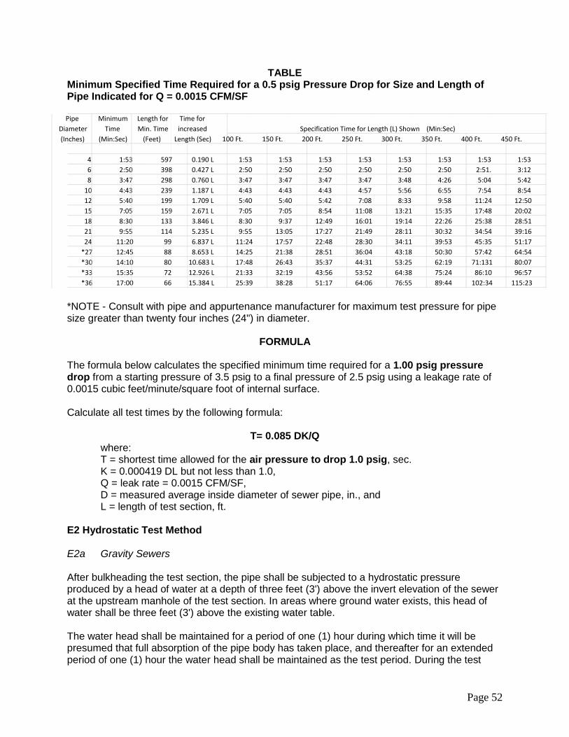
Page 52
TABLE Minimum Specified Time Required for a 0.5 psig Pressure Drop for Size and Length of Pipe Indicated for Q = 0.0015 CFM/SF
*NOTE - Consult with pipe and appurtenance manufacturer for maximum test pressure for pipe size greater than twenty four inches (24") in diameter.
FORMULA The formula below calculates the specified minimum time required for a 1.00 psig pressure drop from a starting pressure of 3.5 psig to a final pressure of 2.5 psig using a leakage rate of 0.0015 cubic feet/minute/square foot of internal surface. Calculate all test times by the following formula:
T= 0.085 DK/Q
where: T = shortest time allowed for the air pressure to drop 1.0 psig, sec. K = 0.000419 DL but not less than 1.0, Q = leak rate = 0.0015 CFM/SF, D = measured average inside diameter of sewer pipe, in., and L = length of test section, ft.
E2 Hydrostatic Test Method E2a Gravity Sewers After bulkheading the test section, the pipe shall be subjected to a hydrostatic pressure produced by a head of water at a depth of three feet (3') above the invert elevation of the sewer at the upstream manhole of the test section. In areas where ground water exists, this head of water shall be three feet (3') above the existing water table. The water head shall be maintained for a period of one (1) hour during which time it will be presumed that full absorption of the pipe body has taken place, and thereafter for an extended period of one (1) hour the water head shall be maintained as the test period. During the test
100 Ft. 150 Ft. 200 Ft. 250 Ft. 300 Ft. 350 Ft. 400 Ft. 450 Ft.
4 1:53 597 0.190 L 1:53 1:53 1:53 1:53 1:53 1:53 1:53 1:53 6 2:50 398 0.427 L 2:50 2:50 2:50 2:50 2:50 2:50 2:51. 3:12 8 3:47 298 0.760 L 3:47 3:47 3:47 3:47 3:48 4:26 5:04 5:42
10 4:43 239 1.187 L 4:43 4:43 4:43 4:57 5:56 6:55 7:54 8:54 12 5:40 199 1.709 L 5:40 5:40 5:42 7:08 8:33 9:58 11:24 12:50 15 7:05 159 2.671 L 7:05 7:05 8:54 11:08 13:21 15:35 17:48 20:02 18 8:30 133 3.846 L 8:30 9:37 12:49 16:01 19:14 22:26 25:38 28:51 21 9:55 114 5.235 L 9:55 13:05 17:27 21:49 28:11 30:32 34:54 39:16 24 11:20 99 6.837 L 11:24 17:57 22:48 28:30 34:11 39:53 45:35 51:17
*27 12:45 88 8.653 L 14:25 21:38 28:51 36:04 43:18 50:30 57:42 64:54 *30 14:10 80 10.683 L 17:48 26:43 35:37 44:31 53:25 62:19 71:131 80:07 *33 15:35 72 12.926 L 21:33 32:19 43:56 53:52 64:38 75:24 86:10 96:57 *36 17:00 66 15.384 L 25:39 38:28 51:17 64:06 76:55 89:44 102:34 115:23
Specification Time for Length (L) Shown (Min:Sec) Pipe
Diameter (Inches)
Minimum Time
(Min:Sec)
Length for Min. Time
(Feet)
Time for increased
Length (Sec)
Page 53
period, the measured water loss within the test section, including service stubs, shall not exceed an infiltration / exfiltration rate of thirty five (35) gallons / inch diameter / mile / day. If measurements indicate exfiltration within a test action section is not greater than the allowable maximum, the section will be accepted as passing the test. E2b Pressure Sewers For sewers designated as pressure pipe sewers, the sewer shall be subjected to hydrostatic testing under 2611.3G Hydrostatic Testing of Watermains, except the hydrostatic testing pressure shall be two (2) times the maximum design operating pressure, but not less than one hundred (100) psig and the duration of the test shall be one hour. E3 Test Failure and Remedy In the event of test failure on any test section, testing shall be continued until all leakage has been detected and corrected to meet the requirements. All repair work shall be subject to approval of the Engineer. Introduction of sealant substances by means of the test water will not be permitted. Unsatisfactory repairs or test results may result in an order to remove and replace pipe as the Engineer considers necessary for test conformance. All repair and replacement work shall be at the Contractor's expense. F Deflection Test Deflection tests shall be performed on all plastic gravity sewer pipes. The test shall be conducted after the sewer trench has been backfilled to the desired finished grade and has been in place for thirty (30) days. The deflection test shall be performed by pulling a rigid ball or nine-point mandrel (MnDOT Technical Memorandum 98-24-B-01 or latest revision) through the pipe without the aid of mechanical pulling devices. The ball or mandrel shall have a minimum diameter equal to ninety five percent (95%) of the actual inside diameter of the pipe. The maximum allowable deflection shall not exceed five percent (5%) of the pipe's internal diameter. The line will be considered acceptable if the mandrel can progress through the line without binding. The time of the test, method of testing, and the equipment to be used for the test shall be subject to the approval of the Engineer. All testing shall be performed by the Contractor at his expense without any direct compensation being made therefore, and he shall furnish all necessary equipment and materials required. F1 Test Failure and Remedy In the event of test failure on any test section, the section shall be replaced, with all repair work subject to approval of the Engineer. The replaced section shall be retested for leakage and deflection in conformance with the specifications contained herein. All repairs, replacement, and retesting shall be at the Contractor's expense.
Page 54
G Televising Sewer line televising may be required by the Engineer, at the cost of the Contractor, if visual inspection, leakage testing, or deflection testing indicate the sewer has not been constructed in accordance with these specifications and the requirements of the Plans, Specifications, and Special Provisions. 2621.4 METHOD OF MEASUREMENT All items will be measured separately according to design designation as indicated in the Pay Item name and as may be detailed and defined in the Plans, Specifications, or Special Provisions. Complete-in-place items shall include all component parts thereof as described or required to complete the unit, but excluding any excesses covered by separate Pay Items. Linear measurement of piping will include the running length of any special fittings (tees, wyes, elbows, gates, etc.) installed within the line of measure between specified terminal points. A Sewer Pipe Sewer pipe of each design designation will be measured by length in linear feet along the line of pipe. Terminal points of measurement will be the pipe end at free outlets; the point of connection with in-place pipe; the center of manholes or catch basins; the point of centerline intersections at branch fittings; or the point of juncture with other appurtenances or units as defined. Separation of quantities according to "depth zone classification", when so designated in the Pay Item, will be determined by depth of pipe invert below the ground surface profile. B Manholes Manholes of each design designation will be measured by number of each constructed complete-in-place, including the base and castings as required, but excluding any excess depth greater than eight feet (8') measured from top of manhole cover to invert elevation of lowest pipe. Excess manhole depth of each design designation will be measured by the linear foot difference in depth between the eight feet (8') allowed as standard and the actual increased depth as constructed. C Catch Basins Catch basins of each design designation will be measured by number of each constructed complete-in-place, including the base and castings as required, but excluding any excess depth greater than five feet (5') measured from top of grate (low point) to invert elevation of lowest outlet pipe. Excess catch basin depth of each design designation will be measured by the linear foot difference in depth between the five feet (5') allowed as standard and the actual increased depth as constructed.
Page 55
D Outside Drop Connection Outside drop connections of each design will be measured by linear foot constructed complete-in-place, and shall include granular encasement, fittings, any special piping required, including coring holes and watertight boots for existing manholes for the drop connection. Measurement shall be made vertically from the invert of the lower outside drop invert to the upper outside drop invert. E Service Connection Service Connections of each design will be measured by number of each constructed complete-in-place as specified. F Service Pipe Service pipe of each design will be measured separately by length in linear feet, horizontally along the line of installation, between the service end and the point of juncture with the main pipe connection fitting. G Special Pipe Fittings Special pipe fittings (wyes, tees, bends, etc.) of each design designation will be measured by number of each installed complete-in-place as specified, but excluding any such fittings required to be installed as a component part of any other Work Unit. H Appurtenant Items Appurtenant items such as aprons, trash guards, gates and other prefabricated units or assemblies as identified by Pay Item name will be measured separately by number of each installed complete-in-place as specified. 2621.5 BASIS OF PAYMENT Payment for sewer pipe and service pipe items at the Contract prices per linear foot of pipe of each design shall be compensation in full for all costs of providing a complete-in-place pipeline, including excavation, foundation preparation, backfilling, leakage testing, restoration of surface improvements, disposal of surplus or waste materials, final cleanup, and such other work as may be specified, but excluding the construction of other structures or special sections and the placement of special fittings, appurtenances or materials specifically designated for payment under other Contract Items. Payment for manhole, catch basin, outside drop connection, service connection, and other structures as specified, at the Contract prices per structure, shall be compensation in full for all costs of constructing each unit complete-in-place as specified, including all required castings, special fittings, base or encasement, and appurtenant materials as specified for the complete structure or section, but excluding such additional work as may be designated for payment under other Contract Items. Where the specified standard manhole, catch basin, or outside drop connection depths are exceeded, the excess depth of each design will be paid for separately as linear footage items
Page 56
and payment at the Contract prices therefor shall be compensation in full for all costs of providing the extra depth. Special pipe fittings such as wyes, tees and bends will be paid for as separate Contract Items to the extent they are required to be installed in the sewer pipe and service pipe lines and not as a component part of a complete-in-place structure (outside drop connections, service connections, etc.) Appurtenant items such as aprons, trash guards, drainage gates, and other prefabricated units or assemblies and specials as designated will be paid for as separate Contract Items to the extent they are not included as a component part of any complete-in-place structure.
Page 57
SECTION 2631 CIPPS – STANDARD SPECIFICATIONS FOR SEWER PIPE REHABILITATION WITH CURED IN-PLACE PIPE SYSTEMS (CIPPS)
2631.1 CIPPS DESCRIPTION A General This work shall consist of the rehabilitation of pipelines and conduits by the installation of a resin-impregnated flexible tube Cured-In-Place Pipe System (CIPPS). The rehabilitation of pipelines shall be constructed by the installation of a resin-impregnated flexible tube which, when cured, shall be continuous and tight-fitting throughout the entire length of the original pipe. The CIPP shall extend the full length of the original pipe and provide a structurally sound, joint less and watertight new pipe within the existing pipe. The Contractor is responsible for proper, accurate and complete installation of the CIPP using the system selected by the Contractor. Neither the CIPP system, nor its installation, shall cause adverse effects to any downstream facilities. The use of the product shall not result in the formation or production of any detrimental compounds or by-products that may affect downstream structures, pups, pipe, equipment and wastewater treatment facilities. The Contractor shall notify the Engineer and identify any by-products produced as a result of the installation operations, test and monitor the levels, and comply with any and all local waste discharge requirements. The Contractor shall cleanup, restore existing surface conditions and structures, and repair any of the CIPP system determined to be defective. The Contractor shall conduct installation operations and schedule cleanup in a manner to cause the least possible obstruction and inconvenience to traffic, pedestrians, businesses, and residents. The use of the term "Plans, Specifications, and Special Provisions" within this specification shall be construed to mean those documents which compliment, modify, or clarify these specifications and are an enforceable component of the Contract Documents. All references to MnDOT Specifications shall mean the latest published edition of the Minnesota Department of Transportation “Standard Specifications for Construction”, and all supplements and amendments thereto, published prior to the date of advertisement for bids. All references to other Specifications of AASHTO, ASTM, ANSI, AWWA, etc. shall mean the latest published edition available on the date of advertisement for bids. The following specifications have been referenced in this Specification:
ASTM - F1216 Standard Practice for Rehabilitation of Existing Pipelines and Conduits by the Inversion and Curing of a Resin-Impregnated Tube ASTM - F1743 Standard Practice for Rehabilitation of Existing Pipelines and Conduits by the Pull in and inflate and Curing of a Resin-Impregnated Tube ASTM - D543 Standard and Practice for Evaluating the Resistance of Plastics to Chemical Reagents ASTM - D638 Standard Test Method for Tensile Properties of Plastics
Page 58
ASTM - D790 Standard Test Methods for Flexural Properties of Un-reinforced and Reinforced Plastics and Electrical Insulating Materials ASTM - D792 Standard Test Methods for Density and Specific Gravity of Plastics by displacement. ASTM - F2019-03 Standard Practice for Rehabilitation of Existing Pipelines and Conduits by the Pulled in Place Installation of Glass Reinforced Plastic (GRP) Cured-in- Place Thermosetting Resin Pipe (CIPP) ASTM - D2122-98(2004) Standard Test Method for Determining Dimensions of Thermoplastic Pipe and Fittings ASTM - D2990 Standard Test Methods for Tensile, Compressive, and Flexural Creep and Creep-Rupture of Plastics ASTM - D5813 Standard Specification for Cured-in Place Thermosetting Resin Sewer Pipe
B Qualifications The Contractor shall be responsible for all aspects of the design of the liner pipe. The Contractor shall guarantee that the installed liner is capable of sustaining outside loads, resist chemical attack that normally occurs in sanitary and storm sewer systems, and will maintain hydraulic characteristics over a fifty (50) year design life. Unless provided otherwise in the plans or Special Provisions, the existing sewer pipe shall be considered to be in a fully deteriorated condition, is not structurally sound, and cannot support soil and live loads. The cured-in-place pipe shall be designed to support hydraulic, soil, and live loads. The sewer products are intended to have a fifty (50) year or greater design life, and in order to minimize the Owner’s risk, only proven products with substantial successful long term track records will be approved. B1 Manufactured Products and Installation Contractors must meet all of the following criteria:
a. For a Product to be considered acceptable, a minimum of 100,000 linear feet or two hundred fifty (250) manhole-to-manhole line sections of successful wastewater collection system installations in the U.S. must be documented to the satisfaction of the Engineer. In addition, at least 50,000 linear feet of the product shall have been in successful service within the State for a minimum of five (5) years.
b. The Contractor’s personnel must satisfy all insurance, financial, and bonding requirements of the Owner, and must have had at least 5 (five) years active experience in the commercial installation of the product bid. In addition, the Contractor’s personnel must have successfully installed at least 100,000 feet of the same product bid. The Field Supervisor/Foreman shall have a minimum five (5) years as a foreman/superintendent for a cured-in-place lining crew (installing actual
Page 59
product included with this bid/proposal), and a minimum of 100,000 lineal feet of cured-in-place lining, diameters up to and including twenty-four inches (24") installed under his/her supervision. Such experience shall include the actual product, by trade name, Contractor proposes to install. Acceptable documentation of these minimum installations must be submitted to the Engineer.
c. Sewer rehabilitation products submitted for approval must provide Third Party Test Results supporting the long term performance and structural strength of the product and such data shall be satisfactory to the Engineer. Test samples shall be prepared so as to simulate installation methods and trauma of the product. No product will be approved without independent third party testing verification.
2631.2 CIPPS MATERIALS A General All materials required for this work shall be new material conforming to requirements of the referenced specifications for the class, kind, type, size, grade, and other details indicated in the Contract. Unless otherwise indicated, all required materials shall be furnished by the Contractor. If any options are provided for, as to type, grade, or design of the material, the choice shall be limited as may be stipulated in the Plans, Specifications, or Special Provisions. All manufactured products shall conform in detail to such standard design drawings as may be referenced or furnished in the Plans. Otherwise, the Owner may require advance approval of material suppliers, product design, or other unspecified details as it deems desirable for maintaining adopted standards. All materials shipped to the project site shall be accompanied by test reports certifying that the material conforms to the ASTM standards listed herein. Materials shall be shipped, stored, and handled in a manner consistent with written recommendations of the CIPP manufacturer to avoid damage. Damage includes but is not limited to, gouging, abrasion, flattening, cutting, puncturing, and ultra-violet (UV) degradation. All damaged materials shall be promptly removed from the project site at no cost to the Owner. On site material storage locations shall be approved by the Engineer. A1 CIPPS Fabric Tube The CIPPS fabric “Tube” shall consist of one or more layers of absorbent non-woven felt fabric, felt/fiberglass or fiberglass and meet the requirements of ASTM F 1216, ASTM F 1743, ASTM D 5813 & ASTM F2019. The fabric Tube shall be capable of absorbing and carrying resins, manufactured to withstand installation pressures and curing temperatures, have sufficient strength to bridge missing pipe segments, and stretch to fit irregular pipe sections. The fabric Tubes shall have a uniform thickness that when compressed at installation pressures will equal the specified nominal tube thickness. The wet-out fabric tube shall have a uniform thickness and excess resin distribution that when compressed at installation pressures will meet or exceed the design thickness after cure. The fabric tube shall be manufactured to a size and length that when installed will tightly fit the internal circumference and length of the original pipe. Allowance shall be made for

Page 60
circumferential stretching during installation. The tube shall be properly sized to the diameter of the existing pipe and the length to be rehabilitated and be able to stretch to fit irregular pipe sections and negotiate bends. The Contractor shall determine the minimum tube length necessary to effectively span the designated run between manholes. The Contractor shall verify the lengths in the field prior to ordering and prior to impregnation of the tube with resin, to ensure that the tube will have sufficient length to extend the entire length of the run. The Contractor shall also measure the inside diameter of the existing pipelines in the field prior to ordering liner so that the liner can be installed in a tight-fitted condition. Overlapped layers of felt in longitudinal seams that cause lumps in the final product shall not be allowed. The minimum length of the fabric tube shall be that deemed necessary by the installer to effectively span the distance from the starting manhole to the terminating manhole or access point, plus that amount required to run-in and run-out for the installation process. The outside and/or inside layer of the fabric tube (before inversion/pull-in, as applicable) shall be coated with an impermeable, flexible membrane that will contain the resin and facilitate, if applicable, vacuum impregnation and monitoring of the resin saturation during the resin impregnation (wet-out) procedure. No material shall be included in the fabric tube that may cause de-lamination in the cured CIPP. No dry or unsaturated layers shall be acceptable upon visual inspection as evident by color contrast between the felt fabric and the activated resin containing a colorant. The tube shall be homogeneous across the entire wall thickness containing no intermediate or encapsulated elastomeric layers. No materials shall be included in the tube that is subject to delamination in the CIPPS. The wall color of the interior pipe surface of CIPP after installation shall be a light reflective color so that a clear detailed examination with closed circuit television inspection equipment may be made. The hue of the color shall be dark enough to distinguish a contrast between the fully resin saturated felt fabric and dry or resin lean areas. Seams in the fabric tube, if applicable, shall meet the requirements of ASTM D5813. The outside of the fabric tube shall be marked every five feet (5') with the name of the manufacturer or CIPP system, manufacturing lot and production footage. The nominal fabric tube wall thickness shall be constructed to the nearest 0.5 mm increment, rounded up from the design thickness for that section of installed CIPP. Wall thickness transitions, in 0.5 mm increments or greater as appropriate, may be fabricated into the fabric tube between installation entrance and exit access points. The quantity of resin used in the impregnation shall be sufficient to fill all of the felt voids for the nominal felt thickness. The resin shall be a corrosion resistant polyester or vinyl ester resin and catalyst system that when properly cured within the tube composite meets the requirements of ASTM F1216, ASTM F1743 or F2019, the physical properties herein, and those, which are to be utilized in the design of the CIPP for this application. The resin shall produce CIPP which will comply with or exceed the structural and chemical resistance requirements of this specification.
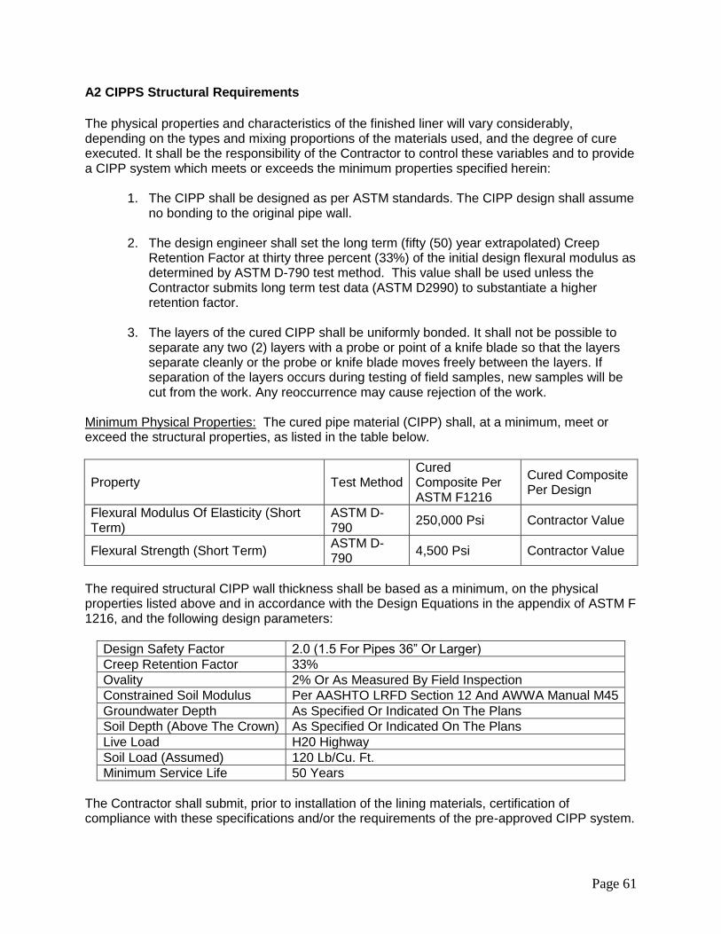
Page 61
A2 CIPPS Structural Requirements
The physical properties and characteristics of the finished liner will vary considerably, depending on the types and mixing proportions of the materials used, and the degree of cure executed. It shall be the responsibility of the Contractor to control these variables and to provide a CIPP system which meets or exceeds the minimum properties specified herein:
1. The CIPP shall be designed as per ASTM standards. The CIPP design shall assume no bonding to the original pipe wall.
2. The design engineer shall set the long term (fifty (50) year extrapolated) Creep
Retention Factor at thirty three percent (33%) of the initial design flexural modulus as determined by ASTM D-790 test method. This value shall be used unless the Contractor submits long term test data (ASTM D2990) to substantiate a higher retention factor.
3. The layers of the cured CIPP shall be uniformly bonded. It shall not be possible to separate any two (2) layers with a probe or point of a knife blade so that the layers separate cleanly or the probe or knife blade moves freely between the layers. If separation of the layers occurs during testing of field samples, new samples will be cut from the work. Any reoccurrence may cause rejection of the work.
Minimum Physical Properties: The cured pipe material (CIPP) shall, at a minimum, meet or exceed the structural properties, as listed in the table below.
Property Test Method Cured Composite Per ASTM F1216
Cured Composite Per Design
Flexural Modulus Of Elasticity (Short Term)
ASTM D-790
250,000 Psi Contractor Value
Flexural Strength (Short Term) ASTM D-790
4,500 Psi Contractor Value
The required structural CIPP wall thickness shall be based as a minimum, on the physical properties listed above and in accordance with the Design Equations in the appendix of ASTM F 1216, and the following design parameters:
Design Safety Factor 2.0 (1.5 For Pipes 36” Or Larger)
Creep Retention Factor 33%
Ovality 2% Or As Measured By Field Inspection
Constrained Soil Modulus Per AASHTO LRFD Section 12 And AWWA Manual M45
Groundwater Depth As Specified Or Indicated On The Plans
Soil Depth (Above The Crown) As Specified Or Indicated On The Plans
Live Load H20 Highway
Soil Load (Assumed) 120 Lb/Cu. Ft.
Minimum Service Life 50 Years
The Contractor shall submit, prior to installation of the lining materials, certification of compliance with these specifications and/or the requirements of the pre-approved CIPP system.
Page 62
Certified material test results shall be included that confirm that all materials conform to these specifications. Materials not complying with these requirements will be rejected. CIPP Short-Liners or segmental liners shall be of the same materials and meet the structural requirements of the full CIPP Tube liner. A3 Material Testing Requirements
1. Chemical Resistance - The CIPP shall meet the chemical resistance requirements of ASTM F1216, Appendix X2. CIPP samples for testing shall be of tube and resin system similar to that proposed for actual construction. It is required that CIPP samples with and without plastic coating meet these chemical testing requirements.
2. Hydraulic Capacity - Overall, the hydraulic profile shall be maintained as large as
possible. The CIPP shall have a minimum of the full flow capacity of the original pipe before rehabilitation. Calculated capacities may be derived using a commonly accepted roughness coefficient for the existing pipe material taking into consideration its age and condition.
3. CIPP Field Samples - When requested by the Owner, the Contractor shall submit
test results from field installations in the USA of the same resin system and tube materials as proposed for the actual installation. These test results must verify that the CIPP physical properties specified in above have been achieved in previous field applications. Samples for this project shall be made and tested as described herein.
2631.3 CIPPS CONSTRUCTION REQUIREMENTS The Contractor shall clean the interior of the existing host pipe prior to installation of the CIPP liner. All debris and obstructions that will affect the installation and the final CIPP product shall be removed and disposed of. The CIPP liner shall be constructed of materials and methods, that when installed, shall provide a joint less and continuous structurally sound liner able to withstand all imposed static and dynamic loads on a long-term basis. A Installation of CIPPS A1 Access It will be the responsibility of the Owner to locate and designate all manhole access points open and accessible for the work, and provide rights of access to these points. If a street must be closed to traffic because of the orientation of the sewer, the Contractor shall institute the actions necessary to do this for the mutually agreed time period. Traffic Control shall be the responsibility of the Contractor and shall conform to the latest revision of the MMUTCD and other provisions of this specification herein. The Contractor shall keep the roadway open to traffic at all times unless given prior approval by the Engineer. A2 Water Usage Water is available from the City at designated locations for cleaning, inversion, and other work items requiring water. Use of an approved double check backflow assembly shall be required. The Contractor shall provide his own approved assembly. The Contractor may use City water
Page 63
but shall inform the Public Works Department of such use and obtain a meter for documenting water usage. No fees will be charged for water. A3 Cleaning of Sewer Lines The Contractor shall remove all internal debris from the pipe line that will interfere with the installation and the final product delivery of the CIPP as required in these specifications. Solid debris and deposits shall be removed from the system and disposed of properly by the Contractor. Moving material from manhole section to manhole section shall not be allowed. As applicable the contractor shall either plug or install a flow bypass pumping system to properly clean the pipe lines. The Contractor shall ensure that no debris is transferred downstream during cleaning operations. The Contractor shall use a vacuum vehicle or similar means to remove debris during cleaning operations. Precaution shall be taken, by the Contractor in the use of cleaning equipment to avoid damage to the existing pipe. The repair of any damage, caused by the cleaning equipment, shall be the responsibility of the Contractor. Disposal of the cleaning debris shall be in accordance with local, State and Federal Law and shall be incidental to the CIPPS. A4 Bypassing Wastewater The Contractor shall provide a by-pass for the flow of existing mainline and service connection effluent around the section or sections of pipe designated for CIPP installation. Installation of the liner shall not begin until the Contractor has installed a sewage by-pass system and all pumping facilities have been installed and tested under full operating conditions including the bypass of mainline and side sewer flows. Once the lining process has begun, existing sewage flows shall be maintained, until the resin/felt tube composite is fully cured, cooled down, fully televised and the CIPP ends finished. The Contractor shall coordinate sewer bypass and flow interruptions with the Engineer at least fourteen (14) days in advance and with the property owners and businesses at least three (3) business days in advance. The pump and bypass lines shall be of adequate capacity and size to handle peak flows. The Contractor shall submit a detail of the bypass plan and design to the Engineer prior to proceeding with any CIPP installation. Compensation for by-pass pumping and all associated plans and approvals shall be included in the price bid for CIPPS Installation. A5 Inspection of Pipelines Inspection of pipelines shall be performed by experienced personnel trained in locating breaks, obstacles, and service connections by closed circuit television. The interior of the pipeline shall be carefully inspected to determine the location of any conditions which may prevent proper installation of the CIPPS into the pipelines and it shall be noted so that these conditions can be corrected. A videotape and suitable log shall be kept for later reference by the Owner. The Owner has copies of a video inspection of the sewers to be relined, and these are available for prospective bidders. However, since the deterioration of sewer is an ongoing process, and roots, solids, and deposits can accumulate over time, the Contractor shall base the design of the liner on inspections made immediately prior to installation. A6 Line Obstructions It shall be the responsibility of the Contractor to clear the line of obstructions such as solids and roots that will prevent the insertion of CIPP. If pre-installation inspection reveals an obstruction such as a protruding service connection, dropped joint, or a collapse that will prevent the
Page 64
inversion process, that was not evident on the pre-bid video and it cannot be removed by conventional sewer cleaning equipment, if directed by the Owner, the Contractor shall make a point repair excavation to uncover and remove or repair the obstruction. Such excavation shall be approved in writing by the Owner's representative prior to the commencement of the work and shall be considered as a separate pay item. A7 Public Notification The Contractor shall make every effort to maintain service usage throughout the duration of the project. In the event that a service will be out of service, the maximum amount of time of no service shall be eight (8) hours for any property served by the sewer. A public notification program shall be implemented, and shall as a minimum, require the Contractor to be responsible for contacting each home or business connected to the sanitary sewer and informing them of the work to be conducted, and when the sewer will be off-line. The Contractor shall also provide the following:
1. Written notice to be delivered to each home or business the day prior to the beginning of work being conducted on the section, and a local telephone number of the Contractor they can call to discuss the project or any problem which could arise.
2. Personal contact with any home or business, which cannot be reconnected within the time stated in the written notice.
The Contractor shall be responsible for confirming the locations of all branch service connections prior to installing and curing the CIPP. A8 Liner Installation CIPP installation shall be in accordance with the applicable ASTM standards with the following modifications:
1. The wet-out tube shall be positioned in the pipeline using the method specified by the manufacturer. Care should be exercised not to damage the tube as a result of installation. The tube should be pulled-in or inverted through an existing manhole or approved access point and fully extend to the next designated manhole or termination point. If pulled into place, a power winch should be utilized and care should be exercised not to damage the tube as a result of pull-in friction.
2. Prior to installation and as recommended by the manufacturer remote temperature
gauges or sensors shall be placed inside the host pipe to monitor the temperatures during the cure cycle. Liner and/or host pipe interface temperature shall be monitored and logged during curing of the liner.
3. Curing shall be accomplished by utilizing the appropriate medium in accordance with
the manufacturer’s recommended cure schedule. The curing source or in and output temperatures shall be monitored and logged during the cure cycles. The manufacturer’s recommended cure schedule shall be used for each line segment installed, and the liner wall thickness and the existing ground conditions with regard to temperature, moisture level, and thermal conductivity of soil, per ASTM as applicable, shall be taken into account by the Contractor.
Page 65
4. The Contractor shall remove protruding taps to the inside wall of the pipe. In no case shall the pipe be less than ninety five percent (95%) open to flow.
A9 Resin Impregnation The quantity of resin used for tube impregnation shall be sufficient to fill the volume of air voids in the tube with additional allowances for polymerization shrinkage and the loss of resin through cracks and irregularities in the original pipe wall. A vacuum impregnation process shall be used. To insure a through wet-out, the point of vacuum shall be no further than twenty five feet (25') from the point of initial resin introductions. After vacuum in the tube is established, the vacuum points shall be no further than seventy five feet (75') from the leading edge of the resin. The leading edge of the resin slug shall be as near to perpendicular to the longitudinal axis of the tube as possible. A roller system shall be used to uniformly distribute tie resin throughout the tube. If the Installer proposes an alternate method of resin impregnation, the method must produce the same results and the method approved by the Engineer. A10 Cool Down The Contractor shall cool the CIPP in accordance with the manufacturer’s recommendations. Temperatures and curing data shall be monitored and recorded, by the Contractor, throughout the installation process to ensure that each phase of the process is achieved as approved in accordance with the CIPP System manufacturer’s recommendations. A11 Finishing Operations The installed CIPP shall be continuous over the entire length of a sewer line section and be free from visual defects such as foreign inclusions, dry spots, pinholes, major wrinkles and delamination. The lining shall be impervious and free of any leakage from the pipe to the surrounding ground or from the ground to inside the lined pipe. Any defect, which will or could affect the structural integrity or strength of the linings, shall be repaired at the Contractor’s expense. The beginning and end of the CIPP shall be sealed to the existing host pipe. The sealing material shall be compatible with the pipe end and shall provide a watertight seal. If any of the service connections leak water between the host pipe and the installed liner, the connection mainline interface shall be sealed to provide a watertight connection. If the wall of the CIPP leaks, it shall be repaired or removed and replaced with a watertight pipe as recommended by the manufacture of the CIPP system. At all points where the liner pipe has been exposed (such as service connection fittings, or other points where the old pipe must be removed), the liner pipe and fittings shall be encased in cement-stabilized sand or other high density material as specified by the Engineer to prevent deflection due to difference in subsidence. After the encasement material is in place and accepted by the Engineer, backfill is placed and compacted to require finish grade in accordance with the specifications. Particular care should be taken to ensure compaction of earth beneath the lateral/service pipe in order to reduce subsidence and resultant bending at the lateral connection at the sewer main. A12 Manhole Connections A seal, consisting of a resin mixture or hydrophilic seal compatible with the installed CIPP shall be applied at manhole walls in accordance with the CIPP System manufacturer’s recommendations.
Page 66
A13 Reconnections of Existing Services Services shall be identified by the Contractor prior to lining work. After the pipe has been reconstructed and tested, the service connections shall be reconnected. It is the Contractor’s responsibility to make sure that all service connections are reconnected, unless otherwise directed by the Engineer. A CCTV camera and remote cutting tool shall be used for internal reconnections. The machined opening shall be at least ninety five percent (95%) of the service connection opening and the bottom of both openings must match. The opening shall not be more than one hundred percent (100%) of the service connection opening. The edges of the opening shall not have pipe fragments or liner fragments, which may obstruct flow or snag debris. In the event that service reinstatements result in openings that are greater than one hundred percent (100%) of the service connection opening, the Contractor shall install a CIPP type repair, sufficiently in size to completely cover the over-cut service connection. No additional compensation will be paid for the repair of over-cut service connections. Discs of pipe material resulting from service tap cutting shall be collected at the next manhole downstream of the pipe rehabilitation operation prior to leaving the site. Discs shall not be allowed to pass through the system. A14 CIPP Short-Liner The CIPP short-liner shall meet the requirements of the full length CIPP liner and the following:
1. The Short-Liner shall be inserted into the existing sewer line with a power winch and steel cable attached to the end of the liner by use of an appropriate pulling head. Length of the liner to be inserted at any one time shall be governed by the length of the section in need of repair or the maximum length of the installation equipment considering the size and condition of the sewer.
2. A mobile installation unit shall be brought to the site ready to process the liner. The
installation unit shall contain heat generating equipment, CCTV facility and other auxiliary miscellaneous equipment necessary for controlling processing of the Short-Liner pipe. The equipment shall be positioned next to the point of entry with minimum obstruction to the other side activities and shall be operated by trained personnel only.
3. The pressure shall be increased to compensate for the heating-cooling transition and
it shall be maintained until the temperature at the lowest critical point is 100º F (38º C). This shall constitute completion of the Short-Liner pipe processing. The pipe within the pipe shall be tight fitting and adapted to the existing sewer pipe.
B TESTING AND INSPECTION B1 Testing CIPP samples shall be prepared and tested in accordance with ASTM F1216, Section 8.1, using either method proposed. Leakage testing of the CIPP shall be accomplished during cure while under a positive head. CIPP products in which the pipe wall is cured while not in direct contact with the pressurizing fluid (e.g., a removable bladder) must be tested by an alternative method approved by the Engineer.
Page 67
B2 Inspection Visual inspection of the CIPP shall be in accordance with ASTM F1216, Section 8.4. The relined pipe shall be continuous without joints through the entire pipe length. The liner shall be free of all visible defects except those resulting from pre-lined conditions which the Contractor has noted prior to lining. There shall be no pits, pinholes, cracks, or crazing, and the surface shall be smooth and free of waviness throughout the pipe. Any defects shall be repaired by the Contractor with no expense to the Owner. Where leakage is observed through the wall of the pipe, the contractor shall institute additional testing including but not limited to air testing, localized testing and any other testing that will verify the leak proof integrity of the installed CIPP to the satisfaction of the Owner. B3 Televising Prior to final acceptance of any sanitary sewer relining including short-liners, the Contractor shall inspect by means of remote closed circuit television equipment the entire segment of sanitary sewer, manhole-to manhole. Sewer shall be cleaned prior to inspection. A videotape of the inspection shall be furnished to the City. The following conditions shall apply to the sewer acceptance TV inspection:
1. The videotape shall be in a format to be decided by the Owner, that creates high
quality picture and sound and shall be recorded in color. 2. The TV camera shall be pulled through the sewer at a maximum rate of thirty five
feet (35') per minute. 3. The camera shall be pulled downstream in all cases. 4. The lens of the camera shall be cleaned at each manhole or when directed by the
Owner. 5. The recording shall have an on-screen display showing the following:
a. Upstream and downstream manhole numbers b. Footage from the upstream manhole c. Inspection date
6. Sewers shall not be televised within forty eight (48) hours of a rainfall event
greater than one half inch (½").
7. The CIPPS shall be re-televised one (1) month prior to expiration of the one-year warranty. A videotape and written report shall be supplied to the City.
2631.4 CIPPS METHOD OF MEASUREMENT Measurement for CIPP Lining shall be on a linear foot basis, to the nearest whole foot, measured from center of manhole to center of manhole.
Page 68
2631.5 CIPPS BASIS OF PAYMENT The proposal form shall cover all work shown on the contract drawings, specifications, and Special Provisions. All costs associated with the work including furnishing of all materials, providing all construction and equipment, and performing all necessary labor, coordination, supervision, and management to fully complete the work, shall be included in the unit or lump sum prices quoted in the proposal form. This work shall include restoration of all surfaces to their original condition or better. Reconnection of all existing services shall be considered incidental to the CIPPS. All work not specifically set forth as a pay item in the proposal form shall be considered a subsidiary obligation of the Contractor and all costs in connection therewith shall be included in the amounts and prices submitted in the proposal form. The following methods of measurement for payment will be used to derive the quantities installed:
1. Site Protection and Restoration
a) No separate payment will be made for protection and restoration of roadway surfaces, curb and gutter, landscaping, and other site features unless otherwise specified.
2. Spot Repair to existing pipe
a) Bid items have been provided in the proposal for removal and replacement of
pipe as Spot or Point Repairs. No additional compensation will be granted for repairs.
3. Cured-in-Place Pipe System (CIPPS)
a) Payment shall be made at the unit price as listed on the proposal. All work
related to the cleaning, installation and acceptance of the system as a whole shall be considered incidental to CIPPS installation.
b) Payment for re-instatement of services shall be at the unit price listed on the proposal per each service, and shall be compensation in full for all materials, labor, equipment, and maintenance necessary to complete the work as required by the plans or required by the Engineer.
c) Payment for Short-Liner installations shall be made at the unit price listed on the
proposal and shall be compensation in full for all materials, labor, equipment, and maintenance necessary to complete the work as required by the plans or required by the Engineer.
Page 69
SECTION 2641 – STANDARD SPECIFICATIONS FOR PIPELINE REHABILITATION BY PIPE BURSTING
2641.1 DESCRIPTION A General All references to MnDOT Specifications shall mean the latest published edition of the Minnesota Department of Transportation “Standard Specifications for Construction”, and all supplements and amendments thereto, published prior to the date of advertisement for bids. This specification shall cover the rehabilitation of existing gravity and pressure utility pipelines using pipe bursting methods. Pipe bursting is a process by which the bursting unit fractures the existing pipe while simultaneously installing a new pipe of the same size or larger size pipe in the place of the existing pipe. Existing lateral and service connections are disconnected prior to mainline pipe bursting to reduce lateral pipe/service pipe damage, then reconnected after testing and disinfection of the new pipe as applicable is approved, television inspection of the new pipe is performed, and the installation is completed in accordance with the contract documents. 2641.2 QUALIFICATIONS The Contractor shall be certified by the particular Pipe Bursting System Manufacturer as a fully trained installer of the pipe bursting system. The Contractor shall provide certifications of training and proficiency in the use of the equipment. Only the Contractor’s employees that are trained and certified shall operate the equipment. The Contractor shall have a minimum of five (5) years' experience using the pipe-bursting method proposed and shall have installed no less than 50,000 feet by this method. 2641.3 MATERIALS Pipe materials meet the requirements described in Sections 2611.2 and 2621.2 of these specifications, and as provided in the Special Provisions and the following:
1. Sizes of the new pipe insertions shall be such to renew the pipe mainline to greater than the original flow capacity.
2. All pipe and fittings shall be made of virgin material. No rework except that obtained
from the manufacturer’s own production of the same formulation shall be used.
3. The pipe shall be homogenous throughout and shall be free of visible cracks, holes, foreign material, blisters, or other deleterious faults.
4. Tensile strength of the pipe shall be in accordance with manufacturer’s recommendation for the specified purpose and method of installation.
5. Material color shall be as specified with interior of pipe having a light reflective color to
allow for viewing for television inspection. The fused pipe joints shall be de-beaded to reduce collection of sediment and allow a camera to pass during inspection.

Page 70
6. The Contractor shall consult with the selected pipe bursting equipment manufacturer regarding recommendations for the installation of pipe materials specified.
2641.4 SUBMITTALS The Contractor shall submit the following:
1. Tests for compliance with this specification shall be made as specified herein and in accordance with the applicable ASTM Specification. A certificate from the manufacturer indicating the materials furnished meet the requirements of these specifications.
2. Shop drawings, catalog data, and manufacturer’s technical data showing complete information on material composition, physical properties, and dimensions of new pipe and fittings. Include manufacturer’s recommendations for handling, storage, and repair of pipe and fittings damaged.
3. Certification of Contractor and assigned personnel training for installing pipe.
4. Detailed submittal of the procedures and method proposed by the Contractor to burst the
existing pipe and insert the new pipe.
5. Television inspection reports and video made of the existing pipe and after new pipe installation.
2641.5 DELIVERY, STORAGE, AND HANDLING The Contactor shall transport, handle, and store pipe and fittings as recommended by the manufacturer. If new pipe and fittings become damaged before or during installation, it shall be repaired as recommended by the manufacturer or replaced as required by the Engineer at the Contractor’s expense, before proceeding further. Deliver, store and handle other materials as required to prevent damage. 2641.6 LICENSE AGREEMENTS The Contractor shall submit evidence acceptable to the Owner, such as a certified copy of a license or agreement that it has the authority to use the proposed method from the patent holder and licensed manufacturer. The Contractor agrees to defend, indemnify, and hold harmless the Owner and the Engineer against all claims, suits, and actions or other damages as a result of negligence of any person or property arising out of patent infringement by the Contractor or the Contractor’s employee’s, agents, the suppliers, or any tier of subcontractors involved in the work. 2641.7 CONSTRUCTION REQUIREMENTS Before excavation is started, it will be the responsibility of the Contractor to check with the various utility companies and determine the location and depth of the existing utilities in the vicinity of the work area. Damage to utilities and the resulting repair, temporary service cost, etc., shall be borne by the Contractor. Access pits shall be backfilled in accordance with Section 2600, Trench Excavation and Backfill.
Page 71
All excavations shall be properly sheeted/shored in accordance with relevant specifications for trench safety systems. Any damage resulting from improperly shored excavations shall be corrected to the satisfaction of the Engineer with no compensation to the Contractor. All open excavations shall be kept secure at all times by the use of barricades and fencing with appropriate lights and signs, construction tape, covering with steel plates, etc., or as directed by the Engineer. All lateral and service connections shall be identified, located and excavated prior to the pipe insertion to expedite reconnection. The Contractor shall use excavation methods that will not create a rise or sag at the service or lateral connection for gravity sewers. A rise or sag in the sewer will be repaired by the contractor at no expense to the Owner, in a manner approved by the Engineer. The location and number of insertion and receiving excavations shall be planned by the Contractor and submitted in writing for approval by the Engineer at least ten (10) days prior to excavation. One (1) or more receiving pits shall be excavated at the end(s) of the pipe to be replaced or at appropriate points within the length of the existing pipe. Pit shall be centered over the existing pipe. The number of pits for machine and pipe insertion shall be the minimum necessary to most efficiently accomplish the work. The Contractor shall give consideration to the use of excavation required for other purposes such as for sanitary sewer service reconnections and manhole replacement. Where manholes are used as machine or new pipe insertion pits, the Contractor shall identify such manholes and replace them at no additional cost to the Owner if damaged. Any manhole modification or replacement required shall be considered incidental to the installation of the new pipe. Equipment used to perform the work shall be located away from buildings so as not to create noise impact. Provide a silent engine compartment to reduce machine noise as required to meet local requirements. The Contractor shall install all pulleys, rollers, bumpers, alignment control devices, and other equipment required to protect existing manholes and pipe components not intended for removal/replacement, and to protect the new pipe from damage during installation. Lubrication may be used as recommended by the manufacturer. If lubrication is used for insertion, the Contractor shall ensure that the lubricant does not backfill existing services. Under no circumstances will the pipe be stressed beyond eighty percent (80%) of its elastic limit as published and recommended by the manufacturer. Pipe insertion shall be continuous and without interruption from manhole to manhole for sewers, or junction to junction for watermain, except as approved by the Engineer. Upon completion of insertion of the new pipe, and after the relaxation period, the Contractor shall expedite the reconnection of laterals and services so as to minimize any inconvenience to customers. Connection of services shall be in accordance with Sections 2611 and 2621 of these specifications and as provided in the Special Provisions. The installed pipe shall be allowed the manufacturer’s recommended amount of time, but not less than four (4) hours, for cooling and relaxation due to tensile stressing prior to any reconnection of service lines, sealing of the annulus or backfilling of the insertion pit. Sufficient
Page 72
excess length of new pipe, but not less than four inches (4"), shall be allowed to protrude into manholes. Restraint of pipe ends shall be achieved by means of electrofusion couplings. The electrofusion couplings shall be slipped over pipe ends against manhole wall and fused in place. Installation of electrofusion couplings shall be done in accordance with the manufacturers recommended procedures. Following the relaxation period, the annular space at the manhole shall be sealed. Sealing shall be made with material approved by the Engineer and shall extend a minimum of eight inches (8") into the manhole wall in such a manner as to form a smooth, uniform, watertight joint. Fused pipe joints shall be de-beaded to create a smooth flow line. There shall be no ridges or burrs from the fusion method exposed on the interior of the pipe following installation. Tracer wire shall be installed with the pipe in accordance with 2611 and 2621. Equipment: The pipe bursting tool shall increase the external dimensions sufficiently, causing breakage of the existing pipe at the same time expanding the surrounding ground. Simultaneously, the new pipe, directly attached to the expander, shall also move forward. See manufacturer’s specifications for what size tool should be used in what diameter of pipe, as well as parameters of what size tool for percentage of upsize allowed. The bursting head shall incorporate a shield/expander to prevent collapse of the hole ahead of the pipe insertion. Bypass Pumping: The Contractor, when and where required for sanitary sewer replacement, shall provide diversion for the pipe bursting/replacement process. The pumps and by-pass lines shall be of adequate capacity and size to handle all flows. All costs for by-pass pumping required during installation of the pipe shall be incidental to the installation of the pipe, unless otherwise provided in the Special Provisions. Temporary Water: The Contractor when and where required for watermain replacement, shall provide all labor, materials, and equipment associated with managing, constructing, and maintaining a temporary potable water distribution system for all existing water users which must be taken out of service for a period exceeding eight (8) hours, or as required at the discretion of the Engineer. All costs to provide temporary water required during installation of the pipe shall be incidental to the installation of the pipe, unless otherwise provided in the Special Provisions. 2641.8 TESTING AND INSPECTION Testing: Tests for compliance with this specification shall be made as described herein and in accordance with the applicable ASTM Specification. A certificate with this specification shall be furnished, upon request, by the manufacturer for all material furnished under this specification. Inspection: Video inspection of pipelines shall be performed by experienced personnel trained in locating breaks, obstacles, and service connections by closed circuit color television. Video inspection shall include the following:
Two (2) copies of the DVD’s in mpeg4 format (post) to be submitted to the Owner before final invoice.
Page 73
DVD’s are to remain property of the Owner; Contractor to retain second copy.
All flows tributary to reach of sewer being inspected are to be completely by-passed around the reach during inspection if necessary and required by the Owner.
Pre-construction video of the existing pipe and post construction video inspection upon completion of reconstruction of each reach of pipe, with the voice description, with stationing of services indicated. Data and stationing to be on video.
Should any portion of the video inspection be of inadequate quality or coverage, as determined by the Owner the Contractor will have the portion re-inspected and video recorded at no additional expense to the Owner.
2641.9 METHOD OF MEASUREMENT Measurement for pipe bursting shall be on a linear foot basis, to the nearest whole foot, measured from center of manhole to center of manhole or junction point to junction point as indicated on the plans.
2641.10 BASIS OF PAYMENT Pipe Bursting: The work performed as prescribed by this item will be paid for by the linear foot at the unit price bid for the pipe bursting/replacement at the specified pipe diameter and location which price shall be full compensation for the installation of the new pipe, furnishing and placing of all materials, labor, tools, equipment, cleaning, and preparation of the existing pipe to receive the new pipe, tracer wire, pipe bedding, backfill material, annulus sealing material and launching pits, and video inspection of final installed pipe, bypass pumping, temporary water distribution, traffic control, sealing at manholes, locating, excavating, disconnecting, testing in accordance with the Contract Documents, and all else incidental thereto for which separate payment is not provided under other Items in the Bid Form.

GENERAL SPECIFICATIONS AND APPENDIX B STANDARD DETAIL PLATES FOR STREET AND UTILITY CONSTRUCTION CITY OF NORTH ST. PAUL, MN DECEMBER 2018
APPENDIX B
CITY OF NORTH ST. PAUL STANDARD DETAIL PLATES
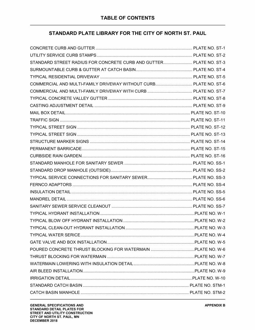
TABLE OF CONTENTS
STANDARD PLATE LIBRARY FOR THE CITY OF NORTH ST. PAUL
GENERAL SPECIFICATIONS AND APPENDIX B STANDARD DETAIL PLATES FOR STREET AND UTILITY CONSTRUCTION CITY OF NORTH ST. PAUL, MN DECEMBER 2018
CONCRETE CURB AND GUTTER .................................................................................... PLATE NO. ST-1
UTILITY SERVICE CURB STAMPS ................................................................................... PLATE NO. ST-2
STANDARD STREET RADIUS FOR CONCRETE CURB AND GUTTER ......................... PLATE NO. ST-3
SURMOUNTABLE CURB & GUTTER AT CATCH BASIN ................................................. PLATE NO. ST-4
TYPICAL RESIDENTIAL DRIVEWAY ................................................................................ PLATE NO. ST-5
COMMERCIAL AND MULTI-FAMILY DRIVEWAY WITHOUT CURB ................................ PLATE NO. ST-6
COMMERCIAL AND MULTI-FAMILY DRIVEWAY WITH CURB ....................................... PLATE NO. ST-7
TYPICAL CONCRETE VALLEY GUTTER ......................................................................... PLATE NO. ST-8
CASTING ADJUSTMENT DETAIL ..................................................................................... PLATE NO. ST-9
MAIL BOX DETAIL ............................................................................................................ PLATE NO. ST-10
TRAFFIC SIGN ................................................................................................................. PLATE NO. ST-11
TYPICAL STREET SIGN .................................................................................................. PLATE NO. ST-12
TYPICAL STREET SIGN .................................................................................................. PLATE NO. ST-13
STRUCTURE MARKER SIGNS ....................................................................................... PLATE NO. ST-14
PERMANENT BARRICADE.............................................................................................. PLATE NO. ST-15
CURBSIDE RAIN GARDEN .............................................................................................. PLATE NO. ST-16
STANDARD MANHOLE FOR SANITARY SEWER ........................................................... PLATE NO. SS-1
STANDARD DROP MANHOLE (OUTSIDE) ....................................................................... PLATE NO. SS-2
TYPICAL SERVICE CONNECTIONS FOR SANITARY SEWER ....................................... PLATE NO. SS-3
FERNCO ADAPTORS ........................................................................................................ PLATE NO. SS-4
INSULATION DETAIL ......................................................................................................... PLATE NO. SS-5
MANDREL DETAIL ............................................................................................................. PLATE NO. SS-6
SANITARY SEWER SERVICE CLEANOUT ...................................................................... PLATE NO. SS-7
TYPICAL HYDRANT INSTALLATION .................................................................................. PLATE NO. W-1
TYPICAL BLOW OFF HYDRANT INSTALLATION .............................................................. PLATE NO. W-2
TYPICAL CLEAN-OUT HYDRANT INSTALLATION ............................................................ PLATE NO. W-3
TYPICAL WATER SERICE ................................................................................................... PLATE NO. W-4
GATE VALVE AND BOX INSTALLATION ............................................................................ PLATE NO. W-5
POURED CONCRETE THRUST BLOCKING FOR WATERMAIN ...................................... PLATE NO. W-6
THRUST BLOCKING FOR WATERMAIN ............................................................................ PLATE NO. W-7
WATERMAIN LOWERING WITH INSULATION DETAIL ..................................................... PLATE NO. W-8
AIR BLEED INSTALLATION ................................................................................................. PLATE NO. W-9
IRRIGATION DETAIL .......................................................................................................... PLATE NO. W-10
STANDARD CATCH BASIN ............................................................................................ PLATE NO. STM-1
CATCH BASIN MANHOLE .............................................................................................. PLATE NO. STM-2
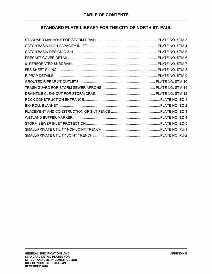
TABLE OF CONTENTS
STANDARD PLATE LIBRARY FOR THE CITY OF NORTH ST. PAUL
GENERAL SPECIFICATIONS AND APPENDIX B STANDARD DETAIL PLATES FOR STREET AND UTILITY CONSTRUCTION CITY OF NORTH ST. PAUL, MN DECEMBER 2018
STANDARD MANHOLE FOR STORM DRAIN................................................................ PLATE NO. STM-3
CATCH BASIN HIGH CAPACITY INLET ......................................................................... PLATE NO. STM-4
CATCH BASIN DESIGN G & H ....................................................................................... PLATE NO. STM-5
PRECAST COVER DETAIL ............................................................................................. PLATE NO. STM-6
6" PERFORATED SUBDRAIN ......................................................................................... PLATE NO. STM-7
FES SHEET PILING ........................................................................................................ PLATE NO. STM-8
RIPRAP DETAILS ............................................................................................................ PLATE NO. STM-9
GROUTED RIPRAP AT OUTLETS ............................................................................... PLATE NO. STM-10
TRASH GUARD FOR STORM SEWER APRONS ........................................................ PLATE NO. STM-11
DRAINTILE CLEANOUT FOR STORM DRAIN ............................................................. PLATE NO. STM-12
ROCK CONSTRUCTION ENTRANCE ............................................................................... PLATE NO. EC-1
BIO-ROLL BLANKET .......................................................................................................... PLATE NO. EC-2
PLACEMENT AND CONSTRUCTION OF SILT FENCE ................................................... PLATE NO. EC-3
WETLAND BUFFER MARKER ........................................................................................... PLATE NO. EC-4
STORM SEWER INLET PROTECTION ............................................................................. PLATE NO. EC-5
SMALL/PRIVATE UTILITY NON-JOINT TRENCH ............................................................. PLATE NO. PU-1
SMALL/PRIVATE UTILITY JOINT TRENCH ...................................................................... PLATE NO. PU-2
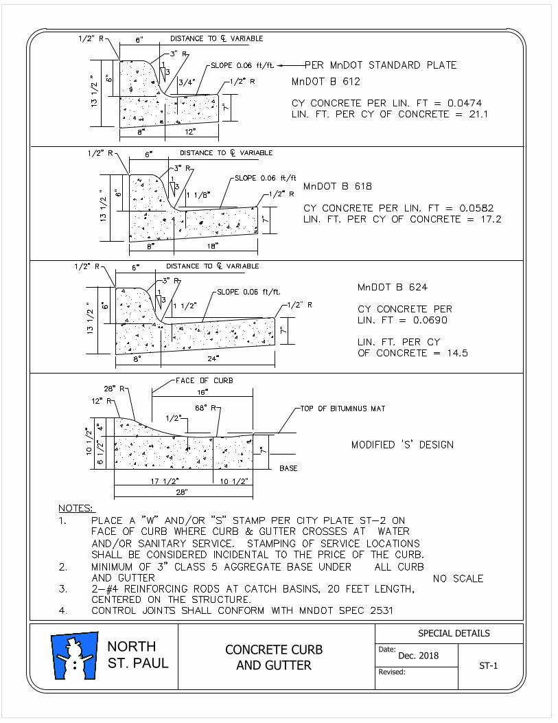
CONCRETE CURB
AND GUTTER
ST-1
Dec. 2018
SPECIAL DETAILS
Date:
Revised:
NORTH
ST. PAUL
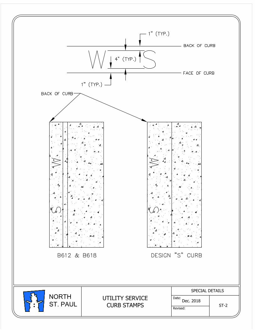
Dec. 2018
SPECIAL DETAILS
Date:
Revised:
NORTH
ST. PAUL
UTILITY SERVICE
CURB STAMPS
ST-2
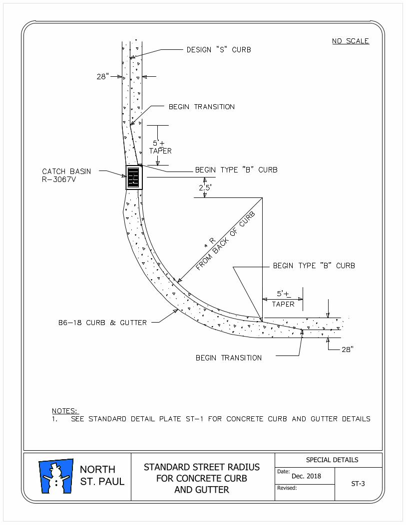
STANDARD STREET RADIUS
FOR CONCRETE CURB
AND GUTTER
ST-3
Dec. 2018
SPECIAL DETAILS
Date:
Revised:
NORTH
ST. PAUL
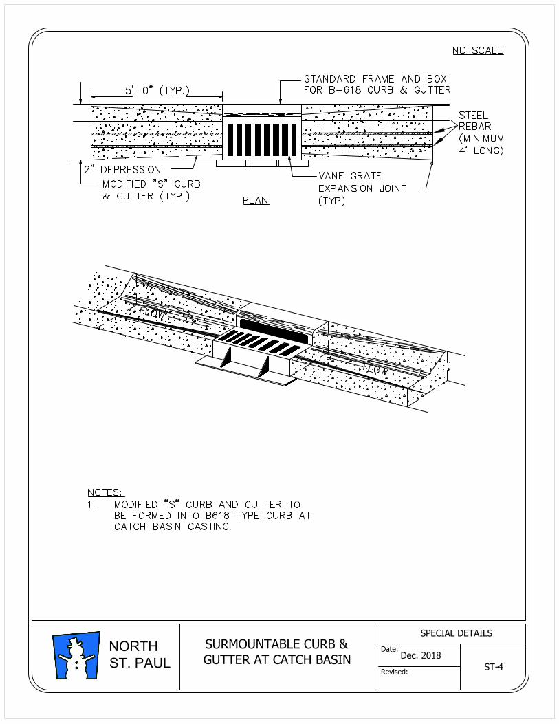
SURMOUNTABLE CURB &
GUTTER AT CATCH BASIN
ST-4
Dec. 2018
SPECIAL DETAILS
Date:
Revised:
NORTH
ST. PAUL
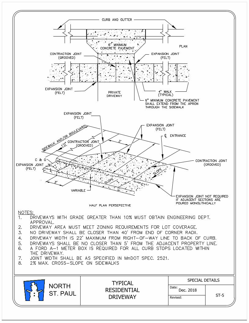
TYPICAL
RESIDENTIAL
DRIVEWAY
ST-5
Dec. 2018
SPECIAL DETAILS
Date:
Revised:
NORTH
ST. PAUL
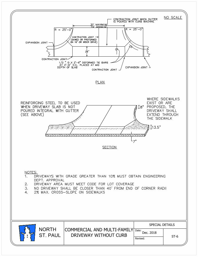
COMMERCIAL AND MULTI-FAMILY
DRIVEWAY WITHOUT CURB
ST-6
Dec. 2018
SPECIAL DETAILS
Date:
Revised:
NORTH
ST. PAUL
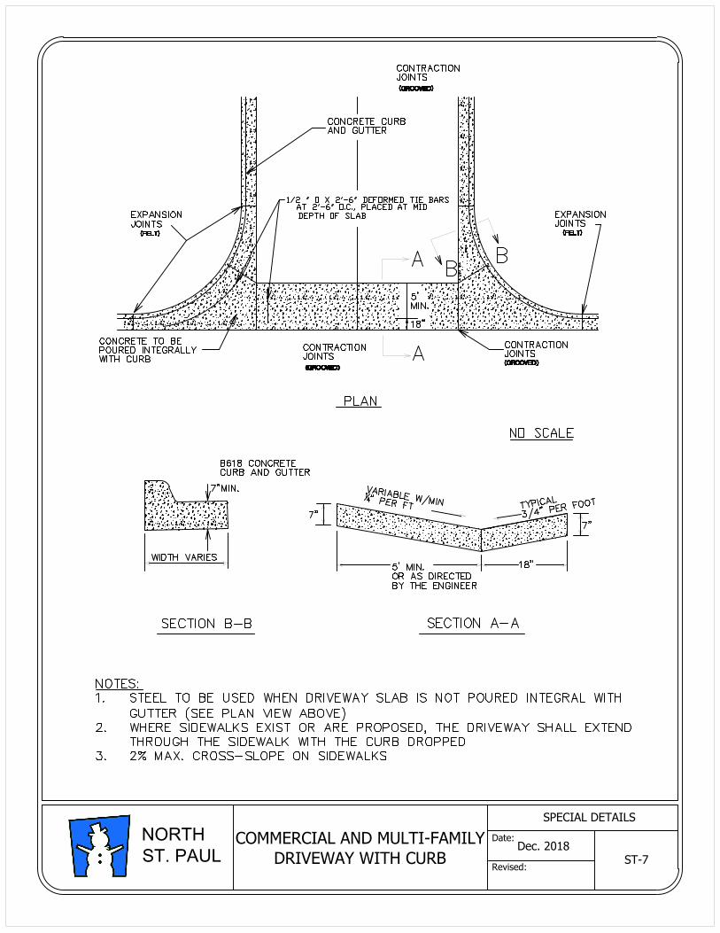
Dec. 2018
SPECIAL DETAILS
Date:
Revised:
NORTH
ST. PAUL
ST-7
COMMERCIAL AND MULTI-FAMILY
DRIVEWAY WITH CURB
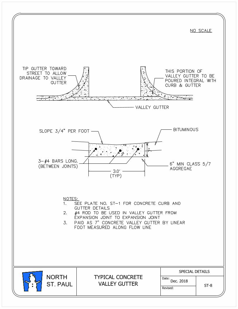
TYPICAL CONCRETE
VALLEY GUTTER
ST-8
Dec. 2018
SPECIAL DETAILS
Date:
Revised:
NORTH
ST. PAUL
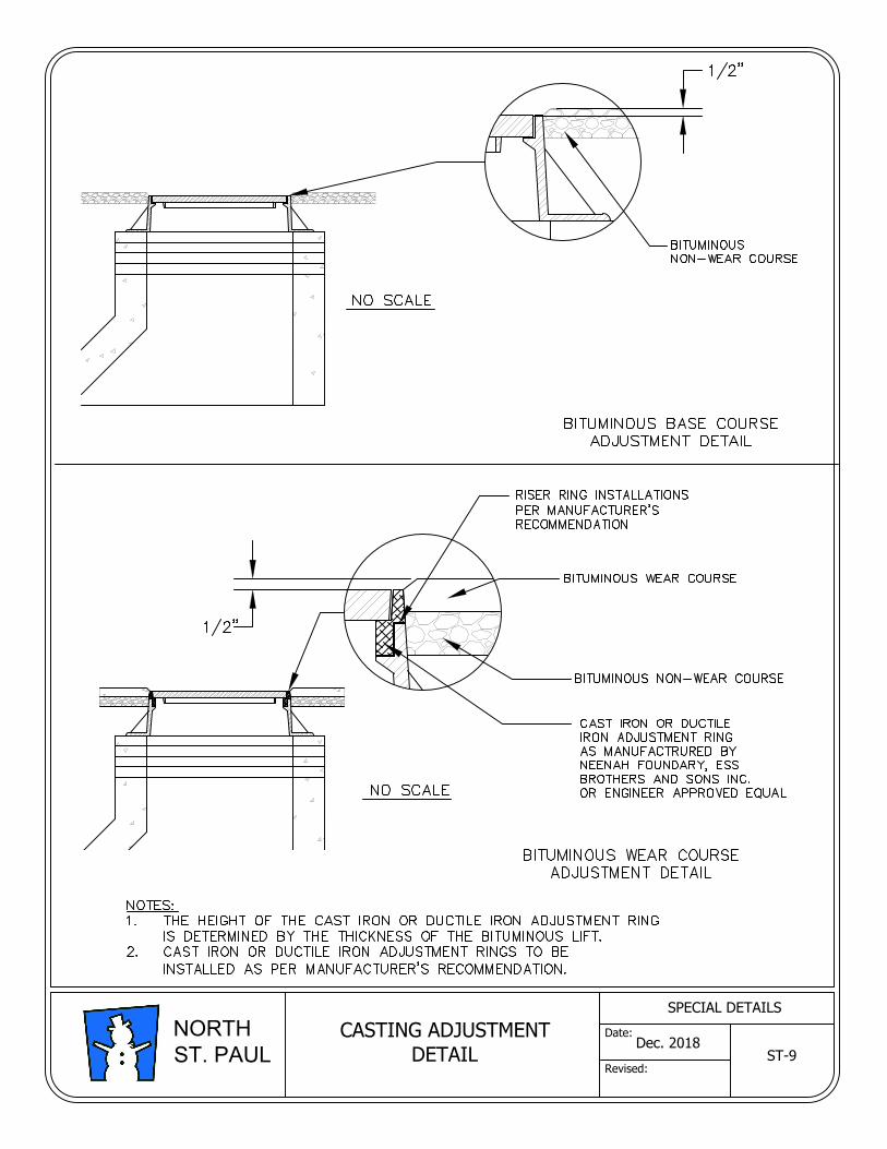
ST-9
CASTING ADJUSTMENT
DETAIL
Dec. 2018
SPECIAL DETAILS
Date:
Revised:
NORTH
ST. PAUL
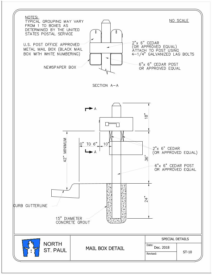
ST-10
MAIL BOX DETAIL
Dec. 2018
SPECIAL DETAILS
Date:
Revised:
NORTH
ST. PAUL
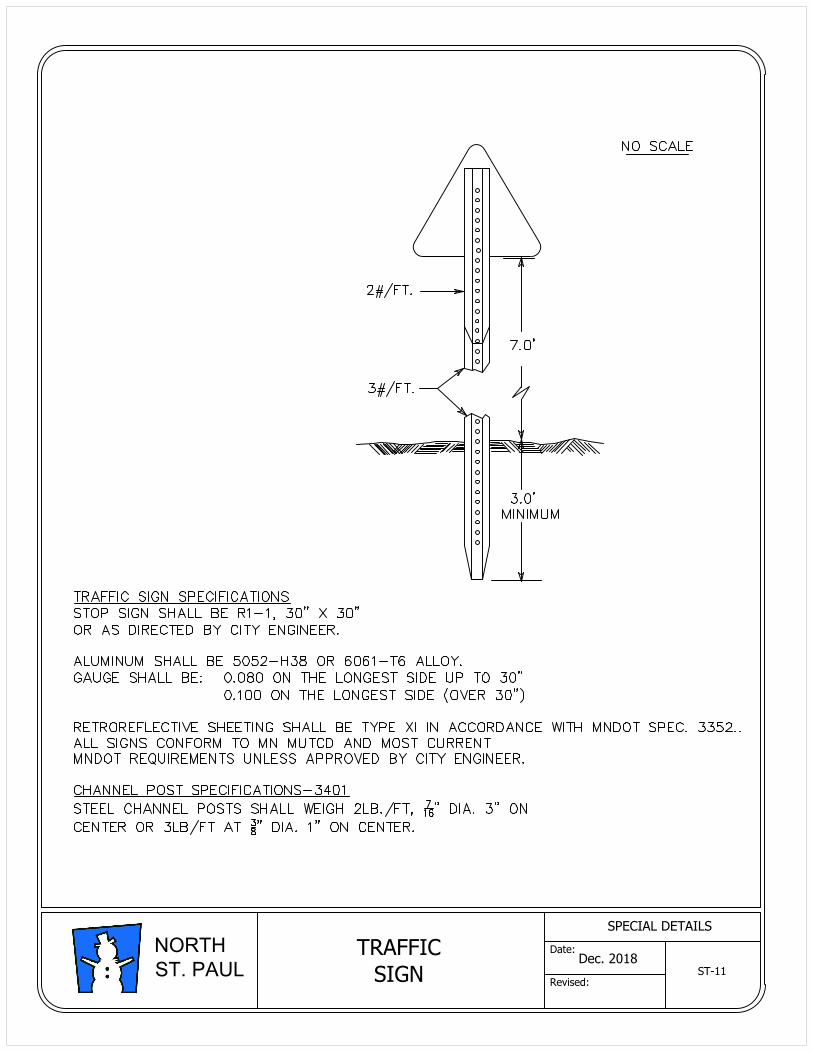
TRAFFIC
SIGN
ST-11
Dec. 2018
SPECIAL DETAILS
Date:
Revised:
NORTH
ST. PAUL
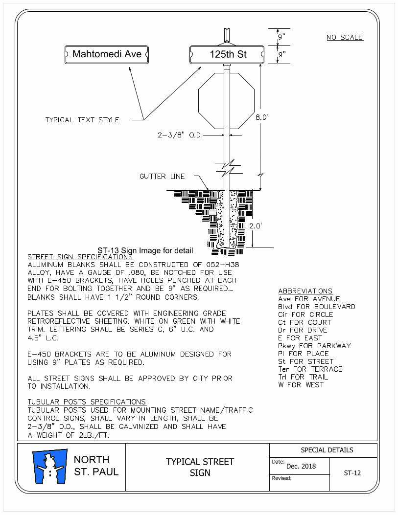
Mahtomedi Ave 125th St
TYPICAL STREET
SIGN
ST-12
Dec. 2018
SPECIAL DETAILS
Date:
Revised:
NORTH
ST. PAUL
ST-13 Sign Image for detail

Mahtomedi Ave 125th St
TYPICAL STREET
SIGN
ST-13
Dec. 2018
SPECIAL DETAILS
Date:
Revised:
NORTH
ST. PAUL
ST-13 Sign Image for detail
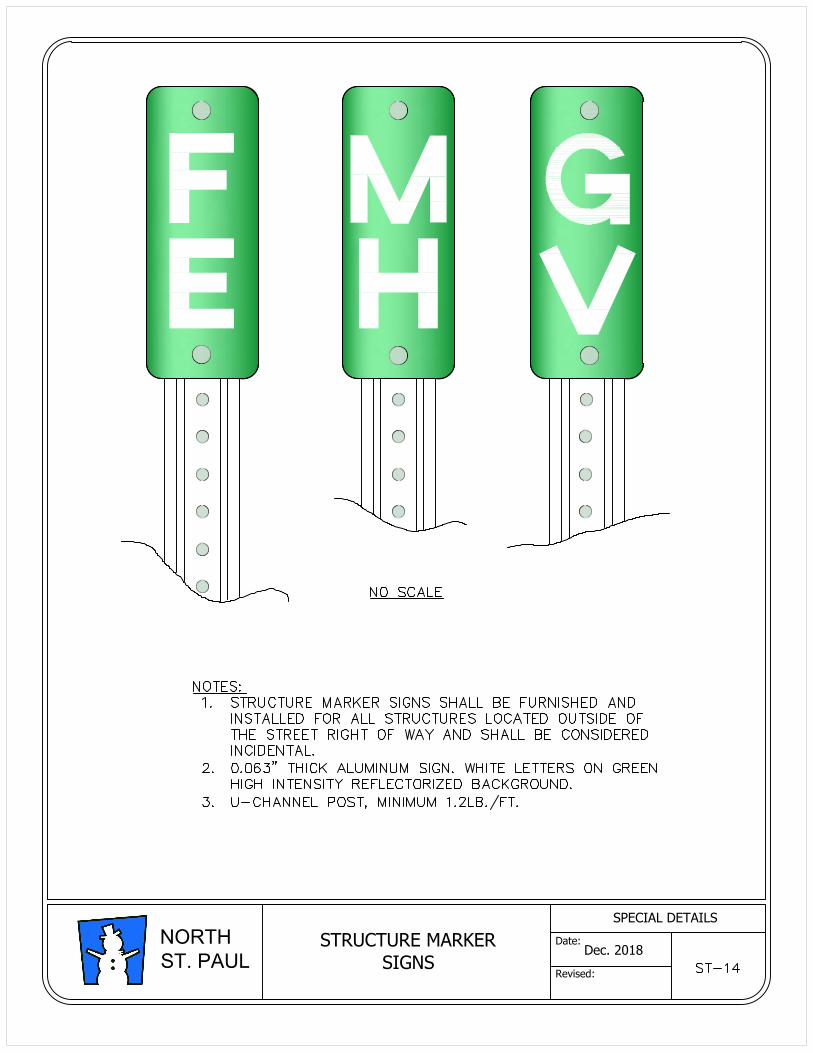
STRUCTURE MARKER
SIGNS
Dec. 2018
SPECIAL DETAILS
Date:
Revised:
NORTH
ST. PAUL
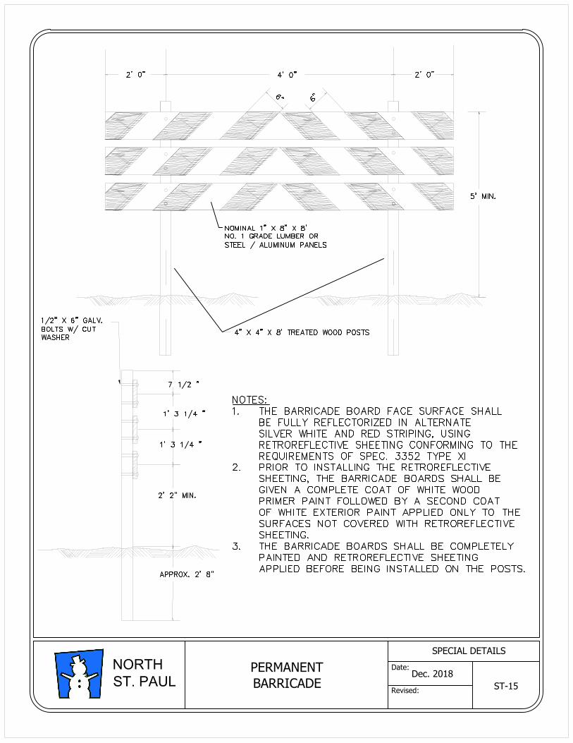
PERMANENT
BARRICADE
ST-15
Dec. 2018
SPECIAL DETAILS
Date:
Revised:
NORTH
ST. PAUL
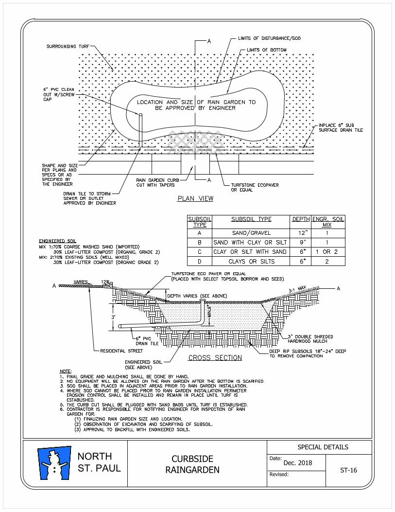
ST-16
CURBSIDE
RAINGARDEN
Dec. 2018
SPECIAL DETAILS
Date:
Revised:
NORTH
ST. PAUL
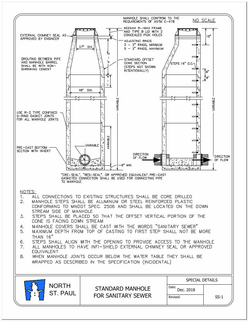
STANDARD MANHOLE
FOR SANITARY SEWER
SS-1
Dec. 2018
SPECIAL DETAILS
Date:
Revised:
NORTH
ST. PAUL
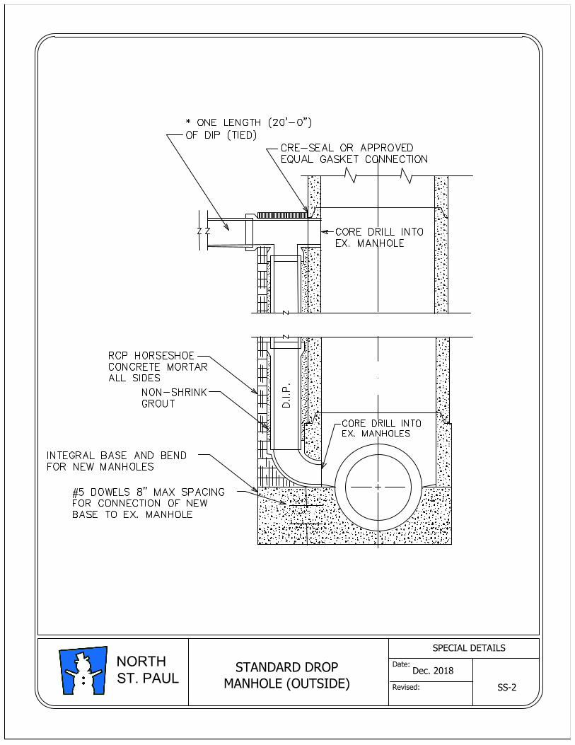
STANDARD DROP
MANHOLE (OUTSIDE)
SS-2
Dec. 2018
SPECIAL DETAILS
Date:
Revised:
NORTH
ST. PAUL
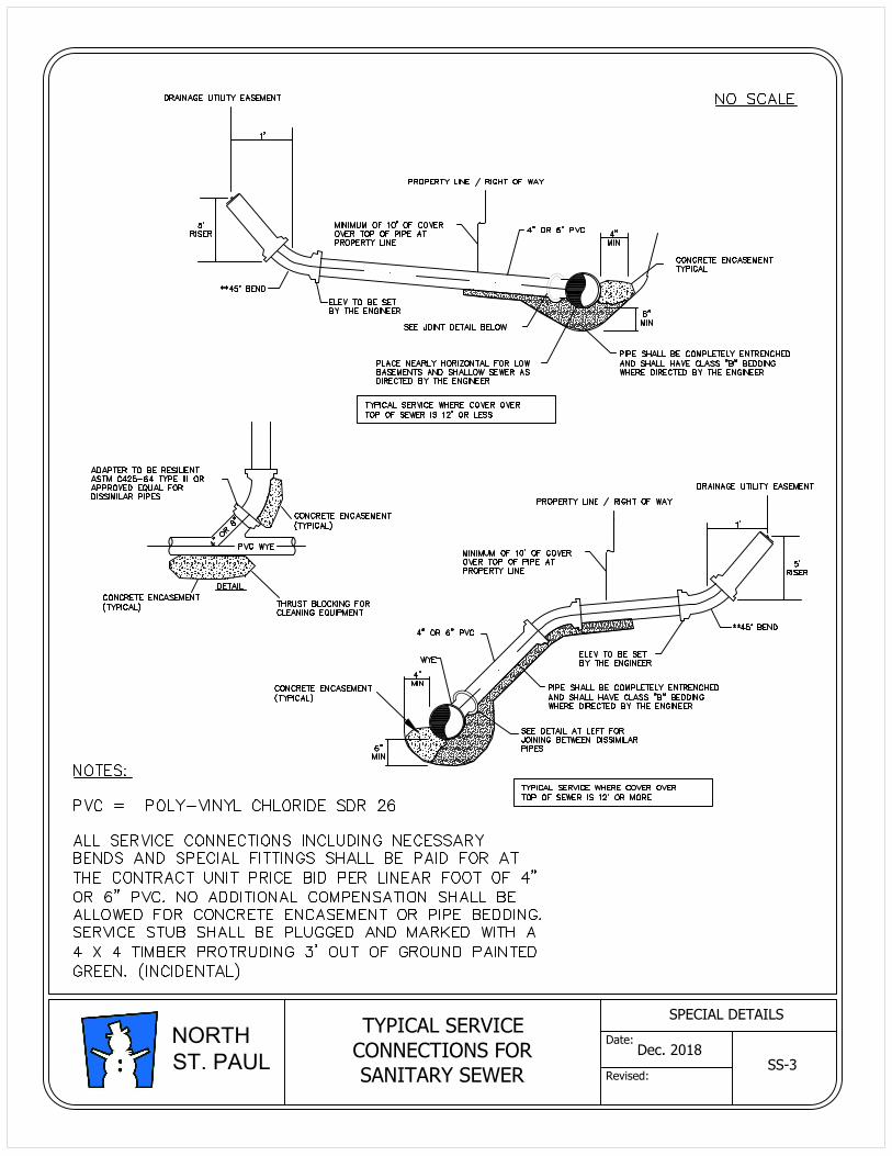
TYPICAL SERVICE
CONNECTIONS FOR
SANITARY SEWER
SS-3
Dec. 2018
SPECIAL DETAILS
Date:
Revised:
NORTH
ST. PAUL
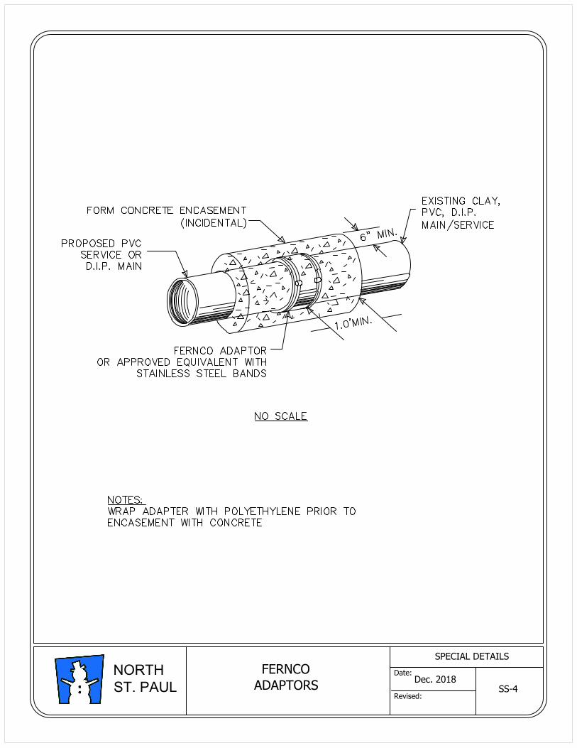
FERNCO
ADAPTORS
SS-4
Dec. 2018
SPECIAL DETAILS
Date:
Revised:
NORTH
ST. PAUL
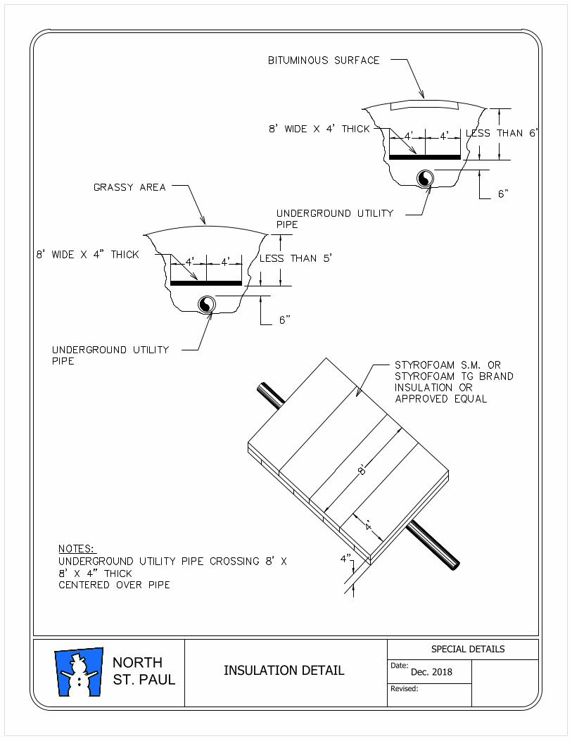
INSULATION DETAILDec. 2018
SPECIAL DETAILS
Date:
Revised:
NORTH
ST. PAUL
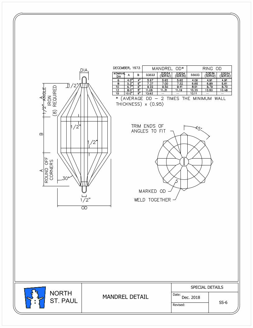
MANDREL DETAIL
--- --- --- ---
SS-6
Dec. 2018
SPECIAL DETAILS
Date:
Revised:
NORTH
ST. PAUL
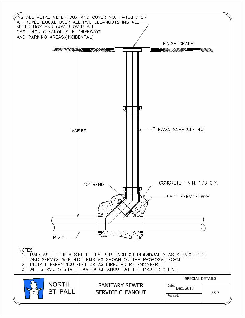
.
SANITARY SEWER
SERVICE CLEANOUT SS-7
Dec. 2018
SPECIAL DETAILS
Date:
Revised:
NORTH
ST. PAUL
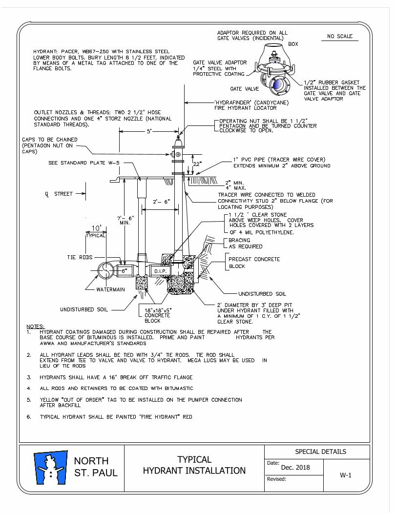
TYPICAL
HYDRANT INSTALLATION
W-1
Dec. 2018
SPECIAL DETAILS
Date:
Revised:
NORTH
ST. PAUL
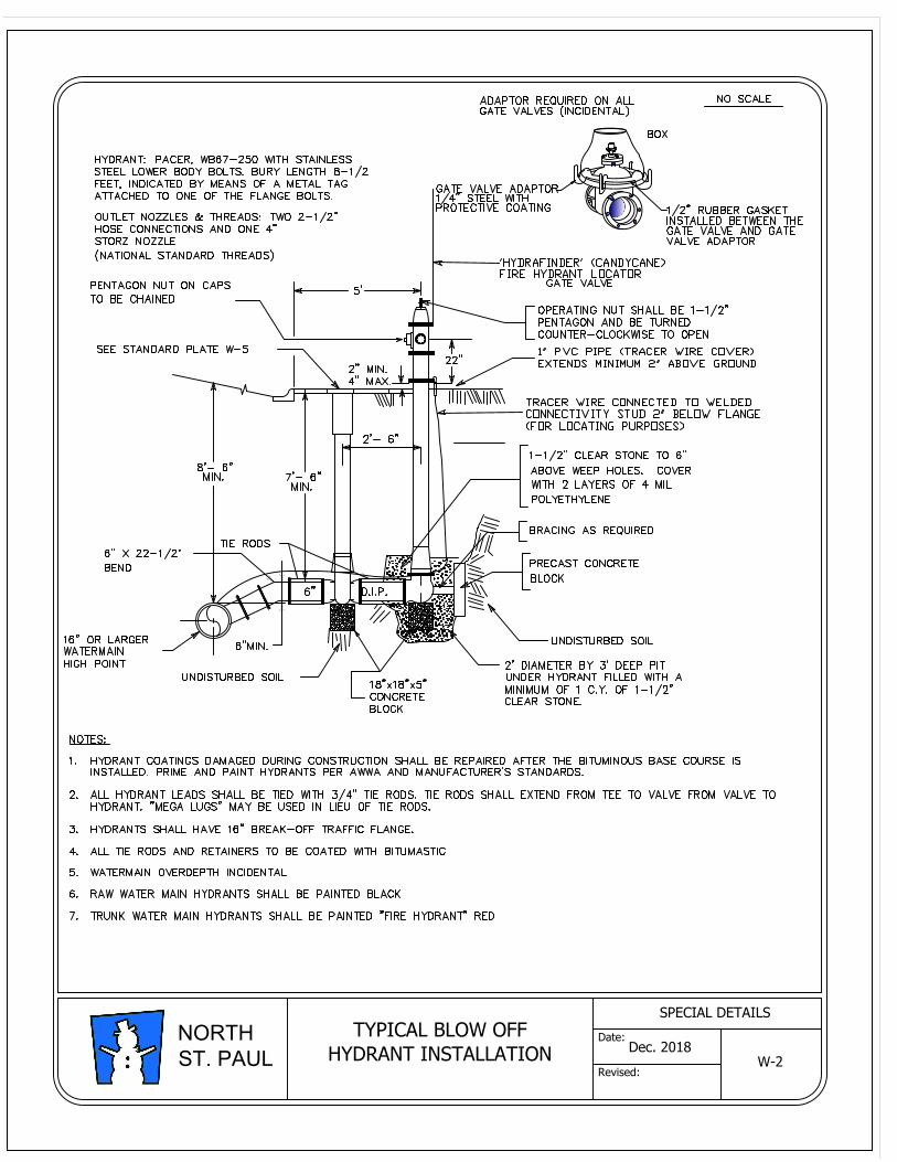
W-2
TYPICAL BLOW OFF
HYDRANT INSTALLATION
Dec. 2018
SPECIAL DETAILS
Date:
Revised:
NORTH
ST. PAUL
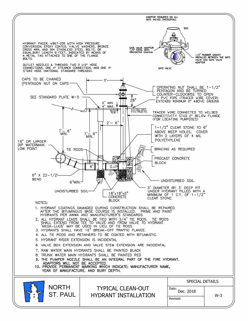
Dec. 2018
SPECIAL DETAILS
Date:
Revised:
NORTH
ST. PAUL
TYPICAL CLEAN-OUT
HYDRANT INSTALLATION
W-3
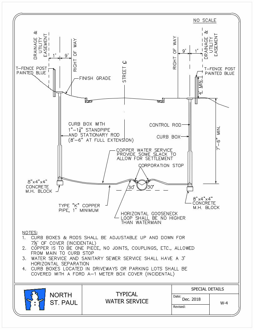
TYPICAL
WATER SERVICE
W-4
Dec. 2018
SPECIAL DETAILS
Date:
Revised:
NORTH
ST. PAUL
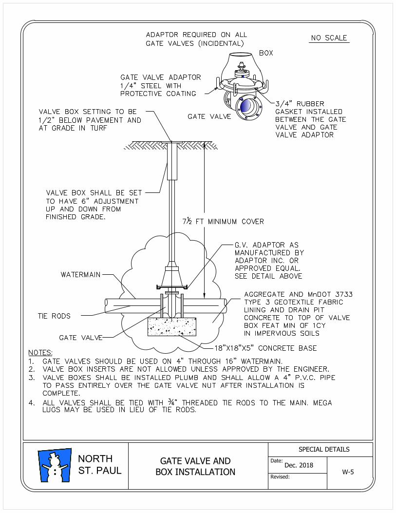
GATE VALVE AND
BOX INSTALLATION
W-5
Dec. 2018
SPECIAL DETAILS
Date:
Revised:
NORTH
ST. PAUL
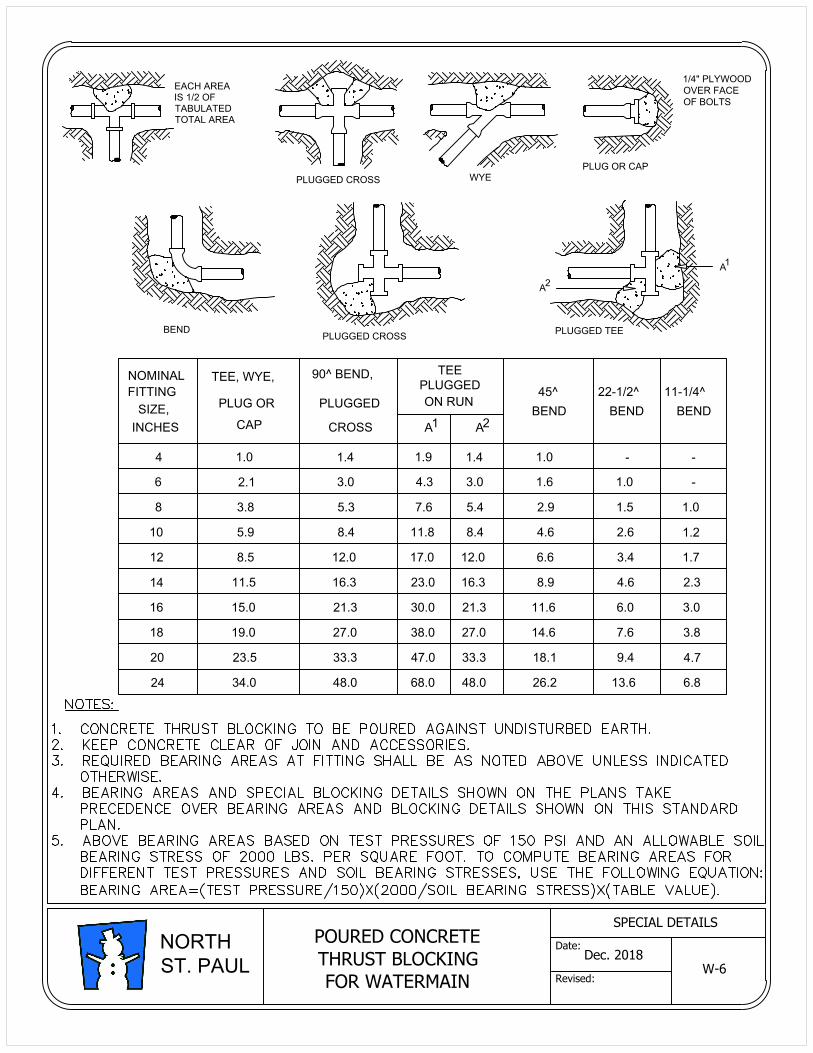
POURED CONCRETE
THRUST BLOCKING
FOR WATERMAIN
W-6
NOMINAL
FITTING
SIZE,
INCHES
4
6
8
10
12
14
16
18
20
24 34.0
23.5
19.0
15.0
11.5
8.5
5.9
2.1
3.8
1.0
PLUG OR
CAP
TEE, WYE,
48.0
33.3
27.0
21.3
16.3
12.0
8.4
3.0
5.3
1.4
PLUGGED
CROSS
90^ BEND,
68.0
47.0
38.0
30.0
23.0
17.0
11.8
4.3
7.6
1.9
ON RUN
A
PLUGGED
TEE
48.0
33.3
27.0
21.3
16.3
12.0
8.4
3.0
5.4
1.4
A
26.2
18.1
14.6
11.6
8.9
6.6
4.6
1.6
2.9
1.0
BEND
45^
13.6
9.4
7.6
6.0
4.6
3.4
2.6
1.0
1.5
-
BEND
22-1/2^
6.8
4.7
3.8
3.0
2.3
1.7
1.2
-
1.0
-
BEND
11-1/4^
1 2
PLUG OR CAP
1/4" PLYWOOD
OVER FACE
OF BOLTS
EACH AREA
IS 1/2 OF
TABULATED
TOTAL AREA
PLUGGED CROSS
BEND
PLUGGED CROSS
WYE
A
2
PLUGGED TEE
A
1
Dec. 2018
SPECIAL DETAILS
Date:
Revised:
NORTH
ST. PAUL
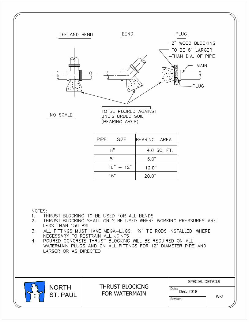
THRUST BLOCKING
FOR WATERMAIN
W-7
Dec. 2018
SPECIAL DETAILS
Date:
Revised:
NORTH
ST. PAUL
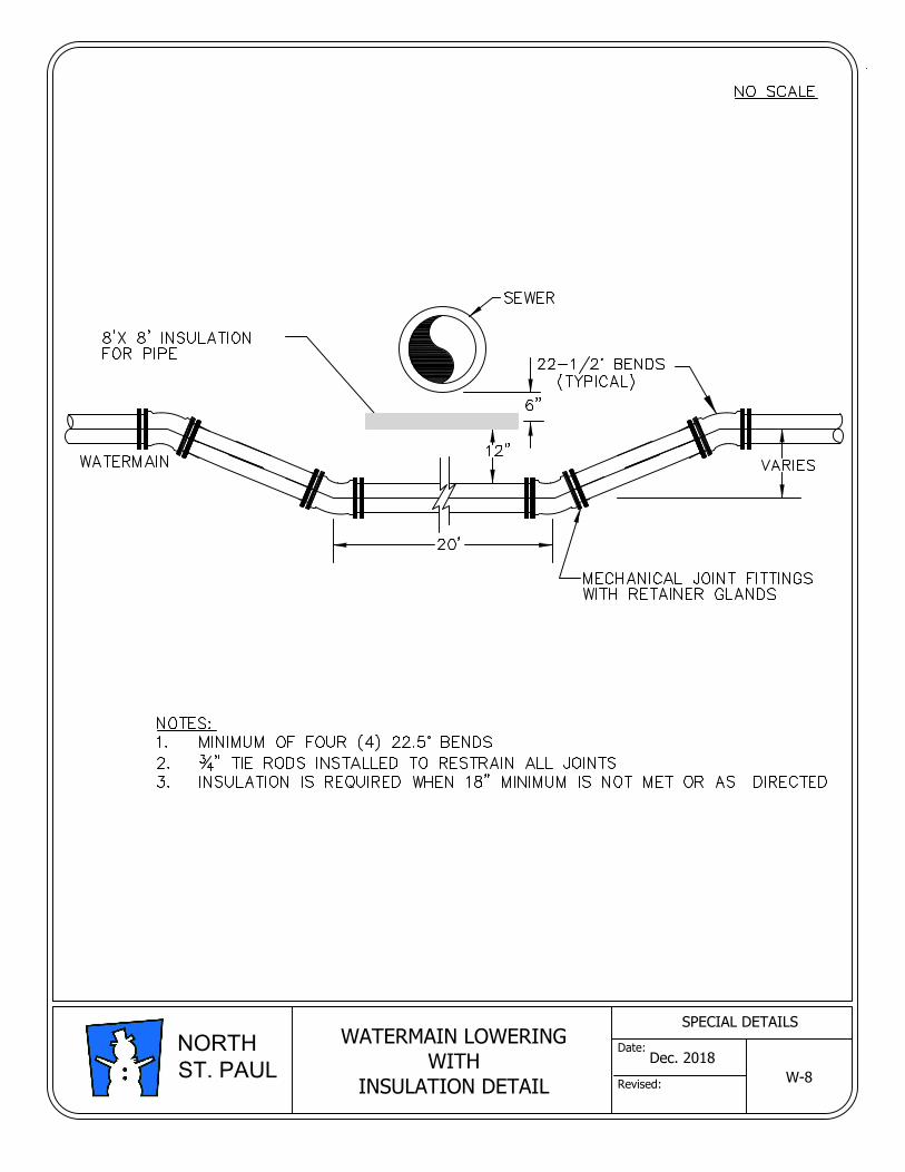
WATERMAIN LOWERING
WITH
INSULATION DETAIL
W-8
Dec. 2018
SPECIAL DETAILS
Date:
Revised:
NORTH
ST. PAUL
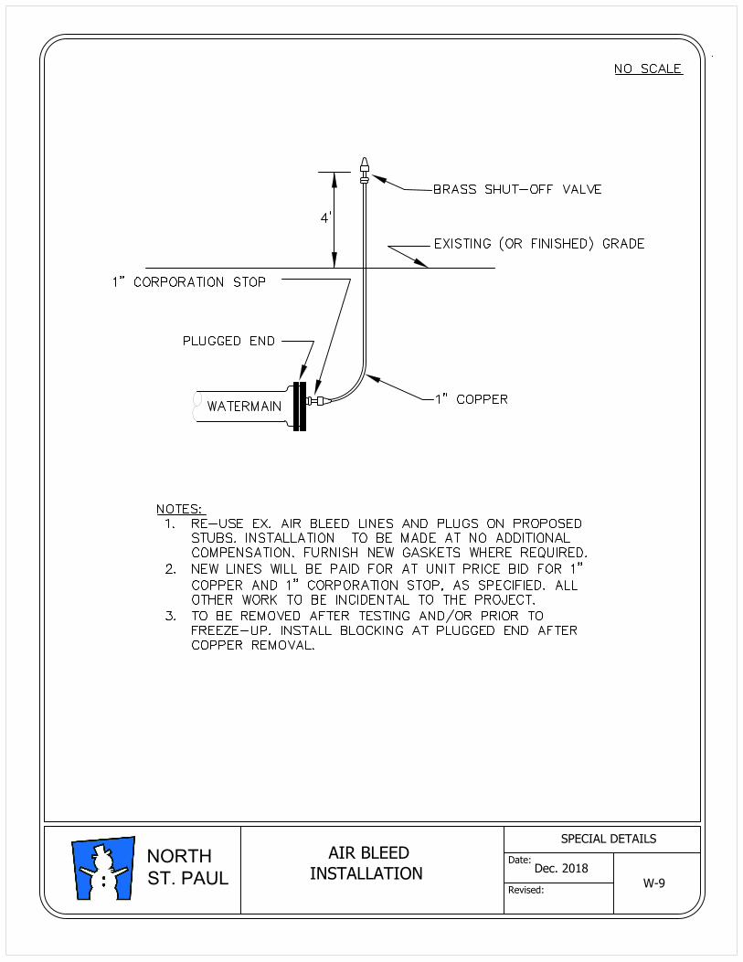
AIR BLEED
INSTALLATION
W-9
Dec. 2018
SPECIAL DETAILS
Date:
Revised:
NORTH
ST. PAUL
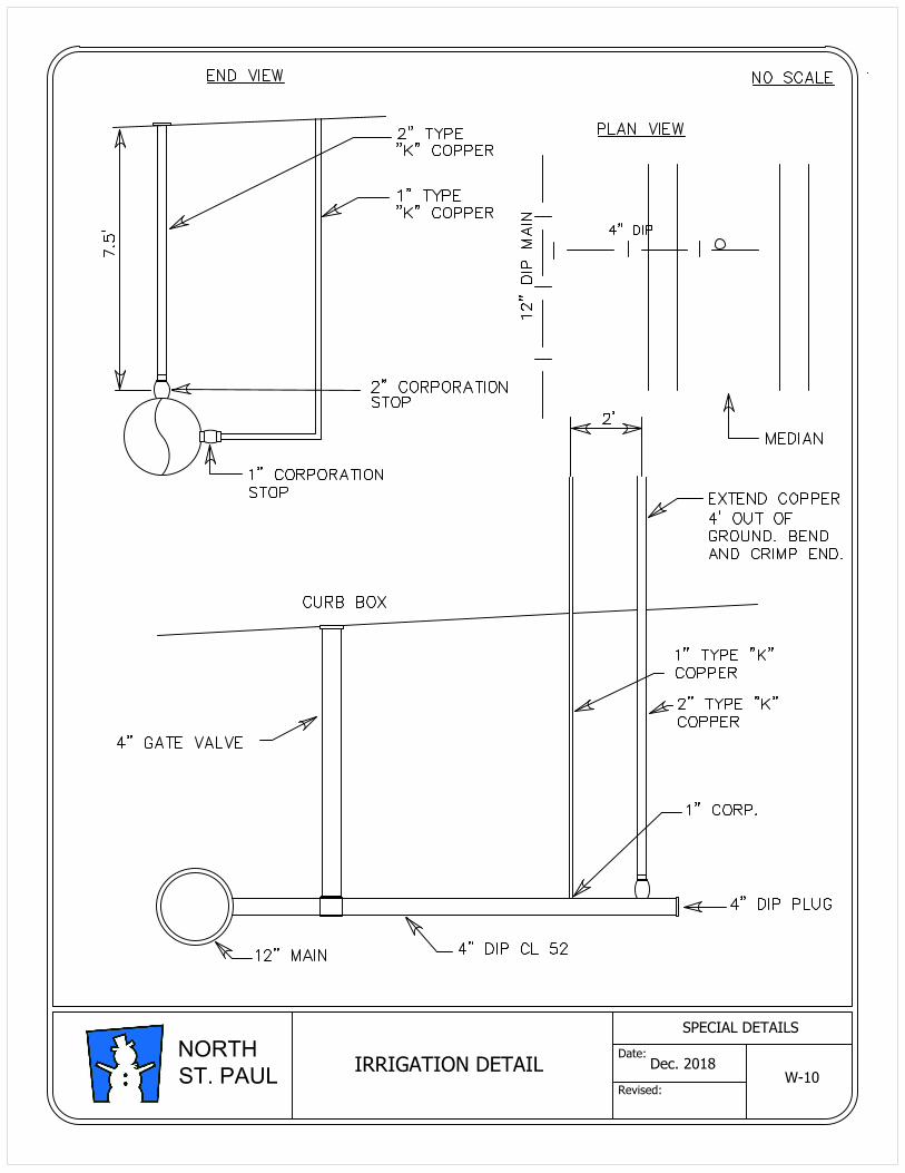
IRRIGATION DETAIL
W-10
Dec. 2018
SPECIAL DETAILS
Date:
Revised:
NORTH
ST. PAUL
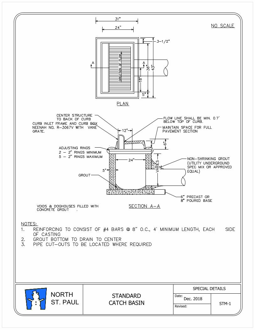
STANDARD
CATCH BASINSTM-1
Dec. 2018
SPECIAL DETAILS
Date:
Revised:
NORTH
ST. PAUL
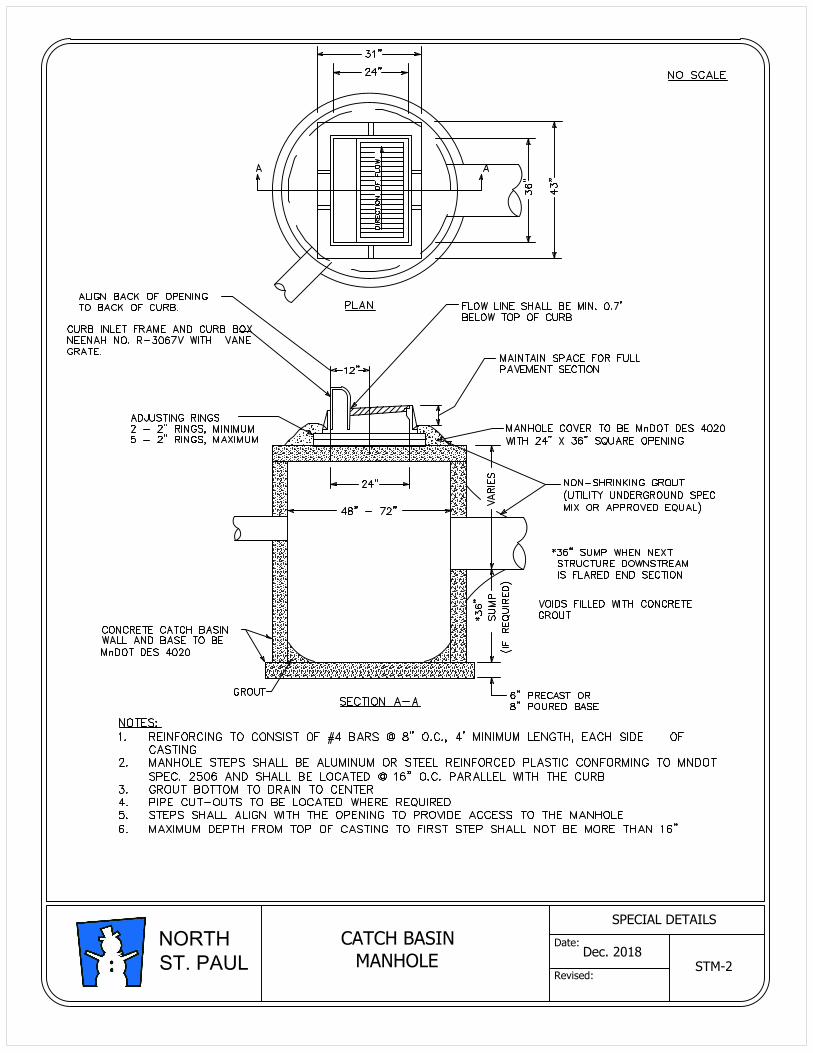
CATCH BASIN
MANHOLE
STM-2
Dec. 2018
SPECIAL DETAILS
Date:
Revised:
NORTH
ST. PAUL
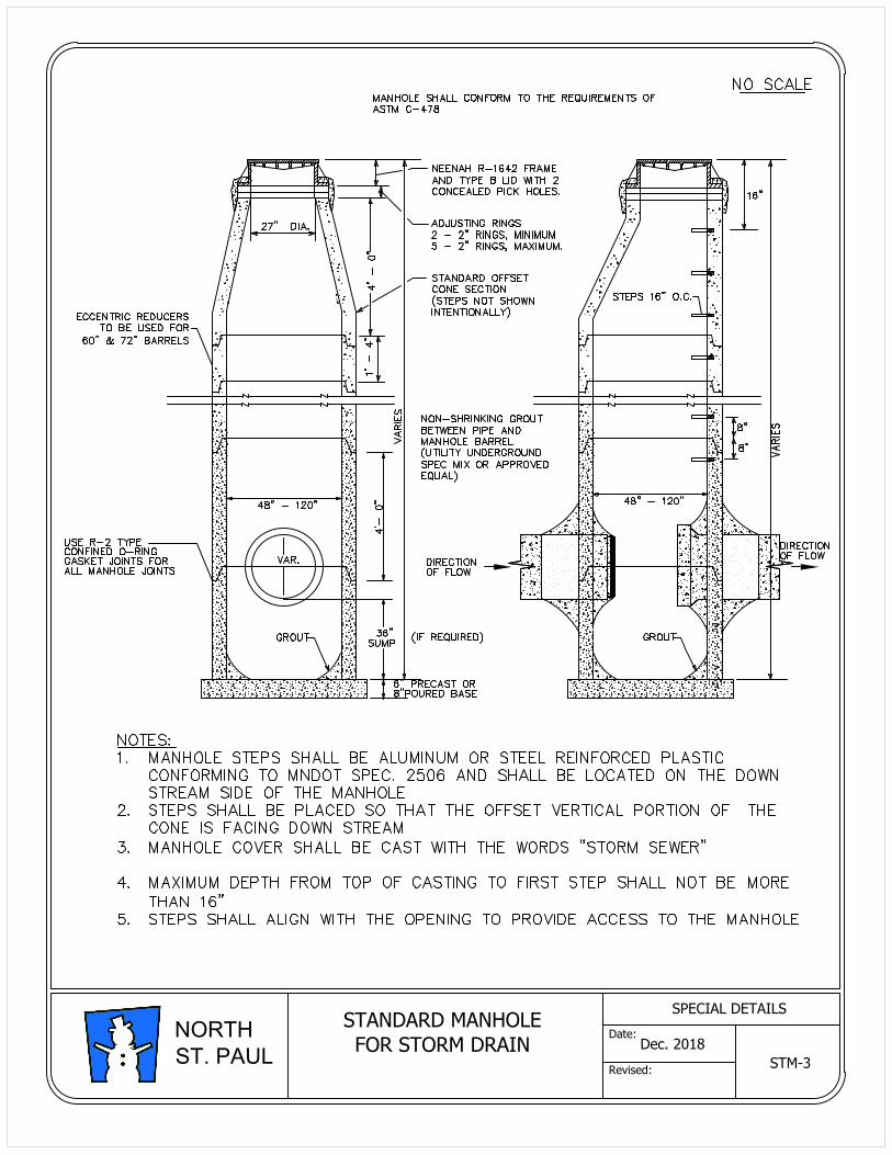
STANDARD MANHOLE
FOR STORM DRAIN
STM-3
Dec. 2018
SPECIAL DETAILS
Date:
Revised:
NORTH
ST. PAUL
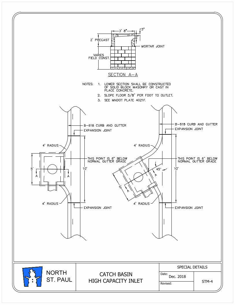
CATCH BASIN
HIGH CAPACITY INLETSTM-4
Dec. 2018
SPECIAL DETAILS
Date:
Revised:
NORTH
ST. PAUL
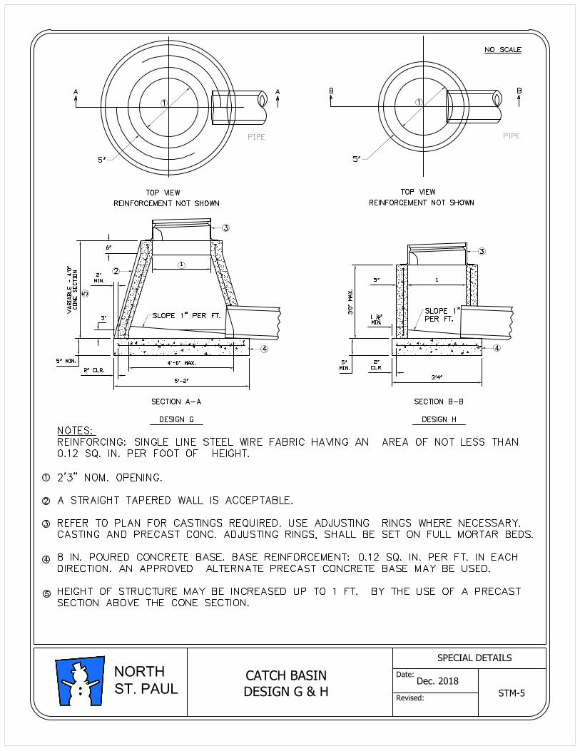
CATCH BASIN
DESIGN G & HSTM-5
Dec. 2018
SPECIAL DETAILS
Date:
Revised:
NORTH
ST. PAUL
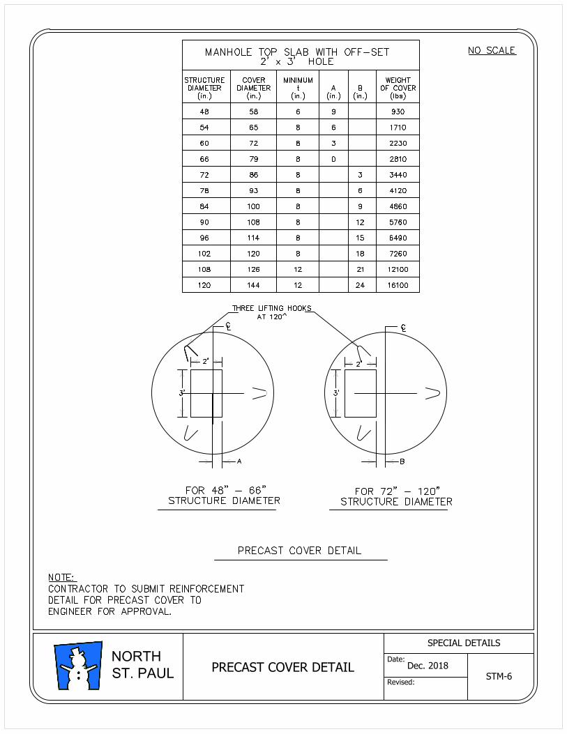
PRECAST COVER DETAIL
STM-6
Dec. 2018
SPECIAL DETAILS
Date:
Revised:
NORTH
ST. PAUL
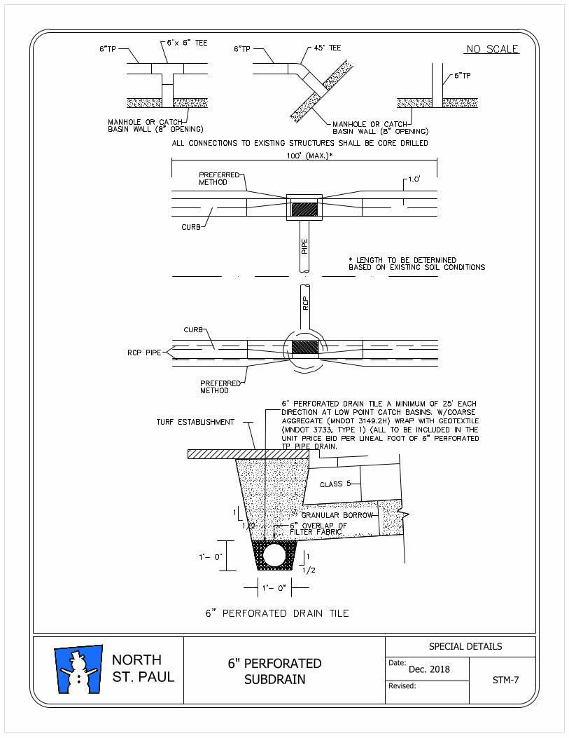
6" PERFORATED
SUBDRAINSTM-7
Dec. 2018
SPECIAL DETAILS
Date:
Revised:
NORTH
ST. PAUL
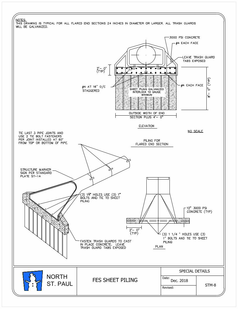
FES SHEET PILING
STM-8
Dec. 2018
SPECIAL DETAILS
Date:
Revised:
NORTH
ST. PAUL
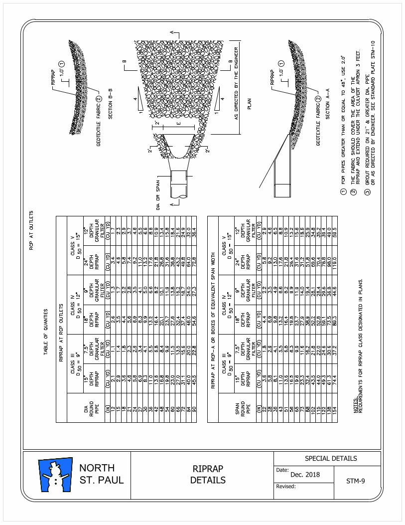
RIPRAP
DETAILS STM-9
Dec. 2018
SPECIAL DETAILS
Date:
Revised:
NORTH
ST. PAUL
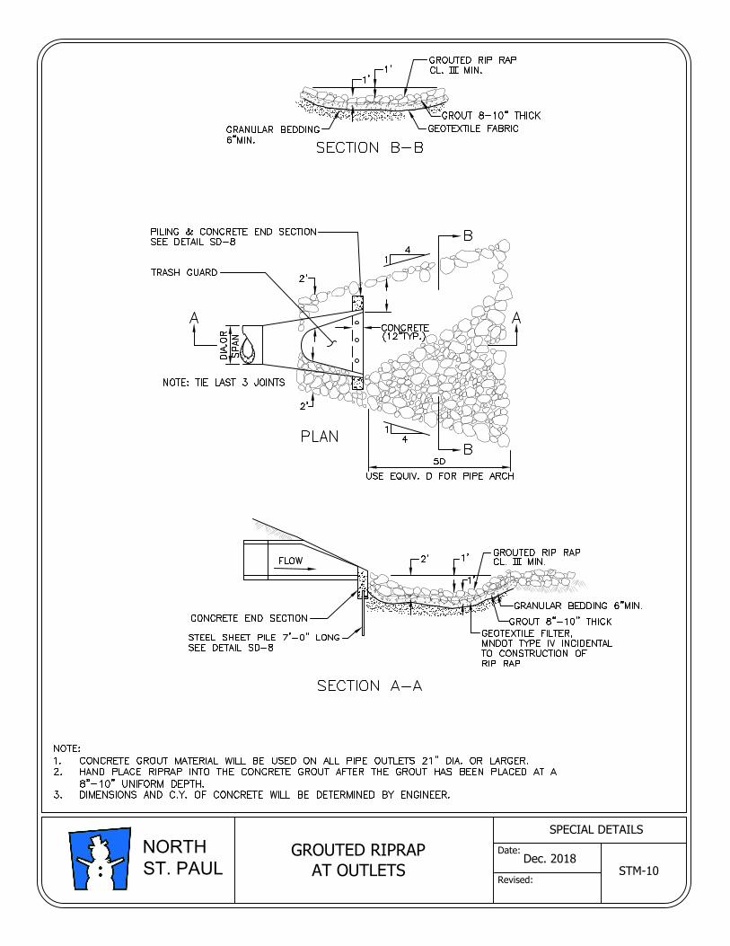
Dec. 2018
SPECIAL DETAILS
Date:
Revised:
NORTH
ST. PAUL
GROUTED RIPRAP
AT OUTLETS
STM-10
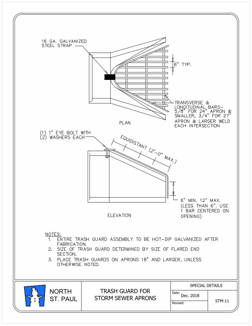
TRASH GUARD FOR
STORM SEWER APRONS
STM-11
Dec. 2018
SPECIAL DETAILS
Date:
Revised:
NORTH
ST. PAUL
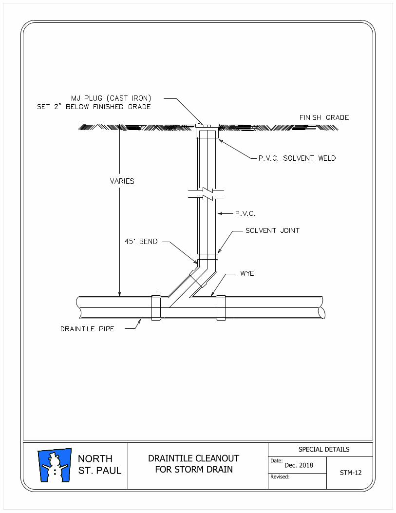
DRAINTILE CLEANOUT
FOR STORM DRAIN
STM-12
Dec. 2018
SPECIAL DETAILS
Date:
Revised:
NORTH
ST. PAUL
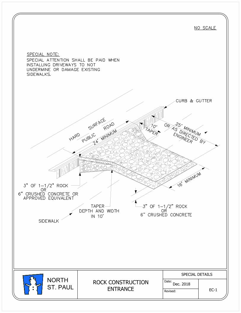
ROCK CONSTRUCTION
ENTRANCE
EC-1
Dec. 2018
SPECIAL DETAILS
Date:
Revised:
NORTH
ST. PAUL
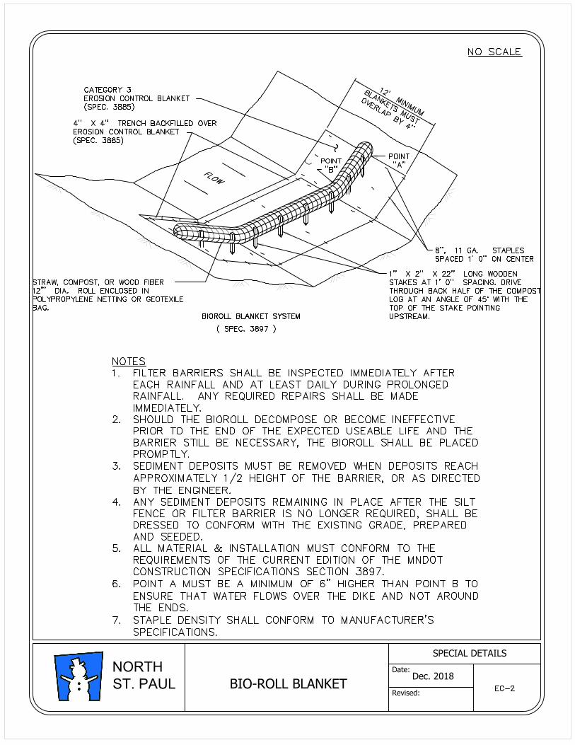
BIO-ROLL BLANKET
Dec. 2018
SPECIAL DETAILS
Date:
Revised:
NORTH
ST. PAUL
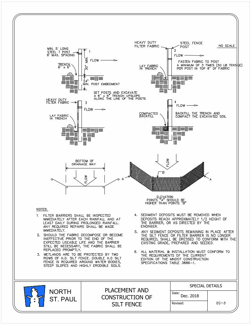
PLACEMENT AND
CONSTRUCTION OF
SILT FENCE
Dec. 2018
SPECIAL DETAILS
Date:
Revised:
NORTH
ST. PAUL
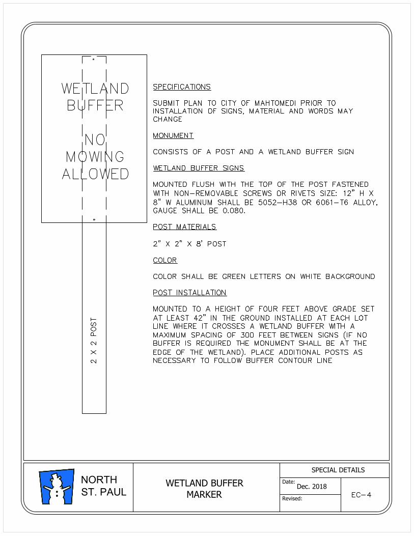
WETLAND BUFFER
MARKER
Dec. 2018
SPECIAL DETAILS
Date:
Revised:
NORTH
ST. PAUL
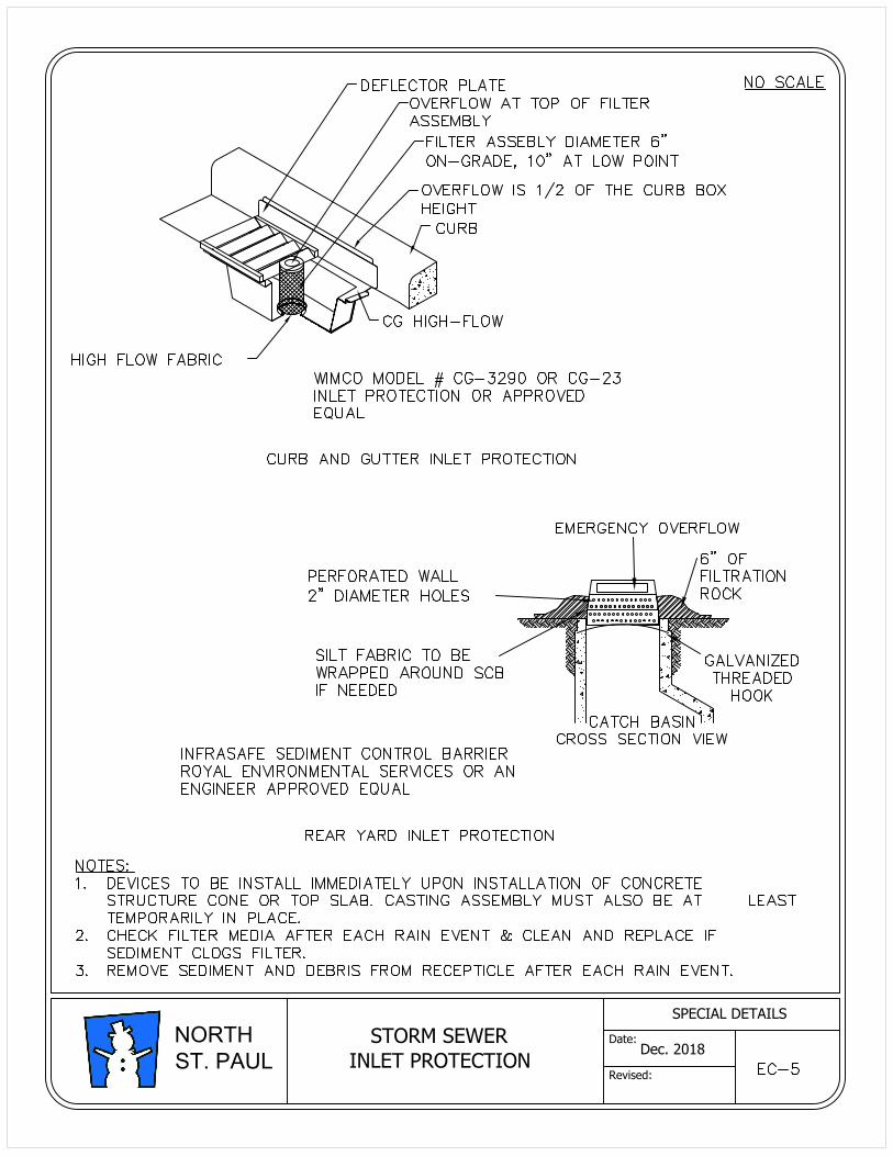
STORM SEWER
INLET PROTECTION
Dec. 2018
SPECIAL DETAILS
Date:
Revised:
NORTH
ST. PAUL
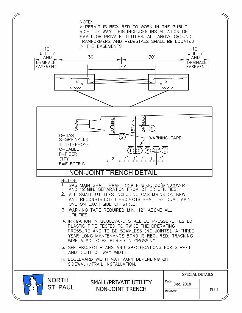
NON-JOINT TRENCH DETAIL
Dec. 2018
SPECIAL DETAILS
Date:
Revised:
NORTH
ST. PAUL
SMALL/PRIVATE UTILITY
NON-JOINT TRENCHPU-1
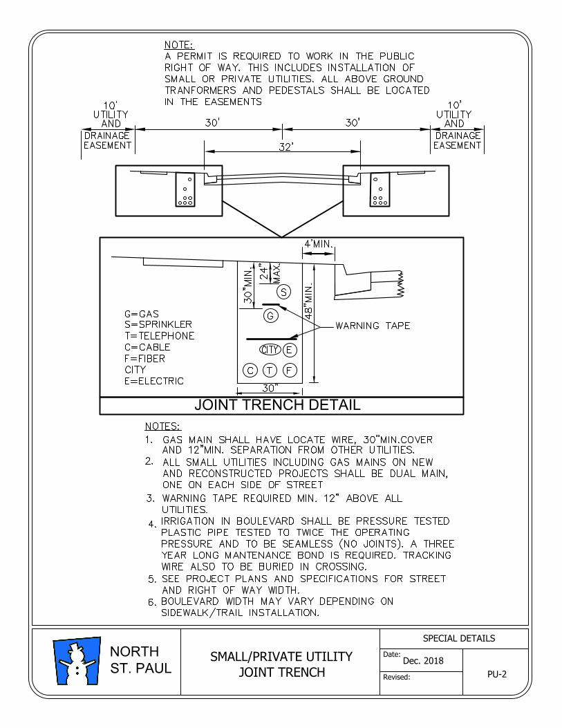
JOINT TRENCH DETAIL
Dec. 2018
SPECIAL DETAILS
Date:
Revised:
NORTH
ST. PAUL
SMALL/PRIVATE UTILITY
JOINT TRENCHPU-2
GENERAL SPECIFICATIONS AND APPENDIX C STANDARD DETAIL PLATES FOR STREET AND UTILITY CONSTRUCTION CITY OF NORTH ST. PAUL, MN DECEMBER 2018
APPENDIX C
AWWA C153 COMPACT FITTING WEIGHTS

Size 90° 45° 22 1/2° 11 1/4°4" 23 19 17 166" 44 37 33 31 NOTE:8" 61 49 44 40 DO NOT use 90° bends.
10" 94 74 64 57 Use (2) 45° bends.12" 124 101 85 7314" 220 164 148 12916" 264 202 179 16218" 410 289 292 19620" 505 348 364 22724" 586 475 385 345
Size 4" 6" 8" 10" 12" 14" 16" 18" 20" 24"4" 326" 51 638" 61 75 87
10" 80 93 102 11712" 98 113 123 137 15614" 183 206 229 235 28116" 229 248 265 281 317 32318" 275 280 286 370 415 445 49020" 335 383 410 432 475 530 560 60524" 415 445 470 500 550 580 625 660 720
Size 4" 6" 8" 10" 12" 14" 16" 18" 20" 24"4" 426" 68 728" 99 108 108
10" 98 118 138 14412" 100 140 162 190 21414" 181 259 223 244 29916" 250 289 345 397 333 38518" 260 282 308 384 63020" 306 341 370 392 451 634 547 60524" 403 431 465 494 553 714 809 830
Size 4" 6" 8" 10" 12" 14" 16" 18" 20" 24"6" 328" 43 54
10" 61 64 6212" 82 85 82 8214" 108 104 100 10016" 136 132 128 125 14018" 194 196 185 190 19620" 225 210 208 225 23324" 310 315 324 312 315
Size Short Long Size Size4" 17 20 4" 9 4" 106" 28 33 6" 15 6" 168" 38 46 8" 22 8" 26
10" 49 62 10" 32 10" 3612" 56 76 12" 42 12" 4614" 111 140 14" 66 14" 7516" 130 170 16" 92 16" 9518" 160 200 18" 114 18" 12120" 195 255 20" 125 20" 13524" 225 300 24" 166 24" 175
CAPS (MJ) FLAT PLUGS (MJ) FLAT
Ductile Iron Mechanical Joint Compact Fittings
Weight in Pounds per AWWA C153
BENDS (MJ-MJ)
TEES (MJ-MJ)
CROSSES (MJ-MJ)
REDUCERS (MJ-MJ)
SOLID SLEEVES (MJ)

GENERAL SPECIFICATIONS AND APPENDIX D STANDARD DETAIL PLATES FOR STREET AND UTILITY CONSTRUCTION CITY OF NORTH ST. PAUL, MN DECEMBER 2018
APPENDIX D
DISINFECTING WATER MAINS (AWWA C651)