Embed Size (px)
Citation preview
Technical
Specifications
Technical Specifications for PLC System
IOCL, Barauni Refinery, Instrumentation Department Page 2 of 59
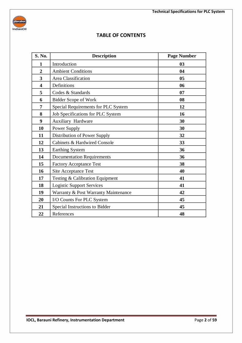
TABLE OF CONTENTS
S. No. Description Page Number
1 Introduction 03
2 Ambient Conditions 04
3 Area Classification 05
4 Definitions 06
5 Codes & Standards 07
6 Bidder Scope of Work 08
7 Special Requirements for PLC System 12
8 Job Specifications for PLC System 16
9 Auxiliary Hardware 30
10 Power Supply 30
11 Distribution of Power Supply 32
12 Cabinets & Hardwired Console 33
13 Earthing System 36
14 Documentation Requirements 36
15 Factory Acceptance Test 38
16 Site Acceptance Test 40
17 Testing & Calibration Equipment 41
18 Logistic Support Services 41
19 Warranty & Post Warranty Maintenance 42
20 I/O Counts For PLC System 45
21 Special Instructions to Bidder 45
22 References 48
Technical Specifications for PLC System
IOCL, Barauni Refinery, Instrumentation Department Page 3 of 59
Indian Oil Corporation, Barauni Refinery invites bids from reputed Bidders of
Programmable Logic Controller (PLC) having latest model with state of the art technology
having proven track record of performance on LSTK basis.
Definitions
The following definition shall apply:
OWNER : Indian Oil Corporation Limited, Barauni Refinery
BIDDER : Bidder who is opting to quote for this tender document
SITE : Barauni Refinery, Barauni, Bihar, India
Name of the Project: Supply, Installation, Commissioning & Post warranty
Comprehensive Annual maintenance contract (CAMC) of new
Programmable Logic Controller (PLC)
1) Introduction
Technical Specifications for PLC System
IOCL, Barauni Refinery, Instrumentation Department Page 4 of 59
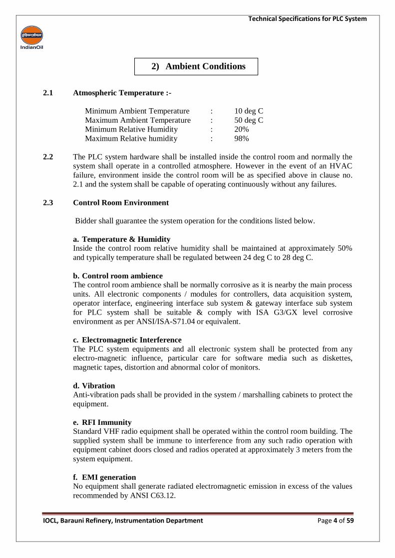
2.1 Atmospheric Temperature :-
Minimum Ambient Temperature : 10 deg C
Maximum Ambient Temperature : 50 deg C
Minimum Relative Humidity : 20%
Maximum Relative humidity : 98%
2.2 The PLC system hardware shall be installed inside the control room and normally the
system shall operate in a controlled atmosphere. However in the event of an HVAC
failure, environment inside the control room will be as specified above in clause no.
2.1 and the system shall be capable of operating continuously without any failures.
2.3 Control Room Environment
Bidder shall guarantee the system operation for the conditions listed below.
a. Temperature & Humidity Inside the control room relative humidity shall be maintained at approximately 50%
and typically temperature shall be regulated between 24 deg C to 28 deg C.
b. Control room ambience
The control room ambience shall be normally corrosive as it is nearby the main process
units. All electronic components / modules for controllers, data acquisition system,
operator interface, engineering interface sub system & gateway interface sub system
for PLC system shall be suitable & comply with ISA G3/GX level corrosive
environment as per ANSI/ISA-S71.04 or equivalent.
c. Electromagnetic Interference
The PLC system equipments and all electronic system shall be protected from any
electro-magnetic influence, particular care for software media such as diskettes,
magnetic tapes, distortion and abnormal color of monitors.
d. Vibration
Anti-vibration pads shall be provided in the system / marshalling cabinets to protect the
equipment.
e. RFI Immunity
Standard VHF radio equipment shall be operated within the control room building. The
supplied system shall be immune to interference from any such radio operation with
equipment cabinet doors closed and radios operated at approximately 3 meters from the
system equipment.
f. EMI generation
No equipment shall generate radiated electromagnetic emission in excess of the values
recommended by ANSI C63.12.
2) Ambient Conditions
Technical Specifications for PLC System
IOCL, Barauni Refinery, Instrumentation Department Page 5 of 59
g. Equipment Noise
The noise level of all the equipment including cooling fans shall be less than 55 dBA.
The noise level measurement shall be based on the type test carried out in accordance
with any of the methods detailed in international standards and expressed in terms of
dBA.
3.1 Plant Area classification is Zone-1, Gas Gr.IIA, IIB T3 as per IEC 60079. However
the control room where the system hardware is installed is a non-hazardous area. All
the barriers, isolators shall be suitable for instruments located for classified area EEx
(ia) Gr. IIA, IIB T3.
3.2 Following certificates shall be supplied by Bidder for final submission to End user:
a. Certificate from statutory authority like FM, CENELEC, ATEX etc. for Items of
foreign origin shall necessarily have approval certification from CCOE (Chief
Controller of Explosives) of Petroleum & explosive safety organization (PESO)
India for applicable items, irrespective of country of origin.
b. All the barriers, isolators shall be suitable for classified area and shall have
electrical classification EEx (ia) Gr. IIA, IIB T3.
3) Area Classification
Technical Specifications for PLC System
IOCL, Barauni Refinery, Instrumentation Department Page 6 of 59
4.1 Switch over Time: Time required for a back up instrument to come on-line automatically
in case of failure of the main instrument.
4.2 Loop Integrity: The system shall be said to have loop integrity if the failure of one
component in the system / subsystem does not affect more than one loop.
4.3 Interchangeability: Systems / sub-systems shall be said to have full interchangeability if
the functions and information available on one system / sub-system shall also be available
on the other in totality.
4.4 Redundancy: A system component shall be termed as redundant if it takes over the
operation automatically on failure of the main component in a bump-less manner without
causing any interruption in the system, upsetting the process and simultaneously making
the plant data continuously available for the operator for control and for historization. The
repaired or replaced device shall be brought inline only through operator action.
4.5 Scan Time: Scan time for different sub-systems shall be defined as follows:
a. Process Control System (Close-Loops): Scan time for a close-loop shall be defined
as the cycle time taken by controller to read and process input, perform control
calculations and update control output for all the loops configured within the
controller.
b. Process Control System (Open-Loops): Scan time for an open loop shall be defined as
the cycle time required by the data acquisition sub system to read input, processing and
computation of all the open loops configured within the data acquisition sub-system.
c. Programmable Logic Controller: The scan time for a Programmable logic controller
shall be defined as the cycle time taken by the system to read input, input processing
executing logic and Updating control output for all the logic configured within the
programmable logic controller.
4.6 Bus Degradation: Bus degradation shall be defined as a change in the system
performance from the specified one while loading the communication sub-system from 10
through 100 percent.
4.7 Real time trend: Real time trend shall be defined as a continuously progressing graphical
record showing continuously updated parameter with most recent value and a past record
of minimum 10 minutes without depressing any additional key for moving backward in
time.
4.8 Call-up time: Call-up time shall be defined as the time taken by the system to display a
particular display/data on the CRT after getting the corresponding command from the
operator.
4.9 Display Update Rate: Display update rate shall be defined as the rate at which the
information present in the system input terminal is getting updated on current display on
the LED screen.
4) Definitions
Technical Specifications for PLC System
IOCL, Barauni Refinery, Instrumentation Department Page 7 of 59
4.10 Mean time between failures (MTBF): MTBF is the mean (average) time between
failures of a system.
4.11 Mean Time To Repair (MTTR): MTTR is the average time to repair a system back to
acceptable operating conditions.
4.12 Engineering console: Engineering console shall be the engineer’s main interface device
via which engineer can view the plant gives instructions to peripherals to execute
commands and can configure and maintain the system.
The design, manufacture, inspection, testing and installation of all equipment and system
covered under this section shall conform to the latest editions of codes and standards at
the time of procurement.
IEC 801.4 - Electromagnetic compatibility for industrial
process measurement & control equipment.
IEC 529 - Classification of degree of protection provided by
enclosures.
NEC - National Electrical code.
NFPA-496 - Purged and pressurized enclosures for electrical
equipment.
ISA-S51.1 - Process Instrumentation Terminology
ISA-S5.2 - Binary Logic diagrams for process operations.
ISA-S5.3 - Graphic symbols for Distributed control/Shared
display instrumentation/Logic and computer system.
ISA-S5.4 - Instrument Loop Diagrams.
ISA-S18.1 - Annunciator Sequences and Specifications
ISA-RP55.1 - Recommended practice-Hardware testing of digital process
computers.
ISA-S71.01 - Environmental conditions for process measurement &
control systems-Temperature & Humidity.
ISA-S71.04 - Environmental conditions for process measurement &
control systems –Airborne Contaminants.
ICS-6 - Enclosures for Industrial control and systems
EN500014/IEC-79/API-500- Explosive Area Classification
IEC-61508 - Safety Integrity Level
IEC-61131/ISA S 5.2 - Logic
IEC-801.4 - Electromagnetic compatibility for industrial process
measurement & control equipment.
NFPA 70 - National Electrical code
IEC-61511 - Functional Safety-Safety Instrumented system for the
process industry sector.
5) Codes and Standards
Technical Specifications for PLC System
IOCL, Barauni Refinery, Instrumentation Department Page 8 of 59
6.1 This specification and it’s enclosed attachments covers the minimum requirements for
design, engineering, manufacture, selection & supply of all material & accessories,
assembly at manufacturer’s works, testing, Factory acceptance test, packing &
forwarding to IOCL site, dismantling of existing PLC systems, installation of new PLC
systems, testing, Site Acceptance Test, Pre-Commissioning, Commissioning and handing
over of complete PLC system to the IOCL on lump sum turnkey basis for TPS section of
Barauni Refinery.
6.2 The intent of this specification is to provide minimum requirements as required by the
Bidder and does not relieve the Bidder from his responsibility regarding design, reliable,
efficient and safe operation of the supplied system. Any omission in the specification
(hardware and or software) will not relieve the Bidder from his obligation to supply the
system compatible with the intent of this specification.
6.3 In case of any conflict between this specifications, enclosed data sheets, enclosed
attachments, related codes and standards etc, Bidder shall refer the matter in writing to
the IOCL and shall obtain clarification in writing before starting the manufacturing.
However, In general more stringent requirements will prevail & owner decision will be
final & binding to Bidder for execution without any implication to IOCL.
6.4 The intending tenderers are to meet the technical pre-qualification criteria and have to
enclose all necessary documents along with their bids. Technical evaluation of the
intending bidders/tenderers shall only be done if they are meeting the technical pre-
qualification criteria.
6.5 All system hardware and software shall be completely seamless integrated, factory tested
and ready to function as soon as assembled, powered and connected to field devices.
Bidder shall be responsible to comply with this specification & its attached enclosures,
codes, standards and statutory requirements (if any). Bidder shall be responsible for
selection of the hardware.
6.6 All software supply & generation is part of PLC system. Bidder’s scope shall essentially
consist of development of all the application software that is required to make the PLC
system fully functional to comply all requirements.
6.7 It is decided to replace the existing PLC systems of New DM Plant and BXP DM Plant
including I/O marshalling racks/ cabinets/Consoles/ Hardwired consoles/PDP etc by new
PLC system. To achieve this goal, all the existing I/Os are to be shifted to new PLC
system. The proposed PLC systems shall be installed in BXP DM Plant rack room.
Existing field cables shall be used for BXP DM Plant whereas new cables shall be used
for New DM Plant PLC. PLC systems shall be replaced as when clearance given by
IOCL.
6) Bidder’s Scope of Work
Technical Specifications for PLC System
IOCL, Barauni Refinery, Instrumentation Department Page 9 of 59
Details are as follows :-
Unit PLC
New DM Plant Rockwell PLC to be replaced
BXP DM Plant GE PLC to be replaced
6.8 The entire job of replacement of the above mentioned existing systems with proposed
new PLC system shall be carried out by the Bidder on LSTK basis. Bidders shall visit
site, prior to Pre-bid meeting for their own assessment of jobs involved & to survey the
control marshalling space available.
6.9 Any hardware or software not specifically mentioned in this tender document but
required to make the system complete for the safe operation shall be included in the
Bidder’s scope of supply.
6.10 Prior to submission of Techno-Commercial offer, a pre bid meeting shall be held, during
which Bidders shall be given opportunity to ask queries and get clarifications with
respect to the Tender. No extension of offer submission date shall be granted under any
circumstances thereafter.
6.11 Dismantling of existing PLC systems hardware, cabinets, hardwired consoles,
interconnecting cables & other associated hardware etc. as per the existing architecture
and to install the hardware based on new system architecture is in the scope of bidder.
Dismantled and unused component shall be handed over to the designated person from
IOCL side. Plan for shutdown activity shall be discussed and finalized during detailed
engineering.
6.12 Removal of termination of existing PLC system, all field cables from the existing
marshalling racks and dropping from the existing panels, proper fixing of identification
marks on these cables for re-use, dismantling of existing panel and shifting to outside
control room are in scope of Bidder.
6.13 Before dismantling of field cables from marshalling cabinets, it is responsibility of the
bidder to tag individual pair of cables with tag no. of the instruments, for ease of
reinstallation. A proper document of existing cables having information from field
instrument to marshalling cabinets shall be generated by the bidder & approved by
Engineer in In-charge. Ferruling in Multi-core side of the field Junction Box/ Panel etc in
the field, all of which will get changed because of reengineering in new PLC system, is
in the scope of vendor. The Job involves opening of field Junction Box/ panel, replace
existing ferrules with correct ferrules, dressing, termination, close and reseal the Junction
box cover properly with screws/ nuts/ gaskets etc.
6.14 Cutting, pulling back or re-routing of field cables inside control room and laying of new
cables inside control room wherever required, removal, refixing, modification of false
floor tiles etc. are in scope of Bidder.
6.15 Installation of all types of cabinets, consoles, monitors & all associated hardware of new
PLC system including cable glanding and termination of all types of existing cables is in
the scope of Bidder. The cabinets / consoles shall be installed on base frames. Supply &
installation of Base frames required for cabinets / consoles are in the scope of the Bidder.
Technical Specifications for PLC System
IOCL, Barauni Refinery, Instrumentation Department Page 10 of 59
6.16 Replacement of existing cable glands of field cables & replacement of existing ferrules
with new printed sleeves type ferrules for all type of existing cables is in scope of
Bidder. Ferruling machine shall be supplied by the bidder.
6.17 Bidder shall supply all interconnecting cables and cable glands for system cabinets,
marshalling cabinets, power distribution cabinets, auxiliary consoles, printers & operator
stations cabinets etc. Interconnecting cables between system cabinets and marshalling
cabinets shall also be supplied by the Bidder and shall consist of prefabricated cables
with plug-in connectors at both ends. All interconnecting cables which are not entirely
routed within the cabinets shall be preferably armored & run in minimum 2 mm thick GI
metallic trays with covers. All the cables shall be identified with heat shrink type ferrules
with proper cable dressing by providing permanent tags.
6.18 Bidder scope also includes supply of cable glands, glanding, and termination of
incoming cables from field in the marshalling cabinet wherever required.
6.19 Bidder’s scope shall include the supply of completely pre-wired panels, with all
necessary hardware duly mounted in cabinets and power distribution cabinets.
6.20 Transportation of new PLC systems and accessories from stores to site is in the scope of
Bidder. Approximate distance between stores and site is 1 KM.
6.21 The PLC shall be used for critical application of DM Plants in TPS unit. Shifting of the
control from the existing PLC to the new PLC shall be based on shutdown availability of
the individual units. Vendor’s job includes complete transfer of control from the existing
PLC to new PLC system.
6.22 Bidder shall be responsible for designing PLC systems to address cyber threat
vulnerabilities and provide system security updates during warranty and CAMC services
also. USB ports shall be disabled during SAT. In case any dongle is provided for license,
it shall be provided inside PC cabinet. Bidder is responsible to address weak network
design, inadequate firewall rules, privileges, permissions and access controls to protect
the system from cyber threats. Bidder is responsible to deliver systems that are able to
survive cyber attack without compromising critical functionality of the total control
system. Any additional hardware or software required to achieve the above objective
shall be in bidder’s scope of supply.
6.23 Supply of premium quality furniture required for installing engineering stations, printers
and peripherals is in the scope of Bidder. Make of furniture shall be of Godrej make only
6.24 Supply of Power distribution board (PDB) cabinet for control system, power supply
cables from PDB cabinet to individual cabinets of PLC system, PDB cabinet for Non-
control system consumers, isolation transformer for the control system power supply etc.
shall be under Bidder’s scope. Each Relay cabinet & marshalling cabinet shall have its
independent Regulated Power Supply (RPS) for control system components like barriers
etc. installed in it.
Technical Specifications for PLC System
IOCL, Barauni Refinery, Instrumentation Department Page 11 of 59
6.25 Bidder shall furnish colored System architecture diagrams and write-up of the proposed
system along with a bill of material (indicating redundancies) and make and model
number of all quoted hardware & software along with the offer.
6.26 Bidder to provide FAT and SAT procedure separately for the supplied system. FAT and
SAT procedure shall be finalized after incorporating comments from IOCL.
6.27 The minimum activities in terms of supply & execution for the replacement of existing
PLC by new PLC System has been described under Bidder scope of work. However, the
said job is not limited to above mentioned activities only, whatever else is required for
successful completion of the job shall be in Bidder scope of Supply / Execution.
6.28 Installed spares philosophy is as follows-
a. Loading of the controller of PLC system shall not be more than 60% i.e. each
Processor shall have 40% spare memory capacity for the future expansion. Loading
of communication bus shall not exceed 25%. However, controller, communication
bus & processor loading shall be verified during SAT considering with other I/O’s,
communications etc. specified elsewhere given vide technical specification.
Loading verified during FAT shall be taken as reference only.
b. All type of Input & output modules of PLC system shall have 25% spares channels
complete with all necessary hardware like barriers, relays fully wired up to field
terminals in the marshalling cabinets & shall be kept ready for field cables
termination.
c. Installed spare hardware items (i.e. barrier’s, signal isolators / multipliers, relays,
LED lamps, miniature push buttons etc.) shall be wired up to the marshalling /
relay cabinets terminals.
d. All the system power supplies shall be RPS type & shall not be loaded beyond 35%
in worst case. The loading of individual BPS should be such that the failure of
single BPS shall not result in loading of the other operating / redundant BPS
beyond 70% of their individual rated capacity.
e. Each I/O racks of PLC system shall have 20% additional usable spare slots for
installing I/O cards of each type for future requirement.
f. 20% spare terminals with sufficient space shall be provided in all the marshalling
cabinets of PLC system.
g. 25% spare MCBs to be provided.
h. Consumable Spare: All paper and ink cartridges required for printers, fuses,
potable solid state drives and all other consumable items, required for minimum of
six months duration after site acceptance test shall be supplied along with the
system.
6.29 All the Barriers (MTL or P&F make only) for inputs and outputs shall be of active type.
6.30 PLC Relays shall be plug-in type with LED indication. Make of the relay shall be
Omron/OEN only.
6.31 The process schemes and other inputs like analyzer readings are included in the total I/O
count specified in clause no. 20 of this document.
Technical Specifications for PLC System
IOCL, Barauni Refinery, Instrumentation Department Page 12 of 59
6.32 Bidder’s scope includes supply of network switches and firewall. Make of the switches
& firewall shall be Cisco / Netgear only. The switches and the firewall must be industrial
grade only with reliable 24 X 7 operation capability.
6.33 All changes / modifications as required during FAT / Pre-commissioning and
commissioning activities in PLC engineering at the Bidder works / site to meet the
functional requirements including manpower assistance shall be under Bidder scope
without any cost and time implication to IOCL.
6.34 Bidder’s shall be responsible for providing training to the IOCL’s personnel as specified
in tender document, both at manufacturer’s works and at site, in system software, system
operation, maintenance and engineering of the system.
6.35 All I/Os shall be duplicated as per DMR philosophy by duplicated signal conditioning
circuits per I/O point. The use of relays or signal multipliers shall not be implemented for
duplication of I/Os, same is to be implemented by use of duplicated signal conditioning
circuit boards.
6.36 Processor cards, I/O cards, FTA boards and other systems cards must be from same PLC
family offered by the vendor. The offered PLC processor system and associated I/O
cards/FTA boards must be latest and IOCL reserves the right to review the quoted
system.
6.37 IOCL shall provide following :-
110VAC UPS and 230VAC Non-UPS utility power supply
All control and signal cables upto PLC cabinets
All cable tray outside rack room/control room
FO cable from RO plant PLC to new PLC for third party communication
All armoured power cables upto the vendor Power distribution panels
Earthing cable shall not be provided by IOCL and Bidder shall arrange the same.
However, IOCL shall provide cable tray for the earthing cables.
7.1 Following system redundancy shall be available as a minimum
Controller - 1:1
All I/O cards - 1:1
Internal Communication - 1:1
Power Supply - 1:1
Communication Card - 1:1
7.2 The system shall be designed ‘fault avoidant’ as a minimum by selecting high grade
components of proven quality and proper design of system electronics. Redundancy shall
be provided as per these specifications to improve the system availability and reliability.
7) Special Requirement for PLC System

Technical Specifications for PLC System
IOCL, Barauni Refinery, Instrumentation Department Page 13 of 59
7.3 All sub-systems of the system shall be able to operate satisfactorily from 10 deg C to 50
deg C and 20 to 98 % non-condensing humidity. The system shall have high MTBF value.
7.4 The systems shall be modular in construction and expandable, in future by adding
additional modules. The type of modules shall be kept to the minimum possible in order to
have interchangeability and low inventory.
7.5 The system software shall be governed by the operating system running in a real time
mode and shall be able to meet all functional requirements specified in the specifications
as a minimum. Any other standard/special software package, if available shall also be
offered describing the full capabilities. All firmware & software offered for PLC hardware
shall be of latest version.
7.6 Bidder shall not quote any product/item which has become obsolete or which would
become obsolete within next 10 years time from the date of order placement of the system.
7.7 All updates/upgrades, hardware upgrades, software patches for system improvements shall
be provided free of cost to IOCL without any commercial implications from the date of
commissioning of the PLC system to next 10 years from the date of order placement of the
system.
7.8 Bidder shall confirm that service support of the supplied product/items shall be offered for
at least 10 years from the date of order placement of the system. Bidder shall guarantee the
availability of spares & services including all third party equipment supplied by Bidder
along with the system for next 10 years.
7.9 Bidder shall furnish services & spares support certificates from principals (parent
company) for the offered PLC along with the offer. Bidder to submit written
undertaking/guarantee certificates for the above to the IOCL.
7.10 Bidder shall confirm to supply the PLC system hardware like processor cards, I/O cards
Communication cards etc with necessary conformal coating suitable for G3/GX level
corrosive environment (as per standard ISA–71.04–1985 or equivalent) operating
condition, to avoid any hardware/software failure and to increase the system reliability &
availability of the system. The documentary evidence of compliance shall be furnished
along with the offer.
7.11 The system shall have an extensive set of self-diagnostic routines functions which shall
locate and identify the system failure at least up to I/O module level including redundant
modules through detailed LED displays and system log reports.
7.12 On-line replacement of any module shall be done without de-energizing/shutdown of the
system. Further there should not be any mal-functions in the PLC system while replacing a
faulty module.
7.13 The operator station, engineering station shall be designed in such a way that failure of one
operator/engineering station does not lead to the failure of the other operator/engineering
stations. Electronics of each operator station/engineering station shall be independent.
Technical Specifications for PLC System
IOCL, Barauni Refinery, Instrumentation Department Page 14 of 59
7.14 The system shall be suitable for power supply as specified in this tender specification.
Suitable battery backup shall be provided for volatile memory protection as required.
Battery drain indication & alarm shall be provided on operator stations.
7.15 One set of licensed system software for PLC system and any other system (which requires
licensed software) shall be supplied with the system and two sets of application software
shall be supplied with the system in a potable USB hard disk drive of 1TB.
7.16 The UPS power supply shall be provided by IOCL for PLC system up to PDB cabinet.
Redundant feeder shall be provided as per IOCL reliability schemes from UPS distribution
board up to PLC system PDB. Further distribution / conversion to different power levels
including isolation transformers if required, shall be in the scope of Bidder. Vendor shall
provide Molded Case Circuit Breaker of adequate capacity to connect all incoming
110VAC feeders from UPS. Normal MCBs shall be used for Non-UPS utility power
supply of 230VAC.
Unit UPS power supply Field SOV power
supply
Non-UPS utility
power supply
NDMP 110 VAC± 10%,
50±5% Hz
110 VAC± 10%,
50±5% Hz
230 VAC±10%,
50±5% Hz
BXP DMP 110 VAC± 10%,
50±5% Hz
230 VAC± 10%,
50±5% Hz
230 VAC±10%,
50±5% Hz
All HMI stations/ Engineering stations etc shall use 110VAC UPS power only.
7.17 110 VAC/230VAC power supply required for field solenoid valves shall be provided by
IOCL at PDB. All necessary cabling from PDB, glanding, termination and further
distribution to relay cabinets shall be in the scope of the Bidder. All necessary armoured
power cables shall be provided by IOCL.
7.18 The system load shall be calculated considering:
a. Expandability of I/Os including installed spares and installed future spare chassis slot.
b. In rush current for system/user load shall be considered.
c. Provision of proper switch ratings & fuse coordination in AC & DC power
distribution
Power load calculation shall be submitted to IOCL for approval.
7.19 All the terminals in PDB panel shall be provided independent accessibility in a segregated
way such that tripping of any single switch / MCB shall not affect other system / unit
operation.
7.20 Separate cable tray shall be used for system, power and signal cables with segregation
between different types of signals inside the rack room/control room. IS cables shall be
provided with blue color cable duct.
Technical Specifications for PLC System
IOCL, Barauni Refinery, Instrumentation Department Page 15 of 59
7.21 Bidder shall be responsible to carry out all the changes as required during FAT / Pre-
commissioning and commissioning activities in PLC system engineering at Bidder
works/site to meet the functional requirement without any cost implication to IOCL.
7.22 For all cabinets of PLC system, Graphic based monitoring, temperature indications, fan
failure alarm, individual Regulated power supply (RPS) supply failure alarms & individual
DC power supply unit loading indication, UPS trouble failure alarm, UPS power source
trending etc shall be provided.
7.23 PLC system engineering and execution shall be carried out by Original Equipment
Manufacturer (OEM) only.
7.24 All field instruments signal / Relay contact wiring shall terminate first at field terminal
blocks of marshalling cabinets of PLC system. Cross wirings cabinets shall not be
permitted. All powered outputs shall have fused terminals. All spare channels of the I/Os
shall be completely wired up to the field terminals along with barriers/relays etc.
7.25 Dynamic data display on a LED shall have an update time of one second or less.
7.26 Graphic call up time shall be a maximum of two seconds.
7.27 System basic software shall be held in non-volatile ROM.
7.28 The list of batteries and the identification of battery type shall be provided.
7.29 Time Synchronization :
The time synchronization with external clock i.e GPS shall be provided by vendor. The
frequency of time synchronization shall be configurable. Vendor scope shall include the
following as minimum
Development of time synchronization documents part of functional design specifications
(FDS)
Identification of the specific material required for time synchronizing between all the
control system and its sub-systems
Design, supply and installation of GPS antenna, receiver units, splitters, special cables
for interconnection time synchronization equipments, GPS antenna etc. including
glanding and termination at both ends
The GPS system with minimum 2 nos of additional (spare) NTP ports and 2 Nos of
IRIG-B ports for connection to external third party devices. These spare ports shall be
utilized by IOCL in future.
The supply, laying, and termination of cables for interface with vendor supplied PLC
systems shall be in the scope of vendor.
Technical Specifications for PLC System
IOCL, Barauni Refinery, Instrumentation Department Page 16 of 59
8.1 General
a) Programmable Logic Controller shall be microprocessor based system which shall be
used to execute all the process, and safety shutdown logic. Programmable logic
controller shall be of Dual Modular Redundant (DMR) type.
b) The PLC unit(s) shall be sized considering I/O’s and other sizing requirements like
scan time, CPU loading etc. The sizing calculations shall be reviewed during detail
engineering. Bidder shall be fully responsible to supply number of PLC’s as required
meeting above requirements and approved sizing calculations.
c) PLC shall be modular in concept, comprising of a Dual Modular Redundant (DMR)
configuration with redundant I/Os and multiple communication/network ports.
d) PLC shall utilize open system architecture with multiple communication/network
ports in order to maximize the number of telecommunication devices that they are
compatible with.
e) To compensate for possible hardware failure or testing, a software” override
function” shall be available to enable “forcing” of the measurement associated with
specific input point or to “force” changes to an output (analog, digital or software).
f) Even if the PLC main components (Engineering Work Stations, CPU/Electronics
Cabinets, I/O Modules Cabinets, Printers, Barriers Cabinets, etc.) will be installed in
air conditioned buildings, they shall be designed in accordance with the requirements
of ISA Standard S71.01: ”Environmental Conditions for Process Measurement and
Control Systems: Temperature and Humidity”.
g) In addition to the requirement of previous point, the PLC components must be
designed in order to match the recommendations of ISA Standard S71.04:
Environmental Conditions for Process Measurement and Control Systems: Airborne
Contaminants”.
h) The functionality of PLC shall be implemented in the standard open system
architecture utilizing standard operating system, standard network protocols, standard
user interface and standard software development tools.
i) Any element or system hardware such as processor, I/O modules, power supply etc.
shall be replaceable and upgraded by simple change out or “plug in” without
affecting the rest of the system and without requiring any software modification.
j) The design of PLC shall be carried out with the aim to achieve the following main
technical features:
User friendly operation of the Man Machine Interface
Easy future extensions for both Hardware and Software
8) Job Specification for PLC System
System Architecture
Technical Specifications for PLC System
IOCL, Barauni Refinery, Instrumentation Department Page 17 of 59
k) Bidder shall take into account the PLC sizing rules to define the hardware and
software requirements, especially the rules concerning: plant partition, PLC
functional splitting, redundancy requirements, estimate I/O count, system required
performances, data communication with other systems, etc.
l) A facility shall be provided for modification & online download of the PLC
application software from the engineering workstation without affecting the
operation of the plant. The access to the modification and download of the
application software shall be password protected. PLC shall have dedicated security
switch, which can be set to enable/disable any modification of program variable &
download of modified application software. The normal operation /run mode of the
key – switch will prevent inadvertent writing e.g. download, forcing, parameter
change etc. from the engineering workstation to PLC. Online modification shall be
possible in the offered PLC. The key switch can be set to enable the writing from the
engineering workstation.
m) Communication sub system shall be totally redundant such that failure of any
communication processor, cable or related hardware shall not result in interruption in
PLC and plant operation.
n) It shall be possible to modify the application program on-line and upload to PLC
without affecting plant operation. System shall have facility of logging the
engineering changes made along with detail of activities, user name and time stamp.
o) The rating for relays shall be as follows:
i) For feedback signals from MCC: Potential free MCC contacts shall be wired in
the 24 V DC coil circuit of interposing relays. Contact of the interposing relay shall
be wired to digital input of PLC (as required) in the 24 V DC interrogation circuit.
Each relay shall be with 2 change over contacts & contact rating shall be 3 Amps @
24 V DC. Fuse type terminals shall be used for outgoing 24 V DC positive line.
ii) For command signals to MCC: The coil rating of the interposing relay shall be
24 V DC. Each Relay shall be with 2 change over contacts & contact rating shall be
5 Amps @ 240 V AC for LT drives and 5 Amps @ 220 V DC for HT drives.
Terminals & wiring carrying 240 V AC /220 VDC shall be segregated from 24 VDC
wiring & terminals. No fuses / fused terminals shall be used.
iii) For Digital output signals for SOVs: The coil rating of the interposing relay
shall be 24 V DC. Each Relay shall be with 2 change over contacts & contact rating
shall be 5 Amps @ 240 V AC. Terminals & wiring carrying 240 V AC /110 VAC
etc shall be segregated from 24 VDC wiring & terminals. Fused terminals shall be
used for SOV operating supply.
p) PLC system engineering and execution shall be carried out by Original Equipment
Manufacturer (OEM) only.
q) All maintenance and operation related features to be demonstrated during factory
acceptance and site acceptance test.
Technical Specifications for PLC System
IOCL, Barauni Refinery, Instrumentation Department Page 18 of 59
r) The scan time of programmable controller shall be 100 milli second or better.
s) PLC shall have extensive self diagnostic capabilities & should able to identify faulty
channels in input/output cards, faulty system cards & power supplies. The outputs
shall be fail safe & shall have secondary means of de-energisation in case of CPU
failure. PLC shall have sequence of event (SOE) functionality. Time stamping of the
alarms shall be in HH:MM:SS:msec (e.g. 11:10:15:240) format.
t) The necessary software and hardware for Sequence of event recording shall be
provided. SOE shall be implemented in PLC with a resolution of 1 millisecond. SOE
shall be implemented in separate sequence of event retrieval station other than
engineering station. However engineering station shall have capability to process and
generate event logs and SOE as required. The SOE data shall also be stored in
engineering station of PLC for at least 10000 alarms. All I/Os points of PLC system
shall be considered in SOE. The system shall have facility of keeping 360 hours of
record at the time with last in and first out facility. It shall be possible to archive the
data from SOE on CD/DVD drive.
8.2 Functional requirements –
PLC shall have standard control algorithms required to achieve control of processes.
These shall include, but not limited to -
On/Off Control
Secure Digital outputs
Auto/manual control selection
PID Controls (P, P+I, P+I+D)
Standard logic gates
Mathematical functions
Totalizer function.
Timers, counter
Flip-flop functions.
Cause & effect matrix logic.
Ladder Logic
Boolean Operations
Discrepancy alarming,
Ratio Algorithms
Changing tuning constants.
Regulatory Control
Indication functions
Normal PID/Self Tuning PID
Cascaded Loops
Feed Forward Control
Set Point Tracking (Remote/Local)
Split range
Bumpless, Direct / Reverse action
Auto/manual processing,
Stand-by selection & change over
Change of controller mode
( Manual/ Auto/ cascade etc )
Increase/ Decrease of Set point
Changing Manipulated Variable.
Changing o/p to final control element.
In cascade loops, the primary controller output shall be able to track the set point
of the secondary controller when the secondary controller is not operating in the
cascade mode.
In case of UPS power failure, the set point should be latched to last value.
8.3 Controller Single Failure Mode
a) Controllers shall have 100 % availability and this will require a redundant controller
with the back up in hot standby. In the event of a single controller failure, the backup
shall take control with no loss or degradation of control.
Technical Specifications for PLC System
IOCL, Barauni Refinery, Instrumentation Department Page 19 of 59
b) Back-up controller shall be configured to track the primary controller and acquire all
information such as intermediate calculations and operator set points to ensure no
loss or degradation of control during switchover and ensure:
Automatic switchover to standby units
Bumpless switchovers. Transparent switchover (i.e. recognized by operator only
through a system alarm).
Initialization / Start-up Mode of Controllers
8.4 Hardware and Standard Software Design
a) Controller unit
PLC shall consist of dual processors configuration with redundant I/Os with automatic
changeover. PLC shall be supplied and engineered to achieve the required reliability
and integrity with the objective that spurious shutdown functions shall be avoided.
Central Processing Units (CPU) shall be microprocessor based multi-loop, devices
capable of receiving and transmitting different signals, performing control and/or
logic and sequence functions for plant safety condition. Design of PLC system shall
be such as to avoid any common mode failures. Failure of any card, Power supply,
Communication card etc. should not degrade the system performance/operation in any
way. The system should be engineered taking care of the same. All the maintenance
should be possible in the, on line, while the plant is running
CPU redundancy system (including power supply) shall ensure continuous automatic
control in the event of CPU failure. This means that the backup CPU shall
automatically take over all card functions and control strategies of primary controller
without loss of automatic control, process disturbance, or control upset (bump less
transfer).
Failure of any CPU shall cause an alarm to be displayed and logged on both PLC
Engineering stations & operator stations. Loss of both the active and redundant CPUs
shall cause system outputs to freeze at their last position, or to drive to pre-defined
fail-safe conditions.
Engineering stations & SOE stations shall be provided as indicated in the Ann-1 &
Ann-6.
The PLC operating system, PLC hardware and the engineering / programming
software version shall be of latest release. The system shall have a protection
mechanism against unrecoverable failure in case of PLC hardware malfunction and
power failure.
Microprocessors shall have non-volatile memory (24 hours battery backup for
memory is an acceptable alternate) and be able to perform their control functions
without access to the communication bus. Operator interfaces or communication bus
failure shall not destroy the process-to-CPU interface nor prevent blind operation of
the plant.
Technical Specifications for PLC System
IOCL, Barauni Refinery, Instrumentation Department Page 20 of 59
b) Functional requirements
It shall be responsibility of Bidder to fully develop the functionality of the PLC Logic
during the Detailed Design phase. The functional design shall be based upon the
following documents:
i. Trip Descriptions and process narratives.
ii. Cause and Effect Diagram
iii. Functional Logic Diagram
iv. Piping and Instrumentation Diagram
The PLC system shall be implemented using a failsafe design concept i.e. Energized
for Normal condition and De-energized for Abnormal conditions.
c) Digital Algorithms
i. The PLC must handle a large number of binary inputs and outputs to operate
valves and pumps. This requires the use of binary "blocks" allowing several
inputs and several outputs to be processed to implement: auto/manual processing,
on/off control, discrepancy alarming, interlocking, and duty/standby changeover.
ii. The PLC shall support logic functions such as AND, OR, NOR, NOT, as well as
timers, delays and counters.
d) Sequence Control
Possibility to have interactions between analogue algorithms and sequences is a
mandatory requirement.
The running of sequences in parallel in a controller is required. Bidder shall
ensure that the system is designed to avoid locking-up the processors on a
sequence.
e) Input/output requirements
All I/O modules provided with PLC shall have redundancy and shall be in hot stand-
by configuration with auto change over. All I/O modules shall be dual redundant. I/O
cards shall be designed such that a short circuit or a high-voltage on one I/O will not
induce a fault on any other I/O of the card. Redundancy shall be provided for all
systems and components as below -
Controller
I/O cards
Communication Bus
Communication port
Power Supply
Technical Specifications for PLC System
IOCL, Barauni Refinery, Instrumentation Department Page 21 of 59
f) Maintenance Override Switches for field input devices shall be implemented through
the PLC system engineering station. Process or Start-up Override Switches shall be
as specified in Cause & Effect Diagram or Functional Logic Diagram.
g) System I/O modules shall be selected so that the need for separate signal conversion
shall be avoided. The use of I/O with signal processing facilities built-in shall be
preferred.
h) System components shall be modular in design with rack mounting and plug-in type
assemblies. Each system module shall be equipped with light indicators for fault and
status display.
i) All I/O modules shall be redundant to provide hot swap capability of faulty I/O cards.
I/O cards shall be from same PLC controller version/family offered.
j) The system shall have self-diagnostic programs that run independently from the
application programs on a continuous basis with fault detection capability down to
the I/O module individual channel. It shall be possible to replace cards without
switching off the power. All modules shall be replaceable on-line without degrading
the system performance, affecting other components or causing a system failure. Re-
initialization of newly installed module shall be automatic.
k) The number of channels per I/O card shall be as follows-
For DI/DO/AI cards : 32 channels card
For AO cards : 16 or 32 channels card can be used
l) I/O requirements
i. Analogue Input
Analogue Input modules shall be designed to accept 0-22 mA current signals, being
the normal range of operation 4-20 mA. 0-22 mA input card shall also measure both
over range (> 20 mA) and under range (< 4mA) currents and shall provide a fault
alarm.
Linearization shall be provided for non-linear inputs.
Common and differential mode input surge protection shall be provided.
Accidental application of main supply voltage or test voltages shall not damage the
modules. Bidder shall state limits that his equipment can withstand.
ii. Digital Inputs
Input modules to be provided with LED indicators on the front, showing the status
of the field input circuits.
The system shall accommodate both normally open and normally closed contacts
(configurable).
Proximity Switches (NAMUR) shall also be used along with barriers
All DIs shall be isolated from field by interposing relays
Technical Specifications for PLC System
IOCL, Barauni Refinery, Instrumentation Department Page 22 of 59
Powering: “voltage free” input contacts, shall be powered by the system, using a
24 V DC.
iii. Digital Outputs
Digital outputs are relays, isolated per channel, free of voltage and ground.
The contact outputs shall be configurable
Fail-safe option is required
All DOs shall be isolated from field by interposing relays
Powering: the output channels will be powered by the PLC or by an external power
supply as required
m) Input and Output modules shall provide galvanic isolation between field & system.
8.5 Data communication System
a) Any PLC back up communication device (cable, interfaces) shall be automatically
and permanently self-tested and/or controlled by watchdog to ensure that it is not out
of service. A system alarm shall be generated in the case of failure. Transfer to a
back-up communication channel shall be automatic without disrupting the system
operation, but alarmed to the operator.
b) The communication cable shall be flexible for ease of installation and termination
within equipment cabinets. Cable and fittings shall be of premium quality and shall
be field proven. The system shall be designed for quick and easy connection and
disconnection of devices.
8.6 Software engineering tools
a) Bidder shall provide all the software and hardware engineering tools necessary to
build and to modify the configuration of Engineering workstation, PLC Logics as
well as network communication interfaces. The tools shall be clearly identified and
supplied in sufficient quantity.
b) The software engineering tools shall allow modifying the configuration. It shall
include as a minimum the facilities for:
I/Os assignment.
Point configuration.
Online control loop (analogue & digital).
Sequence and Logic diagrams.
Graphic builder.
Cross reference list between database and display.
c) All engineering tools must be self-documenting: all required reports, prints, drawings
etc. must be provided by the Bidder to allow engineering and maintenance staff to
understand the entire configuration and programming.
d) Bidder shall provide the programming language including software license and tools
necessary to implement sequential control
Technical Specifications for PLC System
IOCL, Barauni Refinery, Instrumentation Department Page 23 of 59
8.7 All stations like Operator, Engineering, SOE stations, OPC server should communicate
with the controllers directly and no communication/controller failure shall be initiated
in case of failure of the any station individually or simultaneously.
8.8 PLC Engineering Stations & SOE stations
PLC Engineering station shall also be capable of programming, program storing,
fault diagnostics, monitoring, SOE storage etc.
Manual forcing of any input or output connected to PLC shall be possible by
keyboard.
Engineering stations shall be loaded with Bidder license SCADA software and
graphical representation of system diagnostics shall be provided. Single line
graphical interlocks pages shall also be provided. Engineering station shall also have
SOE functionality.
It should be possible to connect and monitor both New DM Plant and BXP DM Plant
PLCs from all Engineering stations and SOE stations.
Engineering stations and SOE stations shall be a latest commercial grade type for use
in 24X7 hour continuous industrial application & shall have minimum specifications
as per Annexure-VI.
The printer connected with engineering station shall be able to print the ladder/logic
diagram, diagnostic messages as and when generated, and diagnostic reports when
called for, process alarms connected to PLC, I/O maps showing status of all inputs.
Configuration displays:
Configuration display shall provide a separate detailed display for each loop
indicating the configuration of that loop. When control requires more than one
loop, all inter related loops shall also be displayed. Following information is
required to be available for configuration display:
Loop configuration giving designation of each block.
Control blocks interconnection showing soft wiring or hard wiring.
Value of each block parameter like P,I,D, ratio bias, dead time, lead time
etc.
It shall be possible to configure & reconfigure the loops from this view using user-
friendly software.
Engineering station shall be capable of doing all the functions of operator station in
addition to all engineering functions.
It shall be possible to perform all system configuration functions from the
engineering station.
Technical Specifications for PLC System
IOCL, Barauni Refinery, Instrumentation Department Page 24 of 59
Tuning of a control loop shall be possible from engineering as well as from operator
station.
During the normal operation, the engineering station, in no case, shall interfere with
the process operation or system software. However any change in the configuration
shall be down loaded into the system with proper knowledge of the operator.
All detailed diagnostics of the system shall appear on the engineering station. Any
special diagnostic package if available with the system shall also be offered. Detailed
description and capability of this package shall be supplied.
It should be possible to search/ view all the related tags and Channel/slot/point
allocated to a particular tag. The Bidder shall supply any additional software required
for the same.
Engineering workstation software shall allow:
Cross-referencing and tag search function
Off-line simulation, Offline and online programming,
Test and debug program execution which allows software testing before actual
program downloading,
Download configuration software and application program,
Monitor the real time program execution with program variable updates on the
function block logic diagrams,
Automatic documentation and report generation for documenting programs, audit
trail of program changes and user actions,
Before any revised program download, a revision comparison shall be done
between the program running in the processor and the source program in the
engineering workstation to identify all the exceptions or modifications. The log
file of the revision comparator shall allow the engineer to view and verify that all
modifications have been correctly incorporated into the revised application
software.
8.9 Operator Stations
Four operator stations shall be installed in the Main DM Plant control room whereas
two operator stations shall be installed in BXP DM Plant rack room.
Four operator stations installed in the Main DM Plant control room shall be provided
with table top type control desk along with provision to install the annunciator. The
Consoles shall be designed properly to match the aesthetics of the Control Room.
Bidder shall provide console dimension drawings, layout drawings for approval to
IOCL before manufacturing.
Two operator stations shall be installed in BXP DM Plant rack room shall be normal
table top type without any annunciator provision.
Technical Specifications for PLC System
IOCL, Barauni Refinery, Instrumentation Department Page 25 of 59
The operator stations shall provide the centralized information to the plant Operators.
Operators will monitor the process and initiate all control functions from operator
interface stations. All operator stations should have the facility for data storage and
trend viewing.
Operator stations shall be a latest commercial grade type for use in 24X7 hour
continuous industrial application & shall have minimum specifications as per
Annexure-VI.
All operator stations shall have Dual Monitor Support (Provision of Connecting two
LED monitors)
Operator stations shall be loaded with antivirus software and other system related
software along with original CD/DVD of operating system, other software & all
licenses with lifetime validity.
Each HMI shall be capable of storing all particular graphics assigned to that console
and any other console graphics once transferred from the data storage medium,
without the need of disks, cartridges etc.
The visual Display shall be Anti glare type screen with high resolution graphics,
capable of displaying alpha-numeric & graphic displays and shall be flicker-free and
glare-free. Standard VDU controls such as brightness, etc., shall be accessible to the
operator. Multiple colors shall be used to distinguish parameters such as control,
information, process and alarms etc. The display screen shall be able to display the
full alpha numeric tag number of a process variable.
Bidder shall note that the PLC supply includes all software licences for the whole
system including operating stations (multiple Windows, Soft view), ES, SOE , OPC
Servers etc with lifetime validity.
Supply of PLC system shall also include the necessary design and maintenance
software (this shall include but not be limited to graphic display development tools,
testing tools in addition to configuration tools).
The controller and power supply cards shall have LED indications to indicate the
status of various cards and battery backup for memory protection. All I/O cards and
communication cards also shall have status indication.
All Process logics & PLC safe shutdown logics of all units, to be made in Graphics
for real time display on operator stations for monitoring by the operator.
The operator interface sub-system shall provide the plant personnel with following
information not limited to the following.
Indication of all analog and digital process variables of control loops, open loops
and all related parameters
Manipulation of closed loops for changing set points, output mode, configuration,
tuning and computational constants.
Display related to diagnostics of system
Technical Specifications for PLC System
IOCL, Barauni Refinery, Instrumentation Department Page 26 of 59
Graphic displays related to the plant with real time variables and status indication
in best colors.
Maintenance oriented displays for HW and SW maintenance of system.
Real time and historical trend and logging of parameters.
Displays related to emergencies, start up and shutdowns.
Alarm displays and annunciation.
Alarm summary for un-acknowledged and acknowledged alarms
Real time display of System Architecture of PLC system including all auxiliary
hardware.
Real time display of Process Interlocks & PLC logics
8.10 OPC Server
PLC system shall have OPC (Object Linking and Embedding for Process Control)
connectivity to MIS system. Bidder shall also provide necessary software &
hardware (OPC server and software) and manpower support & assistance for
establishing connectivity of the system with existing system. Bidder shall consider
license for minimum 2000 tags for OPC server connectivity to the OPC clients.
OPC Server station shall be a latest commercial grade type for use in 24X7 hour
continuous industrial application & shall have minimum specifications as per
Annexure-VI.
Supply of any additional hardware or software required for implementation of OPC
Servers connectivity through redundant firewalls with plant local network is in the
scope of the Bidder.
OPC server preloaded with Operating system, antivirus software and any other
OPC Server related software along with original CD/DVD & all licenses with
lifetime validity for the OPC servers. Operating System & the service packs should
be latest.
8.11 Operating system of all stations
Vendor is responsible to provide the latest operating system and service packs for
all the stations like operator/Engineering/OPC Server/SOE stations etc. Any up-
gradation of hardware or software due windows operating system obsolescence
upto completion of CAMC shall be in scope of vendor. For example, if the vendor
is providing Windows 7 operating platform, for which extended support shall end
on 14th January, 2020, vendor, shall be responsible to upgrade operator
/Engineering /Server/SOE/ stations etc to latest operating platform before 14th
January, 2020. Complete supply, installation and commissioning of such up-
gradation shall be done by vendor without any cost implication to IOCL.
8.12 Safety & Security
It is recommended to have different levels of access with each level having the
possibility for different passwords. The different levels could correlate to operator,
engineer access, as described below. Multilevel password protection is required.
Technical Specifications for PLC System
IOCL, Barauni Refinery, Instrumentation Department Page 27 of 59
Operator Access: Operators may operate the plant but are unable to modify
engineering data or system configuration. Rights of access are limited to control of
all process equipment and systems.
Engineer Access: Engineers may operate the plant and modify engineering data,
modify system configuration. Rights of access will include changing loop tuning
constants, calculations, report, trends and data related to application software
packages; modify engineering data and system configuration. Rights of access will
include, controller configuration, communications configuration and all other
parameters associated with system design.
A facility shall be provided for modification & download of the application
software from the Engineering Workstation. Access to the modification and
download of the application software shall be password protected.
All cabinets shall be provided with key locks. All cabinets shall be operable with
the same key.
The system shall have a protection mechanism against unrecoverable failure in
case of hardware malfunction and power failure.
The access criteria / parameter for each of access shall be detailed out during the
engineering stage of the project.
License dongle, if any, shall be installed inside the PC chassis.
8.13 Electrical Protection
Internal power supply wiring shall be clearly labeled. High voltage distribution and
modules above 48 V shall be clearly identified and all terminals protected by
transparent plastic covers.
Separate grounding systems are to be provided for equipment safety ground and
instrument ground. Dedicated copper instrument ground bars are to be provided for
each type of ground. Additionally the instruments ground bar shall be fully isolated
from all system cabinets. Field wiring from all field detectors and discrete device
inputs and outputs will consist of individual/overall shield wires. Terminals for all
shields are to be provided and linked together. These linked shield terminals are to
be connected to the instrument ground bar.
The safety ground bar shall be electrically connected to all system hardware and
cabinets. Cabinet doors shall be wired to the safety ground bar. Metallic structures,
enclosures, doors and equipment shall be bonded within each cabinet to a single
safety earth point. This single point shall be brass or copper bolted lug connection,
adequate to receive a minimum 16-mm2 copper earth cable terminated in a ring
lug.
Each cabinet shall contain an instrumentation earth bar, of minimum cross section
35 mm2, which shall be insulated from the cabinet.
8.14 Abnormal operation
a) Communication Failure:
Technical Specifications for PLC System
IOCL, Barauni Refinery, Instrumentation Department Page 28 of 59
In the case of communication failure the controllers will continue to operate using
the last valid values inputted from the operator and the current process variable
data.
The PLC will therefore perform no shutdown or other action in case of
communication failure other than to alarm. The plant will continue operating
without supervision (usually in automatic mode) until operators are mobilized to
the local control room.
PLC systems will continue operating during communications failure, therefore
maintaining plant safety.
b) Power Supply Failure
Power distribution system shall be redundant and supplied from the electrical
system by battery backed-up redundant UPS. Therefore, power failure is
considered a very remote possibility.
In the unlikely event of power failure the controllers shall be configurable to fail to
a safe/ pre-defined state.
c) Controller Single Failure Mode
Back-up controller shall be configured to track the primary controller and acquire
all information such as intermediate calculations and operator set points to ensure
no loss or degradation of control during switchover and shall ensure:
Automatic switchover to standby units.
Bump less switchover
Transparent switchover (i.e. recognised by operator only through a system alarm).
Initialisation / Start-up Mode of Controllers
Controllers shall start-up with all loops in manual mode.
8.15 Maintainability
The design shall incorporate a high degree of modularity and standardization for
the advantage of holding the minimum spare parts.
PLC shall be designed to allow “hot” replacement (online) of any failed component
without any damage to the module and without any loss of performance of the
system while maintaining the same level of safety protection. No plant, process
shutdown shall be initiated during the maintenance unless required by the process /
safety condition.
Fault repairs shall consist of replacing faulty modules only. All fault / diagnostics
messages shall be available at the engineering workstation.
System modules shall be provided with LEDs for normal and fault indication.
8.16 Trend displays
a) Both historical and real-time trend displays shall be available for any variable point.
In addition these shall be able to include set point. Trend displays shall be able to
accommodate at least three different points simultaneously in different colors.
Technical Specifications for PLC System
IOCL, Barauni Refinery, Instrumentation Department Page 29 of 59
b) The facility shall be included to allow the operator to create/save custom sets of trend
displays for repeated use as necessary.
c) The system shall be capable of displaying the following trends:
i. Real time trends.
ii. Historical trends.
d) Real time and historical trend shall be possible on any parameter or variable like
measured variable, set point, output etc.
e) It shall be possible to sample and store data of instantaneous and average value at the
intervals mentioned below.
At intervals 1 second and above for the real time trend.
At 5, 10, 30, 60 seconds, 1 minute and 10 minute interval for historical trend.
f) Selection of the tag number and sampling time for real time and historical trending
shall be possible.
g) History and Real time trend shall be considered for following
All analog Inputs
All set point variables
All analog output variables
All Setpoint changes by operator shall be historized
All control valve output changes by operator shall be historized
All control valve auto/manual selection alarm shall be historised
h) The system shall be sized to have real time trending for all the tags. The real time
trending sampling period shall be 1 sec. It should be possible to display all the real
time and historical trends in the Operator stations. Historical trending requirements
are mentioned below:
At 1 sec. sample rate for a period of 3 days for all tags.
At 1 min sample rate for a period of 30 days for all tags.
Hourly averages for all tags for 6 months.
It shall be possible to transfer the data to the removable media for the long term
historical data storage & archiving. The history storage shall be on redundant
stations.
i) The system shall be configured to provide shift wise and day wise reports for the
parameters provided by IOCL. The system shall allow parameter addition/deletion as
per requirement. The report shold be in printable format for daily shift wise printing
as required.
Technical Specifications for PLC System
IOCL, Barauni Refinery, Instrumentation Department Page 30 of 59
9.1 Alarm and Annunciator System
a) Alarm & Annunciator system shall be modular & split architecture type (Two
annunciators with 24 windows each). Annunciator system shall be mounted above
consoles. Design of each module shall be such that by simply jumpering suitable
point, it may be change from normally open mode of operation to a normally closed
mode of operation and vice versa. Alarm Annunciator window facia shall be
miniature type.
b) All the critical alarms shall be annunciated in the alarm annunciator. The list of all
such alarms shall be finalized during detail engineering.
c) Lamps shall be clustered LED type with long life and replaceable from the front.
d) Hooter in general, shall be solid state type with audibility of the order of 100 dB at a
distance of 3 meters.
e) An interruption of power supply for duration of 20 milli second or less shall not
affect the functioning of the annunciator.
9.2 Printers
Quantity, type and location of printers shall be as per Ann- 6 System components and
requirements. All printers supplied on hubs should be networked printers.
9.3 System Furniture:
All system furniture like table top equipments shall be of Godrej make.
10.1 AC Power
a) 110 VAC, 50 Hz, 1 phase, AC power supply shall be derived from Uninterruptible
Power Supply (UPS) provided by IOCL. The system shall be capable of operating
during voltage variations up to (+/-) 10% and frequency variation (+/-) 5%.
b) Redundant power supply shall be provided inside the control room up to the PDB,
the Bidder shall do further distribution. Each power supply shall have fuses /
isolators / MCBs etc. and shall be under Bidder’s scope of Supply. Power supply
shall be individual for each cabinet. All Power distribution cabinet shall be provided
by the Bidder.
c) Both PLCs shall have independent power distribution such that any problem in one
PLC PDB shall not affect other PLC.
9) Auxiliary Hardware
10) Power supply
Technical Specifications for PLC System
IOCL, Barauni Refinery, Instrumentation Department Page 31 of 59
d) IOCL shall provide redundant UPS supply upto the power distribution panel.
Glanding, termination and further power distribution shall be in the scope of bidder.
e) Bidder shall calculate and provide the source load for each system.
f) AC power supply throughout the system shall be divided, so as to obtain maximum
reliability on sub system basis. Power failure in one sub system shall not jeopardize
the functionality of the other sub system.
g) Power supply to 4-wire field transmitters shall be provided by the Bidder from the
AC PDB and individual MCB shall be provided for each 4-wire transmitter.
h) AC power for lighting and sockets shall be provided from non-UPS source. IOCL
shall provide non-UPS 230VAC power supply upto the power distribution panel.
Glanding, termination and further power distribution shall be in the scope of bidder.
i) Looping of power (110V AC, 110V DC, and 24V DC) is not acceptable and power to
each device (including barriers) shall be fed with two independent wires.
j) Each cabinet should have individual redundant RPS installed in the cabinets.
k) Power supply required for solenoid valves shall be provided through redundant UPS
feeders by IOCL to PLC system PDB. All necessary cabling from PDB, glanding,
termination and further distribution shall be in the scope of Bidder.
10.2 DC Power Supply
a) Bidder shall provide dedicated DC power supply to the controller sub system, I/Os,
etc.
b) 24VDC power supply for PLC system components like controller cards/IO Cards etc
shall be separate from the 24VDC power supply going to the field devices. Bidder
shall ensure complete 24VDC power segregation between field devices and PLC
system cards.
c) Analogue loop powered transmitters shall be powered by the system itself.
d) Each power supply unit shall have built in diagnostic circuitry to monitor out of
range voltage and over temperature conditions.
e) Each power supply unit shall have its own circuit breaker protection on the incoming
side.
f) Each power supply unit shall have status indication on its faceplate, provision to
provide load indication and power supply failure contact, which shall be hardwired to
PLC system for online monitoring & alarm status. Power supply failure contact
should actuate when power supply voltage drops below 20 VDC. Failure of power
supply shall be a system alarm.
Technical Specifications for PLC System
IOCL, Barauni Refinery, Instrumentation Department Page 32 of 59
g) Vendor to ensure that online replacement of faulty power supply, diode O ring unit
etc. should be possible. Such online replacement should not create any system
disturbance. MCBs for isolation to be provided at both ends.
11.1 The system shall normally operate on uninterrupted power supply unless otherwise
specified.
11.2 Isolation transformer shall be provided for AC power supply distribution from main
feeder to the subsystems, as applicable.
11.3 Supply of PDB along with MCBs, cables and other accessories required for further
distribution of power supply is in Bidder’s scope. All MCBs shall be DPDT type only.
11.4 In redundant configuration, individual RPS shall not be loaded more than 35% under full
load. Each RPS power shall be routed through individual diode ‘O’ ring for each RPS.
Each cabinet should have individual redundant RPS installed in the cabinets.
11.5 Each consumer shall be provided with a separate double pole MCB of suitable rating for
isolation and protection.
11.6 Transmitters in field are normally two wire type & shall be powered with individual
power supply through barrier, however in case of any transmitter / field instrument needs
separate 24V DC power supply, it shall be powered from common DC distribution using
individual power cable run, and double pole MCB for isolation.
11.7 The distribution network shall be designed in such a way that overload in any branch
shall not trip the main power supply.
11.8 Separate power supply is to be taken from PDB for each type of cabinet. Same MCB
should not be used for more than one cabinet of power supply
11.9 All Ethernet switches shall have redundant power supply taken from PDB panels, Power
of switches should not be sourced from adjacent available stations.
11.10 All type of stations, servers, printers supplied along with PLC system should accept
universal power i.e. 110 / 230V AC. Separate industrial grade continuous rating
electrical fittings and MCBs for power supply to be provided for each node/station of the
PLC system at both the end. Power distribution from ACDB to all workstations and
printers shall be through armored power cable only. The power cable for this shall be
provided by IOCL.
11) Distribution of Power supply
Technical Specifications for PLC System
IOCL, Barauni Refinery, Instrumentation Department Page 33 of 59
12.1 Following cabinets shall be required, in general:
a. Power distribution cabinets (for AC/DC Power distribution)
b. Barrier mounting cabinets
c. System cabinet.
d. Input / Output cabinets
e. Relay cabinets.
f. Other auxiliary card mounting cabinets.
12.2 All the cabinets and panels shall be completely wired.
12.3 All cabinets, panels, racks must be designed to avoid congestion for ease of maintenance.
Bidder shall be fully responsible for sizing of each cabinet / rack / panel to ensure
sufficient maintenance space. A cabinet found congested at any stage of job execution
shall be replaced by Bidder without any cost and time delay implication to IOCL.
12.4 All the cabinets shall be of free standing, enclosed type and shall be designed for bottom
entry for cable connection. Cabinet structure shall be sound and rigid and shall be
provided with removable lifting lugs to permit lifting of the cabinets.
12.5 Cabinets shall be fabricated from cold rolled steel sheet of minimum 1.6 mm thickness
suitably reinforced to prevent warping and buckling. Doors shall be fabricated from cold
rolled sheet of minimum 2 mm thick. Cabinets shall be thoroughly de-burred and all
sharp edges shall be grounded smooth after fabrication.
12.6 Each cabinet shall be of maximum of 2100 mm height and 800/1200 mm width.
Construction shall be modular preferably to accommodate 19” standard electrical racks.
All racks shall be of same height. Maximum swing out for pivoted card racks, doors and
drawers shall be limited to 600 mm.
12.7 Cabinet shall be equipped with front and rear access doors. Doors shall be equipped with
lockable handles and concealed hinges with pull pins for easy door removal. Cabinets
shall have double door facility except for system cabinet. All system cabinets shall have
glass door for ease of checking of status of modules.
12.8 In order to effectively remove dissipated heat from the cabinets, vent louvers backed by
filters shall be provided to cabinet doors.
12.9 Four no. fans are required on both front side & front top and rear side & rear top of
panel with Non UPS 230V AC and Fluorescent lamp with door operated (230V AC Non
UPS) shall be provided with each cabinets
12.10 Illumination shall be provided for all cabinets and door operated micro switch.
12.11 Equipment, within the cabinet, shall be laid out in an accessible and logically segregated
manner. Clamping rails shall be provided for incoming cables to prevent excessive stress
12) Cabinets & Consoles
Technical Specifications for PLC System
IOCL, Barauni Refinery, Instrumentation Department Page 34 of 59
on the individual terminal. All metal parts of the cabinet including doors shall be
electrically continuous and with a common grounding lug.
12.12 Bidder shall ensure that all the system and marshalling cabinets shall be of RITTAL
make only. Look, size and color of all the cabinets to be identical. Paint color and surface
coating shall be provided during detailed engineering
12.13 Cable color coding for power, signal, control etc., ferruling philosophy for heat shrink
ferrules, duct color inside the cabinets, tag numbering philosophy shall be provided
during detailed engineering. Bidder to comply for the same.
12.14 UPS incomer in PDB cabinet shall have bolted connection. Terminal blocks shall be
used only up to 6 mm2 cable. Above this size, bus bars with bolted connection shall be
provided.
12.15 Nameplates shall be provided for each Instrument / components mounted on Panel /
Console. Name plates shall be made of black laminated plastic with white engraved
letters. Nameplate shall be provided on the rear of the panel also for each instrument.
12.16 All cabinets shall have name plates of SS on both front & rear side. Exact philosophy of
nameplates shall be decided during detail engineering.
12.17 Panels / hard wired console should be fabricated preferably from 3 mm thick cold rolled
steel sheet. Angle iron frame shall use a minimum section of 50 x 50 x 3mm angle.
12.18 Provision shall also be kept for keeping plant communication console /handsets also on
hardwired console.
12.19 Notes on wiring
a. All wiring shall conform to API RP Part-1 sections 7 and 12. Different signal level
cables shall be routed under false flooring with separation distance as
recommended by API RP 550 section 7.
b. All wiring inside racks, cabinets and back of the panels shall be housed in
covered, non-flammable plastic raceways to permit easy accessibility to various
instruments for maintenance, adjustments, repair and removal.
c. All wiring in the raceways shall be properly clamped. All incoming cables shall be
terminated by Bidder at marshalling rack with cable glanding including supply of
cable glands. Total wiring cross sectional area shall not exceed 50% of the
raceway cross sectional area.
d. Separate wiring raceways shall be used for power supply wiring, DC and low level
signal wiring, and intrinsically safe wiring. Parallel runs of AC and DC wiring
closer than 300 mm shall be avoided. Bidder can alternately offer pre-fabricated
cables for interconnection between different cabinets/ panels.
Technical Specifications for PLC System
IOCL, Barauni Refinery, Instrumentation Department Page 35 of 59
e. Wire termination shall be done by using self insulating crimping lugs. More than
two wires shall not be terminated on one side of single terminal. The use of short
links for looping are not allowed.
f. Terminal housing shall be strictly sized with considerations for accessibility and
maintenance. Following points should be considered.
g. Distance between terminal strip and side of the cabinet parallel to the strip up to
50 terminals shall be minimum 50mm. Distance between terminal strip and top
and bottom of the cabinet shall be minimum 75mm. Distance between two
adjacent terminals strips shall be minimum 100mm. Distance between cable gland
plate and the bottom of the strip shall be minimum 300mm.
h. All terminal strips shall be mounted on suitable anodised metallic or plastic stand-
off. No splicing is allowed in between wire / cable straight run.
i. Terminal strips shall be arranged group wise for incoming and outgoing cables.
j. Cabinet and rack layout shall be made considering proper accessibility and
maintenance. Terminal blocks for intrinsically safe wiring shall be separate
k. All spare cores shall be terminated on the marshalling rack. No cable /core shall be
left un terminated in the rack/cabinet. No terminals or terminal strips shall be
located on the side panel of the rack/cabinet.
l. All digital output terminals except MCC shall be fused type provided with LED
indication. MCC related digital outputs terminals shall use non fuse TBs.
m. All power terminal blocks shall be provided with fused terminals and LED
indications. All live terminations at a voltage above 60 VAC or DC with respect to
earth shall be protected against accidental contact by covers requiring tools for
removal. Covers shall carry appropriate warning labels.
n. Sufficient space shall be provided between rows of terminal blocks for bending
the field cable and fanning out the leads for maintenance.
o. All unused channels shall be wired up to terminal board. This does not include
wired spares, which shall be wired up to terminal block.
p. Cross ferruling shall be used for all wiring/cabling
q. Instrument signal wiring (analog input/output, digital input) and low voltage alarm
wiring shall be 1.5 mm2, multi stranded, copper wire, shielded twisted pairs. 24
VDC control wiring shall be 2.5 mm2 (digital outputs).
r. All system wiring shall be flame retardant as described in references IEC 60331
and IEC 60332.
s. Interpanel wiring to be minimised. In case of unavoidable the same shall be
followed by use of armoured cable only.
Technical Specifications for PLC System
IOCL, Barauni Refinery, Instrumentation Department Page 36 of 59
13.1 Each panel, cabinet, console and other equipment in control room shall be provided with
an earthing lug. All these lugs shall be properly secured to the AC mains earthing bus.
13.2 All circuit grounds of electronic instruments, shields and drain wires of signal cables
shall be connected to instrument ground bus, which is electrically isolated from the AC
mains earthing bus. This bus shall be typically 25 mm wide and 6 mm thick copper
conductor.
13.3 The instrument ground bus is connected to independent instrument system ground buses
through insulated wires.
13.4 Bidder’s scope includes construction of redundant earth pits based on system
requirements for the complete system. Minimum four earth pits – 2 for frame earth and 2
for signal earth shall be constructed by vendor.
13.5 Bidder is responsible to meet all earthing requirements for the system provided by them.
13.6 The earth pit shall be made using 12”x12”x12mm size tinned annealed copper plate, with
dual 25mmx3mm copper strip of suitable connection along with GI pipe protection. The
earth pit shall have minimum resistance path for protection of system. Scope of supply of
redundant earthing copper cables (as per sizing) from pit to panel and distribution with
proper size tinned copper lugs for termination shall be under Bidder’s scope. Earth bus
bars inside rack room shall also be under Bidder’s scope. Bidder to submit earth pits
drawings, earthing system layout & resistance value of each earth pit before system
commissioning to IOCL for review & approval. The earth pit bus bar shall be covered
with metal-frame for maintenance activity.
13.7 Earth resistance of earth pits shall be meet system requirements and standards.
13.8 Earthing cable shall be minimum as follows –
- Frame Earth :- Separate 16AWG Earthing cables for frame earth
- Signal Earth – Separate 25AWG Earthing cables for signal earth
- Two cables from each earth pit are necessary
- Distance between earth pits and boiler panels is apprx. 200 meters.
- Existing earthing cable tray can be used
Documents that provide key information will be required for review/approval by IOCL.
System Specification Document: Following documents shall be submitted by Bidder
after award of contract.
13) Earthing System
14) Documentation Requirements
Technical Specifications for PLC System
IOCL, Barauni Refinery, Instrumentation Department Page 37 of 59
14.1 General Specifications and engineering documentation. Cabinets drawing (Layout &
wiring), individual controllers signal lists etc. shall be submitted by Bidder.
14.2 Bidder shall supply System architecture diagrams for complete PLC system showing all
processors, workstations, peripherals, consoles and external devices connected to the
system, including all interconnections between the components or modules.
14.3 Load calculation sheets of communications network and controller, power load
calculation of AC & DC power supply, Heat load calculation of total system offered
including the installed spares as well as components which would be installed in space
reserved for future expansion shall be submitted by bidder
14.4 Loop wiring diagrams, I/O assignment, General arrangements drawings (front, rear,
internal view, with racks and card location) of PDB, system, marshalling & relay
cabinets, Hardware design specification with system architecture diagram shall also be
submitted by bidder.
14.5 Project schedule: The schedule shall be kept updated at all times showing proposed,
revised and actual completions.
14.6 Commissioning Plan: IOCL shall review, comment and approve this plan and return it
to the Bidder for final preparation.
14.7 Periodic Progress Report: This shall be submitted by the Bidder on a regular basis.
Periodicity shall be agreed during kick off meeting (KOM) after placement of
FOA/Purchase order. The report shall indicate the progress made during the preceding
period. It shall show detailed progress of each item as well as cumulative progress
towards schedule completion, expressed as percentage of all items comprised in the
manufacturing schedule. It shall also include detail problem areas, potential future
problems and restraints caused by internal problems of Bidder’s or IOCL’s.
14.8 Hardware and software manuals: These documents shall contain all the necessary
information to install, operate and maintain the system at all levels. They have to be
comprehensive and of the highest professional quality. Examples contained shall be free
of errors.
14.9 Bidder shall be responsible for keeping documentation of supplied PLC system for a
minimum of five years from the date of placement of order. All such records shall be
made available to IOCL upon proper request.
14.10 As built documentation of PLC system shall be provided at final stage after completion
of the site work and commissioning. As built loop wiring diagram of PLC system should
also have details of Junction Boxes with terminal numbers, service of tag, type of relay
contact used etc. along with other system related data.
14.11 Soft copy of all type of documentations shall be provided by Bidder on CD/DVDs for
records.
14.12 Bidder to provide Two nos. portable Hard-Disc (external powered, USB supported) with
shock absorbing case of minimum 1 TB or higher capacity, separately for storage of soft
Technical Specifications for PLC System
IOCL, Barauni Refinery, Instrumentation Department Page 38 of 59
documentations, PLC system backup. Make of hard disks shall be
HP/Hitachi/Seagate/Transcend/WD.
15.1 Bidder shall test and demonstrate the functional integrity of the system hardware and
software. No material or equipment shall be transported until all required tests are
successfully completed and certified “Ready for Shipment” by the IOCL.
15.2 The purchaser reserves the right to be involved and satisfy himself at each and every
stage of inspection. The purchaser shall be free to request any specific test on any
equipment considered necessary by him although not listed in this specification, as a part
of approval of factory testing procedure.
15.3 Bidder to note that acceptance of any system or the exemption of inspection or testing
shall in no way absolve the Bidder of the responsibility for delivering the system meeting
all the requirements as specified in tender document.
15.4 It shall be Bidder’s responsibility to modify and/or replace any hardware and modify the
software if the specified functions are not completely achieved satisfactorily during FAT.
15.5 Factory acceptance test procedure shall be submitted for approval at least 4 weeks before
the FAT at Bidder works.
15.6 During FAT Bidder shall not replace any system component/module/sub-system unless it
is failed. A log of all failed components/modules in a system shall be maintained. If
malfunction of a component / module in a system repeat, the test shall terminate and
Bidder shall replace the faulty component / module. Thereafter the test shall commence
all over again. If a system fails during the test and is not repaired and made successfully
operational within four hours of active repair time after the failure, the test shall be
suspended and restarted all over again only after the Bidder has replaced the device for
the acceptable operation.
15.7 The inspection and FAT shall be carried out in two phases. The minimum requirements
for testing during these two phases shall be as follows:-
a) Under first phase Bidder shall perform tests at his works to ensure that all components
function in accordance with their respective specifications for each type of test. A
detailed test report shall be submitted to the IOCL for review within two weeks of
completion of each type of test.
b) The burn-in time shall start after the complete PLC system in fully assembled condition
is powered up. Systems shall undergo a minimum of 30 days burn-in period.
15.8 Following tests shall be performed by the Bidder and report shall be forwarded to the
IOCL.
15) Factory Acceptance Test (FAT)
Technical Specifications for PLC System
IOCL, Barauni Refinery, Instrumentation Department Page 39 of 59
a) Quality control tests shall be carried out to assure quality of all components and
modules in accordance with Bidder’s quality control and assurance procedures. Bidder
shall forward the details of these procedures for IOCL review.
b) System pre test which shall be physical check of all subsystem components, modules
and racks.
c) System Power-up test which shall functionally check the systems hardware and
software including diagnostic software at sub-system level by stimulating the inputs.
15.9 Second phase of test should systematically and functionally test all the hardware and
software in the presence of IOCL representative. All the systems shall be interconnected
to simulate, as close as possible, the total integrated system. Graphics and functionality
testing of interlock and closed loops shall be witnessed by IOCL representative. Bidder
purchased item shall also be connected to the system. Barrier cabinets shall be used as
the connecting points for test inputs and outputs.
The duration of the testing shall be mentioned by the Bidder with reasons. System shall
be shipped to site only after this testing and certified ready for shipment by IOCL.
Following steps will be carried out
Data review: IOCL shall perform a comparison of all current data. Any revision or
changes required shall be informed to the Bidder. The test reports forwarded by
Bidder after first phase testing shall be reviewed. IOCL has right to witness any test
performed in first phase, if deemed necessary.
Visual and mechanical testing : Visual and mechanical testing shall be carried out
in principle to assure correct, proper, good and neat workmanship by the Bidder.
Functional testing: This shall include the simulation of each input and output to
verify proper system response for both analog and discrete signals. The testing, as a
minimum, shall include the following:-
Complete system configuration loading
Demonstration of all Processor functions from local as well as from central level
e.g. changing of running constants, loop tuning, checking of algorithm functions
changing algorithms, changing Processor mode, changing Processor action etc.
Checking of scan time values of open loop & close loop in system & PLC scan
time. Bidder to make suitable arrangement for demonstration of scan time of PLC
system during FAT.
Checking of loop configuration for correctness with respect to ranges, limits,
alarm points, engineering units etc.
Checking of all types of displays including process and system displays on
operator, engineering stations.
System Redundancy checks including correct change-over of the back-up units in
case of main unit failure. This shall be carried out for processors, power supplies,
communication bus and any other redundancy as specified in tender document.
Checking of Processor loading & communication loading.
Technical Specifications for PLC System
IOCL, Barauni Refinery, Instrumentation Department Page 40 of 59
System diagnostics check for all sub-systems on local level as well as on operator
& engineering stations. These shall include failure of a sub-system, module,
power supply, interface unit, failure of transfer to redundant module on main
module failure etc. and other detailed diagnostic displays. Diagnostic alarms for
any ventilation fan failure shall also be checked.
Testing of proper functioning of all printers and others auxiliary hardware.
Checking of various log formats, shut down reports, I/O mapping and other MIS
formats printing.
Checking of process interlock, complex loops & PLC logics for safe shutdown
for all the units for their proper configuration and operation.
Checking of proper system operation at power supply specifications, interfacing,
communication etc. as specified in the tender document.
Checking of communication bus-degradation while loading the bus from 10% to
100%.
Simulation of power supply failure and restarts, changing the input voltage &
noting down the values at which power supply fail contact actuates.
Checking of all hardwired instrumentation including all alarm cards, alarm
annunciator system, switches and other indicating instruments.
15.10 Testing record
Each test carried out during second phase shall be recorded. Any deficiency or
problem shall be clearly brought-out and shall be corrected.
Any change in the data or configuration etc. informed to the Bidder shall be
recorded and carried out by the Bidder.
During FAT, on random selection basis few power supply, diode O ring etc. shall
be checked for 100% load testing and temperature rise will be observed & record
of the same shall be maintained / compare w.r.t. technical specification of the
same.
15.11 The Bidder shall notify the IOCL at least three weeks prior to final system testing. In the
event that representatives arrive and the system is not ready for testing, the Bidder will
be liable for back charges for any extra time and expenses incurred.
15.12 FAT shall not be commenced unless and until Bidder submits detailed QC test reports.
All engineering like configuration of process interlock, complex loops, and PLC logics
for safe shutdown for all the units shall be completed before starting of FAT. No
engineering shall be allowed to be carried out during FAT except for the punch list.
16.1 IOCL shall provisionally take over the system from Bidder after site acceptance test. Site
acceptance test shall be started only after the satisfactory performance of loop checking,
commissioning and verification of records by Engineer-in-charge.
16) Site Acceptance Test (SAT)
Technical Specifications for PLC System
IOCL, Barauni Refinery, Instrumentation Department Page 41 of 59
16.2 The site acceptance test shall be carried out in the presence of IOCL representative and
Engineer-in-charge or his authorized representative.
16.3 Bidder shall carry out the following functional tests, as a part of site acceptance test as a
minimum :-
Hardware verification
Visual and mechanical check-up for proper workmanship, identification, ferruling,
nameplates etc.
System configuration as per approved System architecture diagram.
Demonstration of all system diagnostics.
Checking of correct change-over of redundant devices
Checking of proper functioning of all disc drives, alarm summary, printers etc.
16.4 Performance Test (SAT) : IOCL shall take over the system after uninterrupted,
satisfactory, trouble free, fully functional performance test for a period of four weeks (to
check the system stability) after successful commissioning of PLC system in totality &
completion of all SAT punch points at the site. Minutes of meeting shall be made for
recording the date of handover of the PLC system. Warranty of the system shall start
from this date of handover.
16.5 During above Performance test period, any malfunctioning of the system components
shall be replaced / repaired as required free of cost by the Bidder. Once the system
failure is detected, the performance test shall start as a fresh from the beginning.
17.1 Bidder shall make available all consumable, instruments and equipments necessary for
testing, calibration, maintenance etc. as required during commissioning of the PLC
system. All instruments and equipments used for the above purpose shall be of standard
make with accuracy better than the accuracy expected from the calibrated/tested
instruments, and certified by National Physical Laboratory.
17.2 Bidder shall arrange for adequate number of test equipments like meggers, multimeters,
CROs, 2-wire transmitter simulators, thermocouple / RTD simulators etc as required for
testing & commissioning of the PLC system. Also test equipment of adequate
specifications to monitor main system power supply from UPS shall be arranged by
Bidder to establish power quality before system is powered on at site.
18.1 Training : The requirements of training for IOCL persons are given below.
Hardware & Software Maintenance training
- 10 * 5 = 50 Man days for PLC at Bidders works
17) Testing & Calibration Equipments
18) Logistic Support Service
Technical Specifications for PLC System
IOCL, Barauni Refinery, Instrumentation Department Page 42 of 59
Operation training
- 10 * 5 = 50 Man days for PLC at Bidder's works
18.2 Training shall be provided by the bidder free of cost at bidders works. Travelling and
lodging/boarding costs shall be borne by IOCL.
18.3 Bidder shall be responsible for furnishing details of course outlines, manuals of training,
equipment necessary to conduct the training, exercises to evaluate trainees’ progress.
Bidder shall also be responsible for any other requirements necessary to train the
engineers deputed by IOCL within a time limit so that they acquire the necessary
expertise to operate and maintain the supplied PLC system.
18.4 Training manuals
All training manuals shall be provided during training. After course completion, these
manuals shall become the property of the IOCL.
19.1 Warranty
a) Bidder shall be fully responsible for the system in respect of proper maintenance
& trouble free operation of PLC systems with quality workmanship of industrial
level and operation of all the equipment, accessories etc. supplied by the Bidder
during the warranty period. Warranty of the supplied system shall be as per GPC
of IOCL tender.
b) It shall be obligatory on the part of Bidder to modify and/or replace any
hardware/software and modify the operating software (application and
diagnostic) free of cost, in case any malfunctions is revealed even during online
operation of the PLC system during the warranty period.
c) Bidder shall also provide the total maintenance of the system during warranty
period. The scope of work during warranty period shall be identical / same as
Comprehensive Annual Maintenance Contract (CAMC) as specified in clause no.
19.2 to 19.9.
19.2 Comprehensive Annual Maintenance Contract (CAMC)
a) Bidder shall start the Post warranty CAMC for five years for complete PLC
system (This shall also cover all the bought out items like OPC servers, Printers
& any other hardware as supplied by the Bidder). The validity of CAMC should
be counted after completion of warranty period.
b) The CAMC shall cover supply of all necessary modules / all types of spares /
consumables of supplied PLC system including sub-vendors hardware &
19) Warranty & Post -Warranty Maintenance (CAMC)
Technical Specifications for PLC System
IOCL, Barauni Refinery, Instrumentation Department Page 43 of 59
software along with all services necessary in maintaining trouble free & reliable
operation of the PLC system.
c) No additional cost shall be payable towards renewal of all types of software
license fees, if any, for PLC system during the CAMC period.
d) The Bidder shall depute well experienced Service Engineer having sufficient
experience & expertise in maintaining the reliable & trouble free operation of
PLC system during the Warranty & CAMC period. It is an obligatory on the part
of Bidder to submit complete bio-data of the Service Engineer having details of
qualification & experience to IOCL for review / approval.
e) In the event of any malfunction of the PLC system hardware / software,
experienced expert service engineer shall be made available at IOCL site within
24 hours on the receipt of such information from the IOCL.
f) The Warranty service & CAMC charges shall include supply of all types of
spares, standard tools & tackles as required for trouble free operation of PLC
system and travel, boarding & lodging charges of service engineer.
19.3 The Post warranty CMAC shall cover following services
Preventive maintenance: Once in a year / planned shutdown, involving complete
overhaul of the system, cleaning of PLC system hardware, making the system dirt
& dust free, inspection of hardware and software, documentation node & Alarm
management system functionality check, fault prediction of the system, inspection
of power supply quality, environmental & operating condition, Earth-pits resistance
checks, calibration checks, major repairs / replacements, configuration of new
modules/chassis if required and submission of detailed structured report format
recording all relevant parameters/data of the PLC system in hardcopy & soft form
to IOCL.
Periodic maintenance: Quarterly, every three months in a year, involves
inspection of general healthiness of the system, study and advice on daily
maintenance including logic modifications, new documents additions in document
node, new configuration in alarm management system, inspection of hardware &
software, if any problem is reported and running of test programs on-line servicing
and solving reported problems. Checks shall be conducted on running system. Each
Quarterly visit shall be of two days each.
Software Maintenance: Maintaining existing system software including antivirus
software to improve and utilize existing application and improve performance of
the system. All modification in all types of software including addition of new
graphic building & graphics modifications as & when required shall be covered
under this scope. All types of software up gradation is also included in the scope of
the Bidder.
Emergency service: The service engineer must report at site within 24 hours of
report of failure, with necessary spares. The system must be brought back in
operation within 24 hours or earlier after reporting at site.
Technical Specifications for PLC System
IOCL, Barauni Refinery, Instrumentation Department Page 44 of 59
19.4 Bidder shall carry out engineering & configuration of new PLC tags, new graphics
building, communication of new tags with PLC, configuration & commissioning of new
tags as & when required during warranty & CAMC period without any additional cost
implication to IOCL.
19.5 Bidder to note that while carrying out the Post Warranty CAMC activities IOCL
engineers shall associate with system engineers. On-job training of these associated
engineers shall be covered under this scope. The details of modalities of CAMC shall be
finalized with Engineer-In-charge in a structured way.
19.6 Minimum Spares as per attached “List of Spares to be stocked at site at Bidder’s Risk &
cost for PLC” (Annexure-4) of this tender document should be stocked at site separately
to take care of the reliable operation of the PLC system & emergency situation during
Warranty & CAMC period. If the items are to be used from this stock, the same have to
be replaced within one month period from the date of consumption.
19.7 The spares stock as mentioned in Annexure-4 shall be maintained by the Bidder at IOCL
site without any commercial implication to IOCL. IOCL will provide used panel of
system to be made lockable cupboard to store all these items at site during warranty and
CAMC period. However, Bidder to take insurance of all the cards, items to be stored at
site. The faulty hardware shall be taken out from IOCL site by the Bidder as & when it is
replaced with new hardware. The unused spares shall be returned to the Bidder after
successful completion of CAMC.
19.8 If the Bidder fails to restore any system hardware, all types of stations/servers within 10
calender days of intimation including the day of intimation, during warranty & CMAC,
payment will be deducted on pro-rata basis of the quoted quarterly charges of CAMC
from the date of intimation.
19.9 Supply of printer cartridges subject to two nos. of each type per year is in the scope of
Bidder.
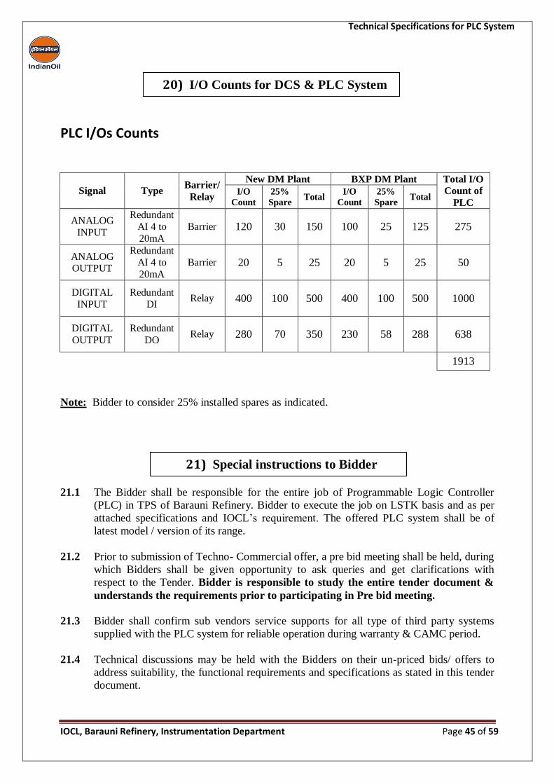
Technical Specifications for PLC System
IOCL, Barauni Refinery, Instrumentation Department Page 45 of 59
PLC I/Os Counts
Signal Type Barrier/
Relay
New DM Plant BXP DM Plant Total I/O
Count of
PLC I/O
Count
25%
Spare Total
I/O
Count
25%
Spare Total
ANALOG
INPUT
Redundant
AI 4 to
20mA
Barrier 120 30 150 100 25 125 275
ANALOG OUTPUT
Redundant
AI 4 to
20mA
Barrier 20 5 25 20 5 25 50
DIGITAL
INPUT
Redundant
DI Relay 400 100 500 400 100 500 1000
DIGITAL
OUTPUT
Redundant
DO Relay 280 70 350 230 58 288 638
1913
Note: Bidder to consider 25% installed spares as indicated.
21.1 The Bidder shall be responsible for the entire job of Programmable Logic Controller
(PLC) in TPS of Barauni Refinery. Bidder to execute the job on LSTK basis and as per
attached specifications and IOCL’s requirement. The offered PLC system shall be of
latest model / version of its range.
21.2 Prior to submission of Techno- Commercial offer, a pre bid meeting shall be held, during
which Bidders shall be given opportunity to ask queries and get clarifications with
respect to the Tender. Bidder is responsible to study the entire tender document &
understands the requirements prior to participating in Pre bid meeting.
21.3 Bidder shall confirm sub vendors service supports for all type of third party systems
supplied with the PLC system for reliable operation during warranty & CAMC period.
21.4 Technical discussions may be held with the Bidders on their un-priced bids/ offers to
address suitability, the functional requirements and specifications as stated in this tender
document.
20) I/O Counts for DCS & PLC System
21) Special instructions to Bidder
Technical Specifications for PLC System
IOCL, Barauni Refinery, Instrumentation Department Page 46 of 59
21.5 Details of barriers for different types of inputs like analog inputs & outputs etc. shall be
finalized during detail Engineering.
21.6 All barriers & relays should have tag number of the instrument for which it is being used
pasted on them. i.e. 07-FI-0909, 11-FV-565 etc. Spares barriers & relays should have tag
number as “Spare” written on them.
21.7 Online real time display of system architecture (including all PLC & auxiliary hardware)
to be made in graphics so as to monitor healthiness of all system.
21.8 Bidder to provide temperature indication, fan running status, Power feed module status,
Regulated power supply status on a separate graphic for all cabinets. Bidder to consider
these I/Os in addition to I/Os given in clause no. 20 of this tender document.
21.9 Voltage to current convertors with 4- 20mA output shall be provided in AC power
supply in PDB for online monitoring of supplied voltage with trending & alarm
configuration.
21.10 Bidder to provide separate Diode-O ring for each power supply installed to increase
reliability of the system.
21.11 All Process logics & PLC safe shutdown logics of all units, to be made in Graphics for
real time display operator stations for monitoring by the operator.
21.12 Bidder to ensure that 30% spare cable entries of each size shall be provided on the gland
plate with suitable plugs on the provided panels.
21.13 Open free space for office(s), go downs, assembly yard etc. shall be provided free of
charge to the Bidder as per IOCL’s convenience and availability of space. Water and
electricity shall be provided to the Bidder free of charge.
21.14 After placement of PO, Bidder shall submit certified drawings and spec sheet for each
item & its accessories which shall include the following as a minimum for IOCL
approval.
System Architecture diagram
Detailed dimensional drawings of internal component
Power consumption in volt amperes
GA drawings of system, marshalling, relay cabinets & PDBs cabinets
Rack layout including physical I/O modules locations
I/O assignments
Power supply distribution drawings
Load calculation sheets of communications network and controller
Power load calculation of AC & DC power supply
Total Heat load & Heat dissipation figures for each components
Functional design specification
FAT/SAT procedure
Wiring drawings for system cabinets & marshalling racks
I/O mapping with including MODBUS address
Technical Specifications for PLC System
IOCL, Barauni Refinery, Instrumentation Department Page 47 of 59
21.15 Bidder shall provide heat load calculations for the total system offered, considering the
installed spares as well as components which would be installed in space reserved for
future expansion. These calculations are required to be submitted within a week of
placement of FOA/Purchase order.
21.16 Bidder to indicate in their offer the source of all bought out item & it shall be premium
quality of reputed make. However IOCL’s concurrence regarding bought-out items is
must before finalizing the order.
21.17 Material brought in at site shall not be taken out and all items brought inside shall then
be the property of IOCL and shall be non-returnable. Excess material left out after
completion of the job shall be handed over to IOCL store by the Bidder.
21.18 The offer shall be in following format only. Each section shall be separately segregated
& highlighted with distinct Marker / Flags between the sections. Offer submitted in any
other format shall not be considered for evaluation & summarily rejected.
Section 1: Signed and stamped (on each page) copy of complete specifications shall be
submitted as a confirmation of acceptance of this tender specification without any
deviations. Bidder to fill values in Bidder response column wherever it is required to be
indicated, simply writing noted /confirmed in place of value is not acceptable. Bidder to
submit Bidder response sheet duly filled for every clause of tender document in the
following format, without which the offer of Bidder shall not be evaluated.
S. No. CLAUSE NO. DEVIATION TECHNICAL REASON FOR DEVIATION
Section 2: Deviations to specification if any shall be clearly listed under this section. If
there are no deviations, Bidder shall say “NO DEVIATIONS” under this section.
Deviations mentioned elsewhere in the offer shall be considered null and void and shall
not be considered for offer evaluation. In absence of any written deviation clearly
specified in the offer under this section, it will be assumed that all the specifications and
requirements of the subject tender are complied with and No deviations whatever will be
accepted after the placement of order.
Section 3: Complete technical catalogues of supplied PLC system & bought out item
shall be attached against this section. Wherever Bidder has been asked to furnish details
under the technical specifications, the same shall be included in this section.
Section 4: The offer shall be in the Price Schedule Format as given below. Offer in any
other format is not accepted & may be liable for rejection.
Technical Specifications for PLC System
IOCL, Barauni Refinery, Instrumentation Department Page 48 of 59
Annexure-1 – Proposed Architecture Diagram for PLC system
Annexure-2 – PLC Specification Table
Annexure-3 – Brief list of Sub-Supplier
Annexure-4 – List of Spares to be stocked at site at Bidder’s Risk & cost for PLC
Annexure-5 – Third Party Subsystem Serial Interfacing Requirements
Annexure-6 – System components and requirements
Annexure-7 – Specifications for PLC Workstations
22) References
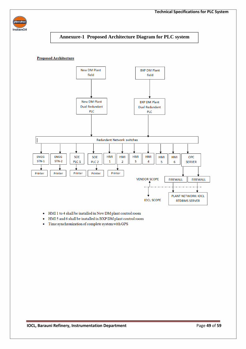
Technical Specifications for PLC System
IOCL, Barauni Refinery, Instrumentation Department Page 49 of 59
Annexure-1 Proposed Architecture Diagram for PLC system
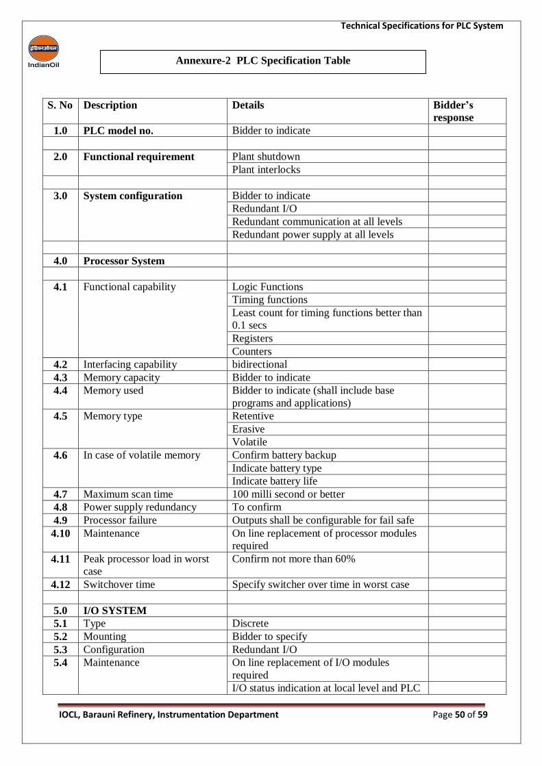
Technical Specifications for PLC System
IOCL, Barauni Refinery, Instrumentation Department Page 50 of 59
S. No Description Details Bidder’s
response
1.0 PLC model no. Bidder to indicate
2.0 Functional requirement Plant shutdown
Plant interlocks
3.0 System configuration Bidder to indicate
Redundant I/O
Redundant communication at all levels
Redundant power supply at all levels
4.0 Processor System
4.1 Functional capability Logic Functions
Timing functions
Least count for timing functions better than
0.1 secs
Registers
Counters
4.2 Interfacing capability bidirectional
4.3 Memory capacity Bidder to indicate
4.4 Memory used Bidder to indicate (shall include base
programs and applications)
4.5 Memory type Retentive
Erasive
Volatile
4.6 In case of volatile memory Confirm battery backup
Indicate battery type
Indicate battery life
4.7 Maximum scan time 100 milli second or better
4.8 Power supply redundancy To confirm
4.9 Processor failure Outputs shall be configurable for fail safe
4.10 Maintenance On line replacement of processor modules
required
4.11 Peak processor load in worst
case
Confirm not more than 60%
4.12 Switchover time Specify switcher over time in worst case
5.0 I/O SYSTEM
5.1 Type Discrete
5.2 Mounting Bidder to specify
5.3 Configuration Redundant I/O
5.4 Maintenance On line replacement of I/O modules
required
I/O status indication at local level and PLC
Annexure-2 PLC Specification Table
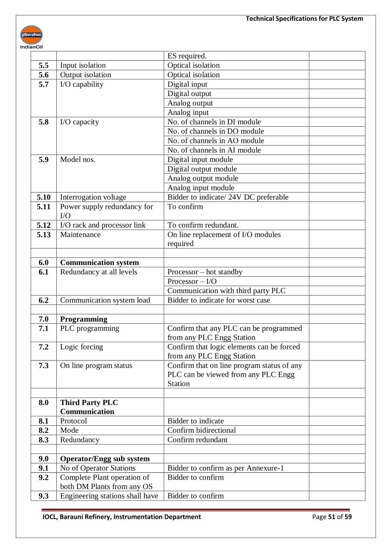
Technical Specifications for PLC System
IOCL, Barauni Refinery, Instrumentation Department Page 51 of 59
ES required.
5.5 Input isolation Optical isolation
5.6 Output isolation Optical isolation
5.7 I/O capability Digital input
Digital output
Analog output
Analog input
5.8 I/O capacity No. of channels in DI module
No. of channels in DO module
No. of channels in AO module
No. of channels in AI module
5.9 Model nos. Digital input module
Digital output module
Analog output module
Analog input module
5.10 Interrogation voltage Bidder to indicate/ 24V DC preferable
5.11 Power supply redundancy for
I/O
To confirm
5.12 I/O rack and processor link To confirm redundant.
5.13 Maintenance On line replacement of I/O modules
required
6.0 Communication system
6.1 Redundancy at all levels Processor – hot standby
Processor – I/O
Communication with third party PLC
6.2 Communication system load Bidder to indicate for worst case
7.0 Programming
7.1 PLC programming Confirm that any PLC can be programmed
from any PLC Engg Station
7.2 Logic forcing Confirm that logic elements can be forced
from any PLC Engg Station
7.3 On line program status Confirm that on line program status of any
PLC can be viewed from any PLC Engg
Station
8.0 Third Party PLC
Communication
8.1 Protocol Bidder to indicate
8.2 Mode Confirm bidirectional
8.3 Redundancy Confirm redundant
9.0 Operator/Engg sub system
9.1 No of Operator Stations Bidder to confirm as per Annexure-1
9.2 Complete Plant operation of
both DM Plants from any OS
Bidder to confirm
9.3 Engineering stations shall have Bidder to confirm
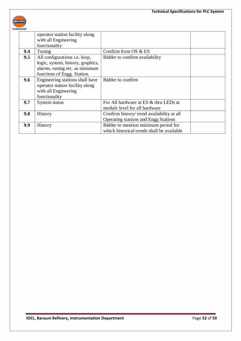
Technical Specifications for PLC System
IOCL, Barauni Refinery, Instrumentation Department Page 52 of 59
operator station facility along
with all Engineering
functionality
9.4 Tuning Confirm from OS & ES
9.5 All configurations i.e. loop,
logic, system, history, graphics,
alarms, tuning etc. as minimum
functions of Engg. Station.
Bidder to confirm availability
9.6 Engineering stations shall have
operator station facility along
with all Engineering
functionality
Bidder to confirm
9.7 System status For All hardware at ES & thru LEDs at
module level for all hardware
9.8 History Confirm history/ trend availability at all
Operating stations and Engg Stations
9.9 History Bidder to mention minimum period for
which historical trends shall be available
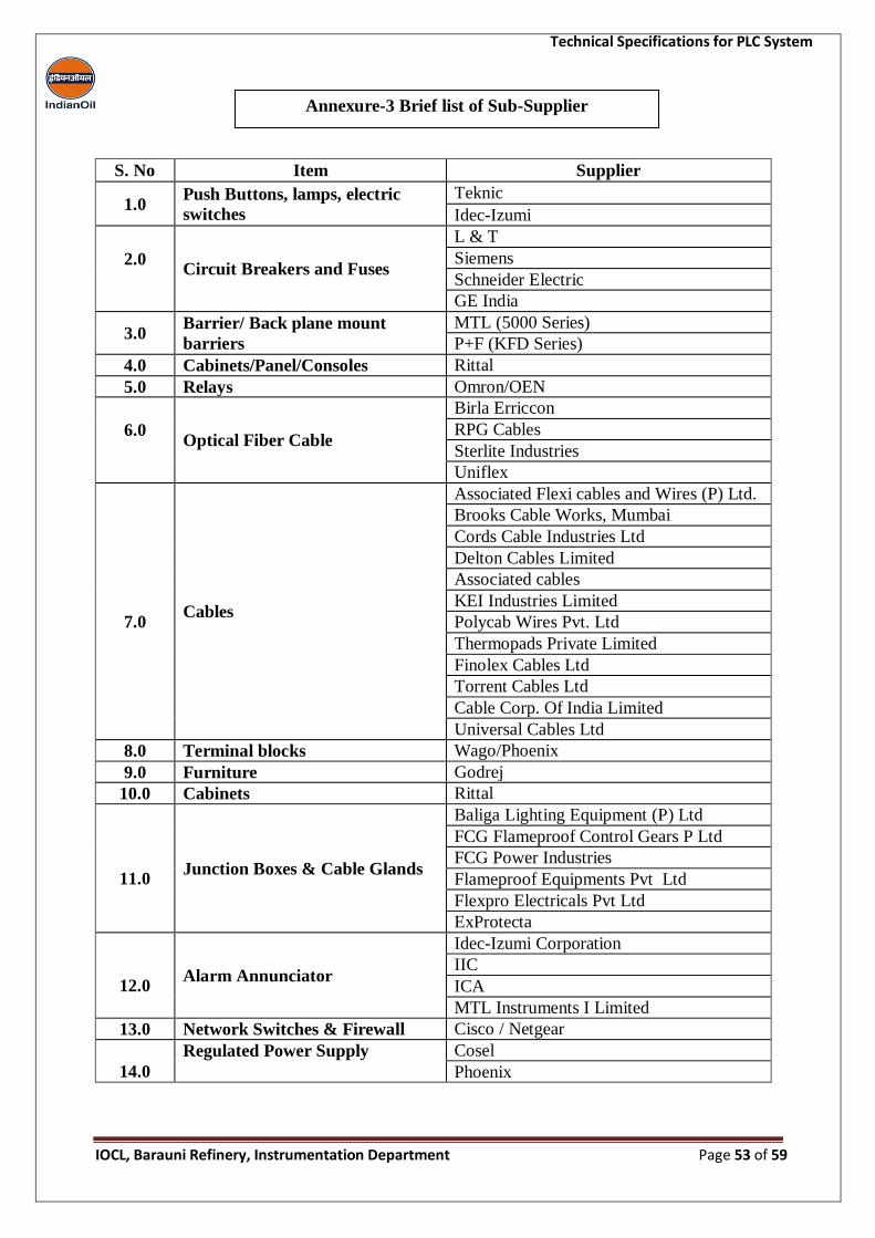
Technical Specifications for PLC System
IOCL, Barauni Refinery, Instrumentation Department Page 53 of 59
S. No Item Supplier
1.0 Push Buttons, lamps, electric
switches
Teknic
Idec-Izumi
2.0
Circuit Breakers and Fuses
L & T
Siemens
Schneider Electric
GE India
3.0 Barrier/ Back plane mount
barriers
MTL (5000 Series)
P+F (KFD Series)
4.0 Cabinets/Panel/Consoles Rittal
5.0 Relays Omron/OEN
6.0
Optical Fiber Cable
Birla Erriccon
RPG Cables
Sterlite Industries
Uniflex
7.0 Cables
Associated Flexi cables and Wires (P) Ltd.
Brooks Cable Works, Mumbai
Cords Cable Industries Ltd
Delton Cables Limited
Associated cables
KEI Industries Limited
Polycab Wires Pvt. Ltd
Thermopads Private Limited
Finolex Cables Ltd
Torrent Cables Ltd
Cable Corp. Of India Limited
Universal Cables Ltd
8.0 Terminal blocks Wago/Phoenix
9.0 Furniture Godrej
10.0 Cabinets Rittal
11.0 Junction Boxes & Cable Glands
Baliga Lighting Equipment (P) Ltd
FCG Flameproof Control Gears P Ltd
FCG Power Industries
Flameproof Equipments Pvt Ltd
Flexpro Electricals Pvt Ltd
ExProtecta
12.0 Alarm Annunciator
Idec-Izumi Corporation
IIC
ICA
MTL Instruments I Limited
13.0 Network Switches & Firewall Cisco / Netgear
14.0
Regulated Power Supply Cosel
Phoenix
Annexure-3 Brief list of Sub-Supplier

Technical Specifications for PLC System
IOCL, Barauni Refinery, Instrumentation Department Page 54 of 59
S. No PLC
1.0 Modules
A) Minimum one nos. modules of each type
(Processor module, I/O module,
communication module, power supply module,
etc.) being used inclusive of those used in
consoles. This shall include spares modules for
hardwired instrumentation also.
B) Minimum two nos. of each type of Safety
barriers, Signal converters, Signal multipliers,
relays etc.
C) Minimum two nos. of each type of fuses,
MCBs, Auxiliary relays etc.
D) Minimum one nos. of regulated power supply
unit of each rating.
E) Minimum one nos. of each type of
communication system components such as
hubs, network switches, routers, etc.
2.0 Stations/Servers
A) Minimum one nos. for Operator/Engineering
station
B) Minimum one no. Disks, DVD drive, LED,
switches, lamps, Push buttons, etc. whichever
is higher.
3.0 Printer Cartridges per year
Two nos. of each type
4.0
Annunciator
Power Supply Module, Flasher
Module, Tone Generator Card,
I/O Module, Lamps
A)
Minimum one no. of each type
Fuses B) 10 nos. of each type
Annexure-4 List of spares to be stocked at site at Bidder’s Risk & cost for PLC
Technical Specifications for PLC System
IOCL, Barauni Refinery, Instrumentation Department Page 55 of 59
Redundant serial communication shall be established between BXP DM Plant PLC and third
party Honeywell make ML200 PLC in RO plant. FO converters, media converters, special
cables, Interfacing cables etc for successful communication is under the Bidder’s scope. The
data received from RO plant PLC shall be further sent to outside network using new OPC server.
IOCL shall provide following to ensure the communication:-
Communication card at third party PLC end
Expert support from third party vendors for establishing communications
Fiber optic cable up to BXP DM Plant control room
Annexure-5 Third Party Subsystem Serial Interfacing Requirements
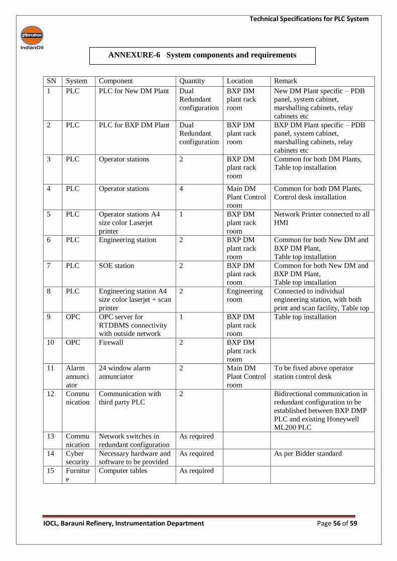
Technical Specifications for PLC System
IOCL, Barauni Refinery, Instrumentation Department Page 56 of 59
SN System Component Quantity Location Remark
1 PLC PLC for New DM Plant Dual Redundant
configuration
BXP DM plant rack
room
New DM Plant specific – PDB panel, system cabinet,
marshalling cabinets, relay
cabinets etc
2 PLC PLC for BXP DM Plant Dual Redundant
configuration
BXP DM plant rack
room
BXP DM Plant specific – PDB panel, system cabinet,
marshalling cabinets, relay
cabinets etc
3 PLC Operator stations 2 BXP DM plant rack
room
Common for both DM Plants, Table top installation
4 PLC Operator stations 4 Main DM
Plant Control room
Common for both DM Plants,
Control desk installation
5 PLC Operator stations A4
size color Laserjet
printer
1 BXP DM
plant rack
room
Network Printer connected to all
HMI
6 PLC Engineering station 2 BXP DM
plant rack
room
Common for both New DM and
BXP DM Plant,
Table top installation
7 PLC SOE station 2 BXP DM plant rack
room
Common for both New DM and BXP DM Plant,
Table top installation
8 PLC Engineering station A4 size color laserjet + scan
printer
2 Engineering room
Connected to individual engineering station, with both
print and scan facility, Table top
9 OPC OPC server for
RTDBMS connectivity with outside network
1 BXP DM
plant rack room
Table top installation
10 OPC Firewall 2 BXP DM
plant rack
room
11 Alarm
annunci
ator
24 window alarm
annunciator
2 Main DM
Plant Control
room
To be fixed above operator
station control desk
12 Communication
Communication with third party PLC
2 Bidirectional communication in redundant configuration to be
established between BXP DMP
PLC and existing Honeywell ML200 PLC
13 Commu
nication
Network switches in
redundant configuration
As required
14 Cyber security
Necessary hardware and software to be provided
As required As per Bidder standard
15 Furnitur
e
Computer tables As required
ANNEXURE-6 System components and requirements
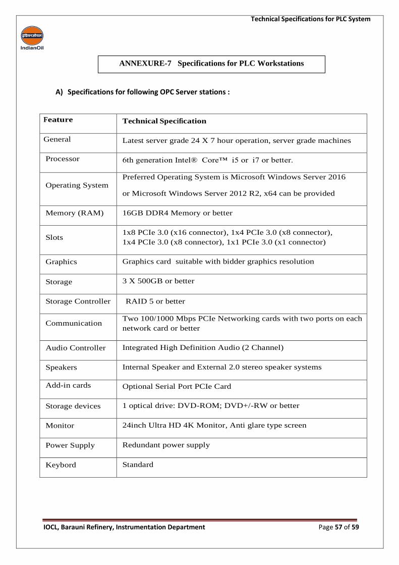
Technical Specifications for PLC System
IOCL, Barauni Refinery, Instrumentation Department Page 57 of 59
A) Specifications for following OPC Server stations :
Feature Technical Specification
General Latest server grade 24 X 7 hour operation, server grade machines
Processor 6th generation Intel® Core™ i5 or i7 or better.
Operating System Preferred Operating System is Microsoft Windows Server 2016
or Microsoft Windows Server 2012 R2, x64 can be provided
Memory (RAM) 16GB DDR4 Memory or better
Slots 1x8 PCIe 3.0 (x16 connector), 1x4 PCIe 3.0 (x8 connector),
1x4 PCIe 3.0 (x8 connector), 1x1 PCIe 3.0 (x1 connector)
Graphics Graphics card suitable with bidder graphics resolution
Storage 3 X 500GB or better
Storage Controller RAID 5 or better
Communication Two 100/1000 Mbps PCIe Networking cards with two ports on each
network card or better
Audio Controller Integrated High Definition Audio (2 Channel)
Speakers Internal Speaker and External 2.0 stereo speaker systems
Add-in cards Optional Serial Port PCIe Card
Storage devices 1 optical drive: DVD-ROM; DVD+/-RW or better
Monitor 24inch Ultra HD 4K Monitor, Anti glare type screen
Power Supply Redundant power supply
Keybord Standard
ANNEXURE-7 Specifications for PLC Workstations
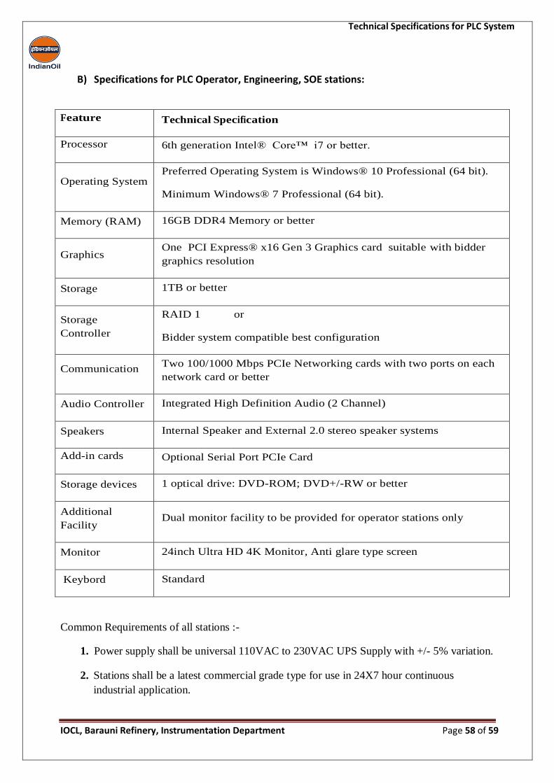
Technical Specifications for PLC System
IOCL, Barauni Refinery, Instrumentation Department Page 58 of 59
B) Specifications for PLC Operator, Engineering, SOE stations:
Feature Technical Specification
Processor 6th generation Intel® Core™ i7 or better.
Operating System Preferred Operating System is Windows® 10 Professional (64 bit).
Minimum Windows® 7 Professional (64 bit).
Memory (RAM) 16GB DDR4 Memory or better
Graphics One PCI Express® x16 Gen 3 Graphics card suitable with bidder
graphics resolution
Storage 1TB or better
Storage
Controller
RAID 1 or
Bidder system compatible best configuration
Communication Two 100/1000 Mbps PCIe Networking cards with two ports on each
network card or better
Audio Controller Integrated High Definition Audio (2 Channel)
Speakers Internal Speaker and External 2.0 stereo speaker systems
Add-in cards Optional Serial Port PCIe Card
Storage devices 1 optical drive: DVD-ROM; DVD+/-RW or better
Additional
Facility Dual monitor facility to be provided for operator stations only
Monitor 24inch Ultra HD 4K Monitor, Anti glare type screen
Keybord Standard
Common Requirements of all stations :-
1. Power supply shall be universal 110VAC to 230VAC UPS Supply with +/- 5% variation.
2. Stations shall be a latest commercial grade type for use in 24X7 hour continuous
industrial application.
Technical Specifications for PLC System
IOCL, Barauni Refinery, Instrumentation Department Page 59 of 59
3. Stations shall be Pre-loaded with Operating system, antivirus software and any other
DCS/PLC related system software along with original CD/DVD & all licenses with
lifetime validity.
4. Operating System & the service packs should be latest


