Embed Size (px)
Citation preview

Specifications
ConstructionDocuments–AmendmentA5April,2013 200WillardStreetSuite2CCocoa,Florida32922LACA5070

REQUESTS FOR BIDS / INVITATION FOR BIDS Construct Airport Traffic Control Tower
City of Hammond Louisiana, Hammond Northshore Airport Hammond Louisiana – RFP #13-27
Sealed bids will be received until May 13, 2013, 2PM CST , and then publicly opened and read aloud at the Hammond Northshore Regional Airport, 600 Judge Leon Ford Drive, Hammond, Louisiana 70404-2788, for furnishing all labor, materials and equipment and performing all work necessary to Construct Airport Traffic Control tower and related utilities.
One (1) copy of the bid documents including project drawings and technical specifications will be furnished to prime bidders properly licensed by the Louisiana State Licensing Board for Contractors at a cost of $206.42 by check or money order only, credit cards are not accepted.
Order bid documents by email to [email protected]. Allow 24 hours processing time, after email confirmation is sent to you, before pick up. Provide evidence of license by the Louisiana State Licensing Board on this email. Bid documents may be picked up at the airport. Shipping of documents shall be processed by the Contractor.
Electronic copies are available for download at: http://www.hammond.org/?page_id=610
National plan shops will be working with the City for copies available to their subscribers.
A Non Mandatory prebid conference for this project will be held on April 30th at 2PM CST at the Airport Manager’s Office, 600 Judge Leon Ford Drive, Hammond, LA 70401. To be placed on the bidder’s list please contact Mr. Ernest Peters, Sr. 985-277-5632. Bidders list will be posted on the City’s website. All prime bidders shall provide full company name, address, phone and fax number, email and contact name.
Each proposal must be accompanied by a bid guaranty in the amount of five (5) percent of the total amount of the bid. The bid guaranty may be by certified check or bid bond made payable to the City of Hammond. The estimated cost for this project is between $1M and $1.3M.
Bids may be held by the City of Hammond for a period not to exceed forty five (45) calendar days of receipt of bids to award the contract to the lowest responsible bidder or reject all bids. However, written extensions of thirty calendar days may be mutually agreed to by the City and the lowest responsible bidders.
The right is reserved, as the City of Hammond may require, to reject any and all bids and to waive any informality in the bids received as permitted by public bid law. The provisions of Louisiana Law, Revised Statutes, Title 38, RS38:2212 shall not be waived by the City of Hammond.
This project is subject to the requirements of the Davis-Bacon Act, as amended. The Contractor is required to comply with wage and labor provisions and to pay minimum wages in accordance with the schedule of wage rates established by the United States Department of Labor.
Award of contract will be based on the lowest proposal submitted from those bidders that are confirmed as being qualified, responsive and responsible.
Award of contract is also subject to the following Federal provisions:
Executive Order 11246 and DOL Regulation 41 CFR PART 60 - Affirmative Action to Ensure Equal Employment Opportunity
DOL Regulation 29 CFR Part 5 – Davis Bacon Act
11 April, 2013 Construction Document Specification Book Page 1

RFB/IFB Page2 AJTEngineering,Inc.
DOT Regulation 49 CFR PART 29 – Government wide Debarment and Suspension and Government wide Requirements for Drug-free Workplace
DOT Regulation 49 CFR PART 30 - Denial of Public Works Contracts to Suppliers of Goods and Services of Countries that Deny Contracts to Suppliers of Goods and Services of Countries that Deny Procurement Market Access to U.S. Contractors (Foreign Trade Restriction).
TITLE 49 United States Code, CHAPTER 501 – Buy American Preferences Federal Provisions This project is subject to the following Federal provisions, statutes and regulations;
Equal Employment Opportunity - Executive Order 11246 and 41 CFR Part 60: The Bidder’s attention is called to the "Equal Opportunity Clause" and the "Standard Federal Equal Employment Opportunity Construction Contract Specifications" set forth within the supplementary provisions. The successful Bidder shall not discriminate against any employee or applicant for employment because of race, color, religion, sex, or national origin. The Contractor will take affirmative action to ensure that applicants are employed, and that employees are treated during employment without regard to their race, color, religion, sex, or national origin. Goals for Minority and Female Participation – Executive Order 11246 and 41 CFR Part 60: 1. The Bidder’s attention is called to the "Equal Opportunity Clause" and the "Standard Federal Equal
Employment Opportunity Construction Contract Specifications" set forth within the supplementary provisions.
2. The goals and timetables for minority and female participation, expressed in percentage terms for the
contractor's aggregate workforce in each trade on all construction work in the covered area, are as follows: Timetables: Goals for minority participation for each trade: 26.5%
Goals for female participation in each trade: 6.9%
These goals are applicable to all of the contractor's construction work (whether or not it is Federal or federally-assisted) performed in the covered area. If the contractor performs construction work in a geographical area located outside of the geographical area where the work is actually performed. With regard to this second area, the contractor also is subject to the goals for both its Federally involved and non-federally involved construction. Certification of Nonsegregated Facilities – 41 CFR Part 60: A certification of Nonsegregated Facilities must be submitted prior to the award of a federally-assisted construction contract exceeding $10,000 which is not exempt from the provisions of the Equal Opportunity Clause. Contractors receiving federally assisted construction contract awards exceeding $10,000, which are not exempt from the provisions of the Equal Opportunity Clause will be required to provide for the forwarding of the notice to prospective subcontractors for supplies and construction contracts where the subcontracts exceed $10,000 and are not exempt from the provisions of the Equal Opportunity Clause. The penalty for making false statements in offers in prescribed in 18 U.S.C. 1001.
11 April, 2013 Construction Document Specification Book Page 2

RFB/IFB Page3 AJTEngineering,Inc.
Davis-Bacon Act, as amended – 29 CFR Part 5: The Contractor is required to comply with wage and labor provisions and to pay minimum wages in accordance with the current schedule of wage rates established by the United States Department of Labor. Current rates are included later in these specifications however it is up to the bidder to verify and conform to the latest published rates. Debarment, Suspension, Ineligibility and Voluntary Exclusion – 49 CFR Part 29: The bidder certifies, by submission of a proposal or acceptance of a contract, that neither it nor its principals are presently debarred, suspended, proposed for debarment, declared ineligible, or voluntarily excluded from participation in this transaction by any Federal department or agency. Individuals or companies listed in the General Services Administration’s “Excluded Parties Listing System” will not be considered for award of contract. Foreign Trade Restriction – 49 CFR Part 30 The Bidder and Bidder’s subcontractors, by submission of an offer and/or execution of a contract, is required to certify that it:
a. is not owned or controlled by one or more citizens of a foreign country included in the list of countries that discriminate against U.S. firms published by the Office of the United States Trade Representative (USTR);
b. has not knowingly entered into any contract or subcontract for this project with a person that is a citizen or national of a foreign country on said list, or is owned or controlled directly or indirectly by one or more citizens or nationals of a foreign country on said list;
c. has not procured any product nor subcontracted for the supply of any product for use on the project that is produced in a foreign country on said list.
Buy American Certificate – Aviation Safety and Capacity Act of 1990: This contract is subject to the “Buy American Preferences” of the Aviation Safety and Capacity Act of 1990. Prospective Bidders are required to certify that steel and manufactured products have been produced in the United States and to clearly identify those items produced or manufactured outside of the United States.
Additional Provisions Modification to the project documents may only be made by written addendum by the Owner or Owner’s authorized Representative. The proposal must be made on the forms provided within this document. Bidders must supply all required information prior to the time of bid opening.
11 April, 2013 Construction Document Specification Book Page 3

RFB/IFB Page4 AJTEngineering,Inc.
Submittal of Proposals Additional information and instruction for submittal of a proposal are provided within the Instructions-to-Bidders. Envelopes containing bids must be sealed and the upper left hand corner of the sealed envelope must identify the following information:
CONTRACT PROPOSAL Bid of Name of Contractor LA License No.: LA License Number for construction improvements at Hammond Northshore Airport ATCT Project No. : 13-27 To be opened at: Time and Date of Bid Opening
11 April, 2013 Construction Document Specification Book Page 4

Hammond Northshore Regional Airport - Construct ATCT Hammond, Louisiana
TABLE OF CONTENTS BIDDING PROPOSAL REQUIREMENTS GROUP
REQUESTS FOR BIDS / INVITATION FOR BIDS
INSTRUCTIONS TO BIDDERS
LOUISIANA UNIFORM PUBLIC WORK BID FORM
UNIT PRICE FORM
BID BOND
ACKNOWLEDGEMENTS BY BIDDER
REFERENCES
ATTESTATION CLAUSE
CONTRACT AGREEMENT
INSURANCE REQUIREMENTS
PAYMENT BOND
PERFORMANCE BOND
GENERAL PROVISIONS
SECTION 50 — CONTROL OF WORK
SECTION 70 — LEGAL REGULATIONS AND RESPONSIBILITY TO PUBLIC
SECTION 80 — PROSECUTION AND PROGRESS
SECTION 90 — MEASUREMENT AND PAYMENT
SECTION 100 — CONTRACTOR QUALITY CONTROL PROGRAM
SUPPLEMENTARY PROVISIONS
WAGE DETERMINATION
SPECIFICATIONS GROUP GENERAL REQUIREMENTS SUBGROUP DIVISION 01 - GENERAL REQUIREMENTS Section Title 01 10 00 Summary 01 30 00 Administrative Requirements 01 33 00 Submittal Procedures 01 50 00 Temporary Facilities and Controls 01 60 00 Product Requirements 01 70 00 Execution and Closeout Requirements
11 April, 2013 Construction Document Specification Book Page 5

Hammond Northshore Regional Airport - Construct ATCT Hammond, Louisiana
TECHNICAL SPECIFICATIONS DIVISION 02 – CIVIL WORKS (Sealed under separate cover by Spangler Engineering) CSI SECTION 02050 CONSTRUCTION LAYOUT 02100 CLEARING AND PREPARING SITE AND SIGNAGE 02110 SITE DEMOLITION 02200 EXCAVATION AND EMBAKNMENT, HUAL-IN BACKFILL 02200A EXCAVATION, TRENCHING AND BACKFILL FOR UTILITIES 02325 EROSION CONTROL 02362 SOIL CEMENT-STABILIZED SUBBASE 02515 MANHOLES, WET WELLS, INLETS, AND CATCH BASINS 02550 DRAINAGE CULVERTS 02556 WATER LINES 02600 PORTLAND CEMENT CONCRETE 02611 AGGREGATE SURFACE COURSE 02730 SANITARY SEWER 02741 HOT ASPHALTIC CONCRETE DIVISION 03 - CONCRETE 03 30 00 Cast-In-Place Concrete 31 09 19 Pile Dynamic Load Tests 31 62 14 Prestressed Concrete Piles 03 45 00 Precast Architectural Concrete DIVISION 04 - MASONRY No Sections DIVISION 05 - METALS 05 12 00 Structural Steel Framing 05 31 13 Steel Decking 05 40 00 Cold-Formed Metal Framing 05 51 00 Metal Stairs DIVISION 06 - WOOD, PLASTICS, AND COMPOSITES 06 41 00 Architectural Wood Casework DIVISION 07 - THERMAL AND MOISTURE PROTECTION 07 18 00 Traffic Coatings 07 61 03 Manufactured Sheet Metal Roofing 07 54 23 TPO Roof System 07 84 00 Firestopping DIVISION 08 - OPENINGS 08 11 16 Aluminum Doors 08 12 14 Standard Steel Frames 08 13 14 Standard Steel Doors 08 44 13 Glazed Aluminum Curtain Walls
11 April, 2013 Construction Document Specification Book Page 6

Hammond Northshore Regional Airport - Construct ATCT Hammond, Louisiana
08 80 00 Glazing DIVISION 09 - FINISHES 09 21 16 Gypsum Board Assemblies 09 24 23 Portland Cement Stucco 09 90 00 Painting and Coating DIVISION 10 - SPECIALTIES 10 13 00 Beacon 10 14 00 Signage DIVISION 14 - CONVEYING EQUIPMENT 14 24 23 Hydraulic Passenger Elevators DIVISIONS 15 TO 20 - NOT USED DIVISION 21 - FIRE SUPPRESSION 21 05 00 Common Work Results for Fire Suppression 21 12 00 Fire Suppression Standpipes DIVISION 22 - PLUMBING 22 05 03 Pipes and Tubes for Plumbing Piping and Equipment 22 05 23 General-Duty Valves for Plumbing Piping 22 05 29 Hangers and Supports for Plumbing Piping and Equipment 22 05 53 Identification for Plumbing Piping and Equipment 22 07 00 Plumbing Insulation 22 33 00 Electric Domestic Water Heaters 22 40 00 Plumbing Fixtures DIVISION 23 - 26 - NOT USED DIVISION 26 - ELECTRICAL 26 05 19 Low-Voltage Electrical Power Conductors and Cables 26 05 53 Identification for Electrical Systems 26 51 00 Interior Lighting DIVISION 27 – NOT USED DIVISION 28 - ELECTRONIC SAFETY AND SECURITY 28 13 00 Video Intercom and Access Control System 28 31 00 Fire Detection and Alarm DIVISION 29 - NOT USED SITE AND INFRASTRUCTURE SUBGROUP DIVISION 30 - NOT USED DIVISION 31 – EARTHWORK - NOT USED
11 April, 2013 Construction Document Specification Book Page 7

Hammond Northshore Regional Airport - Construct ATCT Hammond, Louisiana
GEOTECHNICAL INVESTIGATION AND REPORT FAA Reference Documents FAA Electrical Specification C 1217F ELECTRICAL WORK, INTERIOR FAA Standard 019e Lightning and Surge Protection, Grounding and Bonding Requirements
200 Willard Street, Suite 2C Cocoa, FL 32922
321 863 2527 LAPEL Certificate of Authorization EF 5070
11 April, 2013 Construction Document Specification Book Page 8

InstructionstoBidders Page1 AJTEngineering,Inc.
INSTRUCTIONS TO BIDDERS Owner and Owner’s Representative The Owner or Sponsor as stated herein refers to the City of Hammond. The Owner’s authorized representative as stated herein refers to the Owner’s Consultant AJT Engineering, Inc. herein referred to as Engineer. Communications with the Owner and Owner’s Representative Any and all questions and comments regarding this project shall be in writing either through letter or email. DO NOT CONTACT THE AIRPORT MANAGER with any questions. All questions or comments shall be sent to [email protected]. NO PHONE CALLS. A listing of registered bidders (bidders list) will be posted on the website shown on the Request for Bids. The airport or the Engineer will not provide this list or directions on how to obtain this list. Bidder Representations By submittal of a proposal (bid), the BIDDER represents the following:
The Bidder has read and thoroughly examined the project documents The Bidder has a complete understanding of the terms and conditions required for the satisfactory performance of project
work. The Bidder has fully informed themselves of the project site, the project site conditions and the surrounding area. The Bidder has familiarized themselves of the requirements of working on an operating airport and understands the
conditions that may in any manner affect cost, progress or performance of the work The Bidder has correlated their observations with that of the project documents. The Bidder has found no errors, conflicts, ambiguities or omissions in the project documents, except as previously
submitted in writing to the owner that would affect cost, progress or performance of the work. The Bidder is familiar with all applicable Federal, State and local laws, rules and regulations pertaining to execution of the
contract and the project work. The Bidder acknowledges that it is required of them to apply for and obtain any and all required local and state permits to
construct this building and site. The Bidder has complied with all requirements of these instructions and the associated bid documents.
Bid Documents The bid documents are comprised of the following; Notice-to-Bidders, Instructions-to-Bidders, General Provisions, Supplementary Provisions, Technical Specifications, Project Drawings, Proposal Form with attachments, Form of Contract Agreement, any authorized addenda issued by the Owner and any document incorporated in whole or in part by reference therein. All documents comprising the Bid Documents are complementary to one another and together establish the complete terms, conditions and obligations of the successful bidder. The following documents are to be submitted as the bid proposal: a. Louisiana Uniform Public Works Bid Form; b. Alternates and Unit Cost; c. Bid security; and, d. Corporate resolution All other documentation required to evaluate the bids shall be delivered to the City within 10 calendar days following opening of bids and determination of the low bidder. Modifications to Project Documents Modifications to the project documents may only be made by written addendum issued by the Owner or the Engineer. Verbal explanations, interpretations or comments made by the Owner or Owner’s representative shall not be binding. Addenda will be transmitted to all known official plan holders. Addenda must be delivered to all prime bidders who have requested bid documents within twenty-four hours of issuance either by fax, e-mail, other electronic means or by hand and a copy shall be mailed to all prime bidders who have requested bid documents. If the addendum cannot be transmitted by fax, e-mail, other electronic means or by
11 April, 2013 Construction Document Specification Book Page 9

InstructionstoBidders Page2 AJTEngineering,Inc.
hand, the bid opening shall be postponed by at least seven (7) days. Each bidder shall certify at the time of bid submittal that they acknowledge receipt of all issued addenda.
Errors and Discrepancies in Project Documents Should Bidder find an error, discrepancy, ambiguity or omission in the project documents prior to submittal of a proposal, the Bidder is obligated to contact the Owner or Engineer with written notice of the error, discrepancy, ambiguity or omission. The written notice shall identify the nature and location of the error, discrepancy, ambiguity or omission. Corrections or modifications to the project documents will only be made by written addendum as prescribed herein. By submittal of a Bid Proposal, Bidder represents that they have thoroughly reviewed the project documents and that they have not identified any error, discrepancy, ambiguity or omission that would affect cost, progress or performance of the project work. Clarifications and Interpretations A bidder requiring a clarification or interpretation of the project documents shall make a written request to the Owner or Engineer. The Owner or Engineer must receive the written request a minimum of seven (7) calendar days prior to the date of the bid opening. Examination of Plans, Specifications and Site Conditions As stated within the “Bidder Representations” and reaffirmed herein, the Bidder is expected to carefully examine the site of the proposed work, the proposal, drawings, specifications, terms and conditions of the proposed agreement and the form of agreement. The Bidder shall satisfy themselves as to the character, quality, and quantities of work to be performed, materials to be furnished and as to the requirements of the proposed contract. The submission of a proposal shall be prima facie evidence that the Bidder has made such examination and is satisfied as to the conditions to be encountered in performing the work and as to the requirements of the proposed contract, plans and specifications. Boring logs and other records of subsurface investigations and tests, as appropriate may be available for inspection by the Bidder. It is understood and agreed that such subsurface information, whether included in the project drawings, specifications or otherwise made available to the Bidder, was obtained and is intended for the owner’s design and estimating purposes only. Such information has been made available for the convenience of all bidders. It is further understood and agree that Bidder is solely responsible for all assumptions, deductions, or conclusions which he or she may make from his or her examination of the boring logs and other records of subsurface investigations and tests that are furnished by the Owner. Issuance of Proposal Forms The Owner reserves the right to refuse to issue a proposal form to a prospective bidder should the bidder be in default for any of the following reasons:
a. Failure to comply with any pre-qualification regulations of the owner, if such regulations are cited or otherwise included, in the proposal as a requirement for bidding.
b. Failure to pay, or satisfactory settle, all bills due for labor and materials on former contracts in force (with the owner) at the time the owner issues the proposal to a prospective bidder.
c. Contractor default under previous contracts with the owner d. Unsatisfactory work on previous contracts with the owner
Form of Proposal All bid proposals shall be made on the forms provided by the Owner. No bidder may submit more than one proposal. All proposals are to be written in ink and shall be clearly legible. All blank spaces in the proposal forms shall be legibly completed for each and every bid item. The Bidder shall not qualify any bid item. The Bidder shall initial any erasures and alterations made on the proposal form by the bidder. The Bidder shall state the price of their bid in U.S. dollars and cents in both written and numeral format. In the event of a discrepancy, the written value will take precedence. Signature of Proposal The proposal shall be signed and dated by an authorized representative of the Bidder. All signatures shall be made with an ink pen. The Bidder’s representative shall have the legal authority to obligate and bind the Bidder to the terms and conditions of the contract.
For bids by corporations, an officer of the corporation shall sign the bid, the State of incorporation shall be identified and the corporate seal affixed.
11 April, 2013 Construction Document Specification Book Page 10

InstructionstoBidders Page3 AJTEngineering,Inc.
For bids submitted by a partnership or joint venture, the proposal shall identify the name of all firms and the authorized parties of all firms. A copy of the partnership/joint-venture agreement shall be provided to the Owner.
Modification or Withdrawal of Bid Proposal Bidder may modify or withdraw their proposal at any point up to the specified time and date identified for receipt of proposals. Any request for bid withdrawal or modification by the Bidder that is received after the specified time and date for receipt of proposals will be returned unopened to the sender. Any modification to a Bidder’s proposal, subject to the time constraint noted herein, must be made on the proposal forms. All bid modifications must be made in the proper place on the statutorily required bid form. The Bidder’s authorized representative must sign the modification. The modification shall be placed in a sealed envelope and the statement “Modification to Proposal” shall be legibly marked in the upper left hand corner. Withdrawal of a proposal may be made, subject to the time constraint noted herein, only with written confirmation under signature of the Bidder. Pursuant to La. R.S. 38:2214 (C), bids containing patently obvious, unintentional, and substantial mechanical, clerical, or mathematical errors, or errors of unintentional omission of substantial quantity of work, labor, material, or services made directly in the compilation of the bid may be withdrawn subject to the conditions set forth in the statute. Bid Guaranty Each bid proposal shall be accompanied by a bid guaranty in the amount of five percent (5%) of the total amount of the bid. The bid guaranty may be by bid bond or certified check made payable to the Owner. The bid bond shall be from a responsible surety qualified to conduct business within the State of Louisiana. A certified check shall be issued from a responsible and solvent bank or trust company. C. Prompt Payment. The prime contractor agrees to pay each subcontractor under this prime contract for satisfactory performance
of its contract no later than 10 calender days from the receipt of each payment the prime contractor receives from Sponsor. The prime contractor agrees further to return retainage payments to each subcontractor within 30 days after the subcontractor’s work is satisfactorily completed. Any delay or postponement of payment from the above referenced time frame may occur only for good cause following written approval of the Sponsor.
D. Contractor's Required Submission. The Sponsor requires the submission of the following information:
1. Proposed Subcontractors
Bidder Qualifications Each Bidder shall furnish the owner satisfactory evidence of their experience, competency and financial capability to perform the proposed work. The Bidder shall demonstrate that they are a responsible firm that possesses the skills, abilities, and integrity to faithfully perform the project work. Evidence of competency shall consist of statements covering the Bidder’s past experience on Airport Traffic Control Towers or other high rise buildings or structures taller than 40 ft., a listing of the projects within the last 5 years, name, telephone, email listing of the owner/client and a listing of key personnel and their experience that will be assigned to this project. The sponsor reserves the right to approve or disapprove any key personnel substitution. Evidence of financial responsibility shall consist of a confidential statement or report of the Bidder’s financial resources and liabilities as of the last calendar year. A public accountant must certify such statements and reports. If the Bidder is presently pre-qualified with the State Highway agency, evidence of this pre-qualification may serve as evidence of financial responsibility in lieu of the certified financial statements and reports. If the City proposes to disqualify any bidder on the grounds that the bidder is not “responsible”, the bidder shall be given written notice for the proposed disqualification citing all reasons for the proposed disqualification and the opportunity to be heard at an informal hearing to refute the reasons for the disqualification. Alternate Bids Bidder shall complete all blanks provided on the proposal forms. When so permitted by the Owner, the Bidder shall legibly write the statement “No Bid” for those alternate bid options that the Bidder elects not to submit a proposal.
11 April, 2013 Construction Document Specification Book Page 11

InstructionstoBidders Page4 AJTEngineering,Inc.
Submission of Bid Proposal Proposals shall be sent to arrive at the specified time and date for receipt of bids. Proposals received after the specified time will not receive consideration and will be returned unopened. Proposals shall be enclosed in a sealed opaque envelope. Each proposal shall be addressed to the office location identified in the Notice-to-bidders. The upper left hand corner of the envelope shall be marked as follows:
Sealed Bid Proposal
Bid of Insert Name of Bidder
LA License No.: Insert LA License Number
For construction improvements at Hammond Northshore Airport ATCT.
Project No: 13-27
To be opened at: Insert Time and Date for Receipt of bids For a modification to a previously submitted proposal, insert “Modification to Proposal” in place of “Sealed Bid Proposal” Bid Opening All proposals submitted prior to the stated time and date for receipt of bids will be publicly opened and read aload by the Owner or the Owner’s representative. Bidders, their authorized agents, and other interested parties are invited to attend. Proposals submitted after the stated time and date for receipt of bids will be automatically rejected without consideration and will be returned unopened. Evaluation of Proposals Proposals may be held by the Owner for purposes of review and evaluation by the Owner for a period not to exceed forty five (45) calendar days from the stated date for receipt of bids. The Owner will tabulate all bids and verify proper extension of unit costs. The Bidder shall honor their proposal for the duration of this period of review and evaluation. The bid guaranty will be held by the Owner until this period of review has expired or a contract has been formally executed. Bid Informalities and Irregularities The Owner reserves the right to waive any informality or irregularity discovered in any proposal, which in the owner’s judgment best serves the Owner’s interest. In the situation where an extension of a unit price is found to be incorrect, the stated unit price and correct extension will govern. In the event of a discrepancy between the written and numeral values, the written value shall take precedence. However, the provisions of LA RS 38:2212, those stated in the Advertisement for Bids and those required on the bid form shall not be waived by the City. Irregular Proposals Proposals meeting the following criteria are subject to consideration as being irregular:
1. If the proposal is on a form other than that furnished by the Owner or Owner’s representative. 2. If the form furnished by the Owner or Owner’s representative is altered or detached from the original document. 3. If there are unauthorized additions, conditional or alternate pay items or irregularities of any kind that make the proposal
incomplete, indefinite, or otherwise ambiguous. 4. If the proposal does not contain a unit price for each pay item listed in the proposal, except in the case of authorized pay
items, for which the Bidder is not required to furnish a unit price. 5. If the proposal contains unit prices that are obviously unbalanced. 6. If the proposal is not accompanied by the bid guarantee specified herein.
Disqualification of Bid Proposals The Owner reserves the right to reject any or all bids, as determined to be in the best interest of the Owner. Causes for rejection of proposals include but are not limited to:
Submittal of an irregular proposal; Submittal of more than one proposal from the same partnership, firm or corporation; Failure by Bidder to submit the bid prior to the stated time and date for receipt of bids; Failure by Bidder to furnish satisfactory bid guarantee; Failure by Bidder to provide all information required of the bid forms; Failure by Bidder to comply with the requirements of bid instructions;
11 April, 2013 Construction Document Specification Book Page 12

InstructionstoBidders Page5 AJTEngineering,Inc.
Failure by the Bidder to demonstrate good faith efforts in obtaining participation by certified DBE firms; Determination by the Owner that Bidder is not qualified to accomplish the project work; Determination by the Owner that the Bidder has placed conditions on or qualified their proposal; Discovery of any alteration, interlineations or erasure of any project requirement by the Bidder; Inclusion of the Bidder on the “Excluded Parties Listing System” as maintained and published by the General Services
Administration; Evidence of collusion among bidders.
Cancellation of Award At any time prior to execution of a contract agreement, the Owner reserves the right to cancel the award for any reason without liability to the Bidder, with the exception of the return of the bid guaranty, at any time prior to execution of the contract. Notice of Award of Contract It is the intent of the Owner, after a period of review and evaluation, to award a contract to the responsible bidder that submits the lowest responsive proposal. The successful bidder will be informed their bid has been accepted through the Owner’s issuance of a Notice-of-Award. The Notice-of-Award shall not be construed as a binding agreement. The proper execution of a contract agreement shall serve as the binding agreement. Federal Funding Assistance It is the intent of the Owner to seek Federal participation assistance for this project under an Other Transaction Agreement. The issuance of the Notice-of-award will not be made until the FAA has concurred in award. Award of Alternates Alternates, if accepted, shall be accepted in the order they are listed on the bid form. Determination of the low bidder shall be determined on the basis of the base bid and any alternates accepted. However, the Owner may accept alternates in any order which does not affect determination of the low bidder. Return of Bid Guaranty The bid guaranty of the successful Bidder will be returned upon successful execution of the contract documents as specified herein. Failure by the successful Bidder to execute the contract documents within the specified time shall result in forfeiture of the bid guaranty. The bid guaranty of the second and third lowest responsible bidders will be retained for a period of 90 days or pending the execution of the contract documents by the successful bidder. Except as noted above, the bid guaranty of unsuccessful bidders will be returned at the point their proposal is rejected. Contract Agreement The successful Bidder shall execute the contract agreement in accordance with the accepted bid proposal within fourteen (14) days of the date of the Notice-of-Award. Failure to execute the contract agreement within the specified time frame may result in the bid being awarded to the next low bidder and shall result in the forfeiture of the Bidder’s bid guarantee as a liquidated damage. Performance and Payment Bonds The successful Bidder shall furnish separate performance and payment bonds each in the amount of 100% of the contract price. The bonds shall be made payable to the Owner as security for faithful performance of the contract and for the payment of all persons, firms or corporations to whom the Bidder may become legally indebted for labor, materials, tools, equipment or services in the performance of the project work. The form of the bond shall be that provided within the project manual. The current power of attorney for the person signing the bond as a representative of the surety shall be attached to the bonds. The executed bonds shall be delivered to the Owner within fifteen (15) calendar days from the date of contract execution. Bonds should not be executed prior to execution of the contract agreement. Surety for bid bond, performance bond and payments bond must be currently on the U.S. Department of the Treasury Financial Management Service list of approved bonding companies or by a Louisiana domiciled insurance company in accordance with La R. S. 38:2218(C) and 38:2219(A)(1)(a). Certificates of Insurance The successful Bidder shall furnish to the Owner all required certificates of insurance as specified prior to contract award.
11 April, 2013 Construction Document Specification Book Page 13

InstructionstoBidders Page6 AJTEngineering,Inc.
Approval of the Contract Upon receipt of the Contract Agreement, Contract Bonds and Certificate of Insurance as executed by the successful Bidder, the Owner will complete execution of the contract conditioned upon the Owner’s judgment that it remains in their best interest to enter into the Agreement. Delivery of the fully executed Contract Agreement to the successful Bidder shall constitute the Owner’s approval to be bound by the successful Bidder’s proposal and all terms and conditions of the Contract Agreement. Upon satisfactory execution of the contract by the successful Bidder and the Owner, all references to “Bidder” in the bid documents become equivalent to the term “Contractor”.
11 April, 2013 Construction Document Specification Book Page 14

LOUISIANA UNIFORM PUBLIC WORK BID FORM TO: City of Hammond, Louisiana
Hammond Northshore Airport 600 Judge Leon Ford Drive Hammond, Louisiana 70401
BID FOR: Construction of Airport Traffic Control Tower Hammond Northshore Airport 600 Judge Leon Ford Drive Hammond, Louisiana 70401
The undersigned bidder hereby declares and represents that she/he; a) has carefully examined and understands the Bidding Documents, b) has not received, relied on, or based his bid on any verbal instructions contrary to the Bidding Documents or any addenda, c) has personally inspected and is familiar with the project site, and hereby proposes to provide all labor, materials, tools, appliances and facilities as required to perform, in a workmanlike manner, all work and services for the construction and completion of the referenced project, all in strict accordance with the Bidding Documents prepared by: AJT Engineering, Inc. and Spangler Engineering, Inc. dated: 4 March, 2013
Bidders must acknowledge all addenda. The Bidder acknowledges receipt of the following ADDENDA: (Enter the number the
Designer has assigned to each of the addenda that the Bidder is acknowledging) __________________________________________ . TOTAL BASE BID: For all work required by the Bidding Documents (including any and all unit prices designated “Base Bid” * but not alternates) the sum of:
Dollars ($ ) ALTERNATES: For any and all work required by the Bidding Documents for Alternates including any and all unit prices designated as alternates in the unit price description. Alternate No. 1 Finish Level 4 and Install Elevator with stops at Levels 1 and 4 as indicated on plans for the lump sum of:
Dollars ($ ) Alternate No. 2 Install Exterior Sign and Main Entry Canopy for the lump sum of:
Dollars ($ ) Alternate No. 3 Construct Unfinished Level 2 and Level 3 for the lump sum of:
Dollars ($ ) NAME OF BIDDER:
ADDRESS OF BIDDER:
LOUISIANA CONTRACTOR’S LICENSE NUMBER:
NAME OF AUTHORIZED SIGNATORY OF BIDDER:
TITLE OF AUTHORIZED SIGNATORY OF BIDDER:
SIGNATURE OF AUTHORIZED SIGNATORY OF BIDDER **:
DATE: _______________________
* The Unit Price Form shall be used if the contract includes unit prices. Otherwise it is not required and need not be included with the form. The number of unit prices that may be included is not limited and additional sheets may be included if needed. ** If someone other than a corporate officer signs for the Bidder/Contractor, a copy of a corporate resolution or other signature authorization shall be required for submission of bid. Failure to include a copy of the appropriate signature authorization, if required, may result in the rejection of the bid unless bidder has complied with La. R.S. 38:2212(A)(1)(c) or RS 38:2212(O) . BID SECURITY in the form of a bid bond, certified check or cashier’s check as prescribed by LA RS 38:2218.A is attached to and made a part of this bid.
11 April, 2013 Construction Document Specification Book Page 15

LOUISIANA UNIFORM PUBLIC WORK BID FORM UNIT PRICE FORM
TO: City of Hammond, Louisiana
Hammond Northshore Airport 600 Judge Leon Ford Drive Hammond, Louisiana 70401
BID FOR: Construction of Airport Traffic Control Tower Hammond Northshore Airport 600 Judge Leon Ford Drive Hammond, Louisiana 70401
UNIT PRICES: This form shall be used for any and all work required by the Bidding Documents and described as unit prices. Amounts shall be stated in figures and only in figures. DESCRIPTION: Base Bid or Alt.# ___ Provide Cost per Foot of Additional Piling Length in the event soils are not consistent with geotechnical report
REF. NO. QUANTITY: UNIT OF MEASURE: UNIT PRICE UNIT PRICE EXTENSION (Quantity times Unit Price)
Piling Length 1 Foot
DESCRIPTION: Base Bid or Alt.# ___ Additional time and testing in the event additional testing is required and a restrike is ordered, within 24 hrs of first restrike.
REF. NO. QUANTITY: UNIT OF MEASURE: UNIT PRICE UNIT PRICE EXTENSION (Quantity times Unit Price)
Dynamic Restrike 1 Each
DESCRIPTION: Base Bid or Alt.# ___ Cost to Install Airport provided Beacon, remove and pack existing Beacon and Demolish Existing Tower
REF. NO. QUANTITY: UNIT OF MEASURE: UNIT PRICE UNIT PRICE EXTENSION (Quantity times Unit Price)
Beacon 1 Lump Sum
DESCRIPTION: Base Bid or Alt.# ___Cost to Install Airport Provided Emergency Generator
REF. NO. QUANTITY: UNIT OF MEASURE: UNIT PRICE UNIT PRICE EXTENSION (Quantity times Unit Price)
Generator 1 Lump Sum
DESCRIPTION: Base Bid or Alt.# ___
REF. NO. QUANTITY: UNIT OF MEASURE: UNIT PRICE UNIT PRICE EXTENSION (Quantity times Unit Price)
None
DESCRIPTION: Base Bid or Alt.# ___
REF. NO. QUANTITY: UNIT OF MEASURE: UNIT PRICE UNIT PRICE EXTENSION (Quantity times Unit Price)
None
DESCRIPTION: Base Bid or Alt.# ___
REF. NO. QUANTITY: UNIT OF MEASURE: UNIT PRICE UNIT PRICE EXTENSION (Quantity times Unit Price)
None
DESCRIPTION: Base Bid or Alt.# ___
REF. NO. QUANTITY: UNIT OF MEASURE: UNIT PRICE UNIT PRICE EXTENSION (Quantity times Unit Price)
None
Wording for “DESCRIPTION” is to be provided by the Owner. All quantities are estimated. The contractor will be paid based upon actual quantities as verified by the Owner
11 April, 2013 Construction Document Specification Book Page 16
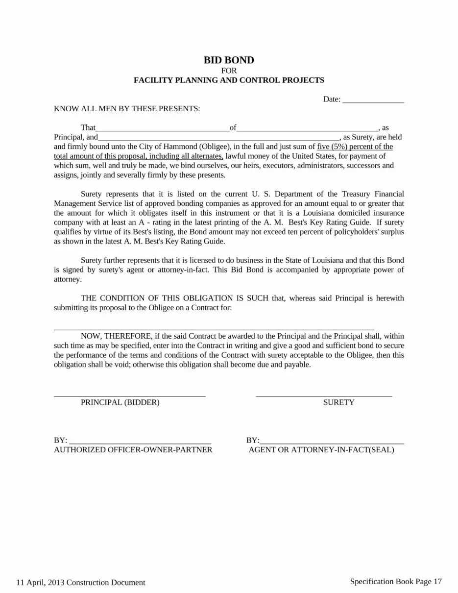
BID BOND FOR FACILITY PLANNING AND CONTROL PROJECTS Date: KNOW ALL MEN BY THESE PRESENTS:
That of , as Principal, and , as Surety, are held and firmly bound unto the City of Hammond (Obligee), in the full and just sum of five (5%) percent of the total amount of this proposal, including all alternates, lawful money of the United States, for payment of which sum, well and truly be made, we bind ourselves, our heirs, executors, administrators, successors and assigns, jointly and severally firmly by these presents.
Surety represents that it is listed on the current U. S. Department of the Treasury Financial Management Service list of approved bonding companies as approved for an amount equal to or greater that the amount for which it obligates itself in this instrument or that it is a Louisiana domiciled insurance company with at least an A - rating in the latest printing of the A. M. Best's Key Rating Guide. If surety qualifies by virtue of its Best's listing, the Bond amount may not exceed ten percent of policyholders' surplus as shown in the latest A. M. Best's Key Rating Guide.
Surety further represents that it is licensed to do business in the State of Louisiana and that this Bond is signed by surety's agent or attorney-in-fact. This Bid Bond is accompanied by appropriate power of attorney.
THE CONDITION OF THIS OBLIGATION IS SUCH that, whereas said Principal is herewith submitting its proposal to the Obligee on a Contract for: ________________________________________________________________________________
NOW, THEREFORE, if the said Contract be awarded to the Principal and the Principal shall, within such time as may be specified, enter into the Contract in writing and give a good and sufficient bond to secure the performance of the terms and conditions of the Contract with surety acceptable to the Obligee, then this obligation shall be void; otherwise this obligation shall become due and payable.
PRINCIPAL (BIDDER) SURETY BY: BY: AUTHORIZED OFFICER-OWNER-PARTNER AGENT OR ATTORNEY-IN-FACT(SEAL)
11 April, 2013 Construction Document Specification Book Page 17

Hammond Northshore Regional Airport – Construct ATCT Hammond, Louisiana
ACKNOWLEDGEMENTS BY BIDDER
a. By submittal of a proposal, the BIDDER acknowledges and accepts that the quantities established by the OWNER are an approximate estimate of the quantities required to fully complete the Project and that the estimated quantities are principally intended to serve as a basis for evaluation of bids. The BIDDER further acknowledges and accepts that payment under this contract will be made only for actual quantities and that quantities will vary in accordance with the General Provisions subsection entitled “Alteration of Work and Quantities”.
b. The BIDDER acknowledges and accepts that the Bid Documents are comprised of the documents identified within the Instructions to Bidders. The BIDDER further acknowledges that each the individual documents that comprise the Bid Documents are complementary to one another and together establishes the complete terms, conditions and obligations of the successful BIDDER.
c. As evidence of good faith in submitting this proposal, the undersigned encloses a bid guaranty in the form of a certified check or bid bond in the amount of 5% of the bid price. The BIDDER acknowledges and accepts that refusal or failure to accept award and execute a contract within the terms and conditions established herein will result in forfeiture of the bid guaranty to the owner as a liquidated damage.
d. The BIDDER acknowledges and accepts the OWNER’S right to reject any or all bids and to waive any minor informality in any Bid or solicitation procedure.
e. The BIDDER acknowledges and accepts the OWNER’S right to hold all Proposals for purposes of review and evaluation and not issue a notice-of-award for a period not to exceed 90 calendar days from the stated date for receipt of bids.
f. The undersigned agrees that upon written notice of award of contract, he or she will execute the contract within fourteen (14) days of the notice-of-award and furthermore and provide executed payment and performance bonds within fifteen (15) days from the date of contract execution. The undersigned accepts that failure to execute the contract and provide the required bonds within the stated timeframe shall result in forfeiture of the bid guaranty to the owner as a liquidated damage.
g. Time of Performance: By submittal of this proposal, the undersigned acknowledges and agrees to commence work within ten (10) calendar days of the date specified in the written “Notice-to-Proceed” as issued by the OWNER. The undersigned further agrees to complete the Project within 270 Calendar days from the commencement date specified in the Notice-to-Proceed.
h. The undersigned acknowledges and accepts that for each and every Calendar/Working day the project remains incomplete beyond the contract time of performance, the Contractor shall pay the non-penal amount of $1,000 per Calendar/Working day as a liquidated damage to the OWNER.
i. The BIDDER, by submission of a proposal, acknowledges that award of this contract is subject to the provisions of the David Bacon Act. The BIDDER accepts the requirement to pay prevailing wages for each classification and type of worker as established in the attached wage rate determination as issued by the United States Department of Labor. The BIDDER further acknowledges and accepts their requirement to incorporate the provision to pay the established prevailing wages in every subcontract agreement entered into by the Bidder under this project.
11 April, 2013 Construction Document Specification Book Page 18

Hammond Northshore Regional Airport – Construct ATCT Hammond, Louisiana
REPRESENTATIONS BY BIDDER
By submittal of a proposal (bid), the BIDDER represents the following:
a. The BIDDER has read and thoroughly examined the bid documents including all authorized addenda.
b. The BIDDER has a complete understanding of the terms and conditions required for the satisfactory performance of project work.
c. The BIDDER has fully informed themselves of the project site, the project site conditions and the surrounding area.
d. The BIDDER has familiarized themselves of the requirements of working on an operating airport and understands the conditions that may in any manner affect cost, progress or performance of the work
e. The BIDDER has correlated their observations with that of the project documents.
f. The BIDDER has found no errors, conflicts, ambiguities or omissions in the project documents, except as previously submitted in writing to the owner that would affect cost, progress or performance of the work.
g. The BIDDER is familiar with all applicable Federal, State and local laws, rules and regulations pertaining to execution of the contract and the project work.
h. The BIDDER has complied with all requirements of these instructions and the associated project documents.
i. The BIDDER is aware that Pursuant to La. R.S. 38:2214 (C), bids containing patently obvious, unintentional, and substantial mechanical, clerical, or mathematical errors, or errors of unintentional omission of substantial quantity of work, labor, material, or services made directly in the compilation of the bid may be withdrawn subject to the conditions set forth in the statute.
CERTIFICATIONS BY BIDDER
a. The undersigned hereby declares and certifies that the only parties interested in this proposal are named herein and that this proposal is made without collusion with any other person, firm or corporation. The undersigned further certifies that no member, officer or agent of OWNER’S has direct or indirect financial interest in this proposal.
b. Certification of Non-Segregated Facilities: (41 CFR Part 60-1.8) The BIDDER, as a potential federally-assisted construction contractor, certifies that it does not maintain or provide, for its employees, any segregated facilities at any of its establishments and that it does not permit its employees to perform their services at any location, under its control, where segregated facilities are maintained. The BIDDER certifies that it will not maintain or provide, for its employees, segregated facilities at any of its establishments and that it will not permit its employees to perform their services at any location under its control where segregated facilities are maintained. The Bidder agrees that a breach of this certification is a violation of the Equal Opportunity Clause, which is to be incorporated in the contract. As used in this certification, the term "segregated facilities" means any waiting rooms, work areas, restrooms, and washrooms, restaurants and other eating areas, timeclocks, locker rooms and other storage or dressing areas, parking lots, drinking fountains, recreation or entertainment areas, transportation, and housing facilities provided for employees which are segregated on the basis of race, color, religion, or national origin because of habit, local custom, or any other reason. The Bidder agrees that (except where it has obtained identical certifications from proposed subcontractors for specific time periods) it will obtain identical certifications from proposed subcontractors prior to the award of subcontracts exceeding $10,000 which are not exempt from the provisions of the Equal Opportunity Clause and that it will retain such certifications in its files.
11 April, 2013 Construction Document Specification Book Page 19

Hammond Northshore Regional Airport – Construct ATCT Hammond, Louisiana
c. Trade Restriction Certification: (49 CFR Part 30) The Bidder, by submission of an offer certifies that it:
1. is not owned or controlled by one or more citizens of a foreign country included in the list of countries that discriminate against U.S. firms published by the Office of the United States Trade Representative (USTR);
2. has not knowingly entered into any contract or subcontract for this project with a person that is a citizen or national of a foreign country on said list, or is owned or controlled directly or indirectly by one or more citizens or nationals of a foreign country on said list;
3. has not procured any product nor subcontracted for the supply of any product for use on the project that is produced in a foreign country on said list.
d. Certification Regarding Debarment, Suspension, Ineligibility and Voluntary Exclusion: (49 CFR Part 29) The Bidder certifies, by submission of this proposal, that neither it nor its principals is presently debarred, suspended, proposed for debarment, declared ineligible, or voluntarily excluded from participation in this transaction by any Federal department or agency. It further agrees by submitting this proposal that it will include this clause without modification in all lower tier transactions, solicitations, proposals, contracts, and subcontracts. Where the Bidder or any lower tier participant is unable to certify to this statement, it shall attach an explanation to this solicitation/proposal.
e. Buy American Certification: (Title 49 U.S.C. Chapter 501) By submitting a proposal under this solicitation, except for those items listed by the Bidder below or on a separate and clearly identified attachment to this bid/proposal, the Bidder certifies that steel and each manufactured product, are produced in the United States, as defined in the clause Buy American - Steel and Manufactured Products for Construction Contracts) and that components of unknown origin are considered to have been produced or manufactured outside the United States.
Bidder may obtain from the owner a listing of articles, materials and supplies excepted from this provision.
Product Country of Origin
11 April, 2013 Construction Document Specification Book Page 20
HHaammmmoonndd NNoorrtthhsshhoorree RReeggiioonnaall AAiirrppoorrtt –– CCoonnssttrruucctt AATTCCTT HHaammmmoonndd,, LLoouuiissiiaannaa
ProposalForms Page9 AJTEngineering,Inc.
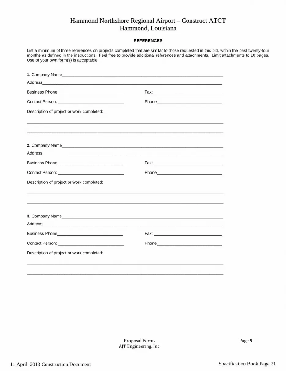
REFERENCES List a minimum of three references on projects completed that are similar to those requested in this bid, within the past twenty-four months as defined in the instructions. Feel free to provide additional references and attachments. Limit attachments to 10 pages. Use of your own form(s) is acceptable. 1. Company Name_____________________________________________________________________
Address_____________________________________________________________________________ Business Phone____________________________ Fax: _____________________________ Contact Person: ____________________________ Phone____________________________ Description of project or work completed: ____________________________________________________________________________________ ____________________________________________________________________________________ 2. Company Name_____________________________________________________________________
Address_____________________________________________________________________________ Business Phone____________________________ Fax: _____________________________ Contact Person: ____________________________ Phone____________________________ Description of project or work completed: ____________________________________________________________________________________ ____________________________________________________________________________________ 3. Company Name_____________________________________________________________________
Address_____________________________________________________________________________ Business Phone____________________________ Fax: _____________________________ Contact Person: ____________________________ Phone____________________________ Description of project or work completed: ____________________________________________________________________________________ ____________________________________________________________________________________
11 April, 2013 Construction Document Specification Book Page 21

Construct Airport Traffic Control Tower City of Hammond Louisiana, Hammond Northshore Airport Hammond, Louisiana – RFP #13-27
ATTESTATION CLAUSE REQUIRED BY LA. R.S. 38:2227 (PAST CRIMINAL CONVICTIONS OF BIDDERS)
Appearer, as a Bidder on the above-entitled Public Works Project, does hereby attest that: A. No sole proprietor or individual partner, incorporator, director, manager, officer, organizer,
or member who has a minimum of a ten percent (10%) ownership in the bidding entity named below has been convicted of, or has entered a plea of guilty or nolo contendere to any of the following state crimes or equivalent federal crimes:
(a) Public bribery (R.S. 14:118) (c) Extortion (R.S. 14:66)
(b) Corrupt influencing (R.S. 14:120) (d) Money laundering (R.S. 14:23) B. Within the past five years from the project bid date, no sole proprietor or individual partner,
incorporator, director, manager, officer, organizer, or member who has a minimum of a ten percent (10%) ownership in the bidding entity named below has been convicted of, or has entered a plea of guilty or nolo contendere to any of the following state crimes or equivalent federal crimes, during the solicitation or execution of a contract or bid awarded pursuant to the provisions of Chapter 10 of Title 38 of the Louisiana Revised Statutes:
(a) Theft (R.S. 14:67) (b) Identity Theft (R.S. 14:67.16) (c) Theft of a business record (R.S.14:67.20) (d) False accounting (R.S. 14:70) (e) Issuing worthless checks (R.S. 14:71)
(f) Bank fraud (R.S. 14:71.1) (g) Forgery (R.S. 14:72) (h) Contractors; misapplication of payments (R.S. 14:202) (i) Malfeasance in office (R.S. 14:134)
____________________________________ ________________________________________________ NAME OF BIDDER NAME OF AUTHORIZED SIGNATORY OF BIDDER
____________________________________ _________________________________________________ DATE TITLE OF AUTHORIZED SIGNATORY OF BIDDER
__________________________________________________________
SIGNATURE OF AUTHORIZED SIGNATORY OF BIDDER
11 April, 2013 Construction Document Specification Book Page 22

HHaammmmoonndd NNoorrtthhsshhoorree RReeggiioonnaall AAiirrppoorrtt -- CCoonnssttrruucctt AATTCCTT HHaammmmoonndd,, LLoouuiissiiaannaa
ContractAgreement Page1
Form of CONTRACT AGREEMENT City of Hammond, Louisiana
Project Number 13-27
STATE OF LOUISIANA PARISH OF TANGIPAHOA
AGREEMENT #
This Agreement (“Agreement”) made and entered into this ___day of ______________, by and between: CITY
OF HAMMOND, through its authorized representative (hereinafter referred to as (“City”) and
____________________________________________________________(hereinafter referred to as “Contractor”).
WITNESSETH:
WHEREAS, Article VII, Section 14 (C) of the Constitution of the State of Louisiana provides that “For a public
purpose, the state and its political subdivisions or political corporations may engage in agreements with each other, with
the United States or its agencies, or with any public or private association, corporation, or individual.”:
WHEREAS, the City desires to contract with the Contractor in the manner as
hereinafter provided;
WHEREAS, the City has an obligation and right to hire a Contractor of Building Construction, the City chooses
to execute this obligation by contracting with the Contractor;
WHEREAS, the public purpose to be derived from this obligation is to provide
such Construction services;
WHEREAS, the actions of the City and the Contractor will result in a public benefit described in detail not
disproportionate to the consideration in this Agreement.
NOW, THEREFORE, in consideration of the mutual covenants herein contained, the legal obligation; the public
purpose; and the public benefit the parties hereto agree make improvements at the Hammond Northshore Airport generally
described as as follows:
11 April, 2013 Construction Document Specification Book Page 23

HHaammmmoonndd NNoorrtthhsshhoorree RReeggiioonnaall AAiirrppoorrtt -- CCoonnssttrruucctt AATTCCTT HHaammmmoonndd,, LLoouuiissiiaannaa
ContractAgreement Page2
Construct Airport Traffic Control Tower hereinafter referred to as the Project. NOW THEREFORE in consideration of the mutual covenants hereinafter set forth, CITY and CONTRACTOR agree as follows:
Article 1 - Work
It is hereby mutually agreed that for and in consideration of the payments as provided for herein to the CONTRACTOR by the CITY, CONTRACTOR shall faithfully furnish all necessary labor, equipment, and material and shall fully perform all necessary work to complete the Project in strict accordance with this Contract Agreement and the Contract Documents.
Article 2 – Contract Documents
CONTRACTOR agrees that the Contract Documents consist of the following: this Agreement, General Provisions, Supplementary Provisions, Specifications, Drawings, all issued addenda, Notice-to-Bidders, Instructions-to-Bidders, Proposal and associated attachments, Performance Bond, Payment Bond, Wage Rate Determination, Insurance certificates, documents incorporated by reference, documents incorporated by attachment, and all CITY authorized change orders issued subsequent to the date of this agreement. All documents comprising the Contract Documents are complementary to one another and together establish the complete terms, conditions and obligations of the CONTRACTOR. All said Contract Documents are incorporated by reference into the Contract Agreement as if fully rewritten herein or attached thereto. Article 3 – Contract Price In consideration of the faithful performance and completion of the Work by the CONTRACTOR in accordance with the Contract Documents, CITY shall pay the CONTRACTOR an amount equal to:
$_____________________________________ ($___________________)
(Amount in Written Words) (Amount in Numerals) subject to the following;
a. Said amount is based on the schedule of prices stated in CONTRACTOR’S Bid Proposal, which is attached to and made a part of this Agreement;
b. Said amount is the aggregate sum of the result of the CONTRACTOR’S Base Bid and Add Alternates so chosen by the City;
c. Said amount is subject to modification for additions and deductions as provided for within the Contract General Provisions.
d. Contractor hereby agrees that responsibility for payment of taxes from the funds thus received under this Agreement and/or legislative appropriation shall be Contractor’s obligation and identified under Federal Tax Identification number _________________________.
11 April, 2013 Construction Document Specification Book Page 24

HHaammmmoonndd NNoorrtthhsshhoorree RReeggiioonnaall AAiirrppoorrtt -- CCoonnssttrruucctt AATTCCTT HHaammmmoonndd,, LLoouuiissiiaannaa
ContractAgreement Page3
Article 4 – Payment
Upon the completion of the work and its acceptance by the CITY, all sums due the CONTRACTOR by reason of faithful performance of the work, taking into consideration additions to or deductions from the Contract price by reason of alterations or modifications of the original Contract or by reason of “Extra Work” authorized under this Contract, will be paid to the CONTRACTOR by the CITY after said completion and acceptance.
The acceptance of final payment by the CONTRACTOR shall be considered as a release in full of all claims against the CITY, arising out of, or by reason of, the work completed and materials furnished under this Contract.
CITY shall make progress payments to the CONTRACTOR in accordance with the terms set forth in the General Provisions. Progress payments shall be based on estimates prepared by the ENGINEER for the value of work performed and materials completed in place in accordance with the Contract Drawings and Specifications.
Progress payments are subject to retainage requirements as set forth in the General Provisions.
Article 5 – Contract Time
The CONTRACTOR agrees to commence work within ten (10) calendar days of the date specified in the CITY’S Notice-to-Proceed. CONTRACTOR further agrees to complete said work within 250 Calendar Days of the commencement date stated within the Notice-to-Proceed. It is expressly understood and agreed that the stated Contract Time is reasonable for the completion of the Work, taking all factors into consideration. Furthermore, extensions of the Contract Time may only be permitted by execution of a formal modification to this Contract Agreement in accordance with the General Provisions and as approved by the CITY.
Article 6 – Liquidated Damages
The CONTRACTOR and CITY understand and agree that time is of essence for completion of the Work and that the CITY will suffer additional expense and financial loss if said Work is not completed within the authorized Contract Time. Furthermore, the CONTRACTOR and CITY recognize and understand the difficulty, delay, and expense in establishing the exact amount of actual financial loss and additional expense. Accordingly, in place of requiring such proof, the CONTRACTOR expressly agrees to pay the CITY as liquidated damages the non-penal sum of $1000.00 per day for each work day required in excess of the authorized Contract Time. Furthermore, the CONTRACTOR understands and agrees that;
a. the CITY has the right to deduct from any moneys due the CONTRACTOR, the amount of said liquidated damages;
b. the CITY has the right to recover the amount of said liquidated damages from the CONTRACTOR, SURETY or both.
11 April, 2013 Construction Document Specification Book Page 25

HHaammmmoonndd NNoorrtthhsshhoorree RReeggiioonnaall AAiirrppoorrtt -- CCoonnssttrruucctt AATTCCTT HHaammmmoonndd,, LLoouuiissiiaannaa
ContractAgreement Page4
Article 7 – CONTRACTOR’S Representations
The CONTRACTOR understands and agrees that all representations made by the CONTRACTOR within the Proposal shall apply under this Agreement as if fully rewritten herein.
Article 8 - TERMINATION CLAUSE
The City may terminate this Agreement for cause based upon the failure of the Contractor to comply with the terms and/or conditions of the Agreement provided that the City shall give the Contractor written notice specifying the Contractor’s failure. If within thirty (30) days after receipt of such notice, the Contractor shall not have either corrected such failure and thereafter proceeded diligently to complete such correction, then the City may, at its option, place the Contactor in default and the Agreement shall terminate on the date specified in such notice. The Contractor may exercise any rights available to it under Louisiana law to terminate for cause upon the failure of the City to comply with the terms and conditions of this Agreement; provided that the Contractor shall give the City written notice specifying the City’s failure and a reasonable opportunity for the City to cure the defect.
Termination for Convenience The City may terminate this Agreement at any time by giving thirty (30) days written notice to the Contractor. The Contractor shall be entitled to payment for deliverables in progress, to the extent that the work has been performed satisfactorily. The Contractor may terminate this agreement at any time by giving thirty (30) days written notice to the City and shall receive payment for work performed to the date of termination.
Article 9 - Ownership All records, reports, documents and other material delivered or transmitted to Contractor by City shall remain the property of City, and shall be returned by Contractor to City at Contractor’s expense, at termination or expiration of this Agreement. All records, reports, documents, or other material related to this Agreement and/or obtained or prepared by Contractor in connection with the performance of the services contracted for herein shall become the property of City, and shall, upon request, be returned by Contractor to the City, at Contractor’s expense, at termination or expiration of this Agreement.
Article 10 - Nonassignability No Contractor shall assign any interest in this Agreement by assignment, transfer, or novation, without prior written consent of the City. This provision shall not be construed to prohibit the Contractor from assigning his bank, trust company, or other financial institution any money due or to become due from approved agreements or contracts without such prior written consent. Notice of any such assignment or transfer shall be furnished promptly to the City and the Office of Contractual Review.
Article 11 - Auditors Clause It is hereby agreed that the Legislative Auditor for the State of Louisiana and/or the Office of the Governor, Division of Administration auditors shall have the option of auditing all accounts of Contractor which relate to this Agreement. Article 12 - Fiscal Funding The continuation of this Agreement is contingent upon the appropriation of funds to fulfill the requirements of the Agreement by the Legislature. If the City Council fails to appropriate sufficient monies to provide for the
11 April, 2013 Construction Document Specification Book Page 26

HHaammmmoonndd NNoorrtthhsshhoorree RReeggiioonnaall AAiirrppoorrtt -- CCoonnssttrruucctt AATTCCTT HHaammmmoonndd,, LLoouuiissiiaannaa
ContractAgreement Page5
continuation of the Agreement, or if such appropriation is reduced by the veto of the Mayor or by any means provided in the appropriations act to prevent the total appropriation for the year from exceeding revenues for that year, or for any other lawful purpose, and the effect of such reduction is to provide insufficient monies for the continuation of the Agreement, the Agreement shall terminate on the date of the beginning of the first fiscal year for which funds are not appropriated. Article 13 - Indemnifications; Insurance Contractor shall indemnify and save harmless the City and AJT Engineering, Inc. their representatives or agents, and the officers, directors, agents, employees, and assigns against any and all claims, losses, liabilities, demand suites, causes of action, damages, and judgments of sums of money to any party accruing against the City growing out of, resulting from, or by reason of any act or omission of Contractor, its agents, servants, independent contractors, or employees while engaged in, about, or in connection with the discharge or performance of the term of this Agreement. Such indemnification shall include the City’s and AJT Engineering, Inc.’s fees and costs of litigation, including, but not limited to, reasonable attorney’s fees. Contractor shall provide and bear the expense of all personal and professional insurance related to its duties arising under this Agreement.
Article 14 – CONTRACTOR’S Certifications
The CONTRACTOR understands and agrees that all certifications made by the CONTRACTOR within the Proposal shall apply under this Agreement as if fully rewritten herein. The CONTRACTOR further certifies the following;
a. Certification of Eligibility (29 CFR Part 5.5) i. By Entering into this contract, the CONTRACTOR certifies that neither he or she nor any
person or firm who has an interest in the CONTRACTOR’S firm is a person or firm ineligible to be awarded Government contracts by virtue of Section 3(a) of the Davis-Bacon Act or 29 CFR 5.12(a)(1);
ii. No part of this contract shall be subcontracted to any person or firm ineligible for award of a Government contract by virtue of Section 3(a) of the Davis-Bacon Act or 29 CFR 5.12(a)(1);
iii. The penalty for making false statements is prescribed in the U.S. Criminal Code 18 U.S.C.
b. Certification of Non-Segregated Facilities (41 CFR Part 60-1.8) The federally-assisted construction CONTRACTOR, certifies that it does not maintain or provide, for its employees, any segregated facilities at any of its establishments and that it does not permit its employees to perform their services at any location, under its control, where segregated facilities are maintained. The BIDDER certifies that it will not maintain or provide, for its employees, segregated facilities at any of its establishments and that it will not permit its employees to perform their services at any location under its control where segregated facilities are maintained. The Bidder agrees that a breach of this certification is a violation of the Equal Opportunity Clause, which is to be incorporated in the contract. As used in this certification, the term "segregated facilities" means any waiting rooms, work areas, restrooms, and washrooms, restaurants and other eating areas, timeclocks, locker rooms and other storage or dressing areas, parking lots, drinking fountains, recreation or entertainment areas, transportation, and housing facilities provided for employees which are segregated on the basis of race, color, religion, or national origin because of habit, local custom, or any other reason. The Bidder agrees that (except where it has obtained identical certifications from proposed subcontractors for specific time
11 April, 2013 Construction Document Specification Book Page 27

HHaammmmoonndd NNoorrtthhsshhoorree RReeggiioonnaall AAiirrppoorrtt -- CCoonnssttrruucctt AATTCCTT HHaammmmoonndd,, LLoouuiissiiaannaa
ContractAgreement Page6
periods) it will obtain identical certifications from proposed subcontractors prior to the award of subcontracts exceeding $10,000 which are not exempt from the provisions of the Equal Opportunity Clause and that it will retain such certifications in its files.
c. Discrimination The Contractor agrees to abide by the requirements of the following, as applicable: Title VI and VII of the Civil Rights Act of 1964, as amended by the Equal Opportunity Act of 1972, Federal Executive Order 11246, the Federal Rehabilitation Act of 1973, as amended, the Vietnam Era Veteran’s Readjustment Assistance Act of 1974, Title IX of the Education Amendments of 1972, the Age Act of 1975, and Contractor agrees to abide by the requirements of the Americans with Disabilities Act of 1990. Contractor agrees not to discriminate in its employment practices, and will render services under this Agreement without regard to race, color, religion, sex, national origin, veteran status, political affiliation, disabilities. Any act of discrimination committed by Contractor, or failure to comply with these statutory obligations, when applicable, shall be grounds for termination of this Agreement.
Article 15 – Miscellaneous
a. The CITY’S Technical Representative, herein referred to as ENGINEER, is AJT Engineering, Inc., 200 Willard Street, Suite 2C, Cocoa, FL 32922. Said ENGINEER will act as the CITY’S representative and shall assume all rights and authority assigned to the ENGINEER as stated within the Contract Documents in connection with the completion of the Project Work.
b. CONTRACTOR understands that it shall be solely responsible for the means, methods, techniques, sequences and procedures of construction in connection with completion of the Work;
c. CONTRACTOR understands and agrees that it shall not accomplish any work or furnish any materials that are not covered or authorized by the Contract Documents unless authorized in writing by the CITY or ENGINEER;
d. The rights of each party under this Agreement shall not be assigned or transferred to any other person, entity, firm or corporation without prior written consent of both parties;
e. CITY and CONTRACTOR each bind itself, their partners, successors, assigns and legal representatives to the other party in respect to all covenants, agreements, and obligations contained in the Contract Documents.
Article 16 - Partial Invalidity; Severability If any term, covenant, condition, or provision of this Agreement or the application thereof to any person or circumstances shall, at any time or to any extent, be invalid or unenforceable, the remainder of this Agreement, or the application of such term, covenant, condition or provision to person or circumstances other than those as to which it is held invalid or unenforceable, shall be affected thereby, and each term, covenant, condition, and provision of this Agreement shall be valid and be enforced to the fullest extent permitted by law.
11 April, 2013 Construction Document Specification Book Page 28

HHaammmmoonndd NNoorrtthhsshhoorree RReeggiioonnaall AAiirrppoorrtt -- CCoonnssttrruucctt AATTCCTT HHaammmmoonndd,, LLoouuiissiiaannaa
ContractAgreement Page7
Article 17 - Entire Agreement; Modification This Agreement, including any attachments that are expressly referred to in this Agreement, contains the entire agreement between the parties and supersedes any and all agreements or contracts previously entered into between the parties. No representations were made or relied upon by either party, other than those that are expressly set forth herein. This Agreement may be modified or amended at any time by mutual consent of the parties, provided that, before any modification or amendment shall be operative and valid, it must be reduced to writing and signed by both parties. Article 18 - Controlling Law The validity, interpretation, and performance of this Agreement shall be controlled by and construed in accordance with the laws of the State of Louisiana. Article 19 - Legal Compliance Contractor shall comply with all federal, state, and local laws and regulations, including specifically, the Louisiana Code of Governmental Ethics (R.S. 42:1101, et seq.) in carrying out the provisions of this Agreement. Article 20 - Remedies for Default In the event of default by either party, the aggrieved party shall have all rights granted by the general laws of the State of Louisiana. Article 21 - Notices All notices and other communications pertaining to this Agreement shall be in writing and shall be transmitted either by personal hand delivery (and receipted for) or deposited in the United States mail, as certified mail, return receipt requested and postage prepaid, to the other party, addressed as follows:
If to City:
City of Hammond Post Office Drawer 2788 Hammond, LA 70404 Attention: Mayor Mayson Foster and Andre G. Coudrain Cashe, Lewis, Coudrain & Sandage Post Office Box 1509 Hammond, LA 70404
If to Contractor: ______________________________ ______________________________
11 April, 2013 Construction Document Specification Book Page 29

HHaammmmoonndd NNoorrtthhsshhoorree RReeggiioonnaall AAiirrppoorrtt -- CCoonnssttrruucctt AATTCCTT HHaammmmoonndd,, LLoouuiissiiaannaa
ContractAgreement Page8
IN WITNESS WHEREOF, CITY and CONTRACTOR have executed five (5) copies of this Agreement on the day and year first noted herein. Note: This document is not fully executed without both parties’ signatures.
CITY
Name: City of Hammond
Address: 312 East Charles Street Hammond, LA 70404
By: __________________________________ Signature
__________________________________ Title of Representative
ATTEST
By: __________________________________ Signature
__________________________________ Title
CONTRACTOR
Name: _____________________________
Address: _____________________________
_____________________________
_____________________________
By: ___________________________________ Signature
___________________________________ Title of Representative
ATTEST
By: ___________________________________ Signature
___________________________________ Title
11 April, 2013 Construction Document Specification Book Page 30

Insurance Requirements Page 1 AJT Engineering, Inc.
INSURANCE
Contractor agrees to procure and maintain during the performance of this Contract, at its own expense, the applicable insurance policies indicated below, including any coverage required by law, with limits not less than those specified. Any insurance on a "claims made" basis shall be maintained for at least 3 years after completion of the Work or any time period required by the Contract, whichever is longer.
Required Insurance Coverage and Limits
(1) Workers’ Compensation Statutory
(2) Employer's Liability $ 1,000,000 per occurrence
(3) Comprehensive General Liability $ 1,000,000 per occurrence
Combined single limit per occurrence, for bodily injury, personal injury, property damage, contractual liability, and broad form property damage.
(4) Comprehensive Automobile Liability $ 1,000,000 per occurrence Combined single limit per accident, for bodily injury and property damage, including City, non-
owned, hired, leased or rented vehicles.
(5) Builders Risk (See note below) $ Full amount of project cost with the City of Hammond named as Loss Payee
(5) Umbrella Liability $ 1,000,000 aggregate In excess of (1), (2), (3), and (4) above.
Prior to the commencement of the Work, Subcontractor shall submit with original certificates of insurance evidencing the required insurance as listed in the Policy Form below.
Such certificates shall be issued by an insurance carrier(s) meeting a minimum financial AM Best and Company rating of no less than A:VII. .
Insurance Note: No work shall commence until proper ACORD 25 Certificate is received. Special provisions must be shown in the endorsement box as previously furnished. Builders Risk The Contractor shall secure all-risk type of builder's risk insurance covering work performed under the Contract, and materials, equipment, expedited deliveries or other items to be incorporated therein, while the same are located at the construction site, stored off-site, or at the place of manufacture. The policy shall cover not less than losses due to fire, flood, explosion, hail, lightning, weather, vandalism, malicious mischief, wind, collapse, riot, aircraft, smoke or other cataclysmic events, until the date of final acceptance of the work. The making of progress payments to the Design/Builder shall not be construed as relieving the Design/Builder or his subcontractors or the insurance company or companies providing the coverage described herein of responsibility for loss or direct physical loss, damage or destruction occurring prior to final acceptance.
Policy Form:
a) All policies required by this Contract, with the exception of Workers Compensation, or unless specific approval is given by the City, are to be written on an occurrence basis, shall name AJT Engineering, Inc. and the City of Hammond, its Elected Officials, Officers, Agents, Employees as additional insured as their interest may appear under this Contract. Insurer(s), with the exception of Workers Compensation, shall agree to waive all rights of
11 April, 2013 Construction Document Specification Book Page 31

Insurance Requirements Page 2 AJT Engineering, Inc.
subrogation against AJT Engineering, Inc. and the City of Hammond, its Elected Officials, Officers, Agents, and Employees.
b) Insurance requirements itemized in this Contract, and required of the Contractor, shall be provided on behalf of all subcontractors to cover their operations performed under this Contract. The Contractor shall be held responsible for any modifications, deviations, or omissions in these insurance requirements as they apply to subcontractors.
c) Each insurance policy required by this Contract shall:
(1) apply separately to each insured against whom claim is made and suit is brought, except with respect to limits of the insurer’s liability;
(2) be endorsed to state that coverage shall not be suspended, voided or canceled by either party except after thirty (30) calendar days prior written notice by certified mail, return receipt requested, has been given to AJT Engineering, Inc. and the City of Hammond. Note that failure to mail such notice shall impose no obligation or liability of any kind upon the AJT or the City.
d) AJT and the City shall retain the right to review, at any time, coverage form, and amount of insurance.
e) The procuring of required policies of insurance shall not be construed to limit Contractor’s liability nor to fulfill the indemnification provisions and requirements of this Contract.
f) The Contractor shall be solely responsible for payment of all premiums for insurance contributing to the satisfaction of this Contract and shall be solely responsible for the payment of any deductible and/or retention to which such policies are subject, whether or not the City is an insured under the policy. In the event that claims in excess of the insured amounts provided herein are filed by reason of operations under the contract, the amount excess of such claims, or any portion thereof, may be withheld from any payment due or to become due to the contractor until such time the contractor shall furnish additional security covering such claims as may be determined by AJT and the City.
g) Claims Made Policies will be accepted for professional and hazardous materials and such other risks as are authorized by the City. All Claims Made Policies contributing to the satisfaction of the insurance requirements herein shall have an extended reporting period option or automatic coverage of not less than two years. If provided as an option, the Contractor agrees to purchase the extended reporting period on cancellation or termination unless a new policy is affected with a retroactive date, including at least the last policy year.
h) Certificates of Insurance evidencing Claims Made or Occurrence form coverage and conditions to this Contract, as well as the City’s Bid Number and description of work, are to be furnished to the AJT Engineering, Inc. and the City of Hammond, ten (10) business days prior to commencement of work and a minimum of thirty (30) calendar days prior to expiration of the insurance policy.
i) Notices of Accidents and Notices of Claims associated with work being performed under this Contract, shall be provided to the Contractor’s insurance company, AJT and the City, as soon as practicable after notice to the insured.
j) All property losses shall be payable to, and adjusted with the City.
k) The City may increase or decrease the coverage and coverage limits required of the contractor by change order.
11 April, 2013 Construction Document Specification Book Page 32

Payment Bond – Page 1
PAYMENT BOND Bond Number
PRINCIPAL (Legal Name and Business Address)
SURETY (Legal Name and Business Address)
STATE OF INCORPORATION
PENAL SUM OF BOND (Expressed in words and numerals)
CONTRACT NO.
CONTRACT DATE
OBLIGATION KNOW ALL PERSONS BY THESE PRESENTS, that the above named PRINCIPAL, hereinafter referred to and called CONTRACTOR, and the above named SURETY hereby bind themselves unto Insert Legal Name and Address of Sponsor, as OBLIGEE, hereinafter referred to and called OWNER, in the penal sum stated above, in lawful money of the United States of America to be paid to OWNER. For payment of the penal sum, we bind ourselves, our heirs, executors, administrators, successors and assigns, jointly and severally, firmly by these presents. WHEREAS, CONTRACTOR has entered into the written contract agreement identified hereinabove with the OWNER for the following project:
Project Name: Construct Airport Traffic Control Tower
Project Location: Hammond Northshore Regional Airport, Hammond, Louisiana
which said contract and associated contract documents, including any present or future amendment thereto, is incorporated herein by reference and is hereinafter referred to as the Contract. CONDITION NOW, THEREFORE, THE CONDITION OF THIS OBLIGATION is such that, if CONTRACTOR shall promptly make payment to all employees, persons, firms or corporations for all incurred indebtedness and just claims for labor, supplies, materials and services furnished for or used in connection with the performance of the Contract, then this obligation shall be void; otherwise it shall remain in full force and effect subject to the following additional conditions:
1. CONTRACTOR and SURETY indemnify and hold harmless the OWNER for all claims, demands, liens or suits that arise from performance of the Contract
2. SURETY, for value received, hereby stipulates and agrees that no change, extension of time, modification, omission, addition or change in or to the Contract, or the work performed thereunder or the specifications accompanying the same, shall in any way affect the SURETY’S obligation on this bond; and SURETY hereby agrees to waive notice of any and all such extensions, modifications, omissions, alterations, and additions to the terms of the Contract, work or specifications.
3. No final settlement between the OWNER and the CONTRACTOR shall abridge the right of any beneficiary hereunder, whose claim may be unsatisfied.
4. The amount of this bond shall be reduced by and to the extent of any payments made in good faith hereunder.
5. Amounts owed by the OWNER to the CONTRACTOR under the Contract shall be used for the performance of the Contract and to satisfy claims, if any, under any Performance Bond. By the CONTRACTOR furnishing and the OWNER accepting this Bond, they agree that all funds earned by the CONTRACTOR in the performance of the Contract are dedicated to satisfy obligations of the CONTRACTOR and the SURETY under this Bond, subject to the OWNER’S priority to use the funds for the completion of the project.
11 April, 2013 Construction Document Specification Book Page 33

Payment Bond – Page 2
WITNESS
In witness whereof, this instrument is executed this the _______ day of ___________________, 20___.
INDIVIDUAL PRINCIPAL:
Company Name:
Signature:
Name and Title:
CORPORATE PRINCIPAL:
ATTEST:
Corporate Name:
Signature: Signature:
Name and Title: Name and Title:
(Affix Corporate Seal)
SURETY:
ATTEST:
Surety Name:
Signature: Signature:
Name and Title: Name and Title:
(Affix Seal) (Attach Power of Attorney)
OWNER ACCEPTANCE
The OWNER approves the form of this Payment Bond.
Date: Signature:
Name and Title:
ATTEST:
Signature:
Name and Title:
(Affix Seal)
11 April, 2013 Construction Document Specification Book Page 34

Performance Bond – Page 1
PERFORMANCE BOND Bond Number
PRINCIPAL (Legal Name and Business Address)
SURETY (Legal Name and Business Address)
STATE OF INCORPORATION
PENAL SUM OF BOND (Expressed in words and numerals)
CONTRACT NO.
CONTRACT DATE
OBLIGATION KNOW ALL PERSONS BY THESE PRESENTS, that the above named PRINCIPAL, hereinafter referred to and called CONTRACTOR, and the above named SURETY hereby bind themselves unto Insert Legal Name and Address of Sponsor, as OBLIGEE, hereinafter referred to and called OWNER, in the penal sum stated above, in lawful money of the United States of America to be paid to OWNER. For payment of the penal sum, we bind ourselves, our heirs, executors, administrators, successors and assigns, jointly and severally, firmly by these presents. WHEREAS, CONTRACTOR has entered into the written contract agreement identified hereinabove with the OWNER for the following project:
Project Name: Construct Airport Traffic Control Tower
Project Location: Hammond Northshore Regional Airport, Hammond, Louisiana
which said contract and associated contract documents, including any present or future amendment thereto, is incorporated herein by reference and is hereinafter referred to as the Contract. CONDITION NOW, THEREFORE, THE CONDITION OF THIS OBLIGATION is such that, if CONTRACTOR shall promptly and faithfully perform all undertakings, covenants, terms, conditions and agreements of the Contract during the original term of the Contract and any extensions thereof that are granted by the OWNER, with or without notice to the SURETY, and during the period of any guarantee or warranties required under the Contract, and if CONTRACTOR shall perform and fulfill all undertakings, covenants, terms, conditions and agreements of any and all duly authorized modifications of the Contract that hereafter are made, then this obligation shall be void; otherwise it shall remain in full force and effect subject to the following additional conditions:
1. SURETY, for value received, hereby stipulates and agrees that no change, extension of time, modification, omission, addition or change in or to the Contract, or the work performed thereunder or the specifications accompanying the same, shall in any way affect the SURETY’S obligation on this bond; and SURETY hereby agrees to waive notice of any and all such extensions, modifications, omissions, alterations, and additions to the terms of the Contract, work or specifications.
2. Whenever CONTRACTOR shall be and declared by the OWNER to be in default under the Contract, the Surety shall promptly and at the SURETY’S expense remedy the default by implementing one or more of the following actions:
a. Arrange for the CONTRACTOR, with consent of the OWNER, to perform and complete the Contract; or
b. Undertake to perform and complete the Contract itself, through its agents or through independent contractors; or
c. Obtain bids or negotiated proposals from qualified contractors acceptable to the OWNER for a contract for performance and completion of the Contract; arrange for a contract to be prepared for execution by the OWNER and the contractor selected with the OWNER’S concurrence, to be secured with performance and payment bonds executed by a qualified surety equivalent to the Bonds issued on the Contract; and make available as work progresses (even though there should be a default or a succession of defaults under the contract or contracts of completion arranged under this paragraph) sufficient funds to pay the cost of completion less the balance of the contract price; but not exceeding, including other costs and damages for which the Surety may be liable hereunder, the penal sum of the bond. The term "balance of the contract price", as used in this
11 April, 2013 Construction Document Specification Book Page 35

Performance Bond – Page 2
paragraph, shall mean the total amount payable by OWNER to CONTRACTOR under the Contract and any amendments thereto, disbursed at the rate provided in the original contract, less the amount properly paid by OWNER to CONTRACTOR.
d. With written consent of the OWNER, SURETY may waive its right to perform and complete, arrange for completion or obtain a new contractor and with reasonable promptness, investigate and determine the amount the SURETY is liable to the OWNER and tender payment therefor to the OWNER.
3. CONTRACTOR and SURETY agree that if in connection with the enforcement of this Bond, the OWNER is required to engage the services of an attorney, that reasonable attorney fees incurred by the OWNER, with or without suit, are in addition to the balance of the contract price.
4. No right of action shall accrue on this bond to or for the use of any person or corporation other than the OWNER named herein or the successors or assigns of the OWNER.
WITNESS
In witness whereof, this instrument is executed this the _______ day of ___________________, 20___.
INDIVIDUAL PRINCIPAL:
Company Name:
Signature:
Name and Title:
CORPORATE PRINCIPAL:
ATTEST:
Corporate Name:
Signature: Signature:
Name and Title: Name and Title:
(Affix Corporate Seal)
SURETY:
ATTEST:
Surety Name:
Signature: Signature:
Name and Title: Name and Title:
(Affix Seal) (Attach Power of Attorney)
11 April, 2013 Construction Document Specification Book Page 36

Performance Bond – Page 3
OWNER ACCEPTANCE
The OWNER approves the form of this Payment Bond.
Date: Signature:
Name and Title:
ATTEST:
Signature:
Name and Title:
(Affix Seal)
11 April, 2013 Construction Document Specification Book Page 37

HHaammmmoonndd NNoorrtthhsshhoorree RReeggiioonnaall AAiirrppoorrtt -- CCoonnssttrruucctt AATTCCTT HHaammmmoonndd,, LLoouuiissiiaannaa
Control of Work Section 50 Page 1 AJT Engineering, Inc.
GENERAL PROVISIONS
SECTION 50 — CONTROL OF WORK 50-01 AUTHORITY OF THE ENGINEER. The Engineer shall decide any and all questions which may arise as to the quality
and acceptability of materials furnished, work performed, and as to the manner of performance and rate of progress of the work. He shall decide all questions which may arise as to the interpretation of the specifications or plans relating to the work, the fulfillment of the contract on the part of the Contractor, and the rights of different Contractors on the project. The Engineer shall determine the amount and quality of the several kinds of work performed and materials furnished which are to be paid for the under contract.
50-02 CONFORMITY WITH PLANS AND SPECIFICATIONS. All work and all materials furnished shall be in reasonably
close conformity with the plans, cross sections, dimensions, material requirements, and testing requirements that are specified (including specified tolerances) in the contract, plans or specifications.
If the Engineer finds the materials furnished, work performed, or the finished product not within reasonably close conformity with the plans and specifications but that the portion of the work affected will, in his/her opinion, result in a finished product having a level of safety, economy, durability, and workmanship acceptable to the owner, he will advise the owner of his/her determination that the affected work be accepted and remain in place. In this event, the Engineer will document his/her determination and recommend to the owner a basis of acceptance which will provide for an adjustment in the contract price for the affected portion of the work. The Engineer's determination and recommended contract price adjustments will be based on good engineering judgment and such tests or retests of the affected work as are, in his/her opinion, needed. Changes in the contract price shall be covered by contract modifications (change order or supplemental agreement) as applicable. If the Engineer finds the materials furnished, work performed, or the finished product are not in reasonably close conformity with the plans and specifications and have resulted in an unacceptable finished product, the affected work or materials shall be removed and replaced or otherwise corrected by and at the expense of the Contractor in accordance with the Engineer's written orders. For the purpose of this subsection, the term “reasonably close conformity” shall not be construed as waiving the Contractor's responsibility to complete the work in accordance with the contract, plans, and specifications. The term shall not be construed as waiving the Engineer's right to insist on strict compliance with the requirements of the contract, plans, and specifications during the Contractor's prosecution of the work, when, in the Engineer's opinion, such compliance is essential to provide an acceptable finished portion of the work. For the purpose of this subsection, the term “reasonably close conformity” is also intended to provide the Engineer with the authority to use good engineering judgment in his/her determinations as to acceptance of work that is not in strict conformity but will provide a finished product equal to or better than that intended by the requirements of the contract, plans and specifications.
50-03 COORDINATION OF CONTRACT, PLANS, AND SPECIFICATIONS. The contract, plans, specifications, and all referenced standards cited are essential parts of the contract requirements. A requirement occurring in one is as binding as though occurring in all. They are intended to be complementary and to describe and provide for a complete work. In case of discrepancy, calculated dimensions will govern over scaled dimensions; contract technical specifications shall govern over contract general provisions, plans, cited standards for materials or testing, and cited FAA advisory circulars; contract general provisions shall govern over plans, cited standards for materials or testing, and cited FAA advisory circulars; plans shall govern over cited standards for materials or testing and cited FAA advisory circulars.
The Contractor shall not take advantage of any apparent error or omission on the plans or specifications. In the event the Contractor discovers any apparent error or discrepancy, he shall immediately call upon the Engineer for his/her
11 April, 2013 Construction Document Specification Book Page 38

HHaammmmoonndd NNoorrtthhsshhoorree RReeggiioonnaall AAiirrppoorrtt -- CCoonnssttrruucctt AATTCCTT HHaammmmoonndd,, LLoouuiissiiaannaa
Control of Work Section 50 Page 2 AJT Engineering, Inc.
interpretation and decision, and such decision shall be final.
50-04 COOPERATION OF CONTRACTOR. The Contractor will be supplied with two hard copies each of the plans and specifications and one soft copy. He shall have available on the work at all times one full size hard copy each of the plans and specifications. Additional copies of plans and specifications may be obtained by the Contractor for the cost of reproduction plus 15%.
The Contractor shall give constant attention to the work to facilitate the progress thereof, and he shall cooperate with the Engineer and his/her inspectors and with other contractors in every way possible. The Engineer shall allocate the work and designate the sequence of construction in case of controversy between contractors. The Contractor shall have a competent superintendent on the work at all times who is fully authorized as his/her agent on the work. The superintendent shall be capable of reading and thoroughly understanding the plans and specifications and shall receive and fulfill instructions from the Engineer or his/her authorized representative.
50-05 COOPERATION BETWEEN CONTRACTORS. The owner reserves the right to contract for and perform other or additional work on or near the work covered by this contract.
When separate contracts are let within the limits of any one project, each Contractor shall conduct his/her work so as not to interfere with or hinder the progress of completion of the work being performed by other Contractors. Contractors working on the same project shall cooperate with each other as directed. Each Contractor involved shall assume all liability, financial or otherwise, in connection with his/her contract and shall protect and save harmless the owner from any and all damages or claims that may arise because of inconvenience, delays, or loss experienced by him because of the presence and operations of other Contractors working within the limits of the same project. The Contractor shall arrange his/her work and shall place and dispose of the materials being used so as not to interfere with the operations of the other Contractors within the limits of the same project. He shall join his/her work with that of the others in an acceptable manner and shall perform it in proper sequence to that of the others.
50-06 CONSTRUCTION LAYOUT AND STAKES. The Contractor must establish all layout required for the construction of
the work. Such stakes and markings as the Engineer may set for either his/her own or the Contractor's guidance shall be preserved by the Contractor. In case of negligence on the part of the Contractor, or his/her employees, resulting in the destruction of such stakes or markings, an amount equal to the cost of replacing the same may be deducted from subsequent estimates due the Contractor at the discretion of the Engineer.
50-07 Paragraph Intentionally blank. 50-08 AUTHORITY AND DUTIES OF INSPECTORS. Inspectors employed by the owner shall be authorized to inspect all
work done and all material furnished. Such inspection may extend to all or any part of the work and to the preparation, fabrication, or manufacture of the materials to be used. Inspectors are not authorized to revoke, alter, or waive any provision of the contract. Inspectors are not authorized to issue instructions contrary to the plans and specifications or to act as foreman for the Contractor.
Inspectors employed by the owner are authorized to notify the Contractor or his/her representatives of any failure of the work or materials to conform to the requirements of the contract, plans, or specifications and to reject such nonconforming materials in question until such issues can be referred to the Engineer for his/her decision.
50-09 INSPECTION OF THE WORK. All materials and each part or detail of the work shall be subject to inspection by the
Engineer. The Engineer shall be allowed access to all parts of the work and shall be furnished with such information and assistance by the Contractor as is required to make a complete and detailed inspection. If the Engineer requests it, the Contractor, at any time before acceptance of the work, shall remove or uncover such portions of the finished work as may be directed. After examination, the Contractor shall restore said portions of the work to the standard required by the specifications. Should the work thus exposed or examined prove acceptable, the
11 April, 2013 Construction Document Specification Book Page 39

HHaammmmoonndd NNoorrtthhsshhoorree RReeggiioonnaall AAiirrppoorrtt -- CCoonnssttrruucctt AATTCCTT HHaammmmoonndd,, LLoouuiissiiaannaa
Control of Work Section 50 Page 3 AJT Engineering, Inc.
uncovering, or removing, and the replacing of the covering or making good of the parts removed will be paid for as extra work; but should the work so exposed or examined prove unacceptable, the uncovering, or removing, and the replacing of the covering or making good of the parts removed will be at the Contractor's expense. Any work done or materials used without supervision or inspection by an authorized representative of the owner may be ordered removed and replaced at the Contractor's expense unless the owner's representative failed to inspect after having been given reasonable notice in writing that the work was to be performed.
Should the contract work include relocation, adjustment, or any other modification to existing facilities, not the property of the (contract) owner, authorized representatives of the owners of such facilities shall have the right to inspect such work. Such inspection shall in no sense make any facility owner a party to the contract, and shall in no way interfere with the rights of the parties to this contract.
50-10 REMOVAL OF UNACCEPTABLE AND UNAUTHORIZED WORK. All work which does not form to the requirements
of the contract, plans, and specifications will be considered unacceptable, unless otherwise determined acceptable by the Engineer as provided in the subsection titled CONFORMITY WITH PLANS AND SPECIFICATIONS of this section.
Unacceptable work, whether the result of poor workmanship, use of defective materials, damage through carelessness, or any other cause found to exist prior to the final acceptance of the work, shall be removed immediately and replaced in an acceptable manner in accordance with the provisions of the subsection titled CONTRACTOR'S RESPONSIBILITY FOR WORK of Section 70. Work done contrary to the instructions of the Engineer, work done beyond the lines shown on the plans or as given, except as herein specified, or any extra work done without authority, will be considered as unauthorized and will not be paid for under the provisions of the contract. Work so done may be ordered removed or replaced at the Contractor's expense. Upon failure on the part of the Contractor to comply forthwith with any order of the Engineer made under the provisions of this subsection, the Engineer will have authority to cause unacceptable work to be remedied or removed and replaced and unauthorized work to be removed and to deduct the costs (incurred by the owner) from any monies due or to become due the Contractor.
50-11 LOAD RESTRICTIONS. The Contractor shall comply with all legal load restrictions in the hauling of materials on
public roads beyond the limits of the work. A special permit will not relieve the Contractor of liability for damage which may result from the moving of material or equipment. The operation of equipment of such weight or so loaded as to cause damage to structures or to any other type of construction will not be permitted. Hauling of materials over the base course or surface course under construction shall be limited as directed. No loads will be permitted on a concrete pavement, base, or structure before the expiration of the curing period. The Contractor shall be responsible for all damage done by his/her hauling equipment and shall correct such damage at his/her own expense.
50-12 MAINTENANCE DURING CONSTRUCTION. The Contractor shall maintain the work during construction and until the
work is accepted. This maintenance shall constitute continuous and effective work prosecuted day by day, with adequate equipment and forces so that the work is maintained in satisfactory condition at all times.
All costs of maintenance work during construction and before the project is accepted shall be included in the unit prices bid on the various contract items, and the Contractor will not be paid an additional amount for such work.
50-13 FAILURE TO MAINTAIN THE WORK. Should the Contractor at any time fail to maintain the work as provided in the
subsection titled MAINTENANCE DURING CONSTRUCTION of this section, the Engineer shall immediately notify the Contractor of such noncompliance. Such notification shall specify a reasonable time within which the Contractor shall be required to remedy such unsatisfactory maintenance condition. The time specified will give due consideration to the urgency of the condition that exists.
11 April, 2013 Construction Document Specification Book Page 40

HHaammmmoonndd NNoorrtthhsshhoorree RReeggiioonnaall AAiirrppoorrtt -- CCoonnssttrruucctt AATTCCTT HHaammmmoonndd,, LLoouuiissiiaannaa
Control of Work Section 50 Page 4 AJT Engineering, Inc.
Should the Contractor fail to respond to the Engineer's notification, the Engineer may suspend any work necessary for the owner to correct such unsatisfactory maintenance condition, depending on the urgency of the condition that exists. Any maintenance cost incurred by the owner, shall be deducted from monies due or to become due the Contractor.
50-14 PARTIAL ACCEPTANCE. If at any time during the prosecution of the project the Contractor substantially completes a
usable unit or portion of the work, the occupancy of which will benefit the owner, he may request the Engineer to make final inspection of that unit. If the Engineer finds upon inspection that the unit has been satisfactorily completed in compliance with the contract, he may accept it as being completed, and the Contractor may be relieved of further responsibility for that unit. Such partial acceptance and beneficial occupancy by the owner shall not void or alter any provision of the contract.
50-15 FINAL ACCEPTANCE. Upon due notice from the Contractor of presumptive completion of the entire project, the
Engineer and owner will make an inspection. If all construction provided for and contemplated by the contract is found to be completed in accordance with the contract, plans, and specifications, such inspection shall constitute the final inspection. The Engineer shall notify the Contractor in writing of final acceptance as of the date of the final inspection. If, however, the inspection discloses any work, in whole or in part, as being unsatisfactory, the Engineer will give the Contractor the necessary instructions for correction of same and the Contractor shall immediately comply with and execute such instructions. Upon correction of the work, another inspection will be made which shall constitute the final inspection, provided the work has been satisfactorily completed. In such event, the Engineer will make the final acceptance and notify the Contractor in writing of this acceptance as of the date of final inspection.
50-16 CLAIMS FOR ADJUSTMENT AND DISPUTES. If for any reason the Contractor deems that additional compensation
is due him for work or materials not clearly provided for in the contract, plans, or specifications or previously authorized as extra work, he shall notify the Engineer in writing of his/her intention to claim such additional compensation before he begins the work on which he bases the claim. If such notification is not given or the Engineer is not afforded proper opportunity by the Contractor for keeping strict account of actual cost as required, then the Contractor hereby agrees to waive any claim for such additional compensation. Such notice by the Contractor and the fact that the Engineer has kept account of the cost of the work shall not in any way be construed as proving or substantiating the validity of the claim. When the work on which the claim for additional compensation is based has been completed, the Contractor shall, within l0 calendar days, submit his/her written claim to the Engineer who will present it to the owner for consideration in accordance with local laws or ordinances.
Nothing in this subsection shall be construed as a waiver of the Contractor's right to dispute final payment based on differences in measurements or computations.
11 April, 2013 Construction Document Specification Book Page 41

HHaammmmoonndd NNoorrtthhsshhoorree RReeggiioonnaall AAiirrppoorrtt -- CCoonnssttrruucctt AATTCCTT HHaammmmoonndd,, LLoouuiissiiaannaa
Regulations and Responsibilities Section 70 Page 1 AJT Engineering, Inc.
GENERAL PROVISIONS
SECTION 70 — LEGAL REGULATIONS AND RESPONSIBILITY TO PUBLIC 70-1 LAWS TO BE OBSERVED. The Contractor shall keep fully informed of all Federal and state laws, all local laws,
ordinances, and regulations and all orders and decrees of bodies or tribunals having any jurisdiction or authority, which in any manner affect those engaged or employed on the work, or which in any way affect the conduct of the work. He shall at all times observe and comply with all such laws, ordinances, regulations, orders, and decrees; and shall protect and indemnify the owner and all his/her officers, agents, or servants against any claim or liability arising from or based on the violation of any such law, ordinance, regulation, order, or decree, whether by himself or his/her employees.
70-02 PERMITS, LICENSES, AND TAXES. The Contractor shall procure all permits and licenses, pay all charges, fees, and
taxes, and give all notices necessary and incidental to the due and lawful prosecution of the work. 70-03 PATENTED DEVICES, MATERIALS, AND PROCESSES. If the Contractor is required or desires to use any design,
device, material, or process covered by letters of patent or copyright, he shall provide for such use by suitable legal agreement with the patentee or owner. The Contractor and the surety shall indemnify and save harmless the owner, any third party, or political subdivision from any and all claims for infringement by reason of the use of any such patented design, device, material or process, or any trademark or copyright, and shall indemnify the owner for any costs, expenses, and damages which it may be obliged to pay by reason of an infringement, at any time during the prosecution or after the completion of the work.
70-04 RESTORATION OF SURFACES DISTURBED BY OTHERS. The owner reserves the right to authorize the
construction, reconstruction, or maintenance of any public or private utility service, FAA or National Oceanic and Atmospheric Administration (NOAA) facility, or a utility service of another government agency at any time during the progress of the work. To the extent that such construction, reconstruction, or maintenance has been coordinated with the owner, such authorized work (by others) is indicated on the Contract Drawings:
Except as shown on the Contract Drawings, the Contractor shall not permit any individual, firm, or corporation to excavate or otherwise disturb such utility services or facilities located within the limits of the work without the written permission of the Engineer. Should the owner of public or private utility service, FAA, or NOAA facility, or a utility service of another government agency be authorized to construct, reconstruct, or maintain such utility service or facility during the progress of the work, the Contractor shall cooperate with such owners by arranging and performing the work in this contract so as to facilitate such construction, reconstruction or maintenance by others whether or not such work by others is listed above. When ordered as extra work by the Engineer, the Contractor shall make all necessary repairs to the work which are due to such authorized work by others, unless otherwise provided for in the contract, plans, or specifications. It is understood and agreed that the Contractor shall not be entitled to make any claim for damages due to such authorized work by others or for any delay to the work resulting from such authorized work.
70-05 FEDERAL AID PARTICIPATION. The United States Government has agreed to reimburse the owner for some
portion of the contract costs. Such reimbursement is made from time to time upon the owner's (sponsor's) request to the FAA. In consideration of the United Sates Government's (FAA's) agreement with the owner, the owner has included provisions in this contract pursuant to the requirements of the Airport Improvement Act of 1982, as amended by the Airport and Airway Safety and Capacity Expansion Act of 1987, and the Rules and Regulations of the FAA that pertain to the work. As required by the Act, the contract work is subject to the inspection and approval of duly authorized representatives of the Administrator, FAA, and is further subject to those provisions of the rules and regulations that are cited in the contract, plans, or specifications. No requirement of the Act, the rules and regulations implementing the Act, or this contract shall be construed as
11 April, 2013 Construction Document Specification Book Page 42

HHaammmmoonndd NNoorrtthhsshhoorree RReeggiioonnaall AAiirrppoorrtt -- CCoonnssttrruucctt AATTCCTT HHaammmmoonndd,, LLoouuiissiiaannaa
Regulations and Responsibilities Section 70 Page 2 AJT Engineering, Inc.
making the Federal Government a party to the contract nor will any such requirement interfere, in any way, with the rights of either party to the contract.
70-06 SANITARY, HEALTH, AND SAFETY PROVISIONS. The Contractor shall provide and maintain in a neat, sanitary
condition such accommodations for the use of his/her employees as may be necessary to comply with the requirements of the state and local Board of Health, or of other bodies or tribunals having jurisdiction. Attention is directed to Federal, state, and local laws, rules and regulations concerning construction safety and health standards. The Contractor shall not require any worker to work in surroundings or under conditions are unsanitary, hazardous, or dangerous to his/her health or safety.
70-07 PUBLIC CONVENIENCE AND SAFETY. The Contractor shall control his/her operations and those of his/her
subcontractors and all suppliers, to assure the least inconvenience to the traveling public. Under all circumstances, safety shall be the most important consideration.
The Contractor shall maintain the free and unobstructed movement of aircraft and vehicular traffic with respect to his/her own operations and those of his/her subcontractors and all suppliers in accordance with the subsection titled MAINTENANCE OF TRAFFIC of Section 40 hereinbefore specified and shall limit such operations for the convenience and safety of the traveling public as specified in the subsection titled LIMITATION OF OPERATIONS of Section 80 hereinafter.
70-08 BARRICADES, WARNING SIGNS, AND HAZARD MARKINGS. The Contractor shall furnish, erect, and maintain all barricades, warning signs, and markings for hazards necessary to protect the public and the work. When used during periods of darkness, such barricades, warning signs, and hazard markings shall be suitably illuminated.
For vehicular and pedestrian traffic, the Contractor shall furnish, erect, and maintain barricades, warning signs, lights and other traffic control devices in reasonable conformity with the Manual of Uniform Traffic Control Devices for Streets and Highways (published by the United States Government Printing Office). When the work requires closing an air operations area of the airport or portion of such area, the Contractor shall furnish, erect, and maintain temporary markings and associated lighting conforming to the requirements of AC 150/5340-1, Marking of Paved Areas on Airports. The Contractor shall furnish, erect, and maintain markings and associated lighting of open trenches, excavations, temporary stock piles, and his/her parked construction equipment that may be hazardous to the operation of emergency fire-rescue or maintenance vehicles on the airport in reasonable conformance to AC 150/5370-2, Operational Safety on Airports During Construction Activity. The Contractor shall identify each motorized vehicle or piece of construction equipment in reasonable conformance to AC 150/5370-2. The Contractor shall furnish and erect all barricades, warning signs, and markings for hazards prior to commencing work which requires such erection and shall maintain the barricades, warning signs, and markings for hazards until their dismantling is directed by the Engineer. Open-flame type lights shall not be permitted within the air operations areas of the airport. 70-09 USE OF EXPLOSIVES is not permitted 70-10 PROTECTION AND RESTORATION OF PROPERTY AND LANDSCAPE. The Contractor shall be
responsible for the preservation of all public and private property, and shall protect carefully from disturbance or damage all land monuments and property markers until the Engineer has witnessed or otherwise referenced their location and shall not move them until directed.
11 April, 2013 Construction Document Specification Book Page 43

HHaammmmoonndd NNoorrtthhsshhoorree RReeggiioonnaall AAiirrppoorrtt -- CCoonnssttrruucctt AATTCCTT HHaammmmoonndd,, LLoouuiissiiaannaa
Regulations and Responsibilities Section 70 Page 3 AJT Engineering, Inc.
The Contractor shall be responsible for all damage or injury to property of any character, during the prosecution of the work, resulting from any act, omission, neglect, or misconduct in his/her manner or method of executing the work, or at any time due to defective work or materials, and said responsibility will not be released until the project shall have been completed and accepted. When or where any direct or indirect damage or injury is done to public or private property by or on account of any act, omission, neglect, or misconduct in the execution of the work, or in consequence of the nonexecution thereof by the Contractor, he shall restore, at his/her own expense, such property to a condition similar or equal to that existing before such damage or injury was done, by repairing, or otherwise restoring as may be directed, or he shall make good such damage or injury in an acceptable manner.
70-11 RESPONSIBILITY FOR DAMAGE CLAIMS. The Contractor shall indemnify and save harmless the
Engineer and the owner and their officers, and employees from all suits actions, or claims of any character brought because of any injuries or damage received or sustained by any person, persons, or property on account of the operations of the Contractor; or on account of or in consequence of any neglect in safeguarding the work; or through use of unacceptable materials in constructing the work; or because of any act or omission, neglect, or misconduct of said Contractor; or because of any claims or amounts recovered from any infringements of patent, trademark, or copyright; or from any claims or amounts arising or recovered under the `Workmen's Compensation Act,'' or any other law, ordinance, order, or decree. Money due the Contractor under and by virtue of his/her contract as may be considered necessary by the owner for such purpose may be retained for the use of the owner or, in case no money is due, his/her surety may be held until such suit or suits, action or actions, claim or claims for injuries or damages as aforesaid shall have been settled and suitable evidence to that effect furnished to the owner, except that money due the Contractor will not be withheld when the Contractor produces satisfactory evidence that he is adequately protected by public liability and property damage insurance.
70-12 THIRD PARTY BENEFICIARY CLAUSE. It is specifically agreed between the parties executing the contract
that it is not intended by any of the provisions of any part of the contract to create the public or any member thereof a third party beneficiary or to authorize anyone not a party to the contract to maintain a suit for personal injuries or property damage pursuant to the terms or provisions of the contract.
70-13 OPENING SECTIONS OF THE WORK TO TRAFFIC. No portion of the work may be opened by the
Contractor for public use until ordered by the Engineer in writing. Should it become necessary to open a portion of the work to public traffic on a temporary or intermittent basis, such openings shall be made when, in the opinion of the Engineer, such portion of the work is in an acceptable condition to support the intended traffic. Temporary or intermittent openings are considered to be inherent in the work and shall not constitute either acceptance of the portion of the work so opened or a waiver of any provision of the contract. Any damage to the portion of the work so opened that is not attributable to traffic which is permitted by the owner shall be repaired by the Contractor at his/her expense. The Contractor shall make his/her own estimate of the inherent difficulties involved in completing the work under the conditions herein described and shall not claim any added compensation by reason of delay or increased cost due to opening a portion of the contract work.
70-14 CONTRACTOR'S RESPONSIBILITY FOR WORK. Until the Engineer's final written acceptance of the entire completed work, excepting only those portions of the work accepted in accordance with the subsection titled PARTIAL ACCEPTANCE of Section 50, the Contractor shall have the charge and care thereof and shall take every precaution against injury or damage to any part due to the action of the elements or from any other cause, whether arising from the execution or from the nonexecution of the work. The Contractor shall rebuild, repair, restore, and make good all injuries or damages to any portion of the work occasioned by any of the above causes before final acceptance and shall bear the expense thereof except damage to the work due to unforeseeable causes beyond the control of and without the fault or negligence of the
11 April, 2013 Construction Document Specification Book Page 44

HHaammmmoonndd NNoorrtthhsshhoorree RReeggiioonnaall AAiirrppoorrtt -- CCoonnssttrruucctt AATTCCTT HHaammmmoonndd,, LLoouuiissiiaannaa
Regulations and Responsibilities Section 70 Page 4 AJT Engineering, Inc.
Contractor, including but not restricted to acts of God such as earthquake, tidal wave, tornado, hurricane or other cataclysmic phenomenon of nature, or acts of the public enemy or of government authorities. If the work is suspended for any cause whatever, the Contractor shall be responsible for the work and shall take such precautions necessary to prevent damage to the work. The Contractor shall provide for normal drainage and shall erect necessary temporary structures, signs, or other facilities at his/her expense. During such period of suspension of work, the Contractor shall properly and continuously maintain in an acceptable growing condition all living material in newly established planting, seedings, and soddings furnished under his/her contract, and shall take adequate precautions to protect new tree growth and other important vegetative growth against injury.
70-15 CONTRACTOR'S RESPONSIBILITY FOR UTILITY SERVICE AND FACILITIES OF OTHERS. As
provided in the subsection titled RESTORATION OF SURFACES DISTURBED BY OTHERS of this section, the Contractor shall cooperate with the owner of any public or private utility service, FAA or NOAA, or a utility service of another government agency that may be authorized by the owner to construct, reconstruct or maintain such utility services or facilities during the progress of the work. In addition, the Contractor shall control his/her operations to prevent the unscheduled interruption of such utility services and facilities.
It is understood and agreed that the owner does not guarantee the accuracy or the completeness of the location information relating to existing utility services, facilities, or structures that may be shown on the plans or encountered in the work. Any inaccuracy or omission in such information shall not relieve the Contractor of his/her responsibility to protect such existing features from damage or unscheduled interruption of service. It is further understood and agreed that the Contractor shall, upon execution of the contract, notify the owners of all utility services or other facilities of his/her plan of operations. Such notification shall be in writing addressed to THE PERSON TO CONTACT as provided hereinbefore in this subsection and the subsection titled RESTORATION OF SURFACES DISTURBED BY OTHERS of this section. A copy of each notification shall be given to the Engineer. In addition to the general written notification hereinbefore provided, it shall be the responsibility of the Contractor to keep such individual owners advised of changes in his/her plan of operations that would affect such owners.
Prior to commencing the work in the general vicinity of an existing utility service or facility, the Contractor shall again notify each such owner of his/her plan of operation. If, in the Contractor's opinion, the owner's assistance is needed to locate the utility service or facility or the presence of a representative of the owner is desirable to observe the work, such advice should be included in the notification. Such notification shall be given by the most expeditious means to reach the utility owner's PERSON TO CONTACT no later than two normal business days prior to the Contractor's commencement of operations in such general vicinity. The Contractor shall furnish a written summary of the notification to the Engineer. The Contractor's failure to give the two day's notice herein above provided shall be cause for the Engineer to suspend the Contractor's operations in the general vicinity of a utility service or facility. Where the outside limits of an underground utility service have been located and staked on the ground, the Contractor shall be required to use excavation methods acceptable to the Engineer within 3 feet (90 cm) of such outside limits at such points as may be required to ensure protection from damage due to the Contractor's operations. Should the Contractor damage or interrupt the operation of a utility service or facility by accident or otherwise, he shall immediately notify the proper authority and the Engineer and shall take all reasonable measures to prevent further damage or interruption of service. The Contractor, in such events, shall
11 April, 2013 Construction Document Specification Book Page 45

HHaammmmoonndd NNoorrtthhsshhoorree RReeggiioonnaall AAiirrppoorrtt -- CCoonnssttrruucctt AATTCCTT HHaammmmoonndd,, LLoouuiissiiaannaa
Regulations and Responsibilities Section 70 Page 5 AJT Engineering, Inc.
cooperate with the utility service or facility owner and the Engineer continuously until such damage has been repaired and service restored to the satisfaction of the utility or facility owner. The Contractor shall bear all costs of damage and restoration of service to any utility service or facility due to his/her operations whether or not due to negligence or accident. The contract owner reserves the right to deduct such costs from any monies due or which may become due the Contractor, or his/her surety.
70-16 FURNISHING RIGHTS-OF-WAY. The owner will be responsible for furnishing all rights-of-way upon which
the work is to be constructed in advance of the Contractor's operations. 70-17 PERSONAL LIABILITY OF PUBLIC OFFICIALS. In carrying out any of the contract provisions or in
exercising any power or authority granted to him by this contract, there shall be no liability upon the Engineer, his/her authorized representatives, or any officials of the owner either personally or as an official of the owner. It is understood that in such matters they act solely as agents and representatives of the owner.
70-18 NO WAIVER OF LEGAL RIGHTS. Upon completion of the work, the owner will expeditiously make final
inspection and notify the Contractor of final acceptance. Such final acceptance, however, shall not preclude or stop the owner from correcting any measurement, estimate, or certificate made before or after completion of the work, nor shall the owner be precluded or stopped from recovering from the Contractor or his/her surety, or both, such overpayment as may be sustained, or by failure on the part of the Contractor to fulfill his/her obligations under the contract. A waiver on the part of the owner of any breach of any part of the contract shall not be held to be a waiver of any other or subsequent breach.
The Contractor, without prejudice to the terms of the contract, shall be liable to the owner for latent defects, fraud, or such gross mistakes as may amount to fraud, or as regards the owner's rights under any warranty or guaranty.
70-19 ENVIRONMENTAL PROTECTION. The Contractor shall comply with all Federal, state, and local laws and regulations controlling pollution of the environment. He shall take necessary precautions to prevent pollution of streams, lakes, ponds, and reservoirs with fuels, oils, bitumens, chemicals, or other harmful materials and to prevent pollution of the atmosphere from particulate and gaseous matter.
70-20 ARCHAEOLOGICAL AND HISTORICAL FINDINGS. Unless otherwise specified in this subsection, the
Contractor is advised that the site of the work is not within any property, district, or site, and does not contain any building, structure, or object listed in the current National Register of Historic Places published by the United States Department of Interior. Should the Contractor encounter, during his/her operations, any building, part of a building, structure, or object which is incongruous with its surroundings, he shall immediately cease operations in that location and notify the Engineer. The Engineer will immediately investigate the Contractor's finding and will direct the Contractor to either resume his/her operations or to suspend operations as directed. Should the Engineer order suspension of the Contractor's operations in order to protect an archaeological or historical finding, or order the Contractor to perform extra work, such shall be covered by an appropriate contract modification (change order or supplemental agreement) as provided in the subsection titled EXTRA WORK of Section 40 and the subsection titled PAYMENT FOR EXTRA WORK AND FORCE ACCOUNT WORK of Section 90. If appropriate, the contract modification shall include an extension of contract time in accordance with the subsection titled DETERMINATION AND EXTENSION OF CONTRACT TIME of Section 80.
11 April, 2013 Construction Document Specification Book Page 46

HHaammmmoonndd NNoorrtthhsshhoorree RReeggiioonnaall AAiirrppoorrtt -- CCoonnssttrruucctt AATTCCTT HHaammmmoonndd,, LLoouuiissiiaannaa
Prosecution and Progress Section 80 Page 1 AJT Engineering, Inc.
GENERAL PROVISIONS
SECTION 80 — PROSECUTION AND PROGRESS 80-01 SUBLETTING OF CONTRACT. The owner will not recognize any subcontractor on the work. The
Contractor shall at all times when work is in progress be represented either in person, by a qualified superintendent, or by other designated, qualified representative who is duly authorized to receive and execute orders of the Engineer. Should the Contractor elect to assign his/her contract, said assignment shall be concurred in by the surety, shall be presented for the consideration and approval of the owner, and shall be consummated only on the written approval of the owner. In case of approval, the Contractor shall file copies of all subcontracts with the Engineer.
80-02 NOTICE TO PROCEED. The notice to proceed shall state the date on which it is expected the Contractor will begin the construction and from which date contract time will be charged. The Contractor shall begin the work to be performed under the contract within 10 days of the date set by the Engineer in the written notice to proceed, but in any event, the Contractor shall notify the Engineer at least 24 hours in advance of the time actual construction operations will begin.
80-03 PROSECUTION AND PROGRESS. Unless otherwise specified, the Contractor shall submit his/her progress schedule for the Engineer's approval within 10 days after the effective date of the notice to proceed. The Contractor's progress schedule, when approved by the Engineer, may be used to establish major construction operations and to check on the progress of the work. The Contractor shall provide sufficient materials, equipment, and labor to guarantee the completion of the project in accordance with the plans and specifications within the time set forth in the proposal. If the Contractor falls significantly behind the submitted schedule, the Contractor shall, upon the Engineer's request, submit a revised schedule for completion of the work within the contract time and modify his/her operations to provide such additional materials, equipment, and labor necessary to meet the revised schedule. Should the prosecution of the work be discontinued for any reason, the Contractor shall notify the Engineer at least 24 hours in advance of resuming operations.
80-04 LIMITATION OF OPERATIONS. The Contractor shall control his/her operations and the operations of
his/her subcontractors and all suppliers so as to provide for the free and unobstructed movement of aircraft in the AIR OPERATIONS AREAS of the airport. When the work requires the Contractor to conduct his/her operations within an AIR OPERATIONS AREA of the airport, the work shall be coordinated with airport management (through the Engineer) at least 48 hours prior to commencement of such work. The Contractor shall not close an AIR OPERATIONS AREA until so authorized by the Engineer and until the necessary temporary marking and associated lighting is in place as provided in the subsection titled BARRICADES, WARNING SIGNS, AND HAZARD MARKINGS of Section 70. When the contract work requires the Contractor to work within an AIR OPERATIONS AREA of the airport on an intermittent basis (intermittent opening and closing of the AIR OPERATIONS AREA), the Contractor shall maintain constant communications as hereinafter specified; immediately obey all instructions to vacate the AIR OPERATIONS AREA; immediately obey all instructions to resume work in such AIR OPERATIONS AREA. Failure to maintain the specified communications or to obey instructions shall be cause for
11 April, 2013 Construction Document Specification Book Page 47
HHaammmmoonndd NNoorrtthhsshhoorree RReeggiioonnaall AAiirrppoorrtt -- CCoonnssttrruucctt AATTCCTT HHaammmmoonndd,, LLoouuiissiiaannaa
Prosecution and Progress Section 80 Page 2 AJT Engineering, Inc.
suspension of the Contractor's operations in the AIR OPERATIONS AREA until the satisfactory conditions are provided.
80-05 CHARACTER OF WORKERS, METHODS, AND EQUIPMENT. The Contractor shall, at all times, employ
sufficient labor and equipment for prosecuting the work to full completion in the manner and time required by the contract, plans, and specifications. All workers shall have sufficient skill and experience to perform properly the work assigned to them. Workers engaged in special work or skilled work shall have sufficient experience in such work and in the operation of the equipment required to perform the work satisfactorily. All equipment which is proposed to be used on the work shall be of sufficient size and in such mechanical condition as to met requirements of the work and to produce a satisfactory quality of work. Equipment used on any portion of the work shall be such that no injury to previously completed work, adjacent property, or existing airport facilities will result from its use. When the methods and equipment to be used by the Contractor in accomplishing the work are not prescribed in the contract, the Contractor is free to use any methods or equipment that will accomplish the work in conformity with the requirements of the contract, plans, and specifications. When the contract specifies the use of certain methods and equipment, such methods and equipment shall be used unless others are authorized by the Engineer. If the Contractor desires to use a method or type of equipment other than specified in the contract, he may request authority from the Engineer to do so. The request shall be in writing and shall include a full description of the methods and equipment proposed and of the reasons for desiring to make the change. If approval is given, it will be on the condition that the Contractor will be fully responsible for producing work in conformity with contract requirements. If, after trial use of the substituted methods or equipment, the Engineer determines that the work produced does not meet contract requirements, the Contractor shall discontinue the use of the substitute method or equipment and shall complete the remaining work with the specified methods and equipment. The Contractor shall remove any deficient work and replace it with work of specified quality, or take such other corrective action as the Engineer may direct. No change will be made in basis of payment for the contract items involved nor in contract time as a result of authorizing a change in methods or equipment under this subsection.
80-06 TEMPORARY SUSPENSION OF THE WORK. The Engineer shall have the authority to suspend the work wholly, or in part, for such period or periods as he may deem necessary, due to unsuitable weather, or such other conditions as are considered unfavorable for the prosecution of the work, or for such time as is necessary due to the failure on the part of the Contractor to carry out orders given or perform any or all provisions of the contract. In the event that the Contractor is ordered by the Engineer, in writing, to suspend work for some unforeseen cause not otherwise provided for in the contract and over which the Contractor has no control, the Contractor may be reimbursed for actual money expended on the work during the period of shutdown. No allowance will be made for anticipated profits. The period of shutdown shall be computed from the effective date of the Engineer's order to suspend work to the effective date of the Engineer's order to resume the work. Claims for such compensation shall be filed with the Engineer within the time period stated in the Engineer's order to resume work. The Contractor shall submit with his/her claim information substantiating the amount shown on the claim. The Engineer will forward the Contractor's claim to the owner for consideration in accordance with local laws or ordinances. No provision of this article shall be construed as entitling the Contractor to compensation for delays due to inclement weather, for suspensions made at the request of the Contractor, or for any other delay provided for in the contract, plans, or specifications. If it should become necessary to suspend work for an indefinite period, the Contractor shall store all
11 April, 2013 Construction Document Specification Book Page 48

HHaammmmoonndd NNoorrtthhsshhoorree RReeggiioonnaall AAiirrppoorrtt -- CCoonnssttrruucctt AATTCCTT HHaammmmoonndd,, LLoouuiissiiaannaa
Prosecution and Progress Section 80 Page 3 AJT Engineering, Inc.
materials in such manner that they will not become an obstruction nor become damaged in any way. He shall take every precaution to prevent damage or deterioration of the work performed and provide for normal drainage of the work. The Contractor shall erect temporary structures where necessary to provide for traffic on, to, or from the airport.
80-07 DETERMINATION AND EXTENSION OF CONTRACT TIME. The number of calendar or working days allowed for completion of the work shall be stated in the proposal and contract and shall be known as the CONTRACT TIME. Should the contract time require extension for reasons beyond the Contractor's control, it shall be adjusted as follows: CONTRACT TIME based on WORKING DAYS shall be calculated weekly by the Engineer. The Engineer will furnish the Contractor a copy of his/her weekly statement of the number of working days charged against the contract time during the week and the number of working days currently specified for completion of the contract (the original contract time plus the number of working days, if any, that have been included in approved CHANGE ORDERS or SUPPLEMENTAL AGREEMENTS covering EXTRA WORK). The Engineer shall base his/her weekly statement of contract time charged on the following considerations:
(1) No time shall be charged for days on which the Contractor is unable to proceed with the principal
item of work under construction at the time for at least 6 hours with the normal work force employed on such principal item. Should the normal work force be on a double-shift, 12 hours shall be used. Should the normal work force be on a triple-shift, 18 hours shall apply. Conditions beyond the Contractor’s control such as strikes, lockouts, unusual delays in transportation, temporary suspension of the principal item of work under construction or temporary suspension of the entire work which have been ordered by the Engineer for reasons not the fault of the Contractor, shall not be charged against the contract time.
(2) The Engineer will not make charges against the contract time prior to the effective date of the notice to proceed.
(3) The Engineer will begin charges against the contract time on the first working day after the effective date of the notice to proceed.
(4) The Engineer will not make charges against the contract time after the date of final acceptance as defined in the subsection titled FINAL ACCEPTANCE of Section 50.
(5) The Contractor will be allowed 1 week in which to file a written protest setting forth his/her objections to the Engineer’s weekly statement. If no objection is filed within such specified time, the weekly statement shall be considered as acceptable to the Contractor. a. The contract time (stated in the proposal) is based on the originally estimated quantities as
described in the subsection titled INTERPRETATION OF ESTIMATED PROPOSAL QUANTITIES of Section 20. Should the satisfactory completion of the contract require performance of work in greater quantities than those estimated in the proposal, the contract time shall be increased in the same proportion as the cost of the actually completed quantities bears to the cost of the originally estimated quantities in the proposal. Such increase in contract time shall not consider either the cost of work or the extension of contract time that has been covered by change order or supplemental agreement and shall be made at the time of final payment.
11 April, 2013 Construction Document Specification Book Page 49

HHaammmmoonndd NNoorrtthhsshhoorree RReeggiioonnaall AAiirrppoorrtt -- CCoonnssttrruucctt AATTCCTT HHaammmmoonndd,, LLoouuiissiiaannaa
Prosecution and Progress Section 80 Page 4 AJT Engineering, Inc.
b. CONTRACT TIME based on CALENDAR DAYS shall consist of the number of calendar days stated in the contract counting from the effective date of the notice to proceed and including all Saturdays, Sundays, holidays, and nonwork days. All calendar days elapsing between the effective dates of the Engineer's orders to suspend and resume all work, due to causes not the fault of the Contractor, shall be excluded.
At the time of final payment, the contract time shall be increased in the same proportion as the cost of the actually completed quantities bears to the cost of the originally estimated quantities in the proposal. Such increase in the contract time shall not consider either cost of work or the extension of contract that has been covered by a changeorder or supplemental agreement. Charges against the contract time will cease as of the date of final acceptance.
c. When the contract time is a specified completion date, it shall be the date on which all
contract work shall be substantially completed.
If the Contractor finds it impossible for reasons beyond his/her control to complete the work within the contract time as specified, or as extended in accordance with the provisions of this subsection, he may, at any time prior to the expiration of the contract time as extended, make a written request to the Engineer for an extension of time setting forth the reasons which he believes will justify the granting of his/her request. The Contractor's plea that insufficient time was specified is not a valid reason for extension of time. If the Engineer finds that the work was delayed because of conditions beyond the control and without the fault of the Contractor, he may extend the time for completion in such amount as the conditions justify. The extended time for completion shall then be in full force and effect, the same as though it were the original time for completion.
80-08 FAILURE TO COMPLETE ON TIME. For each calendar day or working day, as specified in the contract,
that any work remains uncompleted after the contract time (including all extensions and adjustments as provided in the subsection titled DETERMINATION AND EXTENSION OF CONTRACT TIME of this Section) the sum specified in the contract and proposal as liquidated damages will be deducted from any money due or to become due the Contractor or his/her surety. Such deducted sums shall not be deducted as a penalty but shall be considered as liquidation of a reasonable portion of damages that will be incurred by the owner should the Contractor fail to complete the work in the time provided in his/her contract. Permitting the Contractor to continue and finish the work or any part of it after the time fixed for its completion, or after the date to which the time for completion may have been extended, will in no way operate as a wavier on the part of the owner of any of its rights under the contract.
80-09 DEFAULT AND TERMINATION OF CONTRACT. The Contractor shall be considered in default of his/her
contract and such default will be considered as cause for the owner to terminate the contract for any of the following reasons if the Contractor:
a. Fails to begin the work under the contract within the time specified in the “Notice to Proceed”, or
b. Fails to perform the work or fails to provide sufficient workers, equipment or materials to assure
completion of work in accordance with the terms of the contract, or c. Performs the work unsuitably or neglects or refuses to remove materials or to perform anew such
work as may be rejected as unacceptable and unsuitable, or
11 April, 2013 Construction Document Specification Book Page 50

HHaammmmoonndd NNoorrtthhsshhoorree RReeggiioonnaall AAiirrppoorrtt -- CCoonnssttrruucctt AATTCCTT HHaammmmoonndd,, LLoouuiissiiaannaa
Prosecution and Progress Section 80 Page 5 AJT Engineering, Inc.
d. Discontinues the prosecution of the work, or
e. Fails to resume work which has been discontinued within a reasonable time after notice to do so, or
f. Becomes insolvent or is declared bankrupt, or commits any act of bankruptcy or insolvency, or
g. Allows any final judgment to stand against him unsatisfied for a period of 10 days, or
h. Makes an assignment for the benefit of creditors, or
i. For any other cause whatsoever, fails to carry on the work in an acceptable manner.
Should the Engineer consider the Contractor in default of the contract for any reason hereinbefore, he shall immediately give written notice to the Contractor and the Contractor's surety as to the reasons for considering the Contractor in default and the owner's intentions to terminate the contract. If the Contractor or surety, within a period of 10 days after such notice, does not proceed in accordance therewith, then the owner will, upon written notification from the Engineer of the facts of such delay, neglect, or default and the Contractor's failure to comply with such notice, have full power and authority without violating the contract, to take the prosecution of the work out of the hands of the Contractor. The owner may appropriate or use any or all materials and equipment that have been mobilized for use in the work and are acceptable and may enter into an agreement for the completion of said contract according to the terms and provisions thereof, or use such other methods as in the opinion of the Engineer will be required for the completion of said contract in an acceptable manner. All costs and charges incurred by the owner, together with the cost of completing the work under contract, will be deducted from any monies due or which may become due the Contractor. If such expense exceeds the sum which would have been payable under the contract, then the Contractor and the surety shall be liable and shall pay to the owner the amount of such excess.
80-10 TERMINATION FOR NATIONAL EMERGENCIES. The owner shall terminate the contract or portion thereof by written notice when the Contractor is prevented from proceeding with the construction contract as a direct result of an Executive Order of the President with respect to the prosecution of war or in the interest of national defense. When the contract, or any portion thereof, is terminated before completion of all items of work in the contract, payment will be made for the actual number of units or items of work completed at the contract price or as mutually agreed for items of work partially completed or not started. No claims or loss of anticipated profits shall be considered. Reimbursement for organization of the work, and other overhead expenses, (when not otherwise included in the contract) and moving equipment and materials to and from the job will be considered, the intent being that an equitable settlement will be made with the Contractor. Acceptable materials, obtained or ordered by the Contractor for the work and that are not incorporated in the work shall, at the option of the Contractor, be purchased from the Contractor at actual cost as shown by receipted bills and actual cost records at such points of delivery as may be designated by the Engineer. Termination of the contract or a portion thereof shall neither relieve the Contractor of his/her responsibilities for the completed work nor shall it relieve his/her surety of its obligation for and concerning any just claim arising out of the work performed.
11 April, 2013 Construction Document Specification Book Page 51

Hammond Northshore Regional Airport - Construct ATCT Hammond, Louisiana
Measurement and Payment Section 90 Page 1 AJT Engineering, Inc.
GENERAL PROVISIONS
SECTION 90 — MEASUREMENT AND PAYMENT 90-01 MEASUREMENT OF QUANTITIES. All work completed under the contract will be measured by the
Engineer, or his/her authorized representatives, using United States Customary Units of Measurement.
The method of measurement and computations to be used in determination of quantities of material furnished and of work performed under the contract will be those methods generally recognized as conforming to good engineering practice.
90-02 SCOPE OF PAYMENT. The Contractor shall receive and accept compensation provided for in the
contract as full payment for furnishing all materials, for performing all work under the contract in a complete and acceptable manner, and for all risk, loss, damage, or expense of whatever character arising out of the nature of the work or the prosecution thereof, subject to the provisions of the subsection titled NO WAIVER OF LEGAL RIGHTS of Section 70.
90-03 COMPENSATION FOR ALTERED QUANTITIES. When the accepted quantities of work vary from the
quantities in the proposal, the Contractor shall accept as payment in full, so far as contract items are concerned, payment at the original contract price for the accepted quantities of work actually completed and accepted. No allowance, except as provided for in the subsection titled ALTERATION OF WORK AND QUANTITIES of Section 40 will be made for any increased expense, loss of expected reimbursement, or loss of anticipated profits suffered or claimed by the Contractor which results directly from such alterations or indirectly from his/her unbalanced allocation of overhead and profit among the contract items, or from any other cause.
90-04 PAYMENT FOR OMITTED ITEMS. As specified in the subsection titled OMITTED ITEMS of Section
40, the Engineer shall have the right to omit from the work (order nonperformance) any contract item, except major contract items, in the best interest of the owner.
Should the Engineer omit or order nonperformance of a contract item or portion of such item from the work, the Contractor shall accept payment in full at the contract prices for any work actually completed and acceptable prior to the Engineer's order to omit or nonperform such contract item. Acceptable materials ordered by the Contractor or delivered on the work prior to the date of the Engineer's order will be paid for at the actual cost to the Contractor and shall thereupon become the property of the owner. In addition to the reimbursement hereinbefore provided, the Contractor shall be reimbursed for all actual costs incurred for the purpose of performing the omitted contract item prior to the date of the Engineer's order. Such additional costs incurred by the Contractor must be directly related to the deleted contract item and shall be supported by certified statements by the Contractor as to the nature the amount of such costs.
90-05 PAYMENT FOR EXTRA AND FORCE ACCOUNT WORK. Extra work, performed in accordance with
the subsection titled EXTRA WORK of Section 40, will be paid for at the contract prices or agreed prices specified in the change order or supplemental agreement authorizing the extra work. When the change order or supplemental agreement authorizing the extra work requires that it be done by force account, such force account shall be measured and paid for based on expended labor, equipment, and materials plus a negotiated and agreed upon allowance for overhead and profit.
11 April, 2013 Construction Document Specification Book Page 52

Hammond Northshore Regional Airport - Construct ATCT Hammond, Louisiana
Measurement and Payment Section 90 Page 2 AJT Engineering, Inc.
a. Miscellaneous. No additional allowance will be made for general superintendence, the use of
small tools, or other costs for which no specific allowance is herein provided.
b. Comparison of Record. The Contractor and the Engineer shall compare records of the cost of force account work at the end of each day. Agreement shall be indicated by signature of the Contractor and the Engineer or their duly authorized representatives.
c. Statement. No payment will be made for work performed on a force account basis until the Contractor has furnished the Engineer with duplicate itemized statements of the cost of such force account work detailed as follows:
1. Name, classification, date, daily hours, total hours, rate and extension for each laborer
and foreman.
2. Designation, dates, daily hours, total hours, rental rate, and extension for each unit of machinery and equipment.
3. Quantities of materials, prices, and extensions.
4. Transportation of materials.
5. Cost of property damage, liability and workman's compensation insurance premiums, unemployment insurance contributions, and social security tax.
Statements shall be accompanied and supported by a receipted invoice for all materials used and transportation charges. However, if materials used on the force account work are not specifically purchased for such work but are taken from the Contractor's stock, then in lieu of the invoices the Contractor shall furnish an affidavit certifying that such materials were taken from his/her stock, that the quantity claimed was actually used, and that the price and transportation claimed represent the actual cost to the Contractor.
90-06 PARTIAL PAYMENTS. Partial payments will be made at least once each month as the work
progresses. Said payments will be based upon estimates prepared by the Engineer of the value of the work performed and materials complete in place in accordance with the contract, plans, and specifications. Such partial payments may also include the delivered actual cost of those materials stockpiled and stored in accordance with the subsection titled PAYMENT FOR MATERIALS ON HAND of this section.
No partial payment will be made when the amount due the Contractor since the last estimate amounts to less than five hundred dollars. From the total of the amount determined to be payable on a partial payment, 5 percent of such total amount will be deducted and retained by the owner until the final payment is made, except as may be provided (at the Contractor's option) in the subsection titled PAYMENT OF WITHHELD FUNDS of this section. The balance (95 percent) of the amount payable, less all previous payments, shall be certified for payment. Should the Contractor exercise his/her option, as provided in the subsection titled PAYMENT OF WITHHELD FUNDS of this section, no such 5 percent retainage shall be deducted. When not less than 95 percent of the work has been completed the Engineer may, at his/her discretion and with the consent of the surety, prepare an estimate from which will be retained an amount not less
11 April, 2013 Construction Document Specification Book Page 53
Hammond Northshore Regional Airport - Construct ATCT Hammond, Louisiana
Measurement and Payment Section 90 Page 3 AJT Engineering, Inc.
than twice the contract value or estimated cost, whichever is greater, of the work remaining to be done. The remainder, less all previous payments and deductions, will then be certified for payment to the Contractor. It is understood and agreed that the Contractor shall not be entitled to demand or receive partial payment based on quantities of work in excess of those provided in the proposal or covered by approved change orders or supplemental agreements, except when such excess quantities have been determined by the Engineer to be a part of the final quantity for the item of work in question. No partial payment shall bind the owner to the acceptance of any materials or work in place as to quality or quantity. All partial payments are subject to correction at the time of final payment as provided in the subsection titled ACCEPTANCE AND FINAL PAYMENT of this section.
90-07 PAYMENT FOR MATERIALS ON HAND. Partial payments may be made to the extent of the delivered
cost of materials to be incorporated in the work, provided that such materials meet the requirements of the contract, plans, and specifications and are delivered to acceptable sites on the airport property or at other sites in the vicinity that are acceptable to the owner. Such delivered costs of stored or stockpiled materials may be included in the next partial payment after the following conditions are met:
a. The material has been stored or stockpiled in a manner acceptable to the Engineer at or on an
approved site.
b. The Contractor has furnished the Engineer with acceptable evidence of the quantity and quality of such stored or stockpiled materials.
c. The Contractor has furnished the Engineer with satisfactory evidence that the material and transportation costs have been paid.
d. The Contractor has furnished the owner legal title (free of liens or encumbrances of any kind) to the material so stored or stockpiled.
e. The Contractor has furnished the owner evidence that the material so stored or stockpiled is
insured against loss by damage to or disappearance of such materials at anytime prior to use in the work.
It is understood and agreed that the transfer of title and the owner's payment for such stored or stockpiled materials shall in no way relieve the Contractor of his/her responsibility for furnishing and placing such materials in accordance with the requirements of the contract, plans, and specifications. In no case will the amount of partial payments for materials on hand exceed the contract price for such materials or the contract price for the contract item in which the material is intended to be used. No partial payment will be made for stored or stockpiled living or perishable plant materials. The Contractor shall bear all costs associated with the partial payment of stored or stockpiled materials in accordance with the provisions of this subsection.
90-08 PAYMENT OF WITHHELD FUNDS. At the Contractor's option, he/she may request that the owner
accept (in lieu of the 5 percent retainage on partial payments described in the subsection titled PARTIAL PAYMENTS of this section) the Contractor's deposits in escrow under the following conditions.
11 April, 2013 Construction Document Specification Book Page 54

Hammond Northshore Regional Airport - Construct ATCT Hammond, Louisiana
Measurement and Payment Section 90 Page 4 AJT Engineering, Inc.
a. The Contractor shall bear all expenses of establishing and maintaining an escrow account and
escrow agreement acceptable to the owner.
b. The Contractor shall deposit to and maintain in such escrow only those securities or bank certificates of deposit as are acceptable to the owner.
c. The Contractor shall enter into an escrow agreement satisfactory to the owner.
d. The Contractor shall obtain the written consent of the surety to such agreement. 90-09 ACCEPTANCE AND FINAL PAYMENT. When the contract work has been accepted in accordance
with the requirements of the subsection titled FINAL ACCEPTANCE of Section 50, the Engineer will prepare the final estimate of the items of work actually performed. The Contractor shall approve the Engineer's final estimate or advise the Engineer of his/her objections to the final estimate which are based on disputes in measurements or computations of the final quantities to be paid under the contract as amended by change order or supplemental agreement. The Contractor and the Engineer shall resolve all disputes (if any) in the measurement and computation of final quantities to be paid within 30 calendar days of the Contractor's receipt of the Engineer's final estimate. If, after such 30-day period, a dispute still exists, the Contractor may approve the Engineer's estimate under protest of the quantities in dispute, and such disputed quantities shall be considered by the owner as a claim in accordance with the subsection titled CLAIMS FOR ADJUSTMENT AND DISPUTES of Section 50. After the Contractor has approved, or approved under protest, the Engineer's final estimate, final payment will be processed based on the entire sum, or the undisputed sum in case of approval under protest, determined to be due the Contractor less all previous payments and all amounts to be deducted under the provisions of the contract. All prior partial estimates and payments shall be subject to correction in the final estimate and payment. If the Contractor has filed a claim for additional compensation under the provisions of the subsection titled CLAIMS FOR ADJUSTMENTS AND DISPUTES of Section 50 or under the provisions of this subsection, such claims will be considered by the owner in accordance with local laws or ordinances. Upon final adjudication of such claims, any additional payment determined to be due the Contractor will be paid pursuant to a supplemental final estimate.
11 April, 2013 Construction Document Specification Book Page 55

Hammond Northshore Regional Airport - Construct ATCT Hammond, Louisiana
Quality Control Section 100 Page 1 AJT Engineering, Inc.
GENERAL PROVISIONS
SECTION 100 — CONTRACTOR QUALITY CONTROL PROGRAM 100-01 GENERAL. When the specifications require a Contractor Quality Control Program, the Contractor shall
establish, provide, and maintain an effective Quality Control Program that details the methods and procedures that will be taken to assure that all materials and completed construction conform to contract plans, technical specifications and other requirements, whether manufactured by the Contractor, or procured from subcontractors or vendors. Although guidelines are established and certain minimum requirements are specified herein and elsewhere in the contract technical specifications, the Contractor shall assume full responsibility for accomplishing the stated purpose.
The intent of this section is to enable the Contractor to establish a necessary level of control that will: 1. Adequately provide for the production of acceptable quality materials.
2. Provide sufficient information to assure both the Contractor and the Engineer that the specification
requirements can be met.
3. Allow the Contractor as much latitude as possible to develop his or her own standard of control. The Contractor shall be prepared to discuss and present, at the preconstruction conference, his/her understanding of the quality control requirements. The Contractor shall not begin any construction or production of materials to be incorporated into the completed work until the Quality Control Program has been reviewed by the Engineer. No partial payment will be made for materials subject to specific quality control requirements until the Quality Control Program has been reviewed.
The quality control requirements contained in this section and elsewhere in the contract technical specifications are in addition to and separate from the acceptance testing requirements.
100-02 DESCRIPTION OF PROGRAM.
General Description. The Contractor shall establish a Quality Control Program to perform inspection and testing of all items of work required by the technical specifications, including those performed by subcontractors. This Quality Control Program shall ensure conformance to applicable specifications and plans with respect to materials, workmanship, construction, finish, and functional performance. The Quality Control Program shall be effective for control of all construction work performed under this Contract and shall specifically include surveillance and tests required by the technical specifications, in addition to other requirements of this section and any other activities deemed necessary by the Contractor to establish an effective level of quality control. Quality Control Program. The Contractor shall describe the Quality Control Program in a written document which shall be reviewed by the Engineer prior to the start of any production, construction, or off-site fabrication. The written Quality Control Program shall be submitted to the Engineer for review at least 14 calendar days before the Preconstruction Conference.
The Quality Control Program shall be organized to address, as a minimum, the following items:
1. Quality control organization;
2. Project progress schedule;
11 April, 2013 Construction Document Specification Book Page 56

Hammond Northshore Regional Airport - Construct ATCT Hammond, Louisiana
Quality Control Section 100 Page 2 AJT Engineering, Inc.
3. Submittals schedule;
4. Inspection requirements;
5. Quality control testing plan;
6. Documentation of quality control activities; and
7. Requirements for corrective action when quality control and/or acceptance criteria are not met.
The Contractor is encouraged to add any additional elements to the Quality Control Program that he/she deems necessary to adequately control all production and/or construction processes required by this contract.
100-03 QUALITY CONTROL ORGANIZATION Not Applicable 100-04 PROJECT PROGRESS SCHEDULE. The Contractor shall submit a coordinated construction schedule for
all work activities. The schedule shall be prepared as a network diagram in Critical Path Method (CPM), PERT, or other format, or as otherwise specified in the contract. As a minimum, it shall provide information on the sequence of work activities, milestone dates, and activity duration.
The Contractor shall maintain the work schedule and provide an update and analysis of the progress schedule on a twice monthly basis, or as otherwise specified in the contract. Submission of the work schedule shall not relieve the Contractor of overall responsibility for scheduling, sequencing, and coordinating all work to comply with the requirements of the contract.
100-05 SUBMITTALS SCHEDULE. The Contractor shall submit a detailed listing of all submittals (e.g., mix designs, material certifications) and shop drawings required by the technical specifications. The listing can be developed in a spreadsheet format and shall include:
a. Specification number; b. Item description; c. Description of submittal; d. Specification paragraph requiring submittal; and e. Scheduled date of submittal.
100-06 INSPECTION REQUIREMENTS. As defined in the individual technical specification sections and contract
drawings. 100-07 QUALITY CONTROL TESTING PLAN. As a part of the overall Quality Control Program, the Contractor
shall implement a quality control testing plan, as required by the technical specifications. The testing plan shall include the minimum tests and test frequencies required by each technical specification item, as well as any additional quality control tests that the Contractor deems necessary to adequately control production and/or construction processes. The testing plan can be developed in a spreadsheet fashion and shall, as a minimum, include the following:
a. Specification item number
b. Item description
c. Test type
11 April, 2013 Construction Document Specification Book Page 57

Hammond Northshore Regional Airport - Construct ATCT Hammond, Louisiana
Quality Control Section 100 Page 3 AJT Engineering, Inc.
d. Test standard (e.g., ASTM or AASHTO test number, as applicable);
e. Test frequency (e.g., as required by technical specifications or minimum frequency when
requirements are not stated);
f. Responsibility (e.g., plant technician); and
g.. Control requirements (e.g., target, permissible deviations).
The Engineer shall be provided the opportunity to witness quality control sampling and testing. All quality control test results shall be documented by the Contractor as required by Section 100-08.
100-08 DOCUMENTATION. The Contractor shall maintain current quality control records of all inspections and tests performed. These records shall include factual evidence that the required inspections or tests have been performed, including type and number of inspections or tests involved; results of inspections or tests; nature of defects, deviations, causes for rejection, etc.; proposed remedial action; and corrective actions taken.
These records must cover both conforming and defective or deficient features, and must include a statement that all supplies and materials incorporated in the work are in full compliance with the terms of the contract. Legible copies of these records shall be furnished to the Engineer as completed. The records shall cover all work placed subsequent to the previously furnished records and shall be verified and signed by the Contractor's Program Administrator.
100-09 CORRECTIVE ACTION REQUIREMENTS. The Quality Control Program shall indicate the appropriate
action to be taken when a process is deemed, or believed, to be out of control (out of tolerance) and detail what action will be taken to bring the process into control. The requirements for corrective action shall include both general requirements for operation of the Quality Control Program as a whole, and for individual items of work contained in the technical specifications. The Quality Control Program shall detail how the results of quality control inspections and tests will be used for determining the need for corrective action and shall contain clear sets of rules to gauge when a process is out of control and the type of correction to be taken to regain process control. When applicable or required by the technical specifications, the Contractor shall establish and utilize statistical quality control charts for individual quality control tests. The requirements for corrective action shall be linked to the control charts.
100-10 SURVEILLANCE BY THE ENGINEER. All items of material and equipment shall be subject to surveillance
by the Engineer at the point of production, manufacture or shipment to determine if the Contractor, producer, manufacturer or shipper maintains an adequate quality control system in conformance with the requirements detailed herein and the applicable technical specifications and plans. In addition, all items of materials, equipment and work in place shall be subject to surveillance by the Engineer at the site for the same purpose.
Surveillance by the Engineer does not relieve the Contractor of performing quality control inspections of either on-site or off-site Contractor's or subcontractor's work.
11 April, 2013 Construction Document Specification Book Page 58

Hammond Northshore Regional Airport - Construct ATCT Hammond, Louisiana
Quality Control Section 100 Page 4 AJT Engineering, Inc.
100-11 NONCOMPLIANCE. a. The Engineer will notify the Contractor of any noncompliance with any of the foregoing
requirements. The Contractor shall, after receipt of such notice, immediately take corrective action. Any notice, when delivered by the Engineer or his/her authorized representative to the Contractor or his/her authorized representative at the site of the work, shall be considered sufficient notice.
b. In cases where quality control activities do not comply with either the Contractor's Quality Control Program or the contract provisions, or where the Contractor fails to properly operate and maintain an effective Quality Control Program, as determined by the Engineer, the Engineer may:
1. Order the Contractor to replace ineffective or unqualified quality control personnel
or subcontractors.
2. Order the Contractor to stop operations until appropriate corrective actions are taken.
11 April, 2013 Construction Document Specification Book Page 59

HHaammmmoonndd NNoorrtthhsshhoorree RReeggiioonnaall AAiirrppoorrtt -- CCoonnssttrruucctt AATTCCTT HHaammmmoonndd,, LLoouuiissiiaannaa
Supplementary Provisions 1 AJT Engineering, Inc.
SUPPLEMENTARY PROVISIONS
These Supplementary Conditions amend and/or supplement the General Provision of the Contract and other provisions of the Contract Documents as indicated herein. All contract provisions that are not so amended or supplemented remain in full force and effect. FEDERAL PROVISIONS LOBBYING AND INFLUENCING FEDERAL EMPLOYEES: (49 CFR Part 20)
(1) No Federal appropriated funds shall be paid, by or on behalf of the Contractor, to any person for influencing or attempting to influence an officer or employee of any agency, a Member of Congress, an officer or employee of Congress, or an employee of a Member of Congress in connection with the making of any Federal grant and the amendment or modification of any Federal grant.
(2) If any funds other than Federal appropriated funds have been paid or will be paid to any person for influencing or attempting to influence an officer or employee of any agency, a Member of Congress, an officer or employee of Congress, or an employee of a Member of Congress in connection with any Federal grant, the Contractor shall complete and submit Standard Form-LLL, “Disclosure of Lobby Activities,” in accordance with its instructions.
TRADE RESTRICTION CLAUSE: (49 CFR Part 30) The Contractor or subcontractor, by submission of an offer and/or execution of a contract, certifies that it:
(a) is not owned or controlled by one or more citizens of a foreign country included in the list of countries that discriminate against U.S. firms published by the Office of the United States Trade Representative (USTR);
(b) has not knowingly entered into any contract or subcontract for this project with a person that is a citizen or national of a foreign country on said list, or is owned or controlled directly or indirectly by one or more citizens or nationals of a foreign country on said list;
(c) has not procured any product nor subcontracted for the supply of any product for use on the project that is produced in a foreign country on said list.
Unless the restrictions of this clause are waived by the Secretary of Transportation in accordance with 49 CFR 30.17, no contract shall be awarded to a contractor or subcontractor who is unable to certify to the above. If the Contractor knowingly procures or subcontracts for the supply of any product or service of a foreign country on said list for use on the project, the Federal Aviation Administration may direct through the Sponsor cancellation of the contract at no cost to the Government. Further, the Contractor agrees that, if awarded a contract resulting from this solicitation, it will incorporate this provision for certification without modification in each contract and in all lower tier subcontracts. The Contractor may rely on the certification of a prospective subcontractor unless it has knowledge that the certification is erroneous. The Contractor shall provide immediate written notice to the sponsor if the Contractor learns that its certification or that of a subcontractor was erroneous when submitted or has become erroneous by reason of changed circumstances. The subcontractor agrees to provide written notice to the Contractor if at any time it learns that its certification was erroneous by reason of changed circumstances. This certification is a material representation of fact upon which reliance was placed when making the award. If it is later determined that the Contractor or subcontractor knowingly rendered an erroneous certification, the Federal Aviation Administration may direct through the Sponsor cancellation of the contract or subcontract for default at no cost to the Government.
11 April, 2013 Construction Document Specification Book Page 60

HHaammmmoonndd NNoorrtthhsshhoorree RReeggiioonnaall AAiirrppoorrtt -- CCoonnssttrruucctt AATTCCTT HHaammmmoonndd,, LLoouuiissiiaannaa
Supplementary Provisions 2 AJT Engineering, Inc.
Nothing contained in the foregoing shall be construed to require establishment of a system of records in order to render, in good faith, the certification required by this provision. The knowledge and information of a contractor is not required to exceed that which is normally possessed by a prudent person in the ordinary course of business dealings. This certification concerns a matter within the jurisdiction of an agency of the United States of America and the making of a false, fictitious, or fraudulent certification may render the maker subject to prosecution under Title 18, United States Code, Section 1001. BUY AMERICAN PREFERENCES: (Title 49 U.S.C. Chapter 501)
(a) The Aviation Safety and Capacity Expansion Act of 1990 provides that preference be given to steel and manufactured products produced in the United States when funds are expended pursuant to a grant issued under the Airport Improvement Program. The following terms apply:
1. Steel and manufactured products. As used in this clause, steel and manufactured products include (1) steel produced in the United States or (2) a manufactured product produced in the United States, if the cost of its components mined, produced or manufactured in the United States exceeds 60 percent of the cost of all its components and final assembly has taken place in the United States. Components of foreign origin of the same class or kind as the products referred to in subparagraphs b. (1) or (2) shall be treated as domestic.
2. Components. As used in this clause, components means those articles, materials, and supplies incorporated directly into steel and manufactured products.
3. Cost of Components. This means the costs for production of the components, exclusive of final assembly labor costs.
(b) The successful bidder will be required to assure that only domestic steel and manufactured products will be used by the Contractor, subcontractors, materialmen and suppliers in the performance of this contract, except those:
1. that the US Department of Transportation has determined, under the Aviation Safety and Capacity Expansion Act of 1990, are not produced in the United States in sufficient and reasonably available quantities and of a satisfactory quality;
2. that the US Department of Transportation has determined, under the Aviation Safety and Capacity Expansion Act of 1990, that domestic preference would be inconsistent with the public interest; or
3. that inclusion of domestic material will increase the cost of the overall project contract by more than 25 percent.
ACCESS TO RECORDS AND REPORTS: (49 CFR Part 18.36(i)) The Contractor shall maintain an acceptable cost accounting system. The Contractor agrees to provide the Sponsor, the Federal Aviation Administration and the Comptroller General of the United States or any of their duly authorized representatives access to any books, documents, papers, and records of the Contractor which are directly pertinent to the specific contract for the purpose of making audit, examination, excerpts and transcriptions. The Contractor agrees to maintain all books, records and reports required under this contract for a period of not less than three years after final payment is made and all pending matters are closed. BREACH OF CONTRACT TERMS: (49 CFR Part 18.36) Any violation or breach of terms of this contract on the part of the Contractor or their subcontractors may result in the suspension or termination of this contract or such other action that may be necessary to enforce the rights of the parties of this agreement. The duties and obligations imposed by the Contract Documents
11 April, 2013 Construction Document Specification Book Page 61
HHaammmmoonndd NNoorrtthhsshhoorree RReeggiioonnaall AAiirrppoorrtt -- CCoonnssttrruucctt AATTCCTT HHaammmmoonndd,, LLoouuiissiiaannaa
Supplementary Provisions 3 AJT Engineering, Inc.
and the rights and remedies available thereunder shall be in addition to and not a limitation of any duties, obligations, rights and remedies otherwise imposed or available by law. TERMINATION OF CONTRACT: (49 CFR Part 18.36(i)(2))
a) The Sponsor may, by written notice, terminate this contract in whole or in part at any time, either for the Sponsor's convenience or because of failure to fulfill the contract obligations. Upon receipt of such notice services shall be immediately discontinued (unless the notice directs otherwise) and all materials as may have been accumulated in performing this contract, whether completed or in progress, delivered to the Sponsor.
b) If the termination is for the convenience of the Sponsor, an equitable adjustment in the contract price shall be made, but no amount shall be allowed for anticipated profit on unperformed services.
c) If the termination is due to failure to fulfill the Contractor's obligations, the Sponsor may take over the work and prosecute the same to completion by contract or otherwise. In such case, the Contractor shall be liable to the Sponsor for any additional cost occasioned to the Sponsor thereby.
d) If, after notice of termination for failure to fulfill contract obligations, it is determined that the Contractor had not so failed, the termination shall be deemed to have been effected for the convenience of the Sponsor. In such event, adjustment in the contract price shall be made as provided in paragraph 2 of this clause.
e) The rights and remedies of the sponsor provided in this clause are in addition to any other rights and remedies provided by law or under this contract.
RIGHTS TO INVENTIONS: (49 CFR Part 18.36(i)(8)) All rights to inventions and materials generated under this contract are subject to regulations issued by the FAA and the Sponsor of the Federal grant under which this contract is executed. DAVIS BACON REQUIREMENTS: (29 CFR Part 5.5)
1. Minimum Wages
(i) All laborers and mechanics employed or working upon the site of the work will be paid
unconditionally and not less often than once a week, and without subsequent deduction or rebate on any account (except such payroll deductions as are permitted by the Secretary of Labor under the Copeland Act (29 CFR Part 3)), the full amount of wages and bona fide fringe benefits (or cash equivalent thereof) due at time of payment computed at rates not less than those contained in the wage determination of the Secretary of Labor which is attached hereto and made a part hereof, regardless of any contractual relationship which may be alleged to exist between the Contractor and such laborers and mechanics.
Contributions made or costs reasonably anticipated for bona fide fringe benefits under section 1(b)(2) of the Davis-Bacon Act on behalf of laborers or mechanics are considered wages paid to such laborers or mechanics, subject to the provisions of paragraph (1)(iv) of this section; also, regular contributions made or costs incurred for more than a weekly period (but not less often than quarterly) under plans, funds, or programs which cover the particular weekly period, are deemed to be constructively made or incurred during such weekly period. Such laborers and mechanics shall be paid the appropriate wage rate and fringe benefits on the wage determination for the classification of work actually performed, without regard to skill, except as provided in 29 CFR Part 5.5(a)(4). Laborers or mechanics performing work in more than one classification may be compensated at the rate specified for each classification for
11 April, 2013 Construction Document Specification Book Page 62

HHaammmmoonndd NNoorrtthhsshhoorree RReeggiioonnaall AAiirrppoorrtt -- CCoonnssttrruucctt AATTCCTT HHaammmmoonndd,, LLoouuiissiiaannaa
Supplementary Provisions 4 AJT Engineering, Inc.
the time actually worked therein: Provided, That the employer's payroll records accurately set forth the time spent in each classification in which work is performed. The wage determination (including any additional classification and wage rates conformed under (1)(ii) of this section) and the Davis-Bacon poster (WH-1321) shall be posted at all times by the Contractor and its subcontractors at the site of the work in a prominent and accessible place where it can easily be seen by the workers.
(ii)(A) The contracting officer shall require that any class of laborers or mechanics, including helpers, which is not listed in the wage determination and which is to be employed under the contract shall be classified in conformance with the wage determination. The contracting officer shall approve an additional classification and wage rate and fringe benefits therefore only when the following criteria have been met:
(1) The work to be performed by the classification requested is not performed by
a classification in the wage determination; and (2) The classification is utilized in the area by the construction industry; and (3) The proposed wage rate, including any bona fide fringe benefits, bears a
reasonable relationship to the wage rates contained in the wage determination.
(B) If the Contractor and the laborers and mechanics to be employed in the classification (if
known), or their representatives, and the contracting officer agree on the classification and wage rate (including the amount designated for fringe benefits where appropriate), a report of the action taken shall be sent by the contracting officer to the Administrator of the Wage and Hour Division, Employment Standards Administration, U.S. Department of Labor, Washington, D.C. 20210. The Administrator, or an authorized representative, will approve, modify, or disapprove every additional classification action within 30 days of receipt and so advise the contracting officer or will notify the contracting officer within the 30-day period that additional time is necessary.
(C) In the event the Contractor, the laborers or mechanics to be employed in the classification
or their representatives, and the contracting officer do not agree on the proposed classification and wage rate (including the amount designated for fringe benefits where appropriate), the contracting officer shall refer the questions, including the views of all interested parties and the recommendation of the contracting officer, to the Administrator for determination. The Administrator, or an authorized representative, will issue a determination within 30 days of receipt and so advise the contracting officer or will notify the contracting officer within the 30-day period that additional time is necessary.
(D) The wage rate (including fringe benefits where appropriate) determined pursuant to
subparagraphs (1)(ii) (B) or (C) of this paragraph, shall be paid to all workers performing work in the classification under this contract from the first day on which work is performed in the classification.
(iii) Whenever the minimum wage rate prescribed in the contract for a class of laborers or
mechanics includes a fringe benefit which is not expressed as an hourly rate, the Contractor shall either pay the benefit as stated in the wage determination or shall pay another bona fide fringe benefit or an hourly cash equivalent thereof.
(iv) If the Contractor does not make payments to a trustee or other third person, the Contractor may consider as part of the wages of any laborer or mechanic the amount of any costs reasonably anticipated in providing bona fide fringe benefits under a plan or program,
11 April, 2013 Construction Document Specification Book Page 63

HHaammmmoonndd NNoorrtthhsshhoorree RReeggiioonnaall AAiirrppoorrtt -- CCoonnssttrruucctt AATTCCTT HHaammmmoonndd,, LLoouuiissiiaannaa
Supplementary Provisions 5 AJT Engineering, Inc.
Provided, That the Secretary of Labor has found, upon the written request of the Contractor, that the applicable standards of the Davis-Bacon Act have been met. The Secretary of Labor may require the Contractor to set aside in a separate account assets for the meeting of obligations under the plan or program.
2. Withholding.
The Federal Aviation Administration or the Sponsor shall upon its own action or upon written request of an authorized representative of the Department of Labor withhold or cause to be withheld from the Contractor under this contract or any other Federal contract with the same prime Contractor, or any other Federally-assisted contract subject to David-Bacon prevailing wage requirements, which is held by the same prime Contractor, so much of the accrued payments or advances as may be considered necessary to pay laborers and mechanics, including apprentices, trainees, and helpers, employed by the Contractor or any subcontractor the full amount of wages required by the contract. In the event of failure to pay any laborer or mechanic, including any apprentice, trainee, or helper, employed or working on the site of work, all or part of the wages required by the contract, the Federal Aviation Administration may, after written notice to the Contractor, sponsor, applicant, or owner, take such action as may be necessary to cause the suspension of any further payment, advance, or guarantee of funds until such violations have ceased.
3. Payrolls and basic records.
(i) Payrolls and basic records relating thereto shall be maintained by the Contractor during the
course of the work and preserved for a period of three years thereafter for all laborers and mechanics working at the site of the work. Such records shall contain the name, address, and social security number of each such worker, his or her correct classification, hourly rates of wages paid (including rates of contributions or costs anticipated for bona fide fringe benefits or cash equivalents thereof of the types described in 1(b)(2)(B) of the Davis-Bacon Act), daily and weekly number of hours worked, deductions made and actual wages paid. Whenever the Secretary of Labor has found under 29 CFR 5.5(a)(1)(iv) that the wages of any laborer or mechanic include the amount of any costs reasonably anticipated in providing benefits under a plan or program described in section 1(b)(2)(B) of the Davis-Bacon Act, the Contractor shall maintain records which show that the commitment to provide such benefits is enforceable, that the plan or program is financially responsible, and that the plan or program has been communicated in writing to the laborers or mechanics affected, and records which show the costs anticipated or the actual costs incurred in providing such benefits. Contractors employing apprentices or trainees under approved programs shall maintain written evidence of the registration of apprenticeship programs and certification of trainee programs, the registration of the apprentices and trainees, and the ratios and wage rates prescribed in the applicable programs.
(ii) (A) The Contractor shall submit weekly, for each week in which any contract work is performed, a copy of all payrolls to the applicant, sponsor, or owner, as the case may be, for transmission to the Federal Aviation Administration. The payrolls submitted shall set out accurately and completely all of the information required to be maintained under paragraph 5.5(a)(3)(i) above. This information may be submitted in any form desired. Optional Form WH-347 is available for this purpose and may be purchased from the Superintendent of Documents (Federal Stock Number 029-005-00014-1), U.S. Government Printing Office, Washington, D.C. 20402. The prime Contractor is responsible for the submission of copies of payrolls by all subcontractors.
(B) Each payroll submitted shall be accompanied by a "Statement of Compliance," signed
by the Contractor or subcontractor or his or her agent who pays or supervises the payment of the persons employed under the contract and shall certify the following:
11 April, 2013 Construction Document Specification Book Page 64

HHaammmmoonndd NNoorrtthhsshhoorree RReeggiioonnaall AAiirrppoorrtt -- CCoonnssttrruucctt AATTCCTT HHaammmmoonndd,, LLoouuiissiiaannaa
Supplementary Provisions 6 AJT Engineering, Inc.
(1) That the payroll for the payroll period contains the information required to be
maintained under paragraph (3)(i) above and that such information is correct and complete;
(2) That each laborer and mechanic (including each helper, apprentice and
trainee) employed on the contract during the payroll period has been paid the full weekly wages earned, without rebate, either directly or indirectly, and that no deductions have been made either directly or indirectly from the full wages earned, other than permissible deductions as set forth in Regulations 29 CFR Part 3;
(3) That each laborer or mechanic has been paid not less than the applicable
wage rates and fringe benefits or cash equivalents for the classification of work performed, as specified in the applicable wage determination incorporated into the contract.
(C) The weekly submission of a properly executed certification set forth on the reverse side of Optional Form WH-347 shall satisfy the requirement for submission of the "Statement of Compliance" required by paragraph (3)(ii)(B) of this section.
(D) The falsification of any of the above certifications may subject the Contractor or
subcontractor to civil or criminal prosecution under Section 1001 of Title 18 and Section 231 of Title 31 of the United States Code.
(iii) The Contractor or subcontractor shall make the records required under paragraph (3)(i) of
this section available for inspection, copying or transcription by authorized representatives of the Sponsor, the Federal Aviation Administration or the Department of Labor, and shall permit such representatives to interview employees during working hours on the job. If the Contractor or subcontractor fails to submit the required records or to make them available, the Federal agency may, after written notice to the Contractor, sponsor, applicant or owner, take such action as may be necessary to cause the suspension of any further payment, advance, or guarantee of funds. Furthermore, failure to submit the required records upon request or to make such records available may be grounds for debarment action pursuant to 29 CFR 5.12.
4. Apprentices and Trainees.
(i) Apprentices. Apprentices will be permitted to work at less than the predetermined rate for the work they performed when they are employed pursuant to and individually registered in a bona fide apprenticeship program registered with the U.S. Department of Labor, Employment and Training Administration, Bureau of Apprenticeship and Training, or with a State Apprenticeship Agency recognized by the Bureau, or if a person is employed in his or her first 90 days of probationary employment as an apprentice in such an apprenticeship program, who is not individually registered in the program, but who has been certified by the Bureau of Apprenticeship and Training or a State Apprenticeship Agency (where appropriate) to be eligible for probationary employment as an apprentice. The allowable ratio of apprentices to journeymen on the job site in any craft classification shall not be greater than the ratio permitted to the Contractor as to the entire work force under the registered program. Any worker listed on a payroll at an apprentice wage rate, who is not registered or otherwise employed as stated above, shall be paid not less than the applicable wage rate on the wage determination for the classification of work actually performed. In addition, any apprentice performing work on the job site in excess of the ratio permitted under the registered program shall be paid not less than the applicable wage rate on the wage
11 April, 2013 Construction Document Specification Book Page 65
HHaammmmoonndd NNoorrtthhsshhoorree RReeggiioonnaall AAiirrppoorrtt -- CCoonnssttrruucctt AATTCCTT HHaammmmoonndd,, LLoouuiissiiaannaa
Supplementary Provisions 7 AJT Engineering, Inc.
determination for the work actually performed. Where a contractor is performing construction on a project in a locality other than that in which its program is registered, the ratios and wage rates (expressed in percentages of the journeyman's hourly rate) specified in the Contractor's or subcontractor's registered program shall be observed. Every apprentice must be paid at not less than the rate specified in the registered program for the apprentice's level of progress, expressed as a percentage of the journeymen hourly rate specified in the applicable wage determination. Apprentices shall be paid fringe benefits in accordance with the provisions of the apprenticeship program. If the apprenticeship program does not specify fringe benefits, apprentices must be paid the full amount of fringe benefits listed on the wage determination for the applicable classification. If the Administrator determines that a different practice prevails for the applicable apprentice classification, fringes shall be paid in accordance with that determination. In the event the Bureau of Apprenticeship and Training, or a State Apprenticeship Agency recognized by the Bureau, withdraws approval of an apprenticeship program, the Contractor will no longer be permitted to utilize apprentices at less than the applicable predetermined rate for the work performed until an acceptable program is approved.
(ii) Trainees. Except as provided in 29 CFR 5.16, trainees will not be permitted to work at less than the predetermined rate for the work performed unless they are employed pursuant to and individually registered in a program which has received prior approval, evidenced by formal certification by the U.S. Department of Labor, Employment and Training Administration. The ratio of trainees to journeymen on the job site shall not be greater than permitted under the plan approved by the Employment and Training Administration. Every trainee must be paid at not less than the rate specified in the approved program for the trainee's level of progress, expressed as a percentage of the journeyman hourly rate specified in the applicable wage determination. Trainees shall be paid fringe benefits in accordance with the provisions of the trainee program. If the trainee program does not mention fringe benefits, trainees shall be paid the full amount of fringe benefits listed on the wage determination unless the Administrator of the Wage and Hour Division determines that there is an apprenticeship program associated with the corresponding journeyman wage rate on the wage determination which provides for less than full fringe benefits for apprentices. Any employee listed on the payroll at a trainee rate who is not registered and participating in a training plan approved by the Employment and Training Administration shall be paid not less than the applicable wage rate on the wage determination for the classification of work actually performed. In addition, any trainee performing work on the job site in excess of the ratio permitted under the registered program shall be paid not less than the applicable wage rate on the wage determination for the work actually performed. In the event the Employment and Training Administration withdraws approval of a training program, the Contractor will no longer be permitted to utilize trainees at less than the applicable predetermined rate for the work performed until an acceptable program is approved.
(iii) Equal Employment Opportunity. The utilization of apprentices, trainees and journeymen under this part shall be in conformity with the equal employment opportunity requirements of Executive Order 11246, as amended, and 29 CFR Part 30.
5. Compliance With Copeland Act Requirements.
The Contractor shall comply with the requirements of 29 CFR Part 3, which are incorporated by reference in this contract.
6. Subcontracts.
The Contractor or subcontractor shall insert in any subcontracts the clauses contained in 29 CFR Part 5.5(a)(1) through (10) and such other clauses as the Federal Aviation Administration may by appropriate
11 April, 2013 Construction Document Specification Book Page 66

HHaammmmoonndd NNoorrtthhsshhoorree RReeggiioonnaall AAiirrppoorrtt -- CCoonnssttrruucctt AATTCCTT HHaammmmoonndd,, LLoouuiissiiaannaa
Supplementary Provisions 8 AJT Engineering, Inc.
instructions require, and also a clause requiring the subcontractors to include these clauses in any lower tier subcontracts. The prime Contractor shall be responsible for the compliance by any subcontractor or lower tier subcontractor with all the contract clauses in 29 CFR Part 5.5.
7. Contract Termination: Debarment.
A breach of the contract clauses in paragraph 1 through 10 of this section may be grounds for termination of the contract, and for debarment as a Contractor and a subcontractor as provided in 29 CFR 5.12.
8. Compliance With Davis-Bacon and Related Act Requirements.
All rulings and interpretations of the Davis-Bacon and Related Acts contained in 29 CFR Parts 1, 3, and 5 are herein incorporated by reference in this contract.
9. Disputes Concerning Labor Standards.
Disputes arising out of the labor standards provisions of this contract shall not be subject to the general disputes clause of this contract. Such disputes shall be resolved in accordance with the procedures of the Department of Labor set forth in 29 CFR Parts 5, 6 and 7. Disputes within the meaning of this clause include disputes between the Contractor (or any of its subcontractors) and the contracting agency, the U.S. Department of Labor, or the employees or their representatives.
10. Certification of Eligibility.
(i) By entering into this contract, the Contractor certifies that neither it (nor he or she) nor any
person or firm who has an interest in the Contractor's firm is a person or firm ineligible to be awarded Government contracts by virtue of section 3(a) of the Davis-Bacon Act or 29 CFR 5.12(a)(1).
(ii) No part of this contract shall be subcontracted to any person or firm ineligible for award of a
Government contract by virtue of section 3(a) of the Davis-Bacon Act or 29 CFR 5.12(a)(1). (iii) The penalty for making false statements is prescribed in the U.S. Criminal Code, 18 U.S.C.
1001. CONTRACT WORKHOURS AND SAFETY STANDARDS ACT REQUIREMENTS: (29 CFR Part 5)
1. Overtime Requirements.
No contractor or subcontractor contracting for any part of the contract work which may require or involve the employment of laborers or mechanics shall require or permit any such laborer or mechanic, including watchmen and guards, in any workweek in which he or she is employed on such work to work in excess of forty hours in such workweek unless such laborer or mechanic receives compensation at a rate not less than one and one-half times the basic rate of pay for all hours worked in excess of forty hours in such workweek.
2. Violation; Liability for Unpaid Wages; Liquidated Damages.
In the event of any violation of the clause set forth in paragraph (1) above, the contractor and any subcontractor responsible therefor shall be liable for the unpaid wages. In addition, such contractor and subcontractor shall be liable to the United States (in the case of work done under contract for the District of Columbia or a territory, to such District or to such territory), for liquidated damages. Such
11 April, 2013 Construction Document Specification Book Page 67

HHaammmmoonndd NNoorrtthhsshhoorree RReeggiioonnaall AAiirrppoorrtt -- CCoonnssttrruucctt AATTCCTT HHaammmmoonndd,, LLoouuiissiiaannaa
Supplementary Provisions 9 AJT Engineering, Inc.
liquidated damages shall be computed with respect to each individual laborer or mechanic, including watchmen and guards, employed in violation of the clause set forth in paragraph 1 above, in the sum of $10 for each calendar day on which such individual was required or permitted to work in excess of the standard workweek of forty hours without payment of the overtime wages required by the clause set forth in paragraph 1 above.
3. Withholding for Unpaid Wages and Liquidated Damages.
The Federal Aviation Administration or the Sponsor shall upon its own action or upon written request of an authorized representative of the Department of Labor withhold or cause to be withheld, from any monies payable on account of work performed by the contractor or subcontractor under any such contract or any other Federal contract with the same prime contractor, or any other Federally-assisted contract subject to the Contract Work Hours and Safety Standards Act, which is held by the same prime contractor, such sums as may be determined to be necessary to satisfy any liabilities of such contractor or subcontractor for unpaid wages and liquidated damages as provided in the clause set forth in paragraph 2 above.
4. Subcontractors.
The contractor or subcontractor shall insert in any subcontracts the clauses set forth in paragraphs 1 through 4 and also a clause requiring the subcontractor to include these clauses in any lower tier subcontracts. The prime contractor shall be responsible for compliance by any subcontractor or lower tier subcontractor with the clauses set forth in paragraphs 1 through 4 of this section.
VETERAN’S PREFERENCE: (Title 49 U.S.C. 47112(c))
In the employment of labor (except in executive, administrative, and supervisory positions), preference shall be given to Veterans of the Vietnam era and disabled veterans as defined in Section 515(c)(1) and (2) of the Airport and Airway Improvement Act of 1982. However, this preference shall apply only where the individuals are available and qualified to perform the work to which the employment relates. CIVIL RIGHTS ACT OF 1964, TITLE VI – CONTRACTOR CONTRACTUAL REQUIREMENTS: (49 CFR Part 21) During the performance of this contract, the Contractor, for itself, its assignees and successors in interest (hereinafter referred to as the "Contractor") agrees as follows:
1.1 Compliance with Regulations. The Contractor shall comply with the Regulations relative to nondiscrimination in federally assisted programs of the Department of Transportation (hereinafter, "DOT") Title 49, Code of Federal Regulations, Part 21, as they may be amended from time to time (hereinafter referred to as the Regulations), which are herein incorporated by reference and made a part of this contract.
1.2 Nondiscrimination. The Contractor, with regard to the work performed by it during the contract, shall
not discriminate on the grounds of race, color, or national origin in the selection and retention of subcontractors, including procurements of materials and leases of equipment. The Contractor shall not participate either directly or indirectly in the discrimination prohibited by section 21.5 of the Regulations, including employment practices when the contract covers a program set forth in Appendix B of the Regulations.
11 April, 2013 Construction Document Specification Book Page 68

HHaammmmoonndd NNoorrtthhsshhoorree RReeggiioonnaall AAiirrppoorrtt -- CCoonnssttrruucctt AATTCCTT HHaammmmoonndd,, LLoouuiissiiaannaa
Supplementary Provisions 10 AJT Engineering, Inc.
1.3 Solicitations for Subcontracts, Including Procurements of Materials and Equipment. In all solicitations either by competitive bidding or negotiation made by the Contractor for work to be performed under a subcontract, including procurements of materials or leases of equipment, each potential subcontractor or supplier shall be notified by the Contractor of the Contractor's obligations under this contract and the Regulations relative to nondiscrimination on the grounds of race, color, or national origin.
1.4 Information and Reports. The Contractor shall provide all information and reports required by the
Regulations or directives issued pursuant thereto and shall permit access to its books, records, accounts, other sources of information, and its facilities as may be determined by the Sponsor or the Federal Aviation Administration (FAA) to be pertinent to ascertain compliance with such Regulations, orders, and instructions. Where any information required of a Contractor is in the exclusive possession of another who fails or refuses to furnish this information, the Contractor shall so certify to the sponsor or the FAA, as appropriate, and shall set forth what efforts it has made to obtain the information.
1.5 Sanctions for Noncompliance. In the event of the Contractor's noncompliance with the
nondiscrimination provisions of this contract, the sponsor shall impose such contract sanctions as it or the FAA may determine to be appropriate, including, but not limited to:
a. Withholding of payments to the Contractor under the contract until the Contractor complies, and/or
b. Cancellation, termination, or suspension of the contract, in whole or in part.
1.6 Incorporation of Provisions. The Contractor shall include the provisions of paragraphs 1 through 5 in every subcontract, including procurements of materials and leases of equipment, unless exempt by the Regulations or directives issued pursuant thereto. The Contractor shall take such action with respect to any subcontract or procurement as the sponsor or the FAA may direct as a means of enforcing such provisions including sanctions for noncompliance. Provided, however, that in the event a contractor becomes involved in, or is threatened with, litigation with a subcontractor or supplier as a result of such direction, the Contractor may request the Sponsor to enter into such litigation to protect the interests of the sponsor and, in addition, the Contractor may request the United States to enter into such litigation to protect the interests of the United States.
AIRPORT AND AIRWAY IMPROVEMENT ACT OF 1982: (Section 520 - General Civil Rights Provisions)
The Contractor assures that it will comply with pertinent statutes, Executive orders and such rules as are promulgated to assure that no person shall, on the grounds of race, creed, color, national origin, sex, age, or handicap be excluded from participating in any activity conducted with or benefiting from Federal assistance. In the case of Contractors, this provision binds the Contractors from the bid solicitation period through the completion of the contract. This provision is in addition to that required of Title VI of the Civil Rights Act of 1964. EQUAL EMPLOYMENT OPPORTUNITY: (41 CFR PART 60-1.4(b)) During the performance of this contract, the Contractor agrees as follows:
(1) The Contractor will not discriminate against any employee or applicant for employment because of race, color, religion, sex, or national origin. The Contractor will take affirmative action to ensure that applicants are employed, and that employees are treated during employment without regard to their race, color, religion, sex, or national origin. Such action shall include, but not be limited to the following: Employment, upgrading, demotion, or transfer; recruitment or recruitment advertising; layoff or termination; rates of pay or other forms of compensation; and selection for training, including apprenticeship. The Contractor agrees to post in conspicuous places, available to employees and
11 April, 2013 Construction Document Specification Book Page 69

HHaammmmoonndd NNoorrtthhsshhoorree RReeggiioonnaall AAiirrppoorrtt -- CCoonnssttrruucctt AATTCCTT HHaammmmoonndd,, LLoouuiissiiaannaa
Supplementary Provisions 11 AJT Engineering, Inc.
applicants for employment, notices to be provided setting forth the provisions of this nondiscrimination clause.
(2) The Contractor will, in all solicitations or advertisements for employees placed by or on behalf of the
Contractor, state that all qualified applicants will receive considerations for employment without regard to race, color, religion, sex, or national origin.
(3) The Contractor will send to each labor union or representative of workers with which s/he has a
collective bargaining agreement or other contract or understanding, a notice to be provided advising the said labor union or workers' representatives of the Contractor's commitments under this section, and shall post copies of the notice in conspicuous places available to employees and applicants for employment.
(4) The Contractor will comply with all provisions of Executive Order 11246 of September 24, 1965, as
amended, and of the rules, regulations, and relevant orders of the Secretary of Labor. (5) The Contractor will furnish all information and reports required by Executive Order 11246 of September
24, 1965, and by rules, regulations, and orders of the Secretary of Labor, or pursuant thereto, and will permit access to his books, records, and accounts by the administering agency and the Secretary of Labor for purposes of investigation to ascertain compliance with such rules, regulations, and orders.
(6) In the event of the Contractor's noncompliance with the nondiscrimination clauses of this contract or
with any of the said rules, regulations, or orders, this contract may be canceled, terminated or suspended in whole or in part and the Contractor may be declared ineligible for further Government contracts or federally assisted construction contracts in accordance with procedure authorized in Executive Order 11246 of September 24, 1965, and such other sanctions may be imposed and remedies invoked as provided in Executive Order 11246 of September 24, 1965, or by rule, regulation, or order of the Secretary of Labor, or as otherwise provided by law.
(7) The Contractor will include the portion of the sentence immediately preceding paragraph (1) and the
provisions of paragraphs (1) through (7) in every subcontract or purchase order unless exempted by rules, regulations, or orders of the Secretary of Labor issued pursuant to section 204 of Executive Order 11246 of September 24, 1965, so that such provisions will be binding upon each subcontractor or vendor. The Contractor will take such action with respect to any subcontract or purchase order as the administering agency may direct as a means of enforcing such provision, including sanctions for noncompliance: Provided, however, that in the event a Contractor becomes involved in, or is threatened with, litigation with a subcontractor or vendor as a result of such direction by the administering agency the Contractor may request the United States to enter into such litigation to protect the interests of the United States.
EEO COMPLIANCE: (41 CFR Part 60-1.7)
Reporting Requirements: Pursuant to Executive Order 11246 and Federal Regulation 49 CFR Part 60-1.7, the CONTRACTOR and its subcontractors shall, within 30 days after award of contract, file a compliance report on Standard Form 100 (EEO-1) if said report has not been submitted within the twelve months preceding the date of award. This report is required if the CONTRACTOR or it’s subcontractors meet the following criteria:
a. It is not exempt from the provisions as described in 49 CFR Part 60-5.1; b. It has 50 or more employees; c. Is a prime a prime contractor or first tier subcontractor; d. Has a contract, subcontract or purchase order amounting to $50,000 or more.
11 April, 2013 Construction Document Specification Book Page 70
HHaammmmoonndd NNoorrtthhsshhoorree RReeggiioonnaall AAiirrppoorrtt -- CCoonnssttrruucctt AATTCCTT HHaammmmoonndd,, LLoouuiissiiaannaa
Supplementary Provisions 12 AJT Engineering, Inc.
STANDARD FEDERAL EQUAL EMPLOYMENT OPPORTUNITY CONSTRUCTION CONTRACT SPECIFICATIONS: (41 CFR Part 60.4.3)
1. As used in these specifications:
a. "Covered area" means the geographical area described in the solicitation from which this contract resulted;
b. "Director" means Director, Office of Federal Contract Compliance Programs (OFCCP), U.S. Department of Labor, or any person to whom the Director delegates authority;
c. "Employer identification number" means the Federal social security number used on the Employer's Quarterly Federal Tax Return, U.S. Treasury Department Form 941;
d. "Minority" includes: (1) Black (all) persons having origins in any of the Black African racial groups not of Hispanic origin);
(2) Hispanic (all persons of Mexican, Puerto Rican, Cuban, Central or South American, or other Spanish culture or origin regardless of race);
(3) Asian and Pacific Islander (all persons having origins in any of the original peoples of the Far East, Southeast Asia, the Indian Subcontinent, or the Pacific Islands); and
(4) American Indian or Alaskan native (all persons having origins in any of the original peoples of North America and maintaining identifiable tribal affiliations through membership and participation or community identification).
2. Whenever the Contractor, or any subcontractor at any tier, subcontracts a portion of the work involving
any construction trade, it shall physically include in each subcontract in excess of $10,000 the provisions of these specifications and the Notice which contains the applicable goals for minority and female participation and which is set forth in the solicitations from which this contract resulted.
3. If the Contractor is participating (pursuant to 41 CFR 60-4.5) in a Hometown Plan approved by the U.S.
Department of Labor in the covered area either individually or through an association, its affirmative action obligations on all work in the Plan area (including goals and timetables) shall be in accordance with that Plan for those trades which have unions participating in the Plan. Contractors shall be able to demonstrate their participation in and compliance with the provisions of any such Hometown Plan. Each contractor or subcontractor participating in an approved plan is individually required to comply with its obligations under the EEO clause and to make a good faith effort to achieve each goal under the Plan in each trade in which it has employees. The overall good faith performance by other contractors or subcontractors toward a goal in an approved Plan does not excuse any covered contractor's or subcontractor's failure to take good faith efforts to achieve the Plan goals and timetables.
4. The Contractor shall implement the specific affirmative action standards provided in paragraphs 18.7a
through 18.7p of these specifications. The goals set forth in the solicitation from which this contract resulted are expressed as percentages of the total hours of employment and training of minority and female utilization the Contractor should reasonably be able to achieve in each construction trade in which it has employees in the covered area. Covered construction contractors performing construction work in a geographical area where they do not have a Federal or federally assisted construction contract shall apply the minority and female goals established for the geographical area where the work is being performed. Goals are published periodically in the Federal Register in notice form, and such notices may be obtained from any Office of Federal Contract Compliance Programs office or from Federal procurement contracting officers. The Contractor is expected to make substantially uniform progress in meeting its goals in each craft during the period specified.
11 April, 2013 Construction Document Specification Book Page 71

HHaammmmoonndd NNoorrtthhsshhoorree RReeggiioonnaall AAiirrppoorrtt -- CCoonnssttrruucctt AATTCCTT HHaammmmoonndd,, LLoouuiissiiaannaa
Supplementary Provisions 13 AJT Engineering, Inc.
5. Neither the provisions of any collective bargaining agreement nor the failure by a union with whom the Contractor has a collective bargaining agreement to refer either minorities or women shall excuse the Contractor's obligations under these specifications, Executive Order 11246 or the regulations promulgated pursuant thereto.
6. In order for the non-working training hours of apprentices and trainees to be counted in meeting the
goals, such apprentices and trainees shall be employed by the Contractor during the training period and the Contractor shall have made a commitment to employ the apprentices and trainees at the completion of their training, subject to the availability of employment opportunities. Trainees shall be trained pursuant to training programs approved by the U.S. Department of Labor.
7. The Contractor shall take specific affirmative actions to ensure equal employment opportunity. The
evaluation of the Contractor's compliance with these specifications shall be based upon its effort to achieve maximum results from its actions. The Contractor shall document these efforts fully and shall implement affirmative action steps at least as extensive as the following:
a. Ensure and maintain a working environment free of harassment, intimidation, and coercion
at all sites, and in all facilities at which the Contractor's employees are assigned to work. The Contractor, where possible, will assign two or more women to each construction project. The Contractor shall specifically ensure that all foremen, superintendents, and other onsite supervisory personnel are aware of and carry out the Contractor's obligation to maintain such a working environment, with specific attention to minority or female individuals working at such sites or in such facilities.
b. Establish and maintain a current list of minority and female recruitment sources, provide
written notification to minority and female recruitment sources and to community organizations when the Contractor or its unions have employment opportunities available, and maintain a record of the organizations' responses.
c. Maintain a current file of the names, addresses, and telephone numbers of each minority
and female off-the-street applicant and minority or female referral from a union, a recruitment source, or community organization and of what action was taken with respect to each such individual. If such individual was sent to the union hiring hall for referral and was not referred back to the Contractor by the union or, if referred, not employed by the Contractor, this shall be documented in the file with the reason therefore along with whatever additional actions the Contractor may have taken.
d. Provide immediate written notification to the Director when the union or unions with which
the Contractor has a collective bargaining agreement has not referred to the Contractor a minority person or female sent by the Contractor, or when the Contractor has other information that the union referral process has impeded the Contractor's efforts to meet its obligations.
e. Develop on-the-job training opportunities and/or participate in training programs for the area
which expressly include minorities and women, including upgrading programs and apprenticeship and trainee programs relevant to the Contractor's employment needs, especially those programs funded or approved by the Department of Labor. The Contractor shall provide notice of these programs to the sources compiled under 7b above.
f. Disseminate the Contractor's EEO policy by providing notice of the policy to unions and
training programs and requesting their cooperation in assisting the Contractor in meeting its EEO obligations; by including it in any policy manual and collective bargaining agreement; by publicizing it in the company newspaper, annual report, etc.; by specific review of the policy with all management personnel and with all minority and female employees at least
11 April, 2013 Construction Document Specification Book Page 72
HHaammmmoonndd NNoorrtthhsshhoorree RReeggiioonnaall AAiirrppoorrtt -- CCoonnssttrruucctt AATTCCTT HHaammmmoonndd,, LLoouuiissiiaannaa
Supplementary Provisions 14 AJT Engineering, Inc.
once a year; and by posting the company EEO policy on bulletin boards accessible to all employees at each location where construction work is performed.
g. Review, at least annually, the company's EEO policy and affirmative action obligations under
these specifications with all employees having any responsibility for hiring, assignment, layoff, termination, or other employment decisions including specific review of these items with onsite supervisory personnel such a superintendents, general foremen, etc., prior to the initiation of construction work at any job site. A written record shall be made and maintained identifying the time and place of these meetings, persons attending, subject matter discussed, and disposition of the subject matter.
h. Disseminate the Contractor's EEO policy externally by including it in any advertising in the
news media, specifically including minority and female news media, and providing written notification to and discussing the Contractor's EEO policy with other contractors and subcontractors with whom the Contractor does or anticipates doing business.
i. Direct its recruitment efforts, both oral and written, to minority, female, and community organizations, to schools with minority and female students; and to minority and female recruitment and training organizations serving the Contractor's recruitment area and employment needs. Not later than one month prior to the date for the acceptance of applications for apprenticeship or other training by any recruitment source, the Contractor shall send written notification to organizations, such as the above, describing the openings, screening procedures, and tests to be used in the selection process.
j. Encourage present minority and female employees to recruit other minority persons and
women and, where reasonable provide after school, summer, and vacation employment to minority and female youth both on the site and in other areas of a contractor's workforce.
k. Validate all tests and other selection requirements where there is an obligation to do so
under 41 CFR Part 60-3. l. Conduct, at least annually, an inventory and evaluation at least of all minority and female
personnel, for promotional opportunities and encourage these employees to seek or to prepare for, through appropriate training, etc., such opportunities.
m. Ensure that seniority practices, job classifications, work assignments, and other personnel
practices do not have a discriminatory effect by continually monitoring all personnel and employment related activities to ensure that the EEO policy and the Contractor's obligations under these specifications are being carried out.
n. Ensure that all facilities and company activities are non-segregated except that separate or
single user toilet and necessary changing facilities shall be provided to assure privacy between the sexes.
o. Document and maintain a record of all solicitations of offers for subcontracts from minority
and female construction contractors and suppliers, including circulation of solicitations to minority and female contractor associations and other business associations.
p. Conduct a review, at least annually, of all supervisor's adherence to and performance under
the Contractor's EEO policies and affirmative action obligations.
8. Contractors are encouraged to participate in voluntary associations, which assist in fulfilling one or more of their affirmative action obligations (18.7a through 18.7p). The efforts of a contractor association, joint contractor union, contractor community, or other similar groups of which the
11 April, 2013 Construction Document Specification Book Page 73

HHaammmmoonndd NNoorrtthhsshhoorree RReeggiioonnaall AAiirrppoorrtt -- CCoonnssttrruucctt AATTCCTT HHaammmmoonndd,, LLoouuiissiiaannaa
Supplementary Provisions 15 AJT Engineering, Inc.
Contractor is a member and participant, may be asserted as fulfilling any one or more of its obligations under 18.7a through 18.7p of these specifications provided that the Contractor actively participates in the group, makes every effort to assure that the group has a positive impact on the employment of minorities and women in the industry, ensures that the concrete benefits of the program are reflected in the Contractor's minority and female workforce participation, makes a good faith effort to meet its individual goals and timetables, and can provide access to documentation which demonstrates the effectiveness of actions taken on behalf of the Contractor. The obligation to comply, however, is the Contractor's and failure of such a group to fulfill an obligation shall not be a defense for the Contractor's noncompliance.
9. A single goal for minorities and a separate single goal for women have been established. The
Contractor, however, is required to provide equal employment opportunity and to take affirmative action for all minority groups, both male and female, and all women, both minority and non-minority. Consequently, if the particular group is employed in a substantially disparate manner (for example, even though the Contractor has achieved its goals for women generally,) the Contractor may be in violation of the Executive Order if a specific minority group of women is underutilized.
10. The Contractor shall not use the goals and timetables or affirmative action standards to discriminate
against any person because of race, color, religion, sex, or national origin. 11. The Contractor shall not enter into any subcontract with any person or firm debarred from Government
contracts pursuant to Executive Order 11246. 12. The Contractor shall carry out such sanctions and penalties for violation of these specifications and of
the Equal Opportunity Clause, including suspension, termination, and cancellation of existing subcontracts as may be imposed or ordered pursuant to Executive Order 11246, as amended, and its implementing regulations, by the Office of Federal Contract Compliance Programs. Any contractor who fails to carry out such sanctions and penalties shall be in violation of these specifications and Executive Order 11246, as amended.
13. The Contractor, in fulfilling its obligations under these specifications, shall implement specific
affirmative action steps, at least as extensive as those standards prescribed in paragraph 18.7 of these specifications, so as to achieve maximum results from its efforts to ensure equal employment opportunity. If the Contractor fails to comply with the requirements of the Executive Order, the implementing regulations, or these specifications, the Director shall proceed in accordance with 41 CFR 60-4.8.
14. The Contractor shall designate a responsible official to monitor all employment related activity to
ensure that the company EEO policy is being carried out, to submit reports relating to the provisions hereof as may be required by the Government, and to keep records. Records shall at least include for each employee, the name, address, telephone number, construction trade, union affiliation if any, employee identification number when assigned, social security number, race, sex, status (e.g., mechanic, apprentice, trainee, helper, or laborer), dates of changes in status, hours worked per week in the indicated trade, rate of pay, and locations at which the work was performed. Records shall be maintained in an easily understandable and retrievable form; however, to the degree that existing records satisfy this requirement, contractors shall not be required to maintain separate records.
15. Nothing herein provided shall be construed as a limitation upon the application of other laws which
establish different standards of compliance or upon the application of requirements for the hiring of local or other area residents (e.g., those under the Public Works Employment Act of 1977 and the Community Development Block Grant Program).
11 April, 2013 Construction Document Specification Book Page 74

HHaammmmoonndd NNoorrtthhsshhoorree RReeggiioonnaall AAiirrppoorrtt -- CCoonnssttrruucctt AATTCCTT HHaammmmoonndd,, LLoouuiissiiaannaa
Supplementary Provisions 16 AJT Engineering, Inc.
REQUIREMENT FOR AFFIRMATIVE ACTION TO ENSURE EQUAL EMPLOYMENT OPPORTUNITY - 41 CFR Part 60-2
1. The goals and timetables for minority and female participation, expressed in percentage terms for the contractor's aggregate workforce in each trade on all construction work in the covered area, are identified in the Notice-to-Bidders
These goals are applicable to all the Contractor's construction work (whether or not it is Federal or federally-assisted) performed in the covered area. If the Contractor performs construction work in a geographical area located outside of the covered area, it shall apply the goals established for such geographical area where the work is actually performed. With regard to this second area, the Contractor also is subject to the goals for both its Federally involved and non-federally involved construction.
The Contractor's compliance with the Executive Order and the regulations in 41 CFR Part 60-4 shall be based on its implementation of the Equal Opportunity Clause, specific affirmative action obligations required by the specifications set forth in 41 CFR 60-4.3(a), and its efforts to meet the goals. The hours of minority and female employment and training shall be substantially uniform throughout the length of the contract, and in each trade, and the Contractor shall make a good faith effort to employ minorities and women evenly on each of its projects. The transfer of minority or female employees or trainees from contractor to contractor or from project to project, for the sole purpose of meeting the Contractor's goals, shall be a violation of the contract, the Executive Order, and the regulations in 41 CFR Part 60-4. Compliance with the goals will be measured against the total work hours performed.
2. The Contractor shall provide written notification to the Director, OFCCP, within 10 working days of
award of any construction subcontract in excess of $10,000 at any tier for construction work under the contract resulting from this solicitation. The notification shall list the name, address, and telephone number of the subcontractor; employer identification number of the subcontractor; estimated dollar amount of the subcontract; estimated starting and completion dates of subcontract; and the geographical area in which the subcontract is to be performed.
3. As used in this notice and in the Contract, the "covered area" means the geographical area described
in the solicitation from which the Contract results; CERTIFICATION OF NONSEGREGATED FACILITIES: (41 CFR Part 60-1.8)
Notice to Prospective Subcontractors of Requirements for Certification of Non-Segregated Facilities
1. A Certification of Non-segregated Facilities shall be submitted prior to the award of a subcontract
exceeding $10,000, which is not exempt from the provisions of the Equal Opportunity Clause.
2. Contractors receiving subcontract awards exceeding $10,000 which are not exempt from the provisions of the Equal Opportunity Clause will be required to provide for the forwarding of this notice to prospective subcontractors for supplies and construction contracts where the subcontracts exceed $10,000 and are not exempt from the provisions of the Equal Opportunity Clause. NOTE: The penalty for making false statements in offers is prescribed in 18 U.S.C. 1001.
CERTIFICATION OF NONSEGREGATED FACILITIES
The federally-assisted construction Contractor, certifies that it does not maintain or provide, for its employees, any segregated facilities at any of its establishments and that
11 April, 2013 Construction Document Specification Book Page 75
HHaammmmoonndd NNoorrtthhsshhoorree RReeggiioonnaall AAiirrppoorrtt -- CCoonnssttrruucctt AATTCCTT HHaammmmoonndd,, LLoouuiissiiaannaa
Supplementary Provisions 17 AJT Engineering, Inc.
it does not permit its employees to perform their services at any location, under its control, where segregated facilities are maintained. The BIDDER certifies that it will not maintain or provide, for its employees, segregated facilities at any of its establishments and that it will not permit its employees to perform their services at any location under its control where segregated facilities are maintained. The Bidder agrees that a breach of this certification is a violation of the Equal Opportunity Clause, which is to be incorporated in the contract. As used in this certification, the term "segregated facilities" means any waiting rooms, work areas, restrooms, and washrooms, restaurants and other eating areas, timeclocks, locker rooms and other storage or dressing areas, parking lots, drinking fountains, recreation or entertainment areas, transportation, and housing facilities provided for employees which are segregated on the basis of race, color, religion, or national origin because of habit, local custom, or any other reason. The Bidder agrees that (except where it has obtained identical certifications from proposed subcontractors for specific time periods) it will obtain identical certifications from proposed subcontractors prior to the award of subcontracts exceeding $10,000 which are not exempt from the provisions of the Equal Opportunity Clause and that it will retain such certifications in its files.
CLEAN AIR AND WATER POLLUTION CONTROL: (49 CFR Part 18.36(i)(12)) Contractors and subcontractors agree:
a. That any facility to be used in the performance of the contract or subcontract or to benefit from the contract is not listed on the Environmental Protection Agency (EPA) List of Violating Facilities;
b. To comply with all the requirements of Section 114 of the Clean Air Act, as amended, 42 U.S.C.
1857 et seq. and Section 308 of the Federal Water Pollution Control Act, as amended, 33 U.S.C. 1251 et seq. relating to inspection, monitoring, entry, reports, and information, as well as all other requirements specified in Section 114 and Section 308 of the Acts, respectively, and all other regulations and guidelines issued thereunder;
c. That, as a condition for the award of this contract, the Contractor or subcontractor will notify the
awarding official of the receipt of any communication from the EPA indicating that a facility to be used for the performance of or benefit from the contract is under consideration to be listed on the EPA List of Violating Facilities;
d. To include or cause to be included in any construction contract or subcontract which exceeds $
100,000 the aforementioned criteria and requirements. ENERGY CONSERVATION REQUIREMENTS: (49 CFR Part 18.36) The Contractor agrees to comply with mandatory standards and policies relating to energy efficiency that are contained in the state energy conservation plan issued in compliance with the Energy Policy and Conservation Act (Public Law 94-163)
11 April, 2013 Construction Document Specification Book Page 76

General Decision Number: LA130003 02/15/2013 LA3
Superseded General Decision Number: LA20120003
State: Louisiana
Construction Type: Building
Counties: Allen, Assumption, Avoyelles, Beauregard, Bienville, Caldwell, Cameron, Catahoula, Claiborne, Concordia, De Soto, East Carroll, East Feliciana, Evangeline, Franklin, Grant, Iberia, Iberville, Jackson, Jefferson Davis, La Salle, Lincoln, Madison, Morehouse, Natchitoches, Pointe Coupee, Red River, Richland, Sabine, St Helena, St Mary, Tangipahoa, Tensas, Union, Vermilion, Vernon, Washington, West Carroll, West Feliciana and Winn Counties in Louisiana.
BUILDING CONSTRUCTION PROJECTS (Does not include residentialconstruction consisting of single family homes and apartmentsup to and including 4 stories)
Modification Number Publication Date 0 01/04/2013 1 01/18/2013 2 02/15/2013
ELEC0130-001 12/01/2012
ASSUMPTION and ST. MARY (Northeast of Atchafalaya River)PARISHES
Rates Fringes
ELECTRICIAN (includes low voltage wiring and installation of fire alarms, security systems, telephones, computers, and temperature controls)........................$ 28.50 9.24---------------------------------------------------------------- ELEC0194-001 09/03/2012
BIENVILLE, CLAIBORNE, DE SOTO, NATCHITOCHES (Northeast of theRed River), and RED RIVER PARISHES
Rates Fringes
ELECTRICIAN (includes low voltage wiring and installation of fire alarms, security systems, telephones, computers, and temperature controls)........................$ 25.25 9.56---------------------------------------------------------------- ELEC0446-001 01/01/2013
CALDWELL, EAST CARROLL, FRANKLIN, JACKSON, LINCOLN, MADISON,MOREHOUSE, RICHLAND, TENSAS, UNION AND WEST CARROLL PARISHES
http://www.wdol.gov/wdol/scafiles/davisbacon/LA3.dvb?v=2
1 of 6 3/7/2013 2:12 PM11 April, 2013 Construction Document Specification Book Page 77

Rates Fringes
ELECTRICIAN (includes low voltage wiring and installation of fire alarms, security systems, telephones, computers, and temperature controls)........................$ 21.40 1%+9.23---------------------------------------------------------------- ELEC0576-001 09/01/2012
AVOYELLES, CATAHOULA, CONCORDIA, EVANGELINE, GRANT, LA SALLE,NATCHITOCHES (Southwest of Red River), SABINE, VERNON AND WINNPARISHES
Rates Fringes
ELECTRICIAN (includes low voltage wiring and installation of fire alarms, security systems, telephones, computers, and temperature controls)........................$ 23.50 4.25%+5.60---------------------------------------------------------------- ELEC0861-001 01/01/2013
ALLEN, BEAUREGARD, CAMERON, IBERIA, JEFFERSON DAVIS, ST. MARY(Southwest of Atchafalaya River), AND VERMILION PARISHES
Rates Fringes
ELECTRICIAN (includes low voltage wiring and installation of fire alarms, security systems, telephones, computers, and temperature controls)........................$ 23.70 4%+9.83---------------------------------------------------------------- ELEC0995-001 01/01/2012
EAST FELICIANA, IBERVILLE, POINTE COUPEE, ST. HELENA, AND WESTFELICIANA PARISHES
Rates Fringes
ELECTRICIAN (includes low voltage wiring and installation of fire alarms, security systems, telephones, computers, and temperature controls)........................$ 22.68 8.82---------------------------------------------------------------- ELEC1077-001 09/01/2012
TANGIPAHOA and WASHINGTON PARISHES
Rates Fringes
http://www.wdol.gov/wdol/scafiles/davisbacon/LA3.dvb?v=2
2 of 6 3/7/2013 2:12 PM11 April, 2013 Construction Document Specification Book Page 78

ELECTRICIAN (includes low voltage wiring)..................$ 22.50 7.17---------------------------------------------------------------- IRON0058-001 06/01/2011
TANGIPAHOA (Southeastern Portion) and WASHINGTON PARISHES
Rates Fringes
Ironworkers, Structural..........$ 19.85 7.67---------------------------------------------------------------- IRON0623-001 06/01/2011
ASSUMPTION, AVOYELLES, CATAHOULA (Southern Tip Only), CONCORDIA(Southern Portion), EAST FELICIANA, IBERIA, IBERVILLE, POINTECOUPEE, ST. HELENA, ST. MARY, TANGIPAHOA (NorthwesternPortion), and WEST FELICIANA PARISHES
Rates Fringes
IRONWORKER, STRUCTURAL...........$ 19.91 7.32---------------------------------------------------------------- IRON0623-005 06/01/2011
BIENVILLE, CLAIBORNE, DESOTO, NATCHITOCHES, RED RIVER, ANDSABINE PARISHES
Rates Fringes
IRONWORKER, STRUCTURAL...........$ 19.91 7.32---------------------------------------------------------------- IRON0623-010 06/01/2011
ALLEN, BEAUREGARD, CALDWELL, CAMERON, CATAHOULA, CONCORDIA(Northern Portion), EAST CARROLL, EVANGELINE, FRANKLIN, GRANT,JACKSON, JEFFERSON DAVIS, LASALLE, LINCOLN, MADISON, MOREHOUSE,RICHLAND, TENSAS, UNION, VERMILION, VERNON, WEST CARROLL, ANDWINN PARISHES
Rates Fringes
IRONWORKER, STRUCTURAL...........$ 19.91 7.32----------------------------------------------------------------* SFLA0669-001 01/01/2013
Rates Fringes
SPRINKLER FITTER.................$ 25.71 14.37---------------------------------------------------------------- SHEE0214-001 07/01/2009
Washington Parish
Rates Fringes
SHEET METAL WORKER (includes HVAC Duct).......................$ 24.54 9.65----------------------------------------------------------------
http://www.wdol.gov/wdol/scafiles/davisbacon/LA3.dvb?v=2
3 of 6 3/7/2013 2:12 PM11 April, 2013 Construction Document Specification Book Page 79

SHEE0214-004 02/01/2009
Allen, Assumption, Beauregard, Cameron, East Feliciana,Evangeline, Iberia, Iberville, Jefferson Davis, Pointe Coupee,St. Helena, St. Mary, Tangipahoa, Vermilion, and West FelicianaParishes
Rates Fringes
SHEET METAL WORKER (includes HVAC Duct).......................$ 24.37 9.205---------------------------------------------------------------- SHEE0361-001 07/01/2012
AVOYELLES, BIENVILLE, CALDWELL, CATAHOULA, CLAIBORNE,CONCORDIA, DE SOTO, EAST CARROLL, FRANKLIN, GRANT, JACKSON, LASALLE, LINCOLN, MADISON, MOREHOUSE, NATCHITOCHES, RED RIVER,RICHLAND, SABINE, TENSAS, UNION, VERNON, WEST CARROLL AND WINNPARISHES
Rates Fringes
Sheet Metal Worker (includes HVAC duct).......................$ 26.09 10.22+3%---------------------------------------------------------------- SULA2004-004 03/25/2004
Rates Fringes
Carpenters Drywall & Metal Stud Installation................$ 14.05 0.00 Formbuilding/Formsetting....$ 13.31 0.00 All Other Work..............$ 12.70 1.21 LABORER Common......................$ 8.74 0.00 Grade Checker...............$ 10.00 0.00 PAINTER Brush, Roller, & Spray......$ 10.00 0.00 PLUMBER (including HVAC pipe)....$ 16.90 0.00 Power Equipment Operator Backhoe/Excavator...........$ 13.50 0.00 Bulldozer...................$ 14.83 1.62 Forklift....................$ 14.29 0.00 Front End Loader............$ 12.88 0.00 Roller......................$ 11.50 0.00 Trackhoe....................$ 14.63 1.62----------------------------------------------------------------
WELDERS - Receive rate prescribed for craft performingoperation to which welding is incidental.
================================================================
Unlisted classifications needed for work not included within
http://www.wdol.gov/wdol/scafiles/davisbacon/LA3.dvb?v=2
4 of 6 3/7/2013 2:12 PM11 April, 2013 Construction Document Specification Book Page 80

the scope of the classifications listed may be added afteraward only as provided in the labor standards contract clauses(29CFR 5.5 (a) (1) (ii)).
----------------------------------------------------------------
The body of each wage determination lists the classificationand wage rates that have been found to be prevailing for thecited type(s) of construction in the area covered by the wagedetermination. The classifications are listed in alphabeticalorder of "identifiers" that indicate whether the particularrate is union or non-union.
Union Identifiers
An identifier enclosed in dotted lines beginning withcharacters other than "SU" denotes that the unionclassification and rate have found to be prevailing for thatclassification. Example: PLUM0198-005 07/01/2011. The firstfour letters , PLUM, indicate the international union and thefour-digit number, 0198, that follows indicates the local unionnumber or district council number where applicable , i.e.,Plumbers Local 0198. The next number, 005 in the example, isan internal number used in processing the wage determination.The date, 07/01/2011, following these characters is theeffective date of the most current negotiated rate/collectivebargaining agreement which would be July 1, 2011 in the aboveexample.
Union prevailing wage rates will be updated to reflect anychanges in the collective bargaining agreements governing therates.
0000/9999: weighted union wage rates will be published annuallyeach January.
Non-Union Identifiers
Classifications listed under an "SU" identifier were derivedfrom survey data by computing average rates and are not unionrates; however, the data used in computing these rates mayinclude both union and non-union data. Example: SULA2004-0075/13/2010. SU indicates the rates are not union majority rates,LA indicates the State of Louisiana; 2004 is the year of thesurvey; and 007 is an internal number used in producing thewage determination. A 1993 or later date, 5/13/2010, indicatesthe classifications and rates under that identifier were issuedas a General Wage Determination on that date.
Survey wage rates will remain in effect and will not changeuntil a new survey is conducted.
----------------------------------------------------------------
WAGE DETERMINATION APPEALS PROCESS
http://www.wdol.gov/wdol/scafiles/davisbacon/LA3.dvb?v=2
5 of 6 3/7/2013 2:12 PM11 April, 2013 Construction Document Specification Book Page 81
1.) Has there been an initial decision in the matter? This canbe:
* an existing published wage determination* a survey underlying a wage determination* a Wage and Hour Division letter setting forth a position on a wage determination matter* a conformance (additional classification and rate) ruling
On survey related matters, initial contact, including requestsfor summaries of surveys, should be with the Wage and HourRegional Office for the area in which the survey was conductedbecause those Regional Offices have responsibility for theDavis-Bacon survey program. If the response from this initialcontact is not satisfactory, then the process described in 2.)and 3.) should be followed.
With regard to any other matter not yet ripe for the formalprocess described here, initial contact should be with theBranch of Construction Wage Determinations. Write to:
Branch of Construction Wage Determinations Wage and Hour Division U.S. Department of Labor 200 Constitution Avenue, N.W. Washington, DC 20210
2.) If the answer to the question in 1.) is yes, then aninterested party (those affected by the action) can requestreview and reconsideration from the Wage and Hour Administrator(See 29 CFR Part 1.8 and 29 CFR Part 7). Write to:
Wage and Hour Administrator U.S. Department of Labor 200 Constitution Avenue, N.W. Washington, DC 20210
The request should be accompanied by a full statement of theinterested party's position and by any information (wagepayment data, project description, area practice material,etc.) that the requestor considers relevant to the issue.
3.) If the decision of the Administrator is not favorable, aninterested party may appeal directly to the AdministrativeReview Board (formerly the Wage Appeals Board). Write to:
Administrative Review Board U.S. Department of Labor 200 Constitution Avenue, N.W. Washington, DC 20210
4.) All decisions by the Administrative Review Board are final.
================================================================
END OF GENERAL DECISION
http://www.wdol.gov/wdol/scafiles/davisbacon/LA3.dvb?v=2
6 of 6 3/7/2013 2:12 PM11 April, 2013 Construction Document Specification Book Page 82

Hammond Northshore Regional Airport - Construct ATCT Hammond, Louisiana
Summary Page 1
SECTION 01 10 00
SUMMARY
GENERAL
1.1 SECTION INCLUDES A. Contract description. B. Work by Owner. C. Contractor's use of site and premises. D. Work sequence. E. Owner occupancy. F. Specification Conventions.
1.2 CONTRACT DESCRIPTION
Work of the Project includes construction of an Airport Traffic Control Tower constructed of precast concrete shaft panels and steel framed cab. Site work includes asphaltic concrete drive and parking, careful coordination of utilities and minor concrete sidewalk .
1.3 WORK BY OWNER
A. The Owner will provide for supply and installation of ATCT communications equipment, and minor other items commencing on or about the completion of this contract.
1.4 CONTRACTOR'S USE OF SITE AND PREMISES
A. Access to Site: Limited to the area as shown on the plan.
B. Utility Outages and Shutdown: Contractor shall coordinate all outages affecting all facilities including the existing adjacent buildings.
1.5 OWNER OCCUPANCY
A. Cooperate with Owner to minimize conflict, and to facilitate Owner's operations.
B. Schedule the Work to accommodate Owner occupancy.
1.6 SPECIFICATION CONVENTIONS
These specifications are written in imperative mood and streamlined form. This imperative language is directed to the Contractor, unless specifically noted otherwise. The words “shall be” are included by inference where a colon (:) is used within sentences or phrases.
1.7 SPECIFICATION ON DRAWINGS
There are some items that are specified in the drawings and not in the specifications.
A. PRODUCTS - Not Used
B. EXECUTION - Not Used
11 April, 2013 Construction Document Specification Book Page 83

Hammond Northshore Regional Airport ‐ Construct ATCT Hammond, Louisiana
AdministrativeRequirements Page1
SECTION 01 30 00
ADMINISTRATIVE REQUIREMENTS
PART 1 GENERAL THE CONTRACTOR IS REQUIRED TO FOLLOW THESE REQUIREMENTS AND ALL APPLICABLE BUILDING CODES AS DEFINED BY THE CITY OF HAMMOND, THE STATE OF LOUISIANA OFFICE OF STATE FIRE MARSHAL CODE ENFORCEMENT AND BUILDING SAFETY AND SPECIAL PROVISIONS AND APPLICABLE FEDERAL AVIATION ADMINISTRATION (FAA) GUIDELINES, RULES AND ORDERS, WHICHEVER IS MORE STRINGENT. THE STATE INFORMATION CAN BE FOUND AT www.dps.state.la.us/sfm. FAA DOCUMENTATION CAN BE FOUND AT WWW.FAA.GOV. THE ORDER OF PRECEDENCE IS AS FOLLOWS:
1. THE BUILDING AND FIRE CODES AS DEFINED BY THE CITY OF HAMMOND AND THE STATE
2. THESE SPECIFICATIONS AND DRAWINGS 3. FAA GUIDELINES, RULES AND ORDERS (AS NOTED AND APPLICABLE) UNLESS OTHERWISE SPECIFICALLY NOTED, THE MORE STRINGENT SHALL APPLY
PERMITS ARE REQUIRED TO BE OBTAINED BY THE CONTRACTOR. IT IS THE CONTRACTOR’S AND THE CONTRACTOR’S SPECIALTY SUBCONTRACTORS’ RESPONSIBILITY TO UNDERSTAND, CONFORM AND OBTAIN ANY AND ALL APPLICABLE CODES AND PERMITTING NECESSARY. THE CITY AND ALL APPLICABLE AGENCIES HAVE UNDERGONE REVIEW OF THIS PROJECT. PERMITTING FEES ARE WAIVED FOR THIS PROJECT BY THE CITY. ALL OTHER FEES SHALL BE PAID BY THE CONTRACTOR
1.1 SECTION INCLUDES A. Coordination and project conditions. B. Field engineering. C. Preconstruction meeting. D. Site mobilization meeting. E. Progress meetings. F. Pre-installation meetings. G. Special procedures.
1.2 COORDINATION AND PROJECT CONDITIONS
A. Coordinate scheduling, submittals, and Work of various sections of Project Manual to ensure efficient and orderly sequence of installation of interdependent construction elements.
11 April, 2013 Construction Document Specification Book Page 84

Hammond Northshore Regional Airport ‐ Construct ATCT Hammond, Louisiana
AdministrativeRequirements Page2
B. Verify utility requirements and characteristics of operating equipment are compatible with building utilities. Coordinate work of various sections having interdependent responsibilities for installing, connecting to, and placing in service, operating equipment.
C. Coordinate space requirements, supports, and installation of mechanical and electrical Work indicated diagrammatically on Drawings. Follow routing shown for pipes, ducts, and conduit, as closely as practicable; place runs parallel with lines of building. Utilize spaces efficiently to maximize accessibility for other installations, for maintenance, and for repairs.
D. In finished areas except as otherwise indicated, conceal pipes, ducts, and wiring within construction. Coordinate locations of fixtures and outlets with finish elements.
E. Coordinate completion and clean-up of Work of separate sections in preparation for Substantial Completion.
F. After Owner occupancy of premises, coordinate access to site for correction of defective Work and Work not in accordance with Contract Documents, to minimize disruption of Owner's activities.
1.3 FIELD ENGINEERING
A. Employ Land Surveyor registered in State of Louisiana and acceptable to Engineer.
B. Locate and protect survey control and reference points. Promptly notify Engineer of discrepancies discovered.
C. Control datum for survey is that shown on Drawings.
D. Confirm drawing dimensions and elevations.
E. Provide field engineering services. Establish elevations, lines, and levels, utilizing recognized engineering survey practices.
F. Submit copy of site drawing and certificate signed by Land Surveyor certifying elevations and locations of the Work are in conformance with Contract Documents.
G. On completion of foundation and major site improvements, prepare certified survey illustrating dimensions, locations, angles, and elevations of construction.
H. Protect survey control points prior to starting site work; preserve permanent reference points during construction.
I. Promptly report to Engineer loss or destruction of reference point or relocation required because of changes in grades or other reasons.
J. Replace dislocated survey control points based on original survey control. Make no changes without prior written notice to Engineer.
11 April, 2013 Construction Document Specification Book Page 85

Hammond Northshore Regional Airport ‐ Construct ATCT Hammond, Louisiana
AdministrativeRequirements Page3
K. Upon completion of cab finished floor, survey and install permanent benchmark on ground level of first floor, equipment room level and cab level. Benchmark shall show elevation above mean sea level. Provide latitude and longitude of all four corners by survey. Provide five (5) copies of a letter from the Land Surveyor indicating this data and the location of the benchmark. Letter shall be signed and sealed.
1.4 PRECONSTRUCTION MEETING
A. Owner will schedule meeting after Notice of Award.
B. Attendance Required: Owner, Engineer, Contractor and key Subcontractors as defined by Engineer.
C. Tentative Agenda (as a minimum): 1. Execution of Owner-Contractor Agreement. 2. Submission of executed bonds and insurance certificates. 3. Distribution of Contract Documents. 4. Submission of list of Subcontractors, list of products, schedule of values, and progress
schedule. 5. Designation of personnel representing parties in Contract, and Engineer. 6. Procedures and processing of field decisions, submittals, substitutions, applications for
payments, proposal request, Change Orders, and Contract closeout procedures. 7. Scheduling.
a. Detailed scheduling of site and utilities. 8. Use of premises by Owner and Contractor. 9. Owner's requirements. 10. Construction facilities and controls provided by Owner. 11. Temporary utilities provided by Owner. 12. Survey and building layout. 13. Security and housekeeping procedures. 14. Schedules. 15. Application for payment procedures. 16. Procedures for testing. 17. Procedures for maintaining record documents. 18. Requirements for start-up of equipment. 19. Inspection and acceptance of equipment put into service during construction period.
D. Airport will initiate and contractor will take over and maintain an action item list to include assigned person, due date, priority etc…
1.5 PROGRESS MEETINGS
A. Owner/Engineer/Contractor will schedule and administer meetings throughout progress of the Work at weekly intervals.
B. Meetings will occur either at Owner’s or Contractor’s on site facilities.
11 April, 2013 Construction Document Specification Book Page 86

Hammond Northshore Regional Airport ‐ Construct ATCT Hammond, Louisiana
AdministrativeRequirements Page4
C. Attendance Required: Job superintendent, major subcontractors and suppliers, Owner, Engineer, as appropriate to agenda topics for each meeting.
D. Agenda: 1. Review minutes of previous meetings. 2. Review of Work progress. 3. Field observations, problems, and decisions. 4. Identification of problems impeding planned progress. 5. Review of submittals schedule and status of submittals. 6. Review of off-site fabrication and delivery schedules. 7. Maintenance of progress schedule. 8. Corrective measures to regain projected schedules. 9. Planned progress during succeeding work period. 10. Coordination of projected progress. 11. Maintenance of quality and work standards. 12. Effect of proposed changes on progress schedule and coordination. 13. Action Item List 14. Other business relating to Work.
E. Contractor shall record minutes and distribute copies within two days after meeting to participants, with one copy to Engineer, Owner, and those affected by decisions made. Email distribution in MS Word is acceptable. Email distribution in MS Word is acceptable.
F. Update Action Item List
1.6 PRE-INSTALLATION MEETINGS
A. When required in individual specification sections, convene pre-installation meetings at Project site prior to commencing work of specific section.
B. Require attendance of parties directly affecting, or affected by, Work of specific section.
C. Notify Engineer five working days in advance of meeting date.
D. Prepare agenda and preside at meeting: 1. Review conditions of installation, preparation and installation procedures. 2. Review coordination with related work.
E. Record minutes and distribute copies within two days after meeting to participants, with one copies to Engineer, Owner, and those affected by decisions made. Email distribution in MS Word is acceptable.
11 April, 2013 Construction Document Specification Book Page 87

Hammond Northshore Regional Airport ‐ Construct ATCT Hammond, Louisiana
AdministrativeRequirements Page5
1.7 GENERAL NOTES THIS PROJECT IS ON AIRPORT PROPERTY AND IN THE VICINITY OF THE AIRPORT RAMP AND TAXIWAY WHERE AIRCRAFT ARE BOTH ACTIVE AND PARKED. ANY AREA INSIDE OF THE EXISTING AIRPORT PERIMETER FENCE LINE IS CONSIDERED AIR OPERATIONS AREA (AOA). SPECIAL INSTRUCTIONS FOR CONSTRUCTION/WORK SHALL BE CAREFULLY FOLLOWED.
A. AIRPORT SECURITY IS OF UTMOST IMPORTANCE. THE CONTRACTOR SHALL SUPPLY
HIS OWN LOCK FOR ACCESS GATES, AND SHALL KEEP THE AOA GATES LOCKED OR GUARDED AT ALL TIMES, EXCEPT FOR THE BRIEF PERIOD REQUIRED FOR PASSAGE OF AUTHORIZED VEHICLES OR EQUIPMENT.
B. THE CONTRACTOR SHALL VIDEO THE ENTIRE WORK AREA AND AREAS WHERE CONSTRUCTION EQUIPMENT CROSSES EXISTING PAVEMENTS PRIOR TO COMMENCING OPERATIONS. THE CONTRACTOR SHALL PROVIDE ONE (1) COPY OF THE VIDEO TAPE(S) OR DIGITAL MEDIA TO THE AIRPORT MANAGEMENT. THIS DOCUMENTATION SHALL BE USED TO DETERMINE THE AMOUNT OF DAMAGE, IF ANY, CAUSED TO THE PAVEMENTS BY THE CONSTRUCTION EQUIPMENT CROSSINGS AND THE QUALITY OF CONSTRUCTION WHICH SHALL BE REQUIRED FOR THE REPAIRS.
C. THE CONTRACTOR SHALL BE RESPONSIBLE FOR PROVIDING HIS OWN PROJECT OFFICE, TOILET FACILITIES AND OTHER NECESSARY BUILDINGS OR SHELTERS. THE AIRPORT WILL NOT PROVIDE FACILITIES TO THE CONTRACTOR DURING CONSTRUCTION. TOILET FACILITIES SHALL BE MAINTAINED IN WORKING CONDITION BY THE CONTRACTOR AT ALL TIMES. THE CONTRACTOR SHALL PAY FOR ALL MONTHLY UTILITY BILLS AND INSTALLATION FEES TO INCLUDE ELEVATOR FEES AND COSTS AND UTILITY BILLS ASSOCIATED WITH THE TOWER PRIOR TO CERTIFICATE OF OCCUPANCY. THE CONTRACTOR SHALL PROVIDE ELEVATOR SERVICE TO ALL AIRPORT COMMUNICATIONS EQUIPMENT INSTALLERS AT NO COST TO THE AIRPORT.
D. THE CONTRACTOR'S PROJECT SUPERINTENDENT SHALL BE ON SITE DURING ALL WORK ACTIVITIES BY EITHER THE CONTRACTOR'S PERSONNEL OR BY ANY SUB-CONTRACTOR. THE CONTRACTOR SHALL HAVE SUFFICIENT EQUIPMENT AND PERSONNEL ON SITE TO ACCOMPLISH EFFICIENT AND PROMPT CONSTRUCTION OF THE VARIOUS WORK ITEMS, INCLUDING WORK ON MORE THAN ONE WORK ITEM SIMULTANEOUSLY.
E. CONSTRUCTION EQUIPMENT AND VEHICLES SHALL NOT EXCEED 10 MPH WITHIN THE AIRPORT PROPERTY.
F. EMPLOYEE PARKING SHALL BE WITHIN THE STAGING AREA AS MUTUALLY AGREED. PARKING SHALL NOT OCCUR ON THE ROADSIDE OR ON ANY EXISTING PAVED AREAS.
G. CONTRACTOR IS RESPONSIBLE TO CLEAN JUDGE LEON FORD ROAD OF ALL DEBRIS ON A WEEKLY BASIS OR AS ORDERED BY THE AIRPORT.
11 April, 2013 Construction Document Specification Book Page 88

Hammond Northshore Regional Airport ‐ Construct ATCT Hammond, Louisiana
AdministrativeRequirements Page6
H. CONSTRUCTION WORKERS WILL NOT BE ALLOWED TO ESTABLISH OVERNIGHT RESIDENCE ON AIRPORT PROPERTY. ALL CONSTRUCTION WORKERS SHALL LEAVE THE CONSTRUCTION SITE AT THE END OF THEIR WORK PERIOD.
I. THE CONTRACTOR SHALL MAINTAIN A CLEAN SAFE CONSTRUCTION WORK AREA. THE CONTRACTOR SHALL PERFORM CLEANUP OPERATIONS ON DAILY BASIS. ALL WASTE OR SPOIL MATERIAL SHALL BE DISPOSED OF OFF THE AIRPORT PROPERTY BY THE CONTRACTOR, UNLESS OTHERWISE NOTED, AT ADDITIONAL EXPENSE TO THE CONTRACT.
J. FOR WORK ON THE AOA, (IF REQUIRED) THE CONTRACTOR SHALL PROVIDE A MOTORIZED MECHANICAL SWEEPER, ALONG WITH A "FOREIGN OBJECTS DAMAGE" (FOD) PLAN, PRIOR TO BEGINNING WORK. THE FOD PLAN AND DAILY ACTIVITIES SHALL BE COORDINATED WITH THE AIRPORT MANAGEMENT. THE FOD PLAN SHALL BE PRESENTED BY THE CONTRACTOR PRIOR TO INITIATION OF WORK. THE FOD PLAN IS SUBJECT TO APPROVAL BY THE AIRPORT MANAGEMENT.
SCHEDULING AND MEETINGS K. WORK CANNOT COMMENCE ON EACH PHASE UNTIL:
a. ALL SAFETY EQUIPMENT FOR PERSONNEL AND CONSTRUCTION EQUIPMENT IS IN PLACE AND OPERABLE.
b. A NOTICE TO PROCEED HAS BEEN ISSUED BY THE CITY. L. INTERIM PROJECT SCHEDULES SHALL BE PROVIDED ON THE FIRST OF EACH MONTH
AND INCLUDE:
a. ORIGINAL BASELINE. b. UPDATE TO CURRENT CONSTRUCTION ACTIVITY. c. ANTICIPATED OUTAGES
M. THE CONTRACTOR'S PROJECT SUPERINTENDENT SHALL PARTICIPATE IN A
MANDATORY WEEKLY COORDINATION MEETING WITH AIRPORT MANAGER AND PROJECT ENGINEER. THE DAY OF THE WEEK FOR THESE MEETINGS MAY BE DETERMINED BY AGREEMENT BETWEEN THE AIRPORT MANAGEMENT, THE PROJECT ENGINEER AND THE CONTRACTOR. THESE MEETINGS SHALL BE CONDUCTED BY THE PROJECT ENGINEER. A 3 WEEK LOOK AHEAD SCHEDULE AND A PROGRESS REPORT SHALL BE SUBMITTED BY NOON THE DAY BEFORE THE MEETING. A SAMPLE PROGRESS REPORT WILL BE ISSUED TO THE CONTRACTOR PRIOR TO START OF WORK FOR USE AS A GUIDE.
11 April, 2013 Construction Document Specification Book Page 89

Hammond Northshore Regional Airport ‐ Construct ATCT Hammond, Louisiana
AdministrativeRequirements Page7
SITEWORK N. CONSTRUCTION AREA SHALL BE SHAPED TO ALLOW DRAINAGE OF SURFACE OR
GROUND WATER DURING EACH WORK OPERATION. IF NECESSARY, SURFACE OR GROUND WATER SHALL BE PUMPED IMMEDIATELY FROM EACH CONSTRUCTION AREA. THE COST OF DEWATERING SHALL BE SUBSIDIARY TO CONSTRUCTION.
O. EXCAVATIONS, TRENCHES, OR OTHER CONDITIONS SHALL BE CONSPICUOUSLY MARKED AND LIGHTED.
P. THE CONTRACTOR SHALL ANTICIPATE ALL UNDERGROUND OBSTRUCTIONS SUCH AS, BUT NOT LIMITED TO, WATER MAINS, GAS LINES, STORM AND SANITARY SEWERS, TELEPHONE OR ELECTRIC LIGHT OR POWER DUCTS, CONCRETE, AND DEBRIS. ANY SUCH LINES OR OBSTRUCTIONS INDICATED ON THE DRAWINGS SHOW ONLY THE APPROXIMATE LOCATIONS AND SHALL BE VERIFIED IN THE FIELD BY THE CONTRACTOR. THE OWNER AND ENGINEER WILL ENDEAVOR TO FAMILIARIZE THE CONTRACTOR WITH ALL KNOWN UTILITIES AND OBSTRUCTIONS, BUT THIS SHALL NOT RELIEVE THE CONTRACTOR FROM FULL RESPONSIBILITY IN ANTICIPATING ALL UNDERGROUND OBSTRUCTIONS WHETHER OR NOT SHOWN ON THE DRAWINGS.
Q. THE CONTRACTOR SHALL BE RESPONSIBLE FOR REPAIR OF ANY DAMAGE TO AIRPORT OR NON AIRPORT OWNED FACILITIES INCLUDING BUT NOT LIMITED TO EXISTING PAVEMENTS, BARRICADES, UNDERGROUND CABLES, LIGHTS, SIGNS, BUILDINGS, PIPELINES, ETC. ENCOUNTERED DURING CONSTRUCTION. ALL REPAIRS MUST BE MADE TO EQUAL OR BETTER QUALITY AND IN COMPLIANCE WITH THE AIRPORT MANAGEMENT AND THE ENGINEER. ALL REPAIR AND REPLACEMENT COSTS SHALL BE AT THE EXPENSE OF THE CONTRACTOR.
R. CONTRACTOR SHALL BE RESPONSIBLE FOR LOCATING AND ACQUIRING AN ACCEPTABLE WATER SOURCE AS REQUIRED FOR CONSTRUCTION.
S. THE CONTRACTOR SHALL, AT HIS OWN EXPENSE, MAINTAIN IN PROPER WORKING ORDER AND WITHOUT INTERRUPTION OF SERVICE ALL EXISTING UTILITIES AND SERVICES WHICH MAY BE ENCOUNTERED IN THE WORK. WITH THE CONSENT OF THE ENGINEER AND UTILITY OWNER SUCH SERVICE CONNECTIONS MAY BE TEMPORARILY INTERRUPTED TO PERMIT THE CONTRACTOR TO REMOVE DESIGNATED LINES OR TO MAKE TEMPORARY CHANGES IN THE LOCATIONS OF SERVICES. THE COST OF MAKING ANY CHANGES SHALL BE AT THE CONTRACTOR'S EXPENSE. CONTRACTOR SHALL NOTIFY THE ENGINEER 48 HOURS PRIOR TO SERVICE INTERRUPTION.
T. THE CONTRACTOR SHALL, AT HIS OWN EXPENSE, NOTIFY ALL UTILITY COMPANIES INVOLVED TO HAVE THEIR UTILITIES LOCATED AND MARKED IN THE FIELD. ALL UNDERGROUND UTILITIES SHALL THEN BE UNCOVERED TO VERIFY LOCATION AND
11 April, 2013 Construction Document Specification Book Page 90

Hammond Northshore Regional Airport ‐ Construct ATCT Hammond, Louisiana
AdministrativeRequirements Page8
ELEVATION BEFORE CONSTRUCTION BEGINS AT NO ADDITIONAL COST TO THE OWNER. THE CONTRACTOR SHALL COORDINATE WITH UTILITY OWNER IF UTILITY INSPECTOR MUST BE ON SITE WHEN LOCATING OR EXCAVATING NEAR UTILITIES.
U. INSTALL SHEETING AND BRACING NECESSARY TO SUPPORT THE SIDES OF TRENCHES AND OTHER EXCAVATIONS WITH VERTICAL SIDES, AS REQUIRED BY CURRENT OSHA REGULATIONS. COST OF SHEETING AND BRACING SHALL BE SUBSIDIARY TO THE CONSTRUCTION.
V. THE CONTRACTOR SHALL PROVIDE AND MAINTAIN ALL HORIZONTAL AND VERTICAL CONSTRUCTION STAKING AS REQUIRED FOR THE PROJECT DEVELOPMENT.
W. THE CONTRACTOR IS RESPONSIBLE FOR THE LOCATION AND RESTRICTIONS FOR SERVICING AND MAINTAINING EQUIPMENT AND DISPOSAL OF USED LUBRICANTS, ETC. ACCORDING TO THE PERTINENT LAWS AND REGULATIONS.
X. IN THE EVENT THAT UNANTICIPATED ARCHEOLOGICAL DEPOSITS ARE ENCOUNTERED DURING CONSTRUCTION, WORK IN THE IMMEDIATE AREA WILL CEASE AND THE ENGINEER WILL BE NOTIFIED.
Y. IN THE EVENT THAT UNANTICIPATED HAZARDOUS MATERIALS ARE ENCOUNTERED DURING CONSTRUCTION, WORK IN THE IMMEDIATE AREA WILL CEASE AND THE ENGINEER WILL BE NOTIFIED.
Z. HAZARDOUS WASTE; ALL SPILLS MUST BE REPORTED IMMEDIATELY TO THE PROJECT ENGINEER.
HIGH REACH/CRANES AND LIFTING EQUIPMENT AA. CONTRACTOR SHALL NOTIFY THE ENGINEER AT LEAST 7 CALENDAR DAYS BEFORE
ANY WORK OR HIGH REACH/LIFT EQUIPMENT IS USED THAT CAN EXTEND BEYOND 25 FEET ABOVE GRADE. ALL STRUCTURES THAT EXTEND ABOVE 25 FT. SHALL BE MARKED AND/OR LIT IN ACCORDANCE WITH FAA AC 150/5370-2E, "OPERATIONAL SAFETY ON AIRPORTS DURING CONSTRUCTION".
BB. ALL EQUIPMENT/APPURTENANCES CAPABLE OF EXTENDING/LIFTING ABOVE 25 FEET IN HEIGHT ABOVE GRADE SHALL BE MARKED IN ACCORDANCE WITH FAA AC 150/5370-2E, "OPERATIONAL SAFETY ON AIRPORTS DURING CONSTRUCTION".
AIR OPERATIONS AREA (AOA) CC. THE AIR OPERATIONS AREA (AOA) IS DEFINED AS ALL PAVED AND UNPAVED AREAS OF
THE AIRPORT INSIDE THE PERIMETER FENCE AND INCLUDES BUT IS NOT LIMITED TO APRONS, TAXIWAYS, RUNWAYS, AND RUNWAY AND TAXIWAY SAFETY AREAS.
11 April, 2013 Construction Document Specification Book Page 91

Hammond Northshore Regional Airport ‐ Construct ATCT Hammond, Louisiana
AdministrativeRequirements Page9
NO VEHICLE OR EQUIPMENT SHALL MOVE UPON ACTIVE PORTIONS OF THE AOA, UNLESS THE VEHICLE IS IDENTIFIED BY FLAG OR FLASHING AMBER LIGHT (FLAG OR LIGHT FOR DAY TIME ACTIVITY AND LIGHT FOR NIGHT TIME ACTIVITY) AND IS MONITORING THE APPROPRIATE RADIO FREQUENCY OR UNDER THE ESCORT OF A VEHICLE MONITORING THE APPROPRIATE RADIO FREQUENCY. THE CONTRACTOR SHALL PROVIDE THE NECESSARY NUMBER OF RADIOS FOR THEIR VEHICLES AND EQUIPMENT. DURING PERFORMANCE OF THIS CONTRACT, THE AIRPORT RUNWAYS, TAXIWAYS, AND AIRCRAFT PARKING APRONS SHALL REMAIN IN USE BY AIRCRAFT. AIRCRAFT USE OF AREAS NEAR THE CONTRACTOR'S WORK WILL BE CONTROLLED TO MINIMIZE DISTURBANCE TO THE CONTRACTOR'S OPERATION. THE CONTRACTOR SHALL NOT ALLOW HIS/HER EMPLOYEES, SUBCONTRACTOR'S SUPPLIERS, OR ANY PERSON OVER WHO HE/SHE HAS CONTROL TO ENTER OR REMAIN IN ANY PART OF THE AIRPORT WHICH WOULD BE HAZARDOUS TO PERSONS OR TO AIRCRAFT OPERATIONS. WHENEVER AIRCRAFT OPERATIONS REQUIRE, THE ENGINEER, MAY ORDER THE CONTRACTOR TO SUSPEND OPERATIONS, MOVE PLANT, PERSONNEL, EQUIPMENT, AND MATERIALS TO A SAFE LOCATION AND STAND BY UNTIL AIRCRAFT USE IS COMPLETED.
DD. WHEN OPERATING ON THE AOA OR AS REQUESTED, MONITOR HAMMOND AIRPORT COMMON TRAFFIC ADVISORY FREQUENCY 122.7. THE AIRPORT CAN FURNISH ONE (1) HANDHELD RADIO FOR CONTRACTOR USE ON AN AS NEEDED BASIS. SEE JJ BELOW.
EE. IT IS THE INTENT OF THESE PLANS TO MINIMIZE INTERFERENCE TO AIRCRAFT MOVEMENT; THEREFORE, IN ACTIVE PORTIONS OF THE AOA AIRCRAFT MOVEMENT SHALL HAVE THE RIGHT-OF-WAY AT ALL TIMES.
FF. WORK ON THE AOA CANNOT BEGIN UNTIL A PLAN IS SUBMITTED AND APPROVED AND SUFFICIENT BARRICADES ARE IN PLACE TO CONFINE THE WORK AREA AND CREATE A BARRIER BETWEEN AIRCRAFT AND VEHICLE MOVEMENT AREAS AND THE CONSTRUCTION AREA.
GG. CONTRACTOR SHALL NOTIFY THE ENGINEER AT LEAST 48 HOURS BEFORE ANY WORK OR ACCESS IS REQUIRED ON THE AOA.
HH. FLAG MEN OR ESCORTS WILL BE REQUIRED TO DIRECT THE CONTRACTOR'S TRUCKS AND EQUIPMENT WHICH ARE OPERATING ON ACTIVE PORTIONS OF THE AOA.
II. ALL WORK SHALL BE IN ACCORDANCE WITH FAA AC 150/5370-2E, "OPERATIONAL SAFETY ON AIRPORTS DURING CONSTRUCTION".
JJ. CONSTRUCTION PERSONNEL WILL NOT BE ALLOWED TO OPERATE VEHICLES OR EQUIPMENT IN THE AOA UNTIL THEY HAVE NOTIFIED THE AIRPORT MANAGER AND REQUESTED ESCORT.
11 April, 2013 Construction Document Specification Book Page 92

Hammond Northshore Regional Airport ‐ Construct ATCT Hammond, Louisiana
AdministrativeRequirements Page10
DEMOBILIZATION KK. CONDITIONS OF THE PROJECT AREA UPON COMPLETION OF THE JOB SHALL BE AS
GOOD AS OR BETTER THAN THE CONDITION PRIOR TO STARTING WORK, IN ADDITION TO THE WORK ITEMS LISTED.
LL. THE PROJECT AREA SHALL BE FREE OF ANY CONTRACTOR STOCKPILE MATERIALS
UPON COMPLETION OF THE JOB UNLESS OTHERWISE DIRECTED BY THE ENGINEER.
MM. TOPSOIL REPLACEMENT IS REQUIRED IN ALL DISTURBED AREAS. TOPSOIL SHALL INCLUDE THE TOP FOUR (4) INCHES OF EXCAVATION. TOPSOIL SHALL BE KEPT SEPARATE FROM GENERAL EXCAVATED MATERIAL. IN CULTIVATED AREAS, ROCK FROM THE EXCAVATION SHALL NOT BE INCLUDED IN THE TOP FOUR INCHES OF TOPSOIL BACKFILL. ALL AREAS OF BACKFILL OR EXCAVATION SHALL BE BROUGHT TO WITHIN FOUR (4) INCHES OF FINAL GRADE AND BROUGHT TO GRADE WITH COMPACTED TOP SOIL.
NN. UPON COMPLETION OF FINAL GRADING, ALL AREAS DISTURBED BY THE CONTRACTOR SHALL BE RESTORED AS NOTED ON THE DRAWINGS.
OO. UPON COMPLETION OF THE PROJECT, ALL THE ENTRY AND HAUL ROUTES SHALL BE PROPERLY CLEANED TO PREVENT OBSTRUCTION AND/OR CAUSE INCONVENIENCE TO NORMAL REGULAR TRAFFIC.
PP. ALL CONSTRUCTION EQUIPMENT, AND ANY FACILITIES TEMPORARILY PLACED ON SITE FOR THE PROJECT SHALL BE REMOVED FROM THE SITE.
QQ. ANY PROPERTIES BELONGING TO THE AIRPORT SHALL BE RETURNED TO THE AIRPORT.
RR. PROPER DRAINAGE (NO LOCALIZED PONDING) SHALL BE MAINTAINED, DURING AND AFTER MOBILIZATION.
SS. DEMOBILIZATION SHALL BE COMPLETED IN A MANNER THAT WILL MINIMIZE ANY INCONVENIENCE TO AIRPORT OPERATIONS.
TT. DEMOBILIZATION SHALL BE COMPLETED TO THE SATISFACTION OF THE ENGINEER AND AIRPORT MANAGEMENT.
UU. ANY DAMAGE TO THE AIRPORT PROPERTIES DURING DEMOBILIZATION SHALL BE REPAIRED AND PAID FOR AT THE CONTRACTOR'S OWN EXPENSE.
VV. SAFETY REGULATIONS SHALL REMAIN IN EFFECT DURING DEMOBILIZATION.
11 April, 2013 Construction Document Specification Book Page 93

Hammond Northshore Regional Airport ‐ Construct ATCT Hammond, Louisiana
AdministrativeRequirements Page11
WW. THE CONTRACTOR SHALL VIDEO TAPE THE ENTIRE WORK AREA AFTER COMPLETION OF ALL PROJECT CONSTRUCTION ACTIVITIES. THE CONTRACTOR SHALL PROVIDE ONE COPY OF THE VIDEO TAPE OR MEDIA TO THE AIRPORT MANAGEMENT AND ONE COPY TO THE ENGINEER.
PART 2 PRODUCTS - Not Used PART 3 EXECUTION- Not Used
END OF SECTION
11 April, 2013 Construction Document Specification Book Page 94

Hammond Northshore Regional Airport - Construct ATCT Hammond, Louisiana
Submittal Procedures Page 1
SECTION 01 33 00
SUBMITTAL PROCEDURES
PART 1 GENERAL
1.1 SECTION INCLUDES A. Submittal procedures. B. Construction progress schedules. C. Proposed products list. D. Product data. E. Shop drawings. F. Samples. G. Design data. H. Test reports. I. Certificates. J. Manufacturer's instructions. K. Manufacturer's field reports. L. Erection drawings. M. Construction photographs.
1.2 SUBMITTAL PROCEDURES
A. The majority of submittals are completed electronically. Some will require hardcopy to include, but not be limited to, structural steel shop drawings, any item having color selection, etc.
B. Transmit each submittal with Contractor’s Transmittal Form.
C. Sequentially number transmittal forms. Mark revised submittals with original number and sequential alphabetic suffix.
D. Identify Project, Contractor, subcontractor and supplier; pertinent drawing and detail number, and specification section number, appropriate to submittal.
E. Apply Contractor's stamp, signed or initialed certifying that review, approval, verification of products required, field dimensions, adjacent construction Work, and coordination of information is in accordance with requirements of the Work and Contract Documents. Submittals will be refused unless previously reviewed and approved by the Contractor.
F. Submit number of copies Contractor requires, plus two copies to Engineer and one copy to Airport. Engineer and Airport will retain one copy each. Email addresses will be provided at the Pre work Meeting for soft copy submittals.
G. Note, electronic submittals have been the latest trend for effectively routing submittals. Hard copies for steel, elevator and precast will still be required.
H. Schedule submittals to expedite Project, and deliver to Engineer at AJT Engineering, Inc., 200 Willard Street, Suite 2C, Cocoa, FL 32922. Coordinate submission of related items.
NOTICE: Contractor shall assemble color samples of all materials to be installed or fabricated on the exterior of the ATCT as soon as practical after award of contract. Submittals will not be approved for any of these items until all samples are submitted.
11 April, 2013 Construction Document Specification Book Page 95

Hammond Northshore Regional Airport - Construct ATCT Hammond, Louisiana
Submittal Procedures Page 2
I. For each submittal for review, allow 15 days excluding delivery time to and from Contractor.
J. Identify variations from Contract Documents and product or system limitations which may be detrimental to successful performance of completed Work.
K. Highlight items pertinent to the products being furnished.
L. Allow space on submittals for Contractor and Engineer review stamps.
M. When revised for resubmission, identify changes made since previous submission.
N. Distribute copies of reviewed submittals as appropriate. Instruct parties to promptly report inability to comply with requirements.
O. Schedule submittals to provide all information for interrelated work at one time. No review will be performed on submittals requiring coordination with other submittals. The engineer will return the submittals for resubmission as a complete package.
P. Fabrication or installation of any products prior to the approval of submittals is done at the Contractor's risk. Products not meeting the requirements of contract documents are defective and may be rejected at the Owner's option.
Q. Maintain a log of submissions 1. Indicate submittal numbers, descriptions, and dates of processing. 2. Periodically compare the Contractor’s log to the Engineer's log to determine that all submittals have been received.
P. Engineering cost for excessive review of submittals will be paid by the Contractor. 1. Excessive review of submittals is defined as any review required after the original review has been made and the first resubmittal has been checked to see that corrections have been made. 2. Cost for additional review time will be billed to the Owner by the Engineer for the actual hours required for the review and marking of submittals by the Engineer and in accordance with the rates shown in paragraph 1.9.C.1. 3. Pay cost for the additional review to the Owner on a monthly basis.
Q. Need for more than one resubmission or any other delay in obtaining Engineer's review of
submittals will not entitle the Contractor to an extension of contract time. All costs associated with such delays shall be at the Contractor's expense.
R. The name of a certain brand, make, manufacturer, or definite specification is utilized only to denote the quality standard of product desired and the bidder is not restricted to the specific brand, make, manufacturer, or definite specification named. The specific brand, make, manufacturer, or definite specification named is used only to convey to prospective bidders the general style, type, character and quality of product desired. Equivalent products will be acceptable if preapproved by the professionally employed engineer for this project
11 April, 2013 Construction Document Specification Book Page 96

Hammond Northshore Regional Airport - Construct ATCT Hammond, Louisiana
Submittal Procedures Page 3
1.3 PROPOSED PRODUCTS LIST A. Within 15 days after date of Owner-Contractor Agreement, submit list of major products
proposed for use, with name of manufacturer, trade name, and model number of each product. B. For products specified only by reference standards, give manufacturer, trade name, model or
catalog designation, and reference standards.
1.4 PRODUCT DATA A. Product Data: Submit to Engineer for review for limited purpose of checking for conformance
with information given and design concept expressed in Contract Documents. B. Submit number of copies Contractor requires, plus three copies Engineer will retain. C. Mark each copy to identify applicable products, models, options, and other data. Supplement
manufacturers' standard data to provide information specific to this Project. D. Indicate product utility and electrical characteristics, utility connection requirements, and location
of utility outlets for service for functional equipment and appliances. E. After review, produce copies and distribute in accordance with SUBMITTAL PROCEDURES
article and for record documents described in Section 01 70 00 - Execution and Closeout Requirements.
1.5 SHOP DRAWINGS
A. Shop Drawings: Submit to Engineer for review for limited purpose of checking for conformance with information given and design concept expressed in Contract Documents.
B. Indicate special utility and electrical characteristics, utility connection requirements, and location of utility outlets for service for functional equipment and appliances.
C. When required by individual specification sections, provide shop drawings signed and sealed by professional engineer responsible for designing components shown on shop drawings.
1. Include signed and sealed calculations to support design. 2. Submit drawings and calculations in form suitable for submission to and approval by
authorities having jurisdiction. 3. Make revisions and provide additional information when required by authorities having
jurisdiction.
D. After review, produce copies and distribute in accordance with SUBMITTAL PROCEDURES article and for record documents described in Section 01 70 00 - Execution and Closeout Requirements.
1.6 SAMPLES
A. Samples For Selection as Specified in Product Sections.
A. Submit color charts and samples not less than thirty days prior to when these products are to be ordered or released for fabrication to comply with the schedule for construction of the project.
B. Exterior finish and color samples shall be submitted during the submittal process at one time to airport for approval. Submit all color charts and samples at one time.
11 April, 2013 Construction Document Specification Book Page 97

Hammond Northshore Regional Airport - Construct ATCT Hammond, Louisiana
Submittal Procedures Page 4
C. Interior Finish and color samples shall be submitted at one time during the submittal process to airport for approval. Submit all color charts and samples at one time.
D. Submit samples of finishes from full range of manufacturers' standard colors, textures, and patterns .
E. Submit samples to illustrate functional and aesthetic characteristics of Products, with integral parts and attachment devices. Coordinate sample submittals for interfacing work.
F. Include identification on each sample, with full Project information.
G. Submit number of samples specified in individual specification sections; Engineer will retain two samples.
H. Reviewed samples which may be used in the Work are indicated in individual specification sections.
I. Samples will not be used for testing purposes unless specifically stated in specification section.
J. After review, produce duplicates and distribute in accordance with SUBMITTAL PROCEDURES article and for record documents purposes described in Section 01 70 00 - Execution and Closeout Requirements.
1.7 DESIGN DATA
A. Submit for information for limited purpose of assessing conformance with information given and design concept expressed in Contract Documents.
1.8 TEST REPORTS
A. Submit test reports for information for limited purpose of assessing conformance with information given and design concept expressed in Contract Documents.
1.9 CERTIFICATES
A. When specified in individual specification sections, submit certification by manufacturer, installation/application subcontractor, or Contractor to Engineer, in quantities specified for Product Data.
B. Indicate material or product conforms to or exceeds specified requirements. Submit supporting reference data, affidavits, and certifications as appropriate.
C. Certificates may be recent or previous test results on material or Product, but must be acceptable to Engineer.
11 April, 2013 Construction Document Specification Book Page 98

Hammond Northshore Regional Airport - Construct ATCT Hammond, Louisiana
Submittal Procedures Page 5
1.10 MANUFACTURER'S INSTRUCTIONS
A. When specified in individual specification sections, submit printed instructions for delivery, storage, assembly, installation, start-up, adjusting, and finishing, to Engineer for delivery to Owner in quantities specified for Product Data.
B. Indicate special procedures, perimeter conditions requiring special attention, and special environmental criteria required for application or installation.
1.11 MANUFACTURER'S FIELD REPORTS
A. Submit report in triplicate within 24 hours of observation to Engineer for information.
B. Submit for information for limited purpose of assessing conformance with information given and design concept expressed in Contract Documents.
1.12 ERECTION DRAWINGS
A. Submit for information for limited purpose of assessing conformance with information given and design concept expressed in Contract Documents.
B. Data indicating inappropriate or unacceptable Work may be subject to action by Engineer or Owner.
1.13 CONSTRUCTION PHOTOGRAPHS
A. Provide photographs of site and construction throughout progress of Work produced by an experienced photographer, acceptable to Engineer a minimum of three times weekly.
B. Photographs: Shall be posted, as taken, on a website maintained by the Contractor. Links to view the project photo website shall be password protected. Password shall be shared with those involved with the project or as requested by the Engineer. Photo files shall be dated. All photos shall have the capability to be downloaded by the viewer, free of charge. Two copies of a DVD or CD with copies of the photos taken during that period shall be provided to the Engineer with the submittal for progress payment.
C. As a minimum, take four site photographs from differing directions and twenty interior photographs indicating relative progress of the Work.
D. Take photographs as evidence of existing project conditions as follows: 1. Exterior views:20 minimum.
E. Identify each print on file name. Identify name of Project, contract number, phase, orientation of view, date and time of view, name and address of photographer, and photographer's numbered identification of exposure.
11 April, 2013 Construction Document Specification Book Page 99

Hammond Northshore Regional Airport - Construct ATCT Hammond, Louisiana
Submittal Procedures Page 6
1.14 SUBMITTALS FOR SUBSTITUTIONS
A. Substitutions are defined as any product that the Contractor proposes to provide for the project in lieu of the specified product.
B. If the Contractor desires to submit a manufacturer or product that is not specified, the Contractor must submit the following for consideration of approval of the substitution. 1. Provide a request for deviation from the contract documents per paragraph 1.8. 2. Indicate on a point-by-point basis for each specified feature that the product is acceptable to meet the intent of the Contract Documents. 3. Make a direct comparison with the specified manufacturer's published data sheets and available information. Provide this printed material with the submittal. 4. Provide a certification that in making the substitution request, the Contractor: a. Has determined that the substituted product will perform in substantially the same manner and result in the same ability to meet the specified performance as the specified product. b. Will provide the same warranties and/or bonds for the substituted product as specified or as would be provided by the manufacturer of the specified product. c. Will assume all responsibility to coordinate any modifications that may be necessary to incorporate the substituted product into the project and will waive all claims for additional work which may be necessary to incorporate the substituted product into the project which may subsequently become apparent. d. Will maintain the same time schedule as for the specified product.
C. The engineering cost for review of substitutions will be paid by the Airport.
1. Cost for additional review time of submittals as previously discussed will be billed to the Owner by the Engineer for the actual hours required for the review and marking of submittals by Engineer and in accordance with the following rates:
$100.00 per hour
2. The cost for the additional review shall be paid to the Owner by the Contractor on a monthly basis. The Contractor shall be responsible for any additional costs or delays for having furnished materials, equipment, or fixtures other than those specified and shall reimburse the Owner for any increased costs, including but not limited to design and testing, resulting from such substitutions.
D. Prove that the product is acceptable as a substitute. It is not the Engineer's responsibility to prove the product is not acceptable as a substitute. E. The decision of the Engineer regarding the acceptability of the proposed substitution is final.
A. PRODUCTS - Not Used
B. EXECUTION - Not Used
11 April, 2013 Construction Document Specification Book Page 100

Hammond Northshore Regional Airport - Construct ATCT Hammond, Louisiana
Quality Requirements Page 1
SECTION 01 40 00
QUALITY REQUIREMENTS
PART 1 GENERAL
1.1 SECTION INCLUDES A. Quality control and control of installation. B. Tolerances. C. References. D. Labeling. E. Mock-up requirements. F. Testing and inspection services. G. Manufacturers' field services. H. Examination. I. Preparation.
1.2 QUALITY CONTROL AND CONTROL OF INSTALLATION
A. Monitor quality control over suppliers, manufacturers, products, services, site conditions, and workmanship, to produce Work of specified quality.
B. Comply with manufacturers' instructions, including each step in sequence.
C. When manufacturers' instructions conflict with Contract Documents, request clarification from Engineer before proceeding.
D. Comply with specified standards as minimum quality for the Work except where more stringent tolerances, codes, or specified requirements indicate higher standards or more precise workmanship.
E. Perform Work by persons qualified to produce required and specified quality.
F. Verify field measurements are as indicated on Shop Drawings or as instructed by manufacturer.
G. Secure products in place with positive anchorage devices designed and sized to withstand stresses, vibration, physical distortion, or disfigurement.
1.3 TOLERANCES
A. Monitor fabrication and installation tolerance control of products to produce acceptable Work. Do not permit tolerances to accumulate.
B. Comply with manufacturers' tolerances. When manufacturers' tolerances conflict with Contract Documents, request clarification from Engineer before proceeding.
C. Adjust products to appropriate dimensions; position before securing products in place.
11 April, 2013 Construction Document Specification Book Page 101

Hammond Northshore Regional Airport - Construct ATCT Hammond, Louisiana
Quality Requirements Page 2
1.4 REFERENCES
A. For products or workmanship specified by association, trade, or other consensus standards, comply with requirements of standard, except when more rigid requirements are specified or are required by applicable codes.
B. Conform to reference standard by date of issue current on date of Contract Documents, except where specific date is established by code.
C. Obtain copies of standards where required by product specification sections.
D. When specified reference standards conflict with Contract Documents, request clarification from Engineer before proceeding.
E. Neither contractual relationships, duties, nor responsibilities of parties in Contract nor those of Engineer shall be altered from Contract Documents by mention or inference otherwise in reference documents.
1.5 LABELING
A. Attach label from agency approved by authority having jurisdiction for products, assemblies, and systems required to be labeled by applicable code.
B. Label Information: Include manufacturer's or fabricator's identification, approved agency identification, and the following information, as applicable, on each label. 1. Model number. 2. Serial number. 3. Performance characteristics.
1.6 MOCK-UP REQUIREMENTS
A. Tests will be performed under provisions identified in this section and identified in respective product specification sections.
B. Assemble and erect specified items with specified attachment and anchorage devices, flashings, seals, and finishes.
C. Accepted mock-ups shall be comparison standard for remaining Work.
D. Where mock-up has been accepted by Engineer and is specified in product specification sections to be removed; remove mock-up and clear area when directed to do so by Engineer.
1.7 TESTING AND INSPECTION SERVICES
A. Employ and pay for services of an independent testing agency or laboratory acceptable to Owner to perform specified testing. 1. Prior to start of Work, submit testing laboratory name, address, and telephone number, and
names of full time specialist and responsible officer.
11 April, 2013 Construction Document Specification Book Page 102

Hammond Northshore Regional Airport - Construct ATCT Hammond, Louisiana
Quality Requirements Page 3
2. Submit copy of report of laboratory facilities inspection made by Materials Reference Laboratory of National Bureau of Standards during most recent inspection, with memorandum of remedies of deficiencies reported by inspection.
B. The independent firm will perform tests, inspections and other services specified in individual specification sections and as required by Engineer. 1. Laboratory: Authorized to operate in State of Louisiana. 2. Laboratory Staff: Maintain full time registered Engineer on staff to review services. 3. Testing Equipment: Calibrated at reasonable intervals with devices of an accuracy traceable
to National Bureau of Standards or accepted values of natural physical constants.
C. Testing, inspections and source quality control may occur on or off project site. Perform off-site testing as required by Engineer or Owner.
D. Reports will be submitted by independent firm to Engineer, Contractor, and authority having jurisdiction, in duplicate, indicating observations and results of tests and indicating compliance or non-compliance with Contract Documents. 1. Submit final report indicating correction of Work previously reported as non-compliant.
E. Cooperate with independent firm;furnish samples of materials, design mix, equipment, tools, storage, safe access, and assistance by incidental labor as requested. 1. Notify Engineer and independent firm 24 hours prior to expected time for operations
requiring services. 2. Make arrangements with independent firm and pay for additional samples and tests required
for Contractor's use.
F. Testing and employment of testing agency or laboratory shall not relieve Contractor of obligation to perform Work in accordance with requirements of Contract Documents.
G. Re-testing or re-inspection required because of non-conformance to specified requirements shall be performed by same independent firm on instructions by Engineer. Payment for re-testing or re-inspection will be charged to Contractor by deducting testing charges from Contract Sum/Price.
H. Agency Responsibilities: 1. Test samples of mixes submitted by Contractor. 2. Provide qualified personnel at site. Cooperate with Engineer and Contractor in performance
of services. 3. Perform specified sampling and testing of products in accordance with specified standards. 4. Ascertain compliance of materials and mixes with requirements of Contract Documents. 5. Promptly notify Engineer and Contractor of observed irregularities or non-conformance of
Work or products. 6. Perform additional tests required by Engineer. 7. Attend preconstruction meetings and progress meetings.
I. Agency Reports: After each test, promptly submit two copies of report to Engineer, Contractor, and authority having jurisdiction. When requested by Engineer, provide interpretation of test results. Include the following: 1. Date issued.
11 April, 2013 Construction Document Specification Book Page 103

Hammond Northshore Regional Airport - Construct ATCT Hammond, Louisiana
Quality Requirements Page 4
2. Project title and number. 3. Name of inspector. 4. Date and time of sampling or inspection. 5. Identification of product and specifications section. 6. Location in Project. 7. Type of inspection or test. 8. Date of test. 9. Results of tests. 10. Conformance with Contract Documents.
J. Limits On Testing Authority: 1. Agency or laboratory may not release, revoke, alter, or enlarge on requirements of Contract
Documents. 2. Agency or laboratory may not approve or accept any portion of the Work. 3. Agency or laboratory may not assume duties of Contractor. 4. Agency or laboratory has no authority to stop the Work.
PART 2 PRODUCTS - Not Used
PART 3 EXECUTION- Not Used
11 April, 2013 Construction Document Specification Book Page 104

Hammond Northshore Regional Airport - Construct ATCT Hammond, Louisiana
Temporary Facilities And Controls Page 1
SECTION 01 50 00
TEMPORARY FACILITIES AND CONTROLS
PART 1 GENERAL
1.1 SECTION INCLUDES
A. Temporary Utilities: 1. Temporary electricity. 2. Temporary lighting for construction purposes. 3. Temporary ventilation. 4. Telephone service. 5. Facsimile service. 6. Temporary water service. 7. Temporary sanitary facilities.
B. Construction Facilities: 1. Field offices and sheds. 2. Vehicular access. 3. Parking. 4. Progress cleaning and waste removal. 5. Project identification. 6. Traffic regulation. 7. Fire prevention facilities.
C. Temporary Controls: 1. Barriers. 2. Enclosures and fencing. 3. Security. 4. Water control. 5. Dust control. 6. Erosion and sediment control. 7. Noise control. 8. Pest control. 9. Pollution control.
D. Removal of utilities, facilities, and controls.
1.2 TEMPORARY ELECTRICITY
A. Provide and pay for power service required from utility source as needed for construction operation.
B. Provide temporary electric feeder from existing power pole electrical service as shown on drawings. Do not disrupt Owner's use of service.
11 April, 2013 Construction Document Specification Book Page 105

Hammond Northshore Regional Airport - Construct ATCT Hammond, Louisiana
Temporary Facilities And Controls Page 2
1.3 TEMPORARY LIGHTING FOR CONSTRUCTION PURPOSES
A. Provide and maintain incandescent lighting for construction operations.
B. Provide and maintain 2 foot candle lighting to exterior site, staging and storage areas after dark for security purposes.
C. Permanent building lighting may be utilized during construction.
1.4 TEMPORARY VENTILATION
A. Ventilate enclosed areas to achieve curing of materials, to dissipate humidity, and to prevent accumulation of dust, fumes, vapors, or gases.
B. Utilize existing ventilation equipment. Extend and supplement equipment with temporary fan units as required to maintain clean air for construction operations.
1.5 TELEPHONE SERVICE
A. Provide, maintain, and pay for telephone service to field office at time of project mobilization.
1.6 INTERNET ACCESS
A. Provide, maintain and pay for internet access service to field office for email communications at time of project mobilization.
1.7 TEMPORARY WATER SERVICE
A. Provide and pay for suitable quality water service as needed to maintain specified conditions for construction operations. Connect to existing water source.
1.8 TEMPORARY SANITARY FACILITIES
A. Provide and maintain required facilities and enclosures. Existing facility use is not permitted. Provide facilities at time of project mobilization. Facilities shall be maintained clean and shall be pumped out at a minimum on a weekly basis.
1.9 FIELD OFFICES AND SHEDS
A. Office: Weather tight, with lighting, electrical outlets, heating, cooling and ventilating equipment, and equipped with sturdy furniture and drawing display table.
B. Construction: Portable or mobile buildings, or buildings constructed with floors raised above ground, securely fixed to foundations with steps and landings at entrance doors. 1. Construction: Structurally sound, secure, weather tight enclosures for office and storage
spaces. Maintain during progress of Work; remove at completion of Work. 2. Temperature Transmission Resistance of Floors, Walls, and Ceilings: Compatible with
occupancy and storage requirements. 3. Exterior Materials: Weather resistant, finished in one color acceptable to Engineer.
11 April, 2013 Construction Document Specification Book Page 106

Hammond Northshore Regional Airport - Construct ATCT Hammond, Louisiana
Temporary Facilities And Controls Page 3
4. Interior Materials in Storage Sheds: As required to provide specified conditions for storage of products.
C. Storage Areas And Sheds: Size to storage requirements for products of individual Sections, allowing for access and orderly provision for maintenance and for inspection of products to requirements of Section 01 60 00 - Product Requirements.
D. Installation: 1. Install office spaces ready for occupancy within 30 days after date fixed in Notice to
Proceed. 2. Employee Residential Occupancy: Not allowed on Owner's property.
E. Maintenance And Cleaning: 1. Weekly janitorial services for offices; periodic cleaning and maintenance for office and
storage areas. 2. Maintain approach walks free of mud, water, and snow.
F. Removal: At completion of Work remove buildings, foundations, utility services, and debris. Restore areas.
1.10 PARKING
A. Provide temporary surface parking areas to accommodate construction personnel.
B. Locate tradesman parking on vacant lot west of site. Parking is not allowed on paved Airport Terminal parking or AOA ramp area.
C. When site space is not adequate, provide additional off-site parking as approved by the Engineer.
D. Use of designated existing on-site streets and driveways used for construction traffic is permitted. Tracked vehicles are not allowed on paved areas.
E. Permanent Pavements And Parking Facilities: Avoid traffic loading beyond paving design capacity. Tracked vehicles are not allowed.
F. Maintenance: 1. Maintain traffic and parking areas in sound condition free of excavated material,
construction equipment, products, mud, snow, and ice. 2. Maintain existing and permanent paved areas used for construction; promptly repair breaks,
potholes, low areas, standing water, and other deficiencies, to maintain paving and drainage in original, or specified, condition.
G. Removal, Repair: 1. Remove temporary materials and construction before Substantial Completion. 2. Remove underground work and compacted materials to depth of 2 feet; fill and grade site as
specified. 3. Repair existing facilities damaged by use, to original condition.
11 April, 2013 Construction Document Specification Book Page 107

Hammond Northshore Regional Airport - Construct ATCT Hammond, Louisiana
Temporary Facilities And Controls Page 4
H. Mud From Site Vehicles: Provide means of removing mud from vehicle wheels before entering streets. Clean all soil and/or mud from streets on a monthly basis or as required by the Engineer. Soil and/or mud brought on to AOA pavement shall be cleaned daily or immediately as required by the Engineer.
1.11 PROGRESS CLEANING AND WASTE REMOVAL
A. Maintain areas free of waste materials, debris, and rubbish. Maintain site in clean and orderly condition.
B. Remove debris and rubbish from pipe chases, plenums, attics, crawl spaces, and other closed or remote spaces, prior to enclosing spaces.
C. Broom and vacuum clean interior areas prior to start of surface finishing, and continue cleaning to eliminate dust.
D. Collect and remove waste materials, debris, and rubbish from site weekly and dispose off-site.
E. Open free-fall chutes are not permitted. Terminate closed chutes into appropriate containers with lids.
1.12 PROJECT IDENTIFICATION
A. Project Identification Sign: 1. One painted sign, 32 sq ft area, bottom 6 feet above ground. 2. Content:
a. Project number, title, logo and name of Owner as indicated on Contract Documents. b. Names and titles of authorities. c. Names and titles and logo of the City, Airport, Engineer and Consultants. d. Name of Prime Contractor and major Subcontractors (if desired).
3. Graphic Design, Colors, Style of Lettering: coordinated with the Engineer.
B. Project Informational Signs: 1. No other signs are allowed without Owner permission except those required by law.
C. Design sign and structure to withstand 60 miles/hr wind velocity.
D. Sign Painter: Experienced as professional sign painter for minimum three years.
E. Finishes, Painting: Adequate to withstand weathering, fading, and chipping for duration of construction.
F. Show content, layout, lettering, and color, prior to fabrication.
G. Sign Materials: 1. Structure and Framing: New, wood, structurally adequate. 2. Sign Surfaces: Exterior grade plywood with medium density overlay, minimum 3/4 inches
thick, standard large sizes to minimize joints. 3. Rough Hardware: Galvanized.
11 April, 2013 Construction Document Specification Book Page 108

Hammond Northshore Regional Airport - Construct ATCT Hammond, Louisiana
Temporary Facilities And Controls Page 5
4. Paint and Primers: Exterior quality, two coats; sign background of color as selected. 5. Lettering: Exterior quality paint, colors as selected.
H. Installation: 1. Install project identification sign within 30 days after date fixed by Notice to Proceed. 2. Erect at designated location. 3. Erect supports and framing on secure foundation, rigidly braced and framed to resist wind
loadings. 4. Install sign surface plumb and level, with butt joints. Anchor securely. 5. Paint exposed surfaces of sign, supports, and framing.
I. Maintenance: Maintain signs and supports clean, repair deterioration and damage.
J. Removal: Remove signs, framing, supports, and foundations at completion of Project and restore area.
1.13 TRAFFIC REGULATION
A. Traffic Signs And Signals: 1. Provide signs at approaches to site and on site, at crossroads, detours, parking areas, and
elsewhere as needed to direct construction and affected public traffic. 2. Relocate as Work progresses, to maintain effective traffic control.
B. Removal: 1. Remove equipment and devices when no longer required. 2. Repair damage caused by installation.
1.14 FIRE PREVENTION FACILITIES
A. Conform to the City of Hammond and the State of Louisiana Fire Prevention requirements to include, as a minimum:
1. Prohibit smoking within buildings under construction. Designate area on site where smoking is permitted. Provide approved ashtrays in designated smoking areas.
2. Establish fire watch for cutting and welding and other hazardous operations capable of starting fires. Maintain fire watch before, during, and after hazardous operations until threat of fire does not exist.
3. Standpipes: Install minimum one standpipe for use during construction before building reaches 40 feet in height.
4. Portable Fire Extinguishers: NFPA 10; 10 pound capacity, 4A-60B: C UL rating. a) Provide one fire extinguisher at each stair on each floor of buildings under
construction. b) Provide minimum one fire extinguisher in every construction trailer and storage
shed. c) Provide minimum one fire extinguisher on roof during roofing operations using heat
producing equipment.
11 April, 2013 Construction Document Specification Book Page 109

Hammond Northshore Regional Airport - Construct ATCT Hammond, Louisiana
Temporary Facilities And Controls Page 6
1.15 BARRIERS
A. Provide barriers to prevent unauthorized entry to construction areas and to protect existing facilities and adjacent properties from damage from construction operations.
B. Protect non-owned vehicular traffic, stored materials, site, and structures from damage.
1.16 SECURITY
A. Security Program: 1. Protect Work existing premises and Owner's operations from theft, vandalism, and
unauthorized entry. 2. Initiate program in coordination with Owner's existing security system at project
mobilization. 3. Maintain program throughout construction period until Owner occupancy.
B. Entry Control: 1. Restrict entrance of persons and vehicles into Project site and existing facilities. 2. Allow entrance only to authorized persons with proper identification. 3. Maintain log of workers and visitors, make available to Owner on request. 4. Control entrance of persons and vehicles related to Owner's operations. 5. Coordinate access of Owner's personnel to site in coordination with Owner.
1.17 WATER CONTROL
A. Grade site to drain. Maintain excavations free of water. Provide, operate, and maintain pumping equipment.
B. Protect site from puddling or running water.
1.18 DUST CONTROL
A. Execute Work by methods to minimize raising dust from construction operations.
B. Provide positive means to prevent air-borne dust from dispersing into atmosphere.
1.19 EROSION AND SEDIMENT CONTROL A. Plan and execute construction by methods to control surface drainage from cuts and fills, from
borrow and waste disposal areas. Prevent erosion and sedimentation. B. Minimize surface area of bare soil exposed at one time. C. Provide temporary measures including berms, dikes, and drains, and other devices to prevent
water flow. D. Construct fill and waste areas by selective placement to avoid erosive surface silts or clays. E. Periodically inspect earthwork to detect evidence of erosion and sedimentation; promptly apply
corrective measures.
1.20 NOISE CONTROL
A. Provide methods, means, and facilities to minimize noise produced by construction operations.
11 April, 2013 Construction Document Specification Book Page 110

Hammond Northshore Regional Airport - Construct ATCT Hammond, Louisiana
Temporary Facilities And Controls Page 7
1.21 PEST CONTROL
A. Provide methods, means, and facilities to prevent pests and insects from damaging the Work and entering facility.
1.22 POLLUTION CONTROL A. Provide methods, means, and facilities to prevent contamination of soil, water, and atmosphere
from discharge of noxious, toxic substances, and pollutants produced by construction operations. B. Comply with pollution and environmental control requirements of authorities having jurisdiction
and the City of Greenwood.
1.23 REMOVAL OF UTILITIES, FACILITIES, AND CONTROLS
A. Remove temporary utilities, equipment, facilities, materials, prior to Substantial Completion inspection.
B. Remove underground installations to minimum depth of 2 feet. Grade site as indicated on Drawings.
C. Clean and repair damage caused by installation or use of temporary work.
D. Restore existing and permanent facilities used during construction to original condition. Restore permanent facilities used during construction to specified condition.
PART 2 PRODUCTS - Not Used
PART 3 EXECUTION - Not Used
END OF SECTION
11 April, 2013 Construction Document Specification Book Page 111

Hammond Northshore Regional Airport - Construct ATCT Hammond, Louisiana
Product Requirements Page 1
SECTION 01 60 00
PRODUCT REQUIREMENTS
PART 1 GENERAL
1.1 SECTION INCLUDES A. Products. B. Product delivery requirements. C. Product storage and handling requirements. D. Product options. E. Product substitution procedures. F. Equipment electrical characteristics and components.
1.2 PRODUCTS
A. Furnish products of qualified manufacturers suitable for intended use. Furnish products of each type by single manufacturer unless specified otherwise.
B. Do not use materials and equipment removed from existing premises, except as specifically permitted by Contract Documents.
C. Furnish interchangeable components from same manufacturer for components being replaced.
1.3 PRODUCT DELIVERY REQUIREMENTS
A. Transport and handle products in accordance with manufacturer's instructions.
B. Promptly inspect shipments to ensure products comply with requirements, quantities are correct, and products are undamaged.
C. Provide equipment and personnel to handle products by methods to prevent soiling, disfigurement, or damage.
1.4 PRODUCT STORAGE AND HANDLING REQUIREMENTS
A. Store and protect products in accordance with manufacturers' instructions.
B. Store with seals and labels intact and legible.
C. Store sensitive products in weather tight, climate controlled, enclosures in an environment favorable to product.
D. For exterior storage of fabricated products, place on sloped supports above ground.
E. Provide off-site storage and protection when site does not permit on-site storage or protection.
11 April, 2013 Construction Document Specification Book Page 112

Hammond Northshore Regional Airport - Construct ATCT Hammond, Louisiana
Product Requirements Page 2
F. Cover products subject to deterioration with impervious sheet covering. Provide ventilation to prevent condensation and degradation of products.
G. Store loose granular materials on solid flat surfaces in well-drained area. Prevent mixing with foreign matter.
H. Provide equipment and personnel to store products by methods to prevent soiling, disfigurement, or damage.
I. Arrange storage of products to permit access for inspection. Periodically inspect to verify products are undamaged and are maintained in acceptable condition.
1.5 PRODUCT OPTIONS
A. Products Specified by Reference Standards or by Description Only: Any product meeting those standards or description.
B. Products Specified by Naming One or More Manufacturers: Products of one of manufacturers named and meeting specifications, no options or substitutions allowed.
C. Products Specified by Naming One or More Manufacturers with Provision for Substitutions: Submit request for substitution for any manufacturer not named in accordance with the following article.
1.6 PRODUCT SUBSTITUTION PROCEDURES
A. Architect/Engineer will consider requests for Substitutions only within 15 days after date of Owner-Contractor Agreement.
B. Substitutions may be considered when a product becomes unavailable through no fault of Contractor.
C. Document each request with complete data substantiating compliance of proposed Substitution with Contract Documents.
D. A request constitutes a representation that Contractor: 1. Has investigated proposed product and determined that it meets or exceeds quality level of
performance and architectural appearance specified product. 2. Will provide same warranty for Substitution as for specified product. 3. Will coordinate installation and make changes to other Work which may be required for the
Work to be complete with no additional cost to Owner. 4. Waives claims for additional costs or time extension which may subsequently become
apparent. 5. Will reimburse Owner and Architect/Engineer for review or redesign services associated
with re-approval by authorities having jurisdiction.
E. Substitutions will not be considered when they are indicated or implied on Shop Drawing or Product Data submittals, without separate written request, or when acceptance will require revision to Contract Documents.
11 April, 2013 Construction Document Specification Book Page 113

Hammond Northshore Regional Airport - Construct ATCT Hammond, Louisiana
Product Requirements Page 3
F. Substitution Submittal Procedure: 1. Submit three copies of request for Substitution for consideration. Limit each request to one
proposed Substitution. 2. Submit Shop Drawings, Product Data, and certified test results attesting to proposed product
equivalence. Burden of proof is on proposer. 3. Architect/Engineer will notify Contractor in writing of decision to accept or reject request.
PART 2 PRODUCTS
2.1 EQUIPMENT ELECTRICAL CHARACTERISTICS AND COMPONENTS
A. Wiring Terminations: Furnish terminal lugs to match branch circuit conductor quantities, sizes, and materials indicated. Include lugs for terminal box.
B. Cord and Plug: Furnish minimum 6 foot cord and plug including grounding connector for connection to electric wiring system. Cord of longer length is specified in individual specification sections.
PART 3 EXECUTION - Not Used
END OF SECTION
11 April, 2013 Construction Document Specification Book Page 114

Hammond Northshore Regional Airport - Construct ATCT Hammond, Louisiana
Execution And Closeout Requirements Page 1
SECTION 01 70 00
EXECUTION AND CLOSEOUT REQUIREMENTS
PART 1 GENERAL
1.1 SECTION INCLUDES A. Closeout procedures. B. Final cleaning. C. Starting of systems. D. Demonstration and instructions. E. Testing, adjusting and balancing. F. Protecting installed construction. G. Project record documents. H. Operation and maintenance data. I. Manual for materials and finishes. J. Manual for equipment and systems. K. Spare parts and maintenance products. L. Product warranties and product bonds. M. Maintenance service.
1.2 CLOSEOUT PROCEDURES
A. Submit written certification that Contract Documents have been reviewed, Work has been inspected, and that Work is complete in accordance with Contract Documents and ready for Engineer's review.
B. Provide submittals to Engineer required by authorities having jurisdiction.
C. Submit final Application for Payment identifying total adjusted Contract Sum, previous payments, and sum remaining due.
D. Owner will install communications and weather systems equipment and occupy these portions of building an estimated 45 days prior to acceptance of the entire project.
1.3 FINAL CLEANING
A. Execute pre final and final cleaning prior to final project assessment. Prefinal cleaning is required prior to mobilization of Owner’s communications and weather equipment installation.
B. Clean interior and exterior glass, surfaces exposed to view; remove temporary labels, stains and foreign substances, polish transparent and glossy surfaces, vacuum carpeted and soft surfaces.
C. Clean equipment and fixtures to sanitary condition with cleaning materials appropriate to surface and material being cleaned.
D. Replace filters of operating equipment.
11 April, 2013 Construction Document Specification Book Page 115

Hammond Northshore Regional Airport - Construct ATCT Hammond, Louisiana
Execution And Closeout Requirements Page 2
E. Clean debris from roofs, gutters, downspouts, and drainage systems.
F. Clean site; sweep paved areas, rake clean landscaped surfaces.
G. Remove waste and surplus materials, rubbish, and construction facilities from site.
1.4 STARTING OF SYSTEMS
A. Coordinate schedule for start-up of various equipment and systems.
B. Notify Engineer seven days prior to start-up of each item.
C. Verify each piece of equipment or system has been checked for proper lubrication, drive rotation, belt tension, control sequence, and for conditions which may cause damage.
D. Verify tests, meter readings, and specified electrical characteristics agree with those required by equipment or system manufacturer.
E. Verify wiring and support components for equipment are complete and tested.
F. Execute start-up under supervision of applicable Contractors' personnel in accordance with manufacturers' instructions.
G. When specified in individual specification Sections, require manufacturer to provide authorized representative to be present at site to inspect, check, and approve equipment or system installation prior to start-up, and to supervise placing equipment or system in operation.
H. Submit a written report in accordance with Section 01 33 00 - Submittal Procedures that equipment or system has been properly installed and is functioning correctly.
1.5 DEMONSTRATION AND INSTRUCTIONS
A. Demonstrate operation and maintenance of products to Owner's personnel two weeks prior to date of final inspection.
B. Utilize operation and maintenance manuals as basis for instruction. Review contents of manual with Owner's personnel in detail to explain all aspects of operation and maintenance.
C. Demonstrate start-up, operation, control, adjustment, trouble-shooting, servicing, maintenance, and shutdown of each item of equipment at agreed time, at equipment location.
D. Prepare and insert additional data in operations and maintenance manuals when need for additional data becomes apparent during instruction.
E. Required instruction time for each item of equipment and system is specified in individual sections.
11 April, 2013 Construction Document Specification Book Page 116

Hammond Northshore Regional Airport - Construct ATCT Hammond, Louisiana
Execution And Closeout Requirements Page 3
1.6 PROTECTING INSTALLED CONSTRUCTION
A. Protect installed Work and provide special protection where specified in individual specification sections.
B. Provide temporary and removable protection for installed products. Control activity in immediate work area to prevent damage.
C. Provide protective coverings at walls, projections, jambs, sills, and soffits of openings.
D. Protect finished floors, stairs, and other surfaces from traffic, dirt, wear, damage, or movement of heavy objects, by protecting with durable sheet materials.
E. Prohibit traffic or storage upon waterproofed or roofed surfaces. When traffic or activity is necessary, obtain recommendations for protection from waterproofing or roofing material manufacturer.
F. Prohibit traffic from landscaped areas.
1.7 PROJECT RECORD DOCUMENTS
A. Maintain on site one set of the following record documents; record actual revisions to the Work: 1. Drawings. 2. Specifications. 3. Addenda. 4. Change Orders and other modifications to the Contract. 5. Reviewed Shop Drawings, Product Data, and Samples. 6. Manufacturer's instruction for assembly, installation, and adjusting.
B. Ensure entries are complete and accurate, enabling future reference by Owner.
C. Store record documents separate from documents used for construction.
D. Record information concurrent with construction progress, not less than weekly.
E. Specifications: Legibly mark and record at each product section description of actual products installed, including the following:
1. Manufacturer's name and product model and number. 2. Product substitutions or alternates utilized. 3. Changes made by Addenda and modifications.
F. Record Drawings: Legibly mark each item to record actual construction including: 1. Measured depths of foundations in relation to finish floor datum. 2. Measured horizontal and vertical locations of underground utilities and appurtenances,
referenced to permanent surface improvements. 3. Measured locations of internal utilities and appurtenances concealed in construction,
referenced to visible and accessible features of the Work. 4. Field changes of dimension and detail. 5. Details not on original Contract drawings.
11 April, 2013 Construction Document Specification Book Page 117

Hammond Northshore Regional Airport - Construct ATCT Hammond, Louisiana
Execution And Closeout Requirements Page 4
G. Submit documents to Engineer prior to scheduling of final inspection.
1.8 OPERATION AND MAINTENANCE DATA
A. Submit two copies of data bound in 8-1/2 x 11 inch (A4) text pages, three D side ring binders with durable plastic covers fifteen days prior to final inspection.
B. Prepare binder cover with printed title "OPERATION AND MAINTENANCE INSTRUCTIONS", title of project, and subject matter of binder when multiple binders are required.
C. Internally subdivide binder contents with permanent page dividers, logically organized as described below; with tab titling clearly printed under reinforced laminated plastic tabs.
D. Drawings: Provide with reinforced punched binder tab. Bind in with text; fold larger drawings to size of text pages.
E. Contents: Prepare Table of Contents for each volume, with each product or system description identified, typed on white paper, in three parts as follows:
1. Part 1: Directory, listing names, addresses, and telephone numbers of Engineer, Contractor, Subcontractors, and major equipment suppliers.
2. Part 2: Operation and maintenance instructions, arranged by system and subdivided by specification section. For each category, identify names, addresses, and telephone numbers of Subcontractors and suppliers. Identify the following: a. Significant design criteria. b. List of equipment. c. Parts list for each component. d. Operating instructions. e. Maintenance instructions for equipment and systems. f. Maintenance instructions for special finishes, including recommended cleaning
methods and materials, and special precautions identifying detrimental agents. 3. Part 3: Project documents and certificates, including the following:
a. Shop drawings and product data. b. Air and water balance reports. c. Certificates. d. Originals of warranties and bonds.
1.9 SPARE PARTS AND MAINTENANCE PRODUCTS
A. Furnish spare parts, maintenance, and extra products in quantities specified in individual specification sections.
B. Deliver to Project site; obtain receipt prior to final payment.
1.10 PRODUCT WARRANTIES AND PRODUCT BONDS
A. Obtain warranties and bonds executed in duplicate by responsible subcontractors, suppliers, and manufacturers, within ten days after completion of applicable item of work.
11 April, 2013 Construction Document Specification Book Page 118
Hammond Northshore Regional Airport - Construct ATCT Hammond, Louisiana
Execution And Closeout Requirements Page 5
B. Execute and assemble transferable warranty documents and bonds from subcontractors, suppliers, and manufacturers.
C. Verify documents are in proper form, contain full information, and are notarized.
D. Co-execute submittals when required.
E. Include Table of Contents and assemble in three D side ring binder with durable plastic cover.
F. Submit prior to final Application for Payment.
1.11 MAINTENANCE SERVICE
A. Furnish service and maintenance of components indicated in specification sections
B. Do not assign or transfer maintenance service to agent or Subcontractor without prior written consent of Owner.
1.12 REINSPECTION
A. Pay fees to the Owner to compensate the Engineer for reinspection of the work required by the failure of the work to comply with the claims of status of completion made by the Contractor.
B. Cost for additional inspections will be billed to the Owner by the Engineer for the actual hours and any related travel and miscellaneous costs required for the inspection and preparation of related reports in accordance with the rates detailed in Section 01 33 00. Submittal Procedures to include reasonable travel and perdiem as applicable. Minimum fee for each trip per person is $3,100. These costs will be deducted from the final contact payment.
PART 2 PRODUCTS - Not Used
PART 3 EXECUTION - Not Used
END OF SECTION
11 April, 2013 Construction Document Specification Book Page 119

11 April, 2013 Construction Document Specification Book Page 120

11 April, 2013 Construction Document Specification Book Page 121

11 April, 2013 Construction Document Specification Book Page 122

11 April, 2013 Construction Document Specification Book Page 123

11 April, 2013 Construction Document Specification Book Page 124

11 April, 2013 Construction Document Specification Book Page 125

11 April, 2013 Construction Document Specification Book Page 126

11 April, 2013 Construction Document Specification Book Page 127

11 April, 2013 Construction Document Specification Book Page 128

11 April, 2013 Construction Document Specification Book Page 129

11 April, 2013 Construction Document Specification Book Page 130

11 April, 2013 Construction Document Specification Book Page 131

11 April, 2013 Construction Document Specification Book Page 132

11 April, 2013 Construction Document Specification Book Page 133

11 April, 2013 Construction Document Specification Book Page 134

11 April, 2013 Construction Document Specification Book Page 135

11 April, 2013 Construction Document Specification Book Page 136

11 April, 2013 Construction Document Specification Book Page 137

11 April, 2013 Construction Document Specification Book Page 138

11 April, 2013 Construction Document Specification Book Page 139

11 April, 2013 Construction Document Specification Book Page 140
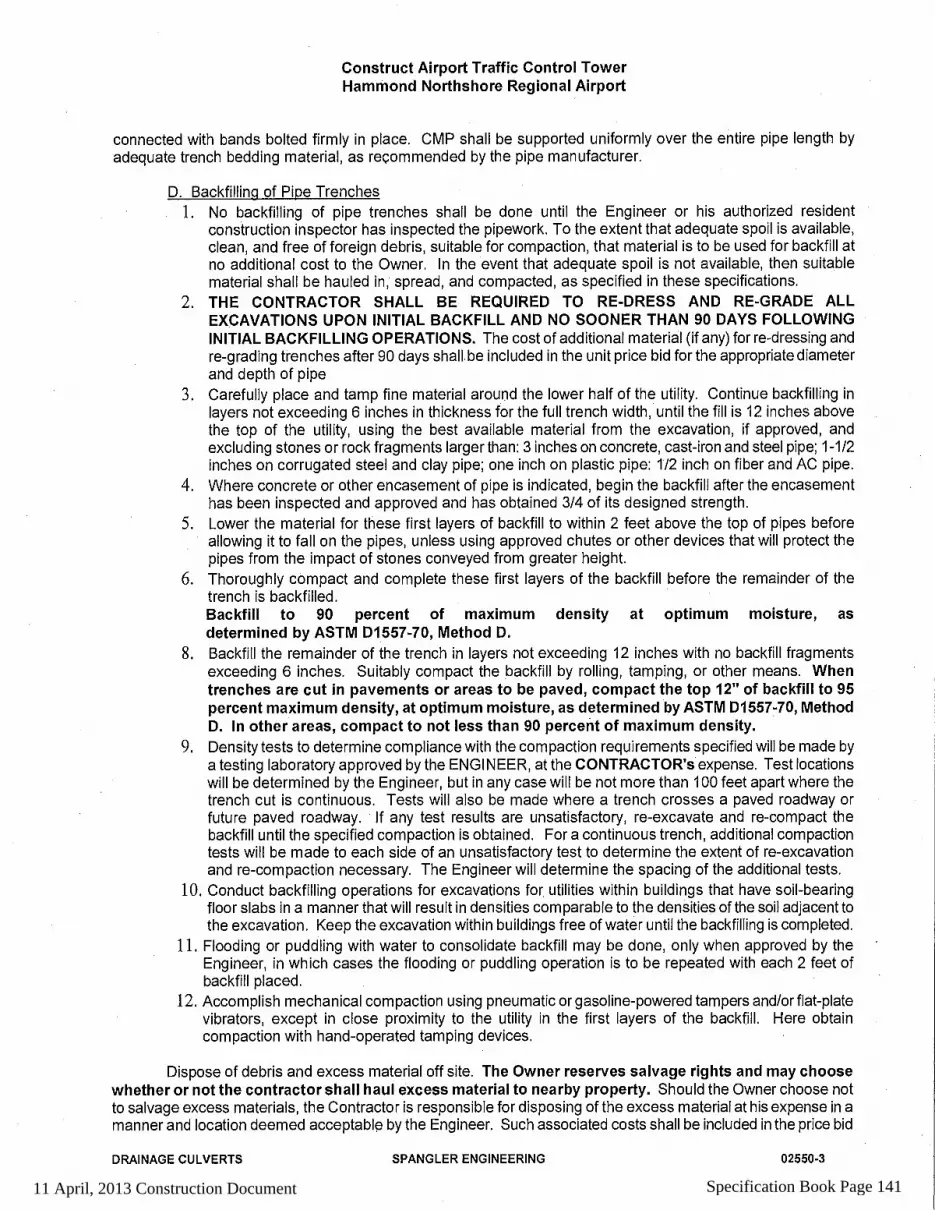
11 April, 2013 Construction Document Specification Book Page 141

11 April, 2013 Construction Document Specification Book Page 142

11 April, 2013 Construction Document Specification Book Page 143

11 April, 2013 Construction Document Specification Book Page 144
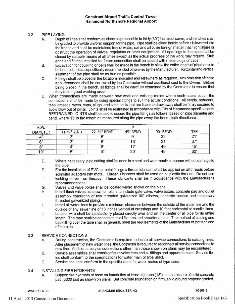
11 April, 2013 Construction Document Specification Book Page 145

11 April, 2013 Construction Document Specification Book Page 146

11 April, 2013 Construction Document Specification Book Page 147

11 April, 2013 Construction Document Specification Book Page 148

11 April, 2013 Construction Document Specification Book Page 149

11 April, 2013 Construction Document Specification Book Page 150

11 April, 2013 Construction Document Specification Book Page 151

11 April, 2013 Construction Document Specification Book Page 152

11 April, 2013 Construction Document Specification Book Page 153

11 April, 2013 Construction Document Specification Book Page 154

11 April, 2013 Construction Document Specification Book Page 155

11 April, 2013 Construction Document Specification Book Page 156

11 April, 2013 Construction Document Specification Book Page 157

11 April, 2013 Construction Document Specification Book Page 158

11 April, 2013 Construction Document Specification Book Page 159

11 April, 2013 Construction Document Specification Book Page 160
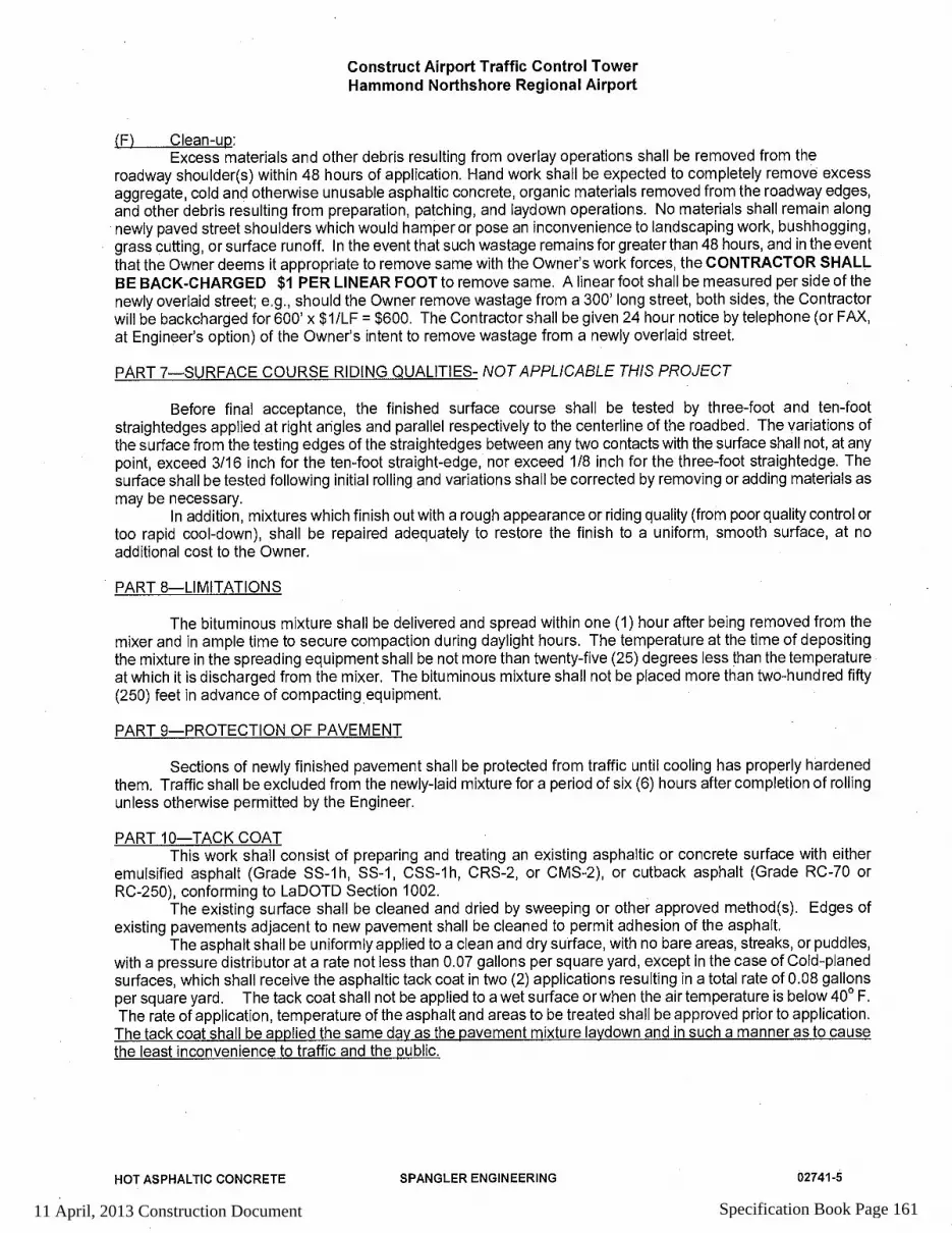
11 April, 2013 Construction Document Specification Book Page 161

11 April, 2013 Construction Document Specification Book Page 162

Hammond Northshore Regional Airport - Construct ATCT Hammond, Louisiana
Cast-In-Place Concrete Page 1
SECTION 03 30 00
CAST-IN-PLACE CONCRETE Note: This section does not include concrete for paving.
PART 1 GENERAL
1.1 SUMMARY
Section includes cast-in-place concrete for the following: 1. Foundation walls. 2. Supported slabs. 3. Slabs on grade. 4. Control, expansion and contraction joint devices. 5. Equipment pads.
1.2 REFERENCES
A. American Concrete Institute: 1. ACI 301 - Specifications for Structural Concrete. 2. ACI 305 - Hot Weather Concreting. 3. ACI 306.1 - Standard Specification for Cold Weather Concreting. 4. ACI 308.1 - Standard Specification for Curing Concrete. 5. ACI 318 - Building Code Requirements for Structural Concrete.
B. ASTM International: 1. ASTM C31/C31M - Standard Practice for Making and Curing Concrete Test Specimens in
the Field. 2. ASTM C33 - Standard Specification for Concrete Aggregates. 3. ASTM C39/C39M - Standard Test Method for Compressive Strength of Cylindrical
Concrete Specimens. 4. ASTM C42/C42M - Standard Test Method for Obtaining and Testing Drilled Cores and
Sawed Beams of Concrete. 5. ASTM C94/C94M - Standard Specification for Ready-Mixed Concrete. 6. ASTM C143/C143M - Standard Test Method for Slump of Hydraulic Cement Concrete. 7. ASTM C150 - Standard Specification for Portland Cement. 8. ASTM C172 - Standard Practice for Sampling Freshly Mixed Concrete. 9. ASTM C231 - Standard Test Method for Air Content of Freshly Mixed Concrete by the
Pressure Method. 10. ASTM C260 - Standard Specification for Air-Entraining Admixtures for Concrete. 11. ASTM C494/C494M - Standard Specification for Chemical Admixtures for Concrete. 12. ASTM C595 - Standard Specification for Blended Hydraulic Cements. 13. ASTM C618 - Standard Specification for Coal Fly Ash and Raw or Calcined Natural
Pozzolan for Use as a Mineral Admixture in Concrete. 14. ASTM C989 - Standard Specification for Ground Granulated Blast-Furnace Slag for Use in
Concrete and Mortars.
11 April, 2013 Construction Document Specification Book Page 163

Hammond Northshore Regional Airport - Construct ATCT Hammond, Louisiana
Cast-In-Place Concrete Page 2
15. ASTM C1017/C1017M - Standard Specification for Chemical Admixtures for Use in Producing Flowing Concrete.
16. ASTM C1064/C1064M - Standard Test Method for Temperature of Freshly Mixed Hydraulic-Cement Concrete.
17. ASTM C1240 - Standard Specification for Silica Fume Used in Cementitious Mixtures. 18. ASTM D1751 - Standard Specification for Preformed Expansion Joint Filler for Concrete
Paving and Structural Construction (Nonextruding and Resilient Bituminous Types). 19. ASTM D6690 - Standard Specification for Joint and Crack Sealants, Hot Applied, for
Concrete and Asphalt Pavements. 20. ASTM E96/E96M - Standard Test Methods for Water Vapor Transmission of Materials. 21. ASTM E1643 - Standard Practice for Installation of Water Vapor Retarders Used in Contact
with Earth or Granular Fill under Concrete Slabs. 22. ASTM E1745 - Standard Specification for Plastic Water Vapor Retarders Used in Contact
with Soil or Granular Fill under Concrete Slabs.
1.3 PERFORMANCE REQUIREMENTS
Vapor Retarder Permeance: Maximum 0.3 perms when tested in accordance with ASTM E96/E96M, water method.
1.4 SUBMITTALS
A. Section 01 33 00 - Submittal Procedures: Submittal procedures.
B. Design Data: 1. Submit concrete mix design for each concrete strength. Submit separate mix designs when
admixtures are required for the following: a. Hot and cold weather concrete work.
2. Identify mix ingredients and proportions, including admixtures.
1.5 CLOSEOUT SUBMITTALS
A. Section 01 70 00 - Execution and Closeout Requirements: Closeout procedures.
B. Project Record Documents: Accurately record actual locations of embedded utilities and components concealed from view in finished construction.
1.6 QUALITY ASSURANCE
A. Perform Work in accordance with ACI 318.
B. Conform to ACI 305 when concreting during hot weather.
C. Conform to ACI 306.1 when concreting during cold weather.
1.7 ENVIRONMENTAL REQUIREMENTS
A. Section 01 60 00 - Product Requirements: Environmental conditions affecting products on site.
11 April, 2013 Construction Document Specification Book Page 164

Hammond Northshore Regional Airport - Construct ATCT Hammond, Louisiana
Cast-In-Place Concrete Page 3
B. Maintain concrete temperature after installation at minimum 50 degrees F for minimum 7 days.
1.8 COORDINATION
A. Section 01 30 00 - Administrative Requirements: Coordination and project conditions.
B. Coordinate placement of joint devices with erection of concrete formwork and placement of form accessories.
PART 2 PRODUCTS
2.1 CONCRETE MATERIALS
A. Cement: ASTM C150, Type I/II - Normal Portland type.
B. Normal Weight Aggregates: ASTM C33. 1. Coarse Aggregate Maximum Size: one inch.
C. Water: ACI 318; potable, without deleterious amounts of chloride ions.
2.2 ADMIXTURES
A. Manufacturers: 1. BASF Construction Chemicals, LLC. 2. Sika Corporation. 3. Euclid Chemical Company. 4. Substitutions: Section 01 60 00 - Product Requirements.
B. Air Entrainment: ASTM C260.
C. Chemical: ASTM C494/C494M.
D. Fly Ash: ASTM C618 Class C.
E. Silica Fume: ASTM C1240.
F. Slag: ASTM C989; Grade 100; ground granulated blast furnace slag.
G. Plasticizing: ASTM C1017/C1017M Type I, plasticizing.
2.3 ACCESSORIES
A. Vapor Retarder: ASTM E1745 Class A; 6 mil thick fabric reinforced plastic film; type recommended for below grade application. Furnish joint tape recommended by manufacturer.
B. Non-Shrink Grout: ASTM C1107/C1107M; premixed compound consisting of metallic aggregate, cement, water reducing and plasticizing agents; capable of developing minimum
11 April, 2013 Construction Document Specification Book Page 165

Hammond Northshore Regional Airport - Construct ATCT Hammond, Louisiana
Cast-In-Place Concrete Page 4
compressive strength of 4000 psi in 48 hours and 9,000 psi in 28 days manufactured by MBT, BASF Construction Chemicals, LLC.
2.4 JOINT DEVICES AND FILLER MATERIALS
Joint Filler Type A, ASTM D1751; Asphalt impregnated fiberboard or felt, 1/2 inch thick.
2.5 CONCRETE MIX
A. Select proportions for normal weight concrete in accordance with ACI 301 Method 1.
B. Provide concrete to the following criteria
Location: Foundations and Slab-on-Grade
Material and Property Measurement
Compressive Strength (28 day) 3000 psi
Cement Type ASTM C150
Aggregate Type Normal weight
Water-Cement Ratio (maximum) 0.50 by weight
Aggregate Size (maximum) 3/4 inch
Air Content 6 percent plus or minus 1.5 percent
Slump 4 inches plus or minus 1 inch
Location: Slab on Metal Deck
Material and Property Measurement
Compressive Strength (28 day) 4000 psi
Cement Type ASTM C150
Aggregate Type Normal weight
11 April, 2013 Construction Document Specification Book Page 166

Hammond Northshore Regional Airport - Construct ATCT Hammond, Louisiana
Cast-In-Place Concrete Page 5
Water-Cement Ratio (maximum) 0.45 by weight
Aggregate Size (maximum) 3/4 inch
Air Content 6 percent plus or minus 1.5 percent
Slump 4 inches plus or minus 1 inch
C. Admixtures: Include admixture types and quantities indicated in concrete mix designs only when approved by Architect/Engineer. 1. Do not use calcium chloride or admixtures containing calcium chloride. 2. Use set retarding admixtures during hot weather. 3. Add air entrainment admixture to concrete mix for work exposed to freezing and thawing.
D. Average Compressive Strength Reduction: Permitted in accordance with ACI 318.
E. Ready Mixed Concrete: Mix and deliver concrete in accordance with ASTM C94/C94M.
PART 3 EXECUTION
3.1 EXAMINATION
A. Section 01 30 00 - Administrative Requirements: Coordination and project conditions.
B. Verify requirements for concrete cover over reinforcement.
C. Verify anchors, seats, plates, reinforcement and other items to be cast into concrete are accurately placed, positioned securely, and will not interfere with placing concrete.
3.2 PREPARATION
A. Prepare previously placed concrete by cleaning with steel brush and applying bonding agent. Remove laitance, coatings, and unsound materials.
B. In locations where new concrete is doweled to existing work, drill holes in existing concrete, insert steel dowels and pack solid with non-shrink grout.
C. Remove debris and ice from formwork, reinforcement, and concrete substrates.
D. Remove water from areas receiving concrete before concrete is placed.
3.3 PLACING CONCRETE
A. Place concrete in accordance with ACI 301.
B. Notify testing laboratory and Architect/Engineer minimum 24 hours prior to commencement of operations.
11 April, 2013 Construction Document Specification Book Page 167

Hammond Northshore Regional Airport - Construct ATCT Hammond, Louisiana
Cast-In-Place Concrete Page 6
C. Ensure reinforcement, inserts, embedded parts, formed expansion and contraction joints are not disturbed during concrete placement.
D. Install vapor retarder under interior slabs on grade in accordance with ASTM E1643. Lap joints minimum 6 inches and seal watertight by taping edges and ends.
E. Repair vapor retarder damaged during placement of concrete reinforcing. Repair with vapor retarder material; lap over damaged areas minimum 6 inches and seal watertight.
F. Deposit concrete at final position. Prevent segregation of mix.
G. Place concrete in continuous operation for each panel or section determined by predetermined joints.
H. Consolidate concrete.
I. Maintain records of concrete placement. Record date, location, quantity, air temperature, and test samples taken.
J. Place concrete continuously between predetermined expansion, control, and construction joints.
K. Do not interrupt successive placement; do not permit cold joints to occur.
L. Screed floors and slabs on grade level, maintaining surface flatness of maximum 1/4 inch in 10 ft.
3.4 CONCRETE FINISHING
A. Provide formed concrete surfaces to be left exposed with smooth rubbed finish.
B. Finish concrete floor surfaces in accordance with ACI 301.
C. Steel trowel surfaces which are indicated to be exposed.
D. In areas with floor drains, maintain floor elevation at walls; pitch surfaces uniformly to drains at 1/8 inch per foot nominal.
3.5 CURING AND PROTECTION
A. Immediately after placement, protect concrete from premature drying, excessively hot or cold temperatures, and mechanical injury. 1. Protect concrete footings from freezing for minimum 5 days.
B. Maintain concrete with minimal moisture loss at relatively constant temperature for period necessary for hydration of cement and hardening of concrete.
C. Cure concrete in accordance with ACI 308.1 using liquid membrane spray compound method.
11 April, 2013 Construction Document Specification Book Page 168

Hammond Northshore Regional Airport - Construct ATCT Hammond, Louisiana
Cast-In-Place Concrete Page 7
3.6 FIELD QUALITY CONTROL
A. Section 01 40 00 - Quality Requirements: Field inspecting, testing, adjusting, and balancing.
B. Perform field inspection and testing in accordance with ACI 318.
C. Provide free access to Work and cooperate with appointed firm.
D. Submit proposed mix design of each class of concrete to testing firm for review prior to commencement of Work.
E. Concrete Inspections: 1. Continuous Placement Inspection: Inspect for proper installation procedures. 2. Periodic Curing Inspection: Inspect for specified curing temperature and procedures.
F. Strength Test Samples: 1. Sampling Procedures: ASTM C172.
2. Cylinder Molding and Curing Procedures: ASTM C31/C31M, cylinder specimens, field
cured.
3. Sample concrete and make one set of three cylinders for every 75 cu yds or less of each class of concrete placed each day and for every 5,000 sf of surface area for slabs and walls.
4. When volume of concrete for any class of concrete would provide less than 5 sets of cylinders, take samples from five randomly selected batches, or from every batch when less than 5 batches are used.
5. Make one additional cylinder during cold weather concreting, and field cure.
G. Field Testing: 1. Slump Test Method: ASTM C143/C143M. 2. Air Content Test Method: ASTM C231. 3. Temperature Test Method: ASTM C1064/C1064M. 4. Measure slump and temperature for each compressive strength concrete sample. 5. Measure air content in air entrained concrete for each compressive strength concrete sample.
H. Cylinder Compressive Strength Testing: 1. Test Method: ASTM C39/C39M. 2. Test Acceptance: In accordance with ACI 318. 3. Test one cylinder at 7 days. 4. Test two cylinders at 28 days. 5. Dispose remaining cylinders when testing is not required.
I. Core Compressive Strength Testing: 1. Sampling and Testing Procedures: ASTM C42/C42M. 2. Test Acceptance: In accordance with ACI 318. 3. Drill two cores for each failed strength test from concrete represented by failed strength test.
J. Maintain records of concrete placement. Record date, location, quantity, air temperature and test samples taken.
11 April, 2013 Construction Document Specification Book Page 169

Hammond Northshore Regional Airport - Construct ATCT Hammond, Louisiana
Cast-In-Place Concrete Page 8
3.7 PATCHING
A. Allow Architect/Engineer to inspect concrete surfaces immediately upon removal of forms.
B. Excessive honeycomb or embedded debris in concrete is not acceptable. Notify Architect/Engineer upon discovery.
C. Patch imperfections in accordance with ACI 301.
3.8 DEFECTIVE CONCRETE
A. Defective Concrete: Concrete not conforming to required lines, details, dimensions, tolerances or specified requirements.
B. Repair or replacement of defective concrete will be determined by Architect/Engineer.
C. Do not patch, fill, touch-up, repair, or replace exposed concrete except upon express direction of Architect/Engineer for each individual area.
END OF SECTION
11 April, 2013 Construction Document Specification Book Page 170

HHaammmmoonndd NNoorrtthhsshhoorree RReeggiioonnaall AAiirrppoorrtt –– CCoonnssttrruucctt AATTCCTT HHaammmmoonndd,, LLoouuiissiiaannaa
Prestressed Concrete Piles Page 1
Section 31 62 14
SECTION 31 62 14
PRESTRESSED CONCRETE PILES
PART 1 GENERAL
1.1 SUMMARY
A. Section Includes: 1. Prestressed precast concrete piles.
B. Related Sections: 1. Section 03 30 00 - Cast-In-Place Concrete: Requirements for concrete, and placement of pile
caps and grade beams. 2. Section 31 09 19 - Pile Dynamic Load Tests: Requirements for pile load tests. 3. Section 31 23 16 - Excavation: Excavating to working level.
1.2 UNIT PRICES - MEASUREMENT AND PAYMENT
A. Designed Piles: 1. Design Pile Quantity: Determined by number of piles indicated in Contract Documents. 2. Design Pile Length: as indicated on Drawings. 3. Test Pile: 5 feet longer than design length piles. Test piling shall not be a perimeter piling.
B. Actual Piles: 1. Actual Pile Quantity: Determined by number of piles identified in Project Record
Documents. 2. Actual Pile Length: Determined by length of piles identified in Project Record Documents.
Contractor shall provide unit cost per foot if additional pile length is required to achieve design strength. See Bid Schedule.
1.3 REFERENCES
A. ASTM International: 1. ASTM A416/A416M - Standard Specification for Steel Strand, Uncoated Seven-Wire for
Prestressed Concrete. 2. ASTM A615/A615M - Standard Specification for Deformed and Plain Billet-Steel Bars for
Concrete Reinforcement.
B. Precast/Prestressed Concrete Institute: 1. PCI MNL-116S - Manual for Quality Control for Plants and Production of Precast and
Prestressed Concrete Products.
C. DOTD Standard Specifications for Roads and Bridges – Part VIII--Structures
1.4 PERFORMANCE REQUIREMENTS
A. Drive piles as indicated on Drawings and the geotechnical report.
11 April, 2013 Construction Document Specification Book Page 171

HHaammmmoonndd NNoorrtthhsshhoorree RReeggiioonnaall AAiirrppoorrtt –– CCoonnssttrruucctt AATTCCTT HHaammmmoonndd,, LLoouuiissiiaannaa
Prestressed Concrete Piles Page 2
Section 31 62 14
1.5 SUBMITTALS
A. Section 01 33 00 - Submittal Procedures: Requirements for submittals.
B. Shop Drawings: Indicate details and schedule of pile construction and installation sequence. Identify pile length and size to suit design requirements.
C. Product Data: 1. Submit concrete mix design indicating cured properties and mix components. 2. Submit data for tendons, and reinforcing. 3. Submit details of cushion blocks. 4. Submit conformance to DOTD Specifications.
D. Design Data: Include design calculations signed and sealed by professional engineer.
1.6 CLOSEOUT SUBMITTALS
A. Section 01 70 00 - Execution and Closeout Requirements: Requirements for submittals.
B. Project Record Documents: Accurately record the following: 1. Sizes, lengths, and locations of piles. 2. Sequence of driving. 3. Number of blows per foot for entire length of piles and measured set for last 10 blows. 4. Piles requiring drilling and hole diameters. 5. Final base and top elevations. 6. Driving force of each hammer blow.
1.7 QUALITY ASSURANCE
A. Perform Work in accordance with PCI MNL-116S.
B. Perform Work in accordance with the Louisiana Department of Transportation and Development (DOTD) Manual, Section 804.
1.8 QUALIFICATIONS
A. Installer: Company specializing in performing the Work of this section with minimum 5 years documented experience.
B. Monitor pile driving operations by Geotechnical Engineer experienced in this Work and licensed in State of Louisiana. Reference drawings and Testing specification section. Ardaman & Associates, Inc., 316 Highlandia Drive, Baton Rouge, Louisiana 70884, Phone (225) 752-4790, provided the Geotechnical Study. Please consider contacting them for testing and quality control.
1.9 PRE-INSTALLATION MEETINGS
A. Section 01 30 00 - Administrative Requirements: Pre-installation meeting.
B. Convene minimum one week prior to commencing Work of this section.
11 April, 2013 Construction Document Specification Book Page 172

HHaammmmoonndd NNoorrtthhsshhoorree RReeggiioonnaall AAiirrppoorrtt –– CCoonnssttrruucctt AATTCCTT HHaammmmoonndd,, LLoouuiissiiaannaa
Prestressed Concrete Piles Page 3
Section 31 62 14
1.10 SCHEDULING
A. Section 01 30 00 - Administrative Requirements: Requirements for scheduling.
B. Schedule test pile and production pilings installation.
PART 2 PRODUCTS
2.1 MATERIALS
A. Concrete: Minimum 6000 psi 28 day strength, Normal Portland cement; aggregates and sand as recommended by pile manufacturer.
B. Tensioning Steel Tendons: ASTM A416/A416M Grade 270K, of sufficient strength commensurate with member design.
C. Reinforcing Steel: ASTM A615/A615M Grade 60, deformed steel bars.
2.2 FABRICATION
A. Pile Points: Hardened steel, hollowed tip to minimize bounce or deflection.
B. Cure piles to attain design strength.
2.3 SOURCE QUALITY CONTROL
A. Section 01 40 00 - Quality Requirements: Testing, inspection and analysis requirements.
B. Test sample piles in accordance with PCI MNL-116S.
PART 3 EXECUTION
3.1 EXAMINATION
A. Section 01 30 00 - Administrative Requirements: Verification of existing conditions before starting work.
3.2 PREPARATION
A. Use driving method which will not cause damage to nearby structures.
B. Protect structures near the Work from damage.
3.3 DRILLING
A. Drill holes to facilitate driving only when piling cannot be completed in specified manner. Drill only through strata obstructing driving.
11 April, 2013 Construction Document Specification Book Page 173

HHaammmmoonndd NNoorrtthhsshhoorree RReeggiioonnaall AAiirrppoorrtt –– CCoonnssttrruucctt AATTCCTT HHaammmmoonndd,, LLoouuiissiiaannaa
Prestressed Concrete Piles Page 4
Section 31 62 14
B. Hole Diameter: Maximum 1 inch smaller than tip dimension.
3.4 INSTALLATION
A. Protect pile head during driving, using cushion cap with full bearing on pile butt for even distribution of hammer blow.
B. Deliver hammer blows to central axis of pile.
C. Do not damage piles during driving operations.
D. When driving is interrupted before refusal, drive an additional 12 inches before resuming recording of performance data.
E. Re-drive piles which have lifted due to driving adjacent piles, or by soil uplift.
F. Prepare pile top to receive pile caps.
3.5 ERECTION TOLERANCES
A. Section 01 40 00 - Quality Requirements: Tolerances.
B. Maximum Variation From Vertical For Plumb Piles: 1 in 48. Piles shall be installed so that the axial alignment is within 2 percent of the specified alignment shown in the plans. For piles that cannot be inspected internally after installation, an alignment check shall be made before installing the last 5 feet (1.5 m) of pile, or after installation is completed provided the exposed portion of the pile is not less than 5 feet (1.5 m) in length. The engineer may require that driving be stopped in order to check the pile alignment. Pulling laterally on piles to correct misalignment, or splicing a properly aligned section on a misaligned section shall not be permitted. If the location and/or alignment tolerances specified herein are exceeded, the contractor shall provide the engineer with a sketch showing the actual versus theoretical positions of the piles. If corrective measures are necessary, the contractor shall bear all costs, including delays, associated with the corrective action.
C. Maximum Variation From Pile Cut-off Elevation: 4 inches.
D. Maximum Out-of-Position: 2 inches.
E. No pile shall be nearer than 6 inches from any edge of the cap. Any increases in size of cap to meet these edge distance requirements shall be at the contractor's expense.
3.6 FIELD QUALITY CONTROL
A. Section 01 40 00 - Quality Requirements 01 70 00 - Execution and Closeout Requirements: Field inspecting, testing, adjusting, and balancing.
B. Perform and Request inspection of foundations.
C. Perform load tests to requirements of Section 31 09 19.
11 April, 2013 Construction Document Specification Book Page 174

HHaammmmoonndd NNoorrtthhsshhoorree RReeggiioonnaall AAiirrppoorrtt –– CCoonnssttrruucctt AATTCCTT HHaammmmoonndd,, LLoouuiissiiaannaa
Prestressed Concrete Piles Page 5
Section 31 62 14
D. Test Pile: Same diameter and type as specified for other piling, placed in same manner.
E. Accepted test pile may be used in the Work.
F. Unacceptable Piles: Piles that fail tests, are placed out of position, are below cut-off elevations, or are damaged.
G. Provide additional piles or replace piles to conform to specified requirements.
END OF SECTION
11 April, 2013 Construction Document Specification Book Page 175

HHaammmmoonndd NNoorrtthhsshhoorree RReeggiioonnaall AAiirrppoorrtt –– CCoonnssttrruucctt AATTCCTT HHaammmmoonndd,, LLoouuiissiiaannaa
Pile Load Tests
Section 31 09 19 Page 1
SECTION 31 09 19
PILE DYNAMIC LOAD TESTS PART 1 GENERAL
1.1 SUMMARY
A. Section Includes: 1. Pile dynamic load testing using Pile Driving Analyzer (PDA). 2. Documented test results.
B. Related Sections: 1. Section 31 23 16 - Excavation: Excavating to working and test equipment level. 2. Section 31 62 14 - Prestressed Concrete Piles.
1.2 UNIT PRICE - MEASUREMENT AND PAYMENT
A. Additional Tests: 1. Basis of Measurement: Each additional retest. 2. Basis of Payment: Includes set-up, applying test load, test equipment, monitoring, reporting
results.
1.3 REFERENCES
A. ASTM International: ASTM D4945 - Standard Test Method for High-Strain Dynamic Testing of Piles.
B. DOTD Standard Specifications for Roads and Bridges – Part VIII--Structures
1.4 SUBMITTALS
A. Section 01 33 00 - Submittal Procedures: Requirements for submittals.
B. Shop Drawings: Indicate test method and equipment, load type, calibration equipment.
1.5 QUALITY ASSURANCE
A. Perform Work in accordance with DOTD Standards and ASTM D4945
1.6 QUALIFICATIONS
A. Monitor pile placement and elevations under direct supervision of Professional Engineer experienced in testing of this Work and licensed in the State of Louisiana.
1.7 SEQUENCING
A. Sequence Work to allow proper dynamic test monitoring. 1. Drive test production pile. Test production pile shall not be a perimeter pile. 2. Allow 7 days prior to restrike testing. 3. Allow an additional 24 hours prior to restrike if failure of initial testing occurs.
11 April, 2013 Construction Document Specification Book Page 176

HHaammmmoonndd NNoorrtthhsshhoorree RReeggiioonnaall AAiirrppoorrtt –– CCoonnssttrruucctt AATTCCTT HHaammmmoonndd,, LLoouuiissiiaannaa
Pile Load Tests
Section 31 09 19 Page 2
PART 2 PRODUCTS
2.1 EQUIPMENT
A. Equipment Type, Load Carrying Device, Load, and Instrumentation: Conform to ASTM D4945 of same type as will be used for pile placement of the Work.
B. Quantity: Provide all equipment and devices as required by the testing company.
PART 3 EXECUTION
3.1 EXAMINATION
A. Section 01 30 00 - Administrative Requirements: Verification of existing conditions before starting work.
B. Verify site conditions will support cribbing and load for testing purposes.
3.2 PREPARATION
A. Establish stable working elevation for test equipment.
3.3 TESTING
A. Perform load tests.
B. When tested piles do not conform to requirements, perform additional testing of pile after a minimum of 24 hours’ time has lapsed.
.
3.4 FIELD QUALITY CONTROL
A. Section 01 40 00 - Quality Requirements 01 70 00 - Execution and Closeout Requirements: Field inspecting, testing, adjusting, and balancing.
B. An independent inspection firm will be engaged by the Contractor to observe and document test method and results.
C. Document test equipment used, method of calibration and recording, test results, recommendations or modification of piling method used.
D. Accurately record actual dimensions and locations of tested piles and movement or distortion caused by testing.
E. Provide copies of the testing reports to the Engineer and Owner.
END OF SECTION
11 April, 2013 Construction Document Specification Book Page 177

Hammond Northshore Regional Airport - Construct ATCT Hammond, Louisiana
Precast Architectural Concrete Page 1
SECTION 03 45 00
PRECAST ARCHITECTURAL CONCRETE
PART 1 GENERAL
1.1 SUMMARY.
A. This section includes the performance criteria, materials, production and erection of architectural concrete wall panels. The work performed under this section includes all labor, material, equipment, related services and supervision for the manufacture and erection of architectural precast concrete work shown on the contract drawings.
B. Section includes structural precast concrete units with an architectural finish for use as exterior building envelope and structural elements:
1. Structural Wall panels. 2. Supports, anchors, and attachments. 3. Perimeter joint seals. 4. Intermediate joint seals. 5. Grouting under panels.
C. Related Sections: 1. Section 03 30 00 - Cast-In-Place Concrete: Building structural frame. 2. Section 05 12 00 - Structural Steel Framing: Building structural frame.
1.2 REFERENCES
A. American Concrete Institute: 1. ACI 301 - Specifications for Structural Concrete. 2. ACI 318 - Building Code Requirements for Structural Concrete.
B. ASTM International: 1. ASTM A36/A36M - Standard Specification for Carbon Structural Steel. 2. ASTM A123/A123M - Standard Specification for Zinc (Hot-Dip Galvanized)
Coatings on Iron and Steel Products. 3. ASTM A153/A153M - Standard Specification for Zinc Coating (Hot-Dip) on
Iron and Steel Hardware. 4. A185/A185M-07 Standard Specification for Steel Welded Wire Reinforcement,
Plain, for Concrete. 5. ASTM A307 - Standard Specification for Carbon Steel Bolts and Studs, 60 000
PSI Tensile Strength. 6. ASTM A325 - Standard Specification for Structural Bolts, Steel, Heat Treated,
120/105 ksi Minimum Tensile Strength. 7. ASTM A416/A416M - Standard Specification for Steel Strand, Uncoated Seven-
Wire for Prestressed Concrete. 8. ASTM A615/A615M - Standard Specification for Deformed and Plain Billet-
Steel Bars for Concrete Reinforcement.
11 April, 2013 Construction Document Specification Book Page 178

Hammond Northshore Regional Airport - Construct ATCT Hammond, Louisiana
Precast Architectural Concrete Page 2
9. ASTM C31/C31M - Standard Practice for Making and Curing Concrete Test Specimens in the Field.
10. ASTM C33 - Standard Specification for Concrete Aggregates. 11. ASTM C143/C143M - Standard Test Method for Slump of Hydraulic Cement
Concrete. 12. ASTM C150 - Standard Specification for Portland Cement. 13. ASTM C260 - Standard Specification for Air-Entraining Admixtures for
Concrete. 14. ASTM C330 - Standard Specification for Lightweight Aggregates for Structural
Concrete. 15. ASTM E84 - Standard Test Method for Surface Burning Characteristics of
Building Materials.
C. American Welding Society: 1. AWS D1.1 - Structural Welding Code - Steel. 2. AWS D1.4 - Structural Welding Code - Reinforcing Steel.
D. Precast/Prestressed Concrete Institute: 1. PCI MNL-117 - Manual for Quality Control for Plants and Production of
Architectural Precast Concrete Products. 2. PCI MNL-120 - PCI Design Handbook - Precast and Prestressed Concrete. 3. PCI MNL-122 - Architectural Precast Concrete. 4. PCI MNL-123 - Design and Typical Details of Connections for Precast and
Prestressed Concrete.
1.3 DESIGN REQUIREMENTS
A. Structural Performance: Provide architectural precast concrete units and connections capable of withstanding design loads within limits and under conditions indicated. Design units to withstand design loads and erection forces. Calculate structural properties of units in accordance with ACI 318.
B. Design units to accommodate construction tolerances, deflection of building structural members, and clearances of intended openings.
C. Design component connections to accommodate building movement and thermal movement. Provide adjustment to accommodate misalignment of structure without unit distortion or damage.
1.4 SUBMITTALS
A. Section 01 33 00 - Submittal Procedures: Submittals procedures.
B. Shop (Erection) Drawings: Detail fabrication and installation of architectural precast concrete units. Indicate member locations, plans, elevations, dimensions, shapes and cross sections. Indicate aesthetic intent including joints, reveals, and extent and location of each surface finish. Indicate details at building corners.
1. Indicate separate face and backup mix locations, and thicknesses.
11 April, 2013 Construction Document Specification Book Page 179

Hammond Northshore Regional Airport - Construct ATCT Hammond, Louisiana
Precast Architectural Concrete Page 3
2. Indicate welded connections by AWS standard symbols. Detail loose and cast-in hardware, and connections.
3. Indicate locations, tolerances and details of anchorage devices to be embedded in or attached to structure or other construction.
4. Indicate locations, extent and treatment of dry joints if two-stage casting is proposed. 5. Indicate plans, and/or elevations showing unit location, and sequence of erection for
special conditions. 6. Indicate location of each architectural precast concrete unit by same identification mark
placed on panel. 7. Indicate relationship of architectural precast concrete units to adjacent materials. 8. Indicate locations and details of joint treatment. 9. Indicate Reinforcement at each panel.
C. Design Data: Submit engineering design signed and sealed by the qualified professional engineer
responsible for its preparation registered in the State of Louisiana. Show governing panel types, connections, and types of reinforcement, including special reinforcement. Coordinate the location, type, magnitude and direction of all imposed loadings from the precast system to the building structural frame with the Engineer of Record.
D. Samples: Submit two panels, 12 x12 inch in size illustrating surface finish, color and texture. Submit Sealant color samples. NOTE: ALL PANEL SEALANT COLORS SHALL MATCH ADJACENT PANELS UNLESS OTHERWISE DIRECTED BY THE ENGINEER
E. Welding Certificates: Copies of certificates for welding procedure specifications (WPS) and personnel.
F. Qualification Data: For firms and persons specified in “Quality Assurance” Article to demonstrate their capabilities and experience. Include list of completed projects with project names and addresses, names and addresses of architects and owners, and other information specified.
1.5 CLOSEOUT SUBMITTALS
A. Section 01 70 00 - Execution and Closeout Requirements: Closeout procedures.
B. Operation and Maintenance Data: Procedures for Project closeout submittals. Indicate surface cleaning instructions.
1.6 QUALITY ASSURANCE
A. Perform Work in accordance with PCI MNL-117, PCI MNL-120, PCI MNL-122, PCI MNL-123, ACI 318.
B. Welding: AWS D1.1 and AWS D1.4.
1.7 QUALIFICATIONS A. Fabricator Qualifications: A firm that complies with the following requirements and is
experienced in producing architectural precast concrete units similar to those indicated for this Project and with a record of successful in-service performance.
11 April, 2013 Construction Document Specification Book Page 180

Hammond Northshore Regional Airport - Construct ATCT Hammond, Louisiana
Precast Architectural Concrete Page 4
1. Assumes responsibility for engineering architectural precast concrete units to comply with
performance requirements. This responsibility includes preparation of Shop Drawings and comprehensive engineering analysis by a qualified professional engineer.
2. Professional Engineer Qualifications: A professional engineer who is legally qualified to practice in State of Lousiana and who is experienced in providing engineering services of the kind indicated. Engineering services are defined as those performed for installations of architectural precast concrete that are similar to those indicated for this Project in material, design, and extent.
3. Participates in PCI’s Plant Certification program at the time of bidding and is designated a PCI-certified plant for Group A, Category A1- Architectural Cladding and Load Bearing Units.
4. Has sufficient production capacity to produce required units without delaying the Work.
B. Precast Erectors: An erector with a minimum of 2 years of experience who has completed architectural precast concrete work similar in material, design, and extent to that indicated for this Project and whose work has resulted in construction with a record of successful in-service performance and follows requirements “PCI Erector’s Manual - Standards and Guidelines for the Erection of Precast Concrete Products” MNL 127. Erectors without this experience can provide evidence to the Engineer regarding their experience, capabilities and work plan for approval prior to any precast panel erection. Engineer has the right to disapprove evidence and require experience listed above.
C. Welder: Qualified within previous 12 months in accordance with AWS D1.1 and AWS D1.4.
1.8 PRE-INSTALLATION MEETINGS
A. Section 01 30 00 - Administrative Requirements: Pre-installation meeting.
B. Convene minimum one week prior to commencing work of this section.
1.9 DELIVERY, STORAGE, AND HANDLING
A. Section 01 60 00 - Product Requirements: Product storage and handling requirements.
B. Handle precast units to position, consistent with their shape and design. Lift and support only from support points.
C. Blocking and Lateral Support During Transport and Storage: Clean, non-staining, without causing harm to exposed surfaces. Provide temporary lateral support to prevent bowing and warping.
D. Protect units to prevent staining, chipping, or spalling of concrete.
E. Mark units with date of production in location not visible to view when in final position in structure.
PART 2 PRODUCTS
2.1 MANUFACTURERS
Manufacturers:
11 April, 2013 Construction Document Specification Book Page 181

Hammond Northshore Regional Airport - Construct ATCT Hammond, Louisiana
Precast Architectural Concrete Page 5
1. Speed Fab-Crete Inc. 2. Boykin Brothers, Inc., Baton Rouge, LA 3. Tulsa Dynaspan Inc 4. Substitutions: Section 01 60 00 - Product Requirements.
2.2 MATERIALS
A. Cement: ASTM C150, Type I or III. 1. For surfaces exposed to view in finished structure, use white, same type, brand,
and mill source throughout the precast concrete production. 2. Standard gray Portland cement may be used for non-exposed backup concrete.
B. Concrete Materials: ASTM C33; water and sand.
C. Reinforcement: ASTM A615/A615M, Grade 60, deformed steel bars, ASTM A185/A185M, welded steel wire fabric, ASTM A416/A416M, pre-stressing strand; strength and size commensurate with precast unit design.
D. Air Entrainment Admixture: ASTM C260.
E. Admixtures: Air entrainment and as specified in Section 03 30 00.
F. Surface Finish Fine Aggregate: Selected, hard, and durable; free of material that reacts with cement or causes staining; to match selected finish sample.
2.3 EXTERIOR FINISH
A. The exterior exposed surface shall consist of fine aggregate, chemically retarded and water washed. The finish of the exterior face shall include an Integral Color of a minimum 4 inches in thickness.
B. Panel colors: DCS #600 Taupe, 1% white Portland cement
C. Accent Panel colors: DCS #48 Dark Orange Buff, 5% white Portland cement
D. Surface Retarder: As recommended by the precast manufacture.
E. Grout: Non-shrink, Non-metallic, minimum 10,000 psi, 28 day strength.
2.4 FORM LINERS
Units of face design texture, arrangement, and configuration indicated. Provide solid backing and form supports to ensure that form liners remain in place during concrete placement. Use with manufacturer’s recommended liquid-release agent that will not bond with, stain, or adversely affect precast concrete surfaces and will not impair subsequent surface or joint treatments of precast concrete. Liners shall extend full length of panel without splices. Note lead time on liners could impact schedule.
Manufacturers: 1. Fitzgerald Formliners Model: 14301 Fluted Rib.
11 April, 2013 Construction Document Specification Book Page 182

Hammond Northshore Regional Airport - Construct ATCT Hammond, Louisiana
Precast Architectural Concrete Page 6
2. Substitutions: Section 01 60 00 - Product Requirements.
2.5 INTERIOR FINISH
The interior surface shall be smooth steel trowelled surface.
2.6 SUPPORT DEVICES
A. Connecting and Support Devices: ASTM A36/A36M general construction steel.
B. Primer: Zinc rich type.
2.7 ACCESSORIES
A. Bearing Pads: High density plastic, Neoprene (Chloroprene), smooth both sides.
B. Sealant and backer rod : Per PCI specifications. Color to match precast wall panels.
2.8 MIX
Separate face mix and backup mix:
A. Face mix: Minimum 5,000 psi, 28 day strength, air entrained to 5 to 7 percent in accordance with ACI 318.
B. Backup mix: Same aggregate-cement ratio as face mix; achieve 28 day compressive strength of 5000 psi.
2.9 FABRICATION
A. Fabricate in conformance with PCI MNL-117 and ACI 318.
B. Maintain plant records and quality control program during production of precast units. Make records available upon request.
C. Use rigid molds, constructed to maintain precast unit uniform in shape, size, and finish.
D. Utilize form liners.
E. Maintain consistent quality during manufacture.
F. Fabricate connecting devices, plates, angles, items fit to steel framing members, inserts, bolts, and accessories. Fabricate to permit initial placement and final attachment.
G. Weld steel fabrications in accordance with AWS D1.1. Weld reinforcing steel in accordance with AWS D1.4. Do not tack weld reinforcing.
H. Embed reinforcing steel, anchors, inserts plates, angles, and other cast-in items.
I. Locate hoisting devices to permit removal after erection.
11 April, 2013 Construction Document Specification Book Page 183

Hammond Northshore Regional Airport - Construct ATCT Hammond, Louisiana
Precast Architectural Concrete Page 7
J. Cure units to develop concrete quality, and to minimize appearance blemishes including non-uniformity, staining, or surface cracking.
K. Minor patching in plant is acceptable, providing structural adequacy and appearance of units is not impaired.
2.10 FINISH - PRECAST UNITS
A. Panel faces shall be free of joint marks, grain, and other obvious defects. Corners, including false joints shall be uniform, straight and sharp. Finish exposed-face surfaces of architectural precast concrete units to match approved sample panels
2.11 FINISH - SUPPORT DEVICES
A. Clean surfaces of rust, scale, grease, and foreign matter.
B. Prime paint in one coat, except surfaces in direct contact with concrete or requiring field welding.
2.12 FABRICATION TOLERANCES
A. Conform to PCI MNL-117.
2.13 SOURCE QUALITY CONTROL AND TESTS
A. Section 01 40 00 - Quality Requirements: Testing, inspection and analysis requirements.
B. Test and analyze concrete in accordance with PCI MNL-117.
When fabricator is approved by authority having jurisdiction, submit certificate of compliance indicating Work performed at fabricator's facility conforms to Contract Documents. Specified shop tests are not required for Work performed by approved fabricator.
NOTE: The engineer has the right to stop erection and refuse shipment of any/all panels the have been damaged during shipment or erection.
PART 3 EXECUTION
3.1 EXAMINATION
A. Section 01 30 00 - Administrative Requirements: Coordination and project conditions.
B. Verify building structure, anchors, devices, and openings are ready to receive work of this Section.
11 April, 2013 Construction Document Specification Book Page 184

Hammond Northshore Regional Airport - Construct ATCT Hammond, Louisiana
Precast Architectural Concrete Page 8
3.2 PREPARATION
Provide for erection procedures and induced loads during erection. Maintain temporary bracing in place until final support is provided.
3.3 ERECTION
A. Erect units without damage to shape or finish. Replace or repair damaged panels.
B. Erect units level and plumb within allowable tolerances.
C. Align and maintain uniform horizontal and vertical joints as erection progresses.
D. When units require adjustment beyond design or tolerance criteria, discontinue affected work; advise Architect/Engineer.
E. Weld units in place. Perform welding in accordance with AWS D1.1.
F. Touch-up scratched or damaged primed painted surfaces.
G. Weld reinforcing steel in accordance with AWS D1.4. Do not tack weld reinforcing.
H. Set vertical units dry, without grout, attaining joint dimension with lead or plastic spacers. Pack grout to base of unit.
3.4 ERECTION TOLERANCES
A. Section 01 40 00 - Quality Requirements: Tolerances.
B. Maximum Variation from Plane of Location: 1/4 inch in 10 feet and 3/4 inch in 100 feet, non-cumulative.
C. Maximum Offset from Indicated Alignment Between Two Connecting Units: 1/4 inch.
D. Joint Tolerance: Plus or minus 1/4 inch.
3.5 FIELD QUALITY CONTROL
A. Welding: Inspect welds in accordance with AWS D1.1.
3.6 ADJUSTING
A. Section 01 70 00 - Execution and Closeout Requirements: Testing, adjusting, and balancing.
B. Adjust units so joint dimensions are within tolerances.
3.7 PROTECTION OF INSTALLED CONSTRUCTION
A. Section 01 70 00 - Execution and Closeout Requirements: Protecting installed construction.
B. Use non-combustible shields during welding operations to protect adjacent Work.
11 April, 2013 Construction Document Specification Book Page 185

Hammond Northshore Regional Airport - Construct ATCT Hammond, Louisiana
Precast Architectural Concrete Page 9
END OF SECTION
11 April, 2013 Construction Document Specification Book Page 186
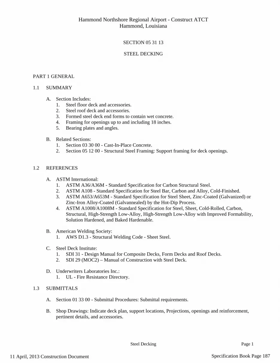
Hammond Northshore Regional Airport - Construct ATCT Hammond, Louisiana
Steel Decking Page 1
SECTION 05 31 13
STEEL DECKING
PART 1 GENERAL
1.1 SUMMARY
A. Section Includes: 1. Steel floor deck and accessories. 2. Steel roof deck and accessories. 3. Formed steel deck end forms to contain wet concrete. 4. Framing for openings up to and including 18 inches. 5. Bearing plates and angles.
B. Related Sections: 1. Section 03 30 00 - Cast-In-Place Concrete. 2. Section 05 12 00 - Structural Steel Framing: Support framing for deck openings.
1.2 REFERENCES
A. ASTM International: 1. ASTM A36/A36M - Standard Specification for Carbon Structural Steel. 2. ASTM A108 - Standard Specification for Steel Bar, Carbon and Alloy, Cold-Finished. 3. ASTM A653/A653M - Standard Specification for Steel Sheet, Zinc-Coated (Galvanized) or
Zinc-Iron Alloy-Coated (Galvannealed) by the Hot-Dip Process. 4. ASTM A1008/A1008M - Standard Specification for Steel, Sheet, Cold-Rolled, Carbon,
Structural, High-Strength Low-Alloy, High-Strength Low-Alloy with Improved Formability, Solution Hardened, and Baked Hardenable.
B. American Welding Society: 1. AWS D1.3 - Structural Welding Code - Sheet Steel.
C. Steel Deck Institute: 1. SDI 31 - Design Manual for Composite Decks, Form Decks and Roof Decks. 2. SDI 29 (MOC2) – Manual of Construction with Steel Deck.
D. Underwriters Laboratories Inc.: 1. UL - Fire Resistance Directory.
1.3 SUBMITTALS
A. Section 01 33 00 - Submittal Procedures: Submittal requirements.
B. Shop Drawings: Indicate deck plan, support locations, Projections, openings and reinforcement, pertinent details, and accessories.
11 April, 2013 Construction Document Specification Book Page 187

Hammond Northshore Regional Airport - Construct ATCT Hammond, Louisiana
Steel Decking Page 2
C. Product Data: Submit deck profile characteristics and dimensions, structural properties and finishes.
D. Welders Certificates: Certify welders employed on the Work, verifying AWS qualification within previous 12 months.
1.4 QUALITY ASSURANCE
A. Perform Work in accordance with SDI 31 – Design Manual for Composite Decks, Form Decks and Roof Decks, Code of Standard Practice.
1.5 QUALIFICATIONS
A. Installer: Company specializing in performing Work of this section with minimum three years experience.
DELIVERY, STORAGE, AND HANDLING
B. Section 01 60 00 - Product Requirements: Product storage and handling requirements.
C. Cut plastic wrap to encourage ventilation.
D. Store deck on dry wood sleepers; slope for positive drainage.
PART 2 PRODUCTS
2.1 MATERIALS
A. Manufacturers: 1. Nucor Vulcraft Group. 2. Epic Metals Corp. 3. Canam Steel Corp 4. Substitutions: Section 01 60 00 - Product Requirements.
B. Sheet Steel: ASTM A653/A653M, Grade 33Structural Quality; with G60 galvanized coating.
C. Welding Materials: AWS D1.3.
D. Touch-Up Primer for Galvanized Surfaces: SSPC Paint 20 Type I Inorganic
2.2 FABRICATION
A. Metal Roof Deck: Sheet steel, configured as noted on drawings.
B. Composite Metal Deck: Sheet steel, configured as noted on drawings.
11 April, 2013 Construction Document Specification Book Page 188

Hammond Northshore Regional Airport - Construct ATCT Hammond, Louisiana
Steel Decking Page 3
C. Related Deck Accessories: Metal closure strips, wet concrete stops, cover plates, cant strips, 18 gage thick galvanized sheet steel; of profile and size as indicated on drawings.
D. Fasteners: Galvanized hardened steel, self tapping.
E. Weld Washers: Mild steel, uncoated, 3/4 inch outside diameter, 1/8 inch thick.
PART 3 EXECUTION
3.1 EXAMINATION
A. Section 01 30 00 - Administrative Requirements: Coordination and project conditions.
3.2 INSTALLATION
A. Erect metal deck in accordance with SDI 29 Manual.
B. Bear deck on steel supports with 1-1/2 inch minimum bearing. Align and level.
C. Bear pour stops on steel supports with 2 inch minimum bearing.
D. Fasten deck to steel support members at ends and intermediate supports as noted on drawings.
E. Weld in accordance with AWS D1.3.
F. Weld male/female side laps at spacing noted on drawings.
G. Reinforce steel deck openings from 6 to 18 inches in size with 4 x 4 x 1/4 inch steel angles. Place angles perpendicular to flutes; extend minimum two flutes beyond each side of opening and fusion weld to deck at each flute.
H. Install 6 inch minimum wide sheet steel cover plates, of same thickness as deck, where deck changes direction. Fusion weld 12 inches oc maximum.
I. Install wet concrete stops at floor edge upturned to top surface of slab, to contain wet concrete. Install stops of sufficient strength to remain stationary without distortion.
J. Install sheet steel closures and angle flashings to close openings between deck and walls, columns, and openings.
K. Immediately after welding deck and other metal components in position, coat welds, burned areas, and damaged surface coating, with touch-up prime paint.
3.3 FIELD QUALITY CONTROL
A. Welding: Inspect welds in accordance with AWS D1.3.
END OF SECTION
11 April, 2013 Construction Document Specification Book Page 189

Hammond Northshore Regional Airport - Construct ATCT Hammond, Louisiana
Cold-Formed Metal Framing Page 1
SECTION 05 40 00
COLD-FORMED METAL FRAMING
PART 1 GENERAL
1.1 SUMMARY
A. Section includes formed steel stud interior wall, exterior soffit framing; and shaft wall framing and bridging.
B. Related Sections: 1. Section 05 31 13 - Steel Decking: Metal floor decking supported by wall stud metal framing. 2. Section 09 21 16 - Gypsum Board Assemblies: Light weight, non-load bearing metal stud
framing.
1.2 REFERENCES
A. American Iron and Steel Institute: 1. AISI General - Standard for Cold-Formed Steel Framing - General Provisions. 2. AISI Header - Standard for Cold-Formed Steel Framing - Header Design. 3. AISI NAS - North American Specification for Design of Cold-Formed Steel Structural
Members.
B. ASTM International: 1. ASTM A1003/A1003M - Standard Specification for Steel Sheet, Carbon, Metallic- and
Nonmetallic-Coated for Cold-Formed Framing Members. 2. ASTM C955 - Standard Specification for Load-Bearing (Transverse and Axial) Steel Studs,
Runners (Tracks), and Bracing or Bridging for Screw Application of Gypsum Panel Products and Metal Plaster Bases.
C. American Welding Society: 1. AWS D1.1 - Structural Welding Code - Steel. 2. AWS D1.3 - Structural Welding Code - Sheet Steel.
D. National Association of Architectural Metal Manufacturers: 1. NAAMM ML/SFA 540 - Lightweight Steel Framing Systems Manual.
E. SSPC: The Society for Protective Coatings: 1. SSPC Paint 15 - Steel Joist Shop Paint. 2. SSPC Paint 20 - Zinc-Rich Primers (Type I - Inorganic and Type II - Organic).
F. Steel Stud Manufacturers Association: 1. SSMA - Product Technical Information.
11 April, 2013 Construction Document Specification Book Page 190

Hammond Northshore Regional Airport - Construct ATCT Hammond, Louisiana
Cold-Formed Metal Framing Page 2
1.3 PERFORMANCE REQUIREMENTS
A. Select stud thickness to resist minimum 10 psf uniform load and maximum 1/240 deflection.
1.4 SUBMITTALS
A. Section 01 33 00 - Submittal Procedures: Submittal requirements.
B. Product Data: Submit data on standard framing members; describe materials and finish, galvanized coating thickness, product criteria.
C. Manufacturer's Installation Instructions: Submit special procedures, perimeter conditions requiring special attention.
1.5 QUALITY ASSURANCE
A. Furnish framing materials in accordance with SSMA - Product Technical Information.
B. Perform Work in accordance with the following: 1. Framing: AISI General and AISI NAS. 2. Headers: AISI Header. 3. Wall Studs: AISI WSD. 4. Lateral Design: AISI Lateral.
1.6 QUALIFICATIONS
A. Manufacturer: Company specializing in manufacturing products specified in this section with minimum three years experience. 1. Current member of Steel Stud Manufacturers Association.
B. Installer: Company specializing in performing Work of this section with minimum three years experience.
C. Form, fabricate, provide, and connect components in accordance with NAAMM ML/SFA 540 - Lightweight Steel Framing Systems Manual.
1.7 COORDINATION
A. Section 01 30 00 - Administrative Requirements: Coordination and project conditions.
B. Coordinate placement of components within stud framing system with mechanical, electrical and plumbing details shown on drawings.
11 April, 2013 Construction Document Specification Book Page 191

Hammond Northshore Regional Airport - Construct ATCT Hammond, Louisiana
Cold-Formed Metal Framing Page 3
PART 2 PRODUCTS
2.1 COLD-FORMED METAL FRAMING
A. Manufacturers: 1. Dietrich Metal Framing. 2. The Steel Network. 3. Unimast Incorporated. 4. Substitutions: Section 01 60 00 - Product Requirements.
B. Cold-Formed Metal Framing: ASTM C955.
2.2 FRAMING COMPONENTS
A. Steel Sheet: ASTM A1003/A1003M; Structural Grade, Type H, metallic coated. 1. Grade: ST33H. 2. Coating: G60.
B. Studs: Steel sheet, formed to C-Stud shape, solid web; 0.0451 inch thick, 3.625 inch face and 1.625 inch depth, unless otherwise noted on drawings.
C. Joists, purlins, and furring channel: Steel sheet, formed to C-Stud, hat shape, punched web; 0,0451 inch thick, 3.625 inch face, 1.625 inch depth, unless otherwise noted on drawings.
D. Track: Steel sheet, formed to channel shape; same width as studs, tight fit; 0.0451 inch thick, solid web, otherwise noted on drawings.
2.3 ACCESSORIES
A. Bracing, Furring, Bridging: Formed sheet steel, 0.0346 inch thick.
B. Plates, Gussets, Clips: Formed sheet steel, 0.0566 inch thick.
C. Touch-Up Primer for Galvanized Surfaces: SSPC Paint 20 Type I Inorganic.
2.4 FASTENERS
A. Self-drilling, Self-tapping Screws, Bolts, Nuts, and Washers: Steel, hot dip galvanized.
B. Anchorage Devices: Power actuated, drilled expansion bolts and screws with sleeves.
C. Welding: In conformance with AWS D1.1 and AWS D1.3.
PART 3 EXECUTION
3.1 EXAMINATION
A. Section 01 30 00 - Administrative Requirements: Coordination and project conditions.
11 April, 2013 Construction Document Specification Book Page 192

Hammond Northshore Regional Airport - Construct ATCT Hammond, Louisiana
Cold-Formed Metal Framing Page 4
B. Verify substrate surfaces and building framing components are ready to receive Work.
C. Verify rough-in utilities are in proper location.
3.2 ERECTION OF STUDS
A. Place studs at 16 inches oc; not more than 2 inches from abutting walls and at each side of openings. Connect studs to tracks using fastener method.
B. Construct corners using minimum three studs. Double stud wall openings, door jambs, and window jambs.
C. Erect load bearing studs one piece full length. Splicing of studs is not permitted.
D. Erect load bearing studs, brace, and reinforce to develop full strength, to achieve design requirements.
E. Fully seat axial loaded studs in receiving tracks (maximum 1/16 inch gap between stud and track web).
F. Install intermediate studs above and below openings to align with wall stud spacing.
G. Install studs with deflection allowance in stud track, directly below horizontal building framing at non-load bearing framing.
H. Attach furring channels to studs for attachment of fixtures anchored to walls.
I. Install framing between studs for attachment of mechanical and electrical items, and to prevent stud rotation.
3.3 ERECTION TOLERANCES
A. Section 01 40 00 - Quality Requirements: Tolerances in accordance with NAAMM ML/SFA 540.
END OF SECTION
11 April, 2013 Construction Document Specification Book Page 193
Hammond Northshore Regional Airport - Construct ATCT Hammond, Louisiana
Metal Stairs Page 1
SECTION 05 51 00
METAL STAIRS
PART 1 GENERAL
1.1 SUMMARY
A. Section includes steel stair frame of structural sections, with closed risers; pan to receive concrete fill, stair treads and landings; integral balusters and handrailing.
B. Related Sections: 1. Section 03 30 00 - Cast-In-Place Concrete: Execution requirements for placement of metal
anchors specified in this section in concrete. Section 03 30 00 - Cast-In-Place Concrete: Concrete fill in stair pans and landings; mesh reinforcement for landings.
2. Section 03 45 00 - Precast Wall Panels: Execution requirements for placement of metal anchors specified in this section in precast concrete.
1.2 REFERENCES
A. American National Standards Institute: 1. ANSI A117.1 - Accessible and Usable Buildings and Facilities.
B. ASTM International: 1. ASTM A36/A36M - Standard Specification for Carbon Structural Steel. 2. ASTM A53/A53M - Standard Specification for Pipe, Steel, Black and Hot-Dipped, Zinc-
Coated, Welded and Seamless. 3. ASTM A123/A123M - Standard Specification for Zinc (Hot-Dip Galvanized) Coatings on
Iron and Steel Products. 4. ASTM A153/A153M - Standard Specification for Zinc Coating (Hot-Dip) on Iron and Steel
Hardware. 5. ASTM A325 - Standard Specification for Structural Bolts, Steel, Heat Treated, 120/105 ksi
Minimum Tensile Strength. 6. ASTM A563 - Standard Specification for Carbon and Alloy Steel Nuts. 7. ASTM F436 - Standard Specification for Hardened Steel Washers. 8. ASTM E935 - Standard Test Methods for Performance of Permanent Metal Railing Systems
and Rails for Buildings. 9. ASTM E985 - Standard Specification for Permanent Metal Railing Systems and Rails for
Buildings.
C. American Welding Society: 1. AWS A2.4 - Standard Symbols for Welding, Brazing, and Nondestructive Examination. 2. AWS D1.1 - Structural Welding Code - Steel.
D. SSPC: The Society for Protective Coatings: 1. SSPC - Steel Structures Painting Manual. 2. SSPC SP 1 - Solvent Cleaning. 3. SSPC Paint 15 - Steel Joist Shop Paint.
11 April, 2013 Construction Document Specification Book Page 194

Hammond Northshore Regional Airport - Construct ATCT Hammond, Louisiana
Metal Stairs Page 2
E. National Association of Architectural Metal Manufacturers 1. NAAMM AMP 510 - Metal Stairs Manual
1.3 DESIGN REQUIREMENTS
A. Fabricate stair assembly to support uniform live load of 100 lb/sq ft and concentrated load on stair threads of 300 lbf applied on an area of 4 square inches with deflection of stringer or landing framing not to exceed 1/240 of span. Concentrated and uniform loads need not be assumed to act concurrently.
B. Railing assembly, wall rails, and attachments to resist a concentrated load of 200 lbf applied in any direction and a uniform load of 50 lbf/ft. applied in any direction. Concentrated and uniform loads need not be assumed to act concurrently.
1.4 SUBMITTALS
A. Section 01 33 00 - Submittal Procedures: Submittal requirements.
B. Shop Drawings: Indicate profiles, sizes, connection attachments, reinforcing, anchorage, headroom clearances, size and type of fasteners, and accessories.
C. Shop Drawings: Indicate welded connections using standard AWS A2.4 welding symbols. Indicate net weld lengths.
D. Design Data: Submit design calculations signed and sealed by a structural engineer registered in the State of Louisiana.
E. Welders Certificates: Certify welders employed on the Work, verifying AWS qualification within previous 12 months.
1.5 QUALITY ASSURANCE
A. Perform Work in accordance with ASTM E985 - Permanent Metal Railing Systems and Rails for Buildings.
B. Finish joints in accordance with NOMMA Guideline 1.
1.6 PRE-INSTALLATION MEETINGS
A. Section 01 30 00 - Administrative Requirements: Pre-installation meeting.
1.7 FIELD MEASUREMENTS
A. Verify field measurements prior to fabrication.
11 April, 2013 Construction Document Specification Book Page 195

Hammond Northshore Regional Airport - Construct ATCT Hammond, Louisiana
Metal Stairs Page 3
PART 2 PRODUCTS
2.1 METAL STAIRS
A. Manufacturers: 1. American Stair Corporation Inc. 2. Peachtree Stair Co. 3. Contractors Iron & Steel Co. 4. Substitutions: Section 01 60 00 - Product Requirements.
2.2 COMPONENTS
A. Steel Sections: ASTM A36/A36M.
B. Steel Plate: ASTM A36/A36M.
C. Tread and Landing Concrete Reinforcement: Mesh type as detailed, unfinished.
D. Bolts: ASTM A325; Type 1. 1. Finish: Unfinished.
E. Nuts: ASTM A563 heavy hex type. 1. Finish: Unfinished.
F. Washers: ASTM F436; Type 1. 1. Finish: Unfinished.
G. Welding Materials: AWS D1.1; type required for materials being welded.
H. Shop Primer: SSPC Paint 15, Type 1, red oxide.
I. Touch-Up Primer: Match shop primer.
J. Stair Treads: concrete in metal pan; 2 inches deep; smooth surface; non-slip edge.
K. Concrete: Type specified in Section 03 30 00.
2.3 FABRICATION
A. Fit and shop assemble components in largest practical sections, for delivery to site.
B. Fabricate components with joints tightly fitted and secured.
C. Exposed Mechanical Fastenings: Flush countersunk screws or bolts; unobtrusively located; consistent with design of component, except where specifically noted otherwise.
D. Supply components required for anchorage of fabrications. Fabricate anchors and related components of same material and finish as fabrication, except where specifically noted otherwise.
11 April, 2013 Construction Document Specification Book Page 196

Hammond Northshore Regional Airport - Construct ATCT Hammond, Louisiana
Metal Stairs Page 4
E. Accurately form components required for anchorage of stairs, landings and railings to each other and to building structure.
F. Construct stairs and railings with all components necessary for support and anchorage, and to provide a complete installation.
2.4 FABRICATION - PAN STAIRS AND LANDINGS
A. Fabricate stairs and landings with closed risers and treads of metal pan construction, ready to receive concrete.
B. Form treads and risers with minimum 14 gage sheet steel stock.
C. Secure tread pans to stringers with clip angles; welded in place.
D. Form stringers with rolled steel channels 12 inches deep.
E. Form landings with minimum 14 gage sheet stock or 20 ga. Metal floor deck as noted on drawings. Reinforce underside with angles to attain design load requirements.
F. Form balusters with 1 1/2 inch diameter steel sections, welded to stringers.
2.5 SHOP FINISHING
A. Prepare surfaces to be primed in accordance with SSPC SP 2.
B. Do not prime surfaces in direct contact with concrete or where field welding is required.
C. Prime paint items with one coat immediately after shop fabrication and cleaning, apply primer to a minimum DFT as recommended by primer manufacturer.
PART 3 EXECUTION
3.1 EXAMINATION
A. Section 01 30 00 - Administrative Requirements: Coordination and project conditions.
B. Verify field conditions are acceptable and are ready to receive work.
C. Verify concealed blocking and reinforcement is installed and correctly located to receive wall mounted handrails.
3.2 PREPARATION
A. Clean and strip primed steel items to bare metal where site welding is required.
B. Supply items required to be cast into concrete with setting templates.
11 April, 2013 Construction Document Specification Book Page 197

Hammond Northshore Regional Airport - Construct ATCT Hammond, Louisiana
Metal Stairs Page 5
3.3 INSTALLATION
A. Install components plumb and level, accurately fitted, free from distortion or defects.
B. Install anchors, plates, angles and hangers required for connecting stairs to structure.
C. Allow for erection loads. Install sufficient temporary bracing to maintain framing safe, plumb, and in alignment.
D. Field weld components indicated on shop drawings. Perform field welding in accordance with AWS D1.1.
E. Field bolt and weld to match shop bolting and welding. Conceal bolts and screws whenever possible.
F. Mechanically fasten joints butted tight, flush, and hairline. Grind welds smooth and flush.
G. Obtain approval of Architect/Engineer prior to site cutting or creating adjustments not scheduled.
3.4 ERECTION TOLERANCES
A. Section 01 40 00 - Quality Requirements: Tolerances.
B. Maximum Variation From Plumb: 1/4 inch per story, non-cumulative.
C. Maximum Offset From Alignment: 1/4 inch.
3.5 FIELD QUALITY CONTROL
A. Welding: Inspect welds in accordance with AWS D1.1.
END OF SECTION
11 April, 2013 Construction Document Specification Book Page 198

Hammond Northshore Regional Airport - Construct ATCT Hammond, Louisiana
Architectural Wood Casework Page 1
SECTION 06 41 00
ARCHITECTURAL WOOD CASEWORK
PART 1 GENERAL
1.1 SUMMARY
A. Section includes custom-fabricated cabinet units; counter tops; cabinet hardware; preparation for installing utilities in cabinets.
1.2 REFERENCES
A. American National Standards Institute: 1. ANSI A156.9 - Cabinet Hardware.
B. Architectural Woodwork Institute: 1. AWI - Quality Standards Illustrated.
C. ASTM International: 1. ASTM E84 - Standard Test Method for Surface Burning Characteristics of Building
Materials. 2. ASTM F1667 - Standard Specification for Driven Fasteners: Nails, Spikes, and Staples.
D. Federal Specification Unit: 1. FS A-A-1936 - Adhesive, Contact, Neoprene Rubber.
E. Hardwood Plywood and Veneer Association: 1. HPVA HP-1 - American National Standard for Hardwood and Decorative Plywood.
F. National Electrical Manufacturers Association: 1. NEMA LD 3 - High Pressure Decorative Laminates.
G. National Fire Protection Association: 1. NFPA 286 - Standard Methods of Fire Tests for Evaluating Contribution of Wall and Ceiling
Interior Finish to Room Fire Growth.
H. Woodwork Institute: 1. WI - Manual of Millwork.
1.3 SUBMITTALS
A. Shop Drawings: Indicate materials, component profiles and elevations, assembly methods, joint details, fastening methods, accessory listings, hardware location and schedule of finishes.
B. Product Data: Submit data for hardware accessories.
Note: Cabinet construction shall strictly follow these specifications and the contract drawings. Cabinets not conforming will be removed and replaced.
11 April, 2013 Construction Document Specification Book Page 199

Hammond Northshore Regional Airport - Construct ATCT Hammond, Louisiana
Architectural Wood Casework Page 2
1.4 QUALITY ASSURANCE
A. Perform work in accordance with AWI (Architectural Woodwork Institute) Custom Grade
B. Fabricator: Company specializing in performing Work of this section with minimum three years experience.
1.5 PRE-INSTALLATION MEETINGS
A. Convene minimum one week prior to commencing work of this section.
1.6 DELIVERY, STORAGE, AND HANDLING
A. Protect units from moisture damage.
1.7 ENVIRONMENTAL REQUIREMENTS
A. During and after installation of Work of this section, maintain same temperature and humidity conditions in building spaces as will occur after occupancy.
1.8 FIELD MEASUREMENTS
A. Verify field measurements prior to fabrication.
PART 2 PRODUCTS
2.1 CUSTOM CABINETS
2.2 COMPONENTS See Drawings For Additional Cabinet Specifications.
A. High Pressure Decorative Laminate: NEMA LD 3, GP50 for horizontal surfaces, GP28 for vertical surfaces, CL20 for cabinet liner surfaces, BK20 for undecorated backing sheets, FR50 for fire-retardant surfaces; color, and pattern, surface texture as selected.
2.3 ACCESSORIES
A. Adhesive for High Pressure Decorative Laminates: Type recommended by laminate manufacturer to suit application.
B. Fasteners and Anchors: 1. Fasteners: Electro galvanized steel for high humidity and treated wood locations, unfinished
steel elsewhere. 2. Nails and Staples: ASTM F1667.
C. Bolts, Nuts, Washers, Lags, Pins, and Screws: Of size and type to suit application.
D. Grommets: Plastic material for cut-outs, black finish.
E. Hardware: See Drawing A18 For Cabinet Specifications.
11 April, 2013 Construction Document Specification Book Page 200

Hammond Northshore Regional Airport - Construct ATCT Hammond, Louisiana
Architectural Wood Casework Page 3
F. FABRICATION
G. Shop assemble casework for delivery to site in units easily handled and to permit passage through building openings.
H. Fit shelves, doors, and exposed edges with matching veneer edging. Use one piece for full length only.Cap exposed high pressure decorative laminate finish edges with material of same finish and pattern.
I. Door and Drawer Fronts: 3/4 inch thick; overlay style.
J. When necessary to cut and fit on site, fabricate materials with ample allowance for cutting. Furnish trim for scribing and site cutting.
K. Apply high pressure decorative laminate finish in full uninterrupted sheets consistent with manufactured sizes. Fit corners and joints hairline; secure with concealed fasteners.
L. Fabricate metal counter top surfaces pressure glued to plywood core backing with butt joints without visible joints.
M. Fabricate cabinets and counter tops with cutouts for plumbing fixtures, inserts, appliances, outlet boxes, fixtures and fittings. Verify locations of cutouts from on-site dimensions.
2.4 SHOP FINISHING , Counter Edging
A. Sand work smooth and set exposed nails and screws.
B. Apply wood filler in exposed nail indentations.
C. On items to receive transparent finishes, use wood filler matching surrounding surfaces and of types recommended for applied finishes.
PART 3 EXECUTION
3.1 EXAMINATION
A. Verify adequacy of backing and support framing.
B. Verify location and sizes of utility rough-in associated with work of this section.
3.2 INSTALLATION
A. Set and secure casework in place; rigid, plumb, and level.
B. Use fixture attachments in concealed locations for wall mounted components.
C. Use concealed joint fasteners to align and secure adjoining cabinet units and counter tops.
11 April, 2013 Construction Document Specification Book Page 201
Hammond Northshore Regional Airport - Construct ATCT Hammond, Louisiana
Architectural Wood Casework Page 4
D. Carefully scribe casework abutting other components, with maximum gaps of 1/32 inch. Do not use additional overlay trim for this purpose.
E. Secure cabinet and counter bases to floor using appropriate angles and anchorages.
3.3 ADJUSTING
A. Adjust moving or operating parts to function smoothly and correctly.
3.4 CLEANING
A. Clean casework, counters, shelves, hardware, fittings, and fixtures.
END OF SECTION
11 April, 2013 Construction Document Specification Book Page 202
Hammond Northshore Regional Airport - Construct ATCT Hammond, Louisiana
Traffic Coatings Page 1
SECTION 07 18 00
TRAFFIC COATINGS-CATWALK SURFACE
PART 1 GENERAL
1.1 SUMMARY
A. Section includes fluid applied membrane coating.
1.2 REFERENCES
A. ASTM International: 1. ASTM D412 - Standard Test Methods for Vulcanized Rubber and Thermoplastic
Elastomers-Tension. 2. ASTM D903 - Standard Test Method for Peel or Stripping Strength of Adhesive Bonds. 3. ASTM D1044 - Standard Test Method for Resistance of Transparent Plastics to Surface
Abrasion. 4. ASTM D1360 - Standard Test Method for Fire Retardancy of Paints (Cabinet Method). 5. ASTM E84 - Standard Test Method for Surface Burning Characteristics of Building
Materials. 6. ASTM E96/E96M - Standard Test Methods for Water Vapor Transmission of Materials.
B. Underwriters Laboratories Inc.: 1. UL - Fire Resistance Directory.
1.3 SUBMITTALS
A. Section 01 33 00 - Submittal Procedures: Submittal procedures.
B. Product Data: Submit product characteristics, limitations, and identify dissolving solvents, fuels, and potential destructive compounds.
C. Manufacturer's Installation Instructions: Submit special environmental conditions required to install the Product and potential incompatibilities with adjacent materials.
1.4 CLOSEOUT SUBMITTALS
A. Operation and Maintenance Data: Submit procedures for stain removal, repairing surface, and cleaning.
B. Warranty: Submit manufacturer's warranty and ensure forms have been completed in Owner's name and registered with manufacturer.
11 April, 2013 Construction Document Specification Book Page 203

Hammond Northshore Regional Airport - Construct ATCT Hammond, Louisiana
Traffic Coatings Page 2
1.5 QUALITY ASSURANCE Maintain one copy of each document on site.
1.6 QUALIFICATIONS
A. Applicator: Company specializing in performing Work of this section with minimum three years documented experience approved by manufacturer.
1.7 PRE-INSTALLATION MEETINGS
A. Convene minimum one week prior to commencing work of this section.
1.8 DELIVERY, STORAGE, AND HANDLING A. Maintain ambient storage temperature of 55 degrees F. B. Keep away from fire or open flame.
1.9 ENVIRONMENTAL REQUIREMENTS
A. Do not install materials when temperature is below 50 degrees F or above 90 degrees F. B. Maintain this temperature range, 24 hours before, during and 72 hours after application. C. Restrict traffic from area where materials are being installed or are curing.
1.10 WARRANTY
A. Section 01 70 00 - Execution and Closeout Requirements: Product warranties and product bonds. B. Furnish five year manufacturer warranty coverage for delamination of system from substrate.
PART 2 PRODUCTS
2.1 TRAFFIC MEMBRANE
A. Manufacturer: Sonneborn Conipur 11, medium duty
2.2 EXAMINATION
A. Verify substrate is ready to receive work, surface is clean, dry and free of substances which could affect bond.
2.3 PREPARATION
A. Clean substrate surface free of foreign matter.
B. Protect adjacent surfaces.
2.4 INSTALLATION
A. Apply system materials in accordance with manufacture’s specifications.
B. "tan" color, 4 inches base height.
END OF SECTION
11 April, 2013 Construction Document Specification Book Page 204

Hammond Northshore Regional Airport - Construct ATCT Hammond, Louisiana
Metal Siding And Soffit Page 1
SECTION 07 42 13
METAL SIDING AND SOFFIT
PART 1 GENERAL
1.1 SUMMARY
A. Section includes preformed metal siding system for walls, and soffits, with related flashings and accessory components. 1. Provide building paper back-up over gypsum sheathed walls.
1.2 REFERENCES
A. American Society of Civil Engineers: 1. ASCE 7 - Minimum Design Loads for Buildings and Other Structures.
B. ASTM International: 1. ASTM A666 - Standard Specification for Austenitic Stainless Steel Sheet, Strip, Plate, and
Flat Bar. 2. ASTM A755/A755M - Standard Specification for Steel Sheet, Metallic Coated by the Hot-
Dip Process and Prepainted by the Coil-Coating Process for Exterior Exposed Building Products.
3. ASTM A792/A792M - Standard Specification for Steel Sheet, 55% Aluminum-Zinc Alloy-Coated by the Hot-Dip Process.
4. ASTM B209 - Standard Specification for Aluminum and Aluminum-Alloy Sheet and Plate. 5. ASTM C665 - Standard Specification for Mineral-Fiber Blanket Thermal Insulation for
Light Frame Construction and Manufactured Housing. 6. ASTM D226 - Standard Specification for Asphalt-Saturated Organic Felt Used in Roofing
and Waterproofing. 7. ASTM E84 - Standard Test Method for Surface Burning Characteristics of Building
Materials. 8. ASTM E119 - Standard Test Methods for Fire Tests of Building Construction and Materials. 9. ASTM E330 - Standard Test Method for Structural Performance of Exterior Windows,
Curtain Walls, and Doors By Uniform Static Air Pressure Difference.
1.3 SYSTEM DESCRIPTION
A. System: Preformed and prefinished metal siding system of horizontal and vertical profile; site assembled .
1.4 PERFORMANCE REQUIREMENTS
A. Components: Design and size components to withstand dead and live loads caused by positive and negative wind pressure acting normal to plane of wall as calculated in accordance with ASCE-7.
11 April, 2013 Construction Document Specification Book Page 205

Hammond Northshore Regional Airport - Construct ATCT Hammond, Louisiana
Metal Siding And Soffit Page 2
B. Movement: Accommodate movement within system without damage to components or deterioration of seals, movement within system; movement between system and perimeter components when subject to seasonal temperature cycling; dynamic loading and release of loads; deflection of structural support framing.
C. Drainage: Provide positive drainage to exterior for moisture entering or condensation occurring within panel system.
D. Products: Provide continuity of thermal barrier at building enclosure elements in conjunction with thermal insulating materials.
E. Vapor Retarder: Provide continuity of vapor retarder at building enclosure elements in conjunction with vapor retarders specified in Section 07260.
F. Air Seal: Provide continuity of air barrier seal at building enclosure elements in conjunction with siding and soffit Manufactures specifications.
1.5 SUBMITTALS
A. Section 01330 - Submittal Procedures: Submittal procedures.
B. Product Data: Submit data on panels.
C. Design Data: Submit design calculations.
D. Samples: Submit two samples of siding,12x12 inch in size illustrating finish color, sheen, and texture.
E. Manufacturer’s Installation Instructions: Submit special procedures.
1.6 QUALITY ASSURANCE
A. Maintain one copy of each document on site.
1.7 QUALIFICATIONS
A. Manufacturer: Company specializing in manufacturing products specified in this section with minimum three years experience.
B. Installer: Company specializing in performing Work of this section with minimum three years experience approved by manufacturer.
1.8 DELIVERY, STORAGE, AND HANDLING
A. Section 01600 - Product Requirements: Product storage and handling requirements.
B. Protect panels from accelerated weathering by removing or venting sheet plastic shipping wrap.
11 April, 2013 Construction Document Specification Book Page 206

Hammond Northshore Regional Airport - Construct ATCT Hammond, Louisiana
Metal Siding And Soffit Page 3
C. Store prefinished material off ground protected from weather, to prevent twisting, bending, or abrasion, and to provide ventilation. Slope metal sheets to ensure drainage.
D. Prevent contact with materials capable of causing discoloration or staining.
1.9 COORDINATION
A. Section 01300 - Administrative Requirements: Coordination and project conditions.
B. Coordinate Work for installation of vapor retarder and air barrier seals.
C. Coordinate Work with installation of adjacent components or materials.
1.10 WARRANTY
A. Section 01700 - Execution Requirements: Product warranties and product bonds.
B. Furnish five year manufacturer warranty for metal siding.
PART 2 PRODUCTS
2.1 MANUFACTURED METAL SIDING
A. Manufacturers: 1. Centria Model IW – 10A concealed fastener, 12 inch x 1 ½ inch flush panel 2. Substitutions: Section 01600 - Product Requirements.
2.2 COMPONENTS
A. Exterior Siding and soffit Panel and Other Sheet Materials: Minimum 22 gage thick precoated steel stock . 1. Precoated Galvanized Steel: ASTM A755/A755M; G90; shop precoated with manufacturer’s
Duraguard Plus coating. Exposed Exterior Surfaces: Color as selected.from manufacturer's standard range.
2. Finish . a. .8 mil primer coat b. .8 mil polyvinylidene fluoride coat ( color as selected by Airport ) c. .8 mil polyvinylidene coat ( clear ) d. Internal and External Corners: Same material, thickness, and finish as exterior sheets;
profile to suit system; brake formed to required angles. e. Trim, Closure Pieces, Caps, Flashings, Facias and Infills: Same material, thickness and
finish as exterior sheets; brake formed to required profiles.
B. Anchors: Galvanized steel.
11 April, 2013 Construction Document Specification Book Page 207

Hammond Northshore Regional Airport - Construct ATCT Hammond, Louisiana
Metal Siding And Soffit Page 4
2.3 ACCESSORIES
A. Gaskets: Manufacturer's standard type suitable for use with system, permanently resilient; ultraviolet and ozone resistant; color to match siding.
B. Sealants: Manufacturer's standard type suitable for use with installation of system. Color to match siding.
C. Fasteners: Manufacturer's standard type to suit application; with soft neoprene washers,steel, hot dip galvanized
D. Field Touch-up Paint: As recommended by panel manufacturer.
E. Bituminous Paint: Asphalt base.
F. Building Paper: Cellulose fiber building paper, water repellent breather type. Type II, No. 30 unperforated asphalt felt.
2.4 FABRICATION
A. Form sections to shape indicated on Drawings, accurate in size, square, and free from distortion or defects.
B. Form pieces in longest practicable lengths.
PART 3 EXECUTION
3.1 EXAMINATION
A. Section 01300 - Administrative Requirements: Coordination and project conditions.
B. Verify framing members are ready to receive panel system.
3.2 INSTALLATION - BUILDING PAPER
A. Install 1 layers building paper horizontally on walls to receive metal siding.
B. Weather lap edges 6 inches and ends minimum 6 inches, minimum.
C. Stagger vertical joints of each layer.
D. Securely nail in place.
3.3 INSTALLATION
A. Protect surfaces in contact with cementitious materials and dissimilar metals with bituminous paint. Allow to dry prior to installation.
11 April, 2013 Construction Document Specification Book Page 208

Hammond Northshore Regional Airport - Construct ATCT Hammond, Louisiana
Metal Siding And Soffit Page 5
B. Fasten siding to structural supports; aligned, level, and plumb. Space fasteners maximum 24 inches on center either horizontally or vertically to suit application.
C. Locate joints over supports.
D. Use concealed fasteners unless otherwise approved by Architect/Engineer.
E. Seal and place gaskets to prevent weather penetration. Maintain neat appearance.
3.4 ERECTION TOLERANCES
A. Maximum Offset From Indicated Alignment Between Adjacent Members Butting or In Line: 1/16 inch.
B. Maximum Variation from Plane or Location Indicated on Drawings: 1/8 inch.
3.5 CLEANING
A. Section 01700 - Execution Requirements: Final cleaning.
B. Remove site cuttings from finish surfaces.
C. Clean and wash prefinished surfaces with mild soap and water; rinse with clean water.
END OF SECTION
11 April, 2013 Construction Document Specification Book Page 209

Hammond Northshore Regional Airport - Construct ATCT Hammond, Louisiana
Section 07 54 23 Page 1
y SECTION 07 54 23
TPO ROOF SYSTEM GENERAL PART 1 1.01 DESCRIPTION
A. Provide all labor, material, tools, equipment, and supervision necessary to complete the
installation of the 60 mil white, reinforced TPO (Thermoplastic Polyolefin) reinforced membrane Adhered Roofing and parapet System including flashings and insulation as specified herein and as indicated on the drawings in accordance with the manufacturer's most current specifications and details.
B. The roofing contractor shall be fully knowledgeable of all requirements of the contract documents
and shall make themselves aware of all job site conditions that will affect their work. 1.03 SUBMITTALS
A. Prior to starting work, the roofing contractor must submit the following:
1. Shop drawings showing layout, details of construction and identification of materials. 2. A sample of the manufacturer's Membrane System Warranty. 3. Submit a letter of certification from the manufacturer which certifies the roofing
contractor is authorized to install the manufacturer's roofing system and lists foremen who have received training from the manufacturer along with the dates training was received.
4. Certification from the membrane manufacturer indicating the membrane thickness over
the reinforcing scrim (top ply membrane thickness) is nominal 15 mil. 5. Certification of the manufacturer's warranty reserve.
1.04 PRODUCT DELIVERY, STORAGE AND HANDLING
A. Deliver materials to the job site in the manufacturer's original, unopened containers or wrappings with the manufacturer's name, brand name and installation instructions intact and legible. Deliver in sufficient quantity to permit work to continue without interruption.
B. Comply with the manufacturer's written instructions for proper material storage.
1. Store membrane in the original undisturbed plastic wrap in a cool, shaded area.
2. Store curable materials (adhesives and sealants) between 60F and 80F in dry areas protected from water and direct sunlight. If exposed to lower temperature, restore to 60F minimum temperature before using.
Contractor is responsible to notify all trades working on the roof to protect the surface and that roof leaks can be caused by debris, fasteners, hot items, etc.
11 April, 2013 Construction Document Specification Book Page 210

Hammond Northshore Regional Airport - Construct ATCT Hammond, Louisiana
Section 07 54 23 Page 2
3. Store materials containing solvents in dry, well ventilated spaces with proper fire and safety precautions. Keep lids on tight. Use before expiration of their shelf life.
C. Insulation must be on pallets, off the ground and tightly covered with waterproof materials. D. Any materials which are found to be damaged shall be removed and replaced at the applicator's
expense.
1.05 WORK SEQUENCE
Schedule and execute work to prevent leaks and excessive traffic on completed roof sections. Care should be exercised to provide protection for the interior of the building and to ensure water does not flow beneath any completed sections of the membrane system.
1.06 JOB SITE PROTECTION
A. Do not overload any portion of the building, by either use of or placement of equipment, storage
of debris, or storage of materials. B. Protect against fire and flame spread. Maintain proper and adequate fire extinguishers. C. Take precautions to prevent drains from clogging during the roofing application. Remove debris
at the completion of each day's work and clean drains, if required. At completion, test drains to ensure the system is free running and drains are watertight. Remove strainers and plug drains in areas where work is in progress. Install flags or other telltales on plugs. Remove plugs each night and screen drain.
D. Store moisture susceptible materials above ground and protect with waterproof coverings. E. Remove all traces of piled bulk material and return the job site to its original condition upon
completion of the work. 1.07 SAFETY
The roofing contractor shall be responsible for all means and methods as they relate to safety and shall comply with all applicable local, state and federal requirements that are safety related. Safety shall be the responsibility of the roofing contractor. All related personnel shall be instructed daily to be mindful of the full time requirement to maintain a safe environment for the facility's occupants including staff, visitors, customers and the occurrence of the general public on or near the site.
1.08 WORKMANSHIP
A. Applicators installing new roof, flashing and related work shall be factory trained and approved by the manufacturer they are representing.
B. All work shall be of highest quality and in strict accordance with the manufacturer's published
specifications and to the building owner's satisfaction. C. There shall be a supervisor on the job site at all times while work is in progress.
1.09 QUALITY ASSURANCE
11 April, 2013 Construction Document Specification Book Page 211

Hammond Northshore Regional Airport - Construct ATCT Hammond, Louisiana
Section 07 54 23 Page 3
A. The TPO membrane roofing system must achieve a UL Class and must have been successfully
tested to meet or exceed the calculated uplift pressure for 90 mph winds required by the International Building Code (ASCE-7) or ANSI/SPRI WD-1.
B. Unless otherwise noted in this specification, the roofing contractor must strictly comply with the
manufacturer’s current specifications and details. C. The roofing system must be installed by an applicator authorized and trained by the manufacturer
in compliance with shop drawings as approved by the manufacturer. The roofing applicator shall be thoroughly experienced and upon request be able to provide evidence of having at least five (5) years successful experience installing single-ply TPO roofing systems and having installed at least one (1) roofing application or several similar systems of equal or greater size within one year.
D. Provide adequate number of experienced workmen regularly engaged in this type of work who
are skilled in the application techniques of the materials specified. Provide at least one thoroughly trained and experienced superintendent on the job at all times roofing work is in progress.
E. There shall be no deviations made from this specification or the approved shop drawings without
the prior written approval of the specifier. Any deviation from the manufacturer’s installation procedures must be supported by a written certification on the manufacturer’s letterhead and presented for the specifier’s consideration.
1.10 JOB CONDITIONS, CAUTIONS AND WARNINGS
A. Material Safety Data Sheets (MSDS) must be on location at all times during the transportation, storage and application of materials.
B. When positioning membrane sheets, exercise care to locate all field splices away from low spots
and out of drain sumps. All field splices should be shingled to prevent bucking of water. C. Proceed with roofing work only when weather conditions are in compliance with the
manufacturer's recommended limitations, and when conditions will permit the work to proceed in accordance with the manufacturer's requirements and recommendations.
D. Proceed with work so new roofing materials are not subject to construction traffic. When
necessary, new roof sections shall be protected and inspected upon completion for possible damage.
E. Provide protection, such as 3/4 inch thick plywood, for all roof areas exposed to traffic during
construction. Plywood must be smooth and free of fasteners and splinters. F. The surface on which the insulation or roofing membrane is to be applied shall be clean, smooth,
dry, and free of projections or contaminants that would prevent proper application of or be incompatible with the new installation, such as fins, sharp edges, foreign materials, oil and grease.
G. New roofing shall be complete and weather tight at the end of the work day.
11 April, 2013 Construction Document Specification Book Page 212

Hammond Northshore Regional Airport - Construct ATCT Hammond, Louisiana
Section 07 54 23 Page 4
H. Contaminants such as grease, fats and oils shall not be allowed to come in direct contact with the roofing membrane.
1.11 WARRANTY
A. The installer shall provide the manufacturer’s 20 year written System Warranty and install the roof system in accordance with materials and methods as prescribed by the manufacturer for said warranty.
B. The installer shall Provide 2 year Warranty for the total roof system.
PART 2 PRODUCTS 2.01 GENERAL
A. All components of the specified roofing system shall be products of Carlisle SynTec Incorporated or approved equal.
B. All products (including insulation, fasteners, fastening plates and edgings) must be manufactured
and supplied by the roofing system manufacturer and covered by the warranty.
2.02 MEMBRANE
Furnish 60 mil, white , reinforced TPO (Thermoplastic Polyolefin) membrane as needed to complete the roofing and parapet system. Membrane thickness over the reinforcing scrim (top-ply thickness) shall be nominal 15 mil thick.
2.03 INSULATION/UNDERLAYMENT
A. When applicable, insulation shall be installed in multiple layers. The first and second layers of
insulation shall be mechanically fastened to the substrate in accordance with the manufacturer's published specifications.
B. Insulation shall be a mechanical attached closed cell polyisocyanurate insulation boards as
supplied by Carlisle SynTec Incorporated. Provide a 1/8 inch tapered closed cell polyisocyanurate insulation boards for roof sloped areas. Provide a roof cover board over the roof insulation as per roof manufacturer's published specifications.
2.04 ADHESIVES AND CLEANERS
All products shall be furnished by the same manufacture and specifically formulated for the intended purpose.
2.05 FASTENERS AND PLATES Fasteners shall meet the roof manufactures specifications and the windload performance requirements as
indicated on the structural drawings.
2.06 METAL EDGING AND MEMBRANE TERMINATIONS
Coated metal sheeets made from 24 gauge galvanized steel with a minimum 35 mil thick non-reinforced
11 April, 2013 Construction Document Specification Book Page 213

Hammond Northshore Regional Airport - Construct ATCT Hammond, Louisiana
Section 07 54 23 Page 5
tan membrane can be welded directly to the Coated Metal in accordance with the manufacturer’s detail. PART 3 EXECUTION 3.01 GENERAL
A. Comply with the manufacturer's published instructions for the installation of the membrane roofing system including proper substrate preparation, job site considerations and weather restrictions.
B. Position sheets to accommodate contours of the roof deck and shingle splices to avoid bucking
water.
3.02 INSULATION PLACEMENT AND ATTACHMENT
A. Install insulation or membrane underlayment over the substrate with boards butted tightly together with no joints or gaps greater than 1/4 inch. Stagger joints horizontally and vertically if multiple layers are provided.
B. Secure insulation to the substrate with the required mechanical fasteners or insulation adhesive in
accordance with the manufacturer’s specifications. 3.03 MEMBRANE PLACEMENT AND ATTACHMENT
A. Position membrane over the acceptable substrate. Fold membrane sheet back lengthwise (onto itself) so half the underside of the membrane is exposed.
B. Apply Bonding Adhesive in accordance with the manufacturer's published instructions, to the
exposed underside of the membrane and the corresponding substrate area. Do not apply Bonding Adhesive along the splice edge of the membrane to be hot air welded over the adjoining sheet. Allow the adhesive to dry until it is tacky but will not string or stick to a dry finger touch.
1. Roll the coated membrane into the coated substrate while avoiding wrinkles. Brush down
the bonded section of the membrane sheet immediately after rolling the membrane into the adhesive with a soft bristle push broom to achieve maximum contact.
2. Fold back the unbonded half of the sheet lengthwise and repeat the bonding procedures.
C. Position adjoining sheets to allow a minimum overlap of 2 inches. D. Hot air weld the membrane sheets using the Automatic Hot Air Welding Machine or Hot Air
Hand Welder in accordance with the manufacturer's hot air welding procedures. E. Pull the membrane back along the welded splice so the entire underside of the membrane is
exposed once the Hot Air Weld has been completed. F. Apply Bonding Adhesive to the exposed underside of the membrane sheet and the substrate. G. Allow adhesive to dry until tacky and roll the membrane into the substrate and brush down the
bonded section with a bristle broom following the procedure noted above.
11 April, 2013 Construction Document Specification Book Page 214

Hammond Northshore Regional Airport - Construct ATCT Hammond, Louisiana
Section 07 54 23 Page 6
H. Continue to install adjoining membrane sheets in the same manner, overlapping edges a minimum of 2 inches and complete the bonding procedures as stated previously.
3.04 MEMBRANE SPLICING/HOT AIR WELDING PROCEDURES
A. Hot air weld the membrane using an Automatic Hot Air Welding Machine or Hot Air Hand Welder in accordance with the manufacturer's specifications. At all splice intersections, roll the seam with a silicone roller to ensure a continuous hot air welded seam. All splice intersections shall be overlaid with non-reinforced flashing
B. Probe all seams once the hot air welds have thoroughly cooled (approximately 30 minutes).
C. Repair all seam deficiencies the same day they are discovered. D. Apply Cut Edge Sealant on all cut edges of reinforced membrane (where the scrim reinforcement
is exposed) after seam probing is complete. Cut Edge Sealant is not required on vertical splices. 3.05 FLASHING
A. Flashing of parapets, curbs, expansion joints and other parts of the roof must be performed using reinforced membrane. non-reinforced membrane can be used for flashing pipe penetrations, Sealant Pockets, and scuppers, as well as inside and outside corners, when the use of pre-molded accessories is not feasible.
B. Follow manufacturer's typical flashing procedures for all wall, curb, and penetration flashing
including metal edging/coping and roof drain applications. 3.06 WALKWAYS
A. Install walkways at all traffic concentration points (such as roof hatches, access doors, rooftop ladders, etc.) and all locations as identified on the specifier's drawing.
B. Glue and hot air weld walkway pads to the membrane in accordance with the manufacturer's specifications. Remove all air pockets. Walkways with air pockets will not be be accepted.
3.07 DAILY SEAL
A. On phased roofing, when the completion of flashings and terminations is not achieved by the end of the work day, a daily seal must be performed to temporarily close the membrane to prevent water infiltration.
B. Complete an acceptable membrane seal in accordance with the manufacturer's requirements.
3.08 CLEAN UP, FINAL TESTING AND FINAL CLEANUP
A. Perform daily clean up to collect all wrappings, empty containers, paper, and other debris from the project site.
B. Contact Engineer to schedule on site witness of test. Upon completion of project and prior to
11 April, 2013 Construction Document Specification Book Page 215

Hammond Northshore Regional Airport - Construct ATCT Hammond, Louisiana
Section 07 54 23 Page 7
final inspection for Certificate of Occupancy, remove all debris, sweep roof, install roof drain plugs and flood roof, inspect ceiling below for any leakage. Mop and thoroughly clean roof removing all dirt and stains with a solution acceptable to the manufacturer.
C. Prior to the manufacturer's inspection for warranty, the applicator must perform a pre-inspection
to review all work and to verify all flashing has been completed as well as the application of all caulking.
END OF SECTION
11 April, 2013 Construction Document Specification Book Page 216

Hammond Northshore Regional Airport - Construct ATCT Hammond, Louisiana
Manufactured Sheet Metal Roof Page 1
SECTION 07 61 03
MANUFACTURED SHEET METAL ROOF
PART 1 GENERAL
1.1 SUMMARY
A. Section Includes: 1. Architectural batten seam metal roofing. 2. Metal soffit panels. 3. Structural supports. 4. Underlayment. 5. Metal fascia, flashings, and trim.
1.2 REFERENCES
A. American Architectural Manufacturers Association: 1. AAMA 2603 - Voluntary Specification, Performance Requirements and Test Procedures for
Pigmented Organic Coatings on Aluminum Extrusions and Panels. 2. AAMA 2604 - Voluntary specification, Performance Requirements and Test Procedures for
High Performance Organic Coatings on Aluminum Extrusions and Panels. 3. AAMA 2605 - Voluntary Specification, Performance Requirements and Test Procedures for
Superior Performing Organic Coatings on Aluminum Extrusions and Panels.
B. American Iron and Steel Institute: 1. AISI General - Standard for Cold-Formed Steel Framing - General Provisions. 2. AISI Header - Standard for Cold-Formed Steel Framing - Header Design. 3. AISI NASPEC - North American Specification for Design of Cold-Formed Steel Structural
Members.
C. American Society of Civil Engineers: 1. ASCE 7 - Minimum Design Loads for Buildings and Other Structures.
D. National Roofing Contractors Association: 1. NRCA - The NRCA Roofing and Waterproofing Manual.
E. Sheet Metal and Air Conditioning Contractors: 1. SMACNA - Architectural Sheet Metal Manual.
F. Underwriters Laboratories Inc.: 1. UL 580 - Tests for Uplift Resistance of Roof Assemblies.
1.3 DESIGN REQUIREMENTS, See Structural Drawings For Design Loads
1.4 SUBMITTALS
A. Section 01 33 00 - Submittal Procedures: Submittal procedures.
11 April, 2013 Construction Document Specification Book Page 217
Hammond Northshore Regional Airport - Construct ATCT Hammond, Louisiana
Manufactured Sheet Metal Roof Page 2
B. Shop Drawings: 1. Indicate metal roofing and soffit panel profiles, jointing patterns, jointing details, fastening
methods, flashings, terminations, and installation details.
C. Product Data: 1. Submit data on metal types, finishes, and characteristics. 2. Submit color charts for finish selection.
D. Design Data: 1. Submit structural design calculations for metal roofing signed and sealed by professional
engineer.
E. Manufacturer's Installation Instructions: Submit instructions including special procedures for roofing penetrations, flashings, and perimeter conditions requiring special attention.
1.5 QUALITY ASSURANCE
A. Calculate structural properties of framing members in accordance with AISI NASPEC.
B. Perform Work in accordance with SMACNA Architectural Sheet Metal Manual and The NRCA Roofing and Waterproofing Manual.
1.6 QUALIFICATIONS
A. Manufacturer: Company specializing in manufacturing Products specified in this section with minimum five years experience.
B. Installer: Company specializing in performing work of this section with minimum five years experience approved by manufacturer.
1.7 PRE-INSTALLATION MEETINGS
A. Convene minimum one week prior to commencing work of this section.
1.8 DELIVERY, STORAGE, AND HANDLING
A. Section 01 60 00 - Product Requirements: Requirements for transporting, handling, storing, and protecting products.
B. Stack material to prevent twisting, bending, and abrasion, and to provide ventilation. Slope metal sheets to ensure drainage.
C. Prevent contact with materials causing discoloration or staining.
1.9 FIELD MEASUREMENTS
A. Verify field measurements prior to fabrication.
11 April, 2013 Construction Document Specification Book Page 218

Hammond Northshore Regional Airport - Construct ATCT Hammond, Louisiana
Manufactured Sheet Metal Roof Page 3
1.10 WARRANTY
A. Furnish five year manufacturer warranty for sheet metal roofing against corrosion, and water penetration.
B. Furnish 20 year manufacturer warranty for metal finish against fading, chipping, chalking, and blistering.
PART 2 PRODUCTS
2.1 MANUFACTURED SHEET METAL ROOFING
A. Manufacturers: 1. Centria Model ADP-100C.
2. Substitutions: Section 01 60 00 - Product Requirements
B. Architectural Standing Seam Metal Roofing: Factory formed metal roofing panel system with concealed fasteners. 1. Panel Materials: Pre-finished, galvalume steel sheet 0.024 inch base metal thickness. 2. Panel Width: Nominal 12 inches. 3. Panel Profile: Flat rib. 4. Seam Type: Sanding seam with snap on cover. 5. Seam Height: 1 inches. 6. Color: Dark bronze.
C. Metal Soffit Panels: Factory formed metal soffit panel system with concealed fasteners.
Match standing seam roof material and finish
2.2 SHEET METAL MATERIALS
A. Pre-Finished Galvanized Steel Sheet: ASTM A755/A755M coil coated.
1. Exposed Finish: Minimum two coat fluoropolymer coating with minimum 70 percent polyvinylidene fluoride resin.
2. Unexposed Finish: Manufacturer’s standard coating.
2.3 STRUCTURAL SUPPORTS
A. Structural Supports: ASTM A653/A653M, Structural Quality, minimum Grade 33 roll formed galvanized steel, G90 zinc coating, minimum 0.024 inch thick. Furnish following components, type and size as required to suit application. 1. Channel or Zee purlins. 2. Hat channels. 3. Channels, studs, and tracks. 4. Angles.
11 April, 2013 Construction Document Specification Book Page 219
Hammond Northshore Regional Airport - Construct ATCT Hammond, Louisiana
Manufactured Sheet Metal Roof Page 4
2.4 ACCESSORIES
A. Fasteners and Sealant: Type recommended by roofing manufacturer
B. Reglets: Surface mounted type, galvanized steel, Match metal roof finish.
2.5 FABRICATION
A. Form sections shape as indicated on Drawings, accurate in size, square, and free from distortion or defects.
B. Fabricate facia, trim, flashing, and other metal components from same material as metal roof panels. Provide exposed metal surfaces with same finish as exposed face of metal roof panels.
C. Fabricate cleats of same material as sheet, to interlock with sheet.
D. Fabricate starter strips of same material as sheet, continuous, to interlock with sheet.
E. Form pieces in single length sheets.
F. Hem exposed edges on underside 1/2 inch; miter and seam corners.
G. At moving joints, use sealed lapped, bayonet-type or interlocking hooked seams.
H. Fabricate corners from one piece with minimum 18 inch long legs; seam for rigidity, seal with sealant.
I. Fabricate vertical faces with bottom edge formed outward 1/4 inch and hemmed to form drip.
J. Fabricate flashings to allow toe to extend 2 inches over roofing. Return and brake edges.
PART 3 EXECUTION
3.1 EXAMINATION
A. Structural Framing Substrate: 1. Verify primary and secondary framing members are installed and fastened, properly aligned
and sloped. 2. Verify damaged shop coatings are repaired with touch up paint.
3.2 INSTALLATION - STRUCTURAL SUPPORTS
A. Install structural supports in accordance with Drawings.
B. Install supports spaced maximum two feet on center. Provide support at roof panel end laps.
C. Secure supports to building structural frame with mechanical fasteners.
11 April, 2013 Construction Document Specification Book Page 220

Hammond Northshore Regional Airport - Construct ATCT Hammond, Louisiana
Manufactured Sheet Metal Roof Page 5
3.3 INSTALLATION - ICE DAM MEMBRANE
A. Place eave edge and gable edge metal flashings tight with fascia boards. Weather lap joints minimum 2 inches and seal with plastic cement. Secure flange with nails at maximum 12 inches on center.
3.4 INSTALLATION - UNDERLAYMENT
A. Apply ¾ inch PT plywood underlayment over entire roof and soffit area in single layer fastened to substrate. 1. Install underlayment laid perpendicular to slope. 2. Stagger end joints minimum 24 inches.
3.5 INSTALLATION - BATTEN SEAM ROOFING A. Conform to SMACNA details. B. Install clips to secure roof panels without deforming roof panels. C. Snap batten cap in place over roofing panel vertical legs. Miter batten cap at changes in direction.
Form end cap to conceal batten space at roofing panel terminations. D. Terminate roofing panels with sheet metal trim and flashing for watertight installation. Close and
conceal openings between roofing panels, panel seams, and roof substrate. E. Seal metal joints watertight.
3.6 INSTALLATION - SOFFIT PANELS
A. Install soffit panels to form flat, flush surface. B. Fit soffit panels in single length between perimeter trim. Secure panels to soffit framing.
3.7 INSTALLATION - FLASHING
A. Conform to SMACNA details.
B. Insert flashings into reglets to form tight fit. Seal flashings into reglets with sealant.
C. Place eave edge and gable edge metal flashings tight to fascia. Weather lap joints 2 inches and seal with plastic cement. Secure flange to substrate.
D. Secure flashings in place using concealed fasteners. Use exposed fasteners only where permitted.
E. Secure flashing exposed edges with continuous cleats.
F. Apply plastic cement compound between metal flashings and felt flashings.
G. Fit flashings tight in place. Make corners square, surfaces true and straight in planes, and lines accurate to profiles.
H. Seal metal joints watertight.
END OF SECTION
11 April, 2013 Construction Document Specification Book Page 221

Hammond Northshore Regional Airport - Construct ATCT Hammond, Louisiana
Firestopping Page 1
SECTION 07 84 00
FIRESTOPPING
PART 1 GENERAL
1.1 SUMMARY
A. Section Includes: 1. Firestopping through-penetrations of fire rated assemblies. 2. Firestopping joints in fire rated assemblies. 3. Firestopping tops of fire rated walls. 4. Smoke sealing at joints between floor slabs and exterior walls. 5. Smoke sealing penetrations and joints of smoke partition
1.2 REFERENCES
A. ASTM International: 1. ASTM E84 - Standard Test Method for Surface Burning Characteristics of Building
Materials. 2. ASTM E119 - Standard Test Methods for Fire Tests of Building Construction and
Materials. 3. ASTM E814 - Standard Test Method for Fire Tests of Through-Penetration Fire
Stops. 4. ASTM E1966 - Standard Test Method for Fire-Resistive Joint Systems.
B. Intertek Testing Services (Warnock Hersey Listed): 1. WH - Certification Listings.
C. Underwriters Laboratories Inc.: 1. UL 263 - Fire Tests of Building Construction and Materials. 2. UL 1479 - Fire Tests of Through-Penetration Firestops. 3. UL 2079 - Tests for Fire Resistance of Building Joint Systems. 4. UL - Fire Resistance Directory.
1.3 DEFINITIONS
A. Firestopping (Through-Penetration Protection System): Sealing or stuffing material or assembly placed in spaces between and penetrations through building materials to arrest movement of fire, smoke, heat, and hot gases through fire rated construction.
1.4 PERFORMANCE REQUIREMENTS
A. Conform to UL for fire resistance ratings and surface burning characteristics.
B. Provide certificate of compliance from authority having jurisdiction indicating approval of materials used.
11 April, 2013 Construction Document Specification Book Page 222

Hammond Northshore Regional Airport - Construct ATCT Hammond, Louisiana
Firestopping Page 2
1.5 SUBMITTALS A. Product Data: Submit data on product characteristics, performance and limitation criteria. B. Schedule: Submit schedule of opening locations and sizes, penetrating items, and required listed
design numbers to seal openings to maintain fire resistance rating of adjacent assembly. C. Manufacturer's Installation Instructions: Submit preparation and installation instructions. D. Manufacturer's Certificate: Certify products meet or exceed specified requirements. E. Engineering Judgements: For conditions not covered by UL or WH listed designs, submit
judgements by licensed professional engineer suitable for presentation to authority having jurisdiction for acceptance as meeting code fire protection requirements.
1.6 QUALITY ASSURANCE
A. Through Penetration Firestopping of Fire Rated Assemblies: UL 1479 or ASTM E814 with 0.10 inch water gage minimum positive pressure differential to achieve fire F-Ratings and temperature T-Ratings as indicated on Drawings, but not less than 1-hour. 1. Wall Penetrations: Fire F-Ratings as indicated on Drawings, but not less than 1-
hour. 2. Floor and Roof Penetrations: Fire F-Ratings and temperature T-Ratings as indicated
on Drawings, but not less than 1-hour. a. Floor Penetrations Within Wall Cavities: T-Rating is not required.
B. Through Penetration Firestopping of Non-Fire Rated Floor and Roof Assemblies: Materials to resist free passage of flame and products of combustion. 1. Noncombustible Penetrating Items: Noncombustible materials for penetrating items
connecting maximum of three stories. 2. Penetrating Items: Materials approved by authorities having jurisdiction for
penetrating items connecting maximum of two stories.
C. Fire Resistant Joints in Fire Rated Floor, Roof, and Wall Assemblies: ASTM E1966 or UL 2079 to achieve fire resistant rating as indicated on Drawings for assembly in which joint is installed. 1. Smoke Barrier Joints Air Leakage: Maximum 5 cfm per foot 0.30 inches water gage
pressure differential
D. Fire Resistant Joints Between Floor Slabs and Exterior Walls: ASTM E119 with 0.10 inch water gage minimum positive pressure differential to achieve fire resistant rating as indicated on Drawings for floor assembly.
E. Surface Burning Characteristics: Maximum 25/450 flame spread/smoke developed index when tested in accordance with ASTM E84.
1.7 QUALIFICATIONS A. Manufacturer: Company specializing in manufacturing products specified in this section with
minimum three years experience. B. Applicator: Company specializing in performing Work of this section with minimum three years
experience.
11 April, 2013 Construction Document Specification Book Page 223

Hammond Northshore Regional Airport - Construct ATCT Hammond, Louisiana
Firestopping Page 3
1.8 ENVIRONMENTAL REQUIREMENTS A. Do not apply materials when temperature of substrate material and ambient air is below 60
degrees F. B. Maintain this minimum temperature before, during, and for minimum 3 days after installation of
materials. C. Provide ventilation in areas to receive solvent cured materials.
PART 2 PRODUCTS
2.1 FIRESTOPPING
Product Description: Different types of products by multiple manufacturers are acceptable as required to meet specified system description and performance requirements; provide only one type for each similar application.
2.2 ACCESSORIES
A. Primer: Type recommended by firestopping manufacturer for specific substrate surfaces and suitable for required fire ratings.
B. Installation Accessories: Provide clips, collars, fasteners, temporary stops or dams, and other devices required to position and retain materials in place.
PART 3 EXECUTION
3.1 EXAMINATION
A. Verify openings are ready to receive firestopping.
3.2 PREPARATION
A. Clean substrate surfaces of dirt, dust, grease, oil, loose material, or other matter affecting bond of firestopping material.
B. Remove incompatible materials affecting bond.
3.3 APPLICATION A. Install material at fire rated construction perimeters and openings containing penetrating sleeves,
piping, ductwork, conduit and other items, requiring firestopping. B. Apply primer where recommended by manufacturer for type of firestopping material and
substrate involved, and as required for compliance with required fire ratings. C. Apply firestopping material in sufficient thickness to achieve required fire and smoke rating,to
uniform density and texture.
3.4 FIELD QUALITY CONTROL
A. Inspect installed firestopping for compliance with specifications and submitted schedule.
11 April, 2013 Construction Document Specification Book Page 224

Hammond Northshore Regional Airport - Construct ATCT Hammond, Louisiana
Firestopping Page 4
3.5 CLEANING
A. Clean adjacent surfaces of firestopping materials.
3.6 PROTECTION OF INSTALLED CONSTRUCTION
A. Protect adjacent surfaces from damage by material installation.
END OF SECTION
11 April, 2013 Construction Document Specification Book Page 225
Hammond Northshore Regional Airport - Construct ATCT Hammond, Louisiana
Section 081116 Page 1
SECTION 081116 Aluminum Doors
PART 1 - GENERAL 1.1 Section Includes A. Flush aluminum doors. B. Aluminum door frames. 1.2 References A. Aluminum Association, Inc. (AA). 1. AA 5005-H14 - Sheet Architectural. 2. AA DAF-45 - Designation System for Aluminum Finishes. B. American Architectural Manufacturers Association (AAMA). 1. AAMA 611-98 - Anodized Architectural Standards. 2. AAMA 701 - Pile Weatherstrip. C. American Society for Testing Materials (ASTM). 1. A 123 - Zinc (Hot-Dip Galvanized) Coatings. 2. C 591-01 - Unfaced Preformed Rigid Cellular Polyisocyanurate. 3. C 728-97 - Insulation Board, Mineral Aggregate. 4. E 330-97el - Structural Performance of Exterior Doors. 1.5 Submittals A. Submit under provisions of Section 01 30 00 . B. Product Data: Manufacturer’s descriptive literature for each type door and
frame. Include the following information: 1. Fabrication methods. 2. Finishing. 3. Hardware preparation. 4. Accessories. C. Shop Drawings: Indicate the following: 1. Elevations and details of each door and frame type. 2. Schedule of doors and frames. 3. Conditions at openings with various wall thicknesses and materials. 4. Location and installation requirements for hardware. 1.6 Quality Assurance A. Manufacturer Qualifications: Company specializing in manufacturing
aluminum door and frame systems of the type required for this project, with minimum ten continuous years documented experience.
B. Product Qualifications: Wind-load test certification conforming to ASTM E 330 on samples of previous products shall be provided for the type of door to be used.
C. Installer’s Qualifications: Workmen skilled in handling aluminum door and frame systems of the type required for this project.
Notice: Contractor shall protect all doors and frames from damage during construction. Damaged doors will require replacement as repairs will not be accepted.
11 April, 2013 Construction Document Specification Book Page 226

Hammond Northshore Regional Airport - Construct ATCT Hammond, Louisiana
Section 081116 Page 2
D. Instruction: The manufacturer or his representative will be available for consultation to all parties engaged in the project, including instruction to installation personnel.
1.7 Delivery, Storage and Handling A. Deliver doors and frames palleted, or individually crated. Doors shall be side
protected with surrounding grooved 2-inch by 4-inch wood frame and covered with 275-pound test corrugated cardboard.
B. Inspect delivered doors and frames for damage; unload and store with minimum handling. Repair minor damage if refinished items are equal in all respects to new work; otherwise, remove damaged items and replace with new.
C. Store products of this section under cover in manufacturer’s unopened packaging until installation.
1. Place units on minimum 4-inch wood blocking. 2. Avoid non-vented plastic or canvas covers. 3. Remove packaging immediately if packaging becomes wet. 4. Provide 0.25-inch air spaces between stacked doors. 1.8 Project Conditions A. Field Measurements: Take field measurements of areas to receive aluminum
frames; note discrepancies on submitted shop drawings. 1.9 Scheduling A. Ensure that all approvals and/or shop drawings are supplied or returned to the
manufacturer in time for fabrication without affecting construction progress schedule.
B. Ensure that actual hardware requested by manufacturer are available in time for fabrication without affecting construction progress schedule.
1.10 Warranty A. Manufacturer: Ten-year warranty against defects in workmanship and
materials, including warping, rotting, decaying or bowing. B. Installer: Warrant installation procedures and performance for five years
against defects due to workmanship and materials handling. PART 2 - PRODUCTS 2.1 Manufacturers A. Acceptable Manufacturer: Model: Series 100BE Cline Aluminum Doors, Inc. B. Requests for substitution will be considered in accordance with provisions of
Section 01 60 00,
11 April, 2013 Construction Document Specification Book Page 227

Hammond Northshore Regional Airport - Construct ATCT Hammond, Louisiana
Section 081116 Page 3
2.2 Components A. Aluminum Members: Alloy and temper recommended by manufacturer for
strength, corrosion resistance, and application of required finish. B. Flush Aluminum Door Composite Components: Minimum 5-ply composite
laminated construction to include: 1. Facing: One-piece 0.040-inch smooth 5005-H14 stretcher-leveled
aluminum alloy. 2. Substrate: One-piece 0.085-inch oil-tempered hardboard; neither
pegboard nor non-tempered hardboard shall be accepted. 3. Core: Pre-stabilized, five pound minimum, EPS foam. No injected
foams or poured-in-place foams acceptable to avoid air pockets and destabilization.
4. Hardware Backup: Provide continuous, nonspecific hardware reinforcement with full internal perimeter aluminum tube, 4.25-inches in width, 0.125-inch minimum wall thickness.
5. Bonding Agent: Shall be a commercial bonding adhesive with a strength buildup of 350 pounds per square inch .
6. Extrusion Wall: Thickness of 0.125-inch minimum, except beads and trim.
7. Beads and Trim: Wall Thickness of 0.050-inch minimum. Replaceable lock stile door edge of 6063-T5 extruded aluminum alloy with special beveled edge cap design shall be provided with integral weatherstripping. Hinge lock style to a clip mortise square edge design to accommodate standard weight and heavy weight butt hinges. Use of integral door edging not acceptable.
8. Weatherstripping: Replaceable wool pile with nylon fabric, polypropylene backing meeting AAMA 701 standards.
9. Materials: Only nonferrous, non-rusting members shall be acceptable, including tie rods, screws and reinforcement plates.
C. Aluminum Frames: 1. Frame Components: Extruded channel (tubular) 6063-T5 aluminum
alloy, minimum wall thickness 0.125-inch ; cut corners square and joinery shall be mechanical with no exposed fasteners.
2. Profile: Open Back with Applied Stop (OBS), 1.75-inches by 5-inches . 3. Hinge and Strike Mounting Plates: Extruded aluminum alloy bar stock,
0.1875-inch thick mounted in a concealed integral channel with no exposed fasteners.
4. Replaceable Weatherstripping: AAMA 701, wool pile with nylon fabric, polypropylene backing, at head and jambs.
5. Door Stop: No screw-on stops acceptable. 6. Frame Finish: Shall be anodized with Class II mechanical finish to
match door finish.
11 April, 2013 Construction Document Specification Book Page 228

Hammond Northshore Regional Airport - Construct ATCT Hammond, Louisiana
Section 081116 Page 4
2.3 Finish: Dark Bronze anodic coating; AA-M12C22A44 Class I mechanical finish, non-specular as fabricated, with medium-matte chemical etch, minimum thickness 0.4-mil . 2.4 Fabrication
A. General: Receive hardware if required by manufacturer. B. Aluminum Flush Door Construction: Of type, size and design indicated:
1. Minimum Thickness: 1.75-inches , 5-ply composite laminate system. No 3-ply doors accepted for commercial application.
2. Door Size: Sizes shown are nominal; provide standard clearances as follows:
a. Hinge and Lock Stiles: 0.125-inch . b. Between Meeting Stiles: 0.25-inch . c. At Top Rails: 0.125-inch . d. Between Door Bottom and Threshold: 0.125-inch . 3. Face Panels: Exterior and interior aluminum panels shall be one-piece
stretcher-leveled aluminum alloy, each laminated edge-to-edge to one-piece oil-tempered hardboard substrate.
4. Substrate: Oil-tempered hardboard substrates shall have 100-percent bilateral lamination to a pre-stabilized, five pound minimum, EPS foam core and internal hardware backup tube.
5. Reinforcement: Internal tube shall reinforce the full internal door perimeter to allow for all specified and non-specified hardware.
6. Core: Pre-stabilized, five pound minimum, EPS foam core shall have 100-percent bilateral lamination to facing substrate and to internal reinforcement system.
7. Door Edge: Door perimeter shall be trimmed with a field replaceable 6063-T5 extruded aluminum alloy, with a beveled edge on the lock stile and a clip mortise squares edged on the hinge stile, to protect door edges.
8. Weatherstripping: Lock stile of door shall have wool pile weatherstripping applied.
C. Aluminum Frames: Of shapes and contours indicted. 1. Corners shall be cut square. 2. Reinforce and secure mechanically. 2.5 Accessories A. Fasteners: Aluminum, non-magnetic stainless steel, or other material warranted by manufacturer as non-corrosive and compatible with aluminum components. 1. Do not use exposed fasteners. B. Brackets and Reinforcements: Manufacturer’s high-strength aluminum units where feasible, otherwise, nonferrous stainless steel. C. Bituminous Coating: Cold-applied asphaltic mastic, compounded for 30-mil thickness per coat.
11 April, 2013 Construction Document Specification Book Page 229

Hammond Northshore Regional Airport - Construct ATCT Hammond, Louisiana
Section 081116 Page 5
PART 3 - EXECUTION 3.1 Examination A. Verify that wall surfaces and openings are ready to receive frames and are within tolerances specified in manufacturer’s instructions. B. Verify that frames installed by other trades for installation of doors of this section are in strict accordance with recommendations and approved shop drawings and within tolerances specified in manufacturer’s instructions. 3.2 Preparation A. Perform cutting, fitting, forming, drilling, and grinding of frames as required for project conditions; do not damage sight-exposed finishes. B. Separate dissimilar metals to prevent electrolytic action between metals. 3.3 Installation A. Install doors and frames in accordance with manufacturer’s instructions and approved shop drawings; set frames plumb, square, level, and aligned to receive doors. B. Anchor frames to adjacent construction in strict accordance with recommendations and approved shop drawings and within tolerances specified in manufacturer’s instructions. 1. Seal metal-to-metal joints between framing members using good quality elastomeric sealant. C. Where aluminum surfaces contact with metals other than stainless steel, zinc or small areas of white bronze, protect from direct contact by one or more of the following methods. 1. Paint dissimilar metal with one coat of heavy-bodied bituminous paint. 2. Apply good quality elastomeric sealant between aluminum and dissimilar metal. 3. Paint dissimilar metal with one coat of primer and one coat of paint recommended for aluminum surface applications. 4. Use non-absorptive tape or gasket in permanently dry locations. D. Hang doors with required clearances as follows: 1. Hinge and Lock Stiles: 0.125-inch . 2. Between Meeting Stiles: 0.250-inch . 3. At Top Rails: 0.125-inch . 4. Between Door Bottom and Threshold: 0.125-inch . E. Adjust doors and hardware to operate properly. G. Install hardware for doors of this section. H. Installation of door hardware is specified in the drawings. 3.4 Cleaning A. Upon completion of installation, thoroughly clean door and frame surfaces in accordance with AAMA 609. B. Do not use abrasive, caustic or acid cleaning agents.
11 April, 2013 Construction Document Specification Book Page 230

Hammond Northshore Regional Airport - Construct ATCT Hammond, Louisiana
Section 081116 Page 6
3.5 Protection A. Protect products of this section from damage caused by subsequent construction until substantial completion. B. Repair damaged or defective products to original specified condition in accordance with manufacturer’s recommendations. C. Replace damaged or defective products that cannot be repaired to Engineer’s acceptance. End of Section
Note: The manufacturer’s plastic coating is usually not adequate protection of the doors. We recommend a heavy duty plastic coating be installed. We will not accept any damaged doors. Repair is usually not possible.
11 April, 2013 Construction Document Specification Book Page 231

Hammond Northshore Regional Airport - Construct ATCT Hammond, Louisiana
Standard Steel Frames Page 1
SECTION 08 12 14
STANDARD STEEL FRAMES
PART 1 GENERAL
1.1 SUMMARY
A. Section includes fire rated and non-rated steel frames.
1.2 REFERENCES
A. American National Standards Institute: 1. ANSI A250.8 - Recommended Specifications for Standard Steel Doors and Frames.
B. National Fire Protection Association: 1. NFPA 80 - Standard for Fire Doors, Fire Windows. 2. NFPA 105 - Standard for the Installation of Smoke Door Assemblies and other Opening
Protectives. 3. NFPA 252 - Standard Methods of Fire Tests of Door Assemblies.
C. Underwriters Laboratories Inc.: 1. UL 10B - Fire Tests of Door Assemblies. 2. UL 10C - Positive Pressure Fire Tests of Door Assemblies. 3. UL 1784 - Air Leakage Tests of Door Assemblies.
1.3 SUBMITTALS
A. Section 01 33 00 - Submittal Procedures : Submittal procedures.
B. Shop Drawings: Indicate frame elevations, reinforcement, anchor types and spacing, location of cut-outs for hardware, and finish.
C. Product Data: Submit frame configuration and finishes.
D. Manufacturer's Certificate: Certify products meet or exceed specified requirements.
1.4 QUALITY ASSURANCE
A. Conform to requirements of ANSI A250.8.
B. Fire Rated Frame Construction: Conform to one of the following: 1. NFPA 252; with neutral pressure level at 40 inches maximum above sill at 5 minutes into
test.
C. Installed Fire Rated Frame Assembly: Conform to NFPA 80 for fire rated class same as fire door.
11 April, 2013 Construction Document Specification Book Page 232
Hammond Northshore Regional Airport - Construct ATCT Hammond, Louisiana
Standard Steel Frames Page 2
1. Air Leakage: Maximum 3.0 cfm/sf of door opening with 0.10 inch water gage pressure differential.
D. Attach label from agency approved by authority having jurisdiction to identify each fire rated door frame. 1. Attach smoke label to smoke and draft control door frames. Maintain one copy of each
document on site.
1.5 QUALIFICATIONS
A. Manufacturer: Company specializing in manufacturing products specified in this section with minimum three years experience.
1.6 DELIVERY, STORAGE, AND HANDLING
A. Accept frames on site in manufacturer's packaging. Inspect for damage.
B. Break seal on-site to permit ventilation.
1.7 COORDINATION
A. Coordinate Work with frame opening construction, door, and hardware installation.
B. Sequence installation to accommodate required door hardware electric wire connections.
PART 2 PRODUCTS
2.1 STANDARD STEEL FRAMES
2.2 Manufacture : Curries CG series
A. Product Description: Standard shop fabricated steel frames, fire rated and non-rated types. 1. Frames: To suit ANSI A250.8 Grade and Model of door specified in Section 08 13 14.
2.3 ACCESSORIES
A. Bituminous Coating: Non-asbestos fibered asphalt emulsion.
B. Primer: ANSI A250.10 rust inhibitive type.
C. Silencers: rubber
D. Door Hardware : See hardware schedule
2.4 FABRICATION
A. Fabricate frames with hardware reinforcement plates welded in place. Prepare frames for silencers. Provide three single silencers for single doors on strike side.
11 April, 2013 Construction Document Specification Book Page 233

Hammond Northshore Regional Airport - Construct ATCT Hammond, Louisiana
Standard Steel Frames Page 3
B. Attach fire rated label to each fire rated frame.
2.5 SHOP FINISHING
A. Primer: Baked.
B. Coat inside of frame profile with bituminous coating to minimum thickness of 1/16 inch.
PART 3 EXECUTION
3.1 EXAMINATION
A. Verify opening sizes and tolerances are acceptable.
3.2 INSTALLATION
A. Install frames in accordance with ANSI A250.8.
3.3 ERECTION TOLERANCES
A. Maximum Diagonal Distortion: 1/16 inch measured with straight edges, crossed corner to corner.
3.4 SCHEDULE
A. Refer to Door and Frame Schedule appended to this section.
END OF SECTION
11 April, 2013 Construction Document Specification Book Page 234

Hammond Northshore Regional Airport - Construct ATCT Hammond, Louisiana
Standard Steel Doors Page 1
SECTION 08 13 14
STANDARD STEEL DOORS
PART 1 GENERAL
1.1 SUMMARY
A. Section includes non-rated, fire rated, steel doors and door louvers.
REFERENCES
B. American National Standards Institute: 1. ANSI A250.8 - Recommended Specifications for Standard Steel Doors and Frames.
C. ASTM International: 1. ASTM C1363 - Standard Test Method for the Thermal Performance of Building Assemblies
by Means of a Hot Box Apparatus. 2. ASTM E84 - Standard Test Method for Surface Burning Characteristics of Building
Materials. 3. ASTM E413 - Classification for Rating Sound Insulation.
D. Hollow Metal Manufacturers Association: 1. HMMA 810 - Hollow Metal Doors.
E. National Fire Protection Association: 1. NFPA 80 - Standard for Fire Doors, Fire Windows. 2. NFPA 105 - Standard for the Installation of Smoke Door Assemblies and other Opening
Protectives. 3. NFPA 252 - Standard Methods of Fire Tests of Door Assemblies.
F. Steel Door Institute: 1. SDI 108 - Recommended Selection and Usage Guide for Standard Steel Doors.
G. Underwriters Laboratories Inc.: 1. UL 10B - Fire Tests of Door Assemblies. 2. UL 10C - Positive Pressure Fire Tests of Door Assemblies. 3. UL 1784 - Air Leakage Tests of Door Assemblies.
1.2 SUBMITTALS
A. Section 01 33 00 - Submittal Procedures: Requirements for submittals.
B. Shop Drawings: Indicate door elevations, internal reinforcement, closure method, and cut-outs for glazing, louvers, and finishes.
C. Product Data: Submit door configurations, location of cut-outs for hardware reinforcement.
11 April, 2013 Construction Document Specification Book Page 235

Hammond Northshore Regional Airport - Construct ATCT Hammond, Louisiana
Standard Steel Doors Page 2
D. Manufacturer's Installation Instructions: Submit special installation instructions.
E. Manufacturer's Certificate: Certify Products meet or exceed specified requirements.
1.3 QUALITY ASSURANCE Fire Rated Door Construction: 1. NFPA 252; with neutral pressure level at 40 inches maximum above sill at 5 minutes into
test. 2. UL 10C. Fire Tests of Door Assemblies.
B. Fire Rated Stair Doors: Rate of rise of 450 degrees F across door thickness.
C. Installed Fire Rated Door Assembly: Conform to NFPA 80 for fire rated class as indicated on Drawings.
D. Smoke and Draft Control Doors: Tested in accordance with UL 1784 and installed in accordance with NFPA 105. 1. Air Leakage: Maximum 3.0 cfm/sf of door opening with 0.10 inch water gage pressure
differential.
E. Attach label from agency approved by authority having jurisdiction to identify each fire rated door. 1. Indicate temperature rise rating for stair doors. 2. Attach smoke label to smoke and draft control doors.
F. Surface Burning Characteristics: 1. Foam Insulation: Maximum 75/450 flame spread/smoke developed index when tested in
accordance with ASTM E84.
G. Apply label from agency approved by authority having jurisdiction to identify each foam plastic insulation board.
1.4 QUALIFICATIONS
A. Installer: Company specializing in performing work of this section with minimum five years experience approved by manufacturer.
1.5 DELIVERY, STORAGE, AND HANDLING
A. Accept doors on site in manufacturer's packaging. Inspect for damage.
B. Break seal on site to permit ventilation.
1.6 COORDINATION
A. Coordinate Work with door opening construction, door frame, and door hardware installation.
B. Coordinate installation to accommodate door hardware electric wire connections.
11 April, 2013 Construction Document Specification Book Page 236

Hammond Northshore Regional Airport - Construct ATCT Hammond, Louisiana
Standard Steel Doors Page 3
PART 2 PRODUCTS
2.1 STANDARD STEEL DOORS
Manufacturers: Curies 607
Primer: Baked Enamel
DOOR VISION LITES
Manufacturers: PEMCO LT – B1, 20 gage
Primer: Baked Enamel
PART 3 EXECUTION
3.1 EXAMINATION
A. Verify opening sizes and tolerances are acceptable.
3.2 INSTALLATION
A. Install doors in accordance with ANSI A250.8.
B. Install door louvers, plumb and level.
3.3 ERECTION TOLERANCES
A. Maximum Diagonal Distortion: 1/16 inch measured with straight edge, corner to corner.
3.4 ADJUSTING
A. Adjust door for smooth and balanced door movement.
END OF SECTION
Note: The manufacturer’s plastic coating is usually not adequate protection of the doors. We recommend a heavy duty plastic coating be installed. We will not accept any damaged doors. Repair is usually not possible.
11 April, 2013 Construction Document Specification Book Page 237

Hammond Northshore Regional Airport - Construct ATCT Hammond, Louisiana
Glazed Aluminum Curtain Walls Page 1
SECTION 08 44 13
GLAZED ALUMINUM CURTAIN WALLS
PART 1 GENERAL
1.1 SUMMARY
A. Section includes control cab aluminum tube frame glazed curtain wall system. 1. Cab glass and glazing , See Glass specifications drawing A – 18 2. Cab column covers.
B. Section includes fixed and operable windows. 1. Insulated tinted glass , See Glass specifications drawing A – 18
1.2 REFERENCES
A. Aluminum Association: 1. AA DAF-45 - Designation System for Aluminum Finishes.
B. American Architectural Manufacturers Association: 1. AAMA/WDMA 101/I.S.2 - Specifications for Windows, Doors, and Unit Skylights. 2. AAMA 502 - Voluntary Specification for Field Testing of Windows and Sliding Glass
Doors. 3. AAMA 503 - Voluntary Specification for Field Testing of Metal Storefronts. Curtain Wall
and Sloped Glazing Systems. 4. AAMA 611 - Voluntary Specification for Anodized Architectural Aluminum. 5. AAMA 1503 - Voluntary Test Method for Thermal Transmittance and Condensation
Resistance of Windows, Doors and Glazed Wall Sections. 6. AAMA 1801 - Voluntary Specification for the Acoustical Rating of Windows, Doors and
Glazed Wall Sections. 7. AAMA 2603 - Voluntary Specification, Performance Requirements and Test Procedures for
Pigmented Organic Coatings on Aluminum Extrusions and Panels. 8. AAMA 2604 - Voluntary specification, Performance Requirements and Test Procedures for
High Performance Organic Coatings on Aluminum Extrusions and Panels. 9. AAMA 2605 - Voluntary Specification, Performance Requirements and Test Procedures for
Superior Performing Organic Coatings on Aluminum Extrusions and Panels. 10. AAMA CW-10 - Care and Handling of Architectural Aluminum from Shop to Site. 11. AAMA CW-11 - Design Windloads for Buildings and Boundary Layer Wind Tunnel
Testing. 12. AAMA CW-DG-1 - Aluminum Curtain Wall Design Guide Manual. 13. AAMA MCWM-1 - Metal Curtain Wall Manual. 14. AAMA SFM-1 - Aluminum Store Front and Entrance Manual.
C. American Society of Civil Engineers: 1. ASCE 7 - Minimum Design Loads for Buildings and Other Structures.
D. ASTM International:
11 April, 2013 Construction Document Specification Book Page 238

Hammond Northshore Regional Airport - Construct ATCT Hammond, Louisiana
Glazed Aluminum Curtain Walls Page 2
1. ASTM A36/A36M - Standard Specification for Carbon Structural Steel. 2. ASTM A123/A123M - Standard Specification for Zinc (Hot-Dip Galvanized) Coatings on
Iron and Steel Products. 3. ASTM A653/A653M - Standard Specification for Steel Sheet, Zinc-Coated (Galvanized) or
Zinc-Iron Alloy-Coated (Galvannealed) by the Hot-Dip Process. 4. ASTM B209 - Standard Specification for Aluminum and Aluminum-Alloy Sheet and Plate. 5. ASTM B221 - Standard Specification for Aluminum and Aluminum-Alloy Extruded Bars,
Rods, Wire, Profiles, and Tubes. 6. ASTM E84 - Standard Test Method for Surface Burning Characteristics of Building
Materials. 7. ASTM E283 - Standard Test Method for Determining the Rate of Air Leakage Through
Exterior Windows, Curtain Walls, and Doors Under Specified Pressure Differences Across the Specimen.
8. ASTM E330 - Standard Test Method for Structural Performance of Exterior Windows, Curtain Walls, and Doors By Uniform Static Air Pressure Difference.
9. ASTM E331 - Standard Test Method for Water Penetration of Exterior Windows, Curtain Walls, and Doors By Uniform Static Air Pressure Difference.
10. ASTM E1105 - Standard Test Method for Field Determination of Water Penetration of Installed Exterior Windows, Curtain Walls, and Doors by uniform or Cyclic Static Air Pressure Difference.
11. ASTM E1425 - Standard Practice for Determining the Acoustical Performance of Windows, Doors, Skylight, and Glazed Wall Systems.
12. ASTM E1886 - Standard Test Method for Performance of Exterior Windows, Curtain Walls, Doors, and Impact Protective Systems Impacted by Missile(s) and Exposed to Cyclic Pressure Differentials.
13. ASTM E1996 - Standard Specification for Performance of Exterior Windows, Curtain Walls, Doors and Impact Protective Systems Impacted by Windborne Debris in Hurricanes.
E. National Fenestration Rating Council Incorporated: 1. NFRC 100 - Procedures for Determining Fenestration Product U-Factors.
F. SSPC: The Society for Protective Coatings: 1. SSPC Paint 20 - Zinc-Rich Primers (Type I - Inorganic and Type II - Organic). 2. SSPC Paint 25 - Red Iron Oxide, Zinc Oxide, Raw Linseed Oil, and Alkyd Primer.
1.3 SYSTEM DESCRIPTION
A. Cab Curtain Wall System, operable and fixed windows: Tubular aluminum sections with self supporting supplementary support framing, factory prefinished, glass and glazing,; related joint sealers, flashings, anchorage and attachment devices. 1. System to be reglazable from exterior 2. Curtain wall system shall accept control cab glass and insulated windows , See Glass
specifications drawing A – 18
B. System Assembly: Site assembled. Shop unitized assembly.
11 April, 2013 Construction Document Specification Book Page 239

Hammond Northshore Regional Airport - Construct ATCT Hammond, Louisiana
Glazed Aluminum Curtain Walls Page 3
1.4 PERFORMANCE REQUIREMENTS
A. Wind Loads: Design and size components to withstand dead loads and live loads caused by positive and negative wind loads acting normal to plane of wall, including building corners as calculated in accordance with ASCE 7 – 05, Calculation of Wind Loads, as measured in accordance with AAMA CW-11 ASTM E330. Reference Structural Sheets in Contract Drawings.
B. Seismic Loads: Design and size components to withstand seismic loads and sway displacement as calculated in accordance with applicable code and Contract Drawings.
C. Deflection: Limit mullion deflection to 1/175 for panes under 13’-6” and 1/240 plus 1/4” for spans over 13’-6” 1/175 flexure limit of glass 3/4 inch with full recovery of glazing materials.
D. System Assembly: Accommodate following without damage to system, components or deterioration of seals. 1. Movement within system. 2. Movement between system and perimeter framing components. 3. Dynamic loading and release of loads. 4. Deflection of structural support framing. 5. Tolerance of supporting components. 6. Shortening of building concrete structural columns. 7. Creep of concrete structural members. 8. Interstory drift. 9. Mid-span slab edge deflection of inch. 10. Water Leakage: None, when measured in accordance with AAMA/WDMA 101/I.S.2 ASTM
E331 with test pressure difference of 20 percent of design pressure, with minimum differential of 2.86 lbf/sq ft and maximum of 12.00 lbf/sq ft.
E. Expansion / Contraction: System to provide for expansion and contraction within system components caused by cycling temperature range of 170 degrees F over 12 hour period without causing detrimental effect to system components.
F. System Internal Drainage: Drain water entering joints, condensation occurring in glazing channels, or migrating moisture occurring within system, to exterior by weep drainage network.
G. Air and Vapor Seal: Maintain continuous air barrier and vapor retarder throughout assembly, primarily in line with inside pane of glass and heel bead of glazing compound. Position thermal insulation on exterior surface of air barrier and vapor retarder.
H. Not Permitted: Vibration harmonics, wind whistles, noises caused by thermal movement, thermal movement transmitted to other building elements, loosening, weakening, or fracturing of attachments or components of system.
11 April, 2013 Construction Document Specification Book Page 240

Hammond Northshore Regional Airport - Construct ATCT Hammond, Louisiana
Glazed Aluminum Curtain Walls Page 4
1.5 SUBMITTALS
A. Section 01 33 00 - Submittal Procedures: Submittal procedures.
B. Shop Drawings: Indicate system dimensions, framed opening requirements and tolerances, anticipated deflection under load, affected related work, weep drainage network, expansion and contraction joint location and details, and field welding required. Include shop and field sealants by manufacture and product name, and locate on drawings. Show sealant joint sizes, including tolerances and maximum/minimum joint sizes required.
C. Product Data: Submit component dimensions, describe components within assembly, anchorage and fasteners, glass and infill, internal drainage details and water flow drainage diagrams.
D. Design Data: Indicate framing member structural and physical characteristics, calculations, dimensional limitations, signed and sealed by an engineer registered in the State of Louisiana.
E. Test Reports: Indicate substantiating engineering data, test results of previous tests by independent laboratory which purport to meet performance criteria, and other supportive data.
F. Manufacturer’s Certificate: Certify products meet or exceed specified requirements.
G. Installation Data: Special installation requirements.
1.6 QUALITY ASSURANCE
A. Perform Work in accordance with AAMA MCWM-1 - Metal Curtain Wall, Window, Store Front and Entrance - Guide Specifications Manual. AAMA CW-DG-1 - Aluminum Curtain Wall Design Guide Manual. QUALIFICATIONS
B. Manufacturer: Company specializing in manufacturing products specified in this section with minimum three years documented experience.
C. Installer: Company specializing in performing Work of this section with minimum years documented experience approved by manufacturer.
D. Design structural support framing components under direct supervision of Professional Engineer experienced in design of this Work and licensed at Project location. in State of Louisiana.
1.7 PRE-INSTALLATION MEETINGS
A. Convene minimum one week prior to commencing work of this section.
1.8 DELIVERY, STORAGE, AND PROTECTION
A. Handle Work of this Section in accordance with AAMA MCWM-1 - Curtain Wall Manual.
11 April, 2013 Construction Document Specification Book Page 241

Hammond Northshore Regional Airport - Construct ATCT Hammond, Louisiana
Glazed Aluminum Curtain Walls Page 5
B. Protect prefinished aluminum surfaces with wrapping. strippable coating. Do not use adhesive papers or sprayed coatings which bond when exposed to sunlight or weather. Puncture wrappings at ends for ventilation.
1.9 ENVIRONMENTAL REQUIREMENTS
A. Do not install sealants when ambient temperature is less than 40 degrees Fduring and 48 hours after installation.
1.10 COORDINATION
1.11 WARRANTY
A. Furnish five year manufacturer warranty for systems.
PART 2 PRODUCTS
2.1 CURTAIN WALL SYSTEM
A. Manufacturers: 1. Kawneer Co. Inc. Model.1600 concealed reinforcing where required 2. Substitutions: Section 01 60 00 3. Product Requirements Product Description: Glazed aluminum curtain wall, with interior
tubular section insulated from exterior glass retaining member; matching stops and glass retaining member of sufficient size and strength to provide bite on glass and; drainage holes, deflector plates and internal flashings to accommodate internal weep drainage system.
2.2 OPERABLE WINDOWS
A. Manufacturers: 1. Kawneer Co. Inc. Model 8225TLXO Isolock, project out awning, insulated. 2. Substitutions: Section 01 60 00 3. Product requirements: Lever handle with cam lock, aluminum insect screen, charcoal mesh.
See Section 08 80 00 for glazing.
2.3 COMPONENTS
A. Extruded Aluminum: ASTM B221; 6063 alloy, T5 temper typical, 6061 alloy, T6 temper for extruded structural members.
B. Sheet Aluminum: ASTM B209, 3003 or 5005 alloy, H15, H16, or H34 temper.
C. Sheet Steel: ASTM A653/A653M; galvanized to minimum G90 coating class.
11 April, 2013 Construction Document Specification Book Page 242

Hammond Northshore Regional Airport - Construct ATCT Hammond, Louisiana
Glazed Aluminum Curtain Walls Page 6
D. Steel Sections: ASTM A36/A36M; shaped to suit mullion sections, galvanized. Column Covers: To match curtain wall mullion sections in material and finish; smooth uniform surface. Sealant and Backing Materials: 1. Perimeter Sealants: Silicone Multi-component polyurethane Multi-component polysulfide. 2. Sealant Used within System (Not Used for Glazing): Manufacturer’s standard types for
specific applications.
E. Flashings: Minimum 0.032 inch thick aluminum 0.025 inch thick stainless steel to match curtain wall mullion sections where exposed. 1. Secure flashings with concealed fastening method.
F. Fasteners: Stainless Hot-dip galvanized steel.
2.4 FABRICATION
A. Fabricate system components with minimum clearances and shim spacing around perimeter of assembly, yet enabling installation and dynamic movement of perimeter seal.
B. Accurately fit and secure joints and corners. Make joints flush, hairline, and weatherproof.
C. Prepare components to receive anchor devices. Fabricate anchors.
D. Arrange fasteners and attachments to conceal from view.
E. Reinforce interior horizontal head rail to receive drapery blind track brackets and attachments.
F. Reinforce framing members for external imposed loads.
2.5 SHOP FINISHING
A. Color Anodized Aluminum Surfaces: AA-M12C22A44 non-specular as fabricated mechanical finish, medium matte chemical finish, and Architectural Class I 0.7 mils dark bronze anodized coating. 1. Conform to AAMA 611. Concealed Steel Items: Galvanized to ASTM A123/A123M;
minimum 1.2 2.0oz/sq ft coating thickness; galvanize after fabrication. Unfinished. Primed with iron oxide paint.
B. Apply bituminous paint to concealed aluminum and steel surfaces in contact with cementitious or dissimilar materials.
C. Shop and Touch-Up Primer for Steel Components: SSPC Paint 25 red oxide.
D. Touch-Up Primer for Galvanized Steel Surfaces: SSPC Paint 20 zinc rich.
E. Extent of Finish: 1. Apply factory coating to surfaces exposed at completed assemblies. 2. Apply finish to surfaces cut during fabrication so no natural aluminum is visible in
completed assemblies, including joint edges.
11 April, 2013 Construction Document Specification Book Page 243

Hammond Northshore Regional Airport - Construct ATCT Hammond, Louisiana
Glazed Aluminum Curtain Walls Page 7
3. Apply touch-up materials recommended by coating manufacturer for field application to cut ends and minor damage to factory applied finish.
PART 3 EXECUTION
3.1 EXAMINATION A. Verify dimensions, tolerances, and method of attachment with other work. B. Verify wall openings and adjoining air barrier and vapor retarder materials are ready to receive
Work of this section.
3.2 INSTALLATION A. Install wall system in accordance with AAMA MCWM-1 - Metal Curtain Wall, Window, Store
Front and Entrance - Guide Specifications Manual. B. Attach to structure to permit sufficient adjustment to accommodate construction tolerances and
other irregularities. C. Provide alignment attachments and shims to permanently fasten system to building structure. D. Align assembly plumb and level, free of warp or twist. Maintain assembly dimensional tolerances E. Provide thermal isolation where components penetrate or disrupt building insulation. F. Install sill flashings. Turn up ends and edges; seal to adjacent Work to form water tight dam. G. Coordinate attachment and seal of perimeter air barrier and vapor retarder materials.
3.3 ERECTION TOLERANCES
A. Maximum Variation from Plumb: 0.06 inches every 3 ft non-cumulative or 0.5 inches per 100 ft, whichever is less.
B. Maximum Misalignment of Two Adjoining Members Abutting in Plane: 1/32 inch. C. Sealant Space Between Curtain Wall Mullions and Adjacent Construction: Maximum of 3/4 inch
and minimum of 1/4 inch.
3.4 FIELD QUALITY CONTROL
A. Inspection to monitor quality of installation and glazing.
3.5 MANUFACTURER'S FIELD SERVICES +++Comply with Section 08 80 00 Paragraph 1.5-D A. Curtain wall and glass product manufacturers to provide field surveillance of installation of their
Products. B. Monitor and report installation procedures and unacceptable conditions.
3.6 CLEANING
A. Remove protective material from prefinished aluminum surfaces. B. Wash down surfaces with solution of mild detergent in warm water, applied with soft, clean
wiping cloths. Take care to remove dirt from corners. Wipe surfaces clean. C. Remove excess sealant by moderate use of mineral spirits or other solvent acceptable to sealant
manufacturer.
3.7 PROTECTION OF INSTALLED CONSTRUCTION
A. Protect finished Work from damage.
11 April, 2013 Construction Document Specification Book Page 244

Hammond Northshore Regional Airport - Construct ATCT Hammond, Louisiana
Glazing Page 1
SECTION 08 80 00
GLAZING
PART 1 GENERAL
1.1 SUMMARY
A. Section Includes: 1. Cab Glass glazing for glazed walls. 2. Glass for windows and view windows in doors.
1.2 REFERENCES
A. American National Standards Institute: 1. ANSI Z97.1 - Safety Glazing Materials Used in Buildings Safety.
B. American Society of Civil Engineers: 1. ASCE 7 - Minimum Design Loads for Buildings and Other Structures.
C. ASTM International: 1. ASTM C509 - Standard Specification for Elastomeric Cellular Preformed Gasket and
Sealing Material. 2. ASTM C 542: Specification for Lock-Strip Gaskets 1. ASTM C 719: Test Method for Adhesion and Cohesion of Elastomeric Joint Sealants Under
Cyclic Movement (Hockman Cycle) 3. ASTM C864 - Standard Specification for Dense Elastomeric Compression Seal Gaskets,
Setting Blocks, and Spacers. 4. ASTM C920 - Standard Specification for Elastomeric Joint Sealants. 5. ASTM C1036 - Standard Specification for Flat Glass. 6. ASTM C1048 - Standard Specification for Heat-Treated Flat Glass-Kind HS, Kind FT
Coated and Uncoated Glass. 2. ASTM C 1115: Specification for Dense Elastomeric Silicone Rubber Gaskets and
Accessories 7. ASTM C1172 - Standard Specification for Laminated Architectural Flat Glass. 8. ASTM C1193 - Standard Guide for Use of Joint Sealants. 9. ASTM C1376 - Standard Specification for Pyrolytic and Vacuum Deposition Coatings on
Flat Glass. 10. ASTM D635 - Standard Test Method for Rate of Burning and or Extent and Time of
Burning of Plastics in a Horizontal Position. 11. ASTM D1929 - Standard Test Method for Determining Ignition Temperature of Plastics. 12. ASTM D4802 - Standard Specification for Poly (Methyl Methacrylate) Acrylic Plastic
Sheet. 13. ASTM E84 - Standard Test Method for Surface Burning Characteristics of Building
Materials. 14. ASTM E90 - Standard Test Method for Laboratory Measurement of Airborne Sound
Transmission Loss of Building Partitions and Elements. 15. ASTM E119 - Standard Test Methods for Fire Tests of Building Construction and Materials.
11 April, 2013 Construction Document Specification Book Page 245

Hammond Northshore Regional Airport - Construct ATCT Hammond, Louisiana
Glazing Page 2
16. ASTM E 774 Specification for Sealed Insulating Glass Units 17. ASTM E1300 - Standard Practice for Determining Load Resistance of Glass in Buildings. 18. ASTM E1425 - Standard Practice for Determining the Acoustical Performance of Windows,
Doors, Skylight, and Glazed Wall Systems. 19. ASTM E2190 - Standard Specification for Insulating Glass Unit Performance and
Evaluation. 20. ASTM E1886 - Standard Test Method for Performance of Exterior Windows, Curtain Walls,
Doors, and Impact Protective Systems Impacted by Missile(s) and Exposed to Cyclic Pressure Differentials.
21. ASTM E1996 - Standard Specification for Performance of Exterior Windows, Curtain Walls, Doors and Impact Protective Systems Impacted by Windborne Debris in Hurricanes.
D. Consumer Products Safety Commission: CPSC 16 CFR 1201 - Safety Standard for Architectural Glazing.
E. Deutsches Institut für Normung: DIN 18516-4 - Back-ventilated, Non-Loadbearing, External Enclosures of Buildings, Made from Tempered Safety Glass Panels - Requirements and Testing.
F. Federal Aviation Administration FAA ORDER 6480.7
G. Glass Association of North America: 1. GANA - Sealant Manual. 2. GANA - Glazing Manual. 3. GANA - Laminated Glass Design Guide.
H. National Fenestration Rating Council Incorporated: 1. NFRC 100 - Procedures for Determining Fenestration Product U-Factors. 2. NFRC 200 - Procedure for Determining Fenestration Product Solar Heat Gain Coefficient
and Visible Transmittance at Normal Incidence. 3. NFRC 300 - Test Method for Determining the Solar Optical Properties of Glazing Materials
and Systems.
I. National Fire Protection Association: 1. NFPA 80 - Standard for Fire Doors, Fire Windows. 2. NFPA 252 - Standard Methods of Fire Tests of Door Assemblies. 3. NFPA 257 - Standard on Fire Test for Window and Glass Block Assemblies.
J. Underwriters Laboratories Inc.: 1. UL 10C - Positive Pressure Fire Tests of Door Assemblies. 2. UL - Building Materials Directory.
1.3 PERFORMANCE REQUIREMENTS
A. Provide glass and glazing materials for continuity of building enclosure vapor retarder and air barrier:
11 April, 2013 Construction Document Specification Book Page 246

Hammond Northshore Regional Airport - Construct ATCT Hammond, Louisiana
Glazing Page 3
a. To utilize inner pane of multiple pane sealed units for continuity of air barrier and vapor retarder seal.
b. To maintain continuous air barrier and vapor retarder throughout glazed assembly from glass pane to heel bead of glazing sealant.
B. Glass Thickness: Select minimum thickness in accordance with ASTM E1300 to resist specified design loads with the following maximum probability of breakage:
a. Wind Loads: Design and size glass to withstand positive and negative wind loads acting normal to plane of wall, including increased loads at building corners.
b. Design Wind Load: As calculated in accordance with applicable code and ASCE 7 with 110 mph basic wind speed, exposure C, importance factor 1.15, Building Classification IV, the cab glass pressure is -49 psf based on an equivalent area (ERA) of 48 SF.
c. Seismic Loads: Design and size components to withstand seismic loads and sway displacement as Detailed on Sheet S1 of the contract documents.
d. Exterior Glass Deflection: Maximum of 1/175 of glass edge length or 3/4 inch, whichever is less with full recovery of glazing materials.
e. Interior Glass Deflection: Maximum differential deflection for two adjacent unsupported edges when 50 plf force is applied to one panel at any point up to 42 inches above finished floor less than thickness of glass.
1.4 SUBMITTALS
A. Shop Drawings (cab glazing): Signed and sealed by professional engineer. Indicate sizes, layout, thicknesses, and loading conditions for glass.
B. Product Data: a. Cab Glass and Glass: Provide structural, physical, and thermal and solar optical performance
characteristics, size limitations, special handling or installation requirements. b. Glazing Sealants, Compounds and Accessories: Provide chemical, functional, and
environmental characteristics, limitations, special application requirements. Identify available colors where exposed.
C. Design Data: Signed and sealed by professional engineer. Submit design calculations for glass thicknesses.
D. Manufacturer's Certificate: Certify cab glass and sealed insulating glass, meets or exceeds specified requirements. Certificate submittals shall include the following:
a. Product data for each glass product and glazing material indicated. b. Product certificates signed by glazing materials manufacturers certifying that their products
comply with specified requirements. c. Separate certifications are not required for glazing materials bearing manufacturer’s
permanent labels designating type and thickness of glass, provided labels represent a quality
11 April, 2013 Construction Document Specification Book Page 247

Hammond Northshore Regional Airport - Construct ATCT Hammond, Louisiana
Glazing Page 4
control program of a recognized certification agency or independent testing agency acceptable to authorities having jurisdiction.
d. Compatibility and adhesion test reports from sealant manufacturer indicating that glazing materials were tested for compatibility and adhesion with glazing sealants. Include sealant manufacturer’s interpretation of test results relative to sealant performance and recommendations for primers and substrate preparation needed for adhesion.
e. Compatibility test report from manufacturer of insulating glass edge sealant indicating that glass edge sealants were tested for compatibility with other glazing materials including sealants, glazing tape, gaskets, setting blocks, and edge blocks.
f. Product test reports for each type of glazing sealant and gasket indicated, evidencing compliance with requirements specified.
E. Installer's Certificate: Certify glass furnished without identification label is installed in accordance with Construction Documents and applicable code.
F. Samples: Contractor shall submit the following samples: a. Not less than 1 sample, 12 by 12 inches of each glass of the specified type, class, thickness,
and finish, shall be provided to the Architect/Engineer prior to fabrication and delivery. b. Low E Coated Insulated Control Cab Glass (complete assembly)
1.5 QUALITY ASSURANCE A. Perform Work in accordance with GANA Glazing Manual, GANA Sealant Manual, GANA
Laminated Glass Design Guide for glazing installation methods. B. Smoke Developed Index: Maximum 450 when tested in accordance with ASTM E84 or maximum
75 when tested in accordance with ASTM D2843 in thickness for intended use. C. Fire Rated Door Glazing: Tested in accordance with one of the following and complying with NFPA
80. a. NFPA 252; with neutral pressure level at 40 inches maximum above sill at 5 minutes into
test. b. UL 10C. c. Apply label from agency approved by authority having jurisdiction to identify each fire rated
glass lite.
D. The Contractor shall provide a testing and inspection report to the Engineer’s prior to and after installation of the manufactured cab glass. The testing and inspection activities shall include checks for double imaging, cracks, cleanliness, flaws or defects, capillary tube installation, sealant and adhesive integrity, and proper shipping methods. The glass shall be rejected due to edge damage, chips, scratches, and any other of the above or otherwise stated requirements before glass installation takes place. Note, this is a precursory check and does not relieve the Glazing Contractor of responsibility in case damage goes undetected. The FAA will inspect the glazing during day and night time operations.
1.6 QUALIFICATIONS
A. Installer: Company specializing in performing Work of this section with minimum three years experience approved by manufacturer. Cab glass installer shall have a minimum of two (2) successful Airport Traffic Control Tower glazing installations completed. Contractor shall furnish references for these installations to the Engineer.
11 April, 2013 Construction Document Specification Book Page 248

Hammond Northshore Regional Airport - Construct ATCT Hammond, Louisiana
Glazing Page 5
B. Design glass under direct supervision of Professional Engineer experienced in design of this Work and licensed at Project location in State of Louisiana.
C. Convene a pre-installation meeting a minimum one week before starting Work of this section.
1.7 ENVIRONMENTAL REQUIREMENTS
A. Do not proceed with glazing when ambient and substrate temperature or atmospheric conditions are outside the limits permitted by glazing materials manufacturer or when glazing channel substrates are wet from rain, frost, condensation or other causes.
B. Maintain minimum ambient temperature before, during and 24 hours after installation of glazing compounds.
B. Install liquid sealants at ambient and substrate temperatures above 40 deg. F.
C. Delivery and Storage Protect glazing materials to comply with manufacturer’s directions and as needed to prevent damage to glass and glazing materials from condensation, temperature changes, direct exposure to sun, or other causes.
Manufactured glass units shall be delivered and stored in the manufacturer's container's, until installation, in a safe, dry, well ventilated location and shall be clearly marked on the exterior as to type, and quantity of units.
1. Where insulating glass units will be exposed to substantial altitude changes,
comply with insulating glass fabricator’s recommendations for venting and sealing to avoid hermetic seal ruptures.
2. Leave capillary breather tubes open until the insulated glass units reach their destination, allow them to equilibrate for seven days on site, then crimp and seal the tubes.
3. When special moisture protection is required, glass shall be stored in accordance
with the manufacturer's recommendations.
1.8 WARRANTY
Furnish ten year warranty on insulated glass and five year warrantee on coated glass to include coverage for sealed glass units from seal failure, interpane dusting or misting, and replacement of same. Warranty covers only deterioration due to normal conditions of use and not to handling, installing, protecting, and maintaining practices contrary to glass manufacturer’s published instructions.
11 April, 2013 Construction Document Specification Book Page 249

Hammond Northshore Regional Airport - Construct ATCT Hammond, Louisiana
Glazing Page 6
PART 2 PRODUCTS
2.1 FLOAT GLASS MATERIALS
A. Annealed Glass: ASTM C1036, Type 1 transparent flat, Quality Q3, float glass.
2.2 FLOAT GLASS PRODUCTS
A. Clear Cab Glass: Annealed, float glass as specified; Class 1 clear. Clear annealed glass (FG-CA).
B. Non Cab Low E Insulated Glass: Annealed float glass as specified; a. Tinted Low E annealed glass (FG-ETA). b. Minimum Thickness: 1/4 inch unless otherwise indicated. c. Tint: Bronze Coating: ASTM C1376; FIRE RESISTIVE GLASS PRODUCTS
C. Wired Glass: ASTM C1036, Type II wired flat, Class 1 clear, polished both sides, Quality Q6 glazing; Mesh M1 diamond of woven stainless steel wire, manufacturer’s standard grid size; conforming to ANSI Z91.7.
a. Clear Wired Glass (FRG-CW): Polished both sides. b. Minimum Thickness: ¼ inch unless otherwise indicated. c. Fire Rating: 90 minute rating as listed in UL Building Materials Directory and approved by
authority having jurisdiction for applications indicated.
2.3 CONTROL TOWER CAB INSULATING GLASS
A. Control tower cab glass shall be constructed and installed in accordance with FAA Order
6480.7, Para. 151.
Insulating glass units for ATC cab shall meet the wind load design requirement as indicated on the structural drawings. Insulating glass shall be Class A pre-assembled units of dual-seal construction consisting of two lites of glass separated by an aluminum spacer, bronze anodized, with desiccant and dehydrated space conforming to ASTM E 773 and ASTM E 774. Spacer shall be roll-formed, with bent or tightly welded or keyed and seal joints, to completely seal the spacer periphery to eliminate moisture and hydrocarbon vapor transmission into airspace through corners. Primary seal shall be compressed polyisobutylene. Secondary seal shall be silicone. Within bottom 1/3 of one of the vertical edges of each unit, the manufacturer shall install an open 12 inch long capillary/breather tube for pressure equalization at cab elevation, in accordance with sub para (A) ‘hermetically sealed’ of the above mentioned FAA order. The insulating glass units shall be free of parallax or optical distortions. The insulating glass units shall be a total thickness of 1-1/4 inch, consisting of two 3/8 inch thick panes and ½ inch air space, unless otherwise determined by analysis. Glass type shall be as follows: Clear insulating glass shall consist of two float glass panels separated by an air space and shall conform to ASTM C 1036, Type I transparent flat glass, quality q3 glazing select.
11 April, 2013 Construction Document Specification Book Page 250
Hammond Northshore Regional Airport - Construct ATCT Hammond, Louisiana
Glazing Page 7
Interior glass and exterior glass shall be Class 1 – clear. Glass performance shall be minimum visible transmittance of 65 percent for each panel. The cab glass shall not be tempered or heat treated. Low E coating shall not be applied to cab glass. Assembly of glass in frames shall be in accordance with glass and frame manufacturer’s requirements and in accordance with applicable ASTM Standards. Double imaging will not be accepted in any event. Cab glass shall be thoroughly tested in accordance with all applicable ASTM standards for acceptable visibility, distortion and clarity, prior to installation.
B. NON CAB INSULATING GLASS:
ASTM E2190 certified by Insulating Glass Certification Council and Insulating Glass Manufacturers Alliance
Total Unit Thickness: 1 inch unless otherwise indicated.
C. GLAZING SEALANTS, GASKET, TAPES,COMPOUNDS:
a. Preformed Tape
Preformed tape shall be elastomeric rubber extruded into a ribbon of a width and thickness suitable for specific application. Tape shall be of type which will remain resilient, have excellent adhesion, and be chemically compatible to glass, metal, or wood.
b. Sealant
Sealant shall be elastomeric conforming to ASTM C 920, Type S or M, Grade NS, Class 12.5, Use G, of type chemically compatible with setting blocks, preformed sealing tape. Color of sealant shall match window frames.
c. Glazing Gaskets
Glazing gaskets shall be extruded with continuous integral locking projection designed to engage into metal glass holding members to provide a watertight seal during dynamic loading, building movements and thermal movements. Glazing gaskets for a single glazed opening shall be continuous one-piece units with factory-fabricated injection-molded corners free of flashing and burrs. Glazing gaskets shall be in lengths or units recommended by manufacturer to ensure against pull-back at corners.
11 April, 2013 Construction Document Specification Book Page 251

Hammond Northshore Regional Airport - Construct ATCT Hammond, Louisiana
Glazing Page 8
d. Fixed Glazing Gaskets
Fixed glazing gaskets shall be closed-cell (sponge) smooth extruded compression gaskets of cured elastomeric virgin neoprene compounds conforming to ASTM C 509.
Wedge glazing gaskets shall be high-quality extrusions of cured elastomeric virgin neoprene compounds, ozone resistant, conforming to ASTM C 864, Option 1, Shore A durometer between 65 and 75.
e. Aluminum Framing Glazing Gaskets
Glazing gaskets for aluminum framing shall be permanent, elastic, non-shrinking, non-migrating, watertight and weathertight.
f. Setting and Edge Blocking
Neoprene setting blocks shall be dense extruded type conforming to ASTM D 395, Method B, Shore A durometer between 70 and 90. Edge blocking shall be Shore A durometer of 50 (+ or - 5). Silicone setting blocks shall be required when blocks are in contact with silicone sealant. Profiles, lengths and locations shall be as required and recommended in writing by glass manufacturer.
PART 3 EXECUTION
3.1 EXAMINATION
Verify surfaces of glazing channels or recesses are clean, free of obstructions impeding moisture movement, weeps are clear, and ready to receive glazing.
3.2 PREPARATION
A. Clean contact surfaces with solvent and wipe dry.
B. Seal porous glazing channels or recesses with substrate compatible primer or sealer.
C. Prime surfaces scheduled to receive sealant.
E. Perform installation in accordance with GANA Glazing Manual. 1. Glazing Sealants: Comply with ASTM C1193. 2. Fire Rated Openings: Comply with NFPA 80.
3.3 PROTECTION OF INSTALLED CONSTRUCTION
After installation, mark pane with an 'X' by using removable plastic tape or paste.
11 April, 2013 Construction Document Specification Book Page 252

Hammond Northshore Regional Airport - Construct ATCT Hammond, Louisiana
Glazing Page 9
3.4 CLEANING AND MAINTENANCE
A. Remove glazing materials from finish surfaces.
B. Remove labels after Work is complete.
C. Clean glass and adjacent surfaces.
D. Contractor shall keep all glass clean throughout the construction process. Protection of the cab glass is the of the most importance. Dust and dirt can damage the surface and distort the view. Plan on monthly cleaning or more periodic during dust producing activities. Consider the use of protective material as approved by the glass manufacturer and engineer.
END OF SECTION
11 April, 2013 Construction Document Specification Book Page 253

Hammond Northshore Regional Airport - Construct ATCT Hammond, Louisiana
Gypsum Board Assemblies Page 1
SECTION 09 21 16
GYPSUM BOARD ASSEMBLIES
PART 1 GENERAL
1.1 SUMMARY
A. Section includes metal stud wall framing; metal channel ceiling framing; shaft wall system; gypsum board and joint treatment; gypsum sheathing; acoustic insulation; and textured finish.
1.2 REFERENCES
A. ASTM International: 1. ASTM C475/C475M - Standard Specification for Joint Compound and Joint Tape for
Finishing Gypsum Board. 2. ASTM C514 - Standard Specification for Nails for the Application of Gypsum Board. 3. ASTM C557 - Standard Specification for Adhesives for Fastening Gypsum Wallboard to
Wood Framing. 4. ASTM C645 - Standard Specification for Nonstructural Steel Framing Members. 5. ASTM C665 - Standard Specification for Mineral-Fiber Blanket Thermal Insulation for
Light Frame Construction and Manufactured Housing. 6. ASTM C754 - Standard Specification for Installation of Steel Framing Members to Receive
Screw-Attached Gypsum Panel Products. 7. ASTM C840 - Standard Specification for Application and Finishing of Gypsum Board. 8. ASTM C954 - Standard Specification for Steel Drill Screws for the Application of Gypsum
Panel Products or Metal Plaster Bases to Steel Studs from 0.033 in. (0.84 mm) to 0.112 in. (2.84 mm) in Thickness.
9. ASTM C1002 - Standard Specification for Steel Drill Screws for the Application of Gypsum Panel Products or Metal Plaster Bases.
10. ASTM C1007 - Standard Specification for Installation of Load Bearing (Transverse and Axial) Steel Studs and Related Accessories.
11. ASTM C1178/C1178M - Standard Specification for Coated Glass Mat Water-Resistant Gypsum Backing Panel.
12. ASTM C1280 - Standard Specification for Application of Gypsum Sheathing. 13. ASTM C1288 - Standard Specification for Discrete Non-Asbestos Fiber-Cement Interior
Substrate Sheets. 14. ASTM C1325 - Standard Specification for Non-Asbestos Fiber-Mat Reinforced Cement
Substrate Sheets. 15. ASTM C1396/C1396M - Standard Specification for Gypsum Board. 16. ASTM E84 - Standard Test Method for Surface Burning Characteristics of Building
Materials. 17. ASTM E90 - Standard Test Method for Laboratory Measurement of Airborne Sound
Transmission Loss of Building Partitions and Elements. 18. ASTM E119 - Standard Test Methods for Fire Tests of Building Construction and Materials. 19. ASTM F1667 - Standard Specification for Driven Fasteners: Nails, Spikes, and Staples.
11 April, 2013 Construction Document Specification Book Page 254

Hammond Northshore Regional Airport - Construct ATCT Hammond, Louisiana
Gypsum Board Assemblies Page 2
B. Gypsum Association: 1. GA 214 - Recommended Levels of Gypsum Board Finish. 2. GA 216 - Application and Finishing of Gypsum Board. 3. GA 600 - Fire Resistance Design Manual Sound Control.
C. Intertek Testing Services (Warnock Hersey Listed): 1. WH - Certification Listings.
D. National Fire Protection Association: 1. NFPA 265 - Standard Methods of Fire Tests for Evaluating Room Fire Growth Contribution
of Textile Coverings on Full Height Panels and Walls, Method B. 2. NFPA 286 - Standard Methods of Fire Tests for Evaluating Room Fire Growth Contribution
of Wall and Ceiling Interior Finish.
E. Underwriters Laboratories Inc.: 1. UL - Fire Resistance Directory with ASTM E90.
1.3 SUBMITTALS
A. Section 01 33 00 - Submittal Procedures
B. Shop Drawings: Indicate special details associated with fireproofing.
C. Product Data: Submit data on metal framing, and fire rated walls. Submit specific UL rated details for each type of firewall. Product data shall be keyed to the wall type legend on Drawing A1.
1.4 QUALITY ASSURANCE
A. Fire Rated Walls, Floor / ceiling Construction: Rating as indicated on Drawings 1. Tested Rating: Determined in accordance with ASTM E119.Fire Rated Partitions: Listed
assembly by UL 2. Fire Rated Ceiling: Listed assembly by UL 3. Fire Rated Structural Column Framing: Listed assembly by UL 4. Fire Rated Shaft Wall: Listed assembly by UL QUALIFICATIONS
B. Manufacturer: Company specializing in manufacturing products specified in this section with minimum three years documented experience.
C. Installer: Company specializing in performing Work of this section with minimum three years documented experience.
1.5 PRE-INSTALLATION MEETINGS
A. Convene minimum one week prior to commencing work of this section.
11 April, 2013 Construction Document Specification Book Page 255

Hammond Northshore Regional Airport - Construct ATCT Hammond, Louisiana
Gypsum Board Assemblies Page 3
PART 2 PRODUCTS
2.1 GYPSUM BOARD ASSEMBLIES
2.2 COMPONENTS
A. Framing Materials: 1. Studs and Tracks: GA-216 and GA-600; galvanized sheet steel, Fasteners: GA-216; length to
suit application. 2. Anchorage to Substrate: Tie wire, nails, screws, and other metal supports, of type and size to
suit application; to rigidly secure materials in place. 3. Adhesive: GA-216.
B. Gypsum Board Materials: ASTM C1396/C1396M; Type X fire resistant where indicated on Drawings. 1. Standard Gypsum Board: 5/8 inch thick, maximum available length in place; ends square cut
tapered and beveled edges. 2. Gypsum Sheathing Board: 5/8 inch thick, maximum available size in place; ends square cut,
edges; water repellent paper faces. 3. Gypsum Coreboard: ASTM C442, 1 inch thick, maximum available size in place.
2.3 ACCESSORIES
A. Gypsum Board Accessories: ASTM C1047; metal; corner beads, edge trim, and expansion joints. 1. Metal Accessories: Galvanized steel.
B. Joint Materials: ASTM C475/C475M; GA-216; reinforcing tape, joint compound, and water.
C. Textured Finish Materials: Latex based texturing material.Gypsum Board Screws: length to suit application.
PART 3 EXECUTION
3.1 EXAMINATION
A. Section 01 30 00 - Administrative Requirements: Coordination and project conditions.
B. Verify site conditions are ready to receive work and opening dimensions are as instructed by manufacturer.
3.2 INSTALLATION
A. Metal Stud Installation: 1. Install studs in accordance with GA-216 and GA-600. 2. Metal Stud Spacing: 16 inches on center. 3. Refer to Drawings for indication of partitions extending stud framing through ceiling to
structure above. Maintain clearance under structural building members to avoid deflection transfer to studs. Provide extended leg ceiling runners.
11 April, 2013 Construction Document Specification Book Page 256
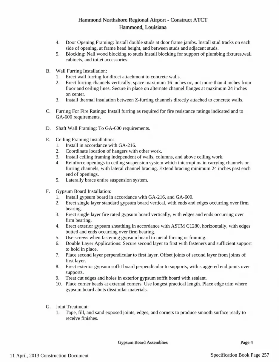
Hammond Northshore Regional Airport - Construct ATCT Hammond, Louisiana
Gypsum Board Assemblies Page 4
4. Door Opening Framing: Install double studs at door frame jambs. Install stud tracks on each side of opening, at frame head height, and between studs and adjacent studs.
5. Blocking: Nail wood blocking to studs Install blocking for support of plumbing fixtures,wall cabinets, and toilet accessories.
B. Wall Furring Installation: 1. Erect wall furring for direct attachment to concrete walls. 2. Erect furring channels vertically; space maximum 16 inches oc, not more than 4 inches from
floor and ceiling lines. Secure in place on alternate channel flanges at maximum 24 inches on center.
3. Install thermal insulation between Z-furring channels directly attached to concrete walls.
C. Furring For Fire Ratings: Install furring as required for fire resistance ratings indicated and to GA-600 requirements.
D. Shaft Wall Framing: To GA-600 requirements.
E. Ceiling Framing Installation: 1. Install in accordance with GA-216. 2. Coordinate location of hangers with other work. 3. Install ceiling framing independent of walls, columns, and above ceiling work. 4. Reinforce openings in ceiling suspension system which interrupt main carrying channels or
furring channels, with lateral channel bracing. Extend bracing minimum 24 inches past each end of openings.
5. Laterally brace entire suspension system.
F. Gypsum Board Installation: 1. Install gypsum board in accordance with GA-216, and GA-600. 2. Erect single layer standard gypsum board vertical, with ends and edges occurring over firm
bearing. 3. Erect single layer fire rated gypsum board vertically, with edges and ends occurring over
firm bearing. 4. Erect exterior gypsum sheathing in accordance with ASTM C1280, horizontally, with edges
butted and ends occurring over firm bearing. 5. Use screws when fastening gypsum board to metal furring or framing. 6. Double Layer Applications: Secure second layer to first with fasteners and sufficient support
to hold in place. 7. Place second layer perpendicular to first layer. Offset joints of second layer from joints of
first layer. 8. Erect exterior gypsum soffit board perpendicular to supports, with staggered end joints over
supports. 9. Treat cut edges and holes in exterior gypsum soffit board with sealant. 10. Place corner beads at external corners. Use longest practical length. Place edge trim where
gypsum board abuts dissimilar materials.
G. Joint Treatment: 1. Tape, fill, and sand exposed joints, edges, and corners to produce smooth surface ready to
receive finishes.
11 April, 2013 Construction Document Specification Book Page 257

Hammond Northshore Regional Airport - Construct ATCT Hammond, Louisiana
Gypsum Board Assemblies Page 5
2. Feather coats on to adjoining surfaces so that camber is maximum 1/32 inch.Texture Finish: Spray apply finish texture coating.
3.3 ERECTION TOLERANCES
A. Maximum Variation of Finished Gypsum Board Surface from Flat Surface:1/8 inch in 10 feet.
3.4 SCHEDULES
Reference contract drawings for finish schedule and
A. Finishes in accordance with GA-214 Level: 1. Level 1: Above finished ceilings concealed from view. 2. Level 4: Walls exposed to view. 3. Level 4: Ceilings exposed to view.
END OF SECTION
11 April, 2013 Construction Document Specification Book Page 258

Hammond Northshore Regional Airport - Construct ATCT Hammond, Louisiana
Portland Cement Stucco Page 1
Section 09 24 23
Portland Cement Stucco PART 1 GENERAL 1.01 SUMMARY
A. Materials and installation of waterproofing/air barrier over sheathing, concrete, and concrete masonry surfaces. Materials and installation of exterior stucco wall covering.
1.03 REFERENCES
A. ASTM Standards:
1. A 641 Standard Specification for Zinc-Coated (Galvanized ) Carbon Steel Wire
2. A 653 Specification for Sheet Steel Zinc coated (Galvanized) by the Hot-Dip Process, Commercial Quality
3. B 69 Specification for Rolled Zinc 4. C 144 Specification for Aggregate for Masonry Mortar 5. C 578 Specification for Preformed, Cellular Polystyrene Thermal
Insulation 6. C 847 Standard Specification for Metal Lath 7. C 897 Standard Specification for Aggregate for Job-Mixed Portland
Cement-Based Plasters 8. C 1032 Standard Specification for Woven Wire Plaster Base 9. C 1063 Standard Specification for Installation of Lathing and Furring for
Portland Cement Plaster 10. C 1177 Specification for Glass Mat Gypsum for Use as Sheathing 11. C 1278 Specification for Fiber-Reinforced Gypsum Panel 12. C 1396 Standard Specification for Gypsum Board 13. D 1784 Specification for Rigid Poly (Vinyl Chloride) (PVC) Compounds
and Chlorinated Poly (Vinyl Chloride) (CPVC) Compounds 14. D 2247 Practice for Testing Water Resistance of Coatings in 100%
Relative Humidity 15. E 84 Test Method for Surface Burning Characteristics of Building
Materials 16. E 119 Method for Fire Tests of Building Construction and Materials 17. E 136 Behavior of Materials in Vertical Tube Furnace at 750˚C 18. E 283 Test Method for Determining the Rate of Air Leakage Through
Exterior Windows, Curtain Walls, and Doors Under Specified Pressure Differences Across the Specimen
19. E 330 Test Method for Structural Performance of Windows, Curtain Walls, and Doors by Uniform Static air Pressure Difference
11 April, 2013 Construction Document Specification Book Page 259

Hammond Northshore Regional Airport - Construct ATCT Hammond, Louisiana
Portland Cement Stucco Page 2
20. E 331 Test Method for Water Penetration of Exterior Windows, Curtain Walls, and Doors by Uniform Static Air Pressure Difference
B. Gypsum Association
1. GA-253 Application of Gypsum Sheathing
C. ICBO ES (International Conference of Building Officials Evaluation Service) 1. AC 11 Acceptance Criteria for Cementatious Exterior Wall Coatings
1.06 SUBMITTALS A. Manufacturer’s specifications, details, installation intstructions and product data. B. Manufacturer’s code compliance report. C. Manufacturer’s standard warranty
D. Prepare and submit project-specific details 1.07 QUALITY ASSURANCE
A. Manufacturer requirements
1. Waterproofing/air barrier and stucco products manufacturer for a minimum of twenty (20) years.
2. Waterproofing/Air barrier and stucco finish products manufactured under ISO 9001:2000 Certified Quality System.
B. Contractor requirements
1. Licensed,insured and engaged in application of portland cement stucco for
a minimum of three (3) years. 2. Knowledgeable in the proper use and handling of specified stucco
materials. 3. Employ skilled mechanics who are experienced and knowledgeable in
waterproofing/air barrier, lathing and furring, portland cement stucco application, and familiar with the requirements of the specified work.
4. Successful completion of minimum of three (3) projects of similar size and complexity to the specified project.
11 April, 2013 Construction Document Specification Book Page 260

Hammond Northshore Regional Airport - Construct ATCT Hammond, Louisiana
Portland Cement Stucco Page 3
5. Provide the proper equipment, manpower and supervision on the job site to install the system in compliance with stucco manufacturer's published instructions and details and the project plans and specifications.
PART 2 PRODUCTS MANUFACTURERS
A. Sto Corp.
Provide waterproofing/air barrier, stucco, primer and finish from single source manufacturer. Substitutions: Section 01 60 00 - Product Requirements
2.01 DESIGN REQUIREMENTS
A. See Structural drawings for design requirements
B. Moisture Control
1. Prevent the accumulation of water into or behind the stucco, either by condensation or leakage into the wall construction, in the design and detailing of the wall assembly. a. Provide corrosion resistant flashing to direct water to the exterior
where it is likely to penetrate components in the wall assembly, including, above window and door heads, beneath window and door sills, at roof/wall intersections, decks, abutments of lower walls with higher walls, above projecting features, and at the base of the wall.
b. Air Leakage Prevention—prevent excess air leakage in the design and detailing of the wall assembly. Provide continuity between air barrier components in the wall assembly. Refer to StoGuard™ Air Barrier and Moisture Control Handbook.
c. Vapor Diffusion and Condensation—perform a dew point analysis of the wall assembly to determine the potential for accumulation of moisture in the wall assembly as a result of water vapor diffusion and condensation. Adjust insulation thickness and/or other wall assembly components accordingly to minimize the risk of condensation. Avoid the use of vapor retarders on the interior side of the wall in warm, humid climates.
d. On framed wall construction provide StoGuard™ Waterproofing/Air Barrier over sheathing. Note: Building codes vary with respect to the type of moisture barrier required and the number of layers. (see note below)
e. Protect sills of rough openings with barrier membrane. Where casing bead is used back-to-back at wxpansion joints, back joints with barrier membrane. Refer to Sto details.
11 April, 2013 Construction Document Specification Book Page 261

Hammond Northshore Regional Airport - Construct ATCT Hammond, Louisiana
Portland Cement Stucco Page 4
C. Joints
1. Provide two piece expansion joints in the stucco system where building movement is anticipated: at joints in the substrate or supporting construction, where the system is to be installed over dissimilar construction or substrates, at changes in building height, at floor lines, at columns and cantilevered areas.
2. Provide one piece expansion/control joints every 144 ft2 . Do not exceed length to width ratio of 2-1/2:1 in expansion joint layout and do not exceed more than 18 feet in any direction without an expansion joint. Cut and wire tie lath to the expansion/control joint accessory so lath is discontinuous beneath the accessory. At expansion joints, back the joint with barrier membrane. Refer to details by manufacturer.
3. Provide appropriate accessories at stucco terminations and joints. 4. Provide appropriate sealant at stucco terminations. 5. Indicate location of joints, accessories and accessory type on architectural
drawings.
D. Stucco Thickness: General
1. Application to Metal Plaster Bases: a. Woven wire fabric lath: stucco thickness shall be ½ inch (13 mm)
applied in one or two coats b. Galvanized diamond mesh metal lath:
i. Minimum 1.75 lb/yd2 : stucco thickness shall be ½ inch (13 mm) applied in one or two coats.
ii. Minimum 2.5 lb/yd2 : stucco thickness shall be ½ to ⅞ inch . ½ inch thickness shall be applied in one or two coats. Thicknesses in excess of ½ inch up to ⅞ inch shall be applied in two coats.
2. Thickness shall be uniform throughout the wall area.
2.02 PERFORMANCE REQUIREMENTS
A. StoGuard™ Waterproofing/Air Barrier
TEST METHOD CRITERIA RESULTS
1. Aging/Water Penetration Resistance
AATCC 127 and ICC ES AC 212 (Water Column)
Resist 21.6 in (55 cm) water for 5 hours before and after aging
No water penetration before and after aging
2. Water Resistance Testing
ASTM D 2247
Absence of deleterious effects after 14 day exposure
No deleterious effects after 14 day exposure
11 April, 2013 Construction Document Specification Book Page 262

Hammond Northshore Regional Airport - Construct ATCT Hammond, Louisiana
Portland Cement Stucco Page 5
TEST METHOD CRITERIA RESULTS
3. Water Vapor Transmission
ASTM E 96 Method B (Water Method)
Measure
Sto Gold Fill®: 17.3 perms [994 ng/(Pa·s·m2)] Sto Emerald Coat™: 13.4 perms [769 ng/(Pa·s·m2)]
4. Air Leakage: Sto Gold Fill
ASTM E 283 (CCMC Technical Guide Method)
< 0.003 ft3/min·ft2 @ 1.56psf (< 0.02 L/s·m2 @ 75 Pa)
< 0.0002 ft3/min·ft2 (< 0.0014 L/s·m2)
5. Tensile Adhesion ASTM D 4541
>15 psi (103 kPa)
Gypsum (ASTM C 79): 16.5 psi (114 kPa) Gypsum (ASTM C 1177): > 15.8 psi (109 kPa) Exposure 1 OSB: 62.6 psi (432 kPa) Exterior Plywood: 91.0 psi (627 kPa)
6. Surface Burning ASTM E 84 Flame Spread: <25 Smoke Developed: <450
Flame Spread: <25 Smoke Developed: <450 NFPA or ICC Class A building material
B. StoPowerwall® Stucco
TEST METHOD CRITERIA RESULT
1. Accelerated Weathering
ASTM G 155 2000 hours No chalking, cracking, checking, crazing, or erosion
2. Freeze-Thaw ICBO AC 11 10 cycles No cracking, checking or crazing
3. Surface Burning ASTM E 84
Flame spread of less than 25,
Smoke Developed of less than 450
Flame Spread: < 5
Smoke Developed: < 10
NFPA or ICC Class A building material
4. Fire Resistance ASTM E 119 One hour fire resistive rating
Pass, refer to
ICC-ES ESR 2323 for listed assemblies.
5. Combustibility ASTM E 136 Noncombustible Material Pass
6. Wind Loads ASTM E 330 Allowable design pressure
Pass, refer to
ICC-ES ESR 2323 for listed assemblies.
2.03 WATERPROOFING/AIR BARRIER
A. StoGuard™-- fluid applied waterproofing/air barrier for sheathing substrates consisting of three components: Emerald Coat, StoGuard Fabric and StoGuard RediCorner)
11 April, 2013 Construction Document Specification Book Page 263
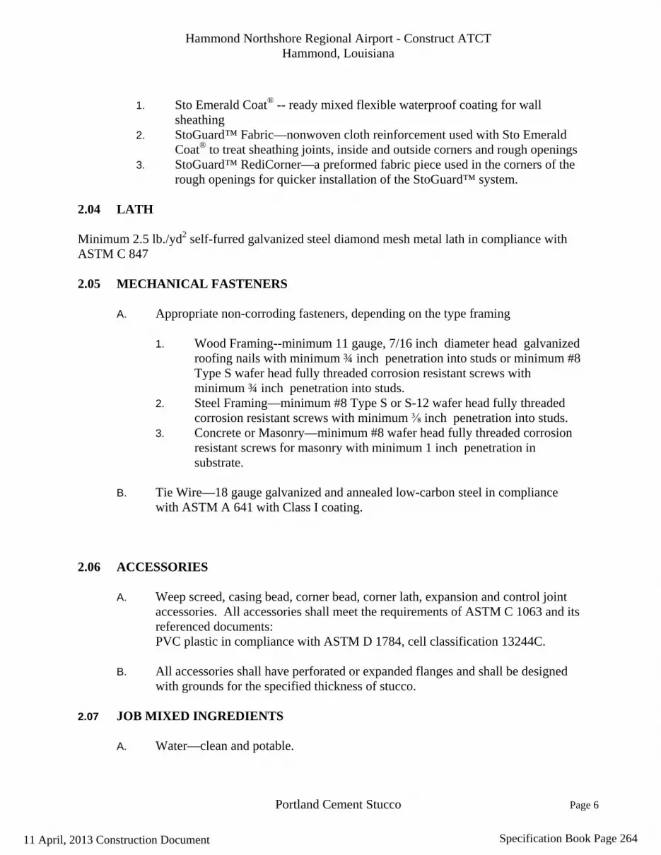
Hammond Northshore Regional Airport - Construct ATCT Hammond, Louisiana
Portland Cement Stucco Page 6
1. Sto Emerald Coat® -- ready mixed flexible waterproof coating for wall
sheathing 2. StoGuard™ Fabric—nonwoven cloth reinforcement used with Sto Emerald
Coat® to treat sheathing joints, inside and outside corners and rough openings 3. StoGuard™ RediCorner—a preformed fabric piece used in the corners of the
rough openings for quicker installation of the StoGuard™ system. 2.04 LATH Minimum 2.5 lb./yd2 self-furred galvanized steel diamond mesh metal lath in compliance with ASTM C 847
2.05 MECHANICAL FASTENERS
A. Appropriate non-corroding fasteners, depending on the type framing
1. Wood Framing--minimum 11 gauge, 7/16 inch diameter head galvanized roofing nails with minimum ¾ inch penetration into studs or minimum #8 Type S wafer head fully threaded corrosion resistant screws with minimum ¾ inch penetration into studs.
2. Steel Framing—minimum #8 Type S or S-12 wafer head fully threaded corrosion resistant screws with minimum ⅜ inch penetration into studs.
3. Concrete or Masonry—minimum #8 wafer head fully threaded corrosion resistant screws for masonry with minimum 1 inch penetration in substrate.
B. Tie Wire—18 gauge galvanized and annealed low-carbon steel in compliance
with ASTM A 641 with Class I coating. 2.06 ACCESSORIES
A. Weep screed, casing bead, corner bead, corner lath, expansion and control joint accessories. All accessories shall meet the requirements of ASTM C 1063 and its referenced documents: PVC plastic in compliance with ASTM D 1784, cell classification 13244C.
B. All accessories shall have perforated or expanded flanges and shall be designed
with grounds for the specified thickness of stucco. 2.07 JOB MIXED INGREDIENTS
A. Water—clean and potable.
11 April, 2013 Construction Document Specification Book Page 264
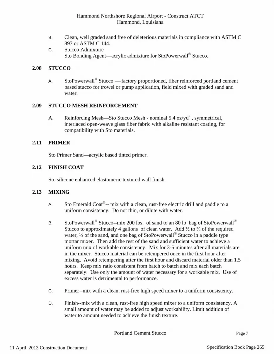
Hammond Northshore Regional Airport - Construct ATCT Hammond, Louisiana
Portland Cement Stucco Page 7
B. Clean, well graded sand free of deleterious materials in compliance with ASTM C 897 or ASTM C 144.
C. Stucco Admixture Sto Bonding Agent—acrylic admixture for StoPowerwall® Stucco.
2.08 STUCCO
A. StoPowerwall® Stucco factory proportioned, fiber reinforced portland cement based stucco for trowel or pump application, field mixed with graded sand and water.
2.09 STUCCO MESH REINFORCEMENT
A. Reinforcing Mesh—Sto Stucco Mesh - nominal 5.4 oz/yd2 , symmetrical, interlaced open-weave glass fiber fabric with alkaline resistant coating, for compatibility with Sto materials.
2.11 PRIMER
Sto Primer Sand—acrylic based tinted primer. 2.12 FINISH COAT
Sto silicone enhanced elastomeric textured wall finish. 2.13 MIXING
A. Sto Emerald Coat®-- mix with a clean, rust-free electric drill and paddle to a
uniform consistency. Do not thin, or dilute with water.
B. StoPowerwall® Stucco--mix 200 lbs. of sand to an 80 lb bag of StoPowerwall® Stucco to approximately 4 gallons of clean water. Add ½ to ⅔ of the required water, ½ of the sand, and one bag of StoPowerwall® Stucco in a paddle type mortar mixer. Then add the rest of the sand and sufficient water to achieve a uniform mix of workable consistency. Mix for 3-5 minutes after all materials are in the mixer. Stucco material can be retempered once in the first hour after mixing. Avoid retempering after the first hour and discard material older than 1.5 hours. Keep mix ratio consistent from batch to batch and mix each batch separately. Use only the amount of water necessary for a workable mix. Use of excess water is detrimental to performance.
C. Primer--mix with a clean, rust-free high speed mixer to a uniform consistency.
D. Finish--mix with a clean, rust-free high speed mixer to a uniform consistency. A
small amount of water may be added to adjust workability. Limit addition of water to amount needed to achieve the finish texture.
11 April, 2013 Construction Document Specification Book Page 265

Hammond Northshore Regional Airport - Construct ATCT Hammond, Louisiana
Portland Cement Stucco Page 8
E. Mix only as much material as can readily be used.
F. Do not use anti-freeze compounds or other additives.
PART 3 EXECUTION 3.01 EXAMINATION
A. Inspect surfaces for: 1. Contaminationalgae, chalkiness, dirt, dust, efflorescence, form oil,
fungus, grease, laitance, mildew or other foreign substances. 2. Surface absorption and chalkiness. 3. Cracksmeasure crack width and record location of cracks. 4. Damage and deterioration. 5. Moisture damage–-record any areas of moisture damage.
B. Inspect sheathing application for compliance with applicable requirement:
1. Glass Mat Faced or Fiber-Reinforced Gypsum Sheathing—refer to
manufacturer’s instructions.
3.02 DELIVERY, STORAGE AND HANDLING
A. Deliver all materials in their original sealed containers bearing manufacturer's name and identification of product.
B. Protect coatings (pail products) from freezing and temperatures in excess of 90F
(32 C). Store away from direct sunlight.
C. Protect portland cement based materials (bag products) from moisture and humidity. Store under cover off the ground in a cool, dry location.
3.03 PROJECT/SITE CONDITIONS
A. Maintain ambient and surface temperatures above 40F (4C) during application and drying period of waterproofing/air barrier. Maintain ambient and surface temperatures above 40F (4C) during application and for 24 hours after set of stucco.
B. Provide supplementary heat for installation in temperatures less than 40F (4C)
such that temperatures are maintained as in 1.09A. Prevent concentration of heat on uncured stucco and vent fumes and other products of combustion to the outside to prevent contact with stucco.
11 April, 2013 Construction Document Specification Book Page 266

Hammond Northshore Regional Airport - Construct ATCT Hammond, Louisiana
Portland Cement Stucco Page 9
C. Prevent uneven or excessive evaporation of moisture from stucco during hot, dry or windy weather. For installation under any of these conditions provide special measures to properly moist cure the stucco.
D. Provide protection of surrounding areas and adjacent surfaces from application of
materials. 3.04 COORDINATION/SCHEDULING
A. Protect sheathing from climatic conditions to prevent weather damage until the installation of the waterproofing/air barrier.Provide protection of the waterproofing/air barrier installation with stucco no later than 60 days after installation.
B. Provide minimum 28 day cure of concrete and concrete masonry units before the
installation of stucco.
C. For load bearing concrete masonry and stud wall assemblies, commence the stucco installation after completion of all floor, roof construction and other construction that imposes dead loads on the walls to prevent excessive deflection and potential cracking of the stucco.
D. Sequence interior work such as drywall installation prior to stucco installation to
prevent stud distortion and potential cracking of the stucco.
E. Provide site grading such that the stucco terminates above earth grade minimum 4 inches and above finished grade (pavers/sidewalk) minimum 2 inches . Provide increased clearance in freeze/thaw climate zones.
F. Install diverter flashings wherever water can enter the wall assembly to direct water to the exterior.
G. Install copings and sealant immediately after installation of the stucco and when
finish coatings are dry.
H. Attach penetrations through stucco to structural support and provide water tight seal at penetrations.
3.05 SURFACE PREPARATION
A. Remove surface contaminants and replace damaged sheathing. B. All sheathing must be handled and installed in compliance with applicable code
and/or manufacturer requirements. Installed sheathing must be clean, dry and free
11 April, 2013 Construction Document Specification Book Page 267

Hammond Northshore Regional Airport - Construct ATCT Hammond, Louisiana
Portland Cement Stucco Page 10
from damage, frost, and all bond-inhibiting materials. Gap sheathing (if required) maximum 1/8 inch at joints. Should gaps exceed ⅛ inch up to ¼ inch wide, apply low expanding urethane foam into joints and rasp or shave flush with sheathing surface in preparation for installation of StoGuard™.
C. Spot surface defects in sheathing with joint treatment (Sto Gold Fill® or additional
layer Sto Emerald Coat®). 3.06 WATERPROOFING/AIR BARRIER INSTALLATION
The following instructions are applicable to: Glass Mat Faced Gypsum Sheathing in compliance with ASTM C 1177 Fiber Reinforced Gypsum Sheathing in compliance with ASTM C 1278 Concrete or Masonry surfaces
A. Reinforcement Options:
Sto Guard® Fabric: Liberally apply Sto Emerald Coat® (approximately 15 mils) over sheathing joint approximately 4 inches wide by spray, roller, or brush. Apply 4 inch StoGuard™ Fabric centered over the joint, then reapply a second coat of Sto Emerald Coat® to completely embed the fabric in Sto Emerald Coat®. Check for pinholes and thin spots. Correct with additional Sto Emerald Coat®. Follow same procedure for 6 inch StoGuard™ Fabric and StoGuard™ RediCorner used at rough openings. Refer to Sto detail 20.09E. Protect from rain and freezing until dry.
B. Surface Defects and Fasteners in Sheathing: 1. Spot surface defects such as knots and checks in plywood sheathing with
Sto Gold Fill® . 2. Spot fasteners with Sto Emerald Coat® or Sto Gold Fill®. Protect from
rain and freezing until dry.
C. Sheathing Surface Waterproofing: 1. Apply Sto Emerald Coat® by spray or roller over sheathing surface,
including the dry joint treatment, to a uniform wet mil thickness of 10 mils in one coat. Use ½ inch nap roller for plywood, gypsum sheathing, and fiber reinforced gypsum sheathing. Use ¾ inch nap roller for OSB and glass mat faced gypsum sheathing. Protect from rain and freezing until dry. Note: Back rolling is not required for spray applications over sheathing. OSB sheathing may require touch-up with a second coat of Sto Emerald Coat® where wood strands are raised from the surface. Inspect surface after initial application of Sto Emerald Coat® and touch-up as needed.
2. Coordinate installation of connecting waterproofing/air barrier components, for example at expansion joints, penetrations, openings,
11 April, 2013 Construction Document Specification Book Page 268

Hammond Northshore Regional Airport - Construct ATCT Hammond, Louisiana
Portland Cement Stucco Page 11
foundation, and roof, with other trades to provide a continuous air tight membrane and moisture protection.
3. Coordinate installation of flashing and other moisture protection components with other trades to achieve complete moisture protection such that water is directed to the exterior, not into the wall assembly, and drained to the exterior at sources of leaks (windows, doors and similar penetrations through the wall assembly).
4. Note that some flashing components such as window or door head flashing, roof sidewall step flashing, and weep screeds at the base of the wall, require a splice strip of reinforcing mesh, joint treatment and waterproofing. This creates a “shingle lap” and proper shedding of water onto the face of the flashing, not behind the flashing (refer to Sto details 5.09E and 5.23bE).
D. Concrete or Masonry Surface Waterproofing:
1. Repair cracks in masonry or concrete surfaces up to 1/8 inch with Sto Gold Fill. For cracks larger than 1/8 inch , up to ¼ inch , fill with a paintable latex caulk , tool flush and allow to dry. Apply Sto Emerald Coat® by spray or roller over concrete or masonry surface to a uniform wet mil thickness of 10 to 30 mils in one coat depending on surface conditions. Apply second coat of 10 to 30 wet mil thickness to achieve a pin hole void free surface. If Sto Emerald Coat® is to be applied using spray equipment, backrolling of each coat will be necessary. Sto Emerald Coat® may also be applied using a paint roller with a nap thickness of ¾ inch .
2. Coordinate installation of connecting waterproofing/air barrier components, for example at expansion joints, penetrations, openings, foundation, and roof, with other trades to provide a continuous air tight membrane and moisture protection.
3.06 STUCCO INSTALLATION
A. Weep Screed Installation
1. Install foundation weep screed at the base of the wall securely to framing with the appropriate fastener. Attach to sill plate at no more than 7 inches on center. Locate foundation weep screed so that it overlaps the joint between the foundation and framing by a minimum of 1inch . Locate the nosing of the foundation weep screed minimum 4 inches above earth grade, 2 inches above finished grade (paved surfaces, for example).
2. Apply waterproofing/air barrier over foundation weep screed attachment flange. Refer to Sto Detail 5.09E.
B. Casing Bead and Expansion Joint Installation
1. Install casing beads at stucco terminations—doors, windows and other through wall penetrations. Install two piece expansion joints (or back-to-
11 April, 2013 Construction Document Specification Book Page 269

Hammond Northshore Regional Airport - Construct ATCT Hammond, Louisiana
Portland Cement Stucco Page 12
back casing beads) at building expansion joints, where the stucco is to be installed over dissimilar construction or substrates, at changes in building height, at floor lines, columns, and cantilevered areas. Install full accessory pieces where possible and avoid small pieces. Seal adjoining pieces by embedding ends in sealant. Abut horizontal into vertical joint accessories. Attach at no more than 7 inches into framing with appropriate fasteners.
C. Lath Installation
1. Diamond Mesh Metal Lath a. General--install metal lath with the long dimension at right angles to
structural framing (horizontally on concrete or masonry substrates). Terminate lath at expansion joints. Do no install continuously across joints.
b. Seams/Overlaps--overlap side seams minimum ½ inch and end seams minimum 1 inch . Stagger end seams. Overlap casing beads and two piece expansion joints minimum 1 inch over narrow wing accessories, minimum 2 inches over expanded flange accessories. Do not install lath continuously beneath expansion joints.
c. Attachment--fasten securely through sheathing into structural framing at 7 inches on center maximum vertically and 16 inches on center horizontally*. Wire tie at no more than 9 inches on center at: side laps, accessory overlaps, and where end laps occur between supports.
2. Woven wire fabric lath--follow installation as for metal lath except overlap all seams by one mesh minimum.
3. Paper-backed lath--follow installation as for metal lath. Lap lath over lath, not paper to lath overlap. For horizontal overlaps the paper backing must lap shingle style behind the lath to lath overlap.
D. One Piece Expansion/Control Joint Installation (installed after lath installation)
Cut lath in a straight line with shears at expansion/control joint location. Do not cut into or damage moisture barrier. Install one piece expansion/control joints over lath at through wall penetrations, for example, above and below doors or windows (unless another type of expansion joint is already provided at these locations). Install one piece expansion/control joints over lath every 144 ft2 . Wire tie one piece expansion/control joints to cut lath at no more than 7 inches on center. Make certain lath is discontinuous beneath joints. Do not exceed length to width ratio of 2 ½:1 in expansion/control joint layout and do not exceed more than 18 feet in any direction without an expansion/control joint.
E. Inside and Outside Corners Bend lath at inside corners and extend minimum 24 inches past corner. Attach through lath into framing at no more than 7 inches on center with appropriate fasteners. Alternatively, butt lath at corners and attach corner lath at no more than 7 inches on center into framing with appropriate fasteners. Install corner bead at
11 April, 2013 Construction Document Specification Book Page 270

Hammond Northshore Regional Airport - Construct ATCT Hammond, Louisiana
Portland Cement Stucco Page 13
outside corners over lath. Attach at no more than 7 inches on center intro framing with appropriate fasteners.
F. Stucco Installation
1. Scratch Coat: apply stucco with sufficient pressure to key into and embed the metal lath. Apply sufficient material, 3/8 - 1/2 inch , to cover the metal lath and to permit scoring the surface. Score the stucco upon completion of each panel in preparation for a second coat. Score horizontally.
2. Brown Coat: as soon as the first coat is firm enough to receive the second coat without damage, apply the second coat. Alternatively, moist cure the first coat up to 48 hours and dampen the scratched surface with water immediately before applying the second coat. Apply the second coat with sufficient pressure to ensure intimate contact with the first coat and as needed to bring the stucco to a uniform thickness that matches the grounds of the accessories.
3. Embed Sto Stucco Mesh into the wet brown coat. Trowel from the center to the edges of the mesh to avoid wrinkles and remove excess brown coat material. Overlap mesh seams minimum 3 inches .
4. Use a rod or straight edge to bring the surface to a true, even plane. Fill depressions in plane with stucco. Final thickness of stucco shall be minimum ½ inch , maximum ⅞ inch as required by project conditions and specifications. Stucco shall be uniform in thickness throughout the wall area.
5. After the stucco has become slightly firm float the surface lightly with a darby or wood float to densify the surface and to provide a smooth, even surface.
6. Moist cure after the stucco has set by lightly fogging for at least 48 hours. Fog as frequently as required during the 48 hour period to prevent loss of moisture from the stucco. Avoid eroding the stucco surface with excess moisture. If relative humidity exceeds 75% the frequency of moist curing can be diminished.
H. Primer Installation
1. Sto Hot Prime—Moist cure stucco for a minimum of 48 hours. Apply primer evenly with brush, roller or proper spray equipment over the clean, dry stucco and foam build-outs, and allow to dry before applying finish.
2. Sto Primer Sand—Moist cure stucco for a minimum of 48 hours. Wait until stucco is 28 days old or the pH level of the surface is below 10 before applying primer and allow to dry before applying finish.
I. Finish Installation
Apply finish to primed stucco and foam build-outs when dry. Apply finish by spraying or troweling with a stainless steel trowel, depending on the finish specified. Follow these general rules for application of finish:
a. Avoid application in direct sunlight.
11 April, 2013 Construction Document Specification Book Page 271

Hammond Northshore Regional Airport - Construct ATCT Hammond, Louisiana
Portland Cement Stucco Page 14
b. Apply finish in a continuous application, and work a wet edge towards the unfinished wall area. Work to an architectural break in the wall before stopping to avoid cold joints.
c. Weather conditions affect application and drying time. Hot or dry conditions limit working time and accelerate drying. Adjustments in the scheduling of work may be required to achieve desired results; cool or damp conditions extend working time and retard drying and may require added measures of protection against wind, dust, dirt, rain and freezing. Adjust work schedule and provide protection.
d. Float "R" (rilled texture) finishes with a plastic float to achieve their rilled texture.
e. Do not install separate batches of finish side-by-side. f. Do not apply finish into or over joints or accessories. Apply finish to
outside face of wall only. g. Do not apply finish over irregular or unprepared surfaces, or surfaces
not in compliance with the requirements of the project specifications. 3.07 PROTECTION
A. Provide protection of installed materials from water infiltration into or behind them.
B. Provide protection of installed stucco from dust, dirt, precipitation, and freezing.
C. Provide protection of installed primer and finish from dust, dirt, precipitation,
freezing and continuous high humidity until fully dry.
11 April, 2013 Construction Document Specification Book Page 272

Hammond Northshore Regional Airport - Construct ATCT Hammond, Louisiana
Painting And Coating Page 1
SECTION 09 90 00
PAINTING AND COATING
PART 1 GENERAL
1.1 SUMMARY
A. Section includes surface preparation and field application of paints, stains, varnishes, and other coatings.
B. Related Sections: 1. Section 05 50 00 - Metal Fabrications: Shop primed items. 2. Section 05 51 00 - Metal Stairs: Shop primed items. 3. Section 09 96 00 - High-Performance Coatings. 4. Section 22 05 53 - Identification for Plumbing Piping and Equipment.
1.2 REFERENCES
A. ASTM International: 1. ASTM D16 - Standard Terminology for Paint, Related Coatings, Materials, and
Applications. 2. ASTM D4442 - Standard Test Methods for Direct Moisture Content Measurement of Wood
and Wood-Base Materials. 3. ASTM E84 - Standard Test Method for Surface Burning Characteristics of Building
Materials.
B. Painting and Decorating Contractors of America: 1. PDCA - Architectural Painting Specification Manual.
C. SSPC: The Society for Protective Coatings: 1. SSPC - Steel Structures Painting Manual.
1.3 DEFINITIONS
A. Conform to ASTM D16 for interpretation of terms used in this section.
1.4 SUBMITTALS
A. Samples: Submit two paper chip samples, illustrating range of colors available for each surface finishing product scheduled to Owner for approval.
B. Manufacturer's Installation Instructions: Submit special surface preparation procedures, substrate conditions requiring special attention.
C. Product Data: Submit product data for paint P1 through P6. The submittal shall be labeled and keyed for each paint as shown on the drawings and specifications.
11 April, 2013 Construction Document Specification Book Page 273

Hammond Northshore Regional Airport - Construct ATCT Hammond, Louisiana
Painting And Coating Page 2
1.5 CLOSEOUT SUBMITTALS
A. Operation and Maintenance Data: Submit data on cleaning, touch-up, and repair of painted and coated surfaces.
1.6 QUALITY ASSURANCE
A. Surface Burning Characteristics: Fire Retardant Finishes: Maximum 25/450 flame spread/smoke developed index when tested in accordance with ASTM E84.
1.7 QUALIFICATIONS
A. Applicator: Company specializing in performing work of this section with minimum 5 years documented experience approved by manufacturer.
1.8 PRE-INSTALLATION MEETINGS
A. Convene minimum one week prior to commencing work of this section.
1.9 DELIVERY, STORAGE, AND HANDLING
A. Deliver products to site in sealed and labeled containers; inspect to verify acceptability.
B. Container Label: Include manufacturer's name, type of paint, brand name, lot number, brand code, coverage, surface preparation, drying time, cleanup requirements, color designation, and instructions for mixing and reducing.
C. Paint Materials: Store at minimum ambient temperature of 45 degrees F and maximum of 90 degrees F, in ventilated area, and as required by manufacturer's instructions.
1.10 ENVIRONMENTAL REQUIREMENTS
A. Do not apply materials when surface and ambient temperatures are outside temperature ranges required by paint product manufacturer.
B. Do not apply exterior coatings during rain or snow when relative humidity is outside humidity ranges, or moisture content of surfaces exceed those required by paint product manufacturer.
C. Minimum Application Temperatures for Latex Paints: 45 degrees F for interiors; 50 degrees F for exterior; unless required otherwise by manufacturer's instructions.
1.11 EXTRA MATERIALS
A. Supply 1 gallon of each color, and surface texture; store where directed.
B. Label each container with color, type, texture, room locations, and in addition to manufacturer's label.
11 April, 2013 Construction Document Specification Book Page 274

Hammond Northshore Regional Airport - Construct ATCT Hammond, Louisiana
Painting And Coating Page 3
PART 2 PRODUCTS
2.1 PAINTS AND COATINGS
A. See specifications on Drawing.
2.2 COMPONENTS
A. Coatings: Ready mixed, except field catalyzed coatings. Prepare coatings: 1. To soft paste consistency, capable of being readily and uniformly dispersed to homogeneous
coating. 2. For good flow and brushing properties. 3. Capable of drying or curing free of streaks or sags.
PART 3 EXECUTION
3.1 EXAMINATION
A. Verify substrate conditions are ready to receive Work as instructed by product manufacturer.
B. Examine surfaces scheduled to be finished prior to commencement of work. Report conditions capable of affecting proper application.
C. Test shop applied primer for compatibility with subsequent cover materials.
D. Measure moisture content of surfaces using electronic moisture meter. Do not apply finishes unless moisture content of surfaces are below the following maximums: 1. Gypsum Wallboard: 12 percent. 2. Concrete walls: 12 percent. 3. Interior Wood: 15 percent, measured in accordance with ASTM D4442. 4. Exterior Wood: 15 percent, measured in accordance with ASTM D4442. 5. Concrete Floors: 8 percent.
3.2 PREPARATION
A. Surface Appurtenances: Remove or mask electrical plates, hardware, light fixture trim, escutcheons, and fittings prior to preparing surfaces or finishing.
B. Surfaces: Correct defects and clean surfaces capable of affecting work of this section.
C. Marks: Seal with shellac those which may bleed through surface finishes.
D. Impervious Surfaces: Remove mildew by scrubbing with solution of tetra-sodium or tri-sodium phosphate and bleach. Rinse with clean water and allow surface to dry.
E. Aluminum Surfaces Scheduled for Paint Finish: Remove surface contamination by steam or high pressure water. Remove oxidation with acid etch and solvent washing. Apply etching primer immediately following cleaning.
11 April, 2013 Construction Document Specification Book Page 275

Hammond Northshore Regional Airport - Construct ATCT Hammond, Louisiana
Painting And Coating Page 4
F. Asphalt, Creosote, or Bituminous Surfaces Scheduled for Paint Finish: Remove foreign particles to permit adhesion of finishing materials. Apply latex based compatible sealer or primer.
G. Insulated Coverings: Remove dirt, grease, and oil from canvas and cotton.
H. Concrete Floors: Remove contamination, acid etch, and rinse floors with clear water. Verify required acid-alkali balance is achieved. Allow to dry.
I. Copper Surfaces Scheduled for Paint Finish: Remove contamination by steam, high pressure water, or solvent washing. Apply vinyl etch primer immediately following cleaning.
J. Copper Surfaces Scheduled for Natural Oxidized Finish: Remove contamination by applying oxidizing solution of copper acetate and ammonium chloride in acetic acid. Rub on repeatedly for required effect. Once attained, rinse surfaces with clear water and allow to dry.
K. Gypsum Board Surfaces: Fill minor defects with filler compound. Spot prime defects after repair.
L. Galvanized Surfaces: Remove surface contamination and oils and wash with solvent. Apply coat of etching primer.
M. Concrete and Unit Masonry Surfaces Scheduled to Receive Paint Finish: Remove dirt, loose mortar, scale, salt or alkali powder, and other foreign matter. Remove oil and grease with solution of tri-sodium phosphate; rinse well and allow to dry. Remove stains caused by weathering of corroding metals with solution of sodium metasilicate after thoroughly wetting with water. Allow to dry.
N. Uncoated Steel and Iron Surfaces: Remove grease, mill scale, weld splatter, dirt, and rust. Where heavy coatings of scale are evident, remove by power tool wire brushing or sandblasting; clean by washing with solvent. Apply treatment of phosphoric acid solution, ensuring weld joints, bolts, and nuts are similarly cleaned. Spot prime paint after repairs. Obtain primer from steel fabricator to match color.
O. Shop Primed Steel Surfaces: Sand and scrape to remove loose primer and rust. Feather edges to make touch-up patches inconspicuous. Clean surfaces with solvent. Prime bare steel surfaces. Spot prime paint after repairs. Obtain primer from steel fabricator to match color.
P. Interior Wood Items Scheduled to Receive Transparent Finish: Wipe off dust and grit prior to sealing, seal knots, pitch streaks, and sappy sections with sealer. Fill nail holes and cracks after sealer has dried; sand lightly between coats.
Q. Metal Doors Scheduled for Painting: Prime metal door top and bottom edge surfaces.
3.3 APPLICATION
A. Do not apply finishes to surfaces that are not dry. Allow applied coats to dry before next coat is applied.
B. Apply each coat to uniform appearance. Apply each coat of paint slightly darker than preceding coat unless specified otherwise.
11 April, 2013 Construction Document Specification Book Page 276

Hammond Northshore Regional Airport - Construct ATCT Hammond, Louisiana
Painting And Coating Page 5
C. Sand metal surfaces lightly between coats to achieve required finish.
D. Vacuum clean surfaces of loose particles. Use tack cloth to remove dust and particles just prior to applying next coat.
E. Where clear finishes are required, tint fillers to match wood. Work fillers into grain before set. Wipe excess from surface.
F. Prime concealed surfaces of interior wood surfaces scheduled to receive stain or varnish finish with gloss varnish reduced 25 percent with thinner.
G. Finishing Mechanical And Electrical Equipment: 1. Prime and paint fire water piping, valves, hangers, brackets, collars and supports red color. 2. Paint both sides and edges of plywood backboards for electrical and telephone equipment
before installing equipment.
3.4 FIELD QUALITY CONTROL
A. Inspect and test questionable coated areas.
3.5 CLEANING
A. Collect waste material which may constitute fire hazard, place in closed metal containers, and remove daily from site.
3.6 SCHEDULE - SHOP PRIMED ITEMS FOR SITE FINISHING
A. Metal Fabrications (Section 05 50 00): elevator pit ladders.
B. Metal Stairs (Section 05 51 00): Exposed surfaces of stringers, exposed vertical risers.
3.7 SCHEDULE - COLORS 1. See Drawing for colors.
END OF SECTION
11 April, 2013 Construction Document Specification Book Page 277

11 April, 2013 Construction Document Specification Book Page 278

11 April, 2013 Construction Document Specification Book Page 279

11 April, 2013 Construction Document Specification Book Page 280

11 April, 2013 Construction Document Specification Book Page 281

11 April, 2013 Construction Document Specification Book Page 282

Hammond Northshore Regional Airport - Construct ATCT Hammond, Louisiana
Signage Page 1
SECTION 10 14 00
SIGNAGE
PART 1 GENERAL
1.1 SUMMARY
A. Section includes interior signs.
1.2 SUBMITTALS
A. Section 01 33 00 - Submittal Procedures: Submittal procedures.
B. Shop Drawings: Indicate sign styles, lettering font, foreground and background colors, locations, overall dimensions of each sign.
1.3 QUALITY ASSURANCE
A. Perform Work in accordance with the International Building Code, 2006.
1.4 QUALIFICATIONS
A. Manufacturer: Company specializing in manufacturing Products specified in this section with minimum three years’ experience.
1.5 DELIVERY, STORAGE, AND HANDLING
A. Package signs, labeled in name groups.
B. Store adhesive attachment tape at ambient room temperatures.
1.6 ENVIRONMENTAL REQUIREMENTS
A. Do not install signs when ambient temperature is lower than recommended by manufacturer.
B. Maintain this minimum temperature during and after installation of signs.
PART 2 PRODUCTS
2.1 INTERIOR SIGNS
A. Manufacturers: TACTILE SIGNS INC
B. Substitutions: Section 01 60 00 - Product Requirement Product Description And Size: See drawings.
11 April, 2013 Construction Document Specification Book Page 283

Hammond Northshore Regional Airport - Construct ATCT Hammond, Louisiana
Signage Page 2
2.2 COMPONENTS
A. Injection Molded Signs: Acrylic plastic: 1. Sign Color: Color as selected. 2. Character Color: Contrasting color as selected. 3. Perimeter border Thickness: 3/8 inch. 4. Edges: ½” radius 5. Letters 1 inches high.
2.3 ACCESSORIES
A. Tape Adhesive: Double sided tape, permanent adhesive.
PART 3 EXECUTION
3.1 EXAMINATION
3.2 INSTALLATION
A. Install signs after surfaces are finished, in locations indicated on Drawings, in accordance with the Manufacturers written instructions and the International Building Code, Americans with Disability Act, Accessibility Standards and the State of Louisiana.
END OF SECTION
11 April, 2013 Construction Document Specification Book Page 284

Hammond Northshore Regional Airport - Construct ATCT Hammond, Louisiana
HYDRAULIC ELEVATORS - PASSENGER 14240
Page 1
SECTION 14240 HYDRAULIC ELEVATORS PART 1 GENERAL 1.01 SUMMARY A. Section includes: Hydraulic passenger elevators as shown and specified. Elevator work includes: 1. Standard pre-engineered hydraulic passenger elevators. 2. Elevator car enclosures, hoist way entrances and signal equipment. 3. Jack(s). 4. Operation and control systems. 5. Accessibility provisions for physically disabled persons. 6. Equipment, machines, controls, systems and devices as required for safely operating the specified
elevators at their rated speed and capacity. 7. Materials and accessories as required to complete the elevator installation.
B. General contractor shall provide the following in accordance with the requirements of the International Building Code, 2009, Life Safety Code 101, Section 9.4 and ANSI A17.1 Code. For specific rules, refer to ANSI A17.1, Section 300 for hydraulic elevators. State or local requirements must be used if more stringent.
1. Elevator hoist beam to be provided at top of elevator shaft. Beam must be able to accommodate
proper loads and clearances for elevator installation and operation. 2. Supply in ample time for installation by other trades, inserts, anchors, bearing plates, brackets,
supports and bracing including all setting templates and diagrams for placement. 3. Hatch walls require a minimum two hours of fire rating. Hoist way should be clear and plumb
with variations not to exceed 1/2'' at any point. 4. Elevator hoist ways shall have barricades, as required. 5. Install bevel guards at 75° on all recesses, projections or setbacks over 2'' (4'' for A17.1 2000
areas) except for loading or unloading. 6. Provide rail bracket supports at pit, each floor and roof. For guide rail bracket supports, provide
divider beams between hoist way at each floor and roof. 7. Pit floor shall be level and free of debris. Reinforce dry pit to sustain normal vertical forces from
rails and buffers. 8. Where pit access is by means of the lowest hoist way entrance, a vertical ladder of non-
combustible material extending 42'' minimum, (48'' minimum for A17.1-2000 areas) shall be provided at the same height, above sill of access door or handgrips.
9. Machine room to be enclosed and protected. 10. Machine Room temperature must be maintained between 55º and 90º F. 11. If machine room is remote from the elevator hoist way, clear access must be available above the
ceiling or metal/concrete raceways in floor for oil line and wiring duct from machine room. 12. Access to the machinery space and machine room must be in accordance with the governing
authority or code. 13. Provide an 8” x 16” cutout through machine room wall, for oil line and wiring duct, coordinated
with elevator contractor at the building site. 14. All wire and conduit should run remote from either the hoist ways or the machine room. 15. When heat, smoke or combustion sensing devices are required, connect to elevator machine
11 April, 2013 Construction Document Specification Book Page 285

Hammond Northshore Regional Airport - Construct ATCT Hammond, Louisiana
HYDRAULIC ELEVATORS - PASSENGER 14240
Page 2
room terminals. Contacts on the sensors should be sided for 120 volt D.C. 16. Install and furnish finished flooring in elevator cab. 17. Finished floors and entrance walls are not to be constructed until after sills and door frames are
in place. Consult elevator contractor for rough opening size. The general contractor shall supply the drywall framing so that the wall fire resistance rating is maintained, when drywall construction is used.
18. Where sheet rock or drywall construction is used for front walls, it shall be of sufficient strength to maintain the doors in true lateral alignment. Drywall contractor to coordinate with elevator contractor.
19. Before erection of rough walls and doors; erect hoist way sills, headers, and frames. After rough walls are finished; erect fascias and toe guards. Set sill level and slightly above finished floor at landings.
20. To maintain legal fire rating (masonry construction), door frames are to be anchored to walls and properly grouted in place.
21. The elevator wall shall interface with the hoist way entrance assembly and be in strict compliance with the elevator contractor's requirements.
22. General Contractor shall fill and grout around entrances, as required. 23. Elevator sill supports shall be provided at each opening. 24. All walls and sill supports must be plumb where openings occur. 25. For applications with jack hole, free and clear access to the elevator pit area for the jack hole-
drilling rig is required. 26. Where jack hole is required, remove all spoils from jack hole drilling. 27. When not provided by Elevator Contractor, jack hole shall accommodate the jack unit. If
required the jack hole is to be provided in strict accordance with the elevator contractor's shop drawings.
28. Locate a light fixture and convenience outlet in pit with switch located adjacent to the access door.
29. A light switch and fused disconnect switch for each elevator should be located inside the machine room adjacent to the door, where practical, per the National Electrical Code (NFPA No. 70).
30. As indicated by elevator contractor, provide a light outlet for each elevator, in center of hoist way (or in the machine room).
31. For signal systems and power operated door: provide ground and branch wiring circuits, including main line switch. For car light and fan: provide a feeder and branch wiring circuits, including main line switch.
32. Wall thickness may increase when fixtures are mounted in drywall. These requirements must be coordinated between the general contractor and the elevator contractor.
33. Provide supports, patching and recesses to accommodate hall button boxes, signal fixtures, etc.. 34. Locate telephone and convenience outlet on control panel.
1.02 SUBMITTALS A. Product data: When requested, the elevator contractor will provide standard cab, entrance and signal
fixture data to describe product for approval. B. Shop drawings: 1. Show equipment arrangement in the machine room/control space, pit and hoist way. Provide
plans, elevations, sections and details of assembly, erection, anchorage, and equipment location.
11 April, 2013 Construction Document Specification Book Page 286

Hammond Northshore Regional Airport - Construct ATCT Hammond, Louisiana
HYDRAULIC ELEVATORS - PASSENGER 14240
Page 3
2. Indicate elevator system capacities, sizes, performances, safety features, finishes and other pertinent information.
3. Show floors served, travel distances, maximum loads imposed on the building structure at points of support and all similar considerations of the elevator work.
4. Indicate electrical power requirements and branch circuit protection device recommendations. C. Powder Coat Paint selection: Submit manufacturer’s standard selection charts for exposed finishes and
materials. D. Plastic laminate selection: Submit manufacturer’s standard selection charts for exposed finishes and
materials. E. Metal Finishes: Upon request, standard metal samples provided. F. Operation and maintenance data. Include the following: 1. Owners Manual and Wiring Diagrams. 2. Parts list, with recommended parts inventory. 1.03 QUALITY ASSURANCE A. Manufacturer Qualifications: An approved manufacturer with minimum fifteen years experience in
manufacturing, installing, and servicing elevators of the type required for the project. 1. Must be the manufacturer of the power unit, controller, signal fixtures, door operators cab,
entrances, and all other major parts of the elevator operating equipment. a. The major parts of the elevator equipment shall be manufactured in the United States, and
not be an assembled system. 2. The manufacturer shall have a documented, on-going quality assurance program. 3. ISO-9001:2000 Manufacturer Certified 4. ISO-14001:2004 Environmental Management System Certified B. Installer Qualifications: The manufacturer or an authorized agent of the manufacturer with not less than
fifteen years of satisfactory experience installing elevators equal in character and performance to the project elevators.
C. Regulatory Requirements: 1. ASME/ANSI A17.1 Safety Code for Elevators and Escalators, latest edition or as required by the
local building code; and ASME A 17.2.2 Inspector’s Manual for Hydraulic Elevators. 2. International Building Code, 2009 3. Life Safety Code 101
3. NFPA 70 National Electrical Code. 4. NFPA 80 Fire Doors and Windows. 5. ADA-ABA Accessibility Guidelines, July 23, 2004 (also known as the 2010 Standards). 6. Fire Fighter's Service Requirements of ASME A17.1, Safety Code for Elevators and Escalators. D. Fire-rated Entrance Assemblies: Opening protective assemblies including frames, hardware, and
operation shall comply with ASTM E2074, UL10(B), and NFPA 80. Provide entrance assembly units bearing Class B or 1 1/2 hour label by a Nationally Recognized Testing Laboratory .
E. Inspection and testing: Elevator Installer shall obtain and pay for all required inspections, tests, permits
11 April, 2013 Construction Document Specification Book Page 287

Hammond Northshore Regional Airport - Construct ATCT Hammond, Louisiana
HYDRAULIC ELEVATORS - PASSENGER 14240
Page 4
and fees for elevator installation. 1. Arrange for inspections and make required tests. 2. Deliver to the Owner upon completion and acceptance of elevator work. 1.04 DELIVERY, STORAGE AND HANDLING A. Manufacturing will deliver elevator materials, components and equipment and the contractor is
responsible to provide secure and safe storage on job site. 1.05 PROJECT CONDITIONS A. Elevator, once installed shall be used for temporary service during the construction period before
Substantial Completion and acceptance by the purchaser. A mutually agreed upon arrangement by the Elevator Contractor and General Contractor shall occur. General Contractor shall be responsible for keeping and restoring elevator to original, new condition prior to final acceptance by the Owner.
1.06 WARRANTY A. Warranty: Submit elevator manufacturer's standard written warranty agreeing to repair, restore or
replace defects in elevator work materials and workmanship not due to ordinary wear and tear or improper use or care for 12 months from date of Substantial Completion.
1.07 MAINTENANCE A. Furnish maintenance and call back service for a period of 3 months for each elevator from date of
Substantial Completion during normal working hours, excluding callbacks. Service shall consist of periodic examination of the equipment, adjustment, lubrication, cleaning, supplies and parts to keep the elevators in proper operation.
Manufacturer shall have a service office and full time service personnel within a 100 mile radius of the
project site. PART 2 PRODUCTS 2.01 MANUFACTURERS A. Manufacturer: ThyssenKrupp Elevator 2.02 MATERIALS, GENERAL A. Colors, patterns, and finishes: As selected by the Architect from manufacturer's standard colors,
patterns, and finish charts. B. Steel: 1. Shapes and bars: Carbon. 2. Sheet: Cold-rolled steel sheet, commercial quality, Class 1, matte finish. 3. Finish: Factory-applied baked enamel.
11 April, 2013 Construction Document Specification Book Page 288

Hammond Northshore Regional Airport - Construct ATCT Hammond, Louisiana
HYDRAULIC ELEVATORS - PASSENGER 14240
Page 5
C. Plastic laminate: Decorative high-pressure type, complying with NEMA LD3, Type GP-50 General Purpose Grade, nominal 0.050" thickness.
D. Tile: By others. 2.03 HOISTWAY EQUIPMENT A. Platform: Fabricated frame of formed or structural steel shapes, gusseted and rigidly welded with a
wood subfloor. Underside of the platform shall be fireproofed. The car platform shall be designed and fabricated to support one-piece loads weighing up to 25% of the rated capacity.
B. Sling: Steel stiles affixed to a steel crosshead and bolstered with bracing members to remove strain from
the car enclosure. C. Guide Rails: Steel, omega shaped, fastened to the building structure with steel brackets.
C. Guide Shoes: Slide guides shall be mounted on top and bottom of the car. D. Buffers: Provide substantial buffers in the elevator pit. Mount buffers on a steel template that is
fastened to the pit floor or continuous channels fastened to the elevator guide rail or securely anchored to the pit floor. Provide extensions if required by project conditions.
E. Jack: Jack unit shall be of sufficient size to lift the gross load the height specified. Factory test jack to
insure adequate strength and freedom from leakage. Brittle material, such as gray cast iron, is prohibited in the jack construction. Provide the following jack type: Twin post hole less telescopic 3-stage. Two jacks piped together, mounted one on each side of the car with each having three telescopic sections designed to extend in a synchronized manner when oil is pumped into the Assembly. Each jack section will be guided from within the casing or the plunger assembly used to house the section. Each plunger shall have a high pressure sealing system which will not allow for seal movement or displacement during the course of operation. A follower guide shall be furnished for the top of the lower two plungers and be guided by rollers running inside a steel guide channel which is firmly attached to the guide rail system. This plunger guide system shall maintain a stabilized support for the plunger sections. Each Jack Assembly shall have check valves built into the assembly to allow for automatically re-syncing the three plunger sections by moving the jack to its fully contracted position.
G. Automatic Self-Leveling: Provide each elevator car with a self-leveling feature to automatically bring
the car to the landings and correct for over travel or under travel. Self-leveling shall, within its zone, be automatic and independent of the operating device. The car shall be maintained approximately level with the landing irrespective of its load.
H. Wiring, Piping, and Oil: Provide all necessary hoist way wiring in accordance with the National
Electrical Code. All necessary code compliant pipe and fittings shall be provided to connect the power unit to the jack unit. Provide proper grade oil as specified by the manufacturer of the power unit.
2.04 POWER UNIT A. Power Unit (Oil Pumping and Control Mechanism): A self-contained unit consisting of the following
items:
11 April, 2013 Construction Document Specification Book Page 289

Hammond Northshore Regional Airport - Construct ATCT Hammond, Louisiana
HYDRAULIC ELEVATORS - PASSENGER 14240
Page 6
1. Oil reservoir with tank cover. 2. An oil hydraulic pump. 3. An electric motor operating on 460V/3PH/60HZ. 4. Oil control valve with the following components built into single housing; high pressure relief
valve, check valve, automatic unloading up start valve, lowering and leveling valve, and electro-magnetic controlling solenoids.
B. Pump: Positive displacement type pump specifically manufactured for oil-hydraulic elevator service.
Pump shall be designed for steady discharge with minimum pulsation to give smooth and quiet operation. Output of pump shall not vary more than 10 percent between no load and full load on the elevator car.
C. Motor: Standard manufacture motor specifically designed for oil-hydraulic elevator service. Duty rating
shall be selected for specified speed and load. D. Control System: Shall be microprocessor based and protected from environmental extremes and
excessive vibrations in a NEMA 1 enclosure. E. Oil Control Unit: The following components shall be built into a single housing. Welded manifolds
with separate valves to accomplish each function are not acceptable. Adjustments shall be accessible and be made without removing the assembly from the oil line.
1. Relief valve shall be externally adjustable and be capable of bypassing the total oil flow without increasing back pressure more than 10 percent above that required to barely open the valve.
2. Up start and stop valve shall be adjustable and designed to bypass oil flow during start and stop of motor pump assembly. Valve shall close slowly, gradually diverting oil to or from the jack unit, ensuring smooth up starts and up stops.
3. Check valve shall be designed to close quietly without permitting any perceptible reverse flow. 4. Lowering valve and leveling valve shall be adjustable for down start speed, lowering speed,
leveling speed and stopping speed to ensure smooth "down" starts and stops. The leveling valve shall be designed to level the car to the floor in the direction the car is traveling after slowdown is initiated.
F. Solid State Starting: Provide an electronic starter featuring adjustable starting currents. 2.05 HOISTWAY ENTRANCES A. Doors and Frames: Provide complete hollow metal type hoist way entrances at each hoist way opening
bolted\knock down construction. 1. Manufacturer's standard entrance design consisting of hangers, doors, hanger supports, hanger
covers, fascia plates, sight guards, and necessary hardware. 2. Main landing door & frame finish: ASTM A1008 steel panels, factory applied powder coat finish. 3. Typical door & frame finish: ASTM A 366 steel panels,factory applied powder coat enamel
finish. B. Interlocks: Equip each hoist way entrance with an approved type interlock tested as required by code.
Provide door restriction devices as required by code. C. Door Hanger and Tracks: Provide sheave type two point suspension hangers and tracks for each hoist
way horizontal sliding door.
11 April, 2013 Construction Document Specification Book Page 290

Hammond Northshore Regional Airport - Construct ATCT Hammond, Louisiana
HYDRAULIC ELEVATORS - PASSENGER 14240
Page 7
1. Sheaves: Polyurethane tires with ball bearings properly sealed to retain grease. 2. Hangers: Provide an adjustable device beneath the track to limit the up-thrust of the doors during
operation. 3. Tracks: Drawn steel shapes, smooth surface and shaped to conform to the hanger sheaves. D. Hoist way Sills: Extruded metal, with groove(s) in top surface. Provide mill finish on aluminum. 2.06 CAR ENCLOSURE A. Car Enclosure:
1. Walls: the wall finish the cab walls
2. Canopy: Cold-rolled steel with hinged exit. 3. Ceiling: Down light type, metal pans with suspended LED down lights.
4. Cab Fronts, Return,Transom, Soffit and Strike: Provide panels faced with brushed stainless steel. 5. Doors: Horizontal sliding car doors reinforced with steel for panel rigidity. Hang doors on sheave
type hangers with polyurethane tires that roll on a polished steel track and are guided at the bottom by non-metallic sliding guides.
a. Door Finish: ASTM A1008 steel panels, factory applied powder coat enamel finish. b. Cab Sills: Extruded aluminum, mill finish.
6. Handrail: Provide 1.5'' diameter cylindrical metal on side and rear walls on front opening cars and side walls only on front and rear opening cars. Handrails shall have a stainless steel, no. 4 brushed finish.
7. Ventilation: Manufacturer’s standard exhaust fan, mounted on the car top. B. Car Top Inspection: Provide a car top inspection station with an “Auto-Inspection” switch, an
"emergency stop" switch, and constant pressure "up and down" direction and safety buttons to make the normal operating devices inoperative. The station will give the inspector complete control of the elevator. The car top inspection station shall be mounted in the door operator assembly.
2.07 DOOR OPERATION A. Door Operation: Provide a direct current motor driven heavy duty operator designed to operate the car
and hoist way doors simultaneously. Door movements shall be electrically cushioned at both limits of travel and the door operating mechanism shall be arranged for manual operation in event of power failure. Doors shall automatically open when the car arrives at the landing and automatically close after an adjustable time interval or when the car is dispatched to another landing. Closed-loop, microprocessor controlled motor-driven linear door operator, with adjustable torque limits, also acceptable. AC controlled units with oil checks or other deviations are not acceptable.
1. No Un-Necessary Door Operation: The car door shall open only if the car is stopping for a car or
hall call, answering a car or hall call at the present position or selected as a dispatch car. 2. Door Open Time Saver: If a car is stopping in response to a car call assignment only (no coincident
hall call), the current door hold open time is changed to a shorter field programmable time when the electronic door protection device is activated.
3. Nudging Operation: The doors shall remain open as long as the electronic detector senses the
presence of a passenger or object in the door opening. If door closing is prevented for a field programmable time, a buzzer will sound. When the obstruction is removed, the door will begin to
11 April, 2013 Construction Document Specification Book Page 291

Hammond Northshore Regional Airport - Construct ATCT Hammond, Louisiana
HYDRAULIC ELEVATORS - PASSENGER 14240
Page 8
close at reduced speed. If the infra-red door protection system detects a person or object while closing on nudging, the doors will stop and resume closing only after the obstruction has been removed.
4. Limited Door Reversal: If the doors are closing and the infra-red beam(s) is interrupted, the doors will reverse and reopen partially. After the obstruction is cleared, the doors will begin to close.
5. Door Open Watchdog: If the doors are opening, but do not fully open after a field adjustable time, the doors will recycle closed then attempt to open six times to try and correct the fault.
6. Door Close Watchdog: If the doors are closing, but do not fully close after a field adjustable time, the doors will recycle open then attempt to close six times to try and correct the fault.
7. Door Close Assist: When the doors have failed to fully close and are in the recycle mode, the door drive motor shall have increased torque applied to possibly overcome mechanical resistance or differential air pressure and allow the door to close.
B. Door Protection Devices: Provide a door protection system using 150 or more microprocessor controlled
infra-red light beams. The beams shall project across the car opening detecting the presence of a passenger or object. If door movement is obstructed, the doors shall immediately reopen.
2.08 CAR OPERATING STATION A. Car Operating Station, General: The main car control in each car shall contain the devices required for
specific operation mounted in an integral swing return panel requiring no applied faceplate. Swing return shall have a brushed stainless steel finish. The main car operating panel shall be mounted in the return and comply with handicap requirements. Pushbuttons that illuminate using long lasting LED’s shall be included for each floor served, and emergency buttons and switches shall be provided per code. All polycarbonate pushbuttons shall be manufactured with Microban® antimicrobial protection. Switches for car light and accessories shall be provided.
B. Emergency Communications System: Provide in accordance with and conforming to Life Safety 101:7.2.12.1.1 and IBC 1007.8 Provide two-way communication between the elevator landing(s) and a central point (located in coordination with the local fire department).
The two-way communication system shall: a) include directions for the use of the two-way communication system b) instructions for summoning assistance via the two-way communication system c) written identification of the location shall be posted adjacent to the two-way communication
system. d) be in accordance with ADA-ABA 207 and 216.
11 April, 2013 Construction Document Specification Book Page 292

Hammond Northshore Regional Airport - Construct ATCT Hammond, Louisiana
HYDRAULIC ELEVATORS - PASSENGER 14240
Page 9
2.09 CONTROL SYSTEMS
A. Controller: The elevator control system shall be microprocessor based and software oriented. Control of the elevator shall be automatic in operation by means of push buttons in the car numbered to correspond to floors served, for registering car stops, and by "up-down" push buttons at each intermediate landing and "call" push buttons at terminal landings.
B. Automatic Light and Fan shut down: The control system shall evaluate the system activity and automatically turn off the cab lighting and ventilation fan during periods of inactivity. The settings shall be field programmable.
C. Elevator recall shall be activated by smoke detection in each elevator lobby and in associated elevator machine rooms.
2.10 HALL STATIONS A. Hall Stations, General: Provide buttons with red-illuminating LED halos to indicate that a call has been
registered at that floor for the indicated direction. Provide 1 set of pushbutton risers. Provide one pushbutton riser with faceplates having a brushed stainless steel finish.
1. Phase 1 firefighter’s service key switch, with instructions, shall be incorporated into the hall station at the designated level.
2. All polycarbonate pushbuttons be manufactured with have Microban® antimicrobial protection. B. Floor Identification Pads: Provide door jamb pads at each floor. Jamb pads shall comply with Americans
with Disabilities Act (ADA) requirements. C. Hall Position Indicator: An electronic dot matrix position indicator shall be provided and mounted for
optimum viewing. As the car travels, its position in the hoist way shall be indicated by the illumination of the alphanumeric character corresponding to the landing which the elevator is stopped or passing. When hall lanterns are provided, the position indicator shall be combined with the hall lanterns in the same faceplate. Faceplates shall match hall stations. Provide at all typical landings.
D. Hall lanterns: A hall lantern with adjustable chime shall be provided at each landing and located adjacent
to the entrance. The lanterns, when illuminated, shall indicate the elevator car that shall stop at the landing and in what direction the car is set to travel. When the car reaches a predetermined distance from the floor where it is going to stop, the corresponding hall lantern shall illuminate and the chime shall sound. The hall lantern shall remain illuminated until the car doors close in preparation for leaving the floor. Illumination of the arrow shall be with LED’s. Faceplates shall match the hall station finish. Provide at all typical landings.
2.11 MISCELLANEOUS ELEVATOR COMPONENTS A. Oil Hydraulic Silencer: Install an oil hydraulic silencer (muffler device) at the power unit location. The
silencer shall contain pulsation absorbing material inserted in a blowout proof housing arranged for inspecting interior parts without removing unit from oil line.
11 April, 2013 Construction Document Specification Book Page 293

Hammond Northshore Regional Airport - Construct ATCT Hammond, Louisiana
HYDRAULIC ELEVATORS - PASSENGER 14240
Page 10
PART 3 EXECUTION 3.01 EXAMINATION A. Before starting elevator installation, inspect hoist way, hoist way openings, pits and machine
rooms/control space, as constructed and verify all critical dimensions, and examine supporting structures and all other conditions under which elevator work is to be installed. Do not proceed with elevator installation until unsatisfactory conditions have been corrected in a manner acceptable to the installer.
B. Installation constitutes acceptance of existing conditions and responsibility for satisfactory performance. 3.02 INSTALLATION A. Install elevator systems components and coordinate installation of hoist way wall construction. 1. Work shall be performed by competent elevator installation personnel in accordance with ASME
A17.1, manufacturer's installation instructions and approved shop drawings. 2. Comply with the National Electrical Code for electrical work required during installation. B. Coordination: Coordinate elevator work with the work of other trades, for proper time and sequence to
avoid construction delays. Use benchmarks, lines, and levels designated by the Contractor, to ensure dimensional coordination of the work.
C. Alignment: Coordinate installation of hoist way entrances with installation of elevator guide rails for
accurate alignment of entrances with cars. Where possible, delay final adjustment of sills and doors until car is operable in shaft. Reduce clearances to minimum safe, workable dimensions at each landing.
D. Lubricate operating parts of system where recommended by manufacturer. 3.03 FIELD QUALITY CONTROL A. Acceptance testing: Upon completion of the elevator installation and before permitting use of elevator,
perform acceptance tests as required by A17.1 Code and local authorities having jurisdiction. Perform other tests, if any, as required by governing regulations or agencies.
B. Advise Owner, Contractor, Architect, and governing authorities in advance of dates and times tests are to
be performed on the elevator. 3.04 ADJUSTING A. Make necessary adjustments of operating devices and equipment to ensure elevator operates smoothly
and accurately. 3.05 CLEANING A. Before final acceptance, remove protection from finished surfaces and clean and polish surfaces in
accordance with manufacturer's recommendations for type of material and finish provided. Stainless stall shall be cleaned with soap and water and dried with a non-abrasive surface; shall not be cleaned with bleached-based cleansers.
11 April, 2013 Construction Document Specification Book Page 294

Hammond Northshore Regional Airport - Construct ATCT Hammond, Louisiana
HYDRAULIC ELEVATORS - PASSENGER 14240
Page 11
B. At completion of elevator work, remove tools, equipment, and surplus materials from site. Clean equipment rooms and hoist way. Remove trash and debris.
3.06 PROTECTION A. At time of Substantial Completion of elevator work, or portion thereof, provide suitable protective
coverings, barriers, devices, signs, or other such methods or procedures to protect elevator work from damage or deterioration. Maintain protective measures throughout remainder of construction period.
3.07 DEMONSTRATION A. Instruct Owner's personnel in proper use, operations, and daily maintenance of elevators. Review
emergency provisions, including emergency access and procedures to be followed at time of failure in operation and other building emergencies. Train Owner's personnel in normal procedures to be followed in checking for sources of operational failures or malfunctions.
B. Make a final check of each elevator operation, with Owner's personnel present, immediately before date
of substantial completion. Determine that control systems and operating devices are functioning properly. Demonstrate that the elevator runs properly with 3,500 lbs. dead weight when operating on utility company power. If elevator is also to operate on standby generator power, adjust the solid state pump motor starter to operate smoothly on generator power.
3.08 ELEVATOR SCHEDULE A. Elevator Qty. 1 1. Elevator Model: AMEE 35 2. Rated Capacity: 3500 lbs. 3. Rated Speed: 80 ft./min. 4. Operation System: TAC32 5. Travel: 32'-1'' 6. Landings: 2 total 7. Openings: a. Front: 8. Clear Car Inside: 6' - 8'' wide x 5' - 5'' deep 9. Cab Height: 8'-0'' nominal 10. Hoist way Entrance Size: 3' - 6'' wide x 7'-0'' high 11. Door Type: Single Speed 12. Power Characteristics: 460 volts, 3 Phase, 60 Hz.
13. Seismic Requirements: Zone 1 14. Fixture & Button Style: Signa4 Signal Fixtures with Microban® antimicrobial protection.
3.09 SPECIAL CONDITIONS 1. Provide provision for 2 future stops 2. Provide separate pricing for an additional elevator door at level 2 3. Provide separate pricing for an additional elevator door at level 3
END OF SECTION
11 April, 2013 Construction Document Specification Book Page 295

DIVISION 21 - FIRE SUPPRESSION 21 05 00 Common Work Results for Fire Suppression 21 12 00 Fire Suppression Standpipes DIVISION 22 - PLUMBING 22 05 03 Pipes and Tubes for Plumbing Piping and Equipment 22 05 23 General-Duty Valves for Plumbing Piping 22 05 29 Hangers and Supports for Plumbing Piping and Equipment 22 05 53 Identification for Plumbing Piping and Equipment 22 07 00 Plumbing Insulation 22 33 00 Electric Domestic Water Heaters 22 40 00 Plumbing Fixtures DIVISION 23 - 26 - NOT USED DIVISION 26 - ELECTRICAL 26 05 19 Low-Voltage Electrical Power Conductors and Cables 26 05 53 Identification for Electrical Systems 26 51 00 Interior Lighting DIVISION 27 – NOT USED DIVISION 28 - ELECTRONIC SAFETY AND SECURITY 28 13 00 Video Intercom and Access Control System 28 31 00 Fire Detection and Alarm
Seal here
date
Prepared by:
200 Willard Street, Suite 2C Cocoa, FL 32922
321 863 2527 LAPEL Certificate of Authorization EF 5070
11 April, 2013 Construction Document Specification Book Page 296
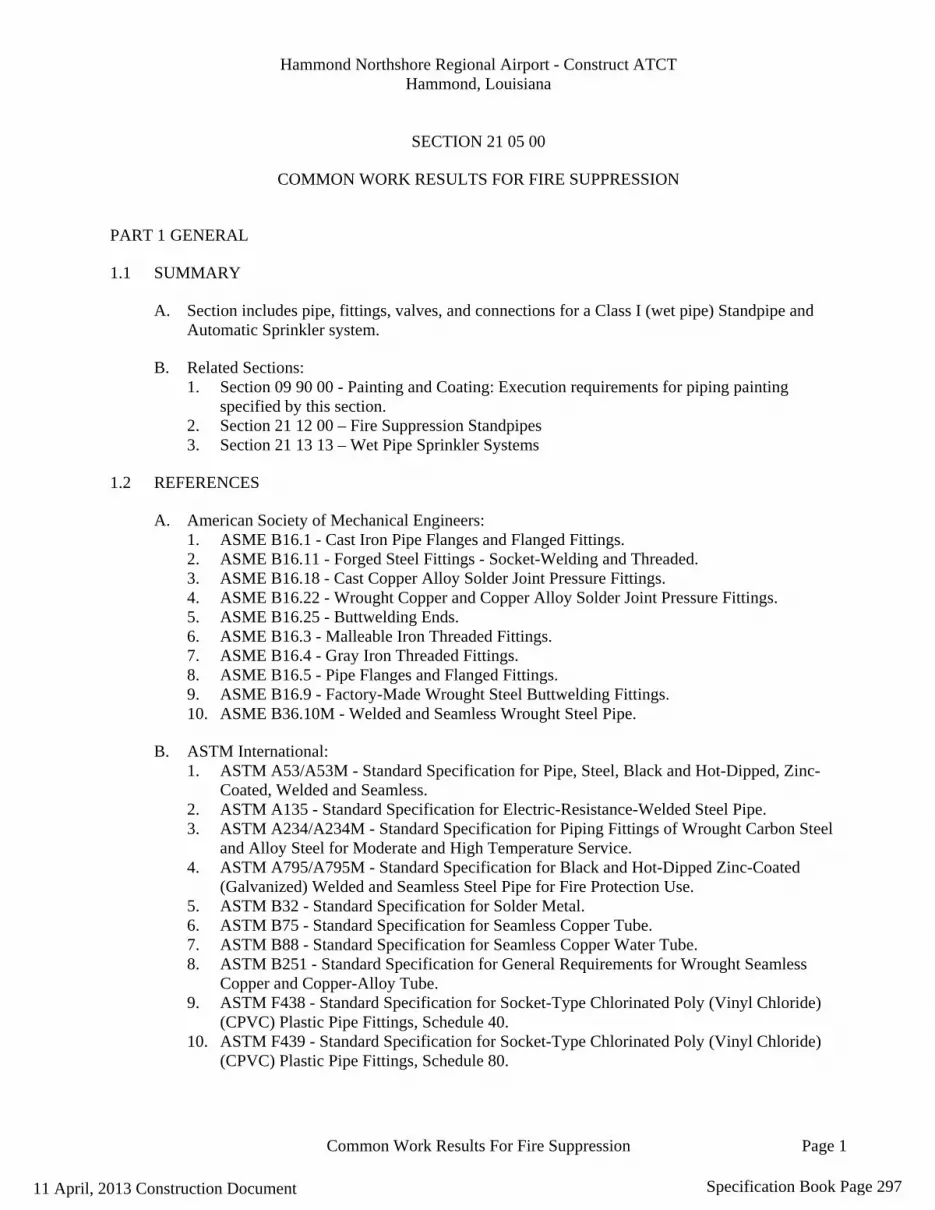
Hammond Northshore Regional Airport - Construct ATCT Hammond, Louisiana
Common Work Results For Fire Suppression Page 1
SECTION 21 05 00
COMMON WORK RESULTS FOR FIRE SUPPRESSION
PART 1 GENERAL
1.1 SUMMARY
A. Section includes pipe, fittings, valves, and connections for a Class I (wet pipe) Standpipe and Automatic Sprinkler system.
B. Related Sections: 1. Section 09 90 00 - Painting and Coating: Execution requirements for piping painting
specified by this section. 2. Section 21 12 00 – Fire Suppression Standpipes 3. Section 21 13 13 – Wet Pipe Sprinkler Systems
1.2 REFERENCES
A. American Society of Mechanical Engineers: 1. ASME B16.1 - Cast Iron Pipe Flanges and Flanged Fittings. 2. ASME B16.11 - Forged Steel Fittings - Socket-Welding and Threaded. 3. ASME B16.18 - Cast Copper Alloy Solder Joint Pressure Fittings. 4. ASME B16.22 - Wrought Copper and Copper Alloy Solder Joint Pressure Fittings. 5. ASME B16.25 - Buttwelding Ends. 6. ASME B16.3 - Malleable Iron Threaded Fittings. 7. ASME B16.4 - Gray Iron Threaded Fittings. 8. ASME B16.5 - Pipe Flanges and Flanged Fittings. 9. ASME B16.9 - Factory-Made Wrought Steel Buttwelding Fittings. 10. ASME B36.10M - Welded and Seamless Wrought Steel Pipe.
B. ASTM International: 1. ASTM A53/A53M - Standard Specification for Pipe, Steel, Black and Hot-Dipped, Zinc-
Coated, Welded and Seamless. 2. ASTM A135 - Standard Specification for Electric-Resistance-Welded Steel Pipe. 3. ASTM A234/A234M - Standard Specification for Piping Fittings of Wrought Carbon Steel
and Alloy Steel for Moderate and High Temperature Service. 4. ASTM A795/A795M - Standard Specification for Black and Hot-Dipped Zinc-Coated
(Galvanized) Welded and Seamless Steel Pipe for Fire Protection Use. 5. ASTM B32 - Standard Specification for Solder Metal. 6. ASTM B75 - Standard Specification for Seamless Copper Tube. 7. ASTM B88 - Standard Specification for Seamless Copper Water Tube. 8. ASTM B251 - Standard Specification for General Requirements for Wrought Seamless
Copper and Copper-Alloy Tube. 9. ASTM F438 - Standard Specification for Socket-Type Chlorinated Poly (Vinyl Chloride)
(CPVC) Plastic Pipe Fittings, Schedule 40. 10. ASTM F439 - Standard Specification for Socket-Type Chlorinated Poly (Vinyl Chloride)
(CPVC) Plastic Pipe Fittings, Schedule 80.
11 April, 2013 Construction Document Specification Book Page 297

Hammond Northshore Regional Airport - Construct ATCT Hammond, Louisiana
Common Work Results For Fire Suppression Page 2
11. ASTM F442/F442M - Standard Specification for Chlorinated Poly (Vinyl Chloride) (CPVC) Plastic Pipe (SDR-PR).
12. ASTM F493 - Standard Specification for Solvent Cements for Chlorinated Poly (Vinyl Chloride) (CPVC) Plastic Pipe and Fittings.
C. American Welding Society: 1. AWS A5.8 - Specification for Filler Metals for Brazing and Braze Welding. 2. AWS D1.1 - Structural Welding Code - Steel.
D. American Water Works Association: 1. AWWA C110 - American National Standard for Ductile-Iron and Grey-Iron Fittings, 3 in.
through 48 in. (75 mm through 1200 mm), for Water and Other Liquids. 2. AWWA C111 - American National Standard for Rubber-Gasket Joints for Ductile-Iron
Pressure Pipe and Fittings. 3. AWWA C151 - American National Standard for Ductile-Iron Pipe, Centrifugally Cast, for
Water.
E. National Fire Protection Association: 1. NFPA 13 - Installation of Sprinkler Systems. 2. NFPA 14 - Standard for the Installation of Standpipe, Private Hydrants and Hose Systems. 3. NFPA 24 - Installation of Private Fire Service Mains and Their Appurtenances.
F. Underwriter Laboratories, Inc.: 1. UL 1887 - Fire Tests of Plastic Sprinkler Pipe for Visible Flame and Smoke Characteristics.
1.3 SUBMITTALS
A. Section 01 33 00 - Submittal Procedures: Submittal procedures.
B. Shop Drawings: Indicate pipe materials used, jointing methods, supports, floor and wall penetration seals. Indicate installation, layout, weights, mounting and support details, and piping connections. Submit to the design engineer for concurrence and then to the Authority Having Jurisdiction for approval.
C. Product Data: Submit manufacturers catalogue information. Indicate valve data and ratings.
D. Manufacturer's Certificate: Certify products meet or exceed specified requirements.
1.4 CLOSEOUT SUBMITTALS
A. Section 01 70 00 - Execution and Closeout Requirements: Closeout procedures.
B. Project Record Documents: Record actual locations of components and tag numbering.
C. Operation and Maintenance Data: Submit spare parts lists.
1.5 QUALITY ASSURANCE
A. Provide a Class I (wet pipe) Standpipe system.
11 April, 2013 Construction Document Specification Book Page 298
Hammond Northshore Regional Airport - Construct ATCT Hammond, Louisiana
Common Work Results For Fire Suppression Page 3
B. Perform Work in accordance with NFPA 14.
C. Maintain one copy of each document on site.
1.6 QUALIFICATIONS
A. Manufacturer: Company specializing in manufacturing products specified in this section with minimum three years experience, and with service facilities within 100 miles of Project.
B. Installer: Company specializing in performing Work of this section with minimum three years experience.
1.7 PRE-INSTALLATION MEETINGS
A. Section 01 30 00 - Administrative Requirements: Pre-installation meeting.
B. Convene minimum one week prior to commencing work of this section.
1.8 DELIVERY, STORAGE, AND HANDLING
A. Section 01 60 00 - Product Requirements: Product storage and handling requirements.
B. Deliver and store valves in shipping containers, with labeling in place.
C. Furnish cast iron and steel valves with temporary protective coating.
D. Furnish temporary end caps and closures on piping and fittings. Maintain in place until installation.
1.9 WARRANTY
A. Section 01 70 00 - Execution and Closeout Requirements: Product warranties and product bonds.
B. Furnish one year manufacturer warranty for basic fire suppression materials and methods.
1.10 EXTRA MATERIALS
A. Section 01 70 00 - Execution and Closeout Requirements: Spare parts and maintenance products.
B. Furnish two sets of valve stem packing for each size and type of valve installed.
PART 2 PRODUCTS
2.1 VALVES
Furnish materials in accordance with Municipality standards.
A. Gate Valves:
11 April, 2013 Construction Document Specification Book Page 299

Hammond Northshore Regional Airport - Construct ATCT Hammond, Louisiana
Common Work Results For Fire Suppression Page 4
1. Up to and including 2 inches: Bronze body and trim, rising stem, hand wheel, solid wedge or disc, threaded ends.
2. Over 2 inches: Iron body, bronze trim, rising stem pre-grooved for mounting tamper switch, hand wheel, OS&Y, solid bronze or cast iron wedge, flanged ends.
3. Over 4 inches: Iron body, bronze trim, non-rising stem with bolted bonnet, solid bronze wedge, flanged ends, iron body indicator post assembly.
B. Globe or Angle Valves: 1. Up to and including 2 inches: Bronze body, bronze trim, rising stem and hand wheel, inside
screw, renewable rubber disc, threaded ends, with back seating capacity packable under pressure.
2. Over 2 inches: Iron body, bronze trim, rising stem, hand wheel, OS&Y, plug-type disc, flanged ends, renewable seat and disc.
C. Ball Valves: 1. Up to and including 2 inches: Bronze two piece body, brass, chrome plated bronze, or
stainless steel ball, teflon seats and stuffing box ring, lever handle and balancing stops, threaded ends with union.
2. Over 2 inches: Manufacturers: Cast steel body, chrome plated steel ball, teflon seat and stuffing box seals, lever handle, flanged.
D. Check Valves: 1. Up to and including 2 inches: Bronze body and swing disc, rubber seat, threaded ends. 2. Over 2 inches: Iron body, bronze trim, swing check with rubber disc, renewable disc and
seat, flanged ends with automatic ball check. 3. 4 inches and Over: Iron body, bronze disc with stainless steel spring, resilient seal, threaded,
wafer, or flanged ends.
E. Drain Valves: 1. Compression Stop: Bronze with hose thread nipple and cap. 2. Ball Valve: Brass with cap and chain, 2 inch hose thread.
2.2 BURIED PIPING
A. Steel Pipe: ASTM A53/A53M, Grade B, ASTM A135/135M/135M, ASTM A795/A795M, or ASME B36.10, Schedule 40 galvanized, with ASME C105 polyethylene jacket, or double layer, half-lapped 10 mil polyethylene tape. 1. Steel Fittings: ASME B16.9, wrought steel, butt welded; ASME B16.25, butt weld ends;
ASTM A234/A234M, wrought carbon steel and alloy steel; ASME B16.5, steel flanges and fittings; ASME B16.11, forged steel socket welded and threaded; with double layer, half-lapped 10 mil polyethylene tape.
2. Cast Iron Fittings: ASME B16.1, flanges and flanged fittings. 3. Joints: AWS D1.1, welded. 4. Casing: Closed glass cell insulation. Polyurethane insulation with high density polyethylene
jacket and heat shrink sleeves.
B. CPVC Pipe: ASTM F442/F442M, SDR 13.5. 1. Fittings: ASTM F438 schedule 40, or ASTM F439 schedule 80, CPVC. 2. Joints: ASTM F493, solvent weld.
11 April, 2013 Construction Document Specification Book Page 300
Hammond Northshore Regional Airport - Construct ATCT Hammond, Louisiana
Common Work Results For Fire Suppression Page 5
C. Copper Tubing:, ASTM B88, or Type K annealed. 1. Fittings: ASME B16.18, cast copper alloy, or ASME B16.22, wrought copper and bronze,
solder joint, pressure type. 2. Joints: AWS A5.8 Classification BCuP-3 or BCuP-4 silver braze or ASTM B32, Alloy
Grade Sb5 tin-antimony solder. 3. Casing: Closed glass cell insulation. Polyurethane insulation with high density polyethylene
jacket and heat shrink sleeves.
D. Cast Iron Pipe: AWWA C151. 1. Fittings: AWWA C110, standard thickness. 2. Joints: AWWA C111, rubber gasket. 3. Mechanical Couplings: Shaped composition sealing gasket, steel bolts, nuts, and washers.
2.3 ABOVE GROUND PIPING
A. Steel Pipe: ASTM A53/A53M, Grade B; ASTM A135/135M; ASTM A135/135M UL listed, threadable, light wall; ASTM A795/A795M; or ASME B36.10; Schedule 40 black galvanized. 1. Steel Fittings: ASME B16.9, wrought steel, butt welded; ASME B16.25, butt weld ends;
ASTM A234/A234M, wrought carbon steel and alloy steel; ASME B16.5, steel flanges and fittings; ASME B16.11, forged steel socket welded and threaded.
2. Cast Iron Fittings: ASME B16.1, flanges and flanged fittings; ASME B16.4, threaded fittings.
3. Malleable Iron Fittings: ASME B16.3, threaded fittings ASTM B47.Mechanical Grooved Couplings: Malleable iron housing clamps to engage and lock, "C" shaped elastomeric sealing gasket, steel bolts, nuts, and washers; galvanized for galvanized pipe.
4. Mechanical Formed Fittings: Carbon-steel housing with integral pipe stop and O-ring pocked and O-ring uniformly compressed into permanent mechanical engagement onto pipe.
B. CPVC Pipe: ASTM F442/F442M, SDR 13.5. 1. Fittings: ASTM F438 schedule 40, or ASTM F439 schedule 80, CPVC. 2. Joints: ASTM F493, solvent weld.
C. Cast Iron Pipe: AWWA C151. 1. Fittings: AWWA C110, standard thickness. 2. Joints: AWWA C111, rubber gasket. 3. Mechanical Grooved Couplings: Malleable iron housing clamps to engage and lock, "C"
shaped composition sealing gasket, steel bolts, nuts, and washers; galvanized for galvanized pipe.
2.4 PIPE HANGERS AND SUPPORTS
A. Conform to NFPA 13 NFPA 14.
B. Hangers for Pipe Sizes 1/2 to 1-1/2 inch: Malleable iron Carbon steel, adjustable swivel, split ring.
C. Hangers for Pipe Sizes 2 inch and Over: Carbon steel, adjustable, clevis.
D. Multiple or Trapeze Hangers: Steel channels with welded spacers and hanger rods.
11 April, 2013 Construction Document Specification Book Page 301

Hammond Northshore Regional Airport - Construct ATCT Hammond, Louisiana
Common Work Results For Fire Suppression Page 6
E. Wall Support for Pipe Sizes to 3 inches: Cast iron hook.
F. Wall Support for Pipe Sizes 4 inches and Over: Welded steel bracket and wrought steel clamp.
G. Vertical Support: Steel riser clamp.
H. Floor Support: Cast iron adjustable pipe saddle, lock nut, nipple, floor flange, and concrete pier or steel support.
I. Copper Pipe Support: Carbon steel ring, adjustable, copper plated.
PART 3 EXECUTION
3.1 PREPARATION A. Ream pipe and tube ends. Remove burrs. Bevel plain end ferrous pipe. B. Remove scale and foreign material, from inside and outside, before assembly. C. Prepare piping connections to equipment with flanges or unions.
3.2 INSTALLATION
A. Install Work in accordance with State Municipality of Highways Public Work's standards.
B. Route piping in orderly manner, plumb and parallel to building structure. Maintain gradient.
C. Install piping to conserve building space, to not interfere with use of space and other work.
D. Group piping whenever practical at common elevations.
E. Install pipe sleeve at piping penetrations through footings partitions, walls, and floors. Seal pipe and sleeve penetrations to maintain fire resistance equivalent to fire separation.
F. Install piping to allow for expansion and contraction without stressing pipe, joints, or connected equipment.
G. Pipe Hangers and Supports: 1. Install in accordance with NFPA 13 and NFPA 14. 2. Install hangers to with minimum 1/2 inch space between finished covering and adjacent
work. 3. Place hangers within 12 inches of each horizontal elbow. 4. Use hangers with 1-1/2 inch minimum vertical adjustment. Design hangers for pipe
movement without disengagement of supported pipe. 5. Support vertical piping at every floor. Support riser piping independently of connected
horizontal piping. 6. Where installing several pipes in parallel and at same elevation, provide multiple or trapeze
hangers. 7. Prime coat exposed steel hangers and supports. Refer to Section 09 90 00. Hangers and
supports located in crawl spaces, pipe shafts, and suspended ceiling spaces are not considered exposed.
11 April, 2013 Construction Document Specification Book Page 302

Hammond Northshore Regional Airport - Construct ATCT Hammond, Louisiana
Common Work Results For Fire Suppression Page 7
H. Slope piping and arrange systems to drain at low points. Install eccentric reducers to maintain top of pipe level.
I. Prepare pipe, fittings, supports, and accessories for finish painting. Where pipe support members are welded to structural building framing, scrape, brush clean, and apply one coat of zinc rich primer to welding. Refer to Section 09 90 00.
J. Do not penetrate building structural members unless indicated.
K. Where more than one piping system material is specified, install compatible system components and joints. Install flanges, union, and couplings at locations requiring servicing.
L. Die cut threaded joints with full cut standard taper pipe threads with red lead and linseed oil or other non-toxic joint compound applied to male threads only.
M. Install valves with stems upright or horizontal, not inverted. Remove protective coatings prior to after installation.
N. Install gate ball or butterfly valves for shut-off or isolating service.
O. Install drain valves at main shut-off valves, low points of piping and apparatus.
P. Where inserts are omitted, drill through concrete slab from below and install through-bolt with recessed square steel plate and nut above flush with top of recessed into and grouted flush with slab.
3.3 INTERFACE WITH OTHER PRODUCTS
A. Inserts: 1. Install inserts for placement in concrete forms. 2. Install inserts for suspending hangers from reinforced concrete slabs and sides of reinforced
concrete beams. 3. Install hooked rod to concrete reinforcement section for inserts carrying pipe over 4 inches. 4. Where concrete slabs form finished ceiling, locate inserts flush with slab surface.
3.4 CLEANING
A. Section 01 70 00 - Execution and Closeout Requirements: Final cleaning.
B. Clean entire system after other construction is complete.
END OF SECTION
11 April, 2013 Construction Document Specification Book Page 303

Hammond Northshore Regional Airport - Construct ATCT Hammond, Louisiana
Fire-Suppression Standpipes Page 1
SECTION 21 12 00
FIRE-SUPPRESSION STANDPIPES
PART 1 GENERAL
1.1 SUMMARY
A. Section includes entire standpipe system from fire department connection to fire hose connection.
B. Related Sections: 1. Section 21 05 00 - Common Work Results for Fire Suppression: Product and execution
requirements for pipe, fittings, valves, hangers, supports, identification and painting for placement by this section.
1.2 REFERENCES
A. National Fire Protection Association: 1. NFPA 14 - Standard for the Installation of Standpipe, Private Hydrants and Hose Systems.
B. International Building Code
1.3 SUBMITTALS
A. Section 01 33 00 - Submittal Procedures: Submittal procedures. Submit to the design engineer for concurrence and then to the Authority Having Jurisdiction for approval.
B. Shop Drawings: Indicate supports, components, accessories, and sizes.
C. Product Data: Submit manufacturer's catalog sheet for equipment indicating rough-in size, finish, and accessories.
D. Field Test Reports: Indicate compliance with specified performance.
E. Manufacturer's Installation Instructions: Submit with product data.
F. Manufacturer's Certificate: Certify products meet or exceed specified requirements.
1.4 CLOSEOUT SUBMITTALS
A. Section 01 70 00 - Execution and Closeout Requirements: Closeout procedures.
B. Operation and Maintenance Data: Submit servicing requirements and test schedule.
11 April, 2013 Construction Document Specification Book Page 304

Hammond Northshore Regional Airport - Construct ATCT Hammond, Louisiana
Fire-Suppression Standpipes Page 2
1.5 QUALITY ASSURANCE
A. Perform Work in accordance with NFPA 14 and State & Municipality standards.
1.6 QUALIFICATIONS
A. Manufacturer: Company specializing in manufacturing products specified in this section with minimum three years experience.
B. Installer: Company specializing in performing Work of this section with minimum three years experience.
1.7 PRE-INSTALLATION MEETINGS
A. Section 01 30 00 - Administrative Requirements: Pre-installation meeting.
B. Convene minimum one week prior to commencing work of this section.
1.8 DELIVERY, STORAGE, AND HANDLING
A. Section 01 60 00 - Product Requirements: Requirements for transporting, handling, storing, and protecting products.
B. Deliver and store products in shipping packaging until installation.
1.9 WARRANTY
A. Section 01 70 00 - Execution and Closeout Requirements: Product warranties and product bonds.
B. Furnish one year manufacturer warranty for standpipes components.
PART 2 PRODUCTS
2.1 VALVES
A. Manufacturers: 1. Any meeting this spec.
B. Furnish materials in accordance with State and Municipality standards.
C. Hose Connection Valve: Angle type; brass or chrome plated finish; 2-1/2 inch size, thread to match fire department hardware, 300 psi working pressure, with threaded cap and chain of brass or chrome plated finish.
11 April, 2013 Construction Document Specification Book Page 305

Hammond Northshore Regional Airport - Construct ATCT Hammond, Louisiana
Fire-Suppression Standpipes Page 3
2.2 FIRE DEPARTMENT CONNECTION
A. Type: As specified on drawings.
B. Drain: 2 inch Outlets:
C. Drip Line: 3/4 inch outside.
D. Label: "Standpipe - Fire Department Connection".
PART 3 EXECUTION
3.1 EXAMINATION
A. Section 01 30 00 - Administrative Requirements: Coordination and project conditions.
3.2 INSTALLATION
A. Install in accordance with NFPA 14.
B. Install Work in accordance with State and Municipality standards.
C. Connect standpipe system to water source per drawings.
3.3 FIELD QUALITY CONTROL
A. Section 01 40 00 - Quality Requirements 01 70 00 - Execution and Closeout Requirements:Field inspecting, testing, adjusting, and balancing.
B. Test entire system in accordance with NFPA 14.
C. Require test be witnessed by Authority having jurisdiction.
3.4 CLEANING
A. Section 01 70 00 - Execution and Closeout Requirements: Final cleaning.
B. Flush entire system of foreign matter.
END OF SECTION
11 April, 2013 Construction Document Specification Book Page 306

Hammond Northshore Regional Airport - Construct ATCT Hammond, Louisiana
Pipes And Tubes For Plumbing Piping And Equipment Page 1
SECTION 22 05 03
PIPES AND TUBES FOR PLUMBING PIPING AND EQUIPMENT
PART 1 GENERAL
1.1 SUMMARY
A. Section Includes: Pipe and pipe fittings for the following systems: 1. Domestic water piping. 2. Sanitary sewer piping 3. Chemical resistant sewer piping. 4. Storm water piping. 5. Equipment drains and over flows. 6. Compressed air piping. 7. Unions and flanges. 8. Underground pipe markers. 9. Bedding and cover materials.
B. Related Sections: 1. Section 07 84 00 - Firestopping: Product requirements for firestopping for placement by this
section. 2. Section 08 31 13 - Access Doors and Frames: Product requirements for access doors for
placement by this section. 3. Section 09 90 00 - Painting and Coating: Product and execution requirements for painting
specified by this section. 4. Section 22 05 23 - General-Duty Valves for Plumbing Piping: Product requirements for
valves for placement by this section. 5. Section 22 05 29 - Hangers and Supports for Plumbing Piping and Equipment: Product
requirements for pipe hangers and supports and firestopping for placement by this section. 6. Section 22 07 00 - Plumbing Insulation: Product requirements for piping insulation for
placement by this section. 7. Section 33 12 13 - Water Service Connections: Product and execution requirements for
domestic water piping outside of building.
1.2 REFERENCES
A. American Society of Mechanical Engineers: 1. ASME B16.1 - Cast Iron Pipe Flanges and Flanged Fittings. 2. ASME B16.3 - Malleable Iron Threaded Fittings. 3. ASME B16.4 - Gray Iron Threaded Fittings. 4. ASME B16.18 - Cast Copper Alloy Solder Joint Pressure Fittings. 5. ASME B16.22 - Wrought Copper and Copper Alloy Solder Joint Pressure Fittings. 6. ASME B16.23 - Cast Copper Alloy Solder Joint Drainage Fittings (DWV). 7. ASME B16.26 - Cast Copper Alloy Fittings for Flared Copper Tubes. 8. ASME B16.29 - Wrought Copper and Wrought Copper Alloy Solder Joint Drainage Fittings
- DWV. 9. ASME B31.9 - Building Services Piping.
11 April, 2013 Construction Document Specification Book Page 307

Hammond Northshore Regional Airport - Construct ATCT Hammond, Louisiana
Pipes And Tubes For Plumbing Piping And Equipment Page 2
10. ASME B36.10M - Welded and Seamless Wrought Steel Pipe. 11. ASME Section IX - Boiler and Pressure Vessel Code - Welding and Brazing Qualifications.
B. ASTM International: 1. ASTM A47/A47M - Standard Specification for Ferritic Malleable Iron Castings. 2. ASTM A53/A53M - Standard Specification for Pipe, Steel, Black and Hot-Dipped, Zinc-
Coated, Welded and Seamless. 3. ASTM A74 - Standard Specification for Cast Iron Soil Pipe and Fittings. 4. ASTM A234/A234M - Standard Specification for Piping Fittings of Wrought Carbon Steel
and Alloy Steel for Moderate and High Temperature Service. 5. ASTM A395/A395M - Standard Specification for Ferritic Ductile Iron Pressure-Retaining
Castings for Use at Elevated Temperatures. 6. ASTM A536 - Standard Specification for Ductile Iron Castings. 7. ASTM B32 - Standard Specification for Solder Metal. 8. ASTM B42 - Standard Specification for Seamless Copper Pipe, Standard Sizes. 9. ASTM B43 - Standard Specification for Seamless Red Brass Pipe, Standard Sizes. 10. ASTM B75 - Standard Specification for Seamless Copper Tube. 11. ASTM B88 - Standard Specification for Seamless Copper Water Tube. 12. ASTM B251 - Standard Specification for General Requirements for Wrought Seamless
Copper and Copper-Alloy Tube. 13. ASTM B280 - Standard Specification for Seamless Copper Tube for Air Conditioning and
Refrigeration Field Service. 14. ASTM B302 - Standard Specification for Threadless Copper Pipe, Standard Sizes. 15. ASTM B306 - Standard Specification for Copper Drainage Tube (DWV). 16. ASTM B584 - Standard Specification for Copper Alloy Sand Castings for General
Applications. 17. ASTM C14 - Standard Specification for Concrete Sewer, Storm Drain, and Culvert Pipe. 18. ASTM C76 - Standard Specification for Reinforced Concrete Culvert, Storm Drain, and
Sewer Pipe. 19. ASTM C443 - Standard Specification for Joints for Concrete Pipe and Manholes, Using
Rubber Gaskets. 20. ASTM C564 - Standard Specification for Rubber Gaskets for Cast Iron Soil Pipe and
Fittings. 21. ASTM D1785 - Standard Specification for Poly (Vinyl Chloride) (PVC) Plastic Pipe,
Schedules 40, 80, and 120. 22. ASTM D2235 - Standard Specification for Solvent Cement for Acrylonitrile-Butadiene-
Styrene (ABS) Plastic Pipe and Fittings. 23. ASTM D2239 - Standard Specification for Polyethylene (PE) Plastic Pipe (SIDR-PR) Based
on Controlled Inside Diameters. 24. ASTM D2241 - Standard Specification for Polyethylene (PE) Plastic Pipe (SIDR-PR) Based
on Controlled Inside Diameter. 25. ASTM D2447 - Standard Specification for Polyethylene (PE) Plastic Pipe, Schedules 40 and
80, Based on Outside Diameter. 26. ASTM D2464 - Standard Specification for Threaded Poly (Vinyl Chloride) (PVC) Plastic
Pipe Fittings, Schedule 80. 27. ASTM D2466 - Standard Specification for Poly (Vinyl Chloride) (PVC) Plastic Pipe
Fittings, Schedule 40. 28. ASTM D2467 - Standard Specification for Poly (Vinyl Chloride) (PVC) Plastic Pipe
Fittings, Schedule 80.
11 April, 2013 Construction Document Specification Book Page 308
Hammond Northshore Regional Airport - Construct ATCT Hammond, Louisiana
Pipes And Tubes For Plumbing Piping And Equipment Page 3
29. ASTM D2513 - Standard Specification for Thermoplastic Gas Pressure Pipe, Tubing, and Fittings.
30. ASTM D2564 - Standard Specification for Solvent Cements for Poly (Vinyl Chloride) (PVC) Plastic Piping Systems.
31. ASTM D2609 - Standard Specification for Plastic Insert Fittings for Polyethylene (PE) Plastic Pipe.
32. ASTM D2661 - Standard Specification for Acrylonitrile-Butadiene-Styrene (ABS) Schedule 40 Plastic Drain, Waste, and Vent Pipe and Fittings.
33. ASTM D2665 - Standard Specification for Poly (Vinyl Chloride) (PVC) Plastic Drain, Waste, and Vent Pipe and Fittings.
34. ASTM D2680 - Standard Specification for Acrylonitrile-Butadiene-Styrene (ABS) and Poly (Vinyl Chloride) (PVC) Composite Sewer Piping.
35. ASTM D2683 - Standard Specification for Socket-Type Polyethylene Fittings for Outside Diameter-Controlled Polyethylene Pipe and Tubing.
36. ASTM D2729 - Standard Specification for Poly (Vinyl Chloride) (PVC) Sewer Pipe and Fittings.
37. ASTM D2751 - Standard Specification for Acrylonitrile-Butadiene-Styrene (ABS) Sewer Pipe and Fittings.
38. ASTM D2846/D2846M - Standard Specification for Chlorinated Poly (Vinyl Chloride) (CPVC) Plastic Hot- and Cold-Water Distribution Systems.
39. ASTM D2855 - Standard Practice for Making Solvent-Cemented Joints with Poly (Vinyl Chloride) (PVC) Pipe and Fittings.
40. ASTM D2996 - Standard Specification for Filament-Wound Fiberglass (Glass-Fiber-Reinforced Thermosetting Resin) Pipe.
41. ASTM D2997 - Standard Specification for Centrifugally Cast Fiberglass (Glass-Fiber-Reinforced Thermosetting-Resin) Pipe.
42. ASTM D3034 - Standard Specification for Type PSM Poly (Vinyl Chloride) (PVC) Sewer Pipe and Fittings.
43. ASTM D3035 - Standard Specification for Polyethylene (PE) Plastic Pipe (DR-PR) Based on Controlled Outside Diameter.
44. ASTM D3139 - Standard Specification for Joints for Plastic Pressure Pipes Using Flexible Elastomeric Seals.
45. ASTM D3262 - Standard Specification for "Fiberglass" (Glass-Fiber-Reinforced Thermosetting-Resin) Sewer Pipe.
46. ASTM D3517 - Standard Specification for "Fiberglass" (Glass-Fiber-Reinforced Thermosetting-Resin) Pressure Pipe.
47. ASTM D3754 - Standard Specification for "Fiberglass" (Glass-Fiber-Reinforced Thermosetting-Resin) Sewer and Industrial Pressure Pipe.
48. ASTM D3840 - Standard Specification for "Fiberglass" (Glass-Fiber-Reinforced Thermosetting-Resin) Pipe Fittings for Non-pressure Applications.
49. ASTM F437 - Standard Specification for Threaded Chlorinated Poly (Vinyl Chloride) (CPVC) Plastic Pipe Fittings, Schedule 80.
50. ASTM F438 - Standard Specification for Socket-Type Chlorinated Poly (Vinyl Chloride) (CPVC) Plastic Pipe Fittings, Schedule 40.
51. ASTM F439 - Standard Specification for Socket-Type Chlorinated Poly (Vinyl Chloride) (CPVC) Plastic Pipe Fittings, Schedule 80.
52. ASTM F441/F441M - Standard Specification for Chlorinated Poly (Vinyl Chloride) (CPVC) Plastic Pipe, Schedules 40 and 80.
11 April, 2013 Construction Document Specification Book Page 309

Hammond Northshore Regional Airport - Construct ATCT Hammond, Louisiana
Pipes And Tubes For Plumbing Piping And Equipment Page 4
53. ASTM F442/F442M - Standard Specification for Chlorinated Poly (Vinyl Chloride) (CPVC) Plastic Pipe (SDR-PR).
54. ASTM F477 - Standard Specification for Elastomeric Seals (Gaskets) for Joining Plastic Pipe.
55. ASTM F493 - Standard Specification for Solvent Cements for Chlorinated Poly (Vinyl Chloride) (CPVC) Plastic Pipe and Fittings.
56. ASTM F628 - Standard Specification for Acrylonitrile-Butadiene-Styrene (ABS) Schedule 40 Plastic Drain, Waste, and Vent Pipe With a Cellular Core.
57. ASTM F679 - Standard Specification for Poly (Vinyl Chloride) (PVC) Large-Diameter Plastic Gravity Sewer Pipe and Fittings.
58. ASTM F1281 - Standard Specification for Cross linked Polyethylene/Aluminum/Cross linked Polyethylene (PEX-AL-PEX) Pressure Pipe.
59. ASTM F1282 - Standard Specification for Polyethylene/Aluminum/Polyethylene (PE-AL-PE) Composite Pressure Pipe.
60. ASTM F1476 - Standard Specification for Performance of Gasketed Mechanical Couplings for Use in Piping Applications.
C. American Welding Society: 1. AWS A5.8 - Specification for Filler Metals for Brazing and Braze Welding. 2. AWS D1.1 - Structural Welding Code - Steel.
D. American Water Works Association: 1. AWWA C104 - American National Standard for Cement-Mortar Lining for Ductile-Iron
Pipe and Fittings for Water. 2. AWWA C105 - American National Standard for Polyethylene Encasement for Ductile-Iron
Pipe Systems. 3. AWWA C110 - American National Standard for Ductile-Iron and Grey-Iron Fittings, 3 in.
through 48 in. (75 mm through 1200 mm), for Water and Other Liquids. 4. AWWA C111 - American National Standard for Rubber-Gasket Joints for Ductile-Iron
Pressure Pipe and Fittings. 5. AWWA C151 - American National Standard for Ductile-Iron Pipe, Centrifugally Cast, for
Water. 6. AWWA C900 - Polyvinyl Chloride (PVC) Pressure Pipe, 4 in. through 12 in., for Water
Distribution. 7. AWWA C901 - Polyethylene (PE) Pressure Pipe and Tubing, 1/2 in. through 3 in., for Water
Service. 8. AWWA C950 - Fiberglass Pressure Pipe.
E. Cast Iron Soil Pipe Institute: 1. CISPI 301 - Standard Specification for Hubless Cast Iron Soil Pipe and Fittings for Sanitary
and Storm Drain, Waste, and Vent Piping Applications. 2. CISPI 310 - Specification for Coupling for Use in Connection with Hubless Cast Iron Soil
Pipe and Fittings for Sanitary and Storm Drain, Waste, and Vent Piping Applications.
F. National Fire Protection Association: 1. NFPA 99 - Standard for Health Care Facilities.
1.3 SUBMITTALS
11 April, 2013 Construction Document Specification Book Page 310

Hammond Northshore Regional Airport - Construct ATCT Hammond, Louisiana
Pipes And Tubes For Plumbing Piping And Equipment Page 5
A. Section 01 33 00 - Submittal Procedures: Submittal procedures.
B. Product Data: Submit data on pipe materials and fittings. Submit manufacturers catalog information.
1.4 FIELD MEASUREMENTS
A. Verify field measurements prior to fabrication.
1.5 COORDINATION
A. Section 01 30 00 - Administrative Requirements: Requirements for coordination.
B. Coordinate installation of buried piping with trenching.
PART 2 PRODUCTS
2.1 DOMESTIC WATER PIPING
A. Copper Tubing: ASTM B42, Temper O61 annealed. 1. Fittings: ASME B16.26 cast bronze. 2. Joints: Flared.
2.2 DOMESTIC WATER PIPING, ABOVE GRADE
A. Copper Tubing: ASTM B88, Type K, drawn. 1. Fittings: ASME B16.18, cast copper alloy or ASME B16.22, wrought copper and bronze. 2. Joints: ASTM AC443, rubber compression gasket.
2.3 SANITARY SEWER PIPING
A. PVC Pipe: ASTM D3034 SDR 35, polyvinyl chloride (PVC) material. 1. Fittings: ASTM D3034, PVC. 2. Joints: ASTM F477, elastomeric gaskets.
B. PVC Pipe: ASTM D1785, Schedule 80, polyvinyl chloride (PVC) material, bell and spigot style solvent sealed joint ends. 1. Fittings: ASTM D2467, Schedule 80, PVC. 2. Joints: ASTM D2855, solvent weld with ASTM D2564 Solvent cement.
11 April, 2013 Construction Document Specification Book Page 311

Hammond Northshore Regional Airport - Construct ATCT Hammond, Louisiana
Pipes And Tubes For Plumbing Piping And Equipment Page 6
2.4 SANITARY SEWER PIPING, ABOVE GRADE
VERTICAL STACKS
A. Cast Iron Pipe: ASTM A74, service weight. 1. Fittings: Cast iron, ASTM A74. 2. Joints: ASTM C564, rubber gasket joint devices or lead and oakum. OR
B. Cast Iron Pipe: CISPI 301, hub-less, service weight. 1. Fittings: Cast iron, CISPI 301. 2. Joints: CISPI 310, neoprene gaskets and stainless steel clamp-and-shield assemblies.
HORIZONTAL AND SHORT VERTICAL RUNS
C. Copper Tube: ASTM B88 Type K. 1. Fittings: ASME B16.23, cast bronze, or ASME B16.29, wrought copper.
2. Joints: ASTM B32, Alloy Grade Sb5 tin-antimony, or Alloy Grade Sn95 tin-silver, lead free
solder.
2.5 CHEMICAL RESISTANT SEWER PIPING
A. Cast Iron Pipe: CISPI 301, hubless, service weight. 1. Fittings: Cast iron, CISPI 301. 2. Joints: CISPI 310, neoprene gaskets and stainless steel clamp-and-shield assemblies.
B. ABS Pipe: ASTM D2751 or ASTM F628, Acrylonitrile-Butadiene-Styrene (ABS) material. 1. Fittings: ABS, ASTM D2751. 2. Joints: ASTM D2235, solvent weld. 3. PVC Pipe: ASTM D2729 or ASTM D2665, polyvinyl chloride (PVC) material.
2.6 STORM WATER PIPING
A. Cast Iron Pipe: ASTM A74, extra heavy service weight, bell and spigot plain ends. 1. Fittings: Cast iron, ASTM A74. 2. Joints: ASTM C564, rubber gasket joint devices or lead and oakum.
2.7 STORM WATER PIPING, ABOVE GRADE
VERTICAL STACKS
A. Cast Iron Pipe: ASTM A74 service weight, bell and spigot OR plain ends. 1. Fittings: Cast iron, ASTM A74. 2. Joints: ASTM C564, neoprene gasket system or lead and oakum. OR
11 April, 2013 Construction Document Specification Book Page 312

Hammond Northshore Regional Airport - Construct ATCT Hammond, Louisiana
Pipes And Tubes For Plumbing Piping And Equipment Page 7
B. Cast Iron Pipe: CISPI 301, hubless, service weight. 1. Fittings: Cast iron, CISPI 301. 2. Joints: Neoprene gaskets and stainless steel clamp-and-shield assemblies.
C. Cab Level - Horizontal and vertical 1. PVC Pipe, Schedule 80 required for sound deadening purpose. 2. May substitute drainage or sprinkler fittings to meet odd angles or rounded bends.
2.8 EQUIPMENT DRAINS AND OVERFLOWS
A. PVC Pipe: ASTM D1785, Schedule 40 or Schedule 80 per drawings, or ASTM D2241, SDR 21 or 26, polyvinyl chloride (PVC) material. 1. Fittings: ASTM D2466, Schedule 40 or Schedule 80 PVC per drawings 2. Joints: ASTM D2855, solvent weld with ASTM D2564 solvent cement.
2.9 UNIONS AND FLANGES
A. Unions for Pipe 2 inches and Smaller: 1. Ferrous Piping: Class 150, malleable iron, threaded. 2. Copper Piping: Class 150, bronze unions with soldered brazed joints. 3. Dielectric Connections: Union with galvanized or plated steel threaded end, copper solder
end, water impervious isolation barrier. 4. PVC Piping: PVC.
B. Flanges for Pipe 2-1/2 inches and Larger: 1. Ferrous Piping: Class 150 250 300, forged steel, slip-on flanges. 2. Copper Piping: Class 150, slip-on bronze flanges. 3. PVC Piping: PVC flanges. 4. CPVC Piping: CPVC flanges. 5. Gaskets: 1/16 inch thick preformed neoprene gaskets.
C. PVC Pipe Materials: For connections to equipment and valves with threaded connections, furnish solvent-weld socket to screwed joint adapters and unions, or ASTM D2464, Schedule 80, threaded, PVC pipe.
PART 3 EXECUTION
3.1 EXAMINATION
A. Section 01 30 00 - Administrative Requirements: Verification of existing conditions before starting work.
B. Verify excavations are to required grade, dry, and not over-excavated.
C. Verify trenches are ready to receive piping.
11 April, 2013 Construction Document Specification Book Page 313

Hammond Northshore Regional Airport - Construct ATCT Hammond, Louisiana
Pipes And Tubes For Plumbing Piping And Equipment Page 8
3.2 PREPARATION
A. Ream pipe and tube ends. Remove burrs. Bevel plain end ferrous pipe.
B. Remove scale and dirt on inside and outside before assembly.
C. Prepare piping connections to equipment with flanges or unions.
D. Keep open ends of pipe free from scale and dirt. Protect open ends with temporary plugs or caps.
3.3 INSTALLATION - ABOVE GROUND PIPING
A. Route piping in orderly manner and maintain gradient. Route parallel and perpendicular to walls.
B. Install piping to maintain headroom without interfering with use of space or taking more space than necessary.
C. Group piping whenever practical at common elevations.
D. Sleeve pipe passing through partitions, walls and floors. Refer to Section 22 05 29.
E. Provide clearance in hangers and from structure and other equipment for installation of insulation and access to valves and fittings. Refer to Section 22 07 00.
F. Provide access where valves and fittings are not accessible. Coordinate size and location of access doors with Section 08 31 13.
G. Install non-conducting dielectric connections wherever jointing dissimilar metals.
H. Establish invert elevations, slopes for drainage to 1/8 inch per foot minimum. Maintain gradients.
I. Slope piping and arrange systems to drain at low points.
J. Protect piping systems from entry of foreign materials by temporary covers, completing sections of the Work, and isolating parts of completed system.
K. Install piping penetrating roofed areas to maintain integrity of roof assembly.
L. Install valves in accordance with Section 22 05 23.
M. Install piping specialties in accordance with Section 23 21 16.
N. Install pipe identification in accordance with Section 22 05 53.
3.4 INSTALLATION - SANITARY WASTE AND VENT PIPING SYSTEMS
A. Install sanitary waste and vent piping systems in accordance with ASME B31.9.
11 April, 2013 Construction Document Specification Book Page 314

Hammond Northshore Regional Airport - Construct ATCT Hammond, Louisiana
Pipes And Tubes For Plumbing Piping And Equipment Page 9
3.5 FIELD QUALITY CONTROL
A. Section 01 40 00 - Quality Requirements 01 70 00 - Execution and Closeout Requirements: Field inspecting, testing, adjusting, and balancing.
B. Test domestic water piping system in accordance with local authority having jurisdiction.
C. Test sanitary waste and vent piping system in accordance with local authority having jurisdiction.
D. Test storm drainage piping system in accordance with local authority having jurisdiction.
3.6 CLEANING
A. Section 01 70 00 - Execution and Closeout Requirements: Requirements for cleaning.
B. Clean and disinfect domestic water distribution system in accordance with Section local.
END OF SECTION
11 April, 2013 Construction Document Specification Book Page 315

Hammond Northshore Regional Airport - Construct ATCT Hammond, Louisiana
Hangers And Supports For Plumbing Piping And Equipment Page 1
SECTION 22 05 29
HANGERS AND SUPPORTS FOR PLUMBING PIPING AND EQUIPMENT
PART 1 GENERAL
1.1 SUMMARY
A. Section Includes: 1. Pipe hangers and supports. 2. Hanger rods. 3. Inserts. 4. Flashing. 5. Sleeves (furnished by supplier in precast panels). 6. Mechanical sleeve seals. 7. Formed steel channel. 8. Firestopping relating to plumbing work. 9. Firestopping accessories. 10. Equipment bases and supports.
B. Related Sections: 1. Section 09 90 00 - Painting and Coating: Product and execution requirements for painting
specified by this section. 2. Section 22 05 03 - Pipes and Tubes for Plumbing Piping and Equipment: Execution
requirements for placement of hangers and supports specified by this section.
1.2 REFERENCES
A. American Society of Mechanical Engineers: 1. ASME B31.9 - Building Services Piping.
B. ASTM International: 1. ASTM E84 - Standard Test Method for Surface Burning Characteristics of Building
Materials. 2. ASTM E119 - Standard Test Methods for Fire Tests of Building Construction and Materials. 3. ASTM E814 - Standard Test Method for Fire Tests of Through Penetration Fire Stops. 4. ASTM F708 - Standard Practice for Design and Installation of Rigid Pipe Hangers. 5. ASTM E1966 - Standard Test Method for Fire-Resistive Joint Systems.
C. American Welding Society: 1. AWS D1.1 - Structural Welding Code - Steel.
D. Manufacturers Standardization Society of the Valve and Fittings Industry: 1. MSS SP 58 - Pipe Hangers and Supports - Materials, Design and Manufacturer. 2. MSS SP 69 - Pipe Hangers and Supports - Selection and Application. 3. MSS SP 89 - Pipe Hangers and Supports - Fabrication and Installation Practices.
11 April, 2013 Construction Document Specification Book Page 316

Hammond Northshore Regional Airport - Construct ATCT Hammond, Louisiana
Hangers And Supports For Plumbing Piping And Equipment Page 2
1.3 DEFINITIONS
A. Firestopping (Through-Penetration Protection System): Sealing or stuffing material or assembly placed in spaces between and penetrations through building materials to arrest movement of fire, smoke, heat, and hot gases through fire rated construction.
1.4 SYSTEM DESCRIPTION
A. See Section 07 84 00 Firestopping.
1.5 PERFORMANCE REQUIREMENTS
A. Firestopping: Conform to applicable code for fire resistance ratings and surface burning characteristics.
B. Firestopping: Provide certificate of compliance from authority having jurisdiction indicating approval of materials used.
1.6 SUBMITTALS
A. Section 01 33 00 - Submittal Procedures: Submittal procedures.
B. Shop Drawings: Indicate system layout with location including critical dimensions, sizes, and pipe hanger and support locations and detail of trapeze hangers.
C. Product Data: 1. Hangers and Supports: Submit manufacturers catalog data including load capacity. 2. Firestopping: Submit data on product characteristics, performance and limitation criteria.
D. Firestopping Schedule: Submit schedule of opening locations and sizes, penetrating items, and required listed design numbers to seal openings to maintain fire resistance rating of adjacent assembly.
E. Manufacturer's Installation Instructions: 1. Hangers and Supports: Submit special procedures and assembly of components. 2. Firestopping: Submit preparation and installation instructions.
1.7 QUALITY ASSURANCE
A. Through Penetration Firestopping of Non-Fire Rated Floor and Roof Assemblies: Materials to resist free passage of flame and products of combustion. 1. Noncombustible Penetrating Items: Noncombustible materials for penetrating items
connecting maximum of three stories. 2. Penetrating Items: Materials approved by authorities having jurisdiction for penetrating
items connecting maximum of two stories.
B. Fire Resistant Joints in Fire Rated Floor, Roof, and Wall Assemblies: ASTM E1966 or UL 2079 to achieve fire resistant rating as indicated on Drawings for assembly in which joint is installed.
11 April, 2013 Construction Document Specification Book Page 317

Hammond Northshore Regional Airport - Construct ATCT Hammond, Louisiana
Hangers And Supports For Plumbing Piping And Equipment Page 3
C. Fire Resistant Joints Between Floor Slabs and Exterior Walls: ASTM E119 with 0.10 inch water gage minimum positive pressure differential to achieve fire resistant rating as indicated on Drawings for floor assembly.
D. Surface Burning Characteristics: Maximum 25/450 flame spread/smoke developed index when tested in accordance with ASTM E84.
E. Perform Work in accordance with applicable authority for welding hanger and support attachments to building structure.
F. Maintain one copy of each document on site.
1.8 FIELD MEASUREMENTS
A. Verify field measurements prior to fabrication.
1.9 WARRANTY
A. Section 01 70 00 - Execution and Closeout Requirements: Product warranties and product bonds.
B. Furnish one year manufacturer warranty for pipe hangers and supports.
PART 2 PRODUCTS
2.1 PIPE HANGERS AND SUPPORTS
A. Manufacturers: 1. Carpenter & Paterson Inc. . 2. Creative Systems Inc. 3. Flex-Weld, Inc. 4. Globe Pipe Hanger Products Inc. 5. Michigan Hanger Co. 6. Superior Valve Co. 7. Substitutions: Section 01 60 00 - Product Requirements.
B. Plumbing Piping - DWV: 1. Conform to ASME B31.9 ASTM F708 MSS SP58 MSS SP69 MSS SP89. 2. Hangers for Pipe Sizes 1/2 to 1-1/2 inch: Malleable iron Carbon steel, adjustable swivel,
split ring. 3. Hangers for Pipe Sizes 2 inches and Larger: Carbon steel, adjustable, clevis. 4. Multiple or Trapeze Hangers: Steel channels with welded spacers and hanger rods. 5. Wall Support for Pipe Sizes 3 inches and Smaller: Cast iron hook. 6. Wall Support for Pipe Sizes 4 inches and Larger: Welded steel bracket and wrought steel
clamp. 7. Vertical Support: Steel riser clamp. 8. Floor Support: Cast iron adjustable pipe saddle, lock nut, nipple, floor flange, and concrete
pier or steel support. 9. Copper Pipe Support: Copper-plated, carbon-steel adjustable, ring.
11 April, 2013 Construction Document Specification Book Page 318
Hammond Northshore Regional Airport - Construct ATCT Hammond, Louisiana
Hangers And Supports For Plumbing Piping And Equipment Page 4
C. Plumbing Piping - Water: 1. Conform to ASME B31.9 ASTM F708 MSS SP58 MSS SP69 MSS SP89. 2. Hangers for Pipe Sizes 1/2 to 1-1/2 inch: Malleable iron Carbon steel, adjustable swivel,
split ring. 3. Hangers for Cold Pipe Sizes 2 inches and Larger: Carbon steel, adjustable, clevis. 4. Hangers for Hot Pipe Sizes 2 to 4 inches: Carbon steel, adjustable, clevis. 5. Hangers for Hot Pipe Sizes 6 inches and Larger: Adjustable steel yoke, cast iron roll, double
hanger. 6. Multiple or Trapeze Hangers: Steel channels with welded spacers and hanger rods. 7. Multiple or Trapeze Hangers for Hot Pipe Sizes 6 inches and Larger: Steel channels with
welded spacers and hanger rods, cast iron roll. 8. Wall Support for Pipe Sizes 3 inches and Smaller: Cast iron hook. 9. Wall Support for Pipe Sizes 4 inches and Larger: Welded steel bracket and wrought steel
clamp. 10. Wall Support for Hot Pipe Sizes 6 inches and Larger: Welded steel bracket and wrought
steel clamp with adjustable steel yoke and cast iron roll. 11. Vertical Support: Steel riser clamp. 12. Floor Support for Cold Pipe: Cast iron adjustable pipe saddle, lock nut, nipple, floor flange,
and concrete pier or steel support. 13. Floor Support for Hot Pipe Sizes 4 inches and Smaller: Cast iron adjustable pipe saddle, lock
nut, nipple, floor flange, and concrete pier or steel support. 14. Floor Support for Hot Pipe Sizes 6 inches and Larger: Adjustable cast iron roll and stand,
steel screws, and concrete pier or steel support. 15. Copper Pipe Support: Copper-plated, Carbon-steel ring.
2.2 ACCESSORIES
A. Hanger Rods: Mild steel threaded both ends, threaded on one end, or continuous threaded.
2.3 INSERTS
A. Manufacturers: 1. any Model.
B. Inserts: Malleable iron case of galvanized steel shell and expander plug for threaded connection with lateral adjustment, top slot for reinforcing rods, lugs for attaching to forms; size inserts to suit threaded hanger rods.
2.4 FLASHING
A. Metal Flashing: 26 gage thick galvanized steel.
B. Metal Counterflashing: 22 gage thick galvanized steel.
C. Lead Flashing: 1. Waterproofing: 5 lb./sq. ft sheet lead. 2. Soundproofing: 1 lb./sq. ft sheet lead.
D. Flexible Flashing: 47 mil thick sheet butyl; compatible with roofing.
11 April, 2013 Construction Document Specification Book Page 319

Hammond Northshore Regional Airport - Construct ATCT Hammond, Louisiana
Hangers And Supports For Plumbing Piping And Equipment Page 5
E. Caps: Steel, 22 gage minimum; 16 gage at fire resistant elements.
2.5 SLEEVES
A. Sleeves for Pipes Through Non-fire Rated Floors: 18 gage thick galvanized steel.
B. Sleeves for Pipes Through Non-fire Rated Beams, Walls, Footings, and Potentially Wet Floors: Steel pipe or 18 gage thick galvanized steel.
C. Sealant: refer to Section 07 84 00 Firestopping.
PART 3 EXECUTION
3.1 EXAMINATION
A. Verify openings are ready to receive sleeves.
B. Verify openings are ready to receive firestopping.
3.2 PREPARATION
A. Clean substrate surfaces of dirt, dust, grease, oil, loose material, or other matter affecting bond of firestopping material.
B. Remove incompatible materials affecting bond.
C. Install backing damming materials to arrest liquid material leakage.
D. Obtain permission from Architect/Engineer before drilling or cutting structural members.
3.3 INSTALLATION - INSERTS
A. Install inserts for placement in concrete forms.
B. Install inserts for suspending hangers from reinforced concrete slabs and sides of reinforced concrete beams.
C. Provide hooked rod to concrete reinforcement section for inserts carrying pipe 4 inches and larger.
D. Where concrete slabs form finished ceiling, locate inserts flush with slab surface.
E. Where inserts are omitted, drill through concrete slab from below and provide through-bolt with recessed square steel plate and nut recessed into and grouted flush with slab.
3.4 INSTALLATION - PIPE HANGERS AND SUPPORTS
A. Support horizontal piping as scheduled.
11 April, 2013 Construction Document Specification Book Page 320

Hammond Northshore Regional Airport - Construct ATCT Hammond, Louisiana
Hangers And Supports For Plumbing Piping And Equipment Page 6
B. Install hangers with minimum 1/2 inch space between finished covering and adjacent work.
C. Place hangers within 12 inches of each horizontal elbow.
D. Use hangers with 1-1/2 inch minimum vertical adjustment.
E. Support horizontal cast iron pipe adjacent to each hub, with 5 feet maximum spacing between hangers.
F. Support vertical piping at every floor. Support vertical cast iron pipe at each floor at hub.
G. Where piping is installed in parallel and at same elevation, provide multiple pipe or trapeze hangers.
H. Support riser piping independently of connected horizontal piping.
I. Provide copper plated hangers and supports for copper piping.
J. Design hangers for pipe movement without disengagement of supported pipe.
K. Prime coat exposed steel hangers and supports. Refer to Section 09 90 00. Hangers and supports located in crawl spaces, pipe shafts, and suspended ceiling spaces are not considered exposed.
L. Provide clearance in hangers and from structure and other equipment for installation of insulation. Refer to Section 22 07 00.
3.5 INSTALLATION - FLASHING
A. Provide flexible flashing and metal counterflashing where piping penetrates weather or waterproofed walls, floors, and roofs.
B. Flash vent and soil pipes projecting 3 inches minimum above finished roof surface with lead worked 1 inch minimum into hub, 8 inches minimum clear on sides with 24 x 24 inches sheet size. For pipes through outside walls, turn flanges back into wall and caulk, metal counter-flash, and seal.
C. Flash floor drains in floors with topping over finished areas with lead, 10 inches clear on sides with minimum 36 x 36 inch sheet size. Fasten flashing to drain clamp device.
D. Seal floor drains watertight to adjacent materials.
E. Adjust storm collars tight to pipe with bolts; caulk around top edge. Use storm collars above roof jacks. Screw vertical flange section to face of curb.
3.6 INSTALLATION - SLEEVES
A. Exterior watertight entries: Seal with mechanical sleeve seals.
B. Set sleeves in position in forms. Provide reinforcing around sleeves.
11 April, 2013 Construction Document Specification Book Page 321

Hammond Northshore Regional Airport - Construct ATCT Hammond, Louisiana
Hangers And Supports For Plumbing Piping And Equipment Page 7
C. Size sleeves large enough to allow for movement due to expansion and contraction. Provide for continuous insulation wrapping.
D. Extend sleeves through floors 1 inch above finished floor level. Caulk sleeves.
E. Where piping penetrates floor, ceiling, or wall, close off space between pipe and adjacent work with stuffing insulation and caulk airtight. Provide close fitting metal collar or escutcheon covers at both sides of penetration.
F. Install chrome plated steel escutcheons at finished surfaces.
3.7 FIELD QUALITY CONTROL
A. Section 01 40 00 - Quality Requirements 01 70 00 - Execution and Closeout Requirements: Field inspecting, testing, adjusting, and balancing.
B. Inspect installed firestopping for compliance with specifications and submitted schedule.
3.8 CLEANING
A. Section 01 70 00 - Execution and Closeout Requirements: Requirements for cleaning.
B. Clean adjacent surfaces of firestopping materials.
3.9 PROTECTION OF FINISHED WORK
A. Section 01 70 00 - Execution and Closeout Requirements: Requirements for protecting finished Work.
B. Protect adjacent surfaces from damage by material installation.
11 April, 2013 Construction Document Specification Book Page 322

Hammond Northshore Regional Airport - Construct ATCT Hammond, Louisiana
Hangers And Supports For Plumbing Piping And Equipment Page 8
3.10 SCHEDULES
PIPE HANGER SPACING
PIPE MATERIAL
MAXIMUM
HANGER SPACING
Feet
HANGER ROD
DIAMETER
Inches
ABS (All sizes) 4 3/8
Aluminum (All sizes) 10 1/2
Brass
Cast Iron (All Sizes) 5 5/8
Cast Iron (All Sizes) with 10 foot length of pipe 10 5/8
CPVC, 1 inch and smaller 3 1/2
CPVC, 1-1/4 inches and larger 4 1/2
Copper Tube, 1-1/4 inches and smaller 6 1/2
Copper Tube, 1-1/2 inches and larger 10 1/2
Fiberglass 4 1/2
Glass 8 1/2
Polybutylene 2.67 3/8
Polypropylene 4 3/8
PVC (All Sizes) 4 3/8
Steel, 3 inches and smaller 12 1/2
Steel, 4 inches and larger 12 5/8
END OF SECTION
11 April, 2013 Construction Document Specification Book Page 323

Hammond Northshore Regional Airport - Construct ATCT Hammond, Louisiana
Identification For Plumbing Piping And Equipment Page 1
SECTION 22 05 53
IDENTIFICATION FOR PLUMBING PIPING AND EQUIPMENT
PART 1 GENERAL
1.1 SUMMARY
A. Section Includes: 1. Nameplates. 2. Tags. 3. Stencils. 4. Pipe markers. 5. Ceiling tacks. 6. Labels. 7. Lockout devices.
B. Related Sections: 1. Section 09 90 00 - Painting and Coating: Execution requirements for painting specified by
this section.
1.2 REFERENCES
A. American Society of Mechanical Engineers: 1. ASME A13.1 - Scheme for the Identification of Piping Systems.
B. National Fire Protection Association: 1. NFPA 99 - Standard for Health Care Facilities.
1.3 SUBMITTALS
A. Section 01 33 00 - Submittal Procedures: Submittal procedures.
B. Product Data: Submit manufacturers catalog literature for each product required.
C. Shop Drawings: Submit list of wording, symbols, letter size, and color coding for mechanical identification and valve chart and schedule, including valve tag number, location, function, and valve manufacturer's name and model number.
D. Samples: Submit one labels, and pipe markers, size used on project.
E. Manufacturer's Installation Instructions: Indicate installation instructions, special procedures, and installation.
F. Manufacturer's Certificate: Certify products meet or exceed specified requirements.
11 April, 2013 Construction Document Specification Book Page 324
Hammond Northshore Regional Airport - Construct ATCT Hammond, Louisiana
Identification For Plumbing Piping And Equipment Page 2
1.4 CLOSEOUT SUBMITTALS
A. Section 01 70 00 - Execution and Closeout Requirements: Closeout procedures.
B. Project Record Documents: Record actual locations of tagged valves; include valve tag numbers.
1.5 QUALITY ASSURANCE
A. Conform to NFPA 99 requirements for labeling and identification of medical gas piping systems and accessories.
B. Conform to ASME A13.1 for color scheme for identification of piping systems and accessories.
C. Maintain one copy of each document on site.
1.6 QUALIFICATIONS
A. Manufacturer: Company specializing in manufacturing products specified in this section with minimum three years experience.
B. Installer: Company specializing in performing Work of this section with minimum three years experience.
1.7 PRE-INSTALLATION MEETINGS
A. Section 01 30 00 - Administrative Requirements: Pre-installation meeting.
B. Convene minimum one week prior to commencing work of this section.
1.8 FIELD MEASUREMENTS
A. Verify field measurements prior to fabrication.
PART 2 PRODUCTS
2.1 PIPE MARKERS
A. Color and Lettering: Conform to ASME A13.1.
B. Plastic Pipe Markers: 1. Manufacturers:
a. Any meeting specifications 2. Factory fabricated, flexible, semi-rigid plastic, preformed to fit around pipe or pipe covering.
Larger sizes may have maximum sheet size with spring fastener.
C. Plastic Tape Pipe Markers: 1. Manufacturers:
a. Any meeting specifications
11 April, 2013 Construction Document Specification Book Page 325

Hammond Northshore Regional Airport - Construct ATCT Hammond, Louisiana
Identification For Plumbing Piping And Equipment Page 3
2. Flexible, vinyl film tape with pressure sensitive adhesive backing and printed markings.
D. Plastic Underground Pipe Markers: 1. Manufacturers:
a. Any meeting specifications 2. Bright colored continuously printed plastic ribbon tape, minimum 6 inches wide by 4 mil
thick, manufactured for direct burial service.
2.2 LABELS
A. Description: Laminated Mylar, size 1.9 x 0.75 inches, adhesive backed with printed identification.
PART 3 EXECUTION
3.1 PREPARATION
A. Degrease and clean surfaces to receive adhesive for identification materials.
B. Prepare surfaces in accordance with Section 09 90 00 for stencil painting.
3.2 INSTALLATION
A. Apply stencil painting in accordance with Section 09 90 00.
B. Install identifying devices after completion of coverings and painting.
C. Install plastic nameplates with corrosive-resistant mechanical fasteners, or adhesive.
D. Install labels with sufficient adhesive for permanent adhesion and seal with clear lacquer. For unfinished canvas covering, apply paint primer before applying labels.
E. Install tags using corrosion resistant chain. Number tags consecutively by location.
F. Install underground plastic pipe markers 6 to 8 inches below finished grade, directly above buried pipe.
G. Identify water heaters, pumps, tanks, and water treatment devices with plastic nameplates stencil painting. Identify in-line pumps and other small devices with tags.
H. Identify control panels and major control components outside panels with plastic nameplates.
I. Identify valves in main and branch piping with tags.
J. Identify piping, concealed or exposed, with plastic pipe markers plastic tape pipe markers stenciled painting. Use tags on piping 3/4 inch diameter and smaller. Identify service, flow direction, and pressure. Install in clear view and align with axis of piping. Locate identification
11 April, 2013 Construction Document Specification Book Page 326

Hammond Northshore Regional Airport - Construct ATCT Hammond, Louisiana
Identification For Plumbing Piping And Equipment Page 4
not to exceed 20 feet on straight runs including risers and drops, adjacent to each valve and tee, at each side of penetration of structure or enclosure, and at each obstruction.
K. Provide ceiling tacks to locate valves above T-bar type panel ceilings. Locate in corner of panel closest to equipment.
END OF SECTION
11 April, 2013 Construction Document Specification Book Page 327

Hammond Northshore Regional Airport - Construct ATCT Hammond, Louisiana
Plumbing Insulation Page 1
SECTION 22 07 00
PLUMBING INSULATION
PART 1 GENERAL
1.1 SUMMARY
A. Section Includes: 1. Plumbing piping insulation, jackets and accessories. 2. Plumbing equipment insulation, jackets and accessories.
B. Related Sections: 1. Section 07 84 00 - Firestopping: Product requirements for firestopping for placement by this
section.
1.2 REFERENCES
A. ASTM International: 1. ASTM C547 - Standard Specification for Mineral Fiber Pipe Insulation. 2. ASTM C553 - Standard Specification for Mineral Fiber Blanket Thermal Insulation for
Commercial and Industrial Applications. 3. ASTM C578 - Standard Specification for Rigid, Cellular Polystyrene Thermal Insulation. 4. ASTM C585 - Standard Practice for Inner and Outer Diameters of Rigid Thermal Insulation
for Nominal Sizes of Pipe and Tubing (NPS System). 5. ASTM C591 - Standard Specification for Unfaced Preformed Rigid Cellular
Polyisocyanurate Thermal Insulation. 6. ASTM C921 - Standard Practice for Determining the Properties of Jacketing Materials for
Thermal Insulation. 7. ASTM D1785 - Standard Specification for Rigid Poly (Vinyl Chloride) (PVC) Compounds
and Chlorinated Poly (Vinyl Chloride) (CPVC) Compounds. 8. ASTM E84 - Standard Test Method for Surface Burning Characteristics of Building
Materials. 9. ASTM E96/E96M - Standard Test Methods for Water Vapor Transmission of Materials.
1.3 SUBMITTALS
A. Section 01 33 00 - Submittal Procedures: Submittal procedures.
B. Product Data: Submit product description, thermal characteristics and list of materials and thickness for each service, and location.
C. Samples: Submit one samples of representative size illustrating each insulation type.
11 April, 2013 Construction Document Specification Book Page 328

Hammond Northshore Regional Airport - Construct ATCT Hammond, Louisiana
Plumbing Insulation Page 2
1.4 QUALITY ASSURANCE
A. Test pipe insulation for maximum flame spread index of 25 and maximum smoke developed index of not exceeding 50 in accordance with ASTM E84.
B. Pipe insulation manufactured in accordance with ASTM C585 for inner and outer diameters.
C. Factory fabricated fitting covers manufactured in accordance with ASTM C450.
D. Maintain one copy of each document on site.
1.5 QUALIFICATIONS
A. Manufacturer: Company specializing in manufacturing products specified in this section with minimum three years experience.
B. Applicator: Company specializing in performing Work of this section with minimum three years experience.
1.6 ENVIRONMENTAL REQUIREMENTS
A. Section 01 60 00 - Product Requirements: Environmental conditions affecting products on site.
B. Install insulation only when ambient temperature and humidity conditions are within range recommended by manufacturer.
C. Maintain temperature before, during, and after installation for minimum period of 24 hours.
1.7 FIELD MEASUREMENTS
A. Verify field measurements prior to fabrication.
1.8 WARRANTY
A. Section 01 70 00 - Execution and Closeout Requirements: Product warranties and product bonds.
B. Furnish one year manufacturer warranty for manmade fiber.
PART 2 PRODUCTS
2.1 MANUFACTURER
A. Manufacturers for Closed Cell Elastomeric Insulation Products: 1. Aeroflex. Aerocell. 2. Armacell, LLC. Armaflex.
11 April, 2013 Construction Document Specification Book Page 329

Hammond Northshore Regional Airport - Construct ATCT Hammond, Louisiana
Plumbing Insulation Page 3
3. Nomaco. K-flex. 4. (submit data for other).
5. Substitutions: Section 01 60 00 - Product Requirements.
B. Manufacturers for Extruded Polystyrene Insulation Products: 1. Dow Chemical Company. 2. submit data for other.
3. Substitutions: Section 01 60 00 - Product Requirements.
2.2 PIPE INSULATION
A. TYPE P-1: ASTM C547, molded glass fiber pipe insulation. Conform to ASTM C795 for application on Austenitic stainless steel. 1. Thermal Conductivity: 0.23 at 75 degrees F. 2. Operating Temperature Range: 0 to 850 degrees F. 3. Vapor Barrier Jacket: ASTM C1136, Type I, factory applied reinforced foil kraft with self-
sealing adhesive joints. 4. Jacket Temperature Limit: minus 20 to 150 degrees F.
B. TYPE P-2: ASTM C547, molded glass fiber pipe insulation. Conform to ASTM C795 for application on Austenitic stainless steel. 1. Thermal Conductivity: 0.23 at 75 degrees F. 2. Operating Temperature Range: 0 to 850 degrees F.
C. TYPE P-2: CLOSED CELL FOAM 1. Polyisocyanurate or extruded polystyrene 2. Preformed sections for elbow and traps
PART 3 EXECUTION
3.1 EXAMINATION
A. Verify piping has been tested before applying insulation materials.
B. Verify surfaces are clean and dry, with foreign material removed.
3.2 INSTALLATION - PIPING SYSTEMS
A. Piping Exposed to View in Finished Spaces: Locate insulation and cover seams in least visible locations.
11 April, 2013 Construction Document Specification Book Page 330

Hammond Northshore Regional Airport - Construct ATCT Hammond, Louisiana
Plumbing Insulation Page 4
B. Continue insulation through penetrations of building assemblies or portions of assemblies having fire resistance rating of one hour or less. Provide intumescent firestopping when continuing insulation through assembly. Finish at supports, protrusions, and interruptions. Refer to Section 07 84 00 for penetrations of assemblies with fire resistance rating greater than one hour.
C. Piping Systems Conveying Fluids Below Ambient Temperature: 1. Insulate entire system including fittings, valves, unions, flanges, strainers, flexible
connections, and expansion joints. 2. Furnish factory-applied or field-applied vapor retarder jackets. Secure factory-applied
jackets with pressure sensitive adhesive self-sealing longitudinal laps and butt strips. Secure field-applied jackets with outward clinch expanding staples and seal staple penetrations with vapor retarder mastic.
3. Insulate fittings, joints, and valves with molded insulation of like material and thickness as adjacent pipe. Finish with glass cloth and vapor retarder adhesive or PVC fitting covers.
D. Glass Fiber Board Insulation: 1. Apply insulation close to equipment by grooving, scoring, and beveling insulation. Fasten
insulation to equipment with studs, pins, clips, adhesive, wires, or bands. 2. Fill joints, cracks, seams, and depressions with bedding compound to form smooth surface.
On cold equipment, use vapor retarder cement. 3. Cover wire mesh or bands with cement to a thickness to remove surface irregularities.
E. Polyisocyanurate Foam Insulation Extruded Polystyrene Insulation: 1. Wrap elbows and fitting with vapor retarder tape. 2. Seal butt joints with vapor retarder tape.
F. Hot Piping Systems less than 140 degrees F: 1. Furnish factory-applied or field-applied standard jackets. Secure with outward clinch
expanding staples or pressure sensitive adhesive system on standard factory-applied jacket and butt strips or both.
2. Insulate fittings, joints, and valves with insulation of like material and thickness as adjoining pipe. Finish with glass cloth and adhesive or PVC fitting covers.
3. Do not insulate unions and flanges at equipment, but bevel and seal ends of insulation at such locations.
G. Inserts and Shields: 1. Piping 1-1/2 inches Diameter and Smaller: Install galvanized steel shield between pipe
hanger and insulation. 2. Piping 2 inches Diameter and Larger: Install insert between support shield and piping and
under finish jacket. a. Insert Configuration: Minimum 6 inches long, of thickness and contour matching
adjoining insulation; may be factory fabricated. b. Insert Material: Compression resistant insulating material suitable for planned
temperature range and service. 3. Piping Supported by Roller Type Pipe Hangers: Install galvanized steel shield between roller
and inserts.
H. Insulation Terminating Points:
11 April, 2013 Construction Document Specification Book Page 331

Hammond Northshore Regional Airport - Construct ATCT Hammond, Louisiana
Plumbing Insulation Page 5
1. Coil Branch Piping 1 inch and Smaller: Terminate hot water piping at union upstream of the coil control valve.
2. Chilled Water Coil Branch Piping: Insulate chilled water piping and associated components up to coil connection.
3. Condensate Piping: Insulate entire piping system and components to prevent condensation.
I. Closed Cell Elastomeric Insulation: 1. Push insulation on to piping. 2. Miter joints at elbows. 3. Seal seams and butt joints with manufacturer’s recommended adhesive. 4. When application requires multiple layers, apply with joints staggered. 5. Insulate fittings and valves with insulation of like material and thickness as adjacent pipe. 6. Finish with canvas jacket sized for finish painting.
J. Prepare pipe insulation in exposed areas for finish painting. Refer to Section 09 90 00.
3.3 SCHEDULES
A. Water Supply Services Piping Insulation Schedule:
PIPING SYSTEM
INSULATION
TYPE
PIPE SIZE
INSULATION
THICKNESS
inches
Domestic Hot Water Supply and Recirculation
P-1 or P-2 1-1/4 inches and smaller
1-1/2 inches and larger
0.5
1.0
Domestic Hot Water Supply and Recirculation systems with domestic water temperature maintenance cable
P-1 or P-2 1 inch and smaller
1-1/4 inches to 2 inches
2-1/2 inches and larger
1.0
1.5
Domestic Cold Water P-1 or P-2 1-1/4 inches and smaller
1-1/2 inches and larger
0.5
1.0
B. Drainage Services Piping Insulation Schedule:
11 April, 2013 Construction Document Specification Book Page 332

Hammond Northshore Regional Airport - Construct ATCT Hammond, Louisiana
Plumbing Insulation Page 6
PIPING SYSTEM
INSULATION
TYPE
PIPE SIZE
INSULATION
THICKNESS
inches
Storm Piping (horizontal above ground within building)
P-1 or P-2 All sizes 0.5, 1.0
Storm Piping (horizontal and vertical above ground within building when PVC pipe is used)
P-1 or P-2 All sizes 0.5, 1.0
Sanitary Sewer Piping (horizontal and vertical above ground within building when PVC piping is used)
P-1 or P-2 All sizes 0.5, 1.0
END OF SECTION
11 April, 2013 Construction Document Specification Book Page 333
Hammond Northshore Regional Airport - Construct ATCT Hammond, Louisiana
Plumbing Fixtures Page 1
SECTION 22 40 00
PLUMBING FIXTURES
PART 1 GENERAL
1.1 SUMMARY
A. Section Includes: 1. Water closets. 2. Lavatories. 3. Sinks. 4. Service and laundry sinks. 5. Drinking fountains.
1.2 SUBMITTALS
A. Section 01 33 00 - Submittal Procedures: Submittal procedures.
B. Product Data: Submit catalog illustrations of fixtures, sizes, rough-in dimensions, utility sizes, trim, and finishes.
PART 2 PRODUCTS
2.1 WATER CLOSETS
A. Manufacturers: 1. See drawings 2. Substitutions: Must be approved in advance.
2.2 LAVATORIES
A. Manufacturers: 1. See drawings 2. Substitutions: Must be approved in advance.
2.3 SINKS 1. See drawings 2. Substitutions: Must be approved in advance.
2.4 DRINKING FOUNTAINS
A. Manufacturers: 1. See drawings
11 April, 2013 Construction Document Specification Book Page 334

Hammond Northshore Regional Airport - Construct ATCT Hammond, Louisiana
Plumbing Fixtures Page 2
2. Substitutions: Shall be approved in advance.
2.5 SERVICE AND LAUNDRY SINKS 1. See drawings 2. Substitutions: Must be approved in advance.
PART 3 EXECUTION
3.1 EXAMINATION
A. Section 01 30 00 - Administrative Requirements: Coordination and project conditions.
B. Verify walls and floor finishes are prepared and ready for installation of fixtures.
C. Verify electric power is available and of correct characteristics.
D. Confirm millwork is constructed with adequate provision for installation of counter top lavatories and sinks.
3.2 PREPARATION
A. Rough-in fixture piping connections in accordance with minimum sizes indicated in fixture rough-in schedule for particular fixtures.
3.3 INSTALLATION
A. Install each fixture with trap, easily removable for servicing and cleaning.
B. Install components level and plumb.
C. Install and secure fixtures in place with wall supports and bolts as required.
D. Seal fixtures to wall and floor surfaces with sealant, color to match fixture.
E. Solidly attach water closets to floor with lag screws. Lead flashing is not intended hold fixture in place.
F. For ADA accessible water closets, install flush valve with handle to wide side of stall.
3.4 INTERFACE WITH OTHER PRODUCTS
Review millwork shop-drawings. Confirm location and size of fixtures and openings before rough in and installation.
3.5 ADJUSTING
A. Section 01 70 00 - Execution and Closeout Requirements: Testing, adjusting, and balancing.
11 April, 2013 Construction Document Specification Book Page 335

Hammond Northshore Regional Airport - Construct ATCT Hammond, Louisiana
Plumbing Fixtures Page 3
B. Adjust stops or valves for intended water flow rate to fixtures without splashing, noise, or overflow.
3.6 CLEANING
A. Section 01 70 00 - Execution and Closeout Requirements: Final cleaning.
B. Clean plumbing fixtures and equipment.
3.7 PROTECTION OF INSTALLED CONSTRUCTION
A. Section 01 70 00 - Execution and Closeout Requirements: Protecting installed construction.
B. Do not permit use of fixtures before final acceptance.
3.8 SCHEDULES
A. Fixture Mounting Heights: 1. Water Closet:
a. Standard: 15 inches to top of bowl rim. b. Accessible: 18 inches to top of seat.
2. Lavatory: a. Standard: 31 inches to top of basin rim. b. Accessible: 34 inches to top of basin rim.
3. Drinking Fountain: a. Accessible: 36 inches to top of spout.
B. Fixture Rough-In: See drawings for fixture installation schedule
C. END OF SECTION
11 April, 2013 Construction Document Specification Book Page 336

Hammond Northshore Regional Airport - Construct ATCT Hammond, Louisiana
Low-Voltage Electrical Power Conductors And Cables Page 1
SECTION 26 05 19
LOW-VOLTAGE ELECTRICAL POWER CONDUCTORS AND CABLES
PART 1 GENERAL
1.1 SUMMARY
A. Section includes building wire and cable; nonmetallic-sheathed cable; direct burial cable; service entrance cable; armored cable; metal clad cable; and wiring connectors and connections.
B. Related Sections: 1. Section 26 05 53 - Identification for Electrical Systems: Product requirements for wire
identification. 2. FAA Specifications and Guides (as applicable)
1.2 REFERENCES
A. International Electrical Testing Association: 1. NETA ATS - Acceptance Testing Specifications for Electrical Power Distribution
Equipment and Systems.
B. National Fire Protection Association: 1. NFPA 70 - National Electrical Code. 2. NFPA 262 - Standard Method of Test for Flame Travel and Smoke of Wires and Cables for
Use in Air-Handling Spaces.
C. Underwriters Laboratories, Inc.: 1. UL 1277 - Standard for Safety for Electrical Power and Control Tray Cables with Optional
Optical-Fiber Members.
1.3 SYSTEM DESCRIPTION
A. Product Requirements: Provide products as follows: 1. Stranded conductors for control circuits. 2. Conductor not smaller than 12 AWG for power and lighting circuits. 3. Conductor not smaller than 16-20 AWG for control circuits, or as indicated on drawings. 4. See POWER PANEL SCHEDULES for wire sizes.
B. Wiring Methods: Provide the following wiring methods: 1. Dry Interior Locations: Use only building wire, Type THHN insulation, in EMT or rigid
galvanized pipe. 2. Connections to equipment racks may be run in metallic flex up to 36 inches in length or as
indicated on drawings. 3. Exterior Locations: Use only building wire Type THHN insulation, in PVC conduit. 4. Underground Locations: Use only Type THHN insulation, in PVC conduit.
11 April, 2013 Construction Document Specification Book Page 337
Hammond Northshore Regional Airport - Construct ATCT Hammond, Louisiana
Low-Voltage Electrical Power Conductors And Cables Page 2
1.4 DESIGN REQUIREMENTS
A. Conductor sizes are based on copper. Aluminum wire not allowed in control towers.
1.5 SUBMITTALS
A. Section 01 33 00 - Submittal Procedures: Requirements for submittals.
B. Product Data: Submit for building wire.
1.6 CLOSEOUT SUBMITTALS
A. Section 01 70 00 - Execution and Closeout Requirements: Requirements for submittals.
B. Project Record Documents: Record actual locations of components and circuits.
1.7 COORDINATION
A. Section 01 30 00 - Administrative Requirements: Requirements for coordination.
B. Where wire and cable destination is indicated and routing is not shown, determine routing and lengths required.
PART 2 PRODUCTS
2.1 BUILDING WIRE
A. Manufacturers: 1. AETNA Model. 2. American Insulated Wire Corp. Model. 3. Colonial Wire Model. 4. Encore Wire Model. 5. General Cable Co. Model. 6. Republic Wire Model. 7. Rome Cable Model. 8. Service Wire Co. Model. 9. Southwire Model. 10. Superior Essex Model. 11. Substitutions: Section 01 60 00 - Product Requirements.
B. Product Description: Single conductor insulated wire.
C. Conductor: Copper.
D. Insulation Voltage Rating: 600 volts for power wiring.
11 April, 2013 Construction Document Specification Book Page 338

Hammond Northshore Regional Airport - Construct ATCT Hammond, Louisiana
Low-Voltage Electrical Power Conductors And Cables Page 3
2.2 SERVICE ENTRANCE CABLE
A. Manufacturers: 1. Diamond Wire & Cable Co. Model. 2. Essex Group Inc. Model. 3. General Cable Co. Model. 4. Substitutions: Section 01 60 00 - Product Requirements.
B. Conductor: Copper. Aluminum wire not allowed in control towers.
C. Insulation Voltage Rating: 600 volts.
D. Insulation: Type USE SE USE-2 XHHW-2 RHH RHW-2.
E.
2.3 TERMINATIONS
A. Terminal Lugs for Wires 6 AWG and Smaller: Solderless, compression type copper.
B. Lugs for Wires 4 AWG and Larger: Color keyed, compression type copper, with insulating sealing collars.
PART 3 EXECUTION
3.1 EXAMINATION
A. Section 01 30 00 - Administrative Requirements: Coordination and project conditions.
B. Verify interior of building has been protected from weather.
C. Verify mechanical work likely to damage wire and cable has been completed.
D. Verify raceway installation is complete and supported.
3.2 PREPARATION
A. Completely and thoroughly swab raceway before installing wire.
3.3 EXISTING WORK
A. Remove exposed abandoned wire and cable. Patch surfaces where removed cables pass through building finishes.
B. Disconnect abandoned circuits and remove circuit wire and cable. Remove abandoned boxes when wire and cable servicing boxes is abandoned and removed. Install blank cover for abandoned boxes not removed.
11 April, 2013 Construction Document Specification Book Page 339

Hammond Northshore Regional Airport - Construct ATCT Hammond, Louisiana
Low-Voltage Electrical Power Conductors And Cables Page 4
C. Provide access to existing wiring connections remaining active and requiring access. Modify installation or install access panel.
D. Extend existing circuits using materials and methods as specified.
E. Clean and repair existing wire and cable remaining or wire and cable to be reinstalled.
3.4 INSTALLATION
A. Route wire and cable to meet Project conditions. Floor penetrations as indicated on drawings. Do not use cable tray for routing power or building grounding wiring.
B. Neatly train and lace wiring inside boxes, equipment, and panelboards.
C. Identify wire and cable under provisions of Section 26 05 53. Identify each conductor with its circuit number or other designation indicated.
D. Special Techniques--Building Wire in Raceway: 1. Pull conductors into raceway at same time. 2. Install building wire 4 AWG and larger with pulling equipment.
E. Special Techniques - Wiring Connections: 1. Clean conductor surfaces before installing lugs and connectors. 2. Make splices, taps, and terminations to carry full ampacity of conductors with no perceptible
temperature rise. 3. Tape uninsulated conductors and connectors with electrical tape to 150 percent of insulation
rating of conductor. 4. Install split bolt connectors for copper conductor splices and taps, 6 AWG and larger. 5. Install solderless pressure connectors with insulating covers for copper conductor splices and
taps, 8 AWG and smaller. 6. Install insulated spring wire connectors with plastic caps for copper conductor splices and
taps, 10 AWG and smaller. 7. Re-tighten pressure connections after one week.
F. Size lugs in accordance with manufacturer’s recommendations terminating wire sizes. Install 2-hole type lugs to connect wires 4 AWG and larger to copper bus bars.
G. For terminal lugs fastened together such as on motors, transformers, and other apparatus, or when space between studs is small enough that lugs can turn and touch each other, insulate for dielectric strength of 2-1/2 times normal potential of circuit.
3.5 WIRE COLOR
A. General: 1. For wire sizes 10 AWG and smaller, install wire colors in accordance with the following:
a. Black and red for single phase circuits at 120/240 volts. b. Black, red, and blue for circuits at 120/208 volts single or three phase. c. Orange, brown, and yellow for circuits at 277/480 volts single or three phase.
11 April, 2013 Construction Document Specification Book Page 340

Hammond Northshore Regional Airport - Construct ATCT Hammond, Louisiana
Low-Voltage Electrical Power Conductors And Cables Page 5
2. For wire sizes 8 AWG and larger, identify wire with colored tape at terminals, splices and boxes. Colors are as follows: a. Black and red for single phase circuits at 120/240 volts. b. Black, red, and blue for circuits at 120/208 volts single or three phase. c. Orange, brown, and yellow for circuits at 277/480 volts single or three phase.
B. Neutral Conductors: White. When two or more neutrals are located in one conduit, individually identify each with proper circuit number.
C. Branch Circuit Conductors: Install three or four wire home runs with each phase uniquely color coded.
D. Feeder Circuit Conductors: Uniquely color code each phase.
E. Ground Conductors: 1. For 6 AWG and smaller: Green. 2. For 4 AWG and larger: Identify with green tape at both ends and visible points including
junction boxes.
3.6 FIELD QUALITY CONTROL
A. Section 01 40 00 - Quality Requirements 01 70 00 - Execution and Closeout Requirements: Field inspecting, testing, adjusting, and balancing.
B. Inspect and test in accordance with NETA ATS, except Section 4.
C. Perform inspections and tests listed in NETA ATS, Section 7.3.1.
11 April, 2013 Construction Document Specification Book Page 341
Hammond Northshore Regional Airport - Construct ATCT Hammond, Louisiana
Interior Lighting Page 1
SECTION 26 51 00
INTERIOR LIGHTING
PART 1 GENERAL
1.1 SUMMARY
A. Section includes interior luminaires, lamps, ballasts, and accessories.
B. Related Sections: 1. Section 26 05 26 - Grounding and Bonding for Electrical Systems. 2. Section 26 05 33 - Raceway and Boxes for Electrical Systems.
1.2 REFERENCES
A. American National Standards Institute: 1. ANSI C82.1 - American National Standard for Lamp Ballast-Line Frequency Fluorescent
Lamp Ballast. 2. ANSI C82.4 - American National Standard for Ballasts-for High-Intensity-Discharge and
Low-Pressure Sodium Lamps (Multiple-Supply Type).
1.3 SUBMITTALS
A. Section 01 33 00 - Submittal Procedures: Submittal procedures.
B. Shop Drawings: Indicate dimensions and components for each luminaire not standard product of manufacturer.
C. Product Data: Submit dimensions, ratings, and performance data.
D. Samples: Submit two color chips 3 x 3 inch in size illustrating luminaire finish color where indicated in luminaire schedule.
1.4 FIELD MEASUREMENTS
A. Verify field measurements prior to fabrication.
PART 2 PRODUCTS
2.1 INTERIOR LUMINAIRES
A. Product Description: Complete interior luminaire assemblies, with features, options, and accessories as scheduled.
B. Refer to Section 01 60 00 - Product Requirements for product options. Substitutions are not permitted.
11 April, 2013 Construction Document Specification Book Page 342
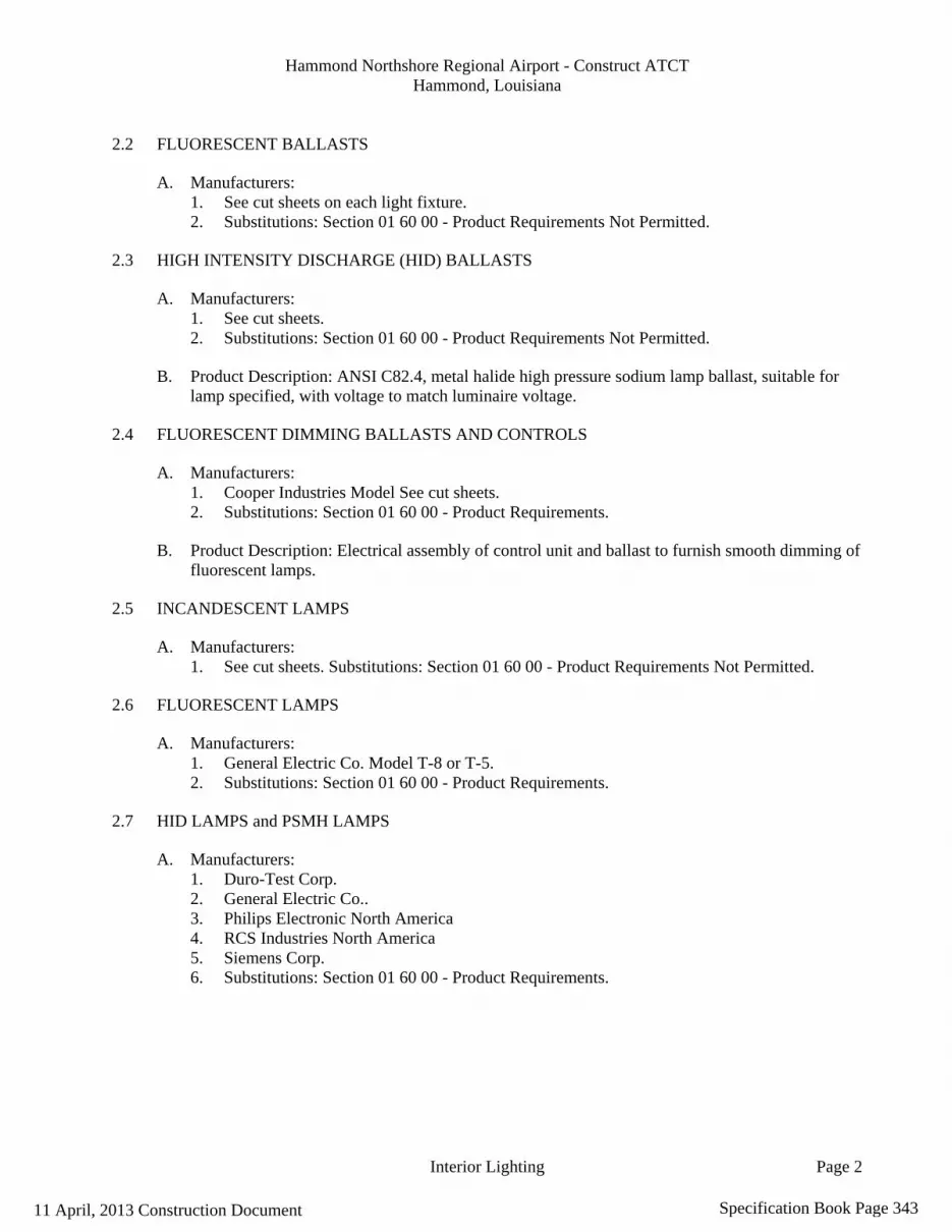
Hammond Northshore Regional Airport - Construct ATCT Hammond, Louisiana
Interior Lighting Page 2
2.2 FLUORESCENT BALLASTS
A. Manufacturers: 1. See cut sheets on each light fixture. 2. Substitutions: Section 01 60 00 - Product Requirements Not Permitted.
2.3 HIGH INTENSITY DISCHARGE (HID) BALLASTS
A. Manufacturers: 1. See cut sheets. 2. Substitutions: Section 01 60 00 - Product Requirements Not Permitted.
B. Product Description: ANSI C82.4, metal halide high pressure sodium lamp ballast, suitable for lamp specified, with voltage to match luminaire voltage.
2.4 FLUORESCENT DIMMING BALLASTS AND CONTROLS
A. Manufacturers: 1. Cooper Industries Model See cut sheets. 2. Substitutions: Section 01 60 00 - Product Requirements.
B. Product Description: Electrical assembly of control unit and ballast to furnish smooth dimming of fluorescent lamps.
2.5 INCANDESCENT LAMPS
A. Manufacturers: 1. See cut sheets. Substitutions: Section 01 60 00 - Product Requirements Not Permitted.
2.6 FLUORESCENT LAMPS
A. Manufacturers: 1. General Electric Co. Model T-8 or T-5. 2. Substitutions: Section 01 60 00 - Product Requirements.
2.7 HID LAMPS and PSMH LAMPS
A. Manufacturers: 1. Duro-Test Corp. 2. General Electric Co.. 3. Philips Electronic North America 4. RCS Industries North America 5. Siemens Corp. 6. Substitutions: Section 01 60 00 - Product Requirements.
11 April, 2013 Construction Document Specification Book Page 343

Hammond Northshore Regional Airport - Construct ATCT Hammond, Louisiana
Interior Lighting Page 3
PART 3 EXECUTION
3.1 INSTALLATION
A. Install suspended luminaires using pendants supported from swivel hangers. Install pendant length required to suspend luminaire at indicated height.
B. Locate recessed ceiling luminaires as indicated on Drawings.
C. Install surface mounted luminaires plumb and adjust to align with building lines and with each other. Secure to prevent movement.
D. Install specified lamps in each luminaire.
E. Ground and bond interior luminaires in accordance with Section 26 05 26.
3.2 ADJUSTING
A. Section 01 70 00 - Execution and Closeout Requirements: Testing, adjusting, and balancing.
B. Aim and adjust luminaires.
3.3 CLEANING
A. Section 01 70 00 - Execution and Closeout Requirements: Final cleaning.
B. Remove dirt and debris from enclosures.
C. Clean photometric control surfaces as recommended by manufacturer.
D. Clean finishes and touch up damage.
3.4 PROTECTION OF FINISHED WORK
A. Section 01 70 00 - Execution and Closeout Requirements: Protecting finished work.
B. Relamp luminaires having failed lamps at Substantial Completion.
END OF SECTION
11 April, 2013 Construction Document Specification Book Page 344

Hammond Northshore Regional Airport - Construct ATCT Hammond, Louisiana
Video Intercom and Access Control 28 13 00 - 1
SECTION 28 13 00
VIDEO INTERCOM AND ACCESS CONTROL SYSTEM
PART 1 GENERAL 1.1 SECTION INCLUDES
A. Hands-free color video intercom system. 1.2 REFERENCES
A. ISO 9001:2008 – Quality Management Systems – Requirements. 1.3 SYSTEM DESCRIPTION – STANDARD VIDEO INTERCOM SYSTEM
A. Answering Door Call in Hands-Free Mode: 1. Press CALL button. 2. Chime tone sounds, caller is seen on video monitor, and outside sound is heard. 3. Audio and video turn off after approximately 45 seconds if not answered. 4. Press TALK button momentarily, then communicate hands-free. Red transmit LED lights
when you talk, and goes off as you listen to caller or hear outside sounds. 5. Press TALK button once to end call.
B. Answering Door Call in Press-to-Talk (PTT) Mode:
1. Press CALL button. 2. Chime tone sounds, caller is seen on video monitor, and outside sound is heard. 3. Audio and video turn off after approximately 45 seconds if not answered. 4. During communication, press and hold TALK button for minimum of 1 second to change to
press-to-talk mode. If TALK button is pressed less than 0.5 seconds, communication ends. 5. To continue speaking using press-to-talk mode, press TALK button for minimum of 1 second
each time to talk, and release to listen to caller. 6. Press TALK button momentarily to end.
C. Instant Voice Call Function:
1. Press CALL button. 2. Even without answering, door area can be seen and heard with video and audio for
approximately 45 seconds. Inside sound is not heard outside.
D. Activating Door Release: 1. Press DOOR RELEASE button. Hold to activate, release to deactivate. 2. Open door while release mechanism is activated.
E. Entrance Monitoring:
1. Press MONITOR button. 2. Video monitor displays image from door station and incoming audio is heard. Sound from
inside is not heard outside. 3. Press MONITOR button again to end.
11 April, 2013 Construction Document Specification Book Page 345

Hammond Northshore Regional Airport - Construct ATCT Hammond, Louisiana
Video Intercom and Access Control 28 13 00 - 2
4. When busy tone sounds while pressing TALK button, another station is in use. 1.4 SUBMITTALS
A. Comply with Section 01330 (01 33 00) – Submittal Procedures.
B. Product Data: Submit manufacturer’s product data, including installation instructions.
C. Shop Drawings: Submit the following: 1. Wiring Diagrams: Indicate wiring for each item of equipment and interconnections between
items of equipment. 2. Include manufacturer’s names, model numbers, ratings, power requirements, equipment layout,
device arrangement, complete wiring point-to-point diagrams, and conduit layouts.
D. Installation and Operation Manuals: 1. Submit manufacturer’s installation and operation manual, including operation instructions and
component wiring diagrams. 2. Provide detailed information required for Owner to properly operate equipment.
E. Warranty: Submit manufacturer’s standard warranty.
1.7 QUALITY ASSURANCE
A. Manufacturer’s Qualifications: ISO 9001:2008 certified company. 1.8 DELIVERY, STORAGE, AND HANDLING
A. Delivery: Deliver materials to site in manufacturer’s original, unopened containers and packaging, with labels clearly identifying product name and manufacturer.
B. Storage: Store materials in clean, dry area indoors in accordance with manufacturer’s instructions.
C. Handling: Protect materials during handling and installation to prevent damage.
1.9 WARRANTY
A. Warranty Period: Two years from date of Substantial Completion. PART 2 PRODUCTS 2.1 MANUFACTURER
A. Aiphone Corporation, 1700 130th Avenue NE, Bellevue, Washington 98005. Toll Free (800) 692-0200. Phone (425) 455-0510. Fax (425) 455-0071. Website www.aiphone.com. E-mail [email protected].
2.2 VIDEO INTERCOM AND ACCESS CONTROL SYSTEM
A. Standard Hands-Free Color Video Intercom System: Aiphone “JF Series”.
11 April, 2013 Construction Document Specification Book Page 346

Hammond Northshore Regional Airport - Construct ATCT Hammond, Louisiana
Video Intercom and Access Control 28 13 00 - 3
1. Power Source:
a. 18 V DC. b. Model PS-1820UL.
2. Calling: a. Chime, image, and audio. b. Approximately 45 seconds.
3. Communication: a. Automatic (hands-free): To activate, momentarily press TALK button. b. Manual (press-to-talk/release-to-listen): To activate, press TALK button for 1 second or
until talk LED turns on. 4. Camera: CCD. 5. Video Monitor:
a. 3.5-inch direct-view TFT color LCD. b. Scanning Lines: 525. c. Minimum Illumination: 5 Lux at 1 foot.
6. Night Viewing: Up to 1 foot from camera, with white LED projected, background beyond 1 foot cannot be seen.
7. Door Release: a. Contact Rating: N/O 24 V AC/DC, 500 mA. b. Door Release Relay: Model RY-18L for Form C high-current contact.
8. Wiring: a. Door to Master Station: 2 conductor. b. Standard Master Monitor Station to Sub Monitor Station: 6 conductor. c. Enhanced Master Monitor Station to Sub Monitor Station: 4 conductor. d. Mid capacitance, solid, non-shielded. Use AIPHONE Wire # 87180250C (18 AWG 2
conductor solid core cable) for up to 330 ft. distance. Do not substitute. 9. (Not used)
10. Picture Memory: a. Record up to 50 image sequences (1 frame per second, 8 frames per image). b. Save up to 10 sequences (80 frames).
11. Voice Memo: Record maximum 3 voice memos (maximum approximately 15 seconds per memo).
12. Message for Entrance: Record maximum 2 messages (maximum approximately 10 seconds per message).
B. Door Stations:
1. Fixed Video Door Station: Model JF-DV. ( Interior recessed mounted )
a. Faceplate: Die-cast zinc. b. Surface mount. c. Microphone. d. Speaker. e. Camera: Color CCD with white illuminator LEDs. f. Call button. g. Vandal resistant. h. Weather resistant. i. Operating Temperature: 14 degrees F to 140 degrees F (minus 10 degrees C to 60
degrees C). 2. Fixed Video Door Station: Model JF-DVF. ( Exterior recessed mounted )
a. Faceplate: Stainless steel.
11 April, 2013 Construction Document Specification Book Page 347
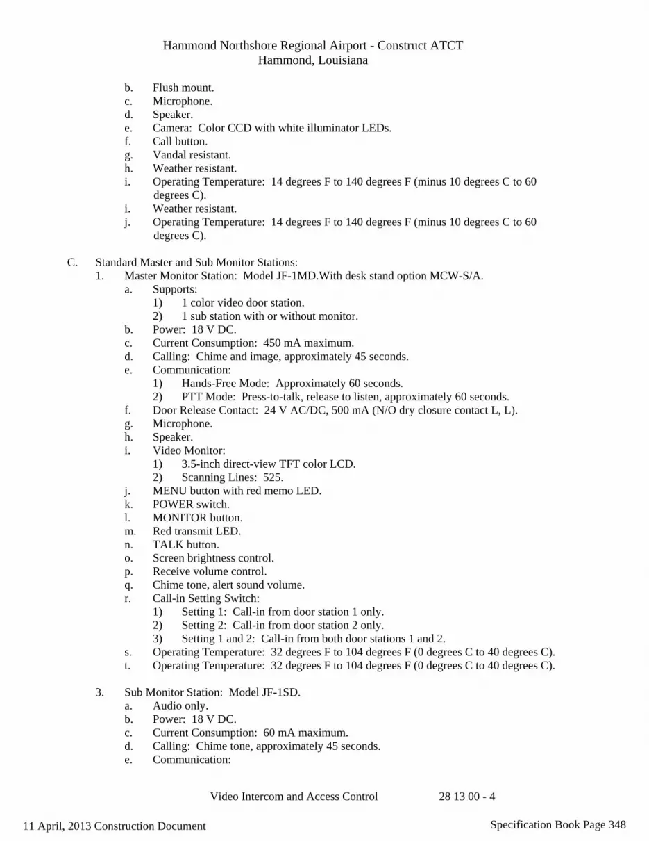
Hammond Northshore Regional Airport - Construct ATCT Hammond, Louisiana
Video Intercom and Access Control 28 13 00 - 4
b. Flush mount. c. Microphone. d. Speaker. e. Camera: Color CCD with white illuminator LEDs. f. Call button. g. Vandal resistant. h. Weather resistant. i. Operating Temperature: 14 degrees F to 140 degrees F (minus 10 degrees C to 60
degrees C). i. Weather resistant. j. Operating Temperature: 14 degrees F to 140 degrees F (minus 10 degrees C to 60
degrees C).
C. Standard Master and Sub Monitor Stations: 1. Master Monitor Station: Model JF-1MD.With desk stand option MCW-S/A.
a. Supports: 1) 1 color video door station. 2) 1 sub station with or without monitor.
b. Power: 18 V DC. c. Current Consumption: 450 mA maximum. d. Calling: Chime and image, approximately 45 seconds. e. Communication:
1) Hands-Free Mode: Approximately 60 seconds. 2) PTT Mode: Press-to-talk, release to listen, approximately 60 seconds.
f. Door Release Contact: 24 V AC/DC, 500 mA (N/O dry closure contact L, L). g. Microphone. h. Speaker. i. Video Monitor:
1) 3.5-inch direct-view TFT color LCD. 2) Scanning Lines: 525.
j. MENU button with red memo LED. k. POWER switch. l. MONITOR button. m. Red transmit LED. n. TALK button. o. Screen brightness control. p. Receive volume control. q. Chime tone, alert sound volume. r. Call-in Setting Switch:
1) Setting 1: Call-in from door station 1 only. 2) Setting 2: Call-in from door station 2 only. 3) Setting 1 and 2: Call-in from both door stations 1 and 2.
s. Operating Temperature: 32 degrees F to 104 degrees F (0 degrees C to 40 degrees C). t. Operating Temperature: 32 degrees F to 104 degrees F (0 degrees C to 40 degrees C).
3. Sub Monitor Station: Model JF-1SD.
a. Audio only. b. Power: 18 V DC. c. Current Consumption: 60 mA maximum. d. Calling: Chime tone, approximately 45 seconds. e. Communication:
11 April, 2013 Construction Document Specification Book Page 348

Hammond Northshore Regional Airport - Construct ATCT Hammond, Louisiana
Video Intercom and Access Control 28 13 00 - 5
1) Hands-Free Mode: Voice actuated (VOX), approximately 60 seconds. 2) PTT Mode: Press-to-talk, release to listen, approximately 60 seconds.
f. Microphone. g. Speaker. h. Red transmit LED. i. TALK button. j. DOOR RELEASE button. k. Reset switch. l. Chime TONE volume control. m. Operating Temperature: 32 degrees F to 104 degrees F (0 degrees C to 40 degrees C).
2.3 ACCESSORIES
A. 1-Gang Mounting Plate: Model MKW-P. ( Interior recessed mounted ) 1. For fixed video door station Model JF-DV.
B. Surface Mount Box: Model SBX-DVF. ( Exterior recessed mounted )
1. For fixed video door station Model JF-DVF.
C. Electric Door Strike: Model EL-9S or door strike suitable for door being released. 1. 12 V AC, 350 mA.
D. Selective Door Release Adaptor: Model RY-3DL.
E. Form C Door Release Relay: Model RY-18L.
1. For each door.
F. Call Extension Speaker: Model IER-2.
G. External Signaling Relay: Model TAR-3 with Model SKK-620 power supply.
H. CCTV Camera Interface Module: Model JBW-M. PART 3 EXECUTION 3.1 EXAMINATION
A. Examine areas to receive hands-free color video intercom system.
B. Notify Architect of conditions that would adversely affect installation or subsequent use.
C. Do not begin installation until unacceptable conditions are corrected. 3.2 INSTALLATION
A. Install hands-free color video intercom system in accordance with manufacturer’s instructions at locations indicated on the Drawings.
11 April, 2013 Construction Document Specification Book Page 349

Hammond Northshore Regional Airport - Construct ATCT Hammond, Louisiana
Video Intercom and Access Control 28 13 00 - 6
B. Mount equipment plumb, level, square, and secure. 3.3 ADJUSTING
A. Adjust hands-free color video intercom system for proper operation in accordance with manufacturer’s instructions.
3.4 DEMONSTRATION AND TRAINING
A. Demonstration: 1. Demonstrate that hands-free color video intercom system functions properly. 2. Perform demonstration at final system inspection by qualified representative of manufacturer.
B. Instruction and Training:
1. Provide instruction and training of Owner’s personnel as required for operation of hands-free color video intercom system.
2. Provide hands-on demonstration of operation of system components and complete system, including user-level program changes and functions.
3. Provide instruction and training by qualified representative of manufacturer. 3.5 PROTECTION
A. Protect installed hands-free color video intercom system from damage during construction.
END OF SECTION Aiphone Corporation April 2007 1700 130th Avenue NE Bellevue, Washington 98005 Toll Free (800) 692-0200 Phone (425) 455-0510 Fax (425) 455-0071 Website www.aiphone.com E-mail [email protected]
11 April, 2013 Construction Document Specification Book Page 350
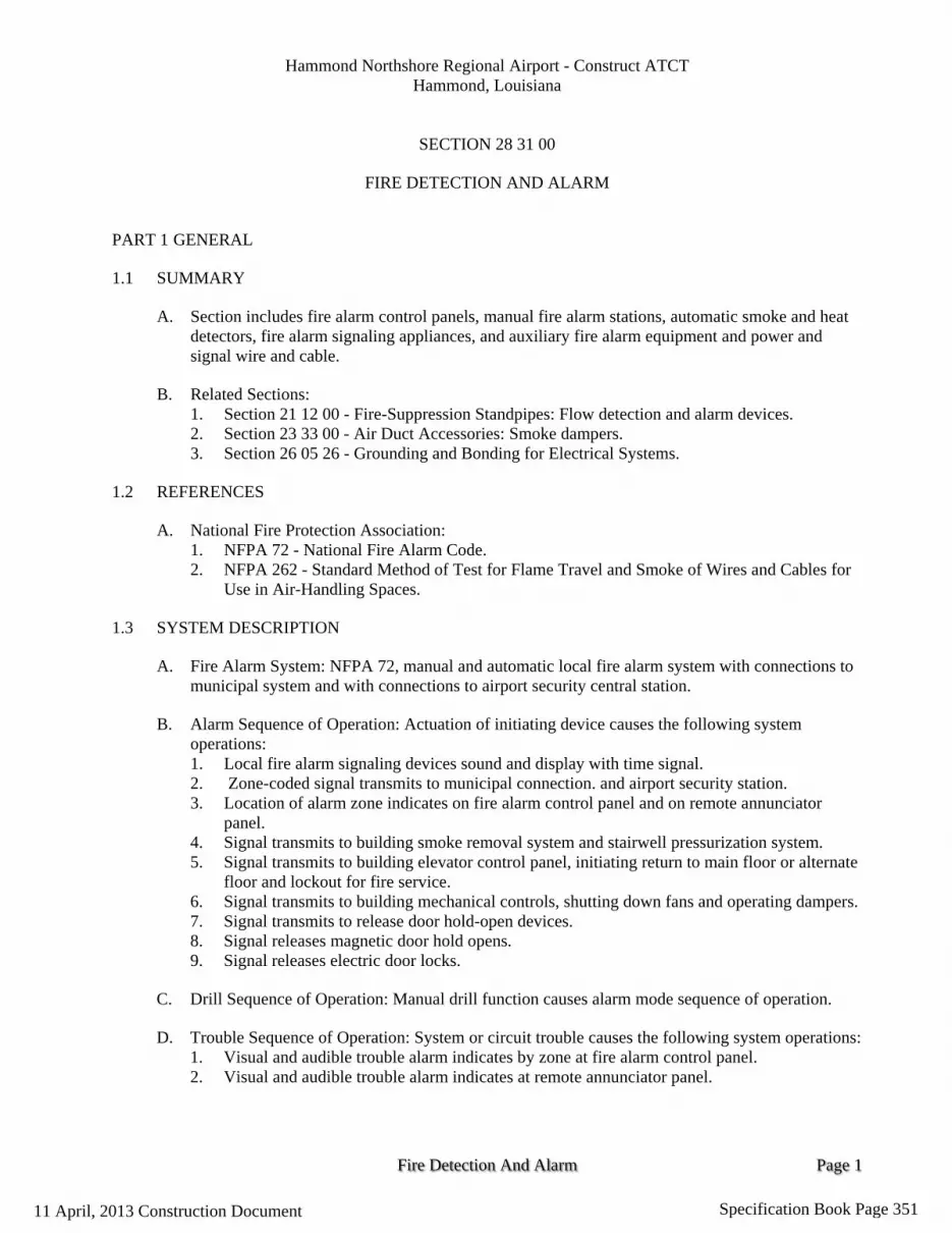
Hammond Northshore Regional Airport - Construct ATCT Hammond, Louisiana
Fire Detection And Alarm Page 1
SECTION 28 31 00
FIRE DETECTION AND ALARM
PART 1 GENERAL
1.1 SUMMARY
A. Section includes fire alarm control panels, manual fire alarm stations, automatic smoke and heat detectors, fire alarm signaling appliances, and auxiliary fire alarm equipment and power and signal wire and cable.
B. Related Sections: 1. Section 21 12 00 - Fire-Suppression Standpipes: Flow detection and alarm devices. 2. Section 23 33 00 - Air Duct Accessories: Smoke dampers. 3. Section 26 05 26 - Grounding and Bonding for Electrical Systems.
1.2 REFERENCES
A. National Fire Protection Association: 1. NFPA 72 - National Fire Alarm Code. 2. NFPA 262 - Standard Method of Test for Flame Travel and Smoke of Wires and Cables for
Use in Air-Handling Spaces.
1.3 SYSTEM DESCRIPTION
A. Fire Alarm System: NFPA 72, manual and automatic local fire alarm system with connections to municipal system and with connections to airport security central station.
B. Alarm Sequence of Operation: Actuation of initiating device causes the following system operations: 1. Local fire alarm signaling devices sound and display with time signal. 2. Zone-coded signal transmits to municipal connection. and airport security station. 3. Location of alarm zone indicates on fire alarm control panel and on remote annunciator
panel. 4. Signal transmits to building smoke removal system and stairwell pressurization system. 5. Signal transmits to building elevator control panel, initiating return to main floor or alternate
floor and lockout for fire service. 6. Signal transmits to building mechanical controls, shutting down fans and operating dampers. 7. Signal transmits to release door hold-open devices. 8. Signal releases magnetic door hold opens. 9. Signal releases electric door locks.
C. Drill Sequence of Operation: Manual drill function causes alarm mode sequence of operation.
D. Trouble Sequence of Operation: System or circuit trouble causes the following system operations: 1. Visual and audible trouble alarm indicates by zone at fire alarm control panel. 2. Visual and audible trouble alarm indicates at remote annunciator panel.
11 April, 2013 Construction Document Specification Book Page 351

Hammond Northshore Regional Airport - Construct ATCT Hammond, Louisiana
Fire Detection And Alarm Page 2
3. Trouble signal transmits to airport security station.
E. Zoning: As indicated on Drawings.
1.4 SUBMITTALS
A. Section 01 33 00 - Submittal Procedures: Submittal procedures.
B. Shop Drawings: Indicate system wiring diagram showing each device and wiring connection, wiring pathway, wire size and protection, annunciator layout, and design calculations. Provide riser diagram and layout drawings. Do not include security and/or communications on drawings.
C. Product Data: Submit catalog data showing electrical characteristics and connection requirements.
D. Test Reports: Indicate procedures and results for specified field testing and inspection.
E. Manufacturer's Field Reports: Indicate activities on site, adverse findings, and recommendations.
1.5 CLOSEOUT SUBMITTALS
A. Section 01 70 00 - Execution and Closeout Requirements: Closeout procedures.
B. Project Record Documents: Record actual locations of fire alarm equipment.
C. Operation and Maintenance Data: Submit manufacturer’s standard operating and maintenance instructions.
1.6 QUALITY ASSURANCE
A. Provide wiring materials located in plenums with peak optical density not greater than 0.5, average optical density not greater than 0.15, and flame spread not greater than 5 feet (1.5 m) when tested in accordance with NFPA 262.
B. Maintain 2 copies of each document on site.
1.7 QUALIFICATIONS
A. Manufacturer: Company specializing in manufacturing products specified in this section with minimum three years experience, and with service facilities within 100 miles of project.
B. Installer: Certified fire alarm installer with service facilities within 100 miles of Project.
C. Design fire alarm under direct supervision of Professional Engineer experienced in design of this Work and licensed in State of Louisiana.
1.8 MAINTENANCE SERVICE
A. Section 01 70 00 - Execution and Closeout Requirements: Maintenance service.
11 April, 2013 Construction Document Specification Book Page 352

Hammond Northshore Regional Airport - Construct ATCT Hammond, Louisiana
Fire Detection And Alarm Page 3
B. Furnish service and maintenance of fire alarm equipment for one year from Date of Substantial Completion.
1.9 MAINTENANCE MATERIALS
A. Section 01 70 00 - Execution and Closeout Requirements: Spare parts and maintenance products.
B. Furnish ten manual station break-glass rods.
C. Furnish six keys of each type.
1.10 EXTRA MATERIALS
A. Section 01 70 00 - Execution and Closeout Requirements: Spare parts and maintenance products.
B. Furnish three of each type of automatic smoke detector without base.
PART 2 PRODUCTS
2.1 CONTROL PANEL
A. Manufacturers: 1. Any meeting specifications.
B. Product Description: Modular fire alarm control panel with semi recessed wall-mounted enclosure.
C. Power supply: Adequate to serve control panel modules, remote detectors, remote annunciators, smoke dampers, relays, and alarm signaling devices. Include battery-operated emergency power supply with capacity for operating system in standby mode for 24 hours followed by alarm mode for 10 minutes.
D. System Supervision: Component or power supply failure places system in trouble mode.
E. Initiating Device Circuits: Supervised zone module with alarm and trouble indication; occurrence of single ground or open condition places circuit in trouble mode but does not disable circuit from initiating alarm.
F. Indicating Appliance Circuits: Supervised march time signal module, sufficient for signal devices connected to system; occurrence of single ground or open condition places circuit in trouble mode but does not disable circuit from signaling alarm.
G. Municipal Trip Circuit: Output connections for connection to parallel telephone circuit municipal master fire alarm box. remote station transmitter. Include municipal trip DISCONNECT switch.
H. Auxiliary Relays: Sufficient SPDT auxiliary relay contacts to provide accessory functions specified. Interface with electrician on relays suitable to operate electrical equipment.
11 April, 2013 Construction Document Specification Book Page 353

Hammond Northshore Regional Airport - Construct ATCT Hammond, Louisiana
Fire Detection And Alarm Page 4
2.2 MANUAL FIRE ALARM STATIONS
A. Any meeting specifications
B. Product Description: Manual single-action double-action station with break-glass rod.
C. Mounting: Surface.
D. Type: Coded.
E. Backbox: Manufacturer's standard.
2.3 SPOT HEAT DETECTOR
A. Manufacturers: Any meeting specifications
B. Product Description: Rate-of-rise and fixed temperature, spot heat detector per drawings.
C. Temperature Rating: 135 degrees F.
D. Rate-of-Rise: 15 degrees F.
2.4 CEILING SMOKE DETECTOR
A. Manufacturers: Any meeting specifications
B. Any meeting specifications Product Description: NFPA 72, ionization type ceiling smoke detector with the following features: 1. Adjustable sensitivity. 2. Plug-in base. 3. Auxiliary relay contact. 4. Integral thermal element rated 135 degrees F. 5. Visual indication of detector actuation. 6. Comply with UL 268.
C. Mounting: 102 mm outlet box.
D. Furnish four-wire detector with separate power supply and signal circuits.
2.5 FIRE SPRINKLER WATER FLOW DETECTOR
A. Wire detectors provided by fire protection contractor.
2.6 ALARM LIGHTS
A. Manufacturers: Any meeting specifications
B. Product Description: NFPA 72, strobe lamp and flasher with red lettered "FIRE" on white lens.
C. Control cab requires a red lamp installed in a lighting panel instead of any strobe or horn.
11 April, 2013 Construction Document Specification Book Page 354

Hammond Northshore Regional Airport - Construct ATCT Hammond, Louisiana
Fire Detection And Alarm Page 5
2.7 ALARM HORN
A. Manufacturers: Any meeting specifications
B. Product Description: NFPA 72, surface type fire alarm horn with the following features: 1. Sound Rating: 87 dB at 10 ft. 2. Integral strobe lamp and flasher with red lettered "FIRE" on white lens.
C. Product Description: Exterior mounted horn with the following features: 1. Sound Rating: 87 dB at 10 feet.
2.8 REMOTE ANNUNCIATOR
A. Manufacturers: Any meeting specifications
B. Product Description: Remote annunciator including audible and visual indication of fire alarm by zone, and audible and visual indication of system trouble.
C. Mounting: Factory mounted in surface wall-mounted enclosure.
2.9 WIRE AND CABLE
A. Manufacturers: Any meeting specifications
B. Product Description: Non-power limited fire-protective signaling cable, copper conductor, 150 volt insulation rated 60 degrees C.
C. Cable Located Exposed in Plenums: Power limited fire-protective signaling cable classified for fire and smoke characteristics, copper conductor, 300 volts insulation rated 105 degrees C, suitable for use in air handling ducts, hollow spaces used as ducts, and plenums.
D. Fire alarm circuit conductors have insulation color or code as follows: 1. Power Branch Circuit Conductors: Black, red, white. 2. Initiating Device Circuit: Black, red. 3. Detector Power Supply: Violet, brown. 4. Signal Device Circuit: Blue (positive), white (negative). 5. Door Release: Gray, gray. 6. Municipal Trip Circuit: Orange, orange. 7. Municipal Fire Alarm Loop: Black, white.
PART 3 EXECUTION
3.1 EXAMINATION
A. Section 01 30 00 - Administrative Requirements: Coordination and project conditions.
B. Verify products and systems receiving devices are ready for installation.
11 April, 2013 Construction Document Specification Book Page 355

Hammond Northshore Regional Airport - Construct ATCT Hammond, Louisiana
Fire Detection And Alarm Page 6
3.2 EXISTING WORK (N/A)
3.3 INSTALLATION
A. Install manual station with operating handle 55 inches above floor.
B. Install audible and visual signal devices 90 inches above floor.
C. Install 16 AWG minimum size conductors for fire alarm detection and signal circuit conductors in conduit.
D. Mount end-of-line device in control panel.
E. Connect conduit and wire to door release devices, sprinkler valve tamper switches, fire suppression system control panels, sprinkler flow switches and standpipe.
F. Automatic Detector Installation: Conform to NFPA 72.
G. Install engraved plastic nameplates in accordance with Louisiana Fire Marshal criteria.
H. Ground and bond fire alarm equipment and circuits in accordance with Section 26 05 26.
3.4 FIELD QUALITY CONTROL
A. Section 01 40 00 - Quality Requirements 01 70 00 - Execution and Closeout Requirements: Field inspecting, testing, adjusting, and balancing.
B. Test in accordance with NFPA 72 and local fire department requirements.
3.5 MANUFACTURER'S FIELD SERVICES
A. Section 01 40 00 - Quality Requirements: Manufacturer’s field services.
B. Include services of certified technician to supervise installation, adjustments, final connections, and system testing.
3.6 DEMONSTRATION AND TRAINING
A. Furnish 0.5 hours of instruction each for 8 persons, to be conducted at project site with manufacturer's representative.
11 April, 2013 Construction Document Specification Book Page 356

FAA-C-1217f February 26, 1996 SUPERSEDING US DEPARTMENT FAA-C-1217e, 01/25/91 OF TRANSPORTATION Federal Aviation Administration
U. S. Department of Transportation Federal Aviation Administration
Specification
ELECTRICAL WORK, INTERIOR
11 April, 2013 Construction Document Specification Book Page 357

11 April, 2013 Construction Document Specification Book Page 358

FAA-C-1217f February 26, 1996
1
11 April, 2013 Construction Document Specification Book Page 359

FAA-C-1217f February 26, 1996
2
FORWARD This document has been revised to reflect current technology changes and to incorporate the latest commercial standards.
11 April, 2013 Construction Document Specification Book Page 360

FAA-C-1217f February 26, 1996
3
l. SCOPE
1.1 Scope.- This specification covers the minimum requirements for electrical work at FAA facilities. Where the phrase "unless otherwise indicated" or similar wording appears, it refers exclusively to other documents that are specific parts of the contract. Where there are requirements peculiar to specific FAA facility types, e.g., air route traffic control centers (ARTCCs), metroplex control facilities (MCFs), terminal radar control (TRACONs), etc., these requirements will be added following the appropriate paragraph.
2. APPLICABLE DOCUMENTS.- The current issues of the following documents in effect on the date of the invitation-for-bids or request-for-proposals form a part of this specification, and are applicable to the extent specified herein.
2.1 Federal specifications
J-C-30 Cable and Wire, Electrical (Power, Fixed Installation)
W-C-375 Circuit Breakers, Molded Case; Branch Circuit and Service
W-F-414 Fixture, Lighting (Fluorescent, Alternating Current, Pedant Mounting)
W-L-305 Light Set, General Illumination (Emergency or Auxiliary)
W-P-115 Panel, Power Distribution WW-C-566 Conduit, Metal, Flexible
QQ-W-343 Wire, Electrical, (uninsulated)
11 April, 2013 Construction Document Specification Book Page 361
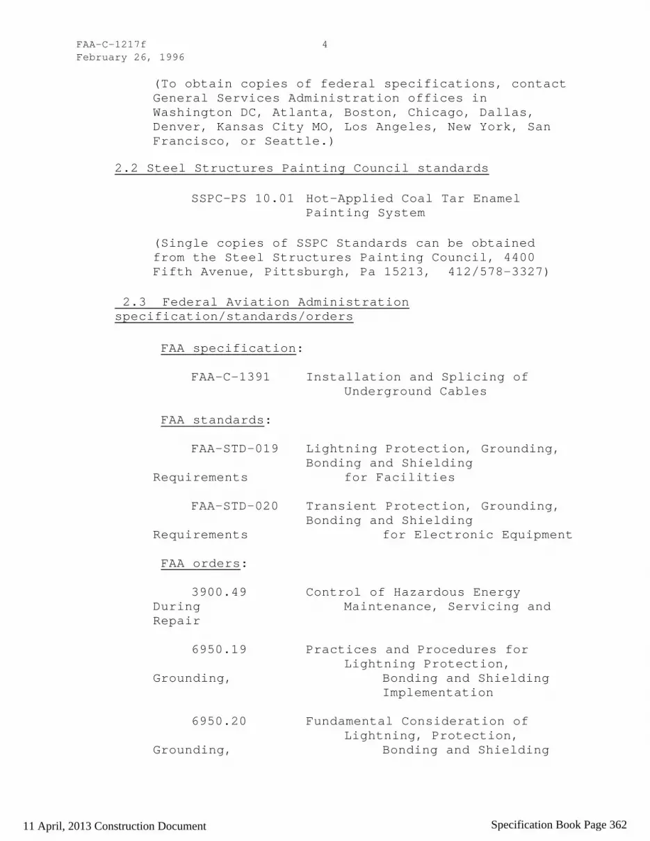
FAA-C-1217f February 26, 1996
4
(To obtain copies of federal specifications, contact General Services Administration offices in Washington DC, Atlanta, Boston, Chicago, Dallas, Denver, Kansas City MO, Los Angeles, New York, San Francisco, or Seattle.)
2.2 Steel Structures Painting Council standards
SSPC-PS 10.01 Hot-Applied Coal Tar Enamel Painting System
(Single copies of SSPC Standards can be obtained from the Steel Structures Painting Council, 4400 Fifth Avenue, Pittsburgh, Pa 15213, 412/578-3327)
2.3 Federal Aviation Administration specification/standards/orders
FAA specification:
FAA-C-1391 Installation and Splicing of Underground Cables
FAA standards:
FAA-STD-019 Lightning Protection, Grounding, Bonding and Shielding Requirements for Facilities
FAA-STD-020 Transient Protection, Grounding, Bonding and Shielding Requirements for Electronic Equipment FAA orders:
3900.49 Control of Hazardous Energy During Maintenance, Servicing and Repair
6950.19 Practices and Procedures for Lightning Protection, Grounding, Bonding and Shielding Implementation
6950.20 Fundamental Consideration of Lightning, Protection, Grounding, Bonding and Shielding
11 April, 2013 Construction Document Specification Book Page 362

FAA-C-1217f February 26, 1996
5
6950.22 Maintenance of Electrical Power and Control Cables
6950.27 Short Circuit Analysis and Protective Device Coordination Study (Copies of FAA specifications may be obtained from the Contracting Officer in the office issuing the invitation-for-bids or request-for-proposals. Requests should fully identify material desired, i.e., specifications, standard, amendment, and drawing numbers and dates. Requests should cite the invitation-for-bids, request-for-proposals, or the contract involved or other use to be made of the requested material.)
2.4 National Fire Protection Association (NFPA) publications
NFPA 70 National Electrical Code (NEC)
(Requests for copies of NFPA publications should be addressed to the National Fire Protection Association, Batterymarch Park, Quincy MA 02269.)
2.5 National Electrical Manufacturers Association (NEMA) standards
OS-1 Sheet Steel Outlet Boxes, Device Boxes, covers and Box Supports MG-1 Standard for Motors and Generators
ST 20 Dry Type Transformers for General Applications
VE 1 Cable Tray Systems
WC 5 Thermoplastic Insulated Wire and Cable for the Transmission and Distribution of Electrical Energy
11 April, 2013 Construction Document Specification Book Page 363

FAA-C-1217f February 26, 1996
6
WD 1 General Requirements for Wiring Devices
(For copies of NEMA standards, contact the National Electrical Manufacturers Association, 2101 L Street N.W. Washington DC 20057, 202/457-8400.)
2.6 Underwriters' Laboratories (UL) Inc. standards
UL 5 Surface Metal Raceways and Fittings UL 6 Rigid Metal Conduit
UL 50 Enclosures for Electrical Equipment
UL 486A Wire Connectors and Soldering Lugs for Use with Copper Conductors UL 486C Splicing Wire Connectors UL 486E Equipment Wiring Terminals for Use with Aluminum and/or Copper Conductors UL 514A Metallic Outlet Boxes UL 514B Fittings for Conduit and Outlet Boxes
UL 542 Lampholders, Starters, and Starter Holders for Fluorescent Lamps
UL 651 Schedule 40 and 80 Rigid PVC
UL 797 Electrical Metallic Tubing UL 870 Wireways, Auxiliary Gutters and Associated Fittings UL 935 Fluorescent-Lamp Ballasts UL 1242 Intermediate Metal Conduit
11 April, 2013 Construction Document Specification Book Page 364

FAA-C-1217f February 26, 1996
7
(For copies of UL standards, contact Underwriters' Laboratories Inc., Publication Department, 333 Pfingsten Rd., Northbrook IL 60062.)
2.7 Institute of Electrical and Electronics Engineers (IEEE) Inc. standards
STD C57.12.80 Standard Terminology for Power and Distribution Transformers
STD 141 Recommended Practice for Electric Power Distribution for Industrial Plants
STD 519 Recommended Practices and Requirements for Harmonic Control and Electrical Power Systems
STD 1100 Recommended Practice for Powering and Grounding Sensitive Electronic Equipment
For copies of this standard, contact the IEEE Inc., Service Department, 445 Hoes Lane, PO Box 1331, Piscataway NJ 08855-1331.)
2.8 Other documents
2.8.1 Local utility companies.- The rules and regulations of the local utility companies providing service.
2.8.2 Local governing bodies.- The rules, regulations, and codes of local governing bodies.
3. MATERIALS
3.1 General.- The contractor shall furnish all materials not specifically identified as Government Furnished Materials in the invitation-for-bids or contract. Materials and equipment shall comply with all requirements of the contract documents. Materials furnished by the contractor shall be new, the standard
11 April, 2013 Construction Document Specification Book Page 365

FAA-C-1217f February 26, 1996
8
products of manufacturers regularly engaged in the production of such materials, and of the manufacturer's latest designs that comply with the specification requirements. If materials and equipment requirements conflict, the order of precedence for selection shall be as follows: special contract provision, the contract drawings, this specification, and then continuing order of precedence, referenced FAA documents, Military documents, Federal specifications, NFPA publications, IEEE standards; UL standards and NEMA standards. Wherever standards have been established by Underwriters' Laboratories, Inc., the material shall bear the UL label.
4. INSTALLATION
NOTE: Unscheduled interruptions of the electrical service to FAA facilities may cause aircraft accidents and loss of life. Work requiring a temporary or permanent deenergization of equipment shall be scheduled in writing with the onsite FAA maintenance personnel. Only onsite FAA maintenance personnel are authorized to energize, deenergize equipment or to operate a circuit breaker, switch, or fuse in an FAA facility. Work procedures shall include lock-out/tag-out procedures in accordance with FAA Order 3900.49.
4.1 General.- The rules, regulations and reference specifications enumerated herein shall be considered as minimum requirements. FAA requirements often exceed those of other standards organizations such as the NEC. Adherence to other standards shall not relieve the contractor from furnishing and installing higher grades of materials and workmanship when so required by this specification. Adherence to this specification shall not relieve the contractor from furnishing and installing higher grades of materials and workmanship when so required by the contract drawings or special contract provisions. This specification shall govern when conflicts occur between it and the documents referenced in paragraph 2, Applicable documents, and in the order of precedence established in paragraph 3, Materials.
4.1.1 Short circuit analysis and protective device coordination (SCA/PDC). - The distribution system and all component parts, when installed or as modified, shall be in accordance with IEEE Standard 519, Recommended Practices and Requirements for Harmonic Control and
11 April, 2013 Construction Document Specification Book Page 366

FAA-C-1217f February 26, 1996
9
Electrical Systems, and shall include a short circuit analysis and protective device coordination study in accordance with FAA Order 6950.27.
4.2 Workmanship.- All materials and equipment shall be installed in accordance with the contract drawings. When manufacturers recommended installation methods conflict with contract requirements, differences shall be resolved by the Contracting Officer. The installation shall be accomplished by qualified workers regularly engaged in this type of work. Where required by local regulations, the workers shall be properly licensed.
4.3 Contract drawings.- Where the electrical drawings indicate (by diagram or otherwise) the work intended and the functions to be performed, even though some details are not shown, the contractor shall furnish all equipment, material (other than the Government-furnished items, see paragraph 3.1) and labor to complete the installation work and to accomplish all the indicated functions of the electrical installation. Further, the contractor shall be responsible for taking the necessary actions to ensure that all electrical work is coordinated and compatible with architectural, mechanical, and structural plans, and the layout of any special electronic equipment.
4.3.1 Minor departures.- Minor departures from exact dimensions shown on the electrical plans may be permitted when required to avoid conflict or unnecessary difficulty in placement of a dimensioned item, provided all contract requirements are met. The contractor shall promptly obtain approval from the Contracting Officer prior to undertaking any such departure and shall provide appropriate documentation of the departure.
4.4 Grounding
4.4.1 General.- FAA grounding requirements often exceed those of the NEC. Grounding systems shall be as indicated on the contract drawings and as specified herein. Reference IEEE Standard 1100-1992, Recommended Practice for Powering and Grounding Sensitive Electronic Equipment, when installing all NAS equipment. In no case, however, shall the NEC be violated.
11 April, 2013 Construction Document Specification Book Page 367

FAA-C-1217f February 26, 1996
10
4.4.2 Grounding electrode conductor.- The grounding electrode conduct shall be bare or insulated copper and shall be sized as shown in the contract documents. When not indicated in the contract documents, the conductor shall be copper and sized in accordance with Table 250-94, "Grounding Electrode Conductor for AC Systems", of the NEC, except that the conductor shall not be smaller than No. 6 AWG. Where the grounding electrode conductor is routed through a metal raceway, the raceway shall be electrically continuous and bonded to the conductor at each end. The grounding electrode conductor shall be bonded to the earth electrode system with an exothermic welded joint. For a separately derived system such as an isolation transformer, the grounding electrode conductor shall be connected in accordance with the NEC. This conductor shall be permitted to terminate by exothermic welding to an equipment room's perimeter ground cable under a raised floor.
4.4.3 Earth electrode system.- The earth electrode system shall be installed as shown in the contract documents. Unless otherwise indicated in these documents, the earth electrode system shall consist of a minimum of four (4) ground rods located at the corners of a structure. Rods shall be spaced apart a distance equal to or greater than the length of the rods. Ground rods shall be 3/4 inch by 10 feet, copper or copper-clad steel. Sectionalized type or exothermic butt welded rods shall be used when deeper earth penetration is required. Rods shall be interconnected by a bare copper cable forming a closed loop around a structure. The cable shall be a minimum No. 4/0 AWG and shall be buried at least 2 feet below grade. The top of the vertically-driven ground rods shall be a minimum of 12 inches below grade. All underground metal pipes (excluding gas piping systems), tanks, and the telephone ground, if present, shall be connected to the earth electrode system by a copper cable no smaller than No. 2 AWG. All underground connections shall be made by exothermic welding process unless otherwise indicated.
4.4.4 Earth electrode system resistance.- The resistance of the earth electrode system shall not exceed 10 ohms, as tested per paragraph 5.3.6, unless otherwise indicated. If the measured resistance exceeds 10 ohms,
11 April, 2013 Construction Document Specification Book Page 368

FAA-C-1217f February 26, 1996
11
the Contracting Officer shall be notified immediately for further guidance.
4.4.5 Equipment grounding conductor
4.4.5.1 General.- All metallic non-current carrying parts of electrical equipment shall be grounded with equipment grounding conductors whether or not shown on the drawings. Equipment grounding conductors shall always be green insulated copper conductors unless otherwise indicated. Non-insulated equipment grounding conductors are not allowed. When these conductors are not sized, or shown on the contract drawings, they shall be sized in accordance with Table 250-95, "Minimum Size Equipment Grounding Conductors for Grounding Raceway and Equipment", of the NEC.
4.4.5.2 Connections.- There shall be no interconnection between equipment grounding conductors and neutral conductors except at the main service and separately derived sources. All connections to equipment to be grounded shall be made with a grounding connector specifically intended for that purpose. Bare wire, wrapped around mounting bolts and screws, is not acceptable as a grounding connection. All ground lugs shall be of a noncorrosive material suitable for use as a grounding connection, and must be compatible with the type of metal being grounded. All mating surfaces and connections shall be between cleaned bare metal to bare metal surfaces.
4.4.5.3 Installation.- Each overcurrent device shall have its own equipment grounding conductor, i.e., a single-pole single-phase overcurrent device shall be supplied with an equipment grounding conductor; a two-pole, single-phase overcurrent device shall be supplied with its own equipment grounding conductor; a three-pole, three-phase overcurrent device shall be supplied with its own equipment grounding conductor. The equipment grounding conductor shall be installed in the same conduit as its related branch and feeder conductors and shall be connected to the ground bus in the branch or distribution panelboard. Metal conduit housing the equipment grounding conductor shall be electrically continuous, forming a parallel path to the equipment grounding conductor, except as allowed by the NEC. Where parallel feeders are installed in more than one raceway,
11 April, 2013 Construction Document Specification Book Page 369

FAA-C-1217f February 26, 1996
12
a full sized equipment grounding conductor shall be installed in each raceway.
4.4.6 Raceway grounding.- Surface metal raceways, wireways, or cable rack systems shall be installed in a manner that assures electrical continuity. Insulated copper bonding jumpers shall be installed between adjacent raceway sections to assure proper bonding. Uninsulated conductors shall not be used. Unless otherwise indicated, the minimum size for these bonding jumpers shall be No. 6 AWG. Where aluminum raceways are used, the jumpers shall be bonded with approved connectors for the dissimilar metals. All metallic raceway penetrations into a facility structure shall be bonded to the earth electrode system in accordance with FAA-STD-019.
4.4.7 Other grounding systems.- Any additional grounding systems used for electronic equipment shall be connected directly to the exterior earth electrode system or the perimeter ground cable under a raised floor in an equipment room. Other grounding systems shall not be used in place of the equipment grounding conductor system. The conductor used for other grounding (i.e., NEC 250-74, exception #4) systems shall be color coded green with a yellow stripe for single point isolated signal ground, green with an orange stripe for multipoint signal ground, green with a red stripe for high energy ground, green with a violet stripe for isolated equipment grounding connections.
4.5 Electrical surge protection
4.5.1 General.- All electrical surge protection systems shall be installed in accordance with FAA-STD-019.
4.5.2 Supply transformer.- For utility owned transformers, protective devices shall be at the discretion of the utility. For FAA owned transformers, proper protection shall be provided on the primary side of the transformer.
4.5.3 Service entrance surge arrester.- A fused surge arrester provided with disconnect capability shall be installed on the line, (supply-side) of the service as close as possible to the service terminals. Separate terminating lugs shall be provided for the surge
11 April, 2013 Construction Document Specification Book Page 370

FAA-C-1217f February 26, 1996
13
arrester. This arrester shall be compatible with the service voltage, and shall be wired to avoid loops, sharp bends and kinks, and to minimize the number of bends. There shall be no interconnection between neutral and ground within the arrester. Arrester conductors shall be No. 4 AWG insulated copper or larger, unless a smaller size is recommended by the arrester manufacturer.
4.5.4 Transient suppression installations.- Where transient suppression devices are installed in the electrical power distribution system they shall be installed in accordance with manufacturers instructions unless otherwise specified.
4.5.5 Land line/cable penetration installations.- Suppression systems shall be provided for land line and cable penetration systems in accordance with FAA-STD-019. High energy grounding conductors shall be bonded directly to the earth electrode system or to the perimeter ground cable under raised floors in equipment rooms.
4.6 Wiring methods
4.6.1 General.- All wiring shall consist of insulated copper conductors installed in metallic raceways, unless otherwise specified.
4.6.1.1 Conductor routing.- Panelboards, surge arresters, disconnect switches, etc., shall not be used as raceway for conductor routing other than conductors that originate or terminate in these enclosures. Isolated ground conductors will be allowed to traverse these enclosures.
4.6.1.2 Conductor separation - Power conductors shall be routed separately from all other conductor types. This may be accomplished by routing power conductors and other conductors in separate raceways, or by a metallic divider between the power conductors and the other conductors in the same raceway.
4.6.2 Neutral conductor.- Shared/common neutrals shall not be permitted, i.e., each overcurrent device shall have its' own separate neutral conductor. Neutral conductor sizes shall not be less than the respective feeder or phase conductor sizes.
11 April, 2013 Construction Document Specification Book Page 371
FAA-C-1217f February 26, 1996
14
4.6.3 Raceway systems
4.6.3.1 General.- Each run shall be complete, and shall be fished and swabbed before conductors are installed. Ends of raceway systems not terminated in boxes or cabinets shall be capped. Exposed raceways shall be installed parallel to or at right angles with the lines of the structure. Crushed or deformed raceways shall not be installed. A pull wire shall be installed in all empty tubing and conduit systems in which wiring is to be installed by others. The pull wire shall be No. 14 AWG zinc-coated steel, or plastic with a minimum 200-pound tensile strength. Ten inches of slack shall be left at each end of the pull wire. Sections of raceways which pass through to damp, concealed, or underground locations shall be of a type allowed for such locations by NEC Article 300-5, and shall extend a minimum of 12 inches beyond the damp, concealed, or underground area. Where raceway has to be cut in the field, it shall be cut square and burrs and sharp edges removed. Where conduits penetrate walls or floors separating the building interior from the exterior, they shall be sealed to prevent moisture and rodent entry and to deter air transfer. In addition, where conduits penetrate walls separating individually controlled temperature or humidity controlled areas, they shall be sealed to prevent air circulation. Sealing methods and sealants shall be accordance with NEC Article 300-7. Openings around penetrations through fire-resistant-rated walls, partitions, floors, or ceilings shall be fire stopped using approved methods to maintain the fire resistance rating.
4.6.3.2 Conduit. Minimum conduit size shall be 3/4 inch unless otherwise specified. Conduit for telephone and signal systems shall be allowed to be 1/2 inch. Where threads have to be cut on conduit, the threads shall have the same effective length and shall have the same thread dimensions and taper as specified for factory cut threads on conduit.
NOTE:
For ARTCCs, MCFs, and Large TRACONs, rigid steel conduit (RSC)or intermediate metal conduit (IMC) shall be used for all distribution panel feeders, transformer feeders, motor control center feeders and distribution
11 April, 2013 Construction Document Specification Book Page 372

FAA-C-1217f February 26, 1996
15
switchboards. Electrical metallic tubing (EMT) maybe used for communication, lighting and branch circuits.
4.6.3.2.1 Zinc coated rigid steel conduit (RSC).- Zinc coated rigid steel conduit (RSC) shall conform to UL 6. RSC, may be used in all locations and shall be used for all underground service conductors. For installation below slab, on-grade, or underground, the conduit shall conform to Steel Structures Painting Council Standard, SSPC-PS 10.01, or shall be field wrapped with 0.01-inch thick pipe wrapping plastic tape applied with 50% overlap. Fittings used underground shall be protected by field wrapping as specified herein for conduit. All fittings used with rigid steel conduit shall be the threaded type, of the same material as the conduit. Where conduits enter enclosures without threaded hubs, double locknuts (one on each side of the enclosure wall) shall be used to securely bond the conduit to the enclosure. In addition, a bushing shall be installed on the interior threaded end of the conduit to protect conductor insulation.
4.6.3.2.2 Intermediate metal conduit (IMC). IMC shall be zinc coated steel, shall conform to UL Standard 1242, and shall bear the UL label. For installation below slab on grade or underground, the conduit shall conform to Steel Structures Painting Council Standard, SSPC-PS 10.01, or shall be field wrapped with 0.01-inch thick pipe wrapping plastic tape applied with 50% overlay. Fittings used underground shall be protected by field wrapping as specified herein for conduit. Where it is necessary to fabricate IMC bends in the field, the tooling required to fabricate those bends shall be specifically designed for IMC. All fittings shall be of the threaded type, of the same material as the conduit. Where conduits enter enclosures without threaded hubs, double locknuts (one on each side of the enclosure wall) shall be used to securely bond the conduit to the enclosure. In addition, a bushing shall be installed on the interior threaded end of the conduit to protect conductor insulation.
4.6.3.2.3 Electrical metallic tubing (EMT).- EMT shall conform to UL 797. EMT may be used only in dry interior locations, and where not subject to physical damage. EMT shall not be used on circuits above 600 volts nor in sizes greater than 34 inches in diameter. Fittings used
11 April, 2013 Construction Document Specification Book Page 373

FAA-C-1217f February 26, 1996
16
with EMT shall be standard compression-type fittings designed for this type of EMT, unless otherwise indicated. Screw-type fittings are not acceptable. Where EMT enters enclosures without threaded hubs, an appropriate connector with threads and cast or machined (not sheet metal) locknut shall be used to securely bond the conduit to the enclosure. The connector body and locknut shall be installed so that firm contact is made on each side of the enclosure. In addition the connectors shall have an insulated-throat, smooth bell shaped end, or a bushing.
4.6.3.2.4 Rigid aluminum conduit.- Aluminum raceways shall not be used for any installation.
4.6.3.2.5 Rigid nonmetallic conduit.- Rigid nonmetallic conduit shall be heavywall PVC conforming to UL 651. Rigid nonmetallic conduit used to protect electrical power conductors may only be used underground, or in concrete, or as a vertical riser to 6 inches above grade or floor surface for connection to metal conduit; and only when required by the contract drawings or specific job specifications. PVC fittings shall be used with PVC conduit and shall be assembled in accordance with manufacturer's instructions. A PVC threaded fitting with locknut and plastic bushing shall be used to connect PVC conduit to boxes or cabinets without threaded hubs. Rigid nonmetallic conduit may be used to protect lightning protection system conductors and, in interior locations, to protect signal grounding conductors.
4.6.3.2.6 Flexible metal conduit.- Flexible metal conduit shall conform to Federal Specification, WW-C-566. Flexible metal conduit shall be used for terminal connections to motors or motor driven equipment, and in lengths only up to 6 feet for other applications permitted by the NEC. Liquid-tight flexible metal conduit shall be used outdoors and in wet locations. All flexible metal conduit shall be of a type where both the conduit and fittings are listed for grounding. This last requirement shall not apply to factory assembled equipment.
NOTE: Flexible metal conduit may be used under raised floor for branch circuits in lengths longer than 6 feet in computer room locations that meet all the requirements
11 April, 2013 Construction Document Specification Book Page 374

FAA-C-1217f February 26, 1996
17
of Article 645 of the NEC. All fittings and junction boxes shall be liquid tight types under the raised floor.
4.6.3.2.7 Flexible nonmetallic conduit.- Flexible nonmetallic conduit shall not be used.
4.6.3.3 Surface raceways.- Nonmetallic surface raceways shall not be used. Surface metal raceways shall conform to UL 5. Surface metal raceways shall be installed only in exposed, dry locations not subject to physical damage. Surface metal raceways shall meet NEC requirements, however, they shall not be used for circuits above 600 volts.
4 .6.3.4 Wireways.- Wireways shall conform to UL 870. Wireways shall only be installed in accessible locations. Wireways installed in wet or outdoor locations shall be rated for these locations.
4.6.3.5 Cable rack systems
4.6.3.5.1 General.- Cable rack systems shall be of the ladder or ventilated trough type conforming to NEMA Standard VE l, unless otherwise indicated. All components for each cable rack system shall be the product of a single manufacturer. Cable rack support spacing shall be as recommended by the manufacturer except that in no case shall spacing of supports exceed 6 feet. Cable racks shall be supported from structural members only.
4.6.3.5.2 Dimensions.- Straight sections, bends, tees, offsets, reducers, etc., for ladder-type cable rack systems shall consist of 3 inch minimum side channels with suitable cross channels (rungs) installed on 6 inch centers unless otherwise indicated. Straight sections, fittings, etc., for ventilated-type cable rack systems, shall have 3 inch minimum high sides and a ventilated bottom with cross pieces 2 inches (maximum) wide on 3 inch (maximum) centers and openings 2 inches (maximum) wide. Cable rack widths shall be as shown on the drawings.
4.6.4 Raceway support systems
4.6.4.1 General.- Raceways shall be securely supported at intervals specified in the NEC Article 300-11,
11 April, 2013 Construction Document Specification Book Page 375

FAA-C-1217f February 26, 1996
18
"Securing and Supporting", and fastened in place with pipe straps, wall brackets, hangers, or ceiling trapezes. Fastenings shall be by wood screws, nails or screw-type nails to wood; by toggle bolts on hollow masonry units; by expansion-bolts on concrete or brick; by machine screws, welded threaded studs, or spring tension clamps on steel work. Nail type nylon anchors or threaded studs driven by a power charge and provided with lock washers and nuts may be used in lieu of expansion bolts, machine screws, or wood screws. Threaded C clamps with retainers may be used. Raceways or pipe straps depth of more than 1-1/2 inch in reinforced concrete beams, or to a depth of more than 3/4 inch in reinforced concrete joists, shall not cut the main reinforcing bars. Holes not used shall be filled. In partitions of light steel construction, sheet-metal screws may be used. Raceways shall not be supported from sheet-metal roof decks. In suspended-ceiling construction, raceways shall not be fastened to the suspended-ceiling supports.
4.6.4.2 Telephone and signal raceways.- Telephone and signal system raceways shall be installed in accordance with the previous requirements for conduit and tubing, with the additional requirements that no length of run shall exceed 50 feet for 1/2-inch and 3/4-inch sizes, and 100 feet for-1-inch or larger sizes; and shall not contain more than two 90-degree bends or the equivalent. Pull or junction boxes shall be installed to comply with these limitations, whether or not indicated on the drawings. Bends in conduit, 1 inch and larger, shall have minimum inside radii of 12 times the nominal conduit diameter.
4.6.5 Conductors
4.6.5.1 Uninsulated conductors.- Uninsulated conductors shall be copper and in accordance with Federal Specification QQ-W-343.
4.6.5.2 Insulated conductors.- Unless otherwise indicated, insulated conductors shall be copper with thermoplastic or thermosetting insulation, type THW, THWN, and XHHW for general use, or type THHN for use in dry locations only, all insulated for 600 volts in accordance with Federal Specification J-C-30. Unless otherwise indicated, conductors No. 10 AWG and smaller shall be solid. Conductors No. 8 AWG and larger shall be
11 April, 2013 Construction Document Specification Book Page 376

FAA-C-1217f February 26, 1996
19
stranded. Minimum branch circuit conductor size shall be No. 12 AWG. Stranded conductors may be used with wire compression connectors or a pressure washer type lug; lugs with screw only compression are not allowed. Minimum control wire size shall be No. 14 AWG unless noted otherwise. Stranded conductors smaller than 10 AWG is allowed in applications where vibration and flexing may be encountered.
4.6.5.2.1 Fixture wiring.- Fixture wiring shall be thermoplastic insulated copper, rated for 600 volts, in accordance with Federal Specification J-C-30 and the NEC.
4.6.5.2.2. Color coding.- All feeder and branch circuits, including neutral conductors, shall be identified at both ends of the conductor with panel and circuit number indicated. This shall be accomplished using shrink embossed labels only. The color coding shall be continuous throughout the facility on each phase conductor to its point of utilization so that the conductor phase connection is readily identifiable. Equipment grounding conductors shall be color coded green. Conductors covered with green insulation with yellow, orange, violet or red tracers shall be used for other grounding systems. Neutral conductors shall be white insulated for 120/208/240 volt systems and gray insulated for 277/480 volt systems. For conductors, No. 4 AWG and larger, where appropriate insulation color is not available, color coded tape, half lapped for a minimum length of 3 inches shall be used. Switch leg conductors shall be violet insulated. Green, white, and gray insulated conductors shall not be reidentified. All conductor color codes including reidentified conductors shall be visible at all junction boxes, pullboxes, panelboards, outlets, switches, at access locations in closed raceways, every three (3) feet in open raceways, under all raised floors and at all terminations. Phase conductors shall be color coded as follows:
Single Phase
120 Volts 120/208/240 Volts
Line 1 - Black Line 1 - Black Line 2 - Red
Neutral - White Neutral - White
11 April, 2013 Construction Document Specification Book Page 377

FAA-C-1217f February 26, 1996
20
Three Phase
120/208/240 Volts 277/480 Volts
Phase A - Black Phase A - Yellow Phase B - Red Phase B - Brown Phase C - Blue Phase C - Orange Neutral - White Neutral - Gray
Color coding for conductors in control cables shall be in accordance with NEMA Standard WC 5. DC power conductors. shall be color coded as follows: positive conductor, red with brown tracer; negative conductor, brown with red tracer; neutral conductors, if used, shall be white.
4.6.5.3 Splices.- Splices shall be made only at outlets , junction boxes or accessible raceways. Splicing of ungrounded conductors in panelboards is not permitted. Splices shall be made with solderless connectors conforming to UL 486A, UL 486C, AND UL 486E. Insulated wire nuts may only be used to splice conductors sized No. 10 AWG and smaller. Compression connectors shall be used to splice conductors No. 8 AWG and larger. All splices, including those made with insulated wire nuts, shall be insulated with electrical tape or shrink tubing to a level equal to that of the factory insulated conductors. All underground splicing shall be accomplished in accordance with FAA-C-1391.
NOTE:
Conductors in critical power systems shall not be spliced.
4.7 Boxes.- Boxes shall be either the cast-metal threaded-hub type conforming to UL 514A and UL514B, galvanized steel type conforming to UL 514A and UL 514B, or metal outlet boxes conforming to NEMA OS l. All enclosures shall conform to NEMA standards.
4.7.1 Applications.- Boxes shall be provided in the wiring or raceway system for pulling wires, making connections, and mounting devices or fixtures. All outdoor boxes shall be rated minimum NEMA 3R. In hazardous areas, boxes shall be explosion proof. Each electrical outlet box shall have a machine screw which
11 April, 2013 Construction Document Specification Book Page 378

FAA-C-1217f February 26, 1996
21
fits into a tapped hole in the box for the ground connection. Boxes shall be sized in accordance with the NEC Article 370. Boxes for mounting lighting fixtures shall not be less than 4 inches square. Boxes installed for concealed wiring shall be provided with extension rings or plaster covers. The front edge of the box shall be flush or recessed not more than 1/4-inch from the finished wall surface. Boxes for use in masonry-block or tile walls shall be square-cornered tile-type, or standard boxes having square-cornered tile-type covers. Cast-metal boxes installed in wet locations and boxes installed flush with exterior surfaces shall be gasketed. Separate boxes shall be provided for flush or recessed fixtures where required by the fixture terminal operating temperature, and fixtures shall be readily removable for access to the boxes unless ceiling access panels are provided. Boxes for fixtures on suspended ceilings shall be supported independently of the ceiling supports. Boxes shall not be supported from sheet-metal roof decks. Non-metallic boxes may be used only with non-metallic raceway systems.
4.7.2 Supports.- Boxes and supports shall be securely fastened to wood with wood screws, nails, screw-type nails, carriage bolts, or lag screws of equal holding strength, with bolts and expansion shields on concrete or brick, with toggle bolts on hollow masonry units, and with machine screws or welded studs on steel work. Support systems shall be capable of carrying the weight of the box and its contents. Threaded studs driven by powder charge and provided with lockwashers and nuts, or nail-type nylon anchors may be used in lieu of expansion shields, or machine screws. In open overhead spaces, cast-metal boxes threaded to raceways need not be separately supported except where used for fixture support; cast-metal boxes having threadless connectors and sheet-metal boxes shall be supported directly from the building structure or by bar hangers. Where bar hangers are used, the bar shall be attached to raceways on opposite sides of the box and the raceway shall be supported with an approved fastener not more than 24 inches from the box. Penetration shall be no more than 1-1/2 inches into reinforced concrete beams nor more than 3/4-inch into reinforced concrete joists. Main reinforcing steel shall not be cut.
4.8 Wiring devices
11 April, 2013 Construction Document Specification Book Page 379
FAA-C-1217f February 26, 1996
22
4.8.1 Receptacles.- All receptacles shall be specification grade in accordance with NEMA STD WD-l. Unless otherwise indicated, general purpose duplex receptacles shall be specification grade, 20 ampere rating, 125 volt, grounding type NEMA 5-20R. Receptacles with push-in connections or a combination of screw-type and push-in connectors are not acceptable. Unless noted otherwise, receptacles shall be installed 12 inches above finished floor. All receptacles, unless they are of the isolated-ground type, shall be grounded by the installation of a green grounding pigtail from the receptacle grounding screw directly to the grounding screw on the outlet box where the green equipment grounding conductor is terminated.
NOTE: For all critical power circuits, the receptacles shall be twist lock type except where the receptacles are not subject to be kicked or bumped (e.g., receptacles mounted inside an equipment rack).
4.8.1.1 General.
4.8.1.2 Ground fault circuit-interrupter (GFCI) receptacles.- GFCI receptacles shall be installed in all locations required by the NEC and in other locations as indicated on the drawings. GFCI receptacles shall be 125-volt, duplex, UL Group I, Class A, rated for 20 amperes minimum. All exterior GFCI receptacles shall be mounted in weatherproof boxes with weatherproof covers.
4.8.1.3 Reserved
4.8.1.4. Isolated ground terminal receptacles.- When isolated ground terminal receptacles are shown in the contract documents, they shall be installed in accordance with Article 250-74 exception #4, of the NEC. Isolated ground terminal receptacles shall only be used where shown on the drawings. All isolated ground terminal receptacles shall be colored orange.
4.8.1.5 Plug-in strip outlets
4.8.1.5.1 General.- Fixed multi-outlet assemblies shall consist of a surface metal raceway with grounding type
11 April, 2013 Construction Document Specification Book Page 380

FAA-C-1217f February 26, 1996
23
receptacles. Phase and neutral conductors shall not be smaller than No. 12 AWG and shall have the type of insulation specified for branch circuit conductors. In addition, a No. 12 AWG or larger green insulated equipment grounding conductor having the same insulation as the phase conductors shall be installed. This grounding conductor shall connect all receptacle ground terminals and each section of the surface metal raceway, and shall be securely connected to the equipment grounding conductor from the branch power panel. Where more than one circuit is indicated as serving a group of similar receptacles in a common raceway, adjacent receptacles shall not be connected to the same circuit.
4.8.1.5.2 Associated hardware.- Surface metal raceways shall be provided with snap-on blank covers and/or snap-on receptacle covers for the receptacles furnished, all manufactured by the raceway manufacturer. They shall be installed to prevent open cracks. Where industry standard device plates are to be installed on raceways, snap-on blank covers shall be accurately cut to avoid open cracks. Fittings, elbows, clips, mounting straps, connection blocks, and insulators, shall be provided as required for a complete installation.
4.8.1.6 Emergency light receptacles.- Emergency light receptacles shall be grounding type single receptacles in accordance with NEMA standard WD 1.
4.8.2 Wall switches.- Single-pole and three-way wall switches shall be specification grade, rated 120/277 volts, and shall be fully rated 20 amperes, AC only. Wiring terminals shall be of the screw type. Switches with push-in connections or a combination of screw-type and push-in connections are not acceptable. Switches shall be equipped with grounding terminals and shall be grounded with a green grounding pigtail connected from the switch grounding screw directly to the grounding lug or screw on the outlet box where the green equipment grounding conductor is terminated. Switches shall be the quiet-operating type. Not more than one switch shall be installed in a single gang position.
4.8.3 Device plates.- Plates of the one-piece type shall be provided for all outlets and fittings to suit the devices installed. Plate screws shall be of metal with countersunk heads, in a color to match the finish of the
11 April, 2013 Construction Document Specification Book Page 381
FAA-C-1217f February 26, 1996
24
plate. Telephone and communication outlets shall be provided with a blank cover plate unless otherwise indicated. Plates shall be installed with all four edges in continuous contact with finished wall surfaces with the use of mats or similar devices. Plaster fillings will not be permitted. Plates shall be installed with an alignment tolerance of 1/16 inch. The use of sectional type device plates will not be permitted. Plates installed in wet locations shall be gasketed. Device plates for telephone and intercommunication outlets shall have a 3/8-inch bushed opening in the center or a dome-shaped grommet on the side.
4.8.4 Photoelectric control.- Unless otherwise indicated, photoelectric controls for floodlighting or obstruction lighting shall be 120 volt, 3000 watt, single-pole, single-throw, double-break type. Photoelectric controls shall be mounted in an appropriate weatherproof housings installed on the building exterior. The housing should be vented if possible, faced in a northerly direction. At no time shall the controllers be mounted in the same enclosure with thre batteries.
4.9 Service equipment
4.9.1 Power.- Service entrance equipment and installation for power shall be in accordance with the regulations of the local utility providing service and NEC Article 230.
4.9.1.1 Service entrance conduits.- Service entrance conduits shall be installed as shown on the drawings and shall be heavywall zinc coated rigid steel unless otherwise indicated. Grounding bushings shall be installed on both ends of the service entrance conduit.
4.9.1.1.1 Underground service.- Underground service entrance conduits shall be installed a minimum of 2 feet below finished grade. Service entrance conduit shall be electrically continuous between the service disconnecting means and the facility transformer housing. The conduit shall be bonded to the counterpoise.
4.9.1.1.2 Aerial service.- A minimum of 4 feet of slack in all service entrance conductors shall be extended from an appropriate weatherproof entrance fitting to permit connection to the service drop. Conduit shall be
11 April, 2013 Construction Document Specification Book Page 382

FAA-C-1217f February 26, 1996
25
concealed within the building where possible and conduit penetrations into the building shall be caulked with sealing compound.
4.9.1.2 Service disconnecting means.- Service equipment shall be a fused disconnect switch, separately mounted circuit breaker, or main circuit breaker in the main distribution panel. All switches and circuit breakers used as service entrance disconnecting means shall be UL rated for service equipment.
4.10 Panelboards
4.10.1 General.- Panelboards shall be dead-front type, shall conform to Federal Specification W-P-115, Type I, Class l, and shall be listed by UL except for installations which require special panelboards to incorporate items not available as UL listed. Panelboards shall be mounted so that the height to the top of the panelboard shall not exceed 81 inches above the finished floor level. Unless otherwise specified, panelboards shall have a full hinged front cover with a hinged door in that cover for access to circuit breaker switches. Doors shall have flush type cylinder locks and catches. Doors over 48 inches in height shall have auxiliary fasteners on top and bottom. All locks in a project shall be keyed alike, and two keys shall be furnished with each lock. Directories shall be type written to indicate the load served by each circuit and shall be mounted on the inside of the door in a holder with a protective covering. Circuits shall be connected as indicated on the drawing. The directory shall be arranged so that the typed entries simulate circuit breaker positions in the panelboard.
4.10.2 Wiring gutters.- The minimum size of side wiring gutters shall be 4 inches for power feeders up to and including 100 amperes, 6 inches for power feeders over 100 amperes and up to 225 amperes, and 8 inches for power feeders over 225 amperes and up to 600 amperes.
4.10.3 Circuit breakers.- Circuit breaker ratings shall be in accordance with the SCA/PDC study, FAA Order 6950.27. All circuit breakers shall be UL listed thermal magnetic type or electronic solid state type, as described herein, and with a minimum rating of 10,000 AIC. Circuit breakers shall also have trip ratings,
11 April, 2013 Construction Document Specification Book Page 383

FAA-C-1217f February 26, 1996
26
voltage ratings, and number of poles as defined on the drawings. All circuit breakers shall have a trip indicating feature. Single-pole breakers shall be full-size modules. Two-pole and three-pole breakers shall be physically sized in even multiples of a single-pole breaker. Breakers shall be sized so that two single-pole breakers can not fit in a single housing. Multipole circuit breakers shall have an internal common trip mechanism. All circuit breakers and the panelboards in which the breakers are installed shall be products of the same manufacturer. Plug in type load centers and/or plug in type branch or feeder circuit breakers shall not be used. Positive integral locking plug-in circuit breakers, and associated panelboards, may be used.
4.10.3.1 Thermal magnetic.- All thermal magnetic breakers shall be quick make, quick break type conforming to Federal specification W-C-375. Adjustable breakers shall have setting adjustments readily accessible and visible from the front of the panel board, after installation.
4.10.3.2 Solid state.- Adjustable, solid-state or microprocessor-controlled circuit breakers shall have adjustments readily accessible and visible from the front of the panelboard, after installation. Individual circuit breaker frame size shall not exceed the panelboard bus rating.
4.10.3.3 Self enclosed circuit breakers
4.10.3.3.1 General.- Circuit breakers shall be UL listed thermal magnetic type or electronic solid state type, as described herein. Multiple circuit breakers shall have an internal common trip mechanism. Circuit breakers shall comply with Federal Specification W-C-375.
4.10.3.3.2 Thermal magnetic.- These circuit breakers shall be of the molded-case type, shall have a quick-make and quick-break toggle mechanism, inverse-time trip characteristics and shall be trip-free on overload or short-circuit. Automatic release shall be secured by a BI-metallic thermal element releasing the mechanism latch. In addition, a magnetic armature shall be provided to trip the breaker instantaneously for short-circuit currents above the overload range.
11 April, 2013 Construction Document Specification Book Page 384

FAA-C-1217f February 26, 1996
27
Automatic tripping shall be indicated by a handle position between the manual OFF and ON positions.
4.10.3.3.3 Solid state/microprocessor.- These circuit breakers may be used providing they meet or exceed the performance characteristics given by paragraph 4.10.3.3.2 above.
4.10.4 Bus bars.- All phase bus bars shall be copper or plated copper. Neutral and ground bus bars shall be copper or plated copper. Bus capacity shall be as indicated on the drawings. Where bus capacity is not indicated on the drawings, the capacity shall be equal to or greater than the panelboard feeder overcurrent protective device. Except as indicated paragraph 4.10.3, circuit breaker current-carrying connections shall be bolted. Bus bar connections to branch circuit breakers shall be of the sequence phase type. The neutral bus shall be insulated from all panelboards except where the panelboard is used as the service disconnecting means. Where "provisions for," "future," or "space" is noted on the drawings, the panelboard shall be equipped with bus connections for the future installation of circuit breakers.
4.10.4.1 Ground bus.- All panelboards shall have an uninsulated ground bus that is separate from the neutral bus. The ground bus shall be securely bonded to the cabinet and adequately sized for the panelboard capacity and with the number of terminations equal to the number of poles in the panelboard. The ground bus shall only be bonded to the neutral bus at the service disconnecting means. The ground bus bar shall be structurally integral to the panelboard or attached to the panelboard with a bolt, nut and lock washer. If the ground bus bar is mounted to the enclosures with screw threads only (i.e., tapped blind hole) a separate, bolted ground lug shall be installed on the panelboard and bonded to the ground bus bar. The bond conductor shall have the same current carrying capacity as the largest equipment grounding conductor terminated to the ground bus bar.
4.11 Reserved.
4.12 Safety switches.- Safety switches shall be type "HD," heavy duty, locking type unless otherwise indicated. Switches mounted in dry locations shall be
11 April, 2013 Construction Document Specification Book Page 385

FAA-C-1217f February 26, 1996
28
NEMA type 1 enclosures. Switches installed outdoors, or in damp locations shall be mounted in NEMA type 3R enclosures. Switches shall be of the voltage and current ratings indicated on the drawings. Switches shall be the quick-make, quick-break type. Except for ground lugs which shall be bonded to the housing, all parts shall be mounted on insulating bases to permit replacement of any part from the front of the switch. All current-carrying parts shall be of high-conductivity copper unless otherwise specified. Switch contacts shall be silver-tungsten or plated to minimize corrosion, pitting and oxidation. When used for motors a safety switch shall be sized in accordance with NEC Article 380. Switches shall disconnect all ungrounded conductors.
4.13 Cabinets.- Telephone and signal systems cabinets shall be constructed of zinc coated sheet steel in accordance with NEC Article 373-10, and shall meet the requirements of UL 50. Cabinets shall be constructed with interior dimensions not less than those indicated on the drawings. Cabinets shall be mounted so that the height to the top of the cabinet does not exceed 81 inches above the finished floor level. A locking catch and two keys shall be provided with each cabinet unless otherwise indicated. All locks in a project shall be keyed alike. Cabinets shall also be provided with a 5/8-inch plywood backboard unless otherwise indicated.
4.14 Motors and controls
4.14.1 Motors.- Motors furnished under this specification shall be of sufficient size for the duty to be performed, and shall not exceed the full-load rating when the driven equipment is operating at specified capacity. Motors shall be rated for the voltage of the system to which they are to be connected. Unless otherwise indicated, all motors shall have open frames, and continuous-duty classifications. Polyphase motors shall conform to NEMA Standard MG-1, and shall be type II, class 3, minimum insulation class B, squirrel-cage type, having normal starting-torque and low-starting-current characteristics, unless otherwise specified. When motor horsepower ratings are indicated on electrical drawings, these ratings are only approximate. Higher ratings may be required to adequately power driven equipment selected by the contractor for the duty to be performed.
11 April, 2013 Construction Document Specification Book Page 386

FAA-C-1217f February 26, 1996
29
4.14.2 Motor controls.- Each motor, 1/8 horsepower or larger, shall have overload protection in each phase, or other equally rated method in accordance with the NEC. The overload-protection device shall be provided either integral with the motor, or with the control, or shall be mounted in a separate enclosure. In any case the reset button shall be in an accessible location. Unless otherwise indicated, the protective device shall be of the manual reset type. Single or double-pole tumbler switches specifically designed for AC operation may be used as manual controllers for single-phase motors having a current rating not in excess of 80 percent of the switch rating. Automatic control devices such as thermostats and float or pressure switches may control the starting and stopping of motors directly, provided the devices used are designed for that purpose and have an adequate horsepower rating. When the automatic control device operates the motor directly, a double-throw, three-position tumbler or rotary switch shall be provided for manual control.
4.14.2.1 Reduced-voltage controllers.- Reduced voltage starting methods when required shall be as indicated on the drawings.
4.14.3 Motor disconnecting means.- Each motor shall be provided with a disconnecting means and a manually operated switch as shown on the drawings or when required by the NEC. For single-phase motors, a single-pole or double-pole toggle switch, rated only for AC, will be acceptable for capacities less than 30 amperes, provided the ampere rating of the switch is at least 125 percent of the motor full load amperages (FLA). Enclosed safety switches shall conform with paragraph 4.12 above.
4.15 Dry-type transformers
4.15.1 General.- Dry-type transformers shall be of the sizes and characteristics shown on drawings. Unless otherwise indicated, the design, manufacture, and testing of dry-type transformers, and the methods of conducting tests and preparing reports shall be in accordance with NEMA ST 20, and UL standards. These transformers shall be dry-type self-cooled (Class AA) as defined by ANSI/IEEE C57.12.80. Unless otherwise indicated, minimum Basic Insulation Levels (BIL) shall be in accordance with IEEE STD 141.
11 April, 2013 Construction Document Specification Book Page 387

FAA-C-1217f February 26, 1996
30
4.15.2 Windings and taps.- Dry-type transformers shall be provided with separate primary and separate secondary windings for each phase. The transformers shall be provided with copper windings. Unless otherwise indicated, each primary winding of each transformer rated 15 KVA and greater shall be provided with four taps, two of which shall provide 2-1/2 percent increments above full rated voltage and two of which shall provide 2-1/2 percent increments below full rated voltage. Each primary winding of each transformer rated below 15 KVA shall, be provided with not less than two taps, each providing a 5 percent increment above and below full rated voltage.
4.15.3 Insulation.- Insulation provided in transformers having ratings not exceeding 25 KVA shall have 185°C rise rating. Insulation provided in transformers having ratings exceeding 25 KVA shall have 220°C rise rating.
4.15.4 Terminal compartments.- Each dry-type transformer shall be provided with a suitable terminal compartment to accommodate the required primary and secondary wiring connections, and side or bottom conduit entrance. Transformers having ratings not exceeding 25 KVA shall be provided with terminal leads equipped with factory installed and supported connectors. Transformers rated greater than 25 KVA shall have terminal boards equipped with factory installed clamp-type connectors. The terminal compartment temperature shall not exceed 75°C when the transformer is operating continuously at rated load with an ambient temperature of 40°C.
4.15.5 Sound pressure levels and vibration isolation.- Sound pressure levels of dry-type transformers shall be determined in accordance with NEMA Standard ST 20. Levels shall not exceed 40 db for transformers rated at 9 KVA or less; 45 db for transformers rated over 9 KVA but not over 50 KVA; and 50 db for transformers rated over 50 KVA but not over 150 KVA. All dry-type transformers 45 KVA and greater shall have integral vibration isolation supports between the core and coil assembly and the transformer enclosure. Transformers of lesser rating shall have either integral or external vibration isolation supports. Conduit connections to transformers shall be made with flexible metal conduit, nominally 12 inches length but not more than 36 inches in length.
11 April, 2013 Construction Document Specification Book Page 388

FAA-C-1217f February 26, 1996
31
4.15.6 Enclosures.- Single-phase transformers larger than 25 KVA and three-phase transformers larger than 15 KVA shall be fully encased in steel enclosures. Transformers smaller than 15 KVA shall be fully encased in steel enclosures with or without compound fill, or shall have exposed cores, impregnated windings, and steel enclosures encircling all live parts. Enclosures shall be bonded to the grounding system. The surface temperature of the transformer shall not exceed 65°C when the transformer is operating continuously at rated load with an ambient temperature of 40°C.
4.15.7 Mounting.- Transformers shall be mounted to allow for adequate ventilation. Unless otherwise indicated on drawings, dry-type transformers having ratings not exceeding 25 KVA shall be suitable for wall mounting. Shop drawings of wall brackets and platforms for transformers shall be submitted for approval.
4.16 Identification.- Motor controllers, panelboards, safety switches and self-enclosed circuit breakers shall be identified with a name plate showing the functional name of the unit, voltage utilized, the number of phases, and other pertinent formation. Switches for local lighting need not be identified. Additional equipment shall be identified if called for on the drawings.
4.16.1 Name plates.- Name plates shall be non-ferrous metal or rigid plastic, stamped, embossed or engraved with 3/8-inch minimum height characters. The plates shall be secured to the equipment with a weather-proof bonding material or a minimum of two screws.
4.17 Fuses.- A complete set of fuses shall be installed and one set of spares shall be furnished for each fusible device. Time and current tripping characteristics of fuses serving motors or connected in series with circuit breakers shall be determined by the facility Protective Device Coordination Study (PDC). Fuses shall have a voltage rating not less than the circuit voltage. Required fuse interrupting ratings, determined by the Short Circuit Analysis (SCA) calculations, shall be as shown on the drawings, except that these interrupting ratings shall not be less than 100,000 amperes in branch and feeder circuits, and not less than 200,000 amperes in a service entrance switch.
11 April, 2013 Construction Document Specification Book Page 389

FAA-C-1217f February 26, 1996
32
4.18 Lamps and lighting fixtures
4.18.1 General.- Lamps and lighting fixtures shall be of the types indicated on the drawings. All lighting fixtures shall be UL approved and shall bear the UL label. All incandescent lamps shall be rated for 130 volts unless otherwise indicated. Flexible metal conduit, minimum 3/8 inch nominal trade size is permitted. External bonding jumpers are not required across the lighting fixture flexible conduit.
4.18.2 Fluorescent fixtures.- Unless otherwise indicated, fluorescent fixture lenses shall be the prismatic-type, made of virgin acrylic. Fluorescent lamps shall be rapid start, cool white unless otherwise indicated. Ballasts for fluorescent fixtures shall be class P, protected (including inherent automatic thermal reset and fuse) rapid start, high power factor type, conforming to UL Standard UL 935. Unless otherwise indicated, all ballasts shall be provided with factory installed choke-type radio frequency interference suppressers. Lampholders shall have silver plated contacts, and shall conform to standard UL 542.
4.18.2.1 Recessed fluorescent fixtures.- Recessed fluorescent fixtures shall conform to NEC Article 410-64 through 410-72, and shall be installed in suspended ceiling openings. These fixtures shall have adjustable fittings to permit alignment with ceiling panels.
4.18.2.2 Suspended fluorescent fixtures.- Pendant-mount fluorescent fixtures shall conform to Federal Specification W-F-414 and shall be of the types indicated on the drawings. Single-unit suspended fluorescent fixtures shall have twin-stem hangers. Multiple-unit or continuous row fluorescent units shall have tubing or a stem for wiring at one point, and tubing or a stem suspension provided for each unit length of chassis, including one at each end.
4.18.3 Suspended incandescent fixtures.- Pendant-mounted incandescent fixtures shall be provided with swivel hangers to insure a plumb installation.
4.18.4 Emergency lights.- Emergency lights shall conform to Federal Specification W-L-305, type I, class I, style D or E, with the number of heads as indicated on the
11 April, 2013 Construction Document Specification Book Page 390

FAA-C-1217f February 26, 1996
33
drawings. Emergency light sets shall be connected to the wiring system by a cord no more than 3 feet in length to a single receptacle.
4.18.5. High intensity discharge (HID) lamps.- HID lamps including mercury vapor, metal halide, and high or low pressure sodium shall be as indicated on the drawings. High power factor, constant wattage ballasts shall be furnished with HID lamps. Mercury vapor lamps shall be the color improved type.
4.19 Signal and communications
4.19.1 Entrance conduits.- Conduit materials shall be RSC unless otherwise indicated. Except where otherwise indicated, underground conduits shall be a minimum of 2 feet below finished grade and extend at least 5 feet beyond the grounding electrode system. The conduits shall be bonded to the grounding electrode system with No. 2 AWG bare copper conductor by exothermic welds or FAA-approved pressure connectors. Conduits installed for future use by others, such as for telephone, communications, electronic signals, etc., shall have both ends capped.
4.19.2 Transient protection demarcation box for electronic landlines.- A metallic, appropriately rated NEMA junction box, shall be installed where electronic landlines or conduits enter the facility. This box will house terminal boards, cables, and circuit transient protectors as shown on the contract drawings.
4.19.3 Fiber optics.- The use of fiber optics is recommended to replace metallic, control cables. Using fiber optics will eliminate outages and loss of service due to lightning strikes.
4.20 Painting and finishing.- Where factory finishes are not adequate to protect metal surfaces from corrosion, the contractor shall paint exposed surfaces prior to or after installation. All marred or damaged surfaces, except exposed metal for grounding purposes, shall be refinished to leave a smooth, uniform finish at final inspection.
4.21 Repair of existing work.- Electrical work shall be carefully planned. Where cutting, channeling, chasing,
11 April, 2013 Construction Document Specification Book Page 391

FAA-C-1217f February 26, 1996
34
or drilling of floors, wall partitions, ceilings, or other surfaces is necessary for the proper installation, support, or anchorage of the conduit, raceways, or other electrical work, it shall be carefully done. The contractor shall repair, with equal material by skilled workers, any damage to facilities caused by the contractor's workers or equipment. Contracting Officer's prior approval must be obtained for the materials, workers, time of day or night, repair method, and for temporary or permanent repairs purposes. On completion, repair work shall be inspected and approved by the Contracting Officer with the concurrence of any other affected parties such as utility companies and airport authorities.
5. QUALITY ASSURANCE PROVISIONS
5.1 List of materials and equipment.- When required by the contract the contractor shall submit a list of materials and equipment to the Contracting Officer for approval.
5.1.1 Information required.- This list shall include manufacturer's style or catalog numbers. Partial lists submitted from time to time shall not be considered as fulfilling this requirement. Approval of materials will be based on manufacturer's published data. Approval of materials and equipment will be tentative, subject to submission of complete shop drawings, when required, indicating compliance with the contract documents.
5.1.2 Statement.- A manufacturer's statement indicating complete compliance with the applicable federal specification, military specification, or standards of ASTM, NEMA, or other commercial standard, is acceptable as indicating compliance with contract documents.
5.2 Shop drawings.- When required by the contract or by direction of the contracting officer, the contractor shall submit shop drawings for materials and equipment not completely identified by information submitted in the materials and equipment lists. This information shall include, but is not limited to panelboards, lighting fixtures, cable trays, switchgear, transformers, busways, cabinets, and lightning protection systems. In addition, the contractor shall provide the completed Short Circuit
11 April, 2013 Construction Document Specification Book Page 392
FAA-C-1217f February 26, 1996
35
Analysis/Protective Device (SCA/PDC) study, FAA Order 6950.27.
5.2.1 Coordination.- Drawings and submitted data shall be checked and coordinated with the work of other construction trades involved, before they are submitted for approval, and shall bear the contractor's stamp of approval as evidence of such checking and coordination.
5.2.2 Required data.- Drawings and submitted data shall be complete, assembled in sets and shall bear the date, drawing revision number, name of project or facility, name of contractor and subcontractor, and the clear identity of contents and location of work.
5.2.3 Approval.- The approval of drawings and submitted data shall not be construed as (1) permitting any departure from the contract requirements; (2) relieving the contractor of the responsibility for any errors, including details, dimensions, materials, etc.; or (3) approving departures from full size details furnished by the Contracting Officer.
5.2.4 Variations.- If drawings show variations from the contract requirements because of standard shop practice or for other reasons, the contractor shall describe such variations in a letter of transmittal to the Contracting Officer. If acceptable, the Contracting Officer may approve any or all such variations, subject to a proper adjustment in the contract. Contractors failing to describe such variations shall not be relieved of the responsibility for executing the work in accordance with the contract, even though such drawings have been approved.
5.2.5 Submission.- The contractor shall submit and obtain approval of shop drawings by the Contracting Officer before ordering materials or proceeding with any work associated with the shop drawings.
5.3 Tests
5.3.1 General.- Unless otherwise indicated, the contractor shall furnish all test instruments, materials and labor necessary to perform the following tests. All tests shall be performed in the presence of the Contracting Officer or his designated representative.
11 April, 2013 Construction Document Specification Book Page 393

FAA-C-1217f February 26, 1996
36
All instruments shall have been calibrated within a period of two years preceding testing. Calibrations shall be traceable to applicable industry recognized standards.
5.3.2 Cables.- All cables shall be tested in accordance with FAA Order 6950.22 prior to installation and again upon completion of the installation. All testing shall be accomplished before connection is made to any existing equipment.
5.3.3 Load balancing.- After the electrical installation has been completed, the contractor shall take current readings with a true RMS ammeter for the purpose of load balancing. These readings shall be taken at the service entrance, each feeder panelboard, each branch panelboard, and each separately derived source. The contractor shall redistribute single-phase loads where there is greater than a 20% difference between readings in any two phases. The contractor shall also be required to notify the Contracting Officer of current readings taken before and after installation, and any phase loaded above 80% of the rating of its overcurrent protective device.
5.3.4 Insulation resistance tests.- Feeder and branch circuit insulation tests shall be performed after installation, but before connection to fixtures or appliances. Motors shall be tested for grounds or short circuits after installation but before start-up. All conductors shall test free from short circuits and grounds, and have a minimum phase-to-phase and phase-to-ground insulation resistance of 30 megohms when measured with a 500-volt DC insulation resistance tester. Apply the test voltage for at least one minute after the meter reading has stabilized. The contractor shall submit a letter type test report to the Contracting Officer prior to final FAA inspection of the contractor's work. The report shall list the tests performed and results obtained.
5.3.5 Neutral isolation tests.- For all new installations, the neutral in the service entrance switch shall be tested for isolation from ground with an ohmmeter capable of reading greater than 20,000 ohms. This procedure to be used is detailed in the Appendix. This procedures can also be used to determine if there
11 April, 2013 Construction Document Specification Book Page 394

FAA-C-1217f February 26, 1996
37
are any other neutral-ground connections on the load side of the service disconnecting means.
5.3.6 Earth resistance test.- To demonstrate compliance with paragraph 4.4.4, the contractor shall measure the resistance of the grounding electrode system. Tests shall not be conducted within 48 hours of a rainfall or in frozen soil. The contractor shall immediately notify the Contracting Officer if the specified resistance is not obtained. Upon project completion, the contractor shall also submit a written test report to the Contracting Officer, defining the test procedure and results obtained.
5.3.7 Operating test.- After the interior wiring system installation is completed, and at such time as the Contracting Offer may direct, the contractor shall conduct an operating test for approval. The equipment shall be demonstrated to operate in accordance with the requirements of this specification. The test shall be performed in the presence of the Contracting Officer or designated representative.
6. NOTES
6.1 General.- This specification is to be used as part of the contract documentation for construction and facility modification projects that do not require major design efforts. No waivers to contractors, other than those indicated as alternatives, are allowed. This specification is not to be used as a design guide. For design information, consult FAA-STD-019, Lightning Protection, Grounding, Bonding and Shielding Requirements for Facilities; FAA-STD-020, Transient Protection, Grounding, Bonding and Shielding Requirements for Equipment; FAA Order 6950.19, Practices and Procedures for Lightning Protection, Grounding, Bonding, and Shielding Implementation; FAA Order 6950.20, Fundamental Considerations for Lightning Protection, Grounding, Bonding and Shielding and other documentation as applicable.
6.2 Conflicts between documents.- In all but the smallest of modification or construction contracts, conflicts are unavoidable between the various documents cited in the contract or referenced in an included specification. Any proposal request using this document
11 April, 2013 Construction Document Specification Book Page 395

FAA-C-1217f February 26, 1996
38
should contain the following provisions: "Prospective contractors shall, as part of their proposals, enumerate, identify, and list conflicts that exist with the contract documents, and between those documents and the rules, regulations, and codes of the local utility company and local, county or state governing bodies."
11 April, 2013 Construction Document Specification Book Page 396

FAA-C-1217f February 26, 1996
1
Appendix
FACILITY NEUTRAL/GROUND ISOLATION TESTING. The following testing is to be utilized to verify required isolation between facility neutral and ground systems within the electrical distribution system and facility equipment. Neutral grounding at the service entrance disconnect means is still required by NFPA, NEC Article 250. EQUIPMENT NEEDED: Volt-ohm meter, flash light, allen wrenches, screw drivers, socket wrenches, and wire markers. NOTE l: A resistance value of greater than 20,000 ohms is the minimum value for an acceptable neutral/ground isolation test. Any lesser value indicates an unacceptable isolation condition that must be investigated. NOTE 2: Capacitors on the neutral line or capacitive effects of the distribution system will impact resistance readings. Always use the final, stabilized readings. NOTE 3: High impedance meters are susceptible to acting as an antenna, picking up stray fields that would not be picked up by lower impedance meters. For this series of tests, it is highly recommended that low impedance meters be used, such as an analog meter the Simpson 260 or its equivalent, or use a digital meter the Fluke 8060a series or its equivalent. STEPS: 1. Schedule a facility outage in order to conduct the tests. 2. Review one-line diagrams of the facility electrical distribution system. 3. Isolate and lock out all standby power sources. 4. Remove facility power by opening the service disconnect means. CAUTION: Voltage is still present at the supply side (line side) of the service entrance disconnect.
11 April, 2013 Construction Document Specification Book Page 397

FAA-C-1217e February 26, 1996
2
5. Verify that no voltage is present at the load side of the service disconnect means with the voltmeter using progressively lower scales. 6. Open all circuit breakers in the facility distribution
system. 7. Disconnect load side neutral conductor(s). 8. Measure resistance between disconnected load side neutral conductor(s) and the service entrance enclosure ground bus. 9. If resistance reading is acceptable, reconnect neutral conductor(s) and terminate testing. 10. If resistance reading is unacceptable, tag the grounded neutral conductor(s) and leave the conductor(s) disconnected. 11. Trace the tagged conductor(s) to the load and correct the unacceptable neutral/ground bond, or to the next downstream (towards the load) neutral termination. 12. At the next downstream location, remove each load side neutral conductor one at a time and measure resistance between the conductor and the enclosure. If the resistance reading is acceptable, re-terminate the conductor. If the resistance reading is unacceptable, tag the grounded neutral conductor and leave it disconnected. Measure resistance of the rest of the neutral bus immediately after identifying a grounded conductor, to possibly verify the rest of the bus as acceptable. 13. Continue downstream as described above until all unintentional neutral/ground bonds are found and corrected. 14. Reconnect all neutral conductor(s) except at the service entrance disconnect means. Measure resistance between the load side neutral conductor(s) and the service entrance enclosure to verify successful isolation of neutral/ground conductors. 15. Reconnect neutral conductor(s), close service entrance disconnect means. 16. Place standby power source on line.
11 April, 2013 Construction Document Specification Book Page 398

FAA-STD-019e December 22, 2005
DEPARTMENT OF TRANSPORTATION FEDERAL AVIATION ADMINISTRATION STANDARD
LIGHTNING AND SURGE PROTECTION, GROUNDING, BONDING AND SHIELDING REQUIREMENTS FOR FACILITIES AND
ELECTRONIC EQUIPMENT
11 April, 2013 Construction Document Specification Book Page 399

ii
ε
This Page Intentionally Left Blank
11 April, 2013 Construction Document Specification Book Page 400

iii
ε
FOREWORD All construction of Federal Aviation Administration (FAA) operational facilities and the electronic equipment installed therein shall conform to this standard. This document defines minimum requirements for all FAA facilities. When the specific needs of a facility exceed these minimum requirements, the facility shall be designed and installed to meet these specific needs. These needs are influenced by the equipment to be installed at the site, the configuration of the structures and location of the equipment, and by the physical environment present at the location. The requirements contained in this document reflect investigation and resolution of malfunctions and failures experienced at field locations. The requirements thus are considered the minimum necessary to harden sites sufficiently for the FAA missions – to prevent delay or loss of service, to minimize or preclude outages, and to enhance personnel safety. Further, the requirements in the document have been coordinated with industry standards, and in some cases exceed industry standards where necessary to meet the FAA missions. In this document the use of “shall” or verbs such as “construct”, “weld”, “connect”, etc indicates a requirement necessitating mandatory compliance. In cases when implementation of certain requirements is not technically feasible, a National Airspace System (NAS) Change Proposal (NCP) must be submitted with adequate justification and technical documentation and approved by the NAS Configuration Control Board (CCB) before a deviation is permitted. This document is organized in accordance with MIL-STD-962D.
11 April, 2013 Construction Document Specification Book Page 401

iv
ε
This Page Intentionally Left Blank
11 April, 2013 Construction Document Specification Book Page 402

v
ε
TABLE OF CONTENTS 1 SCOPE..................................................................................................... 1 1.1 Scope ........................................................................................................................1 1.2 Purpose .....................................................................................................................1
2 APPLICABLE DOCUMENTS....................................................................... 3 2.1 Government Documents ................................................................................................3 2.2 Non-Government Documents..........................................................................................4
3 DEFINITIONS........................................................................................... 7 3.1 Access Well ................................................................................................................7 3.2 Air Terminal ..............................................................................................................7 3.3 Armored Cable ...........................................................................................................7 3.4 Arrester.....................................................................................................................7 3.5 Bond.........................................................................................................................7 3.6 Bond, Direct ...............................................................................................................7 3.7 Bond, Indirect.............................................................................................................7 3.8 Bonding.....................................................................................................................7 3.9 Bonding Jumper ..........................................................................................................7 3.10 Branch Circuit ............................................................................................................7 3.11 Building.....................................................................................................................7 3.12 Bulkhead Plate ............................................................................................................8 3.13 Cabinet .....................................................................................................................8 3.14 Cable ........................................................................................................................8
3.14.1 Cable, AC (not the same as armored (DEB) cable)................................................................................8 3.14.2 Cable, Armored Direct Earth Burial (DEB)...........................................................................................8 3.14.3 Cable, Axial ...............................................................................................................................................8 3.14.4 Cable, Shielded..........................................................................................................................................8
3.15 Case .........................................................................................................................8 3.16 Catenary Wire ............................................................................................................8 3.17 Chassis ......................................................................................................................8 3.18 Clamp Voltage ............................................................................................................8 3.19 Conductor, Bare..........................................................................................................8 3.20 Conductor, Insulated....................................................................................................9 3.21 Conductor, Lightning Bonding (Secondary) .......................................................................9 3.22 Conductor, Lightning Down...........................................................................................9 3.23 Conductor, Lightning Main ...........................................................................................9 3.24 Conductor, Lightning Roof ............................................................................................9 3.25 Crowbar ....................................................................................................................9 3.26 Earth Electrode System (EES) ........................................................................................9 3.27 Electromagnetic Interference (EMI).................................................................................9
11 April, 2013 Construction Document Specification Book Page 403

vi
ε
3.28 Electronic Multipoint Ground System ..............................................................................9 3.29 Electronic Single Point Ground (SPG) System....................................................................9 3.30 Enclosed Ferrous Cable Tray ....................................................................................... 10 3.31 Equipment Areas....................................................................................................... 10 3.32 Equipment Grounding Conductor ................................................................................. 10 3.33 Equipment ............................................................................................................... 10 3.34 Facility Ground System............................................................................................... 10 3.35 Faraday Cage ........................................................................................................... 10 3.36 Feeder..................................................................................................................... 10 3.37 Ferrous Conduit ........................................................................................................ 10 3.38 Fitting, High Compression........................................................................................... 10 3.39 Ground ................................................................................................................... 10 3.40 Grounded Conductor.................................................................................................. 10 3.41 Grounded ................................................................................................................ 11 3.42 Grounding Conductor................................................................................................. 11 3.43 Grounding Electrode .................................................................................................. 11 3.44 Grounding Electrode Conductor ................................................................................... 11 3.45 High frequency ......................................................................................................... 11 3.46 Horizontal Transitions ................................................................................................ 11 3.47 Landline .................................................................................................................. 11 3.48 Line Replaceable Unit................................................................................................. 11 3.49 Low Frequency ......................................................................................................... 11 3.50 Main Service Disconnect.............................................................................................. 11 3.51 National Electrical Code.............................................................................................. 12 3.52 Operational Areas...................................................................................................... 12 3.53 OPR ....................................................................................................................... 12 3.54 Overshoot Voltage ..................................................................................................... 12 3.55 Pressure Connector .................................................................................................... 12 3.56 Rack ....................................................................................................................... 12 3.57 Reference Plane or Point, Electronic Signal (Signal Ground) ............................................... 12 3.58 Rigid Metal Conduit (RMC)......................................................................................... 12 3.59 RGS ....................................................................................................................... 12 3.60 Shield...................................................................................................................... 12 3.61 Signal...................................................................................................................... 12 3.62 Standard Version....................................................................................................... 13 3.63 Structure ................................................................................................................. 13 3.64 Surge ...................................................................................................................... 13 3.65 Susceptibility Level .................................................................................................... 13 3.66 Transient ................................................................................................................. 13 3.67 Transient Suppressor.................................................................................................. 13
11 April, 2013 Construction Document Specification Book Page 404

vii
ε
3.68 Turn-on Voltage ........................................................................................................ 13 3.69 Zone of Protection ..................................................................................................... 13
4 GENERAL REQUIREMENTS .....................................................................15 4.1 Requirements Common to Both Facilities and Equipment................................................... 15
4.1.1 Bonding Requirements ...........................................................................................................................15 4.1.1.1 Resistance of Bonds..................................................................................................................15 4.1.1.2 Methods of Bonding .................................................................................................................15
4.1.1.2.1 Exothermic Welds .............................................................................................................15 4.1.1.2.2 Welded Assemblies............................................................................................................15 4.1.1.2.3 Dissimilar Metals...............................................................................................................16 4.1.1.2.4 Mechanical Connections...................................................................................................17
4.1.1.3 Bonding Straps and Jumpers ..................................................................................................18 4.1.1.4 Fasteners ...................................................................................................................................19 4.1.1.5 Temporary Bonds.....................................................................................................................19 4.1.1.6 Inaccessible Locations..............................................................................................................19 4.1.1.7 Surface Preparation .................................................................................................................19
4.1.1.7.1 Area to Be Cleaned............................................................................................................20 4.1.1.7.2 Final Cleaning ...................................................................................................................20 4.1.1.7.3 Completion of the Bond ....................................................................................................20 4.1.1.7.4 Refinishing of Bond...........................................................................................................20 4.1.1.7.5 Surface Plating or Treatments .........................................................................................20
4.1.1.8 Bond Protection........................................................................................................................20 4.1.1.8.1 Paint ...................................................................................................................................20 4.1.1.8.2 Compression Bonds in Protected Areas ..........................................................................21 4.1.1.8.3 Corrosion Protection.........................................................................................................21
4.1.1.9 Bonding across Shock Mounts ................................................................................................21 4.1.1.10 Enclosure Bonding...............................................................................................................21 4.1.1.11 Subassemblies ......................................................................................................................21 4.1.1.12 Equipment............................................................................................................................21 4.1.1.13 Connector Mounting ...........................................................................................................21 4.1.1.14 Shield Terminations ............................................................................................................22 4.1.1.15 RF Gaskets ...........................................................................................................................22
4.1.2 Shielding Requirements..........................................................................................................................23 4.1.2.1 Design ........................................................................................................................................23 4.1.2.2 Facility Shielding ......................................................................................................................23 4.1.2.3 Conductor and Cable Shielding ..............................................................................................23
4.1.2.3.1 Signal Lines and Cables....................................................................................................23 4.1.2.3.2 Termination of Individual Shields ...................................................................................23 4.1.2.3.3 Termination of Overall Shields........................................................................................24
4.1.2.4 Electromagnetic Environment Control ..................................................................................26 4.1.2.4.1 Space Separation ...............................................................................................................26 4.1.2.4.2 Wire and Cable Routing...................................................................................................26 4.1.2.4.3 Gaskets ...............................................................................................................................27 4.1.2.4.4 Filter Integration...............................................................................................................27 4.1.2.4.5 Bonding and Grounding of Compartment Shields.........................................................27
4.1.3 Electrostatic Discharge (ESD) Requirements.......................................................................................27 4.1.3.1 ESD Sensitivity Classification .................................................................................................28 4.1.3.2 ESD Protection Requirements ................................................................................................28 4.1.3.3 Classification of Materials .......................................................................................................28
4.1.3.3.1 General...............................................................................................................................28 4.1.3.3.2 Conductive Materials........................................................................................................28 4.1.3.3.3 Electrostatic Shielding Materials .....................................................................................28 4.1.3.3.4 Electromagnetic Shielding Materials...............................................................................29 4.1.3.3.5 Static Dissipative Materials ..............................................................................................29
11 April, 2013 Construction Document Specification Book Page 405

viii
ε
4.1.3.3.6 Antistatic Materials...........................................................................................................29 4.1.3.3.7 Static-Generative Materials, Non-Conductors, and Insulators.....................................29
4.1.3.4 Protection of ESD Susceptible and Sensitive Items...............................................................29 4.1.3.4.1 Static Protected Zone........................................................................................................29 4.1.3.4.2 ESD Special Protection Areas ..........................................................................................30 4.1.3.4.3 ESD Controls Required for ESD Special Protection Areas...........................................30 4.1.3.4.4 ESD Signs, Labels, Cautions, and Warnings ..................................................................31 4.1.3.4.5 ESD Protected Workstations............................................................................................31 4.1.3.4.6 ESD Protective Storage Areas..........................................................................................32 4.1.3.4.7 Hard and Soft Grounds ....................................................................................................33 4.1.3.4.8 ESD Control Flooring and Floor Coverings ...................................................................33 4.1.3.4.9 ESD Requirements for Raised Floors..............................................................................34 4.1.3.4.10 ESD Protective Worksurfaces .......................................................................................35 4.1.3.4.11 Static Dissipative Coatings.............................................................................................36
4.1.4 Electromagnetic Compatibility Requirements .....................................................................................36 4.1.4.1 General ......................................................................................................................................36 4.1.4.2 Requirements............................................................................................................................36 4.1.4.3 Approval....................................................................................................................................36
4.2 Facility Requirements ................................................................................................. 36 4.2.1 Passive Transient Protection Requirements .........................................................................................36
4.2.1.1 Existing Metallic Conduit, Conductors and Cables ..............................................................36 4.2.1.2 Electromagnetic Shielding for Lines, Conductors and Cables .............................................37
4.2.1.2.1 Facility Entrance Conduit ................................................................................................37 4.2.1.2.2 Buried External Power Cables.........................................................................................37 4.2.1.2.3 Conduit Joints and Fittings ..............................................................................................37
4.2.1.3 Above Ground Ferrous Conduit Penetration of Facility ......................................................38 4.2.1.4 Armored Direct Earth Burial (DEB) Cables .........................................................................38 4.2.1.5 Guard Wires .............................................................................................................................38 4.2.1.6 Metal Bulkhead Connector Plates ..........................................................................................38 4.2.1.7 Balanced Pair Lines .................................................................................................................39 4.2.1.8 Fiber Optic Cable .....................................................................................................................39 4.2.1.9 Interior Lines, Conductors and Cables ..................................................................................39
4.2.2 Active Transient Protection Requirements...........................................................................................40 4.2.2.1 Conducted Power Line Surges ................................................................................................40 4.2.2.2 Facility Service Entrance Surge Protective Device................................................................40 4.2.2.3 Surge Protective Devices for Feeder and Branch Panels ......................................................40 4.2.2.4 SPD General Requirements.....................................................................................................41
4.2.2.4.1 SPD Operational Characteristics.....................................................................................41 4.2.2.4.2 Surge Levels.......................................................................................................................42 4.2.2.4.3 Slope Resistance ................................................................................................................43 4.2.2.4.4 3kA Voltages V3.................................................................................................................43 4.2.2.4.5 Indicator Lamps................................................................................................................43 4.2.2.4.6 Accessibility .......................................................................................................................44
4.2.2.5 Signal, Control, and Data Line Protection Design ................................................................44 4.2.2.6 SPD Requirements for Signal Data and Control Lines.........................................................45
4.2.2.6.1 Signal, Control, and Data Line Protection Requirements .............................................45 4.2.2.7 Axial Cable Protection Design.................................................................................................46
4.2.3 Lightning Protection System Requirements .........................................................................................46 4.2.3.1 General ......................................................................................................................................46 4.2.3.2 Lightning Protection System Materials..................................................................................47
4.2.3.2.1 Lightning Protection System Conductors .......................................................................47 4.2.3.2.2 Lightning Protection System Hardware..........................................................................47 4.2.3.2.3 Guards................................................................................................................................47
4.2.3.3 Lightning Protection System Bonds........................................................................................47 4.2.3.3.1 Metallic Bodies Subject to Direct Lightning Strikes ......................................................47
11 April, 2013 Construction Document Specification Book Page 406

ix
ε
4.2.3.3.2 Metallic Bodies Subject to Induced Charges ..................................................................48 4.2.3.3.3 Exhaust Stack Grounding. ...............................................................................................48 4.2.3.3.4 Above Ground Fuel and Oil Storage Tanks. ..................................................................48 4.2.3.3.5 Conductive Bodies Within a Zone of Protection. ...........................................................48
4.2.3.4 Conductor Routing...................................................................................................................48 4.2.3.4.1 Down Conductors on Fiberglass Mounting Poles...........................................................49 4.2.3.4.2 Down Conductor Terminations .......................................................................................49
4.2.3.5 Lightning Protection for Buildings and Structures...............................................................49 4.2.3.5.1 Air Terminals ....................................................................................................................49 4.2.3.5.2 ATCT Potential Equalization...........................................................................................50 4.2.3.5.3 Number of Down Conductors for Buildings ...................................................................50 4.2.3.5.4 Metal Parts of Buildings ...................................................................................................50 4.2.3.5.5 Roof Mounted Antenna Masts .........................................................................................50
4.2.3.6 Lightning Protection for Antenna Towers .............................................................................51 4.2.3.6.1 Number of Down Conductors for Towers.......................................................................51 4.2.3.6.2 Towers without Radomes .................................................................................................51 4.2.3.6.3 Radomes.............................................................................................................................51 4.2.3.6.4 Towers with Radomes.......................................................................................................52 4.2.3.6.5 Antenna Protection ...........................................................................................................53 4.2.3.6.6 Tower Guying....................................................................................................................53 4.2.3.6.7 Waveguide, Axial Cable, and Conduit Grounding.........................................................53 4.2.3.6.8 Staircase/Ladder Protection.............................................................................................53
4.2.3.7 Lightning Protection for Facilities without Buildings or Antennas .....................................54 4.2.3.8 Lightning Protection for Fences and Gates............................................................................54
4.2.3.8.1 Fences Requiring an EES .................................................................................................54 4.2.3.8.2 Fences Crossed by Overhead Power Lines .....................................................................56
4.2.4 Earth Electrode System (EES) Requirements ......................................................................................57 4.2.4.1 General ......................................................................................................................................57 4.2.4.2 Site Survey ................................................................................................................................57 4.2.4.3 Design ........................................................................................................................................58
4.2.4.3.1 Chemical Enhancements. .................................................................................................58 4.2.4.3.2 Chemical Rods...................................................................................................................58 4.2.4.3.3 Engineered Soil Materials ................................................................................................58 4.2.4.3.4 Coke Breeze .......................................................................................................................58 4.2.4.3.5 Ground Dissipation Plates ................................................................................................59 4.2.4.3.6 Installation of Earth Electrode Systems in Corrosive Soils ...........................................59 4.2.4.3.7 Configuration ....................................................................................................................61 4.2.4.3.8 Ground rods.......................................................................................................................61 4.2.4.3.9 Interconnections ................................................................................................................61 4.2.4.3.10 Access Well ......................................................................................................................61
4.2.5 Main and Supplemental Ground Plates ................................................................................................62 4.2.6 General Grounding and Bonding Requirements .................................................................................62
4.2.6.1 Secure Facilities ........................................................................................................................62 4.2.6.2 Electronic Signal Return Path.................................................................................................62 4.2.6.3 Interior Metal Piping Systems.................................................................................................63 4.2.6.4 Electrical Supporting Structures ............................................................................................63
4.2.6.4.1 Conduit...............................................................................................................................63 4.2.6.4.2 Cable Trays and Wireways ..............................................................................................63
4.2.6.5 Building Structural Steel Bonding Requirements .................................................................64 4.2.6.6 High RF Field Bonding Requirements ...................................................................................64
4.2.7 Signal Reference Structures Requirements ..........................................................................................65 4.2.7.1 Multipoint Ground Systems ....................................................................................................66
4.2.7.1.1 Multipoint Ground Plates and Buses ..............................................................................67 4.2.7.1.2 Ground Conductors – Plate to Plate and Plate to Bus ...................................................67 4.2.7.1.3 Ground Conductors (Plate and Bus to Equipment) .......................................................68 4.2.7.1.4 Protection...........................................................................................................................68
11 April, 2013 Construction Document Specification Book Page 407

x
ε
4.2.7.1.5 Conductor Labeling ..........................................................................................................68 4.2.7.2 Signal Reference Planes ...........................................................................................................69 4.2.7.3 Connection of MPG and SRP Systems to the Main and Supplemental Ground Plates .....70 4.2.7.4 Connection of Electronic Enclosures to the SRS ...................................................................70
4.2.8 Electronic Single Point Ground System Requirements .......................................................................70 4.2.8.1 General ......................................................................................................................................70 4.2.8.2 Ground Plates ...........................................................................................................................70 4.2.8.3 Isolation between Single Point and SRP or MPG Systems ...................................................71
4.2.8.3.1 Resistance...........................................................................................................................71 4.2.8.4 Ground Conductors .................................................................................................................71
4.2.8.4.1 Main Ground Conductor..................................................................................................71 4.2.8.4.2 Trunk and Branch Ground Conductors .........................................................................71 4.2.8.4.3 Electronic Equipment Ground Conductors....................................................................71
4.2.8.5 Interconnections .......................................................................................................................71 4.2.8.6 Labeling.....................................................................................................................................71
4.2.8.6.1 Conductor Identification ..................................................................................................72 4.2.8.6.2 Ground Plate Labeling .....................................................................................................72 4.2.8.6.3 Protection...........................................................................................................................72
4.2.9 DC Bus Grounding Requirements.........................................................................................................73 4.2.10 National Electrical Code (NEC) Grounding Compliance....................................................................73
4.2.10.1 General .................................................................................................................................73 4.2.10.2 Grounding Electrode Conductors ......................................................................................74 4.2.10.3 Equipment Grounding Conductors ...................................................................................74 4.2.10.4 Color Coding of Conductors...............................................................................................75
4.2.10.4.1 Grounded Conductors....................................................................................................75 4.2.10.4.2 Equipment Grounding Conductors...............................................................................75 4.2.10.4.3 Control and DC Power Cables and Conductors ..........................................................75
4.2.10.5 Non-Current-Carrying Metal Equipment Enclosures .....................................................76 4.2.11 Airport Traffic Control Towers (ATCT) Special Requirements ........................................................76
4.2.11.1 General .................................................................................................................................77 4.2.11.2 Main Ground Connections .................................................................................................77 4.2.11.3 Power Distribution ..............................................................................................................77 4.2.11.4 Bonding.................................................................................................................................78 4.2.11.5 Signal, Communications, Axial Cables and Control Line Protection .............................78 4.2.11.6 Signal Reference Structure .................................................................................................79 4.2.11.7 Floor Coverings for Electronic Equipment and Operational Areas ...............................79 4.2.11.8 Single Point Grounding.......................................................................................................79
4.3 Equipment Requirements ............................................................................................ 79 4.3.1 Electronic Signal Lines and Cables .......................................................................................................79
4.3.1.1 Termination of Individual Shields ..........................................................................................79 4.3.1.2 Termination of Overall Shields ...............................................................................................79
4.3.2 Signal Control and Data Line Entrance................................................................................................79 4.3.2.1 Equipment Transient Levels ...................................................................................................80 4.3.2.2 Lines and Cables Requiring Protection..................................................................................80
4.3.3 Power Entrance .......................................................................................................................................80 4.3.3.1 Slope Resistance .......................................................................................................................81 4.3.3.2 DC Power Supply Transient Suppression..............................................................................82 4.3.3.3 Externally Mounted Electronic Equipment ...........................................................................83
4.3.4 Electronic Equipment Grounding .........................................................................................................83 4.3.4.1 Electronic Cabinets, Racks, and Cases...................................................................................83 4.3.4.2 Isolated Grounding Receptacles..............................................................................................83 4.3.4.3 Portable Equipment (with grounding conductor) .................................................................83 4.3.4.4 AC Power Filters ......................................................................................................................83
4.3.5 Equipment Signal Grounding Requirements .......................................................................................83 4.3.5.1 Input and Output Electronic Signals......................................................................................84
11 April, 2013 Construction Document Specification Book Page 408

xi
ε
4.3.5.2 Multipoint Grounding of Electronic Equipment...................................................................84 4.3.5.2.1 Prevention of Resonance in Bonding Straps ...................................................................84
4.3.5.3 Single Point Grounding of Electronic Equipment.................................................................84 4.3.5.3.1 Single Point Input and Output Signal Requirements.....................................................84 4.3.5.3.2 Single Point Case Isolation Requirements ......................................................................84 4.3.5.3.3 Single Point Power Isolation Requirements....................................................................85
4.3.5.4 Equipment Single Point Ground Terminals ..........................................................................85 4.3.5.4.1 Connection of Electronic Equipment to the Single Point Ground System...................85
4.3.6 Equipment Shielding Requirements......................................................................................................87 4.3.6.1 Control of Apertures................................................................................................................87 4.3.6.2 Metal Control Shafts................................................................................................................87 4.3.6.3 Shielded Compartments...........................................................................................................87
4.3.7 Circuit and Equipment ESD Design Requirements .............................................................................87 4.3.7.1 Circuit Design and Layout.......................................................................................................87 4.3.7.2 Component Protection .............................................................................................................87 4.3.7.3 ESD Withstand Requirements ................................................................................................87
5 DETAILED REQUIREMENTS ....................................................................89
6 NOTES....................................................................................................91 6.1 Acronyms and Abbreviations........................................................................................ 91 6.2 Guidelines ................................................................................................................ 92 6.3 Version Cross-Reference ............................................................................................. 92
1 SCOPE..................................................................................................... 1 1.1 Scope ........................................................................................................................1 1.2 Purpose .....................................................................................................................1
2 APPLICABLE DOCUMENTS....................................................................... 3 2.1 Government Documents ................................................................................................3 2.2 Non-Government Documents..........................................................................................4
3 DEFINITIONS........................................................................................... 7 3.1 Access Well ................................................................................................................7 3.2 Air Terminal ..............................................................................................................7 3.3 Armored Cable ...........................................................................................................7 3.4 Arrester.....................................................................................................................7 3.5 Bond.........................................................................................................................7 3.6 Bond, Direct ...............................................................................................................7 3.7 Bond, Indirect.............................................................................................................7 3.8 Bonding.....................................................................................................................7 3.9 Bonding Jumper ..........................................................................................................7 3.10 Branch Circuit ............................................................................................................7 3.11 Building.....................................................................................................................7 3.12 Bulkhead Plate ............................................................................................................8 3.13 Cabinet .....................................................................................................................8 3.14 Cable ........................................................................................................................8
11 April, 2013 Construction Document Specification Book Page 409

xii
ε
3.14.1 Cable, AC (not the same as armored (DEB) cable)................................................................................8 3.14.2 Cable, Armored Direct Earth Burial (DEB)...........................................................................................8 3.14.3 Cable, Axial ...............................................................................................................................................8 3.14.4 Cable, Shielded..........................................................................................................................................8
3.15 Case .........................................................................................................................8 3.16 Catenary Wire ............................................................................................................8 3.17 Chassis ......................................................................................................................8 3.18 Clamp Voltage ............................................................................................................8 3.19 Conductor, Bare..........................................................................................................8 3.20 Conductor, Insulated....................................................................................................9 3.21 Conductor, Lightning Bonding (Secondary) .......................................................................9 3.22 Conductor, Lightning Down...........................................................................................9 3.23 Conductor, Lightning Main ...........................................................................................9 3.24 Conductor, Lightning Roof ............................................................................................9 3.25 Crowbar ....................................................................................................................9 3.26 Earth Electrode System (EES) ........................................................................................9 3.27 Electromagnetic Interference (EMI).................................................................................9 3.28 Electronic Multipoint Ground System ..............................................................................9 3.29 Electronic Single Point Ground (SPG) System....................................................................9 3.30 Enclosed Ferrous Cable Tray ....................................................................................... 10 3.31 Equipment Areas....................................................................................................... 10 3.32 Equipment Grounding Conductor ................................................................................. 10 3.33 Equipment ............................................................................................................... 10 3.34 Facility Ground System............................................................................................... 10 3.35 Faraday Cage ........................................................................................................... 10 3.36 Feeder..................................................................................................................... 10 3.37 Ferrous Conduit ........................................................................................................ 10 3.38 Fitting, High Compression........................................................................................... 10 3.39 Ground ................................................................................................................... 10 3.40 Grounded Conductor.................................................................................................. 10 3.41 Grounded ................................................................................................................ 11 3.42 Grounding Conductor................................................................................................. 11 3.43 Grounding Electrode .................................................................................................. 11 3.44 Grounding Electrode Conductor ................................................................................... 11 3.45 High frequency ......................................................................................................... 11 3.46 Horizontal Transitions ................................................................................................ 11 3.47 Jordan Dissipation Plate Design .................................................................................... 11 3.48 Landline .................................................................................................................. 11 3.49 Line Replaceable Unit................................................................................................. 11 3.50 Low Frequency ......................................................................................................... 12 3.51 Main Service Disconnect.............................................................................................. 12
11 April, 2013 Construction Document Specification Book Page 410
xiii
ε
3.52 National Electrical Code.............................................................................................. 12 3.53 Operational Areas...................................................................................................... 12 3.54 OPR ....................................................................................................................... 12 3.55 Overshoot Voltage ..................................................................................................... 12 3.56 Pressure Connector .................................................................................................... 12 3.57 Rack ....................................................................................................................... 12 3.58 Reference Plane or Point, Electronic Signal (Signal Ground) ............................................... 12 3.59 Rigid Metal Conduit (RMC)......................................................................................... 12 3.60 RGS ....................................................................................................................... 12 3.61 Shield...................................................................................................................... 13 3.62 Signal...................................................................................................................... 13 3.63 Standard Version....................................................................................................... 13 3.64 Structure ................................................................................................................. 13 3.65 Surge ...................................................................................................................... 13 3.66 Susceptibility Level .................................................................................................... 13 3.67 Transient ................................................................................................................. 13 3.68 Transient Suppressor.................................................................................................. 13 3.69 Turn-on Voltage ........................................................................................................ 13 3.70 Zone of Protection ..................................................................................................... 13
4 GENERAL REQUIREMENTS .....................................................................15 4.1 Requirements Common to Both Facilities and Equipment................................................... 15
4.1.1 Bonding Requirements ...........................................................................................................................15 4.1.1.1 Resistance of Bonds..................................................................................................................15 4.1.1.2 Methods of Bonding .................................................................................................................15
4.1.1.2.1 Exothermic Welds ...............................................................................................................15 4.1.1.2.2 Welded Assemblies ..............................................................................................................16 4.1.1.2.3 Dissimilar Metals .................................................................................................................16 4.1.1.2.4 Mechanical Connections .....................................................................................................18
4.1.1.3 Bonding Straps and Jumpers ..................................................................................................19 4.1.1.4 Fasteners ...................................................................................................................................20 4.1.1.5 Temporary Bonds.....................................................................................................................20 4.1.1.6 Inaccessible Locations..............................................................................................................20 4.1.1.7 Surface Preparation .................................................................................................................21
4.1.1.7.1 Area to Be Cleaned..............................................................................................................21 4.1.1.7.2 Final Cleaning......................................................................................................................21 4.1.1.7.3 Completion of the Bond ......................................................................................................21 4.1.1.7.4 Refinishing of Bond .............................................................................................................21 4.1.1.7.5 Surface Plating or Treatments ...........................................................................................21
4.1.1.8 Bond Protection........................................................................................................................21 4.1.1.8.1 Paint......................................................................................................................................21 4.1.1.8.2 Compression Bonds in Protected Areas ............................................................................22 4.1.1.8.3 Corrosion Protection ...........................................................................................................22
4.1.1.9 Bonding across Shock Mounts ................................................................................................22 4.1.1.10 Enclosure Bonding ...................................................................................................................22 4.1.1.11 Subassemblies ...........................................................................................................................22 4.1.1.12 Equipment.................................................................................................................................22 4.1.1.13 Connector Mounting ................................................................................................................23
11 April, 2013 Construction Document Specification Book Page 411
xiv
ε
4.1.1.14 Shield Terminations .................................................................................................................23 4.1.1.15 RF Gaskets................................................................................................................................23
4.1.2 Shielding Requirements..........................................................................................................................24 4.1.2.1 Design ........................................................................................................................................24 4.1.2.2 Facility Shielding ......................................................................................................................24 4.1.2.3 Conductor and Cable Shielding ..............................................................................................24
4.1.2.3.1 Signal Lines and Cables ......................................................................................................24 4.1.2.3.2 Termination of Individual Shields .....................................................................................24 4.1.2.3.3 Termination of Overall Shields ..........................................................................................25
4.1.2.4 Electromagnetic Environment Control ..................................................................................27 4.1.2.4.1 Space Separation .................................................................................................................27 4.1.2.4.2 Wire and Cable Routing .....................................................................................................27 4.1.2.4.3 Gaskets .................................................................................................................................28 4.1.2.4.4 Filter Integration .................................................................................................................28 4.1.2.4.5 Bonding and Grounding of Compartment Shields ...........................................................28
4.1.3 Electrostatic Discharge (ESD) Requirements.......................................................................................28 4.1.3.1 ESD Sensitivity Classification .................................................................................................29 4.1.3.2 ESD Protection Requirements ................................................................................................29 4.1.3.3 Classification of Materials .......................................................................................................29
4.1.3.3.1 General .................................................................................................................................29 4.1.3.3.2 Static Conductive Materials ...............................................................................................29 4.1.3.3.3 Electrostatic Shielding Materials .......................................................................................29 4.1.3.3.4 Electromagnetic Shielding Materials .................................................................................30 4.1.3.3.5 Static Dissipative Materials ................................................................................................30 4.1.3.3.6 Antistatic Materials .............................................................................................................30 4.1.3.3.7 Static-Generative Materials, Non-Conductors, and Insulators .......................................30
4.1.3.4 Protection of ESD Susceptible and Sensitive Items...............................................................30 4.1.3.4.1 Static Protected Zone ..........................................................................................................30 4.1.3.4.2 ESD Special Protection Areas ............................................................................................31 4.1.3.4.3 ESD Controls Required for ESD Special Protection Areas .............................................31 4.1.3.4.4 ESD Signs, Labels, Cautions, and Warnings.....................................................................32 4.1.3.4.5 ESD Protected Workstations..............................................................................................32 4.1.3.4.6 ESD Protective Storage Areas ............................................................................................33 4.1.3.4.7 Hard and Soft Grounds.......................................................................................................34 4.1.3.4.8 ESD Control Flooring and Floor Coverings......................................................................34 4.1.3.4.9 ESD Requirements for Raised Floors ................................................................................35 4.1.3.4.10 ESD Protective Worksurfaces...........................................................................................35 4.1.3.4.11 Static Dissipative Coatings ................................................................................................36
4.1.4 Electromagnetic Compatibility Requirements .....................................................................................36 4.1.4.1 General ......................................................................................................................................36 4.1.4.2 Requirements............................................................................................................................37 4.1.4.3 Approval....................................................................................................................................37
4.2 Facility Requirements ................................................................................................. 37 4.2.1 Passive Transient Protection Requirements .........................................................................................37
4.2.1.1 Existing Metallic Conduit, Conductors and Cables ..............................................................37 4.2.1.2 Electromagnetic Shielding for Lines, Conductors and Cables .............................................37
4.2.1.2.1 Facility Entrance Conduit...................................................................................................38 4.2.1.2.2 Buried External Power Cables and Conductors...............................................................38 4.2.1.2.3 Buried Landlines .................................................................................................................38 4.2.1.2.4 Conduit Joints and Fittings ................................................................................................38
4.2.1.3 Above Ground Ferrous Conduit Penetration of Facility ......................................................38 4.2.1.4 Armored Direct Earth Burial (DEB) Cables .........................................................................39 4.2.1.5 Guard Wires .............................................................................................................................39 4.2.1.6 Metal Bulkhead Connector Plates ..........................................................................................39 4.2.1.7 Balanced Pair Lines .................................................................................................................40
11 April, 2013 Construction Document Specification Book Page 412

xv
ε
4.2.1.8 Fiber Optic Cable .....................................................................................................................40 4.2.1.9 Interior Lines, Conductors and Cables ..................................................................................40
4.2.2 Active Transient Protection Requirements...........................................................................................40 4.2.2.1 Conducted Power Line Surges ................................................................................................41 4.2.2.2 Facility Entrance Surge Protective Devices ...........................................................................41 4.2.2.3 Surge Protective Devices for Feeder and Branch Panels ......................................................41 4.2.2.4 SPD General Requirements.....................................................................................................42
4.2.2.4.1 SPD Operational Characteristics .......................................................................................42 4.2.2.4.2 Surge Levels .........................................................................................................................43 4.2.2.4.3 Slope Resistance...................................................................................................................44 4.2.2.4.4 3kA Voltages V3 ...................................................................................................................44 4.2.2.4.5 Indicator Lamps ..................................................................................................................44 4.2.2.4.6 Accessibility..........................................................................................................................45
4.2.2.5 Signal, Control, and Data Line Protection Design ................................................................45 4.2.2.6 SPD Requirements for Signal Data and Control Lines.........................................................46
4.2.2.6.1 Signal, Control, and Data Line Protection Requirements ...............................................46 4.2.2.7 Axial Cable Protection Design.................................................................................................47
4.2.3 Lightning Protection System Requirements .........................................................................................47 4.2.3.1 General ......................................................................................................................................47 4.2.3.2 Lightning Protection System Materials..................................................................................48
4.2.3.2.1 Lightning Protection System Conductors..........................................................................48 4.2.3.2.2 Lightning Protection System Hardware............................................................................48 4.2.3.2.3 Guards ..................................................................................................................................48
4.2.3.3 Lightning Protection System Bonds........................................................................................48 4.2.3.3.1 Metallic Bodies Subject to Direct Lightning Strikes ........................................................48 4.2.3.3.2 Metallic Bodies Subject to Induced Charges.....................................................................49 4.2.3.3.3 Exhaust Stack Grounding...................................................................................................49 4.2.3.3.4 Above Ground Fuel and Oil Storage Tanks. .....................................................................49
4.2.3.4 Conductor Routing...................................................................................................................49 4.2.3.4.1 Down Conductors on Fiberglass Mounting Poles .............................................................50 4.2.3.4.2 Down Conductor Terminations..........................................................................................50
4.2.3.5 Lightning Protection for Buildings and Structures...............................................................50 4.2.3.5.1 Air Terminals.......................................................................................................................50 4.2.3.5.2 ATCT Potential Equalization .............................................................................................51 4.2.3.5.3 Number of Down Conductors for Buildings......................................................................51 4.2.3.5.4 Metal Parts of Buildings......................................................................................................51 4.2.3.5.5 Roof Mounted Antenna Masts............................................................................................51
4.2.3.6 Lightning Protection for Antenna Towers .............................................................................52 4.2.3.6.1 Number of Down Conductors for Towers .........................................................................52 4.2.3.6.2 Pole Type Towers ................................................................................................................52 4.2.3.6.3 Towers without Radomes....................................................................................................52 4.2.3.6.4 Radomes ...............................................................................................................................52 4.2.3.6.5 Towers with Radomes .........................................................................................................53 4.2.3.6.6 Antenna Protection..............................................................................................................54 4.2.3.6.7 Tower Guying ......................................................................................................................54 4.2.3.6.8 Waveguide, Axial Cable, and Conduit Grounding...........................................................54 4.2.3.6.9 Staircase/Ladder Protection ...............................................................................................54
4.2.3.7 Lightning Protection for Facilities without Buildings or Antennas .....................................55 4.2.3.8 Lightning Protection for Fences and Gates............................................................................55
4.2.3.8.1 Fences in High Risk Locations ...........................................................................................56 4.2.3.8.2 Fence Grounding for High Risk Locations........................................................................56 4.2.3.8.3 Fences Crossed by Overhead Power Lines........................................................................58
4.2.4 Earth Electrode System (EES) Requirements ......................................................................................58 4.2.4.1 General ......................................................................................................................................58 4.2.4.2 Site Survey ................................................................................................................................59 4.2.4.3 Design ........................................................................................................................................59
11 April, 2013 Construction Document Specification Book Page 413

xvi
ε
4.2.4.3.1 Chemical Enhancements.....................................................................................................59 4.2.4.3.2 Chemical Rods. ....................................................................................................................59 4.2.4.3.3 Engineered Soil Materials...................................................................................................59 4.2.4.3.4 Coke Breeze..........................................................................................................................60 4.2.4.3.5 Ground Dissipation Plates ..................................................................................................60 4.2.4.3.6 Installation of Earth Electrode Systems in Corrosive Soils .............................................60 4.2.4.3.7 Configuration.......................................................................................................................62 4.2.4.3.8 Ground rods.........................................................................................................................62 4.2.4.3.9 Interconnections ..................................................................................................................62 4.2.4.3.10 Access Well .........................................................................................................................62
4.2.5 Main and Supplemental Ground Plates ................................................................................................63 4.2.6 General Grounding and Bonding Requirements .................................................................................63
4.2.6.1 Secure Facilities ........................................................................................................................63 4.2.6.2 Electronic Signal Return Path.................................................................................................63 4.2.6.3 Interior Metal Piping Systems.................................................................................................64 4.2.6.4 Electrical Supporting Structures ............................................................................................64
4.2.6.4.1 Conduit .................................................................................................................................64 4.2.6.4.2 Cable Trays and Wireways.................................................................................................64
4.2.6.5 Building Structural Steel Bonding Requirements .................................................................65 4.2.6.6 High RF Field Bonding Requirements ...................................................................................65
4.2.7 Signal Reference Structures Requirements ..........................................................................................66 4.2.7.1 Multipoint Ground Systems ....................................................................................................67
4.2.7.1.1 Multipoint Ground Plates and Buses.................................................................................68 4.2.7.1.2 Ground Conductors – Plate to Plate and Plate to Bus .....................................................68 4.2.7.1.3 Ground Conductors (Plate and Bus to Equipment) .........................................................69 4.2.7.1.4 Protection .............................................................................................................................69 4.2.7.1.5 Conductor Labeling.............................................................................................................69
4.2.7.2 Signal Reference Planes ...........................................................................................................70 4.2.7.3 Connection of MPG and SRP Systems to the Main and Supplemental Ground Plates .....71 4.2.7.4 Connection of Electronic Enclosures to the SRS ...................................................................71
4.2.8 Electronic Single Point Ground System Requirements .......................................................................71 4.2.8.1 General ......................................................................................................................................71 4.2.8.2 Ground Plates ...........................................................................................................................71 4.2.8.3 Isolation between Single Point and SRP or MPG Systems ...................................................72
4.2.8.3.1 Resistance .............................................................................................................................72 4.2.8.4 Ground Conductors .................................................................................................................72
4.2.8.4.1 Main Ground Conductor ....................................................................................................72 4.2.8.4.2 Trunk and Branch Ground Conductors............................................................................72 4.2.8.4.3 Electronic Equipment Ground Conductors ......................................................................72
4.2.8.5 Interconnections .......................................................................................................................72 4.2.8.6 Labeling.....................................................................................................................................72
4.2.8.6.1 Conductor Identification.....................................................................................................73 4.2.8.6.2 Ground Plate Labeling........................................................................................................73 4.2.8.6.3 Protection .............................................................................................................................73
4.2.9 DC Bus Grounding Requirements.........................................................................................................74 4.2.10 National Electrical Code (NEC) Grounding Compliance....................................................................74
4.2.10.1 General ......................................................................................................................................74 4.2.10.2 Grounding Electrode Conductors...........................................................................................75 4.2.10.3 Equipment Grounding Conductors ........................................................................................75 4.2.10.4 Color Coding of Conductors ...................................................................................................76
4.2.10.4.1 Grounded Conductors .......................................................................................................76 4.2.10.4.2 Equipment Grounding Conductors..................................................................................76 4.2.10.4.3 Control and DC Power Cables and Conductors .............................................................76
4.2.10.5 Non-Current-Carrying Metal Equipment Enclosures ..........................................................77 4.2.11 Airport Traffic Control Towers (ATCT) Special Requirements ........................................................77
4.2.11.1 General ......................................................................................................................................78
11 April, 2013 Construction Document Specification Book Page 414

xvii
ε
4.2.11.2 Main Ground Connections ......................................................................................................78 4.2.11.3 Power Distribution ...................................................................................................................78 4.2.11.4 Bonding .....................................................................................................................................79 4.2.11.5 Signal, Communications, Axial Cables and Control Line Protection..................................79 4.2.11.6 Signal Reference Structure......................................................................................................80 4.2.11.7 Floor Coverings for Electronic Equipment and Operational Areas....................................80 4.2.11.8 Single Point Grounding ...........................................................................................................80
4.3 Equipment Requirements ............................................................................................ 80 4.3.1 Electronic Signal Lines and Cables .......................................................................................................80
4.3.1.1 Termination of Individual Shields ..........................................................................................80 4.3.1.2 Termination of Overall Shields ...............................................................................................80
4.3.2 Signal Control and Data Line Entrance................................................................................................80 4.3.2.1 Lines and Cables Requiring Protection..................................................................................81
4.3.3 Power Entrance .......................................................................................................................................81 4.3.3.1 Slope Resistance .......................................................................................................................82 4.3.3.2 DC Power Supply Transient Suppression..............................................................................83 4.3.3.3 Externally Mounted Electronic Equipment ...........................................................................84
4.3.4 Electronic Equipment Grounding .........................................................................................................84 4.3.4.1 Electronic Cabinets, Racks, and Cases...................................................................................84 4.3.4.2 Isolated Grounding Receptacles..............................................................................................84 4.3.4.3 Portable Equipment (with grounding conductor) .................................................................84 4.3.4.4 AC Power Filters ......................................................................................................................84
4.3.5 Equipment Signal Grounding Requirements .......................................................................................84 4.3.5.1 Input and Output Electronic Signals......................................................................................85 4.3.5.2 Multipoint Grounding of Electronic Equipment...................................................................85
4.3.5.2.1 Prevention of Resonance in Bonding Straps .....................................................................85 4.3.5.3 Single Point Grounding of Electronic Equipment.................................................................85
4.3.5.3.1 Single Point Input and Output Signal Requirements.......................................................85 4.3.5.3.2 Single Point Case Isolation Requirements.........................................................................85 4.3.5.3.3 Single Point Power Isolation Requirements ......................................................................86
4.3.5.4 Equipment Single Point Ground Terminals ..........................................................................86 4.3.5.4.1 Connection of Electronic Equipment to the Single Point Ground System .....................86
4.3.6 Equipment Shielding Requirements......................................................................................................88 4.3.6.1 Control of Apertures................................................................................................................88 4.3.6.2 Metal Control Shafts................................................................................................................88 4.3.6.3 Shielded Compartments...........................................................................................................88
4.3.7 Circuit and Equipment ESD Design Requirements .............................................................................88 4.3.7.1 Circuit Design and Layout.......................................................................................................88 4.3.7.2 Component Protection .............................................................................................................88 4.3.7.3 ESD Withstand Requirements ................................................................................................88
5 DETAILED REQUIREMENTS ....................................................................90
6 NOTES....................................................................................................92 6.1 Acronyms and Abbreviations........................................................................................ 92 6.2 Guidelines ................................................................................................................ 93 6.3 Version Cross-Reference ............................................................................................. 93
11 April, 2013 Construction Document Specification Book Page 415

xviii
ε
List of Figures Figure I. Order of Assembly for Bolted Connections.................................................19 Figure II. Bonding of Connectors to Mounting Surface..............................................23 Figure III. Grounding of Overall Cable Shields to Connectors and Penetrating Walls .........26 Figure IV. Grounding of Overall Cable Shield to Terminal Strip ..................................27 Figure V. Lightning Protection for Radomes and Radar Antenna Platforms......................53 Figure VI Common Collective Area of Increased Risk ...............................................56 Figure VII. Fence Grounding..............................................................................57 Figure VIII. Grounding Fences Requiring an EES.....................................................58 Figure IX. Grounding Trench Detail .....................................................................61 Figure X. Jordan Dissipation Plate Design ..............................................................61 Figure XI. Facility Grounding System ...................................................................67 Figure XII. Multipoint Ground Conductor Size Determination.....................................69 Figure XIII. Electronic Single Point Ground System Installation ...................................74 Figure XIV. Bonding of Conduit and Grounding Conductor........................................77 Figure XV. Airport Traffic Control Tower Levels ....................................................79 Figure XVI. Lines and Cables Requiring Protection .................................................81 Figure XVII. Single Point Electronic Ground Bus Bar Installation in Rack or Cabinet .........87 List of Tables Table I. Mechanical Bonds Between Dissimilar Metals ..............................................17 Table II. Torque Requirements for Bolted Bonds .....................................................18 Table III. Minimum Separation Distance Between Signal and Power Conductors. .............28 Table IV. Surge Current Lifetime Requirements ......................................................43 Table V. Entrance, Feeder, and Branch Panels Slope Resistance Requirements ................44 Table VI. Protection Voltages at 3kA ...................................................................44 Table VII. SPD Lifetime Conducted Landline Transient Level Requirements ...................47 Table VIII. Grounding Conductor Color Codes .......................................................65 Table IX. Size of Electronic Multipoint Ground Interconnecting Conductors ...................69 Table X. Equipment Power Entrance Slope Resistance Requirements ............................83 Table XI. Protection Voltages at 3kA for the Equipment Power Entrance .......................83 Table XII. Electronic Equipment Power Entrance SPD Requirements ............................83
11 April, 2013 Construction Document Specification Book Page 416

xix
ε
This Page Intentionally Left Blank
11 April, 2013 Construction Document Specification Book Page 417

1
ε
1 SCOPE 1.1 Scope This document mandates standard lightning protection, transient protection, grounding, bonding and shielding configurations and procedures and control of electrostatic discharge (ESD) for new facilities, modifications and upgrades to existing facilities, new equipment installations, and new electronic equipment used in the National Airspace Systems (NAS). It provides requirements for the design, construction, modification or evaluation of facilities and equipment. (It is recommended that the OPR of this document be contacted to obtain technical guidance on the applicability of the requirements to modifications, upgrades and new equipment installations in existing facilities.) This document is not mandatory for programs that have been funded prior to the issue date of this document, nor is it mandatory for construction contracts associated with programs funded prior to the issue of the document. Application of this document is at the discretion of the user for programs that have been funded prior to the issue of the document. The Office of Primary Responsibility (OPR) can mandate the use of this document for programs started before the issue date of this document, if funding is provided. The interface between contractor owned equipment or electronic equipment not used for operational purposes (administrative local area network (LAN), administrative telephone, etc.) and the operational facility shall be in accordance with this document. 1.2 Purpose The requirements of this standard provide a systematic approach to minimize electrical hazards to personnel, electromagnetic interference and damage to facilities and electronic equipment from lightning, transients, ESD, and power faults.
11 April, 2013 Construction Document Specification Book Page 418

2
ε
This Page Intentionally Left Blank
11 April, 2013 Construction Document Specification Book Page 419
3
ε
2 APPLICABLE DOCUMENTS 2.1 Government Documents Due to the continuous updating of Government documents, the Contracting Officer and/or the Implementation Engineer must specify the version current at contract award or project design. These documents form a part of this standard and are applicable to the extent specified elsewhere in this document. If conflicts occur between these documents and the contents of this standard, the contents of this standard provide the superseding requirements. FAA Specifications FAA-C-1217 Electrical Work, Interior FAA-G-2100 Electronic Equipment, General Requirements NAS-SS-1000 Functional and Performance Requirements for the National
Airspace Air Traffic Control Element FAA Orders Order 6950.19 Practices and Procedures for Lightning Protection, Grounding,
Bonding and Shielding Implementation Order 6950.20 Fundamental Considerations of Lightning Protection,
Grounding, Bonding and Shielding (Copies of these specifications, standards, orders, and other applicable FAA documents may be obtained from the Contracting Officer issuing the invitation-for-bids or request-for-proposals. Requests should fully identify material desired, i.e. specification, standard, amendment, drawing numbers and dates. Requests should cite the invitation-for-bids, request-for-proposals, the contract involved, or other use to be made of the requested material.) Military Documents MIL-HDBK-232 Revision A Red/Black Engineering-Installation Guidelines MIL-HDBK-237 Electromagnetic Compatibility Management Guide for
Platforms, Systems and Equipment MIL-HDBK-253 Guidance for the Design and Test of Systems Protected Against
the Effects of Electromagnetic Energy DOD/MIL-HDBK-263 Electrostatic Discharge Control Handbook DOD-STD-1686 Electrostatic Discharge Control Program for Protection of
Electrical and Electronic Parts, Assemblies and Equipment (Excluding Electrically Initiated Explosive Devices)
MIL-HDBK-419 Grounding, Bonding, and Shielding for Electronic Equipment and Facilities
MIL-PRF-87893 Performance Specification, Workstations, Electrostatic Discharge Control
11 April, 2013 Construction Document Specification Book Page 420

4
ε
MIL-W-87893 Military Specification, Workstations, Electrostatic Discharge (ESD) Control
MIL-STD-461 The Control of Electromagnetic Interference Emissions and Susceptibility
MIL-STD-889 Dissimilar Metals MIL-STD-1686 Electrostatic Discharge Control Program for Protection of
Electrical and Electronic Parts, Assemblies, and Equipment (Excluding Electrically Initiated Explosive Devices)
NACSIM 5203 Guidelines for Facility Design and Red/Black Installation (Confidential Document)
Single copies of Military specifications, standards, and handbooks may be requested by mail or telephone from Document Automation and Production Service Customer Service, Standardization Documents Order Desk, 700 Robbins Avenue, Building 4D Philadelphia, PA 19111-5094 or via dodssp.daps.dla.mil. Not more than five items may be ordered on a single request; the Invitation for Bid or Contract Number should be cited where applicable. Only latest revisions (complete with latest amendments) are available; slash sheets must be individually requested. Request all items by document number. 2.2 Non-Government Documents Due to the continuous updating of Non-Government documents, the Contracting Officer and/or the Implementation Engineer must specify the version current at contract award or project design unless a specific version is called out in the requirements of this standard. These documents form a part of this standard and are applicable to the extent specified herein. While this standard may exceed the requirements of the following documents, Nationally required practices shall always be performed as a minimum. Electronic Industries Alliance (EIA) EIA Standard EIA-625
Requirements for Handling Electrostatic-Discharge-Sensitive (ESDS) Devices
Requests for copies of EIA Standards should be addressed to Electronic Industries Alliance, Corporate Engineering Department, 2500 Wilson Boulevard, Arlington, VA 22201 or telephone 703 907-7500. www.eia.org National Fire Protection Association (NFPA) NFPA 70 National Electrical Code (NEC) NFPA 77 Static Electricity NFPA 780 Standard for the Installation of Lightning Protection Systems Requests for copies of NFPA documents should be addressed to the National Fire Protection Association, One Batterymarch Park, Quincy MA 02269. www.nfpa.org Underwriters Laboratories, Inc. (UL)
11 April, 2013 Construction Document Specification Book Page 421

5
ε
UL 96 Lightning Protection Components UL 96A Installation Requirements for Lightning Protection Systems UL 779 (ANSI-A148.1) Electrically Conductive Floorings UL 1449 Transient Voltage Surge Suppressors Requests for copies of UL documents should be addressed to Global Engineering Documents, 1500 Inverness Way, East Englewood, CO 80112. Telephone 303 397-7945, 800 854-7179. www.ul.com Institute of Electrical and Electronic Engineers (IEEE) ANSI/IEEE C62.41 Recommended Practice on Surge Voltages in Low Voltage AC
Power Circuits ANSI/IEEE C62.45 IEEE Guide on Surge Testing for Equipment Connected to Low-
Voltage AC Power Circuits ANSI/IEEE 1100 Recommended Practice for Powering and Grounding Sensitive
Electronic Equipment (Emerald Book) Requests for copies of IEEE documents should be addressed to Institute of Electrical and Electronic Engineers, 445 Hoes Lane, P.O. Box 1331, Piscataway, NJ 08855-9916. www.ieee.org Electrostatic Discharge (ESD) Association Documents ESD ADV53.1 ESD Protective Workstations ANSI/ESD S4.1 Worksurfaces – Resistance Measurements ANSI/ESD S7.1 Floor Materials, Characterization of Materials ANSI/ESD S8.1 Symbols – ESD Awareness ANSI/ESD S11.11 Surface Resistance Measurement of Static Dissipative Planar
Materials ANSI/ESD S20.20 Development of an Electrostatic Discharge Control Program for
Protection of Electrical and Electronic Parts, Assemblies and Equipment
ANSI/ESD STM5.1 Sensitivity Testing, Human Body Model (HBM), Component Level
ANSI/ESD STM12.1 Seating - Resistive Measurement ESD TR20.20 Development of an Electrostatic Discharge Control Program for
Protection of Electrical and Electronic Parts, Assemblies and Equipment – Handbook
Requests for copies of ESD Association documents should be addressed to the ESD Association, 7900 Turin Road, Bldg 3, Suite 2, Rome, NY 13440-2069. Telephone 315 339-6937. www.esda.org
11 April, 2013 Construction Document Specification Book Page 422

6
ε
This Page Intentionally Left Blank
11 April, 2013 Construction Document Specification Book Page 423

7
ε
3 DEFINITIONS 3.1 Access Well A covered opening in the earth using concrete, clay pipe or other wall material to provide access to an EES connection. 3.2 Air Terminal That component of a lightning protection system specifically designed to accept lightning strikes. 3.3 Armored Cable Power, signal, control or data cable having an overall armor or covering constructed of ferrous (steel) material that provides both structural protection and electromagnetic shielding for direct buried cables. 3.4 Arrester Components, devices or circuits used to attenuate, suppress, limit, and/or divert adverse electrical (surge and transient) energy. The terms arrester, suppressor and protector are used interchangeably except that the term arrester is used herein for components, devices and circuits at the service disconnecting means. 3.5 Bond The electrical connection between two metallic surfaces used to provide a low resistance path between them. 3.6 Bond, Direct An electrical connection utilizing continuous metal-to-metal contact between the members being joined. 3.7 Bond, Indirect An electrical connection employing an intermediate electrical conductor between the bonded members. 3.8 Bonding The joining of metallic parts to form an electrically conductive path to assure electrical continuity and the capacity to conduct current imposed between the metallic parts. 3.9 Bonding Jumper A conductor installed to assure electrical conductivity between metal parts required to be electrically connected. 3.10 Branch Circuit The circuit conductors between the final overcurrent device protecting the circuit and the load served. 3.11 Building The fixed or transportable structure which provides environmental protection.
11 April, 2013 Construction Document Specification Book Page 424

8
ε
3.12 Bulkhead Plate A metallic plate located where conduits, conductor, waveguides etc first enter the facility. The bulkhead plate provides a central point for the grounding of conduits, conductors and waveguides entering the facility or structure. 3.13 Cabinet An enclosure designed either for surface mounting or flush mounting and is provided with a frame, mat, or trim in which a swinging door or doors are or can be hung. 3.14 Cable A fabricated assembly of one or more conductors in a single outer insulation. Types include axial, armored and shielded. 3.14.1 Cable, AC (not the same as armored (DEB) cable) Type AC cable is a fabricated assembly of insulated conductors in a flexible metallic enclosure. 3.14.2 Cable, Armored Direct Earth Burial (DEB) Cable with a ferrous shield designed to provide both physical and electromagnetic protection to the conductors. 3.14.3 Cable, Axial Cable where all conductors are oriented on a single axis. Examples include coaxial, biaxial, and triaxial cables 3.14.4 Cable, Shielded Cable with a metalized or braid shield to improve resistance to electromagnetic interference (EMI). 3.15 Case A protective housing for a unit or piece of electrical or electronic equipment. 3.16 Catenary Wire A catenary lightning protection system consisting of one or more overhead ground wires and supporting masts. 3.17 Chassis The metal structure that supports the electrical or electronic components which make up the unit or system. 3.18 Clamp Voltage Clamp voltage is the voltage that appears across the SPD terminals when the suppressor is conducting a surge or transient current. 3.19 Conductor, Bare An electrical conductor that has no covering or electrical insulation.
11 April, 2013 Construction Document Specification Book Page 425

9
ε
3.20 Conductor, Insulated An electrical conductor encased within material of composition and thickness recognized by the NEC as electrical insulation. 3.21 Conductor, Lightning Bonding (Secondary) An electrical conductor used to bond a metal object, within the zone of protection and subject to currents induced by lightning strikes, to the lightning protection system. 3.22 Conductor, Lightning Down The down conductor serves as the path to the earth grounding system from the roof system of air terminals and roof conductors or from an overhead ground wire. 3.23 Conductor, Lightning Main The main conductors are the conductors intended to carry lightning currents between air terminals and ground terminations. These can be the roof conductors interconnecting the air terminals on the roof, the conductor to connect a metal object on or above roof level that is subject to a direct lightning strike to the lightning protection system, or the down conductor. 3.24 Conductor, Lightning Roof Roof conductors interconnecting all air terminals to form a two-way path to ground from the base of each air terminal. 3.25 Crowbar The term “crowbar” refers to a method of shorting a surge, voltage, or current using surge protective devices. 3.26 Earth Electrode System (EES) A network of electrically interconnected rods, plates, mats, piping, incidental electrodes (metallic tanks, etc.) or grids installed below grade to establish a low resistance contact with earth. 3.27 Electromagnetic Interference (EMI) Any emitted, radiated, conducted or induced voltage which degrades, obstructs, or interrupts the desired performance of electronic equipment. 3.28 Electronic Multipoint Ground System An electrically continuous network consisting of interconnected ground plates, equipment racks, cabinets, conduit junction boxes, raceways, duct work, pipes, copper grid system, building steel, and other non-current-carrying metal elements. It includes conductors, jumpers and straps that connect individual items of electronic equipment to the SRP or MPG system. 3.29 Electronic Single Point Ground (SPG) System An SPG signal reference network provides a single point reference in the facility for equipment that requires single point grounding. It consists of conductors, plates and equipment terminals, all of which are isolated from any other grounding system except at the main ground plate.
11 April, 2013 Construction Document Specification Book Page 426

10
ε
3.30 Enclosed Ferrous Cable Tray A cable tray with steel sides and bottom with a steel cover or lid. This tray may have small holes and gaps. 3.31 Equipment Areas Areas that contain electronic equipment used to support NAS operation. These include electronic equipment rooms, TELCO rooms, VORs, Radars etc. 3.32 Equipment Grounding Conductor The conductor with the phase and neutral conductors used to connect non-current-carrying metal parts of equipment, raceways, and other enclosures to the system grounded conductor and/or to the grounding electrode conductors at the main service disconnecting means or at the point of origin (Xo bond) of a separately derived system. 3.33 Equipment A general term including materials, fittings, devices, appliances, fixtures, apparatus, machines, etc, used as a part of, or in connection with, an electrical installation. 3.34 Facility Ground System Consists of the complete ground system at a facility including the EES , SRP or MPG system, electronic single point ground system (SPG), equipment grounding conductors, grounding electrode conductor(s), and lightning protection system. 3.35 Faraday Cage A closed conducting surface, such as wire mesh, completely surrounding an object or person so as to protect from impinging electromagnetic waves. 3.36 Feeder All circuit conductors between the service equipment or the source of a separately derived system and the final branch circuit overcurrent device. 3.37 Ferrous Conduit Material composed of and/or containing iron. Rigid Galvanized Steel Conduit (RGS) thick walled threaded conduit (NEC Rigid Metal Conduit (RMC)). For the purpose of this document, conduits not adequate for magnetic shielding include Electrical Metallic Tubing (EMT), Intermediate Metal Conduit (IMC) and conduits made from silicon bronze and stainless steel. 3.38 Fitting, High Compression See “Pressure Connector”. 3.39 Ground A conducting connection, whether intentional or accidental, between an electrical circuit or equipment and the earth, or to some conducting body that serves in place of the earth. 3.40 Grounded Conductor A system or circuit conductor that is intentionally grounded at the service disconnecting means
11 April, 2013 Construction Document Specification Book Page 427

11
ε
or at the source of a separately derived system. This grounded conductor is the neutral conductor for the power system. 3.41 Grounded Connected to earth through a connection of sufficiently low impedance and having sufficient current carrying capacity so that fault current which occurs cannot build up to voltages dangerous to personnel. 3.42 Grounding Conductor A conductor used to connect equipment or the grounded circuit of a wiring system to the grounding electrode system. (In this standard, grounding conductors not related to or not used as part of NEC required electrical system grounding, are used for the electronic equipment grounding system). 3.43 Grounding Electrode Copper rod, plate or wire embedded in the ground for the specific purpose of dissipating electric energy to the earth. 3.44 Grounding Electrode Conductor The conductor used to connect the grounding electrode to the equipment grounding conductor and/or to the grounded (neutral) conductor of the facility at the service disconnecting means or at the source of a separately derived system. 3.45 High frequency All electrical signals at frequencies greater than 100 kilohertz (kHz), and pulse and digital signals with rise and fall times of less than 10 µs are classified as high frequency signals. 3.46 Horizontal Transitions Architectural term used to describe horizontal elements in a vertical structure (floors stair landings, etc.). 3.47 Jordan Dissipation Plate Design Based on original design from W. Jordan FAA OKC. 3.48 Landline Any conductor, line or cable installed externally above or below grade to interconnect electronic equipment in different facility structures or to interconnect externally mounted electronic equipment. 3.49 Line Replaceable Unit Hardware elements whose design enables removal, replacement and checkout by organizational maintenance.
11 April, 2013 Construction Document Specification Book Page 428

12
ε
3.50 Low Frequency Includes all voltages and currents, whether signal, control, or power, up to and including 100 kHz. Pulse and digital signals with rise and fall times of 10 µs or greater are considered to be low frequency signals. 3.51 Main Service Disconnect Main Service Disconnect is a switch, fused switch or circuit breaker that disconnects main service AC power (generally utility power) from a facility. Also referred to as Service Disconnecting Means (SDM). 3.52 National Electrical Code A standard containing provisions that govern the use of electrical wire, cable, equipment and fixtures installed in buildings. 3.53 Operational Areas Areas used to provide NAS support such as IFR rooms, ARTCC control rooms, ATCT tower cabs and operations control centers. 3.54 OPR OPR is an acronym for Office of Primary Responsibility. The OPR is assigned to maintain and interpret this standard. 3.55 Overshoot Voltage The fast rising voltage that appears across transient suppressor terminals before the suppressor turns on (conducts current) and clamps the input voltage to a specified level. 3.56 Pressure Connector For purpose of this document, “FAA approved pressure connectors” shall be those that use hydraulically crimped terminations to effect closure. 3.57 Rack A frame in which one or more equipment units are mounted. 3.58 Reference Plane or Point, Electronic Signal (Signal Ground) The conductive terminal, wire, bus, plane, or network which serves as the relative zero potential for all associated electronic signals. 3.59 Rigid Metal Conduit (RMC) A threadable raceway of circular cross section designed for the physical protection and routing of conductors and cables and for use as an equipment grounding conductor when installed with its integral or associated coupling and appropriate fittings. 3.60 RGS See Ferrous Conduit.
11 April, 2013 Construction Document Specification Book Page 429

13
ε
3.61 Shield A housing, shield, or cover which substantially reduces the coupling of electric and magnetic fields into or out of circuits or prevents accidental contact of objects or persons with parts or components operating at hazardous voltage levels. 3.62 Signal Any electromagnetic transmission of information or control function. A signal can be analog, digital data or a control function such as a relay closure. 3.63 Standard Version The applicable version of the standard is that issue in effect on the date of a contract signing. 3.64 Structure Any fixed or transportable building, shelter, tower, or mast that is intended to house electrical or electronic equipment or otherwise support or function as an integral element of the air traffic control system. 3.65 Surge An overvoltage or overcurrent of short duration occurring on a power line. 3.66 Susceptibility Level The electronic equipment susceptibility level is the least of the damage, degradation, or upset levels considering all electronic components potentially affected by conducted or radiated transients. 3.67 Transient An overvoltage or overcurrent pulse on a power, signal, control, or data line. 3.68 Transient Suppressor Components, devices or circuits designed for the purpose of attenuating, absorbing and suppressing conducted transient and surge energy to protect facility equipment. 3.69 Turn-on Voltage The voltage required across transient suppressor terminals to cause the suppressor to conduct current. 3.70 Zone of Protection The zone of protection is that space adjacent to a lightning protection system that has a reduced probability of receiving a direct lightning strike.
11 April, 2013 Construction Document Specification Book Page 430

14
ε
This Page Intentionally Left Blank
11 April, 2013 Construction Document Specification Book Page 431

15
ε
4 GENERAL REQUIREMENTS 4.1 Requirements Common to Both Facilities and Equipment This section provides requirements that are established to ensure the proper operation of FAA facilities and equipment. The use of the term “facilities” in this document can differ from the manner in which it is frequently used in other FAA documents. In this document, physical proximity of equipment(s) defines a single facility, while physical separation would define separate facilities. For example, the cab and electronic/electrical equipment located on the junction and subjunction levels of an Airport Traffic Control Tower (ATCT) are a single facility. An ATCT with a base building containing electronic equipment is an example of two facilities located at the same site. Other examples of two or more facilities include the ARSR-4 (the tower and base building are separate facilities) and Air Route Traffic Control Centers (ARTCC) with multiple buildings that must be treated as separate facilities. An example of a single facility (for purposes of this document) is a Remote Controlled Air to Ground Site (RCAG) collocated in a VHF Omni-directional Range (VOR) building. Contact the Office of Primary Responsibility (OPR) of this document for specific guidance on new facilities/systems. 4.1.1 Bonding Requirements 4.1.1.1 Resistance of Bonds Unless otherwise specified in this standard, all bonds shall have a maximum DC resistance of 1 milliohm when measured between the bonded components with a 4-terminal milliohmmeter. 4.1.1.2 Methods of Bonding Bonding for electrical purposes shall be accomplished by a method that provides the required degree of mechanical strength, achieves the value of low and high frequency impedance required for proper functioning of the equipment. Soft soldered or brazed connections shall not be used for any part of the power grounding system, EES or the lightning protection system (air terminals, roof conductors, down conductors, fasteners, and conduit). Soft solder shall only be used to improve conductivity at joints already secured with mechanical fasteners. Soft solder shall not be used to provide mechanical restraint. 4.1.1.2.1 Exothermic Welds Exothermic welds shall be allowed for any type of bond connection specified herein. Exothermic welds shall be used for all buried or subject to submersion connections. Where exothermic welds are not be possible between certain materials, shapes, or in hazardous locations, i.e., near fuel tanks, where nearby objects are subject to damage, etc., connections using UL listed connectors shall be permitted. Exothermic welding shall be used for the permanent bonding of copper conductors to steel. Where the combustion products of a standard exothermic weld present problems, a smokeless exothermic process is commercially available and shall be used. All residual fluxes shall be removed or neutralized to prevent corrosion.
11 April, 2013 Construction Document Specification Book Page 432

16
ε
4.1.1.2.2 Welded Assemblies Individual components of a welded assembly shall not require additional bonds between components if the DC resistance between individual components is less than 1 milliohm. 4.1.1.2.3 Dissimilar Metals Mechanical bonds shall comply with Table I unless specifically approved by the OPR. The legend shown below is for Table I and represents the four basic categories of possible metal interfaces. no Not suitable. This interface is highly likely to result in significant corrosion. • Suitable for indoor environments where temperature and humidity are controlled
(non-condensing environment). •• Suitable for all indoor environment. ••• Suitable for all environments.
11 April, 2013 Construction Document Specification Book Page 433

17
ε
Table I. Mechanical Bonds Between Dissimilar Metals
METAL
Cop
per,
sol
id o
r pl
ate
Bra
ss a
nd b
ronz
e
Sta
inle
ss S
teel
Tin
-pla
te;
tin-le
ad s
olde
r
Alu
min
um,
wro
ught
allo
ys o
f he
200
0 S
erie
s
Iron
, w
roug
ht,
gray
or
mal
leab
le,
plai
n ca
rbon
and
low
allo
y st
eels
Alu
min
um, w
roug
ht a
lloys
oth
er th
an 2
000
Ser
ies
alum
inum
, ca
st a
lloys
of
the
silic
on
type
Alu
min
um,
cast
allo
ys o
ther
tha
n si
licon
ty
pe, p
late
d an
d ch
rom
ate
Gal
vani
zed
stee
l
Zin
c, w
roug
ht;
zinc
-bas
e di
e-ca
stin
g al
loys
; zi
nc p
late
d
Copper, solid or plate ••• ••• •• • • • no no no no
Brass and bronze ••• ••• •• •• • • • no no no
Stainless Steel •• •• ••• ••• ••• •• • • no no
Tin-plate; tin-lead solder • •• ••• ••• ••• •• •• • no no
Aluminum, wrought alloys of the 2000 Series • • ••• ••• ••• ••• ••• •• • •
Iron, wrought, gray or malleable, plain carbon and low alloy steels • • •• •• ••• ••• ••• ••• • •
Aluminum, wrought alloys other han 2000 Series aluminum, cast alloys of the silicon type
no • • •• ••• ••• ••• ••• • •
Aluminum, cast alloys other than silicon type, plated and chromate
no no • • •• ••• ••• ••• •• •
Galvanized steel no no no no • • • •• ••• •••
Zinc, wrought; zinc-based die-cas ing alloys; zinc plated
no no no no • • • • ••• •••
11 April, 2013 Construction Document Specification Book Page 434

18
ε
4.1.1.2.4 Mechanical Connections 4.1.1.2.4.1 Coupling of Dissimilar Metals Compression bonding with bolts and clamps should be used between metals having acceptable couples depending on the location as shown in Table I. When the base metals form couples that are not allowed, the metals shall be coated, plated, or otherwise protected with a conductive finish. MlL-STD-889 provides specific information in this area. 4.1.1.2.4.2 Bolted Connections for Electrical Bonding Bolts shall be used primarily as mechanical fasteners for holding the component members of the bond in place. Bolts shall be tightened sufficiently to maintain the contact pressures required for effective bonding but shall not be over-tightened to the extent that deformation of bond members occurs. Disc springs (Belleville spring washers) shall be installed on all bolted connections ¼ inches diameter and greater to prevent loosening. Bolted joints other than those intentionally used to attach bonding straps or conductors, shall not be used in lieu of dedicated bonding jumpers. a) All bolted connections ¼ inches diameter and greater shall conform to the torque
requirements in Table II. b) All bolted connections in corrosive, damp, or wet locations, ¼ inches diameter and greater
shall utilize stainless steel bolts, nuts, and load distribution washers to meet the strength requirements of same size SAE Standard J429 Grade 5. All other locations shall use corrosion inhibited SAE Standard J429 Grade 5 nuts and bolts. Load distribution washers shall comply with ANSI B18.22.1 for stainless steel washers, Wide Series, Type B.
c) Bolted connections ¼ inches diameter and greater shall be assembled in the order shown in Figure I. Additional load distribution washers, if used, shall be positioned directly underneath the bolt head. Disc springs shall be between the nut and the load distribution washer. Washers shall not be placed between bonded members. Load distribution washers be wide Series, Type B.
Table II. Torque Requirements for Bolted Bonds
Bolt Size Torque (ft-lbs)
Bolt Load (lbs)
Washers Required
Solon Part Number*
1/4 in. 10 2500 3 4-EH-70-301 5/16 in. 21 4000 3 5-EH-80-301 3/8 in. 34 5500 3 6-EH-89-301 7/16 in. 55 7500 6 7-L-70-301 1/2 in. 83 10,000 2 8-18-125-301 9/16 in. 117 12,500 N/A N/A 5/8 in. 167 16,000 3 10-EH-150-177 3/4 in. 288 23,000 3 12-EH-168-177 7/8 in. 452 31,000 3 14-EH-168-177 1 in. 567 40,000 3 15-H-187-177
*Other manufacturers of disc spring washers are equally suitable
11 April, 2013 Construction Document Specification Book Page 435

19
ε
Bond Strap
Belleville Washer
Metal Member
Note:
Belleville Washer
Load Distribution Washer
Remove all paint on the whole bonding area of the metal member. Stack Belleville washers to obtain required number.
Figure I. Order of Assembly for Bolted Connections
4.1.1.2.4.3 Sheet Metal Screws Sheet metal screws shall not be used to provide an electrical bond. 4.1.1.2.4.4 Hydraulically Crimped Terminations Where crimped connectors are used for conductors 6 AWG or larger, the connectors shall be accomplished hydraulically using a minimum force of 12 tons concentrically applied. 4.1.1.2.4.5 Soldering The use of silver solder to improve mechanical bonds by excluding contaminants from the mating surfaces shall be allowed. Mechanical bonds shall be mechanically secured prior to applying solder to prevent cold solder joints. Soldered mechanical connections shall not be used for any part of the power grounding system or the lightning protection system. See FAA Order 6950.20, Chapter 5, paragraph 99 for additional information. 4.1.1.2.4.6 Riveting Rivets shall be employed solely as mechanical fasteners to hold multiple smooth, clean metal surfaces together or to provide a mechanical load bearing capability to a soldered bond. 4.1.1.3 Bonding Straps and Jumpers Bonding straps, including jumpers, shall conform to the following:
11 April, 2013 Construction Document Specification Book Page 436

20
ε
(a) Bonding jumpers shall be insulated except those used under a raised floor which shall be bare. Bonding jumpers for structural steel, rebar, connected to the EES, the lightning protection system, and any plenum or environmental airspace shall be bare also. Short bonding straps may be bare. ( This requirement is to maintain compliance with the requirements of the NEC)
(b) Bonding straps shall be attached to the basic component rather than through any adjacent parts.
(c) Bonding straps shall be installed so that the electrical bond is not affected by motion or vibration.
(d) Braided bonding straps shall not be used for bonding transmitters or other sources of radio frequency (RF) fields.
(e) Bonding straps shall be installed whenever possible in areas accessible for maintenance and inspection.
(f) Bonding straps shall be installed so they will not restrict movement of the components being bonded or other components nearby which must be able to move as part of normal functional operation.
(g) Two or more bonding straps shall not be connected in series to provide a single bonding path. (h) The method of installation and point of attachment of bonding straps shall not weaken the
components to which they are attached. (i) Bonding straps shall not be compression-fastened through non-metallic material. (j) Bonding straps shall be designed not to have resonant impedances at equipment operating
frequencies. Two short, low-impedance grounding straps between the signal reference structure and two corners of the equipment should be used. These straps shall be connected as far apart as possible on the equipment (ideally on opposite corners) in order to reduce mutual inductance and they shall have few bends or sags. Two straps with a 20% to 30% difference in length should be used so that if one strap experiences resonance, limiting current flow, the other strap will not.
(k) The length of the equipment bonding conductor connections shall be as short as possible and ideally be limited to 1/20th of a wavelength of the signal frequency, e.g., about six inches at 100 MHz.
(l) Broad flat conductors, with a large surface area (at least one inch wide) shall be used for bonding straps since they have a lower inductance than round conductors. All bonding straps shall be fabricated with integral terminations that approximate the width of the strap, permitting proper terminations. Lower impedance can be achieved by multiple bonds.
4.1.1.4 Fasteners Fastener materials for bonding aluminum and copper jumpers to structures shall conform to the materials listed in Table I. 4.1.1.5 Temporary Bonds Alligator clips and other spring loaded clamps shall be employed only as temporary bonds while performing repair work on equipment or facility wiring. 4.1.1.6 Inaccessible Locations All bonds in permanently concealed or inaccessible locations shall be exothermically welded.
11 April, 2013 Construction Document Specification Book Page 437

21
ε
4.1.1.7 Surface Preparation All surfaces to be bonded shall be thoroughly cleaned to remove all dirt, grease, oxides, nonconductive films, or other foreign material. Paints and other coatings shall be removed to expose the base metal. 4.1.1.7.1 Area to Be Cleaned Clean all surfaces at least 1/4 inches (6.4 mm) beyond all sides of the larger bonded area on all mating surfaces. 4.1.1.7.2 Final Cleaning Clean surfaces with a solvent suitable for electrical work immediately prior to assembly. 4.1.1.7.2.1 Clad Metals Clean clad metal to a bright, shiny, smooth surface without penetrating the cladding. Wipe the cleaned area with solvent and allow to air dry before completing the bond. 4.1.1.7.2.2 Aluminum Alloys A conductive finish shall be applied to aluminum mating surfaces after cleaning to a bright finish. 4.1.1.7.3 Completion of the Bond Mating surfaces shall be joined within 2 hours after cleaning if an intentional protective coating has been removed from the metal surface. If delays beyond two hours are necessary in corrosive environments, the cleaned surfaces must be protected with an appropriate coating that must be removed before completion of the bond. 4.1.1.7.4 Refinishing of Bond Where practicable restore areas around bonds so as to match the original finish. 4.1.1.7.5 Surface Plating or Treatments Surface treatments that include plating provided for added abrasion resistance or corrosion protection shall offer high conductivity. Unless suitably protected from the atmosphere, silver and other easily tarnished metals shall not be used to plate bond surfaces, except where an increase in surface contact resistance cannot be tolerated. 4.1.1.8 Bond Protection All bonds shall be protected against weather, corrosive atmospheres, vibration, and mechanical damage. Under dry conditions, apply a compatible corrosion preventive or sealant, within 24 hours of assembly of the bond materials. Under conditions exceeding 60% humidity, seal the bond with a compatible corrosion preventive or sealant within 1 hour of joining. 4.1.1.8.1 Paint If a paint finish is required on the final assembly, the bond shall be sealed with the recommended finish. Care shall be taken to assure that all means by which moisture or other contaminants
11 April, 2013 Construction Document Specification Book Page 438

22
ε
enter the bond are sealed. A waterproof type of paint or primer shall be used if the recommended finish is not waterproof. 4.1.1.8.2 Compression Bonds in Protected Areas Sealing is not required for compression bonds between copper conductors or between compatible aluminum alloys located in readily accessible areas that are not exposed to moisture, corrosive fumes, or excessive dust. 4.1.1.8.3 Corrosion Protection All exterior and interior bonds exposed to moisture or high humidity shall be protected against corrosion. All interior bonds made between dissimilar metals shall be protected against corrosion in accordance with paragraph 4.1.1.2.3 and paragraph 4.1.1.2.4.1. All exothermic welds shall be cleaned of all residual slag. Protection shall be provided by a moisture proof paint conforming to the requirements of FAA-STD-012 or shall be sealed with a silicone or petroleum-based sealant to prevent moisture from reaching the bond area. Bonds protected by conductive finishes (alodine, iridite, et. al.) shall not require painting to meet the requirements of this standard. 4.1.1.9 Bonding across Shock Mounts Bonding straps installed across shock mounts or other suspension or support devices shall not impede the performance of the mounting device. They shall be capable of withstanding the anticipated motion and vibration requirements without suffering metal fatigue or other failures. 4.1.1.10 Enclosure Bonding Directly bond subassemblies and equipment at the areas of physical contact with the mounting surface. 4.1.1.11 Subassemblies Utilize the maximum possible contact area when bonding subassemblies to the chassis. All feed throughs, filters, and connectors shall be bonded around the periphery to the subassembly enclosure to maintain shield effectiveness. Covers shall exhibit intimate contact around their periphery, and contact shall be achieved and maintained through the use of closely spaced screws or bolts, or the use of resilient conductive gaskets, or both. Note: COTS equipment should be treated as a sealed unit for the purposes of this requirement. 4.1.1.12 Equipment The chassis or case of equipment shall be directly bonded to the rack, frame, or cabinet in which it is mounted. Clean all flange surfaces and the contact surface on the supporting element of all paint or other insulating substances in accordance with the requirements of paragraph 4.1.1.7. Fasteners shall maintain sufficient pressure to assure adequate surface contact to meet the bond resistance requirements in paragraph 4.1.1.1. Captive nuts and sheet metal screws shall not be used for fasteners. If equipment must remain operational when partially or completely withdrawn from its mounted position, the bond shall be maintained by a moving area of contact or by the use of a flexible bonding strap. Mechanical designs shall employ direct bonding, without straps, whenever feasible.
11 April, 2013 Construction Document Specification Book Page 439
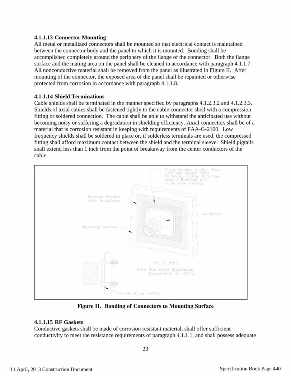
23
ε
4.1.1.13 Connector Mounting All metal or metallized connectors shall be mounted so that electrical contact is maintained between the connector body and the panel to which it is mounted. Bonding shall be accomplished completely around the periphery of the flange of the connector. Both the flange surface and the mating area on the panel shall be cleaned in accordance with paragraph 4.1.1.7. All nonconductive material shall be removed from the panel as illustrated in Figure II. After mounting of the connector, the exposed area of the panel shall be repainted or otherwise protected from corrosion in accordance with paragraph 4.1.1.8. 4.1.1.14 Shield Terminations Cable shields shall be terminated in the manner specified by paragraphs 4.1.2.3.2 and 4.1.2.3.3. Shields of axial cables shall be fastened tightly to the cable connector shell with a compression fitting or soldered connection. The cable shall be able to withstand the anticipated use without becoming noisy or suffering a degradation in shielding efficiency. Axial connectors shall be of a material that is corrosion resistant in keeping with requirements of FAA-G-2100. Low frequency shields shall be soldered in place or, if solderless terminals are used, the compressed fitting shall afford maximum contact between the shield and the terminal sleeve. Shield pigtails shall extend less than 1 inch from the point of breakaway from the center conductors of the cable.
Figure II. Bonding of Connectors to Mounting Surface
4.1.1.15 RF Gaskets Conductive gaskets shall be made of corrosion resistant material, shall offer sufficient conductivity to meet the resistance requirements of paragraph 4.1.1.1, and shall possess adequate
11 April, 2013 Construction Document Specification Book Page 440

24
ε
strength, resiliency, and hardness to maintain the shielding effectiveness of the bond. The surfaces of contact with the gasket shall be smooth and free of insulating films, corrosion, moisture, and paint. The gasket shall be firmly affixed to one of the bond surfaces by screws, conductive cement, or other means that do not interfere with the effectiveness of the gasket; or a milled slot shall be provided that prevents lateral movement or dislodging of the gasket when the bond is disassembled. Gaskets shall be a minimum of 1/8 inch wide. The gasket as well as the contact surfaces shall be protected from corrosion. 4.1.2 Shielding Requirements 4.1.2.1 Design The facility design and construction shall incorporate both protective shields to attenuate radiated signals, and separation of equipment and conductors to minimize the coupling of interference. The equipment design shall incorporate component compartments and overall shields as necessary to meet the electromagnetic susceptibility and emission requirements of MIL-STD-461 as required by NAS-SS-1000 and FAA-G-2100. In addition, the design shall provide the shields necessary to protect personnel. 4.1.2.2 Facility Shielding Shielding of facility buildings, shelters or equipment spaces shall be provided when other facility or environmental sources of radiation are of sufficient magnitude to degrade the operation and performance of electronic equipment or system. Where rebar or a rudimentary Faraday cage exists, it shall be connected to the EES with a minimum 2 AWG copper conductor that is applied via an exothermic weld or a hydraulically crimped termination. 4.1.2.3 Conductor and Cable Shielding Conductor and cable shielding shall comply with the following sub-paragraphs: 4.1.2.3.1 Signal Lines and Cables Cables consisting of multiple twisted pairs shall have individual shields for each twisted pair.. The shields shall be isolated from each other. Cables with an overall shield shall have the shield insulated and isolated from the individual shields.. 4.1.2.3.2 Termination of Individual Shields Shields of pairs of conductors, line shields, and the shield of cables containing unshielded conductors shall be terminated in accordance with the following: (a) Shields shall be terminated to ensure correct equipment operation. (b) Shield terminations shall employ minimum length pigtails between the shield and the
connection to the bonding halo or ferrule ring and between the halo or ferrule ring and the shield pin on the connector. The unshielded length of a signal line shall not exceed 1 inch (25 mm) with not more than 1/2 inch (13 mm) of exposed length as the desired goal.
(c) Shields, individually and collectively, shall be isolated from overall shields of cable bundles and from electronic equipment cases, racks, cabinets, junction boxes, conduit, cable trays, and elements of the electronic multipoint ground system. Except for one interconnection, individual shields shall be isolated from each other. This isolation shall be maintained in
11 April, 2013 Construction Document Specification Book Page 441

25
ε
junction boxes, patch panels and distribution boxes throughout the cable run. When a signal line is interrupted such as in a junction box, the shield shall be carried through. The length of unshielded conductors shall not exceed 1 inch (25 mm). To meet this requirement, the length of shield pigtail longer than 1 inch shall be allowed but shall be the minimum required.
(d) Circuits and chassis shall be designed to minimize the distance from the connector or terminal strip to the point of attachment of the shield grounding conductor to the electronic signal reference. The size of the wire used to extend the shield to the circuit reference shall be as large as practical but shall not be less than 16 AWG or the maximum wire size that will fit the connector pin. A common shield ground wire for input and output signals, for both high level and low level signals, for signal lines and power conductors, or for electronic signal lines and control lines shall not be used.
(e) Nothing in this requirement shall preclude the extension of the shields through the connector or past the terminal strip to individual circuits or chassis if required to minimize unwanted coupling inside the electronic equipment. Where extensions of this type are necessary, overall cable or bundle shields grounded in accordance with paragraph 4.1.2.3.3 shall be provided.
4.1.2.3.3 Termination of Overall Shields Cables that have an overall shield over individually shielded pairs shall have the overall shield grounded at each end unless otherwise required by the equipment. Grounding through an SPD is permissible if grounding both ends of the conductors degrades system performance. The drain wire if present shall be grounded the same as the shield. (a) Cable shields terminated to connectors shall be bonded to the connector shell as shown in
Figure IIIa or Figure IIIb. The shield shall be carefully cleaned to remove dirt, moisture, and corrosion products. The connector securing clamp shall be carefully tightened to assure that a low resistance bond to the connector shell is achieved completely around the circumference of the cable shield. The bond shall be protected against corrosion in accordance with paragraph 4.1.1.8. The panel-mounted part of the connector shall be bonded to the mounting surface in accordance with paragraph 4.1.1.13.
(b) Where the cable continuity is interrupted, such as in a junction box, the shield shall be carried through and grounded at the box. The length of unshielded conductors shall not exceed 1 inch (25 mm). If necessary, the shield pigtail shall be allowed longer than 1 inch to reach ground but shall be as short as possible.
(c) Cables which penetrate walls or panels of cases or enclosures without the use of connectors shall have their shields bonded to the penetrated surface in the manner shown in Figure IIIc. Overall shields shall be terminated to the outer surface of cases to the maximum extent possible.
(d) Grounding of overall shields to terminal strips shall be as shown in Figure IV.
11 April, 2013 Construction Document Specification Book Page 442

26
ε
Figure III. Grounding of Overall Cable Shields to Connectors and Penetrating Walls
11 April, 2013 Construction Document Specification Book Page 443

27
ε
Figure IV. Grounding of Overall Cable Shield to Terminal Strip
4.1.2.4 Electromagnetic Environment Control Shielding shall be integrated with other basic interference control measures such as filtering, wire routing, cable and circuit layout, signal processing, spectrum control, and frequency assignment to achieve the highest operational reliability of the equipment. Implementation procedures necessary to achieve the required filtering and shielding shall be detailed in the control plan described in paragraph 4.1.4.2 to include material requirements, shield configurations, placement and installation limitations, gasket utilization, filter integration, aperture control, bonding and grounding requirements, and wire routing and circuit layout constraints. 4.1.2.4.1 Space Separation The design and layout of facilities shall physically separate electronic equipment and conductors that produce interference from equipment and conductors that are susceptible to interference. The minimum separation distance between power and signal cables shall be in accordance with Table III. 4.1.2.4.2 Wire and Cable Routing The routing and layout of wires, conductors and cables shall be performed in a manner that does not jeopardize the integrity of the equipment shield. Signals with power level differences of greater than 20dB shall be routed as far apart as feasible. AC power conductors and control lines shall be routed away from sensitive digital or other susceptible circuits. Shielded cables shall be
11 April, 2013 Construction Document Specification Book Page 444
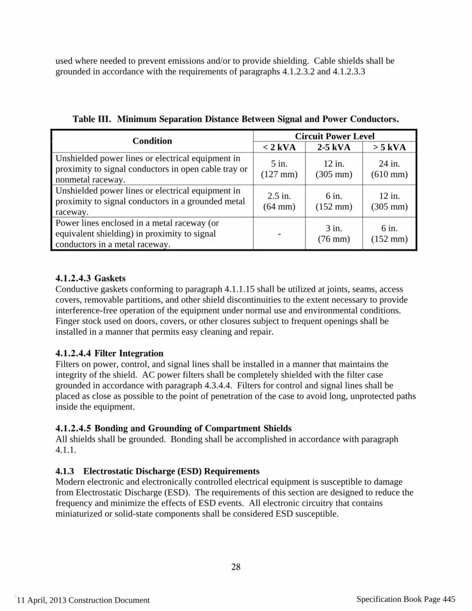
28
ε
used where needed to prevent emissions and/or to provide shielding. Cable shields shall be grounded in accordance with the requirements of paragraphs 4.1.2.3.2 and 4.1.2.3.3
Table III. Minimum Separation Distance Between Signal and Power Conductors.
Circuit Power Level Condition < 2 kVA 2-5 kVA > 5 kVA
Unshielded power lines or electrical equipment in proximity to signal conductors in open cable tray or nonmetal raceway.
5 in. (127 mm)
12 in. (305 mm)
24 in. (610 mm)
Unshielded power lines or electrical equipment in proximity to signal conductors in a grounded metal raceway.
2.5 in. (64 mm)
6 in. (152 mm)
12 in. (305 mm)
Power lines enclosed in a metal raceway (or equivalent shielding) in proximity to signal conductors in a metal raceway.
- 3 in.
(76 mm) 6 in.
(152 mm)
4.1.2.4.3 Gaskets Conductive gaskets conforming to paragraph 4.1.1.15 shall be utilized at joints, seams, access covers, removable partitions, and other shield discontinuities to the extent necessary to provide interference-free operation of the equipment under normal use and environmental conditions. Finger stock used on doors, covers, or other closures subject to frequent openings shall be installed in a manner that permits easy cleaning and repair. 4.1.2.4.4 Filter Integration Filters on power, control, and signal lines shall be installed in a manner that maintains the integrity of the shield. AC power filters shall be completely shielded with the filter case grounded in accordance with paragraph 4.3.4.4. Filters for control and signal lines shall be placed as close as possible to the point of penetration of the case to avoid long, unprotected paths inside the equipment. 4.1.2.4.5 Bonding and Grounding of Compartment Shields All shields shall be grounded. Bonding shall be accomplished in accordance with paragraph 4.1.1. 4.1.3 Electrostatic Discharge (ESD) Requirements Modern electronic and electronically controlled electrical equipment is susceptible to damage from Electrostatic Discharge (ESD). The requirements of this section are designed to reduce the frequency and minimize the effects of ESD events. All electronic circuitry that contains miniaturized or solid-state components shall be considered ESD susceptible.
11 April, 2013 Construction Document Specification Book Page 445
29
ε
4.1.3.1 ESD Sensitivity Classification Classification of items as ESD sensitive shall be in accordance with the Human Body Model testing procedures and requirements of ANSI/ESD STM5.1. Electronic parts, components, and assemblies shall be classified as either sensitive or supersensitive. Items that will fail from ESD at 1000 to 16000 Volts shall be classified as ESD sensitive. Those items that will fail below 1000 Volts shall be classified as supersensitive. Any exceptions to this guidance shall be through the OPR of this document. Devices with a sensitivity of less than +/- 200 Volts require additional ESD protection measures than those specified in this standard. ESD susceptible items shall not be exposed to an electrostatic field (E-field) greater than 100 Volts/meter or brought closer than 24” to known static generators or non-essential insulative materials. 4.1.3.2 ESD Protection Requirements All NAS electrical and electronic equipment, subassemblies, and components subject to damage from exposure to electrostatic fields or electrostatic discharge (ESD) shall be protected in accordance with the protection requirements herein. ESD controlled areas shall be provided for all operations, storage, repair, and maintenance spaces used for electrical and electronic equipment or subassemblies that are subject to damage from static electricity or ESD. 4.1.3.3 Classification of Materials 4.1.3.3.1 General Most materials and products that are used to control and prevent ESD are classified by their resistive properties as conductive or static dissipative. Antistatic materials are an exception to this and are classified by their propensity to not generate static electricity from triboelectric charging. Any material used for construction of ESD protected areas (with the exception of antistatic materials) shall meet the resistive properties specified for type and use of the material. Materials that will tribocharge to greater than +/- 200 Volts (EIA-625), if the material were to contact and separate from itself or from other materials, shall not be used in ESD controlled areas. 4.1.3.3.2 Static Conductive Materials Those materials with a surface resistivity less than 1.0 x 10⁵ ohms/square when tested per ANSI/ ESD S11.11 shall be considered conductive. Conductive ESD control materials shall not be used for ESD control work surfaces, tabletop mats, floor mats, flooring, or carpeting where the threat of personnel contact with energized electrical or electronic equipment exists. Conductive ESD control materials are not to be used in any other application where their use could result in electromagnetic interference (EMI) or radio frequency interference (RFI) that would be created by rapid, high voltage ESD spark discharges. Any exceptions to this guidance shall be through the OPR of this document. 4.1.3.3.3 Electrostatic Shielding Materials Electrostatic shielding materials are a subset of conductive materials with a surface resistance equal to or less than 1.0 x 10³ ohms when tested per ANSI/ESD S11.11. Electrostatic shielding materials shall be allowed as barriers for protection of ESD sensitive items from electrostatic fields where required.
11 April, 2013 Construction Document Specification Book Page 446
30
ε
4.1.3.3.4 Electromagnetic Shielding Materials Electromagnetic shielding materials with highly conductive surfaces (< 10 ohms) or specifically designed composite materials that absorb and reflect electromagnetic radiation over a broad range of frequencies shall also be allowed as barriers where required to protect ESD sensitive items from electromagnetic fields. 4.1.3.3.5 Static Dissipative Materials Those materials with a surface resistivity greater than 1.0 x 10⁵ ohms/square but less than or equal to 1.0 x 10¹² ohms/square when tested per ANSI/ESD S11.11 are classified as static dissipative materials. Static dissipative materials with a surface resistance less than or equal to 1.0 x 10⁹ ohms shall be used to provide controlled bleed-off of accumulated static charges in ESD controlled areas. Static dissipative materials with a surface resistance of greater than 1.0 x 10⁹ ohms shall not be used for applications where controlled bleed-off of accumulated static charges is essential. Any exception to this guidance shall be through the OPR of this document. 4.1.3.3.6 Antistatic Materials Any material that inhibits or has a low propensity to generate static electricity from triboelectric charging shall be considered antistatic. Antistatic ESD control items and materials used for construction of ESD controlled areas in new or renovated facilities shall not tribocharge to greater than +/- 200 Volts when being used for their intended application. Antistatic materials with a surface resistance greater than 1 x 10⁹ ohms shall not be used for ESD protective work surfaces, tabletop mats, floor mats, flooring, and carpeting when charge dissipation is the primary consideration. If the surface resistance (Rtt) of an antistatic material is greater than 1012 ohms it shall normally be considered to be too resistive for use in ESD controlled areas. Use of antistatic items and materials that utilize hygroscopic surfactants that depend on ambient humidity to promote absorption of water shall be limited. Only antistatic materials that are intrinsically antistatic and will retain their antistatic properties shall be used in ESD controlled areas. Exceptions to this guidance shall be through the OPR of this document. 4.1.3.3.7 Static-Generative Materials, Non-Conductors, and Insulators Materials having a surface resistance greater than 1.0 x 10¹² ohms (ANSI/ESD S11.11) shall be considered to be insulators and a possible source of triboelectric charging. These include common plastics, Plexiglas, Styrofoam, Teflon, nylon, rubber, untreated polyethylene, and polyurethane. Their use shall be minimized where ESD sensitive items are located. 4.1.3.4 Protection of ESD Susceptible and Sensitive Items 4.1.3.4.1 Static Protected Zone A static protected zone shall be a volume or area where unprotected ESD sensitive items will be safe from direct contact with electrostatic potentials greater than +/- 200 volts, electrostatic fields greater than 100 volts/meter, or radiated electromagnetic interference and radio frequency interference produced by rapid, high voltage ESD spark discharges. Static protected zones shall be incorporated into the construction of ESD special protection areas, ESD protected workstations, and ESD protected storage areas.
11 April, 2013 Construction Document Specification Book Page 447

31
ε
4.1.3.4.2 ESD Special Protection Areas Special protection areas shall be designated areas that require extraordinary ESD control measures to accomplish the following: (a) Minimize triboelectric charging. (b) Control bleed-off and dissipation of accumulated static charges. (c) Neutralize charges. (d) Minimize the effects of E-Fields, H-Fields, and EMI and RFI from ESD spark discharges. Areas within a facility that shall be designated as ESD special protection areas are: (a) Air traffic operations areas (e.g., tower cab, TRACON, ARTCC control rooms, AFSS, etc.). (b) Electronic equipment rooms. (c) Storage areas for ESD susceptible components, subassemblies, circuit cards, etc. (d) Areas that contain personal computers and Local Area Networks (LANs) that are connected
to or interface directly with NAS electronic equipment. (e) All other locations where jacks, plug in connectors or interfaces of ESD sensitive electronic
equipment are exposed and vulnerable to damage from ESD by direct human contact shall also be designated as ESD special protection areas.
4.1.3.4.3 ESD Controls Required for ESD Special Protection Areas The following minimum ESD control measures shall be implemented in all areas designated as ESD special protection areas: 4.1.3.4.3.1 ESD Groundable Point (GP) Each ESD control material, surface, or item used in an ESD controlled area shall have a designated groundable point (GP) to provide ease of connection to the nearest Signal Reference Structure (SRS). 4.1.3.4.3.2 Grounded Static Dissipative Surfaces All work surfaces which include work surface laminates, paints and sealers, writing surfaces, table tops, consoles, workbenches, and table top mats shall be static dissipative and connected to any SRS in the area served – except to a single point ground system. The point-to-point resistance and surface to ground resistance of static dissipative work surfaces shall be greater than 1.0 x 10⁶ ohms and less than 1.0 x 10⁹ ohms (ANSI/ESD S4.1). 4.1.3.4.3.3 Limiting the Use of Non-ESD Control Materials Materials that will tribocharge (e.g., generate electrostatic potentials by contact and separation with themselves or other materials) shall not be used for construction in ESD special protection areas. Insulative materials and any other non-essential triboelectric charge generators that generate potentials in excess of +/- 200 Volts shall not be permitted within 24 inches of ESD special protection areas. 4.1.3.4.3.4 Static Dissipative Chairs Chairs (e.g., seating) provided for ESD special protection areas shall incorporate a continuous path between all chair elements (e.g., cushion and arm rests) to the ground points of greater than
11 April, 2013 Construction Document Specification Book Page 448

32
ε
1.0 x 10⁵ ohms to less than 1.0 x 10⁹ ohms. The ground points for ESD chairs are static dissipative or conductive casters that provide electrical continuity from all elements of the chair to ESD control carpeting, tile, or floor mats that are properly bonded to any SRS – except to a single point ground system . ESD control chairs must be tested and meet the requirements of ANSI/ESD STM12.1. 4.1.3.4.3.5 Static Dissipative ESD Control Floor Coverings Static dissipative ESD control floor coverings shall include static dissipative tile, carpeting, static limiting floor finishes, and floor mats. Floor coverings in ESD special protection areas shall have a point-to-point resistance and surface-to-ground resistance of greater than 1.0 x 10⁶ ohms and less than 1.0 x 10⁹ ohms (ANSI/ESD S7.1). These floor coverings shall be bonded to any SRS in the area served in accordance with paragraphs 4.1.3.4.3.1 and 4.1.3.4.8 – except to a single point ground system. In circumstances involving extremely static sensitive equipment a static conductive floor covering with a lower resistance limit of 2.5 x 10⁴ ohms (UL779) shall be implemented when it is part of a designed approach for ESD control for the equipment approved by the OPR of this document. This designed approach shall include all steps required to produce an electrically safe working environment.
4.1.3.4.3.6 Relative Humidity Control Relative humidity in ESD special protection areas shall be maintained within the range of 40 to 60%. 4.1.3.4.4 ESD Signs, Labels, Cautions, and Warnings ESD warning signs that include ESD sensitive device warning symbols with appropriate cautions and warnings shall be posted in ESD special protection areas and all other ESD controlled areas. Exterior cabinets of ESD sensitive electronic equipment shall also be marked or labeled with an ESD sensitive device symbol with a warning that is visible from at least 3 feet. Any signs or labels shall be consistent with the requirements of ANSI/ESD S8.1. 4.1.3.4.5 ESD Protected Workstations These workstations are for the maintenance and repair of ESD sensitive equipment. 4.1.3.4.5.1 ESD Protected Workstation Minimum Requirements All ESD control items at an ESD protected workstation shall be connected to a common groundable point, i.e., ESD ground, that is connected to any SRS in the area served – except to a single point ground system. ESD protected workstations shall be free of all non-essential static charge generators; and provide a means of personnel grounding. They shall have a grounded static dissipative work surface, and grounded static dissipative ESD control floor or mat. Storage containers provided at ESD protected workstations shall provide ESD protection and shall also be connected to the ESD ground. All outlets at ESD protected workstations shall be protected with ground fault circuit interruption (GFCI) capability to minimize danger to grounded personnel from electrical shock. 4.1.3.4.5.2 Use of Ionization Selective use of bench top or area ionizers shall be allowed at ESD protected workstations if static generative items (e.g., insulators) are deemed essential and cannot be removed from ESD
11 April, 2013 Construction Document Specification Book Page 449

33
ε
protected workstation areas or if grounding of mobile personnel would be cumbersome or create a safety hazard. 4.1.3.4.5.3 Identification of ESD Protected Workstations The boundaries of all ESD protected workstations shall be clearly defined. The boundaries of ESD protected workstations shall extend a minimum of 24 inches beyond where ESD sensitive items will be located and will be marked with yellow tape. ESD warning signs that are yellow with black markings and lettering shall be posted that will be visible to anyone entering these areas. Signs shall include an ESD sensitive electronic device warning symbol and appropriate warnings and cautions. 4.1.3.4.6 ESD Protective Storage Areas 4.1.3.4.6.1 Shelves, Bins, and Drawers Shelves, bins, and drawers shall be static dissipative and electrically continuous with the support structure of the storage shelves, bins, or container. 4.1.3.4.6.2 Grounding The storage container metal support structure shall have a groundable point (GP) that shall be connected to the nearest SRS – except to a single point ground system . The resistance from the ground point of storage containers, shelving, cabinets, and bins used to store ESD sensitive items to the nearest SRS shall be less than one ohm. 4.1.3.4.6.3 Personnel Grounding Wrist straps shall be equipped with one megohm or greater series resistance to protect personnel. Standard 0.157 inch banana jacks for personnel grounding wrist straps shall be connected to the ESD ground or directly to any SRS in the area served – except to a single point ground system. The resistance from a banana jack to a ground point and/or to the nearest SRS – except to a single point ground system shall be less than one ohm. 4.1.3.4.6.4 Materials Prohibited in ESD Protective Storage Areas Static generative (e.g., insulative) materials shall not be used for construction in any areas where ESD sensitive items will be stored. All materials that can generate potentials greater than +/- 200 Volts shall be a minimum of 24 inches from ESD protected storage areas. 4.1.3.4.6.5 Resistance to ESD Ground for Shelves, Drawers, and Bins All surfaces and drawers of the storage media provided shall be made with static dissipative materials and meet the requirements and be tested the same as work surfaces (ANSI/ESD S4.1). The surface-to-surface resistance (Rtt) and surface-to-ground resistance (Rtg) from the shelves, bins, and drawers of storage containers that will be used to store unprotected ESD sensitive items shall be greater than 1.0 x 10⁶ ohms and less than 1.0 x 10⁹ ohms (ESD ADV53.1). 4.1.3.4.6.6 Identification of ESD Protective Storage Areas The boundaries of all ESD protective storage areas shall be clearly defined. Boundaries of ESD protective storage areas shall extend a minimum of 24 inches beyond where ESD sensitive items will be located and will be marked with yellow tape. ESD warning signs that are yellow with
11 April, 2013 Construction Document Specification Book Page 450

34
ε
black markings and lettering shall be posted that will be visible to anyone entering these areas. Signs shall include an ESD sensitive electronic device warning symbol and appropriate warnings and cautions. 4.1.3.4.7 Hard and Soft Grounds 4.1.3.4.7.1 Hard Grounds Any item, material, or product that is a part of the ESD control system that is intentionally or unintentionally connected to an ESD ground, or directly to any SRS in the area served – except to a single point ground system – shall be considered to be hard grounded. Unless specified otherwise or justified by the OPR for this document, ESD control worksurfaces, cabinets, flooring, carpeting, test equipment, and any other items used for ESD control shall be hard grounded. 4.1.3.4.7.2 Soft Grounds A soft ground is an intentional connection to ground through a series current limiting resistor. Soft grounding shall only be used in personnel grounding skin contact devices such as wrist straps, leg or ankle straps, conductive shoes, and heel or toe grounders. The nominal resistance of the resistor used for soft grounding of personnel shall be greater than 1.0 X10⁶ ohms unless otherwise specified by the OPR for this document. All other elements of the ESD control system shall be hard grounded. 4.1.3.4.8 ESD Control Flooring and Floor Coverings All ESD control floors and floor coverings shall have a point to point resistance and a surface to ground resistance of greater than 1.0 x 10⁶ ohms and less than 1.0 x 10⁹ ohms (ESD STM7.1). ESD control flooring and floor coverings include vinyl tile, vinyl sheet, carpet, carpet tile, carpet tile with positioning buttons and others but not to include applied coatings. These control floors and floor coverings shall be installed, grounded, and initially tested only by trained installers. A representative ten-feet-square section of the floor system shall be tested and the results approved and accepted by FAA personnel, prior to installation of the full floor system. ESD control floors and floor coverings shall be bonded to the nearest SRS at a minimum of four locations. The connections and method shall be recommended by the floor manufacturer and approved by the OPR. These connections shall utilize copper: strip, foil, conductive fabric ribbon, or stranded wire. Electrical contact shall be made with the underside of the floor material or connections may be embedded in the conductive permanent or releasable adhesive used to lay the floor. The ESD control flooring shall not be bonded to any single point ground system. 4.1.3.4.8.1 Surface Resistance (Rtt) Surface resistance (Rtt - Resistance top-to-top or surface-to-surface) of ESD control floors, carpets or floor mats shall be greater than 1.0 x 10⁶ ohms and less than 1.0 x 10⁹ ohms (ANSI/ESD S7.1). A minimum of five readings shall be taken at different locations on the floor surface and averaged together for each 500 square feet (or fraction thereof) of floor surface. These readings shall be recorded in the FRDF.
11 April, 2013 Construction Document Specification Book Page 451
35
ε
4.1.3.4.8.2 Resistance Surface-to-Ground (Rtg) Resistance from the floor surface to ground (Rtg - Resistance top-to-ground) of ESD control floors, carpets or floor mats shall be greater than 1.0 x 10⁶ ohms and less than 1.0 x 10⁹ ohms (ANSI/ESD S7.1). A minimum of five readings shall be taken at different locations on the floor surface and averaged together for each 500 square feet (or fraction thereof) of floor surface. These readings shall be recorded in the FRDF. 4.1.3.4.8.3 Triboelectric Charging Limitation ESD control floors, carpets, or floor mats shall limit and control generation and accumulation of static charges to less than +/- 200 Volts in ESD controlled area. 4.1.3.4.9 ESD Requirements for Raised Floors 4.1.3.4.9.1 Resistance from Carpet Surface to Pedestal Understructure Carpet tiles shall have a resistance from the carpeted surface of the raised floor to the pedestal greater than 1.0 x 10⁶ ohms and less than 1.0 x 10⁹ ohms. 4.1.3.4.9.2 Panel to Floor Understructure Resistance Panel-to-understructure (metal-to-metal) contact resistances between individual raised floor panels and the floor understructure shall be 10 ohms or less. 4.1.3.4.9.3 Carpet Tile Installation on Raised Floor Panels Install individual carpet tiles on raised floor panels with either permanent or releasable conductive adhesive depending on the application. 4.1.3.4.9.4 Grounding There shall be a minimum of four connections per 1,000 square feet of installed ESD control carpeting from the carpeting undersurface and conductive adhesive to the raised floor panel understructure. The Connections and method shall be in accordance with paragraph 4.1.3.4.8. 4.1.3.4.10 ESD Protective Worksurfaces Static dissipative materials or electrostatic dissipative laminates shall be used to cover all worksurfaces, consoles, workbenches, and writing surfaces in areas that contain ESD sensitive equipment and in all areas designated as ESD special protection areas, static-safe zones, and ESD protected areas. 4.1.3.4.10.1 Requirements for ESD Protective Worksurfaces Static dissipative worksurfaces shall be provided for new or upgrade facilities unless otherwise specified. Permanent static dissipative worksurfaces shall be connected to any SRS in the area served – except to a single point ground system. Permanent ESD protective static dissipative worksurfaces shall have a resistance greater than 1.0 x 10⁶ ohms point-to-point (Rtt) and less than 1.0 x 10⁹ ohms (ANSI/ESD S4.1). Permanent ESD protective worksurfaces shall have a resistance from their surface to the groundable point (Rtg) greater than 1.0 x 10⁶ ohms and less than 1.0 x 10⁹ ohms (ANSI/ESD S4.1).
11 April, 2013 Construction Document Specification Book Page 452

36
ε
4.1.3.4.10.1.1 Worksurface Types ESD protective worksurfaces used for FAA workstations shall meet the requirements of MIL-PRF-87893 Performance Specification, Workstation, Electrostatic Discharge Control and MIL-W-87893 Military Specification, Workstation, Electrostatic Discharge (ESD) Control. 4.1.3.4.10.1.2 Type I Worksurface - Hard Type I worksurfaces shall be constructed of rigid static dissipative materials of any color having an average Shore D hardness in excess of 90. Two male or female 0.395 inch ground snap (female) or stud (male) fasteners shall be installed on both corners on one of the longest sides of the worksurface to accommodate the male or female snap or stud fastener of the common point grounding cord. The locations of the two snaps or studs shall be 2 inches from each corner. 4.1.3.4.10.1.3 Type II Worksurface - Soft Type II worksurfaces shall be constructed of cushioned static dissipative materials of any color having an average Shore A (ATSM D2240) hardness in excess of 45 and less than 85. Two male or female 0.395 inch ground snap (female) or stud (male) fasteners shall be installed on both corners on one of the longest sides of the worksurface to accommodate the male or female snap or stud fastener of the common point grounding cord. The locations of the two male or female snaps or studs shall be 2 inches from each corner. No low-density open-cell materials shall be used for Type II worksurfaces. 4.1.3.4.10.2 Static Dissipative Laminates High pressure, multi- layer static dissipative laminates shall be used to cover surfaces such as plywood, fiber board, particle board, bench tops, counter tops, and consoles in ESD controlled areas and special protection areas. Laminates shall include a buried conductive layer to provide for ease of grounding using a through bolted pressure type ESD grounding terminal. 4.1.3.4.10.3 Grounding of Laminated Surfaces The resistance across the surface (Rtt) of the static dissipative laminate shall be greater.1.0 x 106ohms and less 1.0 x 10⁹ohms. The resistance from the surface of the laminate to ground (Rtg) shall be greater than 1.0 x 10⁶ ohms and less than 1.0 x 10⁹ ohms (ANSI/ESD S4.1). A minimum of five readings of each shall be taken and averaged together. These readings and averages shall be recorded in the FRDF. 4.1.3.4.11 Static Dissipative Coatings Permanent clear or colored static dissipative coatings used in ESD controlled areas, including all painted surfaces, shall have a point to point resistance greater than 1.0 x 10⁶ ohms and less than 1.0 x 10⁹ ohms. 4.1.4 Electromagnetic Compatibility Requirements 4.1.4.1 General A comprehensive plan for the application of various sections of this document is required to assure the compatible operation of equipment in complex systems. Additional considerations of this section shall be implemented to reduce susceptibility and emissions of equipment.
11 April, 2013 Construction Document Specification Book Page 453

37
ε
4.1.4.2 Requirements The emission and susceptibility limits contained in MIL-STD-461 shall be applied unless otherwise specified. An EMI Control and Test Plan shall be developed in accordance with MIL-HDBK-237 to assure compliance with the applicable requirements. The plan shall include a verification matrix to track the satisfaction of requirement by test, analysis or inspection. . 4.1.4.3 Approval Control Plans and Test Plans shall be submitted to the OPR of this document for approval. 4.2 Facility Requirements 4.2.1 Passive Transient Protection Requirements All metallic conduit, conductors and cables in NAS operational facilities are subject to currents induced by nearby lightning strikes. These induced effects can adversely affect the operation of sensitive electronic equipment. 4.2.1.1 Existing Metallic Conduit, Conductors and Cables Unless the facility manager disapproves the removal, all unused conduits, conductors and cables shall be removed. The facility manager shall be consulted to validate the decision to remove any metallic conduit, conductors or cables prior to acting. If they are to remain, the following actions shall be accomplished to minimize the voltage differential between ends: (a) Metallic conduits shall be bonded to adjacent grounded metalwork at both ends. (b) Unused conductors bonded to adjacent grounded metalwork at both ends. (c) Unused cables shall have conductors and shields bonded to adjacent grounded metalwork at
both ends. If not direct connected the above bonding shall utilize a 6AWG minimum pigtail no longer than 18 inches. Multiple conductors shall be grouped together and bonded to the adjacent metalwork directly or via a single pigtail. Unused conductors of a structured cable system installed for spares purposes with vertical risers of no more than fifty feet and of circuit length totaling no more than three hundred feet are exempted from this requirement if they do not pass between facilities. Where circulating currents are present, installation of a SPD at one end of the cable shall be allowed for this requirement.. The OPR of this document should be contacted for additional information. 4.2.1.2 Electromagnetic Shielding for Lines, Conductors and Cables
11 April, 2013 Construction Document Specification Book Page 454

38
ε
4.2.1.2.1 Facility Entrance Conduit All lines, conductors and cables, both overhead and buried, shall enter the facility through a minimum of 10 feet of ferrous conduit (RGS). Conduit routed by other than a direct route shall be allowed to achieve this 10-foot requirement. All entrance conduits shall be bonded to the EES with a bare copper stranded conductor, 2 AWG minimum. This entrance conduit, if buried, shall extend 5 feet beyond the earth electrode system. 4.2.1.2.2 Buried External Power Cables and Conductors Buried external power cables and conductors shall have magnetic shielding to prevent coupling of damaging transient currents, from man made and lightning sources. This shielding can only be provided by a ferrous metal. This may be in the form of a sheath, ferrous armor or ferrous conduit (RGS). Specification details of this type of cable and potential sources are available from the OPR and the LPGBS web page. Ferrous armor cable has been shown to be extremely cost effective when compared to ferrous conduit and presents a marginal increase in cost over unarmored cable. Cables may be installed in metallic or nonmetallic conduit where permitted by the NEC. When a conduit is not used cables shall be identified for direct earth burial (DEB). For portions of buried external power cables and conductors greater than 300 feet cable length from the facility ferrous shielding is recommended but not required. Facility entrance surge protection shall be provided that fully complies with paragraph 4.2.2 and all sub paragraphs. 4.2.1.2.3 Buried Landlines The preferred type of buried landline that represents best engineering practice is fiber optic type. Fiber optic cable does not require electromagnetic shielding and is exempt from these requirements. Metallic buried landlines that carry NAS Critical, Essential or Mission Support Services to a facility shall have a ferrous shield or be enclosed in ferrous conduit (RGS). For portions of these buried landlines located greater than 300 feet cable length from the facility, ferrous shielding is recommended but not required. For these landlines facility entrance surge protection shall be provided that fully complies with paragraph 4.2.2 and all sub paragraphs. 4.2.1.2.4 Conduit Joints and Fittings Conduit joints and fittings shall be electrically continuous with bonding resistance of 5 milliohms or less between joined parts. Conduit enclosing signal, control, status, power, or other conductors to electronic equipment shall be terminated using conductive fittings to their respective junction boxes, equipment cabinets, enclosures, or other grounded metal structures. 4.2.1.3 Above Ground Ferrous Conduit Penetration of Facility At each location, where above ground conduits first penetrate a shelter or building a bonding connection shall be made. The conduit shall be bonded directly to the EES, or to a bulkhead connector plate that is bonded to the EES in accordance with paragraph 4.2.1.6. If neither of these bonds is feasible, the bond shall be made to the main or supplemental ground plate. The bond to the EES, or the bulkhead connector plate, or to the multipoint ground plate shall be a 2 AWG stranded copper conductor using exothermic welds or UL listed pressure connectors.
11 April, 2013 Construction Document Specification Book Page 455

39
ε
4.2.1.4 Armored Direct Earth Burial (DEB) Cables The DEB cable armor shall be bonded to the EES with a 2 AWG conductor prior to entry into the conduit. The DEB cable armor shall also be bonded to the main or supplemental ground plate. If bonding to the main or supplemental ground plates is not feasible the armor shall be bonded to the ground bus at the service disconnecting means (SDM). If armor is continued to the electronic equipment, bond it to any SRS – except to a single point ground system – of the electronic equipment unless the equipment is required to be isolated. All bonds shall be less than 5 milliohms between joined parts. Apply this requirement during initial cable installation. Complete cable replacement is not required if only a short length requires repair. 4.2.1.5 Guard Wires A 1/0 AWG bare copper stranded guard wire shall be provided for all buried cables and conductors not routed in ferrous conduit. The guard wire shall be embedded in the soil, a minimum of 10 inches (25 cm) above the cable to be protected and located directly above and parallel to the lines or cables being protected. When the width of the cable run or duct does not exceed 3 ft (90 cm), one guard wire, centered over the cable run or duct, shall be installed. When the cable run or duct is more than 3 feet (90 cm) in width, two guard wires shall be installed. The guard wires shall be spaced at least 12 inches (30 cm) apart and be not less than 12 inches (30 cm) nor more than 18 inches (45 cm) inside the outermost wires or the edges of the duct. The guard wire shall be bonded to the EES at each end and to ground rods at approximately 90-foot intervals using exothermic welds. The spacing between ground rods must vary by 10% to 20% to prevent resonance. Install the ground rods at approximately 6 feet (2 m) on either side of the trench. Where cables run parallel to the edge of a runway, they shall be located 10 feet from the edge lights on the outside of the lights. 4.2.1.6 Metal Bulkhead Connector Plates A metal bulkhead connector plate shall be provided where overhead axial-type cables, waveguides, etc., first enter a facility. The bulkhead connector plate shall be mounted on the outside surface of the facility, a minimum of 1/4 inch thick, and shall be constructed of tin-plated copper. The plate or plates shall have the required number and types of feed-through connectors to terminate all axial cables and shall provide adequate surface area for bonding waveguides, cable shields, conduits etc. Cable shields shall be bonded and grounded, except when the shield must be isolated for proper equipment operation. If external and internal cables are of different sizes, the changeover in cable size shall be allowed by the feed-through connectors at the plate. Axial type cables, Waveguides, etc.(and conduits where not bonded directly to the EES) shall be bonded to the bulkhead plates with a minimum 4 AWG bonding jumper. The 4 AWG bonding cable for a waveguide can be connected to the waveguide flange with an appropriately sized ring terminal. Conduits shall be bonded with a UL listed U-Bolt bonding connector. Axial cable shields shall be bonded with bonding kits sized for the specific cable type. Bonding jumpers shall be connected to the plate with either an exothermic weld or a double-bolted lug and shall be no longer than 12 inches. The bulkhead plate shall be bonded to the EES with a minimum 4/0 AWG copper cable color-coded green with a red tracer. When the bulkhead connector plate is located within 6 feet of
11 April, 2013 Construction Document Specification Book Page 456
40
ε
building steel, the bulkhead plate shall be connected to building steel with a 4/0 AWG copper conductor color coded green with a red tracer. The building structural steel is required to be bonded to the EES. Exothermic welds shall be used for these connections. 4.2.1.7 Balanced Pair Lines When possible, signal and control circuits routed external to equipment shall be balanced, two conductor, shielded circuits. 4.2.1.8 Fiber Optic Cable Fiber optic cables are not inherently susceptible to electromagnetic interference or the induction fields produced by lightning. Fiber optic cables should replace metallic cables when economically and technically feasible. Ferrous conduit shielding is not required for fiber optic lines. Suppression components are not required for fiber optic cables. Where metallic or electrically conductive sheaths or strength members are present, they shall be grounded to any SRS – except to a single point ground system at each end. To prevent circulating ground currents, a SPD shall be allowed at one end for grounding. The fiber optic transmitter and receiver modules shall have 90 dB of attenuation against all sources of electromagnetic interference (EMI). Where an external fiber optic cable uses conductive armor, the armor shall be bonded directly or via a SPD to the EES at the facility entrance using a 2 AWG bare copper conductor. If the cable is internal to the facility, conductive armor shall be bonded to any SRS – except to a single point ground system – at the equipment entrance. The bonding conductor shall be a 4 AWG stranded copper conductor insulated green with an orange tracer. The use of fiber optic cables without a conductive shield or armor is permitted. The fiber optic transmitter and receiver modules shall be contained in ferrous enclosures bonded to the nearest SRS – except to a single point ground system. Penetrations of the enclosures shall be gasketed or constructed to limit RF coupling. SPD’s for the metallic signal circuits and power circuits shall be installed as equipment level protection at the fiber optic receiver or transmitter equipment entrance and bonded to the chassis. 4.2.1.9 Interior Lines, Conductors and Cables All permanently installed single conductors, cables and wiring shall be in ferrous conduit (RGS), ferrous intermediate metal conduit (IMC), ferrous electrical metallic tubing (EMT), ferrous cable trays, or ferrous wireways (except as prohibited by the NEC). These shall be connected to any SRS – except to a single point ground system – as specified in paragraphs 4.2.6.4.1 and 4.2.6.4.2. When routing between floors the vertical section of the runs shall be in ferrous conduit (RGS), ferrous IMC, ferrous EMT, enclosed ferrous cable trays, or ferrous wireways that are connected to any SRS – except to a single point ground system – as specified in paragraphs 4.2.6.4.1 and 4.2.6.4.2. Cable tray systems employing single rail or wire construction are prohibited at any location. 4.2.2 Active Transient Protection Requirements
11 April, 2013 Construction Document Specification Book Page 457

41
ε
4.2.2.1 Conducted Power Line Surges Surge protective devices (SPDs) shall be provided at the service disconnecting means (SDM), at all facility penetrations (entrances), and at feeder and branch panelboards as specified in paragraph 4.2.2.3. Additional SPDs shall be provided at the power line entrances to operational electronic equipment. SPDs at the service disconnecting means, facility penetrations (entrances), feeder and branch panelboards as well as transient suppression provided at electronic equipment power line entrances shall be coordinated in accordance with the guidance provided in paragraphs 4.2.2.2 and 4.2.2.3. 4.2.2.2 Facility Entrance Surge Protective Devices A facility power SPD shall be installed on the load side of the facility service disconnecting means, at any facility penetration (entrance) and between the load side of a Engine Generator transfer switch and the first feeder panel. The SPD shall be a combination of solid-state circuits, varistors, or other devices and shall meet the requirements provided in this paragraph and its subparagraphs. Protection will be provided between all lines, including neutral where provided, and ground. A surge arrestor shall also be installed on the primary side of FAA owned distribution transformers. These arresters and SPDs shall be approved by the OPR of this document. The SPD shall be installed as close as possible (within 12 inches) to the facility SDM and with the shortest and most direct conductor connection to the SDM. Connections shall be made with UL listed connectors identified for the wire size and type used. (a) Connections. SPD terminals shall be connected to corresponding terminals of the service
disconnecting means with insulated 2 AWG (minimum) copper conductors. The conductors shall be as short and direct as possible without loops, sharp bends or kinks, be all the same size, and be color-coded in accordance with FAA-C-1217. The ground bus in the service entrance enclosure shall be bonded directly to the SPD terminal marked G or ground. The SPD enclosure shall be bonded to the SPD ground terminal.
(b) Conduit sealing. The conduit connecting the SPD enclosure to the SDM enclosure shall be sealed with duct seal or other UL listed nonflammable medium to prevent soot from entering the SDM enclosure in the event of SPD failure.
4.2.2.3 Surge Protective Devices for Feeder and Branch Panels SPDs shall be installed on all panels providing service to NAS operational equipment or supplying exterior circuits. Examples of exterior circuits include obstruction lights, convenience outlets, guard shacks, security systems, electric gates and feeds to other facilities. Exterior circuits shall be protected in accordance with the requirements of paragraph 4.2.2.2. Where feeder and branch panels are located close together and the panels do not serve exterior circuits, the OPR of this document shall be allowed to grant relief from providing separate protection on each panel. SPD’s for panels that provide service to any exterior circuits shall meet the requirements given by paragraphs 4.2.2.4.2, 4.2.2.4.3, and 4.2.2.4.4 for facility entrance SPD’s. The SPD’s shall be installed as close as possible to the panel they serve and in accordance with the manufacturer’s instructions. The conduit connecting the SPD enclosure to the panel enclosure shall be sealed with duct seal or other UL listed nonflammable medium to prevent soot
11 April, 2013 Construction Document Specification Book Page 458

42
ε
from entering the enclosure in the event of SPD failure. A feeder or branch panel SPD shall be provided with an overcurrent device. Examples of this overcurrent device include a fuse or circuit breaker fitted internally to the SPD or fitted to the panelboard for the sole use of the SPD. The overcurrent device shall not increase the clamp voltage of the SPD by greater than 5% and shall pass the surge current levels listed in Table IV up to the 40kA level without opening. Overcurrent devices for any exterior circuits shall pass all values shown in Table IV. All overcurrent devices, both internal and external to the SPD, and SPD short circuit current ratings shall be properly sized and coordinated in accordance with the NEC and be field resettable or replaceable. 4.2.2.4 SPD General Requirements SPDs shall be listed in accordance with UL 1449 Second Edition. All components comprising a SPD shall be packaged in a single National Electrical Manufacturers Association (NEMA) type 12 steel enclosure for indoor use only, or a NEMA type 4 steel enclosure for indoor or outdoor use. SPDs enclosed within panelboards or switchgear enclosures shall be allowed, provided the integrated SPD and panelboard or switchgear is UL listed/recognized as components and as an assembly. The use of potting material in SPDs is strictly prohibited. All SPD components must be accessible for inspection by qualified FAA personnel. Heavy duty, screw-type studs shall be provided for all input and output connections. The SPD phase and neutral terminals, when not connected, shall be electrically isolated from the enclosure by a minimum of 10 megohms resistance measured at 100V DC. The enclosure door shall be hinged and electrically bonded with a bonding jumper to the enclosure. Fuses, lights, fuse wires, and arrester elements or components shall be readily accessible for inspection and replacement. Manufacturers shall supply clear installation instructions with each unit. 4.2.2.4.1 SPD Operational Characteristics Minimum functional and operational characteristics of SPDs are given in Table IV, Table V, and Table VI. Other characteristics will also include the following: (a) Maximum continuous operating voltage (MCOV). The maximum continuous operating
voltage is the maximum RMS voltage an SPD will withstand at its maximum operating temperature continuously without degradation or change to any of its parameters greater than +/- 10%. The MCOV shall not be less than 10 percent above the nominal system voltage. Leakage current as defined below shall not be exceeded.
(b) Leakage current. The DC leakage current shall be less than 1mA for voltages at or below 1.414 x MCOV VDC.
(c) Clamp (discharge) voltage. Clamp (discharge) voltage is the maximum voltage that appears across an SPD output terminal while conducting surge currents. This voltage, measured at 3kA (to ensure performance in the linear region without impacting the device lifetime performance) with an 8/20 microsecond waveform, shall not change more than 10 percent over the operating life (as defined in Table IV. Surge Current Lifetime Requirements) of the SPD.
(d) Overshoot voltage. Overshoot voltage shall not exceed twice the SPD clamp voltage for more than 10 nanoseconds. Overshoot voltage is the surge voltage level that appears across the SPD terminals before the device turns on and clamps the surge to the specified voltage level.
11 April, 2013 Construction Document Specification Book Page 459

43
ε
(e) Self-restoring capability. The SPD shall automatically return to an off state after surge dissipation when line voltage returns to normal.
(f) Operating lifetime. The SPD shall safely dissipate the number and amplitude of surges listed in Table IV. Surge Current Lifetime Requirements.
(g) In-line inductors. In-line inductance, other than that normally caused by routing conductors, is not permitted.
(h) Fusing. Any fuses part of a SPD installation shall be able to pass all surge currents specified in Table IV without opening.
4.2.2.4.2 Surge Levels Table IV defines line-to-ground, line-to-neutral, neutral to ground, and line-to-line surge currents, and number of occurrences for AC services in FAA facilities below 600V. In this table, the 8/20 µs wave form defines a transient reaching peak value in 8 µs and decays to 50 percent of peak value 20 µs after inception. These devices shall be able to tolerate surges of shorter duration without malfunction.
Table IV. Surge Current Lifetime Requirements
Surge Current Amplitude
8/20µs Waveform
Surge Number Lifetime
Any Facility Entrance
Surge Number Lifetime
Feeder and Branch Panels
10kA 1500 1000 20kA 700 500 30kA 375 250 40kA 50 25 50kA 8 1 60kA 6 70kA 4 100kA 2 200kA 1
Each level of surge current and the number required represents a single lifetime of an SPD. (a) Any change greater than 10% in the 8/20µs clamping voltage at 3kA during service or when
the pre life/service test and the post life or in-service test results are compared is a device failure. The pre life test value shall be taken as the 100% value.
(b) Any change greater than 10% in the RMS voltage required to drive 1mA RMS through the device when the pre life/service test and the post life or in-service test results are compared is a device failure. The pre life test value will be taken as the 100% value.
(c) Any change greater than 10% in the DC voltage required to drive 1mA DC through the device when the pre life/service test and the post life or in-service test results are compared is a device failure. The pre life test value will be taken as the 100% value.
(d) Clamping voltages for each of the devices/assemblies/system voltages will be measured at 1kA and 10kA 8/20µs.
11 April, 2013 Construction Document Specification Book Page 460

44
ε
4.2.2.4.3 Slope Resistance It is the purpose of this parameter to specify a region on the SPD characteristic where it is possible to ensure device coordination. A slope resistance (the slope of the voltage/current characteristic of an SPD in its linear region) shall be calculated from the formula below: Rslope = (V10-V1)/9000 Where V10 = the clamping voltage measured at 10kA 8/20µs and Where V1 = the clamping voltage measured at 1kA 8/20µs The values of V10 and V1 used will be the absolute values as measured and not as a calculated value. The slope values shall conform to Table V.
Table V. Entrance, Feeder, and Branch Panels Slope Resistance Requirements
Location Slope Resistance Any Facility Entrance 8 mΩ Maximum Feeder and Branch Panels 30 mΩ +/- 15 mΩ
4.2.2.4.4 3kA Voltages V3 The voltages that must be achieved during testing at 3kA with an 8/20µs current impulse is shown in Table VI. All voltages shall be measured at the device terminals. The 8/20µs current impulse wave shape shall not lead or lag the voltage wave shape by more than 30 degrees.
Table VI. Protection Voltages at 3kA
Location System V3 Limit Any Facility Entrance
120/208V 120/240V 400 L-N, L-G
700 L-L Maximum
Any Facility Entrance
277/480V 700 L-L, L-G Maximum
Any Facility Entrance
380V Delta 1200 L-L,L-G Maximum
Any Facility Entrance
480V Delta 1200 L-L, L-G Maximum
Feeder and Branch panels
120/208V 120/240V 475 L-N, L-G
775 L-L +/- 45V
Feeder and Branch panels
277/480V 775 L-N, L-G
1275 L-L +/- 45V
Feeder and Branch panels
380V Delta 1275 L-L, L-G +/- 45V
Feeder and Branch panels
480V Delta 1275 L-L, L-G +/- 45V
4.2.2.4.5 Indicator Lamps Indicator lamps shall be provided for each phase on the SPD enclosure cover. They shall visually indicate normal condition (power applied to the SPD with any component fuses intact).
11 April, 2013 Construction Document Specification Book Page 461

45
ε
If indicator lamps are used that have a service life of less than 50,000 hours then two lamps per phase shall be provided. 4.2.2.4.6 Accessibility All SPD installations shall be safely accessible for visual inspection and evaluation. The use of potting material or other encapsulating materials that prevent component inspection in SPDs shall be limited to inorganic particulates. All SPD components shall be accessible for maintenance and replacement by qualified FAA personnel. Determination of the acceptability of potting material or other encapsulating materials in a given design resides with the OPR of this document. 4.2.2.5 Signal, Control, and Data Line Protection Design Transient protection shall be provided for all signal, data and control lines; both at facility entrances and at entrances to all electronic equipment used in direct support of the NAS including those provided or installed by a telecommunications service provider. The suppression components at the facility and electronic equipment entrances shall be coordinated to function together and limit the transient voltage and energy safely below circuit susceptibility levels. Coordination of suppression components is dependant on several factors including separation distance, equipment system bandwidth, etc. In principle facility entrance devices and electronic equipment entrance devices shall not affect each others operation. The coordination of these protectors is achieved at the system design stage – not intended to be accomplished by field personnel (see paragraph 4.3.2). Detailed analyses of suppression component and electronic equipment circuit characteristics are required to select components compatible with the requirements herein and to provide suppression circuits that will function without adversely affecting signals and information transmitted by individual landlines. Design requirements for selection of components are as follows: (a) Unipolar suppression components shall be selected and installed for signals and voltages that
are always positive or always negative relative to reference ground. Bipolar suppression components shall be selected for signals and voltages that are both positive and negative relative to reference ground.
(b) The total series impedance of the suppression circuits at both ends of a landline shall be designed so as not to significantly degrade electronic equipment performance.
(c) The protection components at facility entrances and equipment shall be selected so that their operating levels are coordinated and transient levels to equipment are limited safely below electronic equipment susceptibility levels for individual lines.
Surge protective devices shall be placed on both ends of signal, data and control lines longer than 10 feet connecting pieces of equipment or facilities not located on and bonded to the same SRS, or when the SRGG, SRGP, and the multipoint ground system is located in different rooms or on different floors. This includes all signal, data, control, and status lines both internal and external. This also includes interfacility lines installed above and below grade between facility structures and to externally mounted electronic equipment and particularly vertically routed conductors and
11 April, 2013 Construction Document Specification Book Page 462

46
ε
cables such as those between an ATCT cab and base building or radar tower and base building. This requirement includes fire alarm and security wiring where it has direct impact on NAS equipment. All unused conductors of a cable shall be grounded at each end. Grounding through an SPD is permissible if grounding both ends of the conductors degrades system performance. 4.2.2.6 SPD Requirements for Signal Data and Control Lines Facility level SPDs for signal, data, and control lines shall be installed at the point where the lines transfer to FAA control and at any building/structure entrance under FAA control. Where a battery feeds signal, data or control lines, the suppression components shall be housed in a metal enclosure. For facility level SPD enclosures, a ground bus bar, electrically isolated from the enclosure, shall be provided to serve as the ground point. This ground bus bar shall be directly connected to the EES with an insulated 4 AWG or larger copper conductor of minimum length with no loops, sharp bends or kinks, and ensure a short direct path for connection to the SPD’s. NOTE: When at the top of a tall ATCT (greater than 100 feet) the main ground plate on the lowest level containing NAS electronic equipment serves in lieu of the EES. The conductor insulation shall be color-coded green with a red tracer. A UL listed double bolted lug shall be used to bond the conductor to the ground bus bar. The bonding to the EES shall be an exothermic weld. The ground bus bar location shall ensure a short, direct path to ground for SPD’s. The installation shall provide easy access to component terminals for visual inspection, test and replacement. SPD’s for landlines that combine the protection specified herein shall be located at the facility entrance, and have approval by the OPR of this document prior to implementation of vendor proposed protection. (Reference paragraph 4.2.2.5) Field designed protection schemes shall be submitted to the OPR of this document for guidance and approval. Transient suppression components for axial-type cables shall be packaged in a sealed metal enclosure with appropriate connectors at each end to permit in-line installation at the bulkhead connector plate required in paragraph 4.2.1.6. 4.2.2.6.1 Signal, Control, and Data Line Protection Requirements The 10/1000 µs waveform defines a transient with a 10µs rise time and decay to 50 percent of the peak voltage in 1000 µs. SPDs must survive the transients listed in Table VII. Failure or end of life performance of a protector shall not normally disrupt the operation of the circuit being protected.
11 April, 2013 Construction Document Specification Book Page 463

47
ε
Table VII. SPD Lifetime Conducted Landline Transient Level Requirements
Lifetime Number of Transients
Transient Levels
1,000 100V 50A 500 500V 100A 50 750V 375A 5 1000V 1000A
Each level of surge current and the number required represents a single lifetime of an SPD. 4.2.2.7 Axial Cable Protection Design Special attention shall be given to the design of transient protection for axial-type cables. Design of transient protection is particularly critical at RF frequencies due to insertion losses. The following design requirements apply: (a) Analyses and tests shall be performed to assure that suppression components do not degrade
signals to an unacceptable degree or cause marginal performance of electronic equipment. (b) Particular attention shall be given to the impedance, insertion loss, phase distortion, and
voltage standing wave ratio for RF signals. (c) Transient protection for electronic equipment using coaxial, tri-axial, and twin-axial cables
shall be provided both at facility entrances and at the electronic equipment. Transient suppression shall be provided for each axial conductor and for shields that are not bonded directly to the electronic equipment case. 4.2.3 Lightning Protection System Requirements 4.2.3.1 General The intended purpose of the lightning protection system is to provide preferred paths for lightning discharges to enter or leave the earth without causing facility damage or injury to personnel or equipment. The essential components of a lightning protection system are air terminals, roof and down conductors connecting to the EES, the EES and SPDs. These components act together as a system to dissipate lightning energy. The lightning protection system shall meet or exceed the requirements of all relevant FAA standards and orders; Standard for the Installation of Lightning Protection Systems, National Fire Protection Association (NFPA 780); Installation Requirements for Lightning Protection Systems, Underwriters Laboratories (UL 96A); and, as specified herein. The risk assessment guide in NFPA 780 indicates that many NAS facilities have a high risk index. Accordingly lightning protection that exceeds the minimum requirement of NFPA 780 is specified. The provision of a UL Master label is not sufficient to indicate compliance with this document.
11 April, 2013 Construction Document Specification Book Page 464

48
ε
4.2.3.2 Lightning Protection System Materials All equipment shall be UL listed for lightning protection purposes and marked in accordance with UL requirements. All equipment shall be new and of a design and construction to suit the application in accordance with UL 96A requirements, except that aluminum shall only be used on aluminum roofs, aluminum siding or other aluminum surfaces. Bimetallic connectors shall be used for interconnecting copper and aluminum conductors. Dissimilar materials shall conform to the bonding requirements of paragraph 4.1.1.2.3. 4.2.3.2.1 Lightning Protection System Conductors All conductors used in a lightning protection system (main and bonding) shall be class 2 main sized conductors as defined by NFPA 780 or larger. 4.2.3.2.2 Lightning Protection System Hardware 4.2.3.2.2.1 Fasteners Roof and down conductors shall be fastened at intervals not exceeding 3 feet (0.9 m). Fasteners shall be of the same material as the conductor base material or bracket being fastened, or other equally corrosion resistant material. Plastic, galvanized or plated materials shall not be used. Where fasteners are used for bonding the surface shall be prepared and protected in accordance with paragraphs 4.1.1.7 and 4.1.1.8. 4.2.3.2.2.2 Fittings Bonding devices, conductor splices, conductor attachments and connectors shall be suitable for use with the installed conductor and shall be stainless steel, copper, bronze, or aluminum with bolt pressure connections to the conductor. Crimp type fittings shall not be used anywhere for any purpose in the lightning protection system. Aluminum fittings shall only be used with aluminum conductors. Copper and bronze fittings shall only be used with copper conductors. Interconnection between copper and aluminum portions of the lightning protection system shall be accomplished with bimetallic connectors. 4.2.3.2.3 Guards Guards shall be provided for down conductors located in or next to driveways, walkways or other areas where they are at risk of being displaced or damaged. Guards shall extend at least 6 feet (1.8 m) above and 1 foot (0.3 m) below grade level. Guards shall be schedule 40 polyvinyl chloride (PVC) conduit or better. When metal guards are used, the guard shall be bonded to the down conductor at both ends of the guard. Bonding jumpers shall be of the same size as the down conductor. PVC guards do not require bonding. 4.2.3.3 Lightning Protection System Bonds 4.2.3.3.1 Metallic Bodies Subject to Direct Lightning Strikes Metallic bodies that protrude beyond the zone of protection provided by the installed air terminals, are subject to direct lightning strikes. This includes, but is not limited to, exhaust pipes, exhaust fans, metal cooling towers, HVAC units, ladders, railings, antennas, and large louvered structures, etc. When these metallic bodies have a metal thickness of 3/16 inch or greater, they shall be bonded to the nearest main lightning protection system conductor. These
11 April, 2013 Construction Document Specification Book Page 465

49
ε
fittings shall provide bonding surfaces of not less than 3 square inches. If the metal parts of these units are less than 3/16 inch thick, additional air terminals, main conductors and fittings shall be installed, providing two paths to ground from the air terminals. 4.2.3.3.2 Metallic Bodies Subject to Induced Charges Metallic bodies that are subject to induced charges from lightning (including those in a zone of protection) shall be bonded to the lightning protection system in accordance with the guidance provided in NFPA 780. This includes, but is not limited to, roof drains, vents, coping, flashing, gutters, downspouts, doors, door and window frames, balcony railing, conduits, pipes, etc. 4.2.3.3.3 Exhaust Stack Grounding. Bond all fossil fuel exhaust stacks to the nearest point in the lightning protection system or directly to the EES with a conductor of equal size as the main conductor. The bond to the exhaust stacks shall be made with an exothermic weld or a mechanical connector. Where exhaust stacks are not in close proximity (6 feet) to a main conductor, they shall be bonded directly to a ground rod in the EES. 4.2.3.3.4 Above Ground Fuel and Oil Storage Tanks. Lightning protection shall be provided for all above-ground fuel and oil storage tanks. An air terminal shall be mounted to the top of non-pressurized fuel and oil tank vent pipes, high enough to provide the required zone of protection for the entire tank, and be connected directly to the EES using a main-sized down conductor. Tanks shall be provided with at least two easily accessible, widely separated grounding points. Each of these grounding points shall be bonded directly to the EES. All other metallic components, e.g., stairs and skids, shall be bonded with 4/0 AWG copper conductors or if 4/0 AWG is not feasible then the largest feasible conductors. These conductors shall be exothermically welded to the EES. Pressurized fuel tanks (propane, compressed natural gas, etc.) shall be bonded directly to the EES at one of the support legs. 4.2.3.4 Conductor Routing Down conductors shall follow the most direct downward course. Main and bonding conductors must maintain a downward or horizontal course, and are permitted to rise at no greater than ¼ pitch. No bend in a main and bonding conductor shall form an included angle of less than 90 degrees, nor shall it have a bend radius (sweep) of less than 8 inches. Connections between crossing conductors will use sweeps in all directions. T-connectors shall be allowed only for mechanical support. Conductors shall be routed outside of any structure and not penetrate or invade that structure (except as indicated below in paragraph 4.2.3.6). Conductors shall be routed 6 feet or more from
11 April, 2013 Construction Document Specification Book Page 466

50
ε
power or signal conductors in air or through walls. If this clearance cannot be met, the power and signal conductors shall be routed in ferrous conduit (RGS) or enclosed ferrous cable tray. Conductors shall be allowed to pass through a parapet, eave, walkway, wall, etc., where necessary to maintain horizontal or downward course of main conductors. Pass-throughs shall always be accomplished using main conductors, routed through Trade Size 2, Schedule 80, rigid PVC conduit. When a conductor penetrates a metallic structure of any thickness, the conductor shall be bonded to the metallic structure. Conductors passing through gratings or plates do not require conduit but do require bonding. 4.2.3.4.1 Down Conductors on Fiberglass Mounting Poles Where a fiberglass pole is used to mount an air terminal, the air terminal shall extend two feet above the top of the pole and shall be securely fastened to the pole in accordance with the requirements of NFPA 780. The down conductor from the air terminal shall be run on the exterior of the fiberglass pole and shall be fastened to the pole at intervals not exceeding 3 feet. This down conductor shall be connected to the EES in accordance with paragraph 4.2.3.4.2. 4.2.3.4.2 Down Conductor Terminations Down conductors shall be exothermically welded to a 4/0 AWG copper conductor prior to entering the ground at not less than 18 inches above the ground level. The 4/0 AWG copper conductor shall enter the ground and be welded to a ground rod that is exothermically welded to the EES. 4.2.3.5 Lightning Protection for Buildings and Structures Lightning protection shall be provided for all buildings and structures, or parts thereof, not within a zone of protection provided by another building or higher part of a building, or by an antenna or tower. Zones of protection for all structures shall be as defined in NFPA 780. 4.2.3.5.1 Air Terminals Air terminals shall be solid copper, bronze, or aluminum. In areas of high corrosion, air terminals shall be stainless steel. Copper air terminals shall be allowed to have nickel-plating. Air terminals shall be a minimum of 12 inches in height, at least 1/2 inch in diameter for copper and at least 5/8 inch in diameter for aluminum. Air terminals shall be located and installed in accordance with the requirements of NFPA 780 and UL 96A, and as required by this document. Closer spacing shall be allowed for unique geometries. Air terminals shall extend at least 10 inches above the object or area it is to protect. Air terminals shall be placed on the ridges of pitched roofs and around the perimeter of flat or gently sloping roofs at intervals not exceeding 20 feet except that air terminals 24 inches or higher shall be allowed at intervals not exceeding 25 feet. SAFETY NOTE: The tip of vertical air terminals shall not be less than 5 feet above adjacent walking or working surfaces to avoid the risk of personnel injury.
11 April, 2013 Construction Document Specification Book Page 467

51
ε
4.2.3.5.2 ATCT Potential Equalization A continuous potential equalization loop (halo ring) shall be installed on the roof or roof parapet, within 24 inches of the periphery of the structure. All air terminals and down conductors shall be connected to this loop. Any parts of the structure below the roof level that extend outboard of the potential equalization loop shall be provided with additional air terminals at the extremities of the structure. Potential equalization loops shall be installed at intermediate levels, evenly spaced no more than 60 feet apart, measured from the roof loop. Additional horizontal air terminals will be installed at each potential equalization loop. All exterior catwalks and personnel access areas shall be provided with a potential equalization loop interconnected to the down conductors. Horizontal air terminals shall be installed at each corner. 4.2.3.5.3 Number of Down Conductors for Buildings The number of down conductors shall be based of both the building height and perimeter. For the purpose of this paragraph, an ATCT with a base building shall be treated as two separate buildings. Buildings and structures less than 50 feet high (measured to the highest point of the building or structure) shall have at least two down conductors. Buildings and structures more than 50 feet and less than 100 feet high shall have at least four down conductors. Buildings and structures more than 100 feet high, other than antenna towers, shall have one additional down conductor for each 50 feet of height or part thereof, e.g., a 150 foot building would have a minimum of five down conductors, a 300 foot building would have a minimum of eight down conductors, etc. Buildings and structures with perimeters in excess of 250 feet shall have an additional down conductor for each 100 feet of perimeter distance or part thereof. Down conductors shall be as widely separated as possible, e.g., at diagonally opposite corners on square or rectangular buildings. The down conductors shall be equally spaced and without any sharp bends, or kinks. Building steel, metal supporting structures, and conduits shall not be used in place of down conductors. 4.2.3.5.4 Metal Parts of Buildings Metal roofing, structural and reinforcing steel, siding, eave troughs, down spouts, ladders, duct, and similar metal parts shall not be used as substitutes for roof or down conductors. A lightning protection system shall be applied to the metal roof and to the metal siding of a metal clad building in the same manner as on a building without metal covering. Building metal parts shall be bonded in accordance with paragraph 4.2.3.3. 4.2.3.5.5 Roof Mounted Antenna Masts Unless it is a radiating or receiving part of the antenna, a metallic mast of a roof-mounted antenna shall be bonded to the nearest roof or down conductor. If a roof or down conductor is not available then the antenna mast shall be bonded directly to the EES.
11 April, 2013 Construction Document Specification Book Page 468

52
ε
4.2.3.6 Lightning Protection for Antenna Towers 4.2.3.6.1 Number of Down Conductors for Towers Towers that consist of multiple, parallel segments or legs that sit on a single pad or footing not over nine square feet in area are also considered pole type towers. All other towers shall have at least two down conductors. Large towers, such as radar towers, shall have one down conductor per leg. Down conductors on all towers shall be bonded to each tower section. Down conductors shall be routed down the inside of the legs wherever practical and secured at intervals not exceeding 3 feet. 4.2.3.6.2 Pole Type Towers Pole type towers shall be protected by at least one air terminal and have at least one down conductor. This is to provide a zone of protection for all antennas located on the tower. 4.2.3.6.3 Towers without Radomes Protection shall be provided for large radar antennas by extending structural members above the antenna and mounting the air terminal on top as shown in Figure V unless specifically disapproved by the Radar system OPR. Structural members shall be braced as necessary and shall not be used as part of the air terminal or down conductor. The air terminal shall be supported on the structural member and shall have a UL listed fitting on its base. The down conductor from the air terminal shall be connected to a perimeter conductor that forms a loop around the perimeter of the tower platform. Down conductors shall be run from the perimeter conductor to the EES. Each air terminal shall be provided with at least two paths to ground. All conductors shall be in accordance with NFPA 780 requirements for main conductors. All tower legs shall be bonded to the EES with a 4/0 AWG copper conductor exothermically welded at each end. This bonding conductor shall be either a separate conductor, or is permitted to be a part of the down conductor, as described in paragraph 4.2.3.4.2. 4.2.3.6.4 Radomes Radomes shall be located within a zone of protection established according to the 100 foot radius “rolling sphere model” as described in NFPA 780. This protection can be either from air terminals mounted on the radome or air terminals or catenary wires mounted independently of the radome. When air terminals are mounted on the radome they must have two paths to the EES. A perimeter conductor shall be established at the radar antenna deck level. Lightning protection systems for standalone radomes shall be designed and installed in consultation between the system OPR and the OPR of this document. The narrative in paragraph 4.2.3.6.5 shall be used as guidance in developing lightning protection systems for these radomes.
11 April, 2013 Construction Document Specification Book Page 469

53
ε
2 . W H E R E A R A D O M E H A S A N E L E C T R IC A L L Y C O N T IN U O U S F R A M E , T H E F R A M IN G M A Y B E U SE D IN L IE U O F T H E L O W E R A IR T E R M IN A L S .
1 . B O N D D O W N C O N D U C T O R S T O E A C H T O W E R L E G SE C T IO N . E X O T H E R M IC A L L Y W E L D D O W N C O N D U C T O R T O A 4 / 0 A W G C O P P E R C O N D U C T O R A B O V E G R A D E .
R O U T E 4 / 0 C O N D U C T O R T H R O U G H 1 " P V C C O N D U IT A R O U N D C O N C R E T E P IE R A N D 1 2 " B E L O W G R A D E T O T H E E E S .
N O T E S :
3 . A L L L IG H T N IN G P R O T E C T IO N C O N N E C T IO N S SH A L L B E F R E E O F P A IN T A N D G A L V A N IZ IN G . SC R A P E A L L ST E E L F R E E O F SU R F A C E C O N T A M IN A N T S O R SU R F A C E T R E A T M E N T S P R IO R T O M A K IN G E X O T H E R M IC W E L D S O R M E C H A N IC A L C O N N E C T IO N S .
Figure V. Lightning Protection for Radomes and Radar Antenna Platforms
4.2.3.6.5 Towers with Radomes Lightning protection systems for towers with radomes shall be designed and installed in consultation between the system OPR and the OPR of this document. The narrative below shall be used as guidance in developing lightning protection systems for these structures. Towers with radomes shall be protected with a minimum 2 foot (0.62 m) air terminal at the peak and four or more air terminals equally spaced around the circumference of the radome and oriented perpendicular to the radome. The spacing and quantity of the circumferential air terminals shall be adjusted if the antenna pattern is affected, but their sizing, position and height shall establish a protection zone as specified in 4.2.3.6.4. The circumferential air terminals shall be interconnected with main sized conductors. The radial down conductors, as indicated in Figure V, shall be connected to the air terminal on the peak. The radial down conductors shall also be connected to the perimeter conductor that forms a loop around the base of the radome.
11 April, 2013 Construction Document Specification Book Page 470
54
ε
The radial down conductors on the radome shall be routed from the air terminal at the peak of the radome, in a path following the contour of the radome, to connection with the circumferential air terminals and then to connection with the perimeter conductor as shown in Figure V. Deviations from the shortest possible path shall be allowed where near field radar analyses determine that interference from the conductors will degrade the performance of the radar. Any bends in the radial down conductors on the radome shall maintain the largest possible radii and in no case be less than 12 inches. One down conductor per leg shall connect the perimeter conductor at the base of the radome to the EES. The down conductors shall be bonded to each leg section. All tower legs shall be bonded to the EES with a 4/0 AWG copper conductor exothermically welded at each end. This bonding conductor can be the same conductor required in paragraph 4.2.3.4.2. 4.2.3.6.6 Antenna Protection Air terminals shall be placed to protect structural towers and buildings, and antennas mounted to towers and on buildings. 4.2.3.6.7 Tower Guying All metallic guy wire systems without insulators shall be connected to the EES with a 4/0 AWG copper conductor. 4.2.3.6.7.1 Anchors Where multiple guy wires terminate on a single anchor, one jumper shall be allowed to connect all guy wires to the EES. The jumper shall be exothermically welded to a ground rod that is exothermically welded to the EES. Mechanically bonded jumpers of the same material and size as the guy wire shall be placed across any intermediate turnbuckles in a guy wire. On guy wires terminating in low conductivity anchors (such as concrete), a jumper of the same material and size as the guy wire shall be mechanically bonded to each guy wire above its lowest turnbuckle and bonded to the EES. All jumper connections to the guy wires shall be made with appropriate compatible connectors. 4.2.3.6.8 Waveguide, Axial Cable, and Conduit Grounding Waveguide, axial cable, and conduit located on the tower and feeding into the facility shall be separately bonded to a ground plate mounted on the tower or directly to the EES. This bond shall be above and no greater than 2 feet (0.6 m) from the transition bend (90 degree bend) near the tower’s base. Bond the ground plate to the EES with a 4/0 AWG copper conductor in accordance with the requirement in paragraph 4.2.1.6. A separate bond shall be made from the point of origin within the tower structure of each waveguide, axial cable, or conduit to the metallic tower structure. These are in addition to the bulkhead connector plate required in paragraph 4.2.1.6. 4.2.3.6.9 Staircase/Ladder Protection The metallic access to the tower, i.e., staircase, ladder, etc., shall be exothermically bonded near its base to the EES with a 4/0 AWG copper conductor installed in a location that avoids accidental tripping or striking that could result in personnel injury. Where staircase sections, platforms etc. are not welded together, bonding jumpers shall be installed between them.
11 April, 2013 Construction Document Specification Book Page 471

55
ε
4.2.3.7 Lightning Protection for Facilities without Buildings or Antennas Facilities such as Runway Visual Ranges are commonly built without buildings or antennas. While these are small facilities their loss can have an impact on the NAS far out of proportion to their size. These small facilities must be included within a zone of protection established with either air terminals or overhead catenary wires to prevent damage from lightning strikes. 4.2.3.8 Lightning Protection for Fences and Gates General airport fencing is not subject to the mandates of this document. Non-FAA owned fencing, that is adjacent to FAA facilities and meets the distance criteria set out in this and sub paragraphs, shall be protected as mandated after agreement with the owner of the fencing. Fences shall be constructed using electrically conducting materials e.g., chain link fabric, metal crossbar, stranded wire, etc., using metal posts that extend a minimum of 2 feet (0.6 m) below grade into a concrete base. Metallic fence fabric with non-conductive coatings shall not be used. A ground rod shall be installed at spacings no greater than 100 feet, and bonded to a fence post with a 4/0 AWG stranded copper conductor, exothermically welded. Install a 1 inch by 1/8 inch flexible tinned copper bond strap or an insulated 4/0 AWG flexible (welding) copper conductor from any gate to the adjacent post (exothermic welding is recommended). Install the bonding strap from the gate to the post so it will not limit full motion of the gate (whether swing or slide type). Exothermically weld a 4/0 AWG bare copper conductor from the posts at each side of the gate to ground rods installed at each side of the gate. Connect the conductor to the gateposts at a height no greater than one foot above grade. Interconnect the ground rods at either side of the gate with an exothermically welded 4/0 AWG bare copper conductor buried a minimum of 18 inches below grade. Bond across any terminations in the security wire using a short piece of the security wire material and UL listed bonding connectors. Bond the security wires to the fence posts at intervals of approximately 40 feet using a 6 AWG stranded tinned copper conductor and UL listed bonding connectors. Attach the metallic fence fabric to the fence posts with wire ties of the same material. The method of bonding fences is illustrated in Figure VII. For gates, a horizontal bare 6 AWG stranded tinned copper conductor shall be threaded continuously through the gate fabric and mechanically bonded to the vertical gate rails. Portions of a fence that are within 22 feet of a facility EES shall be bonded to that EES with a 4/0 AWG bare copper conductor exothermically welded to a fence post ground rod. Connections shall be made at a maximum interval of 40 feet with a minimum of two connections. The above requirements are designed to meet the minimum National Electrical Safety Code (NESC) ANSI C2, Rule 92E.and IEEE Std 80. Long fences, of 100 feet or greater, shall be positioned so they do not approach any part of an FAA lightning protection system closer than 50 feet if at all feasible. Grounding for portions of long fences that approach closer than 50 feet to any part of a FAA lightning protection system shall be referred to the OPR of this document.
11 April, 2013 Construction Document Specification Book Page 472

56
ε
4.2.3.8.1 Fences in High Risk Locations NFPA 780 identifies the ability of structures to attract lightning from a significant surrounding area increasing the lightning strike frequency. For NAS facilities, the calculated high risk indices and lightning strike frequency values identify an “increased risk of strike”, resultant damage, step potentials and touch potentials for adjacent areas. Consequently certain facilities require additional fence grounding for portions of the fence that fall within the combined area produced by drawing a boundary around each structure equal to 1.5 times the height of that structure in accordance with Figure VI Common Collective Area of Increased Risk. This additional fence grounding shall be in accordance with paragraph 4.2.3.8.2. This requirement applies to the following facilities.
a) Radar sites such as ASR, ARSR, TDWR, PRM. b) ARTCC’s c) ATCT’s over 100 feet in height (tall towers) d) Large TRACON’s
Grounding for fences for structures such as VOR, RTR, RCAG and lighted Navaids shall be in accordance with the site configuration design controlled by the program offices for those systems and have the approval of the OPR of this document.
Figure VI Common Collective Area of Increased Risk
4.2.3.8.2 Fence Grounding for High Risk Locations A buried bare 4/0 AWG stranded copper conductor (fence EES) shall be installed outside the fence where feasible (inside where not), within three feet of the fence, and two feet below grade. A horizontal bare 6 AWG stranded tinned copper conductor shall be threaded through the fencing fabric, approximately midpoint of the fence fabric, and shall be mechanically bonded to the fence posts at intervals not greater than 40 feet. A ground rod is required at these bonding locations and exothermically welded to the fence EES. The fence posts at these bonding locations shall be bonded to the fence EES with a bare 4/0 AWG stranded copper conductor,
11 April, 2013 Construction Document Specification Book Page 473

57
ε
exothermically welded to the fence posts and to the ground rod. The method of bonding a fence requiring an EES is illustrated in Figure VIII.
Figure VII. Fence Grounding
The fence EES shall be connected to other EES within the fence EES using buried bare 4/0 AWG stranded copper conductors. A minimum of four connections shall be installed between the fence EES and other EES for structures or buildings with an aggregate footprint of 5,000 square feet or less (preferably at the corners). A minimum of eight connections shall be installed between the fence EES and other EES for structures or buildings with an aggregate footprint greater than 5,000 square feet (preferably at the corners and at the midpoints). Aggregate footprint is defined as the sum of all building and structure footprints. For swing gates, the horizontal bare 6 AWG stranded tinned copper conductor in the fence fabric shall continue to and be threaded through the gate fabric.
11 April, 2013 Construction Document Specification Book Page 474

58
ε
4.2.3.8.3 Fences Crossed by Overhead Power Lines When overhead power lines cross a fence, bond a fence post on each side of the crossing to a ground rod with a bare 4/0 AWG copper conductor. These connections shall be on each side of and at least 20 feet from the overhead wire crossing. Bond the fence fabric at the top, middle and bottom of the fence and each strand of security wire placed above the fencing fabric to the grounded post with a bare 6 AWG tinned copper conductor. Where crossbars or stranded wire is used, each horizontal strand or cross bar shall be bonded to these posts. Figure VIII shows a typical fence post grounding and bonding.
Figure VIII. Grounding Fences Requiring an EES
4.2.4 Earth Electrode System (EES) Requirements 4.2.4.1 General An EES shall be installed at each facility. The purpose of the EES is to provide a low resistance to earth for lightning discharges, electrical and electronic equipment grounding and surge and transient protection. The EES shall be capable of dissipating within the earth the energy of direct
11 April, 2013 Construction Document Specification Book Page 475

59
ε
lightning strikes with no ensuing degradation to itself. The system shall dissipate DC, AC and RF currents from equipment and facility grounding conductors. 4.2.4.2 Site Survey A site survey shall be conducted for all sites to determine the geological and other physical characteristics. Information to be collected shall include location of rock formations, gravel deposits, soil types etc. Perform a soil resistivity test at probe spacings of 10, 20, 30 and 40 feet (3, 6, 9 and 12m) in four directions from the proposed facility. All survey data, including soil resistivity measurements, shall be noted on a scaled drawing or sketch of the site and included in the Facility Reference Data File. Additional guidance can be found in FAA Orders 6950.19 and 6950.20. 4.2.4.3 Design The EES shall normally consist of driven ground rods, buried interconnecting conductors and connections to underground metallic pipes (not including gas lines), and tanks. The site survey required in paragraph 4.2.4.2 shall be used as the basis for the design of the EES. The design goal for the resistance to earth of the EES shall be as low as practicable and not over 10 ohms. Where conditions are encountered such as rock near the surface, shallow soils, permafrost and soils with low moisture or mineral content, after evaluation, one of the ground enhancements listed in paragraphs 4.2.4.3.1 through 4.2.4.3.4 shall be used. 4.2.4.3.1 Chemical Enhancements. Chemical enhancements (doping) with materials such as mineral salts, Epsom salts, sulfates, etc. should only be utilized as a last resort. Chemical enhancement is dependent on soil moisture content and requires periodic (usually yearly) re-treatment and continuous monitoring to be effective. The chemicals leach into the surrounding soil and can be deposited into the water table. Typical installation is in bored holes with ground rods and in trenches. 4.2.4.3.2 Chemical Rods. Chemical rods also require re-treatment and monitoring to ensure continuous effectiveness. Many of these systems require a drip irrigation system in dry soil conditions. Inspections must be conducted frequently for timely detection of corrosion at connection points between conductors and the chemical rod attachment point. Normal installation is insertion into the soil in accordance with manufacturer's instructions. 4.2.4.3.3 Engineered Soil Materials Engineered soil materials are cements, soils or clays treated with a variety of materials to enhance their conductive properties. These engineered soils can be a mixture of moisture absorbing materials such as Bentonite or homogenous clays in combination with native soils and/or chemicals. Some engineered soil enhancements utilize concrete-based materials. These materials should be avoided in areas with soil movement. The concrete can break the interconnecting conductor when combined with soil movement. Engineered soil requires the presence of moisture (> 14%) to be effective. Concrete type enhancements can be very expensive. Normal installation is installation in bored holes with ground rods and in trenches.
11 April, 2013 Construction Document Specification Book Page 476
60
ε
4.2.4.3.4 Coke Breeze Coke breeze is a material that is produced as a by-product of coke production. Coke breeze is environmentally safe, stable, and conductive even when completely dry or frozen, non-moisture dependant, compactable and very economical to install. Normal installation is in a one-foot square trench in an EES configuration with a continuous 4/0 AWG stranded copper conductor in the center of the material (see Figure IX). Placement of the trench is based on the geometry of the facility and the physical site location. Radial trenches with a center conductor can be utilized to enhance Radio Frequency (RF) ground planes in communication facilities. The top of the coke breeze trench must be covered by a minimum of one foot of native soil. Coke breeze shall contain no more than 1% sulfur by weight. Charcoal and/or petroleum-based coke breeze shall not be substituted for coke breeze derived from coal in coke ovens. Charcoal and petroleum coke typically contain high levels of sulfur, which in the presence of moisture will accelerate corrosion of the EES. 4.2.4.3.5 Ground Dissipation Plates In shallow soil locations with limited surface space, ground dissipation plates shall be allowed in place of ground rods in the earth electrode system. The plates shall be installed at the corners of the EES at the farthest accessible point from the facility to be protected. Plates shall be constructed of a minimum one quarter-inch thick copper and be a minimum of two feet square. These plates should be installed in a vertical plane to take advantage of seasonal moisture and temperature changes in the soil. Install the plates at the same depth or deeper than the interconnecting conductor, but maintain a minimum of one-foot of native soil above the upper edge of the plate. Attachment to the EES shall be with a 4/0 AWG bare stranded copper conductor, exothermically welded to the EES and the plate. For maximum performance, the attachment point at the plate shall be at the center of the plate, not near the edge or the corners. To further enhance the effectiveness of ground dissipation plates, they shall be configured as a Jordan Dissipation Plate Design or equal as shown in Figure X. This configuration provides 2/3 more surface area at the edge than a square plate and provides multiple sharp points for increased dissipation capability. In difficult soils/areas a combination of coke breeze trenches and ground dissipation plates is highly recommended (see Figure IX and Figure X). 4.2.4.3.6 Installation of Earth Electrode Systems in Corrosive Soils Careful consideration must be given to the installation of any grounding system in soils with corrosive elements. Two geological areas of known concern are the volcanic soils in Hawaii and Alaska. It is recommended that supplemental cathodic protection be applied to the grounding system at these locations. A buried steel plate (acting as a sacrificial anode) is connected to the EES by a 4/0 AWG stranded bare copper conductor. The 4/0 AWG conductor shall be exothermically welded to the EES and to the sacrificial plate. The conductor shall be welded to the center of the plate, not near the edge or near the corners. Minimum sizing for the sacrificial plate is four feet square (4'x4') at ½ inch thickness. In shallow soils, this would be in addition to the standard copper ground plates. For enhanced performance, plates shall be a Jordan Dissipation Plate Design or equal (see Figure X).
11 April, 2013 Construction Document Specification Book Page 477

61
ε
Figure IX. Grounding Trench Detail
FRONT VIEW
PLAN VIEW
END VIEW
Figure X. Jordan Dissipation Plate Design
11 April, 2013 Construction Document Specification Book Page 478

62
ε
4.2.4.3.7 Configuration The EES shall consist of at least four ground rods whose configuration and depth shall be determined by a soil test included in the site survey. At facilities that have two or more structures, e.g. a building and antenna tower, separated by 15 feet or less, a single EES surrounding both structures shall be provided. Where structures are separated by more than 15 feet but less than 30 feet, an EES shall be provided for each structure, but the EES for each structure shall be allowed to share a common side. Where the structures are separated by more than 30 feet but less than 100 feet an EES shall surround each structure and the EESs shall be interconnected by at least two buried conductors. Guidance is provided in FAA Orders 6950.19 and 6950.20. 4.2.4.3.8 Ground rods Ground rods and their installation shall meet the following requirements: (a) Material and Size. Ground rods shall be copper or copper clad steel, a minimum of 10 feet in
length and ¾ inch in diameter. Rod cladding shall not be less than 1/100 inch thick. (b) Spacing. Ground rods shall be as widely spaced as possible, and in no case spaced less than
one-rod length. Nominal spacing between ground rods is between two and three times the rod length.
(c) Depth of Rods. Tops of ground rods shall be not less than 1foot below grade level. (d) Location. Ground rods shall be located 2 to 6 feet outside the foundation or exterior footing
of the structure. On buildings with overhangs or sidewalks in close proximity, ground rods shall be allowed at locations further out.
4.2.4.3.9 Interconnections Ground rods shall be interconnected by a buried, bare, 4/0 AWG copper conductor. The conductor shall be buried at least 2 feet (0.6 m) below grade level. Connections to the ground rods shall be exothermically welded. The interconnecting conductor shall close on itself forming a complete loop with the ends exothermically welded. The structural steel columns of buildings shall be connected to the EES at approximately every other column at intervals not over 60 feet with a bare, 4/0 AWG stranded copper conductor. Connections shall be by exothermic welds. All underground metallic pipes, except where prohibited by the NEC (for example gas piping), and tanks (unless cathodically protected), and the telephone ground, if present, shall be connected to the EES by a copper conductor no smaller than 2 AWG. All underground, interconnecting conductors shall be bare. Exothermic welds shall not be used where hazards exist, i.e. near fuel tanks. In these cases, connections shall be accomplished with hydraulically-crimped terminations using a minimum force of 12 tons concentrically applied. The bonding resistance of all interconnections shall be one milliohm or less for each bond when measured with a 4-terminal milliohm meter. 4.2.4.3.10 Access Well Access wells are permissible at facilities. The well should be located at a ground rod that is in an area with access to the open soil so that checks of the EES can be made once the facility is in use. The access well shall be made from clay pipe, poured concrete, or other approved wall material and shall have a removable cover. The access well shall be constructed to provide a minimum clearance (12 inches radius) from the center of the ground rod to the inside wall of the
11 April, 2013 Construction Document Specification Book Page 479

63
ε
access well. The access well shall have an opening of a minimum 12 inch radius. Connections shall be by exothermic welds. 4.2.5 Main and Supplemental Ground Plates A main ground plate shall be established as a common point of connection for all Signal Reference Structures (SRSs) for the entire facility. This main ground plate shall be connected to the EES with one 500 kcmil conductor. The conductor from the main ground plate to the EES shall be exothermically welded at the EES and shall be exothermically welded or connected with a UL listed pressure connector to the main ground plate. The main ground plate location shall be chosen to minimize conductor length, but shall not be more than 50 feet from the EES. Ground plates shall be copper and at least 12 inches (305 mm) long, 6 inches(152 mm) wide and 1/4 inch (6.4 mm) thick. The main ground plate shall have a clear plastic cover that bears the caption “MAIN GROUND PLATE” in black 3/8 inch (10 mm) high letters and green slashes around the caption. The main ground plate conductor shall be color-coded green at each end. A supplemental ground plate shall be established at the opposite side of the facility to the main ground plate and shall be color coded green/orange. This supplemental ground plate shall be used only for a second connection of the signal reference plane (SRP) and multipoint ground (MPG) systems to the EES. A large facility shall be allowed to employ more than one supplemental ground plate (contact the OPR when more than one supplemental ground plate is considered). Each supplemental ground plate or plates shall be connected to the EES with a 500 kcmil conductor. The conductor from each supplemental ground plate to the EES shall be exothermically welded at the EES and shall be exothermically welded or connected with UL listed pressure connector to the plate. The length of this conductor shall be 30% longer or shorter than the conductor between the main ground plate and the EES. Ground plates shall be copper and at least 12 inches long, 6 inches wide and 1/4 inch thick. The supplemental ground plate shall have a clear plastic cover that bears the caption “SUPPLEMENTAL GROUND PLATE” in black 3/8 inch high letters and green slashes around the caption. The supplemental ground plate conductor shall be color-coded green with red tracer. A 4/0 AWG bonding conductor shall be provided internally between the main and each supplemental ground plate and shall be color-coded green with orange tracer. 4.2.6 General Grounding and Bonding Requirements 4.2.6.1 Secure Facilities In all areas of facilities required to maintain communications security, equipment and power systems shall be grounded in accordance with NACSIM-5203 and MIL-HDBK-232A. 4.2.6.2 Electronic Signal Return Path The electronic signal return path shall be routed with the circuit conductor. For axial circuits, the shield serves this purpose. The electronic equipment case and SRS shall not be used as a signal return conductor.
11 April, 2013 Construction Document Specification Book Page 480
64
ε
4.2.6.3 Interior Metal Piping Systems The interior metal piping systems shall be bonded in accordance with the NEC. An additional bond shall be required in the tower cab between the power ground system and water supply systems. Where there is a separately derived power system for the tower cab, the interior metallic piping systems near the top of the ATCT shall also be bonded to the ground plate as required in paragraph 4.2.11.2. 4.2.6.4 Electrical Supporting Structures All metallic electrical support structures shall be electrically continuous and shall be bonded to the signal reference plane (SRP) or multipoint ground (MPG) system and to the EES. 4.2.6.4.1 Conduit All metal conduits shall be grounded as follows: (a) Conduit shall have a means to be bonded, prior to entering a structure, to a ground plate or
bulkhead plate located outside the structure or directly to the EES. Plate(s) shall be bonded to the EES with an insulated 4/0 AWG stranded copper conductor color-coded green with a red tracer.
(b) All joints between conduit sections and between conduit, couplings, and boxes shall be electrically continuous. Surfaces shall be prepared in accordance with paragraph 4.1.1.7. Joints that are not otherwise electrically continuous shall be bonded with short jumpers of 6 AWG or larger copper conductor. The jumpers shall be welded in place or shall be attached with clamps, grounding bushings, or other devices approved for this purpose. All bonds shall be protected against corrosion in accordance with paragraph 4.1.1.8.3.
(c) Cover plates of conduit fittings, pull boxes, junction boxes, and outlet boxes shall be grounded by securely tightening all available screws.
(d) Every component of metallic conduit runs such as individual sections, couplings, line fittings, pull boxes, junction boxes and outlet boxes shall be bonded, either directly or indirectly, to the SRP or MPG system or facility steel at intervals not exceeding 50 feet.
(e) Conduit brackets and hangers shall be securely bonded to the conduit and to the metal structure to which they are attached.
4.2.6.4.2 Cable Trays and Wireways The individual sections of all metallic support structures (cable tray systems) and wireways shall be bonded together with a minimum 6 AWG insulated copper conductor. All bonds shall be in accordance with procedures and requirements specified in paragraph 4.1.1. All cable trays shall be bonded to the SRP or MPG system within 2 feet (0.6 m) of each end of the run and at intervals not exceeding 50 feet (15 m). The resistance of each of these connections shall not exceed 5 milliohms. The minimum size bonding conductor for connection of a cable tray and wireway to the SRP or the MPG shall be 2 AWG copper conductor.
11 April, 2013 Construction Document Specification Book Page 481

65
ε
Table VIII. Grounding Conductor Color Codes
Color Use Solid green NEC required grounds Green with red and yellow tracers
Isolated grounds
Green with yellow tracer Single point ground Green with orange tracer Multipoint ground Green with red tracer High-Energy ground
Note: Some commercial-off-the-shelf (COTS) equipment uses green with yellow tracer as a color code for equipment grounding conductors. These conductors shall be retained and grounded as required by the NEC. 4.2.6.5 Building Structural Steel Bonding Requirements Major structural metal members internal to and about the periphery of NAS electronic equipment rooms shall be made electrically continuous by welding each joint. This shall be accomplished for all the joints of each major structural member, including welding of each roof truss to each column location. In addition, vertical columns on the periphery of the building that are bonded to the EES (paragraph 4.2.4.3.9) shall be welded as described above. Where rebar exists, it shall be connected to the EES with a minimum 2 AWG copper conductor that is applied via an exothermic weld or a hydraulically crimped termination. In NAS electronic equipment rooms, where steel material is used in construction (including preformed decking, wall covering, etc), it shall be directly bonded (welded) to structural steel or to reinforcing bar. Where direct bonding is not practical, indirect bonds with copper conductor conforming to Table IX shall be used with a minimum of two 2 AWG conductors per 100 square feet of steel decking, wall covering etc. These connections shall be applied via an exothermic weld or a hydraulically crimped two-hole termination. All surface coatings shall be removed in accordance with paragraph 4.1.1.7. For additional installation guidance, contact the OPR of this document. 4.2.6.6 High RF Field Bonding Requirements FAA facilities that are located in proximity to other facilities that generate high RF levels need additional shielding to protect personnel and sensitive equipment from these external RF sources. Where a determination has been made that the signal level is sufficient to cause concern the following shall be accomplished. Metal building components and attachments such as walls, roofs, floors, door and window frames, gratings and other metallic architectural features shall be directly bonded to structural steel or to reinforcing bar if structural steel is not present, in accordance with paragraph 4.1.1. Where direct bonding is not practical, indirect bonds with copper conductor conforming to Table IX shall be used. Removable or adjustable parts and objects shall be grounded with an appropriate type bond strap as specified in paragraph 4.1.1.3. All bonds shall conform to the requirements of paragraph 4.1.1. Metal building components with a maximum dimension of 3 feet (0.9 m) or less are exempt from the requirements of this paragraph as they are not efficient receiving antennas.
11 April, 2013 Construction Document Specification Book Page 482

66
ε
4.2.7 Signal Reference Structures Requirements All FAA enclosed building facilities, used to house NAS equipment, shall be equipped with a Signal Reference Structure (SRS). Types of SRS include the following systems: (a) Multipoint Ground (MPG) systems
1. Conductor and plate (b) Signal Reference Plane (SRP)
1. Signal Reference Ground Plane (SRGP) 2. Signal Reference Ground Grid (SRGG)
(c) Single Point Ground (SPG) systems (d) Combination of engineered hybrid system as approved by the OPR of this document. A SRS shall be constructed in the following areas: a) All facility operational areas (entire room area). b) All other areas containing electronic equipment supporting facility operations (entire room
area). c) Any area containing electrical equipment installed to address power quality (e.g., isolation
transformers, power conditioning equipment, etc.) not in the same area as the operational or electronic equipment (on different floors, etc.) shall be bonded to the SRS system described above.
The above referenced operational, electronic and electrical equipment shall be bonded to the SRS installations in the area. In turn, all installed SRS’s - on the same floor and on different floors - shall be bonded together. Individual areas of the SRS on a single floor shall be bonded to adjacent areas via at least two separate paths. The grounding system on each floor with electrical, electromechanical, or electronic equipment shall be bonded to adjacent floors via at least two separate paths. The specific SRS type shall be selected by the OPR. SRS systems will be designed for the site-specific requirements of the facilities and equipment. SRS applications require the analysis of equipment bandwidth, and equipment and SRS impedances. SRS analysis will consider, among other parameters, operating frequencies and impedances, transmission line communication models for bonding wires, noise levels in low frequency analog-based equipment, and the influence of high frequency digital signal and logic equipment. SRGGs and SRGPs will be considered when recommended by a vendor. MPGs, SRGGs, and SRGPs can be constructed on ceilings, walls, or floors. Multiple components of the facility SRS – except any SPGs – shall be bonded together with a minimum of two 4/0 AWG conductors. All signal-carrying conductors, axial lines, and waveguides and cabling and interconnections between equipments shall be routed in immediate proximity to the SRGG or SRGP when utilized. A typical ground system is shown in Figure XI.
11 April, 2013 Construction Document Specification Book Page 483
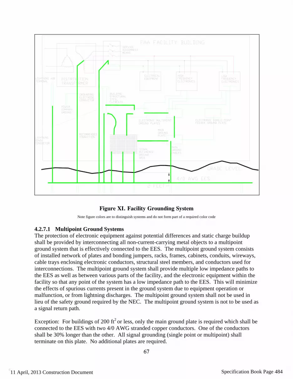
67
ε
Figure XI. Facility Grounding System Note figure colors are to distinguish systems and do not form part of a required color code
4.2.7.1 Multipoint Ground Systems The protection of electronic equipment against potential differences and static charge buildup shall be provided by interconnecting all non-current-carrying metal objects to a multipoint ground system that is effectively connected to the EES. The multipoint ground system consists of installed network of plates and bonding jumpers, racks, frames, cabinets, conduits, wireways, cable trays enclosing electronic conductors, structural steel members, and conductors used for interconnections. The multipoint ground system shall provide multiple low impedance paths to the EES as well as between various parts of the facility, and the electronic equipment within the facility so that any point of the system has a low impedance path to the EES. This will minimize the effects of spurious currents present in the ground system due to equipment operation or malfunction, or from lightning discharges. The multipoint ground system shall not be used in lieu of the safety ground required by the NEC. The multipoint ground system is not to be used as a signal return path. Exception: For buildings of 200 ft2 or less, only the main ground plate is required which shall be connected to the EES with two 4/0 AWG stranded copper conductors. One of the conductors shall be 30% longer than the other. All signal grounding (single point or multipoint) shall terminate on this plate. No additional plates are required.
11 April, 2013 Construction Document Specification Book Page 484

68
ε
4.2.7.1.1 Multipoint Ground Plates and Buses The location of the ground plate shall be chosen to facilitate the interconnection of all equipment cabinets, racks and cases within a particular area. If more than one ground plate is necessary, they shall be installed at various locations within the facility. Ground buses shall be used when distributed grounding is desired with a long row of equipment cabinets. Ground plates shall be copper and at least 12 inches long, 6 inches wide and ¼ inch thick. Ground buses shall be copper. Ground bus width and thickness shall be selected from Table IX, and shall be as long as required. Ground plates and buses shall be identified with a permanently attached plastic or metal label that is green with distinguishing bright orange slashes. The label shall bear the caption “ELECTRONIC MULTIPOINT GROUND SYSTEM” in black 3/8-inch (10 mm) high letters. 4.2.7.1.2 Ground Conductors – Plate to Plate and Plate to Bus Conductors between plates and buses in the multipoint system shall be insulated and sized in accordance with Table IX based on the maximum path length to the farthest point in the multipoint ground system from the EES. To determine the distance to the farthest point in the multipoint system, add the length of all conductors in the multipoint system to reach the farthest plate in the system via the longest path as shown in Figure XII. Divide the sum obtained by two to obtain the maximum path length. Utilize this path length to determine the conductor size from Table IX, but in no case use a conductor smaller than 4/0 AWG. These conductors shall be color-coded green with an orange tracer or shall be clearly marked for four inches at each end and wherever exposed with a green tape overlaid with an orange tracer. Additionally, when routed in cable trays, conductors shall be color-coded every three feet. Where conductors are routed through cable trays, they shall be insulated and separated from the other conductors as far as possible. These conductors shall be insulated.
11 April, 2013 Construction Document Specification Book Page 485

69
ε
Figure XII. Multipoint Ground Conductor Size Determination
4.2.7.1.3 Ground Conductors (Plate and Bus to Equipment) Conductors from plates and buses in the multipoint system to equipment chassis shall be sized in accordance with Table IX based on the maximum path length from the plate or bus to the equipment. These insulated conductors shall be color-coded green with an orange tracer or shall be clearly marked for 4 inches at each end and wherever exposed with a green tape overlaid with an orange tracer. Where routed through wireways, the color-coding shall be visible by opening any cover. Provide color-coding 4 inches long at intervals not exceeding 3 feet where ground conductors are routed through cable trays.
Table IX. Size of Electronic Multipoint Ground Interconnecting Conductors
Conductor Size Max. Path Length Bus Bar Size Max. Path Length Ft. (m) Inch (mm) Ft. (m)
750 kcmil* 375 (114.3) 4 x 1/4 (100 x 6.4) 636 (193.9) 600 kcmil* 300 (91.4) 4 x 1/8 (100 x 3.2) 318 (96.9) 500 kcmil 250 (76.2) 3 x 1/4 (75 x 6.4) 476 (145.1) 350 kcmil 175 (53.3) 3 x 1/8 (75 x 3.2) 238 (72.5) 300 kcmil 150 (45.7) 2 x 1/4 (50 x 6.4) 318 (96.9) 250 kcmil 125 (38.1) 2 x 1/8 (50 x 3.2) 159 (48.5) 4/0 AWG 105 (32.0) 2 x 1/16 (50 x 1.6) 79 (24.1) 3/0 AWG 84 (25.6) 1 x 1/4 (25 x 6.4) 159 (48.5) 2/0 AWG 66 (20.1) 1 x 1/8 (25 x 3.2) 79 (24.1) 1/0 AWG 53 (16.2) 1 x 1/16 (25 x 1.6) 39 (11.9) 1 AWG 41 (12.5) 2 AWG 33 (10.1) 4 AWG 21 (6.4) 6 AWG 13 (4.0)
* Where these conductors are not available, parallel conductors shall be allowed, such as three 250 kcmil conductors in place of one 750 kcmil conductor, or two 300 kcmil conductors in place of one 600 kcmil conductor. The conductor sizing is based on providing a cross-sectional area of 2000 circular mils per linear foot. The bus bar sizes are chosen from available cross sections and exceed the cross-sectional requirement of 2000 circular mils per linear foot. 4.2.7.1.4 Protection Provide mechanical protection for all conductors in the electronic multipoint ground system where they are subject to physical damage. This protection shall be provided by conduit, floor trenches, routing behind permanent structural members, or other means as applicable. Where routed through metal conduit, the conduit shall be bonded to the conductor at each end. 4.2.7.1.5 Conductor Labeling At each multipoint grounding conductor termination the conductor shall be labeled to identify the point of termination of the other end of the conductor. This shall be accomplished by
11 April, 2013 Construction Document Specification Book Page 486

70
ε
embossed label. These conductors shall also be identified every 50 feet and in junction boxes in the manner above indicating both ends. 4.2.7.2 Signal Reference Planes Signal reference planes (SRPs) shall be constructed of either an SRGG, SRGP, or a combination of both, in accordance with the narrative below: (a) Signal Reference Ground Grid (SRGG): A SRGG shall consist of a grid of two inch wide
copper strips, 26 gauge or thicker, laid on a two feet by two feet grid, welded at each grid intersection. The SRGG shall be installed below a raised floor, at or above a dropped ceiling, or both. The perimeter of the SRGG shall extend to within six inches of the room perimeter or the edge of the raised floor (and/or dropped ceiling) area if the raised floor (and/or dropped ceiling) does not fill the entire room. The SRGG and raised floor shall be bonded together at least every six feet with bare conductors. Dropped ceiling metalwork shall be bonded to ceiling mounted SRGG using guidance provided by the OPR. A 4/0 AWG or larger bare copper conductor shall be routed around the SRGG within six inches of the grid perimeter. The copper strips of the SRGG shall be bonded to the perimeter 4/0 AWG bare copper conductor at every intersection with 4 AWG bare copper conductors. The 4/0 AWG perimeter conductor shall be bonded to the EES with a minimum of four 4/0 AWG conductors spaced as widely apart as practicable.
Building structural steel within the perimeter of the grid and within 6 feet of the grid shall be bonded to the SRGG with a 4/0 AWG or larger conductor. All conduits, wireways, pipes, cable trays, or other metallic elements that penetrate the area shall be bonded to the SRGG where they enter the area and every 25 feet for their entire length within the area. All conduits, wireways, pipes, cable trays, or other metallic elements within 6 feet of the grid shall be bonded to the SRGG. These bonds shall be made with 4 AWG copper conductors minimum.
(b) Signal Reference Ground Plane (SRGP): All SRGP designs shall be approved by the OPR of this document. A SRGP shall consist of copper sheets, 24 gauge thickness minimum. The sheets shall be welded by any method approved by the OPR including butt, pan or lap methods. The SRGP shall be bonded to the EES with a minimum of four 4/0 AWG conductors spaced as widely as practicable. Building structural steel within the perimeter of the ground plane and within 6 feet of the ground plane shall be bonded to the SRGP with a 4/0 AWG or larger conductor. All conduits, wireways, pipes, cable trays, or other metallic elements that penetrate the area shall be bonded to the SRGP where they enter the area and every 25 feet for their entire length within the area. All conduits, wireways, pipes, cable trays, or other metallic elements within 6 feet of the ground plane shall be bonded to the SRGP. These bonds shall be made with 4 AWG copper conductors minimum.
All conductors and cabling shall lay on or very close (nominally, less than λ/20 of the highest system frequency) to the SRGG or SRGP. Installation of a SRGG or a SRGP shall be permitted below a raised floor, at or above a dropped ceiling, or both. Floor and ceiling portions of a
11 April, 2013 Construction Document Specification Book Page 487

71
ε
SRGG or a SRGP shall be bonded together with a minimum of four 4/0 AWG conductors spaced as widely spaced as practicable. All bonding connections between the equipment and the SRGG or SRGP shall be close-coupled, i.e., the bonding jumpers shall be as short as possible, and routed to the closest SRGG or SRGP location. When either an SRGG or an SRGP is utilized under equipment, a raised floor construction is preferred to enable routing of all connecting conductors and cabling close to the SRGG or SRGP. In this case conductors and cabling shall enter at the base of the equipment 4.2.7.3 Connection of MPG and SRP Systems to the Main and Supplemental Ground
Plates The MPG and SRP systems shall be connected to the Main and Supplemental ground plates with conductors sized in accordance with paragraph 4.2.7.1.2. Each connection shall be to the nearest MPG plate or SRP. 4.2.7.4 Connection of Electronic Enclosures to the SRS Bonding connections to the SRS shall be allowed either to the below floor SRP or directly to the raised floor system or alternatively to an MPG as constructed in paragraph 4.2.7.1. The length of the bonding conductor shall be less than 19 inches. To prevent the possibility of problems due to resonance of a single bonding strap, two widely spaced straps of unequal length (one of the conductors shall be 30% longer or shorter than the other) shall be used to bond the equipment to the SRS. Bonding straps shall be at least 1” wide and at least 26 gauge. Bonding straps shall be in accordance with paragraph 4.1.1.3 and installed in accordance with paragraph 4.1.1.2. When necessary, any radius in the bonding connectors shall be 8 inches minimum. 4.2.8 Electronic Single Point Ground System Requirements 4.2.8.1 General Electronic single point ground systems shall be installed in FAA facilities where required by equipment or requested by the vendor and approved by the OPR of this document. FAA facilities that do not utilize single point ground equipment are not required to install a single point ground system. The electronic single point ground system shall be isolated from the power grounding system, the lightning protection system and SRP or MPG systems (except at the main ground plate). The electronic single point ground system shall be terminated at the main ground plate or to the EES, whichever is the closest. The electronic single point ground system shall be configured to minimize conductor lengths. Conductive loops shall be avoided by maintaining a trunk and branch arrangement as shown in Figure XIII. 4.2.8.2 Ground Plates Main, branch and feeder ground plates shall be of copper and at least 12 inches long, 6 inches wide, and ¼ inch thick. The plates shall be mounted on non-conductive material of sufficient cross section to rigidly support the plates after all conductors are connected. Bolts or other devices used to secure the plates in place shall be insulated or shall be of a non-conducting material. The plates shall be mounted in a manner that provides ready accessibility for future inspection and maintenance.
11 April, 2013 Construction Document Specification Book Page 488

72
ε
4.2.8.3 Isolation between Single Point and SRP or MPG Systems The minimum resistance between the electronic single point ground and the SRP or MPG systems shall be 10 megohms. The resistance shall be measured after the complete network is installed and before connection to the EES or to the SRP or MPG system at the main ground plate. 4.2.8.3.1 Resistance The maximum resistance of any bond to a ground plate shall not be greater than 1 milliohm. 4.2.8.4 Ground Conductors All ground conductors shall be insulated copper conductors color-coded green with a yellow tracer. 4.2.8.4.1 Main Ground Conductor When a single point ground system is established directly from the EES, the single point main ground conductor shall be an insulated 500 kcmil copper conductor not exceeding 50 feet in length. The main ground conductor shall be connected to the EES by an exothermic weld in accordance with paragraph 4.1.1.2.1. 4.2.8.4.2 Trunk and Branch Ground Conductors An insulated trunk ground conductor shall be installed in each facility from the main ground plate to each of the branch plates as shown in Figure XIII. Insulated copper branch ground conductors shall be installed between feeder plates and branch ground plates. These conductors shall be routed to provide the shortest practical path. Trunk conductors shall be 4/0 AWG insulated copper conductors with a yellow tracer for systems where the farthest feeder plate in the system is no more than 400 feet from the EES via the conductor runs. For longer runs, select a conductor size based on providing a cross sectional area of 500 circular mils (cmil) per running foot of conductor length but in no case smaller than 250 kcmil. Trunk ground conductors shall be exothermically welded or connected with UL listed double bolted connectors to the ground plates in accordance with paragraph 4.1.1.2.4 and shall be mounted as shown on the facility drawings. 4.2.8.4.3 Electronic Equipment Ground Conductors The conductor from the feeder ground plate (branch ground plate if there is no need for a feeder ground plate in the conductor run) to the isolated terminal or bus on the electronic equipment shall be sized at 500 cmil per running foot with a minimum size of 6 AWG. 4.2.8.5 Interconnections All connections to the single point ground system shall be made on ground plates or buses. Split bolts and other connections to existing conductors are not allowed. 4.2.8.6 Labeling The single point ground system shall be clearly labeled to preserve its integrity as described in the following sections.
11 April, 2013 Construction Document Specification Book Page 489

73
ε
4.2.8.6.1 Conductor Identification At each single point grounding conductor termination the conductor shall be labeled to identify the point of termination of the other end of the conductor. This shall be accomplished by embossed label. These conductors shall also be identified every 50 feet and in junction boxes in the manner above indicating both ends. 4.2.8.6.2 Ground Plate Labeling All ground plates shall be protected with a clear plastic protective cover spaced ¾ inch (19 mm) from the plate and extending 1 inch (25.4 mm) beyond each edge. This cover shall have a green label with distinguishing bright yellow slashes attached bearing the caption: “CAUTION, ELECTRONIC SINGLE POINT GROUND” in black 3/8 inch high (10 mm) letters. 4.2.8.6.3 Protection Provide mechanical protection for all conductors in the electronic single point ground system where they are subject to damage. This protection shall be provided by conduit, floor trenches, routing behind permanent structural members, or other means as applicable. Single point ground conductors shall be isolated from contact with any metal elements.
11 April, 2013 Construction Document Specification Book Page 490

74
ε
Figure XIII. Electronic Single Point Ground System Installation
4.2.9 DC Bus Grounding Requirements Contact the OPR for specific DC Bus grounding designs. 4.2.10 National Electrical Code (NEC) Grounding Compliance 4.2.10.1 General The facility electrical grounding shall exceed requirements of NEC Article 250 as specified herein.
500 kcmil Main Ground Conductor
11 April, 2013 Construction Document Specification Book Page 491
75
ε
4.2.10.2 Grounding Electrode Conductors Grounding electrode conductors shall conform to the following: (a) Facilities shall have the grounded conductor (neutral) connected to the EES by a copper
grounding electrode conductor at the service disconnecting means. The grounding electrode conductor shall be sized in accordance with the NEC, but never smaller than 2 AWG.
(b) The grounding electrode conductor connection shall be made to the neutral bus in the service disconnecting means.
(c) If the grounding electrode conductor is spliced using a hydraulically crimped connector, the connector will comply with paragraph 4.1.1.2.4.4. When a grounding electrode conductor is routed through a metal enclosure, e.g., conduit, the enclosure shall be bonded at each end to the grounding electrode conductor.
(d) An equipment grounding conductor shall be routed with associated phase conductors to a second building or structure. The grounded conductor routed from the first building or structure shall not be connected to the equipment grounding conductor or EES at the second building or structure.
(e) For a separately derived system, the system bonding jumper and the grounding electrode conductor shall be located at the first downstream system disconnecting means or overcurrent device. For the grounding electrode conductor the connection shall be to the nearest effectively grounded structural metal member. Where it is not feasible to connect the grounding electrode conductor to a structural metal member, the EES shall be used. The grounding electrode conductor shall be copper and sized in accordance with NEC requirements, except that it shall not be smaller than 2 AWG. Separately derived systems, other than at the top of a tall ATCT, serving NAS critical and essential services shall have an additional grounding electrode conductor terminated to the EES.
4.2.10.3 Equipment Grounding Conductors The equipment grounding conductor shall be a green-insulated wire routed in the same raceway as its’ related phase and neutral conductors. Cord-connected equipment requiring an equipment ground shall include the equipment grounding conductor as an integral part of the power cord. Where power is supplied to electronic equipment through a cable and connector, the connector shall contain a pin to continue the equipment grounding conductor to the equipment chassis. Conduit or cable shields shall not be used as the equipment grounding conductor. All installations shall be in accordance with the NEC, FAA-C-1217 and with the following: (a) Parity-sized equipment grounding conductors, same sized as the associated phase conductors,
shall be used when it is recommended as good practice in a manufacturer’s equipment installation requirements. Where a parity-sized equipment grounding conductor is installed it shall be bonded to bonding bushings at each end of the raceway with a bonding jumper the same size as the equipment grounding conductor. This shall be accomplished for branch circuits as a minimum.
(b) Grounding terminals in all receptacles on multioutlet assemblies shall be hardwired to an equipment grounding conductor. Strips that depend upon serrated or toothed fingers for
11 April, 2013 Construction Document Specification Book Page 492

76
ε
grounding shall not be used. (c) All flexible metal conduits shall be provided with an external bonding jumper in addition to
the internal equipment grounding conductor. The bonding jumper shall be a 6 AWG green-insulated stranded copper conductor. The bonding jumper shall terminate on fittings listed for grounding at each end of the flexible metal conduit.
(d) A seperate equipment grounding conductor shall be provided for each overcurrent device and as required by the NEC.
4.2.10.4 Color Coding of Conductors 4.2.10.4.1 Grounded Conductors (a) Grounded conductors shall be insulated and color-coded white for 120/208V and 120/240V
and gray for voltages above 120/240V. Conductors larger than 6 AWG shall be allowed to be re-identified as the grounded conductor except that green conductors shall not be re-identified.
(b) In any raceway, box, cable tray, or enclosure, where grounded conductors of different systems are present, each grounded conductor shall be identified by system, in accordance with the NEC.
(c) Color-coding of grounded conductors shall be applied at each connection and at every point where the conductor is accessible. Where routed through raceways with covers, the color coding shall be visible by removing or opening any cover. Where conductors are routed through cable trays, color coding 3 inches (75 mm) in length shall be provided at intervals not exceeding 3 feet (0.9 m).
4.2.10.4.2 Equipment Grounding Conductors (a) Equipment grounding conductors shall be solid green in color. Insulated conductors larger
than 6 AWG shall be allowed to be re-identified with green tape. White or gray conductors shall not be re-identified as equipment grounding conductors. The equipment grounding conductor from the grounding terminal of an isolated receptacle shall be color-coded green with yellow and red tracers.
(b) Color-coding of equipment grounding conductors shall be applied at each connection and at every point where the conductor is accessible. Where routed through raceways with covers, the coding shall be visible by removing or opening any cover. Where conductors are routed through cable trays, color coding 3 inches (75 mm) long shall be provided at intervals not exceeding 3 feet (0.9 m).
(c) Some COTS equipment is supplied with a green and yellow equipment grounding conductor. These conductors do not need to be replaced. These conductors shall not be connected to the single point ground system.
4.2.10.4.3 Control and DC Power Cables and Conductors Color-coding for conductors in control cables shall be in accordance with NEMA Standard WC-5. DC power conductors, including battery cables, shall be color-coded as follows: a red for positive conductor and black for a negative conductor. The red conductor shall be marked with a positive (+) symbol and the black conductor shall be marked with a (-) symbol. The symbols shall be applied to the conductor with a shrink embossed label.
11 April, 2013 Construction Document Specification Book Page 493
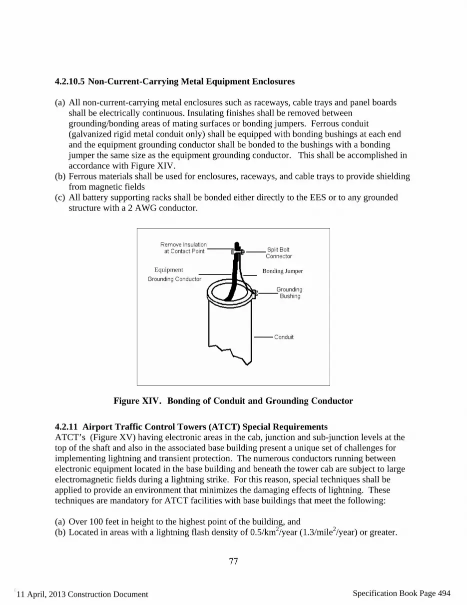
77
ε
4.2.10.5 Non-Current-Carrying Metal Equipment Enclosures (a) All non-current-carrying metal enclosures such as raceways, cable trays and panel boards
shall be electrically continuous. Insulating finishes shall be removed between grounding/bonding areas of mating surfaces or bonding jumpers. Ferrous conduit (galvanized rigid metal conduit only) shall be equipped with bonding bushings at each end and the equipment grounding conductor shall be bonded to the bushings with a bonding jumper the same size as the equipment grounding conductor. This shall be accomplished in accordance with Figure XIV.
(b) Ferrous materials shall be used for enclosures, raceways, and cable trays to provide shielding from magnetic fields
(c) All battery supporting racks shall be bonded either directly to the EES or to any grounded structure with a 2 AWG conductor.
Equipment
Figure XIV. Bonding of Conduit and Grounding Conductor
4.2.11 Airport Traffic Control Towers (ATCT) Special Requirements ATCT’s (Figure XV) having electronic areas in the cab, junction and sub-junction levels at the top of the shaft and also in the associated base building present a unique set of challenges for implementing lightning and transient protection. The numerous conductors running between electronic equipment located in the base building and beneath the tower cab are subject to large electromagnetic fields during a lightning strike. For this reason, special techniques shall be applied to provide an environment that minimizes the damaging effects of lightning. These techniques are mandatory for ATCT facilities with base buildings that meet the following: (a) Over 100 feet in height to the highest point of the building, and (b) Located in areas with a lightning flash density of 0.5/km2/year (1.3/mile2/year) or greater.
Bonding Jumper
11 April, 2013 Construction Document Specification Book Page 494

78
ε
These techniques are recommended for application to all ATCT facilities. 4.2.11.1 General The lightning protection, electrical, electromechanical, electronic systems, and building steel of structures shall be bonded together for safety. It is not possible for equipment near the top of the tower and at the base to have the same electrical potential during a lightning strike. It is therefore necessary to reference all systems at the top of the tower to each other and treat this area as a separate facility. SPD’s shall be provided at the base building/tower shaft facility entrance and at the top of the shaft. 4.2.11.2 Main Ground Connections In order to assure good high frequency grounding during normal operation a low impedance connection must be provided to the EES. A main ground plate shall be established on the lowest level with electrical, electromechanical, or electronic equipment serving the ATCT cab (see Figure XV). All grounding systems present at or above this level within the ATCT shall be connected to this main ground plate. A 1-foot wide 26 gauge or thicker copper strap shall connect this main ground plate to a plate at the base of the ATCT. This strap shall be routed continuously from the main ground plate to the base plate without sharp bends, loops, kinks, or splices and will provide two square feet of surface per linear foot of conductor. Substitution of a combination of conductors providing the same surface area per linear foot shall be allowed. This strap or conductors shall be mechanically bonded to the main ground plate and the base plate. The strap shall be sandwiched between the plate at each end and a 1'x1"x1/8" copper bar to insure good electrical contact and mechanical strength. Connect the base plate to the EES in an access well with two exothermically welded 500 kcmil conductors. The OPR should be consulted for assistance in meeting this requirement. 4.2.11.3 Power Distribution All power distribution for the areas at the top of the ATCT shall be via separately derived systems. These separately derived systems shall be grounded in accordance with the requirements of NEC article 250 and paragraph 4.2.10.2(e) at the first downstream disconnecting means or overcurrent device. This point of connection is mandated to facilitate the effective installation of an SPD. An SPD, in accordance with paragraph 4.2.2.2 shall be installed on the load side of the first downstream disconnecting means or overcurrent device of each separately derived system. The ground bus at the first disconnecting means or overcurrent device shall be bonded to the main ground plate established in accordance with the requirements paragraph4.2.11.2. This connection is in addition to the grounding electrode conductor requirements of NEC article 250. The interior metallic piping systems at the top of the ATCT shall be bonded to the main ground plate established in accordance with the requirements paragraph4.2.11.2. This connection is in addition to the bonding requirements of NEC article 250.
11 April, 2013 Construction Document Specification Book Page 495

79
ε
Figure XV. Airport Traffic Control Tower Levels
4.2.11.4 Bonding Metal elements comprising the ATCT shall be bonded together and to the EES. Provision shall be made to ensure that all rebar used in tower construction is electrically bonded together – continuous laterally and vertically to the EES – for the entire ATCT. Rebar shall be bonded to the EES with a minimum 2 AWG copper conductor that is applied via an exothermic weld or a hydraulically crimped termination. At the top of the ATCT, the tower cab and all equipment locations supporting the cab shall be enveloped in a rudimentary Faraday cage. This shall be accomplished by bonding together all structural and fabrication steel. In turn, this steel cage shall be electrically bonded to the rebar in the concrete construction. Penetrations of the Faraday cage, e.g., conduit, water pipe, etc., shall be bonded to the cage at the point of entry. Bonding jumpers shall be a minimum 2 AWG copper conductor. At all levels of an ATCT, horizontal metal transitions (floors, stairs, walkways, etc.) shall be bonded to structural steel and/or rebar. Elevator support structures shall be bonded to horizontal metal transitions and to the EES. All bonding jumpers shall be a minimum 2 AWG copper conductor. If this last requirement cannot be met, contact the OPR of this document. 4.2.11.5 Signal, Communications, Axial Cables and Control Line Protection Transient protection shall be applied at each end of vertical cables routed between the equipment room near the top of the ATCT and the associated base building. Cables between the tower cab
11 April, 2013 Construction Document Specification Book Page 496

80
ε
and equipment room areas shall be protected in accordance with paragraphs 4.2.2.5 through 4.2.2.7. Both facility and equipment levels of protection shall be provided for these lines. Enclosing metallic cabling in ferrous conduit or the use of all dielectric fiber optic cable can significantly reduce the threat of lightning related damage to ATCT and base building circuits. 4.2.11.6 Signal Reference Structure An SRS shall be constructed in accordance with paragraph 4.2.7. This shall be accomplished for the cab and all other areas at the top of the ATCT that contain electrical, electromechanical or electronic equipment serving the cab. 4.2.11.7 Floor Coverings for Electronic Equipment and Operational Areas Floor coverings for the cab and areas serving the cab shall be either tile or carpeting and shall be of static dissipative material. These shall be installed per manufacturers' specifications and connected to a component of the SRS – except to any single point ground system. The floor covering and installation shall meet the requirements of paragraph 4.1.3.4.8. 4.2.11.8 Single Point Grounding Single point ground systems, if required, shall be constructed in accordance with paragraph 4.2.8. All single point ground systems and independent ground systems mandated by equipment manufacturers shall be bonded to the ATCT main ground plate established in accordance with the requirements paragraph4.2.11.2. 4.3 Equipment Requirements Electronic equipment installed in FAA NAS facilities must comply with the requirements contained in this section. 4.3.1 Electronic Signal Lines and Cables Electronic signal lines shall be shielded twisted pairs with an insulated covering. Cables consisting of multiple twisted pairs shall have the individual shields isolated from each other. Cables shall have an overall shield with an overall insulated covering. 4.3.1.1 Termination of Individual Shields Termination of individual shields shall be in accordance with paragraph 4.1.2.3.2. 4.3.1.2 Termination of Overall Shields Termination of overall shields shall be in accordance with paragraph 4.1.2.3.3. 4.3.2 Signal Control and Data Line Entrance Procurement organizations are responsible for ensuring that electronic equipment, such as radars, navaids, or transmitters, supplied for use in FAA operational facilities, shall be provided with transient protection that reduce surges and transients to below the equipment transient susceptibility level. Signal control and data line entrance protection shall be provided as an integral part of all electronic equipment mounted internally or on the exterior of the equipment and at the facility entrance. The equipment susceptibility level is defined as the transient level
11 April, 2013 Construction Document Specification Book Page 497

81
ε
on the signal, control or data lines that cause damage, degradation, or upset to electronic circuitry connected to the line. Protection for these lines is in addition to the facility protection levels specified in paragraphs 4.2.2.5 through 4.2.2.7. The procurement organizations are responsible for ensuring that testing is performed to determine voltage, current, or energy levels that will cause immediate damage to components, shorten operating life, or cause operational upset to the equipment. These tests shall consider all electrical and electronic equipment components exposed to the effects of surges or transients. The procurement organization shall ensure that facility and equipment entrance protection is coordinated to limit transients at the equipment to below the equipment susceptibility level. Requirements of this paragraph shall be included in the comprehensive control and test plans outlined in paragraph 4.1.4.2. In all cases, the following characteristics shall be evaluated. (a) Component damage threshold. The damage threshold is the transient level that renders the
component nonfunctional or operationally deficient. For solid-state components, voltage is usually the relevant parameter.
(b) Component degradation level. The component degradation level is the transient voltage or energy level that shortens the useful life of the component.
(c) Operational upset level. The operational upset level is the transient voltage or energy level that causes an unacceptable change in operating characteristics for longer than 10 milliseconds for analog equipment or a change of logic state for digital equipment.
4.3.2.1 Lines and Cables Requiring Protection Surge protective devices shall be placed on both ends of signal, data, and control lines longer than 10 feet connecting pieces of equipment not located on and bonded to the same SRS, or when the SRGG, SRGP, and the multipoint ground system is located in different rooms or on different floors. (refer to Figure XVI). This includes all signal, data, and control lines. This equipment shall be protected as specified in paragraph 4.3.2.
>10 ft, same SRS, no protection needed
>10 ft, different SRS,data line protectionrequired
<10 ft, different SRS, no protection needed
<10 ft, same SRS,no protection needed
Figure XVI. Lines and Cables Requiring Protection
4.3.3 Power Entrance Surge protective devices, components or circuits for protection of electronic equipment power lines shall be provided by the equipment manufacturer as an integral part of all electronic equipment mounted internally or on the exterior of the equipment at the cable entrance (see paragraph 4.2.2.1). These devices shall be positioned at the AC power conductor entrance to electronic equipment housed in a shielded, compartmentalized enclosure. SPDs at equipment shall provide a clamping level less than the equipment operational upset susceptibility level as
11 April, 2013 Construction Document Specification Book Page 498

82
ε
defined in paragraph 4.3.2(c) and must conform to the relevant columns of Table X, Table XI, and Table XII. (a) Maximum continuous operating voltage (MCOV). The maximum continuous operating
voltage is the maximum RMS voltage an SPD will withstand at its maximum operating temperature continuously without degradation or change to any of its parameters greater than +/-10%. The MCOV will be at least 10% above the nominal system voltage. Leakage current as defined below shall not be exceeded.
(b) Leakage current. The DC leakage current will be less than 1mA for voltages at or below 1.414 x MCOV VDC.
(c) Clamp (discharge) voltage. Clamp (discharge) voltage is the maximum voltage that appears across an SPD output terminal while conducting surge currents. Clamp (discharge) voltage measured at 3kA (to ensure performance in the linear region without impacting the device lifetime performance) 8/20 microseconds shall not change more than 10% over the operating life of the Surge Protection Device as defined in Table XII. Electronic Equipment Power Entrance SPD Requirements.
(d) Overshoot voltage. Overshoot voltage shall not exceed 2 times the SPD clamp voltage for more than 10 nanoseconds. Overshoot voltage is the surge voltage level that appears across the SPD terminals before the device turns on and clamps the surge to the specified voltage level.
(e) Self-restoring capability. The SPD shall automatically return to an off state after surge dissipation when line voltage returns to normal.
(f) Operating lifetime. The SPD shall safely dissipate the number and amplitude of surges listed in Table XII.
(g) Fusing. Any fusing shall not increase the clamp voltage of the SPD and shall pass the surge current levels listed in Table XII up to the 20kA level without opening. Any fusing provided shall be coordinated with the supply fusing.
4.3.3.1 Slope Resistance It is the purpose of this parameter to create a regime where it is possible to ensure device coordination. The slope resistance for the equipment protection shall meet the requirements of Table X and is calculated via the formula below: Rslope = (V10- V1)/9000 Where V10 = the clamping voltage measured at 10kA 8/20µs and Where V1 = the clamping voltage measured at 1kA 8/20µs The values of V10 and V1 used shall be measured values determined in actual testing of the SPDs and not calculated.
11 April, 2013 Construction Document Specification Book Page 499

83
ε
Table X. Equipment Power Entrance Slope Resistance Requirements
Location Slope Resistance Electronic equipment power
entrance 60 mΩ Minimum
The voltages that must be achieved during testing at 3kA with an 8/20µs current impulse is shown in Table VI. All voltages shall be measured at the device terminals. The 8/20µs current impulse wave shape shall not lead or lag the voltage wave shape by more than 30 degrees.
Table XI. Protection Voltages at 3kA for the Equipment Power Entrance
Location System Voltage V3 Limit
Electronic equipment power entrance
120/208 120/240 550 L-N, L-G
850 L-L Minimum
Electronic equipment power entrance
277/480 850 L-N, L-G
1350 L-L Minimum
Electronic equipment power entrance
380Delta 1350 L-L, L-G Minimum
Electronic equipment power entrance
480 Delta 1350 L-L, L-G Minimum
Table XII. Electronic Equipment Power Entrance SPD Requirements
Surge Current Amplitude 8/20µs Waveform
Surge Number lifetime Electronic equipment power entrance
1kA 100 10kA 25 20kA 1
Each level of surge current and the number required represents a single lifetime of an SPD. 4.3.3.2 DC Power Supply Transient Suppression Procurement organizations are responsible for ensuring that power supplies that use 60 Hertz (Hz) power and furnish DC operating voltages to solid-state equipment used in direct support of the NAS, shall have transient suppression components from each output of the power supply to the equipment chassis. The chassis side of suppressors shall be connected as directly as possible to rectifier output ground. Operating characteristics of suppression components provided for power supply rectifier output lines shall be as follows:
11 April, 2013 Construction Document Specification Book Page 500

84
ε
(a) Operating lifetime. The transient suppressors shall safely dissipate 1000 surges with an amplitude of 200 Amps and a waveform of 1.2/50 µs. Methods of testing shall be in accordance with the guidance in IEEE C62.45.
(b) Limiting Voltage. The voltage shall be limited to a point 20% below the maximum Peak Inverse Voltage (PIV) of the DC rectifier.
4.3.3.3 Externally Mounted Electronic Equipment When electronic equipment is not enclosed in a facility (e.g. RVR, LLWAS, OM, etc.) the power SPD protection specified in this document rated for facility entrance shall be provided. For the signal and control cables of this equipment both facility and electronic equipment entrance shall be provided at the equipment entrance as a combined protector. The grounding conductor shall be bonded to the equipment chassis and shall be of minimum length and routed to avoid sharp bends, kinks or loops. Access shall be provided for visual inspection and replacement of these SPDs. 4.3.4 Electronic Equipment Grounding 4.3.4.1 Electronic Cabinets, Racks, and Cases All electronic cabinets, racks, and cases shall provide a grounding terminal or bus whereby a grounding jumper or wire can be mechanically connected through an electrically conductive surface to the basic frame. The metal enclosure of each individual unit or piece of electronic equipment shall be bonded to its cabinet, rack, or directly to the SRP or MPG system. 4.3.4.2 Isolated Grounding Receptacles For reduction of electrical noise, isolated receptacles installed in accordance with the NEC shall be permitted. The isolated equipment grounding conductors used for these receptacles shall be color-coded green with red and yellow tracers at each termination, and when passing through an enclosure without termination. 4.3.4.3 Portable Equipment (with grounding conductor) Portable electrical or electronic equipment cases, enclosures, and housings shall be considered to be adequately grounded for fault protection through the equipment grounding conductor of the power cord, provided continuity is firmly established between the case, enclosure or housing, and the receptacle ground terminal. The power cord equipment grounding conductor shall not be used for signal grounding. 4.3.4.4 AC Power Filters All filter cases shall be directly bonded in accordance with paragraph 4.1.1.10 to the equipment case or enclosure. Filter leakage current shall not exceed 5 milliamperes (mA) per filter. Transient suppression devices, components or circuits shall be installed in accordance with paragraph 4.2.2.1. 4.3.5 Equipment Signal Grounding Requirements
11 April, 2013 Construction Document Specification Book Page 501

85
ε
4.3.5.1 Input and Output Electronic Signals Where a common signal reference is used, low frequency analog input and output signals shall be balanced with respect to the signal reference. Extreme care shall be taken to maintain isolation between the single point ground system and the SRP or MPG system, except at the main ground plate or EES. 4.3.5.2 Multipoint Grounding of Electronic Equipment When permitted by circuit design requirements, all internal ground references shall be directly bonded to the chassis and the equipment case. Where mounted in a rack, cabinet or enclosure, the electronic equipment case shall be bonded to the racks, cabinet or enclosure in accordance with paragraph 4.3.4.1. The DC resistance between any two points within a chassis or electronic equipment cabinet serving as ground shall be less than 25 milliohms total and not more than 2.5 milliohms per joint. Shields shall be provided as required for personnel protection and electromagnetic interference reduction. 4.3.5.2.1 Prevention of Resonance in Bonding Straps To prevent the possibility of problems due to resonance of a single bonding strap, two widely spaced straps of unequal length shall be used to connect the equipment to the multipoint grounding bus in the equipment cabinet. Bonding shall be in accordance with the recommended practices as expressed in paragraph 4.2.7.4 and IEEE Std 1100-1999 paragraph 8.5.4.6. 4.3.5.3 Single Point Grounding of Electronic Equipment When electronic equipment performance necessitates an isolated electronic single point ground system for proper operation, all the equipment and its installation shall comply with the following: The single point ground system or plane shall be isolated from the electronic equipment case. If a metal chassis is used as the electronic single point ground, the chassis shall be floated relative to the case. Design practices shall be such that the single point ground of the electronic equipment can be properly interfaced with other electronic equipment without compromising the system. If necessary, this single point ground system shall be filtered for high frequencies. 4.3.5.3.1 Single Point Input and Output Signal Requirements The “high” and “low” sides of input and output signals shall be isolated from the electronic equipment case and balanced with respect to the signal reference. Operating and adjusting controls, readouts or indicating devices, protective devices, monitoring jacks and signal connectors shall be designed to isolate both the high and low side of the signal from the case. 4.3.5.3.2 Single Point Case Isolation Requirements The isolation between the single point ground system terminals and the case shall be 10 megohms or greater with all external power, signal and control lines disconnected from the electronic equipment.
11 April, 2013 Construction Document Specification Book Page 502

86
ε
4.3.5.3.3 Single Point Power Isolation Requirements The isolation between the single point ground system terminals and each power conductor (including AC neutral) shall be 10 megohms or greater with the power switch in the on position and the power disconnected from the supply. 4.3.5.4 Equipment Single Point Ground Terminals Insulated single point ground system terminal(s) shall be provided on each electronic equipment case where an isolated signal reference is required. The single point ground reference for the internal circuits shall be connected to this terminal. This terminal(s) shall be used to terminate cable shields as appropriate, and to connect the isolated signal ground of the electronic equipment to the single point ground system in the facility. A connector pin, a screw or pin on a terminal strip, an insulated stud, jack or feed through, or an insulated wire shall be an acceptable terminal so long as each terminal is clearly marked, labeled, or coded in a manner that does not interfere with its intended function. These marks, codes, or labels shall be permanently affixed and shall utilize green with yellow stripes. Wire insulation shall be green with a yellow tracer. 4.3.5.4.1 Connection of Electronic Equipment to the Single Point Ground System Each equipment single point ground terminal shall be connected to the facility single point ground system in accordance with the following: (a) Individual units or pieces of electronic equipment which by nature of their location or
function cannot or should not be mounted with other electronic equipment, shall have an insulated copper conductor installed between the electronic single point ground terminal specified in paragraph 4.3.5.4 and the nearest electronic single point ground system ground plate. This conductor shall have a cross-sectional area of 500 circular mils per linear foot with a minimum size of 6 AWG.
(b) Where two or more units or pieces of electronic equipment are mounted together in a rack or cabinet, a single point ground bus bar shall be installed as shown in Figure XVII. The bus bar shall be copper and shall provide a minimum cross-sectional area of 125,000 circular mils (e.g., a 1inch by 1/8inch bus bar). The bus bar shall be drilled and tapped for #10 screws. The holes shall be located as required by the relative location of the isolated electronic single point grounding terminals on the electronic equipment. The bus bar shall be mounted on insulating supports that provide at least 10 megohms resistance between the bus bar and the rack or cabinet.
(c) Each electronic equipment isolated single point ground terminal shall be interconnected to the bus bar by means of a solid or flexible tinned (6 AWG minimum) copper jumper of sufficient cross sectional area so that its resistance is 5 milliohms or less. The jumper shall be insulated or mounted in a manner that maintains the required degree of isolation between the reference conductor and the enclosure. The interconnecting jumper shall be attached to the bus bar at a point nearest to the single point ground terminal to which the strap is attached. An insulated copper conductor shall be installed from the bus bar in the cabinet to the nearest electronic single point ground system. This conductor shall provide at least 500 circular mils per linear foot, and must be a minimum 6 AWG conductor.
11 April, 2013 Construction Document Specification Book Page 503

87
ε
Figure XVII. Single Point Electronic Ground Bus Bar Installation in Rack or Cabinet
Single Point Bus Bar
6 AWG Minimum
To Single Point Grounding System
11 April, 2013 Construction Document Specification Book Page 504

88
ε
4.3.6 Equipment Shielding Requirements 4.3.6.1 Control of Apertures Unnecessary apertures shall be avoided. Only those shield openings needed to achieve proper functioning and operation of the equipment shall be provided. Controls, switches, and fuse holders shall be mounted so close metal-to-metal contact is maintained between the cover housing of the devices and the case. Metal control shafts shall be grounded in accordance with paragraph 4.3.6.2. Where nonconductive control shafts are necessary, a close fitting metal sleeve peripherally bonded to the case shall be provided for the shaft. The length of the sleeve shall be no less than four times its diameter. Lights shall be filtered or shielded as needed to maintain the required degree of shielding effectiveness. Ventilation and drainage holes shall utilize appropriate shielding techniques. Care shall be taken to assure that the shielding is well bonded to the shield completely around the opening. 4.3.6.2 Metal Control Shafts Metal control shafts shall be grounded to the equipment case through a low impedance path provided by close-fitting conductive gaskets, metal finger stock, or grounding nuts. 4.3.6.3 Shielded Compartments Shields shall be bonded to the chassis for fault protection in accordance with paragraph 4.1.1. 4.3.7 Circuit and Equipment ESD Design Requirements 4.3.7.1 Circuit Design and Layout The design, layout, and packaging of assemblies, circuits, and components integrated into electrical and electronic equipment shall incorporate methods and techniques to reduce susceptibility to ESD. 4.3.7.2 Component Protection External protection shall be provided for all integrated circuits, discrete components, and other parts without internal ESD protection that are inherently susceptible to ESD. Protective components shall be installed as close as possible to the ESD susceptible item. 4.3.7.3 ESD Withstand Requirements In the installed and operational configuration, all equipment cabinets, enclosures, racks, controls, meters, displays, test points, interfaces, etc., shall withstand a static discharge of 15,000 Volts per ESD Association Standard Test Method ESD-STM 5.1, Electrostatic Discharge Sensitivity Testing – Human Body Model (HBM). Equipment that is tested shall not suffer any operational upset or damage to any component or assembly to successfully pass ESD withstand requirements.
11 April, 2013 Construction Document Specification Book Page 505

89
ε
This Page Intentionally Left Blank
11 April, 2013 Construction Document Specification Book Page 506

90
ε
5 DETAILED REQUIREMENTS Section is not applicable to this standard.
11 April, 2013 Construction Document Specification Book Page 507

91
ε
This Page Intentionally Left Blank
11 April, 2013 Construction Document Specification Book Page 508

92
ε
6 NOTES 6.1 Acronyms and Abbreviations The following are acronyms and abbreviations used in this standard A Amperes L-L Line to Line AC Alternating current L-N Line to Neutral
ANSI American National Standards Institute
LRU Line replacement unit
AWG American Wire Gauge m Meter Cm Centimeter(s) mA Milliampere Cmil Circular mils MCM See kcmil DC Direct current MCOV Maximum continuous operating voltage e.g. For example MHz Megahertz EES Earth electrode system MPG Electronic multipoint ground system EMI Electromagnetic interference mm Millimeter(s) EPP Equipotential plane NAS National Airspace System EOS Electrical overstress NEC National Electrical Code ESD Electrostatic discharge NEMA National Electrical Manufacturers
Association Et.al. And others NFPA National Fire Protection Association FAA Federal Aviation Administration No. Number ft. Foot (feet) OPR Office of Primary Responsibility GP Groundable point PVC Polyvinyl chloride Hz Hertz RF Radio frequency i.e. That is RGS Rigid galvanized steel in. Inch(es) RFI Radio frequency interference IEEE Institute of Electrical and Electronics
Engineers RMM Remote maintenance monitoring
kA Kiloampere SAS Silicon avalanche diode suppressors kcmil Thousand circular mils SDM Service disconnecting means kg Kilogram SPD Surge protective device kHz Kilohertz SPG Electronic single point ground system LAN Local area network SRG Signal reference grid LPGBS Lightning Protection, Grounding,
Bonding and Sheilding UL Underwriters Laboratories
“ Inch(es) µs Microseconds # Number ‘ Foot (feet) L-G Line to Ground V Volts
11 April, 2013 Construction Document Specification Book Page 509

93
ε
6.2 Guidelines Engineering design guidelines are provided for lightning protection, grounding, bonding, shielding, and transient protection in FAA Orders 6950.19 and 6950.20. Guidance for EMI protection is in MIL-HDBK-253, and for electrostatic discharge (ESD) in NFPA 77, DOD-HDBK-263, DOD-STD-1686 and IEEE1100. 6.3 Version Cross-Reference Due to the major reorganization of FAA-STD-019e it is not feasible to provide an exact cross-reference between this standard and the previous version, FAA-STD-019d. However the handbook to FAA-STD-019e will provide information on requirements revisions and detail cost effective methods of applying them. Where possible references to the original requirements in FAA-STD-019d will be provided.
11 April, 2013 Construction Document Specification Book Page 510

11 April, 2013 Construction Document Specification Book Page 511

11 April, 2013 Construction Document Specification Book Page 512

11 April, 2013 Construction Document Specification Book Page 513

11 April, 2013 Construction Document Specification Book Page 514
11 April, 2013 Construction Document Specification Book Page 515

11 April, 2013 Construction Document Specification Book Page 516

11 April, 2013 Construction Document Specification Book Page 517

12 December 2012
Specification Book Page 492

12 December 2012 Specification Book Page 493

12 December 2012
Specification Book Page 494
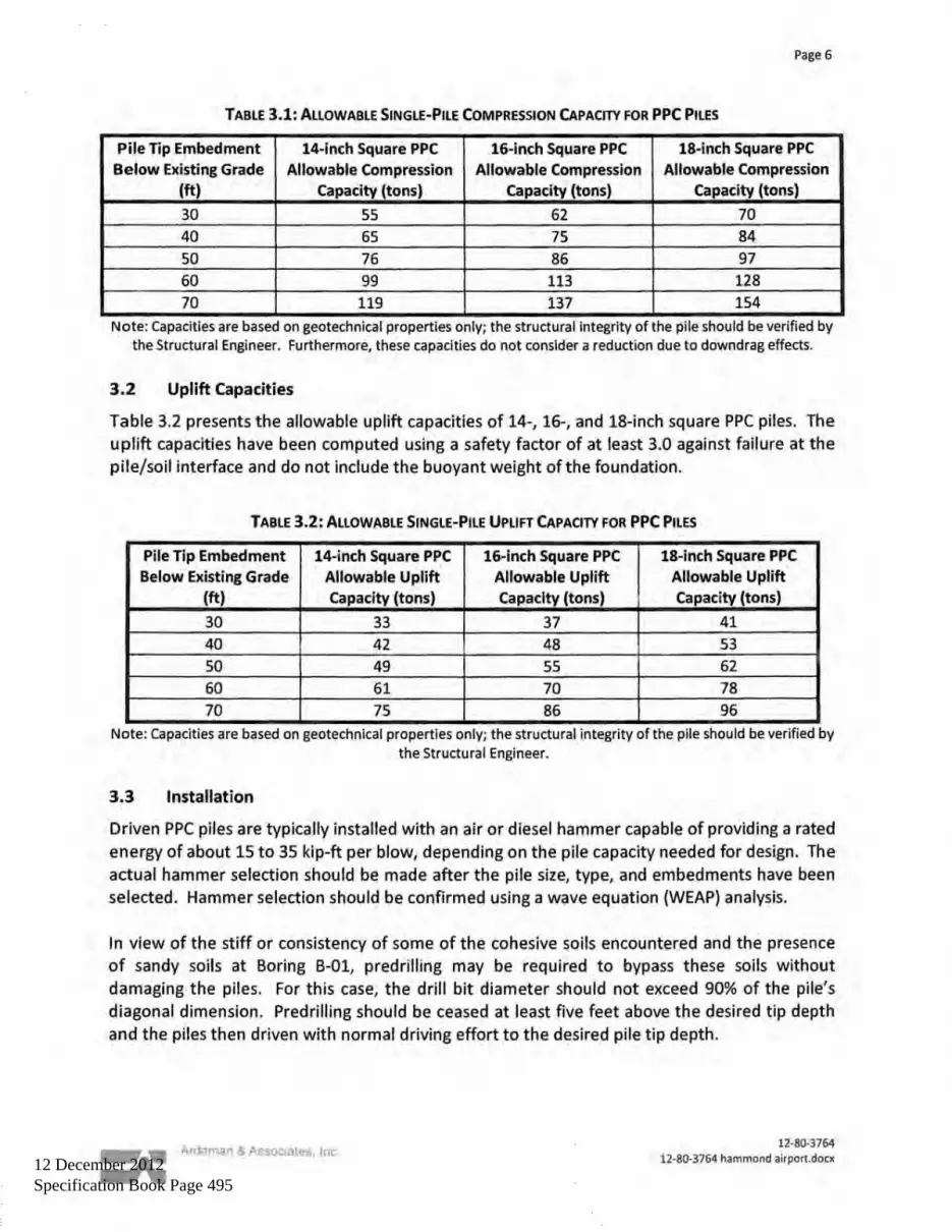
12 December 2012 Specification Book Page 495

12 December 2012
Specification Book Page 496

12 December 2012
Specification Book Page 497

12 December 2012
Specification Book Page 498

12 December 2012 Specification Book Page 499
12 December 2012
Specification Book Page 500

12 December 2012
Specification Book Page 501

12 December 2012
Specification Book Page 502

12 December 2012 Specification Book Page 503

12 December 2012 Specification Book Page 504

12 December 2012 Specification Book Page 505

12 December 2012
Specification Book Page 506

12 December 2012 Specification Book Page 507

12 December 2012
Specification Book Page 508

12 December 2012
Specification Book Page 509

12 December 2012 Specification Book Page 510

12 December 2012 Specification Book Page 511

12 December 2012 Specification Book Page 512

12 December 2012 Specification Book Page 513

12 December 2012 Specification Book Page 514

12 December 2012 Specification Book Page 515

12 December 2012
Specification Book Page 516

12 December 2012 Specification Book Page 517