Embed Size (px)
Citation preview
SPECIFICATIONS
LAKE CITY, FLORIDA
PROJECT: 573A-12-200
FINAL BID DOCUMENTS
MES GROUP #2013504
i
SECTION 01 00 00 GENERAL REQUIREMENTS
TABLE OF CONTENTS
1.1 GENERAL INTENTION .................................................................................................................... 1 1.2 STATEMENT OF BID ITEM(S) ................................................................................................... 2 1.3 SPECIFICATIONS AND DRAWINGS FOR CONTRACTOR ........................................................ 2 1.4 CONSTRUCTION SECURITY REQUIREMENTS ............................................................................ 2 1.5 FIRE SAFETY ................................................................................................................................... 4 1.6 OPERATIONS AND STORAGE AREAS .......................................................................................... 7 1.8 INFECTION PREVENTION MEASURES...................................................................................... 10 1.9 DISPOSAL AND RETENTION ...................................................................................................... 13 1.10 PROTECTION OF EXISTING VEGETATION, STRUCTURES, EQUIPMENT, UTILITIES, AND IMPROVEMENTS .................................................................................................... 13 1.11 RESTORATION .............................................................................................................................. 13 1.12 PHYSICAL DATA ......................................................................................................................... 14 1.14 LAYOUT OF WORK ....................................................................................................................... 14 1.15 AS-BUILT DRAWINGS ................................................................................................................ 15 1.18 TEMPORARY USE OF MECHANICAL AND ELECTRICAL EQUIPMENT ............................ 16 1.22 AVAILABILITY AND USE OF UTILITY SERVICES ......................................................... 16 1.24 TESTS............................................................................................................................................. 17 1.25 INSTRUCTIONS ............................................................................................................................ 18 1.26 GOVERNMENT-FURNISHED PROPERTY ................................................................................... 19
Upgrade Energy Management System 01 00 00-1 VA Medical Center Lake City, FL. Project 573A4-12-200
SECTION 01 00 00 GENERAL REQUIREMENTS
1.1 GENERAL INTENTION
A. Contractor shall completely prepare site for building operations,
including demolition and removal of existing structures, and furnish
labor and materials and perform work for “Upgrade Energy Management
System (EMS)”, VA Medical Center Lake City, FL., Project 573A-12-200.”
as required by drawings and specifications.
B. Visits to the site by Bidders may be made only by appointment with the
Medical Center Engineering Officer.
C. Offices of MES Group, Inc., as Architect-Engineers, will render certain
technical services during construction. Such services shall be
considered as advisory to the Government and shall not be construed as
expressing or implying a contractual act of the Government without
affirmations by Contracting Officer or his duly authorized
representative.
D. Before placement and installation of work subject to tests by testing
laboratory retained by Department of Veterans Affairs, the Contractor
shall notify the Contracting Officer’s Representative (COR) in
sufficient time to enable testing laboratory personnel to be present at
the site in time for proper taking and testing of specimens and field
inspection. Such prior notice shall be not less than three work days
unless otherwise designated by the Contracting Officer’s Representative
(COR).
E. All employees of general contractor and subcontractors shall comply with
VA security management program and obtain permission of the VA police,
be identified by project and employer, and restricted from unauthorized
access.
F. Prior to commencing work, general contractor shall provide proof that a
OSHA designated “competent person” (CP) (29 CFR 1926.20(b)(2) will
maintain a presence at the work site whenever the general or
subcontractors are present.
G. Training:
1. All employees of general contractor or subcontractors shall have the
10-hour or 30-hour OSHA Construction Safety course and other relevant
competency training, as determined by RE/COR acting as the
Construction Safety Officer with input from the facility Construction
Safety Committee.
Upgrade Energy Management System 01 00 00-2 VA Medical Center Lake City, FL. Project 573A4-12-200
2. Submit training records of all such employees for approval before the
start of work.
3. Project superintendent shall have the 30-hr OSHA certified
construction safety course, all other workers are required to
have 10-hr OSHA cards. Copies of OSHA cards must be provided
to the VA COR prior to start of work.
H. VHA Directive 2011-36, Safety and Health during Construction, dated
9/22/2011 in its entirety is made a part of this section
1.2 STATEMENT OF BID ITEM(S)
A. Base Bid: Work includes all of the scope of work line item tasks A through K, including the following: Replacement of the existing Siemens energy management system panels to a BACNet open protocol system with all new graphics, replacing any failed sensors, providing a new Ethernet backbone to connect the new panels, providing front end computer and workstations with complete software package including graphics, remote notification, and trend logging, associated mechanical and electrical work defined on the drawings, and making provisions for the necessary removal of existing panels and components to make way for new work. B. BID ALTERNATE NO.1: Same as base bid, except:
• Deduct the replacement of floor/field controllers and panels that will work with Open Protocol BACnet format providing necessary information to the EMS front end.
• Reconfigure existing floor/field controller and reuse. • Existing panels to be examined and newer existing panels shall be
reconfigured to work in Open Protocol BACnet format. C. BID ALTERNATE NO.2: Same as base bid, except:
• Deduct the conversion of pneumatically actuated valves to DDC. • Existing pneumatically controlled devices to be updated and
reconfigured to work in Open Protocol format. D. BID ALTERNATE NO.3: Same as base bid, except:
• Deduct both Bid Alternate 1 and Bid Alternate 2 deduct tasks and complete alternate tasks in Bid Alternate 1 and Bid Alternate 2.
1.3 SPECIFICATIONS AND DRAWINGS FOR CONTRACTOR
A. AFTER AWARD OF CONTRACT, contractor shall download drawings and
specifications from Fed Biz Ops in sufficient quantities for
their use.
B. Additional sets of drawings may be made by the Contractor, at
Contractor's expense, from reproducible sepia prints furnished by
Issuing Office. Such sepia prints shall be returned to the Issuing
Office immediately after printing is completed.
1.4 CONSTRUCTION SECURITY REQUIREMENTS
A. Security Plan:
Upgrade Energy Management System 01 00 00-3 VA Medical Center Lake City, FL. Project 573A4-12-200
1. The security plan defines both physical and administrative security
procedures that will remain effective for the entire duration of the
project.
2. The General Contractor is responsible for assuring that all sub-
contractors working on the project and their employees also comply
with these regulations.
B. Security Procedures:
1. General Contractor’s employees shall not enter the project site
without appropriate badge. They may also be subject to inspection of
their personal effects when entering or leaving the project site.
2. For working outside the “regular hours” as defined in the contract,
The General Contractor shall give 3 days notice to the Contracting
Officer so that security can be provided for the employees. This
notice is separate from any notices required for utility shutdown
described later in this section.
3. No photography of VA premises is allowed without written permission
of the Contracting Officer.
4. VA reserves the right to close down or shut down the project site and
order General Contractor’s employees off the premises in the event of
a national emergency. The General Contractor may return to the site
only with the written approval of the Contracting Officer.
C. Key Control:
1. The General Contractor shall provide duplicate keys and lock
combinations to the Contracting Officer’s Representative (COR) for
the purpose of security inspections of every area of project
including tool boxes and parked machines and take any emergency
action.
2. The General Contractor shall turn over all permanent lock cylinders
to the VA locksmith for permanent installation. See Section 08 71 00,
DOOR HARDWARE and coordinate.
3. The General Contractor shall turn over any issues keys to the VA COR.
Coordinate with Resident Site Engineer and Site Lock Smith.
D. Document Control:
1. Before starting any work, the General Contractor/Sub Contractors
shall submit an electronic security memorandum describing the
approach to following goals and maintaining confidentiality of
“sensitive information”.
2. The General Contractor is responsible for safekeeping of all
drawings, project manual and other project information. This
information shall be shared only with those with a specific need to
accomplish the project.
Upgrade Energy Management System 01 00 00-4 VA Medical Center Lake City, FL. Project 573A4-12-200
3. Certain documents, sketches, videos or photographs and drawings may
be marked “Law Enforcement Sensitive” or “Sensitive Unclassified”.
Secure such information in separate containers and limit the access
to only those who will need it for the project. Return the
information to the Contracting Officer upon request.
4. These security documents shall not be removed or transmitted from the
project site without the written approval of Contracting Officer.
5. All paper waste or electronic media such as CD’s and diskettes shall
be shredded and destroyed in a manner acceptable to the VA.
6. Notify Contracting Officer and Site Security Officer immediately when
there is a loss or compromise of “sensitive information”.
7. All electronic information shall be stored in specified location
following VA standards and procedures using an Engineering Document
Management Software (EDMS).
a. Security, access and maintenance of all project drawings, both
scanned and electronic shall be performed and tracked through the
EDMS system.
b. “Sensitive information” including drawings and other documents may
be attached to e-mail provided all VA encryption procedures are
followed.
E. Motor Vehicle Restrictions
1. Vehicle authorization request shall be required for any vehicle
entering the site and such request shall be submitted 24 hours before
the date and time of access. Access shall be restricted to picking up
and dropping off materials and supplies.
2. Separate permits shall be issued for General Contractor and its
employees for parking in designated areas only.
1.5 FIRE SAFETY
A. Applicable Publications: Publications listed below form part of this
Article to extent referenced. Publications are referenced in text by
basic designations only.
1. American Society for Testing and Materials (ASTM):
E84-2009.............Surface Burning Characteristics of Building
Materials
2. National Fire Protection Association (NFPA):
10-2010..............Standard for Portable Fire Extinguishers
30-2008..............Flammable and Combustible Liquids Code
51B-2009.............Standard for Fire Prevention During Welding,
Cutting and Other Hot Work
70-2011..............National Electrical Code
Upgrade Energy Management System 01 00 00-5 VA Medical Center Lake City, FL. Project 573A4-12-200
241-2009.............Standard for Safeguarding Construction,
Alteration, and Demolition Operations
3. Occupational Safety and Health Administration (OSHA):
29 CFR 1926..........Safety and Health Regulations for Construction
B. Fire Safety Plan: Establish and maintain a fire protection program in accordance with 29 CFR 1926. Prior to start of work, prepare a plan
detailing project-specific fire safety measures, including periodic
status reports, and submit to Project Manager for review for compliance
with contract requirements in accordance with Section 01 33 23, SHOP
DRAWINGS, PRODUCT DATA AND SAMPLES Prior to any worker for the
contractor or subcontractors beginning work, they shall undergo a safety
briefing provided by the general contractor’s competent person per OSHA
requirements. This briefing shall include information on the
construction limits, VAMC safety guidelines, means of egress, break
areas, work hours, locations of restrooms, use of VAMC equipment, etc.
Documentation shall be provided to the Contracting Officer’s
Representative (COR) that individuals have undergone contractor’s safety
briefing.
C. Site and Building Access: Maintain free and unobstructed access to
facility emergency services and for fire, police and other emergency
response forces in accordance with NFPA 241.
D. Separate temporary facilities, such as trailers, storage sheds, and
dumpsters, from existing buildings and new construction by distances in
accordance with NFPA 241. For small facilities with less than 6 m (20
feet) exposing overall length, separate by 3m (10 feet).
E. Temporary Construction Partitions:
1. Install and maintain temporary construction partitions to provide
smoke-tight separations between construction areas and adjoining
areas. Construct partitions of gypsum board or treated plywood (flame
spread rating of 25 or less in accordance with ASTM E84) on both
sides of fire retardant treated wood or metal steel studs. Extend the
partitions through suspended ceilings to floor slab deck or roof.
Seal joints and penetrations. At door openings, install Class C, ¾
hour fire/smoke rated doors with self-closing devices.
2. Install fire-rated construction partitions as shown on drawings to
maintain integrity of existing exit stair enclosures, exit
passageways, fire-rated enclosures of hazardous areas, horizontal
exits, smoke barriers, vertical shafts and openings enclosures.
3. Close openings in smoke barriers and fire-rated construction to
maintain fire ratings. Seal penetrations with listed through-
Upgrade Energy Management System 01 00 00-6 VA Medical Center Lake City, FL. Project 573A4-12-200
penetration firestop materials in accordance with Section 07 84 00,
FIRESTOPPING.
F. Temporary Heating and Electrical: Install, use and maintain
installations in accordance with 29 CFR 1926, NFPA 241 and NFPA 70.
G. Means of Egress: Do not block exiting for occupied buildings, including
paths from exits to roads. Minimize disruptions and coordinate with
Contracting Officer’s Technical Representative and facility
Safety Manager Officer.
H. Egress Routes for Construction Workers: Maintain free and unobstructed
egress. Inspect daily. Report findings and corrective actions weekly to
Contracting Officer’s Technical Representative.
I. Fire Extinguishers: Provide and maintain extinguishers in construction
areas and temporary storage areas in accordance with 29 CFR 1926, NFPA
241 and NFPA 10.
J. Flammable and Combustible Liquids: Store, dispense and use liquids in
accordance with 29 CFR 1926, NFPA 241 and NFPA 30.
M. Existing Fire Protection: Do not impair automatic sprinklers, smoke and
heat detection, and fire alarm systems, except for portions immediately
under construction, and temporarily for connections.
N. Smoke Detectors: Prevent accidental operation. Remove temporary covers
at end of work operations each day. Coordinate with Contracting
Officer’s Technical Representative.
O. Hot Work: Perform and safeguard hot work operations in accordance with
NFPA 241 and NFPA 51B. Coordinate with Contracting Officer’s Technical
Representative. Obtain facility permits from facility Safety Manager
Officer at least 3 hours in advance. Designate contractor's responsible
project-site fire prevention program manager to permit hot work.
P. Fire Hazard Prevention and Safety Inspections: Inspect entire
construction areas weekly. Coordinate with, and report findings and
corrective actions weekly to Contracting Officer’s Technical
Representative.
Q. Smoking: Smoking is prohibited in and adjacent to construction areas
inside existing buildings and additions under construction. In separate
and detached buildings under construction, smoking is prohibited except
in designated smoking rest areas.
R. Dispose of waste and debris in accordance with NFPA 241. Remove from
buildings daily.
S. Perform other construction, alteration and demolition operations in
accordance with 29 CFR 1926.

Upgrade Energy Management System 01 00 00-7 VA Medical Center Lake City, FL. Project 573A4-12-200
T. If required, submit documentation to the Contracting Officer’s
Representative (COR) that personnel have been trained in the fire safety
aspects of working in areas with impaired structural or
compartmentalization features.
1.6 OPERATIONS AND STORAGE AREAS
A. The Contractor shall confine all operations (including storage of
materials) on Government premises to areas authorized or approved by the
Contracting Officer. The Contractor shall hold and save the Government,
its officers and agents, free and harmless from liability of any nature
occasioned by the Contractor's performance.
B. Temporary buildings (e.g., storage sheds, shops, offices) and utilities
may be erected by the Contractor only with the approval of the
Contracting Officer and shall be built with labor and materials
furnished by the Contractor without expense to the Government. The
temporary buildings and utilities shall remain the property of the
Contractor and shall be removed by the Contractor at its expense upon
completion of the work. With the written consent of the Contracting
Officer, the buildings and utilities may be abandoned and need not be
removed.
C. The Contractor shall, under regulations prescribed by the Contracting
Officer, use only established roadways, or use temporary roadways
constructed by the Contractor when and as authorized by the Contracting
Officer. When materials are transported in prosecuting the work,
vehicles shall not be loaded beyond the loading capacity recommended by
the manufacturer of the vehicle or prescribed by any Federal, State, or
local law or regulation. When it is necessary to cross curbs or
sidewalks, the Contractor shall protect them from damage. The Contractor
shall repair or pay for the repair of any damaged curbs, sidewalks, or
roads.
(FAR 52.236-10)
D. Working space and space available for storing materials shall be as
determined by the Contracting Officer’s Representative (COR).
E. Workmen are subject to rules of Medical Center.
F. Execute work so as to interfere as little as possible with normal
functioning of Medical Center as a whole, including operations of
utility services, fire protection systems and any existing equipment,
and with work being done by others. Use of equipment and tools that
transmit vibrations and noises through the building structure, are not
permitted in buildings that are occupied, during construction, jointly
by patients or medical personnel, and Contractor's personnel, except as
permitted by Contracting Officer’s Technical Representative where
Upgrade Energy Management System 01 00 00-8 VA Medical Center Lake City, FL. Project 573A4-12-200
required by limited working space. Coordinate with Contracting Officer’s
Technical Representative.
1. Do not store materials and equipment in other than assigned areas.
2. Where access by Medical Center personnel to vacated portions of
buildings is not required, storage of Contractor's materials and
equipment will be permitted subject to fire and safety requirements.
F. Utilities Services: Where necessary to cut existing pipes, electrical
wires, conduits, cables, etc., of utility services, or of fire
protection systems or communications systems (except telephone), they
shall be cut and capped at suitable places where shown; or, in absence
of such indication, where directed by Contracting Officer’s
Representative (COR). All such actions shall be coordinated with the
Utility Company involved:
1. Whenever it is required that a connection fee be paid to a public
utility provider for new permanent service to the construction
project, for such items as water, sewer, electricity, gas or steam,
payment of such fee shall be the responsibility of the Government and
not the Contractor.
G. Phasing: To insure such executions, Contractor shall furnish the
Contracting Officer’s Technical Representative with a schedule of
approximate dates on which the Contractor intends to accomplish work in
each specific area of site, building or portion thereof. In addition,
Contractor shall notify the Contracting Officer two weeks in advance of
the proposed date of starting work in each specific area of site,
building or portion thereof. Arrange such dates to insure accomplishment
of this work in successive phases mutually agreeable to Medical Center
Director, and Contracting Officer’s Technical Representative and
Contractor, as follows:
Phase I: Shall include the demolition of all existing equipment within
corresponding buildings and modifying existing structures and systems to
accommodate new equipment.
Phase II: Shall include the installation of the new equipment, making all
final connections and testing of all new equipment.
H. Construction Fence: Before construction operations begin, Contractor
shall provide a chain link construction fence, 2.1m (seven feet) minimum
height, around the construction area indicated on the drawings. Provide
gates as required for access with necessary hardware, including hasps
and padlocks. Fasten fence fabric to terminal posts with tension bands
and to line posts and top and bottom rails with tie wires spaced at
maximum 375mm (15 inches). Bottom of fences shall extend to 25mm (one
Upgrade Energy Management System 01 00 00-9 VA Medical Center Lake City, FL. Project 573A4-12-200
inch) above grade. Remove the fence when directed by Contracting
Officer’s Representative (COR).
I. Utilities Services: Maintain existing utility services for Medical
Center at all times. Provide temporary facilities, labor, materials,
equipment, connections, and utilities to assure uninterrupted services.
Where necessary to cut existing water, steam, gases, sewer or air pipes,
or conduits, wires, cables, etc. of utility services or of fire
protection systems and communications systems (including telephone),
they shall be cut and capped at suitable places where shown; or, in
absence of such indication, where directed by Contracting Officer’s
Representative (COR).
1. No utility service such as water, gas, steam, sewers or electricity,
or fire protection systems and communications systems may be
interrupted without prior approval of Contracting Officer’s
Representative (COR). Electrical work shall be accomplished with all
affected circuits or equipment de-energized. When an electrical
outage cannot be accomplished, work on any energized circuits or
equipment shall not commence without the Medical Center Director’s
prior knowledge and written approval. Refer to specification Sections
26 05 11, REQUIREMENTS FOR ELECTRICAL INSTALLATIONS, 27 05 11
REQUIREMENTS FOR COMMUNICATIONS INSTALLATIONS and 28 05 11,
REQUIREMENTS FOR ELECTRONIC SAFETY AND SECURITY INSTALLATIONS for
additional requirements.
2. Contractor shall submit a request to interrupt any such services to
Contracting Officer’s Representative (COR), in writing, 48 hours in
advance of proposed interruption. Request shall state reason, date,
exact time of, and approximate duration of such interruption.
3. Contractor will be advised (in writing) of approval of request, or of
which other date and/or time such interruption will cause least
inconvenience to operations of Medical Center. Interruption time
approved by Medical Center may occur at other than Contractor's
normal working hours.
4. Major interruptions of any system must be requested, in writing, at
least 15 calendar days prior to the desired time and shall be
performed as directed by the Contracting Officer’s Technical
Representative.
5. In case of a contract construction emergency, service will be
interrupted on approval of Contracting Officer’s Technical
Representative. Such approval will be confirmed in writing as soon as
practical.
Upgrade Energy Management System 01 00 00-10 VA Medical Center Lake City, FL. Project 573A4-12-200
6. Whenever it is required that a connection fee be paid to a public
utility provider for new permanent service to the construction
project, for such items as water, sewer, electricity, gas or steam,
payment of such fee shall be the responsibility of the Government and
not the Contractor.
J. Abandoned Lines: All service lines such as wires, cables, conduits,
ducts, pipes and the like, and their hangers or supports, which are to
be abandoned but are not required to be entirely removed, shall be
sealed, capped or plugged. The lines shall not be capped in finished
areas, but shall be removed and sealed, capped or plugged in ceilings,
within furred spaces, in unfinished areas, or within walls or
partitions; so that they are completely behind the finished surfaces.
K. Coordinate the work for this contract with other construction operations
as directed by Contracting Officer’s Technical Representative. This
includes the scheduling of traffic and the use of roadways, as specified
in Article, USE OF ROADWAYS.
1.8 INFECTION PREVENTION MEASURES
A. Implement the requirements of VAMC’s Infection Control Risk Assessment
(ICRA) team. ICRA Group may monitor dust in the vicinity of the
construction work and require the Contractor to take corrective action
immediately if the safe levels are exceeded.
B. Establish and maintain a dust control program as part of the
contractor’s infection preventive measures in accordance with the
guidelines provided by ICRA Group. Prior to start of work, prepare a
plan detailing project-specific dust protection measures, including
periodic status reports, and submit to Project Engineer for review for
compliance with contract requirements in accordance with Section 01 33
23, SHOP DRAWINGS, PRODUCT DATA AND SAMPLES.
1. All personnel involved in the construction or renovation activity
shall be educated and trained in infection prevention measures
established by the medical center.
C. Medical center Infection Control personnel shall monitor for airborne
disease (e.g. aspergillosis) as appropriate during construction. A
baseline of conditions may be established by the medical center prior to
the start of work and periodically during the construction stage to
determine impact of construction activities on indoor air quality. In
addition:
1. The RE and VAMC Infection Control personnel shall review pressure
differential monitoring documentation to verify that pressure
differentials in the construction zone and in the patient-care rooms
are appropriate for their settings. The requirement for negative air
Upgrade Energy Management System 01 00 00-11 VA Medical Center Lake City, FL. Project 573A4-12-200
pressure in the construction zone shall depend on the location and
type of activity. Upon notification, the contractor shall implement
corrective measures to restore proper pressure differentials as
needed.
2. In case of any problem, the medical center, along with assistance
from the contractor, shall conduct an environmental assessment to
find and eliminate the source.
D. In general, following preventive measures shall be adopted during
construction to keep down dust and prevent mold.
1. Dampen debris to keep down dust and provide temporary construction
partitions in existing structures where directed by Contracting
Officer’s Representative (COR). Blank off ducts and diffusers to
prevent circulation of dust into occupied areas during construction.
2. Do not perform dust producing tasks within occupied areas without the
approval of the Contracting Officer’s Representative (COR). For
construction in any areas that will remain jointly occupied by the
medical Center and Contractor’s workers, the Contractor shall:
a. Provide dust proof two-hour fire-rated temporary drywall
construction barriers to completely separate construction from the
operational areas of the hospital in order to contain dirt debris
and dust. Barriers shall be sealed and made presentable on
hospital occupied side. Install a self-closing rated door in a
metal frame, commensurate with the partition, to allow worker
access. Maintain negative air at all times. A fire retardant
polystyrene, 6-mil thick or greater plastic barrier meeting local
fire codes may be used where dust control is the only hazard, and
an agreement is reached with the Contracting Officer’s
Representative (COR) and Medical Center.
b. HEPA filtration is required where the exhaust dust may reenter the
breathing zone. Contractor shall verify that construction exhaust
to exterior is not reintroduced to the medical center through
intake vents, or building openings. Install HEPA (High Efficiency
Particulate Accumulator) filter vacuum system rated at 95% capture
of 0.3 microns including pollen, mold spores and dust particles.
Insure continuous negative air pressures occurring within the work
area. HEPA filters should have ASHRAE 85 or other prefilter to
extend the useful life of the HEPA. Provide both primary and
secondary filtrations units. Exhaust hoses shall be heavy duty,
flexible steel reinforced and exhausted so that dust is not
reintroduced to the medical center.
Upgrade Energy Management System 01 00 00-12 VA Medical Center Lake City, FL. Project 573A4-12-200
c. Adhesive Walk-off/Carpet Walk-off Mats, minimum 600mm x 900mm (24”
x 36”), shall be used at all interior transitions from the
construction area to occupied medical center area. These mats
shall be changed as often as required to maintain clean work areas
directly outside construction area at all times.
d. Vacuum and wet mop all transition areas from construction to the
occupied medical center at the end of each workday. Vacuum shall
utilize HEPA filtration. Maintain surrounding area frequently.
Remove debris as they are created. Transport these outside the
construction area in containers with tightly fitting lids.
e. The contractor shall not haul debris through patient-care areas
without prior approval of the Contracting Officer’s Representative
(COR) and the Medical Center. When, approved, debris shall be
hauled in enclosed dust proof containers or wrapped in plastic and
sealed with duct tape. No sharp objects should be allowed to cut
through the plastic. Wipe down the exterior of the containers with
a damp rag to remove dust. All equipment, tools, material, etc.
transported through occupied areas shall be made free from dust
and moisture by vacuuming and wipe down.
f. Using a HEPA vacuum, clean inside the barrier and vacuum ceiling
tile prior to replacement. Any ceiling access panels opened for
investigation beyond sealed areas shall be sealed immediately when
unattended.
g. There shall be no standing water during construction. This
includes water in equipment drip pans and open containers within
the construction areas. All accidental spills must be cleaned up
and dried within 12 hours. Remove and dispose of porous materials
that remain damp for more than 72 hours.
h. At completion, remove construction barriers and ceiling protection carefully, outside of normal work hours. Vacuum and clean all
surfaces free of dust after the removal.
E. Final Cleanup:
1. Upon completion of project, or as work progresses, remove all
construction debris from above ceiling, vertical shafts and utility
chases that have been part of the construction.
2. Perform HEPA vacuum cleaning of all surfaces in the construction
area. This includes walls, ceilings, cabinets, furniture (built-in or
free standing), partitions, flooring, etc.
3. All new air ducts shall be cleaned prior to final inspection.
Upgrade Energy Management System 01 00 00-13 VA Medical Center Lake City, FL. Project 573A4-12-200
1.9 DISPOSAL AND RETENTION
A. Materials and equipment accruing from work removed and from demolition
of buildings or structures, or parts thereof, shall be disposed of as
follows:
1. Reserved items which are to remain property of the Government are
identified by attached tags or noted on drawings or in specifications
as items to be stored. Items that remain property of the Government
shall be removed or dislodged from present locations in such a manner
as to prevent damage which would be detrimental to re-installation
and reuse. Store such items where directed by Contracting Officer’s
Technical Representative.
2. Items not reserved shall become property of the Contractor and be
removed by Contractor from Medical Center.
3. Items of portable equipment and furnishings located in rooms and
spaces in which work is to be done under this contract shall remain
the property of the Government. When rooms and spaces are vacated by
the Department of Veterans Affairs during the alteration period, such
items which are NOT required by drawings and specifications to be
either relocated or reused will be removed by the Government in
advance of work to avoid interfering with Contractor's operation.
1.10 PROTECTION OF EXISTING VEGETATION, STRUCTURES, EQUIPMENT, UTILITIES, AND IMPROVEMENTS
A. The Contractor shall protect from damage all existing improvements and
utilities at or near the work site and on adjacent property of a third
party, the locations of which are made known to or should be known by
the Contractor. The Contractor shall repair any damage to those
facilities, including those that are the property of a third party,
resulting from failure to comply with the requirements of this contract
or failure to exercise reasonable care in performing the work. If the
Contractor fails or refuses to repair the damage promptly, the
Contracting Officer may have the necessary work performed and charge the
cost to the Contractor.
1.11 RESTORATION
A. Remove, cut, alter, replace, patch and repair existing work as necessary
to install new work. Except as otherwise shown or specified, do not cut,
alter or remove any structural work, and do not disturb any ducts,
plumbing, steam, gas, or electric work without approval of the COR.
Existing work to be altered or extended and that is found to be
defective in any way, shall be reported to the COR. before it is
disturbed. Materials and workmanship used in restoring work, shall
Upgrade Energy Management System 01 00 00-14 VA Medical Center Lake City, FL. Project 573A4-12-200
conform in type and quality to that of original existing construction,
except as otherwise shown or specified.
B. Upon completion of contract, deliver work complete and undamaged.
Existing work (walls, ceilings, partitions, floors, mechanical and
electrical work, lawns, paving, roads, walks, etc.) disturbed or removed
as a result of performing required new work, shall be patched, repaired,
reinstalled, or replaced with new work, and refinished and left in as
good condition as existed before commencing work.
C. At Contractor's own expense, Contractor shall immediately restore to
service and repair any damage caused by Contractor's workmen to existing
piping and conduits, wires, cables, etc., of utility services or of fire
protection systems and communications systems (including telephone)
which are indicated on drawings and which are not scheduled for
discontinuance or abandonment.
D. Expense of repairs to such utilities and systems not shown on drawings
or locations of which are unknown will be covered by adjustment to
contract time and price in accordance with clause entitled "CHANGES"
(FAR 52.243-4 and VAAR 852.236-88) and "DIFFERING SITE CONDITIONS" (FAR
52.236-2).
1.12 PHYSICAL DATA
A. Data and information furnished or referred to below is for the
Contractor's information. The Government shall not be responsible for
any interpretation of or conclusion drawn from the data or information
by the Contractor.
1. The indications of physical conditions on the drawings and in the
specifications are the result of site investigations by MES Group,
Inc.
1.14 LAYOUT OF WORK
A. The Contractor shall lay out the work from Government established base
lines and bench marks, indicated on the drawings, and shall be
responsible for all measurements in connection with the layout. The
Contractor shall furnish, at Contractor's own expense, all stakes,
templates, platforms, equipment, tools, materials, and labor required to
lay out any part of the work. The Contractor shall be responsible for
executing the work to the lines and grades that may be established or
indicated by the Contracting Officer. The Contractor shall also be
responsible for maintaining and preserving all stakes and other marks
established by the Contracting Officer until authorized to remove them.
If such marks are destroyed by the Contractor or through Contractor's
negligence before their removal is authorized, the Contracting Officer
Upgrade Energy Management System 01 00 00-15 VA Medical Center Lake City, FL. Project 573A4-12-200
may replace them and deduct the expense of the replacement from any
amounts due or to become due to the Contractor.
B. Establish and plainly mark center lines for each building and/or
addition to each existing building, lines for each gravesite control
monument, and such other lines and grades that are reasonably are in
accordance with lines and elevations shown on contract drawings.
C. Following completion of general mass excavation and before any other
permanent work is performed, establish and plainly mark (through use of
appropriate batter boards or other means) sufficient additional survey
control points or system of points as may be necessary to assure proper
alignment, orientation, and grade of all major features of work. Survey
shall include, but not be limited to, location of lines and grades of
footings, exterior walls, center lines of columns in both directions,
major utilities and elevations of floor slabs:
1. Such additional survey control points or system of points thus
established shall be checked and certified by a registered land
surveyor or registered civil engineer. Furnish such certification to
the Contracting Officer’s Representative (COR) before any work (such
as footings, floor slabs, columns, walls, utilities and other major
controlling features) is placed.
D. Whenever changes from contract drawings are made in line or grading
requiring certificates, record such changes on a reproducible drawing
bearing the registered land surveyor or registered civil engineer seal,
and forward these drawings upon completion of work to Contracting
Officer’s Representative (COR).
1.15 AS-BUILT DRAWINGS
A. The contractor shall maintain two full size sets of as-built drawings
which will be kept current during construction of the project, to
include all contract changes, modifications and clarifications.
B. All variations shall be shown in the same general detail as used in the
contract drawings. To insure compliance, as-built drawings shall be made
available for the Contracting Officer’s Representative’s (COR) review,
as often as requested.
C. Contractor shall deliver two approved completed sets of as-built
drawings to the Contracting Officer’s Representative (COR) within 15
calendar days after each completed phase and after the acceptance of the
project by the Contracting Officer’s Representative (COR).
D. Paragraphs A, B, & C shall also apply to all shop drawings.
Upgrade Energy Management System 01 00 00-16 VA Medical Center Lake City, FL. Project 573A4-12-200
1.18 TEMPORARY USE OF MECHANICAL AND ELECTRICAL EQUIPMENT
A. Use of new installed mechanical and electrical equipment to provide
heat, ventilation, plumbing, light and power will be permitted subject
to compliance with the following provisions:
1. Permission to use each unit or system must be given by COR. If the
equipment is not installed and maintained in accordance with the
following provisions, the Contracting Officer’s Representative (COR)
will withdraw permission for use of the equipment.
2. Electrical installations used by the equipment shall be completed in
accordance with the drawings and specifications to prevent damage to
the equipment and the electrical systems, i.e. transformers, relays,
circuit breakers, fuses, conductors, motor controllers and their
overload elements shall be properly sized, coordinated and adjusted.
Voltage supplied to each item of equipment shall be verified to be
correct and it shall be determined that motors are not overloaded.
The electrical equipment shall be thoroughly cleaned before using it
and again immediately before final inspection including vacuum
cleaning and wiping clean interior and exterior surfaces.
3. Units shall be properly lubricated, balanced, and aligned. Vibrations
must be eliminated.
4. Automatic temperature control systems for preheat coils shall
function properly and all safety controls shall function to prevent
coil freeze-up damage.
5. The air filtering system utilized shall be that which is designed for
the system when complete, and all filter elements shall be replaced
at completion of construction and prior to testing and balancing of
system.
6. All components of heat production and distribution system, metering
equipment, condensate returns, and other auxiliary facilities used in
temporary service shall be cleaned prior to use; maintained to
prevent corrosion internally and externally during use; and cleaned,
maintained and inspected prior to acceptance by the Government.
B. Prior to final inspection, the equipment or parts used which show wear
and tear beyond normal, shall be replaced with identical replacements,
at no additional cost to the Government.
C. This paragraph shall not reduce the requirements of the mechanical and
electrical specifications sections.
1.22 AVAILABILITY AND USE OF UTILITY SERVICES
A. The Government shall make all reasonably required amounts of utilities
available to the Contractor from existing outlets and supplies, as
specified in the contract. The amount to be paid by the Contractor for
Upgrade Energy Management System 01 00 00-17 VA Medical Center Lake City, FL. Project 573A4-12-200
chargeable electrical services shall be the prevailing rates charged to
the Government. The Contractor shall carefully conserve any utilities
furnished without charge.
B. The Contractor, at Contractor's expense and in a workmanlike manner
satisfactory to the Contracting Officer, shall install and maintain all
necessary temporary connections and distribution lines, and all meters
required to measure the amount of electricity used for the purpose of
determining charges. Before final acceptance of the work by the
Government, the Contractor shall remove all the temporary connections,
distribution lines, meters, and associated paraphernalia.
C. Contractor shall install meters at Contractor's expense and furnish the
Medical Center a monthly record of the Contractor's usage of electricity
as hereinafter specified.
D. Electricity (for Construction and Testing): Furnish all temporary
electric services.
1. Obtain electricity by connecting to the Medical Center electrical
distribution system. The Contractor shall meter and pay for
electricity required for electric cranes and hoisting devices,
electrical welding devices and any electrical heating devices
providing temporary heat. Electricity for all other uses is available
at no cost to the Contractor.
1.24 TESTS
A. Pre-test mechanical and electrical equipment and systems and make
corrections required for proper operation of such systems before
requesting final tests. Final test will not be conducted unless
pre-tested.
B. Conduct final tests required in various sections of specifications in
presence of an authorized representative of the Contracting Officer.
Contractor shall furnish all labor, materials, equipment, instruments,
and forms, to conduct and record such tests.
C. Mechanical and electrical systems shall be balanced, controlled and
coordinated. A system is defined as the entire complex which must be
coordinated to work together during normal operation to produce results
for which the system is designed. For example, air conditioning supply
air is only one part of entire system which provides comfort conditions
for a building. Other related components are return air, exhaust air,
steam, chilled water, refrigerant, hot water, controls and electricity,
etc. Another example of a complex which involves several components of
different disciplines is a boiler installation. Efficient and acceptable
boiler operation depends upon the coordination and proper operation of
Upgrade Energy Management System 01 00 00-18 VA Medical Center Lake City, FL. Project 573A4-12-200
fuel, combustion air, controls, steam, feedwater, condensate and other
related components.
D. All related components as defined above shall be functioning when any
system component is tested. Tests shall be completed within a reasonably
short period of time during which operating and environmental conditions
remain reasonably constant.
E. Individual test result of any component, where required, will only be
accepted when submitted with the test results of related components and
of the entire system.
1.25 INSTRUCTIONS
A. Contractor shall furnish Maintenance and Operating manuals (hard copies
and electronic) and verbal instructions when required by the various
sections of the specifications and as hereinafter specified.
B. Manuals: Maintenance and operating manuals and one compact disc (four
hard copies and one electronic copy each) for each separate piece of
equipment shall be delivered to the COR, coincidental with the delivery
of the equipment to the job site. Manuals shall be complete, detailed
guides for the maintenance and operation of equipment. They shall
include complete information necessary for starting, adjusting,
maintaining in continuous operation for long periods of time and
dismantling and reassembling of the complete units and sub-assembly
components. Manuals shall include an index covering all component parts
clearly cross-referenced to diagrams and illustrations. Illustrations
shall include "exploded" views showing and identifying each separate
item. Emphasis shall be placed on the use of special tools and
instruments. The function of each piece of equipment, component,
accessory and control shall be clearly and thoroughly explained. All
necessary precautions for the operation of the equipment and the reason
for each precaution shall be clearly set forth. Manuals must reference
the exact model, style and size of the piece of equipment and system
being furnished. Manuals referencing equipment similar to but of a
different model, style, and size than that furnished will not be
accepted.
C. Instructions: Contractor shall provide qualified, factory-trained
manufacturers' representatives to give detailed instructions to assigned
Department of Veterans Affairs personnel in the operation and complete
maintenance for each piece of equipment. All such training will be at the
job site. These requirements are more specifically detailed in the various
technical sections. Instructions for different items of equipment that are
component parts of a complete system, shall be given in an integrated,
progressive manner. All instructors for every piece of component equipment
Upgrade Energy Management System 01 00 00-19 VA Medical Center Lake City, FL. Project 573A4-12-200
in a system shall be available until instructions for all items included in
the system have been completed. This is to assure proper instruction in the
operation of inter-related systems. All instruction periods shall be at
such times as scheduled by the Contracting Officer’s Representative (COR)
and shall be considered concluded only when the Contracting Officer’s
Representative (COR) is satisfied in regard to complete and thorough
coverage. The Department of Veterans Affairs reserves the right to request
the removal of, and substitution for, any instructor who, in the opinion of
the Contracting Officer’s Representative (COR), does not demonstrate
sufficient qualifications in accordance with requirements for instructors
above.
1.26 GOVERNMENT-FURNISHED PROPERTY
A. The Government shall deliver to the Contractor, the Government-furnished
property shown on the drawings.
B. Equipment furnished by Government to be installed by Contractor will be
furnished to Contractor at the Medical Center.
C. Notify Contracting Officer in writing, 60 days in advance, of date on
which Contractor will be prepared to receive equipment furnished by
Government. Arrangements will then be made by the Government for
delivery of equipment.
1. Immediately upon delivery of equipment, Contractor shall arrange for
a joint inspection thereof with a representative of the Government.
At such time the Contractor shall acknowledge receipt of equipment
described, make notations, and immediately furnish the Government
representative with a written statement as to its condition or
shortages.
2. Contractor thereafter is responsible for such equipment until such
time as acceptance of contract work is made by the Government.
D. Equipment furnished by the Government will be delivered in a partially
assembled (knock down) condition in accordance with existing standard
commercial practices, complete with all fittings, fastenings, and
appliances necessary for connections to respective services installed
under contract. All fittings and appliances (i.e., couplings, ells,
tees, nipples, piping, conduits, cables, and the like) necessary to make
the connection between the Government furnished equipment item and the
utility stub-up shall be furnished and installed by the contractor at no
additional cost to the Government.
E. Completely assemble and install the Government furnished equipment in
place ready for proper operation in accordance with specifications and
drawings.
Upgrade Energy Management System 01 00 00-20 VA Medical Center Lake City, FL. Project 573A4-12-200
E. Furnish supervision of installation of equipment at construction site by
qualified factory trained technicians regularly employed by the
equipment manufacturer.
- - - E N D - - -
Upgrade Energy Management System 00 01 10-1 VA Medical Center Lake City, FL. Project 573A4-12-200
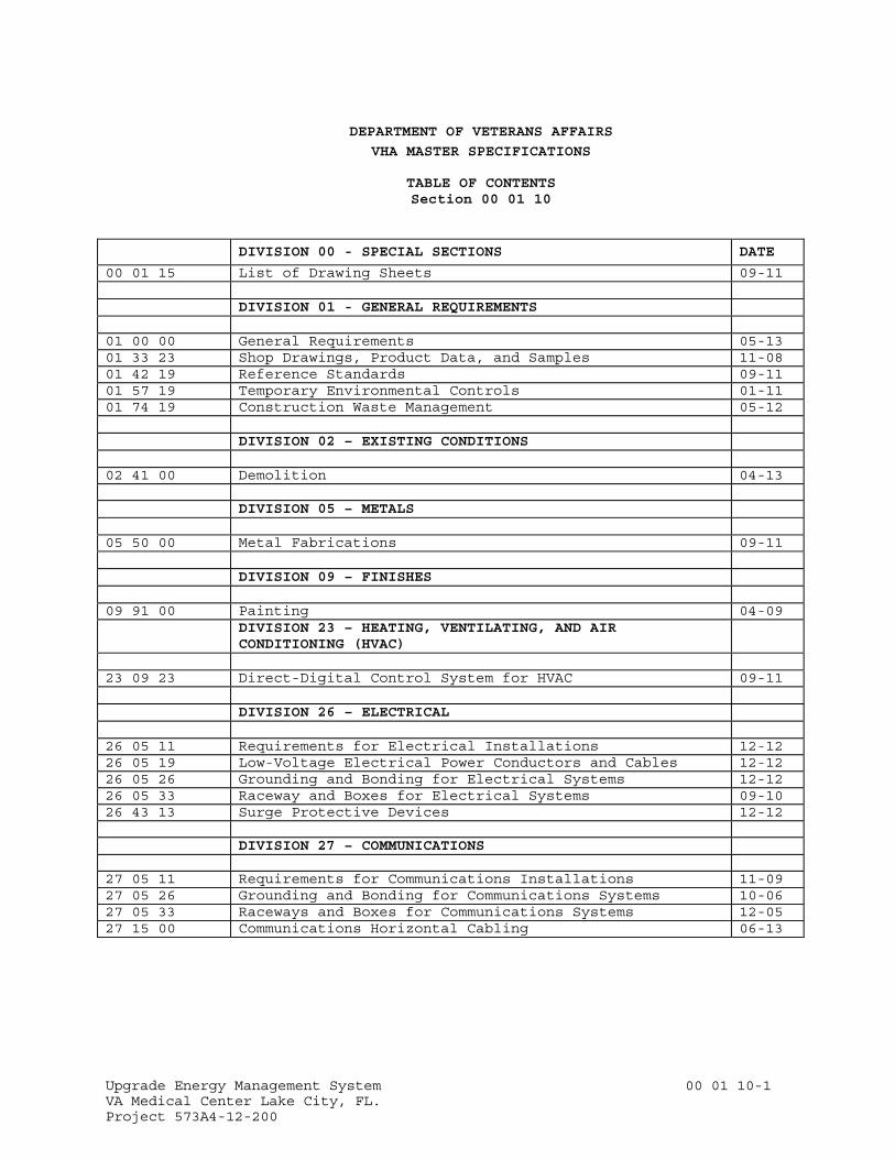
DEPARTMENT OF VETERANS AFFAIRS
VHA MASTER SPECIFICATIONS TABLE OF CONTENTS
Section 00 01 10
DIVISION 00 - SPECIAL SECTIONS DATE
00 01 15 List of Drawing Sheets 09-11 DIVISION 01 - GENERAL REQUIREMENTS 01 00 00 General Requirements 05-13 01 33 23 Shop Drawings, Product Data, and Samples 11-08 01 42 19 Reference Standards 09-11 01 57 19 Temporary Environmental Controls 01-11 01 74 19 Construction Waste Management 05-12 DIVISION 02 – EXISTING CONDITIONS 02 41 00 Demolition 04-13 DIVISION 05 – METALS 05 50 00 Metal Fabrications 09-11 DIVISION 09 – FINISHES 09 91 00 Painting 04-09 DIVISION 23 – HEATING, VENTILATING, AND AIR
CONDITIONING (HVAC)
23 09 23 Direct-Digital Control System for HVAC 09-11 DIVISION 26 – ELECTRICAL 26 05 11 Requirements for Electrical Installations 12-12 26 05 19 Low-Voltage Electrical Power Conductors and Cables 12-12 26 05 26 Grounding and Bonding for Electrical Systems 12-12 26 05 33 Raceway and Boxes for Electrical Systems 09-10 26 43 13 Surge Protective Devices 12-12 DIVISION 27 – COMMUNICATIONS 27 05 11 Requirements for Communications Installations 11-09 27 05 26 Grounding and Bonding for Communications Systems 10-06 27 05 33 Raceways and Boxes for Communications Systems 12-05 27 15 00 Communications Horizontal Cabling 06-13
Upgrade Energy Management System 00 01 15-1 VA Medical Center Lake City, FL. Project 573A4-12-200
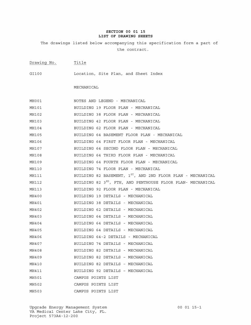
SECTION 00 01 15 LIST OF DRAWING SHEETS
The drawings listed below accompanying this specification form a part of
the contract.
Drawing No. Title
GI100 Location, Site Plan, and Sheet Index
MECHANICAL
MH001 NOTES AND LEGEND - MECHANICAL
MH101 BUILDING 19 FLOOR PLAN - MECHANICAL
MH102 BUILDING 38 FLOOR PLAN - MECHANICAL
MH103 BUILDING 42 FLOOR PLAN - MECHANICAL
MH104 BUILDING 62 FLOOR PLAN - MECHANICAL
MH105 BUILDING 64 BASEMENT FLOOR PLAN - MECHANICAL
MH106 BUILDING 64 FIRST FLOOR PLAN - MECHANICAL
MH107 BUILDING 64 SECOND FLOOR PLAN - MECHANICAL
MH108 BUILDING 64 THIRD FLOOR PLAN - MECHANICAL
MH109 BUILDING 64 FOURTH FLOOR PLAN - MECHANICAL
MH110 BUILDING 74 FLOOR PLAN - MECHANICAL
MH111 BUILDING 82 BASEMENT, 1ST, AND 2ND FLOOR PLAN - MECHANICAL
MH112 BUILDING 82 3RD, FTH, AND PENTHOUSE FLOOR PLAN- MECHANICAL
MH113 BUILDING 92 FLOOR PLAN - MECHANICAL
MH400 BUILDING 19 DETAILS - MECHANICAL
MH401 BUILDING 38 DETAILS - MECHANICAL
MH402 BUILDING 62 DETAILS - MECHANICAL
MH403 BUILDING 64 DETAILS - MECHANICAL
MH404 BUILDING 64 DETAILS - MECHANICAL
MH405 BUILDING 64 DETAILS - MECHANICAL
MH406 BUILDING 64-2 DETAILS - MECHANICAL
MH407 BUILDING 74 DETAILS - MECHANICAL
MH408 BUILDING 82 DETAILS - MECHANICAL
MH409 BUILDING 82 DETAILS – MECHANICAL
MH410 BUILDING 82 DETAILS – MECHANICAL
MH411 BUILDING 92 DETAILS – MECHANICAL
MH501 CAMPUS POINTS LIST
MH502 CAMPUS POINTS LIST
MH503 CAMPUS POINTS LIST

Upgrade Energy Management System 00 01 15-2 VA Medical Center Lake City, FL. Project 573A4-12-200
- - - END - - -
Upgrade Energy Management System 01 33 23 -1 VA Medical Center Lake City, FL Project 573A4-12-200
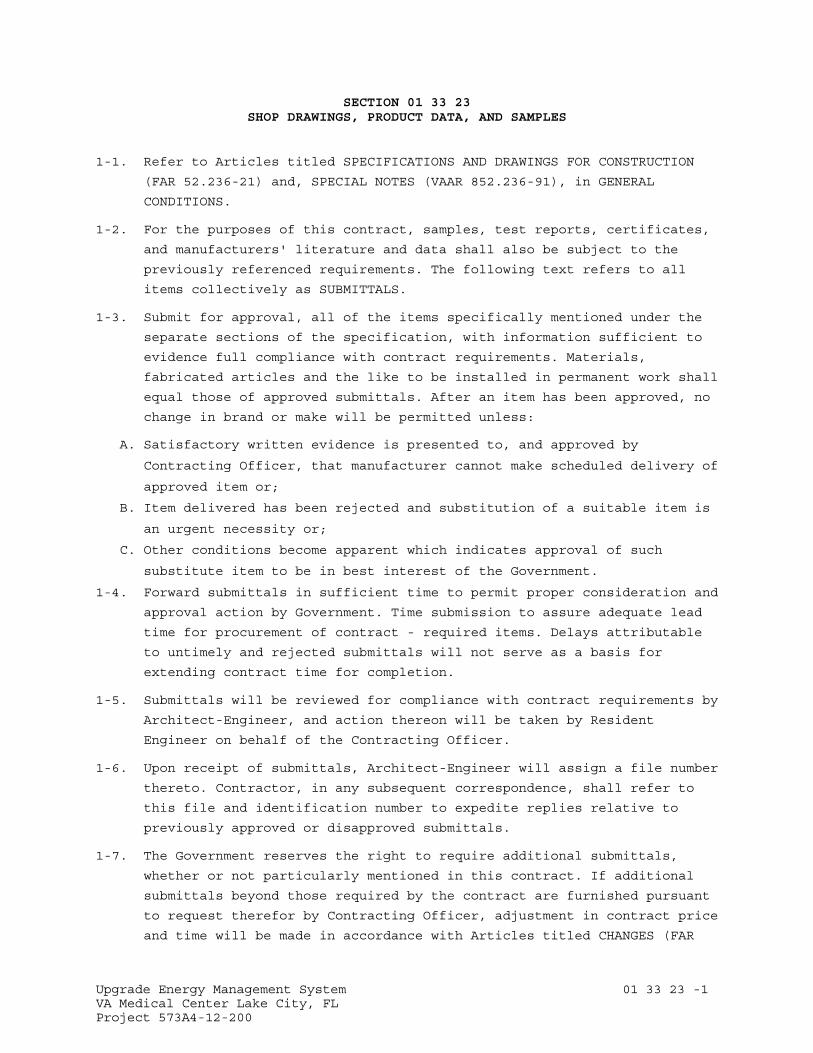
SECTION 01 33 23 SHOP DRAWINGS, PRODUCT DATA, AND SAMPLES
1-1. Refer to Articles titled SPECIFICATIONS AND DRAWINGS FOR CONSTRUCTION
(FAR 52.236-21) and, SPECIAL NOTES (VAAR 852.236-91), in GENERAL
CONDITIONS.
1-2. For the purposes of this contract, samples, test reports, certificates,
and manufacturers' literature and data shall also be subject to the
previously referenced requirements. The following text refers to all
items collectively as SUBMITTALS.
1-3. Submit for approval, all of the items specifically mentioned under the
separate sections of the specification, with information sufficient to
evidence full compliance with contract requirements. Materials,
fabricated articles and the like to be installed in permanent work shall
equal those of approved submittals. After an item has been approved, no
change in brand or make will be permitted unless:
A. Satisfactory written evidence is presented to, and approved by
Contracting Officer, that manufacturer cannot make scheduled delivery of
approved item or;
B. Item delivered has been rejected and substitution of a suitable item is
an urgent necessity or;
C. Other conditions become apparent which indicates approval of such
substitute item to be in best interest of the Government.
1-4. Forward submittals in sufficient time to permit proper consideration and
approval action by Government. Time submission to assure adequate lead
time for procurement of contract - required items. Delays attributable
to untimely and rejected submittals will not serve as a basis for
extending contract time for completion.
1-5. Submittals will be reviewed for compliance with contract requirements by
Architect-Engineer, and action thereon will be taken by Resident
Engineer on behalf of the Contracting Officer.
1-6. Upon receipt of submittals, Architect-Engineer will assign a file number
thereto. Contractor, in any subsequent correspondence, shall refer to
this file and identification number to expedite replies relative to
previously approved or disapproved submittals.
1-7. The Government reserves the right to require additional submittals,
whether or not particularly mentioned in this contract. If additional
submittals beyond those required by the contract are furnished pursuant
to request therefor by Contracting Officer, adjustment in contract price
and time will be made in accordance with Articles titled CHANGES (FAR
Upgrade Energy Management System 01 33 23 -2 VA Medical Center Lake City, FL Project 573A4-12-200
52.243-4) and CHANGES - SUPPLEMENT (VAAR 852.236-88) of the GENERAL
CONDITIONS.
1-8. Schedules called for in specifications and shown on shop drawings shall
be submitted for use and information of Department of Veterans Affairs
and Architect-Engineer. However, the Contractor shall assume
responsibility for coordinating and verifying schedules. The Contracting
Officer and Architect- Engineer assumes no responsibility for checking
schedules or layout drawings for exact sizes, exact numbers and detailed
positioning of items.
1-9. Submittals must be submitted by Contractor only and shipped prepaid.
Contracting Officer assumes no responsibility for checking quantities or
exact numbers included in such submittals.
A. Submit other samples in single units unless otherwise specified. Submit
shop drawings, schedules, manufacturers' literature and data, and
certificates in quadruplicate, except where a greater number is
specified.
B. Submittals will receive consideration only when covered by a transmittal
letter signed by Contractor. Letter shall be sent via first class mail
and shall contain the list of items, name of Medical Center Cemetery,
name of Contractor, contract number, applicable specification paragraph
numbers, applicable drawing numbers (and other information required for
exact identification of location for each item), manufacturer and brand,
ASTM or Federal Specification Number (if any) and such additional
information as may be required by specifications for particular item
being furnished. In addition, catalogs shall be marked to indicate
specific items submitted for approval.
1. A copy of letter must be enclosed with items, and any items received
without identification letter will be considered "unclaimed goods"
and held for a limited time only.
2. Each sample, certificate, manufacturers' literature and data shall be
labeled to indicate the name and location of the Medical Center, name
of Contractor, manufacturer, brand, contract number and ASTM or
Federal Specification Number as applicable and location(s) on
project.
3. Required certificates shall be signed by an authorized representative
of manufacturer or supplier of material, and by Contractor.
D. If submittal samples have been disapproved, resubmit new samples as soon
as possible after notification of disapproval. Such new samples shall be
marked "Resubmitted Sample" in addition to containing other previously
specified information required on label and in transmittal letter.
Upgrade Energy Management System 01 33 23 -3 VA Medical Center Lake City, FL Project 573A4-12-200
E. Approved samples will be kept on file by the Resident Engineer at the
site until completion of contract, at which time such samples will be
delivered to Contractor as Contractor's property. Where noted in
technical sections of specifications, approved samples in good condition
may be used in their proper locations in contract work. At completion of
contract, samples that are not approved will be returned to Contractor
only upon request and at Contractor's expense. Such request should be
made prior to completion of the contract. Disapproved samples that are
not requested for return by Contractor will be discarded after
completion of contract.
F. Submittal drawings (shop, erection or setting drawings) and schedules,
required for work of various trades, shall be checked before submission
by technically qualified employees of Contractor for accuracy,
completeness and compliance with contract requirements. These drawings
and schedules shall be stamped and signed by Contractor certifying to
such check.
1. For each drawing required, submit one legible photographic paper or
vellum reproducible.
2. Reproducible shall be full size.
3. Each drawing shall have marked thereon, proper descriptive title,
including Medical Center location, project number, manufacturer's
number, reference to contract drawing number, detail Section Number,
and Specification Section Number.
4. A space 120 mm by 125 mm (4-3/4 by 5 inches) shall be reserved on
each drawing to accommodate approval or disapproval stamp.
5. Submit drawings, ROLLED WITHIN A MAILING TUBE, fully protected for
shipment.
6. One reproducible print of approved or disapproved shop drawings will
be forwarded to Contractor.
7. When work is directly related and involves more than one trade, shop
drawings shall be submitted to Architect-Engineer under one cover.
1-10. Samples shop drawings, test reports, certificates and manufacturers'
literature and data, shall be submitted for approval to
MES Group, Inc 5421 Beaumont Center Blvd., Suite 675 Tampa, Fl 33634
1-11. At the time of transmittal the contractor must be submitted to the
COTR (1 copy) and A/E for approval. A/E submits recommendation to VA
COTR and COTR makes final determination.

Upgrade Energy Management System 01 33 23 -4 VA Medical Center Lake City, FL Project 573A4-12-200
- - - E N D - - -
Upgrade Energy Management System 01 42 19 -1 VA Medical Center Lake City, FL Project 573A4-12-200
SECTION 01 42 19 REFERENCE STANDARDS
PART 1 - GENERAL
1.1 DESCRIPTION
This section specifies the availability and source of references and
standards specified in the project manual under paragraphs APPLICABLE
PUBLICATIONS and/or shown on the drawings.
1.2 AVAILABILITY OF SPECIFICATIONS LISTED IN THE GSA INDEX OF FEDERAL SPECIFICATIONS, STANDARDS AND COMMERCIAL ITEM DESCRIPTIONS FPMR PART 101-29 (FAR 52.211-1) (AUG 1998)
A. The GSA Index of Federal Specifications, Standards and Commercial Item
Descriptions, FPMR Part 101-29 and copies of specifications, standards,
and commercial item descriptions cited in the solicitation may be
obtained for a fee by submitting a request to – GSA Federal Supply
Service, Specifications Section, Suite 8100, 470 East L’Enfant Plaza,
SW, Washington, DC 20407, Telephone (202) 619-8925, Facsimile (202) 619-
8978.
B. If the General Services Administration, Department of Agriculture, or
Department of Veterans Affairs issued this solicitation, a single copy
of specifications, standards, and commercial item descriptions cited in
this solicitation may be obtained free of charge by submitting a request
to the addressee in paragraph (a) of this provision. Additional copies
will be issued for a fee.
1.3 AVAILABILITY FOR EXAMINATION OF SPECIFICATIONS NOT LISTED IN THE GSA INDEX OF FEDERAL SPECIFICATIONS, STANDARDS AND COMMERCIAL ITEM DESCRIPTIONS (FAR 52.211-4) (JUN 1988)
The specifications and standards cited in this solicitation can be
examined at the following location:
DEPARMENT OF VETERANS AFFAIRS
Office of Construction & Facilities Management
Facilities Quality Service (00CFM1A)
425 Eye Street N.W, (sixth floor)
Washington, DC 20001
Telephone Numbers: (202) 632-5249 or (202) 632-5178
Between 9:00 AM - 3:00 PM
Upgrade Energy Management System 01 42 19 -2 VA Medical Center Lake City, FL Project 573A4-12-200
1.4 AVAILABILITY OF SPECIFICATIONS NOT LISTED IN THE GSA INDEX OF FEDERAL SPECIFICATIONS, STANDARDS AND COMMERCIAL ITEM DESCRIPTIONS (FAR 52.211-3) (JUN 1988)
The specifications cited in this solicitation may be obtained from the
associations or organizations listed below.
AA Aluminum Association Inc.
http://www.aluminum.org
AABC Associated Air Balance Council
http://www.aabchq.com
AAMA American Architectural Manufacturer's Association
http://www.aamanet.org
AAN American Nursery and Landscape Association
http://www.anla.org
AASHTO American Association of State Highway and Transportation Officials
http://www.aashto.org
AATCC American Association of Textile Chemists and Colorists
http://www.aatcc.org
ACGIH American Conference of Governmental Industrial Hygienists
http://www.acgih.org
ACI American Concrete Institute
http://www.aci-int.net
ACPA American Concrete Pipe Association
http://www.concrete-pipe.org
ACPPA American Concrete Pressure Pipe Association
http://www.acppa.org
ADC Air Diffusion Council
http://flexibleduct.org
AGA American Gas Association
http://www.aga.org
AGC Associated General Contractors of America
http://www.agc.org
Upgrade Energy Management System 01 42 19 -3 VA Medical Center Lake City, FL Project 573A4-12-200
AGMA American Gear Manufacturers Association, Inc.
http://www.agma.org
AHAM Association of Home Appliance Manufacturers
http://www.aham.org
AISC American Institute of Steel Construction
http://www.aisc.org
AISI American Iron and Steel Institute
http://www.steel.org
AITC American Institute of Timber Construction
http://www.aitc-glulam.org
AMCA Air Movement and Control Association, Inc.
http://www.amca.org
ANLA American Nursery & Landscape Association
http://www.anla.org
ANSI American National Standards Institute, Inc.
http://www.ansi.org
APA The Engineered Wood Association
http://www.apawood.org
ARI Air-Conditioning and Refrigeration Institute
http://www.ari.org
ASAE American Society of Agricultural Engineers
http://www.asae.org
ASCE American Society of Civil Engineers
http://www.asce.org
ASHRAE American Society of Heating, Refrigerating, and
Air-Conditioning Engineers
http://www.ashrae.org
ASME American Society of Mechanical Engineers
http://www.asme.org
ASSE American Society of Sanitary Engineering
http://www.asse-plumbing.org
Upgrade Energy Management System 01 42 19 -4 VA Medical Center Lake City, FL Project 573A4-12-200
ASTM American Society for Testing and Materials
http://www.astm.org
AWI Architectural Woodwork Institute
http://www.awinet.org
AWS American Welding Society
http://www.aws.org
AWWA American Water Works Association
http://www.awwa.org
BHMA Builders Hardware Manufacturers Association
http://www.buildershardware.com
BIA Brick Institute of America
http://www.bia.org
CAGI Compressed Air and Gas Institute
http://www.cagi.org
CGA Compressed Gas Association, Inc.
http://www.cganet.com
CI The Chlorine Institute, Inc.
http://www.chlorineinstitute.org
CISCA Ceilings and Interior Systems Construction Association
http://www.cisca.org
CISPI Cast Iron Soil Pipe Institute
http://www.cispi.org
CLFMI Chain Link Fence Manufacturers Institute
http://www.chainlinkinfo.org
CPMB Concrete Plant Manufacturers Bureau
http://www.cpmb.org
CRA California Redwood Association
http://www.calredwood.org
CRSI Concrete Reinforcing Steel Institute
http://www.crsi.org
Upgrade Energy Management System 01 42 19 -5 VA Medical Center Lake City, FL Project 573A4-12-200
CTI Cooling Technology Institute
http://www.cti.org
DHI Door and Hardware Institute
http://www.dhi.org
EGSA Electrical Generating Systems Association
http://www.egsa.org
EEI Edison Electric Institute
http://www.eei.org
EPA Environmental Protection Agency
http://www.epa.gov
ETL ETL Testing Laboratories, Inc.
http://www.et1.com
FAA Federal Aviation Administration
http://www.faa.gov
FCC Federal Communications Commission
http://www.fcc.gov
FPS The Forest Products Society
http://www.forestprod.org
GANA Glass Association of North America
http://www.cssinfo.com/info/gana.html/
FM Factory Mutual Insurance
http://www.fmglobal.com
GA Gypsum Association
http://www.gypsum.org
GSA General Services Administration
http://www.gsa.gov
HI Hydraulic Institute
http://www.pumps.org
HPVA Hardwood Plywood & Veneer Association
http://www.hpva.org
Upgrade Energy Management System 01 42 19 -6 VA Medical Center Lake City, FL Project 573A4-12-200
ICBO International Conference of Building Officials
http://www.icbo.org
ICEA Insulated Cable Engineers Association Inc.
http://www.icea.net
\ICAC Institute of Clean Air Companies
http://www.icac.com
IEEE Institute of Electrical and Electronics Engineers
http://www.ieee.org\
IMSA International Municipal Signal Association
http://www.imsasafety.org
IPCEA Insulated Power Cable Engineers Association
NBMA Metal Buildings Manufacturers Association
http://www.mbma.com
MSS Manufacturers Standardization Society of the Valve and Fittings
Industry Inc.
http://www.mss-hq.com
NAAMM National Association of Architectural Metal Manufacturers
http://www.naamm.org
NAPHCC Plumbing-Heating-Cooling Contractors Association
http://www.phccweb.org.org
NBS National Bureau of Standards
See - NIST
NBBPVI National Board of Boiler and Pressure Vessel Inspectors
http://www.nationboard.org
NEC National Electric Code
See - NFPA National Fire Protection Association
NEMA National Electrical Manufacturers Association
http://www.nema.org
NFPA National Fire Protection Association
http://www.nfpa.org
Upgrade Energy Management System 01 42 19 -7 VA Medical Center Lake City, FL Project 573A4-12-200
NHLA National Hardwood Lumber Association
http://www.natlhardwood.org
NIH National Institute of Health
http://www.nih.gov
NIST National Institute of Standards and Technology
http://www.nist.gov
NLMA Northeastern Lumber Manufacturers Association, Inc.
http://www.nelma.org
NPA National Particleboard Association
18928 Premiere Court
Gaithersburg, MD 20879
(301) 670-0604
NSF National Sanitation Foundation
http://www.nsf.org
NWWDA Window and Door Manufacturers Association
http://www.nwwda.org
OSHA Occupational Safety and Health Administration
Department of Labor
http://www.osha.gov
PCA Portland Cement Association
http://www.portcement.org
PCI Precast Prestressed Concrete Institute
http://www.pci.org
PPI The Plastic Pipe Institute
http://www.plasticpipe.org
PEI Porcelain Enamel Institute, Inc.
http://www.porcelainenamel.com
PTI Post-Tensioning Institute
http://www.post-tensioning.org
RFCI The Resilient Floor Covering Institute
http://www.rfci.com

Upgrade Energy Management System 01 42 19 -8 VA Medical Center Lake City, FL Project 573A4-12-200
RIS Redwood Inspection Service
See - CRA
RMA Rubber Manufacturers Association, Inc.
http://www.rma.org
SCMA Southern Cypress Manufacturers Association
http://www.cypressinfo.org
SDI Steel Door Institute
http://www.steeldoor.org
IGMA Insulating Glass Manufacturers Alliance
http://www.igmaonline.org
SJI Steel Joist Institute
http://www.steeljoist.org
SMACNA Sheet Metal and Air-Conditioning Contractors
National Association, Inc.
http://www.smacna.org
SSPC The Society for Protective Coatings
http://www.sspc.org
STI Steel Tank Institute
http://www.steeltank.com
SWI Steel Window Institute
http://www.steelwindows.com
TCA Tile Council of America, Inc.
http://www.tileusa.com
TEMA Tubular Exchange Manufacturers Association
http://www.tema.org
TPI Truss Plate Institute, Inc.
583 D'Onofrio Drive; Suite 200
Madison, WI 53719
(608) 833-5900
UBC The Uniform Building Code
See ICBO
Upgrade Energy Management System 01 42 19 -9 VA Medical Center Lake City, FL Project 573A4-12-200
UL Underwriters' Laboratories Incorporated
http://www.ul.com
ULC Underwriters' Laboratories of Canada
http://www.ulc.ca
WCLIB West Coast Lumber Inspection Bureau
6980 SW Varns Road, P.O. Box 23145
Portland, OR 97223
(503) 639-0651
WRCLA Western Red Cedar Lumber Association
P.O. Box 120786
New Brighton, MN 55112
(612) 633-4334
WWPA Western Wood Products Association
http://www.wwpa.org
- - - E N D - - -
Upgrade Energy Management System 01 57 19 -1 VA Medical Center Lake City, FL. Project 573A4-12-200
SECTION 01 57 19 TEMPORARY ENVIRONMENTAL CONTROLS
PART 1 - GENERAL
1.1 DESCRIPTION
A. This section specifies the control of environmental pollution and damage
that the Contractor must consider for air, water, and land resources. It
includes management of visual aesthetics, noise, solid waste, radiant
energy, and radioactive materials, as well as other pollutants and
resources encountered or generated by the Contractor. The Contractor is
obligated to consider specified control measures with the costs included
within the various contract items of work.
B. Environmental pollution and damage is defined as the presence of
chemical, physical, or biological elements or agents which:
1. Adversely effect human health or welfare,
2. Unfavorably alter ecological balances of importance to human life,
3. Effect other species of importance to humankind, or;
4. Degrade the utility of the environment for aesthetic, cultural, and
historical purposes.
C. Definitions of Pollutants:
1. Chemical Waste: Petroleum products, bituminous materials, salts,
acids, alkalis, herbicides, pesticides, organic chemicals, and
inorganic wastes.
2. Debris: Combustible and noncombustible wastes, such as leaves, tree
trimmings, ashes, and waste materials resulting from construction or
maintenance and repair work.
3. Sediment: Soil and other debris that has been eroded and transported
by runoff water.
4. Solid Waste: Rubbish, debris, garbage, and other discarded solid
materials resulting from industrial, commercial, and agricultural
operations and from community activities.
5. Surface Discharge: The term "Surface Discharge" implies that the
water is discharged with possible sheeting action and subsequent soil
erosion may occur. Waters that are surface discharged may terminate
in drainage ditches, storm sewers, creeks, and/or "water of the
United States" and would require a permit to discharge water from the
governing agency.
6. Rubbish: Combustible and noncombustible wastes such as paper, boxes,
glass and crockery, metal and lumber scrap, tin cans, and bones.
Upgrade Energy Management System 01 57 19 -2 VA Medical Center Lake City, FL. Project 573A4-12-200
7. Sanitary Wastes:
a. Sewage: Domestic sanitary sewage and human and animal waste.
b. Garbage: Refuse and scraps resulting from preparation, cooking,
dispensing, and consumption of food.
1.2 QUALITY CONTROL
A. Establish and maintain quality control for the environmental protection
of all items set forth herein.
B. Record on daily reports any problems in complying with laws,
regulations, and ordinances. Note any corrective action taken.
1.3 REFERENCES
A. The publications listed below form a part of this specification to the
extent referenced. The publications are referred to in the text by basic
designation only.
B. U.S. National Archives and Records Administration (NARA):
33 CFR 328..............Definitions
1.4 SUBMITTALS
A. In accordance with Section, 01 33 23, SHOP DRAWINGS, PRODUCT DATA, AND
SAMPLES, furnish the following:
1. Environmental Protection Plan: After the contract is awarded and
prior to the commencement of the work, the Contractor shall meet with
the Resident Engineer to discuss the proposed Environmental
Protection Plan and to develop mutual understanding relative to
details of environmental protection. Not more than 20 days after the
meeting, the Contractor shall prepare and submit to the Resident
Engineer and the Contracting Officer for approval, a written and/or
graphic Environmental Protection Plan including, but not limited to,
the following:
a. Name(s) of person(s) within the Contractor's organization who is
(are) responsible for ensuring adherence to the Environmental
Protection Plan.
b. Name(s) and qualifications of person(s) responsible for
manifesting hazardous waste to be removed from the site.
c. Name(s) and qualifications of person(s) responsible for training
the Contractor's environmental protection personnel.
d. Description of the Contractor's environmental protection personnel
training program.
e. A list of Federal, State, and local laws, regulations, and permits
concerning environmental protection, pollution control, noise

Upgrade Energy Management System 01 57 19 -3 VA Medical Center Lake City, FL. Project 573A4-12-200
control and abatement that are applicable to the Contractor's
proposed operations and the requirements imposed by those laws,
regulations, and permits.
f. Methods for protection of features to be preserved within
authorized work areas including trees, shrubs, vines, grasses,
ground cover, landscape features, air and water quality, fish and
wildlife, soil, historical, and archeological and cultural
resources.
g. Procedures to provide the environmental protection that comply
with the applicable laws and regulations. Describe the procedures
to correct pollution of the environment due to accident, natural
causes, or failure to follow the procedures as described in the
Environmental Protection Plan.
h. Permits, licenses, and the location of the solid waste disposal
area.
i. Drawings showing locations of any proposed temporary excavations
or embankments for haul roads, stream crossings, material storage
areas, structures, sanitary facilities, and stockpiles of excess
or spoil materials. Include as part of an Erosion Control Plan
approved by the District Office of the U.S. Soil Conservation
Service and the Department of Veterans Affairs.
j. Environmental Monitoring Plans for the job site including land,
water, air, and noise.
k. Work Area Plan showing the proposed activity in each portion of
the area and identifying the areas of limited use or nonuse. Plan
should include measures for marking the limits of use areas. This
plan may be incorporated within the Erosion Control Plan.
B. Approval of the Contractor's Environmental Protection Plan will not
relieve the Contractor of responsibility for adequate and continued
control of pollutants and other environmental protection measures.
1.5 PROTECTION OF ENVIRONMENTAL RESOURCES
A. Protect environmental resources within the project boundaries and those
affected outside the limits of permanent work during the entire period
of this contract. Confine activities to areas defined by the
specifications and drawings.
B. Protection of Land Resources: Prior to construction, identify all land
resources to be preserved within the work area. Do not remove, cut,
deface, injure, or destroy land resources including trees, shrubs,
vines, grasses, top soil, and land forms without permission from the
Resident Engineer. Do not fasten or attach ropes, cables, or guys to
Upgrade Energy Management System 01 57 19 -4 VA Medical Center Lake City, FL. Project 573A4-12-200
trees for anchorage unless specifically authorized, or where special
emergency use is permitted.
1. Work Area Limits: Prior to any construction, mark the areas that
require work to be performed under this contract. Mark or fence
isolated areas within the general work area that are to be saved and
protected. Protect monuments, works of art, and markers before
construction operations begin. Convey to all personnel the purpose of
marking and protecting all necessary objects.
2. Protection of Landscape: Protect trees, shrubs, vines, grasses, land
forms, and other landscape features shown on the drawings to be
preserved by marking, fencing, or using any other approved
techniques.
a. Box and protect from damage existing trees and shrubs to remain on
the construction site.
b. Immediately repair all damage to existing trees and shrubs by
trimming, cleaning, and painting with antiseptic tree paint.
c. Do not store building materials or perform construction activities
closer to existing trees or shrubs than the farthest extension of
their limbs.
3. Reduction of Exposure of Unprotected Erodible Soils: Plan and conduct
earthwork to minimize the duration of exposure of unprotected soils.
Clear areas in reasonably sized increments only as needed to use.
Form earthwork to final grade as shown. Immediately protect side
slopes and back slopes upon completion of rough grading.
4. Temporary Protection of Disturbed Areas: Construct diversion ditches,
benches, and berms to retard and divert runoff from the construction
site to protected drainage areas approved under paragraph 208 of the
Clean Water Act.
a. Sediment Basins: Trap sediment from construction areas in
temporary or permanent sediment basins that accommodate the runoff
of a local design year storm. After each storm, pump the basins
dry and remove the accumulated sediment. Control overflow/drainage
with paved weirs or by vertical overflow pipes, draining from the
surface.
b. Reuse or conserve the collected topsoil sediment as directed by
the Resident Engineer. Topsoil use and requirements are specified
in Section 31 20 00, EARTH MOVING.
c. Institute effluent quality monitoring programs as required by
Federal, State, and local environmental agencies.
5. Erosion and Sedimentation Control Devices: The erosion and sediment
controls selected and maintained by the Contractor shall be such that
Upgrade Energy Management System 01 57 19 -5 VA Medical Center Lake City, FL. Project 573A4-12-200
water quality standards are not violated as a result of the
Contractor's activities. Construct or install all temporary and
permanent erosion and sedimentation control features shown on the
Environmental Protection Plan. Maintain temporary erosion and
sediment control measures such as berms, dikes, drains, sedimentation
basins, grassing, and mulching, until permanent drainage and erosion
control facilities are completed and operative.
6. Manage borrow areas on and off Government property to minimize
erosion and to prevent sediment from entering nearby water courses or
lakes.
7. Manage and control spoil areas on and off Government property to
limit spoil to areas on the Environmental Protection Plan and prevent
erosion of soil or sediment from entering nearby water courses or
lakes.
8. Protect adjacent areas from despoilment by temporary excavations and
embankments.
9. Handle and dispose of solid wastes in such a manner that will prevent
contamination of the environment. Place solid wastes (excluding
clearing debris) in containers that are emptied on a regular
schedule. Transport all solid waste off Government property and
dispose of waste in compliance with Federal, State, and local
requirements.
10. Store chemical waste away from the work areas in corrosion resistant
containers and dispose of waste in accordance with Federal, State,
and local regulations.
11. Handle discarded materials other than those included in the solid
waste category as directed by the Resident Engineer.
C. Protection of Water Resources: Keep construction activities under
surveillance, management, and control to avoid pollution of surface and
ground waters and sewer systems. Implement management techniques to
control water pollution by the listed construction activities that are
included in this contract.
1. Washing and Curing Water: Do not allow wastewater directly derived
from construction activities to enter water areas. Collect and place
wastewater in retention ponds allowing the suspended material to
settle, the pollutants to separate, or the water to evaporate.
2. Control movement of materials and equipment at stream crossings
during construction to prevent violation of water pollution control
standards of the Federal, State, or local government.
3. Monitor water areas affected by construction.

Upgrade Energy Management System 01 57 19 -6 VA Medical Center Lake City, FL. Project 573A4-12-200
D. Protection of Fish and Wildlife Resources: Keep construction activities
under surveillance, management, and control to minimize interference
with, disturbance of, or damage to fish and wildlife. Prior to beginning
construction operations, list species that require specific attention
along with measures for their protection.
E. Protection of Air Resources: Keep construction activities under
surveillance, management, and control to minimize pollution of air
resources. Burning is not permitted on the job site. Keep activities,
equipment, processes, and work operated or performed, in strict
accordance with the State of Florida emission and performance laws and
standards. Maintain ambient air quality standards set by the
Environmental Protection Agency, for those construction operations and
activities specified.
1. Particulates: Control dust particles, aerosols, and gaseous by-
products from all construction activities, processing, and
preparation of materials (such as from asphaltic batch plants) at all
times, including weekends, holidays, and hours when work is not in
progress.
2. Particulates Control: Maintain all excavations, stockpiles, haul
roads, permanent and temporary access roads, plant sites, spoil
areas, borrow areas, and all other work areas within or outside the
project boundaries free from particulates which would cause a hazard
or a nuisance. Sprinklering, chemical treatment of an approved type,
light bituminous treatment, baghouse, scrubbers, electrostatic
precipitators, or other methods are permitted to control particulates
in the work area.
3. Hydrocarbons and Carbon Monoxide: Control monoxide emissions from
equipment to Federal and State allowable limits.
4. Odors: Control odors of construction activities and prevent obnoxious
odors from occurring.
F. Reduction of Noise: Minimize noise using every action possible. Perform
noise-producing work in less sensitive hours of the day or week as
directed by the Resident Engineer. Maintain noise-produced work at or
below the decibel levels and within the time periods specified.
1. Perform construction activities involving repetitive, high-level
impact noise only between 8:00 a.m. and 6:00 p.m unless otherwise
permitted by local ordinance or the Resident Engineer. Repetitive
impact noise on the property shall not exceed the following dB
limitations:
Time Duration of Impact Noise Sound Level in dB
Upgrade Energy Management System 01 57 19 -7 VA Medical Center Lake City, FL. Project 573A4-12-200
More than 12 minutes in any hour 70
Less than 30 seconds of any hour 85
Less than three minutes of any hour 80
Less than 12 minutes of any hour 75
2. Provide sound-deadening devices on equipment and take noise abatement
measures that are necessary to comply with the requirements of this
contract, consisting of, but not limited to, the following:
a. Maintain maximum permissible construction equipment noise levels
at 15 m (50 feet) (dBA):
EARTHMOVING MATERIALS HANDLING
FRONT LOADERS 75 CONCRETE MIXERS 75
BACKHOES 75 CONCRETE PUMPS 75
DOZERS 75 CRANES 75
TRACTORS 75 DERRICKS IMPACT 75
SCAPERS 80 PILE DRIVERS 95
GRADERS 75 JACK HAMMERS 75
TRUCKS 75 ROCK DRILLS 80
PAVERS, STATIONARY
80 PNEUMATIC TOOLS 80
GENERATORS 75 SAWS 75
COMPRESSORS 75 VIBRATORS 75
b. Use shields or other physical barriers to restrict noise
transmission.
c. Provide soundproof housings or enclosures for noise-producing
machinery.
d. Use efficient silencers on equipment air intakes.
e. Use efficient intake and exhaust mufflers on internal combustion
engines that are maintained so equipment performs below noise
levels specified.
f. Line hoppers and storage bins with sound deadening material.
g. Conduct truck loading, unloading, and hauling operations so that
noise is kept to a minimum.
3. Measure sound level for noise exposure due to the construction at
least once every five successive working days while work is being
performed above 55 dB(A) noise level. Measure noise exposure at the
property line or 15 m (50 feet) from the noise source, whichever is
greater. Measure the sound levels on the A weighing network of a
Upgrade Energy Management System 01 57 19 -8 VA Medical Center Lake City, FL. Project 573A4-12-200
General Purpose sound level meter at slow response. To minimize the
effect of reflective sound waves at buildings, take measurements at
900 to 1800 mm (three to six feet) in front of any building face.
Submit the recorded information to the Resident Engineer noting any
problems and the alternatives for mitigating actions.
G. Restoration of Damaged Property: If any direct or indirect damage is
done to public or private property resulting from any act, omission,
neglect, or misconduct, the Contractor shall restore the damaged
property to a condition equal to that existing before the damage at no
additional cost to the Government. Repair, rebuild, or restore property
as directed or make good such damage in an acceptable manner.
H. Final Clean-up: On completion of project and after removal of all
debris, rubbish, and temporary construction, Contractor shall leave the
construction area in a clean condition satisfactory to the Resident
Engineer. Cleaning shall include off the station disposal of all items
and materials not required to be salvaged, as well as all debris and
rubbish resulting from demolition and new work operations.
- - - E N D - - -
Upgrade Energy Management System 01 74 19 -1 VA Medical Center Lake City, FL. Project 573A4-12-200
SECTION 01 74 19 CONSTRUCTION WASTE MANAGEMENT
PART 1 – GENERAL
1.1 DESCRIPTION
A. This section specifies the requirements for the management of non-
hazardous building construction and demolition waste.
B. Waste disposal in landfills shall be minimized to the greatest extent
possible. Of the inevitable waste that is generated, as much of the
waste material as economically feasible shall be salvaged, recycled or
reused.
C. Contractor shall use all reasonable means to divert construction and
demolition waste from landfills and incinerators, and facilitate their
salvage and recycle not limited to the following:
1. Waste Management Plan development and implementation.
2. Techniques to minimize waste generation.
3. Sorting and separating of waste materials.
4. Salvage of existing materials and items for reuse or resale.
5. Recycling of materials that cannot be reused or sold.
D. At a minimum the following waste categories shall be diverted from
landfills:
1. Soil.
2. Inerts (eg, concrete, masonry and asphalt).
3. Clean dimensional wood and palette wood.
4. Green waste (biodegradable landscaping materials).
5. Engineered wood products (plywood, particle board and I-joists,
etc).
6. Metal products (eg, steel, wire, beverage containers, copper, etc).
7. Cardboard, paper and packaging.
8. Bitumen roofing materials.
9. Plastics (eg, ABS, PVC).
10. Carpet and/or pad.
11. Gypsum board.
12. Insulation.
13. Paint.
14. Fluorescent lamps.
Upgrade Energy Management System 01 74 19 -2 VA Medical Center Lake City, FL. Project 573A4-12-200
1.2 RELATED WORK
A. Section 02 41 00, DEMOLITION.
B. Section 01 00 00, GENERAL REQUIREMENTS.
C. Lead Paint: Section 02 83 33.13, LEAD BASED PAINT REMOVAL AND DISPOSAL.
1.3 QUALITY ASSURANCE
A. Contractor shall practice efficient waste management when sizing,
cutting and installing building products. Processes shall be employed
to ensure the generation of as little waste as possible. Construction
/Demolition waste includes products of the following:
1. Excess or unusable construction materials.
2. Packaging used for construction products.
3. Poor planning and/or layout.
4. Construction error.
5. Over ordering.
6. Weather damage.
7. Contamination.
8. Mishandling.
9. Breakage.
B. Establish and maintain the management of non-hazardous building
construction and demolition waste set forth herein. Conduct a site
assessment to estimate the types of materials that will be generated by
demolition and construction.
C. Contractor shall develop and implement procedures to recycle
construction and demolition waste to a minimum of 50 percent.
D. Contractor shall be responsible for implementation of any special
programs involving rebates or similar incentives related to recycling.
Any revenues or savings obtained from salvage or recycling shall accrue
to the contractor.
E. Contractor shall provide all demolition, removal and legal disposal of
materials. Contractor shall ensure that facilities used for recycling,
reuse and disposal shall be permitted for the intended use to the
extent required by local, state, federal regulations. The Whole
Building Design Guide website http://www.cwm.wbdg.org provides a
Construction Waste Management Database that contains information on
companies that haul, collect, and process recyclable debris from
construction projects.
Upgrade Energy Management System 01 74 19 -3 VA Medical Center Lake City, FL. Project 573A4-12-200
F. Contractor shall assign a specific area to facilitate separation of
materials for reuse, salvage, recycling, and return. Such areas are to
be kept neat and clean and clearly marked in order to avoid
contamination or mixing of materials.
G. Contractor shall provide on-site instructions and supervision of
separation, handling, salvaging, recycling, reuse and return methods to
be used by all parties during waste generating stages.
H. Record on daily reports any problems in complying with laws,
regulations and ordinances with corrective action taken.
1.4 TERMINOLOGY
A. Class III Landfill: A landfill that accepts non-hazardous resources
such as household, commercial and industrial waste resulting from
construction, remodeling, repair and demolition operations.
B. Clean: Untreated and unpainted; uncontaminated with adhesives, oils,
solvents, mastics and like products.
C. Construction and Demolition Waste: Includes all non-hazardous resources
resulting from construction, remodeling, alterations, repair and
demolition operations.
D. Dismantle: The process of parting out a building in such a way as to
preserve the usefulness of its materials and components.
E. Disposal: Acceptance of solid wastes at a legally operating facility
for the purpose of land filling (includes Class III landfills and inert
fills).
F. Inert Backfill Site: A location, other than inert fill or other
disposal facility, to which inert materials are taken for the purpose
of filling an excavation, shoring or other soil engineering operation.
G. Inert Fill: A facility that can legally accept inert waste, such as
asphalt and concrete exclusively for the purpose of disposal.
H. Inert Solids/Inert Waste: Non-liquid solid resources including, but not
limited to, soil and concrete that does not contain hazardous waste or
soluble pollutants at concentrations in excess of water-quality
objectives established by a regional water board, and does not contain
significant quantities of decomposable solid resources.
I. Mixed Debris: Loads that include commingled recyclable and non-
recyclable materials generated at the construction site.
J. Mixed Debris Recycling Facility: A solid resource processing facility
that accepts loads of mixed construction and demolition debris for the
Upgrade Energy Management System 01 74 19 -4 VA Medical Center Lake City, FL. Project 573A4-12-200
purpose of recovering re-usable and recyclable materials and disposing
non-recyclable materials.
K. Permitted Waste Hauler: A company that holds a valid permit to collect
and transport solid wastes from individuals or businesses for the
purpose of recycling or disposal.
L. Recycling: The process of sorting, cleansing, treating, and
reconstituting materials for the purpose of using the altered form in
the manufacture of a new product. Recycling does not include burning,
incinerating or thermally destroying solid waste.
1. On-site Recycling – Materials that are sorted and processed on site
for use in an altered state in the work, i.e. concrete crushed for
use as a sub-base in paving.
2. Off-site Recycling – Materials hauled to a location and used in an
altered form in the manufacture of new products.
M. Recycling Facility: An operation that can legally accept materials for
the purpose of processing the materials into an altered form for the
manufacture of new products. Depending on the types of materials
accepted and operating procedures, a recycling facility may or may not
be required to have a solid waste facilities permit or be regulated by
the local enforcement agency.
N. Reuse: Materials that are recovered for use in the same form, on-site
or off-site.
O. Return: To give back reusable items or unused products to vendors for
credit.
P. Salvage: To remove waste materials from the site for resale or re-use
by a third party.
Q. Source-Separated Materials: Materials that are sorted by type at the
site for the purpose of reuse and recycling.
R. Solid Waste: Materials that have been designated as non-recyclable and
are discarded for the purposes of disposal.
S. Transfer Station: A facility that can legally accept solid waste for
the purpose of temporarily storing the materials for re-loading onto
other trucks and transporting them to a landfill for disposal, or
recovering some materials for re-use or recycling.
1.5 SUBMITTALS
A. In accordance with Section 01 33 23, SHOP DRAWINGS, PRODUCT DATA, and
SAMPLES, furnish the following:
Upgrade Energy Management System 01 74 19 -5 VA Medical Center Lake City, FL. Project 573A4-12-200
B. Prepare and submit to the Resident Engineer a written demolition debris
management plan. The plan shall include, but not be limited to, the
following information:
1. Procedures to be used for debris management.
2. Techniques to be used to minimize waste generation.
3. Analysis of the estimated job site waste to be generated:
a. List of each material and quantity to be salvaged, reused,
recycled.
b. List of each material and quantity proposed to be taken to a
landfill.
4. Detailed description of the Means/Methods to be used for material
handling.
a. On site: Material separation, storage, protection where
applicable.
b. Off site: Transportation means and destination. Include list of
materials.
1) Description of materials to be site-separated and self-hauled
to designated facilities.
2) Description of mixed materials to be collected by designated
waste haulers and removed from the site.
c. The names and locations of mixed debris reuse and recycling
facilities or sites.
d. The names and locations of trash disposal landfill facilities or
sites.
e. Documentation that the facilities or sites are approved to
receive the materials.
C. Designated Manager responsible for instructing personnel, supervising,
documenting and administer over meetings relevant to the Waste
Management Plan.
D. Monthly summary of construction and demolition debris diversion and
disposal, quantifying all materials generated at the work site and
disposed of or diverted from disposal through recycling.
1.6 APPLICABLE PUBLICATIONS
A Publications listed below form a part of this specification to the
extent referenced. Publications are referenced by the basic designation
only. In the event that criteria requirements conflict, the most
stringent requirements shall be met.
Upgrade Energy Management System 01 74 19 -6 VA Medical Center Lake City, FL. Project 573A4-12-200
B. U.S. Green Building Council (USGBC):
LEED Green Building Rating System for New Construction
1.7 RECORDS
Maintain records to document the quantity of waste generated; the
quantity of waste diverted through sale, reuse, or recycling; and the
quantity of waste disposed by landfill or incineration. Records shall
be kept in accordance with the LEED Reference Guide and LEED Template.
PART 2 - PRODUCTS
2.1 MATERIALS
A. List of each material and quantity to be salvaged, recycled, reused.
B. List of each material and quantity proposed to be taken to a landfill.
C. Material tracking data: Receiving parties, dates removed,
transportation costs, weight tickets, tipping fees, manifests,
invoices, net total costs or savings.
PART 3 – EXECUTION
3.1 COLLECTION
A. Provide all necessary containers, bins and storage areas to facilitate
effective waste management.
B. Clearly identify containers, bins and storage areas so that recyclable
materials are separated from trash and can be transported to respective
recycling facility for processing.
C. Hazardous wastes shall be separated, stored, disposed of according to
local, state, federal regulations.
3.2 DISPOSAL
A. Contractor shall be responsible for transporting and disposing of
materials that cannot be delivered to a source-separated or mixed
materials recycling facility to a transfer station or disposal facility
that can accept the materials in accordance with state and federal
regulations.
B. Construction or demolition materials with no practical reuse or that
cannot be salvaged or recycled shall be disposed of at a landfill or
incinerator.
Upgrade Energy Management System 01 74 19 -7 VA Medical Center Lake City, FL. Project 573A4-12-200
3.3 REPORT
A. With each application for progress payment, submit a summary of
construction and demolition debris diversion and disposal including
beginning and ending dates of period covered.
B. Quantify all materials diverted from landfill disposal through salvage
or recycling during the period with the receiving parties, dates
removed, transportation costs, weight tickets, manifests, invoices.
Include the net total costs or savings for each salvaged or recycled
material.
C. Quantify all materials disposed of during the period with the receiving
parties, dates removed, transportation costs, weight tickets, tipping
fees, manifests, invoices. Include the net total costs for each
disposal.
- - - E N D - - -
Upgrade Energy Management System 02 41 00 -1 VA Medical Center Lake City, FL. Project 573A4-12-200
SECTION 02 41 00 DEMOLITION
PART 1 - GENERAL
1.1 DESCRIPTION:
This section specifies demolition and removal of buildings, portions of
buildings, utilities, other structures and debris from trash dumps
shown.
1.2 RELATED WORK:
A. Safety Requirements: GENERAL CONDITIONS Article, ACCIDENT PREVENTION.
B. Disconnecting utility services prior to demolition: Section 01 00 00,
GENERAL REQUIREMENTS.
C. Reserved items that are to remain the property of the Government:
Section 01 00 00, GENERAL REQUIREMENTS.
D. Environmental Protection: Section 01 57 19, TEMPORARY ENVIRONMENTAL
CONTROLS.
E. Infectious Control: Section 01 00 00, GENERAL REQUIREMENTS, Article 1.7,
INFECTION PREVENTION MEASURES.
1.3 PROTECTION:
A. Perform demolition in such manner as to eliminate hazards to persons and
property; to minimize interference with use of adjacent areas, utilities
and structures or interruption of use of such utilities; and to provide
free passage to and from such adjacent areas of structures. Comply with
requirements of GENERAL CONDITIONS Article, ACCIDENT PREVENTION.
B. Provide safeguards, including warning signs, barricades, temporary
fences, warning lights, and other similar items that are required for
protection of all personnel during demolition and removal operations.
Comply with requirements of Section 01 00 00, GENERAL REQUIREMENTS,
Article PROTECTION OF EXISTING VEGETATION, STRUCTURES, EQUIPMENT,
UTILITIES AND IMPROVEMENTS.
C. Maintain fences, barricades, lights, and other similar items around
exposed excavations until such excavations have been completely filled.
D. Prevent spread of flying particles and dust. Sprinkle rubbish and debris
with water to keep dust to a minimum. Do not use water if it results in
hazardous or objectionable condition such as, but not limited to; ice,
flooding, or pollution. Vacuum and dust the work area daily.
E. In addition to previously listed fire and safety rules to be observed in
performance of work, include following:
Upgrade Energy Management System 02 41 00 -2 VA Medical Center Lake City, FL. Project 573A4-12-200
1. Wherever a cutting torch or other equipment that might cause a fire
is used, provide and maintain fire extinguishers nearby ready for
immediate use. Instruct all possible users in use of fire
extinguishers.
2. Keep hydrants clear and accessible at all times. Prohibit debris from
accumulating within a radius of 4500 mm (15 feet) of fire hydrants.
F. Before beginning any demolition work, the Contractor shall survey the
site and examine the drawings and specifications to determine the extent
of the work. The contractor shall take necessary precautions to avoid
damages to existing items to remain in place, to be reused, or to remain
the property of the Medical Center; any damaged items shall be repaired
or replaced as approved by the COR. The Contractor shall coordinate the
work of this section with all other work and shall construct and
maintain shoring, bracing, and supports as required. The Contractor
shall ensure that structural elements are not overloaded and shall be
responsible for increasing structural supports or adding new supports as
may be required as a result of any cutting, removal, or demolition work
performed under this contract. Do not overload structural elements.
Provide new supports and reinforcement for existing construction
weakened by demolition or removal works. Repairs, reinforcement, or
structural replacement must have COR’s approval.
G. The work shall comply with the requirements of Section 01 57 19,
TEMPORARY ENVIRONMENTAL CONTROLS.
H. The work shall comply with the requirements of Section 01 00 00, GENERAL
REQUIREMENTS, Article 1.7 INFECTION PREVENTION MEASURES.
I. Prior to conducting any penetrations through the slab, or walls the area
must first be x-rayed or equivalent to ensure that there are no
utilities located within the penetration site. The authority having
jurisdiction will determine whether the equivalent meets the needs of
the facility.
1.4 UTILITY SERVICES:
A. Demolish and remove outside utility service lines shown to be removed.
B. Remove abandoned outside utility lines that would interfere with
installation of new utility lines and new construction.
PART 2 – EXECUTION
2.1 DEMOLITION:
A. Completely demolish and remove buildings and structures, including all
appurtenances related or connected thereto, as noted below:
1. As required for installation of new utility service lines.
Upgrade Energy Management System 02 41 00 -3 VA Medical Center Lake City, FL. Project 573A4-12-200
2. To full depth within an area defined by hypothetical lines located
1500 mm (5 feet) outside building lines of new structures.
B. Debris, including brick, concrete, stone, metals and similar materials
shall become property of Contractor and shall be disposed of by him
daily, off the Medical Center to avoid accumulation at the demolition
site. Materials that cannot be removed daily shall be stored in areas
specified by the COR. Break up concrete slabs below grade that do not
require removal from present location into pieces not exceeding 600 mm
(24 inches) square to permit drainage. Contractor shall dispose debris
in compliance with applicable federal, state or local permits, rules
and/or regulations.
C. In removing buildings and structures of more than two stories, demolish
work story by story starting at highest level and progressing down to
third floor level. Demolition of first and second stories may proceed
simultaneously.
D. Remove and legally dispose of all materials, other than earth to remain
as part of project work, from any trash dumps shown. Materials removed
shall become property of contractor and shall be disposed of in
compliance with applicable federal, state or local permits, rules and/or
regulations. All materials in the indicated trash dump areas, including
above surrounding grade and extending to a depth of 1500mm (5feet) below
surrounding grade, shall be included as part of the lump sum
compensation for the work of this section. Materials that are located
beneath the surface of the surrounding ground more than 1500 mm (5
feet), or materials that are discovered to be hazardous, shall be
handled as unforeseen. The removal of hazardous material shall be
referred to Hazardous Materials specifications.
E. Remove existing utilities as indicated or uncovered by work and
terminate in a manner conforming to the nationally recognized code
covering the specific utility and approved by the COR. When Utility
lines are encountered that are not indicated on the drawings, the COR
shall be notified prior to further work in that area.
F. Equipment such as air handling units, pumps, and other items which have
a VA applied bar code, and which are not to be reused, shall be removed
from the construction site and turned over to the VA at an on-site
location to be determined by the COR.
2.2 CLEAN-UP:
On completion of work of this section and after removal of all debris,
leave site in clean condition satisfactory to COR. Clean-up shall
include off the Medical Center disposal of all items and materials not
Upgrade Energy Management System 02 41 00 -4 VA Medical Center Lake City, FL. Project 573A4-12-200
required to remain property of the Government as well as all debris and
rubbish resulting from demolition operations.
- - - E N D - - -
Upgrade Energy Management System 05 50 00 -1 VA Medical Center Lake City, FL. Project 573A4-12-200
SECTION 05 50 00 METAL FABRICATIONS
PART 1 - GENERAL
1.1 DESCRIPTION
A. This section specifies items and assemblies fabricated from structural
steel shapes and other materials as shown and specified.
B. Items specified.
1. Support for Wall and Ceiling Mounted Items: (12, 14A, 14C)
2. Frames: (24E)
3. Covers and Frames for Pits and Trenches.
4. Gratings
1.2 RELATED WORK
A. Prime and finish painting: Section 09 91 00, PAINTING.
1.3 SUBMITTALS
A. Submit in accordance with Section 01 33 23, SHOP DRAWINGS, PRODUCT DATA,
AND SAMPLES.
B. Manufacturer's Literature and Data:
Grating, each type Floor plate
Trap door Wheel guards
Ceiling hatch Sidewalk Access door
Manhole Covers Safety nosing
C. Shop Drawings:
1. Each item specified, showing complete detail, location in the
project, material and size of components, method of joining various
components and assemblies, finish, and location, size and type of
anchors.
2. Mark items requiring field assembly for erection identification and
furnish erection drawings and instructions.
3. Provide templates and rough-in measurements as required.
D. Manufacturer's Certificates:
1. Anodized finish as specified.
2. Live load designs as specified.
E. Design Calculations for specified live loads including dead loads.
F. Furnish setting drawings and instructions for installation of anchors to
be preset into concrete and masonry work, and for the positioning of
items having anchors to be built into concrete or masonry construction.
Upgrade Energy Management System 05 50 00 -2 VA Medical Center Lake City, FL. Project 573A4-12-200
1.4 QUALITY ASSURANCE
A. Each manufactured product shall meet, as a minimum, the requirements
specified, and shall be a standard commercial product of a manufacturer
regularly presently manufacturing items of type specified.
B. Each product type shall be the same and be made by the same
manufacturer.
C. Assembled product to the greatest extent possible before delivery to the
site.
D. Include additional features, which are not specifically prohibited by
this specification, but which are a part of the manufacturer's standard
commercial product.
1.5 APPLICABLE PUBLICATIONS
A. The publications listed below form a part of this specification to the
extent referenced. The publications are referenced in the text by the
basic designation only.
B. American Society of Mechanical Engineers (ASME):
B18.6.1-97..............Wood Screws
B18.2.2-87(R2005).......Square and Hex Nuts
C. American Society for Testing and Materials (ASTM):
A36/A36M-08.............Structural Steel
A47-99(R2009)...........Malleable Iron Castings
A48-03(R2008)...........Gray Iron Castings
A53-10..................Pipe, Steel, Black and Hot-Dipped, Zinc-Coated
Welded and Seamless
A123-09.................Zinc (Hot-Dip Galvanized) Coatings on Iron and
Steel Products
A167-99(R2009)..........Stainless and Heat-Resisting Chromium-Nickel
Steel Plate, Sheet and Strip
A269-10.................Seamless and Welded Austenitic Stainless Steel
Tubing for General Service
A307-10.................Carbon Steel Bolts and Studs, 60,000 PSI Tensile
Strength
A312/A312M-09...........Seamless, Welded, and Heavily Cold Worked
Austenitic Stainless Steel Pipes
A391/A391M-07...........Grade 80 Alloy Steel Chain
A653/A653M-10...........Steel Sheet, Zinc Coated (Galvanized) or Zinc-
Iron Alloy Coated (Galvannealed) by the Hot-Dip
Process
A786/A786M-09...........Rolled Steel Floor Plate
Upgrade Energy Management System 05 50 00 -3 VA Medical Center Lake City, FL. Project 573A4-12-200
B221-08.................Aluminum and Aluminum-Alloy Extruded Bars, Rods,
Wire, Shapes, and Tubes
B456-03(R2009)..........Electrodeposited Coatings of Copper Plus Nickel
Plus Chromium and Nickel Plus Chromium
B632-08.................Aluminum-Alloy Rolled Tread Plate
C1107-08................Packaged Dry, Hydraulic-Cement Grout (Nonshrink)
D3656-07................Insect Screening and Louver Cloth Woven from
Vinyl-Coated Glass Yarns
F436-10.................Hardened Steel Washers
F468-10.................Nonferrous Bolts, Hex Cap Screws, and Studs for
General Use
F593-02(R2008)..........Stainless Steel Bolts, Hex Cap Screws, and Studs
F1667-11................Driven Fasteners: Nails, Spikes and Staples
D. American Welding Society (AWS):
D1.1-10.................Structural Welding Code Steel
D1.2-08.................Structural Welding Code Aluminum
D1.3-08.................Structural Welding Code Sheet Steel
E. National Association of Architectural Metal Manufacturers (NAAMM)
AMP 521-01..............Pipe Railing Manual
AMP 500-06..............Metal Finishes Manual
MBG 531-09..............Metal Bar Grating Manual
MBG 532-09..............Heavy Duty Metal Bar Grating Manual
F. Structural Steel Painting Council (SSPC)/Society of Protective Coatings:
SP 1-04.................No. 1, Solvent Cleaning
SP 2-04.................No. 2, Hand Tool Cleaning
SP 3-04.................No. 3, Power Tool Cleaning
G. Federal Specifications (Fed. Spec):
RR-T-650E...............Treads, Metallic and Nonmetallic, Nonskid
PART 2 – PRODUCTS
2.1 DESIGN CRITERIA
A. In addition to the dead loads, design fabrications to support the
following live loads unless otherwise specified.
B. Floor Plates, Gratings, Covers, Trap Doors, Catwalks, and Platforms:
500 kg/m2 (100 pounds per square foot). Use 1000 kg (pounds) for
concentrated loads.
2.2 MATERIALS
A. Structural Steel: ASTM A36.
B. Stainless Steel: ASTM A167, Type 302 or 304.
Upgrade Energy Management System 05 50 00 -4 VA Medical Center Lake City, FL. Project 573A4-12-200
C. Aluminum, Extruded: ASTM B221, Alloy 6063-T5 unless otherwise specified.
For structural shapes use alloy 6061-T6 and alloy 6061-T4511.
D. Floor Plate:
1. Steel ASTM A786.
2. Aluminum: ASTM B632.
E. Steel Pipe: ASTM A53.
1. Galvanized for exterior locations.
2. Type S, Grade A unless specified otherwise.
3. NPS (inside diameter) as shown.
F. Cast-Iron: ASTM A48, Class 30, commercial pattern.
G. Malleable Iron Castings: A47.
H. Primer Paint: As specified in Section 09 91 00, PAINTING.
I. Stainless Steel Tubing: ASTM A269, type 302 or 304.
J. Modular Channel Units:
1. Factory fabricated, channel shaped, cold formed sheet steel shapes,
complete with fittings bolts and nuts required for assembly.
2. Form channel with in turned pyramid shaped clamping ridges on each
side.
3. Provide case hardened steel nuts with serrated grooves in the top
edges designed to be inserted in the channel at any point and be
given a quarter turn so as to engage the channel clamping ridges.
Provide each nut with a spring designed to hold the nut in place.
4. Factory finish channels and parts with oven baked primer when exposed
to view. Channels fabricated of ASTM A525, G90 galvanized steel may
have primer omitted in concealed locations. Finish screws and nuts
with zinc coating.
5. Fabricate snap-in closure plates to fit and close exposed channel
openings of not more than 0.3 mm (0.0125 inch) thick stainless steel.
K. Grout: ASTM C1107, pourable type.
L. Insect Screening: ASTM D3656.
2.3 HARDWARE
A. Rough Hardware:
1. Furnish rough hardware with a standard plating, applied after
punching, forming and assembly of parts; galvanized, cadmium plated,
or zinc-coated by electro-galvanizing process. Galvanized G-90 where
specified.
2. Use G90 galvanized coating on ferrous metal for exterior work unless
non-ferrous metal or stainless is used.
B. Fasteners:
1. Bolts with Nuts:
a. ASME B18.2.2.
Upgrade Energy Management System 05 50 00 -5 VA Medical Center Lake City, FL. Project 573A4-12-200
b. ASTM A307 for 415 MPa (60,000 psi) tensile strength bolts.
c. ASTM F468 for nonferrous bolts.
d. ASTM F593 for stainless steel.
2. Screws: ASME B18.6.1.
3. Washers: ASTM F436, type to suit material and anchorage.
4. Nails: ASTM F1667, Type I, style 6 or 14 for finish work.
2.4 FABRICATION GENERAL
A. Material
1. Use material as specified. Use material of commercial quality and
suitable for intended purpose for material that is not named or its
standard of quality not specified.
2. Use material free of defects which could affect the appearance or
service ability of the finished product.
B. Size:
1. Size and thickness of members as shown.
2. When size and thickness is not specified or shown for an individual
part, use size and thickness not less than that used for the same
component on similar standard commercial items or in accordance with
established shop methods.
C. Connections
1. Except as otherwise specified, connections may be made by welding,
riveting or bolting.
2. Field riveting will not be approved.
3. Design size, number and placement of fasteners, to develop a joint
strength of not less than the design value.
4. Holes, for rivets and bolts: Accurately punched or drilled and burrs
removed.
5. Size and shape welds to develop the full design strength of the parts
connected by welds and to transmit imposed stresses without permanent
deformation or failure when subject to service loadings.
6. Use Rivets and bolts of material selected to prevent corrosion
(electrolysis) at bimetallic contacts. Plated or coated material will
not be approved.
7. Use stainless steel connectors for removable members machine screws
or bolts.
D. Fasteners and Anchors
1. Use methods for fastening or anchoring metal fabrications to building
construction as shown or specified.
2. Where fasteners and anchors are not shown, design the type, size,
location and spacing to resist the loads imposed without deformation
Upgrade Energy Management System 05 50 00 -6 VA Medical Center Lake City, FL. Project 573A4-12-200
of the members or causing failure of the anchor or fastener, and suit
the sequence of installation.
3. Use material and finish of the fasteners compatible with the kinds of
materials which are fastened together and their location in the
finished work.
4. Fasteners for securing metal fabrications to new construction only,
may be by use of threaded or wedge type inserts or by anchors for
welding to the metal fabrication for installation before the concrete
is placed or as masonry is laid.
5. Fasteners for securing metal fabrication to existing construction or
new construction may be expansion bolts, toggle bolts, power actuated
drive pins, welding, self drilling and tapping screws or bolts.
E. Workmanship
1. General:
a. Fabricate items to design shown.
b. Furnish members in longest lengths commercially available within
the limits shown and specified.
c. Fabricate straight, true, free from warp and twist, and where
applicable square and in same plane.
d. Provide holes, sinkages and reinforcement shown and required for
fasteners and anchorage items.
e. Provide openings, cut-outs, and tapped holes for attachment and
clearances required for work of other trades.
f. Prepare members for the installation and fitting of hardware.
g. Cut openings in gratings and floor plates for the passage of
ducts, sumps, pipes, conduits and similar items. Provide
reinforcement to support cut edges.
h. Fabricate surfaces and edges free from sharp edges, burrs and
projections which may cause injury.
2. Welding:
a. Weld in accordance with AWS.
b. Welds shall show good fusion, be free from cracks and porosity and
accomplish secure and rigid joints in proper alignment.
c. Where exposed in the finished work, continuous weld for the full
length of the members joined and have depressed areas filled and
protruding welds finished smooth and flush with adjacent surfaces.
d. Finish welded joints to match finish of adjacent surface.
3. Joining:
a. Miter or butt members at corners.
b. Where frames members are butted at corners, cut leg of frame
member perpendicular to surface, as required for clearance.
Upgrade Energy Management System 05 50 00 -7 VA Medical Center Lake City, FL. Project 573A4-12-200
4. Anchors:
a. Where metal fabrications are shown to be preset in concrete, weld
32 x 3 mm (1-1/4 by 1/8 inch) steel strap anchors, 150 mm (6
inches) long with 25 mm (one inch) hooked end, to back of member
at 600 mm (2 feet) on center, unless otherwise shown.
b. Where metal fabrications are shown to be built into masonry use 32
x 3 mm (1-1/4 by 1/8 inch) steel strap anchors, 250 mm (10 inches)
long with 50 mm (2 inch) hooked end, welded to back of member at
600 mm (2 feet) on center, unless otherwise shown.
5. Cutting and Fitting:
a. Accurately cut, machine and fit joints, corners, copes, and
miters.
b. Fit removable members to be easily removed.
c. Design and construct field connections in the most practical place
for appearance and ease of installation.
d. Fit pieces together as required.
e. Fabricate connections for ease of assembly and disassembly without
use of special tools.
f. Joints firm when assembled.
g. Conceal joining, fitting and welding on exposed work as far as
practical.
h. Do not show rivets and screws prominently on the exposed face.
i. The fit of components and the alignment of holes shall eliminate
the need to modify component or to use exceptional force in the
assembly of item and eliminate the need to use other than common
tools.
F. Finish:
1. Finish exposed surfaces in accordance with NAAMM Metal Finishes
Manual.
2. Aluminum: NAAMM AMP 501.
a. Mill finish, AA-M10, as fabricated, use unless specified
otherwise.
b. Clear anodic coating, AA-C22A41, chemically etched medium matte,
with Architectural Class 1, 0.7 mils or thicker.
c. Colored anodic coating, AA-C22A42, chemically etched medium matte
with Architectural Class 1, 0.7 mils or thicker.
d. Painted: AA-C22R10.
3. Steel and Iron: NAAMM AMP 504.
a. Zinc coated (Galvanized): ASTM A123, G90 unless noted otherwise.
b. Surfaces exposed in the finished work:
1) Finish smooth rough surfaces and remove projections.
Upgrade Energy Management System 05 50 00 -8 VA Medical Center Lake City, FL. Project 573A4-12-200
2) Fill holes, dents and similar voids and depressions with epoxy
type patching compound.
c. Shop Prime Painting:
1) Surfaces of Ferrous metal:
a) Items not specified to have other coatings.
b) Galvanized surfaces specified to have prime paint.
c) Remove all loose mill scale, rust, and paint, by hand or
power tool cleaning as defined in SSPC-SP2 and SP3.
d) Clean of oil, grease, soil and other detrimental matter by
use of solvents or cleaning compounds as defined in SSPC-
SP1.
e) After cleaning and finishing apply one coat of primer as
specified in Section 09 91 00, PAINTING.
2) Non ferrous metals: Comply with MAAMM-500 series.
4. Stainless Steel: NAAMM AMP-504 Finish No. 4.
5. Chromium Plating: ASTM B456, satin or bright as specified, Service
Condition No. SC2.
G. Protection:
1. Insulate aluminum surfaces that will come in contact with concrete,
masonry, plaster, or metals other than stainless steel, zinc or white
bronze by giving a coat of heavy-bodied alkali resisting bituminous
paint or other approved paint in shop.
2. Spot prime all abraded and damaged areas of zinc coating which expose
the bare metal, using zinc rich paint on hot-dip zinc coat items and
zinc dust primer on all other zinc coated items.
2.5 SUPPORTS
A. General:
1. Fabricate ASTM A36 structural steel shapes as shown.
2. Use clip angles or make provisions for welding hangers and braces to
overhead construction.
3. Field connections may be welded or bolted.
B. For Wall Mounted Items:
1. For items supported by metal stud partitions.
2. Steel strip or hat channel minimum of 1.5 mm (0.0598 inch) thick.
3. Steel strip minimum of 150 mm (6 inches) wide, length extending one
stud space beyond end of item supported.
4. Steel hat channels where shown. Flange cut and flatted for anchorage
to stud.
5. Structural steel tube or channel for grab bar at water closets floor
to structure above with clip angles or end plates formed for anchors.
Upgrade Energy Management System 05 50 00 -9 VA Medical Center Lake City, FL. Project 573A4-12-200
6. Use steel angles for thru wall counters. Drill angle for fasteners at
ends and not over 100 mm (4 inches) on center between ends.
C. For Trapeze Bars:
1. Construct assembly above ceilings as shown and design to support not
less than a 340 kg (750 pound) working load at any point.
2. Fabricate trapeze supports as shown, with all exposed members,
including screws, nuts, bolts and washers, fabricated of stainless
steel.
3. Fabricate concealed components of structural steel shapes unless
shown otherwise.
4. Stainless steel ceiling plate drilled for eye bolt.
5. Continuously weld connections where welds shown.
6. Use modular channel where shown with manufacturers bolts and
fittings.
a. Weld ends of steel angle braces to steel plates and secure to
modular channel units as shown. Drill plates for anchor bolts.
b. Fabricate eye bolt, special clamp bolt, and plate closure full
length of modular channel at ceiling line and secure to modular
channel unit with manufacturers standard fittings.
2.6 FRAMES
C. Frames for Breech Opening:
1. Fabricate from steel channels, or combination of steel plates and
angles to size and contour shown.
2. Weld strap anchors on back of frame at not over 600 mm (2 feet) on
centers for concrete or masonry openings.
2.7 COVERS AND FRAMES FOR PITS AND TRENCHES
A. Fabricate covers to support live loads specified.
B. Galvanized steel members after fabrication in accordance with ASTM A123,
G-90 coating.
C. Steel Covers:
1. Use 6 mm (1/4 inch) thick floor plate for covers unless otherwise
shown. Use gratings where shown as specified in paragraph GRATINGS.
Use smooth floor plate unless noted otherwise.
2. Provide clearance at all sides to permit easy removal of covers.
3. Make cutouts within 6 mm (1/4 inch) of penetration for passage of
pipes and ducts.
4. Drill covers for flat head countersunk screws.
5. Make cover sections not to exceed 2.3 m2 (25 square feet) in area and
90 kg (200 pounds) in weight.
Upgrade Energy Management System 05 50 00 -10 VA Medical Center Lake City, FL. Project 573A4-12-200
6. Fabricate trench cover sections not be over 900 mm (3 feet) long and
if width of trench is more than 900 mm (3 feet)or over, equip one end
of each section with an angle or "T" bar stiffener to support
adjoining plate.
7. Use two, 13 mm (1/2 inch) diameter steel bar flush drop handles for
each cover section.
D. Cast Iron Covers
1. Fabricate covers to support live loads specified.
2. Fabricate from ASTM A48, cast-iron, 13 mm (1/2 inch) minimum metal
thickness, cast with stiffeners as required.
3. Fabricate as flush type with frame, reasonably watertight and be
equipped with flush type lifting rings. Provide seals where
watertight covers noted.
4. Make covers in sections not over 90 kg (200 pounds) except round
covers.
E. Steel Frames:
1. Form frame from structural steel angles as shown. Where not shown use
63 x 63 x 6 mm (2-1/2 x 2-1/2 x 1/4 inch) angles for frame openings
over 1200 mm (4 feet) long and 50 x 50 x 6 mm (2 ix 2 x 1/4 inch) for
frame openings less than 1200 mm (4 feet).
2. Fabricate intermediate supporting members from steel "T's" or angles;
located to support cover section edges.
3. Where covers are required use steel border bars at frames so that top
of cover will be flush with frame and finish floor.
4. Weld steel strap anchors to frame. Space straps not over 600 mm (24
inches) o.c., not shown otherwise between end anchors. Use 6 x 25 x
200 mm (1/4 x 1 x 8 inches) with 50 mm (2 inch) bent ends strap
anchors unless shown otherwise.
5. Drill and tap frames for screw anchors where plate covers occur.
F. Cast Iron Frames:
1. Fabricate from ASTM A48 cast iron to shape shown.
2. Provide anchors for embedding in concrete, spaced near ends and not
over 600 mm (24 inches) apart.
2.8 GRATINGS
A. Fabricate gratings to support live loads specified and a concentrated
load as specified.
B. Provide clearance at all sides to permit easy removal of grating.
C. Make cutouts in gratings with 6 mm (1/4 inch) minimum to 25 mm (one
inch) maximum clearance for penetrations or passage of pipes and ducts.
Edge band cutouts.
Upgrade Energy Management System 05 50 00 -11 VA Medical Center Lake City, FL. Project 573A4-12-200
D. Fabricate in sections not to exceed 2.3 m2 (25 square feet) in area and
90 kg (200 pounds) in weight.
E. Fabricate sections of grating with end-banding bars.
F. Fabricate angle frames and supports, including anchorage as shown.
1. Fabricate intermediate supporting members from "T's" or angles.
2. Locate intermediate supports to support grating section edges.
3. Fabricate frame to finish flush with top of grating.
4. Locate anchors at ends and not over 600 mm (24 inches) o.c.
5. Butt or miter, and weld angle frame at corners.
G. Steel Bar Gratings:
1. Fabricate grating using steel bars, frames, supports and other
members shown in accordance with Metal Bar Grating Manual.
2. Galvanize steel members after fabrication in accordance with ASTM
A123, G-90 for exterior gratings, gratings in concrete floors, and
interior grating where specified.
3. Interior gratings: Prime paint unless specified galvanized.
I. Plank Gratings:
1. Conform to Fed. Spec. RR-G-1602.
2. Manufacturers standard widths, lengths and side channels to meet live
load requirements.
3. Galvanize exterior steel gratings ASTM A123, G-90 after fabrication.
4. Fabricate interior steel gratings from galvanized steel sheet, ASTM
A525, where bearing on concrete or masonry.
5. Fabricate other interior grating from steel sheet and finish with
shop prime paint. Prime painted galvanized sheet may be used.
J. Cast Iron Gratings:
1. Fabricate gratings to support a live load of 23940 Pa (500 pounds per
square foot).
2. Fabricate gratings and frames for gutter type drains from cast-iron
conforming to ASTM A48.
3. Fabricate gratings in section not longer than 1200 mm (4 feet) or
over 90 kg (200 pounds) and fit so as to be readily removable.
PART 3 – EXECUTION
3.1 INSTALLATION, GENERAL
A. Set work accurately, in alignment and where shown, plumb, level, free of
rack and twist, and set parallel or perpendicular as required to line
and plane of surface.
B. Items set into concrete or masonry.
Upgrade Energy Management System 05 50 00 -12 VA Medical Center Lake City, FL. Project 573A4-12-200
1. Provide temporary bracing for such items until concrete or masonry is
set.
2. Place in accordance with setting drawings and instructions.
3. Build strap anchors, into masonry as work progresses.
C. Set frames of gratings, covers, corner guards, trap doors and similar
items flush with finish floor or wall surface and, where applicable,
flush with side of opening.
D. Field weld in accordance with AWS.
1. Design and finish as specified for shop welding.
2. Use continuous weld unless specified otherwise.
E. Install anchoring devices and fasteners as shown and as necessary for
securing metal fabrications to building construction as specified. Power
actuated drive pins may be used except for removable items and where
members would be deformed or substrate damaged by their use.
F. Spot prime all abraded and damaged areas of zinc coating as specified
and all abraded and damaged areas of shop prime coat with same kind of
paint used for shop priming.
G. Isolate aluminum from dissimilar metals and from contact with concrete
and masonry materials as required to prevent electrolysis and corrosion.
H. Secure escutcheon plate with set screw.
3.2 INSTALLATION OF SUPPORTS
A. Anchorage to structure.
1. Secure angles or channels and clips to overhead structural steel by
continuous welding unless bolting is shown.
2. Secure supports to concrete inserts by bolting or continuous welding
as shown.
3. Secure supports to mid height of concrete beams when inserts do not
exist with expansion bolts and to slabs, with expansion bolts. unless
shown otherwise.
B. Supports for Trapeze Bars:
1. Secure plates to overhead construction with fasteners as shown.
2. Secure angle brace assembly to overhead construction with fasteners
as shown and bolt plate to braces.
3. Fit modular channel unit flush with finish ceiling, and secure to
plate with modular channel unit manufacturer's standard fittings
through steel shims or spreaders as shown.
a. Install closure plates in channel between eye bolts.
b. Install eyebolts in channel.
C. Support for Communion Rail Posts:
1. Anchor steel plate supports for posts as shown.
2. Use four bolts per plate, locate two at top and two at bottom.
Upgrade Energy Management System 05 50 00 -13 VA Medical Center Lake City, FL. Project 573A4-12-200
3. Use lag bolts.
3.3 COVERS AND FRAMES FOR PITS AND TRENCHES
A. Set frame and cover flush with finish floor.
B. Secure plates to frame with flat head countersunk screws.
C. Set gratings loose in drainage trenches or over pits unless shown
anchored.
3.4 GUARDS
A. Steel Angle Corner Guards:
1. Build into masonry as the work progress.
2. Set into formwork before concrete is placed.
3. Set angles flush with edge of opening and finish floor or wall or as
shown.
4. At existing construction fasten angle and filler piece to adjoining
construction with 16 mm (5/8 inch) diameter by 75 mm (3 inch) long
expansion bolts 450 mm (18 inches) on center.
5. Install Guard Angles at Edges of Trench and openings in Slab.
B. Channel Guard at Top Edge of Concrete Platforms:
1. Install in formwork before concrete is placed.
2. Set channel flush with top of the platform.
C. Wheel Guards:
1. Set flanges of wheel guard at least 50 mm (2 inches) into pavement.
2. Anchor to walls as shown, expansion bolt if not shown.
3.5 GRATINGS
A. Set grating flush with finish floor; top of curb, or areaway wall. Set
frame so that horizontal leg of angle frame is flush with face of wall
except when frame is installed on face of wall.
B. Set frame in formwork before concrete is placed.
C. Where grating terminates at a wall bolt frame to concrete or masonry
with expansion bolts unless shown otherwise.
D. Secure removable supporting members in place with stainless steel bolts.
E. Bolt gratings to supports.
- - - E N D - - -
Upgrade Energy Management System 09 91 00 -1 VA Medical Center Lake City, FL. Project 573A4-12-200
SECTION 09 91 00 PAINTING
PART 1-GENERAL
1.1 DESCRIPTION
A. Section specifies field painting.
B. Section specifies prime coats which may be applied in shop under other
sections.
C. Painting includes shellacs, stains, varnishes, coatings specified, and
striping or markers and identity markings.
1.2 RELATED WORK
A. Shop prime painting of steel and ferrous metals: Division 05 - METALS,
Division 08 - OPENINGS, Division 10 - SPECIALTIES, Division 11 -
EQUIPMENT, Division 13 – SPECIAL CONSTRUCTION, Division 22 - PLUMBING,
Division 23 – HEATING, VENTILATION AND AIR-CONDITIONING, Division 26 –
ELECTRICAL.
B. Asphalt and concrete pavement marking: Section 32 17 23, PAVEMENT
MARKINGS.
1.3 SUBMITTALS
A. Submit in accordance with Section 01 33 23, SHOP DRAWINGS, PRODUCT DATA,
AND SAMPLES.
B. Manufacturer's Literature and Data:
Before work is started, or sample panels are prepared, submit
manufacturer's literature, the current Master Painters Institute (MPI)
"Approved Product List" indicating brand label, product name and product
code as of the date of contract award, will be used to determine
compliance with the submittal requirements of this specification. The
Contractor may choose to use subsequent MPI "Approved Product List",
however, only one list may be used for the entire contract and each
coating system is to be from a single manufacturer. All coats on a
particular substrate must be from a single manufacturer. No variation from
the MPI "Approved Product List" where applicable is acceptable.
C. Sample Panels:
1. After painters' materials have been approved and before work is started
submit sample panels showing each type of finish and color specified.
2. Panels to show color: Composition board, 100 by 250 by 3 mm (4 inch by
10 inch by 1/8 inch).
3. Panel to show transparent finishes: Wood of same species and grain
pattern as wood approved for use, 100 by 250 by 3 mm (4 inch by 10 inch

Upgrade Energy Management System 09 91 00 -2 VA Medical Center Lake City, FL. Project 573A4-12-200
face by 1/4 inch) thick minimum, and where both flat and edge grain
will be exposed, 250 mm (10 inches) long by sufficient size, 50 by 50
mm (2 by 2 inch) minimum or actual wood member to show complete finish.
4. Attach labels to panel stating the following:
a. Federal Specification Number or manufacturers name and product
number of paints used.
b. Specification code number specified in Section 09 06 00, SCHEDULE
FOR FINISHES.
c. Product type and color.
d. Name of project.
5. Strips showing not less than 50 mm (2 inch) wide strips of undercoats
and 100 mm (4 inch) wide strip of finish coat.
D. Sample of identity markers if used.
E. Manufacturers' Certificates indicating compliance with specified
requirements:
1. Manufacturer's paint substituted for Federal Specification paints meets
or exceeds performance of paint specified.
2. High temperature aluminum paint.
3. Epoxy coating.
4. Intumescent clear coating or fire retardant paint.
5. Plastic floor coating.
1.4 DELIVERY AND STORAGE
A. Deliver materials to site in manufacturer's sealed container marked to
show following:
1. Name of manufacturer.
2. Product type.
3. Batch number.
4. Instructions for use.
5. Safety precautions.
B. In addition to manufacturer's label, provide a label legibly printed as
following:
1. Federal Specification Number, where applicable, and name of material.
2. Surface upon which material is to be applied.
3. If paint or other coating, state coat types; prime, body or finish.
C. Maintain space for storage, and handling of painting materials and
equipment in a neat and orderly condition to prevent spontaneous
combustion from occurring or igniting adjacent items.
D. Store materials at site at least 24 hours before using, at a temperature
between 18 and 30 degrees C (65 and 85 degrees F).
Upgrade Energy Management System 09 91 00 -3 VA Medical Center Lake City, FL. Project 573A4-12-200
1.5 MOCK-UP PANEL
A. Before starting application of paint, apply paint as specified to an area,
not to exceed 9 m2 (100 ft2), selected by Contracting Officer’s Technical
Representative .
B. Finish and texture approved by Contracting Officer’s Technical
Representative will be used as a standard of quality for remainder of
work.
1.6 APPLICABLE PUBLICATIONS
A. Publications listed below form a part of this specification to the extent
referenced. Publications are referenced in the text by basic designation
only.
B. American Conference of Governmental Industrial Hygienists (ACGIH):
ACGIH TLV-BKLT-2008.....Threshold Limit Values (TLV) for Chemical
Substances and Physical Agents and Biological
Exposure Indices (BEIs)
ACGIH TLV-DOC-2008......Documentation of Threshold Limit Values and
Biological Exposure Indices, (Seventh Edition)
C. American National Standards Institute (ANSI):
A13.1-07................Scheme for the Identification of Piping Systems
D. American Society for Testing and Materials (ASTM):
D260-86..........Boiled Linseed Oil
E. Commercial Item Description (CID):
A-A-1555................Water Paint, Powder (Cementitious, White and
Colors) (WPC) (cancelled)
A-A-3120................Paint, For Swimming Pools (RF) (cancelled)
F. Federal Specifications (Fed Spec):
TT-P-1411A..............Paint, Copolymer-Resin, Cementitious (For
Waterproofing Concrete and Masonry Walls) (CEP)
G. Master Painters Institute (MPI):
No. 1-07................Aluminum Paint (AP)
No. 4-07................Interior/ Exterior Latex Block Filler
No. 5-07................Exterior Alkyd Wood Primer
No. 7-07................Exterior Oil Wood Primer
No. 8-07................Exterior Alkyd, Flat MPI Gloss Level 1 (EO)
No. 9-07................Exterior Alkyd Enamel MPI Gloss Level 6 (EO)
No. 10-07...............Exterior Latex, Flat (AE)
No. 11-07...............Exterior Latex, Semi-Gloss (AE)
No. 18-07...............Organic Zinc Rich Primer
No. 22-07...............Aluminum Paint, High Heat (up to 590% - 1100F)
(HR)
Upgrade Energy Management System 09 91 00 -4 VA Medical Center Lake City, FL. Project 573A4-12-200
No. 26-07...............Cementitious Galvanized Metal Primer
No. 27-07...............Exterior / Interior Alkyd Floor Enamel, Gloss (FE)
No. 31-07...............Polyurethane, Moisture Cured, Clear Gloss (PV)
No. 36-07...............Knot Sealer
No. 43-07...............Interior Satin Latex, MPI Gloss Level 4
No. 44-07...............Interior Low Sheen Latex, MPI Gloss Level 2
No. 45-07...............Interior Primer Sealer
No. 46-07...............Interior Enamel Undercoat
No. 47-07...............Interior Alkyd, Semi-Gloss, MPI Gloss Level 5 (AK)
No. 48-07...............Interior Alkyd, Gloss, MPI Gloss Level 6 (AK)
No. 49-07...............Interior Alkyd, Flat, MPI Gloss Level 1 (AK)
No. 50-07...............Interior Latex Primer Sealer
No. 51-07...............Interior Alkyd, Eggshell, MPI Gloss Level 3
No. 52-07...............Interior Latex, MPI Gloss Level 3 (LE)
No. 53-07...............Interior Latex, Flat, MPI Gloss Level 1 (LE)
No. 54-07...............Interior Latex, Semi-Gloss, MPI Gloss Level 5 (LE)
No. 59-07...............Interior/Exterior Alkyd Porch & Floor Enamel, Low
Gloss (FE)
No. 60-07...............Interior/Exterior Latex Porch & Floor Paint, Low
Gloss
No. 66-07...............Interior Alkyd Fire Retardant, Clear Top-Coat (ULC
Approved) (FC)
No. 67-07...............Interior Latex Fire Retardant, Top-Coat (ULC
Approved) (FR)
No. 68-07...............Interior/ Exterior Latex Porch & Floor Paint,
Gloss
No. 71-07...............Polyurethane, Moisture Cured, Clear, Flat (PV)
No. 74-07...............Interior Alkyd Varnish, Semi-Gloss
No. 77-07...............Epoxy Cold Cured, Gloss (EC)
No. 79-07...............Marine Alkyd Metal Primer
No. 90-07...............Interior Wood Stain, Semi-Transparent (WS)
No. 91-07...............Wood Filler Paste
No. 94-07...............Exterior Alkyd, Semi-Gloss (EO)
No. 95-07...............Fast Drying Metal Primer
No. 98-07...............High Build Epoxy Coating
No. 101-07..............Epoxy Anti-Corrosive Metal Primer
No. 108-07..............High Build Epoxy Coating, Low Gloss (EC)
No. 114-07..............Interior Latex, Gloss (LE) and (LG)
No. 119-07..............Exterior Latex, High Gloss (acrylic) (AE)
No. 135-07..............Non-Cementitious Galvanized Primer
Upgrade Energy Management System 09 91 00 -5 VA Medical Center Lake City, FL. Project 573A4-12-200
No. 138-07..............Interior High Performance Latex, MPI Gloss Level 2
(LF)
No. 139-07..............Interior High Performance Latex, MPI Gloss Level 3
(LL)
No. 140-07..............Interior High Performance Latex, MPI Gloss Level 4
No. 141-07..............Interior High Performance Latex (SG) MPI Gloss
Level 5
H. Steel Structures Painting Council (SSPC):
SSPC SP 1-04 (R2004)....Solvent Cleaning
SSPC SP 2-04 (R2004)....Hand Tool Cleaning
SSPC SP 3-04 (R2004)....Power Tool Cleaning
PART 2 - PRODUCTS
2.1 MATERIALS
A. Cementitious Paint (CEP): TT-P-1411A [Paint, Copolymer-Resin, Cementitious
(CEP)], Type 1 for exterior use, Type II for interior use.
B. Plastic Tape:
1. Pigmented vinyl plastic film in colors as specified in Section 09 06
00, SCHEDULE FOR FINISHES or specified.
2. Pressure sensitive adhesive back.
3. Widths as shown.
C. Identity markers options:
1. Pressure sensitive vinyl markers.
2. Snap-on coil plastic markers.
D. Aluminum Paint (AP): MPI 1.
E. Interior/Exterior Latex Block Filler: MPI 4.
F. Exterior Alkyd, Flat (EO): MPI 8.
G. Exterior Alkyd Enamel (EO): MPI 9.
H. Exterior Latex, Flat (AE): MPI 10.
I. Exterior Latex, Semi-Gloss (AE): MPI 11.
J. Organic Zinc rich Coating (HR): MPI 22.
L. Cementitious Galvanized Metal Primer: MPI 26.
M. Epoxy Cold Cured, Gloss (EC): MPI 77.
N. Marine Alkyd Metal primer: MPI 79.
O. Exterior Alkyd, Semi-Gloss (EO): MPI 94.
P. Fast Drying Metal Primer: MPI 95.
Q. High Build Epoxy Coating: MPI 98.
R. Epoxy Anti-Corrosive Metal Primer: MPI 101.
S. High Build Epoxy Marine Coating (EC): MPI 108.
T. Interior latex, Gloss (LE) and (LG): MPI 114.
Upgrade Energy Management System 09 91 00 -6 VA Medical Center Lake City, FL. Project 573A4-12-200
U. Exterior Latex, High Gloss (acrylic) (AE): MPI 119.
V. Waterborne Galvanized Primer: MPI 134.
W. Non-Cementitious Galvanized Primer: MPI 135.
X. Interior High Performance Latex, MPI Gloss Level 2(LF): MPI 138.
Y. Interior High Performance Latex, MPI Gloss Level 3 (LL): MPI 139.
Z. Interior High Performance Latex, MPI Gloss Level 4: MPI 140.
AA. Interior High Performance Latex (SG), MPI Gloss Level 5: MPI 141.
2.2 PAINT PROPERTIES
A. Use ready-mixed (including colors), except two component epoxies,
polyurethanes, polyesters, paints having metallic powders packaged
separately and paints requiring specified additives.
B. Where no requirements are given in the referenced specifications for
primers, use primers with pigment and vehicle, compatible with substrate
and finish coats specified.
2.3 REGULATORY REQUIREMENTS/QUALITY ASSURANCE
A. Paint materials shall conform to the restrictions of the local
Environmental and Toxic Control jurisdiction.
1. Volatile Organic Compounds (VOC): VOC content of paint materials shall
not exceed 10g/l for interior latex paints/primers and 50g/l for
exterior latex paints and primers.
2. Lead-Base Paint:
a. Comply with Section 410 of the Lead-Based Paint Poisoning Prevention
Act, as amended, and with implementing regulations promulgated by
Secretary of Housing and Urban Development.
b. Regulations concerning prohibition against use of lead-based paint
in federal and federally assisted construction, or rehabilitation of
residential structures are set forth in Subpart F, Title 24, Code of
Federal Regulations, Department of Housing and Urban Development.
c. For lead-paint removal, see Section 02 83 33.13, LEAD-BASED PAINT
REMOVAL AND DISPOSAL.
3. Asbestos: Materials shall not contain asbestos.
4. Chromate, Cadmium, Mercury, and Silica: Materials shall not contain
zinc-chromate, strontium-chromate, Cadmium, mercury or mercury
compounds or free crystalline silica.
5. Human Carcinogens: Materials shall not contain any of the ACGIH-BKLT
and ACGHI-DOC confirmed or suspected human carcinogens.
6. Use high performance acrylic paints in place of alkyd paints, where
possible.
Upgrade Energy Management System 09 91 00 -7 VA Medical Center Lake City, FL. Project 573A4-12-200
7. VOC content for solvent-based paints shall not exceed 250g/l and shall
not be formulated with more than one percent aromatic hydro carbons by
weight.
PART 3 – EXECUTION
3.1 JOB CONDITIONS
A. Safety: Observe required safety regulations and manufacturer's warning and
instructions for storage, handling and application of painting materials.
1. Take necessary precautions to protect personnel and property from
hazards due to falls, injuries, toxic fumes, fire, explosion, or other
harm.
2. Deposit soiled cleaning rags and waste materials in metal containers
approved for that purpose. Dispose of such items off the site at end of
each days work.
B. Atmospheric and Surface Conditions:
1. Do not apply coating when air or substrate conditions are:
a. Less than 3 degrees C (5 degrees F) above dew point.
b. Below 10 degrees C (50 degrees F) or over 35 degrees C (95 degrees
F), unless specifically pre-approved by the Contracting Officer and
the product manufacturer. Under no circumstances shall application
conditions exceed manufacturer recommendations.
2. Maintain interior temperatures until paint dries hard.
3. Do no exterior painting when it is windy and dusty.
4. Do not paint in direct sunlight or on surfaces that the sun will soon
warm.
5. Apply only on clean, dry and frost free surfaces except as follows:
a. Apply water thinned acrylic and cementitious paints to damp (not
wet) surfaces where allowed by manufacturer's printed instructions.
b. Dampened with a fine mist of water on hot dry days concrete and
masonry surfaces to which water thinned acrylic and cementitious
paints are applied to prevent excessive suction and to cool surface.
6. Varnishing:
a. Apply in clean areas and in still air.
b. Before varnishing vacuum and dust area.
c. Immediately before varnishing wipe down surfaces with a tack rag.
3.2 SURFACE PREPARATION
A. Method of surface preparation is optional, provided results of finish
painting produce solid even color and texture specified with no overlays.
Upgrade Energy Management System 09 91 00 -8 VA Medical Center Lake City, FL. Project 573A4-12-200
B. General:
1. Remove prefinished items not to be painted such as lighting fixtures,
escutcheon plates, hardware, trim, and similar items for reinstallation
after paint is dried.
2. Remove items for reinstallation and complete painting of such items and
adjacent areas when item or adjacent surface is not accessible or
finish is different.
3. See other sections of specifications for specified surface conditions
and prime coat.
4. Clean surfaces for painting with materials and methods compatible with
substrate and specified finish. Remove any residue remaining from
cleaning agents used. Do not use solvents, acid, or steam on concrete
and masonry.
C. Ferrous Metals:
1. Remove oil, grease, soil, drawing and cutting compounds, flux and other
detrimental foreign matter in accordance with SSPC-SP 1 (Solvent
Cleaning).
2. Remove loose mill scale, rust, and paint, by hand or power tool
cleaning, as defined in SSPC-SP 2 (Hand Tool Cleaning) and SSPC-SP 3
(Power Tool Cleaning). Exception: where high temperature aluminum paint
is used, prepare surface in accordance with paint manufacturer's
instructions.
3. Fill dents, holes and similar voids and depressions in flat exposed
surfaces of hollow steel doors and frames, access panels, roll-up steel
doors and similar items specified to have semi-gloss or gloss finish
with TT-F-322D (Filler, Two-Component Type, For Dents, Small Holes and
Blow-Holes). Finish flush with adjacent surfaces.
a. This includes flat head countersunk screws used for permanent
anchors.
b. Do not fill screws of item intended for removal such as glazing
beads.
4. Spot prime abraded and damaged areas in shop prime coat which expose
bare metal with same type of paint used for prime coat. Feather edge of
spot prime to produce smooth finish coat.
5. Spot prime abraded and damaged areas which expose bare metal of factory
finished items with paint as recommended by manufacturer of item.
D. Zinc-Coated (Galvanized) Metal, Aluminum, Copper and Copper Alloys
Surfaces Specified Painted:
1. Clean surfaces to remove grease, oil and other deterrents to paint
adhesion in accordance with SSPC-SP 1 (Solvent Cleaning).
Upgrade Energy Management System 09 91 00 -9 VA Medical Center Lake City, FL. Project 573A4-12-200
2. Spot coat abraded and damaged areas of zinc-coating which expose base
metal on hot-dip zinc-coated items with MPI 18 (Organic Zinc Rich
Coating). Prime or spot prime with MPI 134 (Waterborne Galvanized
Primer) or MPI 135 (Non- Cementitious Galvanized Primer) depending on
finish coat compatibility.
E. Masonry, Concrete, Cement Board, Cement Plaster and Stucco:
1. Clean and remove dust, dirt, oil, grease efflorescence, form release
agents, laitance, and other deterrents to paint adhesion.
2. Use emulsion type cleaning agents to remove oil, grease, paint and
similar products. Use of solvents, acid, or steam is not permitted.
3. Remove loose mortar in masonry work.
4. Replace mortar and fill open joints, holes, cracks and depressions with
new mortar specified in Section 04 05 13, MASONRY MORTARING Section 04
05 16, MASONRY GROUTING. Do not fill weep holes. Finish to match
adjacent surfaces.
5. Neutralize Concrete floors to be painted by washing with a solution of
1.4 Kg (3 pounds) of zinc sulfate crystals to 3.8 L (1 gallon) of
water, allow to dry three days and brush thoroughly free of crystals.
6. Repair broken and spalled concrete edges with concrete patching
compound to match adjacent surfaces as specified in CONCRETE Sections.
Remove projections to level of adjacent surface by grinding or similar
methods.
3.3 PAINT PREPARATION
A. Thoroughly mix painting materials to ensure uniformity of color, complete
dispersion of pigment and uniform composition.
B. Do not thin unless necessary for application and when finish paint is used
for body and prime coats. Use materials and quantities for thinning as
specified in manufacturer's printed instructions.
C. Remove paint skins, then strain paint through commercial paint strainer to
remove lumps and other particles.
D. Mix two component and two part paint and those requiring additives in such
a manner as to uniformly blend as specified in manufacturer's printed
instructions unless specified otherwise.
E. For tinting required to produce exact shades specified, use color pigment
recommended by the paint manufacturer.
3.4 APPLICATION
A. Start of surface preparation or painting will be construed as acceptance
of the surface as satisfactory for the application of materials.
Upgrade Energy Management System 09 91 00 -10 VA Medical Center Lake City, FL. Project 573A4-12-200
B. Unless otherwise specified, apply paint in three coats; prime, body, and
finish. When two coats applied to prime coat are the same, first coat
applied over primer is body coat and second coat is finish coat.
C. Apply each coat evenly and cover substrate completely.
D. Allow not less than 48 hours between application of succeeding coats,
except as allowed by manufacturer's printed instructions, and approved by
Contracting Officer’s Technical Representative .
E. Finish surfaces to show solid even color, free from runs, lumps,
brushmarks, laps, holidays, or other defects.
F. Apply by brush, roller or spray, except as otherwise specified.
G. Do not spray paint in existing occupied spaces unless approved by
Contracting Officer’s Technical Representative, except in spaces sealed
from existing occupied spaces. Spray painting at existing buildings
occupied during the course of the work not allowed. Spray painting may be
allowed in certain areas of new additions or separate buildings
1. Apply painting materials specifically required by manufacturer to be
applied by spraying.
2. In areas, where paint is applied by spray, mask or enclose with
polyethylene, or similar air tight material with edges and seams
continuously sealed including items specified in WORK NOT PAINTED,
motors, controls, telephone, and electrical equipment, fronts of
sterilizes and other recessed equipment and similar prefinished items.
H. Do not paint in closed position operable items such as access doors and
panels, window sashes, overhead doors, and similar items except overhead
roll-up doors and shutters.
3.5 PRIME PAINTING
A. After surface preparation prime surfaces before application of body and
finish coats, except as otherwise specified.
B. Spot prime and apply body coat to damaged and abraded painted surfaces
before applying succeeding coats.
C. Additional field applied prime coats over shop or factory applied prime
coats are not required except for exterior exposed steel apply an
additional prime coat.
D. Metals except boilers, incinerator stacks, and engine exhaust pipes:
1. Steel and iron: Use MPI 101 (Cold Curing Epoxy Primer) where MPI 98
(High Build Epoxy Coating) finish is specified.
2. Zinc-coated steel and iron: MPI 135 (Non-Cementitious Galvanized
Primer).
3. Aluminum scheduled to be painted: MPI 95 (Fast Drying Metal Primer).
4. Terne Metal: MPI 95 (Fast Drying Metal Primer).
Upgrade Energy Management System 09 91 00 -11 VA Medical Center Lake City, FL. Project 573A4-12-200
5. Copper and copper alloys scheduled to be painted: MPI 95 (Fast Drying
Metal Primer).
6. Machinery not factory finished: MPI 9 (Exterior Alkyd Enamel (EO)).
7. Asphalt coated metal: MPI 1 (Aluminum Paint (AP)).
8. Metal over 94 degrees C. (200 degrees F), Boilers, Incinerator Stacks,
and Engine Exhaust Pipes: MPI 22 (High Heat Resistant Coating (HR)).
E. Concrete Masonry Units except glazed or integrally colored and decorative
units:
1. MPI 4 (Block Filler) on interior surfaces.
2. Prime exterior surface as specified for exterior finishes.
F. Cement Plaster or stucco, Concrete Masonry, and Brick Masonry Interior
Surfaces of Ceilings and Walls:
1. MPI 52 (Interior Latex, MPI Gloss Level 3 (LE)) except use two coats
where substrate has aged less than six months.
2. Use MPI 139 (Interior High Performance Latex, MPI Gloss level 3 (LL))
as scheduled.
K. Concrete Floors: MPI 68 (Interior/ Exterior Latex Porch & Floor Paint,
Gloss)
3.6 EXTERIOR FINISHES
A. Apply following finish coats where specified in Section 09 06 00, SCHEDULE
FOR FINISHES.
B. Steel and Ferrous Metal:
1. Two coats of MPI 8 (Exterior Alkyd, Flat (EO)) on exposed surfaces,
except on surfaces over 94 degrees C (200 degrees F).
C. Concrete Masonry Units, Brick, Cement Plaster, Concrete:
1. General:
a. Where specified in Section 09 06 00, SCHEDULE FOR FINISHES or shown.
b. Mix as specified in manufacturer's printed directions.
c. Do not mix more paint at one time than can be used within four hours
after mixing. Discard paint that has started to set.
d. Dampen warm surfaces above 24 degrees C (75 degrees F) with fine
mist of water before application of paint. Do not leave free water
on surface.
e. Cure paint with a fine mist of water as specified in manufacturer's
printed instructions.
2. Use two coats of TT-P-1411 (Paint, Co-polymer-Resin, Cementitious
(CEP)), unless specified otherwise.
Upgrade Energy Management System 09 91 00 -12 VA Medical Center Lake City, FL. Project 573A4-12-200
3.7 INTERIOR FINISHES
A. Apply following finish coats over prime coats in spaces or on surfaces
specified in Section 09 06 00, SCHEDULE FOR FINISHES.
B. Metal Work:
1. Apply to exposed surfaces.
2. Omit body and finish coats on surfaces concealed after installation
except electrical conduit containing conductors over 600 volts.
3. Ferrous Metal, Galvanized Metal, and Other Metals Scheduled:
a. Apply two coats of MPI 47 (Interior Alkyd, Semi-Gloss (AK)) unless
specified otherwise.
b. Two coats of MPI 48 (Interior Alkyd Gloss (AK)).
c. One coat of MPI 46 (Interior Enamel Undercoat) plus one coat of MPI
47 (Interior Alkyd, Semi-Gloss (AK)) on exposed interior surfaces of
alkyd-amine enamel prime finished windows.
d. Machinery: One coat MPI 9 (Exterior Alkyd Enamel (EO)).
e. Ferrous Metal over 94 degrees K (200 degrees F): Boilers,
Incinerator Stacks, and Engine Exhaust Pipes: One coat MPI 22 (High
Heat Resistant Coating (HR).
C. Masonry and Concrete Walls:
1. Over MPI 4 (Interior/Exterior Latex Block Filler) on CMU surfaces.
2. Two coats of MPI 53 (Interior Latex, Flat, MPI Gloss Level 1 (LE)).
3. Two coats of MPI 138 (Interior High Performance Latex, MPI Gloss Level
2 (LF)).
D. Cement Board: One coat of MPI 138 (Interior High Performance Latex, MPI
Gloss Level 2 (LF)) MPI 114 (Interior Latex, Gloss (LE) and (LG)).
E. Concrete Floors: One coat of MPI 68 (Interior/ Exterior Latex Porch &
Floor Paint, Gloss (FE)).
F. Miscellaneous:
1. Apply where specified in Section 09 06 00, SCHEDULE FOR FINISHES.
2. MPI 1 (Aluminum Paint): Two coats of aluminum paint.
3. Gold Paint (GP): Two coats of gold paint.
4. Existing acoustical units scheduled to be repainted except acoustical
units with a vinyl finish:
a. Clean units free of dust, dirt, grease, and other deterrents to
paint adhesion.
b. Mineral fiber units: One coat of MPI 53 (Interior Latex, Flat, MPI
Gloss Level 1 (LE)).
c. Units of organic fiber or other material not having a class A
rating: One coat of MPI 66 (Interior Alkyd Fire Retardant, Clear
Top-Coat (ULC Approved) (FC)) fire retardant paint.
Upgrade Energy Management System 09 91 00 -13 VA Medical Center Lake City, FL. Project 573A4-12-200
G. Interstitial floor markings: One coat MPI 27 (Exterior/ Interior Alkyd
Floor Enamel, Gloss (FE)).
3.8 REFINISHING EXISTING PAINTED SURFACES
A. Clean, patch and repair existing surfaces as specified under surface
preparation.
B. Remove and reinstall items as specified under surface preparation.
C. Remove existing finishes or apply separation coats to prevent non
compatible coatings from having contact.
D. Patched or Replaced Areas in Surfaces and Components: Apply spot prime and
body coats as specified for new work to repaired areas or replaced
components.
E. Except where scheduled for complete painting apply finish coat over plane
surface to nearest break in plane, such as corner, reveal, or frame.
F. In existing rooms and areas where alterations occur, clean existing
stained and natural finished wood retouch abraded surfaces and then give
entire surface one coat of MPI 31 (Polyurethane, Moisture Cured, Clear
Gloss).
G. Refinish areas as specified for new work to match adjoining work unless
specified or scheduled otherwise.
H. Sand or dull glossy surfaces prior to painting.
I. Sand existing coatings to a feather edge so that transition between new
and existing finish will not show in finished work.
3.9 PAINT COLOR
A. For additional requirements regarding color see Articles, REFINISHING
EXISTING PAINTED SURFACE and MECHANICAL AND ELECTRICAL FIELD PAINTING
SCHEDULE.
B. Coat Colors:
1. Color of priming coat: Lighter than body coat.
2. Color of body coat: Lighter than finish coat.
3. Color prime and body coats to not show through the finish coat and to
mask surface imperfections or contrasts.
C. Painting, Caulking, Closures, and Fillers Adjacent to Casework:
1. Paint to match color of casework where casework has a paint finish.
2. Paint to match color of wall where casework is stainless steel, plastic
laminate, or varnished wood.
3.10 MECHANICAL AND ELECTRICAL WORK FIELD PAINTING SCHEDULE
A. Field painting of mechanical and electrical consists of cleaning,
touching-up abraded shop prime coats, and applying prime, body and finish
Upgrade Energy Management System 09 91 00 -14 VA Medical Center Lake City, FL. Project 573A4-12-200
coats to materials and equipment if not factory finished in space
scheduled to be finished.
B. In spaces not scheduled to be finish painted in Section 09 06 00, SCHEDULE
FOR FINISHES paint as specified under paragraph H, colors.
C. Paint various systems specified in Division 02 – EXISTING CONDITIONS,
Division 21 – FIRE SUPPRESSION, Division 22 - PLUMBING, Division 23 –
HEATING, VENTILATION AND AIR-CONDITIONING, Division 26 - ELECTRICAL,
Division 27 - COMMUNICATIONS, and Division 28 – ELECTRONIC SAFETY AND
SECURITY.
D. Paint after tests have been completed.
E. Omit prime coat from factory prime-coated items.
F. Finish painting of mechanical and electrical equipment is not required
when located in interstitial spaces, above suspended ceilings, in
concealed areas such as pipe and electric closets, pipe basements, pipe
tunnels, trenches, attics, roof spaces, shafts and furred spaces except on
electrical conduit containing feeders 600 volts or more.
G. Omit field painting of items specified in paragraph, Building and
Structural WORK NOT PAINTED.
H. Color:
1. Paint items having no color specified in Section 09 06 00, SCHEDULE FOR
FINISHES to match surrounding surfaces.
2. Paint colors as specified in Section 09 06 00, SCHEDULE FOR FINISHES
except for following:
a. White ....................Exterior unfinished surfaces of enameled
plumbing fixtures. Insulation coverings on breeching and uptake
inside boiler house, drums and drum-heads, oil heaters, condensate
tanks and condensate piping.
b. Gray: ......................Heating, ventilating, air conditioning
and refrigeration equipment (except as required to match surrounding
surfaces), and water and sewage treatment equipment and sewage
ejection equipment.
c. Aluminum Color: Ferrous metal on outside of boilers and in
connection with boiler settings including supporting doors and door
frames and fuel oil burning equipment, and steam generation system
(bare piping, fittings, hangers, supports, valves, traps and
miscellaneous iron work in contact with pipe).
d. Federal Safety Red: Exposed fire protection piping hydrants, post
indicators, electrical conducts containing fire alarm control
wiring, and fire alarm equipment.
e. Federal Safety Orange: .Entire lengths of electrical conduits
containing feeders 600 volts or more.

Upgrade Energy Management System 09 91 00 -15 VA Medical Center Lake City, FL. Project 573A4-12-200
f. Color to match brickwork sheet metal covering on breeching outside
of exterior wall of boiler house.
I. Apply paint systems on properly prepared and primed surface as follows:
1. Exterior Locations:
a. Apply two coats of MPI 8 (Exterior Alkyd, Flat (EO)) to the
following ferrous metal items:
b. Apply two coats of MPI 10 (Exterior Latex, Flat (AE)) MPI 119
(Exterior Latex, High Gloss (acrylic) (AE)) to the following metal
items:
Galvanized and zinc-copper alloy metal.
c. Apply one coat of MPI 22 (High Heat Resistant Coating (HR)), 650
degrees C (1200 degrees F) to incinerator stacks, boiler stacks, and
engine generator exhaust.
2. Interior Locations:
a. Apply two coats of MPI 47 (Interior Alkyd, Semi-Gloss (AK)) to
following items:
1) Metal under 94 degrees C (200 degrees F) of items such as bare
piping, fittings, hangers and supports.
2) Equipment and systems such as hinged covers and frames for
control cabinets and boxes, cast-iron radiators, electric
conduits and panel boards.
3) Heating, ventilating, air conditioning, plumbing equipment, and
machinery having shop prime coat and not factory finished.
b. Ferrous metal exposed in hydrotherapy equipment room and chlorinator
room of water and sewerage treatment plants: One coat of MPI 101
(Cold Curing Epoxy Primer) and one coat of MPI 77 (Epoxy Cold Cured,
Gloss (EC).
c. Apply one coat of MPI 50 (Interior Latex Primer Sealer) and one coat
of MPI 53 (Interior Latex, Flat, MPI Gloss Level 1 (LE)) on finish
of insulation on boiler breeching and uptakes inside boiler house,
drums, drumheads, oil heaters, feed water heaters, tanks and piping.
d. Paint electrical conduits containing cables rated 600 volts or more
using two coats of MPI 9 (Exterior Alkyd Enamel (EO)) in the Federal
Safety Orange color in exposed and concealed spaces full length of
conduit.
3. Other exposed locations:
a. Metal surfaces, except aluminum, of cooling towers exposed to view,
including connected pipes, rails, and ladders: Two coats of MPI 1
(Aluminum Paint (AP)).
b. Cloth jackets of insulation of ducts and pipes in connection with
plumbing, air conditioning, ventilating refrigeration and heating
Upgrade Energy Management System 09 91 00 -16 VA Medical Center Lake City, FL. Project 573A4-12-200
systems: One coat of MPI 50 (Interior Latex Primer Sealer) and one
coat of MPI 10 (Exterior Latex, Flat (AE)).
3.11 BUILDING AND STRUCTURAL WORK FIELD PAINTING
A. Painting and finishing of interior and exterior work except as specified
under paragraph 3.11 B.
1. Painting of disturbed, damaged and repaired or patched surfaces when
entire space is not scheduled for complete repainting or refinishing.
2. Painting of ferrous metal and galvanized metal.
3. Painting of wood with fire retardant paint exposed in attics, when used
as mechanical equipment space.
4. Identity painting and safety painting.
B. Building and Structural Work not Painted:
1. Prefinished items:
a. Casework, doors, elevator entrances and cabs, metal panels, wall
covering, and similar items specified factory finished under other
sections.
b. Factory finished equipment and pre-engineered metal building
components such as metal roof and wall panels.
2. Finished surfaces:
a. Hardware except ferrous metal.
b. Anodized aluminum, stainless steel, chromium plating, copper, and
brass, except as otherwise specified.
c. Signs, fixtures, and other similar items integrally finished.
3. Concealed surfaces:
a. Inside dumbwaiter, elevator and duct shafts, interstitial spaces,
pipe basements, crawl spaces, pipe tunnels, above ceilings, attics,
except as otherwise specified.
b. Inside walls or other spaces behind access doors or panels.
c. Surfaces concealed behind permanently installed casework and
equipment.
4. Moving and operating parts:
a. Shafts, chains, gears, mechanical and electrical operators,
linkages, and sprinkler heads, and sensing devices.
b. Tracks for overhead or coiling doors, shutters, and grilles.
5. Labels:
a. Code required label, such as Underwriters Laboratories Inc.,
Inchcape Testing Services, Inc., or Factory Mutual Research
Corporation.
b. Identification plates, instruction plates, performance rating, and
nomenclature.
Upgrade Energy Management System 09 91 00 -17 VA Medical Center Lake City, FL. Project 573A4-12-200
6. Galvanized metal:
a. Exterior chain link fence and gates, corrugated metal areaways, and
gratings.
b. Gas Storage Racks.
c. Except where specifically specified to be painted.
7. Metal safety treads and nosings.
8. Gaskets.
9. Concrete curbs, gutters, pavements, retaining walls, exterior exposed
foundations walls and interior walls in pipe basements.
10. Face brick.
11. Structural steel encased in concrete, masonry, or other enclosure.
12. Structural steel to receive sprayed-on fire proofing.
13. Ceilings, walls, columns in interstitial spaces.
14. Ceilings, walls, and columns in pipe basements.
3.12 IDENTITY PAINTING SCHEDULE
A. Identify designated service in accordance with ANSI A13.1, unless
specified otherwise, on exposed piping, piping above removable ceilings,
piping in accessible pipe spaces, interstitial spaces, and piping behind
access panels.
1. Legend may be identified using 2.1 G options or by stencil
applications.
2. Apply legends adjacent to changes in direction, on branches, where
pipes pass through walls or floors, adjacent to operating accessories
such as valves, regulators, strainers and cleanouts a minimum of 12 000
mm (40 feet) apart on straight runs of piping. Identification next to
plumbing fixtures is not required.
3. Locate Legends clearly visible from operating position.
4. Use arrow to indicate direction of flow.
5. Identify pipe contents with sufficient additional details such as
temperature, pressure, and contents to identify possible hazard. Insert
working pressure shown on drawings where asterisk appears for High,
Medium, and Low Pressure designations as follows:
a. High Pressure - 414 kPa (60 psig) and above.
b. Medium Pressure - 104 to 413 kPa (15 to 59 psig).
c. Low Pressure - 103 kPa (14 psig) and below.
d. Add Fuel oil grade numbers.
6. Legend name in full or in abbreviated form as follows:
COLOR OF COLOR OF COLOR OF LEGEND
PIPING EXPOSED PIPING BACKGROUND LETTERS BBREVIATIONS
Upgrade Energy Management System 09 91 00 -18 VA Medical Center Lake City, FL. Project 573A4-12-200
A/C Condenser Water Supply Green White A/C Cond Wtr Sup
A/C Condenser Water Return Green White A/C Cond Wtr Ret
Chilled Water Supply Green White Ch. Wtr Sup
Chilled Water Return Green White Ch. Wtr Ret
Drain Line Green White Drain
Chemical Feed Yellow Black Chem Feed
Cold Water (Domestic) White Green White C.W. Dom
7. Electrical Conduits containing feeders over 600 volts, paint legends
using 50 mm (2 inch) high black numbers and letters, showing the
voltage class rating. Provide legends where conduits pass through walls
and floors and at maximum 6100 mm (20 foot) intervals in between. Use
labels with yellow background with black border and words Danger High
Voltage Class, 5000.
8. See Sections for methods of identification, legends, and abbreviations
of the following:
a. Regular compressed air lines: Section 22 15 00, GENERAL SERVICE
COMPRESSED-AIR SYSTEMS.
b. Conduits containing high voltage feeders over 600 volts: Section 26
05 33, RACEWAY AND BOXES FOR ELECTRICAL SYSTEMS / Section 27 05 33,
RACEWAYS AND BOXES FOR COMMUNICATIONS SYSTEMS / Section 28 05 33,
C. Identify columns in pipe basements and interstitial space:
1. Apply stenciled number and letters to correspond with grid numbering
and lettering shown.
2. Paint numbers and letters 100 mm (4 inches) high, locate 450 mm (18
inches) below overhead structural slab.
3. Apply on four sides of interior columns and on inside face only of
exterior wall columns.
4. Color:
a. Use black on concrete columns.
b. Use white or contrasting color on steel columns.
3.14 PROTECTION CLEAN UP, AND TOUCH-UP
A. Protect work from paint droppings and spattering by use of masking, drop
cloths, removal of items or by other approved methods.
B. Upon completion, clean paint from hardware, glass and other surfaces and
items not required to be painted of paint drops or smears.
C. Before final inspection, touch-up or refinished in a manner to produce
solid even color and finish texture, free from defects in work which was
damaged or discolored.
- - - E N D - - -

Upgrade Energy Management System 09 91 00 -19 VA Medical Center Lake City, FL. Project 573A4-12-200
APPENDIX
Coordinate the following abbreviations used in Section 09 91 00, PAINTING,
with other Sections, especially Section 09 06 00, SCHEDULE FOR FINISHES
and other COATING SECTIONS listed. Use the same abbreviation and terms
consistently.
Paint or coating Abbreviation
Acrylic Emulsion AE (MPI 10 – flat/MPI 11 – semigloss/MPI 119 - gloss)
Alkyd Flat Ak (MPI 49)
Alkyd Gloss Enamel G (MPI 48)
Alkyd Semigloss Enamel SG (MPI 47)
Aluminum Paint AP (MPI 1)
Cementitious Paint CEP (TT-P-1411)
Exterior Latex EL??(MPI 10 / 11 / 119)??
Exterior Oil EO (MPI 9 – gloss/MPI 8 – flat/MPI 94 – semigloss)
Epoxy Coating EC (MPI 77 – walls, floors/MPI 108 – CMU, concrete)
Fire Retardant Paint FR (MPI 67)
Fire Retardant Coating (Clear) FC (MPI 66, intumescent type)
Floor Enamel FE (MPI 27 – gloss/MPI 59 – eggshell)
Latex Emulsion LE (MPI 53, flat/MPI 52, eggshell/MPI 54, semigloss/MPI
114, gloss Level 6
Latex Flat LF (MPI 138)
Latex Gloss LG (MPI 114)
Latex Semigloss SG (MPI 141)
Latex Low Luster LL (MPI 139)
Plastic Floor Coating PL
Rubber Paint RF (CID-A-A-3120 - Paint for Swimming Pools (RF)).
Water Paint, Cement WPC (CID-A-A-1555 - Water Paint, Powder).
Verify abbreviations used in the following coating sections:
Section 09 96 59, HIGH-BUILD GLAZED COATINGS GC
Section 09 94 19, MULTICOLOR INTERIOR FINISHING MC
- - - E N D - - -
Upgrade Energy Management System 23 09 23 -1 VA Medical Center Lake City, FL Project 573A4-12-200
SECTION 23 09 23
DIRECT-DIGITAL CONTROL SYSTEM FOR HVAC
PART 1 – GENERAL
1.1 DESCRIPTION
A. The control system(s) shall be as indicated on the project
documents, point list, interoperability tables or documents,
plans, drawings and as described in these specifications. This
scope of work shall include a complete and working system
including all engineering, programming, controls and
installation materials, installation labor, commissioning and
start-up, training, final project documentation and warranty.
1. The direct-digital control system(s) shall consist of high-
speed, peer-to-peer network of DDC controllers, a control system
server, and an Engineering Control Center (ECC). Provide for
remote users using a standard web browser to access the control
system graphics and change adjustable setpoints with the proper
password(s).
2. The direct-digital control system(s) shall be native BACnet.
All new workstations, controllers, devices and components shall
be listed by BACnet Testing Laboratories (BTL). All new
workstations, controllers, devices and components shall be
accessible using a Web browser interface and shall communicate
exclusively using the ASHRAE Standard 135 BACnet communications
protocol without the use of gateways, unless otherwise allowed
by this Section of the technical specifications, specifically
shown on the design drawings and specifically requested
otherwise by the VA.
3. The work administered by this Section of the technical
specifications shall include all labor, materials, special
tools, equipment, enclosures, power supplies, software, software
licenses, Project specific software configurations and database
entries, interfaces, wiring, tubing, installation, labeling,
engineering, calibration, documentation, submittals, testing,
verification, training services, permits and licenses,
transportation, shipping, handling, administration, supervision,
management, insurance, Warranty, specified services and any
Upgrade Energy Management System 23 09 23 -2 VA Medical Center Lake City, FL Project 573A4-12-200
other items required for complete and fully functional Controls
Systems.
4. The control systems shall be designed such that each mechanical
system shall operate under stand-alone mode. The contractor
administered by this Section of the technical specifications
shall provide a separate controller for each mechanical system.
In the event of a network communication failure, or the loss of
any other controller, the control system shall continue to
operate independently and stand alone. Failure of the
Engineering Control Center shall have no effect on the field
controllers, including those involved with global strategies.
5. The control system shall accommodate 3 Engineering Control
Center, one in each of the following location: Boiler Room, HVAC
Shop, and Security and the control system shall accommodate 6
web-based Users simultaneously, and the access to the system
should be limited only by operator password.
B. Provide a Building Automation System (BAS) incorporating the
native BACnet technology as indicated above for the network
methodology and management, programming tools and data exchange
to control the specified HVAC and other related building
systems. The BAS shall consist of Direct Digital Control
controllers, Network Devices, Graphical User Interface, sensors,
relays, valves, actuators, and other equipment as may be
necessary to provide for a complete and operational control
system for the HVAC and other building related systems as
described within these specifications. The definition of BACnet
shall be defined within these specifications and subject to
interpretation by the owner and their designated representative.
All manufacturer specific BAS and installing contractors shall
be required to demonstrate their BACnet compliance to the owner
and their representative and gain qualification approval prior
to submission of bids for this project. Qualification approval
does not exempt the manufacturer or the installing contractor
from any of the requirements contained with this specification
or of subsequent addendums.
C. The system installed shall seamlessly connect devices other than
HVAC throughout the building regardless of subsystem type
without the need for gateways. All field installed controllers
Upgrade Energy Management System 23 09 23 -3 VA Medical Center Lake City, FL Project 573A4-12-200
for the HVAC system shall be provided by one manufacturer. Any
components not supplied by the primary BAS manufacturer shall be
integrated to share common software for network communications,
time scheduling, alarm handling, and history logging.
D. The documentation contained in this section and other contract
documents pertaining to HVAC Controls is schematic in nature.
The Contractor shall provide hardware and software necessary to
implement the functions shown or as implied in the contract
documents.
E. System configuration and monitoring shall be performed via a
PC-type computer. Under no circumstances shall the PC be used
as a control device for the network. It can be used for
storage of data.
F. All system controllers shall utilize a peer-to-peer
communications scheme to communicate with each other. The use of
a higher level controller to perform control logic other than
alarm, trends and schedules shall not be accepted.
1.2 SYSTEMS DESIGN
A. The intent of the specification contained herein is to provide
for an open interoperable Building Automaton System (BAS). The
BAS provided shall maintain open interoperability in the
following areas.
B. Communications - All communication between field level
controllers, routers and field level user interface devices,
network level devices and personal computers used as GUI or
service tools shall communication language that is the
published BACnet protocol standard.
C. Network Management - Network management tools shall be
interchangeable between manufacturers’ products and BAS.
The test of this interchangeability shall be as follows:
Demonstrate that the proposed network management tool for
the BAS can open up a database from at least three other
manufacturer’s BAS, read and write to all exposed data from
the controllers and add additional control devices from
any of the three manufacturers to the network.
D. Databases - All databases shall be provided in a format that
can be access and expanded by other manufacturer’s network
management tools. Demonstrate database compatibility with at
Upgrade Energy Management System 23 09 23 -4 VA Medical Center Lake City, FL Project 573A4-12-200
least 3 other network management tools as part of the pre-
qualification. The database shall be stored on the owner PC
which serves as the Graphical User Interface and provide on a
separate CD upon final acceptance of the project. An updated
database shall be provided on a CD at the end of the warranty
period. Administrative level password shall be provided to the
owner upon acceptance of the project.
E. Device Software - Engineering and operating software shall be
available for purchase by the owner from multiple sources in
the marketplace for all level of devices including field level
controllers and servers.
F. Field Level Controls - All field level controls shall conform
to industry standards for control logic functionality, input
and out configurations and interchangeability. This
conformity to industry standards shall be established by:
1. Demonstrating that the controllers to be used on the project
shall be certified by BTL that they conform to the standards
for functionality and input and output configurations and
interchangeability appropriate to their intended application.
2. Demonstrate interchangeability of product with a live
demonstration of 3 different manufacturers’ BACnet
controllers. Such demonstration shall include the
replacement of one type controller such as a VAV with
another like controller from another manufacturer and the
sharing of information with other controllers on the network.
3. Providing to the owner for all controllers provided under
this specification a file that identifies and describes the
function of all points both hardware and software that are
contained within the controller.
4. Demonstrate that all points within a controller including
hardware I/O and software based points are available for
viewing and manipulation by other manufacturers’ network
management and Graphical User Interface tools.
G. Software Tools - All software tools needed for full functional
use, including programming of controllers, network management
and expansion, and graphical user interface use and development,
of the BAS described within these specifications shall be
provided to the owner or his designated agent. The installing

Upgrade Energy Management System 23 09 23 -5 VA Medical Center Lake City, FL Project 573A4-12-200
contractor shall be demonstrate to the owner or their designated
agent that they comply with the specified requirements of the
software based programming tools as described in BAS software
tool section of this specification. Any licensing required by
the manufacturer now and into the future, including changes to
the licensee of the software tools and the addition of hardware
corresponding to the licenses, to allow for a complete and
operational system for both normal day to day operation and
servicing shall be provided. Any such changes to the designated
license holders for servicing and expansion shall be made by the
manufacturer upon written request by the owner, future owners or
their agent. Any cost associated with the license changes shall
be identified within the BAS submittals. The Installing
Contractors acceptance of a purchase order by the owner or his
designated agent shall imply agreement with this section of the
specification.
H. Distribution - All product types (controllers, etc.) provided
within these specifications shall be available for purchase, by
the owner or his designated agent, through multiple sources and
provide interoperability with the neetwork.
I. Training - Manufacturer provided training on the use and
operation of all products provided within these specifications
shall be available for purchase and attendance by the Owner or
his designated agent. Such training shall be of the same
curriculum as the training courses provided by the manufacturer
to the System Integrator. A manufacturer certified instructor
shall give all training classes. A list of training courses and
the associated cost shall be provided as part of the BAS
submittals.
J. Engineering Control Center (ECC) shall include:
1. Operator Workstation Web-Browser User Interface (UI).
2. Ethernet, IP Supervisory Network.
3. Portable Laptop servicing device with software.
4. Graphic Operational Interface.
5. Software Configuration Tools (SCT).
6. Scheduling and Alarm Management software.
7. Network Area Controllers (NAC).
8. Data and File Server (DFS).
Upgrade Energy Management System 23 09 23 -6 VA Medical Center Lake City, FL Project 573A4-12-200
9. Unitary Control Units (UCU).
10. BACnet Application Controllers and field devices.
11. Connected I/O devices.
12. Third arty system Data Integration.
K. The Controls Contractor’s work shall include all labor,
materials, special tools, equipment, enclosures, power supplies,
software, software licenses, Project specific software
configurations and database entries, interfaces, wiring, tubing,
installation, labeling, engineering, calibration, documentation,
submittals, testing, verification, training services, permits
and licenses, transportation, shipping, handling,
administration, supervision, management, insurance, warranty,
specified services and items required by the Contract for the
complete and fully functional Controls Systems.
L. Following control devices and systems shall be used to provide
the functional requirements of HVAC equipment and systems.
1. Direct Digital Control (DDC) of HVAC equipment and systems
with electric or electronic positioning of valves and
dampers.
2. Controllers for terminal units including VAV Boxes, Fan
Powered Boxes, Unit Heaters, Cabinet Unit Heaters, Fan
Coil Units, Base Board Heaters, Secondary Humidifiers and
similar units for control of room environment conditions
may be equipped with integral controls furnished and
installed by the equipment manufacturer or field
mounted.
M. Base bid includes the replacement of the ECC and the controllers
and the installation of new DDC controllers as well as well as
input and output devices as indicated on the temperature control
diagrams or the I/O Points List or as indicated elsewhere in
order to provide a fully functioning system. The Contractor
shall insure all existing devices, where permitted to be reused,
shall conform to requirements as for new devices regarding
accuracy, repeatability, and suitability for maintaining the
required sequences of operations.
N. Connect the new work to the existing peripheral input and output
devices as permitted and tested and verified as compatible with
new controllers. The new system including interface to existing
Upgrade Energy Management System 23 09 23 -7 VA Medical Center Lake City, FL Project 573A4-12-200
input and output devices shall operate and function as one
complete system including one database of control point objects
and global control logic capabilities. Facility operators shall
have complete operations and control capability over all
systems including; monitoring, trending, graphing, scheduling,
alarm management, global point sharing, global strategy
deployment, graphical operations interface and custom reporting
as specified.
O. The control subcontractor shall supply as required, all
necessary hardware equipment and software packages to interface
with existing peripheral input or output devices to provide a
fully functioning system.
P. The control systems shall be designed such that each mechanical
system shall operate under stand-alone mode. The contractor
shall provide new BACnet compliant controllers for each
mechanical system. In the event of a network communication
failure, or the loss of any other controller, the control
system shall continue to operate independently. Failure of the
ECC shall have no effect on the field controllers, including
those involved with global strategies.
Q. The entire system shall communicate using American Society of
Heating and Refrigerating and Air-Conditioning
Engineers/American National Standards Institute (ASHRAE/ANSI)
Standard 135 (BACnet) protocol. The system shall reside on the
BACnet/IP Ethernet (ISO 8802-3) local area network, and provide
information via standard BACnet object types and application
services.
R. The intent of this specification is to provide a peer-to peer
networked, stand-alone, distributed control system.
S. The control system shall accommodate 10 users simultaneously,
and the access to the system should be limited only by
operator password.
1.3 RELATED WORK
A. Section 26 05 11, REQUIREMENTS FOR ELECTRICAL INSTALLATIONS.
B. Section 26 05 33, RACEWAY AND BOXES FOR ELECTRICAL SYSTEMS.
C. Section 26 05 19, LOW-VOLTAGE ELECTRICAL POWER CONDUCTORS AND
CABLES (600 VOLTS AND BELOW).
D. Section 26 27 26, WIRING DEVICES.
Upgrade Energy Management System 23 09 23 -8 VA Medical Center Lake City, FL Project 573A4-12-200
1.4 DEFINITION
A. Algorithm: A logical procedure for solving a recurrent
mathematical problem; A prescribed set of well-defined rules or
processes for the solution of a problem in a finite number of
steps.
B. ACU: Auxiliary Control Unit (ACU) used for controls of air
handling units, reports to RCU.
C. Analog: A continuously varying signal value (e.g., temperature,
current, velocity etc.
D. BACnet: Building Automation Control Network Protocol, ASHRAE
Standard 135.
E. Baud: It is a signal change in a communication link. One
signal change can represent one or more bits of information
depending on type of transmission scheme. Simple peripheral
communication is normally one bit per Baud. (e.g., Baud rate
= 78,000 Baud/sec is 78,000 bits/sec, if one signal change =
1 bit).
F. Binary: A two-state system where a high signal level
represents an "ON" condition and an "OFF" condition is
represented by a low signal level.
G. BMP or bmp: Suffix, computerized image file, used after the
period in a DOS-based computer file to show that the file is an
image stored as a series of pixels.
H. Bus Topology: A network topology that physically
interconnects workstations and network devices in parallel on
a network segment.
I. Control Unit (CU): Generic term for any controlling unit,
stand-alone, microprocessor based, digital controller residing
on secondary LAN or Primary LAN, used for local controls or
global controls. In this specification, there are three types
of control units are used; Unitary Control Unit (UCU),
Auxiliary Control Unit (ACU), and Remote Control Unit (RCU).
J. Deadband: A temperature range over which no heating or
cooling is supplied, i.e., 22-25 degrees C (72-78 degrees
F), as opposed to a single point change over or overlap).
K. Diagnostic Program: A software test program, which is used to
detect and report system or peripheral malfunctions and
failures. Generally, this system is performed at the initial
Upgrade Energy Management System 23 09 23 -9 VA Medical Center Lake City, FL Project 573A4-12-200
startup of the system.
L. Direct Digital Control (DDC): Microprocessor based control
including Analog/Digital conversion and program logic. A
control loop or subsystem in which digital and analog
information is received and processed by a microprocessor, and
digital control signals are generated based on control
algorithms and transmitted to field devices in order to achieve
a set of predefined conditions.
M. Distributed Control System: A system in which the processing
of system data is decentralized and control decisions can and
are made at the subsystem level. System operational programs
and information are provided to the remote subsystems and
status is reported back to the Engineering Control Center.
Upon the loss of communication with the Engineering Control
center, the subsystems shall be capable of operating in a
stand-alone mode using the last best available data.
N. Download: The electronic transfer of programs and data
files from a central computer or operation workstation with
secondary memory devices to remote computers in a network
(distributed) system.
O. DXF: An AutoCAD 2-D graphics file format. Many CAD systems
import and export the DXF format for graphics interchange.
P. Electrical Control: A control circuit that operates on line or
low voltage and uses a mechanical means, such as a temperature
sensitive bimetal or bellows, to perform control functions, such
as actuating a switch or positioning a potentiometer.
Q. Electronic Control: A control circuit that operates on low
voltage and uses a solid-state components to amplify input
signals and perform control functions, such as operating a relay
or providing an output signal to position an actuator.
R. Engineering Control Center (ECC): The centralized control
point for the intelligent control network. The ECC comprises
of personal computer and connected devices to form a single
workstation.
S. Ethernet: A trademark for a system for exchanging messages
between computers on a local area network using coaxial, fiber
optic, or twisted-pair cables.
T. Firmware: Firmware is software programmed into read only
Upgrade Energy Management System 23 09 23 -10 VA Medical Center Lake City, FL Project 573A4-12-200
memory (ROM) chips. Software may not be changed without
physically altering the chip.
U. GIF: Abbreviation of Graphic interchange format.
V. Graphic Program (GP): Program used to produce images of air
handler systems, fans, chillers, pumps, and building spaces.
These images can be animated and/or color-coded to indicate
operation of the equipment.
W. Graphic Sequence of Operation: It is a graphical
representation of the sequence of operation, showing all
inputs and output logical blocks.
X. I/O Unit: The section of a digital control system through which
information is received and transmitted. I/O refers to analog
input (AI, digital input (DI), analog output (AO) and digital
output (DO). Analog signals are continuous and represent
temperature, pressure, flow rate etc, whereas digital signals
convert electronic signals to digital pulses (values),
represent motor status, filter status, on-off equipment etc.
Y. I/P: Internet Protocol-global network, connecting
workstations and other host computers, servers etc. to
share the information.
AA.JPEG: A standardized image compression mechanism stands for Joint
Photographic Experts Group, the original name of the committee
that wrote the standard.
BB. Local Area Network (LAN): A communication bus that interconnects
operator workstation and digital controllers for peer-to-peer
communications, sharing resources and exchanging information.
CC. Network: A set of computers or other digital devices
communicating with each other over a medium such as wire,
coax, fiber optics cable etc.
DD. Network Area Controller: Digital controller, supports a family
of auxiliary control units and unitary control units, and
communicates with peer-to-peer network for transmission of
global data.
EE. MS/TP: Master-slave/token-passing.
FF. Network Repeater: A device that receives data packet from one
network and rebroadcasts to another network. No routing
information is added to the protocol.
GG. Operating system (OS): Software, which controls the execution
Upgrade Energy Management System 23 09 23 -11 VA Medical Center Lake City, FL Project 573A4-12-200
of computer application programs.
HH. PCX: File type for an image file. When photographs are scanned
onto a personal computer they can be saved as PCX files and
viewed or changed by a special application program as Photo
Shop.
II. Peripheral: Different components that make the control system
function as one unit. Peripherals include monitor, printer, and
I/O unit.
JJ. Peer-to-Peer: A networking architecture that treats all
network stations as equal partners.
KK. PICS: Protocol Implementation Conformance Statement
LL. UCU: Unitary Control Unit, digital controller, dedicated to a
specific piece of equipment, such as VAV boxes, chillers, fan
coil units, heat exchangers etc.
1.5 QUALITY ASSURANCE
A. Criteria:
1. The Controls and Instrumentation System Contractor
shall be a primary equipment manufacturer-owned branch
office that is regularly engaged in the
engineering, programming, installation and service of total
integrated Facility Management Systems of similar size,
scope and complexity to the EEC specified in this
Contract. Distributors, manufacturer’s representatives and
wholesalers will not be acceptable.
2. Single Source Responsibility of subcontractor: The
Contractor shall obtain hardware and software supplied under
this Section and delegates the responsibility to a single
source controls installation subcontractor. The controls
subcontractor shall be responsible for the complete design,
installation, and commissioning of the system. The controls
subcontractor shall be in the business of design,
installation and service of such building automation
control systems similar in size and complexity.
3. Equipment and Materials: Equipment and materials shall
be cataloged products of manufacturers regularly engaged
in production and installation of HVAC control systems.
Products shall be manufacturer’s latest standard design and
have been tested and proven in actual use.
Upgrade Energy Management System 23 09 23 -12 VA Medical Center Lake City, FL Project 573A4-12-200
4. The controls subcontractor shall provide a list of no less
than five similar projects which have building control
systems as specified in this Section. These projects must be
on-line and functional such that the Department of Veterans
Affairs (VA) representative would observe the control
systems in full operation.
5. The controls subcontractor shall have (minimum of five
years) experience in design and installation of building
automation systems similar in scope, size and performance to
those specified in this Section. Provide evidence of
experience by submitting resumes of the project manager, the
local branch manager, project engineer, the application
engineering staff, and the electronic technicians who would
be involved with the supervision, the engineering, and the
installation of the control systems. Training and experience
of these personnel shall not be less than three years.
Failure to disclose this information will be a ground for
disqualification of the supplier.
6. The controls subcontractor shall have in-place facility
within 50 miles with technical staff, spare parts inventory
for the next five (5) years, and necessary test and
diagnostic equipment to support the control systems.
7. Provide a competent and experienced Project Manager
employed by the Controls Contractor. The Project Manager
shall be supported as necessary by other Contractor
employees in order to provide professional engineering,
technical and management service for the work. The Project
Manager shall attend scheduled Project Meetings as required
and shall be empowered to make technical, scheduling and
related decisions on behalf of the Controls Contractor.
B. Codes and Standards:
1. All work shall conform to the applicable Codes and Standards.
2. Electronic equipment shall conform to the requirements of FCC
Regulation, Part 15, Governing Radio Frequency
Electromagnetic Interference, and be so labeled.
3. Peer-to-peer controllers, unitary controllers shall conform
to the requirements of UL 916, Category PAZX.
C. COMMISSIONING:
Upgrade Energy Management System 23 09 23 -13 VA Medical Center Lake City, FL Project 573A4-12-200
Comply with the requirements of Section 01 91 13 as a
Commissioning Team member for the commissioning of the
various building systems.
1.6 PERFORMANCE
A. The system shall conform to the following:
1. Graphics Configuration: A home page that shows the entire
campus with an icon on each of the buildings. When you click
on the ICON on the building, the building is shown in 3D and
there is an icon on each floor. You select a floor icon and
then the AutoCAD of the floors come up. Contractor shall be
provided with 2D CAD drawings of each floor. Each of the
floor plans will have the thermostats located on them and the
actual temperature of the space. When you select the
temperature sensor the VAV box, RH coil or corresponding
device will show up graphically. If you select a VAV box, it
should associate it with the AHU that is controlling it.
When you select the ICON on the AHU it will show you all that
is working on the AHU. If you look at a floor plan, the
floor plan should be broken up by zone in color so that you
can see the zone that the vav box is in and is covered by the
AC unit. And so on. If the VAV box or corresponding AHU is
in alarm, the color graphic should go red for alarm and warn
the operator visually that there is a problem. Probably
needs to be included in the scope of work or no one else will
do it.
2. Graphic Display: The system shall display up to 4 graphics
on a single screen with a minimum of (20) dynamic points
per graphic. All current data shall be displayed within
(10) seconds of the request.
3. Graphic Refresh: The system shall update all dynamic points
with current data within (10) seconds. Data refresh shall be
automatic, without operator intervention.
4. Object Command: The maximum time between the command of a
binary object by the operator and the reaction by the
device shall be (10) seconds. Analog objects shall start to
adjust within (3) seconds.
5. Object Scan: All changes of state and change of analog values
shall be transmitted over the network such that any data used
Upgrade Energy Management System 23 09 23 -14 VA Medical Center Lake City, FL Project 573A4-12-200
or displayed at a controller or work-station will be current,
within the prior (10) seconds.
6. Alarm Response Time: The maximum time from when an object
goes into alarm to when it is annunciated at the workstation
shall not exceed (10) seconds.
7. Program Execution Frequency: Custom and standard
applications shall be capable of running as
often as once every (5) seconds. The
Contractor shall be responsible for selecting
execution times consistent with the mechanical
process under control.
8. Performance: Programmable Controllers shall be able to
execute DDC PID control loops at a selectable frequency from
at least once every five (5) seconds. The controller shall
scan and update the process value and output generated
by this calculation at this same frequency.
9. Multiple Alarm Annunciations: All workstations on the
network shall receive alarms within (5) seconds of each
other.
10. Reporting Accuracy: Listed below are minimum acceptable
reporting accuracies for all values reported by the
specified system:
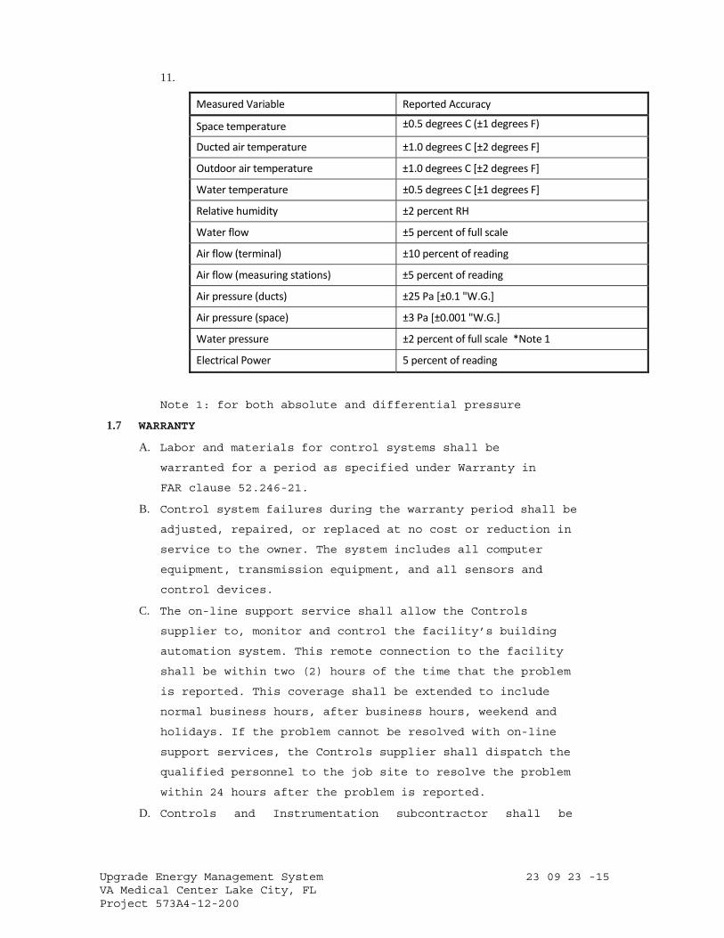
Upgrade Energy Management System 23 09 23 -15 VA Medical Center Lake City, FL Project 573A4-12-200
11.
Measured Variable Reported Accuracy
Space temperature ±0.5 degrees C (±1 degrees F)
Ducted air temperature ±1.0 degrees C [±2 degrees F]
Outdoor air temperature ±1.0 degrees C [±2 degrees F]
Water temperature ±0.5 degrees C [±1 degrees F]
Relative humidity ±2 percent RH
Water flow ±5 percent of full scale
Air flow (terminal) ±10 percent of reading
Air flow (measuring stations) ±5 percent of reading
Air pressure (ducts) ±25 Pa [±0.1 "W.G.]
Air pressure (space) ±3 Pa [±0.001 "W.G.]
Water pressure ±2 percent of full scale *Note 1
Electrical Power 5 percent of reading
Note 1: for both absolute and differential pressure
1.7 WARRANTY
A. Labor and materials for control systems shall be
warranted for a period as specified under Warranty in
FAR clause 52.246-21.
B. Control system failures during the warranty period shall be
adjusted, repaired, or replaced at no cost or reduction in
service to the owner. The system includes all computer
equipment, transmission equipment, and all sensors and
control devices.
C. The on-line support service shall allow the Controls
supplier to, monitor and control the facility’s building
automation system. This remote connection to the facility
shall be within two (2) hours of the time that the problem
is reported. This coverage shall be extended to include
normal business hours, after business hours, weekend and
holidays. If the problem cannot be resolved with on-line
support services, the Controls supplier shall dispatch the
qualified personnel to the job site to resolve the problem
within 24 hours after the problem is reported.
D. Controls and Instrumentation subcontractor shall be
Upgrade Energy Management System 23 09 23 -16 VA Medical Center Lake City, FL Project 573A4-12-200
responsible for temporary operations and maintenance of
the control systems during the construction period until
final commissioning, training of facility operators and
acceptance of the project by VA.
1.8 SUBMITTALS
A. Submit shop drawings in accordance with Section 01 33 23,
SHOP DRAWINGS, PRODUCT DATA, AND SAMPLES.
B. Manufacturer’s literature and data for all components including
the following:
1. A wiring diagram for each type of input device and output
device including DDC controllers, modems, repeaters, etc.
Diagram shall show how the device is wired and powered,
showing typical connections at the digital controllers and
each power supply, as well as the device itself. Show for
all field connected devices, including but not limited to,
control relays, motor starters, electric or electronic
actuators, and temperature pressure, flow and humidity
sensors and transmitters.
2. A diagram of each terminal strip, including digital
controller terminal strips, terminal strip location,
termination numbers and the associated point names.
3. Control dampers and control valves schedule, including the
size and pressure drop.
4. Installation instructions for smoke dampers and combination
smoke/fire dampers, if furnished.
5. Catalog cut sheets of all equipment used. This includes, but
is not limited to DDC
controllers, panels, peripherals, airflow measuring stations
and associated components, and auxiliary control devices
such as sensors, actuators, and control dampers.
When manufacturer’s cut sheets apply to a product series
rather than a specific product, the data specifically
applicable to the project shall be highlighted. Each
submitted piece of literature and drawings should clearly
reference the specification and/or drawings that it supposed
to represent.
6. Sequence of operations for each HVAC system and the
associated control diagrams.
Upgrade Energy Management System 23 09 23 -17 VA Medical Center Lake City, FL Project 573A4-12-200
Equipment and control labels shall correspond to those shown
on the drawings.
7. Color prints of proposed graphics with a list of points for
display.
8. Furnish PICS for each BACNET compliant device.
C. Product Certificates: Compliance with Article, QUALITY ASSURANCE.
D. As Built Control Drawings:
1. Furnish three (3) copies of as-built drawings for each
control system. The documents shall be submitted for approval
prior to final completion.
2. Furnish one (1) stick set of applicable control system prints
for each mechanical system for wall mounting. The documents
shall be submitted for approval prior to final completion.
3. Furnish one (1) CD-ROM in CAD DWG and/or .DXF format for the
drawings noted in subparagraphs above.
E. Operation and Maintenance (O/M) Manuals):
1. Submit in accordance with Article, INSTRUCTIONS, in
Specification Section 01 00 00, GENERAL REQUIREMENTS.
2. Include the following documentation:
a. General description and specifications for all components,
including logging on/off, alarm handling, producing trend
reports, overriding computer control, and changing set
points and other variables.
b. Detailed illustrations of all the control systems specified
for ease of maintenance and repair/replacement procedures,
and complete calibration procedures.
c. One copy of the final version of all software provided
including operating systems, programming language,
operator workstation software, and graphics software.
d. Complete troubleshooting procedures and guidelines for all
systems.
e. Complete operating instructions for all systems.
f. Recommended preventive maintenance procedures for all
system components including a schedule of tasks for
inspection, cleaning and calibration. Provide a list of
recommended spare parts needed to minimize downtime.
g. Licenses, guaranty, and other pertaining documents for all
equipment and systems.

Upgrade Energy Management System 23 09 23 -18 VA Medical Center Lake City, FL Project 573A4-12-200
h. Training Manuals: Submit the course outline and training
material to the Owner for approval three (3) weeks prior
to the training of the VA facility personnel. These
persons will be responsible for maintaining and the
operation of the control systems, including programming.
The Owner reserves the right to modify any or all of the
course outline and training material.
F. Submit Performance Report to Resident Engineer prior to final
inspection.
1.9 INSTRUCTIONS
A. Instructions to VA operations personnel: Perform in accordance
with Article, INSTRUCTIONS, in Specification Section 01 00 00,
GENERAL REQUIREMENTS, and as noted below. Contractor shall also
video tape instruction sessions noted below.
1. First Phase: Formal instructions to the VA facilities
personnel for a total of 24 hours, conducted sometime
between the completed installation and prior to the
performance test period of the control system, at a time
mutually agreeable to the Contractor and the VA.
2. Second Phase: This phase of training shall comprise of on
the job training during start-up, checkout period, and
performance test period. VA facilities personnel will work
with the Contractor’s installation and test personnel on a
daily basis during start-up and checkout period. During the
performance test period, controls subcontractor will provide
16 hours of instructions to the VA facilities personnel.
3. The O/M Manuals shall contain approved submittals as
outlined in Article 1.7, SUBMITTALS. The Controls
subcontractor will review the manual contents with VA
facilities personnel during second phase of training.
4. Training by independent or franchised dealers who are not
direct employees of the controls supplier will not be
acceptable.
1.10 PROJECT CONDITIONS (ENVIRONMENTAL CONDITIONS OF OPERATION)
A. The ECC and peripheral devices and system support equipment
shall be designed to operate in ambient condition of 20 to 35
degrees C (65 to 90 degrees F) at a relative humidity of 20 to
80 percent non-condensing.
Upgrade Energy Management System 23 09 23 -19 VA Medical Center Lake City, FL Project 573A4-12-200
B. The CUs and associated equipment used in controlled environment
shall be mounted in NEMA 1 enclosures for operation at 0 to 50
degrees C (32 to 122 degrees F) at a relative humidity of 10 to
90 percent non-condensing.
C. The CUs used outdoors shall be mounted in NEMA 4 waterproof
enclosures, and shall be rated for operation at –40 to 65
degrees C (-40 to 150 degrees F).
D. All electronic equipment shall operate properly with power
fluctuations of plus 10 percent to minus 15 percent of nominal
supply voltage.
E. Sensors and controlling devices shall be designed to operate in
the environment in which they are sensing or controlling.
1.11 APPLICABLE PUBLICATIONS
A. The publications listed below form a part of this
specification to the extent referenced. The publications are
referenced in the text by the basic designation only.
B. American Society of Heating, Refrigerating, and Air-
Conditioning Engineers (ASHRAE): Standard 135-04 BACNET
Building Automation and Control Networks
C. American Society of Mechanical Engineers (ASME):
B16.18-01 Cast Copper Alloy Solder Joint Pressure Fittings.
B16.22-01 Wrought Copper and Copper Alloy Solder Joint
Pressure Fittings. BPVC-CC-N-04 Boiler and Pressure
Vessel Code
D. American Society of Testing Materials (ASTM):
B32-04 Standard Specification for Solder Metal
B88-03 Standard Specifications for Seamless Copper Water
Tube
B88M-05 Standard Specification for Seamless Copper Water
Tube (Metric)
B280-03 Standard Specification for Seamless Copper Tube
for Air-Conditioning and Refrigeration Field
Service
D2737-03 Standard Specification for Polyethylene (PE)
Plastic Tubing
E. Federal Communication Commission (FCC):
Rules and Regulations Title 47 Chapter 1-2001 Part 15..Radio
Upgrade Energy Management System 23 09 23 -20 VA Medical Center Lake City, FL Project 573A4-12-200
Frequency Devices.
F. Institute of Electrical and Electronic Engineers (IEEE):
802.3-05 Information Technology-
Telecommunications and
Information Exchange between Systems-Local and
Metropolitan Area Networks- Specific
Requirements-Part 3: Carrier Sense Multiple
Access with Collision Detection (CSMA/CD)
Access method and Physical Layer
Specifications
G. Instrument Society of America (ISA): 7.0.01-1996 Quality Standard
for Instrument Air
H. National Fire Protection Association NFPA): 70-05
National Electric Code90A- 02 Standard for
Installation of Air-Conditioning and Ventilation
Systems
I. Underwriter Laboratories Inc (UL):
94-06 Tests for Flammability of Plastic Materials for
Parts and Devices and Appliances
294-05 Access Control System Units
486A/486B-04- Wire Connectors
555S-03 Standard for Smoke
Dampers 916-Rev 2-04 Energy
Management Equipment
1076-05 Proprietary Burglar Alarm Units and Systems
PART 2 – PRODUCTS
2.1 CONTROLS SYSTEM ARCHITECTURE
A. General
1. The Controls Systems shall consist of multiple Nodes and
associated equipment connected by industry standard digital
and communication network arrangements.
2. The Operator Workstations, Servers and principal network
computer equipment shall be standard products of recognized
major manufacturers available through normal PC and
computer vendor channels – not "Clones" assembled by a third-
party subcontractor.
3. Provide licenses for all software residing on and used by the
Upgrade Energy Management System 23 09 23 -21 VA Medical Center Lake City, FL Project 573A4-12-200
Controls Systems and transfer these licenses to the Owner
prior to completion.
4. The networks shall, at minimum, comprise, as necessary, the
following:
a. Operator Workstations – fixed and portable as required by
the Specifications.
b. Network computer processing, data storage and
communication equipment including Servers and digital
data processors.
c. Routers, bridges, switches, hubs, modems, interfaces
and the like communication equipment.
d. Programmable field panels and controllers together with
their power supplies and associated equipment.
e. Addressable elements, sensors, transducers and end devices.
f. Third-party equipment interfaces as required by the
Contract Documents.
g. Other components required for a complete and working
Control Systems as specified.
B. The Specifications for the individual elements and component
subsystems shall be minimum requirements and shall be augmented
as necessary by the Contractor to achieve both compliance with
all applicable codes, standards and to meet all requirements of
the Contract Documents.
C. Network Architecture
1. The Controls Systems Application network shall utilize an
open architecture capable of each and all of the following:
a. Utilizing standard Ethernet communications and operate at
a minimum speed of 10/100 Mb/sec.
b. Connecting via BACNET with ANSI/ASHRAE Standard 135.
2. The networks shall utilize only copper and optical fiber
communication media as appropriate and shall comply with
applicable codes, ordinances and regulations. They may also
utilize digital wireless technologies if required by the VA.
3. All necessary telephone lines, ISDN lines and internet
Service Provider services and connections will be provided by
the owner.
4. The Controls Contractor shall provide the IT interfacing
equipment and shall coordinate on configuration and
Upgrade Energy Management System 23 09 23 -22 VA Medical Center Lake City, FL Project 573A4-12-200
interfacing arrangements with the Data Cabling System
contractor.
D. Third Party Interfaces:
1. The Controls Systems shall include necessary hardware,
equipment and software to allow data communications between
the Controls Systems and building systems supplied by other
trades.
2. The other manufacturers and contractors supplying other
associated systems and equipment
will provide their necessary hardware, software and start-up
at their cost and will cooperate fully with the Controls
Contractor in a timely manner and at their cost to ensure
complete functional integration.
E. Servers:
1. Provide Controls Systems Application Server(s) to archive
historical data including trends, alarm and event histories
and transaction logs.
2. Equip these Server(s) with a software Tool Set for system
configuration and custom logic definition and color
graphic configuration.
3. Access to all information on the Controls Systems Server(s)
shall be through the same browser Operator Interface
functionality used to access individual nodes. As required
for the functional operation of the Controls Systems, the
Controls Contractor shall provide all necessary digital
processor programmable Server(s). These Server(s) shall
be utilized for Controls Systems Application configuration,
for archiving, reporting and trending of data, for Operator
transaction archiving and reporting, for network information
management, for alarm annunciation, for Operator Interface
tasks, for Controls Application management and the like.
These Server(s) shall utilize IT industry standard data
base platforms such as Microsoft SQL Server and Microsoft
Data Engine (MSDE) or approved equal.
2.2 DIRECT DIGITAL CONTROLLERS
A. (NAC) Network Area Controllers shall be stand-alone, multi-
tasking, multi-user, real-time digital processor complete with
all hardware, software, and communications interfaces, power
Upgrade Energy Management System 23 09 23 -23 VA Medical Center Lake City, FL Project 573A4-12-200
supplies. The Controls System shall be designed and implemented
entirely for use and operation on the Internet. NACs shall have
access to data within the industry standard IT network to the
Data Server and other NACs as needed to accomplish required
global control strategies.
1. NACs shall provide both standalone and networked direct
digital control of mechanical and electrical building system
controllers as required by the Specifications. The primary
NAC shall support a minimum of [5,000] field points
together with all associated features, sequences,
schedules, applications required for a fully functional
distributed processing operation.
2. NACs shall monitor and report communication status to the
Controls Systems Application.
The Controls Systems shall provide a system advisory upon
communication failure and restoration.
3. All NACs on the network shall be equipped with all software
functionality necessary to operate the complete user
interface, including graphics, via a Browser connected to
the Node on the network or directly via a local port on the
NAC.
4. All NAC shall be provided with face mounted LED type
annunciation to continually display its operational mode,
power and communications.
5. The controllers shall reside on the BACnet Ethernet (ISO
8802-3) local area network and provide Read (Initiate) and
Write (Execute) services as defined in Clauses 15.5 and
15.8, respectively of ASHRAE Standard 135, to communicate
BACnet objects. Objects supported shall include: Analog
input, analog output, analog value, binary input, binary
output, binary value, and device.
6. Each NAC shall be provided with the necessary un-
interruptible power facilities to ensure its continued
normal operation during periods of line power outages of,
at minimum, 1- minute duration. Normal functionality
shall include all normal software processing,
communication with powered field devices and network
communications with other powered Controls Systems NAC,
Upgrade Energy Management System 23 09 23 -24 VA Medical Center Lake City, FL Project 573A4-12-200
Data Servers and OWS. Each NAC shall report its
communication status to the Application. The Application
shall provide a system advisory upon communication failure and
restoration. Each NAC shall retain program, control
algorithms, and setpoint information in non-volatile memory in
the event of a power failure, and shall return to normal
operation upon restoration of power.
7. Each NAC shall have sufficient memory to support its
operating system, database, and program requirements,
including the following:
a. Device and network management.
b. Data sharing.
C. Alarm and event management including custom alarm
messages for each level alarm for the points noted in
the I/O Schedule.
d. Energy management.
e. Historical trend data for points specified.
f. Maintenance report.
g. Scheduling.
h. Dial up and network communications.
i. Manual override monitoring.
8. Each NAC shall support firmware upgrades without the need
to replace hardware and shall have a minimum of 15
percent spare capacity of secondary system
controllers, point capacity and programming functions.
9. Each NAC shall continuously perform self-diagnostics,
communication diagnosis, and provide both local and remote
annunciation of any detected component failures, low
battery condition; and upon failure shall assume the
predetermined failure mode.
10. Each NAC shall monitor the status of all overrides and
inform the operator that automatic control has inhibited,
and allow the operator to manually override automatic or
centrally executed command.
11. Provide the capability to generate and modify the Controls
Systems Application software- based sequences, database
elements, associated operational definition information and
user-
Upgrade Energy Management System 23 09 23 -25 VA Medical Center Lake City, FL Project 573A4-12-200
required revisions to same at any designated
Workstation together with the means to download same to
the associated System Controllers.
12. In the event of loss of normal power, there shall be
orderly shutdown of the controllers to prevent the loss of
database or software programming. When power is restored
flash memory, battery backup or super capacitor will be
automatically loaded into non-volatile flash memory and
shall be incorporated for all programming data.
B. Auxiliary Control Units (ACUs) shall be stand-alone, multi-
tasking, multi-user, real time digital processor complete with
all hardware, software and communication interfaces, power
supplies, and input/output modular devices.
1. ACUs shall reside on the Ethernet network and provide data
using BACnet.
2. All ACUs shall be provided with LED type
annunciation to continually display its operational
mode, power and communications.
3. Each ACU shall have sufficient memory to support its
operating system, database including the following:
a. Data sharing.
b. Device and network management.
c. Alarm and event management.
d. Scheduling.
e. Energy Management.
4. Each ACU shall support firmware upgrades without the need to
replace hardware and shall have a minimum of 15 percent
spare capacity of I/O functions. The type of spares shall be
in the same proportion as the implemented functions on the
controller, but in no case there shall be less than one point
of each implemented I/O type.
5. Each ACU shall continuously perform self-diagnostics,
communication diagnosis, and provide both local and
remote annunciation of any detected component failures,
low battery condition; and upon failure shall assume the
predetermined failure mode.
6. In the event of loss of normal power, there shall be orderly
shutdown of the controllers to prevent the loss of database
Upgrade Energy Management System 23 09 23 -26 VA Medical Center Lake City, FL Project 573A4-12-200
or software programming. When power is restored flash memory,
battery backup or super capacitor will be automatically
loaded into non-volatile flash memory and shall be
incorporated for all programming data.
C. Unitary Control Units (UCUs) shall be microprocessor-based.
They shall be capable of stand- alone operation, continuing to
provide stable control functions if communication is lost with
the rest of the system.
1. Unitary Control Units shall reside on the Ethernet network
and provide data using BACnet.
2. Each UCU shall have sufficient memory to support its own
operating system, including data sharing.
3. All UCUs shall be provided with LED type annunciation to
continually display its operational mode, power and
communications.
4. In the event of loss of normal power, there shall be
orderly shutdown of the controllers to prevent the loss of
database or software programming. When power is
restored flash memory, battery backup or super capacitor
will be automatically loaded into non-volatile flash
memory and shall be incorporated for all programming data.
D. Provide I/O module that connects sensors and actuators onto the
field bus network for use by the direct digital controllers. I/O
devices shall support the communication technology specified for
each controller.
1. Analog input shall allow the monitoring of low voltage (0-10
VDC), current (4-20 ma), or resistance signals (thermistor,
RTD). Analog input shall be compatible with, and field
configurable to commonly available sensing devices. Analog
output shall provide a modulating signal for these control
devices.
2. Binary inputs shall allow the monitoring of on/off signals
from remote devices. Binary inputs shall provide a wetting
current of at least 12 milliamps to be compatible with
commonly available control devices. Binary outputs shall
provide on/off operation, or a pulsed low voltage signal
for pulse width modulation control. Outputs shall be
selectable for either normally open or normally closed
Upgrade Energy Management System 23 09 23 -27 VA Medical Center Lake City, FL Project 573A4-12-200
operation.
3. Binary outputs shall have 3-position (on/off/auto)
override switches and status lights. Analog outputs shall
have status lights and a 2-position (auto/manual) switch
and manually adjustable potentiometer for manual override.
4. Each output point shall be provided with a light emitting
diode (LED) to indicate status of outputs.
E. Communication Ports:
1. NACs controllers in the DDC systems shall be connected in a
system local area network using protocol defined by ASHRAE
Standard 135, BACnet protocol.
2. The control supplier shall provide connectors, repeaters,
hubs, and routers necessary for all network
communication.
3. Minimum baud rate between the peer-to-peer controllers in the
system LAN shall be maintained at the rate of 10 Mbps.
4. Provide RS-232 port with DB-9 or RJ-11 connector for
communication with each controller that will allow direct
connection of standard printers, operator terminals,
modems, and portable laptop operator’s terminal. Controllers
shall allow temporary use of portable devices without
interrupting the normal operation of permanently connected
modems, printers or terminals.
5. Database, such as points; status information, reports, system
software, custom programs of any one controller shall be
readable by any other controller on the network.
F. Diagnostic Devices (DD):
1. Provide a laptop computer capable of accessing all system
data. This device may be connected to any point on the
system network or may be connected directly to any digital
controller for programming, set-up, and troubleshooting.
2. Laptop computer shall be PC notebook style containing
necessary software and hardware
required. The PC shall contain as a minimum:
a. 2.4 GHZ Intel Pentium Processor.
b. 128MB, 100 MHz RAM.
c. 60GB Hard Drive.
d. One-Die 256K L2 Cache.
Upgrade Energy Management System 23 09 23 -28 VA Medical Center Lake City, FL Project 573A4-12-200
e. 3.5 inch, 1.44MB Floppy Disk Drive
f. 48 X CD RW Drive.
g. 56K Internal Modem.
h. 32MB video memory graphics.
i. Ethernet IP network card.
j. Operating system compatible with PC Microsoft XP
professional listed under Operator Workstation.
G. Electric Outlet: Provide a single phase, 120 VAC electrical
receptacles inside or within 2 meters (6 feet) of the
controller enclosures for use with test equipment.
H. Spare Equipment:
1. Provide spare digital controller (CU) boards and spare
I/O boards as required. It shall be possible for trained
hospital personnel to replace CU boards and load software
via the Laptop computer or the ECC.
2. Provide a minimum of one spare digital controller board
of each type and associated parts including batteries to
make at least one complete set of DDC control equipment
spares.
3. If I/O boards are separate from the CU boards, provide
two spare I/O boards for each spare CU board provided
above.
2.3 DIRECT DIGITAL CONTROLLER SOFTWARE
A. The software programs specified in this section shall be
commercially available, concurrent, multi-tasking operating
system and support the use of software application that
operates under DOS or Microsoft Windows.
B. All points shall be identified by up to 30-character point name
and 16-character point descriptor.
The same names shall be used at the operator workstation.
C. All control functions shall execute within the stand-alone
control units via DDC algorithms. The VA shall be able to
customize control strategies and sequences of operations
defining the appropriate control loop algorithms and choosing
the optimum loop parameters.
D. All CU’s shall be capable of being programmed to utilize stored
default values for assured fail- safe operation of critical
processes. Default values shall be invoked upon sensor failure
Upgrade Energy Management System 23 09 23 -29 VA Medical Center Lake City, FL Project 573A4-12-200
or, if the primary value is normally provided by the central or
another CU, or by loss of network communication. Individual
application software packages shall be structured to assume a
fail- safe condition upon loss of input sensors. Loss of an
input sensor shall result in output of a sensor-failed message
at the ECC workstation. Each ACU and RCU shall have capability
for local readouts of all functions. The UCUs shall be read
remotely.
E. All DDC control loops shall be able to utilize any of the
following control modes:
1. Two position (on-off, slow-fast) control.
2. Proportional control.
3. Proportional plus integral (PI) control.
4. Proportional plus integral plus derivative (PID)
control. All PID programs shall automatically
invoke integral wind up prevention routines whenever the
controlled unit is off, under manual control of an
automation system or time initiated program.
5. Automatic tuning of control loops.
F. System Security: Operator access shall be secured using
individual password and operator’s name. Passwords shall
restrict the operator to the level of object, applications, and
system functions assigned to him. A minimum of six (6) levels
of security for operator access shall be provided.
G. Application Software: The CUs shall provide the following
programs as a minimum for the purpose of optimizing energy
consumption while maintaining comfortable environment for
occupants. All application software shall reside and run in the
system digital controllers. Editing of the application shall
occur at the operator workstation or via a portable workstation,
when it is necessary, to access directly the programmable unit.
1. Event Scheduling: Provide a comprehensive menu driven
program to automatically start and stop designated
points or a group of points according to a stored time.
This program shall provide the capability to individually
command a point or group of points. When points are
assigned to one common load group it shall be possible
to assign variable time advances/delays between each

Upgrade Energy Management System 23 09 23 -30 VA Medical Center Lake City, FL Project 573A4-12-200
successive start or stop within that group. Scheduling
shall be calendar based and advance schedules may be
defined up to one year in advance. Advance schedule
shall override the day-to-day schedule. The operator
shall be able to define the following information:
a. Time, day.
b. Commands such as on, off, auto.
c. Time delays between successive commands.
d. Manual overriding of each schedule.
e. Allow operator intervention.
2. Alarm Reporting: The operator shall be able to determine
the action to be taken in the event of an alarm. Alarms
shall be routed to the appropriate workstations based
on time and events. An alarm shall be able to start
programs, login the event, print and display the
messages. The system shall allow the operator to
prioritize the alarms to minimize nuisance reporting and
to speed operator’s response to critical alarms. A
minimum of six (6) priority levels of alarms shall be
provided for each point.
3. Remote Communications: The system shall have the ability
to dial out in the event of an alarm to workstations and
alpha-numeric pagers. The alarm message shall include the
name of the calling location, the device that generated
the alarm, and the alarm message itself. The operator
shall be able to remotely access and operate the
system using dial up communications. Remote access
shall allow the operator to function the same as local
access.
4. Maintenance Management (PM): The program shall
monitor equipment status and generate maintenance messages
based upon the operators defined equipment run time,
starts, and/or calendar date limits. A preventative
maintenance alarm shall be printed indicating maintenance
requirements based on pre-defined run time. Each
preventive message shall include point description, limit
criteria and preventative maintenance instruction assigned
to that limit. A minimum of 480-character PM shall be
Upgrade Energy Management System 23 09 23 -31 VA Medical Center Lake City, FL Project 573A4-12-200
provided for each component of units such as air handling
units.
5. Chilled water Plant Operation: This program shall have
the ability to sequence the multiple chillers to minimize
energy consumption. The program shall provide sequence of
operation as described on the drawings and include the
following as a minimum:
a. Automatic start/stop of chillers and auxiliaries in
accordance with the sequence of operation shown on
the drawings, while incorporating requirements and
restraints, such as starting frequency of the
equipment imposed by equipment manufacturers.
b. Secondary chilled water pumps and controls.
c. Generate chilled water plant load profiles for
different seasons for use in forecasting efficient
operating schedule.
d. Cooling Tower Operation Program: The objective of
cooling tower control is to optimize chiller/tower
energy use within the equipment restraints and
minimum condenser water temperature limit
recommended by the equipment manufacturer. Maintain
chilled water plant performance records and print
reports at intervals selected by the operator. It
shall be possible for the operator to change the set
points and the operating schedule.
e. The chilled water plant program shall
display the following as a minimum:
aa. Secondary chilled flow rate.
bb. Secondary chilled water supply and
return temperature.
cc. Condenser water supply and return
temperature.
dd. Outdoor air dry bulb temperature.
ee. Outdoor air wet bulb temperature.
ff. Ton-hours of chilled water per
day/month/year.
gg. On-off status for each chiller.
hh. Chilled water flow rate.
Upgrade Energy Management System 23 09 23 -32 VA Medical Center Lake City, FL Project 573A4-12-200
ii. Chilled water supply and
return temperature.
jj. Operating set points-
temperature and pressure.
kk. Kilowatts and
power factor.
ll. Current limit
set point.
mm. Date and time.
nn. Operating or alarm
status.
oo. Operating hours.
2.4 SENSORS (AIR, WATER AND STEAM)
A. Temperature and Humidity Sensors:
1. Electronic Sensors: Provide all remote sensors as required
for the systems. All sensors shall be vibration and corrosion
resistant for wall, immersion, and/or duct mounting.
a. Temperature Sensors: Thermistor type for terminal units
and Resistance Temperature Device (RTD) with an integral
transmitter type for all other sensors.
b. Duct sensors shall be rigid or averaging type as shown on
drawings. Averaging sensor shall be a minimum of 1 linear ft
of sensing element for each sq ft of cooling coil face area.
c. Immersion sensors shall be provided with a separable well
made of stainless steel, bronze or monel material. Pressure
rating of well is to be consistent with the system pressure
in which it is to be installed.
d. Space sensors shall be equipped with set-point adjustment,
override switch, display, and/or communication port as shown
on the drawings.
e. Match room thermostats, locking cover.
f. Outdoor air temperature sensors shall have watertight
inlet fittings and be shielded from direct sunlight.
g. Room security sensors shall have stainless steel cover
plate with insulated back and security screws.
h. Wire: Twisted, shielded-pair cable.
i. Humidity Sensors: Bulk polymer sensing element type.
i. Output Signal: 4-20 ma.
Upgrade Energy Management System 23 09 23 -33 VA Medical Center Lake City, FL Project 573A4-12-200
ii. Duct and room sensors shall have a sensing range
of 20 to 80 percent with accuracy of 3 percent
RH, including hysteresis, linearity, and
repeatability.
iii. Outdoor humidity sensors shall be furnished with
element guard and mounting plate and have a
sensing range of 0 to 100 percent RH.
B. Static Pressure Sensors: Non-directional,
temperature compensated.
i. 4-20 ma output signal.
1. 0 to 5 inches wg for duct static pressure range.
2. 0 to 0.25 inch wg for Building static pressure
range.
C. Steam Flow Sensor/Transmitter:
1. Sensor: Vortex shedder incorporating wing type sensor and
amplification technology for high signal-to-noise ratio,
carbon steel body with 316 stainless steel working parts, 24
VDC power, NEMA 4 enclosure.
a. Ambient conditions, -40 to 80 degrees C (-40 to 175 degrees
F).
b. Process conditions, 900 kPa (125 psig) saturated steam.
c. Turn down ratio, 20 to 1.
d. Accuracy, plus or minus 1.0 percent of span.
e. Repeatability, plus or minus 0.1 percent.
f. Output signal, 4-20 ma DC.
i. Processor/Transmitter, NEMA 4 enclosure with keypad
program selector and six digit LCD output display of
instantaneous flow rate or totalized flow, solid state
switch closure signal shall be provided to the nearest
DDC panel for totalization. Ambient conditions, -20 to
50 degrees C (0-120 degrees F), 0 95 percent non-
condensing RH.
ii. Power supply, 120 VAC, 60 hertz or 24 VDC.
iii. Internal battery, provided for 24-month retention of RAM
contents when all other power sources are removed.
g. Sensor on all steam lines shall be protected by pigtail
siphons installed between the sensor and the line, and
shall have an isolation valve installed between the
Upgrade Energy Management System 23 09 23 -34 VA Medical Center Lake City, FL Project 573A4-12-200
sensor and pressure source.
D. Flow switches:
1. Shall be either paddle or differential pressure type.
i. Paddle-type switches (liquid service only) shall be
UL Listed, SPDT snap-acting, adjustable sensitivity
with NEMA 4 enclosure.
ii. Differential pressure type switches (air or water
service) shall be UL listed, SPDT snap acting, NEMA 4
enclosure, with scale range and differential suitable
for specified
iii. application.
E. Current Switches: Current operated switches shall be self-
powered, solid state with adjustable trip current as well as
status, power, and relay command status LED indication. The
switches shall be selected to match the current of the
application and output requirements of the DDC systems.
2.5 TRANSIT TIME ULTRASONIC FLOW METER
A. The transit time ultrasonic flow measurement system shall be a
digital signal processing (DSP) based transit time (time of
flight) measuring type providing an electronic output signal
proportional to the flow of liquid in closed piping systems as
may be required. It shall consist of a transmitter and one
transducer set that is either integrally connected or remotely
connected by up to 990 feet [300 meters] of cable.
B. Certifications
1. Class I Division 2 Groups C, D T6 Hazardous Areas
2. Class I Zone 2 EEx nA IIB T6 Hazardous Areas
3. CE certification to IEC 61326-1
4. CIP™ Common Industrial Protocol certification
C. Operating principle: Two ultrasonic transducers function as
both transmitters and receivers. Flow measurement is made by
measuring the difference time of flight between two digitally
synthesized contra propagating acoustic chirps traveling
between the two ultrasonic transducers positioned lineally, a
known distance apart, on the outside of a closed pipe.
Difference time is proportional to fluid velocity, with
system Reynolds Number, pipe roughness and speed of sound
correction factors applied.
Upgrade Energy Management System 23 09 23 -35 VA Medical Center Lake City, FL Project 573A4-12-200
D. Water flow sensors:
1. Type: Insertion vortex type with retractable probe assembly
and 2 IN full port gate valve.
a. Pipe size: 3 to 24 IN.
b. Retractor: ASME threaded, non-rising stem type with hand
wheel.
c. Mounting connection: 2 IN 150 PSI flange.
d Sensor assembly: Design for expected water flow and pipe
size.
e. Seal: Teflon (PTFE).
2. Controller:
a. Integral to unit.
b. Locally display flow rate and total.
c. Output flow signal to BMCS: Digital pulse type.
3. Performance:
a. Accuracy: 1.0% of reading
b. Repeatability: 0.15% of reading
c. Turndown: 20:1
d. Response time: Adjustable from 1 to 100 seconds.
e. Power: 24 volt DC
4. Manufacturer: Emco V-Bar 910
5. Install flow meters according to manufacturer’s
recommendations. Where recommended by manufacturer because of
mounting conditions, provide flow rectifier.
E. Transducer:
1. Primary Sensor: The compression-mode acoustic transducer
shall contain a polarized PZT crystal with impedance matched
wave-guide.
a. Standard transducers shall operate on pipe sizes
ranging from 2” through 100” [50 through 2540 mm] and
have a center frequency of 1 MHz.
b. Large pipe transducers shall operate on pipes larger than
24” [600 mm] and have a center frequency of 0.5 MHz.
c. Small-pipe transducers shall operate on pipe sizes from
1/2” through 2” [12 through 50 mm], are specific to a pipe
outside diameter and have a center frequency of either 1
or 2 MHz. Small-pipe transducer can be integrally mounted
Upgrade Energy Management System 23 09 23 -36 VA Medical Center Lake City, FL Project 573A4-12-200
with the transmitter enclosure or remotely connected with
coaxial cable.
d. Transducer housing shall be constructed from PVC, CPVC,
PTFE, Ultem® and/or Vespel®.
e. Transducers shall be rated for a Type 6 [IP 67] environment.
f. PVC transducers shall have continuous operating temperature
of -40 o to 185 o F [-40° to
+85° C]
g. CPVC transducers shall have continuous operating temperature
of -40o to 250oF [-40° to
+121° C]
h. PTFE transducers shall have continuous operating temperature
of -40 o to 350 o F [-40° to
+176° C]
F. Transmitter
1. Enclosure shall be Type 4; epoxy-coated aluminum,
stainless steel and polycarbonate construction.
2. Power supply shall be 95-264 VAC @ 47-63 Hz or 10-28 VDC
3. AC power consumption shall be 17 VA maximum and DC power
consumption shall be 5 VA maximum
4. Operating temperature shall be -40 o to 185 o F [-40o to 85 o
C]
5. Outputs:
a. 4-20ma; 12-bit resolution, internally powered, can span
negative to positive flow rates; test function allows
simulated flow output to verify proper installation and
span settings on receiving equipment
b. Pulse rate output, 0-1,000 Hz, 12-bit resolution, open-
collector and turbine meter simulation,
internal/external pull-up resistor selection, can span
negative to positive flow rates
c. Control outputs; 2 independently configurable open-collector
outputs, can be configured as flow rate alarm, signal
strength alarm, error alarm or totalizer pulse;
internal/external pull-up resistors selection
6. Industrial Communications (native):
a. RS485, ¼-node, 126 units/network; Modbus RTU protocol
Upgrade Energy Management System 23 09 23 -37 VA Medical Center Lake City, FL Project 573A4-12-200
b. 10/100 Base-T Ethernet (ODVA™ CIP™ Compliant); Modbus
TCP/IP and BACnet®/IP protocols
7. Control and Programming:
a. All parameter and commands shall be entered via a
personal computer, Windows® software utility and
standard USB A/B cable. Windows utility permits flow
meter configurations to be saved and recalled.
b. Firmware shall up field upgradeable via the USB connection c.
Optional 4-key keypad
8. Transmitter shall output a digitally synthesized waveform
from a discrete, field uploadable file.
9. Measurements shall be made by measuring differential time
of contrapropogating waveforms using cross-correlation of
data sets. Automatic Reynolds Number and pipe
roughness corrections are applied.
G. Transmitter and Transducer Performance
1. Measuring range –40 to +40 FPS [-12 to +12 MPS]
2. Accuracy shall be ±1% of reading at rates > 1 FPS [0.3 MPS]
3. Repeatability: 0.5% of reading
4. Sensitivity is 0.001 FPS [0.0003 MPS]
5. Maximum separation between transmitter and transducer shall be
990 feet
H. Indication
1. Display shall be two lines: 8-digit LCD with .7” high
numerical values and 8-digit LCD with 0.35” high alpha
numeric values. Display is backlit with white LEDs.
2. Indicators for Run and Program modes and Relay 1 and Relay 2
status
I. Equipment
1. The transit time ultrasonic flow meter and software shall
be selected to be a complete and integrated system with
features that are compatible with the facility’s Johnson
Control system.
2. A software utility shall be utilized to configure,
calibrate, backup and conduct diagnostic functions on the
flow meter. The software shall be compatible with Windows 95,
Windows
98, Windows 2000, Windows 2000, Windows XP and Windows Vista®
Upgrade Energy Management System 23 09 23 -38 VA Medical Center Lake City, FL Project 573A4-12-200
operating systems.
2.5 ENGINEERING CONTROL CENTER (ECC)—OPERATOR’S WORKSTATION
A. Operator workstation(s) shall utilize standard Web Browser
software and be able to access data from all the digital
controllers distributed throughout the control systems. These
workstations shall reside on the same high-speed network as all
other controllers with the ability to provide internet access to
the system.
B. The ECC shall consist of the following:
1. Personal Computer: Microsoft compatible PC containing
necessary software and hardware, including serial and
parallel ports, network connections and all cables, and
Uninterruptible Power Source (UPS) system, necessary for the
complete function of the control systems. The system shall
be designed so that additional workstations and/or
peripheral equipment can be added in the future. The PC shall
contain the following as a minimum:
a. 750MHz Intel Pentium Processor.
b. 128MB RAM at 100 MHz.
c. 60GB Hard Drive.
d. One-die 256KB Cache.
e. 1.44MB Floppy, Disk Drive.
f. 48X CD-RW Drive.
g. 56 K Internal Modem.
h. Graphics: 32 MB Video memory.
i. Monitor: Capable of handling advanced graphics and
multimedia applications.
j. Mouse/Keyboard: Quiet keyboard with 3-button mouse.
k. Uninterruptible power supply with minimum 30-minute backup.
2. Alarm Printer: Tractor-feed and 8-1/2x11 multi-fold type
paper:
a. Speed: 160 characters per second.
b. Character spacing: Minimum 10 characters per inch.
c. Paper: One box of 2000 sheets of printer paper.
3. Laser Printer: Black and white:
a. Resolution: 1200x1200 dpi black text.
b. RAM: 4MB.
Upgrade Energy Management System 23 09 23 -39 VA Medical Center Lake City, FL Project 573A4-12-200
c. Speed: 10 pages per minute, with a 250-sheet paper cassette
and with manual feed.
4. Monitor:
a. Size: 17-inch Flat Panel.
b. Resolution: 1280 X 1024.
c. Response Rate: 25 ms
d. Height adjustable and pivot rotation capability
5. Surge Protection: 110-volt strip with at least 6 outlet
connections.
C. ECC Software:
1. The Controls Systems Operator Interfaces shall be user
friendly, readily understood and shall make maximum use
of colors, graphics, icons, embedded images, animation,
text based information and data visualization techniques
to enhance and simplify the use and understanding of the
displays by authorized users at the ECC.
2. User access shall be protected by a flexible and
Owner re-definable software-based password access
protection. Password protection shall be multi-level and
partitionable to
accommodate the varied access requirements of the
different user groups to which individual users may be
assigned. Provide the means to define unique access
privileges for
each individual authorized user. Provide the means to on-
line manage password access
control under the control of a project specific Master
Password. Provide an audit trail of all user activity on the
Controls Systems including all actions and changes.
3. Operator Workstation shall be user friendly, easily
understood and commercially available software, multi-tasking
operating system. The operating system shall be Window NT
or Windows 2000 XP or better, and shall support the third
party software.
D. The system shall be completely field-programmable from the
common operator’s keyboard thus allowing hard disk storage of
all data automatically. All programs for the CUs shall be able
to be downloaded from the hard disk. The software shall provide
Upgrade Energy Management System 23 09 23 -40 VA Medical Center Lake City, FL Project 573A4-12-200
the following functionality as a minimum:
1. Point database editing, storage and downloading of controller
databases.
2. Scheduling and override of building environmental control
systems.
3. Collection and analysis of historical data.
4. Alarm reporting, routing, messaging, and acknowledgement.
5. Definition and construction of dynamic color graphic displays.
6. Real-time graphical viewing and control of environment.
7. Scheduling trend reports.
Upgrade Energy Management System 23 09 23 -41 VA Medical Center Lake City, FL Project 573A4-12-200
8. Program editing.
9. Operating activity log and system security.
10. Transfer data to third party software.
E. Provide graphical user software, which shall minimize the use
of keyboard through the use of the mouse and "point and click"
approach to menu selection.
F. The software shall provide a multi-tasking type environment
that will allow the user to run several applications
simultaneously. The mouse or Alt-Tab keys shall be used to
quickly select and switch between multiple applications. The
operator shall be able automatically export data to and work in
Microsoft Word, Excel, and other Windows based software
programs, while concurrently on-line system alarms and
monitoring information.
G. Provide functionality such that using the least amount of steps
to initiate the desired event may perform any of the following
simultaneously:
1. Dynamic color graphics and graphic control.
2. Alarm management.
3. Event scheduling.
4. Dynamic trend definition and presentation.
5. Program and database editing.
6. Each operator shall be required to log on to the system with
a user name and password to view, edit or delete the data.
System security shall be selectable for each operator, and
the password shall be able to restrict the operator’s access
for viewing and changing the system programs. Each operator
shall automatically be logged off the system if no keyboard
or mouse activity is detected for a selected time.
H. Graphic Displays:
1. The workstation shall allow the operator to access various
system schematics and floor plans via a graphical
penetration scheme, menu selection, or text based commands.
Graphic
software shall permit the importing of AutoCAD or
scanned pictures in the industry standard format (such as
Upgrade Energy Management System 23 09 23 -42 VA Medical Center Lake City, FL Project 573A4-12-200
PCX, BMP, GIF, and JPEG) for use in the system.
2. Dynamic temperature values, humidity values, flow rates,
and status indication shall be shown in their locations
and shall automatically update to represent current
conditions without operator intervention and without pre-
defined screen refresh values.
3. Color shall be used to indicate status and change in status
of the equipment. The state colors shall be user definable.
4. A clipart library of HVAC equipment, such as chillers,
boilers, air handling units, fans, terminal units, pumps,
coils, standard ductwork, piping, valves and laboratory
symbols
shall be provided in the system. The operator shall have the
ability to add custom symbols to the clipart library.
5. A dynamic display of the site-specific architecture
showing status of the controllers, PC workstations and
network shall be provided.
6. The windowing environment of the workstation shall allow
the user to simultaneously view several applications at a
time to analyze total building operation or to allow the
display of graphic associated with an alarm to be viewed
without interrupting work in progress. The graphic system
software shall also have the capability to split screen,
half portion of the screen with graphical representation
and the other half with sequence of operation of the same
HVAC system.
I. Trend reports shall be generated on demand or pre-defined
schedule and directed to monitor display, printers or disk. As
a minimum, the system shall allow the operator to easily obtain
the following types of reports:
1. A general list of all selected points in the network.
2. List of all points in the alarm.
3. List of all points in the override status.
4. List of all disabled points.
5. List of all points currently locked out.
6. List of user accounts and password access levels.
7. List of weekly schedules.
8. List of holiday programming.
Upgrade Energy Management System 23 09 23 -43 VA Medical Center Lake City, FL Project 573A4-12-200
9. List of limits and dead bands.
10. Custom reports.
11. System diagnostic reports, including, list of digital
controllers on the network.
12. List of programs.
J. Scheduling and Override:
1. Provide a calendar type format for time-of-day scheduling and
overrides of building control systems. Schedules reside in
the PC workstation, digital controllers shall ensure
equipment time scheduling when PC is off-line. PC shall not
be required to execute time scheduling.
Provide override access through menu selection or function
key. Provide the following spreadsheet graphics as a minimum:
a. Weekly schedules.
b. Zone schedules, minimum of 100 zones.
c. Scheduling up to 365 days in advance.
d. Scheduled reports to print at workstation.
K. Collection and Analysis of Historical Data:
1. Provide trending capabilities that will allow the operator
to monitor and store records of system activity over an
extended period of time. Points may be trended automatically
on time based intervals or change of value, both of which
shall be user definable. The trend interval could be five
(5) minutes to 120 hours. Trend data may be stored on hard
disk for future diagnostic and reporting. Additionally trend
data may be archived to network drives or removable disk
media for off-site retrieval.
2. Reports may be customized to include individual points or
predefined groups of at least six points. Provide additional
functionality to allow pre-defined groups of up to 250
trended points to be easily accessible by other industry
standard word processing and spreadsheet packages. The
reports shall be time and date stamped and shall contain a
report title and the name of the facility.
3. System shall have the set up to generate spreadsheet reports
to track energy usage and cost based on weekly or monthly
interval, equipment run times, equipment efficiency, and/or
building environmental conditions.
Upgrade Energy Management System 23 09 23 -44 VA Medical Center Lake City, FL Project 573A4-12-200
4. Provide additional functionality that will allow the operator
to view real time trend data on trend graph displays. A
minimum of 20 points may be graphed regardless of whether
they have been predefined for trending. In addition, the
user may pause the graph and take snapshots of the screens
to be stored on the workstation disk for future reference
and trend analysis. Exact point values may be viewed and the
graph may be printed. Operator shall be able to command
points directly on the trend plot by double clicking on the
point.
L. Alarm Management:
1. Alarm routing shall allow the operator to send alarm
notification to selected printers or operator workstation
based on time of day, alarm severity, or point type.
2. Alarm notification shall be provided via two alarm icons, to
distinguish between routine, maintenance type alarms and
critical alarms. The critical alarms shall display on the
screen
at the time of its occurrence, while others shall display by
clicking on their icon.
3. Alarm display shall list the alarms with highest priority at
the top of the display. The alarm display shall provide
selector buttons for display of the associated point
graphic and message in English language. The operator shall
be able to sort out the alarms.
4. Alarm messages shall be customized for each point to display
detailed instructions to the operator regarding actions to
take in the event of an alarm.
5. An operator with proper security level access may
acknowledge and clear the alarm. All that have not been
cleared shall be archived at workstation disk.
M. Clock Synchronization:
1. The system shall be able to automatically synchronize all
system clocks from any operator- designated device in the
system, and shall adjust for daylight savings and standard
time, if applicable. In the event of a power failure, all
clocks shall be adjusted on the command of an operator if the
power outage is extended beyond 72 hours.
Upgrade Energy Management System 23 09 23 -45 VA Medical Center Lake City, FL Project 573A4-12-200
N. Remote Communications:
1. The system shall have the ability to send text alerts and
email alerts the event of an alarm. Receivers shall include
operator workstations, e-mail addresses, and alpha-numeric
pagers.
2. The alarm message shall include the name of the calling
location, the device that generated the alarm, and the alarm
message itself.
O. System Configuration:
1. Network control strategies shall not be restricted to a
single digital controller, but shall be able to include
data from all other network devices to allow the
development of global control strategies.
2. Provide automatic backup and restore of all digital
controller databases on the workstation hard disk. In
addition to all backup data, all databases shall be performed
while the workstation is on-line without disturbing other
system operations.
2.6 CONTROL CABLES
A. As specified in Division 26.
2.7 THERMOSTATS AND HUMIDISTATS
A. Room thermostats controlling heating and cooling devices shall
have three modes of operation (heating - null or dead band -
cooling). Thermostats for patient bedrooms shall have
capability of being adjusted to eliminate null or dead band.
Wall mounted thermostats shall have satin chrome finish,
setpoint range and temperature display and external adjustment:
1. Electronic Thermostats: Solid-state, microprocessor
based, programmable to daily, weekend, and holiday
schedules.
a. Public Space Thermostat: Public space thermostat shall be a
platinum sensor and shall
not have a visible means of set point adjustment.
Adjustment shall be via the digital controller to which it
is connected.
b. Patient Room Thermostats: Platinum sensor with set point
adjustment and an indicator.
c. Psychiatric Patient Room Sensors: Electronic duct sensor as
Upgrade Energy Management System 23 09 23 -46 VA Medical Center Lake City, FL Project 573A4-12-200
noted under Article 2.4.
d. Battery replacement without program loss.
B. Strap-on thermostats shall be enclosed in a dirt-and-
moisture proof housing with fixed temperature switching
point and single pole, double throw switch.
C. Freezestats shall have a minimum of 300 mm (one linear foot) of
sensing element for each 0.093 square meter (one square foot) of
coil area. A freezing condition at any increment of 300 mm (one
foot) anywhere along the sensing element shall be sufficient to
operate the thermostatic element.
D. Room Humidistats: Provide fully proportioning humidistat with
adjustable throttling range for accuracy of settings and
conservation. The humidistat shall have set point scales shown
in percent of relative humidity located on the instrument.
Systems showing moist/dry or high/low are not acceptable.
2.8 SPECIAL CONTROLLERS
A. Laboratory rooms and the fume hoods in those rooms shall be
controlled to allow for a variable flow of conditioned air into
the room, general exhaust from the room, and exhaust through
the fume hood while maintaining a safe face velocity at the
hood sash opening and proper space pressurization.
B. Fume Hood Exhaust Air Controller: The air flow through the open
face of the hood, regardless of sash position, shall be
controlled at a face velocity between 30 to 36 meter per minute
(100 fpm and 120 fpm). A velocity sensor controller located in a
sampling tube in the side wall of the hood shall control a
damper in the hood discharge to maintain the face velocity.
C. Room Differential Pressure Controller: The differential pressure
in laboratory rooms, operating rooms and isolation rooms shall
be maintained by controlling the quantity of air exhausted from
or supplied to the room. A sensor-controller shall measure and
control the velocity of air flowing into or out of the room
through a sampling tube installed in the wall separating the
room from the adjacent space, and display the value on its
monitor. The sensor controller shall meet the following as a
minimum:
1. Operating range: -0.20 to +0.20 inches of water
2. Resolution: 5 percent of reading
Upgrade Energy Management System 23 09 23 -47 VA Medical Center Lake City, FL Project 573A4-12-200
3. Accuracy: +/- 10 percent of reading +/- 0.00001 inches of
water
4. Analog output: 0-10 VDC or 4-20 ma
5. Operating temperature range: 32-120 degrees F
2.9 FINAL CONTROL ELEMENTS AND OPERATORS
A. Fail Safe Operation: Control valves and dampers shall provide
"fail safe" operation in either the normally open or normally
closed position as required for freeze, moisture, and smoke or
fire protection.
B. Electronic motors shall be as required for system sequencing and
to provide tight shut-off.
C. Power Operated Control Dampers (other than VAV Boxes): Factory
fabricated, balanced type dampers. All modulating dampers shall
be opposed blade type and gasketed. Blades for two- position,
duct-mounted dampers shall be parallel, airfoil (streamlined)
type for minimum noise generation and pressure drop.
1. Leakage: Except as specified in subparagraph 2 below,
maximum leakage in closed position shall not exceed 7 L/S
(15 CFM) differential pressure for outside air and exhaust
dampers and 200 L/S/ square meter (40 CFM/sq. ft.) at 50
mm (2 inches) differential pressure for other dampers.
2. Frame shall be galvanized steel channel with seals as required
to meet leakage criteria.
3. Blades shall be galvanized steel or aluminum, 200 mm (8
inch) maximum width, with edges sealed as required.
4. Bearing shall be nylon, bronze sleeve or ball type.
5. Hardware shall be zinc-plated steel. Connected rods and
linkage shall be non-slip. Working parts of joints shall be
brass, bronze, nylon or stainless steel.
D. Operators shall be electric type operating at 140 kPa (20 psig)
as required for proper operation.
1. See drawings for required control operation.
2. Metal parts shall be aluminum, mill finish galvanized steel,
or zinc plated steel or stainless steel.
3. Maximum air velocity and pressure drop through free area the
dampers:
a. Smoke damper in air handling unit; 210 meter per minute
Upgrade Energy Management System 23 09 23 -48 VA Medical Center Lake City, FL Project 573A4-12-200
(700 fpm).
b. Duct mounted damper; 600 meter per minute (2000 fpm).
c. Maximum static pressure loss, 50 Pascal (0.20 inches water
gage).
E. Smoke Dampers and Combination Fire/Smoke Dampers: Dampers and
operators are specified in Section 23 31 00, HVAC DUCTS AND
CASINGS. Control of these dampers is specified under this
Section.
F. Control Valves:
1. Control valves shall be pressure independent type with the
following properties.
2. Valves shall be rated for a minimum of 150 percent of
system operating pressure at the valve location but not less
than 900 kPa (125 psig).
3. Valves 50 mm (2 inches) and smaller shall be bronze
body with threaded or flare connections.
4. Valves 60 mm (2 1/2 inches) and larger shall be iron body with
flanged connections.
5. Brass or bronze seats except for valves controlling media
above 100 degrees C (210 degrees F), which shall have
stainless steel (304 SS) seats.
6. Flow characteristics:
a. Control valves shall be pressure independent type flow
control.
7. Maximum pressure drop:
a. Two position steam control: 20 percent of inlet gauge
pressure.
b. Modulating Steam Control: 80 percent of inlet gauge
pressure (acoustic velocity limitation).
c. Modulating water flow control, greater of 3 meters (10
feet) of water or the pressure drop through the apparatus.
d. Two position water valves shall be line size.
8. Rangeability shall be 100:1.
9. Basis of Design is Flow Control Industries, Inc., Models HDP
and EDP.
G. Damper and Valve Operators and Relays:
1. Electric damper operator shall provide full modulating
Upgrade Energy Management System 23 09 23 -49 VA Medical Center Lake City, FL Project 573A4-12-200
control of dampers. A linkage and pushrod shall be furnished
for mounting the actuator on the damper frame internally in
the duct or externally in the duct or externally on the
duct wall, or shall be furnished with a direct-coupled
design.
2. Electronic damper operators: VAV Box actuator shall be
mounted on the damper axle or shall be of the air valve
design, and shall provide complete modulating control of
the damper. The motor shall have a closure torque of 35-inch
pounds minimum with full torque applied at close off to
attain minimum leakage.
2.10 AIR FLOW CONTROL
A. Airflow and static pressure shall be controlled via digital
controller (CUs) with inputs from airflow control measuring
stations and static pressure inputs as specified. Controller
outputs shall be true analog output signals variable frequency
drives. Pulse width modulation outputs are not acceptable. The
CUs shall include the capability to control via simple
proportional (P) control, proportional plus integral (PI),
proportional plus integral plus derivative (PID), and on- off.
The airflow control programs shall be factory-tested programs
that are documented in the literature of the control
manufacturer.
B. Air Flow Measuring and Control Station:
1. Frame: Nominal 6" x 13/8" (152 mm x 35 mm) 6063T5 extruded
aluminum hat channel with 0.125" (3.18) wall thickness.
Provide mounting flanges on both sides of frame.
C. Blades and Sensors
1. Airfoil shaped 6063T5 heavy gage extruded aluminum.
Anodized monitoring blades are fixed within the damper frame
and contain air pressure sensing ports.
D. Seals
1. Jamb seals: flexible metal compression type. Blade seals:
Neoprene seal along control blade edges.
E. Bearings
1. Molded synthetic.
F. Linkage
1. Galvanized steel, concealed in frame.
Upgrade Energy Management System 23 09 23 -50 VA Medical Center Lake City, FL Project 573A4-12-200
G. Axles
1. 1/2" (13 mm) plated steel hex.
H. Operating Temperatures
1. -22°F to +140°F (-30°C to +60°C) standard.
I. Power Requirements
1. 120VAC 50/60 Hz connection to the damper control panel.
J. Electric Actuator(s)
1. Power: 24VAC, 50/60 Hz single phase (from control panel).
2. Signal: 2-10VDC modulating action.
3. Spring return: 20 sec.
4. Manual override: hex crank.
5. Torque: 133 in-lbs. (Operates 20 ft2 damper area).
6. Position feedback signal: 2-10VDC.
K. Digital Controller
1. Application Specific Controller designed for the air
monitoring and damper control. Programming logic and
calibration in a nonvolatile EPROM.
L. Air Straightener Section
1. Air straightener contained in 5" (127) long sleeve attached
to damper frame.
2.11 AIR FLOW MONITORS AND AIR PRESSURE SENSORS
A. Air Flow Sensor Probe:
1. Each air flow sensor shall contain two individual thermal
sensing elements. One element shall determine the velocity of
the air stream while the other element shall compensate for
changes in temperature. Each thermal flow sensor and its
associated control circuit and signal conditioning circuit
shall be factory calibrated and be interchangeable to
allow replacement of a sensor without recalibration of the
entire flow station. The sensor in the array shall be located
at the center of equal area segment of the duct and the
number of sensors shall be adequate to accommodate the
expected velocity profile and variation in flow and
temperature. The airflow station shall be of the insertion
type in which sensor support structures are inserted from
the outside of the ducts to make up the complete electronic
velocity array.
Upgrade Energy Management System 23 09 23 -51 VA Medical Center Lake City, FL Project 573A4-12-200
2. Thermal flow sensor shall be constructed of
hermetically sealed thermistors or nickel chromium or
reference grade platinum wire, wound over an epoxy,
stainless steel or ceramic mandrel and coated with a
material suitable for the conditions to be encountered. Each
dual sensor shall be mounted in an extruded aluminum alloy
strut.
B. Air Flow Sensor Grid Array:
1. Each sensor grid shall consist of a lattice network of
temperature sensors and linear integral controllers (ICs)
situated inside an aluminum casing suitable for mounting
in a duct. Each sensor shall be mounted within a strut
facing downstream of the airflow and located so that it is
protected on the upstream side. All wiring shall be
encased (out of the air stream) to protect against
mechanical damage.
2. The casing shall be made of welded aluminum of sufficient
strength to prevent structural bending and bowing. Steel or
iron composite shall not be acceptable in the casing
material.
3. Pressure drop through the flow station shall not exceed
4 Pascal (0.015" W.G.) at 1,000 meter per minute (3,000
FPM).
C. Electronics Panel:
1. Electronics Panel shall consist of a surface mounted
enclosure complete with solid-state microprocessor and
software.
2. Electronics Panel shall be A/C powered 120 VAC and shall have
the capability to transmit signals of 0-5 VDC, 0-10 VCD or
4-20 ma for use in control of the HVAC Systems. The
electronic panel shall have the capability to accept user
defined scaling parameters for all output signals.
3. Electronics Panel shall have the capability to
digitally display airflow in CFM and temperature in
degrees F. The displays shall be provided as an
integral part of the electronics panel. The electronic
panel shall have the capability to totalize the output flow
in CFM for two or more systems, as required. A single
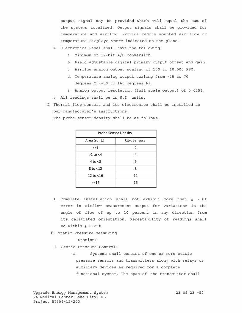
Upgrade Energy Management System 23 09 23 -52 VA Medical Center Lake City, FL Project 573A4-12-200
output signal may be provided which will equal the sum of
the systems totalized. Output signals shall be provided for
temperature and airflow. Provide remote mounted air flow or
temperature displays where indicated on the plans.
4. Electronics Panel shall have the following:
a. Minimum of 12-bit A/D conversion.
b. Field adjustable digital primary output offset and gain.
c. Airflow analog output scaling of 100 to 10,000 FPM.
d. Temperature analog output scaling from -45 to 70
degrees C (-50 to 160 degrees F).
e. Analog output resolution (full scale output) of 0.025%.
5. All readings shall be in S.I. units.
D. Thermal flow sensors and its electronics shall be installed as
per manufacturer’s instructions.
The probe sensor density shall be as follows:
Probe Sensor Density
Area (sq.ft.) Qty. Sensors
<=1 2
>1 to <4 4
4 to <8 6
8 to <12 8
12 to <16 12
>=16 16
1. Complete installation shall not exhibit more than ± 2.0%
error in airflow measurement output for variations in the
angle of flow of up to 10 percent in any direction from
its calibrated orientation. Repeatability of readings shall
be within ± 0.25%.
E. Static Pressure Measuring
Station:
1. Static Pressure Control:
a. Systems shall consist of one or more static
pressure sensors and transmitters along with relays or
auxiliary devices as required for a complete
functional system. The span of the transmitter shall
Upgrade Energy Management System 23 09 23 -53 VA Medical Center Lake City, FL Project 573A4-12-200
not exceed two times the design static pressure at the
point of measurement. The output of the transmitter
shall be true representation of the input pressure
with plus or minus 25 Pascal (0.1 inch) W.G. of the
true input pressure. aa. Static pressure sensors
shall have the same requirements as Airflow Measuring
Devices except that total pressure sensors are
optional, and only multiple static pressure sensors
positioned on an equal area basis connected to a
network of headers are required.
b. For systems with multiple major trunk supply
ducts, furnish a static pressure transmitter for each
trunk duct. The transmitter signal representing the
lowest static pressure shall be selected and this shall
be the input signal to the CU.
c. The CU shall receive the static pressure
transmitter signal and CU shall provide a control output
signal to the supply fan capacity control device. The
control mode shall be proportional plus integral (PI)
(automatic reset) and where required shall also include
derivative mode.
d. In systems with multiple static pressure
transmitters, provide a switch located near the fan
discharge to prevent excessive pressure during abnormal
operating conditions.
F. Constant Volume
Control:
1. Systems shall consist of an air flow measuring station along
with such relays and auxiliary devices as required to
produce a complete functional system. The transmitter shall
receive
its air flow signal and static pressure signal from the flow
measuring station and shall have a span not exceeding three
times the design flow rate. The CU shall receive the
transmitter signal and shall provide an output to the fan
volume control device to maintain a constant flow rate. The
CU shall provide proportional plus integral (PI) (automatic
reset) control mode and where required also inverse
Upgrade Energy Management System 23 09 23 -54 VA Medical Center Lake City, FL Project 573A4-12-200
derivative mode. Overall system accuracy shall be
plus or minus the equivalent of 2 Pascal (0.008 inch)
velocity pressure as measured by the flow station.
G. Airflow Synchronization:
1. Systems shall consist of an air flow measuring station for
each supply and return duct, the CU and such relays, as
required to provide a complete functional system that will
maintain
a constant flow rate difference between supply and return air
to an accuracy of ±10%. In
systems where there is no suitable location for a flow
measuring station that will sense total supply or return
flow, provide multiple flow stations with a differential
pressure transmitter for each station. Signals from the
multiple transmitters shall be added through the CU such that
the resultant signal is a true representation of total flow.
2. The total flow signals from supply and return air shall be
the input signals to the CU. This CU shall track the
return air fan capacity in proportion to the supply air
flow under all conditions.
PART 3 - EXECUTION
3.1 INSTALLATION
A. General:
1. Examine project plans for control devices and
equipment locations; and report any discrepancies,
conflicts, or omissions to Resident Engineer for resolution
before proceeding for installation.
2. Work Coordination: Section 00 72 00, GENERAL CONDITIONS.
3. Install equipment, piping, wiring /conduit parallel to or at
right angles to building lines.
4. Install all equipment and piping in readily accessible
locations. Do not run tubing and conduit concealed under
insulation or inside ducts.
5. Mount control devices, tubing and conduit located on ducts
and apparatus with external insulation on standoff support to
avoid interference with insulation.
6. Provide sufficient slack and flexible connections to
Upgrade Energy Management System 23 09 23 -55 VA Medical Center Lake City, FL Project 573A4-12-200
allow for vibration of piping and equipment.
7. Run tubing and wire connecting devices on or in control
cabinets parallel with the sides of the cabinet neatly racked
to permit tracing.
8. Install equipment level and plum.
B. Piping Installation:
1. All piping associated with smoke control shall be hard drawn
copper.
2. Tubing passing through or buried in concrete shall be
installed in rigid steel conduit of sufficient strength to
prevent damage to tubing.
3. Except for short apparatus connections, non-metallic
tubing in all exposed locations, including mechanical
rooms shall be protected from damage by installing the
tubing in electric conduit or raceways. Provide protective
grommet where tubing exits conduit.
4. Non-metallic tubing exposed to outdoors shall be protected by
a sleeve or larger tubing.
5. In concealed but accessible locations such as above lay-in
ceilings, non-metallic tubing may be run without conduit or
raceway.
6. All tubing which is not run in conduit or raceway, both
metallic and non-metallic, shall be neatly routed and securely
fastened to building structure at not more than 36-IN.
intervals.
7. Welding shall be performed in accordance with Section 23 21
13, HYDRONIC PIPING and Section 23 22 13, STEAM AND
CONDENSATE HEATING PIPING.
8. Label and identify control air piping in accordance with
specification Section 23 05 11, COMMON WORK RESULTS FOR HVAC
AND STEAM GENERATION.
C. Electrical Wiring
Installation:
1. Install conduits and wiring in accordance with Specification
Section 26 05 33, RACEWAY AND BOXES FOR ELECTRICAL SYSTEMS.
2. Install signal and communication cables in accordance with
Specification Section 26 05 21,
LOW-VOLTAGE ELECTRICAL POWER CONDUCTORS AND CABLES (600 VOLTS
Upgrade Energy Management System 23 09 23 -56 VA Medical Center Lake City, FL Project 573A4-12-200
AND BELOW).
3. Install conduit and wiring between operator workstation(s),
digital controllers, electrical panels, indicating devices,
instrumentation, miscellaneous alarm points, thermostats,
and relays as shown on the drawings or as required under
this section. All wiring shall be installed in conduits.
4. Install all electrical work required for a fully functional
system and not shown on electrical plans or required by
electrical specifications. Where low voltage power is
required, provide suitable transformers.
5. Install all system components in accordance with local
Building Code and National Electric Code.
a. Splices: Splices in shielded and coaxial cables shall
consist of terminations and the use of shielded cable
couplers. Terminations shall be in accessible
locations. Cables shall be harnessed with cable ties.
b. Equipment: Fit all equipment contained in cabinets or
panels with service loops, each loop being at least 300
mm (12 inches) long. Equipment for fiber optics system
shall be rack mounted, as applicable, in ventilated,
self-supporting, code gauge steel enclosure. Cables
shall be supported for minimum sag.
c. Cable Runs: Keep cable runs as short as possible. Allow
extra length for connecting to the terminal board. Do
not bend flexible coaxial cables in a radius less than
ten times the cable outside diameter.
d. Use vinyl tape, sleeves, or grommets to protect cables
from vibration at points where they pass around sharp
corners, through walls, panel cabinets, etc.
6. Conceal cables, except in mechanical rooms and areas where
other conduits and piping are exposed.
7. Permanently label or code each point of all field terminal
strips to show the instrument or item served. Color-coded
cable with cable diagrams may be used to accomplish cable
identification.
8. Grounding: ground electrical systems per manufacturer’s
written requirements for proper and safe operation.
D. Install Sensors and
Upgrade Energy Management System 23 09 23 -57 VA Medical Center Lake City, FL Project 573A4-12-200
Controls:
1. Temperature Sensors:
a. Install all sensors and instrumentation according to
manufacturer’s written instructions.
Temperature sensor locations shall be readily accessible,
permitting quick replacement and servicing of them without
special skills and tools.
b. Calibrate sensors to accuracy specified, if not factory
calibrated.
c. Use of sensors shall be limited to its duty, e.g., duct
sensor shall not be used in lieu of room sensor.
d. Install room sensors permanently supported on wall
frame. They shall be mounted at 1.5 meter (5.0 feet)
above the finished floor.
e. Mount sensors rigidly and adequately for the
environment within which the sensor operates.
f. Sensors used in mixing plenum, and hot and cold decks
shall be of the averaging of type. Averaging sensors shall
be installed in a serpentine manner horizontally across
duct. Each bend shall be supported with a capillary clip.
g. All pipe mounted temperature sensors shall be installed in
wells.
h. All wires attached to sensors shall be air sealed in
their conduits or in the wall to stop air transmitted
from other areas affecting sensor reading.
i. Permanently mark terminal blocks for identification.
Protect all circuits to avoid interruption of service due
to short-circuiting or other conditions. Line-protect all
wiring that comes from external sources to the site from
lightning and static electricity.
2. Pressure Sensors:
a. Install duct static pressure sensor tips facing directly
downstream of airflow.
b. Install high-pressure side of the differential switch
between the pump discharge and the check valve.
c. Install snubbers and isolation valves on steam pressure
sensing devices.
3. Actuators:
Upgrade Energy Management System 23 09 23 -58 VA Medical Center Lake City, FL Project 573A4-12-200
a. Mount and link damper and valve actuators according
to manufacturer’s written instructions.
b. Check operation of damper/actuator combination to confirm
that actuator modulates the damper smoothly throughout
stroke to both open and closed position.
c. Check operation of valve/actuator combination to
confirm that actuator modulates valve smoothly in both
open and closed position.
4. Flow Switches:
a. Install flow switch according to manufacturer’s written
instructions.
b. Mount flow switch a minimum of 5 pipe diameters up
stream and 5 pipe diameters downstream or 600 mm (2
feet) whichever is greater, from fittings and other
obstructions.
c. Assure correct flow direction and alignment.
d. Mount in horizontal piping-flow switch on top of the pipe.
E. Transit Time Ultrasonic Flow Meter
Calibration/Verification
1. Flow meter calibration data shall be entered via a personal
computer, Windows® software utility and USB A/B programming
cable. No additional equipment shall be required. Internal
self-diagnostics shall be available to assist in
installation and maintenance of the flow meter.
2. Transit Time Ultrasonic Flow Meter
Transmitter Function Details The following
functions shall be provided:
3. The flow meter shall output, via USB port, flow rate,
positive, negative and net flow accumulations and
diagnostic data.
4. A local display shall display flow rate and total accumulated
flows.
5. The transducers shall transmit and receive acoustic signals to
accurately measure liquid flow.
6. Operational range shall be adjustable by entering new data via
USB port or optional keypad.
7. The flow meter shall be capable of zero to full scale 4-20
mA output simulation to assure proper operation with
Upgrade Energy Management System 23 09 23 -59 VA Medical Center Lake City, FL Project 573A4-12-200
receiving equipment.
8. There shall be no internal potentiometers used in programming or
adjusting the transmitter.
9. The power to operate the transducers shall come solely
from the transmitter over the transducer interconnection
cable.
10. If the flow meter is equipped with dual control signal
outputs it shall be programmable for rate of flow,
batch/total accumulation, loss of signal strength or system
error.
11. The flow meter shall have a FLASH memory and shall not
require a battery to ensure protection of stored data.
12. Flow meter shall provide automatic Reynolds Number, pipe
roughness and speed of sound compensation.
14 Installation
a. Follow manufacturer’s recommendation upstream and
downstream straight pipe diameters and transducer
orientation to achieve optimum performance.
b. Enter pipe and liquid configuration information into the
flow meter. The flow meter will calculate transducer
separation from the data entered.
c. Mount the transducers onto the pipe at the calculated
separation distance – if required.
d. Additional cable for the transducers shall be RG59 coaxial.
e. All connections shall be 75 Ohm.
F. Installation of Network:
1. Ethernet:
a. The network shall employ Ethernet LAN architecture, as
defined by IEEE 802.3. The Network Interface shall be
fully Internet Protocol (IP) compliant allowing
connection to currently installed IEEE 802.3, Compliant
Ethernet Networks.
b. The network shall directly support connectivity to a
variety of cabling types. As a minimum provide the
following connectivity: 10 Base 2 (ThinNet RG-58 A/U
Coaxial
cabling with BNC connectors), 10 Base T (Twisted-Pair RJ-
45 terminated UTP cabling).
Upgrade Energy Management System 23 09 23 -60 VA Medical Center Lake City, FL Project 573A4-12-200
2. Third Party Interfaces: Contractor shall integrate real-
time data from building systems by other trades and
databases originating from other manufacturers as
specified and required to make the system work as one
system.
G. Installation of Digital Controllers and Programming:
a. Provide a new, separate digital control panel for each
major piece of equipment if the existing panel is not
sufficient in size or capability or if it is not in
proper mechanical and electrical condition, to support
such equipment as air handling units, chillers, pumping
units etc. Points used for control loop reset such as
outdoor air, outdoor humidity, or space temperature could
be located on any of the remote control units.
b. Provide sufficient internal memory for the specified
control sequences and trend logging. There shall be a
minimum of 25 percent of available memory free for
future
use.
c. System point names shall be modular in design,
permitting easy operator interface without the use of a
written point index.
d. Provide software programming for the applications
intended for the systems specified, and adhere to the
strategy algorithms provided.
e. Provide graphics for each piece of equipment and floor
plan in the building. This includes each chiller, cooling
tower, air handling unit, fan, terminal unit, boiler,
pumping unit etc. These graphics shall show all points
dynamically as specified in the point list.
3.2 SYSTEM VALIDATION AND DEMONSTRATION
A. As part of final system acceptance, a System Demonstration is
required (see below). Prior to start of this Demonstration,
the contractor is to perform a complete Validation of all
aspects of the Controls and Instrumentation System.
B. Validation
1. Prepare and submit for approval a Validation Test Plan
including Test Procedures for the performance verification
Upgrade Energy Management System 23 09 23 -61 VA Medical Center Lake City, FL Project 573A4-12-200
tests. Test Plan shall address all specified functions of the
Engineering Control Center and all specified sequences of
operation. Explain in detail actions and expected results
used to demonstrate compliance with the requirements of this
specification. Explain the method for simulating the
necessary conditions of operation used to demonstrate
performance of the system. Test Plan shall include a Test
Check List to be used by the Installer’s agent to check
and initial that each test has been successfully
completed. Deliver Test Plan documentation for the
performance verification tests to the owner’s representative
30 days prior to start of performance verification tests.
Provide draft copy of operation and maintenance manual with
performance verification test.
2. After approval of the Validation Test Plan, Installer shall
carry out all tests and procedures therein. Installer shall
completely check out, calibrate, and test all connected
hardware and software to insure that system performs in
accordance with approved specifications and sequences of
operation submitted. Installer shall complete and submit Test
Check List.
C. DEMONSTRATION
1. System operation and calibration to be demonstrated by the
Installer in the presence of the Architect or Owner's
representative on random samples of equipment as dictated by
the Owner’s representative. Should random sampling indicate
improper commissioning, the owner reserves the right to
subsequently witness complete calibration of the system at
no addition cost to the owner.
2. Demonstrate to authorities that all required safeties and
life safety functions are fully functional and complete.
3. Make accessible, personnel to provide necessary adjustments
and corrections to systems as directed by balancing agency.
4. The following witnessed demonstrations of field control
equipment shall be included:
a. Observe HVAC systems in shut down condition. Check dampers
and valves for normal position.
b. Test application software for its ability to communicate
Upgrade Energy Management System 23 09 23 -62 VA Medical Center Lake City, FL Project 573A4-12-200
with digital controllers, operator workstation, and
uploading and downloading of control programs.
c. Demonstrate the software ability to edit the control
program off-line.
d. Demonstrate reporting of alarm conditions for each alarm
and ensure that these alarms are received at the assigned
location, including operator workstations.
e. Demonstrate ability of software program to function for the
intended applications-trend reports, change in status etc.
f. Demonstrate via graphed trends to show the sequence of
operation is executed in correct manner, and that the HVAC
systems operate properly through the complete sequence of
operation, e.g., seasonal change, occupied/unoccupied mode,
and warm-up condition.
g. Demonstrate hardware interlocks and safeties functions, and
that the control systems perform the correct sequence of
operation after power loss and resumption of power loss.
h. Prepare and deliver to the VA graphed trends of all control
loops to demonstrate that each control loop is stable and
the set points are maintained.
i. Demonstrate that each control loop responds to set point
adjustment and stabilizes within one (1) minute. Control
loop trend data shall be instantaneous and the time between
data points shall not be greater than one (1) minute.
5. Witnessed validation demonstration of Operator’s Terminal
functions shall consist of:
a. Running each specified report.
b. Display and demonstrate each data entry to show site
specific customizing capability.
Demonstrate parameter changes.
c. Step through penetration tree, display all graphics,
demonstrate dynamic update, and direct access to graphics.
d. Execute digital and analog commands in graphic mode.
e. Demonstrate DDC loop precision and stability via trend logs
of inputs and outputs (6 loops minimum).
f. Demonstrate EMS performance via trend logs and command
trace.
Upgrade Energy Management System 23 09 23 -63 VA Medical Center Lake City, FL Project 573A4-12-200
g. Demonstrate scan, update, and alarm responsiveness.
h. Demonstrate spreadsheet/curve plot software, and its
integration with database.
i. Demonstrate on-line user guide, and help function and mail
facility.
j. Demonstrate digital system configuration graphics
with interactive upline and downline load, and
demonstrate specified diagnostics.
k. Demonstrate multitasking by showing dynamic curve plot,
and graphic construction operating simultaneously via
split screen.
l. Demonstrate class programming with point options of beep
duration, beep rate, alarm archiving, and color banding.
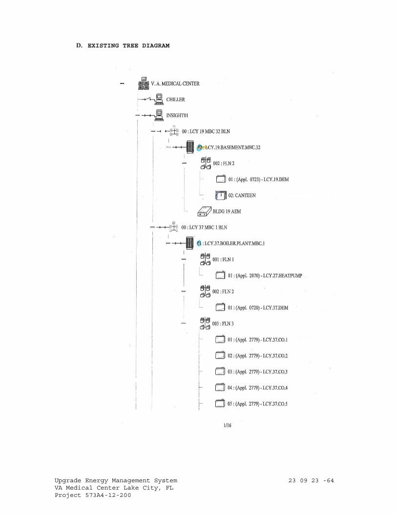
Upgrade Energy Management System 23 09 23 -64 VA Medical Center Lake City, FL Project 573A4-12-200
D. EXISTING TREE DIAGRAM
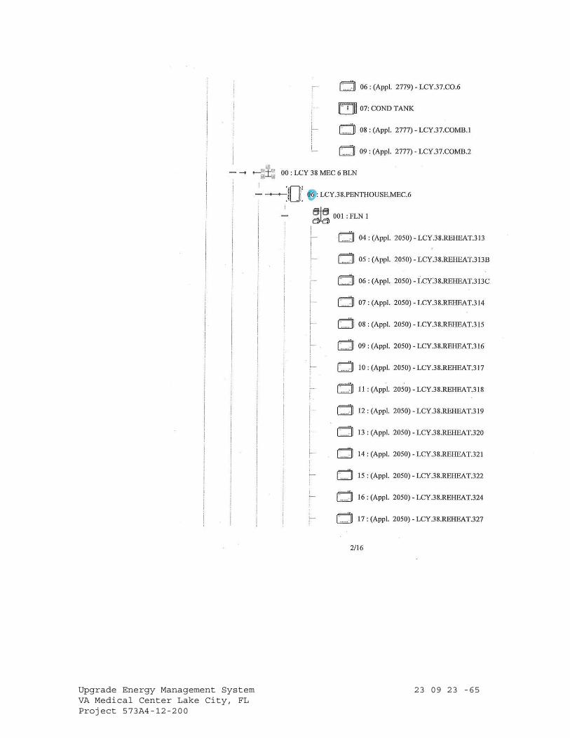
Upgrade Energy Management System 23 09 23 -65 VA Medical Center Lake City, FL Project 573A4-12-200
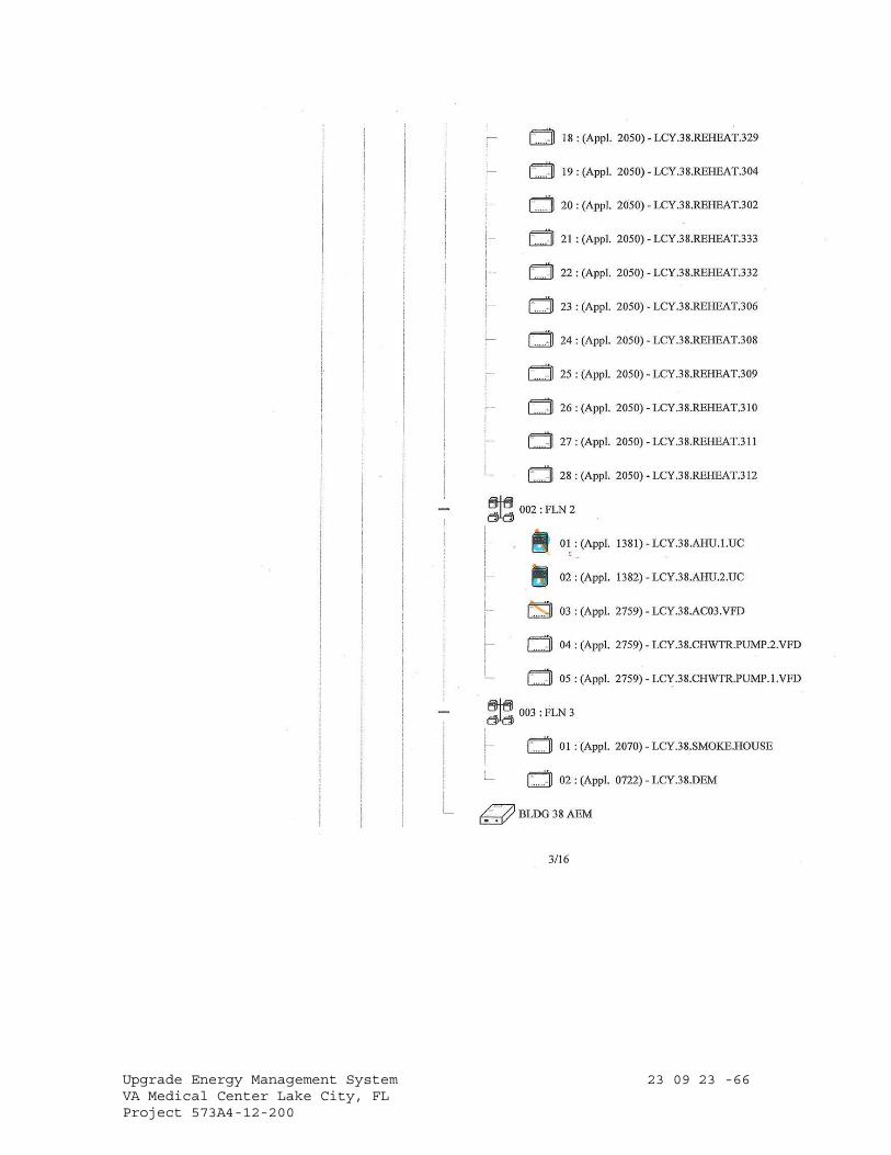
Upgrade Energy Management System 23 09 23 -66 VA Medical Center Lake City, FL Project 573A4-12-200
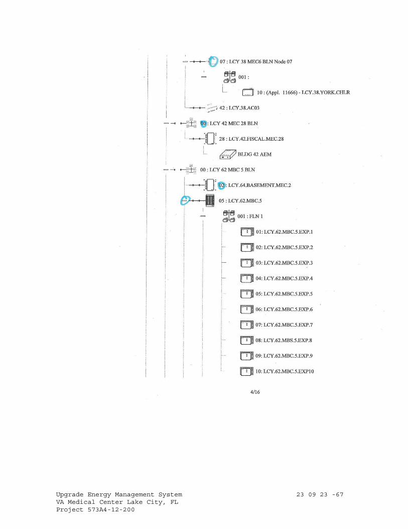
Upgrade Energy Management System 23 09 23 -67 VA Medical Center Lake City, FL Project 573A4-12-200
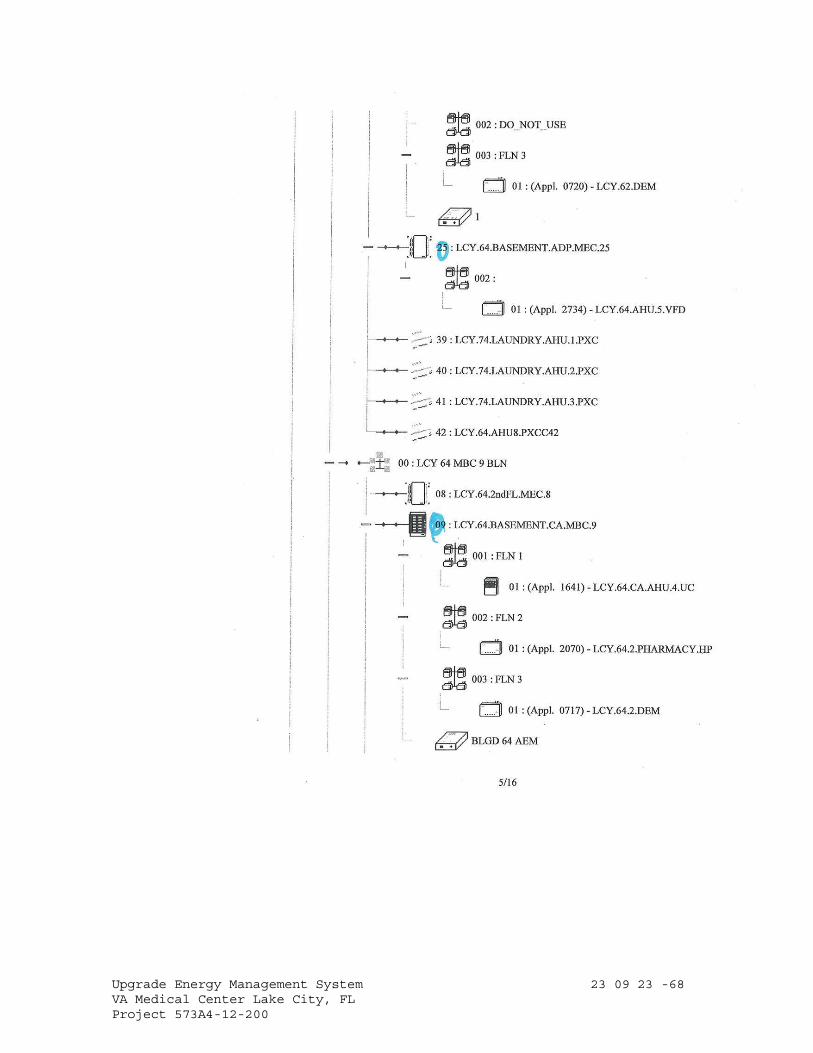
Upgrade Energy Management System 23 09 23 -68 VA Medical Center Lake City, FL Project 573A4-12-200
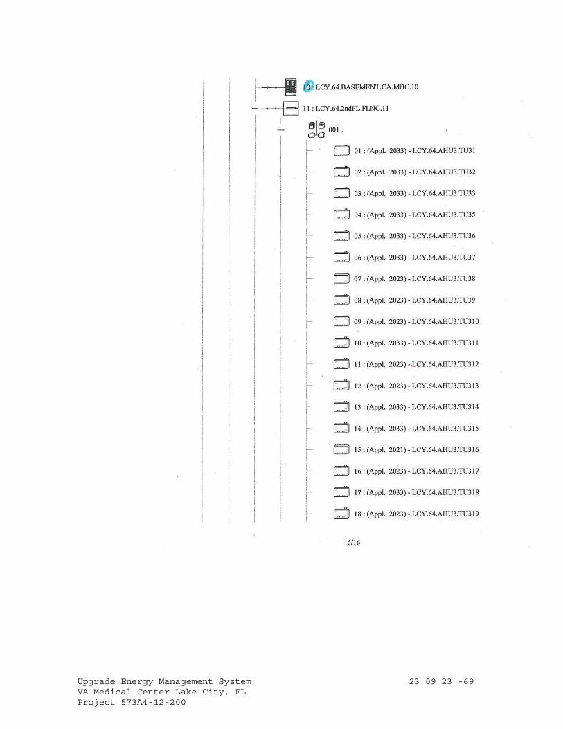
Upgrade Energy Management System 23 09 23 -69 VA Medical Center Lake City, FL Project 573A4-12-200
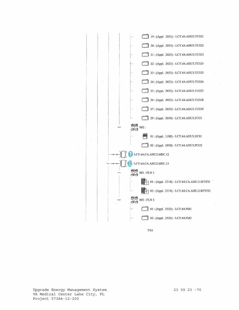
Upgrade Energy Management System 23 09 23 -70 VA Medical Center Lake City, FL Project 573A4-12-200
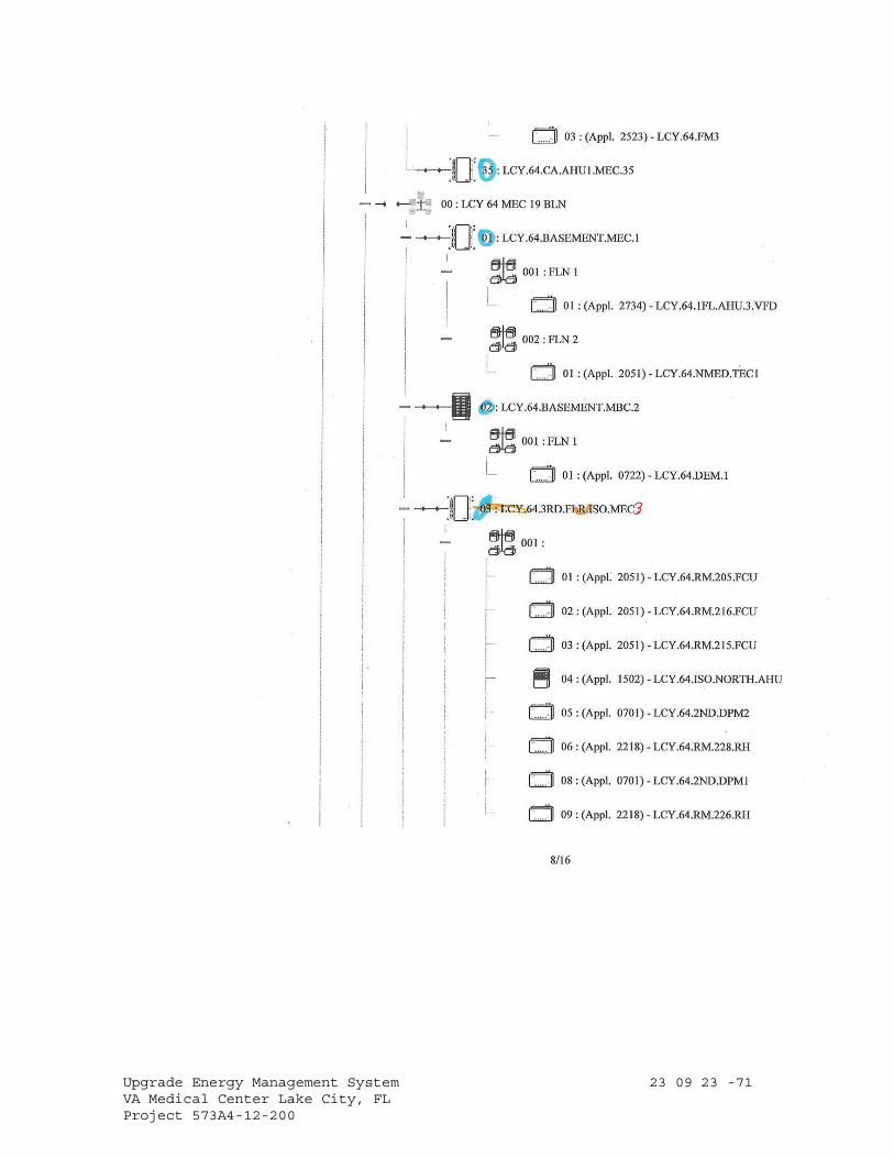
Upgrade Energy Management System 23 09 23 -71 VA Medical Center Lake City, FL Project 573A4-12-200
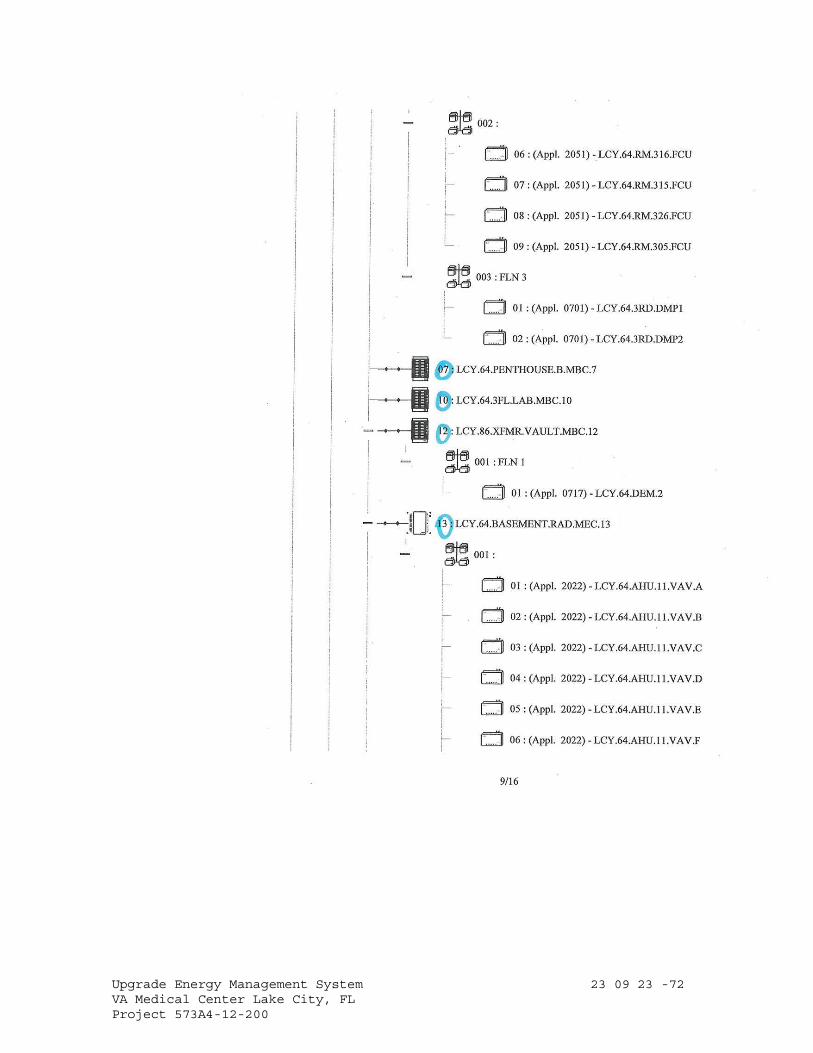
Upgrade Energy Management System 23 09 23 -72 VA Medical Center Lake City, FL Project 573A4-12-200

Upgrade Energy Management System 23 09 23 -73 VA Medical Center Lake City, FL Project 573A4-12-200
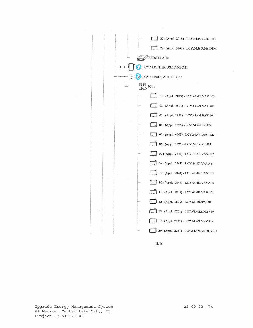
Upgrade Energy Management System 23 09 23 -74 VA Medical Center Lake City, FL Project 573A4-12-200
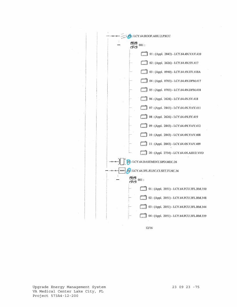
Upgrade Energy Management System 23 09 23 -75 VA Medical Center Lake City, FL Project 573A4-12-200
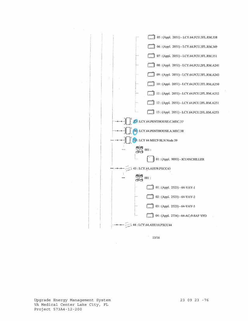
Upgrade Energy Management System 23 09 23 -76 VA Medical Center Lake City, FL Project 573A4-12-200

Upgrade Energy Management System 23 09 23 -77 VA Medical Center Lake City, FL Project 573A4-12-200
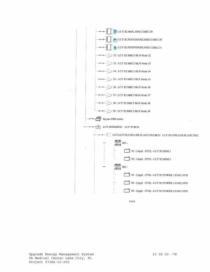
Upgrade Energy Management System 23 09 23 -78 VA Medical Center Lake City, FL Project 573A4-12-200
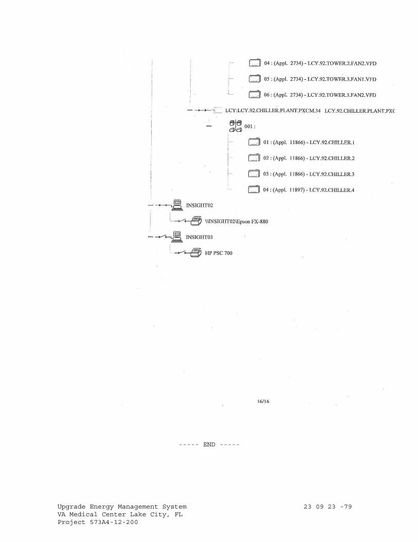
Upgrade Energy Management System 23 09 23 -79 VA Medical Center Lake City, FL Project 573A4-12-200
----- END -----
Upgrade Energy Management System 26 05 11 -1 VA Medical Center Lake City, FL. Project 573A4-12-200
SECTION 26 05 11 REQUIREMENTS FOR ELECTRICAL INSTALLATIONS
PART 1 - GENERAL
1.1 DESCRIPTION
A. This section applies to all sections of Division 26.
B. Furnish and install electrical wiring, systems, equipment and
accessories in accordance with the specifications and drawings.
Capacities and ratings of motors, transformers, cable, switchboards,
switchgear, panelboards, motor control centers, generators, automatic
transfer switches, and other items and arrangements for the specified
items are shown on drawings.
C. Electrical service entrance equipment and arrangements for temporary and
permanent connections to the utility’s system shall conform to the
utility's requirements. Coordinate fuses, circuit breakers and relays
with the utility’s system, and obtain utility approval for sizes and
settings of these devices.
D. Wiring ampacities specified or shown on the drawings are based on copper
conductors, with the conduit and raceways accordingly sized. Aluminum
conductors are prohibited.
1.2 MINIMUM REQUIREMENTS
A. References to the International Building Code (IBC), National Electrical
Code (NEC), Underwriters Laboratories, Inc. (UL) and National Fire
Protection Association (NFPA) are minimum installation requirement
standards.
B. Drawings and other specification sections shall govern in those
instances where requirements are greater than those specified in the
above standards and the drawings. Where drawings and specifications
have greater requirements than the code, the drawings and specifications
shall govern.
1.3 TEST STANDARDS
A. All materials and equipment shall be listed, labeled or certified by a
nationally recognized testing laboratory to meet Underwriters
Laboratories, Inc., standards where test standards have been
established. Equipment and materials which are not covered by UL
Standards will be accepted provided equipment and material is listed,
labeled, certified or otherwise determined to meet safety requirements
of a nationally recognized testing laboratory. Equipment of a class
which no nationally recognized testing laboratory accepts, certifies,
Upgrade Energy Management System 26 05 11 -2 VA Medical Center Lake City, FL. Project 573A4-12-200
lists, labels, or determines to be safe, will be considered if inspected
or tested in accordance with national industrial standards, such as
NEMA, or ANSI. Evidence of compliance shall include certified test
reports and definitive shop drawings.
B. Definitions:
1. Listed; Equipment, materials, or services included in a list
published by an organization that is acceptable to the authority
having jurisdiction and concerned with evaluation of products or
services, that maintains periodic inspection of production or listed
equipment or materials or periodic evaluation of services, and whose
listing states that the equipment, material, or services either meets
appropriate designated standards or has been tested and found
suitable for a specified purpose.
2. Labeled; Equipment or materials to which has been attached a label,
symbol, or other identifying mark of an organization that is
acceptable to the authority having jurisdiction and concerned with
product evaluation, that maintains periodic inspection of production
of labeled equipment or materials, and by whose labeling the
manufacturer indicates compliance with appropriate standards or
performance in a specified manner.
3. Certified; equipment or product which:
a. Has been tested and found by a nationally recognized testing
laboratory to meet nationally recognized standards or to be safe
for use in a specified manner.
b. Production of equipment or product is periodically inspected by a
nationally recognized testing laboratory.
c. Bears a label, tag, or other record of certification.
4. Nationally recognized testing laboratory; laboratory which is
approved, in accordance with OSHA regulations, by the Secretary of
Labor.
1.4 QUALIFICATIONS (PRODUCTS AND SERVICES)
A. Manufacturers Qualifications: The manufacturer shall regularly and
presently produce, as one of the manufacturer's principal products, the
equipment and material specified for this project, and shall have
manufactured the item for at least three years.
B. Product Qualification:
1. Manufacturer's product shall have been in satisfactory operation, on
three installations of similar size and type as this project, for
approximately three years.
Upgrade Energy Management System 26 05 11 -3 VA Medical Center Lake City, FL. Project 573A4-12-200
2. The Government reserves the right to require the Contractor to submit
a list of installations where the products have been in operation
before approval.
C. Service Qualifications: There shall be a permanent service organization
maintained or trained by the manufacturer which will render satisfactory
service to this installation within four hours of receipt of
notification that service is needed. Submit name and address of service
organizations.
1.5 APPLICABLE PUBLICATIONS
A. Applicable publications listed in all Sections of Division are the
latest issue, unless otherwise noted.
B. Products specified in all sections of Division 26 shall comply with the
applicable publications listed in each section.
1.6 MANUFACTURED PRODUCTS
A. Materials and equipment furnished shall be of current production by
manufacturers regularly engaged in the manufacture of such items, for
which replacement parts shall be available.
B. When more than one unit of the same class or type of equipment is
required, such units shall be the product of a single manufacturer.
C. Equipment Assemblies and Components:
1. Components of an assembled unit need not be products of the same
manufacturer.
2. Manufacturers of equipment assemblies, which include components made
by others, shall assume complete responsibility for the final
assembled unit.
3. Components shall be compatible with each other and with the total
assembly for the intended service.
4. Constituent parts which are similar shall be the product of a single
manufacturer.
D. Factory wiring shall be identified on the equipment being furnished and
on all wiring diagrams.
E. When Factory Testing Is Specified:
1. The Government shall have the option of witnessing factory tests. The
contractor shall notify the VA through the COR a minimum of 15
working days prior to the manufacturers making the factory tests.
2. Four copies of certified test reports containing all test data shall
be furnished to the COR prior to final inspection and not more than
90 days after completion of the tests.
Upgrade Energy Management System 26 05 11 -4 VA Medical Center Lake City, FL. Project 573A4-12-200
3. When equipment fails to meet factory test and re-inspection is
required, the contractor shall be liable for all additional expenses,
including expenses of the Government.
1.7 EQUIPMENT REQUIREMENTS
Where variations from the contract requirements are requested in
accordance with Section 00 72 00, GENERAL CONDITIONS and Section 01 33
23, SHOP DRAWINGS, PRODUCT DATA, AND SAMPLES, the connecting work and
related components shall include, but not be limited to additions or
changes to branch circuits, circuit protective devices, conduits, wire,
feeders, controls, panels and installation methods.
1.8 EQUIPMENT PROTECTION
A. Equipment and materials shall be protected during shipment and storage
against physical damage, vermin, dirt, corrosive substances, fumes,
moisture, cold and rain.
1. Store equipment indoors in clean dry space with uniform temperature
to prevent condensation. Equipment shall include but not be limited
to switchgear, switchboards, panelboards, transformers, motor control
centers, motor controllers, uninterruptible power systems,
enclosures, controllers, circuit protective devices, cables, wire,
light fixtures, electronic equipment, and accessories.
2. During installation, equipment shall be protected against entry of
foreign matter; and be vacuum-cleaned both inside and outside before
testing and operating. Compressed air shall not be used to clean
equipment. Remove loose packing and flammable materials from inside
equipment.
3. Damaged equipment shall be, as determined by the COR, placed in first
class operating condition or be returned to the source of supply for
repair or replacement.
4. Painted surfaces shall be protected with factory installed removable
heavy kraft paper, sheet vinyl or equal.
5. Damaged paint on equipment and materials shall be refinished with the
same quality of paint and workmanship as used by the manufacturer so
repaired areas are not obvious.
1.9 WORK PERFORMANCE
A. All electrical work must comply with the requirements of NFPA 70 (NEC),
NFPA 70B, NFPA 70E, OSHA Part 1910 subpart J, OSHA Part 1910 subpart S
and OSHA Part 1910 subpart K in addition to other references required by
contract.
Upgrade Energy Management System 26 05 11 -5 VA Medical Center Lake City, FL. Project 573A4-12-200
B. Job site safety and worker safety is the responsibility of the
contractor.
C. Electrical work shall be accomplished with all affected circuits or
equipment de-energized. When an electrical outage cannot be accomplished
in this manner for the required work, the following requirements are
mandatory:
1. Electricians must use full protective equipment (i.e., certified and
tested insulating material to cover exposed energized electrical
components, certified and tested insulated tools, etc.) while working
on energized systems in accordance with NFPA 70E.
2. Electricians must wear personal protective equipment while working on
energized systems in accordance with NFPA 70E.
3. Before initiating any work, a job specific work plan must be
developed by the contractor with a peer review conducted and
documented by the COR and Medical Center staff. The work plan must
include procedures to be used on and near the live electrical
equipment, barriers to be installed, safety equipment to be used and
exit pathways.
4. Work on energized circuits or equipment cannot begin until prior
written approval is obtained from the COR.
D. For work on existing stations, arrange, phase and perform work to assure
electrical service for other buildings at all times. Refer to Article
OPERATIONS AND STORAGE AREAS under Section 01 00 00, GENERAL
REQUIREMENTS.
E. New work shall be installed and connected to existing work neatly,
safely and professionally. Disturbed or damaged work shall be replaced
or repaired to its prior conditions, as required by Section 01 00 00,
GENERAL REQUIREMENTS.
F. Coordinate location of equipment and conduit with other trades to
minimize interferences.
1.10 EQUIPMENT INSTALLATION AND REQUIREMENTS
A. Equipment location shall be as close as practical to locations shown on
the drawings.
B. Working spaces shall not be less than specified in the NEC for all
voltages specified.
C. Inaccessible Equipment:
1. Where the Government determines that the Contractor has installed
equipment not conveniently accessible for operation and maintenance,
the equipment shall be removed and reinstalled as directed at no
additional cost to the Government.
Upgrade Energy Management System 26 05 11 -6 VA Medical Center Lake City, FL. Project 573A4-12-200
2. "Conveniently accessible" is defined as being capable of being
reached quickly for operation, maintenance, or inspections without
the use of ladders, or without climbing or crawling under or over
obstacles such as, but not limited to, motors, pumps, belt guards,
transformers, piping, ductwork, conduit and raceways.
1.11 EQUIPMENT IDENTIFICATION
A. In addition to the requirements of the NEC, install an identification
sign which clearly indicates information required for use and
maintenance of items such as switchboards and switchgear, panelboards,
cabinets, motor controllers (starters), fused and unfused safety
switches, automatic transfer switches, separately enclosed circuit
breakers, individual breakers and controllers in switchboards,
switchgear and motor control assemblies, control devices and other
significant equipment.
B. Nameplates for Normal Power System equipment shall be laminated black
phenolic resin with a white core with engraved lettering. Nameplates
for Essential Electrical System (EES) equipment, as defined in the NEC,
shall be laminated red phenolic resin with a white core with engraved
lettering. Lettering shall be a minimum of 1/2 inch [12mm] high.
Nameplates shall indicate equipment designation, rated bus amperage,
voltage, number of phases, number of wires, and type of EES power branch
as applicable. Secure nameplates with screws.
C. Install adhesive arc flash warning labels on all equipment as required
by NFPA 70E. Label shall indicate the arc hazard boundary (inches),
working distance (inches), arc flash incident energy at the working
distance (calories/cm2), required PPE category and description including
the glove rating, voltage rating of the equipment, limited approach
distance (inches), restricted approach distance (inches), prohibited
approach distance (inches), equipment/bus name, date prepared, and
manufacturer name and address.
1.12 SUBMITTALS
A. Submit in accordance with Section 01 33 23, SHOP DRAWINGS, PRODUCT DATA,
AND SAMPLES.
B. The Government's approval shall be obtained for all equipment and
material before delivery to the job site. Delivery, storage or
installation of equipment or material which has not had prior approval
will not be permitted at the job site.
C. All submittals shall include adequate descriptive literature, catalog
cuts, shop drawings and other data necessary for the Government to
Upgrade Energy Management System 26 05 11 -7 VA Medical Center Lake City, FL. Project 573A4-12-200
ascertain that the proposed equipment and materials comply with
specification requirements. Catalog cuts submitted for approval shall
be legible and clearly identify equipment being submitted.
D. Submittals for individual systems and equipment assemblies which consist
of more than one item or component shall be made for the system or
assembly as a whole. Partial submittals will not be considered for
approval.
1. Mark the submittals, "SUBMITTED UNDER SECTION__________________".
2. Submittals shall be marked to show specification reference including
the section and paragraph numbers.
3. Submit each section separately.
E. The submittals shall include the following:
1. Information that confirms compliance with contract requirements.
Include the manufacturer's name, model or catalog numbers, catalog
information, technical data sheets, shop drawings, pictures,
nameplate data and test reports as required.
2. Submittals are required for all equipment anchors and supports.
Submittals shall include weights, dimensions, center of gravity,
standard connections, manufacturer's recommendations and behavior
problems (e.g., vibration, thermal expansion,) associated with
equipment or piping so that the proposed installation can be properly
reviewed. Include sufficient fabrication information so that
appropriate mounting and securing provisions may be designed and/or
attached to the equipment.
3. Elementary and interconnection wiring diagrams for communication and
signal systems, control systems and equipment assemblies. All
terminal points and wiring shall be identified on wiring diagrams.
4. Parts list which shall include those replacement parts recommended by
the equipment manufacturer.
F. Manuals: Submit in accordance with Section 01 00 00, GENERAL
REQUIREMENTS.
1. Maintenance and Operation Manuals: Submit as required for systems and
equipment specified in the technical sections. Furnish four copies,
bound in hardback binders, (manufacturer's standard binders) or an
approved equivalent. Furnish one complete manual as specified in the
technical section but in no case later than prior to performance of
systems or equipment test, and furnish the remaining manuals prior to
contract completion.
2. Inscribe the following identification on the cover: the words
"MAINTENANCE AND OPERATION MANUAL," the name and location of the
system, equipment, building, name of Contractor, and contract number.

Upgrade Energy Management System 26 05 11 -8 VA Medical Center Lake City, FL. Project 573A4-12-200
Include in the manual the names, addresses, and telephone numbers of
each subcontractor installing the system or equipment and the local
representatives for the system or equipment.
3. Provide a "Table of Contents" and assemble the manual to conform to
the table of contents, with tab sheets placed before instructions
covering the subject. The instructions shall be legible and easily
read, with large sheets of drawings folded in.
4. The manuals shall include:
a. Internal and interconnecting wiring and control diagrams with data
to explain detailed operation and control of the equipment.
b. A control sequence describing start-up, operation, and shutdown.
c. Description of the function of each principal item of equipment.
d. Installation instructions.
e. Safety precautions for operation and maintenance.
f. Diagrams and illustrations.
g. Periodic maintenance and testing procedures and frequencies,
including replacement parts numbers and replacement frequencies.
h. Performance data.
i. Pictorial "exploded" parts list with part numbers. Emphasis shall
be placed on the use of special tools and instruments. The list
shall indicate sources of supply, recommended spare parts, and
name of servicing organization.
j. List of factory approved or qualified permanent servicing
organizations for equipment repair and periodic testing and
maintenance, including addresses and factory certification
qualifications.
G. Approvals will be based on complete submission of manuals together with
shop drawings.
H. After approval and prior to installation, furnish the COR with one
sample of each of the following:
1. A 300 mm (12 inch) length of each type and size of wire and cable
along with the tag from the coils of reels from which the samples
were taken.
2. Each type of conduit coupling, bushing and termination fitting.
3. Conduit hangers, clamps and supports.
4. Duct sealing compound.
5. Each type of receptacle, toggle switch, occupancy sensor, outlet box,
manual motor starter, device wall plate, engraved nameplate, wire and
cable splicing and terminating material, and branch circuit single
pole molded case circuit breaker.
Upgrade Energy Management System 26 05 11 -9 VA Medical Center Lake City, FL. Project 573A4-12-200
1.13 SINGULAR NUMBER
Where any device or part of equipment is referred to in these
specifications in the singular number (e.g., "the switch"), this
reference shall be deemed to apply to as many such devices as are
required to complete the installation as shown on the drawings.
1.14 N/A
1.15 ACCEPTANCE CHECKS AND TESTS
A. The Contractor shall furnish the instruments, materials, and labor for
tests.
B. Where systems are comprised of components specified in more than one
section of Division 26, the Contractor shall coordinate the
installation, testing, and adjustment of all components between various
manufacturer’s representatives and technicians so that a complete,
functional, and operational system is delivered to the Government.
C. When test results indicate any defects, the Contractor shall repair or
replace the defective materials or equipment, and repeat the tests.
Repair, replacement, and retesting shall be accomplished at no
additional cost to the Government.
1.16 WARRANTY
A. All work performed and all equipment and material furnished under this
Division shall be free from defects and shall remain so for a period of
one year from the date of acceptance of the entire installation by the
Contracting Officer for the Government.
1.17 INSTRUCTION
A. Instruction to designated Government personnel shall be provided for the
particular equipment or system as required in each associated technical
specification section.
B. Furnish the services of competent instructors to give full instruction
in the adjustment, operation, and maintenance of the specified equipment
and system, including pertinent safety requirements. Instructors shall
be thoroughly familiar with all aspects of the installation, and shall
be trained in operating theory as well as practical operation and
maintenance procedures.
C. A training schedule shall be developed and submitted by the Contractor
and approved by the COTR at least 30 days prior to the planned training.
- - - E N D - - -

Upgrade Energy Management System 26 05 19 -1 VA Medical Center Lake City, FL. Project 573A4-12-200
SECTION 26 05 19 LOW-VOLTAGE ELECTRICAL POWER CONDUCTORS AND CABLES (600 VOLTS AND BELOW)
PART 1 - GENERAL
1.1 DESCRIPTION
This section specifies the furnishing, installation, and connection of
the low voltage power and lighting wiring.
1.2 RELATED WORK
A. Section 07 84 00, FIRESTOPPING: Sealing around penetrations to maintain
the integrity of fire-rated construction.
B. Section 26 05 11, REQUIREMENTS FOR ELECTRICAL INSTALLATIONS: General
electrical requirements that are common to more than one section.
C. Section 26 05 26, GROUNDING AND BONDING FOR ELECTRICAL SYSTEMS:
Requirements for personnel safety and to provide a low impedance path
for possible ground fault currents.
D. Section 26 05 33, RACEWAY AND BOXES FOR ELECTRICAL SYSTEMS: Conduits for
cables and wiring.
1.3 QUALITY ASSURANCE
Refer to Paragraph, QUALIFICATIONS, in Section 26 05 11, REQUIREMENTS
FOR ELECTRICAL INSTALLATIONS.
1.4 FACTORY TESTS
Low voltage cables shall be thoroughly tested at the factory per NEMA
WC-70 to ensure that there are no electrical defects. Factory tests
shall be certified.
1.5 SUBMITTALS
In accordance with Section 26 05 11, REQUIREMENTS FOR ELECTRICAL
INSTALLATIONS, submit the following:
1. Manufacturer's Literature and Data: Showing each cable type and
rating.
2. Certifications: Two weeks prior to the final inspection, submit four
copies of the following certifications to the COR:
a. Certification by the manufacturer that the materials conform to
the requirements of the drawings and specifications.
b. Certification by the contractor that the materials have been
properly installed, connected, and tested.
Upgrade Energy Management System 26 05 19 -2 VA Medical Center Lake City, FL. Project 573A4-12-200
1.6 APPLICABLE PUBLICATIONS
A. Publications listed below (including amendments, addenda, revisions,
supplements and errata) form a part of this specification to the extent
referenced. Publications are reference in the text by designation only.
B. American Society of Testing Material (ASTM):
D2301-04................Standard Specification for Vinyl Chloride
Plastic Pressure-Sensitive Electrical Insulating
Tape
C. National Fire Protection Association (NFPA):
70-08...................National Electrical Code (NEC)
D. National Electrical Manufacturers Association (NEMA):
WC 70-09................Power Cables Rated 2000 Volts or Less for the
Distribution of Electrical Energy
E. Underwriters Laboratories, Inc. (UL):
44-05...................Thermoset-Insulated Wires and Cables
83-08...................Thermoplastic-Insulated Wires and Cables
467-071.................Electrical Grounding and Bonding Equipment
486A-486B-03............Wire Connectors
486C-04.................Splicing Wire Connectors
486D-05.................Sealed Wire Connector Systems
486E-94.................Equipment Wiring Terminals for Use with Aluminum
and/or Copper Conductors
493-07..................Thermoplastic-Insulated Underground Feeder and
Branch Circuit Cable
514B-04.................Conduit, Tubing, and Cable Fittings
1479-03.................Fire Tests of Through-Penetration Fire Stops
PART 2 - PRODUCTS
2.1 CONDUCTORS AND CABLES
A. Conductors and cables shall be in accordance with NEMA WC-70 and as
specified herein.
B. Single Conductor:
1. Shall be annealed copper.
2. Shall be stranded for sizes No. 8 AWG and larger, solid for sizes No.
10 AWG and smaller.
3. Shall be minimum size No. 12 AWG, except where smaller sizes are
allowed herein.
C. Insulation:
1. XHHW-2 or THHN-THWN shall be in accordance with NEMA WC-70, UL 44,
and UL 83.
D. Color Code:
Upgrade Energy Management System 26 05 19 -3 VA Medical Center Lake City, FL. Project 573A4-12-200
1. Secondary service feeder and branch circuit conductors shall be
color-coded as follows:
208/120 volt Phase 480/277 volt
Black A Brown
Red B Orange
Blue C Yellow
White Neutral Gray *
* or white with colored (other than green) tracer.
a. Lighting circuit “switch legs” and 3-way switch “traveling wires”
shall have color coding that is unique and distinct (e.g., pink
and purple) from the color coding indicated above. The unique
color codes shall be solid and in accordance with the NEC.
Coordinate color coding in the field with the COR.
2. Use solid color insulation or solid color coating for No. 12 AWG and
No. 10 AWG branch circuit phase, neutral, and ground conductors.
3. Conductors No. 8 AWG and larger shall be color-coded using one of the
following methods:
a. Solid color insulation or solid color coating.
b. Stripes, bands, or hash marks of color specified above.
c. Color as specified using 0.75 in [19 mm] wide tape. Apply tape in
half-overlapping turns for a minimum of 3 in [75 mm] for terminal
points, and in junction boxes, pull-boxes, troughs, and manholes.
Apply the last two laps of tape with no tension to prevent
possible unwinding. Where cable markings are covered by tape,
apply tags to cable, stating size and insulation type.
4. For modifications and additions to existing wiring systems, color
coding shall conform to the existing wiring system.
2.2 SPLICES AND JOINTS
A. In accordance with UL 486A, C, D, E, and NEC.
B. Aboveground Circuits (No. 10 AWG and smaller):
1. Connectors: Solderless, screw-on, reusable pressure cable type, rated
600 V, 220˚ F [105˚ C], with integral insulation, approved for copper
and aluminum conductors.
2. The integral insulator shall have a skirt to completely cover the
stripped wires.
3. The number, size, and combination of conductors, as listed on the
manufacturer's packaging, shall be strictly followed.
Upgrade Energy Management System 26 05 19 -4 VA Medical Center Lake City, FL. Project 573A4-12-200
C. Aboveground Circuits (No. 8 AWG and larger):
1. Connectors shall be indent, hex screw, or bolt clamp-type of high
conductivity and corrosion-resistant material, listed for use with
copper and aluminum conductors.
2. Field-installed compression connectors for cable sizes 250 kcmil and
larger shall have not fewer than two clamping elements or compression
indents per wire.
3. Insulate splices and joints with materials approved for the
particular use, location, voltage, and temperature. Splice and joint
insulation level shall be not less than the insulation level of the
conductors being joined.
4. Plastic electrical insulating tape: Per ASTM D2304, flame-retardant,
cold and weather resistant.
D. Underground Branch Circuits and Feeders:
1. Submersible connectors in accordance with UL 486D, rated 600 V, 190˚
F [90˚ C], with integral insulation.
2.3 CONTROL WIRING
A. Unless otherwise specified elsewhere in these specifications, control
wiring shall be as specified for power and lighting wiring, except that
the minimum size shall be not less than No. 14 AWG.
B. Control wiring shall be large enough such that the voltage drop under
in-rush conditions does not adversely affect operation of the controls.
2.4 WIRE LUBRICATING COMPOUND
A. Lubricating compound shall be suitable for the wire insulation and
conduit, and shall not harden or become adhesive.
PART 3 - EXECUTION
3.1 GENERAL
A. Install in accordance with the NEC, and as specified.
B. Install all wiring in raceway systems.
C. Splice cables and wires only in outlet boxes, junction boxes or pull-
boxes.
D. Wires of different systems (e.g., 120 V, 277 V) shall not be installed
in the same conduit or junction box system.
E. Install cable supports for all vertical feeders in accordance with the
NEC. Provide split wedge type which firmly clamps each individual cable
and tightens due to cable weight.
Upgrade Energy Management System 26 05 19 -5 VA Medical Center Lake City, FL. Project 573A4-12-200
F. For panel boards, cabinets, wireways, switches, and equipment
assemblies, neatly form, train, and tie the cables in individual
circuits.
G. Seal cable and wire entering a building from underground between the
wire and conduit where the cable exits the conduit, with a non-hardening
approved compound.
H. Wire Pulling:
1. Provide installation equipment that will prevent the cutting or
abrasion of insulation during pulling of cables. Use lubricants
approved for the cable.
2. Use nonmetallic ropes for pulling feeders.
3. Attach pulling lines for feeders by means of either woven basket
grips or pulling eyes attached directly to the conductors, as
approved by the COR.
4. All cables in a single conduit shall be pulled simultaneously.
5. Do not exceed manufacturer’s recommended maximum pulling tensions and
sidewall pressure values.
I. No more than three single-phase branch circuits shall be installed in
any one conduit.
3.2 N/A
3.3 SPLICE INSTALLATION
A. Splices and terminations shall be mechanically and electrically secure.
B. Tighten electrical connectors and terminals according to manufacturer's
published torque values.
C. Where the Government determines that unsatisfactory splices or
terminations have been installed, remove the devices and install
approved devices at no additional cost to the Government.
3.4 FEEDER IDENTIFICATION
A. In each interior pull-box and junction box, install metal tags on all
circuit cables and wires to clearly designate their circuit
identification and voltage. The tags shall be the embossed brass type,
1.5 in [40 mm] in diameter and 40 mils thick. Attach tags with plastic
ties.
3.5 EXISTING WIRING
Unless specifically indicated on the plans, existing wiring shall not be
reused for a new installation.
Upgrade Energy Management System 26 05 19 -6 VA Medical Center Lake City, FL. Project 573A4-12-200
3.6 CONTROL AND SIGNAL WIRING INSTALLATION
A. Unless otherwise specified in other sections, install wiring and connect
to equipment/devices to perform the required functions as shown and
specified.
B. Except where otherwise required, install a separate power supply circuit
for each system so that malfunctions in any system will not affect other
systems.
C. Where separate power supply circuits are not shown, connect the systems
to the nearest panel boards of suitable voltages, which are intended to
supply such systems and have suitable spare circuit breakers or space
for installation.
3.7 CONTROL AND SIGNAL SYSTEM WIRING IDENTIFICATION
A. Install a permanent wire marker on each wire at each termination.
B. Identifying numbers and letters on the wire markers shall correspond to
those on the wiring diagrams used for installing the systems.
C. Wire markers shall retain their markings after cleaning.
3.8 N/A
3.9 ACCEPTANCE CHECKS AND TESTS
A. Feeders and branch circuits shall have their insulation tested after
installation and before connection to utilization devices, such as
fixtures, motors, or appliances. Test each conductor with respect to
adjacent conductors and to ground. Existing conductors to be reused
shall also be tested.
B. Applied voltage shall be 500VDC for 300-volt rated cable, and 1000VDC
for 600-volt rated cable. Apply test for one minute or until reading is
constant for 15 seconds, whichever is longer. Minimum insulation
resistance values shall not be less than 25 megohms for 300-volt rated
cable and 100 megohms for 600-volt rated cable.
C. Perform phase rotation test on all three-phase circuits.
D. The contractor shall furnish the instruments, materials, and labor for
all tests.
- - - E N D - - -
Upgrade Energy Management System 26 05 26 -1 VA Medical Center Lake City, FL. Project 573A4-12-200
SECTION 26 05 26 GROUNDING AND BONDING FOR ELECTRICAL SYSTEMS
PART 1 - GENERAL
1.1 DESCRIPTION
A. This section specifies the general grounding and bonding requirements
for electrical equipment and operations to provide a low impedance path
for possible ground fault currents.
B. “Grounding electrode system” refers to all electrodes required by NEC,
as well as made, supplementary, and lightning protection system
grounding electrodes.
C. The terms “connect” and “bond” are used interchangeably in this
specification and have the same meaning.
1.2 RELATED WORK
A. Section 26 05 11, REQUIREMENTS FOR ELECTRICAL INSTALLATIONS: General
electrical requirements and items that are common to more than one
section of Division 26.
B. Section 26 05 21, LOW-VOLTAGE ELECTRICAL POWER CONDUCTORS AND CABLES
(600 VOLTS AND BELOW): Low Voltage power and lighting wiring.
C. Section 26 24 16, PANELBOARDS: Low voltage panelboards.
D. Section 26 24 19, MOTOR CONTROL CENTERS: Low voltage motor control
centers.
E. Section 26 36 23, AUTOMATIC TRANSFER SWITCHES: Automatic transfer
switches.
F. Section 26 41 00, FACILITY LIGHTNING PROTECTION: Requirements for
lightning protection.
1.3 QUALITY ASSURANCE
Refer to Paragraph, QUALIFICATIONS, in Section 26 05 11, REQUIREMENTS
FOR ELECTRICAL INSTALLATIONS.
1.4 SUBMITTALS
A. Submit in accordance with Section 26 05 11, REQUIREMENTS FOR ELECTRICAL
INSTALLATIONS.
B. Shop Drawings:
1. Clearly present enough information to determine compliance with
drawings and specifications.
Upgrade Energy Management System 26 05 26 -2 VA Medical Center Lake City, FL. Project 573A4-12-200
2. Include the location of system grounding electrode connections and
the routing of aboveground and underground grounding electrode
conductors.
C. Test Reports: Provide certified test reports of ground resistance.
D. Certifications: Two weeks prior to final inspection, submit four copies
of the following to the COR:
1. Certification that the materials and installation are in accordance
with the drawings and specifications.
2. Certification by the contractor that the complete installation has
been properly installed and tested.
1.5 APPLICABLE PUBLICATIONS
A. Publications listed below (including amendments, addenda, revisions,
supplements, and errata) form a part of this specification to the extent
referenced. Publications are referenced in the text by designation only.
B. American Society for Testing and Materials (ASTM):
B1-07...................Standard Specification for Hard-Drawn Copper
Wire
B3-07...................Standard Specification for Soft or Annealed
Copper Wire
B8-11...................Standard Specification for Concentric-Lay-
Stranded Copper Conductors, Hard, Medium-Hard,
or Soft
C. Institute of Electrical and Electronics Engineers, Inc. (IEEE):
81-83...................IEEE Guide for Measuring Earth Resistivity,
Ground Impedance, and Earth Surface Potentials
of a Ground System Part 1: Normal Measurements
D. National Fire Protection Association (NFPA):
70-11...................National Electrical Code (NEC)
70E-12..................National Electrical Safety Code
99-12...................Health Care Facilities
E. Underwriters Laboratories, Inc. (UL):
44-10 ..................Thermoset-Insulated Wires and Cables
83-08 ..................Thermoplastic-Insulated Wires and Cables
467-07 .................Grounding and Bonding Equipment
Upgrade Energy Management System 26 05 26 -3 VA Medical Center Lake City, FL. Project 573A4-12-200
PART 2 - PRODUCTS
2.1 GROUNDING AND BONDING CONDUCTORS
A. Equipment grounding conductors shall be UL 44 or UL 83 insulated
stranded copper, except that sizes No. 10 AWG [6 mm²] and smaller shall
be solid copper. Insulation color shall be continuous green for all
equipment grounding conductors, except that wire sizes No. 4 AWG [25
mm²] and larger shall be identified per NEC.
B. Bonding conductors shall be ASTM B8 bare stranded copper, except that
sizes No. 10 AWG [6 mm²] and smaller shall be ASTM B1 solid bare copper
wire. Bonding conductors shall be stranded for final connection to
motors, transformers, and vibrating equipment.
C. Conductor sizes shall not be less than shown on the drawings, or not
less than required by the NEC, whichever is greater.
2.2 GROUND RODS
A. Stainless steel or copper clad steel, 0.75 in [19 mm] diameter by 10 ft
[30 M] long, conforming to UL 467.
B. Quantity of rods shall be as required to obtain the specified ground
resistance of 5 Ohms or less.
2.3 CONCRETE ENCASED ELECTRODE
Concrete encased electrode shall be No. 4 AWG bare copper wire,
installed per NEC.
2.4 MEDIUM VOLTAGE SPLICES AND TERMINATIONS
Components shall meet or exceed UL 467 and be clearly marked with the
manufacturer, catalog number, and permitted conductor size(s).
2.5 GROUND CONNECTIONS
A. Below Grade: Exothermic-welded type connectors.
B. Above Grade:
1. Bonding Jumpers: Compression-type connectors, using zinc-plated
fasteners and external tooth lockwashers.
2. Connection to Building Steel: Exothermic-welded type connectors.
3. Ground Busbars: Two-hole compression type lugs, using tin-plated
copper or copper alloy bolts and nuts.
4. Rack and Cabinet Ground Bars: One-hole compression-type lugs, using
zinc-plated or copper alloy fasteners.
Upgrade Energy Management System 26 05 26 -4 VA Medical Center Lake City, FL. Project 573A4-12-200
2.6 EQUIPMENT RACK AND CABINET GROUND BARS
Provide solid copper ground bars designed for mounting on the framework
of open or cabinet-enclosed equipment racks with minimum dimensions of
0.375 in [4 mm] thick x 0.75 in [19 mm] wide.
2.7 GROUND TERMINAL BLOCKS
At any equipment mounting location (e.g., backboards and hinged cover
enclosures) where rack-type ground bars cannot be mounted, provide
screw lug-type terminal blocks.
2.8 GROUNDING BUS
Pre-drilled rectangular copper bar with stand-off insulators, minimum
0.25 in [6.3 mm] thick x 4 in [100 mm] high in cross-section, length as
shown on drawings, with 0.281 in [7.1 mm] holes spaced 1.125 in [28 mm]
apart.
PART 3 - EXECUTION
3.1 GENERAL
A. Ground in accordance with the NEC, as shown on drawings, and as
specified herein.
B. System Grounding:
1. Secondary service neutrals: Ground at the supply side of the
secondary disconnecting means and at the related transformers.
2. Separately derived systems (transformers downstream from the service
entrance): Ground the secondary neutral.
C. Equipment Grounding: Metallic structures, including ductwork and
building steel, enclosures, raceways, junction boxes, outlet boxes,
cabinets, machine frames, and other conductive items in close proximity
with electrical circuits, shall be bonded and grounded.
3.2 INACCESSIBLE GROUNDING CONNECTIONS
Make grounding connections, which are normally buried or otherwise
inaccessible (except connections for which access for periodic testing
is required), by exothermic weld.
3.3 MEDIUM VOLTAGE EQUIPMENT AND CIRCUITS
A. Switchgear: Provide a bare grounding electrode conductor from the
switchgear ground bus to the grounding electrode system.
Upgrade Energy Management System 26 05 26 -5 VA Medical Center Lake City, FL. Project 573A4-12-200
B. Pad-Mounted Transformers:
1. Provide a driven ground rod and bond with a grounding electrode
conductor to the transformer grounding pad.
2. Ground the secondary neutral.
C. Lightning Arresters: Connect lightning arresters to the equipment
ground bus or ground rods as applicable.
3.4 SECONDARY VOLTAGE EQUIPMENT AND CIRCUITS
A. Main Bonding Jumper: Bond the secondary service neutral to the ground
bus in the service equipment.
B. Metallic Piping, Building Steel, and Supplemental Electrode(s):
1. Provide a grounding electrode conductor sized per NEC between the
service equipment ground bus and all metallic water pipe systems,
building steel, and supplemental or made electrodes. Provide jumper
insulating joints in the metallic piping. All connections to
electrodes shall be made with fittings that conform to UL 467.
2. Provide a supplemental ground electrode and bond to the grounding
electrode system.
C. Service Disconnect (Separate Individual Enclosure): Provide a ground
bar bolted to the enclosure with lugs for connecting the various
grounding conductors.
3.5 RACEWAY
A. Conduit Systems:
1. Ground all metallic conduit systems. All metallic conduit systems
shall contain an equipment grounding conductor.
2. Non-metallic conduit systems, except non-metallic feeder conduits
that carry a grounded conductor from exterior transformers to
interior or building-mounted service entrance equipment, shall
contain an equipment grounding conductor.
3. Conduit that only contains a grounding conductor, and is provided
for its mechanical protection, shall be bonded to that conductor at
the entrance and exit from the conduit.
4. Metallic conduits which terminate without mechanical connection to
an electrical equipment housing by means of locknut and bushings or
adapters, shall be provided with grounding bushings. Connect
bushings with a bare grounding conductor to the equipment ground
bus.
Upgrade Energy Management System 26 05 26 -6 VA Medical Center Lake City, FL. Project 573A4-12-200
B. Feeders and Branch Circuits: Install equipment grounding conductors
with all feeders and power and lighting branch circuits.
C. Boxes, Cabinets, Enclosures, and Panelboards:
1. Bond the equipment grounding conductor to each pullbox, junction
box, outlet box, device box, cabinets, and other enclosures through
which the conductor passes.
2. Provide lugs in each box and enclosure for equipment grounding
conductor termination.
D. Wireway Systems:
1. Bond the metallic structures of wireway to provide 100% electrical
continuity throughout the wireway system, by connecting a No. 6 AWG
[16 mm²] bonding jumper at all intermediate metallic enclosures and
across all section junctions.
2. Install insulated No. 6 AWG [16 mm²] bonding jumpers between the
wireway system, bonded as required above, and the closest building
ground at each end and approximately every 50 ft [16 M].
3. Use insulated No. 6 AWG [16 mm²] bonding jumpers to ground or bond
metallic wireway at each end for all intermediate metallic
enclosures and across all section junctions.
4. Use insulated No. 6 AWG [16 mm²] bonding jumpers to ground cable
tray to column-mounted building ground plates (pads) at each end and
approximately every 49 ft [15 M].
E. Receptacles shall not be grounded through their mounting screws. Ground
receptacles with a jumper from the receptacle green ground terminal to
the device box ground screw and a jumper to the branch circuit
equipment grounding conductor.
F. Ground lighting fixtures to the equipment grounding conductor of the
wiring system when the green ground is provided; otherwise, ground the
fixtures through the conduit systems. Fixtures connected with flexible
conduit shall have a green ground wire included with the power wires
from the fixture through the flexible conduit to the first outlet box.
G. Fixed electrical appliances and equipment shall be provided with a
ground lug for termination of the equipment grounding conductor.
H. Panelboard bonding in patient care areas: The equipment grounding
terminal buses of the normal and essential branch circuit panelboards
serving the same individual patient vicinity shall be bonded together
with an insulated continuous copper conductor not less than No. 10 AWG.
The conductors shall be installed in rigid metal conduit.
Upgrade Energy Management System 26 05 26 -7 VA Medical Center Lake City, FL. Project 573A4-12-200
3.6 N/A
3.7 CORROSION INHIBITORS
When making ground and ground bonding connections, apply a corrosion
inhibitor to all contact surfaces. Use corrosion inhibitor appropriate
for protecting a connection between the metals used.
3.8 CONDUCTIVE PIPING
A. Bond all conductive piping systems, interior and exterior, to the
grounding electrode system. Bonding connections shall be made as close
as practical to the equipment ground bus.
3.9 LIGHTNING PROTECTION SYSTEM
Bond the lightning protection system to the electrical grounding
electrode system.
3.10 ELECTRICAL ROOM GROUNDING
Building Earth Ground Busbars: Provide ground busbar and mounting
hardware at each electrical room and connect to pigtail extensions of
the building grounding ring.
3.11 N/A
3.12 GROUND RESISTANCE
A. Grounding system resistance to ground shall not exceed 5 ohms. Make any
modifications or additions to the grounding electrode system necessary
for compliance without additional cost to the Government. Final tests
shall ensure that this requirement is met.
B. Resistance of the grounding electrode system shall be measured using a
four-terminal fall-of-potential method as defined in IEEE 81. Ground
resistance measurements shall be made before the electrical
distribution system is energized and shall be made in normally dry
conditions not fewer than 48 hours after the last rainfall. Resistance
measurements of separate grounding electrode systems shall be made
before the systems are bonded together below grade. The combined
resistance of separate systems may be used to meet the required
resistance, but the specified number of electrodes must still be
provided.
Upgrade Energy Management System 26 05 26 -8 VA Medical Center Lake City, FL. Project 573A4-12-200
C. Services at power company interface points shall comply with the power
company ground resistance requirements.
D. Below-grade connections shall be visually inspected by the COR prior to
backfilling. The contractor shall notify the COR 24 hours before the
connections are ready for inspection.
3.12 GROUND ROD INSTALLATION
A. For outdoor installations, drive each rod vertically in the earth,
until top of rod is 24 in [609 mm] below final grade.
B. For indoor installations, leave 4 in [100 mm] of rod exposed.
C. Where permanently concealed ground connections are required, make the
connections by the exothermic process, to form solid metal joints. Make
accessible ground connections with mechanical pressure-type ground
connectors.
D. Where rock prevents the driving of vertical ground rods, install angled
ground rods or grounding electrodes in horizontal trenches to achieve
the specified resistance.
3.13 ACCEPTANCE CHECKS AND TESTS
A. Resistance of the grounding electrode system shall be measured using a
four-terminal fall-of-potential method as defined in IEEE 81. Ground
resistance measurements shall be made before the electrical
distribution system is energized or connected to the electric utility
company ground system, and shall be made in normally dry conditions not
fewer than 48 hours after the last rainfall.
B. Resistance measurements of separate grounding electrode systems shall
be made before the systems are bonded together. The combined
resistance of separate systems may be used to meet the required
resistance, but the specified number of electrodes must still be
provided.
C. Below-grade connections shall be visually inspected by the COR prior to
backfilling. The Contractor shall notify the COR 24 hours before the
connections are ready for inspection.
- - - E N D - - -
Upgrade Energy Management System 26 05 33 -1 VA Medical Center Lake City, FL. Project 573A4-12-200
SECTION 26 05 33 RACEWAY AND BOXES FOR ELECTRICAL SYSTEMS
PART 1 - GENERAL
1.1 DESCRIPTION
A. This section specifies the furnishing, installation, and connection of
conduit, fittings, and boxes, to form complete, coordinated, grounded
raceway systems. Raceways are required for all wiring unless shown or
specified otherwise.
B. Definitions: The term conduit, as used in this specification, shall mean
any or all of the raceway types specified.
1.2 RELATED WORK
A. Section 07 84 00, FIRESTOPPING: Sealing around penetrations to maintain
the integrity of fire rated construction.
B. Section 09 91 00, PAINTING: Identification and painting of conduit and
other devices.
C. Section 26 05 11, REQUIREMENTS FOR ELECTRICAL INSTALLATIONS: General
electrical requirements and items that are common to more than one
section of Division 26.
D. Section 26 05 26, GROUNDING AND BONDING FOR ELECTRICAL SYSTEMS:
Requirements for personnel safety and to provide a low impedance path
for possible ground fault currents.
1.3 QUALITY ASSURANCE
Refer to Paragraph, QUALIFICATIONS, in Section 26 05 11, REQUIREMENTS
FOR ELECTRICAL INSTALLATIONS.
1.4 SUBMITTALS
In accordance with Section 26 05 11, REQUIREMENTS FOR ELECTRICAL
INSTALLATIONS, submit the following:
A. Manufacturer's Literature and Data: Showing each cable type and rating.
The specific item proposed and its area of application shall be
identified on the catalog cuts.
B. Shop Drawings:
1. Size and location of main feeders.
2. Size and location of panels and pull-boxes.
3. Layout of required conduit penetrations through structural elements.
C. Certifications:
1. Two weeks prior to the final inspection, submit four copies of the
following certifications to the COR:
Upgrade Energy Management System 26 05 33 -2 VA Medical Center Lake City, FL. Project 573A4-12-200
a. Certification by the manufacturer that the material conforms to
the requirements of the drawings and specifications.
b. Certification by the contractor that the material has been
properly installed.
1.5 APPLICABLE PUBLICATIONS
A. Publications listed below (including amendments, addenda, revisions,
supplements, and errata) form a part of this specification to the extent
referenced. Publications are referenced in the text by designation only.
B. American National Standards Institute (ANSI):
C80.1-05................Electrical Rigid Steel Conduit
C80.3-05................Steel Electrical Metal Tubing
C80.6-05................Electrical Intermediate Metal Conduit
C. National Fire Protection Association (NFPA):
70-08...................National Electrical Code (NEC)
D. Underwriters Laboratories, Inc. (UL):
1-05....................Flexible Metal Conduit
5-04....................Surface Metal Raceway and Fittings
6-07....................Electrical Rigid Metal Conduit - Steel
50-95...................Enclosures for Electrical Equipment
360-093.................Liquid-Tight Flexible Steel Conduit
467-07..................Grounding and Bonding Equipment
514A-04.................Metallic Outlet Boxes
514B-04.................Conduit, Tubing, and Cable Fittings
514C-96.................Nonmetallic Outlet Boxes, Flush-Device Boxes and
Covers
797-07..................Electrical Metallic Tubing
1242-06.................Electrical Intermediate Metal Conduit - Steel
E. National Electrical Manufacturers Association (NEMA):
FB1-07..................Fittings, Cast Metal Boxes and Conduit Bodies
for Conduit, Electrical Metallic Tubing and
Cable
PART 2 - PRODUCTS
2.1 MATERIAL
A. Conduit Size: In accordance with the NEC, but not less than 03/4” unless
otherwise shown. Where permitted by the NEC, 3/4” in flexible conduit
may be used for tap connections to recessed lighting fixtures.
B. Conduit:
1. Rigid steel: Shall conform to UL 6 and ANSI C80.1.
2. Rigid intermediate steel conduit (IMC): Shall conform to UL 1242 and
ANSI C80.6.
Upgrade Energy Management System 26 05 33 -3 VA Medical Center Lake City, FL. Project 573A4-12-200
3. Electrical metallic tubing (EMT): Shall conform to UL 797 and ANSI
C80.3. Maximum size not to exceed 4 in [105 mm] and shall be
permitted only with cable rated 600 V or less.
4. Flexible galvanized steel conduit: Shall conform to UL 1.
5. Liquid-tight flexible metal conduit: Shall conform to UL 360.
6. Surface metal raceway: Shall conform to UL 5.
C. Conduit Fittings:
1. Rigid steel and IMC conduit fittings:
a. Fittings shall meet the requirements of UL 514B and NEMA FB1.
b. Standard threaded couplings, locknuts, bushings, conduit bodies,
and elbows: Only steel or malleable iron materials are acceptable.
Integral retractable type IMC couplings are also acceptable.
c. Locknuts: Bonding type with sharp edges for digging into the metal
wall of an enclosure.
d. Bushings: Metallic insulating type, consisting of an insulating
insert, molded or locked into the metallic body of the fitting.
Bushings made entirely of metal or nonmetallic material are not
permitted.
e. Erickson (union-type) and set screw type couplings: Approved for
use in concrete are permitted for use to complete a conduit run
where conduit is installed in concrete. Use set screws of case-
hardened steel with hex head and cup point to firmly seat in
conduit wall for positive ground. Tightening of set screws with
pliers is prohibited.
f. Sealing fittings: Threaded cast iron type. Use continuous drain-
type sealing fittings to prevent passage of water vapor. In
concealed work, install fittings in flush steel boxes with blank
cover plates having the same finishes as that of other electrical
plates in the room.
2. Electrical metallic tubing fittings:
a. Fittings and conduit bodies shall meet the requirements of UL
514B, ANSI C80.3, and NEMA FB1.
b. Only steel or malleable iron materials are acceptable
c. Compression couplings and connectors: Concrete-tight and rain-
tight, with connectors having insulated throats.
d. Indent-type connectors or couplings are prohibited.
e. Die-cast or pressure-cast zinc-alloy fittings or fittings made of
"pot metal" are prohibited.
4. Flexible steel conduit fittings:
a. Conform to UL 514B. Only steel or malleable iron materials are
acceptable.
Upgrade Energy Management System 26 05 33 -4 VA Medical Center Lake City, FL. Project 573A4-12-200
b. Clamp-type, with insulated throat.
5. Liquid-tight flexible metal conduit fittings:
a. Fittings shall meet the requirements of UL 514B and NEMA FB1.
b. Only steel or malleable iron materials are acceptable.
c. Fittings must incorporate a threaded grounding cone, a steel or
plastic compression ring, and a gland for tightening. Connectors
shall have insulated throats.
6. Direct burial plastic conduit fittings:
Fittings shall meet the requirements of UL 514C and NEMA TC3.
7. Surface metal raceway fittings: As recommended by the raceway
manufacturer. Include couplings, offsets, elbows, expansion joints,
adapters, hold-down straps, end caps, conduit entry fittings,
accessories, and other fittings as required for complete system.
8. Expansion and deflection couplings:
a. Conform to UL 467 and UL 514B.
b. Accommodate a 0.75 in [19 mm] deflection, expansion, or
contraction in any direction, and allow 30 degree angular
deflections.
c. Include internal flexible metal braid, sized to guarantee conduit
ground continuity and a low-impedance path for fault currents, in
accordance with UL 467 and the NEC tables for equipment grounding
conductors.
d. Jacket: Flexible, corrosion-resistant, watertight, moisture and
heat-resistant molded rubber material with stainless steel jacket
clamps.
D. Conduit Supports:
1. Parts and hardware: Zinc-coat or provide equivalent corrosion
protection.
2. Individual Conduit Hangers: Designed for the purpose, having a
pre-assembled closure bolt and nut, and provisions for receiving a
hanger rod.
3. Multiple conduit (trapeze) hangers: Not less than 1.5 x 1.5 in [38 mm
x 38 mm], 12-gauge steel, cold-formed, lipped channels; with not less
than 0.375 in [9 mm] diameter steel hanger rods.
4. Solid Masonry and Concrete Anchors: Self-drilling expansion shields,
or machine bolt expansion.
E. Outlet, Junction, and Pull Boxes:
1. UL-50 and UL-514A.
2. Cast metal where required by the NEC or shown, and equipped with
rustproof boxes.
3. Sheet metal boxes: Galvanized steel, except where otherwise shown.
Upgrade Energy Management System 26 05 33 -5 VA Medical Center Lake City, FL. Project 573A4-12-200
4. Flush-mounted wall or ceiling boxes shall be installed with raised
covers so that the front face of raised cover is flush with the wall.
Surface-mounted wall or ceiling boxes shall be installed with
surface-style flat or raised covers.
F. Wireways: Equip with hinged covers, except where removable covers are shown. Include couplings, offsets, elbows, expansion joints, adapters,
hold-down straps, end caps, and other fittings to match and mate with
wireways as required for a complete system.
G. PART 3 - EXECUTION
3.1 PENETRATIONS
A. Cutting or Holes:
1. Cut holes in advance where they should be placed in the structural
elements, such as ribs or beams. Obtain the approval of the COR prior
to drilling through structural elements.
2. Cut holes through concrete and masonry in new and existing structures
with a diamond core drill or concrete saw. Pneumatic hammers, impact
electric, hand, or manual hammer-type drills are not allowed, except
where permitted by the COR as required by limited working space.
B. Firestop: Where conduits, wireways, and other electrical raceways pass
through fire partitions, fire walls, smoke partitions, or floors,
install a fire stop that provides an effective barrier against the
spread of fire, smoke and gases as specified in Section 07 84 00,
FIRESTOPPING.
3.2 INSTALLATION, GENERAL
A. In accordance with UL, NEC, as shown, and as specified herein.
B. Essential (Emergency) raceway systems shall be entirely independent of
other raceway systems, except where shown on drawings.
C. Install conduit as follows:
1. In complete mechanically and electrically continuous runs before
pulling in cables or wires.
2. Unless otherwise indicated on the drawings or specified herein,
installation of all conduits shall be concealed within finished
walls, floors, and ceilings.
3. Flattened, dented, or deformed conduit is not permitted. Remove and
replace the damaged conduits with new undamaged material.
4. Assure conduit installation does not encroach into the ceiling height
head room, walkways, or doorways.
5. Cut square, ream, remove burrs, and draw up tight.
Upgrade Energy Management System 26 05 33 -6 VA Medical Center Lake City, FL. Project 573A4-12-200
6. Independently support conduit at 8 ft [2.4 M] on centers. Do not use
other supports, i.e., suspended ceilings, suspended ceiling
supporting members, lighting fixtures, conduits, mechanical piping,
or mechanical ducts.
7. Support within 12 in [300 mm] of changes of direction, and within 12
in [300 mm] of each enclosure to which connected.
8. Close ends of empty conduit with plugs or caps at the rough-in stage
until wires are pulled in, to prevent entry of debris.
9. Conduit installations under fume and vent hoods are prohibited.
10. Secure conduits to cabinets, junction boxes, pull-boxes, and outlet
boxes with bonding type locknuts. For rigid and IMC conduit
installations, provide a locknut on the inside of the enclosure, made
up wrench tight. Do not make conduit connections to junction box
covers.
11. Conduit bodies shall only be used for changes in direction, and shall
not contain splices.
D. Conduit Bends:
1. Make bends with standard conduit bending machines.
2. Conduit hickey may be used for slight offsets and for straightening
stubbed out conduits.
3. Bending of conduits with a pipe tee or vise is prohibited.
E. Layout and Homeruns:
1. Install conduit with wiring, including homeruns, as shown on
drawings.
2. Deviations: Make only where necessary to avoid interferences and only
after drawings showing the proposed deviations have been submitted
approved by the COR.
3.3 CONCEALED WORK INSTALLATION
A. In Concrete:
1. Conduit: Rigid steel, IMC, or EMT. Do not install EMT in concrete
slabs that are in contact with soil, gravel, or vapor barriers.
2. Align and run conduit in direct lines.
3. Install conduit through concrete beams only:
a. Where shown on the structural drawings.
b. As approved by the COR prior to construction, and after submittal
of drawing showing location, size, and position of each
penetration.
4. Installation of conduit in concrete that is less than 3” thick is
prohibited.
Upgrade Energy Management System 26 05 33 -7 VA Medical Center Lake City, FL. Project 573A4-12-200
a. Conduit outside diameter larger than one-third of the slab
thickness is prohibited.
b. Space between conduits in slabs: Approximately six conduit
diameters apart, and one conduit diameter at conduit crossings.
c. Install conduits approximately in the center of the slab so that
there will be a minimum of 0.75 in [19 mm] of concrete around the
conduits.
5. Make couplings and connections watertight. Use thread compounds that
are UL approved conductive type to ensure low resistance ground
continuity through the conduits.
B. Above Furred or Suspended Ceilings and in Walls:
1. Conduit for conductors 600 V and below: Rigid steel, IMC, or EMT.
Mixing different types of conduits indiscriminately in the same
system is prohibited.
2. Align and run conduit parallel or perpendicular to the building
lines.
4. Connect recessed lighting fixtures to conduit runs with maximum 6 ft
[1.8 M] of flexible metal conduit extending from a junction box to
the fixture.
3.4 EXPOSED WORK INSTALLATION
A. Unless otherwise indicated on the drawings, exposed conduit is only
permitted in mechanical and electrical rooms.
B. Conduit for Conductors 600 V and Below: Rigid steel, IMC, or EMT. Mixing
different types of conduits indiscriminately in the system is
prohibited.
C. Align and run conduit parallel or perpendicular to the building lines.
D. Install horizontal runs close to the ceiling or beams and secure with
conduit straps.
E. Support horizontal or vertical runs at not over 8 ft [2.4 M] intervals.
F. Surface metal raceways: Use only where shown.
G. Painting:
1. Paint exposed conduit as specified in Section 09 91 00, PAINTING.
3.5 TRANSITION FROM BELOW GRADE OR TRANSITION FROM CONCRETE SLAB
A. All underground 90 degree elbows or sweeps are to be rigid galvanized
conduit. No PVC 90 degree elbows will be permitted for transition of
conduit from ground/concrete to above grade/above slab.
Upgrade Energy Management System 26 05 33 -8 VA Medical Center Lake City, FL. Project 573A4-12-200
3.6 HAZARDOUS LOCATIONS
A. Use rigid steel conduit only, notwithstanding requirements otherwise
specified in this or other sections of these specifications.
B. Install UL approved sealing fittings that prevent passage of explosive
vapors in hazardous areas equipped with explosion-proof lighting
fixtures, switches, and receptacles, as required by the NEC.
3.7 WET OR DAMP LOCATIONS
A. Unless otherwise shown, use conduits of rigid steel or IMC.
B. Provide sealing fittings to prevent passage of water vapor where
conduits pass from warm to cold locations, i.e., refrigerated spaces,
constant-temperature rooms, air-conditioned spaces, building exterior
walls, roofs, or similar spaces.
C. Unless otherwise shown, use rigid steel or IMC conduit within 5 ft [1.5
M] of the exterior and below concrete building slabs in contact with
soil, gravel, or vapor barriers. Conduit shall be half-lapped with 10
mil PVC tape before installation. After installation, completely recoat
or retape any damaged areas of coating.
3.8 MOTORS AND VIBRATING EQUIPMENT
A. Use flexible metal conduit for connections to motors and other
electrical equipment subject to movement, vibration, misalignment,
cramped quarters, or noise transmission.
B. Use liquid-tight flexible metal conduit for installation in exterior
locations, moisture or humidity laden atmosphere, corrosive atmosphere,
water or spray wash-down operations, inside airstream of HVAC units, and
locations subject to seepage or dripping of oil, grease, or water.
Provide a green equipment grounding conductor with flexible metal
conduit.
3.9 EXPANSION JOINTS
A. Conduits 3 in [75 mm] and larger that are secured to the building
structure on opposite sides of a building expansion joint require
expansion and deflection couplings. Install the couplings in accordance
with the manufacturer's recommendations.
B. Provide conduits smaller than 3 in [75 mm] with junction boxes on both
sides of the expansion joint. Connect conduits to junction boxes with
sufficient slack of flexible conduit to produce 5 in [125 mm] vertical
drop midway between the ends. Flexible conduit shall have a bonding
jumper installed. In lieu of this flexible conduit, expansion and
Upgrade Energy Management System 26 05 33 -9 VA Medical Center Lake City, FL. Project 573A4-12-200
deflection couplings as specified above for conduits 15 in [375 mm] and
larger are acceptable.
C. Install expansion and deflection couplings where shown.
3.10 CONDUIT SUPPORTS, INSTALLATION
A. Safe working load shall not exceed one-quarter of proof test load of
fastening devices.
B. Use pipe straps or individual conduit hangers for supporting individual
conduits.
C. Support multiple conduit runs with trapeze hangers. Use trapeze hangers
that are designed to support a load equal to or greater than the sum of
the weights of the conduits, wires, hanger itself, and 200 lbs [90 kg].
Attach each conduit with U-bolts or other approved fasteners.
D. Support conduit independently of junction boxes, pull-boxes, fixtures,
suspended ceiling T-bars, angle supports, and similar items.
E. Fasteners and Supports in Solid Masonry and Concrete:
1. New Construction: Use steel inserts set in place prior to placing the
concrete.
2. Existing Construction:
a. Steel expansion anchors not less than 0.25 in [6 mm] bolt size and
not less than 1.125 in [28 mm] embedment.
b. Power set fasteners not less than 0.25 in [6 mm] diameter with
depth of penetration not less than 3 in [75 mm].
c. Use vibration and shock-resistant anchors and fasteners for
attaching to concrete ceilings.
E. Hollow Masonry: Toggle bolts.
F. Bolts supported only by plaster or gypsum wallboard are not acceptable.
G. Metal Structures: Use machine screw fasteners or other devices
specifically designed and approved for the application.
H. Attachment by wood plugs, rawl plug, plastic, lead or soft metal
anchors, or wood blocking and bolts supported only by plaster is
prohibited.
I. Chain, wire, or perforated strap shall not be used to support or fasten
conduit.
J. Spring steel type supports or fasteners are prohibited for all uses
except horizontal and vertical supports/fasteners within walls.
K. Vertical Supports: Vertical conduit runs shall have riser clamps and
supports in accordance with the NEC and as shown. Provide supports for
cable and wire with fittings that include internal wedges and retaining
collars.
Upgrade Energy Management System 26 05 33 -10 VA Medical Center Lake City, FL. Project 573A4-12-200
3.11 BOX INSTALLATION
A. Boxes for Concealed Conduits:
1. Flush-mounted.
2. Provide raised covers for boxes to suit the wall or ceiling,
construction, and finish.
B. In addition to boxes shown, install additional boxes where needed to
prevent damage to cables and wires during pulling-in operations.
C. Remove only knockouts as required and plug unused openings. Use threaded
plugs for cast metal boxes and snap-in metal covers for sheet metal
boxes.
D. Outlet boxes mounted back-to-back in the same wall are prohibited. A
minimum 24 in [600 mm] center-to-center lateral spacing shall be
maintained between boxes.
E. Minimum size of outlet boxes for ground fault interrupter (GFI)
receptacles is 4 in [100 mm] square x 2.125 in [55 mm] deep, with device
covers for the wall material and thickness involved.
F. Stencil or install phenolic nameplates on covers of the boxes identified
on riser diagrams; for example "SIG-FA JB No. 1."
G. On all branch circuit junction box covers, identify the circuits with
black marker.
- - - E N D - - -
Upgrade Energy Management System 26 43 13 -1 VA Medical Center Lake City, FL. Project 573A4-12-200
SECTION 26 43 13 SURGE PROTECTIVE DEVICES
PART 1 - GENERAL
1.1 DESCRIPTION
A. This section specifies the furnishing, installation, and connection of
Type 2 Surge Protective Devices, as defined in NFPA 70, and indicated
as transient voltage surge suppression or TVSS in this section.
1.2 RELATED WORK
A. Section 26 05 11, REQUIREMENTS FOR ELECTRICAL INSTALLATIONS:
Requirements that apply to all sections of Division 26.
B. Section 26 23 00, LOW-VOLTAGE SWITCHGEAR: For factory-installed or
external TVSS.
C. Section 26 24 13, DISTRIBUTION SWITCHBOARDS: For factory-installed or
external TVSS.
D. Section 26 24 16, PANELBOARDS: For factory-installed or external TVSS.
E. Section 26 26 00, POWER DISTRIBUTION UNITS FOR STATIC UNINTERRUPTIBLE
POWER SYSTEMS: For factory-installed or external TVSS.
1.3 QUALITY ASSURANCE
A. Refer to Paragraph, QUALIFICATIONS (PRODUCTS AND SERVICES), in Section
26 05 11, REQUIREMENTS FOR ELECTRICAL INSTALLATIONS.
1.4 SUBMITTALS
A. Submit six copies of the following in accordance with Section 26 05 11,
REQUIREMENTS FOR ELECTRICAL INSTALLATIONS.
1. Shop Drawings:
a. Submit sufficient information to demonstrate compliance with
drawings and specifications.
b. Include electrical ratings and device nameplate data.
2. Manuals:
a. Submit, simultaneously with the shop drawings, companion copies
of complete maintenance and operating manuals including technical
data sheets, wiring diagrams, and information for ordering
replacement parts.
b. If changes have been made to the maintenance and operating
manuals originally submitted, submit updated maintenance and
operating manuals two weeks prior to the final inspection.
Upgrade Energy Management System 26 43 13 -2 VA Medical Center Lake City, FL. Project 573A4-12-200
3. Certifications: Two weeks prior to final inspection, submit the
following.
a. Certification by the manufacturer that the TVSS conforms to the
requirements of the drawings and specifications.
b. Certification by the Contractor that the TVSS has been properly
installed.
1.5 APPLICABLE PUBLICATIONS
A. Publications listed below (including amendments, addenda, revisions,
supplement and errata) form a part of this specification to the extent
referenced. Publications are referenced in the text by the basic
designation only.
B. Institute of Engineering and Electronic Engineers (IEEE):
IEEE C62.41.2-02........Recommended Practice on Characterization of
Surges in Low-Voltage (1000 V and Less) AC
Power Circuits
IEEE C62.45-03..........Recommended Practice on Surge Testing for
Equipment Connected to Low-Voltage (1000 V and
Less) AC Power Circuits
C. National Fire Protection Association (NFPA):
70-11...................National Electrical Code (NEC)
D. Underwriters Laboratories, Inc. (UL):
UL 1283-05..............Electromagnetic Interference Filters
UL 1449-06..............Surge Protective Devices
PART 2 – PRODUCTS
2.1 SWITCHGEAR/SWITCHBOARD TVSS
A. General Requirements:
1. Comply with IEEE and UL.
2. Modular design with field-replaceable modules, or non-modular
design.
3. Fuses, rated at 200 kA interrupting capacity.
4. Bolted compression lugs for internal wiring.
5. Integral disconnect switch.
6. Redundant suppression circuits.
7. LED indicator lights for power and protection status.
8. Audible alarm, with silencing switch, to indicate when protection
has failed.

Upgrade Energy Management System 26 43 13 -3 VA Medical Center Lake City, FL. Project 573A4-12-200
9. Form-C contacts rated at 5 A and 250-V ac, one normally open and one
normally closed, for remote monitoring of protection status.
Contacts shall reverse on failure of any surge diversion module or
on opening of any current-limiting device.
10. Four-digit transient-event counter.
B. Surge Current per Phase: Minimum 240kA per phase.
2.2 PANELBOARD TVSS
A. General Requirements:
1. Comply with UL 1449 and IEEE C62.41.2.
2. Modular design with field-replaceable modules, or non-modular
design.
3. Fuses, rated at 200 kA interrupting capacity.
4. Bolted compression lugs for internal wiring.
5. Integral disconnect switch.
6. Redundant suppression circuits.
7. LED indicator lights for power and protection status.
8. Audible alarm, with silencing switch, to indicate when protection
has failed.
9. Form-C contacts rated at 5 A and 250-V ac, one normally open and one
normally closed, for remote monitoring of protection status.
Contacts shall reverse on failure of any surge diversion module or
on opening of any current-limiting device.
10. Four-digit transient-event counter.
B. Surge Current per Phase: Minimum 120kA per phase.
2.3 ENCLOSURES
A. Enclosures: NEMA 1 OR 3R, as required.
PART 3 – EXECUTION
3.1 INSTALLATION
A. Factory-installed TVSS: Switchgear, switchboard, or panelboard
manufacturer shall install TVSS at the factory.
B. Field-installed TVSS: Contractor shall install TVSS with conductors or
buses between TVSS and points of attachment as short and straight as
possible. Do not exceed manufacturer's recommended lead length. Do
not bond neutral and ground.
Upgrade Energy Management System 26 43 13 -4 VA Medical Center Lake City, FL. Project 573A4-12-200
1. Provide a circuit breaker as a dedicated disconnecting means for
TVSS as shown on drawings.
C. Do not perform insulation resistance tests on switchgear, switchboards,
panelboards, or feeders with the TVSS connected. Disconnect TVSS
before conducting insulation resistance tests, and reconnect TVSS
immediately after insulation resistance tests are complete.
3.2 ACCEPTANCE CHECKS AND TESTS
A. Perform in accordance with the manufacturer's recommendations. In
addition, include the following:
1. Visual Inspection and Tests:
a. Compare equipment nameplate data with specifications and approved
shop drawings.
b. Inspect physical, electrical, and mechanical condition.
c. Verify that disconnecting means and feeder size and maximum
length to TVSS corresponds to approved shop drawings.
d. Verifying tightness of accessible bolted electrical connections
by calibrated torque-wrench method.
e. Vacuum-clean enclosure interior. Clean enclosure exterior.
f. Verify the correct operation of all sensing devices, alarms, and
indicating devices.
3.3 FOLLOW-UP VERIFICATION
A. After completion of acceptance checks and tests, the Contractor shall
show by demonstration in service that TVSS are in good operating
condition and properly performing the intended function.
3.4 INSTRUCTION
A. Provide the services of a factory-trained technician for one 2-hour
training period for instructing personnel in the maintenance and
operation of the TVSS, on the date requested by the COTR.
---END---
Upgrade Energy Management System 27 05 11 -1 VA Medical Center Lake City, FL. Project 573A4-12-200
SECTION 27 05 11 REQUIREMENTS FOR COMMUNICATIONS INSTALLATIONS
PART 1 – GENERAL
1.1 DESCRIPTION
A. This Section, Requirements for Communications Installations, applies to
all sections of Division 27.
B. Furnish and install communications cabling, systems, equipment, and
accessories in accordance with the specifications and drawings.
Capacities and ratings of transformers, cable, and other items and
arrangements for the specified items are shown on drawings.
1.2 MINIMUM REQUIREMENTS
A. References to industry and trade association standards and codes are
minimum installation requirement standards.
B. Drawings and other specification sections shall govern in those
instances where requirements are greater than those specified in the
above standards.
1.3 QUALIFICATIONS (PRODUCTS AND SERVICES)
A. Manufacturers Qualifications: The manufacturer shall regularly and
presently produce, as one of the manufacturer's principal products, the
equipment and material specified for this project, and shall have
manufactured the item for at least three years.
B. Product Qualification:
1. Manufacturer's product shall have been in satisfactory operation, on
three installations of similar size and type as this project, for
approximately three years.
2. The Government reserves the right to require the Contractor to submit
a list of installations where the products have been in operation
before approval.
C. Service Qualifications: There shall be a permanent service organization
maintained or trained by the manufacturer which will render satisfactory
service to this installation within eight hours of receipt of
notification that service is needed. Submit name and address of service
organizations.
1.4 MANUFACTURED PRODUCTS
A. Materials and equipment furnished shall be of current production by
manufacturers regularly engaged in the manufacture of such items, for
which replacement parts shall be available.

Upgrade Energy Management System 27 05 11 -2 VA Medical Center Lake City, FL. Project 573A4-12-200
B. When more than one unit of the same class of equipment is required, such
units shall be the product of a single manufacturer.
C. Equipment Assemblies and Components:
1. Components of an assembled unit need not be products of the same
manufacturer.
2. Manufacturers of equipment assemblies, which include components made
by others, shall assume complete responsibility for the final
assembled unit.
3. Components shall be compatible with each other and with the total
assembly for the intended service.
4. Constituent parts which are similar shall be the product of a single
manufacturer.
D. Factory wiring shall be identified on the equipment being furnished and
on all wiring diagrams.
E. When Factory Testing Is Specified:
1. The Government shall have the option of witnessing factory tests. The
contractor shall notify the VA through the Resident Engineer a
minimum of 15 working days prior to the manufacturers making the
factory tests.
2. Four copies of certified test reports containing all test data shall
be furnished to the Resident Engineer prior to final inspection and
not more than 90 days after completion of the tests.
3. When equipment fails to meet factory test and re-inspection is
required, the contractor shall be liable for all additional expenses,
including expenses of the Government.
1.5 EQUIPMENT REQUIREMENTS
Where variations from the contract requirements are requested in
accordance with the GENERAL CONDITIONS and Section 01 33 23, SHOP
DRAWINGS, PRODUCT DATA, AND SAMPLES, the connecting work and related
components shall include, but not be limited to additions or changes to
branch circuits, circuit protective devices, conduits, wire, feeders,
controls, panels and installation methods.
1.6 EQUIPMENT PROTECTION
A. Equipment and materials shall be protected during shipment and storage
against physical damage, dirt, moisture, cold and rain:
1. During installation, enclosures, equipment, controls, controllers,
circuit protective devices, and other like items, shall be protected
against entry of foreign matter; and be vacuum cleaned both inside
and outside before testing and operating and repainting if required.
Upgrade Energy Management System 27 05 11 -3 VA Medical Center Lake City, FL. Project 573A4-12-200
2. Damaged equipment shall be, as determined by the Resident Engineer,
placed in first class operating condition or be returned to the
source of supply for repair or replacement.
3. Painted surfaces shall be protected with factory installed removable
heavy kraft paper, sheet vinyl or equal.
4. Damaged paint on equipment and materials shall be refinished with the
same quality of paint and workmanship as used by the manufacturer so
repaired areas are not obvious.
1.7 WORK PERFORMANCE
A. Job site safety and worker safety is the responsibility of the
contractor.
B. For work on existing stations, arrange, phase and perform work to assure
communications service for other buildings at all times. Refer to
Article OPERATIONS AND STORAGE AREAS under Section 01 00 00, GENERAL
REQUIREMENTS.
C. New work shall be installed and connected to existing work neatly and
carefully. Disturbed or damaged work shall be replaced or repaired to
its prior conditions, as required by Section 01 00 00, GENERAL
REQUIREMENTS.
D. Coordinate location of equipment and pathways with other trades to
minimize interferences. See the GENERAL CONDITIONS.
1.8 EQUIPMENT INSTALLATION AND REQUIREMENTS
A. Equipment location shall be as close as practical to locations shown on
the drawings.
B. Inaccessible Equipment:
1. Where the Government determines that the Contractor has installed
equipment not conveniently accessible for operation and maintenance,
the equipment shall be removed and reinstalled as directed at no
additional cost to the Government.
2. "Conveniently accessible" is defined as being capable of being
reached without the use of ladders, or without climbing or crawling
under or over obstacles such as, but not limited to, motors, pumps,
belt guards, transformers, piping, ductwork, conduit and raceways.
1.9 EQUIPMENT IDENTIFICATION
A. Install an identification sign which clearly indicates information
required for use and maintenance of equipment.
B. Nameplates shall be laminated black phenolic resin with a white core
with engraved lettering, a minimum of 6 mm (1/4 inch) high. Secure
Upgrade Energy Management System 27 05 11 -4 VA Medical Center Lake City, FL. Project 573A4-12-200
nameplates with screws. Nameplates that are furnished by manufacturer as
a standard catalog item, or where other method of identification is
herein specified, are exceptions.
1.10 SUBMITTALS
A. Submit in accordance with Section 01 33 23, SHOP DRAWINGS, PRODUCT DATA,
AND SAMPLES.
B. The Government's approval shall be obtained for all equipment and
material before delivery to the job site. Delivery, storage, or
installation of equipment or material which has not had prior approval
will not be permitted at the job site.
C. All submittals shall include adequate descriptive literature, catalog
cuts, shop drawings, and other data necessary for the Government to
ascertain that the proposed equipment and materials comply with
specification requirements. Catalog cuts submitted for approval shall
be legible and clearly identify equipment being submitted.
D. Submittals for individual systems and equipment assemblies which consist
of more than one item or component shall be made for the system or
assembly as a whole. Partial submittals will not be considered for
approval.
1. Mark the submittals, "SUBMITTED UNDER SECTION__________________".
2. Submittals shall be marked to show specification reference including
the section and paragraph numbers.
3. Submit each section separately.
E. The submittals shall include the following:
1. Information that confirms compliance with contract requirements.
Include the manufacturer's name, model or catalog numbers, catalog
information, technical data sheets, shop drawings, pictures,
nameplate data and test reports as required.
2. Elementary and interconnection wiring diagrams for communication and
signal systems, control system and equipment assemblies. All terminal
points and wiring shall be identified on wiring diagrams.
3. Parts list which shall include those replacement parts recommended by
the equipment manufacturer, quantity of parts, current price and
availability of each part.
F. Manuals: Submit in accordance with Section 01 00 00, GENERAL
REQUIREMENTS.
1. Maintenance and Operation Manuals: Submit as required for systems and
equipment specified in the technical sections. Furnish four copies,
bound in hardback binders, (manufacturer's standard binders) or an
approved equivalent. Furnish one complete manual as specified in the
Upgrade Energy Management System 27 05 11 -5 VA Medical Center Lake City, FL. Project 573A4-12-200
technical section but in no case later than prior to performance of
systems or equipment test, and furnish the remaining manuals prior to
contract completion.
2. Inscribe the following identification on the cover: the words
"MAINTENANCE AND OPERATION MANUAL," the name and location of the
system, equipment, building, name of Contractor, and contract number.
Include in the manual the names, addresses, and telephone numbers of
each subcontractor installing the system or equipment and the local
representatives for the system or equipment.
3. Provide a "Table of Contents" and assemble the manual to conform to
the table of contents, with tab sheets placed before instructions
covering the subject. The instructions shall be legible and easily
read, with large sheets of drawings folded in.
4. The manuals shall include:
a. Internal and interconnecting wiring and control diagrams with data
to explain detailed operation and control of the equipment.
b. A control sequence describing start-up, operation, and shutdown.
c. Description of the function of each principal item of equipment.
d. Installation and maintenance instructions.
e. Safety precautions.
f. Diagrams and illustrations.
g. Testing methods.
h. Performance data.
i. Pictorial "exploded" parts list with part numbers. Emphasis shall
be placed on the use of special tools and instruments. The list
shall indicate sources of supply, recommended spare parts, and
name of servicing organization.
j. Appendix; list qualified permanent servicing organizations for
support of the equipment, including addresses and certified
qualifications.
G. Approvals will be based on complete submission of manuals together with
shop drawings.
H. After approval and prior to installation, furnish the Resident Engineer
with one sample of each of the following:
1. A 300 mm (12 inch) length of each type and size of wire and cable
along with the tag from the coils of reels from which the samples
were taken.
2. Each type of conduit and pathway coupling, bushing and termination
fitting.
3. Raceway and pathway hangers, clamps and supports.
4. Duct sealing compound.
Upgrade Energy Management System 27 05 11 -6 VA Medical Center Lake City, FL. Project 573A4-12-200
I. In addition to the requirement of SUBMITTALS, the VA reserves the right
to request the manufacturer to arrange for a VA representative to see
typical active systems in operation, when there has been no prior
experience with the manufacturer or the type of equipment being
submitted.
1.11 SINGULAR NUMBER
Where any device or part of equipment is referred to in these
specifications in the singular number (e.g., "the switch"), this
reference shall be deemed to apply to as many such devices as are
required to complete the installation as shown on the drawings.
1.12 TRAINING
A. Training shall be provided in accordance with Article, INSTRUCTIONS, of
Section 01 00 00, GENERAL REQUIREMENTS.
B. Training shall be provided for the particular equipment or system as
required in each associated specification.
C. A training schedule shall be developed and submitted by the contractor
and approved by the Resident Engineer at least 30 days prior to the
planned training.
- - - E N D - - -
Upgrade Energy Management System 27 05 26 -1 VA Medical Center Lake City, FL. Project 573A4-12-200
SECTION 27 05 26 GROUNDING AND BONDING FOR COMMUNICATIONS SYSTEMS
PART 1 - GENERAL
1.1 DESCRIPTION
A. This section specifies general grounding and bonding requirements of
telecommunication installations for equipment operations.
B. “Grounding electrode system” refers to all electrodes required by NEC,
as well as including made, supplementary, telecommunications system
grounding electrodes.
C. The terms “connect” and “bond” are used interchangeably in this
specification and have the same meaning.
1.2 RELATED WORK
A. Section 27 05 11, REQUIREMENTS FOR COMMUNICATIONS INSTALLATIONS:
General electrical requirements and items that are common to more than
one section of Division 27.
B. Section 27 10 00, STRUCTURED CABLING: Low Voltage power and lighting
wiring.
C. Section 26 41 00, FACILITY LIGHTNING PROTECTION: Requirements for a
lightning protection system.
1.3 SUBMITTALS
A. Submit in accordance with Section 27 05 11, REQUIREMENTS FOR
COMMUNICATIONS INSTALLATIONS.
B. Shop Drawings:
1. Sufficient information, clearly presented, shall be included to
determine compliance with drawings and specifications.
2. Include the location of system grounding electrode connections and
the routing of aboveground and underground grounding electrode
conductors.
C. Test Reports: Provide certified test reports of ground resistance.
D. Certifications: Two weeks prior to final inspection, submit four copies
of the following to the Resident Engineer:
1. Certification that the materials and installation is in accordance
with the drawings and specifications.
2. Certification, by the Contractor, that the complete installation has
been properly installed and tested.
Upgrade Energy Management System 27 05 26 -2 VA Medical Center Lake City, FL. Project 573A4-12-200
1.4 APPLICABLE PUBLICATIONS
Publications listed below (including amendments, addenda, revisions,
supplements, and errata) form a part of this specification to the
extent referenced. Publications are referenced in the text by the basic
designation only.
A. American Society for Testing and Materials (ASTM):
B1-2001.................Standard Specification for Hard-Drawn Copper
Wire
B8-2004.................Standard Specification for Concentric-Lay-
Stranded Copper Conductors, Hard, Medium-Hard,
or Soft
B. Institute of Electrical and Electronics Engineers, Inc. (IEEE):
81-1983.................IEEE Guide for Measuring Earth Resistivity,
Ground Impedance, and Earth Surface Potentials
of a Ground System
C. National Fire Protection Association (NFPA):
70-2005.................National Electrical Code (NEC)
D. Telecommunications Industry Association, (TIA)
J-STO-607-A-2002........Commercial Building Grounding (Earthing) and
Bonding Requirements for Telecommunications
E. Underwriters Laboratories, Inc. (UL):
44-2005 ................Thermoset-Insulated Wires and Cables
83-2003 ................Thermoplastic-Insulated Wires and Cables
467-2004 ...............Grounding and Bonding Equipment
486A-486B-2003 .........Wire Connectors
PART 2 - PRODUCTS
2.1 GROUNDING AND BONDING CONDUCTORS
A. Equipment grounding conductors shall be UL 83 insulated stranded
copper, except that sizes 6 mm² (10 AWG) and smaller shall be solid
copper. Insulation color shall be continuous green for all equipment
grounding conductors, except that wire sizes 25 mm² (4 AWG) and larger
shall be permitted to be identified per NEC.
B. Bonding conductors shall be ASTM B8 bare stranded copper, except that
sizes 6 mm² (10 AWG) and smaller shall be ASTM B1 solid bare copper
wire.
Upgrade Energy Management System 27 05 26 -3 VA Medical Center Lake City, FL. Project 573A4-12-200
C. Isolated Power System: Type XHHW-2 insulation with a dielectric
constant of 3.5 or less.
D. Telecom System Grounding Riser Conductor: Telecommunications Grounding
Riser shall be in accordance with J STO-607A. Use a minimum 50mm² (1/0
AWG) insulated stranded copper grounding conductor unless indicated
otherwise.
2.2 GROUND RODS
A. Copper clad steel, 19 mm (3/4-inch) diameter by 3000 mm (10 feet) long,
conforming to UL 467.
B. Quantity of rods shall be as required to obtain the specified ground
resistance.
2.3 SPLICES AND TERMINATION COMPONENTS
Components shall meet or exceed UL 467 and be clearly marked with the
manufacturer, catalog number, and permitted conductor size(s).
2.4 TELECOMMUNICATION SYSTEM GROUND BUSBARS
A. Provide solid copper busbar, pre-drilled from two-hole lug connections
with a minimum thickness of 6 mm (1/4 inch) for wall and backboard
mounting using standard insulators sized as follows:
1. Room Signal Grounding: 300 mm x 100 mm (12 inches x 4 inch).
2. Master Signal Ground: 600 mm x 100 mm (24 inches x 4 inch).
2.5 GROUND CONNECTIONS
A. Below Grade: Exothermic-welded type connectors.
B. Above Grade:
1. Bonding Jumpers: compression type connectors, using zinc-plated
fasteners and external tooth lockwashers.
2. Ground Busbars: Two-hole compression type lugs using tin-plated
copper or copper alloy bolts and nuts.
3. Rack and Cabinet Ground Bars: one-hole compression-type lugs using
zinc-plated or copper alloy fasteners.
A. Cable Shields: Make ground connections to multipair communications
cables with metallic shields using shield bonding connectors with screw
stud connection.
Upgrade Energy Management System 27 05 26 -4 VA Medical Center Lake City, FL. Project 573A4-12-200
2.6 EQUIPMENT RACK AND CABINET GROUND BARS
Provide solid copper ground bars designed for mounting on the framework
of open or cabinet-enclosed equipment racks with minimum dimensions of
4 mm thick by 19 mm wide (3/8 inch x ¾ inch).
2.7 GROUND TERMINAL BLOCKS
At any equipment mounting location (e.g. backboards and hinged cover
enclosures) where rack-type ground bars cannot be mounted, provide
screw lug-type terminal blocks.
2.8 SPLICE CASE GROUND ACCESSORIES
Splice case grounding and bonding accessories shall be supplied by the
splice case manufacturer when available. Otherwise, use 16 mm² (6 AWG)
insulated ground wire with shield bonding connectors.
PART 3 - EXECUTION
3.1 GENERAL
A. Ground in accordance with the NEC, as shown on drawings, and as
hereinafter specified.
B. System Grounding:
1. Secondary service neutrals: Ground at the supply side of the
secondary disconnecting means and at the related transformers.
2. Separately derived systems (transformers downstream from the service
entrance): Ground the secondary neutral.
3. Isolation transformers and isolated power systems shall not be
system grounded.
C. Equipment Grounding: Metallic structures (including ductwork and
building steel), enclosures, raceways, junction boxes, outlet boxes,
cabinets, machine frames, and other conductive items in close proximity
with electrical circuits shall be bonded and grounded.
3.2 INACCESSIBLE GROUNDING CONNECTIONS
Make grounding connections, which are buried or otherwise normally
inaccessible (except connections for which periodic testing access is
required) by exothermic weld.
Upgrade Energy Management System 27 05 26 -5 VA Medical Center Lake City, FL. Project 573A4-12-200
3.3 SECONDARY EQUIPMENT AND CIRCUITS
A. Main Bonding Jumper: Bond the secondary service neutral to the ground
bus in the service equipment.
B. Metallic Piping, Building Steel, and Supplemental Electrode(s):
1. Provide a grounding electrode conductor sized per NEC between the
service equipment ground bus and all metallic water and gas pipe
systems, building steel, and supplemental or made electrodes. Jumper
insulating joints in the metallic piping. All connections to
electrodes shall be made with fittings that conform to UL 467.
2. Provide a supplemental ground electrode and bond to the grounding
electrode system.
F. Conduit Systems:
1. Ground all metallic conduit systems. All metallic conduit systems
shall contain an equipment grounding conductor.
2. Non-metallic conduit systems shall contain an equipment grounding
conductor, except that non-metallic feeder conduits which carry a
grounded conductor from exterior transformers to interior or
building-mounted service entrance equipment need not contain an
equipment grounding conductor.
3. Conduit containing only a grounding conductor, and which is provided
for mechanical protection of the conductor, shall be bonded to that
conductor at the entrance and exit from the conduit.
G. Feeders and Branch Circuits: Install equipment grounding conductors
with all feeders and power and lighting branch circuits.
H. Boxes, Cabinets, Enclosures, and Panelboards:
1. Bond the equipment grounding conductor to each pullbox, junction
box, outlet box, device box, cabinets, and other enclosures through
which the conductor passes (except for special grounding systems for
intensive care units and other critical units shown).
2. Provide lugs in each box and enclosure for equipment grounding
conductor termination.
3. Provide ground bars in panelboards, bolted to the housing, with
sufficient lugs to terminate the equipment grounding conductors.
J. Receptacles shall not be grounded through their mounting screws. Ground
with a jumper from the receptacle green ground terminal to the device
box ground screw and the branch circuit equipment grounding conductor.
Upgrade Energy Management System 27 05 26 -6 VA Medical Center Lake City, FL. Project 573A4-12-200
3.4 CORROSION INHIBITORS
When making ground and ground bonding connections, apply a corrosion
inhibitor to all contact surfaces. Use corrosion inhibitor appropriate
for protecting a connection between the metals used.
3.5 CONDUCTIVE PIPING
A. Bond all conductive piping systems, interior and exterior, to the
building to the grounding electrode system. Bonding connections shall
be made as close as practical to the equipment ground bus.
B. In operating rooms and at intensive care and coronary care type beds,
bond the gases and suction piping, at the outlets, directly to the room
or patient ground bus.
3.6 TELECOMMUNICATIONS SYSTEM
A. Bond telecommunications system grounding equipment to the electrical
grounding electrode system.
B. Furnish and install all wire and hardware required to properly ground,
bond and connect communications raceway, cable tray, metallic cable
shields, and equipment to a ground source.
C. Ground bonding jumpers shall be continuous with no splices. Use the
shortest length of bonding jumper possible.
D. Provide ground paths that are permanent and continuous with a
resistance of 1 ohm or less from raceway, cable tray, and equipment
connections to the building grounding electrode. The resistance across
individual bonding connections shall be 10 milli ohms or less.
E. Below-Grade Grounding Connections: When making exothermic welds, wire
brush or file the point of contact to a bare metal surface. Use
exothermic welding cartridges and molds in accordance with the
manufacturer’s recommendations. After welds have been made and cooled,
brush slag from the weld area and thoroughly cleaned the joint area.
Notify the Resident Engineer prior to backfilling any ground
connections.
F. Above-Grade Grounding Connections: When making bolted or screwed
connections to attach bonding jumpers, remove paint to expose the
entire contact surface by grinding where necessary; thoroughly clean
all connector, plate and other contact surfaces; and apply an
appropriate corrosion inhibitor to all surfaces before joining.
G. Bonding Jumpers:
Upgrade Energy Management System 27 05 26 -7 VA Medical Center Lake City, FL. Project 573A4-12-200
1. Use insulated ground wire of the size and type shown on the
Drawings or use a minimum of 16 mm² (6 AWG) insulated copper
wire.
2. Assemble bonding jumpers using insulated ground wire terminated
with compression connectors.
3. Use compression connectors of proper size for conductors
specified. Use connector manufacturer’s compression tool.
H. Bonding Jumper Fasteners:
1. Conduit: Fasten bonding jumpers using screw lugs on grounding
bushings or conduit strut clamps, or the clamp pads on push-type
conduit fasteners. When screw lug connection to a conduit strut
clamp is not possible, fasten the plain end of a bonding jumper wire
by slipping the plain end under the conduit strut clamp pad; tighten
the clamp screw firmly. Where appropriate, use zinc-plated external
tooth lockwashers.
2. Wireway and Cable Tray: Fasten bonding jumpers using zinc-plated
bolts, external tooth lockwashers, and nuts. Install protective
cover, e.g., zinc-plated acorn nuts on any bolts extending into
wireway or cable tray to prevent cable damage.
3. Ground Plates and Busbars: Fasten bonding jumpers using two-hole
compression lugs. Use tin-plated copper or copper alloy bolts,
external tooth lockwashers, and nuts.
4. Unistrut and Raised Floor Stringers: Fasten bonding jumpers using
zinc-plated, self-drill screws and external tooth lockwashers.
3.7 COMMUNICATION ROOM GROUNDING
A. Telecommunications Ground Busbars:
1. Provide communications room telecommunications ground busbar
hardware at 950 mm (18 inches) at locations indicated on the
Drawings.
2. Connect the telecommunications room ground busbars to other room
grounding busbars as indicated on the Grounding Riser diagram.
B. Telephone-Type Cable Rack Systems: aluminum pan installed on telephone-
type cable rack serves as the primary ground conductor within the
communications room. Make ground connections by installing the
following bonding jumpers:

Upgrade Energy Management System 27 05 26 -8 VA Medical Center Lake City, FL. Project 573A4-12-200
1. Install a 16 mm² (6 AWG) bonding between the telecommunications
ground busbar and the nearest access to the aluminum pan installed
on the cable rack.
2. Use 16 mm² (6 AWG) bonding jumpers across aluminum pan junctions.
C. Self-Supporting and Cabinet-Mounted Equipment Rack Ground Bars:
1. When ground bars are provided at the rear of lineup of bolted
together equipment racks, bond the copper ground bars together using
solid copper splice plates supplied by the ground bar manufacturer.
2. Bond together nonadjacent ground bars on equipment racks and
cabinets with 16 mm² (6 AWG) insulated copper wire bonding jumpers
attached at each end with compression-type connectors and mounting
bolts.
3. Provide a 16 mm² (6 AWG) bonding jumper between the rack and/or
cabinet ground busbar and the aluminum pan of an overhead cable tray
or the raised floor stringer as appropriate.
D. Backboards: Provide a screw lug-type terminal block or drilled and
tapped copper strip near the top of backboards used for communications
cross-connect systems. Connect backboard ground terminals to the
aluminum pan in the telephone-type cable tray using an insulated 16 mm²
(16 AWG) bonding jumper.
E. Other Communication Room Ground Systems: Ground all metallic conduit,
wireways, and other metallic equipment located away from equipment
racks or cabinets to the cable tray pan or the telecommunications
ground busbar, whichever is closer, using insulated 16 mm² (6 AWG)
ground wire bonding jumpers.
3.8 COMMUNICATIONS CABLE GROUNDING
A. Bond all metallic cable sheaths in multipair communications cables
together at each splicing and/or terminating location to provide 100
percent metallic sheath continuity throughout the communications
distribution system.
1. At terminal points, install a cable shield bonding connector provide
a screw stud connection for ground wire. Use a bonding jumper to
connect the cable shield connector to an appropriate ground source
like the rack or cabinet ground bar.
2. Bond all metallic cable shields together within splice closures
using cable shield bonding connectors or the splice case grounding
and bonding accessories provided by the splice case manufacturer.
Upgrade Energy Management System 27 05 26 -9 VA Medical Center Lake City, FL. Project 573A4-12-200
When an external ground connection is provided as part of splice
closure, connect to an approved ground source and all other metallic
components and equipment at that location.
3.9 COMMUNICATIONS CABLE TRAY SYSTEMS:
A. Bond the metallic structures of one cable tray in each tray run
following the same path to provide 100 percent electrical continuity
throughout this cable tray systems as follows:
1. Splice plates provided by the cable tray manufacturer can be used
for providing a ground bonding connection between cable tray
sections when the resistance across a bolted connection is 10
milliohms or less. The Subcontractor shall verify this loss by
testing across one slice plate connection in the presence of the
Contractor.
2. Install a 16 mm² (6 AWG) bonding jumper across each cable tray
splice or junction where splice plates cannot be used.
3. When cable tray terminations to cable rack, install 16 mm² (6 AWG)
bonding jumper between cable tray and cable rank pan.
3.10 COMMUNCIATIONS RACEWAY GROUNDING
A. Conduit: Use insulated 16 mm² (6 AWG) bonding jumpers to ground
metallic conduit at each end and to bond at all intermediate metallic
enclosures.
B. Wireway: use insulated 16 mm² (6 AWG) bonding jumpers to ground or bond
metallic wireway at each end at all intermediate metallic enclosures
and across all section junctions.
C. Cable Tray Systems: Use insulated 16 mm² (6 AWG) bonding jumpers to
ground cable tray to column-mounted building ground plates (pads) at
each end and approximately every 16 meters (50 feet).
3.11 GROUND RESISTANCE
A. Grounding system resistance to ground shall not exceed 5 ohms. Make
necessary modifications or additions to the grounding electrode system
for compliance without additional cost to the Government. Final tests
shall assure that this requirement is met.
B. Resistance of the grounding electrode system shall be measured using a
four-terminal fall-of-potential method as defined in IEEE 81. Ground
resistance measurements shall be made before the electrical
Upgrade Energy Management System 27 05 26 -10 VA Medical Center Lake City, FL. Project 573A4-12-200
distribution system is energized and shall be made in normally dry
conditions not less than 48 hours after the last rainfall. Resistance
measurements of separate grounding electrode systems shall be made
before the systems are bonded together below grade. The combined
resistance of separate systems may be used to meet the required
resistance, but the specified number of electrodes must still be
provided.
C. Services at power company interface points shall comply with the power
company ground resistance requirements.
D. Below-grade connections shall be visually inspected by the Resident
Engineer prior to backfilling. The Contractor shall notify the Resident
Engineer 24 hours before the connections are ready for inspection.
3.12 GROUND ROD INSTALLATION
A. Drive each rod vertically in the earth, not less than 3000 mm (10 feet)
in depth.
B. Where permanently concealed ground connections are required, make the
connections by the exothermic process to form solid metal joints. Make
accessible ground connections with mechanical pressure type ground
connectors.
C. Where rock prevents the driving of vertical ground rods, install angled
ground rods or grounding electrodes in horizontal trenches to achieve
the specified resistance.
- - - E N D - - -
Upgrade Energy Management System 27 05 33 -1 VA Medical Center Lake City, FL. Project 573A4-12-200
SECTION 27 05 33 RACEWAYS AND BOXES FOR COMMUNICATIONS SYSTEMS
PART 1 - GENERAL
1.1 DESCRIPTION
A. This section specifies the furnishing, installation, and connection of
conduit, fittings, and boxes to form complete, coordinated, raceway
systems. Raceways are required for all communications cabling unless
shown or specified otherwise.
B. Definitions: The term conduit, as used in this specification, shall mean
any or all of the raceway types specified.
1.2 RELATED WORK
A. Sealing around penetrations to maintain the integrity of fire rated
construction: Section 07 84 00, FIRESTOPPING.
B. Sealing around conduit penetrations through the building envelope to
prevent moisture migration into the building: Section 07 92 00, JOINT
SEALANTS.
C. Identification and painting of conduit and other devices: Section 09 91
00, PAINTING.
D. General electrical requirements and items that is common to more than
one section of Division 27: Section 27 05 11, REQUIREMENTS FOR
COMMUNICATIONS INSTALLATIONS.
E. Requirements for personnel safety and to provide a low impedance path
for possible ground fault currents: Section 27 05 26, GROUNDING AND
BONDING FOR COMMUNICATIONS SYSTEMS.
1.3 SUBMITTALS
In accordance with Section 01 33 23, SHOP DRAWINGS, PRODUCT DATA, AND
SAMPLES, furnish the following:
A. Shop Drawings:
1. Size and location of panels and pull boxes
2. Layout of required conduit penetrations through structural elements.
3. The specific item proposed and its area of application shall be
identified on the catalog cuts.
B. Certification: Prior to final inspection, deliver to the Resident
Engineer four copies of the certification that the material is in
accordance with the drawings and specifications and has been properly
installed.
Upgrade Energy Management System 27 05 33 -2 VA Medical Center Lake City, FL. Project 573A4-12-200
1.4 APPLICABLE PUBLICATIONS
A. Publications listed below (including amendments, addenda, revisions,
supplements and errata) form a part of this specification to the extent
referenced. Publications are referenced in the text by the basic
designation only.
B. National Fire Protection Association (NFPA):
70-05...................National Electrical Code (NEC)
C. Underwriters Laboratories, Inc. (UL):
1-03....................Flexible Metal Conduit
5-01....................Surface Metal Raceway and Fittings
6-03....................Rigid Metal Conduit
50-03...................Enclosures for Electrical Equipment
360-03..................Liquid-Tight Flexible Steel Conduit
467-01..................Grounding and Bonding Equipment
514A-01.................Metallic Outlet Boxes
514B-02.................Fittings for Cable and Conduit
514C-05.................Nonmetallic Outlet Boxes, Flush-Device Boxes and
Covers
651-02..................Schedule 40 and 80 Rigid PVC Conduit
651A-03.................Type EB and A Rigid PVC Conduit and HDPE Conduit
797-03..................Electrical Metallic Tubing
1242-00.................Intermediate Metal Conduit
D. National Electrical Manufacturers Association (NEMA):
TC-3-04.................PVC Fittings for Use with Rigid PVC Conduit and
Tubing
FB1-03..................Fittings, Cast Metal Boxes and Conduit Bodies
for Conduit, Electrical Metallic Tubing and
Cable
PART 2 – PRODUCTS
2.1 MATERIAL
A. Conduit Size: In accordance with the NEC, but not less than 13 mm
(1/2 inch) unless otherwise shown. Where permitted by the NEC, 13 mm
(1/2 inch) flexible conduit may be used for tap connections to recessed
lighting fixtures.
B. Conduit:
1. Rigid galvanized steel: Shall Conform to UL 6, ANSI C80.1.
2. Rigid aluminum: Shall Conform to UL 6A, ANSI C80.5.
3. Rigid intermediate steel conduit (IMC): Shall Conform to UL 1242,
ANSI C80.6.
Upgrade Energy Management System 27 05 33 -3 VA Medical Center Lake City, FL. Project 573A4-12-200
4. Electrical metallic tubing (EMT): Shall Conform to UL 797, ANSI
C80.3. Maximum size not to exceed 105 mm (4 inch) and shall be
permitted only with cable rated 600 volts or less.
5. Flexible galvanized steel conduit: Shall Conform to UL 1.
6. Liquid-tight flexible metal conduit: Shall Conform to UL 360.
7. Direct burial plastic conduit: Shall conform to UL 651 and UL 651A,
heavy wall PVC or high density polyethylene (PE).
8. Surface metal raceway: Shall Conform to UL 5.
C. Conduit Fittings:
1. Rigid steel and IMC conduit fittings:
a. Fittings shall meet the requirements of UL 514B and ANSI/ NEMA
FB1.
a. Standard threaded couplings, locknuts, bushings, and elbows: Only
steel or malleable iron materials are acceptable. Integral
retractable type IMC couplings are also acceptable.
b. Locknuts: Bonding type with sharp edges for digging into the metal
wall of an enclosure.
c. Bushings: Metallic insulating type, consisting of an insulating
insert molded or locked into the metallic body of the fitting.
Bushings made entirely of metal or nonmetallic material are not
permitted.
d. Erickson (union-type) and set screw type couplings: Approved for
use in concrete are permitted for use to complete a conduit run
where conduit is installed in concrete. Use set screws of case
hardened steel with hex head and cup point to firmly seat in
conduit wall for positive ground. Tightening of set screws with
pliers is prohibited.
e. Sealing fittings: Threaded cast iron type. Use continuous drain
type sealing fittings to prevent passage of water vapor. In
concealed work, install fittings in flush steel boxes with blank
cover plates having the same finishes as that of other electrical
plates in the room.
2. Rigid aluminum conduit fittings:
a. Standard threaded couplings, locknuts, bushings, and elbows:
Malleable iron, steel or aluminum alloy materials; Zinc or cadmium
plate iron or steel fittings. Aluminum fittings containing more
than 0.4 percent copper are prohibited.
b. Locknuts and bushings: As specified for rigid steel and IMC
conduit.
c. Set screw fittings: Not permitted for use with aluminum conduit.
3. Electrical metallic tubing fittings:
Upgrade Energy Management System 27 05 33 -4 VA Medical Center Lake City, FL. Project 573A4-12-200
a. Fittings shall meet the requirements of UL 514B and ANSI/ NEMA
FB1.
b. Only steel or malleable iron materials are acceptable.
c. Couplings and connectors: Concrete tight and rain tight, with
connectors having insulated throats. Use gland and ring
compression type couplings and connectors for conduit sizes 50 mm
(2 inches) and smaller. Use set screw type couplings with four set
screws each for conduit sizes over 50 mm (2 inches). Use set
screws of case-hardened steel with hex head and cup point to
firmly seat in wall of conduit for positive grounding.
d. Indent type connectors or couplings are prohibited.
e. Die-cast or pressure-cast zinc-alloy fittings or fittings made of
"pot metal" are prohibited.
4. Flexible steel conduit fittings:
a. Conform to UL 514B. Only steel or malleable iron materials are
acceptable.
b. Clamp type, with insulated throat.
5. Liquid-tight flexible metal conduit fittings:
a. Fittings shall meet the requirements of UL 514B and ANSI/ NEMA
FB1.
b. Only steel or malleable iron materials are acceptable.
c. Fittings must incorporate a threaded grounding cone, a steel or
plastic compression ring, and a gland for tightening. Connectors
shall have insulated throats.
6. Direct burial plastic conduit fittings:
a. Fittings shall meet the requirements of UL 514C and NEMA TC3.
b. As recommended by the conduit manufacturer.
7. Surface metal raceway fittings: As recommended by the raceway
manufacturer.
8. Expansion and deflection couplings:
a. Conform to UL 467 and UL 514B.
b. Accommodate, 19 mm (0.75 inch) deflection, expansion, or
contraction in any direction, and allow 30 degree angular
deflections.
c. Include internal flexible metal braid sized to guarantee conduit
ground continuity and fault currents in accordance with UL 467,
and the NEC code tables for ground conductors.
d. Jacket: Flexible, corrosion-resistant, watertight, moisture and
heat resistant molded rubber material with stainless steel jacket
clamps.
D. Conduit Supports:
Upgrade Energy Management System 27 05 33 -5 VA Medical Center Lake City, FL. Project 573A4-12-200
1. Parts and hardware: Zinc-coat or provide equivalent corrosion
protection.
2. Individual Conduit Hangers: Designed for the purpose, having a
pre-assembled closure bolt and nut, and provisions for receiving a
hanger rod.
3. Multiple conduit (trapeze) hangers: Not less than 38 mm by 38 mm
(1-1/2 by 1-1/2 inch), 12 gage steel, cold formed, lipped channels;
with not less than 9 mm (3/8 inch) diameter steel hanger rods.
4. Solid Masonry and Concrete Anchors: Self-drilling expansion shields,
or machine bolt expansion.
E. Outlet, Junction, and Pull Boxes:
1. UL-50 and UL-514A.
2. Cast metal where required by the NEC or shown, and equipped with
rustproof boxes.
3. Sheet metal boxes: Galvanized steel, except where otherwise shown.
4. Flush mounted wall or ceiling boxes shall be installed with raised
covers so that front face of raised cover is flush with the wall.
Surface mounted wall or ceiling boxes shall be installed with surface
style flat or raised covers.
F. Wireways: Equip with hinged covers, except where removable covers are shown.
PART 3 – EXECUTION
3.1 PENETRATIONS
A. Cutting or Holes:
1. Locate holes in advance where they are proposed in the structural
sections such as ribs or beams. Obtain the approval of the Resident
Engineer prior to drilling through structural sections.
2. Cut holes through concrete and masonry in new and existing structures
with a diamond core drill or concrete saw. Pneumatic hammer, impact
electric, hand or manual hammer type drills are not allowed, except
where permitted by the Resident Engineer as required by limited
working space.
B. Fire Stop: Where conduits, wireways, and other communications raceways
pass through fire partitions, fire walls, smoke partitions, or floors,
install a fire stop that provides an effective barrier against the
spread of fire, smoke and gases as specified in Section 07 84 00,
FIRESTOPPING, with rock wool fiber or silicone foam sealant only.
Completely fill and seal clearances between raceways and openings with
the fire stop material.
Upgrade Energy Management System 27 05 33 -6 VA Medical Center Lake City, FL. Project 573A4-12-200
C. Waterproofing: At floor, exterior wall, and roof conduit penetrations,
completely seal clearances around the conduit and make watertight as
specified in Section 07 92 00, JOINT SEALANTS.
3.2 INSTALLATION, GENERAL
A. Install conduit as follows:
1. In complete runs before pulling in cables or wires.
2. Flattened, dented, or deformed conduit is not permitted. Remove and
replace the damaged conduits with new undamaged material.
3. Assure conduit installation does not encroach into the ceiling height
head room, walkways, or doorways.
4. Cut square with a hacksaw, ream, remove burrs, and draw up tight.
5. Mechanically continuous.
6. Independently support conduit at 8’0” on center. Do not use other
supports i.e., (suspended ceilings, suspended ceiling supporting
members, lighting fixtures, conduits, mechanical piping, or
mechanical ducts).
7. Support within 300 mm (1 foot) of changes of direction, and within
300 mm (1 foot) of each enclosure to which connected.
8. Close ends of empty conduit with plugs or caps at the rough-in stage
to prevent entry of debris, until wires are pulled in.
9. Conduit installations under fume and vent hoods are prohibited.
10. Secure conduits to cabinets, junction boxes, pull boxes and outlet
boxes with bonding type locknuts. For rigid and IMC conduit
installations, provide a locknut on the inside of the enclosure, made
up wrench tight. Do not make conduit connections to junction box
covers.
11. Do not use aluminum conduits in wet locations.
12. Unless otherwise indicated on the drawings or specified herein, all
conduits shall be installed concealed within finished walls, floors
and ceilings.
B. Conduit Bends:
1. Make bends with standard conduit bending machines.
2. Conduit hickey may be used for slight offsets, and for straightening
stubbed out conduits.
3. Bending of conduits with a pipe tee or vise is prohibited.
C. Layout and Homeruns:
2. Deviations: Make only where necessary to avoid interferences and only
after drawings showing the proposed deviations have been submitted
approved by the Resident Engineer.
Upgrade Energy Management System 27 05 33 -7 VA Medical Center Lake City, FL. Project 573A4-12-200
3.3 CONCEALED WORK INSTALLATION
A. In Concrete:
1. Conduit: Rigid steel, IMC or EMT. Do not install EMT in concrete
slabs that are in contact with soil, gravel or vapor barriers.
2. Align and run conduit in direct lines.
3. Install conduit through concrete beams only when the following
occurs:
a. Where shown on the structural drawings.
b. As approved by the Resident Engineer prior to construction, and
after submittal of drawing showing location, size, and position of
each penetration.
4. Installation of conduit in concrete that is less than 75 mm (3
inches) thick is prohibited.
a. Conduit outside diameter larger than 1/3 of the slab thickness is
prohibited.
b. Space between conduits in slabs: Approximately six conduit
diameters apart, except one conduit diameter at conduit crossings.
c. Install conduits approximately in the center of the slab so that
there will be a minimum of 19 mm (3/4 inch) of concrete around the
conduits.
5. Make couplings and connections watertight. Use thread compounds that
are UL approved conductive type to insure low resistance ground
continuity through the conduits. Tightening set screws with pliers is
prohibited.
B. Furred or Suspended Ceilings and in Walls:
1. Conduit for conductors above 600 volts:
a. Rigid steel or rigid aluminum.
b. Aluminum conduit mixed indiscriminately with other types in the
same system is prohibited.
2. Conduit for conductors 600 volts and below:
a. Rigid steel, IMC, rigid aluminum, or EMT. Different type conduits
mixed indiscriminately in the same system is prohibited.
3. Align and run conduit parallel or perpendicular to the building
lines.
4. Connect recessed lighting fixtures to conduit runs with maximum 1800
mm (six feet) of flexible metal conduit extending from a junction box
to the fixture.
5. Tightening set screws with pliers is prohibited.
Upgrade Energy Management System 27 05 33 -8 VA Medical Center Lake City, FL. Project 573A4-12-200
3.4 EXPOSED WORK INSTALLATION
A. Unless otherwise indicated on the drawings, exposed conduit is only
permitted in mechanical and electrical rooms.
B. Conduit for conductors above 600 volts:
1. Rigid steel or rigid aluminum.
2. Aluminum conduit mixed indiscriminately with other types in the same
system is prohibited.
C. Conduit for Conductors 600 volts and below:
1. Rigid steel, IMC, rigid aluminum, or EMT. Different type of conduits
mixed indiscriminately in the system is prohibited.
D. Align and run conduit parallel or perpendicular to the building lines.
E. Install horizontal runs close to the ceiling or beams and secure with
conduit straps.
F. Support horizontal or vertical runs at not over 2400 mm (eight foot)
intervals.
G. Surface metal raceways: Use only where shown.
H. Painting:
1. Paint exposed conduit as specified in Section09 91 00, PAINTING.
2. Paint all conduits containing cables rated over 600 volts safety
orange. Refer to Section 09 91 00, PAINTING for preparation, paint
type, and exact color. In addition, paint legends, using 50 mm (two
inch) high black numerals and letters, showing the cable voltage
rating. Provide legends where conduits pass through walls and floors
and at maximum 6000 mm (20 foot) intervals in between.
3.5 EXPANSION JOINTS
A. Conduits 75 mm (3 inches) and larger, that are secured to the building
structure on opposite sides of a building expansion joint, require
expansion and deflection couplings. Install the couplings in accordance
with the manufacturer's recommendations.
B. Provide conduits smaller than 75 mm (3 inches) with junction boxes on
both sides of the expansion joint. Connect conduits to junction boxes
with sufficient slack of flexible conduit to produce 125 mm (5 inch)
vertical drop midway between the ends. Flexible conduit shall have a
copper green ground bonding jumper installed. In lieu of this flexible
conduit, expansion and deflection couplings as specified above for 375
mm (15 inches) and larger conduits are acceptable.
C. Install expansion and deflection couplings where shown.
Upgrade Energy Management System 27 05 33 -9 VA Medical Center Lake City, FL. Project 573A4-12-200
3.6 CONDUIT SUPPORTS, INSTALLATION
A. Safe working load shall not exceed 1/4 of proof test load of fastening
devices.
B. Use pipe straps or individual conduit hangers for supporting individual
conduits. Maximum distance between supports is 2.5 m (8 foot) on center.
C. Support multiple conduit runs with trapeze hangers. Use trapeze hangers
that are designed to support a load equal to or greater than the sum of
the weights of the conduits, wires, hanger itself, and 90 kg (200
pounds). Attach each conduit with U-bolts or other approved fasteners.
D. Support conduit independently of junction boxes, pull boxes, fixtures,
suspended ceiling T-bars, angle supports, and similar items.
E. Fasteners and Supports in Solid Masonry and Concrete:
1. New Construction: Use steel or malleable iron concrete inserts set in
place prior to placing the concrete.
2. Existing Construction:
a. Steel expansion anchors not less than 6 mm (1/4 inch) bolt size
and not less than 28 mm (1-1/8 inch) embedment.
b. Power set fasteners not less than 6 mm (1/4 inch) diameter with
depth of penetration not less than 75 mm (3 inches).
c. Use vibration and shock resistant anchors and fasteners for
attaching to concrete ceilings.
F. Hollow Masonry: Toggle bolts are permitted.
G. Bolts supported only by plaster or gypsum wallboard are not acceptable.
H. Metal Structures: Use machine screw fasteners or other devices
specifically designed and approved for the application.
I. Attachment by wood plugs, rawl plug, plastic, lead or soft metal
anchors, or wood blocking and bolts supported only by plaster is
prohibited.
J. Chain, wire, or perforated strap shall not be used to support or fasten
conduit.
K. Spring steel type supports or fasteners are prohibited for all uses
except: Horizontal and vertical supports/fasteners within walls.
L. Vertical Supports: Vertical conduit runs shall have riser clamps and
supports in accordance with the NEC and as shown. Provide supports for
cable and wire with fittings that include internal wedges and retaining
collars.
3.7 BOX INSTALLATION
A. Boxes for Concealed Conduits:
1. Flush mounted.
Upgrade Energy Management System 27 05 33 -10 VA Medical Center Lake City, FL. Project 573A4-12-200
2. Provide raised covers for boxes to suit the wall or ceiling,
construction and finish.
B. In addition to boxes shown, install additional boxes where needed to
prevent damage to cables and wires during pulling in operations.
C. Remove only knockouts as required and plug unused openings. Use
threaded plugs for cast metal boxes and snap-in metal covers for sheet
metal boxes.
D. Stencil or install phenolic nameplates on covers of the boxes identified
on riser diagrams; for example "SIG-FA JB No. 1".
3.11 COMMUNICATION SYSTEM CONDUIT
A. Install the communication raceway system as shown on drawings.
B. Minimum conduit size of 19 mm (3/4 inch), but not less than the size
shown on the drawings.
C. All conduit ends shall be equipped with insulated bushings.
D. All 100 mm (four inch) conduits within buildings shall include pull
boxes after every two 90 degree bends. Size boxes per the NEC.
E. Vertical conduits/sleeves through closets floors shall terminate not
less than 75 mm (3 inches) below the floor and not less than 75 mm (3
inches) below the ceiling of the floor below.
F. Terminate conduit runs to/from a backboard in a closet or interstitial
space at the top or bottom of the backboard. Conduits shall enter
communication closets next to the wall and be flush with the backboard.
G. Were drilling is necessary for vertical conduits, locate holes so as not
to affect structural sections such as ribs or beams.
H. All empty conduits located in communication closets or on backboards
shall be sealed with a standard non-hardening duct seal compound to
prevent the entrance of moisture and gases and to meet fire resistance
requirements.
I. Conduit runs shall contain no more than four quarter turns (90 degree
bends) between pull boxes/backboards. Minimum radius of communication
conduit bends shall be as follows (special long radius):
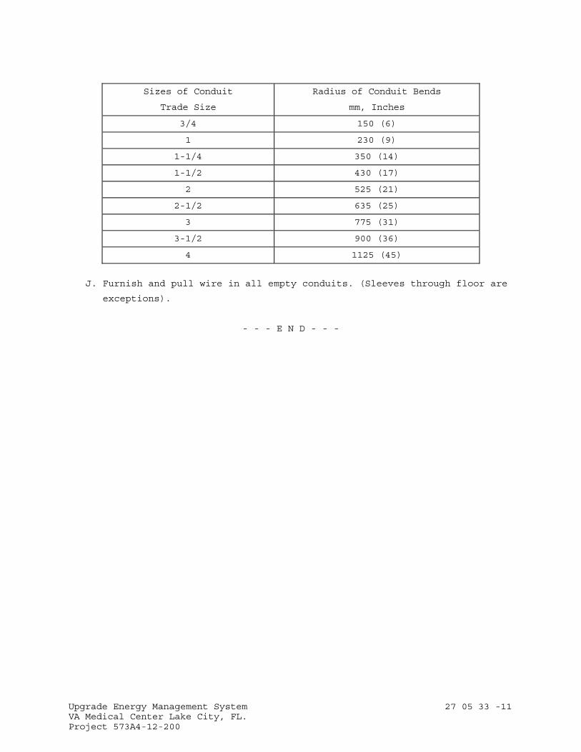
Upgrade Energy Management System 27 05 33 -11 VA Medical Center Lake City, FL. Project 573A4-12-200
Sizes of Conduit
Trade Size
Radius of Conduit Bends
mm, Inches
3/4 150 (6)
1 230 (9)
1-1/4 350 (14)
1-1/2 430 (17)
2 525 (21)
2-1/2 635 (25)
3 775 (31)
3-1/2 900 (36)
4 1125 (45)
J. Furnish and pull wire in all empty conduits. (Sleeves through floor are
exceptions).
- - - E N D - - -
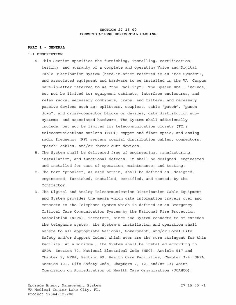
Upgrade Energy Management System 27 15 00 -1 VA Medical Center Lake City, FL. Project 573A4-12-200
SECTION 27 15 00 COMMUNICATIONS HORIZONTAL CABLING
PART 1 - GENERAL
1.1 DESCRIPTION
A. This Section specifies the furnishing, installing, certification,
testing, and guaranty of a complete and operating Voice and Digital
Cable Distribution System (here-in-after referred to as “the System”),
and associated equipment and hardware to be installed in the VA Campus
here-in-after referred to as “the Facility”. The System shall include,
but not be limited to: equipment cabinets, interface enclosures, and
relay racks; necessary combiners, traps, and filters; and necessary
passive devices such as: splitters, couplers, cable “patch”, “punch
down”, and cross-connector blocks or devices, data distribution sub-
systems, and associated hardware. The System shall additionally
include, but not be limited to: telecommunication closets (TC);
telecommunications outlets (TCO); copper and fiber optic, and analog
radio frequency (RF) systems coaxial distribution cables, connectors,
“patch” cables, and/or “break out” devices.
B. The System shall be delivered free of engineering, manufacturing,
installation, and functional defects. It shall be designed, engineered
and installed for ease of operation, maintenance, and testing.
C. The term “provide”, as used herein, shall be defined as: designed,
engineered, furnished, installed, certified, and tested, by the
Contractor.
D. The Digital and Analog Telecommunication Distribution Cable Equipment
and System provides the media which data information travels over and
connects to the Telephone System which is defined as an Emergency
Critical Care Communication System by the National Fire Protection
Association (NFPA). Therefore, since the System connects to or extends
the telephone system, the System’s installation and operation shall
adhere to all appropriate National, Government, and/or Local Life
Safety and/or Support Codes, which ever are the more stringent for this
Facility. At a minimum , the System shall be installed according to
NFPA, Section 70, National Electrical Code (NEC), Article 517 and
Chapter 7; NFPA, Section 99, Health Care Facilities, Chapter 3-4; NFPA,
Section 101, Life Safety Code, Chapters 7, 12, and/or 13; Joint
Commission on Accreditation of Health Care Organization (JCAHCO),
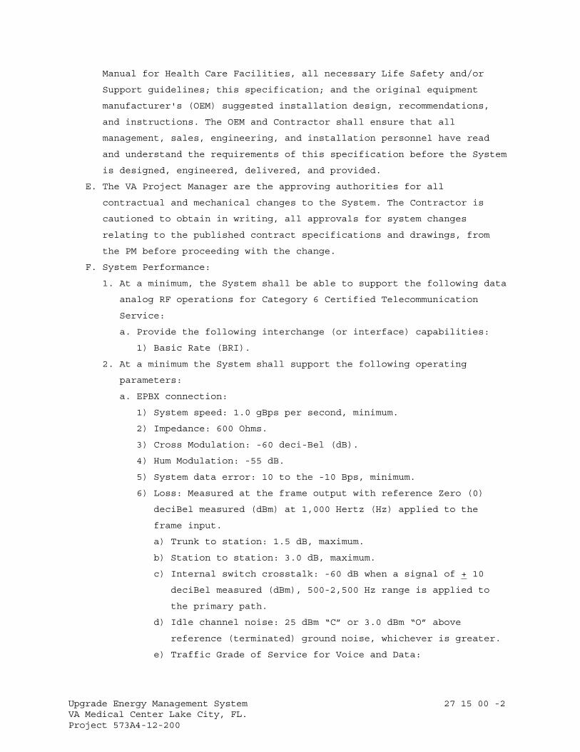
Upgrade Energy Management System 27 15 00 -2 VA Medical Center Lake City, FL. Project 573A4-12-200
Manual for Health Care Facilities, all necessary Life Safety and/or
Support guidelines; this specification; and the original equipment
manufacturer's (OEM) suggested installation design, recommendations,
and instructions. The OEM and Contractor shall ensure that all
management, sales, engineering, and installation personnel have read
and understand the requirements of this specification before the System
is designed, engineered, delivered, and provided.
E. The VA Project Manager are the approving authorities for all
contractual and mechanical changes to the System. The Contractor is
cautioned to obtain in writing, all approvals for system changes
relating to the published contract specifications and drawings, from
the PM before proceeding with the change.
F. System Performance:
1. At a minimum, the System shall be able to support the following data
analog RF operations for Category 6 Certified Telecommunication
Service:
a. Provide the following interchange (or interface) capabilities:
1) Basic Rate (BRI).
2. At a minimum the System shall support the following operating
parameters:
a. EPBX connection:
1) System speed: 1.0 gBps per second, minimum.
2) Impedance: 600 Ohms.
3) Cross Modulation: -60 deci-Bel (dB).
4) Hum Modulation: -55 dB.
5) System data error: 10 to the -10 Bps, minimum.
6) Loss: Measured at the frame output with reference Zero (0)
deciBel measured (dBm) at 1,000 Hertz (Hz) applied to the
frame input.
a) Trunk to station: 1.5 dB, maximum.
b) Station to station: 3.0 dB, maximum.
c) Internal switch crosstalk: -60 dB when a signal of + 10
deciBel measured (dBm), 500-2,500 Hz range is applied to
the primary path.
d) Idle channel noise: 25 dBm “C” or 3.0 dBm “O” above
reference (terminated) ground noise, whichever is greater.
e) Traffic Grade of Service for Voice and Data:
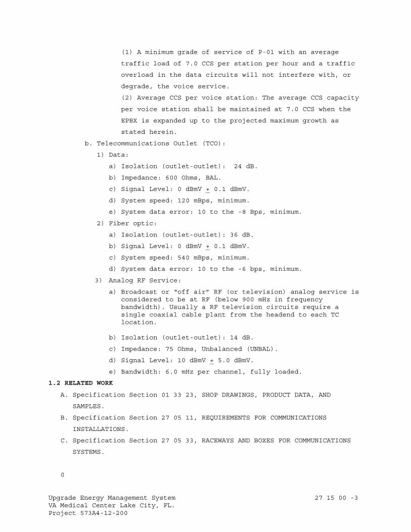
Upgrade Energy Management System 27 15 00 -3 VA Medical Center Lake City, FL. Project 573A4-12-200
(1) A minimum grade of service of P-01 with an average
traffic load of 7.0 CCS per station per hour and a traffic
overload in the data circuits will not interfere with, or
degrade, the voice service.
(2) Average CCS per voice station: The average CCS capacity
per voice station shall be maintained at 7.0 CCS when the
EPBX is expanded up to the projected maximum growth as
stated herein.
b. Telecommunications Outlet (TCO):
1) Data:
a) Isolation (outlet-outlet): 24 dB.
b) Impedance: 600 Ohms, BAL.
c) Signal Level: 0 dBmV + 0.1 dBmV.
d) System speed: 120 mBps, minimum.
e) System data error: 10 to the -8 Bps, minimum.
2) Fiber optic:
a) Isolation (outlet-outlet): 36 dB.
b) Signal Level: 0 dBmV + 0.1 dBmV.
c) System speed: 540 mBps, minimum.
d) System data error: 10 to the -6 bps, minimum.
3) Analog RF Service:
a) Broadcast or “off air” RF (or television) analog service is considered to be at RF (below 900 mHz in frequency bandwidth). Usually a RF television circuits require a single coaxial cable plant from the headend to each TC location.
b) Isolation (outlet-outlet): 14 dB.
c) Impedance: 75 Ohms, Unbalanced (UNBAL).
d) Signal Level: 10 dBmV + 5.0 dBmV.
e) Bandwidth: 6.0 mHz per channel, fully loaded.
1.2 RELATED WORK
A. Specification Section 01 33 23, SHOP DRAWINGS, PRODUCT DATA, AND
SAMPLES.
B. Specification Section 27 05 11, REQUIREMENTS FOR COMMUNICATIONS
INSTALLATIONS.
C. Specification Section 27 05 33, RACEWAYS AND BOXES FOR COMMUNICATIONS
SYSTEMS.
0
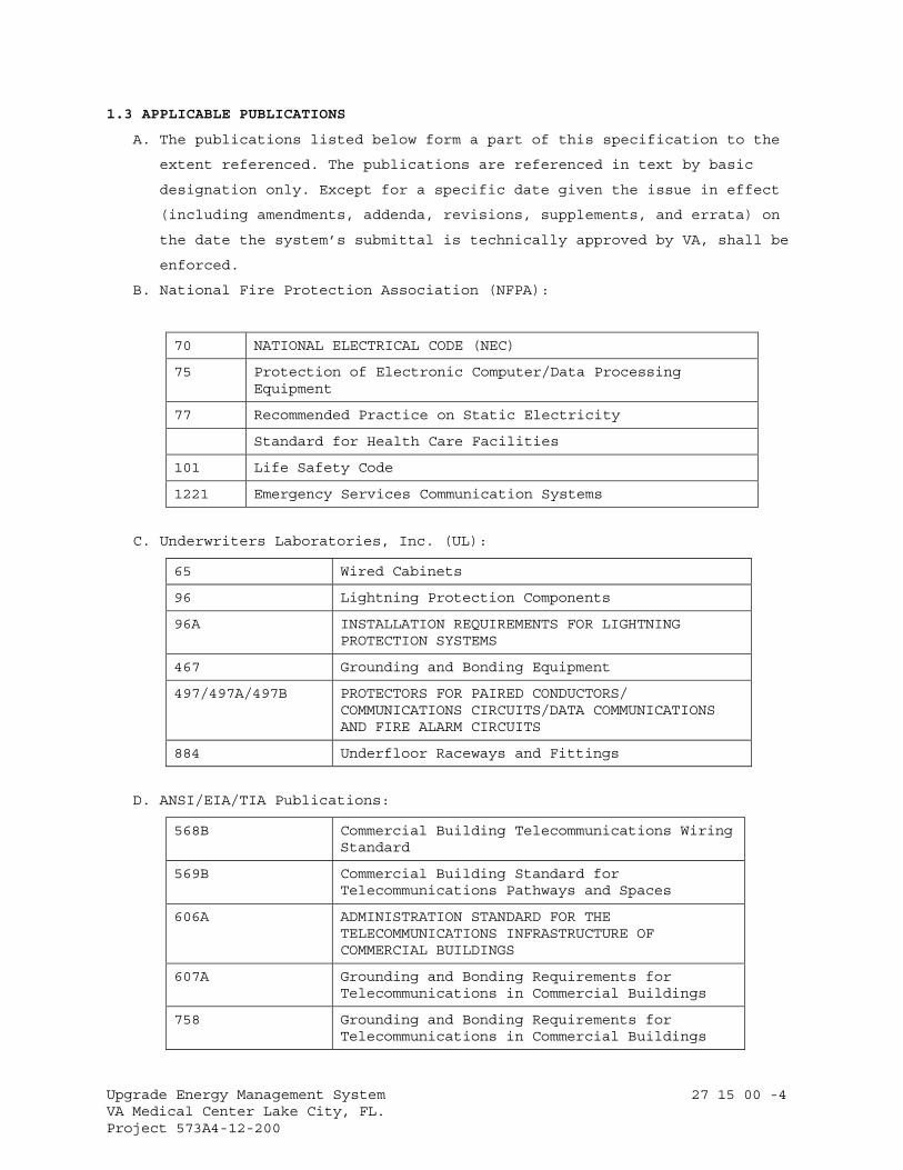
Upgrade Energy Management System 27 15 00 -4 VA Medical Center Lake City, FL. Project 573A4-12-200
1.3 APPLICABLE PUBLICATIONS
A. The publications listed below form a part of this specification to the
extent referenced. The publications are referenced in text by basic
designation only. Except for a specific date given the issue in effect
(including amendments, addenda, revisions, supplements, and errata) on
the date the system’s submittal is technically approved by VA, shall be
enforced.
B. National Fire Protection Association (NFPA):
70 NATIONAL ELECTRICAL CODE (NEC)
75 Protection of Electronic Computer/Data Processing Equipment
77 Recommended Practice on Static Electricity
Standard for Health Care Facilities
101 Life Safety Code
1221 Emergency Services Communication Systems
C. Underwriters Laboratories, Inc. (UL):
65 Wired Cabinets
96 Lightning Protection Components
96A INSTALLATION REQUIREMENTS FOR LIGHTNING PROTECTION SYSTEMS
467 Grounding and Bonding Equipment
497/497A/497B PROTECTORS FOR PAIRED CONDUCTORS/ COMMUNICATIONS CIRCUITS/DATA COMMUNICATIONS AND FIRE ALARM CIRCUITS
884 Underfloor Raceways and Fittings
D. ANSI/EIA/TIA Publications:
568B Commercial Building Telecommunications Wiring Standard
569B Commercial Building Standard for Telecommunications Pathways and Spaces
606A ADMINISTRATION STANDARD FOR THE TELECOMMUNICATIONS INFRASTRUCTURE OF COMMERCIAL BUILDINGS
607A Grounding and Bonding Requirements for Telecommunications in Commercial Buildings
758 Grounding and Bonding Requirements for Telecommunications in Commercial Buildings
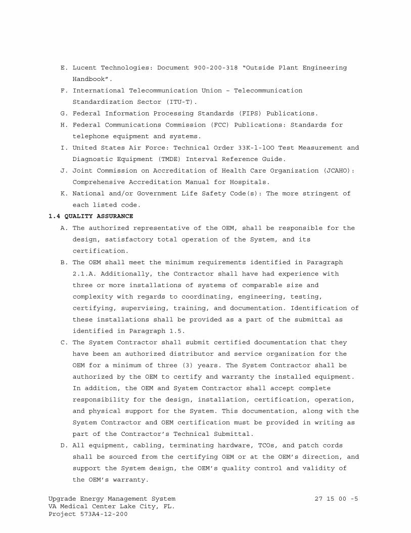
Upgrade Energy Management System 27 15 00 -5 VA Medical Center Lake City, FL. Project 573A4-12-200
E. Lucent Technologies: Document 900-200-318 “Outside Plant Engineering
Handbook”.
F. International Telecommunication Union – Telecommunication
Standardization Sector (ITU-T).
G. Federal Information Processing Standards (FIPS) Publications.
H. Federal Communications Commission (FCC) Publications: Standards for
telephone equipment and systems.
I. United States Air Force: Technical Order 33K-l-lOO Test Measurement and
Diagnostic Equipment (TMDE) Interval Reference Guide.
J. Joint Commission on Accreditation of Health Care Organization (JCAHO):
Comprehensive Accreditation Manual for Hospitals.
K. National and/or Government Life Safety Code(s): The more stringent of
each listed code.
1.4 QUALITY ASSURANCE
A. The authorized representative of the OEM, shall be responsible for the
design, satisfactory total operation of the System, and its
certification.
B. The OEM shall meet the minimum requirements identified in Paragraph
2.1.A. Additionally, the Contractor shall have had experience with
three or more installations of systems of comparable size and
complexity with regards to coordinating, engineering, testing,
certifying, supervising, training, and documentation. Identification of
these installations shall be provided as a part of the submittal as
identified in Paragraph 1.5.
C. The System Contractor shall submit certified documentation that they
have been an authorized distributor and service organization for the
OEM for a minimum of three (3) years. The System Contractor shall be
authorized by the OEM to certify and warranty the installed equipment.
In addition, the OEM and System Contractor shall accept complete
responsibility for the design, installation, certification, operation,
and physical support for the System. This documentation, along with the
System Contractor and OEM certification must be provided in writing as
part of the Contractor’s Technical Submittal.
D. All equipment, cabling, terminating hardware, TCOs, and patch cords
shall be sourced from the certifying OEM or at the OEM’s direction, and
support the System design, the OEM’s quality control and validity of
the OEM’s warranty.
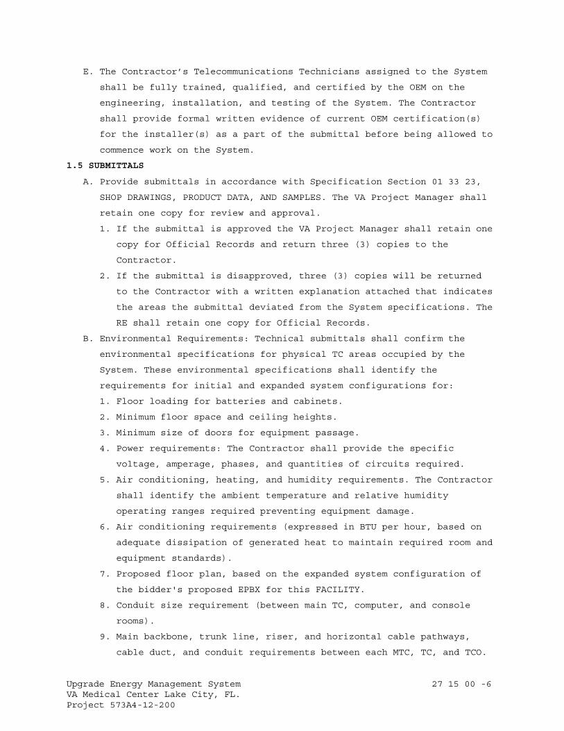
Upgrade Energy Management System 27 15 00 -6 VA Medical Center Lake City, FL. Project 573A4-12-200
E. The Contractor’s Telecommunications Technicians assigned to the System
shall be fully trained, qualified, and certified by the OEM on the
engineering, installation, and testing of the System. The Contractor
shall provide formal written evidence of current OEM certification(s)
for the installer(s) as a part of the submittal before being allowed to
commence work on the System.
1.5 SUBMITTALS
A. Provide submittals in accordance with Specification Section 01 33 23,
SHOP DRAWINGS, PRODUCT DATA, AND SAMPLES. The VA Project Manager shall
retain one copy for review and approval.
1. If the submittal is approved the VA Project Manager shall retain one
copy for Official Records and return three (3) copies to the
Contractor.
2. If the submittal is disapproved, three (3) copies will be returned
to the Contractor with a written explanation attached that indicates
the areas the submittal deviated from the System specifications. The
RE shall retain one copy for Official Records.
B. Environmental Requirements: Technical submittals shall confirm the
environmental specifications for physical TC areas occupied by the
System. These environmental specifications shall identify the
requirements for initial and expanded system configurations for:
1. Floor loading for batteries and cabinets.
2. Minimum floor space and ceiling heights.
3. Minimum size of doors for equipment passage.
4. Power requirements: The Contractor shall provide the specific
voltage, amperage, phases, and quantities of circuits required.
5. Air conditioning, heating, and humidity requirements. The Contractor
shall identify the ambient temperature and relative humidity
operating ranges required preventing equipment damage.
6. Air conditioning requirements (expressed in BTU per hour, based on
adequate dissipation of generated heat to maintain required room and
equipment standards).
7. Proposed floor plan, based on the expanded system configuration of
the bidder's proposed EPBX for this FACILITY.
8. Conduit size requirement (between main TC, computer, and console
rooms).
9. Main backbone, trunk line, riser, and horizontal cable pathways,
cable duct, and conduit requirements between each MTC, TC, and TCO.
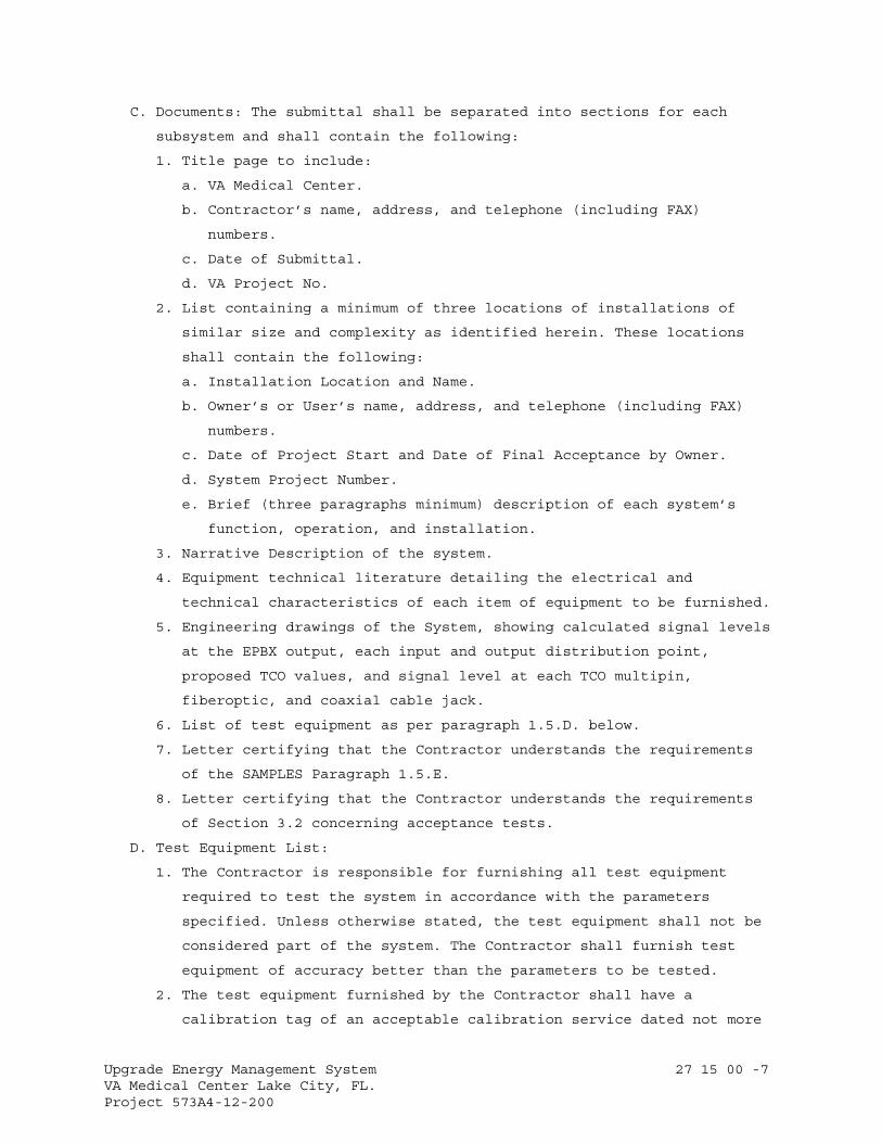
Upgrade Energy Management System 27 15 00 -7 VA Medical Center Lake City, FL. Project 573A4-12-200
C. Documents: The submittal shall be separated into sections for each
subsystem and shall contain the following:
1. Title page to include:
a. VA Medical Center.
b. Contractor’s name, address, and telephone (including FAX)
numbers.
c. Date of Submittal.
d. VA Project No.
2. List containing a minimum of three locations of installations of
similar size and complexity as identified herein. These locations
shall contain the following:
a. Installation Location and Name.
b. Owner’s or User’s name, address, and telephone (including FAX)
numbers.
c. Date of Project Start and Date of Final Acceptance by Owner.
d. System Project Number.
e. Brief (three paragraphs minimum) description of each system’s
function, operation, and installation.
3. Narrative Description of the system.
4. Equipment technical literature detailing the electrical and
technical characteristics of each item of equipment to be furnished.
5. Engineering drawings of the System, showing calculated signal levels
at the EPBX output, each input and output distribution point,
proposed TCO values, and signal level at each TCO multipin,
fiberoptic, and coaxial cable jack.
6. List of test equipment as per paragraph 1.5.D. below.
7. Letter certifying that the Contractor understands the requirements
of the SAMPLES Paragraph 1.5.E.
8. Letter certifying that the Contractor understands the requirements
of Section 3.2 concerning acceptance tests.
D. Test Equipment List:
1. The Contractor is responsible for furnishing all test equipment
required to test the system in accordance with the parameters
specified. Unless otherwise stated, the test equipment shall not be
considered part of the system. The Contractor shall furnish test
equipment of accuracy better than the parameters to be tested.
2. The test equipment furnished by the Contractor shall have a
calibration tag of an acceptable calibration service dated not more
Upgrade Energy Management System 27 15 00 -8 VA Medical Center Lake City, FL. Project 573A4-12-200
than 12 months prior to the test. As part of the submittal, a test
equipment list shall be furnished that includes the make and model
number of the following type of equipment as a minimum:
a. Spectrum Analyzer.
b. Signal Level Meter.
c. Volt-Ohm Meter.
d. Time Domain Reflectometer (TDR) with strip chart recorder (Data
and Optical Measuring).
e. Bit Error Test Set (BERT).
f. Camera with a minimum of 60 pictures to that will develop
immediately to include appropriate test equipment adapters. A
video camera in VHS format is an acceptable alternate.
E. Samples: A sample of each of the following items shall be furnished to
the RE for approval prior to installation.
1. TCO Wall Outlet Box 4" x 4"x 2.5" with:
a. Two each multi pin data rj45 jacks installed.
b. Cover Plate installed.
c. Fiber optic ST jack(s) installed.
d. RF (F)/video (BNC)/audio (XL)jack(s) installed.
2. Data CCS patch panel, punch block or connection device with RJ45
connectors installed.
3. Fiber optic CCS patch panel or breakout box with cable management
equipment and “ST” connectors installed.
4. 610 mm (2 ft.) section of each copper cable to be used with cable
sweep tags as specified in paragraph 2.4.H and connectors installed.
5. 610 mm (2 ft.) section of each fiber optic cable to be used with
cable sweep tags as specified in paragraph 2.4.H and connectors
installed.
6. 610 mm (2 ft.) section of each analog RF, video coaxial and audio
cable to be used with cable sweep tags as specified in paragraph
2.4.H and connectors installed. //
F. Certifications:
1. Submit written certification from the OEM indicating that the
proposed supervisor of the installation and the proposed provider of
the contract maintenance are authorized representatives of the OEM.
Include the individual's exact name and address and OEM credentials
in the certification.
Upgrade Energy Management System 27 15 00 -9 VA Medical Center Lake City, FL. Project 573A4-12-200
2. Submit written certification from the OEM that the wiring and
connection diagrams meet National and/or Government Life Safety
Guidelines, NFPA, NEC, UL, this specification, and JCAHCO
requirements and instructions, requirements, recommendations, and
guidance set forth by the OEM for the proper performance of the
System as described herein. The VA will not approve any submittal
without this certification.
3. Preacceptance Certification: This certification shall be made in
accordance with the test procedure outlined in paragraph 3.2.B.
G. Equipment Manuals: Fifteen (15) working days prior to the scheduled
acceptance test, the Contractor shall deliver four complete sets of
commercial operation and maintenance manuals for each item of equipment
furnished as part of the System to the RE. The manuals shall detail the
theory of operation and shall include narrative descriptions, pictorial
illustrations, block and schematic diagrams, and parts list.
H. Record Wiring Diagrams:
1. Fifteen (15) working days prior to the acceptance test, the
Contractor shall deliver four complete sets of the Record Wiring
Diagrams of the System to the RE. The diagrams shall show all inputs
and outputs of electronic and passive equipment correctly identified
according to the markers installed on the interconnecting cables,
Equipment and room/area locations.
2. The Record Wiring Diagrams shall be in hard copy and two compact
disk (CD) copies properly formatted to match the Facility’s current
operating version of Computer Aided Drafting (AutoCAD) system. The
RE shall verify and inform the Contractor of the version of AutoCAD
being used by the Facility.
I. Surveys Required As A Part Of The Technical Submittal: The Contractor
shall provide the following surveys that depict various system features
and capacities are required in addition to the on site survey
requirements described herein. Each survey shall be in writing and
contain the following information (the formats are suggestions and may
be used for the initial Technical Submittal survey requirements), as a
minimum:
1. Cable Distribution System Design Plan: A design plan for the entire
cable distribution systems requirements shall be provided with this
document. A specific cable count shall coincide with the total growth
items as described herein. It is the Contractor’s responsibility to
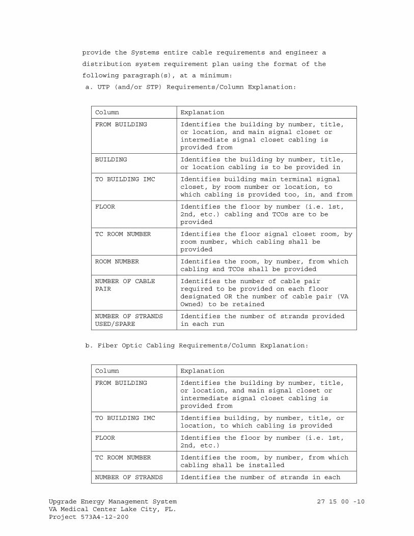
Upgrade Energy Management System 27 15 00 -10 VA Medical Center Lake City, FL. Project 573A4-12-200
provide the Systems entire cable requirements and engineer a
distribution system requirement plan using the format of the
following paragraph(s), at a minimum:
a. UTP (and/or STP) Requirements/Column Explanation:
Column Explanation
FROM BUILDING Identifies the building by number, title, or location, and main signal closet or intermediate signal closet cabling is provided from
BUILDING Identifies the building by number, title, or location cabling is to be provided in
TO BUILDING IMC Identifies building main terminal signal closet, by room number or location, to which cabling is provided too, in, and from
FLOOR Identifies the floor by number (i.e. 1st, 2nd, etc.) cabling and TCOs are to be provided
TC ROOM NUMBER Identifies the floor signal closet room, by room number, which cabling shall be provided
ROOM NUMBER Identifies the room, by number, from which cabling and TCOs shall be provided
NUMBER OF CABLE PAIR
Identifies the number of cable pair required to be provided on each floor designated OR the number of cable pair (VA Owned) to be retained
NUMBER OF STRANDS USED/SPARE
Identifies the number of strands provided in each run
b. Fiber Optic Cabling Requirements/Column Explanation:
Column Explanation
FROM BUILDING Identifies the building by number, title, or location, and main signal closet or intermediate signal closet cabling is provided from
TO BUILDING IMC Identifies building, by number, title, or location, to which cabling is provided
FLOOR Identifies the floor by number (i.e. 1st, 2nd, etc.)
TC ROOM NUMBER Identifies the room, by number, from which cabling shall be installed
NUMBER OF STRANDS Identifies the number of strands in each
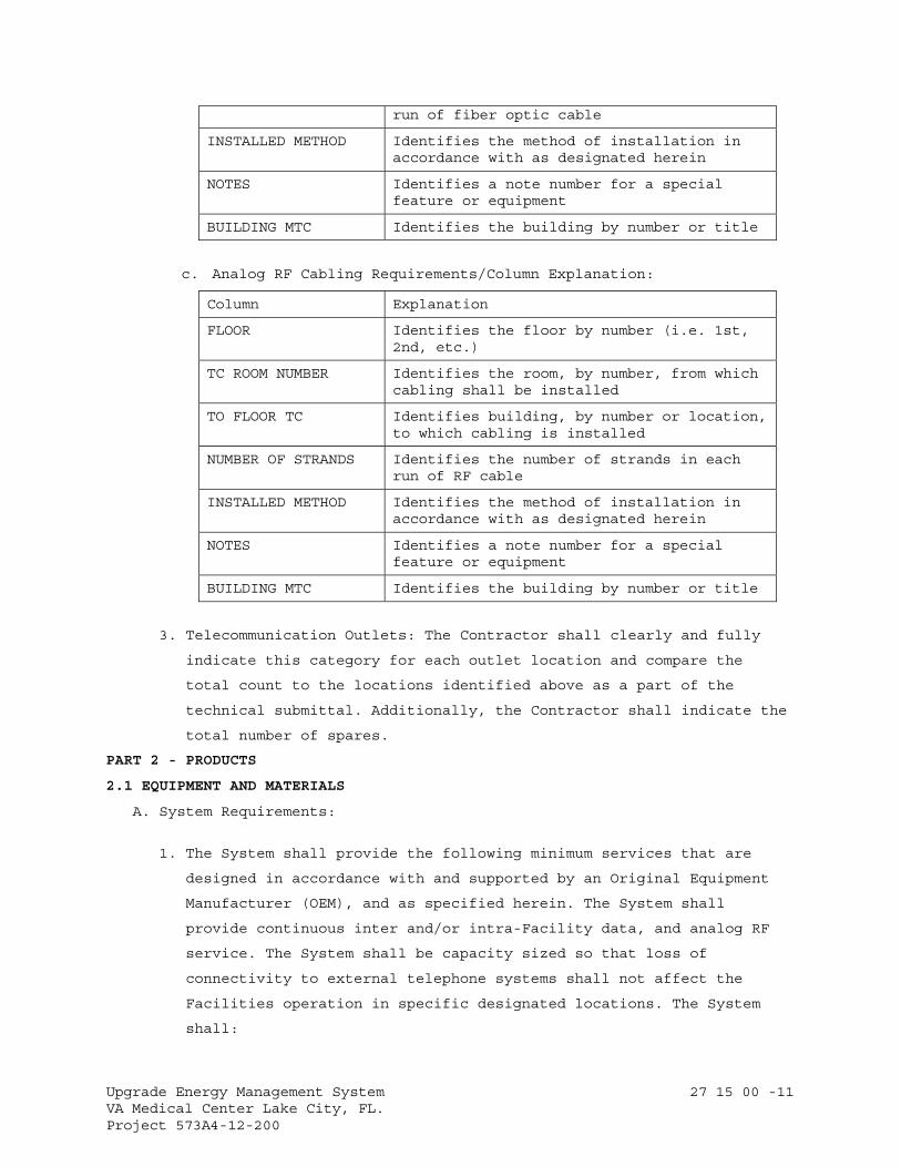
Upgrade Energy Management System 27 15 00 -11 VA Medical Center Lake City, FL. Project 573A4-12-200
run of fiber optic cable
INSTALLED METHOD Identifies the method of installation in accordance with as designated herein
NOTES Identifies a note number for a special feature or equipment
BUILDING MTC Identifies the building by number or title
c. Analog RF Cabling Requirements/Column Explanation:
Column Explanation
FLOOR Identifies the floor by number (i.e. 1st, 2nd, etc.)
TC ROOM NUMBER Identifies the room, by number, from which cabling shall be installed
TO FLOOR TC Identifies building, by number or location, to which cabling is installed
NUMBER OF STRANDS Identifies the number of strands in each run of RF cable
INSTALLED METHOD Identifies the method of installation in accordance with as designated herein
NOTES Identifies a note number for a special feature or equipment
BUILDING MTC Identifies the building by number or title
3. Telecommunication Outlets: The Contractor shall clearly and fully
indicate this category for each outlet location and compare the
total count to the locations identified above as a part of the
technical submittal. Additionally, the Contractor shall indicate the
total number of spares.
PART 2 - PRODUCTS
2.1 EQUIPMENT AND MATERIALS
A. System Requirements:
1. The System shall provide the following minimum services that are
designed in accordance with and supported by an Original Equipment
Manufacturer (OEM), and as specified herein. The System shall
provide continuous inter and/or intra-Facility data, and analog RF
service. The System shall be capacity sized so that loss of
connectivity to external telephone systems shall not affect the
Facilities operation in specific designated locations. The System
shall:
Upgrade Energy Management System 27 15 00 -12 VA Medical Center Lake City, FL. Project 573A4-12-200
a. Be a data cable distribution system that is based on a physical
“Star” Topology. An Analog RF coaxial cable distribution system
shall be provided in a “home run” configuration from each
associated riser TC to identified locations and as shown on the
drawings.
b. Be compatible with and able to provide direct digital connection
to trunk level equipment including, but, not limited to: directly
accessing trunk level equipment including the telephone system,
audio paging, Industry Standard “T” and/or “DS” carrier services
and external protocol converters. Additionally, connections to
“T” and/or “DS” access/equipment or Customer Service Units (CSU)
that are used in FTS and other trunk applications shall be
included in the System design. Provide T-1 access/equipment (or
CSU), as required for use, in FTS and other trunk applications by
system design if this equipment is not provided by the existing
telephone system and/or will be deactivated by the installation
of the System. The Contractor shall provide all T-1 equipment
necessary to terminate and make operational the quantity of
circuits designated. The CSU's shall be connected to the System’s
emergency battery power supply. The System shall be fully capable
of operating in the Industry Standard “DS” protocol and provide
that service when required.
2. Cable Systems - Twisted Pair and Fiber optic, and Analog RF Coaxial:
a. General:
1) The Contractor shall be responsible for providing a new system
conforming to current and accepted digital, and analog RF
industrial/commercial cable distribution standards. The
distribution cable installation shall be fully coordinated
with the Facility, the PM, the RE and the Contractor prior to
the start of installation.
2) The Contractor is responsible for complete knowledge of the
space and cable pathways (i.e. equipment rooms, TCs, conduits,
wireways, etc.) of the Facility. The Contractor shall at a
minimum design and install the System using the Pathway Design
Handbook H-088C3, TIA/EIA Telecommunications Building Wiring
Standards, and Facility Chief of Information Resource
Management’s (IRM) instructions, as approved in writing by the
PM.
Upgrade Energy Management System 27 15 00 -13 VA Medical Center Lake City, FL. Project 573A4-12-200
3) The System cables shall be fully protected by cable duct,
trays, wireways, conduit (rigid, thin wall, or flex), and when
specifically approved, flexible innerduct. It is the
responsibility of the Contractor to confirm all contract
drawings and the Facility’s physical layout to determine the
necessary cable protective devices to be provided. If flexible
innerduct is used, it shall be installed in the same manner as
conduit.
4) Cable provided in the system (i.e. backbone, outside plant,
inside plant, and station cabling) shall conform to accepted
industry and OEM standards with regards to size, color code,
and insulation. The pair twists of any pair shall not be
exactly the same as any other pair within any unit or sub-unit
of cables that are bundled in twenty-five (25) pairs or less.
The absence of specifications regarding details shall imply
that best general industry practices shall prevail and that
first quality material and workmanship shall be provided.
Certification Standards, (i.e., EIA, CCITT, FIPPS, and NFPA)
shall prevail.
5) Some areas of this Facility may be considered “plenum”. All
wire and cable used in support of the installation in those
areas (if any) shall be in compliance with national and local
codes pertaining to plenum environments. It is the
responsibility of the Contractor to review the VA’s cable and
wire requirements with the PM and the IRM prior to
installation to confirm the type of environment present at
each location.
6) The Contractor shall provide outside and inside plant cables
that furnishes the number of cable pairs required in
accordance with the System requirements described herein. The
Contractor shall fully coordinate and obtain approval of the
design with the OEM, RE and the IRM prior to installation.
7) All metallic cable sheaths, etc. shall be grounded by the
Contractor (i.e.: risers, underground, station wiring, etc.)
as described herein.
8) If temporary cable and wire pairs are used, they shall be
installed so as to not present a pedestrian safety hazard and
the Contractor shall be responsible for all work associated
Upgrade Energy Management System 27 15 00 -14 VA Medical Center Lake City, FL. Project 573A4-12-200
with the temporary installation and for their removal when no
longer necessary. Temporary cable installations are not
required to meet Industry Standards; but, must be reviewed and
approved by the RE and the IRM prior to installation.
9) Conductors shall be cabled to provide protection against
induction in voice and data, and analog RF circuits. Crosstalk
attenuation within the System shall be in excess of -80 dB
throughout the frequency ranges specified.
10) Measures shall be employed by the Contractor to minimize the
radiation of RF noise generated by the System equipment so as
not to interfere with audio, video, data, computer main
distribution frame (MDF), and electronic private branch
exchange (EPBX) equipment the System may service.
11) The System’s cables shall be labeled on each end and been
fully tested and certified in writing by the Contractor to the
RE before proof of performance testing can be conducted. The
as-installed drawings shall identify each cable as labeled,
used cable, and bad cable pairs. Minimum test requirements are
for impedance compliance, inductance, capacitance, signal
level compliance, opens, shorts, cross talk, noise, and
distortion, and split pairs on all cables in the frequency
ranges specified. The tests required for data cable must be
made to guarantee the operation of this cable at not less than
10 mega (m) Hertz (Hz) full bandwidth, fully channel loaded
and a Bit Error Rate of a minimum of 10-6 at the maximum rate
of speed. All cable installation and test records shall be
made available at acceptance testing by the RE or Contractor
and thereafter maintained in the Facility’s Telephone Switch
Room. All changes (used pair, failed pair, etc.) shall be
posted in these records as the change occurs.
12) The Contractor shall coordinate with the LEC to install the
telephone entrance cable to the nearest point of entry into
the Facility and as shown on the drawings. The Contractor
shall coordinate with the RE and the LEC to provide all cable
pairs/circuits from the Facility point of entry to the
Telephone Switch Room all telephone, FTS, DHCP, ATM, Frame
Relay, data, pay stations, patient phones, and any low voltage
circuits as described herein.

Upgrade Energy Management System 27 15 00 -15 VA Medical Center Lake City, FL. Project 573A4-12-200
13) The Contractor shall coordinate with the PM and the IRM to
install the computer interface cable to the Facility Telephone
Switch Room from the Facility’s Computer Room for all data,
DHCP, FTS, ATM, Frame Relay, and telephone circuits and as
shown on the drawings.
14) The Contractor shall coordinate with the PM and the IRM to
provide all cable pairs/circuits from the Facility Telephone
Switch Room and establish circuits throughout the Facility for
all voice, data, computer alarm (except fire alarm), private
maintenance line, Radio Paging, PA, LAN, DHCP, and any low
voltage circuits as described herein.
15) The Contractor shall provide proper test equipment to
guarantee that cable pairs and analog RF coaxial cable meet
each OEM’s standard transmission requirements, and guarantee
the cable will carry data transmissions at the required
speeds, frequencies, and fully loaded bandwidth.
b. Telecommunications Closets (TC): In TC’s that are served with
both a UTP and STP backbone cable and a fiber optic backbone
cable, the UTP and STP cable shall be terminated on separate RJ-
45, 8-pin connectors with 110A or equivalent type punch down
blocks located on the back or front of a 48-port modular patch
panel dedicated to data applications. Only the UTP and STP
backbone cable pairs, identified as being connected to the fiber
optic backbone, shall be extended to the fiber optic interface
device. All connecting cables required to extend these cables
(i.e. patch cords, twenty-five pair connectors, etc.), to the
fiber optic interface device, in the TC’s shall also be provided
by the Contractor to insure a complete and operational fiber
optic distribution system:
1) In TC’s, which are only served by a UTP and STP backbone
cable, the cable shall be terminated on separate modular
connecting devices (110A or equivalent) that are dedicated to
data applications. In order to provide full service to all
data cable pairs as identified in each TC/cabinet including
spare capacity noted herein, the size of all vertical (riser)
cables and/or outside cables serving these TC’s shall be
increased as required.
c. Backbone and Trunk Cables:
Upgrade Energy Management System 27 15 00 -16 VA Medical Center Lake City, FL. Project 573A4-12-200
1) The Contractor shall identify, in the technical submittal, the
data (analog RF coaxial cable shall not be provided in main
trunk or backbone lines) connecting arrangements required by
the LEC for interconnection of the System to the commercial
telephone and FTS networks. The Contractor shall provide all
required voice and data connecting arrangements.
2) The Contractor shall be responsible for compatibility of the
proposed TCs (to be compliant with the EPBX and CSU equipment)
numbering scheme with the numbering plan for the FTS, DID,
local stations, and the North American Numbering Plan. The
Contractor shall consult with the VA and the LEC regarding the
FTS and North American Numbering plan to be implemented for
the Facility to ensure system compatibility.
3) All submitted equipment shall meet or exceed standards, rules,
and regulations of the Federal Communications Commission (FCC)
and shall be capable of operating without outboard or “extra”
devices. The Contractor shall identify the FCC registration
number of the System equipment, EPBX, and proposed CSU (if
known) in the technical submittal.
d. Riser Cable:
1) All communication riser cables shall be listed as being
suitable for the purpose and marked accordingly per Articles
517, 700, and 800 of the NEC.
2) All voice and data communication (analog RF coaxial cable is
not to be provided in riser systems) riser cables shall be STP
or Unshielded Twisted Pair (UTP), minimum 24 American Wire
Gauge (AWG) solid, thermoplastic insulated conductors. They
shall be enclosed with a thermoplastic outer jacket.
3) The Contractor shall provide and install inside riser cables
to insure full service to all voice cable pairs identified in
each TC terminating enclosure plus not less than 50%
additional spare capacity.
4) The complete riser cabling system shall be labeled and tested
as described herein.
e. Horizontal and Station Cable:
1) A Four (4) UTP 24 AWG station wiring cable shall be installed
from the top TCO jack to the TC and shall be of a type
designed to support Category 6 communications (250 mega-Hertz
Upgrade Energy Management System 27 15 00 -17 VA Medical Center Lake City, FL. Project 573A4-12-200
[mHz] or above). At the jack location, terminate all four pair
on the RJ-45/11 jack. At the signal closet, all four pair
shall be terminated on the modular punch down blocks dedicated
to telephone applications.
2) A Four (4) UTP 24 AWG (in thermoplastic jacket unless
otherwise specified by RE) station wiring cable shall be
installed from each of the two (2) bottom TCO RJ-45 jacks
(shall conform to EIA/TIA 568 Standard "T568A" and NFPA) to
the TC and shall be of a type designed to support Category 6
communications (250 mHz or above).
f. Telecommunication Outlets (TCO), Jacks: All TCO’s shall have a
minimum of three (3) RJ-45 type jacks. The top jack shall be an
eight pin RJ-45/11 compatible jack, labeled, and designated for
telephone applications only. The bottom two jacks shall be eight
pin RJ-45 type unkeyed (sometimes called center keyed) jacks,
labeled, and designated for data.
g. Patient Bedside Prefabricated Units (PBPU): Where PBPU’s exist in
the Facility, the Contractor shall identify the single gang "box"
location on the PBPU designated for installation of the telephone
jack. This location shall here-in-after be identified as the
PBTCO. The Contractor shall be responsible for obtaining written
approval and specific instructions from the PBPU OEM regarding
the necessary disassembly and reassembly of each PBPU to the
extent necessary to pull wire from above the ceiling junction box
to the PBPU box reserved for the PBTCO. A Contractor provided
stainless steel cover plate approved for use by the PBPU OEM and
Facility IRM Chief shall finish out the jack installation. Under
no circumstances shall the Contractor proceed with the PBPU
installations without the written approval of the PBPU OEM and
the specific instructions regarding the attachment to or
modifying of the PBPU. The PM shall be available to assist the
Contractor in obtaining these approvals and instructions in a
timely manner as related to the project’s time constraints. It is
the responsibility of the Contractor to maintain the UL integrity
of each PBPU. If the Contractor violates that integrity, it shall
be the responsibility of the Contractor to obtain on site UL re-
certification of the violated PBPU at the direction of the RE and
at the Contractor’s expense.
Upgrade Energy Management System 27 15 00 -18 VA Medical Center Lake City, FL. Project 573A4-12-200
h. Fiber Optics:
1) A complete fiber optic cable distribution system shall be
provided as a part of the System. The Contractor shall provide
a fiber optic cable that meets the minimum bandwidth
requirements for FDDI, ATM, and Frame Relay services. This
fiber optic cable shall be a 50/125 micron multi-mode,
containing a minimum of 18 strands of fiber, unless otherwise
specified, and shall not exceed a distance of 2,000 Meters
(M), or 6,560 feet (ft.) in a single run. Loose tube cable,
which separates the individual fibers from the environment,
shall be installed for all outdoor runs or for any area which
includes an outdoor run. Tight buffered fiber cable shall be
used for indoor runs. The multimode fibers shall be terminated
and secured at both ends in “ST” type female stainless steel
connectors installed in an appropriate patch or breakout panel
with a cable management system. A 610 mm (2 ft.) cable loop
(minimum) shall be provided at each end to allow for future
movement.
2) In addition, a 12 strand (minimum), 8.3 mm single mode fiber
optic cable shall be provided. Single mode fibers shall be
terminated and secured at both ends with “ST” type female
stainless steel connectors installed in an appropriate patch
or breakout panel. The panel shall be provided with a cable
management system. A 610 mm (2 ft.) cable loop (minimum) shall
be provided at each end to allow for future movement.
3) The fiber optic backbone shall use a conventional hierarchical
“star” design where each TC is wired to the primary hub (main
cross-connect system) or a secondary hub (intermediate cross-
connect system) and then to the primary hub. There shall be
no more than two hierarchical levels of cross-connects in the
backbone wiring. Each primary hub shall be connected and
terminated to a CCS in the Telephone Switch Room.
Additionally, a parallel separate fiber optic interconnection
shall be provided between the Telephone Switch Room CCS and
the MDF in the Main Computer Room.
4) In the TC’s, Telephone Switch Room, and Main Computer Room,
all fiber optic cables shall be installed in a CCS and/or MDF
rack mounted fiber optic cable distribution component/splice
Upgrade Energy Management System 27 15 00 -19 VA Medical Center Lake City, FL. Project 573A4-12-200
case (Contractor provided and installed rack), patch, or
breakout panel in accordance with industry standards. Female
"ST" connectors shall be provided and installed on the
appropriate panel for termination of each strand.
5) The Contractor shall test each fiber optic strand. Cable
transmission performance specifications shall be in accordance
with EIA/TIA standards. Attenuation shall be measured in
accordance with EIA fiber optic test procedures EIA/TIA-455-
46, -61, or -53 and NFPA. Information transmission capacity
shall be measured in accordance with EIA/TIA-455-51 or -30 and
NFPA. The written results shall be provided to the RE for
review and approval.
3. Specific Subsystem Requirements: The System shall consist, as a
minimum, of the following independent sub-systems to comprise a
complete and functional digital and analog RF telecommunications
cabling system: “Main” (MTC), “intermediate” (IMTC), and “riser”
(RTC) TC’s; “backbone” cabling (BC) system; “vertical” (or “riser”)
trunk cabling system; “horizontal” (or “lateral”) sub-trunk cabling
system, vertical and horizontal cross-connection (VCC and HCC
respectively) cabling systems, and TCO’s with a minimum of three (3)
RJ-45 jacks for the appropriate telephone, Data connections, and
additional jacks, connectors, drop and patch cords, terminators, and
adapters provided.
a. Telecommunication Closet (TC):
1) There shall be a minimum of one TC for the MTC, each building
IMTC, and each RTC per building floor location. However, in
large building(s), where the horizontal distance to the
farthest voice and digital work area may exceed 90 Meters (M)
(or 295 feet [ft]), additional TC’s shall be provided as
described herein. The maximum DC resistance per cable pair
shall be no more than 28.6 Ohms per 305 M (1,000 feet). Each
TC shall be centrally located to cover the maximum amount of
local floor space. The TC’s house in cabinets or enclosures,
on relay racks, and/or on backboards, various
telecommunication data equipment, controllers, multiplexers,
bridges, routers, LAN hub(s), telephone cross-connecting,
active and passive equipment.
Upgrade Energy Management System 27 15 00 -20 VA Medical Center Lake City, FL. Project 573A4-12-200
2) Additionally, the TC’s may house fire alarm, nurses call, code
one (or blue), video, public address, radio entertainment,
intercom, and radio paging equipment. Regardless of the method
of installation, mounting, termination, or cross-connecting
used, all backbone, vertical, and horizontal copper and fiber
optic and analog RF coaxial cables shall be terminated on
appropriate cross-connection systems (CCS) containing patch
panel(s), punch blocks, and/or breakout devices provided in
enclosures and tested as described herein. A cable and/or wire
management system shall be a part of each CCS.
a) A minimum of three 110-120 VAC active quad outlets shall be
provided, each with “U” grounded receptacles at a minimum
of one outlet for each front, side and back wall. These
outlets shall be separately protected by an AC circuit
breaker provided in the designated Government Emergency
Critical Care AC power panel, that is connected to the
Facilities Emergency AC Power Distribution System. For
larger building TC applications, a minimum of one
additional quad AC outlet shall be provided for every 800M²
(or 8,000 ft²) of useable floor space. Additional outlets
shall be equally spaced along the wall.
b) Climate control shall be provided in each TC 24 hours a
day, seven days per week and 52 week per year to prevent
failure of electronic components and for mission critical
functional applications. The Facility Chief Engineering
Officer are responsible for informing the Contractor
regarding the minimum climate control requirements. In
identified hostile TC locations where it has been
determined (by the Facility Chief Engineer) that proper TC
climate or external signal radiation cannot be properly
maintained or controlled, the Contractor may, at his/her
option, provide a minimum of two individual and properly
sized self contained climate controlled equipment cabinet
enclosures; one designated for data, and one additional
cabinet designated for analog RF service, in each TC
location identified on the drawings, in lieu of providing
additional required TC air handling capability.
b. Cross-connect Systems (CCS):
Upgrade Energy Management System 27 15 00 -21 VA Medical Center Lake City, FL. Project 573A4-12-200
1) The CCS shall be selected based on the following criteria:
requires the use of a single tool, has the fewest amount of
parts, and requires the least amount of assembly or projected
trouble shooting time during the life of the system.
2) The CCS system used at the MTC, each IMTC, and each TC shall
force cross-connect cable slack management through adherence
to the OEM’s installation methods, provided cable management
systems, and as described herein, so that moves, adds, and
changes can be administered easily and cost effectively.
3) Copper Cables: The MTC, each IMTC, and TC shall contain a
copper CCS sized to support the System TCO’s and connections
served by each individual TC and as shown on the drawings. The
System layout shall allow for a minimum of 50% anticipated
growth. Additionally, each CCS must provide maximum
flexibility, while maintaining performance, in order to meet
system-changing requirements that are likely to occur
throughout its useful life.
4) Fiber Optic Cables:
a) The MTC and each TC shall contain a fiber CCS sized to
support the System TCO’s and connections served by each
individual TC and as shown on the drawings. The System
layout shall allow for a minimum of 50% anticipated growth.
b) Each fiber CCS must provide maximum flexibility and cable
management while maintaining performance in order to meet
changing requirements that are likely to occur throughout
the expected life of the system. All fiber optic cable
slack shall be stored in protective enclosures.
c) If it is determined that a fiber optic distribution system
is not necessary for the immediate system needs. Each TC
shall be provided with fiber optic cable(s) that contain a
minimum of 12 strands “dark” multimode fiber and 12 strands
“dark” single mode fiber, each fiber properly terminated on
its respective female stainless steel connector mounted in
an appropriate fiber termination enclosure provided in each
TC.
5) The Contractor shall not “cross-connect” the copper or fiber
optic cabling systems and subsystems even though appropriate
“patch” cords are to be provided for each “patch”, “punch”, or
Upgrade Energy Management System 27 15 00 -22 VA Medical Center Lake City, FL. Project 573A4-12-200
“breakout” panel. In addition, the Contractor shall not
provide active electronic distribution or interface equipment
as a part of the System.
6) Grounding: Proper grounding and bonding shall be provided for
each TC and all internal equipment. Reference shall be made to
proper codes and standards, such that all grounding systems
must comply with all applicable National, Regional, and Local
Building and Electrical codes. The most stringent code of
these governing bodies shall apply.
a) If local grounding codes do not exist for the System
location, then at a minimum, a #6 American Wire Gauge (AWG)
stranded copper wire, or equivalent copper braid, shall be
connected to a separate earth grounding system for each TC
(the looping of TC’s in a general location is allowed as
long as the specifications contained herein are met). Under
no circumstance shall the AC neutral be used for this
ground. See PART 3 – EXECUTION for specific grounding
instructions.
b) Each copper UTP or STP cable that enters a TC from the
outside of a building (regardless if the cable is installed
underground or aerial) shall be provided with a surge
protector and grounded an to earth ground at each cable’s
entry point in and out of the MTC and each IMTC.
c. Data Cross-Connection Subsystems:
1) The MCCS shall be a Main Distribution Terminating (MDT) data
unit and shall be provided in the MTC. The MDT shall consist
of a “patch” panel(s) provided with modular RJ45 female
connectors for cross-connection of all copper data cable
terminations. The panels shall provide for system grounding
(where no dielectric cables are used) and be provided with a
cable management system.
2) Each panel shall conform to EIA dimensions and be suitable for
mounting in standard equipment racks, have the RJ45 jacks
aligned in two horizontal rows (up to a maximum of 48 jacks
per panel), and shall not exceed the OEM’s recommendations.
Each RJ45 jack shall be of modular design and capable of
accepting and functioning with other modular (i.e. RJ11) plugs
without damaging the jack. It is not necessary to provide a
Upgrade Energy Management System 27 15 00 -23 VA Medical Center Lake City, FL. Project 573A4-12-200
jack for unused positions that are not part of the 50%
expansion requirement.
a) All data system inputs from the server(s), data LAN,
bridge, or interface distribution systems shall appear on
the “top” row of jacks of the appropriate patch panel.
b) All System outputs or backbone cable connections shall
appear on the “bottom” row of jacks of the same patch
panel.
c) The splitting of pairs within cables between different
jacks shall not be allowed. In the case of ISDN and/or ATM
and/or Frame Relay applications, terminating resistors
shall be provided externally to the patch panel connector
or jack.
3) A patch cord shall be provided for each system “pair” of
connection jacks. Each patch cord shall have modular RJ45
connectors provided on each end to match the panel’s modular
RJ45 female jack’s being provided.
e. Fiber optic Cross-Connection Subsystems: The MTC shall be
provided with a separate fiber MCCS. Each TC shall be provided
with a rack mounted patch or distribution panel that is installed
inside a lockable cabinet or “breakout enclosure” that
accommodates a minimum of 12 strands multimode fiber and 12
strand single mode fiber (these counts shall not be included the
50% spare requirement). Two of the single mode fibers shall be
designated for educational analog video applications. A cable
management system shall be provided for each panel.
1) The panel(s) shall contain a minimum of 24 female “ST”
connectors, be able to accommodate splices and field mountable
connectors and have capacity for additional connectors to be
added up to the OEM’s maximum standard panel size for this
type of use. All patch panel sides, including the front and
back, shall be protected by a cabinet or enclosure.
2) The panel(s) shall conform to EIA dimensions and be suitable
for installation in standard racks, cabinets, and enclosures.
The panels shall provide for system grounding (where no
dielectric cables are used).
3) The patch panel with the highest OEM approved density of fiber
“ST” termination’s (maximum of 72 each), while maintaining a
Upgrade Energy Management System 27 15 00 -24 VA Medical Center Lake City, FL. Project 573A4-12-200
high level of manageability, shall be selected. Patch cables,
with proper “ST” connectors installed on each end shall be
provided for each pair of fiber optic cable “ST” connectors.
a) All System “inputs” from interface equipment or
distribution systems shall appear on the “top” row of
connectors of the appropriate patch panel.
b) All System “outputs” or backbone cable connections shall
appear on the “bottom” row of connectors of the same patch
panel.
4) In order to achieve a high level of reliability that
approximates that of an OEM connector, field installable
connectors shall have an OEM specified physical contact
polish. Every fiber cable shall be terminated with the
appropriate connector, and tested to ensure compliance to OEM
and specifications outlines herein. Where a local fiber optic
system connector standard, Industry Standard fiber optic “ST”
female connector terminated with a fiber optic cable, shall be
used. But, if the fiber optic cable is not used (or “dark”), a
“ST” male terminating “cap” shall be provided for each unused
“ST” female connector.
f. Intermediate Cross-connection Subsystems (IMCCS): The MTC and
each IMTC shall be provided with an IMCCS that shall be the
connection point between the MCCS system and the distribution
backbone cable and the IMCCS, that is located in one or more
buildings on a campus, where each IMCCS is placed by system
design. For a technical explanation of internal equipment and
system requirements, refer to the above MTC and MCCS paragraphs.
g. Distribution Cable Systems / Backbone Cable System (Common to
Inter-buildings): The backbone cable system extends from the MCCS
to each IMCCS to establish service between buildings on a campus.
The media (copper and fiber optic) used in the BC system shall be
designed according to the system requirements, OEM standards and
guidelines, and as described herein. A multi-pair copper for
voice and data, and separate multiple fiber optic backbone system
shall be provided as a part of the BC distribution system.
1) All outside cable shall be minimum of STP or UTP, 22 AWG solid
conductors, solid PVC insulation, and filled core (flexgel -
waterproof Rural Electric Association (REA) LISTED PE 39 CODE)
Upgrade Energy Management System 27 15 00 -25 VA Medical Center Lake City, FL. Project 573A4-12-200
between the outer armor or jacket and inner conductors
protective lining.
2) The copper cable system shall be configured as a “Star”
Topology with separate dedicated cables between the MCCS and
each IMCCS.
3) UTP and STP copper cables shall consist of thermoplastic
insulated conductors formed into binder groups. The groups are
to be identified by distinctly colored binders and assembled
to form a single compact core covered by a protective sheath.
Each cable shall be rated for Category 6 Telecommunications
System Service. A minimum of eight pairs per circuit, plus an
additional 50% spare for growth shall be provided.
4) Where the distance limitations of UTP or STP may be exceeded,
multimode (or single mode) fiber optic cable(s) shall be used
to augment the voice and/or data backbone cable system(s). The
total loss of each fiber shall not exceed 12 decibel (dB) at
850 nano-Meter (nM), 11 dB at 1,300 nM, or 10 dB at 1,500 nM.
5) All voice system “inputs” from the MCCS via the BC
distribution system shall appear on the “left” side of IDC
(minimum 110 blocks) punch terminals of the IMCCS.
6) All voice system “outputs” or trunk line connections shall
appear on the “right” side of the same IDC (minimum 110
blocks) of the IMCCS.
7) All data system “inputs” from the MCCS via the BC distribution
system shall appear on the “top” row of jacks of the
appropriate patch panel of the IMCCS.
8) All data system “outputs” or trunk line connections shall
appear on the “bottom” row of jacks in the same patch panel of
the IMCCS.
9) The splitting of pairs within cables between different jacks
shall not be allowed. In the case of ISDN and/or ATM and /or
Frame Relay applications, terminating resistors shall be
provided externally to the patch panel connector or jack.
10) A patch cord shall be provided for each system “pair” of
connection jacks. Each patch cord shall have modular
connectors provided on each end to match the panel’s modular
female jack.
Upgrade Energy Management System 27 15 00 -26 VA Medical Center Lake City, FL. Project 573A4-12-200
11) All BC shall be identified with permanent labels at both
ends. Labels will indicate system, floor, closet, and zone.
The label designations shall match those used for cross-
connect terminals and patch panels.
i. Distribution (Common to Intra-Building) Cabling Systems: The
intra-building trunk cabling system provides for connection
between the IMCCS and each Riser TC’s provided vertical cross-
connecting system (VCCS) within a building. The media (copper,
fiber optic and RF coaxial) used in the intra-building backbone
cabling system shall be designed according to the system
requirements, OEM standards and guidelines, and as described
herein. A multi-pair copper for voice and data, and separate
multiple fiber optic and analog RF coaxial trunk system shall be
provided as a part of the System.
1) Category 6 UTP or STP multi-pair trunk cable(s) shall be used
in the data trunk-line-cabling systems. A minimum of eight
pairs per circuit, plus an additional 50% spare for growth
shall be provided.
2) Where the distance limitations of UTP and/or STP will be
exceeded, multimode (or single mode) fiber optic cable shall
be used in the voice and/or trunk cabling systems. The total
loss of the fiber trunks shall not exceed 12 dB at 850 nM , 11
dB at 1,300 nM, or 10 dB at 1,500 nM.
a) All voice system “outputs” from the IMCCS to the trunk-line
distribution system shall appear on the “right” side of IDC
(minimum 110A blocks) punch terminals of the IMCCS.
b) All data system “outputs” from the IMCCS to the trunk-line
distribution system shall appear on the “bottom” row of
jacks of the same IDC (minimum 110A blocks) of the IMCCS.
c) The splitting of pairs within cables between different
jacks shall not be allowed.
d) A patch cord shall be provided for each system “pair” of
connection jacks. Each patch cord shall have modular
connectors provided on each end to match the panel’s
modular female jack.
3) The fiber optic trunk line system shall be configured as a
“Buss” Topology with separate dedicated fibers between the
IMCCS and each RCS. The System shall be sized to meet the
Upgrade Energy Management System 27 15 00 -27 VA Medical Center Lake City, FL. Project 573A4-12-200
System requirements with a expansion capability of 50%
provided. Separate individual fiber optic cable(s) with a
minimum of 18 strands multimode fiber and/or 12 strands single
mode fiber shall be provided. Two of the single mode fibers
shall be designated for analog video service.
4) All trunk lines shall be identified with permanent labels at
both ends. Labels will indicate system, floor, closet, and
zone. The label designations shall match those used for cross-
connects and patch panels.
a) All System outputs from the IMCCS to the trunk-line
distribution system shall appear on the “bottom” row of
“ST” connectors in the appropriate patch panel.
b) A patch cord shall be provided for each system “pair” of
connection “ST” connectors. As a minimum, each patch cord
shall have “ST” male connectors provided on each end to
match the panel’s female “ST” connector provided.
5) An analog RF coaxial cable trunk system shall be provided.
A minimum of two coaxial cables shall be provided between the
IMCCS and each Riser VCCS to comprise an individual circuit as
designated and as shown on the drawings. Additional analog RF
coaxial cables shall be provided as system design dictates and
as shown on the drawings.
6) The analog RF coaxial trunk-line systems shall be connected
between each IMCCS “bottom” row of “F” connectors and shall
terminate on the VCCS “top” row of “F” connectors on an
appropriate patch panel. A minimum of six coaxial cables shall
be provided in the riser trunk-line system.
j. VCCS and Horizontal Cross-connecting (HCCS) Systems: Each TC
shall be provided with a separate VCCS and HCCS located within
the TC. The VCCS and HCCS shall interconnect and interface the
riser (vertical) trunk line cables with the horizontal (or
station) sub-trunk line cables. The media (copper, fiber optic
and analog RF coaxial) used in the CCS system shall be designed
according to the System requirements, OEM standards and
guidelines, and as described herein. A multi-pair copper for
voice and data, and separate multiple fiber optic and RF coaxial
CCS system shall be provided as a part of the System.
Upgrade Energy Management System 27 15 00 -28 VA Medical Center Lake City, FL. Project 573A4-12-200
1) The UTP, STP, and fiber optic and RF coaxial trunk-line
cabling systems are that connected between the trunk-lines and
Riser VCCS, shall be terminated:
a) On the “left” or “top” IDC (or 110A blocks) for each UTP or
STP voice cable.
b) On the “top” row of RJ45 jacks on the appropriate patch
panel for each UTP or STP data cable.
c) On the “top” row of “ST” connectors on the appropriate
patch panel for each fiber and “F” connectors for each
analog RF coaxial cable.
2) The UTP, STP, and fiber optic and analog RF coaxial sub-trunk
(lateral) floor distribution cabling systems that are
connected between each RTC and each TCO or secondary system
distribution or connection point, shall terminate on an
appropriate HCCS, at the:
a) On the “right” IDC (or 110A block) used as the VCCS input
for each UTP or STP voice cable.
b) On the “bottom row of RJ45 jacks on the appropriate patch
panel used as the VCCS input for each UTP or STP data
cable.
c) On the “bottom” row of “ST” connectors on the appropriate
patch panel used as the VCCS input for each fiber and “F”
connectors for each analog RF coaxial cable.
d) The technical requirements of the VCCS and HCCS “patch”,
“terminating”, or “breakout” panels and cable management
assemblies for voice, data and fiber optic ( and RF
coaxial) cables shall be as described in the above MCCS,
IMCCS, and TC technical paragraphs.
3) The Contractor shall not “cross-connect” the VCCS or HCCS
cabling systems even though appropriate patch cords are
provided for each “patch”, “punch”, or “breakout” panel. Also,
the Contractor shall not provide active interface or
distribution electronic equipment as a part of the System.
4) The analog RF coaxial cabling systems shall be connected
between each IMCS and RTC shall terminate on the VCCS on the
“top” row of “F” connectors on an appropriate patch panel.
Additionally, each horizontal distribution analog RF coaxial
Upgrade Energy Management System 27 15 00 -29 VA Medical Center Lake City, FL. Project 573A4-12-200
cable shall terminate on the HCCS on the “bottom” row of “F”
connectors of the same panel.
5) The analog RF terminating panel(s) shall be the “patch” type.
Each panel shall be the 19” EIA rack dimensions and provided
with a minimum of 12 double female “F” connector rows. Each
patch panel shall be provided with the expansion capability of
a maximum of 24 double row “F” slots that can be field
activated.
6) Each analog RF “patch” panel shall be provided inside a
lockable cabinet or enclosure. Stacking of the “patch” panels
is permitted as long as installation guidelines are met.
k. Horizontal (or Station) Cabling (HC): The HC distribution cabling
systems connects the distribution field of data HCCS, in a “Star”
Topology, to each TCO or connector and as shown on the drawings
via the sub-trunk system.
1) Horizontal cables shall consist of insulated, UTP or STP
conductors that are rated for Category 6 telecommunications
service for data systems.
2) The number of UTP or STP distribution pairs dedicated to each
floor from the HC shall be sufficient to accommodate all the
horizontal data circuits served by the distribution cable to
each TCO.
a) A minimum of four pairs for voice shall be connected to the
“right” side of the IDC (or 110A block) that the VCCS
“input” connections appear in the RTC.
b) A minimum of two separate sets of four pairs each for data
shall be connected to the “bottom” row of RJ45 jacks that
the VCCS “input” connections appear in the RTC.
3) The horizontal cable length to the farthest system outlet
shall be limited to a maximum of 90M (or 295 ft). These
maximum lengths must be derated, adjusted and reduced to
include cross-connection and distribution system losses.
Additional TC(s) shall be provided on large floor areas of
buildings to limit the horizontal distribution to a maximum of
90M (or 295 ft).
4) The splitting of pairs within a cable between different jacks
shall not be permitted.
Upgrade Energy Management System 27 15 00 -30 VA Medical Center Lake City, FL. Project 573A4-12-200
5) The installation of the HC shall conform to appropriate OEM
recommendations and standards outlined herein. This
requirement will insure adequate protection for Electro-
Magnetic Interference (EMI) sources.
6) A system design where “looping” the HC distribution cables
from room to room shall not be permitted.
7) The number of fiber optic cables dedicated from the “bottom”
row of “ST” connectors of the appropriate patch panel that the
VCCS “input” connections were made, to each floor shall be
sufficient to accommodate all the horizontal TCO’s served by
the distribution cable system in a “home run” configuration
minimum of two cables (one multimode and one single mode) per
each TCO and as shown on the drawings.
8) The analog RF coaxial cables dedicated from the “bottom” row
of “F” connectors of the appropriate VCCS patch panel where
the “input” connections were made, to each floor TCO shall
provided in the “home run” configuration and be sufficient to
accommodate all the TCO’s served by the HC distribution cable
system minimum of one analog RF coaxial cable shall be
provided for each TCO circuit and as shown on the drawings).
l. System Telecommunication Outlets (TCO): The System shall be
capable of receiving the specified telephone (or voice) and data
signals acquired from the LEC, FTS contracted carrier and
computer system, and one each analog RF cable, and one each fiber
optic single mode and multimode cables and shall process and
distribute them to the designated TCO’s and as shown on the
drawings. At a minimum, one TCO shall be provided on each room
wall, associated with an active 120 VAC shall be provided and as
shown on the drawings. The only exception to the general rule, of
one outlet per wall, shall be those “special” locations (e.g.,
surgical suites, radiology MRI rooms, labs, patient bed rooms,
warehouse, loading docks, storage rooms, etc.) where there is
usually only one TCO provided as designated on the drawings.
1) Each TCO shall consist of two multipin modular RJ45 jacks, for
data service, and two fiber optic “ST” connectors, one
designated for multimode fiber optic cable and the other for
single mode fiber optic cable connection(s) and one analog RF
coaxial “F” connector. Each TCO with appropriate jacks
Upgrade Energy Management System 27 15 00 -31 VA Medical Center Lake City, FL. Project 573A4-12-200
installed shall be provided by the Contractor in each
designated location and as shown on the drawings.
2) The Contractor shall connect each telephone multipin modular
RJ45 jack to a separate “right side as you look at it”
telephone HC distribution system HCCS “punch down” 110A block
or approved IDC terminating device in each associated RTC. The
modular RJ45 jack shall be able to accept and operate with
smaller modular RJ11 plugs while providing proper connection
and not damaging the modular jack. he OEM shall warrant all
modular RJ45/11 jacks in such a manner to be usable for
modular RJ11 plugs.
3) The Contractor shall connect each TCO data multipin modular
RJ45 jack to a separate lower row jack on the HCCS “patch
panel” in each associated RTC. The Contractor is not to
“cross-connect” VCCS and HCCS data distribution cables or
provides active electronic data distribution equipment as a
part of the System.
4) A non-impact termination method, using either a stuffer cap
with installation tool or full-cycle terminating tool having
both tactile and audible feedback to indicate proper
termination shall be used. High impact installation tools
shall not be used.
5) Each terminated conductor end shall be properly trimmed to
assure a minimum clearance of 6.35 mm (0.250 in) clearance
between the conductors of adjacent modules.
6) The multipin RJ45 jack shall be modular in construction that
will accept and operate with a modular UTP and STP RJ45
connector and its pin assignments.
7) The Contractor shall connect each fiber optic TCO “ST”
connector to a separate fiber optic “bottom” row “ST”
connector HCCS “patch panel” or “breakout” terminating device
in each associated TC. The Contractor is not to
“interconnect” VCCS and HCCS fiber optic distributions cables
or provide active fiber optic electronic distribution
equipment as a part of the system.
8) The Contractor shall connect each analog RF cable to a female
“F” connector provided on each TCO and as shown on the
drawings and to each bottom row of “F” connectors on the HCCS
Upgrade Energy Management System 27 15 00 -32 VA Medical Center Lake City, FL. Project 573A4-12-200
patch panel(s) serving the area. The Contractor is not to
“interconnect” VCCS and HCCS analog RF distribution cables OR
provides active analog RF distribution equipment as a part of
the System.
B. System Performance:
1. At a minimum, the System shall be able to support the following data
and analog RF operations for Category 6.
a. Telecommunications Outlet (TCO):
1) Voice:
a) Isolation (outlet-outlet): 24 dB.
b) Impedance: 600 Ohms, balanced (BAL).
c) Signal Level: 0 deciBel per mili-Volt (dBmV) + 0.1 dBmV.
d) System speed: 100 mBps, minimum.
e) System data error: 10 to the -6 Bps, minimum.
2) Data:
a) Isolation (outlet-outlet): 24 dB.
b) Impedance: 600 Ohms, BAL.
c) Signal Level: 0 dBmV + 0.1 dBmV.
d) System speed: 120 mBps, minimum.
e) System data error: 10 to the -8 Bps, minimum.
3) Fiber optic:
a) Isolation (outlet-outlet): 36 dB.
b) Signal Level: 0 dBmV + 0.1 dBmV.
c) System speed: 540 mBps, minimum.
d) System data error: 10 to the -6 BPS, minimum.
4) Analog RF Service: Broadcast or “off air” RF (or television)
analog service is considered to be at RF (below 900 mHz in
frequency bandwidth). Usually a RF television circuits require
a single coaxial cable plant from the headend to each TC
location.
a) Isolation (outlet-outlet): 14 dB.
b) Impedance: 75 Ohms, Unbalanced (UNBAL).
c) Signal Level: 10 dBmV + 5.0 dBmV.
d) Bandwidth: 6.0 mHz per channel, fully loaded //
C. General:
1. All equipment to be supplied under this specification shall be new
and the current model of a standard product of an OEM or record. An
OEM of record shall be defined as a company whose main occupation is
Upgrade Energy Management System 27 15 00 -33 VA Medical Center Lake City, FL. Project 573A4-12-200
the manufacture for sale of the items of equipment supplied and
which:
a. Maintains a stock of replacement parts for the item submitted.
b. Maintains engineering drawings, specifications, and operating
manuals for the items submitted.
c. Has published and distributed descriptive literature and
equipment specifications on the items of equipment submitted at
least 30 days prior to the Invitation for Bid.
2. Specifications of equipment as set forth in this document are
minimum requirements, unless otherwise stated, and shall not be
construed as limiting the overall quality, quantity, or performance
characteristics of items furnished in the System. When the
Contractor furnishes an item of equipment for which there is a
specification contained herein, the item of equipment shall meet or
exceed the specification for that item of equipment.
3. The Contractor shall provide written verification, in writing to the
RE at time of installation, that the type of wire/cable being
provided is recommended and approved by the OEM. The Contractor is
responsible for providing the proper size and type of cable duct
and/or conduit and wiring even though the actual installation may be
by another subcontractor.
5. Active electronic component equipment shall consist of solid state
components, be rated for continuous duty service, comply with the
requirements of FCC standards for telephone equipment, systems, and
service.
6. All passive distribution equipment shall meet or exceed -80 dB
radiation shielding specifications.
7. All interconnecting twisted pair, fiber-optic or coaxial cables
shall be terminated on equipment terminal boards, punch blocks,
breakout boxes, splice blocks, and unused equipment ports/taps shall
be terminated according to the OEM’s instructions for telephone
cable systems without adapters. The Contractor shall not leave
unused or spare twisted pair wire, fiber-optic, or coaxial cable
unterminated, unconnected, loose or unsecured.
8. Color code all distribution wiring to conform to the Telephone
Industry standard, EIA/TIA, and this document, which ever is the
more stringent. At a minimum, all equipment, cable duct and/or
conduit, enclosures, wiring, terminals, and cables shall be clearly

Upgrade Energy Management System 27 15 00 -34 VA Medical Center Lake City, FL. Project 573A4-12-200
and permanently labeled according to and using the provided record
drawings, to facilitate installation and maintenance.
9. Connect the System’s primary input AC power to the Facility’
Critical Branch of the Emergency AC power distribution system as
shown on the plans or if not shown on the plans consult with RE
regarding a suitable circuit location prior to bidding.
10. Plug-in connectors shall be provided to connect all equipment,
except coaxial cables and interface points. Coaxial cable
distribution points and RF transmission lines shall use coaxial
cable connections recommended by the cable OEM and approved by the
System OEM. Base- band cable systems shall utilize barrier terminal
screw type connectors, at a minimum. Crimp type connectors installed
with a ratchet type installation tool are and acceptable alternate
as long as the cable dress, pairs, shielding, grounding, and
connections and labeling are provided the same as the barrier
terminal strip connectors. Tape of any type, wire nuts, or solder
type connections are unacceptable and will not be approved.
11. All equipment faceplates utilized in the System shall be stainless
steel, anodized aluminum, or UL approved cycolac plastic for the
areas where provided.
12. Noise filters and surge protectors shall be provided for each
equipment interface cabinet, switch equipment cabinet, control
console, local, and remote active equipment locations to ensure
protection from input primary AC power surges and noise glitches are
not induced into low Voltage data circuits.
Underground warning tape shall be standard, 4-Mil polyethylene 76 mm
(3 inch) wide tape detectable, red with black letters imprinted with
“CAUTION BURIED ELECTRIC LINE BELOW”, orange with black letters
imprinted with “CAUTION BURIED TELEPHONE LINE BELOW” or orange with
black letters imprinted with “CAUTION BURIED FIBER OPTIC LINE
BELOW”, as applicable.
D. Equipment Functional Characteristics:
FUNCTIONS CHARACTERISTICS
Input Voltage 105 to 130 VAC
POWER LINE FREQUENCY 60 HZ ±2.0 HZ
Operating Temperature O to 50 degrees (°) Centigrade (C)
Upgrade Energy Management System 27 15 00 -35 VA Medical Center Lake City, FL. Project 573A4-12-200
Humidity 80 percent (%) minimum rating
E. Equipment Standards and Testing:
1. The System has been defined herein as connected to systems
identified as Critical Care performing Life Support Functions.
Therefore, at a minimum, the system shall conform to all
aforementioned National and/or Local Life Safety Codes (which ever
are the more stringent), NFPA, NEC, this specification, JCAHCO Life
Safety Accreditation requirements, and the OEM recommendations,
instructions, and guidelines.
2. All supplies and materials shall be listed, labeled or certified by
UL or a nationally recognized testing laboratory where such
standards have been established for the supplies, materials or
equipment. See paragraph minimum requirements Section 27 05 11,
REQUIREMENTS FOR COMMUNICATIONS INSTALLATIONS, and the guidelines
listed in paragraph 2.J.2.
3. The provided active and passive equipment required by the System
design and approved technical submittal must conform with each UL
standard in effect for the equipment, as of the date of the
technical submittal (or the date when the RE approved system
equipment necessary to be replaced) was technically reviewed and
approved by VA. Where a UL standard is in existence for equipment to
be used in completion of this contract, the equipment must bear the
approved UL seal.
4. Each item of electronic equipment to be provided under this contract
must bear the approved UL seal or the seal of the testing laboratory
that warrants the equipment has been tested in accordance with, and
conforms to the specified standards.
2.2 DISTRIBUTION EQUIPMENT AND SYSTEMS
A. Telecommunication Outlet (TCO):
1. The TCO shall consist of two data multipin jacks, and one single
mode fiber optic, and one multimode fiber optic, and one baseband
analog RF jack mounted in a steel outlet box. A separate 100mm
(4in.) x 100mm (4in.) x 63mm (2.5in.) steel outlet box with a
labeled stainless steel faceplate will be used. A second 100mm
(4in.) x 100mm (4in.) x 63mm (2.5in.) steel outlet box with a
labeled faceplate shall be provided as required adjacent to the
Upgrade Energy Management System 27 15 00 -36 VA Medical Center Lake City, FL. Project 573A4-12-200
first box to ensure system connections and expandability
requirements are met.
2. All telephone multipin connections shall be RJ-45/11 compatible
female types. All data multipin connections shall be RJ-45 female
types. All fiber optic (single mode and multimode) connections shall
be “ST” stainless steel female types. All analog RF, video, and
audio connections shall be “F”, “BNC”, or “XL” female types
respectively.
3. The TCO shall be fed from the appropriate CCS located in the
respective RTC in a manner to provide a uniform and balanced
distribution system.
4. Interface of the data multipin jacks to appropriate patch panels (or
approved “punch down” blocks) in the associated RTC, is the
responsibility of the Contractor. The Contractor shall not extend
data cables from the RTCs to data terminal equipment or install data
terminal equipment.
5. The wall outlet shall be provided with a stainless steel or approve
alternate cover plate to fit the telephone multipin jack, data
multi- pin jacks, fiber optic jacks, analog jack(s) and the outlet
box provided (100mm (4in.) x 100mm (4in.) for single and 100mm
(4in.) x 200mm (8in.) for dual outlet box applications). For PBPU
installations, the cover plate shall be stainless steel.
6. Interface of the fiber optic “ST” jacks to appropriate patch panels
in the associated RTC, is the responsibility of the Contractor. The
Contractor shall not cross-connect fiber optic cables in the to
fiber optic equipment or install fiber optic equipment.
7. Interface of the analog RF “F”, video “BNC”, and audio “XL” jacks to
appropriate patch panels in the associated RTC, is the
responsibility of the Contractor. The Contractor shall not cross-
connect analog cables in the RTCs to analog equipment or install
active analog equipment.
B. Distribution Cables: Each cable shall meet or exceed the following
specifications for the specific type of cable. Each cable reel shall be
sweep tested and certified by the OEM by tags affixed to each reel. The
Contractor shall turn over all sweep tags to the RE or PM.
Additionally, the Contractor shall provide a 610 mm (2 ft.) sample of
each provided cable, to the RE and receive approval before
installation. Cables installed in any outside location (i.e. above
Upgrade Energy Management System 27 15 00 -37 VA Medical Center Lake City, FL. Project 573A4-12-200
ground, under ground in conduit, ducts, pathways, etc.) shall be filled
with a waterproofing compound between outside jacket (not immediately
touching any provided armor) and inter conductors to seal punctures in
the jacket and protect the conductors from moisture.
1. Remote Control:
a. The remote control cable shall be multi-conductor with stranded
(solid is permissible) conductors. The cable shall be able to
handle the power and voltage necessary to control specified
system equipment from a remote location. The cable shall be UL
listed and pass the FR-1 vertical flame test, at a minimum. Each
conductor shall be color-coded. Combined multi-conductor and
coaxial cables are acceptable for this installation, as long as
all system performance standards are met.
b. Technical Characteristics:
Length As required, in 1K (3,000 ft.) reels minimum
Connectors As required by system design
Size 18 AWG, minimum, Outside
20 AWG, minimum, Inside
Color coding Required, EIA industry standard
Bend radius 10X the cable outside diameter
Impedance As required
Shield coverage As required by OEM specification
Attenuation
Frequency in mHz dB per 305 M (1,000ft.), maximum
0.7 5.2
1.0 6.5
4.0 14.0
8.0 19.0
16.0 26.0
20.0 29.0
25.0 33.0
31.0 36.0
50.0 52.0
2. Data Multi-Conductor:
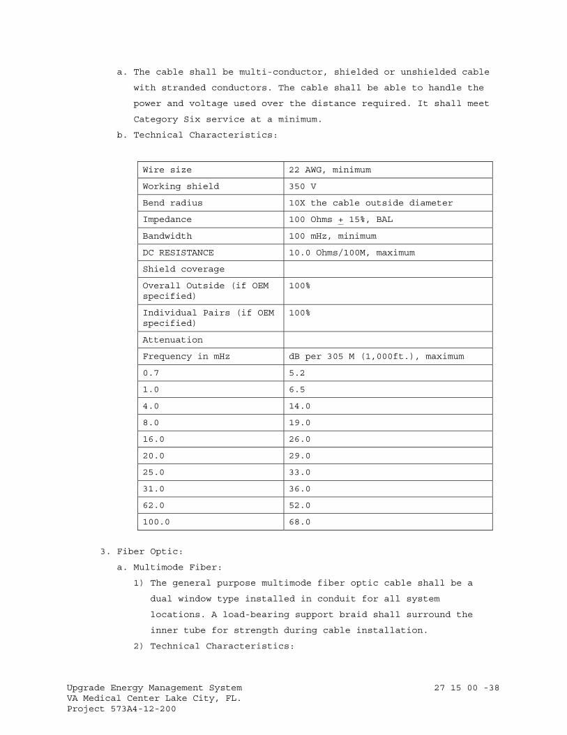
Upgrade Energy Management System 27 15 00 -38 VA Medical Center Lake City, FL. Project 573A4-12-200
a. The cable shall be multi-conductor, shielded or unshielded cable
with stranded conductors. The cable shall be able to handle the
power and voltage used over the distance required. It shall meet
Category Six service at a minimum.
b. Technical Characteristics:
Wire size 22 AWG, minimum
Working shield 350 V
Bend radius 10X the cable outside diameter
Impedance 100 Ohms + 15%, BAL
Bandwidth 100 mHz, minimum
DC RESISTANCE 10.0 Ohms/100M, maximum
Shield coverage
Overall Outside (if OEM specified)
100%
Individual Pairs (if OEM specified)
100%
Attenuation
Frequency in mHz dB per 305 M (1,000ft.), maximum
0.7 5.2
1.0 6.5
4.0 14.0
8.0 19.0
16.0 26.0
20.0 29.0
25.0 33.0
31.0 36.0
62.0 52.0
100.0 68.0
3. Fiber Optic:
a. Multimode Fiber:
1) The general purpose multimode fiber optic cable shall be a
dual window type installed in conduit for all system
locations. A load-bearing support braid shall surround the
inner tube for strength during cable installation.
2) Technical Characteristics:
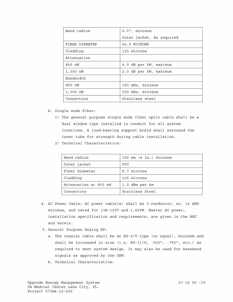
Upgrade Energy Management System 27 15 00 -39 VA Medical Center Lake City, FL. Project 573A4-12-200
Bend radius 6.0", minimum
Outer jacket, As required
FIBER DIAMETER 62.5 MICRONS
Cladding 125 microns
Attenuation
850 nM 4.0 dB per kM, maximum
1,300 nM 2.0 dB per kM, maximum
Bandwidth
850 nM 160 mHz, minimum
1,300 nM 500 mHz, minimum
Connectors Stainless steel
b. Single mode Fiber:
1) The general purpose single mode fiber optic cable shall be a
dual window type installed in conduit for all system
locations. A load-bearing support braid shall surround the
inner tube for strength during cable installation.
2) Technical Characteristics:
Bend radius 100 mm (4 in.) minimum
Outer jacket PVC
Fiber diameter 8.7 microns
Cladding 125 microns
Attenuation at 850 nM 1.0 dBm per km
Connectors Stainless Steel
4. AC Power Cable: AC power cable(s) shall be 3-conductor, no. 12 AWG
minimum, and rated for 13A-125V and 1,625W. Master AC power,
installation specification and requirements, are given in the NEC
and herein.
5. General Purpose Analog RF:
a. The coaxial cable shall be an RG-6/U type (or equal), minimum and
shall be increased in size (i.e. RG-ll/U, .500”, .750”, etc.) as
required to meet system design. It may also be used for baseband
signals as approved by the OEM.
b. Technical Characteristics:
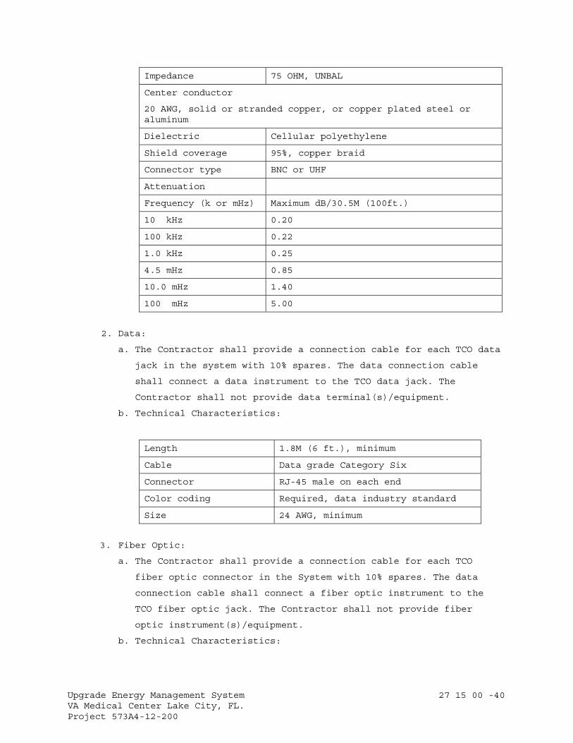
Upgrade Energy Management System 27 15 00 -40 VA Medical Center Lake City, FL. Project 573A4-12-200
Impedance 75 OHM, UNBAL
Center conductor
20 AWG, solid or stranded copper, or copper plated steel or aluminum
Dielectric Cellular polyethylene
Shield coverage 95%, copper braid
Connector type BNC or UHF
Attenuation
Frequency (k or mHz) Maximum dB/30.5M (100ft.)
10 kHz 0.20
100 kHz 0.22
1.0 kHz 0.25
4.5 mHz 0.85
10.0 mHz 1.40
100 mHz 5.00
2. Data:
a. The Contractor shall provide a connection cable for each TCO data
jack in the system with 10% spares. The data connection cable
shall connect a data instrument to the TCO data jack. The
Contractor shall not provide data terminal(s)/equipment.
b. Technical Characteristics:
Length 1.8M (6 ft.), minimum
Cable Data grade Category Six
Connector RJ-45 male on each end
Color coding Required, data industry standard
Size 24 AWG, minimum
3. Fiber Optic:
a. The Contractor shall provide a connection cable for each TCO
fiber optic connector in the System with 10% spares. The data
connection cable shall connect a fiber optic instrument to the
TCO fiber optic jack. The Contractor shall not provide fiber
optic instrument(s)/equipment.
b. Technical Characteristics:
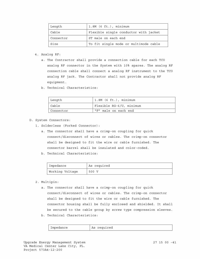
Upgrade Energy Management System 27 15 00 -41 VA Medical Center Lake City, FL. Project 573A4-12-200
Length 1.8M (6 ft.), minimum
Cable Flexible single conductor with jacket
Connector ST male on each end
Size To fit single mode or multimode cable
4. Analog RF:
a. The Contractor shall provide a connection cable for each TCO
analog RF connector in the System with 10% spares. The analog RF
connection cable shall connect a analog RF instrument to the TCO
analog RF jack. The Contractor shall not provide analog RF
equipment.
b. Technical Characteristics:
Length 1.8M (6 ft.), minimum
Cable Flexible RG-6/U, minimum
Connector “F” male on each end
D. System Connectors:
1. Solderless (Forked Connector):
a. The connector shall have a crimp-on coupling for quick
connect/disconnect of wires or cables. The crimp-on connector
shall be designed to fit the wire or cable furnished. The
connector barrel shall be insulated and color-coded.
b. Technical Characteristics:
Impedance As required
Working Voltage 500 V
2. Multipin:
a. The connector shall have a crimp-on coupling for quick
connect/disconnect of wires or cables. The crimp-on connector
shall be designed to fit the wire or cable furnished. The
connector housing shall be fully enclosed and shielded. It shall
be secured to the cable group by screw type compression sleeves.
b. Technical Characteristics:
Impedance As required

Upgrade Energy Management System 27 15 00 -42 VA Medical Center Lake City, FL. Project 573A4-12-200
Working Voltage 500 V
Number of pins As requires, usually 25 pairs minimum
3. Modular (RJ-45/11 and RJ-45): The connectors shall be commercial
types for voice and high speed data transmission applications. he
connector shall be compatible with telephone instruments, computer
terminals, and other type devices requiring linking through the
modular telecommunications outlet to the System. The connector shall
be compatible with UTP and STP cables.
a. Technical Characteristics:
Type Number of Pins
RJ-11/45 Compatible with RJ45
RJ-45 Eight
Dielectric Surge
Voltage 1,000V RMS, 60 Hz @ one minute, minimum
Current 2.2A RMS @ 30 Minutes or 7.0A RMS @ 5.0 seconds
Leakage 100 μA, maximum
Connectability
Initial contact resistance
20 mili-Ohms, maximum
Insulation displacement 10 mili-Ohms, maximum
Interface Must interface with modular jacks from a variety of OEMs. RJ-11/45 plugs shall provide connection when used in RJ-45 jacks.
Durability 200 insertions/withdrawals, minimum
4. Fiber Optic: The connectors shall be commercial types for voice and
high speed data transmission applications. The connector shall be
compatible with telephone instruments, computer terminals, and other
type devices requiring linking through the modular
telecommunications outlet to the system. The connector shall be
compatible with UTP and STP cables.
5. “BNC” Type:
a. The BNC connector shall have a bayonet locking coupling for quick
connect/disconnect of coaxial cable/termination's. It shall be a
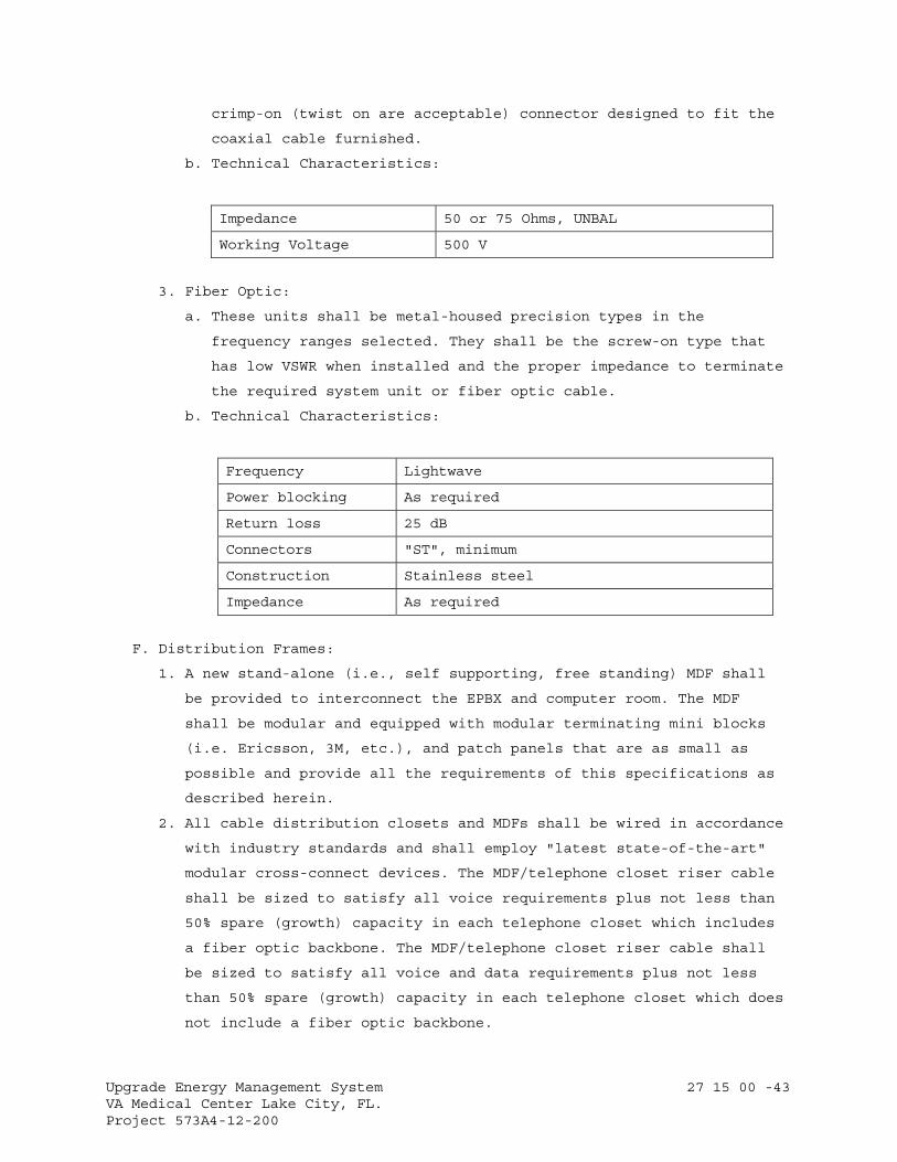
Upgrade Energy Management System 27 15 00 -43 VA Medical Center Lake City, FL. Project 573A4-12-200
crimp-on (twist on are acceptable) connector designed to fit the
coaxial cable furnished.
b. Technical Characteristics:
Impedance 50 or 75 Ohms, UNBAL
Working Voltage 500 V
3. Fiber Optic:
a. These units shall be metal-housed precision types in the
frequency ranges selected. They shall be the screw-on type that
has low VSWR when installed and the proper impedance to terminate
the required system unit or fiber optic cable.
b. Technical Characteristics:
Frequency Lightwave
Power blocking As required
Return loss 25 dB
Connectors "ST", minimum
Construction Stainless steel
Impedance As required
F. Distribution Frames:
1. A new stand-alone (i.e., self supporting, free standing) MDF shall
be provided to interconnect the EPBX and computer room. The MDF
shall be modular and equipped with modular terminating mini blocks
(i.e. Ericsson, 3M, etc.), and patch panels that are as small as
possible and provide all the requirements of this specifications as
described herein.
2. All cable distribution closets and MDFs shall be wired in accordance
with industry standards and shall employ "latest state-of-the-art"
modular cross-connect devices. The MDF/telephone closet riser cable
shall be sized to satisfy all voice requirements plus not less than
50% spare (growth) capacity in each telephone closet which includes
a fiber optic backbone. The MDF/telephone closet riser cable shall
be sized to satisfy all voice and data requirements plus not less
than 50% spare (growth) capacity in each telephone closet which does
not include a fiber optic backbone.
Upgrade Energy Management System 27 15 00 -44 VA Medical Center Lake City, FL. Project 573A4-12-200
3. The MDF and all intermediate distribution frames shall be connected
to the EPBX system ground.
4. Technical Characteristics:
Telephone
IDC type unit As described in Part 2
Contact wires 50 micron of Gold over Nickel
Contact pressure 100 Grams, MIN
110A Punch blocks Acceptable alternate to IDC
Data 110A blocks as described in Part 2
Fiber optic Patch panel as described in Part 2
Analog Video Patch panel as described in Part 2
2.3 TELECOMMUNCATIONS CLOSET REQUIREMENTS
Refer to VA Handbook H-088C3, Telephone System Requirements, for specific TC
guidelines for size, power input, security, and backboard mounting
requirements. It is the Contractors responsibility to ensure TC compliance
with the System Requirements.
2.4 ENVIRONMENTAL REQUIREMENTS
Technical submittals shall identify the environmental specifications
for housing the system. These environmental specifications shall
identify the requirements for initial and expanded system
configurations for:
A. Floor loading for batteries and cabinets.
B. Minimum floor space and ceiling heights.
C. Minimum size of doors for equipment passage.
D. Power requirements: The bidders shall provide the specific voltage,
amperage, phases, and quantities of circuits required.
E. Air conditioning, heating, and humidity requirements. The bidder shall
identify the ambient temperature and relative humidity operating ranges
required preventing equipment damage.
F. Air conditioning requirements (expressed in BTU per hour, based on
adequate dissipation of generated heat to maintain required room and
equipment standards).
G. Proposed floor plan based on the expanded system configuration of the
bidder's proposed EPBX for this Facility.
H. Conduit size requirement (between equipment room and console room).
Upgrade Energy Management System 27 15 00 -45 VA Medical Center Lake City, FL. Project 573A4-12-200
2.5 INSTALLATION KIT
The kit shall be provided that, at a minimum, includes all connectors
and terminals, labeling systems, audio spade lugs, barrier strips,
punch blocks or wire wrap terminals, heat shrink tubing, cable ties,
solder, hangers, clamps, bolts, conduit, cable duct, and/or cable tray,
etc., required to accomplish a neat and secure installation. All wires
shall terminate in a spade lug and barrier strip, wire wrap terminal or
punch block. Unfinished or unlabeled wire connections shall not be
allowed. Turn over to the RE all unused and partially opened
installation kit boxes, coaxial, fiberoptic, and twisted pair cable
reels, conduit, cable tray, and/or cable duct bundles, wire rolls,
physical installation hardware. The following are the minimum required
installation sub-kits:
A. System Grounding:
1. The grounding kit shall include all cable and installation hardware
required. All radio equipment shall be connected to earth ground via
internal building wiring, according to the NEC.
2. This includes, but is not limited to:
a. Coaxial Cable Shields.
b. Control Cable Shields.
c. Data Cable Shields.
d. Equipment Racks.
e. Equipment Cabinets.
f. Conduits.
g. Duct.
h. Cable Trays.
i. Power Panels.
j. Connector Panels.
k. Grounding Blocks.
B. Coaxial Cable: The coaxial cable kit shall include all coaxial
connectors, cable tying straps, heat shrink tabbing, hangers, clamps,
etc., required to accomplish a neat and secure installation.
C. Wire and Cable: The wire and cable kit shall include all connectors and
terminals, audio spade lugs, barrier straps, punch blocks, wire wrap
strips, heat shrink tubing, tie wraps, solder, hangers, clamps, labels
etc., required to accomplish a neat and orderly installation.
D. Conduit, Cable Duct, and Cable Tray: The kit shall include all conduit,
duct, trays, junction boxes, back boxes, cover plates, feed through
Upgrade Energy Management System 27 15 00 -46 VA Medical Center Lake City, FL. Project 573A4-12-200
nipples, hangers, clamps, other hardware required to accomplish a neat
and secure conduit, cable duct, and/or cable tray installation in
accordance with the NEC and this document.
E. Equipment Interface: The equipment kit shall include any item or
quantity of equipment, cable, mounting hardware and materials needed to
interface the systems with the identified sub-system(s) according to
the OEM requirements and this document.
F. Labels: The labeling kit shall include any item or quantity of labels,
tools, stencils, and materials needed to completely and correctly label
each subsystem according to the OEM requirements, as-installed
drawings, and this document.
G. Documentation: The documentation kit shall include any item or
quantity of items, computer discs, as installed drawings, equipment,
maintenance, and operation manuals, and OEM materials needed to
completely and correctly provide the system documentation as required
by this document and explained herein.
PART 3 - EXECUTION
3.1 INSTALLATION
A. Product Delivery, Storage and Handling:
1. Delivery: Deliver materials to the job site in OEM's original
unopened containers, clearly labeled with the OEM's name and
equipment catalog numbers, model and serial identification numbers.
The RE may inventory the cable, patch panels, and related equipment.
2. Storage and Handling: Store and protect equipment in a manner, which
will preclude damage as directed by the RE.
B. System Installation:
1. After the contract’s been awarded, and within the time period
specified in the contract, the Contractor shall deliver the total
system in a manner that fully complies with the requirements of this
specification. The Contractor shall make no substitutions or changes
in the System without written approval from the RE and PM.
2. The Contractor shall install all equipment and systems in a manner
that complies with accepted industry standards of good practice, OEM
instructions, the requirements of this specification, and in a
manner which does not constitute a safety hazard. The Contractor
shall insure that all installation personnel understands and
complies with all the requirements of this specification.
Upgrade Energy Management System 27 15 00 -47 VA Medical Center Lake City, FL. Project 573A4-12-200
3. The Contractor shall install suitable filters, traps, directional
couplers, splitters, TC’s, and pads for minimizing interference and
for balancing the System.
4. All passive equipment shall be connected according to the OEM's
specifications to insure future correct termination, isolation,
impedance match, and signal level balance at each telephone/data
outlet.
5. Where TCOs are installed adjacent to each other, install one outlet
for each instrument.
6. All lines shall be terminated in a suitable manner to facilitate
future expansion of the System. There shall be a minimum of one
spare 25 pair cable at each distribution point on each floor.
7. All vertical and horizontal copper and fiber optic, and coaxial
cables shall be terminated so any future changes only requires
modifications of the existing EPBX or signal closet equipment only.
8. Terminating resistors or devices shall be used to terminate all
unused branches, outlets, equipment ports of the System, and shall
be devices designed for the purpose of terminating fiber optic or
twisted pair, and coaxial, and lightwave cables carrying data, and
analog signals data
9. Equipment installed outdoors shall be weatherproof or installed in
weatherproof enclosures with hinged doors and locks with two keys.
10. Equipment installed indoors shall be installed in metal cabinets
with hinged doors and locks with two keys.
C. Conduit and Signal Ducts:
1. Conduit:
a. The Contractor shall employ the latest installation practices and
materials. The Contractor shall provide conduit, junction boxes,
connectors, sleeves, weatherheads, pitch pockets, and associated
sealing materials not specifically identified in this document as
GFE. Conduit penetrations of walls, ceilings, floors,
interstitial space, fire barriers, etc., shall be sleeved and
sealed. The minimum conduit size shall be 19 mm (3/4 in.).
b. All cables shall be installed in separate conduit and/or signal
ducts (exception from the separate conduit requirement to allow
telephone cables to be installed in partitioned cable tray with
data cables may be granted in writing by the RE if requested.)
Conduits shall be provided in accordance with Section 27 05 33,
Upgrade Energy Management System 27 15 00 -48 VA Medical Center Lake City, FL. Project 573A4-12-200
RACEWAYS AND BOXES FOR COMMUNICATIONS SYSTEMS, and NEC Articles
517 for Critical Care and 800 for Communications systems, at a
minimum.
c. When metal, plastic covered, etc., flexible cable protective
armor or systems are specifically authorized to be provided for
use in the System, their installation guidelines and standards
shall be as specified herein, Section 27 05 33, RACEWAYS AND
BOXES FOR COMMUNICATIONS SYSTEMS, and the NEC.
d. When ”innerduct” flexible cable protective systems is
specifically authorized to be provided for use in the System,
it’s installation guidelines and standards shall be as the
specified herein, Section 27 05 33, RACEWAYS AND BOXES FOR
COMMUNICATIONS SYSTEMS, and the NEC.
e. Conduit (including GFE) fill shall not exceed 40%. Each conduit
end shall be equipped with a protective insulator or sleeve to
cover the conduit end, connection nut or clamp, to protect the
wire or cable during installation and remaining in the conduit.
Electrical power conduit shall be installed in accordance with
the NEC. AC power conduit shall be run separate from signal
conduit.
f. When metal, plastic covered, etc., flexible cable protective
armor or systems are specifically authorized to be provided for
use in the System, their installation guidelines and standards
shall be as specified herein, Section 27 05 33, RACEWAYS AND
BOXES FOR COMMUNICATIONS SYSTEMS, and the NEC.
2. Signal Duct, Cable Duct, or Cable Tray:
a. The Contractor shall use existing signal duct, cable duct, and/or
cable tray, when identified and approved by the RE.
b. Approved signal and/or cable duct shall be a minimum size of 100
mm x 100 mm (4 in. X 4 in.) inside diameter with removable tops
or sides, as appropriate. Protective sleeves, guides or barriers
are required on all sharp corners, openings, anchors, bolts or
screw ends, junction, interface and connection points.
c. Approved cable tray shall be fully covered, mechanically and
physically partitioned for multiple electronic circuit use, and
be UL certified and labeled for use with telecommunication
circuits and/or systems. The RE shall approve width and height
dimensions.
Upgrade Energy Management System 27 15 00 -49 VA Medical Center Lake City, FL. Project 573A4-12-200
D. Distribution System Signal Wires and Cables:
1. Wires and cables shall be provided in the same manner and use like
construction practices as Fire Protective and other Emergency
Systems that are identified and outlined in NFPA 101, Life Safety
Code, Chapters 7, 12, and/or 13, NFPA 70, National Electrical Code,
Chapter 7, Special Conditions. The wires and cables shall be able to
withstand adverse environmental conditions in their respective
location without deterioration. Wires and cables shall enter each
equipment enclosure, console, cabinet or rack in such a manner that
all doors or access panels can be opened and closed without removal
or disruption of the cables.
a. Each wire and cable shall terminate on an item of equipment by
direct connection. Spare or unused wire and cable shall be
provided with appropriate connectors (female types) that are
installed in appropriate punch blocks, barrier strips, patch, or
bulkhead connector panels.
b. Fiber optic cables that are spare, unused or dark shall be
provided with Industry Standard “ST” type female connectors
installed in appropriate break out, patch, or bulkhead connector
panels provided in enclosure(s) and shall be protected from the
environment.
c. Coaxial cables that are spare, unused or dark shall be provided
with the cable OEM specified type female connectors installed in
appropriate break out, patch, or bulkhead connector panels
provided in enclosure(s) and shall be protected from the
environment.
d. All cable junctions and taps shall be accessible. Provide an 8”
X 8” X 4” (minimum) junction box attached to the cable duct or
raceway for installation of distribution system passive
equipment. Ensure all equipment and tap junctions are accessible.
2. Routing and Interconnection:
a. Wires or cables between consoles, cabinets, racks and other
equipment shall be in an approved conduit, signal duct, cable
duct, or cable tray that is secured to building structure.
b. Wires and cables shall be insulated to prevent contact with
signal or current carrying conductors. Wires or cables used in
assembling consoles, panels, equipment cabinets and racks shall
be formed into harnesses that are bundled and tied. Harnessed
Upgrade Energy Management System 27 15 00 -50 VA Medical Center Lake City, FL. Project 573A4-12-200
wires or cables shall be combed straight, formed and dressed in
either a vertical or horizontal relationship to equipment,
controls, components or terminations.
c. Harnesses with intertwined members are not acceptable. Each wire
or cable that breaks out from a harness for connection or
termination shall have been tied off at that harness or bundle
point, and be provided with a neatly formed service loop.
d. Wires and cables shall be grouped according to service (i.e.: AC,
grounds, signal, DC, control, etc.). DC, control and signal
cables may be included with any group. Wires and cables shall be
neatly formed and shall not change position in the group
throughout the conduit run. Wires and cables in approved signal
duct, conduit, cable ducts, or cable trays shall be neatly
formed, bundled, tied off in 600 mm to 900 mm (24 in. to 36 in.)
lengths and shall not change position in the group throughout the
run. Concealed splices are not allowed.
e. Separate, organize, bundle, and route wires or cables to restrict
EMI, channel crosstalk, or feedback oscillation inside any
enclosure. Looking at any enclosure from the rear (wall mounted
enclosures, junction, pull or interface boxes from the front),
locate AC power, DC and speaker wires or cables on the left;
coaxial, control, microphone and line level audio and data wires
or cables, on the right. This installation shall be accomplished
with ties and/or fasteners that will not damage or distort the
wires or cables. Limit spacing between tied off points to a
maximum of 150 mm (6 inches).
f. Do not pull wire or cable through any box, fitting or enclosure
where change of cable tray or signal or cable duct alignment or
direction occurs. Ensure the proper bend radius is maintained for
each wire or cable as specified by it's OEM.
g. Employ temporary guides, sheaves, rollers, and other necessary
items to protect the wire or cable from excess tension or damage
from bending during installation. Abrasion to wire or cable
jackets is not acceptable and will not be allowed. Replace all
cables whose jacket has been abraded. The discovery of any
abraded and/or damaged cables during the proof of performance
test shall be grounds for declaring the entire system
unacceptable and the termination of the proof of performance
Upgrade Energy Management System 27 15 00 -51 VA Medical Center Lake City, FL. Project 573A4-12-200
test. Completely cover edges of wire or cable passing through
holes in chassis, cabinets or racks, enclosures, pull or junction
boxes, conduit, etc., with plastic or nylon grommeting.
h. Cable runs shall be splice free between conduit junction and
interface boxes and equipment locations.
i. Cables shall be installed and fastened without causing sharp
bends or rubbing of the cables against sharp edges. Cables shall
be fastened with hardware that will not damage or distort them.
j. Cables shall be labeled with permanent markers at the terminals
of the electronic and passive equipment and at each junction
point in the System. The lettering on the cables shall correspond
with the lettering on the record diagrams.
k. Completely test all of the cables after installation and replace
any defective cables.
l. Wires or cables that are installed outside of buildings shall be
in conduit, secured to solid building structures. If specifically
approved, on a case by case basis, to be run outside of conduit,
the wires or cables shall be installed, as described herein. The
bundled wires or cables must: Be tied at not less than 460 mm (18
in.) intervals to a solid building structure; have ultra violet
protection and be totally waterproof (including all connections).
The laying of wires or cables directly on roof tops, ladders,
drooping down walls, walkways, floors, etc. is not allowed and
will not be approved.
m. Wires or cables installed outside of conduit, cable trays,
wireways, cable duct, etc.
1) Only when specifically authorized as described herein, will
wires or cables be identified and approved to be installed
outside of conduit. The wire or cable runs shall be UL rated
plenum and OEM certified for use in air plenums.
2) Wires and cables shall be hidden, protected, fastened and tied
at 600 mm (24 in.) intervals, maximum, as described herein to
building structure.
3) Closer wire or cable fastening intervals may be required to
prevents sagging, maintain clearance above suspended ceilings,
remove unsightly wiring and cabling from view and discourage
tampering and vandalism. Wire or cable runs, not provided in
conduit, that penetrate outside building walls, supporting
Upgrade Energy Management System 27 15 00 -52 VA Medical Center Lake City, FL. Project 573A4-12-200
walls, and two hour fire barriers shall be sleeved and sealed
with an approved fire retardant sealant.
4) Wire or cable runs to system components installed in walls
(i.e.: volume attenuators, circuit controllers, signal, or
data outlets, etc.) may, when specifically authorized by the
RE, be fished through hollow spaces in walls and shall be
certified for use in air plenum areas.
n. Wires or cables installed in underground conduit, duct, etc.
1) Wires or cables installed in underground installations shall
be waterproofed by the inclusion of a water protective barrier
(i.e. gel, magma, etc.) or flooding compound between the
outside jacket and first shield. Each underground connection
shall be accessible in a manhole, recessed ground level
junction box, above ground pedestal, etc., and shall be
provided with appropriate waterproof connectors to match the
cable being installed. Once the System has been tested and
found to meet the System performance standards and accepted by
VA, the Contractor shall provide waterproof shrink tubing or
approved mastic to fully encompass each wire or cable
connection and overlay at least 150 mm (6 inches) above each
wire or cable jacket trim point.
2) It is not acceptable to connect waterproofed cable directly to
an inside CCS punch block or directly to an equipment
connection port. When an under ground cable enters a building,
it shall be routed directly to the closest TC that has been
designated as the building’s IMTC. The Contractor shall
provide a “transition” splice in this TC where the “water
proofed” cable enters on one side and “dry” cable exits on the
other side. The “transition” splice shall be fully waterproof
and be capable of reentry for system servicing. Additionally,
the transition splice shall not allow the waterproofing
compound to migrate from the water proof cable to the dry
cable.
3) Warning tape shall be continuously placed 300 mm (12 inches)
above buried conduit, cable, etc.
E. Outlet Boxes, Back Boxes, and Faceplates:
Upgrade Energy Management System 27 15 00 -53 VA Medical Center Lake City, FL. Project 573A4-12-200
1. Outlet Boxes: Signal, power, interface, connection, distribution,
and junction boxes shall be provided as required by the system
design, on-site inspection, and review of the contract drawings.
2. Back Boxes: Back boxes shall be provided as directed by the OEM as
required by the approved system design, on-site inspection, and
review of the contract drawings.
3. Face Plates (or Cover Plates): Faceplates shall be of a standard
type, stainless steel, anodized aluminum or UL approved cycolac
plastic construction and provided by the Contractor for each
identified system outlet location. Connectors and jacks appearing on
the faceplate shall be clearly and permanently marked.
F. Connectors: Circuits, transmission lines, and signal extensions shall
have continuity, correct connection and polarity. A uniform polarity
shall be maintained between all points in the system.
1. Wires:
a. Wire ends shall be neatly formed and where insulation has been
cut, heat shrink tubing shall be employed to secure the
insulation on each wire. Tape of any type is not acceptable.
b. Audio spade lugs shall be installed on each wire (including spare
or unused) end and connect to screw terminals of appropriate size
barrier strips. AC barrier strips shall be provided with a
protective cover to prevent accidental contact with wires
carrying live AC current. Punch blocks are approved for signal,
not AC wires. Wire Nut or "Scotch Lock" connectors are not
acceptable for signal wire installation.
2. Cables: Each connector shall be designed for the specific size cable
being used and installed with the OEM's approved installation tool.
Typical system cable connectors include; but, are not limited to:
Audio spade lug, punch block, wirewrap, etc.
G. AC Power: AC power wiring shall be run separately from signal cable.
H. Grounding:
1. General: The Contractor shall ground all Contractor Installed
Equipment and identified Government Furnished Equipment to eliminate
all shock hazards and to minimize, to the maximum extent possible,
all ground loops, common mode returns, noise pickup, crosstalk, etc.
The total ground resistance shall be 0.1 Ohm or less.
a. The Contractor shall install lightning arrestors and grounding in
accordance with the NFPA and this specification.

Upgrade Energy Management System 27 15 00 -54 VA Medical Center Lake City, FL. Project 573A4-12-200
c. Under no conditions shall the AC neutral, either in a power panel
or in a receptacle outlet, be used for system control, subcarrier
or audio reference ground.
d. The use of conduit, signal duct or cable trays as system or
electrical ground is not acceptable and will not be permitted.
These items may be used only for the dissipation of internally
generated static charges (not to be confused with externally
generated lightning) that may applied or generated outside the
mechanical and/or physical confines of the System to earth
ground. The discovery of improper system grounding shall be
grounds to declare the System unacceptable and the termination of
all system acceptance testing.
2. Cabinet Buss: A common ground buss of at least #10 AWG solid copper
wire shall extend throughout each equipment cabinet and be connected
to the system ground. Provide a separate isolated ground connection
from each equipment cabinet ground buss to the system ground. Do not
tie equipment ground busses together.
3. Equipment: Equipment shall be bonded to the cabinet bus with copper
braid equivalent to at least #12 AWG. Self grounding equipment
enclosures, racks or cabinets, that provide OEM certified functional
ground connections through physical contact with installed
equipment, are acceptable alternates.
4. Cable Shields: Cable shields shall be bonded to the cabinet ground
buss with #12 AWG minimum stranded copper wire at only one end of
the cable run. Cable shields shall be insulated from each other,
faceplates, equipment racks, consoles, enclosures or cabinets;
except, at the system common ground point. Coaxial and audio cables,
shall have one ground connection at the source; in all cases, cable
shield ground connections shall be kept to a minimum.
I. Labeling: Provide labeling in accordance with ANSI/EIA/TIA-606-A.
Handwritten labels are not acceptable.
1. Cable and Wires (Hereinafter referred to as “Cable”): Cables shall
be labeled at both ends in accordance with ANSI/EIA/TIA-606-A.
Labels shall be permanent in contrasting colors. Cables shall be
identified according to the System “Record Wiring Diagrams”.
2. Equipment: System equipment shall be permanently labeled with
contrasting plastic laminate or bakelite material. System equipment
Upgrade Energy Management System 27 15 00 -55 VA Medical Center Lake City, FL. Project 573A4-12-200
shall be labeled on the face of the unit corresponding to its
source.
3. Conduit, Cable Duct, and/or Cable Tray: The Contractor shall label
all conduit, duct and tray, including utilized GFE, with permanent
marking devices or spray painted stenciling a minimum of 3 meters
(10 ft.) identifying it as the System. In addition, each enclosure
shall be labeled according to this standard.
4. Termination Hardware: The Contractor shall label workstation outlets
and patch panel connections using color coded labels with
identifiers in accordance with ANSI/EIA/TIA-606-A and the “Record
Wiring Diagrams”.
3.2 TESTS
A. Interim Inspection:
1. This inspection shall verify that the equipment provided adheres to
the installation requirements of this document. The interim
inspection will be conducted by a factory-certified representative
and witnessed by a Government Representative. Each item of installed
equipment shall be checked to insure appropriate UL certification
markings. This inspection shall verify cabling terminations in
telecommunications rooms and at workstations adhere to color code
for T568B pin assignments and cabling connections are in compliance
with ANSI/EIA/TIA standards. Visually confirm Category 6 marking of
outlets, faceplates, outlet/connectors and patch cords.
2. Perform fiber optical field inspection tests via attenuation
measurements on factory reels and provide results along with
manufacturer certification for factory reel tests. Remove failed
cable reels from project site upon attenuation test failure.
3. The Contractor shall notify the RE, in writing, of the estimated
date the Contractor expects to be ready for the interim inspection,
at least 20 working days before the requested inspection date.
4. Results of the interim inspection shall be provided to the PM. If
major or multiple deficiencies are discovered, a second interim
inspection may be required before permitting the Contractor to
continue with the system installation.
5. The PM shall determine if an additional inspection is required, or
if the Contractor will be allowed to proceed with the installation.
In either case, re-inspection of the deficiencies noted during the
Upgrade Energy Management System 27 15 00 -56 VA Medical Center Lake City, FL. Project 573A4-12-200
interim inspection(s), will be part of the proof of performance
test. The interim inspection shall not affect the Systems’
completion date. The Contracting Officer shall ensure all test
documents will become a part of the Systems record documentation.
B. Pretesting:
1. Upon completing the installation of the System, the Contractor shall
align and balance the system. The Contractor shall pretest the
entire system.
2. Pretesting Procedure:
a. During the system pretest, the Contractor shall verify (utilizing
the approved spectrum analyzer and test equipment) that the
System is fully operational and meets all the system performance
requirements of this standard.
b. The Contractor shall pretest and verify that all System functions
and specification requirements are met and operational, no
unwanted aural effects, such as signal distortion, noise pulses,
glitches, audio hum, poling noise, etc. are present. The
Contractor shall measure and record the aural carrier levels of
each system telephone and data channel, at each of the following
points in the system:
1) Local Telephone Company Interfaces or Inputs.
2) EPBX interfaces or inputs and outputs.
3) MDF interfaces or inputs and outputs.
4) EPBX output S/NR for each telephone and data channel.
5) Signal Level at each interface point to the distribution
system, the last outlet on each trunk line plus all outlets
installed as part of this contract.
3. The Contractor shall provide four (4) copies of the recorded system
pretest measurements and the written certification that the System
is ready for the formal acceptance test shall be submitted to the
RE.
C. Acceptance Test: After the System has been pretested and the Contractor
has submitted the pretest results and certification to the RE, then the
Contractor shall schedule an acceptance test date and give the RE 30
days written notice prior to the date the acceptance test is expected
to begin. The System shall be tested in the presence of a Government
Representative and an OEM certified representative. The System shall be
tested utilizing the approved test equipment to certify proof of
Upgrade Energy Management System 27 15 00 -57 VA Medical Center Lake City, FL. Project 573A4-12-200
performance and Life Safety compliance. The test shall verify that the
total System meets the requirements of this specification. The
notification of the acceptance test shall include the expected length
(in time) of the test.
D. Verification Tests:
1. Test the UTP backbone copper cabling for DC loop resistance, shorts,
opens, intermittent faults, and polarity between conductors, and
between conductors and shield, if cable has an overall shield. Test
the operation of shorting bars in connection blocks. Test cables
after termination and prior to cross-connection.
2. Multimode Fiber Optic Cable: Perform end-to-end attenuation tests in
accordance with ANSI/EIA/TIA-568-B.3 and ANSI/EIA/TIA-526-14A using
OTDR. Perform verification acceptance test.
3. Single mode Fiber Optic Cable: Perform end-to-end attenuation tests
in accordance with ANSI/EIA/TIA-568-B.3 and ANSI/EIA/TIA-526-7 using
OTDR. Perform verification acceptance test.
E. Performance Testing:
1. Perform Category 6 tests in accordance with ANSI/EIA/TIA-568-B.1 and
ANSI/EIA/TIA-568-B.2. Test shall include the following: wire map,
length, insertion loss, return loss, NEXT, PSNEXT, ELFEXT, PSELFEXT,
propagation delay and delay skew.
2. Fiber Optic Links: Perform end-to-end fiber optic cable link tests
in accordance with ANSI/EIA/TIA-568-B.3.
F. Total System Acceptance Test: The Contractor shall perform verification
tests for UTP copper cabling system(s) and the multimode and single
mode fiber optic cabling system(s) after the complete telecommunication
distribution system and workstation outlet are installed.
1. Data Testing: Connect to the network interface device at the
demarcation point. Log onto the network to ensure proper connection
to the network is achieved.
3.3 TRAINING
A. Furnish the services of a factory-trained engineer or technician for a
total of two four hour classes to instruct designated Facility IRM
personnel. Instruction shall include cross connection, corrective, and
preventive maintenance of the System and equipment.
B. Before the System can be accepted by the VA, this training must be
accomplished. Training will be scheduled at the convenience of the
Facilities Contracting Officer and Chief of Engineering Service.
Upgrade Energy Management System 27 15 00 -58 VA Medical Center Lake City, FL. Project 573A4-12-200
3.4 WARRANTY
A. Comply with FAR clause 52.246-21, except that warranty shall be as
follows:
1. The Contractor shall warranty that all installed material and
equipment will be free from defects, workmanship, and will remain so
for a period of one year from date of final acceptance of the System
by the VA. The Contractor shall provide OEM’s equipment warranty
documents, to the RE (or Facility Contracting Officer if the
Facility has taken procession of the building(s)), that certifies
each item of equipment installed conforms to OEM published
specifications.
2. The Contractor's maintenance personnel shall have the ability to
contact the Contractor and OEM for emergency maintenance and
logistic assistance, remote diagnostic testing, and assistance in
resolving technical problems at any time. The Contractor and OEM
shall provide this contact capability at no additional cost to the
VA.
3. All Contractor installation, maintenance, and supervisor personnel
shall be fully qualified by the OEM and must provide two (2) copies
of current and qualified OEM training certificates and OEM
certification upon request.
4. Additionally, the Contractor shall accomplish the following minimum
requirements during the one year warranty period:
a. Response Time:
1) The RE (or facility Contracting Officer if the facility has
taken possession of the building[s]) are the Contractor’s
reporting and contact officials for the System trouble calls,
during the warranty period.
2) A standard workweek is considered 8:00 A.M. to 5:00 P.M.,
Monday through Friday exclusive of Federal Holidays.
3) The Contractor shall respond and correct on-site trouble
calls, during the standard work week to:
a) A routine trouble call within one working days of its
report. A routine trouble is considered a trouble which
causes a system outlet, station, or patch cord to be
inoperable.
b) An emergency trouble call within 6 hours of its report. An
emergency trouble is considered a trouble which causes a
Upgrade Energy Management System 27 15 00 -59 VA Medical Center Lake City, FL. Project 573A4-12-200
subsystem or distribution point to be inoperable at
anytime. Additionally, the loss of a minimum of 50 station
or system lines shall be deemed as this type of a trouble
call.
4) The Contractor shall respond on-site to a catastrophic trouble
call within 4 hours of its report. A catastrophic trouble call
is considered total system failure.
a) If a system failure cannot be corrected within four hours
(exclusive of the standard work time limits), the
Contractor shall be responsible for providing alternate
system CSS or TCO equipment, or cables. The alternate
equipment and/or cables shall be operational within four
hours after the four hour trouble shooting time.
b) Routine or emergency trouble calls in critical emergency
health care facilities (i.e., cardiac arrest, intensive
care units, etc.) shall also be deemed as a catastrophic
trouble call if so determined by the RE or Facility
Director. The RE or Facility Contracting Officer shall
notify the Contractor of this type of trouble call at the
direction of the Facilities Director.
b. Required on-site visits during the one year warranty period
1) The Contractor shall visit, on-site, for a minimum of eight
hours, once every 12 weeks, during the warranty period, to
perform system preventive maintenance, equipment cleaning, and
operational adjustments to maintain the System according the
descriptions identified in this SPEC.
a) The Contractor shall arrange all Facility visits with the
RE or Facility Contracting Officer prior to performing the
required maintenance visits.
b) The Contractor in accordance with the OEM’s recommended
practice and service intervals shall perform preventive
maintenance during a non-busy time agreed to by the RE or
Facility Contracting Officer and the Contractor.
c) The preventive maintenance schedule, functions and reports
shall be provided to and approved by the RE or Facility
Contracting Officer.
2) The Contractor shall provide the Facility Contracting Officer
a type written report itemizing each deficiency found and the
Upgrade Energy Management System 27 15 00 -60 VA Medical Center Lake City, FL. Project 573A4-12-200
corrective action performed during each required visit or
official reported trouble call. The Contractor shall provide
the RE with sample copies of these reports for review and
approval at the beginning of the Total System Acceptance Test.
The following reports are the minimum required:
a) Monthly Report: The Contractor shall provide a monthly
summary all equipment and sub-systems serviced during this
warranty period to RE or Facilities Contracting Officer by
the fifth working day after the end of each month. The
report shall clearly and concisely describe the services
rendered, parts replaced and repairs performed. The report
shall prescribe anticipated future needs of the equipment
and Systems for preventive and predictive maintenance
b) Contractor Log: The Contractor shall maintain a separate
log entry for each item of equipment and each sub-system of
the System. The log shall list dates and times of all
scheduled, routine, and emergency calls. Each emergency
call shall be described with details of the nature and
causes of emergency steps taken to rectify the situation
and specific recommendations to avoid such conditions in
the future.
3) The Facility Contracting Officer shall provide the Facility
Engineering Officer, two (2) copies of actual reports for
evaluation.
a) The Facility Contracting Officer shall ensure copies of
these reports are entered into the System’s official
acquisition documents.
b) The Facilities Chief Engineer shall ensure copies of these
reports are entered into the System’s official technical
as-installed documents.
B. Work Not Included: Maintenance and repair service shall not include the
performance of any work due to improper use, accidents, other vendor,
contractor, owner tampering or negligence, for which the Contractor is
not directly responsible and does not control. The Contractor shall
immediately notify the Facility Contracting Officer in writing upon the
discovery of these incidents. The Facility Contracting Officer will
investigate all reported incidents and render findings concerning any
Contractor’s responsibility.

Upgrade Energy Management System 27 15 00 -61 VA Medical Center Lake City, FL. Project 573A4-12-200
- - - E N D - - -