Embed Size (px)
Citation preview
FR-E700INSTRUCTION MANUAL (BASIC)FR-E720-0.1K to 15KFR-E740-0.4K to 15K
INVERTER
IB(NA)-0600276ENG-D(0801)MEE Printed in Japan Specifications subject to change without notice.
FR-E700
INVER
TERIN
STRU
CTIO
N M
AN
UA
L (BA
SIC)
D
700HEAD OFFICE: TOKYO BUILDING 2-7-3, MARUNOUCHI, CHIYODA-KU, TOKYO 100-8310, JAPAN
1
2
3
4
5
6
CONTENTS
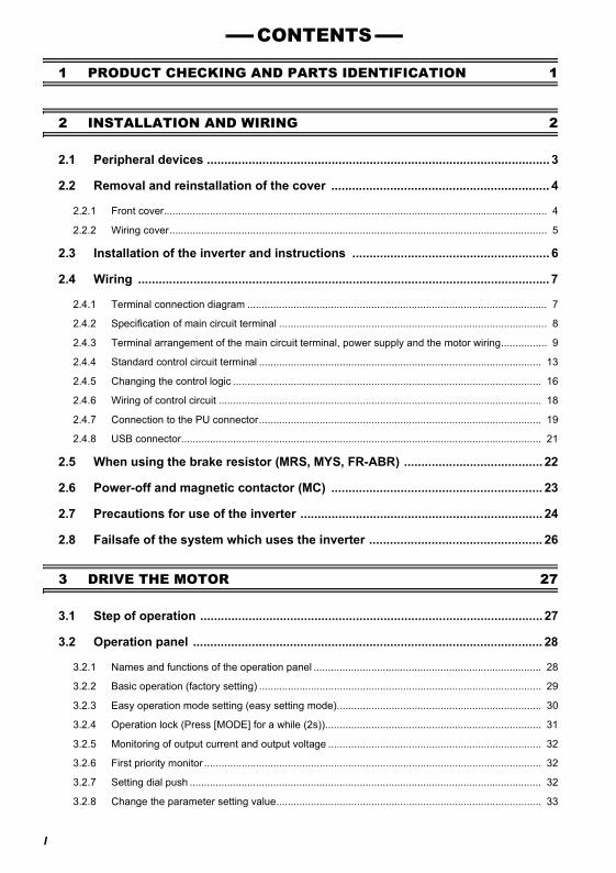
PRODUCT CHECKING AND PARTS IDENTIFICATION ............................. 1
INSTALLATION AND WIRING ..................................................................... 22.1 Peripheral devices..................................................................................................... 32.2 Removal and reinstallation of the cover.................................................................... 42.3 Installation of the inverter and instructions ............................................................... 62.4 Wiring ........................................................................................................................ 72.5 When using the brake resistor (MRS, MYS, FR-ABR)........................................... 222.6 Power-off and magnetic contactor (MC)................................................................. 232.7 Precautions for use of the inverter.......................................................................... 242.8 Failsafe of the system which uses the inverter....................................................... 26
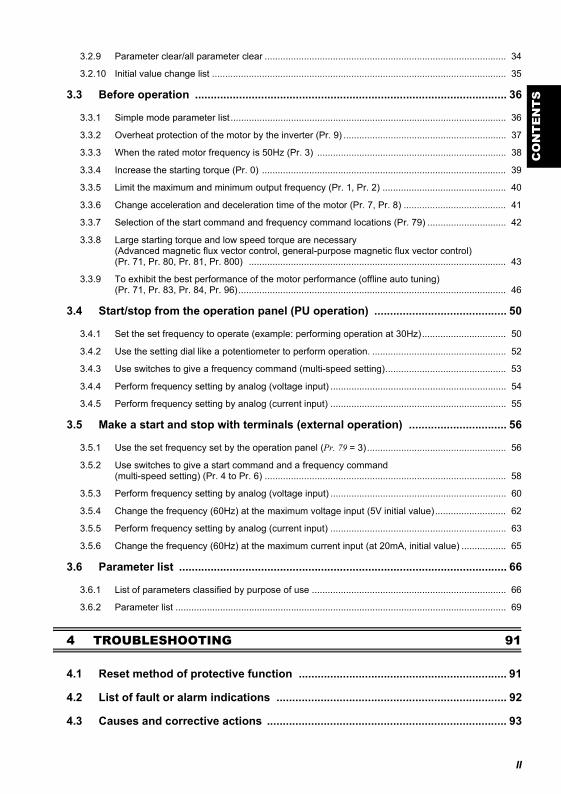
DRIVE THE MOTOR ................................................................................... 273.1 Step of operation..................................................................................................... 273.2 Operation panel....................................................................................................... 283.3 Before operation...................................................................................................... 363.4 Start/stop from the operation panel (PU operation)................................................ 503.5 Make a start and stop with terminals (external operation)...................................... 563.6 Parameter list .......................................................................................................... 66
TROUBLESHOOTING ................................................................................ 914.1 Reset method of protective function ....................................................................... 914.2 List of fault or alarm indications .............................................................................. 924.3 Causes and corrective actions................................................................................ 934.4 Correspondences between digital and actual characters..................................... 1014.5 Check and clear of the faults history..................................................................... 1024.6 Check first when you have some troubles............................................................ 104
PRECAUTIONS FOR MAINTENANCE AND INSPECTION..................... 1075.1 Inspection items .................................................................................................... 107
SPECIFICATIONS..................................................................................... 1156.1 Rating .................................................................................................................... 1156.2 Common specifications......................................................................................... 1176.3 Outline dimension drawings.................................................................................. 118
APPENDIX................................................................................................. 123
Thank you for choosing this Mitsubishi Inverter.This Instruction Manual (basic) is intended for users who "just want to run the inverter".If you are going to utilize functions and performance, refer to the Instruction Manual (applied) [IB-0600277ENG]. TheInstruction Manual (applied) is separately available from where you purchased the inverter or your Mitsubishi salesrepresentative.
1
2
3
4
5
6
This instruction manual (basic) provides handling information and precautions for use of the equipment.Please forward this instruction manual (basic) to the end user.
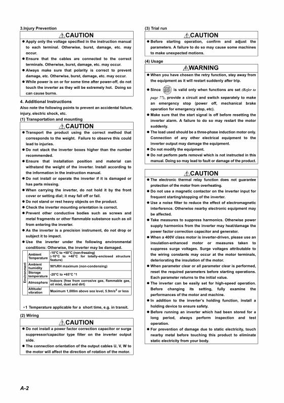
1. Electric Shock Prevention
2. Fire Prevention
This section is specifically about safety mattersDo not attempt to install, operate, maintain or inspect theinverter until you have read through the Instruction Manual(basic) and appended documents carefully and can use theequipment correctly. Do not use this product until you havea full knowledge of the equipment, safety information andinstructions.In this Instruction Manual (basic), the safety instructionlevels are classified into "WARNING" and "CAUTION".
Assumes that incorrect handling maycause hazardous conditions, resultingin death or severe injury.
Assumes that incorrect handling maycause hazardous conditions, resultingin medium or slight injury, or maycause physical damage only.
Note that even the level may lead to a seriousconsequence according to conditions. Please follow theinstructions of both levels because they are important topersonnel safety.
WARNING
CAUTION
CAUTION
While power is on or when the inverter is running, do notopen the front cover. Otherwise you may get an electricshock.Do not run the inverter with the front cover or wiring coverremoved. Otherwise, you may access the exposed high-voltage terminals or the charging part of the circuitry andget an electric shock.Even if power is off, do not remove the front cover exceptfor wiring or periodic inspection. You may access thecharged inverter circuits and get an electric shock.Before starting wiring or inspection, switch off power,check to make sure that the operation panel indicator isoff, wait for at least 10 minutes after the power supply hasbeen switched off, and check that there are no residualvoltage using a tester or the like. The capacitor is chargedwith high voltage for some time after power off and it isdangerous.This inverter must be earthed (grounded). Earthing(grounding) must conform to the requirements of nationaland local safety regulations and electrical code. (NECsection 250, IEC 536 class 1 and other applicablestandards)Use an neutral-point earthed (grounded) power supply for400V class inverter in compliance with EN standard.Any person who is involved in the wiring or inspection ofthis equipment should be fully competent to do the work.Always install the inverter before wiring. Otherwise, youmay get an electric shock or be injured.Perform setting dial and key operations with dry hands toprevent an electric shock. Otherwise you may get anelectric shock.Do not subject the cables to scratches, excessive stress,heavy loads or pinching. Otherwise, you may get anelectric shock.Do not change the cooling fan while power is on. It isdangerous to change the cooling fan while power is on.Do not touch the printed circuit board with wet hands.Otherwise, you may get an electric shock. When measuring the main circuit capacitor capacity, theDC voltage is applied to the motor for 1s at powering off.Never touch the motor terminal, etc. right after poweringoff to prevent an electric shock.
Install the inverter on an incombustible wall without holes,etc. Mounting it to or near combustible material can causea fire.If the inverter has become faulty, switch off the inverterpower. A continuous flow of large current could cause afire.When using a brake resistor, make up a sequence that willturn off power when an alarm signal is output. Otherwise,the brake resistor may excessively overheat due todamage of the brake transistor and such, causing a fire.Do not connect a resistor directly to the DC terminals P/+,N/-. This could cause a fire.
WARNING
CAUTION
A-1
3.Injury Prevention
4. Additional InstructionsAlso note the following points to prevent an accidental failure,injury, electric shock, etc.(1) Transportation and mounting
(2) Wiring
(3) Trial run
(4) Usage
Apply only the voltage specified in the instruction manualto each terminal. Otherwise, burst, damage, etc. mayoccur.Ensure that the cables are connected to the correctterminals. Otherwise, burst, damage, etc. may occur.Always make sure that polarity is correct to preventdamage, etc. Otherwise, burst, damage, etc. may occur.While power is on or for some time after power-off, do nottouch the inverter as they will be extremely hot. Doing socan cause burns.
Transport the product using the correct method thatcorresponds to the weight. Failure to observe this couldlead to injuries. Do not stack the inverter boxes higher than the numberrecommended.Ensure that installation position and material canwithstand the weight of the inverter. Install according tothe information in the instruction manual.Do not install or operate the inverter if it is damaged orhas parts missing.When carrying the inverter, do not hold it by the frontcover or setting dial; it may fall off or fail.Do not stand or rest heavy objects on the product.Check the inverter mounting orientation is correct.Prevent other conductive bodies such as screws andmetal fragments or other flammable substance such as oilfrom entering the inverter.As the inverter is a precision instrument, do not drop orsubject it to impact.Use the inverter under the following environmentalconditions: Otherwise, the inverter may be damaged.
∗1 Temperature applicable for a short time, e.g. in transit.
Do not install a power factor correction capacitor or surgesuppressor/capacitor type filter on the inverter outputside.The connection orientation of the output cables U, V, W tothe motor will affect the direction of rotation of the motor.
CAUTION
CAUTION
Envi
ronm
ent
AmbientTemperature
-10°C to +50°C (non-freezing)(-10°C to +40°C for totally-enclosed structurefeature)
Ambienthumidity 90%RH maximum (non-condensing)
Storagetemperature -20°C to +65°C *1
Atmosphere Indoors (free from corrosive gas, flammable gas,oil mist, dust and dirt)
Altitude/vibration Maximum 1,000m above sea level, 5.9m/s2 or less
CAUTION
Before starting operation, confirm and adjust theparameters. A failure to do so may cause some machinesto make unexpected motions.
When you have chosen the retry function, stay away fromthe equipment as it will restart suddenly after trip.
Since is valid only when functions are set (Refer to
page 77), provide a circuit and switch separately to makean emergency stop (power off, mechanical brakeoperation for emergency stop, etc).Make sure that the start signal is off before resetting theinverter alarm. A failure to do so may restart the motorsuddenly.The load used should be a three-phase induction motor only.Connection of any other electrical equipment to theinverter output may damage the equipment.Do not modify the equipment.Do not perform parts removal which is not instructed in thismanual. Doing so may lead to fault or damage of the product.
The electronic thermal relay function does not guaranteeprotection of the motor from overheating. Do not use a magnetic contactor on the inverter input forfrequent starting/stopping of the inverter.Use a noise filter to reduce the effect of electromagneticinterference. Otherwise nearby electronic equipment maybe affected.Take measures to suppress harmonics. Otherwise powersupply harmonics from the inverter may heat/damage thepower factor correction capacitor and generator.When a 400V class motor is inverter-driven, please use aninsulation-enhanced motor or measures taken tosuppress surge voltages. Surge voltages attributable tothe wiring constants may occur at the motor terminals,deteriorating the insulation of the motor.When parameter clear or all parameter clear is performed,reset the required parameters before starting operations.Each parameter returns to the initial value.The inverter can be easily set for high-speed operation.Before changing its setting, fully examine theperformances of the motor and machine.In addition to the inverter’s holding function, install aholding device to ensure safety.Before running an inverter which had been stored for along period, always perform inspection and testoperation.For prevention of damage due to static electricity, touchnearby metal before touching this product to eliminatestatic electricity from your body.
CAUTION
WARNING
CAUTION
A-2
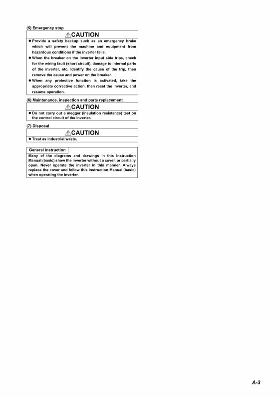
(5) Emergency stop
(6) Maintenance, inspection and parts replacement
(7) Disposal
Provide a safety backup such as an emergency brakewhich will prevent the machine and equipment fromhazardous conditions if the inverter fails.When the breaker on the inverter input side trips, checkfor the wiring fault (short circuit), damage to internal partsof the inverter, etc. Identify the cause of the trip, thenremove the cause and power on the breaker.When any protective function is activated, take theappropriate corrective action, then reset the inverter, andresume operation.
Do not carry out a megger (insulation resistance) test onthe control circuit of the inverter.
Treat as industrial waste.
General instructionMany of the diagrams and drawings in this InstructionManual (basic) show the inverter without a cover, or partiallyopen. Never operate the inverter in this manner. Alwaysreplace the cover and follow this Instruction Manual (basic)when operating the inverter.
CAUTION
CAUTION
CAUTION
A-3
CONTENTS
1 PRODUCT CHECKING AND PARTS IDENTIFICATION 1
2 INSTALLATION AND WIRING 2
2.1 Peripheral devices ................................................................................................... 3
2.2 Removal and reinstallation of the cover ............................................................... 4
2.2.1 Front cover..................................................................................................................................... 4
2.2.2 Wiring cover................................................................................................................................... 5
2.3 Installation of the inverter and instructions ......................................................... 6
2.4 Wiring ....................................................................................................................... 7
2.4.1 Terminal connection diagram ........................................................................................................ 7
2.4.2 Specification of main circuit terminal ............................................................................................. 8
2.4.3 Terminal arrangement of the main circuit terminal, power supply and the motor wiring................ 9
2.4.4 Standard control circuit terminal .................................................................................................. 13
2.4.5 Changing the control logic ........................................................................................................... 16
2.4.6 Wiring of control circuit ................................................................................................................ 18
2.4.7 Connection to the PU connector.................................................................................................. 19
2.4.8 USB connector............................................................................................................................. 21
2.5 When using the brake resistor (MRS, MYS, FR-ABR) ........................................ 22
2.6 Power-off and magnetic contactor (MC) ............................................................. 23
2.7 Precautions for use of the inverter ...................................................................... 24
2.8 Failsafe of the system which uses the inverter .................................................. 26
3 DRIVE THE MOTOR 27
3.1 Step of operation ................................................................................................... 27
3.2 Operation panel ..................................................................................................... 28
3.2.1 Names and functions of the operation panel ............................................................................... 28
3.2.2 Basic operation (factory setting) .................................................................................................. 29
3.2.3 Easy operation mode setting (easy setting mode)....................................................................... 30
3.2.4 Operation lock (Press [MODE] for a while (2s))........................................................................... 31
3.2.5 Monitoring of output current and output voltage .......................................................................... 32
3.2.6 First priority monitor ..................................................................................................................... 32
3.2.7 Setting dial push .......................................................................................................................... 32
3.2.8 Change the parameter setting value............................................................................................ 33
I
CO
NT
EN
TS
3.2.9 Parameter clear/all parameter clear ............................................................................................ 34
3.2.10 Initial value change list ................................................................................................................ 35
3.3 Before operation ................................................................................................... 36
3.3.1 Simple mode parameter list ......................................................................................................... 36
3.3.2 Overheat protection of the motor by the inverter (Pr. 9) .............................................................. 37
3.3.3 When the rated motor frequency is 50Hz (Pr. 3) ........................................................................ 38
3.3.4 Increase the starting torque (Pr. 0) ............................................................................................. 39
3.3.5 Limit the maximum and minimum output frequency (Pr. 1, Pr. 2) ............................................... 40
3.3.6 Change acceleration and deceleration time of the motor (Pr. 7, Pr. 8) ....................................... 41
3.3.7 Selection of the start command and frequency command locations (Pr. 79) .............................. 42
3.3.8 Large starting torque and low speed torque are necessary (Advanced magnetic flux vector control, general-purpose magnetic flux vector control)(Pr. 71, Pr. 80, Pr. 81, Pr. 800) .................................................................................................. 43
3.3.9 To exhibit the best performance of the motor performance (offline auto tuning)(Pr. 71, Pr. 83, Pr. 84, Pr. 96)...................................................................................................... 46
3.4 Start/stop from the operation panel (PU operation) .......................................... 50
3.4.1 Set the set frequency to operate (example: performing operation at 30Hz)................................ 50
3.4.2 Use the setting dial like a potentiometer to perform operation. ................................................... 52
3.4.3 Use switches to give a frequency command (multi-speed setting).............................................. 53
3.4.4 Perform frequency setting by analog (voltage input) ................................................................... 54
3.4.5 Perform frequency setting by analog (current input) ................................................................... 55
3.5 Make a start and stop with terminals (external operation) ............................... 56
3.5.1 Use the set frequency set by the operation panel (Pr. 79 = 3)..................................................... 56
3.5.2 Use switches to give a start command and a frequency command (multi-speed setting) (Pr. 4 to Pr. 6) ............................................................................................ 58
3.5.3 Perform frequency setting by analog (voltage input) ................................................................... 60
3.5.4 Change the frequency (60Hz) at the maximum voltage input (5V initial value)........................... 62
3.5.5 Perform frequency setting by analog (current input) ................................................................... 63
3.5.6 Change the frequency (60Hz) at the maximum current input (at 20mA, initial value) ................. 65
3.6 Parameter list ........................................................................................................ 66
3.6.1 List of parameters classified by purpose of use .......................................................................... 66
3.6.2 Parameter list .............................................................................................................................. 69
4 TROUBLESHOOTING 91
4.1 Reset method of protective function .................................................................. 91
4.2 List of fault or alarm indications ......................................................................... 92
4.3 Causes and corrective actions ............................................................................ 93
II

4.4 Correspondences between digital and actual characters ............................... 101
4.5 Check and clear of the faults history ................................................................ 102
4.6 Check first when you have some troubles ....................................................... 104
4.6.1 Motor will not start...................................................................................................................... 104
4.6.2 Motor generates abnormal noise ............................................................................................... 104
4.6.3 Motor generates heat abnormally .............................................................................................. 105
4.6.4 Motor rotates in opposite direction............................................................................................. 105
4.6.5 Speed greatly differs from the setting ........................................................................................ 105
4.6.6 Acceleration/deceleration is not smooth .................................................................................... 105
4.6.7 Motor current is large................................................................................................................. 105
4.6.8 Speed does not increase ........................................................................................................... 105
4.6.9 Speed varies during operation................................................................................................... 106
4.6.10 Operation mode is not changed properly................................................................................... 106
4.6.11 Operation panel display is not operating ................................................................................... 106
4.6.12 Parameter write cannot be performed ....................................................................................... 106
5 PRECAUTIONS FOR MAINTENANCE AND INSPECTION 107
5.1 Inspection items .................................................................................................. 107
5.1.1 Daily inspection.......................................................................................................................... 107
5.1.2 Periodic inspection..................................................................................................................... 107
5.1.3 Daily and periodic inspection ..................................................................................................... 108
5.1.4 Display of the life of the inverter parts ....................................................................................... 109
5.1.5 Cleaning..................................................................................................................................... 110
5.1.6 Replacement of parts................................................................................................................. 111
5.1.7 Inverter replacement.................................................................................................................. 114
6 SPECIFICATIONS 115
6.1 Rating ................................................................................................................... 115
6.2 Common specifications ...................................................................................... 117
6.3 Outline dimension drawings .............................................................................. 118
APPENDIX 123
Appendix1 For customers who have replaced the conventional model with this inverter ....................................................................................... 123
III
CO
NT
EN
TS
Appendix 1-1 Replacement of the FR-E500 series ............................................................................. 123
Appendix2 Instructions for Compliance with the European Directives................. 125
Appendix3 Instructions for UL and cUL..................................................................... 127
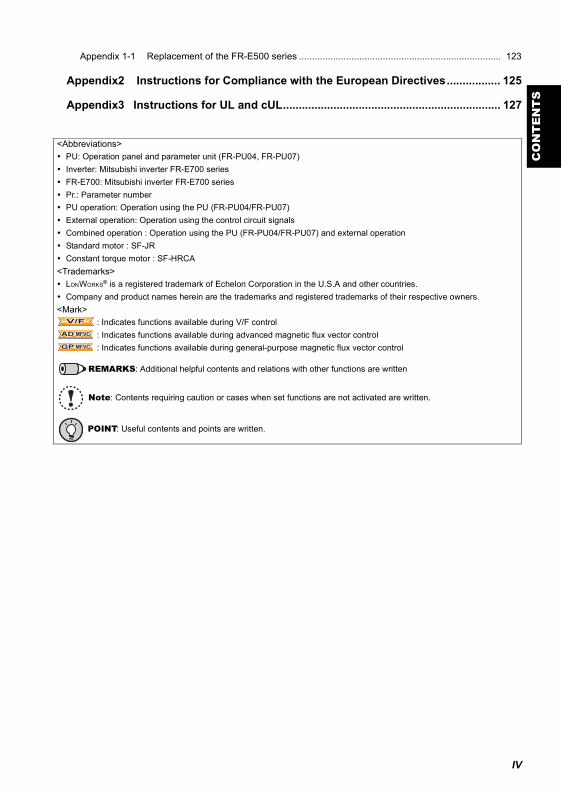
<Abbreviations>PU: Operation panel and parameter unit (FR-PU04, FR-PU07)Inverter: Mitsubishi inverter FR-E700 seriesFR-E700: Mitsubishi inverter FR-E700 seriesPr.: Parameter numberPU operation: Operation using the PU (FR-PU04/FR-PU07)External operation: Operation using the control circuit signalsCombined operation : Operation using the PU (FR-PU04/FR-PU07) and external operationStandard motor : SF-JRConstant torque motor : SF-HRCA
<Trademarks>LONWORKS® is a registered trademark of Echelon Corporation in the U.S.A and other countries.Company and product names herein are the trademarks and registered trademarks of their respective owners.
<Mark> : Indicates functions available during V/F control : Indicates functions available during advanced magnetic flux vector control : Indicates functions available during general-purpose magnetic flux vector control
REMARKS: Additional helpful contents and relations with other functions are written
Note: Contents requiring caution or cases when set functions are not activated are written.
POINT: Useful contents and points are written.
V/FV/FV/F
AD MFVCAD MFVCAD MFVC
GP MFVCGP MFVCGP MFVC
IV

V
MEMO
1
1
PRO
DU
CT
CH
ECK
ING
AN
D P
AR
TS ID
ENTI
FIC
ATIO
N
1 PRODUCT CHECKING AND PARTS IDENTIFICATION
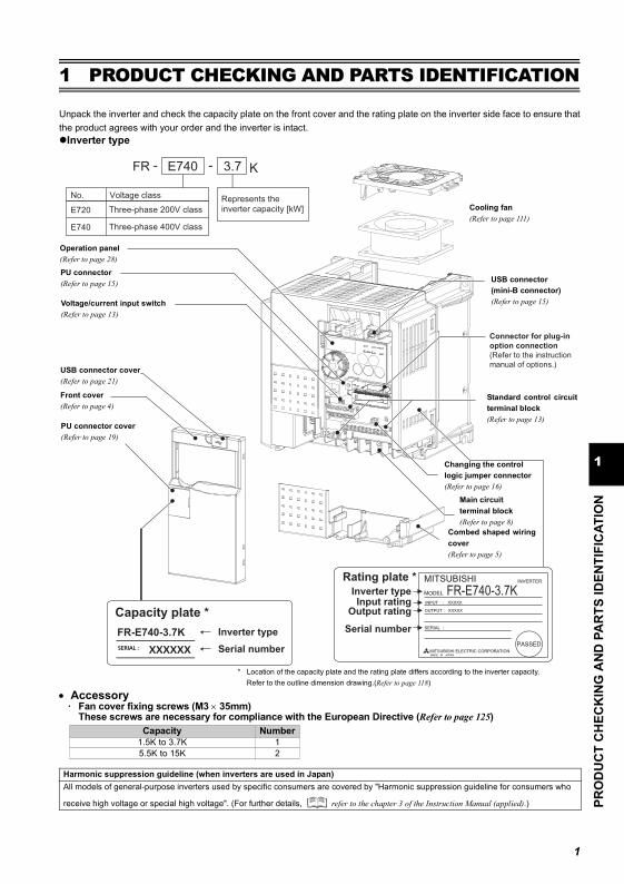
Unpack the inverter and check the capacity plate on the front cover and the rating plate on the inverter side face to ensure thatthe product agrees with your order and the inverter is intact.
Inverter type
* Location of the capacity plate and the rating plate differs according to the inverter capacity.Refer to the outline dimension drawing.(Refer to page 118)
• Accessory· Fan cover fixing screws (M3 × 35mm)
These screws are necessary for compliance with the European Directive (Refer to page 125)Capacity Number
1.5K to 3.7K 15.5K to 15K 2
Harmonic suppression guideline (when inverters are used in Japan)All models of general-purpose inverters used by specific consumers are covered by "Harmonic suppression guideline for consumers who
receive high voltage or special high voltage". (For further details, refer to the chapter 3 of the Instruction Manual (applied).)
Inverter type
Serial number
Capacity plate *
Connector for plug-in
option connection
(Refer to the instruction
manual of options.)
Rating plate *
Inverter typeInput rating
Output rating
Serial numberFR-E740-3.7K
FR-E740-3.7K
Cooling fan(Refer to page 111)
USB connector(mini-B connector)(Refer to page 15)
Standard control circuitterminal block(Refer to page 13)
Changing the control logic jumper connector(Refer to page 16)
Combed shaped wiringcover(Refer to page 5)
Main circuit terminal block(Refer to page 8)
PU connector cover(Refer to page 19)
Front cover(Refer to page 4)
USB connector cover(Refer to page 21)
Voltage/current input switch(Refer to page 13)
Operation panel(Refer to page 28)
PU connector(Refer to page 15)
FR - -
No. Voltage class
E740 3.7
Represents the
inverter capacity [kW]E720 Three-phase 200V class
E740 Three-phase 400V class
K
2
2 INSTALLATION AND WIRING
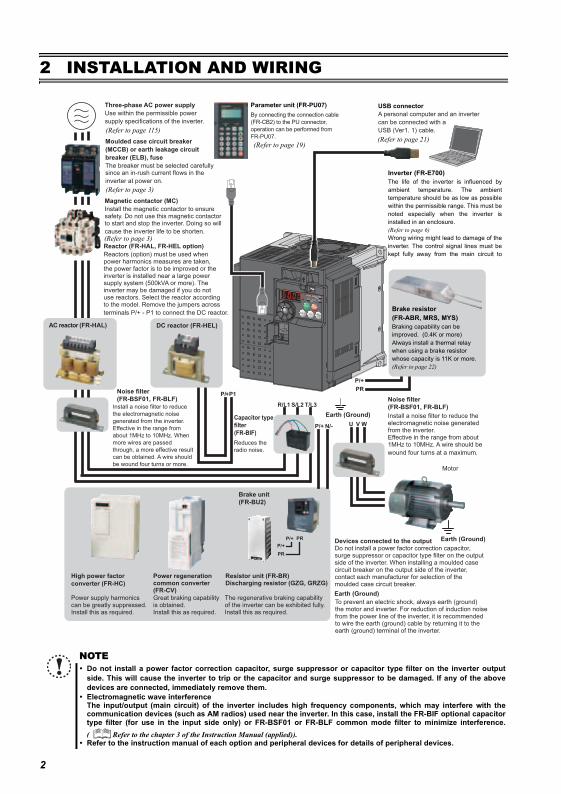
NOTEDo not install a power factor correction capacitor, surge suppressor or capacitor type filter on the inverter outputside. This will cause the inverter to trip or the capacitor and surge suppressor to be damaged. If any of the abovedevices are connected, immediately remove them.Electromagnetic wave interferenceThe input/output (main circuit) of the inverter includes high frequency components, which may interfere with thecommunication devices (such as AM radios) used near the inverter. In this case, install the FR-BIF optional capacitortype filter (for use in the input side only) or FR-BSF01 or FR-BLF common mode filter to minimize interference.( Refer to the chapter 3 of the Instruction Manual (applied)).Refer to the instruction manual of each option and peripheral devices for details of peripheral devices.
Three-phase AC power supply
Use within the permissible power
supply specifications of the inverter.
Magnetic contactor (MC)
Install the magnetic contactor to ensure safety. Do not use this magnetic contactor to start and stop the inverter. Doing so will
cause the inverter life to be shorten.
Noise filter
(FR-BSF01, FR-BLF)
Install a noise filter to reduce the electromagnetic noise generated from the inverter.Effective in the range from about 1MHz to 10MHz. A wire should be
wound four turns at a maximum.
Motor
Earth (Ground)
Earth (Ground)
Devices connected to the outputDo not install a power factor correction capacitor, surge suppressor or capacitor type filter on the output side of the inverter. When installing a moulded case circuit breaker on the output side of the inverter, contact each manufacturer for selection of the moulded case circuit breaker.
The regenerative braking capability of the inverter can be exhibited fully.Install this as required.
Power supply harmonics can be greatly suppressed.Install this as required.
High power factor
converter (FR-HC)
Power regeneration common converter (FR-CV)
USB connector
A personal computer and an inverter
can be connected with a
USB (Ver1. 1) cable.
Earth (Ground)
R/L1 S/L2 T/L3
P1P/+
N/-P/+ U W
P/+
PR
V
Great braking capability is obtained.Install this as required.
Reactor (FR-HAL, FR-HEL option)
Reactors (option) must be used when power harmonics measures are taken, the power factor is to be improved or the inverter is installed near a large power supply system (500kVA or more). The inverter may be damaged if you do not use reactors. Select the reactor according to the model. Remove the jumpers across
terminals P/+ - P1 to connect the DC reactor.
Noise filter
(FR-BSF01, FR-BLF)
Moulded case circuit breaker
(MCCB) or earth leakage circuit
breaker (ELB), fuse
The breaker must be selected carefully since an in-rush current flows in the
inverter at power on.
Install a noise filter to reduce
the electromagnetic noise
generated from the inverter.
Effective in the range from
about 1MHz to 10MHz. When
more wires are passed
through, a more effective result
can be obtained. A wire should
be wound four turns or more.
To prevent an electric shock, always earth (ground) the motor and inverter. For reduction of induction noise from the power line of the inverter, it is recommended to wire the earth (ground) cable by returning it to the earth (ground) terminal of the inverter.
AC reactor (FR-HAL) DC reactor (FR-HEL)
Parameter unit (FR-PU07)
By connecting the connection cable
(FR-CB2) to the PU connector,
operation can be performed from
FR-PU07.
Capacitor type
filter
(FR-BIF)
P/+
P/+
PR
PR
Brake unit
(FR-BU2)
Reduces the
radio noise.
Resistor unit (FR-BR) Discharging resistor (GZG, GRZG)
(Refer to page 115)
(Refer to page 3)
(Refer to page 3)
(Refer to page 21)
Inverter (FR-E700)The life of the inverter is influenced byambient temperature. The ambienttemperature should be as low as possiblewithin the permissible range. This must benoted especially when the inverter isinstalled in an enclosure. (Refer to page 6)Wrong wiring might lead to damage of theinverter. The control signal lines must bekept fully away from the main circuit to
(Refer to page 19)
Brake resistor(FR-ABR, MRS, MYS)Braking capability can be improved. (0.4K or more)Always install a thermal relay when using a brake resistor whose capacity is 11K or more. (Refer to page 22)
3
2
INST
ALL
ATIO
N A
ND
WIR
ING
Peripheral devices
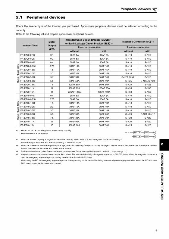
2.1 Peripheral devices
Check the inverter type of the inverter you purchased. Appropriate peripheral devices must be selected according to thecapacity.Refer to the following list and prepare appropriate peripheral devices:
∗1 Select an MCCB according to the power supply capacity.Install one MCCB per inverter.
∗2 When the inverter capacity is larger than the motor capacity, select an MCCB and a magnetic contactor according tothe inverter type and cable and reactor according to the motor output.
∗3 When the breaker on the inverter primary side trips, check for the wiring fault (short circuit), damage to internal parts of the inverter, etc. Identify the cause ofthe trip, then remove the cause and power on the breaker.
∗4 For installations in the United States or Canada, use the class T type fuse certified by the UL and cUL. (Refer to page 127)∗5 Magnetic contactor is selected based on the AC-1 class. The electrical durability of magnetic contactor is 500,000 times. When the magnetic contactor is
used for emergency stop during motor driving, the electrical durability is 25 times.When using the MC for emergency stop during motor driving or using on the motor side during commercial-power supply operation, select the MC with classAC-3 rated current for the motor rated current.
Inverter TypeMotor Output
(kW)
Moulded Case Circuit Breaker (MCCB) ∗1or Earth Leakage Circuit Breaker (ELB) ∗4
Magnetic Contactor (MC) ∗5
Reactor connection Reactor connectionwithout with without with
Thre
e-Ph
ase
200V
FR-E720-0.1K 0.1 30AF 5A 30AF 5A S-N10 S-N10FR-E720-0.2K 0.2 30AF 5A 30AF 5A S-N10 S-N10FR-E720-0.4K 0.4 30AF 5A 30AF 5A S-N10 S-N10FR-E720-0.75K 0.75 30AF 10A 30AF 10A S-N10 S-N10FR-E720-1.5K 1.5 30AF 15A 30AF 15A S-N10 S-N10FR-E720-2.2K 2.2 30AF 20A 30AF 15A S-N10 S-N10FR-E720-3.7K 3.7 30AF 30A 30AF 30A S-N20, S-N21 S-N10FR-E720-5.5K 5.5 50AF 50A 50AF 40A S-N25 S-N20, S-N21FR-E720-7.5K 7.5 100AF 60A 50AF 50A S-N25 S-N25FR-E720-11K 11 100AF 75A 100AF 75A S-N35 S-N35FR-E720-15K 15 225AF 125A 100AF 100A S-N50 S-N50
Thre
e-Ph
ase
400V
FR-E740-0.4K 0.4 30AF 5A 30AF 5A S-N10 S-N10FR-E740-0.75K 0.75 30AF 5A 30AF 5A S-N10 S-N10FR-E740-1.5K 1.5 30AF 10A 30AF 10A S-N10 S-N10FR-E740-2.2K 2.2 30AF 15A 30AF 10A S-N10 S-N10FR-E740-3.7K 3.7 30AF 20A 30AF 15A S-N10 S-N10FR-E740-5.5K 5.5 30AF 30A 30AF 20A S-N20 S-N11, S-N12FR-E740-7.5K 7.5 30AF 30A 30AF 30A S-N20 S-N20FR-E740-11K 11 50AF 50A 50AF 40A S-N20 S-N20FR-E740-15K 15 100AF 60A 50AF 50A S-N25 S-N20
MCCB INV
MCCB INV
IM
IM
Removal and reinstallation of the cover
2.2 Removal and reinstallation of the cover
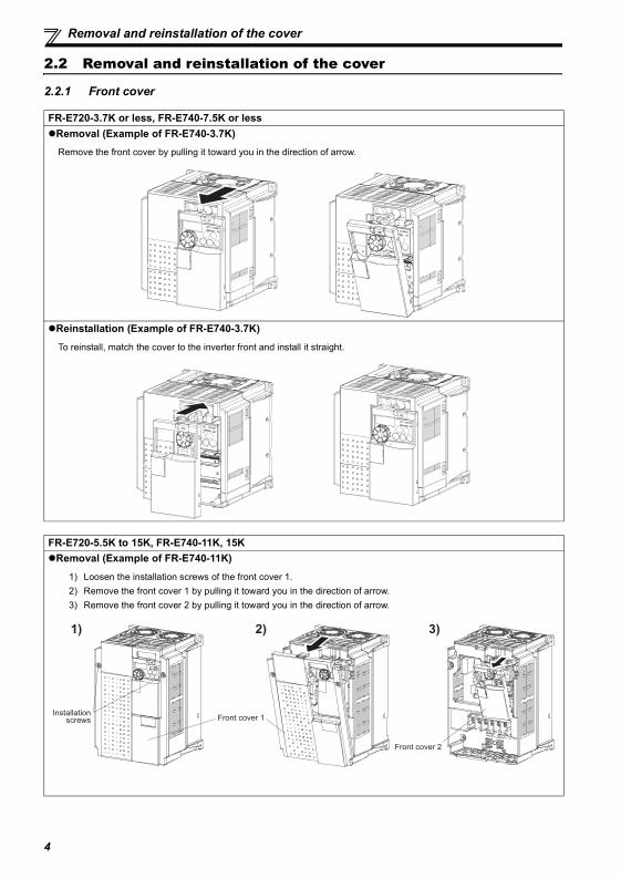
2.2.1 Front cover
FR-E720-3.7K or less, FR-E740-7.5K or lessRemoval (Example of FR-E740-3.7K)Remove the front cover by pulling it toward you in the direction of arrow.
Reinstallation (Example of FR-E740-3.7K)
To reinstall, match the cover to the inverter front and install it straight.
FR-E720-5.5K to 15K, FR-E740-11K, 15KRemoval (Example of FR-E740-11K)
1) Loosen the installation screws of the front cover 1.2) Remove the front cover 1 by pulling it toward you in the direction of arrow.3) Remove the front cover 2 by pulling it toward you in the direction of arrow.
Installation screws Front cover 1
Front cover 2
1) 2) 3)
4
2
INST
ALL
ATIO
N A
ND
WIR
ING
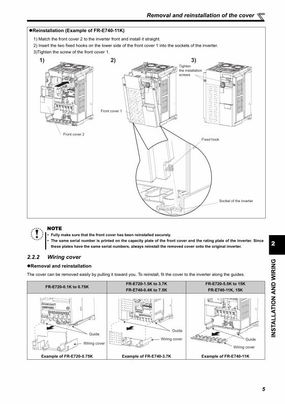
Removal and reinstallation of the cover
2.2.2 Wiring coverRemoval and reinstallation
The cover can be removed easily by pulling it toward you. To reinstall, fit the cover to the inverter along the guides.
Reinstallation (Example of FR-E740-11K)
1) Match the front cover 2 to the inverter front and install it straight.2) Insert the two fixed hooks on the lower side of the front cover 1 into the sockets of the inverter.3)Tighten the screw of the front cover 1.
NOTEFully make sure that the front cover has been reinstalled securely.The same serial number is printed on the capacity plate of the front cover and the rating plate of the inverter. Sincethese plates have the same serial numbers, always reinstall the removed cover onto the original inverter.
FR-E720-0.1K to 0.75KFR-E720-1.5K to 3.7KFR-E740-0.4K to 7.5K
FR-E720-5.5K to 15KFR-E740-11K, 15K
Example of FR-E720-0.75K Example of FR-E740-3.7K Example of FR-E740-11K
Front cover 2
Front cover 1
Fixed hook
Socket of the inverter
Tighten
the installation
screws
1) 2) 3)
Wiring cover
GuideGuide
Wiring cover
Wiring cover
Guide
5
6
Installation of the inverter and instructions
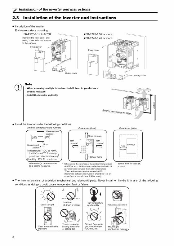
2.3 Installation of the inverter and instructions
Installation of the inverterEnclosure surface mounting
Install the inverter under the following conditions.
The inverter consists of precision mechanical and electronic parts. Never install or handle it in any of the followingconditions as doing so could cause an operation fault or failure.
NoteWhen encasing multiple inverters, install them in parallel as acooling measure.Install the inverter vertically.
Remove the front cover and
wiring cover to fix the inverter
to the surface.
Front cover
Wiring cover
Front cover
Wiring cover
FR-E720-0.1K to 0.75K FR-E720-1.5K or moreFR-E740-0.4K or more
Refer to the clearances below.
Vert
ical
Ambient temperature and humidity
Measurement
position
Measurement
position
Inverter5cm 5cm
5cm
Humidity: 90% RH maximum
Clearances (side)
1cm
or more*
Inverter
Clearances (front)
10cm or more
10cm or more
1cm
or more*
1cm
or more*
* 5cm or more for the 5.5K
or more
Leave enough clearances and
take cooling measures.
Temperature: -10 C to +50 C
-10 C to +40 C for totally
-enclosed structure feature
* When using the inverters at the ambient temperature
of 40 C or less, the inverters can be installed without
any clearance between them (0cm clearance).
When ambient temperature exceeds 40 C,
clearances between the inverters should be 1cm or
more (5cm or more for the 5.5K or more).
Direct sunlightVibration
(5.9m/s2 or more)High temperature, high humidity
Oil mist, flammable gas, corrosive gas, fluff, dust, etc.
Horizontal placement
Transportation by holding front coveror setting dial
When mounted inside enclosure
Mounting to combustible material
7
2
INST
ALL
ATIO
N A
ND
WIR
ING
Wiring
2.4 Wiring
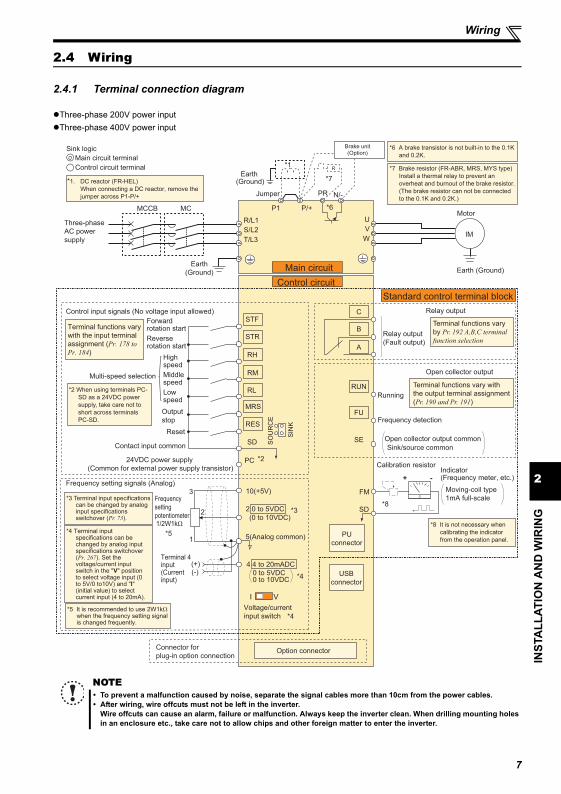
2.4.1 Terminal connection diagram
Three-phase 200V power inputThree-phase 400V power input
NOTETo prevent a malfunction caused by noise, separate the signal cables more than 10cm from the power cables.After wiring, wire offcuts must not be left in the inverter.Wire offcuts can cause an alarm, failure or malfunction. Always keep the inverter clean. When drilling mounting holesin an enclosure etc., take care not to allow chips and other foreign matter to enter the inverter.
Earth (Ground)
Motor
IM
Earth (Ground)
Three-phase
AC power
supply
MCCB MC
R/L1
P1 P/+
PR N/-
S/L2
T/L3
U
V
W
Earth
(Ground)
*7 Brake resistor (FR-ABR, MRS, MYS type)
Install a thermal relay to prevent an
overheat and burnout of the brake resistor.
(The brake resistor can not be connected
to the 0.1K and 0.2K.)
*6 A brake transistor is not built-in to the 0.1K
and 0.2K.
Forward rotation start
Reverse rotation start
Middle speed
High speed
Low speed
Output
stop
Reset
Control input signals (No voltage input allowed)
Contact input common
24VDC power supply
(Common for external power supply transistor)
STR
STF
RH
RM
RL
MRS
SD
PC
Relay output
Running
Frequency detection
Open collector output
Open collector output common
Sink/source common
FU
RUN
SE
A
B
C
FM
SD
Indicator(Frequency meter, etc.)+ -
Moving-coil type
1mA full-scale
Calibration resistor
Frequency setting signals (Analog)
2 0 to 5VDC
10(+5V)
2
3
1
4 4 to 20mADC
Frequency
setting
potentiometer1/2W1kΩ
Terminal 4 input(Current input)
(+)(-)
5(Analog common)
*5 It is recommended to use 2W1kΩ when the frequency setting signal is changed frequently.
*5
Connector for
plug-in option connectionOption connector
*3 Terminal input specifications can be changed by analog input specifications switchover (Pr. 73).
*2 When using terminals PC-
SD as a 24VDC power
supply, take care not to
short across terminals
PC-SD.
PU
connector
USB
connector
*8 It is not necessary when
calibrating the indicator
from the operation panel.
*1. DC reactor (FR-HEL)
When connecting a DC reactor, remove the
jumper across P1-P/+
Control circuit terminal
Main circuit terminal
Sink logic
Jumper
*1
*7
*6
*2
*3
*4
*8
Terminal functions vary
with the input terminal
assignment (Pr. 178 to
Pr. 184)
Multi-speed selection
Terminal functions vary with
the output terminal assignment
(Pr. 190 and Pr. 191)
Terminal functions vary
by Pr. 192 A,B,C terminal
function selection
SIN
K
SO
UR
CE
I V
*4
0 to 5VDC
(0 to 10VDC)
0 to 10VDC
*4 Terminal input specifications can be changed by analog input specifications switchover (Pr. 267). Set the voltage/current input switch in the "V" position to select voltage input (0 to 5V/0 to10V) and "I" (initial value) to select current input (4 to 20mA).
Voltage/current
input switch
Main circuit
Control circuit
Standard control terminal block
R
RES
Relay output
(Fault output)
Brake unit(Option)

Wiring
2.4.2 Specification of main circuit terminal
Terminal Symbol
Terminal Name Description
R/L1,S/L2,T/L3
AC power inputConnect to the commercial power supply.Keep these terminals open when using the high power factor converter (FR-HC) or power regeneration common converter (FR-CV).
U, V, W Inverter output Connect a three-phase squirrel-cage motor.
P/+, PR Brake resistor connectionConnect a brake resistor (FR-ABR, MRS, MYS) across terminals P/+-PR.(The brake resistor can not be connected to the 0.1K or 0.2K.)
P/+, N/- Brake unit connectionConnect the brake unit (FR-BU2), power regeneration common converter (FR-CV) or high power factor converter (FR-HC).
P/+, P1 DC reactor connection Remove the jumper across terminals P/+-P1 and connect a DC reactor.
Earth (Ground) For earthing (grounding) the inverter chassis. Must be earthed (grounded).
8
2
INST
ALL
ATIO
N A
ND
WIR
ING
Wiring
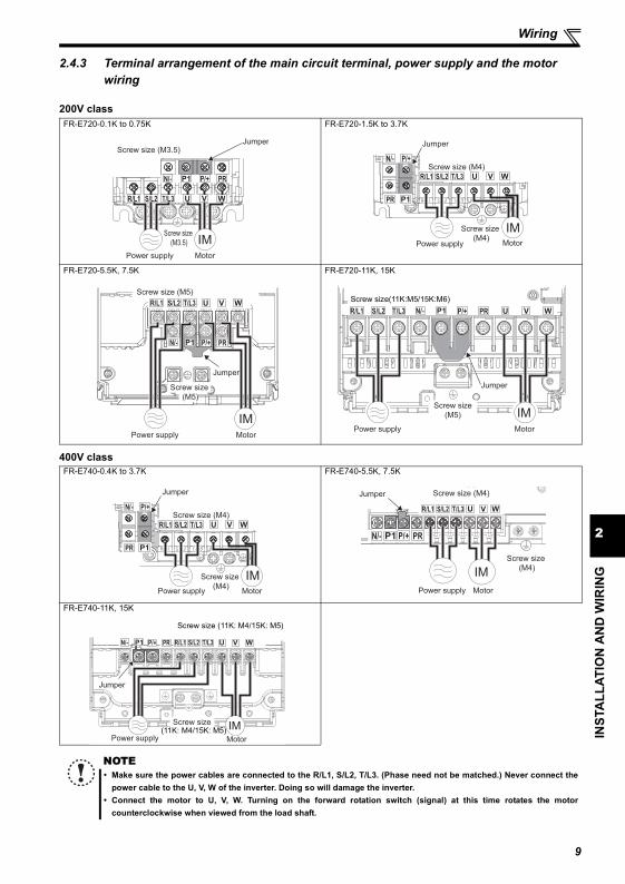
2.4.3 Terminal arrangement of the main circuit terminal, power supply and the motor wiring
200V class
400V class
FR-E720-0.1K to 0.75K FR-E720-1.5K to 3.7K
FR-E720-5.5K, 7.5K FR-E720-11K, 15K
FR-E740-0.4K to 3.7K FR-E740-5.5K, 7.5K
FR-E740-11K, 15K
NOTEMake sure the power cables are connected to the R/L1, S/L2, T/L3. (Phase need not be matched.) Never connect thepower cable to the U, V, W of the inverter. Doing so will damage the inverter.Connect the motor to U, V, W. Turning on the forward rotation switch (signal) at this time rotates the motorcounterclockwise when viewed from the load shaft.
Screw size
(M3.5)
MotorPower supply
N/- P/+ PR
IM
R/L1 S/L2 T/L3
JumperScrew size (M3.5)
Screw size
(M4)MotorPower supply
N/- P/+
PR
IM
R/L1 S/L2 T/L3
Jumper
Screw size (M4)
MotorPower supply
IM
N/- P/+ PR
R/L1 S/L2 T/L3
Jumper
Screw size (M5)
Screw size
(M5)
N/- P/+ PRR/L1 S/L2 T/L3
Jumper
Screw size
(M5)
MotorPower supply
IM
Screw size(11K:M5/15K:M6)
N/- P/+
PR
R/L1 S/L2 T/L3
Screw size
(M4)MotorPower supply
IM
Jumper
Screw size (M4)
N/- P/+ PR
R/L1 S/L2 T/L3
Screw size (M4)
Screw size
(M4)
MotorPower supply
Jumper
IM
MotorPower supply
IM
N/- P/+ PR R/L1 S/L2 T/L3
Jumper
Screw size(11K: M4/15K: M5)
Screw size (11K: M4/15K: M5)
9
Wiring
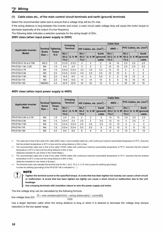
(1) Cable sizes etc., of the main control circuit terminals and earth (ground) terminals
Select the recommended cable size to ensure that a voltage drop will be 2% max.If the wiring distance is long between the inverter and motor, a main circuit cable voltage drop will cause the motor torque todecrease especially at the output of a low frequency.The following table indicates a selection example for the wiring length of 20m.200V class (when input power supply is 220V)
400V class (when input power supply is 440V)
∗1 The cable size is that of the cable (HIV cable (600V class 2 vinyl-insulated cable) etc.) with continuous maximum permissible temperature of 75°C. Assumesthat the ambient temperature is 50°C or less and the wiring distance is 20m or less.
∗2 The recommended cable size is that of the cable (THHW cable) with continuous maximum permissible temperature of 75°C. Assumes that the ambienttemperature is 40°C or less and the wiring distance is 20m or less.(Selection example for use mainly in the United States.)
∗3 The recommended cable size is that of the cable (THHW cable) with continuous maximum permissible temperature of 70°C. Assumes that the ambienttemperature is 40°C or less and the wiring distance is 20m or less.(Selection example for use mainly in Europe.)
∗4 The terminal screw size indicates the terminal size for R/L1, S/L2, T/L3, U, V, W, and a screw for earthing (grounding).A screw for earthing (grounding) of the FR-E720-15K is indicated in ( ).
The line voltage drop can be calculated by the following formula:
line voltage drop [V]=
Use a larger diameter cable when the wiring distance is long or when it is desired to decrease the voltage drop (torquereduction) in the low speed range.
Applicable InverterModel
Terminal ScrewSize ∗4
TighteningTorque
N·m
Crimping Terminal
Cable Size
HIV Cables, etc. (mm2) ∗1 AWG ∗2 PVC Cables, etc. (mm2) ∗3
R/L1S/L2T/L3
U, V, WR/L1S/L2T/L3
U, V, WEarth
(ground) cable
R/L1S/L2T/L3
U, V, WR/L1S/L2T/L3
U, V, WEarth
(ground) cable
FR-E720-0.1K to 0.75K M3.5 1.2 2-3.5 2-3.5 2 2 2 14 14 2.5 2.5 2.5FR-E720-1.5K, 2.2K M4 1.5 2-4 2-4 2 2 2 14 14 2.5 2.5 2.5FR-E720-3.7K M4 1.5 5.5-4 5.5-4 3.5 3.5 3.5 12 12 4 4 4FR-E720-5.5K M5 2.5 5.5-5 5.5-5 5.5 5.5 5.5 10 10 6 6 6FR-E720-7.5K M5 2.5 14-5 8-5 14 8 5.5 6 8 16 10 6FR-E720-11K M5 2.5 14-5 14-5 14 14 14 6 6 16 16 16FR-E720-15K M6(M5) 4.4 22-6 22-6 22 22 14 4 4 25 25 16
Applicable InverterModel
Terminal ScrewSize ∗4
TighteningTorque
N·m
Crimping Terminal
Cable Size
HIV Cables, etc. (mm2) ∗1 AWG ∗2 PVC Cables, etc. (mm2) ∗3
R/L1S/L2T/L3
U, V, WR/L1S/L2T/L3
U, V, WEarth
(ground) cable
R/L1S/L2T/L3
U, V, WR/L1S/L2T/L3
U, V, WEarth
(ground) cable
FR-E740-0.4K to 3.7K M4 1.5 2-4 2-4 2 2 2 14 14 2.5 2.5 2.5FR-E740-5.5K M4 1.5 5.5-4 2-4 3.5 2 3.5 12 14 4 2.5 4FR-E740-7.5K M4 1.5 5.5-4 5.5-4 3.5 3.5 3.5 12 12 4 4 4FR-E740-11K M4 1.5 5.5-4 5.5-4 5.5 5.5 8 10 10 6 6 10FR-E740-15K M5 2.5 8-5 8-5 8 8 8 8 8 10 10 10
NOTETighten the terminal screw to the specified torque. A screw that has been tighten too loosely can cause a short circuitor malfunction. A screw that has been tighten too tightly can cause a short circuit or malfunction due to the unitbreakage.Use crimping terminals with insulation sleeve to wire the power supply and motor.
3 × wire resistance[mΩ/m] × wiring distance[m] × current[A]
1000
10
2
INST
ALL
ATIO
N A
ND
WIR
ING
Wiring
(2) Earthing (Grounding) precautionsLeakage currents flow in the inverter. To prevent an electric shock, the inverter and motor must be earthed (grounded). Thisinverter must be earthed (grounded). Earthing (Grounding) must conform to the requirements of national and local safetyregulations and electrical codes. (NEC section 250, IEC 536 class 1 and other applicable standards) Use an neutral-point earthed (grounded) power supply for 400V class inverter in compliance with EN standard.
Use the dedicated earth (ground) terminal to earth (ground) the inverter. (Do not use the screw in the casing, chassis, etc.)Use the thickest possible earth (ground) cable. Use the cable whose size is equal to or greater than that indicated on page10 , and minimize the cable length. The earthing (grounding) point should be as near as possible to the inverter.
POINTTo be compliant with the European Directive (Low Voltage Directive), earth (ground) the inverter according to theinstructions on page 125.
11
Wiring
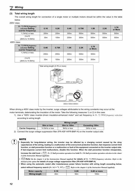
(3) Total wiring lengthThe overall wiring length for connection of a single motor or multiple motors should be within the value in the tablebelow.
200V class
400V class
When driving a 400V class motor by the inverter, surge voltages attributable to the wiring constants may occur at themotor terminals, deteriorating the insulation of the motor. Take the following measures 1) or 2) in this case.
1) Use a "400V class inverter-driven insulation-enhanced motor" and set frequency in Pr. 72 PWM frequency selectionaccording to wiring length
2) Connect the surge voltage suppression filter (FR-ASF-H/FR-BMF-H) on the inverter output side.
Pr. 72 PWM frequency selection Setting
(carrier frequency)0.1K 0.2K 0.4K 0.75K 1.5K 2.2K 3.7K
or More
1 (1kHz) or less 200m 200m 300m 500m 500m 500m 500m2 to15
(2kHz to 14.5kHz)30m 100m 200m 300m 500m 500m 500m
Pr. 72 PWM frequency selection Setting
(carrier frequency)0.4K 0.75K 1.5K 2.2K 3.7K
or More
1 (1kHz) or less200m 200m 300m 500m 500m
2 to15(2kHz to 14.5kHz)
30m 100m 200m 300m 500m
Total wiring length (3.7K or more)
Wiring Length50m or less 50m to 100m Exceeding 100m
Carrier frequency 14.5kHz or less 8kHz or less 2kHz or less
NOTEEspecially for long-distance wiring, the inverter may be affected by a charging current caused by the straycapacitances of the wiring, leading to a malfunction of the overcurrent protective function, fast response current limitfunction, or stall prevention function or a malfunction or fault of the equipment connected on the inverter output side.If fast-response current limit malfunctions, disable this function. When the stall prevention function misoperates,
increase the stall level. ( Pr. 22 Stall prevention operation level and Pr. 156 Stall prevention operation selection in the chater4 of the Instruction Manual (applied))
Refer to the chapter 4 of the Instrunction Manual (applied) for details of Pr. 72 PWM frequency selection. Refer to themanual of the option for details of surge voltage suppression filter (FR-ASF-H/FR-BMF-H).When using the automatic restart after instantaneous power failure function with wiring length exceeding below,
select without frequency search (Pr. 162 = "1, 11"). ( Refer to the chapter 4 of the Instruction Manual (applied))
500m or less
300m
300m
300m+300m=600m
Motor capacity 0.1K 0.2K 0.4K or moreWiring length 20m 50m 100m
12
2
INST
ALL
ATIO
N A
ND
WIR
ING
Wiring
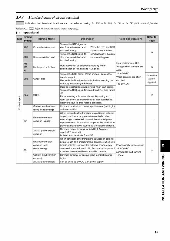
2.4.4 Standard control circuit terminal indicates that terminal functions can be selected using Pr. 178 to Pr. 184, Pr. 190 to Pr. 192 (I/O terminal function
selection). ( Refer to the Instruction Manual (applied)).(1) Input signal
TypeTerminal Symbol
Terminal Name Description Rated SpecificationsRefer to
Page
Con
tact
inpu
t
STF Forward rotation startTurn on the STF signal to start forward rotation and turn it off to stop.
When the STF and STR signals are turned on simultaneously, the stop command is given.
Input resistance 4.7kΩVoltage when contacts are open21 to 26VDCWhen contacts are short-circuited4 to 6mADC
56
STR Reverse rotation startTurn on the STR signal to start reverse rotation and turn it off to stop.
RH,RM,RL
Multi-speed selectionMulti-speed can be selected according to the combination of RH, RM and RL signals. 58
MRS Output stop
Turn on the MRS signal (20ms or more) to stop the inverter output.Use to shut off the inverter output when stopping the motor by electromagnetic brake.
Instruction Manual
(applied)
RES Reset
Used to reset fault output provided when fault occurs. Turn on the RES signal for more than 0.1s, then turn it off.Factory setting is for reset always. By setting Pr. 75, reset can be set to enabled only at fault occurrence. Recover about 1s after reset is cancelled.
91
SD
Contact input common (sink) (initial setting)
Common terminal for contact input terminal (sink logic) and terminal FM.
— —External transistor common (source)
When connecting the transistor output (open collector output), such as a programmable controller, when source logic is selected, connect the external power supply common for transistor output to this terminal to prevent a malfunction caused by undesirable currents.
24VDC power supply common
Common output terminal for 24VDC 0.1A power supply (PC terminal).Isolated from terminals 5 and SE.
PC
External transistor common (sink) (initial setting)
When connecting the transistor output (open collector output), such as a programmable controller, when sink logic is selected, connect the external power supply common for transistor output to this terminal to prevent a malfunction caused by undesirable currents.
Power supply voltage range 22 to 26VDCpermissible load current 100mA
17
Contact input common (source)
Common terminal for contact input terminal (source logic).
24VDC power supply Can be used as 24VDC 0.1A power supply.
13
Wiring
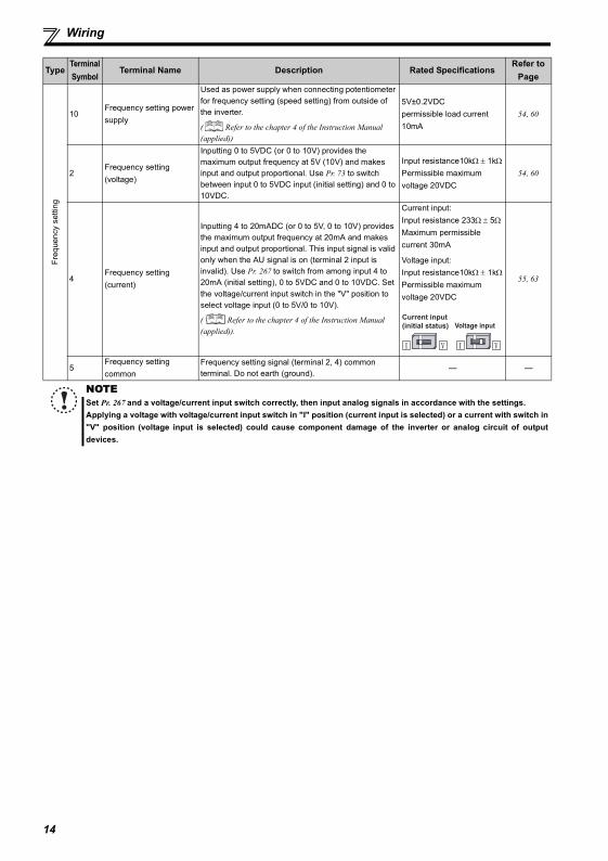
Freque
ncy
setti
ng
10Frequency setting power supply
Used as power supply when connecting potentiometer for frequency setting (speed setting) from outside of the inverter.
( Refer to the chapter 4 of the Instruction Manual (applied))
5V±0.2VDCpermissible load current 10mA
54, 60
2Frequency setting (voltage)
Inputting 0 to 5VDC (or 0 to 10V) provides the maximum output frequency at 5V (10V) and makes input and output proportional. Use Pr. 73 to switch between input 0 to 5VDC input (initial setting) and 0 to 10VDC.
Input resistance10kΩ ± 1kΩPermissible maximum voltage 20VDC
54, 60
4Frequency setting (current)
Inputting 4 to 20mADC (or 0 to 5V, 0 to 10V) provides the maximum output frequency at 20mA and makes input and output proportional. This input signal is valid only when the AU signal is on (terminal 2 input is invalid). Use Pr. 267 to switch from among input 4 to 20mA (initial setting), 0 to 5VDC and 0 to 10VDC. Set the voltage/current input switch in the "V" position to select voltage input (0 to 5V/0 to 10V).
( Refer to the chapter 4 of the Instruction Manual (applied)).
Current input:Input resistance 233Ω ± 5ΩMaximum permissible current 30mA
Voltage input:Input resistance10kΩ ± 1kΩPermissible maximum voltage 20VDC
55, 63
5Frequency setting common
Frequency setting signal (terminal 2, 4) common terminal. Do not earth (ground).
— —
NOTESet Pr. 267 and a voltage/current input switch correctly, then input analog signals in accordance with the settings.Applying a voltage with voltage/current input switch in "I" position (current input is selected) or a current with switch in"V" position (voltage input is selected) could cause component damage of the inverter or analog circuit of outputdevices.
TypeTerminal Symbol
Terminal Name Description Rated SpecificationsRefer to
Page
Voltage input
Current input
(initial status)
14
2
INST
ALL
ATIO
N A
ND
WIR
ING
Wiring
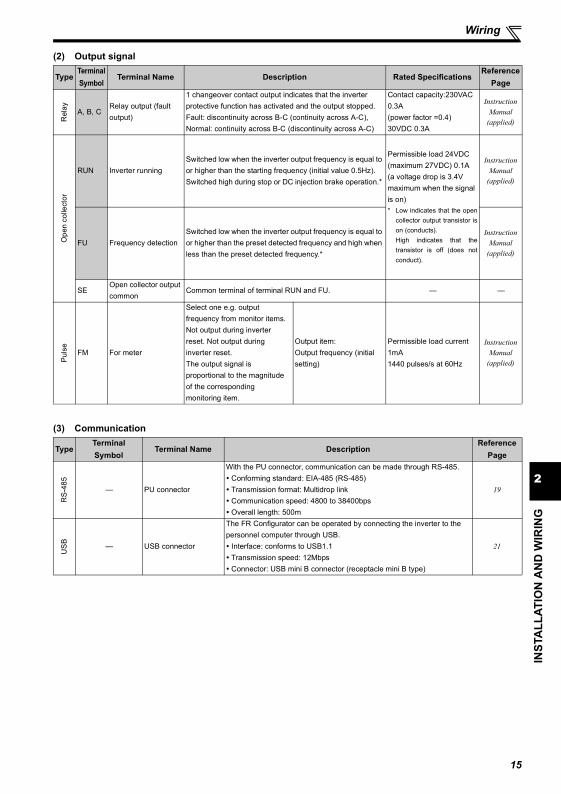
(2) Output signal
(3) Communication
TypeTerminal Symbol
Terminal Name Description Rated SpecificationsReference
Page
Rel
ay A, B, CRelay output (fault output)
1 changeover contact output indicates that the inverter protective function has activated and the output stopped.Fault: discontinuity across B-C (continuity across A-C), Normal: continuity across B-C (discontinuity across A-C)
Contact capacity:230VAC 0.3A(power factor =0.4)30VDC 0.3A
Instruction Manual
(applied)
Ope
n co
llect
or
RUN Inverter runningSwitched low when the inverter output frequency is equal to or higher than the starting frequency (initial value 0.5Hz). Switched high during stop or DC injection brake operation.*
Permissible load 24VDC(maximum 27VDC) 0.1A(a voltage drop is 3.4V maximum when the signal is on)* Low indicates that the open
collector output transistor ison (conducts).High indicates that thetransistor is off (does notconduct).
Instruction Manual
(applied)
FU Frequency detectionSwitched low when the inverter output frequency is equal to or higher than the preset detected frequency and high when less than the preset detected frequency.*
Instruction Manual
(applied)
SEOpen collector output common
Common terminal of terminal RUN and FU. — —
Puls
e
FM For meter
Select one e.g. output frequency from monitor items.Not output during inverter reset. Not output during inverter reset.The output signal is proportional to the magnitude of the corresponding monitoring item.
Output item:Output frequency (initial setting)
Permissible load current 1mA1440 pulses/s at 60Hz
Instruction Manual
(applied)
TypeTerminal Symbol
Terminal Name DescriptionReference
Page
RS-
485
— PU connector
With the PU connector, communication can be made through RS-485.Conforming standard: EIA-485 (RS-485)Transmission format: Multidrop linkCommunication speed: 4800 to 38400bpsOverall length: 500m
19
US
B — USB connector
The FR Configurator can be operated by connecting the inverter to the personnel computer through USB.
Interface: conforms to USB1.1Transmission speed: 12MbpsConnector: USB mini B connector (receptacle mini B type)
21
15
Wiring
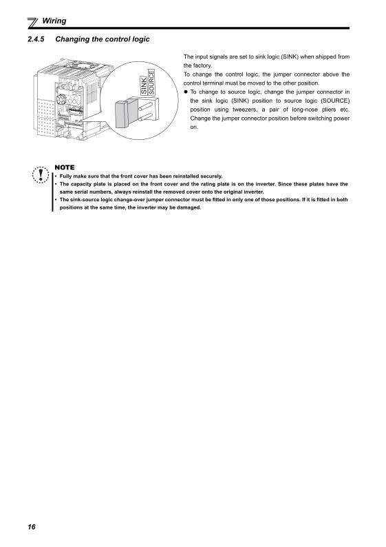
2.4.5 Changing the control logic
The input signals are set to sink logic (SINK) when shipped fromthe factory. To change the control logic, the jumper connector above thecontrol terminal must be moved to the other position.
To change to source logic, change the jumper connector inthe sink logic (SINK) position to source logic (SOURCE)position using tweezers, a pair of long-nose pliers etc.Change the jumper connector position before switching poweron.
NOTEFully make sure that the front cover has been reinstalled securely. The capacity plate is placed on the front cover and the rating plate is on the inverter. Since these plates have thesame serial numbers, always reinstall the removed cover onto the original inverter.The sink-source logic change-over jumper connector must be fitted in only one of those positions. If it is fitted in bothpositions at the same time, the inverter may be damaged.
16
2
INST
ALL
ATIO
N A
ND
WIR
ING
Wiring
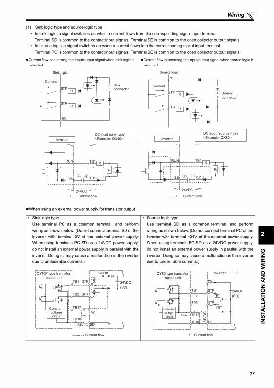
(1) Sink logic type and source logic typeIn sink logic, a signal switches on when a current flows from the corresponding signal input terminal.Terminal SD is common to the contact input signals. Terminal SE is common to the open collector output signals.In source logic, a signal switches on when a current flows into the corresponding signal input terminal.Terminal PC is common to the contact input signals. Terminal SE is common to the open collector output signals.
When using an external power supply for transistor output
Current flow concerning the input/output signal when sink logic is selected
Current flow concerning the input/output signal when source logic is selected
Sink logic typeUse terminal PC as a common terminal, and performwiring as shown below. (Do not connect terminal SD of theinverter with terminal 0V of the external power supply.When using terminals PC-SD as a 24VDC power supply,do not install an external power supply in parallel with theinverter. Doing so may cause a malfunction in the inverterdue to undesirable currents.)
Source logic typeUse terminal SD as a common terminal, and performwiring as shown below. (Do not connect terminal PC of theinverter with terminal +24V of the external power supply.When using terminals PC-SD as a 24VDC power supply,do not install an external power supply in parallel with theinverter. Doing so may cause a malfunction in the inverterdue to undesirable currents.)
Current
PC
STFR
STR
Source logic
Source
connector
Current
SD
STFR
STRR
Sink
connector
Sink logic
DC input (source type)
<Example: QX80>
24VDC
RUN
SE
TB1
TB18
R
Inverter
R
Current flow
DC input (sink type)
<Example: QX40>Inverter
24VDC
RUN
SE
TB1
TB17
R
R
Current flow
R
QY40P type transistor
output unit
TB1
TB2
TB17
TB18
24VDC SD
PC
STR
STF
Inverter
24VDC
(SD)
Current flow
Constant voltage circuit
QY80 type transistor
output unit
Constant
voltage
circuit
PC
TB1
TB2
TB17Fuse
TB18
STF
STR
SD
Inverter
24VDC
(SD)
24V
DC
Current flow
17
Wiring
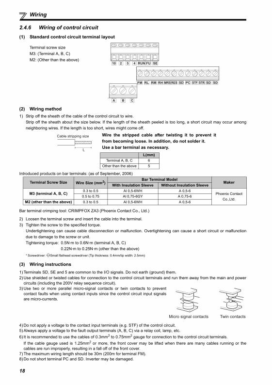
2.4.6 Wiring of control circuit
(1) Standard control circuit terminal layout
(2) Wiring method1) Strip off the sheath of the cable of the control circuit to wire.
Strip off the sheath about the size below. If the length of the sheath peeled is too long, a short circuit may occur amongneighboring wires. If the length is too short, wires might come off.
Introduced products on bar terminals: (as of September, 2006)
Bar terminal crimping tool: CRIMPFOX ZA3 (Phoenix Contact Co., Ltd.)
2) Loosen the terminal screw and insert the cable into the terminal.3) Tighten the screw to the specified torque.
Undertightening can cause cable disconnection or malfunction. Overtightening can cause a short circuit or malfunctiondue to damage to the screw or unit.Tightening torque: 0.5N·m to 0.6N·m (terminal A, B, C)
0.22N·m to 0.25N·m (other than the above)* Screwdriver: Small flathead screwdriver (Tip thickness: 0.4mm/tip width: 2.5mm)
(3) Wiring instructions1) Terminals SD, SE and 5 are common to the I/O signals. Do not earth (ground) them.2) Use shielded or twisted cables for connection to the control circuit terminals and run them away from the main and power
circuits (including the 200V relay sequence circuit).3) Use two or more parallel micro-signal contacts or twin contacts to prevent
contact faults when using contact inputs since the control circuit input signalsare micro-currents.
4) Do not apply a voltage to the contact input terminals (e.g. STF) of the control circuit.5) Always apply a voltage to the fault output terminals (A, B, C) via a relay coil, lamp, etc.6) It is recommended to use the cables of 0.3mm2 to 0.75mm2 gauge for connection to the control circuit terminals.
If the cable gauge used is 1.25mm2 or more, the front cover may be lifted when there are many cables running or thecables are run improperly, resulting in a fall off of the front cover.
7) The maximum wiring length should be 30m (200m for terminal FM).8) Do not short terminal PC and SD. Inverter may be damaged.
Terminal screw sizeM3: (Terminal A, B, C)M2: (Other than the above)
Wire the stripped cable after twisting it to prevent itfrom becoming loose. In addition, do not solder it.Use a bar terminal as necessary.
L(mm)Terminal A, B, C 6
Other than the above 5
Terminal Screw Size Wire Size (mm2)Bar Terminal Model
MakerWith Insulation Sleeve Without Insulation Sleeve
M3 (terminal A, B, C)0.3 to 0.5 Al 0,5-6WH A 0,5-6
Phoenix Contact Co.,Ltd.
0.5 to 0.75 Al 0,75-6GY A 0,75-6M2 (other than the above) 0.3 to 0.5 Al 0,5-6WH A 0,5-6
SDSDSTF STRPCSDRESMRSRHRMRLFM
CBA
10 2 5 4 RUN FU SE
Cable stripping size
L
Micro signal contacts Twin contacts
18
2
INST
ALL
ATIO
N A
ND
WIR
ING
Wiring
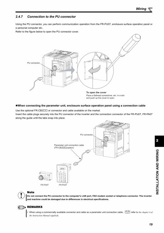
2.4.7 Connection to the PU connector
Using the PU connector, you can perform communication operation from the FR-PU07, enclosure surface operation panel ora personal computer etc.Refer to the figure below to open the PU connector cover.
When connecting the parameter unit, enclosure surface operation panel using a connection cable
Use the optional FR-CB2 or connector and cable available on the market.Insert the cable plugs securely into the PU connector of the inverter and the connection connector of the FR-PU07, FR-PA07along the guide until the tabs snap into place.
NoteDo not connect the PU connector to the computer's LAN port, FAX modem socket or telephone connector. The inverterand machine could be damaged due to differences in electrical specifications.
REMARKS
When using a commercially available connector and cable as a parameter unit connection cable, refer to the chapter 4 ofthe Instruction Manual (applied).
PU connector
Place a flathead screwdriver, etc. in a slot
and push up the cover to open.
To open the cover
STF FWD PU
FR-PU07
Parameter unit connection cable
(FR-CB2��)(option)
PU connector
FR-PA07
19
Wiring
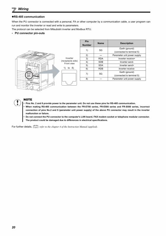
RS-485 communicationWhen the PU connector is connected with a personal, FA or other computer by a communication cable, a user program canrun and monitor the inverter or read and write to parameters.The protocol can be selected from Mitsubishi inverter and Modbus RTU.
PU connector pin-outs
For further details, refer to the chapter 4 of the Instruction Manual (applied).
Pin Number
Name Description
1) SGEarth (ground)
(connected to terminal 5)2) — Parameter unit power supply3) RDA Inverter receive+4) SDB Inverter send-5) SDA Inverter send+6) RDB Inverter receive-
7) SGEarth (ground)
(connected to terminal 5)8) — Parameter unit power supply
NOTEPins No. 2 and 8 provide power to the parameter unit. Do not use these pins for RS-485 communication.When making RS-485 communication between the FR-E700 series, FR-E500 series and FR-S500 series, incorrectconnection of pins No.2 and 8 (parameter unit power supply) of the above PU connector may result in the invertermalfunction or failure.Do not connect the PU connector to the computer's LAN board, FAX modem socket or telephone modular connector.The product could be damaged due to differences in electrical specifications.
8)1) to
Inverter
(receptacle side)
Front view
20
2
INST
ALL
ATIO
N A
ND
WIR
ING
Wiring
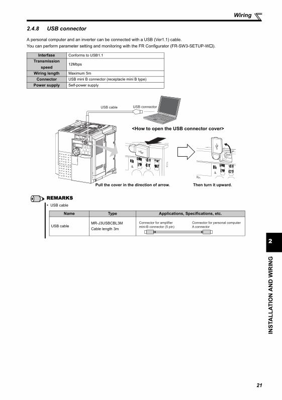
2.4.8 USB connector
A personal computer and an inverter can be connected with a USB (Ver1.1) cable.You can perform parameter setting and monitoring with the FR Configurator (FR-SW3-SETUP-W ).
Interfase Conforms to USB1.1Transmission
speed12Mbps
Wiring length Maximum 5mConnector USB mini B connector (receptacle mini B type)
Power supply Self-power supply
REMARKSUSB cable
USB cable USB connector
<How to open the USB connector cover>
Pull the cover in the direction of arrow. Then turn it upward.
Name Type Applications, Specifications, etc.
USB cableMR-J3USBCBL3MCable length 3m
Connector for personal computer
A connector
Connector for amplifier
mini-B connector (5 pin)
21
22
When using the brake resistor (MRS, MYS, FR-ABR)
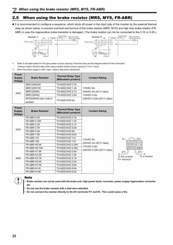
2.5 When using the brake resistor (MRS, MYS, FR-ABR)It is recommended to configure a sequence, which shuts off power in the input side of the inverter by the external thermalrelay as shown below, to prevent overheat and burnout of the brake resistor (MRS, MYS) and high duty brake resistor (FR-ABR) in case the regenerative brake transistor is damaged. (The brake resistor can not be connected to the 0.1K or 0.2K.)
∗1 Refer to the table below for the type number of each capacity of thermal relay and the diagram below for the connection. (Always install a thermal relay when using a brake resistor whose capacity is 11K or more)
∗2 When the power supply is 400V class, install a step-down transformer.
Power Supply Voltage
Brake Resistor Thermal Relay Type(Mitsubishi product) Contact Rating
200V
MRS120W200 TH-N20CXHZ-0.7A110VAC 5A, 220VAC 2A (AC11 class)110VDC 0.5A, 220VDC 0.25A (DC11 class)
MRS120W100 TH-N20CXHZ-1.3AMRS120W60 TH-N20CXHZ-2.1AMRS120W40 TH-N20CXHZ-3.6AMYS220W50 (two units in parallel)
TH-N20CXHZ-5A
Power Supply Voltage
Brake Resistor Thermal Relay Type(Mitsubishi product) Contact Rating
200V
FR-ABR-0.4K TH-N20CXHZ-0.7A
110VAC 5A220VAC 2A (AC11 class)110VDC 0.5A, 220VDC 0.25A (DC11 class)
FR-ABR-0.75K TH-N20CXHZ-1.3AFR-ABR-2.2K TH-N20CXHZ-2.1AFR-ABR-3.7K TH-N20CXHZ-3.6AFR-ABR-5.5K TH-N20CXHZ-5AFR-ABR-7.5K TH-N20CXHZ-6.6AFR-ABR-11K TH-N20CXHZ-11AFR-ABR-15K TH-N20CXHZ-11A
400V
FR-ABR-H0.4K TH-N20CXHZ-0.24AFR-ABR-H0.75K TH-N20CXHZ-0.35AFR-ABR-H1.5K TH-N20CXHZ-0.9AFR-ABR-H2.2K TH-N20CXHZ-1.3AFR-ABR-H3.7K TH-N20CXHZ-2.1AFR-ABR-H5.5K TH-N20CXHZ-2.5AFR-ABR-H7.5K TH-N20CXHZ-3.6AFR-ABR-H11K TH-N20CXHZ-6.6AFR-ABR-H15K TH-N20CXHZ-6.6A
NoteBrake resistor can not be used with the brake unit, high power factor converter, power supply regeneration converter,etc.Do not use the brake resistor with a lead wire extended.Do not connect the resistor directly to the DC terminals P/+ and N/-. This could cause a fire.
MC Inverter
MC
R
PR
P/+
S/L2
T/L3
R/L1
ONOFF
OCR
Contact
Power supply
F
<Example 1>
MC
High-duty brake
resistor (FR-ABR)
T
Thermal relay(OCR) (*1)
*2
Inverter
MC
R
PR
P/+
S/L2
T/L3
R/L1
ONOFF
B
C
Power supply
F
<Example 2>MC
MC
High-duty brake
resistor (FR-ABR)
OCR
Contact
T
Thermal relay(OCR) (*1)
*2
To the inverter
P/+ terminal
To a resistor
TH-N20
1/L1 5/L3
2/T1 6/T3
23
2
INST
ALL
ATIO
N A
ND
WIR
ING
Power-off and magnetic contactor (MC)
2.6 Power-off and magnetic contactor (MC)
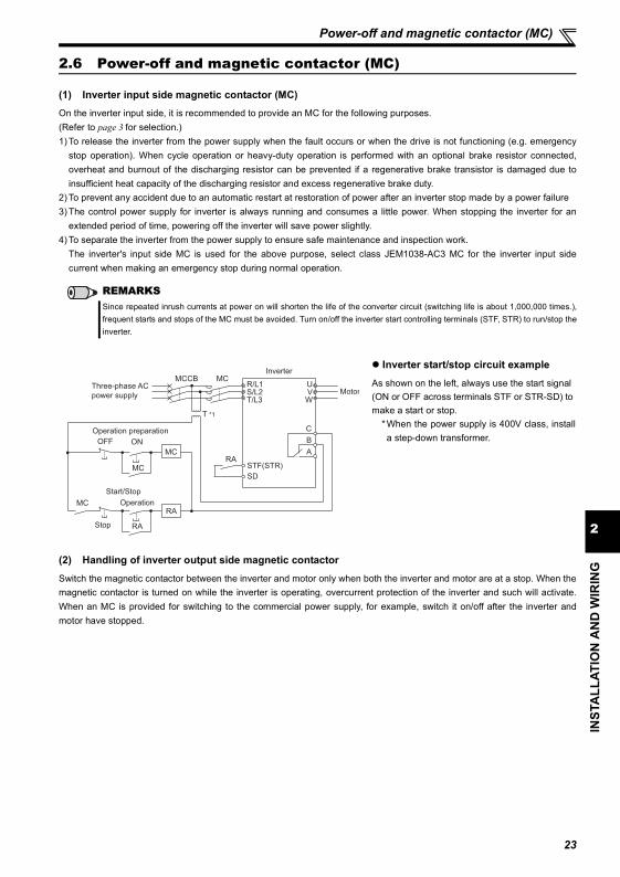
(1) Inverter input side magnetic contactor (MC)On the inverter input side, it is recommended to provide an MC for the following purposes.(Refer to page 3 for selection.)1) To release the inverter from the power supply when the fault occurs or when the drive is not functioning (e.g. emergency
stop operation). When cycle operation or heavy-duty operation is performed with an optional brake resistor connected,overheat and burnout of the discharging resistor can be prevented if a regenerative brake transistor is damaged due toinsufficient heat capacity of the discharging resistor and excess regenerative brake duty.
2) To prevent any accident due to an automatic restart at restoration of power after an inverter stop made by a power failure3) The control power supply for inverter is always running and consumes a little power. When stopping the inverter for an
extended period of time, powering off the inverter will save power slightly.4) To separate the inverter from the power supply to ensure safe maintenance and inspection work.
The inverter's input side MC is used for the above purpose, select class JEM1038-AC3 MC for the inverter input sidecurrent when making an emergency stop during normal operation.
(2) Handling of inverter output side magnetic contactor
Switch the magnetic contactor between the inverter and motor only when both the inverter and motor are at a stop. When themagnetic contactor is turned on while the inverter is operating, overcurrent protection of the inverter and such will activate.When an MC is provided for switching to the commercial power supply, for example, switch it on/off after the inverter andmotor have stopped.
REMARKSSince repeated inrush currents at power on will shorten the life of the converter circuit (switching life is about 1,000,000 times.),frequent starts and stops of the MC must be avoided. Turn on/off the inverter start controlling terminals (STF, STR) to run/stop theinverter.
Inverter start/stop circuit example
As shown on the left, always use the start signal (ON or OFF across terminals STF or STR-SD) to make a start or stop.
* When the power supply is 400V class, installa step-down transformer.
Three-phase AC
power supply
R/L1S/L2T/L3
UVW
Motor
MCCB MC
SD
STF(STR)
A
B
C
RA
OFF ON
MC
Stop
Operation
RA
MC
Operation preparation
Start/Stop
RA
MC
Inverter
T *1
Precautions for use of the inverter
2.7 Precautions for use of the inverter
The FR-E700 series is a highly reliable product, but incorrect peripheral circuit making or operation/handling method mayshorten the product life or damage the product.Before starting operation, always recheck the following items.
(1) Use crimping terminals with insulation sleeve to wire the power supply and motor.
(2) Application of power to the output terminals (U, V, W) of the inverter will damage the inverter. Never perform such wiring.
(3) After wiring, wire offcuts must not be left in the inverter.Wire offcuts can cause an alarm, failure or malfunction. Always keep the inverter clean.When drilling mounting holes in an enclosure etc., take care not to allow chips and other foreign matter to enter theinverter.
(4) Use cables of the size to make a voltage drop 2% maximum.If the wiring distance is long between the inverter and motor, a main circuit cable voltage drop will cause the motor torqueto decrease especially at the output of a low frequency.Refer to page 10 for the recommended wire sizes.
(5) The overall wiring length should be 500m maximum.Especially for long distance wiring, the fast-response current limit function may decrease or the equipment connected tothe secondary side may malfunction or become faulty under the influence of a charging current due to the stray capacityof the wiring. Therefore, note the overall wiring length. (Refer to page 12)
(6) Electromagnetic wave interferenceThe input/output (main circuit) of the inverter includes high frequency components, which may interfere with thecommunication devices (such as AM radios) used near the inverter. In this case, install the FR-BIF optional capacitortype filter (for use in the input side only) or FR-BSF01 or FR-BLF common mode filter to minimize interference.
(7) Do not install a power factor correction capacitor, surge suppressor or capacitor type filter on the inverter output side.This will cause the inverter to trip or the capacitor and surge suppressor to be damaged. If any of the above devices areconnected, immediately remove them.
(8) Before starting wiring or other work after the inverter is operated, wait for at least 10 minutes after the power supply hasbeen switched off, and check that there are no residual voltage using a tester or the like. The capacitor is charged withhigh voltage for some time after power off and it is dangerous.
(9) A short circuit or earth (ground) fault on the inverter output side may damage the inverter modules.Fully check the insulation resistance of the circuit prior to inverter operation since repeated short circuits caused byperipheral circuit inadequacy or an earth (ground) fault caused by wiring inadequacy or reduced motor insulationresistance may damage the inverter modules.Fully check the to-earth (ground) insulation and phase to phase insulation of the inverter output side before power-on.Especially for an old motor or use in hostile atmosphere, securely check the motor insulation resistance etc.
(10) Do not use the inverter input side magnetic contactor to start/stop the inverter.Always use the start signal (turn on/off terminals STF, STR-SD) to start/stop the inverter. (Refer to page 23)
(11) Across P/+ and PR terminals, connect only an external regenerative brake discharging resistor.Do not connect a mechanical brake.The brake resistor can not be connected to the 0.1K or 0.2K. Leave terminals P/+ and PR open.Also, never short between these terminals.
24
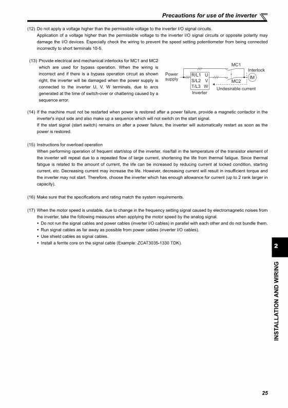
2
INST
ALL
ATIO
N A
ND
WIR
ING
Precautions for use of the inverter
(12) Do not apply a voltage higher than the permissible voltage to the inverter I/O signal circuits.Application of a voltage higher than the permissible voltage to the inverter I/O signal circuits or opposite polarity maydamage the I/O devices. Especially check the wiring to prevent the speed setting potentiometer from being connectedincorrectly to short terminals 10-5.
(14) If the machine must not be restarted when power is restored after a power failure, provide a magnetic contactor in theinverter's input side and also make up a sequence which will not switch on the start signal.If the start signal (start switch) remains on after a power failure, the inverter will automatically restart as soon as thepower is restored.
(15) Instructions for overload operationWhen performing operation of frequent start/stop of the inverter, rise/fall in the temperature of the transistor element ofthe inverter will repeat due to a repeated flow of large current, shortening the life from thermal fatigue. Since thermalfatigue is related to the amount of current, the life can be increased by reducing current at locked condition, startingcurrent, etc. Decreasing current may increase the life. However, decreasing current will result in insufficient torque andthe inverter may not start. Therefore, choose the inverter which has enough allowance for current (up to 2 rank larger incapacity).
(16) Make sure that the specifications and rating match the system requirements.
(17) When the motor speed is unstable, due to change in the frequency setting signal caused by electromagnetic noises fromthe inverter, take the following measures when applying the motor speed by the analog signal.
Do not run the signal cables and power cables (inverter I/O cables) in parallel with each other and do not bundle them. Run signal cables as far away as possible from power cables (inverter I/O cables). Use shield cables as signal cables. Install a ferrite core on the signal cable (Example: ZCAT3035-1330 TDK).
(13) Provide electrical and mechanical interlocks for MC1 and MC2which are used for bypass operation. When the wiring isincorrect and if there is a bypass operation circuit as shownright, the inverter will be damaged when the power supply isconnected to the inverter U, V, W terminals, due to arcsgenerated at the time of switch-over or chattering caused by asequence error.
Power supply
InverterUndesirable current
MC2
MC1
InterlockU
V
W
R/L1
S/L2
T/L3
IM
25
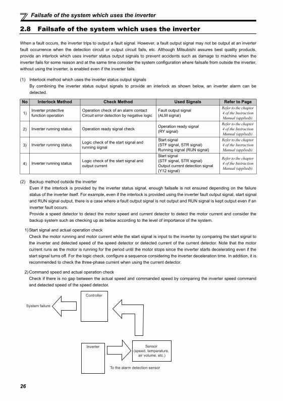
26
Failsafe of the system which uses the inverter
2.8 Failsafe of the system which uses the inverter
When a fault occurs, the inverter trips to output a fault signal. However, a fault output signal may not be output at an inverterfault occurrence when the detection circuit or output circuit fails, etc. Although Mitsubishi assures best quality products,provide an interlock which uses inverter status output signals to prevent accidents such as damage to machine when theinverter fails for some reason and at the same time consider the system configuration where failsafe from outside the inverter,without using the inverter, is enabled even if the inverter fails.
(1) Interlock method which uses the inverter status output signals By combining the inverter status output signals to provide an interlock as shown below, an inverter alarm can bedetected.
(2) Backup method outside the inverterEven if the interlock is provided by the inverter status signal, enough failsafe is not ensured depending on the failurestatus of the inverter itself. For example, even if the interlock is provided using the inverter fault output signal, start signaland RUN signal output, there is a case where a fault output signal is not output and RUN signal is kept output even if aninverter fault occurs.Provide a speed detector to detect the motor speed and current detector to detect the motor current and consider thebackup system such as checking up as below according to the level of importance of the system.
1) Start signal and actual operation checkCheck the motor running and motor current while the start signal is input to the inverter by comparing the start signal tothe inverter and detected speed of the speed detector or detected current of the current detector. Note that the motorcurrent runs as the motor is running for the period until the motor stops since the inverter starts decelerating even if thestart signal turns off. For the logic check, configure a sequence considering the inverter deceleration time. In addition, it isrecommended to check the three-phase current when using the current detector.
2) Command speed and actual operation checkCheck if there is no gap between the actual speed and commanded speed by comparing the inverter speed commandand detected speed of the speed detector.
No Interlock Method Check Method Used Signals Refer to Page
1)Inverter protective function operation
Operation check of an alarm contactCircuit error detection by negative logic
Fault output signal (ALM signal)
Refer to the chapter 4 of the Instruction Manual (applied)).
2) Inverter running status Operation ready signal check Operation ready signal (RY signal)
Refer to the chapter 4 of the Instruction Manual (applied)).
3) Inverter running status Logic check of the start signal and running signal
Start signal (STF signal, STR signal)Running signal (RUN signal)
Refer to the chapter 4 of the Instruction Manual (applied)).
4) Inverter running status Logic check of the start signal and output current
Start signal (STF signal, STR signal)Output current detection signal (Y12 signal)
Refer to the chapter 4 of the Instruction Manual (applied)).
Inverter
Controller
System failure
To the alarm detection sensor
Sensor
(speed, temperature,
air volume, etc.)
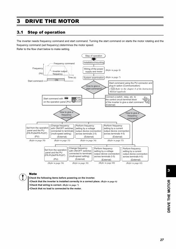
27
DR
IVE
THE
MO
TOR
3
Step of operation
3 DRIVE THE MOTOR
3.1 Step of operation
The inverter needs frequency command and start command. Turning the start command on starts the motor rotating and thefrequency command (set frequency) determines the motor speed.Refer to the flow chart below to make setting.
NoteCheck the following items before powering on the inverter.Check that the inverter is installed correctly in a correct place. (Refer to page 6)Check that wiring is correct. (Refer to page 7)Check that no load is connected to the motor.
Step of operation
Start command with
on the operation panel (PU)
Installation/mounting
System examination
Wiring of the power
supply and motor
Connect a switch, relay, etc. to
the control circuit terminal block
of the inverter to give a start command
(External)
Start command using the PU connector and
plug-in option (Communication)
Change frequency
with ON/OFF switches
connected to terminals
(multi-speed setting)
(External)
Perform frequency
setting by a current
output device (connection
across terminals 4-5)
(External)
Perform frequency
setting by a voltage
output device (connection
across terminals 2-5)
(External)
Change frequency
with ON/OFF switches
connected to terminals
(multi-speed setting)
(External)
Perform frequency
setting by a current
output device (connection
across terminals 4-5)
(External)
Perform frequency
setting by a voltage
output device (connection
across terminals 2-5)
(External)
How to give a
frequency
command?
How to give a
frequency
command?
How to give a
start command?
(PU)
Set from the operation
panel and the PU
(FR-PU04/FR-PU07)
ON
Frequency
Time (s)
(Hz)
Start command
Frequency command
Inverter output
frequency
(PU)
Set from the operation
panel and the PU
(FR-PU04/FR-PU07)
(Refer to page 50) (Refer to page 53) (Refer to page 54) (Refer to page 55)
(Refer to page 56) (Refer to page 58) (Refer to page 60) (Refer to page 63)
(Refer to page 6)
(Refer to page 7)
( Refer to the chapter 4 of the InstructionManual (applied))
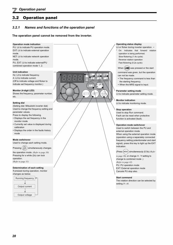
Operation panel
3.2 Operation panel
3.2.1 Names and functions of the operation panel
The operation panel cannot be removed from the inverter.
Operation mode indicationPU: Lit to indicate PU operation mode.EXT: Lit to indicate external operation mode.NET: Lit to indicate network operation mode.PU, EXT: Lit to indicate external/PU combined operation mode 1, 2.
Unit indicationHz: Lit to indicate frequency.A: Lit to indicate current.(Off to indicate voltage and flicker to indicate set frequency monitor.)
Monitor (4-digit LED)Shows the frequency, parameter number, etc.
Setting dial(Setting dial: Mitsubishi inverter dial)Used to change the frequency setting and parameter values.Press to display the following.
Displays the set frequency in the monitor modeCurrently set value is displayed during calibrationDisplays the order in the faults history mode
Mode switchoverUsed to change each setting mode.
Pressing simultaneously changes
the operation mode. (Refer to page 30)Pressing for a while (2s) can lock operation. (Refer to page 31)
Determination of each settingIf pressed during operation, monitor changes as below;
Running frequency
Output current
Output voltage
Operating status displayLit or flicker during inverter operation. ∗* On: Indicates that forward rotation
operation is being performed.Slow flickering (1.4s cycle): Reverse rotation operationFast flickering (0.2s cycle):
When was pressed or the start
command was given, but the operation can not be made.
The frequency command is less than the starting frequency.When the MRS signal is input.
Parameter setting modeLit to indicate parameter setting mode.
Monitor indicationLit to indicate monitoring mode.
Stop operationUsed to stop Run command.Fault can be reset when protective function is activated (fault).
Operation mode switchoverUsed to switch between the PU and external operation mode.When using the external operation mode (operation using a separately connected frequency setting potentiometer and start signal), press this key to light up the EXT indication.
(Press simultanesouly (0.5s) (Refer
to page 30), or change Pr. 79 setting to change to combined mode .)(Refer to page 42)PU: PU operation modeEXT: External operation modeCancels PU stop also.
Start commandThe rotation direction can be selected by setting Pr. 40.
28
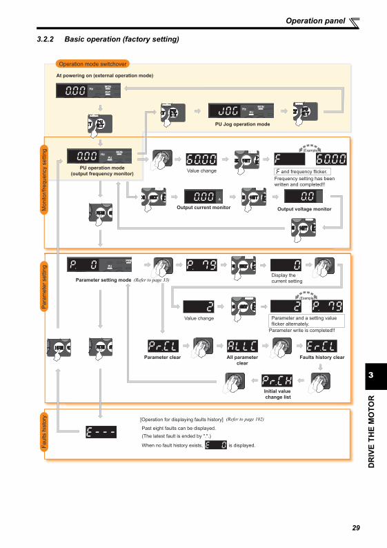
DR
IVE
THE
MO
TOR
3
Operation panel
3.2.2 Basic operation (factory setting)
STOP
Operation mode switchover
Para
mete
r settin
gF
aults h
isto
ryM
onitor/
frequency s
ettin
g
At powering on (external operation mode)
PU operation mode
(output frequency monitor)
Parameter setting mode
PU Jog operation mode
Output current monitor Output voltage monitor
Display the
current setting
Value change
Value change
Parameter write is completed!!
Parameter and a setting value
flicker alternately.
Parameter clear All parameter
clear
Faults history clear
Initial value
change list
(Example)
(Example)
Frequency setting has been
written and completed!!
and frequency flicker.
[Operation for displaying faults history]
Past eight faults can be displayed.
(The latest fault is ended by ".".)
When no fault history exists, is displayed.
(Refer to page 33)
(Refer to page 102)
29
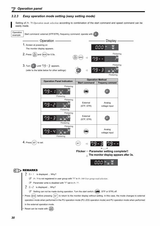
30
Operation panel
3.2.3 Easy operation mode setting (easy setting mode)
Setting of Pr. 79 Operation mode selection according to combination of the start command and speed command can beeasily made.
Operation example Start command: external (STF/STR), frequency command: operate with
Operation Display 1. Screen at powering on
The monitor display appears.
2. Press and for 0.5s.
3. Turn until appears.
(refer to the table below for other settings)
4. Press to set.
Flicker ··· Parameter setting complete!!The monitor display appears after 3s.
REMARKS is displayed ... Why?
Pr. 79 is not registered in user group with "1" in Pr. 160 User group read selection.
Parameter write is disabled with "1" set in Pr. 77.
is displayed ... Why?
Setting can not be made during operation. Turn the start switch ( , STF or STR) off.
Press before pressing to return to the monitor display without setting. In this case, the mode changes to external
operation mode when performed in the PU operation mode (PU JOG operation mode) and PU operation mode when performed
in the external operation mode.
Reset can be made with .
Flickering
Flickering
Flickering
Operation Panel Indication Operation MethodStart command Frequency command
External(STF, STR)
Analogvoltage input
External(STF, STR)
Analogvoltage input
Flickering
Flickering
Flickering
Flickering
Flickering
Flickering
Flickering
Flickering
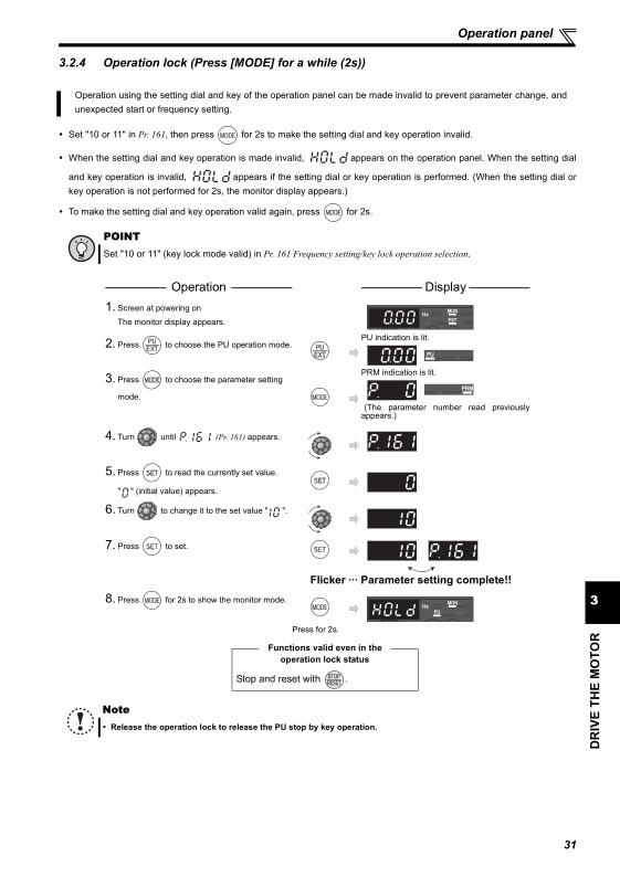
DR
IVE
THE
MO
TOR
3
Operation panel
3.2.4 Operation lock (Press [MODE] for a while (2s))
Set "10 or 11" in Pr. 161, then press for 2s to make the setting dial and key operation invalid.
When the setting dial and key operation is made invalid, appears on the operation panel. When the setting dial
and key operation is invalid, appears if the setting dial or key operation is performed. (When the setting dial orkey operation is not performed for 2s, the monitor display appears.)
To make the setting dial and key operation valid again, press for 2s.
Operation using the setting dial and key of the operation panel can be made invalid to prevent parameter change, andunexpected start or frequency setting.
POINTSet "10 or 11" (key lock mode valid) in Pr. 161 Frequency setting/key lock operation selection.
Operation Display 1. Screen at powering on
The monitor display appears.
2. Press to choose the PU operation mode.PU indication is lit.
3. Press to choose the parameter setting
mode.
PRM indication is lit.
(The parameter number read previouslyappears.)
4. Turn until (Pr. 161) appears.
5. Press to read the currently set value.
" " (initial value) appears.
6. Turn to change it to the set value " ".
7. Press to set.
Flicker ··· Parameter setting complete!!
8. Press for 2s to show the monitor mode.
Press for 2s.
Functions valid even in the operation lock status
Stop and reset with .
NoteRelease the operation lock to release the PU stop by key operation.
31
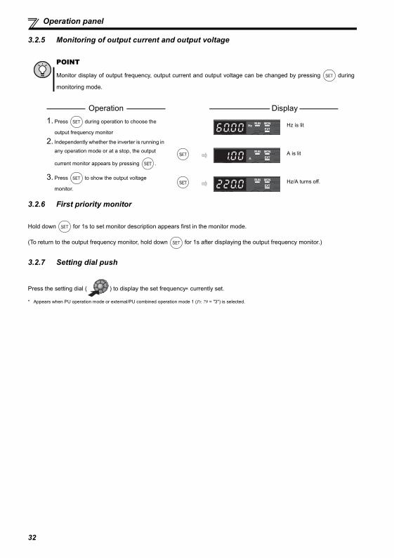
Operation panel
3.2.5 Monitoring of output current and output voltage
3.2.6 First priority monitor
Hold down for 1s to set monitor description appears first in the monitor mode.
(To return to the output frequency monitor, hold down for 1s after displaying the output frequency monitor.)
3.2.7 Setting dial push
Press the setting dial ( ) to display the set frequency∗ currently set.
* Appears when PU operation mode or external/PU combined operation mode 1 (Pr. 79 = "3") is selected.
POINT
Monitor display of output frequency, output current and output voltage can be changed by pressing during
monitoring mode.
Operation Display 1. Press during operation to choose the
output frequency monitorHz is lit
2. Independently whether the inverter is running in
any operation mode or at a stop, the output
current monitor appears by pressing .
A is lit
3. Press to show the output voltage
monitor.Hz/A turns off.
32
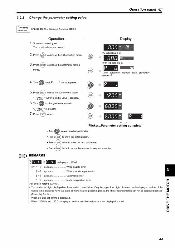
33
Operation panel
DR
IVE
THE
MO
TOR
3
3.2.8 Change the parameter setting value
Changing example Change the Pr. 1 Maximum frequency setting.
Operation Display 1. Screen at powering on
The monitor display appears.
2. Press to choose the PU operation mode.PU indication is lit.
3. Press to choose the parameter setting
mode.
PRM indication is lit.
(The parameter number read previouslyappears.)
4. Turn until (Pr. 1) appears.
5. Press to read the currently set value.
" "(120.0Hz (initial value)) appears.
6. Turn to change the set value to
" " (60.00Hz).
7. Press to set.
Flicker...Parameter setting complete!!
Turn to read another parameter.
Press to show the setting again.
Press twice to show the next parameter.
Press twice to return the monitor to frequency monitor.
REMARKS
is displayed...Why?
appears .................... Write disable error
appears .................... Write error during operation
appears .................... Calibration error
appears .................... Mode designation error(For details, refer to page 93.)
The number of digits displayed on the operation panel is four. Only the upper four digits of values can be displayed and set. If thevalues to be displayed have five digits or more including decimal places, the fifth or later numerals can not be displayed nor set.(Example) For Pr. 1When 60Hz is set, 60.00 is displayed.When 120Hz is set, 120.0 is displayed and second decimal place is not displayed nor set.
to
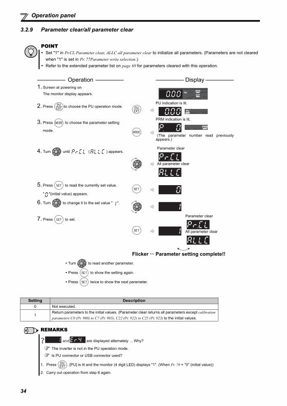
34
Operation panel
3.2.9 Parameter clear/all parameter clear
POINT Set "1" in Pr.CL Parameter clear, ALLC all parameter clear to initialize all parameters. (Parameters are not cleared
when "1" is set in Pr. 77Parameter write selection.)Refer to the extended parameter list on page 69 for parameters cleared with this operation.
Operation Display 1. Screen at powering on
The monitor display appears.
2. Press to choose the PU operation mode.PU indication is lit.
3. Press to choose the parameter setting
mode.
PRM indication is lit.
(The parameter number read previouslyappears.)
4. Turn until ( ) appears.Parameter clear
All parameter clear
5. Press to read the currently set value.
" "(initial value) appears.
6. Turn to change it to the set value " ".
7. Press to set.Parameter clear
All parameter clear
Flicker ··· Parameter setting complete!!
Turn to read another parameter.
Press to show the setting again.
Press twice to show the next parameter.
Setting Description0 Not executed.
1Return parameters to the initial values. (Parameter clear returns all parameters except calibration parameters C0 (Pr. 900) to C7 (Pr. 905), C22 (Pr. 922) to C25 (Pr. 923) to the initial values.
REMARKS
are displayed alternately ... Why?
The inverter is not in the PU operation mode.
Is PU connector or USB connector used?
1. Press . [PU] is lit and the monitor (4 digit LED) displays "1". (When Pr. 79 = "0" (initial value))
2. Carry out operation from step 6 again.
and
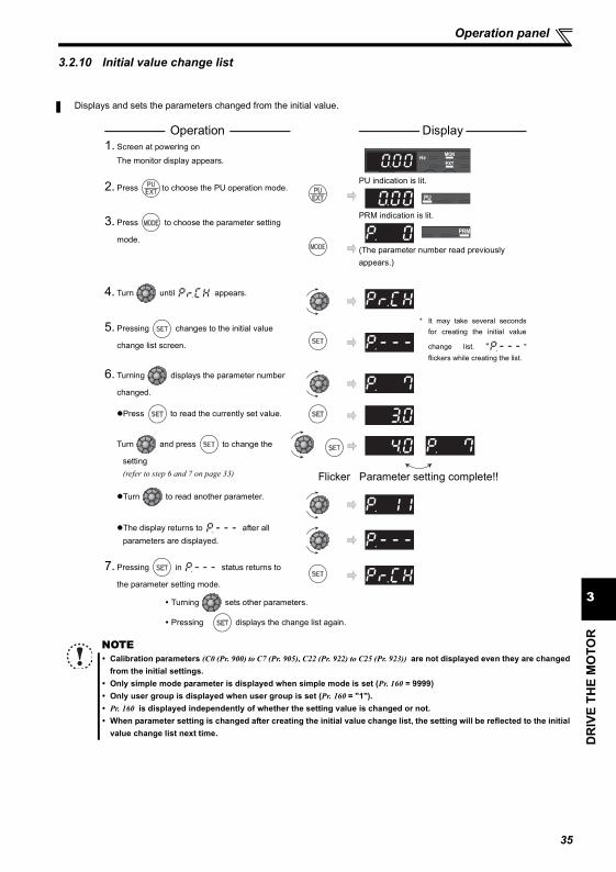
35
Operation panel
DR
IVE
THE
MO
TOR
3
3.2.10 Initial value change list
Displays and sets the parameters changed from the initial value.
Operation Display 1. Screen at powering on
The monitor display appears.
2. Press to choose the PU operation mode.PU indication is lit.
3. Press to choose the parameter setting
mode.
PRM indication is lit.
(The parameter number read previously appears.)
4. Turn until appears.
5. Pressing changes to the initial value
change list screen.
* It may take several secondsfor creating the initial value
change list. " "flickers while creating the list.
6. Turning displays the parameter number
changed.
Press to read the currently set value.
Turn and press to change the
setting (refer to step 6 and 7 on page 33) Flicker Parameter setting complete!!
Turn to read another parameter.
The display returns to after all parameters are displayed.
7. Pressing in status returns to
the parameter setting mode.
Turning sets other parameters.
Pressing displays the change list again.
NOTECalibration parameters (C0 (Pr. 900) to C7 (Pr. 905), C22 (Pr. 922) to C25 (Pr. 923)) are not displayed even they are changedfrom the initial settings.Only simple mode parameter is displayed when simple mode is set (Pr. 160 = 9999) Only user group is displayed when user group is set (Pr. 160 = "1"). Pr. 160 is displayed independently of whether the setting value is changed or not. When parameter setting is changed after creating the initial value change list, the setting will be reflected to the initialvalue change list next time.

36
Before operation
3.3 Before operation
3.3.1 Simple mode parameter list
For simple variable-speed operation of the inverter, the initial setting of the parameters may be used as they are. Set thenecessary parameters to meet the load and operational specifications. Parameter setting, change and check can be madefrom the operation panel. (For details of parameters, refer to the chapter 4 of the Instruction Manual (applied)).
POINTOnly simple mode parameter can be displayed using Pr. 160 User group read selection. (All parameters are displayedwith the initial setting. Set Pr. 160 User group read selection as required. (Refer to page 33 for parameter change)
Pr. 160 Description9999 Parameters classified as simple mode can be displayed.
0(initial value)
Both the parameters classified as simple mode and the parameters classified as extended mode can be displayed.
1 Only the parameters registered to the user group can be displayed.
Parameter Number
Name UnitInitial Value
Range ApplicationReference
Page
0 Torque boost 0.1%6%/4%/3%/
2%∗0 to 30%
Set when you want to increase a starting torque or when the motor with a load will not rotate, resulting in an alarm [OL] and a trip [OC1].∗ Initial values differ according to the
inverter capacity. (0.75K or less/1.5K to 3.7K/5.5K, 7.5K/11K, 15K)
39
1 Maximum frequency 0.01Hz 120Hz 0 to 120HzSet when the maximum output frequency need to be limited.
402 Minimum frequency 0.01Hz 0Hz 0 to 120Hz
Set when the minimum output frequency need to be limited.
3 Base frequency 0.01Hz 60Hz 0 to 400HzSet when the rated motor frequency is 50Hz.Check the motor rating plate.
38
4Multi-speed setting (high speed)
0.01Hz 60Hz 0 to 400HzSet when changing the preset speed in the parameter with a terminal.
585Multi-speed setting (middle speed)
0.01Hz 30Hz 0 to 400Hz
6Multi-speed setting (low speed)
0.01Hz 10Hz 0 to 400Hz
7 Acceleration time 0.1s 5s/10s/15s∗ 0 to 3600sAcceleration/deceleration time can be set.∗ Initial values differ according to the
inverter capacity. (3.7K or less/5.5K, 7.5K/11K, 15K)
41
8 Deceleration time 0.1s 5s/10s/15s∗ 0 to 3600s
9Electronic thermal O/L relay
0.01ARated
inverter current
0 to 500AThe inverter protects the motor from overheat.Set the rated motor current.
37
79Operation mode selection
1 00, 1, 2, 3, 4, 6, 7
Select the start command location and frequency command location.
42
125Terminal 2 frequency setting gain frequency
0.01Hz 60Hz 0 to 400HzFrequency for the maximum value of the potentiometer (5V initial value) can be changed.
62
126Terminal 4 frequency setting gain frequency
0.01Hz 60Hz 0 to 400HzFrequency for the maximum current input (20mA initial value) can be changed.
65
160User group read selection
1 0 0, 1, 9999Parameter which can be read from the operation panel and parameter unit can be restricted.
—
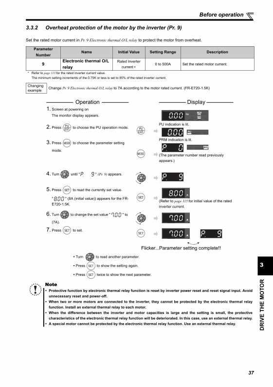
37
DR
IVE
THE
MO
TOR
3
Before operation
3.3.2 Overheat protection of the motor by the inverter (Pr. 9)
Set the rated motor current in Pr. 9 Electronic thermal O/L relay to protect the motor from overheat.
Parameter Number
Name Initial Value Setting Range Description
9Electronic thermal O/L relay
Rated Inverter current ∗
0 to 500A Set the rated motor current.
* Refer to page 115 for the rated inverter current value.The minimum setting increments of the 0.75K or less is set to 85% of the rated inverter current.
Changing example Change Pr. 9 Electronic thermal O/L relay to 7A according to the motor rated current. (FR-E720-1.5K)
Operation Display 1. Screen at powering on
The monitor display appears.
2. Press to choose the PU operation mode.PU indication is lit.
3. Press to choose the parameter setting
mode.
PRM indication is lit.
(The parameter number read previously appears.)
4. Turn until " " (Pr. 9) appears.
5. Press to read the currently set value.
" " (8A (initial value)) appears for the FR-E720-1.5K.
(Refer to page 115 for initial value of the rated inverter current.
6. Turn to change the set value " " to
(7A).
7. Press to set.
Flicker...Parameter setting complete!!
Turn to read another parameter.
Press to show the setting again.
Press twice to show the next parameter.
NoteProtective function by electronic thermal relay function is reset by inverter power reset and reset signal input. Avoidunnecessary reset and power-off.When two or more motors are connected to the inverter, they cannot be protected by the electronic thermal relayfunction. Install an external thermal relay to each motor.When the difference between the inverter and motor capacities is large and the setting is small, the protectivecharacteristics of the electronic thermal relay function will be deteriorated. In this case, use an external thermal relay.A special motor cannot be protected by the electronic thermal relay function. Use an external thermal relay.
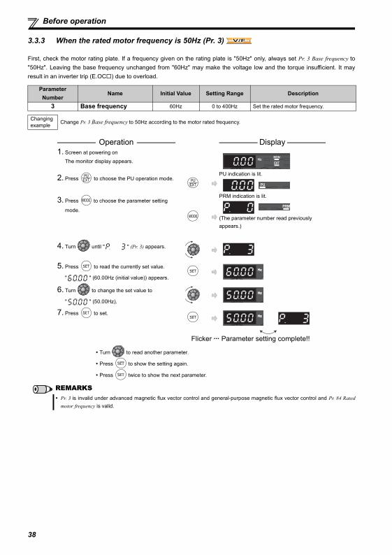
38
Before operation
3.3.3 When the rated motor frequency is 50Hz (Pr. 3)
First, check the motor rating plate. If a frequency given on the rating plate is "50Hz" only, always set Pr. 3 Base frequency to"50Hz". Leaving the base frequency unchanged from "60Hz" may make the voltage low and the torque insufficient. It mayresult in an inverter trip (E.OC ) due to overload.
Parameter Number
Name Initial Value Setting Range Description
3 Base frequency 60Hz 0 to 400Hz Set the rated motor frequency.
Changing example Change Pr. 3 Base frequency to 50Hz according to the motor rated frequency.
Operation Display 1. Screen at powering on
The monitor display appears.
2. Press to choose the PU operation mode.PU indication is lit.
3. Press to choose the parameter setting
mode.
PRM indication is lit.
(The parameter number read previously appears.)
4. Turn until " " (Pr. 3) appears.
5. Press to read the currently set value.
" " (60.00Hz (initial value)) appears.
6. Turn to change the set value to
" " (50.00Hz).
7. Press to set.
Flicker ··· Parameter setting complete!!
Turn to read another parameter.
Press to show the setting again.
Press twice to show the next parameter.
REMARKSPr. 3 is invalid under advanced magnetic flux vector control and general-purpose magnetic flux vector control and Pr. 84 Ratedmotor frequency is valid.
V/FV/FV/F
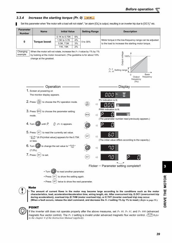
39
DR
IVE
THE
MO
TOR
3
Before operation
3.3.4 Increase the starting torque (Pr. 0) Set this parameter when "the motor with a load will not rotate", "an alarm [OL] is output, resulting in an inverter trip due to [OC1]," etc.
Parameter Number
Name Initial Value Setting Range Description
0 Torque boost
0.1K to 0.75K 6%
0 to 30%Motor torque in the low-frequency range can be adjusted to the load to increase the starting motor torque.
1.5K to 3.7K 4%5.5K, 7.5K 3%11K, 15K 2%
Changing example
When the motor will not rotate, increase the Pr. 0 value by 1% by 1% by looking at the motor movement. (The guideline is for about 10% change at the greatest.
Operation Display 1. Screen at powering on
The monitor display appears.
2. Press to choose the PU operation mode.PU indication is lit.
3. Press to choose the parameter setting
mode.
PRM indication is lit.
(The parameter number read previously appears.)
4. Turn until (Pr. 0) appears.
5. Press to read the currently set value.
" " (6.0%(initial value)) appears for the 0.75K or less. (The initial value differs according to the capacity.)
6. Turn to change the set value to " "
(7.0%).
7. Press to set.
Flicker ··· Parameter setting complete!!
Turn to read another parameter.
Press to show the setting again.
Press twice to show the next parameter.
NoteThe amount of current flows in the motor may become large according to the conditions such as the motorcharacteristics, load, acceleration/deceleration time, wiring length, etc. After overcurrent trip, E.OC1 (overcurrent tripduring acceleration)), overload trip (E.THM (motor overload trip), or E.THT (inverter overload trip) may occur.(When a fault occurs, release the start command, and decrease the Pr. 0 setting 1% by 1% to reset.) (Refer to page 91.)
POINTIf the inverter still does not operate properly after the above measures, set Pr. 80, Pr. 81, and Pr. 800 (advancedmagnetic flux vector control). The Pr. 0 setting is invalid under advanced magnetic flux vector control. ( Referto the chapter 4 of the Instruction Manual (applied)).
V/FV/FV/F
Outp
ut voltage
Pr. 0Pr. 46
Setting range
Output frequency
(Hz)
Base frequency
0
100%
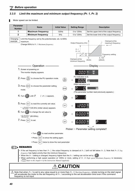
40
Before operation
3.3.5 Limit the maximum and minimum output frequency (Pr. 1, Pr. 2)
Motor speed can be limited.
Parameter Number
Name Initial Value Setting Range Description
1 Maximum frequency 120Hz 0 to 120Hz Set the upper limit of the output frequency.
2 Minimum frequency 0Hz 0 to 120Hz Set the lower limit of the output frequency.
Changing example
Limit the frequency set by the potentiometer, etc. to 60Hz maximum.Change 60Hz to Pr. 1 Maximum frequency.
Operation Display 1. Screen at powering on
The monitor display appears.
2. Press to choose the PU operation mode.PU indication is lit.
3. Press to choose the parameter setting
mode.
PRM indication is lit.
(The parameter number read previously appears.)
4. Turn until (Pr. 1) appears.
5. Press to read the currently set value.
" "(120.0Hz (initial value)) appears.
6. Turn to change the set value to
" " (60.00Hz).
7. Press to set.
Flicker ··· Parameter setting complete!!
Turn to read another parameter.
Press to show the setting again.
Press twice to show the next parameter.
REMARKSIf the set frequency is less than Pr. 2, the output frequency is clamped at Pr. 2 (will not fall below Pr. 2). Note that Pr. 15 Jogfrequency has higher priority than the minimum frequency.When the Pr. 1 setting is changed, frequency higher than the Pr. 1 setting can not be set by .When performing a high speed operation at 120Hz or more, setting of Pr. 18 High speed maximum frequency is necessary.( Refer to the chapter 4 of the Instruction Manual (applied)).
CAUTIONNote that when Pr. 2 is set to any value equal to or more than Pr. 13 Starting frequency, simply turning on the start signal will accelerate the motor to the set frequency of Pr. 2 according to the set acceleration time even if the command frequency is not input.
Pr. 2
Output frequency (Hz)
Pr. 1
Pr. 18
Frequency setting
Clamped at the
maximum frequency
Clamped at the
minimum frequency
5, 10V
(20mA)
0
(4mA)
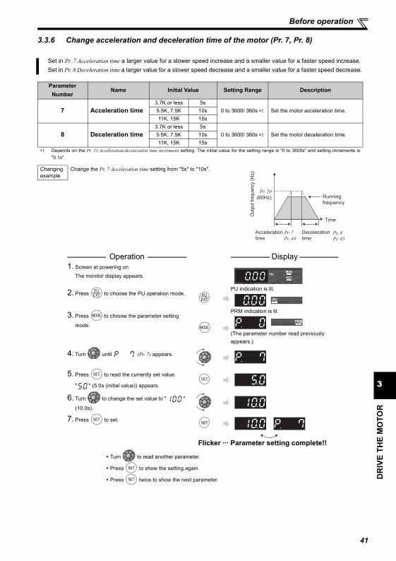
41
DR
IVE
THE
MO
TOR
3
Before operation
3.3.6 Change acceleration and deceleration time of the motor (Pr. 7, Pr. 8)
Set in Pr. 7 Acceleration time a larger value for a slower speed increase and a smaller value for a faster speed increase.Set in Pr. 8 Deceleration time a larger value for a slower speed decrease and a smaller value for a faster speed decrease.
Parameter Number
Name Initial Value Setting Range Description
7 Acceleration time3.7K or less 5s
0 to 3600/ 360s ∗1 Set the motor acceleration time.5.5K, 7.5K 10s11K, 15K 15s
8 Deceleration time3.7K or less 5s
0 to 3600/ 360s ∗1 Set the motor deceleration time.5.5K, 7.5K 10s11K, 15K 15s
∗1 Depends on the Pr. 21 Acceleration/deceleration time increments setting. The initial value for the setting range is "0 to 3600s" and setting increments is"0.1s".
Changing example
Change the Pr. 7 Acceleration time setting from "5s" to "10s".
Operation Display 1. Screen at powering on
The monitor display appears.
2. Press to choose the PU operation mode.PU indication is lit.
3. Press to choose the parameter setting
mode.
PRM indication is lit.
(The parameter number read previously appears.)
4. Turn until (Pr. 7) appears.
5. Press to read the currently set value.
" " (5.0s (initial value)) appears.
6. Turn to change the set value to " "
(10.0s).
7. Press to set.
Flicker ··· Parameter setting complete!!
Turn to read another parameter.
Press to show the setting again.
Press twice to show the next parameter.
Running
frequency
Acceleration
time
Deceleration
time
Time
Pr. 20
(60Hz)
Pr. 7 Pr. 8
Outp
ut fr
equency
(H
z)
Pr. 44 Pr. 45
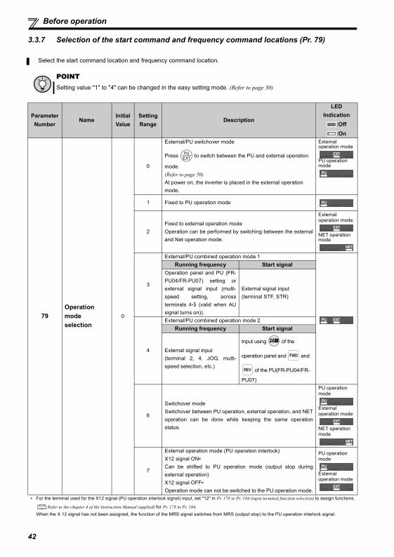
42
Before operation
3.3.7 Selection of the start command and frequency command locations (Pr. 79)
Select the start command location and frequency command location.
POINTSetting value "1" to "4" can be changed in the easy setting mode. (Refer to page 30)
Parameter Number
NameInitial Value
Setting Range
Description
LED Indication
:Off:On
79Operation mode selection
0
0
External/PU switchover mode
Press to switch between the PU and external operation
mode.(Refer to page 50)At power on, the inverter is placed in the external operation mode.
External operation mode
PU operation mode
1 Fixed to PU operation mode
2Fixed to external operation modeOperation can be performed by switching between the externaland Net operation mode.
External operation mode
NET operation mode
3
External/PU combined operation mode 1Running frequency Start signal
Operation panel and PU (FR-PU04/FR-PU07) setting orexternal signal input (multi-speed setting, acrossterminals 4-5 (valid when AUsignal turns on)).
External signal input(terminal STF, STR)
4
External/PU combined operation mode 2Running frequency Start signal
External signal input(terminal 2, 4, JOG, multi-speed selection, etc.)
Input using of the
operation panel and and
of the PU(FR-PU04/FR-
PU07)
6
Switchover modeSwitchover between PU operation, external operation, and NEToperation can be done while keeping the same operationstatus.
PU operation mode
External operation mode
NET operation mode
7
External operation mode (PU operation interlock)X12 signal ON∗Can be shifted to PU operation mode (output stop duringexternal operation)X12 signal OFF∗Operation mode can not be switched to the PU operation mode.
PU operation mode
External operation mode
∗ For the terminal used for the X12 signal (PU operation interlock signal) input, set "12" in Pr. 178 to Pr. 184 (input terminal function selection) to assign functions.
Refer to the chapter 4 of the Instruction Manual (applied) for Pr. 178 to Pr. 184.When the X 12 signal has not been assigned, the function of the MRS signal switches from MRS (output stop) to the PU operation interlock signal.
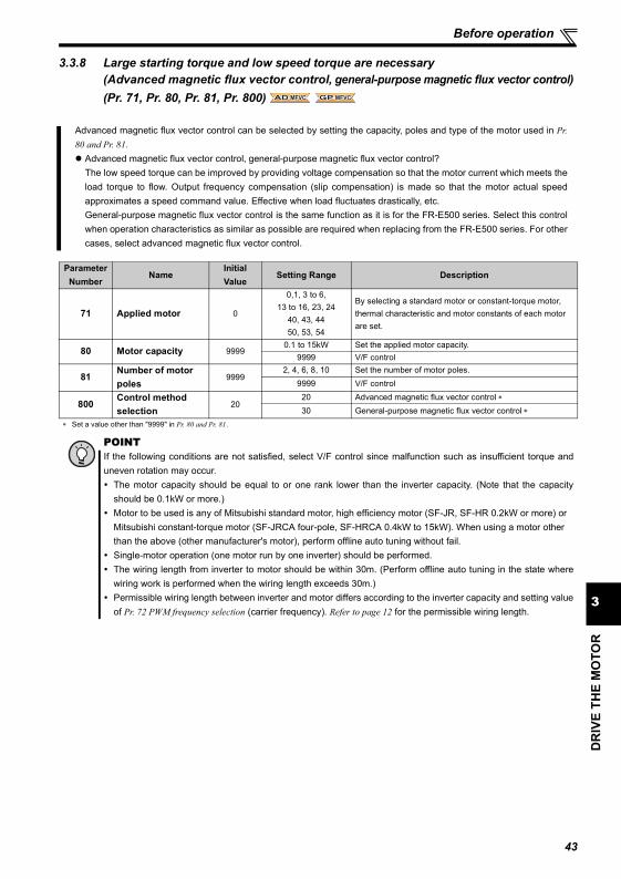
Before operation
DR
IVE
THE
MO
TOR
3
3.3.8 Large starting torque and low speed torque are necessary (Advanced magnetic flux vector control, general-purpose magnetic flux vector control)(Pr. 71, Pr. 80, Pr. 81, Pr. 800)
Advanced magnetic flux vector control can be selected by setting the capacity, poles and type of the motor used in Pr.80 and Pr. 81.
Advanced magnetic flux vector control, general-purpose magnetic flux vector control?The low speed torque can be improved by providing voltage compensation so that the motor current which meets theload torque to flow. Output frequency compensation (slip compensation) is made so that the motor actual speedapproximates a speed command value. Effective when load fluctuates drastically, etc.General-purpose magnetic flux vector control is the same function as it is for the FR-E500 series. Select this controlwhen operation characteristics as similar as possible are required when replacing from the FR-E500 series. For othercases, select advanced magnetic flux vector control.
Parameter Number
NameInitial Value
Setting Range Description
71 Applied motor 0
0,1, 3 to 6,13 to 16, 23, 24
40, 43, 4450, 53, 54
By selecting a standard motor or constant-torque motor, thermal characteristic and motor constants of each motor are set.
80 Motor capacity 99990.1 to 15kW Set the applied motor capacity.
9999 V/F control
81Number of motor poles
99992, 4, 6, 8, 10 Set the number of motor poles.
9999 V/F control
800Control method selection
2020 Advanced magnetic flux vector control ∗30 General-purpose magnetic flux vector control ∗
∗ Set a value other than "9999" in Pr. 80 and Pr. 81.
POINTIf the following conditions are not satisfied, select V/F control since malfunction such as insufficient torque anduneven rotation may occur.
The motor capacity should be equal to or one rank lower than the inverter capacity. (Note that the capacityshould be 0.1kW or more.)Motor to be used is any of Mitsubishi standard motor, high efficiency motor (SF-JR, SF-HR 0.2kW or more) or Mitsubishi constant-torque motor (SF-JRCA four-pole, SF-HRCA 0.4kW to 15kW). When using a motor other than the above (other manufacturer's motor), perform offline auto tuning without fail.Single-motor operation (one motor run by one inverter) should be performed.The wiring length from inverter to motor should be within 30m. (Perform offline auto tuning in the state wherewiring work is performed when the wiring length exceeds 30m.)Permissible wiring length between inverter and motor differs according to the inverter capacity and setting valueof Pr. 72 PWM frequency selection (carrier frequency). Refer to page 12 for the permissible wiring length.
AD MFVCAD MFVCAD MFVC GP MFVCGP MFVCGP MFVC
43
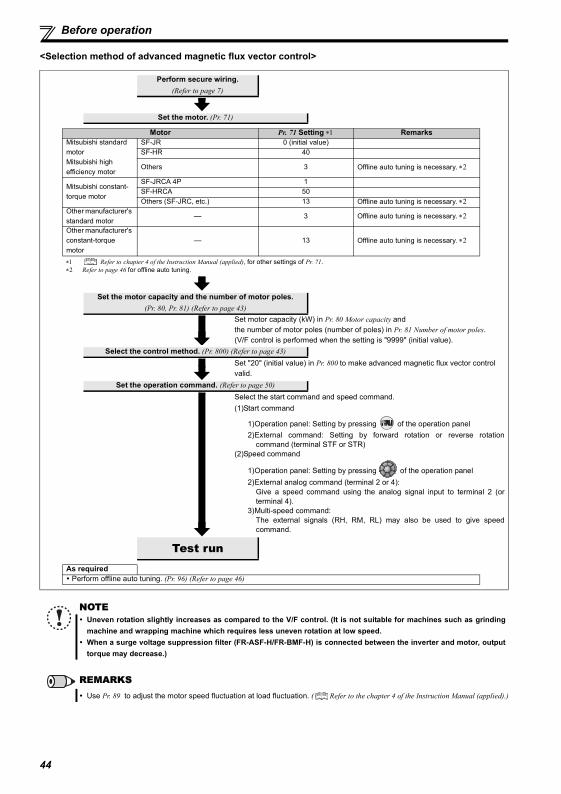
Before operation
<Selection method of advanced magnetic flux vector control>
Perform secure wiring.(Refer to page 7)
Set the motor. (Pr. 71)
Motor Pr. 71 Setting ∗1 RemarksMitsubishi standard motorMitsubishi high efficiency motor
SF-JR 0 (initial value)SF-HR 40
Others 3 Offline auto tuning is necessary. ∗2
Mitsubishi constant-torque motor
SF-JRCA 4P 1SF-HRCA 50Others (SF-JRC, etc.) 13 Offline auto tuning is necessary. ∗2
Other manufacturer's standard motor
— 3 Offline auto tuning is necessary. ∗2
Other manufacturer's constant-torque motor
— 13 Offline auto tuning is necessary. ∗2
∗1 Refer to chapter 4 of the Instruction Manual (applied), for other settings of Pr. 71.∗2 Refer to page 46 for offline auto tuning.
Set the motor capacity and the number of motor poles. (Pr. 80, Pr. 81) (Refer to page 43)
Set motor capacity (kW) in Pr. 80 Motor capacity and the number of motor poles (number of poles) in Pr. 81 Number of motor poles.(V/F control is performed when the setting is "9999" (initial value).
Select the control method. (Pr. 800) (Refer to page 43)Set "20" (initial value) in Pr. 800 to make advanced magnetic flux vector control valid.
Set the operation command. (Refer to page 50)Select the start command and speed command.(1)Start command
1)Operation panel: Setting by pressing of the operation panel2)External command: Setting by forward rotation or reverse rotation
command (terminal STF or STR)(2)Speed command
1)Operation panel: Setting by pressing of the operation panel2)External analog command (terminal 2 or 4):
Give a speed command using the analog signal input to terminal 2 (orterminal 4).
3)Multi-speed command:The external signals (RH, RM, RL) may also be used to give speedcommand.
Test runAs required Perform offline auto tuning. (Pr. 96) (Refer to page 46)
NOTEUneven rotation slightly increases as compared to the V/F control. (It is not suitable for machines such as grindingmachine and wrapping machine which requires less uneven rotation at low speed.When a surge voltage suppression filter (FR-ASF-H/FR-BMF-H) is connected between the inverter and motor, outputtorque may decrease.)
REMARKSUse Pr. 89 to adjust the motor speed fluctuation at load fluctuation. ( Refer to the chapter 4 of the Instruction Manual (applied).)
44
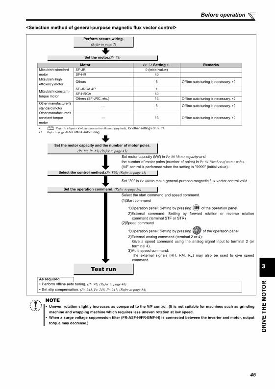
Before operation
DR
IVE
THE
MO
TOR
3
<Selection method of general-purpose magnetic flux vector control>
Perform secure wiring.(Refer to page 7)
Set the motor.(Pr. 71)
Motor Pr. 71 Setting ∗1 RemarksMitsubishi standard motorMitsubishi high efficiency motor
SF-JR 0 (initial value)SF-HR 40
Others 3 Offline auto tuning is necessary. ∗2
Mitsubishi constant-torque motor
SF-JRCA 4P 1SF-HRCA 50Others (SF-JRC, etc.) 13 Offline auto tuning is necessary. ∗2
Other manufacturer's standard motor
— 3 Offline auto tuning is necessary. ∗2
Other manufacturer's constant-torque motor
— 13 Offline auto tuning is necessary. ∗2
∗1 Refer to chapter 4 of the Instruction Manual (applied), for other settings of Pr. 71.∗2 Refer to page 46 for offline auto tuning.
Set the motor capacity and the number of motor poles.(Pr. 80, Pr. 81) (Refer to page 43)
Set motor capacity (kW) in Pr. 80 Motor capacity and the number of motor poles (number of poles) in Pr. 81 Number of motor poles.(V/F control is performed when the setting is "9999" (initial value).
Select the control method.(Pr. 800) (Refer to page 43)
Set "30" in Pr. 800 to make general-purpose magnetic flux vector control valid.
Set the operation command. (Refer to page 50)Select the start command and speed command.(1)Start command
1)Operation panel: Setting by pressing of the operation panel2)External command: Setting by forward rotation or reverse rotation
command (terminal STF or STR)(2)Speed command
1)Operation panel: Setting by pressing of the operation panel2)External analog command (terminal 2 or 4):
Give a speed command using the analog signal input to terminal 2 (orterminal 4).
3)Multi-speed command:The external signals (RH, RM, RL) may also be used to give speedcommand.
Test runAs required Perform offline auto tuning. (Pr. 96) (Refer to page 46) Set slip compensation. (Pr. 245, Pr. 246, Pr. 247) (Refer to page 84)
NOTEUneven rotation slightly increases as compared to the V/F control. (It is not suitable for machines such as grindingmachine and wrapping machine which requires less uneven rotation at low speed.When a surge voltage suppression filter (FR-ASF-H/FR-BMF-H) is connected between the inverter and motor, outputtorque may decrease.)
45
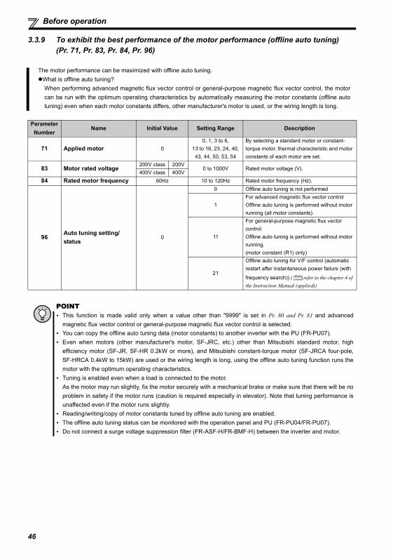
Before operation
3.3.9 To exhibit the best performance of the motor performance (offline auto tuning)(Pr. 71, Pr. 83, Pr. 84, Pr. 96)
The motor performance can be maximized with offline auto tuning.What is offline auto tuning?When performing advanced magnetic flux vector control or general-purpose magnetic flux vector control, the motorcan be run with the optimum operating characteristics by automatically measuring the motor constants (offline autotuning) even when each motor constants differs, other manufacturer's motor is used, or the wiring length is long.
ParameterNumber
Name Initial Value Setting Range Description
71 Applied motor 00, 1, 3 to 6,
13 to 16, 23, 24, 40, 43, 44, 50, 53, 54
By selecting a standard motor or constant-torque motor, thermal characteristic and motor constants of each motor are set.
83 Motor rated voltage200V class 200V
0 to 1000V Rated motor voltage (V).400V class 400V
84 Rated motor frequency 60Hz 10 to 120Hz Rated motor frequency (Hz).
96Auto tuning setting/status
0
0 Offline auto tuning is not performed
1For advanced magnetic flux vector controlOffline auto tuning is performed without motor running (all motor constants).
11
For general-purpose magnetic flux vector controlOffline auto tuning is performed without motor running.(motor constant (R1) only)
21
Offline auto tuning for V/F control (automatic restart after instantaneous power failure (with
frequency search)) ( refer to the chapter 4 of the Instruction Manual (applied))
POINTThis function is made valid only when a value other than "9999" is set in Pr. 80 and Pr. 81 and advancedmagnetic flux vector control or general-purpose magnetic flux vector control is selected.You can copy the offline auto tuning data (motor constants) to another inverter with the PU (FR-PU07).Even when motors (other manufacturer's motor, SF-JRC, etc.) other than Mitsubishi standard motor, highefficiency motor (SF-JR, SF-HR 0.2kW or more), and Mitsubishi constant-torque motor (SF-JRCA four-pole,SF-HRCA 0.4kW to 15kW) are used or the wiring length is long, using the offline auto tuning function runs themotor with the optimum operating characteristics.Tuning is enabled even when a load is connected to the motor.As the motor may run slightly, fix the motor securely with a mechanical brake or make sure that there will be noproblem in safety if the motor runs (caution is required especially in elevator). Note that tuning performance isunaffected even if the motor runs slightly.Reading/writing/copy of motor constants tuned by offline auto tuning are enabled.The offline auto tuning status can be monitored with the operation panel and PU (FR-PU04/FR-PU07).Do not connect a surge voltage suppression filter (FR-ASF-H/FR-BMF-H) between the inverter and motor.
46

Before operation
DR
IVE
THE
MO
TOR
3
(1) Before performing offline auto tuning
Check the following before performing offline auto tuning.Make sure advanced magnetic flux vector control or general-purpose magnetic flux vector control (Pr. 80, Pr. 81) isselected. (Tuning can be performed even under V/F control selected by turning on X18.)A motor should be connected. Note that the motor should be at a stop at a tuning start.The motor capacity should be equal to or one rank lower than the inverter capacity. (note that the capacity should be0.1kW or more)The maximum frequency is 120Hz.A high-slip motor, high-speed motor and special motor cannot be tuned.As the motor may run slightly, fix the motor securely with a mechanical brake or make sure that there will be no problemin safety if the motor runs (caution is required especially in elevator). Note that tuning performance is unaffected even ifthe motor runs slightly. Offline auto tuning will not be performed properly if it is performed with a surge voltage suppression filter (FR-ASFH/FR-BMF-H) connected between the inverter and motor. Remove it before starting tuning.
(2) Setting
1) Select advanced magnetic flux vector control or general-purpose magnetic flux vector control. (Refer to page 43)2) Set "1" or "11" in Pr. 96 Auto tuning setting/status.
When the setting is "1" .......Tune all motor constants without running the motor.When performing advanced magnetic flux vector control, set "1" to perform tuning. It takes approximately 25 to 75s∗ until tuning is completed.(Excitation noise is produced during tuning.)∗Tuning time differs according to the inverter capacity and motor type.
When the setting is "11" ......Tune motor constants (R1) only without running the motor.When performing general-purpose magnetic flux vector control, set "11" to perform tuning. It takes approximately 9s until tuning is completed.
3) Set the rated motor current (initial value is rated inverter current) in Pr. 9 Electronic thermal O/L relay. (Refer to page 37)4) Set the rated voltage of motor (initial value is 200V/400V) in Pr. 83 Motor rated voltage and rated motor frequency (initial
value is 60Hz) in Pr. 84 Rated motor frequency.(For a Japanese standard motor, etc. which has both 50Hz and 60Hz rated values, use it with an initial value (200V/60Hzor 400V/60Hz).
5) Set Pr. 71 Applied motor according to the motor used.Motor Pr. 71 Setting ∗1
Mitsubishi standard motorMitsubishi high efficiency motor
SF-JR 3SF-JR 4P 1.5kW or less 23SF-HR 43Others 3
Mitsubishi constant-torque motorSF-JRCA 4P 13SF-HRCA 53Others (SF-JRC, etc.) 13
Other manufacturer's standard motor — 3
Other manufacturer's constant-torque motor — 13
∗1 Refer to the chapter 4 of the Instruction Manual (applied), for other settings of Pr. 71.
47
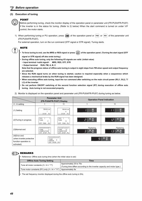
Before operation
(3) Execution of tuning
1) When performing tuning or PU operation, press of the operation panel or or of the parameter unit(FR-PU04/FR-PU07).For external operation, turn on the run command (STF signal or STR signal). Tuning starts.
2) Monitor is displayed on the operation panel and parameter unit (FR-PU04/FR-PU07) during tuning as below.
POINTBefore performing tuning, check the monitor display of the operation panel or parameter unit (FR-PU04/FR-PU07)if the inverter is in the status for tuning. (Refer to 2) below) When the start command is turned on under V/Fcontrol, the motor starts.
NOTE
To force tuning to end, use the MRS or RES signal or press of the operation panel. (Turning the start signal (STF
signal or STR signal) off also ends tuning.)During offline auto tuning, only the following I/O signals are valid: (initial value) Input terminal <valid signal> MRS, RES, STF, STR Output terminal RUN, FM, A, B, C
Note that the progress status of offline auto tuning is output in eight steps from FM when speed and output frequencyare selected.Since the RUN signal turns on when tuning is started, caution is required especially when a sequerence whichreleases a mechanical brake by the RUN signal has been designed.When executing offline auto tuning, input the run command after switching on the main circuit power (R/L1, S/L2, T/L3) of the inverter.Do not perform ON/OFF switching of the second function selection signal (RT) during execution of offline autotuning. Auto tuning is not excecuted properly.
Parameter Unit(FR-PU04/FR-PU07) Display
Operation Panel Indication
Pr. 96 setting 1 11 1 11
(1) Setting
(2)Tuning in progress
(3)Normal end
(4)Error end (when inverter protective function operation is activated)
REMARKSReference: Offline auto tuning time (when the initial value is set)
The set frequency monitor displayed during the offline auto tuning is 0Hz.
STOP PU
1
READ:List
STOP PU
11
READ:List
FWD PU
2
STF
TUNE
FWD PU
12
STF
TUNE
STOP PU
3
STF
TUNECOMPLETION
STOP PU
13
STF
TUNECOMPETION
Flickering Flickering
STOP PU
9
STF
TUNEERROR
Offline Auto Tuning Setting Time
Tune all motor constants (Pr. 96 = "1")Approximately 25 to 75s(Tuning time differs according to the inverter capacity and motor type.)
Tune motor constants (R1) only (Pr. 96 = "11") Approximately 9s
48
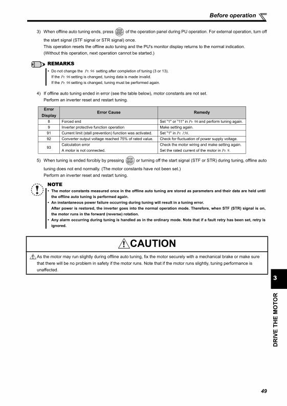
Before operation
DR
IVE
THE
MO
TOR
3
3) When offline auto tuning ends, press of the operation panel during PU operation. For external operation, turn off
the start signal (STF signal or STR signal) once.This operation resets the offline auto tuning and the PU's monitor display returns to the normal indication.(Without this operation, next operation cannot be started.)
4) If offline auto tuning ended in error (see the table below), motor constants are not set.Perform an inverter reset and restart tuning.
5) When tuning is ended forcibly by pressing or turning off the start signal (STF or STR) during tuning, offline auto
tuning does not end normally. (The motor constants have not been set.)Perform an inverter reset and restart tuning.
REMARKSDo not change the Pr. 96 setting after completion of tuning (3 or 13).If the Pr. 96 setting is changed, tuning data is made invalid.If the Pr. 96 setting is changed, tuning must be performed again.
Error Display
Error Cause Remedy
8 Forced end Set "1" or "11" in Pr. 96 and perform tuning again. 9 Inverter protective function operation Make setting again.91 Current limit (stall prevention) function was activated. Set "1" in Pr. 156.92 Converter output voltage reached 75% of rated value. Check for fluctuation of power supply voltage.
93Calculation errorA motor is not connected.
Check the motor wiring and make setting again.Set the rated current of the motor in Pr. 9.
NOTEThe motor constants measured once in the offline auto tuning are stored as parameters and their data are held untilthe offline auto tuning is performed again.An instantaneous power failure occurring during tuning will result in a tuning error.After power is restored, the inverter goes into the normal operation mode. Therefore, when STF (STR) signal is on,the motor runs in the forward (reverse) rotation.Any alarm occurring during tuning is handled as in the ordinary mode. Note that if a fault retry has been set, retry isignored.
CAUTIONAs the motor may run slightly during offline auto tuning, fix the motor securely with a mechanical brake or make sure that there will be no problem in safety if the motor runs. Note that if the motor runs slightly, tuning performance is unaffected.
49
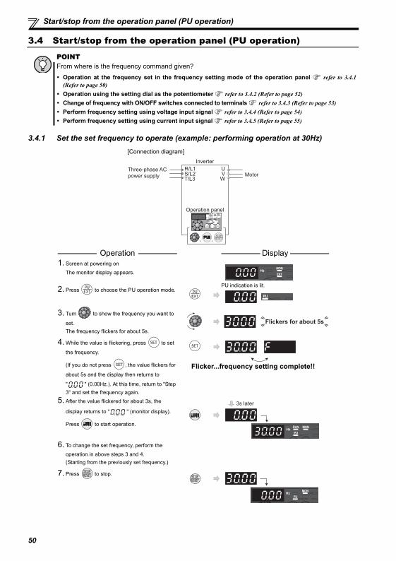
Start/stop from the operation panel (PU operation)
3.4 Start/stop from the operation panel (PU operation)
3.4.1 Set the set frequency to operate (example: performing operation at 30Hz)
POINTFrom where is the frequency command given?
Operation at the frequency set in the frequency setting mode of the operation panel refer to 3.4.1(Refer to page 50) Operation using the setting dial as the potentiometer refer to 3.4.2 (Refer to page 52)Change of frequency with ON/OFF switches connected to terminals refer to 3.4.3 (Refer to page 53) Perform frequency setting using voltage input signal refer to 3.4.4 (Refer to page 54) Perform frequency setting using current input signal refer to 3.4.5 (Refer to page 55)
Operation Display 1. Screen at powering on
The monitor display appears.
2. Press to choose the PU operation mode.PU indication is lit.
3. Turn to show the frequency you want to
set.The frequency flickers for about 5s.
4. While the value is flickering, press to set
the frequency.
(If you do not press , the value flickers for
about 5s and the display then returns to
" " (0.00Hz.). At this time, return to "Step 3" and set the frequency again.
Flicker...frequency setting complete!!
5. After the value flickered for about 3s, the
display returns to " " (monitor display).
Press to start operation.
6. To change the set frequency, perform the
operation in above steps 3 and 4.(Starting from the previously set frequency.)
7. Press to stop.
Three-phase AC
power supply
Inverter
R/L1S/L2T/L3
UVW
Operation panel
Motor
, ,
[Connection diagram]
Flickers for about 5s
3s later
50
DR
IVE
THE
MO
TOR
3
Start/stop from the operation panel (PU operation)
REMARKS
Operation cannot be performed at the set frequency ... Why?
Did you carry out step 4 within 5s after step 3? (Did you press within 5s after turning ?)
The frequency does not change by turning ... Why?
Check to see if the operation mode selected is the external operation mode. (Press to change to the PU operation
mode.)
Operation does not change to the PU operation mode ... Why?
Check that "0" (initial value) is set in Pr. 79 Operation mode selection?
Check that the start command is not on.
Change acceleration deceleration time
Pr. 7 (Refer to page 41)
Change deceleration time
Pr. 8 (Refer to page 41)
For example, operation not exceeding 60Hz
Set "60Hz" in Pr. 1. (Refer to page 40)
Press to show the set frequency.
can also be used like a potentiometer to perform operation. (Refer to page 52)
Use Pr. 295 Magnitude of frequency change setting to change the frequency setting increments of .
51
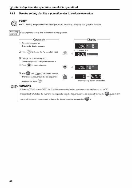
Start/stop from the operation panel (PU operation)
3.4.2 Use the setting dial like a potentiometer to perform operation.
POINTSet "1" (setting dial potentiometer mode) in Pr. 161 Frequency setting/key lock operation selection.
Changing example Changing the frequency from 0Hz to 60Hz during operation
Operation Display 1. Screen at powering on
The monitor display appears.
2. Press to choose the PU operation mode.PU indication is lit.
3. Change the Pr. 161 setting to "1".
(Refer to page 33 for change of the setting.)
4. Press to start the inverter.
5. Turn until " "(60.00Hz) appears.
The flickering frequency is the set frequency.
You need not press . The frequency flickers for about 5s.
REMARKSIf flickering "60.00" turns to "0.00", the Pr. 161 Frequency setting/key lock operation selection setting may not be "1".
Independently of whether the inverter is running or at a stop, the frequency can be set by merely turning the . (Use Pr. 295
Magnitude of frequency change setting to change the frequency setting increments of .)
52
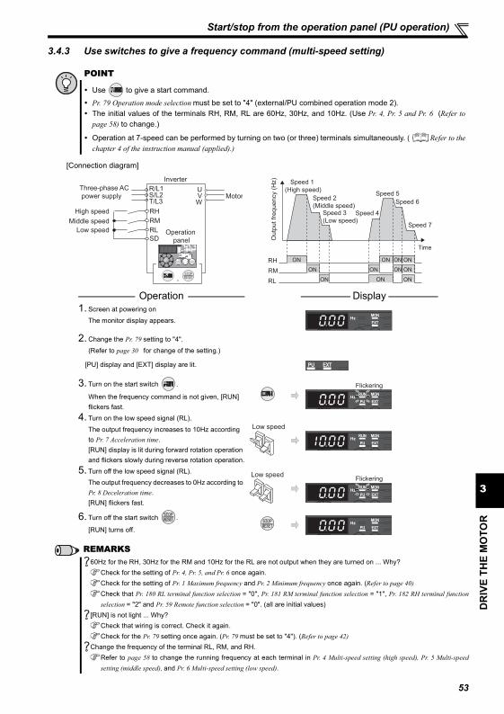
DR
IVE
THE
MO
TOR
3
Start/stop from the operation panel (PU operation)
3.4.3 Use switches to give a frequency command (multi-speed setting)
POINT
Use to give a start command.
Pr. 79 Operation mode selection must be set to "4" (external/PU combined operation mode 2).The initial values of the terminals RH, RM, RL are 60Hz, 30Hz, and 10Hz. (Use Pr. 4, Pr. 5 and Pr. 6 (Refer topage 58) to change.)
Operation at 7-speed can be performed by turning on two (or three) terminals simultaneously. ( Refer to thechapter 4 of the instruction manual (applied).)
[Connection diagram]
Operation Display 1. Screen at powering on
The monitor display appears.
2. Change the Pr. 79 setting to "4".
(Refer to page 30 for change of the setting.)
[PU] display and [EXT] display are lit.
3. Turn on the start switch .
When the frequency command is not given, [RUN] flickers fast.
4. Turn on the low speed signal (RL).
The output frequency increases to 10Hz according to Pr. 7 Acceleration time.[RUN] display is lit during forward rotation operation and flickers slowly during reverse rotation operation.
5. Turn off the low speed signal (RL).The output frequency decreases to 0Hz according to Pr. 8 Deceleration time.[RUN] flickers fast.
6. Turn off the start switch .
[RUN] turns off.
REMARKS60Hz for the RH, 30Hz for the RM and 10Hz for the RL are not output when they are turned on ... Why?
Check for the setting of Pr. 4, Pr. 5, and Pr. 6 once again.Check for the setting of Pr. 1 Maximum frequency and Pr. 2 Minimum frequency once again. (Refer to page 40)Check that Pr. 180 RL terminal function selection = "0", Pr. 181 RM terminal function selection = "1", Pr. 182 RH terminal functionselection = "2" and Pr. 59 Remote function selection = "0". (all are initial values)
[RUN] is not light ... Why?Check that wiring is correct. Check it again.Check for the Pr. 79 setting once again. (Pr. 79 must be set to "4"). (Refer to page 42)
Change the frequency of the terminal RL, RM, and RH.Refer to page 58 to change the running frequency at each terminal in Pr. 4 Multi-speed setting (high speed), Pr. 5 Multi-speedsetting (middle speed), and Pr. 6 Multi-speed setting (low speed).
Three-phase AC
power supply
Inverter
R/L1S/L2T/L3
UVW
Operation
panel
Motor
,
High speed
Middle speed
Low speed
SD
RH
RM
RL
Speed 1
(High speed)
Speed 2
(Middle speed)Speed 3
(Low speed)Speed 4
Speed 5
Speed 6
Speed 7
ON ON ON ON
ON ON ON ON
ONON ON
Time
Outp
ut
frequency (
Hz)
RL
RH
RM
Flickering
Low speed
Low speedFlickering
53
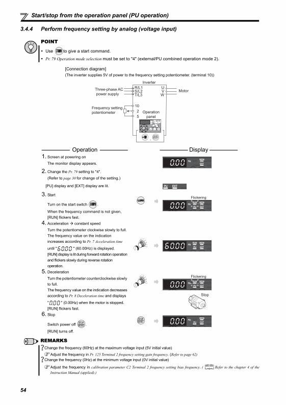
Start/stop from the operation panel (PU operation)
3.4.4 Perform frequency setting by analog (voltage input)
POINT
Use to give a start command.
Pr. 79 Operation mode selection must be set to "4" (external/PU combined operation mode 2).
[Connection diagram](The inverter supplies 5V of power to the frequency setting potentiometer. (terminal 10))
Operation Display 1. Screen at powering on
The monitor display appears.
2. Change the Pr. 79 setting to "4".
(Refer to page 30 for change of the setting.)
[PU] display and [EXT] display are lit.
3. Start
Turn on the start switch .
When the frequency command is not given, [RUN] flickers fast.
4. Acceleration constant speed
Turn the potentiometer clockwise slowly to full.The frequency value on the indication increases according to Pr. 7 Acceleration time
until " " (60.00Hz) is displayed.[RUN] display is lit during forward rotation operation and flickers slowly during reverse rotation operation.
5. Deceleration
Turn the potentiometer counterclockwise slowly to full.The frequency value on the indication decreases according to Pr. 8 Deceleration time and displays
" " (0.00Hz) when the motor is stopped.[RUN] flickers fast.
6. Stop
Switch power off .
[RUN] turns off.
REMARKSChange the frequency (60Hz) at the maximum voltage input (5V initial value)
Adjust the frequency in Pr. 125 Terminal 2 frequency setting gain frequency. (Refer to page 62)Change the frequency (0Hz) at the minimum voltage input (0V initial value)
Adjust the frequency in calibration parameter C2 Terminal 2 frequency setting bias frequency. ( Refer to the chapter 4 of theInstruction Manual (applied).)
Three-phase AC
power supply
Frequency setting
potentiometer
Inverter
R/L1S/L2T/L3
UVW
Operation
panel
Motor
,
5
10
2
Flickering
Flickering
Stop
54
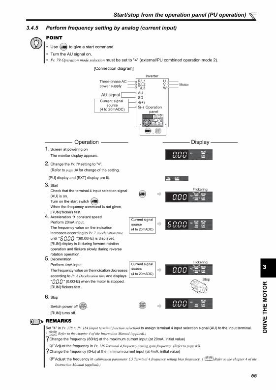
DR
IVE
THE
MO
TOR
3
Start/stop from the operation panel (PU operation)
3.4.5 Perform frequency setting by analog (current input)
POINT
Use to give a start command.
Turn the AU signal on.Pr. 79 Operation mode selection must be set to "4" (external/PU combined operation mode 2).
[Connection diagram]
Operation Display 1. Screen at powering on
The monitor display appears.
2. Change the Pr. 79 setting to "4".(Refer to page 30 for change of the setting.
[PU] display and [EXT] display are lit.
3. StartCheck that the terminal 4 input selection signal (AU) is on.Turn on the start switch .When the frequency command is not given, [RUN] flickers fast.
4. Acceleration constant speedPerform 20mA input.The frequency value on the indication increases according to Pr. 7 Acceleration time until " "(60.00Hz) is displayed.[RUN] display is lit during forward rotation operation and flickers slowly during reverse rotation operation.
5. DecelerationPerform 4mA input.The frequency value on the indication decreases according to Pr. 8 Deceleration time and displays " " (0.00Hz) when the motor is stopped.[RUN] flickers fast.
6. Stop
Switch power off .
[RUN] turns off.
REMARKSSet "4" in Pr. 178 to Pr. 184 (input terminal function selection) to assign terminal 4 input selection signal (AU) to the input terminal.( Refer to the chapter 4 of the Instruction Manual (applied).)
Change the frequency (60Hz) at the maximum current input (at 20mA, initial value)
Adjust the frequency in Pr. 126 Terminal 4 frequency setting gain frequency. (Refer to page 65)Change the frequency (0Hz) at the minimum current input (at 4mA, initial value)
Adjust the frequency in calibration parameter C5 Terminal 4 frequency setting bias frequency. ( Refer to the chapter 4 of theInstruction Manual (applied).)
Three-phase AC
power supply
Inverter
R/L1S/L2T/L3
UVW
Operation
panel
Motor
,
5(-)
4(+)Current signal source
(4 to 20mADC)
SD
AUAU signal
Flickering
Current signal source(4 to 20mADC)
Current signal source(4 to 20mADC)
Flickering
Stop
55
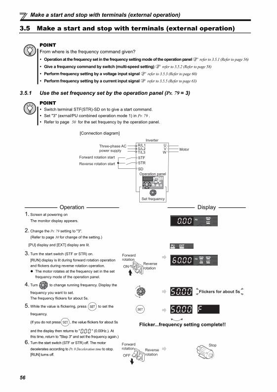
Make a start and stop with terminals (external operation)
3.5 Make a start and stop with terminals (external operation)
3.5.1 Use the set frequency set by the operation panel (Pr. 79 = 3)
POINTFrom where is the frequency command given?
Operation at the frequency set in the frequency setting mode of the operation panel refer to 3.5.1 (Refer to page 56)
Give a frequency command by switch (multi-speed setting) refer to 3.5.2 (Refer to page 58)
Perform frequency setting by a voltage input signal refer to 3.5.3 (Refer to page 60)
Perform frequency setting by a current input signal refer to 3.5.5 (Refer to page 63)
POINTSwitch terminal STF(STR)-SD on to give a start command.Set "3" (exrnal/PU combined operation mode 1) in Pr. 79 .Refer to page 50 for the set frequency by the operation panel.
Operation Display 1. Screen at powering on
The monitor display appears.
2. Change the Pr. 79 setting to "3".(Refer to page 30 for change of the setting.)
[PU] display and [EXT] display are lit.
3. Turn the start switch (STF or STR) on.
[RUN] display is lit during forward rotation operation and flickers during reverse rotation operation.
The motor rotates at the frequency set in the set frequency mode of the operation panel.
4. Turn to change running frequency. Display the
frequency you want to set.The frequency flickers for about 5s.
5. While the value is flickering, press to set the
frequency.
(If you do not press , the value flickers for about 5s
and the display then returns to " " (0.00Hz.). At this time, return to "Step 3" and set the frequency again.)
Flicker...frequency setting complete!!
6. Turn the start switch (STF or STR) off. The motor
decelerates according to Pr. 8 Deceleration time to stop.[RUN] turns off.
Three-phase AC
power supply
Inverter
R/L1S/L2T/L3
UVW
Operation panel
Set frequency
Motor
SD
STF
STR
Forward rotation start
Reverse rotation start
[Connection diagram]
Forward rotation
Reverse
rotationON
Flickers for about 5s
Forward rotation Reverse
rotationOFF
Stop
56
DR
IVE
THE
MO
TOR
3
Make a start and stop with terminals (external operation)
REMARKSPr. 178 STF terminal function selection must be set to "60" (or Pr. 179 STR terminal function selection must be set to "61"). (all are initial values)When Pr. 79 Operation mode selection is set to "3", multi-speed operation (Refer to page 58) is also made valid.
Pressing to stop the motor and the display shows .
1. Turn the start switch (STF or STR) off.
2. The display can be reset by .
57
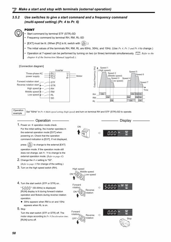
Make a start and stop with terminals (external operation)
3.5.2 Use switches to give a start command and a frequency command (multi-speed setting) (Pr. 4 to Pr. 6)
POINTStart command by terminal STF (STR)-SDFrequency command by terminal RH, RM, RL-SD
[EXT] must be lit. (When [PU] is lit, switch with .)
The initial values of the terminals RH, RM, RL are 60Hz, 30Hz, and 10Hz. (Use Pr. 4, Pr. 5 and Pr. 6 to change.)
Operation at 7-speed can be performed by turning on two (or three) terminals simultaneously. Refer to thechapter 4 of the Instruction Manual (applied) ).
Operation example Set "50Hz" in Pr. 4 Multi-speed setting (high speed) and turn on terminal RH and STF (STR)-SD to operate.
Operation Display 1. Power on operation mode check
For the initial setting, the inverter operates in the external operation mode [EXT] when powering on. Check that the operation command indication is [EXT]. If not displayed,
press to change to the external [EXT]
operation mode. If the operation mode still does not change, set Pr. 79 to change to the external operation mode. (Refer to page 42)
2. Change the Pr.4 setting to "50".
(Refer to page 33 for change of the setting.)3. Turn on the high speed switch (RH).
4. Turn the start switch (STF or STR) on.
" " (50.00Hz) is displayed.[RUN] display is lit during forward rotation operation and flickers during reverse rotation operation.
30Hz appears when RM is on and 10Hz appears when RL is on.
5. Stop
Turn the start switch (STF or STR) off. The motor stops according to Pr. 8 Deceleration time.[RUN] turns off.
Three-phase AC power supply
InverterR/L1S/L2T/L3
UVW
Motor
Forward rotation startReverse rotation start
High speedRM
STFSTRRH
Middle speedLow speed
SDRL
[Connection diagram]Speed 1
(High speed)
Speed 2
(Middle speed)Speed 3
(Low speed)Speed 4
Speed 5
Speed 6
Speed 7
ON ON ON ON
ON ON ON ON
ONON ON
Time
Outp
ut
frequency (
Hz)
RL
RH
RM
ON
High speed
Middle speed
Low speedON
Forward rotation
Reverse
rotationON
Forward rotation Reverse
rotationOFF Stop
58
DR
IVE
THE
MO
TOR
3
Make a start and stop with terminals (external operation)
REMARKS
[EXT] is not lit even when is pressed...Why?
Switchover of the operation mode with is valid when Pr. 79 = "0" (initial value).
50Hz for the RH, 30Hz for the RM and 10Hz for the RL are not output when they are turned on...Why?
Check for the setting of Pr. 4, Pr. 5, and Pr. 6 once again.
Check for the setting of Pr. 1 Maximum frequency and Pr. 2 Minimum frequency once again. (Refer to page 40)
Check for the Pr. 79 setting once again. Pr. 79 must be set to "0" or "2". (Refer to page 42)
Check that Pr. 180 RL terminal function selection ="0", Pr. 181 RM terminal function selection ="1", Pr. 182 RH terminal functionselection ="2" and Pr. 59 Remote function selection ="0". (all are initial values)
[RUN] is not light...Why?
Check that wiring is correct. Check it again.
Check that "60" is set in Pr. 178 STF terminal function selection (or "61" is set in Pr. 179 STR terminal function selection). (all areinitial values)
How is the frequency setting from 4 to 7 speed?
The setting differs according to Pr. 24 to Pr. 27 (multi-speed setting). Refer to the chapter 4 of the Instruction Manual(applied).
Perform multi-speed operation higher than 8 speed...How?
Use the REX signal to perform the operation. Refer to the chapter 4 of the Instruction Manual (applied).External operation is fixed by setting "2" (external operation mode) in Pr. 79 Operation mode selection when you do not want to
take time pressing or when you want to use the current operation command and frequency command. (Refer to page 42)
59
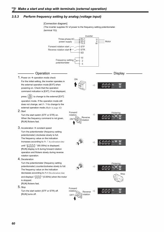
Make a start and stop with terminals (external operation)
3.5.3 Perform frequency setting by analog (voltage input)
[Connection diagram](The inverter supplies 5V of power to the frequency setting potentiometer. (terminal 10))
Operation Display 1. Power on operation mode check
For the initial setting, the inverter operates in the external operation mode [EXT] when powering on. Check that the operation command indication is [EXT]. If not displayed,
press to change to the external [EXT]
operation mode. If the operation mode still does not change, set Pr. 79 to change to the external operation mode.(Refer to page 42)
2. Start
Turn the start switch (STF or STR) on.When the frequency command is not given, [RUN] flickers fast.
3. Acceleration constant speed
Turn the potentiometer (frequency setting potentiometer) clockwise slowly to full.The frequency value on the indication increases according to Pr. 7 Acceleration time
until " "(60.00Hz) is displayed.[RUN] display is lit during forward rotation operation and flickers slowly during reverse rotation operation.
4. Deceleration
Turn the potentiometer (frequency setting potentiometer) counterclockwise slowly to full.The frequency value on the indication decreases according to Pr.8 Deceleration time
and displays " " (0.00Hz) when the motor is stopped.[RUN] flickers fast.
5. StopTurn the start switch (STF or STR) off.[RUN] turns off.
Three-phase AC
power supply
Frequency setting
potentiometer
Inverter
R/L1S/L2T/L3
UVW
Motor
5
10
2
Forward rotation start
Reverse rotation start
STF
STR
SD
ON
Forward rotation
Reverse
rotationON
Flickering
Flickering
Stop
Forward rotation Reverse
rotationOFF
60
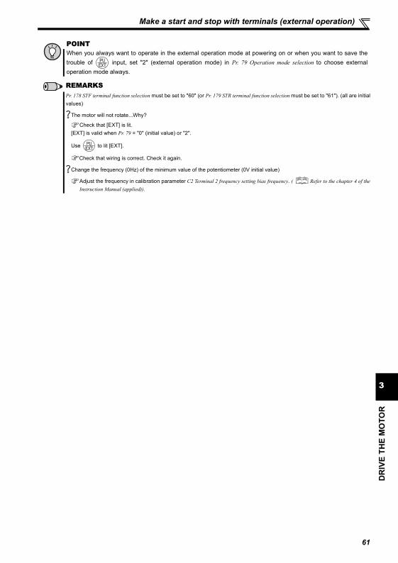
DR
IVE
THE
MO
TOR
3
Make a start and stop with terminals (external operation)
POINTWhen you always want to operate in the external operation mode at powering on or when you want to save thetrouble of input, set "2" (external operation mode) in Pr. 79 Operation mode selection to choose externaloperation mode always.
REMARKSPr. 178 STF terminal function selection must be set to "60" (or Pr. 179 STR terminal function selection must be set to "61"). (all are initialvalues)
The motor will not rotate...Why?
Check that [EXT] is lit.[EXT] is valid when Pr. 79 = "0" (initial value) or "2".
Use to lit [EXT].
Check that wiring is correct. Check it again.
Change the frequency (0Hz) of the minimum value of the potentiometer (0V initial value)
Adjust the frequency in calibration parameter C2 Terminal 2 frequency setting bias frequency. ( Refer to the chapter 4 of theInstruction Manual (applied)).
61

Make a start and stop with terminals (external operation)
3.5.4 Change the frequency (60Hz) at the maximum voltage input (5V initial value)
< How to change the maximum frequency?>Changing example
When you use the 0 to 5VDC input and want to change the frequency at 5V from 60Hz (initial value) to 50Hz, set "50Hz" in Pr. 125.
Operation Display 1. Turn until " " (Pr. 125) appears.
2. Press to show the currently set value
" " (60.00Hz).
3. Turn to change the set value to
" "(50.00Hz).
4. Press to set.
Flicker...50Hz output at 5V input complete!!5. Mode/monitor check
Press twice to choose the monitor/
frequency monitor.6. To check the setting, turn the start switch (STF
or STR) on and input 5V (turn the potentiometer clockwise slowly to full). (Refer to operation 2 to 5 of the section 3.5.3)
REMARKSTo change the value to more than 120Hz, the maximum frequency must be set to more than 120Hz.
The frequency meter (indicator) connected to across terminals FM-SD does not indicate just 50Hz ... Why?
The frequency meter can be adjusted using calibration parameter C0 FM terminal calibration. ( Refer to the chapter 4 ofthe Instruction Manual (applied)).
Use calibration parameter C2 to set frequency at 0V andcalibration parameter C0 to adjust the indicator.
( Refer to the chapter 4 of the Instruction Manual (applied)).
As other adjustment methods of frequency setting voltage gain, there are methods to adjust with a voltage applied to acrossterminals 2-5 and adjust at any point without a voltage applied. ( Refer to the Instruction Manual (applied) for the settingmethod of calibration parameter C4.)
Initial value
Bias
C2 (Pr. 902)
0
0
Frequency
setting signal
100%
10V
0 5V
C3 (Pr. 902) C4 (Pr. 903)
Gain
Pr. 125
Outp
ut
frequency
(Hz)
60Hz
62
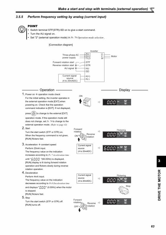
DR
IVE
THE
MO
TOR
3
Make a start and stop with terminals (external operation)
3.5.5 Perform frequency setting by analog (current input)
POINTSwitch terminal STF(STR)-SD on to give a start command.Turn the AU signal on.Set "2" (external operation mode) in Pr. 79 Operation mode selection .
[Connection diagram]
Operation Display 1. Power on operation mode check
For the initial setting, the inverter operates in the external operation mode [EXT] when powering on. Check that the operation command indication is [EXT]. If not displayed,
press to change to the external [EXT]
operation mode. If the operation mode still does not change, set Pr. 79 to change to the external operation mode. (Refer to page 42)
2. Start
Turn the start switch (STF or STR) on.When the frequency command is not given, [RUN] flickers fast.
3. Acceleration constant speed
Perform 20mA input.The frequency value on the indication increases according to Pr. 7 Acceleration time
until " "(60.00Hz) is displayed.[RUN] display is lit during forward rotation operation and flickers slowly during reverse rotation operation.
4. Deceleration
Perform 4mA input.The frequency value on the indication decreases according to Pr.8 Deceleration time
and displays " " (0.00Hz) when the motor is stopped.[RUN] flickers fast.
5. Stop
Turn the start switch (STF or STR) off.[RUN] turns off.
Three-phase AC
power supply
Inverter
R/L1S/L2T/L3
UVW
Motor
5(-)
4(+)
SD
AUAU signal
Forward rotation start
Reverse rotation start
STF
STR
Current signal source
(4 to 20mADC)
ON
Forward rotation
Reverse
rotationON
Flickering
Current signal source(4 to 20mADC)
Current signal source(4 to 20mADC)
Flickering
Stop
Forward rotation Reverse
rotationOFF
63

Make a start and stop with terminals (external operation)
REMARKSSet "4" in Pr.178 to Pr.184 (input terminal function selection) to assign terminal 4 input selection signal (AU) to the input terminal.
( Refer to the chapter 4 of the Instruction Manual (applied)).
The motor will not rotate...Why?
Check that [EXT] is lit.
[EXT] is valid when Pr. 79 = "0" (initial value) or "2".
Use to lit [EXT].
Check that the AU signal is on.
Turn the AU signal on.
Check that wiring is correct. Check it again.
Change the frequency (0Hz) at the minimum current input (at 4mA, initial value)
Adjust the frequency in calibration parameter C5 Terminal 4 frequency setting bias frequency. ( Refer to the chapter 4 of the
Instruction Manual (applied)).
64
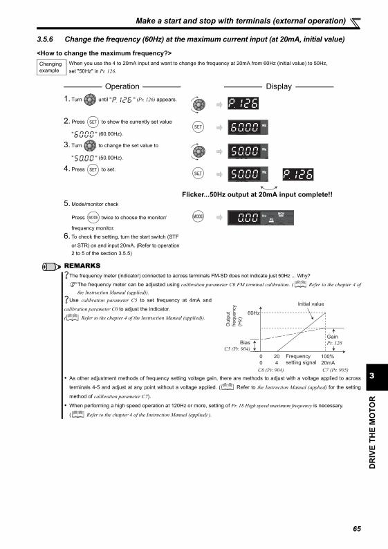
DR
IVE
THE
MO
TOR
3
Make a start and stop with terminals (external operation)
3.5.6 Change the frequency (60Hz) at the maximum current input (at 20mA, initial value)
<How to change the maximum frequency?>Changing example
When you use the 4 to 20mA input and want to change the frequency at 20mA from 60Hz (initial value) to 50Hz, set "50Hz" in Pr. 126.
Operation Display 1. Turn until " " (Pr. 126) appears.
2. Press to show the currently set value
" " (60.00Hz).
3. Turn to change the set value to
" " (50.00Hz).
4. Press to set.
Flicker...50Hz output at 20mA input complete!!5. Mode/monitor check
Press twice to choose the monitor/
frequency monitor.6. To check the setting, turn the start switch (STF
or STR) on and input 20mA. (Refer to operation 2 to 5 of the section 3.5.5)
REMARKSThe frequency meter (indicator) connected to across terminals FM-SD does not indicate just 50Hz ... Why?
The frequency meter can be adjusted using calibration parameter C0 FM terminal calibration. ( Refer to the chapter 4 ofthe Instruction Manual (applied)).
Use calibration parameter C5 to set frequency at 4mA and
calibration parameter C0 to adjust the indicator.
( Refer to the chapter 4 of the Instruction Manual (applied)).
As other adjustment methods of frequency setting voltage gain, there are methods to adjust with a voltage applied to across
terminals 4-5 and adjust at any point without a voltage applied. ( Refer to the Instruction Manual (applied) for the setting
method of calibration parameter C7).
When performing a high speed operation at 120Hz or more, setting of Pr. 18 High speed maximum frequency is necessary.
( Refer to the chapter 4 of the Instruction Manual (applied) ).
Outp
ut
frequency
(Hz)
60Hz
Initial value
Bias
C5 (Pr. 904)
Gain
Pr. 126
0 Frequency
setting signal100%
0
20
4 20mA
C6 (Pr. 904) C7 (Pr. 905)
65
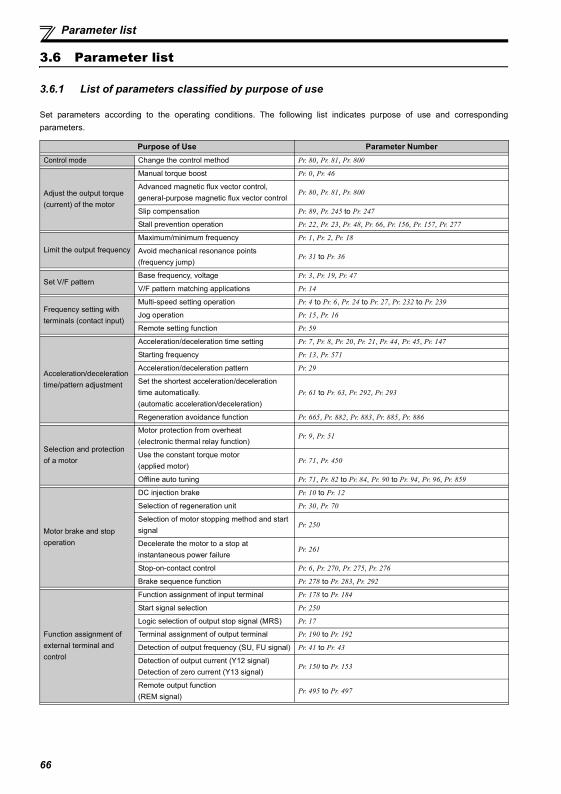
Parameter list
3.6 Parameter list
3.6.1 List of parameters classified by purpose of use
Set parameters according to the operating conditions. The following list indicates purpose of use and correspondingparameters.
Purpose of Use Parameter NumberControl mode Change the control method Pr. 80, Pr. 81, Pr. 800
Adjust the output torque (current) of the motor
Manual torque boost Pr. 0, Pr. 46
Advanced magnetic flux vector control, general-purpose magnetic flux vector control
Pr. 80, Pr. 81, Pr. 800
Slip compensation Pr. 89, Pr. 245 to Pr. 247
Stall prevention operation Pr. 22, Pr. 23, Pr. 48, Pr. 66, Pr. 156, Pr. 157, Pr. 277
Limit the output frequencyMaximum/minimum frequency Pr. 1, Pr. 2, Pr. 18
Avoid mechanical resonance points (frequency jump)
Pr. 31 to Pr. 36
Set V/F patternBase frequency, voltage Pr. 3, Pr. 19, Pr. 47
V/F pattern matching applications Pr. 14
Frequency setting with terminals (contact input)
Multi-speed setting operation Pr. 4 to Pr. 6, Pr. 24 to Pr. 27, Pr. 232 to Pr. 239
Jog operation Pr. 15, Pr. 16
Remote setting function Pr. 59
Acceleration/deceleration time/pattern adjustment
Acceleration/deceleration time setting Pr. 7, Pr. 8, Pr. 20, Pr. 21, Pr. 44, Pr. 45, Pr. 147
Starting frequency Pr. 13, Pr. 571
Acceleration/deceleration pattern Pr. 29
Set the shortest acceleration/deceleration time automatically. (automatic acceleration/deceleration)
Pr. 61 to Pr. 63, Pr. 292, Pr. 293
Regeneration avoidance function Pr. 665, Pr. 882, Pr. 883, Pr. 885, Pr. 886
Selection and protection of a motor
Motor protection from overheat (electronic thermal relay function)
Pr. 9, Pr. 51
Use the constant torque motor (applied motor)
Pr. 71, Pr. 450
Offline auto tuning Pr. 71, Pr. 82 to Pr. 84, Pr. 90 to Pr. 94, Pr. 96, Pr. 859
Motor brake and stop operation
DC injection brake Pr. 10 to Pr. 12
Selection of regeneration unit Pr. 30, Pr. 70
Selection of motor stopping method and start signal
Pr. 250
Decelerate the motor to a stop at instantaneous power failure
Pr. 261
Stop-on-contact control Pr. 6, Pr. 270, Pr. 275, Pr. 276
Brake sequence function Pr. 278 to Pr. 283, Pr. 292
Function assignment of external terminal and control
Function assignment of input terminal Pr. 178 to Pr. 184
Start signal selection Pr. 250
Logic selection of output stop signal (MRS) Pr. 17
Terminal assignment of output terminal Pr. 190 to Pr. 192
Detection of output frequency (SU, FU signal) Pr. 41 to Pr. 43
Detection of output current (Y12 signal)Detection of zero current (Y13 signal)
Pr. 150 to Pr. 153
Remote output function (REM signal)
Pr. 495 to Pr. 497
66
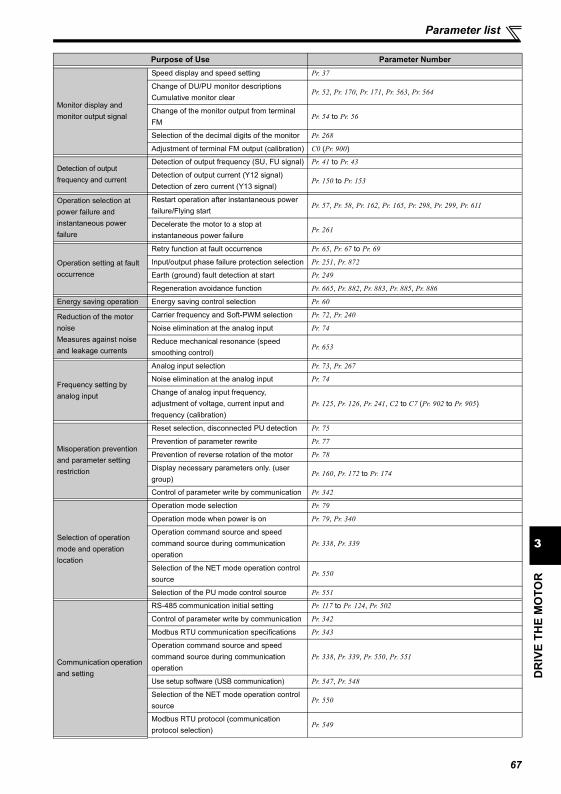
DR
IVE
THE
MO
TOR
3
Parameter list
Monitor display and monitor output signal
Speed display and speed setting Pr. 37
Change of DU/PU monitor descriptions Cumulative monitor clear
Pr. 52, Pr. 170, Pr. 171, Pr. 563, Pr. 564
Change of the monitor output from terminal FM
Pr. 54 to Pr. 56
Selection of the decimal digits of the monitor Pr. 268
Adjustment of terminal FM output (calibration) C0 (Pr. 900)
Detection of output frequency and current
Detection of output frequency (SU, FU signal) Pr. 41 to Pr. 43
Detection of output current (Y12 signal)Detection of zero current (Y13 signal)
Pr. 150 to Pr. 153
Operation selection at power failure and instantaneous power failure
Restart operation after instantaneous power failure/Flying start
Pr. 57, Pr. 58, Pr. 162, Pr. 165, Pr. 298, Pr. 299, Pr. 611
Decelerate the motor to a stop at instantaneous power failure
Pr. 261
Operation setting at fault occurrence
Retry function at fault occurrence Pr. 65, Pr. 67 to Pr. 69
Input/output phase failure protection selection Pr. 251, Pr. 872
Earth (ground) fault detection at start Pr. 249
Regeneration avoidance function Pr. 665, Pr. 882, Pr. 883, Pr. 885, Pr. 886
Energy saving operation Energy saving control selection Pr. 60
Reduction of the motor noiseMeasures against noise and leakage currents
Carrier frequency and Soft-PWM selection Pr. 72, Pr. 240
Noise elimination at the analog input Pr. 74
Reduce mechanical resonance (speed smoothing control)
Pr. 653
Frequency setting by analog input
Analog input selection Pr. 73, Pr. 267
Noise elimination at the analog input Pr. 74
Change of analog input frequency, adjustment of voltage, current input and frequency (calibration)
Pr. 125, Pr. 126, Pr. 241, C2 to C7 (Pr. 902 to Pr. 905)
Misoperation prevention and parameter setting restriction
Reset selection, disconnected PU detection Pr. 75
Prevention of parameter rewrite Pr. 77
Prevention of reverse rotation of the motor Pr. 78
Display necessary parameters only. (user group)
Pr. 160, Pr. 172 to Pr. 174
Control of parameter write by communication Pr. 342
Selection of operation mode and operation location
Operation mode selection Pr. 79
Operation mode when power is on Pr. 79, Pr. 340
Operation command source and speed command source during communication operation
Pr. 338, Pr. 339
Selection of the NET mode operation control source
Pr. 550
Selection of the PU mode control source Pr. 551
Communication operation and setting
RS-485 communication initial setting Pr. 117 to Pr. 124, Pr. 502
Control of parameter write by communication Pr. 342
Modbus RTU communication specifications Pr. 343
Operation command source and speed command source during communication operation
Pr. 338, Pr. 339, Pr. 550, Pr. 551
Use setup software (USB communication) Pr. 547, Pr. 548
Selection of the NET mode operation control source
Pr. 550
Modbus RTU protocol (communication protocol selection)
Pr. 549
Purpose of Use Parameter Number
67

Parameter list
Special operation and frequency control
PID control Pr. 127 to Pr. 134
Dancer control Pr. 128 to Pr. 134
Droop control Pr. 286, Pr. 287
Useful functions
Increase cooling fan life Pr. 244
To determine the maintenance time of parts. Pr. 255 to Pr. 259, Pr. 503, Pr. 504, Pr. 555 to Pr. 557
Use the operation panel (PA02) of the FR-E500 series.
Pr. 146, C22 to C25 (Pr. 922, Pr. 923)
Setting the parameter unit and operation panel
RUN key rotation direction selection Pr. 40
Parameter unit display language selection Pr. 145
Operation selection of the operation panel Pr. 161
Control of the parameter unit buzzer Pr. 990
Contrast adjustment of the parameter unit Pr. 991
Purpose of Use Parameter Number
68
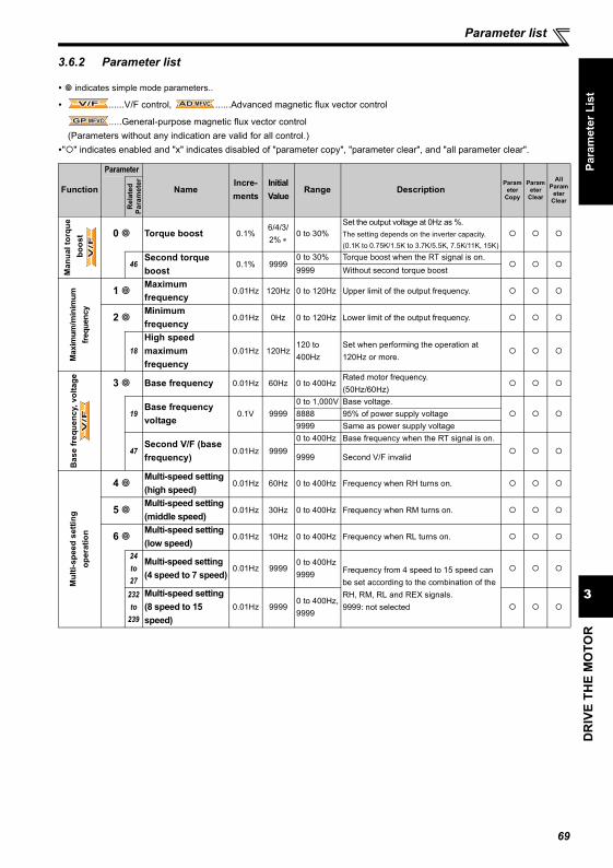
DR
IVE
THE
MO
TOR
3
Parameter list
Para
met
er L
ist
3.6.2 Parameter list
indicates simple mode parameters..
......V/F control, ......Advanced magnetic flux vector control
.....General-purpose magnetic flux vector control(Parameters without any indication are valid for all control.)
" " indicates enabled and "x" indicates disabled of "parameter copy", "parameter clear", and "all parameter clear".
Function
Parameter
NameIncre-ments
Initial Value
Range DescriptionParam
eter Copy
Parameter
Clear
All Param
eter Clear
Rel
ated
Para
met
er
Man
ual t
orqu
e b
oost 0 Torque boost 0.1%
6/4/3/2% ∗
0 to 30%Set the output voltage at 0Hz as %.The setting depends on the inverter capacity. (0.1K to 0.75K/1.5K to 3.7K/5.5K, 7.5K/11K, 15K)
46Second torque boost
0.1% 99990 to 30% Torque boost when the RT signal is on.9999 Without second torque boost
Max
imum
/min
imum
fre
quen
cy
1 Maximum frequency
0.01Hz 120Hz 0 to 120Hz Upper limit of the output frequency.
2 Minimum frequency
0.01Hz 0Hz 0 to 120Hz Lower limit of the output frequency.
18High speed maximum frequency
0.01Hz 120Hz120 to 400Hz
Set when performing the operation at 120Hz or more.
Bas
e fr
eque
ncy,
vol
tage 3 Base frequency 0.01Hz 60Hz 0 to 400Hz
Rated motor frequency. (50Hz/60Hz)
19Base frequency voltage
0.1V 99990 to 1,000V Base voltage.8888 95% of power supply voltage9999 Same as power supply voltage
47Second V/F (base frequency)
0.01Hz 99990 to 400Hz Base frequency when the RT signal is on.
9999 Second V/F invalid
Mul
ti-sp
eed
setti
ng
oper
atio
n
4 Multi-speed setting (high speed)
0.01Hz 60Hz 0 to 400Hz Frequency when RH turns on.
5 Multi-speed setting (middle speed)
0.01Hz 30Hz 0 to 400Hz Frequency when RM turns on.
6 Multi-speed setting (low speed)
0.01Hz 10Hz 0 to 400Hz Frequency when RL turns on.
24to27
Multi-speed setting (4 speed to 7 speed)
0.01Hz 99990 to 400Hz9999 Frequency from 4 speed to 15 speed can
be set according to the combination of the RH, RM, RL and REX signals. 9999: not selected
232to
239
Multi-speed setting (8 speed to 15 speed)
0.01Hz 99990 to 400Hz,9999
V/FV/FV/F AD MFVCAD MFVCAD MFVC
GP MFVCGP MFVCGP MFVC
V/F
V/F
V/F
V/F
V/F
V/F
69
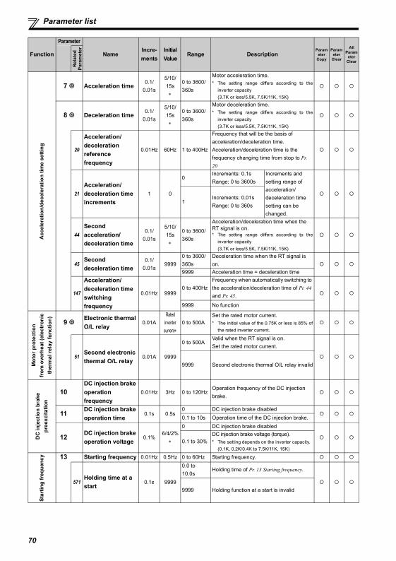
Parameter list
Acc
eler
atio
n/de
cele
ratio
n tim
e se
tting
7 Acceleration time0.1/
0.01s
5/10/15s
∗
0 to 3600/360s
Motor acceleration time.* The setting range differs according to the
inverter capacity (3.7K or less/5.5K, 7.5K/11K, 15K)
8 Deceleration time0.1/
0.01s
5/10/15s
∗
0 to 3600/360s
Motor deceleration time.* The setting range differs according to the
inverter capacity(3.7K or less/5.5K, 7.5K/11K, 15K)
20
Acceleration/deceleration reference frequency
0.01Hz 60Hz 1 to 400Hz
Frequency that will be the basis of acceleration/deceleration time. Acceleration/deceleration time is the frequency changing time from stop to Pr. 20
21Acceleration/deceleration time increments
1 0
0Increments: 0.1sRange: 0 to 3600s
Increments and setting range of acceleration/deceleration time setting can be changed.
1Increments: 0.01sRange: 0 to 360s
44Second acceleration/deceleration time
0.1/0.01s
5/10/15s
∗
0 to 3600/360s
Acceleration/deceleration time when the RT signal is on.* The setting range differs according to the
inverter capacity(3.7K or less/5.5K, 7.5K/11K, 15K)
45Second deceleration time
0.1/0.01s
99990 to 3600/360s
Deceleration time when the RT signal is on.
9999 Acceleration time = deceleration time
147
Acceleration/deceleration time switching frequency
0.01Hz 99990 to 400Hz
Frequency when automatically switching to the acceleration/deceleration time of Pr. 44 and Pr. 45.
9999 No function
Mot
or p
rote
ctio
n fr
om o
verh
eat (
elec
tron
ic
ther
mal
rela
y fu
nctio
n) 9 Electronic thermal O/L relay
0.01ARated
inverter current∗
0 to 500ASet the rated motor current.* The initial value of the 0.75K or less is 85% of
the rated inverter current.
51Second electronic thermal O/L relay
0.01A 9999
0 to 500AValid when the RT signal is on.Set the rated motor current.
9999 Second electronic thermal O/L relay invalid
DC
inje
ctio
n br
ake
pree
xcita
tion
10DC injection brake operation frequency
0.01Hz 3Hz 0 to 120HzOperation frequency of the DC injection brake.
11 DC injection brake operation time
0.1s 0.5s0 DC injection brake disabled0.1 to 10s Operation time of the DC injection brake.
12 DC injection brake operation voltage
0.1%6/4/2%
∗
0 DC injection brake disabled
0.1 to 30%DC injection brake voltage (torque).* The setting depends on the inverter capacity.
(0.1K, 0.2K/0.4K to 7.5K/11K, 15K)
Star
ting
freq
uenc
y 13 Starting frequency 0.01Hz 0.5Hz 0 to 60Hz Starting frequency.
571Holding time at a start
0.1s 9999
0.0 to 10.0s
Holding time of Pr. 13 Starting frequency.
9999 Holding function at a start is invalid
Function
Parameter
NameIncre-ments
Initial Value
Range DescriptionParam
eter Copy
Parameter
Clear
All Param
eter Clear
Rel
ated
Para
met
er
70
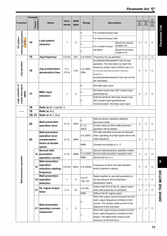
DR
IVE
THE
MO
TOR
3
Parameter list
Para
met
er L
ist
V/F
patte
rn
mat
chin
g ap
plic
atio
ns
14 Load pattern selection
1 0
0 For constant torque load
1 For reduced-torque load
2For constant torque elevators
Boost for reverse rotation 0%
3 Boost for forward rotation 0%
Jog
oper
atio
n
15 Jog frequency 0.01Hz 5Hz 0 to 400Hz Frequency for jog operation.
16 Jog acceleration/deceleration time
0.1/0.01s
0.5s0 to 3600/360s
Acceleration/deceleration time for jog operation. The time taken to reach the frequency (initial value is 60Hz) set in Pr. 20 Acceleration/deceleration reference frequency.Acceleration/deceleration time can not be set separately.
Logi
c se
lect
ion
of
outp
ut s
top
sign
al
(MR
S) 17 MRS input selection
1 0
0 Normally open input
2Normally closed input (NC contact input specifications)
4External terminal: Normally closed input (NC contact input specifications)Communication: Normally open input
——18 Refer to Pr. 1 and Pr. 2.19 Refer to Pr.3.20, 21 Refer to Pr.7, Pr.8.
Stal
l pre
vent
ion
oper
atio
n
22 Stall prevention operation level
0.1% 150%0
Stall prevention operation selection becomes invalid.
0.1 to 200%
Current value at which stall prevention operation will be started.
23
Stall prevention operation level compensation factor at double speed
0.1% 9999
0 to 200%The stall operation level can be reduced when operating at a high speed above the rated frequency.
9999 Constant according to Pr. 22
48Second stall prevention operation current
0.1% 9999
0 Second stall prevention operation invalid0.1 to 200% Second stall prevention operation level.
9999 Same level as Pr.22.
66
Stall prevention operation reduction starting frequency
0.01Hz 60Hz 0 to 400HzFrequency at which the stall operation level is started to reduce.
156Stall prevention operation selection
1 00 to 31100, 101
Select whether to use stall prevention or not according to the acceleration/deceleration status.
157OL signal output timer
0.1s 0s0 to 25s
Output start time of the OL signal output when stall prevention is activated.
9999 Without the OL signal output
277Stall prevention operation current switchover
1 0
0
When the output current exceeds the limit level, output frequency is limited to limit current. The inverter rated current is the reference to the limit level.
1
When the output torque exceeds the limit level, output frequency is limited to limit torque. The rated motor torque is the reference to the limit level.
Function
Parameter
NameIncre-ments
Initial Value
Range DescriptionParam
eter Copy
Parameter
Clear
All Param
eter Clear
Rel
ated
Para
met
er
V/F
V/F
V/F
71
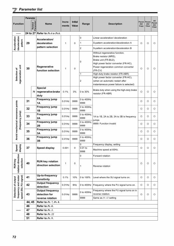
Parameter list
—— 24 to 27 Refer to Pr.4 to Pr.6.
Acc
eler
atio
n/d
ecel
erat
ion
pat
tern
29Acceleration/deceleration pattern selection
1 0
0 Linear acceleration/ deceleration
1 S-pattern acceleration/deceleration A
2 S-pattern acceleration/deceleration B
Sele
ctio
n of
re
gene
ratio
n un
it
30 Regenerative function selection
1 0
0
Without regenerative function,Brake resistor (MRS),Brake unit (FR-BU2),High power factor converter (FR-HC), Power regeneration common converter (FR-CV)
1 High-duty brake resistor (FR-ABR)
2High power factor converter (FR-HC), (when an automatic restart after instantaneous power failure is selected)
70Special regenerative brake duty
0.1% 0% 0 to 30%Brake duty when using the high-duty brake resistor (FR-ABR)
Avoi
d m
echa
nica
l res
onan
ce p
oint
s(fr
eque
ncy
jum
p)
31 Frequency jump 1A
0.01Hz 99990 to 400Hz9999
1A to 1B, 2A to 2B, 3A to 3B is frequency jumps9999: Function invalid
32 Frequency jump 1B
0.01Hz 99990 to 400Hz,9999
33 Frequency jump 2A
0.01Hz 99990 to 400Hz,9999
34 Frequency jump 2B
0.01Hz 99990 to 400Hz,9999
35 Frequency jump 3A
0.01Hz 99990 to 400Hz,9999
36 Frequency jump 3B
0.01Hz 99990 to 400Hz,9999
Spee
d di
spla
y
37 Speed display 0.001 00 Frequency display, setting0.01 to 9998
Machine speed at 60Hz.
RU
N k
ey
rota
tion
dire
ctio
n s
elec
tion
40 RUN key rotation direction selection
1 0
0 Forward rotation
1 Reverse rotation
Det
ectio
n of
out
put
freq
uenc
y an
d m
otor
sp
eed
(SU
, FU
sig
nal) 41 Up-to-frequency
sensitivity0.1% 10% 0 to 100% Level where the SU signal turns on.
42 Output frequency detection
0.01Hz 6Hz 0 to 400Hz Frequency where the FU signal turns on.
43Output frequency detection for reverse rotation
0.01Hz 99990 to 400Hz
Frequency where the FU signal turns on in reverse rotation.
9999 Same as Pr. 42 setting
——
44, 45 Refer to Pr. 7, Pr. 8.46 Refer to Pr. 0.47 Refer to Pr. 3.48 Refer to Pr. 2251 Refer to Pr. 9.
Function
Parameter
NameIncre-ments
Initial Value
Range DescriptionParam
eter Copy
Parameter
Clear
All Param
eter Clear
Rel
ated
Para
met
er
72
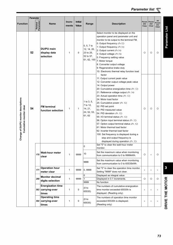
DR
IVE
THE
MO
TOR
3
Parameter list
Para
met
er L
ist
Cha
nge
of D
U/P
U m
onito
r des
crip
tions
C
umul
ativ
e m
onito
r cle
ar
52DU/PU main display data selection
1 0
0, 5, 7 to 12, 14, 20, 23 to 25, 52 to 57, 61, 62, 100
Select monitor to be displayed on the operation panel and parameter unit and monitor to be output to the terminal FM. 0: Output frequency (Pr.52) 1: Output frequency (Pr.54) 2: Output current (Pr.54) 3: Output voltage (Pr.54) 5: Frequency setting value7: Motor torque8: Converter output voltage9: Regenerative brake duty10: Electronic thermal relay function load
factor11: Output current peak value12: Converter output voltage peak value14: Output power20: Cumulative energization time (Pr. 52) 21: Reference voltage output (Pr. 54) 23: Actual operation time (Pr. 52) 24: Motor load factor25: Cumulative power (Pr. 52) 52: PID set point53: PID measured value54: PID deviation (Pr. 52) 55: I/O terminal status (Pr. 52) 56: Option input terminal status (Pr. 52) 57: Option output terminal status (Pr. 52) 61: Motor thermal load factor62: Inverter thermal load factor100: Set frequency is displayed during a
stop and output frequency is displayed during operation (Pr. 52)
54 FM terminal function selection
1 1
1 to 3, 5,7 to 12,14, 21, 24, 52, 53, 61, 62
170Watt-hour meter clear
1 9999
0Set "0" to clear the watt-hour meter monitor.
×10 Set the maximum value when monitoring from communication to 0 to 9999kWh.
9999Set the maximum value when monitoring from communication to 0 to 65535kWh.
171Operation hour meter clear
1 9999 0, 9999Set "0" to clear the operation time monitor.Setting "9999" does not clear.
× × ×
268Monitor decimal digits selection
1 99990 Displayed as integral value1 Displayed in 0.1 increments.9999 No function
563Energization time carrying-over times
1 0(0 to 65535)
The numbers of cumulative energization time monitor exceeded 65535h is displayed. (Reading only)
× × ×
564Operating time carrying-over times
1 0(0 to 65535)
The numbers of operation time monitor exceeded 65535h is displayed. (Reading only)
× × ×
Function
Parameter
NameIncre-ments
Initial Value
Range DescriptionParam
eter Copy
Parameter
Clear
All Param
eter Clear
Rel
ated
Para
met
er
73
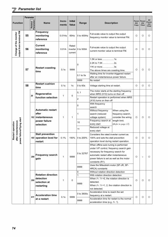
Parameter list
Cha
nge
of th
e m
onito
r ou
tput
from
term
inal
FM
55Frequency monitoring reference
0.01Hz 60Hz 0 to 400HzFull-scale value to output the output frequency monitor value to terminal FM.
56Current monitoring reference
0.01ARated
inverter current
0 to 500AFull-scale value to output the output current monitor value to terminal FM.
Res
tart
ope
ratio
n af
ter i
nsta
ntan
eous
po
wer
failu
re/F
lyin
g st
art
57 Restart coasting time
0.1s 9999
0
1.5K or less .................. 1s
2.2K to 7.5K ................. 2s
11K or more.................. 3sThe above times are coasting time.
0.1 to 5sWaiting time for inverter-triggered restart after an instantaneous power failure.
9999 No restart
58 Restart cushion time
0.1s 1s 0 to 60s Voltage starting time at restart.
30Regenerative function selection
1 00, 1
The motor starts at the starting frequency when MRS (X10) turns on then off
2Restart operation is performed when MRS (X10) turns on then off
162
Automatic restart after instantaneous power failure selection
1 1
0With frequency search
When using the frequency search, consider the wiring length limit.(Refer to page 12)
1Without frequency search (reduced voltage system)
10Frequency search at every start
11Reduced voltage at every start
165Stall prevention operation level for restart
0.1% 150% 0 to 200%Considers the rated inverter current as 100% and sets the stall prevention operation level during restart operation.
298Frequency search gain
1 99990 to 32767
When offline auto tuning is performed under V/F control, frequency search gain necessary for frequency search for automatic restart after instantaneous power failure is set as well as the motor constants (R1).
×
9999Uses the Mitsubishi motor (SF-JR, SF-HRCA) constants
299
Rotation direction detection selection at restarting
1 0
0 Without rotation direction detection1 With rotation direction detection
9999
When Pr. 78 =0, the rotation direction is detected.When Pr. 78 =1, 2, the rotation direction is not detected.
611Acceleration time at a restart
0.1s 99990 to 3600s
Acceleration time to reach the set frequency at a restart.
9999Acceleration time for restart is the normal acceleration time (e.g. Pr. 7).
Function
Parameter
NameIncre-ments
Initial Value
Range DescriptionParam
eter Copy
Parameter
Clear
All Param
eter Clear
Rel
ated
Para
met
er
74
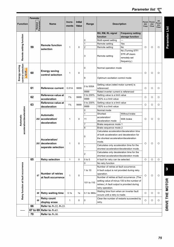
DR
IVE
THE
MO
TOR
3
Parameter list
Para
met
er L
ist
Rem
ote
setti
ng fu
nctio
n
59 Remote function selection
1 0
0
RH, RM, RL signal function
Frequency setting storage function
Multi-speed setting —1 Remote setting Yes2 Remote setting No
3 Remote setting
No (Turning STF/STR off clears remotely-set frequency.)
Ener
gy s
avin
g co
ntro
l sel
ectio
n
60 Energy saving control selection
1 0
0 Normal operation mode
9 Optimum excitation control mode
Aut
omat
ic
acce
lera
tion/
dece
lera
tion
61 Reference current 0.01A 99990 to 500A
Setting value (rated motor current) is referenced
9999 Rated inverter current is referenced
62 Reference value at acceleration
1% 99990 to 200% Setting value is a limit value9999 150% is a limit value
63 Reference value at deceleration
1% 99990 to 200% Setting value is a limit value9999 150% is a limit value
292Automatic acceleration/deceleration
1 0
0 Normal mode1 Shortest
acceleration/deceleration mode
Without brake
11 With brake
7 Brake sequence mode 18 Brake sequence mode 2
293Acceleration/deceleration separate selection
1 0
0
Calculates acceleration/deceleration time of both acceleration and deceleration for the shortest acceleration/deceleration mode.
1Calculates only acceleration time for the shortest acceleration/deceleration mode.
2Calculates only deceleration time for the shortest acceleration/deceleration mode
Ret
ry fu
nctio
n at
faul
t occ
urre
nce
65 Retry selection 1 0 0 to 5 A fault for retry can be selected.
67Number of retries at fault occurrence
1 0
0 No retry function
1 to 10Number of retries at fault occurrence. A fault output is not provided during retry operation.
101 to 110
Number of retries at fault occurrence. (The setting value of minus 100 is the number of retries.) A fault output is provided during retry operation.
68 Retry waiting time 0.1s 1s 0.1 to 360sWaiting time from when an inverter fault occurs until a retry is made.
69Retry count display erase
1 0 0Clear the number of restarts succeeded by retry.
——66 Refer to Pr.22, Pr.23.
67 to 69 Refer to Pr.65.70 Refer to Pr.30.
Function
Parameter
NameIncre-ments
Initial Value
Range DescriptionParam
eter Copy
Parameter
Clear
All Param
eter Clear
Rel
ated
Para
met
er
V/F
V/F
V/F
75
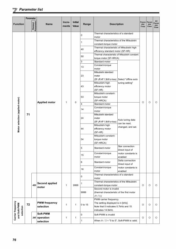
Parameter list
Mot
or s
elec
tion
(app
lied
mot
or)
71
Applied motor 1 0
0Thermal characteristics of a standard motor
1Thermal characteristics of the Mitsubishi constant-torque motor
40Thermal characteristic of Mitsubishi high efficiency standard motor (SF-HR)
50Thermal characteristic of Mitsubishi constant torque motor (SF-HRCA)
3 Standard motor
Select "offline auto tuning setting"
13Constant-torque motor
23Mitsubishi standard motor(SF-JR 4P 1.5kW or less)
43Mitsubishi high efficiency motor(SF-HR)
53Mitsubishi constant-torque motor(SF-HRCA)
4 Standard motor
Auto tuning data can be read, changed, and set.
14Constant-torque motor
24Mitsubishi standard motor(SF-JR 4P 1.5kW or less)
44Mitsubishi high efficiency motor(SF-HR)
54Mitsubishi constant-torque motor(SF-HRCA)
5 Standard motorStar connectionDirect input of motor constants is enabled
15Constant-torque motor
6 Standard motorDelta connectionDirect input of motor constants is enabled
16Constant-torque motor
450Second applied motor
1 9999
0Thermal characteristics of a standard motor
1Thermal characteristics of the Mitsubishi constant-torque motor
9999Second motor is invalid(thermal characteristic of the first motor (Pr.71))
Car
rier f
requ
ency
an
d So
ft-PW
M
sele
ctio
n 72 PWM frequency selection
1 1 0 to 15
PWM carrier frequency. The setting displayed is in [kHz].Note that 0 indicates 0.7kHz and 15 indicates 14.5kHz.
240Soft-PWM operation selection
1 10 Soft-PWM is invalid
1 When Pr. 72 = "0 to 5", Soft-PWM is valid.
Function
Parameter
NameIncre-ments
Initial Value
Range DescriptionParam
eter Copy
Parameter
Clear
All Param
eter Clear
Rel
ated
Para
met
er
76
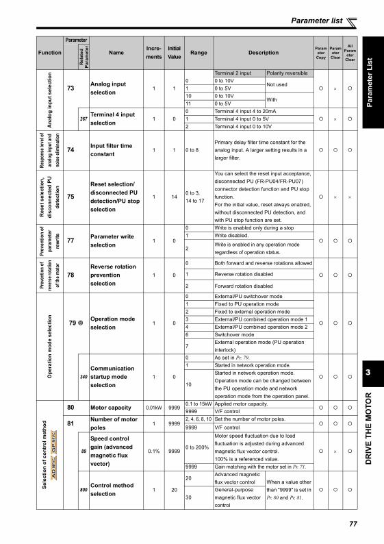
DR
IVE
THE
MO
TOR
3
Parameter list
Para
met
er L
ist
Ana
log
inpu
t sel
ectio
n
73 Analog input selection
1 1
Terminal 2 input Polarity reversible
×0 0 to 10V
Not used1 0 to 5V10 0 to 10V
With11 0 to 5V
267Terminal 4 input selection
1 00 Terminal 4 input 4 to 20mA
×1 Terminal 4 input 0 to 5V2 Terminal 4 input 0 to 10V
Resp
onse
leve
l of
analo
g in
put a
nd
noise
elim
inat
ion
74 Input filter time constant
1 1 0 to 8Primary delay filter time constant for the analog input. A larger setting results in a larger filter.
Res
et s
elec
tion,
di
scon
nect
ed P
U
dete
ctio
n
75
Reset selection/disconnected PU detection/PU stop selection
1 140 to 3, 14 to 17
You can select the reset input acceptance, disconnected PU (FR-PU04/FR-PU07) connector detection function and PU stop function.For the initial value, reset always enabled, without disconnected PU detection, and with PU stop function are set.
× ×
Prev
entio
n of
pa
ram
eter
re
writ
e
77 Parameter write selection
1 0
0 Write is enabled only during a stop1 Write disabled.
2Write is enabled in any operation mode regardless of operation status.
Prev
entio
n of
re
vers
e rot
atio
n of
the m
otor
78Reverse rotation prevention selection
1 0
0 Both forward and reverse rotations allowed
1 Reverse rotation disabled
2 Forward rotation disabled
Ope
ratio
n m
ode
sele
ctio
n
79 Operation mode selection
1 0
0 External/PU switchover mode1 Fixed to PU operation mode2 Fixed to external operation mode3 External/PU combined operation mode 14 External/PU combined operation mode 26 Switchover mode
7External operation mode (PU operation interlock)
340Communication startup mode selection
1 0
0 As set in Pr. 79.1 Started in network operation mode.
10
Started in network operation mode. Operation mode can be changed between the PU operation mode and network operation mode from the operation panel.
Sele
ctio
n of
con
trol
met
hod
80 Motor capacity 0.01kW 99990.1 to 15kW Applied motor capacity.9999 V/F control
81 Number of motor poles
1 99992, 4, 6, 8, 10 Set the number of motor poles.9999 V/F control
89
Speed control gain (advanced magnetic flux vector)
0.1% 99990 to 200%
Motor speed fluctuation due to load fluctuation is adjusted during advanced magnetic flux vector control.100% is a referenced value.
×
9999 Gain matching with the motor set in Pr. 71.
800Control method selection
1 20
20Advanced magnetic flux vector control When a value other
than "9999" is set in Pr. 80 and Pr. 81.30
General-purpose magnetic flux vector control
Function
Parameter
NameIncre-ments
Initial Value
Range DescriptionParam
eter Copy
Parameter
Clear
All Param
eter Clear
Rel
ated
Para
met
er
AD
MF
VC
AD
MF
VC
AD
MF
VC
GP
MF
VC
GP
MF
VC
GP
MF
VC
77
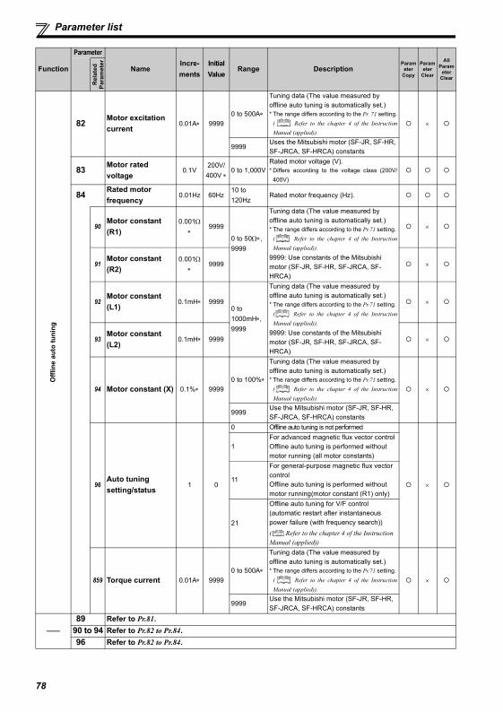
Parameter list
Offl
ine
auto
tuni
ng
82 Motor excitation current
0.01A∗ 99990 to 500A∗
Tuning data (The value measured by offline auto tuning is automatically set.)* The range differs according to the Pr. 71 setting.
( Refer to the chapter 4 of the InstructionManual (applied)).
×
9999Uses the Mitsubishi motor (SF-JR, SF-HR, SF-JRCA, SF-HRCA) constants
83 Motor rated voltage
0.1V200V/400V ∗
0 to 1,000VRated motor voltage (V).* Differs according to the voltage class (200V/
400V)
84 Rated motor frequency
0.01Hz 60Hz10 to 120Hz
Rated motor frequency (Hz).
90Motor constant (R1)
0.001Ω∗
9999
0 to 50Ω∗, 9999
Tuning data (The value measured by offline auto tuning is automatically set.)* The range differs according to the Pr.71 setting.
( Refer to the chapter 4 of the InstructionManual (applied)).
9999: Use constants of the Mitsubishi motor (SF-JR, SF-HR, SF-JRCA, SF-HRCA)
×
91Motor constant (R2)
0.001Ω∗
9999 ×
92Motor constant (L1)
0.1mH∗ 99990 to 1000mH∗, 9999
Tuning data (The value measured by offline auto tuning is automatically set.)* The range differs according to the Pr.71 setting.
( Refer to the chapter 4 of the InstructionManual (applied)).
9999: Use constants of the Mitsubishi motor (SF-JR, SF-HR, SF-JRCA, SF-HRCA)
×
93Motor constant (L2)
0.1mH∗ 9999 ×
94 Motor constant (X) 0.1%∗ 99990 to 100%∗
Tuning data (The value measured by offline auto tuning is automatically set.)* The range differs according to the Pr.71 setting.
( Refer to the chapter 4 of the InstructionManual (applied)).
×
9999Use the Mitsubishi motor (SF-JR, SF-HR, SF-JRCA, SF-HRCA) constants
96Auto tuning setting/status
1 0
0 Offline auto tuning is not performed
×
1For advanced magnetic flux vector controlOffline auto tuning is performed without motor running (all motor constants)
11
For general-purpose magnetic flux vector controlOffline auto tuning is performed without motor running(motor constant (R1) only)
21
Offline auto tuning for V/F control (automatic restart after instantaneous power failure (with frequency search)) ( Refer to the chapter 4 of the Instruction Manual (applied))
859 Torque current 0.01A∗ 99990 to 500A∗
Tuning data (The value measured by offline auto tuning is automatically set.)* The range differs according to the Pr.71 setting.
( Refer to the chapter 4 of the InstructionManual (applied)).
×
9999Use the Mitsubishi motor (SF-JR, SF-HR, SF-JRCA, SF-HRCA) constants
——89 Refer to Pr.81.
90 to 94 Refer to Pr.82 to Pr.84.96 Refer to Pr.82 to Pr.84.
Function
Parameter
NameIncre-ments
Initial Value
Range DescriptionParam
eter Copy
Parameter
Clear
All Param
eter Clear
Rel
ated
Para
met
er
78
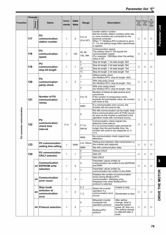
DR
IVE
THE
MO
TOR
3
Parameter list
Para
met
er L
ist
PU c
onne
ctor
com
mun
icat
ion
117PU communication station number
1 00 to 31(0 to 247)
Inverter station number.Set the inverter station numbers when two or more inverters are connected to one personal computer. When "1" (Modbus-RTU protocol) is set in Pr. 549, the setting range within parenthesis is applied.
118PU communication speed
1 19248, 96,192, 384
Communication speed.The setting value X 100 equals the communication speed.(For example, 19200bps when the setting value is 92)
119PU communication stop bit length
1 1
0 Stop bit length: 1 bit data length: 8bit1 Stop bit length: 2 bit data length: 8bit10 Stop bit length: 1 bit data length: 7bit11 Stop bit length: 2 bit data length: 7bit
120PU communication parity check
1 2
0 Without parity check(for Modbus-RTU: stop bit length: 2bit)
1 With odd parity check(for Modbus-RTU: stop bit length: 1bit)
2 With even parity check(for Modbus-RTU: stop bit length: 1bit)
121Number of PU communication retries
1 10 to 10
Number of retries at data receive error occurrenceIf the number of consecutive errors exceeds the permissible value, the inverter will come to trip.
9999 If a communication error occurs, the inverter will not come to trip.
122PU communication check time interval
0.1s 0
0RS-485 communication can be made. Note that a communication error (E.PUE) occurs as soon as the inverter is switched to the operation mode with command source.
0.1 to 999.8s
Communication check (signal loss detection) time intervalIf a no-communication state persists for longer than the permissible time, the inverter will come to trip (depends on Pr. 502).
9999 No communication check (signal loss detection)
123 PU communication waiting time setting 1 9999
0 to 150ms Waiting time between data transmission to the inverter and response.
9999 Set with communication data.
124 PU communication CR/LF selection 1 1
0 Without CR/LF1 With CR2 With CR/LF
342Communication EEPROM write selection
1 00
Parameter values written by communication are written to the EEPROM and RAM.
1 Parameter values written by communication are written to the RAM.
343 Communication error count 1 0 —
Displays the number of communication errors during Modbus-RTU communication. (Reading only)Displayed only when Modbus-RTU protocol is selected.
× × ×
502
Stop mode selection at communication error
1 0
0, 3 Select the inverter operation if a communication error occurs.
Coasts to stop
1, 2 Decelerates to stop
549 Protocol selection 1 0
0Mitsubishi inverter (computer link operation) protocol
After setting change, reset is required (switch power off, then on). The setting change is reflected after a reset.
1 Modbus-RTU protocol
Function
Parameter
NameIncre-ments
Initial Value
Range DescriptionParam
eter Copy
Parameter
Clear
All Param
eter Clear
Rel
ated
Para
met
er
79
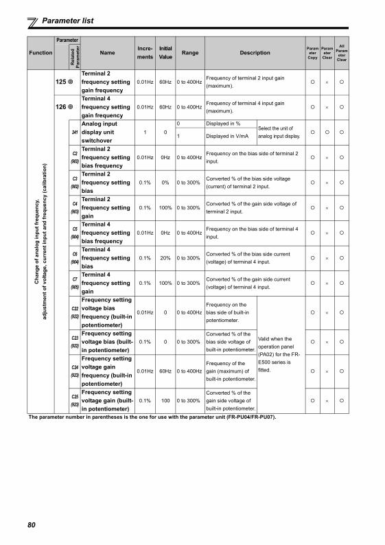
Parameter list
Cha
nge
of a
nalo
g in
put f
requ
ency
,ad
just
men
t of v
olta
ge, c
urre
nt in
put a
nd fr
eque
ncy
(cal
ibra
tion)
125 Terminal 2 frequency setting gain frequency
0.01Hz 60Hz 0 to 400HzFrequency of terminal 2 input gain (maximum).
×
126 Terminal 4 frequency setting gain frequency
0.01Hz 60Hz 0 to 400HzFrequency of terminal 4 input gain (maximum).
×
241Analog input display unit switchover
1 0
0 Displayed in %Select the unit of analog input display.1 Displayed in V/mA
C2(902)
Terminal 2 frequency setting bias frequency
0.01Hz 0Hz 0 to 400HzFrequency on the bias side of terminal 2 input.
×
C3(902)
Terminal 2 frequency setting bias
0.1% 0% 0 to 300%Converted % of the bias side voltage (current) of terminal 2 input.
×
C4(903)
Terminal 2 frequency setting gain
0.1% 100% 0 to 300%Converted % of the gain side voltage of terminal 2 input.
×
C5(904)
Terminal 4 frequency setting bias frequency
0.01Hz 0Hz 0 to 400HzFrequency on the bias side of terminal 4 input.
×
C6(904)
Terminal 4 frequency setting bias
0.1% 20% 0 to 300%Converted % of the bias side current (voltage) of terminal 4 input.
×
C7(905)
Terminal 4 frequency setting gain
0.1% 100% 0 to 300%Converted % of the gain side current (voltage) of terminal 4 input.
×
C22(922)
Frequency setting voltage bias frequency (built-in potentiometer)
0.01Hz 0 0 to 400HzFrequency on the bias side of built-in potentiometer.
Valid when the operation panel (PA02) for the FR-E500 series is fitted.
×
C23(922)
Frequency setting voltage bias (built-in potentiometer)
0.1% 0 0 to 300%Converted % of the bias side voltage of built-in potentiometer.
×
C24(923)
Frequency setting voltage gain frequency (built-in potentiometer)
0.01Hz 60Hz 0 to 400HzFrequency of the gain (maximum) of built-in potentiometer.
×
C25(923)
Frequency setting voltage gain (built-in potentiometer)
0.1% 100 0 to 300%Converted % of the gain side voltage of built-in potentiometer.
×
The parameter number in parentheses is the one for use with the parameter unit (FR-PU04/FR-PU07).
Function
Parameter
NameIncre-ments
Initial Value
Range DescriptionParam
eter Copy
Parameter
Clear
All Param
eter Clear
Rel
ated
Para
met
er
80
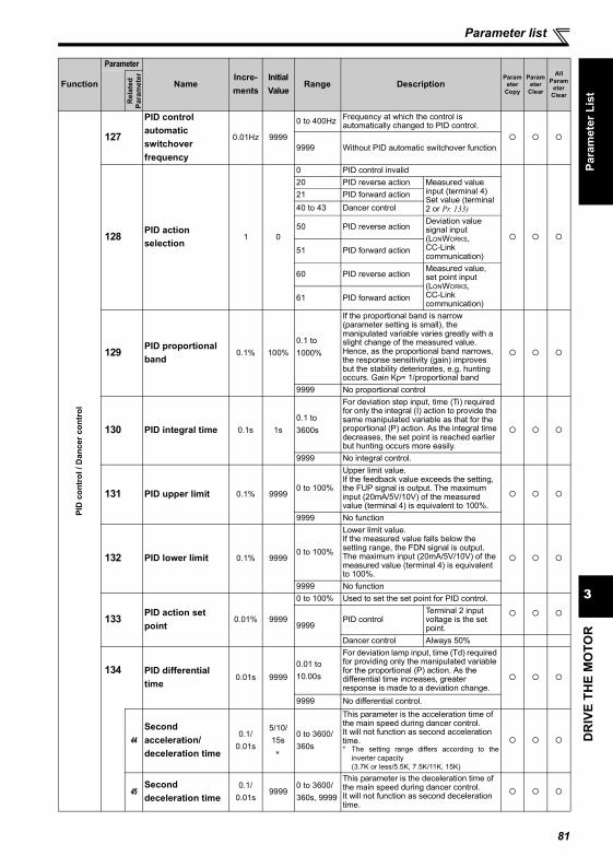
DR
IVE
THE
MO
TOR
3
Parameter list
Para
met
er L
ist
PID
con
trol
/ D
ance
r con
trol
127
PID control automatic switchover frequency
0.01Hz 9999
0 to 400Hz Frequency at which the control is automatically changed to PID control.
9999 Without PID automatic switchover function
128 PID action selection
1 0
0 PID control invalid20 PID reverse action Measured value
input (terminal 4)Set value (terminal 2 or Pr. 133)
21 PID forward action40 to 43 Dancer control
50 PID reverse actionDeviation value signal input (LONWORKS, CC-Link communication)
51 PID forward action
60 PID reverse actionMeasured value, set point input (LONWORKS, CC-Link communication)
61 PID forward action
129 PID proportional band
0.1% 100%0.1 to 1000%
If the proportional band is narrow (parameter setting is small), the manipulated variable varies greatly with a slight change of the measured value. Hence, as the proportional band narrows, the response sensitivity (gain) improves but the stability deteriorates, e.g. hunting occurs. Gain Kp= 1/proportional band
9999 No proportional control
130 PID integral time 0.1s 1s0.1 to 3600s
For deviation step input, time (Ti) required for only the integral (I) action to provide the same manipulated variable as that for the proportional (P) action. As the integral time decreases, the set point is reached earlier but hunting occurs more easily.
9999 No integral control.
131 PID upper limit 0.1% 99990 to 100%
Upper limit value. If the feedback value exceeds the setting, the FUP signal is output. The maximum input (20mA/5V/10V) of the measured value (terminal 4) is equivalent to 100%.
9999 No function
132 PID lower limit 0.1% 99990 to 100%
Lower limit value. If the measured value falls below the setting range, the FDN signal is output. The maximum input (20mA/5V/10V) of the measured value (terminal 4) is equivalent to 100%.
9999 No function
133 PID action set point
0.01% 9999
0 to 100% Used to set the set point for PID control.
9999PID control
Terminal 2 input voltage is the set point.
Dancer control Always 50%
134 PID differential time
0.01s 99990.01 to 10.00s
For deviation lamp input, time (Td) required for providing only the manipulated variable for the proportional (P) action. As the differential time increases, greater response is made to a deviation change.
9999 No differential control.
44Second acceleration/deceleration time
0.1/0.01s
5/10/15s
∗
0 to 3600/360s
This parameter is the acceleration time of the main speed during dancer control.It will not function as second acceleration time.* The setting range differs according to the
inverter capacity(3.7K or less/5.5K, 7.5K/11K, 15K)
45Second deceleration time
0.1/0.01s
99990 to 3600/360s, 9999
This parameter is the deceleration time of the main speed during dancer control.It will not function as second deceleration time.
Function
Parameter
NameIncre-ments
Initial Value
Range DescriptionParam
eter Copy
Parameter
Clear
All Param
eter Clear
Rel
ated
Para
met
er
81
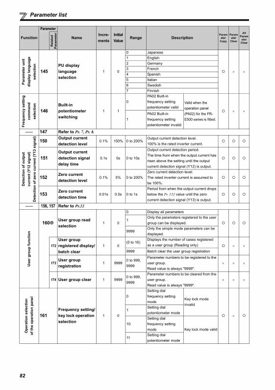
Parameter list
Param
eter
uni
t di
spla
y la
ngua
ge
sele
ctio
n
145PU display language selection
1 0
0 Japanese
× ×
1 English2 Germany3 French4 Spanish5 Italian6 Swedish7 Finnish
Freq
uenc
y se
tting
co
mm
and
sele
ctio
n
146Built-in potentiometer switching
1 1
0PA02 Built-in frequency setting potentiometer valid
Valid when the operation panel (PA02) for the FR-E500 series is fitted.
× ×
1PA02 Built-in frequency setting potentiometer invalid
—— 147 Refer to Pr. 7, Pr. 8.
Det
ectio
n of
out
put
curr
ent (
Y12
sign
al)
Det
ectio
n of
zer
o cu
rren
t (Y1
3 si
gnal
)
150 Output current detection level
0.1% 150% 0 to 200%Output current detection level.100% is the rated inverter current.
151Output current detection signal delay time
0.1s 0s 0 to 10s
Output current detection period. The time from when the output current has risen above the setting until the output current detection signal (Y12) is output.
152 Zero current detection level
0.1% 5% 0 to 200%Zero current detection level.The rated inverter current is assumed to be 100%.
153 Zero current detection time
0.01s 0.5s 0 to 1sPeriod from when the output current drops below the Pr. 152 value until the zero current detection signal (Y13) is output.
—— 156, 157 Refer to Pr.22
Use
r gro
up fu
nctio
n
160 User group read selection
1 0
0 Display all parameters
1Only the parameters registered to the user group can be displayed.
9999Only the simple mode parameters can be displayed.
172User group registered display/batch clear
1 0(0 to 16)
Displays the number of cases registered as a user group (Reading only) × ×
9999 Batch clear the user group registration
173User group registration
1 99990 to 999,9999
Parameter numbers to be registered to the user group.Read value is always "9999".
× × ×
174 User group clear 1 99990 to 999,9999
Parameter numbers to be cleared from the user group.Read value is always "9999".
× × ×
Ope
ratio
n se
lect
ion
of th
e op
erat
ion
pane
l
161Frequency setting/key lock operation selection
1 0
0Setting dial frequency setting mode
Key lock mode invalid
×1
Setting dialpotentiometer mode
10Setting dial frequency setting mode Key lock mode valid
11Setting dialpotentiometer mode
Function
Parameter
NameIncre-ments
Initial Value
Range DescriptionParam
eter Copy
Parameter
Clear
All Param
eter Clear
Rel
ated
Para
met
er
82
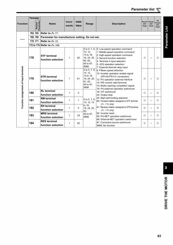
DR
IVE
THE
MO
TOR
3
Parameter list
Para
met
er L
ist
——
162, 165 Refer to Pr. 57.168, 169 Parameter for manufacturer setting. Do not set.170, 171 Refer to Pr. 52.
172 to 174 Refer to Pr. 160.
Func
tion
assi
gnm
ent o
f inp
ut te
rmin
al
178 STF terminal function selection
1 60
0 to 5, 7, 8,10, 12,14 to 16,18, 24, 25, 60, 62,65 to 67,9999
0: Low-speed operation command1: Middle-speed operation command2: High-speed operation command3: Second function selection4: Terminal 4 input selection5: JOG operation selection7: External thermal relay input8: Fifteen speed selection10: Inverter operation enable signal
(FR-HC/FR-CV connection)12: PU operation external interlock14: PID control valid terminal15: Brake opening completion signal16: PU-external operation switchover18: V/F switchover24: Output stop25: Start self-holding selection60: Forward rotation (assigned to STF terminal
(Pr. 178) only) 61: Reverse rotation (assigned to STR terminal
(Pr. 179) only) 62: Inverter reset65: PU-NET operation switchover66: External-NET operation switchover67: Command source switchover9999: No function
×
179 STR terminal function selection
1 61
0 to 5, 7, 8,10, 12, 14 to 16,18, 24, 25, 61, 62,65 to 67,9999
×
180 RL terminal function selection
1 0
0 to 5, 7, 8,10, 12, 14 to 16,18, 24, 25, 62,65 to 67,9999
×
181 RM terminal function selection
1 1 ×
182 RH terminal function selection
1 2 ×
183 MRS terminal function selection
1 24 ×
184 RES terminal function selection
1 62 ×
Function
Parameter
NameIncre-ments
Initial Value
Range DescriptionParam
eter Copy
Parameter
Clear
All Param
eter Clear
Rel
ated
Para
met
er
83
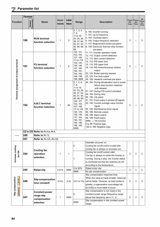
Parameter list
Term
inal
ass
ignm
ent o
f out
put t
erm
inal
190 RUN terminal function selection
1 0
0, 1, 3, 47, 8, 11 to 16, 20, 25, 26, 46, 47, 64, 90, 91, 93, 95, 96, 98, 99,100, 101, 103, 104, 107, 108, 111 to 116 120, 125 126, 146 147, 164 190, 191, 193, 195, 196, 198, 199, 9999
0, 100: Inverter running1, 101: Up to frequency3, 103: Overload alarm4, 140: Output frequency detection7, 107: Regenerative brake pre-alarm 8, 108: Electronic thermal relay function
pre-alarm11, 111: Inverter operation ready12, 112: Output current detection13, 113: Zero current detection14, 114: PID lower limit15, 115: PID upper limit16, 116: PID forward/reverse rotation
output20, 120: Brake opening request25, 125: Fan fault output26, 126: Heatsink overheat pre-alarm46, 164: During deceleration due to power
failure stop function (retained until release)
47, 147: During PID control activated64, 164: During retry90, 190: Life alarm91, 191: Fault output 3 (power-off signal)93, 193: Current average value monitor
signal95, 195: Maintenance timer signal96, 196: Remote output98, 198: Alarm output99, 199: Fault output9999, —: No function0 to 99: Positive logic 100 to 199: Negative logic
×
191 FU terminal function selection
1 4 ×
192 A,B,C terminal function selection
1 99
0, 1, 3, 4, 7, 8, 11 to 16,20, 25, 26, 46, 47, 64, 90, 91, 95, 96, 98, 99, 100, 101, 103, 104, 107, 108, 111 to 116, 120, 125, 126, 146, 147, 164, 190, 191, 195, 196, 198, 199, 9999
×
——232 to 239 Refer to Pr.4 to Pr.6.240 Refer to Pr.72.241 Refer to Pr.125, Pr.126.
Incr
ease
coo
ling
fan
life
244Cooling fan operation selection
1 1
0Operates at power onCooling fan on/off control invalid (the cooling fan is always on at power on)
1
Cooling fan on/off control validThe fan is always on while the inverter is running. During a stop, the inverter status is monitored and the fan switches on-off according to the temperature.
Slip
com
pens
atio
n
245 Rated slip 0.01% 99990 to 50% Rated motor slip.9999 No slip compensation
246 Slip compensation time constant
0.01s 0.5s 0.01 to 10s
Slip compensation response time. When the value is made smaller, response will be faster. However, as load inertia is greater, a regenerative overvoltage trip (E.OV ) is more liable to occur.
247
Constant-power range slip compensation selection
1 99990
Slip compensation is not made in the constant power range (frequency range above the frequency set in Pr. 3).
9999Slip compensation in the constant power range.
Function
Parameter
NameIncre-ments
Initial Value
Range DescriptionParam
eter Copy
Parameter
Clear
All Param
eter Clear
Rel
ated
Para
met
er
GP
MF
VC
GP
MF
VC
GP
MF
VC
V/F
V/F
V/F
84
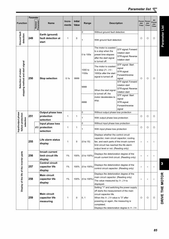
DR
IVE
THE
MO
TOR
3
Parameter list
Para
met
er L
ist
Gro
und
faul
t de
tect
ion
249Earth (ground) fault detection at start
1 0
0 Without ground fault detection
1 With ground fault detection
Sele
ctio
n of
mot
or
stop
ping
met
hod
and
star
t sig
nal
250 Stop selection 0.1s 9999
0 to 100s
The motor is coasted to a stop when the preset time elapses after the start signal is turned off.
STF signal: Forward rotation startSTR signal: Reverse rotation start
1000 to 1100s
The motor is coasted to a stop (Pr. 250 - 1000)s after the start signal is turned off.
STF signal: Start signalSTR signal: Forward/reverse signal
9999When the start signal is turned off, the motor decelerates to stop.
STF signal: Forward rotation startSTR signal: Reverse rotation start
8888
STF signal: Start signalSTR signal: Forward/reverse signal
Inpu
t/out
put p
hase
fa
ilure
pro
tect
ion
sele
ctio
n 251Output phase loss protection selection
1 1
0 Without output phase loss protection
1 With output phase loss protection
872Input phase loss protection selection
1 1
0 Without input phase loss protection
1 With input phase loss protection
Dis
play
of t
he li
fe o
f the
inve
rter
par
ts
255 Life alarm status display
1 0 (0 to 15)
Displays whether the control circuit capacitor, main circuit capacitor, cooling fan, and each parts of the inrush current limit circuit has reached the life alarm output level or not. (Reading only)
× × ×
256Inrush current limit circuit life display
1% 100% (0 to 100%)Displays the deterioration degree of the inrush current limit circuit. (Reading only)
× × ×
257Control circuit capacitor life display
1% 100% (0 to 100%)Displays the deterioration degree of the control circuit capacitor. (Reading only)
× × ×
258Main circuit capacitor life display
1% 100% (0 to 100%)
Displays the deterioration degree of the main circuit capacitor. (Reading only)The value measured by Pr. 259 is displayed.
× × ×
259Main circuit capacitor life measuring
1 0 0, 1
Setting "1" and switching the power supply off starts the measurement of the main circuit capacitor life.When the Pr. 259 value is "3" after powering on again, the measuring is completed. Displays the deterioration degree in Pr. 258.
Function
Parameter
NameIncre-ments
Initial Value
Range DescriptionParam
eter Copy
Parameter
Clear
All Param
eter Clear
Rel
ated
Para
met
er
85
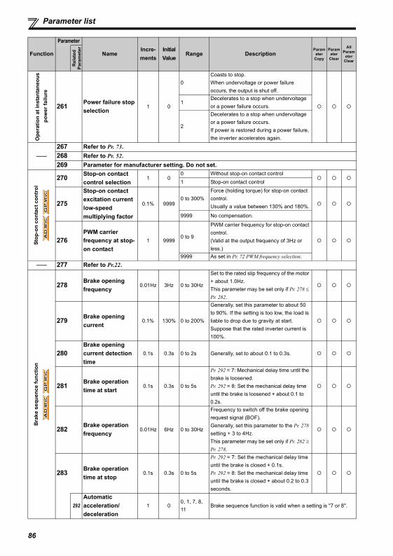
Parameter list
Ope
ratio
n at
inst
anta
neou
s p
ower
failu
re
261 Power failure stop selection
1 0
0Coasts to stop.When undervoltage or power failure occurs, the output is shut off.
1Decelerates to a stop when undervoltage or a power failure occurs.
2
Decelerates to a stop when undervoltage or a power failure occurs.If power is restored during a power failure, the inverter accelerates again.
——267 Refer to Pr. 73.268 Refer to Pr. 52.269 Parameter for manufacturer setting. Do not set.
Stop
-on
cont
act c
ontr
ol
270 Stop-on contact control selection
1 00 Without stop-on contact control1 Stop-on contact control
275
Stop-on contact excitation current low-speed multiplying factor
0.1% 99990 to 300%
Force (holding torque) for stop-on contact control.Usually a value between 130% and 180%.
9999 No compensation.
276PWM carrier frequency at stop-on contact
1 99990 to 9
PWM carrier frequency for stop-on contact control.(Valid at the output frequency of 3Hz or less.)
9999 As set in Pr. 72 PWM frequency selection.—— 277 Refer to Pr.22.
Bra
ke s
eque
nce
func
tion
278 Brake opening frequency
0.01Hz 3Hz 0 to 30Hz
Set to the rated slip frequency of the motor + about 1.0Hz.This parameter may be set only if Pr. 278 ≤ Pr. 282.
279 Brake opening current
0.1% 130% 0 to 200%
Generally, set this parameter to about 50 to 90%. If the setting is too low, the load is liable to drop due to gravity at start.Suppose that the rated inverter current is 100%.
280Brake opening current detection time
0.1s 0.3s 0 to 2s Generally, set to about 0.1 to 0.3s.
281 Brake operation time at start
0.1s 0.3s 0 to 5s
Pr. 292 = 7: Mechanical delay time until the brake is loosened.Pr. 292 = 8: Set the mechanical delay time until the brake is loosened + about 0.1 to 0.2s.
282 Brake operation frequency
0.01Hz 6Hz 0 to 30Hz
Frequency to switch off the brake opening request signal (BOF). Generally, set this parameter to the Pr. 278 setting + 3 to 4Hz.This parameter may be set only if Pr. 282 ≥ Pr. 278.
283 Brake operation time at stop
0.1s 0.3s 0 to 5s
Pr. 292 = 7: Set the mechanical delay time until the brake is closed + 0.1s.Pr. 292 = 8: Set the mechanical delay time until the brake is closed + about 0.2 to 0.3 seconds.
292Automatic acceleration/deceleration
1 00, 1, 7, 8, 11
Brake sequence function is valid when a setting is "7 or 8".
Function
Parameter
NameIncre-ments
Initial Value
Range DescriptionParam
eter Copy
Parameter
Clear
All Param
eter Clear
Rel
ated
Para
met
er
AD
MF
VC
AD
MF
VC
AD
MF
VC
GP
MF
VC
GP
MF
VC
GP
MF
VC
AD
MF
VC
AD
MF
VC
AD
MF
VC
GP
MF
VC
GP
MF
VC
GP
MF
VC
86
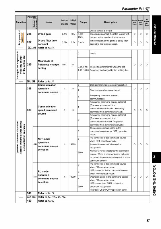
DR
IVE
THE
MO
TOR
3
Parameter list
Para
met
er L
ist
Dro
op c
ontr
ol
286 Droop gain 0.1% 0%0 Droop control is invalid0.1 to 100%
Drooping amount at the rated torque with respect to the rated motor frequency.
287 Droop filter time constant
0.01s 0.3s 0 to 1sTime constant of the primary delay filter applied to the torque current.
—— 292, 293 Refer to Pr. 61.
Setti
ng o
f the
mag
nitu
de o
f fr
eque
ncy
chan
ge
by th
e se
tting
dia
l
295Magnitude of frequency change setting
0.01 0
0 Invalid
0.01, 0.10, 1.00, 10.00
The setting increments when the set frequency is changed by the setting dial.
—— 298, 299 Refer to Pr. 57.
Ope
ratio
n co
mm
and
sour
ce a
nd
spee
d co
mm
and
sour
ce d
urin
g co
mm
unic
atio
n op
erat
ion
338Communication operation command source
1 0
0 Start command source communication
1 Start command source external
339Communication speed command source
1 0
0Frequency command source communication
1
Frequency command source external (Frequency command from communication is invalid, frequency command from terminal 2 is valid)
2
Frequency command source external (Frequency command from communication is valid, frequency command from terminal 2 is invalid)
550
NET mode operation command source selection
1 9999
0The communication option is the command source when NET operation mode.
2PU connector is the command source when NET operation mode.
9999
Automatic communication option recognitionNormally, PU connector is the command source. When a communication option is mounted, the communication option is the command source.
551
PU mode operation command source selection
1 9999
2PU connector is the command source when PU operation mode.
3USB connector is the command source when PU operation mode.
4Operation panel is the command source when PU operation mode.
9999USB connection, PU07 connection automatic recognitionPriorities: USB>PU07>operation panel
——340 Refer to Pr. 79.342, 343 Refer to Pr. 117 to Pr. 124.450 Refer to Pr.71.
Function
Parameter
NameIncre-ments
Initial Value
Range DescriptionParam
eter Copy
Parameter
Clear
All Param
eter Clear
Rel
ated
Para
met
er
AD
MF
VC
AD
MF
VC
AD
MF
VC
87
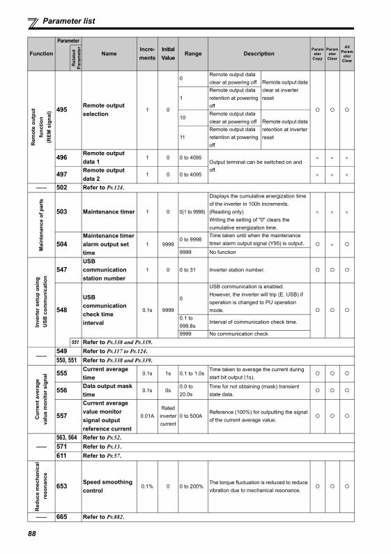
Parameter list
Remot
e ou
tput
fu
nctio
n (R
EM s
igna
l) 495 Remote output selection
1 0
0Remote output data clear at powering off Remote output data
clear at inverter reset1
Remote output data retention at powering off
10Remote output data clear at powering off Remote output data
retention at inverter reset11
Remote output data retention at powering off
496 Remote output data 1
1 0 0 to 4095Output terminal can be switched on and off.
× × ×
497 Remote output data 2
1 0 0 to 4095 × × ×
—— 502 Refer to Pr.124.
Mai
nten
ance
of p
arts
503 Maintenance timer 1 0 0(1 to 9998)
Displays the cumulative energization time of the inverter in 100h increments. (Reading only)Writing the setting of "0" clears the cumulative energization time.
× × ×
504Maintenance timer alarm output set time
1 99990 to 9998
Time taken until when the maintenance timer alarm output signal (Y95) is output. ×
9999 No function
Inve
rter
set
up u
sing
USB
com
mun
icat
ion
547USB communication station number
1 0 0 to 31 Inverter station number.
548
USB communication check time interval
0.1s 9999
0
USB communication is enabled. However, the inverter will trip (E. USB) if operation is changed to PU operation mode.
0.1 to 999.8s
Interval of communication check time.
9999 No communication check551 Refer to Pr.338 and Pr.339.
——549 Refer to Pr.117 to Pr.124.550, 551 Refer to Pr.338 and Pr.339.
Cur
rent
ave
rage
va
lue
mon
itor s
igna
l 555 Current average time
0.1s 1s 0.1 to 1.0sTime taken to average the current during start bit output (1s).
556 Data output mask time
0.1s 0s0.0 to 20.0s
Time for not obtaining (mask) transient state data.
557
Current average value monitor signal output reference current
0.01ARated
inverter current
0 to 500AReference (100%) for outputting the signal of the current average value.
——563, 564 Refer to Pr.52.571 Refer to Pr.13.611 Refer to Pr.57.
Red
uce
mec
hani
cal
reso
nanc
e
653 Speed smoothing control
0.1% 0 0 to 200%The torque fluctuation is reduced to reduce vibration due to mechanical resonance.
—— 665 Refer to Pr.882.
Function
Parameter
NameIncre-ments
Initial Value
Range DescriptionParam
eter Copy
Parameter
Clear
All Param
eter Clear
Rel
ated
Para
met
er
88
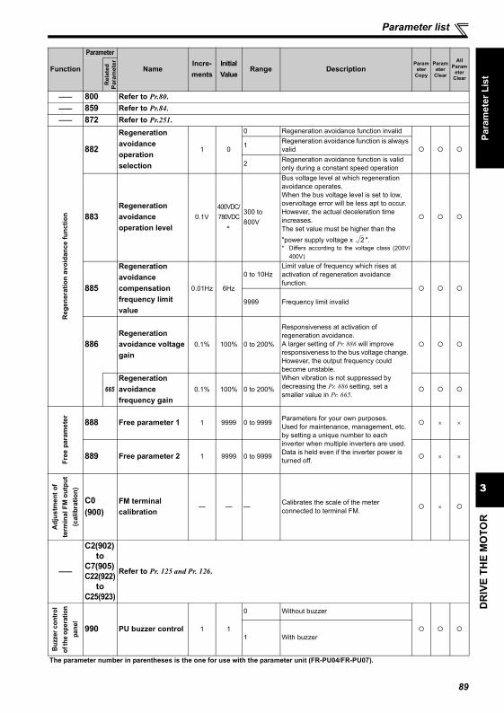
DR
IVE
THE
MO
TOR
3
Parameter list
Para
met
er L
ist
—— 800 Refer to Pr.80.—— 859 Refer to Pr.84.—— 872 Refer to Pr.251.
Reg
ener
atio
n av
oida
nce
func
tion
882
Regeneration avoidance operation selection
1 0
0 Regeneration avoidance function invalid
1 Regeneration avoidance function is always valid
2 Regeneration avoidance function is valid only during a constant speed operation
883Regeneration avoidance operation level
0.1V400VDC/780VDC
∗
300 to 800V
Bus voltage level at which regeneration avoidance operates. When the bus voltage level is set to low, overvoltage error will be less apt to occur. However, the actual deceleration time increases.The set value must be higher than the "power supply voltage x ".* Differs according to the voltage class (200V/
400V)
885
Regeneration avoidance compensation frequency limit value
0.01Hz 6Hz
0 to 10HzLimit value of frequency which rises at activation of regeneration avoidance function.
9999 Frequency limit invalid
886Regeneration avoidance voltage gain
0.1% 100% 0 to 200%
Responsiveness at activation of regeneration avoidance. A larger setting of Pr. 886 will improve responsiveness to the bus voltage change. However, the output frequency could become unstable.When vibration is not suppressed by decreasing the Pr. 886 setting, set a smaller value in Pr. 665.
665Regeneration avoidance frequency gain
0.1% 100% 0 to 200%
Free
par
amet
er 888 Free parameter 1 1 9999 0 to 9999 Parameters for your own purposes.Used for maintenance, management, etc. by setting a unique number to each inverter when multiple inverters are used.Data is held even if the inverter power is turned off.
× ×
889 Free parameter 2 1 9999 0 to 9999 × ×
Adj
ustm
ent o
f te
rmin
al F
M o
utpu
t (c
alib
ratio
n)
C0(900)
FM terminal calibration
— — — Calibrates the scale of the meter connected to terminal FM. ×
——
C2(902)to
C7(905)C22(922)
toC25(923)
Refer to Pr. 125 and Pr. 126.
Buzz
er c
ontro
l of
the
oper
atio
n pa
nel
990 PU buzzer control 1 1
0 Without buzzer
1 With buzzer
The parameter number in parentheses is the one for use with the parameter unit (FR-PU04/FR-PU07).
Function
Parameter
NameIncre-ments
Initial Value
Range DescriptionParam
eter Copy
Parameter
Clear
All Param
eter Clear
Rel
ated
Para
met
er
2
89
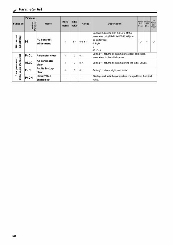
Parameter list
PU c
ontr
ast
adju
stm
ent
991 PU contrast adjustment
1 58 0 to 63
Contrast adjustment of the LCD of the parameter unit (FR-PU04/FR-PU07) can be performed.0: Light↓63: Dark
×
Cle
ar p
aram
eter
, in
itial
val
ue c
hang
e lis
t Pr.CL Parameter clear 1 0 0, 1Setting "1" returns all parameters except calibration parameters to the initial values.
ALLC All parameter clear
1 0 0, 1 Setting "1" returns all parameters to the initial values.
Er.CL Faults history clear
1 0 0, 1 Setting "1" clears eight past faults.
Pr.CH Initial value change list
— — —Displays and sets the parameters changed from the initial value.
Function
Parameter
NameIncre-ments
Initial Value
Range DescriptionParam
eter Copy
Parameter
Clear
All Param
eter Clear
Rel
ated
Para
met
er
90
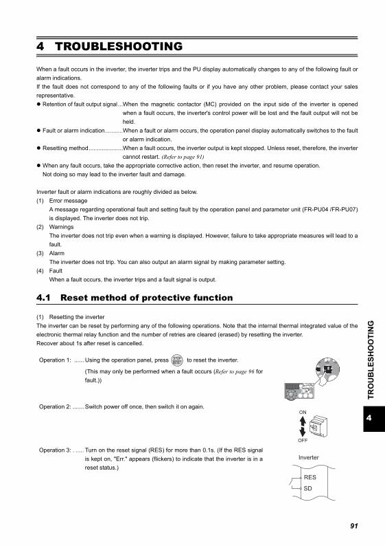
4
TRO
UB
LESH
OO
TIN
G
Reset method of protective function
4 TROUBLESHOOTING
When a fault occurs in the inverter, the inverter trips and the PU display automatically changes to any of the following fault oralarm indications.If the fault does not correspond to any of the following faults or if you have any other problem, please contact your salesrepresentative.
Retention of fault output signal ...When the magnetic contactor (MC) provided on the input side of the inverter is openedwhen a fault occurs, the inverter's control power will be lost and the fault output will not beheld.
Fault or alarm indication...........When a fault or alarm occurs, the operation panel display automatically switches to the faultor alarm indication.
Resetting method.....................When a fault occurs, the inverter output is kept stopped. Unless reset, therefore, the invertercannot restart. (Refer to page 91)
When any fault occurs, take the appropriate corrective action, then reset the inverter, and resume operation.Not doing so may lead to the inverter fault and damage.
Inverter fault or alarm indications are roughly divided as below.(1) Error message
A message regarding operational fault and setting fault by the operation panel and parameter unit (FR-PU04 /FR-PU07)is displayed. The inverter does not trip.
(2) WarningsThe inverter does not trip even when a warning is displayed. However, failure to take appropriate measures will lead to afault.
(3) AlarmThe inverter does not trip. You can also output an alarm signal by making parameter setting.
(4) FaultWhen a fault occurs, the inverter trips and a fault signal is output.
4.1 Reset method of protective function
(1) Resetting the inverterThe inverter can be reset by performing any of the following operations. Note that the internal thermal integrated value of theelectronic thermal relay function and the number of retries are cleared (erased) by resetting the inverter.Recover about 1s after reset is cancelled.
Operation 1: ...... Using the operation panel, press to reset the inverter.
(This may only be performed when a fault occurs (Refer to page 96 forfault.))
Operation 2: ....... Switch power off once, then switch it on again.
Operation 3: . ..... Turn on the reset signal (RES) for more than 0.1s. (If the RES signalis kept on, "Err." appears (flickers) to indicate that the inverter is in areset status.)
ON
OFF
SD
Inverter
RES
91
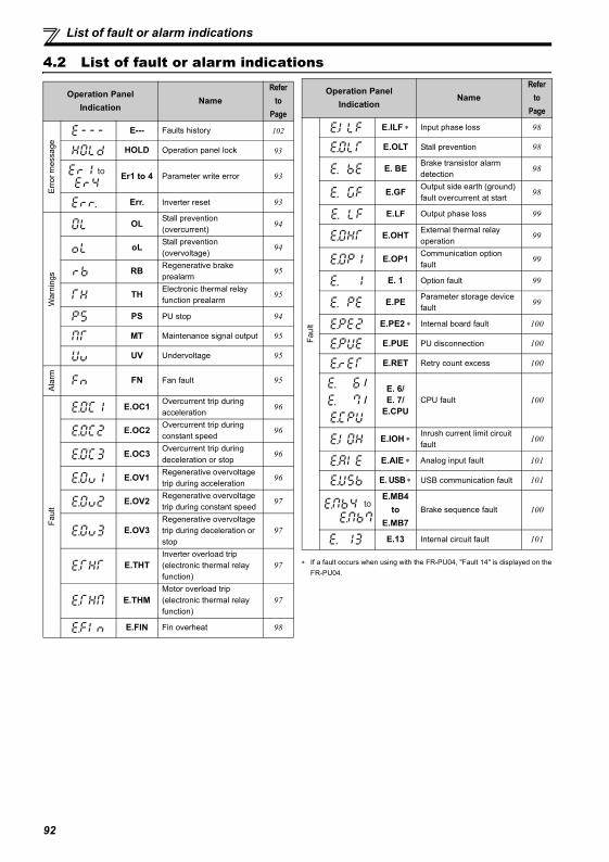
List of fault or alarm indications
4.2 List of fault or alarm indications
∗ If a fault occurs when using with the FR-PU04, "Fault 14" is displayed on theFR-PU04.
Operation Panel Indication
NameRefer
to Page
Erro
r mes
sage
E--- Faults history 102
HOLD Operation panel lock 93
Er1 to 4 Parameter write error 93
Err. Inverter reset 93
War
ning
s
OL Stall prevention (overcurrent)
94
oL Stall prevention (overvoltage)
94
RB Regenerative brake prealarm
95
TH Electronic thermal relay function prealarm
95
PS PU stop 94
MT Maintenance signal output 95
UV Undervoltage 95
Ala
rm FN Fan fault 95
Faul
t
E.OC1 Overcurrent trip during acceleration
96
E.OC2 Overcurrent trip during constant speed
96
E.OC3 Overcurrent trip during deceleration or stop
96
E.OV1 Regenerative overvoltage trip during acceleration
96
E.OV2 Regenerative overvoltage trip during constant speed
97
E.OV3Regenerative overvoltage trip during deceleration or stop
97
E.THTInverter overload trip (electronic thermal relay function)
97
E.THMMotor overload trip (electronic thermal relay function)
97
E.FIN Fin overheat 98
to
Faul
t
E.ILF ∗ Input phase loss 98
E.OLT Stall prevention 98
E. BE Brake transistor alarm detection
98
E.GF Output side earth (ground) fault overcurrent at start
98
E.LF Output phase loss 99
E.OHT External thermal relay operation
99
E.OP1 Communication option fault
99
E. 1 Option fault 99
E.PE Parameter storage device fault
99
E.PE2 ∗ Internal board fault 100
E.PUE PU disconnection 100
E.RET Retry count excess 100
/ /
E. 6/E. 7/
E.CPUCPU fault 100
E.IOH ∗Inrush current limit circuit fault
100
E.AIE ∗ Analog input fault 101
E. USB ∗ USB communication fault 101
E.MB4 to
E.MB7Brake sequence fault 100
E.13 Internal circuit fault 101
Operation Panel Indication
NameRefer
to Page
to
92
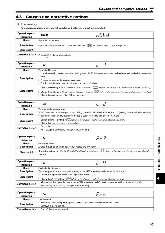
4
TRO
UB
LESH
OO
TIN
G
Causes and corrective actions
4.3 Causes and corrective actions
(1) Error messageA message regarding operational troubles is displayed. Output is not shutoff.
Operation panel indication
HOLD
Name Operation panel lock
Description Operation lock mode is set. Operation other than is made invalid. (Refer to page 31)
Check point --------------
Corrective action Press for 2s to release lock.
Operation panel indication
Er1
Name Write disable error
Description
1. You attempted to make parameter setting when Pr. 77 Parameter write selection has been set to disable parameter write.
2. Frequency jump setting range overlapped.3. The PU and inverter cannot make normal communication.
Check point1. Check the setting of Pr. 77 Parameter write selection. ( Refer to the chapter 4 of the Instruction Manual (applied)).
2. Check the settings of Pr. 31 to Pr. 36 (frequency jump). ( Refer to the chapter 4 of the Instruction Manual (applied))3. Check the connection of the PU and inverter.
Operation panel indication
Er2
Name Write error during operation
DescriptionWhen parameter write was performed during operation with a value other than "2" (writing is enabled independently of operation status in any operation mode) is set in Pr. 77 and the STF (STR) is on.
Check point 1. Check the Pr. 77 setting. ( Refer to the chapter 4 of the Instruction Manual (applied)).2. Check that the inverter is not operating.
Corrective action1. Set "2" in Pr. 77.2. After stopping operation, make parameter setting.
Operation panel indication
Er3
Name Calibration errorDescription Analog input bias and gain calibration values are too close.
Check point Check the settings of C3, C4, C6 and C7 (calibration functions). ( Refer to the chapter 4 of the Instruction Manual (applied)).
Operation panel indication
Er4
Name Mode designation errorDescription You attempted to make parameter setting in the NET operation mode when Pr. 77 is not 2.
Check point1. Check that operation mode is PU operation mode.
2. Check the Pr. 77 setting. ( Refer to the chapter 4 of the Instruction Manual (applied)).
Corrective action1. After setting the operation mode to the "PU operation mode", make parameter setting. (Refer to page 42)2. After setting "2" in Pr. 77, make parameter setting.
Operation panel indication
Err.
Name Inverter reset
DescriptionExecuting reset using RES signal, or reset command from communication or PUDisplays at powering off.
Corrective action Turn off the reset command
93
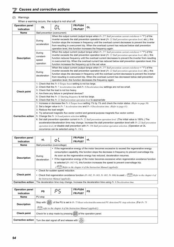
Causes and corrective actions
(2) WarningsWhen a warning occurs, the output is not shut off.
Operation panel indication
OLFR-PU04FR-PU07
OL
Name Stall prevention (overcurrent)
Description
During acceleration
When the output current (output torque when Pr. 277 Stall prevention current switchover = "1") of the inverter exceeds the stall prevention operation level (Pr. 22 Stall prevention operation level, etc.), this function stops the increase in frequency until the overload current decreases to prevent the inverter from resulting in overcurrent trip. When the overload current has reduced below stall prevention operation level, this function increases the frequency again.
During constant-speed operation
When the output current (output torque when Pr. 277 Stall prevention current switchover = "1") of the inverter exceeds the stall prevention operation level (Pr. 22 Stall prevention operation level, etc.), this function reduces frequency until the overload current decreases to prevent the inverter from resulting in overcurrent trip. When the overload current has reduced below stall prevention operation level, this function increases the frequency up to the set value.
During deceleration
When the output current (output torque when Pr. 277 Stall prevention current switchover = "1") of the inverter exceeds the stall prevention operation level (Pr. 22 Stall prevention operation level, etc.), this function stops the decrease in frequency until the overload current decreases to prevent the inverter from resulting in overcurrent trip. When the overload current has decreased below stall prevention operation level, this function decreases the frequency again.
Check point
1. Check that the Pr. 0 Torque boost setting is not too large.2. Check that the Pr. 7 Acceleration time and Pr. 8 Deceleration time settings are not too small.3. Check that the load is not too heavy.4. Are there any failure in peripheral devices?5. Check that the Pr. 13 Starting frequency is not too large.6. Check that the Pr. 22 Stall prevention operation level is appropriate
Corrective action
1. Increase or decrease the Pr. 0 Torque boost setting 1% by 1% and check the motor status. (Refer to page 39)2. Set a larger value in Pr. 7 Acceleration time and Pr. 8 Deceleration time. (Refer to page 41)3. Reduce the load weight.4. Try advanced magnetic flux vector control and general-purpose magnetic flux vector control.5. Change the Pr. 14 Load pattern selection setting.6. Set stall prevention operation current in Pr. 22 Stall prevention operation level. (The initial value is 150%.) The
acceleration/deceleration time may change. Increase the stall prevention operation level with Pr. 22 Stall prevention operation level, or disable stall prevention with Pr. 156 Stall prevention operation selection. (Operation at OL occurrence can be selected using Pr. 156.)
Operation panel indication
oLFR-PU04FR-PU07
oL
Name Stall prevention (overvoltage)
DescriptionDuring deceleration
If the regenerative energy of the motor becomes excessive to exceed the regenerative energy consumption capability, this function stops the decrease in frequency to prevent overvoltage trip. As soon as the regenerative energy has reduced, deceleration resumes.If the regenerative energy of the motor becomes excessive when regeneration avoidance function is selected (Pr. 882 =1), this function increases the speed to prevent overvoltage trip.
( Refer to the chapter 4 of the Instruction Manual (applied)).
Check pointCheck for sudden speed reduction.
Check that regeneration avoidance function (Pr. 882, Pr. 883, Pr. 885, Pr. 886) is used. ( Refer to the chapter 4 of the Instruction Manual (applied)).
Corrective action The deceleration time may change. Increase the deceleration time using Pr. 8 Deceleration time.
Operation panel indication
PSFR-PU04FR-PU07
PS
Name PU stop
DescriptionStop with of the PU is set in Pr. 75 Reset selection/disconnected PU detection/PU stop selection. (For Pr. 75
refer to the chapter 4 of the Instruction Manual (applied).)
Check point Check for a stop made by pressing of the operation panel.
Corrective action Turn the start signal off and release with .
94
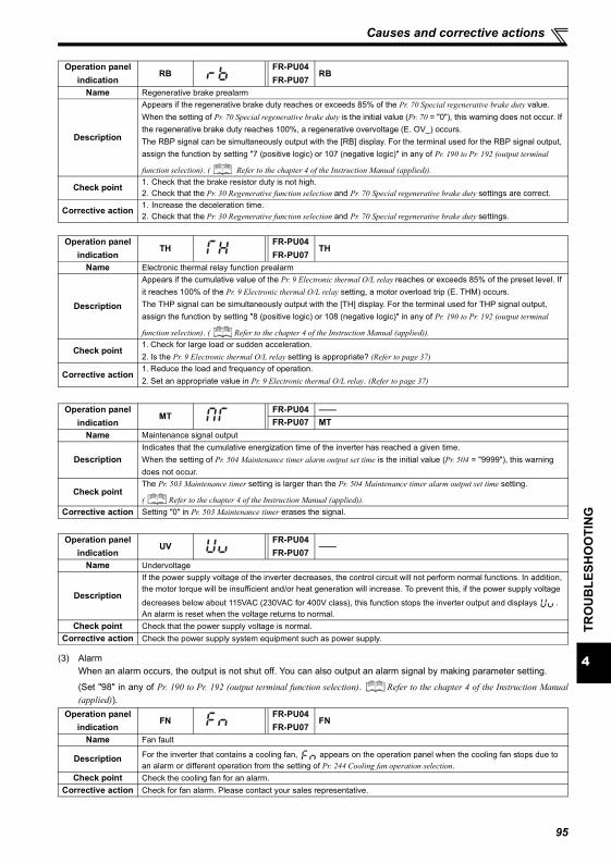
4
TRO
UB
LESH
OO
TIN
G
Causes and corrective actions
(3) AlarmWhen an alarm occurs, the output is not shut off. You can also output an alarm signal by making parameter setting.
(Set "98" in any of Pr. 190 to Pr. 192 (output terminal function selection). Refer to the chapter 4 of the Instruction Manual(applied)).
Operation panel indication
RBFR-PU04FR-PU07
RB
Name Regenerative brake prealarm
Description
Appears if the regenerative brake duty reaches or exceeds 85% of the Pr. 70 Special regenerative brake duty value. When the setting of Pr. 70 Special regenerative brake duty is the initial value (Pr. 70 = "0"), this warning does not occur. If the regenerative brake duty reaches 100%, a regenerative overvoltage (E. OV_) occurs.The RBP signal can be simultaneously output with the [RB] display. For the terminal used for the RBP signal output, assign the function by setting "7 (positive logic) or 107 (negative logic)" in any of Pr. 190 to Pr. 192 (output terminal
function selection). ( Refer to the chapter 4 of the Instruction Manual (applied)).
Check point 1. Check that the brake resistor duty is not high.2. Check that the Pr. 30 Regenerative function selection and Pr. 70 Special regenerative brake duty settings are correct.
Corrective action 1. Increase the deceleration time.2. Check that the Pr. 30 Regenerative function selection and Pr. 70 Special regenerative brake duty settings.
Operation panel indication
THFR-PU04FR-PU07
TH
Name Electronic thermal relay function prealarm
Description
Appears if the cumulative value of the Pr. 9 Electronic thermal O/L relay reaches or exceeds 85% of the preset level. If it reaches 100% of the Pr. 9 Electronic thermal O/L relay setting, a motor overload trip (E. THM) occurs.The THP signal can be simultaneously output with the [TH] display. For the terminal used for THP signal output, assign the function by setting "8 (positive logic) or 108 (negative logic)" in any of Pr. 190 to Pr. 192 (output terminal
function selection). ( Refer to the chapter 4 of the Instruction Manual (applied)).
Check point1. Check for large load or sudden acceleration.2. Is the Pr. 9 Electronic thermal O/L relay setting is appropriate? (Refer to page 37)
Corrective action1. Reduce the load and frequency of operation.2. Set an appropriate value in Pr. 9 Electronic thermal O/L relay. (Refer to page 37)
Operation panel indication
MTFR-PU04 ——FR-PU07 MT
Name Maintenance signal output
DescriptionIndicates that the cumulative energization time of the inverter has reached a given time.When the setting of Pr. 504 Maintenance timer alarm output set time is the initial value (Pr. 504 = "9999"), this warning does not occur.
Check pointThe Pr. 503 Maintenance timer setting is larger than the Pr. 504 Maintenance timer alarm output set time setting.
( Refer to the chapter 4 of the Instruction Manual (applied)).Corrective action Setting "0" in Pr. 503 Maintenance timer erases the signal.
Operation panel indication
UVFR-PU04FR-PU07
——
Name Undervoltage
Description
If the power supply voltage of the inverter decreases, the control circuit will not perform normal functions. In addition, the motor torque will be insufficient and/or heat generation will increase. To prevent this, if the power supply voltage
decreases below about 115VAC (230VAC for 400V class), this function stops the inverter output and displays .An alarm is reset when the voltage returns to normal.
Check point Check that the power supply voltage is normal.Corrective action Check the power supply system equipment such as power supply.
Operation panel indication
FNFR-PU04FR-PU07
FN
Name Fan fault
Description For the inverter that contains a cooling fan, appears on the operation panel when the cooling fan stops due to an alarm or different operation from the setting of Pr. 244 Cooling fan operation selection.
Check point Check the cooling fan for an alarm.Corrective action Check for fan alarm. Please contact your sales representative.
95
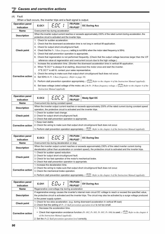
Causes and corrective actions
(4) FaultWhen a fault occurs, the inverter trips and a fault signal is output.
Operation panel indication
E.OC1FR-PU04FR-PU07
OC During Acc
Name Overcurrent trip during acceleration
Description When the inverter output current reaches or exceeds approximately 230% of the rated current during acceleration, the protective circuit is activated and the inverter trips.
Check point
1. Check for sudden acceleration.2. Check that the downward acceleration time is not long in vertical lift application.3. Check for output short-circuit/ground fault.4. Check that the Pr. 3 Base frequency setting is not 60Hz when the motor rated frequency is 50Hz.5. Check that stall prevention operation is appropriate.6. Check that regeneration is not performed frequently. (Check that the output voltage becomes larger than the V/F
reference value at regeneration and overcurrent occurs due to the high voltage.)
Corrective action
1. Increase the acceleration time. (Shorten the downward acceleration time in vertical lift application.2. When "E.OC1" is always lit at starting, disconnect the motor once and start the inverter.
If "E.OC1" is still lit, contact your sales representative.3. Check the wiring to make sure that output short circuit/ground fault does not occur.4. Set 50Hz in Pr. 3 Base frequency. (Refer to page 38)
5. Perform stall prevention operation appropriately. ( Refer to the chapter 4 of the Instruction Manual (applied)).
6. Set base voltage (rated voltage of the motor, etc.) in Pr. 19 Base frequency voltage. ( Refer to the chapter 4 of theInstruction Manual (applied))
Operation panel indication
E.OC2FR-PU04FR-PU07
Stedy Spd OC
Name Overcurrent trip during constant speed
Description When the inverter output current reaches or exceeds approximately 230% of the rated current during constant speed operation, the protective circuit is activated and the inverter trips.
Check point1. Check for sudden load change.2. Check for output short-circuit/ground fault.3. Check that stall prevention operation is appropriate.
Corrective action1. Keep load stable.2. Check the wiring to make sure that output short circuit/ground fault does not occur.
3. Perform stall prevention operation appropriately. ( Refer to the chapter 4 of the Instruction Manual (applied)).
Operation panel indication
E.OC3FR-PU04FR-PU07
OC During Dec
Name Overcurrent trip during deceleration or stop
Description When the inverter output current reaches or exceeds approximately 230% of the rated inverter current during deceleration (other than acceleration or constant speed), the protective circuit is activated and the inverter trips.
Check point
1. Check for sudden speed reduction.2. Check for output short-circuit/ground fault.3. Check for too fast operation of the motor's mechanical brake.4. Check that stall prevention operation is appropriate.
Corrective action
1. Increase the deceleration time.2. Check the wiring to make sure that output short circuit/ground fault does not occur.3. Check the mechanical brake operation.
4. Perform stall prevention operation appropriately. ( Refer to the chapter 4 of the Instruction Manual (applied)).
Operation panel indication
E.OV1FR-PU04FR-PU07
OV During Acc
Name Regenerative overvoltage trip during acceleration
DescriptionIf regenerative energy causes the inverter's internal main circuit DC voltage to reach or exceed the specified value, the protective circuit is activated and the inverter trips. The circuit may also be activated by a surge voltage produced in the power supply system.
Check point 1. Check for too slow acceleration. (e.g. during downward acceleration in vertical lift load)2. Check that the setting of Pr. 22 Stall prevention operation level is not too small.
Corrective action
1. Decrease the acceleration time.
Check that regeneration avoidance function (Pr. 882, Pr. 883, Pr. 885, Pr. 886) is used. ( Refer to the chapter 4 of the Instruction Manual (applied)).
2. Set the Pr.22 Stall prevention operation level correctly.
96
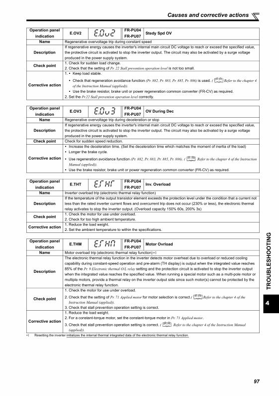
4
TRO
UB
LESH
OO
TIN
G
Causes and corrective actions
∗1 Resetting the inverter initializes the internal thermal integrated data of the electronic thermal relay function.
Operation panel indication
E.OV2FR-PU04FR-PU07
Stedy Spd OV
Name Regenerative overvoltage trip during constant speed
DescriptionIf regenerative energy causes the inverter's internal main circuit DC voltage to reach or exceed the specified value, the protective circuit is activated to stop the inverter output. The circuit may also be activated by a surge voltage produced in the power supply system.
Check point 1. Check for sudden load change.2. Check that the setting of Pr. 22 Stall prevention operation level is not too small.
Corrective action
1. Keep load stable.
Check that regeneration avoidance function (Pr. 882, Pr. 883, Pr. 885, Pr. 886) is used. ( Refer to the chapter 4 of the Instruction Manual (applied)).Use the brake resistor, brake unit or power regeneration common converter (FR-CV) as required.
2. Set the Pr.22 Stall prevention operation level correctly.
Operation panel indication
E.OV3FR-PU04FR-PU07
OV During Dec
Name Regenerative overvoltage trip during deceleration or stop
DescriptionIf regenerative energy causes the inverter's internal main circuit DC voltage to reach or exceed the specified value, the protective circuit is activated to stop the inverter output. The circuit may also be activated by a surge voltage produced in the power supply system.
Check point Check for sudden speed reduction.
Corrective action
Increase the deceleration time. (Set the deceleration time which matches the moment of inertia of the load)Longer the brake cycle.
Use regeneration avoidance function (Pr. 882, Pr. 883, Pr. 885, Pr. 886). ( Refer to the chapter 4 of the Instruction Manual (applied)).Use the brake resistor, brake unit or power regeneration common converter (FR-CV) as required.
Operation panel indication
E.THTFR-PU04FR-PU07
Inv. Overload
Name Inverter overload trip (electronic thermal relay function)
DescriptionIf the temperature of the output transistor element exceeds the protection level under the condition that a current not less than the rated inverter current flows and overcurrent trip does not occur (230% or less), the electronic thermal relay activates to stop the inverter output. (Overload capacity 150% 60s, 200% 3s)
Check point 1. Check the motor for use under overload.2. Check for too high ambient temperature.
Corrective action 1. Reduce the load weight.2. Set the ambient temperature to within the specifications.
Operation panel indication
E.THMFR-PU04FR-PU07
Motor Ovrload
Name Motor overload trip (electronic thermal relay function) ∗1
Description
The electronic thermal relay function in the inverter detects motor overheat due to overload or reduced cooling capability during constant-speed operation and pre-alarm (TH display) is output when the integrated value reaches 85% of the Pr. 9 Electronic thermal O/L relay setting and the protection circuit is activated to stop the inverter output when the integrated value reaches the specified value. When running a special motor such as a multi-pole motor or multiple motors, provide a thermal relay on the inverter output side since such motor(s) cannot be protected by the electronic thermal relay function.
Check point
1. Check the motor for use under overload.
2. Check that the setting of Pr. 71 Applied motor for motor selection is correct.( Refer to the chapter 4 of the Instruction Manual (applied)).
3. Check that stall prevention operation setting is correct.
Corrective action
1. Reduce the load weight.2. For a constant-torque motor, set the constant-torque motor in Pr. 71 Applied motor.
3. Check that stall prevention operation setting is correct. ( Refer to the chapter 4 of the Instruction Manual (applied)).
97
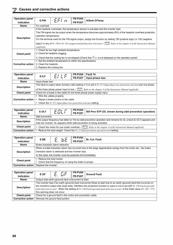
Causes and corrective actions
Operation panel indication
E.FINFR-PU04FR-PU07
H/Sink O/Temp
Name Fin overheat
Description
If the heatsink overheats, the temperature sensor is actuated and the inverter trips.The FIN signal can be output when the temperature becomes approximately 85% of the heatsink overheat protection operation temperature.For the terminal used for the FIN signal output, assign the function by setting "26 (positive logic) or 126 (negative
logic)" in any of Pr. 190 to Pr. 192 (output terminal function selection). ( Refer to the chapter 4 of the Instruction Manual (applied)).
Check point1. Check for too high ambient temperature.2. Check for heatsink clogging.
3. Check that the cooling fan is not stopped (Check that is not displayed on the operation panel).
Corrective action1. Set the ambient temperature to within the specifications.2. Clean the heatsink.3. Replace the cooling fan.
Operation panel indication
E.ILFFR-PU04 Fault 14FR-PU07 Input phase loss
Name Input phase loss
DescriptionThis fault is output when function valid setting (=1) is set in Pr. 872 Input phase loss protection selection and one phase
of the three phase power input is lost. ( Refer to the chapter 4 of the Instruction Manual (applied)).Check point Check for a break in the cable for the three-phase power supply input.
Corrective actionWire the cables properly.Repair a brake portion in the cable.Check the Pr. 872 Input phase loss protection selection setting.
Operation panel indication E.OLT FR-PU04
FR-PU07 Stll Prev STP (OL shown during stall prevention operation)
Name Stall prevention
Description If the output frequency has fallen to 1Hz by stall prevention operation and remains for 3s, a fault (E.OLT) appears and trips the inverter. OL appears while stall prevention is being activated.
Check point Check the motor for use under overload. ( Refer to the chapter 4 of the Instruction Manual (applied)).Corrective action Reduce the load weight. Check the Pr. 22 Stall prevention operation level setting.
Operation panel indication
E.BEFR-PU04FR-PU07
Br. Cct. Fault
Name Brake transistor alarm detection
DescriptionWhen a brake transistor alarm has occurred due to the large regenerative energy from the motor etc., the brake transistor alarm is detected and the inverter trips.In this case, the inverter must be powered off immediately.
Check point Reduce the load inertia.Check that the frequency of using the brake is proper.
Corrective action Replace the inverter.
Operation panel indication
E.GFFR-PU04FR-PU07
Ground Fault
Name Output side earth (ground) fault overcurrent at start
Description
The inverter trips if an earth (ground) fault overcurrent flows at start due to an earth (ground) fault that occurred on the inverter's output side (load side). Whether this protective function is used or not is set with Pr. 249 Earth (ground) fault detection at start . When the setting of Pr. 249 Earth (ground) fault detection at start is the initial value (Pr. 249 ="0"), this warning does not occur.
Check point Check for a ground fault in the motor and connection cable.Corrective action Remedy the ground fault portion.
98
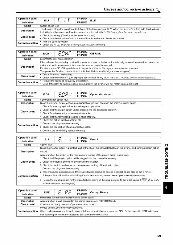
4
TRO
UB
LESH
OO
TIN
G
Causes and corrective actions
Operation panel indication
E.LFFR-PU04FR-PU07
E.LF
Name Output phase loss
Description This function stops the inverter output if one of the three phases (U, V, W) on the inverter's output side (load side) is lost. Whether the protective function is used or not is set with Pr. 251 Output phase loss protection selection.
Check point Check the wiring. (Check that the motor is normal.)Check that the capacity of the motor used is not smaller than that of the inverter.
Corrective action Wire the cables properly.Check the Pr. 251 Output phase loss protection selection settting.
Operation panel indication
E.OHT FR-PU04FR-PU07 OH Fault
Name External thermal relay operation
Description
If the external thermal relay provided for motor overheat protection or the internally mounted temperature relay in the motor, etc. switches on (contacts open), the inverter output is stopped.Functions when "7" (OH signal) is set to any of Pr. 178 to Pr. 184 (input terminal function selection).This protective function does not function in the initial status (OH signal is not assigned).
Check point Check for motor overheating.Check that the value of 7 (OH signal) is set correctly in any of Pr. 178 to Pr. 184 (input terminal function selection).
Corrective action Reduce the load and frequency of operation.Even if the relay contacts are reset automatically, the inverter will not restart unless it is reset.
Operation panel indication
E.OP1 FR-PU04FR-PU07 Option slot alarm 1
Name Communication option faultDescription Stops the inverter output when a communication line fault occurs in the communication option.
Check point
1. Check for a wrong option function setting and operation.2. Check that the plug-in option unit is plugged into the connector securely.3. Check for a break in the communication cable.4. Check that the terminating resistor is fitted properly.
Corrective action
1. Check the option function setting, etc.2. Connect the plug-in option securely.3. Check the connection of communication cable.4. Connect the terminating resistor correctly.
Operation panel indication
E. 1 FR-PU04FR-PU07 Fault 1
Name Option fault
DescriptionStops the inverter output if a contact fault or the like of the connector between the inverter and communication option occurs.Appears when the switch for the manufacturer setting of the plug-in option is changed.
Check point1. Check that the plug-in option unit is plugged into the connector securely.2. Check for excess electrical noises around the inverter.3. Check the switch position for the manufacturer setting of the plug-in option.
Corrective action
1. Connect the plug-in option securely.2. Take measures against noises if there are devices producing excess electrical noises around the inverter.
If the problem still persists after taking the above measure, please contact your sales representative.
3. Return the switch position for the manufacturer setting of the plug-in option to the initial status. ( Refer to the instruction manual of each option)
Operation panel indication
E.PEFR-PU04FR-PU07
Corrupt Memry
Name Parameter storage device fault (control circuit board)Description Appears when a fault occurred in the stored parameters. (EEPROM fault)Check point Check for too many number of parameter write times.
Corrective actionPlease contact your sales representative.When performing parameter write frequently for communication purposes, set "1" in Pr. 342 to enable RAM write. Note that powering off returns the inverter to the status before RAM write.
99
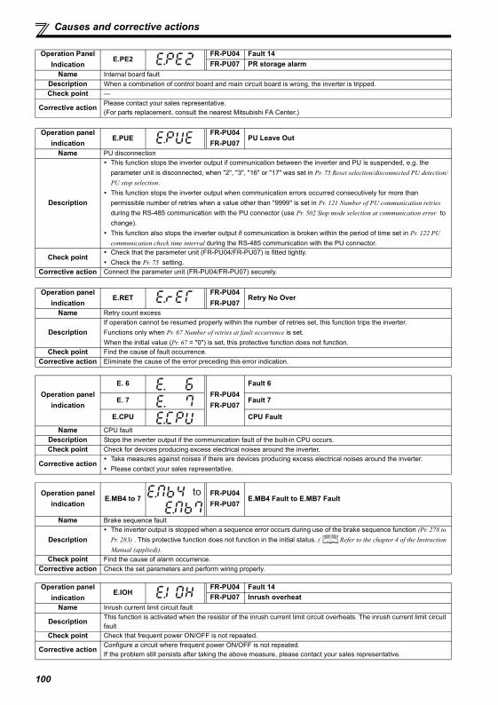
Causes and corrective actions
Operation Panel Indication
E.PE2FR-PU04 Fault 14FR-PU07 PR storage alarm
Name Internal board faultDescription When a combination of control board and main circuit board is wrong, the inverter is tripped.Check point —
Corrective action Please contact your sales representative.(For parts replacement, consult the nearest Mitsubishi FA Center.)
Operation panel indication
E.PUEFR-PU04FR-PU07
PU Leave Out
Name PU disconnection
Description
This function stops the inverter output if communication between the inverter and PU is suspended, e.g. the parameter unit is disconnected, when "2", "3", "16" or "17" was set in Pr. 75 Reset selection/disconnected PU detection/PU stop selection. This function stops the inverter output when communication errors occurred consecutively for more than permissible number of retries when a value other than "9999" is set in Pr. 121 Number of PU communication retries during the RS-485 communication with the PU connector (use Pr. 502 Stop mode selection at communication error to change).This function also stops the inverter output if communication is broken within the period of time set in Pr. 122 PU communication check time interval during the RS-485 communication with the PU connector.
Check pointCheck that the parameter unit (FR-PU04/FR-PU07) is fitted tightly.Check the Pr. 75 setting.
Corrective action Connect the parameter unit (FR-PU04/FR-PU07) securely.
Operation panel indication
E.RETFR-PU04FR-PU07
Retry No Over
Name Retry count excess
DescriptionIf operation cannot be resumed properly within the number of retries set, this function trips the inverter.Functions only when Pr. 67 Number of retries at fault occurrence is set. When the initial value (Pr. 67 = "0") is set, this protective function does not function.
Check point Find the cause of fault occurrence.Corrective action Eliminate the cause of the error preceding this error indication.
Operation panel indication
E. 6FR-PU04FR-PU07
Fault 6
E. 7 Fault 7
E.CPU CPU Fault
Name CPU faultDescription Stops the inverter output if the communication fault of the built-in CPU occurs.Check point Check for devices producing excess electrical noises around the inverter.
Corrective actionTake measures against noises if there are devices producing excess electrical noises around the inverter.Please contact your sales representative.
Operation panel indication
E.MB4 to 7FR-PU04FR-PU07
E.MB4 Fault to E.MB7 Fault
Name Brake sequence fault
DescriptionThe inverter output is stopped when a sequence error occurs during use of the brake sequence function (Pr. 278 to Pr. 283) . This protective function does not function in the initial status. ( Refer to the chapter 4 of the Instruction Manual (applied)).
Check point Find the cause of alarm occurrence.Corrective action Check the set parameters and perform wiring properly.
Operation panel indication
E.IOHFR-PU04 Fault 14FR-PU07 Inrush overheat
Name Inrush current limit circuit fault
Description This function is activated when the resistor of the inrush current limit circuit overheats. The inrush current limit circuit fault
Check point Check that frequent power ON/OFF is not repeated.
Corrective action Configure a circuit where frequent power ON/OFF is not repeated.If the problem still persists after taking the above measure, please contact your sales representative.
to
100
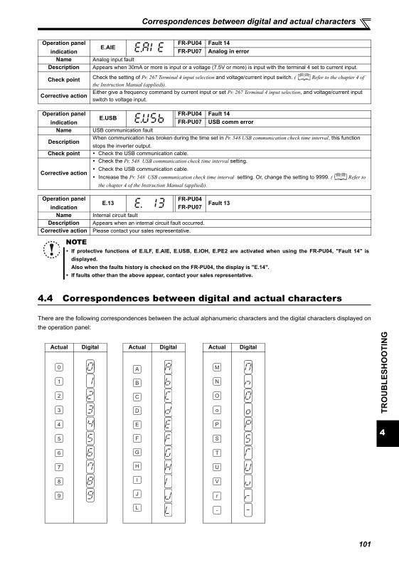
4
TRO
UB
LESH
OO
TIN
G
Correspondences between digital and actual characters
4.4 Correspondences between digital and actual characters
There are the following correspondences between the actual alphanumeric characters and the digital characters displayed onthe operation panel:
Operation panel indication
E.AIEFR-PU04 Fault 14FR-PU07 Analog in error
Name Analog input faultDescription Appears when 30mA or more is input or a voltage (7.5V or more) is input with the terminal 4 set to current input.
Check point Check the setting of Pr. 267 Terminal 4 input selection and voltage/current input switch. ( Refer to the chapter 4 of the Instruction Manual (applied)).
Corrective action Either give a frequency command by current input or set Pr. 267 Terminal 4 input selection, and voltage/current input switch to voltage input.
Operation panel indication
E.USBFR-PU04 Fault 14FR-PU07 USB comm error
Name USB communication fault
DescriptionWhen communication has broken during the time set in Pr. 548 USB communication check time interval, this function stops the inverter output.
Check point Check the USB communication cable.
Corrective action
Check the Pr. 548 USB communication check time interval setting.Check the USB communication cable.Increase the Pr. 548 USB communication check time interval setting. Or, change the setting to 9999. ( Refer to the chapter 4 of the Instruction Manual (applied)).
Operation panel indication
E.13FR-PU04FR-PU07
Fault 13
Name Internal circuit faultDescription Appears when an internal circuit fault occurred.
Corrective action Please contact your sales representative.
NOTEIf protective functions of E.ILF, E.AIE, E.USB, E.IOH, E.PE2 are activated when using the FR-PU04, "Fault 14" isdisplayed.Also when the faults history is checked on the FR-PU04, the display is "E.14".If faults other than the above appear, contact your sales representative.
Actual Digital
0
1
2
3
4
5
6
7
8
9
Actual Digital
A
B
C
E
F
G
H
I
J
L
D
Actual Digital
M
N
O
o
P
T
U
V
r
-
S
101
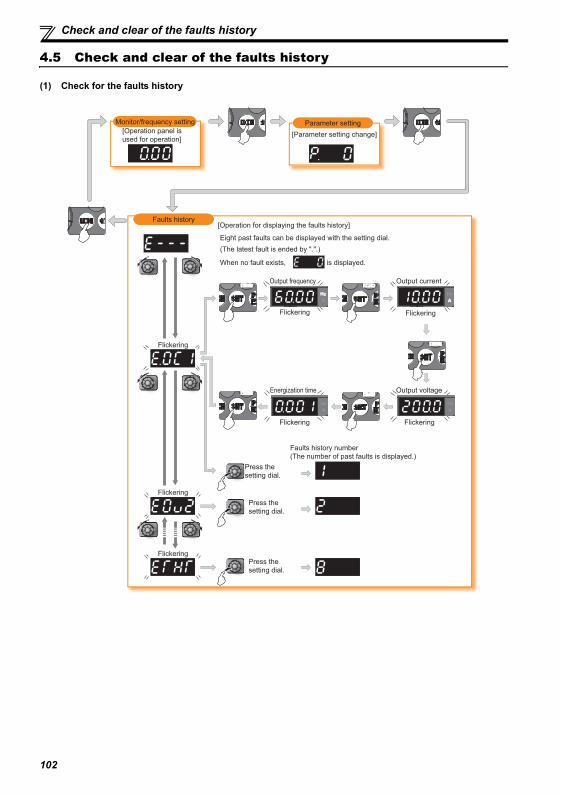
Check and clear of the faults history
4.5 Check and clear of the faults history
(1) Check for the faults history
Faults history
Monitor/frequency setting
[Operation panel is
used for operation]
Parameter setting
[Parameter setting change]
[Operation for displaying the faults history]
Eight past faults can be displayed with the setting dial.
(The latest fault is ended by ".".)
When no fault exists, i is displayed.
Flickering
Output frequency Output current
Flickering
Flickering
Flickering
Flickering
Press the
setting dial.
Press the
setting dial.
Press the
setting dial.
Faults history number
(The number of past faults is displayed.)
Hz
A
Output voltage
Flickering
Energization time
Flickering
102
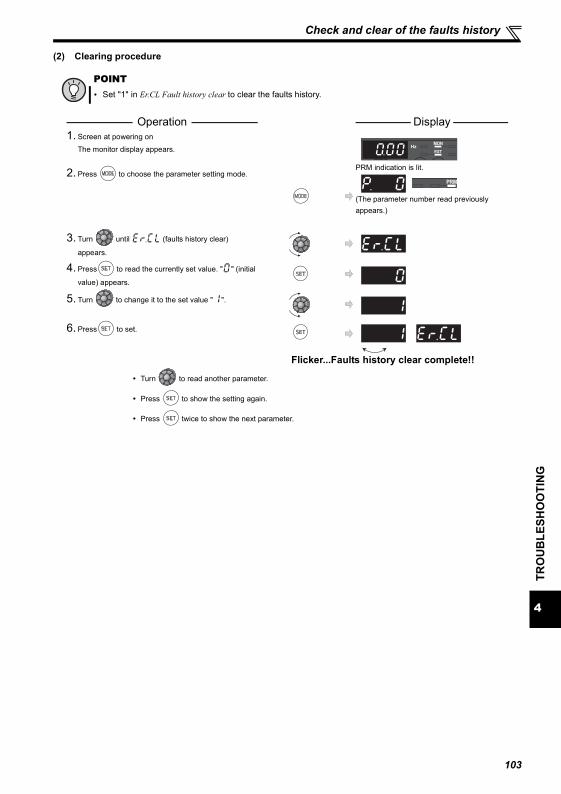
Check and clear of the faults history
4
TRO
UB
LESH
OO
TIN
G
(2) Clearing procedure
POINTSet "1" in Er.CL Fault history clear to clear the faults history.
Operation Display 1. Screen at powering on
The monitor display appears.
2. Press to choose the parameter setting mode.PRM indication is lit.
(The parameter number read previously appears.)
3. Turn until (faults history clear)
appears.
4. Press to read the currently set value. " " (initial
value) appears.
5. Turn to change it to the set value " ".
6. Press to set.
Flicker...Faults history clear complete!!
Turn to read another parameter.
Press to show the setting again.
Press twice to show the next parameter.
103
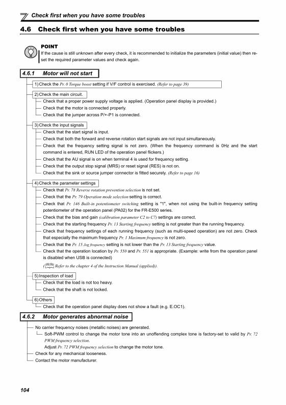
Check first when you have some troubles
4.6 Check first when you have some troubles
POINTIf the cause is still unknown after every check, it is recommended to initialize the parameters (initial value) then re-set the required parameter values and check again.
4.6.1 Motor will not start
1) Check the Pr. 0 Torque boost setting if V/F control is exercised. (Refer to page 39)
2) Check the main circuit.Check that a proper power supply voltage is applied. (Operation panel display is provided.)Check that the motor is connected properly.Check that the jumper across P/+-P1 is connected.
3) Check the input signalsCheck that the start signal is input.Check that both the forward and reverse rotation start signals are not input simultaneously.Check that the frequency setting signal is not zero. (When the frequency command is 0Hz and the startcommand is entered, RUN LED of the operation panel flickers.)Check that the AU signal is on when terminal 4 is used for frequency setting.Check that the output stop signal (MRS) or reset signal (RES) is not on.Check that the sink or source jumper connector is fitted securely. (Refer to page 16)
4) Check the parameter settingsCheck that Pr. 78 Reverse rotation prevention selection is not set.Check that the Pr. 79 Operation mode selection setting is correct.Check that Pr. 146 Built-in potentiometer switching setting is "1", when not using the built-in frequency settingpotentiometer of the operation panel (PA02) for the FR-E500 series.Check that the bias and gain (calibration parameter C2 to C7) settings are correct.Check that the starting frequency Pr. 13 Starting frequency setting is not greater than the running frequency.Check that frequency settings of each running frequency (such as multi-speed operation) are not zero. Checkthat especially the maximum frequency Pr. 1 Maximum frequency is not zero.Check that the Pr. 15 Jog frequency setting is not lower than the Pr. 13 Starting frequency value.Check that the operation location by Pr. 550 and Pr. 551 is appropriate. (Example: write from the operation panelis disabled when USB is connected)
( Refer to the chapter 4 of the Instruction Manual (applied)).
5) Inspection of loadCheck that the load is not too heavy.Check that the shaft is not locked.
6) OthersCheck that the operation panel display does not show a fault (e.g. E.OC1).
4.6.2 Motor generates abnormal noise
No carrier frequency noises (metallic noises) are generated.Soft-PWM control to change the motor tone into an unoffending complex tone is factory-set to valid by Pr. 72PWM frequency selection.Adjust Pr. 72 PWM frequency selection to change the motor tone.
Check for any mechanical looseness.Contact the motor manufacturer.
104
4
TRO
UB
LESH
OO
TIN
G
Check first when you have some troubles
4.6.3 Motor generates heat abnormally
Is the fan for the motor is running? (Check for dust accumulated.)Check that the load is not too heavy. Lighten the load.Are the inverter output voltages (U, V, W) balanced?Check that the Pr. 0 Torque boost setting is correct.Was the motor type set? Check the setting of Pr. 71 Applied motor.When using any other manufacturer's motor, perform offline auto tuning. (Refer to page 46.)
4.6.4 Motor rotates in opposite direction
Check that the phase sequence of output terminals U, V and W is correct.Check that the start signals (forward rotation, reverse rotation) are connected properly. (Refer to page 56)
Check that the Pr. 40 RUN key rotation direction selection setting is correct. ( Refer to the chapter 4 of the InstructionManual (applied)).
4.6.5 Speed greatly differs from the setting
Check that the frequency setting signal is correct. (Measure the input signal level.)Check that the Pr. 1, Pr. 2, Pr. 19, Pr. 245, calibration parameter Pr. 125, Pr. 126, C2 to C7 settings are correct.Check that the input signal lines are not affected by external noise. (use shielded cables)Check that the load is not too heavy.Check that the Pr. 31 to Pr. 36 (frequency jump) settings are correct.
4.6.6 Acceleration/deceleration is not smooth
Check that the acceleration and deceleration time settings are not too short.Check that the load is not too heavy.Check that the torque boost (Pr. 0, Pr. 46) setting is not too large to activate the stall function under V/F control.
4.6.7 Motor current is large
Check that the load is not too heavy.Check that the Pr. 0 Torque boost setting is correct.Check that the Pr. 3 Base frequency setting is correct.Check that the Pr. 19 Base frequency voltage setting is correctCheck that the Pr. 14 Load pattern selection setting is correct.
4.6.8 Speed does not increase
Check that the Pr. 1 Maximum frequency setting is correct. (If you want to run the motor at 120Hz or more, set Pr. 18
High speed maximum frequency. ( Refer to the chapter 4 of the Instruction Manual (applied)).Check that the load is not too heavy. (In agitators, etc., load may become heavier in winter.)Check that the torque boost (Pr. 0, Pr. 46) setting is not too large to activate the stall function under V/F control.Check that the brake resistor is not connected to terminals P/+-P1 or P1-PR accidentally.
105
Check first when you have some troubles
4.6.9 Speed varies during operation
When slip compensation is set under general-purpose magnetic flux vector control, or advanced magnetic flux vectorcontrol is exercised, the output frequency varies with load fluctuation between 0 and 2Hz. This is a normal operationand is not a fault.
1) Inspection of loadCheck that the load is not varying.
2) Check the input signalsCheck that the frequency setting signal is not varying.Check that the frequency setting signal is not affected by noise. Set filter to the analog input terminal using Pr. 74Input filter time constant.Check for a malfunction due to undesirable currents when the transistor output unit is connected. (Refer to page17)
3) OthersCheck that the value of Pr. 80 Motor capacity and Pr. 81 Number of motor poles are correct to the inverter capacity andmotor capacity under advanced magnetic flux vector control and general-purpose magnetic flux vector control.Check that the wiring length is not exceeding 30m when advanced magnetic flux vector control or general-
purpose magnetic flux vector control is exercised. Perform offline auto tuning. ( Refer to the chapter 4 of theCheck that the wiring length is not too long for V/F control.Change the Pr. 19 Base frequency voltage setting (about 3%) under V/F control.
4.6.10 Operation mode is not changed properly
If the operation mode does not change correctly, check the following:
1) External input signal Check that the STF or STR signal is off. When it is on, the operation mode cannot bechanged.
2) Parameter settingCheck the Pr. 79 setting.
When the Pr. 79 Operation mode selection setting is "0" (initial value), the inverter is placed in the external
operation mode at input power-on. At this time, press on the operation panel (press when the
parameter unit (FR-PU04/FR-PU07) is used) to switch to the PU operation mode. For other values (1 to 4, 6, 7),the operation mode is limited accordingly.
Check that the operation location by Pr. 550 and Pr. 551 is correct. (Example: write from the operation panel isdisabled when USB is connected)
( Refer to the chapter 4 of the Instruction Manual (applied)).
4.6.11 Operation panel display is not operating
Check that wiring is securely performed and installation is correct.Make sure that the connector is fitted securely across terminals P-P1.
4.6.12 Parameter write cannot be performed
Make sure that operation is not being performed (signal STF or STR is not ON).Make sure that you are not attempting to set the parameter in the external operation mode.Check Pr. 77 Parameter write selection.Check Pr. 161 Frequency setting/key lock operation selection.Check that the operation location by Pr. 550 and Pr. 551 is correct. (Example: write from the operation panel isdisabled when USB is connected)
( Refer to the chapter 4 of the Instruction Manual (applied)).
106
5
PREC
AU
TIO
NS
FOR
MA
INTE
NA
NC
E A
ND
INSP
ECTI
ON
Inspection items
5 PRECAUTIONS FOR MAINTENANCE AND INSPECTION
The inverter is a static unit mainly consisting of semiconductor devices. Daily inspection must be performed to prevent anyfault from occurring due to the adverse effects of the operating environment, such as temperature, humidity, dust, dirt andvibration, changes in the parts with time, service life, and other factors.
Precautions for maintenance and inspectionFor some short time after the power is switched off, a high voltage remains in the smoothing capacitor. When accessing theinverter for inspection, wait for at least 10 minutes after the power supply has been switched off, and then make sure that thevoltage across the main circuit terminals P/+-N/- of the inverter is not more than 30VDC using a tester, etc.
5.1 Inspection items
5.1.1 Daily inspection
Basically, check for the following faults during operation.(1) Motor operation fault(2) Improper installation environment(3) Cooling system fault(4) Abnormal vibration, abnormal noise(5) Abnormal overheat, discolorationDuring operation, check the inverter input voltages using a tester.
5.1.2 Periodic inspection
Check the areas inaccessible during operation and requiring periodic inspection.Consult us for periodic inspection.(1) Check for cooling system fault. .......... Clean the air filter, etc.(2) Tightening check and retightening ..... The screws and bolts may become loose due to vibration, temperature changes,
etc. Check and tighten them.Tighten them according to the specified tightening torque (Refer to page 10, 18).
(3) Check the conductors and insulating materials for corrosion and damage.(4) Measure insulation resistance.(5) Check and change the cooling fan and relay.
107
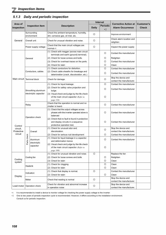
Inspection items
5.1.3 Daily and periodic inspection
∗1 It is recommended to install a device to monitor voltage for checking the power supply voltage to the inverter.∗2 One to two years of periodic inspection cycle is recommended. However, it differs according to the installation environment.
Consult us for periodic inspection.
Area of Inspection
Inspection Item DescriptionInterval
Corrective Action at Alarm Occurrence
Customer's CheckDaily
Periodic ∗2
General
Surrounding environment
Check the ambient temperature, humidity, dirt, corrosive gas, oil mist, etc.
Improve environment
Overall unit Check for unusual vibration and noise.Check alarm location and retighten
Power supply voltageCheck that the main circuit voltages are normal.∗1
Inspect the power supply
Main circuit
General
(1) Check with megger (across main circuit terminals and earth (ground) terminal).
Contact the manufacturer
(2) Check for loose screws and bolts. Retighten
(3) Check for overheat traces on the parts. Contact the manufacturer
(4) Check for stain Clean
Conductors, cables(1) Check conductors for distortion.(2) Check cable sheaths for breakage and
deterioration (crack, discoloration, etc.)
Contact the manufacturer
Contact the manufacturer
Terminal block Check for damage.Stop the device and contact the manufacturer.
Smoothing aluminum electrolytic capacitor
(1) Check for liquid leakage. Contact the manufacturer(2) Check for safety valve projection and
bulge.Contact the manufacturer
(3) Visual check and judge by the life check of the main circuit capacitor (Refer to page 110)
RelayCheck that the operation is normal and no chatter is heard.
Contact the manufacturer
Control circuit,
Protective circuit
Operation check
(1) Check that the output voltages across phases with the inverter operated alone is balanced
Contact the manufacturer
(2) Check that no fault is found in protective and display circuits in a sequence protective operation test.
Contact the manufacturer
Par
ts c
heck
Overall(1) Check for unusual odor and
discoloration.Stop the device and contact the manufacturer.
(2) Check for serious rust development Contact the manufacturer
Aluminum electrolytic capacitor
(1) Check for liquid leakage in a capacitor and deformation trance
Contact the manufacturer
(2) Visual check and judge by the life check of the main circuit capacitor (Refer to page 109)
Cooling system
Cooling fan
(1) Check for unusual vibration and noise. Replace the fan
(2) Check for loose screws and bolts Retighten
(3) Check for stain Clean
Heatsink(1) Check for clogging Clean
(2) Check for stain Clean
DisplayIndication
(1) Check that display is normal. Contact the manufacturer
(2) Check for stain Clean
Meter Check that reading is normalStop the device and contact the manufacturer.
Load motor Operation checkCheck for vibration and abnormal increase in operation noise
Stop the device and contact the manufacturer.
108
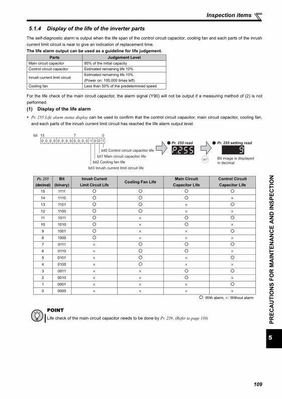
5
PREC
AU
TIO
NS
FOR
MA
INTE
NA
NC
E A
ND
INSP
ECTI
ON
Inspection items
5.1.4 Display of the life of the inverter partsThe self-diagnostic alarm is output when the life span of the control circuit capacitor, cooling fan and each parts of the inrushcurrent limit circuit is near to give an indication of replacement time.The life alarm output can be used as a guideline for life judgement.
For the life check of the main circuit capacitor, the alarm signal (Y90) will not be output if a measuring method of (2) is notperformed.(1) Display of the life alarm
Pr. 255 Life alarm status display can be used to confirm that the control circuit capacitor, main circuit capacitor, cooling fan,and each parts of the inrush current limit circuit has reached the life alarm output level.
Parts Judgement LevelMain circuit capacitor 85% of the initial capacityControl circuit capacitor Estimated remaining life 10%
Inrush current limit circuitEstimated remaining life 10% (Power on: 100,000 times left)
Cooling fan Less than 50% of the predetermined speed
Pr. 255(decimal)
Bit(binary)
Inrush CurrentLimit Circuit Life
Cooling Fan LifeMain Circuit
Capacitor LifeControl Circuit Capacitor Life
15 1111
14 1110 ×13 1101 ×12 1100 × ×11 1011 ×10 1010 × ×9 1001 × ×8 1000 × × ×7 0111 ×6 0110 × ×5 0101 × ×4 0100 × × ×3 0011 × ×2 0010 × × ×1 0001 × × ×0 0000 × × × ×
: With alarm, ×: Without alarm
POINTLife check of the main circuit capacitor needs to be done by Pr. 259. (Refer to page 110)
0 0 0 0 0 0 0 0 0 0 0 0 1 0 0
bit0 Control circuit capacitor life
1
15bit 7 0
bit1 Main circuit capacitor life
bit2 Cooling fan life
bit3 Inrush current limit circuit life
Pr. 255 read Pr. 255 setting read
Bit image is displayed
in decimal
109
Inspection items
(2) Measuring method of life of the main circuit capacitorIf the value of capacitor capacity measured before shipment is considered as 100%, Pr. 255 bit1 is turned on when themeasured value falls below 85%.Measure the capacitor capacity according to the following procedure and check the deterioration level of the capacitorcapacity.
1) Check that the motor is connected and at a stop.2) Set "1" (measuring start) in Pr. 259.3) Switch power off. The inverter applies DC voltage to the motor to measure the capacitor capacity while the inverter is
off.4) After confirming that the LED of the operation panel is off, power on again.5) Check that "3" (measuring completion) is set in Pr. 259 then read Pr. 258 and check the life of the main circuit
capacitor.
5.1.5 CleaningAlways run the inverter in a clean status.When cleaning the inverter, gently wipe dirty areas with a soft cloth immersed in neutral detergent or ethanol.
REMARKSWhen the main circuit capacitor life is measured under the following conditions, "forced end" (Pr. 259 = "8") or "measuring error"(Pr. 259 = "9") occurs or it remains in "measuring start" (Pr. 259 = "1"). Therefore, do not measure in such case. In addition, evenwhen "measurement completion" (Pr. 259 = "3") is confirmed under the following conditions, normal measurement can not bedone.
(a)FR-HC, FR-CV, or FR-BU2 is connected.(b)DC power supply is connected to terminal P/+ and N/-.(c)Switch power on during measuring.(d)The motor is not connected to the inverter.(e)The motor is running (coasting).(f)The motor capacity is two rank smaller as compared to the inverter capacity.(g)The inverter is at an alarm stop or an alarm occurred while power is off.(h)The inverter output is shut off with the MRS signal.(i)The start command is given while measuring.(j)The parameter unit (FR-PU04/FR-PU07) is connected.(k)Using terminal PC as power supply.(l) I/O terminal of the control terminal block and plug-in option is on (continuity).(m)Plug-in option is fitted. (Only for the 0.75K or less)
Turning the power on during measuring before LED of the operation panel turns off, it may remain in “measuring” (Pr. 259 = ”2”)status.In such case, carry out operation from step 2.
POINTFor the accurate life measuring of the main circuit capacitor, perform after more than 3 hrs passed since the turnoff of the power as it is affected by the capacitor temperature.
WARNING When measuring the main circuit capacitor capacity (Pr. 259 Main circuit capacitor life measuring = "1"), the DC voltage is
applied to the motor for 1s at powering off. Never touch the motor terminal, etc. right after powering off to prevent an electric shock.
NOTEDo not use solvent, such as acetone, benzene, toluene and alcohol, as they will cause the inverter surface paint to peel off.The display, etc. of the operation panel and parameter unit (FR-PU04/FR-PU07) are vulnerable to detergent and alcohol.Therefore, avoid using them for cleaning.
110
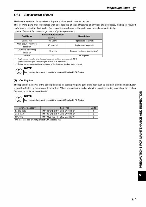
5
PREC
AU
TIO
NS
FOR
MA
INTE
NA
NC
E A
ND
INSP
ECTI
ON
Inspection items
5.1.6 Replacement of parts
The inverter consists of many electronic parts such as semiconductor devices.The following parts may deteriorate with age because of their structures or physical characteristics, leading to reducedperformance or fault of the inverter. For preventive maintenance, the parts must be replaced periodically.Use the life check function as a guidance of parts replacement.
∗1 Replacement years for when the yearly average ambient temperature is 40°C(without corrosive gas, flammable gas, oil mist, dust and dirt etc.)
∗2 Output current: equivalent to rating current of the Mitsubishi standard motor (4 poles)
(1) Cooling fanThe replacement interval of the cooling fan used for cooling the parts generating heat such as the main circuit semiconductoris greatly affected by the ambient temperature. When unusual noise and/or vibration is noticed during inspection, the coolingfan must be replaced immediately.
Part NameStandard Replacement
Interval ∗1Description
Cooling fan 10 years Replace (as required)Main circuit smoothing
capacitor10 years ∗2 Replace (as required)
On-board smoothing capacitor
10 years Replace the board (as required)
Relays — as required
NOTEFor parts replacement, consult the nearest Mitsubishi FA Center.
NOTEFor parts replacement, consult the nearest Mitsubishi FA Center.
Inverter Capacity Fan Type Units1.5K to 3.7K MMF-06F24ES-RP1 BKO-CA1638H01 15.5K, 7.5K MMF-06F24ES-RP1 BKO-CA1638H01 211K, 15K MMF-08D24ES-RP1 BKO-CA1639H01 2The 0.75K or less are not provided with a cooling fan.
111
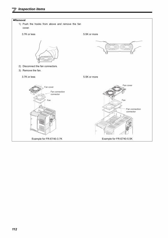
Inspection items
Removal1) Push the hooks from above and remove the fan
cover.
3.7K or less 5.5K or more
2) Disconnect the fan connectors.3) Remove the fan.
3.7K or less
Example for FR-E740-3.7K
5.5K or more
Example for FR-E740-5.5K
Fan connection
connector
Fan
Fan cover
Fan connection
connector
Fan
Fan cover
112
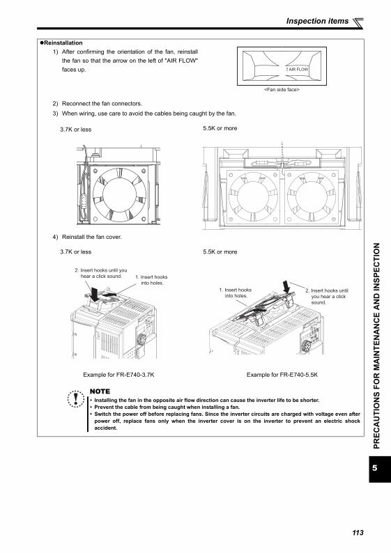
5
PREC
AU
TIO
NS
FOR
MA
INTE
NA
NC
E A
ND
INSP
ECTI
ON
Inspection items
Reinstallation1) After confirming the orientation of the fan, reinstall
the fan so that the arrow on the left of "AIR FLOW"faces up.
2) Reconnect the fan connectors.
3) When wiring, use care to avoid the cables being caught by the fan.
3.7K or less 5.5K or more
4) Reinstall the fan cover.
3.7K or less
Example for FR-E740-3.7K
5.5K or more
Example for FR-E740-5.5K
AIR FLOW
<Fan side face>
2. Insert hooks until you
hear a click sound. 1. Insert hooks
into holes.
1. Insert hooks
into holes.2. Insert hooks until
you hear a click
sound.
NOTEInstalling the fan in the opposite air flow direction can cause the inverter life to be shorter.Prevent the cable from being caught when installing a fan.Switch the power off before replacing fans. Since the inverter circuits are charged with voltage even afterpower off, replace fans only when the inverter cover is on the inverter to prevent an electric shockaccident.
113
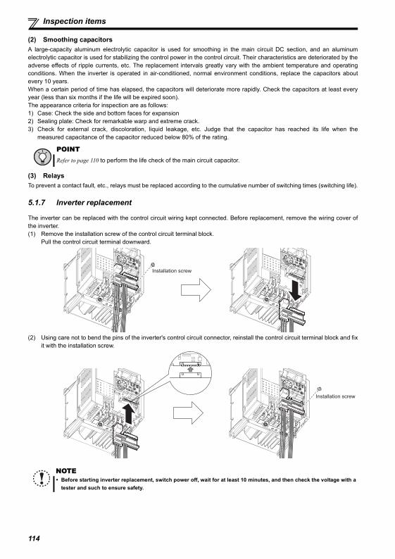
Inspection items
(2) Smoothing capacitorsA large-capacity aluminum electrolytic capacitor is used for smoothing in the main circuit DC section, and an aluminumelectrolytic capacitor is used for stabilizing the control power in the control circuit. Their characteristics are deteriorated by theadverse effects of ripple currents, etc. The replacement intervals greatly vary with the ambient temperature and operatingconditions. When the inverter is operated in air-conditioned, normal environment conditions, replace the capacitors aboutevery 10 years.When a certain period of time has elapsed, the capacitors will deteriorate more rapidly. Check the capacitors at least everyyear (less than six months if the life will be expired soon).The appearance criteria for inspection are as follows:1) Case: Check the side and bottom faces for expansion2) Sealing plate: Check for remarkable warp and extreme crack.3) Check for external crack, discoloration, liquid leakage, etc. Judge that the capacitor has reached its life when the
measured capacitance of the capacitor reduced below 80% of the rating.
(3) RelaysTo prevent a contact fault, etc., relays must be replaced according to the cumulative number of switching times (switching life).
5.1.7 Inverter replacement
The inverter can be replaced with the control circuit wiring kept connected. Before replacement, remove the wiring cover ofthe inverter.(1) Remove the installation screw of the control circuit terminal block.
Pull the control circuit terminal downward.
(2) Using care not to bend the pins of the inverter's control circuit connector, reinstall the control circuit terminal block and fixit with the installation screw.
POINTRefer to page 110 to perform the life check of the main circuit capacitor.
NOTEBefore starting inverter replacement, switch power off, wait for at least 10 minutes, and then check the voltage with atester and such to ensure safety.
Installation screw
Installation screw
114
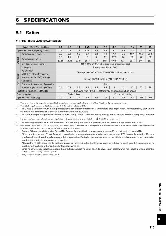
6
SPEC
IFIC
ATIO
NS
Rating
6 SPECIFICATIONS
6.1 Rating
Three-phase 200V power supply
∗1 The applicable motor capacity indicated is the maximum capacity applicable for use of the Mitsubishi 4-pole standard motor.∗2 The rated output capacity indicated assumes that the output voltage is 230V.∗3 The % value of the overload current rating indicated is the ratio of the overload current to the inverter's rated output current. For repeated duty, allow time for
the inverter and motor to return to or below the temperatures under 100% load.∗4 The maximum output voltage does not exceed the power supply voltage. The maximum output voltage can be changed within the setting range. However,
the pulse voltage value of the inverter output side voltage remains unchanged at about that of the power supply.
∗5 The power supply capacity varies with the value of the power supply side inverter impedance (including those of the input reactor and cables).∗6 Setting 2kHz or more in Pr. 72 PWM frequency selection to perform low acoustic noise operation in the ambient temperature exceeding 40°C (totally-enclosed
structure is 30°C), the rated output current is the value in parenthesis.∗7 Connect DC power supply to terminal P/+ and N/-. Connect the plus side of the power supply to terminal P/+ and minus side to terminal N/-.
Since the voltage between P/+ and N/- may increase due to the regeneration energy from the motor and exceeds 415V temporarily, select the DC powersupply which can withstand the voltage/energy during regeneration. If using the power supply which can not withstand voltage/energy during regeneration,insert diodes in series for reverse current prevention.Although the FR-E700 series has the built-in inrush current limit circuit, select the DC power supply considering the inrush current at powering on as theinrush current four times of the rated inverter flows at powering on.Since the power supply capacity depends on the output impedance of the power, select the power supply capacity which has enough allowance accordingto the AC power supply system capacity.
∗8 Totally enclosed structure series ends with -C.
Type FR-E720- K(-C) ∗8 0.1 0.2 0.4 0.75 1.5 2.2 3.7 5.5 7.5 11 15Applicable motor capacity (kW) ∗1 0.1 0.2 0.4 0.75 1.5 2.2 3.7 5.5 7.5 11 15
Out
put
Rated capacity (kVA) ∗2 0.3 0.6 1.2 2.0 3.2 4.4 7.0 9.5 13.1 18.7 23.9
Rated current (A) ∗60.8
(0.8)1.5
(1.4)3
(2.5)5
(4.1)8
(7)11
(10)17.5
(16.5)24
(23)33
(31)47
(44)60
(57)Overload current rating ∗3 150% 60s, 200% 3s (inverse time characteristics)Voltage ∗4 Three-phase 200 to 240V
Pow
er s
uppl
y
Rated inputAC (DC) voltage/frequency
Three-phase 200 to 240V 50Hz/60Hz (283 to 339VDC ∗7)
Permissible AC (DC) voltage fluctuation
170 to 264V 50Hz/60Hz (240 to 373VDC ∗7)
Permissible frequency fluctuation ±5%Power supply capacity (kVA) ∗5 0.4 0.8 1.5 2.5 4.5 5.5 9 12 17 20 28
Protective structure (JEM1030) Enclosed type (IP20). IP40 for totally enclosed structure series.Cooling system Self-cooling Forced air coolingApproximate mass (kg) 0.5 0.5 0.7 1.0 1.4 1.4 1.7 4.3 4.3 9.0 9.0
2
115
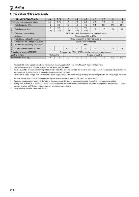
Rating
Three-phase 400V power supply
∗1 The applicable motor capacity indicated is the maximum capacity applicable for use of the Mitsubishi 4-pole standard motor.∗2 The rated output capacity indicated assumes that the output voltage is 440V.∗3 The % value of the overload current rating indicated is the ratio of the overload current to the inverter's rated output current. For repeated duty, allow time for
the inverter and motor to return to or below the temperatures under 100% load.∗4 The maximum output voltage does not exceed the power supply voltage. The maximum output voltage can be changed within the setting range. However,
the pulse voltage value of the inverter output side voltage remains unchanged at about that of the power supply.
∗5 The power supply capacity varies with the value of the power supply side inverter impedance (including those of the input reactor and cables).∗6 Setting 2kHz or more in Pr. 72 PWM frequency selection to perform low acoustic noise operation with the ambient temperature exceeding 40°C (totally-
enclosed structure is 30°C), the rated output current is the value in parenthesis.∗7 Totally enclosed structure series ends with -C.
Model FR-E740- K(-C)∗7 0.4 0.75 1.5 2.2 3.7 5.5 7.5 11 15Applicable motor capacity (kW)∗1 0.4 0.75 1.5 2.2 3.7 5.5 7.5 11 15
Out
put
Rated capacity (kVA)∗2 1.2 2.0 3.0 4.6 7.2 9.1 13.0 17.5 23.0
Rated current (A)∗61.6
(1.4)2.6
(2.2)4.0
(3.8)6.0
(5.4)9.5
(8.7)12 17 23 30
Overload current rating∗3 150% 60s, 200% 3s (inverse-time characteristics)Voltage∗4 Three phase 380 to 480V
Pow
er s
uppl
y Rated input voltage/frequency Three-phase 380 to 480V 50Hz/60HzPermissible AC voltage fluctuation 325 to 528V 50Hz/60HzPermissible frequency fluctuation ±5%
Power supply capacity (kVA)∗5 1.5 2.5 4.5 5.5 9.5 12 17 20 28
Protective structure (JEM1030) Enclosed type (IP20). IP40 for totally enclosed structure series.Cooling system Self-cooling Forced air coolingApproximate mass (kg) 1.4 1.4 1.9 1.9 1.9 3.2 3.2 5.9 5.9
2
116
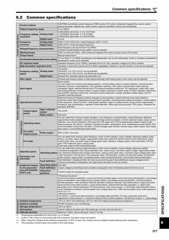
117
6
SPEC
IFIC
ATIO
NS
Common specifications
6.2 Common specificationsC
ontr
ol s
peci
ficat
ions
Control method Soft-PWM control/high carrier frequency PWM control (V/F control, advanced magnetic flux vector control, general-purpose magnetic flux vector control, optimum excitation control can be selected)
Output frequency range 0.2 to 400Hz
Frequency setting resolution
Analog input0.06Hz/60Hz (terminal2, 4: 0 to 10V/10bit)0.12Hz/60Hz (terminal2, 4: 0 to 5V/9bit)0.06Hz/60Hz (terminal4: 4 to 20mA/10bit)
Digital input 0.01HzFrequency accuracy
Analog input Within ±0.5% of the max. output frequency (25°C ±10°C)Digital input Within 0.01% of the set output frequency
Voltage/frequency characteristics Base frequency can be set from 0 to 400HzConstant torque/variable torque pattern can be selected
Starting torque 200% or more (at 0.5Hz)...when advanced magnetic flux vector control is set (3.7K or less)Torque boost Manual torque boost
Acceleration/deceleration time setting 0.01 to 360s, 0.1 to 3600s (acceleration and deceleration can be set individually), linear or S-pattern acceleration/deceleration mode can be selected.
DC injection brake Operation frequency (0 to 120Hz), operation time (0 to 10s), operation voltage (0 to 30%) variableStall prevention operation level Operation current level can be set (0 to 200% adjustable), whether to use the function or not can be selected
Ope
ratio
n sp
ecifi
catio
ns
Frequency setting signal
Analog inputTwo pointsTerminal 2: 0 to 10V, 0 to 5V can be selectedTerminal 4: 0 to 10V, 0 to 5V, 4 to 20mA can be selected
Digital input Entered from operation panel and parameter unitStart signal Forward and reverse rotation or start signal automatic self-holding input (3-wire input) can be selected.
Input signal
Seven pointsYou can select from among multi-speed selection, remote setting, stop-on contact selection, second function selection, terminal 4 input selection, JOG operation selection, PID control valid terminal, brake opening completion signal, external thermal input, PU-external operation switchover, V/F switchover, output stop, start self-holding selection, forward rotation, reverse rotation command, inverter reset, PU-NET operation switchover, external-NET operation switchover, command source switchover, inverter operation enable signal, and PU operation external interlock
Operational functions
Maximum/minimum frequency setting, frequency jump operation, external thermal relay input selection, automatic restart after instantaneous power failure operation, forward/reverse rotation prevention, remote setting, brake sequence, second function, multi-speed operation, stop-on contact control, droop control, regeneration avoidance, slip compensation, operation mode selection, offline auto tuning function, PID control, computer link operation (RS-485)
Out
put s
igna
l
Output signal points
Open collector output Two points
Relay output One point
Operating status
You can select from among inverter operation, up-to-frequency, overload alarm, output frequency detection, regenerative brake prealarm, electronic thermal relay function prealarm, inverter operation ready, output current detection, zero current detection, PID lower limit, PID upper limit, PID forward/reverse rotation output, brake opening request, fan alarm∗2, heatsink overheat pre-alarm, deceleration at an instantaneous power failure, PID control activated, during retry, life alarm, current average value monitor, remote output, alarm output, fault output, fault output 3, and maintenance timer alarm
For meterOutput points Pulse output MAX 2.4kHz: one point
For meter
You can select from among output frequency, motor current (steady), output voltage, frequency setting, motor torque, converter output voltage, regenerative brake duty, electronic thermal relay function load factor, output current peak value, converter output voltage peak value, reference voltage output, motor load factor, PID set point, PID measured value, output powerPulse train output (1440 pulses/s/full scale)
Indi
catio
n
Operation panel
Parameter unit (FR-PU07)
Operating status
You can select from among output frequency, motor current (steady), output voltage, frequency setting, cumulative energization time, actual operation time, motor torque, converter output voltage, regenerative brake duty, electronic thermal relay function load factor, output current peak value, converter output voltage peak value, motor load factor, PID set point, PID measured value, PID deviation, inverter I/O terminal monitor, I/O terminal option monitor, output power, cumulative power, motor thermal load factor, and inverter thermal load factor.
Fault definition Fault definition is displayed when the fault occurs and the past 8 fault definitions (output voltage/current/frequency/cumulative energization time right before the fault occurs) are stored
Additional display by the parameter unit (FR-PU04/FR-PU07) only
Operating status Not usedFault definition Output voltage/current/frequency/cumulative energization time immediately before the fault occursInteractive guidance Function (help) for operation guide
Protective/warning function
<Protective functions>Overcurrent during acceleration, overcurrent during constant speed, overcurrent during deceleration, overvoltage during acceleration, overvoltage during constant speed, overvoltage during deceleration, inverter protection thermal operation, motor protection thermal operation, heatsink overheat, input phase failure, output side earth (ground) fault overcurrent at start∗4, output phase failure, external thermal relay operation ∗4, option fault, parameter error, internal board fault, PU disconnection, retry count excess ∗4, CPU fault, brake transistor alarm, inrush resistance overheat, communication error, analog input error, USB communication error, brake sequence error 4 to 7 ∗4<Warning functions>Fan alarm∗2, overcurrent stall prevention, overvoltage stall prevention, PU stop, parameter write error, regenerative brake prealarm ∗4, electronic thermal relay function prealarm, maintenance output ∗4, undervoltage
Envi
ronm
ent Ambient temperature -10°C to +50°C (non-freezing) (-10°C to +40°C for totally-enclosed structure feature) ∗3
Ambient humidity 90%RH maximum (non-condensing)Storage temperature∗1 -20°C to +65°CAtmosphere Indoors (without corrosive gas, flammable gas, oil mist, dust and dirt etc.)Altitude/vibration Maximum 1000m above sea level, 5.9m/s 2 or less
∗1 Temperatures applicable for a short time, e.g. in transit.∗2 As the 0.75K or less is not provided with the cooling fan, this alarm does not function.∗3 When using the inverters at the ambient temperature of 40°C or less, the inverters can be installed closely attached (0cm clearance).∗4 This protective function does not function in the initial status.
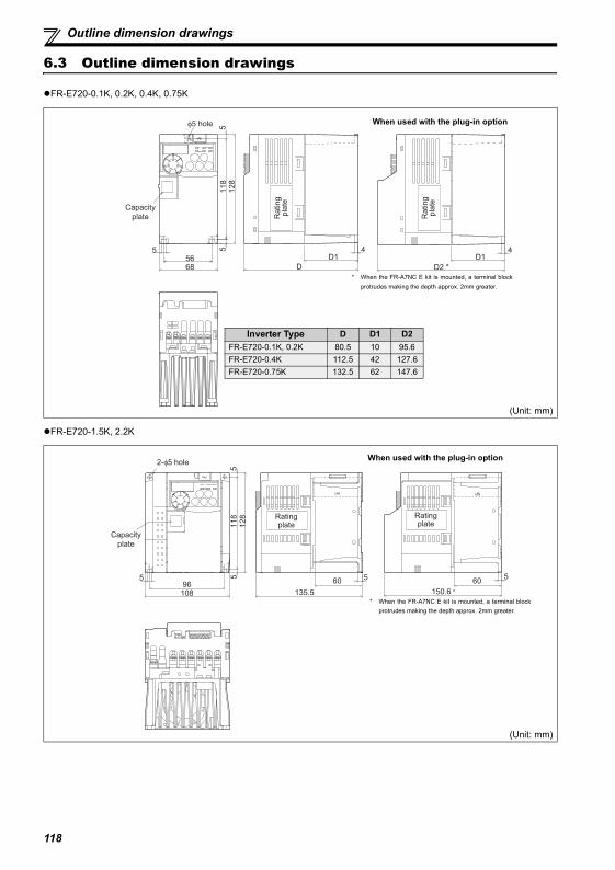
Outline dimension drawings
6.3 Outline dimension drawings
FR-E720-0.1K, 0.2K, 0.4K, 0.75K
FR-E720-1.5K, 2.2K
(Unit: mm)
(Unit: mm)
5
6856
5118
5
128
φ5 hole
D
4
D2 *
4
Capacity
plate Rating
pla
te
Rating
pla
te
D1 D1
Inverter Type D D1 D2FR-E720-0.1K, 0.2K 80.5 10 95.6FR-E720-0.4K 112.5 42 127.6FR-E720-0.75K 132.5 62 147.6
When used with the plug-in option
* When the FR-A7NC E kit is mounted, a terminal blockprotrudes making the depth approx. 2mm greater.
2-φ5 hole
96108
5118
5128
5
135.5
5
150.6 *
5
Capacity
plate
Rating plate
Rating plate
60 60
When used with the plug-in option
* When the FR-A7NC E kit is mounted, a terminal blockprotrudes making the depth approx. 2mm greater.
118
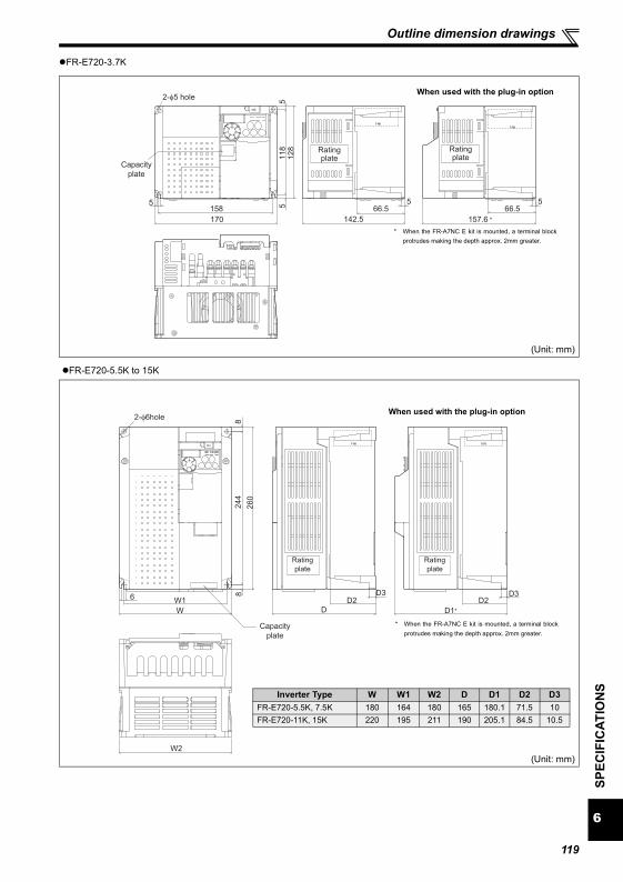
6
SPEC
IFIC
ATIO
NS
Outline dimension drawings
FR-E720-3.7K
FR-E720-5.5K to 15K
(Unit: mm)
(Unit: mm)
5158
170
5118
5128
2-φ5 hole
5
142.5 157.6 *
5
Capacity
plate
Rating plate
Rating plate
66.5 66.5
When used with the plug-in option
* When the FR-A7NC E kit is mounted, a terminal blockprotrudes making the depth approx. 2mm greater.
6 W1
W
8244
8
260
D3
D
D3
D1*
2-φ6hole
W2
D2 D2
Capacity
plate
Rating
plate
Rating
plate
Inverter Type W W1 W2 D D1 D2 D3FR-E720-5.5K, 7.5K 180 164 180 165 180.1 71.5 10FR-E720-11K, 15K 220 195 211 190 205.1 84.5 10.5
When used with the plug-in option
* When the FR-A7NC E kit is mounted, a terminal blockprotrudes making the depth approx. 2mm greater.
119
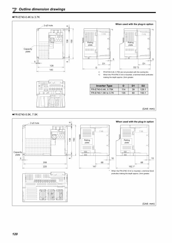
Outline dimension drawings
FR-E740-0.4K to 3.7K
FR-E740-5.5K, 7.5K
(Unit: mm)
(Unit: mm)
5
D
D15
128
140
138
66
2-φ5 hole
150
5
D2 *2
D1
*1 *1
Rating
plate
Rating
plate
Capacity
plate
Inverter Type D D1 D2FR-E740-0.4K, 0.75K 114 39 129.1FR-E740-1.5K to 3.7K 135 60 150.1
When used with the plug-in option
∗1 FR-E740-0.4K, 0.75K are not provided with the cooling fan.∗2 When the FR-A7NC E kit is mounted, a terminal block protrudes
making the depth approx. 2mm greater.
2-φ5 hole
138
66
150
5
208
220
10
147
68
10
162.1*
68
Capacity
plate
Rating
plate
Rating
plate
When used with the plug-in option
* When the FR-A7NC E kit is mounted, a terminal blockprotrudes making the depth approx. 2mm greater.
120
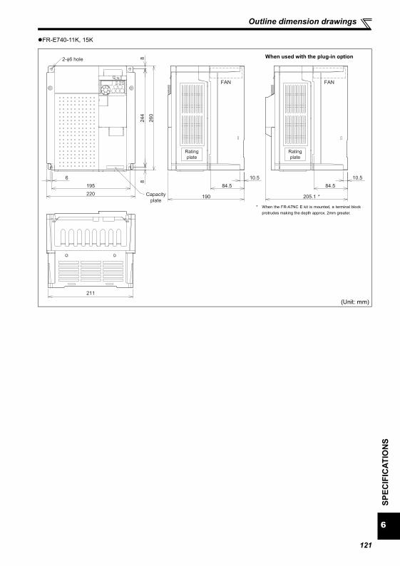
6
SPEC
IFIC
ATIO
NS
Outline dimension drawings
FR-E740-11K, 15K
(Unit: mm)
6
195
88
260
244
FAN
10.5
84.5 84.5
190
2-φ6 hole
FAN
10.5
205.1 *
211
220 Capacity
plate
Rating
plate
Rating
plate
When used with the plug-in option
* When the FR-A7NC E kit is mounted, a terminal blockprotrudes making the depth approx. 2mm greater.
121
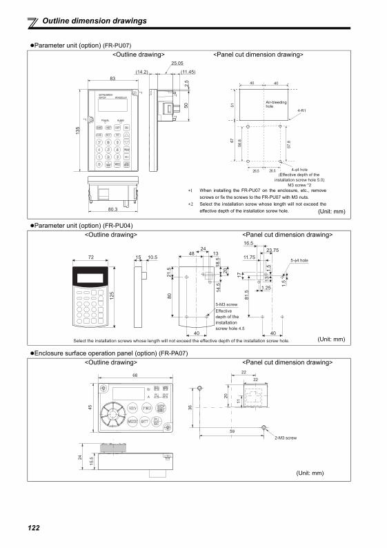
Outline dimension drawings
Parameter unit (option) (FR-PU07)<Outline drawing> <Panel cut dimension drawing>
Parameter unit (option) (FR-PU04)<Outline drawing> <Panel cut dimension drawing>
Enclosure surface operation panel (option) (FR-PA07)<Outline drawing> <Panel cut dimension drawing>
67
51
40
56
.8
57
.8
26.5
4-R1
26.5
40
4-φ4 hole
(Effective depth of the
installation screw hole 5.0)
M3 screw *2
Air-bleeding hole
80.3
(14.2)
2.5
50
(11.45)
25.05
13
583
*1
*1*1
*1
∗1 When installing the FR-PU07 on the enclosure, etc., removescrews or fix the screws to the FR-PU07 with M3 nuts.
∗2 Select the installation screw whose length will not exceed theeffective depth of the installation screw hole. (Unit: mm)
40
5-φ4 hole
23.75
11.75
81.5
1.25
1.5
131
716.5
1.5
125
72 15 10.5
18.5
40
80
48
5-M3 screw
2413
20
21.5
14.5
Effective
depth of the
installation
screw hole 4.5
Select the installation screws whose length will not exceed the effective depth of the installation screw hole. (Unit: mm)
68
59
22
22
2-M3 screw
(Unit: mm)
122
APPENDIX
Appendix 1-1 Replacement of the FR-E500 series(1) Instructions for installation
1) Removal procedure of the front cover was changed. (Refer to page 4)2) The operation panel cannot be removed from the inverter.3) Plug-in options of the FR-E500 series are not compatible.4) Setup software (FR-SW0-SETUP, FR-SW1-SETUP, FR-SW2-SETUP) can not be used.
(2) Instructions for continuous use of the FR-PU04 (parameter unit)
1) For the FR-E700 series, many functions (parameters) have been added. User initial value list and userclear of the HELP function can not be used.
2) For the FR-E700 series, many protective functions have been added. These functions activate, but allfaults are displayed as "Fault 14". When the faults history has been checked, "E.14" appears. Addedfaults display will not appear on the parameter unit.
3) User initial value setting can not be used.4) User registration/clear (user group 2) can not be used.5) Parameter copy/verification function can not be used.
(3) Parameter resetting
It is easy if you use setup software (FR Configurator FR-SW3-SETUP).
Appendix1 For customers who have replaced the conventional model with this inverter
123
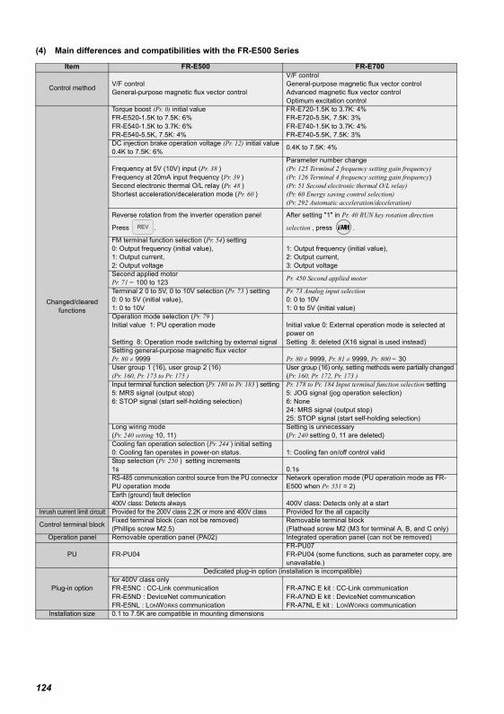
(4) Main differences and compatibilities with the FR-E500 Series
Item FR-E500 FR-E700
Control method V/F controlGeneral-purpose magnetic flux vector control
V/F controlGeneral-purpose magnetic flux vector controlAdvanced magnetic flux vector controlOptimum excitation control
Changed/cleared functions
Torque boost (Pr. 0) initial valueFR-E520-1.5K to 7.5K: 6%FR-E540-1.5K to 3.7K: 6%FR-E540-5.5K, 7.5K: 4%
FR-E720-1.5K to 3.7K: 4%FR-E720-5.5K, 7.5K: 3%FR-E740-1.5K to 3.7K: 4%FR-E740-5.5K, 7.5K: 3%
DC injection brake operation voltage (Pr. 12) initial value0.4K to 7.5K: 6% 0.4K to 7.5K: 4%
Frequency at 5V (10V) input (Pr. 38 ) Frequency at 20mA input frequency (Pr. 39 )Second electronic thermal O/L relay (Pr. 48 )Shortest acceleration/deceleration mode (Pr. 60 )
Parameter number change(Pr. 125 Terminal 2 frequency setting gain frequency)(Pr. 126 Terminal 4 frequency setting gain frequency)(Pr. 51 Second electronic thermal O/L relay) (Pr. 60 Energy saving control selection)(Pr. 292 Automatic acceleration/deceleration)
Reverse rotation from the inverter operation panel
Press .
After setting "1" in Pr. 40 RUN key rotation direction
selection , press .
FM terminal function selection (Pr. 54) setting0: Output frequency (initial value), 1: Output current,2: Output voltage
1: Output frequency (initial value), 2: Output current,3: Output voltage
Second applied motorPr. 71 = 100 to 123 Pr. 450 Second applied motor
Terminal 2 0 to 5V, 0 to 10V selection (Pr. 73 ) setting0: 0 to 5V (initial value),1: 0 to 10V
Pr. 73 Analog input selection0: 0 to 10V1: 0 to 5V (initial value)
Operation mode selection (Pr. 79 )Initial value 1: PU operation mode
Setting 8: Operation mode switching by external signal
Initial value 0: External operation mode is selected at power onSetting 8: deleted (X16 signal is used instead)
Setting general-purpose magnetic flux vector Pr. 80 ≠ 9999 Pr. 80 ≠ 9999, Pr. 81 ≠ 9999, Pr. 800 = 30User group 1 (16), user group 2 (16)(Pr. 160, Pr. 173 to Pr. 175 )
User group (16) only, setting methods were partially changed(Pr. 160, Pr. 172, Pr. 173 )
Input terminal function selection (Pr. 180 to Pr. 183 ) setting5: MRS signal (output stop)6: STOP signal (start self-holding selection)
Pr. 178 to Pr. 184 Input terminal function selection setting5: JOG signal (jog operation selection)6: None24: MRS signal (output stop)25: STOP signal (start self-holding selection)
Long wiring mode(Pr. 240 setting 10, 11)
Setting is unnecessary(Pr. 240 setting 0, 11 are deleted)
Cooling fan operation selection (Pr. 244 ) initial setting0: Cooling fan operates in power-on status. 1: Cooling fan on/off control validStop selection (Pr. 250 ) setting increments1s 0.1sRS-485 communication control source from the PU connectorPU operation mode
Network operation mode (PU operatioin mode as FR-E500 when Pr. 551 = 2)
Earth (ground) fault detection400V class: Detects always 400V class: Detects only at a start
Inrush current limit circuit Provided for the 200V class 2.2K or more and 400V class Provided for the all capacity
Control terminal block Fixed terminal block (can not be removed) (Phillips screw M2.5)
Removable terminal block (Flathead screw M2 (M3 for terminal A, B, and C only)
Operation panel Removable operation panel (PA02) Integrated operation panel (can not be removed)
PU FR-PU04FR-PU07FR-PU04 (some functions, such as parameter copy, are unavailable.)
Plug-in option
Dedicated plug-in option (installation is incompatible)for 400V class onlyFR-E5NC : CC-Link communicationFR-E5ND : DeviceNet communicationFR-E5NL : LONWORKS communication
FR-A7NC E kit : CC-Link communicationFR-A7ND E kit : DeviceNet communicationFR-A7NL E kit : LONWORKS communication
Installation size 0.1 to 7.5K are compatible in mounting dimensions
124
(1) EMC Directive
1) Our view of transistorized inverters for the EMC DirectiveA transistorized inverter is a component designed for installation in an enclosure and for use with the other equipment tocontrol the equipment/device. Therefore, we understand that the EMC Directive does not apply directly to transistorizedinverters. For this reason, we do not place the CE mark on the transistorized inverters. (The CE mark is placed on invertersin accordance with the Low Voltage Directive.) CEMEP
2) ComplianceWe understand that the general-purpose inverters are not covered directly by the EMC Directive. However, the EMCDirective applies to machines/equipment into which inverters have been incorporated, and these machines and equipmentmust carry the CE marks. EMC Installation Guidelines BCN-A21041-202
3) Outline of installation methodInstall an inverter using the following methods:∗ Use the inverter with an European Standard-compliant noise filter.∗ For wiring between the inverter and motor, use shielded cables or run them in a metal piping and ground the cables on
the inverter and motor sides with the shortest possible distance.∗ Insert a common mode filter and ferrite core into the power and control lines as required.
Full information including the European Standard-compliant noise filter specifications are written in the technicalinformation "EMC Installation Guidelines" (BCN-A21041-202). Please contact your sales representative.
(2) Low Voltage DirectiveWe have self-confirmed our inverters as products compliant to the Low Voltage Directive (Conforming standard EN 50178)and place the CE mark on the inverters.
Outline of instructions∗ Do not use an earth leakage circuit breaker as an electric shock protector without connecting the equipment to the earth.
Connect the equipment to the earth securely.∗ Wire the earth (ground) terminal independently. (Do not connect two or more cables to one terminal.)∗ Use the cable sizes on page 10 under the following conditions.
Ambient Temperature: 40°C maximumIf conditions are different from above, select appropriate wire according to EN60204 ANNEX C TABLE 5.
∗ When tightening the screw, be careful not to damage the threads.For use as a product compliant with the Low Voltage Directive, use PVC cable on page 10.
∗ Use the moulded case circuit breaker and magnetic contactor which conform to the EN or IEC Standard.∗ When using an earth leakage circuit breaker, use a residual current operated protective device (RCD) of type B (breaker
which can detect both AC and DC). If not, provide double or reinforced insulation between the inverter and otherequipment, or put a transformer between the main power supply and inverter.
∗ Use the inverter under the conditions of overvoltage category II (usable regardless of the earth (ground) condition of thepower supply), overvoltage category III (usable with the earthed-neutral system power supply, 400V class only) specifiedin IEC664.
To use the inverter under the conditions of pollution degree 3, install it in the enclosure of IP54 or higher.
Appendix2 Instructions for Compliance with the European Directives
125
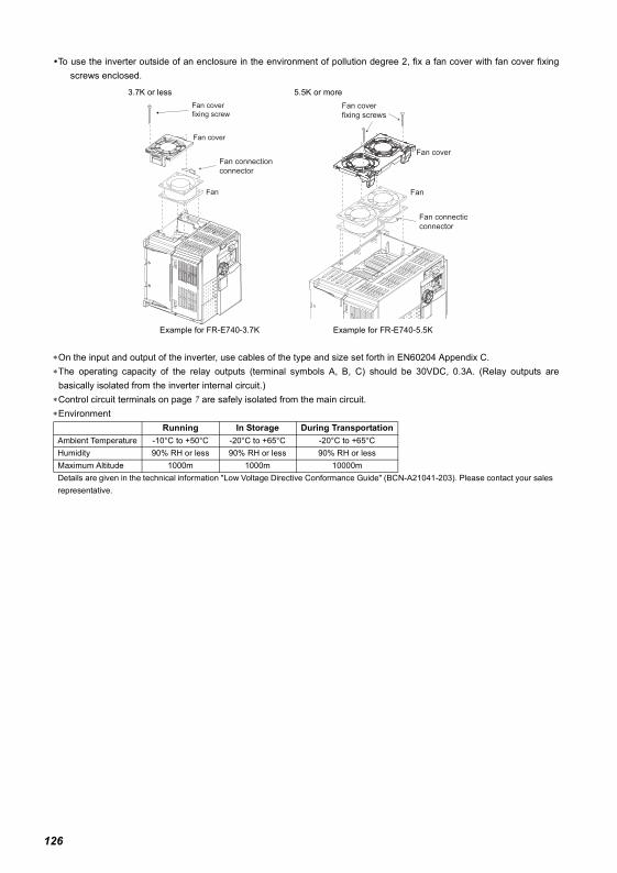
To use the inverter outside of an enclosure in the environment of pollution degree 2, fix a fan cover with fan cover fixingscrews enclosed.
∗On the input and output of the inverter, use cables of the type and size set forth in EN60204 Appendix C.∗The operating capacity of the relay outputs (terminal symbols A, B, C) should be 30VDC, 0.3A. (Relay outputs arebasically isolated from the inverter internal circuit.)
∗Control circuit terminals on page 7 are safely isolated from the main circuit.∗Environment
3.7K or less 5.5K or more
Example for FR-E740-3.7K Example for FR-E740-5.5K
Running In Storage During TransportationAmbient Temperature -10°C to +50°C -20°C to +65°C -20°C to +65°CHumidity 90% RH or less 90% RH or less 90% RH or lessMaximum Altitude 1000m 1000m 10000mDetails are given in the technical information "Low Voltage Directive Conformance Guide" (BCN-A21041-203). Please contact your sales representative.
Fan connection
connector
Fan
Fan cover
Fan cover
fixing screw
Fan
Fan cover
Fan cover
fixing screws
Fan connectio
connector
126
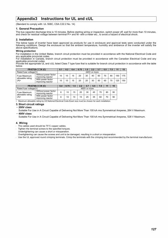
(Standard to comply with: UL 508C, CSA C22.2 No. 14)
1. General PrecautionThe bus capacitor discharge time is 10 minutes. Before starting wiring or inspection, switch power off, wait for more than 10 minutes,and check for residual voltage between terminal P/+ and N/- with a meter etc., to avoid a hazard of electrical shock.
2. InstallationThe below types of inverter have been approved as products for use in enclosure and approval tests were conducted under thefollowing conditions. Design the enclosure so that the ambient temperature, humidity and ambience of the inverter will satisfy theabove specifications.Wiring protectionFor installation in the United States, branch circuit protection must be provided in accordance with the National Electrical Code andany applicable provincial codes.For installation in Canada, branch circuit protection must be provided in accordance with the Canadian Electrical Code and anyapplicable provincial codes.Provide the appropriate UL and cUL listed Class T type fuse that is suitable for branch circuit protection in accordance with the tablebelow.
∗ Maximum allowable rating by US National Electrical Code.Exact size must be chosen for each installation.
3. Short circuit ratings • 200V class
Suitable For Use in A Circuit Capable of Delivering Not More Than 100 kA rms Symmetrical Amperes, 264 V Maximum. • 400V class
Suitable For Use in A Circuit Capable of Delivering Not More Than 100 kA rms Symmetrical Amperes, 528 V Maximum.
4. Wiring⋅ The cables used should be 75°C copper cables.⋅ Tighten the terminal screws to the specified torques.
Undertightening can cause a short or misoperation.Overtightening can cause the screws and unit to be damaged, resulting in a short or misoperation.
⋅ Use the UL approved round crimping terminals. Crimp the terminals with the crimping tool recommended by the terminal manufacturer.
Appendix3 Instructions for UL and cUL
FR-E720- K (C) 0.1 0.2 0.4 0.75 1.5 2.2 3.7 5.5 7.5 11 15Rated fuse voltage(V) 240V or more
Fuse Maximum allowable rating (A)∗
Without power factor improving reactor 15 15 15 20 30 40 60 70 80 150 175
With power factor improving reactor 15 15 15 20 20 30 50 60 70 125 150
FR-E740- K (C) 0.4 0.75 1.5 2.2 3.7 5.5 7.5 11 15Rated fuse voltage(V) 480V or more
Fuse Maximum allowable rating (A)∗
Without power factor improving reactor 6 10 15 20 30 40 70 80 90
With power factor improving reactor 6 10 10 15 25 35 60 70 90
127
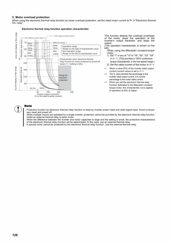
5. Motor overload protectionWhen using the electronic thermal relay function as motor overload protection, set the rated motor current to Pr. 9 "Electronic thermalO/L relay".
This function detects the overload (overheat)of the motor, stops the operation of theinverter's output transistor, and stops theoutput. (The operation characteristic is shown on theleft)
When using the Mitsubishi constant-torquemotor1) Set "1" or any of "13" to "16", "50", "53", "54"
in Pr. 71. (This provides a 100% continuous torque characteristic in the low-speed range.)
2) Set the rated current of the motor in Pr. 9.∗1 When a value 50% of the inverter rated output
current (current value) is set in Pr. 9 ∗2 The % value denotes the percentage to the
inverter rated output current. It is not the percentage to the motor rated current.
∗3 When you set the electronic thermal relay function dedicated to the Mitsubishi constant-torque motor, this characteristic curve applies to operation at 6Hz or higher.
Note⋅ Protective function by electronic thermal relay function is reset by inverter power reset and reset signal input. Avoid unneces-
sary reset and power-off.⋅ When multiple motors are operated by a single inverter, protection cannot be provided by the electronic thermal relay function.
Install an external thermal relay to each motor.⋅ When the difference between the inverter and motor capacities is large and the setting is small, the protective characteristics
of the electronic thermal relay function will be deteriorated. In this case, use an external thermal relay.⋅ A special motor cannot be protected by the electronic thermal relay function. Use the external thermal relay.
Operation range
Range on the right of characteristic curve
Non-operation range
Range on the left of characteristic curve
Range for
transistor
protection
Inverter output current(%)(% to the rated inverter current)
52.5% 105%
50 100 150
60
120
180
240
50
60
70
(min
) unit d
ispla
y in this
range
Opera
tion tim
e (
min
)
Pr. 9 = 50% setting of inverter rating*1, 2
Pr. 9 = 100% setting of inverter rating*2
(s)
unit d
ispla
y in this
range
Opera
tion tim
e (
s)
Characteristic when electronic thermal
relay function for motor protection is turned off
(when Pr. 9 setting is 0(A))
6Hz
20Hz
10Hz
6Hz
0.5Hz
30Hz or more *330Hz or more *3
20Hz10Hz
0.5Hz
230
Electronic thermal relay function operation characteristic
128

129
MEMO
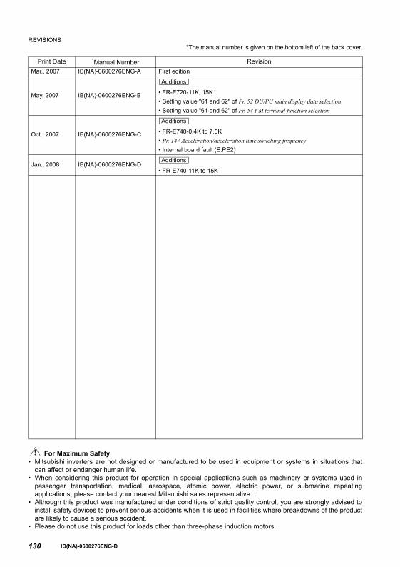
130
REVISIONS*The manual number is given on the bottom left of the back cover.
For Maximum Safety• Mitsubishi inverters are not designed or manufactured to be used in equipment or systems in situations that
can affect or endanger human life.• When considering this product for operation in special applications such as machinery or systems used in
passenger transportation, medical, aerospace, atomic power, electric power, or submarine repeatingapplications, please contact your nearest Mitsubishi sales representative.
• Although this product was manufactured under conditions of strict quality control, you are strongly advised toinstall safety devices to prevent serious accidents when it is used in facilities where breakdowns of the productare likely to cause a serious accident.
• Please do not use this product for loads other than three-phase induction motors.
Print Date *Manual Number RevisionMar., 2007 IB(NA)-0600276ENG-A First edition
May, 2007 IB(NA)-0600276ENG-B • FR-E720-11K, 15K• Setting value "61 and 62" of Pr. 52 DU/PU main display data selection• Setting value "61 and 62" of Pr. 54 FM terminal function selection
Oct., 2007 IB(NA)-0600276ENG-C • FR-E740-0.4K to 7.5K• Pr. 147 Acceleration/deceleration time switching frequency• Internal board fault (E.PE2)
Jan., 2008 IB(NA)-0600276ENG-D• FR-E740-11K to 15K
Additions
Additions
Additions
IB(NA)-0600276ENG-D


![Game Theory [FR]](https://img.dokumen.tips/doc/110x75/6321969b61d7e169b00c3b47/game-theory-fr.jpg)


