Embed Size (px)
Citation preview
ds.
EVERYDAY
ELEC fRONlr`
and computer PROJECTS
SEPTEMBER 1984
MW
o -
WK
�GHTNE�►R
�.,
IMF"
I
[TROplQ4, . ,
_ Z
a�
0 Wr
A
GUITAR
HEADPHONE
AMPLIFIER
90p
MICROCOMPUTER
i
Australia 51.60 New Zealand =1.75 Malaysia 54.95
Everyday Electronics
Colour Print Service
What better way of ensuring your
pleasure than to actually see your prints
before you pay—and then to be charged
only for the successful pictures within
the price ranges quoted. That is the deal
you get from our colour print service
providing the best all-round value for
money available.
Over the past ten years, hundreds of
thousands of magazine readers have been
delighted with our postal service. They
have sent their films in to us again and
again. So why not give it a whirl yourself?
QUALITY
Every print is checked at every stage of
processing to ensure accurate colour
reproduction.
RELIABILITY
Processing and printing take up to 48
hours. Allowing for postal or peak-period
delays, you should normally expect your
prints after seven to ten days.
LARGER PRINTS
Our Superprints give you 30 per cent
more picture area at no extra charge.
EASY CREDIT
You pay only for your successful shots
within the price ranges quoted—and
then only after you have seen the prints.
COMPARE PRICES
If you are invoiced for £2.70, plus 30p
postage and packing per film, that could
be for as many as 24 successful prints.
See your
111111
prints
before
You pay
See our price range:
No. of Superprints
or standard prints
0-6
7-12
13-18
19-24
25-30
31-36
Price (inc.
15% VAT
E1.20
£1.70
£2.20
£2.70
£3.20
£3.70
LUXURY COLOUR PRINTS
You will be amazed at the beautiful
colours and sheen finish of your prints.
They have elegant rounded corners and
are borderless to give you maximum
picture area. Choose either standard
prints or the larger Superprints by ticking
the appropriate box on the enclosed
envelope or on the coupon below.
Superprints Print size (approx.)
35mm 110 126 Disc
4"x53/4" 4"x51/8" 4"x4" 4"x51/8"
Standard prints Print size (approx.)
31/2"x5" 31/2"x41/2"3y2"x31/2"N/A
NO MONEY—NO STAMP
Just send any good make of colour print
film, including disc film, inside the
Freepost envelope enclosed with this
issue. Or fill in the coupon below and send
with your colour print film in a strong
envelope to: Everyday Electronics
Colour Print Service, FREEPOST,
Reading, RG 1 1 BR.
PERSONALISED SERVICE
Our valued readers know we care for
their prints. If you have any queries
about this highly-personalised service,
contact Customer Service, Kenavon
Drive, Reading, RG1 3HT or ring
Reading (0734) 597332.
YOU BENEFIT IN FOUR WAYS
1. Processing is free—you pay only for
successful prints (plus p & p).
2. You enjoy a highly personalised
service with every care-taken over each
individual print.
3. You are not hampered with credit
vouchers.
4. You get more prints for your money,
so it is worth your while always having
your camera action-ready. Compare the
shop prices.
FILMS AT REDUCED PRICES
Order replacement films 35/24,
110/24 or 126/24 at a special
price of £1.20. a roll,
or three for £3.
Offer excludes Black & White,
transparency, sub-miniature, C22 &
Agfa CNS film. Superprints can be
produced only from Kodacolour II, C41
onssette, cartridge and disc film, not half
frame. Prices are correct at the time of
going to press and are for UK readers
only. Standard terms of business are
available on request.
USE THIS LABEL IF YOU HAVE NO ENVELOPE, OR PASS IT TO A FRIEND. IT IS USED TO SEND YOUR PRINTS.
To: Everyday Electronics Colour Print
Service, FREEPOST, Reading, RG1 1 BR.
• Print my enclosed film (Please tick box)
Superprint size ❑
Standard size ❑
• Rush me of 35/24 of 110/24
of 126/24 at £1.20
or three for £3.
From: Everyday Electronics Colour Print
Service, FREEPOST, Reading, RG1 1 BR.
Name
Address
Postcode

EVERYDAY
ELECTRONICS
and computer PROJECTS
VOL. 13 NO. 9 SEPTEMBER 1984
PROJECTS ... THEORY ... NEWS ...
COMMENT... POPULAR FEATURES ...
I IPC Magazines Limited 1984. Copyright in all
drawings, photographs and articles published in
EVERYDAY ELECTRONICS is fully protected, and
reproduction or imitations in whole or in part are
expressly forbidden.
PROJECTS
MICROCOMPUTER DIGITISER by J. Howden PhD
A fast and easy method of loading complex images into your computer
GUITAR HEADPHONE AMPLIFIER by M. G. Argent
Small amplifier for tuning and practice
OP-AMP POWER SUPPLY by T. J. Johnson
Fixed positive and negative 1 5V outputs at 50mA maximum
SOUND OPERATED FLASH by M.rG. Argent
Take action flash photos
CARAVAN DIPSTICK by T. R. de Vaux Balbirnie
Campers---make sure your water is hi-de-hi I
SERIES
TEACH-IN 84 by George Hylton
Part 12: Aids to Design
ANATOMY OF YOUR MICRO by Owen Bishop
Part Three: Video, disc and TV interfacing
FUNTRONICS by Thakery
A new outlook on electronics: The Decibel
OSCILLATORS by J. R. Davies
Part Four: Hysteresis Oscillators
FEATURES
EDITORIAL
Learning, Check It Out, SEDAC
CIRCUIT EXCHANGE
A forum for readers' ideas
SHOP TALK by Dave Barrington
Product news and component buying
RADIO WORLD by Pat Hawker G3VA
Operation Overkill; Japanese DBS Woes; Cellular Radio
FOR YOUR ENTERTAINMENT by Barry Fox
In The Swim; Censorship; Global Village
FISSION AND FUSION by A. J. Bentley
Atomic power or atomic bomb, what's the difference?
COUNTER INTELLIGENCE by Paul Young
A retailer comments
EVERYDAY NEWS
What's happening in the world of electronics
SCHOOLS COMPETITION
The 1984 award-winning designs
PRINTED CIRCUIT BOARD SERVICE
Our October 1984 issue will be published on
Friday, September 21. Seepage 581 for details.
Readers" Services • Editorial and Advertisement Departments
550
554
563
574
582
556
566
572
593
549
555,565
560
576
577
578
580
586
588
597
549
Everyday Electronics, September 1984
4s

ELECTRIOALE
POLYESTER LAYER (Sie-mens) 8.32509 5mm PCM
1 U11. tolerance 63V. In 13
values from 00011 to 047µF
8.32510 7 5mm PCM 10%
tolerance IOOV min. In 7 val-ues from OOD47 to 047µF
8.32512 15mm PCM 10%
tolerance 10GV 1µF 22 F
8.32560 7 5mm PCM 26
types III% tolerance 400V
0001 to 00068µF
9% tolerance from 00082 to
0.68µF in 400. 250 8 10011
for
CAPACITORS
of all preferred types
CERAMIC PLATE
Above 10OOpF, in E 6 values
to 4700pF
C3M IOOVdc 1 84700pF - 10
types
8.37448 63Vdc 2 5mm PCM
0.01-068pF - 5 types
6.37449 63Vdc 5mm PCM
0.047, 0.68, 01µF
CERAMIC DISC
InF IOnF 30OVac
ELECTROLYTIC
Axial in 48 values from I to
I0000µF. 10 to 63Vdc
Canned in 9 values from
2000 to 220000µF, voltages to
350
Reversible from 2 to 100µF
Low Leak, Almnm 0.1-IOOµF,
17 values. 650ydc
Redial 15 values 11000µF, f 6-63Vdc
TANTALUM BEADS
in 18 values from O 1 100µF.
6335Vdc
POLYSTYRENE Memories)
39 values 5pF to 18nF,
16OVdc
The above ranges should
meet the majority of current
requirements. Mention EE
when sending for our very
latest free 40-page A list
stowing many more types.
BRITAIN'S LEADING QUALITY COMPONENT
SUPPLIERS - SEND FOR FREE 40 PAGE A-Z LIST
ATTRACTIVE DISCOUNTS FREE POSTAGE GOOD SERVICE & DELIVERY
ELECTRO ALUE LTD
28 St. Jude's Rd. Engle-field Green, Egham,
Surrey TWIG OFiB.
(0784) 33603 Telex 264475 (CALLERS ONLYI 680 Burnage Lane M/c 1061-
432 4945) EV Computing Shop, 700 Burnage Lane, Manchester M19 1NA
1061431 1866)
pCCESSICppp
BARCIA ordets
phoned
Welcome
MOTORIZED GEARBOX
As featured in 'Computer Control of
Small Vehicles' in May issue. Complete
set of components (not PCB)
Gearbox & Wheels (as recommended
by the authors) for E37.
These units are as used in a
computerized tank, and offer the
experimenter in robotics the
opportunity to buy the electro-mechanical parts required in building
remote controlled vehicles. The unit
has 2 x 3V motors, linked by a
Ta netic clutch, thus enabling turning
the vehicle, and a gearbox contained
within the black ABS housing, reducing
the final drive speed to approx 50rpm.
Data is supplied with the unit showing
various options on driving the motors
etc. E5.95. Suitable wheels also
available. 3x ' Dia plastic with blue tyre,
drilled to push-fit on spindle. 2 for E1.30
(limited qty). 3' dia aluminium disc
3mm thick, drilled to push-fit on
spindle. 2 for 68p.
NICAD CHARGERS
Versatile unit for charging AA, C, D and
PP3 batteries. Charge/test switch, LED
indicators at each of the 5 charging
points. Mains powered. 210 x 100 x
50mm E7.96.
Model A124. Unit plugs directly into
13A socket, and will charge up to 4 AA
cells at a lime. Only E4.80.
NI-CAD BATTERIES
AA size 91 each; C size 199p; D size
220p; PP3 size 395p.
SPECIAL!! 6 x 'D' size, only E11.00!1
THE 1884
GREENWELD
84 PAGE CATALOGUE
NOW AVAILABLE 11
It's Bigger, Brighter, Better, more
components then ever before. With
each copy there's discount vouchers,
Bargain List, Wholesale Discount List,
Bulk Buyers List, Order Form and
Reply Paid Envelope. AN for just E1.001
Ei ns tein-N
COLOUR MICRO COMPUTER
* 64k RAM + 16k for
Display
* Built-in Disc Drive, 500k
* 16 colours, 32 sprites
• Runs CP/M
tit 3 Channel Sound
it Proper keyboard
• RS232 Interface
• Centronics printer port
• Monitor or UHF Output
• Switched mode PSU
All for £499.95
14" Colour Monitor £240.35
Dot Matrix Printer £228.85
Send for Colour Brochure
Official orders welcome - minimum
invoice charge ETD. No. min. on CWO.
Goods normally despatched by return of post
vin wwsn cmp a...�„ aa,�m
GREENWELD
443D Miebrook Revd eorrrharryrron
801 ONX TN (0703) 772501/78.3740
Y POW= a UM VAl JrlaT ,co eep PaP
. "4 0 ,% truanLv1p Iva Fw 2k BE P W "A'
P " I a " TJ;0
4
,
M
see
wo
CIP1
1'
W low,
YOUR CAREER..YOUR FUTURE..YOUR OWN BUSINESS..YOUR HOBBY
THIS IS THE AGE OF ELECTRONICS!
the woes rosiest granrtn industry...
Our new style course will enable anyone to have a real
understanding of electronics by a modern, practical
and visual method. No previous knowledge is required,
no maths, and an absolute minimum of theory.
You learn by the practical way in easy steps, mastering
all the essentials of your hobby or to start, or further,
a career in electronics or as a self-employed servicing
engineer, All the training can be carried out in the comfort
of your own home and at your own pace.
A tutor K available to whom you can
write personally at any time, for advice
or help during your work. A Certificate
is given at the end of every course.
CACC
you will do the following
• Build a modern oscilloscope
• Recognise and handle current electronic
components
Read, draw and understand circuit diagrarm
Carry out 40 experiments on basic
electronic circuits used in modern
equipment using the oscilloscope
• Build and use digital electronic circuits
and current solid state 'chips"
• Learn how to test and service every type
of electronic device used in industry and
commerce today. Servicing of radio, T.V.,
Hi-Fi, VCR and microprocessor/computer
equipment.
BritishNationalR &&Electrolnics School ReaU,Berks.RG11BR
Please send your brochure without any obligation to
' NAME
t%l COLOUR ADDRESS
1� BROCHURE
'uJ
w
LPost now to:
NatioiWPjkft&El rtynvwtrr Scbool Reading,Berks.RG11BR
I am interested in
546
BLOCK CAPS PLEASE
COURSE IN ELECTRONICS
as described above
RADIO AMATEUR LICENCE
MICROPROCESSORS
OTHER SUBJECTS
please state below
CACC
I
I
OR TELEPHONE US '
0734 51515 OR
TELEX 22758
(24 HR SERVICE)
Everyday Electronics, September 1984
i
SI
i

R
■
=Rapid
=Electronics
MIN DCONNECTORS
0 weV 15 way 26 -V 37 way
Plop wlda IuP 60p 860 1250 1700
Right no;. 1200 1BOD 2400 350P
socket; sue. gap 1300 195. 290.
Mohr angle ISOP 21 Do 290P 440.4
Coven 100p 900 1000 lift
1 ()NNf CIIIRS
DIN Plug Skt Jack Plug Ski
2 pin gp 9p 2.5mm lap 100
3 Din 12P 100 3.5mm 90 BP
5 pin 130 110 Brand." ISP 200
Pnono lap 120 Steno 24P 25P
1- 12p 13p 4mm 180 17p
UHF (CS) Connector.
PL250 Plug 4DO. Reducer 140.
80239 surer• cnaesu skt 31
SO 9S rountl coati. skt Opp.
IEC 3 Din 25pV/eA.
Mug Merie mounting 380
S«bt inn hen9inp 500
5«bt suites 2m Iwo 1201
SC-R.
►C106D
400V BA
400V 12A
30
70
95
SOLDERING IRONS
An tax CS 17W Solder.ng Iron 530
2.3 and 4.7mm bits to wit . 85
C8 17W or XS 25W W-int 230
Ante. XS 26W ..d.rin91ron 580
3.3 and 4 7m bin to wit 86
Solder Pump enolderm9 tool 480
Spar. norrl for abov. 70
10 mate. 22 sw9 sold., 100
0.5k9 22 two sold, 750
MAIL ORDERS:
Unit 3, Hill Farm Industrial Estate,
Boxted, Colchester, Essex C04 5RD.
Tel. Orders: Colchester (0206) 36412.
Telex: 987756.
CABs 1 %
20 men. Pack single tor• Cohost.
Ino cabs• ten d i florant colon n. 750
$P•eker cabs• 100/m
sun are acuehad 1St/m
Twin K,Nned 24P/m
2.5A 3 or. mains 23p/m
10 wey r..nbo. ribbon 1611}2
20 way rainbow ribbo 47p:ft
10 way gory ribbon 14P/It
20 wev g,•y r.ofton 28prit
SWI I( If, S
Subnin loggia
SPST 56p. SPOT BOP. DPDT 650.
Mimes.,. toggle.
SPOT 600. SPOT inn. off BO..
DPDT 90P. DPDT canto olf 1000.
Sundnd toggl.'.
SPST35.. DPOT48P
lit-jr- DPDT f,,do 147
Push to make 140.
Push to Weak 22P.
Rotary type adjustable if
1 P12W, 2P6W, 3P4W .11 550 ..1
DIL swdches.
ASPST BOP 6 PIT BOp 8 PST 100.
Mln DPDT did 14P. Push-,.k. 15.
VOICE SVNTHESISIRI
Now your computer can talk.
The GI SP0256 speech pr«easo,
Is abu to -on noes program to
ry nMes�r. weecn. Allopnon•
la xtanded phoneme) sv,,- gives
u nliniiud v«.bularv.
Eeslly intarlKed with any digital
system; ton TTL comPotlbl. 1.9
n.lt or* used to select in* all
phone.
SP0256AL2 550 Da.. 500.
VI fit
Voro
oboerbl« uo
Vertl Size 0.1 in marl=
1.5x1 . . . .
2.5x375
3.75. 5
3.75: 17
175=17
VO board
V.,osl par 100.
Single sided
Double s,dd
Spot face cutler
Pin ines,non tool
Wn,ng Pen
Span wool 75o Como;
26
95
720
350
455
190
55
65
145
85
375
6
REGULATORS
781-05
781-12
78L15
7805
7812
7815
LM317K
LM317T
LM323K
30
30
30
40
40
45
270
g0
420
791.05
79L12
79L15
7905
7912
7915
LM 723
7BHOS
45
45
45
HAHOWARF
Ple3 battery this,
Red or black cr«oeile Cisco
Black pointer control knob
Dr w Ultramc nanwuClrt
►6V Electronic bu.aer
►12V Electronic Due4er
►P82720 Piaso tnn.dunr
10,64mm 64 ohm speaker
0184mm B onm sonkar
20mm panel fuMholder
Rod or black prow clip.
4mm n,mMah
12 way •I:n«dote' blockultra-min. 6 or 12v eel. SPOT
ditto, but DPDT
f IIIIII IAINNI (: 1011%
e
6
15
390
60
65
75
70
70
25
35
33
30
130
195
Gold flashed Rt .791. W -rop
c OnIK [I plug «kat
64 way A.B 195 230
550 64 war A.0 220 270
96 wav A.B•C 720 330
4
SOCKETS
8'14,
,n
16 p,n
f e r,
20 D'n
22 Pin
24 Pn
28 Pw1
40 pro
Ln Wu.
r nl�l. w P
6P 28V
8P 4Sp
9P 55P
1P 6UP
lap 6eii
16. 50
180 820
130 950
25p 1750
MICRO
2716 310
2532 380
2732 one lame
P,o9rammable
360
2772 MO
2764250 600
2764 BBC 680
27128 2150
6116P3 600
6264115 7120
411614 70
416420 120
Z80A CPU 290
ZBOA PIO 320
Z80A CTC 720
ZBOA 510 880
Z80A DMA880
6800 200
COMPONENT KITS
6802
6809
6810
6821
6840
6850
6852
6875
6880
6502
6522
280
600
140
140
360
65
140
500
1�
370
330
6532
8551
8085A
8156
8251
8253
8255
8159
C 1488
MCM
1189
520
540
720
380
350
370
320
400
70
70
(71UDES
BY127 12
OA47 10
OA90 8
OA91 7
OA200 8
OA202 8
1N914 4
►1N4148 3
111 N4001 3
1N4002 6
1N4006 7
N4007 7
1 N5401 12
1'5404 16
N5408 7
400".- 6
1.3W renen 13
An idea opportunity for the bepinn.r or In* Ix.en•nc.d c-t-lo,
to obtain . wideono. of counponsents at 9realV r.d-.d prices. %W 5%
Resistor kl[. Contains 10 of .ach vow from 1.7 ohm. to IM floss,
of 650 resinon) 530
G.emlc Cap kit. 5 of each value 220 to 0.01u I1J5 cap.l 370
Polyester Cap. kit. 5 of each value 1- 0.01 10 1 u (65 caps) 575
Praest kit. Contains 5 of aach van. horn 100 ohm. Ise I M (tote)
B5.rwts
Nut and Bolt kit 0.1.1 300 -ml . ISOP
2585A '/."bolo 506A washes. 50 60A nuts
5068A washers
256BA 'A"colts 254BA % polls
50 66A nuts 2566A %" bolts
425
LINEAR
555CM05
55SCMOS
709 35
741 16
748 35
AV31270 720
Av38910 390
AY38912 430
CA3046 65
CA3080E 65
CA3089 200
CA309OAQ 375
CA3130E 85
CA3140E 38
CA3160 95
CA3136 100
CA3189 260
CA3240E 100
ICL7106 680
80
150
C7611
CL7621
CL7621
CL8038
CLS211A
CM7224
CM7555
CM 7556
L'317
LF351
11353
LF356
LMIOC
LM301A
1.10311
LM318
LM321
LM3342
LM3352
LM339
LM348
TRANSISTLI17S
98 LM358 50 LM3915 270
190 1_10377 210 LM1360ON 120
200 LM380 90 MC1310 150
295 LM301 120 MC 1496 70
220 LM382 110 MC3302 75
785 LM384 140 MC3340 130
g0 LM396 90 MAOCN 330
150 LM387 120 ML922 390
150 LM393 60 ML924 290
40 LM710 48 ML 925 290
75 LM 711 60 ML926 210
90 LM725 70 ML927 210
325 LM 733 1
0 ML920 210
30 LM741 16 101.929 210
45 110747 60 NE529 225
135 LM 748 75 NE 531 135
45 LM145a 35 NE545
170
85 LM2917NO 195 NE55 18
125 LM3900 45 NE556 45
40 LM3909 85 NE565 115
60 1103914 270 NE566 140
NE567 130
NE 570 370
NE 571 370
NE5532 160
NE5534 10 5
RC4136 65
RC4558 40
SL486 195
SL490 220
SN760111 150
SN76477 780
SPOS29 250
SP0256AL2550
TBA1205 70
T BA 800 70
TBA810 g0
T8A820M 65
TBA9s0 220
TCA940 165
TDA1008 320
TDA1022 490
AC125 35 BC 158 11
AC 26 30 BC1 SO t0
AC 127 30 BC 159 10
AC128 30 BC160 40
AC176 25 BC1611C 10
AC187 25 BC 169C 10
AC188 25 BC170 8
A0142 120 BC171 10
AD161 42 SC172 8
AD162 42 BC177 16
AF124 60 OC178 16
AF126 50 BC179 1B
AF139 40 BC182 10
AF196 70 SC182L 10
A F239 55 BC 183 10
BC 107 10 BC183L 10
BC 1078 12 BC 184 10
SC108 10 BCtal 10
BC1088 12 BC 212 10
BC108C 12 BC212L 10
BC109 10 BC 213 10
BC109C 12 8C 213L 10
OC114 22 BC 214
SC115 22 0C214L
OC117 22 BC237
BC119 JS 0 C28
SC137 40 OC308
OC139 38 OC327
BC 110 29 BC328
SC141 70 SC337
BC1/1 Ze BC378
BC143 70 I SC417
OC147 10 BC478
8C 148 10 BG 79
SC 149 10 BC517
SC157 11 SC547
10
YO
10
10
10
2
2
12
12
12
22
22
30
10
SC548
BC 549
BC551
BC558
BCv70
BCv71
BCY72
BD115
BD131
OD131
BD133
BD135
BD136
B D137
BD 138
BD 139
eD140
BD204
80206
BD222
BF180
BF182
BF184
BF 185
BF194
OF195
BF196
BF 97
BF198
BF199
BF200
BF 257
BF 258
BF259
.1337
BFR40
OFR40
BFRSO
RFRR1
10
0
10
0
16
16
16
55
40
40
50
35
35
35
35
35
35
110
110
85
35
35
35
25
12
12
12
2
15
18
35
32
30
30
35
35
23
23
23
BFX29
BFX84
BF X85
OF X86
BFX87
9'X88
OF Y50 BFy51
BFY52
BFY53
BFY55
BFy56
OS X20
OS X29
BSy95A
BU205
TIS45
T1590
T1591
ZTX107
27X108
ZT X109
27X700
ZTX301
ZTX3f2
ZTX304
ZTX341
27X500
ZTX501
27X502
ZT X503
ZTX504
2N697
214698
2N706A
2N706
214918
2NI18L
216 i13
30
30
30
30
30
30
27
27
27
10
30
70
22
75
30
60
45
30
30
11
11
11
ld
16
16
20
20
13
8
18
18
25
20
40
20
25
35
22
30
2N221BA 45
2N22 9A 28
2N2221A 25
214 2222% 20
2N2368 25
2142369 18
2N2484 27
2'2904 28
2N2904A 28
2N2905 28
2N2905A 28
2N 2906 28
2N2906A 28
2142907 24
2N2907A 24
2N2926 10
2143053 28
2N3054 55
2N3055 50
2N3442 120
2'7702 9
2'3703 10
2N3704 9
2N3705 10
2N3706 10
2N3707 10
2N3708 10
2'3709 10
2N3772 170
2N3773 195
2N3866 90
2N7903
2N7904
2113905
2N3906
2N4037
2N40580
2N4061
10
10
10
0
45
10
0
10
2N4p62 10
40,360 40
10361 50
40762 50
40408 50
0124413 35
BF245 35
BF25613 45
VN10KM 65
VN46AF 94
V N66AF 110
VNSSAF 120
NIP F102 40
MPF 104 40
2143819 32
2143820 50
2141823 65
2145457 70
2145158 30
2N5459 30
2n5485 35
BRY39 50
2N5777 45
T1S43 40
272646 60
TIP31B 35
T IP31C 40
T IP32A 35
TIP320 38
TIP32C 40
BU206 200
BU208 170
MJ2955 99
MJE340 50
MJE520 50
MJE521 90
101E 3055 70
MPSA05 23
MPSA06 25
TDA1024 115
TLO61 40
TL082 65
TL064 105
T 1.071 38
TL072 60
TL074 110
TLOB1 30
TI-082 50
TI-084 105
TL170 50
UA2240 140
ULN2003 80
ULN2004 80
X 82206 365
ZN4124 80
ZN/13 135
ZN424P 130
ZN425E 350
ZN426E 300
ZN427E 600
ZN42BE 450
214159 285
ZN1034E 200
011
3mm red 8 Smm rw 8
3mm green 11 5mm or..n t 1
3mm yellow 11 5mm yellow 11
Clips to suit 3P each.
Rectangular. TIL32 40
tad 12 T1LIl1 60
17 TIL78 40
c,7 n
yeow 17 ORP12 85
ILD74 95 IL074 185
TIL38 35 TIL 100 75
2N1777 45 Tricolor Lao 35
sewn segment mwlav;
Coin c rood. Coin .nod.
OL704 0.3" 95 OL7010.3" 95
FND5000. 5"100 FND50705"100
10 be, DIL LED d"PlaV. red 100
5mm wpe,b,,ght LED 250mcd
led 30
RESISTORS
R IAC.S
400V 4A
400V BA 6
400V 16A 9
5p BR100 2
J(IMPI R 1 1 AOS
\ LM
ACCESS AND
BARCLAYCARD
WELCOME
L.n9tn 14p;n 16Pm 24p1n 40pin
Sol.. mde DIPlnndr P1u9) turn., 145 165 240 380
Db4 ended DIPlh.ad, p1u91 lump•,
B gym. 185 205 300 465
1217;. 195 215 315 490
24 in a. 210 235 345 540
36ms. 230 250 375 595
25 war D Connecto, lumwn
18�ns. to ng angle in dd male 4950
1&na.song pn91, ended' me a 525P
COMPUTER CONNECTORS
ZX81 2. 23 way edge cpnne ,
wn0 for ZX81 150
SPECTRUM 2.28 wav edge
c.hn. for was wrw. 200
A MPHENOL PLUGS
24 war IEEE IOC
36 wav Centro- IDC
Grey R,bbOn cab�rce Pe, foot
10 wev 14 71 wev 58
16 way 25 40 way 68
20 w 18 50 wev 90
26 wev 38 60 weV 100
CAPACITORS
Polyastlr, ramol Ind. 250,,. C280
type 0.01, 0.015, 0.022, 0.033 -
Op. 0.047, 0.086. 0.1 7P: 0.16.
022- go; 0.33, 0.47-131;0.68-200; 1 u - 23P.
E!4w
ith tk, radial or trial Mod.:
0.47/83 v, 1163 V, 2.2A3v, 4.7183 V,
10/25V - 7p: 22/26V, 47/26V - b:
100125V 9p; 220126V - Islip;
470/25V - 22P; 1000/25V - 3OP;
2200/25V 500.
Too end power supply I.t,olV,,c,
2200/40V 1100;4700/4()V.1600
2200/53V 140p:4700/63V 230P
Polve.ur, miniatur. S,-.h. PCB
In
, 2s, Z. 377, 4s, 7, BnB, t On, t 5s,, 70.
22n,33n,47n,68n, Sp:100n.go,
1607, 110: I20n, 130.1
30n,20D.
1
4 261: 680n,29p. 1u33P.2u2,
500.
Tantalum bead:
0.1, 0.22, 0.33, 0.47, 1,0 a 36V -12P. 2.2, 4.7, 10 a 25V - 2OP;
15118V P 30P. 22/16V - 27P; 33/
18V 450, 47/6V-27p. 47116V
70p; 88MV 40P. 100/10V-gap.
Car. diac. 220.0.0 to SOV, 3P asth.
Mullane miniature c.terruc plate_
I.BPF to IOOPF S. each.
P.lynvr.n., 5%Col lop-IDOOP, 6o:
15004700,8D,BB000.012u, 10P.
Trmm.n MwlaraBoese, alo
pF, 270. 2.22pF, 30P. 5."S.F, 350
BRIDGE
RECTIFIERS
1A 50V
IA 400V
2A 200V 40
2A 400V 45
A 100V SO
6A 400V 95
20 VMI8 DIL 0.9A
35 200V s0
IDC CONNECTORS
PCB PCB Socket Edo•
Plug Plup Conn.
150 /0 war S
9a R90 ng
85 120
490 16 way 130 130 110 175
20 wev 145 145 125 195
26 wav 175 175 150 210
34 wav 205 205 170 320
40. 0 sun 220 220 190 310
50 way 235 235 200 395
60 wav 330 330 230 195
Carbon lam 1. 25•
".W 5%4.7 ohm - 1010 2p 1p
'hW 5%1.7ohm -4M7 3p 2p
Metal film
'AW 11610.- 1M 4p 3p
25- pace applies to 25• be,
value not m�. ad
IOOXHr 175
MHe 775
1 843210 200
2 W., 225
2 457610 200
32
76"
276" 150
3 579. 95
4 OM H7 140
f 1 94"HIiw
150
5
wes Hr NO
r top
a W., 8'"M
40
6114 MHr 150
1 "" 50
B OM Hr 140
10010 Hr 110
2 OM Hr 110
6 0MH1 200
Alumni-3=2.1" 65
PIa1•I, .. 4.2%.IA" 95
B screws 4.2%x 2" 95
71.46.22mm 55 6 x 4 x 2" 120
95.71.35mm 88 7.5.2%" 165
14000.55m, 140 B x 6 x 3" 205
BOXES
MPSA12
supSA55 30
MPSA56 30
MP$U05 55
MPSU06 55
MPSU55 55
MPSU56 55
TIP29 75
T IP29A JS
T IP29B 35
TIP 29C 35
TIP30 35
TIP30A 35
T IP70B 75
TIP30D 40
T IP31A 35
TIP33A 65
TIP33C 75
TIP31A 70
T IP34C BO
T IP35A 105
TIP35C 125
TIP36A 115
T IP ]6C 130
T1P41A 45
T IP42A 45
TIP120 60
T IP121 60
TIP122 60
TIP141 110
T IP 142 120
711147 120
TIP2956 70
T 113055 60
T 1543 See VJT,
TIS44 45
29
The Rapid Guarantee
* Same day despatch * Competitive prices
* To If a ualit com a onents * In-depth stocks
Everyday Electronics, September 1984
7400 25
7401 25
7402 25
7403 25
7404 25
7405 25
7406 45
7407 45
7408 25
7409 25
7410 25
7411 25
7412
7413
7414
7416
7417
7420
7421
7422
7427
7428
7430
7432
7433
7477
7438
25
36
60
43
43
25
30
30
30
30
25
35
35
43
45
7440
7442
7444
7446
7447
7448
7450
7451
7453
7451
7460
7472
7473
7474
7475
25
]4
105
30
98
98
25
25
25
25
25
35
10
36
55
7476
7180
7483
7485
7466
7489
74 go
7491
7492
7193
7494
7495
7496
7497
74100
40 74107
50 74109
65 74121
110 74122
38 70 t 23
170 74125
55 74126
So 74172
55 74141
55 74145
900
74147
7 74148
80 74150
170 74153
25 74154
60
SO
85
130
1
1705
0
70
135
40 74157 BO
SO 74160 90
SO 74 161 90
50 74162 90
92 74163 90
50 74164 115
50 74165 90
71167 100
74170 170
74173 100
74174 100
74175 80
7417677 1
8300
80
74179 90
74180 85
74181 230
74182 85
74190 120
74191 120
74192 120
74193 110
74194 80
4195 63
74196 120
74197 85
74198 795
74199 195
CMOS
4000
4001
4002
4006
4007
4008
4009
4010
4011
4012
4013
4014
4015
1016
4017
4018
20 4019
22 4020
24 4021
65 4022
24 4023
50 4024
40 4025
40 4026
2Z 4027
24 1028
35 4029
50 4070
53 4031
32
53
55
35
65
55
60
24
45
24
120
35
ao
24
170
4034
4076
4x39
4ao
4041
4a2
403
4044
4046
4047
4048
4049
4050
4051
4052
4053
145
270
270
58
E5
50
50
50
90
60
50
12
32
60
60
60
4054
5055
4059
4060
4063
4066
4061
4066
4069
4070
4071
4072
4073
4075
4076
4077
70 4081
70 4082
400 4085
SO 4086
80 4089
37 4097
230 4094
24 4095
24 4097
24 4098
N 60106
24 40109
24 40167
24 401 73
60 40175
24 40193
24
25
60
60
120
30
70
70
260
50
43
100
75
100
75
90
4502
4503
4507
4508
4510
4511
4512
4514
1515
1516
4518
4520
4521
4526
4527
4528
50
35
45
115
55
55
50
15
115
55
55
55
110
10
60
50
4529 80
4532 65
4534 390
4538 70
4543 65
4549 390
4553 215
4555 s0
4556 50
4559 390
4560 110
4564 43
4585 65
4724 1.0
LS TTL
LIDO
LS01
LS02
L503
LS04
LS05
LS 08
LS
LS10
LS 11
LS12
LS 13
LS14
LS15
2Z
24
22
24
24
24
22
24
24
24
24
35
60
24
LS20 24
LS21 24
LS22 24
LS26 25
LS27 25
LS30 24
LS32 24
LS37 25
LS38 25
LS40 24
LS42 60
LS47 80
LS48 SO
LS51
LS55
LS73
LS74
25
25
30
32
LS75
L576
LS7B
LS83
LSO5
LS96
LS90
LS92
LS93
LS95
LS96
LS107
1.5109
LS112
S1 13
LS114
LS122
42
30
30
70
82
74
40
48
48
60
120
40
40
40
35
35
58
LS123 80
LS 25 38
LIf 26 38
L5132 50
LS136 35
LS 138 55
LS139 55
LS145 90
LS147 130
LS148 110
LS151
LS153
LS154
LS155
LS157
LS158
LS160
90
80
220
55
50
50
60
LS161
LS162
LS 763
LS164
LS165
LS 166
LS170
LS173
LS 174
1.5175
L5190
LS1912
L519
L1193
LS 195
LS196
LS197
6U LS221
60 LS240
60 1.5211
80 LS242
100 LS243
40 LS244
170 LS245
g0 LS247
87 LS251
g0 LS257
80 LSI58
LS759
90 LS266
LS273
LS779
LS207
LS353
55
80
60
85
85
85
105
105
95
95
05
160
90
60
60
60
130
JO
110
55
80
90
LS365 45
LS366 45
5767 /5
LS368 43
LS373 110
LS374 110
LS375 80
LS377 115
LS 3 ]8 90
LS 90 05
LS393 85
LS399 110
LS541 120
15670 200
ORDERING INFO. All components brand new and full specification. All prices exclude VAT. 1
Please add to total order. Please add 500 carnage to all orders under E15 in value. Send chepue/
P.O. or Access/Visa number with order. Our detailed catalogue is given free with all orders over
E10. Callers most welcome. Telephone orders welcome with Access or Visa. Official orders
accepted from colleges, schools, etc... Callers most welcome, we are open Monday to Friday. J
547

E.E. PROJECT KITS MAGENTA TEACH IN 84
Full Kits inc PCBs, or veroboard, hard-
ware, electronics, cases (unless stat-ed) Less bananas.
If you do not have the issue of E.E.
which Includes the project - you will
need to order the instruction reprint as
an extra - SOD each. Reprints available
separately 50P each . p&p 50p.
ULTRASONIC BURGLAR ALARM July 84 inc
relay sounder E2840
CAPACITANCE COMPARATOR July 84 E8.99
CAR LIGHTS WARNING July 84 E7.99
ELECTRONIC LOCK July 84 E" 29
SPEECH SYNTHESISER June 84 129.22
TRAIN WAIT June 84 115.83
CHANNEL SELECTION SWITCHJune841/028
VARICAP AM RADIO May 84 E10.43
EXPERIMENTAL POWER SUPPLY May
84 fl
SIMPLE LOOP BURGLAR ALARM May
84 E13.62
MASTERMIND TIMER May 84 ES H
AUDIO SINEWAVE SWEEP GENERATOR Apr
84 128 34
FUSE/DIODE CHECKER Apr 84 E3 45
QUASI STEREO ADAPTOR Apr 84 fill 90
TIMER MODULE FOR CENTRAL HEATING
SYSTEMS Apr 84 117 64
DIGITAL MULTIMETER add on for BBC micro
Mar 84 f2498
Ni CAD BATTERY CHARGER Mar 84 E9 85
REVERSING BLEEPER Mar 134 E678
DIN LEAD TESTER Mar 84 ES 32
PIPE FINDER Mar 84 £3 60
LOW POWER STEREO AMP Mar 84 127 88
IONISER Feb B4 E23 98
EPROM PROGRAMMER Feb 84 E14 48
SIGNAL TRACER Feb 94 E14 89
CAR LIGHT WARNING Feb 84 E3 76
GUITAR TUNER Jan B4 177 73
BIOLOGICAL AMPLIFIER Jan 84 E19 16
CONTINUITY TESTER Dec 83 E9 99
CHILDREN'S DISCO LIGHTS Dca 83 Ell 42
NOVEL EGG TIMER Dec a3 me ca 11024
SPEECH SYNTHESIZER FOR THE BBC MICRO
Nov a3 less cable • sockets E21 98
MULTIMOD Nov 83 E16 98
LONG RANGE CAMERA/FLASHGUN TRIGGER
Nov 83 E13
So
HOME INTERCOM less link wire Oct. 83 E11.3B
IMMERSION HEATER TELL-TALE Oct 83E9 98
SHORT WAVE RADIO less phones, Oct
83 E25.63
Mono headphones extra E3.36
DIGITAL TO ANALOGUE BOARD Oct a3 E19 98
W. cable, case 6 connector
HIGH POWER DAC DRIVER BOARD Oct 83 less
case 112.52
A TO D CONVERTER FOR RM38OZ Sept 83 Inc
plug E35.98
HIGH SPEED A TO D CONVERTER Sept 83 less
cable & connector 127.98
SIGNAL CONDITIONING AMP Sept 83 no
case E8 98
STORAGE 'SCOPE INTERFACE FOR BBC MI-CRO Aug 83 less -P.- 11538
PEDESTRIAN CROSSING SIMULATION
BOARD Aug 83 no case E70 29
HIGH POWER INTERFACE BOARD Aug a3 no
E 1038
CAR INTRUDER ALARM Aug 83 E16 98
AUTOMATIC GREENHOUSE WATERING SYS
TEM Jly 83 170 98
TRI BOOST GUITAR TONE CONTROLLER July
83 E8 35
USER PORT 1/0 BOARD less cable -
Plug 149
USER PORT CONTROL BOARD July 83 less
cable • plug EZ5. 14
BINARY BANDIT GAME July 83 less case E9.98
EPROM PROGRAMMER Jun 83 less software
TRS80 EH 99 Genie 145.73
LO ENVEPE SHAPER Jun 83 less case E12.33
REAL TIME CLOCK May 83 less software and
Apple 11E33 98 BBC 139 59 less power plug
MODEL TRAIN CONTROLLER May 83 E27 17
GUITAR HEADPHONE AMPLIFIER Maya3E7 92
M W PERSONAL RADIO less case, May 83 E7 62
MOISTURE DETECTOR May 83 E546
CAR RADIO POWER BOOSTER April 93111 99
FUNCTION GENERATOR April 83 E45 98
F LANGER SOUND EFFECTS April 83 E24 17
NOVELTY EGG TIMER April 83 less use E5.48
Z SPECTRUM AMPLIFIER April 83 E9 87
DUAL POWER SUPPLY March 83 E5938
BUZZ OFF March 83
SPEECH PROCESSOR Feb. 83
PUSH BIKE ALARM Feb. a3
DOUBLE DICE Jan M
ELECTRONIC V/1 METER Dec 82
Z TAPE CONTROL Nov. 82
SINE WAVE GEN Oct 82
G P PRE AMP Oct 82
LIGHTS ON ALERT Oct. 82
CONTINUITY CHECKER Sept. 82
SOUND SPATTER Sept 82
SOUND RECOMBINER Sept. 82
SCREEN WASH DELAY Sept. 82
CB ROGER BLEEPER Aug. 82
2-WAY INTERCOM July 82 no case
ELECTRONIC PITCH PIPE July 82
REFLEX TESTER July 82
SEAT BELT REMINDER Jun 82
EGG TIMER June 82
E4.51
Ell 66
f 11 73
Ell 90
[ 12 52
E7 13
E16 11
E6.09
E4 68
E5 47
F17 35
E4 07
E4 93
E9 32
E4.52
E5 40
E7 77
EI. 10
ES 44
CAR LED VOLTMETER less case. May 82E3. 18
V.C.O SOUND EFFECTS UNIT Apt. 82 [12.71
CAMERA OR FLASH GUN TRIGGER Mar. 82
E13.65 less tripod bushes
POCKET TIMER Mar 82 E4.10
GUITAR TUNER Mar 82 E17.19
SIMPLE STABILISED POWER SUPPLY Jan. 82
E26.98
MINI EGG TIMER. Jan 82 E1.40
SIREN MODULE Jan 82 less speaker E6 10
MODEL TRAIN CHUFFER Jan 82 fe 98
SIMPLE INFRA RED REMOTE CONTROL
Nov 81 E1870
CAPACITANCE METER Oct. 81
SUSTAIN UNIT Oct 81
TAPE NOISE LIMITER Oct. 81
HEADS AND TAILS GAME oa. 81
CONTINUITY TESTER Oct. 81
PHOTO FLASH SLAVE Oct 81
FUZZ BOX Oct 81
SOIL MOISTURE UNIT Oct 81
ICE ALARM Oct 81
E25 81
E13 99
E4 9B
E2 75
E4 48
E3 80
E7 98
E6 39
EB 70
0 12V POWER SUPPLY Sept 81 E7948
CMOS CAR SECURITY ALARM Sept 81 E995
CMOS DIE Sept 81 EB 80
CMOS METRONOME Aug 81 EB 99
COMBINATION LOCK July 81 less case E21 58
SOIL MOISTURE INDICATOR E. E. May 81 149
GUITAR HEADPHONE AMP E.E. May 81 E4.66
PHONE BELL REPEATER/BABY ALARM May
81 E6 15
INTERCOM April 81 E24.43
SIMPLE TRANSISTOR a DIODE TESTERS Mar
81 Ohmele, version 122
Led version 198
LED DICE Mar 81 E9.35
MODULATED TONE DOORBELL Mar 81 E7 35
2 NOTE DOOR CHIME Dec 80 171 35
LIVE WIRE GAME Dec BO E12 87
GUITAR PRACTICE AMPLIFIER Nov 80
E14. 10 less case. Standard case extra 199
SOUND TO LIGHT Nov 80 3 channel E23 40
TRANSISTOR TESTER Nov 80 112 80
AUDIO EFFECTS UNIT FOR WEIRD SOUNDS
Oct 80 E1440
IRON HEAT CONTROL Oct 80 E6 30
T7L LOGIC PROBE Sept all ES 68
ZENER DIODE TESTER Jun. 80 130
LIGHTS WARNING SYSTEM May 80 E5.20
BATTERY VOLTAGE MONITOR May 80 E5.69
CABLE & PIPE LOCATOR less cal former Mar.
80 f161
KITCHEN TIMER Mar 80 176 20
MICRO MUSIC BOX Feb 80 17786
Case extra E3 60
SLIDE/TAPE SYNCHRONISER Feb 80 E13.50
MORSE PRACTICE OSCILLATOR Feb 80 E4 98
SPRING LINE REVERB UNIT Jan. 80 127 20
UN180ARD BURGLAR ALARM Dec. 79 E6.70
DARKROOM TIMER July 79 C3 20
ELECTRONIC CANARY Jun 79 E640
TRANSISTOR TESTER Apr. 79 E5 38
MICROCHIME DOORBELL Feb 79 El748
FUSE CHECKER Sept 79 E2 54
SOUND TO LIGHT Sept. 78 E9 20
CAR BATTERY STATE INDICATOR less case
Sept 78 E2 29
R F SIGNAL GENERATOR Sept 78 E31 20
IN SITU TRANSISTOR TESTER Jun 78 17.50
FLASHMETER less talc b diffuser May
78 E 16 50
WEIRD SOUND EFFECTS GENERATOR Mar
78 E6 20
AUDIO VISUAL METRONOME Jan. 78 16.58
ELECTRONIC TOUCH SWITCH Jan. 78 E2.99
RAPID DIODE CHECK Jan. 78 E3.15
PHONE/DOORBELL REPEATER July 77 Its 20
ELECTRONIC DICE Mar 77 E4 96
MORE KITS AND
COMPONENTS
IN OUR LISTS
FREE PRICE LIST
Price bsI included with
orders or serW see 19 - 4I
CONTAINS LOTS MORE
KITS, PCDs &
COMPONENTS
ELECTRONICS
CATALOGUE
Illustrations, product descriptions, circuits all in-cluded. Up-to-date price list enclosed. All pro-ducts are stock lines for fast delivery.
Send 71p In stamps or add E1 to order.
Free to Schools/Colleges requested on official
letterhead.
MAGENTA ELECTRONICS LTD.
EE20, 135 HUNTER ST.,
BURTON-ON-TRENT
STAFFS. DE14 2ST.
MAIL ORDER ONLY.
0283 65435, Mon-Fri 9-5.
Access/Barclaycard (Visa) by
phone or post
24 hr Answerphone for credit
if
548
ADD SOP P&P TO ALL ORDERS
PRICES INCLUDE VAT
SAE ALL ENQUIRIES.
OFFICIAL ORDERS WELCOME.
OVERSEAS. Payment most be sterling
IRISH REPUBLIC and BFPO UK PRICES
EUROPE UK PRICES plus 10%
ELSEWHERE write for quote
card orders.
man
* MAGENTA'S TEACH IN KIT INCLUDES ALL OF THESE TOP
* QUALITY ITEMS: resistors, pot, capacitors, semiconductors,
* varicap diode, leds, ferrite rod, sockets, crystal earpiece, termi-nal blocks, wire and of course 2 breadboards. PLUS A FREE
* COMPONENT IDENTIFICATION SHEET AND A COPY OF OUR
* CATALOGUE & PRICE LIST. AVAILABLE NOW - TEACH IN 84
KIT. E22.98 inc VAT. P+P 50p. Send now for fast delivery-Reprints of previously published parts 50p each. Official 3f
* school/college orders welcome.
* * * * * * * * * * * * * * * *
SOLDERING/TOOLS
ANTEX X5 SOLDERING IRON 25W
SOLDERING IRON STAND
SPARE BITS. Small, standard, large,
each For X5-X25
SOLDER. Handy sue
SOLDER CARTON
DESOLDER BRAID
HEAT SINK TWEEZERS
DESOLDER PUMP
HOW TO SOLDER LEAFLET
LOW COST CUTTERS
LOW COST LONG NOSE PLIERS
WIRE STRIPPERS 6 CUTTERS
PRECISION PETITE
12V PCB DRILL
DRILL STAND
VERO SPOT FACE CUTTER
PIN INSERTION TOOL
VEROPINS ipk of 10010.1'
MULTIMETER TYPE 1 (1,000 opv) E5.85
CROCODILE CLIP TEST LEAD SET. 10 leads
wun 20 dips E1bS
RESISTOR COLOUR CODE CALCULATOR 23p
CONNECTING WIRE PACK TYPE ED. 11
colours 40p
ILLUMINATED MAGNIFIERS
Smarr 2 ilia. (5* meg) E7.48
Large 3 die. 14. meal £2.52
CORE TRIM TOOL 45p
PRESET TRIM TOOL 72p
FREEZER AEROSOL El 90
CONTACT CLEANER AEROSOL E7.80
ELECOLIT CONDUCTIVE PAINT E4.99
PVC TAPE IRGBI 3 reels 39p
SCREWDRIVER SET E2 50
POCKET TOOL SET 140
PCB ETCHING KIT E648
ZX8I EDGE CONNECTOR E225
ZX81 EDGE PLUG E7 50
ZX SPECTRUM EDGE CONNECTOR E2 55
CRYSTAL EAR PIECE 62p
EUROBREADBOARD E645
PLASTIC TWEEZERS 79p
BOOKS:
om
12.95
E1.25
El 49
E2 50
69p
45P
E5 48
13p
El 98
El 99
E3 57
174 80
E9 78
E 1 90
168
A Practical Introduction to Digital IC's E7.90
How to Design and Make Your Own PCBs
E2 15
Simple L E D Circuits Book 1 £1.50
How to Make Walkie-Talkies E2.10
Projects m OptoElectronics £210
Electronic Projects for Beginners E2.10
Electronic Security Devices E2 10
50 Circuits Using 7400 Series IC's E7 95
Second Book of CMOS IC Projects E7 70
Electronic Household Projects E7 90
Radio Control for Beginners 11105
Electronic Synthesiser Projects 105
How to Identify Unmarked IC's 70p
InternationN Diode Equivalents Guide E2.45
Handbook of Integrated Circuits (IC's) Equiv.
& Substitutes E2 15
Beginners Guide to Building Electronic
Projects 12.15
Second Book of Transistor Equivalents and
Substitutes E2.10
How to Build Your Own Solid State
Oscilloscope E2 15
Semiconductor Data Book Newnes ES 35
Basic Electronics Theory and practice E8.98
Burglar Alarm Systems E5.95
Electronics. Build and Lis n E4.80
Electronic Projects m Music E4 55
Electronic Projects in Photography E4. SS
Microprocessors for Hobbyists E4.98
Electronic Test Equipment Construction
BP75 12.05
Electronic Projects for Home Security [4.55
Questions and Answers Electronics E3 45
20 Solid State Projects Cer and Garage 14.98
110 Electronic Alarm Projects E5 98
52 Pro cis using IC741 El 85
IC555 Projects E2 10
Electronic Music Projects fL05
Practical Construction of Pre 'Amp' Tone
Control Fitter ♦ Atten 1 10
How To Make Walkie Talkies E2 10
Mobile Disco Handbook 17.50
More books in our price list
TMULTIMETER TYPE 2. IYN360TRI 20K o.p.v
with transistor tester 117.98
AC - DC volts. DC current. 4 very useful resin
Lance ranges We ve used it and we like it.
HELPING HANDS JIG E7.98
Heavy base Six ball and
socket joints allow infinite �•
variation of clips through /
360' Has 21' diameter 12.5 `~
magnifier attached), used
and recommended by our
stall
PAIR OF PROBES WITH LEADS Icc) 87p
O MAX PUNCHES
3'8- E4 18, 1/2'E4.24, 5/8' E4 3S; 3/4 E4.S2.
* * * * * * * * * * * * * *
* FUN WITH ELECTRONICS
Enlovable introduction to eleclroo,cs Full of
* very clear full Colour pictures and easy to follow It
text. Ideal for all beginners - children and
3f adults. Only basic tools needed 61 full colour
pages cover all aspects - soldering- fault
* finding - components (identification end how
they work)
* Also full details of how to build 6 projects -
* burglar alarm, radio, games, etc Requires sol-dering - 4 pages clearly show you how
* COMPONENTS SUPPLIED ALLOW ALL *
PROJECTS TO BE BUILT AND KEPT
* Supplied less baneries d cases
FUN WITH ELECTRONICS.
* COMPONENT PACK El698
BOOK EXTRA E7 75
* Book available separately
MORE KITS
More protect kits from our range, similar style
to E.E. InslrueUons/reprnt included with these
kits providing the code number is quoted
GL7. GUITAR ACTIVE TONE CONTROL
less case E12.47
GL2. CHORUS EFFECTS UNIT 1/9 48
GL3. PARAMETRIC EQUALISER E16.90
GL4. DRUM SYNTHESISER (dual) 139.98
GUS. ANALOGUE ECHO 14998
GLI. COMPRESSOR/EXPANDER E1448
GL7 MICRO BASS SYNTHESISER E43 98
GIL KEYED NOISE GATE E28 48
GL9. ZXBISEQUENCER E2598
GL10 MONITOR AMP less case 111 98
case extra F6 40
GL71. AUDIO MIXER (4 inputs) 148 98
G11-12. ADSR ENVELOPE GENERATOR
less casef 19 98
GL13. PHASER MODULE less case 118 98
case extra E3 98
GL14. DUAL MIC PRE AMP f14 48
GL15 ENVELOPE GENERATOR 11698
GL16 GUITAR NOTE EXPANDER E19 98
GL 17 GUITAR PRE AMP less case fill 919
case extra E3 50
ADVENTURES WITH ELECTRONICS :7
An easy to follow book suitable for all ages. Ideal for beginners. No soldering, uses an S
Dec Breadboard. Gives clear instructions with lots of pictures. 16 projects - including
three radios, siren, metronome, organ, intercom, timer, etc. Helps you learn about
electronic components and how circuits work. Component pack includes an S-Dec
breadboard and all the components for the projects.
Adventures with Electronics E2.98. Component pack E20.98 less battery.
Everyday Electronics, September 1984

EVERYDAY
ELECTRONICS
and computer PROJECTS
VOL. 13 NO. 9 SEPTEMBER 1984
Editor
MIKE KENWARD
Secretary
PAULINE MITCHELL
Consultant Editor
FRED BENNETT
Assistant Editors
DAVE BARRINGTON (Production)
DAVID SHORTLAND (Technical)
Technical Editor
MIKE ABBOTT
Projects Editor
DAVID BRUNSKILL
Technical Sub-Editors
RICHARD BARRON
BRIAN BUTLER
Art Editor
JACK POUNTNEY
Assistant Art Editor
KEITH WOODRUFF
Senior Technical 111 or
JOHN PICKERING
Technical Illustrator
ISABELLE GREENAWAY
Editorial Offices
EVERYDAY ELECTRONICS EDITORIAL
WESTOVER HOUSE
WEST QUAY ROAD, POOLE, DORSET BH15 1JG
Phone: Poole (0202) 671 191
We regret that lengthy technical enquiries
cannot be answered over the telephone
Advertisement Manager
DAVIDTILLEARD 01-261 6676
Secretary
CHRISTINE POCKNELL 01-261 6676
Advertisement Sales Executives
ALFRED TONGE 01-261 6819
RICHARD WILLETT 01-261 6865
Classified Supervisor
BARBARA BLAKE 01 -261 5897
Advert Make-Up and Copy Department
JULIE FISH 01-261 6615
Advertisement Offices
EVERYDAY ELECTRONICS ADVERTISEMENTS
KING'S REACH TOWER
STAMFORD STREET
LONDON SE1 9LS
Telex 915748 MAGDIV-G
LEARNING
ANOTHER new course in EE? Yes, the October issue is the starting point for
a series on digital electronics. For those readers who have been following
Teach In '84, the new series will strengthen and expand your knowledge of
digital electronics. With so much electronic technology now relying on digital
techniques, including of course the microprocessor, a basic understanding of
this area is essential to the constructor or engineer.
The new series is suitable for those with a basic understanding of general
electronics as well as providing an excellent refresher for the more advanced
reader. For those readers who have followed Teach In '84 there will be
further interesting features and series coming up in EE (including one on fault
finding) and some may find that items in our sister publication Practical
Electronics may provide an expansion of their knowledge and more challeng-ing constructional projects.
CHECK IT OUT
One of the frustrations suffered by readers is the problem of obtaining
components for projects. While we take every care to make sure all items we
use in EE projects are readily available, we cannot guarantee their availability
in the future. Fortunately many of our past and present projects are now sup-plied in kit form from advertisers, as we are sure observant readers will
notice. In such cases the advertiser has solved your problems by making all
the items very easy to buy. However, readers often decide to build projects
that were published many years ago. If it is your intention to do this, wait
before you start buying bits. If there is no kit available from an advertiser
please check that you can still obtain all the parts you require before you start
spending money.
We get many letters from readers who have started to build a project that
was published up to ten years ago, only to find that one vital part is no longer
available. The speed of development in electronics does mean that items are
discontinued by manufacturers at an alarming rate and very often there is no
way a replacement can be found.
The editorial staff of EE do check out unusual items and keep abreast of
the general component supply situation but we cannot foretell the future and
a component we specify now could be unobtainable in a year or two. So
please make sure you can get every part before committing yourself to a
project.
SEDAC
To all the schools and pupils that took part in our Schools Electronic
Design Award Competition, jointly sponsored by Mullard and EE, we would
like to extend our thanks for your time and interest. Unfortunately you can-not all be winners but we are sure you will be interested to see the finalists
and the prizewinners featured in this issue.
The knowledge and enthusiasm of those taking part is very encouraging
for the future of electronics in the UK.
Readers Enquiries
We cannot undertake to answer readers' letters requesting modifications,
designs or information on commercial equipment or subjects not published
by us. All letters requiring a personal reply should be accompanied by a
stamped self-addressed envelope or international reply coupons.
We cannot undertake to engage in lengthy discussions on the telephone.
Component Supplies
Readers should note that we do not supply electronic components for
building the projects featured in EVERYDAY ELECTRONICS, but these
requirements can be met by our advertisers.
All reasonable precautions are taken to ensure that the advice and data
given to readers are reliable. We cannot, however, guarantee it and we
cannot accept legal responsibility for it. Prices quoted are those current
as we go to press.
Everyday Electronics, September 1984
Back Issues
Certain back issues of EVERYDAY ELECTRONICS are available world-
wide price £1 •00 inclusive of postage and packing per copy. Enquiries
with remittance should be sent to Post Sales Department, IPC Magazines
Ltd., Lavington House, 25 Lavington Street, London SE1 OPF. In the event
of non-availability remittances will be returned.
Binders
Binders to hold one volume (12 issues) are available from the above
address for £4.60 inclusive of postage and packing worldwide.
Please state which Volume.
Subscriptions
Annual subscription for delivery direct to any address in the UK: £ 12.00.
Overseas: £1300. Cheques should be made payable to IPC Magazines
Ltd., and sent to Room 2613, King's Reach Tower, Stamford Street,
London SE 1 9LS.
549
MICROCOMPUTER
DIGITISER
J.HOWDEN PhD
W rIEN I got my BBC micro I looked
forward to seeing lots of complex
images such as maps of the British Isles
on the screen. After all, most high resolu-tion graphics computers are advertised
with this sort of picture to show off their
capabilities. Alas, it soon occurred to me
that getting the required data into the
computer was not going to be easy.
There were several possible methods. I
could copy the map from my atlas onto
squared paper using straight line approx-imation and then number each break
point with screen co-ordinates. Alter-natively, I could use a light pen or
joystick and copy the map by eye. Apart
from not having a light pen, I did not like
any of these. The correct tool for the job
was obviously a digitiser; a pad with a
stylus or cross-hair device which can be
moved over an existing drawing and pass
its co-ordinates to the computer.
DO IT YOURSELF
Professional digitisers are expensive
and complex but if you do not need top
performance a digitiser can be based on a
simple hinged arm with a couple of
ordinary potentiometers.
At this point I had an idea of how the
software might be handled, so I set to
work on the hardware. If you too have a
few simple tools and a few odds and ends
of wood and metal lying around, you may
care to have a go at a digitiser yourself.
The cost will range from zero (in my
case), to a few pounds, depending on
what you have available. You may wish
to modify my design to suit the parts you
have to hand. There are very few critical
dimensions or components in this design
so feel free. The only really vital factors
are to avoid slop in the joints and to get
the two potentiometer shafts vertical.
The digitiser described here is, of
course, only directly usable with com-puters such as the BBC and the Dragon
which have an analogue-to-digital inter-face with at least two channels. It is not
too difficult to add such an interface if
you have a parallel port but if you do so
ensure that the conversion is linear.
550
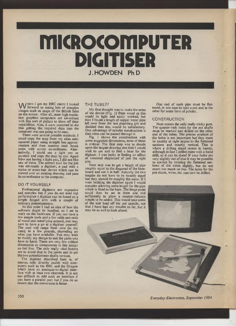
THE TUBE??
My first thought was to make the arms
of the device (Fig. 1) from wood as this
would be light and easily worked, but
then 1 found a length of copper water pipe
left over from the last plumbing job and
decided that this would be satisfactory.
One advantage of tubular construction is
that wires can be passed through it.
Fig. I shows the construction with
some suggested dimensions, none of these
is critical. The first step was to decide
upon the largest drawing size that I would
wish to use and to find a base for the
digitiser. I was lucky in finding an offcut
of veneered chipboard of just the right
size.
Next step was to get a length of pipe
roughly equal to the diagonal of the base-board and cut it in half. Actually the two
lengths do not have to be exactly equal
but they should be roughly the same. If I
were building the digitiser again I would
consider allowing extra length for the pipe
which is fixed to the base. The hinge point
could than be set in from one end
sufficiently to allow a counter-balance
weight to be added. This would take some
of the side load off the pot spindle; not
that I have had any trouble so far, but it
may be as well to look ahead.
One end of each pipe must be flat-tened, in one case to take a pot and in the
other for some form of pointer.
CONSTRUCTION
Next comes the only really tricky part.
The quarter-inch holes for the pot shafts
must be marked and drilled on the other
end of the tubes. The precise position of
the holes is not important but they must
be exactly at right angles to the flattened
sections and exactly vertical. This is
where a drilling stand comes in handy,
although in fact I drilled mine with a hand
drill; so it can be done! If your holes are
very slightly out of true it may be possible
to correct by twisting the flattened sec-tions of the tubes slightly, but do not
count too much on this. The holes for the
pot shank, wires, etc. can now be drilled.
Everyday Electronics, September 1984
i

By this time you should have found or
purchased a couple of pots. Again there is
nothing critical about these although they
must be linear types (as opposed to log.).
I suggest 10 kilohms as nominal but they
could range from perhaps 5kfl to 100kQ
in value and the two pots need not be the
same. I used Colvern wirewound pots
about an inch in diameter. The support
for the baseboard mounted pot consists
of a strip of 18 gauge aluminium which is
easily bent to shape in a vice (Fig. 1). Ad-just the dimensions for your pot and push
switch (if you intend to mount it on this
bracket). The aim should be to support
the pot just clear of the base. Mark out
the bracket and bend it with care or the
pot shaft will not be vertical. I chose to
mount my push switch on the bracket to
avoid having to run wires all round the
base but you may mount it in any con-venient place. Indeed two push switches
could be fitted if you feel you may need
them. The switches are intended to tell the
computer when to input the current arm
positions. If you can, choose one with a
light, silent, action.
When the metal bracket has been
made, drill it for the pot, switch and fixing
screws and mount the pot loosely with the
connection tags toward the top edge of
the board. On the main tube arm mark
and drill one of the holes for the spindle
fixing bolt with a slightly undersized drill.
Turn the pot spindle fully clockwise and
push the appropriate section of tube over
it. Turn this to its fully clockwise position
which should be with the arm in a
"North-East" or roughly "Two o'clock"
position. It is not necessary to be exact
but it IS essential that the pot should be
off its end stop when the arm is later
turned to its "North" or "12 o'clock"
position (Fig. 2a). Now for the only other
tricky bit. Mark out the position of the
hole for the pot shaft fixing bolts on the
pot shaft and drill the shaft with a slightly
undersized drill. It is absolutely essential
that there should be no slop at all between
the fixing bolt (6BA) and the shaft, so
ideally the bolt should have to cut itself a
very slight thread. It might be a good idea
in fact to thread the shaft with a 6BA tap
if you can keep it tight. Use a smaller drill
through the shaft to mark the fixing hole
on the other side of the tube and drill it
out.
Fix the second pot to the end of the
main arm and turn the tags toward the
tube. Rotate the shaft fully anti-clockwise
(as seen from underneath) and repeat the
operation as for the first pot. In this case
the fully clockwise (as seen from on top)
arm position should be about 45 degrees
more clockwise than the in-line position
(Fig. 2c).
ODD JOBS
That completes the difficult operations
and leaves a few odd jobs to do before
wiring up. Shape a small thin piece of
perspex to act as the cursor on the end of
the "moving" arm and inscribe a cross on
Fig. 1. Construction details of the
Digitiser together with the wiring
diagram shown below (pin con-nections are for BBC computer).
it. Mount the cursor on spacers as shown
in Fig. 1 so that it just skims the
baseboard when everything is assembled.
Fix a small strip of insulating material to
the back edge of the metal bracket, or to
the baseboard, to act as a grip for the
main interconnecting cable. Now is the
time to finish the baseboard and tubes to
your usual standards if you wish.
Wiring is very straightforward as
shown in Fig. 1. Any reversal of polarity
can be compensated for in the software. I
would suggest that multicore, overall
screened wire is used for the main cable
since electronic noise pick-up can be a
Problem. Since this is not so easy to get
hold of, especially in the scrap box, I have
included a function in the software which
takes the average of a number of readings
in order to reduce noise problems. If
screened wire is used, the screen should
be connected to OV at the D-type connec-tor.
SOFTWARE
Fig. 3 shows the principle of the essen-tial routine, PROCarm which indicates
the position of the cursor relative to the
a b c
"NORTH' SOUTH IN LINE
Fig. 2. Arm positions for the calibration program.
(f ,G
d
9o°
Everyday Electronics, September 1984
551

LISTING 1
>LIST
100 REM - DIGITISER CALIBRATION PROGRAM
110 REM - J. W.H ,den. - 1983
120 NO E7
130 CLS
140 PRINT" "•Sat m 'North' Intl praaa button"
130 REPEAT UNTIL ADVALl01-1
160 AI-FNAVG(30,1)
170 PRINT Al
180 VW7,REM - BEEP
190 REPEAT UNTIL ADVAL(0)-0
200 PRINT'"Sot • M —d'South' tl profs button"
210 REPEAT UNTILADVAL(0)-1
220 A2-FNAVW 30,1)
230 PRINT A2
240 V W 7
230 REPEAT UNTIL ADVALIO)-O
260 PRINT— Sot : dod • In tn 1119' tl praaa""'button"
270 REPEAT UNTIL ADVALIO)-1
280 A3-FNAVG(30,2)
290 PRINT A3
300 VDU7
310 REPEAT UNTIL ADVAL(0)-0
320 PRINT— Sat $ antl • on '90 dog.' Ind pre$$""'butt"
330 REPEAT UNTILa
ADVAL(0)-1
340 A4-FNAVO(30,2)
330 PRINT A4
360 VDU7
370 REPEAT UNTIL ADVALIO)-O
380 kTI-AI-A2
390 KT2-2-(A4-A3)
400 PRINT "'VALUES FOR DIGITISER PROGRAM DATA""'STATEMENT ARE,"
410 PRINTINT(Al)1"."i INTIKTI)i"."IINTIR311"."IINT(K.T2)
420 END
423
430 REM - AVERAGE N% READINGS FROM PORT SPECIFIED
440 DEFFNAVG(N%,PORT%)
430 LOCAL TL,CX
460 TL-O' CX-0
470 REPEAT
480 TL- TL.ADVAL(PORT%)
490 C%-CX.1
300 UNTIL C%-N%
310 TL-TL/N%
320 -TL
MICROCOMPUTER
DIGITISER
LISTING 2
)LIST
10 REM - DIGITISER PLOTTER PROGRAM
20 REM - J.N.lbwdan. - 1983
30 REM
40 DATA64424,43761.8977,43B79. REM - P•r••atK$ f— c,Iib,.t,. pr ogr44
W DATA 25.0,20.I,REM - Rod lanptha 1-1.1-2 1n 4nY un,ta.
70 REM
BO REM - SET LIP
90 REM
100 MODE7
110 READ AI,KTI,A3,KT2,LI,L2
120'"Pl/KTI
130 K2-PI/KT2
132 REM - At—to next two I,n•a ,f You have Printar 4nd a.r lan duap pr Pqr•-.
135 REM - PRINT TAB(16.3)9"PLOTTER"'
110 REM - -LOAD-SCR-DUMP"
130 ON ERROR WTO 1780
160 CLS
170 PROCac•l9aat
100 INPUT" "'IRIICH MODE%•otle
190 IF da)3 OR •ode-3 GOTO ISO
200 PRI •P
NT'^About tp b g.n
210 I-IWEY(200),REM - - lac. d.I.Y
220 VDU7,REM - DEEP
230 MODE •dda1PROC, net
.40 REM
250 REM - Ma1n 1ppp
260 REM
270 REPEAT
280 PROC•r•
290 PROCac •If
300 PROCkaY
310 IF (ADVgL 10) AND 31.1 THEN PROCpIPt
320 UNTIL FALSE
330 END
340 REM
330 REM - PROCEDURES
360 REM
370 DEFPROCara
390 THE GI TA-IAI-FNAV3./LING
390 .1-L1a81N(T1ETA)
400 vl-1.I •COS (TME Tq)
410 PSI-IFNRW 13,21-A31 Nc2
♦20 PSITOT-PSI.TMETA
430 x3-L_SIN(PSITOTI
440 _SIN(
P91TOT)
430
—1-2460
Y-YI•Y2
470 ENDPROC
48U
490 DEFPROCac4laaat
300 Pq INTTAB10.5.,"Move P—tor tP ra9u.rad bpttw laf t""'. ornar P111— Intl
praaa button.^
310 REPEAT UNTIL ADVAL 101-1
520 PROC•ra
330 9LX-X,BLY-Y
540 VDU7
530 REPEAT UNTIL ADVAL(0 -0
360 PRINT"'Nova p—tar tb 11.d top r,ght"'^c ar nor PP11t.Pn 4ntl praaa butt
X
570 REPEAT UNTIL ADVAL(01-1
580 PROC4ra
390 TRX-X, TRY-V
600 V
hI` XSCAL-1280/(TRY-BLXI
620 Y9CAL-1024/(TRY-BLY)
630 REPEAT UNTIL ADVAL(01-0
640 ENDPROC
630 REM
660 DEF FNAVO(N%. POR T%)
670 LOCAL TL. C%
680 TL-0.C%-O
690 REPEAT
700 TL-TL-ADVAL(PORT%)
710 CX-CX.1
720 UNTIL C%-N%
730 TL-TL/N%
740 -TL
750 REM
760 DEFPROCac•la
770 X-lX-81.X1 aX SCAL
780 Y-(Y-BLY).YSCAL
790 ENDPROC
800 REM
111 DEFPROCkay
020 KE—IW Y$(0)
830 IF KEY:-"" ENDPROC
810 IF KEY:-"M" STATE-4,ENDPROC
030 IF KE Vf-^L" SLATE-51ENDPWC
060 IF KEY•:-^P•• STATE-691ENDPRDC
870 IF S T ATE•211 ENpPROC
960 IF KEY$•"T'• STA TE• 031 ENDPROC
090 IF KEY:-CHR$(34, INPUT""K1IENDPROC
900 IF KEY:-CHR$(167) PROC... d.-. ENDPROC
910 IF KEY$•^S" PROCac ra•Ya, ENDPROC
920 IF KEY:•"0" PROCIP4dacrlENDPROC
930 IF KEYf-"O" PROCgc1 1END11.
940 IF KEY$-"C^ PROCcl.:ENDPROC
950 IF KEY:-CW$(L7F) PROCdaI
960 ENDPROC
970 REM
980 DEFPROCpI Pt
990 PLOT STATE,X,Y
1000 1F STATE-4 THEN STATE-3
1010 FOR N-9 TO 0 STEP-1
1020 OLD XIN.II-01.DX(N), OLDY (N.I1-OLVY I N), OLDS TATE IN. l I-OL DST ATE (N)
1030 NEXT
1040 QDX(0)-XIOLDV(01-YIDLDSTATE(0)-STATE
1050 ENDPROC
1060 REM
1070 DEFPROC, nIt
1080 STATE-4
1090 VDU5,REM - P—t t•.t 4a gr aPhlca.
1093 REM - Dl aabla cwy koy atl,t fun. teen.
1100 -FX4,1
1110 DIM OLDX(I0),GLDY110 .OLDSTATE(I0)
1120 ENDPROC
1130 REM
1140 DEFPROC.I.
1130 PROCgat atr
1160 IF LEFTf(K1,2)-^LS" OR LEFT6(K%,2)•"LG^ THEN CLGISTATE-4
1170 VDU7
I1B0 ENDPROC
1190 REM
1200 DEFPROC... dump
1210 .26,2
1220 CALL LDOD
1230 VDU3, 7
1240 ENDPROC
1230 REM
1260 DEFPROCacra•Ya
1270 PROCg:tatr
1280 IF -FT$I K:,011-9^ VW7,ENDPROC
1290 -OPT1,0
300 ON •ode-1 MID 1 1310,1310,1310.1330.1330,1330
1310 aSAVE-SCREEN••3000 7FFF
1320 GOT 1340
1330 -SAVE -SCREEN-4000 7E7F
1340 VUU7
1330 ENDPROC
1360 REM
1370 DEFPROCIP•dacr
1300 PROCgat atr
1390 IF LEFT$IK9,I--S" VW71ENDPROC
1393 aDP T 1,0
14W aLOAD"SCREEN^
1403 VDU7
1410 ENpPROC
1420 REM
1430 DEFPROCgc P1
1440 PROCgat atr
1430 LOCAL NI.N2
1460 NI•VAL .
Ml D$IKf,4.11)
1470 N2-VAL (I DO ( K:, 6, LEN<K$)-3))
1480 GCOL NI,N2
1490 ENDPRDC
1300 REM
1510 DEPROCgotatr
1320 ":
1330 REPEAT
1.340 C$•1 NKEY110)
1530 IF C1-"" GOTO 1570
1360 KMk,1.C:
1570 UNTIL Cf-CHR1113)
1380 ENDPROC
1590 REM
1600 DEFPROCdai
161U IF 01.1397 ATE 10)-4 DO TO 1660
1620 IF OLD9'ATE 101-83 MOVE 01.13Y(0),OLDY(0), MOVE OLDX(I),OLDY(II,PLOT 87.OLDX(2
).OLDY12)I WTD1660
1630 IF OLDSTATE(OI-69 PLOT 71, OLDX(0).OLDY(0)100TO1660
1640 NOVE OLDX(OI,OLDY(0)
1650 PLOT OLDSTATE(0).2,OLOX(1).OLDY(I)
1660 PROCPdp
1670 ENDPROC
1680 REM
1690 DEFPROCpPp
1700 FOR N-0 TO 9
1710 OLDXIN)-OLDX(N-J)
1720 OLDY(N)-OLDY(N.1)
1730 (ILDSTATE4NI-OLDSTATE(N.1)
1740 NEXT N
1730 ENDPROC
1770 MEN
1780 REM - ERROR WWWER
1790 REM
I BOO IF ERR-17 VW7,GOTO 270
I G10 MODE >, PR INT"•'Err or 1n I.na ",ERL
1820 REPORT
1830 PRINT
1640 -F .0
1830 END
552
Everyday Electronics, September 1984
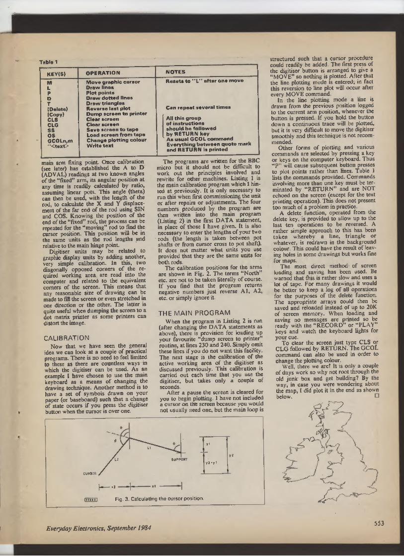
Table 1
KEY(S)
OPERATION
NOTES
M
Move graphic cursor
Resets to "L" after one move
L
Draw lines
P
Plot points
D
Draw dotted lines
T
Draw triangles
(Delete)
Reverse last plot
Can repeat several times
(Copy)
Dump screen to printer
CLS
Clear screen
All this group
CLG
Clear screen
of instructions
SS
Save screen to tape
should be followed
OS
Load screen from tape
by RETURN key
GCOLn,m
Change plotting colour
As usual GCOL command
text
Write text
Everything between quote mark
and RETURN is printed
main arm fixing point. Once calibration
(see later) has established the A to D
(ADVAL) readings at two known angles
of the "fixed" arm, its angular position at
any time is readily calculated by ratio,
assuming linear pots. This angle (theta)
can then be used, with the length of the
rod, to calculate the X and Y displace-ment of the far end of the rod using SIN
and COS. Knowing the position of the
end of the "fixed" rod, the process can be
repeated for the "moving" rod to find the
cursor position. This position will be in
the same units as the rod lengths and
relative to the main hinge point.
Digitiser units may be related to
graphic display units by adding another,
very simple calibration. In this, two
diagonally opposed corners of the re-
quired working area are read into the
computer and related to the equivalent
corners of the screen. This means that
any reasonable size of drawing can be
made to fill the screen or even stretched in
one direction or the other. The latter is
quite useful when dumping the screen to a
dot matrix printer as some printers can
distort the image.
CALIBRATION
Now that we have seen the general
idea we can look at a couple of practical
programs. There is no need to feel limited
to these as there are countless ways in
which the digitiser can be used. As an
example I have chosen to use the main
keyboard as a means of changing the
drawing technique. Another method is to
have a set of symbols drawn on your
paper (or baseboard) such that a change
of state occurs if you press the digitiser
button when the cursor is over one.
The programs are written for the BBC
micro but it should not be difficult to
work out the principles involved and
rewrite for other machines. Listing 1 is
the main calibration program which I hin-ted at previously. It is only necessary to
run this when first commissioning the unit
or after repairs or adjustments. The four
numbers produced by the program are
then written into the main program
(Listing 2) in the first DATA statement,
in place of those I have given. It is also
necessary to enter the lengths of your two
rods (the length is taken between pot
shafts or from cursor cross to pot shaft).
It does not matter what units you use
provided that they are the same units for
both rods.
The calibration positions for the arms
are shown in Fig. 2. The terms "North"
etc. are not to be taken literally of course.
If you find that the program returns
negative numbers just reverse Al, A2,
etc. or simply ignore it.
THE MAIN PROGRAM
When the program in Listing 2 is run
(after changing the DATA statements as
above), there is provision for loading up
your favourite "dump screen to printer"
routine, at lines 230 and 240. Simply omit
these lines if you do not want this facility.
The next stage is the calibration of the
active working area of the digitiser as
discussed previously. This calibration is
carried out each time that you use the
digitiser, but takes only a couple of
seconds.
After a pause the screen is cleared for
you to begin plotting. I have not included
a cursor on the screen because you would
not usually need one, but the main loop is
CURSOR
�--- .2
1"
tEEE\41 Fig. 3. Calculating the cursor position.
structured such that a cursor procedure
could readily be added. The first press of
the digitiser button is arranged to give a
"MOVE" so nothing is plotted. After that
the line plotting mode is entered; in fact
this reversion to line plot will occur after
every MOVE command.
In the line plotting mode a line is
drawn from the previous position logged
to the current arm position, whenever the
button is pressed. If you hold the button
down a continuous trace will be plotted,
but it is very difficult to move the digitiser
smoothly and this technique is not recom-mended.
Other forms of plotting and various
commands are selected by pressing a key
or keys on the computer keyboard. Thus
"P" will cause subsequent button presses
to plot points rather than lines. Table I
lists the commands provided. Commands
involving more than one key must be ter-minated by "RETURN" and are NOT
echoed on the screen (except for the text
printing operation). This does not present
too much of a problem in practice.
A delete function, operated from the
delete key, is provided to allow up to the
last ten operations to be reversed. A
rather simple approach to this has been
taken whereby a line, triangle or
whatever, is redrawn in the background
colour. This could have the result of leav-
ing holes in some drawings but works fine
for maps.
The most direct method of screen
loading and saving has been used. Be
warned that this is rather slow and uses a
lot of tape. For many drawings it would
be better to keep a log of all operations
for the purposes of the delete function.
The appropriate arrays could then be
saved and reloaded instead of up to 20K
of screen memory. When loading and
saving no messages are printed so be
ready with the "RECORD" or "PLAY"
keys and watch the keyboard lights for
your cue.
To clear the screen just type CLS or
CLG followed by RETURN. The GCOL
command can also be used in order to
change the plotting colour.
Well, there we are! It is only a couple
of days work so why not root through the
old junk box and get building? By the
way, in case you were wondering about
the map, I did plot it in the end as shown
below. ❑
1�
C
I
Everyday Electronics, September 1984
553
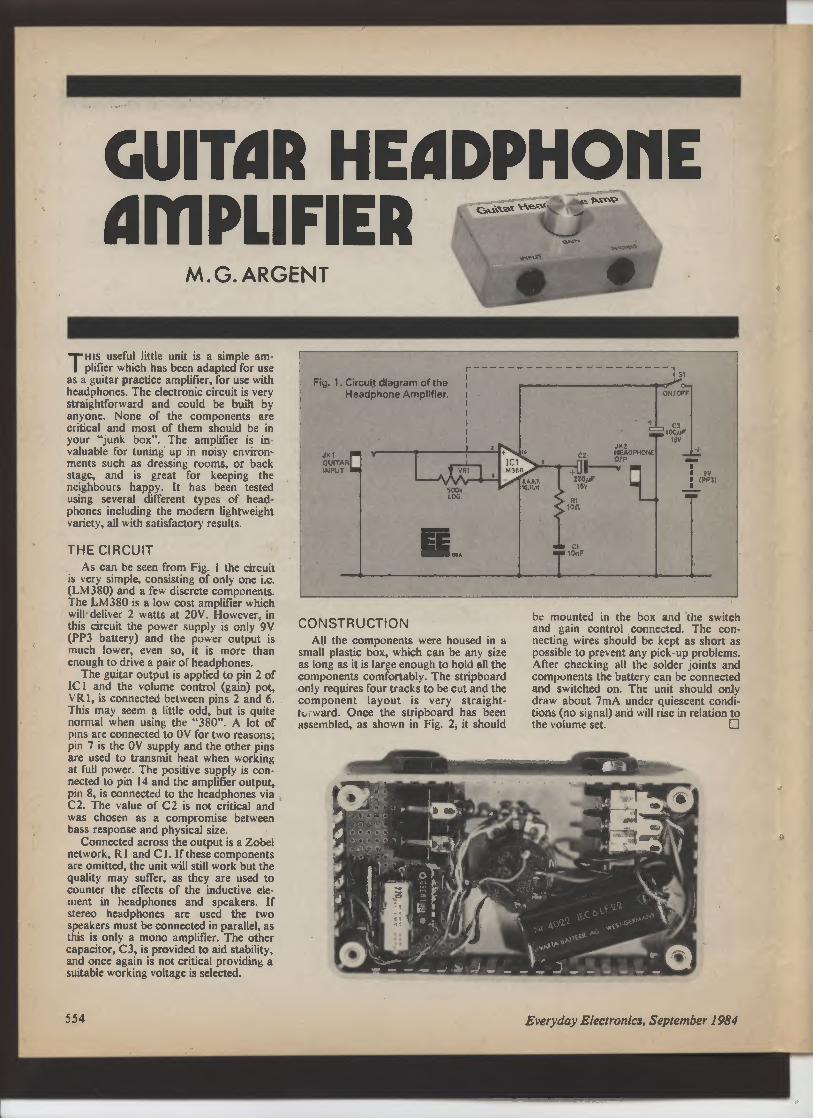
GUITAR HEilDPH011E
ilMPLIFIER
M.G.ARGENT
Tttls useful little unit is a simple am-plifier which has been adapted for use
as a guitar practice amplifier, for use with
headphones. The electronic circuit is very
straightforward and could be built by
anyone. None of the components are
critical and most of them should be in
your "junk box". The amplifier is in-valuable for tuning up in noisy environ-ments such as dressing rooms, or back
stage, and is great for keeping the
neighbours happy. It has been tested
using several different types of head-phones including the modern lightweight
variety, all with satisfactory results.
THE CIRCUIT
As can be seen from Fig. 1 the circuit
is very simple, consisting of only one i.c.
(LM380) and a few discrete components.
The LM380 is a low cost amplifier which
will deliver 2 watts at 20V. However, in
this circuit the power supply is only 9V
(PP3 battery) and the power output is
much lower, even so, it is more than
enough to drive a pair of headphones.
The guitar output is applied to pin 2 of
IC l and the volume control (gain) pot,
VRI, is connected between pins 2 and 6.
This may seem a little odd, but is quite
normal when using the "380". A lot of
pins are connected to OV for two reasons;
pin 7 is the OV supply and the other pins
are used to transmit heat when working
at full power. The positive supply is con-nected to pin 14 and the amplifier output,
pin 8, is connected to the headphones via
C2. The value of C2 is not critical and
was chosen as a compromise between
bass response and physical size.
Connected across the output is a Zobel
network, R I and C 1. If these components
are omitted, the unit will still work but the
quality may suffer, as they are used to
counter the effects of the inductive ele-ment in headphones and speakers. If
stereo headphones are used the two
speakers must be connected in parallel, as
this is only a mono amplifier. The other
capacitor, C3, is provided to aid stability,
and once again is not critical providing a
suitable working voltage is selected.
Fig. 1. Circuit diagram of the
Headphone Amplifier.
JK1
GUITAR
INPUT
r
VRt
6
500k
LOG
IC1
LM380
_
41.
10,11,12
I St
:>yo— ON/OFF
+ C3
100,aF
16V
JK2
C2 HEADPHONE
+0
OIP
220AiF
16V
R1
Ion
C1
10nF
CONSTRUCTION
All the components were housed in a
small plastic box, which can be any size
as long as it is large enough to hold all the
components comfortably. The stripboard
only requires four tracks to be cut and the
component layout is very straight-IL , ward. Once the stripboard has been
assembled, as shown in Fig. 2, it should
be mounted in the box and the switch
and gain control connected. The con-necting wires should be kept as short as
possible to prevent any pick-up problems.
After checking all the solder joints and
components the battery can be connected
and switched on. The unit should only
draw about 7mA under quiescent condi-tions (no signal) and will rise in relation to
the volume set. ❑
554 Everyday Electronics, September 1984

HEADPHONE
SKT
INPUT SKT
[EEbQAf
1 2 3 4 5 6 7
8 9 10 11 12 13
ON/OFF
SWITCH
Fig. 2. Stripboard layout and wiring diagram of the
Headphone Amplifier.
D
0. 0 0.
0 0 0 0
0 0••
0
0. 0 0
0 0. 0
0 0
0 0
0
0 0•
0. 0 0
0 0
0 0
,
0
0• -• 0
0. 0 0
0 0
0 0
,
0
••• 0
0. 0 0
0 0
0 0
•
0•• 0
0. 0 0
0 0
0 0
•• O• O
0 0
0 O
o O
0
000.60.0000••
0
0 0 0 0
0 0 0 0
0 0
0 0
0
0 0 0 0
0 0 0 0
0 0
0 0
•
0 0 0 0
0 0 0.
0 0
0 0
1 2 3 4 5 6 7 8 9 10 11 12 13
K
1
H
G
F
E
D
C
a
A
See
fta
page 560
Approx. cost
Guidance only
£6
COMPONENTS
Resistors
R1 1011+5%aW
VR1 500kQ log, switched
Capacitors
C1 1OnF disc ceramic
C2 220pF 16V electrolytic
axial
C3 100pF 16V electrolytic
axial
Semiconductors
is 1 LM380 audio amplifier
Miscellaneous
S1 (see VR1 n/ocontacts).
JK1 mono -,'in jack socket.
JK2 stereo }in jack socket (or
miniature to suit headphones).
Knob for gain control.
0.1 in matrix stripboard 12 strips
x 13 holes.
PP3 9V battery.
Plastic box as available.
This is the spot where readers pass on to fellow enthusiasts useful
and interesting circuits they have themselves devised. Payment is
CIRCUIT made for all circuits published in this feature. Contributions should
be accompanied by a letter stating that the circuit idea offered is
wholly or in significant part the original work of the sender and that
EXCHANGE it has not been offered for publication elsewhere.
SOFTWARE SALVAGE
Tiiis circuit is for use in retrieving cassette
based software, which will not run on a
computer. A cassette may not load for a
variety of reasons. These include: a lack of
high frequency response, due to azimuth dif-ferences in the recording and playback
machines, a low or varying output, caused by
worn or dirty heads, and noise on the tape
itself induced by stray magnetic fields.
The circuit was designed to overcome these
C4
problems. It connects between two cassette
recorders, and cleans up the signal, enabling a
better quality copy to be made. The input
stage consists of a variable gain amplifier,
which allows adjustment for a range of input
signals. This is followed by a band-pass filter,
made up of two sections. The first is a high-pass filter with a roll off of 9dB per octave
below 120OHz. The second is a low-pass filter
with a roll off of 9dB per octave above
240OHz. The output from this feeds a Schmitt
trigger, with a variable threshold. This may be
adjusted between 0.2V and 2.4V to secure
triggering on the data tones, while dis-
criminating against noise. The Schmitt also
restores "attack" to the signal, and provides a
constant output volume, which is stepped
down, through a potential divider, to suitable
audio levels.
P. Thompson,
Lennoxton,
Glasgow.
Everyday Electronics, September 1984 555

W ELL, here we are at the end of
Teach-In '84. Congratulations for
getting this far. You are now, I'd say,
likely to want to go ahead and design
your own circuits—and having designed
them to build them in a permanent form.
So, before we part company, here are
some hints for design and construction.
TEMPORARY BREADBOARDS
This Teach-In has been based on
solderless methods of construction. Plug-in breadboards like EBBO and its many
rivals are ideal for experiment and for
refining designs by selecting components
by trial and error.
Commercial designers usually try to
produce circuits which will accept the
rather wide tolerances of transistors and
integrated circuits. This is a good princi-ple because a circuit which accepts varia-tions among nominally identical devices
will also accept small changes which
result from ageing.
You, however, as an individual
designer, can improve on this. You can
start off with tolerant circuits, but go on
to select the best possible component
values to suit your particular devices.
AUTO BIAS
To give a simple example, in the "auto
bias" circuit (Fig. 12.1) the "rule of
thumb" is that if Rb is hFF times Rc then
VCE is half Vec. In other words, the
collector sits at half the supply voltage.
The rule falls down rather badly at low
supply voltages because it ignores the
effect of VBE. And in practice hFE is
known only very approximately.
For a given transistor type hFE might
vary over a three to one range such as
100-300. But if you start off with an
average value then adjust Rb by trial and
error while measuring VCE you can get it
just right. In fact you can set up to obtain
not just VCE=Vcc/2 but virtually any
A TWELVE-PART HOME STUDY COURSE IN THE
PRINCIPLES AND PRACTICE OF ELECTRONIC
CIRCUITS. ESSENTIALLY PRACTICAL, EACH PART
INCLUDES EXPERIMENTS TO DEMONSTRATE AND
PROVE THE THEORY.
USE OF A PROPRIETARY BREADBOARD
ELIMINATES NEED FOR SOLDERING AND MAKES
ASSEMBLY OF CIRCUITS SIMPLE.
THE IDEAL INTRODUCTION TO THE SUBJECT FOR
NEWCOMERS. ALSO A USEFUL REFRESHER
COURSE FOR OTHERS.
value of VCE you want, right up to nearly
Vcc itself or down to nearly zero.
With a good meter, a breadboard and
a selection of resistors, the job can be
done in minutes. You then use the actual
transistor and resistors in your permanent
circuit.
PERMANENT BASEBOARDS
Eventually you are ready to build the
circuit in a permanent form. So far, the
only solderless means of doing this which
we've used is the screw terminal block.
This is bulky and won't accept integrated
circuits.
Fig. 12.1. Auto-bias circuit.
Recently, permanent but solderless
breadboards compatible with i.c.s have
come on the market. They are based on
precision engineering.
Imagine a terminal in the form of a
tiny two-pronged fork. The prongs are
just far enough apart to grip firmly a wire
of a particular diameter. By shaping the
prongs so that they cut into the wire
slightly when it's pushed between them, a
good firm connection is made.
When suitably insulated wire is pushed
in, the prongs cut through the insulation
and grip the wire inside. So circuits can
be wired up using insulated wire, but
without soldering.
These "insulation displacement"
systems are simpler and faster to use than
By GEORGE HYLTON
_L(� � ONNTUM
their older rival, the solderless "wire-
wrap" system, in which a special tool
wraps wire round a rectangular post
whose corners bite into the wire.
Insulation-displacement boards are
about the present limit of refinement in
solderless wiring. But even they can't do
everything and some soldering is almost
inevitable. To connect off-the-board,
control-panel-mounted items such as
potentiometers reliably and permanently
calls for soldering to the potentiometer
connecting tags, if not to the board itself.
An essential job, then, is to learn how
to make good soldered joints. The way is
then open to using many forms of perma-nent baseboard. If you can't yet solder,
get someone to show you or follow the
explanations which appear in EE from
time to time.
SOLDERED BASEBOARDS
As you know, the commonest form
of permanent baseboard is the printed
circuit board (p.c.b.). This is a subject in
itself and I'm not going to discuss it here,
except to note that a purpose-designed
printed circuit is almost totally unadap-table. It is designed to do one job very
well, that is, to hold the parts and supply
the interconnections of one particular cir-cuit. It's an end-of-the-line item.
More versatile are "half-way" adap-tions of printed circuits such as
Veroboard or stripboard, where the user
is given a board with printed-circuit strip
connections with component lead holes at
convenient intervals. A simple hand
cutting tool enables the strips to be
broken into convenient segments to suit
individual designs. Boards with a hole
spacing of 1/10 inch (2.54mm) accept
most i.c.s, transistors and passive compo-nents.
Now that the design of plug-in ex-perimental boards is becoming standar-dised, manufacturers are making "half-
556 Everyday Electronics, September 1984

71
way" boards whose conductor patterns
match the terminal arrangements of the
plug-in boards exactly. A design worked
out on a plug-in board can then be easily
transferred to its permanent board.
PIN BOARDS
A crude but simple and versatile bread-board for discrete (not integrated) circuit
components can be made by driving pins
into plywood to form anchorage points
for components and wiring connections.
The ends of leads are wrapped round the
pins then soldered. Domestic pins, if new
and bright, do the job well and cheaply.
The great advantage of pinboard con-struction is that the components and wir-
ing are both on the same side of the
board, which makes checking and fault
tracing easy. Also, the positions of the
pins are entirely under the constructor's
control.
The component layout can be made to
follow the circuit diagram so closely that
with a little ingenuity an actual circuit
diagram, laid over the plywood, can be
used as a wiring plan. Short-lead compo-nents salvaged from printed circuit
boards can be accommodated, and if the
component layout is kept fairly open
modifications can be made later.
ENCLOSURES
Most finished circuits require a hous-ing. Often this must incorporate a panel
on which switches, volume controls, jack
sockets, meters, and the like can be
mounted. Neat plastic or metal boxes can
be bought from advertisers in EE. Boxes
made for other purposes (such as the
switch boxes used by electricians for
mounting switches in walls) can
sometimes be adapted; for example, by
adding a panel cut from sheet aluminium.
Most enclosures are expensive. An
economic alternative is to make your own
from easily-obtained materials. This is
much easier than it sounds. For all-metal
enclosures the most suitable material is
sheet aluminium. For insulated enclosures
the choice includes plywood, hardboard
and laminated materials such as Formica.
Hardboard and plywood are easy to
cut and can be joined by pinning and/or
gluing with wood glue. Formica is less
easy to work, but is by far the most at-tractive in appearance and being thin is
most suitable for panels, where the
thickness of the other materials is often
an embarrassment. Here are some tips on
working with Formica and similar
laminated materials—which, by the way,
can often be bought cheaply from DIY
shops as offcuts.
CUTTING LAMINATED
MATERIALS
Although it can be cut with a hacksaw,
Formica and the like is best cut by a
method known as "score and snap". This
needs some skill and practice but once
mastered is quick and easy. In "score and
snap" the line of cut is first scratched
deeply into the decorative side of the
laminate (which is the harder side). When
bent upwards, "into" the scratch, the
board snaps along the score line.
It's essential to score right across a
piece of Formica, from one edge to
another. Stopping halfway isn't possible.
Use a special tool for the scoring. The
easiest to obtain is a purpose-made scor-
ing blade designed to fit into the holders
of handyman's "trimming knives". (I use
a Stanley blade No. 5194 in a Stanley
199 holder.)
When drilling holes in Formica always
drill from the decorative side. Small
loudspeakers can be glued to the back of
a panel, after first drilling a pattern of
holes to let the sound out.
A form of enclosure which is often
convenient has both a removable panel
and a removable back. To make it, cut
the top, bottom, and sides from
hardboard or plywood and assemble
them into a rectangular tube by using
square-section wooden moulding for cor-ner braces (Fig. 12.2). The panel and
back can be fixed with screws driven into
these corner braces.
FREE COMPONENTS
The average discarded radio or TV set
contains large numbers of components
which potentially are re-usable. Unfor-
tunately, an old TV also contains a pic-ture tube, which can be dangerous! Inside
the tube is a vacuum. Outside is the
atmosphere, pressing down on the tube at
14 pounds per square inch (Ikg/sq.cm).
The total pressure on a large tube is
several tons. If the tube is broken this
pressure makes it implode violently and
although an implosion is less spectacular
than an explosion, chunks of sharp-edged
glass are still thrown about.
In order not to be around when it hap-pens, either remove components from a
TV set without touching the tube or, if
you know how, first remove the tube and
dispose of it safely.
Goggles or a visor should be worn
when working on a TV set with a tube or
handling the tube. Better still, avoid TV
tubes altogether. Some TV repair shops
will sell you old sets with the tube
removed. Many give them away after
removing what parts they need; there are
still plenty left for you.
Resistors, unless special in some way,
are hardly worth the trouble of unsolder-ing from their circuit boards. Capacitors
are a better bet. So are discrete tran-sistors. I.C.s are so difficult to unsolder
that they usually get ruined in the at-
tempt. Inductors of various sorts can be
useful, including those inside metal
"screening cans"; these often have re-windable coil formers (tubes) with dust-iron or ferrite "slugs" for tuning adjust-ment.
Colour TVs may contain a quartz
crystal which (in Europe) resonates at
about 4.3MHz, and a glass delay line
complete with input and output couplers.
COMPONENT CHECKING
Before trying to use salvaged compo-nents check them. For bipolar transistors
a simple two-diode test will sort out most
of the duds. A bipolar transistor has two
junctions, base-emitter and base-collector. Each junction by itself is a
diode. An ohmmeter applied to an intact
junction will register a resistance with the
test leads one way and an open circuit (in-finite resistance) the other, as the meter's
internal battery forward-biases or
reverse-biases the junction.
If your meter has a I.5V cell for ohms
measurements and the transistor is a
silicon type then in the forward direction
the meter needle will probably move to a
position between third-scale and half-scale. (For an old-fashioned germanium
transistor the deflection is less.) Readings
of zero ohms (short-circuits) indicate
duds.
The larger values of capacitor can be
given an ohmmeter check. When the
Fig. 12.2. Open-ended box construction for an equipment enclosure. The back and the front
panel are screwed to the corner braces.
TIMBER CORNER
BRACES
HARDBOARD OR
PLYWOOD
Everyday Electronics, September 1984 557
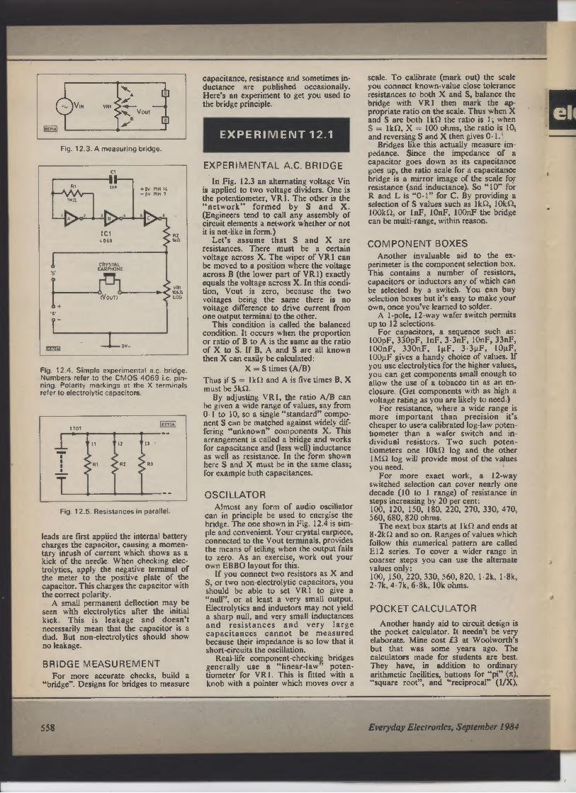
Fig. 12.3. A measuring bridge.
CRYSTAL
EARPHONE
Fig. 12.4. Simple experimental a.c. bridge.
Numbers refer to the CMOS 4069 i.c. pin-ning. Polarity markings at the X terminals
refer to electrolytic capacitors.
EE73A
I TOT
Fig. 12.5. Resistances in parallel
leads are first applied the internal battery
charges the capacitor, causing a momen-tary inrush of current which shows as a
kick of the needle. When checking elec-trolytics, apply the negative terminal of
the meter to the positive plate of the
capacitor. This charges the capacitor with
the correct polarity.
A small permanent defection may be
seen with electrolytics after the initial
kick. This is leakage and doesn't
necessarily mean that the capacitor is a
dud. But non-electrolytics should show
no leakage.
BRIDGE MEASUREMENT
For more accurate checks, build a
"bridge". Designs for bridges to measure
capacitance, resistance and sometimes in-ductance are published occasionally.
Here's an experiment to get you used to
the bridge principle.
EXPERIMENT 12.1
EXPERIMENTAL A.C. BRIDGE
In Fig. 12.3 an alternating voltage Vin
is applied to two voltage dividers. One is
the potentiometer, VRI. The other is the
"network" formed by S and X.
(Engineers tend to call any assembly of
circuit elements a network whether or not
it is net-like in form.)
Let's assume that S and X are
resistances. There must be a certain
voltage across X. The wiper of VRI can
be moved to a position where the voltage
across B (the lower part of VRI) exactly
equals the voltage across X. In this condi-tion, Vout is zero, because the two
voltages being the same there is no
voltage difference to drive current from
one output terminal to the other.
This condition is called the balanced
condition. It occurs when the proportion
or ratio of B to A is the same as the ratio
of X to S. If B, A and S are all known
then X can easily be calculated:
X = S times (A/B)
Thus if S = IkQ and A is five times B, X
must be 5kQ.
By adjusting VRI, the ratio A/B can
be given a wide range of values, say from
0• l to 10, so a single "standard" compo-nent S can be matched against widely dif-fering "unknown" components X. This
arrangement is called a bridge and works
for capacitance and (less well) inductance
as well as resistance. In the form shown
here S and X must be in the same class;
for example both capacitances.
OSCILLATOR
Almost any form of audio oscillator
can in principle be used to energise the
bridge. The one shown in Fig. 12.4 is sim-
ple and convenient. Your crystal earpiece,
connected to the Vout terminals, provides
the means of telling when the output falls
to zero. As an exercise, work out your
own EBBO layout for this.
If you connect two resistors as X and
S, or two non-electrolytic capacitors, you
should be able to set VRI to give a
"null", or at least a very small output.
Electrolytics and inductors may not yield
a sharp null, and very small inductances
and resistances and very large
capacitances cannot be measured
because their impedance is so low that it
short-circuits the oscillation.
Real-life component-checking bridges
generally use a "linear-law" poten-tiometer for VRI. This is fitted with a
knob with a pointer which moves over a
scale. To calibrate (mark out) the scale
you connect known-value close tolerance
resistances to both X and S, balance the
bridge with VRI then mark the ap-propriate ratio on the scale. Thus when X
and S are both l kit the ratio is 1; when
S = IU1, X = 100 ohms, the ratio is 10,
and reversing S and X then gives 0. 1.
Bridges like this actually measure im-pedance. Since the impedance of a
capacitor goes down as its capacitance
goes up, the ratio scale for a capacitance
bridge is a mirror image of the scale for
resistance (and inductance). So "10" for
R and L is "0.1" for C. By providing a
selection of S values such as IkO, IOU1,
IOOkQ, or 1nF, IOnF, 100nF the bridge
can be multi-range, within reason.
COMPONENT BOXES
Another invaluable aid to the ex-
perimeter is the component selection box.
This contains a number of resistors,
capacitors or inductors any of which can
be selected by a switch. You can buy
selection boxes but it's easy to make your
own, once you've learned to solder.
A 1-pole, 12-way wafer switch permits
up to 12 selections.
For capacitors, a sequence such as:
100pF, 330pF, lnF, 3.3nF, 10nF, 33nF,
IOOnF, 330nF, 1µF, 3.3µF, 10µF,
I00gF gives a handy choice of values. If
you use electrolytics for the higher values,
you can get components small enough to
allow the use of a tobacco tin as an en-closure. (Get components with as high a
voltage rating as you are likely to need.)
For resistance, where a wide range is
more important than precision it's
cheaper to use•a calibrated log-law poten-tiometer than a wafer switch and in-dividual resistors. Two such poten-tiometers one 10ki2 log and the other
IMf1 log will provide most of the values
you need.
For more exact work, a 12-way
switched selection can cover nearly one
decade (10 to 1 range) of resistance in
steps increasing by 20 per cent:
100, 120, 150, 180, 220, 270, 330, 470,
560, 680, 820 ohms.
The next box starts at I k Q and ends at
8.2ki2 and so on. Ranges of values which
follow this numerical pattern are called
E12 series. To cover a wider range in
coarser steps you can use the alternate
values only:
100, 150, 220, 330, 560, 820, 1.2k, 1.8k,
2.7k, 4.7k, 6.8k, 10k ohms.
POCKET CALCULATOR
Another handy aid to circuit design is
the pocket calculator. It needn't be very
elaborate. Mine cost £3 at Woolworth's
but that was some years ago. The
calculators made for students are best.
They have, in addition to ordinary
arithmetic facilities, buttons for "pi" (n),
"square root", and "reciprocal" (1/X),
558
Everyday Electronics, September 1984

Of
h
d
:h
4
and a memory to which you can add (or
subtract) numbers.
The number "pi" comes into most a.c.
calculations. The reactance of an induc-tance, for example, is 211 f L ohms, where
f is in hertz and L in henries. (For kHz
you multiply by 1,000, for MHz by I
million. For mH you divide by 1,000, for
µH by 1 million.) Don't buy a very
elaborate calculator with all sorts of
facilities you may never need.
PARALLEL RESISTANCES
A student's calculator is excellent for
doing a job which constantly crops up:
finding resistances in parallel. The key to
the calculation (Fig. 12.5) is the fact that
each resistance feels the full voltage V.
The total current (ITOT) is therefore the
sum of all the individual currents (I1 + I2
+ 13 ... and so on), one current for each
resistance. The equivalent single
resistance is then R = V/1T0T.
A useful way of simplifying the
problem is to think of each resistance not
in terms of its power to resist current flow
but in terms of the extent to which it per-mits current to flow.
A low resistance permits more current
to flow than a high one. If a resistance is
reduced to zero then it becomes a simple
conductor; it conducts with absolute
freedom. A real resistance conducts with
less than absolute freedom, but it still
conducts, a bit. This ability to conduct
partially is called, quite simply, conduc-tance. A low resistance has a high con-ductance. A high resistance has a low
conductance.
CONDUCTANCE
CALCULATIONS
Now, conductance, though it doesn't
often appear in the pages of EE, is an
exact numerical quantity, just like
resistance. It is in fact a sort of mirror
image of resistance.
Conductance is a useful quantity for
our present need because conductances in
parallel simply add together. If, in Fig.
12.5, RI has a conductance of 1 unit, R2
and 2 units and R3 of 3 units then the
total conductance is 1 + 2 + 3 = 6 units.
The unit of conductance has a name,
the siemens, after a German scientist
called Siemens. (In older books it was
called the "mho", which is "ohm" written
backwards to suggest the mirror-image
quality.)
How do you find the conductance if all
you know is the resistance? Easy, with a
calculator. You key in the resistance then
press "I/X". The answer is the conduc-tance. For typical electronics-circuit
values of resistance the conductance of-ten comes out as a messy-looking decimal
fraction. My calculator tells me that the
conductance of a 3.3k52 resistance is
0.000303. But you don't have to worry
about that. The calculator doesn't mind
how messy it looks!
ACCUMULATING MEMORY
Given a calculator with an accu-mulating memory (M+) button, it's easy
to find the total conductance of any num-ber of resistances in parallel.
Key in the first resistance, R 1, press
"I/X" to turn it into its conductance,
store the answer in the accumulating
memory by pressing "M+". Then key in
R2, press "1/X" and add the answer to
what's in the memory. Do the same for
R3 and so on until you've put in all the
resistances in your parallel network. The
memory now contains the total conduc-tance.
Press the "memory recall" button
(usually marked "MR" or "R") and the
calculator will display it. It's still a messy
fraction. To convert it into the equivalent
resistance, press "I/X". That's the
answer, the equivalent single resistance of
all those separate resistances in parallel.
In practice it takes a good deal less
time to do the calculation than it has
taken you to read my rather laboured
description of the process. But you must
have a calculator with an accumulative
memory. Some calculators only have
memories that hold the last figure you
key in. They wipe out what has been put
in before. No good for this job.
COMMON SENSE
Use your common sense in dealing
with the answers. I've just calculated the
equivalent of 3300 and 3.3kQ in parallel.
Answer: 300.000352. But clearly the last
bit is of no practical significance. The
answer for practical purposes is simply
30052. (As a matter of fact 30052 is the
correct answer. The extra fraction of my
calculator is the result of its not being
able to make the calculation to enough
figures to get it absolutely right.)
This calculation shows that if you need
3000 but haven't got a 30052 resistor you
can make one up from 3300 and 3.3kQ
in parallel.
ADJUSTING RESISTANCES
Quite often, the problem is to find
some combination of parallel resistances
of standard values which will make up
some non-standard value which you need.
Suppose, for instance, that you have a
stock of "E12- resistors but need 70052,
which is not in the E 12 series. The nearest
value, 68052, will do for everyday pur-poses, but not for more precise jobs
where the extra error of about 3 per cent
(over and above the tolerance) would be
unacceptable.
Suppose we start with a standard value
which is too high, then connect another
across it, can we get close enough to
70052? Let's try 82052. If we work out the
conductance of 7000 then subtract the
conductance of 8200 we are left with the
extra conductance we need. By inverting
this into its equivalent resistance (with the
ANSWERS TO PART II
O 11. 1 (a) O.5Hz. (The f to V converter
gives a change of 1 mV per
hertz and this is amplified
1,000 times.)
(b) 5 parts per million.
(c) At least every 3 seconds. (A
drift of O.5Hz gives 50OmV
output change and upsets the
system. Time between retun-ings must be less than time
taken to drift 0.5Hz, which is
equivalent to 5 ppm. if the
oscillator drifts 1OOppm in 60
seconds it drifts 5ppm in 3 sec.
This shows how vulnerable the
system is to changes of tem-perature.)
I/X key) we get the required parallel
second resistance.
My calculator says 4,78552. The
nearest E12 value is 4,70052. Will this
do? Try it. My calculator says that
4,70052 and 82052 in parallel come to
6980. This is well within l per cent of
70052 so unless very great precision is
needed it should do. (If very great preci-sion is needed we'll have to use very close
tolerance resistors, in which case we may
as well buy a 70052 precision resistor and
forget about parallel combinations.)
ALIGNMENT CHARTS
Useful though calculators are, for
some jobs using them is tedious. For
example, the resonant frequency of an
LC tuned circuit is 1/[2nV(LC)J. This
may be calculable but it's quicker to use
an alignment chart. Such charts appear in
books about electronics and in magazines
from time to time. The same chart which
gives the resonant frequency can be made
to give the reactances of inductance and
capacitance as well, so you get three for
the price of one.
GOOD LUCK!
That's positively the last bit of theory
in this Teach-In! I hope you've enjoyed
the series and will now move on to greater
things. Good luck, and thanks for coming
along. ❑
Everyday Electronics, September 1984
INVITATION
84 readers to
Teach In with our
continue
new
EE invites
their studies SERIES—
EEECTRON S 21,
October
DIGITAL
Starting date Se
pternber
issueEln of Wiith your NEWSAGENT
Now!
559

Repair Job
Although, thanks to new techniques
and materials, the reliability of printed
circuit boards has improved beyond
recognition, even now it is still possible
to cause damage and/or "curling" of
the copper tracks through excessive
heat.
The repair to such damage can be
rather messy and not always suc-cessful. However, a repair kit from OK
Industries UK promises to take some
of the "trial-and-error' out of the repair
to p.c.b.s.
They also claim that the salvage of
just one printed circuit board assembly
and the new track repair kit is paid for.
The kit is available in de-luxe, stan-dard and economy form, includes
master frames with tracks, fingers,
pads, elbows and flat-pack pads,
eyelets and funnelets plus the setting
tools. Standard and de-luxe kits also
have consumables such as epoxy, flux,
cleaner, spatulas, abrasive sticks and
other items, as well as tweezers,
clamps and knives.
The addition of a temperature con-trolled soldering iron and five high
quality pliers makes up the de-luxe kit.
The copper master frames are not
pre-tinned because the epoxy bond
between the new circuit and the prin-ted circuit board is destroyed later by
re-soldering which melts the tin coat
and epoxy.
All items can be purchased
separately. For more details and prices
write to: OK Industries UK Ltd., Dept
EE, Dutton Lane, Eastleigh, Hants
S05 4AA.
560
BY DAVE BARRINGTON
Blowing A Fuse
The safety of equipment should
always be one of the main criterion
when designing projects and so the in-clusion of a fuse is always to be recom-mended. This is strongly advisable
where mains voltages are present.
Two types of cartridge fuses are
usually used in equipment and consists
of the anti-surge or ''slow-blow" and
the ordinary "quick-blow" types.
The choice of the "slow-blow" type
is used where a high current or "surge"
is present on switch-on. Circuits which
are particularly vulnerable to this effect
are those containing motors, filament
lamps and charging capacitors.
The filament of a cold lamp has a
low resistance so, on first switching on,
there will be a high current until tem-perature rises. Electric motors pass an
unusually high current until they reach
operating speeds.
Another closely linked safety factor
is in making tuseholders touch- or
tamper-proof. To this end, a range of
"fully touch-proof" fuseholders ac-cepting 5 x 20mm fuse cartridges,
with bayonet and screw release
cap/fuse carrier, are available from A.
F. Bulgin.
The bayonet release types have a
new moulded design and robust metal
contacts. They claim that the fuse can-not become open circuit when pushing
cap/fuse carrier after insertion. They
also claim that it is impossible for the
"standard" finger to touch the inner
contacts, even if the fuse is inserted
with cap/carrier removed.
Please mention
EVERYDAY
ELECTRONICS
when replying
to products
mentioned
on this page
and to
Classified Ads
For added safety, moulded insulation
covers to shroud the fuse body and
contacts are available as extras.
The bayonet versions are produced
with either a round or square bezel,
both being low profile. The screw
styles are available with round bezels
with a choice of high or low profile.
For details of local stockists contact:
A. F. Bulgin & Co. PLC, Dept EE,
Bypass Road, Barking, Essex IG11
OAZ.
CONSTRUCTIONAL PROJECTS
Sound Operated Flash
The operational amplifier i.c. used in the
Sound Operated Flash project is the
equivalent of two "popular" 741 devices.
Therefore, if any readers have difficulty in
obtaining the MC1458 i.c. then, by
adapting the wiring and board layout, the
circuit could be built using two 741 s.
However, the MC1458 dual op-amp is
also listed as the LM1458 and is currently
stocked by: Electrovalue; Greenweld
(MC1458); Magenta (MC1458); Rapid and
TK Electronics. All the above mentioned
suppliers also stock the C106D thyristor.
Guitar Headphone Amplifier
The LM380 audio amplifier i.c. called for
in the Guitar Headphone Amplifier is
available from: Magenta; Maplin; Rapid and
TK Electronics.
Op-Amp Power Supply
There should be no problems in obtaining
components for the Op-Amp Power Supply.
The dual-tracking regulator may prove a
little difficult to locate, but is available
from Maplin, Order code XX02C (4195).
The transformer is specified as 15-0-1 5V
at 100mA. If a type of this rating cannot be
obtained then a similar type can be used.
Note, however, that the secondary voltage
must not be any more than that specified.
The current rating of any other transfor-mer can be higher as desired, but note that
no more than 50mA can be drawn from the
circuit whatever the secondary current
rating the alternative transformer has. For
example, a transformer of 12-0-12V at
300mA could be used without damage.
A transformer of 15-0-15V at 50mA
could be used but, of course, the current
available would then only be 25mA per rail.
Caravan Dipstick
The dual operational amplifier type
µA747 used in the Caravan Dipstick is
available from Maplin Electronic Supplies.
Microcomputer Digitiser
We cannot foresee any component buy-ing problems for the Microcomputer
Digitiser.
Everyday Electronics, September 1984
61-PAK BARGAINS
ELECT & PIEZO BUZZERS
0/No VP 101
lisp
CSC'
Ni, VP IM
"Is
Pifll)
Mmoturr .no pnro Ot,, r
ourrer Wn,te piastre ..
n� umpuan
4.Hr appro.
OurDutn
70601A, @ 1 "P
P.- 12Vd c 4rnA,
D.: 22,6a I • 115mm
frung Centres 265mm
PIEZO
Pieto Dotter WNte plaslK 40mm
ieWs For use on ac mains
ha4uerxy 35kHt appro.
Output LO IAI @ lm hip
Power 240Va c 5mA
Dims 321dial . 14mm
Firing centres 38mm
ELECTRONIC
All-in re riec rromc buuers
Sold ,.if wort Dlzsoc 15U
leads F,i,, a rr SOO e,
aDDru.
0- 22.16. 151rm
0 our Me iA, @ m 4p
f. mq centies 2&-N 2t nA Oft VP 82 6V 25mA VP 83
W 25rrus 0, N, VP N 12V 2W VP 86
all each
SUB-BOX
A real -vexing disc provides
Close l0le-Ce substitution re
vatora of 36 preferred values
from 5ohms to 1Kahm Simply
it. clips ,ntu cncuit and swivel
until optimum result ,s
achieved
0 Nn VP 112 E4 75
O
The Third and
Fourth Hand ...
1 e
4 ' you always need
but have never got
until now This helpful
unit with Rod mounted
horizontally on Heavy
Crocodile clips
ed to rod ends Six
8 sockets lomts give
infinde variation and post
tans through 360" also available attached to Rod
a 2J dam magrxfier giving Mx magnification
Helping hand unn available with or without
magnifier Our price with magnifier as illustrated
ORDER NO T402 E5.50.
Without magnifier ORDER NO T400 f4.75.
OPTO 7-Segment Displays
Brand new 1st Quality
LITRONIX DL 707R 14-pin
Red 0.3' Common Anode Display 09 with
right hand decimal point TTL compatible
5v DC Supply Data supplied
IN
PACKS
OF
5 pieces E3
10 pieces ES
50 pieces E20
100 pieces E35
1.000 pieces £300
160p each
150p each,
140p each,
35p each
13Op each
THE MORE YOU BUY -
THE LESS YOU PAY
BI-PAK'S OPTO SPECIAL
A selection of large and small sized LED's
in various shapes, sizes & colours,togeth
er with 7 Segment Displays both anode &
cathode plus photo transistors emitters
and detectors Cadmium Cell ORP12 and
Germ photo transistor OCP71 included In
all a total of 25 Opto pieces valued over
V2 Normal Price
Order No VP57
Our Super Value
Price Just
£5.00
IV
Ittitt
HIGH QUALITY MODULES FOR STEREO,
MONO & OTHER AUDIO EQUIPMENT
Audio Amplifiers
POWER O/P MAX SUP
O/No. R M S VOLTAGE PRICE
AL 30A 10 Watts 30V E4.95
AL 60 25 Watts 30-50V 05.92
AL BO 35 Watts 40.60V E9.75
AL 120 50 Watts 50-70V E15.22
AL 250 125 Watts 50 BOV f20.60
Stabs isod Power Supplies -
Output current 2.5 Amps
0/No AC Input Price
SPM 120/45 40ASV E11.05 Js
SPM 120/55 50-55V E8.05 eair
SPM 120/65 6065V E8.05 ie
Stereo
Pro-Amplifier ✓ AL 250
O/No Supply Vtg. Price
PA 100 30/55V E75 50
Mona Pre-Amplfiers - Operating Vtg 40-65V
O/No
MM 100 Suitable for Disco Mixer
MM 1000 Suitable for Guitar Pre-Amp Mixer
Magnetic Cartridge Pro-Amplifier
O/No MPA30. Sup Vtg 20-30V Price E4.29
Monographic Equaliser
GE 100 MKII 10 Channel
OUR PRICE ONLY 1120.00
Full Spectfications and Data
available on request. Please
send self addressed envelope.
INTRUSION
ALARM
The DOOR BIRD
DB 2000 alerts
you before your
door is opened.
Just hang on
the inside door
knob alarm is
activated as
soon as the
Outside door
knob is touched
ONLY E3.95
TECASBOTY
Price
E14.75
E 14.75
GE 100 MKN
DIGITAL VOLT METER MODULE
3 7 segment displays Basic Circuit 0
2v- instructions provided to extend
v
oltayye 8 current ranges Operating
vz3ge 9/12v Typ Power Con
sumpron 5OmA
0/No VP99 Once only price
£9.95
SINGLE SIDED FIBREGLASS
BOARD
Order NoPreces Sae Sy Ins Price
FBI d 9 v 2, 111 111 50
F82 3 11 . 3" 100 f150
F B3 13 - 3' 156 f2 00
DOUBLE SIDED IF
BOARD
FB4 2 14 x 4' 110 11200
METRIC &
BRITISH
MEASURES,
Yt
ELECTRONIC SIREN 12V OC
Red plastic case with adjustable hang
bracket Emits high pitched will note
of varying pitch - 100 cycles per minute
Dims 90mm Idea I Gomm (depth) Power
IN DC
Our Price: E5.50
RATCHET SCREWDRIVER KIT
Comprises 2 standard screwdnver blades 5 &
7mm sue 2 cross pant sae 4 & 6 1 Ratchet
handle 5-n Kit EIAS each. 0/No 3298
THE ELECTRONIC COMPONENTS AND
SEMICONDUCTOR BARGAIN
Of THE YEAR I
This collection of Components and Semiconductors for the
hobbyist is probably the most value-packed selection ever offered.
it consists of Resistors. carbon and wirewound of various values
Capacitors All types, sons and sizes including electrolitics
Potentiometers - single, dual, slider and preset. Switches, Fuses,
Heatsinks, Wire, P.C.B Board. Plugs, Sockets etc., PLUS a selection
of Semiconductors for everyday use in popular Hobby Projects
These include. SCR s, Diodes, Rectifiers, Trues & Bridges as well
as a first class mix of Transistors and I. C . In all, we estimate the
value of this in current retail catalogues to be over f251 So. help
yourself to a great surprise and order a Box TODAY for 48
ONLY at BI PAK Remember, stocks are limited so .
hurry, You can call us on 09203182i3442 and order JUSt £6.50
with your Barclaycard or Access Card - 24hi
Answerphone Service NOW Order No. VP 85 1
BI-PAK
•
L
� l
OUR GREAT NEW 1984 CATALOGUE
Presented with a Professional Approach and Appeal u; All who
require Ouakty Electromc Components Semiconductors and other
Accessories ALL at realistic prices There are no wasted pages of
useless information so often included in Catalogues published
nowadays Just solid facts a price. description and individual
features of what we have available But remember 81- PAK 's
policy has always been to sell quality components at
competitive prices and THAT WE STILL DO
We, hold vast stocks In stock for fast immediate delivery all
items ,n our Catalogue are avarlable ex stock The Catalogue
,s designed for use with our 24 hours "ansaphone ' service
and the Vtsa/Access credit cards which we accept over
i the telephone
To receive your NEW 1954 BI-PAK Catalogue send
75p PLUS 25p p&p to
Send your orders to Dept EE9 BI PAK PO BOX 6 WARE. HERTS
SHOP AT 3 BALDOCK ST WARE, HERTS
TERMS CASH WITH ORDER SAME DAY DESPATCH ACCESS
BARCLAYCARD ALSO ACCEPTED TEL 1092013182 GIRD 398 7006
ADD 15% VAT AND 75p PER ORDER POSTAGE AND PACKING
IF 100
f 1 50
12 00
SILICON BRIDGE
RECTIFIERS
Comprising 4 .
1 } Amp rectifers
mounted on PCB
VRM - 150 vlts
IFM 15 Amps
Size. 1 inch square
10 off 111.00
50 ott 114.50
100 0 f £7.50
ORDER NO 4R1 B
Rect
MINIATURE VICE
and „
for portability Single coin•
secure or release SUCI
Plastic jaws with rubber p., i..
20mm wide, open oui
40mm. Dien. 85 65 m
60mm appro.
FANTASTIC VALUE
O7No vP 95 ONLY (1 60
TRANSISTOR CLEARANCE
AN Sons Transistors A mated Bag NPN
PNP Silicon & Germ Mainly Uncoded You
100 To Son Pack includes Instructions For
Making Simple Transistor Tester Super
Value Order No VP60 EIM
Pak
No
VPI
VP2
VP3
VP4
VP5
VP6
VP7
VP8
VP9
VP10
VP II
VP12
VP13
VP14
VP15
VP16
VP17
VP18
VP19
VP20
VP21
VP22
VP23
VP24
VP25
VP26
VP27
VP28
VP29
VP30
VP31
VP32
VP33
VP34
VP35
VP36
VP37
VP42
VP43
VALUE PACKS
Dry Desenpbon Price
300 Assorted Resistors Mixed Types fl 00
300 Carbon Resistors a Watt Pre-Formed fl W
200
150 Wan Resistors 100 ohm 1M Mixed E1.00
200 Corted Capacitors All Types 1100
200 Ceramic Caps Miniature Mixed 1100
100 Mixed Ceramics Dix 1pf 5601 Elm
100 Mated Ceramic Disc 68pf 015pf 11.00
100 Assoned Polyester/Potysryrene Caps 111.00
60 C280 Type Caps Metal Fog Mixed 11.00
100 Electrorytics AN Sons f1.00
60 Bead Type Polystyrene Mm Caps 11 ,00
50 Silver Mica Caps Ass 56 pt 1 fit f1.00
50 Silver Mica Gaps Ass le 47ilit El 00
50 High Vohage Cl sc Cersnac 7Wv - BKv
Mixed [too
50 Wwewound Res 9W lavgl Ass 1 ohm
12K 11 00
50 Metres PVC Covered Single Strand
Wire Mixed Colours fl 00
30 Metres PVC Covered Multi Strand
Wire Mated Colours [too
40 Metres PVC Single,Muhi Strand Hook
Up Wire Mated Ell m
6 Rocker Swatches 5 Amp 24N fl Do
20 Pcs 1 - 2 & 4 mm Plugs & Sockets
Matching Sues 111.00
200 Sq Inches Total. Copper Clad Bard
Mixed Saes El 00
10 Assorted Slider Pots Mated Values 11100
10 Slider Pots 40 mm 22K 5 Log 5
Lin El go
10 Slider Pots 40 mm 47K 5 Log 5
Lm 11 00
20 Small 125 Red LED'S 11100
20 Large 2' Red LED'S Ell 00
10 Rectangular 2' Green LED'S Ell 00
30 Ass Zener Diodes 25OmW 1W Mixed
Vil Coded Elm
10 Ass tOW Zener Diodes Mated Nts
Coded [t m
10 5 Amp SCR's TO 6% 50 40D Coded El 00
10 3 Amp SCR's TOES Up To 401)v
Uncoded El 00
200 $g Diodes Switching Like IN4148 00
35Elm
200 Sit Diodes Gen Purpose Like OA200'
BAX13116 fl 00
501 Amp IN4000 Series SO Diodes
Uncoded AN Good El 00
8 Bridge Rects 4 - I Amp 4. 2 Amp
Mixed Vhs Coded f1.00
8 Black Instrument Type Knobs With
Pointer , Std 11 00
10 Black Heatsinks To fit TO 3, TO 220
Ready Dnlled fl m
4 Power finHeatsinks 2 x TO-3 2 x TO
66 Sire Elm
Use your credit card Ring a on Were 3182
NOW and get your order even faster Goods
normally sent 2nd Cuss Mad
Remember you most add VAT at 19% to your
Tool order
Postage add 75p per Total order

FIND YOUR WAY
THROUGH THE DIGITAL
ELECTRONICS MAZE
First there was
SUPERKIT
and now ...
:SUPERKIT II
' This practical self-instruction kit has been developed to extend the
original beginners' SUPERKIT. SUPERKIT II includes an instruction
• manual and many more components, enabling you to design and use
adders, subtractors, counters (ripple, up/down. synchronous, decade
• and Gray code), registers, pattern recognisers and 7-segment displays.
• You need the board and components from SUPERKIT to enable you to
is build the circuits in SUPERKIT If. Together the two kits provide an
• excellent introduction to digital electronics - what really goes on
is inside a computer.
• SUPERKIT (SUP) £22.00 SUPERKIT II (SUP 11) £16.00
Special price £35.00 for both (SUP + 11) (Inc. VAT and p B p)
• The SUPERKIT series is backed by our theory courses, DIGITAL
' COMPUTER LOGIC (beginners' course), which covers the design of
logical circuits. and DIGITALCOMPUTER DESIGN (more advanced),
• which covers the design of digital computers. MICROPROCESSORS
AND MICROELECTRONICS teaches you what a microprocessor is
• and what it can do.
' DIGITAL COMPUTER LOGIC (DCL) £7.00
DIGITAL COMPUTER DESIGN (DCD) £9.50
• MICROPROCESSORS AND MICROELECTRONICS (MIC) E6.50
. . • • • • a • • • • • . a . • . • . • . • • • . . • • • . . .
Please send for full information on these and our other courses.
GUARANTEE 11 you are not completely satisfied return the item to us wdhm28 days for a full •
refund All pnces include worldwide surface postage leak for prepayment invoice for aumafl)
Allow 28 days for delwerym UK Overseas payment by,ntemst,onal cred,f card or by bank draft
drawn on a London bank '
CAMBRIDGE LEARNING LTD, Unit 38, Rivermill Site,
FREEPOST, St Ives, Cambs PE17 4BR, England.
Tel: 0480-67446
VAT No 313026022 Tranataah No 2789159 Reg N*.
13.
28.
16.
2
• • • • • • • • • • • • • • • • • • • .11 • • • is • • • • is •
• Please send me (initial letters used):
SUP @ £22.00 DCL @ £7.00
SUPII @ £16.00 DCD @ £9.50
• SUP + 11 @ £35.00 MIC @ £6.50
I enclose a cheque/PO payable to Cambridge Learning Ltd for£
' Please charge my credit card.
' No Expiry date
• Telephone orders from credit card holders accepted on
0480 67446 (24 hrs)
• Name
Address
Signature
is
CAMBRIDGE
LEARNING
Unit 32. Rivermill Site, FREEPOST,
St Ives, Cambs PE17 4BR, England.
562
DiOnICS
LYNX KEYBOARDS
Consisting of 58 keys in standard qwerty format of which 57 are
connected in a 8X x 1 OY electrical matrix. Easily converted to full
matrix output (instruction supplied). A very attractive, professional
keyboard, ideal for upgrading your micro. Bulk purchasing
enables us to offer at £18.50 (inc. VAT), plus £2.00 post and
packing.
19" RACK KITS
Quality kit in flat pack kit form by Vero in aluminium. Complete
with slotted strip and card guides. Panels 8T" x 16'. Compare our
special price offer of £18.00 (inc. VAT), + postage £3.00.
COMPUTER POWER SUPPLIES
Asdec model AC8151 (40 watt series). Dual line inputs and
regulated outputs of +5V @ 2 5A, + 12V @ 2 OA and -12V @
O 1A. This well known P.S.U. at clearance price of £22.00 (inc.
VAT) + £3.00 p&p. (Send for list of special offers on Gould. Farnell
etc.).
NASCOM COMPONENTS
Send for list (inc. Buffer Board Kits etc.).
TRADE ENQUIRIES WELCOME ON BULK PURCHASES
D101NICS
50 Whitemoor Road, Kenilworth, Warks. CV8 213P.
Telephone: 0926 59658 Telex: 312440.
METERS: 110 x 82 x
35mm
30µA, 50µA, 100µA.
Post 50p.
£8.90
METERS: 45 x 50 x 34mm
50µA, 100µA, lmA, 5mA, 10mA,
25v, 1 A, 2A, 5A 25V.
£3.54. Post 30p.
METERS: 60 x 47 x 33mm
50µA, 100µA, 1mA, 5mA, 10mA,
100mA, 1 A, 2A, 25v, 50v,
50-050µA, 100-0-104A. £8.04.
VU meters £6.04.
Post on above meters 30p.
Silicone grease 50g £1.32.
Post 16p.
NI-CAD BATTERY
CHARGER
Led indicators charge-test
switch. For PP3, HP7, HP11 &
HP2 size betteries.
Price £5.85. Post 94p.
Motorola Piezo Ceramic Tweeter
£5.20 Post 33p
METERS: 60 x46 x33mm
illuminated. Require 6V
supply.
50µA,100µA, 500µL1,
100-0100µA,
1 mA, 1A, 2A, 25V, 30V & VU.
£4.50 post 30p
ALSO IN STOCK
2, 3, 4, 6 & 8A Transformers
TRANSFORMERS
240v Primary
3-0-3v 100mA
6-0-6v 100mA
6-0-6v 250mA
12-0-12v 50mA
12-0-12v 100mA
82p
E1.20
E1.33
£1.13
£1.21
9-09v 75mA £1.20
9-09v 250mA £1.37
Post on above transformers 48p.
9-09v
12-012v
15-015v
6-06v
Post on above
1A £2.05
1A £2.52
1A £3.11
11A £2.20
transformers 94p.
Rotary Switches: 1 Pole 12
Way 2P6W, 3P4Way, 4P3W 42p
Post 16p
Illuminated Rocker Switch
240V 6A Red 88p Post 16p
All above prices include V.A.T. Send fl for a new comprehensive
1983/84 fully illustrated catalogue with a new price list. Send S.A.E.
with all enquiries. Special prices for quantity on request.
All goods despatched within 3 days from receipt o/ the order
M. DZIUBAS
158 Bradshawgate, Bolton,
Lancs. 1311 1 BA. Tel: 29324
Everyday Electronics, September 1984
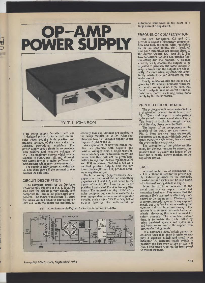
OP—AMP
a POWER SUPPLY
A.
f
3
1
BY T J JOHNSON
THE power supply described here was
designed primarily to be used on cir-
cuits which require both positive and
negative voltages of the same value, for
example, operational amplifiers. The
power supply uses a single i.c. to produce
both positive and negative voltages of
15V. The maximum current which can be
supplied is 50mA per rail, and although
this seems low it is quite sufficient for
most circuits which may be encountered.
The supply is fully protected within the
i.c. and shuts down if the currrent drawn
exceeds the safe limit.
CIRCUIT DESCRIPTION
The complete circuit for the Op-Amp
Power Supply appears in Fig. 1. It can be
seen that the circuit is very simple, and
comprises IC 1 and a few associated com-
ponents. The mains transformer T I steps
the mains voltage down to approximately
30V a.c. With the centre tap earthed, es-
AN
AC.
MARLS
E
sentially two a.c. voltages are applied to
the bridge rectifier D 1 to D4. After rec-tification two d.c. voltages appear at the
respective pins of the i.c.
An explanation of how the bridge rec-tifier can produce both negative and
positive voltages from a single transfor-mer secondary can be found in many text
books and thus will not be given here.
Suffice to say that the two top diodes (D 1
and D3) as shown, produce a full-wave
rectified positive output, and the two
lower diodes (D2 and D4) produce a full-wave negative output.
Each d.c voltage (approximately 22V)
appears across one of the two smoothing
capacitors C 1 and C2, and hence to the
inputs of the i.c. Pin 8 on the i.c. is for
positive inputs and Pin 4 is for negative
inputs. The internal circuitry of the i.c. is
quite complex but can be considered as
two independent conventional regulator
circuits, such as the 78XX series, but of
course having the refinement of
Fig. 1. Complete circuit diagram for the Cp-Amp Power Supply.
15V
0V
15V
01-A= WOMA,400V
Everyday Electronics, September 1984
+ +15V
e
SK1
+15VI
IC1
+ RC61951r8
rCOMP
s ec +
BAL
CJ
R1
I
e zkn
VRi ?OkD T
C6
IBALAW E I
R2
0;_T';_ ♦ -15V 5 8 2k12
C1 cay 4LC5
1000VF.
0IyF'r �
z
• +0'uF
C
IOyF
SK2
SV
1
C
ov
C
SK7
automatic shut-down in the event of a
large current being drawn.
FREQUENCY COMPENSATION
The two capacitors, C3 and C4,
provide a degree of frequency compensa-tion and hum rejection. After regulation
by the i.c., each output, pin 7 (positive)
and pin 5 (negative), are passed direct to
the output sockets SKI and SK2. The
two capacitors, C5 and C6, provide final
smoothing for the outputs. A balance
control, V R 1, enables the outputs to be
adjusted to precisely the same voltage. It
may be found that the outputs are not ex-
actly 15V each when adjusted, this is per-fectly satisfactory and indicates no fault
in the circuit.
Finally, indication that the unit is on, is
given by LP I which illuminates when the
a.c. mains voltage is on. Note here, that
the d.c. outputs have no on/off switch of
their own, on/off switching being done
purely by the mains switch.
PRINTED CIRCUIT BOARD
The prototype unit was constructed on
a single-sided printed circuit board, size
76 x 76mm and the p.c.b. master pattern
to be etched is shown actual size in Fig. 2.
This board is available through the EE
PCB Service, Order code 8409-01.
The layout of the components on the
topside of the board are also shown in
Fig. 2. Note the two large electrolytic
capacitors are mounted with their positive
leads opposite each other, likewise with
the two smaller electrolytics.
The orientation of the bridge rectifier
must, for obvious reasons be correct, the
positive lead is usually the longer of the
four and is nearly always marked on the
top of the device.

SK3 -
(OV)
SK2
1 15v)
SK1
(+15V)
Fig. 2. The printed circuit board master land component layout), which is available from the EE PCB Service, Order code 8409-01. The
layout of the components on the topside of the board are also shown, note the orientation of the electrolytic capacitors.
COMPONENTS
See
Resistors
R1,2 8.2kil12 off)
Both }W carbon ±5%
Capacitors page 560
C1,2 1000µF 25V elect. (2 off)
C3,4 0.1µF polyester (2 off
C5,6 10µF 25V elect. (2 off)
Semiconductors
D 1-4 WO4 1 A, 400V bridge
rectifier
IC1 4195 +15V dual-tracking regulator
Miscellaneous
VR 1 1 OW lin. horizontal
skeleton preset
T1 mains transformer,
0-15V, 0-15V, 100mA
secondaries
S1/LP1 single pole rocker switch
with Aeon
SK1 4mm insulated terminal
post, red
SK2 4mm insulated terminal
post, black
SK3 4mm insulated terminal
post, green
FS 1 1 A fuse and panel
mounting holder
Printed circuit board: single-sided size, 76 x 76mm, EE PCB
Service, Order code 8409-01;
case 153 x 1 14 x 38mm (Maplin
Order code WB2 vinyl); con-necting wire.
Approx. cost
Guidance only
564
£16
Fig. 3. Off board interwiring details for the Op-Amp Power Supply.
Everyday Electronics, September 1984

It TESTING
b
a
d
,e
II
0
1
le
a
I
M
Ie
ih
Dt
)e
Ie
:h
,k
Id
to
a
n
I,
s
e
s
>h
Id
h,
al
b
s
9
it
I
)y
:h
to
Ig
:e
le
4
Initially set the wiper of VRI to about
mid-position and connect a d.c. voltmeter
between the common terminal and the
positive terminal. Set the voltmeter to
25V full-scale deflection. Plug the unit
into the mains and observe almost im-
mediately that the voltmeter shows a
voltage. If no reading is observed, switch
off the unit and re-check for errors.
Assuming all is well the voltmeter
should show a reading of about 15V.
Transfer the meter leads to measure the
negative voltage of the power supply.
This reading should be very nearly the
same as before, if it is not, simply adjust
V R I until the two readings are the same.
As was mentioned earlier the two
voltages may not be exactly 15V, a
reading of 14.9V being typical. Once this
adjustment has been made, there is
nothing further to do and the power sup-ply is then ready for use.
Remember, when using the power sup-ply, the absolute maximum current which
can be drawn from each rail is 50mA. It
is wise in fact to assume that the current
maximum is 45mA, this will give the cir-cuit a 10 per cent operational safety
margin.
Some constructors may find the
voltage of 15V slightly high on some cir-cuits. For example, an op-amp may be
being used with t.t.l. i.c.s, which require
only 5V. Providing the current require-ment of the t.t.l. circuit is not too large,
then the power supply may be effectively
put to use by using two Zener diodes of
5V connected across each terminal. Other
lower voltages, either of the same value or
different values can thus be derived from
the two 15V supplies of the power
supply. ❑
(Left). Interwiring details inside the case.
Details of the front panel, showing the
positioning of the switch and sockets.
>r f E7N ov
i
CIRCUIT
EXCHANGE
DON'r let the simplicity or low cost of this
unit fool you, it works very well on any
LIGHT PEN PIN
black and white, or colour, TV. It uses the
VIC 20's built-in light pen facility to produce
coordinates of its position on the screen. The
pen is constructed using a photodiode (TIL
78), a couple of pieces of wire and an old pen,
and is connected via a 9-pin D-type connector
to the VIC's user port.
Construction could not be simpler, with just
a couple of wires to solder to the photodiode
and the socket. The positive connection is
PHOTO DIODE (TIL76)
OLD BALL POINT PEN
V I C 20 U5ER PORT
Everyday Electronics, September 1984
GND PIN
If 72AJ
VIC-20
LIGHT PEN
made to pin 6 and the negative to pin 8 of the
D-type connector. When the unit is assembled
it is important to ensure that there is as much
of the photodiode showing as possible, to en-sure correct operation.
Testing and operation is very straight-forward. Simply plug in the pen and turn the
screen up to full brightness, then type in the
following program:
10 Y=INT((PEEK(36871)-32)/4)
20 PRINT
30 GOTO 10
When you run the program and touch the
screen with the pen, the number printed is the
Y coordinates and should decrease as you
move the pen up the screen. A similar
program is used for the X coordinates and if
all is satisfactory the brightness and contrast
can be adjusted for optimum efficiency.
The applications of the pen are only limited
by your imagination and software. A starter
program to return coordinates of the pen is
listed below.
10 X=1NT((PEEK(36870)-49)/4):Y=/NT((PEEK(36871)-32)/4)
20 PRINT "X COORDINATE =";X; "Y COORDINATE ="; Y
30 FOR T=1 to 20 ; NEXT T
40 GOTO 10
R. J. Irvine,
Kilbarchan, Renfrewshire.
565

ANN
0
M
PART THREE
N THE FINAL part of this series, the com-
puter "peripheral" equipment is ex-amined. The essentials are a keyboard
and some kind of VDU, of course, but
disk storage and cassette recorders,
sound generation and "joysticks" are also
considered.
KEYBOARD
The keyboard is the main way in which
we control the micro. In the cheaper
machines the keyboard is just a set of
key-switches. The switch is closed when
the key is pressed. The keys connect two
sets of lines, one of which is connected to
the data bus through buffers (Fig. 3.1).
These buffers are quite different from the
buffer areas of memory referred to
earlier. They are integrated circuits with
one input and one output. The output
may take the same logic level as the input
(a non-inverting buffer) or it may take the
opposite level (an inverting buffer). The
function of a buffer is to pass logic levels
from one part of a circuit to another when
required. Some types of buffer are
designed to provide extra power; many
other devices can be connected to the out-
put terminal of such a buffer. Often the
function of a buffer is to isolate one part
of the circuit from another except at cer-tain times.
This is the case with the keyboard cir-cuit. Although the output of the buffer
may take the same logic level ("high" or
..low") as its input, this only happens
when the buffer circuit is enabled. At
other times the output terminal is in its
third state, which we call high impedance.
In this state, it is virtually disconnected so
that it is incapable of giving output of
either kind. The three-state output is par-ticularly important for devices which are
putting data onto the data bus. If more
than one device tried to put data onto the
bus at the same time, the situation would
be utterly confusing. So buffers and other
devices (such as the MPU, and the RAM
Y OF
M
ICR
0
and ROM chips) which put data on the
bus all have three-state outputs. Only
when a device is enabled is its output ac-tive and able to transfer data to the bus.
The MPU goes through a repeated
routine of enabling the buffers when it is
waiting for input from the keyboard. At
the same time it scans the keyboard by
addressing the i.e. (which could be a
74LS138) which makes each of the lines
0 to 7 go low in turn. If a key is pressed,
and the line is made "low", this "low"
appears on the data bus. The MPU
knows which line has just been made
"low", and which data line has shown
this "low", so it can then work out which
key has been pressed.
Such a system is cheap but gives the
MPU a lot of work to do. The higher
priced micros have a special i.e. to read
the keyboard. This is able to detect when
a key is pressed by automatically scan-
ning the board. It uses a method similar
to that described above, to find out which
key it is. It contains an encoder circuit
which puts this information into the form
of an ASCII code. The ASCII code
ELECTRON BEAM
SCANS THE
SCREEN
ON THE SCREEN
n
SUCCESSIVE
SCANS
EE].
ZERO
GIVES
NO DOT
GIVES A
DOT
14.
OWEN BISHOP
(American Standard Code for Informa-tion Interchange) for any given letter,
numeral, symbol or control key consists
of a byte with a definite value. When the
micro wants to find out which key has
been pressed, it simply has to read from
the keyboard decoder i.e. and instantly is
told the ASCII code of the key. This
saves the MPU a lot of time, giving it
more time to spend on operations more
important than routine keyboard-scanning.
VIDEO SCREEN
Most micros provide visual display by
means of a video screen, either a TV set
or a monitor (not to be confused with the
monitor program mentioned last month!).
At present, only a few portable com-
puters, such as the Sharp PC-1251, and
the Casio FX-702P have other methods
of display (liquid crystal displays, limited
to a few characters at a time). The
Grundy NewBrain has a built-in Le.d. dis-
play, but can readily be attached to a TV
CORRESPONDING
AS DISPLAYED BYTES STORED IN
CHARACTER
GENERATOR
00011000
0 0 1 0 0 1 0 0
0 1 0 0 0 0 1 0
0 1 1 1 1 1 1 0
0 1 0 0 0 0 1 0
0 1 0 0 0 0 1 0
1 0 0 0 0 1 0
00000000
Fig. 3.2. How the letter 'A" is built up on the screen from a series of dots.
566 Everyday Electronics, September 1984

•5V
ADDRESS BUS
I EE -I
7 06 DG D3 02 01
--V
DATA BUS
PULL-UP
RESISTORS
3- STATE
DATA BUS
BUFFERS
Fig. 3.1. Simplified keyboard circuit. Lines to data buffers are held "high" by pull-up resistors, but go "low" if a key is pressed and the wire to
that key from the line selector is made "low".
or monitor when it is not being used as a
portable.
To display characters and graphics
designs on the screen, the computer must
be able to produce signals which cause a
pattern of dots to be displayed. The
signals must be synchronised with the
scanning of the screen by the electron
beam. Fig. 3.2 shows the patterns needed
to produce the letter "A". It is obvious
that this pattern must be read from
memory, either directly from a character
generator or from RAM. Special i.c.s are
available to deal with the production of a
suitable signal.
A TV set is designed to receive carrier-wave radio signals and to demodulate
these in order to extract the information
required to produce the sounds and pic-tures of the TV programme.
Unfortunately, they cannot respond
directly to the signals produced by the
video circuits of the computer. These
signals have to be modulated, that is,
combined with a UHF carrier signal,
before they can be of use to the TV set.
For this reason the computer incor-
porates a modulator, with connections to
the aerial socket of the TV set.
There are two unnecessary stages,
modulation and demodulation, between
the originating of a display by the MPU
and its appearance on the TV screen.
There is the inevitable introduction of
noise and other forms of distortion at
both stages, so that the picture appearing
on the screen loses quality, both in defini-tion and in colour rendering.
These two stages can be cut out by
using a monitor, which is able to work
directly with the signals from the video
logic circuits of the computer. There is
usually a marked improvement in the
quality of the picture when a monitor is
used. With TV sets and with many kinds
of monitor, the signals for colour are
mixed with the signals for brightness
before being sent from the computer and
have to be separated before the picture
can be displayed. Separation of signals is
another potential source of degradation.
With an RGB monitor, the three primary
colour signals are fed separately to the
colour tube and a picture of the highest
quality results. Many micros now have a
special RGB output socket, as well as a
socket for an ordinary monitor and one
for a TV set, so that you can connect any
kind of video display.
CASSETTE INTERFACE
Several methods are used for com-
municating with a cassette recorder but
all have one feature in common. The data
is transmitted serially, a bit at a time. Bits
are usually transmitted in groups of eight,
thus each group corresponds to a byte. In
one method, bits are transmitted as a
series of tone bursts. The burst may be of
one of two distinct frequencies, one fre-
quency corresponding to a "1" and the
other to a "0". The TRS-80 marks the
beginning and end of each bit with a
-blip" and, if the bit is a "I there is
another "blip" at the half-way point. The
monitor program of the micro generates
the required signals and feeds them to the
cassette interface. This is often an
operational amplifier which gives a "low"
or "high" output according to what input
it is receiving along the data line. The
cassette input also has an amplifier and
its output is fed to a line of the data bus
when the MPU is in the "cassette read"
program. Naturally, the micro is only
able to interpret signals which it or
another micro of the same make has
generated, so it is virtually impossible for
programs taped by one computer to be
loaded into a computer of a different
make.
DISKS
These are the other main method of
large-scale data storage for micros. They
have many advantages over cassette
tapes, but the considerable cost of the
disk drive means that they are the excep-tion rather than the rule in home com-puter systems. The floppy disk used most
often with personal computers is the mini-
567
4 Everyday Electronics, September 1984

Floppy, which is about 5; inches in
diameter.
It is contained in a protective cover,
with a slot through which the magnetic
surface may be read from or written to by
the head of the disk drive. See Fig. 3.3.
There is another hole in the cover to allow
the disk to be spun on a spindle. The disk
spins at high speed (about 300 r.p.m.) so
that data may be read or written at a very
rapid rate (a hundred or more kilobits per
second).
Compare this with the usual rate of
data transfer with a cassette recorder,
which may be as low as 300 bits (not
kilobits) per second and is rarely as high
as 1500 bits per second. Added to this,
the cassette recorder stores the bits as a
single string running from one end of the
tape to the other. It is not easy to find any
particular part of the tape, yet to run the
tape through the recorder from beginning
to end at its usual speed takes several
minutes.
Moreover, cassette recorders have no
means of automatically finding any re-quired section of track. The disk, with its
concentric tracks and a head that can
slide from one track to another in an
average of 300ms, can rapidly pick out
any segment of a disk. There is no need to
run all the way through the disk to find
the part that is required. In addition, the
disk operating system keeps a directory
of all programs and other material stored
on the disk, and the location of each
program, so that any item of data can be
called up within a few seconds.
SOUND
Even the cheaper of the more recent
micros include a loudspeaker in their
anatomy. Often this occupies a single ad-dress in memory. A write operation to
this address toggles the speaker on, while
a second write operation toggles it off
again. A series of write's repeated at a
suitable frequency cause the speaker to
emit an audible note of the required pitch.
The latest refinement is to have a
special-purpose sound generator chip.
Toggling loudspeakers on and off is
rather menial work for the MPU and oc-
1ue n
c
000 1KIE1
oow
1.1 1
Fig 3.3. A typical floppy disk, showing the
"window" in the protective cover which
allows the disk-head to read or write data.
568
Oc11,MG WcM
IPE1<67P1
UPGRADED COMPUTER
CPU
KEYBOARD
DISPLAY DRIVER
CASSETTEINTERFACE
PRINTER INTERFACE
MEMORY
Includes:
BASIC,
OPERATING SYSTEM,
DIPS,
USER RAM
DISK INTERFACE
FLOPPY DISKS
FLOPPY DISK DRIVES
Fig. 3.4. A computer interfaced to a VDU, a printer, and dual disk drives.
cupies it when it would be better em-ployed in other activities. In a game, for
example, it has plenty to do with moving
graphics characters around the screen,
receiving input from the keyboard and
keeping the score. if it can simply instruct
a sound generator to produce a note of a
given frequency for a given length of time
and then leave it to get on with this task,
it is able to give better attention to the
game in progress.
Most sound generator chips are able to
make more than one musical note at a
time, so allowing chords to be played.
Some also include a "white noise"
generator, which is a very useful addition
for sound effects. The more sophisticated
chips allow you even greater control over
the sounds they make. The sound
generator of the Commodore 64 not only
has three tone generators, each with a
range of nine octaves, but their waveform
can be a sinewave, a triangle wave, a
sawtooth or a squarewave.
The period of attack and decay and
other parameters are all under the control
of the MPU. There are also variable
Filters to further modify the sound which
has been produced, and resonance too is
variable. A small loudspeaker buried
among the micro's i.c.s would do little
justice to such sounds so, in this com-puter (as in the VIC-20, which has a
similar though less comprehensive sound
generator) the sound signals are fed to the
TV set. This brings better quality sound
and allows the overall volume to be set by
adjusting the control on the TV set.
INPUT/OUTPUT PORTS
Most manufacturers of micro-processors also provide compatible i.c.s
for performing other functions of impor-tance in the activities of the computer.
Among these are the input and output
devices. They come with a variety of
names but do roughly the same things.
Examples are: the 6522 Versatile Inter-face Adapter designed to be used with the
6502, and the Z80-PIO, or Parallel In-put/Output controller. Devices of this
kind usually comprise two or more 8-bit
ports. Each port consists of eight latches,
through which data can be transferred
between the data bus of the computer and
peripheral devices such as printers, the
keyboard (in certain micros), robots,
chart plotters, graphics tablets or
anything else that we may wish to link to
the computer. The ports can act as in-puts, receiving data from the external
device (e.g., from a graphics tablet) or as
outputs, passing data from the MPU to,
for example, a printer or robot. See Fig.
3.4. It is, of course, possible to connect
such devices directly to the address and
data buses, in effect making them an in-tegral part of the computer system, but
this leads to certain complications. For
one thing, the device would then have to
have its action more closely synchronised
with the MPU. When instructed to
receive data in a write operation, it would
have to be able to take in the data im-mediately. The data would be on the bus
only for as long as the write operation
lasted—a matter of a few hundred
milliseconds. How could a robot follow
the instruction "move forward two
metres" in such a short time? If the data
is held in the latches of an I/O device, it
remains on the output lines indefinitely
until a new instruction is issued by the
MPU. In the meantime the instruction
remains in force and the robot can con-tinue to obey it.
Similarly, data coming from sensors on
the robot can be fed continuously to the
input ports of the I/O device. The inputs
to the latches may be connected per-manently and directly to these sensors.
When the MPU wants to read the sen-sors, it simply directs a read operation to
the I/O device and there is the data it
wants. As before, there is no need to syn-
Everyday Electronics, September 1984
I
a
p
c
E
b
k
V
i!
A
d
ii
n
n
h
t
s
r
k
C
t
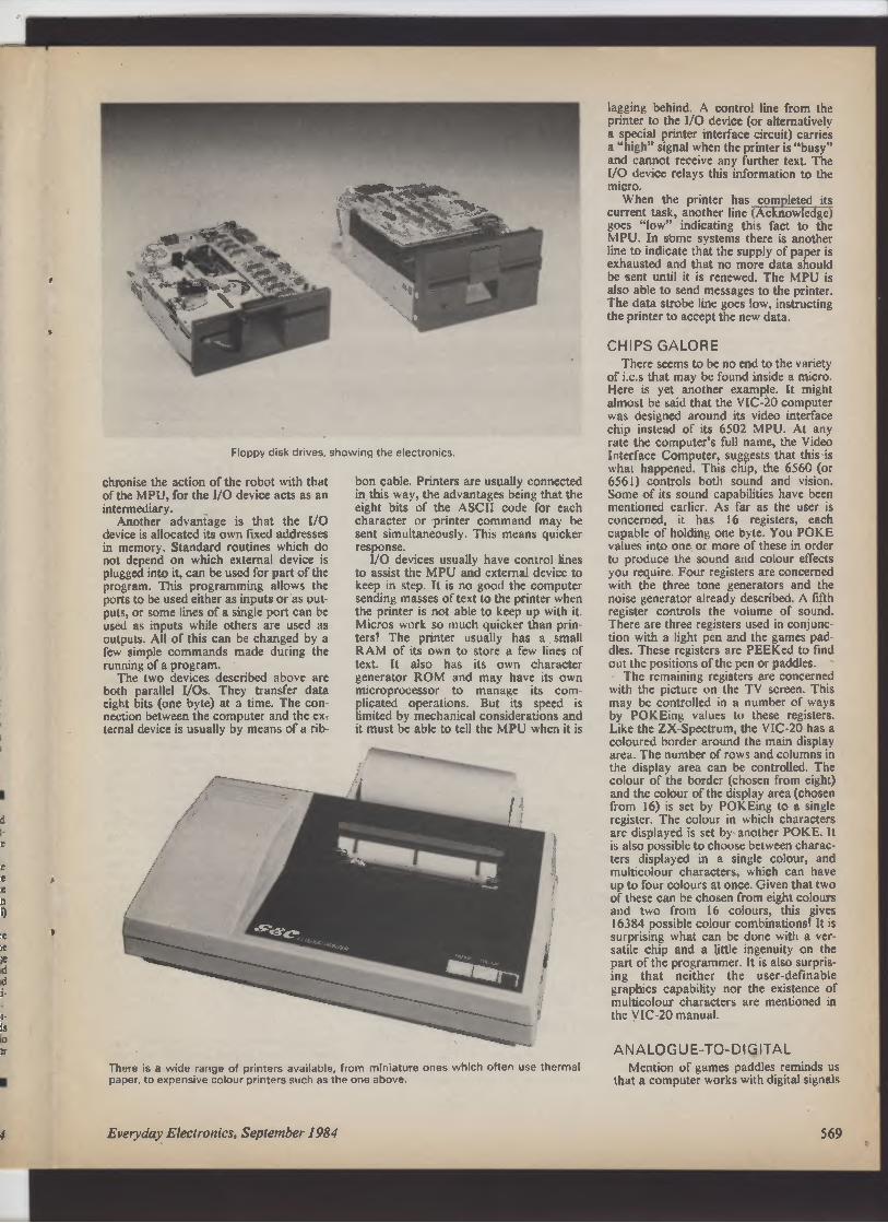
1
d
e
e
e
e
n
i)
le
ie
le
d
d
i-
t-
Is
to
:r
I
Floppy disk drives, showing the electronics.
chronise the action of the robot with that
of the MPU, for the I/O device acts as an
intermediary.
Another advantage is that the 1/0
device is allocated its own fixed addresses
in memory. Standard routines which do
not depend on which external device is
plugged into it, can be used for part of the
program. This programming allows the
ports to be used either as inputs or as out-
puts, or some lines of a single port can be
used as inputs while others are used as
outputs. All of this can be changed by a
few simple commands made during the
running of a program.
The two devices described above are
both parallel I/Os. They transfer data
eight bits (one byte) at a time. The con-nection between the computer and the ex-ternal device is usually by means of a rib-
bon cable. Printers are usually connected
in this way, the advantages being that the
eight bits of the ASCII code for each
character or printer command may be
sent simultaneously. This means quicker
response.
I/O devices usually have control lines
to assist the MPU and external device to
keep in step. It is no good the computer
sending masses of text to the printer when
the printer is not able to keep up with it.
Micros work so much quicker than prin-ters! The printer usually has a small
RAM of its own to store a few lines of
text. It also has its own character
generator ROM and may have its own
microprocessor to manage its com-plicated operations. But its speed is
limited by mechanical considerations and
it must be able to tell the MPU when it is
There is a wide range of printers available, from miniature ones which often use thermal
paper, to expensive colour printers such as the one above.
lagging behind. A control line from the
printer to the I/O device (or alternatively
a special printer interface circuit) carries
a "high" signal when the printer is "busy"
and cannot receive any further text. The
I/O device relays this information to the
micro.
When the printer has completed its
current task, another line (Acknowledge)
goes "low" indicating this fact to the
MPU. In some systems there is another
line to indicate that the supply of paper is
exhausted and that no more data should
be sent until it is renewed. The MPU is
also able to send messages to the printer.
The data strobe line goes low, instructing
the printer to accept the new data.
CHIPS GALORE
There seems to be no end to the variety
of i.c.s that may be found inside a micro.
Here is yet another example. It might
almost be said that the VIC-20 computer
was designed around its video interface
chip instead of its 6502 MPU. At any
rate the computer's full name, the Video
Interface Computer, suggests that this is
what happened. This chip, the 6560 (or
6561) controls both sound and vision.
Some of its sound capabilities have been
mentioned earlier. As far as the user is
concerned, it has 16 registers, each
capable of holding one byte. You POKE
values into one or more of these in order
to produce the sound and colour effects
you require. Four registers are concerned
with the three tone generators and the
noise generator already described. A fifth
register controls the volume of sound.
There are three registers used in conjunc-tion with a light pen and the games pad-dles. These registers are PEEKed to find
out the positions of the pen or paddles.
The remaining registers are concerned
with the picture on the TV screen. This
may be controlled in a number of ways
by POKEing values to these registers.
Like the ZX-Spectrum, the VIC-20 has a
coloured border around the main display
area. The number of rows and columns in
the display area can be controlled. The
colour of the border (chosen from eight)
and the colour of the display area (chosen
from 16) is set by POKEing to a single
register. The colour in which characters
are displayed is set by another POKE. It
is also possible to choose between charac-ters displayed in a single colour, and
multicolour characters, which can have
up to four colours at once. Given that two
of these can be chosen from eight colours
and two from 16 colours, this gives
16384 possible colour combinations! It is
surprising what can be done with a ver-satile chip and a little ingenuity on the
part of the programmer. It is also surpris-ing that neither the user-definable
graphics capability nor the existence of
multicolour characters are mentioned in
the VIC-20 manual.
ANALOGUE-TO-DIGITAL
Mention of games paddles reminds us
that a computer works with digital signals
/ Everyday Electronics, September 1984 569

("highs" and "lows"), whereas many
devices which may be attached to it
produce analogue signals. Their output
voltage may vary smoothly over the
whole of a given range. The games pad-dle, or joystick, is a common example.
Fig. 3.5 shows how this works in the Ap-ple ll. The games paddle is an ordinary
potentiometer and, when it is plugged into
the micro, forms part of a timer circuit,
usually based on the well-known 555 i.e.
When the MPU wants to know the setting
of the paddle, it triggers the timer. Then it
repeatedly reads the output from the
timer. The length of time this output stays
"high" depends on the setting of the
potentiometer. The MPU can measure
this period and so work out the position
of the paddle.
This is an inexpensive but rather crude
method of analogue-to-digital conversion.
Except for the most costly variety (which
are certainly not used in games paddles)
the track of a potentiometer is never per-fectly linear, and soon suffers from wear.
But, since the user is able to receive visual
feedback from the screen, these
irregularities are unimportant in practice.
If you want to interface your micro to a
thermometer or a laboratory instrument,
such as a balance, you will need not only
accuracy but precision. There are several
i.c.s designed to convert an analogue
signal into a digital one. An example is
the ZN427E. This incorporates a voltage
reference against which all input voltages
are compared. This gives the device its
accuracy. The i.e. has eight output ter-minals, which are three-state (see above)
so, if these outputs are wired to the data
bus, the data coming from this converter
may be "read" by the MPU as a single
byte. Provided that the input voltage
varies over the whole range, its value may
be determined to the nearest "bit". This
570
Y
ADDRESS
BUS
EE].
INPUT
OUTPUT
DATA
BUS
BUFFER
LINE DO
OF DATA BUS
•5V
THRESHOLD
DISCHARGE
GAMES I
PADDLE
L—_—J
TIMING
TCAPACITOR
OV
Fig. 3.5. Using a 555 timer i.c. as an analogue-to-digital converter in conjunction with a
games paddle.
gives a precision of 1 in 256 or 0.4 per
cent, which is close enough for most
purposes.
THE ULTIMATE I.C.?
We are nearly at the end of the array
of electronic wonders that you might ex-pect to find inside your micro. Of course,
it must have a power supply, regulated to
the standard +5V on which TTL i.c.s and
most other microcomputer i.c.s work. If it
is a portable micro, it may also have a
battery. These and "power-on" I.e.d.s,
and edge connectors which allow you to
plug other devices on to the buses are
very straightforward in their construc-tion. But one might wonder how it is that,
with such a wide range of possibilities,
some computers manage with so few i.c.s
A professional 16-bit computer system intended for business use.
inside them.
A notable example is the ZX-81.
Those who have built their own from a kit
will know that this contains only four
i.c.s. These comprise the Z80 MPU, a
ROM (holding the ZX-81 monitor
program and the Sinclair BASIC inter-
preter program), and two 2114 RAM i.c.s
to provide the one kilobyte of user
memory. The 2114s can be replaced by a
single RAM i.e., the 4118, which provides
I K, or the 4816, which provides 2K. The
fourth i.c. is the Sinclair Computer Logic
i.c. This undertakes all the functions of
address decoding, video interfacing and
many other routine operations which in
other computers would be done by a
dozen or more separate i.c.s. Mass
production has made it feasible to design
and manufacture a special-purpose chip
solely for running the ZX-81, instead of
using the commonly available i.c.s.
There is a growing trend to adopt this
approach in other micros, in order to
reduce size, simplify the p.c.b., and to cut
costs in general. The usual procedure is to
make use of an uncommitted logic array,
chip. A ULA has a very large number of
logic gates on the chip but these are not
connected at first. The connections can
be added during the final stages of
manufacture but, since the major part of
the work has already been done in design-ing the initial array, the costs of a ULA
are much less than that of designing and
manufacturing a special-purpose logic
system from scratch. The only trouble is
that it is normally fairly easy to get hold
of the circuit diagram of a micro and puz-zle out how it works. But manufacturers
are usually unwilling to publish the details
of what goes on inside their ULAs. With
increasing use of these devices, it may in
future be less easy to write an informative
article on The AnatomY Of Your Micro.
Part One of a new series which will be of
importance to anyone interested in home
computers, titled "Digital Electronics",
will be published next month.
Everyday Electronics, September 1984

all in the
OcTOB
issue'.- �
sue...
M —
uen lal 0; is
chni * ues
I
P
Following on r
Electronics' series we
developed the concepts
deeper into the world
design.
n to Digital
have extended an
of that series to look
of logic circuits and
Radar Security Alarm
A completely self-contained four channel intruder detection system which uses Doppler shift at UHF.
Features include adjustable sensitivity and a signal strength meter.
FILTER SHIFT PHASER
Disc Drive Buyers Guide
PRACTICAL
ELECTRO
1
Ics
ROBOTICS - MICROS - ELECTRONICS - INTERFACING
OCTOBER ISSUE ON SALE FRIDAY, SEPTEMBER 7

�I don't ShlnR were
making t2odeubPJs
Lir\t2-Up the letters tO
6 In a c---)r\Grvous c loa\
OF con Vonet\t r\a,mes.
Ni
4
I
E
V
C
O
E
M
I
C
R
D
O
I
L
P
I
R
M
E
E
I
c
R
Z
N
O
N
P_
O
U
N
O
E
P
R
E
V
O
S
O
H
I
G
C
K
E
A
R
L
O
U
E
TNT =u
0 1 -ct
The rrnl1r,8C'r beh&VICL r of the ear
has Infber U-.e WAY We ff �—Sure
Sax,el lnter,SlueS.If tre SI aIL-st
SCt1n1 aualbl to LW-,eAr 1-rT-repre3entdby i rnm ors a
ornph...
thef.the blAest Sound aauld
be i mum kiLOMETRES
graph.. --
I
GHT
l � . iii ? t
I I AT
Ar\d fats iueUSea ICtVC11G 1„r9
unit c2gBA
ma122S ge IBE
I
\
„ _ sma11 manle r"
The 1:Qvr thm
Is a CDmmon
r the
used e
to
V,ry tar 2
nurnber
WHA_T.1S A
�OMAR_ITN
Tt e logan thm of a er is eQa
to the paver to which to has to be
raised to eQual that number e-g.
10 - W., log of io - 1
IC0 _ 1e :. log'of iao-2 thj5 applies
toary rVxN)0-.
572
l
E
P
5
D
P
U
nYYIY-y
8 did r\gtG
HEaRrE
�tl�e'deubel'is
one tenth of
r' a Bel (after
le<w-\cler Graham
Bell ar d is a loganthmic
unit used tom--&-,ore ore rat 05
of SOUND INTENSITIES
There is rarvgeOf Saxes
intensities called Uv--DYNAMIC RANGE .The
range t i with the
ThresKolAof heanr\Q and
IncrF1 5 t)
the 1p kips
t
saff'd t h heearca wlthst-
ard wltha)b dammaaQ�eecaile l
the THQESI-IoLDo(7 PAIN .
The Threshold of pain is
!,oaoc00'ocb tyres
grr�at�r than the TN-eshdd
of ha3rinq.ttV
Find tl\e lag-
arithm of S NJge wrnb
er (12) &",1 times by W for
paver ar o you haw the
d�lbel i.--120 , a rnUch
easier camber to u5e.!�:
NOTE V,31(
40 UBRARy
� ET RS�TION
20 Wq�
—
10- -̀
o
o �Rir.IG
Everyday Electronics, September 1984

+Vcc(av)
0
d Ift ael,
fAC Xt
"L, wu►eter- T - OMrPMT I
A--if �^ 'Fn AMPLIFIER
the IN�PUTinr
Wh h case the 5
Pin Would ba
yablIe
A le V
11"tiEPFRis theZ
nli � � rt�n ►PrSlon of the cl g,
I �i� It's a NATURAL
�g Ne � 5[ ass a s...
a
SEND
ITN
LASSFL
tuber
the clEcibel 15
r► ctt an absolute
vaiue
III tKrk he's saying,
fwd&ibels is t4.\&
thre5h OO (O'F pair,
Solutions page 584
owl PUT
084 Everyday Electronics, September 1984
TheC GAIN of �- .I►�
I$ FbuM From a Py
Ti
wild be inczn
large had rot tre U13 M.
C.crne to Ghe rexiie
T515t<W 10'—
W RMER g1n o
I ��. jfio
573

SOUMD OPERATED 1
FLASH
THE purpose of this unit is to trigger an
electronic camera flash on receipt of
an audible signal. What on earth for?
You may well ask. Well as can be seen
from the accompanying photographs,
some very spectacular impact-triggered
shots can be made. This low cost sound
operated flash should provide hours of
entertainment limited only by the im-agination of the user.
CIRCUIT OPERATION
As can be seen the unit is quite simple,
consisting of a "pick up" (microphone),
an amplifier and a triggering device. In
this case a CSR is used as the triggering
device.
The complete circuit diagram is shown
in Fig. 1. An amplifier is constructed
using two 741 type op-amps, which are
both contained in a single d.i.l. package
(MC 1458). IC 1 a is wired to have a
voltage gain of 10, set by R4/R I and its
output is fed to IC 1 b which has a gain of
100, R6/R5. This gives a total gain of
1000, which is sufficient for most pur-poses.
The output of IC I b is coupled to the
gate of the triggering device CSR1, via
the d.c. blocking capacitor C2. When a
signal of sufficient amplitude is applied to
the gate of a CSR, then the CSR will con-duct if forward biased. This is a similar
condition to the short circuit required to
operate the flash. The CSR chosen for
this unit is the C 106D, which requires
only 800mV applied to the gate to
operate. It will also handle the flash
current easily.
Any low cost crystal insert
microphone will work with this unit, the
one in the prototype being a crystal lapel
microphone.
CONSTRUCTION
No problems should be encountered
when constructing the sound operated
flash as none of the components are
CMOS and they are all assembled on a
small piece of stripboard as shown in
Fig. 3. When the stripboard has been
assembled it should be checked for shorts
and dry joints. All the polarity sensitive
M.G.ARGENT
MIC. INPUT R1
47kn
)kl
(EEk,G
R2
I Okn
R3
IOkn
- V V
70
-
G 70kn
IC1a
MC',G5
R5
Ikn
6
b C1
T0"
+9V
C3 Cr
A
22NF_T
R6
T
OV
10Okn
E
IC1b
MC1458
OV
CSRI
C1060
C2
4 7p F
A7
Ikf1
A
9
I
Fig. 1. Complete circuit diagram of the Sound Operated Flash unit.
components such as the capacitors and
the CSR should be checked for correct
orientation.
The long microphone lead should, of
course be screened, and all the leads
within the box should be kept as short as
possible to avoid pick-up problems. The
board and battery holder were housed in
a suitable plastic box which could be used
to mount an on-off switch if required.
TESTING
After checking all connections, plug in
the battery and microphone, and if a
small earpiece is available connect it
TO FLASH
across R7, whereby background noise
should be heard if the amplifier section is
working correctly. If all is well, plug in
the electronic flash and switch on. When
it is ready, click your fingers a few feet
away from the microphone and the flash
should operate. If this does not happen
then reverse the flash leads and try again.
RESULTS
The photographs shown were all taken
using a Halina camera and a National
PE-182 flash unit, neither of which are
specialist items. The only specification
being that the camera has the facility to
574 Everyday Electronics, September 1984
, y
a
A
IE
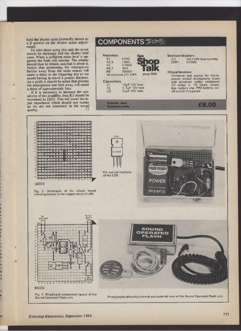
I
s
s
a
t
D
f
If
it
n
if
d
k
d
C
is
d
E
•s
Is
It
in
re
if
it
hold the shutter open (normally shown as
a P symbol on the shutter speed adjust-ment).
To take shots using this unit the room
should be darkened and the shutter held
open. When a sufficient noise level is ap-parent the flash will operate. The shutter
should then be closed, and that is about it.
Notice that positioning the microphone
further away from the noise source will
cause a delay in the triggering due to the
sound having to travel a greater distance.
As a guide it should be noted that placing
the microphone one foot away will cause
a delay of approximately Ims.
If it is necessary to increase the sen-
sitivity of the amplifier, then R I should be
decreased to 22kn. This will lower the in-
put impedance which should not matter
as we are not interested in the sound
quality. ❑
T
0 0 0
0 0
0 0
0 0
0 0 0 0
0 0
0 0
0,
0 0 0
0 0
0 0
0 0
0 0 0 0
0 0
0 0
0 0
0 0 0
0 0
0 0
0 0
0 0 0 0
0 0
0 0
0 0
0 0 0
0 0
0 0
o O
o 0 0 0
0 0
0 0
0 0
0 0 0
0 0
0 0
0 0
0•• 0
0.
0 0
0 0
0 0 0
0 0
0 0
0 0
0. 0 0
0 0
0 0. 0
0 0 0
0 0
0 0
0 0
0•• 0
0 0
0•• 0
0 0 0
0 0. 0
0 0
0 0. 0
0 0
0 0
0 0
0 0 0
0 0
0 0
0 0
0 0 0•• 0
0 0
0 0
0 0 0
0 0
0 0
0 0
0 0 0 0
0 0
0 0
0 0
0 0 0
0 0••• o• o• 0 0
0•• o
o o• o o o•• 0
• 0.
0.
0 0
0 0
0 0 0 0•••• 0
•••
0 0
0 0
0 0
0 0
00
o o•• o
•• 0. 0
0 0
0 0
0 o O
o 0
0 0
0 0
0 0 0 0
0 0
0 0
0 0
0 0 0
0 0
0 0
0 0
0 0 0 0
0 0
0 0
0 0
0••
0 0
0 0
0 0
0 0 0 0
0 0
0 0
0 0
0• 0
0 000
0 0
0 0 0 0
00
O•• O
0 0 0
0 0
0 0
0 0
0 0 0 0
0 0
0 0
0 0
O O O
o O
J 0
0 0
0 0 0 0
0 0
0 0
0 0
9 9 < S 6 , 1 9 q II I! I] 14 16 16 I, 16 19
i EE9a6I■I
Fig. 2. Underside of the circuit board
showing breaks in the copper strips (4 off).
(EE9661A1
Fig. 3. Stripboard component layout of the
Sound Operated Flash unit.
COMPONENTS - I `
=
Resistors
R 1 47kil
R2,3 1 0k
R4 470kn
R5,7 1kQ
R6 1 00k
All resistors }W ±5% page 560
Capacitors
C1 10µF 10V tant.
C2 4.7µF 10V tant.
C3 22µF 10V tant.
Approx. cost
Guidance only
CSAI
Pin out connections
of the CSR.
Semiconductors
ICI MCI 458 dual op-amp
CSR1 C106D
Miscellaneous
Miniature jack socket for micro
phone; crystal microphone insert
and screened cable; stripboard
20 strips x 19 holes; plastic
box, battery clip, PP3 battery; on-off switch if required.
£6.00
Photographs showing internal and external view of the Sound Operated Flash unit.
4 Everyday Electronics, September 1984
575

RADI0
WORLD
Operation Overkill
Even those of us who were involved in
the Normandy campaign of 1944— admittedly in my case not arriving at the
Mulberry harbour at Arromanches until
July—must have felt that the media, par-ticularly television, overdid the com-memoration of D-Day plus 40 years.
The battle was not won in a day and for
the British Army, particularly the tank
crews, the costly battle for Caen lasted
several weeks. Nor did I notice any mention
of the heavy casualties sustained during
several mass bomber raids when the
bombs fell short on to the Allied lines,
emphasising the need for better air liaison
communications.
Nor did the media or politicians see the
need to mark the 40th anniversary of the
liberation of Rome on June 5, 1944 after
the long struggle following the "Husky" in-vasion of Sicily. Operation "Husky" not
"Overlord" was the first sea-borne invasion
of "Fortress Europe" though marked by the
disaster to the glider troops released too
soon and lost in the sea. Again, it was on
the Eastern Front that the German Army
suffered its major defeats.
Wartime radio communications equip-ment was far from reliable and sometimes
failed at the most critical times. It could be
argued in view of the successful intercep-tion and decoding of so much German,
Italian and Japanese top-secret transmis-sions that the enemy might have done
better if his radio had been restricted to
short-range tactical networks.
The mechanical construction of many of
the German communications equipment
was superb. They were also proficient at
developing equipment for detecting cen-timetric radar transmissions, such as H2S
from Allied aircraft —a fact that contributed
to the heavy losses in the later stages of the
RAF's strategic bombing offensive.
Lilli Marlene in Rome
The D-Day nostalgia made much of the
wartime entertainers such as Dame Vera
Lynn, yet the tune of the period that sticks
most firmly in my memory was an
anglicized version of "Lilli Marlene" used as
a tuning signal on the Special Communica-tions 705OkHz transmitter at Crowborough
that broadcast messages to the Jedburgh,
SAS and similar groups in Normandy. One
of the announcers was the late David Niven
who spoke from a temporary studio in a
golf club in the Home Counties.
Other words to the tune of ''Lilli
Marlene" were popular in Italy following
some uncomplimentary remarks by a
British woman politician, whose name es-capes me:
"We"re the D-Day Dodgers, out in Italy
Always on the vino, always on the spree.
576
///m\\ilk AFAMM MN&L
/111N111111 MRSERINIMM,
\\\S\NEI 1111■1111I I\211119
\\1// ItIvI/
rA� r NUFf N11F
BY PAT HAWKER G3VA
Eighth Army scroungers, and their tanks
We live in Rome, among the Yanks,
We are the D-Day Dodgers in sunny
Italy. "
Words that even then reflected the bitter
feeling that their hard-fought Italian cam-
paign had been forgotten in the excitement
of Normandy.
Resistance in Europe
Until April 21 , 1985 there is a special ex-hibition at the Imperial War Museum in
London: "European Resistance to Nazi
Germany 1939-45" (£1.50 entrance) that
brings together some fascinating, if sad,
memorabilia of the Resistance. Included
amongst the exhibits are a number of the
suitcase radios used on the clandestine
links with France, Belgium, Denmark and
Holland—though with the notable excep-tion of the equipment provided by British
Intelligence and manufactured by its
Special Communication Unit at Whaddon
near Bletchley.
The radios include the well-known B2
suitcase set designed by Major John Brown
(later G3EUR) for SOE; the miniature
MCR-1 battery communications receiver
made by Philco (GB); two of the excellent
Anglo-Polish designs AP4 and BP3; and
SOE's S-phone 460MHz radiotelephone
set used to guide aircraft to dropping zones.
A home-made Belgian transmitter used
on an Intelligence link for "Clarence", and a
compact transmitter-receiver built by a
Danish engineer who felt the equipment
supplied from the UK was too bulky. He
proved his point but his equipment did not
have to survive a parachute drop!
Also to be seen is one of the all-too-effective German D/F receivers with the
loop mounted inside a truck to avoid reveal-ing its presence. There are also bits and
pieces, including a Morse key, used by
Yvonne Cormeau one of the more suc-cessful SOE radio operators credited with
more than 400 messages from the same
location and who unlike many others
survived.
A notebook of Yeo-Thomas, who as
"White Rabbit" was one of the most suc-cessful British agents working for de
Gaulle's BCRA (SOE "'RF Section"), con-tains some valuable advice on coping with
interrogations. "Beware of microphones,
stool pigeons, bluff, repetition, reconstruc-tion and bullying, sympathetic or "stupid"
interrogators."
Japanese DBS woes
Japan planned to begin the world's first
fully-operational, high-power direct broad-
casting from satellite (DBS) on May 12,
1984, with NHK, the Japanese non-commercial broadcasting system, providing
two of its programme channels on the Yuri
2A satellite. This satellite was successfully
launched during January but in May the
Japanese announced that faults had
developed in two out of the three 100-watt
12GHz transponders.
The vital travelling-wave tubes for these
had been manufactured in France and
assembled in the USA. The Japanese have
made plain, at a political level, their dis-
pleasure at these costly component
failures.
It is a serious setback to their ambitions
to establish Japanese industry in the
forefront of DBS receiver production. The
necessary parabolic reflector aerials and
converters are already widely on sale in
Japan at a cost of around 200,000 yen
(roughly £620). The NHK educational
channel has been abandoned, and the
whole project re-classified as "experimen-tal" rather than "operational".
The world is thus still waiting for the first
fully-operational DBS service, and becom-
ing increasingly uneasy about the reliability
of high-power transponders in space. This
is not the first time that high-power units
have failed in a matter of months.
MCellular Radio and Safety
Early next year the first 900MHz
computer-controlled "cellular" mobile/por-table radiotelephone system in the UK, the
Racal Vodafone, is expected to open in the
major urban centres in the south of England
and Midlands, extending shortly afterwards to
other main urban centres.
The Vodafone system links a driver with
the public national and international telephone
network in a more flexible manner and with
much greater potential capacity than the v.h.f.
Radiophone services established almost 20
years ago. In the London area BT's
Radiophone has usually had a long list of peo-ple waiting to become suscribers and there are
often appreciable delays in obtaining a con-nection during peak periods.
The much more sophisticated Vodafone
looks set to smooth out many of the
operational problems of having a telephone in
a car. The basic costs at around £63.50 per
month are claimed to be cheaper.
There is, however, one feature that could
give cause for concern. Vodafones will be fit-ted with one of those modern telephone
handsets with in-built push-button dialling.
Convenient to use, but surely raising once
again the question of whether a driver on the
move using a telephone handset linked to the
public telephone system (possibly receiving an
important or emotionally distracting call)
represents a safety hazard.
As I have noted before, in 1965 the
Ministry of Transport was convinced that the
answer was yes, but was persuaded to change
its mind. Hand-held microphones and
handsets are less safe than the boom and
similar hands-free arrangements used by taxi-drivers.
Is it not time that there was an in-depth in-
vestigation into this question before the roads
are filled with drivers using cellular radio
networks? Use of a handset by a passenger
does not pose this problem.
Everyday Electronics, September 1984
r
C
0
if
d
u
n
p
p
p
p
u
0
fi
r
h
e
n
Q

FOR YOUR
ENTERTAINMENT
BY BARRY FOX
In The Swim
You may have read in the popular press
about a new water purifier for swimming
pools. It was on show, tucked away in a
corner, at the Ideal Home Exhibition held at
Earl's Court earlier this year.
The system, called Tarn Pure, is the
brain-child of a firm best known for its hi fi
loudspeakers, IMF Electronics of High
Wycombe. The purification technique used
is derived from the technology built into the
Apollo spacecraft to provide the astronaut's
drinking water. Although Tarn Pure is in-
itially being marketed for use with swim-
ming pools, the same system can be adap-ted to purify water in hotels, schools and
hospitals in remote areas, for instance, the
tropics where there is no reliable tap water
system.
The purifier works on the well-known
principle that silver kills bacteria and copper
kills algae. These are the two types of micro
organisms you have to remove from water
to make it safe for swimming and drinking.
The difficulty is in finding a way of releas-
ing a constant, controlled stream of metal
ions into the water. The incentive is to
avoid the need to use chlorine gas.
As anyone who has swum in a heavily
chlorinated pool will know, it causes red
stinging eyes, by damaging the very sen-sitive transparent layer over the eye-ball. I
once swam in an hotel pool in Hong Kong
that was so rich in chlorine that I could
hardly see for two days afterwards.
A less obvious problem with chlorine is
that it is degraded by heat and ultra-violet
light. So a swimming pool in hot sunny
weather needs a great deal of chlorine to
keep it clean. Exactly how much is basically
a rule of thumb. Hence the risk of over-
dosing.
The answer from IMF is to use an elec-trode which is a mix of pure copper metal
with a few per cent of pure silver metal. The
exact percentage is a closely guarded
secret.
A d.c. amplifier pushes low voltage
(under 30 volts) through a pair of these
electrodes into the water, with the positive-negative polarity changed every half minute
or so. This releases copper and silver ions
into the water. As long as the water is cir-culated, bacteria and algae in a 30,000-
gallon tank can be killed by a power drain of
around 40 watts. That is equivalent to a
small light bulb.
Cost of the system is only around £550
so it is likely that IMF will have hit the
jackpot. Already some public swimming
pools are trying to phase out the use of
chlorine because it is such a horrid
chemical to work with.
Normally I would be suspicious of any
firm claiming to clean water so efficiently
with such a cheap system. But IMF have a
good track record for electronics. They are
involved in the Ambisonics surround-sound
project as well as loudspeakers.
Also, I have seen reports from a public
analysts laboratory in Reading, which con-firms that water at 30°C heavily polluted
with sewage containing 21,500 living
organisms per millilitre was purified within
half an hour, and the bacterial population
reduced to 60 per millilitre. This is safe for
swimming.
A happy bonus is that as the bacteria and
algae are killed, they are electrostatically
charged. This causes them to stick together
in lumps, and are easily filtered off.
When the system is used to purify a
drinking water supply, two separate tanks
are used. One is circulated to speed
purification while the other is left still after
purification. The drinking water supply is
switched so that it is always drawn from
the still tank.
Censorship
If the video software companies think they
have problems over censorship, they should
count themselves lucky they weren't in
business back in the 30s. Earlier this year, the
British Film Institute staged some readings
from the archive files of the British Board of
Film Censors.
The President T. P. O'Connor drew up a
list of 43 forbidden topics. Sex appeal,
violence, the reality of war, mistresses, mutiny,
mocking the crown, nudity, and naughty
words like "twerp, belly, bloody, sex, nappies
and piddling"; all were censored.
One film with an all-negro heaven was ban-ned. So was the word Satan.
The Film, "Follow the Fleet", had a song
about Satan. So they just chopped the word
out, entirely destroying the music rhythm.
Actors often appeared to hiccup, where
words like "bloody" had been excised. In-
cidentally, British TV stations have in the past
excised four-letter words from the film ver-sions of "Mash
- and "Butch Cassidy".
At least they did it by muting or distorting
the audio. In the 30s they quite literally used a
pair of scissors to make the cuts so that the
action jumped like a frog.
Until the outbreak of war Hitler and the
Nazis couldn't be criticised. In the 40s they
had to be ridiculed.
On one art-film script the censor wrote:
"This seems almost meaningless. If there is a
meaning it is doubtless objectionable".
Global Village
Satellites in the sky have made the world
truly a global village. We now see things
when they happen, as they happen.
There is only a delay when a satellite link
breaks down or the censors step in. Pic-tures from the Falklands war zone were
held back by the censors for the obvious
reason that agents in Britain could have
talked on the telephone to the Argentine
forces while watching live coverage of the
battle on TV.
In the early days of satellite transmission,
the links often broke down. Now this
usually only happens in Third World coun-tries.
Recently ITN spent £25,000 on sending
a news crew to Africa for an important
political press conference. But the only
available satellite dish aerial transmitted
such poor pictures that they could not be
used on British TV.
The last remaining barrier to global com-munications is language. There is no point
in watching a live speech from across the
world if it is not in an understandable
tongue.
This is why the electronics companies,
especially Japanese, are beavering away on
machines to give an instant translation
from one language to another. The
technology is relatively straightforward.
Voice recognition circuits register the
words used, and pull equivalent foreign
language codes out of a memory. These
codes then control a speech synthesis cir
cult.
Cognitive Psychology
There are, of course, daunting technical
problems. The speech recognition circuits
have to cope with different dialects and
pronunciations. But the real sticking point is
in what is known as "cognitive psy-chology".
Electronics enthusiasts will be hearing a
lot more of this in future years. I can't do
better than to quote the gist of a letter
recently published in a scientific journal.
Consider the phrase "Time flies like an
arrow". You know what I mean by this
phrase. So do I. But when a computer pulls
equivalent words out of a memory bank it
may well translate the phrase as meaning a
stopwatch used to time flies in the same
way as an arrow. Or it could mean a species
of fly known as the time fly which likes nib-
bling arrows.
It isn't only machines that get this kind of
thing wrong. Classically trained human
translators get into terrible muddles with
technical documents. I once saw a German
description of electronic valves in screening
cans translated as "bottles wearing over-coats".
There is a special problem where the
same person translates both questions and
answers. I have been at press conferences
in Japan where questions asked through an
interpreter produce answers which bear no
relation to the questions.
To take a simple example, if a Western
journalist asks an Eastern electronics
manufacturer "how many lasers a year the
company makes?", the interpreter (falling
into the traditional Eastern language trap of
confusing "Ls" with "Rs") may translate
the question as "razors".
The manufacturer says the company
makes a million razors a year and the inter-
preter, making the same translation mis-take again, announces that the company
makes a million lasers a year.
"Are you sure you mean a million
lasers?" asks the journalist. The Japanese
manufacturer nods confirmation at the
question which is translated as "Are you
sure you mean a million razors a year?".
'4
Everyday Electronics, September 1984 577

What is RADIATION?
W E'VE all seen them, sinister looking
things, perched on the landscape,
hundreds of feet across and needing only
a spluttering fuse on top to complete the
picture. A nuclear reactor looks more like
a bomb than anything else on earth, and
what are the public told about the reactor
core inside that ball? "It works something
like an atom bomb." Great! That raises
more questions than it answers. Like,
"How come it doesn't explode?" and
furthermore "Wha. would happen if it
did?"
THE NUCLEAR FORCE
Most of us have an idea of what a
chain reaction is, how an atom splitting
up sprays off bits of itself, that split other
atoms nearby and so on. That description
is OK so far as it goes, but to really un-derstand this nuclear reaction in detail it
is necessary to discuss the make-up of
atoms and the forces that hold them
together.
Atoms can be broken up into three
main ingredients—electrons, protons and
neutrons. The electrons pass their time in
orbit around the atomic "nucleus", which
consists of a tight cluster of protons and
neutrons. The protons are charged elec-
trically positive and they hold the
negatively-charged electrons in orbit by
electrostatic attraction.
578
A. J. Bentley
—_
Neutrons are not charged but it is their
influence that holds the positive protons
together, despite the electric charge trying
to force them apart. This is what we call
the "nuclear force". Nobody as yet fully
understands how this force works. It
seems to be very powerful but only over a
very short range. A fairly good model is
to compare it with a sort of glue.
Another odd thing about neutrons is
that when they are separated from the
protons they disintegrate—apparently
from sheer loneliness! In fact, a neutron
has only a 50:50 chance of surviving
more than eleven minutes on its own.
(That's what we call a half life of eleven
minutes.)
ATOMS, ELEMENTS AND
ISOTOPES
What makes an atom of say, lead dif-ferent from another atom, oxygen for in-stance, is the number of protons and
neutrons in its nucleus. The electrons are
fairly free to move from atom to atom
(that's electricity) so they tend to cluster
around the nucleus in just sufficient num-bers to neutralise the positive charges of
the protons involved: one electron per
proton.
If we could have just any combination
of protons and neutrons in a nucleus
there would be an infinite number of dif-
The Helium atom—a very happy family.
Protons attract electrons . .
but repel each other.
Neutrons use the nuclear force
to hold protons together .. .
but disintegrate when alone.
Everyday Electronics, September 1984
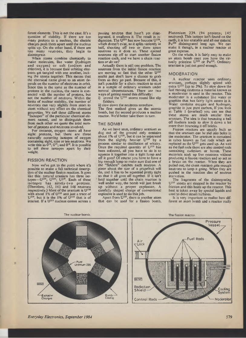
I
I
ferent elements. This is not the case. It's a
question of stability. If there are too
many protons in a nucleus, the electric
charges push them apart until the nucleus
splits up. On the other hand, if there are
too many neutrons, they begin to
disintegrate.
When atoms combine chemically to
make molecules, like water (hydrogen
and oxygen) or salt (sodium and
chlorine), it is because their orbiting elec-trons get tangled with one another, lock-ing the atoms together. This means that
the chemical name given to an atom de-pends on the number of electrons in orbit.
Since this is the same as the number of
protons in the nucleus, the name is con-nected with the number of protons, but
not the number of neutrons. Within the
limits of nuclear stability, the number of
neutrons can vary slightly from atom to
atom without any effect on the chemical
properties. We call these different atoms
Isotopes" of the particular chemical ele-ment named, and to distinguish them
from each other we quote the total num-ber of protons and neutrons involved.
For instance, oxygen atoms all have
eight protons, but there are three
naturally occurring isotopes of oxygen
containing eight, nine or ten neutrons. We
write this as 016; 017; and 0". It is possible
to tell these isotopes apart by their
weight.
FISSION REACTION
Now we've got to the point where it's
possible to make a full technical descrip-tion of the nuclear fission reaction. It goes
like this: natural uranium has three iso-topes—U
214; U235
; U218. Each of these
isotopes has ninety-two protons.
(Therefore, 142, 143 and 146 neutrons
respectively.) Most of the uranium is U21R
with about 1% of U2J` and just a trace of
U234, but it is the 1% of U21` that is of
interest. If a U233 nucleus comes across a
The nuclear bomb.
passing neutron that hasn't yet disin-tegrated, it swallows it. The result is in-digestion. The U2J5 has now become U"',
which doesn't exist, so it splits violently in
half, shooting off two or three spare
neutrons as it does so. These ejected
neutrons zip off to start another fission
reaction each, and we have a chain reac-tion or do we?
Actually there is still one problem. The
neutrons from the initial fission reaction
are moving so fast that the other U211
nuclei just don't have a chance to grab
them as they go past. Because of this, it
isn't possible for a chain reaction to start
in a sample of ordinary uranium under
normal circumstances. There are two
ways of getting round this difficulty:
i) crowd the U23' atoms round like slip
fielders.
ii) slow down the neutrons somehow.
The first method gives us the atomic
bomb, but the second produces a nuclear
reactor. We'd better take them in turn.
THE BOMB!
As we have seen, ordinary uranium as
dug out of the ground only contains
about 1% of U27S, but it can be separated
from the slightly heavier U'-3R by a
process similar to distillation of whisky.
Once the required quantity of U23` has
been collected, all you have to do is to
squeeze it together into a tight lump and
off it goes! Of course you have to have a
big enough lump to make sure that one of
the "fielders" catches each neutron. A
piece about the size of a grapefruit will
do, and it has to be squeezed pretty tight
so that it all goes off together. If it isn't
held together until the chain reaction is
well under way, the bomb will just break
up without a proper explosion. A
carefully shaped charge of conventional
explosive is used to do this job.
Apart from U211, there is another atom
that can be used for a fission bomb,
FE75P
Radiation
Shield—�
Control Rods
Plutonium 239. (94 protons; 145
neutrons). This isotope isn't found on the
earth, it is too unstable and all our natural
Pu2l' disintegrated long ago. We can
make it though, in a nuclear reactor at
great expense.
On the whole, it is fairly easy to make
an atom bomb once you have the vir-tually priceless U
231 or Pu219. Ordinary
uranium is just not good enough.
MODERATION
A nuclear reactor uses ordinary
uranium, perhaps slightly spiced with
extra U219 (up to 3" 6). To slow down the
fast moving neutrons a material known as
a moderator is used in the reactor. This
moderator is a substance like water or
graphite that has fairly light atoms in it.
Water contains oxygen and hydrogen,
graphite is just pure carbon, If you look
at Table I (overleaf) you can see that
these atoms are much smaller than
uranium. The idea is that bouncing a ball
off feathers tends to slow it down a lot
more than bouncing it off bricks.
Fission reactors are usually built so
that the uranium can be slid into holes in
the moderator. The uranium is contained
in tubes known as fuel rods which are
replaced as the Ut" gets used up. As well
as the fuel rods there are also control rods
containing cadmium or boron. These
materials soak up free neutrons without
producing a fission reaction and so act as
a brake on the reactor. When they are
pulled out, the chain reaction gets enough
neutrons to keep it going. When they are
pushed in the reaction dies of neutron
starvation.
The fragments of the disintegrating
Ut1` atoms are stopped in the reactor by
friction and this heats up the reactor. This
heat is taken away by special liquids and
used to drive steam turbines.
It is very important to realise how dif-ferent an atom bomb and a reactor really
The fission reactor.
Cooling
System
`--- Moderator
Everyday Electronics, September 1984
579

Table 1. Some chemical elements and their
atomic structures
Element
Number of
Protons
Usual No
of Neutrons
Hydrogen
1
0
Helium
2
2
Boron
5
6
Carbon
6
6
Oxygen
8
8
Cadmium
48
66
Lead
82
126
Uranium
92
146
are—both to principle and construction.
To say that a nuclear reactor works like
an atom bomb is worse than saying that a
car engine works like a Molotov Cocktail.
A nuclear reactor cannot be used to make
a nuclear explosion because its construc-tion is all wrong.
FUSION—THE HEAVY STUFF
There is another way that we can get
power from nuclear reactions, that is by
fusion. Fusion involves an isotope of
hydrogen. Ordinary hydrogen has the
simplest possible nucleus—one proton,
this single proton nucleus has one solitary
electron orbiting around it. Apart from
this usual arrangement, hydrogen atoms
exist which also have a neutron joined to
the proton. This is the isotope that makes
the fusion reaction possible, and it is so
important that we give it a special name.
Instead of calling it hydrogen 2, we call it
deuterium, or sometimes "heavy"
hydrogen. (Heavy water is a
deuterium/oxygen molecule instead of
hydrogen/oxygen.)
What makes deuterium so important is
that if two deuterium nuclei are forced
together against the electrostatic repul-sion of the protons, they suddenly
"recognise" each other and instead of
pushing apart, they rush together. We
don't know why this is so, one clue is the
fact that when they join they form a
helium nucleus. If you read last month's
article What is Radiation? you will
remember that the helium nucleus is sort
of ultra-stable and is almost impossible to
split open. The resounding smack as the
deuterium nuclei meet gives off tremen-dous energy in the form of heat and
gamma radiation. If there are plenty of
other deuterium atoms about, this heat
smashes them together hard enough to
start another sort of chain reaction.
This fusion reaction produces a lot
more energy than the fission reaction and
this is what makes the hydrogen bomb so
destructive. (Really it ought to be called a
deuterium bomb). The only trouble is that
to start the reaction off you have to push
the deuterium atoms together very hard
indeed. The only way that we have been
able to produce the temperature and
pressure required so far is to use an atom
bomb as a detonator. A hydrogen bomb
is simply an atom bomb containing a lot
of deuterium in the middle.
Obviously we can't use an atom bomb
to start up a power station. It would be a
bit like using a stick of dynamite instead
of sparking plugs in a car. Anyway we
don't want the deuterium to go off all
together. Scientists are working now to
trigger a fusion reaction using lasers in-stead, but it hasn't been done yet and we
are still a long way from a practical
fusion reactor.
An experimental nuclear fusion
reactor under construction.
COUNTER
INTELLIGENCE,
Computer Nasties
I have never thought of it as part of my
brief to pass comment on the social evils of
the present day, but when unpleasant
things transgress in our particular domain, I
think it is time to stand up and be counted.
I am not referring to "Video Nasties", as
there is already sufficient outcry about
these to ensure that some corrective
legislation will be passed. I am referring to
"Computer Nasties" which really do intrude
on our patch.
It has recently been brought to my notice
that there is now a new version of "Killer
Gorilla" called "Killer Priscilla". Without go-ing into all the lurid details, it seems that
poor Priscilla is either carried off by the
man-eating gorilla or suffers a fate worse
than death countless number of times. This
may be an isolated example, but at the risk
of being labelled a puritan, I would say that
this is not suitable for young children.
This game by the way, has been
designed for the BBC machine. Poor Sir
John Reith would never forgive them.
How do you legislate against these
thing0 The difficulties the legislators face
are immense. How do you cover all the
various systems without leaving loopholes,
bearing in mind that computer programs
can be on tape disc, or even solid-state
memories MOMS)?
BY PAUL YOUNG
It needs someone with a fine command
of English to define the terms with precise
wording. A combination of Sir Ernest
Gowers, who wrote the famous "Plain
Words", and Mr. Bowden. Mr. Bowden
worded the patent for his world renowned
cable as follows: "It consists of two mem-bers, the outer being flexible and incom-
pressible and the inner being flexible and
inextensible In spite of its brevity, no one
ever got round it.
In a recent statement, Sir Clive Sinclair
said that he estimated that in a few years it
would be possible to make a computer as
"complex" as the human brain. I have the
feeling that Sir Clive chose the word "com-
plex" after careful deliberation. There is
after all a subtle difference between this,
and saying it would be possible to produce
one capable of intelligence and reasoning,
which I touched on in my last article.
I have just received an interesting letter
from Mr. Murray Eagle, who works in the
Fighting Bay Cable Station at Blenheim
Sound, New Zealand. He kindly sent me a
circuit for a 28-day clock for keeping your
spare car battery on top line (see February
Issue of EVERYDAY ELECTRONICS).
More about that later, but he concluded
his letter by saying that he was disenchan-ted with computers and automation. He
has been a lighthouse keeper for over 13
years and now he has been replaced by a
chip!!
Luckily he still has a job, looking after the
Cook Strait power cables to the North
Island, but it has meant learning a whole lot
of new skills. Unfortunately it will be
Christmas before Mr. Eagle reads this, as he
says it takes almost forever for EE to reach
him. How lucky are our UK readers.
Matter of Opinion
I read recently of a man bringing back
from Japan an electronic gadget that would
instantly translate words and phrases into
several different languages at the touch of a
button. From this, he concludes, erroneous-
ly in my opinion, that we are way behind in
technology.
This is certainly not my impression,
which is why the Japanese are so anxious
to get hold of INMOS, probably one of the
most advanced silicon chip manufacturers
in the world. He goes on to say that British
manufacturers cannot even supply equip-ment for the proposed multi-million pound
Cellnet Radio Network.
While this accusation is serious enough,
it is not necessarily a technological
problem.
Attraction of CB
To end on a lighter note, regular readers
may remember my stern warning that cer-tain unprincipled young ladies were using
CB Radio to lure unsuspecting men to their
doom (or was it room?). I would like to im-
agine that it sparked off a CB boom, but I
don't know.
In America this particular use of CB by
sweethearts and others has grown to such
proportions, that they have had to allocate
a special channel (dubbed the "Mating
Channel") for this purpose. Could romance
by radio be what is needed to empty the
shelves of all those surplus CB sets??
580 Everyday Electronics, September 1984
T
sl
T
n
T
s;
V
V
rl
a
n
p
p
c
i!
n
c
n
v
c
E
c
r
t.
F
c
I.
C
t
s
1

000
MICRO
MEMORY
SYNTHESISER
A musical instrument covering two full octaves (F to F) and featuring attack/decay,
tremolo and variable pitch controls. A memory is provided to store a played tune (up
to 28 notes) and there are ten pre-programmed tunes which can be learnt by press-
ing the learn key; each key in turn is then lit by an I.e.d. and remains on until it is
pressed.
NEW COURSE...
DIGITAL ELECTRONICS
A series of articles explaining the principles of digital electronics, from component descriptions
through logic families and circuit design to microprocessors. An insight into the digital circuit
"building brick" for those with a basic understanding of analogue electronics.
MAINS CABLE DETECTOR
EVERYDAY
ELECTRONIC:
and com •cater PROJECT!
OCTOBER 1984 ISSUE ON SALE FRIDAY, SEPTEMBER 21
Everyday Electronics, September 1984 581

Ca rava n
Dipstick
T. R. de Vauz-Balbirnie
EVEN the most enthusiastic caravanner
shrinks from the thought of carrying
water late at night. If the level in the fresh
water storage container is known, then
the family can regulate their requirements
and refilling can be avoided at incon-venient times.
Unfortunately, the traditional method
of checking the level—peering into the
container with a torch—is itself very in-convenient. This project indicates the
level at any time, simply by pressing a
button on a unit inside the caravan. A
large (0.5in) 7-segment I.e.d. display
lights up with an appropriate letter—"L"
for Low, "I" for Intermediate or "F" for
Full. Although 7-segment displays are
normally used for numbers, letters such
as these are readily produced.
There could be other uses for this pro-ject but remember that it works by
current passing through the liquid—in
this case water—so it would be useless
for non-conducting liquids such as
heating oil.
GENERAL DESCRIPTION
The Logic Dipstick comprises two
components. Firstly, the dipstick itself
which is placed in the water container
outside. The dipstick has a 3-way ter-minal block on top which connects
through a cable to the unit inside the
caravan. This main unit carries the dis-
play, a push-button switch and a terminal
block for the dipstick connections. The
box houses the electronic circuit and a
PP3 battery. Excellent service is provided
by a small battery since it is only used
while the switch is operated.
The letters L, I and F were chosen not
only because they are appropriate but
because they can be produced by simple
logic. This obviates the need for logic
gates.
In the prototype, the top quarter of the
water container was used to signal "F".
The middle half for "I" and the last quar-ter for "L". This was found to be a good
arrangement in practice but some readers
might wish to change the levels to suit
their own requirements.
CIRCUIT DESCRIPTION
The dipstick has three conducting
probes—two (A and B) are at a low level
and one (C) near the top (see Fig. 1).
Probe A is at battery positive voltage.
When the water level is low, then Probe A
will be connected to neither of the other
two probes. At a higher level, Probe A
will be connected to Probe B through the
water. When the water reaches the high
level, then Probe A will be connected to
both Probes B and C.
The information from Probes B and C
is passed to the inputs of the operational
amplifiers ICIa and ICIb. Both op-amps
are in a single i.c. package. These will
switch on and off through very high
resistances such as water. They also
provide the logic for the system to
operate.
Referring to Fig. 1, it will be seen that
the two op-amps are connected slightly
differently. ICIa has its non-inverting in-put held at one-half battery voltage by
means of the potential divider R3 and R4.
IC I b shares this potential divider but this
time the voltage is applied to the inverting
input. RI and R2 connect the remaining
inputs of the op-amps to battery negative.
In this way, when S 1 is pressed, IC I a will
be on and IC I b off. The output from
IC la is connected to segment d while the
output from IC 1 b is connected to seg-ments a and g of the display, X 1.
Whenever S is pressed, segments a and f
will light up since they are connected
through R7 to the battery positive line.
With IC lb on, segments a, e, f and g will
therefore light signalling "F". With both
op-amps off, only segments a and f will be
lit giving "I". With ICIa on, segments e,
f, and d will be lit producing "L". As the
water level in the container falls, this
sequence will be followed.
The current for each segment of the
display is limited to about 20mA by
means of R5, R6 and R7. Note that R6
and R7 have only approximately one-half
the value of R5 since these resistors carry
the current for two display segments
rather than just one. The display is of the
common cathode type where all segments
have a common connection (pin 8) to the
battery negative line.
CONSTRUCTION
Refer to Fig. 3 and construct the
dipstick itself. The details refer to the
prototype and some readers may wish to
use their own ideas. If the water is for
drinking then choose materials which are
normally used for winemaking and
cookery purposes. The prototype dipstick
was made from narrow plastic tubing, 20
s.w.g. bare copper wire and rubber bands.
It is thought that the rubber bands will
only give one season's use but they are
cheap, effective and easily replaced.
Avoid any material which absorbs water
or remains wet when the water level falls
since these will effectively short-circuit
the probes and cause faulty operation.
Note that the dipstick does not need to
reach the bottom of the water container
but only down to the "Low" level. A wire
hook is used to attach the dipstick to the
filler neck.
I found that the plastic tubing was stiff
enough for the purpose but suitable
plastic rod could be used for stiffening if
required. If the tubing has been coiled it
may be straightened by heating it in
steam from a kettle spout and pulling it
straight a few times. Some curling of the
dipstick is permissible.
The 3-way terminal block at the top of
the dipstick is self supporting. It must be
kept well clear of the water since,
otherwise, short circuits may occur.
When the dipstick is complete, con-struct the circuit panel. Refer to Fig. 2
and build the circuit using a piece of
0• lin matrix stripboard 24 strips by 18
holes in size. Start by carefully removing
the corner to give clearance for S 1. A 14-
pin d.i.l. socket is used for IC 1 but the
display, X 1, is soldered direct to the panel
using minimum heat from the soldering
iron. Do not insert IC 1 into its holder
until construction work is complete.
Make the breaks between the rows of
pins of IC 1 also at X 1 and near the fixing
holes. Note that eight links are required
between copper strips. Complete con-struction by soldering 10cm connecting
wires to strips B, H, M and T.
582 Everyday Electronics, September 1984
i
t
1

R3
6
(D
HIGH LEVEL
PROBE
A B
LOW LEVEL
PROBES
R1 R2
4714nt4
R4
Imn
1cla
R5
330n
R7
5011
T +9V
' 51
R6
1508
EE
OV
Fig. 1. Circuit diagram of Caravan Dipstick.
/0 0 0 0 0 0 0 0 0 0 0 1
•• 0 0. 0 0 0 0 0 0•
0 0 0 0 0 0 0 0 0 0 0 0
0 0 0 0 0 0 0 0 0 0 0 0
0 0 0 0 0 0 0 0 0 0 0 0
O O O O O O O O O O O O
0 0 0 00 • 0•• 0 0 0 0 0 0 0 0
• O• O O O• O•••• O•• 0 O O
0 0 0 0 0 0•
0 0 0 0 •
O O O
0 0 0
0 0 0 0 0 0. 0. 0 0 0 0 0 0. 0
0 0 0• o•• o•• 0 0 0 0 0 0 0
• 0 0 0 0•• 0. 0 0 0 0 0 0 0 0
0 0 0 o O o 0 0 o O o 0 0 0 0 o O o
0 0 0 0 0 0 0 0 0 0 0 0 0 0 0 o 0 0
0 0 o O o 0 0 0 0 0 0 0 0 0 0 0 0 0
0 0 0 0 0 0. 0 0 0 0 0 0 0 0 0 0 0
0 0 0 0 0 0•• 0 00 0••
0
000. 0 :.0200.0.
0
• 0•••• 0 0. 0 0 0 0. 0 0 0
0 0 0 0 0 0•• 0 0 0 0. 0 0 0
0 0 0 0 0. 0 0 0 0. 0 0 0
0 0• o
8
0 0 0 0 0 0 0 0 0 0 0 0 0 0 0 0
• 0 0 0 0. 0 0 0 0 0 0 0 0. 0
CORNER RE-MOVED TO
CLEAR 51
l l f
Fig. 2. Stripboard layout (actual size).
COMPONENTS
Resistors
R 1,2 4 7MO (see text) (2 off)
R3,4 1 Mfg (2 off)
R5 330CI
R6,7 1500 12 off)
All -f' W carbon ±5%
Semiconductors
IC1 µA747PC or µA747CN
dual operational amplifier
X1 0.5in 7-segment common
cathode I.e.d. display
Miscellaneous
MB1 plastic box internal dimen-sions 76 x 56 x 35mm; 0 1 in
matrix Stripboard 24 strips by 18
holes in size; 14-pin d.i.l. i.c.
holder; 3-amp terminal block-6
sections required; PP3 battery and
battery connector; stand off in-sulators (see text) (2 off); 3-core
light duty connecting wire;
adhesive pad; materials for
dipstick—plastic tubing, 12 s.w.g.
bare copper wire, elastic bands
see text.
TB1I1 T8112 TB113
TB2
RUBBER BANDS
206.9
TINNED BASE
COPPER
WIRE
NARROW BORE
PLASTIC TUBING
IEE16A
Fig. 3. Construction of the dipstick itself.
page 560
9�
Everyday Electronics, September 1984
�ti;
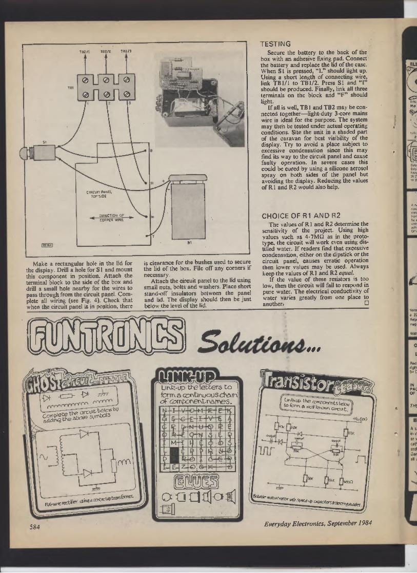
Make a rectangular hole in the lid for
the display. Drill a hole for S 1 and mount
this component in position. Attach the
terminal block to the side of the box and
drill a small hole nearby for the wires to
pass through from the circuit panel. Com-
plete all wiring (see Fig. 4). Check that
when the circuit panel is in position, there
is clearance for the bushes used to secure
the lid of the box. File off any corners if
necessary.
Attach the circuit panel to the lid using
small nuts, bolts and washers. Place short
stand-off insulators between the panel
and lid. The display should then be just
below the level of the lid.
TESTING
Secure the battery to the back of the
box with an adhesive fixing pad. Connect
the battery and replace the lid of the case.
When S is pressed, "L" should light up.
Using a short length of connecting wire,
link TB I / I to TB 1/2. Press S l and "I"
should be produced. Finally, link all three
terminals on the block and "F" should
light.
If all is well, TB l and TB2 may be con-nected together—light-duty 3-core mains
wire is ideal for the purpose. The system
may then be tested under actual operating
conditions. Site the unit in a shaded part
of the caravan for best visibility of the
display. Try to avoid a place subject to
excessive condensation since this may
find its way to the circuit panel and cause
faulty operation. In severe cases this
could be cured by using a silicone aerosol
spray on both sides of the panel but
avoiding the display. Reducing the values
of R 1 and R2 would also help.
CHOICE OF R1 AND R2
The values of R 1 and R2 determine the
sensitivity of the project. Using high
values such as 4.7MQ as in the proto-type, the circuit will work even using dis-tilled water. If readers find that excessive
condensation, either on the dipstick or the
circuit panel, causes erratic operation
then lower values may be used. Always
keep the values of R I and R2 equal.
If the value of these resistors is too
low, then the circuit will fail to respond in
pure water. The electrical conductivity of
water varies greatly from one place to
another. ❑
LinP--up tleletters to
Fn m a ctinGnuouS ct)afn
of Corrpor\ tit r�afneS
C
M-3
...E f"'
L
P
f- E-
1i
O
Crr
V
s
0 E(
IT
a
584
m
ELE
Everyday Electronics, September 1984
s
r HOME LIGHTING KITS
Tees. bb con,«n .11 rouu«r cwnpa'r'u •lie
I WI n«ruclana \ •n d••pnes is •eaKe • ,.r'a«d
«'d c«'ha w l0 3oow o f i,phlinp
TDR300K A-,. Control
Di £14.95
MK6 Tm«nntw for so.- £4.50
TD300K Tovchdrmm., £7.75
T 300 To,ch.wdch £7.75
TOEIK
'P1, li
ning for l
TD300Kr
'E2 50
L0300K po,�.,,,C---led E3 95
DVM/ULTRA SENSITIVE
THERMOMETER KIT
Tors nsw des,pn ,s D+fed on I lie ICL 7126
Cs bw•r Pow., v,s,on of Ind ICL 7106
h'm ilia. 3 r, sign IrR.ra a r•t a ersDlaris Lit w 11 to,m the D.srs OI a d,9 1.1
mWUmK« ionro a few addi,.Onal ,,s,s o1 and
Are 'ta
„c M. • leouvd d.- Is fuoPI.Idlf
„n'.. dyy me.momet, 1 50"C to 150°C+
iri
erng to O1oC The bs«c - has a S-S.I. rtd of
200mv for J 1.11 scale r.aemq au,omarc polanlr
d- on and an .lira Iow pow, 1ep.,emIn,
I we•,
'n9a2K+r1 pi�al Dattery file lrom•ilanea,d 91
3 aeseeno„•+d.d
d Prinf15.50 e
1
K113 MW RADIO KIT
Based on ZN414 IC. kit includes PCB, wound
aerial and crystal earpiece and all Components
w make a sans Ive miniature radio Size 5 5
2 7 2cm; Requires PP3 9V battery IDEAL
FOR BEGINNERS £5.50
ELECTRONIC
LOCK KIT
With hundreds
of uses in doors,
garages.car
anti - theft
devices.
electronic
equipment etc
Only the correct
eas ly changed
four digit code
will open its
Requires a 5 to 15V
do supply.Output 75OmA Fits
into standard electrical wall
box Complete kit (excl
front panel) XK101 £11 50
Electronic lock mechanism
for use with the above kit
70150 £14 95
r WE ALSO
STOCK A WIDE
RANGE OF
ELECTRONIC
COMPONENTS
SEE CATALOGUE
FOR DETAILS
Is AM KITS 'N
MRt ELECTRONIC THERMOSTAT
I2•w L•t'1l IC to •.n•• Kander.-
I$ rC m..l +ne h- to -11h halt«
I1KsrVl Mr,npoww•d F, so
MK2 SOLID 9TA>� R mUa
S__ ,C
140V , lights
nest«. Iron opt RamputF Gr u1.
two rdlage swncMnp. opto ndatwl
Mks
PROPORTIONAL tlO
TIM
PER ATURf CONTROLLER
use,Yf.. punt 0.11 tecnnpue 1 -1.
empw«aeto w,mm05'C lose
la onomOr on,Ma
ined
3K
wire
nw,rrq M.• load 31tW I140v
zl Teo, v.P1o90-C to So
K mS MAINS TIMER
sixi pia reree ume, naDkrp a load
uD to Ixw a17tlV .ae
lo De swrlcrRd
oo
hs Ia a «uDN um! h- 20
35 nor
Lonpe'r snort,
Pw'ms dossrde mina
Iar'po„•ni ClLAM
wr,n Ea SO
MR19 DUAL UTCHED SOLID
STATE It LAY Conrp,rses two MK2s wish 4hn circurl
anaplr„gI
the MK 12 Ld to conha two
I' K W
,neaOarWanhr Two
WtWI Rd uppt r
ramose ond Ir1s l ra M
NCO, MKI90C CONTROLLED
G AUDIO AMPLIFIER
Mar Da used will, h, an, I—
auao -0.1, in connd�hass
volume reble a-'�auge
r ar
«er uu , re h . • Ind MKII
inl,n
red rrer A'r
1 01 10 decoder
LEDs ;s ew included In, rem
input verechon d.1 Isar remote
Lonhd Los (ion
c
J
7C MICROPROCESSOR 1
CONTROLLI
TIMER
Now you can ... you,
n,.1 h..ting. lighting
l 11 s 1. and 101, more
with r lull
O • program
maD1a timers
At
3 acK It i. "signed 10
onhd low " .
outputs
on a
off at
awn comp
and 011apra s 1.1cl,
.
9
d. fl
nin
cy114, ewnC
to cOnlroldou,
cent, .l nesting hncludmg dill•1•nt • dcnrnp , and
lo,
and
fM4LL Nst connect n to dour .pUm O,opramme and set n
aria fo.g•1 n - the clot, oral do lit• ,•«
• 7 LED 12 no.,-ol.r
• o•r o f wes,. •m •lid
mom .uma rna,c non
• ioesncod.cl o 1
msrod
so .-.1..-.1.1.11 11 pr. rs , uu «c
• 5060«a m•,na oo««ion
• en1,r D.c,,P..rs «o,.e
pr
mp lull", P we�
s�16•l1a r of rar�neel
r n
• D�wl•Y aan,,rq poring
oow.rl«iur.lo cona«re
D•tl«r
p pon«m•
l>irl•o�rlul Evelydar runclon
n.a a11 :r - u.. 0--
=.- • =.- 1-1 luncnon
lul.. on• «a hh I„-1orano.,
D.•n.
...-a o,tpu, to es m„r.e
m.arn•Ir or •n., .
wcrl,es,rme
' ♦ If,
7or,ncnon -
lo,
P,",_ens r
3-NOTE DOOR CHIME 1
Based on the SA80600 IC the kit Is supplied
with all COmpOnlnl s. including loudspeaker
printed c,rcuit board. a pre -dulled box (95 r
71 , 35mml and full instructions Requires
only a PP3 9v battery and push Switchto
complete AN IDEAL PROJECT FOR BEGIN
HERS Older as XK 102
£5.50 J
r INFRA RED
14
GARAGEDOOR
CONTROLLER
KIT
For opening
and closing
motorised
garage
doors plus
switching
garage and
drive lights
on and off
up to a
range of
40ft and numerous other
applications like controlling
lights and TV's etc. in the
home. Ideal for aged or dis
abled persons, this coded kit
comprises of a mains powered
infra red remote control re
ceiver with a normally open
relay output plus two latched
transistor outputs; battery-powered four button trans
mitter and an opto isolated
solid state mains switch. As
with all our kits, full
instructions are supplied.
XK103 E25
Extra transmitters
XK105 E10.00 j
Send SAE 9" x 6'' for our FREE
YELLOW CATALOGUE. It's packed
with a full list of our stock range all at
very competitive prices.
L
NOW ONLY
E39.00
15 �10 o5'Xm'o oa
clW
oC@ n Iw
y
. ..till . an. o u
�.aw .. CTa0o0 none
xK114 OFTIONAL RELAY MT
Kn ni,a•• on. r•1.r Pca 1
.cc odn•,. 1.1 W.'s I.
I aK,s. rn.me
CT6000 Do• Pl vdcs
,
up Io
3•m: '.Ov AC n•nw
i l0
•M11wnM rN•ya F l a6 e•c n
COMPONENT PACKS
J
PACK 1 650 R•p«or. 47 ohm 1n 10 M.- loo.,
s E. 00
PACK .0 l6v EI•cnarnc Cawcuo,s tor# to
100011 5 W raise [ ] 26
PACs 3 60%04
C• Par n or 1001 io li 250,
For PACK 4SSuDmns�l S,•Pr.se1. 100onm 1. lM
5 Per dais. [290
P ACK 30 Low P,olu•IC SKLe1s6
cn 12.0
PAC.6 21
S Aed LEDs iSmm o.a llso
HOME
CONTROL
CENTRE
This kit enables
you to control up to
16 different apply
dnces by means of
coded pulses in the
mains wiring
which may be
decoded by special
receivers anywhere in the house
The transmitter may be controlled
manually or by the Computer inter
face enabling your favourite mica
to make your coffee in the morn
ing, switch lights
anywhere in the
ouse, or your
electric blanket
in your bedroom.
Just think of the
possibilities -
and no wiring,
The Kit com
Ditties a trans
matter with pre
drilled box and
two receivers
XK112 £42.00
ADDITIONAL RECEIVERS
XK111 E1000
Add 65P postage & packing 15% VAT to
total overseas Customers.
Add E2 501Europe). E6 00 leis•wherel to, psp
Send S A E to, furthe, STOCK DETAILS
Goods by return subject to avadabdrty
OPENSlam to 5pm Won to Fri)
1Oam to 4pm ISat,
FAST SERVICE R TOP QUALITY R IN low PRICES
No circuit is complete without a call to -
ELECTRONICS=
11-13 Boston Road 01 9
579794E
O
S
NOU
R
London W7 3SJ
J
A
LI HTING KIT
OL MM"
TNe rekrs for mwi•d ,n tax
. a arKlrow •P
. lie•
Na a And •• ns,'c• 'xin
tine
o .w ar,
I
at..nmrm.t«
.lid ncwoorl
amm,Ip conl,oi
Our 10006
A bw•1cesl wrsron ollM •Doi• I•,unnp un
Mm.err.�o P'. se, .oi 0.1.-
=1
7=1
'
es.1 m.rm s«o c,o•«lip Isom 11
o rm,l«enc• to • n,mur..
m
ES 95
115.95
O9m Ioplonp.IDLAI
Allowing • d.I"es«"I - bight
.pons. BOP
DL3000R
TM. 7 chenne south 10 Igrn k,r ,.n
.•1ur•, a•,n
rnn.pe awnriunp .�nom.1,. 1. com,oi .,.,.
Only 112 95,j
24 HOUR CLOCK/
APPLIANCE TIMER KIT
Switches any appliance up to 11kW
on and oil at preset times once per
day. Kit contains. Ay 5 1230 IC
0 5' LED display, mains supply
display drivers, switches. LEDs
macs. PCBs and full Instructions
CTIOOOK9a•rcK-t (14 90
CT100011 with wort! boa
156131.71mmi f17 .o
iaeser 6u.It1 E22 So
19 r.no- -k,ding DC 'dupe 1200
mr 1000 vl and AC rdlag•, DC cun•, 120D
rM 10 AI and, lance 10 2M1 .n
NPN
6 PNP hrwsto, 9- and dons ch•c•
Indul np•llan it 10M Sus 190. 140
somm eoepl.N with Dankey Iest I••M
in carrva lis a ONLY [32.
'REMOTE CONTROL KITS,
113 so
Nal]Drrl
«eslw a•resr. L4 ]5
Ma,9 a cw•rar. M«« ••pl•.. •, n
•mw,l.. n•Ya r9 m.r •ew..e
.ra.•q i •,rim• 1.ni n . o.+. vs+
o i.pn:. iL
Mt 121.1•N Mc1.Y r rw•eiKw,
-lo
is
r a.1.•.l« se.•.rJ
Halo ta..r a "S"'
, a. N"Ne
Iaat\owL , uN
OGED
KP
SKlOIF [R•KRlL t1K000[o a1•A•
I'd rig
COMPUTER SHOWROOM
TOP HARDWARE,
LATEST SOFTWARE PERIPHERALS,
ACCESSORIES AND MUCH,
MUCH MORE!
Ol 5792842 TECHNICAL.. IP«
A L ANAGE
t G•R.GE

EVERYDAY
news
... from the world of
HIGH STANDARD OF INNOVATION MAINTAINED IN THIS YEAR'S
SCHOOLS COMPETITION
SEDAC '84
AWARDS
* WINTERBOURNE
WINS BIG PRIZE
* SCARBOROUGH SECOND
* NORWICH THIRD *
NETWORK SYSTEM to link a school's computer for
greater power and flexibility, designed and built by
sixth-year students David Omar and Zee Bunker, both
aged 17, won the first prize in this year's Schools Elec-tronic Design Award Competition (SEDAC). Their school
The Ridings High School, Winterbourne, Bristol now
becomes the proud possessor of the SEDAC 84 trophy, as
well as L300 cash and a selection of components valued at
£200.
The second prize of £200 plus components valued at
£200 was awarded to Malcolm McKie, aged 14, of Scar-borough College, North Yorkshire, for his Multi-Purpose
Laboratory Timer. Several striking and novel features are
incorporated in this instrument, which should prove an
admirable asset to any schools physics lab.
The third prize of £ 100 plus components valued at £200 was
awarded to a team of three: Rosemary Erskine, 15, Nicola
Hargreaves, 15, and Juliet Wright, 16, of Norwich High School
for Girls, Norwich. This local trio collaborated to produce a
Digital Anemometer and Wind Direction Indicator, suitable for
use in a geography or physics department. It can be used either
as a "stand alone" device, or with a BBC micro so that readings
can be taken, stored and plotted automatically.
The eight remaining finalists received components to the
value of £ 100.
All eleven finalists received a certificate and one year's sub
scription to EVERYDAY ELECTRONICS.
PRESENTATION OF AWARDS
Results of the third Schools Electronic Design Award Competition
were declared and prizes presented to the successful participants on
July I I at Mullard House, London.
Throughout that day eleven finalists' projects were on display with
their young designers in attendance to describe and demonstrate their
purpose and operation. Visitors who toured the exhibition were ob-viously impressed by the wide range of subjects covered and by the en-terprise of the individual students who had won through to this final
stage in this competition sponsored by Mullard and EE.
SEDAC "84 winners David Omar and Lee Bunker of The Ridings High
School, Winterbourne, with Michael Paton of /PC Magazines (left) and
Ivor Cohen of Mullard.
Runner-up Malcolm McKie of Scarborough College receives his prizes
from the Managing Directors of the competition sponsors.
Rosemary Erskine, Juliet Wright and Nicola Hargreaves of Norwich
High School for Girls, winners of the 3rd Prize.
586 Everyday Electronics, September 1984
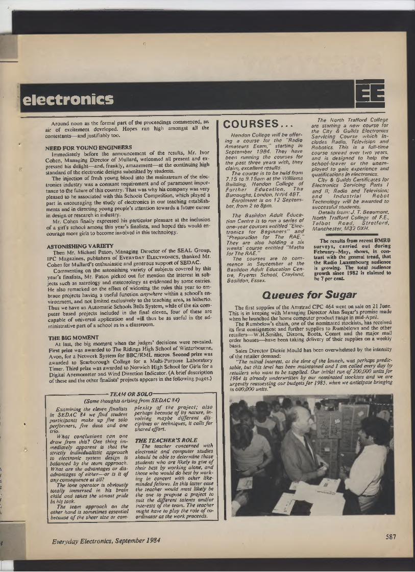
Examining the eleven finalists
in SEDAC 84 we find student
participants make up fire solo
performers, five duos and one
trio.
What conclusions can one
draw from this? One thing im-mediately apparent is that the
strictly individualistic approach
to electronic system design is
balanced by the team approach.
What are the advantages or dis-advantages of either—or is it of
any consequence at all?
The lone operator is obviously
totally immersed in his brain
child and takes the utmost pride
in his task.
The team approach on the
other hand is sometimes essential
because of the sheer size or com-
electronics
EE
Around noon as the formal part of the proceedings commenced, an
air of excitement developed. Hopes ran high amongst all the
contestants—and justifiably too.
NEED FOR YOUNG ENGINEERS
Immediately before the announcement of the results, Mr. Ivor
Cohen, Managing Director of Mullard, welcomed all present and ex
pressed his delight—and, frankly, amazement—at the continuing high
standard of the electronic designs submitted by students.
The injection of fresh young blood into the mainstream of the elec-
tronics industry was a constant requirement and of paramount impor-
tance to the future of this country. That was why his company was very
pleased to be associated with this Schools Competition, which played a
part in encouraging the study of electronics in our teaching establish-
ments and in directing young people's attention towards a future career
in design or research in industry.
Mr. Cohen finally expressed his particular pleasure at the inclusion
of a girl's school among this year's finalists, and hoped this would en-
courage more girls to become involved in this technology.
ASTONISHING VARIETY
Then Mr. Michael Paton, Managing Director of the SEAL Group,
IPC Magazines, publishers of EVERYDAY ELECTRONICS, thanked Mr.
Cohen for Mullard's enthusiastic and generous support of SEDAC.
Commenting on the astonishing variety of subjects covered by this
year's finalists, Mr. Paton picked out for mention the interest in sub
jects such as astrology and meteorology as evidenced by some entries.
He also remarked on the effect of widening the rules this year to em-
brace projects having a useful function anywhere within a school's en-
vironment, and not limited exclusively to the teaching area, as hitherto.
Thus we have an Automatic Schools Bells System, while of the six com-
puter based projects included in the final eleven, four of these are
capable of universal application and will thus be as useful in the ad-
ministrative part of a school as in a classroom.
THE BIG MOMENT
At last, the big moment when the judges' decisions were revealed.
First prize was awarded to The Ridings High School of Winterbourne,
Avon, for a Network System for BBC/RML micros. Second prize was
awarded to Scarborough College for a Multi-Purpose Laboratory
Timer. Third prize was awarded to Norwich High School for Girls for a
Digital Anemometer and Wind Direction Indicator. (A brief description
of these and the other finalists' projects appears in the following pages.)
TEAM OR SOLO
(Some thoughts arising from SEDAC 84)
plexity of the project: also
perhaps because of its nature, in-volving maybe different dis-
ciplines or techniques, it calls for
shared effort.
THE TEACHERS ROLE
The teacher concerned with
electronic and computer studies
should be able to determine those
students who are likely to give of
their best by working alone, and
those who would do best by work-
ing in concert with other like-tninded fellows. In this latter case
the teacher would most likely be
the one to propose a project to
suit the different talents and/or
interests of the team. The teacher
might have to play the role of co-ordinator as the work proceeds.
Everyday Electronics, September 1984
COURSES...
Hendon College will be offer-
ing a course for the "Radio
Amateurs Exam," starting in
September 1984. They have
been running the courses for
the past three years with, they
claim, excellent results.
The course is to be held from
7.15 to 9. 15pm at the Williams
Building, Hendon College of
Further Education, The
Burroughs, London, NW4 4BT.
Enrolment is on 12 Septem-ber, from 2 to 8pm.
The Basildon Adult Educa-tion Centre is to run a series of
one-year courses entitled "Elec-tronics for Beginners" and
"Preparation for The RAE."
They are also holding a six
weeks" course entitled "Maths
for The RAE. "
The courses are to com-mence in September at the
Basildon Adult Education Cen-tre, Fryerns School, Crayland,
Basildon, Essex.
The North Trafford College
are starting a new course for
the City & Guilds Electronics
Servicing Course which in-cludes Radio, Television and
Robotics. This is a full-time
course spread over two years,
and is designed to help the
school-leaver or the unem-ployed to gain experience and
qualifications in electronics.
City & Guilds Certificates for
Electronics Servicing Parts l
and /I; Radio and Television;
and Industrial Robot
Technology will be awarded to
successful students.
Details from: J. T. Beaumont,
North Trafford College of F.E.,
Talbot Road, Stretford,
Manchester, M32 OXH.
The results from recent BMRB
surveys, carried out during
February—May, shows, in con-trast with the general trend, that
the Radio Luxembourg audience
is growing. The total audience
growth since 1982 is claimed to
be 7 per cent.
Queues for Sugar
The first supplies of the Amstrad CPC 464 went on sale on 21 June.
This is in keeping with Managing Director Alan Sugar's promise made
when he launched the home computer product range In mid-April.
The Rumbelow's chain, one of the nominated stockists, has received
its first consignment and further supplies to Rumbelows and the other
retailers— W.H.Smiths, Dixons, Boots, Comet and the major mail
order houses—have been taking delivery of their supplies on a weekly
basis.
Sales Director Dickie Mould has been overwhelmed by the intensity
of the retailer demand:
"The initial interest, at the time of the launch, was perhaps predic-table, but this level has been maintained and I am called every day by
retailers who want to be supplied. Our initial run of 200,000 units for
1984 is already underwritten by our nominated stockists and we are
urgently reassessing our budgets for 1985, when we anticipate bringing
in 600,000 units."
587
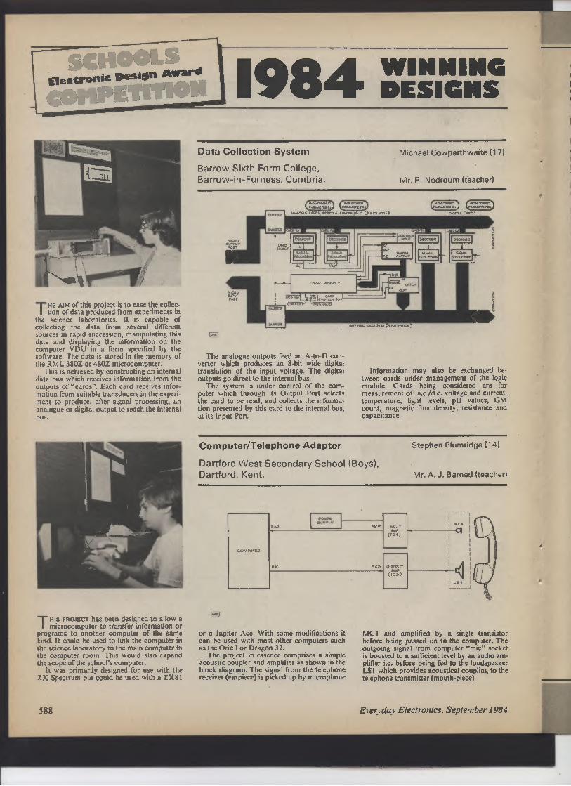
Electronic Design Award
1984
WINNING
DESIGNS
d---wirmool/
THE AIM of this project is to ease the collec-tion of data produced from experiments in
the science laboratories. It is capable of
collecting the data from several different
sources in rapid succession, manipulating this
data and displaying the information on the
computer VDU in a form specified by the
software. The data is stored in the memory of
the RML 380Z or 480Z microcomputer.
This is achieved by constructing an internal
data bus which receives information from the
outputs of "cards". Each card receives infor-mation from suitable transducers in the experi-ment to produce, after signal processing, an
analogue or digital output to reach the internal
bus.
This PROJECT has been designed to allow a
microcomputer to transfer information or
programs to another computer of the same
kind. It could be used to link the computer in
the science laboratory to the main computer in
the computer room. This would also expand
the scope of the school's computer.
It was primarily designed for use with the
ZX Spectrum but could be used with a ZX81
588
Data Collection System
Barrow Sixth Form College,
Barrow-in-Furness, Cumbria.
Michael Cowperthwaite (17)
Mr. R. Nodroum (teacher)
MIfJO
OIIfRlT
1b[r
M_
�N%!T
Po[T
tm
-1—
C se�wt
en, (h[pM[TE[
ni a,�c ueos �ooeess 6 cdrta eua (� em r�o[)
F.—
[O
=lcaur[pl wa
e—T 5--ro
The analogue outputs feed an A-to-D con-verter which produces an 8-bit wide digital
translation of the input voltage. The digital
outputs go direct to the internal bus.
The system is under control of the com-puter which through its Output Port selects
the card to be read, and collects the informa-tion presented by this card to the internal bus,
at its Input Port.
D
Wrc_—"(Dam—)
I\Raeewrt[n�, Nvu�n[[Dt
bECOD
Information may also be exchanged be-tween cards under management of the logic
module. Cards being considered are for
measurement of: a.c./d.c. voltage and current,
temperature, light levels, pH values, GM
count, magnetic flux density, resistance and
capacitance.
Computer/Telephone Adaptor
Dartford West Secondary School (Boys),
Dartford, Kent.
Stephen Plumridge (14)
Mr. A. J. Barned (teacher)
or a Jupiter Ace. With some modifications it
can be used with most other computers such
as the Oric I or Dragon 32.
The project in essence comprises a simple
acoustic coupler and amplifier as shown in the
block diagram. The signal from the telephone
receiver (earpiece) is picked up by microphone
WDUi
AMD
A1)
Mcl
MC I and amplified by a single transistor
before being passed on to the computer. The
outgoing signal from computer "mic" socket
is boosted to a sufficient level by an audio am-plifier i.c. before being fed to the loudspeaker
LS 1 which provides acoustical coupling to the
telephone transmitter (mouth-piece).
Everyday Electronics, September 1984

THis PttaecT was developed to allow a
small desk-top computer to control the
College's 13}-inch reflector telescope, but
other machinery or robot arms may easily be
controlled using this system.
The computer used is an old Honeywell
TSHIS CIRCUIT is designed to improve the
chool bells signal system. It automates a
few simple signals used in the school: three
bells are used to signify wet break and four
bells to signify the caretaker is needed at the
school office. Instead of repeatedly pressing
THis UNIT is operated via the user and
analogue ports of the BBC Micro. Ap-propriate ramp voltages are fed to the compo-nent under test. The resulting currents are
measured via the analogue port.
A full range of characteristic curves can be
drawn on the computer VDU including I—V
curves for diodes, I.e.d.s and Zener diodes, for
both positi-e and negative voltages, as well as
Ib —Vbe and /c —Vice curves for both npn and
pnp transistors.
It can also detect the type of device being
used, as well as calculating other properties of
a given component, for example, current gain.
Computer Controlled Telescope
King George V Sixth Form College, Southport.
L
CTC.2000 8-bit microcomputer. Any com-puter with an 8-bit output port could control
the system by simulating the required simple
control lines.
A small interface has been designed to
provide latching of transient output data and
to facilitate individual addressing of the drive
units. To eliminate the need for any form of
feedback it was decided to employ stepper
School Bells Project
Manor Farm School, Walsall.
(I)
m(e)
(z)
i
the one button three or four times, it is only
necessary to press once one of the two buttons
incorporated in this project, and then the
correct number of bells will be sounded,
evenly spaced and automatically.
When one of the buttons is operated a
bistable chip decides whether three or four
bells are needed. An astable feeds a binary
—1. PU E5
Ian K. Piumarta 0 7)
Gary M. Williams (18)
Mr. F. E. Large (teacher)
O
motors to manipulate (via appropriate gear
ing) the telescope. Two such motors are used:
one for right-ascension and the other for
declination.
Each motor is connected to the interface via
a drive unit which performs the high-current
switching for each coil. A bipolar drive
method was chosen to provide the highest
torque-per-watt available.
John R. Corfield 0 71
Mr. I. S. Creaser (teacher)
BUTTON
RESEr
(1)
D15TABLES
(z)
1
IRELAY
I
r
TO BELL5
counter which counts to produce the bell
.pulses and resets after three or four bells. The
binary counter turns on the second astable
which produces a tone in the monitor
loudspeaker and also triggers a relay to turn
on the bells.
The circuit could easily be extended to
allow for more codes or numbers of bells.
Transistor/ Diode Curve Tracer
For BBC Micro Mill Hill School, London.
POWER
5UP Ly
VDL
RAW
GEti01TOR ^_
Z
0
u
y1FTEQ
AMR/141W
ORSFTIING
4MPufGNN
Ois.SETi�1G
The voltage ramp generator is centred
around the ZN425E digital-to-analogue con-verter i.c. By connection to the user port of the
BBC Micro, the chip's clock can be pulsed to
form a voltage staircase of up to 256 steps.
The ramp generator can also be reset at any
time, by the computer program.
The two ramp voltages are fed to the com-ponent under test. The ramp voltage from
ramp one is applied across Vbe and ramp two
across Vice. The diode is connected across the
collector and emitter.
r
M. L. Melconian (16)
Dr. W. D. Phillips (teacher)
ueEe
Goer
BBC
M OMfUTETER
(CPU)
NIGN
OESOU/110N
VISUY
_y OL]RAY
uyr
Thus a voltage proportional to Ic can be
taken straight from this circuit.
To obtain IN a differential amplifier is used
to amplify the difference between the input
voltages. The output is thus a voltage propor-tional to /t�
The voltages are fed via voltage step-down
and off-setting stages to the analogue port of
the BBC Micro and the programming takes
care of the rest.
Suitable software has been developed for
use with the unit.
Everyday Electronics, September 1984 589

tIIS DEVICE has been designed to give con-tinuous readings of wind speed and direc-
tion for use in a geography or physics depart-ment at school. It is battery driven and can be
used as a "stand alone' device read directly
by users from digital displays or, optionally, it
can be used with a BBC/Acorn computer so
that readings can be taken, stored and plotted
automatically.
A typical application of this last type would
be to monitor wind speed and direction every
minute or so during the night with the results
available next morning for display and
analysis. A high resolution graph could then
be displayed from which details of such things
as strength of gusts and directional changes
could be monitored.
Since the time between readings in this
method of working is fixed by the computer
THIS sysTEM was designed to meet the need
for an inexpensive quick and reliable
means of" loading BASIC programs into the
BBC Micro memory. It easily out-performs
the cassette based loading and provides a
cheaper alternative to disc drives. The
program is stored in Eprom.
The Eproms containing the program are en-cased in a strong plastics case fitted with a
robust multi-pin connector. This affords con-siderable protection to the device, since the 28
legs on the device are fragile and can be
damaged when plugging into and removing
from a socket as is frequently done with the
Eproms sited in the sideways ROM sockets on
the BBC Micro. This is known as the Eprom
Module.
590
Digital Anemometer And
Wind Direction Indicator
Norwich High School For Girls, Norwich.
Rosemary Erskine (15)
Nicola Hargreaves (1 5)
Juliet Wright (16)
Mr. P. W. Stevenson (teacher)
TE+3
♦— dw�cr
cawr
5-Tr TQiG6
software, a wide range of time intervals be-tween readings is possible (from seconds to
tens of minutes).
The wind-speed sensor is a conventional
anemometer head. A single reed switch is
closed once per revolution by a rotating
magnet fixed to the rotor axis. Pulse rate is
thus proportional to wind speed.
The wind-speed readings will be displayed
in two 7-segment I.e.d. displays and there will
be three switchable sets of units in which data
can he collected (km/hr, miles/hr, metres/sec).
The wind-direction sensor consists of a
rotating vane. The shaft carries a coded prin-ted circuit disc at its lower end. Three infra-red
3
• 6
• 7
•ce 1
•cez
1 io c"�'ow,.006E
io r
ee.o.+os �•E •v.a.wi
transmitters/receivers pick up a 3-bit binary
code by reflection from this disc. The wind
direction will thus he coded into one of eight
possible compass directions. The direction will
be indicated by lighting an I.e.d. against the
appropriate point of a compass card on the
instrument front panel.
Eprom Filing System For The BBC Micro
Princess Margaret Royal Free School,
Windsor. Berks.
Graham Ford (16)
Michael Hayward (17
Mr. G. Mort (teacher)
-.,ED QOM S eT
It resides in a spare sideways ROM socket
on the main board but connects to it by a
suitably terminated connector. Different
programs will be contained in different Eprom
Modules. The Eproms are specially program-med with a file name, so when called by its
name, the program data is loaded into RAM
and run automatically.
To put the data into the Eprom in the first
instance, an Eprom blower is required. The
PQOTECTNE _ N USE
CASNG
6k peS MW ,
IN
PQ06CAMM Qr
MODE
Eprom module containing a "clean" Eprom is
simply plugged into the blower which is con-nected to the Printer and User Ports on the
Micro. The Printer Port is used to drive the
14-bit wide address bus and other control
lines. Program data is sent to the E rom along
the User Port; CB2 controls the OE line.
The required +21 V programming voltage is
derived from the BBC Micro +5V through a
switching regulator.
Everyday Electronics, September 1984
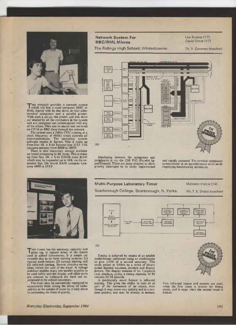
HIS PROJECT provides a network system
which will link a main computer (BBC or
RML micro) with its disc drive, to four other
terminal computers and a parallel printer.
With such a set-up, the printer and disc drive
are shared by all the computers in the system
and any computer can communicate with any
of the others. Files can be stored and retrieved
on CP/M or BBC discs through the network.
The system uses a Z80A CPU running at a
clock frequency of 4MHz which controls all
communications. The operating system
software resides in Eprom. This is made up
from four 4K x 8-bit Eproms type 2532. This
occupies memory from 0000 to 3FFF.
There is also temporary storage available
on board amounting to 8K bytes. This is made
up from four 21K x 8-bit CMOS static RAM
which may be expanded up to 48K via the ex-tension bus. On board RAM occupies loca-tions 4000 to 5FFF.
THIS TIMER has the accuracy, capacity and
price tag to replace many of the timers
used in school laboratories. It is simple yet
versatile due to its three starting systems: (1)
manual push-button; (2) contact starting and
(3) infra-red starting. Several circuitry-saving
ideas reduce the cost of the timer. A voltage
stabiliser enables many low-quality supplies to
be used safely and the display and other parts
are selected to withstand the hard use ex-perienced in the school laboratory.
The timer may be successfully employed in
experiments from timing the decay of radio-activity to the uptake of water by a leafy shoot
to calculating the force of gravity.
Network System For
BBC/RML Micros
The Ridings High School, Winterbourne.
Lee Bunker (17)
David Omar (17)
Dr. V. Coveney (teacher)
Interfacing between the computers and
peripherals is via the Z80 PIO (Parallel In
put/Output). These are daisy-chained to allow
priority interrupts to be easily implemented
and rapidly executed. The terminal computers
communicate in an asynchronous serial mode
employing handshaking techniques.
Multi-Purpose Laboratory Timer
Malcolm McKie (14)
Scarborough College, Scarborough, N. Yorks. Mr. T. E. Drake (teacher)
s c1
D
DECODEQS/p50.Ar
DQ�vER3
i
SEVEN SEGMENT
DISPLAY5
0
`.OLTAGE
STApi MQ
9-qv DC _
INPUT
Timing is achieved by means of an astable
multivibrator calibrated using an oscilloscope
to give 1/100 of a second accuracy. This
sends pulses at 100Hz to a series of binary
coded decimal counters, dividers and display
drivers. The display consists of six 7-segment
I.e.d. displays, giving a timing capacity of 99
minutes 59.99 seconds.
A particularly novel feature is infra-red
starting. This gives the ability to time all or
part of the movement of an object, even
though it may move very quickly and in a ran-dom pattern, and may be already in motion.
MANUAL
STAQT G
C'ecu
VOLTAGE
MDCATOR
R CONTACT
STARTWG
CIRC
SRFRA-QED
STARTING
CKi T
Two infra-red beams and sensors are used,
when the first beam is broken the timing
starts, and it stops when the second beam is
broken.
Everyday Electronics, September 1984
591
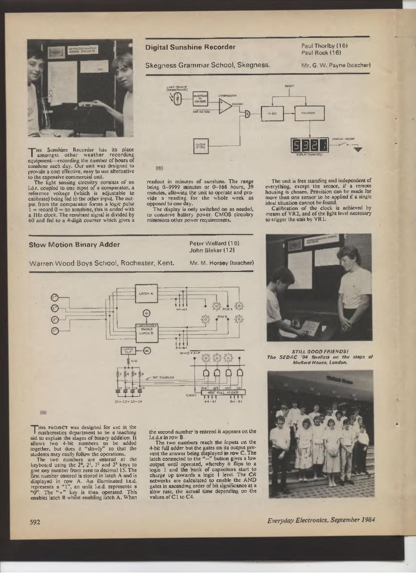
THE Sunshine Recorder has its place
amongst other weather recording
equipment—recording the number of hours of
sunshine each day. Our unit was designed to
provide a cost effective, easy to use alternative
to the expensive commercial unit.
The light sensing circuitry consists of an
I.d.r. coupled to one input of a comparator, a
reference voltage (which is adjustable to
calibrate) being fed to the other input. The out-put from the comparator forms a logic pulse
I = record 0 = no sunshine, this is anded with
a IHz clock. The resultant signal is divided by
60 and fed to a 4-digit counter which gives a
Digital Sunshine Recorder
Paul Thorlby (16)
Paul Rock (16)
Skegness Grammar School, Skegness. Mr. G. W. Payne (teacher)
readout in minutes of sunshine. The range
being 0-9999 minutes or 0-166 hours, 39
minutes, allowing the unit to operate and pro-vide a reading for the whole week as
opposed to one day.
The display is only switched on as needed,
to conserve battery power. CMOS circuitry
minimises other power requirements.
Slow Motion Binary Adder
Warren Wood Boys School, Rochester, Kent.
Peter Wellard (16)
John Blaker (12)
Mr. M. Horsey (teacher)
U
LATCH A
LATCH/0 f
EHA8 E
LATCH D
I
A4-A1
1
C1 C2 C9 C4
7 T T 7
Cl - cz> C5-C4
THIS PROJECT was designed for use in the
mathematics department to be a teaching
aid to explain the stages of binary addition. It
allows two 4-bit numbers to be added
together, but does it "slowly" so that the
students may easily follow the operations.
The two numbers are entered at the
keyboard using the 2°, 21, 21 and 2' keys to
give any number from zero to decimal 15. The
first number entered is stored in latch A and is
displayed in row A. An illuminated I.e.d.
represents a "I", an unlit I.e.d. represents a
"0". The "+" key is then operated. This
enables latch B whilst enabling latch A. When
592
D4-91
A4
Al
54-51
the second number is entered it appears on the
I.e.d.s in row B.
The two numbers reach the inputs on the
4-bit full adder but the gates on its output pre-vent the answer being displayed in row C. The
latch connected to the "_--" button gives a low
output until operated, whereby it flips to a
logic 1 and the bank of capacitors start to
charge up towards a logic I level. The CR
networks are calculated to enable the AND
gates in ascending order of bit significance at a
slow rate, the actual time depending on the
values of C I to C4.
.-I
®®®1
The unit is free standing and independent of
everything, except the sensor, if a remote
housing is chosen. Provision can be made for
more than one sensor to be applied if a single
ideal situation cannot be found.
Calibration of the clock is achieved by
means of VR2, and of the light level necessary
to trigger the unit by VR 1.
STILL GOOD FRIENDSI
The SEDAC "84 finalists on the steps of
Mullard House, London.
Everyday Electronics, September 1984

OSCILLiITORS
A variety of different types of resistance capacitance feedback oscillators, all having wide
use, are described in this short series. Some of the circuits are based on discrete
semiconductors, others on familiar i.c.s. In addition to theory of operation, design pointers
for particular needs and applications are given. Each part in the series also includes a
detailed circuit for a practical project.
Part Four: HYSTERESIS OSCILLATORS
By J. R. DAVIES
THts concluding article in the current
series is devoted to oscillator circuits
which exploit the voltage hysteresis effect.
BASIC SCHMITT
The classic Schmitt trigger circuit, em-
ploying transistors, is shown in Fig. 4.1.
If the base of TR 1 is at the same potential
as the negative rail this transistor is tur-ned off, allowing current to flow through
R 1 and R3 to the base of TR2, which
turns on. The collector-to-emitter current
of TR2 causes voltages to be dropped
across R5 and R2. If the base of TR I is
taken slowly positive a level will be
reached at which TR I commences to
pass collector current. The base current
to TR2 is reduced and its emitter goes
negative, thereby taking TR 1 emitter
negative and causing TR 1 to pass a
higher current. A regenerative effect is set
up which results in TR 1 turning hard on
with TR2 being cut off.
If TR 1 base is now taken negative a
voltage level will be reached at which its
collector current will fall and the voltage
at its collector will rise. Only a fraction of
the collector voltage is applied to TR2
base, and the base of TR 1 has to be taken
negative to a lower voltage than the
previous triggering level if TR I is to cut
off and TR2 be turned on again.
VOLTAGE HYSTERESIS
This effect is referred to as voltage
hysteresis, and can be produced in cir-cuits other than that shown in Fig. 4.1.
Such circuits are also described as
Schmitt triggers and can be made to func-tion as RC oscillators.
Hysteresis oscillators are not new in
this series because the 555 and ICM7555,
which were dealt with in Part Two, func-tion by reason of voltage hysteresis.
When pins 2 and 6 of either of these i.c.'s
are joined together to provide an input,
the output goes negative when this input
rises to two-thirds of supply potential,
and goes positive when the input falls to
one-third of the supply potential.
We shall now consider other hysteresis
oscillators.
SCHMITT NAND GATE
The CMOS i.c. type 4093 is a quad 2-
input NAND Schmitt trigger, and has the
internal circuitry shown in Fig. 4.2. There
are four NAND gates, each having
Schmitt trigger characteristics.
The performance of the NAND gates
can be checked by the circuit of Fig. 4.3.
The two inputs of a NAND gate are
OUTPUT
INPUT
LEE- I
Fig. 4.1. The basic Schmitt trigger.
Fig. 4.3. The performance o a NAND
Schmitt trigger can be evaluated with
this test circuit.
joined together, causing the gate to func-tion as an inverter, and are coupled to the
slider of a potentiometer connected
across the supply rails. Voltmeter ME1
monitors the input voltage whilst
voltmeter ME2 indicates whether the out-
put is high or low. If, with a 9-volt supply,
the potentiometer slider is advanced from
the negative end of the track the output
V00
4093
TOP VIEW
d = SCHMITT
ICE—I
Vss
Fig. 4.2. The CMOS 4093 incorporates
four 2-input NAND Schmitt triggers.
Fig. 4.4. Adding a resistor and a
capacitor causes the Schmitt trigger to
function as an oscillator.
Everyday Electronics, September 1984
593

will be high until the input voltage reaches
around 6 volts, whereupon the output will
abruptly go low. If the input voltage is
next reduced the output will abruptly go
high again when the input voltage is
around 4.7 volts.
The Schmitt NAND gate may be
made to oscillate by adding a resistor and
capacitor, as in Fig. 4.4. At switch-on the
capacitor is discharged and the gate out-
put is high. The capacitor charges
through R and the input voltage increases
until the positive-going trigger level is
reached, whereupon the gate output goes
low. The capacitor next discharges
through the resistor until the input voltage
reaches the negative-going trigger level
and the output then goes high again. Os-cillation proceeds with the capacitor alter-
nately charging and discharging. A near
squarewave is given at the gate output,
with the positive pulses being a little
longer than the negative pulses.
OSCILLATOR FREQUENCY
Oscillator frequency is governed by the
values of R and C, and will vary
somewhat with different gates due to
spread in gate characteristics. In very ap-proximate terms, the cycle length with a
9-volt supply is of the order of 0.8 times
the time constant of the resistor and
capacitor. If R is equal to 1MQ and C to
0.0047µF, the time constant is 0.0047
second. Cycle length is around 0.00376
second, which corresponds with a fre-quency of 266Hz.
The supply current drawn by the os-cillator is largely dependent on the value
of R. The current drawn from a 9-volt
supply is around 0.2mA for resistances in
R between 100kQ and 10MO, rises to
about 0.35mA with a resistance of I0kQ,
and increases to approximately 2mA with
a resistance of MI. Suitable resistance
values which do not cause excessive
current drain lie, therefore, between l0kQ
and 10MO. The oscillator functions
satisfactorily with a value in C as low as
100pF, and the maximum capacitance
which can be used is governed by the
reliability of the oscillator at very low
frequencies.
At frequencies of the order of 0-2Hz or
less there is an occasional tendency for
the oscillator to "stick". What happens
here is that the gate input voltage is rising
or falling very slowly and the limited
linear voltage gain in the gate results in a
relatively slow change in output potential
at one of the input triggering levels. The
oscillator then latches, with the gate out-put and input taking up a steady voltage
at some level between the supply rails.
Because of the effect it is preferable not to
employ the circuit for oscillation below
some 0.5Hz and this, in company with
the value chosen for R, limits the max-imum value for C.
HALF-SECOND BLEEPER
Fig. 4.5 shows a practical working cir-cuit which demonstrates Schmitt NAND
gate operation. Three of the gates in a
4093 are employed to form a bleeper
which produces audible pulses at a repeti-tion frequency of about 2Hz.
Gate GI is in a standard hysteresis
oscillator circuit with its frequency con-trolled by R 1 and C 1. These two compo-nents have a calculated time constant of
0.594 second, whereupon the oscillator
has a frequency of the order of 2Hz. A
second hysteresis oscillator is given by
gate G2 whose timing components, R2
and C2, have a time constant of 0.001
second. Frequency is therefore in the
region of 1.25kHz.
Only one of the gate inputs, pin 9, con-nects to R2 and C2, and the other gate in-put at pin 8 connects to the output of G 1.
Since G2 is a NAND gate the output at
pin 10 is always high when pin 8 is low,
and the oscillator cannot then function.
When pin 8 is high, inversion takes place
between pin 9 and pin 10, and the os-cillator is able to run. Thus, G2 oscillates
only when the G 1 output is high.
Gate G3 functions as a buffer amplifier
and drives TR 1 which, in turn, drives the
loud speaker LS I. Note that when gate
G2 is disabled its output is high, and the
output of gate G3 is then low. In conse-quence, TR I is turned off between bleeps
with a saving in supply current.
The loudspeaker can have any im-
pedance between 1552 and 8052, and R4
is given a value which causes the sum of
its resistance and the speaker impedance
to be approximately equal to 10052.
Bypass capacitor C3 ensures that the
relatively heavy speaker currents do not
upset CMOS operations if the 9-volt bat-
tery has a high internal resistance. The
capacitor is quickly discharged, to pre-
vent irregular oscillation, when the circuit
is switched off. The total current drawn
from the battery averages at approx-imately 20mA.
The fourth gate in the 4093 is not used
and its two inputs, at pins 5 and 6, are
connected to the negative rail. No con-nection is made to the fourth gate output.
TTL NAND OSCILLATOR
A TTL Schmitt NAND gate can also
function as an oscillator employing the
CMOS gate circuit of Fig. 4.4. However,
the very much higher input currents re-
quired by a TTL gate cause the values of
the frequency control components, R and
C, to be considerably different for a given
frequency of oscillation. Also, the TTL
oscillator should be followed by a second
NAND gate which functions as a buffer
amplifier. The output of the second gate is
then used to drive other TTL circuitry.
A typical TTL oscillator and amplifier
can incorporate two gates of a quad 2-
input NAND Schmitt trigger type 74132.
This has the internal circuitry shown in
Fig. 4.6. To give an idea of TTL input
current magnitudes an ordinary NAND
gate, such as appears in the 7400, re-
quires a current of the order of 1 mA to
take an input low to logic 0. Input current
at logic 1 is much lower, being usually in
the region of tens of microamps. With the
74132 the input current at the positive-going Schmitt threshold is typically
0.43mA, and the input current at the
negative-going threshold is typically
0.56mA.
These high currents necessitate a
relatively very low value in R, and the
resistance specified by the i.c. manufac-
Fig. 4.5. A practical working circuit. This produces audio bleeps at a repetition frequency of
approximately 2Hz.
G1
D.
R1
2 7Mn
ct
T 0 22NF
IEE9M
ON-OFF
14
IC1-4093
G2 53
0.11 ®p.
R2
1OOkn
C2
J OIyF
i
7
000
c b o
R3
4 7kn
LS1
�R4
SEE
TEXT
TR1
2N3904
2N3904
BOTTOM VIEW
S1
C3
�100NF
10V
7
594 Everyday Electronics, September 1984

1B I 2A 26 2Y GNO
Fig. 4.6. The internal circuitry of the TTL
74132 quad NAND Schmitt trigger.
Fig. 4.7 (right). In the TTL version of the
Schmitt oscillator the feedback resistor
is 3300 at all frequencies.
LF351
TOP VIEW
Fig. 4.8. A hysteresis oscillator incor-
porating an operational amplifier. RB,
RC and RD all have the same value and
frequency is controlled by RA and C.
turer for the oscillator function is 33052.
In consequence the only variable for fre-quency control is C. The manufacturer
quotes a frequency range for the os-cillator circuit of 0. 1 Hz to IOMHz.
TTL OSCILLATOR CIRCUIT
Fig. 4.7 shows two gates of the 74132
connected to function as an oscillator and
buffer amplifier. For lower frequency os-cillation the capacitor can be electrolytic,
with the negative plate connected to the
negative rail. At higher frequencies it may
be a non-polarised component.
Due to the wide spread in charac-teristics involved, a precise frequency of
oscillation cannot be calculated. Experi-ment shows that the length of a cycle in
seconds is roughly equal to the
capacitance in microfarads divided by
2500. So, a value in C of 2500µF will
give a cycle length in the region of one
second, and a frequency of 1 Hz.
Corresponding values of C and frequency
are given by 250µF and IOHz, 25µF and
IOOHz, 2.5µF and IkHz, and so on.
The duty ratio of the output signal
from the buffer amplifier gate is some 60
to 65 per cent. This refers to the percen-tage of time in the cycle when the output
is at logic 1. The current drawn by the
74132 i.c. from the stabilised 5-volt sup-
aKn.
I EE 7.1
i
• SV STAB
14
7
1
Fig. 4.9. A practical op-amp hysteresis
oscillator. Frequency is slightly less than
1 07kHz.
ply with no connections made to the two
unused gates is some 25mA to 30mA at
all frequencies.
A feature of the TTL Schmitt oscillator
is that if the frequency controlling
capacitor is connected into circuit after
power has been applied the oscillator may
not start. Because of this effect, the tem-
porary disconnection and reconnection of
the capacitor due to a fault condition can
cause the oscillator to stop and stay
stopped.
OP-AMP OSCILLATOR
Fig. 4.8 illustrates a hysteresis os-cillator employing an operational am-
plifier. The three resistors, RB, RC and
RD all have the same value and fre-
quency is controlled by RA and C.
Assuming that the op-amp output goes
fully to the positive rail voltage when it is
high, and fully to the negative rail voltage
when it is low, oscillator functioning can
be described in the following manner.
When power is applied C is dis-
charged, with the result that the inverting
input (-) is negative of the non-inverting
input (+). The op-amp output is therefore
high, causing RD to be effectively in
parallel witlf RB and two-thirds of the
supply voltage to be present at the non-inverting input.
Capacitor C charges via RA until the
voltage across it reaches two-thirds of the
supply voltage, whereupon the op-amp
output starts to go negative. The non-inverting input goes negative also, caus-ing the op-amp output to go fully negative
very rapidly and bringing RD effectively
in parallel with RC. The voltage at the
non-inverting input becomes equal to one-third of the supply voltage.
Since the op-amp output is now low, C
discharges through RA. When the
voltage across the capacitor falls to one-third of the supply voltage the reverse ef-fect to that just described takes place and
causes the op-amp output to swing very
rapidly positive. The capacitor charges
once more through RA until the voltage
across it reaches two-thirds of the supply
voltage and the op-amp output then goes
negative again. Oscillation continues in
this manner, with capacitor C charging to
two-thirds of supply voltage and dis-charging to one-third of supply voltage.
The discharge period from two-thirds
to one-third of the supply voltage is the
same as occurs with the 555 or
ICM7555, as described in Part Two, and
is theoretically equal to 0.685.RA.C.
Because of the circuit symmetry the
charge time from one-third to two-thirds
of supply voltage is the same as the dis-charge time and so the length of the total
cycle is theoretically equal to twice
0.685.RA.0 or 1.37.RA.C.
The reciprocal, at
0.73
RA.0
gives the corresponding frequency.
In practice, apart from devices such as
the CA3130, most op-amp output
voltages do not go fully to the positive rail
or fully to the negative rail, whereupon
the charge and discharge currents for C
are slightly less than would be given with
our initial assumption. The result is that
cycle lengths in practice are a little longer
and frequency is slightly lower.
WORKING CIRCUIT
Any op-amp with high impedance in-puts can be used in the oscillator circuit,
and Fig. 4.9 shows a working circuit em-ploying an LF351. This has a frequency
of oscillation, determined by RA and C,
which is a little lower than the calculated
figure of
0.73
0.068 x 0.01
or 1.07kHz. Reasonable values for RA
are in the range of IOk[2 to 1MS2, and the
LF351 draws approximately 2mA from
the 9-volt supply with all resistor values
within this range. C can be electrolytic for
very low frequencies.
Because the linear voltage gain in an
operational amplifier is very much higher
than is that in the CMOS Schmitt NAND
gate discussed earlier in this chapter there
is little risk of latching at very low os-cillator frequencies.
The oscillator output is available at the
op-anlp output pin. There is also an ap-proximate triangular wave at the upper
plate of the frequency control capacitor.
Everyday Electronics, September 1984 595

HAND CAPACITANCE SWITCH
The project which concludes this Part
incorporates a hysteresis oscillator in a
switching circuit which turns on an elec-trical circuit when a hand is placed lightly
on a sheet of insulating material which
bears no electrical contacts. Behind this
insulating material are two metal plates
and placing a hand on the material in-creases the capacitance between them.
CIRCUIT DESCRIPTION
The circuit of the hand capacitance
switch is given in Fig. 4.10. ICI is an
LF351 hysteresis oscillator running at a
frequency of slightly less than 4.8kHz. Its
output connects to one of the metal
plates.
The other metal plate connects to the
inverting input of IC2, another LF351.
This input is biased to a mid-supply
voltage by the two equal-value resistors,
R5 and R6. The voltage on the non-inverting input is set up by adjusting
VRI. R7 is inserted in series with VRI
because the LF351 does not function
correctly with input voltages which are
close to the negative supply rail.
VRI is adjusted to make the non-inverting input slightly negative of the in-verting input, whereupon the output of
the LF351 is fully negative and is, in
practice, about one volt positive of the
negative rail. This output is applied via
D I and the potential divider consisting of
R8 and R9 to the base of TR I and causes
this transistor to be fully cut off. Connec-ted in the collector circuit of TR I is the
coil of a relay whose contacts control the
external circuit to be switched.
When a hand is placed on the in-sulating material above the metal plates
the output of IC I is coupled to the in-
verting input of IC2 by the added
capacitance between the plates. Although
this capacitance is low it is sufficient to
produce, at IC2 output, a signal which
has the full peak-to-peak voltage swing
for the i.e. The output signal is rectified
by DI, causing a positive voltage to ap-pear on the upper plate of the reservoir
capacitor C4 which is applied to R8. TR I
turns on and energises the relay. The
relay releases as soon as the hand is
removed from the insulating material.
METAL PLATES
The size and spacing of the metal
plates is not critical and they can be
around 3=in square with fin spacing, as
shown in Fig. 4.11. Two pieces of metal
foil glued to the underside of the in-sulating material could be used instead of
the plates, if desired.
To keep stray capacitances between
the two sections of the circuit to a
minimum, all the components around IC 1
are assembled as a module on one side of
the plates and all the components around
IC2 in a second module on the other side
of the plates. The second module includes
the bypass capacitor, C3. The on-off
switch and the 9-volt battery can be
positioned at any convenient points.
The relay should be capable of energis-ing reliably at less than 9 volts and have a
IEE 13.1
METAL PLATES
SUPPLY LEADS
Fig. 4.11. Approximate metal touch-plate dimensions.
coil resistance of 30052 or more. The
current drawn from the battery is approx-imately 3.5mA when the relay is de-energised. To this is added the relay coil
current when the relay is energised.
SETTING-UP
The circuit is set up by adjusting VRI.
The slider of this potentiometer is initially
set near the positive end of its track,
whereupon the output of IC2 goes high
and TR I is turned on by way of the
forward biased diode, DI. VRI slider is
slowly moved towards the negative end of
the track until the relay suddenly releases.
The potentiometer slider is then taken
slightly further towards the negative end
of the track. A little experience with the
circuit soon shows what is required here.
When a hand is placed on the in-sulating material the relay will then
energise. If the relay has a very light
armature with a weak return spring it
may "chatter" slightly as VRI slider
reaches the point at which the relay just
releases. This is not due to a circuit
malfunction and the effect may be
ignored.
The insulating material can be plastic,
card or any other material. For best
results it should not have a thickness
greater than one-sixteenth of an inch.
APPLICATIONS
The hand capacitance switch can be
used as a novelty device in stores, with
customers being invited to place a hand
on the insulating material. The relay
could then cause an advertising sound
and/or vision display to be activated. An
attractive touch would be given by
painting the outline of a hand over the
area where the customer's hand should be
placed. Many other novelty applications
can also be envisaged. ❑
Fig. 4 10. Hand capacitance switch. Placing a hand on a piece of insulating material covering the metal plates causes the relay to energise.
596
R1
100 k(l
R3
100 k!l
H2
Ice✓"
lci
1C
LF3`
C1
T
OO1NF
VR1
100kR
R6
10MIA
R7 .C2
10kIR 'r001NF
RLAr1
RELAY
r &- TO CONTROLLED
CONTACTS CIRCUIT
_L C3
10 RF
1N6002
s1
v
•9V
ON-OFF
02 1 R
3 OR1-T
D1
1N4002
RB
iokfl
1
2N3904
e OTTOM VIEW
e
9
, 7kn
TR1
2 N 3904
Everyday Electronics, September 1984

EVERYDAY ELECTROMICS
PRIIyTED CIRCUIT BOARD
SERVICE
Printed circuit boards for certain EE constructional projects are now
available from the EE PCB Service, see list. These are fabricated in
glass-fibre, and are fully drilled and roller tinned. All prices include
VAT and postage and packing. Add El per board for overseas air-mail. Remittances should be sent to: EE PCB Service, Everyday
Electronics Editorial Offices, Westover House, West Quay Road,
Poole, Dorset BH15 1JG. Cheques should be crossed and made
payable to IPC Magazines Ltd.
Please note that when ordering it is important to give project
title as well as order code. Please print name and address in Block
Caps. Do not send any other correspondence with your order.
Readers ordering both p.c.b.s and software cassettes may send a
single cheque/PO for the combined amounts listed.
Readers are advised to check with prices appearing in
the current issue before ordering.
NOTE: Please allow 28 days for delivery. We can only
supply boards listed here.
PROJECT TITLE
Order Code
Cost
- JUNE'83 -
Eprom Programmer, TRS-80
8306-01
£9.31
Eprom Programmer, Genie
8306-02
£9.31
Eprom Programmer, TRS-80 & Genie
8306-03
£1.98
- JULY'83 -
User Port Input/Output M.I.T. Part 1
8307-01
E4.82
User Port Control M.I.T. Part 1
8307-02
£5.17
- AUGUST'83 -
S•orage'Scope Interface, BBC Micro
8308-01
£3.20
Car Intruder Alarm
8308-02
£5.15
High Power Interface M.I.T. Part 2
8308-03
£5.08
Pedestrian Crossing Simulation
M.I.T. Part
8308-04
E3.56
Electronic Die
8308-05
f4.56
- SEPTEMBER'83 -
High Speed A-to-D Converter
M.I.T. Part 3
8309-01
£4.53
Signal Conditioning Amplifier
M.I.T. Part 3
8309-02
£4.48
Stylus Organ
8309-03
£6.84
D73tress Beacon
•8309-04
E5.36
Distress Beacon Pocket Version
8309-05
£3.98
- OCTOBER'83 -
D-to-A Converter M.I.T. Part 4
8310-01
£5.77
High Power DAC Driver M.I.T. Part 4
8310-02
£5.13
Electronic Pendulum
8310-03
E5.43
- NOVEMBER '83 -
TTL/Power Interface for Stepper Motor
M.I.T. Part 5
8311-01
£5.46
Stepper Motor Manual Controller
M.I.T. Part 5
8311-02
£5.70
Digital Gauss Meter
8311-03
E4.45
Speech Synthesiser for BBC Micro
8311-04
£3.93
Car On/Off Touch Switch
8311-05
£3.1 1
- DECEMBER'83 -
4-Channel High Speed ADC (Analogue)
M.I.T. Part 6
8312-01
£5.72
4-Channel High Speed ADC (Digital)
M.I.T. Part 6
8312-02
f5.29
i'RS-80 Twin Cassette Interface
8312-03/09
f7.43
Environmental Data Recorder
8312-04
f7.24
Touch Operated Die (Dot matrix)
8312-05/06
£4.34
Touch Operated Die (7-segment)
8312-05/07
£4.34
Continuity Tester
8312-08
£3.41
Everyday Electronics, September 1984
PROJECTTITLE
Order Code
Cost
- JANUARY'84 -
Central Heating Pump Delay
8401-01
£3.33
Biological Amplifier M./.T. Part 7
8401-02
£6.27
Temp. Measure & Control for ZX Comprs
Analogue Thermometer Unit
8401-03
£2.35
Analogue-to- Digital Unit
8401-04
£2.56
Games Scoreboard
8401-06/07
f9.60
- FEBRUARY'84 -
Eprom Programmer/ROM Card for ZX81
••8402-01
£7.84
Oric Port Board M.I.T. Part 8
8402-02
£9.56
Negative Ion Generator
••8402-03
E8.95
Temp. Measure & Control for ZX Comprs
Relay Driver
8402-04
f3.52
- MARCH '84 -
Latched Output Port M.I.T. Part 9
8403-01
£5.30
Buffered Input Port M.I.T. Part 9
8403-02
£4.80
VIC-20 Extension Port Connector
M.I.T. Part 9
8403-03
£4.42
Commodore 64 Extension Port Connector
M.I.T. Part 9
8403-04
£4.71
Digital Multimeter Add-On for BBC Micro
8403-05
£4.63
- APRIL'84 -
Multipurpose Interface for Computers
8404-01
£5.72
Data Acquisition "Input" M.I.T. Part 10
8404-02
E5.20
Data Acquisition "Output" M.I.T. Part 10
8404-03
f5.20
Data Acquisition "PSU" M.I.T. Part 10
8404-04
£3.09
Timer Module
8404-05
E3.58
A.F. Sweep Generator
8404-06
f3.55
Quasi Stereo Adaptor
8404-07
f3.56
- MAY '84 -
Simple Loop Burglar Alarm
8405-01
£3.07
Computer Controlled Buggy M.I.T. Part 11
Interface/Motor Drive
8405-02
f5.1 I
Collision Sensing
8405-03
£3.20
Power Supply
8405-04
f4.93
- JUNE'84 -
Infra-Red Alarm System
8406-01
E2.55
Spectrum Bench PSU
8406-02
£3.99
Speech Synthesiser M.I.T. Part 12
8406-03
£4.85
Train Wait
8406-04
£3.42
- JULY'84 -Ultrasonic Alarm System
8407-01
f4.72
Atom EPROM Simulator
8407-02
£3.08
Electronic Code Lock
Main board
8407-03
£2.70
Keyboard
8407-04
£3.24
- AUGUST'84 -
Microwave Alarm System
8408-01
£4.36
Temperature Interface-BBC Micro
8408-02
£2.24
- SEPTEMBER '84 -
Op-Amp Power Supply
8409-01
£3.45
'Set of four boards. - Calibrated with C1, VR 1 and IC3 fitted
M./.T.-Microcomputer Interfacing Techniques, 12-Part Series.
597
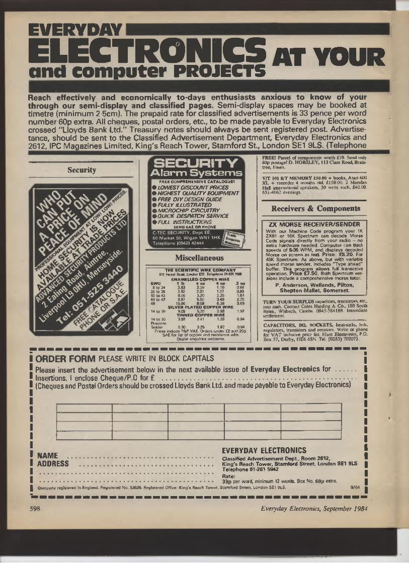
EVERYDAY
ELECTRONICS AT YOUR
and computer PROJECTS
Reach effectively and economically to-days enthusiasts anxious to know of your
through our semi-display and classified pages. Semi-display spaces may be booked at
timetre (minimum 2 5cm). The prepaid rate for classified advertisements is 33 pence per word
number 60p extra. All cheques, postal orders, etc., to be made payable to Everyday Electronics
crossed "Lloyds Bank Ltd." Treasury notes should always be sent registered post. Advertise-tance, should be sent to the Classified Advertisement Department, Everyday Electronics and
2612, IPC Magazines Limited, King's Reach Tower, Stamford St, London SE1 9LS. (Telephone
Security
SECURITY
Alarm Systems
FREE COMPREHENSIVE CATALOOIIEI
• LOWEST DISCOUNT PRICES
• HIGHEST QUALITY EQUIPMENT
• FREE DI Y DESIGN GUIDE
• FULLY ILLUSTRATED
• MICROCHIP CIRCUITRY
• QUICK DESPATCH SERVICE
• FULL INSTRUCTIONS
SEND SAE OR PHONE
C-TEC SECURITY, Dept EE,
60 Market St, Wigan WN1 1 H
Telephone 10942) 42444
Miscellaneous
THE SCIENTIFIC WIRE COMPANY
C11 Forest (load. London EIT Telephone 014M ?W
ENAMELLED COPPER WIRE
SWO 1 lb 8 oz 4 oz 2 oz
8 to 34 3.63 2.09 t 10 0.88
35 to 39 3.82 2.31 t.27 0.93
40, 0 43 6.00 3.20 2.25 1.61
4410 47 8.67 5.80 3.49 2.75
48 15.96 9.58 6.38 3.69
SILVER PLATED COPPER WIRE
14 to 30 9.09 5.20 293 1.97
TINNED COPPER WIRE
14 to 30 3.97 241 1.39 0.94
Fluxcore
Solder 5.90 3.25 1.82 0.94
Prices include P&P VAT. Orders under 12 add 20p.
SAE for list of copper and resistance wire.
Dealer enquiries welcome.
FREE! Parcel of components worth £10. Send only
80p postage! D. HORSLEY, 113 Clare Road, Brain-
tree, Essex.
V/T 101 8/T MEMORY £50.00 + books, Atari 600
XL + recorder 4 months old, £150.(X). 2 Marsdan
Hall international speakers, 30 watts each, £40.00.
651-4062 evenings.
Receivers & Components
ZX MORSE RECEIVER/SENDER
With our Machine Code program your 1K
ZX81 or 16K Spectrum can decode Morse
Code signals directly from your radio - no
extra hardware needed. Computer can track
speeds of 5-35 WPM, and displays decoded
Morse on screen as text. Price: £5.20. For
48K Spectrum: As above, but with variable
speed morse sender, includes "Type ahead"
buffer. This program allows full transceive
operation. Price £7.50. Both Spectrum ver-sions include a comprehensive morse tutor.
P. Anderson, Wellands, Pilton,
Shepton Mallet, Somerset.
TURN YOUR SURPLUS capacitors, transistors, etc.,
into cash. Contact Coles Harding & Co., 103 South
Brink, Wisbech, Cambs. 0945-584188. Immediate
settlement.
CAPACITORS, DIL SOCKETS, heat-sinks, leds,
regulators, transistors and resistors. Write or phone
for VAT inclusive price list. Hunt Electronics, P.O.
Box 57, Derby, DE6 6SN. Tel. (0283) 703071.
ORDER FORM PLEASE WRITE IN BLOCK CAPITALS
Please insert the advertisement below in the next available issue of Everyday Electronics for
Insertions. I enclose Cheque/P.O for £
(Cheques and Postal Orders should be crossed Lloyds Bank Ltd. and made payable to Everyday Electronics)
NAME
ADDRESS
EVERYDAY ELECTRONICS
Classified Advertisement Dept., Room 2612,
King's Reach Tower, Stamford Street, London SE1 9LS
Telephone 01-261 5942
Rate:
33p per word, minimum 12 words. Box No. 60p extra
Company registered in England. Registered No. 53626. Registered Office: King's Reach Tower, Stamford Street, London SE1 9LS.
9/84
598 Everyday Electronics, September 1984

SERVICE
products and services
E7.80 per single column cen-(minimum 12 words), box
and Computer Projects and
ments, together with remit-Computer Projects, Room
01-261 5942).
Service Sheets
INVENTORS
Think of something new?
Write it down!
American industry offers potential
royalties for you innovations and new
products. We offer free confidential
disclosure registration and initial con-sultation in London regarding your
idea's potential value. Write without
delay for your free information
package.
American Inventors Cororation
82 Broad Street, Dept.Viet,
Westfield, Massachusetts 01086,
United States of America
A fee based marketing company
BELL'S TELEVISION SERVICE for service sheets
on Radio, TV etc. £1.50 plus S.A.E. Service Manuals
on Colour TV and Video Recorders, prices on
request. S.A.E. with enquiries to: BTS, 190 King's
Road, Harrogate, N. Yorkshire. Tel: 0423 55885.
FULL SIZE SERVICE SHEETS £2 + Isae; CfV/
C £3 Mus + Isae. Repair/cires almost any named TV/
VCR £9.50. Isae free quotations for manuals, sheets
- free mag inc. service sheet. T.I.S.E.E. 76 Church
Street, LarkhalL Lanarks - Phone 0698 883334.
P.C.B. SERVICING for magazine project boards etc
Glass fibre. drilled, cheap rates. Phone 0606 888446
Educational - Cont.
IMPROVE YOUR PROSPECTS
with skills that employers want Train the easy
way with modern home study courses from
Ideal Schools
MODERN ELECTRONICS
Takes you from the beginning. right up to C 8 G
level and BTEC national level
COMPUTER PROGRAMMING
Learn BASIC with a Spectrum included if you wish.
For free booklet write today to
IDEAL SCHOOLS
:TT (Ref. EE1) Freepost,
J,jJfi Woking,
Surrey GU21 4BR.
- .._. balcerass
* BAKER
GROUP P.A. DISCO t
t
AMPLIFIERS post t2 O O O Ooses ress er
')0 oral Output J input Muer pneamp Illustrated £99
150 wan Output Slave 500 my Input 3 Speaker Outputs CSO
150 - 150 an Stereo 300 wan Mona Slave 500 my Inputs 0125
150 wan P A Vocal 8 inputs High/Low Mixer Echo Socket 0729
too wan Valve Model 4 inputs. 5 Outputs Heavy duty £125
60 wan Valve Model 4 inputs Low Imp and Ioov line output E69
60 wan Motels 24N AC and 12v DC 4-&16 ohms IoCiv hire £69
BAKER LOUDSPEAKERS Post E2 earn
Type MOMI Slae Wette Ohms Price
PA./Disco/GrwP DG50/10 10 50 8/16 [16.00
Midrange Mid 100/10 10 100 8 025.00
HiFi Map 12in 30 4/8/16[16.00
H, F, Superb 12in 30 8/16 026.00
PA/D-o/Group DG45 121n 45 4/8/160I It
H- F. Woofer 1Zn 8o B 025.00
H.-F, Audtonsm 15ro 60 B/t6 037.00
PA/psco/Group DG75 12n 75 d/8n6020.00
PA/Disco/Grolp DG100 12in 100 8/16 C26.00
PA/Disco/Group DG100/15 1son 100 8/16 035.00
DISCO CONSOLE Twin Decks, mien pe artp f10S. Can 015
COMPLETE DISCO 150 wan,33P 300 wan,390. Cart 030
DISCO MIXER. 240V. 4 stereo channels. 2 magnetic 2 ceramic/
lave .'mono mac cannel. level vu meters headphone mouton
oullel slider controls panel or deal mounting grained alummor
taaa Tay output hcllHy 049. Post C1.
DELUXE STEREO DISCO MIXER/EOUAUSER as above plus
L E D v U displays 5 band graphic equalsern
. W+
L
Vnght fade,.
tchable inputs for phone/hir ma e ke/hose L 17111
Headphone Monitor. Mike Talkover Switch L PP C2
ditto 7 Band Graphic £126.
P.A. CABINETS (emplyi Single 12 030; Double 12 036. Carr 010
WITH SPEAKERS 60W 027; 75W 052; 9OW 071; 15OW 060.
HORNBOXES 200 Wan 030, 300 Wan 035. Post C4
WATERPROOF HORNS B ohms 25 wan 020. 30 wan 023. 40 wan
£29 20VV plus i00 volt line 036. Post £2
MOTOROLA PIEZD ELECTRONIC HORN TWEETER, 3kn sooare is
'u; watts No crossover reputed 4&16 dim. 71x 3i1n 010
CROSSOVERS. TWO-WAY 3000 its 30 watt Ell. 100 wan E4.
ar 9S0 cps/ 3000 cgs JO wan rating Its. 60 wan [6. 100 wan i3O.
LOUOSPEAKER BARGAINS Pleas, mpiene. many others m stock
4 ohm. Sin ,Jon 12.50, N,1 8x 5m E3.6m 03.50. 6fm 2OW 07 50.
8 ohm, 2kn 3m 02; 5x3xs 6x4m 7x4m An f2,50; 6yrn. 70W110,00:8
[3: &n. C4.*,, lost E6; 12m Elf, &n 25W 06.50
15 ohm, 2Hn, 310. 5x3in. 6x4n. 12.50. 4n tOW f5. &n G, Won [7.
25 ohm, 3n. Et 5x3m. 6x4M, 7xlm [2.50. 120 Mm, aim tea [l.
Mare Motile Sin Wafts
,, r�.1Ax WOOFER Sin 25
,)DMANS HSAX 7i.4im 100
�DIMNS Hill WOOFER &n 60
,/HARFEOALE WOOFER Bin 30
l i', ESTION OWX&G 12in 120
G W.IGRp
DDMANS
. �IDMANS HPO/DISCO 12m 120
�nDMANS HP/BASS 1&n 250
;�I IDM I
ANS NPD/BASS t&n 270
Ohms Pnm Post
010.60 C1
C30 f2
[13.50 Et
09.50 E2
/1 5 E22, so E2
/15 [29.50 E2
072 E4
[64 Fd
MIKES Dual Imp 016.56, Floor Stand [12.50, boom Stand 022.00. Post C2
RCS SOUND TO LIGHT CONTROLLER IOT
Printed circuit Cabinet 3 channels 1.000 watts each well operate
from Hio-F. or Draw 019. Post Cl
READY BUILT DELUXE 4 CHANNEL 4.000 WATT with chaser -
speed - programme controls 069. Post C2
MAINS TRANSFORMERS Price Post
250.0.250V 8omA 6.3V 3.5A 63V to [7.00 £2
350.0-350V 2501 63V 6A CT 012.00 Shrouded 014.00 C2
250V 60mA 63V 2A 04.75 C1
220V 25mA 6V 1 Amp 03.00 220V 45mA 6V 2 Amp ,4.00 Et
Low, voltage tapped output available
I amp 6. B. 10 12. 16. 18. 20, 24 30. 36. 40, 48 60 16.00 E2
chino 2 amp E110.50 3 anp,12.50 5 amp E1e.00 E2
LOW VOLTAGE MAINS TRANSFORMERS C5.SO each post paid
9V. 3A 12V. 3A. 16V. 2A, 2OV. 1 A, 30V I JA, 3OV. 5A. 17.0, 17V, 2A,
35V, 2A. 20-40-60V. 1A, 12-0.12V. 2A; 200,20V. 1A, 25.0.25V, 2A
•
i
07.50 poet SOP Wt*-MULTI TESTER
Deluxe pocket we precision monng colt
inatint- Impedance ` Capacity 4000
opv Battery included 11 instant ranges
meaawa DC volts, 5 25.250. 500 AC volts
10. 50, 500. 1000 DC amps 0.250ma. a
250me. Resistance 0 to 600K ohms
Da Luxa Range Doubler altar. 50,000
o.p.v. 7 - 5 - 21n Resistance 0/20 rim in
5 ranges Current 5011 to IOA Volts025/
1 OOOv DC. iOv/1000v AC 021.00 post El
PANEL METERS E5.50 post Sop
50,A, 100pA. 50opA Ihei 5mA, IOOmA. 50omA. 1 amp, 2 amp, 5
amp. 25 volt. Vu 21x2xll Stereo Vu 31-i-lin.
ALUMINIUM CHASSIS 10 s.w.0. Undrilled 4 aides, riveted
corners
6 - a 21 Et 75; 12 x 3 x 2Lin. 11.90; 13 - 9 • 2iin. E3.00;
14 9 2iin E3.60; 12 x 5 x 21on. 12.60,
ALI ANGLE BRACKET 6 x f x fin. 301.
ALUMINIUM PANELS 1S a.vv.g. 12 - 121n 111 So th ; 14 - 9 E1.75;
6 - 4n 55p; 12 - Bin 11.30; 10 - Tin. 96p; 8 - son 90p; 14 • 3in
72p;12 . Sin. 90p; 16 - IOm. E2.10; 16 - 6in. E1.30.
ALUMIMUM BOXES. MANY OTHER SIZES IN STOCK.
4 x 21 - 2m. E7.00; 3 - 2 - tin SOP:6 . 4 - tin. 11.6P 8 . 6 - 3
in E2.50; 12 - 5 - 3in. E7.75; 6 - 4 - 3in El SO; 10 - 7 - 3a
_C3_
.,ON VOLTAGE ELECTROLYTICS 32.32/350V SOP
2WS0OV 75P 8.8/500V Cl 32.32,32/450V 01.50
32,35OV 45p 8.16/450V 75p 125/500V E2
32/500V %p 16. 16/350V 75p 16. 32.32/500V C2
2201400V C2
SINGLE PLAY DECKS. Post E2
Make Model Cartridge Price
BSR P170 Ceramic E20
GARRARD 6200 Ceramic 022
BSR P182 Ceramic 026
BSR P232 Magnetic 026in
BSR P200 Magnetic C34
AUTOCHANGER BSR Ceramic E20
DECCA TEAK VENEERED PLINTH
Superior hush w apace and par1M for small ampMie,
Board Cut lot BSR or Garrard 18hn - 141m - 41n E5
Black/chrome taaa aim Tinted Plastic cover C5 Post £I
TINTED PLASTIC COVERS for Decks. CS each. Post C1
V x 13ix 3W. 181x 121x3n 171x 131, 41on
t7 x 121 x 3Yn. 141 v 13 x 31 21 x 131 x 4IIon
22i - 13i • 31n 161 • 13 x elth 301 - 131 - 31m
21i • 141 - 2 in I4 131 ` 21in
RADIO COMPONENT SPECIALISTS
lept 3. 337, WHIT H I R RIAD. CRIYDON
ACCESS SURREY, U.K. TEL 01-684 1665
Post 65p Minimum Callers Welcome
lints 321 same daV despamh Close4 Wed
tA a
102 a de
0 tA
BIG VALUE RESISTOR PACKS
WATT CARBON FILM
f:51 fl-tOMR ten values.
Total 720 resistors.
1%50ppm 10f1-1Mfl E24 range
1 WATT METAL FILM
��
Total %0 resistors
FREE
CATALOGUE
AC/DC COMPONENT PACKS
Pack
Qty
Description
Price
No.
TFII
12
RED 5mm LED
E1.00
TF12
30
500m1 ZENERS 5%
fl.00
TF13
100
IN4148 Diode
E1.00
TF14
100
IN4151 Diode
0.00
TF15
50
1 amp Rect. Diodes in 4000
series
E1DO
TF16
6
1 amp Bridge Rect
0.00
TF17
100
Transistor pads
E1.00
TF18
20
A/S Fuses 20mm
fl.00
TF19
10
3A Rect Diodes
£1.00
TRIO
2
ORP 12
11.00
TF111
5
BR 1DO DIAC
f1.00
TF112
10
BC109B
11.00
TH13
10
IC's all different
fl.00
TF114
50
BFR86
fl.00
TF115
12
8 pin OIL sockets
E1.00
TF116
20
10mm Hertz Pre set
(10 values)
fl.00
TF21
200
47pf 160v Polystone cap
E2.00
TF22
10
LM 3900 N
E200
TF23
10
Mixed DTL
f2.00
TF24
5
4700 mf 25v Tag Elect
2" x 1 "
£2 00
TF25
10
1000 mf 63v Ax Elect
E2.00
TF26
50
.022 mf 400v RAO POLY
f2.00
TF27
10
1ODmf 250v Ax
E2.00
TF28
10
2.2mf 160v Polyester RAD
E2.00
TF51
100
white/red 5mm LED
£5.00
TF52
50
BC 108C
E5.00
TF53
2
10,000mf 63v comp grade
elect
OGG
TF54
I kg reel 22g ersin multicore
solder
f5DID
TF55
10
2N3055 H(RCA)
£5.00
TF56
5
OCP71
f5DO
ALL PRICES INCLUDE VAT - ALL GOODS BRAND
NEW Be NORMALLY DESPATCHED BY RETURN
POST
TERMS. Cash with order. POST So PACKING.
Please add 75p to total order.
AC/DC ELECTRONICS
COMPONENTS
DEPT E.E. 45 CHURCH STREET,
ENFIELD, MIDDLESEX.
Everyday Electronics, September 1984
599

BSR P256 TURNTABLE
P256 turntable chassis • S shaped tone arm
e Belt driven a Alummium platter a Precision
calibrated Counter balance a Anti-skate (bias)
device) 0 Damped cueing ;ever • 240 volt AC
operation (Hz) • Cut-out template supplied e
Completely manual arm This deck has a com
Palely manual arm and is designed primarily
for disco and studio use where all the advan-tages of a manual arm are required
Price 03.60 "ch. E2.50 P&P
PIEZO ELECTRIC TWEETERS - MOTOROLA
Join the Piezo revolution. The low dynamic mass (no voice cod) of a Piezo
tweeter produces an improved transient response with a lower distortion
level than ordinary dynamic tweeters As a crossover is not required these
units can be added to existing speaker systems of up to 100 watts (more if 2
put in series). FREE EXPLANATORY LEAFLETS SUPPLIED WITH EACH
TWEETER.
POWER AMPLIFIER MODULE
NEW OMP100 Mk 11 POWER AMPLIFIER
MODULE Power Ampldier Module complete
READY BUILT L with integral heat sink. toroidal transformer
power supply and glass fibre p c b assembly
Incoporates drive circuit to power a compel-ible LED Vu meter New improved specifi-cation makes this amplifier ideal for PA,
Instrumental and Hi Fi applications
SPECIFICATION
Output Power:-- 110 watts R.M.S.
Loads:- Open and short circuit proof 4i 16
ohms.
Frequency Response:-- 15Hz .30KHz - 3dB
T. H. Cr.- 0.01%.
S.N.R. IUnweighted):- - 118dB t 3 5dB
Sensitivity for Max Output:- 80OmV at
10K.
Size -- 360 115 72mm. Price - f31 .99
• f250 P&P Vu Meter Price-f8.50 - 50p
P&P
OMP100 Mill
V,
New model.
Improved specification
MOS-FET
HIGH SPEC.
MODULES
I
MOS-FET VERSIONS AVAILABLE UP TO 300 W. R.M.S.
Q100 Watt 300mm 123rnm 60mm Price. 139.99 + f2.50 P&P
200 Watt 30 mm , 150mm 100 mm Price: 162.99 +f3.50 P&P
300 Watt 330mm ti 147mm x 102mm Price: E79.99 + f4.50 P&P
niele�
TYPE
A'
TI
YPE C
TYPE 'D'
TYPE '8
(:�3
TYPE 'E'
LARGE S.A.E.
For details o1
disco mixers,
speakers, kits,
amp - modules,
buglar alarms.
turntables, etc
TYPE 'A' (KSN2036A) 3" round with protective wire
mesh, ideal for bookshelf and medium sized Hffi
speakers. Price E4.29 each � 40p P&P.
TYPE 'B' (KSN1005A) 34' super horn. For general
purpose speakers, disco and P.A. systems etc. Price
E4.99 each , 40p P&P.
TYPE 'C' (KSN6016A) 2" x 5" wide dispersion horn.
For quality Hi-fi systems and quality discos etc. Price
E5.99 each • 40p P&P.
TYPE 'D' (KSN1025A) 2" x 6" wide dispersion horn.
Upper frequency response retained extending down
to mid range 12KHz). Suitable for high qualrty Hffi
systems and quality discos. Price E7.99 each � 40p
P&P.
TYPE 'E' (KSN1038A) 3t horn tweeter with attractive
silver finish trim. Suitable for Hi-fi monitor systems
etc. Price E4.99 each + 40p P&P.
HOBBY KITS. Proven designs including glass
fibre printed circuit board and high quality
components complete with Instructions.
FM MICROTRANSMfTTER IBUG) 90/1D5MHz with very sensitive
microphone. Range 100/300 metres. 57 x 46 x 14mm 19 volt)
Price: E8.62 " 75p P&P.
3 WATT FM TRANSMITTER 3 WATT 85/115MHz vaump controlled
professional performance. Rang
e up to 3 miles 35 x 84 x 12mm
(12 voh) Price: E13.74 . 75p P&P.
SINGLE CHANNEL RADIO CONTROLLED TRANSMITTER/
RECEIVER 27MHz. Range up to 500 metres. Double coded modulation.
Receiver output operates relay with 2amp/240 volt contacts. Ideal for
many applications. Receiver 90 x 70 x 22mm (9/12 volt). Price:
E117.82. Transmitter 90 x 50 x 15mm (9/12 volt). Price: E11.27
P&P . 75p each. SAE. for complete list.
A&
ELECTRONICS ❑
ENGINEERING
ELECTRICAL ❑
iENGINEERING
' Name . .
' Address
1 'CS
1
80 Stewarts Road
LtOL"D,..-
on co mKon, London SW8 4UJ.
LOUDSPEAKERS POWER RANGE
THREE QUALITY POWER LOUD-SPEAKERS 05•", 12" and 8" See Photo)
Ideal for both Hi-Fi and Disco applications.
All units have attractive cast aluminium
(ground finish) fixing escutcheons Spa ifi-cations and Prices.
15" 100 watt R.M.S. Impedance 8 ohms
50 oz magnet 2'• aluminium voice coil Res
Freq 20 Hz Freq Resp to 2.5KHz Sens
97,18 Price: (34.00 each f f3 00 P&P
12" 100 watt R.M.S. Impedance 8 ohms
50 oz magnet 2" aluminium voice cod Res
Fred 25Hz Fred Reso to 4 KHz Sens 95,18
Price E26.00 each + E3.00 P&P.
8" 50 watt R.M.S. Impedance 8 ohms 20
or magnet 1'," aluminium voice coil Res.
Freq 401 Freq Resp to 6 KHz Sens 92dB
Black Cone Price: f9.50eaeh. Also available
with black protective grille Price: (10.50
each. P&P f 1 50
12" 85 watts R.M.S. McKENZIE C1285GP (LEAD GUITAR, KEYBOARD, DISCO) 2
alummwm voice coil, aluminium centre dome. 8 ohm imp. Res Freq 45Hz. Freq Resp to
6 5kHz Sens 98dB Price (24.99 • E3 carnage
12" 85 watt R.M.S. McKENZIE C1285TC (P.A.. DISCO) 2" alumnium voice Cod Twin cone
8 ohm imp Res Freq 45HZ . Freq Resp to 14KHz Price (24.99 + E3 carriage
15" 150 watt R.M.S, McKENZIE C1 5 (BASS GUITAR, P.A.) 3" alummiumvoice coil Die case
chassis 8 ohm imp Res Freq 40Hz . Freq Resp to 4KHz Price f49 ; E4 carriage Cabinets
fixings in stock S A E
* SAE for current lists. * Official orders welcome. * All prices include VAT. * Sales Counter *
Be Ka EL EC TRONICS
FREE CAREER BOOKLET
Train for success, for a
better job, better pay
Enjoy all the advantages of an ICS
Diploma Course, training you ready for a
new, higher paid, more exciting career.
Learn in your own home, in your own
time, at your own pace, through ICS home
study, used by over 8 million already!
Look at the wide range of opportunities
awaiting you. Whatever your interest or
skill, there's an ICS Diploma Course
there for you to use.
Send for your FREE CAREER BOOKLET
todav-at no cost or obli ation at all.
- • :66- - 6 y1, 1
AND POST TODAY
TV&AUsI• ❑l
SERVICING
RUNNING YOUR
OWN BUSINESS ❑
1
01 622 9911
(all hoi
UNIT 5, COMET WAY. SOUTHEND ON SEA
ESSEX SS26TR TEL 0702527572
V/SA
INDEX
TO ADVERTISERS
AC/DC Electronics 599
AD Electronics 598
American Inventors Corp. 599
Bi-Pak 561
BK Electronics 600
B.NRES 546
Cambridge Learning 562
Colour Print Express Cover II
C-TEC Security 598
Dionics 562
Dzuibas M. 562
Electrovalue 546
G reenweld 546
ICS Intertext 600
Ideal Schools 599
Leisuretronics Cover III
Magenta Electronics 548
Maplin Electronics Cover IV
P. Anderson 598
Radio Component Specialists 599
Rapid Electronics 547
Scientific Wire 598
T.K. Electronics 585
Published approximately the third Fnday of each month by IPC Magazines Ltd., Kings Reach Towe , Stamford St., London SEI 9LS. Printed in England by Chapel River Press, Andover, Hants.
Sole Agents for Australia and New Zealand-Gordon and Gotch (A/Sia) Ltd. South Africa-Contra News Agency Ltd. Subscriptions: Inland L12.00, Overseas L13.00 per annum payable to [PC
Services, Oakfteld House, Perrymount Road, Haywards Heath, Sussex. Everyday Electronics is sold subject to the following conditions namely that it shall not, without the written consent of the
Publishers first given, be lent, resold, hired out or otherwise disposed of by way of Trade at more than the recommended selling price shown on cover, and that it shall not he lent, resold, or hired
out or otherwise disclosed of in a mutilated condition or in anv unauthorised cover by way of Trade- or affixed to or as pan of any puhlication or advertising, Bteram or nictorlal matter whatsoever

& Music Maker
1 I ctro ics less World
:= 1 E n e °
.��/�-.... �,,.•.�s•,• a
ics & Wir
����:� �11���•�,�`�a•��s� Electron'
ron
:,!_•�- ;:,•�V��;!� E t
d y Electronics
i �� . ,, a
o<:--�� =:��r����,.�� � � very
,;.��i�•i���i���!•i The Guitarist o
•••�.,.
��,������••••�•���,. , .••�����, So� are In
computing co
i' %•'•��������.�• i'-=.�'i Electronics
& ecordin9
°ff
••������� ��•�� ���f�r',/,�����t, a Studio R
•���•� ��.. Hum tronjcs
a•�•�•::������/��' ��'�' practical Wireless
`�►���ini��.�;�,;'. practical
q�.,.B.::: your Robot
s more than
It means ent
250,000 our eci
OT buyers
rodut s,
Will know
and P event in the
that this eve Peak
time,
pre-Christrr'as
offers exciting
new
I for them
Whatever
�deamain interest• If they
the sic, building
are m aking m
U satellites,
robots, tracking or
the garage do
making aticallY, re
Pen aUtOm
roup's latest
rding the v to their
Bring, talking rograrn
friends1 p laying
° 9 �omPuters or p
rn at l_EISURE-game ICS they Will find
s.
/,4T,Mr
l
RON Plus,
Plus, P
a and re are seminars
and
There are
os lined- en away.
prizes being gT.V tube
/There's radio• planned.
station advertising
?)Ir
,V/60
EXPLppE
is all set ton the uK.
vember 819110111,
.
/ will be in
URAL HALL, London Ltd,
ere the action
TICUL Exhibition
e your company
is wa
the RpYAL H� International EgAU England
Triden Devon LI!
V for details•
Make sur Ring David Timmins, 12
d Tavistock,
21 PIY►nO pg22 4671, Telex 454
Telephone
41

rcOU
,
Or`ES�M
Sta1.DFP
Recommended for general purpose,
fine work and pcb's, a top quality flux-cored 60% tin, 40% lead solder. 22swg.
ONLY 82p for 10 metres (FR21x)
RELAYS
Sub-minature 12V relays will switch up to 1 OA at 240V AC.
Single-pole
changeover
Double-pole
changeover
Coil
voltage
8.4 to 15.6V
8.4 to 13.2V
DATA CASSETTES 4
1. FLOPPY DISKS C ..
Pack of 5 good quality
C12 cassettes.
ONLY £1.95 (Bill
Pack of 10 top quality 51/4in
floppy disks single-sided,
single or dual density.
ONLY £17.95 (YJOOA)
Coil Contact ratings
resistance DC current AC Current (resistive) (mm)
400f2 up to l OA at 30V up to 1 OA at 240V 21 x 16x 14
270!2 up to 5A of 30V up to 5A at 240V 29x20xl3
Relays are fully enclosed and direct pcb mounting.
INCREDIBLY LOW PRICE £1.65 each
(SINGLE-POLE YX97F)
(DOUBLE-POLE YX980)
Size
IrOPYING KIT
Copy video tapes to and from virtually
any VHS or Beta machine. Kit makes six
different video and six different audio leads.
ONLY £9.95 (RK71N)
RESISTORS
Far superior to carbon film, these
superb quality, very high stability,
exceptionally low noise resistors
have a ± 1 % tolerance and are
rated 0.4W at 70°C yet are only
6.5mm long and 2.5mm diameter
nominal. E24 range 100 to 1 M.
EXCEPTIONALLY LOW
PRICE 2p each (M+VALUE)
COMPARE OUR PRICES....
then chooseMAPLIN
forQ li-ty and Serin"ce as well!
Well over £11/2 million worth of top quality electronic components always in stock
D-CONNECTORS
Gold over nickel plated contacts
and solder terminations. Thermo-
plastic cover allows side or top
entry and includes cable clamp.
SUPERB QUALITY
AND AMAZINGLY
LOW PRICES
Plug
9-way 611111p (RK60Q)
15-way 95p (BK58N)
25-way M." (YQ48C)
Socket
95p (RK61 R)
E1.43 (BK59P)
£3.19 (YQ49D)
Cover
£1.14 (RK62S)
99p (BK60Q)
£1.14 (YQ50E)
COMPARING OUR PRICES
When you compare our prices, remember that many of our
competitors quote VAT exclusive prices. This hidden extra
makes a big difference to their seemingly low prices.
On an order as little as £6.67, the VAT is a whole £ 1 extra !
r
PRESENT THIS COUPON IN ONE
OF OUR SHOPS AND WE'LL KNOCK
5% OFF ANY ONE COMPLETE ORDER
VALID UNTIL 1 st SEPTEMBER 1984
!tEitnpS Ood[.Y
L_
EE9
TELEPHONE CONNECTORS
Three examples from our range of telephone fittings.
All are BT approved and sockets are shuttered.
Flush fitting jack socket for main
telephone. ONLY £3.99 (FJ27E)
Flush fitting jack socket for
extension telephones.
ONLY £2.65 (FT34N)
Line cord, 3m long, spade
terminals to phone plug.
ONLY £1. ̀ (FG29G)
(I.
N.B. All our prices INCLUDE VAT and Camoge. A 50p handling charge must be
added if your total order is less than £5 on mail-order.
MAPLIN ELECTRONIC SUF IES LTD.
Mail Order. P.O. Box 3, Rayleigh, Essex SS6 BLR. Tel: Southend (0702) 552911.
SHOPS
• BIRMINGHAM lynton Square, Perry Barr, Tel: 021-356-7292.
• LONDON 159-161 King Street, Hammersmith, W6. Tel: 01.748-0926.
• MANCHESTER 8 Oxford Road, Tel: 061-236-0281.
• SOUTHAMPTON 46-48 Bevois Valley Road, Tel: 0703 25831.
• SOUTHEND 282-284 London Road, Westcliff-on-sea, Essex. Tel: 0702 554000.
Shops closed all day Monday. Despatch by return of post where goods available


