Embed Size (px)
Citation preview
5007 FR/FLUK
SCA
N
ASSEMBLY AND INSTRUCTION MANUAL SCAN 5007 FR/FL
UK - ASSEMBLY AND INSTRUCTIONS MANUAL
SCAN 5007 FR/FL
5007 FR/FL
2
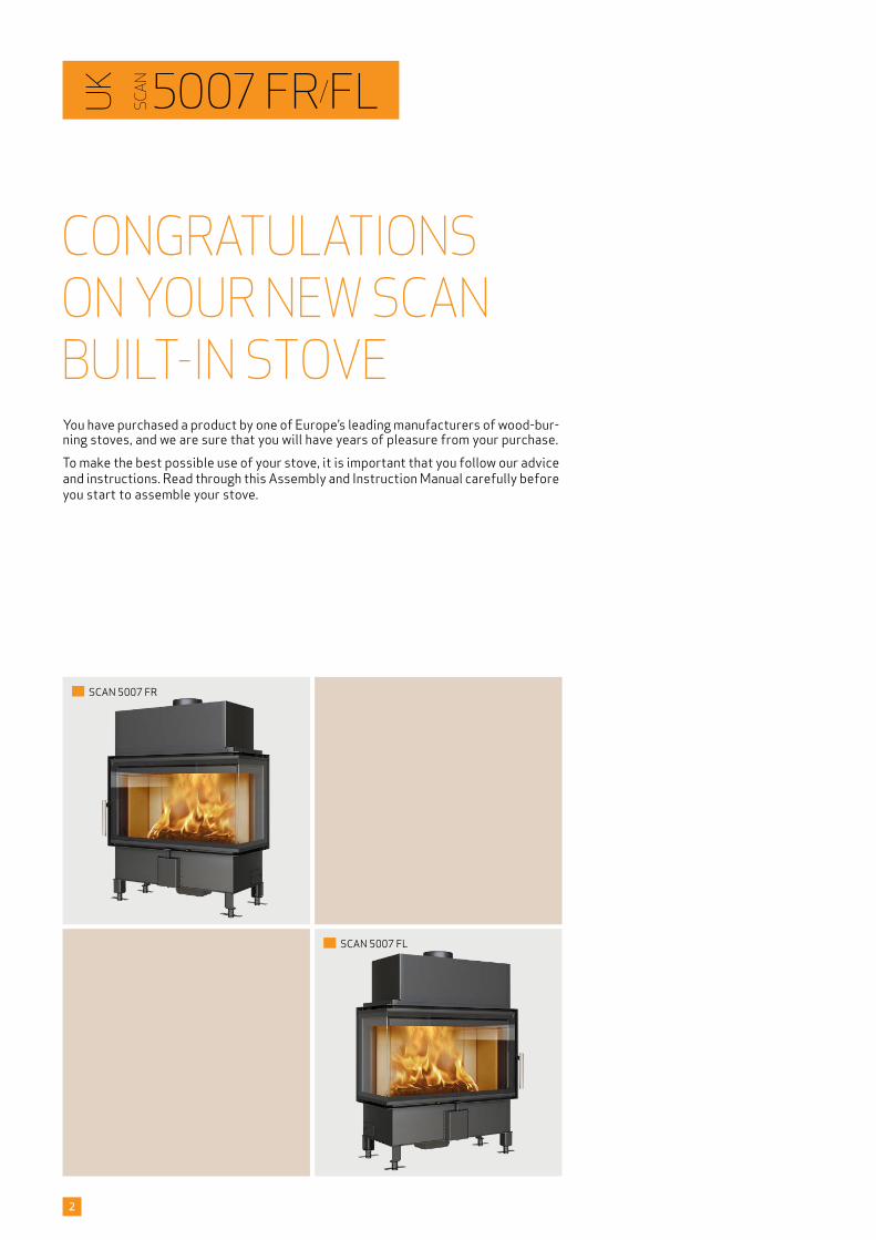
You have purchased a product by one of Europe’s leading manufacturers of wood-bur-ning stoves, and we are sure that you will have years of pleasure from your purchase. To make the best possible use of your stove, it is important that you follow our advice and instructions. Read through this Assembly and Instruction Manual carefully before you start to assemble your stove.
UK
SCA
N
CONGRATULATIONS ON YOUR NEW SCAN BUILT-IN STOVE
SCAN 5007 FL
SCAN 5007 FR
3
CONTENTS¬¬ TECHNICAL DATA 4
Installation 4Safety 4Technical data and dimensions 5
Dimension sketch and minimum distances 6Type plate 8Product registration number 8
¬¬ ASSEMBLY 9Additional accessories 9Disposal of packaging 9Load-bearing foundation 9Floor plate 9Existing chimney and pre-fabricated element chimney 9Connection between built-in stove and steel chimney 9Requirements for chimney 10Balanced flue 10Trim 10Internal installation in non-flammable material 10Minimum distance to flammable materials 10Building in the stove at a fire wall 10
Safety distance 10Cutout in the surround material 11Fresh air intake 12Closed combustion system 12Fresh air box for floor 12Clips for Norway (Large rooms) 13Heat-storage system 13Mounting of the heat shields/convection covers 14Frames 18Convection air 21Mounting of convection grate 21
¬¬ INSTRUCTIONS FOR USE 22Baffle plates 22Ash container 22
Combustion air 22
¬¬ INSTRUCTIONS FOR HEATING 23Environmentally friendly operation 23Lighting 23Using the stove in various weather conditions 23Continuous operation 24Warning about over-firing 24
Firing in the spring or autumn 24General notes 24The function of the chimney 24Chimney fire 24
¬¬ HANDLING OF THE FUEL 25Selecting wood/fuel 25Preparation 25Storing 25
Moisture 25Use of the following as fuel is illegal 25Calorific value of the wood 25
¬¬ MAINTENANCE 26Sweeping the chimney and cleaning the stove 26Checking the stove 26Servicing 26Combustion chamber lining 26
Gaskets 27Painted surfaces 27Cleaning the glass 28Disposal of stove parts 28
¬¬ TROUBLESHOOTING 29
¬¬ WARRANTY 30
4
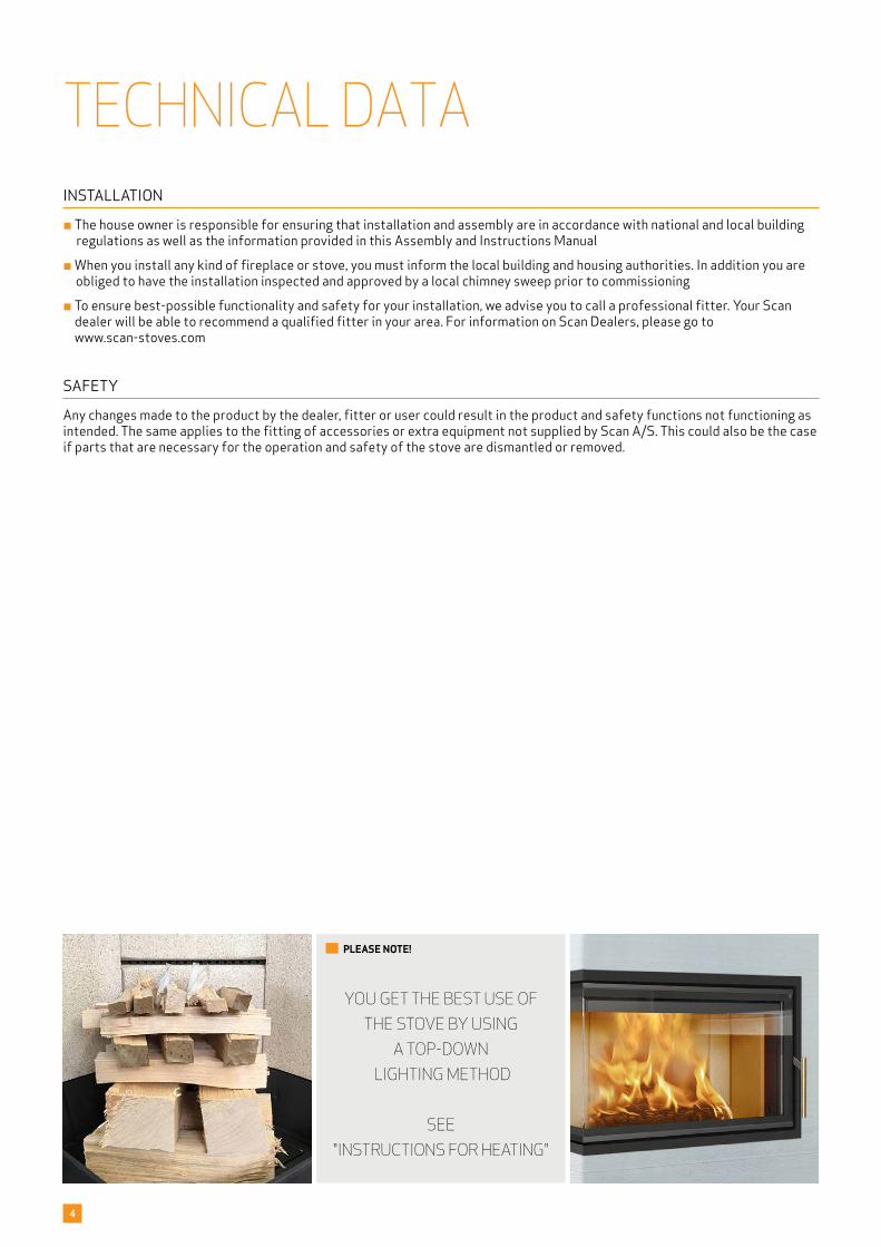
YOU GET THE BEST USE OF THE STOVE BY USING
A TOP-DOWN LIGHTING METHOD
SEE "INSTRUCTIONS FOR HEATING"
PLEASE NOTE!
TECHNICAL DATAINSTALLATION
¬ The house owner is responsible for ensuring that installation and assembly are in accordance with national and local building regulations as well as the information provided in this Assembly and Instructions Manual
¬ When you install any kind of fireplace or stove, you must inform the local building and housing authorities. In addition you are obliged to have the installation inspected and approved by a local chimney sweep prior to commissioning
¬ To ensure best-possible functionality and safety for your installation, we advise you to call a professional fitter. Your Scan dealer will be able to recommend a qualified fitter in your area. For information on Scan Dealers, please go to www.scan-stoves.com
SAFETY
Any changes made to the product by the dealer, fitter or user could result in the product and safety functions not functioning as intended. The same applies to the fitting of accessories or extra equipment not supplied by Scan A/S. This could also be the case if parts that are necessary for the operation and safety of the stove are dismantled or removed.
5
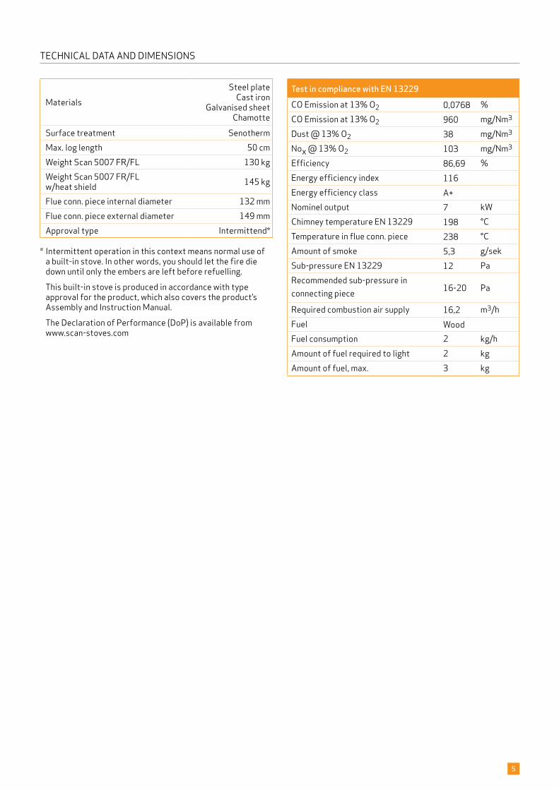
TECHNICAL DATA AND DIMENSIONS
Test in compliance with EN 13229CO Emission at 13% O2 0,0768 %CO Emission at 13% O2 960 mg/Nm3
Dust @ 13% O2 38 mg/Nm3
Nox @ 13% O2 103 mg/Nm3
Efficiency 86,69 %Energy efficiency index 116Energy efficiency class A+Nominel output 7 kWChimney temperature EN 13229 198 °CTemperature in flue conn. piece 238 °CAmount of smoke 5,3 g/sekSub-pressure EN 13229 12 PaRecommended sub-pressure in connecting piece 16-20 Pa
Required combustion air supply 16,2 m3/hFuel WoodFuel consumption 2 kg/hAmount of fuel required to light 2 kgAmount of fuel, max. 3 kg
MaterialsSteel plate
Cast ironGalvanised sheet
Chamotte
Surface treatment SenothermMax. log length 50 cmWeight Scan 5007 FR/FL 130 kgWeight Scan 5007 FR/FL w/heat shield 145 kg
Flue conn. piece internal diameter 132 mmFlue conn. piece external diameter 149 mmApproval type Intermittend*
* Intermittent operation in this context means normal use of a built-in stove. In other words, you should let the fire die down until only the embers are left before refuelling.
This built-in stove is produced in accordance with type approval for the product, which also covers the product’s Assembly and Instruction Manual.
The Declaration of Performance (DoP) is available from www.scan-stoves.com
900
90036
0°
NAV
N:
STI
:
DIM
ENSI
ON
:
MAT
ER
IALE
:D
ATO
:S
IGN
:
Kro
g Iv
erse
n &
Co
A/S
DK
-549
2 V
isse
nbje
rg©
TG.N
R:
EMN
E:
C:\W
orki
ng F
olde
r\Des
igns
\Sca
n 50
03\9
5003
072.
idw
9500
3072
Gul
vpla
de (a
fsta
nd ti
l bræ
ndba
rt)
31-0
3-20
20K
EN
Scan
500
3-S
VÆG
T:
AR
EAL
:
10,1
0 kg
1349
432
mm
^2
YX
800**
Stov
e:
Path
:
Artic
lenum
ber:
Mat
erial
:
Date
:
Cons
tructe
d/Ch
ange
d by
:
SCA
N A
/SD
K-54
92 V
isse
nbje
rg©
Draw
ing
num
ber:
Nam
e:
C:\W
orki
ng F
olde
r\Des
igns
\Sca
n 50
07\9
5007
001.
idw
9500
7001
Mål
skits
e, F
R14
-05-
2020
KEN
Scan
500
7
Weig
ht:
Area
:N
/AN
/A
*Not
e: R
efer
to th
e m
anua
lfo
r dis
tanc
e to
com
bust
ible
floo
r.
937
700
161
375
115939
438 276 - 326*
****
Stov
e:
Path
:
Artic
lenum
ber:
Mat
erial
:
Date
:
Cons
tructe
d/Ch
ange
d by
:
SCA
N A
/SD
K-54
92 V
isse
nbje
rg©
Draw
ing
num
ber:
Nam
e:
C:\W
orki
ng F
olde
r\Des
igns
\Sca
n 50
07\9
5007
002.
idw
9500
7002
Mål
skits
e, F
R, v
arm
eskj
old
til b
rand
mur
16-0
4-20
20
KEN
Scan
500
6
Weig
ht:
Area
:N
/AN
/A
*Not
e: R
efer
to th
e m
anua
lfo
r dis
tanc
e to
com
bust
ible
floo
r.
1031
500
939 115
276 - 326* 438
175
389
539
1017
937
700
174
388
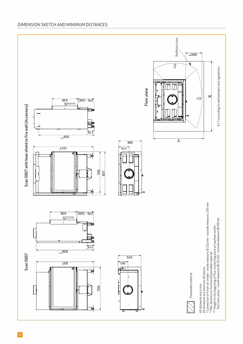
6
Floo
r pla
te
All d
ista
nces
are
in m
m.
All d
ista
nces
are
min
imum
dis
tanc
es* C
onne
ctio
n of
fres
h-ai
r int
ake
- ins
ide
mea
sure
: Ø 1
32 m
m -
outs
ide
mea
sure
: 150
mm
** M
in. d
ista
nce
to fu
rnitu
re/fl
amm
able
mat
eria
l**
* Hei
ght t
o th
e be
ginn
ing
of fl
ue co
nnec
ting
piec
e at
top/
rear
out
let,
fl
ue co
nn. p
iece
- in
side
mea
sure
: Ø13
2 m
m -
outs
ide
mea
sure
: Ø14
9 m
mX
/ Y a
ccor
ding
to n
atio
nal l
aws a
nd re
gula
tions
Flam
mab
le m
ater
ial
Radi
atio
n zo
ne
Scan
500
7Sc
an 5
007
with
heat
shie
ld to
fire
wal
l (Ac
cess
ory)
DIMENSION SKETCH AND MINIMUM DISTANCES
900
900
360°
NAV
N:
STI
:
DIM
ENSI
ON
:
MAT
ER
IALE
:D
ATO
:S
IGN
:
Kro
g Iv
erse
n &
Co
A/S
DK
-549
2 V
isse
nbje
rg©
TG.N
R:
EMN
E:
C:\W
orki
ng F
olde
r\Des
igns
\Sca
n 87
\900
8700
7.id
w
9008
7007
Ops
tillin
gste
gnin
g (a
fsta
nd ti
l bra
ndm
ur)
02-0
2-20
21K
EN
Scan
87
VÆG
T:
AR
EAL
:
N/A
N/A
500
304
680
1480
1693
800
50
NAV
N:
STI
:
M3
NR
.:
MAT
ER
IALE
:D
ATO
:S
IGN
:
DK
-549
2 V
isse
nbje
rg©
TG.N
R:
EMN
E:
C:\W
orki
ng F
olde
r\Des
igns
\Sca
n 50
03\9
5003
003.
idw
9500
3003
Ops
tillin
gsaf
stan
d
09-1
0-20
18sr
Scan
500
3
VÆG
T:
AR
EAL
:
N/A
N/A
D
IM.:
Sca
n A
/S270 mm
500 mm
350 mm **
NAV
N:
STI
:
DIM
ENSI
ON
:
MAT
ER
IALE
:D
ATO
:S
IGN
:
Kro
g Iv
erse
n &
Co
A/S
DK
-549
2 V
isse
nbje
rg©
TG.N
R:
EMN
E:
C:\W
orki
ng F
olde
r\Des
igns
\Sca
n 87
\900
8700
7.id
w
9008
7007
Ops
tillin
gste
gnin
g (a
fsta
nd ti
l bra
ndm
ur)
02-0
2-20
21K
EN
Scan
87
VÆG
T:
AR
EAL
:
N/A
N/A
500
304
680
1480
1693
800
50
Min
. 500
cm2
Min
. 750
cm2
A-A
( 1 :
10 )
AA
NA
VN:
STI:
M3
NR
.:
MA
TER
IALE
:D
ATO
:SI
GN
:
DK-
5492
Vis
senb
jerg
©
TG.N
R:
EMN
E:
C:\W
orki
ng F
olde
r\Des
igns
\Sca
n 50
03\9
5003
004.
idw
9500
3004
Ops
tillin
gsaf
stan
d
26-0
5-20
20sr
Sca
n 50
03
VÆG
T:
AREA
L:
N/A
N/A
D
IM.:
Scan
A/S
100 mm
25 m
m18
Alle
mål
er m
inim
usm
ål.
Møb
lerin
gsaf
stan
d: 8
00 m
m B
rand
bart
mat
eria
le B
rand
mur
F.e
ks. 5
0 m
m J
øtul
fire
wal
l, 11
0 m
m m
urst
en e
ller
ande
t mat
eria
le m
ed ti
lsva
rend
e br
andf
asth
ed o
g is
olat
ions
evne
.
* Af
stan
d til
gla
s
400 mm*
400 425
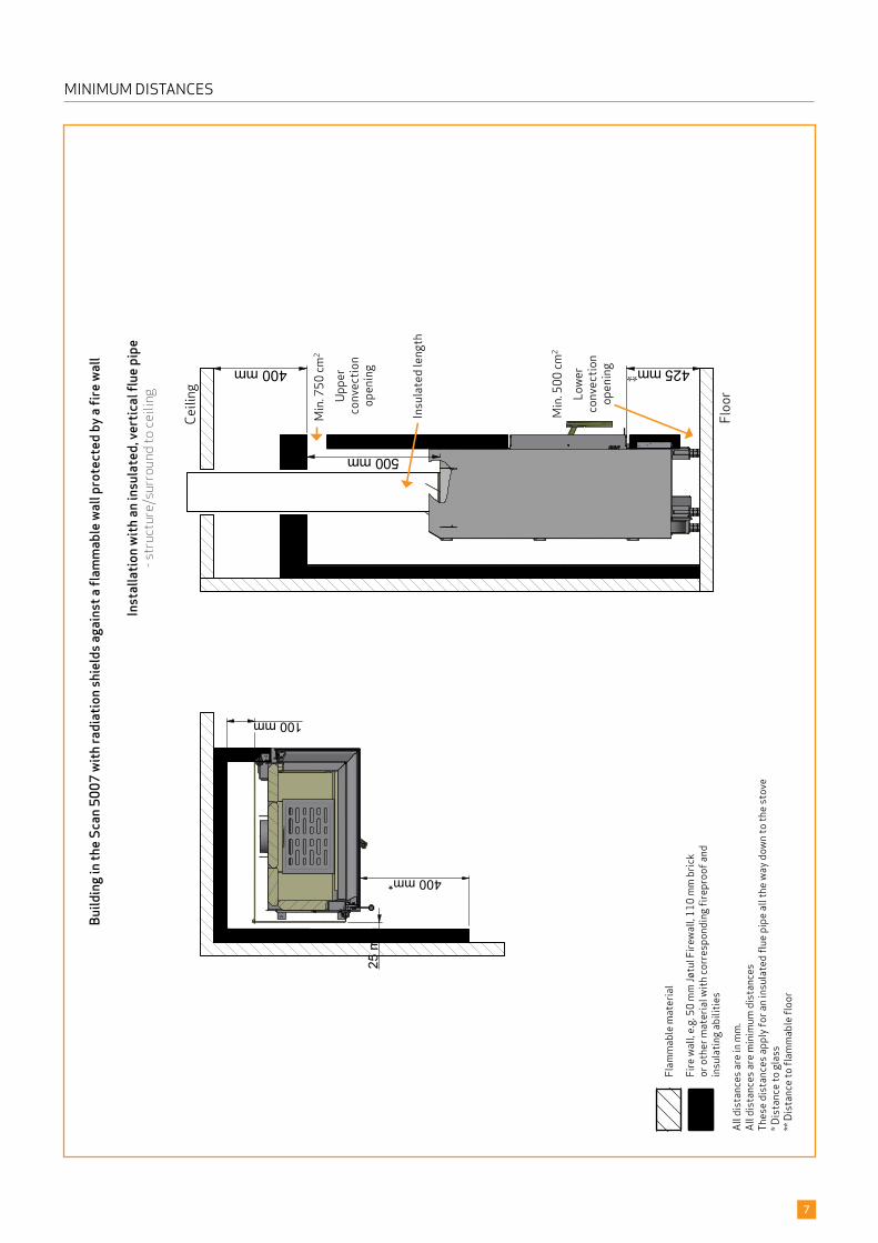
7
Flam
mab
le m
ater
ial
Fire
wal
l, e.g
. 50
mm
Jøtu
l Fire
wal
l, 110
mm
bric
kor
oth
er m
ater
ial w
ith co
rres
pond
ing
firep
roof
and
insu
latin
g ab
ilitie
s
All d
ista
nces
are
in m
m.
All d
ista
nces
are
min
imum
dis
tanc
esTh
ese
dist
ance
s app
ly fo
r an
insu
late
d flu
e pi
pe a
ll th
e w
ay d
own
to th
e st
ove
* Dis
tanc
e to
gla
ss**
Dis
tanc
e to
flam
mab
le fl
oor
MINIMUM DISTANCESBu
ildin
g in t
he S
can 5
007
with
radi
atio
n shi
elds
agai
nst a
flam
mab
le w
all p
rote
cted
by a
fire w
all
Inst
alla
tion w
ith an
insu
late
d, ve
rtic
al fl
ue p
ipe
- str
uctu
re/s
urro
und
to c
eilin
g
Lowe
r co
nvec
tion
open
ing
Uppe
r co
nvec
tion
open
ing
Floo
r
Ceili
ng
Insu
late
d le
ngth
SCAN 5007- SCAN 5007
206A1X00322 / 109915
206A1X0032
8
Type plate Scan 5007 FR/FL
Product registration number Scan 5007 FR/FL
PRODUCT REGISTRATION NUMBER
All Scan built-in stoves are provided with a product registration number. Please make a note of this number at the rear page of this manual; you will always need to quote it when contacting your dealer or Scan A/S.
The product registration number is placed loose in the fireplace.
TYPE PLATE
All Scan built-in stoves are fitted with a type plate that specifies the approval standards and the distance to flammable materials.
The type plate is placed loose in the fireplace.
9
ASSEMBLYADDITIONAL ACCESSORIES
¬ Fresh air box (see page 12) ¬ Connection pipe Ø 100 mm
¬ Heat-storage stones (see page 13) ¬ Heat shields/convection covers (see page 14)
¬ Frames (see page 18) ¬ Convection air grid (see page 21)
¬ Adjustable legs 100 mm and 190 mm ¬ Detachable handle
DISPOSAL OF PACKAGING
Your Scan built-in stove may come supplied with the following packaging:
Wood packaging The wood packaging can be reused and after final use can be incinerated as a CO2 neutral product or sent for recycling
Foam Send for recycling or waste disposal
Plastic bags Send for recycling or waste disposal
Stretch/plastic film Send for recycling or waste disposal
LOAD-BEARING FOUNDATION
All items in our product range come under the category of lightweight fireplaces and stoves and do not normally require any reinforcement of the beam structure. They can be positioned on ordinary beams/floor.
You should of course make sure that the foundation on which the stove is positioned can indeed support the weight of the stove and, where applicable, a steel chimney, if you have opted for this solution. In case of doubt about the carrying capacity of the floor, please consult a building expert.
FLOOR PLATE
If you are placing the stove on a flammable floor, you must comply with the national and local regulations on the size of any non-flammable subsurface required to cover the floor around the stove.
Your local Scan dealer can advise you on regulations concerning protection of flammable materials in the vicinity of your stove.
The floor plate’s function is to protect the floor and flammable material against any sparks that may occur.
EXISTING CHIMNEY AND PRE-FABRICATED ELEMENT CHIMNEY
If you intend to connect your stove to an existing chimney, it makes sense to contact an authorised Scan dealer, or a local chim-ney sweep, for advice. These experts will also let you know if your chimney needs renovating.
¬ When connecting a pre-fabricated element chimney, follow the manufacturer’s connection instructions for the relevant chimney type.
CONNECTION BETWEEN BUILT-IN STOVE AND STEEL CHIMNEY
Your Scan dealer, or local chimney sweep, can advise you on choosing a make and type of steel chimney. This ensures that the chimney will match your wood-burning stove.
10
REQUIREMENTS FOR CHIMNEY
The chimney must have a minimum internal diameter of 148 mm and have a T400 designation, with G for the soot fire test. The length should be min. 5 metres.
If you opt to connect the built-in stove with an elbow pipe, you should use a curved elbow, as this gives a better draught.
If you connect the stove with a sharp elbow pipe, the cleansing lid must be placed in the vertical part so that the horizontal part can be cleaned through here.
If the chimney is fitted with a smoke extractor, it must be possible to adjust it to a suitable draft.
The requirements to the chimney and the flue pipe in terms of safety distances must be met.
¬ Choosing the wrong length or diameter of steel chimney could impair functionality
¬ Always comply exactly with the instructions provided by the steel chimney supplier
BALANCED FLUE
If the stove is connected with a balanced flue, we recommend the use of a 100 mm Lindab tube and a chimney length of min. 5 m.
TRIM
The trim is mounted, when the surfaces of the covering are finished.
INTERNAL INSTALLATION IN NON-FLAMMABLE MATERIAL
When building or fitting into structures that do not contain flammable materials, a minimum distance of 10 mm must be main-tained between the brickwork and the convection hood. This is to prevent cracks in the brickwork caused by the expansion of the metal while the stove is heating. This construction does not require convection grates except for the convection air produced by the convection box of the insert. However, please note that without convection grates, the effect of the insert will be lower.
MINIMUM DISTANCE TO FLAMMABLE MATERIALS
Distance to side: 400 mm - back: 400 mm - glass: 800 mm. - ceiling: 1000 mm.
You should however assess whether furniture or other items might become excessively dry due to being too close to the stove.
¬ The stove is NOT to be built into flammable materials without the use of a fire wall and heat shields!
BUILDING IN THE STOVE AT A FIRE WALL
We refer to the building sketches on page 7.
SAFETY DISTANCE
European, national and local regulations concerning safety distances for wood-burning stoves and flue pipes must be complied with.
The stove must be set up so that the stove itself, the flue pipe, and the chimney can all be cleaned.
/ EXISTING BRICKWORK
(WHICH IS NOT PROTECTED BY FIREWALL)
A ( 1 : 4 )
B ( 1 : 4 )
A
B
NAVN:
STI:
M3 NR.:
MATERIALE: DATO: SIGN:
DK-5492 Vissenbjerg©
TG.NR:EMNE:
C:\Working Folder\Designs\Scan 5006\95006003.idw
95006003Udskæring i firewall for kasse
16-04-2020 KEN
Scan 5006
VÆGT:
AREAL:
N/A
N/A DIM.: Scan A/S
26
36,5
175,
5
137
A ( 1 : 4 )
B ( 1 : 4 )
A
B
NAVN:
STI:
M3 NR.:
MATERIALE: DATO: SIGN:
DK-5492 Vissenbjerg©
TG.NR:EMNE:
C:\Working Folder\Designs\Scan 5003\95003032.idw
95003032Udskæring i firewall for kasse
22-01-2018 sr
Scan 5003
VÆGT:
AREAL:
N/A
N/A DIM.: Scan A/S
26
36,5
175,
5137
A ( 1 : 4 )
B ( 1 : 4 )
A
B
NAVN:
STI:
M3 NR.:
MATERIALE: DATO: SIGN:
DK-5492 Vissenbjerg©
TG.NR:EMNE:
C:\Working Folder\Designs\Scan 5003\95003032.idw
95003032Udskæring i firewall for kasse
22-01-2018 sr
Scan 5003
VÆGT:
AREAL:
N/A
N/A DIM.: Scan A/S
26
36,5
175,
5
137
A ( 1 : 4 )
B ( 1 : 4 )
A
B
NAVN:
STI:
M3 NR.:
MATERIALE: DATO: SIGN:
DK-5492 Vissenbjerg©
TG.NR:EMNE:
C:\Working Folder\Designs\Scan 5006\95006003.idw
95006003Udskæring i firewall for kasse
16-04-2020 KEN
Scan 5006
VÆGT:
AREAL:
N/A
N/A DIM.: Scan A/S
26
36,5
175,
5137
A ( 1 : 4 )
B ( 1 : 4 )
A
B
NAVN:
STI:
M3 NR.:
MATERIALE: DATO: SIGN:
DK-5492 Vissenbjerg©
TG.NR:EMNE:
C:\Working Folder\Designs\Scan 5006\95006003.idw
95006003Udskæring i firewall for kasse
16-04-2020 KEN
Scan 5006
VÆGT:
AREAL:
N/A
N/A DIM.: Scan A/S
26
36,5
175,
5
137
11
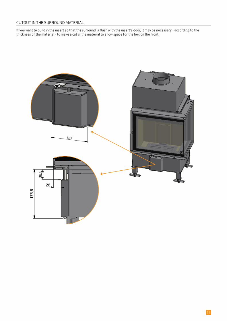
CUTOUT IN THE SURROUND MATERIAL
If you want to build in the insert so that the surround is flush with the insert's door, it may be necessary - according to the thickness of the material - to make a cut in the material to allow space for the box on the front.
H
Stove:
Path:
Articlenumber:
Material:
Date:
Constructed/Changed by:
SCAN A/SDK-5492 Vissenbjerg©
Drawing number:Name:
C:\Working Folder\Designs\Scan 5007\95007004.idw
95007004Friskluftsadapter 03-06-2020
ken
Scan 5007 FR/FL
Weight: Area:N/A N/A
134
138
H
Stove:
Path:
Articlenumber:
Material:
Date:
Constructed/Changed by:
SCAN A/SDK-5492 Vissenbjerg©
Drawing number:Name:
C:\Working Folder\Designs\Scan 5007\95007004.idw
95007004Friskluftsadapter 03-06-2020
ken
Scan 5007 FR/FL
Weight: Area:N/A N/A
134
138
12
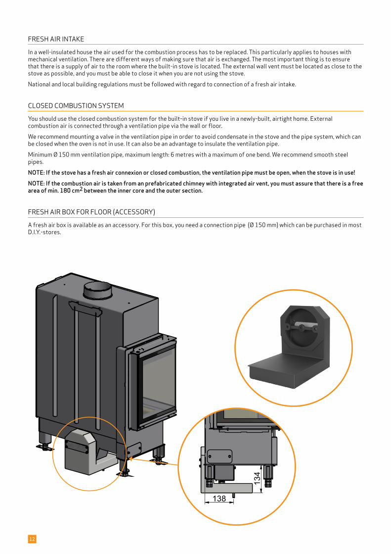
FRESH AIR INTAKE
In a well-insulated house the air used for the combustion process has to be replaced. This particularly applies to houses with mechanical ventilation. There are different ways of making sure that air is exchanged. The most important thing is to ensure that there is a supply of air to the room where the built-in stove is located. The external wall vent must be located as close to the stove as possible, and you must be able to close it when you are not using the stove.
National and local building regulations must be followed with regard to connection of a fresh air intake.
CLOSED COMBUSTION SYSTEM
You should use the closed combustion system for the built-in stove if you live in a newly-built, airtight home. External combustion air is connected through a ventilation pipe via the wall or floor.
We recommend mounting a valve in the ventilation pipe in order to avoid condensate in the stove and the pipe system, which can be closed when the oven is not in use. It can also be an advantage to insulate the ventilation pipe.
Minimum Ø 150 mm ventilation pipe, maximum length: 6 metres with a maximum of one bend. We recommend smooth steel pipes.
NOTE: If the stove has a fresh air connexion or closed combustion, the ventilation pipe must be open, when the stove is in use!NOTE: If the combustion air is taken from an prefabricated chimney with integrated air vent, you must assure that there is a free area of min. 180 cm2 between the inner core and the outer section.
FRESH AIR BOX FOR FLOOR
A fresh air box is available as an accessory. For this box, you need a connection pipe (Ø 150 mm) which can be purchased in most D.I.Y.-stores.
(ACCESSORY)
C ( 1 : 2 )
C
NAVN:
STI:
M3 NR.:
MATERIALE: DATO: SIGN:
DK-5492 Vissenbjerg©
TG.NR:EMNE:
C:\Working Folder\Designs\Scan 5003\95003019.idw
95003019Spjæld clips til Norge, large rums
13-07-2017 sr
Scan 5003
VÆGT:
AREAL:
N/A
N/A DIM.: Scan A/S
C ( 1 : 2 )
C
NAVN:
STI:
M3 NR.:
MATERIALE: DATO: SIGN:
DK-5492 Vissenbjerg©
TG.NR:EMNE:
C:\Working Folder\Designs\Scan 5003\95003019.idw
95003019Spjæld clips til Norge, large rums
13-07-2017 sr
Scan 5003
VÆGT:
AREAL:
N/A
N/A DIM.: Scan A/S
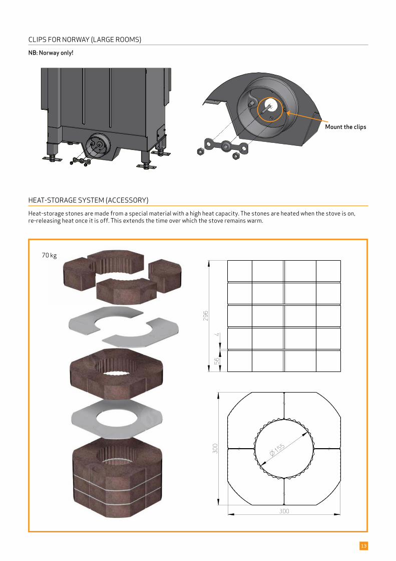
70 kg
13
Mount the clips
CLIPS FOR NORWAY (LARGE ROOMS)
NB: Norway only!
HEAT-STORAGE SYSTEM
Heat-storage stones are made from a special material with a high heat capacity. The stones are heated when the stove is on, re-releasing heat once it is off. This extends the time over which the stove remains warm.
(ACCESSORY)
NAVN:
STI:
M3 NR.:
MATERIALE: DATO: SIGN:
DK-5492 Vissenbjerg©
TG.NR:EMNE:
C:\Working Folder\Designs\Scan 5003\95003009.idw
95003009Montage af varmeskjold
11-07-17 SR
Scan 5003
VÆGT:
AREAL:
N/A
N/A DIM.: Scan A/S
NAVN:
STI:
M3 NR.:
MATERIALE: DATO: SIGN:
DK-5492 Vissenbjerg©
TG.NR:EMNE:
C:\Working Folder\Designs\Scan 5003\95003009.idw
95003009Montage af varmeskjold
11-07-17 SR
Scan 5003
VÆGT:
AREAL:
N/A
N/A DIM.: Scan A/S
3
NAVN:
STI:
M3 NR.:
MATERIALE: DATO: SIGN:
DK-5492 Vissenbjerg©
TG.NR:EMNE:
C:\Working Folder\Designs\Scan 5002\95002007.idw
95002007Montage at varmeskjold
20-06-2017 sr
Scan 5002
VÆGT:
AREAL:
N/A
N/A DIM.: Scan A/S
B ( 0,40 : 1 )
B
Stove:
Path:
Material:
Date:
SCAN A/SDK-5492 Vissenbjerg©
Drawingnumber:Name:
C:\Working Folder\Designs\Scan 5002\95002014.iam
95002014Montage af varmeskjold 22-06-2017
sr
Scan 5002
Weight: Area:N/A N/AArticlenumber:
Constructed /Changed by:
B ( 0,40 : 1 )
B
Stove:
Path:
Material:
Date:
SCAN A/SDK-5492 Vissenbjerg©
Drawingnumber:Name:
C:\Working Folder\Designs\Scan 5002\95002014.iam
95002014Montage af varmeskjold 22-06-2017
sr
Scan 5002
Weight: Area:N/A N/AArticlenumber:
Constructed /Changed by:
1
2
14
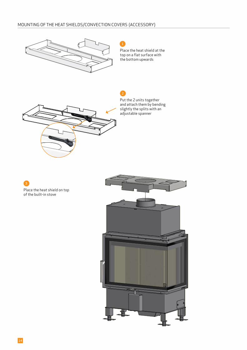
MOUNTING OF THE HEAT SHIELDS/CONVECTION COVERS (ACCESSORY)
Place the heat shield on top of the built-in stove
Place the heat shield at the top on a flat surface with the bottom upwards
Put the 2 units together and attach them by bending slightly the splits with an adjustable spanner
B ( 1 : 2 )
B
NAVN:
STI:
M3 NR.:
MATERIALE: DATO: SIGN:
DK-5492 Vissenbjerg©
TG.NR:EMNE:
C:\Working Folder\Designs\Scan 5003\95003011.idw
95003011Montage af varmeskjold
11-07-17 SR
Scan 5003
VÆGT:
AREAL:
N/A
N/A DIM.: Scan A/S
B ( 1 : 2 )
B
NAVN:
STI:
M3 NR.:
MATERIALE: DATO: SIGN:
DK-5492 Vissenbjerg©
TG.NR:EMNE:
C:\Working Folder\Designs\Scan 5003\95003011.idw
95003011Montage af varmeskjold
11-07-17 SR
Scan 5003
VÆGT:
AREAL:
N/A
N/A DIM.: Scan A/S
A ( 1 : 2 )
A
NAVN:
STI:
M3 NR.:
MATERIALE: DATO: SIGN:
DK-5492 Vissenbjerg©
TG.NR:EMNE:
C:\Working Folder\Designs\Scan 5003\95003010.idw
95003010Montage af varmeskjold
11-07-17 SR
Scan 5003
VÆGT:
AREAL:
N/A
N/A DIM.: Scan A/S
A ( 1 : 2 )
A
NAVN:
STI:
M3 NR.:
MATERIALE: DATO: SIGN:
DK-5492 Vissenbjerg©
TG.NR:EMNE:
C:\Working Folder\Designs\Scan 5003\95003010.idw
95003010Montage af varmeskjold
11-07-17 SR
Scan 5003
VÆGT:
AREAL:
N/A
N/A DIM.: Scan A/S
4
5
A ( 1 : 2 )
A
NAVN:
STI:
M3 NR.:
MATERIALE: DATO: SIGN:
DK-5492 Vissenbjerg©
TG.NR:EMNE:
C:\Working Folder\Designs\Scan 5003\95003010.idw
95003010Montage af varmeskjold
11-07-17 SR
Scan 5003
VÆGT:
AREAL:
N/A
N/A DIM.: Scan A/S
B ( 1 : 2 )
B
NAVN:
STI:
M3 NR.:
MATERIALE: DATO: SIGN:
DK-5492 Vissenbjerg©
TG.NR:EMNE:
C:\Working Folder\Designs\Scan 5003\95003011.idw
95003011Montage af varmeskjold
11-07-17 SR
Scan 5003
VÆGT:
AREAL:
N/A
N/A DIM.: Scan A/S
15
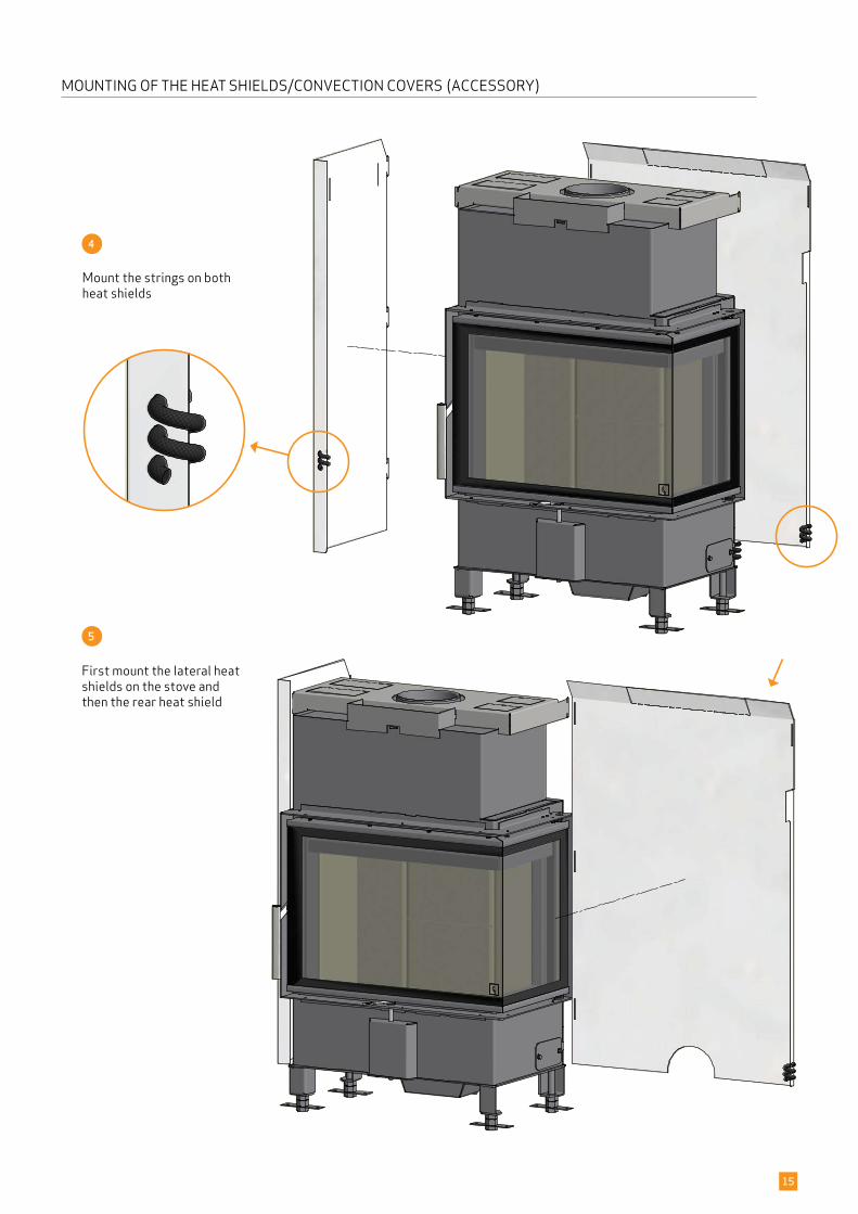
MOUNTING OF THE HEAT SHIELDS/CONVECTION COVERS (ACCESSORY)
Mount the strings on both heat shields
First mount the lateral heat shields on the stove and then the rear heat shield
D ( 1 : 4 )
D
NAVN:
STI:
M3 NR.:
MATERIALE: DATO: SIGN:
DK-5492 Vissenbjerg©
TG.NR:EMNE:
C:\Working Folder\Designs\Scan 5003\95003013.idw
95003013Montage at varmeskjold
12-07-17 sr
Scan 5003
VÆGT:
AREAL:
N/A
N/A DIM.: Scan A/S
C ( 1 : 4 )
C
NAVN:
STI:
M3 NR.:
MATERIALE: DATO: SIGN:
DK-5492 Vissenbjerg©
TG.NR:EMNE:
C:\Working Folder\Designs\Scan 5003\95003012.idw
95003012Montage at varmeskjold
12-07-17 sr
Scan 5003
VÆGT:
AREAL:
N/A
N/A DIM.: Scan A/S
6
B ( 1 : 4 )
B
NAVN:
STI:
M3 NR.:
MATERIALE: DATO: SIGN:
DK-5492 Vissenbjerg©
TG.NR:EMNE:
C:\Working Folder\Designs\Scan 5002\95002012.idw
95002012Montage at varmeskjold
22-06-2017 sr
Scan 5002
VÆGT:
AREAL:
N/A
N/A DIM.: Scan A/S
16
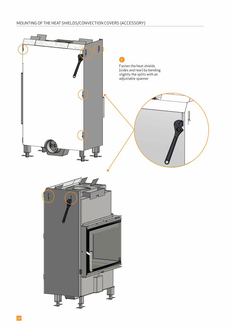
MOUNTING OF THE HEAT SHIELDS/CONVECTION COVERS (ACCESSORY)
Fasten the heat shields (sides and rear) by bending slightly the splits with an adjustable spanner
E ( 1 : 4 )
E
NAVN:
STI:
M3 NR.:
MATERIALE: DATO: SIGN:
DK-5492 Vissenbjerg©
TG.NR:EMNE:
C:\Working Folder\Designs\Scan 5003\95003015.idw
95003015Montage at varmeskjold
12-07-17 sr
Scan 5003
VÆGT:
AREAL:
N/A
N/A DIM.: Scan A/S
E ( 1 : 4 )
E
NAVN:
STI:
M3 NR.:
MATERIALE: DATO: SIGN:
DK-5492 Vissenbjerg©
TG.NR:EMNE:
C:\Working Folder\Designs\Scan 5003\95003016.idw
95003016Montage at varmeskjold
12-07-17 sr
Scan 5003
VÆGT:
AREAL:
N/A
N/A DIM.: Scan A/S
54
7
E ( 1 : 4 )
E
NAVN:
STI:
M3 NR.:
MATERIALE: DATO: SIGN:
DK-5492 Vissenbjerg©
TG.NR:EMNE:
C:\Working Folder\Designs\Scan 5003\95003015.idw
95003015Montage at varmeskjold
12-07-17 sr
Scan 5003
VÆGT:
AREAL:
N/A
N/A DIM.: Scan A/SE ( 1 : 4 )
E
NAVN:
STI:
M3 NR.:
MATERIALE: DATO: SIGN:
DK-5492 Vissenbjerg©
TG.NR:EMNE:
C:\Working Folder\Designs\Scan 5003\95003016.idw
95003016Montage at varmeskjold
12-07-17 sr
Scan 5003
VÆGT:
AREAL:
N/A
N/A DIM.: Scan A/S
54m
m
17
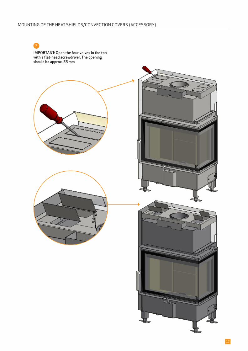
MOUNTING OF THE HEAT SHIELDS/CONVECTION COVERS (ACCESSORY)
IMPORTANT: Open the four valves in the top with a flat-head screwdriver. The opening should be approx. 55 mm
18
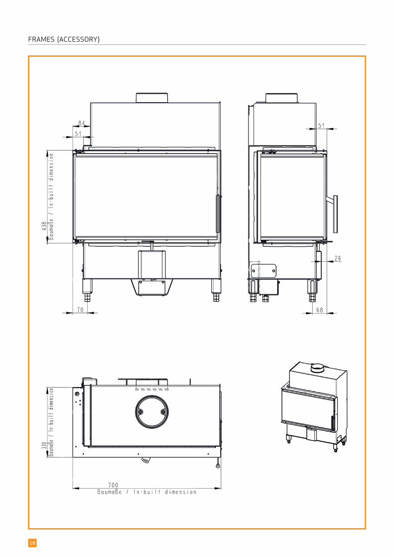
FRAMES (ACCESSORY)
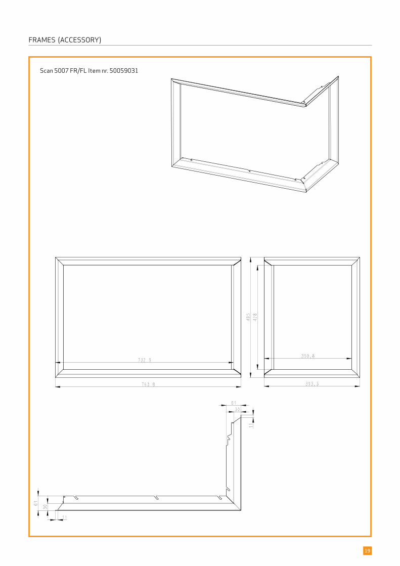
Scan 5007 FR/FL Item nr. 50059031
19
FRAMES (ACCESSORY)
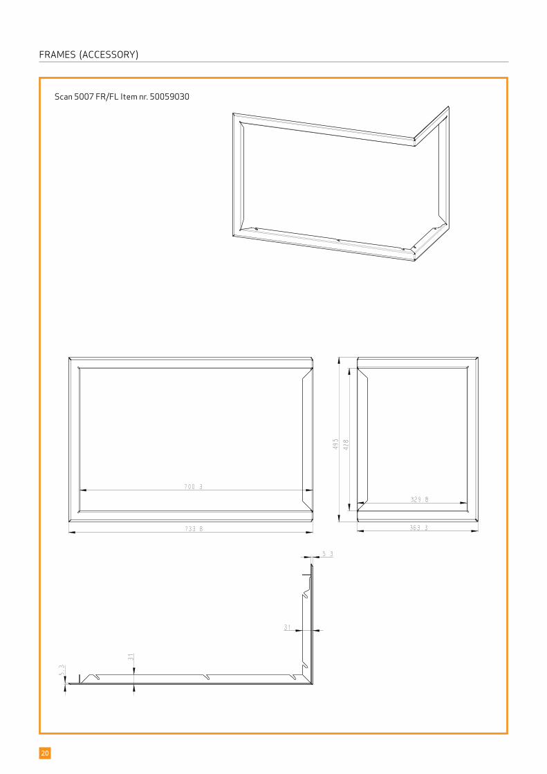
Scan 5007 FR/FL Item nr. 50059030
20
FRAMES (ACCESSORY)
1
2
E ( 1 : 10 )
E
NAVN:
STI:
M3 NR.:
MATERIALE: DATO: SIGN:
Scan A/SDK-5492 Vissenbjerg©
TG.NR:EMNE:
C:\Working Folder\Designs\Scan 5003\95003033.iam
95003033Montage af konventionsrist, Scan 5003
22-01-2018 sr
Scan 5003
VÆGT:
AREAL:
N/A
N/ADIM.:
538
228
E ( 1 : 10 )
E
NAVN:
STI:
M3 NR.:
MATERIALE: DATO: SIGN:
Scan A/SDK-5492 Vissenbjerg©
TG.NR:EMNE:
C:\Working Folder\Designs\Scan 5003\95003033.iam
95003033Montage af konventionsrist, Scan 5003
22-01-2018 sr
Scan 5003
VÆGT:
AREAL:
N/A
N/ADIM.:
538
228
21
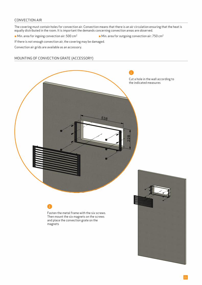
Cut a hole in the wall according to the indicated measures
Fasten the metal frame with the six screws. Then mount the six magnets on the screws and place the convection grate on the magnets
CONVECTION AIR
The covering must contain holes for convection air. Convection means that there is an air circulation ensuring that the heat is equally distributed in the room. It is important the demands concerning convection areas are observed.
¬ Min. area for ingoing convection air: 500 cm2 ¬ Min. area for outgoing convection air: 750 cm2
If there is not enough convection air, the covering may be damaged.
Convection air grids are available as an accessory.
MOUNTING OF CONVECTION GRATE (ACCESSORY)
A ( 1 : 1 )
A
NAVN:
STI:
M3 NR.:
MATERIALE: DATO: SIGN:
DK-5492 Vissenbjerg©
TG.NR:EMNE:
C:\Working Folder\Designs\Scan 5003\95003006.idw
95003006Spjældregulering
05-07-2017 sr
Scan 5003
VÆGT:
AREAL:
N/A
N/A DIM.: Scan A/S
Lukket Åbent
A ( 1 : 1 )
A
NAVN:
STI:
M3 NR.:
MATERIALE: DATO: SIGN:
DK-5492 Vissenbjerg©
TG.NR:EMNE:
C:\Working Folder\Designs\Scan 5003\95003006.idw
95003006Spjældregulering
05-07-2017 sr
Scan 5003
VÆGT:
AREAL:
N/A
N/A DIM.: Scan A/S
Lukket Åbent
22
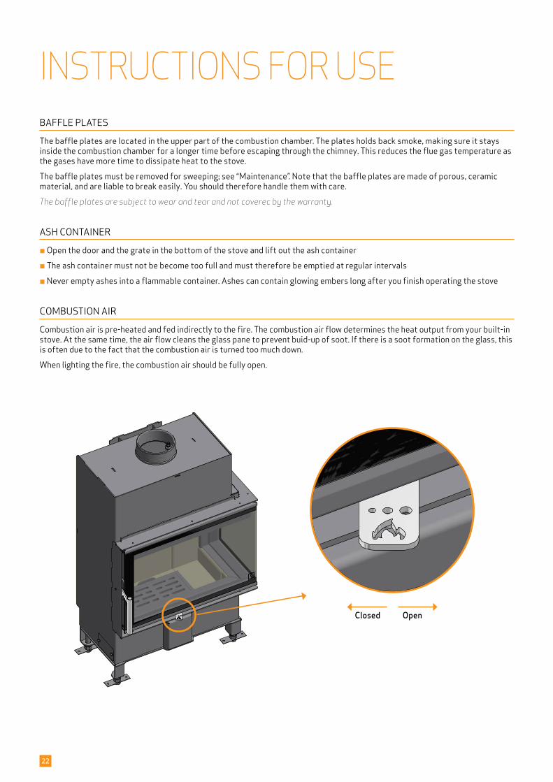
OpenClosed
INSTRUCTIONS FOR USEBAFFLE PLATES
The baffle plates are located in the upper part of the combustion chamber. The plates holds back smoke, making sure it stays inside the combustion chamber for a longer time before escaping through the chimney. This reduces the flue gas temperature as the gases have more time to dissipate heat to the stove.
The baffle plates must be removed for sweeping; see “Maintenance”. Note that the baffle plates are made of porous, ceramic material, and are liable to break easily. You should therefore handle them with care.
The baffle plates are subject to wear and tear and not coverec by the warranty.
ASH CONTAINER
¬ Open the door and the grate in the bottom of the stove and lift out the ash container
¬ The ash container must not be become too full and must therefore be emptied at regular intervals
¬ Never empty ashes into a flammable container. Ashes can contain glowing embers long after you finish operating the stove
COMBUSTION AIR
Combustion air is pre-heated and fed indirectly to the fire. The combustion air flow determines the heat output from your built-in stove. At the same time, the air flow cleans the glass pane to prevent buid-up of soot. If there is a soot formation on the glass, this is often due to the fact that the combustion air is turned too much down.
When lighting the fire, the combustion air should be fully open.
23
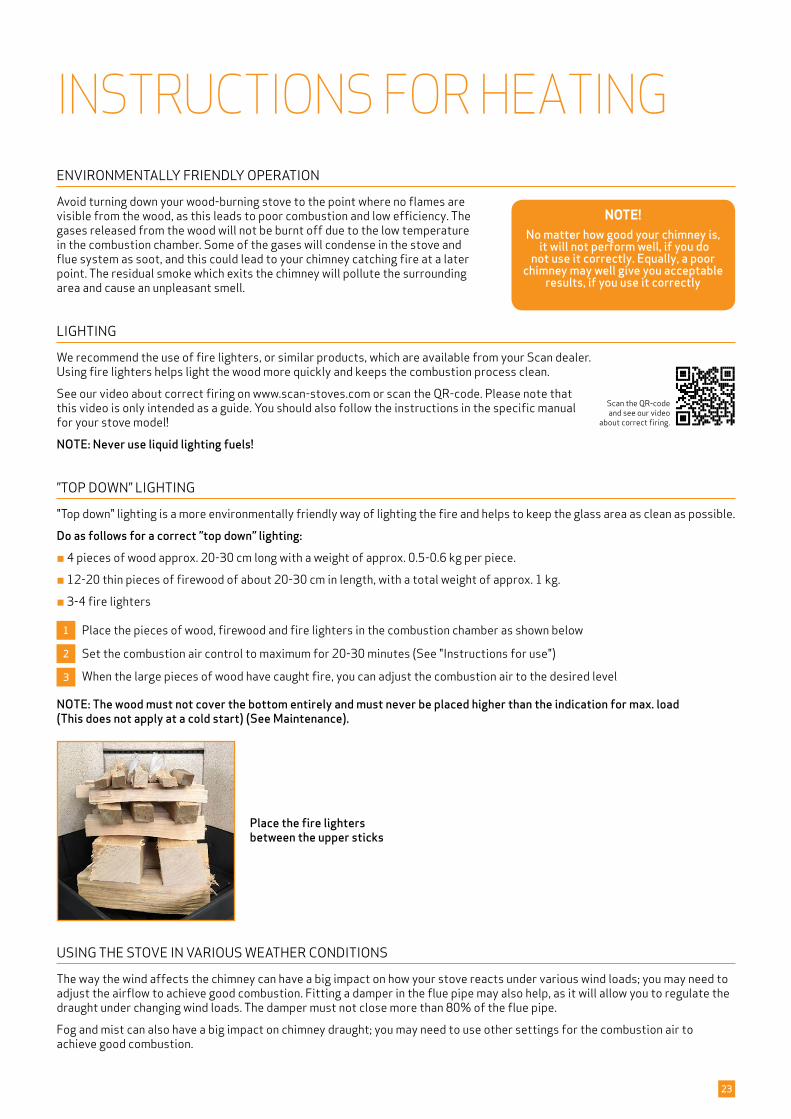
Place the fire lighters between the upper sticks
INSTRUCTIONS FOR HEATINGENVIRONMENTALLY FRIENDLY OPERATION
Avoid turning down your wood-burning stove to the point where no flames are visible from the wood, as this leads to poor combustion and low efficiency. The gases released from the wood will not be burnt off due to the low temperature in the combustion chamber. Some of the gases will condense in the stove and flue system as soot, and this could lead to your chimney catching fire at a later point. The residual smoke which exits the chimney will pollute the surrounding area and cause an unpleasant smell.
LIGHTING
We recommend the use of fire lighters, or similar products, which are available from your Scan dealer. Using fire lighters helps light the wood more quickly and keeps the combustion process clean.
See our video about correct firing on www.scan-stoves.com or scan the QR-code. Please note that this video is only intended as a guide. You should also follow the instructions in the specific manual for your stove model!
NOTE: Never use liquid lighting fuels!
”TOP DOWN” LIGHTING
"Top down" lighting is a more environmentally friendly way of lighting the fire and helps to keep the glass area as clean as possible.
Do as follows for a correct ”top down” lighting:¬ 4 pieces of wood approx. 20-30 cm long with a weight of approx. 0.5-0.6 kg per piece.
¬ 12-20 thin pieces of firewood of about 20-30 cm in length, with a total weight of approx. 1 kg.
¬ 3-4 fire lighters
1 Place the pieces of wood, firewood and fire lighters in the combustion chamber as shown below
2 Set the combustion air control to maximum for 20-30 minutes (See "Instructions for use")
3 When the large pieces of wood have caught fire, you can adjust the combustion air to the desired level
NOTE: The wood must not cover the bottom entirely and must never be placed higher than the indication for max. load (This does not apply at a cold start) (See Maintenance).
NOTE!No matter how good your chimney is,
it will not perform well, if you do not use it correctly. Equally, a poor
chimney may well give you acceptable results, if you use it correctly
Scan the QR-code and see our video
about correct firing.
USING THE STOVE IN VARIOUS WEATHER CONDITIONS
The way the wind affects the chimney can have a big impact on how your stove reacts under various wind loads; you may need to adjust the airflow to achieve good combustion. Fitting a damper in the flue pipe may also help, as it will allow you to regulate the draught under changing wind loads. The damper must not close more than 80% of the flue pipe.
Fog and mist can also have a big impact on chimney draught; you may need to use other settings for the combustion air to achieve good combustion.
24
CONTINUOUS OPERATION
It is important to obtain as high a temperature as possible in the combustion chamber. This results in best possible use of the stove and fuel, as well as achieving clean combustion. In this way you will avoid build-up of soot on the combustion chamber lining and glass pane. During operation, you should not see any smoke; just a movement in the air that indicates combustion is in progress.
¬ After completing the lighting phase, you should have a good layer of embers in the stove; you can then start operation of it properly
¬ Add 3-4 pieces of wood at a time: they should be about 0.4 - 0.6 kg in weight and about 30-40 cm long
NOTE: The wood must catch fire quickly. This is why we recommend setting the combustion air flow fully open. Operating the stove at too low a temperature and with too little the combustion air can lead to gases igniting, which can damage the stove.¬ When adding wood, always open the glass door carefully to prevent smoke escaping
¬ Never add wood, while the fire is burning nicely
WARNING ABOUT OVER-FIRING
If the stove is continiously fired with larger amounts of wood than recommended and/or receives too much air, this can cause a heavy heat development liable to damage both stove and the surrounding walls. We therefore recommend that you always observe the max. recommended amount of fuel (See under ”Technical Data”).
FIRING IN THE SPRING OR AUTUMN
In the spring/autumn transition period, where there is less need for heating, we recommend you light the stove “top down” once, perhaps adding just two pieces of wood to ensure that the combustion chamber lining burns clean again.
GENERAL NOTES
PLEASE NOTE! Parts of the wood-burning stove, especially the outer surfaces, become hot during use. Due care should be exercised.¬ Never empty ashes into a flammable container. Ashes can contain glowing embers long after you finish operating the stove
¬ When the stove is not in use you can close the dampers to avoid a draught through the stove
¬ If the stove has not been used for some time, you should check the flue passageways for potential blockages before relighting
NOTE: Never place flammable material in the radiation zone of the stove!
THE FUNCTION OF THE CHIMNEY
The chimney is the wood-burning stove’s motor; its performance determines how well your stove will work. The draught in the chimney creates negative pressure in the wood-burning stove. The negative pressure draws the smoke out of the stove and takes in air through the combustion air damper to fuel the combustion process. Combustion air is also used for the airwash system that keeps the glass clear of soot.
The draught in the chimney is created by the difference in temperature inside and outside the chimney. The higher the difference in temperature, the better the draught. This is why it is important that the chimney reaches operating temperature before you reduce the damper settings to restrict combustion in the stove (a brickwork chimney will take longer to reach operating temperature than a steel chimney). It is very important that the operating temperature is reached as quickly as possible on days when the draught in the chimney is poor due to unfavourable wind and weather conditions. You need to get a few flames going as quickly as possible. Chop the wood extra thin; use an extra fire lighter etc.
¬ After longer periods without use, you must check the chimney flue for blockages
¬ You can connect several units to the same chimney. You should however first check the relevant regulations in this respect
CHIMNEY FIRE
In the event of a chimney fire, keep the stove door, ash drawer, and all dampers on the stove closed. In an emergency, call the fire service.
¬ We recommend that you get a chimney sweep to check the chimney before using the stove again
25
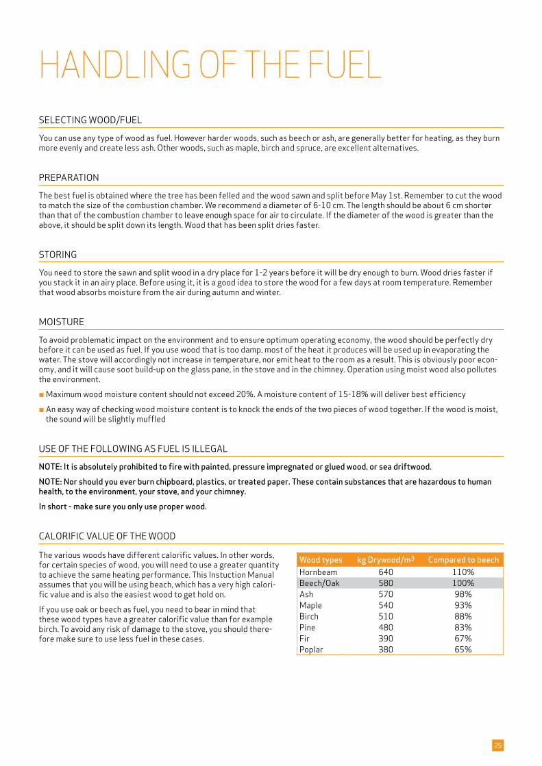
The various woods have different calorific values. In other words, for certain species of wood, you will need to use a greater quantity to achieve the same heating performance. This Instuction Manual assumes that you will be using beach, which has a very high calori-fic value and is also the easiest wood to get hold on.
If you use oak or beech as fuel, you need to bear in mind that these wood types have a greater calorific value than for example birch. To avoid any risk of damage to the stove, you should there-fore make sure to use less fuel in these cases.
CALORIFIC VALUE OF THE WOOD
Wood types kg Drywood/m3 Compared to beechHornbeam 640 110%Beech/Oak 580 100%Ash 570 98%Maple 540 93%Birch 510 88%Pine 480 83%Fir 390 67%Poplar 380 65%
HANDLING OF THE FUELSELECTING WOOD/FUEL
You can use any type of wood as fuel. However harder woods, such as beech or ash, are generally better for heating, as they burn more evenly and create less ash. Other woods, such as maple, birch and spruce, are excellent alternatives.
PREPARATION
The best fuel is obtained where the tree has been felled and the wood sawn and split before May 1st. Remember to cut the wood to match the size of the combustion chamber. We recommend a diameter of 6-10 cm. The length should be about 6 cm shorter than that of the combustion chamber to leave enough space for air to circulate. If the diameter of the wood is greater than the above, it should be split down its length. Wood that has been split dries faster.
STORING
You need to store the sawn and split wood in a dry place for 1-2 years before it will be dry enough to burn. Wood dries faster if you stack it in an airy place. Before using it, it is a good idea to store the wood for a few days at room temperature. Remember that wood absorbs moisture from the air during autumn and winter.
MOISTURE
To avoid problematic impact on the environment and to ensure optimum operating economy, the wood should be perfectly dry before it can be used as fuel. If you use wood that is too damp, most of the heat it produces will be used up in evaporating the water. The stove will accordingly not increase in temperature, nor emit heat to the room as a result. This is obviously poor econ-omy, and it will cause soot build-up on the glass pane, in the stove and in the chimney. Operation using moist wood also pollutes the environment.
¬ Maximum wood moisture content should not exceed 20%. A moisture content of 15-18% will deliver best efficiency
¬ An easy way of checking wood moisture content is to knock the ends of the two pieces of wood together. If the wood is moist, the sound will be slightly muffled
USE OF THE FOLLOWING AS FUEL IS ILLEGAL
NOTE: It is absolutely prohibited to fire with painted, pressure impregnated or glued wood, or sea driftwood. NOTE: Nor should you ever burn chipboard, plastics, or treated paper. These contain substances that are hazardous to human health, to the environment, your stove, and your chimney. In short - make sure you only use proper wood.
NAVN:
STI:
DIMENSION:
MATERIALE: DATO: SIGN:
Krog Iversen & Co A/SDK-5492 Vissenbjerg©
TG.NR:EMNE:
C:\Working Folder\Designs\Scan 5003\95003024.idw
95003024Brandkammerforing
08-01-2018 ken
Scan 5003
VÆGT:
AREAL:
N/A
N/A
NAVN:
STI:
DIMENSION:
MATERIALE: DATO: SIGN:
Krog Iversen & Co A/SDK-5492 Vissenbjerg©
TG.NR:EMNE:
C:\Working Folder\Designs\Scan 5003\95003021.idw
95003021Brandkammerforing, ekspl.
04-01-2018 ken
Scan 5003
VÆGT:
AREAL:
N/A
N/A
1a
6
34b
1b
1c
1d1e
2
5
7
4a
4c
26
MAINTENANCESWEEPING THE CHIMNEY AND CLEANING THE STOVE
Follow national and local regulations for sweeping the chimney. We recommend having the stove cleaned regularly by a chimney sweep.
Before cleaning the stove and sweeping the chimney, the baffle plates must be removed.
NOTE: All service and reparation must be done, when the stove is cold.
CHECKING THE STOVE
Scan A/S recommends that you check your stove thoroughly after sweeping/cleaning. Check all visible surfaces for cracks. Check that all joints are tight and that the gaskets are correctly seated. Worn or deformed gaskets should be replaced.
SERVICING
We recommend that the stove is thoroughly serviced at least every two years by a qualified fitter. Remember only to use original spare parts.
The service should include the following:¬ Lubricate hinges using copper grease.
¬ Check the gaskets. Replace any that are broken or have turned hart.
¬ Check the combustion chamber lining and the grate.
¬ Check heat-insulating materials.
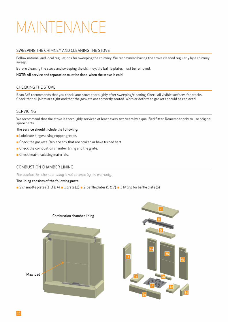
COMBUSTION CHAMBER LINING
The combustion chamber lining is not covered by the warranty.
The lining consists of the following parts:¬ 9 chamotte plates (1, 3 & 4) ¬ 1 grate (2) ¬ 2 baffle plates (5 & 7) ¬ 1 fitting for baffle plate (6)
Combustion chamber lining
Max load
4
1 2
5
3
NAVN:
STI:
DIMENSION:
MATERIALE: DATO: SIGN:
Krog Iversen & Co A/SDK-5492 Vissenbjerg©
TG.NR:EMNE:
C:\Working Folder\Designs\Scan 5003\95003026.idw
95003026Brandkammerforing
08-01-2018 ken
Scan 5003
VÆGT:
AREAL:
N/A
N/A
NAVN:
STI:
DIMENSION:
MATERIALE: DATO: SIGN:
Krog Iversen & Co A/SDK-5492 Vissenbjerg©
TG.NR:EMNE:
C:\Working Folder\Designs\Scan 5003\95003025.idw
95003025Brandkammerforing
08-01-2018 ken
Scan 5003
VÆGT:
AREAL:
N/A
N/A
NAVN:
STI:
DIMENSION:
MATERIALE: DATO: SIGN:
Krog Iversen & Co A/SDK-5492 Vissenbjerg©
TG.NR:EMNE:
C:\Working Folder\Designs\Scan 5003\95003024.idw
95003024Brandkammerforing
08-01-2018 ken
Scan 5003
VÆGT:
AREAL:
N/A
N/A
NAVN:
STI:
DIMENSION:
MATERIALE: DATO: SIGN:
Krog Iversen & Co A/SDK-5492 Vissenbjerg©
TG.NR:EMNE:
C:\Working Folder\Designs\Scan 5003\95003027.idw
95003027Brandkammerforing
08-01-2018 ken
Scan 5003
VÆGT:
AREAL:
N/A
N/ANAVN:
STI:
DIMENSION:
MATERIALE: DATO: SIGN:
Krog Iversen & Co A/SDK-5492 Vissenbjerg©
TG.NR:EMNE:
C:\Working Folder\Designs\Scan 5003\95003028.idw
95003028Brandkammerforing
08-01-2018 ken
Scan 5003
VÆGT:
AREAL:
N/A
N/A
NAVN:
STI:
DIMENSION:
MATERIALE: DATO: SIGN:
Krog Iversen & Co A/SDK-5492 Vissenbjerg©
TG.NR:EMNE:
C:\Working Folder\Designs\Scan 5003\95003029.idw
95003029Brandkammerforing
08-01-2018 ken
Scan 5003
VÆGT:
AREAL:
N/A
N/A
NAVN:
STI:
DIMENSION:
MATERIALE: DATO: SIGN:
Krog Iversen & Co A/SDK-5492 Vissenbjerg©
TG.NR:EMNE:
C:\Working Folder\Designs\Scan 5003\95003030.idw
95003030Brandkammerforing
08-01-2018 ken
Scan 5003
VÆGT:
AREAL:
N/A
N/A
2
4a4b
4c
56
7
1
3
27
GASKETS
All stoves have seals made of ceramic material fitted to the stove, the door and/or the glass. These seals are subject to wear and tear and must be replaced when necessary.
Gaskets are not covered by the warranty.
PAINTED SURFACES
Clean your built-in stove by wiping it down with a dry, lint-free cloth.
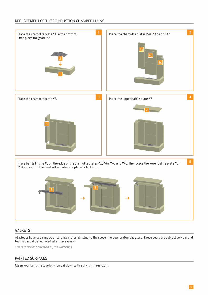
REPLACEMENT OF THE COMBUSTION CHAMBER LINING
Place the chamotte plate #3
Place baffle fitting #6 on the edge of the chamotte plates #3, #4a, #4b and #4c. Then place the lower baffle plate #5. Make sure that the two baffle plates are placed identically
Place the chamotte plate #1 in the bottom. Then place the grate #2
Place the upper baffle plate #7
Place the chamotte plates #4a, #4b and #4c
28
CLEANING THE GLASS
Our stoves are designed to prevent serious soot build-up on the glass. The best way to achieve this is to make sure you have a good supply of combustion air. It is also very important that the wood is dry and the chimney correctly dimensioned.
Even if you operate the stove in accordance with our instructions, a slight film of soot may still accumulate on the glass. You can easily remove this film by wiping the glass down with a dry cloth and then with a cloth dampened with glass cleaner. ¬ Please note that the glass cleaner is not to get into contact with the gaskets, as this can discolour the glass permanently
¬ The glass cleaner must not come into contact with the painted surfaces, as these can be damaged.
DISPOSAL OF STOVE PARTS
Steel/cast iron Send for recycling
Glass Dispose of as ceramic waste
Combustion chamber lining Vermiculite and chamotte are not recyclable. Dispose of as waste
Baffle plates Vermiculite and chamotte are not recyclable. Dispose of as waste
Gaskets Dispose of as waste
29
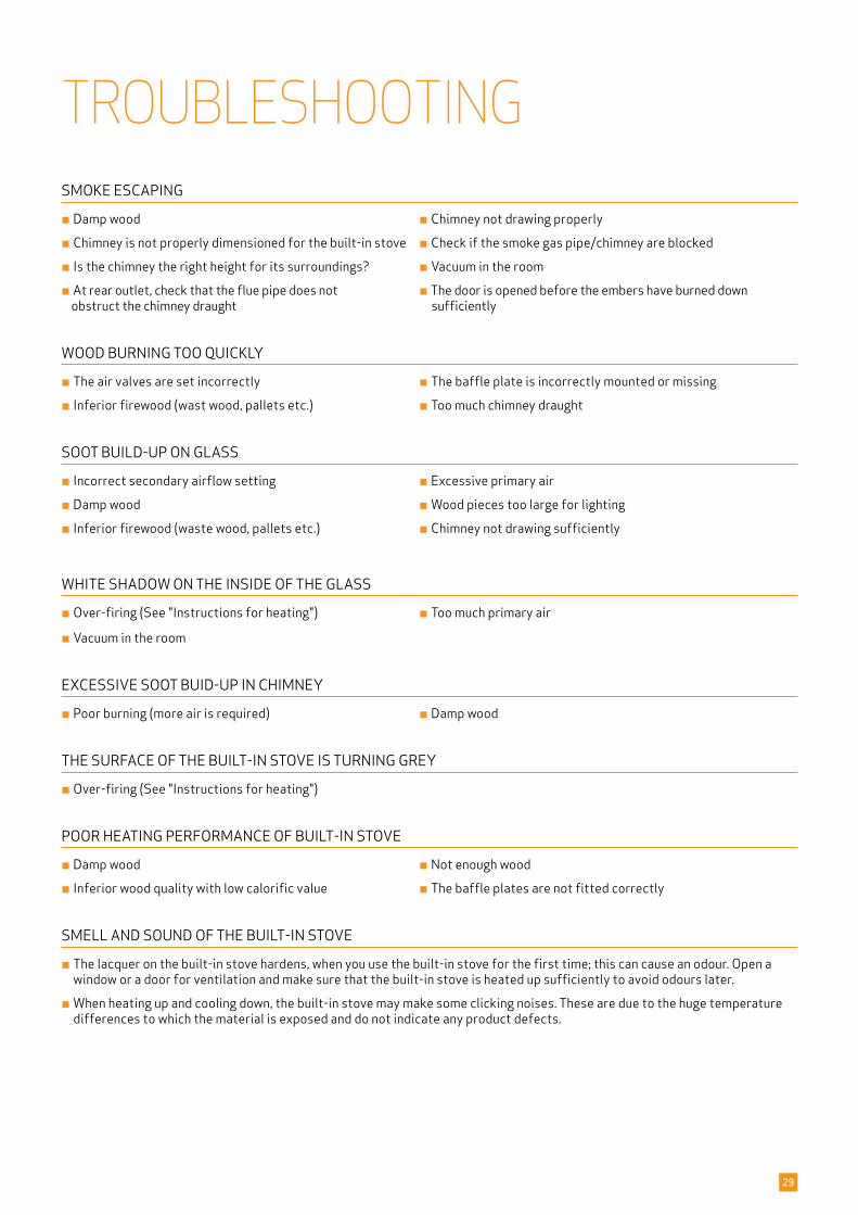
TROUBLESHOOTING SMOKE ESCAPING
¬ Damp wood ¬ Chimney not drawing properly
¬ Chimney is not properly dimensioned for the built-in stove ¬ Check if the smoke gas pipe/chimney are blocked
¬ Is the chimney the right height for its surroundings? ¬ Vacuum in the room
¬ At rear outlet, check that the flue pipe does not ¬ The door is opened before the embers have burned down obstruct the chimney draught sufficiently
WOOD BURNING TOO QUICKLY
¬ The air valves are set incorrectly ¬ The baffle plate is incorrectly mounted or missing
¬ Inferior firewood (wast wood, pallets etc.) ¬ Too much chimney draught
SOOT BUILD-UP ON GLASS
¬ Incorrect secondary airflow setting ¬ Excessive primary air
¬ Damp wood ¬ Wood pieces too large for lighting
¬ Inferior firewood (waste wood, pallets etc.) ¬ Chimney not drawing sufficiently
¬ Vacuum in the room
EXCESSIVE SOOT BUID-UP IN CHIMNEY
¬ Poor burning (more air is required) ¬ Damp wood
THE SURFACE OF THE BUILT-IN STOVE IS TURNING GREY
¬ Over-firing (See "Instructions for heating")
POOR HEATING PERFORMANCE OF BUILT-IN STOVE
¬ Damp wood ¬ Not enough wood
¬ Inferior wood quality with low calorific value ¬ The baffle plates are not fitted correctly
SMELL AND SOUND OF THE BUILT-IN STOVE
¬ The lacquer on the built-in stove hardens, when you use the built-in stove for the first time; this can cause an odour. Open a window or a door for ventilation and make sure that the built-in stove is heated up sufficiently to avoid odours later.
¬ When heating up and cooling down, the built-in stove may make some clicking noises. These are due to the huge temperature differences to which the material is exposed and do not indicate any product defects.
WHITE SHADOW ON THE INSIDE OF THE GLASS
¬ Over-firing (See "Instructions for heating") ¬ Too much primary air
30
WARRANTYAll wood-fired Scan products are made of high-quality materials and subject to strict quality controls before leaving the factory. We give a warranty of 5 years on manufacturing errors or defects.
You must quote your stove‘s product registration number when you contact us or your authorised Scan dealer with a warranty claim.
The warranty covers all parts which in the opinion of Scan A/S require repair or replacement due to manufacturing or construction error
The warranty applies to the original purchaser of the product only, and is not transferable (except on prior sale).
The warranty covers only damage caused by manufacturing or construction errors.
THE FOLLOWING PARTS ARE NOT COVERED BY THE WARRANTY
¬ Wear and tear parts, such as the combustion chamber liners, baffle plates, riddling grate, glass, and seals (except for defects which were present on delivery)
¬ Defects caused by external chemical and physical influences during transportation, storage and assembly, or at a later time
¬ Soot build-up caused by poor chimney draught, damp wood, or improper use
¬ Costs of additional heating in connection with a repair
¬ Transport costs
¬ Costs for setting up or removing the wood stove
THIS WARRANTY IS VOID
¬ In case of incorrect installation (the installer is responsible for observing and complying with legal requirements and local bylaws, along with this Assembly- and Instructionsmanual for the wood-burning stove and accessories)
¬ In case of improper use, and/or use of prohibited fuels, non-original spares (see this Assembly- and instructions manual)
¬ If the product registration number of the stove has been removed or damaged
¬ In case of repairs that do not comply with our instructions or instructions by an authorised Scan dealer
¬ In case of any manipulation of the original state of this Scan product or its accessories
¬ This warranty is only valid in the country to which this Scan product was originally supplied

31
NOTES
26.11.2021SCAN A/S | Damsbovej 1 | DK-5492 Vissenbjerg | www.scan-stoves.com
Edition: UK 95007500 10059347-P02
Product registration number
Quote this number at all enquiries


![Game Theory [FR]](https://img.dokumen.tips/doc/110x75/6321969b61d7e169b00c3b47/game-theory-fr.jpg)


