Embed Size (px)
Citation preview
2
3
4
5
6
1
FR-HC2INSTRUCTION MANUAL
INVERTER
INSTALLATION ANDWIRING
PARAMETERS
PROTECTIVE FUNCTIONS
MAINTENANCE ANDINSPECTION
SPECIFICATIONS
OUTLINE
HEAD OFFICE: TOKYO BUILDING 2-7-3, MARUNOUCHI, CHIYODA-KU, TOKYO 100-8310, JAPAN
IB(NA)-0600381ENG-J(2007)MEE Printed in Japan Specifications subject to change without notice.
INVER
TERFR
-HC
2IN
STRU
CTIO
N M
AN
UA
L
J
FR-HC2-7.5K to 75KFR-HC2-H7.5K to H560K
High power factor converter
PSCLR
REGEN
PWRP.CPY
DRIVE
MODE SET STOPRESET
MON
A-1
Thank you for choosing the Mitsubishi Electric High Power Factor Converter.This Instruction Manual gives handling information and precautions for use of this product. Incorrect handling might cause an unexpected fault. Before using the converter, please read this manual carefully to ensure proper use.Please forward this manual to the end user.
SAFETY INSTRUCTIONS1. Electric Shock Prevention
2. Fire Prevention
3.Injury Prevention
Safety InstructionsDo not attempt to install, operate, maintain or inspect the converter until you have read through this Instruction Manual and supplementary documents carefully and can use the equipment correctly. Do not use this product until you have a full knowledge of this product, safety information and instructions. In this Instruction Manual, the safety instruction levels are classified into "WARNING" and "CAUTION"
Incorrect handling may cause hazardous conditions, resulting in death or severe injury.
Incorrect handling may cause hazardous conditions, resulting in medium or slight injury, or may cause only material damage.
The level may even lead to a serious consequence according to conditions.Both instruction levels must be followed because these are important to personal safety.
While the converter power is ON, do not remove the front cover or the wiring cover. Do not run the converter with the front cover or the wiring cover removed. Doing so may access the exposed high voltage terminals or the charging part of the circuitry and cause an electric shock.
Even if power is OFF, do not remove the front cover except for wiring or periodic inspection. You may accidentally touch the charged converter and get an electric shock.
Before wiring or inspection, check that the display of the operation panel is OFF. Any person who is involved in wiring or inspection shall wait for at least 10 minutes after power OFF and check that there is no residual voltage using a tester or the like. The capacitor is charged with high voltage for some time after power OFF, and it is dangerous.
This converter must be earthed (grounded). Earthing (grounding) must conform with the requirements of national and local safety regulations and electrical code (NEC section 250, IEC 536 class 1 and other applicable standards).
Any person who is involved in wiring or inspection of this product shall be fully competent to do the work.
The product body must be installed before wiring. Otherwise you may get an electric shock or be injured.
Do not touch the setting dial or keys with wet hands. Doing so may cause an electric shock.
Do not subject the cables to scratches, excessive stress, heavy loads or pinching. Doing so may cause an electric shock.
Do not change the cooling fan while power is ON as it is dangerous.
Do not touch the printed circuit board or handle the cables with wet hands. Doing so may cause an electric shock.
WARNING
CAUTION
CAUTION
WARNING
The converter must be installed on a nonflammable wall without holes. Mounting it to or near flammable material can cause a fire.
If the converter becomes faulty, the power of the converter must be switched OFF. A continuous flow of large current could cause a fire.
Daily and periodic inspections must be performed as instructed in the Instruction Manual. There is a possibility of explosion, damage, or fire if this product is used without inspection.
The voltage applied to each terminal must be the ones specified in the Instruction Manual. Otherwise an explosion or damage may occur.
The cables must be connected to the correct terminals. Otherwise an explosion or damage may occur.
Polarity must be correct. Otherwise an explosion or damage may occur.
While power is ON or for some time after power-OFF, do not touch the converter, reactor 1, reactor 2, outside box, filter capacitor, and limit resistor as they will be extremely hot. Doing so may cause burns.
CAUTION
CAUTION
A-2
4. Additional InstructionsThe following instructions must be also followed. If the product is handled incorrectly, it may cause unexpected fault, an injury, or an electric shock. (1) Transportation and installation
(2) Trial run
(3) Usage
(4) Emergency stop
(5) Maintenance, inspection and parts replacement
(6) Disposal
(7) General instruction
Use proper lifting techniques or a trolley when carrying products. Failure to do so may lead to injuries.
Do not stack the boxes containing products higher than the number recommended.
The product must be installed on a surface that withstands the weight of the product according to the information in the Instruction Manual.
Do not install or operate the converter if it is damaged or has parts missing.
When carrying the converter, do not hold it by the front cover or setting dial; it may fall off or break.
Do not stand or place heavy objects on the product. Ensure the mounting orientation of this product is correct. Foreign conductive objects must be prevented from
entering the converter. That includes screws and metal fragments or other flammable substance such as oil.
As the converter is a precision instrument, do not drop or subject it to impact.
The product must be used under the following environment. Otherwise the converter may be damaged.
Temperature applicable for a short time, e.g. in transit. 2.9m/s2 or less for the 160K or higher. If halogens (including fluorine, chlorine, bromine, and
iodine) contained in fumigants for wood packages enter this product, the product may be damaged. Prevent the entry of fumigant residuals or use an alternative method such as heat disinfection. Note that sterilization or disinfection of wood packages should be performed before packing the product.
Before starting the operation, confirm or adjust the parameter settings. Failure to do so may cause some machines to make unexpected motions.
Before starting the operation, the wiring of each peripheral device must be checked. Faulty wiring may cause some machines to make unexpected motions.
CAUTION
Envi
ronm
ent
Surrounding air temperature -10°C to +50°C (non-freezing)
Ambient humidity 90%RH or less (non-condensing)
Storage temperature -20°C to +65°C
Atmosphere Indoors (free from corrosive gas, flammable gas, oil mist, dust and dirt)
Altitude/vibration
Maximum 1000m. 5.9m/s2 or less at 10 to 55Hz (directions of X, Y, Z axes)
CAUTION
Stay away from the equipment when the retry function is set as it will restart suddenly after a trip.
Depending on the function settings, the product does not
stop its output even when the key is pressed. To prepare for it, provide a separate circuit and switch (to turn OFF the power or to take other actions) for an emergency stop.
Be sure to turn OFF the start (STF/STR) signal before clearing the fault as this product will restart the motor suddenly after a fault is cleared.
Use only the specified inverters for the connection with the converter. Connection of any other electrical equipment to the converter output may damage the equipment.
Do not modify this product. Do not remove any part which is not instructed to be
removed in the Instruction Manuals. Doing so may lead to a failure or damage of the product.
Do not repeatedly start or stop this product with a magnetic contactor on its input side. Doing so may shorten the life of this product.
Use a noise filter or other means to minimize electromagnetic interference with other electronic equipment used nearby this product.
As all parameters return to their initial values after the Parameter clear or All parameter clear is performed, the parameters must be set again as required before the operation is started.
Perform an inspection and test operation of this product if it has been stored for a long period of time.
To avoid damage to this product due to static electricity, static electricity in your body must be discharged before you touch this product.
A safety backup such as an emergency brake must be provided for devices or equipment in a system to prevent hazardous conditions in case of failure of the high power factor converter, inverter, or an external device controlling the inverter.
If the breaker installed on the input side of this product trips, check for wiring faults (short circuits etc.) and damage to internal parts of this product. Identify and remove the cause of the trip before resetting the tripped breaker and applying the power to the product again.
When any fault occurs, take an appropriate corrective action, then reset the converter, and resume the operation.
Do not carry out a megger (insulation resistance) test on the control circuit of the converter.
The converter must be treated as industrial waste.
For clarity, illustrations in this Instruction Manual may be drawn with covers or safety guards removed. Ensure all covers and safety guards are properly installed prior to starting operation.
WARNING
CAUTION
CAUTION
CAUTION
CAUTION
I
CO
NT
EN
TS
1 OUTLINE 1
1.1 Pre-operation instructions ..................................................................21.1.1 Features of FR-HC2 (high power factor converter) ........................................................................ 21.1.2 Japanese harmonic suppression guideline .................................................................................... 21.1.3 Product checking and parts identification ....................................................................................... 6
1.2 Converter and peripheral devices.......................................................8
1.3 Precautions for selecting peripheral devices ....................................91.3.1 Measures against noises (EMI) ...................................................................................................... 91.3.2 Peripheral device list .................................................................................................................... 151.3.3 Selecting the rated sensitivity current for the earth leakage circuit breaker ................................. 18
2 INSTALLATION AND WIRING 21
2.1 Removal and installation of the converter (FR-HC2) front cover.....22
2.2 Removal and installation of the outside box (FR-HCB2) front cover ..................................................................................................24
2.3 Installation.........................................................................................252.3.1 Converter placement .................................................................................................................... 25
2.4 Protruding the heat sink....................................................................272.4.1 When using a heat sink protrusion attachment (FR-A7CN) ......................................................... 272.4.2 Heat sink protrusion for 160K or higher........................................................................................ 27
2.5 Installation of peripheral devices .....................................................292.5.1 Installation of reactor 1 and reactor 2 ........................................................................................... 292.5.2 Installation of the outside box (FR-HCB2-7.5K to 75K, FR-HCB2-H7.5K to H220K) ................... 302.5.3 Installation of filter capacitor (FR-HCC2-H280K to H560K).......................................................... 312.5.4 Installation of inrush current limit resistor (FR-HCR2-H280K to H560K)...................................... 312.5.5 Installation of MC power supply stepdown transformer (FR-HCM2-H280K to H560K) ................ 32
2.6 Main circuit terminal specifications.................................................332.6.1 Description of main circuit terminal............................................................................................... 332.6.2 Terminal arrangement of the main circuit terminal ....................................................................... 342.6.3 Cable sizes of the main control circuit terminals and earth (ground) terminals ........................... 37
2.7 Wiring of main circuit (FR-HC2-7.5K to 75K, FR-HC2-H7.5K to H220K)...............................40
2.7.1 Connection diagram (when using with the FR-A800 series) ........................................................ 402.7.2 Wiring of main circuit .................................................................................................................... 41
2.8 Wiring of main circuit (FR-HC2-H280K).............................................472.8.1 Connection diagram (when using with the FR-A800 series) ........................................................ 472.8.2 Wiring of main circuit .................................................................................................................... 49
2.9 Wiring of main circuit (FR-HC2-H400K, H560K)................................53
CONTENTS

II
2.9.1 Connection diagram (when using with the FR-A800 series)......................................................... 532.9.2 Wiring of main circuit .................................................................................................................... 54
2.10 Notes on earthing (grounding).......................................................... 59
2.11 Compatible inverter for the high power factor converter................ 602.11.1 Applicable inverter capacity .......................................................................................................... 602.11.2 Inverter parameter settings........................................................................................................... 61
2.12 Wiring of several inverters to one converter ................................... 62
2.13 Wiring of control circuit .................................................................... 642.13.1 Description of control circuit terminal............................................................................................ 642.13.2 Changing the control logic ............................................................................................................ 672.13.3 Control circuit terminal layout ....................................................................................................... 692.13.4 Wiring instructions ........................................................................................................................ 702.13.5 When connecting the operation panel or parameter unit using a connection cable ..................... 712.13.6 Communication operation (computer link operation) .................................................................... 71
3 PARAMETERS 73
3.1 Operation panel (FR-DU07-CNV)....................................................... 743.1.1 Names and functions of the operation panel (FR-DU07-CNV)..................................................... 743.1.2 Basic operation (factory setting) ................................................................................................... 753.1.3 Changing the parameter setting value.......................................................................................... 76
3.2 Parameter unit (FR-PU07), parameter unit with battery pack (FR-PU07BB(-L)) ......................... 77
3.2.1 Parts identification of the parameter unit ...................................................................................... 773.2.2 Explanation of keys....................................................................................................................... 773.2.3 Monitoring function ....................................................................................................................... 783.2.4 Function menu.............................................................................................................................. 79
3.3 Parameter list ................................................................................... 81
3.4 Description of parameters ................................................................ 833.4.1 Displaying and hiding extended parameters (Pr. 0)..................................................................... 833.4.2 Input frequency to converter (Pr. 1, Pr. 2) ................................................................................... 833.4.3 Input terminal function selection (Pr. 3 to Pr. 7)........................................................................... 843.4.4 Operation selection of SOF signal and OH signal (Pr. 8, Pr. 9)................................................... 853.4.5 Output terminal function selection (Pr. 10 to Pr. 16).................................................................... 863.4.6 DC voltage control (Pr. 22 to Pr. 24, Pr. 80, Pr. 81) .................................................................... 873.4.7 Input current detection function (Y12 signal, Y13 signal, Pr. 25 to Pr. 30) .................................. 883.4.8 Displaying the life of the converter parts (Pr. 31 to Pr. 33) .......................................................... 893.4.9 Maintenance timer alarm (Pr. 34, Pr. 35)..................................................................................... 903.4.10 Cooling fan operation selection (Pr. 36) ...................................................................................... 913.4.11 Instantaneous power failure detection hold (Pr. 44) .................................................................... 913.4.12 Reference of the terminal FM (pulse train output) and terminal AM (analog output) (Pr. 45, Pr. 49,
Pr. 51, Pr. 53, Pr. 55, Pr. 56) ....................................................................................................... 92
III
CO
NT
EN
TS
3.4.13 DU/PU, terminal FM/AM monitor display selection (Pr. 46 to Pr. 48, Pr. 50, Pr. 52, Pr. 54) ....... 943.4.14 Operation selection at instantaneous power failure (Pr. 57)........................................................ 973.4.15 Free parameter (Pr. 58, Pr. 59) ................................................................................................... 983.4.16 Key lock selection of operation panel (Pr. 61) ............................................................................. 983.4.17 Retry function (Pr. 65, Pr. 67 to Pr. 69) ....................................................................................... 993.4.18 Reset selection/disconnected PU detection/PU stop selection (Pr. 75) .................................... 1003.4.19 Parameter write disable selection (Pr. 77)................................................................................. 1023.4.20 Current control (Pr. 82, Pr. 83) .................................................................................................. 1033.4.21 Wiring and configuration of PU connector ................................................................................. 1033.4.22 Initial settings and specifications of RS-485 communication (Pr. 117 to Pr. 124) ..................... 1053.4.23 Mitsubishi inverter protocol (computer link communication) ...................................................... 1063.4.24 Initial setting and specification for the CC-Link communication function (Pr. 542 to Pr. 544) ... 1173.4.25 Operation at a communication error (Pr. 500 to Pr. 502) .......................................................... 1233.4.26 Communication EEPROM write selection (Pr. 342) .................................................................. 1243.4.27 Setting of the parameter unit and operation panel (Pr. 145, Pr. 990, Pr. 991) .......................... 1253.4.28 Terminal FM and AM calibration (calibration parameter C0 (Pr. 900), C1 (Pr. 901)) ................ 126
3.5 Parameter clear / All parameter clear ............................................128
3.6 Parameter copy and parameter verification...................................129
4 PROTECTIVE FUNCTIONS 131
4.1 Troubleshooting...............................................................................132
4.2 Reset method of protective function..............................................132
4.3 List of fault and alarm indications..................................................133
4.4 Causes and corrective actions .......................................................134
4.5 Digital characters and their corresponding printed equivalents...141
4.6 Check and clear of the fault history ...............................................142
4.7 Check first when you have a trouble ..............................................144
5 MAINTENANCE AND INSPECTION 145
5.1 Inspection items..............................................................................1465.1.1 Daily inspection .......................................................................................................................... 1465.1.2 Periodic inspection ..................................................................................................................... 1465.1.3 Daily and periodic inspection list ................................................................................................ 1475.1.4 Checking the converter module.................................................................................................. 1485.1.5 Cleaning ..................................................................................................................................... 1485.1.6 Replacement of parts ................................................................................................................. 149
5.2 Measurement of main circuit voltages, currents and powers .......1535.2.1 Insulation resistance test using megger ..................................................................................... 1545.2.2 Pressure test .............................................................................................................................. 154

IV
6 SPECIFICATIONS 155
6.1 Rated specifications....................................................................... 156
6.2 Common specifications .................................................................. 157
6.3 Outline dimensions ......................................................................... 1586.3.1 Converter (FR-HC2) ................................................................................................................... 1586.3.2 Reactor 1 (FR-HCL21)................................................................................................................ 1656.3.3 Reactor 2 (FR-HCL22)................................................................................................................ 1736.3.4 Difference between the reactor 1 (FR-HCL21) and the reactor 2 (FR-HCL22). ......................... 1806.3.5 Outside box (FR-HCB2)............................................................................................................. 1806.3.6 Filter capacitor (FR-HCC2) ........................................................................................................ 1886.3.7 FR-HCM2................................................................................................................................... 1906.3.8 Inrush current limit resistor (FR-HCR2) ..................................................................................... 1946.3.9 Parameter unit ............................................................................................................................ 195
APPENDICES 197
Appendix 1 Instruction code list .................................................................................. 198
Appendix 2 Instructions for compliance with the EU Directives .............................. 199
Appendix 3 Instructions for UL and cUL..................................................................... 201
Appendix 4 Instructions for EAC ................................................................................. 205
Appendix 5 Restricted Use of Hazardous Substances in Electronic and Electrical Products..................................................................................................... 206
Appendix 6 Referenced Standard (Requirement of Chinese standardized law) ..... 206
1
2
3
4
5
6
1
1 OUTLINE
This chapter explains the "OUTLINE" for use of this product.Always read the instructions before using the equipment.
1.1 Pre-operation instructions ........................................................... 21.2 Converter and peripheral devices ............................................... 81.3 Precautions for selecting peripheral devices ............................ 9
<Abbreviations>PU .................................Operation panel or option parameter unit (FR-PU07/FR-PU07BB)FR-PU07 .......................Option parameter unit (FR-PU07/FR-PU07BB)Converter ......................FR-HC2 series high power factor converterFR-HC2 .........................FR-HC2 series high power factor converterPr. ..................................Parameter number (Number assigned to function)
<Trademarks> Microsoft and Visual C++ are registered trademarks of Microsoft Corporation in the United States
and other countries. Other company and product names herein are the trademarks and registered trademarks of their
respective owners.
<Notes on descriptions in this Instruction Manual> Connection diagrams in this Instruction Manual suppose that the control logic of the input
terminal is the sink logic, unless otherwise specified. (For the control logic, refer to page 67.)
<Marks>
REMARKS: Additional helpful contents and relations with other functions are written.
Note: Contents requiring caution or cases when set functions are not activated are written.
POINT: Useful contents and points are written.
: Content and description of an alarm or fault are written.
2
Pre-operation instructions
1.1 Pre-operation instructions
Incorrect handling may cause the equipment to operate improperly, its life to be reduced considerably, and in the worst case,the converter and inverter to be damaged. Please handle the unit properly in accordance with the information on each sectionas well as the precautions and instructions of this manual.
1.1.1 Features of FR-HC2 (high power factor converter)
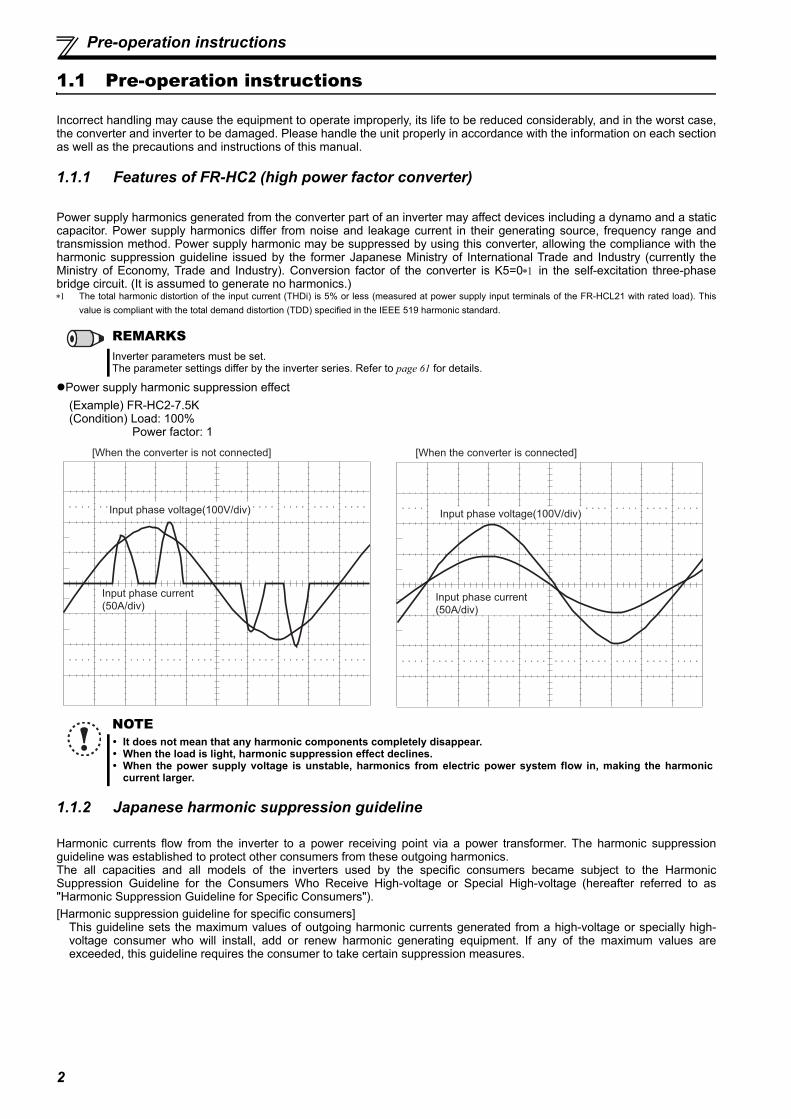
Power supply harmonics generated from the converter part of an inverter may affect devices including a dynamo and a staticcapacitor. Power supply harmonics differ from noise and leakage current in their generating source, frequency range andtransmission method. Power supply harmonic may be suppressed by using this converter, allowing the compliance with theharmonic suppression guideline issued by the former Japanese Ministry of International Trade and Industry (currently theMinistry of Economy, Trade and Industry). Conversion factor of the converter is K5=0 in the self-excitation three-phasebridge circuit. (It is assumed to generate no harmonics.) The total harmonic distortion of the input current (THDi) is 5% or less (measured at power supply input terminals of the FR-HCL21 with rated load). This
value is compliant with the total demand distortion (TDD) specified in the IEEE 519 harmonic standard.
Power supply harmonic suppression effect(Example) FR-HC2-7.5K(Condition) Load: 100% Power factor: 1
1.1.2 Japanese harmonic suppression guideline
Harmonic currents flow from the inverter to a power receiving point via a power transformer. The harmonic suppressionguideline was established to protect other consumers from these outgoing harmonics.The all capacities and all models of the inverters used by the specific consumers became subject to the HarmonicSuppression Guideline for the Consumers Who Receive High-voltage or Special High-voltage (hereafter referred to as"Harmonic Suppression Guideline for Specific Consumers"). [Harmonic suppression guideline for specific consumers]
This guideline sets the maximum values of outgoing harmonic currents generated from a high-voltage or specially high-voltage consumer who will install, add or renew harmonic generating equipment. If any of the maximum values areexceeded, this guideline requires the consumer to take certain suppression measures.
REMARKSInverter parameters must be set.The parameter settings differ by the inverter series. Refer to page 61 for details.
NOTE It does not mean that any harmonic components completely disappear. When the load is light, harmonic suppression effect declines. When the power supply voltage is unstable, harmonics from electric power system flow in, making the harmonic
current larger.
Input phase voltage(100V/div)
Input phase current
(50A/div)
[When the converter is not connected]
Input phase voltage(100V/div)
Input phase current
(50A/div)
[When the converter is connected]

3
1
OU
TLIN
E
Pre-operation instructions
(1) Application of the Harmonic Suppression Guideline for Specific Consumers
Table 2 Conversion Factors
The total harmonic distortion of the input current (THDi) is 5% or less (measured at power supply input terminals of the FR-HCL21 with rated load). Thisvalue is compliant with the total demand distortion (TDD) specified in the IEEE 519 harmonic standard.
Table 3 Equivalent Capacity Limits
Table 4 Harmonic Content (Values at the fundamental current of 100%)
Table 1 Maximum outgoing harmonic current per 1kW contract
Received Power Voltage 5th 7th 11th 13th 17th 19th 23rd Over 23rd
6.6kV 3.5 2.5 1.6 1.3 1.0 0.9 0.76 0.7022kV 1.8 1.3 0.82 0.69 0.53 0.47 0.39 0.3633kV 1.2 0.86 0.55 0.46 0.35 0.32 0.26 0.24
Classification Circuit Type Conversion Factor Ki
1 Three-phase bridge6-pulse converter K11=112-pulse converter K12=0.524-pulse converter K13=0.25
3 Three-phase bridge(Capacitor smoothed)
Without a reactor K31=3.4With a reactor (on AC side) K32=1.8With a reactor (on DC side) K33=1.8Without a reactor (on AC/DC side) K34=1.4
4
Single-phase bridge (smoothing capacitor, double voltage rectification)
Without a reactor K41=2.3With a reactor (on AC side) K42=0.35
Single-phase bridge (smoothing capacitor, full-wave rectification)
Without a reactor K43=2.9With a reactor (on AC side) K44=1.3
5 Self-excitation three-phase bridge With the converter K5=0
Received Power Voltage
Reference Capacity
6.6kV 50kVA22/33kV 300kVA
66kV or more 2000kVA
Reactor 5th 7th 11th 13th 17th 19th 23rd 25thNot used 65 41 8.5 7.7 4.3 3.1 2.6 1.8Used (AC side) 38 14.5 7.4 3.4 3.2 1.9 1.7 1.3Used (DC side) 30 13 8.4 5.0 4.7 3.2 3.0 2.2Used (on AC/DC side) 28 9.1 7.2 4.1 3.2 2.4 1.6 1.4
Install, add or renew
equipment
Calculation of equivalent
capacity total
Equivalent capacity total
Calculation of outgoing
harmonic current
Not more than harmonic current upper
limit?
Harmonic suppression
measures unnecessary
Harmonic suppression
measures necessaryEqual to or less than upper limit
More than upper limit
Above reference
capacity
Equal to or less than reference capacity

4
Pre-operation instructions
(a) Calculation of equivalent capacity P0 of harmonic generating equipmentThe "equivalent capacity" is the capacity of a 6-pulse converter converted from the capacity of a consumer's harmonicgenerating equipment and is calculated with the following equation. When the sum of equivalent capacity exceeds the limitsin Table 3, harmonics must be calculated in the following procedure.
(b) Calculation of outgoing harmonic currentOutgoing harmonic current=fundamental wave current (value converted from received power voltage) operation ratio harmonic content Operation ratio: Operation ratio = actual load factor operation time ratio during 30 minutesHarmonic content: Found in Table 4.
(c) Deciding whether to take harmonic suppression measures When the outgoing harmonic current > the maximum value per 1kW contract contract kW, a harmonic suppressionmeasures are required.
P0 = (Ki Pi) [kVA] Rated capacity: Rated capacity is determined by the capacity of the appliedmotor and found in Table 5. It should be noted that the rated capacity used hereis used to calculate generated harmonic amount and is different from the powersupply capacity required for actual inverter drive.
Ki: Conversion factor(According to Table 2)Pi: Rated capacity of harmonic generating equipment [kVA]i : Number indicating the conversion circuit type
Table 5 Rated Capacity and Outgoing Harmonic Current during Inverter Run
AppliedMotor (kW)
Rated Current [A]
Fundamental Wave Current
Converted from 6.6kV (mA)
Rated Capacity
(kVA)
Harmonic Current Converted from 6.6kV (mA)(No reactor, 100% operation ratio)
200V 400V 5th 7th 11th 13th 17th 19th 23rd 25th
0.4 1.61 0.81 49 0.57 31.85 20.09 4.165 3.773 2.107 1.519 1.274 0.8820.75 2.74 1.37 83 0.97 53.95 34.03 7.055 6.391 3.569 2.573 2.158 1.4941.5 5.50 2.75 167 1.95 108.6 68.47 14.20 12.86 7.181 5.177 4.342 3.0062.2 7.93 3.96 240 2.81 156.0 98.40 20.40 18.48 10.32 7.440 6.240 4.3203.7 13.0 6.50 394 4.61 257.1 161.5 33.49 30.34 16.94 12.21 10.24 7.0925.5 19.1 9.55 579 6.77 376.1 237.4 49.22 44.58 24.90 17.95 15.05 10.427.5 25.6 12.8 776 9.07 504.4 318.2 65.96 59.75 33.37 24.06 20.18 13.9711 36.9 18.5 1121 13.1 728.7 459.6 95.29 86.32 48.20 34.75 29.15 20.1815 49.8 24.9 1509 17.6 980.9 618.7 128.3 116.2 64.89 46.78 39.24 27.16
18.5 61.4 30.7 1860 21.8 1209 762.6 158.1 143.2 79.98 57.66 48.36 33.4822 73.1 36.6 2220 25.9 1443 910.2 188.7 170.9 95.46 68.82 57.72 39.9630 98.0 49.0 2970 34.7 1931 1218 252.5 228.7 127.7 92.07 77.22 53.4637 121 60.4 3660 42.8 2379 1501 311.1 281.8 157.4 113.5 95.16 65.8845 147 73.5 4450 52.1 2893 1825 378.3 342.7 191.4 138.0 115.7 80.1055 180 89.9 5450 63.7 3543 2235 463.3 419.7 234.4 169.0 141.7 98.10
AppliedMotor (kW)
Rated Current [A]
Fundamental Wave Current
Converted from 6.6kV (mA)
Rated Capacity
(kVA)
Harmonic Current Converted from 6.6kV (mA)(With a DC reactor, 100% operation ratio)
200V 400V 5th 7th 11th 13th 17th 19th 23rd 25th
75 245 123 7455 87.2 2237 969 626 373 350 239 224 16490 293 147 8909 104 2673 1158 748 445 419 285 267 196110 357 179 10848 127 3254 1410 911 542 510 347 325 239132 216 13091 153 3927 1702 1100 655 615 419 393 288160 258 15636 183 4691 2033 1313 782 735 500 469 344220 355 21515 252 6455 2797 1807 1076 1011 688 645 473250 403 24424 286 7327 3175 2052 1221 1148 782 733 537280 450 27273 319 8182 3545 2291 1364 1282 873 818 600315 506 30667 359 9200 3987 2576 1533 1441 981 920 675355 571 34606 405 10382 4499 2907 1730 1627 1107 1038 761400 643 38970 456 11691 5066 3274 1949 1832 1247 1169 857450 723 43818 512 13146 5696 3681 2191 2060 1402 1315 964500 804 48727 570 14618 6335 4093 2436 2290 1559 1462 1072560 900 54545 638 16364 7091 4582 2727 2564 1746 1636 1200
5
1
OU
TLIN
E
Pre-operation instructions
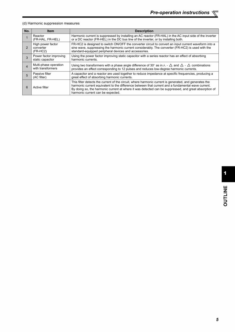
(d) Harmonic suppression measures
No. Item Description
1 Reactor(FR-HAL, FR-HEL)
Harmonic current is suppressed by installing an AC reactor (FR-HAL) in the AC input side of the inverter or a DC reactor (FR-HEL) in the DC bus line of the inverter, or by installing both.
2High power factor converter(FR-HC2)
FR-HC2 is designed to switch ON/OFF the converter circuit to convert an input current waveform into a sine wave, suppressing the harmonic current considerably. The converter (FR-HC2) is used with the standard-equipped peripheral devices and accessories.
3 Power factor improving static capacitor
Using the power factor improving static capacitor with a series reactor has an effect of absorbing harmonic currents.
4 Multi-phase operation with transformers
Using two transformers with a phase angle difference of 30 as in - and - combinations provides an effect corresponding to 12 pulses and reduces low-degree harmonic currents.
5 Passive filter(AC filter)
A capacitor and a reactor are used together to reduce impedance at specific frequencies, producing a great effect of absorbing harmonic currents.
6 Active filterThis filter detects the current of the circuit, where harmonic current is generated, and generates the harmonic current equivalent to the difference between that current and a fundamental wave current. By doing so, the harmonic current at where it was detected can be suppressed, and great absorption of harmonic current can be expected.

6
Pre-operation instructions
1.1.3 Product checking and parts identification
Unpack the product and check the capacity plate on the front cover and the rating plate on the side to ensure that the modeland rated output agree with your order and the product is intact.When combined with a Mitsubishi Electric general-purpose inverter and other converter accessories, this convertersuppresses harmonics according to the harmonic suppression guideline of the former Japanese Ministry of InternationalTrade and Industry (currently the Ministry of Economy, Trade and Industry). Carefully check the specifications including theapplicable capacities. High power factor converter model
Symbol Voltage class
H 400V classNone 200V class Represents the inverter capacity [kW]
FR-HC2- 7.5 K
Converter capacity
Capacity plate Rating plate
Operation panel(FR-DU07-CNV)
Front cover
PU connector
Control circuit terminal block
Main circuit terminal block
Charge lampLit when power is suppliedto the main circuit
Dedicated circuit board for HC2
Power lampLit when the control circuit(R1/L11, S1/L21) is suppliedwith power.
Cooling fan
Alarm lampLit when the converter is in fault.
Connector for plug-in option connection(Refer to the Instruction Manual of options.)
PSCLR
REGEN
PWRP.CPY
DRIVE
MODE SET STOPRESET
MON
FR-HC2-7.5K
Combed shaped wiring cover
Capacity plate
Converter model name Serial number
Rating plateConverter model name
Applicable inverter capacityInput rating
Rated output
Serial number
Country of origin
FR-HC2-7.5K
(Refer to page 149.)
(Refer to page 65.)
(Refer to page 64.)
(Refer to page 34.)
(Refer to page 22.)
(Refer to page 33.)
(Refer to page 74.)

7
1
OU
TLIN
E
Pre-operation instructions
Checking peripheral devices Peripheral devices
Always install the included peripheral devices. Check the model name of the each peripheral device.For the 400V class peripheral devices, H is indicated in front of the model name.
FR-HC2-7.5K to 75K, FR-HC2-H7.5K to H220K
Terminal screws are enclosed for FR-HCB2-7.5K, 15K, FR-HCB2-H7.5K to H30K. (M5 6)
FR-HC2-H280K to H560K
Instruction Manual
If you have any inquiry, or if damage is found on the product, please contact your sales representative.
Peripheral Device Model Name
Description Quantity
FR-HC2-(H)K High power factor converter 1FR-HCL21-(H)K Filter reactor 1 1FR-HCL22-(H)K Filter reactor 2 1FR-HCB2-(H)K Outside box 1
Peripheral Device Model
NameModel Name of Consisting Parts Description
Quantity
280K 400K 560K
FR-HC2-HK FR-HC2-HK High power factor converter 1 1 1FR-HCL21-HK FR-HCL21-HK Filter reactor 1 1 1 1FR-HCL22-HK FR-HCL22-HK Filter reactor 2 1 1 1
FR-HCC2-HKFR-HCC2-HK Filter capacitor 1 2 3MDA-1 filter capacitor alarm detector — 2 3
FR-HCR2-HK0.96OHM BKO-CA1996H21 Inrush current limit resistor (without thermostat) 8 15 150.96OHM BKO-CA1996H31 Inrush current limit resistor (with thermostat) 1 3 3
FR-HCM2-HK
1PH 630VA BKO-CA2001H06MC power supply stepdown transformer (400V-200V)
1 1 1
S-N400FXYS AC200V 2A2B Inrush current limit MC — 3 3S-N600FXYS AC210V 2A2B Inrush current limit MC 1 — —SR-N4FX AC210V 4A or SR-T5FX AC190V 5A
Buffer relay 1 2 2
TS-807BXC-5P Terminal block 6 — —C152C481H21 Terminal block shorting conductor 6 — —C152C423H21 MC shorting conductor — 6 6MYQ4Z AC200/220 Mini relay for filter capacitor alarm detector — 1 1PYF14T Mini relay terminal block — 1 1PYC-A1 Mini relay clip — 2 2M1250 ZENNEJI MC shorting conductor bolt (M12 50) — 24 24M12 MC shorting conductor nut (M12) — 24 24MIGAKI 12 MC shorting conductor washer (flat washer) — 48 48BANE 12 MC shorting conductor washer (spring washer) — 24 24SW-PW-P-NA M5 12 Inrush current limit resistor screw (M5 12) — 54 54
Fan cover fixing screws (7.5K, 15K)Use the screws to tighten the fan cover so thatthe cover will not open easily.
Eyebolt for hanging the converter (30K to 75K (200V class), 30K to 110K and 280K (400V class))
Model Screw Size (mm) QuantityFR-HC2-7.5KFR-HC2-H7.5K, H15K
M4 40 2
FR-HC2-15K M4 50 1
Model Eyebolt Size QuantityFR-HC2-30K, 55KFR-HC2-H30K to H75K
M8 2
FR-HC2-75KFR-HC2-H110K
M10 2
FR-HC2-H280K M12 2
8
Converter and peripheral devices
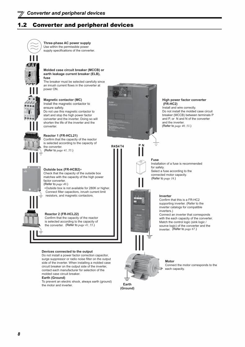
1.2 Converter and peripheral devices
Earth(Ground)
Three-phase AC power supplyUse within the permissible power supply specifications of the converter.
High power factor converter (FR-HC2)Install and wire correctly. Do not install the molded case circuit breaker (MCCB) between terminals P and P, or N and N of the converter and the inverter.
InverterConfirm that this is a FR-HC2 supporting inverter. (Refer to the inverter catalogs for compatible inverters.)Connect an inverter that corresponds with the each capacity of the converter.Match the control logic (sink logic / source logic) of the converter and the inverter.
MotorConnect the motor corresponds to the each capacity.
Magnetic contactor (MC)Install the magnetic contactor to ensure safety.Do not use this magnetic contactor to start and stop the high power factor converter and the inverter. Doing so will shorten the life of the inverter and the converter.
Molded case circuit breaker (MCCB) or earth leakage current breaker (ELB), fuseThe breaker must be selected carefully since an inrush current flows in the converter at power ON.
Reactor 1 (FR-HCL21)Confirm that the capacity of the reactor is selected according to the capacity of the converter.
Reactor 2 (FR-HCL22)Confirm that the capacity of the reactor is selected according to the capacity of the converter.
R4S4T4
Devices connected to the outputDo not install a power factor correction capacitor, surge suppressor or radio noise filter on the output side of the inverter. When installing a molded case circuit breaker on the output side of the inverter, contact each manufacturer for selection of the molded case circuit breaker.Earth (Ground)To prevent an electric shock, always earth (ground) the motor and inverter.
P N
FuseInstallation of a fuse is recommended for safety. Select a fuse according to the connected motor capacity.
Outside box (FR-HCB2)∗Check that the capacity of the outside box matches with the capacity of the high power factor converter.
∗Outside box is not available for 280K or higher. Connect filter capacitors, inrush current limit resistors, and magnetic contactors.
(Refer to page 41, 55.)
(Refer to page 41, 55.)
(Refer to page 40, 53.)
(Refer to page 67.)
(Refer to page 40.)
(Refer to page 16.)
9
1
OU
TLIN
E
Precautions for selecting peripheral devices
1.3 Precautions for selecting peripheral devices
1.3.1 Measures against noises (EMI)
In this section, noises indicate those of more than 40th to 50th high frequencies in a power distribution system, whichgenerally assume irregular conditions.Some noises enter the converter to adversely affect it, and others are radiated by the converter to adversely affect peripheraldevices. Though the converter is designed to be immune to noises, it handles low-level signals, so it requires the followingbasic measures. Also, since the converter chops input voltage at high carrier frequency, it could generate noises. Using theconverter with inverters generates more noise than using only inverters. If these noises affect peripheral devices, measuresshould be taken to suppress noises (EMI measures). The EMI measures differ slightly depending on the noise transmissionpaths.
(1) Basic measuresDo not place the power cables (I/O cables) and signal cables of the converter in parallel with each other and do not
bundle them. For the control signal cable and the connection cable with a detector, use twisted pair shield cables, and connect the
sheath of the shielded cables to the terminal SD. Ground (earth) the reactor 1, reactor 2, outside box, converter, etc. at one point. (Refer to page 59.)Provide recommended noise filters for the converter (refer to page 13). The noise filter is effective against the noises
that enter the converter and the noises that are radiated from the converter.Do not earth (ground) the shields of the communication or control cables of the converter or inverter.
(2) Measures against noises which enter and affect the converterWhen devices, which generate many noises, (for example, magnetic contactors, magnetic brakes, many relays) areinstalled near the converter, the converter may malfunction because of the noises. In that case, the following measuresmust be taken. Provide surge suppressors for the devices that generate many noises, and suppress the noises. Install data line filters to signal cables. Ground (earth) the connection cable with a detector and a control signal cable with a metal cable clamp.
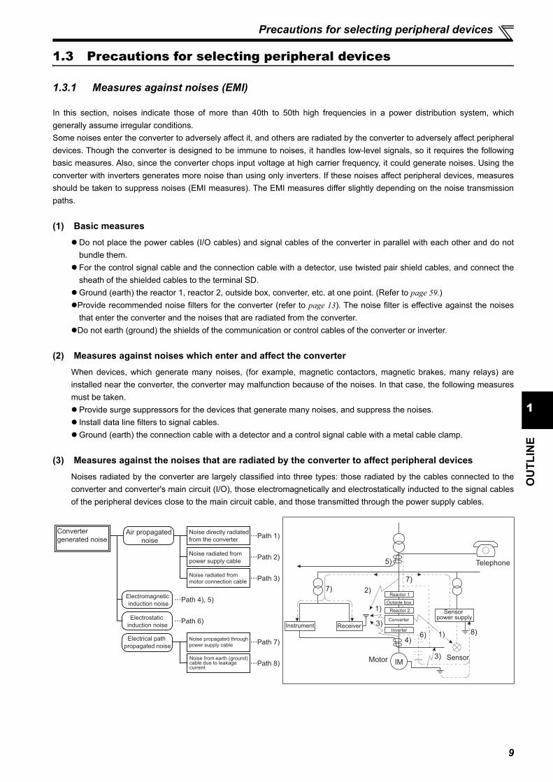
(3) Measures against the noises that are radiated by the converter to affect peripheral devicesNoises radiated by the converter are largely classified into three types: those radiated by the cables connected to theconverter and converter's main circuit (I/O), those electromagnetically and electrostatically inducted to the signal cablesof the peripheral devices close to the main circuit cable, and those transmitted through the power supply cables.
Noise propagated through
power supply cable
Path 3)
Path 2)
Path 1)Noise directly radiated
from the converter
Path 4), 5)
Air propagated
noise
Path 6)
Electrical path
propagated noise
Path 8)
Path 7)
Converter
generated noise
Electromagnetic
induction noise
Electrostatic
induction noise
Noise radiated from
power supply cable
Noise radiated from motor connection cable
Noise from earth (ground)cable due to leakagecurrent
Inverter
Converter
Reactor 2
Reactor 1
Outside box
Instrument Receiver
IMMotor
Telephone
Sensor
1)
2)
3)
3)
8)
7)
5)
7)
4)6) 1)
Sensor power supply

10
Precautions for selecting peripheral devices
The RC5128 reactor core is manufactured by Soshin Electric Co., Ltd. and available on the market.
The FINEMET® FT-3KM F/ FT-3KL F series common mode choke core is manufactured by Hitachi Metals, Ltd. and available on the market.FINEMET is a registered trademark of Hitachi Metals, Ltd.
EMC measures
Recommended noise filter (Refer to page 13.)
Line noise filters (FR-BLF, or non-Mitsubishi Electric product RC5128 or FINEMET® FT-3KM F series) (Refer to page 13.)
Noise Transmission Path
Measures
1) 2) 3)
When the devices, which handle low-level signals and are susceptible to noises (such as measuring instruments, receivers and sensors), are installed near or in the same enclosure with the converter, or their signal cables are placed near of in the same enclosure with the converter, the devices may malfunction due to air-propagated electromagnetic noises. In that case, following measures must be taken.(1) Install the easily affected devices as far away from the converter and inverter as possible.(2) Place the easily affected signal cables as far away from the converter and inverter as possible.(3) Do not place the signal cables and power cables (converter I/O cables) in parallel with each other and do
not bundle them.(4) Install the recommended noise filters (refer to page 13) or the radio noise filters (FR-BIF) on the input side of
the converter, and install the line noise filters (FR-BLF, or non-Mitsubishi Electric product RC5128 or
FINEMET® FT-3KM F/ FT-3KL F series) on the output side of the inverter to suppress radiated noises from the cables.
(5) Use shield cables for signal cables and power cables and place them in individual metal conduits to produce further effects.
4) 5) 6)
When the signal cables are placed in parallel with or bundled with the power cables, magnetic and static induction noises may be transmitted to the signal cables which causes the devices to malfunction. In that case, the following measures must be taken.(1) Install the easily affected devices as far away from the converter and inverter as possible.(2) Place the easily affected signal cables as far away from the converter, inverter, and their I/O cables as
possible.(3) Do not place the signal cables and power cables ( I/O cables of the converter and inverter) in parallel with
each other and do not bundle them.(4) Use shield cables for signal cables and power cables and place them in individual metal conduits to
produce further effects.
7)
When the peripheral devices use the power system of the converter, converter-generated noises may flow back through the power supply cable to the devices, causing malfunction of the devices. In that case, the following measures must be taken.(1) Install the recommended noise filter on the power input cables of the converter.
(2) Install the line noise filters (FR-BLF, or non-Mitsubishi Electric product RC5128 or FINEMET® FT-3KM F/ FT-3KL F series) to the power output cables of the inverter.
8)When a closed loop circuit is configured by connecting the wiring of a peripheral device to the converter, leakage current may flow through the ground (earth) cable of the converter, causing malfunction of the device. In that case, disconnecting the ground (earth) cable of the device may remove the malfunction.
Sensor
Use 4-core cable for motor power cable and use one cable as earth (ground) cable.
Use a shielded twisted pair cable
Power supply
Control power supply
Do not earth (ground) shieldbut connect it to signal common cable.
Enclosure Decrease carrierfrequency
MotorM
Do not earth (ground)enclosure directlyDo not earth (ground)control cable
Separate the inverter andpower line by more than30cm (at least 10cm) fromsensor circuit.
Powersupply
for sensor
∗1 ∗2
Inve
rter
Con
verte
r
Rea
ctor
2
Rea
ctor
1O
utsi
de b
ox
FR-BIF
Refer to page 59 for earthing (grounding) the high power factor converter and accessories.

11
1
OU
TLIN
E
Precautions for selecting peripheral devices
(4) Using options to suppress noisesBy using the radio noise filters (FR-BIF), the line noise filters (FR-BLF), and the recommended noise filters, the noiseradiated from the connection cable can be suppressed. Refer to the Instruction Manual of each option for the details ofthe radio noise filter (FR-BIF) and the line noise filter (FR-BLF). Refer to page 13 for the details of the recommendednoise filter.
Example for the 75K or lower (FR-A800 series)
Install the line noise filter to the terminal R, S, and T of the converter, but not to the power supply. Refer to the Instruction Manual of the noise filter for theinstallation procedure of the noise filter.
The RC5128 reactor core is manufactured by Soshin Electric Co., Ltd. and available on the market. Do not earth (ground) the shield but connect it to the signal common.
NOTE Configure a system where the magnetic contactor at the converter input side shuts off the power supply at a failure of
the converter or the connected inverter. (The converter does not shut off the power supply by itself.)Failure to do so may overheat and burn the resistors in the converter and the connected inverter.
FR-BIF
Line noise filter ∗1 (FR-BLF, RC5128 ∗2)
orRadio noise filter (FR-BIF)
ROH2
ROH1
MC1
P/+P/+N/-N/-
R1/L11S1/L21
X10
RES
SD
RDY
SE
R/L1S/L2T/L3
UVW
R1/L11S1/L21
88R88R
88S88S
ROH
SD
MCR4/L14
R4/L14
S4/L24 S4/L24
T4/L34 T4/L34
R3/L13 R3/
L13S3/L23 S3/
L23T3/L33 T3/
L33
R2/L12
R2/L12
S2/L22
S2/L22
T2/L32
T2/L32
R/L1S/L2
T/L3
R/L1S/L2T/L3
SOF
X1
X2
RES
SD
RSO
CVO
Y1
Y2
Y3
SE2
FM
SD
(-)
(+)AM
5
AB
C
PC
Powersupply
MCCBReactor 1
(FR-HCL21)
Limit resistor
Outside box (FR-HCB2)
Reactor 2(FR-HCL22)
Limit MC1
Filter capacitors
InverterConverter(FR-HC2)
Motor
Earth(Ground)
Auxiliary contact (NO contact)
Overheat detection thermostat for the limit resistor (NC contact)
Contact input common
MC connection terminal
MC connection terminal
Converter stop
Monitor switching
Monitor switching
Contact input common
Reset
24VDC power supply (External transistor common)
Relay output (fault output)
Inverter run enable signalConverter reset
During converter runMulti-purpose output 1Multi-purpose output 2
Open collector output common
Multi-purpose output 3
Open collector output common
Analog signal output (0 to 10VDC)
PU connector
Inrush current limit resistor overheat
protection
+ -
Indicator
∗3
∗3
Line noise filter(FR-BLF, RC5128 ∗2)

12
Precautions for selecting peripheral devices
Example for the 110K or higher (FR-A800 series)
Install the line noise filter to the terminal R, S, and T of the converter, but not to the power supply. Refer to page 13 for the installation method of the recommended noise filter. The RC5128 reactor core is manufactured by Soshin Electric Co., Ltd. and available on the market.
The FINEMET® FT-3KM F series common mode choke core is manufactured by Hitachi Metals, Ltd. and available on the market.FINEMET is a registered trademark of Hitachi Metals, Ltd.
Do not earth (ground) the shield but connect it to the signal common.
NOTE Configure a system where the magnetic contactor at the converter input side shuts off the power supply at a failure of
the converter or the connected inverter. (The converter does not shut off the power supply by itself.)Failure to do so may overheat and burn the resistors in the converter and the connected inverter.
ROH2
ROH1
MC1
P/+P/+N/-N/-
R1/L11S1/L21
X10
RES
SD
RDY
SE
R/L1S/L2T/L3
UVW
R1/L11S1/L21
88R88R
88S88S
ROH
SD
MCR4/L14
R4/L14
S4/L24 S4/L24
T4/L34 T4/L34
R3/L13 R3/
L13S3/L23 S3/
L23T3/L33 T3/
L33
R2/L12
R2/L12
S2/L22
S2/L22
T2/L32
T2/L32
R/L1S/L2
T/L3
R/L1S/L2T/L3
SOF
X1
X2
RES
SD
RSO
CVO
Y1
Y2
Y3
SE2
FM
SD
(-)
(+)AM
5
AB
C
PC
Powersupply
MCCBReactor 1
(FR-HCL21)
Limit resistor
Outside box (FR-HCB2)
Reactor 2(FR-HCL22)
Limit MC1
Filter capacitors
InverterConverter(FR-HC2)
Motor
Earth(Ground)
Auxiliary contact (NO contact)
Overheat detection thermostat for the limit resistor (NC contact)
Contact input common
MC connection terminal
MC connection terminal
Converter stop
Monitor switching
Monitor switching
Contact input common
Reset
24VDC power supply (External transistor common)
Relay output (fault output)
Inverter run enable signalConverter reset
During converter runMulti-purpose output 1Multi-purpose output 2
Open collector output common
Multi-purpose output 3
Open collector output common
Analog signal output (0 to 10VDC)
PU connector
Inrush current limit resistor overheat
protection
+ -
Indicator
Recommended noise filter ∗1∗2
∗5
∗5
Install a line noise filter (FR-BLF, or non-Mitsubishi Electric product RC5128∗3 or FINEMET® FT-3KM F/ FT-3KL F series∗4

13
1
OU
TLIN
E
Precautions for selecting peripheral devices
(5) Recommended noise filterInstall this noise filter to reduce the electromagnetic noise.
[Connection diagram]Install the noise filter composed of zero-phase reactors and damping resistors on the input side of the high power factorconverter.
To compose the noise filter, use the FINEMET® common mode chokes (manufactured by Hitachi Metals, Ltd.) for the zero-phase reactors and the inverter option brake resistor FR-ABR for the damping resistors. FINEMET is a registered trademark of Hitachi Metals, Ltd.The noise filter installed on the input side of the converter is effective in suppressing noises arising from a leakage currentflowing along the path shown in the following figure.
If a leakage current from the inverter and/or the converter flows along the path shown in the following figure, installing zero-phase reactors between the inverter and the motor is effective in suppressing noises arising from the leakage current.
Phase detection/Control power supply
Inverter MotorMechanical load
Stray capacitance
Cable shield or the likeConverter
(FR-HC2)
Recommended noise filter���
Powersupply
MCCBELBfuse
MC
Zero-phase reactors
Damping resistors
Reactor 1 Outside BOX (FR-HCB2)�� Reactor 2
(FR-HCL22)(FR-HCL21)
Mechanical load
Cable shield or the like
Line noise filter
Devices �
Stray capacitance
Devices
�� The outside box is not available for the FR-HC2-H280K or higher.Connect the filter capacitors (FR-HCC2), inrush current limit resistors (FR-HCR2), and magnetic contactors instead.
�� Suppression effectiveness of the recommended noise filter installed anywhere between the power supply and the reactor 1 (FR-HCL21) remains the same.Observe the following precautions for installation of the recommended noise filter.
As a guide, the total length of cable between the noise filter and the converter should be short enough to fit them into an enclosure (about 4 m or shorter).
・
Do not divert some of the current from bus cables between the noise filter and the FR-HCL21.・
�� The leakage current can cause a malfunction of devices placed over the leakage current path.
Phase detection/Control power supply
Powersupply
Recommended noise filter���Zero-phase reactors
Damping resistors
MCCBELBfuse
MC Reactor 1 (FR-HCL21)
Outside BOX (FR-HCB2)�� Reactor 2
(FR-HCL22)Converter (FR-HC2)
Phase detection/Control power supply
Inverter MotorConverter (FR-HC2)
Recommended noise filter���
Powersupply
MCCBELBfuse
MC
Zero-phase reactors
Damping resistors
Outside BOX (FR-HCB2)�� Reactor 2
(FR-HCL22)Reactor 1 (FR-HCL21
14
Precautions for selecting peripheral devices
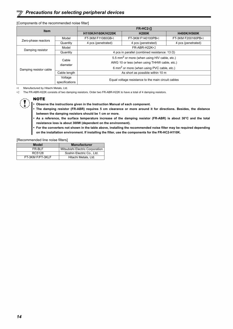
[Components of the recommended noise filter]
Manufactured by Hitachi Metals, Ltd. The FR-ABR-H22K consists of two damping resistors. Order two FR-ABR-H22K to have a total of 4 damping resistors.
[Recommended line noise filters]
ItemFR-HC2-[]
H110K/H160K/H220K H280K H400K/H560K
Zero-phase reactorsModel FT-3KM F11080GB FT-3KM F140100PB FT-3KM F200160PB
Quantity 4 pcs (penetrated) 4 pcs (penetrated) 4 pcs (penetrated)
Damping resistorModel FR-ABR-H22K
Quantity 4 pcs in parallel (combined resistance: 13 Ω)
Damping resistor cable
Cable diameter
5.5 mm2 or more (when using HIV cable, etc.)AWG 10 or less (when using THHW cable, etc.)
6 mm2 or more (when using PVC cable, etc.)Cable length As short as possible within 10 m
Voltage specifications
Equal voltage resistance to the main circuit cables
NOTE Observe the instructions given in the Instruction Manual of each component. The damping resistor (FR-ABR) requires 5 cm clearance or more around it for directions. Besides, the distance
between the damping resistors should be 1 cm or more. As a reference, the surface temperature increase of the damping resistor (FR-ABR) is about 30°C and the total
resistance loss is about 300W (dependent on the environment). For the converters not shown in the table above, installing the recommended noise filter may be required depending
on the installation environment. If installing the filter, use the components for the FR-HC2-H110K.
Model ManufacturerFR-BLF Mitsubishi Electric CorporationRC5128 Soshin Electric Co., Ltd.
FT-3KM F/FT-3KLF Hitachi Metals, Ltd.

15
1
OU
TLIN
E
Precautions for selecting peripheral devices
1.3.2 Peripheral device list
(1) Circuit breakers and magnetic contactorsCheck the model of the converter and select peripheral devices according to the capacity. Refer to the table below to prepareappropriate peripheral devices.200V class
400V class
Select an MCCB according to the power supply capacity.Install one MCCB per converter.(For the use in the United States or Canada, refer to page 201, and select the appropriate fuse.)
Magnetic contactor is selected based on the AC-1 class. The electrical durability of magneticcontactor is 100,000 times. When the magnetic contactor is used for emergency stop during motor driving, the electrical durability is 25 times.When using the MC for emergency stop during motor driving or using on the motor side during commercial-power supply operation, select the MC with classAC-3 rated current for the motor rated current.
Converter ModelMolded Case Circuit Breaker (MCCB) or Earth Leakage Circuit Breaker (ELB)
(NF, NV type)
Magnetic Contactor(MC)
FR-HC2-7.5K 50A S-T35FR-HC2-15K 75A S-T50FR-HC2-30K 150A S-T100FR-HC2-55K 300A S-N180FR-HC2-75K 350A S-N300
Converter ModelMolded Case Circuit Breaker (MCCB) or Earth Leakage Circuit Breaker (ELB)
(NF, NV type)
Magnetic Contactor(MC)
FR-HC2-H7.5K 30A S-T20FR-HC2-H15K 50A S-T25FR-HC2-H30K 75A S-T35FR-HC2-H55K 150A S-T100FR-HC2-H75K 175A S-T100FR-HC2-H110K 250A S-N180FR-HC2-H160K 400A S-N300FR-HC2-H220K 500A S-N400FR-HC2-H280K 700A S-N600FR-HC2-H400K 900A S-N800FR-HC2-H560K 1500A S-N400 (three in parallel)
NOTE When the MCCB on the converter input side trips, check for the wiring fault (short circuit), damage to internal parts of
the converter, etc. Identify the cause of the trip, then remove the cause and power ON the breaker.
MCCB
MCCB
IM
IM
Inverter
Inverter
Converter
Converter

16
Precautions for selecting peripheral devices
(2) FuseInstallation of a fuse is recommended between a high power factor converter and an inverter. Select a fuse according to the capacity of the connected motor. When using a motor, of which the capacity is smaller than theinverter capacity by two ranks or more, select the fuse with the capacity that is one rank lower than the inverter capacity. (Refer topage 44, 51 and 57 for details.)[Fuse selection table]200V class
Manufacturer: Mersen Japan K.K.Contact: Sun-Wa Technos Corporation
Use the CUS102 (without fuse light melting indicator) or CUS102I (with fuse light melting indicator) fuse holders (2-pole type).
Motor capacity (kW) Fuse rating (A) Model Fuse holder (2 poles)
0.1 5 6.900 CP GR 10.38 0005(FR10GR69V5)
CUS102 (without fuse light melting indicator)or CUS102I (with fuse light melting indicator)
0.2 10 6.900 CP GR 10.38 0010(FR10GR69V10) 0.4 16 6.900 CP GR 10.38 0016(FR10GR69V16)
0.75 20 6.900 CP GR 10.38 0020(FR10GR69V20) 1.5 25 6.900 CP GR 10.38 0025(FR10GR69V25) 2.2 50 6.9 URD 30 TTF 0050 —3.7 63 6.9 URD 30 TTF 0063 —5.5 100 6.9 URD 30 TTF 0100 —7.5 125 6.9 URD 30 TTF 0125 —11 160 6.9 URD 30 TTF 0160 —15 200 6.9 URD 30 TTF 0200 —
18.5 250 6.9 URD 30 TTF 0250 —22 315 6.9 URD 30 TTF 0315 —30 400 6.9 URD 30 TTF 0400 —37 500 6.9 URD 30 TTF 0500 —45 630 6.9 URD 31 TTF 0630 —55 700 6.9 URD 31 TTF 0700 —75 800 6.9 URD 31 TTF 0800 —

17
1
OU
TLIN
E
Precautions for selecting peripheral devices
400V class
Manufacturer: Mersen Japan K.K.Contact: Sun-Wa Technos Corporation
Use the CUS102 (without fuse light melting indicator) or CUS102I (with fuse light melting indicator) fuse holders (2-pole type). When installing several fuses in parallel, leave 12mm or more between the fuses.
[Estimated lifespan of fuse]
Estimated lifespan for when the yearly average surrounding air temperature is 50°C (without corrosive gas, flammable gas, oil mist, dust and dirt etc.)
(3) Installation and selection of the molded case circuit breakerInstall a molded case circuit breaker (MCCB) on the power receiving side to protect the wiring at the converter input side.Select an MCCB according to the converter input side power factor, which depends on the power supply voltage, outputfrequency and load. Especially for a completely electromagnetic MCCB, a slightly large capacity must be selected since itsoperation characteristic varies with harmonic currents. (Check it in the data of the corresponding breaker.) As an earthleakage current breaker, use the Mitsubishi earth leakage current breaker designed for harmonics and surge suppression.
Motor capacity (kW)
Fuse rating (A) Model Fuse holder (2 poles)
0.4 12.5 6.900 CP GR 10.38 0012.5(FR10GR69V12.5)
CUS102 (without fuse light melting indicator)or CUS102I (with fuse light melting indicator)
0.75 16 6.900 CP GR 10.38 0016(FR10GR69V16) 1.5 16 6.900 CP GR 10.38 0016(FR10GR69V16) 2.2 20 6.900 CP GR 10.38 0020(FR10GR69V20) 3.7 30 6.900 CP GR 10.38 0030(FR10GR69V30) 5.5 50 6.9 URD 30 TTF 0050 —7.5 50 6.9 URD 30 TTF 0050 —11 80 6.9 URD 30 TTF 0080 —15 125 6.9 URD 30 TTF 0125 —
18.5 125 6.9 URD 30 TTF 0125 —22 160 6.9 URD 30 TTF 0160 —30 200 6.9 URD 30 TTF 0200 —37 250 6.9 URD 30 TTF 0250 —45 315 6.9 URD 30 TTF 0315 —55 350 6.9 URD 30 TTF 0350 —75 450 6.9 URD 30 TTF 0450 —90 500 6.9 URD 30 TTF 0500 —110 550 6.9 URD 31 TTF 0550 —132 630 6.9 URD 31 TTF 0630 —160 800 6.9 URD 31 TTF 0800 —185 900 6.9 URD 32 TTF 0900 —
220 10006.9 URD 32 TTF 1000 or 6.9 URD 31 TTF 0630 2 in parallel
—
250 12506.9 URD 33 TTF 1250 or 6.9 URD 31 TTF 0700 2 in parallel
—
280 14006.9 URD 33 TTF 1400 or 6.9 URD 31 TTF 0800 2 in parallel
—
315 16006.9 URD 232 TDF 1600 or 6.9 URD 31 TTF 0800 2 in parallel
—
355 18006.9 URD 232 TDF 1800 or 6.9 URD 32 TTF 0900 2 in parallel
—
400 18006.9 URD 232 TDF 1800 or 6.9 URD 32 TTF 0900 2 in parallel
—
450 2500 6.9 URD 33 TTF 1250 2 in parallel —500 2700 6.9 URD 32 TTF 0900 3 in parallel —560 2700 6.9 URD 32 TTF 0900 3 in parallel —
NOTE Install a fuse across terminal P/+ of the inverter and the converter and across terminal N/- of the inverter and the
converter.
Part Name Estimated lifespan Replacement methodFuse 10 years Replace with a new one
NOTE If the fuse melts down, wiring failure such as a short circuit may be the cause. Identify the problem and fix it before
replacing the fuse.

18
Precautions for selecting peripheral devices
1.3.3 Selecting the rated sensitivity current for the earth leakage circuit breaker
When using the earth leakage circuit breaker with the inverter circuit, select its rated sensitivity current as follows. Breaker for harmonic and surge
Rated sensitivity current ln 10 (lg1+lgn+lgc+lg2+lgi+lg3+lgm) Standard breaker
Rated sensitivity current ln 10 {lg1+lgn+lgc+lg2+lgi+3(lg3+lgm)}
lg1, lg2, lg3 : leakage current of cable path during commercial power supply operationlgn : leakage current of noise filter on the converter input sidelgc : leakage current of converter (and external option)lgi : leakage current of inverterlgm : leakage currents of motor during commercial power supply operation
<Example>
Selection example (for the diagram shown above) (mA)Breaker for harmonic and surge Standard breaker
Leakage current lg1 (mA) 33 =0.17
Leakage current lgn (mA) 0 (without noise filter)
Leakage current lgc (mA) 2Refer to the next page for the leakage current of the converter.
Leakage current lg2 (mA) 33 = 0.17
Leakage current lgi (mA) 1 (without EMC filter)Refer to the next page for the leakage current of the inverter.
Leakage current lg3 (mA) 33 = 2.31
Leakage current lgm (mA) 0.18Total leakage current (mA) 5.83 10.81Rated sensitivity current
(lg10)(mA) 58.3 108.1
(200V 60Hz)(200V 60Hz)
1. 5 3. 72. 2
7. 5 152211
3730
55455.5 18. 5
0. 1
0. 2
0. 3
0. 50. 7
1. 0
2. 0
0
20
40
60
80
100
120
2 3.55.5
8 14223038
6080100
150
Motor capacity (kW)
Example of leakage current ofcable path per 1km during thecommercial power supply operationwhen the CV cable is routed in metal conduit
Leakage current example ofthree-phase induction motorduring the commercialpower supply operation
Leakage c
urr
ents
(m
A)
Leakage c
urr
ents
(m
A)
Cable size (mm2)
Motor capacity (kW)
For " " connection, the amount of leakage current is appox.1/3 of the above value.
(Three-phase three-wire delta connection 400V60Hz)
Example of leakage current per 1km during the commercial power supply operation when the CV cable is routed in metal conduit
Leakage current example of three-phase induction motor during the commercial power supply operation
(Totally-enclosed fan-cooled type motor 400V60Hz)
0
20
40
60
80
100
120
Leak
age
curr
ents
(mA
)
Leak
age
curr
ents
(mA
)
2 3.55.5
8 14223038
6080100
150
Cable size (mm2)
0. 1
0. 20. 3
0. 50. 71. 0
2. 0
1. 5 3. 72. 2
7. 5 152211
3730
55455.5 18. 5
lg1 lgn lgc lgilg2 lg3lgm
3�200V 2.2kWIMInverter
ELB
Converter
Noise filter
5.5mm2 × 5m 5.5mm2 × 70m5.5mm2 × 5m
5m1000m----------------
5m1000m----------------
70m1000m----------------

19
1
OU
TLIN
E
Precautions for selecting peripheral devices
Leakage current of the converter
Leakage current of the inverter (with and without EMC filter)
Voltage (V) Leakage current (mA) Remarks200 2
Input power conditions220 V/60 Hz (200 V class) or 440 V/60 Hz (400 V class), within 3% of power supply
unbalance
400 4
400 4
Voltage (V)EMC filter
RemarksON (mA) OFF (mA)
200 22 1Input power conditions
220 V/60 Hz (200 V class) or 440 V/60 Hz (400 V class), within 3% of power supply
unbalance
400 35 2
400 2 1
NOTE Install the earth leakage circuit breaker (ELB) on the input side of the converter. In the connection earthed-neutral system, the sensitivity current is blunt against an earth (ground) fault in the
inverter output side. Earthing (Grounding) must conform with the requirements of national and local safetyregulations and electrical codes. (NEC section 250, IEC 536 class 1 and other applicable standards)
When the breaker is installed on the output side of the inverter, it may be unnecessarily operated by harmonics evenif the effective value is less than the rating.In this case, do not install the breaker since the eddy current and hysteresis loss will increase, leading to temperaturerise.
The following models are the standard breakers....BV-C1, BC-V, NVB, NV-L, NV-G2N, NV-G3NA, NV-2F earth leakagerelay (except NV-ZHA), NV with AA neutral wire open-phase protectionThe other models are designed for harmonic and surge suppression....NV-C/NV-S/MN series, NV30-FA, NV50-FA, BV-C2, earth leakage alarm breaker (NF-Z), NV-ZHA, NV-H
Phaseearthing(grounding)
Earthed-neutralsystem
Phaseearthing(grounding)
Earthed-neutralsystem

20
MEMO
21
2
3
4
5
6
1
2 INSTALLATION AND WIRING
This chapter provides an "INSTALLATION AND WIRING" ofthis product.Always read the instructions before using the equipment.
2.1 Removal and installation of the converter (FR-HC2) front cover .............................................................................................. 22
2.2 Removal and installation of the outside box (FR-HCB2) front cover .............................................................................................. 24
2.3 Installation ..................................................................................... 252.4 Protruding the heat sink............................................................... 272.5 Installation of peripheral devices ................................................ 292.6 Main circuit terminal specifications ............................................ 332.7 Wiring of main circuit (FR-HC2-7.5K to 75K, FR-HC2-H7.5K to
H220K)............................................................................................ 402.8 Wiring of main circuit (FR-HC2-H280K) ...................................... 472.9 Wiring of main circuit (FR-HC2-H400K, H560K) ......................... 532.10 Notes on earthing (grounding) .................................................... 592.11 Compatible inverter for the high power factor converter ......... 602.12 Wiring of several inverters to one converter.............................. 622.13 Wiring of control circuit ............................................................... 64

22
Removal and installation of the converter (FR-HC2) front cover
2.1 Removal and installation of the converter (FR-HC2) front cover
Removal of the operation panel
1) Loosen the two fixed screws on the operation panel.(These screws cannot be removed.)
2) Push the left and right hooks of the operation panel and pullthe operation panel toward you to remove.
When reinstalling the operation panel, insert it straight to reinstall securely and tighten the screws of the operation panel.
15K or lowerRemoval
Reinstallation
1) Loosen the installation screws of the frontcover.
2) Pull the front cover toward you to remove by pushing aninstallation hook using left fixed hooks as supports.
Installation hook
Front cover
Front coverFront cover
Front cover
REGEN
PWRP.CPY
DRIVE
MONREGEN
PWRP.CPY
DRIVE
MON
REGEN
PWRP.CPY
DRIVE
MON
1) Insert the two fixed hooks on the left sideof the front cover into the sockets of theinverter.
3) Tighten the installationscrews and fix the frontcover.
2) Using the fixed hooks as supports, securely press the front cover against the inverter. (Although installation can be done with the operation panel mounted, make sure that a connector is securely fixed.)
23
2
INST
ALL
ATIO
N A
ND
WIR
ING
Removal and installation of the converter (FR-HC2) front cover
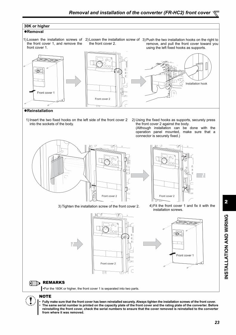
30K or higherRemoval
Reinstallation
NOTE Fully make sure that the front cover has been reinstalled securely. Always tighten the installation screws of the front cover. The same serial number is printed on the capacity plate of the front cover and the rating plate of the converter. Before
reinstalling the front cover, check the serial numbers to ensure that the cover removed is reinstalled to the converterfrom where it was removed.
Front cover 2
Installation hook
Front cover 1
1) Loosen the installation screws ofthe front cover 1, and remove thefront cover 1.
2) Loosen the installation screw ofthe front cover 2.
3) Push the two installation hooks on the right toremove, and pull the front cover toward youusing the left fixed hooks as supports.
Front cover 2 Front cover 2
1) Insert the two fixed hooks on the left side of the front cover 2into the sockets of the body.
2) Using the fixed hooks as supports, securely pressthe front cover 2 against the body.(Although installation can be done with theoperation panel mounted, make sure that aconnector is securely fixed.)
Front cover 2
Front cover 1
3) Tighten the installation screw of the front cover 2. 4) Fit the front cover 1 and fix it with theinstallation screws.
REMARKSFor the 160K or higher, the front cover 1 is separated into two parts.

24
Removal and installation of the outside box (FR-HCB2) front cover
2.2 Removal and installation of the outside box (FR-HCB2) front cover
Removal
Reinstallation
NOTE Fully make sure that the front cover has been reinstalled securely. Always tighten the installation screws of the front cover. The same serial number is printed on the capacity plate of the front cover and the rating plate of the outside box.
Before reinstalling the front cover, check the serial numbers to ensure that the cover removed is reinstalled to theoutside box from where it was removed.
Front cover
Front cover
1) Loosen the installation screws of the front cover. 2) For removal, pull off the front cover.
Front coverFront cover
1) Securely press the front coveragainst the outside box.
2) Tighten the cover with mountingscrews. (Tightening torque: 1.7N m)
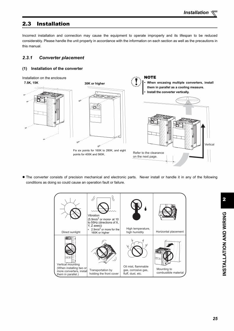
25
2
INST
ALL
ATIO
N A
ND
WIR
ING
Installation
2.3 Installation
Incorrect installation and connection may cause the equipment to operate improperly and its lifespan to be reducedconsiderably. Please handle the unit properly in accordance with the information on each section as well as the precautions inthis manual.
2.3.1 Converter placement
(1) Installation of the converter
The converter consists of precision mechanical and electronic parts. Never install or handle it in any of the followingconditions as doing so could cause an operation fault or failure.
Installation on the enclosure
REGEN
PWRP.CPY
DRIVE
MON
Fix six points for 160K to 280K, and eightpoints for 400K and 560K.
7.5K, 15K 30K or higher
NOTE When encasing multiple converters, install
them in parallel as a cooling measure. Install the converter vertically.
Refer to the clearance
on the next page.
Vertical
Direct sunlight
High temperature,
high humidity Horizontal placement
Mounting to
combustible material
Oil mist, flammable
gas, corrosive gas,
fluff, dust, etc.
Vertical mounting
(When installing two or more converters, install them in parallel.)
Transportation by
holding the front cover
Vibration(5.9m/s2 or more at 10 to 55Hz (directions of X, Y, Z axes)) 2.9m/s2 or more for the
160K or higher

26
Installation
(2) Clearances around the converterTo ensure ease of heat radiation and maintenance, leave at least the shown clearance around the converter. At least thefollowing clearance are required under the converter as a wiring space, and above the converter as a heat radiation space.When designing or building an enclosure for the converter, carefully consider influencing factors such as heat generation ofthe contained devices and the operating environment.
(3) Converter mounting orientationMount the converter on a wall as specified. Do not mount it horizontally or any other way.
(4) Above the converterHeat is blown up from inside the converter by the small fan built in the unit. Any equipment placed above the converter shouldbe heat resistant.
(5) Arrangement of multiple inverters and converters
(6) Placement of ventilation fan and converter
REMARKSFor replacing the cooling fan of the 160K or higher, 30cm of space is necessary in front of the inverter. Refer to page 149 for fanreplacement.
When installing multiple inverters and converters in thesame enclosure, generally arrange them horizontally asshown in the right figure (a). When it is inevitable toarrange them vertically to minimize space, take suchmeasures as to provide guides since heat from thebottom converters can increase the temperatures in thetop inverters, causing inverter failures.
When installing multiple inverters and converters, fullcaution must be taken not to let the surrounding airtemperature of the converters and inverters exceed thepermissible value. Avoid the temperature to exceed thevalue by providing ventilation and increasing theenclosure size, etc. Arrangement of multiple inverters and converters
Heat generated in the converter is blown up from the bottom ofthe unit as warm air by the cooling fan. When installing aventilation fan for that heat, determine the place of ventilationfan installation after fully considering an air flow. (Air passesthrough areas of low resistance. Make an airway and airflowplates to expose the converter to cool air.)
Placement of ventilation fan and converter
5cm
or more
Clearance (front)Surrounding air temperature and humidity
Measurement position
Measurement position
Converter
Leave enough clearance and take
cooling measures.
5cm 5cm
5cm
20cm or more
75K or higher55K or lower
20cm or more
10cm
or more
10cm
or more
10cm
or more5cm
or more
5cm
or more
Temperature: -10°C to 50°CAmbient humidity: 90% RH maximum
Clearance (side)
Converter
Guide Guide
Enclosure Enclosure
Guide
(a) Horizontal arrangement (b) Vertical arrangement
Converter
InverterInverterConverter Inverter
Converter
Converter Converter
<Good example> <Bad example>

27
2
INST
ALL
ATIO
N A
ND
WIR
ING
Protruding the heat sink
2.4 Protruding the heat sinkWhen installing a converter inside an enclosure, the heat generated in the enclosure can be greatly reduced by protruding theheat sink of the converter.This installation method is recommended when downsizing the enclosure and such.
2.4.1 When using a heat sink protrusion attachment (FR-A7CN)For the FR-HC2-7.5K to 75K and FR-HC2-H7.5K to H110K, a heat sink can be protruded outside the enclosure using a heatsink protrusion attachment (FR-A7CN). (For the 160K or higher, the attachment is not necessary when the heat sink is to beprotruded.)Refer to the table below for the applicable heat sink protrusion attachments. For a panel cut dimension drawing and an installation procedure of the heat sink protrusion attachment (FR-A7CN) to theconverter, refer to a manual of "heat sink protrusion attachment".Heat sink protrusion attachments
2.4.2 Heat sink protrusion for 160K or higher(1) Enclosure cut Cut the enclosure according to the capacity of the converter.
Model Name Applicable converterFR-A7CN02 FR-HC2-7.5KFR-A7CN03 FR-HC2-H7.5K, H15KFR-A7CN04 FR-HC2-15K
FR-A7CN05FR-HC2-30K
FR-HC2-H30K
FR-A7CN09 FR-HC2-75KFR-HC2-H110K
FR-A7CN12 FR-HC2-55KFR-A7CN13 FR-HC2-H75KFR-A7CN14 FR-HC2-H55K
FR-HC2-H160K, H220K
(Unit: mm)
FR-HC2-H280K
(Unit: mm)FR-HC2-H400K, H560K
(Unit: mm)
200 200484
1395
418
985
6-M10 screw
Hole Hole
300 300662
1595
415
984
6-M10 screw
771
13
00
21
12
58
21
315 315
Hole
6-M10 screw

28
Protruding the heat sink
(2) Moving and removing the back installation frames
(3) Installing the converter to the enclosureProtrude the heat sink of the converter from the installation enclosure, and secure the converter using the top and bottominstallation frames.
FR-HC2-H160K to H280KOne installation frame is attached to each of the upper and lower partsof the converter. Change the position of the rear side installation frameon the upper and lower sides of the converter to the front side asshown on the right. When changing the installation frames, make surethat the installation orientation is correct.
FR-HC2-H400K, H560KThe converter has installation frames: two on the top and the two onthe bottom. As shown on the right, remove the back installation frameson the top and bottom of the converter.
NOTE• Protruding area contains a cooling fan, so it cannot be used in the environment where water drops, oil mist, dust and
other substances exist. • Foreign substances such as screws and dust must be prevented to enter in the converter or the cooling fan section.
Shift
Shift
Upper
installation
frame
Lower
installation
frame
Upper installation
frame (rear side)
Lower installation
frame (rear side)
Removal
Removal
Converter
Inside the
enclosure
Enclosure
Exhausted air
Installation
frame
Dimension of
the outside of
the enclosure
Cooling
wind
D1
∗
Converter model D1FR-HC2-H160K, H220K 185FR-HC2-H280K to H560K 184
The enclosure enclosing FR-HC2-H160K and higher has a finger guard on its back. The thickness of the enclosure should be less than 10mm (), and do not place anything around the finger guard to avoid contact with the finger guard.
Enclosure
Finger guard10∗ 140
6

29
2
INST
ALL
ATIO
N A
ND
WIR
ING
Installation of peripheral devices
2.5 Installation of peripheral devices
2.5.1 Installation of reactor 1 and reactor 2
(1) Model name confirmationTake caution as the appearances of the reactor 1 (FR-HCL21) and the reactor 2 (FR-HCL22) are very similar.
(2) ClearanceBecause the reactor 1 (FR-HCL21) and the reactor 2 (FR-HCL22) generate heat, leave sufficient space around them.
(3) Installation placeInstall the reactor 1 (FR-HCL21) and the reactor 2 (FR-HCL22) on nonflammable material. Direct installation on aflammable material will cause a fire.
(4) EnvironmentAvoid places where the equipment is subjected to oil mist, flammable gases, fluff, dust, dirt, etc.Install the equipment in a clean place or protect them from suspended substances.
MODELFR-HCL21-XXX
AC REACTOR
SERIAL XXXXX
MODELFR-HCL22-XXX
AC REACTOR
SERIAL XXXXX
Reactor 1(FR-HCL21)
Reactor 2(FR-HCL22) Check "MODEL" on the rating plates of the reactor 1 (FR-HCL21) and the reactor 2 (FR-HCL22).
10cm or more
5cm or more5cm or more

30
Installation of peripheral devices
(5) Installation orientationTo prevent looseness, install the reactor 1 (FR-HCL21) and the reactor 2 (FR-HCL22) on a horizontal surface securelywith screws or bolts.Do not install them on a vertical wall. Install them on a mounting stand which can withstand their weight.
2.5.2 Installation of the outside box (FR-HCB2-7.5K to 75K, FR-HCB2-H7.5K to H220K)
(1) Clearance
(2) Installation area
Mount the outside box (FR-HCB2) on nonflammable material. Installing it directly on flammable material will cause a fire.
(3) Surrounding environmentAvoid places where the equipment is subjected to oil mist, flammable gases, fluff, dust, dirt, etc.Install the equipment in a clean place or protect it from suspended substances.
(4) InstallationInstall the outside box (FR-HCB2) vertically.
NOTESince the charged sections of the reactor 1 and the reactor 2 are uncovered, fully protect them to prevent ground faultand electric shock.
10cm or more
10cm or more
5cm or more5cm or more
NOTESince the charged sections of the outside box areuncovered, take sufficient protective measures toavoid ground faults and electric shocks.
Vertical

31
2
INST
ALL
ATIO
N A
ND
WIR
ING
Installation of peripheral devices
2.5.3 Installation of filter capacitor (FR-HCC2-H280K to H560K)
(1) ClearanceBecause the filter capacitor (FR-HCC2) generates heat, leave sufficient space around it.
(2) Installation place
Install the filter capacitor on nonflammable material. Direct installation on a flammable material will cause a fire.
(3) EnvironmentAvoid places where the equipment is subjected to oil mist, flammable gases, fluff, dust, dirt, etc.Install the equipment in a clean place or protect them from suspended substances.
(4) Installation orientationTo prevent looseness, install the filter capacitor (FR-HCC2) on a horizontal surface securely with screws or bolts.Do not install it on a vertical wall. Install it on a mounting stand which can withstand its weight.
(5) Installation of filter capacitor alarm detector (H400K, H560K)To install a filter capacitor alarm detector (MDA-1), refer to the Instruction Manual appended to the filter capacitor alarmdetector, and perform the installation.
2.5.4 Installation of inrush current limit resistor (FR-HCR2-H280K to H560K)
(1) ClearanceBecause the limit resistor (FR-HCR2) generates heat, leave sufficient space around it.
(2) Installation place
Install the limit resistor (FR-HCR2) on nonflammable material. Installing directly on or near a flammable material willcause a fire.
NOTESince the charged sections of the filter capacitor is uncovered, fully protect it to prevent ground fault and electricshock.
10cm or more
10cm or more10cm or more
Installation foot
3cm or
more
3cm or
more3cm or more
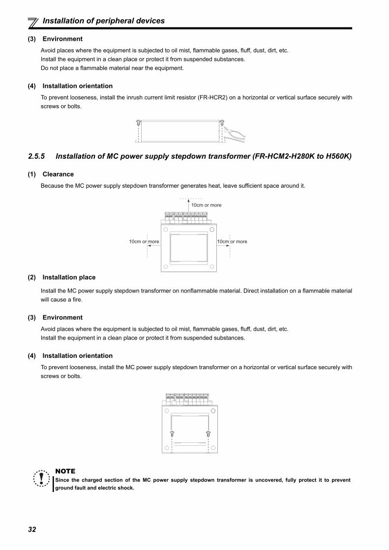
32
Installation of peripheral devices
(3) EnvironmentAvoid places where the equipment is subjected to oil mist, flammable gases, fluff, dust, dirt, etc.Install the equipment in a clean place or protect it from suspended substances.Do not place a flammable material near the equipment.
(4) Installation orientationTo prevent looseness, install the inrush current limit resistor (FR-HCR2) on a horizontal or vertical surface securely withscrews or bolts.
2.5.5 Installation of MC power supply stepdown transformer (FR-HCM2-H280K to H560K)
(1) ClearanceBecause the MC power supply stepdown transformer generates heat, leave sufficient space around it.
(2) Installation place
Install the MC power supply stepdown transformer on nonflammable material. Direct installation on a flammable materialwill cause a fire.
(3) EnvironmentAvoid places where the equipment is subjected to oil mist, flammable gases, fluff, dust, dirt, etc.Install the equipment in a clean place or protect it from suspended substances.
(4) Installation orientationTo prevent looseness, install the MC power supply stepdown transformer on a horizontal or vertical surface securely withscrews or bolts.
NOTESince the charged section of the MC power supply stepdown transformer is uncovered, fully protect it to preventground fault and electric shock.
10cm or more
10cm or more
10cm or more

33
2
INST
ALL
ATIO
N A
ND
WIR
ING
Main circuit terminal specifications
2.6 Main circuit terminal specifications
2.6.1 Description of main circuit terminal
Terminal Symbol Terminal Name Description
R/L1, S/L2, T/L3 Power inputThese terminals are used to detect power phase and power voltage, and to input control power. Connect them to the commercial power supply. If the inverter is operated without connecting them to the commercial power supply, the converter will be damaged.
R4/L14, S4/L24, T4/L34 Power input Connect them to the reactor 2.
R1/L11, S1/L21 Power supply for control circuit
These terminals are connected to the phase detection terminals R/L1 and S/L2 in the initial status. To retain the fault display and fault output, remove the jumpers (cables) and apply external power to these terminals.
P/+, N/- Inverter connection Connect them to the inverter terminals P/+ and N/-.
Earth (Ground) For earthing (grounding) the converter chassis. It must be earthed (grounded).

34
Main circuit terminal specifications
2.6.2 Terminal arrangement of the main circuit terminal
200V classFR-HC2-7.5K FR-HC2-15K
Screw size for terminals R1/L11 and S1/L21 is M4.FR-HC2-30K FR-HC2-55K
FR-HC2-75K
Inverter
N/- P/+
Charge lamp
R1/L11 S1/L21
Power supply
R/L1 S/L2 T/L3
Reactor 2
R4/L14
S4/L24
T4/L34
Screw size (M5)
∗ ∗
Screw size
(M5)
Reactor 2 InverterPower supply
N/- P/+
Charge lamp
R1/L11 S1/L21
Screw size (M4)
Screw size (M6)
R/L1 S/L2 T/L3 R4/L14
S4/L24
T4/L34
Screw size (M6)
N PR4 L14 S4 L24 T4 L34BC172D515H01
Reactor 2 InverterPower supply
N/- P/+
Charge lamp
R1/L11Screw size (M4)
Screw size (M4)
Screw size (M8)
Screw size (M10)
R/L1
S/L2
T/L3 R4/
L14S4/L24
T4/L34
Screw size(M6)
Screw size(M6)
S1/L21
Power supplyReactor 2 Inverter
N/- P/+
Charge lamp
R1/L11 S1/L21
Screw size (M4)
Screw size (M12)
Screw size (M12)
Screw size (M4)
R/L1
S/L2
T/L3
R4/L14
S4/L24
T4/L34
Screw size (M6)
Charge lamp
R1/L11 S1/L21
Reactor 2Power supply Inverter
N/- P/+
Screw size (M4)
Screw size (M4)
Screw size (M12)
Screw size (M12)
R/L1
S/L2
T/L3
R4/L14
S4/L24
T4/L34
Screw size (M10)
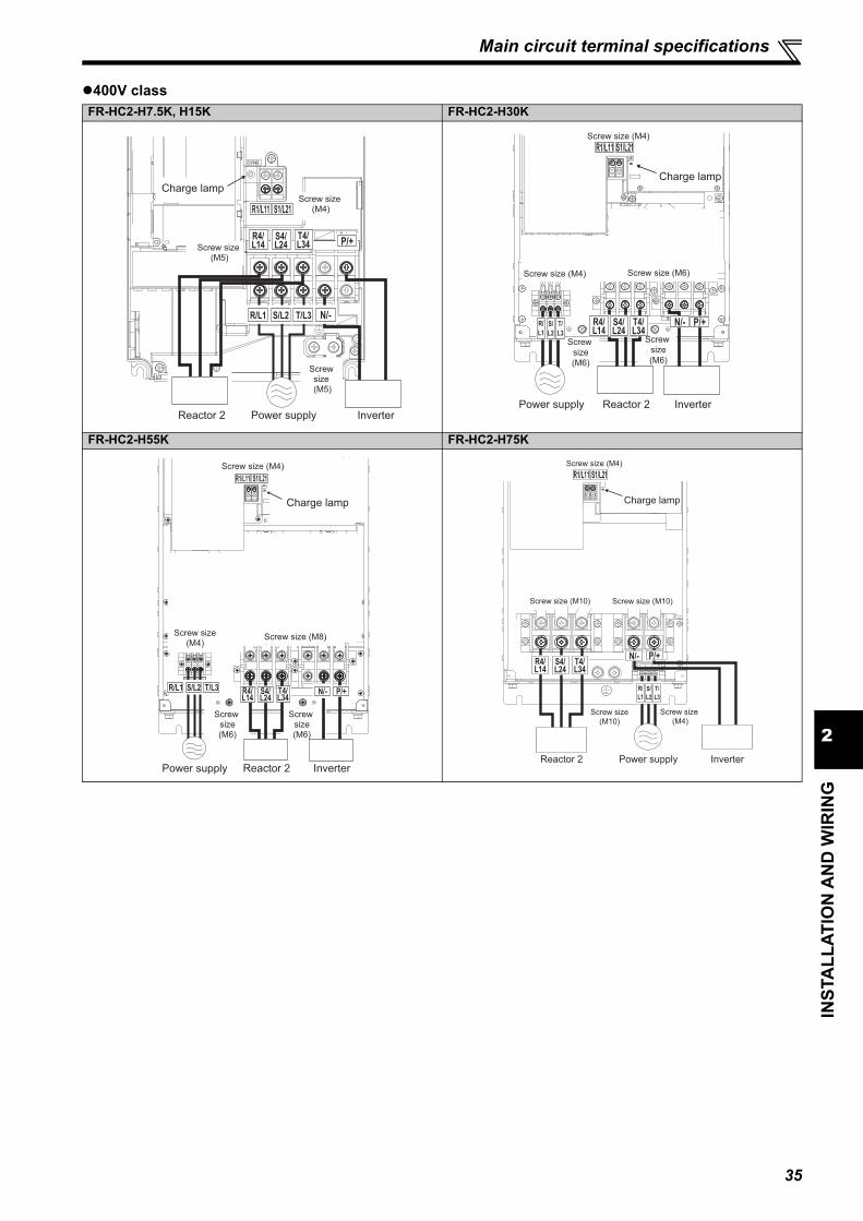
35
2
INST
ALL
ATIO
N A
ND
WIR
ING
Main circuit terminal specifications
400V classFR-HC2-H7.5K, H15K FR-HC2-H30K
FR-HC2-H55K FR-HC2-H75K
P/+R4/L14
S4/L24
T4/L34
R1/L11 S1/L21
R/L1 S/L2 T/L3 N/-
Screw size (M4)
Charge lamp
Screw size (M5)
Screw size (M5)
Reactor 2 Power supply Inverter
R/L1
S/L2
T/L3
P/+S4/L24
R4/L14
T4/L34
N/-
Screw size (M4)
Charge lamp
Screw size (M4) Screw size (M6)
Screw size(M6)
Screw size(M6)
Reactor 2Power supply Inverter
R1/L11 S1/L21
P/+R4/L14
S4/L24
T4/L34
R1/L11 S1/L21
R/L1 S/L2 T/L3N/-
Screw size (M4)
Charge lamp
Screw size (M4)
Screw size (M8)
Screw size (M6)
Screw size (M6)
Reactor 2Power supply Inverter
R/L1
S/L2
T/L3
N/- P/+R4/L14
S4/L24
T4/L34
Screw size (M4)
Charge lamp
Screw size (M10) Screw size (M10)
Screw size (M4)
Reactor 2 Power supply Inverter
Screw size(M10)
R1/L11 S1/L21
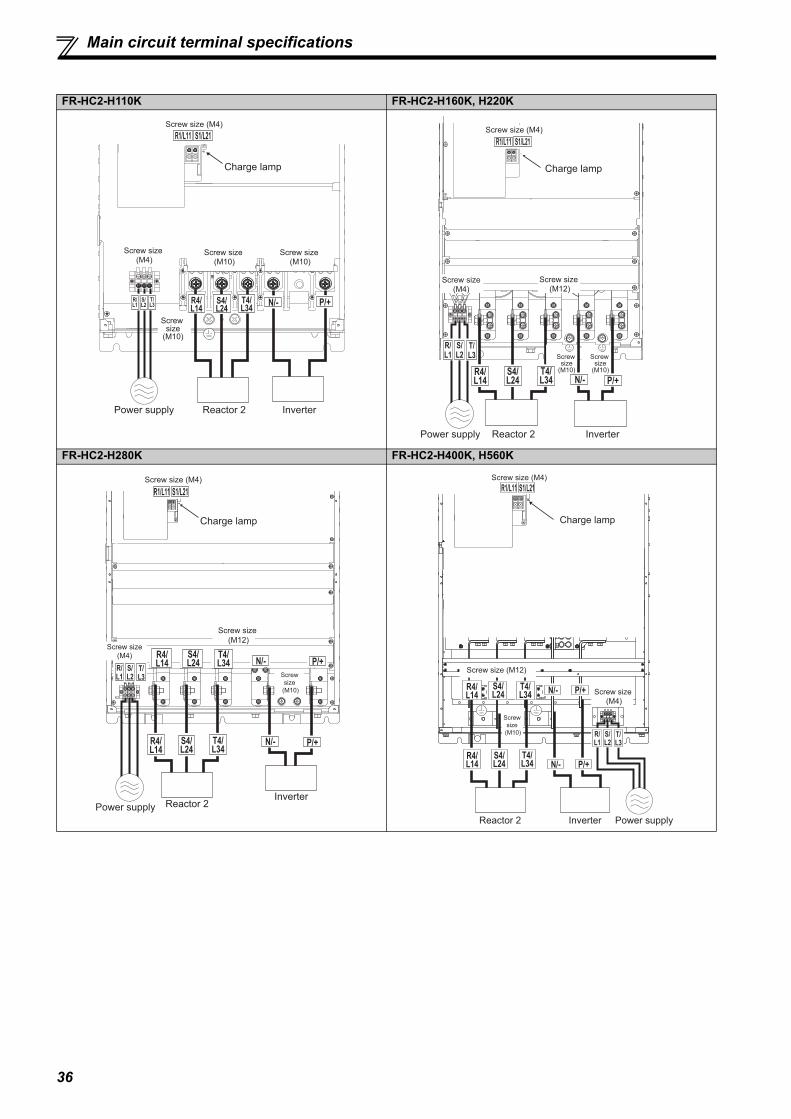
36
Main circuit terminal specifications
FR-HC2-H110K FR-HC2-H160K, H220K
FR-HC2-H280K FR-HC2-H400K, H560K
N/- P/+
R1/L11 S1/L21
R/L1
S/L2
T/L3
R4/L14
S4/L24
T4/L34
Screw size (M4)
Charge lamp
Screw size (M10)
Screw size (M10)
Screw size (M4)
Screw size
(M10)
Reactor 2Power supply Inverter
R4/L14
S4/L24
T4/L34 N/- P/+
R1/L11 S1/L21
R/
L1
S/
L2
T/
L3
Screw size (M4)
Charge lamp
Screw size (M4)
Screw size (M12)
Reactor 2Power supply Inverter
Screw size
(M10)
Screw size
(M10)
R/L1
S/L2
T/L3
R4/L14
S4/L24
T4/L34
R4/L14
S4/L24
T4/L34
N/- P/+
N/- P/+
Charge lamp
Screw size (M4)
Screw size(M4)
Screw size (M12)
Screwsize
(M10)
Reactor 2Inverter
Power supply
R1/L11 S1/L21
R4/L14
S4/L24
T4/L34
R4/L14
S4/L24
T4/L34
R/L1
S/L2
T/L3
N/- P/+
N/- P/+
Charge lamp
Screw size (M4)
Screw size (M12)
Screw size (M4)
Screwsize
(M10)
Reactor 2 Inverter Power supply
R1/L11 S1/L21
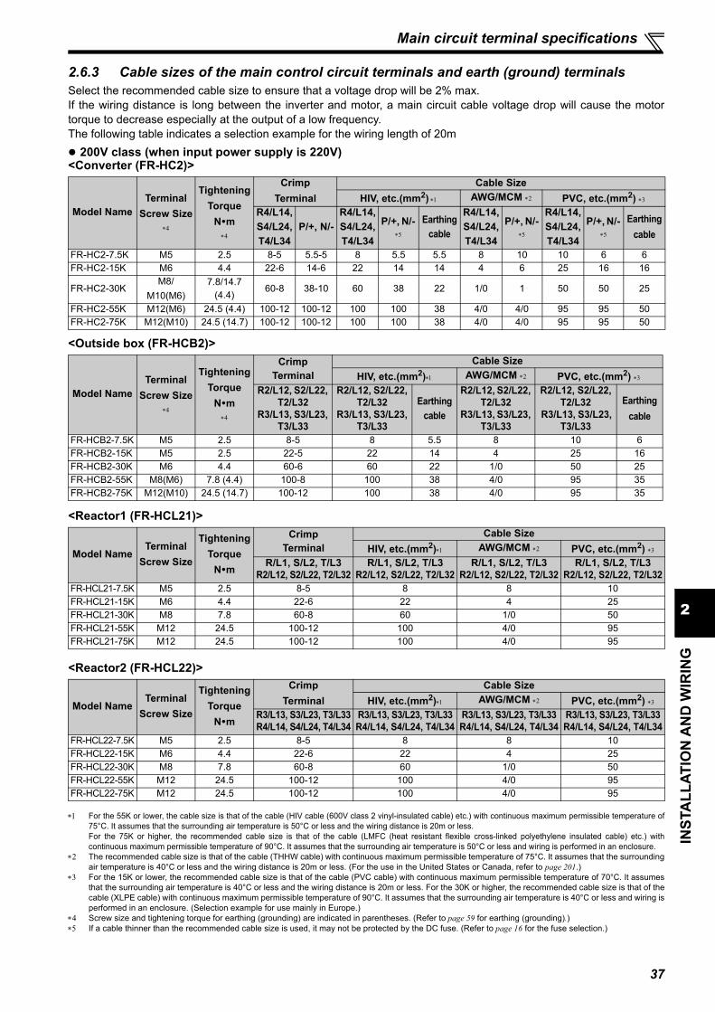
37
2
INST
ALL
ATIO
N A
ND
WIR
ING
Main circuit terminal specifications
2.6.3 Cable sizes of the main control circuit terminals and earth (ground) terminalsSelect the recommended cable size to ensure that a voltage drop will be 2% max.If the wiring distance is long between the inverter and motor, a main circuit cable voltage drop will cause the motortorque to decrease especially at the output of a low frequency.The following table indicates a selection example for the wiring length of 20m 200V class (when input power supply is 220V)<Converter (FR-HC2)>
<Outside box (FR-HCB2)>
<Reactor1 (FR-HCL21)>
<Reactor2 (FR-HCL22)>
For the 55K or lower, the cable size is that of the cable (HIV cable (600V class 2 vinyl-insulated cable) etc.) with continuous maximum permissible temperature of75°C. It assumes that the surrounding air temperature is 50°C or less and the wiring distance is 20m or less.For the 75K or higher, the recommended cable size is that of the cable (LMFC (heat resistant flexible cross-linked polyethylene insulated cable) etc.) withcontinuous maximum permissible temperature of 90°C. It assumes that the surrounding air temperature is 50°C or less and wiring is performed in an enclosure.
The recommended cable size is that of the cable (THHW cable) with continuous maximum permissible temperature of 75°C. It assumes that the surroundingair temperature is 40°C or less and the wiring distance is 20m or less. (For the use in the United States or Canada, refer to page 201.)
For the 15K or lower, the recommended cable size is that of the cable (PVC cable) with continuous maximum permissible temperature of 70°C. It assumesthat the surrounding air temperature is 40°C or less and the wiring distance is 20m or less. For the 30K or higher, the recommended cable size is that of thecable (XLPE cable) with continuous maximum permissible temperature of 90°C. It assumes that the surrounding air temperature is 40°C or less and wiring isperformed in an enclosure. (Selection example for use mainly in Europe.)
Screw size and tightening torque for earthing (grounding) are indicated in parentheses. (Refer to page 59 for earthing (grounding).) If a cable thinner than the recommended cable size is used, it may not be protected by the DC fuse. (Refer to page 16 for the fuse selection.)
Model NameTerminal
Screw Size
Tightening Torque
Nm
Crimp Terminal
Cable SizeHIV, etc.(mm2) AWG/MCM PVC, etc.(mm2)
R4/L14, S4/L24, T4/L34
P/+, N/-R4/L14, S4/L24, T4/L34
P/+, N/-
Earthing cable
R4/L14, S4/L24, T4/L34
P/+, N/-
R4/L14, S4/L24, T4/L34
P/+, N/-
Earthing cable
FR-HC2-7.5K M5 2.5 8-5 5.5-5 8 5.5 5.5 8 10 10 6 6FR-HC2-15K M6 4.4 22-6 14-6 22 14 14 4 6 25 16 16
FR-HC2-30KM8/
M10(M6)7.8/14.7
(4.4)60-8 38-10 60 38 22 1/0 1 50 50 25
FR-HC2-55K M12(M6) 24.5 (4.4) 100-12 100-12 100 100 38 4/0 4/0 95 95 50FR-HC2-75K M12(M10) 24.5 (14.7) 100-12 100-12 100 100 38 4/0 4/0 95 95 50
Model NameTerminal
Screw Size
Tightening Torque
Nm
Crimp Terminal
Cable SizeHIV, etc.(mm2) AWG/MCM PVC, etc.(mm2)
R2/L12, S2/L22, T2/L32
R3/L13, S3/L23, T3/L33
R2/L12, S2/L22, T2/L32
R3/L13, S3/L23, T3/L33
Earthing cable
R2/L12, S2/L22, T2/L32
R3/L13, S3/L23, T3/L33
R2/L12, S2/L22, T2/L32
R3/L13, S3/L23, T3/L33
Earthing cable
FR-HCB2-7.5K M5 2.5 8-5 8 5.5 8 10 6FR-HCB2-15K M5 2.5 22-5 22 14 4 25 16FR-HCB2-30K M6 4.4 60-6 60 22 1/0 50 25FR-HCB2-55K M8(M6) 7.8 (4.4) 100-8 100 38 4/0 95 35FR-HCB2-75K M12(M10) 24.5 (14.7) 100-12 100 38 4/0 95 35
Model NameTerminal
Screw Size
Tightening Torque
Nm
Crimp Terminal
Cable SizeHIV, etc.(mm2) AWG/MCM PVC, etc.(mm2)
R/L1, S/L2, T/L3R2/L12, S2/L22, T2/L32
R/L1, S/L2, T/L3R2/L12, S2/L22, T2/L32
R/L1, S/L2, T/L3R2/L12, S2/L22, T2/L32
R/L1, S/L2, T/L3R2/L12, S2/L22, T2/L32
FR-HCL21-7.5K M5 2.5 8-5 8 8 10FR-HCL21-15K M6 4.4 22-6 22 4 25FR-HCL21-30K M8 7.8 60-8 60 1/0 50FR-HCL21-55K M12 24.5 100-12 100 4/0 95FR-HCL21-75K M12 24.5 100-12 100 4/0 95
Model NameTerminal
Screw Size
Tightening Torque
Nm
Crimp Terminal
Cable SizeHIV, etc.(mm2) AWG/MCM PVC, etc.(mm2)
R3/L13, S3/L23, T3/L33R4/L14, S4/L24, T4/L34
R3/L13, S3/L23, T3/L33R4/L14, S4/L24, T4/L34
R3/L13, S3/L23, T3/L33R4/L14, S4/L24, T4/L34
R3/L13, S3/L23, T3/L33R4/L14, S4/L24, T4/L34
FR-HCL22-7.5K M5 2.5 8-5 8 8 10FR-HCL22-15K M6 4.4 22-6 22 4 25FR-HCL22-30K M8 7.8 60-8 60 1/0 50FR-HCL22-55K M12 24.5 100-12 100 4/0 95FR-HCL22-75K M12 24.5 100-12 100 4/0 95

38
Main circuit terminal specifications
400V class (when input power supply is 440V)<Converter (FR-HC2)>
<Outside box (FR-HCB2)>
<Reactor1 (FR-HCL21)>
Model NameTerminal
Screw Size
Tightening TorqueNm
Crimp Terminal
Cable SizeHIV, etc.(mm2) AWG/MCM PVC, etc.(mm2)
R4/L14, S4/L24, T4/L34
P/+, N/-R4/L14, S4/L24, T4/L34
P/+, N/-
Earthing cable
R4/L14, S4/L24, T4/L34
P/+, N/-
R4/L14, S4/L24, T4/L34
P/+, N/-
Earthing cable
FR-HC2-H7.5K M5 2.5 5.5-5 2-5 3.5 2 3.5 12 14 4 2.5 4FR-HC2-H15K M5 2.5 5.5-5 5.5-5 5.5 5.5 5.5 10 10 6 4 6FR-HC2-H30K M6 4.4 22-6 14-6 22 14 14 4 6 16 10 16FR-HC2-H55K M8(M6) 7.8(4.4) 60-8 38-6 60 38 22 1 2 35 35 25FR-HC2-H75K M10 14.7 38-10 38-10 38 38 38 1 1 50 50 25FR-HC2-H110K M10 14.7 60-10 60-10 60 60 38 1/0 2/0 50 70 35FR-HC2-H160K M12(M10) 24.5(14.7) 100-12 150-12 100 125 38 4/0 250 95 120 70FR-HC2-H220K M12(M10) 24.5(14.7) 150-12 100-12 150 2 100 38 300 2 250 150 150 95FR-HC2-H280K M12(M10) 24.5(14.7) 200-12 150-12 200 2 125 60 400 2 300 185 2 120 120FR-HC2-H400K M12(M10) 24.5(14.7) C2-200 C2-200 2 200 2 200 60 2 400 2 400 2 185 2 185 2 95FR-HC2-H560K M12(M10) 24.5(14.7) C2-250 C2-250 2 250 3 250 100 2 500 2 600 2 240 3 240 2 150
Model NameTerminal
Screw Size
Tightening TorqueNm
Crimp Terminal
Cable SizeHIV, etc.(mm2) AWG/MCM PVC, etc.(mm2)
R2/L12, S2/L22,T2/L32
R3/L13, S3/L23,T3/L33
R2/L12, S2/L22, T2/L32
R3/L13, S3/L23,T3/L33
Earthing cable
R2/L12, S2/L22,T2/L32
R3/L13, S3/L23,T3/L33
R2/L12, S2/L22,T2/L32
R3/L13, S3/L23,T3/L33
Earthing cable
FR-HCB2-H7.5K M5 2.5 5.5-5 3.5 3.5 12 4 4FR-HCB2-H15K M5 2.5 5.5-5 5.5 5.5 10 6 6FR-HCB2-H30K M5 2.5 22-5 22 14 4 16 16FR-HCB2-H55K M8(M6) 7.8(4.4) 60-8 60 22 1 35 25FR-HCB2-H75K M8 7.8 38-8 38 38 1 50 25FR-HCB2-H110K M10 14.7 60-10 60 38 1/0 50 25FR-HCB2-H160K M12(M10) 24.5(14.7) 100-12 100 38 4/0 95 70FR-HCB2-H220K M12(M10) 24.5(14.7) 150-12 150 38 300 150 95FR-HCC2-H280K M12(M8) 15.0(7.8) 60-12 60 60 1/0 50 50FR-HCC2-H400K M12(M8) 15.0(7.8) 60-12 60 60 1/0 50 50FR-HCC2-H560K M12(M8) 25.0(7.8) 38-12 38 38 1 50 50
Model NameTerminal
Screw Size
Tightening TorqueNm
Crimp Terminal
Cable SizeHIV, etc.(mm2) AWG/MCM PVC, etc.(mm2)
R/L1,S/L2,T/L3R2/L12,S2/L22,T2/L32
R/L1,S/L2,T/L3R2/L12,S2/L22,T2/L32
R/L1,S/L2,T/L3R2/L12,S2/L22,T2/L32
R/L1,S/L2,T/L3R2/L12,S2/L22,T2/L32
FR-HCL21-H7.5K M4 1.5 5.5-4 3.5 12 4FR-HCL21-H15K M5 2.5 5.5-5 5.5 10 6FR-HCL21-H30K M6 4.4 22-6 22 4 16FR-HCL21-H55K M8 7.8 60-8 60 1 35FR-HCL21-H75K M10 14.7 38-10 38 1 50FR-HCL21-H110K M12 24.5 60-12 60 1/0 50FR-HCL21-H160K M12 24.5 100-12 100 4/0 95FR-HCL21-H220K M12 24.5 150-12 150 300 150FR-HCL21-H280K M12 24.5 200-12 200 400 185FR-HCL21-H400K M12 24.5 C2-200 2 200 2 400 2 185FR-HCL21-H560K M12 24.5 C2-250 2 250 2 500 2 240

39
2
INST
ALL
ATIO
N A
ND
WIR
ING
Main circuit terminal specifications
<Reactor2 (FR-HCL22)>
For the 55K or lower, the cable size is that of the cable (HIV cable (600V class 2 vinyl-insulated cable) etc.) with continuous maximum permissibletemperature of 75°C. Assumes that the surrounding air temperature is 50°C or less and the wiring distance is 20m or less.For the 75K or higher, the recommended cable size is that of the cable (LMFC (heat resistant flexible cross-linked polyethylene insulated cable) etc.) withcontinuous maximum permissible temperature of 90°C. Assumes that the surrounding air temperature is 50°C or less and wiring is performed in anenclosure.
For the 30K or lower, the recommended cable size is that of the cable (THHW cable) with continuous maximum permissible temperature of 75°C. Assumesthat the surrounding air temperature is 40°C or less and the wiring distance is 20m or less.For the 55K or higher, the recommended cable size is that of the cable (THHN cable) with continuous maximum permissible temperature of 90°C. Assumesthat the surrounding air temperature is 40°C or less and wiring is performed in an enclosure.(For the use in the United States or Canada, refer to page 201.)
For the 30K or lower, the recommended cable size is that of the cable (PVC cable) with continuous maximum permissible temperature of 70°C. Assumesthat the surrounding air temperature is 40°C or less and the wiring distance is 20m or less.For the 55K or higher, the recommended cable size is that of the cable (XLPE cable) with continuous maximum permissible temperature of 90°C. Assumesthat the surrounding air temperature is 40°C or less and wiring is performed in an enclosure.(Selection example for use mainly in Europe.)
Screw size and tightening torque for earthing (grounding) are indicated in parentheses. (Refer to page 59 for earthing (grounding).) If a cable thinner than the recommended cable size is used, it may not be protected by the DC fuse. (Refer to page 16 for the fuse selection.)
Model NameTerminal
Screw Size
Tightening TorqueNm
Crimp Terminal
Cable SizeHIV, etc.(mm2) AWG/MCM PVC, etc.(mm2)
R3/L13,S3/L23,T3/L33R4/L14,S4/L24,T4/L34
R3/L13,S3/L23,T3/L33R4/L14,S4/L24,T4/L34
R3/L13,S3/L23,T3/L33R4/L14,S4/L24,T4/L34
R3/L13,S3/L23,T3/L33R4/L14,S4/L24,T4/L34
FR-HCL22-H7.5K M4 1.5 5.5-4 3.5 12 4FR-HCL22-H15K M5 2.5 5.5-5 5.5 10 6FR-HCL22-H30K M6 4.4 22-6 22 4 16FR-HCL22-H55K M8 7.8 60-8 60 1 35FR-HCL22-H75K M10 14.7 38-10 38 1 50FR-HCL22-H110K M10 14.7 60-10 60 1/0 50FR-HCL22-H160K M12 24.5 100-12 100 4/0 95FR-HCL22-H220K M12 24.5 150-12 150 300 150FR-HCL22-H280K M12 24.5 200-12 200 400 185FR-HCL22-H400K M12 24.5 C2-200 2 200 2 400 2 185FR-HCL22-H560K M12 24.5 C2-250 2 250 2 500 2 240

40
Wiring of main circuit (FR-HC2-7.5K to 75K, FR-HC2-H7.5K to H220K)
2.7 Wiring of main circuit (FR-HC2-7.5K to 75K, FR-HC2-H7.5K to H220K)
Perform wiring securely to conform with the harmonic suppression guideline of the former Ministry of InternationalTrade and Industry (currently the Japanese Ministry of Economy, Trade and Industry). Incorrect wiring causes theconverter to display an alarm or causes a fault or damage.
Refer to the Instruction Manual of each inverter for the wiring of the inverter. Special attention must be paid to thewiring length and wire gauge.
2.7.1 Connection diagram (when using with the FR-A800 series)
Connection method differs by the inverter series. Perform connection by referring to the Instruction Manual of theinverter.
Do not connect anything to the inverter power input terminals R/L1, S/L2 and T/L3. Incorrect connection will damage the inverter. Connecting oppositepolarity of terminals P and N will damage the converter and the inverter.
Use the Input terminal function selection to assign the X10 (X11) signal to a terminal. (Refer to the Instruction Manual of the inverter.) Use the Input terminal function selection to assign the X11 signal to a terminal. For RS-485 or any other form of communication where the start command is
only transmitted once, use the X11 signal to save the operation mode at the time of an instantaneous power failure. (Refer to the Instruction Manual of theinverter.)
Use Pr.13 to Pr.15 (Y1 to Y3 terminal function selection) to assign the IPF signal to a terminal. For wiring, the power phase must be consistent between terminals R4/L14, S4/L24, and T4/L34 and terminals R/L1, S/L2, and T/L3. Do not insert MCCB between terminals P and N (P and P, N and N). Always connect the terminal R/L1, S/L2, T/L3 of the converter to the power supply. If the inverter is operated without connecting the terminals to the power
supply, the converter will be damaged. Do not insert MCCB or MC between (1) (terminal R/L1, S/L2, and T/L3 input of the Reactor 1) and (4) (terminal R4/L14, S4/L24, and T4/L34 input of the
converter) of the above diagram. It will not operate properly. Securely perform grounding (earthing) by using the grounding (earthing) terminal. Installation of a fuse is recommended. (Refer to page 15.) The MC power supply stepdown transformer is only equipped in the 400V class models. Install the UL listed fuse (refer to page 201) on the input side to meet the UL/cUL standards.
Limit resistor
Overheat detection thermostat for the limit resistor (NC contact)
Outside box (FR-HCB2)
Converter(FR-HC2)Reactor1
(FR-HCL21)Reactor2
(FR-HCL22)
Power supply
MCCB
Filter capactors
ROH2
ROH1
P/+P/+N/-N/-
R1/L11S1/L21
X10
RES
SD
RDY
RSO
SE
R/L1S/L2T/L3
UVW
R1/L11S1/L21
88S88S
88R88R
ROH
SD
MCR4/L14
R4/L14
S4/L24 S4/L24
T4/L34 T4/L34
R3/L13 R3/
L13S3/L23 S3/
L23T3/L33 T3/
L33
R2/L12
R2/L12
S2/L22
S2/L22
T2/L32
T2/L32
R/L1S/L2
T/L3
R/L1S/L2T/L3
SOF
X1
X2
RES
SD
PC
IPF
Y2
Y3
SE2
FM
SD
(-)
(+)AM
5
AB
C
Limit MC1
Inverter
Motor
Fuses Earth
CVO
Contact input common
MC connection terminal
MC connection terminal
Converter stop
Monitor switching
Monitor switching
Contact input common24VDC power supply
(External transistor common)
Relay output (fault output)
Inverter run enable signalConverter resetDuring converter runInstantaneous power failure
Multi-purpose output 2
Open collector output common
Analog signal output (0 to 10VDC)
PU connector
Inrush current limit resistor overheat protection
Reset
MC1
MC power supply stepdown
transformer
Open collector output common
Multi - purpose output 3
(Ground)
Auxiliary contact(NO contact)
+ -
Indicator
X11
(1)(2)
(3) (4)
(5)
(6)
(7)
(8)
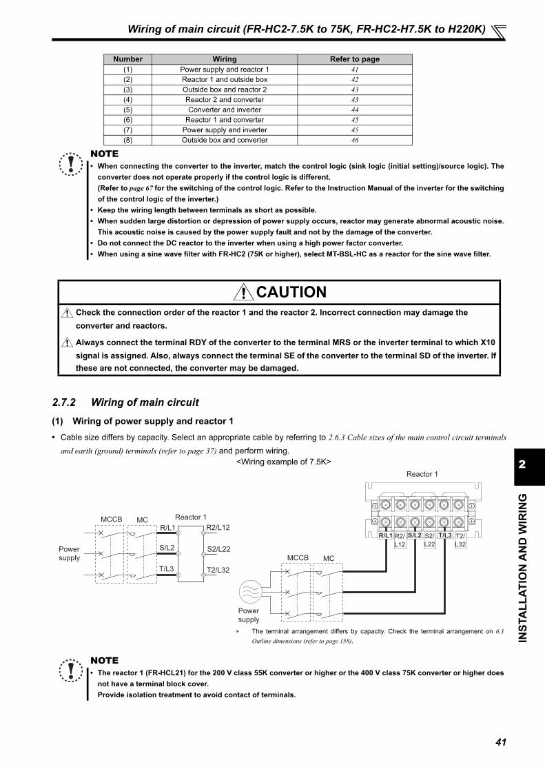
41
2
INST
ALL
ATIO
N A
ND
WIR
ING
Wiring of main circuit (FR-HC2-7.5K to 75K, FR-HC2-H7.5K to H220K)
2.7.2 Wiring of main circuit
(1) Wiring of power supply and reactor 1• Cable size differs by capacity. Select an appropriate cable by referring to 2.6.3 Cable sizes of the main control circuit terminals
and earth (ground) terminals (refer to page 37) and perform wiring.
Number Wiring Refer to page(1) Power supply and reactor 1 41(2) Reactor 1 and outside box 42(3) Outside box and reactor 2 43(4) Reactor 2 and converter 43(5) Converter and inverter 44(6) Reactor 1 and converter 45(7) Power supply and inverter 45(8) Outside box and converter 46
NOTE• When connecting the converter to the inverter, match the control logic (sink logic (initial setting)/source logic). The
converter does not operate properly if the control logic is different. (Refer to page 67 for the switching of the control logic. Refer to the Instruction Manual of the inverter for the switchingof the control logic of the inverter.)
• Keep the wiring length between terminals as short as possible.• When sudden large distortion or depression of power supply occurs, reactor may generate abnormal acoustic noise.
This acoustic noise is caused by the power supply fault and not by the damage of the converter.• Do not connect the DC reactor to the inverter when using a high power factor converter.• When using a sine wave filter with FR-HC2 (75K or higher), select MT-BSL-HC as a reactor for the sine wave filter.
CAUTIONCheck the connection order of the reactor 1 and the reactor 2. Incorrect connection may damage the converter and reactors.
Always connect the terminal RDY of the converter to the terminal MRS or the inverter terminal to which X10 signal is assigned. Also, always connect the terminal SE of the converter to the terminal SD of the inverter. If these are not connected, the converter may be damaged.
<Wiring example of 7.5K>
The terminal arrangement differs by capacity. Check the terminal arrangement on 6.3Outline dimensions (refer to page 158).
NOTE• The reactor 1 (FR-HCL21) for the 200 V class 55K converter or higher or the 400 V class 75K converter or higher does
not have a terminal block cover.Provide isolation treatment to avoid contact of terminals.
MCCB MC Reactor 1
R/L1
S/L2
T/L3
R2/L12
S2/L22
T2/L32
Power
supply MCCB MC
Reactor 1
Power
supply
R/L1 S/L2 T/L3R2/
L12
S2/
L22
T2/
L32

42
Wiring of main circuit (FR-HC2-7.5K to 75K, FR-HC2-H7.5K to H220K)
(2) Wiring of reactor 1 and outside box• Cable size differs by the capacity. Select an appropriate cable by referring to 2.6.3 Cable sizes of the main control circuit
terminals and earth (ground) terminals (refer to page 37) and perform wiring. • The 400V class outside box is equipped with a MC power supply stepdown transformer. Switch the tap (V1, V2, V3) of the
stepdown transformer according to the input power supply voltage as shown in the table below.Power Supply Voltage Switching Tap Position
380V or more, less than 400V V1400V or more, 440V or less V2
More than 440V, 460V or less V3
<Wiring example of 7.5K>
The terminal arrangement differs by capacity. Check the terminal arrangement on 6.3Outline dimensions (refer to page 158).
NOTE• Because the reactor heats up, install the reactor in a place where the outside box will be unaffected by heat.• Perform wiring where the wire sheath does not touch the reactor. • Do not remove or wire the whirl-stop (shown on the right diagram) of
the crimp terminals (R2/L12, S2/L22, T2/L32) of FR-HCB2-H160K andH220K.
Reactor 1 Outside box
R3/L13
S3/L23
T3/L33
R/L1
S/L2
T/L3
R2/L12 R2/L12
S2/L22 S2/L22
T2/L32 T2/L32
Total wiring length
10m or less
• Outside box terminal screws(accessory)
Use the enclosed screws (M5) for the wiring of FR-HCB2-7.5K, 15K and FR-HCB2-H7.5K to H30K.
Model Screw size Quantity
FR-HCB2-7.5K, 15KFR-HCB2-H7.5K to H30K
M5 6
Reactor 1
ROH1 88R 88SROH2
(1)
(2)
(3)
R3
S3
T3
(88S)(88R)(ROH1) (ROH2)
Outside box
R/L1 S/L2 T/L3R2/
L12
S2/
L22
T2/
L32
R2/
L12
S2/
L22
T2/
L32
R2/L12
S2/L22
T2/L32
Whirl-stop
Whirl-stop

43
2
INST
ALL
ATIO
N A
ND
WIR
ING
Wiring of main circuit (FR-HC2-7.5K to 75K, FR-HC2-H7.5K to H220K)
(3) Wiring of outside box and reactor 2• Cable size differs by capacity. Select an appropriate cable by referring to 2.6.3 Cable sizes of the main control circuit terminals
and earth (ground) terminals (refer to page 37) and perform wiring.
(4) Wiring of reactor 2 and high power factor converter• Cable size differs by capacity. Select an appropriate cable by referring to 2.6.3 Cable sizes of the main control circuit terminals
and earth (ground) terminals (refer to page 37) and perform wiring.
<Wiring example of 7.5K>
The terminal arrangement differs by capacity. Check the terminal arrangement on 6.3 Outlinedimensions (refer to page 158).
NOTE• Do not remove or wire the whirl-stop (shown on the right diagram) of
the crimp terminals (R3/L13, S3/L23, T3/L33) of FR-HCB2-H160K andH220K.
• The terminal block cover is not provided for the 75K reactor.Provide isolation treatment to avoid contact of terminals.
<Wiring example of 7.5K>
The terminal arrangement differs by capacity. Check the terminal arrangement on 2.6.2 Terminalarrangement of the main circuit terminal (refer to page 34) and 6.3 Outline dimensions (refer to page 158).
Outside box Reactor 2
R2/L12
S2/L22
T2/L32
R3/L13
S3/L23
T3/L33
R3/L13
S3/L23
T3/L33
R4/L14
S4/L24
T4/L34
Total wiring length
10m or less
• Outside box terminal screws(accessory)
Use the enclosed screws (M5) for the wiring of FR-HCB2-7.5K, 15K and FR-HCB2-H7.5K to H30K.
Model Screw size Quantity
FR-HCB2-7.5K, 15KFR-HCB2-H7.5K to H30K
M5 6
R4/L14
S4/L24
T4/L34
Reactor 2
ROH1 88R 88SROH2
(1)
(2)
(3)
R2
S2
T2
(A2) (A1)
R3/
L13
S3/
L23
T3/
L33
Outside box
R3/
L13
S3/
L23
T3/
L33
R3/L13
S3/L23
T3/L33
Whirl-stop
Whirl-stop
ConverterReactor 2
R3/L13
S3/L23
T3/L33
R4/L14
R4/L14
S4/L24
S4/L24
T4/L34
T4/L34
P/+
N/-
Total wiring length
10m or less
Reactor2
R3/L13
S3/L23
T3/L33
R4/
L14
S4/
L24
T4/
L34
R/L1 S/L2 T/L3
N/- P/+R1/L11 S1/L21
Converter
R4/
L14
S4/
L24
T4/
L34

44
Wiring of main circuit (FR-HC2-7.5K to 75K, FR-HC2-H7.5K to H220K)
(5) Wiring of high power factor converter and inverter• These units should be connected to transmit commands from the high power factor converter to the inverter securely.
Connection method differs depending on the inverter series. Refer to the Instruction Manual of the inverter whenconnecting. Refer to the below table for the wiring length. For the wire gauge of the main circuit terminals P/+ and N/- (across P and P, across N and N), refer to 2.6.3 Cable sizes of themain control circuit terminals and earth (ground) terminals (refer to page 37).
<Wiring example of 7.5K>
The terminal arrangement in the main circuit differs by capacity. Check the terminal arrangement on 2.6.2 Terminal arrangement of the main circuit terminal(refer to page 34).
Total wiring length
Across terminals P and PAcross terminals N and N
50m or less
Other control signal lines 30m or less
NOTE The converter operates as a common converter. Use terminals P/+ and N/- to connect it with the inverter. Do not
connect anything to the inverter power input terminals R/L1, S/L2, and T/L3. Incorrect connection to the inverterpower input will damage the inverter. Connecting opposite polarity of terminals P/+ and N/- will damage the inverterand the converter.
Do not connect the DC reactor to the inverter when using a high power factor converter.
Converter
(FR-HC2) Inverter
P/+
N/-
P/+
N/-
X10
RES
SD
RDY
RSO
SE
∗3
∗1
∗2Control
circuit
R4/L14
S4/L24
T4/L34
Installation of a fuse is recommended to avoid the damage to spread in case of aninverter failure. Select a fuse according to the motor capacity. When using a motor, ofwhich the capacity is smaller than the inverter capacity by two ranks or more, select thefuse with the capacity that is one rank lower than the inverter capacity. Refer to the fuseselection table on page 15, 17.When connecting several inverters, the wire gauge of terminal P/+ and N/- should besame as the wire gauge of the inverter's power supply side. (Refer to the InstructionManual of the inverter.)
The function of the inverter terminal, which is connected to the terminal RDY of theconverter, needs to be set at the inverter side. Refer to the Instruction Manual of theinverter.
Do not insert MCCB between terminals P/+ and N/- (P and P, N and N).Cable gauge for the
control circuit 0.75 to 1.25mm2
2 5 4 1 F/C +24 SD SD S1 S2 PC A1 B1 C1 A2 B2 C2SICSo SOC
AM 5 10E 10 SE SE RUN SU IPF OL FU PC RL RM RH RT AU SD SD CSSTP MRS RES STF STR JOG
PR
PX
R1/L11 S1/L21
R/L1 S/L2 T/L3
R1/L11 S1/L21
Converter
P/+N/-
88R 88S A
CVORSORDYNCNCNC
SENCNCNC
B C NC AM
PCPCY1
PCY2SESE SDSDSDFM
5 X1 X2
ROHSOFRES
NC
Inverter
R/L1 S/L2 T/L3 R4/L14
S4/L24
T4/L34
P/+N/-
88R 88S A
CVORSORDYNCNCNC
SENCNCNC
B C NC AM
PCPCY1
PCY2SESE SDSDSDFM
5 X1 X2
ROHSOFRES
NC
2 5 4 1 F/C +24 SD SD S1 S2 PC A1 B1 C1 A2 B2 C2SICSo SOC
AM 5 10E 10 SE SE RUN SU IPF OL FU PC RL RM RH RT AU SD SD CSSTP X10 RES STF STR JOG

45
2
INST
ALL
ATIO
N A
ND
WIR
ING
Wiring of main circuit (FR-HC2-7.5K to 75K, FR-HC2-H7.5K to H220K)
(6) Wiring reactor 1 and converterSupply power to the power detecting terminals (R/L1, S/L2, T/L3) separately from the main circuit wiring.
(7) Wiring of the power supply and inverterFor the inverters equipped with the control circuit power supply terminals (R1/L11 and S1/L21), connect the control circuitpower supply terminals (R1/L11 and S1/L21) directly to the power supply. Do not connect through the converter.
<Wiring example of 7.5K>
The terminal arrangement differs by capacity. Check the terminal arrangement on 2.6.2Terminal arrangement of the main circuit terminal (refer to page 34) and 6.3 Outline dimensions(refer to page 158).
NOTE The terminal R/L1, S/L2 and T/L3 of the converter are control terminals to detect power supply phases of the power
supply. The voltage phases of the terminals R4/L14, S4/L24, and T4/L34 and the terminals R/L1, S/L2, and T/L3 mustbe matched. If these terminals are not connected correctly, the converter does not operate properly.
If the inverter is operated without connecting the terminals R, S, T of the converter to the power supply, the converterwill be damaged.
NOTE Refer to the Instruction Manual of the inverter, and remove the jumpers across terminals R/L1and R1/L11 and across
terminals S/L2 and S1/L21 on the inverter main circuit. For the inverters equipped with the control circuit power supply terminals (R1/L11 and S1/L21), always connect the
power supply to the terminals. Inverter control power is provided. If not connected, the inverter may trip or bedamaged.
Power supply and the inverter are not connected for the inverters not equipped with control circuit power supplyterminals (R1/L11 and S1/L21).
Converter (FR-HC2)
Reactor 1(FR-HCL21)
R/L1S/L2T/L3
R1/L11S1/L21
R/L1
S/L2
T/L3
Power supply
R2/L12S2/L22
T2/L32
Jumper(The jumper is connected inside the converter.)
Total wiring length
10m or less
Cable gauge 1.25mm2
Reactor 1
R4/L14
S4/L24
T4/L34
N/- P/+R1/L11 S1/L21
Converter
Power supply
R/L1
S/L2
T/L3
R2/L12
S2/L22
T2/L32
R/L1
S/L2
T/L3
Inverter control power
Power
supply
R1/L11
S1/L21
MCCB
Cable gauge 0.75 to 2mm2
R1/L11S1/L21

46
Wiring of main circuit (FR-HC2-7.5K to 75K, FR-HC2-H7.5K to H220K)
(8) Wiring of outside box and high power factor converter Use the cable shown in the below table for the connection.
Converter terminals ROH and SD are used for the control signal for the inrush current limit circuit inside the outside box.Always connect them to the outside box. Failure to do so will cause internal circuit breakage of the outside box.
Connect the output from the MC start command terminals (88R, 88S) to the terminals (88R, 88S) of the outside box.
<Wiring example of 7.5K>
The terminal arrangement in the outside box differs by capacity. Check the terminal arrangement on 6.3 Outline dimensions (refer to page 158).
Cable gauge 0.75 to 1.25mm2
Outside box Converter
ROH1
ROH2
ROH
SD
88R
88S
88R
88S
Total wiring length
10m or less
(1)
(2)
(3)
R2
S2
T2
(A2) (A1)
R1/L11 S1/L21
Converter
P/+N/-
88R 88S A
CVORSORDYNCNCNC
SENCNCNC
B C NC AM
PCPCY1
PCY2SESE SDSDSDFM
5 X1 X2
ROHSOFRES
NC
Outside box
ROH2ROH1 88R 88S
R4/L14
S4/L24
T4/L34
R/L1
S/L2
T/L3
88R 88S A
CVORSORDYNCNCNC
SENCNCNC
B C NC AM
PCPCY1
PCY2SESE SDSDSDFM
5 X1 X2
ROHSOFRES
NC
To 88R of the
outside box
To 88S of the
outside box
To ROH2 of the
outside box
To ROH1 of the
outside box
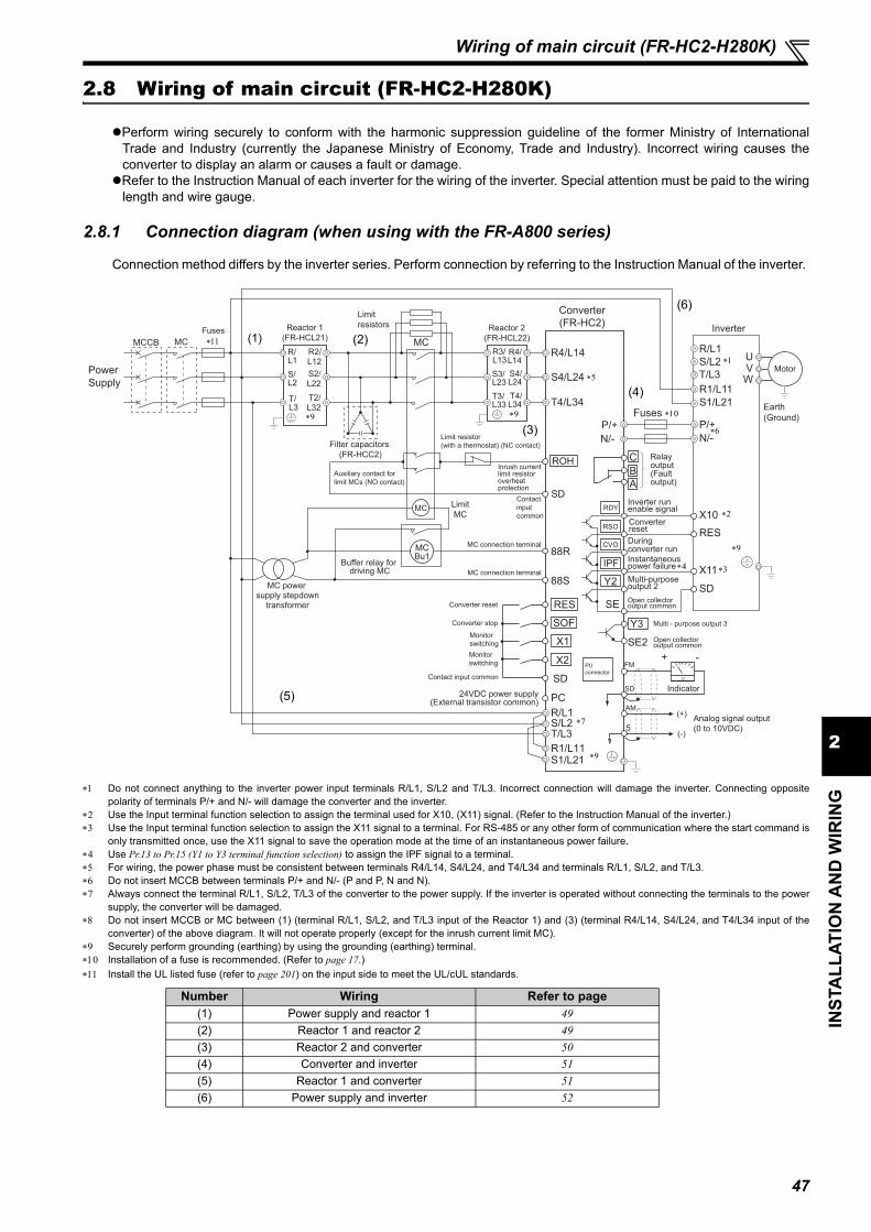
47
2
INST
ALL
ATIO
N A
ND
WIR
ING
Wiring of main circuit (FR-HC2-H280K)
2.8 Wiring of main circuit (FR-HC2-H280K)
Perform wiring securely to conform with the harmonic suppression guideline of the former Ministry of InternationalTrade and Industry (currently the Japanese Ministry of Economy, Trade and Industry). Incorrect wiring causes theconverter to display an alarm or causes a fault or damage.Refer to the Instruction Manual of each inverter for the wiring of the inverter. Special attention must be paid to the wiring
length and wire gauge.
2.8.1 Connection diagram (when using with the FR-A800 series)
Connection method differs by the inverter series. Perform connection by referring to the Instruction Manual of the inverter.
Do not connect anything to the inverter power input terminals R/L1, S/L2 and T/L3. Incorrect connection will damage the inverter. Connecting oppositepolarity of terminals P/+ and N/- will damage the converter and the inverter.
Use the Input terminal function selection to assign the terminal used for X10, (X11) signal. (Refer to the Instruction Manual of the inverter.) Use the Input terminal function selection to assign the X11 signal to a terminal. For RS-485 or any other form of communication where the start command is
only transmitted once, use the X11 signal to save the operation mode at the time of an instantaneous power failure. Use Pr.13 to Pr.15 (Y1 to Y3 terminal function selection) to assign the IPF signal to a terminal. For wiring, the power phase must be consistent between terminals R4/L14, S4/L24, and T4/L34 and terminals R/L1, S/L2, and T/L3. Do not insert MCCB between terminals P/+ and N/- (P and P, N and N). Always connect the terminal R/L1, S/L2, T/L3 of the converter to the power supply. If the inverter is operated without connecting the terminals to the power
supply, the converter will be damaged. Do not insert MCCB or MC between (1) (terminal R/L1, S/L2, and T/L3 input of the Reactor 1) and (3) (terminal R4/L14, S4/L24, and T4/L34 input of the
converter) of the above diagram. It will not operate properly (except for the inrush current limit MC). Securely perform grounding (earthing) by using the grounding (earthing) terminal. Installation of a fuse is recommended. (Refer to page 17.) Install the UL listed fuse (refer to page 201) on the input side to meet the UL/cUL standards.
Number Wiring Refer to page(1) Power supply and reactor 1 49(2) Reactor 1 and reactor 2 49(3) Reactor 2 and converter 50(4) Converter and inverter 51(5) Reactor 1 and converter 51(6) Power supply and inverter 52
Inverter
Converter(FR-HC2)
Filter capacitors (FR-HCC2)
Limitresistors
Motor
Reactor 1(FR-HCL21)
Power Supply
MCCB
LimitMC
Buffer relay for driving MC
MC power supply stepdown
transformer
Reactor 2(FR-HCL22)
Auxiliary contact for limit MCs (NO contact)
Limit resistor (with a thermostat) (NC contact)
MC
Converter stop
Monitorswitching
Converter reset
Contact input common
Monitorswitching
Inverter run enable signalConverterresetDuringconverter runInstantaneous power failure
Open collectoroutput common
Multi-purposeoutput 2
(-)
(+) Analog signal output(0 to 10VDC)
PUconnector
Relay output (Fault output)
MC connection terminal
MC connection terminal
Inrush currentlimit resistor overheatprotection
Contact inputcommon
24VDC power supply(External transistor common)
Earth (Ground)
MC
P/+P/+N/-N/-
R1/L11S1/L21
X10
RES
SD
X11
RDY
RSO
CVO
IPF
Y2
SE
R4/L14 R/L1S/L2T/L3S4/L24
T4/L34
R4/L14S4/L24T4/L34
R3/L13S3/L23T3/L33
R2/L12S2/L22
T2/L32
R/L1S/L2
T/L3
UVW
88R
R/L1S/L2T/L3
88S
R1/L11S1/L21
MCBu1
MC
ROH
SD
Y3
SE2
FM
SD Indicator
+ -
ABC
AM
5
SOF
X1
X2
RES
SD
PC
Fuses
Open collectoroutput common
Multi - purpose output 3
Fuses(1) (2)
(3)
(4)
(5)
(6)
48
Wiring of main circuit (FR-HC2-H280K)
NOTE• When connecting the converter to the inverter, match the control logic (sink logic (initial setting)/source logic). The
converter does not operate properly if the control logic is different. (Refer to page 67 for the switching of the control logic. Refer to the Instruction Manual of the inverter for the switchingof the control logic of the inverter.)
• Keep the wiring length between terminals as short as possible.• When sudden large distortion or depression of power supply occurs, reactor may generate abnormal acoustic noise.
This acoustic noise is caused by the power supply fault and not by the damage of the converter.• Do not connect the DC reactor to the inverter when using a high power factor converter.• When using a sine wave filter with FR-HC2 (75K or higher), select MT-BSL-HC as a reactor for the sine wave filter.
CAUTIONCheck the connection order of the reactor 1 and the reactor 2. Incorrect connection may damage the converter and reactors.
Always connect the terminal RDY of the converter to the terminal MRS or the inverter terminal to which X10 signal is assigned. Also, always connect the terminal SE of the converter to the terminal SD of the inverter. If these are not connected, the converter may be damaged.

49
2
INST
ALL
ATIO
N A
ND
WIR
ING
Wiring of main circuit (FR-HC2-H280K)
2.8.2 Wiring of main circuit
(1) Wiring power supply and reactor 1 Use the cable shown in the below table for the connection.
Use the molded case circuit breaker (MCCB), the earth leakage circuit breaker (ELB) or the magnetic contactor (MC)shown in the below table.
(2) Wiring reactor 1, filter capacitor, limit resistor, inrush current limit MC, and reactor 2
Cable gauge 200mm2
Molded Case Circuit Breaker (MCCB) or Earth Leakage Circuit Breaker (ELB)
(NF or NV type)700A
Magnetic Contactor (MC) S-N600
MCCB MCReactor 1
(FR-HCL21-H280K)
R/ L1
S/L2
T/
L3
R2/ L2
S2/L22
T2/
L32
Power
supply
Reactor 1(FR-HCL21-H280K)
R2/L12S2/L22T2/L32
R/L1S/L2T/L3
Reactor 2(FR-HCL22-H280K)
R4/L14S4/L24T4/L34
R3/L13S3/L23T3/L33
Limit MC
FR-HCC2-H280K
1) Filter capacitor
2)
3)
Converter(FR-HC2-H280K)
Thermostat output
Limit resistor (with thermostat)0.96OHM BKO-CA1996H31
P/+
N/-
ROH
SD
To inverterR4/L14S4/L24T4/L34
Auxiliary contact forlimit MCs (NO contact) 3
∗1
∗1
∗2
∗3
∗3
∗3∗3
∗3
∗3
Inrush current limit resistorConnect the following devices to the appended terminal
block:0.96OHM BKO-CA1996H21 (without thermostat) 3 Inrush current limit resistor (only S-phase)
Connect the following devices to the appended terminalblock:0.96OHM BKO-CA1996H21 (without thermostat) 20.96OHM BKO-CA1996H31 (with thermostat) 1
Appended terminal block and terminal block shortingconductor

50
Wiring of main circuit (FR-HC2-H280K)
1) Filter capacitorInstall three filter capacitors in parallel to the output side of the reactor 1 or to the input side of the inrush current limitMC as shown in the above diagram.Use the cable shown in the table below for the connection of filter capacitor.
2) Limit resistor, inrush current limit MCInstall a pair of a limit resistor and an inrush current limit MC to the output side of the reactor 1, and install anotherpair of those to the input side of the reactor 2. Install the limit resistor to the appended terminal block. Short a terminal block with a terminal block shortingconductor, and use them as a pair in each phase. Connect the appended terminal blocks to the appended inrushcurrent limit MCs.
Use the cable shown in the below table for the connection of each phase between the reactor 1 and reactor 2.
3) Connecting limit resistor thermostats to the converterConnect a limit resistor thermostat across the converter terminals ROH and SD.
(3) Wiring reactor 2 and converter Use the cable shown in the below table for the connection.
Cable gauge 60mm2
Wiring length 2m or less
Cable gauge 200mm2
Total wiring length 10m or less
Cable gauge 200mm2
Total wiring length 10m or less
∗2 Include one appended limit resistor with thermostat in the S-phase.
Wire to the terminal block (22mm2)
Connection example of inrush current limit MCs and limit resistors (of one phase)
Crimp terminal
Crimp terminal
MC conductor
Wire to the terminal block
Power cable
∗1 Make sure that the power cable touches the MC conductor.
Inrush current limit MC
Inrush current limit MC
∗1
∗2
Pow
er cable
Appended terminal blockshorting conductor
Appended terminal block
Reactor 2(FR-HCL22-H280K)
Converter (FR-HC2-H280K)
R3/L13
S3/L23
T3/L33
R4/L14
R4/L14
S4/L24
S4/L24
T4/L34
T4/L34
P/+
N/-

51
2
INST
ALL
ATIO
N A
ND
WIR
ING
Wiring of main circuit (FR-HC2-H280K)
(4) Wiring example of converter and inverter These units should be connected to transmit commands from the converter to the inverter securely.
Connection method differs depending on the inverter series. Refer to the Instruction Manual of the inverter whenconnecting. Refer to the below table for the wiring length.
(5) Wiring reactor 1 and converterSupply power to the power detecting terminals (R/L1, S/L2, T/L3) separately from the main circuit wiring.Switch the tap (V1, V2, V3) of the MC power supply stepdown transformer according to the input power supply voltage as shownin the below table.
Connect the MC start command terminals (88R, 88S) to the MC for the inrush current limit MC (for three phases) through the bufferrelay.
Across terminals P and P / terminals N and N 50m or lessOther control signal lines 30m or less
NOTE The converter operates as a common converter. Use terminals P/+ and N/- to connect it with the inverter. Do not
connect anything to the inverter power input terminals R/L1, S/L2, and T/L3. Incorrect connection to the inverterpower input will damage the inverter. Connecting opposite polarity of terminals P/+ and N/- will damage the inverterand the converter. Do not connect the DC reactor to the inverter when using a high power factor converter.
Power Supply Voltage Switching Tap Position 380V or more, less than 400V V1400V or more, 440V or less V2
More than 440V, 460V or less V3
NOTE The terminal R/L1, S/L2, and T/L3 of the converter are control terminals to detect power supply phases of the power
supply. The voltage phases of the terminals R4/L14, S4/L24 and T4/L34 and the terminals R/L1, S/L2 and T/L3 must bematched. If these terminals are not connected correctly, the converter does not operate properly.
If the inverter is operated without connecting the terminals R/L1, S/L2 and T/L3 of the converter to the power supply,the converter will be damaged.
Inverter
∗3
∗1
∗2
Control
circuit
Converter (FR-HC2-H280K)
P/+
N/-
P/+
N/-
R4/L14
S4/L24
T4/L34
X10
RES
SD
RDY
RSO
SE
Installation of a fuse is recommended to avoid the damage to spread in caseof an inverter failure. Select a fuse according to the motor capacity. Whenusing a motor, of which the capacity is smaller than the inverter capacity bytwo ranks or more, select the fuse capacity according to the inverter capacity.Refer to the fuse selection table on page 15, 17.When connecting several inverters, the wire gauge of terminal P/+ and N/-should be same as the wire gauge of the inverter's power supply side. (Referto the Instruction Manual of the inverter.)
The function of the inverter terminal, which is connected to the terminal RDYof the converter, needs to be set at the inverter side. Refer to the InstructionManual of the inverter.
Do not insert MCCB between terminals P/+ and N/- (P and P, N and N).Cable gauge for the control circuit 0.75 to 2mm2
Converter
(FR-HC2-H280K)Limit MC
Buffer relay for driving MCs
(SR-N4)
Stepdown
transformer (1PH 630VA)
Reactor 1
(FR-HCL21-H280K)
88R
R/L1S/L2T/L3
88S
R1/L11S1/L21
R/L1
S/L2T/L3
R/L1
S/L2
R5/L15
S5/L25
Power
Supply
MC
MCBu1
R2/L12
S2/L22
T2/L32
V1AC410V
V2AC430V
V3AC470V
Total wiring length 10m or lessCable gauge 1.25mm2
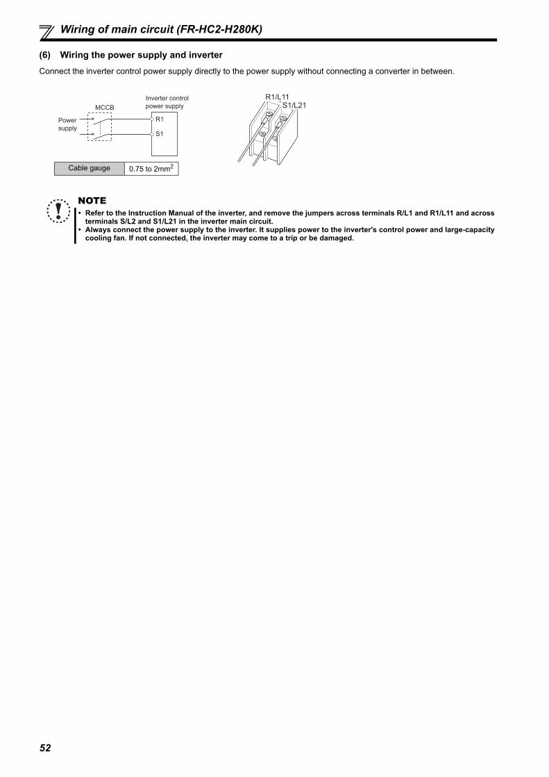
52
Wiring of main circuit (FR-HC2-H280K)
(6) Wiring the power supply and inverterConnect the inverter control power supply directly to the power supply without connecting a converter in between.
NOTE Refer to the Instruction Manual of the inverter, and remove the jumpers across terminals R/L1 and R1/L11 and across
terminals S/L2 and S1/L21 in the inverter main circuit. Always connect the power supply to the inverter. It supplies power to the inverter's control power and large-capacity
cooling fan. If not connected, the inverter may come to a trip or be damaged.
Power
supply
Inverter control
power supply
R1
S1
MCCB
Cable gauge 0.75 to 2mm2
R1/L11S1/L21

53
2
INST
ALL
ATIO
N A
ND
WIR
ING
Wiring of main circuit (FR-HC2-H400K, H560K)
2.9 Wiring of main circuit (FR-HC2-H400K, H560K)
Perform wiring securely to conform with the harmonic suppression guideline of the former Ministry of InternationalTrade and Industry (currently the Japanese Ministry of Economy, Trade and Industry). Incorrect wiring causes theconverter to display an alarm or causes a fault or damage.
Refer to the Instruction Manual of each inverter for the wiring of the inverter. Special attention must be paid to thewiring length and wire gauge.
2.9.1 Connection diagram (when using with the FR-A800 series)
Connection method differs by the inverter series. Perform connection by referring to the Instruction Manual of theinverter.
<Wiring example of 400K>
When connecting the inverter which has power supply input terminals R/L1, S/L2, and T/L3, always keep the terminals open. Incorrect connection willdamage the inverter.
Use the Input terminal function selection to assign the X10 (X11) signal to a terminal. (Refer to the Instruction Manual of the inverter.) Use the Input terminal function selection to assign the X11 signal to a terminal. For RS-485 or any other form of communication where the start command is
only transmitted once, use the X11 signal to save the operation mode at the time of an instantaneous power failure. (Refer to the Instruction Manual of theinverter.)
Use Pr.13 to Pr.15 (Y1 to Y3 terminal function selection) to assign the IPF signal to a terminal. For wiring, the power phase must be consistent between terminals R4/L14, S4/L24, and T4/L34 and terminals R/L1, S/L2, and T/L3. Do not insert MCCB between terminals P/+ and N/- (P and P, N and N). Connecting opposite polarity of terminals P and N will damage the converter and the
inverter. Always connect the terminal R, S, and T of the converter to the power supply. If the inverter is operated without connecting the terminals to the power supply,
the converter will be damaged. Do not insert MCCB or MC between (1) (terminal R/L1, S/L2, T/L3 input of the converter) and (3) (terminal R4/L14, S4/L24, T4/L34 input of the converter) of
the above diagram. It will not operate properly (except for the inrush current limit MC). Securely perform grounding (earthing) by using the grounding (earthing) terminal. Installation of a fuse is recommended for the inverters other than the FR-A842/FR-F842. (Refer to page 15.) Connect three sets consisting of one filter capacitor and one filter capacitor alarm detector for 560K. For 560K, install a set of three MCs to each phase. Install the UL listed fuse (refer to page 201) on the input side to meet the UL/cUL standards. Change the setting of Pr.10 RDY signal logic selection to "0" (positive logic). (This setting change must be made when connecting the FR-A842/F842
separated converter type inverter.) When connecting the FR-A842/F842 inverter and other inverters with the FR-HC2 in common bus system, set the samelogic for the X10 signal same as that of the RDY signal. (Refer to the Inverter Instruction Manual for the setting method.)
Always connect between the FR-HC2 terminal RDY and the inverter terminal MRS (X10), and between the FR-HC2 terminal SE and the inverter terminalSD. Not connecting these terminals may damage the FR-HC2.
Inverter(FR-A842)
Converter(FR-HC2)
Filter capacitors 2(FR-HCC2)
Limit resistor
Motor
Reactor 1(FR-HCL21)
Power Supply
MCCB
��
Limit MC
Buffer relay for driving MCs
MC power supply
stepdowntransformer
Mini relay for filter capacitor alarm detector
Buffer relay for filter capacitor alarm detectors
Reactor 2(FR-HCL22)
Auxiliary contact for limit MCs (NO contact) 3
Filter capacitor alarm detector (NC contact) 2
Limit resistor (with thermostat) (NC contact) 3
MC1
MC2
MC3 R1/L11S1/L21
R4/L14
S4/L24
T4/L34
R4/L14S4/L24T4/L34
R3/L13S3/L23T3/L33
R2/L12S2/L22
T2/L32
R/L1S/L2
T/L3
MC
UVW
88R
R/L1S/L2T/L3
88S
R1/L11S1/L21
MCBu1
MC1
MC2
MC3
ROH
SD
MC2 MC3 MCSmall
MCBu2 MC1
SOF
X1
X2
RES
SD
P/+P/+N/-N/-
MRS(X10)
RES
SD
RDY
RSO
SE
CVO
SE2
FM
SD Indicator
+ -
(-)
(+)AM
5
ABC
Y2
IPF
PC
Inrush current limit resistor overheat protection
Reset
Contact input common
Converter stop
Monitor switching
Monitor switching
Contact input common
24VDC power supply (External transistor common)
Fuses
Relay output (fault output)
Inverter run enable signal
Converter reset
During converter run
Instantaneous power failure
Multi-purpose output 2
Multi-purpose output 3
Open collector output common
Open collector output common
Analog signal output (0 to 10VDC)
PU connector
Y3
Earth
��
��
��
��
��
��
�� ���� (Ground)
���
���
��� Fuses��
�X11
������
���
������
��
(1) (2)
(3)(4)
(5)
(6)
(7)
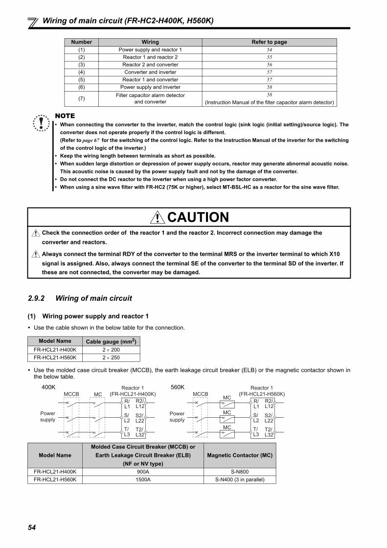
54
Wiring of main circuit (FR-HC2-H400K, H560K)
2.9.2 Wiring of main circuit
(1) Wiring power supply and reactor 1 Use the cable shown in the below table for the connection.
Use the molded case circuit breaker (MCCB), the earth leakage circuit breaker (ELB) or the magnetic contactor shown inthe below table.
Number Wiring Refer to page(1) Power supply and reactor 1 54(2) Reactor 1 and reactor 2 55(3) Reactor 2 and converter 56(4) Converter and inverter 57(5) Reactor 1 and converter 57(6) Power supply and inverter 58
(7) Filter capacitor alarm detectorand converter
58(Instruction Manual of the filter capacitor alarm detector)
NOTE• When connecting the converter to the inverter, match the control logic (sink logic (initial setting)/source logic). The
converter does not operate properly if the control logic is different. (Refer to page 67 for the switching of the control logic. Refer to the Instruction Manual of the inverter for the switchingof the control logic of the inverter.)
• Keep the wiring length between terminals as short as possible.• When sudden large distortion or depression of power supply occurs, reactor may generate abnormal acoustic noise.
This acoustic noise is caused by the power supply fault and not by the damage of the converter.• Do not connect the DC reactor to the inverter when using a high power factor converter.• When using a sine wave filter with FR-HC2 (75K or higher), select MT-BSL-HC as a reactor for the sine wave filter.
CAUTIONCheck the connection order of the reactor 1 and the reactor 2. Incorrect connection may damage the converter and reactors.
Always connect the terminal RDY of the converter to the terminal MRS or the inverter terminal to which X10 signal is assigned. Also, always connect the terminal SE of the converter to the terminal SD of the inverter. If these are not connected, the converter may be damaged.
Model Name Cable gauge (mm2)FR-HCL21-H400K 2 200FR-HCL21-H560K 2 250
Model NameMolded Case Circuit Breaker (MCCB) or
Earth Leakage Circuit Breaker (ELB)(NF or NV type)
Magnetic Contactor (MC)
FR-HCL21-H400K 900A S-N800FR-HCL21-H560K 1500A S-N400 (3 in parallel)
MCCB MC
Reactor 1
(FR-HCL21-H400K)
R/L1
S/L2
T/L3
R2/L12
S2/L22
T2/L32
Power
supply
400KMCCB
MC
Reactor 1
(FR-HCL21-H560K)
R/L1
S/L2
T/L3
R2/L12
S2/L22
T2/L32
Power
supply
MC
MC
560K

55
2
INST
ALL
ATIO
N A
ND
WIR
ING
Wiring of main circuit (FR-HC2-H400K, H560K)
(2) Wiring reactor 1, filter capacitor, limit resistor, inrush current limit MC, and reactor 2
<Wiring example of 400K>
<Wiring example of 560K>
Limit resistor 0.96OHM BKO-CA1996H21 (without thermostat) 50.96OHM BKO-CA1996H31 (with thermostat) 1Connect them to each phase of the shorting conductors of the inrush current limit MCs.
MC shorting conductor
MC2 MC3MC1
13
14
5
9
MCSmall
MCBu2
R2/L12
S2/L22
T2/L32
R/L1
S/L2
T/L3
R4/L14
S4/L24
T4/L34
R3/L13
S3/L23
T3/L33
FR-HCC2-H400K FR-HCC2-H400K
2)
3)
P/+
N/-
ROH
SD
R4/L14S4/L24
T4/L34
*1
*1
*1
*2 *2
*2 *2
*2 *2Reactor 1(FR-HCL21-H400K)
To inverter
Reactor 2(FR-HCL22-H400K)
Converter (FR-HC2-H400K)
Limit MC1
Limit MC2
Limit MC3
1)Filter capacitors 2
Buffer relay for filter capacitor alarm detector
Mini relay for
filter capacitor
alarm detector
Auxiliary contact for
limit MCs (NO contact) 3
Filter capacitor alarm detector (NC contact) 2
To inverter
Reactor 1(FR-HCL21-H560K)
1)Filter capacitors 3
Buffer relay for filter capacitor alarm detector
Mini relay for
filter capacitor
alarm detector
Reactor 2(FR-HCL22-H560K)
Converter (FR-HC2-H560K)
Auxiliary contact for
limit MCs (NO contact) 3
Filter capacitor alarm detector (NC contact) 3
MC2 MC3MC1
13
14
5
9
MCSmall
MCBu2
R2/L12
S2/L22
T2/L32
R/L1
S/L2
T/L3
R4/L14
S4/L24
T4/L34
R3/L13
S3/L23
T3/L33
Limit MC1
Limit MC2
Limit MC3
FR-HCC2-H560K FR-HCC2-H560K FR-HCC2-H560K
2)
3)
P/+
N/-
R4/L14S4/L24T4/L34
ROH
SD
∗1
∗2∗2
∗2∗2
∗2∗2
∗1
∗1
Thermostat output
Limit resistor (with thermostat)0.96OHM BKO-CA1996H31
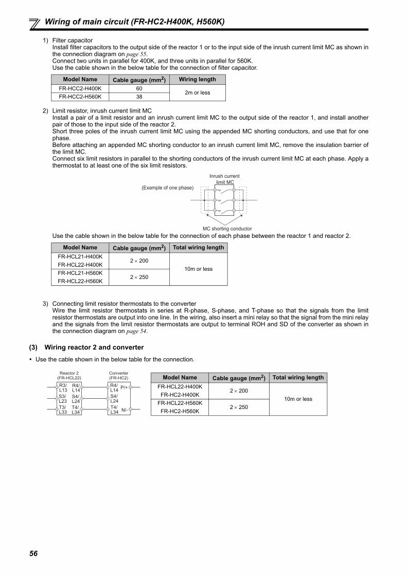
56
Wiring of main circuit (FR-HC2-H400K, H560K)
1) Filter capacitorInstall filter capacitors to the output side of the reactor 1 or to the input side of the inrush current limit MC as shown inthe connection diagram on page 55.Connect two units in parallel for 400K, and three units in parallel for 560K.Use the cable shown in the below table for the connection of filter capacitor.
2) Limit resistor, inrush current limit MCInstall a pair of a limit resistor and an inrush current limit MC to the output side of the reactor 1, and install anotherpair of those to the input side of the reactor 2. Short three poles of the inrush current limit MC using the appended MC shorting conductors, and use that for onephase.Before attaching an appended MC shorting conductor to an inrush current limit MC, remove the insulation barrier ofthe limit MC.Connect six limit resistors in parallel to the shorting conductors of the inrush current limit MC at each phase. Apply athermostat to at least one of the six limit resistors.
Use the cable shown in the below table for the connection of each phase between the reactor 1 and reactor 2.
3) Connecting limit resistor thermostats to the converterWire the limit resistor thermostats in series at R-phase, S-phase, and T-phase so that the signals from the limitresistor thermostats are output into one line. In the wiring, also insert a mini relay so that the signal from the mini relayand the signals from the limit resistor thermostats are output to terminal ROH and SD of the converter as shown inthe connection diagram on page 54.
(3) Wiring reactor 2 and converter Use the cable shown in the below table for the connection.
Model Name Cable gauge (mm2) Wiring lengthFR-HCC2-H400K 60
2m or lessFR-HCC2-H560K 38
Model Name Cable gauge (mm2) Total wiring lengthFR-HCL21-H400KFR-HCL22-H400K
2 20010m or less
FR-HCL21-H560KFR-HCL22-H560K
2 250
Model Name Cable gauge (mm2) Total wiring lengthFR-HCL22-H400K
FR-HC2-H400K2 200
10m or lessFR-HCL22-H560K
FR-HC2-H560K2 250
MC shorting conductor
Inrush current
limit MC(Example of one phase)
Reactor 2(FR-HCL22)
Converter (FR-HC2)
R3/L13
S3/L23
T3/L33
R4/L14
R4/L14
S4/L24
S4/L24
T4/L34
T4/L34
P/+
N/-

57
2
INST
ALL
ATIO
N A
ND
WIR
ING
Wiring of main circuit (FR-HC2-H400K, H560K)
(4) Wiring example of converter and inverter These units should be connected to transmit commands from the converter to the inverter securely.
Connection method differs depending on the inverter series. Refer to the Instruction Manual of the inverter whenconnecting. Refer to the below table for the wiring length.
(5) Wiring reactor 1 and converterSupply power to the power detecting terminals (R/L1, S/L2, T/L3) separately from the main circuit wiring.Switch the tap (V1, V2, V3) of the MC power supply stepdown transformer according to the input power supply voltage as shownin the below table.
Connect the MC start command terminals (88R, 88S) to the inrush current limit MC (for three phases) through the buffer relay.
Across terminals P and P / terminals N and N 50m or lessOther control signal lines 30m or less
NOTE The converter operates as a common converter. Use terminals P/+ and N/- to connect it with the inverter. Do not
connect anything to the inverter power input terminals R/L1, S/L2, and T/L3. Incorrect connection to the inverterpower input will damage to the inverter. Connecting opposite polarity of terminals P/+ and N/- will damage theinverter and the converter.
• Do not connect the DC reactor to the inverter when using a high power factor converter.
Power Supply Voltage Switching Tap Position 380V or more, less than 400V V1400V or more, 440V or less V2
More than 440V, 460V or less V3
NOTE The terminal R/L1, S/L2, and T/L3 of the converter are control terminals to detect power supply phases of the power
supply. The voltage phases of the terminals R4/L14, S4/L24, and T4/L34 and the terminals R/L1, S/L2, and T/L3 mustbe matched. If these terminals are not connected correctly, the converter does not operate properly.
If the inverter is operated without connecting the terminals R/L1, S/L2, and T/L3 of the converter to the power supply,the converter will be damaged.
Inverter
∗3
∗1
∗2
Control circuit
Converter(FR-HC2)
P/+
N/-
P/+
N/-
R4/L14
S4/L24
T4/L34 X10
RES
SD
RDY
RSO
SE
X11IPF∗4
Installation of fuses is recommended for the inverters other than the FR-A842/F842 toprevent the spread of damage caused by an inverter failure. Installation of a fuse isrecommended to avoid the damage to spread in case of an inverter failure. Select a fuseaccording to the motor capacity. When using a motor, of which the capacity is smaller thanthe inverter capacity by two ranks or more, select the fuse capacity according to theinverter capacity. Refer to the fuse selection table on page 17.When connecting several inverters, perform wiring with the wire gauge of the inverter'spower supply side for terminal P/+ and N/-. (Refer to the Instruction Manual of the inverter.)
The function of the inverter terminal, which is connected to the terminal RDY of theconverter, needs to be set at the inverter side. Refer to the Instruction Manual of theinverter.
Do not insert MCCB between terminals P/+ and N/- (P and P, N and N). For RS-485 or any other communication where the start command is only transmitted
once, use the X11 signal to save the operation mode at the time of an instantaneouspower failure.
Wire gauge for the control circuit 0.75 to 2mm2
88R
S/L2T/L3
88S
R1/L11
R/L1
S1/L21
R/L1
S/L2
R5/L15
S5/L25
MC3
MC2
MC1
MCBu1
V1410VAC
V2430VAC
V3470VAC
Reactor 1(FR-HCL21)
Power
Supply
Buffer relay for driving MCs
(SR-N4)
Converter (FR-HC2)
Stepdowntransformer
(1PH 630VA)
Inrush current limit MC
R/L1S/L2T/L3
R2/L12S2/L22T2/L32
Total wiring length 10m or lessCable gauge 1.25mm2

58
Wiring of main circuit (FR-HC2-H400K, H560K)
(6) Wiring the power supply and inverterConnect the inverter control power supply directly to the power supply without connecting a converter in between.
(7) Wiring filter capacitor alarm detector and converter Use the cable shown in the below table for the connection.
Before wiring, read the Instruction Manual appended to the filter capacitor alarm detector carefully.<Wiring example of 400K>
<Wiring example of 560K>
Connect the wiring to the terminals R5/L15 and S5/L25 of the MC power supply stepdown transformer by placing parallel with the wiring of (5) Wiring reactor1 and converter (Refer to page 57).
Install the mini relay using the provided mini relay terminal block (PYF14T) and the mini relay clip (PYC-A1).
NOTE Refer to the Instruction Manual of the inverter, and remove the jumpers across terminals R/L1 and R1/L11 and across
terminals S/L2 and S1/L21 in the inverter main circuit. Always connect the power supply to the inverter. It supplies power to the inverter's control power and large-capacity
cooling fan. If not connected, the inverter may come to a trip or be damaged. "E.P24" may appear on the FR-A842/F842 inverter connected to the converter if the power is shut off while the
inverter control power is supplied from terminals P and N (initial setting).
Cable gauge 2mm2
Power
supply
Inverter control
power supply
R1
S1
MCCB
R1/L11S1/L21
Cable gauge 0.75 to 2mm2
ROH
SD
MCSmall
R/L1S/L2T/L3
R/L1
S/L2
R5/L15
S5/L25
V1AC410V
V2AC430V
V3AC470V
MC1 MC2 MC3MCBu2
R2/L12S2/L22T2/L32
Power
Supply
Reactor 1(FR-HCL21-H400K)
Stepdowntransformer
(1PH 630VA)
Filter capacitor alarm detector (NC contact) 2
Buffer relay for filter capacitor alarm detectors
(SR-N4)
Filter capacitors 2
(FR-HCC2-H400K)
Converter (FR-HC2-H400K)
Auxiliary contact for inrush current limit MCs (NO contact) 3
Mini relay for filter capacitor alarm detector (MYQ4Z AC200/220)
Limit resistor (with thermostat)
(NC contact) 3
R/L1
S/L2T/L3
R2/L12
S2/L22
T2/L32
ROH
SD
MCSmall
Filter capacitors 3
(FR-HCC2-H560K)
R/L1
S/L2
R5/L15
S5/L25
V1AC410V
V2AC430V
V3AC470V
MC1 MC2 MC3MCBu2
Power
Supply
Reactor 1(FR-HCL21-H560K)
Stepdowntransformer
(1PH 630VA)
Converter (FR-HC2-H560K)
Filter capacitor alarm detector (NC contact) 3
Buffer relay for filter capacitor alarm detectors
(SR-N4)
Auxiliary contact for inrush current limit MCs (NO contact) 3
Mini relay for filter capacitor alarm detector (MYQ4Z AC200/220)
Limit resistor (with thermostat)
(NC contact) 3

59
2
INST
ALL
ATIO
N A
ND
WIR
ING
Notes on earthing (grounding)
2.10 Notes on earthing (grounding)
Always earth (ground) the converter with its accessories (reactor 1, reactor 2, outside box, filter capacitor).(1) Purpose of earthing (grounding)
Generally, an electrical apparatus has an earth (ground) terminal, which must be connected to the ground before use. An electrical circuit is usually insulated by an insulating material and encased. However, it is impossible to manufacturean insulating material that can shut off a leakage current completely, and actually, a slight current flow into the case. Thepurpose of earthing (grounding) the case of an electrical apparatus is to prevent operator from getting an electric shockfrom this leakage current when touching it. To avoid the influence of external noises, this earthing (grounding) is important to audio equipment, sensors, computersand other apparatuses that handle low-level signals or operate very fast.
(2) Earthing (grounding) methods and earthing (grounding) workAs described previously, earthing (grounding) is roughly classified into an electrical shock prevention type and a noise-influenced malfunction prevention type. Therefore, these two types should be clearly distinguished, and the followingwork must be done to prevent the leakage current having the converter's high frequency components from entering themalfunction prevention type earthing (grounding):(a) Independently earth (ground) the converter with its accessories whenever possible. If independent earthing
(grounding) (l) is not available, use (ll) common earthing (grounding) in the figure below where the converter isconnected with the other equipment at an earthing (grounding) point.Do not use the other equipment's earthing (grounding) cable to earth (ground) the converter as shown in (III). A leakage current containing many high frequency components flows into the earthing (grounding) cables of theconverter with its accessories. Because of this, the converter must be earthed (grounded) separately from EMI-sensitive devices.In a high building, it may be effective to use the EMI prevention type earthing (grounding) connecting to an ironstructure frame, and electric shock prevention type earthing (grounding) with the independent earthing (grounding)together.
(b) This converter must be earthed (grounded). Earthing (Grounding) must conform to the requirements of national andlocal safety regulations and electrical codes. (NEC section 250, IEC 536 class 1 and other applicable standards).
(c) Use the thickest possible earth (ground) cable. The earth (ground) cable size should be no less than the sizeindicated in the table on page 37.
(d) The converter with its accessories should have their earthing (grounding) points as close as possible to them, andtheir earthing (grounding) cables should be as short as possible.
(e) Run the earth (ground) cable as far away as possible from the I/O wiring of equipment sensitive to noises and runthem in parallel in the minimum distance.
(3) Earthing (grounding) of the reactor(a) The reactor 1 and reactor 2 are usually earthed (grounded) by being mounted securely to the enclosure. If it cannot
be earthed (grounded) securely enough to the enclosure, remove varnish from a mounting hole and use that holeand a cable to earth (ground).(For the position of the varnish-removed mounting hole, refer to the outline dimensions. (Refer to page 165 and 173.))
(b) If the model is equipped with an earth (ground) terminal, wire the cable to that earth (ground) terminal. (Refer to theoutline dimensions for presence/absence of the earth (ground) terminal. (Refer to page 165 and 173.))
(c) The earthing (grounding) cable size of the reactors should be the same as that of the high power factor converter.(Refer to page 37.)
(4) Earthing (grounding) example
(a) Independently earth (ground) the converter with its accessories whenever possible.(b) Wire the earthing (grounding) cable as close as possible to the input cable in parallel.(c) Earth (ground) the high power factor converter with its accessory at one point. (Excluding when the reactors 1 and 2
are mounted on the enclosure surface.)
Converter Other
equipment
(I) Independent earthing (grounding).......Good
(accessories)Other
equipment
(II) Common earthing (grounding).......Good
Converter
(accessories)Converter Other
equipment
(III) Common earthing (grounding) cable .......Not allowed
(accessories)
(d)
(e)
(c)(b)(a) : Earthing (grounding) cable
Powersupply M Motor
Inve
rter
Conv
erte
r
Rea
ctor
2
Rea
ctor
1O
utsi
de b
ox
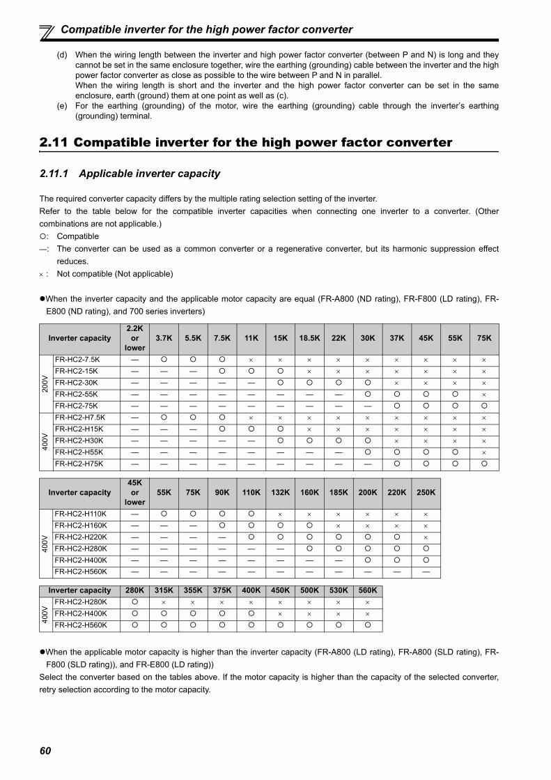
60
Compatible inverter for the high power factor converter
(d) When the wiring length between the inverter and high power factor converter (between P and N) is long and theycannot be set in the same enclosure together, wire the earthing (grounding) cable between the inverter and the highpower factor converter as close as possible to the wire between P and N in parallel.When the wiring length is short and the inverter and the high power factor converter can be set in the sameenclosure, earth (ground) them at one point as well as (c).
(e) For the earthing (grounding) of the motor, wire the earthing (grounding) cable through the inverter’s earthing(grounding) terminal.
2.11 Compatible inverter for the high power factor converter
2.11.1 Applicable inverter capacity
The required converter capacity differs by the multiple rating selection setting of the inverter.Refer to the table below for the compatible inverter capacities when connecting one inverter to a converter. (Othercombinations are not applicable.): Compatible—: The converter can be used as a common converter or a regenerative converter, but its harmonic suppression effect
reduces. : Not compatible (Not applicable)
When the inverter capacity and the applicable motor capacity are equal (FR-A800 (ND rating), FR-F800 (LD rating), FR-E800 (ND rating), and 700 series inverters)
When the applicable motor capacity is higher than the inverter capacity (FR-A800 (LD rating), FR-A800 (SLD rating), FR-F800 (SLD rating)), and FR-E800 (LD rating))
Select the converter based on the tables above. If the motor capacity is higher than the capacity of the selected converter,retry selection according to the motor capacity.
Inverter capacity2.2K
or lower
3.7K 5.5K 7.5K 11K 15K 18.5K 22K 30K 37K 45K 55K 75K
200V
FR-HC2-7.5K — FR-HC2-15K — — — FR-HC2-30K — — — — — FR-HC2-55K — — — — — — — — FR-HC2-75K — — — — — — — — —
400V
FR-HC2-H7.5K — FR-HC2-H15K — — — FR-HC2-H30K — — — — — FR-HC2-H55K — — — — — — — — FR-HC2-H75K — — — — — — — — —
Inverter capacity45Kor
lower55K 75K 90K 110K 132K 160K 185K 200K 220K 250K
400V
FR-HC2-H110K — FR-HC2-H160K — — — FR-HC2-H220K — — — — FR-HC2-H280K — — — — — —
FR-HC2-H400K — — — — — — — —
FR-HC2-H560K — — — — — — — — — — —
Inverter capacity 280K 315K 355K 375K 400K 450K 500K 530K 560K
400V
FR-HC2-H280K FR-HC2-H400K FR-HC2-H560K

61
2
INST
ALL
ATIO
N A
ND
WIR
ING
Compatible inverter for the high power factor converter
When the applicable motor capacity is lower than the inverter capacity (FR-A800 (HD rating)).
2.11.2 Inverter parameter settings
When using the converter with the inverter, some inverter parameters must be set. The parameter settings differ by theinverter series.For the parameters and inverters not listed below, refer to the Instruction Manual of the inverter.
Inverter capacity2.2K
or lower
3.7K 5.5K 7.5K 11K 15K 18.5K 22K 30K 37K 45K 55K
200V
FR-HC2-7.5K — FR-HC2-15K — — — FR-HC2-30K — — — — — FR-HC2-55K — — — — — — — — FR-HC2-75K — — — — — — — — —
400V
FR-HC2-H7.5K — FR-HC2-H15K — — — FR-HC2-H30K — — — — — FR-HC2-H55K — — — — — — — — FR-HC2-H75K — — — — — — — — —
Inverter capacity45Kor
lower55K 75K 90K 110K 132K 160K 185K 220K
400V
FR-HC2-H110K — FR-HC2-H160K — — — FR-HC2-H220K — — — — FR-HC2-H280K — — — — — —
FR-HC2-H400K — — — — — — — —
FR-HC2-H560K — — — — — — — — —
Inverter capacity 250K 280K 315K 355K 400K
400V FR-HC2-H400K
FR-HC2-H560K —
Inverter series Pr. 30 Regenerative function selectionV/F control Other than V/F control
Pr. 19 Base frequency voltage Pr. 83 Rated motor voltageFR-A800, FR-F800 2 or 102
Rated motor voltageFR-E700, FR-F700PJ,
FR-D7000 (Initial value),
2 (when the automatic restart after instantaneous power failure function is enabled)FR-E800

62
Wiring of several inverters to one converter
2.12 Wiring of several inverters to one converter
Up to ten inverters can be connected to one converter. Be sure to use a high power factor converter with the capacity equal toor higher than the total capacity of inverters/motors. Additionally, the total capacity of the inverters or motors needs to be equalto or higher than half the capacity of the high power factor converter. (High power factor converter capacity × 1/2 ≤ totalcapacity of connected inverters or motors ≤ high power factor converter capacity)If the total inverter capacity is less than half the capacity of the high power factor converter, the converter can be used as acommon converter or a regenerative converter. However, its harmonic suppression effect reduces.(1) Junction terminals or cross wiring are used to connect several inverters, so carefully select the wire gauge. Start adding
the inverter capacities from the furthest inverter.(2) When connecting several inverters, connect starting with the inverter with the highest capacity.(3) Installation of a fuse, which corresponds with each motor capacity, is recommended for each inverter when connecting
several inverters to one converter. Select a fuse according to the motor capacity.When using a motor, of which capacity is smaller than the inverter capacity by two ranks or more, select the convertercapacity according to the inverter capacity. (Refer to page 15 and 17.)
(4) Keep the total wiring length within 50m.
Main circuit wiring exampleThe following diagram shows a connection example of the FR-HCL-55K to six inverters: the FR-A820-01540(30K),00770(15K), 00340(5.5K), 00167(2.2K), 00105(1.5K), and 00070(0.75K) (54.95 kW capacity in total).
FR-HC2-55K
A82030K
A82015K
A8205.5K
A8202.2K
A8201.5K
A8200.75K
P
N
P
N
P
N
P
N
P
N
P
N
1st inverter
P
N
Junction terminal 1
Junction terminal 2
Junction terminal 3
Junction terminal 4
Junction terminal 5
Junction terminal 6
1)
2)
4)
6)
8)
10)
3)
5)
7)
9)
11)
12)
INV1
INV2
INV3
INV4
INV5
INV6
Fuse
Motor
Motor
30kW
15kW
5.5kW
2.2kW
1.5kW
0.75kW
Motor
Motor
Motor
Motor
1) Wire gauge between FR-HC2 and the junction terminal 1 is 100mm2 according to the FR-HC2 capacity.
2) Wire gauge between the junction terminal 1 and the inverter is 60mm2 because the inverter capacity is 30K.
2nd inverter 3) Wire gauge between the junction terminal 1 and junction terminal 2 can be calculated as follows: 15+5.5+2.2+1.5+0.75=24.95K, and 24.95K rounds up to 30K, so the wire gauge is 60mm2.
4) The Wire gauge between the junction terminal 2 and the inverter is 22mm2 because the inverter capacity is 15K.
3rd inverter 5) Wire gauge between the junction terminal 2 and junction terminal 3 can be calculated as follows: 5.5+2.2+1.5+0.75=9.95K, and 9.95K rounds up to 11K, so the wire gauge is 14mm2.
6) Wire gauge between the junction terminal 3 and the inverter is 14mm2 because the inverter capacity is 5.5K.
4th inverter 7) Wire gauge between the junction terminal 3 and junction terminal 4 can be calculated as follows: 2.2+1.5+0.75=4.45K, and 4.45 K rounds up to 5.5K, so the wire gauge is 5.5mm2.
8) Wire gauge between the junction terminal 4 and the inverter is 2mm2 because the inverter capacity is 2.2K.
5th inverter 9) Wire gauge between the junction terminal 4 and junction terminal 5 can be calculated as follows: 1.5+0.75=2.25K, and 2.25K rounds down to 2.2K, so the wire gauge is 2mm2.
10) Wire gauge between the junction terminal 5 and the inverter is 2mm2 because the inverter capacity is 1.5K.
6th inverter 11) Wire gauge between the junction terminal 5 and junction terminal 6 is 2mm2 because the inverter capacity is 0.75K.
12) Wire gauge between the junction terminal 6 and the inverter is 2mm2 because the inverter capacity is 0.75K.
Motor

63
2
INST
ALL
ATIO
N A
ND
WIR
ING
Wiring of several inverters to one converter
Example of control circuit wiring
FR-HC2 A82030K
X10RDYRESRSO
SDSE
A82015K
X10RES
SD
A8205.5K
X10RES
SD
A8202.2K
X10RES
SD
A8201.5K
X10RES
SD
A8200.75K
X10RES
SD
INV1
INV2
INV3
INV4
INV5
INV6
For the control circuit wiring, use shielded or twistedwires, and separate the wire from the main circuitand high-voltage circuits.
Keep the total wiring length within 30m.

64
Wiring of control circuit
2.13 Wiring of control circuit
2.13.1 Description of control circuit terminal
indicates that terminal functions can be selected using Pr. 3 to Pr. 7 (input terminal function selection) and Pr. 11 to Pr. 16(output terminal function selection) (Refer to page 84, 86)(1) Input signal
Type Terminal Symbol Terminal Name Description Rated Specifications
Con
tact
inpu
t
RES ResetUsed to reset fault output provided when a fault occurs.Turn ON the RES signal for more than 0.1s, then turn it OFF.
Input resistance 4.7kVoltage at opening 21 to 27VDCCurrent at short-circuited 4 to 6mADC
SOF Converter stop Turning ON the SOF signal stops the converter under PWM control.
ROHInrush current limit resistor overheat protection
200V class7.5K to 75K400V class7.5K to 220K
Connect this terminal to terminal ROH1 of the outside box (FR-HCB2). The ROH signal is input to stop the converter operation when the limit resistor may overheat.
400V class280K to 560K
An auxiliary contact (NO contact) of a limit resistor MC, a limit resistor (with thermostat) (NC contact), and a filter capacitor alarm detector (NC contact, 400K, 560K) are connected to stop the converter operation when overheating of the limit resistor becomes a concern and when a filter capacitor is faulty.
X1Monitor switching
FM and AM output or PU monitor display can be switched by a combination of ON/OFF of X1 signal and X2 signal.X2
SD
Contact input common(sink) (initial setting)
Common terminal for contact input terminal (sink logic) and terminal FM.
External transistor common (source)
When connecting the transistor output (open collector output), such as a programmable controller in source logic, connect the external power supply common for transistor output to this terminal to prevent a malfunction caused by undesirable currents.
24VDC power supply common
Common output terminal for 24VDC 0.1A power supply (terminal PC).Isolated from terminals 5, SE and SE2.
PC
External transistor common(sink) (initial setting)
When connecting the transistor output (open collector output), such as a programmable controller in sink logic, connect the external power supply common for transistor output to this terminal to prevent a malfunction caused by undesirable currents.
Power supply voltage range 19.2 to 28.8VDCPermissible load current 100mA
Contact input common (source)
Common terminal for contact input terminal (source logic)
24VDC power supply Can be used as 24VDC 0.1A power supply.

65
2
INST
ALL
ATIO
N A
ND
WIR
ING
Wiring of control circuit
(2) Output signal
Operation when the RDY signal is assigned to the output terminalWhen the RDY (Inverter operation enable) signal is assigned to terminal RDY, the operation of terminal RDY differs fromthat of one of the other open collector output terminals as follows.
Type Terminal Symbol Terminal Name Description Rated Specifications
Ope
n co
llect
or
RDY Inverter run enable signal
Turns ON at alarm occurrence and reset (RES) signal input.Connect this terminal to the terminal MRS or a terminal where the X10 signal is assigned to in the inverter.Turning ON RDY signal stops the inverter.RYD signal OFF: Inverter can runRYD signal ON: Inverter cannot run
Permissible load 24VDC (27VDC maximum) 0.1A (A voltage drop is 2.8V maximum when the signal is ON.)
CVO During converter run Signal is output during harmonic suppression.
Y1 Multi-purpose output 1
Output item: OL signal (overload alarm) (initial setting)Turns ON at an occurrence of overcurrent (150% overload or more).
Y2 Multi-purpose output 2
Output item: PHS signal (power phase detection) (initial setting)Turns ON when power phase detection is locked.
RSO Converter reset
Turns ON at a converter reset (RES-ON). Connect this terminal to the inverter terminal to which RES signal is assigned.Reset the connected inverter by turning ON the RSO.
SE Open collector output common
Common terminal for the terminals RDY, CVO, OL, Y1, Y2Connect it to the inverter terminal SD (sink logic).
Puls
e
FM For meterSelect one monitor item from multiple monitor items such as input current and bus voltage. Not output during a converter reset.The output signal is proportional to the magnitude of the corresponding monitoring item.Monitor item can be switched by ON/OFF of terminals X1 and X2.
Permissible load current 2mAAt rated input current of the converter: 1440 pulses/s
Ana
log AM Analog signal output
Output signal 0 to 10VDCPermissible load current 1mALoad impedance 10k
5 Analog signal outputcommon
Common terminal for analog signal output
Rel
ay
A, B, C Fault contact
1 changeover contact output indicates that the converter's protective function is activated and the output is stopped.Fault: No conduction across B and C (Conduction across A and C),Normal: Conduction across B and C (No conduction across A and C)
Contact capacity AC230V 0.3A(Power factor=0.4)30VDC output 0.3A
88R, 88S MC connection terminal
Controls the MC for the limit resistor.
Converter control power
Converter main circuit power
Area where inverter operation is enabled
RDY (negative logic) ON
RDY (positive logic)
Other than RDY (negative logic)
Other than RDY (positive logic)
Control power ON
Main circuit power ON
ON
ON ON
ON
OFF
OFFOFF
OFF
OFF
OFFON

66
Wiring of control circuit
(3) Output signals of FR-HC2 dedicated board
(4) Communication
USB connector and RS-485 terminal block cannot be used.
Type Terminal Symbol Terminal Name Description Rated Specifications
Ope
n co
llect
or Y3 Multi-purpose output 3
Output item: Y5 signal (output voltage match) (initial setting)Turns ON when the detected bus voltage equals to the commanded bus voltage.
Permissible load: 24VDC 0.1A
SE2 Open collector output common
Common terminal for terminal Y3
Type Terminal Symbol Terminal Name Description Refer to
page
RS-
485
PU connector
With the PU connector, communication can be made through RS-485. (for connection on a 1:1 basis only)Conforming standard : EIA-485 (RS-485)Transmission format : MultidropCommunication speed : 4800 to 38400bpsOverall length : 500m
103
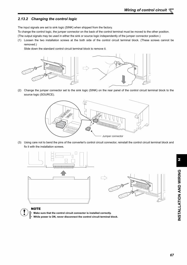
67
2
INST
ALL
ATIO
N A
ND
WIR
ING
Wiring of control circuit
2.13.2 Changing the control logic
The input signals are set to sink logic (SINK) when shipped from the factory.To change the control logic, the jumper connector on the back of the control terminal must be moved to the other position.(The output signals may be used in either the sink or source logic independently of the jumper connector position.)(1) Loosen the two installation screws at the both side of the control circuit terminal block. (These screws cannot be
removed.)Slide down the standard control circuit terminal block to remove it.
(2) Change the jumper connector set to the sink logic (SINK) on the rear panel of the control circuit terminal block to thesource logic (SOURCE).
(3) Using care not to bend the pins of the converter's control circuit connector, reinstall the control circuit terminal block andfix it with the installation screws.
NOTE• Make sure that the control circuit connector is installed correctly.• While power is ON, never disconnect the control circuit terminal block.
Jumper connector

68
Wiring of control circuit
(4) Sink logic and source logicIn the sink logic, a signal switches ON when a current flows from the corresponding signal input terminal.Terminal SD is common to the contact input signals. Terminal SE is common to the open collector output signals.In the source logic, a signal switches ON when a current flows into the corresponding signal input terminal.Terminal PC is common to the contact input signals. Terminal SE is common to the open collector output signals.
When using an external power supply for transistor output
Sink logic typeUse terminal PC as a common terminal, and performwiring as shown below. (Do not connect terminal SD of theconverter with the terminal 0V of the external powersupply. When using terminals PC and SD as a 24VDCpower supply, do not install an external power supply inparallel with the converter. Doing so may cause amalfunction in the inverter due to undesirable currents.)
Source logic typeUse terminal SD as a common terminal, and performwiring as shown below. (Do not connect terminal PC of theconverter with the terminal +24V of the external powersupply. When using terminals PC and SD as a 24VDCpower supply, do not install an external power supply inparallel with the converter. Doing so may cause amalfunction in the inverter due to undesirable currents.)
Current
PC
RESR
SOFR
Source logic
Source
connector
Current
SD
RESR
SOFR
Sink
connector
Sink logic
Current flow concerning the input/output signal
when sink logic is selected
Current flow concerning the input/output signal
when source logic is selected
PC
X10R
RESR
Source
connector
RDY
SE
Converter Inverter
Current flow
SD
RESR
X10R
Sink
connector
Converter Inverter
RDY
SE
Current flow
QY40P type
transistor
output unit TB1
TB2
TB17
TB18
DC24V SD
PC
SOF
RES
Converter
DC24V
(SD)
Current flow
Constant voltage
circuit
QY80 type
transistor
output unit PC
TB1
TB2
TB17Fuse
TB18
RES
SOF
SD
Converter
DC24V
(SD)
DC
24
V
Current flow
Constant voltage
circuit

69
2
INST
ALL
ATIO
N A
ND
WIR
ING
Wiring of control circuit
2.13.3 Control circuit terminal layout
(1) Common terminals of the control circuit (SD, 5, SE, SE2) Terminals SD, 5, SE, and SE2 are all common terminals (0V) for I/O signals and are isolated from each other. Do not earth
(ground) these terminals.Avoid connecting the terminal SD and 5 and the terminal SE and 5.
Terminal SD is a common terminal for the contact input terminals (RES, SOF, X1, X2, ROH) and the pulse train outputterminal (FM). The open collector circuit is isolated from the internal control circuit by photocoupler.
Terminal 5 is a common terminal for the analog output terminal AM. It should be protected from external noise using ashielded or twisted cable.
Terminal SE is a common terminal for the open collector output terminal (RDY, RSO, CVO, Y1, Y2). The contact inputcircuit is isolated from the internal control circuit by photocoupler.
Terminal SE2 is a common terminal for the open collector output terminal (Y3). The contact input circuit is isolated from theinternal control circuit by photocoupler.
Do not connect anything to the free terminal (NC) of the control circuit.
CAUTIONDo not connect anything to the free terminal (NC) of the control circuit. Using the terminal may cause a damage to the converter and the inverter.
Do not tighten a screw when a square washer is turned out of position as shown below. Doing so may damage parts.
5
IRL
NC
IRH
Y3
SE2
NC
TR1
TR2
IRO
MCO
RDO
RDI
MCI
Terminal screw size: M3.5
Terminal screw size: M3
Dedicated board for FR-HC2
Terminals 5, IRH, IRL, TR1, TR2, IRO, MCO, RDO, RDI, and MCI are for manufacturer setting. Keep them open.
88R 88S A
CVORSORDYNCNCNC
SENCNCNC
B C NC AM
PCPCY1
PCY2SESE SDSDSDFM
5 X1 X2
ROHSOFRES
NC

70
Wiring of control circuit
(2) Signal inputs by contactless switches
2.13.4 Wiring instructions It is recommended to use the cables of 0.75mm2 gauge for connection to the control circuit terminals.
If the cable gauge used is 1.25mm2 or more, the front cover may be lifted when there are many cables running or thecables are run improperly, resulting in an operation panel contact fault.
The wiring length should be 30m (200m for the terminal FM) at themaximum.
Use two or more parallel micro-signal contacts or twin contacts to preventa contact faults when using contact inputs since the control circuit inputsignals are micro-currents.
To suppress EMI, use shielded or twisted cables for the control circuitterminals and run them away from the main and power circuits (includingthe 200V relay sequence circuit). For the cables connected to the control circuit terminals, connect their shields to thecommon terminal of the connected control circuit terminal. When connecting an external power supply to the terminalPC, however, connect the shield of the power supply cable to the negative side of the external power supply. Do notdirectly earth (ground) the shield to the enclosure, etc.
Always use relay coil, lamp, etc. for fault output terminals (A, B, C).
Wiring of the control circuit of the FR-HC2-75K, FR-HC2-H110K or higherSeparate the wiring of the control circuit away from the wiring of the main circuit. Make cuts in rubber bush of the converter side and lead wires.
The contacted input terminals of the converter (RES, SOF, X1, X2, ROH)can be controlled using a transistor instead of a contacted switch as shownon the right.
External signal input using transistor
CAUTIONDo not connect anything to the free terminal (NC) of the control circuit. Using the terminal may cause a damage to the converter and the inverter.
Always connect the terminal RDY of the converter to the terminal MRS or the inverter terminal to which X10 signal is assigned. Also, always connect the terminal SE of the converter to the terminal SD of the inverter. If these are not connected, the converter may be damaged.
+24V
RES, etc.
SD
Converter
Micro signal contacts Twin contacts
<Wiring>
Rubber bush
(view from the inside)
Make cuts along the lines inside with
a cutter knife and such.
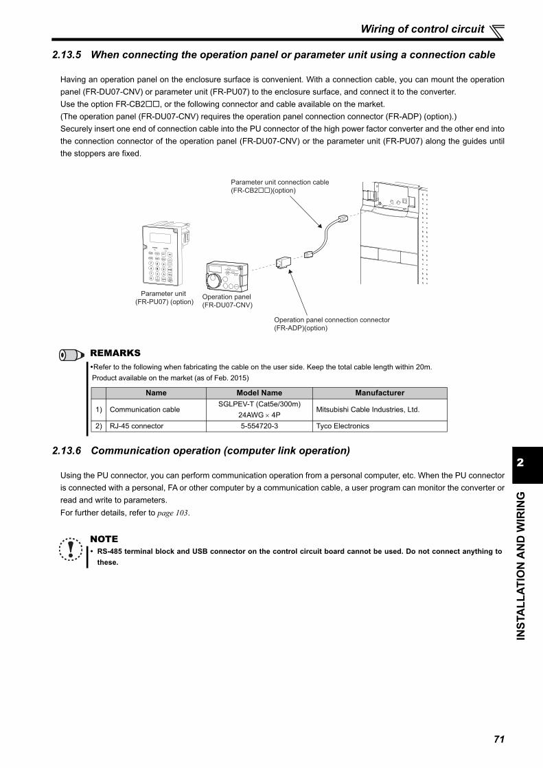
71
2
INST
ALL
ATIO
N A
ND
WIR
ING
Wiring of control circuit
2.13.5 When connecting the operation panel or parameter unit using a connection cable
Having an operation panel on the enclosure surface is convenient. With a connection cable, you can mount the operationpanel (FR-DU07-CNV) or parameter unit (FR-PU07) to the enclosure surface, and connect it to the converter. Use the option FR-CB2, or the following connector and cable available on the market.(The operation panel (FR-DU07-CNV) requires the operation panel connection connector (FR-ADP) (option).)Securely insert one end of connection cable into the PU connector of the high power factor converter and the other end intothe connection connector of the operation panel (FR-DU07-CNV) or the parameter unit (FR-PU07) along the guides untilthe stoppers are fixed.
2.13.6 Communication operation (computer link operation)
Using the PU connector, you can perform communication operation from a personal computer, etc. When the PU connectoris connected with a personal, FA or other computer by a communication cable, a user program can monitor the converter orread and write to parameters.For further details, refer to page 103.
REMARKSRefer to the following when fabricating the cable on the user side. Keep the total cable length within 20m. Product available on the market (as of Feb. 2015)
NOTE RS-485 terminal block and USB connector on the control circuit board cannot be used. Do not connect anything to
these.
Parameter unit connection cable
(FR-CB2��)(option)
Operation panel
(FR-DU07-CNV)
Parameter unit
(FR-PU07) (option)
Operation panel connection connector
(FR-ADP)(option)
Name Model Name Manufacturer
1) Communication cableSGLPEV-T (Cat5e/300m)
24AWG 4PMitsubishi Cable Industries, Ltd.
2) RJ-45 connector 5-554720-3 Tyco Electronics

72
MEMO

1
73
2
4
5
6
3
3 PARAMETERS
This chapter provides the "PARAMETERS" of this product.Always read the instructions before using the equipment.
3.1 Operation panel (FR-DU07-CNV) ................................................. 743.2 Parameter unit (FR-PU07), parameter unit with battery pack
(FR-PU07BB(-L))............................................................................ 773.3 Parameter list ................................................................................ 813.4 Description of parameters ........................................................... 833.5 Parameter clear / All parameter clear.......................................... 1283.6 Parameter copy and parameter verification ............................... 129

74
Operation panel (FR-DU07-CNV)
3.1 Operation panel (FR-DU07-CNV)
3.1.1 Names and functions of the operation panel (FR-DU07-CNV)
REMARKSFR-DU07-CNV cannot be used with the inverter. If FR-DU07-CNV is connected to an inverter, "Err." blinks.
Setting dial(Setting dial: Mitsubishi Electric inverter dial)Used to change the frequency setting and parameter values.
PU stop cancelCancels the (PS) display when
the converter is stopped by the
(PU stop).
Monitor (4-digit LED)Shows the input current, parameter number, etc.
Monitor indicationLit to indicate monitoring mode.
P.CPY: Blinks at the completion of parameter copy.OFF at converter reset.
PWR : Lit at power ON
Power / regenerative drive indicatorDRIVE: Lit during power drivingREGEN: Lit during regenerative driving(DRIVE or REGEN blinks when a stop is made by turning SOF signal ON. (When Pr. 8 is set to "0 (initial setting)".)
Stop operationUsed to stop the converter.Fault can be reset when protective function is activated (fault).
Mode switchoverUsed to changeeach setting mode.
Unit indicator· Hz: Lit to indicate frequency.· A: Lit to indicate current.· V: Lit to indicate voltage.
Used to set each setting.If pressed during operation, monitor changes as below;
Operation mode indicator
Input current
Input voltage
Bus voltage
SS

75
3PA
RA
MET
ERS
Operation panel (FR-DU07-CNV)
3.1.2 Basic operation (factory setting)P
aram
eter
set
ting
Faul
t his
tory
Mon
itor
fault Input voltage at the fault Bus voltage at the fault Energization time at the fault. (After Energization time, it goes back to a fault display.)
Pressing the setting dial shows the fault history number.
Monitor mode (Input current monitor)
Parameter setting mode
Input voltage monitor Bus voltage monitor
The present setting displayed.
Value change
Parameter write is complete!!
Parameter and a setting valueappear alternately.
Parameter clear All parameterclear
Faults clear
Parameter copy
(Example)
[Operation for displaying fault history]
The last eight fault records can be displayed.On the display of the last fault record (fault record 1), a decimal point LED is ON.)
When the fault history is empty, is displayed.
When a fault is displayed, the display shifts as follows by pressing : Input current at the
(Refer to page 142)
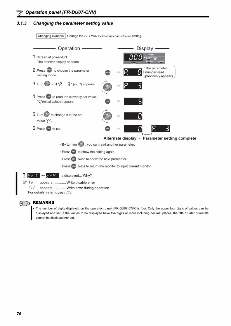
76
Operation panel (FR-DU07-CNV)
3.1.3 Changing the parameter setting value
Changing example Change the Pr. 3 ROH terminal function selection setting.
is displayed... Why?
appears ............. Write disable error appears.............. Write error during operation For details, refer to page 134.
REMARKS The number of digits displayed on the operation panel (FR-DU07-CNV) is four. Only the upper four digits of values can be
displayed and set. If the values to be displayed have five digits or more including decimal places, the fifth or later numeralscannot be displayed nor set.
DisplayOperation1.Screen at power-ON The monitor display appears.
2.Press to choose the parameter setting mode.
3.Turn until " " (Pr. 3) appears.
4.Press to read the currently set value. " "(initial value) appears.
5.Turn to change it to the set
value " ".
6.Press to set.
The parameter number readpreviously appears.
Alternate display ··· Parameter setting complete· By turning , you can read another parameter.
· Press twice to show the next parameter.
· Press twice to return the monitor to input current monitor.
· Press to show the setting again.
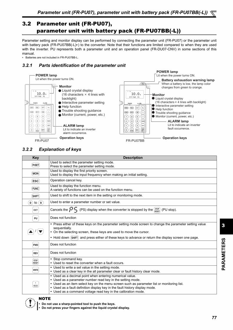
77
3PA
RA
MET
ERS
Parameter unit (FR-PU07), parameter unit with battery pack (FR-PU07BB(-L))
3.2 Parameter unit (FR-PU07), parameter unit with battery pack (FR-PU07BB(-L))
Parameter setting and monitor display can be performed by connecting the parameter unit (FR-PU07) or the parameter unitwith battery pack (FR-PU07BB(-L)) to the converter. Note that their functions are limited compared to when they are usedwith the inverter. PU represents both a parameter unit and an operation panel (FR-DU07-CNV) in some sections of thismanual. Batteries are not included in FR-PU07BB-L.
3.2.1 Parts identification of the parameter unit
3.2.2 Explanation of keys
Key DescriptionUsed to select the parameter setting mode.Press to select the parameter setting mode.Used to display the first priority screen.Used to display the input frequency when making an initial setting.Operation cancel key.Used to display the function menu.A variety of functions can be used on the function menu.Used to shift to the next item in the setting or monitoring mode.
to Used to enter a parameter number or set value.
Cancels the (PS) display when the converter is stopped by the (PU stop).
Does not function
/
Press either of these keys on the parameter setting mode screen to change the parameter setting value sequentially.
On the selecting screen, these keys are used to move the cursor. Hold down and press either of these keys to advance or return the display screen one page.
Does not function
Does not function
Stop command key. Used to reset the converter when a fault occurs. Used to write a set value in the setting mode. Used as a clear key in the all parameter clear or fault history clear mode. Used as a decimal point when entering numerical value. Used as a parameter number read key in the setting mode. Used as an item select key on the menu screen such as parameter list or monitoring list. Used as a fault definition display key in the fault history display mode. Used as a command voltage read key in the calibration mode.
NOTE Do not use a sharp-pointed tool to push the keys. Do not press your fingers against the liquid crystal display.
10.0ASTF FWD PU STF FWD PU
I In
A
I In
10.0
FR-PU07 FR-PU07BB
POWER lampLit when the power turns ON.
Monitor Liquid crystal display (16 characters 4 lines with backlight) Interactive parameter setting Help function Trouble shooting guidance Monitor (current, power, etc.)
ALARM lampLit to indicate an inverter alarm occurrence.
Operation keys
POWER lampLit when the power turns ON.
Battery exhaustion warning lampWhen a battery is low, the lamp color changes from green to orange.
Monitor Liquid crystal display
(16 characters 4 lines with backlight) Interactive parameter setting Help function Trouble shooting guidance
Monitor (current, power, etc.)
ALARM lampLit to indicate an inverter fault occurrence.
Operation keys

78
Parameter unit (FR-PU07), parameter unit with battery pack (FR-PU07BB(-L))
3.2.3 Monitoring function
(1) Monitor display overview
a) Main monitorShows the input frequency, input current, bus voltage, fault history and other monitor data.
Press to display the monitoring list.
Select an item from the monitoring list and press to monitor the selected item. The following items can be monitored.
I In................. : Input current [A]V In ............... : Input voltage [V]Dc Bus .......... : Bus voltage [V]Alarm His ...... : Fault history (The latest 8 faults are displayed)Hz In ............. : Power supply frequency [Hz]THT %........... : Electronic thermal relay load factor [%]Pwr In............ : Input power [kW]Cum Pwr ....... : Cumulative power [kW]Cum Opr ....... : Cumulative energization time [hr]I/P Signal....... : Input signalO/P Signal..... : Output signal
b) Connection phase sequence indicationThe following indicates the connection phase sequence.STF ....... : Positive phaseSTR....... : Negative phase--- .......... : Power supply not detected
c) Operation status indicationThe following indicates the operation status of the converter.STOP .... : During the converter stopFWD...... : During power drive REV ...... : During regenerative driveALAR .... : At fault occurrence
d) Operation mode indicationEXT is always indicated.
e) Unit indicationThe unit of the main monitor is indicated.
f) Warning indicationThe following is indicated when the converter outputs a warning. Nothing is indicated when there is no warning.For the details, refer to page 134. OL ......... : Overload signal detection TH ......... : Electronic thermal relay pre-alarmPS ......... : PU stopMT......... : Maintenance signal outputSL.......... : Power supply not detectedCP......... : Parameter copy
REMARKSAfter the first and second priority monitors are changed by the Pr. 52 setting or the terminals X1 and X2, the changed first andsecond monitors are displayed in the monitoring list at the reading of the monitoring list. If priority monitor is changed while themonitoring list is being read, the change of the priority monitor is not applied.
(d) Operation mode indication
10.0OLA
STF FWD EXT
(a) Main monitor
(b) Connection phase sequence indication
(c) Operating status indication
I In (f) Warning indication
(e) Unit indication
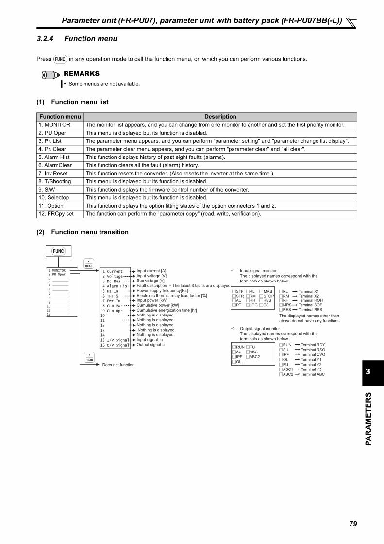
79
3PA
RA
MET
ERS
Parameter unit (FR-PU07), parameter unit with battery pack (FR-PU07BB(-L))
3.2.4 Function menu
Press in any operation mode to call the function menu, on which you can perform various functions.
(1) Function menu list
(2) Function menu transition
REMARKS Some menus are not available.
Function menu Description1. MONITOR The monitor list appears, and you can change from one monitor to another and set the first priority monitor.2. PU Oper This menu is displayed but its function is disabled.3. Pr. List The parameter menu appears, and you can perform "parameter setting" and "parameter change list display".4. Pr. Clear The parameter clear menu appears, and you can perform "parameter clear" and "all clear".5. Alarm Hist This function displays history of past eight faults (alarms).6. AlarmClear This function clears all the fault (alarm) history.7. Inv.Reset This function resets the converter. (Also resets the inverter at the same time.)8. T/Shooting This menu is displayed but its function is disabled.9. S/W This function displays the firmware control number of the converter.10. Selectop This menu is displayed but its function is disabled.11. Option This function displays the option fitting states of the option connectors 1 and 2.12. FRCpy set The function can perform the "parameter copy" (read, write, verification).
Bus voltage [V]
Fault description ∗ The latest 8 faults are displayed
Power supply frequency[Hz]
Electronic thermal relay load factor [%]
Input power [kW]
Cumulative power [kW]
Cumulative energization time [hr]
Nothing is displayed.
Nothing is displayed.
Nothing is displayed.
Nothing is displayed.
Nothing is displayed.
Output signal ∗2
3 4 5 6 7 8 9 10 11 12
3 Dc Bus 4 Alarm His 5 Hz In 6 THT % 7 Pwr In 8 Cum Pwr 9 Cum Opr10 11 12 13 14 15 I/P Signal16 O/P Signal
2 PU Oper 1 MONITOR
Input signal ∗1
Does not function.
Input current [A] 1 CurrentInput voltage [V] 2 Voltage
STF
STR
AU
RT
RL
RM
RH
JOG
MRS
STOP
RES
CS
RL
RMRHMRSRES
RUN
SU
IPF
OL
FU
ABC1
ABC2
Input signal monitor
The displayed names correspond with the
terminals as shown below.
The displayed names correspond with the
terminals as shown below.
The displayed names other than
above do not have any functions
∗1
∗2 Output signal monitor
Terminal X1Terminal X2Terminal ROHTerminal SOFTerminal RES
Terminal RSO
Terminal CVO
Terminal Y1
Terminal Y2
Terminal Y3
Terminal RDY
Terminal ABC
RUN
SU
IPF
OL
FU
ABC1
ABC2
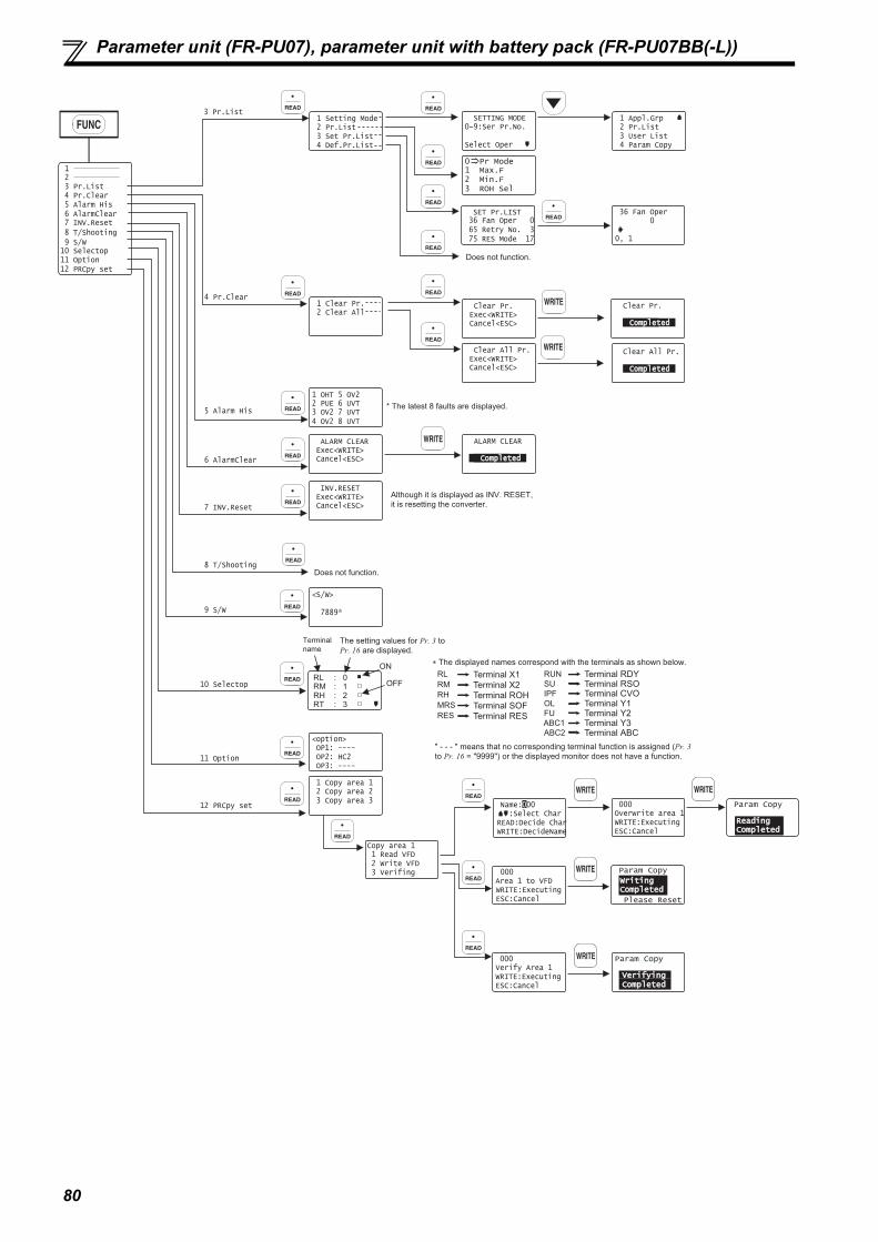
80
Parameter unit (FR-PU07), parameter unit with battery pack (FR-PU07BB(-L))
2 1
3 Pr.List 4 Pr.Clear 5 Alarm His 6 AlarmClear 7 INV.Reset 8 T/Shooting 9 S/W10 Selectop11 Option12 PRCpy set
2 Pr.List 1 Setting Mode
3 Set Pr.List 4 Def.Pr.List
SETTING MODE0~9:Ser Pr.No.
Select Oper
2 Pr.List 1 Appl.Grp
3 User List 4 Param Copy
SET Pr.LIST 36 Fan Oper 0 65 Retry No. 3 75 RES Mode 17
36 Fan Oper 0
0, 1
Does not function.
2 Clear All 1 Clear Pr. Clear Pr.
Exec<WRITE> Cancel<ESC>
Clear All Pr. Exec<WRITE> Cancel<ESC>
Clear Pr.
CompletedCompleted
Clear All Pr.
CompletedCompleted
1 OHT 5 OV22 PUE 6 UVT
4 OV2 8 UVT3 OV2 7 UVT
ALARM CLEAR Exec<WRITE> Cancel<ESC>
* The latest 8 faults are displayed.
ALARM CLEAR
CompletedCompleted
INV.RESET Exec<WRITE> Cancel<ESC>
<S/W>
7889*
2 Copy area 2 1 Copy area 1
3 Copy area 3
OP1: ----<option>
OP2: HC2 OP3: ----
1 Read VFDCopy area 1
2 Write VFD 3 Verifing
:Select Char Name:000
READ:Decide CharWRITE:DecideName
000Overwrite area 1WRITE:ExecutingESC:Cancel
000Area 1 to VFDWRITE:ExecutingESC:Cancel
000Verify Area 1WRITE:ExecutingESC:Cancel
Although it is displayed as INV. RESET, it is resetting the converter.
3 Pr.List
4 Pr.Clear
5 Alarm His
6 AlarmClear
7 INV.Reset
8 T/Shooting
9 S/W
10 Selectop
11 Option
12 PRCpy set
Does not function.
RM RL
RH RT
RLRMRHMRSRES
RUNSUIPFOLFU
1 Max.F 0 Pr Mode
2 Min.F 3 ROH Sel
Terminal name
The setting values for Pr. 3 to Pr. 16 are displayed.
ON
OFF
∗ The displayed names correspond with the terminals as shown below.
" - - - " means that no corresponding terminal function is assigned (Pr. 3 to Pr. 16 = "9999") or the displayed monitor does not have a function.
Terminal Y1Terminal Y2Terminal Y3Terminal ABC
Terminal RSOTerminal CVO
Terminal RDY
ABC1ABC2
Terminal X1Terminal X2Terminal ROHTerminal SOFTerminal RES
: 2: 3
: 0: 1
Param Copy ReadingReadingCompletedCompleted
Param Copy
WritingWritingCompletedCompleted
Please Reset
Param Copy
VerifyingVerifyingCompletedCompleted

81
3PA
RA
MET
ERS
Parameter list
3.3 Parameter list
REMARKS indicates simple mode parameters.
The parameters shaded in allow their settings to be changed during operation even if "1" (write disabled) is set to Pr. 77
Parameter write selection.
Parameter Name Range IncrementsInitial value
Refer to page
Customer setting
0 Simple mode selection 0, 9999 1 0 83 1 Maximum power supply frequency 60Hz (Read only) 60Hz 83 2 Minimum power supply frequency 50Hz (Read only) 50Hz 83
3 ROH terminal function selection
0 to 5, 9999
1 5 844 SOF terminal function selection 1 0 845 X1 terminal function selection 1 1 846 X2 terminal function selection 1 2 847 RES terminal function selection 1 3 848 SOF input selection 0, 1, 2 1 0 859 OH input selection 0, 1 1 0 85
10 RDY signal logic selection 0, 100 1 100 8611 RSO terminal function selection
0 to 16, 98, 99, 100 to 116, 198, 199, 9999
1 1 8612 CVO terminal function selection 1 2 86 13 Y1 terminal function selection 1 3 86 14 Y2 terminal function selection 1 4 86 15 Y3 terminal function selection 1 5 86
16 ABC terminal function selection 1 99 86 22 Current limit level 0 to 220% 0.1% 150% 87
23 Current limit level (regenerative) 0 to 220%, 9999 0.1% 9999 8724 OL signal output timer 0 to 25s, 9999 0.1 0 8725 Input current detection level 0 to 220% 0.1% 150% 8826 Input current detection signal delay time 0 to 10s 0.1s 0s 8827 Input current detection signal retention time 0 to 10s, 9999 0.1s 0.1s 8828 Input current detection operation selection 0, 1 1 0 8829 Zero current detection level 0 to 220% 0.1% 5% 8830 Zero current detection time 0 to 1s 0.01s 0.5s 8831 Life alarm status display 0 to 15 (Read only) 1 0 8932 Inrush current limit circuit life display 0 to 100% (Read only) 1% 100% 8933 Control circuit capacitor life display 0 to 100% (Read only) 1% 100% 8934 Maintenance timer 0 (1 to 9998) 1 0 9035 Maintenance timer alarm output set time 0 to 9998, 9999 1 9999 9036 Cooling fan operation selection 0, 1 1 1 91
44Instantaneous power failure detection signal clear
0, 9999 1 9999 91
45 AM output filter 0 to 5s 0.01s 0.01s 9246 Watt-hour meter clear 0, 10, 9999 1 9999 9447 Energization time carrying-over times Read only 1 0 94
48Cumulative power monitor digit shifted times
0 to 4, 9999 1 9999 94
49Power supply frequency monitoring reference
45Hz to 65Hz 0.01Hz 60Hz 92
50 AM terminal function selection 1 to 3, 5, 6, 7, 21, 1111 to 4444 1 1234 94
51 Input power monitoring reference 0 to 100kW/0 to 3600kW0.01kW/0.1kW
Rated power
92
52 DU/PU main display data selection 0, 5 to 10, 25, 1111 to 4444 1 1234 94
53 Input voltage monitoring reference 0 to 500V 0.1V220V/440V
92
54 FM terminal function selection 1 to 3, 5, 6, 7, 21, 1111 to 4444 1 1234 94
55 Bus voltage monitoring reference 0 to 1000V 0.1V340V/680V
92
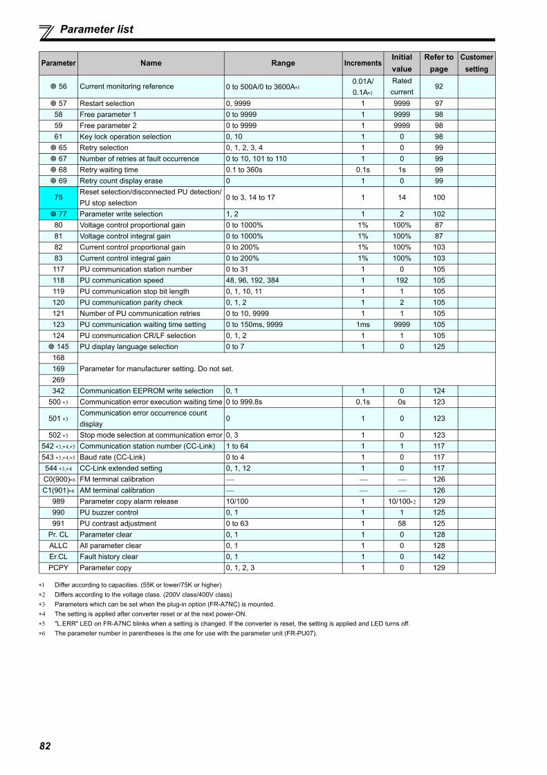
82
Parameter list
Differ according to capacities. (55K or lower/75K or higher) Differs according to the voltage class. (200V class/400V class) Parameters which can be set when the plug-in option (FR-A7NC) is mounted. The setting is applied after converter reset or at the next power-ON. "L.ERR" LED on FR-A7NC blinks when a setting is changed. If the converter is reset, the setting is applied and LED turns off. The parameter number in parentheses is the one for use with the parameter unit (FR-PU07).
56 Current monitoring reference 0 to 500A/0 to 3600A0.01A/0.1A
Rated current
92
57 Restart selection 0, 9999 1 9999 9758 Free parameter 1 0 to 9999 1 9999 9859 Free parameter 2 0 to 9999 1 9999 9861 Key lock operation selection 0, 10 1 0 98 65 Retry selection 0, 1, 2, 3, 4 1 0 99 67 Number of retries at fault occurrence 0 to 10, 101 to 110 1 0 99 68 Retry waiting time 0.1 to 360s 0.1s 1s 99 69 Retry count display erase 0 1 0 99
75Reset selection/disconnected PU detection/PU stop selection
0 to 3, 14 to 17 1 14 100
77 Parameter write selection 1, 2 1 2 10280 Voltage control proportional gain 0 to 1000% 1% 100% 8781 Voltage control integral gain 0 to 1000% 1% 100% 8782 Current control proportional gain 0 to 200% 1% 100% 10383 Current control integral gain 0 to 200% 1% 100% 103117 PU communication station number 0 to 31 1 0 105118 PU communication speed 48, 96, 192, 384 1 192 105119 PU communication stop bit length 0, 1, 10, 11 1 1 105120 PU communication parity check 0, 1, 2 1 2 105121 Number of PU communication retries 0 to 10, 9999 1 1 105123 PU communication waiting time setting 0 to 150ms, 9999 1ms 9999 105124 PU communication CR/LF selection 0, 1, 2 1 1 105 145 PU display language selection 0 to 7 1 0 125
168Parameter for manufacturer setting. Do not set.169
269342 Communication EEPROM write selection 0, 1 1 0 124
500 Communication error execution waiting time 0 to 999.8s 0.1s 0s 123
501 Communication error occurrence count display
0 1 0 123
502 Stop mode selection at communication error 0, 3 1 0 123542 ,, Communication station number (CC-Link) 1 to 64 1 1 117543 ,, Baud rate (CC-Link) 0 to 4 1 0 117544 , CC-Link extended setting 0, 1, 12 1 0 117
C0(900) FM terminal calibration 126C1(901) AM terminal calibration 126
989 Parameter copy alarm release 10/100 1 10/100 129990 PU buzzer control 0, 1 1 1 125991 PU contrast adjustment 0 to 63 1 58 125
Pr. CL Parameter clear 0, 1 1 0 128ALLC All parameter clear 0, 1 1 0 128Er.CL Fault history clear 0, 1 1 0 142PCPY Parameter copy 0, 1, 2, 3 1 0 129
Parameter Name Range IncrementsInitial value
Refer to page
Customer setting
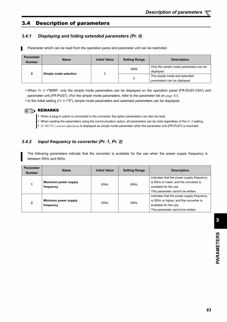
83
3PA
RA
MET
ERS
Description of parameters
3.4 Description of parameters
3.4.1 Displaying and hiding extended parameters (Pr. 0)
When Pr. 0 ="9999", only the simple mode parameters can be displayed on the operation panel (FR-DU07-CNV) andparameter unit (FR-PU07). (For the simple mode parameters, refer to the parameter list on page 81). In the initial setting (Pr. 0 ="0"), simple mode parameters and extended parameters can be displayed.
3.4.2 Input frequency to converter (Pr. 1, Pr. 2)
Parameter which can be read from the operation panel and parameter unit can be restricted.
Parameter Number
Name Initial Value Setting Range Description
0 Simple mode selection 09999
Only the simple mode parameters can be displayed.
0The simple mode and extended parameters can be displayed
REMARKS When a plug-in option is connected to the converter, the option parameters can also be read. When reading the parameters using the communication option, all parameters can be read regardless of the Pr. 0 setting. Pr. 991 PU contrast adjustment is displayed as simple mode parameter when the parameter unit (FR-PU07) is mounted.
The following parameters indicate that the converter is available for the use when the power supply frequency isbetween 50Hz and 60Hz.
Parameter Number
Name Initial Value Setting Range Description
1Maximum power supply frequency
60Hz 60Hz
Indicates that the power supply frequency is 60Hz or lower, and the converter is available for the use.This parameter cannot be written.
2Minimum power supply frequency
50Hz 50Hz
Indicates that the power supply frequency is 50Hz or higher, and the converter is available for the use.This parameter cannot be written.

84
Description of parameters
3.4.3 Input terminal function selection (Pr. 3 to Pr. 7)
(1) Input terminal function assignment Use Pr. 3 to Pr. 7 to set the functions of the input terminals. Refer to the following table and set the parameters.
Use the following parameters to select/change the input terminal functions.
ParameterNumber
NameInitial Value
Initial SignalSetting Range
3 ROH terminal function selection 5 ROH (ROH inrush resistance overheat detection)
0 to 5, 99994 SOF terminal function selection 0 SOF (converter stop)5 X1 terminal function selection 1 X1 (monitor switching)6 X2 terminal function selection 2 X2 (monitor switching)7 RES terminal function selection 3 RES (converter reset)
SettingSignal Name
FunctionRelated
ParametersRefer to
page
0 SOF Converter stopTurning ON this signal stops the converter.Operation can be changed using Pr. 8.
Pr. 8
1 X1 Monitor switching Monitor item at PU (operation panel and parameter unit) and terminals FM and AM can be switched by a combination of ON/OFF of these signals.
Pr. 50, Pr. 52, Pr. 54
942 X2 Monitor switching
3 RES Converter reset Turning ON this signal resets the converter.
4 OHExternal thermal relay input
The signal is input from the external thermal relay. Turning ON the signal stops the converter operation. (E.OHT)Operation can be changed using Pr. 9.
Pr. 9
5 ROHROH inrush resistance overheat detection
The ROH signal turns OFF and the converter trips (E.IOH) when overheating from the inrush resistance occurs or the filter capacitor (FR-HCC2) is detected to be swollen . Filter capacitor alarm detector is only available for 560K.
9999 No function
REMARKS The signals other than the ROH signal can be assigned to two or more terminals. In this case, the logic of terminal input is OR.
If the ROH signal, which is assigned to several terminals, turns OFF once, the converter remains tripped until the ROH signalturns ON at all the terminals.
NOTE Changing the terminal assignment using Pr. 3 to Pr. 7 (input terminal function selection) may affect the other functions. Set
parameters after confirming the function of each terminal.

85
3PA
RA
MET
ERS
Description of parameters
3.4.4 Operation selection of SOF signal and OH signal (Pr. 8, Pr. 9)
<SOF signal input status and Pr. 8 setting for the converter operation >
The converter does not operate at the Pr. 8 = "1" (NC contact) setting while FR-A7NC is not mounted. Set Pr. 8 = "2" (NC contact for external signals, NOcontact for CC-Link communication).
<OH signal input status and Pr. 9 setting for the converter operation >
Operation of SOF signal can be changed by the Pr. 8 setting, and OH signal by the Pr. 9 setting.
ParameterNumber
NameInitial Value
Setting Range
Description
8 SOF input selection 0
0Turning the SOF signal ON stops the converter operation. (NO contact)
1Turning the SOF signal OFF stops the converter operation. (NC contact)
2External signal: NC contactCC-Link communication: NO contact
9 OH input selection 00 Turning the OH signal ON trips the converter. (NO contact)1 Turning the OH signal OFF trips the converter. (NC contact)
SOF Signal Input Status Converter Operation
External terminal
Virtual terminal for CC-Link
communicationPr. 8 = 0 (NO contact) Pr. 8 = 1 (NC contact)
Pr. 8 = 2 (External terminal: NC contact)
(Virtual terminal at CC-Link communication: NO contact)
OFF OFF Operation continues Operation stops Operation stopsOFF ON Operation stops Operation stops Operation stopsON OFF Operation stops Operation stops Operation continuesON ON Operation stops Operation continues Operation stops
OH Signal Input Status (external terminal)
Converter OperationPr. 9 = 0 Pr. 9 = 1
ON Trips Operation continuesOFF Operation continues Trips

86
Description of parameters
3.4.5 Output terminal function selection (Pr. 10 to Pr. 16)
(1) Output signal list Functions of the output terminals can be set. Refer to the following table and set the parameters. (0 to 99: Positive logic, 100 to 199: Negative logic)
For the operation when the RDY signal is assigned to the output terminal, refer to page 65.
Use the following parameters to change the functions of the open collector output terminals and relay output terminal.
ParameterNumber
NameInitial Value
Initial Signal Setting Range
10 RDY signal logic selection
Open collector output terminal
100 RDY (Inverter run enable signal) 0, 10011 RSO terminal function selection 1 RSO (converter reset)
0 to 16, 98, 99, 100 to 116, 198, 199, 9999
12 CVO terminal function selection 2 CVO (converter running)13 Y1 terminal function selection 3 OL (overload alarm)14 Y2 terminal function selection 4 PHS (power supply phase detection)15 Y3 terminal function selection 5 Y5 (output voltage match)
16 ABC terminal function selectionRelayoutput terminal
99 ALM (fault output)
SettingSignal Name
Function OperationRelated
Parameters
Refer to
pagePositive
LogicNegative
Logic
0 100 RDYInverter run enable signal
Output when inverter can run.
1 101 RSO Converter reset Output during a converter reset.
2 102 CVO During converter run Output when the converter is running.
3 103 OL Overload alarm Output when the current limit function is active. Pr. 22, Pr. 23, Pr. 24 87
4 104 PHSPower supply phase detection
Output when a phase is confirmed after a completion of the power supply phase detection.
5 105 Y5 Output voltage match Output when the detected bus voltage equals to the commanded bus voltage.
6 106 IPFInstantaneous power failure
Output when an instantaneous power failure is detected. Pr. 57 97
7 107 Y7Regenerative drive recognition
Output at regenerative operation.
8 108 THPElectronic thermal relay pre-alarm
Output when the electronic thermal relay cumulative value reaches 85% of the transistor protection thermal activation level. (The Electronic thermal relay protection (E.THT) is activated when the cumulative amount reaches a predetermined value.)
9 109 FAN Fan fault output Output at the time of a fan fault. Pr. 36 91
10 110 FINHeat sink overheat pre-alarm
Output when the heat sink temperature reaches about 85% of the heat sink overheat protection providing temperature.
11 111 RTY During retry Output during retry processing. Pr. 65, Pr. 67 to Pr. 69 99
12 112 Y12 Input current detectionOutput when the input current of the converter remains equal to or higher than the Pr. 25 setting for the time set in Pr. 26 or longer.
Pr. 25, Pr. 26 88
13 113 Y13 Zero current detectionOutput when the input current of the converter remains equal to or lower than the Pr. 29 setting for the time set in Pr. 30 or longer.
Pr. 29, Pr. 30 88
14 114 Y14 Life alarmOutput when the control circuit capacitor or the inrush current limit circuit approaches the end of its service life.
Pr. 31 to Pr. 33 89
15 115 Y15 Maintenance timer signal Output when Pr. 34 rises to or above the Pr. 35 setting. Pr. 34, Pr. 35 90
16 116 Y16Instantaneous power failure detection hold
This signal is output when the IPF signal turns ON. Output of this signal is held until a reset or Pr. 44 = "0" is set.This signal is available during the high power factor converter operation.
Pr. 44 91
98 198 LF Alarm output Output when an alarm (fan failure or communication error warning) occurs.
Pr. 36, Pr. 12191, 106
99 199 ALM Fault outputOutput when the converter's protective function activates to stop the output (at fault occurrence).
9999 No function

87
3PA
RA
MET
ERS
Description of parameters
3.4.6 DC voltage control (Pr. 22 to Pr. 24, Pr. 80, Pr. 81)
(1) Adjustment for the DC voltage fluctuation (Pr. 80, Pr. 81)
Adjust the fluctuation range of the DC voltage by setting Pr. 80. Increasing the setting value reduces the DC voltage fluctuation caused by external disturbance. Adjust the recovery time to the commanded value at a fluctuation of DC voltage by setting Pr. 81.
Increasing the setting value shortens the recovery time from the DC voltage fluctuation caused by external disturbance.
(2) Setting the current limit level (Pr. 22 to Pr. 24)
This function limits the output current of the converter at a specified value. Set the current limit level to Pr. 22. Current limit level at the regenerative operation can be individually set by setting avalue other than "9999" to Pr. 23 For Pr. 22 and Pr. 23, set current limits in ratios against the converter rated current. OL signal is output when an output current is limited by the current limit level (when the current limit function is active).
For Pr. 24, set a time from when the command current reaches the current limit level until OL signal is output.
DC voltage of the converter can be controlled to be as commanded. Operation should be stable in the initial setting, but adjust the following parameters when voltage fluctuation occurs dueto the environment such as a voltage condition.
Parameter Number
NameInitial Value
Setting Range
Description
22 Current limit level 150% 0 to 220%Set the current level where the current limit operation starts (during power driving).
23 Current limit level (regenerative) 99990 to 220%
Set the current level where the current limit operation starts (during regenerative driving).
9999 Same as Pr. 22
24 OL signal output timer 0s 0 to 25s, 9999Set the OL signal output start time at the activation of current limit operation.
80Voltage control proportional gain
100% 0 to 1000%Set the proportional gain for the voltage control.Increasing the setting value reduces the DC voltage fluctuation caused by external disturbance.
81 Voltage control integral gain 100% 0 to 1000%Set the integral gain for the voltage control.Increasing the setting value shortens the recovery time from the DC voltage fluctuation caused by external disturbance.
NOTE Setting Pr. 80 too large makes the operation unstable. Setting only Pr. 81 too large makes the operation unstable.
NOTE When the output current reaches the current limit level, DC voltage decreases during power driving, and DC voltage
increases during regeneration.
Pr. 24
Pr. 24
Pr. 24
ON ONOL signal
Pr. 22
Cur
rent
Time
Output current

88
Description of parameters
3.4.7 Input current detection function (Y12 signal, Y13 signal, Pr. 25 to Pr. 30)
The input current during converter running can be detected and output to the output terminal.
Parameter Number Name Initial
Value Setting Range Description
25 Input current detection level 150% 0 to 220%Set the input current detection level. 100% is the rated converter current.
26 Input current detection signal delay time 0s 0 to 10s
Set the input current detection period. Set the time from when the input current has risen above the setting until the input current detection signal (Y12) is output.
27 Input current detection signal retention time 0.1s
0 to 10s Set the retention time when Y12 signal is ON.
9999Y12 signal ON status is retained. The signal is turned OFF at the next start.
28 Input current detection operation selection 0
0 Operation continues when Y12 signal is ON.1 Converter trips when Y12 signal is ON. (E.CDO)
29 Zero current detection level 5% 0 to 220%Set the zero current detection level. The rated converter current is regarded as 100%.
30 Zero current detection time 0.5s 0 to 1sSet the period from when the input current drops below the Pr. 29 value until the zero current detection signal (Y13) is output.
(1) Input current detection(Y12 signal, Pr. 25 to Pr. 28 )
If the input current remains equal to or higher than the Pr. 25 settingfor the time set in Pr. 26 or longer during the converter operation, theInput current detection (Y12) signal is output from the converter'sopen collector or relay output terminal.When Y12 signal turns ON, the ON state is held for the time set in Pr.
27.When Pr. 27 = "9999", the ON state is held until the next start.When Pr. 28 = "1", turning Y12 signal ON stops the output of the
converter and displays the input current detection alarm (E.CDO).When the trip occurs, Y12 signal stays ON for the time set in Pr. 27with Pr. 27 9999 setting, and Y12 signal stays ON until a reset withPr. 27 = 9999 setting. E.CDO does not occur by setting Pr. 28 = "1"while Y12 is ON. Pr. 28 setting becomes valid after Y12 signal turnsOFF. Set "12 (positive logic)" or "112 (negative logic)" to any of Pr. 11 to Pr.
16 (output terminal function selection) to assign the function of Y12signal to the output terminal.
(2) Zero current detection(Y13 signal, Pr. 29, Pr. 30 )
If the input current remains equal to or lower than the Pr. 29 setting forthe time set in Pr. 30 or longer during the converter operation, theZero current detection (Y13) signal is output from the converter'sopen collector or relay output terminal. Set "13 (positive logic)" or "113 (negative logic)" to any of Pr. 11 to Pr.
16 (output terminal function selection) to assign the function of Y13signal to the output terminal.
NOTE The response time of Y12 and Y13 signals is approximately 0.1s. Note that the response time varies with the load. Changing the terminal assignment using Pr. 11 to Pr. 16 (output terminal function selection) may affect other functions. Set
parameters after confirming the function of each terminal.
CAUTIONA safety backup such as an emergency brake must be provided to prevent hazardous condition to the machine and equipment when using the zero current detection signal.
Time
Pr. 25
OFF ON OFFInput current
detection signal
(Y12)
Pr. 27
Minimum 0.1s(initial value)
Input current
Pr. 27 9999, Pr. 28 = 0
Pr. 26
OFF ONStart signal
Time
Inputcurrent
OFF ONZero currentdetection time(Y13) Pr. 30
Detection time
Pr. 30Detection time
Pr. 29
OFF ON
0[A]0.1s ∗
Pr. 29
Once turned ON, the zero current detection timesignal (Y13) is held on for at least 0.1s.
∗

89
3PA
RA
MET
ERS
Description of parameters
3.4.8 Displaying the life of the converter parts (Pr. 31 to Pr. 33)
(1) Life alarm display and signal output (Y14 signal, Pr. 31)Whether any of the control circuit capacitor, cooling fan, and inrush current limit circuit has reached the life alarm output
level or not can be checked by Pr. 31 Life alarm status display and life alarm signal (Y14).
The life alarm signal (Y14) turns ON when any of the control circuit capacitor, cooling fan and inrush current limit circuitreaches the life alarm output level. For the terminal used for the Y14 signal, set "14 (positive logic)" or "114 (negative logic)" to any of Pr. 11 to Pr. 16 (output
terminal function selection).
Degrees of deterioration of control circuit capacitor, cooling fan and inrush current limit circuit can be diagnosed by themonitor.When any part has approached the end of its life, an alarm can be output by self diagnosis to prevent a fault.(Use the life check of this function as a guideline since the life is calculated theoretically.)
Parameter Number
Name Initial ValueSetting Range
Description
31 Life alarm status display 0 (0 to 15)Displays whether the control circuit capacitor, cooling fan, and each parts of the inrush current limit circuit has reached the life alarm output level or not. Reading only
32Inrush current limit circuit life display
100% (0 to 100%)Displays the deterioration degree of the inrush current limit circuit. Reading only
33Control circuit capacitor life display
100% (0 to 100%)Displays the deterioration degree of the control circuit capacitor. Reading only
Pr. 255 (decimal)
bit (binary)
Inrush Current Limit Circuit Life
Cooling Fan Life
Control Circuit Capacitor Life
13 1101
12 1100 9 1001
8 1000 5 0101
4 0100 1 0001
0 0000 :With warnings, : Without warnings
NOTE Changing the terminal assignment using Pr. 11 to Pr. 16 (output terminal function selection) may affect other functions. Set
parameters after confirming the function of each terminal.
0 0 0 0 0 0 0 0 0 0 0 0 1 0 0
Bit 0 Control circuit capacitor life
115Bit 7 0
Bit 2 Cooling fan lifeBit 3 Inrush current limit circuit life
�Pr. 31 read �Pr. 31 setting read
Bit image is displayedin decimal

90
Description of parameters
(2) Life display of the inrush current limit circuit (Pr. 32) The life of the inrush current limit circuit (relay, contactor and inrush resistor) is displayed in Pr. 32. The number of contact (relay, contactor, thyristor) ON times is counted, and it is counted down from 100% (0 time) every
1%/1,000 times.As soon as 10% (90,000 times) is reached, Pr. 31 bit 3 is turned ON, and also an alarm is output to Y14 signal.
(3) Control circuit capacitor life display (Pr. 33) The deterioration degree of the control circuit capacitor is displayed in Pr. 33 as a life. In the operating status, the control circuit capacitor life is calculated from the energization time and temperature, and is
counted down from 100%.As soon as the control circuit capacitor life falls below 10%, Pr. 31 bit 0 is turned ON, and also an alarm is output to Y14signal.
(4) Cooling fan life display The cooling fan speed of 50% or less is detected and "FN" is displayed on the operation panel (FR-DU07-CNV) and
parameter unit (FR-PU07). As an alarm display, Pr. 31 bit 2 is turned ON, and also an alarm is output to the Y14 signal.
3.4.9 Maintenance timer alarm (Pr. 34, Pr. 35)
The cumulative energization time of the converter is stored into the EEPROM every hour and indicated in Pr. 34Maintenance timer in 100h increments. Pr. 34 is clamped at 9998 (999800h). The maintenance timer alarm output signal (Y15) is output when the time set in Pr. 34 has reached the time set in Pr. 35
Maintenance timer alarm output set time (100h increments). For the terminal used for Y15 signal, set "15 (positive logic)" or "115 (negative logic)" to any of Pr. 11 to Pr. 16 (output
terminal function selection).
REMARKS When the converter is mounted with two or more cooling fans, "FN" is displayed with one or more fans with speed of 50% or
less.
NOTE For replacement of each part, contact the nearest Mitsubishi FA center.
When the cumulative energization time of the converter reaches the parameter set time, the maintenance timer output
signal (Y15) is output. (MT) is displayed on the operation panel (FR-DU07-CNV).This can be used as a guideline for the maintenance time of peripheral devices.
Parameter Number Name Initial Value Setting Range Description
34 Maintenance timer 0 0(1 to 9998)
Displays the cumulative energization time of the converter in 100h increments.Reading onlyWriting the setting of "0" clears the cumulative energization time.
35 Maintenance timer alarm output set time 9999
0 to 9998Set the time taken until when the maintenance timer alarm output signal (Y15) is output.
9999 No function
NOTE The cumulative energization time is counted every hour. The energization time of less than 1h is not counted. Changing the terminal assignment using Pr. 11 to Pr. 16 (output terminal function selection) may affect other functions. Set
parameters after confirming the function of each terminal.
First power
Time
ON
Maintenance
timer
(Pr. 34)
Set "0" in Pr. 34
Y15 signal
MT display
OFF ONON
Pr. 35
9998
(999800h)

91
3PA
RA
MET
ERS
Description of parameters
3.4.10 Cooling fan operation selection (Pr. 36)
In either of the following cases, fan operation is regarded as faulty, and [FN] is displayed on the operation panel, and the fanfault (FAN) and alarm (LF) signals are output. Pr. 36 = "0"
When the fan comes to a stop with power ON. Pr. 36 = "1"
When the fan stops during the fan ON command while the converter is running
For the terminal used for the FAN signal output, set "9 (positive logic)" or "109 (negative logic)" to any of Pr. 11 to Pr. 16(output terminal function selection), and for LF signal, set "98 (positive logic)" or "198 (negative logic)".
3.4.11 Instantaneous power failure detection hold (Pr. 44)
Instantaneous power failure detection hold signal (Y16) turns ON when the instantaneous power failure signal (IPF) turnsON during the high power factor converter operation. The Y16 signal is turned OFF by a reset or by setting Pr. 44 = "0".
For the terminal used for the Y16 signal, set "16 (positive logic)" or "116 (negative logic)" to any of Pr. 11 to Pr. 16 (outputterminal function selection).
Cooling fans built into the converter can be controlled.
Parameter Number
NameInitial Value
Setting Range
Description
36 Cooling fan operation selection 1
0A cooling fan operates at power ON.Cooling fan ON/OFF control is invalid. (The cooling fan is always ON at power ON)
1
Cooling fan ON/OFF control is valid.The fan is always ON while the converter is running. During a stop, the converter status is monitored and the fan switches ON/OFF according to the temperature.
NOTE Changing the terminal assignment using Pr. 11 to Pr. 16 (output terminal function selection) may affect other functions. Set
parameters after confirming the function of each terminal.
Use this function to check the history of instantaneous power failures.
Parameter Number
NameInitial Value
Setting Range
Description
44Instantaneous power failure detection signal clear
99990
Turns OFF the instantaneous power failure detection hold signal (Y16).
9999Does not turn OFF the instantaneous power failure detection hold signal (Y16)
NOTE Pr. 44 is always read as "9999". The Y16 signal does not turn OFF even if Pr. 44 = "9999". Changing the terminal assignment using Pr. 11 to Pr. 16 (Output terminal function selection) may affect other functions. Set
parameters after confirming the function of each terminal.
ON
ONOFF
OFF
Write Pr. 44="0"
IPF signal
Y16 signal
ONOFF ONOFF
OFF ON
OFF

92
Description of parameters
3.4.12 Reference of the terminal FM (pulse train output) and terminal AM (analog output) (Pr. 45, Pr. 49, Pr. 51, Pr. 53, Pr. 55, Pr. 56)
(1) Reference for power supply frequency monitor (Pr. 49)
For the calibration of terminal FM, set the full-scale value of the connected meter when the pulse speed of the terminal FMis 1440 pulses/s.Set the frequency to be indicated as the full-scale value on the frequency meter (1mA analog meter) connected betweenterminal FM and SD. The pulse speed is proportional to the power supply frequency. (The maximum pulse train output is 2400 pulses/s.) For the calibration of terminal AM, set the full-scale value of the connected meter when output voltage of terminal AM is
10VDC. Set the frequency to be indicated as the full-scale value on the meter (10VDC voltmeter) connected between terminal AMand 5.Output voltage is proportional to the frequency. (Maximum output voltage is 10VDC.)
Two types of monitor output, pulse train output from the terminal FM and analog voltage output from the terminal AM,are available.Set the reference of the signal output from the terminals FM and AM.
Parameter Number
Name Initial value Setting range Description
45 AM output filter 0.01s 0 to 5s Set the output filter of terminal AM.
49Power supply frequency monitoring reference
60Hz 45Hz to 65HzSet the full-scale value when outputting the power supply frequency monitor value from terminal FM or AM.
51Input power monitoring reference
Rated converter
power
55K or lower
0 to 100kW Set the full-scale value when outputting the input power
monitor value from terminal FM or AM.75K or higher
0 to 3600kW
53Input voltage monitoring reference
200Vclass
220V0 to 500V
Set the full-scale value when outputting the input voltage monitor value from terminal FM or AM.400V
class440V
55Bus voltage monitoring reference
200Vclass
340V0 to 1000V
Set the full-scale value when outputting the bus voltage monitor value from terminal FM or AM.400V
class680V
56Current monitoring reference
Rated converter current
55K or lower
0 to 500A Set the full-scale value when outputting the input current
monitor value from terminal FM or AM.75K or higher
0 to 3600A
60Hz
(initial value)
0Hz
Setting range of Pr. 49
Pu
lse
sp
ee
d (
pu
lse
s/s
)
2400
1440
Ou
tpu
t vo
lta
ge
10VDC
65Hz 60Hz
(initial value)0Hz
Setting range of Pr. 49
65Hz45Hz 45Hz
0V

93
3PA
RA
MET
ERS
Description of parameters
(2) Reference for input power monitor (Pr. 51), input voltage monitor (Pr. 53), bus voltage monitor (Pr. 55),and current monitor (Pr. 56).
For the calibration of terminal FM, set the full-scale value of the connected meter when the pulse speed of terminal FM is1440 pulse/s.Set the power (kW), voltage (V) and current (A) to be indicated as the full-scale values to the frequency meter (1mAanalog meter) connected between terminal FM and SD.Pulse speed is proportional to each monitor. (Maximum pulse train output is 2400 pulse/s. ) For the calibration of terminal AM, set the full-scale value of the connected meter when output voltage of terminal AM is
10VDC. Set the power (kW), voltage (V) and current (A) to be indicated as the full scale values on the meter (10VDC voltmeter)connected between terminal AM and 5.Output voltage is proportional to each monitor. (Maximum output voltage is 10VDC.)
(3) Terminal AM response adjustment (Pr. 45)
Using Pr. 45, the output voltage response of the terminal AM can be adjusted in the range of 0 to 5s. Increasing the setting stabilizes the terminal AM output more but reduces the response level. (Setting "0" sets the
response level to 7ms.)
3600kW0 Pr. 51 Initial setting (rated power)
500V0 Pr. 53 Initial setting (220V(440V))
1000V0 Pr. 55 Initial setting (340V(680V))
3600A0 Pr. 56 Initial setting (rated current)
Setting range
2400
1440
3600kW0 Pr. 51 Initial setting (rated power)
500V0 Pr. 53 Initial setting (220V(440V))
1000V0 Pr. 55 Initial setting (340V(680V))
3600A0 Pr. 56 Initial setting (rated current)
Setting range
10VDC
Pu
lse
sp
ee
d (
pu
lse
s/s
)
Ou
tpu
t vo
lta
ge

94
Description of parameters
3.4.13 DU/PU, terminal FM/AM monitor display selection (Pr. 46 to Pr. 48, Pr. 50, Pr. 52, Pr. 54)
(1) Monitor description list (Pr. 52)
Set the monitor to be displayed on the operation panel (FR-DU07-CNV) and parameter unit (FR-PU07) in Pr. 52 DU/PUmain display data selection. Set the monitor to be output to the terminal FM (pulse train output) in Pr. 54 FM terminal function selection Set the monitor to be output to the terminal AM (0 to 10VDC analog voltage output) in Pr. 50 AM terminal function selection Refer to the following table and set the monitor to be displayed. (The signals marked cannot be selected for monitoring)
The monitor to be displayed on the main screen of the operation panel (FR-DU07-CNV)/parameter unit (FR-PU07) canbe selected. In addition, signals to be output from the terminal FM (pulse train output) and AM (analog voltage output) can beselected.
Parameter Number Name Initial value Setting range Description
46 Watt-hour meter clear 9999
0 Set "0" to clear the watt-hour meter monitor.
10 Set the maximum value in the range of 0 to 9999kWh for the monitoring from communication
9999 Set the maximum value in the range of 0 to 65535kW for the monitoring from communication.
47 Energization time carrying-over times 0 0 to 65535(Reading only)
Displays the numbers of times that the cumulative energization time monitor exceeded 65535h. Reading only
48 Cumulative power monitor digit shifted times 9999
0 to 4
Set the number of times to shift the cumulative power monitor digit.The monitor value is clamped at the maximum value.
9999No shiftThe monitor value is cleared when it exceeds the maximum value.
50 AM terminal function selection 1234 1 to 3, 5, 6, 7, 21, 1111 to 4444 Select the monitor output to terminal AM.
52 DU/PU main display data selection 1234 0, 5 to 10, 25, 1111 to 4444
Select the monitor to be displayed on the operation panel and parameter unit.Refer to the following table for monitor description.
54 FM terminal function selection 1234 1 to 3, 5, 6, 7, 21, 1111 to 4444 Select the monitor output to terminal FM.
Types of Monitor Increments
Pr. 52 SettingPr. 54 (FM)Pr. 50 (AM)
Setting
Full-scale Value of the Terminal FM
and AMDescription
DU LEDPU
main monitor
Input current 0.01A/0.1A 0 1 Pr. 56 Displays the converter input current.
Input voltage 0.1V 0 2 Pr. 53 Displays the converter input voltage effective value.
Bus voltage 0.1V 0 3 Pr. 55 Displays the converter output voltage.Fault display — 0 Displays 8 past faults individually.Power supply frequency 0.01Hz 5 5 Pr. 49 Displays power supply frequency.Electronic thermal relay load factor
0.1% 6 6 100% Displays the motor thermal cumulative value by regarding the thermal operation level as 100%.
Input power0.01kW/0.1kW
7 7 Pr. 51 Displays the converter input power.
Cumulative power 0.01kWh/
0.1kWh 8 —
Displays the cumulative power based on the input power monitor. Can be cleared by Pr. 46 (Refer to page 95)
Cumulative energization time 1h 9 —
Displays the cumulative energization time since the converter shipment.You can check how many times the monitor value exceeded 65535h with Pr. 47.
Input power (with regenerative display) 0.1kW/1kW 10 —
Displays the converter input powerThe value is displayed with "-" (minus sign) during the regenerative driving.
Reference voltage output — 21 — Terminal FM: 1440 pulse/s is output.Terminal AM: 10V is output.
Input terminal status —25
— Displays the input terminal ON/OFF status on the operation panel (Refer to page 95)Output terminal status — —

95
3PA
RA
MET
ERS
Description of parameters
(2) Operation panel (FR-DU07-CNV) I/O terminal monitor (Pr. 52)
When Pr. 52 = "25", the I/O terminal states can be monitored on the operation panel (FR-DU07-CNV). The I/O terminal monitor is displayed on the third monitor. The LED is ON when the terminal is ON, and the LED is OFF when the terminal is OFF. The center line of LED is always ON.On the I/O terminal monitor, the upper LEDs indicate the input terminal status, and the lower LEDs indicate the output
terminal status.
Switching by input terminalDepends on the monitor
1111 to 4444 Depends on the monitor
Monitoring item is changed by ON/OFF of input terminal. (Refer to page 97.)
The cumulative energization time is accumulated from 0 to 65535 hours, then cleared, and accumulated again from 0. When the operation panel (FR-DU07-CNV) is used, the time is displayed up to 65.53 (65530h) by regarding 1h = 0.001, and thereafter, it is added up from0.
When using the parameter unit (FR-PU07), "kW" is displayed Since the panel display of the operation panel (FR-DU07-CNV) is in four digits, the monitor value of more than "9999" is displayed as "----". Differ according to capacities. (55K or lower/75K or higher) It is displayed only in FR-DU07-CNV.
REMARKS By setting "0" to Pr. 52, the monitoring of output frequency to alarm display can be selected in sequence by
.When the operation panel (FR-DU07-CNV) is used, the displayed units are Hz, V and A only and the others are
not displayed. The monitor set in Pr. 52 is displayed in the second monitor position. (The input voltage monitor is changed.)
Note that the input terminal status and the output terminal status are displayed in the third monitor (busvoltage) position.
The monitor displayed at powering ON is the first monitor. Display the monitor you want to display on the first
monitor and hold down for 1s.
(To return to the input current monitor, display the input current monitor and hold down for 1s.)
Example) When Pr. 52 = "9" (cumulative energization time), the monitor is displayed on the operation panel asshown below.
Types of Monitor Increments
Pr. 52 SettingPr. 54 (FM)Pr. 50 (AM)
Setting
Full-scale Value of the Terminal FM
and AMDescription
DU LEDPU
main monitor
Initial setting
• Power-on monitor (first monitor) • Second monitor • Third monitor • Fault monitor
Input voltage monitor Bus voltage monitorInput current monitor
With fault
With fault
Input voltage monitor Cumulative energization time monitorInput current monitor
• Power-on monitor (first monitor) • Second monitor • Third monitor • Fault monitor
X1
SOF
X2
RES
ROH
Y1Y2
Y3CVOABC
88RRDY
RSO
Center line is always ON
Input terminal
- Display example -
When signals X2,
ROH and RDY are ON
Output terminal
MON
PWRP.CPY
DRIVEREGEN
Hz
A
V

96
Description of parameters
(3) Cumulative power monitor and clear (Pr. 46, Pr. 48)
On the cumulative power monitor (Pr. 52 = "8"), the input power is accumulated and updated in 100ms increments. (Thevalue is stored in EEPROM every 1h.) Display increments and display ranges of the operation panel (FR-DU07-CNV), parameter unit (FR-PU07) and
communication (RS-485 communication) are as indicated below.
The monitor data digit can be shifted to the right by the number of Pr. 48.For example, if the cumulative power value is 1278.56kWh when Pr. 48 = "2", the PU/DU display is 12.78 (display in100kWh increments) and the communication data is 12. If the maximum value is exceeded at Pr. 48 = "0 to 4", the power is clamped at the maximum value, indicating that a digit shift
is necessary. If the maximum value is exceeded at Pr. 48 = "9999", the power returns to 0, and the counting starts again. Writing "0" in Pr. 46 clears the cumulative power monitor.
(4) Input power (with regenerative display) (Pr. 52 = "10")On the input power monitor (with regenerative display) (Pr. 52 = "10"), the input power to the converter is displayed with a
sign.On the operation panel (FR-DU07-CNV), the input power is displayed as a positive value (no sign) during the power
driving and displayed with a minus sign during the regenerative driving.
When the monitored value is 100kW or more, the displayed unit is 1kW. When the power value is 1000kW or more, it islimited at 999kW. When the power value is -1000kW or less, it is limited at -999kW. Positive value (no sign) is displayed in the input power display on the communication option and FR-PU07 during power
driving and regenerative driving.
(5) Cumulative energization time monitor(Pr. 47)
On the cumulative energization time monitor (Pr. 52 = "9"), the energization time has been cumulated every hour since theshipment of the converter. If the number of monitor value exceeds 65535, it is added up from 0. You can check how many times the cumulative
energization time monitor exceeded 65535h with Pr. 47.
Operation Panel Parameter Unit Communication
Range Increments Range IncrementsRange
IncrementsPr. 46 = 10 Pr. 46 = 9999
0 to 99.99kWh 0.01kWh 0 to 999.99kWh 0.01kWh0 to 9999kWh
0 to 65535kWh(Initial setting)
1kWh100.0 to 999.9kWh 0.1kWh 1000.0 to 9999.9kWh 0.1kWh1000 to 9999kWh 1kWh 10000 to 99999kWh 1kWh
Power is measured in the range of 0 to 9999.99kWh, and displayed in four digits. When the monitor value exceeds "99.99", a carry occurs, e.g. "100.0", so the value is displayed in 0.1kWh increments.
Power is measured in the range of 0 to 99999.99kWh, and displayed in five digits. When the monitor value exceeds "999.99", a carry occurs, e.g. "1000.0", so the value is displayed in 0.1kWh increments.
REMARKS If "0" is written to Pr. 46, and Pr. 46 is read again, "9999" or "10" is displayed.
REMARKS Input power (with regenerative display) (Pr. 52 ="10") cannot be assigned to a FM/AM analog output terminal.
<DU07-CNV display
during the regenerative driving>
<DU07-CNV display
during the power driving>
The first 7-segment LED is only used to display the sign.

97
3PA
RA
MET
ERS
Description of parameters
(6) Monitor switching with input terminal (Pr. 50, Pr. 52, Pr. 54)
Monitoring item can be switched by ON/OFF of terminals X1 and X2. By setting 1 to 4 to the four digits of Pr. 52 (Pr. 54, Pr. 50), monitor can be switched by the terminals.
Number set in each digits represents the following monitor.
In the initial setting (1234), the monitor changes according to the input terminal status as shown below.
3.4.14 Operation selection at instantaneous power failure (Pr. 57)
If restart after instantaneous power failure is activated at the inverter side, set Pr. 57 Restart selection = "0" at the converterside. When Pr. 57="9999," the inverter output is stopped by the fault signal "E.IPF" from the converter even though the automaticrestart after instantaneous power failure is activated in the inverter.
Pr. 50, Pr. 52, Pr. 54 Setting Monitoring Item1 Input current monitor2 Bus voltage monitor3 Input voltage monitor4 Input power monitor
X1 OFF ON OFF ONX2 OFF OFF ON ON
Monitoring item1
Input current monitor2
Bus voltage monitor3
Input voltage monitor4
Input power monitor
When an instantaneous power failure occurs, the converter can restart at the power restoration.
Parameter Number
Name Initial value Setting range Description
57 Restart selection 99990
Restarts at the power restoration after an instantaneous power failure
9999 Does not restart
CAUTIONThe motor and machine will start suddenly after occurrence of an instantaneous power failure (after the reset time has elapsed). Stay away from the motor and machine when automatic restart after instantaneous power failure has been selected.If the automatic restart after instantaneous power failure function has been selected, apply the CAUTION stickers, which are supplied with the Instruction Manual of the inverter, to easily visible places.
1st digit2nd digit
3rd digit4th digit
1st digit 2nd digit 3rd digit 4th digitPr. 50, Pr. 52, Pr. 54 =
Status of X1
Status of X2
OFF ON OFF ON
OFF OFF ON ON
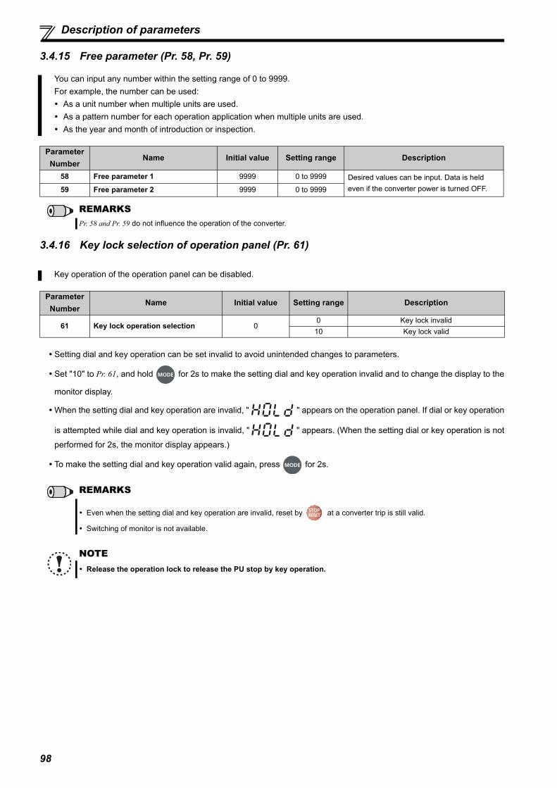
98
Description of parameters
3.4.15 Free parameter (Pr. 58, Pr. 59)
3.4.16 Key lock selection of operation panel (Pr. 61)
Setting dial and key operation can be set invalid to avoid unintended changes to parameters.
Set "10" to Pr. 61, and hold for 2s to make the setting dial and key operation invalid and to change the display to the
monitor display.
When the setting dial and key operation are invalid, " " appears on the operation panel. If dial or key operation
is attempted while dial and key operation is invalid, " " appears. (When the setting dial or key operation is not
performed for 2s, the monitor display appears.)
To make the setting dial and key operation valid again, press for 2s.
You can input any number within the setting range of 0 to 9999.For example, the number can be used: As a unit number when multiple units are used. As a pattern number for each operation application when multiple units are used. As the year and month of introduction or inspection.
Parameter Number
Name Initial value Setting range Description
58 Free parameter 1 9999 0 to 9999 Desired values can be input. Data is held even if the converter power is turned OFF.59 Free parameter 2 9999 0 to 9999
REMARKSPr. 58 and Pr. 59 do not influence the operation of the converter.
Key operation of the operation panel can be disabled.
Parameter Number
Name Initial value Setting range Description
61 Key lock operation selection 00 Key lock invalid
10 Key lock valid
REMARKS
Even when the setting dial and key operation are invalid, reset by at a converter trip is still valid.
Switching of monitor is not available.
NOTE Release the operation lock to release the PU stop by key operation.
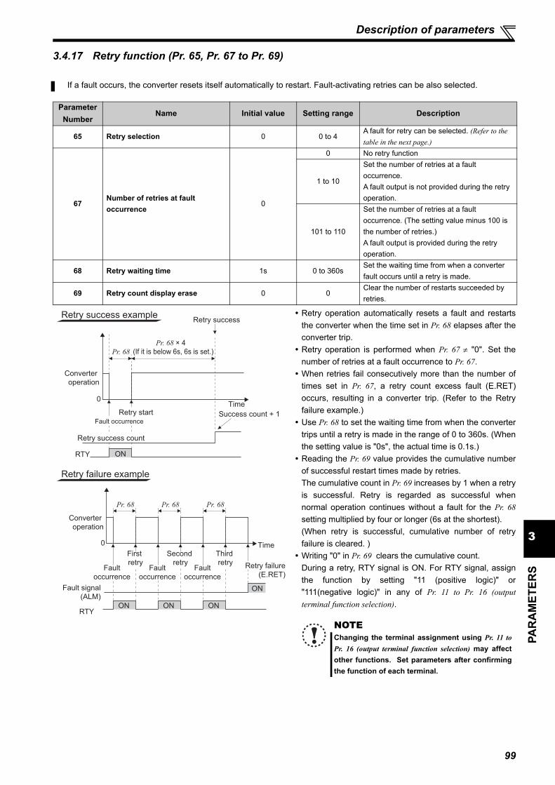
99
3PA
RA
MET
ERS
Description of parameters
3.4.17 Retry function (Pr. 65, Pr. 67 to Pr. 69)
Retry operation automatically resets a fault and restartsthe converter when the time set in Pr. 68 elapses after theconverter trip. Retry operation is performed when Pr. 67 "0". Set the
number of retries at a fault occurrence to Pr. 67. When retries fail consecutively more than the number of
times set in Pr. 67, a retry count excess fault (E.RET)occurs, resulting in a converter trip. (Refer to the Retryfailure example.) Use Pr. 68 to set the waiting time from when the converter
trips until a retry is made in the range of 0 to 360s. (Whenthe setting value is "0s", the actual time is 0.1s.) Reading the Pr. 69 value provides the cumulative number
of successful restart times made by retries.The cumulative count in Pr. 69 increases by 1 when a retryis successful. Retry is regarded as successful whennormal operation continues without a fault for the Pr. 68setting multiplied by four or longer (6s at the shortest).(When retry is successful, cumulative number of retryfailure is cleared. ) Writing "0" in Pr. 69 clears the cumulative count.
During a retry, RTY signal is ON. For RTY signal, assignthe function by setting "11 (positive logic)" or"111(negative logic)" in any of Pr. 11 to Pr. 16 (outputterminal function selection).
If a fault occurs, the converter resets itself automatically to restart. Fault-activating retries can be also selected.
Parameter Number
Name Initial value Setting range Description
65 Retry selection 0 0 to 4A fault for retry can be selected. (Refer to the table in the next page.)
67Number of retries at fault occurrence
0
0 No retry function
1 to 10
Set the number of retries at a fault occurrence.A fault output is not provided during the retry operation.
101 to 110
Set the number of retries at a fault occurrence. (The setting value minus 100 is the number of retries.)A fault output is provided during the retry operation.
68 Retry waiting time 1s 0 to 360sSet the waiting time from when a converter fault occurs until a retry is made.
69 Retry count display erase 0 0Clear the number of restarts succeeded by retries.
NOTEChanging the terminal assignment using Pr. 11 toPr. 16 (output terminal function selection) may affectother functions. Set parameters after confirmingthe function of each terminal.
Converter
operation
ON
0
Pr. 68 Pr. 68 Pr. 68
RTYON ON ON
Converter
operation
0
RTY
Pr. 68 × 4(If it is below 6s, 6s is set.)
ON
Retry success exampleRetry success
Retry startFault occurrence
Success count + 1
Time
Retry success count
Retry failure example
Fault
occurrence
Fault
occurrence
Fault
occurrence
First
retry
Second
retry
Third
retry
Fault signal
(ALM)
Retry failure
(E.RET)
Time
Pr. 68

100
Description of parameters
Using Pr. 65, you can select the fault that will cause a retry. No retry will be made for the fault not indicated. (Refer to page134 for the fault description.) indicates the faults selected for retry.
3.4.18 Reset selection/disconnected PU detection/PU stop selection (Pr. 75)
Fault for Retry
Pr. 65 Setting0 1 2 3 4
E.OC2
E.OV2
E.THT
E.IPF
E.UVT
E.OHT
E.OP3
E.CDO
E.ILF
E.8
NOTE The data stored as the error reset for retry is only that of the fault which occurred the first time. When a converter fault is reset by the retry function at the retry time, the accumulated data of the electronic thermal
relay function, etc. are not cleared. (Different from the power-ON reset.)
CAUTIONStay away from the motor and machine when the converter trips while the retry function is selected. Motor and machine will start suddenly (after the reset time has elapsed) after a converter trip.If the retry function has been selected, apply the CAUTION stickers, which are supplied with the Instruction Manual of the inverter, to easily visible places.
You can select the reset input acceptance, disconnected PU (FR-DU07-CNV/FR-PU07) connector detection functionand PU stop function.
Parameter Number
Name Initial Value Setting Range Description
75Reset selection/disconnected PU detection/PU stop selection
14 0 to 3, 14 to 17
For the initial setting, reset is always enabled, without disconnected PU detection, and with PU stop function are set.
The Pr. 75 value can be set any time. Also, if parameter (all) clear is performed, this setting will not return to the initial value.
Pr. 75Setting Reset Selection Disconnected PU detection PU Stop Selection
0 Reset input always enabledIf the PU is disconnected, operation will be continued.
Stop by is not available. 1
Reset input is enabled only when a fault occurs.
2 Reset input always enabledWhen the PU is disconnected, the converter trips.3
Reset input is enabled only when a fault occurs.
14(Initial setting)
Reset input always enabledIf the PU is disconnected, operation will be continued.
Press to stop.15
Reset input is enabled only when a fault occurs.
16 Reset input always enabledWhen the PU is disconnected, the converter trips.17
Reset input is enabled only when a fault occurs.

101
3PA
RA
MET
ERS
Description of parameters
(1) Reset selection You can select the enable condition of reset function (RES signal, reset command through communication) input. When Pr. 75 is set to any of "1, 3, 15, 17", a reset can be input only when the converter is tripped.
(2) Disconnected PU detection This function detects that the PU (FR-DU07-CNV/FR-PU07) has been disconnected from the converter for 1s or longer
and causes the converter to provide a fault output (E.PUE) and to trip.When Pr. 75 is set to any of "0, 1, 14, 15", operation continues if the PU is disconnected.
(3) PU stop selection
When Pr. 75 is set to any of "14 to 17", input from the PU stops the converter.
When the converter is stopped by the PU stop function, " " is displayed. A fault output is not provided.
(4) How to restart the motor stopped by input from the PU (PU stop (PS) reset method)
The motor can be restarted by making a reset using a power supply reset or RES signal.
NOTE Inputting the reset signal (RES) during operation also resets the inverter. The motor coasts since the inverter being
reset shuts off the output. Also, the cumulative value of the electronic thermal relay is cleared. The reset key of the parameters is only valid when the converter is tripped, independently of the Pr. 75 setting.
NOTE When the PU has been disconnected since before power-ON, it is not judged as a fault. To make a restart, confirm that the PU is connected and then reset the converter. When RS-485 communication operation is performed through the PU connector, the reset selection/PU stop selection
function is valid but the disconnected PU detection function is invalid.
(a) Operation panel (FR-DU07-CNV)1)Turn SOF signal ON and stop the converter operation.
2)Press
••••••(" " reset)
3)Turn SOF signal OFF and restart the converteroperation.
(b) Parameter unit (FR-PU07)1)Turn SOF signal ON and stop the converter operation.
2)Press
••••••(" " reset)
3)Turn SOF signal OFF and restart the converteroperation.
CAUTIONDo not reset the converter while the inverter start signal is being input.Otherwise, the motor will start suddenly after resetting, leading to potentially hazardous conditions.
Time
Key
Key
Stop/restart example for external operation
Operation
panel
SOF
Converter output
OFF ON OFF
EXT
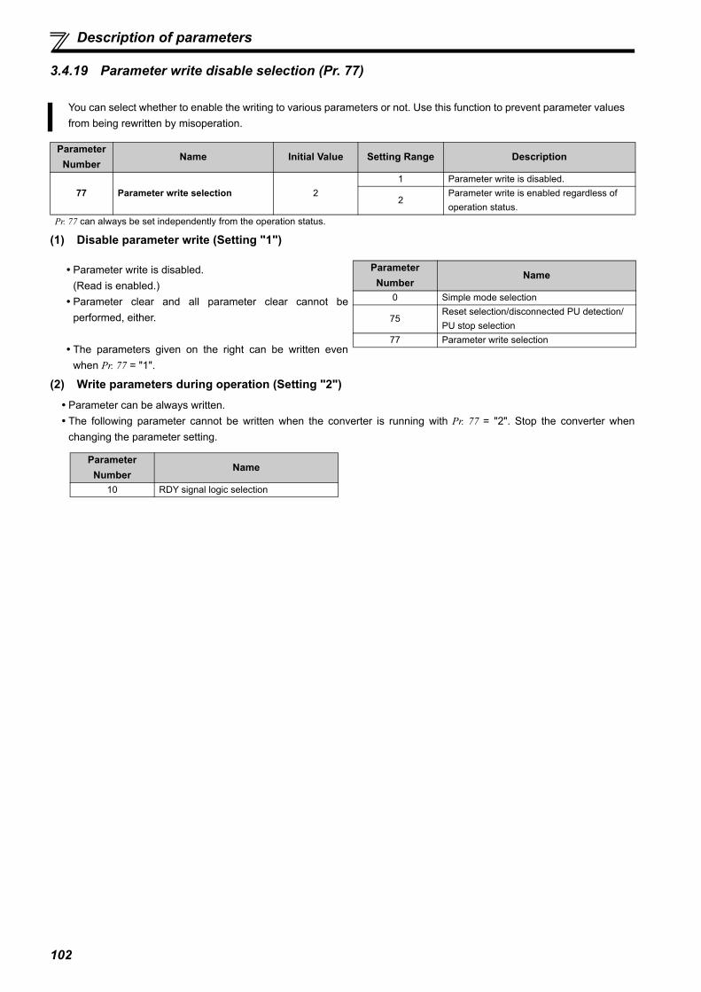
102
Description of parameters
3.4.19 Parameter write disable selection (Pr. 77)
(1) Disable parameter write (Setting "1")
(2) Write parameters during operation (Setting "2") Parameter can be always written. The following parameter cannot be written when the converter is running with Pr. 77 = "2". Stop the converter when
changing the parameter setting.
You can select whether to enable the writing to various parameters or not. Use this function to prevent parameter valuesfrom being rewritten by misoperation.
Parameter Number
Name Initial Value Setting Range Description
77 Parameter write selection 21 Parameter write is disabled.
2Parameter write is enabled regardless of operation status.
Pr. 77 can always be set independently from the operation status.
Parameter write is disabled.(Read is enabled.) Parameter clear and all parameter clear cannot be
performed, either.
The parameters given on the right can be written evenwhen Pr. 77 = "1".
Parameter Number
Name
0 Simple mode selection
75Reset selection/disconnected PU detection/PU stop selection
77 Parameter write selection
Parameter Number
Name
10 RDY signal logic selection

103
3PA
RA
MET
ERS
Description of parameters
3.4.20 Current control (Pr. 82, Pr. 83)
Adjust the fluctuation range of current by setting Pr. 80. Increasing the setting value reduces the current fluctuation caused by external disturbance.
Adjust the recovery time to the commanded current after a current fluctuation by setting Pr. 83. Increasing the setting value shortens the recovery time from the current fluctuation caused by external disturbance.
3.4.21 Wiring and configuration of PU connector
Using the PU connector, you can perform communication operation from a personal computer, etc.When the PU connector is connected with a personal, FA or other computer by a communication cable, a user program canrun and monitor the converter or read and write to parameters.
(1) PU connector pin-outs
This function controls current to be as commanded. Operation should be stable in the initial setting, but adjust the following parameters when current fluctuation occurs dueto the environment such as power source condition.
Parameter Number
NameInitial Value
Setting Range Description
82Current control proportional gain
100% 0 to 200%Set the proportional gain for the current control.Increasing the setting value reduces the current fluctuation caused by external disturbance.
83 Current control integral gain 100% 0 to 200%Set the integral gain for the current control.Increasing the setting value shortens the recovery time from the current fluctuation caused by external disturbance.
NOTE Setting Pr. 82 too large makes the operation unstable. Setting only Pr. 83 too large makes the operation unstable.
Pin Number
Name Description
1) SGEarth (ground)
(connected to terminal 5)2) Operation panel power supply3) RDA Converter receive+4) SDB Converter send-5) SDA Converter send+6) RDB Converter receive-
7) SGEarth (ground)
(connected to terminal 5)8) Operation panel power supply
NOTE Pins No. 2 and No. 8 provide power to the operation panel or parameter unit. Do not use these pins for RS-485
communication. Do not connect the PU connector to the computer's LAN board, FAX modem socket or telephone modular connector.
The product could be damaged due to differences in electrical specifications.
8)
to
1)
Converter
(Receptacle side)
Front viewRS-485 terminal block
cannot be used.

104
Description of parameters
(2) Wiring and configuration of PU connector communication system
System configuration
Wiring of RS-485 computer
Make connection in accordance with the Instruction Manual of the computer to be used with.Fully check the terminal numbers of the computer since they vary with the model.
REMARKS Refer to the following when fabricating the cable on the user side.
Product available on the market (as of Feb. 2015)
Do not use pins No. 2 and No. 8 of the communication cable.
PU
connector
Converter
Station 0Computer
RS-485
interface/
terminals
RJ-45
connector 2)
PU
connector
Converter
FR-DU07-CNV
Connection cable 1)
RJ-45 connector 2)RJ-45 connector 2)
Operation
panel
connector
FR-ADP
(option)
PU
connector
Converter
Station 0Computer
RJ-45
connector 2)
RS-232C
connector
RS-232C-RS-485
converter
RS-232C
cableMaximum15m
Connection cable 1)Connection cable 1)
Computer Side Terminals
Send data
Send data
Receive data
Receive data
Description
Frame ground
Signal ground
Clear to send
Clear to send
Request to send
Request to send
SDB
SDA
RDB
RDA
Signal name
FG
SG
CSB
CSA
RSB
RSA
RDB
RDA
SDB
SDA
PU connector
SG
Converter
∗
0.2mm2 or more
Cable connection and signal direction
Connection cable
Product Type Manufacturer
1) Communication cableSGLPEV-T (Cat5e/300m)
24AWG 4PMitsubishi Cable Industries, Ltd.
2) RJ-45 connector 5-554720-3 Tyco Electronics

105
3PA
RA
MET
ERS
Description of parameters
3.4.22 Initial settings and specifications of RS-485 communication (Pr. 117 to Pr. 124)
[Parameters related to PU connector communication]
This function is used to perform required settings for RS-485 communication between the converter and personalcomputer.Use PU connector of the converter for communication.You can perform parameter setting, monitoring, etc. using Mitsubishi inverter protocol.To make communication between a personal computer and a converter, initialization of the communication
specifications must be made to the converter.Data communication cannot be made if the initial settings are not made or there is any setting error.
Parameter Number
NameInitial Value
Setting Range Description
117 PU communication station number 0 0 to 31Converter station number specificationSet the converter station numbers when two or more converters are connected to one personal computer.
118 PU communication speed 192 48, 96, 192, 384
Set the communication speed.The setting value 100 equals the communication speed.For example, if 192 is set, the communication speed is 19200bps.
119 PU communication stop bit length 1
Stop bit length Data length0 1bit
8 bits1 2 bits
10 1bit7 bits
11 2 bits
120 PU communication parity check 20 Without parity check1 With parity check at odd numbers2 With parity check at even numbers
121Number of PU communication retries
10 to 10
Set the permissible number of retries for unsuccessful data reception. If it is still unsuccessful after the permissible number of retries, the converter stops retrying communication.
9999The converter does not retry communication even when the communication is unsuccessful.
123PU communication waiting time setting
99990 to 150ms
Set the waiting time between data transmission to the converter and the response.
9999 Set with communication data.
124 PU communication CR/LF selection 10 Without CR/LF1 With CR2 With CR/LF
NOTE Always reset the converter after making the initial settings of the parameters. After you change the communication-
related parameters, communication cannot be made until the converter is reset.
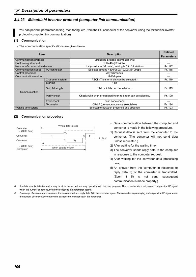
106
Description of parameters
3.4.23 Mitsubishi inverter protocol (computer link communication)
(1) Communication The communication specifications are given below.
(2) Communication procedure
If a data error is detected and a retry must be made, perform retry operation with the user program. The converter stops retrying and outputs the LF signalwhen the number of consecutive retries exceeds the parameter setting.
On receipt of a data error occurrence, the converter returns reply data 3) to the computer again. The converter stops retrying and outputs the LF signal whenthe number of consecutive data errors exceeds the number set in the parameter.
You can perform parameter setting, monitoring, etc. from the PU connector of the converter using the Mitsubishi inverterprotocol (computer link communication).
Item DescriptionRelated
ParametersCommunication protocol Mitsubishi protocol (computer link) Conforming standard EIA-485(RS-485) Number of connectable devices 1:N (maximum 32 units), setting is 0 to 31 stations Pr. 117Communication speed PU connector Selected among 4800/9600/19200/38400bps Pr. 118Control procedure Asynchronous Communication method Half-duplex
Communication
Character system ASCII (7 bits or 8 bits can be selected.) Pr. 119Start bit 1 bit
Stop bit length 1 bit or 2 bits can be selected. Pr. 119
Parity check Check (with even or odd parity) or no check can be selected. Pr. 120
Error check Sum code check Terminator CR/LF (presence/absence selectable) Pr. 124
Waiting time setting Selectable between presence and absence Pr. 123
Data communication between the computer andconverter is made in the following procedure.
1) Request data is sent from the computer to theconverter. (The converter will not send dataunless requested.)
2) After waiting for the waiting time, 3) The converter sends reply data to the computer
in response to the computer request.4) After waiting for the converter data processing
time,5) An answer from the computer in response to
reply data 3) of the converter is transmitted.(Even if 5) is not sent, subsequentcommunication is made properly.)
When data is read
When data is written
1) 5)4)
3)2)
∗1
∗2
Computer(Data flow)
Converter
Computer
(Data flow)
ConverterTime

107
3PA
RA
MET
ERS
Description of parameters
(3) Communication operation presence/absence and data format types Data communication between the computer and converter is made in ASCII code (hexadecimal code). Communication operation presence/absence and data format types are as follows.
Data writing formatCommunication request data from the computer to the converter 1)
Reply data from the converter to the computer 3) (No data error detected)
Reply data from the converter to the computer 3) (With data error)
No. OperationParameter/
Monitor Write
Converter Reset Monitor Parameter
Read
1) Communication request is sent to the converter in accordance with the user program in the computer.
AA1 A B B
2) Converter data processing time Present Absent Present Present
3) Reply data from the converter (Data 1) is checked for an error)
No error (Request accepted)
C C EE1 E
With error (Request rejected) D D D D
4) Computer processing delay time 10ms or more
5)Answer from computer in response to reply data 3). (Data 3) is checked for error)
No error (No converter processing)
Absent Absent Absent (C) Absent (C)
With error (Converter outputs 3) again.)
Absent Absent F F
In the communication request data from the computer to the converter, 10ms or more is also required after "no data error (ACK)".(Refer to page 109.) Reply from the converter to the converter reset request can be selected. (Refer to page 114.)
Format Number of Characters1 2 3 4 5 6 7 8 9 10 11 12 13
A ENQ
Station number
Instruction code Data Sum
check
A1 ENQ
Station number
Instruction code Data Sum
check
Format Number of Characters1 2 3 4
C ACK
Station number
Format Number of Characters1 2 3 4 5
D NAK
Station number
Error code
Indicate a control code Specify the station numbers between H00 and H1F (stations 0 to 31) in hexadecimal. Waiting time
When Pr. 123 (Waiting time setting) 9999, create a communication request data without "waiting time" in the data format. (The number ofcharacters decreases by 1.)
CR, LF codeWhen data is transmitted from the computer to the converter, codes CR (carriage return) and LF (line feed) are automatically set at the end ofa data group on some computers. In this case, setting must also be made on the converter according to the computer. Whether the CR and LFcodes will be present or absent can be selected using Pr. 124 (CR/LF selection).
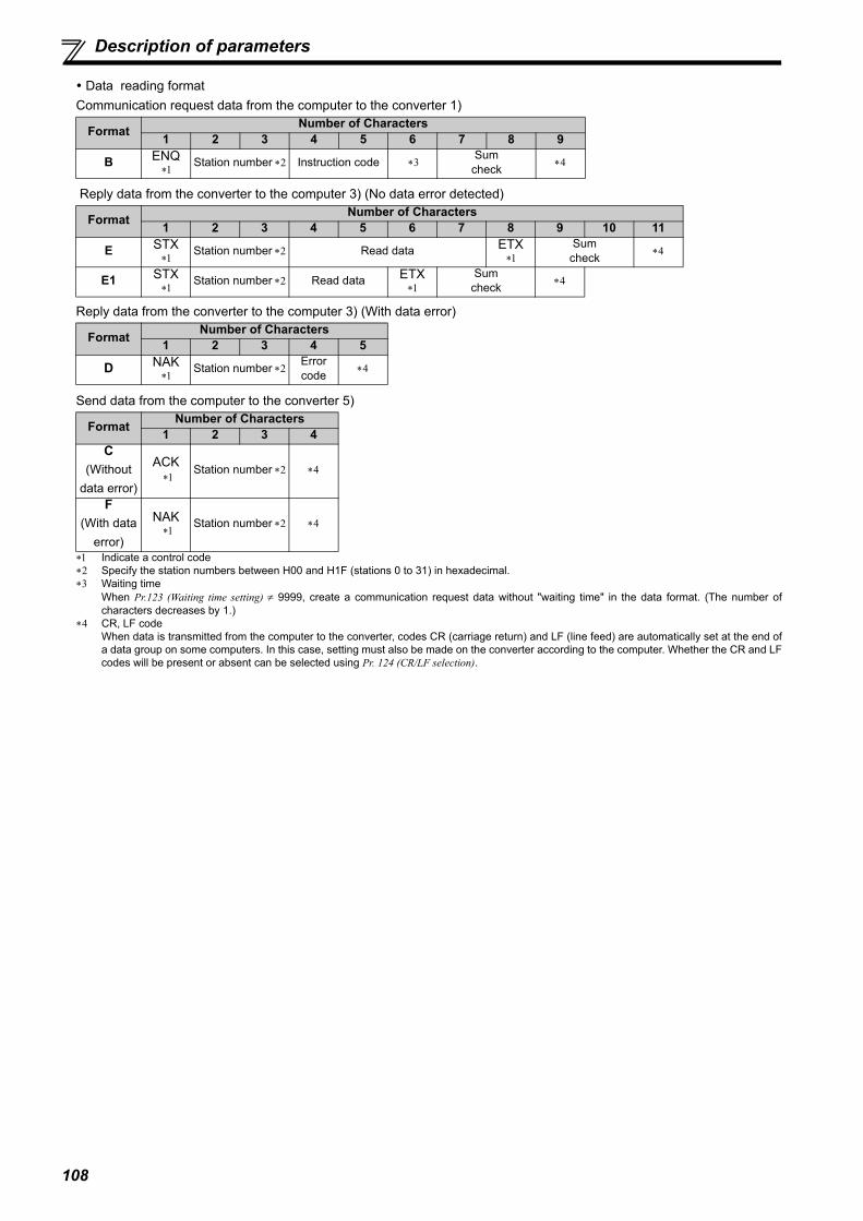
108
Description of parameters
Data reading formatCommunication request data from the computer to the converter 1)
Reply data from the converter to the computer 3) (No data error detected)
Reply data from the converter to the computer 3) (With data error)
Send data from the computer to the converter 5)
Format Number of Characters1 2 3 4 5 6 7 8 9
B ENQ Station number Instruction code Sum
check
Format Number of Characters1 2 3 4 5 6 7 8 9 10 11
E STX Station number Read data ETX
Sum
check
E1 STX Station number Read data ETX
Sum
check
Format Number of Characters1 2 3 4 5
D NAK Station number Error
code
Format Number of Characters1 2 3 4
C(Without
data error)
ACK Station number
F(With data
error)
NAK Station number
Indicate a control code Specify the station numbers between H00 and H1F (stations 0 to 31) in hexadecimal. Waiting time
When Pr.123 (Waiting time setting) 9999, create a communication request data without "waiting time" in the data format. (The number ofcharacters decreases by 1.)
CR, LF codeWhen data is transmitted from the computer to the converter, codes CR (carriage return) and LF (line feed) are automatically set at the end ofa data group on some computers. In this case, setting must also be made on the converter according to the computer. Whether the CR and LFcodes will be present or absent can be selected using Pr. 124 (CR/LF selection).

109
3PA
RA
MET
ERS
Description of parameters
(4) Data definitions
1) Control code
2) Station numberSpecify the station number of the converter which communicates with the computer.
3) Instruction codeSpecify the processing request, e.g. operation or monitoring, given by the computer to the converter. Hence, theconverter can be run and monitored in various ways by specifying the instruction code appropriately. (Refer to page114.)
4) DataIndicates the data such as frequency and parameters transferred to and from the converter. The definitions andranges of set data are determined in accordance with the instruction codes. (Refer to page 114.)
5) Waiting time Specify the waiting time between the receipt of data at the converter from the computer and the transmission of replydata. Set the waiting time in accordance with the response time of the computer in the range of 0 to 150ms in 10msincrements. (Example; 1:10ms, 2:20ms)
6) Sum check codeThe sum check code is a 2-digit ASCII (hexadecimal) representing the lower 1 byte (8 bits) of the sum (binary)derived from the checked ASCII data.
Signal Name
ASCII Code Description
STX H02 Start Of Text (Start of data)ETX H03 End Of Text (End of data)ENQ H05 Enquiry (Communication request)ACK H06 Acknowledge (No data error detected)LF H0A Line FeedCR H0D Carriage Return
NAK H15 Negative Acknowledge (Data error detected)
REMARKS When Pr. 123 (waiting time setting) 9999, create the communication request data without "waiting time" in the data format. (The
number of characters decreases by 1.) The data check time varies by the instruction code. (Refer to page 110.)
Computer
Converter
Converter
Computer
Converter data processing time
= +Waiting time
(setting 10ms)
data check time
(About 10 to 30ms,
which depends on the
instruction code)
(Example 1)
Computer ConverterENQ
*Wa
itin
g
tim
e
1
Instruction codeStation
number
0 1
Data
E 1 0 7 A D F 4
H05 H30 H31 H31H45 H31 H30 H37 H41 H44 H46 H34
Binary code
H30+H31+H45+H31+H31+H30+H37+H41+H44
= H1F4
Sum
(Example 2)
STXData read
Station
number
0 1 1 7 0 3 0
H02 H30 H31 H37H31 H37 H30 H03 H33 H30
Sum
ETX
7
* When the Pr. 123 Waiting time setting "9999", create the communication request
data without "waiting time" in the data format. (The number of characters decreases by 1.)
Converter
ASCII Code
ASCII Code
Binary code
H30+H31+H31+H37+H37+H30
= H130
Sum
check
code
Sum
check
codeComputer

110
Description of parameters
7) Error codeIf any error is found in the data received by the converter, its error definition is sent back to the computer together withthe NAK code.
(5) Response time
[Formula for data transmission time]
Communication specifications Data check time
Error Code
Error Item Error Description Converter Operation
H0 Computer NAK errorThe number of errors consecutively detected in communication request data from the computer is greater than permissible number of retries.
If errors occur consecutively and exceed the number of the permissible number of retries (Pr. 121), the converter outputs the alarm (LF).
H1 Parity error The parity check result does not match the specified parity.
H2 Sum check errorThe sum check code in the computer does not match that of the data received by the converter.
H3 Protocol errorThe data received by the converter has a grammatical mistake. Or, data receive is not completed within the predetermined time. CR or LF is not as set in the parameter.
H4 Framing error The stop bit length differs from the initial setting.
H5 Overrun errorNew data has been sent by the computer before the converter completes receiving the preceding data.
H6
H7 Character errorThe character received is invalid (other than 0 to 9, A to F, control code).
Does not accept the received data.
H8 H9
HA Mode errorParameter write was attempted in other than the computer link operation mode, when the operation command source is not present, or when parameter write is disabled.
Does not accept the received data.
HB Instruction code error The specified instruction code does not exist.HC Data range error Invalid data has been specified for parameter write, etc.HD HE HF
1
Number of data characters (Refer to page 107.)
Communication(Total number of bits)(Refer to the following.)
= data transmission time (s)Communication speed (bps)
Name Number of Bits Item Check Time
Stop bit length1 bit2 bits
Various monitors < 12ms
Data length7 bits8 bits
Parameter read/write, < 30ms
Parity checkPresent 1 bit Parameter clear / all clear < 5sAbsent 0 Reset command No answer
In addition to the above, 1 start bit is necessary.Minimum number of total bits.................9 bitsMaximum number of total bits.................12 bits
10ms or more necessary
Data sending time (refer to the following formula)
Converter data processing time
Data sending time (refer to the following formula)
Waiting time
(setting 10ms)
Data check time
(depends on the
instruction code (see the
following table))TimeComputerConverter
ConverterComputer

111
3PA
RA
MET
ERS
Description of parameters
(6) Retry count setting (Pr. 121)
Set the permissible number of retries at data receive error occurrence. (Refer to page 110 for data receive error for retry.) If data receive errors occur consecutively and exceed the permissible number of retries set, the converter outputs the
alarm (LF). (The converter does not trip.) If "9999" is set, the alarm (LF) is output at a data communication error. (The converter does not trip.)
For the terminal used for LF signal output, set "98 (positive logic)" or "198 (negative logic)" to any of Pr. 11 to Pr. 16 (outputterminal function selection).
Computer
Example: PU connector communication, Pr. 121 = "1" (initial value)
Example: PU connector communication, Pr. 121 = "9999"
Reception error Reception error
Converter
Converter Computer
EN
Q
AC
K
NA
K
NA
K
LF OFF OFF
Reception error Reception error
EN
Q
AC
K
NA
K
NA
K
ON
Wrong
Wrong EN
Q
AC
K
NormalEN
Q
Wrong
EN
Q
Wrong
LF OFF ON
ConverterComputer
Converter Computer
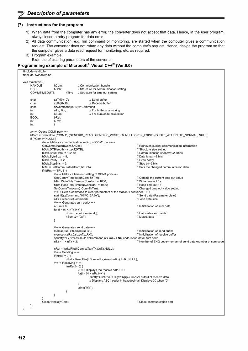
112
Description of parameters
(7) Instructions for the program1) When data from the computer has any error, the converter does not accept that data. Hence, in the user program,
always insert a retry program for data error.2) All data communication, e.g. run command or monitoring, are started when the computer gives a communication
request. The converter does not return any data without the computer's request. Hence, design the program so thatthe computer gives a data read request for monitoring, etc. as required.
3) Program exampleExample of clearing parameters of the converter
Programming example of Microsoft® Visual C++® (Ver.6.0)#include <stdio.h>#include <windows.h>
void main(void){ HANDLE hCom; // Communication handle
DCB hDcb; // Structure for communication settingCOMMTIMEOUTS hTim; // Structure for time out setting
char szTx[0x10]; // Send bufferchar szRx[0x10]; // Receive bufferchar szCommand[0x10];// Commandint nTx,nRx; // For buffer size storingint nSum; // For sum code calculationBOOL bRet;int nRet;int i;
//Opens COM1 porthCom = CreateFile ("COM1", (GENERIC_READ | GENERIC_WRITE), 0, NULL, OPEN_EXISTING, FILE_ATTRIBUTE_NORMAL, NULL);if (hCom != NULL) {
//Makes a communication setting of COM1 portGetCommState(hCom,&hDcb); // Retrieves current communication informationhDcb.DCBlength = sizeof(DCB); // Structure size settinghDcb.BaudRate = 19200; // Communication speed=19200bpshDcb.ByteSize = 8; // Data length=8 bitshDcb.Parity = 2; // Even parityhDcb.StopBits = 2; // Stop bit=2 bitsbRet = SetCommState(hCom,&hDcb); // Sets the changed communication dataif (bRet == TRUE) {
// Makes a time out setting of COM1 portGet CommTimeouts(hCom,&hTim); // Obtains the current time out value hTim.WriteTotalTimeoutConstant = 1000; // Write time out 1shTim.ReadTotalTimeoutConstant = 1000; // Read time out 1sSetCommTimeouts(hCom,&hTim); // Changed time out value setting// Sets a command to clear parameters of the station 1 converter. sprintf(szCommand,"01FC15A5A"); // Send data (Parameter clear)nTx = strlen(szCommand); //Send data size// Generates sum codenSum = 0; // Initialization of sum datafor (i = 0;i < nTx;i++) {
nSum += szCommand[i]; // Calculates sum codenSum &= (0xff); // Masks data
}
// Generates send datamemset(szTx,0,sizeof(szTx)); // Initialization of send buffermemset(szRx,0,sizeof(szRx)); // Initialization of receive buffersprintf(szTx,"\5%s%02X",szCommand,nSum);// ENQ code+send data+sum codenTx = 1 + nTx + 2; // Number of ENQ code+number of send data+number of sum code
nRet = WriteFile(hCom,szTx,nTx,&nTx,NULL);// Sending if(nRet != 0) {
nRet = ReadFile(hCom,szRx,sizeof(szRx),&nRx,NULL);// Receiving
if(nRet != 0) {// Displays the receive data for(i = 0;i < nRx;i++) {
printf("%02X ",(BYTE)szRx[i]);// Consol output of receive data// Displays ASCII coder in hexadecimal. Displays 30 when "0"
}printf("\n\r");
}}
}CloseHandle(hCom); // Close communication port
}}

113
3PA
RA
MET
ERS
Description of parameters
General flowchart
Port open
Communication setting
Time out setting
Send data processingData settingSum code calculationData transmission
Receive data waiting
Receive data processingData retrievalScreen display
CAUTIONAlways set the communication check time interval before starting operation to prevent hazardous conditions.
Data communication is not started automatically but is made only once when the computer provides a communication request. If communication is disabled during operation due to signal loss etc., the converter (inverter) cannot be stopped. Turn the RES signal ON or shut off the power supply to coast the motor to a stop and to stop the converter (inverter) operation.
If communication is broken due to signal cable breakage, computer fault etc., the converter does not detect such a fault. This should be fully noted.

114
Description of parameters
(8) Setting items and set dataAfter completion of parameter settings, set the instruction codes and data, then start communication from the computer toallow various types of operation control and monitoring.
ItemRead/ Write
Instruction code
Data DescriptionNumber of Data Digits
(Format)
Mon
itor
Input current Read H6FH0000 to HFFFF: Input current (hexadecimal) in 0.01A increments
(55K or lower) / 0.1A increments (75K or higher)4 digits(B.E/D)
Input voltage Read H70 H0000 to HFFFF: Input voltage (hexadecimal) in 0.1V increments4 digits(B.E/D)
Bus voltage Read H71 H0000 to HFFFF: Bus voltage (hexadecimal) in 0.1V increments4 digits(B.E/D)
Special monitor
Read H72 H0000 to HFFFF: Monitor data selected in instruction code HF34 digits(B.E/D)
Special monitorselection No.
Read H73H01to H10: Monitor selection dataRefer to the special monitor No. table (page 116).
2 digits(B.E1/D)
Write HF32 digits
(A1,C/D)
Fault record Read H74 to H77
H0000 to HFFFF: Two latest fault records
Refer to the fault data table (page 116).
4 digits(B.E/D)
Converter status monitor (expansion)
Read H79The states of the output signals during power driving, regenerative driving, etc. can be monitored. (Refer to page 116 for the details.)
4 digits(B.E/D)
Converter status monitor
Read H7A2 digits
(B.E1/D)
Converter reset Write HFD
H9696: resets the converter. As the converter is reset at the start of communication by the
computer, the converter cannot send reply data back to the computer.
4 digits(A,C/D)
H9966: resets the converter. When data is sent normally, ACK is returned to the computer,
and then the converter is reset.
4 digits(A,D)
Fault history batch clear
Write HF4 H9696: clears the fault history as a batch.4 digits(A,C/D)
Refer to page 107 for data format (A, A1, B, B1, C, D, E, E1, F).
b15 b8b7 b0
Latest faultSecond fault in past
Third fault in pastFourth fault in past
Fifth fault in pastSixth fault in past
Seventh fault in pastEighth fault in past
H74
H75
H76
H77

115
3PA
RA
MET
ERS
Description of parameters
Parameter clear All clear
Write HFC
All parameters return to the initial settings. Whether to clear communication parameters or not can be selected according to the data. (: Clear, : Not clear)Refer to page 198 for parameter clear, all clear, and communication parameters.
When clear is performed with H9696 or H9966, communication related parameter settings also return to the initial values. When resuming operation, set the parameters again. Performing clear will clear the instruction code HF3, and HFF settings. Turning OFF the power supply while clearing parameters with H5A5A or
H55AA also clears the communication parameter settings back to theinitial settings.
4 digits(A,C/D)
ParameterRead H00 to H5B Refer to the instruction code (page 198) and write and/or read
parameter values as required.When setting Pr. 100 and later, link parameter extended setting must be set.
4 digits(B.E/D)
Write H80 to HDB4 digits(A,C/D)
Link parameter extended setting
Read H7F Parameter description is changed according to the H00 to H09 setting.For details of the settings, refer to the instruction code (page 198).
2 digits(B.E1/D)
Write HFF2 digits
(A1,C/D)
REMARKS Set 65520 (HFFF0) as a parameter value "8888" and 65535 (HFFFF) as "9999". For the instruction codes HFF and HF3, their values are held once written but cleared to zero when a converter reset or all
clear is performed.
ItemRead/ Write
Instruction code
Data DescriptionNumber of Data Digits
(Format)
Refer to page 107 for data format (A, A1, B, B1, C, D, E, E1, F).
Clear Type Data Communication Pr.Parameter
clearH9696
H5A5A All parameter
clearH9966
H55AA
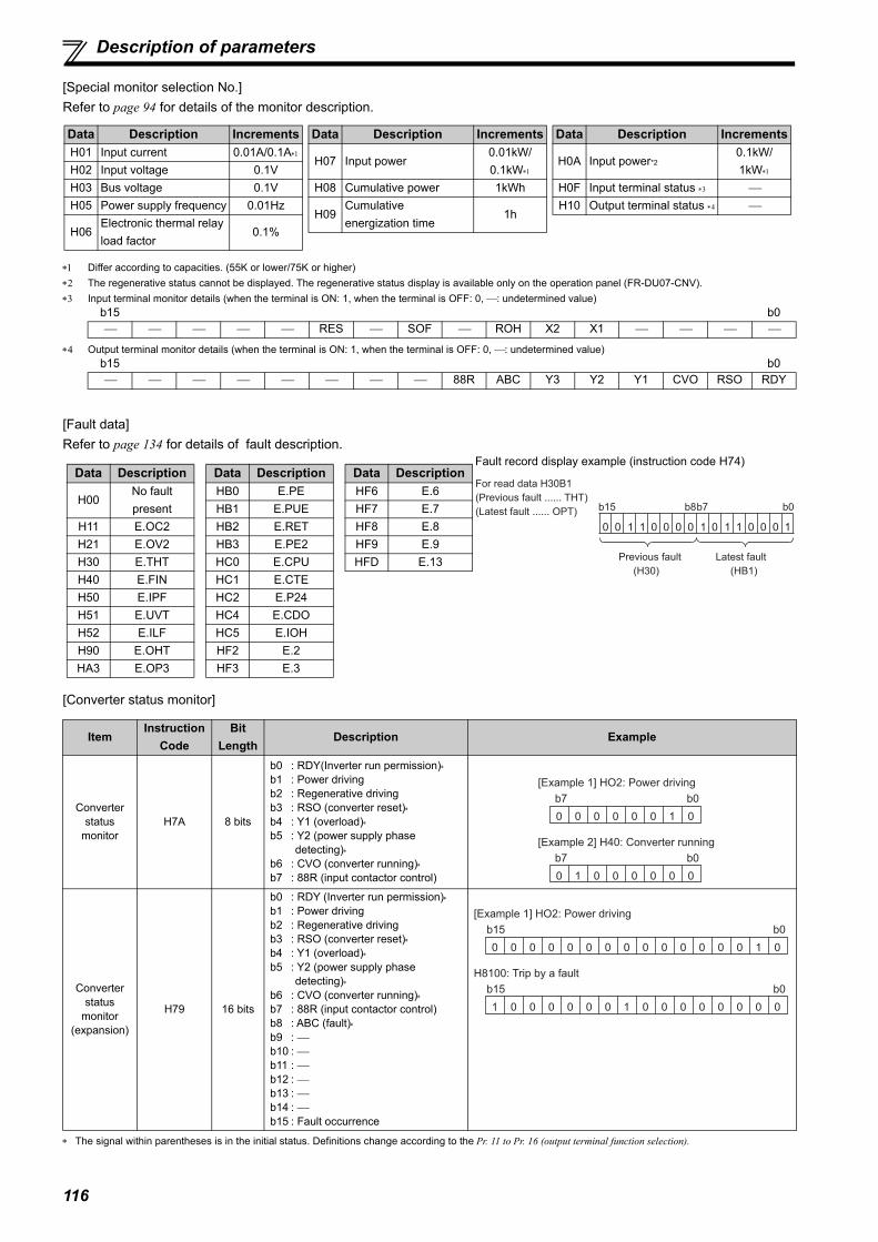
116
Description of parameters
[Special monitor selection No.]Refer to page 94 for details of the monitor description.
Differ according to capacities. (55K or lower/75K or higher) The regenerative status cannot be displayed. The regenerative status display is available only on the operation panel (FR-DU07-CNV). Input terminal monitor details (when the terminal is ON: 1, when the terminal is OFF: 0, : undetermined value)
Output terminal monitor details (when the terminal is ON: 1, when the terminal is OFF: 0, : undetermined value)
[Fault data]Refer to page 134 for details of fault description.
[Converter status monitor]
The signal within parentheses is in the initial status. Definitions change according to the Pr. 11 to Pr. 16 (output terminal function selection).
b15 b0 RES SOF ROH X2 X1
b15 b0 88R ABC Y3 Y2 Y1 CVO RSO RDY
ItemInstruction
CodeBit
LengthDescription Example
Converter status
monitorH7A 8 bits
b0 : RDY(Inverter run permission)b1 : Power driving b2 : Regenerative drivingb3 : RSO (converter reset)b4 : Y1 (overload)b5 : Y2 (power supply phase
detecting)b6 : CVO (converter running)b7 : 88R (input contactor control)
Converter status
monitor(expansion)
H79 16 bits
b0 : RDY (Inverter run permission)b1 : Power driving b2 : Regenerative drivingb3 : RSO (converter reset)b4 : Y1 (overload)b5 : Y2 (power supply phase
detecting)b6 : CVO (converter running)b7 : 88R (input contactor control)b8 : ABC (fault)b9 : b10 : b11 : b12 : b13 : b14 : b15 : Fault occurrence
Data Description IncrementsH01 Input current 0.01A/0.1A
H02 Input voltage 0.1VH03 Bus voltage 0.1VH05 Power supply frequency 0.01Hz
H06Electronic thermal relay load factor
0.1%
H07 Input power0.01kW/0.1kW
H08 Cumulative power 1kWh
H09Cumulative energization time
1h
Data Description Increments
H0A Input power*20.1kW/1kW
H0F Input terminal status H10 Output terminal status
Data Description Increments
For read data H30B1
(Previous fault ...... THT)
(Latest fault ...... OPT)
0 10 1 0 0 0 0 0 1 10001 1
b15 b8b7 b0
Latest fault
(HB1)
Previous fault
(H30)
Fault record display example (instruction code H74)Data Description
H00No fault present
H11 E.OC2H21 E.OV2H30 E.THTH40 E.FINH50 E.IPFH51 E.UVTH52 E.ILFH90 E.OHTHA3 E.OP3
HB0 E.PEHB1 E.PUEHB2 E.RETHB3 E.PE2HC0 E.CPUHC1 E.CTEHC2 E.P24HC4 E.CDOHC5 E.IOHHF2 E.2HF3 E.3
Data DescriptionHF6 E.6HF7 E.7HF8 E.8HF9 E.9HFD E.13
Data Description
0 0 0 0 0 0 1 0
b7 b0
[Example 1] HO2: Power driving
[Example 2] H40: Converter running
0 1 0 0 0 0 0 0
b7 b0
0 0 0 0 0 0 1 0
b0
0 0 0 0 0 0 0 0
b15
[Example 1] HO2: Power driving
0 0 0 0 0 0 0 0
b0
1 0 0 0 0 0 0 1
b15
H8100: Trip by a fault

117
Description of parameters
3PA
RA
MET
ERS
3.4.24 Initial setting and specification for the CC-Link communication function (Pr. 542 to Pr. 544)
Parameters which can be set when the plug-in option (FR-A7NC) is mounted.
(1) Station number setting (Pr. 542)
Use Pr. 542 Communication station number (CC-Link) to set the station number of the converter. Set this parameter within therange of 1 to 64.
Connection example
(2) Baud rate setting (Pr. 543)
Set the transmission speed. (Refer to the manual for the CC-Link master module for the details of the transmission speed.)
Set the station number and baud rate required for the CC-Link communication.
Parameter Number Name Initial
value Setting range Description
542Communication station number (CC-Link)
1 1 to 64 Set the station number of the converter.
543 Baud rate (CC-Link) 0 0 to 4 Set the transmission speed.544 CC-Link extended setting 0 0, 1, 12 Extend the functions of the remote register.
NOTE Use different station numbers for different devices. (If different devices have the same station number, the
communication cannot be performed properly. )
REMARKS Set consecutive numbers for the station numbers. (Do not skip a number in sequence like "station number 1 - station number 2
- station number 4".) The station number does not have to match with the physical connection sequence. (There is no problem with having thephysical connection sequence like "station number 1 - station number 3 - station number 4 - station number 2".)
One converter occupies one station (one remote device station). "L.ERR" LED on FR-A7NC blinks when a setting is changed. The LED turns OFF when the setting becomes valid by turning the
power OFF, then ON, or performing a converter reset.
Pr. 543 Setting Transmission speed0 (Initial setting) 156kbps
1 625kbps2 2.5Mbps3 5Mbps4 10Mbps
REMARKS "L.ERR" LED on FR-A7NC blinks when a setting is changed. The LED turns OFF when the setting becomes valid by turning the
power OFF, then ON, or performing a converter reset.
CC-Link
master module
Programmable controller
remote I/O station
(occupies one station)
Station 01
Converter
Remote device station
Inverter No.1
Remote device stationInverter No.2
Remote device station
Station 02 Station 03 Station 04
Number of stations connected is 4.
Station 00

118
Description of parameters
(3) CC-Link extended setting (Pr. 544)
The functions of the remote register can be extended. Refer to page 118 for the details of the remote I/O signals and theremote registers.
The program used for the conventional inverter series (FR-A5NC) can be used. The upper 8 bits of RWw2 are not used for the link parameter extended setting.
When using the double setting of the CC-Link Ver.2, station data of the master station must be set to double. (If the master station is CC-Link Ver.1, this setting is not available. )
(4) I/O signal list1)Remote I/O signals (32 points) (For details, refer to page 120.)
("n" indicates a value determined by the station number setting. ) These signals are set in the initial setting. Using Pr. 3 to Pr. 7, input signals assigned to the device numbers can be changed.
For the available signals, refer to page 84. These signals are set in the initial setting. Using Pr. 11 to Pr. 16, output signals assigned to the device numbers can be changed.
For the available signals, refer to page 86. Output of the error status flag signal depends on the retry function setting.
Pr. 544 Setting DescriptionCC-Link Ver.0 (Initial setting)
1Occupies one station (FR-A5NC compatible)
1 Occupies one station12 2 Occupies one station, double setting
REMARKS The setting becomes valid after converter reset. (Refer to page 132 for the converter reset.)
Device No. Signal Device No. Signal
RYn0 Not used RXn0 Not usedRYn1 Not used RXn1 Not usedRYn2 Converter stop (terminal SOF function) RXn2 Converter ready (inverter run enable signal)RYn3 Monitor switching (terminal X1 function) RXn3 Converter reset(terminal RSO function) RYn4 Monitor switching (terminal X2 function) RXn4 During converter run(terminal CVO function)
RYn5 Converter reset (terminal RES function) RXn5 Overload alarm(terminal Y1 function)
RYn6 ROH inrush resistance overheat detection (terminal ROH function)
RXn6 Power supply phase detection(terminal Y2 function)
RYn7 Not used RXn7 Output voltage match (terminal Y3 function)
RYn8 Not used RXn8 Fault(terminal ABC function)
RYn9 Not used RXn9 Not usedRYnA Not used RXnA Not usedRYnB Not used RXnB Not usedRYnC Monitor command RXnC MonitoringRYnD Not used RXnD Not usedRYnE Not used RXnE Not usedRYnF Instruction code execution request RXnF Instruction code execution completion
RY(n+1)0 to RY(n+1)7 Reserved RX(n+1)0 to
RX(n+1)7 Reserved
RY(n+1)8 Not used(initial data process completion flag) RX(n+1)8 Not used
(initial data process request flag)
RY(n+1)9 Not used(initial data process request flag) RX(n+1)9 Not used
(initial data process completion flag)RY(n+1)A Error reset request flag RX(n+1)A Error status flag
RY(n+1)B to
RY(n+1)FReserved
RX(n+1)B Remote station readyRX(n+1)C
toRX(n+1)F
Reserved

119
Description of parameters
3PA
RA
MET
ERS
2)Remote register (For the details, refer to page 121.)I/O signals when one station (FR-A5NC compatible) in the CC-Link Ver.1 is occupied. (Pr. 544 = "0")
("n" indicates a value determined by the station number setting.) The upper 8 bits are always H00 even if a value other than H00 is set.
I/O signals when one station in the CC-Link Ver.1 is occupied. (Pr. 544 = "1")
("n" indicates a value determined by the station number setting.)
I/O signals when the double setting is set in the CC-Link Ver.2 (Pr. 544 = "12")
("n" indicates a value determined by the station number setting.)
Device No.Description
Device No.Description
Upper 8 Bits Lower 8 Bits Upper 8 Bits Lower 8 BitsRWwn Monitor code 2 Monitor code 1 RWrn First monitor value
RWwn+1 Not used RWrn+1 Second monitor valueRWwn+2 H00(arbitrary) Instruction Code RWrn+2 Reply codeRWwn+3 Write data RWrn+3 Read data
Device No.Description
Device No.Description
Upper 8 Bits Lower 8 Bits Upper 8 Bits Lower 8 BitsRWwn Monitor code 2 Monitor code 1 RWrn First monitor value
RWwn+1 Not used RWrn+1 Second monitor value
RWwn+2Link parameter
extended settingInstruction code RWrn+2 Reply code H00
RWwn+3 Write data RWrn+3 Read data
Device No.Description
Device No.Description
Upper 8 Bits Lower 8 Bits Upper 8 Bits Lower 8 BitsRWwn Monitor code 2 Monitor code 1 RWrn First monitor value
RWwn+1 Not used RWrn+1 Second monitor value
RWwn+2 Link parameter extended setting Instruction code RWrn+2 Reply code H00
RWwn+3 Write data RWrn+3 Read dataRWwn+4 Monitor code 3 RWrn+4 Third monitor valueRWwn+5 Monitor code 4 RWrn+5 Fourth monitor valueRWwn+6 Monitor code 5 RWrn+6 Fifth monitor valueRWwn+7 Monitor code 6 RWrn+7 Sixth monitor value
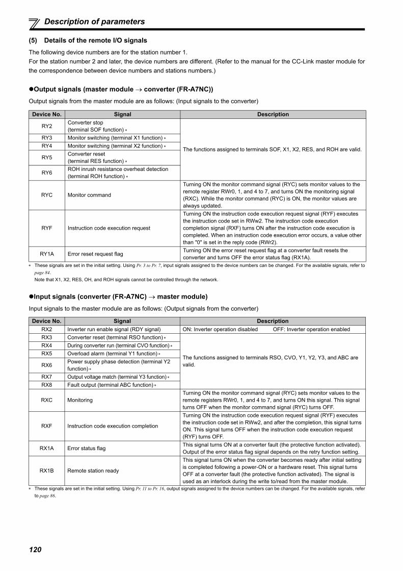
120
Description of parameters
(5) Details of the remote I/O signalsThe following device numbers are for the station number 1. For the station number 2 and later, the device numbers are different. (Refer to the manual for the CC-Link master module forthe correspondence between device numbers and stations numbers.)
Output signals (master module converter (FR-A7NC))Output signals from the master module are as follows: (Input signals to the converter)
These signals are set in the initial setting. Using Pr. 3 to Pr. 7, input signals assigned to the device numbers can be changed. For the available signals, refer topage 84. Note that X1, X2, RES, OH, and ROH signals cannot be controlled through the network.
Input signals (converter (FR-A7NC) master module)Input signals to the master module are as follows: (Output signals from the converter)
These signals are set in the initial setting. Using Pr. 11 to Pr. 16, output signals assigned to the device numbers can be changed. For the available signals, referto page 86.
Device No. Signal Description
RY2 Converter stop(terminal SOF function)
The functions assigned to terminals SOF, X1, X2, RES, and ROH are valid.
RY3 Monitor switching (terminal X1 function) RY4 Monitor switching (terminal X2 function)
RY5 Converter reset(terminal RES function)
RY6 ROH inrush resistance overheat detection(terminal ROH function)
RYC Monitor command
Turning ON the monitor command signal (RYC) sets monitor values to the remote register RWr0, 1, and 4 to 7, and turns ON the monitoring signal (RXC). While the monitor command (RYC) is ON, the monitor values are always updated.
RYF Instruction code execution request
Turning ON the instruction code execution request signal (RYF) executes the instruction code set in RWw2. The instruction code execution completion signal (RXF) turns ON after the instruction code execution is completed. When an instruction code execution error occurs, a value other than "0" is set in the reply code (RWr2).
RY1A Error reset request flag Turning ON the error reset request flag at a converter fault resets the converter and turns OFF the error status flag (RX1A).
Device No. Signal DescriptionRX2 Inverter run enable signal (RDY signal) ON: Inverter operation disabled OFF: Inverter operation enabledRX3 Converter reset (terminal RSO function)
The functions assigned to terminals RSO, CVO, Y1, Y2, Y3, and ABC are valid.
RX4 During converter run (terminal CVO function) RX5 Overload alarm (terminal Y1 function)
RX6 Power supply phase detection (terminal Y2 function)
RX7 Output voltage match (terminal Y3 function) RX8 Fault output (terminal ABC function)
RXC MonitoringTurning ON the monitor command signal (RYC) sets monitor values to the remote registers RWr0, 1, and 4 to 7, and turns ON this signal. This signal turns OFF when the monitor command signal (RYC) turns OFF.
RXF Instruction code execution completion
Turning ON the instruction code execution request signal (RYF) executes the instruction code set in RWw2, and after the completion, this signal turns ON. This signal turns OFF when the instruction code execution request (RYF) turns OFF.
RX1A Error status flag This signal turns ON at a converter fault (the protective function activated). Output of the error status flag signal depends on the retry function setting.
RX1B Remote station ready
This signal turns ON when the converter becomes ready after initial setting is completed following a power-ON or a hardware reset. This signal turns OFF at a converter fault (the protective function activated). The signal is used as an interlock during the write to/read from the master module.

121
Description of parameters
3PA
RA
MET
ERS
(6) Details of the remote registerThe following device numbers are for the station number 1. For the station number 2 and later, the device numbers are different. (Refer to the manual for the CC-Link master module forthe correspondence between device numbers and station numbers.)Remote register (master module converter (FR-A7NC))
Remote register definition
Remote register (converter (FR-A7NC) master module)
Remote register definition
Device No. Remote register Description
RWw0Monitor code1/Monitor code 2
Set the monitor code of the monitoring item. (Refer to page 116.) Turning ON the RYC signal after setting this register sets the monitor data to RWr0/RWr1.
RWw2Link parameter extended setting/Instruction code
Set an instruction code (Refer to page 122) for an operation such as parameter read/write, alarm reference, and alarm clear. Turning ON the RYF signal after setting this register executes the instruction code. The RXF signal turns ON after the instruction code execution is completed. When a value other than "0" is set to Pr. 544 CC-Link extended setting, upper 8 bits are used for the link parameter extended setting. Example) Reading of Pr. 300 The instruction code is 0300H.
RWw3 Write dataSet data for the instruction code set in RWw2. (When required) Turn ON the RYF signal after setting RWw2 and this register. Set "0" when the write data is not required.
RWw4 Monitor code 3Set the monitor code of the monitoring item. Turning ON the RYC signal after setting this register sets the monitor data to RWr. ( indicates a register number. (RWr4 to 7))
RWw5 Monitor code 4RWw6 Monitor code 5RWw7 Monitor code 6
Device No. Remote register Description
RWr0 First monitor valueTurning ON the RYC signal sets the monitor value to the lower 8 bits of the specified monitor code (RWw0).
RWr1 Second monitor valueTurning ON the RYC signal sets the monitor value to the upper 8 bits of the monitor code (RWw0) except when "0" was set to the upper 8 bits.
RWr2 Reply code
Turning ON the RYF signal sets the reply code, which corresponds to the instruction code of RWw2. The value "0" is set for a normal reply, and a value other than "0" is set for errors with data, mode, and other.
RWr3 Read data In a normal reply, a replay code for the instruction code is set. RWr4 Third monitor value
Turning ON the RYC signal sets the monitor values to the specified monitor code (RWw). ( indicates a register number. (RWw4 to 7))
RWr5 Fourth monitor valueRWr6 Fifth monitor valueRWr7 Sixth monitor value
Reply codeDescription Fault descriptionWhen
Pr. 554 = 0When
Pr. 554 0
H0000 H00 NormalNo fault (Instruction codes are executed without any fault.)
H0001 H01Write mode fault
Parameter write is attempted when the converter is running.
H0002 H02Parameter selection fault
Unregistered code is set.
H0003 H03Setting range fault
Set data exceeds the permissible range.
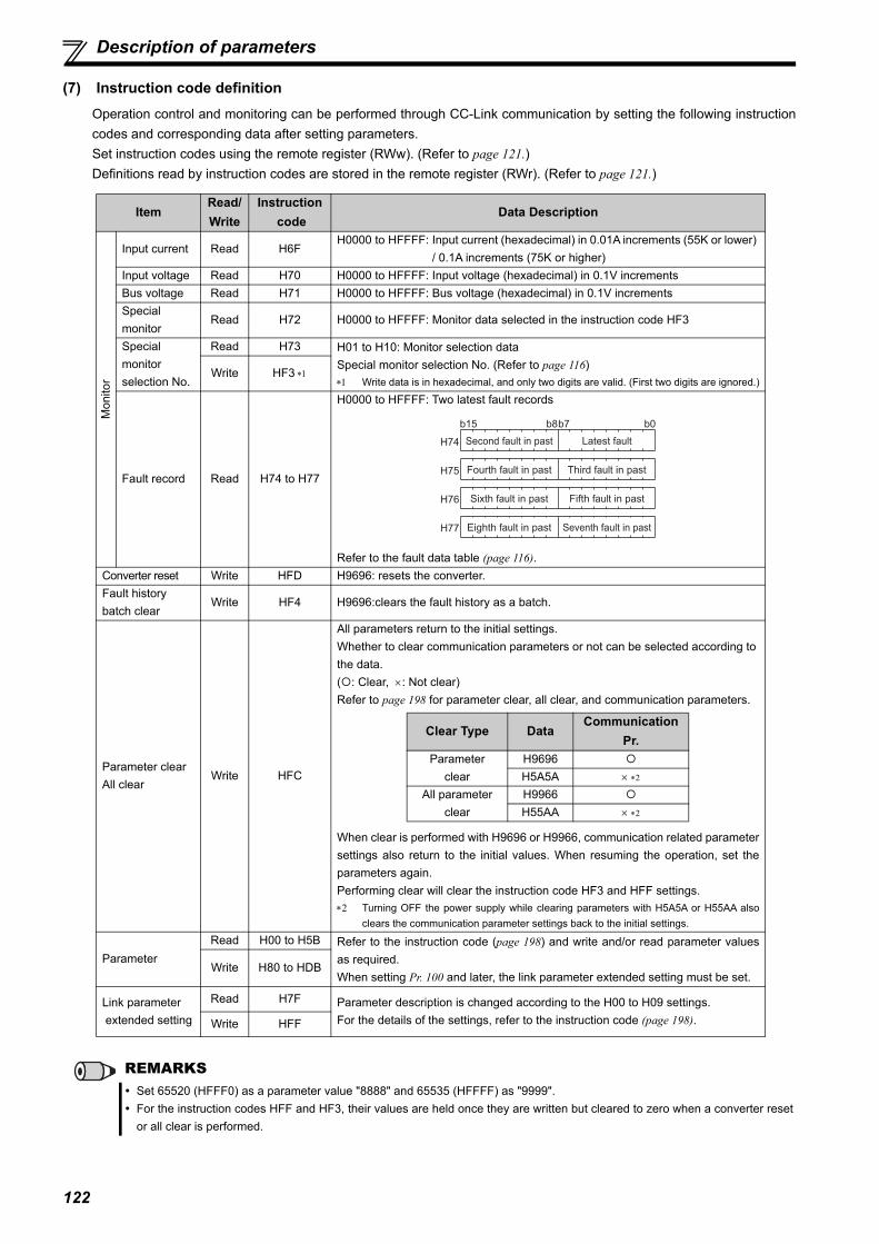
122
Description of parameters
(7) Instruction code definitionOperation control and monitoring can be performed through CC-Link communication by setting the following instructioncodes and corresponding data after setting parameters. Set instruction codes using the remote register (RWw). (Refer to page 121.)Definitions read by instruction codes are stored in the remote register (RWr). (Refer to page 121.)
ItemRead/ Write
Instruction code
Data Description
Mon
itor
Input current Read H6FH0000 to HFFFF: Input current (hexadecimal) in 0.01A increments (55K or lower)
/ 0.1A increments (75K or higher)Input voltage Read H70 H0000 to HFFFF: Input voltage (hexadecimal) in 0.1V incrementsBus voltage Read H71 H0000 to HFFFF: Bus voltage (hexadecimal) in 0.1V incrementsSpecial monitor
Read H72 H0000 to HFFFF: Monitor data selected in the instruction code HF3
Special monitorselection No.
Read H73 H01 to H10: Monitor selection dataSpecial monitor selection No. (Refer to page 116) Write data is in hexadecimal, and only two digits are valid. (First two digits are ignored.)
Write HF3
Fault record Read H74 to H77
H0000 to HFFFF: Two latest fault records
Refer to the fault data table (page 116).Converter reset Write HFD H9696: resets the converter. Fault history batch clear
Write HF4 H9696:clears the fault history as a batch.
Parameter clearAll clear
Write HFC
All parameters return to the initial settings. Whether to clear communication parameters or not can be selected according to the data.(: Clear, : Not clear)Refer to page 198 for parameter clear, all clear, and communication parameters.
When clear is performed with H9696 or H9966, communication related parametersettings also return to the initial values. When resuming the operation, set theparameters again.Performing clear will clear the instruction code HF3 and HFF settings. Turning OFF the power supply while clearing parameters with H5A5A or H55AA also
clears the communication parameter settings back to the initial settings.
ParameterRead H00 to H5B Refer to the instruction code (page 198) and write and/or read parameter values
as required.When setting Pr. 100 and later, the link parameter extended setting must be set.
Write H80 to HDB
Link parameter extended setting
Read H7F Parameter description is changed according to the H00 to H09 settings.For the details of the settings, refer to the instruction code (page 198).Write HFF
REMARKS Set 65520 (HFFF0) as a parameter value "8888" and 65535 (HFFFF) as "9999". For the instruction codes HFF and HF3, their values are held once they are written but cleared to zero when a converter reset
or all clear is performed.
b15 b8b7 b0
Latest faultSecond fault in past
Third fault in pastFourth fault in past
Fifth fault in pastSixth fault in past
Seventh fault in pastEighth fault in past
H74
H75
H76
H77
Clear Type DataCommunication
Pr.Parameter
clearH9696
H5A5A All parameter
clearH9966
H55AA

123
Description of parameters
3PA
RA
MET
ERS
3.4.25 Operation at a communication error (Pr. 500 to Pr. 502)
Parameters which can be set when the plug-in option (FR-A7NC) is mounted.
(1) Waiting time for the communication line error output after a communication error (Pr. 500)
Waiting time for the communication error output after a communication line error occurrence can be set. When a communication line error occurs and lasts longer than the time set in Pr. 500, it is recognized as a communicationerror. If the communication returns to normal within the time, it is not recognized as a communication error, and the operationcontinues.
(2) Displaying and clearing the communication error count (Pr. 501)
The cumulative count of communication error occurrences can be displayed. Write "0" to clear this cumulative count.When a communication line error occurs, the setting of Pr. 501Communication error occurrence count display increases by one.The cumulative count of communication error occurrences is counted from 0 to 65535. When the count exceeds 65535, thedisplayed value is cleared and the counting starts over from 0 again. *1
Since the panel display of the operation panel (FR-DU07-CNV) is in four digits, the monitor value of more than "9999" is displayed as "----".
Operation at a communication error in the CC-Link communication can be selected.
ParameterNumber
Name Initial valueSetting range
Description
500Communication error execution waiting time
0s 0 to 999.8sSet the waiting time for the communication error output after a communication line error occurrence.
501Communication error occurrence count display
0 0Displays the cumulative count of communication error occurrences. Write "0" to clear this cumulative count.
502Stop mode selection at communication error
0 0, 3Set the converter’s operation at a communication line error or an option unit fault.
NOTE Communication error count is temporarily stored in the RAM memory. The error count is stored in EEPROM only
once per hour. If power reset or converter reset is performed, Pr. 501 setting will be the one that is last stored toEEPROM depending on the reset timing.
Normal Error
Pr. 500
setting time
Normal ErrorCommunication line status
Alarm signal(LF)
(Pr. 502 = 3)
Recognition
ON
Pr. 500
setting time
Communication error
(E.OP3)
Normal ErrorCount timing depending on
communication line status Incremented by 1
Normal Error
Incremented by 1
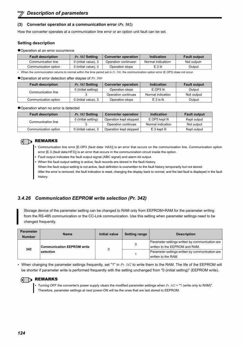
124
Description of parameters
(3) Converter operation at a communication error (Pr. 502)
How the converter operates at a communication line error or an option unit fault can be set.
Setting description
Operation at an error occurrence
When the communication returns to normal within the time period set in Pr. 500, the communication option error (E.OP3) does not occur.
Operation at error detection after elapse of Pr. 500
Operation when no error is detected
3.4.26 Communication EEPROM write selection (Pr. 342)
When changing the parameter settings frequently, set "1" in Pr. 342 to write them to the RAM. The life of the EEPROM willbe shorter if parameter write is performed frequently with the setting unchanged from "0 (initial setting)" (EEPROM write).
Fault description Pr. 502 Setting Converter operation Indication Fault outputCommunication line 0 (initial value), 3 Operation continues Normal indication Not output
Communication option 0 (initial value), 3 Operation stops E.3 lit Output
Fault description Pr. 502 Setting Converter operation Indication Fault output
Communication line0 (Initial setting) Operation stops E.OP3 lit Output
3 Operation continues Normal indication Not outputCommunication option 0 (initial value), 3 Operation stops E.3 is lit Output
Fault description Pr. 502 Setting Converter operation Indication Fault output
Communication line0 (Initial setting) Operation kept stopped E.OP3 kept lit Kept output
3 Operation continues Normal indication Not outputCommunication option 0 (initial value), 3 Operation kept stopped E.3 kept lit Kept output
REMARKS Communication line error [E.OP3 (fault data: HA3)] is an error that occurs on the communication line. Communication option
error [E.3 (fault data:HF3)] is an error that occurs in the communication circuit inside the option. Fault output indicates the fault output signal (ABC signal) and alarm bit output. When the fault output setting is active, fault records are stored in the fault history.
When the fault output setting is not active, fault definition is overwritten to the fault history temporarily but not stored. After the error is removed, the fault indication is reset, changing the display back to normal, and the last fault is displayed in the faulthistory.
Storage device of the parameter setting can be changed to RAM only from EEPROM+RAM for the parameter writing from the RS-485 communication or the CC-Link communication. Use this setting when parameter settings need to be changed frequently.
Parameter Number
Name Initial value Setting range Description
342Communication EEPROM write selection
00
Parameter settings written by communication are written to the EEPROM and RAM.
1Parameter settings written by communication are written to the RAM.
REMARKS Turning OFF the converter's power supply clears the modified parameter settings when Pr. 342 = "1 (write only to RAM)".
Therefore, parameter settings at next power-ON will be the ones that are last stored to EEPROM.

125
3PA
RA
MET
ERS
Description of parameters
3.4.27 Setting of the parameter unit and operation panel (Pr. 145, Pr. 990, Pr. 991)
(1) PU display language selection (Pr. 145) You can switch the display language of the parameter unit (FR-PU07) to another by setting Pr. 145.
(2) Buzzer control (Pr. 990)
Setting Pr. 990 = "1" makes the buzzer "beep" when you press the keys of the operation panel (FR-DU07-CNV) andparameter unit (FR-PU07).
(3) PU contrast adjustment (Pr. 991)
Contrast adjustment of the LCD of the parameter unit (FR-PU07) can be performed.Decreasing the Pr. 991 setting value makes the contrast light. Pr. 991 is displayed as a simple mode parameter only when the parameter unit (FR-PU07) is mounted.
Setting of the operation panel and parameter unit can be changed.
Parameter Number
Name Initial Value Setting Range Description
145 PU display language selection 0
0 Japanese1 English2 German3 French4 Spanish5 Italian6 Swedish7 Finnish
990 PU buzzer control 10 Without buzzer1 With buzzer
991 PU contrast adjustment 58 0 to 630 : Light63: Dark
REMARKS Parameter names and monitor names are always in English regardless of the Pr. 145 setting.
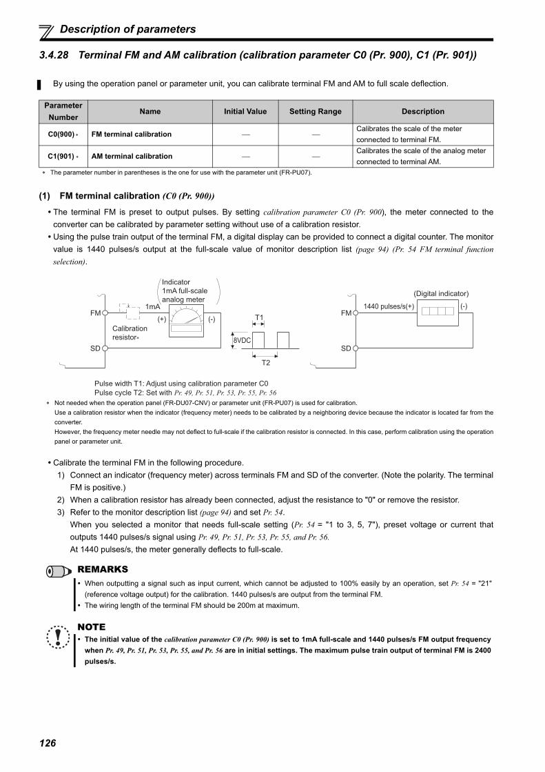
126
Description of parameters
3.4.28 Terminal FM and AM calibration (calibration parameter C0 (Pr. 900), C1 (Pr. 901))
(1) FM terminal calibration (C0 (Pr. 900))
The terminal FM is preset to output pulses. By setting calibration parameter C0 (Pr. 900), the meter connected to theconverter can be calibrated by parameter setting without use of a calibration resistor. Using the pulse train output of the terminal FM, a digital display can be provided to connect a digital counter. The monitor
value is 1440 pulses/s output at the full-scale value of monitor description list (page 94) (Pr. 54 FM terminal functionselection).
Not needed when the operation panel (FR-DU07-CNV) or parameter unit (FR-PU07) is used for calibration. Use a calibration resistor when the indicator (frequency meter) needs to be calibrated by a neighboring device because the indicator is located far from theconverter. However, the frequency meter needle may not deflect to full-scale if the calibration resistor is connected. In this case, perform calibration using the operationpanel or parameter unit.
Calibrate the terminal FM in the following procedure.1) Connect an indicator (frequency meter) across terminals FM and SD of the converter. (Note the polarity. The terminal
FM is positive.)2) When a calibration resistor has already been connected, adjust the resistance to "0" or remove the resistor. 3) Refer to the monitor description list (page 94) and set Pr. 54.
When you selected a monitor that needs full-scale setting (Pr. 54 = "1 to 3, 5, 7"), preset voltage or current thatoutputs 1440 pulses/s signal using Pr. 49, Pr. 51, Pr. 53, Pr. 55, and Pr. 56.At 1440 pulses/s, the meter generally deflects to full-scale.
By using the operation panel or parameter unit, you can calibrate terminal FM and AM to full scale deflection.
Parameter Number
Name Initial Value Setting Range Description
C0(900) FM terminal calibration Calibrates the scale of the meter connected to terminal FM.
C1(901) AM terminal calibration Calibrates the scale of the analog meter connected to terminal AM.
The parameter number in parentheses is the one for use with the parameter unit (FR-PU07).
REMARKS When outputting a signal such as input current, which cannot be adjusted to 100% easily by an operation, set Pr. 54 = "21"
(reference voltage output) for the calibration. 1440 pulses/s are output from the terminal FM. The wiring length of the terminal FM should be 200m at maximum.
NOTE The initial value of the calibration parameter C0 (Pr. 900) is set to 1mA full-scale and 1440 pulses/s FM output frequency
when Pr. 49, Pr. 51, Pr. 53, Pr. 55, and Pr. 56 are in initial settings. The maximum pulse train output of terminal FM is 2400pulses/s.
8VDC
T2
T1
Pulse width T1: Adjust using calibration parameter C0
Pulse cycle T2: Set with Pr. 49, Pr. 51, Pr. 53, Pr. 55, Pr. 56
(Digital indicator)
FM
SD
Indicator
1mA full-scale
analog meter
(+)
1mAFM
SD
(-)1440 pulses/s(+)
Calibration
resistor∗
(-)

127
3PA
RA
MET
ERS
Description of parameters
(2) AM terminal calibration (C1 (Pr. 901))
Calibrate the AM terminal in the following procedure.1) Connect a 0 to 10VDC meter (frequency meter) across converter terminals AM and 5. (Note the polarity. The
terminal AM is positive.)2) Refer to the monitor description list (page 94) and set Pr. 50.
When you selected a monitor that needs full-scale setting (Pr. 50 = "1 to 3, 5, 7"), preset power supply frequency orcurrent that outputs 10V signal using Pr. 49, Pr. 51, Pr. 53, Pr. 55, and Pr. 56 .
(3) How to calibrate the terminal FM when using the operation panel (FR-DU07-CNV)
Terminal AM is initially-set to provide a 10VDC output in the full-scalestatus of the corresponding monitor item. Calibration parameter C1 (Pr. 901)allows the output voltage ratios (gains) to be adjusted according to themeter scale. Note that the maximum output voltage is 10VDC.
REMARKS When outputting a signal such as input current, which cannot be adjusted to 100% easily by an operation, set Pr. 50 = "21"
(reference voltage output) for the calibration. 10VDC is output from the terminal AM.
REMARKS Calibration can be performed during operation.
AM
Converter
DC10V
5
DisplayOperation
1. Confirm the operation status indicator and operation mode indicator
2. Press to choose the parameter setting mode.
The parameter number read previously appears.
C0 to C7setting is enabled.
+
-
3. Turn until " " appears.
4. Press to display " ".
5. Turn until " " appears. Set to C0 FM terminal calibration.
6. Press to enable setting.
8. Turn to adjust the indicator needle to the desired position.
9. Press . Setting is complete.
Press to return to the " " indication (step 4).
By turning , you can read another parameter.
Press twice to show the next parameter (" ").
(When Pr. 54 = 5 (Power supply frequency))
The monitor set to Pr. 54 FM terminal function selection is displayed.
Analog indicator
Alternate display...Parameter setting complete
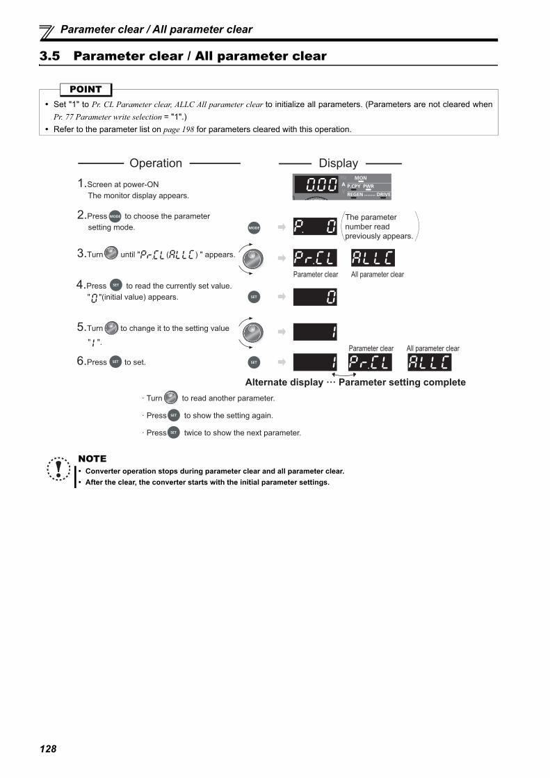
128
Parameter clear / All parameter clear
3.5 Parameter clear / All parameter clear
POINT Set "1" to Pr. CL Parameter clear, ALLC All parameter clear to initialize all parameters. (Parameters are not cleared when
Pr. 77 Parameter write selection = "1".) Refer to the parameter list on page 198 for parameters cleared with this operation.
NOTE Converter operation stops during parameter clear and all parameter clear. After the clear, the converter starts with the initial parameter settings.
Parameter clear All parameter clear
Parameter clear All parameter clear
DisplayOperation
1.Screen at power-ON The monitor display appears.
2.Press to choose the parameter setting mode.
3.Turn until " ( ) " appears.
4.Press to read the currently set value. " "(initial value) appears.
5.Turn to change it to the setting value
" ".
6.Press to set.
The parameter number read previously appears.
Alternate display ··· Parameter setting complete· Turn to read another parameter.
· Press twice to show the next parameter.
· Press to show the setting again.

129
3PA
RA
MET
ERS
Parameter copy and parameter verification
3.6 Parameter copy and parameter verification
(1) Parameter copy
PCPY Setting Description0 Cancel1 Copy the source parameters to the operation panel.2 Write the parameters copied to the operation panel into the destination converter.3 Verify parameters in the converter and operation panel. (Refer to page 130.)
REMARKS When the copy destination is other than the FR-HC2 series converter or when parameter copy is attempted after the parameter
copy reading was stopped, "model error ( )" appears. Refer to page 198 for the availability of parameter copy. When the power is turned OFF or an operation panel is disconnected, etc. during parameter copy writing, write again or check
the setting values by the parameter verification. After a parameter copy, the operation of the converter is in a stop status. Reset the converter after a parameter copy is
completed.
Parameter settings can be copied to multiple converters.
3.Turn until " " (parameter copy)
appears.
4.Press to read the currently set value. " "(initial value) appears.
5.Turn to change it to the setting value
" ".
6.Press to copy the source parameters to the operation panel.
7.Connect the operation panel to the copy destination converter.
8.After performing the steps 2 to 5, turn to change it to " ".
9.Press to write the parameters copied to the operation panel to the destination converter.
10.When copy is completed, " " and " " blink.
11.After writing the parameter values to the copy destination converter, always reset the converter, e.g. switch power OFF once, before starting operation.
Display
The parameter number previously read appears.
Blinks for about 30s
About 30s later
Alternate display ··· Parameter copy complete
The frequency blinks for about 30s
Alternate display··· Parameter copy complete
Operation1.Connect the operation panel to the copy source converter.
2.Press to choose the parameter setting mode.
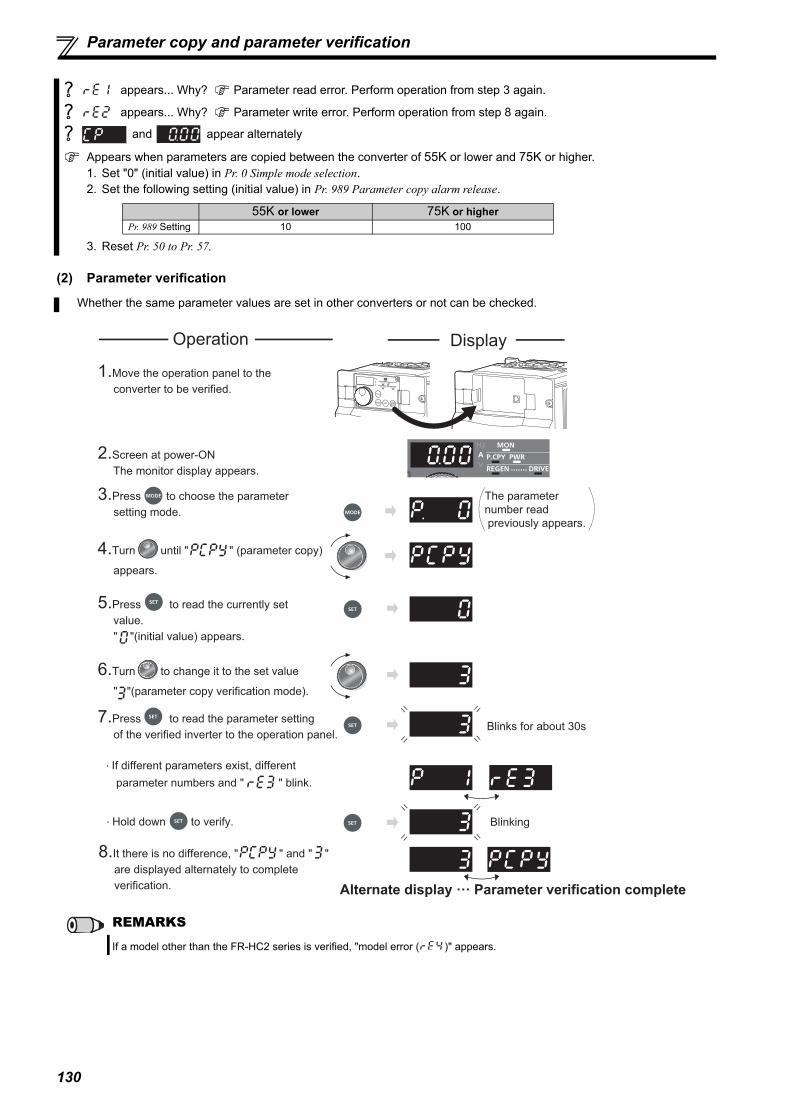
130
Parameter copy and parameter verification
(2) Parameter verification
appears... Why? Parameter read error. Perform operation from step 3 again.
appears... Why? Parameter write error. Perform operation from step 8 again.
and appear alternately
Appears when parameters are copied between the converter of 55K or lower and 75K or higher.1. Set "0" (initial value) in Pr. 0 Simple mode selection.2. Set the following setting (initial value) in Pr. 989 Parameter copy alarm release.
3. Reset Pr. 50 to Pr. 57.
Whether the same parameter values are set in other converters or not can be checked.
REMARKS
If a model other than the FR-HC2 series is verified, "model error ( )" appears.
55K or lower 75K or higherPr. 989 Setting 10 100
1.Move the operation panel to the converter to be verified.
2.Screen at power-ON The monitor display appears.
3.Press to choose the parameter setting mode.
5.Press to read the currently set value. " "(initial value) appears.
6.Turn to change it to the set value
" "(parameter copy verification mode).
7.Press to read the parameter setting of the verified inverter to the operation panel.
· Hold down to verify.
8.It there is no difference, " " and " " are displayed alternately to complete verification. Alternate display ··· Parameter verification complete
Display
The parameter number read previously appears.
Blinks for about 30s
Blinking
Operation
4.Turn until " " (parameter copy)
appears.
· If different parameters exist, different parameter numbers and " " blink.

3
1
131
2
5
6
4
4 PROTECTIVE FUNCTIONS
This chapter provides the "PROTECTIVE FUNCTIONS" ofthis product.Always read the instructions before using the equipment.
4.1 Troubleshooting............................................................................ 1324.2 Reset method of protective function .......................................... 1324.3 List of fault and alarm indications............................................... 1334.4 Causes and corrective actions .................................................... 1344.5 Digital characters and their corresponding printed
equivalents 1414.6 Check and clear of the fault history ............................................ 1424.7 Check first when you have a trouble .......................................... 144

132
Troubleshooting
4.1 Troubleshooting
When a fault occurs in the converter, the protective function activates to trip the converter, and the PU display automaticallychanges to one of the following fault or alarm indications.If the fault does not correspond to any of the following faults or if you have any other problem, please contact your salesrepresentative. Fault or alarm indication ............. When a fault or alarm occurs, the operation panel display automatically switches to a fault
or alarm indication. Resetting method ....................... When a fault occurs, the converter operation is kept stopped. Unless it is reset, the
converter cannot restart. (Refer to page 132.) When any fault occurs, take an appropriate corrective action, then reset the converter, and resume the operation.
Not doing so may lead to the converter fault and damage.
Converter fault or alarm indications are roughly categorized as below.(1) Error message
A message regarding operational fault and setting fault by the operation panel (FR-DU07-CNV) and parameter unit (FR-PU07) is displayed. The converter continues its operation.
(2) WarningThe converter continues its operation even when a warning is displayed. However, failure to take appropriate measureswill lead to a fault.
(3) AlarmThe converter continues its operation. You can also output an alarm signal by making parameter setting.
(4) FaultWhen a fault occurs, the converter trips and a fault signal is output.
4.2 Reset method of protective function
(1) Resetting the converterThe converter can be reset by performing any of the following operations. Note that the internal thermal cumulative value ofthe electronic thermal relay function and the number of retries are cleared (erased) by resetting the converter.Converter recovers about 1s after the reset.
Operation 1: ............. Using the operation panel, press to reset
the converter.(This can be performed only when a faultoccurs. (Refer to page 136 for fault.))
Operation 2: ............. Switch power OFF once, then switch it ONagain.
Operation 3: ............. Turn ON the reset signal (RES) for more than0.1s. (If the RES signal is kept ON, "Err."appears (blinks) to indicate that the converter isin a reset status.)
ON
OFF
SD
Converter
RES

133
4
PRO
TEC
TIVE
FU
NC
TIO
NS
List of fault and alarm indications
4.3 List of fault and alarm indications
If faults other than the above appear, contact your sales representative.
Operation Panel Indication Name Refer to page
Error message
HOLD Operation panel lock 134
Er1 Parameter write error 134
rE1 to 4 Copy operation fault 134
Err. Error 135
Warning
OL Overload signal detection 135
PS PU stop 135
TH Electronic thermal relay pre-alarm 135
MT Maintenance signal output 136
CP Parameter copy 136
SL Power supply not detected 136
Alarm FN Fan fault 136
Fault
E.OC2 Overcurrent trip 136
E.OV2 Overvoltage trip 137
E.THT Converter overload trip (electronic thermal relay function) 137
E.FIN Fin overheat 137
E.IPF Instantaneous power failure 137
E.UVT Undervoltage 137
E.ILF Input phase loss 138
E.OHT External thermal relay operation 138
E. 2 HC2 dedicated board disconnection 138
E. 3 Option fault 138
E.OP3 Communication option fault 138
E.PE Parameter storage device fault 139
E.PE2 Parameter storage device fault 139
E.PUE PU disconnection 139
E.RET Retry count excess 139
E. 6
CPU fault 139E. 7
CPU
E. 8 Input power supply fault 1 139
E. 9 Input power supply fault 2 140
E.CTEOperation panel power supply short circuit, RS-485 terminal power supply short circuit
140
E.P24 24VDC power output short circuit 140
E.CDO Input current detection value exceeded 140
E.IOH Inrush current limit circuit fault 140
E. 13E. 16E. 17
Internal circuit fault 141
OthersE- - - Fault history 142
E. 0 No fault records 141

134
Causes and corrective actions
4.4 Causes and corrective actions
(1) Error messageA message regarding operational troubles is displayed. The converter continues its operation.
Operation Panel Indication
HOLD
Name Operation panel lock
Description Operation lock is set. Operation other than is invalid.
(Refer to page 98.)Checkpoint —————
Corrective action Press for 2s to release the lock.
Operation Panel Indication
Er1
Name Parameter write error
Description
When you attempted to make parameter setting when Pr. 77 Parameter write selection has been set to disable parameter write.
When the PU and the converter cannot make normal communication. When you attempted to set a parameter, of which setting cannot be changed during the converter
operation.
Checkpoint Check if parameter writing is attempted while Pr. 77 Parameter write selection = "1". Check for a connection failure between the PU and the converter. Check that the converter is not operating.
Corrective action Perform parameter writing by setting Pr. 77 Parameter write selection = "2". Check the connection of the PU and the converter. After stopping the operation, make parameter setting.
Operation Panel Indication
rE1
Name Parameter read errorDescription When a failure occurs at the operation panel side EEPROM while reading copied parameters.Checkpoint —————
Corrective action Perform parameter copy again. (Refer to page 129.) Failure of the operation panel (FR-DU07-CNV) might be the cause. Please contact your sales
representative.
Operation Panel Indication
rE2
Name Parameter write errorDescription When a failure occurs at the operation panel side EEPROM while writing copied parameters.Checkpoint Check if FWD or REV LED on the operation panel (FR-DU07-CNV) is lit or blinking.
Corrective action Failure of the operation panel (FR-DU07-CNV) might be the cause. Please contact your sales representative.
Operation Panel Indication
rE3
Name Parameter verification error
Description When the data in the converter are different from the data in the operation panel. When a failure occurs at the operation panel side EEPROM during parameter verification.
Checkpoint Check the parameter setting of the source converter against the setting of the destination converter.
Corrective action Continue the verification by pressing .
Perform parameter verification again. (Refer to page 130.) Failure of the operation panel (FR-DU07-CNV) might be the cause. Please contact your sales
representative.

135
4
PRO
TEC
TIVE
FU
NC
TIO
NS
Causes and corrective actions
(2) WarningWhen a warning occurs, the converter continues its operation.
Operation Panel Indication
rE4
Name Model error
Description Parameter write or parameter verification of the parameter copy function is performed to an invalid model. When writing of copied parameters is attempted after reading of copied parameters is interrupted
Checkpoint
Check that the verifying converter is the same model. Check that the reading of copied parameter is not interrupted by switching OFF the power or by
disconnecting the operation panel. Check if parameter copy writing is attempted while Pr. 77 Parameter write selection = "1".
Corrective action Perform parameter copy and parameter verification to the same model (FR-HC2 series). Read the copied parameter again. Perform parameter copy writing by setting Pr. 77 Parameter write selection = "2".
Operation Panel Indication
Err.
Description
When RES signal is ON. When the PU and the converter cannot make normal communication. (Contact faults of the connector) This error may occur when the voltage at the input side of the converter drops. When using a separate power source for the control circuit power (R1/L11, S1/L21) from the main circuit
power (R/L1, S/L2, T/L3), this error may appear at turning ON of the main circuit. It is not a fault.
Corrective action Turn OFF the RES signal. Check the connection between the PU and the converter. Check the voltage on the input side of the converter.
Operation Panel Indication
OL FR-PU07 OL
Name Overload signal detection Description Appears when the current limit function of the converter activates.
Checkpoint
Check if the acceleration/deceleration time of the inverter is too short. Check that the load is not too heavy. Are there any failure in peripheral devices? Check that the Pr. 22 Current limit level setting is appropriate. (Refer to page 87.)
Corrective action
Set the acceleration/deceleration time of the inverter longer. Reduce the load weight. Check that the peripheral devices are operating properly. Current limit level of the output current can be set with Pr. 22 Current limit level. (Initial setting is 150%.) Set
the current limit level higher with Pr. 22 Current limit level.
Operation Panel Indication
PS FR-PU07 PS
Name PU stop
Description Stop with of the PU is set in Pr. 75 Reset selection/disconnected PU detection/PU stop selection. (For Pr. 75,
refer to page 100.)
Checkpoint Check for a stop made by pressing of the operation panel.
Corrective action Turn the converter stop signal (SOF) ON to stop the converter operation, and press to release the PU
stop.
Operation Panel Indication
TH FR-PU07 TH
Name Electronic thermal relay pre-alarm
Description
Appears if the cumulative value of the electronic thermal relay reaches or exceeds 85% of the preset level. If the specified value is reached, the protection circuit is activated to shut off the output of the converter.THP signal can be simultaneously output with the [TH] display. For the terminal used for THP signal, set "8 (positive logic)" or "108 (negative logic)" to any of Pr. 11 to Pr. 16 (output terminal function selection). (Refer to page 86.)
Checkpoint Check for large load or sudden acceleration.Corrective action Reduce the load and frequency of operation.

136
Causes and corrective actions
(3) AlarmWhen an alarm occurs, the converter continues its operation. You can also output an alarm signal by making parametersetting.(Set "98" in any of Pr. 11 to Pr. 16 (output terminal function selection). Refer to page 86.)
(4) FaultWhen a fault occurs, the converter trips and a fault signal is output. Output of the connected inverter is also shut off.
Operation Panel Indication
MT FR-PU07 MT
Name Maintenance signal output
DescriptionIndicates that the cumulative energization time of the converter has reached a given time.When the setting of Pr. 35 Maintenance timer alarm output set time is the initial setting (Pr. 35 = "9999"), this warning does not occur.
Checkpoint Check that the Pr. 34 Maintenance timer setting is larger than Pr. 35 Maintenance timer alarm output set time setting. (Refer to page 90.)
Corrective action Setting "0" to Pr. 34 Maintenance timer erases the signal.
Operation Panel Indication
CP FR-PU07 CP
Name Parameter copyDescription Appears when parameters are copied between models with capacities of 55K or lower and 75K or higher.Check point Resetting of Pr. 50, Pr. 51, Pr. 52, Pr. 53, Pr. 54, Pr. 55, Pr. 56 and Pr. 57 is necessary.
Corrective action Set the initial value in Pr. 989 Parameter copy alarm release.
Operation Panel Indication
SL FR-PU07 SL
Name Power supply not detected
DescriptionAppears when the power supply detection ends incompletely at a power failure. Appears at the power ON of the control circuit when using separate power sources for the control circuit power source and for the main circuit power source. It is not a fault.
Checkpoint Check the power source and the wiring.Check the wiring for power source detection.
Corrective action Perform wiring correctly.
Operation Panel Indication
FN FR-PU07 FN
Name Fan alarm
Description appears on the operation panel when the cooling fan of the converter trips, when its speed drops, or when it does not operate as commanded by the Pr. 36 Cooling fan operation selection.
Checkpoint Check the cooling fan for a failure.Corrective action Failure of the cooling fan might be the cause. Please contact your sales representative.
Operation Panel Indication
E.OC2 FR-PU07 Stedy Spd OC
Name Overcurrent trip
Description Stops the converter operation when the input current exceeds the specified level during the converter operation.
Checkpoint
Check for sudden load change. Check for output short-circuit. Check that the wiring is performed correctly. Check that any power supply failure did not occur.
Corrective action
Keep the load stable. Check the wiring to make sure that output short circuit does not occur. Check the wiring. Check the power supply.

137
4
PRO
TEC
TIVE
FU
NC
TIO
NS
Causes and corrective actions
Resetting the converter initializes the cumulative value of the internal thermal relay.
Operation Panel Indication
E.OV2 FR-PU07 Stedy Spd OV
Name Overvoltage trip
DescriptionIf the converter's internal main circuit DC voltage reaches or exceeds the specified value, the protective circuit is activated to stop the converter operation. The circuit may also be activated by a surge voltage produced in the power supply system.
Checkpoint Check for sudden load change and excessive regeneration. Check that any power supply failure did not occur.
Corrective action Keep the load stable. Check the power supply.
Operation Panel Indication
E.THT FR-PU07 Inv. Overload
Name Overload trip (electronic thermal relay function)
Description For the protection of transistor, electronic thermal relay activates in inverse-time characteristics against the converter input to stop the converter operation.
Checkpoint Check the motor for the use under overload. Check if the inverter, which exceeds the converter capacity, is being used.
Corrective action Reduce the load. Reconsider the choices of the inverter and the converter.
Operation Panel Indication
E.FIN FR-PU07 H/Sink O/Temp
Name Fin overheat
Description
If the heat sink overheats, the temperature sensor is activated and the output of the converter operation stops.The FIN signal can be output when the temperature becomes approximately 85% of the heat sink overheat protection operation temperature.For the terminal used for FIN signal, set "10 (positive logic)" or "110 (negative logic)" to any of Pr. 11 to Pr. 16 (output terminal function selection). (Refer to page 86.)
Checkpoint Check for too high surrounding air temperature. Check for heat sink clogging.
Check that the cooling fan is not stopped. (Check that is not displayed on the operation panel.)
Corrective action Set the surrounding air temperature to within the specifications. Clean the heat sink. Replace the cooling fan.
Operation Panel Indication
E.IPF FR-PU07 Inst. Pwr. Loss
Name Instantaneous power failure
Description
When a power failure occurs (or when power input to the converter is shut off), the instantaneous power failure protection function activates to stop the converter operation and prevent the control circuit from malfunctioning. If a power failure persists for 100ms or longer, the alarm warning output is not provided, and the converter (inverter) restarts when the start signal is ON upon power restoration. In some operating status (load magnitude, acceleration/deceleration time setting of the inverter, etc.), overcurrent or other protection may be activated upon power restoration.The IPF signal is output when a power failure is detected. (Refer to page 86.)
Checkpoint Identify the cause of instantaneous power failure occurrence.
Corrective action Recover the instantaneous power failure. Prepare a backup power supply for instantaneous power failure. Set the function of automatic restart after instantaneous power failure (Pr. 57). (Refer to page 97.)
Operation Panel Indication
E.UVT FR-PU07 Under Voltage
Name Undervoltage
DescriptionIf the power supply voltage of the converter decreases, the control circuit will not perform its normal functions. The converter operation is stopped when the power supply voltage decreases to about 150VAC (about 300VAC for the 400V class) or lower.
Checkpoint Check for start of large-capacity motor.
Corrective action Check the power supply system equipment such as the power supply.If the problem still persists after taking the above measure, please contact your sales representative.
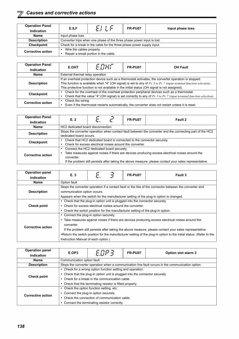
138
Causes and corrective actions
Operation Panel Indication
E.ILF FR-PU07 Input phase loss
Name Input phase lossDescription Converter trips when one phase of the three phase power input is lost.Checkpoint Check for a break in the cable for the three-phase power supply input.
Corrective action Wire the cables properly. Repair a break portion in the cable.
Operation Panel Indication
E.OHT FR-PU07 OH Fault
Name External thermal relay operation
DescriptionIf an overheat protection device such as a thermostat activates, the converter operation is stopped.This function is available when "4" (OH signal) is set to any of Pr. 3 to Pr. 7 (input terminal function selection). This protective function is not available in the initial status (OH signal is not assigned).
Checkpoint Check for the overheat of the overheat protection peripheral devices such as a thermostat. Check that the value "4" (OH signal) is set correctly to any of Pr. 3 to Pr. 7 (input terminal function selection).
Corrective action Check the wiring. Even if the thermostat restarts automatically, the converter does not restart unless it is reset.
Operation Panel Indication
E. 2 FR-PU07 Fault 2
Name HC2 dedicated board disconnection
Description Stops the converter operation when contact fault between the converter and the connecting part of the HC2 dedicated board occurs.
Checkpoint Check that HC2 dedicated board is connected to the connector securely. Check for excess electrical noises around the converter.
Corrective action
Connect the HC2 dedicated board securely. Take measures against noises if there are devices producing excess electrical noises around the
converter. If the problem still persists after taking the above measure, please contact your sales representative.
Operation panel indication
E. 3 FR-PU07 Fault 3
Name Option fault
DescriptionStops the converter operation if a contact fault or the like of the connector between the converter and communication option occurs.Appears when the switch for the manufacturer setting of the plug-in option is changed.
Check point Check that the plug-in option unit is plugged into the connector securely. Check for excess electrical noises around the converter. Check the switch position for the manufacturer setting of the plug-in option.
Corrective action
Connect the plug-in option securely. Take measures against noises if there are devices producing excess electrical noises around the
converter.If the problem still persists after taking the above measure, please contact your sales representative.
Return the switch position for the manufacturer setting of the plug-in option to the initial status. (Refer to the Instruction Manual of each option.)
Operation panel indication
E.OP3 FR-PU07 Option slot alarm 3
Name Communication option faultDescription Stops the converter operation when a communication line fault occurs in the communication option.
Check point
Check for a wrong option function setting and operation. Check that the plug-in option unit is plugged into the connector securely. Check for a break in the communication cable. Check that the terminating resistor is fitted properly.
Corrective action
Check the option function setting, etc. Connect the plug-in option securely. Check the connection of communication cable. Connect the terminating resistor correctly.

139
4
PRO
TEC
TIVE
FU
NC
TIO
NS
Causes and corrective actions
Operation Panel Indication
E.PE FR-PU07 Corrupt Memry
Name Parameter storage device fault (control circuit board)Description Stops the converter operation if a fault occurred in the parameter stored. (EEPROM fault)Checkpoint Check for too many number of parameter write times.
Corrective actionPlease contact your sales representative.When performing parameter write frequently for communication purposes, set "1" to Pr. 342 to enable RAM write. Note that powering OFF returns the converter to the status before RAM write.
Operation Panel Indication
E.PE2 FR-PU07 PR storage alarm
Name Parameter storage device fault (main circuit board)Description Stops the converter operation if a fault occurred in the parameter stored. (EEPROM fault)Checkpoint —————
Corrective action Please contact your sales representative.
Operation Panel Indication
E.PUE FR-PU07 PU Leave Out
Name PU disconnection
Description
This function stops the converter operation if communication between the converter and PU is suspended, e.g. the parameter unit is disconnected, when "2", "3", "16" or "17" was set in Pr. 75 Reset selection/disconnected PU detection/PU stop selection. This protective function is not available in the initial setting (Pr. 75 = "14").
Checkpoint Check that no loose point exists in the installation of FR-DU07-CNV or the parameter unit (FR-PU07). Check the Pr. 75 setting.
Corrective action Install FR-DU07-CNV or the parameter unit (FR-PU07) securely.
Operation Panel Indication
E.RET FR-PU07 Retry No Over
Name Retry count excess
Description
If operation cannot be resumed properly within the number of retries set, this function stops the converter operation.This function is available only when Pr. 67 Number of retries at fault occurrence is set. When the initial value (Pr. 67 = "0") is set, this protective function is not available.
Checkpoint Find the cause of the fault occurrence.Corrective action Eliminate the cause of the fault preceding this fault indication.
Operation Panel Indication
E. 6
FR-PU07
Fault 6
E. 7 Fault 7
CPU CPU fault
Name CPU faultDescription Stops the converter operation if the communication fault of the built-in CPU occurs.Checkpoint Check for devices producing excess electrical noises around the converter.
Corrective action Take measures against noises if there are devices producing excess electrical noises around the
converter. Please contact your sales representative.
Operation Panel Indication
E.8 FR-PU07 Fault 8
Name Input power supply fault 1
Description
When a fault is detected in the power supply frequency. When the phase detection cannot be performed for the normal power supply. When an overvoltage occurs during power failure or at an input phase loss. When the power supply amplitude changes suddenly. When any of the above occurs, it is regarded as a power supply fault, and the converter operation and the inverter output are stopped.
Checkpoint Check the power source and the wiring.Corrective action Perform wiring correctly.
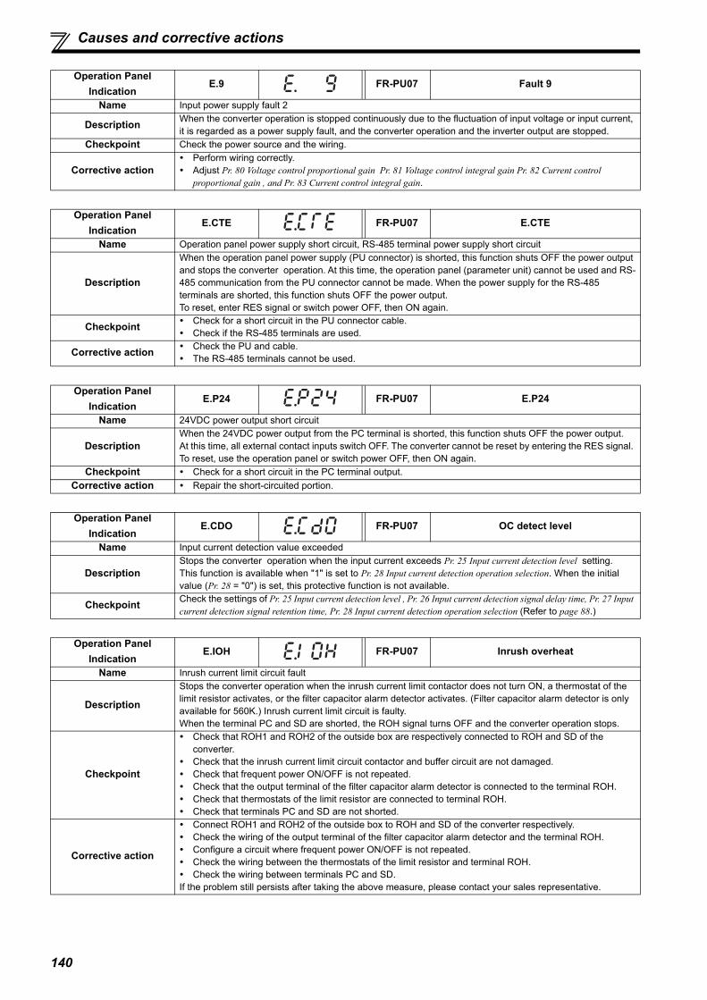
140
Causes and corrective actions
Operation Panel Indication
E.9 FR-PU07 Fault 9
Name Input power supply fault 2
Description When the converter operation is stopped continuously due to the fluctuation of input voltage or input current, it is regarded as a power supply fault, and the converter operation and the inverter output are stopped.
Checkpoint Check the power source and the wiring.
Corrective action Perform wiring correctly. Adjust Pr. 80 Voltage control proportional gain Pr. 81 Voltage control integral gain Pr. 82 Current control
proportional gain , and Pr. 83 Current control integral gain.
Operation Panel Indication
E.CTE FR-PU07 E.CTE
Name Operation panel power supply short circuit, RS-485 terminal power supply short circuit
Description
When the operation panel power supply (PU connector) is shorted, this function shuts OFF the power output and stops the converter operation. At this time, the operation panel (parameter unit) cannot be used and RS-485 communication from the PU connector cannot be made. When the power supply for the RS-485 terminals are shorted, this function shuts OFF the power output.To reset, enter RES signal or switch power OFF, then ON again.
Checkpoint Check for a short circuit in the PU connector cable. Check if the RS-485 terminals are used.
Corrective action Check the PU and cable. The RS-485 terminals cannot be used.
Operation Panel Indication
E.P24 FR-PU07 E.P24
Name 24VDC power output short circuit
DescriptionWhen the 24VDC power output from the PC terminal is shorted, this function shuts OFF the power output.At this time, all external contact inputs switch OFF. The converter cannot be reset by entering the RES signal. To reset, use the operation panel or switch power OFF, then ON again.
Checkpoint Check for a short circuit in the PC terminal output.Corrective action Repair the short-circuited portion.
Operation Panel Indication
E.CDO FR-PU07 OC detect level
Name Input current detection value exceeded
DescriptionStops the converter operation when the input current exceeds Pr. 25 Input current detection level setting.This function is available when "1" is set to Pr. 28 Input current detection operation selection. When the initial value (Pr. 28 = "0") is set, this protective function is not available.
Checkpoint Check the settings of Pr. 25 Input current detection level , Pr. 26 Input current detection signal delay time, Pr. 27 Input current detection signal retention time, Pr. 28 Input current detection operation selection (Refer to page 88.)
Operation Panel Indication
E.IOH FR-PU07 Inrush overheat
Name Inrush current limit circuit fault
Description
Stops the converter operation when the inrush current limit contactor does not turn ON, a thermostat of the limit resistor activates, or the filter capacitor alarm detector activates. (Filter capacitor alarm detector is only available for 560K.) Inrush current limit circuit is faulty. When the terminal PC and SD are shorted, the ROH signal turns OFF and the converter operation stops.
Checkpoint
Check that ROH1 and ROH2 of the outside box are respectively connected to ROH and SD of the converter.
Check that the inrush current limit circuit contactor and buffer circuit are not damaged. Check that frequent power ON/OFF is not repeated. Check that the output terminal of the filter capacitor alarm detector is connected to the terminal ROH. Check that thermostats of the limit resistor are connected to terminal ROH. Check that terminals PC and SD are not shorted.
Corrective action
Connect ROH1 and ROH2 of the outside box to ROH and SD of the converter respectively. Check the wiring of the output terminal of the filter capacitor alarm detector and the terminal ROH. Configure a circuit where frequent power ON/OFF is not repeated. Check the wiring between the thermostats of the limit resistor and terminal ROH. Check the wiring between terminals PC and SD.If the problem still persists after taking the above measure, please contact your sales representative.

141
4
PRO
TEC
TIVE
FU
NC
TIO
NS
Digital characters and their corresponding printed equivalents
(5) OthersThe fault history and the operation status of the inverter are displayed. It is not a fault indication.
4.5 Digital characters and their corresponding printed equivalents
Digital characters displayed on the operation panel are as follows.
Operation Panel Indication
E.13
FR-PU07
Fault 13
E.16 Fault 16
E.17 Fault 17
Name Internal circuit faultDescription Stops the converter operation when an internal circuit fault occurs.
Corrective action Please contact your sales representative.
Operation Panel Indication
E.0 FR-PU07 No Alarm
Name No fault records
DescriptionAppears when no fault records are stored.(Appears when the fault history is cleared after the protective function has been activated.)
Checkpoint Corrective action
NOTE If faults other than the above appear, contact your sales representative.
Printed Digital
0
1
2
3
4
5
6
7
8
9
Printed Digital
A
B
C
E
F
G
H
I
J
L
D
Printed Digital
M
N
O
o
P
T
U
V
r
-
S

142
Check and clear of the fault history
4.6 Check and clear of the fault history
(1) Check and clear of the fault history
The cumulative energization time is accumulated from 0 to 65535 hours, then cleared, and accumulated again from 0. When using the operation panel (FR-DU07-CNV), the time is displayed up to 65.53 (65530h) by regarding 1h = 0.001, and thereafter, it is added up from 0.
BlinkingBlinking
Input current Input voltage
Bus voltage
Monitor/frequency setting[Operation panel is used for operation]
Fault history[Operation for displaying fault history]
Eight past faults can be displayed with the setting dial.(The latest fault is ended by ".".)
When no fault exists, is displayed.
BlinkingBlinking
Fault history number(The number of past faults is displayed.)
Press the setting dial.
Press the setting dial.
Press the setting dial.
Blinking
Blinking
Blinking
[Parameter setting change]
Parameter setting
Energization time�

143
4
PRO
TEC
TIVE
FU
NC
TIO
NS
Check and clear of the fault history
(2) Clearing procedure
POINT Set Er.CL Fault history clear = "1" to clear the fault history.
Operation1.Screen at power-ON The monitor display appears.
2.Press to choose the parameter setting mode.
3.Turn until (fault history clear) appears.
4.Press to read the currently set value. " "(initial value) appears.
5.Turn to change it to the
setting value " ".
6.Press to set.
· Press to show the setting again.
· Press twice to show the next parameter.
· Press to read another parameter.
Display
The parameter number previouslyread appears.
Alternate display ··· Fault history clear complete
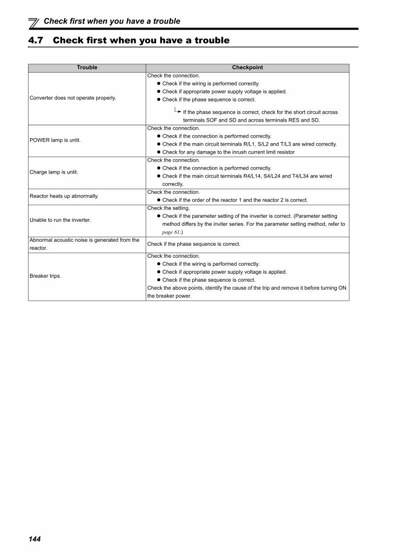
144
Check first when you have a trouble
4.7 Check first when you have a trouble
Trouble Checkpoint
Converter does not operate properly.
Check the connection. Check if the wiring is performed correctly. Check if appropriate power supply voltage is applied. Check if the phase sequence is correct.
If the phase sequence is correct, check for the short circuit across terminals SOF and SD and across terminals RES and SD.
POWER lamp is unlit.
Check the connection. Check if the connection is performed correctly. Check if the main circuit terminals R/L1, S/L2 and T/L3 are wired correctly. Check for any damage to the inrush current limit resistor
Charge lamp is unlit.
Check the connection. Check if the connection is performed correctly. Check if the main circuit terminals R4/L14, S4/L24 and T4/L34 are wired
correctly.
Reactor heats up abnormally.Check the connection. Check if the order of the reactor 1 and the reactor 2 is correct.
Unable to run the inverter.
Check the setting. Check if the parameter setting of the inverter is correct. (Parameter setting
method differs by the inviter series. For the parameter setting method, refer to page 61.)
Abnormal acoustic noise is generated from the reactor.
Check if the phase sequence is correct.
Breaker trips.
Check the connection. Check if the wiring is performed correctly. Check if appropriate power supply voltage is applied. Check if the phase sequence is correct.
Check the above points, identify the cause of the trip and remove it before turning ON the breaker power.
4
3
1
145
2
6
5
5 MAINTENANCE AND INSPECTION
This chapter provides the "MAINTENANCE ANDINSPECTION" of this product.Always read the instructions before using the equipment.
5.1 Inspection items............................................................................ 1465.2 Measurement of main circuit voltages, currents and powers .. 153
146
Inspection items
The converter is a static unit mainly consisting of semiconductor devices. Daily inspection must be performed to prevent anyfault from occurring due to the adverse effects of the operating environment, such as temperature, humidity, dust, dirt andvibration, changes in the parts with time, service life, and other factors.
Precautions for maintenance and inspectionFor some short time after the power is switched OFF, a high voltage remains in the smoothing capacitor. When accessing theconverter for an inspection, wait for at least 10 minutes after the power supply has been switched OFF, and then make surethat the voltage across the main circuit terminals P/+ and N/- of the converter is not more than 30VDC using a tester, etc.
5.1 Inspection items
5.1.1 Daily inspection
Basically, check for the following faults during operation.1) Improper installation environment2) Cooling system fault3) Abnormal vibration, abnormal noise4) Abnormal overheat, discoloration
5.1.2 Periodic inspection
Check the areas inaccessible during operation and requiring periodic inspection.Consult us for periodic inspection.1) Check for cooling system fault................Clean the air filter, etc.2) Tightening check and retightening..........The screws and bolts may become loose due to vibration, temperature changes,
etc. Check and tighten them.Tighten them according to the specified tightening torque. (Refer to page 54.)
3) Check the conductors and insulating materials for corrosion and damage.4) Measure insulation resistance.5) Check and change the cooling fan and relay.
CAUTIONReactor 1 and reactor 2 are extremely hot. Take caution not to get burned.

147
Inspection items
5
MA
INTE
NA
NC
E A
ND
INSP
ECTI
ON
5.1.3 Daily and periodic inspection list
Oil component of the heat dissipation grease used inside the converter may leak out. The oil component, however, is not flammable, corrosive, norconductive and is not harmful to humans. Wipe off such oil component.
It is recommended to install a device to monitor voltage for checking the power supply voltage to the converter. One to two years of periodic inspection cycle is recommended. However, it differs according to the installation environment.
Consult us for periodic inspection.
Area of Inspection
Inspection Item DescriptionInterval Corrective Action at
Alarm OccurrenceCustomer's
CheckDaily Periodic
General
Surrounding environment
Check the surrounding air temperature, humidity, dirt, corrosive gas, oil mist, etc. Improve the environment.
Overall unitCheck for unusual vibration and noise.
Check alarm location and retighten.
Check for dirt, oil, and other foreign material. CleanPower supply voltage
Check that the main circuit voltage and control circuit voltage are normal. Inspect the power supply.
Main Circuit
General
(1) Check with megger (across main circuit terminals and earth (ground) terminal). Contact the manufacturer.
(2) Check for loose screws and bolts. Retighten.(3) Check for overheat traces on the parts. Contact the manufacturer.(4) Check for stain. Clean.
Conductors, cables
(1) Check conductors for distortion.(2) Check cable sheaths for breakage and
deterioration (crack, discoloration, etc.).
Contact the manufacturer.
Contact the manufacturer.
Transistor /Reactor
Check for unusual odor and abnormal increase of whining sound.
Stop the device and contact the manufacturer.
Terminal block Check for a damage. Stop the device and contact the manufacturer.
Smoothing aluminum electrolytic capacitor
(1) Check for liquid leakage. Contact the manufacturer.(2) Check for safety valve projection and bulge. Contact the manufacturer.
(3) Visual check
Relay / Contactor Check that the operation is normal and no chatter is heard. Contact the manufacturer.
Control Circuit
Protective circuit
Operation checkCheck that no fault is found in protective and display circuits in a sequence protective operation test.
Contact the manufacturer.
Parts check
Overall(1) Check for unusual odor and discoloration.
Stop the device and contact the manufacturer.
(2) Check for serious rust development. Contact the manufacturer.Aluminum electrolytic capacitor
(1) Check for liquid leakage in a capacitor and deformation trace. Contact the manufacturer.
(2) Visual check
Cooling system
Cooling fan(1) Check for unusual vibration and noise. Replace the cooling fan.(2) Check for loose screws and bolts. Retighten.(3) Check for stain. Clean.
Heat sink(1) Check for clogging. Clean.(2) Check for stain. Clean.
Air filter, etc.(1) Check for clogging. Clean or replace.(2) Check for stain. Clean or replace.
DisplayIndication
(1) Check that display is normal. Contact the manufacturer.(2) Check for stain. Clean.
Meter Check that reading is normal. Stop the device and contact the manufacturer.
NOTE Continuous use of a leaked, deformed, or degraded smoothing aluminum electrolytic capacitor (as shown in the table
above) may lead to a burst, breakage, or fire. Replace such capacitor without delay.

148
Inspection items
5.1.4 Checking the converter module
<Preparation>(1) Disconnect the external power supply cables (R4/L14, S4/L24, T4/L34, P/+, N/-)(2) Prepare a tester. (Use 100 range.)
<Checking method>Change the polarity of the tester alternately at the converter terminals R4/L14, S4/L24, T4/L34, P/+, N/- and check the electriccontinuity.
(3) <Module device numbers and terminals to be checked>
5.1.5 Cleaning
Always run the converter in a clean status.When cleaning the converter, gently wipe dirty areas with a soft cloth immersed in neutral detergent.
NOTE Before measurement, check that the smoothing capacitor is discharged. At the time of electric discontinuity, the measured value is almost . When there is an instantaneous electric
continuity, due to the smoothing capacitor, the tester may not indicate . At the time of electric continuity, themeasured value is several to several tens of . If all measured values are almost the same, although these valuesare not constant depending on the module type and tester type, the modules are without fault.
NOTEDo not use solvent, such as acetone, benzene, toluene and alcohol, as they will cause the surface paint of the converterto peel off. The display, etc. of the operation panel and parameter unit are vulnerable to detergent and alcohol. Therefore, avoidusing them for cleaning.
TR1 TR2 TR3
TR4 TR5 TR6
R4/L14
S4/L24
T4/L34
C
P/+
N/-
(Assumes the use of an analog meter.)
Converter module
Tester Polarity Measured Value
TR1R4/L14 P Discontinuity
P R4/L14 Continuity
TR2S4/L24 P Discontinuity
P S4/L24 Continuity
TR3T4/L34 P Discontinuity
P T4/L34 Continuity
TR4R4/L14 N Continuity
N R4/L14 Discontinuity
TR5S4/L24 N Continuity
N S4/L24 Discontinuity
TR6T4/L34 N Continuity
N T4/L34 Discontinuity
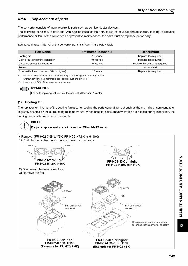
149
Inspection items
5
MA
INTE
NA
NC
E A
ND
INSP
ECTI
ON
5.1.6 Replacement of parts
The converter consists of many electronic parts such as semiconductor devices.The following parts may deteriorate with age because of their structures or physical characteristics, leading to reducedperformance or fault of the converter. For preventive maintenance, the parts must be replaced periodically.
Estimated lifespan interval of the converter parts is shown in the below table.
Estimated lifespan for when the yearly average surrounding air temperature is 40C(without corrosive gas, flammable gas, oil mist, dust and dirt etc.)
Input current: 80% of the converter rated current
(1) Cooling fanThe replacement interval of the cooling fan used for cooling the parts generating heat such as the main circuit semiconductoris greatly affected by the surrounding air temperature. When unusual noise and/or vibration are noticed during inspection, thecooling fan must be replaced immediately.
Part Name Estimated lifespan DescriptionCooling fan 10 years Replace (as required)Main circuit smoothing capacitor 10 years Replace (as required)On-board smoothing capacitor 10 years Replace the board (as required)Relays As requiredFuse inside the converter (160K or higher) 10 years Replace (as required)
REMARKSFor parts replacement, contact the nearest Mitsubishi FA center.
NOTEFor parts replacement, contact the nearest Mitsubishi FA center.
Removal (FR-HC2-7.5K to 75K, FR-HC2-H7.5K to H110K)1) Push the hooks from above and remove the fan cover.
2) Disconnect the fan connectors.3) Remove the fan.
FR-HC2-7.5K, 15KFR-HC2-H7.5K, H15K
(Example for FR-HC2-7.5K)
FR-HC2-7.5K, 15KFR-HC2-H7.5K, H15K FR-HC2-30K or higher
FR-HC2-H30K to H110K
Fan cover
Fan
Fan connection
connector
Fan∗
Fan connection
connector
Fan cover
∗ The number of cooling fans differs
according to the converter capacity.
FR-HC2-30K or higherFR-HC2-H30K to H110K
(Example for FR-HC2-55K)

150
Inspection items
Reinstallation (FR-HC2-7.5K to 75K, FR-HC2-H7.5K to H110K)1) After confirming the orientation of the fan, reinstall the fan so that the arrow on the left of "AIR FLOW" faces up.
<Fan side face>2) Reconnect the fan connectors.
3) Reinstall the fan cover.
AIR FLOW
FR-HC2-7.5KFR-HC2-H7.5K, H15K
FR-HC2-30K or higherFR-HC2-H30K to H110K
FR-HC2-15K
2. Insert hooks until
you hear a click
sound.
1. Insert hooks into
holes.
FR-HC2-7.5K, 15KFR-HC2-H7.5K, H15K
(Example for FR-HC2-7.5K)
2. Insert hooks until
you hear a click
sound.
1. Insert hooks into
holes.
FR-HC2-30K or higherFR-HC2-H30K to H110K
(Example for FR-HC2-55K)
NOTE Installing the fan in the opposite of air flow direction can cause the converter life to be shorter. Prevent the cable from being caught when installing a fan. Switch the power OFF before replacing fans. Since the converter circuits are charged with voltage even after power
OFF, replace fans only when the converter cover is on the converter to prevent an electric shock accident.

151
Inspection items
5
MA
INTE
NA
NC
E A
ND
INSP
ECTI
ON
Removal (FR-HC2-H160K or higher)1) Remove the fan cover.2) Remove the fan connector, then remove the fan block.3) Remove the fan fixing screws, then remove the fan. (Make sure to remove the fan cable from the clamp of the fan
block beforehand.)
(Example for FR-HC2-H560K)Reinstallation (FR-HC2-H160K or higher)
1) After confirming the orientation of the fan, reinstall the fan so that the "AIR FLOW" faces up.
2) Reinstall the fan by referring to the above figure. Tighten the fan with the fan fixing screws. (Tightening torque: 0.7N m)
1)
2)
3)
Fan ∗
Fan fixing screws
Fan connection
connector
Fan cover
Fan block
Unlock the clamp, and pull
out the cable.
∗ The number of cooling fans differs
according to the converter capacity.
AIR FLOW
NOTE Installing the fan in the opposite direction of air flow can cause the converter life to be shorter. Prevent the cable from being caught when installing a fan. Switch the power OFF before replacing fans. Since the converter circuits are charged with voltage even after power
OFF, replace fans only when the converter cover is on the converter to prevent an electric shock accident.
152
Inspection items
(2) Smoothing capacitorsA large-capacity aluminum electrolytic capacitor is used for smoothing in the main circuit DC section, and an aluminumelectrolytic capacitor is used for stabilizing the control power in the control circuit. Their characteristics are deterioratedby the adverse effects of ripple currents, etc. The replacement intervals greatly vary with the surrounding air temperatureand operating conditions. When the converter is operated in air-conditioned, normal environment conditions, replace thecapacitors about every 10 years.When a certain period of time has elapsed, the capacitors will deteriorate more rapidly. Check the capacitors at leastevery year (less than six months if the life will be expired soon).The appearance criteria for inspection are as follows:1) Case: Check the side and bottom faces for expansion2) Sealing plate: Check for remarkable warp and extreme crack.3) Explosion-proof valve: Check for extreme valve expansion, and movement of the value.4) Check for external crack, discoloration, liquid leakage, etc. Judge that the capacitor has reached its life when the
measured capacitance of the capacitor reduced below 85% of the rating.
(3) Relay output terminalsTo prevent a contact fault, etc., relays must be replaced according to the cumulative number of switching times(switching life).
(4) Fuse inside the converter (160K or higher)A fuse is used inside the converter. Surrounding air temperature and operating condition affect the life of fuses. When theconverter is used in a normal air-conditioned environment, replace its fuse after about 10 years.

153
Measurement of main circuit voltages, currents and powers
5
MA
INTE
NA
NC
E A
ND
INSP
ECTI
ON
5.2 Measurement of main circuit voltages, currents and powers
Measurement method of voltage and current at each sectionWhen instruments for commercial frequency are used for measurement, measure the following circuits with the instrumentsgiven below.
When installing meters etc. on the output side of the converterWhen the converter-to-motor wiring length is long, especially in the 400V class, the meters may generate heat due to line-to-line leakage current. Therefore, choose the equipment which has enough allowance for the current rating.
Voltage is output between the terminal P and N of the converter, and it can be measured using a moving-coil type meter(tester). The voltage changes by the power supply voltage, but it decreases when a load is applied.
[Examples of Measuring Points and Instruments]
[Examples of Measuring Points and Instruments]
Operation principle and application of electric meters
Type Symbol Operation Principle Command Applicable meter Characteristic
Moving-coil type
Uses kinetic power generated between the magnetic field of a permanent magnet and the current that flows through the moving-coil.
DC(average value)
Voltmeter/ammeter/resistance meter/thermometer/flux meter/speed meter
High sensitivity and commonly used.Energy saving, small influence of magnetic field
Moving-iron meter
Uses kinetic power generated between the moving-iron and the magnetic field of the current that flows though the fixed coil.
AC(effective value) Voltmeter/ammeter
Strong structure and inexpensive, Large influence from external magnetic field, frequency, and waveform
Ammeter type Air-core coil
Uses kinetic power generated between the currents that flow through two different coils.
AC/DC(effective value)
Wattmeter/voltmeter/ammeter
Scale is divided equally when using a wattmeter.Large influence from external magnetic field, high energy consumption This can be used as a standard meter for AC and DC.
Filter capacitorLimit resistor
Inrush current limit MC
ConverterOutside boxReactor 1 R4
/L14
S4/L24
T4/L34
P/+
N/-
+
-
V
Reactor 2
Power supply
W11
W12
W13
Vu
Vv
Vw
Au
Av
Aw
To the Inverter
Wat
tmet
er
R4/L14
S4/L24
T4/L34
P/+
N/-
+
-
VPower supply
ConverterOutside box
To the InverterFilter capacitorLimit resistor
Inrush current limit MC
Reactor 1 Reactor 2

154
Measurement of main circuit voltages, currents and powers
Measuring Points and Instruments
5.2.1 Insulation resistance test using megger
For the converter, conduct the insulation resistance test on the main circuit only as shown below and do not perform the teston the control circuit. (Use a 500VDC megger.)
5.2.2 Pressure test
Do not conduct a pressure test. Deterioration may occur.
Item Measuring Point Measuring Instrument Remarks (Reference Measured Value)
Power supply voltageV1
Across R and S Across S and TAcross T and R
Moving-iron type AC voltmeterCommercial power supplyWithin permissible AC voltage fluctuation (Refer to page 156.)
Power supply side currentl1 R, S, T line current Moving-iron type AC ammeter
Power supply side power P1
R, S, T and Across R and S Across S and T Across T and R
Electrodynamic type single-phase wattmeter
P1=W11+W12+W13
(3-wattmeter method)
Power supply side power factor Pf1
Calculate after measuring power supply voltage, power supply side current and power supply side power.
Pf1= 100%
Converter output Across P and N Moving-coil type(such as tester)
Converter LED display is lit.1.35 V1
Maximum 380V (200V class) and 750 V or lower (400V class)
Indicator signal Across FM(+) and SD Moving-coil type(such as tester)
(internal resistance 50k or more)
Approximately 5VDC at maximum frequency (without indicator)
Pulse width T1: Adjust with Pr. 900
Input signal RES, SOF, X1, X2, Across ROH(+) and SD
When open20 to 30VDCON voltage: 1V or less
Fault signal Across A and CAcross B and C
Moving-coil type(such as tester)
Electric continuity check [Normal] [Abnormal]
Across A and C Discontinuity ContinuityAcross B and C Continuity Discontinuity
NOTE Before performing the insulation resistance test on the external circuit, disconnect the cables from all terminals of
the converter so that the test voltage is not applied to the converter. For the electric continuity test of the control circuit, use a tester (high resistance range) and do not use the megger or
buzzer.
3V1 l 1
P1
DC8V
T1
P/+
N/-
Inverter
Earth (ground)
500VDC
megger
Power
supply
Converter
R4/L14
S4/L24
T4/L34

3
1
155
2
4
5
6
6 SPECIFICATIONS
This chapter provides the "SPECIFICATIONS" of thisproduct.Always read the instructions before using the equipment.
6.1 Rated specifications ..................................................................... 1566.2 Common specifications ............................................................... 1576.3 Outline dimensions....................................................................... 158
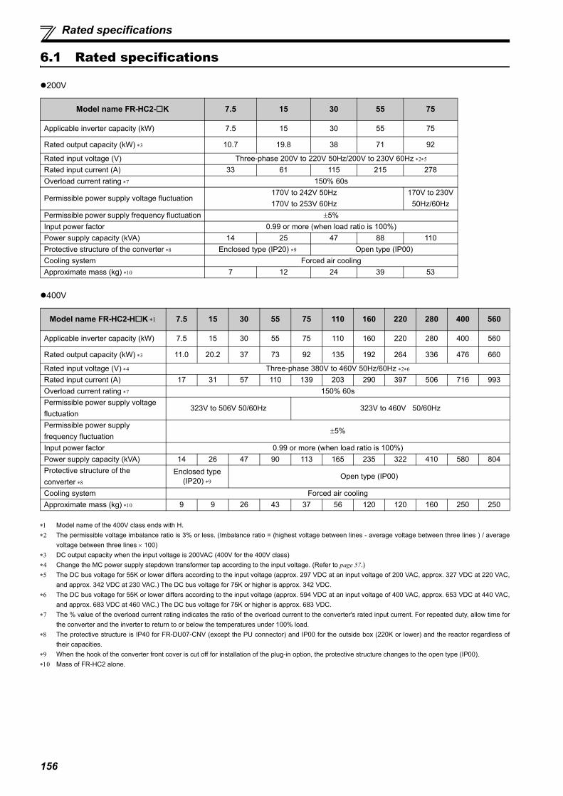
156
Rated specifications
6.1 Rated specifications
200V
400V
Model name of the 400V class ends with H. The permissible voltage imbalance ratio is 3% or less. (Imbalance ratio = (highest voltage between lines - average voltage between three lines ) / average
voltage between three lines 100) DC output capacity when the input voltage is 200VAC (400V for the 400V class) Change the MC power supply stepdown transformer tap according to the input voltage. (Refer to page 57.) The DC bus voltage for 55K or lower differs according to the input voltage (approx. 297 VDC at an input voltage of 200 VAC, approx. 327 VDC at 220 VAC,
and approx. 342 VDC at 230 VAC.) The DC bus voltage for 75K or higher is approx. 342 VDC. The DC bus voltage for 55K or lower differs according to the input voltage (approx. 594 VDC at an input voltage of 400 VAC, approx. 653 VDC at 440 VAC,
and approx. 683 VDC at 460 VAC.) The DC bus voltage for 75K or higher is approx. 683 VDC. The % value of the overload current rating indicates the ratio of the overload current to the converter's rated input current. For repeated duty, allow time for
the converter and the inverter to return to or below the temperatures under 100% load. The protective structure is IP40 for FR-DU07-CNV (except the PU connector) and IP00 for the outside box (220K or lower) and the reactor regardless of
their capacities. When the hook of the converter front cover is cut off for installation of the plug-in option, the protective structure changes to the open type (IP00). Mass of FR-HC2 alone.
Model name FR-HC2-K 7.5 15 30 55 75
Applicable inverter capacity (kW) 7.5 15 30 55 75
Rated output capacity (kW) 10.7 19.8 38 71 92
Rated input voltage (V) Three-phase 200V to 220V 50Hz/200V to 230V 60Hz Rated input current (A) 33 61 115 215 278Overload current rating 150% 60s
Permissible power supply voltage fluctuation 170V to 242V 50Hz170V to 253V 60Hz
170V to 230V50Hz/60Hz
Permissible power supply frequency fluctuation 5%Input power factor 0.99 or more (when load ratio is 100%)Power supply capacity (kVA) 14 25 47 88 110Protective structure of the converter Enclosed type (IP20) Open type (IP00)Cooling system Forced air coolingApproximate mass (kg) 7 12 24 39 53
Model name FR-HC2-HK 7.5 15 30 55 75 110 160 220 280 400 560
Applicable inverter capacity (kW) 7.5 15 30 55 75 110 160 220 280 400 560
Rated output capacity (kW) 11.0 20.2 37 73 92 135 192 264 336 476 660
Rated input voltage (V) Three-phase 380V to 460V 50Hz/60Hz Rated input current (A) 17 31 57 110 139 203 290 397 506 716 993Overload current rating 150% 60sPermissible power supply voltage fluctuation
323V to 506V 50/60Hz 323V to 460V 50/60Hz
Permissible power supply frequency fluctuation
5%
Input power factor 0.99 or more (when load ratio is 100%)Power supply capacity (kVA) 14 26 47 90 113 165 235 322 410 580 804Protective structure of the converter
Enclosed type (IP20) Open type (IP00)
Cooling system Forced air coolingApproximate mass (kg) 9 9 26 43 37 56 120 120 160 250 250
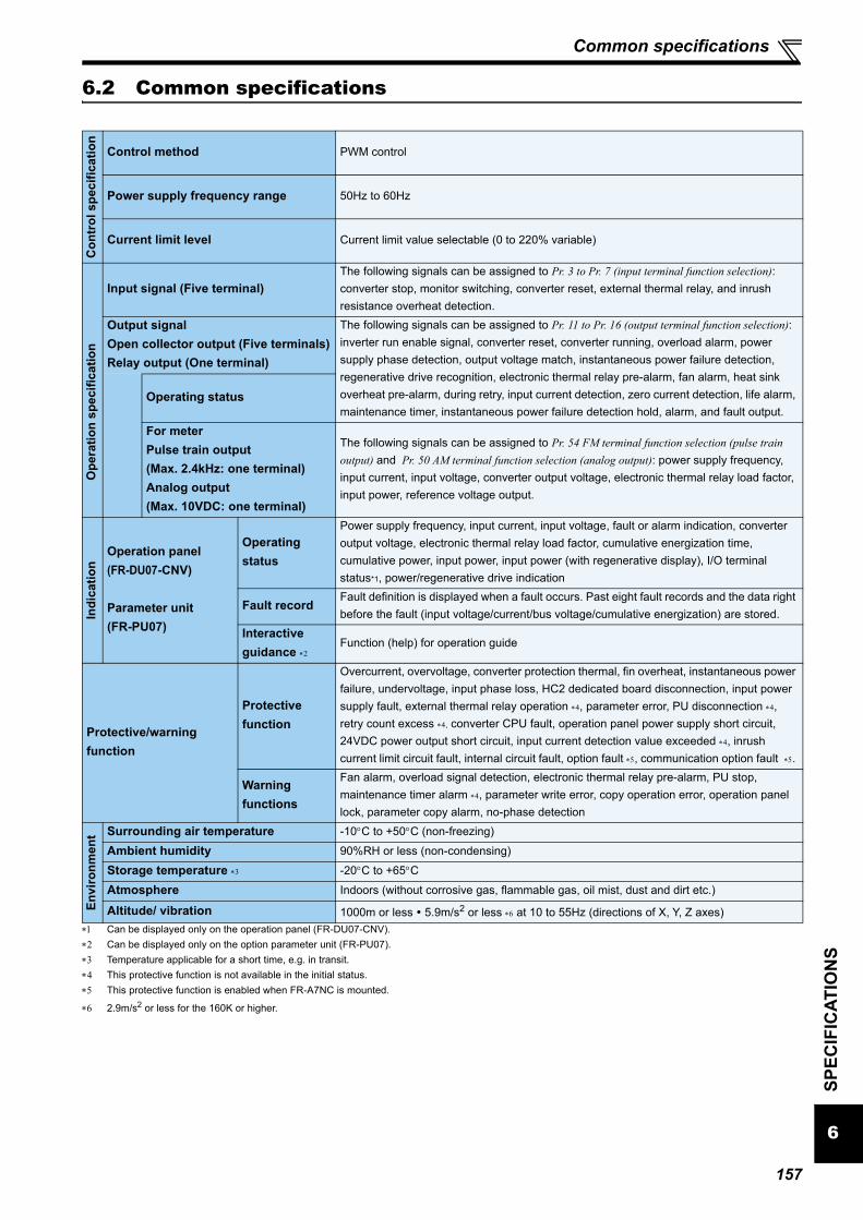
157
Common specifications
6
SPEC
IFIC
ATIO
NS
6.2 Common specifications
Can be displayed only on the operation panel (FR-DU07-CNV). Can be displayed only on the option parameter unit (FR-PU07). Temperature applicable for a short time, e.g. in transit. This protective function is not available in the initial status. This protective function is enabled when FR-A7NC is mounted.
2.9m/s2 or less for the 160K or higher.
Con
trol
spe
cific
atio
n
Control method PWM control
Power supply frequency range 50Hz to 60Hz
Current limit level Current limit value selectable (0 to 220% variable)
Ope
ratio
n sp
ecifi
catio
n
Input signal (Five terminal)The following signals can be assigned to Pr. 3 to Pr. 7 (input terminal function selection): converter stop, monitor switching, converter reset, external thermal relay, and inrush resistance overheat detection.
Output signalOpen collector output (Five terminals)Relay output (One terminal)
The following signals can be assigned to Pr. 11 to Pr. 16 (output terminal function selection): inverter run enable signal, converter reset, converter running, overload alarm, power supply phase detection, output voltage match, instantaneous power failure detection, regenerative drive recognition, electronic thermal relay pre-alarm, fan alarm, heat sink overheat pre-alarm, during retry, input current detection, zero current detection, life alarm, maintenance timer, instantaneous power failure detection hold, alarm, and fault output.
Operating status
For meterPulse train output (Max. 2.4kHz: one terminal)Analog output(Max. 10VDC: one terminal)
The following signals can be assigned to Pr. 54 FM terminal function selection (pulse train output) and Pr. 50 AM terminal function selection (analog output): power supply frequency, input current, input voltage, converter output voltage, electronic thermal relay load factor, input power, reference voltage output.
Indi
catio
n
Operation panel(FR-DU07-CNV)
Parameter unit (FR-PU07)
Operating status
Power supply frequency, input current, input voltage, fault or alarm indication, converter output voltage, electronic thermal relay load factor, cumulative energization time, cumulative power, input power, input power (with regenerative display), I/O terminal status*1, power/regenerative drive indication
Fault recordFault definition is displayed when a fault occurs. Past eight fault records and the data right before the fault (input voltage/current/bus voltage/cumulative energization) are stored.
Interactive guidance
Function (help) for operation guide
Protective/warning function
Protective function
Overcurrent, overvoltage, converter protection thermal, fin overheat, instantaneous power failure, undervoltage, input phase loss, HC2 dedicated board disconnection, input power supply fault, external thermal relay operation , parameter error, PU disconnection , retry count excess , converter CPU fault, operation panel power supply short circuit, 24VDC power output short circuit, input current detection value exceeded , inrush current limit circuit fault, internal circuit fault, option fault , communication option fault .
Warning functions
Fan alarm, overload signal detection, electronic thermal relay pre-alarm, PU stop, maintenance timer alarm , parameter write error, copy operation error, operation panel lock, parameter copy alarm, no-phase detection
Envi
ronm
ent Surrounding air temperature -10C to +50C (non-freezing)
Ambient humidity 90%RH or less (non-condensing)Storage temperature -20C to +65C Atmosphere Indoors (without corrosive gas, flammable gas, oil mist, dust and dirt etc.)
Altitude/ vibration 1000m or less 5.9m/s2 or less at 10 to 55Hz (directions of X, Y, Z axes)

158
Outline dimensions
6.3 Outline dimensions
6.3.1 Converter (FR-HC2)
(1) 200V class
FR-HC2-7.5K
FR-HC2-15K
PSCLR
P.CPY PWR
REGEN DRIVE.......
6
FAN
2-φ6 hole
(7.5
)2
45
26
0
7.5195
220
211
84
17010
Rating plate
(Unit: mm)Mass: 7kg
PSCLR
P.CPY PWR
REGEN DRIVE
FAN
2-φ10 hole
(10
)3
80
40
0
1010
230
250
10
2
242
Rating plate
19010.5
(Unit: mm)Mass: 12kg

159
Outline dimensions
6
SPEC
IFIC
ATIO
NS
FR-HC2-30K
FR-HC2-55K
280
7010
8
PSCLR
P.CPY PWRREGEN DRIVE.......
2-φ20 hole
(18)
298
532
270325
1055
053
0(1
0) (102) 93
1953.2
Eyebolt: 2-M8∗
Rating plate
2-φ10 hole
The eyebolt is enclosed with theproduct. Use it as required.
(Unit: mm)Mass: 24kg
8914
4
282
FAN
PSCLR
P.CPY PWRREGEN DRIVE
595
592
620
(28)(15)
10
2-φ20 hole338
2-φ10 hole
Rating plate
2503.2
(150) 100
300370
10
Eyebolt: 2-M8∗
The eyebolt is enclosed with theproduct. Use it as required.
(Unit: mm)Mass: 39kg

160
Outline dimensions
FR-HC2-75K
(2) 400V class
FR-HC2-H7.5K, H15K
22
26
2430
PSCLR
P.CPY PWR
REGEN DRIVE
FAN
2-φ25 hole
(24
)5
96
10
62
0
59
5
(15
)
Eyebolt : 2-M10∗
436
2-φ25 hole2-φ12 hole
400
465Rating plate 300
3.2
207(93)
12
The eyebolt is enclosed with theproduct. Use it as required.
(Unit: mm)Mass: 53kg
10
1
211
1956
220
82
85
(8)
30
0
190
FAN
10
2-φ6 hole
Rating plate
(Unit: mm)Mass: 9kg

161
Outline dimensions
6
SPEC
IFIC
ATIO
NS
FR-HC2-H30K
FR-HC2-H55K
195
3.2
270
325
53
2(1
8)
270
298
10
53
0(1
0)
55
0
280
13
14
7
Eyebolt: 2-M8∗
10
93(102)
FAN
2-φ20 hole 2-φ10 hole
Rating plate
The eyebolt is enclosed with theproduct. Use it as required.
(Unit: mm)Mass: 26kg
FAN
338
300
10300
370
327
54
17
9
3.22501
06
45
(15
)
67
0
100(142)
64
2(2
8)
Eyebolt: 2-M8∗
2-φ20 hole 2-φ10 hole
Rating plate
The eyebolt is enclosed with theproduct. Use it as required.
(Unit: mm)Mass: 43kg

162
Outline dimensions
FR-HC2-H75K
FR-HC2-H110K
PSCLR
P.CPY PWRREGEN DRIVE.......
FAN
2-φ20 hole
Eyebolt: 2-M8φ
2-φ10 hole
Rating plate
(28) 270
620
595
298
325
282
6816
5
592
27010
(15)
10
2503.2
(142) 100
The eyebolt is enclosed with theproduct. Use it as required.
(Unit: mm)Mass: 37kg
PSCLR
P.CPY PWRREGEN DRIVE.......
2-φ25 hole
Eyebolt : 2-M10∗
2-φ25 hole2-φ12 hole
Rating plate
FAN
(24)
400
620
595
436
465
430
62
222
596
40012
(15)
10
3003.2
(93) 207
The eyebolt is enclosed with theproduct. Use it as required.
(Unit: mm)Mass: 56kg

163
Outline dimensions
6
SPEC
IFIC
ATIO
NS
FR-HC2-H160K, H220K
FR-HC2-H280K
PSCLR
P.CPY PWR
REGEN DRIVE.......
3.2
380498
49 200 200 49
12
10
10
15
98
510
18
5 26
21
00
432
200 200
13
98
41
3
22
FAN
Rating plate4-φ16 hole
3-φ12 hole
(Unit: mm)Mass: 120kg
PSCLR
P.CPY PWR
REGEN DRIVE
FAN
1004
3.2
380
237
119
185
614
300 30012
680
1010
(13)
1398
4
(174) 206
300 300
400
(6)
Eyebolt : 2-M12∗
Rating plate2- 16 hole
2- 30 hole
2- 16 hole
3- 12 hole
(Unit: mm)Mass: 160kg
The eyebolt is enclosed with theproduct. Use it as required.

164
Outline dimensions
FR-HC2-H400K, H560K
FAN
3-φ12 hole 2-φ24 hole
12
315 315
790
4.5
440
15
13
00
15
685
18
5
22
21
94
315 315
498
13
10
(Unit: mm)Mass: 250kg

165
Outline dimensions
6
SPEC
IFIC
ATIO
NS
6.3.2 Reactor 1 (FR-HCL21)
Check that the capacity of the reactor 1 is same as the capacity of the converter.(1) 200V class
FR-HCL21-7.5K, 15K
FR-HCL21-30K
Rating plate
4-M6 hole
R/L1 S/L2 T/L3
R2/L12
S2/L22
T2/L32
W1 0.5
W 2 D 2
H
Within D2
D1-2.5+0
Varnish removed area (front/rear side)
(Unit: mm)
Model W W1 H D D1 D2 MassFR-HCL21-7.5K 130 50 Within 150 98 86 50 4.2kgFR-HCL21-15K 160 75 1675 124 107 60 7.0kg
87
R/L1 S/L2 T/L3R2/L12
S2/L22
T2/L32
100 2
Within 195
With
in
21
0
Within 185
180
75
Within 65 Within 85
+0
-2.5
Rating plate
4-M6 hole
Varnish removed area (front/rear side) (Unit: mm)Mass: 10.7kg
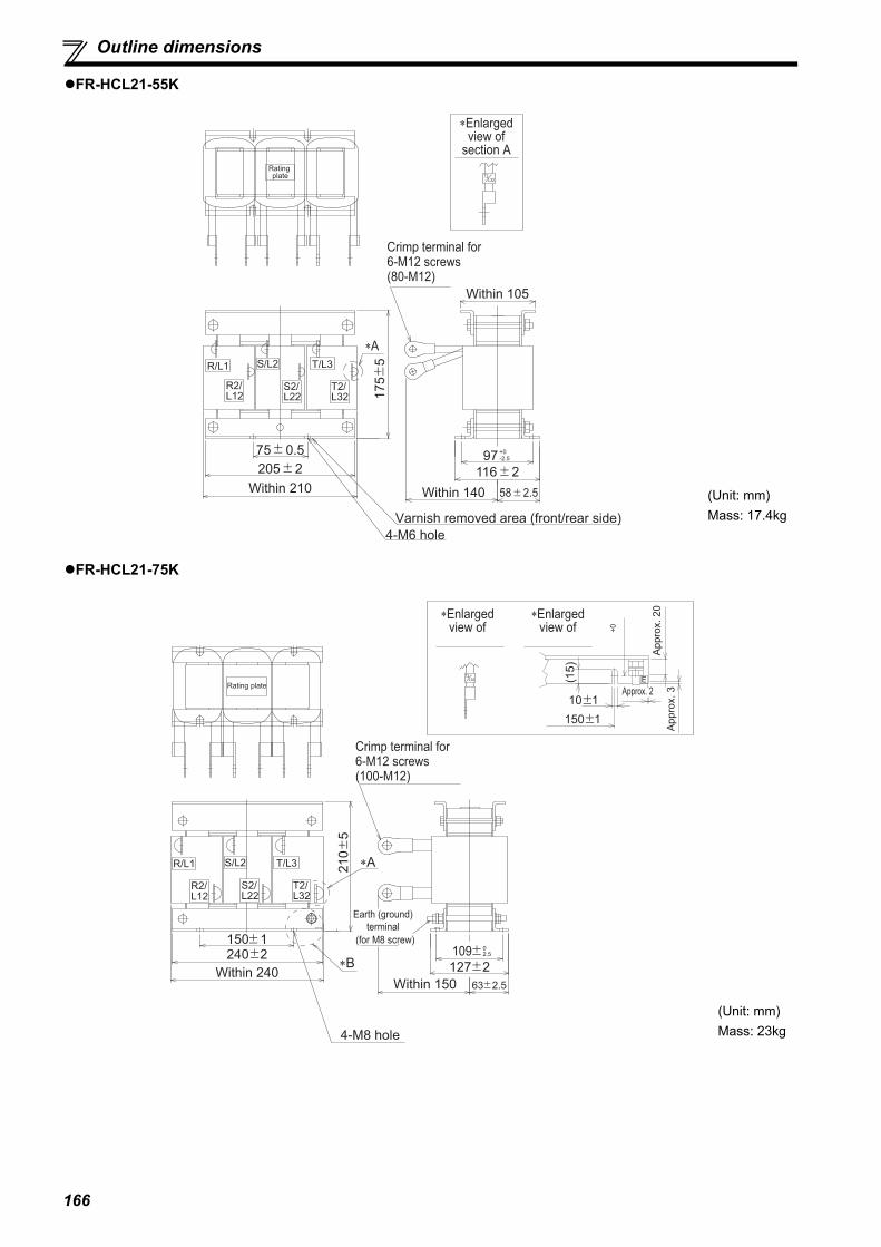
166
Outline dimensions
FR-HCL21-55K
FR-HCL21-75K
R/L1 S/L2 T/L3
R2/L12
S2/L22
T2/L32
∗Enlarged view of
section A
Crimp terminal for 6-M12 screws(80-M12)
75 0.5205 2
175
5
116 258 2.5Within 210
∗A
Within 140
97 -2.5+0
Within 105
Rating plate
4-M6 hole
L32T2
Varnish removed area (front/rear side)
(Unit: mm)Mass: 17.4kg
R/L1 S/L2 T/L3
R2/L12
S2/L22
T2/L32
63 2.5
127 2109 240 2
150 1
210
5
Within 150Within 240
∗A
2.50
Rating plate
Crimp terminal for 6-M12 screws(100-M12)
∗Enlarged view of
4-M8 hole
Earth (ground) terminal
(for M8 screw)
∗B
+0
E(15)
∗Enlarged view of
150 110 1
App
rox.
20
App
rox.
3Approx. 2L32
T2
(Unit: mm)Mass: 23kg

167
Outline dimensions
6
SPEC
IFIC
ATIO
NS
(2) 400V class
FR-HCL21-H7.5K
FR-HCL21-H15K
130 2 98 2
50 0.5+1-0.57
3.2
0 -190
4-M6 hole
Within 55
With
in 1
40
R/L1 S/L2 T/L3
R2/L12
S2/L22
T2/L32
Rating plate
Varnish removed area (front/rear side)
(Unit: mm)Mass: 4kg
2.3
+1-0.57
0 -1105
With
in 1
70
R/L1 S/L2 T/L3
R2/L12
S2/L22
T2/L32
Rating plate
160 2
75 0.5
124 2
Within 65
4-M6 hole
Varnish removed area (front/rear side)
(Unit: mm)Mass: 6kg

168
Outline dimensions
FR-HCL21-H30K
FR-HCL21-H55K
Rating plate
2.3
+1-0.57
0 -190
4-M6 hole
180 2
With
in 1
95
99 2
Within 95
R/L1 S/L2 T/L3R2/L12
S2/L22
T2/L32
75 0.5
Varnish removed area (front/rear side)
(Unit: mm)Mass: 9kg
2.3
With
in 2
45
Rating plate
Within 70 Within 95(25)
(37
)
4-M6 hole
8 0.5
R/L1 S/L2 T/L3R2/L12
S2/L22
T2/L32
131 2.5280 2.5
255 1.5
11
2
1
.5
Varnish removed area (front/rear side)
(Unit: mm)Mass: 18kg

169
Outline dimensions
6
SPEC
IFIC
ATIO
NS
FR-HCL21-H75K
FR-HCL21-H110K
E
R/L1 S/L2 T/L3
R2/L12
S2/L22
T2/L32
∗Enlarged view of
Crimp terminal for6-M10 screws (60-M10)
175
5
127 263 2.5Within 145
105-2.5+0
4-M6 hole
Earth (ground) (for M8 screw)
∗Enlarged view of
Approx. 9
Appro
x. 3
Approx. 20
L32T2
(Unit: mm)Mass: 20kg
∗Enlarged view of
Crimp terminal for 6-M12 screws (100-M12)
225
5
4-M8 hole
Earth (ground) (for M8 screw)
∗Enlarged view of
R/L1 S/L2 T/L3
R2/L12
S2/L22
T2/L32
E
+0-5
(15)
Within
3.2
Approx. 2
App
rox.
10
App
rox.
3
Approx. 9
T2L32
(Unit: mm)Mass: 28kg

170
Outline dimensions
FR-HCL21-H160K
FR-HCL21-H220K
150
0-5
6Rating plate
R/L1
R2/L12
S/L2
S2/L22
T/L3
T2/L32
Crimp terminal for M12 screws
4-oval-shaped hole 10 18 for M8 screw
Earth (ground) (for M8 screw)
4- 20 hole
(Unit: mm)Mass: 45kg
150
0-5
6
R/1
R2/L12
S/2 T/3
T2/L32S2/L22
Crimp terminal for M12 screws
4-oval-shaped hole 12 22 for M10 screw
Earth (ground) (for M8 screw)
4- 24 holeRating plate
(Unit: mm)Mass: 63kg

171
Outline dimensions
6
SPEC
IFIC
ATIO
NS
FR-HCL21-H280K
FR-HCL21-H400K
0 5
(26)
R/L1 S/L2 T/L3
R2/L12
S2/L22
T2/L32
∗Enlarged view of
∗Enlarged view of
Crimp terminal for 6-M12 screws (200-M12)
Approx. 25
Approx.
7
Appr
ox. 3
0
Earth (ground) (for M8 screw)
4-M10 hole
L32T2
E
Appr
ox. 5
(Unit: mm)Mass: 80kg
E
R/L1 R2/L12 S/L2 S2/L22 T/L3 T2/L32
400 2
250 1
60 5
180 5
300 5
With
in 4
604.
5
75
40
25
40305 10
340 10Within
100
250 1
305
10
A
4-M10 eyebolt
Earth (ground)
terminal
(for M8 screw)
For M10 bolt
4-Installation hole
(12 22 oval-shaped hole)
Within
100
R2, S2, T2 sideR, S, T side
2- 15 holefor M12 bolt
φ
Enlarged drawing of section A
(Unit: mm)Mass: 121kg

172
Outline dimensions
FR-HCL21-H560K
R2, S2, T2 sideR, S, T side
S2/L22 T/L3 T2/L32S/L2R2/L12R/L1
For M12 bolt
Earth (ground) terminal
4- 15 holefor M12 bolt
(for M8 screw)
6-terminal
Rating
plate
Within 120Within 120
10
0
40
355 10450 2
300 1
70 5
210 5
350 5
25 40
6
54
0
5
50
395 10
Enlarged
drawing of
section A
E
Approx. 3
Ap
pro
x. 3
7
8
35
5 1
0
300 1
A
4-Installation hole
(15 27 oval-shaped hole) 1
4-M10 eyebolt
φ
(Unit: mm)Mass: 190kg
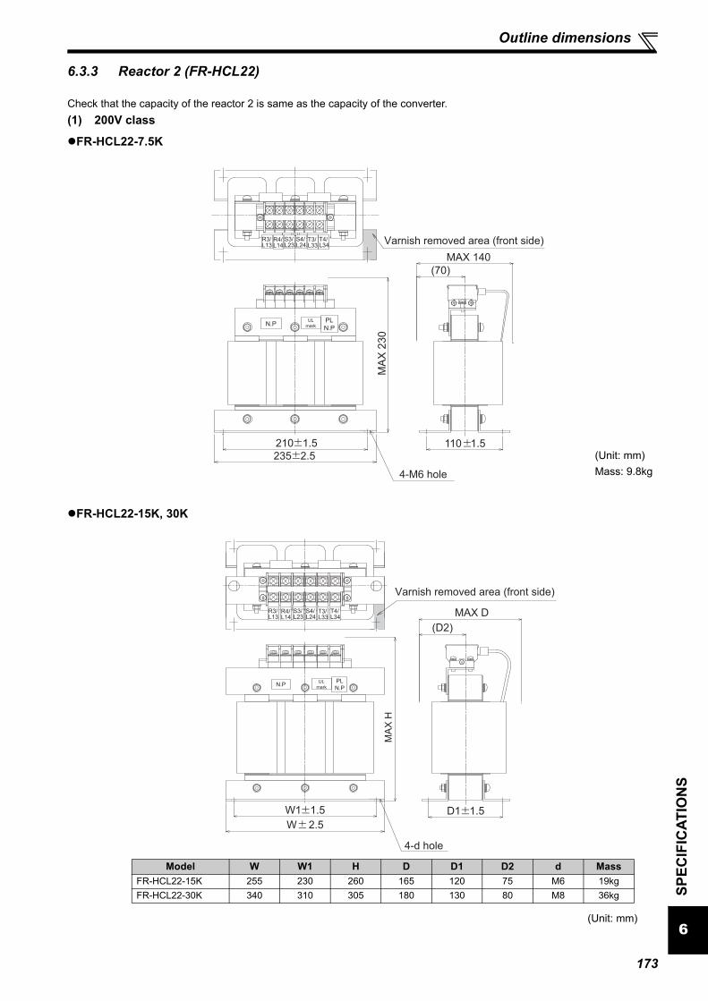
173
Outline dimensions
6
SPEC
IFIC
ATIO
NS
6.3.3 Reactor 2 (FR-HCL22)
Check that the capacity of the reactor 2 is same as the capacity of the converter.(1) 200V class
FR-HCL22-7.5K
FR-HCL22-15K, 30K
4-M6 hole
UL
mark
R4/L14
S4/L24
T4/L34
R3/L13
S3/L23
T3/L33
235 2.5
210 1.5 110 1.5
MAX 140
(70)
MA
X 2
30
N.PPL
N.P
Varnish removed area (front side)
(Unit: mm)Mass: 9.8kg
R4/L14
S4/L24
T4/L34
R3/L13
S3/L23
T3/L33
W 2.5
D1 1.5W1 1.5
MAX D
MA
X H
N.PPL
N.P
(D2)
4-d hole
UL
mark
Varnish removed area (front side)
(Unit: mm)
Model W W1 H D D1 D2 d MassFR-HCL22-15K 255 230 260 165 120 75 M6 19kgFR-HCL22-30K 340 310 305 180 130 80 M8 36kg

174
Outline dimensions
FR-HCL22-55K
FR-HCL22-75K
270 1.5
MA
X 3
80
430 2.5
240 1.5
MAX 280
(140)
4-M8 hole
R4/L14
S4/L24
T4/L34
R3/L13
S3/L23
T3/L33
UL
markPL
N.PN.P
Varnish removed area (front side)
(Unit: mm)Mass: 65kg
R4/L14
T4/L34
R3/L13
T3/L33
S4/L24
S3/L23
130 2430 2
470 4
MA
X 4
60
MAX 280
(190)
N.PPL
N.P
4-M12 hole
UL
mark
Varnish removed area (front side)
(Unit: mm)Mass: 98kg
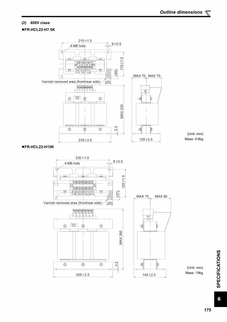
175
Outline dimensions
6
SPEC
IFIC
ATIO
NS
(2) 400V class
FR-HCL22-H7.5K
FR-HCL22-H15K
MA
X 2
20
MAX 70MAX 70
Rating plate
2.3
210 1.5
11
0
1.5
8 0.5
235 2.5 129 2.5
R4/L14
S4/L24
T4/L34
R3/L13
S3/L23
T3/L33
(40
)
(25)
4-M6 hole
Varnish removed area (front/rear side)
(Unit: mm)Mass: 9.8kg
MA
X 2
60
MAX 90MAX 75
Rating plate
(37
)
(25)
3.2
230 1.58 0.5
12
0
1.5
255 2.5 140 2.5
R4/L14
S4/L24
T4/L34
R3/L13
S3/L23
T3/L33
4-M6 hole
Varnish removed area (front/rear side)
(Unit: mm)Mass: 19kg
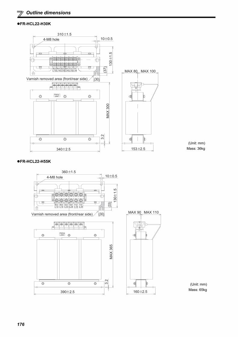
176
Outline dimensions
FR-HCL22-H30K
FR-HCL22-H55K
MAX 100
MA
X 3
00
MAX 80
3.2
R4/L14
S4/L24
T4/L34
R3/L13
S3/L23
T3/L33 (3
7)
(30)
340 2.5 153 2.5
4-M8 hole
310 1.5
10 0.5
13
0
1.5
Rating plate
Varnish removed area (front/rear side)
(Unit: mm)Mass: 36kg
MAX 110
MA
X 3
65
MAX 90
(33)
(30)
3.2
Rating plate
360 1.5
13
0
1.5
10 0.54-M8 hole
R4/L14
S4/L24
T4/L34
R3/L13
S3/L23
T3/L33
390 2.5 160 2.5
Varnish removed area (front/rear side)
(Unit: mm)Mass: 65kg

177
Outline dimensions
6
SPEC
IFIC
ATIO
NS
FR-HCL22-H75K
FR-HCL22-H110K
R4/L14
T4/L34
R3/L13
T3/L33
S4/L24
S3/L23
265 1.5
MA
X 3
95
(160)
MAX 280
MAX 430
N.P
PL
N.PUL mark
(30
)
(40)
4-M10 (φ12 0.5) hole(Recommended
installation 200)
200 1.5
Varnish removed area (front side)
(Unit: mm)Mass: 120kg
R4/L14
T4/L34
R3/L13
T3/L33
S4/L24
S3/L23
350 1.5
MAX 500
MA
X 4
40
(215)
MAX 370
N.P
PL
N.PUL mark
(42
)
(50)
4-M10 ( 12 0.5) hole(Recommended
installation 260)
260 1.5
Varnish removed area (front side)
(Unit: mm)Mass: 175kg

178
Outline dimensions
FR-HCL22-H160K, H220K
FR-HCL22-H280K
MAX W
(H1
)
MAX D2MAX D
N.PPL
N.P
(G)
(75)
MA
X H
R4/L14
T4/L34
R3/L13
T3/L33
S4/L24
S3/L23
4-M12 ( 15 0.5) hole(Recommended
installation D1)
D1 1.5
400 1.5
ULmark
Varnish removed area (front side)
(Unit: mm)
Model W H H1 D D1 D2 G MassFR-HCL22-H160K 560 520 6 430 290 255 52 250kgFR-HCL22-H220K 620 620 9 480 320 290 50 345kg
500 2
MA
X 7
00
MAX 690
MAX 560
(355)
60
R4/L14
T4/L34
R3/L13
T3/L33
S4/L24
S3/L23
N.PPLN.PUL mark
50
4-M12 ( 12 0.5) hole(Recommended
installation 350)
350 2
Varnish removed area (front side)
(Unit: mm)Mass: 450kg

179
Outline dimensions
6
SPEC
IFIC
ATIO
NS
FR-HCL22-H400K
(Unit: mm)Mass: 391kg
FR-HCL22-H560K
E
R3/L13 R4/L14 S3/L23 S4/L24 T3/L33 T4/L34
100 5
300 5
500 5
400 2
630 2
9
With
in 6
75
A 75
435 10
495 10
25
75 40
Within
100
Within
100
400 2
435
10
4-M12 eyebolt
Earth (ground)
terminal
(for M8 screw)
R3, S3, T3 side R4, S4, T4 side
2- 15 holefor M12 screw
For M12 bolt
4-Installation hole
(15-25 oval-shaped hole)
Enlarged drawing of section A
S4/L24 T3/L33 T4/L34S3/L23R4/L14R3/L13
4-M12 eyebolt
E
500 5
300 5
100 5
475 10
535 10
400 2
630 2
9
75
71
5
5
25
40
75
54
5
5
8
7
47
5
10
400 2
Ap
pro
x. 3
Enlarged
drawing of
section A
Approx. 3
For M12 bolt
4-Installation hole
(15-25 oval-shaped hole) 1
Rating
plate
A
R3, S3, T3 side R4, S4, T4 side
2- 15 hole
Within 100Within 100
6-terminal
Earth (ground) terminal
(for M8 screw)
(Unit: mm)Mass: 507kg

180
Outline dimensions
6.3.4 Difference between the reactor 1 (FR-HCL21) and the reactor 2 (FR-HCL22).
Each reactor has a rating plate. Identify the reactor 1 and the reactor 2 by their rating plates. Incorrect connection order of thereactor 1 and the reactor 2 causes the reactors to heat up, and it is dangerous. Take caution to avoid the danger.[Rating plate]
6.3.5 Outside box (FR-HCB2)
(1) Outline drawing
200V class
FR-HCB2-7.5K, 15K
MODELFR-HCL21-XXX
AC REACTOR
SERIAL XXXXX
MODELFR-HCL22-XXX
AC REACTOR
SERIAL XXXXX
Reactor 1(FR-HCL21)
Reactor 2(FR-HCL22) Check "MODEL" on the rating plates of the reactor 1 (FR-HCL21) and the reactor 2 (FR-HCL22).
16013
14
1
13
10
7
165
2.3
Rating plate
32
0
30
5
190
130 77
2-A hole (8)
Type A hole dimensions
(Unit: mm)Mass: 7kg

181
Outline dimensions
6
SPEC
IFIC
ATIO
NS
FR-HCB2-30K, 55K
FR-HCB2-75K
240
270
200203
2.3
Rating plate
13
7
2-A hole
13
17
9
74
35
45
0
(8)
7
10
Type A hole dimensions
(Unit: mm)
Model MassFR-HCB2-30K 11kgFR-HCB2-55K 13kg
175 175
400
340
58
18
0(1
2)
42
8
45
0
10
250
2.3
4-φ16 hole
Rating plate
10
7
13
3-A hole
Type A hole dimensions
7
(Unit: mm)Mass: 27kg
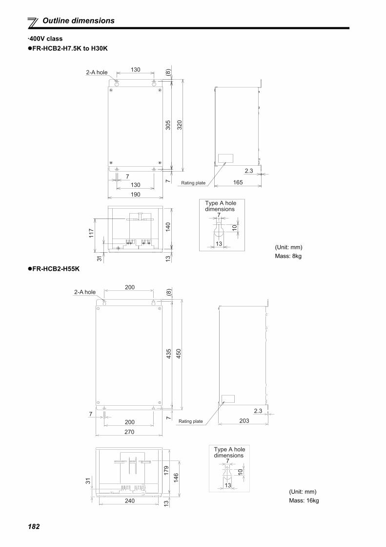
182
Outline dimensions
400V classFR-HCB2-H7.5K to H30K
FR-HCB2-H55K
73
05
(8
)
7
130
130
2.3
165
190
32
0
13
14
0
31
11
7 10
13
7
Rating plate
Type A hole dimensions
2-A hole
(Unit: mm)Mass: 8kg
7
200
200
270
240
2.3
203
74
35
(8
)
45
0
31 14
6
13
17
9
10
13
7
2-A hole
Rating plate
Type A hole dimensions
(Unit: mm)Mass: 16kg

183
Outline dimensions
6
SPEC
IFIC
ATIO
NS
FR-HCB2-H75K
FR-HCB2-H110K
250
7
250
300
2.3
250
10
32
8(1
2)
35
0
255
8
25
21
4
11
8
270
Rating plate
2-A hole
10
13
7
Type A hole dimensions
(Unit: mm)Mass: 16kg
20
4 27
6
17
2
380
2.3125125
7
350
45
0
12
42
81
0
10
13
7
Rating plate
3-A hole
Type A hole dimensions
4-φ16 hole
(Unit: mm)Mass: 37kg

184
Outline dimensions
FR-HCB2-H160K, H220K
12
42
81
0
45
0
7
175 175
400 440
2.3
21
72
12
32
1
38
1
175 175
340
13
41
72
0
20
10
13
7
3-A hole
Rating plate
Type A hole dimensions
4-φ16 hole
(Unit: mm)Mass: 54kg

185
Outline dimensions
6
SPEC
IFIC
ATIO
NS
(2) Terminal block200V classFR-HCB2-7.5K, 15K FR-HCB2-30K, 55K
FR-HCB2-75K
MC
TB1-2 TB1-1
S2/L22
R2/L12 T2/L32
S3/L23
R3/L13 T3/L33
88R 88SROH2ROH1Earth (ground) terminal
<Terminal screw size>
Model MC TB1-1 TB1-2 Earth (ground) terminal
FR-HCB2-7.5K, 15K M5 M3.5 M3.5 M5
MC
S2/L22
R2/L12 T2/L32
S3/L23
R3/L13 T3/L33
TB1-2 TB1-1
88R 88SROH2ROH1
Earth (ground) terminal
<Terminal screw size>
Model MC TB1-1 TB1-2 Earth (ground) terminal
FR-HCB2-30K M6 M3.5 M3.5 M6FR-HCB2-55K M8 M3.5 M3.5 M6
MC
TB1-2 TB1-1
S2/L22R2/L12 T2/L32
S3/L23R3/L13 T3/L33
88R 88SROH2ROH1Earth
(ground)
terminal
<Terminal screw size>
Model MC TB1-1 TB1-2Earth (ground)
terminalFR-HCB2-75K M12 M3.5 M3.5 M10
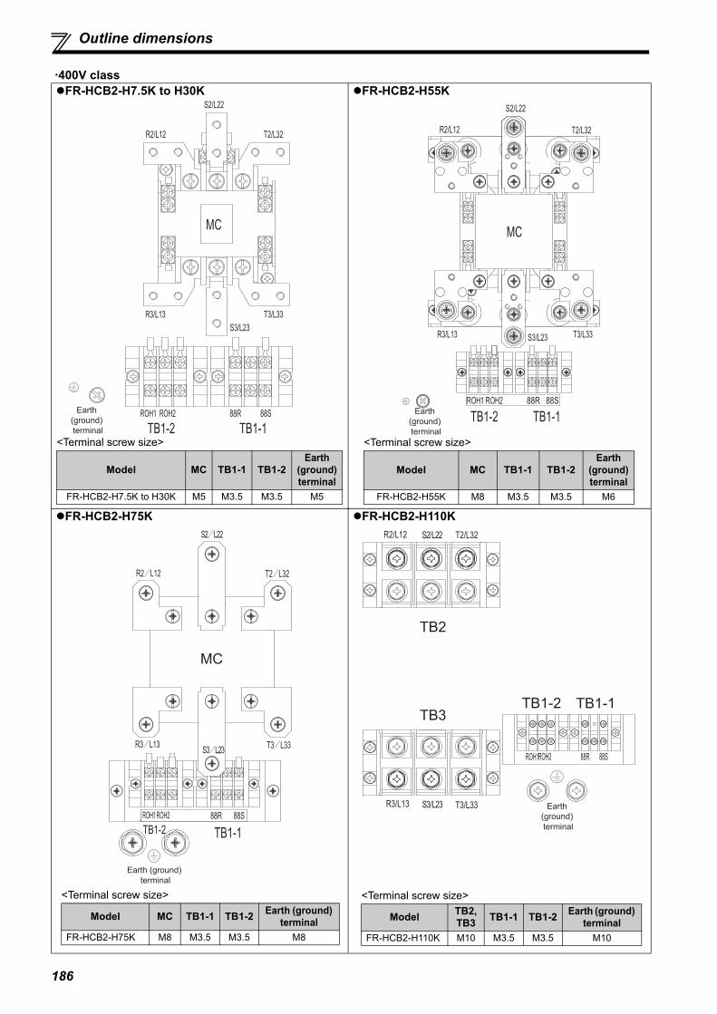
186
Outline dimensions
400V classFR-HCB2-H7.5K to H30K FR-HCB2-H55K
FR-HCB2-H75K FR-HCB2-H110K
MC
S2/L22
R2/L12 T2/L32
S3/L23
R3/L13 T3/L33
TB1-2 TB1-188R 88SROH2ROH1Earth
(ground)
terminal
<Terminal screw size>
Model MC TB1-1 TB1-2Earth
(ground) terminal
FR-HCB2-H7.5K to H30K M5 M3.5 M3.5 M5
MC
S2/L22
R2/L12 T2/L32
S3/L23R3/L13 T3/L33
TB1-2 TB1-1
88R 88SROH2ROH1Earth
(ground)
terminal
<Terminal screw size>
Model MC TB1-1 TB1-2Earth
(ground) terminal
FR-HCB2-H55K M8 M3.5 M3.5 M6
<Terminal screw size>
Model MC TB1-1 TB1-2 Earth (ground) terminal
FR-HCB2-H75K M8 M3.5 M3.5 M8
S2/L22
R2/L12 T2/L32
S3/L23R3/L13 T3/L33
88R 88SROH2ROH1
MC
TB1-2 TB1-1
Earth (ground)
terminal
<Terminal screw size>
Model TB2,TB3 TB1-1 TB1-2 Earth (ground)
terminalFR-HCB2-H110K M10 M3.5 M3.5 M10
S2/L22R2/L12 T2/L32
S3/L23R3/L13 T3/L33
88R 88SROH2ROH1
TB1-2 TB1-1
TB2
TB3
Earth
(ground)
terminal
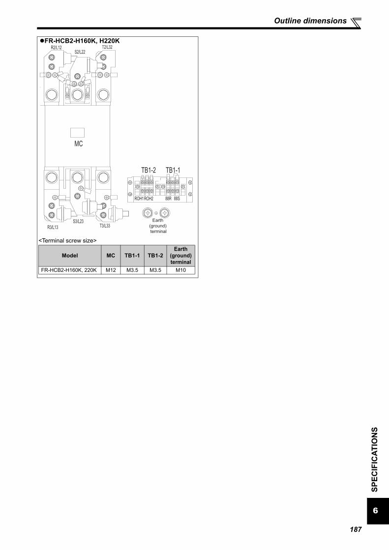
187
Outline dimensions
6
SPEC
IFIC
ATIO
NS
FR-HCB2-H160K, H220K
MC
TB1-2 TB1-1
S2/L22R2/L12 T2/L32
S3/L23R3/L13 T3/L33
88R 88SROH2ROH1
Earth
(ground)
terminal
<Terminal screw size>
Model MC TB1-1 TB1-2Earth
(ground) terminal
FR-HCB2-H160K, 220K M12 M3.5 M3.5 M10
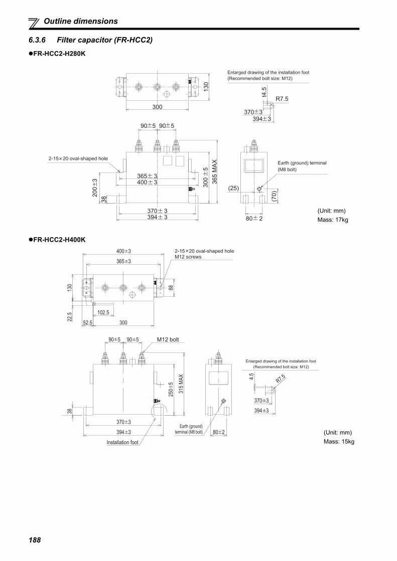
188
Outline dimensions
6.3.6 Filter capacitor (FR-HCC2)
FR-HCC2-H280K
FR-HCC2-H400K
300
13
0
90 5
20
0
3
30
0
5
36
5 M
AX
80 2
(70
)
(25)
365 3400 3
370 3394 3
38
t4.5
394 3370 3
R7.5
90 5
Enlarged drawing of the installation foot
(Recommended bolt size: M12)
Earth (ground) terminal
(M8 bolt)
2-15 20 oval-shaped hole
(Unit: mm)Mass: 17kg
400 3
90 5 90 5
315
MA
X
250
5
38
370 3
394 3 80 2
365 3
88
30052.5
102.5
2-15 20 oval-shaped holeM12 screws
M12 bolt
Earth (ground) terminal (M8 bolt)
Installation foot
4.5
370 3
394 3
R7.5
130
22.5
Enlarged drawing of the installation foot
(Recommended bolt size: M12)
(Unit: mm)Mass: 15kg
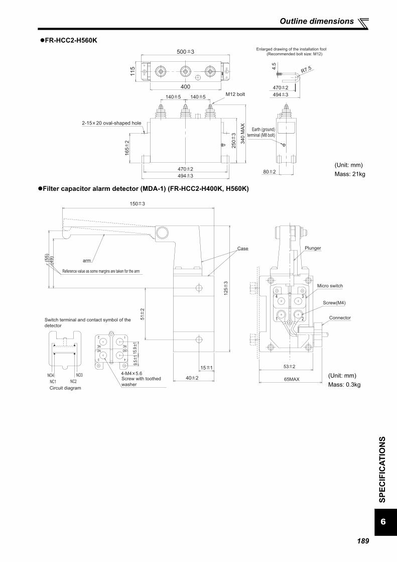
189
Outline dimensions
6
SPEC
IFIC
ATIO
NS
FR-HCC2-H560K
Filter capacitor alarm detector (MDA-1) (FR-HCC2-H400K, H560K)
470 2
494 380 2
M12 bolt
470 2
494 3140 5140 5
16
5
2
25
0
3
34
0 M
AX
115
400
500 3
Earth (ground) terminal (M8 bolt)
R7.5
Enlarged drawing of the installation foot
4.5
(Recommended bolt size: M12)
2-15 20 oval-shaped hole
(Unit: mm)Mass: 21kg
150 3
(49
)(5
5)
51
2
40 2
12
5
3
Case
arm
9.5
1
Switch terminal and contact symbol of the
detector
4-M4 5.6
Plunger
Micro switch
Screw(M4)
Connector
53 2
65MAX
15.9
1
15 1
Reference value as some margins are taken for the arm
NO4
NC1 NC2
NO3
12
3 4
NO NO
NCNC
Circuit diagram
1 2
34
Screw with toothed
washer
(Unit: mm)Mass: 0.3kg

190
Outline dimensions
6.3.7 FR-HCM2Contactor (S-N600FXYS AC210V 2A2B) (FR-HCM2-H280K)
Contactor (S-N400FXYS AC200V 2A2B) (FR-HCM2-H400K, H560K)
MC power supply stepdown transformer (BKO-CA2001H06) (FR-HCM2-H280K to H560K)
Installation hole
for 4-M10 screw 290
70
80 40
12 hole2
70
31
0
13.5
20
3017
.52
75
25
0
263
250
10 235
10.5
156
M16 screw(with washer and spring washer)
M4 screw
(self-up)
(Unit: mm)Mass: 24kg
M4 screw(self-up)
M12 screw
(with washer and
spring washer)
(4-M8 hole)
4-M8 hole
(11.5
)
225
1
(60)
(220)
145
9
26.5
190
243
3055
163195
3.2
136
M4 screw (self-up)
(Unit: mm)Mass: 9.5kg
for M6 bolt
4- 8 open hole
Enlarged drawing of installation hole
Varnish removed area
81 2
100 1
Output side Input side
V1V1V2V2V3V3
R/L1 S/L2
(21)
24 o
r m
ore
7 18 or more
115 2
81 2(30)
8 1
8
153 2
100 1
166 3
132 2
2.3
S5/L25R5/L15
Terminal block for tap switching
M4 screwInput side terminal block
M4 screw
Output side terminal block
M4 screw 5 2
E
Within 180
Rat
ing
plat
e
(Unit: mm)Mass: 10kg

191
Outline dimensions
6
SPEC
IFIC
ATIO
NS
Terminal block (TS-807BXC-5P) (FR-HCM2-H280K)
Terminal block shorting conductor (C152C481H21) (FR-HCM2-H280K)
MC shorting conductor (C152C423H21) (FR-HCM2-H400K, H560K)
Sectional view of X - X
26
20
3712
52
39
28
5.4
128
116
20
3 17.5 2.5
X
X
(Unit: mm)Mass: 0.3kg
28
96
40
30
(2.3) 2.8
8
30
50
.5
16
.5
7.9
7.9
Sectional view of A - A
10-C
2
2-C2
A
A
8 (8)
(4)16(4)
5-oval 7-8
80 0.4
60 0.4
40 0.4
20 0.3
(Unit: mm)Mass: 0.1kg
12
5
(55
)4
03
0
57.5 65
180
(57.5)84- 14 hole (M12)
9-M5 screw for
installation of
inrush resistor
(Unit: mm)Mass: 1.6kg
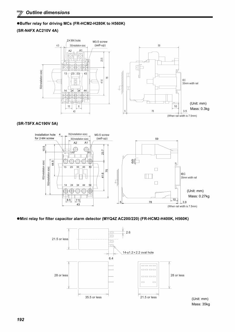
192
Outline dimensions
Buffer relay for driving MCs (FR-HCM2-H280K to H560K)
(SR-N4FX AC210V 4A)
(SR-T5FX AC190V 5A)
Mini relay for filter capacitor alarm detector (MYQ4Z AC200/220) (FR-HCM2-H400K, H560K)
10
23.5
(When rail width is 7.5mm)
3.5
10
43
8
50(In
stalla
tion
size)
35(Installation size)4.5
78
59
41.6
5 78
IEC35mm width rail
2 M4 hole M3.5 screw(self-up)
A1A2
14 24 34 44
13 23 33 43
(Unit: mm)Mass: 0.3kg
438.5
59
3.910
785
23.7
41.6
75
7.5
44.5
10.5
50(In
stalla
tion
size)
60(In
stalla
tion
size)
4 35(Installation size)
30(Installation size)A1A2
24 34 44 5414
33 43 5313 23
IEC35mm width rail
M3.5 screw(self-up)
(When rail width is 7.5mm)
Installation hole for 2-M4 screw
(Unit: mm)Mass: 0.27kg
6.4
21.5 or less
28 or less
2.6
35.5 or less
14-φ1.2 2.2 oval hole
21.5 or less
28 or less
(Unit: mm)Mass: 35kg
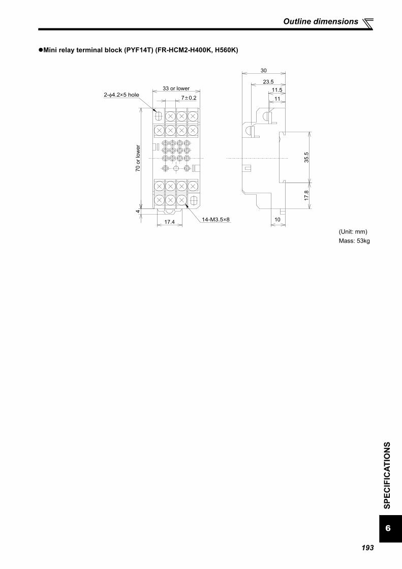
193
Outline dimensions
6
SPEC
IFIC
ATIO
NS
Mini relay terminal block (PYF14T) (FR-HCM2-H400K, H560K)
4
17.4
33 or lower
70
or
low
er
2-φ4.2 5 hole
14-M3.5 8
11
11.5
23.5
30
35
.51
7.8
10
7 0.2
(Unit: mm)Mass: 53kg

194
Outline dimensions
6.3.8 Inrush current limit resistor (FR-HCR2)
With thermostat (BKO-CA1996H31) (FR-HCR2-H280K to H560K)
Without thermostat (BKO-CA1996H21) (FR-HCR2-H280K to H560K)
200 1.2
215 2 2-500 10
2-6 1
13
0
.5
2-5
.3
0.3
8.5
0
.5
60 1.5
30
1
325 15
2-6 1
2-(17)
175 2
Board thickness2.5
(30)
(Unit: mm)Mass: 0.8kg
200 1.2
215 2
13
0
.5
2-5
.3
0.3
8.5
0
.5
30
1
2-(17)
175 2
2-6 1
(30)
Board thickness2.5
2-500 10
60 1.5
(Unit: mm)Mass: 0.8kg
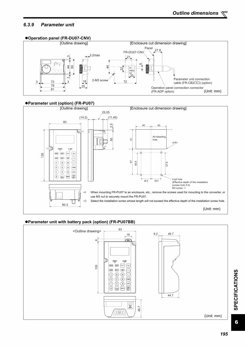
195
Outline dimensions
6
SPEC
IFIC
ATIO
NS
6.3.9 Parameter unit
Operation panel (FR-DU07-CNV)[Outline drawing] [Enclosure cut dimension drawing]
Parameter unit (option) (FR-PU07)[Outline drawing] [Enclosure cut dimension drawing]
Parameter unit with battery pack (option) (FR-PU07BB)
78
5044
723 3
81
33
1625
3.2max
72
44
21
6
20
22
27.8
Operation panel connection connector(FR-ADP option)
Parameter unit connection cable (FR-CB2��) (option)
Air-bleedinghole
2-M3 screw
FR-DU07-CNVPanel
(Unit: mm)
80.3
(14.2)
2.5
50
(11.45)
25.05
135
83
∗1
∗1∗1
∗1
∗2
6751
40
56.8
57.8
26.5
4-R1
Air-bleedinghole
4-φ4 hole(Effective depth of the installationscrews hole 5.0)M3 screw
26.5
40
When mounting FR-PU07 to an enclosure, etc., remove the screws used for mounting to the converter, oruse M3 nut to securely mount the FR-PU07.
Select the installation screw whose length will not exceed the effective depth of the installation screw hole.
(Unit: mm)
<Outline drawing>8.2 46.7
44.7
46.7
135
83
18
6
(Unit: mm)

196
MEMO
197
APPENDICES
This chapter provides the "APPENDICES" of this product.Always read the instructions before using the equipment.
Appendix 1 Instruction code list........................................................... 198Appendix 2 Instructions for compliance with the EU Directives....... 199Appendix 3 Instructions for UL and cUL.............................................. 201Appendix 4 Instructions for EAC.......................................................... 205Appendix 5 Restricted Use of Hazardous Substances in Electronic
and Electrical Products......................................................206Appendix 6 Referenced Standard (Requirement of Chinese
standardized law)............................................................... 206

198
These instruction codes are used to write or read parameters through the RS-485 communication and the CC-Link communication. (Refer to page 106 for the RS-485 communication. Refer to page 117 for the CC-Link communication.)
"" indicates valid and "" indicates invalid of "parameter copy", "parameter clear", and "all parameter clear". These parameters are not cleared by the parameter clear (all parameter clear) command, which are sent through RS-485 communication and CC-Link
communication. (Refer to page 106 for the RS-485 communication. Refer to page 117 for the CC-Link communication.) Read and write of this parameter is enabled only when communicating through the PU connector. Symbols in the table indicate parameters that function when the option is mounted.
...... FR-A7NC
Appendix 1 Instruction code list
Pr. Name
Instruction Code Parameter
Rea
d
Writ
e
Exte
nded
Cop
y
Cle
ar
All
clea
r
0 Simple mode selection 00 80 0
1 Maximum power supply frequency 01 81 0
2 Minimum power supply frequency 02 82 0
3 ROH terminal function selection 03 83 0
4 SOF terminal function selection 04 84 0
5 X1 terminal function selection 05 85 0
6 X2 terminal function selection 06 86 0
7 RES terminal function selection 07 87 0
8 SOF input selection 08 88 0
9 OH input selection 09 89 0
10 RDY signal logic selection 0A 8A 0
11 RSO terminal function selection 0B 8B 0
12 CVO terminal function selection 0C 8C 0
13 Y1 terminal function selection 0D 8D 0
14 Y2 terminal function selection 0E 8E 0
15 Y3 terminal function selection 0F 8F 0
16 ABC terminal function selection 10 90 0
22 Current limit level 16 96 0
23 Current limit level (regenerative) 17 97 0
24 OL signal output timer 18 98 0
25 Input current detection level 19 99 0
26 Input current detection signal delay time 1A 9A 0
27 Input current detection signal retention time 1B 9B 0
28 Input current detection operation selection 1C 9C 0
29 Zero current detection level 1D 9D 0
30 Zero current detection time 1E 9E 0
31 Life alarm status display 1F 9F 0 32 Inrush current limit circuit life display 20 A0 0 33 Control circuit capacitor life display 21 A1 0 34 Maintenance timer 22 A2 0 35 Maintenance timer alarm output set time 23 A3 0
36 Cooling fan operation selection 24 A4 0
44 Instantaneous power failure detection signal clear 2C AC 0
45 AM output filter 2D AD 0
46 Watt-hour meter clear 2E AE 0
47 Energization time carrying-over times 2F AF 0
48 Cumulative power monitor digit shifted times 30 B0 0
49 Power supply frequency monitoring reference 31 B1 0
50 AM terminal function selection 32 B2 0
51 Input power monitoring reference 33 B3 0
52 DU/PU main display data selection 34 B4 0
53 Input voltage monitoring reference 35 B5 0
54 FM terminal function selection 36 B6 0
55 Bus voltage monitoring reference 37 B7 0
56 Current monitoring reference 38 B8 0
57 Restart selection 39 B9 0
58 Free parameter 1 3A BA 0 59 Free parameter 2 3B BB 0 61 Key lock operation selection 3D BD 0
65 Retry selection 41 C1 0
67 Number of retries at fault occurrence 43 C3 0
68 Retry waiting time 44 C4 0
69 Retry count display erase 45 C5 0
75 Reset selection/disconnected PU detection/PU stop selection 4B CB 0
77 Parameter write selection 4D CD 0
80 Voltage control proportional gain 50 D0 0
81 Voltage control integral gain 51 D1 0
82 Current control proportional gain 52 D2 0
83 Current control integral gain 53 D3 0
117 PU communication station number 11 91 1
118 PU communication speed 12 92 1
119 PU communication stop bit length 13 93 1
120 PU communication parity check 14 94 1
121 Number of PU communication retries 15 95 1
123 PU communication waiting time setting 17 97 1
124 PU communication CR/LF selection 18 98 1
145 PU display language selection 2D AD 1 269 Parameter for manufacturer setting. Do not set.342 Communication EEPROM write selection 2A AA 3
500Communication error execution waiting time
00 80 5
501Communication error occurrence count display
01 81 5
502Stop mode selection at communication error
02 82 5
542Communication station number (CC-Link)
2A AA 5
543 Baud rate (CC-Link) 2B AB 5
544 CC-Link extended setting 2C AC 5
C0(900) FM terminal calibration 5C DC 1
C1(901) AM terminal calibration 5D DD 1
989 Parameter copy alarm release 59 D9 9
990 PU buzzer control 5A DA 9
991 PU contrast adjustment 5B DB 9
Pr. Name
Instruction Code Parameter
Rea
d
Writ
e
Exte
nded
Cop
y
Cle
ar
All
clea
r
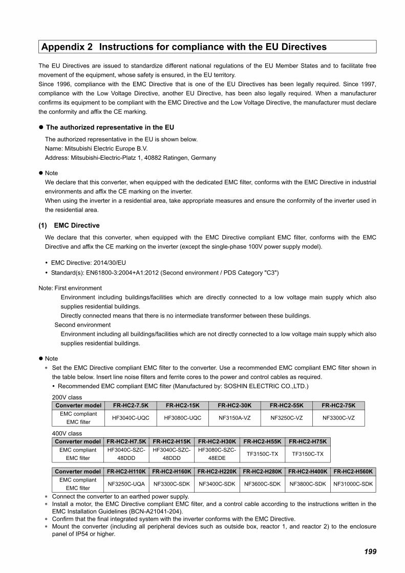
199
The EU Directives are issued to standardize different national regulations of the EU Member States and to facilitate freemovement of the equipment, whose safety is ensured, in the EU territory.Since 1996, compliance with the EMC Directive that is one of the EU Directives has been legally required. Since 1997,compliance with the Low Voltage Directive, another EU Directive, has been also legally required. When a manufacturerconfirms its equipment to be compliant with the EMC Directive and the Low Voltage Directive, the manufacturer must declarethe conformity and affix the CE marking.
The authorized representative in the EUThe authorized representative in the EU is shown below.Name: Mitsubishi Electric Europe B.V.Address: Mitsubishi-Electric-Platz 1, 40882 Ratingen, Germany
NoteWe declare that this converter, when equipped with the dedicated EMC filter, conforms with the EMC Directive in industrialenvironments and affix the CE marking on the inverter. When using the inverter in a residential area, take appropriate measures and ensure the conformity of the inverter used inthe residential area.
(1) EMC DirectiveWe declare that this converter, when equipped with the EMC Directive compliant EMC filter, conforms with the EMCDirective and affix the CE marking on the inverter (except the single-phase 100V power supply model).
EMC Directive: 2014/30/EU Standard(s): EN61800-3:2004+A1:2012 (Second environment / PDS Category "C3")
Note: First environmentEnvironment including buildings/facilities which are directly connected to a low voltage main supply which alsosupplies residential buildings.Directly connected means that there is no intermediate transformer between these buildings.
Second environmentEnvironment including all buildings/facilities which are not directly connected to a low voltage main supply which alsosupplies residential buildings.
Note Set the EMC Directive compliant EMC filter to the converter. Use a recommended EMC compliant EMC filter shown in
the table below. Insert line noise filters and ferrite cores to the power and control cables as required. Recommended EMC compliant EMC filter (Manufactured by: SOSHIN ELECTRIC CO.,LTD.)
200V class
400V class
Connect the converter to an earthed power supply. Install a motor, the EMC Directive compliant EMC filter, and a control cable according to the instructions written in the
EMC Installation Guidelines (BCN-A21041-204). Confirm that the final integrated system with the inverter conforms with the EMC Directive. Mount the converter (including all peripheral devices such as outside box, reactor 1, and reactor 2) to the enclosure
panel of IP54 or higher.
Appendix 2 Instructions for compliance with the EU Directives
Converter model FR-HC2-7.5K FR-HC2-15K FR-HC2-30K FR-HC2-55K FR-HC2-75KEMC compliant
EMC filterHF3040C-UQC HF3080C-UQC NF3150A-VZ NF3250C-VZ NF3300C-VZ
Converter model FR-HC2-H7.5K FR-HC2-H15K FR-HC2-H30K FR-HC2-H55K FR-HC2-H75KEMC compliant
EMC filterHF3040C-SZC-
48DDDHF3040C-SZC-
48DDDHF3080C-SZC-
48EDETF3150C-TX TF3150C-TX
Converter model FR-HC2-H110K FR-HC2-H160K FR-HC2-H220K FR-HC2-H280K FR-HC2-H400K FR-HC2-H560KEMC compliant
EMC filterNF3250C-UQA NF3300C-SDK NF3400C-SDK NF3600C-SDK NF3800C-SDK NF31000C-SDK

200
(2) Low Voltage DirectiveWe declare that this converter conforms with the Low Voltage Directive and affix the CE marking on the converter.• Low Voltage Directive: 2014/35/EU• Conforming standard: EN 61800-5-1:2007
Outline of instructions Do not use an earth leakage circuit breaker as an electric shock protector without connecting the equipment to the earth.
Connect the equipment to the earth securely. Wire the earth (ground) terminal independently. (Do not connect two or more cables to one terminal.) Use the cable sizes on page 37, 54 under the following conditions.Surrounding air temperature: 40°C maximumIf conditions are different from above, select appropriate wire according to EN 60204-1 or IEC 60364-5-52.
Use a tinned (plating should not include zinc) crimp terminal to connect the earth cable. When tightening the screw, becareful not to damage the threads.For use as a product compliant with the Low Voltage Directive, use PVC cable on page 37, 54.
Use the moulded case circuit breaker and magnetic contactor which conform to the EN or IEC Standard. When using an earth leakage circuit breaker, use a residual current operated protective device (RCD) of type B (breaker
which can detect both AC and DC). If not, provide double or reinforced insulation between the converter and otherequipment, or put a transformer between the main power supply and converter.
Use the inverter under the conditions of overvoltage category II (usable regardless of the earth (ground) condition of thepower supply), overvoltage category III (usable with the earthed-neutral system power supply, 400V class only) specifiedin IEC 60664.Mount the converter (including all peripheral devices such as outside box, reactor 1, and reactor 2) to the enclosure
panel of IP54 or higher.
On the input and output of the converter, use cables of the type and size set forth in EN 60204-1 or IEC 60364-5-52. The operating capacity of the relay outputs (terminal symbols A, B, C) should be 30VDC, 0.3A. (Relay output has basic
isolation from the inverter internal circuit.) Control circuit terminals on page 40, 53 are safely isolated from the main circuit. Environment
Provide the Class T fuse or a fuse with faster shutoff speed, which is UL and cUL listed, for branch circuit protection.
Running In Storage During TransportationSurrounding air temperature
-10°C to +50°C -20°C to +65°C -20°C to +65°C
Humidity 90% RH or less 90% RH or less 90% RH or lessMaximum Altitude 1000m 1000m 10000mDetails are given in the technical information "Low Voltage Directive Conformance Guide" (BCN-A21041-203). Please contact your sales representative.
Converter model Fuse type Cat. No Manufacturer Rating
200V
cla
ss
FR-HC2-7.5K UL Recognized High Speed 170M1414 Bussmann 50A, 700 VacFR-HC2-15K UL Recognized High Speed 170M1416 Bussmann 80A, 700 VacFR-HC2-30K UL Recognized High Speed 170M2666 Bussmann 160A, 700 VacFR-HC2-55K UL Recognized High Speed 170M2669 Bussmann 315A, 700 VacFR-HC2-75K UL Recognized High Speed 170M2671 Bussmann 400A, 700 Vac
400V
cla
ss
FR-HC2-H7.5K UL Recognized High Speed 170M1411 Bussmann 25A, 700 VacFR-HC2-H15K UL Recognized High Speed 170M1414 Bussmann 50A, 700 VacFR-HC2-H30K UL Recognized High Speed 170M1416 Bussmann 80A, 700 VacFR-HC2-H55K UL Recognized High Speed 170M2666 Bussmann 160A, 700 VacFR-HC2-H75K UL Recognized High Speed 170M2667 Bussmann 200A, 700 VacFR-HC2-H110K UL Recognized High Speed 170M2669 Bussmann 315A, 700 VacFR-HC2-H160K UL Recognized High Speed 170M2671 Bussmann 400A, 700 VacFR-HC2-H220K UL Recognized High Speed 170M3122 Bussmann 550A, 700 VacFR-HC2-H280K UL Recognized High Speed 170M4117 Bussmann 700A, 700 VacFR-HC2-H400K UL Recognized High Speed 170M5116 Bussmann 1000A, 700 VacFR-HC2-H560K UL Recognized High Speed 170M6117 Bussmann 1400A, 700 Vac

201
(Standard to comply with: UL 508C, CSA C22.2 No. 274-13)1. The scope of the UL and cUL certificate of FR-HC2 seriesThe UL and cUL certificate of FR-HC2 series covers not only the high power factor converter unit itself but also the listedaccessory and the external components.(1) UL Listed Accessory
The FR-HCB2 Series unit is a UL Listed Accessory for use only with the following applicable high power factor converter.
(2) External Components for FR-HC2 series unitsThe following is a description of the External Components to be externally connected with the FR-HC2 Series high powerfactor converter.These components are covered by the certificate for use only with the following applicable high power factor converterwhile UL mark is not indicated on the components. FR-HC2-7.5K to 75K, FR-HC2-H7.5K to H220K
(ⅰ)Input reactor
FR-HC2-H280K to H560K
(ⅰ)Input reactor
(ⅱ)Magnetic contactor
Appendix 3 Instructions for UL and cUL
FR-HCB2 Series Unit Applicable High Power Factor Converter
FR-HCB2-7.5K FR-HC2-7.5KFR-HCB2-15K FR-HC2-15KFR-HCB2-30K FR-HC2-30KFR-HCB2-55K FR-HC2-55KFR-HCB2-75K FR-HC2-75KFR-HCB2-H7.5K FR-HC2-H7.5KFR-HCB2-H15K FR-HC2-H15KFR-HCB2-H30K FR-HC2-H30KFR-HCB2-H55K FR-HC2-H55KFR-HCB2-H75K FR-HC2-H75KFR-HCB2-H110K FR-HC2-H110KFR-HCB2-H160K FR-HC2-H160KFR-HCB2-H220K FR-HC2-H220K
Component name Applicable High Power Factor ConverterFilter Reactor 1 Filter Reactor 2
FR-HCL21-7.5K FR-HCL22-7.5K FR-HC2-7.5KFR-HCL21-15K FR-HCL22-15K FR-HC2-15KFR-HCL21-30K FR-HCL22-30K FR-HC2-30KFR-HCL21-55K FR-HCL22-55K FR-HC2-55KFR-HCL21-75K FR-HCL22-75K FR-HC2-75KFR-HCL21-H7.5K FR-HCL22-H7.5K FR-HC2-H7.5KFR-HCL21-H15K FR-HCL22-H15K FR-HC2-H15KFR-HCL21-H30K FR-HCL22-H30K FR-HC2-H30KFR-HCL21-H55K FR-HCL22-H55K FR-HC2-H55KFR-HCL21-H75K FR-HCL22-H75K FR-HC2-H75KFR-HCL21-H110K FR-HCL22-H110K FR-HC2-H110KFR-HCL21-H160K FR-HCL22-H160K FR-HC2-H160KFR-HCL21-H220K FR-HCL22-H220K FR-HC2-H220K
Component Name Applicable High Power Factor ConverterFilter Reactor 1 Filter Reactor 2
FR-HCL21-H280K FR-HCL22-H280K FR-HC2-H280KFR-HCL21-H400K FR-HCL22-H400K FR-HC2-H400KFR-HCL21-H560K FR-HCL22-H560K FR-HC2-H560K
Component Name Quantity Applicable High Power Factor Converter
S-N600FXYS AC210V 2A2B 1FR-HC2-H280K
SR-N4FX AC210V 4A or SR-T5FX AC190V 5A 1S-N400FXYS AC200V 2A2B 3
FR-HC2-H400K, FR-HC2-H560KSR-N4FX AC210V 4A or SR-T5FX AC190V 5A 2

202
(ⅲ)Pre-charge resistor
(ⅳ)Capacitor
(ⅴ)Transformer
2. General PrecautionCAUTION - Risk of Electric Shock -The bus capacitor discharge time is 10 minutes. Before starting wiring or inspection, switch power off, wait for more than 10 minutes,and check for residual voltage between terminal P/+ and N/- with a meter etc., to avoid a hazard of electrical shock.ATTENTION - Risque de choc électrique -La durée de décharge du condensateur de bus est de 10 minutes. Avant de commencer le câblage ou l’inspection, mettez l’appareilhors tension et attendez plus de 10 minutes.
3. EnvironmentBefore installation, check that the environment meets following specifications.
Surrounding Air Temperature is a temperature measured at a measurement position in an enclosure. Ambient Temperature is a temperature outside an enclosure. 2.9m/s2 or less for the 160K or higher
Component Name Quantity Applicable High Power Factor Converter
0.96OHM BKO-CA1996H21 8FR-HC2-H280K
0.96OHM BKO-CA1996H31 10.96OHM BKO-CA1996H21 15
FR-HC2-H400K, FR-HC2-H560K0.96OHM BKO-CA1996H31 3
Component Name Quantity Applicable High Power Factor Converter
FR-HCC2-H280K 1 FR-HC2-H280KFR-HCC2-H400K 2 FR-HC2-H400KFR-HCC2-H560K 3 FR-HC2-H560K
Component Name Quantity Applicable High Power Factor Converter
1PH 630VA BKO-CA2001H06 1 FR-HC2-H280K, -H400K, -H560K
Surrounding airtemperature
-10°C to + 50°C Maximum (non-freezing)
Enclosure
Ambient humidity 90%RH or less (non-condensing)Storage temperature -20°C to + 65°C
Ambience Indoors (No corrosive and flammable gases, oil mist, dust and dirt.)Altitude, vibration Below 1000m, 5.9m/s2 or less at 10 to 55Hz (directions of X, Y, Z axes)
Measurement position
Measurement position
High power factor converter
5cm 5cm
5cm

203
4. Installation High power factor converter (FR-HC2) and its accessories are open type devices which must be installed inside a separate
and suitable Type 1 enclosure along with the external components (Input reactors, Magnetic Contactor, Pre-ChargeResistor, Capacitors and Transformer).
Make the necessary wiring connections in accordance with the NEC for installations in North America, CEC for Canada andany applicable local codes.
For installation in the United States, branch circuit protection must be provided in accordance with the National ElectricalCode and any applicable provincial codes.For installation in Canada, branch circuit protection must be provided in accordance with the Canadian Electrical Code andany applicable provincial codes.Provide the appropriate fuse in accordance with the table below.
<Fuse installation example>
Due to Type 1 enclosure variables of size, cooling fans, ventilation and location, be sure to monitor the surrounding airtemperature of the converter to not exceed 50C. Use additional cooling means as necessary.
Install all appended accessories inside the enclosure.Minimum spacing distances inside the enclosure are as follows.
Converter model Fuse type Cat. No Manufacturer Rating
200V
cla
ss
FR-HC2-7.5K UL Recognized High Speed 170M1414 Bussmann 50A, 700 VacFR-HC2-15K UL Recognized High Speed 170M1416 Bussmann 80A, 700 VacFR-HC2-30K UL Recognized High Speed 170M2666 Bussmann 160A, 700 VacFR-HC2-55K UL Recognized High Speed 170M2669 Bussmann 315A, 700 VacFR-HC2-75K UL Recognized High Speed 170M2671 Bussmann 400A, 700 Vac
400V
cla
ss
FR-HC2-H7.5K UL Recognized High Speed 170M1411 Bussmann 25A, 700 VacFR-HC2-H15K UL Recognized High Speed 170M1414 Bussmann 50A, 700 VacFR-HC2-H30K UL Recognized High Speed 170M1416 Bussmann 80A, 700 VacFR-HC2-H55K UL Recognized High Speed 170M2666 Bussmann 160A, 700 VacFR-HC2-H75K UL Recognized High Speed 170M2667 Bussmann 200A, 700 VacFR-HC2-H110K UL Recognized High Speed 170M2669 Bussmann 315A, 700 VacFR-HC2-H160K UL Recognized High Speed 170M2671 Bussmann 400A, 700 VacFR-HC2-H220K UL Recognized High Speed 170M3122 Bussmann 550A, 700 VacFR-HC2-H280K UL Recognized High Speed 170M4117 Bussmann 700A, 700 VacFR-HC2-H400K UL Recognized High Speed 170M5116 Bussmann 1000A, 700 VacFR-HC2-H560K UL Recognized High Speed 170M6117 Bussmann 1400A, 700 Vac
Reactor1(FR-HCL21)
Power supply
MCCB MCR2/L12
R2/L12
S2/L22
S2/L22
T2/L32
T2/L32
R/L1S/L2
T/L3
UL listed fuses for branch circuit protection
Converter
(FR-HC2)
Inputreactor
1, 2(FR-HCL21, FR-HCL22)
Outside
box
(FR-HCB2)
500mm or
more
500mm or
more
100mm or
more
100mm or
more
500mm or
more
100mm or
more
100mm or
more
500mm or
more
500mm or
more
100mm or
more
100mm or
more

204
5. Wiring to the power supply and the motor(1) Wiring the converter with the inverter
Use the UL listed copper stranded wire (rated at 75°C) for wiring between the inverter and the converter (P and N), andbetween the converter and input reactor (R4, S4, T4). When wiring to the terminals, refer to the following table, and usethe UL listed crimp ring terminal employing insulation tubing. Crimp the terminals with the crimping tool recommended bythe terminal manufacturer.
(2) The FR-HCB2 Series unit is a UL Listed Accessory for use only with the following converter.
Converter modelMain Circuit-
Terminal Screw Size
Recommended Crimp Terminal by JST Mfg.
Co., Ltd.Recommended Tool by JST
Mfg. Co., Ltd.Tightening-
Torque (Nm)
Cable SizeAWG or kcmil for R4, S4, T4, P, N terminals
R4/L14, S4/L24, T4/L34
P/+, N/- Terminal crimping tool Crimping head
R4/L14,S4/L24,T4/L34
P/+, N/-
200V
cla
ss
FR-HC2-7.5K M5 8-5 8-5
YF-1, E-4YET-150-1
2.5 8 8FR-HC2-15K M6 22-6 22-6 4.4 4 4FR-HC2-30K M8/M10 60-8 60-10 7.8/14.7 1/0 1/0FR-HC2-55K M12 150-12 150-12 24.5 300 300FR-HC2-75K M12 150-12 150-12 24.5 300 300
400V
cla
ss
FR-HC2-H7.5K M5 5.5-5 2-5 2.5 12 14FR-HC2-H15K M5 5.5-5 5.5-5 2.5 10 10FR-HC2-H30K M6 22-6 14-6 4.4 4 6FR-HC2-H55K M8 60-8 38-6 7.8 1 2FR-HC2-H75K M10 38-10 38-10 14.7 1 1FR-HC2-H110K M10 60-10 60-10 14.7 1/0 2/0FR-HC2-H160K M12 100-12 150-12 24.5 4/0 250FR-HC2-H220K M12 150-12 100-12 24.5 300 2 250FR-HC2-H280K M12 200-12 150-12 24.5 400 2 300FR-HC2-H400K M12 RD200-12 RD200-12 YET-300-1,
YET-300N24.5 2 400 2 400
FR-HC2-H560K M12 RD325-12 RD325-12 24.5 3 600 3 600
FR-HCB2 Series unit Applicable Converter
200V
cla
ss
FR-HCB2-7.5K FR-HC2-7.5KFR-HCB2-15K FR-HC2-15KFR-HCB2-30K FR-HC2-30KFR-HCB2-55K FR-HC2-55KFR-HCB2-75K FR-HC2-75K
400V
cla
ss
FR-HCB2-H7.5K FR-HC2-H7.5KFR-HCB2-H15K FR-HC2-H15KFR-HCB2-H30K FR-HC2-H30KFR-HCB2-H55K FR-HC2-H55KFR-HCB2-H75K FR-HC2-H75KFR-HCB2-H110K FR-HC2-H110KFR-HCB2-H160K FR-HC2-H160KFR-HCB2-H220K FR-HC2-H220K
205
The product certified in compliance with the Eurasian Conformity has the EAC marking.
Note: EAC markingIn 2010, three countries (Russia, Belarus, and Kazakhstan) established a Customs Union for the purposes of revitalizing the economy by forming a large economic bloc by abolishing or reducing tariffs and unifying regulatory procedures for the handling of articles.Products to be distributed over these three countries of the Customs Union must comply with the Customs Union Technical Regulations (CU-TR), and the EAC marking must be affixed to the products.
For information on the country of origin, manufacture year and month, and authorized sales representative (importer) in the CU area of this product, refer to the following:
• Country of origin indicationCheck the rating plate of the product. (Refer to page 6.)Example: MADE IN JAPAN
• Manufactured year and monthThe SERIAL number can be checked on the rating plate (refer to page 6) of the product.
• Authorized sales representative (importer) in the CU areaThe authorized sales representative (importer) in the CU area is shown below.Name: Mitsubishi Electric (Russia) LLCAddress: 52, bld 1 Kosmodamianskaya Nab 115054, Moscow, RussiaPhone: +7 (495) 721-2070Fax: +7 (495) 721-2071
Appendix 4 Instructions for EAC
Rating plate example
Symbol Year Month Control number
SERIAL
The SERIAL consists of one symbol, two characters indicating production year and month, and six characters indicating control number. The last digit of the production year is indicated as the Year, and the Month is indicated by 1 to 9, X (October), Y (November), or Z (December).

206
The mark of restricted use of hazardous substances in electronic and electrical products is applied to the product as follows based on the “Management Methods for the Restriction of the Use of Hazardous Substances in Electrical and Electronic Products” of the People's Republic of China.
电器电子产品有害物质限制使用标识要求
本产品中所含有的有害物质的名称、含量、含有部件如下表所示。
•产品中所含有害物质的名称及含量
上表依据 SJ/T11364 的规定编制。 ○:表示该有害物质在该部件所有均质材料中的含量均在 GB/T26572 规定的限量要求以下。 ×:表示该有害物质在该部件的至少一种均质材料中的含量超出 GB/T26572 规定的限量要求。
即使表中记载为×,根据产品型号,也可能会有有害物质的含量为限制值以下的情况。
根据产品型号,一部分部件可能不包含在产品中。
This Product is designed and manufactured accordance with following Chinese standards.
Electrical safety: GB/T 12668.501EMC: GB/T 12668.3
Appendix 5 Restricted Use of Hazardous Substances in Electronic andElectrical Products
环境保护使用期限标识
部件名称 有害物质
铅(Pb)
汞(Hg)
镉(Cd)
六价铬(Cr(VI))
多溴联苯(PBB)
多溴二苯醚(PBDE)
电路板组件 (包括印刷电路板及其构成的零部件,
如电阻、电容、集成电路、
连接器等)、电子部件
× ○ × ○ ○ ○
金属壳体、金属部件 × ○ ○ ○ ○ ○
树脂壳体、树脂部件 ○ ○ ○ ○ ○ ○
螺丝、电线 ○ ○ ○ ○ ○ ○
Appendix 6 Referenced Standard (Requirement of Chinese standardizedlaw)

207
Warranty
When using this product, make sure to understand the warranty described below.
1. Warranty period and coverage
We will repair any failure or defect (hereinafter referred to as "failure") in our FA equipment (hereinafter referred to as the "Product") arisen during warranty period at no charge due to causes for which we are responsible through the distributor from which you purchased the Product or our service provider. However, we will charge the actual cost of dispatching our engineer for an on-site repair work on request by customer in Japan or overseas countries. We are not responsible for any on-site readjustment and/or trial run that may be required after a defective unit are repaired or replaced.
[Term]The term of warranty for Product is twelve months after your purchase or delivery of the Product to a place designated by you or eighteen months from the date of manufacture whichever comes first ("Warranty Period"). Warranty period for repaired Product cannot exceed beyond the original warranty period before any repair work.
[Limitations](1) You are requested to conduct an initial failure diagnosis by yourself, as a general rule. It can also be carried out by us or our
service company upon your request and the actual cost will be charged.However, it will not be charged if we are responsible for the cause of the failure.
(2) This limited warranty applies only when the condition, method, environment, etc. of use are in compliance with the terms and conditions and instructions that are set forth in the instruction manual and user manual for the Product and the caution label affixed to the Product.
(3) Even during the term of warranty, the repair cost will be charged on you in the following cases;1) a failure caused by your improper storing or handling, carelessness or negligence, etc., and a failure caused by your hardware
or software problem2) a failure caused by any alteration, etc. to the Product made on your side without our approval3) a failure which may be regarded as avoidable, if your equipment in which the Product is incorporated is equipped with a safety
device required by applicable laws and has any function or structure considered to be indispensable according to a common sense in the industry
4) a failure which may be regarded as avoidable if consumable parts designated in the instruction manual, etc. are duly maintained and replaced
5) any replacement of consumable parts (condenser, cooling fan, etc.)6) a failure caused by external factors such as inevitable accidents, including without limitation fire and abnormal fluctuation of
voltage, and acts of God, including without limitation earthquake, lightning and natural disasters7) a failure generated by an unforeseeable cause with a scientific technology that was not available at the time of the shipment of
the Product from our company8) any other failures which we are not responsible for or which you acknowledge we are not responsible for
2. Term of warranty after the stop of production(1) We may accept the repair at charge for another seven (7) years after the production of the product is discontinued. The
announcement of the stop of production for each model can be seen in our Sales and Service, etc.(2) Please note that the Product (including its spare parts) cannot be ordered after its stop of production.
3. Service in overseasOur regional FA Center in overseas countries will accept the repair work of the Product; however, the terms and conditions of the repair work may differ depending on each FA Center. Please ask your local FA center for details.
4. Exclusion of loss in opportunity and secondary loss from warranty liabilityRegardless of the gratis warranty term, Mitsubishi shall not be liable for compensation to:(1) Damages caused by any cause found not to be the responsibility of Mitsubishi.(2) Loss in opportunity, lost profits incurred to the user by Failures of Mitsubishi products.(3) Special damages and secondary damages whether foreseeable or not, compensation for accidents, and compensation for
damages to products other than Mitsubishi products.(4) Replacement by the user, maintenance of on-site equipment, start-up test run and other tasks.
5. Change of Product specificationsSpecifications listed in our catalogs, manuals or technical documents may be changed without notice.
6. Application and use of the Product(1) For the use of our product, its applications should be those that may not result in a serious damage even if any failure or
malfunction occurs in product, and a backup or fail-safe function should operate on an external system to product when any failure or malfunction occurs.
(2) Our product is designed and manufactured as a general purpose product for use at general industries.Therefore, applications substantially influential on the public interest for such as atomic power plants and other power plants of electric power companies, and also which require a special quality assurance system, including applications for railway companies and government or public offices are not recommended, and we assume no responsibility for any failure caused by these applications when used.In addition, applications which may be substantially influential to human lives or properties for such as airlines, medical treatments, railway service, incineration and fuel systems, man-operated material handling equipment, entertainment machines, safety machines, etc. are not recommended, and we assume no responsibility for any failure caused by these applications when used.We will review the acceptability of the abovementioned applications, if you agree not to require a specific quality for a specific application. Please contact us for consultation.
208
REVISIONSThe manual number is given on the bottom left of the back cover.
Revision Date Manual Number RevisionAug. 2009 IB(NA)-0600381ENG-A First editionJan. 2010 IB(NA)-0600381ENG-B Edited
Compatibility with FR-A7NC Additional peripheral devices
Inrush current limit resistor (with thermostat) (partial change)Buffer relay (SR-N4FX AC210V 4A)Mini relay for filter capacitor alarm detector (MYQ4Z AC200/220)Mini relay terminal block (PYF14T)Mini relay clip (PYC-A1)
Jul. 2010 IB(NA)-0600381ENG-C Added FR-HC2-7.5K to 75K Pr. 44 Instantaneous power failure detection signal clear Monitored item: input power (with regenerative display) Output signal: Instantaneous power failure detection hold (Y16)Edited Fuse selection
Sep. 2011 IB(NA)-0600381ENG-D Added FR-HC2-H75K, H110K, H280K
Mar. 2012 IB(NA)-0600381ENG-E Added FR-HC2-H7.5K to H55K FR-HC2-H160K, H220K
Nov. 2012 IB(NA)-0600381ENG-F Added FR-HC2-H400K
Jun. 2017 IB(NA)-0600381ENG-G Added Instructions for EAC Restricted Use of Hazardous Substances in Electronic and Electrical ProductsEdited Compatible inverter for the high power factor converter
Apr. 2018 IB(NA)-0600381ENG-H Added Referenced Standard (Requirement of Chinese standardized law)Edited Instructions for UL and cUL
Jul. 2020 IB(NA)-0600381ENG-J Added Compatibility with FR-E800 E.16, E17
IB(NA)-0600381ENG-J

2
3
4
5
6
1
FR-HC2INSTRUCTION MANUAL
INVERTER
INSTALLATION ANDWIRING
PARAMETERS
PROTECTIVE FUNCTIONS
MAINTENANCE ANDINSPECTION
SPECIFICATIONS
OUTLINE
HEAD OFFICE: TOKYO BUILDING 2-7-3, MARUNOUCHI, CHIYODA-KU, TOKYO 100-8310, JAPAN
IB(NA)-0600381ENG-J(2007)MEE Printed in Japan Specifications subject to change without notice.
INVER
TERFR
-HC
2IN
STRU
CTIO
N M
AN
UA
L
J
FR-HC2-7.5K to 75KFR-HC2-H7.5K to H560K
High power factor converter
PSCLR
REGEN
PWRP.CPY
DRIVE
MODE SET STOPRESET
MON


![Game Theory [FR]](https://img.dokumen.tips/doc/110x75/6321969b61d7e169b00c3b47/game-theory-fr.jpg)


