Embed Size (px)
Citation preview

E09200108351
Thank you for selecting a MITSUBISHI MOTORS prod-uct as your new vehicle.
This owner’s manual will add to your understanding and full enjoy-ment of the many fine features of this vehicle.It contains information prepared to acquaint you with the proper wayto operate and maintain your vehicle for the utmost in driving pleasure.
MITSUBISHI MOTORS CORPORATION reserves the right to makechanges in design and specifications and/or to make additions to orimprovements in this product without obligation to install them onproducts previously manufactured.It is an absolute requirement for the driver to strictly observe all lawsand regulations concerning vehicles.
This owner’s manual has been written in compliance with such lawsand regulations, but some of the contents may become contradictorywith later amendment of the laws and regulations.
Please leave this owner’s manual in this vehicle at time of resale. Thenext owner will appreciate having access to the information containedin this owner’s manual.
Foreword
This vehicle is manufactured by PT. Mitsubishi Motors Krama YudhaIndonesia in Indonesia under license from Mitsubishi Motors Corpora-tion.
Throughout this owner’s manual the words WARNING and CAU-TION appear. These serve as reminders to be especially careful.Failure to follow instructions could result in personal injury or dam-age to your vehicle.
Indicates a strong possibility of severe personal injury or death ifinstructions are not followed.
Means hazards or unsafe practices that could cause minor per-sonal injury or damage to your vehicle.You will see another important symbol:
Gives helpful information.*: Indicates optional equipment.It may differ according to the sales classification; refer to the sales catalogue.Abbreviations used in this owner’s manual:M/T: Manual TransmissionA/T: Automatic TransmissionCVT: Continuously Variable TransmissionThe symbol used on the vehicles:
: See owner’s manual
©2019 Mitsubishi Motors Corporation

Table of contents123456789101112
Overview/Quick guideGeneral informationLocking and unlockingSeat and seat beltsInstruments and controlsStarting and drivingFor pleasant drivingFor emergenciesVehicle careMaintenanceSpecificationsAlphabetical index

Instruments and controls
1-1
1
Overview/Quick guide
E08500103163
Instruments and controls
Steering wheel audio remote control switches P.7-19[For Display audio, refer to the separate owner’s manual.]
Supplemental restraint system (SRS) - airbag (for driver’s seat) P.4-23Horn switch P.5-45 Ignition switch* P.6-10
Engine switch* P.6-11
Instruments P.5-2
Windscreen wiper and washer switch P.5-42Rear window wiper and washer switch P.5-43
Active stability control (ASC) OFF switch P.6-32
Electric remote-controlled outside rear-view mirrors switch P.6-8
Multi-information display switch*P.5-4
Combination headlamps and dipper switch P.5-38Turn-signal lever P.5-40Front fog lamp switch* P.5-41
Centre ventilators P.7-2, 7-3
Side ventilators P.7-2, 7-3
Switches for hands free calls*
Cruise control switches* P.6-34

Instruments and controls
Overview/Quick guide 1-2
1
Air conditioning P.7-2Manual air conditioning P.7-6
Steering wheel height and reach adjustment lever P.6-6
Parking brake lever P.6-4
Floor console box P.7-37Accessory socket P.7-34
Drink holder P.7-39
Accessory socket P.7-34
Fuel tank filler door release lever P.2-3
USB input terminal* P.7-31
Fuses P.10-15
Glove box P.7-36
Supplemental restraint system (SRS) - airbag (for front passenger’s seat) P.4-23
Audio* P.7-9[For Display audio, refer to the sepa-rate owner’s manual.] Hazard warning flasher switch
P.5-41
Selector lever P.6-19
Bonnet release lever P.10-3
Rear window demister switch P.5-44

Interior
1-3 Overview/Quick guide
1E08500202558
Interior
Lock switch P.3-24
Electric window control switch P.3-23
Central door lock switch P.3-16
Sun visors P.7-33Vanity mirror P.7-33Ticket holder P.7-33
Inside rear-view mirror P.6-7
Room lamp (front) P.7-34 Seat belts P.4-10
Third seat P.4-7
Armrest P.4-5
Second seat P.4-5
Front seat P.4-4
Room lamp (rear) P.7-34
Head restraints P.4-7
Rear air conditioning P.7-8
Bottle holder P.7-39 Drink holder
P.7-39
Accessory socket P.7-34
Passenger’s seat under tray P.7-38
Convenient hook P.7-40

Luggage area
Overview/Quick guide 1-4
1E08500301666
Luggage area
Tether anchorages for child restraint system P.4-19
Jack P.8-5Tools P.8-5
Luggage floor board P.7-38Luggage floor box P.7-36, 7-38

Exterior - front
1-5 Overview/Quick guide
1E08500403704
Exterior - front
Windscreen wipers P.5-42, 5-42, 10-13
Position lamps P.5-34, 10-20
Bonnet P.10-3
Front fog lamps* P.5-41, 10-20, 10-23
Headlamps P.5-38, 10-20, 10-21
Front turn-signal lamps P.10-20, 10-22
Electric window control P.3-23
Fuel tank filler P.2-3
Outside rear-view mirror P.6-8Side turn-signal lamps P.10-20
Wheel lip moldings*For details, refer to “Vehicle dimensions” on page 11-3.
Except for vehicles equipped with wheel lip moldings
Vehicles equipped with wheel lip moldings
Headlamps P.5-38, 10-20
Front turn-signal lamps P.10-20, 10-22
Front fog lamps* P.5-41, 10-20

Exterior - rear
Overview/Quick guide 1-6
1E08500403717
Exterior - rear
High mounted stop lamp P.10-20
Tailgate P.3-17
Rear window wiper P.5-43, 10-13
Rear-view camera* P.6-39
Licence plate lamps P.10-20, 10-24
Spare wheel P.8-6, 8-11
Antenna* P.7-30
Tail lamps P.10-20
Reversing lamps P.10-20
Rear turn-signal lamps P.10-20, 10-23
Stop lamps P.10-20, 10-23
Tail lamps P.10-20
Keyless entry system P.3-4Keyless operation system* P.3-7Locking and unlocking the doors P.3-8
Changing tyres P.8-6Tyre inflation pressures P.6-2, 10-11Tyre rotation P.10-12Size of tyres and wheels P.10-11, 11-6

Quick guide
1-7 Overview/Quick guide
1E08500501059
E08500602233
Press the key switch, and all doors and thetailgate will be locked or unlocked as desired.It is also possible to operate the outside rear-view mirrors.The key switch will operate within approxi-mately 4 m from the vehicle.
Refer to “Keyless entry system” on page3-4.The outside rear-view mirrors can beretracted and extended automatically if youpress the LOCK switch (1) or UNLOCKswitch (2).
Refer to “Operation of the outside rear-view mirrors” on page 3-5.
When you are carrying the keyless operationkey, if you press the driver’s or front passen-ger’s door lock/unlock switch (A), or the tail-gate lock/unlock switch (B) within theoperating range, the doors and the tailgate arelocked.The operating range is approximately 70 cmfrom the driver’s or front passenger’s doorlock/unlock switch, and tailgate lock/unlockswitch.
Refer to “Keyless operation system” onpage 3-7.
Quick guide
Lock and unlock the doors and tailgate
Keyless entry system
1- LOCK switch2- UNLOCK switch3- Indicator lamp
Keyless entry key Keyless operation key
Keyless operation system*
Driver’s or front passenger’s door lock/unlock switch
Tailgate lock/unlock switch
Quick guide
Overview/Quick guide 1-8
1E08500802378
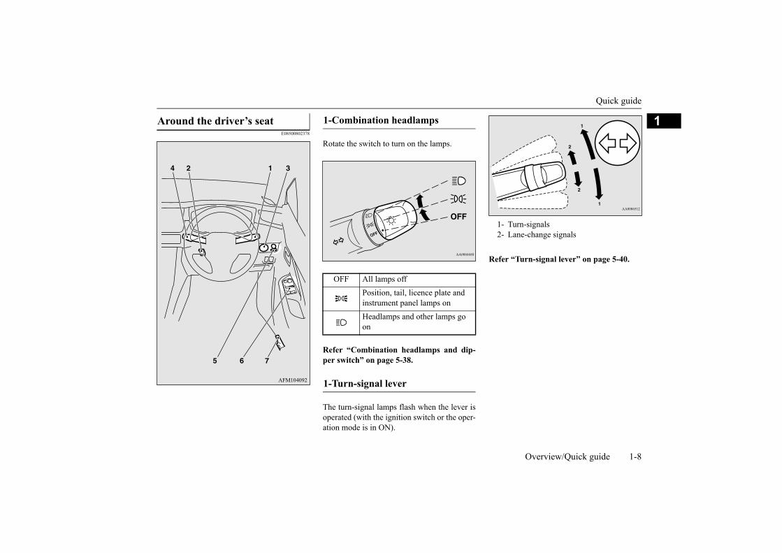
Rotate the switch to turn on the lamps.
Refer “Combination headlamps and dip-per switch” on page 5-38.
The turn-signal lamps flash when the lever isoperated (with the ignition switch or the oper-ation mode is in ON).
Refer “Turn-signal lever” on page 5-40.
Around the driver’s seat 1-Combination headlamps
OFF All lamps offPosition, tail, licence plate and instrument panel lamps onHeadlamps and other lamps go on
1-Turn-signal lever
1- Turn-signals2- Lane-change signals

Quick guide
1-9 Overview/Quick guide
1
1. Release the lever while holding the steer-ing wheel up.
2. Adjust the steering wheel to the desiredposition.
3. Securely lock the steering wheel by pull-ing the lever fully upward.
Refer “Steering wheel height and reachadjustment” on page 6-6.
If you are carrying the keyless operation key,you can start the engine. If you press theengine switch without depressing the brakepedal, you can change the operation mode inthe order of OFF, ACC, ON, OFF.
Refer “Engine switch” on page 6-11.
The washer fluid will be sprayed onto thewindscreen by pulling the lever towards you.
Refer to “Wiper and washer switch” onpage 5-42.
2-Steering wheel height and reach adjustment
A- LockedB- Release
3-Engine switch*
OFF- The indicator lamp on the engineswitch turns off.
ACC- The indicator lamp on the engineswitch illuminates orange.
ON- The indicator lamp on the engineswitch illuminates green.
4-Wiper and washer switch
MIST- Misting functionThe wipers will operate once.
OFF- OffINT- Intermittent (Speed sensitive)LO- SlowHI- Fast

Quick guide
Overview/Quick guide 1-10
1
To adjust the mirror position
Refer “Outside rear-view mirrors: Electricremote-controlled outside rear-view mir-rors” on page 6-8.
Each door window opens or closes while thecorresponding switch is operated.
When this switch (5) is operated, the passen-ger’s switches cannot be used to open or closethe door windows and the driver’s switchcannot open or close any door windows otherthan the driver’s door window. To unlock,push it once again.
Refer “Electric window control switch” onpage 3-23.
The fuel tank filler is located on the rear leftside of your vehicle.Open the fuel tank filler door with the releaselever located the side of the driver’s seat.
Refer “Filling the fuel tank” on page 2-3.
5-Electric remote-controlled out-side rear-view mirrors
Push the switch (A) to the same side as themirror whose adjustment is desired.
L- Left outside mirror adjustmentR- Right outside mirror adjustment
Press the switch (B) to the left, right, up ordown to adjust the mirror position.
1- Up2- Down3- Right4- Left5- Mirror retractor switch
6-Electric window control
1- Driver’s door window2- Front passenger’s door window3- Rear left door window4- Rear right door window5- Lock switch
Lock switch
Driver’s switches
7-Fuel tank filler door release lever

Quick guide
1-11 Overview/Quick guide
1E08502700058
The transmission has 4 forward gears and 1reverse gear.The individual gears are selected automati-cally, depending on the speed of the vehicleand the position of the accelerator pedal.The selector lever has 6 positions, and isequipped with a lock button (A) to avoidinadvertent selection of the wrong gear.
This position locks the transmission to pre-vent the vehicle from moving. The engine canbe started in this position.
This position is to back up.
At this position the transmission is disen-gaged.
This position is for normal driving.
This position is for extra power when drivingup moderately steep hills, and for enginebraking when descending moderately steepgradients.
This position is for driving up very steep hillsand for engine braking at low speeds whendriving down steep hills.
The overdrive control switch can be usedwhile the selector lever is in the “D”(DRIVE) position.
4-speed automatic transmission
Selector lever operation
The lock button must be pressed while the brake pedal is depressed to move the selector lever.The lock button must be pressed to move the selector lever.The lock button need not be pressed to move the selector lever.
Selector lever positions
“P” PARK
“R” REVERSE
“N” NEUTRAL
“D” DRIVE
“2” SECOND
“L” (LOW)
Overdrive control switch

Quick guide
Overview/Quick guide 1-12
1Press the overdrive control switch to turn theoverdrive function on.
Press the overdrive control switch to turn theoverdrive function off.
Refer to “4-speed automatic transmission”on page 6-19.
E08501201662
Always stop the vehicle in a safe place beforeoperating.The following information is included on themulti-information display: warnings, odome-
ter, tripmeter, average and momentary fuelconsumption, average speed etc.
Refer “Multi-information display - Type1” on page 5-3 or “Multi-information dis-play - Type 2” on page 5-16.
During normal driving
During hilly roads driving
Multi-information display
1- mark display P.5-62- “ ” or “ ” mark indicator P.5-53- Information screen P.5-4
Interrupt display screen P.5-54- Odometer P.5-7
Type 1
1- Engine coolant temperature display P.5-19
2- Selector lever position indicator dis-play P.6-20
3- Fuel remaining display P.5-194- Information display P.5-175- Service reminder P.5-20
Type 2


2
General information
Fuel selection ...................................................................................2-2Filling the fuel tank ..........................................................................2-3Installation of accessories ................................................................2-4Modification/alterations to the electrical or fuel systems ................2-5Genuine parts ...................................................................................2-5Used engine oils safety instructions ................................................2-6Event Data Recording ......................................................................2-6

Fuel selection
2-2 General information
2 E00200105836
A mixture of up to 10 % ethanol (grain alco-hol) and 90 % unleaded petrol may be used inyour vehicle, provided the octane number isat least as high as that recommended forunleaded petrol.
A mixture of up to 20 % ethanol (grain alco-hol) and 80 % unleaded petrol may be used inyour vehicle, provided the octane number isat least as high as that recommended forunleaded petrol.
Fuel selection
Recommended fuel
Unleaded petrol octane number 90 RON or higher
CAUTION The use of leaded fuel can result in serious
damage to the engine and catalytic converter.Do not use the leaded fuel.
Ethanol (Gasohol)
Vehicles for Sri Lanka
CAUTIONDo not use more than 10 % concentration of
ethanol (grain alcohol) by volume.Use of more than 10 % concentration maylead to damage to your vehicle fuel system,engine, engine sensors and exhaust system.
Do not operate your vehicle on gasoline con-taining methanol. Using this type of alcoholcould adversely affect the vehicle’s perfor-mance and damage critical parts of the vehi-cle’s fuel system.
NOTERepeatedly driving short distance at low
speeds can cause deposits to form in the fuelsystem and engine, resulting in poor startingand poor acceleration. If these problemsoccur, you are advised to add a detergentadditive to the gasoline when you refuel thevehicle. The additive will remove the depos-its, thereby returning the engine to a normalcondition. Be sure to use a MITSUBISHIMOTORS GENUINE FUEL SYSTEMCLEANER. Using an unsuitable additivecould make the engine malfunction. Fordetails, please contact the nearest authorisedMITSUBISHI MOTORS dealer.
Poor quality petrol can cause problems suchas hard starting, stalling, engine noise andhesitation. If you experience these problems,try another brand and/or grade of petrol.If the check engine warning lamp flashes,have the system checked as soon as possibleat an authorised MITSUBISHI MOTORSdealer.
CAUTION Except for vehicles for Sri Lanka
CAUTIONDo not use more than 20 % concentration of
ethanol (grain alcohol) by volume.Use of more than 20 % concentration maylead to damage to your vehicle fuel system,engine, engine sensors and exhaust system.
Do not operate your vehicle on gasoline con-taining methanol. Using this type of alcoholcould adversely affect the vehicle’s perfor-mance and damage critical parts of the vehi-cle’s fuel system.

Filling the fuel tank
General information 2-3
2
E00200204801
45 litres
1. Before filling with fuel, stop the engine.2. The fuel tank filler is located on the rear
left side of your vehicle.Open the fuel tank filler door with therelease lever located the side of thedriver’s seat.
3. Open the fuel tank filler tube by slowlyturning the cap anticlockwise.
NOTERepeatedly driving short distance at low
speeds can cause deposits to form in the fuelsystem and engine, resulting in poor startingand poor acceleration. If these problemsoccur, you are advised to add a detergentadditive to the gasoline when you refuel thevehicle. The additive will remove the depos-its, thereby returning the engine to a normalcondition. Be sure to use a MITSUBISHIMOTORS GENUINE FUEL SYSTEMCLEANER. Using an unsuitable additivecould make the engine malfunction. Fordetails, please contact the nearest authorisedMITSUBISHI MOTORS dealer.
Poor quality petrol can cause problems suchas hard starting, stalling, engine noise andhesitation. If you experience these problems,try another brand and/or grade of petrol.If the check engine warning lamp flashes,have the system checked as soon as possibleat an authorised MITSUBISHI MOTORSdealer.
Filling the fuel tank
WARNINGWhen handling fuel, comply with the
safety regulations displayed by garagesand filling stations.
Fuel is highly flammable and explosive.You could be burned or seriously injuredwhen handling it. When refuelling yourvehicle, always turn the engine off andkeep away from flames, sparks, and smok-ing materials. Always handle fuel in well-ventilated outdoor areas.
Before removing the fuel cap, be sure toget rid of your body’s static electricity bytouching a metal part of the car or fuelpump. Any static electricity on your bodycould create a spark that ignites fuelvapor.
Perform the whole refuelling process(opening the fuel tank filler door, remov-ing the fuel cap, etc.) by yourself. Do notlet any other person come near the fueltank filler. If you allowed a person to helpyou and that person was carrying staticelectricity, fuel vapor could be ignited.
Do not move away from the fuel tank filleruntil refuelling is finished. If you movedaway and did something else (for example,sitting on a seat) part-way through therefuelling process, you could pick up afresh charge of static electricity.
If the tank cap must be replaced, use onlya MITSUBISHI MOTORS genuine part.
Fuel tank capacity
WARNING Refuelling

Installation of accessories
2-4 General information
2
4. Insert the gun in the tank port as far as itgoes.
5. When the gun stops automatically, do notfill with fuel any more.
6. To close, turn the fuel tank filler tube capslowly clockwise until you hear clickingsounds, then gently push the fuel tankfiller door closed.
E00200302707
Before fitting any accessories, please consultan authorised MITSUBISHI MOTORSdealer.
The installation of accessories, optionalparts, etc., should only be carried outwithin the limits prescribed by law in yourcountry, and in accordance with the guide-lines and warnings contained within thedocuments accompanying this vehicle.Only MITSUBISHI MOTORS approvedaccessories should be fitted to your vehi-cle.
1- Remove2- Close
CAUTION Since the fuel system may be under pressure,
remove the fuel tank filler tube cap slowly.This relieves any pressure or vacuum thatmight have built up in the fuel tank. If youhear a hissing sound, wait until it stopsbefore removing the cap. Otherwise, fuelmay spray out, injuring you or others.
NOTEWhile filling with fuel, store the cap in the
cap holder located on the inside of the fueltank filler door.
CAUTIONDo not tilt the gun.
Installation of accessories
CAUTIONYour vehicle is equipped with a diagnosis
connector for checking and servicing theelectronic control system.Do not connect a device other than a diagno-sis tool for inspections and service to thisconnector. Otherwise, the battery could bedischarged, the electronic devices of thevehicle could malfunction, or other unex-pected problems could result.In addition, malfunctions caused by connect-ing a device other than a diagnosis tool maynot be covered under warranty.

Modification/alterations to the electrical or fuel systems
General information 2-5
2
Improper installation of electrical partscould cause a fire. Refer to the sectionentitled “Modifications to and alterationsof the electrical or fuel systems” in thisowner’s manual.
Using a cellular phone or radio set insidethe vehicle without an external antennamay cause electrical system interference,which could lead to unsafe vehicle opera-tion.
Tyres and wheels which do not meet spec-ifications must not be used.For details on wheel and tyre sizes, referto the section entitled “Specifications”.
Do not fail to read the accessories manu-als prior to the installation of accessories,parts or other modifications to the vehi-cle!
Due to the large number of accessory andreplacement parts of different manufacturesin the market, it is not possible, not only forMITSUBISHI MOTORS CORPORATION,but also an authorised MITSUBISHIMOTORS dealer, to check whether theattachment or installation of such parts affectsthe driving safety of your vehicle.
Even when such parts are officially author-ised, for example by a “general operators per-
mit” (an appraisal for the part) or through theexecution of the part in an officially approvedmanner of construction, or when a singleoperation permit following the attachment orinstallation of such parts, it cannot bededuced from that alone, that the drivingsafety of your vehicles has not been affected.
Consider also that there basically exists noliability on the part of the appraiser or theofficial. Only in the case of parts(MITSUBISHI MOTORS original replace-ment or exchange parts as well asMITSUBISHI MOTORS accessories) thatare recommended and released by an author-ised MITSUBISHI MOTORS dealer and thatare attached or installed by an authorisedMITSUBISHI MOTORS dealer can youassume, that optimal safety has been pro-vided. The same also pertains to modifica-tions of vehicles with respect to theproduction specifications. For your ownsafety, in such cases as well, you should onlyundertake modifications according to the rec-ommendations of an authorisedMITSUBISHI MOTORS dealer.
E00200401600
MITSUBISHI MOTORS has always manu-factured safe, high quality vehicles. In orderto maintain this safety and quality, it is impor-tant that any accessory that is to be fitted, orany modifications carried out which involvethe electrical or fuel systems, should be car-ried out in accordance with MITSUBISHIMOTORS guidelines.
E00200502099
Don’t play around with substitutes.MITSUBISHI MOTORS has gone to greatlengths to bring you a superbly crafted vehi-cle offering the highest quality and dependa-bility. Don’t reduce that quality anddependability by using substitute parts.
Important points!
Modification/alterations to the electrical or fuel systems
CAUTION Please consult an authorised MITSUBISHI
MOTORS dealer concerning any such fit-ment or modification.If the wires interfere with the vehicle body orimproper installation methods are used (pro-tective fuses not included, etc.), electronicdevices may be adversely affected, resultingin a fire or other accident.
Genuine parts

Used engine oils safety instructions
2-6 General information
2
Always use MITSUBISHI MOTORS Genu-ine Parts designed and manufactured to main-tain your vehicle at top performance. Theoperation of vehicle components can be lessefficient in case of using Non-Genuine Parts.Failure to use Genuine Parts may invalidateany future warranty claim. MITSUBISHIMOTORS will not be liable for any malfunc-tion of your vehicle that may have beencaused by the use of substitute parts in placeof MITSUBISHI MOTORS Genuine Parts.At the MITSUBISHI MOTORS dealer youcan also get appropriate advice and theassembling of Genuine Parts will be handledprofessionally.MITSUBISHI MOTORS Genuine Parts areindicated as GENUINE PARTS, and areavailable at all authorised MITSUBISHIMOTORS dealers.
E00200601501
E00205900166
This vehicle is equipped with an event datarecorder (EDR).The main purpose of an EDR is to record, incertain crash or near crash-like situations,such as an airbag deployment or hitting aroad obstacle, data that will assist in under-standing how a vehicle’s systems performed.The EDR is designed to record data related tovehicle dynamics and safety systems for ashort period of time, typically 30 seconds orless.
The EDR in this vehicle is designed to recordsuch data as:
How various systems in your vehicle wereoperating;
How far (if at all) the driver was depress-ing the accelerator and/or brake pedal;and,
How fast the vehicle was travelling.
These data can help provide a better under-standing of the circumstances in whichcrashes and injuries occur.
To read data recorded by an EDR, specialequipment is required, and access to the vehi-cle or the EDR is needed. In addition to thevehicle manufacturer, other parties, such aslaw enforcement, that have the special equip-ment, can read the information if they haveaccess to the vehicle or the EDR.
Used engine oils safety instructions
WARNING Prolonged and repeated contact may
cause serious skin disorders, includingdermatitis and cancer.
Avoid contact with the skin as far as possi-ble and wash thoroughly after any con-tact.
Keep out of reach of children.
Event Data Recording NOTE EDR data are recorded by your vehicle only
if a non-trivial crash situation occurs; no dataare recorded by the EDR under normal driv-ing conditions and no personal data (e.g.,name, gender, age, and crash location) arerecorded. However, other parties, such aslaw enforcement, could combine the EDRdata with the type of personally identifyingdata routinely acquired during a crash inves-tigation.

3
Locking and unlocking
Keys .................................................................................................3-2Electronic immobilizer (Anti-theft starting system) ........................3-3Keyless entry system .......................................................................3-4Keyless operation system* ...............................................................3-7Doors ..............................................................................................3-15Central door locks ..........................................................................3-16“Child-protection” rear doors ........................................................3-17Tailgate ..........................................................................................3-17Security alarm system ....................................................................3-19Electric window control .................................................................3-23

Keys
3-2 Locking and unlocking
3
E00300104768
E00314000122
The key number is stamped on the tag as indi-cated in the illustration.Make a record of the key number and storethe key and key number tag in separateplaces, so that you can order a key from yourauthorised MITSUBISHI MOTORS dealer inthe event the original keys are lost.
Keys
1- Keyless entry key2- Keyless operation key3- Emergency key
WARNINGWhen taking a key on flights, do not press
any switches on the key while on theplane. If a switch is pressed on the plane,the key emits electromagnetic waves,which could adversely affect the plane’sflight operation.When carrying a key in a bag, be carefulthat no switches on the key can be easilypressed by mistake.
Keyless entry key
Keyless operation key
NOTE The key (except for the emergency key) is a
precision electronic part with a built-in sig-nal transmitter. Please observe the followingin order to prevent a malfunction.• Do not leave anywhere that is exposed to
direct sunlight, for example on the dash-board.
• Do not disassemble or modify.• Do not excessively bend the key or subject
it to a strong impact.• Do not expose to water.• Keep away from magnetic key rings.• Keep away from audio systems, personal
computers, TVs, and any other equipmentthat generates a magnetic field.
• Keep away from devices that emit strongelectromagnetic waves, such as cellularphones, wireless devices and high fre-quency equipment (including medicaldevices).
• Do not wash with ultrasonic cleaners orsimilar equipment.
• Do not leave the key where it may beexposed to high temperature or high humid-ity.
The engine is designed so that it will not startif the ID code registered in the immobilizercomputer and the key’s ID code do notmatch. For details on that and on key usage,refer to the section entitled “Electronicimmobilizer”.
Pay attention to the following if the securityalarm is set to “Active”.Refer to “Security alarm system” on page3-19.• If the security alarm is in the system armed
mode, the alarm will sound if the doors areopened after being unlocked with the key,the inside lock knob or the central door lockswitch.
• Even if the security alarm is set to“Active”, the system preparation mode isnot entered if the keyless entry system orthe keyless operation function was not usedto lock the vehicle.
Key number tag
NOTE

Electronic immobilizer (Anti-theft starting system)
Locking and unlocking 3-3
3
E00300204121
The electronic immobilizer is designed toreduce significantly the possibility of vehicletheft. The purpose of the system is to immo-bilize the vehicle if an invalid start isattempted. A valid start attempt can only beachieved, using a key “registered” to theimmobilizer system.
1- Keyless entry key2- Emergency key
Electronic immobilizer (Anti-theft starting system)
CAUTIONDon’t make any alterations or additions to
the immobilizer system; alterations or addi-tions could cause failure of the immobilizer.
NOTE [Except for vehicles equipped with the key-
less operation system]In the following cases, the vehicle may notbe able to receive the registered ID codefrom the registered key and engine may notstart.• When the key contacts a key ring or other
metallic or magnetic object
• When the key grip contacts metal ofanother key
• When the key contacts or is close to otherimmobilizing keys (including keys of othervehicles)
In cases like these, remove the object oradditional key from the vehicle key. Thentry again to start the engine. If the enginedoes not start, contact an authorisedMITSUBISHI MOTORS dealer.
[Vehicles equipped with the keyless opera-tion system]If the engine does not start, we recommendyou to contact an authorised MITSUBISHIMOTORS dealer.
If you lose one of them, contact an author-ised MITSUBISHI MOTORS dealer as soonas possible. To obtain a replacement or extraspare key, take your vehicle and all remain-ing keys to an authorised MITSUBISHIMOTORS dealer. All the keys have to be re-registered in the immobilizer computer unit.For further information, please contact anauthorised MITSUBISHI MOTORS dealer.
NOTE

Keyless entry system
3-4 Locking and unlocking
3
E00300305233
Press the key switch, and all doors and thetailgate will be locked or unlocked as desired.It is also possible to operate the outside rear-view mirrors.
Press the LOCK switch (1). All the doors andthe tailgate will be locked. The turn-signallamps will blink once. When they are lockedwith the room lamp switch in the “” or the“DOOR” position, the room lamp also blinkonce.
Press the UNLOCK switch (2). All the doorsand the tailgate will be unlocked. If the roomlamp switch is in the “” or the “DOOR”position at this time, the room lamp will comeon for approximately 15 seconds and theturn-signal lamps will blink twice.Also, the position and tail lamps will turn onfor approximately 30 seconds.Refer to “Welcome light” on page 5-39 in thesection entitled “Instruments and controls”.
Keyless entry system
1- LOCK switch2- UNLOCK switch3- Indicator lamp
To lock
Keyless entry key Keyless operation key
To unlock
NOTE The outside rear-view mirrors automatically
retract or extend when all the doors and thetailgate are locked or unlocked using the keyswitches of the keyless entry system. Referto “Outside rear-view mirrors” on page 6-8in the section entitled “Starting and driving”.
If the UNLOCK switch (2) is pressed and nodoor or tailgate is opened within approxi-mately 30 seconds, relocking will automati-cally occur.
It is possible to modify functions as follows:For further information, please contact anauthorised MITSUBISHI MOTORS dealer.• The time for automatic relocking can be
changed.• Activating the operation confirmation func-
tion (blinking of the turn-signal lamps) onlyduring locking, or only during unlocking.
• The confirmation function (this indicateslocking or unlocking of the doors and thetailgate with the blink of the turn-signallamps) can be deactivated.
• The number of times the turn-signal lampsare blinked by the confirmation functioncan be changed.
• On vehicles equipped with the keylessoperation system, the buzzer can be set tosound when the vehicle is locked orunlocked using the switches of the keylessoperation key.
The keyless entry system does not operate inthe following conditions:• The key is left in the ignition switch.
(except for vehicles equipped with the key-less operation system)
• The operation mode is not in OFF. (vehiclesequipped with the keyless operation sys-tem)
• The door or tailgate is open. The key switch will operate within approxi-
mately 4 m from the vehicle. However, theoperating range of the key switch maychange if the vehicle is located near a powerstation, or radio/TV broadcasting station.
If either of the following problems occurs,the battery may be exhausted.• The key switch is operated at the correct
distance from the vehicle, but the doors andthe tailgate are not locked/unlocked inresponse.
NOTE

Keyless entry system
Locking and unlocking 3-5
3
E00310802096
Locking the doors and tailgate using theLOCK switch (1), the outside rear-view mir-rors are retracted automatically.
Unlocking the doors and tailgate using theUNLOCK switch (2), the outside rear-viewmirrors are extended automatically.
E00309502413
• The indicator lamp (3) is dim or does notcome on.For further information, please contact anauthorised MITSUBISHI MOTORS dealer.If you replace the battery yourself, refer to“Procedure for replacing the key battery”on page 3-5.
If your key is lost or damaged, please contactan authorised MITSUBISHI MOTORSdealer for a replacement key.
If you wish to add key, please contact anauthorised MITSUBISHI MOTORS dealer.The following numbers of the keys are avail-able.• Keyless entry key: up to four different keys• Keyless operation key: up to four different
keys
Operation of the outside rear-view mirrors
To retract
NOTE To extend
NOTE Functions can be modified as stated below.
Please consult an authorised MITSUBISHIMOTORS dealer.• Automatically extend when the driver’s
door is closed and the ignition switch isturned to the “ON” position or the opera-tion mode is put in ON.In addition, automatically retract when theignition switch is turned to the “LOCK” or“ACC” position or the operation mode isput in OFF or ACC, and the driver’s door isthen opened.
• Automatically extend when the vehiclespeed reaches approximately 30 km/h.
• Deactivate the automatic extension func-tion.
The outside rear-view mirrors can beretracted or extended by the following opera-tions, even if changing to the any of above.After pressing the LOCK switch to lock thedoors and tailgate, if the LOCK switch ispressed again twice in a row within approxi-mately 30 seconds, the outside rear-viewmirrors will retract.After pressing the UNLOCK switch tounlock the doors and tailgate, if theUNLOCK switch is pressed again twice in arow within approximately 30 seconds, theoutside rear-view mirrors will extend again.
Procedure for replacing the key battery
WARNINGDo not swallow a coin type battery.
• This product contains coin type battery.If a coin type battery is swallowed, it cancause severe internal burns and can leadto death.There have been cases where a swallowedbattery has caused severe internal burnsin just 2 hours.
• Keep new and used batteries away fromchildren.
• If the key case does not close securely,stop using the product and keep it awayfrom children.
NOTE

Keyless entry system
3-6 Locking and unlocking
3
1. Before replacing the battery, remove staticelectricity from your body by touching ametal grounded object.
2. Remove the screw (A) from the key.(Keyless entry key only)
3. Remove the emergency key from the key.(Keyless operation key only)Refer to “Emergency key” on page 3-11.
4. With the MITSUBISHI mark facing you,insert the cloth-covered tip of a straightblade (or minus) screwdriver into thenotch in the key case and use it to openthe case.
5. Remove the used battery.
• If you think batteries might have beenswallowed or placed inside any part of aperson’s body, seek immediate medicalattention.
To prevent an explosion or leakage offlammable liquid or gas:• Do not replace the battery with an incor-
rect type. Replace only with the same orequivalent type.
• Do not dispose of a battery into a fire orincinerator, or by mechanically crushingor cutting the battery.
• Do not use, store, or take a battery anyplace where it may be exposed toextremely high temperature or extremelylow air pressure.
CAUTIONWhen the key case is opened, be careful to
keep water, dust, etc. out. Also, do not touchthe internal components.
Dispose of used battery according to the reg-ulations for the disposal of battery.
NOTEYou may purchase a replacement battery at
an electric appliance store.An authorised MITSUBISHI MOTORS
dealer can replace the battery for you if youprefer.
WARNING
Keyless entry key
NOTEBe sure to perform the procedure with the
MITSUBISHI mark facing you. If theMITSUBISHI mark is not facing you whenyou open the key case, the switches maycome out.
Keyless entry key
Keyless operation key

Keyless operation system*
Locking and unlocking 3-7
3
6. Install a new battery with the + side (B)up.
7. Close the key case firmly.8. Attach the screw (A) removed in step 2.
(Keyless entry key only)9. Install the emergency key removed in step
3. (Keyless operation key only)10. Check the keyless entry system to see that
it works.
E00305602692
The keyless operation system allows you tolock and unlock the doors and the tailgate,start the engine and change the operationmode simply by carrying the keyless opera-tion key with you.The switches on the keyless operation keycan also be used as the key switch of keylessentry system.Refer to “Starting and stopping the engine”on page 6-15.Refer to “Keyless entry system” on page 3-4.
The driver should always carry the keylessoperation key. This key is necessary for lock-ing and unlocking the doors and the tailgate,starting the engine and otherwise operatingthe vehicle, so before locking and leaving thevehicle, be sure to check that you have thekeyless operation key.
You can limit the possible operations of thekeyless operation system in the followingways. (The keyless operation system can beused as a keyless entry system.) Please con-sult an authorised MITSUBISHI MOTORSdealer.
Keyless entry key+ side
- side
Coin type battery CR1620
Keyless operation key+ side
- side
Coin type battery CR2032
Keyless operation system*
WARNING People with implantable cardiac pacemak-
ers or implantable cardiovascular-defi-brillators should not go near the exteriortransmitters (A) or the interior transmit-ters (B). The radio waves used by the key-less operation system could adverselyaffect implantable cardiac pacemakers orimplantable cardiovascular-defibrillators.
WARNINGWhen using electro-medical devices other
than implantable cardiac pacemakers orimplantable cardiovascular-defibrilla-tors, contact the electro-medical devicemanufacturer ahead of time to determinethe adverse effects of radio waves on thedevices. Electro-medical device operationscould be affected by radio waves.

Keyless operation system*
3-8 Locking and unlocking
3
You can limit operations to locking andunlocking the doors and tailgate.
You can limit operations to starting theengine.
The keyless operation system can be disa-bled.
E00305701898
If you are carrying the keyless operation key,enter the operating range of the keyless oper-ation system, and press the driver’s or frontpassenger’s door lock/unlock switch, the tail-gate lock/unlock switch, the ID code for yourkey is verified.You can lock and unlock the doors and thetailgate, start the engine and change the oper-ation mode only if the ID codes of your key-less operation key and the vehicle match.
E00306201760
The operating range is approximately 70 cmfrom the driver’s or front passenger’s doorlock/unlock switch, and tailgate lock/unlockswitch.
NOTE The keyless operation key uses an ultra-weak
electromagnetic wave. In the followingcases, the keyless operation system may notoperate properly or may be unstable.• When there is equipment nearby that emits
strong radio waves, such as: a power sta-tion, a radio/TV broadcasting station or anairport.
• The keyless operation system is carriedtogether with a communications devicesuch as a cellular phone or radio set, or withan electronic device such as a personalcomputer.
• The keyless operation key is touching orcovered by a metal object.
• A keyless entry system is being usednearby.
• When the keyless operation key battery isworn out.
• When the keyless operation key is set downin an area with strong radio waves or noise.In such cases, use the emergency key.Refer to “To lock/unlock without using thekeyless operation function” on page 3-11.
Because the keyless operation key receivessignals in order to communicate with thetransmitters in the vehicle, the battery con-tinually wears down regardless of keylessoperation key use. The battery life is 1 to2 years, depending on usage conditions.When the battery wears out, replace the bat-tery according to the description in this man-ual or have it replaced an authorisedMITSUBISHI MOTORS dealer.Refer to “Procedure for replacing the keybattery” on page 3-5.
Because the keyless operation key continu-ally receives signals, strong radio wavereception could affect battery wear. Do notleave the key near a TV, personal computer,or other electronic device.
Operating range of the keyless operation system
NOTE NOTE If the keyless operation key battery is wear-
ing out or there are strong electromagneticwaves or noise present, the operating rangemay become smaller and operation maybecome unstable.
Operating range for locking and unlocking the doors and tailgate
*: Forward direction: Operating range

Keyless operation system*
Locking and unlocking 3-9
3
E00306301569
The operating range is the interior of thevehicle.
E00305803301
When you are carrying the keyless operationkey, if you press the driver’s or front passen-ger’s door lock/unlock switch (A), or the tail-
NOTE Locking and unlocking operate only when
you press a door or tailgate switch thatdetects the keyless operation key.
Operation may not be possible if you are tooclose to the front door, door window or tail-gate.
Even if the keyless operation key is within70 cm of the driver’s or front passenger’sdoor lock/unlock switch or tailgatelock/unlock switch, if the key is near to theground or high up, the system may not oper-ate.
If the keyless operation key is within theoperating range, even someone not carryingthe key can lock and unlock the doors andtailgate by pressing the driver’s or front pas-senger’s door lock/unlock switch, the tail-gate lock/unlock switch.
Operating range for starting the engine and changing the opera-tion mode
*: Forward direction: Operating range
NOTE Even if it is within the operating range, if the
keyless operation key is in a small itemholder such as the glove box, on top of theinstrument panel, door pocket or in the lug-gage compartment, it may be impossible tostart the engine and change the operationmode.
If a keyless operation key is too close to thedoor or door window, it may be possible tostart the engine or change the operationmode even when the key is outside the vehi-cle.
To operate using the keyless operation function
Locking the doors and tailgate
Driver’s or front passenger’s door lock/unlock switch
Tailgate lock/unlock switch

Keyless operation system*
3-10 Locking and unlocking
3
gate lock/unlock switch (B) within theoperating range, the doors and the tailgate arelocked.The turn-signal lamps will blink once and theouter buzzer will sound once.For further details, refer to “Doors”, “Centraldoor locks” and “Tailgate” on pages 3-15,3-16 and 3-17 in the section entitled “Lock-ing and unlocking”.
When you are carrying the keyless operationkey, if you press the driver’s or front passen-ger’s door lock/unlock switch (A), or the tail-gate lock/unlock switch (B) within theoperating range, all the doors and the tailgateare unlocked.If the room lamp switch is in the “” or the“DOOR” position at this time, the room lampwill turn on for 15 seconds. The turn-signallamps will blink twice and the outer buzzerwill sound twice.If the driver’s or front passenger’s doorlock/unlock switch is pressed and any of thedoors or tailgate is not opened within approx-imately 30 seconds, relocking will automati-cally occur.For further details, refer to “Doors”, “Centraldoor locks” and “Tailgate” on pages 3-15,3-16 and 3-17 in the section entitled “Lock-ing and unlocking”.
Operation can be confirmed as shown below.However, the room lamp will illuminate onlyif the room lamp switch is in the “” or the“DOOR” position.When locking: The turn-signal lamps blinkonce and the outer buzzer sounds once.When unlocking: The room lamp illuminatesfor approximately 15 seconds, and the turn-signal lamps blink twice, and the outer buzzersounds twice.
NOTEBe sure to have the keyless operation key
with you before locking the vehicle. Even ifthe keyless operation key is left in the vehi-cle in the glove box or other small storagecompartment, near the instrument panel, orin the luggage compartment, the vehicle maybe locked depending on the radio waves andother conditions in the surrounding environ-ment, trapping the key inside the vehicle.
The outside rear-view mirrors automaticallyretract when all the doors and tailgate arelocked using the keyless operation function.Refer to “Outside rear-view mirrors” on page6-8.
The keyless operation function does notoperate under the following conditions:• The keyless operation key is inside the
vehicle.• A door or the tailgate is open or ajar.• The operation mode is not in OFF.
Unlocking the doors and tailgate
NOTE The outside rear-view mirrors automatically
extend when all the doors and the tailgate areunlocked using the keyless operation func-tion. Refer to “Outside rear-view mirrors” onpage 6-8 in the section entitled “Starting anddriving”.
The keyless operation key does not operatewhen the operation mode is not in OFF.
The time between unlocking and automaticlocking can be adjusted. Please consult anauthorised MITSUBISHI MOTORS dealer.
Operation confirmation when lockingand unlocking
NOTE Functions can be modified as stated below.
For further information, please contact anauthorised MITSUBISHI MOTORS dealer.• Activating the operation confirmation func-
tion (blinking of the turn-signal lamps) onlyduring locking, or only during unlocking.
• Disabling the operation confirmation func-tion (blinking of the turn-signal lamps) andouter buzzer.
• Changing the number of blinks for theoperation confirmation function (blinkingof the turn-signal lamps).
NOTE

Keyless operation system*
Locking and unlocking 3-11
3E00306001221
E00307201839
The emergency key (A) can only be used tolock and unlock the door. To use the emer-gency key, unlock the lock knob (B) andremove it from the keyless operation key (C).
Turning the emergency key in the forwarddirection locks the door, and turning it in therear direction unlocks the door. For furtherdetails, refer to “Doors” on page 3-15 in thesection entitled “Locking and unlocking”.
E00305902334
In order to prevent vehicle theft or the accidental operation of the keyless operation system, the buzzer and the display on the information screenin the multi-information display are used to alert the driver.If a warning is activated, always check the vehicle and the keyless operation key. The warning is also displayed if there is a fault in the keylessoperation system.
To lock/unlock without using the keyless operation function
Emergency key
NOTEOnly use the emergency key for emergen-
cies. If the keyless operation key batterywears out, replace it as quickly as possible sothat you can use the keyless operation key.
The emergency key is built in the keylessoperation key.
After using the emergency key, always returnit into the original position.
Locking and unlocking the door
1- Lock2- Unlock
Warning activation
Item Display Buzzer Note (Solution)Detection of failure Inner buzzer sounds
onceThere is a fault in the keyless operation system.
Keyless operation system*
3-12 Locking and unlocking
3
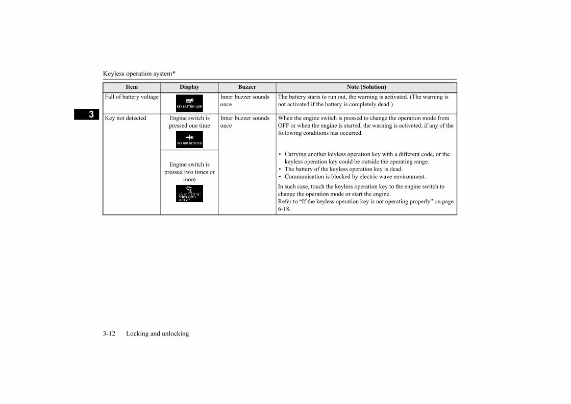
Fall of battery voltage Inner buzzer sounds once
The battery starts to run out, the warning is activated. (The warning is not activated if the battery is completely dead.)
Key not detected Engine switch is pressed one time
Inner buzzer sounds once
When the engine switch is pressed to change the operation mode from OFF or when the engine is started, the warning is activated, if any of the following conditions has occurred.
Engine switch is pressed two times or
more
•
••
Carrying another keyless operation key with a different code, or thekeyless operation key could be outside the operating range.The battery of the keyless operation key is dead.Communication is blocked by electric wave environment.
In such case, touch the keyless operation key to the engine switch to change the operation mode or start the engine.Refer to “If the keyless operation key is not operating properly” on page 6-18.
Item Display Buzzer Note (Solution)

Keyless operation system*
Locking and unlocking 3-13
3
Keyless operation key take-out monitor-ing system
Inner buzzer sounds onceOuter buzzer sounds intermittently
•
•
•
•
When the vehicle is parked with the operation mode in any mode other than OFF, if you close the door after opening any of the doors and taking the keyless operation key out of the vehicle, a warning is issued until the key is detected in the vehicle.If you take the keyless operation key out of the vehicle through a win-dow without opening a door, the keyless operation key take-out moni-toring system does not operate.It is possible to change the setting to make the keyless operation key take-out monitoring system operate if you take the keyless operation key out from the vehicle through a window without opening a door. For further information, please contact an authorised MITSUBISHI MOTORS dealer.Even if you have the keyless operation key within the engine start operating range, if the keyless operation key and vehicle ID codes cannot be matched, for example due to the ambient environment or electromagnetic conditions, the warning may be activated.
Key lock-in preven-tion system
Inner buzzer sounds onceOuter buzzer sounds approximately 3 sec-onds intermittently
•
•
When the operation mode is in OFF, if you close all the doors and the tailgate with the keyless operation key left in the vehicle and you try to lock the doors and tailgate by pressing the driver’s or front passen-ger’s door lock/unlock switch, or the tailgate lock/unlock switch, a warning is issued and you cannot lock the doors and tailgate.Make sure you have the keyless operation key with you before lock-ing the doors. Even if you leave the keyless operation key inside the vehicle, it is possible that the doors will lock depending on the sur-rounding environment and wireless signal conditions.
Door ajar prevention system
Inner buzzer sounds onceOuter buzzer sounds approximately 3 sec-onds intermittently
When the operation mode in OFF, if you try to lock the doors and tail-gate by pressing the driver’s or front passenger’s door lock/unlock switch, or the tailgate lock/unlock switch with one of the doors or the tailgate not completely closed, a warning is issued and you cannot lock the doors and tailgate.
Item Display Buzzer Note (Solution)

Keyless operation system*
3-14 Locking and unlocking
3
Operation mode OFF reminder system
Inner buzzer sounds onceOuter buzzer sounds approximately 3 sec-onds intermittently
When the operation mode is in any mode other than OFF, if you try to lock the doors and tailgate by pressing the driver’s or front passenger’s door lock/unlock switch, or the tailgate lock/unlock switch, a warning is issued and you cannot lock the doors and tailgate.
Item Display Buzzer Note (Solution)

Doors
Locking and unlocking 3-15
3
E00300403908
Set the inside lock knob (1) to the lockedposition, and close the door (2).
E00300501152
If the driver’s door is opened while the key isin the ignition switch, a buzzer will sound toremind you to remove the key.
Doors
CAUTIONMake sure the doors are closed: driving with
doors not completely closed is dangerous.Never leave children in the vehicle unat-
tended.Be careful not to lock the doors while the
key is inside the vehicle.
To lock or unlock with the key
1- Lock 2- Unlock
NOTEWhen locking or unlocking with the key, all
doors and the tailgate will be locked orunlocked.Refer to “Central door locks” on page 3-16.
If the vehicle is equipped with the keylessoperation system, all doors and the tailgatecan be locked or unlocked with the emer-gency key. Refer to “Emergency key” onpage 3-11.
To lock or unlock from inside the vehicle
1- Lock 2- Unlock
NOTE The driver’s door can be opened without
using the lock knob by pulling on the insidedoor handle.
To lock without using the key
Ignition key reminder
Except for vehicles equipped with the keyless operation system

Central door locks
3-16 Locking and unlocking
3 If the driver’s door is opened with the enginestopped and the operation mode in any modeother than OFF, a buzzer will sound to remindyou to put the operation mode in OFF.Refer to “Operation mode ON reminder sys-tem” on page 6-13.
E00300601397
If the key is in the ignition switch or the oper-ation mode is in any mode other than OFF,the lock knob will automatically return to theunlocked position if you push the lock knobforward or press the central door lock switchto lock the doors with the driver’s door open.
E00300803713
All of the doors and the tailgate can be lockedand unlocked as described hereafter.
Using the key on the driver’s door locks orunlocks all doors and the tailgate.
Using the central door lock switch on thedriver’s door locks or unlocks all doors andthe tailgate.
Vehicles equipped with the keyless operation system
“Forgotten-key-prevention” mechanism
Central door locks
NOTERepeated continuous operation between lock
and unlock could activate the central doorlocking systems built-in protection circuitand prevent the system from operating. Ifthis occurs, wait approximately 1 minutebefore operating the central door lock sys-tem.
Driver’s door with key
1- Lock
2- Unlock
NOTE If the vehicle is equipped with the keyless
operation system, the driver’s door can belocked or unlocked with the emergency key.Refer to “Emergency key” on page 3-11.
The central door lock switch
1- Lock2- Unlock

“Child-protection” rear doors
Locking and unlocking 3-17
3It is possible to unlock all of the doors and thetailgate whenever as follows.The selector lever placed the “P” (PARK)position while the ignition switch or the oper-ation mode is in ON.Or the ignition switch is turned to the“LOCK” position or the operation mode isput in OFF.
These functions are deactivated when thevehicle is shipped from the factory. If youwish to activate or deactivate these functions,please contact an authorised MITSUBISHIMOTORS dealer.
E00300902270
Child protection helps prevent the rear doorsfrom being opened accidentally from theinside.If the lever is set to the locked position, therear door cannot be opened using the insidehandle, but only with the outside handle.If the lever is set to the unlock position (2),the child protection mechanism does notfunction.
E00301403022
Unlock using the ignition switch, the engine switch or the selector lever
“Child-protection” rear doors
1- Lock2- Unlock
CAUTIONWhen driving with a child in the rear seat,
please use the child protection to preventaccidental door opening which may cause anaccident.
Tailgate
WARNINGLuggage compartment is not designed to
ride for people. Do not let people ride orchildren play there. This could result in aserious accident.
It is dangerous to drive with the tailgateopen, since carbon monoxide (CO) gas canenter the cabin.You cannot see or smell CO. It can causeunconsciousness and even death.And also, if opening the tailgate whiledriving, luggage may fall from the tail-gate. This could result in a serious acci-dent.
When opening and closing the tailgate,make sure of the surrounding safety andkeep enough space for back and upper ofthe vehicle and be careful not to hit yourhead or pinch your hands, neck, etc.
Tailgate
3-18 Locking and unlocking
3
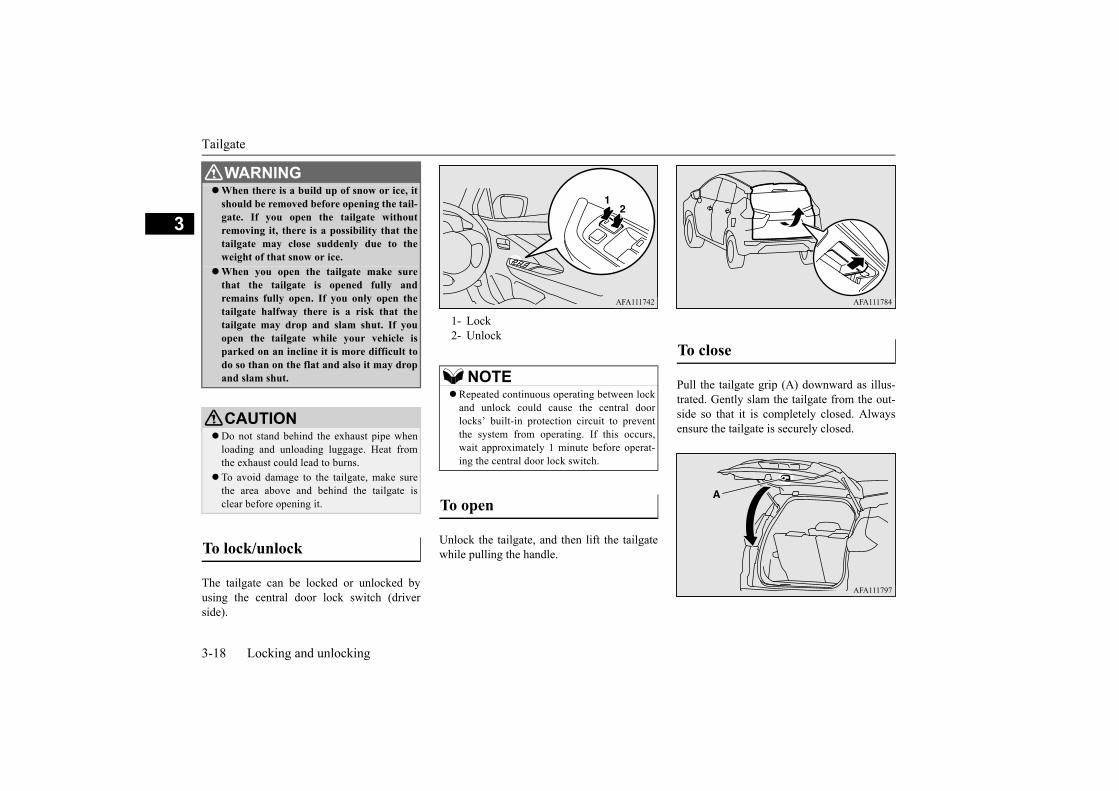
The tailgate can be locked or unlocked byusing the central door lock switch (driverside).
Unlock the tailgate, and then lift the tailgatewhile pulling the handle.
Pull the tailgate grip (A) downward as illus-trated. Gently slam the tailgate from the out-side so that it is completely closed. Alwaysensure the tailgate is securely closed.
When there is a build up of snow or ice, itshould be removed before opening the tail-gate. If you open the tailgate withoutremoving it, there is a possibility that thetailgate may close suddenly due to theweight of that snow or ice.
When you open the tailgate make surethat the tailgate is opened fully andremains fully open. If you only open thetailgate halfway there is a risk that thetailgate may drop and slam shut. If youopen the tailgate while your vehicle isparked on an incline it is more difficult todo so than on the flat and also it may dropand slam shut.
CAUTIONDo not stand behind the exhaust pipe when
loading and unloading luggage. Heat fromthe exhaust could lead to burns.
To avoid damage to the tailgate, make surethe area above and behind the tailgate isclear before opening it.
To lock/unlock
WARNING
1- Lock2- Unlock
NOTERepeated continuous operating between lock
and unlock could cause the central doorlocks’ built-in protection circuit to preventthe system from operating. If this occurs,wait approximately 1 minute before operat-ing the central door lock switch.
To open
To close

Security alarm system
Locking and unlocking 3-19
3
E00301502550
The security alarm system is for alerting thesurrounding area of suspicious behaviour toprevent unlawful entry into the vehicle byoperating an alarm if a door or the tailgate isopened when the vehicle has not beenunlocked using the keyless entry system orthe keyless operation function.
(The buzzer sounds intermittently and thesecurity indicator lamp in the instrument clus-ter blinks.)
Indicator lamp
The system preparation time extends from thepoint at which all of the doors and the tailgateare locked by pressing of the LOCK switchon the key or the keyless operation functionto the point at which the system armed modegoes into effect.During this time, it is possible to temporarilyopen a door or the tailgate without using thekeyless entry system or the keyless operationfunction and without causing the alarm tosound (for example, when you forget some-thing inside the vehicle or realize that a win-dow is open).
CAUTIONWhen closing the tailgate, do not close it
directly putting the hands on the tailgategrip. If the hands or arms got caught, a seri-ous injury could result.
NOTEGas struts (B) are installed to support the
tailgate.
To prevent damage or faulty operation.• Do not hold the gas struts when closing the
tailgate.• Also, do not push or pull the gas struts.• Do not attach any plastic material, tape,
etc., to the gas struts.• Do not tie string, etc., around the gas struts.• Do not hang any object on the gas struts.
Security alarm system
CAUTIONDo not modify or add parts to the security
alarm system.Doing so could cause the security alarm tomalfunction.
NOTE The alarm system will not be activated if the
doors and the tailgate have been locked usinga key, the inside lock knob or the centraldoor lock switch (instead of the keyless entrysystem or the keyless operation function).
The security alarm has four modes:
System preparation mode (approximately 20 seconds)

Security alarm system
3-20 Locking and unlocking
3(The buzzer stops and the security indicatorlamp continues to blink with the indicator’sreduced lit-up duration time.)Once the system preparation mode has ended,the system armed mode starts.If an unlawful opening of any of the doors ortailgate is detected during the system armedmode, the alarm will be activated to warnpeople around the vehicle of an abnormalcondition.Also, if unlawful moving of the vehicle isattempted or a vehicle intrusion is detected,the alarm will be activated.
Inside alarm (approximately 10 seconds):
The buzzer sounds, warning those insidethe vehicle of an abnormal condition.
Outside alarm (approximately 30 seconds):
The turn-signal lamps blink and the hornsounds, warning people around the vehi-cle of an abnormal condition.
Refer to “Alarm activation” on page 3-22.
It is possible to cancel the system activationduring the system preparation mode or thesystem armed mode.In addition, it is possible to cancel the alarmonce it has been activated.Refer to “Cancelling the system” on page3-21, “Cancelling the alarm” on page 3-22.
E00301702637
Follow the procedure below to set the systemto the system armed mode.
1. Turn the ignition switch to the “LOCK”position and then remove the key (exceptfor vehicles equipped with the keylessoperation system), or put the operationmode in OFF (vehicles equipped with thekeyless operation system).
2. Exit the vehicle and close all of the doorsand tailgate.
3. Press the LOCK switch (A) on the key ofthe keyless entry system or the keylessoperation system, the driver’s or frontpassenger’s door lock/unlock switch (B),or the tailgate lock/unlock switch (C) inorder to lock all the doors and the tailgate.
System armed mode
Alarm activation
NOTE The alarm will resume if unlawful actions
are taken again, even if the alarm hasstopped.
System cancellation
NOTEWhen lending the vehicle to another person
or allowing the vehicle to be driven by some-one who is unfamiliar with the security alarmsystem, be sure to give the person a properexplanation of the security alarm system.If a person who is unfamiliar with the secu-rity alarm system accidentally unlocked thevehicle, causing the alarm to sound, thealarm would be a nuisance to people nearby.
Setting the system
Keyless entry key Keyless operation key

Security alarm system
Locking and unlocking 3-21
3
By locking the vehicle using the keylessentry system or the keyless operationfunction, the system preparation mode isactivated.The buzzer makes an intermittent beepingsound and the security indicator lamp inthe instrument cluster flashes for confir-mation.
Indicator lamp
4. After approximately 20 seconds, thebuzzer stops, and when the blinking of thesecurity indicator lamp starts to slowdown, the system armed mode goes intoeffect.The security indicator lamp continues toblink during the system armed mode.
E00301802478
The following methods can be used to cancelthe system when it is in the system prepara-tion mode or the system armed mode.
Pressing the UNLOCK switch on the key.Turning the ignition switch to the “ON”
position. (except for vehicles equippedwith the keyless operation system)
Putting the operation mode in ON. (vehi-cles equipped with the keyless operationsystem)
Opening any one of the doors or the tail-gate, or inserting the key into the ignitionswitch (except for vehicles equipped withthe keyless operation system) when thesystem is in the system preparation mode.
Driver’s or front passenger’s door lock/unlock switch
Tailgate lock/unlock switch
NOTE The system preparation mode is not activated
when the doors and the tailgate have beenlocked using a method other than the keylessentry system or the keyless operation func-tion (namely a key, the inside lock knob orthe central door lock switch).
If the security indicator lamp in the instru-ment cluster does not blink after the lockingoperation using the keyless entry system orthe keyless operation function, the securityalarm system may be malfunctioning.Have the vehicle inspected at an authorisedMITSUBISHI MOTORS dealer.
NOTE The security alarm system can be activated
when people are riding inside the vehicle orwhen the windows are open. To prevent acci-dental activation of the alarm, do not set thesystem to the system armed mode while peo-ple are riding in the vehicle.
Avoid leaving valuable items inside the vehi-cle even when the security alarm system hasbeen set to the “active” mode.
Cancelling the system

Security alarm system
3-22 Locking and unlocking
3
Holding the keyless operation key andpressing the driver’s or front passenger’sdoor lock/unlock switch, or the tailgatelock/unlock switch to unlock the doorsand the tailgate (vehicles equipped withthe keyless operation system).
E00301902512
When the system is in the system armedmode, the alarm will be activated as followsif the vehicle is unlocked or if any of thedoors or tailgate is opened using a methodother than the keyless entry system or thekeyless operation function.
1. The inside alarm will be activated forapproximately 10 seconds.
2. The alarm will be activated for approxi-mately 30 seconds.The turn-signal lamps will flash, and thehorn will sound intermittently.
3. The alarm will resume if unlawful actionsare taken again, even if the alarm hasstopped.
E00302001946
It is possible to halt the activation of an alarmusing the following methods:
Pressing the LOCK or UNLOCK switchon the key.(After pressing of the LOCK switch, thevehicle will lock if all the doors and thetailgate are closed, after which the systempreparation mode will once again go intoeffect.)
Turning the ignition switch to the “ON”position. (except for vehicles equippedwith the keyless operation system)
NOTE If the battery terminals are disconnected
while the system is in the system preparationmode, the memory will be erased.
It is possible to register up to four keys forkeyless entry system and four keys for key-less operation system.As long as they are registered, any of thekeys, other than the one used to activate thesystem, can be used to cancel the system.If you want to register additional keys,please contact an authorised MITSUBISHIMOTORS dealer.
The activation distance for keyless entry sys-tem is approximately 4 m.If it is not possible to lock or unlock thevehicle by pressing the switch at the correctdistance or the security alarm system cannotbe set or cancelled using the switch, the bat-tery may need to be replaced.Replace the battery at your authorisedMITSUBISHI MOTORS dealer.
If the UNLOCK switch on the key, thedriver’s or front passenger’s doorlock/unlock switch, or the tailgatelock/unlock switch is pressed and no door orthe tailgate is opened within 30 seconds, thedoors and the tailgate will automaticallyrelock. In this case as well, the system prepa-ration mode will go into effect.
The time between pressing of the UNLOCKswitch on the key, the driver’s or front pas-senger’s door lock/unlock switch, or the tail-gate lock/unlock switch and automaticlocking can be adjusted. Please consult anauthorised MITSUBISHI MOTORS dealer.
Alarm activation
NOTE
Cancelling the alarm

Electric window control
Locking and unlocking 3-23
3
Putting the operation mode in ON. (vehi-cles equipped with the keyless operationsystem)
Holding the keyless operation key andlocking or unlocking the doors and thetailgate using the keyless operation func-tion (vehicles equipped with the keylessoperation system).
E00302201850
The electric windows can only be operatedwith the ignition switch in the “ON” positionor the operation mode in ON.
E00302303695
Each door window opens or closes while thecorresponding switch is operated.
The driver’s switches can be used to operateall door windows. A window can be openedor closed by operating the correspondingswitch.Press the switch down to open the window,and pull up the switch to close it.If the switch for the driver’s window is fullypressed down/pulled up, the door windowautomatically opens/closes completely.If you want to stop the window movement,operate the switch lightly in the reverse direc-tion.
The passenger’s switches can be used to oper-ate the corresponding passenger’s door win-dows.Press the switch down for opening the win-dow, and pull up the switch for closing.
NOTEWhen the ignition switch is turned to the
“ON” position or the operation mode is putin ON, the buzzer sounds four times. Thisoperation indicates that the alarm was acti-vated while the vehicle was parked.Please check the inside of the vehicle to con-firm that nothing was stolen.
Even if the battery is disconnected, the alarmactivation memory will not be erased.
Electric window control
Electric window control switch
1- Driver’s door window2- Front passenger’s door window3- Rear left door window4- Rear right door window5- Lock switch
WARNINGBefore operating the electric window con-
trol, make sure that nothing is capable ofbeing trapped (head, hand, finger, etc.).
Never leave the vehicle without removingthe key.
Never leave a child (or other person whomight not be capable of safe operation ofthe electric window control) in the vehiclealone.
Driver’s switches Driver’s switches
Passenger’s switches

Electric window control
3-24 Locking and unlocking
3
E00303102749
When this switch is operated, the passenger’sswitches cannot be used to open or close thedoor windows and the driver’s switch cannotopen or close any door windows other thanthe driver’s door window.To unlock, push it once again.
E00302402266
The door windows can be opened or closedfor 30 seconds after the engine is stopped.However, once the driver’s door or the frontpassenger’s door is opened, the windows can-not be operated.
E00302502339
When the door window is automaticallyclosed by pulling up the switch fully, if ahand or head is trapped in the closing win-dow, it will lower automatically.Nonetheless, make sure that nobody putstheir head or hand out of the window whenclosing the driver’s door window.The lowered window will become operationalafter a few seconds.NOTE
Repeated operation with the engine stoppedwill run down the battery. Operate the win-dow switches only while the engine is run-ning.
The rear door windows only open halfway.
Lock switch
1- Lock2- Unlock
WARNINGA child may tamper with the switch at the
risk of its hands or head being trapped inthe window. When driving with a child inthe vehicle, please push the window lockswitch to disable the passenger’s switches.
Timer function
Safety mechanism (driver’s window only)
WARNING If the battery terminals are disconnected
or the fuse for electric window is replaced,the safety mechanism will be cancelled.If a hand or head got trapped, a seriousinjury could result.
CAUTION The safety mechanism is cancelled just
before the window is fully closed. Thisallows the window to close completely.Therefore be especially careful that no fin-gers are trapped in the window.
The safety mechanism is deactivated whilethe switch is pulled up. Therefore be espe-cially careful that fingers are not trapped inthe door window opening.

Electric window control
Locking and unlocking 3-25
3
NOTE The safety mechanism can be activated if the
driving conditions or other circumstancescause the driver’s door window to be sub-jected to a physical shock similar to thatcaused by a trapped hand or head.
If the safety mechanism is activated five ormore times in a row, the safety mechanismwill be cancelled and the door window willnot close correctly.In such a case, the following procedureshould be implemented to rectify this situa-tion. If the window is open, repeatedly raisethe driver’s door window switch until thatwindow has been fully closed. Followingthis, release the switch, raise the switch onceagain and hold it in this condition for at least1 second, then release it. You should now beable to operate in the normal fashion.
If the battery terminals are disconnected orthe fuse for electric window is replaced, thesafety mechanism will be cancelled and thedoor window will not automaticallyopen/close completely.If the window is open, repeatedly raise thedriver’s door window switch until the win-dow has been fully closed. Following this,release the switch, raise the switch onceagain and hold it in this condition for at least1 second, then release it. You should now beable to operate the driver’s door window inthe normal fashion.


4
Seat and seat belts
Seat arrangement .............................................................................4-2Seat adjustment ................................................................................4-4Front seats ........................................................................................4-4Second seats .....................................................................................4-5Third seats ........................................................................................4-7Head restraints .................................................................................4-7Making a luggage area .....................................................................4-9Seat belts ........................................................................................4-10Pregnant women restraint ..............................................................4-14Seat belt pre-tensioner system .......................................................4-15Child restraint ................................................................................4-15Seat belt inspection ........................................................................4-22Supplemental restraint system (SRS) - airbag ...............................4-23

Seat arrangement
4-2 Seat and seat belts
4
E00400202085
By operating the front, second or third seat, select the desired seat arrangement.
Seat arrangement
Normal usage
Seat arrangement
Seat and seat belts 4-3
4
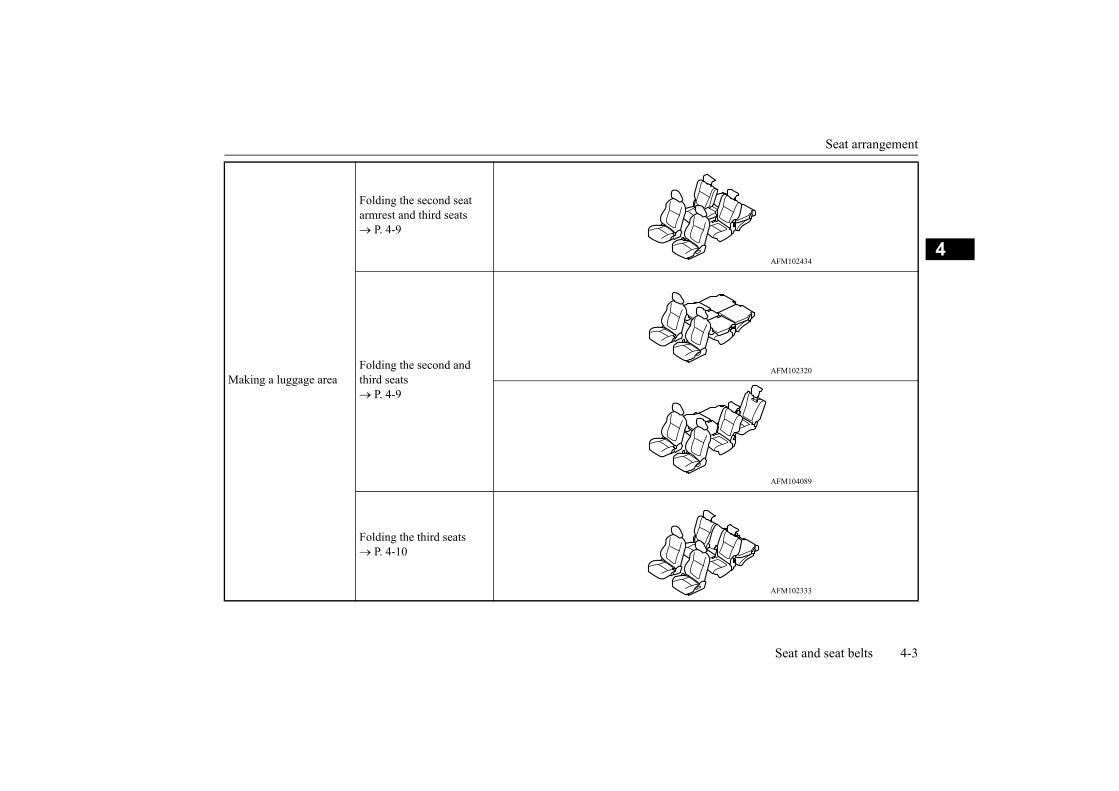
Making a luggage area
Folding the second seat armrest and third seats P. 4-9
Folding the second and third seats P. 4-9
Folding the third seats P. 4-10

Seat adjustment
4-4 Seat and seat belts
4
E00400302233
Adjust the driver’s seat so that you are com-fortable and that you can reach the pedals,steering wheel, switches etc. while retaining aclear field of vision.
E00400401673
Seat adjustment
WARNINGDo not attempt to adjust the seat while
driving. This can cause loss of vehicle con-trol and result in an accident. Afteradjustments are made, ensure the seatingis locked in position by attempting tomove the seat forward and rearward with-out using the adjusting mechanism.
It is extremely dangerous to ride in theluggage area of a vehicle. Also, the luggagearea and rear seats should never be usedas a play area by children. In a collision,people or children riding unrestrained inthese areas are more likely to be seriouslyinjured or killed.
Do not allow people or children to ride inany area of your vehicle that is notequipped with seats and seat belts, andmake sure that everyone travelling in yourvehicle is in a seat and wearing a seat belt,or in the case of a child is strapped in achild restraint.
To minimize the risk of personal injury inthe event of a collision or sudden braking,the seatbacks should always be in thealmost upright position while the vehicle isin motion. The protection provided by theseat belts may be reduced significantlywhen the seatback is reclined. There isgreater risk that the passenger will slideunder the seat belt, resulting in seriousinjury, when the seatback is reclined.
Do not place objects under the seats. Thiscould prevent the seat from lockingsecurely, and it could lead to an accident.It may also cause damage to the seat orother parts.
CAUTIONMake sure the seat is adjusted by an adult or
with adult supervision for correct and safeoperation.
Do not place a cushion or the like betweenyour back and the seatback while driving.The effectiveness of the head restraints willbe reduced in the event of an accident.
The reclining mechanism of the front seat’sseatback is spring loaded, causing it to returnto the vertical position when the lock lever isoperated. When using the lever, sit close tothe seatback or hold it with your hand to con-trol its return motion.
When sliding the seats, be careful not tocatch your hand or foot.
WARNINGWhen sliding or reclining the seat rearward,
pay careful attention to the rear seat passen-gers.
Front seats
1- To adjust forward or backwardLift the handle and adjust the seat tothe desired position, and release thehandle.
2- To recline the seatbackPull the lever up and then lean back-ward to the desired position, andrelease the lever.
3- To adjust seat height (driver’s sideonly)Turn the dial and adjust the seat cush-ion height to the desired position.
CAUTION

Second seats
Seat and seat belts 4-5
4
E00402001631
E00402401648
To use the armrest, pull forward the strap torelease the lock, and fold the armrest down.To return to the original position, push itbackward until it is flush with the seat.
E00412601076
Getting in and out of the third seat can bemade easily by folding the second seat.
1. Adjust the angle of the front seatbacks inthe upright position and move the frontseat forward. (Refer to “Front seats” onpage 4-4.)
2. Store the seat belt buckles in the storagepockets of the second seats.
Refer to “Second and third seat belt stor-age” on page 4-14.
3. Lower the head restraints of the secondseat to the lowest position.Refer to “Head restraints” on page 4-7.
4. If the second seat is in the forward-mostposition, move it rearward.
5. Pull the lever (A) forward, then tilt theseatback forward.When the seatback is tilted forward, thefloor lock will be released and the rear ofthe seat will lift up slightly.
6. Lift the whole seat forward.
Second seats
1- To adjust forward or backwardLift the handle and adjust the seat to thedesired position, and release the han-dle.
2- To recline the seatbackPull the lever forward and adjust theseatback by hand to the desired posi-tion, and release the lever.
Armrest
CAUTIONDo not climb or sit on the armrest.
Doing so could damage the armrest.
To get in and out of the third seat
To fold
NOTE If the second seats are in a forward position,
you may not be able to fold them.
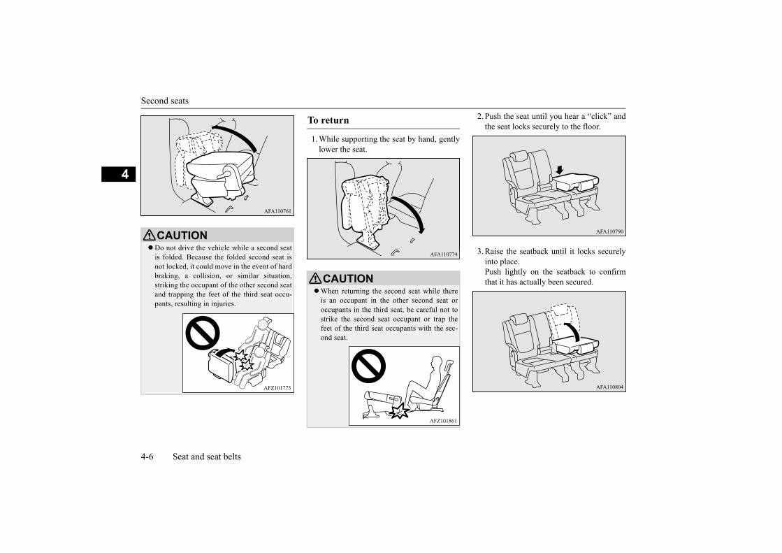
Second seats
4-6 Seat and seat belts
4
1. While supporting the seat by hand, gentlylower the seat.
2. Push the seat until you hear a “click” andthe seat locks securely to the floor.
3. Raise the seatback until it locks securelyinto place.Push lightly on the seatback to confirmthat it has actually been secured.
CAUTIONDo not drive the vehicle while a second seat
is folded. Because the folded second seat isnot locked, it could move in the event of hardbraking, a collision, or similar situation,striking the occupant of the other second seatand trapping the feet of the third seat occu-pants, resulting in injuries.
To return
CAUTIONWhen returning the second seat while there
is an occupant in the other second seat oroccupants in the third seat, be careful not tostrike the second seat occupant or trap thefeet of the third seat occupants with the sec-ond seat.

Third seats
Seat and seat belts 4-7
4
E00402701540
To recline the seatback.Pull up the strap and adjust the seatback byhand to the desired position, and release thestrap.
E00403303013
Adjust the head restraint height so that thecentre of the head restraint is as close as pos-sible to ear level to reduce the chances ofinjury in the event of collision. Any persontoo tall for the head restraint to reach theirseated ear level, should adjust the restraint ashigh as possible.
To raise the head restraint, move it upward.To lower the restraint, move it downwardwhile pushing the height adjusting knob (A)
in the direction of the arrow. After adjust-ment, push the head restraint downward andmake sure that it is locked.
To reduce the risk of injury in an accident,pull up the head restraint to the locked posi-tion.
To raise the head restraint, move it upward.To lower the restraint, move it downwardwhile pushing the height adjusting knob (A)in the direction of the arrow. After adjust-ment, push the head restraint downward andmake sure that it is locked.
Third seats
WARNING For reasons of safety, whenever passen-
gers sit in the third seat, be sure to raiseall the head restraints of the second seats.
Head restraints
WARNINGDriving without the head restraints in
place can cause you and your passengersserious injury or death in an accident. Toreduce the risk of injury in an accident,always make sure the head restraints areinstalled and properly positioned whenthe seat is occupied.
Never place a cushion or similar device onthe seatback. This can adversely affecthead restraint performance by increasingthe distance between your head and therestraint.
To adjust height
Front seats
Second or third seats

Head restraints
4-8 Seat and seat belts
4Lift the head restraint with the height adjust-ing knob (A) pressed in.
Confirm that the head restraint is facing thecorrect direction, and then insert it into theseatback while pressing the height adjustingknob (A) in the direction indicated by thearrow.The head restraint stalk with the adjustmentnotches (B) must be installed in the hole withthe adjusting knob (A).
WARNINGWhen a person sits in the second or the
third seats, pull up the head restraint to aheight at which it locks in position. Besure to make this adjustment before start-ing to drive. Serious injuries could other-wise be suffered in the result of an impact.
NOTE The head restraints of the third seats cannot
be removed.
To remove (front or second seats)
To install (front or second seats)
CAUTIONConfirm that the height adjusting knob (A) is
correctly adjusted as shown in the illustra-tion, and also lift the head restraints toensure that they do not come out of the seat-back.
The shape and size of the head restraint dif-fers according to the seat. Always use thecorrect head restraint provided for the seatand do not install the head restraint in thewrong direction.

Making a luggage area
Seat and seat belts 4-9
4
E00403401557
To create luggage space, you can fold the sec-ond and/or the third seats.
E00465100038
Long items can be loaded while passengersare sitting in the second row outboard seats.
1. Fold the third seats.Refer to “Folding the third seats” on page4-10.
2. Fold the armrest down.Refer to “Armrest” on page 4-5.
E00403501747
1. Fold the third seats.
Refer to “Folding the third seats” on page4-10.
2. Store the seat belt buckles in the storagepockets of the second seats.Refer to “Second and third seat belt stor-age” on page 4-14.
3. Lower the head restraints of the secondseat to the lowest position.Refer to “Head restraints” on page 4-7.
4. Move the second seats to the rear-mostposition.
5. Pull the lever (A) forward, then tilt theseatback forward.When the seatback is tilted forward, thefloor lock will be released and the rear ofthe seat will lift up slightly.
6. Push the seat until you hear a “click” andthe seat locks securely to the floor.
Making a luggage area
WARNINGAfter tilting the seatback of a second seat
forward, push down on the rear of the seatand make sure it is securely locked to thefloor. The seat could move if it is notretained, causing a serious accident.
CAUTIONDo not stack luggage above the seatback
height or load luggage in such a way thatwill interfere with the operation of the vehi-cle. Secure the luggage firmly.Serious accidents could result due to unre-strained objects entering the passenger com-partment during sudden braking.
When folding or storing the seat, be sure notto catch your hand or leg.
NOTE It is possible to folding the seat indepen-
dently on each side.
Folding the second seat armrest and third seats
Folding the second and third seats
To fold

Seat belts
4-10 Seat and seat belts
4
Raise the seatback until it locks securely intoplace.Push lightly on the seatback to confirm that ithas actually been secured.
E00403601142
1. Lower the head restraints of the third seatto the lowest position. (Refer to “Headrestraints” on page 4-7.)
2. Pull up the strap (A), then fold the seat-back forward.
Pull the strap (B), then raise the seatback untilit locks securely into place.Push lightly on the seatback to confirm that ithas actually been secured.
E00404802164
To protect you and your passengers in theevent of an accident, it is the most importantthat the seat belts be worn correctly whiledriving.The front seat belts have a pre-tensioner sys-tem. These belts are used the same way as aconventional seat belt.Refer to “Seat belt pre-tensioner system” onpage 4-15.
To return
Folding the third seats
To fold
To return
Seat belts
WARNING Seat belts should always be worn by every
adult who drives or rides in this vehicle,and by all children who are large enoughto wear seat belts properly.Other children should always use properchild restraint systems.

Seat belts
Seat and seat belts 4-11
4
E00404903234
This type of belt requires no length adjust-ment. Once worn, the belt adjusts itself to themovement of wearer, but in the event of asudden or strong shock, the belt automaticallylocks to hold the wearer’s body.
1. Pull the seat belt out slowly while holdingthe latch plate.
2. Insert the latch plate into the buckle untila “click” is heard.
3. Pull the belt slightly to adjust slackness asdesired.
Always place the shoulder belt over yourshoulder and across your chest. Never putit behind you or under your arm.
One seat belt should be used by only oneperson. Doing otherwise can be danger-ous.
The seat belt will provide its wearer withmaximum protection if the recliner seat-back is placed in fully upright position.When the seatback is reclined, there isgreater risk that the passenger will slideunder the belt, especially in a forwardimpact accident, and may be injured bythe belt or by striking the instrumentpanel or seatbacks.
Remove any twists when using the belt.No modifications or additions should be
made by the user which will either preventthe seat belt adjusting devices from oper-ating to remove slack, or prevent the seatbelt assembly from being adjusted toremove slack.
Never hold a child in your arms or onyour lap when riding in this vehicle, evenif you are wearing your seat belt. To do sorisks severe or fatal injury to your child ina collision or sudden stop.
Always adjust the belt to a snug fit.Always wear the lap portion of the belt
over your hips.
WARNING 3-point type seat belt (with emergency locking mechanism)
NOTEYou can check if the belt locks by pulling it
forward quickly.
To fasten
NOTEWhen the seat belts cannot be pulled out in a
locked condition, pull the belts once force-fully and then return them. After that, pullthe belts out slowly once again.
WARNINGNever wear the lap portion of the belt
across your abdomen. During accidents itcan press sharply against abdomen andincrease the risk of injury.
The seat belts must not be twisted whenworn.

Seat belts
4-12 Seat and seat belts
4
Hold the latch plate and push the button onthe buckle.
E00409802534
If the ignition switch is turned to the “ON”position or the operation mode is put in ONwhile the seat belt is not fastened, the warn-ing lamp comes on and the tone sounds forapproximately 6 seconds to remind the driverand the front passenger to fasten the seat belt.If the vehicle is driven with the seat belt stillunfastened, the warning lamp will blink andthe tone will sound intermittently until theseat belt is fastened. At the same time, “FAS-TEN SEAT BELT” is displayed on the infor-mation screen in the multi-informationdisplay (Type 1 only).
To unfasten
NOTEAs the belt retracts automatically, keep hold-
ing the latch plate while retracting so that thebelt stows slowly. Failure to do this coulddamage the vehicle.
If the seat belt (A) or ring (B) becomes dirty,the belt may not retract smoothly. If the seatbelt and ring are dirty, clean them with amild soap or detergent solution.
Seat belt reminder
NOTE
Type 1
Type 2
WARNINGDo not install any accessory or sticker that
makes the lamp difficult to see.
NOTE If the seat belt subsequently remains unfas-
tened, the warning lamp and the tone willissue further warnings each time the vehiclestarts moving from a stop.
For the front passenger seat, the warningfunction works only while a person is sittingon the seat.
When luggage is placed on the front passen-ger seat, a sensor in the seat cushion may,depending on the weight and position of theluggage, cause the warning tone to soundand the warning lamp to come on.

Seat belts
Seat and seat belts 4-13
4
E00405201298
The second-centre 3-point type seat belt mustbe worn correctly as illustrated.
1. Pull out the buckle (C) from the seat cush-ion.
2. Pull the seat belt and insert the small latchplate (A) into the buckle (C).
3. Insert the latch plate (B) into the buckle(D).
4. Pull the belt slightly to adjust slackness asdesired.
1. Hold the latch plate (B) and push the but-ton on the buckle (D).
2. To release the buckle (C), press the button(E) with a narrow-tipped object (latchplate (B), mechanical key, etc.).
3. After the seat belt is retracted completely,insert the latch plate (B) into the upper slit(F), and then insert the small latch plate(A) into the lower slit (G).
Second-centre 3-point type seat belt
WARNINGBe sure to securely connect the both latch
plate (A and B). Failing to do so could sig-nificantly reduce the amount of protectionand cause serious injures in a collision or asudden stop.
To fasten
To unfasten
CAUTIONAs the belt retracts automatically, keep the
latch plate held while retracting so that thebelt stows slowly. Failure to do this couldcause personal injury or damage to the vehi-cle.

Pregnant women restraint
4-14 Seat and seat belts
4
4. Store the seat belt buckle in the storagepocket.Refer to “Second and third seat belt stor-age” on page 4-14.
E00405301710
Pass the belt through the notch (A).
Refer to “Second-centre 3-point type seatbelt” on page 4-13.
Store the seat belt buckles in the storagepockets.
E00405601250
Second and third seat belt stor-age
Seat belt plate storage
Outboard seating position
Second-centre seating position
Seat belt buckle storage Pregnant women restraint
WARNING Seat belts work for everyone, including
pregnant women. Pregnant women shoulduse the available seat belts. This willreduce the likelihood of injury to both thewoman and the unborn child. The lap beltshould be worn across the thighs and assnug against the hips as possible, but notacross the waist. Consult your doctor ifyou have any additional questions or con-cerns.
Second seat
Third seat

Seat belt pre-tensioner system
Seat and seat belts 4-15
4
E00405701639
The driver’s seat and front passenger’s seateach have a seat belt equipped with a pre-ten-sioner system.
E00405802565
When the ignition switch or the operationmode is under the following conditions, ifthere is a frontal impact severe enough toinjure the driver and/or front passenger, thepre-tensioner system will retract their respec-tive seat belts instantaneously, thus maximiz-ing the seat belt’s effectiveness.[Except for vehicles equipped with the key-less operation system]The ignition switch is in the “ON” or“START” position.[Vehicles equipped with the keyless operationsystem]The operation mode is in ON.
E00405901442
The same warning lamp/display is shared bythe SRS airbags and the pre-tensioner seatbelts.Refer to “SRS warning lamp/display” onpage 4-27.
E00406404038
When transporting children in your vehicle,some type of child restraint system shouldalways be used according to the size of thechild. This is required by law in most coun-tries.The regulations concerning driving with chil-dren in the front seat may differ from countryto country. You are advised to comply withthe relevant regulations.
Seat belt pre-tensioner sys-tem
Pre-tensioner system
WARNINGTo obtain the best results from your pre-
tensioner seat belt, make sure you haveadjusted your seat correctly and wearyour seat belt properly.
CAUTION Installation of audio equipment or repairs in
the vicinity of the pre-tensioner seat belts orfloor console must be performed in line withMITSUBISHI MOTORS guidelines. It isimportant to do so because the work couldaffect the pre-tensioner systems.
If you need to scrap the vehicle, please con-sult an authorised MITSUBISHI MOTORSdealer.It is important to do so because unexpectedactivation of the pre-tensioner seat beltscould cause injuries.
NOTE The pre-tensioner seat belts will be activated
if the vehicle suffers a severe impact, even ifthe seat belts are not worn.
The pre-tensioner seat belts are designed towork only once. After the pre-tensioner seatbelts have been activated, we recommendyou have it replaced by an authorisedMITSUBISHI MOTORS dealer.
SRS warning
Child restraint
WARNINGWhen possible, put children in the rear
seat. Accident statistics indicate that chil-dren of all sizes and ages are safer whenproperly restrained in the rear seat ratherthan in the front seat.
Holding a child in your arms is no substi-tute for a restraint system. Failure to use aproper restraint system can result insevere or fatal injury to your child.
Each child restraint device or fixing is tobe used only by one child.
When attaching a child restraint system tothe second seat, prevent the front seat-backs from touching the child’s feet andchild restraint system.Otherwise, the child could be seriouslyinjured in the event of hard braking or acollision.

Child restraint
4-16 Seat and seat belts
4 The label shown here is attached on vehicleswith front passenger’s airbag.
E00406602401
When transporting infants and small childrenin your vehicle, follow the instruction givenbelow.
For small infants, an infant carrier shouldbe used. For small children whose heightwhen seated allows the shoulder belt to liein contact with the face or the throat, achild seat should be used.
The child restraint system should beappropriate for your child’s weight andheight and properly fit the vehicle. For ahigher degree of safety: THE CHILDRESTRAINT SYSTEM SHOULD BEINSTALLED IN THE REAR SEAT.
Before purchasing a child restraint sys-tem, try installing it in the rear seat tomake sure there is a good fit. Because ofthe location of the seat belt buckles andthe shape of the seat cushion, it may bedifficult to securely install some manufac-turer’s child restraint systems.
Caution for installing the child restraint on vehicle with front passenger’s airbag
WARNINGExtreme Hazard!
NEVER use a rearward facing childrestraint on a seat protected by anACTIVE AIRBAG in front of it, DEATHor SERIOUS INJURY to the CHILD canoccur.
A REARWARD FACING CHILDRESTRAINT must NOT be used in thefront passenger seat as it places an infanttoo close to the passenger’s airbag. Theforce of an inflating airbag could kill orcause serious injuries to the child. A rear-ward facing child restraint must only beused in the rear seat.
A FORWARD FACING CHILDRESTRAINT should be used in the rearseat whenever possible; if used in the frontseat, adjust the seat to the most rearwardposition.
Infants and small children
WARNING
Instruction:

Child restraint
Seat and seat belts 4-17
4
If the child restraint system can be pulledforward or to either side easily on the seatcushion after the seat belt has been tight-ened, choose another manufacturer’s childrestraint system.
E00406701450
Children who have outgrown the childrestraint system should be seated in the rearseat and wear combination lap shoulder belt.The lap portion of the belt should be snug andpositioned low on the abdomen so that it isbelow the top of the hip-bone. Otherwise, thebelt could intrude into the child’s abdomenduring an accident and cause injury.
WARNINGWhen installing a child restraint system,
refer to the instructions provided by themanufacturer of the restraint system.Failure to do so can result in severe orfatal injury to your child.
After installation, push and pull the childrestraint system back and forth, and sideto side, to see that it is positively secured.If the child restraint system is not installedsecurely, it may cause injury to the childor other occupants in the case of accidentor sudden stops.
When the child restraint system is not inuse, keep your child restraint systemsecured with the seat belt or remove itfrom the vehicle in order to prevent itfrom being thrown around inside the vehi-cle during an accident.
NOTEDepending on the seating position in the
vehicle and the child restraint system thatyou have, the child restraint can be attachedusing one of the following two ways:
• Using the lower anchorage in the secondseat ONLY if the child restraint has ISOFIXmountings.Refer to “Installing a child restraint systemto the lower anchorage (ISOFIX childrestraint mountings) and tether anchorage”on page 4-19.
• Using the seat belt.Refer to “Installing a child restraint systemto a 3-point type seat belt (with emergencylocking mechanism)” on page 4-21.
Older children
NOTE

Child restraint
4-18 Seat and seat belts
4
E00406803703
Selecting the child restraint system for each seating position
Suitable for “universal” category child restraint systems
Suitable for i-Size and ISOFIX child restraint systems
Suitable for front-facing child restraint systems only
Rear-facing child restraint systems must not be installed
Not suitable for a child restraint system
This seat is equipped with a top tether anchor
*1: When installing a child restraint system, remove the head restraintfrom the seat and move the seat to the rearmost position. However,do not remove the head restraint when installing a booster cushion(see page 4-19, 4-21).
*2: When installing a child restraint system on the front passengerseat, adjust the seatback angle to 5 steps rearward from the mostupright position.
*3: When installing a child restraint system on a second row outboardseat, adjust the seatback angle to 2 steps rearward from the mostupright position.

Child restraint
Seat and seat belts 4-19
4
E00406902358
Your vehicle’s second seat is fitted with loweranchorages for attaching a child restraint sys-tem with ISOFIX mountings.
CAUTIONWhen installing a child restraint system on a second seat, slide the seat in front of the child restraint system forward or adjust its seatback so that the child’s
feet and the child restraint system do not contact the seat.
Category
Seating Position
Front pas-senger
Second row (left)
Second row (centre)
Second row (right)
Third row (left)
Third row (right)
Seat compatible with a “universal” category child restraint system that is secured using the vehicle’s seat belts
Yes (front-facing only) Yes No Yes No No
Seat compatible with i-Size and ISOFIX child restraint systems No Yes No Yes No No
Seat compatible with a side-facing child restraint system (L1/L2) No No No No No No
Maximum allowable size for a rear-facing child restraint system (R1/R2X/R2/R3) No R3 No R3 No No
Maximum allowable size for a front-facing child restraint system (F1/F2X/F2/F3) No F3 No F3 No No
Installing a child restraint sys-tem to the lower anchorage (ISOFIX child restraint mount-ings) and tether anchorage
Lower anchorage location

Child restraint
4-20 Seat and seat belts
4
There are two child restraint anchorage pointslocated on the back of the second seatbacks.These are for securing a child restraint systemtether strap to each of the two rear seatingpositions in your vehicle.
The child restraint system is designed onlyfor seats that incorporate lower anchorages.Retain the child restraint system using thelower anchorages.It is not necessary to retain the child restraintsystem using the vehicle’s seatbelts.
1. Remove any foreign material in or aroundthe connectors and ensure the vehicle seatbelt is in its normal storage position.
2. Remove the head restraint from the loca-tion in which you wish to install a childrestraint system.
Refer to “Head restraints” on page 4-7.
3. When installing a child restraint system,slide the seat to its most rearward posi-tion.
4. Open the gap a little with your hand toexpose the lower anchorages (A).
5. Push the child restraint system’s connec-tors (B) into the lower anchorages (A) inaccordance with the instructions providedby the child restraint system’s manufac-turer.
Tether anchorage location
WARNINGChild restraint anchorages are designed to
withstand only those loads imposed bycorrectly fitted child restraints. Under nocircumstances are they to be used foradult seatbelts, harnesses or for attachingother items or equipment to the vehicle.
Child restraint system with ISO-FIX mountings
A: Child restraint system connectors
To install
CAUTIONDo not remove the head restraint when
installing a booster cushion.

Child restraint
Seat and seat belts 4-21
4
6. Latch the tether strap hook (C) of thechild restraint system to the tether anchorbar (D) and tighten the top tether straphook so it is securely fastened.
7. Push and pull the child restraint system inall directions to be sure it is secure.
Remove the child restraint system in accord-ance with the instructions provided by thechild restraint system’s manufacturer.
E00408702015
1. Put a child restraint system on the seat inwhich you wish to install it, and removethe head restraint from the seat.Refer to “Head restraints” on page 4-7.
2. When installing a child restraint system,adjust seat slide to its most rearward posi-tion.
A: Lower anchorageB: Connector
If your child restraint system has a supportleg, make sure that there is a support leg atthe stable position on the floor.If your child restraint system requires the useof a tether strap, fasten the tether strap inaccordance with step 6.
To remove
Installing a child restraint sys-tem to a 3-point type seat belt (with emergency locking mech-anism)
To install
CAUTIONDo not remove the head restraint when
installing a booster cushion.

Seat belt inspection
4-22 Seat and seat belts
4
3. Route the belt through the child restraintaccording to the child restraint systemmanufacturer’s instructions, then insertthe latch plate into the buckle.
4. Remove all slack of a lap belt by pullingthe webbing through the belt’s adjustmentfeature.3-point type seat belt requires no lengthadjustment, remove all slack by using thelocking clip.
5. Before putting the child in the restraint,push and pull the restraint in all directionsto be sure it is secure. Do this before eachuse.
Remove the plate from the buckle, thenremove the seat belt from the child restraintsystem.
E00406302017
Check the belts for cuts, worn or frayed web-bing and for cracked or deformed metallicparts. Replace the belt assembly if defective.
WARNING For some types of child restraint, the lock-
ing clip (A) should be used to help avoidpersonal injury during a collision or sud-den manoeuvre.It must be fitted and used in accordancewith the child restraint manufacturer’sinstructions.The locking clip must be removed whenthe child restraint is removed.
To remove
Seat belt inspection
WARNINGWe recommend you to have all seat belt
assemblies including retractors andattaching hardware inspected after anycollision. We recommend that seat beltassemblies in use during a collision bereplaced unless the collision was minorand the belts show no damage and con-tinue to operate properly.
Do not attempt to repair or replace anypart of the seat belt assemblies; we recom-mend you to have this work done by anauthorised MITSUBISHI MOTORSdealer. Incorrect repair or replacementcould reduce the effectiveness of the beltsand could result in serious injury in theevent of a collision.
Once the pre-tensioner has activated, itcannot be re-used.It must be replaced together with theretractor.
Do not insert any foreign objects (pieces ofplastic, paper clips, buttons, etc.) in thebuckle or retractor mechanism. In addi-tion, do not modify, remove, or installthe seat belt. Otherwise, the seat belt maynot be able to provide adequate protectionin a collision or other situation.
A dirty belt should be cleaned with neu-tral detergent in warm water. After rins-ing in water, let it dry in the shade. Do notattempt to bleach or re-dye the beltsbecause this affects their characteristics.
WARNING

Supplemental restraint system (SRS) - airbag
Seat and seat belts 4-23
4
E00407203690
The information written in this supplementalrestraint system (SRS) section containsimportant points concerning the driver’s andfront passenger’s airbags.The SRS airbags are designed to supplementthe primary protection of the driver and frontpassenger side seat belt systems by providingthose occupants with protection against headand chest injuries in certain moderate-to-severe frontal collisions.
The SRS is NOT a substitute for the seatbelts; for maximum protection in all types ofcrashes and accidents, seat belts shouldALWAYS be worn by everyone who drives orrides in this vehicle.
E00407303721
The SRS includes the following components:
Only when the ignition switch or the opera-tion mode is under the following conditions,the airbags will operate.[Except for vehicles equipped with the key-less operation system]The ignition switch is in the “ON” or“START” position.[Vehicles equipped with the keyless operationsystem]The operation mode is in ON.
The airbags deployment produces a sudden,loud noise, and releases some smoke andpowder, but these conditions are not injuri-ous, and do not indicate a fire in the vehicle.People with respiratory problems may feelsome temporary irritation from chemicalsused to produce the deployment; open the
windows after airbag deployment, if safe todo so.The airbags deflate very rapidly after deploy-ment, so there is little danger of obscuredvision.
Supplemental restraint sys-tem (SRS) - airbag
How the supplemental restraint system works
1- Airbag module (Driver)2- Airbag module (Passenger)
CAUTIONAirbags inflate at an extremely rapid speed.
In certain situations, contact with inflatingairbags can result in abrasions, light cuts,bruises, and the like.
WARNING IT IS VERY IMPORTANT TO BE PROP-
ERLY SEATED.A driver or front passenger too close tothe steering wheel or instrument panelduring airbag deployment can be killed orseriously injured.Airbags inflate very fast, and with greatforce.If the driver and front passenger are notproperly seated and restrained, the air-bags may not protect you properly, andcould cause serious or fatal injuries whenit inflates.
Do not sit on the edge of the seat or leanhead or chest close to the steering wheel orinstrument panel. Do not put feet or legson or against the instrument panel.

Supplemental restraint system (SRS) - airbag
4-24 Seat and seat belts
4
E00408802638
The label shown here is attached on vehicleswith front passenger’s airbag.
E00407402161
The driver’s airbag is located under the pad-ded cover in the middle of the steering wheel.The front passenger’s airbag is contained inthe instrument panel above the glove box.The front passenger’s airbag deploys at thesame time as the driver’s airbag, even if thepassenger seat is not occupied.
Place all infants and small children in therear seat and properly restrained using anappropriate child restraint system.The rear seat is the safest for infants andchildren.
Infants and small children should neverbe unrestrained, stand up against theinstrument panel or held in your arms oron your lap. They could be seriouslyinjured or killed in a collision, includingwhen the airbag inflates. They should beproperly seated in the rear seat in anappropriate child restraint system. See the“Child restraint” section of this owner’smanual.
WARNINGOlder children should be seated in the
rear seat, properly wearing the seat belt,with an appropriate booster seat ifneeded.
Caution for installing the child restraint on vehicle with front passenger’s airbag
WARNINGExtreme Hazard!
NEVER use a rearward facing childrestraint on a seat protected by anACTIVE AIRBAG in front of it, DEATHor SERIOUS INJURY to the CHILD canoccur.
WARNING Driver’s and passenger’s front airbag system

Supplemental restraint system (SRS) - airbag
Seat and seat belts 4-25
4
E00412501453
The front airbags are designed to deploywhen the vehicle suffers a moderate to severefrontal impact. A typical condition is shownin the illustration.
The front airbags will deploy if the severityof impact is above the designed thresholdlevel, comparable to an approximately
25 km/h collision when impacting straightinto a solid wall that does not move ordeform. If the severity of the impact is belowthe above threshold level, the front airbagsmay not deploy. However, this thresholdspeed will be considerably higher if the vehi-cle strikes an object that absorbs the impactby either deforming or moving (for example,another stationary vehicle, pole or a guardrail). Because frontal collisions can easily moveyou out of position, it is important to alwaysproperly wear your seat belts. Your seat beltswill help keep you in a safe distance from thesteering wheel and instrument panel duringthe initial stages of airbag deployment. Theinitial stage of airbag inflation is the mostforceful, and can possibly cause serious orfatal injuries. Moreover, the seat belts in yourvehicle are your primary means of protectionin a collision. The SRS airbags are designedto provide additional protection. Therefore,for your safety and the safety of all occu-pants, be sure to always properly wear yourseat belts.
With certain types of frontal collisions, thevehicle’s body structure is designed to absorbthe shock to help protect the occupants from
harm. (The vehicle body’s front area maydeform significantly as it absorbs the impact.)Under such circumstances, the front airbagsmay not deploy irrespective of the deforma-tion and damage to the vehicle body.Examples of some typical conditions areshown in the illustration.
Because the front airbags do not protect theoccupant in all types of frontal collisions, besure to always properly wear your seat belts.
Deployment of front airbags
The front airbags ARE DESIGNED TO DEPLOY when…
1- Head-on collision with a solid wall atspeed of approximately 25 km/h orhigher
2- Moderate to severe frontal impactwithin the shaded area between thearrows
The front airbags MAY NOT DEPLOY when…
1- Collision with a utility pole, tree orother narrow objects
2- Vehicle slides under the rear body of atruck
3- Oblique frontal impacts

Supplemental restraint system (SRS) - airbag
4-26 Seat and seat belts
4The front airbags are not designed to deployin conditions where they cannot typically pro-vide protection to the occupant.Such conditions are shown in the illustration.
Because the front airbags do not protect theoccupant in all types of collisions, be sure toalways properly wear your seat belts.
The front airbags may deploy if the bottom ofthe vehicle suffers a moderate to severeimpact (undercarriage damage).Examples of some typical conditions areshown in the illustration.
Because the front airbags may deploy in cer-tain types of unexpected impacts as shown inthe illustration that can easily move you outof position, it is important to always properlywear your seat belts. Your seat belts will help
keep you in a safe distance from the steeringwheel and instrument panel during the initialstages of airbag deployment. The initial stageof airbag inflation is the most forceful andcan possibly cause serious or fatal injuries ifyou contact it at this stage.
The front airbags ARE NOT DESIGNED TO DEPLOY when…
1- Rear end collisions2- Side collisions3- Vehicle rolls onto its side or roof
The front airbags MAY DEPLOY when…
1- Collision with an elevatedmedian/island or kerb
2- Vehicle travels over a deep hole/pot-hole
3- Vehicle drives down a steep slope andhits the ground
WARNINGDo not attach anything to the steering
wheel padded cover, such as trim material,badges, etc. It might strike and injure anoccupant if the airbag inflates.
Do not set anything on, or attach anythingto, the instrument panel above the glovebox. It might strike and injure an occu-pant if the airbag inflates.
Do not attach accessories to, or put themin front of, the windscreen. These objectscould restrict the airbag inflation, orstrike and injure an occupant if the air-bags inflate.

Supplemental restraint system (SRS) - airbag
Seat and seat belts 4-27
4
E00407803234
There is a supplemental restraint system(“SRS”) warning lamp on the instrumentpanel. The system checks itself every time theignition switch is turned to the “ON” positionor the operation mode is put in ON. The SRSwarning lamp will come on for several sec-onds and then go out. This in normal andmeans the system is working properly.If there is a problem involving one or more ofthe SRS components, the warning lamp willcome on and stay on.At the same time, the warning display willappear on the information screen in the multi-information display (Type 1 only).
The SRS warning lamp/display is shared bythe SRS airbag and the seat belt pre-tensionersystem.Do not put packages, pets or other objects
between the airbags and the driver orfront passenger. It could affect airbag per-formance, or could cause injury when theairbag inflates.
Right after the airbag inflation, severalairbag system components will be hot. Donot touch them; you could be burned.
The airbag system is designed to workonly once. Once the airbags havedeployed, they will not work again. Theymust promptly be replaced and the entireairbag system must be inspected by anauthorised MITSUBISHI MOTORSdealer.
WARNING SRS warning lamp/display*
Type 1
Type 2
WARNING If any of the following conditions occur,
there may be a problem with the SRS air-bags and/or seat belt pre-tensioners, andthey may not function properly in a colli-sion or may suddenly activate without acollision:• Even when the ignition switch or the
operation mode is in ON, the SRS warn-ing lamp does not come on or it remainson.
• The SRS warning lamp and/or the warn-ing display comes on while driving.
The SRS airbags and seat belt pre-ten-sioners are designed to help reduce therisk of serious injury or death in certaincollisions.If either of the above conditions occurs,immediately have your vehicle checked byan authorised MITSUBISHI MOTORSdealer.

Supplemental restraint system (SRS) - airbag
4-28 Seat and seat belts
4
E00407902951
SRS servicing
WARNINGAny maintenance performed on or near
the components of the SRS must be per-formed only by an authorisedMITSUBISHI MOTORS dealer. Do notpermit anyone else to do service, inspec-tion, maintenance or repair on any SRScomponents or wiring; similarly, no partof the SRS should ever be handled or dis-posed of by anyone except an authorisedMITSUBISHI MOTORS dealer.Improper work on the SRS components orwiring could result in inadvertent deploy-ment of the airbags, or could render theSRS inoperative; either situation couldresult in serious injury.
Do not modify your steering wheel, seatbelt retractor or any other SRS compo-nents. For example, replacement of thesteering wheel, or modifications to thefront bumper or body structure canadversely affect SRS performance andlead to possible injury.
If your vehicle has received any damage,you should have the SRS inspected by anauthorised MITSUBISHI MOTORSdealer to ensure it is in proper workingorder.
If you found any tear scratch, crack ordamage to the portion of the airbags, youshould have the SRS inspected by anauthorised MITSUBISHI MOTORSdealer.
NOTE If your vehicle has to be scrapped, do this in
line with local legislation and contact anauthorised MITSUBISHI MOTORS dealerto safely dismantle the airbag system.
WARNING

5
Instruments and controls
Instruments ......................................................................................5-2Multi-information display - Type 1 .................................................5-3Multi-information display - Type 2 ...............................................5-16Indicator lamp, warning lamp, and information
screen display list (multi-information display - Type 1) ............5-23Indicator and warning lamps
(multi-information display - Type 2) .........................................5-33Indicator lamps ..............................................................................5-33Warning lamps ...............................................................................5-34Information screen display (vehicle equipped
with the multi-information display - Type 1) ............................5-36Combination headlamps and dipper switch ...................................5-38Turn-signal lever ............................................................................5-40Hazard warning flasher switch ......................................................5-41Front fog lamp switch*...................................................................5-41Wiper and washer switch ...............................................................5-42Rear window demister switch ........................................................5-44Horn switch ....................................................................................5-45

Instruments
5-2 Instruments and controls
5
E00500103255
E00531301288
Each time you press the rheostat illuminationbutton, there is a sound and the brightness ofthe instruments changes.
Instruments
1- TachometerThe tachometer indicates the enginespeed (r/min). The tachometer can helpyou obtain more economical drivingand also warns you of excessive enginespeeds (Red zone).
Type 1
Type 2
2- Multi-information display (Type 1: TFTcolour LCD) P.5-3Information screen display (Type 1) P.5-24Multi-information display (Type 2:mono-tone LCD) P.5-16
3- Speedometer (km/h)4- Rheostat illumination button (Type 1)
P.5-25- Multi-information display switch (Type
2) P.5-17
CAUTIONWhen driving, watch the tachometer to make
sure that the engine speed indication doesnot rise into the red zone (excessive enginer/min).
Meter illumination control - Type 1
1- Brightness level2- Rheostat illumination button
NOTEYou can adjust to 8 different levels respec-
tively for when the position lamps are illumi-nated and when they are not.
The brightness level of the instruments isstored when the operation mode is put inOFF.

Multi-information display - Type 1
Instruments and controls 5-3
5
E00519903608
Always stop the vehicle in a safe place beforeoperating.The following information is included on themulti-information display: warnings, odome-ter, tripmeter, average and momentary fuelconsumption, average speed etc.
[When the operation mode is OFF] [When the operation mode is ON]
If you press and hold the button for approxi-mately 2 seconds or more when the positionlamps are illuminated, the brightness levelchanges to the maximum level. Pressing andholding the button for approximately 2 sec-onds or more again returns the brightnesslevel to the previous level.
Multi-information display - Type 1
NOTE
1- mark display P.5-62- “ ” or “ ” mark indicator P.5-53- Information screen P.5-4
Interrupt display screen P.5-54- Odometer P.5-7
1- mark display P.5-62- ECO indicator P.5-113- “ ” or “ ” mark indicator P.5-54- Information screen P.5-55- Fuel remaining display P.5-66- Overdrive OFF indicator P.6-227- Odometer P.5-78- Engine coolant temperature display
P.5-69- Selector lever position indicator display
P.6-2010- Cruise control indicator display*
P.6-34
NOTE The fuel units, display language, and other
settings can be changed.Refer to “Changing the function settings” onpage 5-12.

Multi-information display - Type 1
5-4 Instruments and controls
5
E00520002077
Each time the multi-information displayswitch is operated, the buzzer sounds and themulti-information display changes betweeninformation such as warnings, tripmeter,average and momentary fuel consumption,distance range etc.It is also possible to change elements such asthe language and units used on the multi-information display by operating the multi-information display switch.
E00520202082
Each time you lightly press the multi-infor-mation display switch, the display screenswitches in the following order.
E00520702276
When the operation mode is put in ON, thedisplay screen switches in the followingorder.
Multi-information display switch
AFA111032
Information screen (when the operation mode is OFF)
*1: When there is no warning display*2: When there is a warning display1- Tripmeter P.5-72- Tripmeter P.5-73- ECO score display P.5-114- Service reminder P.5-85- Redisplay of a warning display screen
P.5-5
*1
*2
Information screen (when the operation mode is changed from OFF to ON)
*: When the inspection time has arrived1- Screen when the operation mode is
OFF2- System check screen P.5-93- Screen when the operation mode is ON4- Service reminder P.5-8

Multi-information display - Type 1
Instruments and controls 5-5
5
E00521102512
Each time you lightly press the multi-infor-mation display switch, the display screenswitches in the following order.
E00522002042
When there is information to be announced,such as a system fault, the buzzer sounds andthe information screen is switched to thewarning display screen.Refer to the warning list and take the neces-sary measures. Refer to “Warning display list” on page 5-25.When the cause of the warning display iseliminated, the warning display goes outautomatically.
Even if the cause of the warning display isnot eliminated, you can return to the screenthat was displayed before the warning dis-play.
If you press the multi-information displayswitch, the display screen switches to thescreen that was displayed before the warningdisplay and the mark (A) is displayed.
Information screen (when the operation mode is ON)
*1: When there is no warning display*2: When there is a warning display1- Tripmeter P.5-72- Tripmeter P.5-7
*1
*2
3- Driving range display P.5-9ECO drive assist display P.5-11
4- Average fuel consumption display P.5-10ECO drive assist display P.5-11
5- Average speed display P.5-10Momentary fuel consumption display P.5-10
6- ECO score display P.5-117- Service reminder P.5-88- Function setting screen P.5-129- Redisplay of a warning display screen
P.5-5
NOTEWhile driving, the service reminder are not
displayed even if you operate the multi-information display switch. Always stop thevehicle in a safe place before operating.
While driving, the function setting screen isnot displayed even if you operate the multi-information display switch.Always stop the vehicle in a safe placebefore operating and firmly apply the park-ing brake and put the selector lever into the“P” (PARK) position.Refer to “Changing the function settings” onpage 5-12.
When there is information to be announced,such as a system fault, the buzzer sounds andthe screen display is switched.Refer to “Interrupt display screen” on page5-5.
Interrupt display screen
Warning display
To return to the screen displayed beforethe warning display

Multi-information display - Type 1
5-6 Instruments and controls
5
Warning display screens with a “ ” or “ ”mark indicator displayed in the upper right ofthe screen can be switched. If you want toswitch the display, press the multi-informa-tion display switch as follows.“ ”: Press lightly.“ ”: Press for approximately 2 seconds ormore.
When the mark is displayed, if you lightlypress the multi-information display switch afew times, the warning display screen youswitched from is redisplayed.
The operation status of each system is dis-played on the information screen.Refer to the appropriate page in the warningdisplay list for further details.Refer to “Other interrupt displays” on page5-31.
E00533901158
This is displayed when you press the multi-information display switch and return fromthe warning display screen to the previousscreen.This mark is also displayed if there is anotherwarning other than the one displayed.When the cause of the warning display iseliminated, the mark goes out automati-cally.
E00533801203
This indicates the engine coolant tempera-ture.If the coolant becomes hot, “ ” will blink.Pay careful attention to the engine coolanttemperature display while you are driving.
E00522201962
This displays the amount of fuel remaining.
If you want to switch the display
Redisplay of a warning display screen
Other interrupt displays
mark display
NOTEWhen the mark is displayed, the warning
display screen can be redisplayed on theinformation screen.Refer to “Information screen (when the oper-ation mode is OFF)” on page 5-4.Refer to “Information screen (when the oper-ation mode is ON)” on page 5-5.
Engine coolant temperature display
CAUTION If the engine is overheating, “ ” will blink.
In this case, the bar graph is on the red zone.Immediately park the vehicle in a safe placeand take the required measures.Refer to “Engine overheating” on page 8-3.
Fuel remaining display
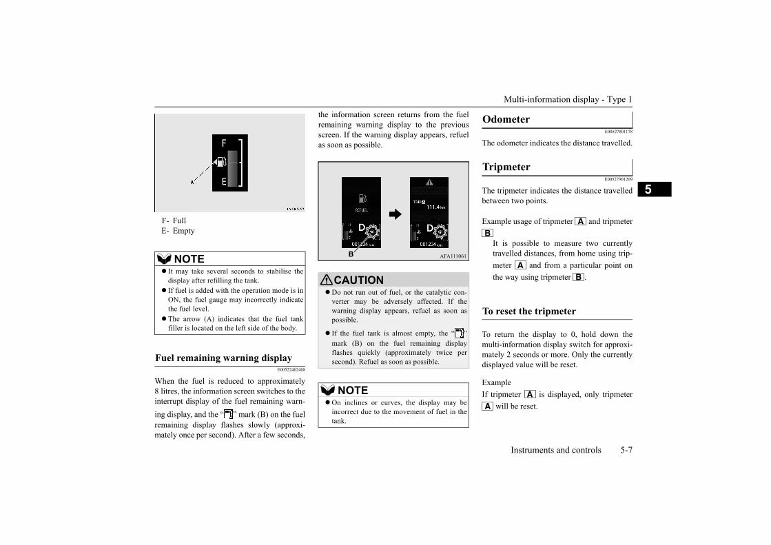
Multi-information display - Type 1
Instruments and controls 5-7
5
E00522402408
When the fuel is reduced to approximately8 litres, the information screen switches to theinterrupt display of the fuel remaining warn-ing display, and the “ ” mark (B) on the fuelremaining display flashes slowly (approxi-mately once per second). After a few seconds,
the information screen returns from the fuelremaining warning display to the previousscreen. If the warning display appears, refuelas soon as possible.
E00527801178
The odometer indicates the distance travelled.
E00527901209
The tripmeter indicates the distance travelledbetween two points.
To return the display to 0, hold down themulti-information display switch for approxi-mately 2 seconds or more. Only the currentlydisplayed value will be reset.
ExampleIf tripmeter is displayed, only tripmeter
will be reset.
F- FullE- Empty
NOTE It may take several seconds to stabilise the
display after refilling the tank. If fuel is added with the operation mode is in
ON, the fuel gauge may incorrectly indicatethe fuel level.
The arrow (A) indicates that the fuel tankfiller is located on the left side of the body.
Fuel remaining warning display
CAUTIONDo not run out of fuel, or the catalytic con-
verter may be adversely affected. If thewarning display appears, refuel as soon aspossible.
If the fuel tank is almost empty, the “ ”mark (B) on the fuel remaining displayflashes quickly (approximately twice persecond). Refuel as soon as possible.
NOTEOn inclines or curves, the display may be
incorrect due to the movement of fuel in thetank.
Odometer
Tripmeter
Example usage of tripmeter and tripmeter
It is possible to measure two currentlytravelled distances, from home using trip-meter and from a particular point onthe way using tripmeter .
To reset the tripmeter

Multi-information display - Type 1
5-8 Instruments and controls
5 E00522502366
Displays the approximate time until the nextperiodic inspection recommended byMITSUBISHI MOTORS. “---” is displayedwhen the inspection time has arrived.
1. Displays the time until the next periodicinspection.
2. This informs you that a periodic inspec-tion is due. Please consult an authorisedMITSUBISHI MOTORS dealer.
At that time, when the operation mode ischanged from OFF to ON, the warningdisplay is displayed for a few seconds onthe information screen.
3. After your vehicle is inspected at anauthorised MITSUBISHI MOTORSdealer, it displays the time until the nextperiodic inspection.
The “---” display can be reset while the oper-ation mode is in OFF. When the display isreset, the time until the next periodic inspec-tion is displayed and the warning display isno longer displayed when the operation modeis changed from OFF to ON.
1. When you lightly press the multi-informa-tion display switch a few times, the infor-mation screen switches to the servicereminder display screen.
NOTEWhen disconnecting the battery terminal, the
memory of tripmeter and arecleared, and the display returns to “0”.
Service reminder
NOTEDepending on the vehicle specifications, the
displayed time may differ from the next peri-odic inspection time recommended byMITSUBISHI MOTORS.In addition, the display settings for the nextperiodic inspection time can be modified.To modify the display settings, have itadjusted at an authorised MITSUBISHIMOTORS dealer.For more details, consult an authorisedMITSUBISHI MOTORS dealer.
NOTE The distance is shown in units of 100 km
(100 miles). The time is shown in units ofmonths.
To reset

Multi-information display - Type 1
Instruments and controls 5-9
5
2. Press and hold the multi-information dis-play switch for approximately 2 secondsor more to display “ ” and make it flash.(If there is no operation for approximately10 seconds with flashing, the displayreturns to the previous screen.)
3. Lightly press the multi-information dis-play switch while the icon is flashing tochange the display from “---” to“CLEAR”. After this, the time until thenext periodic inspection will be displayed.
E00531001230
When the operation mode is put in ON, thesystem check screen is displayed for approxi-mately 4 seconds. If there is no fault, infor-mation screen (when the operation mode isON) is displayed.If there is a fault, the screen changes to warn-ing display.Refer to “Warning display list” on page 5-25.
E00538001170
This displays the approximate driving range(how many more kilometres or miles you candrive). When the driving range falls belowapproximately 50 km (30 miles), “---” is dis-played.Refuel as soon as possible.
CAUTION The customer is responsible for making sure
that periodic inspection and maintenance areperformed.Inspections and maintenance must be per-formed to prevent accidents and malfunc-tions.
NOTE “---” display cannot be reset when the opera-
tion mode is in ON.When “---” is displayed, after a certain dis-
tance and a certain period of time, the dis-play is reset and the time until the nextperiodic inspection is displayed.
If you accidentally reset the display, we rec-ommend you to consult an authorisedMITSUBISHI MOTORS dealer.
System check screen
NOTE The system check screen display varies
depending on the customer’s equipment.
Driving range display
NOTE The driving range is determined based on the
fuel consumption data. This may varydepending on the driving conditions and hab-its. Treat the distance displayed as just arough guideline.
When you refuel, the driving range display isupdated.However, if you only add a small amount offuel, the correct value will not be displayed.Fill with a full tank whenever possible.
On rare occasions, the value displayed forthe driving range may change if you areparked on an extremely steep incline. This isdue to the movement of fuel in the tank anddoes not indicate any malfunction.

Multi-information display - Type 1
5-10 Instruments and controls
5E00531201362
This displays the average fuel consumptionfrom the last reset to the present time.The reset mode conditions for the averagefuel consumption display can be switchedbetween “Auto reset” and “Manual reset”.Refer to “Changing the reset mode for aver-age fuel consumption and average speed” onpage 5-12.For information on how to change the aver-age fuel consumption display setting, refer to“Changing the function settings” on page5-12.
E00533701228
This displays the average speed from the lastreset to the present time.The reset mode conditions for the averagespeed display can be switched between “Autoreset” and “Manual reset”.Refer to “Changing the reset mode for aver-age fuel consumption and average speed” onpage 5-12.
For the method for changing the averagespeed display setting, refer to “Changing thefunction settings” on page 5-12.
E00533601243
While driving, this displays the momentaryfuel consumption, using a bar graph.
The display setting can be changed to thepreferred units (km or miles).Refer to “Changing the function settings” onpage 5-12.
Average fuel consumption dis-play
NOTE The average fuel consumption display can be
reset separately for the auto reset mode andfor the manual reset mode.
NOTE “---” is displayed when the average fuel con-
sumption cannot be measured. The initial (default) setting is “Auto reset
mode”. The average fuel consumption will depend
on the driving conditions (road conditions,how you drive, etc.). The displayed fuel con-sumption may vary from the actual fuel con-sumption. Treat the fuel consumptiondisplayed as just a rough guideline.
The memory of the auto reset mode or man-ual reset mode for the average fuel consump-tion display is erased if the battery isdisconnected.
The display setting can be changed to thepreferred units {km/L, mpg (US), mpg (UK)or L/100 km}.Refer to “Changing the function settings” onpage 5-12.
Average speed display
NOTE
NOTE The average speed display can be reset sepa-
rately for the auto reset mode and for themanual reset mode.
“---” is displayed when the average speedcannot be measured.
The initial (default) setting is “Auto resetmode”.
The display setting can be changed to thepreferred units (km/h or mph).Refer to “Changing the function settings” onpage 5-12.
The memory of the auto reset mode or man-ual reset mode for the average speed displayis erased if the battery is disconnected.
Momentary fuel consumption display

Multi-information display - Type 1
Instruments and controls 5-11
5The “ ” mark (A) in the momentary fuelgauge shows the average fuel consumption.When the value of momentary fuel consump-tion surpasses the value of average fuel con-sumption, the momentary fuel consumption isdisplayed with a green bar graph.Be conscious of maintaining the value ofmomentary fuel consumption below the valueof average fuel consumption, it can help youdrive with the better fuel consumption.
E00529301294
E00531501336
This function displays how fuel-efficientlyyou are driving under different driving condi-tions.The ECO drive assist display will change asfollows if you do fuel-efficient driving usingthe accelerator in a way well matched withthe vehicle speed.
E00531601265
ECO score indicates the points you havescored on fuel-efficient driving by the num-ber of leaves as follows:
[When the operation mode is ON]The display shows the score you achieved inthe last several minutes.
[When the operation mode is put in OFF]The display shows the overall ECO score thefunction has counted from the time when theoperation mode is set to “ON” to the timewhen it is set to “OFF”.
NOTEWhen the momentary fuel consumption can-
not be measured, the bar graph is not dis-played.
The display setting can be changed to thepreferred units {km/L, mpg (US), mpg (UK)or L/100 km}.Refer to “Changing the function settings” onpage 5-12.
It is possible to cancel the green bar graph.Refer to “Changing the function settings” onpage 5-12.
AECO indicator
This indicator will be dis-played when fuel-efficientdriving is achieved.
ECO drive assist display
ECO drive level
Low High
NOTE The ECO drive assist is displayed only when
vehicle is driving with the selector lever inthe “D” (DRIVE) position.
ECO score display
ECO drive level
Low High

Multi-information display - Type 1
5-12 Instruments and controls
5
E00522702485
The “Display language”, “Fuel consumptionunit”, and “Average fuel consumption andspeed reset method” etc. setting can be modi-fied as desired.
1. Stop the vehicle in a safe place.Firmly apply the parking brake and putthe selector lever into the “P” (PARK)position.
2. Lightly press the multi-information dis-play switch a few times to switch theinformation screen to the function settingscreen.Refer to “Information screen (when theoperation mode is ON)” on page 5-5.
3. Press and hold the multi-information dis-play switch for approximately 2 secondsor more to switch from the setting modescreen to the menu screen.
4. Select the item to change on the menuscreen and change to the desired setting.Refer to the following items for furtherdetails on the operation methods.
Refer to “Changing the reset mode foraverage fuel consumption and averagespeed” on page 5-12.Refer to “Changing the fuel consumptiondisplay unit” on page 5-13.Refer to “Changing the display language”on page 5-14.Refer to “Operation sound setting” onpage 5-14.Refer to “Changing the time until “RESTREMINDER” is displayed” on page 5-14.Refer to “Changing the turn-signal sound”on page 5-15.Refer to “Changing the momentary fuelconsumption display” on page 5-15.Refer to “Returning to the factory set-tings” on page 5-15.
E00522902517
The mode conditions for the average fuelconsumption and average speed display canbe switched between “Auto reset” and “Man-ual reset”.
Changing the function settings
CAUTION For safety, stop the vehicle before operating.
While driving, even if you operate the multi-information display switch, the function set-ting screen is not displayed.
NOTE To return the menu screen to the function set-
ting screen, press and hold the multi-infor-mation display switch for approximately2 seconds or more.
If no operations are made within approxi-mately 30 seconds of the menu screen beingdisplayed, the display returns to the functionsetting screen.
NOTE If the battery is disconnected, these function
settings are reset from memory and is auto-matically to the factory settings.
Changing the reset mode for aver-age fuel consumption and average speed

Multi-information display - Type 1
Instruments and controls 5-13
5
1. Press and hold the multi-information dis-play switch for approximately 2 secondsor more to switch from the setting modescreen to the menu screen.Refer to “Changing the function settings”on page 5-12.
2. Lightly press the multi-information dis-play switch to select“AVG (average fuel consumption andaverage speed setting)”.
3. Press and hold the multi-information dis-play switch for approximately 2 secondsor more to switch from A/1 (Auto resetmode) to M/2/P (Manual reset mode), orfrom M/2/P to A/1.The setting is changed to the selectedmode condition.
When the average fuel consumption andaverage speed are being displayed, if youhold down the multi-information displayswitch, the average fuel consumption andaverage speed displayed at that time arereset.
When the operation mode from ACC orOFF to ON, the mode setting is automati-cally switched from manual to auto.
Switching to auto occurs automatically. Ifswitching to manual mode is done, how-ever, the data from the last reset is dis-played.
When the average fuel consumption andaverage speed are being displayed, if youhold down the multi-information displayswitch, the average fuel consumption andaverage speed displayed at that time arereset.
When the operation mode is in ACC orOFF for approximately 4 hours or longer,the average fuel consumption display andaverage speed display are automaticallyreset.
E00523002023
The display unit for fuel consumption can beswitched. The distance, speed, and amountunits are also switched to match the selectedfuel consumption unit.
1. Press and hold the multi-information dis-play switch for approximately 2 secondsor more to switch from the setting modescreen to the menu screen.Refer to “Changing the function settings”on page 5-12.
2. Lightly press the multi-information dis-play switch to select“AVG UNIT (fuel consumption displaysetting)”.
3. Press and hold the multi-information dis-play switch for approximately 2 secondsor more to display “AVG UNIT”.
4. Lightly press the multi-information dis-play switch to select the units.
5. Press and hold the multi-information dis-play switch for approximately 2 secondsor more to change the setting to theselected unit.
Manual reset mode
Auto reset mode
NOTE The average fuel consumption display and
average speed display can be reset separatelyfor the auto reset mode and for the manualreset mode.
The memory of the auto reset mode or man-ual reset mode for the average fuel consump-tion display and average speed display iserased if the battery is disconnected.
Changing the fuel consumption display unit

Multi-information display - Type 1
5-14 Instruments and controls
5The distance and speed units are alsoswitched in the following combinations tomatch the selected fuel consumption unit.
E00523201914
The language of the multi-information dis-play can be switched.
1. Press and hold the multi-information dis-play switch for approximately 2 secondsor more to switch from the setting modescreen to the menu screen.
Refer to “Changing the function settings”on page 5-12.
2. Lightly press the multi-information dis-play switch to select“LANGUAGE” (language setting).
3. Press and hold the multi-information dis-play switch for approximately 2 secondsor more to display “LANGUAGE”.
4. Lightly press the multi-information dis-play switch to select the desired language.
5. If you hold down the multi-informationdisplay switch for approximately 2 sec-onds or more, the setting is changed to theselected language.
E00523401903
You can turn off the operation sounds of themulti-information display switch and rheostatillumination button.
1. Press and hold the multi-information dis-play switch for approximately 2 secondsor more to switch from the setting modescreen to the menu screen.
Refer to “Changing the function settings”on page 5-12.
2. Lightly press the multi-information dis-play switch to select “ ” (operationsound setting).
3. Press and hold the multi-information dis-play switch for approximately 2 secondsor more to switch from ON (operationsound on) to OFF (operation sound off),or from OFF to ON.The setting is changed to the selected con-dition.
E00523501975
The time until the display appears can bechanged.
1. Press and hold the multi-information dis-play switch for approximately 2 secondsor more to switch from the setting modescreen to the menu screen.
NOTE The display units for the driving range, the
average fuel consumption, the average speedand the momentary fuel consumption areswitched, but the units for the indicating nee-dle (speedometer), the odometer and the trip-meter will remain unchanged.
Fuel con-sumption
Distance (driving range)
Speed (average speed)
L/100 km km km/hmpg (US) mile (s) mphmpg (UK) mile (s) mph
km/L km km/h
Changing the display language
NOTE If “---” is selected in the language setting, a
warning message is not displayed when thereis a warning display or interrupt display.
Operation sound setting
NOTE The operation sound setting only deactivates
the operation sound of the multi-informationdisplay switch and rheostat illumination but-ton. The warning display and other soundscannot be deactivated.
Changing the time until “REST REMINDER” is displayed

Multi-information display - Type 1
Instruments and controls 5-15
5
Refer to “Changing the function settings”on page 5-12.
2. Lightly press the multi-information dis-play switch to select “ALARM” (rest timesetting).
3. Press and hold the multi-information dis-play switch for approximately 2 secondsor more to display “ALARM”.
4. Lightly press the multi-information dis-play switch to select the time until the dis-play.
5. Press and hold the multi-information dis-play switch for approximately 2 secondsor more, the setting is changed to theselected time.
E00529101595
It is possible to change the turn-signal sound.
1. Press and hold the multi-information dis-play switch for approximately 2 secondsor more to switch from the setting modescreen to the menu screen.Refer to “Changing the function settings”on page 5-12.
2. Lightly press the multi-information dis-play switch to select (changing theturn-signal sound).
3. Press and hold the multi-information dis-play switch for approximately 2 secondsor more to switch from 1 (turn-signalsound 1) to 2 (turn-signal sound 2), orfrom 2 to 1.The setting changes to the selected turn-signal sound.
E00529201525
It is possible to change the bar graph settingof the momentary fuel consumption display.
1. Press and hold the multi-information dis-play switch for approximately 2 secondsor more to switch from the setting modescreen to the menu screen.Refer to “Changing the function settings”on page 5-12.
2. Lightly press the multi-information dis-play switch to select (changingthe momentary fuel consumption display).
3. Press and hold the multi-information dis-play switch for approximately 2 secondsor more to switch from ON (with thegreen bar graph) to OFF (without thegreen bar graph), or from OFF to ON.
The setting changes to the selected bargraph setting.
E00523602410
Many of the function settings can be returnedto their factory settings.
1. Press and hold the multi-information dis-play switch for approximately 2 secondsor more to switch from the setting modescreen to the menu screen.Refer to “Changing the function settings”on page 5-12.
2. Lightly press the multi-information dis-play switch to select “RESET” (returningto the factory settings).
3. When you press and hold the multi-infor-mation display switch for approximately5 seconds or more, the buzzer sounds andall of the function settings are returned tothe factory settings.
NOTE The drive time is reset when the operation
mode is put in OFF.
Changing the turn-signal sound
Changing the momentary fuel con-sumption display
Returning to the factory settings
NOTE The factory settings are as follows.
• Average fuel consumption and averagespeed reset mode: A (Auto reset)
• Fuel consumption display unit: L/100 km• Display language: THAI• Operation sounds: ON (Operation sounds
on)• “REST REMINDER” display: OFF

Multi-information display - Type 2
5-16 Instruments and controls
5E00519903611
Always stop the vehicle in a safe place beforeoperating.The following information is included on themulti-information display: odometer, tripme-ter, average fuel consumption etc.
• Turn-signal sound: Turn-signal sound 1• Momentary fuel consumption with the
green bar graph: ON
Multi-information display - Type 2
1- Engine coolant temperature display P.5-19
2- Selector lever position indicator dis-play P.6-20
3- Fuel remaining display P.5-194- Information display P.5-17
NOTE 5- Service reminder P.5-20
NOTEWhen the ignition switch is OFF, the infor-
mation display and the service reminder aredisplayed.

Multi-information display - Type 2
Instruments and controls 5-17
5
E00528201573
Each time you lightly press the multi-information display switch (A), the display switches in the following order.
Information display
1- Odometer P.5-182- Tripmeter P.5-183- Tripmeter P.5-184- Meter illumination control P.5-185- Driving range display P.5-18
6- Average fuel consumption display P.5-19
7- Service reminder (distance) P.5-208- Service reminder (month) P.5-20
NOTEWhen the ignition switch is OFF, the information display and the service reminder are displayed.While driving, the service reminder is not displayed even if you operate the multi-information display switch.

Multi-information display - Type 2
5-18 Instruments and controls
5
E00527801181
The odometer indicates the distance travelled.
E00527901212
The tripmeter indicates the distance travelledbetween two points.
To return the display to 0, hold down themulti-information display switch for approxi-mately 2 seconds or more. Only the currentlydisplayed value will be reset.
ExampleIf tripmeter is displayed, only tripmeter
will be reset.
E00537901198
Each time you press and hold the multi-infor-mation display switch (2) for approximately2 seconds or more, there is a sound and thebrightness of the instruments changes. E00538001138
This displays the approximate driving range(how many more kilometres or miles you candrive). When the driving range falls belowapproximately 50 km (30 miles), “---” is dis-played.
Odometer
Tripmeter
Example usage of tripmeter and tripmeter
It is possible to measure two currentlytravelled distances, from home using trip-meter and from a particular point onthe way using tripmeter .
To reset the tripmeter
NOTEWhen disconnecting the battery terminal, the
memory of tripmeter and arecleared, and the display returns to “0”.
Meter illumination control
1- Brightness level2- Multi-information display switch
NOTEYou can adjust to 8 different levels respec-
tively for when the position lamps are illumi-nated and when they are not.Each time you reduce two brightness levels,the segment display of the brightness leveldecreases one by one.
The brightness level of the instruments isstored when the ignition switch is turned off.
Driving range display
NOTE The driving range is determined based on the
fuel consumption data. This may varydepending on the driving conditions and hab-its. Treat the distance displayed as just arough guideline.
When you refuel, the driving range display isupdated.However, if you only add a small amount offuel, the correct value will not be displayed.Fill with a full tank whenever possible.

Multi-information display - Type 2
Instruments and controls 5-19
5
E00531201245
This displays the average fuel consumptionfrom the last reset to the present time.The reset mode conditions for the averagefuel consumption display can be switchedbetween “Auto reset” and “Manual reset”.Refer to “Changing the reset mode for aver-age fuel consumption” on page 5-21.For information on how to change the aver-age fuel consumption display setting, refer to“Changing the function settings” on page5-21.
E00533801216
This indicates the engine coolant tempera-ture.If the coolant becomes hot, “ ” will blink.Pay careful attention to the engine coolanttemperature display while you are driving.
E00522201975
The fuel remaining display indicates the fuellevel in the fuel tank when the ignition switchis ON.
On rare occasions, the value displayed forthe driving range may change if you areparked on an extremely steep incline. This isdue to the movement of fuel in the tank anddoes not indicate any malfunction.
The display setting can be changed to thepreferred units (km or miles).Refer to “Changing the function settings” onpage 5-21.
Average fuel consumption dis-play
NOTE The average fuel consumption display can be
reset separately for the auto reset mode andfor the manual reset mode.
NOTE “---” is displayed when the average fuel con-
sumption cannot be measured. The initial (default) setting is “Auto reset
mode”. The average fuel consumption will depend
on the driving conditions (road conditions,how you drive, etc.). The displayed fuel con-sumption may vary from the actual fuel con-sumption. Treat the fuel consumptiondisplayed as just a rough guideline.
The memory of the manual reset mode orauto reset mode for the average fuel con-sumption display is erased if the battery isdisconnected.
The display setting can be changed to thepreferred units {km/L, L/100 km, mpg}.Refer to “Changing the function settings” onpage 5-21.
Engine coolant temperature display
NOTE
CAUTION If the engine is overheating, “ ” will blink.
In this case, the bar graph is on the red zone.Immediately park the vehicle in a safe placeand take the required measures. Refer to“Engine overheating” on page 8-3.
Fuel remaining display
1- Full

Multi-information display - Type 2
5-20 Instruments and controls
5
E00522402411
If the remaining fuel level is approximately8 litres or less (one segment displayed) whenthe ignition switch is turned to the “ON”position, the last segment of the fuel gaugeflashes. If the warning display appears, refuelas soon as possible.
E00522502379
Displays the approximate time until the nextperiodic inspection that MITSUBISHIMOTORS recommends. “---” is displayedwhen the inspection time has arrived.The spanner mark indicates the periodicinspection. 1. Displays the time until the next periodic
inspection.
0- Empty
NOTE It may take several seconds to stabilise the
display after refilling the tank. If fuel is added with the ignition switch is
ON, the fuel gauge may incorrectly indicatethe fuel level.
The arrow (A) indicates that the fuel tankfiller door is located on the left side of thevehicle.
Fuel remaining warning display
CAUTIONDo not run out of fuel, or the catalytic con-
verter may be adversely affected. If thewarning display appears, refuel as soon aspossible.
If the fuel tank is almost empty, the last seg-
ment of the fuel gauge goes out and “ ”mark flashes. Refuel as soon as possible.
NOTEOn inclines or curves, the display may be
incorrect due to the movement of fuel in thetank.
Service reminder
NOTEDepending on the vehicle specifications, the
displayed time until the next periodic inspec-tion may differ from that of MITSUBISHIMOTORS recommends.In addition, the display settings for the nextperiodic inspection time can be modified.To modify the display settings, have itadjusted at an authorised MITSUBISHIMOTORS dealer.For more details, contact an authorisedMITSUBISHI MOTORS dealer.
NOTE The distance is shown in units of 100 km
(100 miles). The time is shown in units ofmonths.
Distance
Month

Multi-information display - Type 2
Instruments and controls 5-21
5
2. This informs you that a periodic inspec-tion is due. Please consult an authorisedMITSUBISHI MOTORS dealer.
3. After your vehicle is inspected at anauthorised MITSUBISHI MOTORSdealer, it displays the time until the nextperiodic inspection.
The “---” display can be reset while the igni-tion switch is in OFF.
1. When you lightly press the multi-informa-tion display switch a few times, the infor-mation display switches to the servicereminder display.Refer to “Information display” on page5-17.
2. Press and hold the multi-information dis-play switch for approximately 2 secondsor more to make the spanner mark startflashing. (If there is no operation forapproximately 10 seconds with flashing,the display will revert to its original indi-cation.)
3. Lightly press the multi-information dis-play switch while the icon is flashing tochange the display from “---” to “cLEAr”.After this, the time until the next periodicinspection will be displayed.
E00522702469
The “Average fuel consumption reset mode”and “Fuel consumption unit” setting can bemodified as desired, when the ignition switchis ON.
E00522902399
The mode conditions for the average fuelconsumption display can be switchedbetween “Auto reset” and “Manual reset”.
1. When you lightly press the multi-informa-tion display switch a few times, the infor-mation display switches to the drivingrange display.Refer to “Information display” on page5-17.
2. Each time you press the multi-informationdisplay switch for 2 seconds or more ondriving range display, you can switchreset mode for average fuel consumption.
To reset
CAUTION The customer is responsible for making sure
that periodic inspection and maintenance areperformed.Inspections and maintenance must be per-formed to prevent accidents and malfunc-tions.
NOTE “---” display cannot be reset when the igni-
tion switch is in ON.When “---” is displayed, after a certain dis-
tance and a certain period of time, the dis-play is reset and the time until the nextperiodic inspection is displayed.
If you accidentally reset the display, consultan authorised MITSUBISHI MOTORSdealer.
Changing the function settings
CAUTION The driver should not operate the display
while the vehicle is in motion.When operating the system, stop the vehicle
in a safe area.
Changing the reset mode for aver-age fuel consumption

Multi-information display - Type 2
5-22 Instruments and controls
5
(A: Auto reset mode, B: Manual resetmode)
• When the average fuel consumption isbeing displayed, if you hold down themulti-information display switch, theaverage fuel consumption displayed atthat time is reset.
• When the ignition switch is turned fromthe “ACC” or “LOCK” position to the“ON” position, the mode setting is auto-matically switched from manual to auto.
Switching to auto occurs automatically.If switching to manual mode is done,however, the data from the last reset isdisplayed.
• When the average fuel consumption isbeing displayed, if you hold down themulti-information display switch, theaverage fuel consumption displayed atthat time are reset.
• When the ignition switch is in the“ACC” or “LOCK” position for approxi-mately 4 hours or longer, the averagefuel consumption display is automati-cally reset.
E00523001954
The display unit for fuel consumption can beswitched. The distance and amount units arealso switched to match the selected fuel con-sumption unit.
1. When you lightly press the multi-informa-tion display switch a few times, the infor-mation display switches to the averagefuel consumption display.Refer to “Information display” on page5-17.
2. Press and hold the multi-information dis-play switch for approximately 5 secondsor more until buzzer sound is heard twice.
3. Press and hold the multi-information dis-play switch to switch in sequence from“km/L” “L/100 km” “mpg” “km/L”.
Manual reset mode
Auto reset mode Manual reset mode
Auto reset mode
NOTE The average fuel consumption display can be
reset separately for the auto reset mode andfor the manual reset mode.
The memory of the manual reset mode orauto reset mode for the average fuel con-sumption display is erased if the battery isdisconnected.
The initial (default) setting is “Auto resetmode”.
Changing the fuel consumption display unit
NOTE The display units for the driving range, the
average fuel consumption are switched, butthe units for the indicating needle (speedom-eter), the odometer, the tripmeter and the ser-vice reminder will remain unchanged.

Indicator lamp, warning lamp, and information screen display list (multi-information display - Type 1)
Instruments and controls 5-23
5
The distance units is also switched in the fol-lowing combinations to match the selectedfuel consumption unit.
E00523701397
E00523803044
The memory of the unit setting is erased ifthe battery is disconnected, and it returnsautomatically to factory setting.
NOTE Fuel consumption Distance(driving range)
km/L kmL/100 km km
mpg mile (s)
Indicator lamp, warning lamp, and information screen display list (multi-information display - Type 1)
Indicator and warning lamp list
1- Position lamp indicator lamp P.5-34 2- Turn-signal indicator lamps/Hazard warning indicator lamps P.5-33
3- Front fog lamp indicator lamp P.5-34

Indicator lamp, warning lamp, and information screen display list (multi-information display - Type 1)
5-24 Instruments and controls
5
E00523901575
When there is information to be announced, such as lamp reminder, the buzzer sounds and the screen switches to the displays shown below. Referto the appropriate page and take the necessary measures.When the cause of the warning display is eliminated, the warning display goes out automatically.Refer to “Warning display list” on page 5-25.Refer to “Other interrupt display list” on page 5-31.
4- High-beam indicator lamp P.5-345- Electric power steering system (EPS)
warning lamp P.6-316- Security indicator lamp P.3-197- Check engine warning lamp P.5-358- Charge warning lamp P.5-359- Information screen display P.5-24
10- Seat belt warning lamp P.4-1211- Supplemental restraint system (SRS)
warning lamp P.4-2712- Active Stability Control (ASC) OFF
indicator lamp P.6-3313- Anti-lock brake system (ABS) warning
lamp P.6-2914- Active Stability Control (ASC) indica-
tor lamp P.6-3315- Door-ajar warning lamp P.5-3616- Brake warning lamp P.5-34
Information screen display

Indicator lamp, warning lamp, and information screen display list (multi-information display - Type 1)
Instruments and controls 5-25
5E00524002844
NOTEA warning may be displayed on the information screen and the buzzer may sound in the following rare cases.
This is caused by the system picking up interference such as noise or strong electromagnetic waves, and is not a functional problem.• An extremely strong electromagnetic wave is received from a source such as an illegal radio set, a spark from a wire, or a radar station.• Abnormal voltage or a static electricity discharge is generated by the operation of installed electrical equipment (including after-market parts).If the warning display appears many times, consult an authorised MITSUBISHI MOTORS dealer.
Warning display list
Screen Cause Solution (Reference)There is a fault in the electronic immobi-
lizer (Anti-theft starting system).Put the operation mode in OFF, and then
start the engine again.If the warning is not cancelled, please con-tact an authorised MITSUBISHI MOTORS dealer.
There is a fault in the electrical system. Immediately stop the vehicle in a safeplace and consult an authorised MITSUBISHI MOTORS dealer.

Indicator lamp, warning lamp, and information screen display list (multi-information display - Type 1)
5-26 Instruments and controls
5
There is a fault in the keyless operationsystem.
Refer to “Keyless operation system” on page 3-7.
Engine switch is pressed 1 time
Engine switch is pressed 2 times or more
Although the engine switch was pressed,the keyless operation key could not bedetected.
Touch the keyless operation key to theengine switch.Refer to “If the keyless operation key is not operating properly” on page 6-18.
Screen Cause Solution (Reference)

Indicator lamp, warning lamp, and information screen display list (multi-information display - Type 1)
Instruments and controls 5-27
5
You put the operation mode in ON withoutfastening your seat belt.
Fasten your seat belt properly.Refer to “Seat belt reminder” on page 4-12.
There is a fault in the SRS airbag or thepre-tensioner system.
Contact an authorised MITSUBISHIMOTORS dealer to have the systemchecked, immediately.Refer to “SRS warning lamp/display” onpage 4-27.
The fuel is running low. Refuel as soon as possible.Refer to “Fuel remaining warning display”on page 5-7.
There is a fault in the fuel system. Have your vehicle inspected at an author-ised MITSUBISHI MOTORS dealer.
You are driving with the parking brake stillapplied.
Release the parking brake.Refer to “Brake warning display” on page5-36.
The brake fluid level in the reservoir hasfallen to a low level.
There is a fault in the brake system.
Immediately stop the vehicle in a safeplace and consult an authorisedMITSUBISHI MOTORS dealer.Refer to “Brake warning display” on page5-36.
Screen Cause Solution (Reference)

Indicator lamp, warning lamp, and information screen display list (multi-information display - Type 1)
5-28 Instruments and controls
5
There is a fault in the charging system. Immediately stop the vehicle in a safeplace and consult the nearest authorised MITSUBISHI MOTORS dealer.Refer to “Charge warning display” on page 5-37.
There is a fault in the engine oil circulationsystem.
Immediately stop the vehicle in a safeplace and consult the nearest authorised MITSUBISHI MOTORS dealer.Refer to “Oil pressure warning display” on page 5-37.
You have forgotten to turn off the lamps. Refer to “Lamps (headlamps, fog lamp, etc.)auto-cutout function” on page 5-38.
The driver’s door is open when the opera-tion mode is in any mode other than OFF.
Put the operation mode in OFF.Refer to “Operation mode ON remindersystem” on page 6-13.
An attempt was made to lock all the doorsand the tailgate when the operation mode is in any mode other than OFF.
Put the operation mode in OFF.Refer to “Operation mode OFF remindersystem” on page 6-13.
There is a fault in the steering wheel lock. Immediately stop the vehicle in a safeplace and consult an authorisedMITSUBISHI MOTORS dealer.
Screen Cause Solution (Reference)

Indicator lamp, warning lamp, and information screen display list (multi-information display - Type 1)
Instruments and controls 5-29
5
The steering wheel is locked. Press the engine switch while turning steer-ing wheel.Refer to “Steering wheel lock” on page 6-13.
The engine is stopped while the selectorlever is in a position other than the “P”(PARK) position.
Place the selector lever in the “P” (PARK)position to put the operation mode in OFF.
The driver’s door is opened with the steer-ing wheel unlocked.
Refer to “Steering wheel lock” on page 6-13.
There is a fault in the EPS. Have the vehicle inspected by an author-ised MITSUBISHI MOTORS dealer assoon as possible.Refer to “Electric power steering system(EPS)” on page 6-31.
The A/T fluid temperature is too high. Refer to “4-speed automatic transmission: When a malfunction occurs in the A/T” on page 6-23.
There is a fault in the A/T. Have your vehicle inspected at an author-ised MITSUBISHI MOTORS dealer.Refer to “4-speed automatic transmission:When a malfunction occurs in the A/T” onpage 6-23.
Screen Cause Solution (Reference)

Indicator lamp, warning lamp, and information screen display list (multi-information display - Type 1)
5-30 Instruments and controls
5
There is a fault in the hill start assist. Have your vehicle inspected at an author-ised MITSUBISHI MOTORS dealer.Refer to “Warning lamp/display” on page 6-27.
There is a fault in the active stability con-trol (ASC).
Have your vehicle inspected at an author-ised MITSUBISHI MOTORS dealer.Refer to “ASC warning lamp/display” on page 6-34.
There is a fault in the ABS. Avoid sudden braking and high-speed driv-ing, stop the vehicle in a safe place, and take corrective measures.Refer to “ABS warning lamp/display” on page 6-30.
The engine is overheated. Stop the vehicle in a safe place and takecorrective measures.Refer to “Engine overheating” on page 8-3.
Screen Cause Solution (Reference)
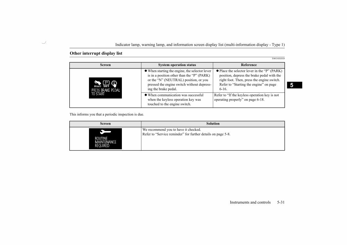
Indicator lamp, warning lamp, and information screen display list (multi-information display - Type 1)
Instruments and controls 5-31
5
E00524202820
This informs you that a periodic inspection is due.
Other interrupt display list
Screen System operation status ReferenceWhen starting the engine, the selector lever
is in a position other than the “P” (PARK) or the “N” (NEUTRAL) position, or you pressed the engine switch without depress-ing the brake pedal.
Place the selector lever in the “P” (PARK)position, depress the brake pedal with the right foot. Then, press the engine switch.Refer to “Starting the engine” on page 6-16.
When communication was successfulwhen the keyless operation key was touched to the engine switch.
Refer to “If the keyless operation key is not operating properly” on page 6-18.
Screen SolutionWe recommend you to have it checked.Refer to “Service reminder” for further details on page 5-8.

Indicator lamp, warning lamp, and information screen display list (multi-information display - Type 1)
5-32 Instruments and controls
5
The setting for rest interval can be changed.
Screen SolutionStop the vehicle in a safe place, turn off the engine, and take a rest.Use this display as rough guide for taking rests during a long drive.The interval from the start of your trip until this message is displayed can be set.Refer to “Changing the time until “REST REMINDER” is displayed” on page 5-14.The display and buzzer alert the driver when the set time is reached. If you continue to drive without having a rest, the buzzer sounds approximately every 5 minutes to encourage you to take a rest. In the following cases, the time driven is reset and the display returns to the previous dis-
play screen. After this, when the set time is reached again, the buzzer and display encourage you to take a rest.• The buzzer sounds 3 times.• Put the operation mode in OFF.• The multi-information display switch is held for approximately 2 seconds or more.

Indicator and warning lamps (multi-information display - Type 2)
Instruments and controls 5-33
5
E00501504572
E00501601266
E00501701762
Indicator and warning lamps (multi-information display - Type 2)
1- Turn-signal indicator lamps/Hazardwarning indicator lamps P.5-33
2- High-beam indicator lamp P.5-343- Overdrive OFF indicator lamp
P.6-224- Position lamp indicator lamp P.5-345- Electric power steering system (EPS)
warning lamp P.6-316- Brake warning lamp P.5-347- ECO indicator lamp P.5-348- Charge warning lamp P.5-359- Check engine warning lamp P.5-35
10- Oil pressure warning lamp P.5-3611- Multi-information display P.5-16
12- Security indicator lamp P.3-19For details, refer to “Steering wheellock” on page 6-13.
13- Door-ajar warning lamp P.5-3614- Seat belt warning lamp P.4-2715- Anti-lock brake system (ABS) warning
lamp P.6-2916- Active Stability Control (ASC) indica-
tor lamp P.6-3317- Active Stability Control (ASC) OFF
indicator lamp P.6-3318- Supplemental restraint system (SRS)
warning lamp P.4-27
Indicator lamps
Turn-signal indicator lamps/Hazard warning indica-tor lamps
These indicator lamps blink onand off when a turn-signallamp is operating.

Warning lamps
5-34 Instruments and controls
5When the hazard warning lamp switch is
pressed, all turn-signal lamps will flash onand off continuously.
When the hazard warning lamps automat-ically activate due to sudden brakingwhile driving. Refer to “Emergency stopsignal system” on page 6-28.
E00501801372
E00501901748
E00508901385
E00529801198
E00502401492
E00502504061
This lamp illuminates whenthe ignition switch is turned tothe “ON” position or the oper-ation mode is put in ON, andgoes off after a few seconds.
Always make sure that the lamp goes offbefore driving.With the ignition switch or the operationmode in ON, the brake warning lamp illumi-nates under the following conditions:
When the parking brake has been applied.When the brake fluid level in the reservoir
falls to a low level.When the brake force distribution func-
tion is not operating correctly.
With the ignition switch or the operationmode in ON, a buzzer sounds under the con-dition that the vehicle speed exceeds a certainspeed with the parking brake applied.
NOTE If the blinking is too fast, the cause may be a
blown lamp bulb or a faulty turn-signal con-nection.
High-beam indicator lamp
This indicator lamp illumi-nates when the high-beam isused.
Front fog lamp indicator lamp*
This lamp illuminates whilethe front fog lamps are on.
Position lamp indicator lamp
This indicator lamp illumi-nates while the position lampsare on.
ECO indicator lamp (vehicle equipped with the multi-infor-mation display - Type 2)
This indicator lamp illumi-nates when fuel-efficientdriving is achieved.
Warning lamps
Brake warning lamp
CAUTION In the situations listed below, brake perfor-
mance may be compromised or the vehiclemay become unstable if brakes are appliedsuddenly; consequently, avoid driving athigh speeds or applying the brakes suddenly.Furthermore, immediately the vehicle shouldbe brought to a stop in a safe location andyour nearest authorised MITSUBISHIMOTORS dealer should be contacted.• The brake warning lamp does not illumi-
nate when the parking brake is applied ordoes not turn off when the parking brake isreleased.

Warning lamps
Instruments and controls 5-35
5
E00502603355
This lamp is a part of anonboard diagnostic systemwhich monitors the emissions,engine control system or A/Tcontrol system.
If a problem is detected in one of these sys-tems, this lamp illuminates or flashes.Although your vehicle will usually be driva-ble and not need towing, we recommend you
to have the system checked as soon as possi-ble.This lamp will also illuminate when the igni-tion switch is turned “ON” or the operationmode is put in ON, and goes off after theengine has started. If it does not go off afterthe engine has started, we recommend you tohave the vehicle checked.
This data will be erased if a battery cable isdisconnected which will make a rapid diagno-sis difficult. Do not disconnect a battery cablewhen the check engine warning lamp is ON.
E00502702450
This lamp illuminates whenthe ignition switch is turned tothe “ON” position or the oper-ation mode is put in ON, andgoes off after the engine has
started.On vehicle equipped with the multi-informa-tion display - type 1, a warning is also dis-played on the multi-information display.
• The brake warning lamp and the ABSwarning lamp illuminate at the same time.For details, refer to “ABS warninglamp/display” on page 6-30.
• The brake warning lamp remains illumi-nated while driving.
The vehicle should be brought to a halt in thefollowing manner when brake performancehas deteriorated.• Depress the brake pedal harder than usual.
Even if the brake pedal moves down to thevery end of its possible stroke, keep itpressed down hard.
• Should the brakes fail, use engine brakingto reduce your speed and carefully pull theparking brake lever.
Depress the brake pedal to operate the stoplamp to alert the vehicles behind you.
Check engine warning lamp
CAUTION
CAUTION Prolonged driving with this lamp on may
cause further damage to the emission controlsystem. It could also affect fuel economy anddrivability.
If the lamp does not illuminate when theignition switch is turned to the “ON” posi-tion or the operation mode is put in ON, werecommend you to have the system checked.
If the lamp illuminates while the engine isrunning, avoid driving at high speeds andhave the system inspected by an authorisedMITSUBISHI MOTORS dealer as soon aspossible.Accelerator pedal and brake pedal responsemay be negatively influenced under theseconditions.
NOTE The engine electronic control module
accommodating the onboard diagnostic sys-tem has various fault data (especially aboutthe exhaust emission) stored.
Charge warning lamp
CAUTION If it illuminates while the engine is running,
there is a problem in the charging system.Immediately park your vehicle in a safeplace and we recommend you to have itchecked.

Information screen display (vehicle equipped with the multi-information display - Type 1)
5-36 Instruments and controls
5E00502801887
This lamp illuminates whenthe ignition switch is turned tothe “ON” position, and goesoff after the engine hasstarted. If it illuminates while
the engine is running, the oil pressure is toolow.Turn the engine off and have it inspected.
E00503302088
This lamp illuminates when adoor or the tailgate is eitheropen or not completely closed.If the vehicle speed reachesapproximately 8 km/h with a
door or the tailgate open or incompletelyclosed, a buzzer sounds 4 times as a warning.
E00524601276
E00524701613
This warning is displayed if you drive withthe parking brake still applied. The warninglamp in the instrument cluster also illumi-nates when the parking brake is applied.If this warning is displayed, lower the parkingbrake lever fully.
Oil pressure warning lamp (vehicle equipped with the multi-information display - Type 2)
CAUTION If the vehicle is driven while the engine oil is
low, or the oil level is normal but the warn-ing lamp is illuminated, the engine may burnout and be damaged.
If the warning lamp is illuminated while theengine is running, immediately park yourvehicle in a safe place and check the engineoil level.Refer to “Maintenance: Engine oil” on page10-4.
If the warning lamp is illuminated while theengine oil level is normal, have it inspected.
NOTE This warning lamp does not indicate the
amount of oil level in the engine. This mustbe determined by checking the oil level onthe dipstick, while the engine is switched off.
Door-ajar warning lamp
CAUTIONBefore moving your vehicle, check that the
warning lamp is OFF.
Information screen display (vehicle equipped with the multi-information display - Type 1)
Brake warning display
CAUTION If a vehicle is driven without releasing the
parking brake, the brake will be overheated,resulting in ineffective braking and possiblebrake failure.

Information screen display (vehicle equipped with the multi-information display - Type 1)
Instruments and controls 5-37
5When the operation mode is put in ON, if thebrake fluid is low, this warning is displayed.The warning lamp in the instrument clusteralso illuminates.
E00524801382
If there is a fault with the charging system,the warning display is displayed on the infor-mation screen in the multi-information dis-play. The warning lamp in the instrumentcluster also illuminates.
E00524901484
If the engine oil pressure drops while theengine is running, the warning display is dis-played on the information screen in the multi-information display.CAUTION
If this warning stays illuminated and doesnot go out while driving, there is a danger ofineffective braking. If this happens, immedi-ately park your vehicle in a safe place andwe recommend you to have it checked.
If the brake warning display is displayed andthe brake warning lamp and the ABS warn-ing lamp are illuminated at the same time,the braking force distribution function willnot operate, so the vehicle may be destabi-lised during sudden braking. Avoid suddenbraking and high-speed driving, stop thevehicle in a safe place, and we recommendyou to have it checked.
The vehicle should be brought to a halt in thefollowing manner when brake performancehas deteriorated.• Depress the brake pedal harder than usual.
Even if the brake pedal moves down to thevery end of its possible stroke, keep itpressed down hard.
• Should the brakes fail, use engine brakingto reduce your speed and carefully pull theparking brake lever.
Depress the brake pedal to operate the stoplamp to alert the vehicles behind you.
Charge warning display
CAUTION If the warning is displayed while the engine
is running, immediately park your vehicle ina safe place and we recommend you to haveit checked.
CAUTION Oil pressure warning display
CAUTION If the vehicle is driven while the engine oil is
low, or the oil level is normal but the warn-ing is displayed, the engine may burn out andbe damaged.
If the warning is displayed while the engineis running, immediately park your vehicle ina safe place and check the engine oil level.Refer to “Maintenance: Engine oil” on page10-4.
If the warning is displayed while the engineoil level is normal, have it inspected.
NOTE This warning display does not indicate the
amount of oil level in the engine. This mustbe determined by checking the oil level onthe dipstick, while the engine is switched off.

Combination headlamps and dipper switch
5-38 Instruments and controls
5
E00506005250
Rotate the switch to turn on the lamps.
E00532701931
If the following operation is performedwhile the lamp switch is in the “ ” posi-tion, the lamps are automatically turnedoff when the driver’s door is opened.[Except for vehicles equipped with thekeyless operation system]The ignition switch is turned to the“LOCK” or “ACC” position, or the key isremoved from the ignition switch.[For vehicles equipped with the keylessoperation system]The operation mode is put in OFF orACC.
If the following operation is performedwhile the lamp switch is in the “ ” posi-tion, the lamps are automatically turnedoff if the driver’s door then remainsclosed for approximately 3 minutes.[Except for vehicles equipped with thekeyless operation system]
The ignition switch is turned to the“LOCK” or “ACC” position, or the key isremoved from the ignition switch.[For vehicles equipped with the keylessoperation system]The operation mode is put in OFF orACC.
1. In the following cases, turn the lampswitch to the “OFF” position.[Except for vehicles equipped with thekeyless operation system]The ignition switch is in the “LOCK” or“ACC” position.[For vehicles equipped with the keylessoperation system]The operation mode is in OFF or ACC.
2. Turn on the lamps with the switch in the“ ” or “ ” position again, then thelamps will remain on.
Combination headlamps and dipper switch
Headlamps
NOTEDo not leave the lamps on for a long time
while the engine is stationary (not running).A run-down battery could result.
When it rains, or when the vehicle has beenwashed, the inside of the lens sometimesbecomes foggy, but this does not indicate afunctional problem.When the lamp is switched on, the heat willremove the fog. However, if water gathersinside the lamp, we recommend you to havechecked.
OFF All lamps offPosition, tail, licence plate and instru-ment panel lamps on
Headlamps and other lamps go on
Lamps (headlamps, fog lamp, etc.) auto-cutout function NOTE
The lamp auto-cutout will not function whenthe lamp switch is in the “ ” position.
The lamp auto-cutout function can also bedisabled.For further information, please contact anauthorised MITSUBISHI MOTORS dealer.
When you want to keep the lamps on:

Combination headlamps and dipper switch
Instruments and controls 5-39
5
E00506101862
If the following operation is performed, abuzzer will sound to remind the driver to turnoff the lamps.[Except for vehicles equipped with the key-less operation system]If the driver’s door is opened when the key isin the “LOCK” or “ACC” position orremoved from the ignition switch while thelamps are on.[For vehicles equipped with the keyless oper-ation system]If the driver’s door is opened when the opera-tion mode is in ACC or OFF while the lampsare on.
In both cases, the buzzer will automaticallystop if the auto-cutoff function is activated,the lamp switch is turned off, or the door isclosed.
E00506201948
When the lamp switch is in the “ ” posi-tion, the beam changes from high to low (orlow to high) each time the lever is pulledfully (1). While the high-beam is on, thehigh-beam indicator lamp in the instrumentcluster will also illuminate.
E00506301486
The high-beams flash when the lever ispulled slightly (2), and will go off when it isreleased.When the high-beam is on, the high-beamindicator lamp in the instrument cluster willilluminate.
E00528902506
This function turns on the position and taillamps for approximately 30 seconds after theUNLOCK switch on the key is pressed whenthe combination headlamps and dipper switchis in the “OFF” position.
E00529002197
This function turns on the headlamps in thelow beam setting for approximately 30 sec-onds after the ignition switch is turned to the
Lamp monitor buzzer
Dipper (high/low beam change)
Headlamp flasher
NOTE The high-beams can also flash when the
lamp switch is OFF. If you turn the lamps off with the headlamps
set to high-beam, the headlamps are auto-matically returned to their low-beam settingwhen the lamp switch is next turned to the“ ” position.
Welcome light
NOTEWhile the welcome light function is operat-
ing, perform one of the following operationsto cancel the function.• Press the LOCK switch on the key.• Turn the combination headlamps and dip-
per switch to the “ ” or “ ” position.• Turn the ignition switch to the “ON” posi-
tion or put the operation mode in ON. It is possible to modify functions as follows:
• The headlamps can be set to come on in thelow beam setting.
• The welcome light function can be deacti-vated.
For further information, please contact anauthorised MITSUBISHI MOTORS dealer.
Coming home light

Turn-signal lever
5-40 Instruments and controls
5
“OFF” position or the operation mode is putin OFF.
1. Turn the combination headlamps and dip-per switch to the “OFF” position.
2. Turn the ignition switch to the “LOCK”position or put the operation mode inOFF. Also, if a key was used to start theengine, remove the key from the ignitionswitch.
3. Within 60 seconds of turning the ignitionswitch to the “LOCK” position or puttingthe operation mode in OFF, pull the turn-signal lever towards you.
4. The headlamps will come on in the lowbeam setting for approximately 30 sec-onds. After the headlamps go off, theheadlamps can be turned on again in thelow beam setting for approximately30 seconds by pulling the turn-signallever towards you within 60 seconds ofturning the ignition switch to the “OFF”position or putting the operation mode inOFF.To turn on the headlamps again after60 seconds of turning the ignition switchto the “LOCK” position or putting theoperation mode in OFF, repeat the processfrom step 1.
E00506503264
The turn-signal lamps flash when the lever isoperated (with the ignition switch or the oper-ation mode is in ON). At the same time, theturn-signal indicator flashes.
NOTEWhile the coming home light function is
operating, perform one of the followingoperations to cancel the function.• Pull the turn-signal lever towards you.• Turn the combination headlamps and dip-
per switch to the “ ” or “ ” position.• Turn the ignition switch to the “ON” posi-
tion or put the operation mode in ON. It is possible to modify functions as follows:
• The time that the headlamps remain on canbe changed.
• The coming home light function can bedeactivated.
For further information, please contact anauthorised MITSUBISHI MOTORS dealer.
Turn-signal lever
1- Turn-signalsWhen making a normal turn, use posi-tion (1). The lever will return automati-cally when cornering is completed.
2- Lane-change signalsWhen moving the lever to (2) slightlyto change a lane, the turn-signal lampsand indicator lamp in the instrumentcluster will only flash while the lever isoperated.Also, when you move the lever to (2)slightly then release it, the turn-signallamps and indicator lamp in the instru-ment cluster will flash 3 times.

Hazard warning flasher switch
Instruments and controls 5-41
5
E00506602398
Use the hazard warning flasher switch whenthe vehicle has to be parked on the road forany emergency.The hazard warning flashers can always beoperated, regardless of the ignition switchposition or the operation mode.
Press the switch to turn on the hazard warn-ing flashers, all turn-signal lamps flash con-tinuously.To turn them off, press the switch again.
E00506802172
The front fog lamps can be operated while theheadlamps or tail lamps are on. Turn the knobin the “ON” direction to turn on the front foglamps. An indicator lamp in the instrumentcluster will also come on. Turn the knob inthe “OFF” direction to turn off the front foglamps. The knob will automatically return toits original position when you release it.
NOTE If the lamp flashes unusually quickly, the
bulb in a turn-signal lamp may have burnedout. Have the vehicle inspected by an author-ised MITSUBISHI MOTORS dealer.
It is possible to activate the following func-tions:• Flashing of the turn-signal lamps when the
lever is operated with the ignition switch orthe operation mode is in ACC.
• The turn-signal lamps 3-flash function forlane changes can be deactivated.
• The time required to operate the lever forthe 3-flash function can be adjusted.
For further information, please contact anauthorised MITSUBISHI MOTORS dealer.
It is possible to change the tone of a sound-ing buzzer as the turn-signal lamps flash.[Vehicle equipped with the multi-informa-tion display - type 1]Refer to “Changing the turn-signal sound”on page 5-15.[Vehicle equipped with the multi-informa-tion display - type 2]For further information, please contact anauthorised MITSUBISHI MOTORS dealer.
Hazard warning flasher switch
NOTEWhile the hazard warning lamps are blinking
due to having manually pressed the switch,the emergency stop signal system does notoperate. Refer to “Emergency stop signalsystem” on page 6-28.
Front fog lamp switch*

Wiper and washer switch
5-42 Instruments and controls
5
E00507102882
The windscreen wipers and washer can beoperated with the ignition switch or the oper-ation mode in ON or ACC.If the blades are frozen to the windscreen orrear window, do not operate the wipers untilthe ice has melted and the blades are freed,otherwise the wiper motor may be damaged.
E00516902323With the lever in the “INT” (speed sensitive)position, the intermittent intervals can beadjusted by turning the knob (A).
Move the lever in the direction of the arrowand release, to operate the wipers once.Use this function when you are driving inmist or drizzle.
NOTE The front fog lamps are automatically turned
off when the headlamps or tail lamps areturned off. To turn the front fog lamps onagain, turn the knob in the “ON” directionafter turning on the headlamps or tail lamps.
Do not use fog lamps except in conditions offog, otherwise excessive lamp glare maytemporarily blind oncoming vehicle drivers.
Wiper and washer switch
CAUTION If the washer is used in cold weather, the
washer fluid sprayed against the glass mayfreeze, which may hinder visibility. Warmthe glass with the defroster before using thewasher.
Windscreen wipers
NOTE To ensure a clear rearward view, the rear
window wiper will automatically performseveral continuous operations if the selectorlever is put in the “R” (REVERSE) positionwhile the windscreen wipers are operating. Refer to “Rear window wiper and washer”on page 5-43.
MIST- Misting functionThe wipers will operate once.
OFF- OffINT- Intermittent (Speed sensitive)LO- SlowHI- Fast
To adjust intermittent intervals
1- Fast2- Slow
NOTE The speed-sensitive-operation function of
the windscreen wipers can be deactivated.For further information, please contact anauthorised MITSUBISHI MOTORS dealer.
Misting function

Wiper and washer switch
Instruments and controls 5-43
5
E00507202968
The washer fluid will be sprayed onto thewindscreen by pulling the lever towards you.The wipers operate automatically severaltimes while the washer fluid is being sprayed.
E00507302813
The rear window wiper and washer switchcan be operated with the ignition switch orthe operation mode in ON or ACC.
Windscreen washer
CAUTION If the washer is used in cold weather, the
washer fluid sprayed against the glass mayfreeze resulting in poor visibility. Heat theglass with the defroster or demister beforeusing the washer.
NOTE The wipers’ operation combined with spray-
ing the washer fluid can be deactivated. Formore details, consult an authorisedMITSUBISHI MOTORS dealer.
Rear window wiper and washer
INT - The wiper operates continuouslyfor several seconds then operatesintermittently at intervals ofapproximately every 8 seconds.
OFF - Off
- The washer fluid will be sprayedonto the rear window when theknob is turned fully in either direc-tion.The wipers operate automaticallyseveral times while the washer fluidis being sprayed.

Rear window demister switch
5-44 Instruments and controls
5
E00507601688
If the moving wipers become blockedpartway through a sweep by ice or otherdeposits on the glass, the wipers may tem-porarily stop operating to prevent themotor from overheating. In this case, parkthe vehicle in a safe place, turn the igni-tion switch to the “LOCK” position or putthe operation mode in OFF, and thenremove the ice or other deposits. Becausethe wipers will start operating again afterthe wiper motor cools down, check thatthe wipers operate before using them.
Do not use the wipers when the glass isdry.They may scratch the glass surface andthe blades wear out prematurely.
Before using the wipers in cold weather,check that the wiper blades are not frozenonto the glass. The motor may burn out ifthe wipers are used with the blades frozenonto the glass.
Avoid using the washer continuously formore than 20 seconds. Do not operate thewasher when the fluid reservoir is empty.Otherwise, the motor may burn out.
Periodically check the level of washerfluid in the reservoir and refill if required.
During cold weather, add a recommendedwasher solution that will not freeze in thewasher reservoir. Failure to do so couldresult in loss of washer function and frostdamage to the system components.
E00507903092
The rear window demister switch can beoperated when the engine is running.Press the switch to turn on the rear windowdemister. It will be turned off automatically inapproximately 20 minutes. To turn off thedemister within approximately 20 minutes,press the switch again.The indicator lamp (A) will illuminate whilethe demister is on.
NOTE The rear window wiper will automatically
perform several continuous operations if theselector lever is put in the “R” (REVERSE)position while the windscreen wipers or therear window wiper is operating. (automaticoperation mode)After the automatic operation, the rear win-dow wiper will stop operating if the knob isin the “OFF” position. If the knob is in the“INT” position, the rear window wiper willreturn to the intermittent operation.It is possible to set the rear window wiper toperform the automatic operation only if theselector lever is put in the “R” (REVERSE)position while the rear window wiper isoperating with the knob in the “INT” posi-tion.For further information, please contact anauthorised MITSUBISHI MOTORS dealer.
If the knob is in the “OFF” position, turn theknob to the “INT” position twice quickly tooperate the rear window wiper continuously.(continuous operation mode)Turn the knob to the “OFF” position to stopthe rear window wiper continuous operation.
The interval for intermittent operation can beadjusted.For further information, please contact anauthorised MITSUBISHI MOTORS dealer.
Precautions to observe when using wipers and washers
Rear window demister switch

Horn switch
Instruments and controls 5-45
5
E00508001852
Press the steering wheel on or around the“ ”mark.
NOTE The demister switch is not to melt snow but
to clear mist. Remove snow before use of thedemister switch.
To avoid unnecessary discharge of the bat-tery, do not use the rear window demisterduring starting of the engine or when theengine is not running. Turn the demister offimmediately after the window is clear.
When cleaning the inside of the rear window,use a soft cloth and wipe gently along theheater wires, being careful not to damage thewires.
Do not allow objects to touch the inside ofthe rear window glass, damaged or brokenwires may result.
Horn switch


6
Starting and driving
Economical driving ..........................................................................6-2Driving, alcohol and drugs ..............................................................6-3Safe driving techniques ....................................................................6-3Running-in recommendations ..........................................................6-4Parking brake ...................................................................................6-4Parking .............................................................................................6-5Steering wheel height and reach adjustment ....................................6-6Inside rear-view mirror ....................................................................6-7Outside rear-view mirrors ................................................................6-8Ignition switch* ..............................................................................6-10Engine switch*................................................................................6-11Steering wheel lock ........................................................................6-13Starting and stopping the engine ....................................................6-154-speed automatic transmission .....................................................6-19Braking ..........................................................................................6-25Hill start assist ................................................................................6-26Brake assist system ........................................................................6-28Emergency stop signal system .......................................................6-28Anti-lock brake system (ABS) .......................................................6-29Electric power steering system (EPS) ............................................6-31Active stability control (ASC) .......................................................6-32Cruise control*................................................................................6-34Rear-view camera* .........................................................................6-39Cargo loads ....................................................................................6-41

Economical driving
6-2 Starting and driving
6
E00600102679
For economical driving, there are some tech-nical requirements that have to be met. Theprerequisite for low fuel consumption is aproperly adjusted engine. In order to achievelonger life of the vehicle and the most eco-nomical operation, have the vehicle Servicedby an authorised MITSUBISHI MOTORSdealer at regular intervals in accordance withthe service standards.Fuel economy and generation of exhaust gasand noise are highly influenced by personaldriving habits as well as the particular operat-ing conditions. The following points shouldbe observed in order to minimize wear ofbrakes, tyres and engine as well as to reduceenvironmental pollution.
Drive according to traffic conditions, andavoid sudden starts, sudden acceleration, andsudden braking, as they will increase fuelconsumption.
Shift only at an appropriate speed and enginespeed. Always use the highest shift positionpossible.
Frequent starting and stopping increases theaverage fuel consumption. Use roads withsmooth traffic flow whenever possible. Whendriving on congested roads, avoid use of alow shift position at high engine speeds.
The vehicle consumes fuel even duringidling. Avoid extended idling whenever pos-sible.
At higher the vehicle speed, more fuel is con-sumed. Avoid driving at full speed. Even aslight release of the accelerator pedal willsave a significant amount of fuel.
Check the tyre inflation pressures at regularintervals. Low tyre inflation pressureincreases road resistance and fuel consump-tion. In addition, low tyre pressures adverselyaffect tyre wear and driving stability.
Do not drive with unnecessary articles in theluggage compartment. Especially during citydriving where frequent starting and stoppingis necessary, the increased weight of the vehi-cle will greatly affect fuel consumption. Alsoavoid driving with unnecessary luggage orcarriers, etc., on the roof; the increased airresistance will increase fuel consumption.
Starting of a cold engine consumes more fuel.Unnecessary fuel consumption is also causedby keeping a hot engine running. After theengine is started, commence driving as soonas possible.
Economical driving
Accelerating and decelerating
Shifting
City traffic
Idling
Speed
Tyre inflation pressure
Cargo loads
Cold engine starting

Driving, alcohol and drugs
Starting and driving 6-3
6
The use of the air conditioner will increasethe fuel consumption.
E00600201211
Drunk driving is one of the most frequentcauses of accidents.Your driving ability can be seriously impairedeven with blood alcohol levels far below thelegal minimum. If you have been drinking,don’t drive. Ride with a designated non-drinking driver, call a cab or a friend, or usepublic transportation. Drinking coffee or tak-ing a cold shower will not make you sober.Similarly, prescription and nonprescriptiondrugs affect your alertness, perception andreaction time. Consult with your doctor orpharmacist before driving while under theinfluence of any of these medications.
E00600301935
Driving safety and protection against injurycannot be fully ensured. However, we recom-mend that you pay extra attention to the fol-lowing:
Before starting the vehicle, make sure thatyou and your passengers have fastened yourseat belts.
Never leave your vehicle unattended withthe key and children inside the vehicle.Children may play with the driving con-trols and this could lead to an accident.
Make sure that infants and small childrenare properly restrained in accordance withthe laws and regulations, and for maxi-mum protection in case of an accident.
Prevent children from playing in the lug-gage compartment. It is quite dangerousto allow them to play there while the vehi-cle is moving.
When loading luggage, be careful not to loadabove the height of seats. This is dangerous
Air conditioning
Driving, alcohol and drugs
WARNINGNEVER DRINK AND DRIVE.
Your perceptions are less accurate, yourreflexes are slower and your judgment isimpaired.
Safe driving techniques
Seat belts
Floor mats
WARNINGKeep floor mats clear of the pedals by cor-
rectly laying floor mats that are suitablefor the vehicle.To prevent the floor mats from slippingout of position, securely retain them usingthe hook etc.Note that laying a floor mat over a pedalor laying one floor mat on top of anothercan obstruct pedal operation and lead to aserious accident.
Carrying children in the vehicle
Loading luggage

Running-in recommendations
6-4 Starting and driving
6
not only because rearward vision will beobstructed, but also the luggage may be pro-jected into the passenger compartment underhard braking.
E00600404764
During the running-in period for the first1,000 km, it is advisable to drive your newvehicle using the following precautions as aguideline to aid long life as well as futureeconomy and performance.
Do not race the engine at high speeds.Avoid rapid starting, accelerating, braking
and prolonged high-speed running.Keep to the running-in speed limit shown
below.Please note that the legal speed limits dis-played must be adhered to.
Do not exceed loading limits.Refrain from towing a trailer.
*1: With overdrive switched OFF*2: With overdrive switched ON
E00600502976
To park the vehicle, first bring it to a com-plete stop, fully apply the parking brake suffi-ciently to hold the vehicle.
E00650200059
Running-in recommenda-tions
Shift point Speed limit“L” (LOW) 30 km/h
“2” (SECOND) 60 km/h
“D” (DRIVE)*1 100 km/h
“D” (DRIVE)*2 105 km/h
Parking brake
To apply
1- Firmly depress and hold the brakepedal, then pull the lever up withoutpressing the button at the end of handgrip.
CAUTIONNormally, When you intend to apply the
parking brake, firmly depress the brake pedalto bring the vehicle to a complete stop beforepulling the parking brake lever.Pulling the parking brake lever with thevehicle moving could make the rear wheelslock up, thereby making the vehicle unstable.It could also make the parking brake mal-function.
NOTEApply sufficient force to the parking brake
lever to hold the vehicle stationary after thefoot brake is released.
If the parking brake does not hold the vehiclestationary after the foot brake is released,contact an authorised MITSUBISHIMOTORS dealer.

Parking
Starting and driving 6-5
6
E00650300063
E00600602951
To park the vehicle, firmly apply the parkingbrake, and then set the selector lever to “P”(PARK) position.
To prevent the vehicle from rolling, followthese procedures:
Turn the front wheels towards the kerb andmove the vehicle forward until the kerb sidewheel gently touches the kerb.Apply the parking brake and place the selec-tor lever into the “P” (PARK) position.If necessary, apply chocks to wheels.
To release
1- Firmly depress and hold the brakepedal, then pull the lever up slightly.
2- Press the button at the end of hand grip.3- Lower the lever fully.
CAUTIONBefore driving, be sure that the parking
brake is fully released and brake warninglamp is off.If you drive without the parking brake fullyreleased, the warning display will appear onthe information screen in the multi-informa-tion display and a buzzer sound when thevehicle speed exceeds a certain speed.If a vehicle is driven without releasing theparking brake, the brake will be overheated,resulting in ineffective braking and possiblebrake failure and rear axle damage.
Warning lamp
Warning display
If the brake warning lamp does not extin-guish when the parking brake is fullyreleased, the brake system may be an abnor-mal.Contact an authorised MITSUBISHIMOTORS dealer.For details, refer to “Brake warning lamp”on page 5-34.
NOTE To prevent the parking brake from being
released unintentionally, the lever must bepulled up slightly before it can be pusheddown. Simply pressing the button does notenable the lever to be pushed down.
Parking
Parking on a hill
Parking on a downhill slope

Steering wheel height and reach adjustment
6-6 Starting and driving
6
Turn the front wheels away from the kerb andmove the vehicle back until the kerb sidewheel gently touches the kerb.Apply the parking brake and place the selec-tor lever into the “P” (PARK) position.If necessary, apply chocks to wheels.
Never leave the engine running while youtake a short sleep/rest. Also, never leave theengine running in a closed or poorly venti-lated place.
More effort could be required to turn thesteering wheel.Refer to “Electric power steering system(EPS)” on page 6-31.
Always carry the key and lock all doors whenleaving the vehicle unattended.
Always try to park your vehicle in a well litarea.
E00600701740
1. Release the lever while holding the steer-ing wheel up.
2. Adjust the steering wheel to the desiredposition.
3. Securely lock the steering wheel by pull-ing the lever fully upward.
Parking on an uphill slope
NOTEBe sure to apply the parking brake before
moving selector lever to the “P” (PARK)position. If you move selector lever to the“P” (PARK) position before applying theparking brake, it may be difficult to disen-gage selector lever from the “P” (PARK)position when next you drive the vehicle,requiring application of a strong force theselector lever to move from the “P” (PARK)position.
Parking with the engine run-ning
WARNINGLeaving the engine running risks injury or
death from accidentally moving the selec-tor lever or the accumulation of toxicexhaust fumes on the passenger compart-ment.
Where you park
WARNINGDo not park your vehicle in areas where
combustible materials such as dry grass orleaves can come in contact with a hotexhaust, since a fire could occur.
Do not keep the steering wheel fully turned for a long time
When leaving the vehicle
Steering wheel height and reach adjustment
A- LockedB- Release
WARNINGDo not attempt to adjust the steering
wheel while you are driving the vehicle.

Inside rear-view mirror
Starting and driving 6-7
6
E00600802243
Adjust the rear-view mirror only after makingany seat adjustments so you have a clear viewto the rear of the vehicle.
Adjust the rear-view mirror to maximize theview through the rear window.
It is possible to move the mirror up and downto adjust its position.
It is possible to move the mirror up/down andleft/right to adjust its position.
The lever (A) at the bottom of the mirror canbe used to adjust the mirror to reduce theglare from the headlamps of vehicles behindyou during night driving.
Inside rear-view mirror
WARNINGDo not attempt to adjust the rear-view
mirror while driving. This can be danger-ous.Always adjust the mirror before driving.
To adjust the vertical mirror position
To adjust the mirror position
To reduce the glare
1- Normal2- Anti-glare

Outside rear-view mirrors
6-8 Starting and driving
6
E00600901898
E00601002242
The outside rear-view mirrors can be oper-ated when the ignition switch is in the “ON”or “ACC” position or the operation mode isput in ON or ACC.
1. Push the switch (A) to the same side asthe mirror whose adjustment is desired.
2. Press the switch (B) to the left, right, up ordown to adjust the mirror position.
3. After completing the adjustment, returnthe switch (A) to the centre position.
E00601102676
The outside mirror can be retracted intowards the side window to prevent damagewhen parking in narrow areas.
With the ignition switch or the operationmode in ON or ACC, press the mirror retrac-tor switch to retract the mirrors.Press it again to extend the mirrors to theiroriginal positions.After turning the ignition switch to the“LOCK” position or putting the operationmode in OFF, it is possible to retract andextend the mirrors using the mirror retractorswitch for approximately 30 seconds.
Outside rear-view mirrors
To adjust the mirror position
WARNINGDo not attempt to adjust the rear-view
mirrors while driving. This can be danger-ous.Always adjust the mirrors before driving.
Your vehicle is equipped with convex typemirrors.Please take into consideration, but objectsyou see in the mirror will look smaller andfarther away compared to a normal flatmirror.Do not use this mirror to estimate distanceof following vehicles when changing lanes.
Electric remote-controlled outside rear-view mirrors
L- Left outside mirror adjustmentR- Right outside mirror adjustment
1- Up2- Down3- Right4- Left5- Mirror retractor switch
Retracting and extending the outside mirrors
CAUTIONDo not drive the vehicle with the mirror
retracted.The lack of rearward visibility normally pro-vided by the mirror could lead to an accident.
Retracting and extending the mir-rors using the mirror retractor switch

Outside rear-view mirrors
Starting and driving 6-9
6
[Except for vehicles equipped with keylessoperation system]The mirrors automatically retract or extendwhen the doors and tailgate are locked orunlocked using the key switches of the key-less entry system.Refer to “Keyless entry system” on page 3-4.[Vehicles with the keyless operation system]The mirrors automatically retract or extendwhen the doors and tailgate are locked orunlocked using the key switches or the key-less operation function of the keyless opera-tion system.
Refer to “Keyless entry system” on page 3-4.Refer to “Keyless operation system: To oper-ate using the keyless operation function” onpage 3-9.
CAUTION It is possible to retract and extend the mirrors
by hand. After retracting a mirror using themirror retractor switch, however, you shouldextend it by using the switch again, not byhand. If you extended the mirror by handafter retracting it using the switch, it wouldnot properly lock in position. As a result, themirror could move because of the wind orvibration while you are driving, and this mayprevent the driver’s rearward visibility.
NOTEBe careful not to get your hands trapped
while a mirror is moving.
If you move a mirror by hand or it movesafter hitting a person or object, you may notbe able to return it to its original positionusing the mirror retractor switch. If this hap-pens, push the mirror retractor switch toplace the mirror in its retracted position andthen push the switch again to return the mir-ror to its original position.
When freezing has occurred and mirrors failto operate as intended, please refrain fromrepeated pushing of the retractor switch asthis action can result in burn-out of the mir-ror motor circuits.
Retracting and extending the mir-rors without using the mirror retractor switch
NOTE
NOTE Functions can be modified as stated below.
Please consult an authorised MITSUBISHIMOTORS dealer.• Automatically extend when the driver’s
door is closed and the ignition switch isturned to the “ON” position or the opera-tion mode is put in ON.In addition, automatically retract when theignition switch is turned to the “LOCK” or“ACC” position or the operation mode isput in OFF or ACC, and the driver’s door isthen opened.
• Automatically extend when the vehiclespeed reaches approximately 30 km/h.
• Deactivate the automatic extension func-tion.

Ignition switch*
6-10 Starting and driving
6
E00601403432
The engine is stopped and the steering wheellocked. The key can only be inserted andremoved in this position.
The engine is stopped, but the audio systemand other electric devices can be operated.
All the vehicle’s electrical devices can beoperated.
The starter motor operates. After the enginehas started, release the key and it will auto-matically return to the “ON” position.
E00620401727
When removing the key, first set the selectorlever to the “P” (PARK) position, and pushthe key in at the “ACC” position and keep itdepressed until it is turned to the “LOCK”position, and remove it.
The outside rear-view mirrors can beretracted or extended by the following opera-tions, even if changing to the any of above. After pressing the LOCK switch on the keyto lock the doors and tailgate, if the LOCKswitch is pressed again twice in a row withinapproximately 30 seconds, the outside rear-view mirrors will retract. After pressing the UNLOCK switch on thekey to unlock the doors and tailgate, if theUNLOCK switch is pressed again twice in arow within approximately 30 seconds, theoutside rear-view mirrors will extend again.
Ignition switch*
NOTE LOCK
ACC
ON
START
NOTEYour vehicle is equipped with an electronic
immobilizer.To start the engine, the ID code which thetransponder inside the key sends must matchthe one registered in the immobilizer com-puter.Refer to “Electronic immobilizer (Anti-theftstarting system)” on page 3-3.
To remove the key

Engine switch*
Starting and driving 6-11
6
E00631801822
In order to prevent theft, the engine will notstart unless a preregistered keyless operationkey is used. (Engine immobilizer function)If you are carrying the keyless operation key,you can start the engine. The indicator lamp on the engine switch turns
off.The operation mode cannot be put in OFFwhen the selector lever is in any positionother than the “P” (PARK) position.
CAUTIONDo not remove the ignition key from the
ignition switch while driving. The steeringwheel will be locked, causing loss of control.
If the engine is stopped while driving, thebrake servomechanism will cease to functionand braking efficiency will deteriorate. Also,the power steering system will not functionand it will require greater manual effort tooperate the steering.
Do not leave the key in the “ON” position fora long time when the engine is not running,doing so will cause the battery to be dis-charged.
Do not turn the key to the “START” positionwhile the engine is running. Doing so coulddamage the starter motor.
Engine switch*
CAUTION The indicator lamp (A) will flash orange
when there is a problem or malfunction inthe keyless operation system. Never drive ifthe indicator lamp on the engine switch isflashing orange. Immediately contact anauthorised MITSUBISHI MOTORS dealer.
If the engine switch operation is not smoothand feels like it is sticking, do not operate theswitch. Immediately contact an authorisedMITSUBISHI MOTORS dealer.
NOTEWhen operating the engine switch, press the
switch all the way in. If the switch is notfully pressed, the engine may not start or theoperation mode may not change. If theengine switch is pressed correctly, there is noneed to hold the engine switch down.
When the battery in the keyless operationkey has worn out, or the keyless operationkey is out of the vehicle, warning displaywill appear.Warning display (when the engine switch ispressed 1 time)
Warning display (when the engine switch ispressed 2 times or more)
Operation mode of the engine switch and its function
OFF
NOTE

Engine switch*
6-12 Starting and driving
6
Electrical devices such as the audio andaccessory socket can be operated.The indicator lamp on the engine switch illu-minates orange.
All vehicle’s electrical devices can be oper-ated.The indicator lamp on the engine switch illu-minates green. The indicator lamp turns offwhen the engine is running.
E00631901692
If you press the engine switch withoutdepressing the brake pedal, you can changethe operation mode in the order of OFF, ACC,ON, OFF.
E00632801744
After approximately 30 minutes has elapsedwith the operation mode in ACC, the functionautomatically cuts out the power for the audio
ACC
ON
NOTEYour vehicle is equipped with an electronic
immobilizer.To start the engine, the ID code which thetransponder inside the key sends must matchthe one registered in the immobilizer com-puter. Refer to “Electronic immobilizer(Anti-theft starting system)” on page 3-3.
Changing the operation mode
CAUTIONWhen the engine is not running, put the oper-
ation mode in OFF. Leaving the operationmode in ON or ACC for a long time whenthe engine is not running may cause the bat-tery to be discharged, making it impossibleto start the engine, lock and unlock the steer-ing wheel.
When the battery is disconnected, the currentoperation mode is memorized. After recon-necting the battery, the memorized mode isselected automatically. Before disconnect-ing the battery for repair or replacement,make sure to put the operation mode in OFF.Be careful if you are not sure which opera-tion mode the vehicle is in when the batteryis run down.
The operation mode cannot be changed fromOFF to ACC or ON if the keyless operationkey is not detected to be in the vehicle. Referto “Keyless operation system: Operatingrange for starting the engine and changingthe operation mode” on page 3-9.
When there is the keyless operation key inthe vehicle and the operation mode isn’tchange, the keyless operation key batterymay have worn out.
NOTE If the operation mode cannot be changed to
OFF, perform the following procedure.1. Move the selector lever to the “P” (PARK)
position, and then change the operationmode to OFF.
2. One of the other causes could be low batteryvoltage. If this occurs, the keyless entry sys-tem, keyless operation function, and steeringlock will also not operate. Contact an author-ised MITSUBISHI MOTORS dealer.
ACC power auto-cutout func-tion
CAUTION

Steering wheel lock
Starting and driving 6-13
6
system and other electric devices that can beoperated with that position. {only thatdriver’s door has closed and the selector leverin the “P” (PARK) position}When you open driver’s door or the engineswitch operate again, the power is suppliedagain.
E00632201692
Warning display
When the operation mode is in any modeother than OFF, if you try to lock the doorsand the tailgate by pressing the driver’s orfront passenger’s door lock/unlock switch, orthe tailgate lock/unlock switch, warning dis-play will appear and the outer buzzer willsound and you cannot lock the doors.
E00632301185
If the driver’s door is opened with the enginestopped and the operation mode in any modeother than OFF, the operation mode ONreminder inner buzzer sounds intermittentlyto remind you to put the operation mode inOFF.
Warning display
E00601502508
Remove the key at the “LOCK” position.Turn the steering wheel until it is locked.
Turn the key to the “ACC” position whilemoving the steering wheel slightly right andleft.
NOTEWhen the ACC power is automatically cut
out, you cannot lock the steering wheel andyou cannot lock and unlock the doors usingthe keyless entry system or keyless operationfunction.
It is possible to modify functions as follows:• The time until the power cuts out can be
changed to approximately 60 minutes.• The ACC power auto-cutout function can
be deactivated.For details, consult an authorisedMITSUBISHI MOTORS dealer.
Operation mode OFF reminder system
Operation mode ON reminder system
Steering wheel lock
Except for vehicles equipped with thekeyless operation system
To lock
To unlock

Steering wheel lock
6-14 Starting and driving
6After pressing the engine switch and opera-tion mode in OFF, when driver’s door isopened, the steering wheel is locked.
The following methods can be used to unlockthe steering wheel.
Put the operation mode in ACC.Start the engine.
CAUTIONRemove the key when leaving the vehicle.
In some countries, it is prohibited to leavethe key on the vehicle when parked.
For vehicles equipped with the keylessoperation system
To lock
CAUTION If the engine is stopped while driving, do not
open a door or press the LOCK switch on thekey until the vehicle stops in a safe place.This could cause the steering wheel to lock,making it impossible to operate the vehicle.
NOTEWhen the following operation is performed
with the operation mode in OFF and theselector lever is in the “P” (PARK) position,the steering wheel is locked.• Open or close the driver’s door.• Close all the doors and the tailgate.• Open one of the doors or the tailgate when
all the doors and the tailgate are closed.
• Lock all the doors and the tailgate with thekeyless entry system or the keyless opera-tion system function.
When the driver’s door is opened while thesteering wheel does not lock, warning dis-play will appear and the inner buzzer soundsto alert the steering wheel is unlocked.
To unlock
CAUTIONCarry the key with you when leaving the
vehicle. If your vehicle needs to be towed, unlock the
steering wheel.Refer to “Towing: Emergency towing” onpage 8-13.
NOTE NOTEWhen the steering wheel does not unlock,
the warning display will appear and the innerbuzzer will sound. Press the engine switchagain while moving the steering wheelslightly right and left.
Warning display
If there is a fault in the steering wheel lockand the steering wheel cannot be locked, thewarning display will appear and the innerbuzzer will sound. Change the operationmode from ON to OFF and trying to lock thesteering wheel again. If the warning displayappears again, have your vehicle checked atan authorised MITSUBISHI MOTORSdealer.
Warning display
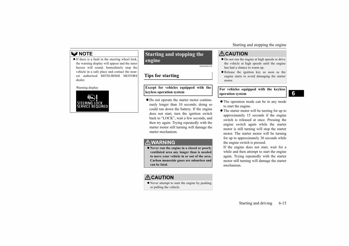
Starting and stopping the engine
Starting and driving 6-15
6
E00620601628
Do not operate the starter motor continu-ously longer than 10 seconds; doing socould run down the battery. If the enginedoes not start, turn the ignition switchback to “LOCK”, wait a few seconds, andthen try again. Trying repeatedly with thestarter motor still turning will damage thestarter mechanism.
The operation mode can be in any modeto start the engine.
The starter motor will be turning for up toapproximately 15 seconds if the engineswitch is released at once. Pressing theengine switch again while the startermotor is still turning will stop the startermotor. The starter motor will be turningfor up to approximately 30 seconds whilethe engine switch is pressed.If the engine does not start, wait for awhile and then attempt to start the engineagain. Trying repeatedly with the startermotor still turning will damage the startermechanism.
If there is a fault in the steering wheel lock,the warning display will appear and the innerbuzzer will sound. Immediately stop thevehicle in a safe place and contact the near-est authorised MITSUBISHI MOTORSdealer.
Warning display
NOTE Starting and stopping the engine
Tips for starting
Except for vehicles equipped with thekeyless operation system
WARNINGNever run the engine in a closed or poorly
ventilated area any longer than is neededto move your vehicle in or out of the area.Carbon monoxide gases are odourless andcan be fatal.
CAUTIONNever attempt to start the engine by pushing
or pulling the vehicle.
Do not run the engine at high speeds or drivethe vehicle at high speeds until the enginehas had a chance to warm up.
Release the ignition key as soon as theengine starts to avoid damaging the startermotor.
For vehicles equipped with the keylessoperation system
CAUTION

Starting and stopping the engine
6-16 Starting and driving
6
E00620702192
The starting procedure is as follows:
1. Insert the ignition key and fasten the seatbelt.
2. Make sure the parking brake is applied.3. Depress and hold the brake pedal.4. Make sure the selector lever is in the “P”
(PARK) position.
5. After turning the ignition switch to the“ON” position, make certain that allwarning lamps are functioning properlybefore starting the engine.
6. Turn the ignition switch to the “START”position without depressing the accelera-tor pedal, and release it when the enginestarts.
After several attempts, you may experiencethat the engine still does not start.
1. Make sure that all electric devices, suchas lamps, air conditioning blower and rearwindow demister, are turned off.
2. While depressing the brake pedal, pressthe accelerator pedal halfway and hold itthere, then crank the engine. Release theaccelerator pedal, immediately after theengine starts.
WARNINGNever run the engine in a closed or poorly
ventilated area any longer than is neededto move your vehicle in or out of the area.Carbon monoxide gases are odourless andcan be fatal.
CAUTIONNever attempt to start the engine by pushing
or pulling the vehicle.Do not run the engine at high speeds or drive
the vehicle at high speeds until the enginehas had a chance to warm up.
Starting the engine
Except for vehicles equipped with thekeyless operation system
NOTE The starter will not operate unless the selec-
tor lever is in the “P” (PARK) or “N” (NEU-TRAL) position.For safety reasons, start the engine in the “P”(PARK) position so that the wheels arelocked.
NOTEMinor noises may be heard on engine start-
up. These will disappear as the engine warmsup.
When the engine is hard to start

Starting and stopping the engine
Starting and driving 6-17
6
3. If the engine still will not start, the enginecould be flooded with too much petrol.While depressing the brake pedal, pressthe accelerator pedal all the way downand hold it there, then crank the engine for5 to 6 seconds. Return the ignition switchto the “LOCK” position and release theaccelerator pedal. Wait a few seconds, andthen crank the engine again for 5 to 6 sec-onds while depressing the brake pedal,but do not press the accelerator pedal.Release the ignition switch if the enginestarts. If the engine fails to start, repeatthese procedures. If the engine still willnot start, contact an authorisedMITSUBISHI MOTORS dealer.
The starting procedure is as follows:
1. Fasten the seat belt.2. Make sure the parking brake is applied.3. Press and hold the brake pedal down
firmly with your right foot.
4. Make sure the selector lever is in the “P”(PARK) position.
5. Press the engine switch.6. Make certain that all warning lamps are
functioning properly.
After several attempts, you may experiencethat the engine still does not start.
1. Make sure that all electric devices, suchas lamps, air conditioning blower and rearwindow demister, are turned off.
2. While depressing the brake pedal, pressthe accelerator pedal halfway and hold itthere, then crank the engine. Release theaccelerator pedal, immediately after theengine starts.
For vehicles equipped with the keylessoperation system
NOTEWhen the engine is not started, it may
become hard to depress the brake pedal andthe vehicle may not be able to detect thepedal operation.Therefore the engine may not be started. Insuch a case, depress the brake pedal morefirmly than usual.
NOTEMinor noises may be heard on engine start-
up. These will disappear as the engine warmsup.
When starting the engine, the selector leveris in a position other than the “P” (PARK) orthe “N” (NEUTRAL) position, or youpressed the engine switch without depressingthe brake pedal, warning display will appear.
Warning display
When the engine is hard to start
NOTE

Starting and stopping the engine
6-18 Starting and driving
6
3. If the engine still will not start, the enginecould be flooded with too much petrol.While depressing the brake pedal, pressthe accelerator pedal all the way downand hold it there, then press the engineswitch to crank the engine. If the enginedoes not start after 5 to 6 seconds, pressthe engine switch to stop the engine, andrelease the accelerator pedal. Put the oper-ation mode in OFF. Wait a few seconds,and then press the engine switch to crankthe engine again while depressing thebrake pedal, but do not press the accelera-tor pedal. If the engine fails to start, repeatthese procedures. If the engine still willnot start, contact an authorisedMITSUBISHI MOTORS dealer.
E00620801633
1. Bring the vehicle to a complete stop.2. Firmly apply the parking brake while
depressing the brake pedal.3. Place the selector lever in the “P” (PARK)
position, and stop the engine.
1. Stop the vehicle.
2. Firmly apply the parking brake whiledepressing the brake pedal.
3. Move the selector lever to the “P”(PARK) position, press the engine switchto stop the engine.
E00632901455
The following operation can be used to startthe engine or change the operation mode.
1. Depress the brake pedal firmly with yourright foot.
2. While depressing the brake pedal, touchthe portion of the keyless operation keyshown in the illustration to the engineswitch.Stopping the engine
Except for vehicles equipped with thekeyless operation system
For vehicles equipped with the keylessoperation system
WARNINGDo not operate the engine switch while
driving except in an emergency. If theengine is stopped while driving, the brakeservomechanism will cease to function andbraking efficiency will deteriorate. Also,the power steering system will not func-tion and it will require greater manualeffort to operate the steering. This couldresult in a serious accident.
NOTE If you have to bring the engine to an emer-
gency stop while driving, press and hold theengine switch for 3 seconds or more, or pressit quickly 3 times or more. The engine willstop and the operation mode will go to ACC.
Do not stop the engine with the selector leverin any position other than the “P” (PARK)position. If the engine is stopped with theselector lever in any position other than the“P” (PARK) position, the operation modewill go to ACC rather than OFF.Put the operation mode in OFF after placingthe selector lever in the “P” (PARK) posi-tion.
If the keyless operation key is not operating properly

4-speed automatic transmission
Starting and driving 6-19
6
3. If the keyless operation key is recognized,the indication lamp on the engine switchilluminates in green, and then the enginecan be started and the operation mode canbe changed within approximately 10 sec-onds. Refer to “Starting the engine” onpage 6-16 and “Changing the operationmode” on 6-12.
E00603202192
E00603302353
The transmission has 4 forward gears and1 reverse gear.The individual gears are selected automati-cally, depending on the speed of the vehicleand the position of the accelerator pedal.The selector lever has 6 positions, and isequipped with a lock button (A) to avoidinadvertent selection of the wrong gear.
NOTE If metal objects or other keys are near the
keyless operation key, the keyless operationkey may not be recognized.
Instead of depressing the brake pedal, thekeyless operation key can also be recognizedin the same way within approximately30 seconds after pushing the engine switch.
To change the operation mode without start-ing the engine, release the brake pedal afterthe indication lamp on the engine switch illu-minates in green, and then press the engineswitch.
4-speed automatic transmis-sion
NOTEDuring running-in period or immediately
after reconnection of the battery cable, theremay be a case where gear shifts are not madesmoothly. This does not indicate a faultytransmission.Gear shifts will become smooth after thetransmission has been shifted several timesby the electronic control system.
Selector lever operation
The lock button must be pressed while the brake pedal is depressed to move the selector lever.The lock button must be pressed to move the selector lever.The lock button need not be pressed to move the selector lever.
BK0286700EN.book 19 ページ 2019年8月7日 水曜日 午後1時26分

4-speed automatic transmission
6-20 Starting and driving
6
E00694800026
When the selector lever cannot be shiftedfrom the “P” (PARK) position to anotherposition while the brake pedal is pressed andheld down with the ignition switch at the“ON” position or the operation mode in ON,the battery may be flat or the shift-lock mech-anism may be malfunctioning. Immediatelyhave your vehicle checked by an authorisedMITSUBISHI MOTORS dealer.If you need to move the vehicle, shift theselector lever as follows.
1. Make sure the parking brake is fullyapplied.
2. Stop the engine if it is running.3. Depress the brake pedal with the right
foot.4. Insert a straight blade (or minus) screw-
driver straight into the shift-lock releasehole (A).Shift the selector lever to the “N” (NEU-TRAL) position while pressing thestraight blade (or minus) screwdriverdown.
E00603502065
When the ignition switch is turned to the“ON” position or the operation mode is put inON, the position of the selector lever is indi-cated in the multi-information display.
WARNING If the lock button is always pressed to
operate the selector lever, the selectorlever may be accidentally shifted into the“P” (PARK), “R” (REVERSE), “2” (SEC-OND) or “L” (LOW) position. Be sure notto press the lock button when performingthe operations indicated by in the illus-tration.
Always depress the brake pedal whenshifting the selector lever into a gear fromthe “P” (PARK) or “N” (NEUTRAL) posi-tion.Never put your foot on the acceleratorpedal while shifting the selector lever fromthe “P” (PARK) or “N” (NEUTRAL) posi-tion.
NOTE To avoid erroneous operation, move the
selector lever firmly into each position andbriefly hold it there. Always check the posi-tion shown by the selector lever position dis-play after moving the selector lever.
If the brake pedal is not depressed and held,the shift-lock device activates to prevent theselector lever from being moved from the“P” (PARK) position.
When the selector lever cannot be shifted from the “P” (PARK) position
Selector lever position indicator display
Vehicles equipped with the mono-tone LCD

4-speed automatic transmission
Starting and driving 6-21
6
E00603801960
This position locks the transmission to pre-vent the vehicle from moving. The engine canbe started in this position.
This position is to back up.
At this position the transmission is disen-gaged. It is the same as the neutral position ona M/T, and should only be used when thevehicle is stationary for an extended length oftime during driving, such as in a traffic jam.
This position is for normal driving. The trans-mission automatically selects a suitable gearfor your speed and acceleration.
This position is for extra power when drivingup moderately steep hills, and for enginebraking when descending moderately steepgradients.
This position is for driving up very steep hillsand for engine braking at low speeds whendriving down steep hills.
Selector lever positions
“P” PARK
“R” REVERSE
CAUTIONNever shift into the “P” (PARK) or “R”
(REVERSE) position while the vehicle is inmotion to avoid a transmission damage.
Vehicles equipped with the TFT colour LCD “N” NEUTRAL
WARNINGNever move the selector lever to the “N”
(NEUTRAL) position while driving. Aserious accident could occur since youcould accidentally move the lever into the“P” (PARK) or “R” (REVERSE) positionor you will lose engine braking.
On a gradient, the engine should bestarted in the “P” (PARK) position, not inthe “N” (NEUTRAL) position.
To prevent rolling, always keep your footon the brake pedal when the vehicle is in“N” (NEUTRAL) position, or when shift-ing into or out of “N” (NEUTRAL) posi-tion.
“D” DRIVE
CAUTION To prevent transmission damage, never shift
into the “D” (DRIVE) position from the “R”(REVERSE) position while the vehicle is inmotion.
“2” SECOND
“L” LOW
WARNINGThis position can be used for maximum
engine braking.Be very careful not to shift into “L”(LOW) position suddenly.Sudden engine braking may cause thetyres to skid.Select this position according to the roadconditions and vehicle speed.

4-speed automatic transmission
6-22 Starting and driving
6E00604001129
The overdrive control switch can be usedwhile the selector lever is in the “D”(DRIVE) position.
Press the overdrive control switch to turn theoverdrive function on. The transmission willshift automatically among the 1st, 2nd, 3rd,and 4th gears, enabling fuel-efficient, eco-nomical driving.
Press the overdrive control switch to turn theoverdrive function off. The transmission willshift automatically among the 1st, 2nd, and3rd gears, and light engine braking will beavailable on downhill roads.
E00614601056
When the overdrive control switch is in theOFF position, the overdrive OFF indicatorlamp in the meter cluster comes on.
When the overdrive control switch is in theOFF position, the overdrive OFF indicatorappears on the multi-information display.
NOTE The A/T has a control function that prevents
over-revving. As a result, it may not performa shift when the selector lever is moved fromthe “D” (DRIVE) position to the “2” (SEC-OND) position or from the “2” (SECOND)position to the “L” (LOW) position.
Overdrive control switch
During normal driving
During hilly roads driving
Overdrive OFF indicator lamp/overdrive OFF indicator
Vehicles equipped with the mono-toneLCD
Vehicles equipped with the TFT colourLCD

4-speed automatic transmission
Starting and driving 6-23
6
E00615101579
E00660800061
E00660900075
When the selector lever position displayblinks while you are driving, there could be amalfunction in the A/T system or A/T fluidtemperature becomes abnormally high.
E00661100090
There could be a system malfunction if the warning display or the warning display
is displayed on the information screen in themulti-information display.
or
When a malfunction occurs in the A/T
Vehicles equipped with the mono-tone LCD
When the selector lever positiondisplay blinks
or
, , ,
,
NOTE “A” indicator does blink only the condition
that the A/T position switch is broken.It does not indicate in normal driving condi-tion.
CAUTION If the selector lever position display blinks
while you are driving, it is likely that a safetydevice is operating because of a malfunctionin the A/T. Immediately have the vehicleinspected by an authorised MITSUBISHIMOTORS dealer.
Vehicles equipped with the TFT colour LCD
When the warning display is dis-played on
NOTE The buzzer may sounds at the time of
warning display appears.
CAUTION If malfunction occurs in the A/T while driv-
ing, the warning display appears on theinformation screen in the multi-informationdisplay.In this case, immediately park your vehiclein a safe place and follow these procedures:
The A/T fluid is overheating. The enginecontrol may activate to lower the A/T fluidtemperature, causing the engine revolutionsand vehicle speed to decrease, or the gearshift timing may change by activating theA/T control. In this case, take one of the fol-lowing procedures.• Slow down your vehicle.• Stop your vehicle in a safe place, put the
selector lever in the “P” (PARK) position,and open the bonnet with the engine run-ning to allow the engine to cool down.

4-speed automatic transmission
6-24 Starting and driving
6 E00604201831
E00604501397
To gain extra acceleration in “D” (DRIVE)position, press the accelerator to the floor.The A/T will automatically downshift.
After a while, confirm that the warningdisplay is no longer showing. It is safe tocontinue driving if the display is no longershowing. If the warning display remains,contact an authorised MITSUBISHIMOTORS dealer immediately.
When the warning display is dis-played on
NOTE The selector lever position display blinks at
the time of warning display appears. The “A” indicator on the selector lever posi-
tion display will blink only when there is aproblem with the A/T position switch.It is not seen during normal driving.
CAUTION If malfunction occurs in the A/T while driv-
ing, the warning display appears on theinformation screen in the multi-informationdisplay.In this case, immediately park your vehiclein a safe place and follow these procedures:
CAUTIONIt may be that there is something unusualhappening in the A/T, causing a safetydevice to activate. Immediately have yourvehicle inspected by an authorisedMITSUBISHI MOTORS dealer.
Operation of the A/T
CAUTIONBefore selecting a gear with the engine run-
ning and the vehicle stationary, fully depressthe brake pedal to prevent the vehicle fromcreeping.The vehicle will begin to move as soon as thegear is engaged, especially when the enginespeed is high, at fast idle or with the air con-ditioner operating, the brakes should only bereleased when you are ready to drive away.
Depress the brake pedal with the right foot atall times.Using the left foot could cause driver move-ment delay in case of an emergency.
To prevent sudden acceleration, never racethe engine when shifting from the “P”(PARK) or “N” (NEUTRAL) position.
Operating the accelerator pedal while theother foot is resting on the brake pedal willaffect braking efficiency and may cause pre-mature wear of brake pads.
CAUTIONUse the selector lever in the correct shift
position in accordance with driving condi-tions.Never coast downhill backward with theselector lever in the {“D” (DRIVE), “2”(SECOND) or “L” (LOW)} or coast forwardwith the selector lever in the “R”(REVERSE) position.The engine may stop and the unexpectedincrease in brake pedal effort and steeringwheel weight could lead to an accident.
Do not race the engine with brake pedalpressed when the vehicle is stationary.This can damage the A/T.Also, when you depress the accelerator pedalwhile holding down the brake pedal with theselector lever in the “P” (PARK), “N” (NEU-TRAL), “D” (DRIVE), “2” (SECOND) or“L” (LOW) position, the engine revolutionsmay not rise as high as when performing thesame operation with the selector lever in the“N” (NEUTRAL) position.
Passing acceleration
CAUTION

Braking
Starting and driving 6-25
6
E00604601415
For short waiting periods, such as at trafficsignals the vehicle can be left in gear and heldstationary with the service brake.For longer waiting periods with the enginerunning, place the selector lever in the “N”(NEUTRAL) position and apply the parkingbrake, while holding the vehicle stationarywith the service brake.
E00604701357
To park the vehicle, first bring it to a com-plete stop, firmly apply the parking brake,and then move the selector lever to the “P”(PARK) position.If you are going to leave the vehicle unat-tended, always switch off the engine andcarry the key.
E00604802036
If the transmission does not change speedswhile driving, or your vehicle does not pickup enough speed when starting on an uphillslope, it may be that there is something unu-sual happening in the transmission, causing asafety device to activate. Immediately haveyour vehicle checked at an authorisedMITSUBISHI MOTORS dealer.
1. If your vehicle has difficulty movinguphill, shift the selector lever into 2ndgear. This method might not workdepending on the transmission malfunc-tion.
2. Once the vehicle is moving on a levelroad, move the selector lever back to “D”(DRIVE).
E00607003225
All the parts of the brake system are criticalto safety. Have the vehicle serviced by anauthorised MITSUBISHI MOTORS dealer atregular intervals according to the servicebooklet.
The service brake is divided into two brakecircuits. And your vehicle is equipped with
Waiting
CAUTIONNever hold the vehicle stationary on a hill
using the accelerator pedal (without usingthe brake pedal). Always apply the parkingbrake and/or service brakes.
Parking
NOTEOn a slope, be sure to apply the parking
brake before moving the selector lever to the“P” (PARK) position. If you move the selec-tor lever to the “P” (PARK) position beforeapplying the parking brake, it may be diffi-cult to disengage the selector lever from the“P” (PARK) position when next you drivethe vehicle, requiring application of a strongforce to the selector lever to move from the“P” (PARK) position.
When the A/T makes no speed change
NOTEWhen the selector lever position display in
the instrument panel blinks, it means thatthere is an abnormal condition in the trans-mission.Refer to “When the selector lever positiondisplay blinks” on page 6-23.
Braking
CAUTIONAvoid driving habits that cause heavy brak-
ing and never “ride” the brakes by restingyour foot on the brake pedal while driving.It causes brake overheating and fade.
Brake system

Hill start assist
6-26 Starting and driving
6
power brakes. If one brake circuit fails, theother is available to stop the vehicle. If yourvehicle should lose the power assist for somereason, the brakes will still work. In these sit-uations, even if the brake pedal moves downto the very end of its possible stroke or resistsbeing depressed, keep depressing the brakepedal down harder and further than usual;stop driving as soon as possible and have thebrake system repaired.
The brake warning lamp illuminates to indi-cate a fault in the braking system. A warningis also displayed on the multi-informationdisplay. Refer to “Brake warning lamp” and“Brake warning display” on page 5-34, 5-36.
Check the brake system while driving at alow speed immediately after starting, espe-cially when the brakes are wet, to confirmthey work normally.A film of water can be formed on the brakediscs and drums and prevent normal brakingafter driving in heavy rain or through largepuddles, or after the vehicle is washed. If thisoccurs, dry the brakes out by driving slowlywhile lightly depressing the brake pedal.
It is important to take advantage of the enginebraking by shifting to a lower shift positionwhile driving on steep downhill roads inorder to prevent the brakes from overheating.
Avoid hard braking situations.New brakes need to be broken-in by mod-erate use for the first 200 km.
The disc brakes are provided with a warn-ing device which emits a shrieking metal-lic sound while braking if the brake padshave reached their limit. If you hear thissound, have the brake pads replacedimmediately.
E00628001527
The hill start assist makes it easy to start offon a steep uphill slope by preventing thevehicle from moving backwards. It keeps thebraking force for approximately 2 secondswhen you move your foot from the brakepedal to the accelerator pedal.
WARNINGDo not turn off the engine while your vehi-
cle is in motion. If you turn off the enginewhile driving, the power assistance for thebraking system will stop working andyour brakes will not work effectively.
If the power assist is lost or if either brakehydraulic system stops working properly,take your vehicle to an authorisedMITSUBISHI MOTORS dealer immedi-ately.
Warning display
When brakes are wet
When driving downhill
WARNINGDo not leave any objects near the brake
pedal or let a floor mat slide under it;doing so could prevent the full pedalstroke that would be necessary in anemergency. Make sure that the pedal canbe operated freely at all times. Make surethe floor mat is securely held in place.
Brake pad
WARNINGDriving with worn brake pads will make it
harder to stop, and can cause an accident.
Hill start assist

Hill start assist
Starting and driving 6-27
6
E00628101603
1. Stop the vehicle completely using thebrake pedal.
2. Place the selector lever into the “D”(DRIVE) position.
3. Release the brake pedal and the hill startassist will maintain the braking forceapplied while stopped for approximately 2seconds.
4. Depress the accelerator pedal and the hillstart assist will gradually decrease thebraking force as the vehicle starts moving.
E00628201646
If an abnormal condition occurs in the sys-tem, the following warning lamp/display willbe shown.
Warning lamp
Warning display
CAUTIONDo not overly rely on the hill start assist to
prevent backwards movement of the vehicle.Under certain circumstances, even when hillstart assist is activated, the vehicle maymove backwards if the brake pedal is not suf-ficiently depressed, if the vehicle is heavilyloaded, or if the road is very steep or slip-pery.
The hill start assist is not designed to keepthe vehicle stopped in place on uphill slopesfor more than 2 seconds.
When facing uphill, do not rely on using thehill start assist to maintain a stopped positionas an alternative to depressing the brakepedal.Doing so could cause an accident.
Do not turn the operation mode in ACC orOFF while the hill start assist is operating.The hill start assist could stop operating,which could result in an accident.
To operate
NOTEWhen reversing on an uphill slope, place the
selector lever into the “R” (REVERSE) posi-tion.
NOTE The hill start assist is activated when all of
the following conditions are met.• The engine is running.
(The hill start assist will not be activatedwhile the engine is starting or immediatelyafter the engine is started.)
• The selector lever is in any position otherthan “P” (PARK) or “N” (NEUTRAL).
• The vehicle is completely stationary, withthe brake pedal depressed.
• The parking brake is released. The hill start assist will not operate if the
accelerator pedal is depressed before thebrake pedal is released.
The hill start assist also operates whenreversing on an uphill slope.
Warning lamp/display
CAUTION If the warning is displayed, the hill start
assist will not operate. Start off carefully. Park your vehicle in a safe place and stop the
engine.Restart the engine and check whether the dis-play/indicator goes out, in which case the hillstart assist is again working normally.If they remain displayed or reappear fre-quently, it is not necessary to stop the vehicleimmediately, but the vehicle should beinspected by an authorised MITSUBISHIMOTORS dealer.

Brake assist system
6-28 Starting and driving
6
E00627001979
The brake assist system is a device assistingdrivers who cannot depress the brake pedalfirmly such as in emergency stop situationsand provides greater braking force.
If the brake pedal is depressed suddenly, thebrakes will be applied with more force thanusual.
E00626001350
This is a device that reduces the possibility ofrear end collisions by the rapid and automaticblinking of the hazard warning lamps to alertvehicles approaching from behind duringsudden braking. When the emergency stopsignal system operates, the hazard warningindicator lamp in the instrument clusterblinks rapidly at the same time.
Brake assist system
CAUTION The brake assist system is not a device
designed to exercise braking force greaterthan its capacity. Make sure to always keep asufficient distance between your vehicle anda vehicle in front of you without relying toomuch on the brake assist system.
NOTEOnce the brake assist system is operational,
it maintains great braking force even if thebrake pedal is lightly released.To stop its operation, completely removeyour foot from the brake pedal.
When the brake assist system is in use whiledriving, you may feel as if the depressedbrake pedal is soft, the pedal moves in smallmotions in conjunction with the operationnoise, or the vehicle body and the steeringwheel vibrate. This occurs when the brakeassist system is operating normally and doesnot indicate faulty operation. Continue todepress the brake pedal.
When the anti-lock brake system warninglamp or only active stability control warninglamp illuminate, the brake assist system innot functioning.
Emergency stop signal sys-tem
NOTE CAUTION If the ABS warning or ASC warning is dis-
played, the emergency stop signal systemmay not operate.Refer to “ABS warning lamp/display” onpage 6-30.Refer to “ASC warning lamp/display” onpage 6-34.
NOTE [Activating condition for the emergency stop
signal system]It activates when all of the following condi-tions are met.• The vehicle speed is approximately 55
km/h or higher.• The brake pedal has been depressed, and
the system judges that it was sudden brak-ing from the vehicle deceleration and theoperating condition of the anti-lock brakesystem (ABS).
[Deactivating condition for the emergencystop signal system]It deactivates when one of the following con-ditions is met.• The brake pedal is released.• The hazard warning flasher switch is
pressed.• The system judges that it was not sudden
braking from the vehicle deceleration andthe operating condition of the anti-lockbrake system (ABS).

Anti-lock brake system (ABS)
Starting and driving 6-29
6
E00607102766
Environmental conditions can have an effecton braking. During sudden braking whenthere is snow, ice, oil, water etc. on the roadsurface, a skid may occur. In this situation,steering control and braking effectiveness isreduced and the stopping distance isincreased. The vehicle may also go into anuncontrolled spin.The ABS helps prevent the wheels from lock-ing during braking, thus maintaining direc-tional stability, ensuring controllability andproviding optimum braking force.
Always maintain the same distance fromthe vehicle in front of you as you wouldfor a vehicle not equipped with ABS.Compared with vehicles not fitted withABS, your vehicle may require a longerstopping distance in the following cases:• Driving on gravel or snow-covered
roads.• Driving with tyre chains installed.• Driving on roads where the road surface
is pitted or has other differences in sur-face height.
• Driving on bumpy roads or other poordriving surfaces.
Operation of ABS is not restricted to situ-ations where brakes are applied suddenly.This system may also operate to preventwheel lock when you are driving overmanholes, steel road-work plates, or thevehicle is driven over steps or level differ-ences in the road, road markings, or othersurfaces which are difficult for the wheelsto grip.
When the ABS is activated, you may feelthe brake pedal pulsation and the vibra-tions of the vehicle body and steeringwheel. You may also hear a characteristicnoise. At this time, you may feel as if thepedal attempts to resist being depressed.This is a normal result of the ABS opera-tion, and does not indicate a problem.If this situation occurs, depress thebrake pedal more firmly in order tooperate the ABS. Do not pump thebrake. This will result in reduced brak-ing performance.
You will hear the operation sound of themotor coming from the engine compart-ment immediately following start off afterstarting the engine. If the brake pedal isdepressed at that moment, a brake pedalpulsating is felt.
This pulsation is due to the self-diagnosisoperation of the ABS and does not indi-cate a malfunction.
The ABS becomes operative after thevehicle has accelerated to a speed inexcess of approximately 10 km/h. It stopsoperating when the vehicle decelerates toa speed below approximately 5 km/h.
Anti-lock brake system (ABS)
Operating hints
CAUTION Even the ABS cannot prevent the natural
laws of physics from acting on the vehicle. Itcannot for instance avoid accidents that mayresult from excessive speed on bends or fol-lowing another vehicle too closely or aqua-planing. It should remain the driver’s task toobserve safety precautions to judge speedsand brake applications correctly in such con-ditions.
Be sure to use tyres of the same type and sizeon 4 wheels.If tyre types or sizes are mixed, ABS maynot function normally.
Never install a limited slip differential,which is not MITSUBISHI MOTORS GEN-UINE parts, as the ABS may not functionnormally.We recommend you to consult an authorisedMITSUBISHI MOTORS dealer.

Anti-lock brake system (ABS)
6-30 Starting and driving
6
E00607202682
Warning lamp
Warning display
If there is a malfunction in the system, theABS warning lamp will come on and thewarning display will appear on the informa-tion screen in the multi-information display.Under normal conditions, the ABS warninglamp only comes on when the ignition switchis turned to the “ON” position or the opera-tion mode is put in ON and goes off a fewseconds later.
E00607302566
Avoid hard braking and high-speed driving.Stop the vehicle in a safe place.Restart the engine and check to see whetherthe lamp goes out after a few minutes driving;if it then remains off during driving, there isno problem.However, if the lamp does not go out, or if itlights up again when the vehicle is driven, werecommend you to have the vehicle checkedas soon as possible.
Warning lamp
Warning display
The ABS and brake force distribution func-tion may not work, so hard braking couldmake the vehicle unstable.Avoid hard braking and high-speed driving.Stop the vehicle in a safe place immediatelyand contact an authorised MITSUBISHIMOTORS dealer.
ABS warning lamp / display
CAUTIONAny of the following warning lamp/display
behaviour indicates that the ABS is not func-tioning and only the standard brake system isworking. (The standard brake system is func-tioning normally.) If this happens, take yourvehicle to an authorised MITSUBISHIMOTORS dealer.
• When the ignition switch is in the “ON”position or the operation mode is put in ON,the warning lamp does not come on or itremains on and does not go off
• The warning lamp comes on while driving• The warning display appears while driving
If the warning lamp/display illuminate while driving
If only the ABS warning lamp/dis-play illuminate
CAUTION If the ABS warning lamp/display and brake warning lamp/display illuminate at the same time

Electric power steering system (EPS)
Starting and driving 6-31
6E00618801362
After driving on snow or icy roads, removeany snow and ice which may have be leftaround the wheels. When doing this, be care-ful not to damage the wheel speed sensors(A) or the cables located at each wheel.
E00629201496
The power steering system operates while theengine is running.It helps reduce the effort needed to turn thesteering wheel.The power steering system has mechanicalsteering capability in case the power assist islost. If the power assist is lost for some rea-son, you will still be able to steer your vehi-cle, but you will notice it takes much moreeffort to steer. If this happens, have your vehi-cle inspected at an authorised MITSUBISHIMOTORS dealer.
Warning lamp
NOTE The ABS warning lamp and brake warning
lamp illuminate at the same time and thewarning displays appear alternately on theinformation screen in the multi-informationdisplay.
After driving on icy roads
Front Rear
Electric power steering sys-tem (EPS)
WARNINGDo not stop the engine while the vehicle is
moving. Stopping the engine would makethe steering wheel extremely hard to turn,possibly resulting in an accident.
NOTEDuring repeated full-lock turning of the
steering wheel (for example, while you aremanoeuvring the vehicle into a parkingspace), a protection function may be acti-vated to prevent overheating of the powersteering system. This function will make thesteering wheel gradually harder to turn. Inthis event, limit your turning of the steeringwheel for a while. When the system hascooled down, the steering effort will returnto normal.
If you turn the steering wheel while the vehi-cle is stationary with the headlamps on, theheadlamps may become dim. This behaviouris not abnormal. The headlamps will returnto their original brightness after a shortwhile.
Electric power steering system warning lamp/warning display
Active stability control (ASC)
6-32 Starting and driving
6
Warning display
If there is a malfunction in the system, thewarning lamp will come on and the warningdisplay will appear on the information screenin the multi-information display.Under normal conditions, the warning lampcomes on when the ignition switch is turnedto the “ON” position or the operation mode isput in ON, and goes off after the engine hasstarted.
E00616701963
The active stability control (ASC) takes over-all control of the anti-lock brake system, trac-
tion control function and stability controlfunction to help maintain the vehicle’s controland traction. Please read this section in con-junction with the page on the anti-lock brakesystem, traction control function and stabilitycontrol function.
Anti-lock brake system (ABS) P.6-29Traction control function P.6-32Stability control function P.6-33
E00619001185
On slippery surfaces, the traction controlfunction prevents the drive wheels from spin-ning excessive, thus helping the vehicle tostart moving from a stopped condition. It alsoprovides sufficient driving force and steeringperformance as the vehicle turns while press-ing the acceleration pedal.
CAUTION If the warning lamp comes on and the warn-
ing display appears while the engine is run-ning, have the vehicle inspected by anauthorised MITSUBISHI MOTORS dealeras soon as possible.It may become harder to turn the steeringwheel.
Active stability control (ASC)
CAUTIONDo not over-rely on the ASC. Even the ASC
cannot prevent the natural laws of physicsfrom acting on the vehicle.This system, like any other system, has lim-its and cannot help you to maintain tractionand control of the vehicle in all circum-stances. Reckless driving can lead to acci-dents. It is the driver’s responsibility to drivecarefully. This means into account the traffic,road and environmental conditions.
Be sure to use the same specified type andsize of tyre on all 4 wheels. Otherwise, theASC may not work properly.
Do not install any aftermarket limited slipdifferential (LSD) on your vehicle. The ASCmay stop functioning properly.
NOTEAn operation noise may be emitted from the
engine compartment in the following situa-tions. The sound is associated with checkingthe operations of the ASC. At this time, youmay feel a shock from the brake pedal if youdepress it. These do not indicate a malfunc-tion.• When the ignition switch is set to the “ON”
position or the operation mode is put in ON.• When the vehicle is driven for a while after
the engine is turned on.When the ASC is activated, you may feel a
vibration in the vehicle body or hear a whin-ing sound from the engine compartment.This indicates that the system is operatingnormally. It does not indicate a malfunction.
When the anti-lock brake system warninglamp is illuminated, the ASC is not active.
Traction control function

Active stability control (ASC)
Starting and driving 6-33
6E00619101144
The stability control function is designed tohelp the driver maintain control of the vehicleon slippery roads or during rapid steeringmaneuvers. It works by controlling the engineoutput and the brake on each wheel.
E00619201930
The ASC is automatically activated when theoperation mode is put in ON. You can deacti-vate the system by pressing down the ASCOFF switch for 3 seconds or longer.When the ASC is deactivated, the indica-tor will turn on. To reactivate the ASC,momentarily press the ASC OFF switch; the
indicator is turned off.
E00619301872
CAUTIONWhen driving a vehicle on a snowy or icy
road, be sure to install snow tyres and drivethe vehicle at moderate speeds.
Stability control function
NOTE The stability control function operates at
speeds of approximately 15 km/h or higher.
ASC OFF switch
CAUTION For safety reasons, the ASC OFF switch
should be operated when your vehicle isstopped.
Be sure to keep the ASC on while driving innormal circumstances.
NOTEWhen moving out of mud, sand or fresh
snow, pressing the accelerator pedal may notallow the engine speed to increase. In suchsituations, temporarily turning off the ASCwith the ASC OFF switch will make it easierto move out your vehicle.
Using the ASC OFF switch turns off both thestability control function and the tractioncontrol function.
If you continue to press the ASC OFF switchafter the ASC is turned off, the “mistakenoperation protection function” will activateand the ASC will turn back on.
ASC operation indicator or ASC OFF indicator
- ASC operation indicatorThe indicator will blink when theASC is operating.
- ASC OFF indicatorThis indicator will turn on when theASC is turned off with the ASC OFFswitch.
CAUTIONWhen indicator blinks, ASC is operating,
which means that the road is slippery or thatyour vehicle’s wheels are beginning to slip.If this happens, drive slower with less accel-erator input.

Cruise control*
6-34 Starting and driving
6
E00619402030
If an abnormal condition occurs in the sys-tem, the following warning lamp/warningdisplay will turn on.
Warning lamp
Warning display
E00609102685
Cruise control is an automatic speed controlsystem that keeps a set speed. It can be acti-vated at approximately 40 km/h or more.
If the temperature in the braking system con-tinues to increase due to continuous brake
control on a slippery road surface, the indicator will blink.To prevent the brake system from overheat-ing, the brake control of the traction controlfunction will be temporarily suspended.The engine control of the traction controlfunction and normal brake operation will notbe affected. Park your vehicle in a safe place.When the temperature in the braking system
has come down, the indicator will beturned off and the traction control functionwill start operating again.
NOTE The indicator may turn on when you start
the engine. This means that the battery volt-age momentarily dropped when the enginewas started. It does not indicate a malfunc-tion, provided that the indicator goes outimmediately.
ASC warning lamp/display
CAUTION- ASC operation indicator
- ASC OFF indicator
CAUTION The system may be malfunctioning.
Park your vehicle in a safe place and stop theengine.Restart the engine and check whether the dis-play/indicator goes out. If they go out, thereis no abnormal condition. If they do not goout or appear frequently, it is not necessaryto stop the vehicle immediately, but we rec-ommend you to have your vehicle inspected.
When towing the vehicle with only the frontwheels or only the rear wheels raised off theground, do not place the ignition switch inthe “ON” position or do not put the operationmode in ON. Placing the ignition switch inthe “ON” position or putting the operationmode in ON could cause the ASC to operate,resulting in an accident.Note that the correct towing method dependson the transmission type and the vehicle’sdrive configuration.For details, refer to “Towing” on page 8-12.
Cruise control*
CAUTIONWhen you do not wish to drive at a set speed,
turn off the cruise control for safety.Do not use cruise control when driving con-
ditions will not allow you to stay at the samespeed, such as in heavy traffic or on roadsthat are winding, icy, snow-covered, wet,slippery, on a steep downhill slope.
CAUTION

Cruise control*
Starting and driving 6-35
6
Used to turn on and off the cruise control.
Used to reduce the set speed and to set thedesired speed.
Used to increase the set speed and to return tothe original set speed.
Used to deactivate the set speed driving.
E00609302876
1. With the operation mode in ON, press theCRUISE CONTROL ON/OFF switch (A)to turn on the cruise control. The indicatordisplay appear on the information screenof the multi-information display.
2. Accelerate or decelerate to your desiredspeed, then push down and release the“SET -” switch (B) when the indicatordisplay appear on the information screenof the multi-information display. Thevehicle will then maintain the desiredspeed.The “SET” indicator appears on the infor-mation screen of the multi-informationdisplay.
NOTECruise control may not be able to keep your
speed on uphills or downhills.Your speed may decrease on a steep uphill.
You may use the accelerator pedal if youwant to stay at your set speed.
Your speed may increase to more than the setspeed on a steep downhill. You have to usethe brake to control your speed. As a result,the set speed driving is deactivated.
Cruise control switches
A- CRUISE CONTROL ON/OFF switch
B- “SET -” switch
C- “RES +” switch
D- “CANCEL” switch
NOTEWhen operating the cruise control switches,
press the cruise control switches correctly.The set speed driving may be deactivatedautomatically if two or more switches of thecruise control are pressed at the same time.
To activate

Cruise control*
6-36 Starting and driving
6
E00609401955
There are two ways to increase the set speed.
Push up and hold the “RES +” switch (C)while driving at the set speed, and your speedwill then gradually increase.
When you reach your desired speed, releasethe switch. Your new cruising speed is nowset.
To increase your speed in small amounts,push up the “RES +” switch (C) for less thanapproximately 1 second and release it.Each time you push up the “RES +” switch(C), your vehicle will go approximately1.6 km/h faster.
While driving at the set speed, use the accel-erator pedal to reach your desired speed andthen push down the “SET -” switch (B) andrelease the switch momentarily to set a newdesired cruising speed.
E00609501884
There are two ways to decrease the set speed.
Push down and hold the “SET -” switch (B)while driving at the set speed, and your speedwill slow down gradually.When you reach your desired speed, releasethe switch. Your new cruising speed is nowset.
NOTEWhen you release the “SET -” switch (B),
the vehicle speed will be set.
To increase the set speed
RES + switch
Accelerator pedal
To decrease the set speed
SET - switch

Cruise control*
Starting and driving 6-37
6To slow down your speed in small amounts,push down the “SET -” switch (B) for lessthan approximately 1 second and release it.Each time you push down the “SET -” switch(B), your vehicle will slow down by approxi-mately 1.6 km/h.
While driving at the set speed, use the brakepedal, which disengages the cruise control,then push down the “SET -” switch (B) andrelease the switch momentarily to set a newdesired cruising speed.
E00609601436
Depress the accelerator pedal as you wouldnormally. When you release the pedal, youwill return to your set speed. Depress the brake pedal to decrease the
speed. To return to the previously set speed,push up the “RES +” switch (C).Refer to “To resume the set speed” on page6-38.
Brake pedal
To temporarily increase or decrease the speed
To temporarily increase the speed
NOTE In some driving conditions, the set speed
driving may be deactivated. If this happens,refer to “To activate” on page 6-35 andrepeat the speed setting procedure.
To temporarily decrease the speed

Cruise control*
6-38 Starting and driving
6
E00609703125
The set speed driving can be deactivated asfollows:
Press the CRUISE CONTROL ON/OFFswitch (A). (Cruise control will be turnedoff.)
Press the “CANCEL” switch (D).Depress the brake pedal.
The set speed driving is deactivated automati-cally in any of the following ways.
When your speed slows to approximately15 km/h or more below the set speedbecause of a hill, etc.
When your speed slows to approximately40 km/h or less.
When the active stability control (ASC)starts operating.Refer to “Active stability control (ASC)”on page 6-32.
Also, the set speed driving may be deacti-vated as follow:
When the engine speed rises andapproaches the tachometer’s red zone (thered-coloured part of the tachometer dial).
E00609802305
If the set speed driving is deactivated by thecondition described in “To deactivate” onpage 6-38, you can resume the previously setspeed by push up the “RES +” switch (C)while driving at a speed of approximately40 km/h or higher. The “SET” indicatorappears on the information screen of themulti-information display.
To deactivate WARNINGAlthough the set speed driving will be
deactivated when shifting to the “N”(NEUTRAL) position, never move theselector lever to the “N” (NEUTRAL)position while driving.You would have no engine braking andcould cause a serious accident.
CAUTIONWhen the set speed driving is deactivated
automatically in any situation other thanthose listed above, there may be a systemmalfunction.Press the CRUISE CONTROL ON/OFFswitch to turn off the cruise control and haveyour vehicle inspected by an authorisedMITSUBISHI MOTORS dealer.
To resume the set speed

Rear-view camera*
Starting and driving 6-39
6
Under either of the following conditions,however, using the switch does not allow youto resume the previously set speed. In thesesituations, repeat the speed setting procedure:
The CRUISE CONTROL ON/OFFswitch is pressed.
The operation mode is put in OFF. Indicator display goes off.
E00618402961
The rear-view camera is a system that showsthe view behind the vehicle on a screen of theDisplay audio.
The range of view of the rear-view camera islimited to the area shown in the illustrations.It cannot show the both sides and the lowerpart of the rear bumper, etc.When reversing, be sure to visually confirmsafety around the vehicle.
The rear-view camera (A) is integrated intothe part near the tailgate handle.
When you place the selector lever in the “R”(REVERSE) position with the operationmode in ON, the view behind the vehicle will
Rear-view camera*
CAUTION The rear-view camera is an assistance system
that enables the driver to check for obstaclesbehind the vehicle. Its range of view is lim-ited, so you should not overly depend on it.Please drive just as carefully as you would ifthe vehicle did not have the rear-view cam-era.
Be sure to visually confirm safety around thevehicle with your own eyes. Do not dependentirely on the rear-view camera.
Range of view of rear-view camera
Location of rear-view camera
Range of view of rear-view camera
How to use the rear-view cam-era

Rear-view camera*
6-40 Starting and driving
6
automatically appear on the screen of the Dis-play audio. When you move the selector leverto any other position, the screen will return toits original indication.
Three reference lines for distance and the topof the rear bumper (A) are shown on thescreen.
CAUTION The rear-view camera has a special lens that
can make objects shown on the screen appearto be closer or further away than they actu-ally are.
NOTEBecause the rear-view camera has a special
lens, the lines on the ground between parkingspaces may not look parallel on the screen.
In the following situations, the screen indica-tion may be difficult to see. There is noabnormality.• Low light (nighttime)• When the light of the sun or the light from a
vehicle’s headlamps shines directly into thelens
If the camera is hot and is then cooled byrain or a car wash, the lens can mist up. Thisphenomenon does not indicate a malfunc-tion.
It is not possible to fully see obstacles whenthe lens is dirty. If the lens becomes contami-nated by water droplets, snow, mud, or oil,wipe off the contamination, taking care notto scratch the lens.
Please observe the following cautions. Ignor-ing them could lead to a camera malfunction.• Do not subject the camera to physical
shock.• Do not apply wax to the camera.• Do not splash the camera with boiling
water.• Do not disassemble the camera.
Reference lines on the screen
NOTE NOTEWhen the vehicle is tilting because of the
number of people in the vehicle, the weightand positioning of luggage, and/or the condi-tion of the road surface, the lines in the viewfrom the rear-view camera may not be accu-rately positioned relative to the actual road.The reference lines for distance and vehiclewidth are based on a level, flat road surface.In the following cases, objects shown on thescreen will appear to be farther off than theyactually are.• When the rear of the vehicle is weighed
down with the weight of passengers andluggage in the vehicle.
A: Actual objectsB: Objects shown on the screen

Cargo loads
Starting and driving 6-41
6
E00609902902• When there is an upward slope at the back.
A: Actual objectsB: Objects shown on the screen
NOTE The reference lines for distance and vehicle
width are intended to indicate the distance toa flat object such as a level, flat road surface.This may make the distance to a projectingobject shown on the screen differ from theactual distance to the projecting object. Donot use them as a guide to distances to solidobjects.Example: On the screen the point B appearsthe nearest, then the point C and A in orderof distance. The point A and B actually arethe same distances from the vehicle, and thepoint C is farther off than the point A and B.
NOTE Cargo loads
Cargo loads precautions
CAUTIONDo not load cargo or luggage higher than the
top of the seatback. Be sure that your cargoor luggage cannot move once your vehicle ismoving. Having the rear view blocked, andyour cargo being thrown inside the cabin ifyou suddenly have to brake can cause a seri-ous accident or injury.
Load heavy cargo or luggage in the front ofthe vehicle. If the load in the back of thevehicle is too heavy, steering may becomeunstable.


7
For pleasant driving
Important air conditioning operating tips ........................................7-2Ventilators ........................................................................................7-2Manual air conditioning ...................................................................7-6Rear air conditioning .......................................................................7-8Air purifier .......................................................................................7-9AM/FM radio/CD player with AUX* ..............................................7-9Handling of Discs ..........................................................................7-10Audio Files (MP3/WMA/AAC) ....................................................7-12Important Points on Safety for the Customer ................................7-15Operation Keys ..............................................................................7-16Listen to Radio ...............................................................................7-19Listen to CDs .................................................................................7-20Listen to MP3s/WMAs/AACs .......................................................7-21Listen to an iPod* ...........................................................................7-22Listen to Audio Files on a USB Device*........................................7-24Use AUX* ......................................................................................7-26Display Indicator ...........................................................................7-26Audio Quality and Volume Balance Adjustment ...........................7-27Time Setting ...................................................................................7-28Troubleshooting .............................................................................7-29Antenna*.........................................................................................7-30Link System*..................................................................................7-31USB input terminal* .......................................................................7-31Sun visors .......................................................................................7-33Accessory socket ...........................................................................7-34Room lamps ...................................................................................7-34Storage spaces ................................................................................7-36Drink holder ...................................................................................7-39
Bottle holder ..................................................................................7-39Convenient hook ............................................................................7-40Assist grips ....................................................................................7-40Coat hook .......................................................................................7-40
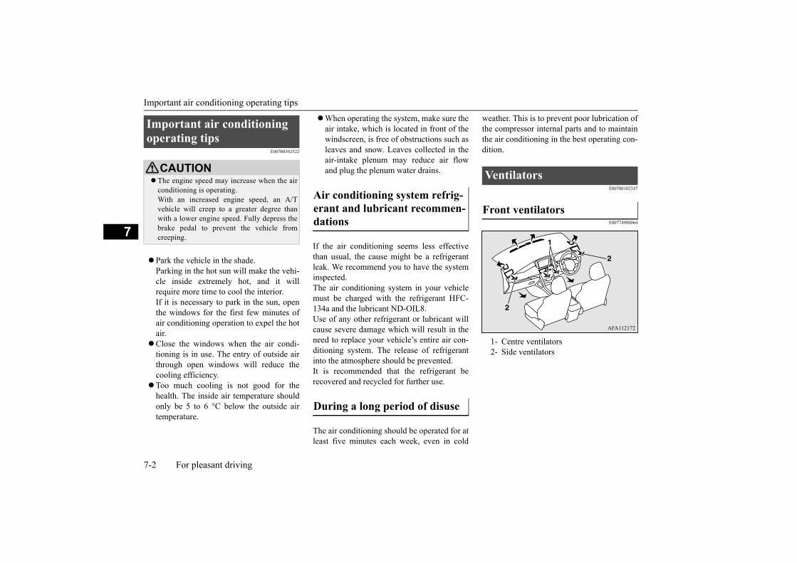
Important air conditioning operating tips
7-2 For pleasant driving
7
E00708302522
Park the vehicle in the shade.Parking in the hot sun will make the vehi-cle inside extremely hot, and it willrequire more time to cool the interior.If it is necessary to park in the sun, openthe windows for the first few minutes ofair conditioning operation to expel the hotair.
Close the windows when the air condi-tioning is in use. The entry of outside airthrough open windows will reduce thecooling efficiency.
Too much cooling is not good for thehealth. The inside air temperature shouldonly be 5 to 6 °C below the outside airtemperature.
When operating the system, make sure theair intake, which is located in front of thewindscreen, is free of obstructions such asleaves and snow. Leaves collected in theair-intake plenum may reduce air flowand plug the plenum water drains.
If the air conditioning seems less effectivethan usual, the cause might be a refrigerantleak. We recommend you to have the systeminspected.The air conditioning system in your vehiclemust be charged with the refrigerant HFC-134a and the lubricant ND-OIL8.Use of any other refrigerant or lubricant willcause severe damage which will result in theneed to replace your vehicle’s entire air con-ditioning system. The release of refrigerantinto the atmosphere should be prevented.It is recommended that the refrigerant berecovered and recycled for further use.
The air conditioning should be operated for atleast five minutes each week, even in cold
weather. This is to prevent poor lubrication ofthe compressor internal parts and to maintainthe air conditioning in the best operating con-dition.
E00700102247
E00774900064
Important air conditioning operating tips
CAUTION The engine speed may increase when the air
conditioning is operating.With an increased engine speed, an A/Tvehicle will creep to a greater degree thanwith a lower engine speed. Fully depress thebrake pedal to prevent the vehicle fromcreeping.
Air conditioning system refrig-erant and lubricant recommen-dations
During a long period of disuse
Ventilators
Front ventilators
1- Centre ventilators2- Side ventilators

Ventilators
For pleasant driving 7-3
7
E00775000088
E00700202352
Move the knob (A) to adjust the air flowdirection.
Move the knob (A) to adjust the air flowdirection.To close the vent, move the knob (A) to theoutside as far as possible.
Move the knob (A) to adjust the air flowdirection.
Rear ventilators
Adjusting the air flow direction
Front centre ventilators
Front side ventilators
1- Close2- Open
Rear ventilators
NOTE The cool air from the ventilators may appear
as a mist.This is due to moist air being suddenlycooled by the air conditioning. This willclear after a few moments.
Be careful not to spill beverages, etc., intothe ventilators. Doing so might cause the air conditioningnot to function normally.

Ventilators
7-4 For pleasant driving
7
E00700302757
To change the position and amount of air flowing from the front ventilators, turn the mode selection dial.
Changing the position of air flowing from the front ventilators

Ventilators
For pleasant driving 7-5
7
The mode selection and air flowing from the front ventilatorsThese symbols are used in the next several illustrations to demonstrate the quantity of air coming from the front ventilators.
: Small amount of air from the ventilators: Medium amount of air from the ventilators: Large amount of air from the ventilators
Face position Foot/Face position Foot position
Foot/Demister position Demister position
NOTEWith the mode selection dial between the “ ” and “ ” positions, air flows mainly to the upper part of the passenger compartment. With the mode
selection dial between the “ ” and “ ” positions, air flows mainly to the leg area.

Manual air conditioning
7-6 For pleasant driving
7
E00731101161
The air conditioning can only be used whilethe engine is running.
Usage• Changing the position of air flowing
from the ventilators P.7-4• Demisting of the windscreen and door
windows → P.7-6• Adjusting the blower speed P.7-6• To stop the fan P.7-7
• Adjusting the temperature control P.7-7
• Cooling P.7-8• Heating P.7-8• Switching the air conditioning system
ON/OFF P.7-7• Switching outside air and recirculated air P.7-7
• Driving in polluted outside air condi-tions P.7-8
E00776400050
1. Press the air conditioning switch to turn iton.
2. Set the mode selection dial to the “ ”position.
3. Select your desired blower speed by turn-ing the blower speed selection dial clock-wise or anticlockwise.
4. Set the temperature rather high by usingthe temperature control dial.
E00771500069
Select the blower speed by turning the blowerspeed selection dial clockwise or anticlock-wise.
Manual air conditioning
1- Mode selection dial P.7-42- Blower speed selection dial P.7-63- Temperature control dial P.7-74- Rear window demister switch
P.5-445- Air selection switch P.7-76- Air conditioning switch P.7-7
Demisting of the windscreen and door windows
CAUTION For safety, make sure you have a clear view
through all the windows.Do not set the temperature to the max. cool
position. Cool air will blow against the win-dow glasses and prevent demisting.
NOTEWhen demisting quick, set the blower to the
maximum speed and the temperature to thehighest position.
To demist the door windows effectively,direct the air flowing of the side ventilatorstowards the door windows.
When the mode selection dial is set to the
“ ” position, the air selection will auto-
matically be set to outside air.
Adjusting the blower speed

Manual air conditioning
For pleasant driving 7-7
7
The blower speed will gradually increase asthe dial is turned clockwise.
E00772100062
Turn the blower speed selection dial to the“OFF” position.
E00771600060
The temperature control dial is used to selectthe desired air temperature.Turn the temperature control dial clockwiseto make the air warmer. Turn it anticlockwiseto make the air cooler.
E00775900045
Press the switch to turn the air conditioningon, the indicator lamp (A) will come on.Press the switch again to switch it off.
E00771900063
To change the air selection, simply press theair selection switch.
Outside air: Indicator lamp (A) is OFFOutside air is introduced into the passen-ger compartment.
Recirculated air: Indicator lamp (A) is ONAir is recirculated inside the passengercompartment.
To stop the fan
Adjusting the temperature con-trol
Switching the air conditioning system ON/OFF
Switching outside air and recir-culated air

Rear air conditioning
7-8 For pleasant driving
7
E00771800062
Select dials and switches as shown in theillustration according to your purpose.
E00775700043
Select dials and switch as shown in the illus-tration according to your purpose.
E00775200064
If the outside air is dusty or otherwise con-taminated when driving through a tunnel or ina traffic jam, press the air selection switch toset the air selection to recirculated air.Refer to “Switching outside air and recircu-lated air” on page 7-7.
E00707701287
The rear air conditioning can be used whilethe manual air conditioning is turned on.Refer to “Cooling” on page 7-8.
1. Turn the temperature control dial to turnon the manual air conditioning.
CAUTIONNormally, use the outside position to keep
the windscreen and side windows clear andquickly remove fog or frost from the wind-screen.If high cooling performance is desired, or ifthe outside air is dusty or otherwise contami-nated, use the recirculation position. Switchto the outside position periodically toincrease ventilation so that the windows donot become fogged up.
Use of the recirculation position for anextended time may cause the windows to fogup.
Cooling
CAUTION If high cooling performance is desired, set
air selection switch to the recirculation posi-tion and the temperature control dial all theway to the left.Switch to the outside position periodically toincrease ventilation so that the windows donot become fogged up.
Heating
Driving in polluted outside air conditions
Rear air conditioning

Air purifier
For pleasant driving 7-9
7
2. Select your desired blower speed by turn-ing the blower speed selection dial of therear air conditioning clockwise or anti-clockwise.
When the engine is stopped or the manual airconditioning is not turned on, the rear air con-ditioning fan will operate without cooling.
E00708401861
An air filter has been incorporated into thisair conditioning so that dirt and dust arecleaned from the air.Replace the air filter periodically as its abilityto clean the air will be reduced as it collectspollen and dirt. For the maintenance interval,refer to the “SERVICE BOOKLET”.
E00708503866
The audio system can only be used when theignition switch or the operation mode is inON or ACC.
E00735501118
This product supports audio playbackfrom iPod/iPhone devices, however dif-fering versions mean that playback cannotbe guaranteed.
Please be aware that depending on theiPod/iPhone model or version, operationmay differ.
E00735701149
If the product becomes dirty, wipe with asoft cloth.
A- Blower speed selection dial
Air purifier
NOTEOperation in certain conditions such as driv-
ing on a dusty road and frequent use of theair conditioning can lead to reduction of ser-vice life of the filter. When you feel that theairflow is lower than normal or when thewindscreen or windows start to fog up easily,replace the air filter.We recommend you to have it checked.
AM/FM radio/CD player with AUX*
NOTE For vehicles equipped with the Keyless oper-
ation system, if the operation mode is left inACC, the accessory power will automaticallyturn off after a certain period of time and youwill no longer be able to use the audio sys-tem. The accessory power comes on again ifthe engine switch is operated with it in the“ACC” position. Refer to “ACC power auto-cutout function” on page 6-12.
If a cellular phone is used inside the vehicle,it may create noise from the audio equip-ment. This does not mean that anything iswrong with your audio equipment. In such acase, use the cellular phone at a place as faraway as possible from the audio equipment.
If foreign objects or water get into the audioequipment, or if smoke or a strange odourcomes from it, immediately turn off theaudio system. We recommend you to have itchecked. Never try to repair it by yourself.Avoid continuous usage without inspectionby a qualified person.
Important Points on Usage
iPod/iPhone Playback Function*
How to Clean
NOTE

Handling of Discs
7-10 For pleasant driving
7
If very dirty, use a soft cloth dipped inneutral detergent diluted in water, andthen wrung out. Do not use benzene, thin-ners, or other chemical wipes. This mayharm the surface.
E00735801456
Product names and other proper namesare the trademarks or registered trade-marks of their respective owners.
Furthermore, even if there is no specificdenotation of trademarks or registeredtrademarks, these are to be observed intheir entirety.
“Made for iPod”, “Made for iPhone”mean that an electronic accessory hasbeen designed to connect specifically toiPod or iPhone, respectively, and has beencertified by the developer to meet Appleperformance standards.iPhone, iPod, iPod classic, iPod nano, andiPod touch are trademarks of Apple Inc.,registered in the U.S. and other countries.Apple is not responsible for the operationof this device or its compliance withsafety and regulatory standards.
Supported models
iPhone5S iPhone5c iPhone5 iPhone4S iPhone4 iPhone3GS iPhone3G iPhone iPod Nano (3rd Generation ~ 7th Genera-
tion) iPod Touch (1st Generation ~ 5th Genera-
tion) iPod Classic
E00735901255
This explains care that should be taken in thehandling of discs.
Fingerprints or other marks on the readsurface of the disc may result in its con-tent being more difficult to read. Whenholding the disc, grip both edges, or oneedge and the centre hole, in order that theread surface is not touched.
Do not affix paper or stickers, or other-wise damage the disc.
Do not forcefully insert a disc if another isalready within the device. This can resultin damage to discs, or malfunction.
Periodically clean the read surface of thedisc. When cleaning, do not wipe in a cir-cular motion. Instead, wipe gently out-wards from the centre of the disc to theouter edge.
New discs may have burring around theouter edge or in the hole in the centre.Ensure you check for these. If there areburrs, these may lead to faulty operation,therefore ensure these are removed.
When not using discs, ensure these arekept in cases, and stored out of direct sun-light.
Trademarks
NOTE iPod and iTunes licensing allows individual
users to privately reproduce and play non-copyrighted material as well as material thatmay be legally copied and reproduced.Infringement of copyright is prohibited.
Handling of Discs
Important Points on Handling
Cleaning
Important Points on Storage

Handling of Discs
For pleasant driving 7-11
7
If discs are not going to be used for a longperiod of time, remove these from theproduct.
In cold environments such as in mid-winterwhen the interior of the vehicle is cold, turn-ing the heater on and immediately trying touse the product may cause condensation(water droplets) to form on the disc and inter-nal optical components, and this may preventthe product from operating correctly.In these conditions, remove the disc, and waita short time before use.
Actions such as unauthorised reproduction,broadcast, public performance, or rental ofdiscs that comprise other than personal useare prohibited by law.
E00736001224
The following marks are printed on the disclabel, package, or jacket.
Playback of discs other than thosedescribed in “Types of Disc That Can BePlayed” is not guaranteed.
8 cm discs may not be used.Do not insert irregularly-shaped discs (for
example, heart-shaped), as these mayresult in malfunction. Additionally, discsthat have transparent portions may not beplayed.
Discs that have not been finalized cannotbe played.
Even if recorded using the correct formaton a recorder or computer, applicationsoftware settings and environments; discpeculiarities, damage, or marking; or dirtor condensation on the lens inside theproduct may render the disc unplayable.
Depending on the disc, some functionsmay not be used, or the disc may not beplayed.
Do not use discs with cracks or warps. If the disc has stickers affixed, remains
from removed stickers, or affixed adhe-sive, then do not use the disc.
Discs that have decorative labels or stick-ers may not be used.
This product will play audio CDs, howeverplease be aware of the following pointsregarding CD standards.
Ensure that you use discs with on thelabel surface.
Playback of other than standard CDs isnot guaranteed. Even if the audio can beplayed, the audio quality cannot be guar-anteed.
When playing other than standard CDs,the following may occur.
Disc Playback Environment
Copyright
Types of Disc That Can Be Played
Type Size
Maxi-mum
playing time
Com-ments
CD-DA 12 cm 74 minutes —
CD-TEXT 12 cm 74 minutes —
CD-R/RW 12 cm — •Disccontain-ing MP3, WMA, AAC files
Discs That May Not Be Played
Nonstandard CDs

Audio Files (MP3/WMA/AAC)
7-12 For pleasant driving
7
• There may be noise during playback.• There may be jumping in the audio.• The disc may not be recognized.• The first track may not be played.• It may take longer than usual before start
of playback of tracks.• Playback may start from within the
track.• Some parts may not be played.• Tracks may freeze during playback.• Tracks may be displayed erroneously.
E00736101238
This product can play MP3/WMA/AAC for-mat audio files recorded on CD-ROM, CD-R/RW, and USB devices.
There are limitations on the files and mediathat can be used, therefore read the followingprior to recording MP3/WMA/AAC formataudio files on discs or USB devices.Additionally, ensure you read the owner’smanuals for your CD-R/RW drive and thewriting software, and ensure these are usedcorrectly.If the MP3/WMA/AAC format audio filesincludes title information or other data, thenthis can be displayed.
E00736301139
Up to 8 folder levels can be recognized.You can create a folder structure as in Genre -Artist - Album - Track (MP3/WMA/AACformat audio files) for management of tracks.
Audio Files (MP3/WMA/AAC)
CAUTIONActions such as copying audio CDs or files
and either distributing these to others for freeor for charge, or uploading files via the Inter-net or other means to servers is an infringe-ment of the law.
Do not append the file extensions “.mp3”,“.wma”, or “.m4a”, to other thanMP3/WMA/AAC format files. Playing discswith these types of files recorded upon themmay cause the files to be incorrectly identi-fied for playback, which may lead to loudnoise, resulting in speaker damage or acci-dent.
NOTEDepending on the condition of the disc
recorder or recording software used, correctplayback may not be possible. In these cases,refer to the owner’s manual for your productor software.
Depending on your computer’s operatingsystem, version, software, or settings, filesmay not have a file extension appended. Inthese cases, append the file extensions“.mp3”, “.wma”, or “.m4a” when copyingthe files.
Files larger than 2GB in size cannot beplayed back.
Folder Structure
ROOT Folder
Audio file
1 level 2 level 3 level 4 level 5 level

Audio Files (MP3/WMA/AAC)
For pleasant driving 7-13
7
E00736401084
MP3 is an abbreviation of “MPEG-1 AudioLayer 3”. MPEG is an abbreviation of“Motion Picture Experts Group”, and this is a
video compression standard used in videoCDs, etc.MP3 is one of the audio compression meth-ods contained in the MPEG audio standard,and reduces the quality of sounds that arebeyond the auditory resolution of the humanear and that are hidden by louder sounds, thuscreating high-quality data with a lower datasize.Because this can compress CD audio toapproximately 1/10 its original data size with-out perceptible loss, approximately 10 CDscan be written to a single CD-R/RW disc.
Specifications for MP3 files that can beplayed are as below.
NameSpeci-fica-tion
Explanation
Format specifica-
tions
ISO9660
Level 1
Maximum 8 character file name, and 3 character file extension.(single-byte alphanumeric capital letters, numerals, “_” may be used)
ISO9660 exten-sion
Joliet Files names up to a maximum 64 characters can be used.
Multises-sion
Not supported (only first ses-sion supported)
Maxi-mum
number of levels
8 levels (if the root is the 1st level)
Maxi-mum folder
number (includ-ing root)
CD 255 folders
USB 100 folders
Maxi-mum file number (total
number on media)
CD 509 files
USB10,000 files(Up to 100 files can be stored in one folder.)
File name and folder
name restric-tions
Maximum 64 bytes (for Uni-code, 32 characters), files/ fold-ers with file/ folder names longer than this will not be dis-played or played.
USB sup-ported formats
The recommended file system is FAT32.1 partition only
NOTE The order in which folders and audio files
are displayed on this product may be differ-ent to how they are displayed on a computer.
What Is MP3?
NameSpeci-fica-tion
Explanation
CAUTIONMP3 files different to the standards at right
may not be played correctly, or file/foldernames may not be displayed correctly.
Standards for MP3 Files That Can Be Played
Item DetailsSpecification MPEG-1 AUDIO LAYER3
MPEG-2 AUDIO LAYER3

Audio Files (MP3/WMA/AAC)
7-14 For pleasant driving
7
E00736601073
WMA is an abbreviation of Windows MediaAudio, and this is an audio compression for-mat from Microsoft. This is a compression
format that has a higher compression ratiothan MP3.
Specifications for WMA files that can beplayed are as below.
E00736801088
AAC is an abbreviation of Advanced AudioCoding, and this is an audio compressionstandard used in “MPEG-2” and “MPEG-4”.This features 1.4x the compression of MP3,with comparable audio quality.
Sampling frequency
[kHz]
MPEG-1: 32/44.1/48MPEG-2: 16/22.05/24
Bit rate [kbps]
MPEG-1: 32 to 320MPEG-2: 8 to 180
VBR (varia-ble bit rate)
Support
Channel mode
Stereo/ Joint stereo/ Dual channel/ Monaural
File exten-sion
mp3
Supported tag informa-
tion
ID3 tag Ver. 1.0, Ver. 1.1, Ver. 2.2, Ver. 2.3, Ver. 2.4 (ISO-8859-1, UTF-16 (Uni-code)), Titles, Artist name, Album name
Maximum number of characters that can be
indicated on the display
64 characters
What Is WMA?
Item Details
NOTEMicrosoft, Windows Media, and Windows
are registered trademarks of Microsoft Cor-poration (USA) and in other countries.
CAUTIONWMA supports digital rights management
(DRM). This product cannot play WMA filesprotected using this system.
WMA files different to the standards at rightmay not be played correctly, or file/foldernames may not be displayed correctly.
“Pro”, “Lossless”, and “Voice” are not sup-ported.
Standards for WMA Files That Can Be Played
Item DetailsSpecification Windows Media Audio
Version7.0/8.0/9.0Sampling fre-quency [kHz]
32/44.1/48
Bit rate [kbps] 32 to 192VBR
(variable bit rate)Support
Channel mode Stereo/MonauralFile extension wmaSupported tag information
WMA tagsTitle name, Artist name, Album name
Maximum num-ber of characters that can be indi-cated on the dis-
play
64 characters
What Is AAC?
CAUTIONAAC supports digital rights management
(DRM). This product cannot play AAC filesprotected using this system.
Item Details

Important Points on Safety for the Customer
For pleasant driving 7-15
7Specifications for AAC files that can beplayed are as below.
E00737001276
This product features a number of pictorialindications as well as points concerning han-dling so that you can use the product cor-rectly and in a safe manner, as well as preventinjury or damage to yourself, other users, orproperty.
AAC files different to the standards at rightmay not be played correctly, or file/foldernames may not be displayed correctly.
Standards for AAC Files That Can Be Played
Item DetailsSpecification Advanced Audio
CodingMPEG4/AAC-LCMPEG2/AAC-LC
Sampling fre-
quency [kHz]
MPEG4 8/11.025/12/16/22.05/24/32/44.1/48
MPEG2 8/11.025/12/16/22.05/24/32/44.1/48
Bit rate [kbps]
MPEG4 16 to 320MPEG2 16 to 320
VBR (variable bit rate)
Support
Channel mode Stereo/MonauralFile extension m4a
CAUTIONSupported tag information
AAC tags or ID3 tagsTitle, Artist name, Album name
Maximum number of characters that
can be indicated on the display
64 characters
Important Points on Safety for the Customer
WARNINGThe driver should not pay close attention
to the display while driving.This may prevent the driver lookingwhere they are going, and cause an acci-dent.
Item Details
The driver should not perform compli-cated operations while driving.Performing complicated operations whiledriving may prevent the driver lookingwhere they are going, and cause an acci-dent.Therefore stop the vehicle in a safe loca-tion before performing such operations.
Do not use during malfunctions, such aswhen no sound is audible.This may lead to accident, fire, or electricshock.
Ensure water or other foreign objects donot enter the product.This may lead to smoking, fire, electricshock, or malfunction.
Do not insert foreign objects into the discslot.This may lead to fire, electric shock, ormalfunction.
In the event of abnormalities occurringwhen foreign objects or water enter theproduct, resulting in smoke or a strangesmell, immediately stop using the product,and consult an authorised MITSUBISHIMOTORS dealer.Continuing to use the product may resultin accident, fire, or electric shock.
Do not disassemble or modify the product.This may lead to malfunction, fire, or elec-tric shock.
WARNING

Operation Keys
7-16 For pleasant driving
7
E00737101277
E00737201249
1. Press the SEL•PWR•VOL key.
Turn the power on, and resume playbackfrom the previous status.
2. Hold down the SEL•PWR•VOL key.Turn the power OFF.
E00737301152
1. Turn the SEL•PWR•VOL key to adjustthe volume.
Turn the SEL•PWR•VOL key clockwiseto increase, and counter-clockwise todecrease the volume.
E00737401179
1. Insert the disc into the disc slot with thelabel surface up.
During thunderstorms, do not touch theantenna or the front panel.This may lead to electrical shock fromlightning.
CAUTIONDo not block ventilation holes or heat sinks
on the product.Blocking ventilation holes or heat sinks mayprevent heat from escaping from within theproduct, leading to fire or malfunction.
Do not turn the volume up to the extent thatyou cannot hear sounds from outside thevehicle while driving.Driving without being able to hear soundsfrom outside the vehicle may result in anaccident.
Do not insert your hand or fingers into thedisc slot.This may result in injury.
Operation Keys
Turn the Power ON/ OFF
WARNING
NOTEHold down the steering MODE button to
also turn the audio function ON/OFF.
Adjust Volume
NOTE The maximum value for volume is “49”, and
the minimum is “0”. The initial setting for volume is “17”.
Insert/Eject Discs

Operation Keys
For pleasant driving 7-17
7Push the disc in a certain amount, and theproduct will pull the disc in, and playbackwill start.
2. Press the key.This will eject the disc from the product,so remove the disc.
CAUTIONWhen replacing discs, first ensure that the
vehicle is stopped in an area in which stop-ping is permitted.
Do not insert your hand, fingers, or foreignobjects into the disc slot. This may lead toinjury, smoking, or fire.
8 cm CDs are not supported.
Disc slot
Disc*Label side

Operation Keys
7-18 For pleasant driving
7
E00737501460
This explains names and functions of each part.
Explanation of Buttons
1- keyUse to eject a disc.
2- 1DISP keySwitch the content of the display.For radio, use as preset key 1.
3- 2PAGE keyDisplay the content page forward.For radio, use as preset key 2.
4- 3keyFor radio, use as preset key 3.
5- MEDIA keyEach time this is pressed, the audiosource switches in the order “CD”,“USB/iPod”, and “AUX”.
6- RADIO keySwitch the radio and the band.
7- key/ keyFor audio, press to select audiotrack/file and hold down to rewind/fastforward;for radio, select radio station.
8- SEL•PWR•VOL keyAdjust the volume, and turn the powerON/OFF. Additionally, adjust audioquality and select items.
9- keyReturn to the previous operation.
10- Disc slot11- AUTO-P key
Auto preset the radio.

Listen to Radio
For pleasant driving 7-19
7
E00737601937
E00737701286
This explains how to listen to AM and FMradio broadcasts.
Press the RADIO key to switch the band.
Switch between AM and FM bands.The selected band is indicated on the display.
Press the key or the key to the fre-quency to listen to.
Register the broadcast station in advance, andselect this at a later time.
1. Tune in to the frequency to register.
12- 4RPT keyFor audio, press to turn repeat playbackmode on/off; for radio, use as presetkey 4.
13- 5RDM keyFor audio, press to turn random play-back mode on/off; for radio, use as pre-set key 5.
14- 6keyFor radio, use as preset key 6.
15- /MENU keySwitch to Menu mode.
16- Auxiliary Audio connector (mini-jack)Connect a commercially-availableaudio device.
Steering wheel audio remote control switches
1- Volume up/down switchAdjust audio functions volume.
2- button, buttonSelect CD and other audio source tracksand radio stations.Hold down to fast forward and rewind.
3- MODE buttonHold down to turn the audio functionON/OFF. Additionally, each time this ispressed, this switches the audio source.The order of switching is as shownbelow.
Listen to Radio
To Listen to the Radio
NOTE Each time the RADIO key is pressed, this
switches in the order “FM1”, “FM2”, and“AM”.
Manual/Seek Station Selection
keyIncreases the frequency being received.
keyReduces the frequency being received.
key(hold down)
Release the button to start seek station selection, and when a station is received, scanning stops.key
(hold down)
Preset Memory

Listen to CDs
7-20 For pleasant driving
7
2. Hold down any of the keys from the1DISP key to the 6 key.
A “Beep” sounds, and the preset key isregistered.
The top 6 stations with a strong signal can beautomatically registered in order with presetkeys in the AUTO-P mode.
Hold down the AUTO-P key.
Switch to the AUTO-P mode, and start auto-matic station selection.After completion of operations, the productwill receive the station registered in the presetkey [1].
E00737801261
This explains how to listen to audio CDs(CD-DA/CD-TEXT).
Insert the disc.
Insert a disc to automatically start playback. “Insert/Eject Discs” (P.7-16)
If a disc is already within the product, pressthe MEDIA key to switch to CD as thesource.
Press the key or key to select thetrack.
This enables selection of the next or previoustrack.
Hold down the key or key.
Fast forward/rewind is possible.
Repeat playback and random playback arepossible.
Press the 4RPT key.
Repeat playback of the track currently beingplayed.
NOTE The preset memory can register a maximum
of 6 stations for each band. If a preset key that already has a station reg-
istered is selected, then this is overwrittenwith the new preset.
Pressing the preset key will select the previ-ously registered frequency.
Auto Preset
CAUTION Please be aware that the formerly-registered
frequency in the memory will be overwrit-ten.
NOTE Pressing the preset key will select the previ-
ously registered frequency. Each time the AUTO-P key is pressed, this
switches between normal reception andAUTO-P mode.
In the AUTO-P mode, manual/seek stationselection, as well as scan operation is alsopossible.
When strong signal is less than 6 stations, theminimum signal is registered in the remain-ing preset keys.
Listen to CDs
Play CDs
Select the Track
Fast Forward or Rewind
Switch Playback Mode
Repeat Playback (RPT)

Listen to MP3s/WMAs/AACs
For pleasant driving 7-21
7
Press the 5RDM key.
Play the tracks on the disc in a random order.
This enables search of the track while playingmusic.
1. Press the SEL•PWR•VOL key.2. Turn the SEL•PWR•VOL key to select
the track.3. Press the SEL•PWR•VOL key.
This plays the selected track.
E00737901259
This explains how to listen to audio files on adisc.
Insert the disc.
Insert a disc to automatically start playback. “Insert/Eject Discs” (P.7-16)If a disc is already within the product, pressthe MEDIA key to switch to CD as thesource.
Press the key or key to select thetrack.
This enables selection of the next or previoustrack.
Hold down the key or key.
Fast forward/rewind is possible.
Repeat playback and random playback arepossible.
Press the 4RPT key.
Repeat playback of the track currently beingplayed.
Press the 4RPT key during repeat playback ofa track.
Repeat playback of the tracks within thefolder currently being played.
NOTE Pressing again will cancel. Ejecting will cancel this.
Random Playback (RDM)
NOTE Pressing again will cancel. Ejecting will cancel this.
Search Tracks
Listen to MP3s/WMAs/AACs
To Listen to MP3s/WMAs/AACs
NOTEDepending on the file structure, it may take
some time to read the contents of the disc.
Select the Track (File)
Fast Forward or Rewind
Switch Playback Mode
Repeat Playback (RPT)
NOTE Pressing the 4RPT key two times will cancel. Ejecting will cancel this.
Folder Repeat Playback

Listen to an iPod*
7-22 For pleasant driving
7Press the 5RDM key.
Play the tracks in the folder in a randomorder.
Press the 5RDM key during playback of thetracks in the folder in a random order.
Play all tracks in folders on the disc in a ran-dom order.
Search folders and files, and select a track.
1. Press the SEL•PWR•VOL key.2. Turn the SEL•PWR•VOL key to select
the folder.3. Press the SEL•PWR•VOL key.
Files within the selected folder are dis-played.
4. Turn the SEL•PWR•VOL key to selectthe file.
5. Press the SEL•PWR•VOL key.
This plays the selected file (track).
E00738001606
By connecting commercially-availableiPod/iPhone devices to this product, you canplay tracks on these through the product.
NOTE Pressing again will cancel. Ejecting will cancel this. Even if the file is selected, folder repeat
playback will not be cancelled.
Random Playback (RDM)
NOTE Pressing the 5RDM key two times will can-
cel. Ejecting will cancel this.
Folder Random Playback
NOTE Pressing again will cancel.
Search Tracks
NOTEWhile the folder is selected, press the
key to cancel track search mode. If there is no operation for 10 seconds after
selecting the folder, then track search modewill be cancelled.
While the file is selected, press the keyto return to the previous operation.
While the file is selected, hold down thekey to cancel track search mode.
Disc operations such as selecting a track willcancel track search mode.
Listen to an iPod*
CAUTIONDo not leave the iPod/iPhone unattended in
the vehicle.Never hold these devices in your hand to
operate while driving, as this is dangerous.No indemnification for data loss resulting
when the iPod/iPhone is connected to theproduct will be possible.
Depending on how the devices are handled,audio files being damaged or lost, thereforeit is recommended that data be backed up.
NOTEDepending on the generation, model, or soft-
ware version of the iPod/iPhone, playbackon this product may not be possible.(P.7-10) Additionally, playback asexplained in this document may not be possi-ble.
Usage of iPod/iPhone hardware with the lat-est software version is recommended.
Regarding how to connect the iPod/iPhone,refer to “How to connect an iPod” on page7-32.

Listen to an iPod*
For pleasant driving 7-23
7
Press the MEDIA key to set the USB (iPod)as the source.
The selected source is indicated on the dis-play.
Press the key or key to select thetrack.
This enables selection of the next or previoustrack.
Hold down the key or key.
Fast forward/rewind is possible.
Repeat playback and shuffle playback arepossible.
Press the 4RPT key.
Repeat playback of the track currently beingplayed.
Press the 5RDM key.
Play tracks in the category currently beingplayed in a random order.
Press the 5RDM key during playback of thealbum in a random order.
Play the album in a random order (tracks inany order on the album).
When connecting the iPod/iPhone, use acommercially-available iPod connectioncable.
Set up the device in order that no unsafeactions, such as plugging in the connectioncable are taken while driving.
When inserting and removing theiPod/iPhone, for safety’s sake first stop thevehicle.
Depending on the status of the iPod/iPhone,it may take some time until the device is rec-ognized, or playback starts.
Depending on the iPod/iPhone, the buttonfunctions on the product may not operatewhile the iPod/iPhone is connected.
iPod/iPhone specifications and settings maymean that connection is not possible, orresult in differences in operation or display.
Depending on audio data in the iPod/iPhone,track information may not be displayed cor-rectly.
Depending on the status of the vehicle anddevice, the iPod/iPhone may not be playedafter starting the engine.
Data containing copyright information maynot be played back.
It is recommended that the iPod/iPhoneequaliser settings be set to flat.
Operate the iPod/iPhone while connected tothis product.
If an iPod/iPhone does not operate correctly,then remove the iPod/iPhone from the prod-uct, reset, then reconnect.
NOTE Play iPod
Select the Track (File)
Fast Forward or Rewind
Switch Playback Mode
Repeat Playback (RPT)
NOTE Pressing again will cancel.
Shuffle Playback (RDM)
NOTE Pressing the 5RDM key two times will can-
cel.
Album Shuffle Playback

Listen to Audio Files on a USB Device*
7-24 For pleasant driving
7
Search categories or track names, and select atrack.
1. Press the SEL•PWR•VOL key.2. Turn the SEL•PWR•VOL key to select
the category.3. Press the SEL•PWR•VOL key. Categories
or tracks within the selected category aredisplayed.
4. Turn the SEL•PWR•VOL key to selectthe category or track.
5. Press the SEL•PWR•VOL key.Repeat steps 1 to 4, and search for tracks.Select the track, and press theSEL•PWR•VOL key to play.
E00736501623
By connecting commercially-available USBdevices such as USB memory to this product,you can play audio files on these through theproduct.
NOTE Pressing again will cancel.
Search Tracks
NOTEWhile the category (1st level) is selected,
press the key to cancel track searchmode.
If there is no operation for 10 seconds afterselecting the category, then track searchmode will be cancelled.
While the track is selected, press the keyto return to the previous operation.
While the track is selected, hold down the key to cancel track search mode.
iPod operations such as selecting a track willcancel track search mode.
Listen to Audio Files on a USB Device*
CAUTIONDo not leave the USB device unattended in
the vehicle.Never hold these devices in your hand to
operate while driving, as this is dangerous.Do not use hard discs, card readers, or mem-
ory readers, as damage may occur to these orto the data contained therein. If these areerroneously connected, then turn the ignitionswitch to the “LOCK” position or put theoperation mode in OFF, then remove.
Because of the risk of data loss, it is recom-mended that files be backed up.
No guarantee is made as regards damage tothe USB device, nor regarding loss or dam-age to data contained therein.
NOTEDepending on how the devices are handled,
audio files being damaged or lost, thereforeit is recommended that data be backed up.
NOTEDigital audio players that support the mass
storage class specifications can be con-nected.
Regarding how to connect USB devices,refer to “How to connect a USB memorydevice” on page 7-31.
When connecting a USB device, use a con-nection cable. Failure to use a connectioncable when connecting may place undue loadon, or damage the USB connector.
Set up the device in order that no unsafeactions, such as plugging in the connectioncable are taken while driving.
When inserting and removing the USBdevice, for safety’s sake first stop the vehi-cle.
Do not insert other than audio devices intothe USB port. Damage to the device orequipment may result.
Depending on the status of the USB device,it may take some time until the device is rec-ognized, or playback starts.
Depending on the USB device, the buttonfunctions on the product may not operatewhile the USB device is connected.
CAUTION

Listen to Audio Files on a USB Device*
For pleasant driving 7-25
7
Press the MEDIA key to set
USB as the source. The selected source isindicated on the display.
Press the key or key to select thetrack.
This enables selection of the next or previoustrack.
Hold down the key or key.
Fast forward/rewind is possible.
Repeat playback and random playback arepossible.
Press the 4RPT key.
Repeat playback of the track currently beingplayed.
Press the 4RPT key during repeat playback ofa track.
Repeat playback of the tracks within thefolder currently being played.
Press the 5RDM key.
Play tracks in the folder currently beingplayed in a random order.
Press the 5RDM key during playback of thetracks in the folder in a random order.
USB device specifications and settings maymean that connection is not possible, orresult in differences in operation or display.
Depending on audio data in the USB device,track information may not be displayed cor-rectly.
Depending on the status of the vehicle anddevice, the iPod/iPhone may not be playedafter starting the engine.
Data containing copyright information maynot be played back.
This product can play MP3, WMA, and AACformat audio files.
Depending on the type of USB device, usagemay not be possible, or functions that can beused may be restricted.
The recommended file system for USBmemory is FAT32.
The maximum supported capacity for USBmemory is 32GB.
Operate the USB device containing recordedaudio files while connected to this product.
Playback of Audio Files on a USB Device
NOTE Select the Track (File)
Fast Forward or Rewind
Switch Playback Mode
Repeat Playback (RPT)
NOTE Pressing the 4RPT key two times will cancel.
Folder Repeat Playback
NOTE Pressing again will cancel. Even if the file is selected, folder repeat
playback will not be cancelled.
Folder Random Playback (RDM)
NOTE Pressing the 5RDM key two times will can-
cel.
All Folder Random Playback

Use AUX*
7-26 For pleasant driving
7
Play the tracks in all folders in a randomorder.
Search folders and files, and select a track.
1. Press the SEL•PWR•VOL key.2. Turn the SEL•PWR•VOL key to select
the folder.3. Press the SEL•PWR•VOL key.
Files within the selected folder are dis-played.
4. Turn the SEL•PWR•VOL key to selectthe file.
5. Press the SEL•PWR•VOL key.This plays the selected file (track).
E00736901210
By connecting external input cables and AUXdevices to this product, you can play trackson these devices through the product.
Press the MEDIA key to switch to the AUXmode.
E00738101232
This explains content of the display indicator.
NOTE Pressing again will cancel. Even if the file is selected, all folder random
playback will not be cancelled.
Search Tracks
NOTEWhile the folder is selected, press the
key to cancel track search mode. If there is no operation for 10 seconds after
selecting the folder, then track search modewill be cancelled.
While the file is selected, press the keyto return to the previous operation.
While the file is selected, hold down thekey to cancel track search mode.
Operations such as selecting a track will can-cel track search mode.
Use AUX*
A- Auxiliary Audio connector (mini-jack)
NOTE CAUTIONConnect an audio device with external sound
input mode canceled, or with the soundturned down.
Even if not inserted, the product will switchto AUX, therefore take care with volumelevels when not inserted.
NOTEDepending on the audio device to be con-
nected, noise may be emitted. For power, use the battery power source
included in the audio device to be connected.Using the connected audio device whilecharging through the cigarette lighter socketin the vehicle may lead to noise being emit-ted through the speakers.
If no audio devices are connected, then donot select the external sound input mode. Ifexternal sound input mode is selected whileno audio devices are connected, then soundmay be emitted through the speakers.
Display Indicator

Audio Quality and Volume Balance Adjustment
For pleasant driving 7-27
7
E00738501278
You can change the content of the displayindicator.Press the 1DISP key to switch the displaycontent.
Each time the 1DISP key is pressed, the dis-play content changes.
This switches in the order “Track No. + play-time”, “Disc text” and “Track text”.
This switches in the order “Track No. + Playtime”, “Folder no/File no”, “Folder text”,“File text”, “Artist text”, “Album text” and“Song text”.
E00738901155
During other than Podcast playback, thisswitches in the order “Track No. + playtime”,“Artist text”, “Album text” and “Song text”.During Podcast playback, this switches in theorder “Track No. + playtime”, “Podcastname”, “Episode name” and “Release date”.
E00738201419
Change audio quality settings.
Change the Display Mode
CAUTION The operation of changing display contents
may impede safe driving, therefore checksafety before operation.
NOTEUp to 10 characters may be displayed at one
time. To display 11 or more characters, pressthe 2PAGE key, and subsequent characterswill be displayed.
During CD-DA playback
NOTE If there is no artist text information to dis-
play, then “Track No. + playtime” is dis-played.
If there is no album text information to dis-play, then “DISC TEXT” is displayed.
If there is no song text information to dis-play, then “TRACK TEXT” is displayed.
During MP3/WMA/AAC Play-back
NOTE If there is no artist text information to dis-
play, then “ARTIST” is displayed. If there is no album text information to dis-
play, then “ALBUM” is displayed. If there is no song text information to dis-
play, then “SONG” is displayed.
During iPod Playback
NOTE If there is no artist text information to dis-
play, then “ARTIST” is displayed. If there is no album text information to dis-
play, then “ALBUM” is displayed. If there is no song text information to dis-
play, then “SONG” is displayed.
Audio Quality and Volume Balance Adjustment

Time Setting
7-28 For pleasant driving
7
1. Press the /MENU key.2. Turn the SEL•PWR•VOL key to select
adjustment items and press theSEL•PWR•VOL key.Turning the SEL•PWR•VOL key counter-clockwise or clockwise, the adjustmentitems switch as shown below.BASSTREBLEFADERBAL-ANCE
3. Turn the SEL•PWR•VOL key to adjustthe adjustment items selected.
E00770700077
This explains how to set time.
1. Hold down the /MENU key.2. Turn the SEL•PWR•VOL key to select
“CLOCK MODE” or “CLOCK ADJUSTMODE”.
3. Press the SEL•PWR•VOL key to com-plete.The selected item is indicated on the dis-play.
This enables selection of the 12-hour clock orthe 24-hour clock.
1. Turn the SEL•PWR•VOL key to selectthe 12-hour clock or the 24-hour clock.
2. Press the SEL•PWR•VOL key to com-plete and the clock display is changed.
Set the time manually.
1. Turn the SEL•PWR•VOL key to adjustthe hour.
2. Press the SEL•PWR•VOL key to set thehour then shift to adjust the minutes.
3. Turn the SEL•PWR•VOL key to adjustthe minutes.
4. Press the /MENU key.This completes the adjustment.
Adjust Audio Quality and Vol-ume Balance
Adjust-ment items
Turn counter-clockwise Turn clockwise
BASS -5~0(Decrease low frequency vol-ume)
0~+5(Increase low frequency vol-ume)
TRE-BLE
-5~0(Decrease high frequency vol-ume)
0~+5(Increase high frequency vol-ume)
FADER R11~0(Emphasise REAR)
0~F11(Emphasise FRONT)
BAL-ANCE
L11~0(Emphasise LEFT)
0~R11(Emphasise RIGHT)
Time Setting
CLOCK MODE
Adjust-ment items
Turn counter-clockwise Turn clockwise
CLOCK ADJUST MODE

Troubleshooting
For pleasant driving 7-29
7
E00738401349
Please check these items if a message appears on the display, or if you think something is not working properly.
A message is displayed on this product according to the situation.
Troubleshooting
If This Message Appears...
Mode Message Cause ResponseCD DISC_ERROR The disc is damaged and/or dirty. Clean the read surface of the disc.
EJECT_E The disc cannot be ejected. Wait a while before ejecting again. If the problem persists, consult an authorised MITSUBISHI MOTORS dealer.
UNSUPPORT Unsupported audio files have been played. Confirm audio files that can be played. “Audio files (MP3/WMA/AAC)” (P.7-12)
PROTECT Audio files protected by DRM (Digital Rights Management) have been played.
Use audio files without DRM (Digital Rights Man-agement).
COM_ERROR Reading the contents of the CD has malfunctioned for some reason.
Turn the power OFF and wait a while. If the prob-lem persists, consult an authorised MITSUBISHI MOTORS dealer.

Antenna*
7-30 For pleasant driving
7
E00710502013
Turn the pole (A) anticlockwise.
USB NO _ FILE There are no audio files that can be played. Confirm audio files that can be played. “Audio files (MP3/WMA/AAC)” (P.7-12)
DEVICE _ ERR An unsupported USB device has been connected. Confirm the USB device.BUS_POWER There is high electrical current. Confirm the USB device.UNSUPPORT Unsupported audio files have been played. Select audio files that can be played. “Audio
files (MP3/WMA/AAC)” (P.7-12)PROTECT Audio files protected by DRM (Digital Rights
Management) have been played.Select audio files that can be played. “Audio files (MP3/WMA/AAC)” (P.7-12)
COM_ERROR Reading the contents of the USB has malfunc-tioned for some reason.
Turn the power OFF and wait a while. If the prob-lem persists, consult an authorised MITSUBISHI MOTORS dealer.
iPod NO _ SONG An iPod/iPhone not containing any tracks has been connected.
Connect an iPod/iPhone containing tracks.
DEVICE _ ERR Audio data in the iPod/iPhone cannot be read. Confirm the iPod/iPhone that can be used. “Trademarks” (P.7-10)
BUS_POWER There is high electrical current. Confirm the USB device.AUT-ERROR iPod/iPhone is not recognized correctly. Confirm the iPod/iPhone.COM_ERROR Reading the audio data in the iPod/iPhone has mal-
functioned for some reason.Turn the power OFF and wait a while. If the prob-lem persists, consult an authorised MITSUBISHI MOTORS dealer.
VER_ERROR This iPod/iPhone software version is not supported. Please change to a supported software version.
Mode Message Cause Response
Antenna* To remove

Link System*
For pleasant driving 7-31
7
Screw the pole (A) clockwise into the base(B) until it is securely retained.
E00764501934
The Link System takes overall control of thedevices connected via the USB input terminal
allowing the connected devices to be operatedby using the switches in the vehicle. Refer to“USB input terminal” on page 7-31.
E00761901852
You can connect your USB memory device oriPod* to play music files stored in the USBmemory device or iPod.This section explains how to connect andremove a USB memory device or iPod.See the following section for details on howto play music files.
Refer to “Listen to an iPod” on page 7-22.Refer to “Listen to Audio Files on a USBDevice” on page 7-24.
*: “iPod” is a registered trademark of AppleInc. in the United States and other countries.
E00762001805
1. Park your vehicle in a safe place and turnthe ignition switch to the “LOCK” posi-tion or put the operation mode in OFF.
2. Open the USB input terminal cover (A)on the centre console.
3. Connect a commercially available USBconnector cable (C) to the USB memorydevice (B).
To install
NOTEBe sure to remove the pole antenna in the
following cases:• When going into an automatic car wash.• When placing a car cover over the vehicle.• When driving into a structure that has a low
ceiling.
Link System*
USB input terminal*
How to connect a USB memory device

USB input terminal*
7-32 For pleasant driving
7
4. Connect the USB connector cable (C) tothe USB input terminal (D).
5. To remove the USB connector cable, turnthe ignition switch to the “LOCK” posi-tion or put the operation mode in OFFfirst and perform the installation steps inreverse.
E00762101851
1. Park your vehicle in a safe place and turnthe ignition switch to the “LOCK” posi-tion or put the operation mode in OFF.
2. Open the USB input terminal cover (A)on the centre console.
3. Connect the connector cable to the iPod.
4. Connect the connector cable (B) to theUSB input terminal (C).
5. To remove the connector cable, turn theignition switch to the “LOCK” position orput the operation mode in OFF first andperform the installation steps in reverse.
NOTEDo not connect the USB memory device to
the USB input terminal directly.The USB memory device may be damaged.
CAUTIONAfter removing the USB connector cable, be
sure to close the terminal cover. Entry of for-eign matter into the terminal may cause amalfunction.
How to connect an iPod
NOTEUse a genuine connector cable from Apple
Inc.
CAUTIONAfter removing the USB connector cable, be
sure to close the terminal cover. Entry of for-eign matter into the terminal may cause amalfunction.

Sun visors
For pleasant driving 7-33
7
E00762201575
For details about the types of connectabledevices and supported file specifications,refer to the following pages and manuals.
[For vehicles equipped with the AM/FMradio/CD player with AUX]Refer to “Listen to an iPod” on page 7-22,“Listen to Audio Files on a USB Device” onpage 7-24 and “Audio Files(MP3/WMA/AAC)” on page 7-12.
[For vehicles equipped with the Displayaudio]Refer to the separate owner’s manual.
E00711202831
A vanity mirror is fitted to the back of the sunvisor.
The holder (A) is located on the back of thesun visor.
Types of connectable devices and supported file specifica-tions
Sun visors
1- To eliminate front glare2- To eliminate side glare
Vanity mirror
Ticket holder
CAUTIONDo not leave plastic cards in the ticket
holder.Because the inside of the vehicle willbecome hot if the vehicle is parked in strongsunlight, the cards could deform or crack.

Accessory socket
7-34 For pleasant driving
7
E00711603340
To use a plug-in type accessory, remove thecap, and insert the plug in the accessorysocket.
The accessory socket can be used while theignition switch or the operation mode is inON or ACC.
E00712003051
Accessory socket
CAUTIONBe sure to use a “plug-in” type accessory
operating at 12 V and at 120 W or less.When using more than one socket at thesame time, make sure that the electricalaccessories are 12 V accessories and that thetotal power consumption does not exceed120 W.
Long use of the electric appliance withoutrunning the engine may run down the bat-tery.
When the accessory socket is not in use, besure to close the lid or install the cap,because the socket might become clogged byforeign material and be short-circuited.
NOTEAccessory sockets in 3 locations can be used
at the same time.
Centre console
Floor console box
Rear
Room lamps
1- Room lamp (front)2- Room lamp (rear)
NOTE If you leave the lamps on without running
the engine, you will run down the battery.Before you leave the vehicle, make sure thatall the lamps are off.

Room lamps
For pleasant driving 7-35
7
Position of lamp switch
On/off control
1-( )
The lamps illuminates regard-less of whether a door or thetailgate is open or closed.
Front
Rear
2- Door()
Delayed off functionThe lamps illuminates when adoor or the tailgate is opened. Itgoes off approximately 15 sec-onds after the all doors and thetailgate are closed.However, the lamp goes offimmediately with all doors andthe tailgate closed in the follow-ing cases:When the ignition switch is
turned to the “ON” positionor the operation mode is putin ON.
When the central door lockfunction is used to lock thevehicle.
When the keyless entry keyor the keyless operation keyis used to lock the vehicle.
If the vehicle is equippedwith the keyless operationsystem, when the keylessoperation function is used tolock the vehicle.
Position of lamp switch
On/off control
Auto cut-out functionIf the lamps is left switched onwith the ignition switch is in the“LOCK” or “ACC” position orthe operation mode is in OFF orACC, and a door or the tailgateis opened, it goes off automati-cally after approximately30 minutes.The lamp will illuminate againafter it automatically goes off inthe following cases:When the ignition switch is
turned to the “ON” positionor the operation mode is putin ON.
When the keyless entry sys-tem or the keyless operationsystem is operated.
When all doors and the tail-gate are closed.
3- OFF( )
The lamps goes off regardlessof whether a door or the tailgateis open or closed.
Position of lamp switch
On/off control

Storage spaces
7-36 For pleasant driving
7
E00713103684
E00726201395
To open, pull the lever (A).
E00777400057
To open, pull the lever (A).
NOTEWhen the ignition key is removed or the
operation mode is put in OFF while the doorsand the tailgate are closed, the lamp illumi-nates and after approximately 15 seconds itgoes off.
The time until the lamp goes off (delayedoff) can be adjusted. For details, please con-sult an authorised MITSUBISHI MOTORSdealer.
The auto cut-out function cannot be operatedwhen the front room lamp switch is in the“ ” position.Also, this function can be deactivated. Fordetails, please consult an authorisedMITSUBISHI MOTORS dealer.
Storage spaces
CAUTIONNever leave lighters, canned carbonated bev-
erage, and spectacles in the cabin when park-ing the vehicle in hot sunshine. The cabinwill become extremely hot, so lighters andother flammable items may catch fire andunopened drink cans may rupture. Also,spectacles with plastic lenses or materialscould deform or crack.
Keep the lids on storage spaces closed whiledriving the vehicle. A lid or the contents of astorage space could otherwise cause injuries.
1- Luggage floor box2- Floor console box3- Passenger’s seat under tray4- Glove box5- Instrument panel lower tray6- Instrument panel lower secret box7- Driver’s side instrument panel lower
box
Glove box
Driver’s side instrument panel lower box

Storage spaces
For pleasant driving 7-37
7
E00777500032
The instrument panel lower tray is on the cen-tre console part.
E00777600033
The instrument panel lower secret box is asmall storage compartment with a cover thatis located on the bottom of the centre console.To open the instrument panel lower secretbox, place your finger on the cover handle(A) of the cover and push.
E00723302608
To open the floor console box, place your fin-ger on the handle (A) of the cover and pushslowly.
Instrument panel lower tray
NOTE Pull the partition (A) of the instrument panel
lower tray rearward to remove it. Store theremoved partition carefully so that it is notlost.
Instrument panel lower secret box
NOTECables for USB devices can pass through the
opening (B) near the cover handle (A).
Do not use the instrument panel lower secretbox as an ashtray. This could cause a fire orthe tray will be damaged.
Floor console box

Storage spaces
7-38 For pleasant driving
7
E00718702037
The box for storing articles is located insidethe luggage compartment.To use the box, raise the luggage floor board.Pull the strap (A) upward to lift the luggagefloor board.
The spaces on the left and right sides of theluggage floor box can be used to store smallitems.
E00725701058
To use this tray, lift it slightly and pull it for-ward.
To remove the tray, pull the tray forward untilit stops, and then pull it out from the railswhile pushing the left and right hooks secur-ing the tray to the rails.
To install the tray, align the left and righthooks with the rails, and then slide the trayonto the rails.
NOTE The tray (B) can be removed. The removed
tray can be stored in the floor console box.
Luggage floor box
Passenger’s seat under tray
NOTEWhen using the tray from the rear seat, lift
the tray slightly and pull it rearward.
Removing and installing the tray

Drink holder
For pleasant driving 7-39
7
E00714502587
The drink holder is located between the frontseats.
E00719001173
The drink holder is located at the both side ofthe third seat.
E00718201716
NOTE The tray can be removed and installed from
the front or rear of the passenger seat.
CAUTIONBe sure to push the tray in until it is locked in
place so that it does not open while you aredriving.
Do not place items with a total weight of 2kg or more in the tray. The items could flyout of the tray during sudden braking, result-ing in an accident.
Do not open or close the tray while driving.Otherwise, an accident could result.
Drink holder
WARNINGDo not spray water or spill beverages
inside the vehicle. If the switches, wires, orelectrical components become wet, theycould malfunction or cause a vehicle fire.If you accidentally spill a beverage, wipeup as much liquid as possible and immedi-ately consult an authorised MITSUBISHIMOTORS dealer.
CAUTIONDo not drink beverages while driving. This is
distracting and could cause an accident.
For the front seat
For the third seat
Bottle holder
WARNINGDo not spray water or spill beverages
inside the vehicle. If the switches, wires, orelectrical components become wet, theycould malfunction or cause a vehicle fire.If you accidentally spill a beverage, wipeup as much liquid as possible and immedi-ately consult an authorised MITSUBISHIMOTORS dealer.
CAUTIONDo not drink beverages while driving. This is
distracting and could cause an accident.Drinks could be spilled by the vibration and
jolts while driving. If the spilt drink is veryhot, you could be burnt.

Convenient hook
7-40 For pleasant driving
7
There are bottle holders located on both sidesof front and rear doors.
E00732901397
Light items of luggage can be hung from thehook.
E00732801514
The assist grips (located above the doors onthe headliner) are not designed to supportbody weight. They are intended for use onlywhile seated in the vehicle.
E00725601813
There is a coat hook on the second seat assistgrip of the both side.
NOTEDo not store cup or drink can in the bottle
holder. Tightly close the cap on drink bottles before
storing them. Some bottles may be too big or the wrong
shape to fit in the holder.
Convenient hook
CAUTIONDo not hang heavy luggage (more than
approximately 5 kg) on the hook.Doing so could cause damage to the hook.
Assist grips
CAUTIONDo not use the assist grips when getting into
or out of the vehicle. The assist grips coulddetach causing you to fall.
Coat hook

Coat hook
For pleasant driving 7-41
7


8
For emergencies
If the vehicle breaks down ...............................................................8-2If the operation mode cannot be changed to OFF
(vehicles equipped with the keyless operation system) ...............8-2Emergency starting ..........................................................................8-2Engine overheating ..........................................................................8-3Tools and jack ..................................................................................8-5How to change a tyre .......................................................................8-6Towing ...........................................................................................8-12Operation under adverse driving conditions ..................................8-15

If the vehicle breaks down
8-2 For emergencies
8
E00800102479
If the vehicle breaks down on the road, moveit to the shoulder and use the hazard warningflashers and/or the warning triangle etc.Refer to “Hazard warning flasher switch” onpage 5-41.
Vehicle operation and control are affected ifthe engine stops. Before moving the vehicleto a safe area, be aware of the following:
The brake booster becomes inoperativeand the pedal effort will increase. Pressdown the brake pedal harder than usual.
Since the power steering system is nolonger operative, the steering wheel feelsheavy when turning it.
E00804900468
If the operation mode cannot be changed toOFF, perform the following procedure.
1. Move the selector lever to the “P”(PARK) position, and then change theoperation mode to OFF.
2. One of the other causes could be low bat-tery voltage. If this occurs, the keylessentry system, keyless operation function,and steering lock will also not operate.Contact an authorised MITSUBISHIMOTORS dealer.
E00800504839
If the engine cannot be started because thebattery is partially or fully discharged, thebattery from another vehicle can be used withjumper cables to start the engine.
1. Get the vehicles close enough so thejumper cables can reach, but be sure thevehicles aren’t touching each other.
2. Turn off all lamps, heater and other elec-trical loads.
3. Set the parking brake firmly on each vehi-cle. Put an A/T or CVT in “P” (PARK) ora M/T in “N” (Neutral). Stop the engine.
4. Make sure battery electrolyte is at theproper level.
If the vehicle breaks down
If the engine stops/fails
If the operation mode can-not be changed to OFF (vehicles equipped with the keyless operation system)
Emergency starting
WARNINGTo start the engine using jumper cables
from another vehicle, perform the correctprocedures according to the instructionbelow. Incorrect procedures could resultin a fire or explosion or damage to thevehicles.
Keep sparks, cigarettes and flames awayfrom the battery because the battery mayproduce an explosion.
CAUTIONDo not attempt to start the engine by pulling
or pushing the vehicle. It could damage yourvehicle.
Check the other vehicle. It must have a 12-volt battery. If the other system isn’t 12-volt,shorting can damage both vehicles.
Use the proper cables suitable for the batterysize to prevent overheating of the cables.
Check the jumper cables for damage and cor-rosion before use.
Always wear protective eye goggles whenworking near the battery.
Keep the battery out of the reach of children.
WARNINGTurn off the ignition on both vehicles
beforehand. Make sure that the cables oryour clothes cannot be caught by the fanor drive belt. Personal injury could result.

Engine overheating
For emergencies 8-3
8
Refer to “Battery” on page 10-8.
5. Connect one end of one jumper cableto the positive (+) terminal of the dis-charged battery (A), and the other endto the positive (+) terminal of the boosterbattery (B).Connect one end of the other jumper cable
to the negative (-) terminal of thebooster battery, and the other end tothe appointed position (shown in the illus-tration) of the vehicle with the dischargedbattery at the point farthest from the bat-tery.
6. Start the engine in the vehicle which hasthe booster battery, let the engine idle afew minutes, then start the engine in thevehicle with the discharged battery.
7. After the engine is started, disconnect thecables in the reverse order and keep theengine running for several minutes.
E00800604524
When the engine is overheating, the warningwill be displayed in the instrument cluster asfollows.
WARNING If electrolyte fluid is not visible, or
appears to be frozen, Do Not AttemptJump Starting!A battery might rupture or explode if thetemperature is below the freezing point orif it is not filled to the proper level.
Electrolyte is corrosive diluted sulphuricacid.If electrolyte (battery acid) comes intocontact with your hands, eyes, clothes orthe painted surface of your vehicle, itshould be thoroughly flushed with water.If electrolyte gets in your eyes, flush themwith water immediately and thoroughly,and get prompt medical attention.
WARNINGMake sure that the connection is made
to the appointed position (shown in theillustration). If the connection is madedirectly to the negative (-) side of the bat-tery, the inflammable gases generatedfrom the battery might catch fire andexplode.
When connecting the jumper cables, donot connect the positive (+) cable to thenegative (-) terminal. Otherwise sparksmight cause explosion of the battery.
CAUTIONUse care not to get the jumper cable caught
in the cooling fan or other rotating part in theengine compartment.
CAUTIONKeep the engine of the vehicle giving assis-
tance running.
NOTE If the vehicle is put in motion without fully
charging the battery, it might cause the lossof the smooth engine operation and the anti-lock brake warning lamp to illuminate.Refer to “Anti-lock brake system (ABS)” onpage 6-29.
Engine overheating

Engine overheating
8-4 For emergencies
8
The information screen in the multi-infor-mation display will be interrupted and theengine coolant temperature warning dis-play will appear. Also “ ” will blink.(TFT colour LCD)
“ ” will blink. (Mono-tone LCD)
If this occurs, take the following correctivemeasures:
1. Stop the vehicle in a safe place.2. Check whether steam is coming from the
engine compartment.
[If steam does not come from the enginecompartment]With the engine still running, raise thebonnet to ventilate the engine compart-ment.
[If steam is coming from the engine com-partment]Stop the engine, and when the steamstops, raise the bonnet to ventilate theengine compartment. Restart the engine. 3. Confirm that the cooling fan (A) is turn-
ing.[If the cooling fan is turning]After the high coolant temperature warn-ing has gone off, stop the engine.[If the cooling fan is not turning]
Stop the engine immediately and contactan authorised MITSUBISHI MOTORSdealer for assistance.
4. Check the coolant level in the reserve tank(C).
WARNINGDo not open the bonnet while steam is
coming from the engine compartment. Itcould cause steam or hot water to spurtout, causing burns. Hot water could spurtout even when there is no steam comingout, and some parts will be very hot. Bevery careful when opening the bonnet.
Be careful of hot steam, which could beblowing off the reserve tank cap.
Do not attempt to remove the radiator capwhile the engine is hot.
*: Front of the vehicle
WARNINGBe careful not to get your hands or clothes
caught in the cooling fan.Because the resistor (B) may be hot even if
the cooling fan has stopped, do not touchthe resistor. Burns could result.

Tools and jack
For emergencies 8-5
85. Add coolant to the radiator and/or reserve
tank if necessary. (Refer to the “Mainte-nance” section.)
6. Examine the radiator hoses for coolantleakage and the drive belt for looseness ordamage.
If there is anything wrong with the cool-ing system or drive belt, we recommendyou to have it checked and repaired.
E00800902839
The tools and jack are stowed on the rightside of the luggage area.The storage location of the tools and jackshould be remembered in case of an emer-gency.
1. Remove the jack lid.2. Retract the jack and remove it from its
installation fitting (A).
WARNINGMake sure that the engine has cooled
down before removing the radiator cap(D), because hot steam or boiling waterotherwise will gush from the filler portand may scald you.
CAUTIONDo not add coolant while the engine is hot.
Suddenly adding cold coolant could damagethe engine. Wait for the engine to cool down,then add coolant a little at a time.
FULL
LOW
Tools and jack
Storage
1- Tools2- Jack
Tools
1- Wheel nut wrench2- Jack bar3- Towing hook
Jack
To remove

How to change a tyre
8-6 For emergencies
81. Retract the jack, then return it to its origi-
nal position.2. Extend the jack and firmly secure it, then
install the jack lid.
E00801204383
Before changing a tyre, first stop your vehiclein a safe, flat location.
1. Park the vehicle on level and stableground, free of loose pebbles, etc.
2. Set the parking brake firmly.3. Move the selector lever to the “P”
(PARK) position and stop the engine.4. Turn on the hazard flashers and set up a
warning triangle, flashing signal lamp,etc., at an adequate distance from thevehicle, and have all your passengersleave the vehicle.
5. To prevent the vehicle from rolling whenjacking up the vehicle, place chocks orblocks (A) at the tyre that is diagonallyopposite from the tyre (B) you are chang-ing.
6. Get the jack bar and wheel nut wrenchready.Refer to “Tools and jack” on page 8-5.
E00803602114
The spare wheel is stored under the floor ofthe luggage area.Check the air pressure of the spare tyre fre-quently and make sure it is ready for emer-gency use at any time.
Maintaining the spare wheel at the highestspecified air pressure will ensure that it canalways be used under any conditions
To store
To retract
To retractTo extend
How to change a tyre WARNINGBe sure to apply chocks or blocks to the
correct tyre when jacking up the vehicle.If the vehicle moves while jacked up, thejack could slip out of position, leading toan accident.
NOTE The chocks shown in the illustration do not
come with your vehicle. It is recommendedthat you keep ones in the vehicle for use ifneeded.
If chocks are not available, use stones or anyother objects that are large enough to holdthe wheel in position.
Spare wheel information

How to change a tyre
For emergencies 8-7
8
(city/high-speed driving, varying load weight,etc.).
E00803501927
1. Open the tailgate and open the luggagefloor board (A).
2. Remove the tyre hanger installation boltcover (B).
3. First, hold the wheel nut wrench as shownin the illustration (C) and loosen the tyrehanger installation bolt. Then, when itbecomes easier to loosen the bolt, hold thewheel nut wrench as shown in the illustra-tion (D) and continue to loosen the bolt.
4. Lift up the tyre hanger (E) at the sectionindicated by the arrow in the diagram,remove it from the hook (F), lower it, andthen take the tyre off the tyre hanger.
CAUTION The pressure should be periodically checked
and maintained at the specified pressurewhile the tyre is stowed.Driving with an insufficient tyre pressure canlead to an accident. If you have no choice butto drive with an insufficient tyre pressure,keep your speed down and inflate the tyre tothe correct pressure as soon as possible.(Refer to “Tyre inflation pressures” on page10-11.)
To remove the spare wheel
CAUTIONBe careful as you loosen the tyre hanger
installation bolt. If you loosen it too far, thehook may come out and let the spare wheelfall.
CAUTIONWhen removing the tyre hanger from the
hook or hanging it back on the hook, hold thetyre hanger carefully so that it does not dropon your feet.

How to change a tyre
8-8 For emergencies
8
E00803202905
1. Loosen the wheel nuts a quarter turn withthe wheel nut wrench. Do not remove thewheel nuts yet.
2. Place the jack under one of the jackingpoints (A) shown in the illustration. Usethe jacking point closest to the tyre youwish to change.
3. Rotate the jack by hand until the flangeportion (B) fits in the groove (C) at the topof the jack.
4. Insert the jack bar (D) into the wheel nutwrench (E). Then put the end of the jackbar into the shaft’s jack end, as shown inthe illustration.Slowly rotate the wheel nut wrench untilthe tyre is raised slightly off the groundsurface.
NOTE Put the spare wheel under the vehicle body
near the jack. This makes it safer if the jackslips out of position.
To change a tyre WARNING
Set the jack only at the positions shownhere. If the jack is set at a wrong position,it could dent your vehicle or the jackmight fall over and cause personal injury.
Do not use the jack on a tilted or soft sur-face.Otherwise, the jack might slip and causepersonal injury. Always use the jack on aflat, hard surface. Before setting the jack,make sure there are no sand or pebblesunder the jack base.

How to change a tyre
For emergencies 8-9
8
5. Remove the wheel nuts with the wheel nutwrench, then take the wheel off.
6. Clean out any mud, etc. on the hub sur-face (F), hub bolts (G) or in the installa-tion holes (H) in the wheel, and thenmount the spare tyre.
7. Finger-tighten the wheel nuts.
• Tighten the wheel nuts until the taperedparts of the wheel nuts make light con-tact with the seats of the wheel holes andthe wheel is not loose.
WARNING Stop jacking up the vehicle as soon as the
tyre is raised off the ground. It is danger-ous to raise the vehicle any higher.
Do not get under your vehicle while usingthe jack.
Do not bump the raised vehicle or leave itsitting on the jack for a long time. Bothare very dangerous.
Do not use a jack except the one that camewith your vehicle.
The jack should not be used for any pur-pose other than to change a tyre.
No one should be in your vehicle whenusing the jack.
Do not start or run the engine while yourvehicle is on the jack.
Do not turn the raised wheel. The tyresstill on the ground could turn and makeyour vehicle fall off the jack.
CAUTIONHandle the wheel carefully when changing
the tyre, to avoid scratching the wheel sur-face.
WARNINGMount the spare wheel with the valve stem
(I) facing outboard. If you cannot see thevalve stem (I), you have installed thewheel backwards.Operating the vehicle with the spare wheelinstalled backwards can cause vehicledamage and result in an accident.
CAUTIONNever apply oil to either the wheel bolts or
the nuts or they will tighten too much.
Vehicle with the tapered nuts
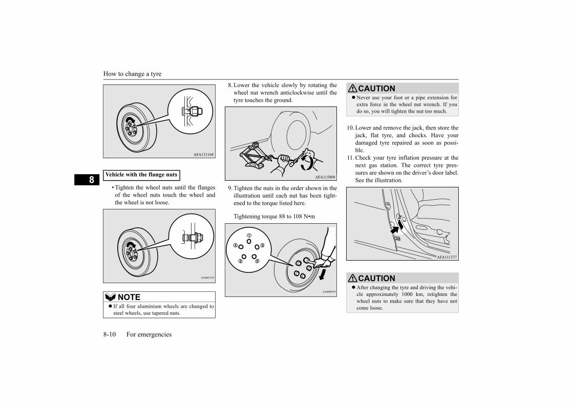
How to change a tyre
8-10 For emergencies
8• Tighten the wheel nuts until the flanges
of the wheel nuts touch the wheel andthe wheel is not loose.
8. Lower the vehicle slowly by rotating thewheel nut wrench anticlockwise until thetyre touches the ground.
9. Tighten the nuts in the order shown in theillustration until each nut has been tight-ened to the torque listed here.
Tightening torque 88 to 108 N•m
10. Lower and remove the jack, then store thejack, flat tyre, and chocks. Have yourdamaged tyre repaired as soon as possi-ble.
11. Check your tyre inflation pressure at thenext gas station. The correct tyre pres-sures are shown on the driver’s door label.See the illustration.
Vehicle with the flange nuts
NOTE If all four aluminium wheels are changed to
steel wheels, use tapered nuts.
CAUTIONNever use your foot or a pipe extension for
extra force in the wheel nut wrench. If youdo so, you will tighten the nut too much.
CAUTIONAfter changing the tyre and driving the vehi-
cle approximately 1000 km, retighten thewheel nuts to make sure that they have notcome loose.

How to change a tyre
For emergencies 8-11
8
E00803701802
1. Put the tyre on the centre of the tyrehanger, with the wheel surface facingupwards.
2. Lift up the tyre hanger (A) and hang it onthe hook (B).
3. Open the tailgate.First, hold the wheel nut wrench as shownin the illustration (C) and tighten the tyrehanger installation bolt. Then, hold thewheel nut wrench as shown in the illustra-tion (D) and tighten the bolt securely.
4. Install the tyre hanger installation boltcover.
5. Close the luggage floor board.
E00803801278
Reverse the removing procedure when stor-ing the jack, jack bar and wheel nut wrench.Refer to “Tools and jack” on page 8-5.
If the steering wheel vibrates when drivingafter changing the tyre, we recommend youto have the tyres checked for balance.
Do not mix one type of tyre with another oruse a different size from the one listed. Thiswould cause early wear and poor handling.
To store the spare wheel
CAUTION Storing the tyre with the wheel surface fac-
ing down may damage the wheel or tyrehanger. If you find any damage on a sparetyre, do not use the tyre and contact anauthorised MITSUBISHI MOTORS dealer.
CAUTION
CAUTIONDo not attach the hook to any part of the tyre
hanger other than the correct position. Other-wise the hook could damage the vehiclebody, or the tyre could fall while driving andcause an accident.
CAUTIONAfter storing the spare wheel, check that the
tyre hanger is securely locked in place. If thetyre hanger is not securely locked in place, itcould come loose and fall while you are driv-ing and cause an accident.
When removing the tyre hanger from thehook or hanging it back on the hook, hold thetyre hanger carefully so that it does not dropon your feet.
To store the tools and jack

Towing
8-12 For emergencies
8
E00801506641
If towing is necessary, we recommend you tohave it done by your authorisedMITSUBISHI MOTORS dealer or a com-mercial tow truck service.
In the following cases, transport the vehicleusing a tow truck.
The engine runs but the vehicle does notmove, or an abnormal noise is produced.
Inspection of the vehicle’s undersidereveals that oil or some other fluid is leak-ing.
If a wheel gets stuck in a ditch, do not try totow the vehicle.Please contact an authorised MITSUBISHIMOTORS dealer or a commercial tow truckservice for assistance.
Only when you cannot receive a towing ser-vice from an authorised MITSUBISHIMOTORS dealer or commercial tow truckservice, tow your vehicle carefully in accord-ance with the instructions given in “Emer-gency towing” in this part.
The regulations concerning towing may differfrom country to country. It is recommendedthat you obey the regulations of the areawhere you are driving your vehicle.
Release the parking brake.Place the selector lever in the “N” (NEU-TRAL) position.
Towing
If your vehicle needs to be towed
Towing the vehicle by a tow truck
CAUTION This vehicle must not be towed by a tow
truck using sling lift type equipment (TypeA) as illustrated. Using a sling lift will dam-age the bumper and front end.
Do not tow the vehicle with the drivingwheels on the ground (Type B) as illustrated.This could result in the driving system dam-age.
If the transmission is malfunctioning or dam-aged, transport the vehicle with the drivingwheels on a carriage (Type C, D or E) asillustrated.
If the vehicle is towed with the operationmode in ON and only the front wheels raisedoff the ground (Type C), the ASC may oper-ate, resulting in an accident. When towingthe vehicle with the front wheels raised, keepthe operation mode in ACC or OFF.
Towing with front wheels off the ground (Type C)

Towing
For emergencies 8-13
8
E00804201194
If towing service is not available in an emer-gency, your vehicle may be temporarilytowed by a rope secured to the towing hook.In case of your vehicle is to be towed byanother vehicle or your vehicle tows anothervehicle, pay careful attention to the followingpoints.
1. Take out the towing hook and jack bar.Refer to “Tools and jack” on page 8-5.
2. Cover the end of the jack bar (A) withcloth and use it to remove the lid from thefront bumper.
3. Use the jack bar to firmly attach the tow-ing hook.
4. Secure the tow rope to the front towinghook.
5. Keep the engine running.If the engine is not running, perform thefollowing operation to unlock the steeringwheel.[Except for vehicles with the keylessoperation system]Turn the ignition switch to the “ON” posi-tion.[For vehicles with the keyless operationsystem]Put the operation mode in ON.
Emergency towing
If your vehicle is to be towed by another vehicle
Type 1
NOTEUsing any part other than the designated
towing hook could result in damage to vehi-cle body.
Type 2Using a wire rope or metal chain can result
in damage to the vehicle body. It is best touse a non-metallic rope. If you use a wirerope or metal chain, wrap it with cloth at anypoint where it touches the vehicle body.
Use care that the tow rope is kept as horizon-tal as possible. An angled tow rope can dam-age the vehicle body.
Secure the tow rope to the same side towinghook, to keep the tow rope as straight as pos-sible.
WARNINGWhen the engine is not running, the brake
booster and power steering system do notoperate. This means higher brake depres-sion force and higher steering effort arerequired. Therefore, vehicle operation isvery difficult.
NOTE

Towing
8-14 For emergencies
8
6. Place the selector lever in the “N” (NEU-TRAL) position.
7. Turn on the hazard warning lamps ifrequired by law. (Follow the local drivinglaws and regulations)
8. During towing make sure that close con-tact is maintained between the drivers ofboth vehicles, and that the vehicles travelat low speed.
9. When finished towing, remove the towinghook, and stow it in the specified location.Refer to “Tools and jack” on page 8-5.When installing the bumper lid, align thehook with the cut out area on the vehicle,and firmly insert.
Remove the bumper lid on the rear bumper,and then install the towing hook (C) and useit for towing. The instructions are the same as
for “If your vehicle is to be towed by anothervehicle”.CAUTION
Do not leave the ignition switch in the“LOCK” position or the operation mode inOFF. The steering wheel will lock, causingloss of control.
WARNINGAvoid sudden braking, acceleration and
steering wheel movements; such drivingoperation could cause damage to the tow-ing hook or towing rope.People in the vicinity could be injured as aresult.
When going down a long slope, the brakesmay overheat, reducing effectiveness.Have your vehicle transported by a towtruck.
CAUTION The person in the vehicle being towed must
pay attention to the brake lamps of the tow-ing vehicle and make sure the rope neverbecomes slack.
When a vehicle is to be towed by anothervehicle with all wheels on the ground, makesure that the towing speed and distance givenbelow are never exceeded, avoiding damageto the transmission.
Towing speed: 40 km/hTowing distance: 40 km
For the towing speed and the towing dis-tance, follow the local driving laws and regu-lations.
If your vehicle tows another vehi-cle NOTE
Do not use the tie-down hook (D) for towing.This hook is provided only for the purpose oftransporting the vehicle itself.Using any part other than the designatedtowing hook (C) could result in damage tovehicle body.
Type 1
Type 2

Operation under adverse driving conditions
For emergencies 8-15
8
E00801704287
If water enters the brake discs, such aswhen driving through puddles, the brakesmay temporarily become ineffective. Insuch cases, lightly depress the brake pedalto see if the brakes operate properly. Ifthey do not, lightly depress the pedal sev-eral times while driving in order to dry thebrake pads.
When driving in rain or on a road withmany puddles a layer of water may formbetween the tyres and the road surface.
This reduces a tyre’s frictional resistanceon the road, resulting in loss of steeringstability and braking capability.
To cope with this, observe the followingitems:
Avoid high-speed operation, suddenacceleration, abrupt brake application andsharp cornering.
Depressing the brake pedal during travelon snowy or icy roads may cause tyreslippage and skidding. When tractionbetween the tyres and the road is reducedthe wheels may skid and the vehicle can-not readily be brought to a stop by con-ventional braking techniques. Brakingwill differ, depending upon whether youhave anti-lock brake system (ABS). Asyour vehicle is equipped with ABS, brakeby pressing the brake pedal hard, andkeeping it pressed.
Allow extra distance between your vehi-cle and the vehicle in front of you, andavoid sudden braking.
Accumulation of ice on the braking sys-tem can cause the wheels to lock. Pullaway from a standstill slowly after con-firming safety around the vehicle.
Drive as slow as possible when driving onbumpy or rutted roads.
Do not tow a vehicle heavier than your ownvehicle.
Operation under adverse driving conditions
On a flooded road
NOTE
(a) Drive your vehicle at a slow speed.(b) Do not drive on worn tyres.(c) Always maintain the specified tyre
inflation pressures.
CAUTIONDo not drive on flooded roads, through deep
puddles, and so on. If you inevitably had torun on a flooded road and the vehicle wasexposed to water, be sure to have your vehi-cle inspected by an authorised MITSUBISHIMOTORS dealer.
On a snow-covered or frozen road
CAUTIONDo not press the accelerator pedal rapidly. If
the wheels break free of the ice, the vehiclecould suddenly start moving and possiblycause an accident.
On a bumpy or rutted road

Operation under adverse driving conditions
8-16 For emergencies
8
CAUTION The impact on tyres and/or wheels when
driving on a bumpy or rutted road can dam-age the tyre and/or wheel.

9
Vehicle care
Vehicle care precautions ..................................................................9-2Cleaning the interior of your vehicle ...............................................9-2Cleaning the exterior of your vehicle ..............................................9-3

Vehicle care precautions
9-2 Vehicle care
9
E00900102034
In order to maintain the value of your vehicle,it is necessary to perform regular mainte-nance using the proper procedures.Always maintain your vehicle in compliancewith any environmental pollution control reg-ulations.Carefully select the materials used for wash-ing, etc., to be sure that they do not containcorrosives.If in doubt, we recommend you to consult aspecialist for the selection of these materials.
E00900201878
After cleaning the interior of your vehiclewith water, cleaner or similar, wipe and dry ina shady, well-ventilated area.
E00900301619
1. Lightly wipe these off with a soft clothsoaked in a mild soap and water solution.
2. Dip cloth in fresh water and wring it outwell. Using this cloth, wipe off the deter-gent thoroughly.
E00900501233
1. To maintain the value of your new vehi-cle, handle the upholstery carefully andkeep the interior clean.
Vehicle care precautions
CAUTIONCleaning products can be dangerous. Always
follow the instructions of the cleaning prod-uct supplier.
To avoid damage, never use the following toclean your vehicle.• Petrol• Paint Thinner• Benzine• Kerosene• Turpentine• Naphtha• Lacquer Thinner• Carbon Tetrachloride• Nail Polish Remover• Acetone
Cleaning the interior of your vehicle
NOTE To clean the inside of the tailgate window,
always use a soft cloth and wipe the windowglass along the demister heater element so asnot to cause damage.
CAUTIONDo not use organic substances (solvents,
benzine, kerosene, alcohol, petrol, etc.) oralkaline or acidic solutions.These chemicals can cause discolouring,staining or cracking of the surface.If you use cleaners or polishing agents, makesure their ingredients do not include the sub-stances mentioned above.
Plastic, vinyl leather, fabric and flocked parts
NOTEDo not use cleaners, conditioners, and pro-
tectants containing silicones or wax.Such products can cause discolouring and,when applied to the instrument panels orother parts, may cause reflections on thewindscreen and obscure vision.Also, if such products get on the switches ofthe electrical accessories, it may lead to fail-ure of these accessories.
Do not use synthetic fiber or dry cloth. Theycan cause discolouring or damaging the sur-face.
Do not place a deodorizer on the instrumentpanel or near lamps and instruments. Theingredients for deodorizer can cause discol-ouring or cracking.
Upholstery

Cleaning the exterior of your vehicle
Vehicle care 9-3
9
Use a vacuum cleaner and brush to cleanthe seats. If stained, vinyl and syntheticleather should be cleaned with an appro-priate cleaner. Cloth fabrics can becleaned with either upholstery cleaner or amild soap and water solution.
2. Clean the carpeting with a vacuumcleaner and remove any stains with carpetcleaner. Oil and grease can be removed bylightly dabbing with a clean colourfastcloth and stain remover.
E00900602042
1. To clean, lightly wipe the leather with asoft cloth soaked in a mild soap and watersolution.
2. Dip cloth in fresh water and wring it outwell. Using this cloth, wipe off the deter-gent thoroughly.
3. Apply leather protecting agent to the gen-uine leather surface.
E00900701293
If the following is left on your vehicle, it maycause corrosion, discolouration and stains,wash the vehicle as soon as possible.
Seawater, road deicing products.Soot and dust, iron powder from factories,
chemical substance (acids, alkalis, coal-tar, etc.).
Droppings from birds, carcasses ofinsects, tree sap, etc.
E00900904502
Chemicals contained in the dirt and dustpicked up from the road surface can damage
the paint coat and body of your vehicle if leftin prolonged contact.Frequent washing and waxing is the best wayto protect your vehicle from this damage.This will also be effective in protecting itfrom environmental elements such as rain,snow, salt air, etc.Do not wash the vehicle in direct sunlight.Park the vehicle in the shade and spray it withwater to remove dust. Next, using an ampleamount of clean water and a car washingbrush or sponge, wash the vehicle from top tobottom.Use a mild car washing soap if necessary.Rinse thoroughly and wipe dry with a softcloth. After washing the vehicle, carefullyclean the joints and flanges of the doors, bon-net and other sections where dirt is likely toremain.
Genuine leather*
NOTE If genuine leather is wet with water or is
washed in water, wipe off water as quickly aspossible with a dry, soft cloth.If left damp, mildew may grow.
Organic solvents such as benzine, kerosene,alcohol and petrol, acid or alkaline solventsmay discolour the genuine leather surface.Be sure to use neutral detergents.
Remove dirty patches or oil substancesquickly as they can stain genuine leather.
The genuine leather surface may harden andshrink if it is exposed to direct rays of thesun for long hours. When your vehicle isparked, place it in the shade as much as pos-sible.
When the temperature of the vehicle interiorrises in summer, vinyl products left on thegenuine leather seat may deteriorate andstick to the seat.
Cleaning the exterior of your vehicle
Washing
NOTE
CAUTIONWhen washing the under side of your vehicle
or wheel, be careful not to injure your hands.Refrain from excessively using a car wash as
its brushes may scratch the paint surface,causing it to lose its gloss. Scratches will beespecially visible on darker coloured vehi-cles.

Cleaning the exterior of your vehicle
9-4 Vehicle care
9
The salt and other chemicals spread on theroads in some areas in winter can have aharmful effect on the vehicle body. Youshould therefore wash the vehicle as often aspossible in accordance with our care-instruc-tions. It is recommended to have a preserva-tive applied and the underfloor protectionchecked before and after the cold weatherseason.After washing your vehicle, wipe off allwater drops from the rubber parts around thedoors to prevent the doors from freezing.
E00901002115
Waxing the vehicle will help prevent theadherence of dust and road chemicals to thepaintwork. Apply a wax solution after wash-ing the vehicle, or at least once every threemonths to assist displacing of water.Do not wax your vehicle in direct sunlight.You should wax after the surfaces havecooled.For information on how to use wax refer tothe owner’s manual of the wax.
E00901101236
The vehicle should only be polished if thepaintwork has become stained or lost its lus-tre. Do not polish parts with a mat coatingand the plastic bumpers. Doing so couldcause stains or damage the finish.
Never spray or splash water on the electricalcomponents in the engine compartment.Doing so could have an adverse effect on theengine startability.Exercise caution also when washing theunderbody; be careful not to spray water intothe engine compartment.
Some types of hot water washing equipmentapply high pressure and heat to the vehicle.They may cause heat distortion and damageto the vehicle resin parts and may result inflooding of the vehicle interior.Therefore;• Maintain a distance of approximately 70 cm
or more between the vehicle body and thewashing nozzle.
• When washing around the door glass, holdthe nozzle at a distance of more than 70 cmand at right angles to the glass surface.
After washing the vehicle, drive the vehicleslowly while lightly depressing the brakepedal several times in order to dry out thebrakes.Leaving the brakes wet could result inreduced braking performance. Also, there isa possibility that they could freeze up orbecome inoperative due to rust, rendering thevehicle unable to move.
CAUTIONUsing an automatic car wash, pay attention
to the following items, referring to theowner’s manual or consulting a car washoperator. If the following procedure is notfollowed, it could result in damage to yourvehicle.• The outside rear-view mirrors are retracted.• The pole antenna is removed. For details,
refer to “Antenna: To remove” on page7-30.
• The wiper arms are secured in place withtape.
• If your vehicle is equipped with a roof rails,consult a car wash operator before using thecar wash.
During cold weather
CAUTION NOTE To prevent freezing of the weatherstripping
on the doors, bonnet, etc., they should betreated with silicone spray.
Waxing
CAUTIONWaxes containing high abrasive compounds
should not be used.
Polishing
Cleaning the exterior of your vehicle
Vehicle care 9-5
9
E00901301980
Use a sponge or chamois leather.If a car wax adheres on a grey or black roughsurface of the bumper, moulding or lamps,the surface becomes white. In such a case,wipe it off using lukewarm water and softcloth or chamois leather.
E00901401268
In order to prevent spots and corrosion ofchrome parts, wash with water, dry thor-oughly, and apply a special protective coat-ing. This should be done more frequently inwinter.
E00901501780
1. Remove dirt using a sponge while sprin-kling water on the wheels.
2. Use neutral detergent on any dirt that can-not be removed easily with water.Rinse off the neutral detergent after wash-ing the wheels.
3. Dry the wheels thoroughly using a cham-ois leather or a soft cloth.
E00901601390
The window glass can normally be cleanedusing only a sponge and water.Glass cleaner can be used to remove oil,grease, insect carcasses, etc. After washing
the glass, wipe it dry with a clean, dry, softcloth. Never use a cloth that is used for clean-ing a painted surface to clean a window. Waxfrom the painted surface could get on theglass and lower glass transparency and visi-bility.
E00901701229
Use a soft cloth and glass cleaner to removegrease, dead insects, etc., from the wiperblades. Replace the wiper blades when theyno longer wipe properly. (Refer to page10-13.)
E00902101594
Clean the engine compartment at the begin-ning and end of winter. Pay particular atten-tion to flanges, crevices and peripheral partswhere dust containing road chemicals andother corrosive materials might collect.
Cleaning plastic parts
CAUTIONDo not use a scrubbing brush or other hard
tools as they may damage the plastic partsurface.
Do not bring the plastic parts into contactwith petrol, light oil, brake fluids, engineoils, greases, paint thinners, and sulphuricacid (battery electrolyte) which may crack,stain or discolour the plastic parts.If they touch the plastic parts, wipe them offwith soft cloth, chamois or the like and anaqueous solution of neutral detergent thenimmediately rinse the affected parts withwater.
Chrome parts
Aluminium wheels*
CAUTIONDo not use a brush or other hard implement
on the wheels.Doing so could scratch the wheels.
Do not use any cleaner that contains an abra-sive substance or is acidic or alkaline. Doingso could cause the coating on the wheels topeel or become discoloured or stained.
Do not directly apply hot water using a steamcleaner or by any other means.
Contact with seawater and road deicer cancause corrosion. Rinse off such substances assoon as possible.
Window glass
NOTE To clean the inside of the rear window,
always use a soft cloth and wipe the windowglass along the demister heater element so asnot to cause damage.
Wiper blades
Engine compartment

Cleaning the exterior of your vehicle
9-6 Vehicle care
9
If salt and other chemicals are used on theroads in your area, clean the engine compart-ment at least every three months.Never spray or splash water on the electricalcomponents in the engine compartment, asthis may cause damage.Do not bring the nearby parts, the plasticparts and so on into contact with sulphuricacid (battery electrolyte) which may crack,stain or discolour them.If they are in contact, wipe off with soft cloth,chamois or the like and an aqueous solutionof neutral detergent then immediately rinsethe affected parts with plenty of water.

10
Maintenance
Service precautions ........................................................................10-2Catalytic converter .........................................................................10-3Bonnet ............................................................................................10-3Engine oil .......................................................................................10-4Engine coolant ...............................................................................10-5Washer fluid ...................................................................................10-6Brake fluid .....................................................................................10-7Battery ............................................................................................10-8Tyres ............................................................................................10-10Wiper blade rubber replacement ..................................................10-13General maintenance ...................................................................10-14Fusible links .................................................................................10-15Fuses ............................................................................................10-15Replacement of lamp bulbs .........................................................10-19

Service precautions
10-2 Maintenance
10
E01000103097
Adequate care of your vehicle at regularintervals serves to preserve the value andappearance as long as possible.Maintenance items as described in thisowner’s manual can be performed by theowner.We recommend you to have the periodicinspection and maintenance performed by anauthorised MITSUBISHI MOTORS dealer oranother specialist.In the event a malfunction or a problem isdiscovered, we recommend you to have itchecked and repaired. This section containsinformation on inspection maintenance pro-cedures that you can do yourself. Follow theinstructions and cautions for each of the vari-ous procedures.
Check items of engine compartment arelocated as shown in the figure below.
Service precautions
A- Cooling fan
B- Caution labelC- Resistor
WARNINGWhen checking or servicing the inside of
the engine compartment, make sure theengine is switched off and has had achance to cool down.
If it is necessary to do work in the enginecompartment with the engine running, beespecially careful that your clothing, hair,etc., does not become caught by the cool-ing fan, drive belts, or other moving parts.
After performing the maintenance work,make sure that no tools or cloths are leftbehind in the engine compartment.If they are left behind, a fire or damage tothe vehicle may occur.
The cooling fan can turn on automaticallyeven if the engine is not running. Turn theignition switch to the “LOCK” position orput the operation mode in OFF to be safewhile you work in the engine compart-ment.
Because the resistor (C) may be hot even ifthe cooling fan has stopped, do not touchthe resistor. Burns could result.
Do not smoke, cause sparks or allow openflames around fuel or battery. The fumesare flammable.
Be extremely cautious when workingaround the battery. It contains poisonousand corrosive sulphuric acid.
Do not get under your vehicle with just thebody jack supporting it. Always use auto-motive jack stands.
Improper handling of components andmaterials used in the vehicle can endangeryour personal safety. We recommend youto consult a specialist for necessary infor-mation.
1. Engine oil level gauge2. Brake fluid reservoir3. Engine oil cap4. Washer fluid reservoir5. Engine coolant reservoir6. Battery
WARNING

Catalytic converter
Maintenance 10-3
10
E01000202730
The exhaust gas scavenging devices usedwith catalytic converter are extremely effi-cient for the reduction of noxious gases. Thecatalytic converter is installed in the exhaustsystem.It is important to keep the engine properlytuned to ensure proper catalyst operation andprevent possible catalyst damage.
E01000304810
1. Pull the release lever towards you tounlock the bonnet.
2. Raise the bonnet while pressing the safetylock.
3. Support the bonnet by inserting the sup-port bar in its slot.
Catalytic converter
WARNINGAs with any vehicle, do not park or oper-
ate this vehicle in areas where combustiblematerials such as dry grass or leaves cancome in contact with a hot exhaust since afire could occur.
Paint should not be applied to the catalyticconverter.
NOTEUse fuel of the type recommended in “Fuel
selection” on page 2-2.
Bonnet
To open
NOTEOnly open the bonnet when the wipers are in
the original position. In any other position,the wipers could damage the paint or bonnet.
CAUTIONNote that the support bar may disengage the
bonnet if the open bonnet is lifted by a strongwind.
After inserting the support bar into the slot,make sure the bar supports the bonnetsecurely from falling down on to your heador body.

Engine oil
10-4 Maintenance
10
1. Unlatch the support bar and clip it in itsholder.
2. Slowly lower the bonnet to a positionapproximately 20 cm above the closedposition, then let it drop.
3. Make sure the bonnet is securely lockedby softly lifting the centre of the bonnet.
E01000405498
The engine oil used has a significant effect onthe engine’s performance, service life andstartability. Be sure to use oil of the recom-mended quality and appropriate viscosity.All engines consume a certain amount of oilduring normal operation. Therefore, it is
important to check the oil level at regularintervals or before starting a long trip.
1. Park the vehicle on a horizontal surface.2. Switch off the engine.3. Wait a few minutes.4. Remove the dipstick and wipe it with a
clean cloth.5. Reinsert the dipstick as far as it goes.6. Remove the dipstick and confirm that the
oil level is between the marks (A) and(B).
7. If the oil level is less than the level indi-cated by the mark (A), remove the capand add enough oil to raise the level tobetween the marks (A) and (B).
8. After adding oil, close the cap securely.9. Confirm the oil level by repeating step 4
to 6.
To close
CAUTIONBe careful that hands or fingers are not
trapped when closing the bonnet.Before driving, make sure that the bonnet is
securely locked. An incompletely lockedbonnet can suddenly open while driving.This can be extremely dangerous.
NOTE If this does not close the bonnet, release it
from a slightly higher position.Do not press down firmly on the bonnet as
doing so could damage it.
Engine oil
To check and refill engine oil
A: Minimum levelB: Maximum level
B A
NOTE To avoid engine damage, do not overfill by
exceeding the mark (B).Be sure to use the specified engine oil and do
not mix various types of oil.When the oil level is checked in step 6
above, check it on a low side of the dipstickbecause it is different in appearance of oillevel in the two sides of the dipstick.
The engine oil will deteriorate rapidly if thevehicle is subjected to severe conditions,requiring earlier oil replacement.Please refer to the maintenance schedule.

Engine coolant
Maintenance 10-5
10
Select engine oil of the proper SAE vis-cosity number according to the atmos-pheric temperature.SAE 0W-20, 5W-20, 0W-30, 5W-30, and5W-40 engine oils can only be used ifthey meet ACEA A3/B3, A3/B4 or A5/B5and API SG (or higher) specifications.
Use engine oil conforming to the follow-ing classification:• API classification: “For service SG” or
higher• ILSAC certificated oil
• ACEA classification:“For service A1/B1, A3/B3, A3/B4, orA5/B5”
E01000503727
A transparent coolant reserve tank (A) islocated in the engine compartment.The coolant level in this tank should be keptbetween the “L” (LOW) and “F” (FULL)marks when measured while the engine iscold.
The cooling system is a closed system andnormally the loss of coolant should be veryslight. A noticeable drop in the coolant levelcould indicate leakage. If this occurs, havethe system checked at an authorisedMITSUBISHI MOTORS dealer as soon aspossible.If the level should drop below the “L” (LOW)level on the reserve tank, open the lid and addcoolant.Also, if the reserve tank is completely empty,remove the radiator cap (B) and add coolantuntil the level reaches the filler neck.
For handling of used engine oils, refer to“Used engine oils safety instructions” onpage 2-6.
Recommended engine oil vis-cosity
NOTE
NOTEUse of additives is not recommended since
they may reduce the effectiveness of addi-tives already included in the engine oil. Itmay result in failure of the mechanicalassembly.
If those classifications are not available, con-tact an authorised MITSUBISHI MOTORSdealer.
Engine coolant
To check the coolant level
To add coolant
FULL
LOW

Washer fluid
10-6 Maintenance
10
The engine coolant contains an ethylene gly-col anti-corrosion agent. Some parts of theengine are cast aluminium alloy, and periodicchanging of the engine coolant is necessary toprevent corrosion of these parts.
MITSUBISHI MOTORS GENUINE Coolanthas excellent protection against corrosion andrust formation of all metals including alumin-ium and can avoid blockages in the radiator,heater, cylinder head, engine block, etc.Because of the necessity of this anti-corrosionagent, the coolant must not be replaced withplain water even in summer. The required
concentration of anti-freeze differs dependingon the expected ambient temperature.
Above -35 °C: 50 % concentration of anti-freezeBelow -35 °C: 60 % concentration of anti-freeze
If the temperatures in your area drop belowfreezing, there is the danger that the coolant
in the engine or radiator could freeze andcause severe damage to the engine and/orradiator. Add a sufficient amount of anti-freeze to the coolant to prevent it from freez-ing.The concentration should be checked beforethe start of cold weather and anti-freezeadded to the system if necessary.
E01000702517
Open the washer fluid reservoir cap andcheck the level of washer fluid.If the level is low, replenish the containerwith washer fluid.
WARNINGDo not open the radiator cap (B) while the
engine is hot. The coolant system is underpressure and any hot coolant escapingcould cause severe burns.
Anti-freeze
Use “MITSUBISHI MOTORS GENUINESUPER LONG LIFE COOLANT PRE-MIUM” or equivalent*.*: similar high quality ethylene glycol based
non-silicate, non-amine, non-nitrate andnon-borate coolant with long life hybridorganic acid technology
CAUTIONDo not use alcohol or methanol anti-freeze or
any engine coolants mixed with alcohol ormethanol anti-freeze. The use of an improperanti-freeze can cause corrosion of the alu-minium components.
Do not use water to adjust the concentrationof coolant.
Concentrations exceeding 60 % will result ina reduction of both the anti-freeze and cool-ing performance thus adversely affecting theengine.
Do not top up with water only.Water by itself reduces the rust-protectiveand anti-freeze qualities of the coolant andhas a lower boiling point. It can also causedamage to the cooling system if it shouldfreeze. Do not use tap water, as it can causecorrosion and rust formation.
During cold weather
Washer fluid
LOW

Brake fluid
Maintenance 10-7
10
To ensure proper operation of the washers atlow temperatures, use a fluid containing ananti-freezing agent.
E01000802055
The fluid level must be between the “MAX”and “MIN” marks on the reservoir.
The fluid level is monitored by a float. Whenthe fluid level falls below the “MIN” mark,the brake warning lamp lights up.The fluid level falls slightly with wear of thebrake pads, but this does not indicate anyabnormality.
The fluid in the master cylinder should bechecked when doing other work under thebonnet. The brake system should also bechecked for leaks at the same time.
If the fluid level falls markedly in a shortlength of time, it indicates leaks from thebrake system.If this occurs, we recommend you to have thevehicle checked.
Use brake fluid conforming to DOT3 orDOT4 from a sealed container. The brakefluid is hygroscopic. Too much moisture inthe brake fluid will adversely affect the brakesystem, reducing the performance.
CAUTIONDo not use any fluid other than water or
washer fluid.Also, do not use soapy water, engine anti-freeze, or other liquid instead of washerfluid.Other liquids could cause streaking on thevehicle’s painted surfaces, damage thewasher pump, or clog the nozzle, leading tothe washer fluid not spraying.
NOTE The washer fluid container serves the wind-
screen and rear window. If the washer fluid level in the washer fluid
reservoir is at the LOW mark, you canreplenish with approximately 2 litres ofwasher fluid.
During cold weather
Brake fluid
To check the fluid level
Fluid type
WARNINGTake care in handling brake fluid as it is
harmful to the eyes, may irritate your skinand will damage to painted surfaces. Wipeup spills immediately. If brake fluid getson your hands or in your eyes, flush imme-diately with clean water. Follow up with adoctor as necessary.
CAUTIONUse only the specified brake fluid.
Do not mix or add different brand of brakefluid to prevent chemical reaction.Do not let any petroleum-based fluid touch,mix with, or get into the brake fluid.This will damage the seals.

Battery
10-8 Maintenance
10
E01001203981
The condition of the battery is very importantfor quick starting and to keep the vehicle’selectrical system working properly. Regularinspection and care are especially importantin cold weather.
Keep the reservoir tank cap closed to preventthe brake fluid from deteriorating exceptmaintenance.
Make sure that the projection on the fillercap is pointing rearward as shown in theillustration when the cap is closed.
*: Front of the vehicleClean the filler cap before removing and
close the cap securely after maintenance.
Battery
CAUTION NOTEAfter replacing the battery, the electronic
control system data for the automatic trans-mission, etc., will be erased. As a result, shiftshocks may occur.Shift shocks will become smoother after sev-eral changes in speed.
Battery precautions
WARNINGNote operating instructions
When you handle the battery, carefullyobserve the following cautions for safety.
No smoking, no naked flames, no sparks
Keep sparks, cigarettes, and flames awayfrom the battery because the battery couldexplode. Also, do not short-circuit the bat-tery terminals. Doing so could createsparks.
Shield eyes
Always wear protective eye goggles whenworking near the battery. Battery electro-lyte contains sulphuric acid, so getting itin your eyes is dangerous.
Battery acid
Battery electrolyte contains sulphuricacid, so you must wear gloves and eye pro-tection when handling the battery.If battery electrolyte gets in your eyes oron your skin, rinse it away with cleanwater and immediately see a doctor.If you accidentally swallow battery elec-trolyte, immediately see a doctor.If battery electrolyte splashes on yourclothing or on the vehicle, rinse it off withlots of water.
Explosive gas
The battery emits highly explosive hydro-gen gas. Ventilate when charging the bat-tery in an enclosed space.
WARNING

Battery
Maintenance 10-9
10
The electrolyte level must be between thespecified limit on the outside of the battery.Replenish with distilled water as necessary.The inside of the battery is divided into sev-eral compartments; remove the cap from eachcompartment and fill to the upper mark. Donot top up beyond the upper mark becausespillage during driving could cause damage.
Check the electrolyte level at least once everyfour weeks, depending on the operating con-ditions.If the battery is not used, it will discharge byitself with time.Check it once every four weeks and chargewith low current as necessary.
The capacity of the battery is reduced at lowtemperatures. This is an inevitable result ofits chemical and physical properties. This iswhy a very cold battery, particularly one thatis not fully charged will only deliver a frac-tion of the starter current which is normallyavailable.We recommend you to have the batterychecked before the start of cold weather and,if necessary, have it charged or replaced.This does not only ensures reliable starting,but a battery which is kept fully charged alsohas a longer life.
To disconnect the battery cable, stop theengine, first disconnect the negative (-) termi-nal and then the positive (+) terminal. Whenconnecting the battery, first connect the posi-
tive (+) terminal and then the negative (-) ter-minal.
Keep away from children
Keep it out of reach of children.
Checking battery electrolyte level
WARNING
During cold weather
Disconnection and connection
NOTEOpen the terminal cover (A) before discon-
necting or connecting the positive (+) termi-nal of the battery.
Loosen the nut (B), and then disconnect thebattery cable from the positive (+) terminal.
WARNINGKeep sparks, cigarettes, and flames away
from the battery because the battery couldexplode.
The battery electrolyte is extremely caus-tic. Do not allow it to come in contact withyour eyes, skin, clothing, or the paintedsurfaces of the vehicle.Spilt electrolyte should be flushed imme-diately with ample amounts of water.Irritation to eyes or skin from contactwith electrolyte requires immediate medi-cal attention.

Tyres
10-10 Maintenance
10E01001301526
Ventilate when charging or using the bat-tery in an enclosed space.
CAUTIONKeep it out of reach of children.Never disconnect the battery when the igni-
tion switch is in the “ON” position or theoperation mode in ON. Doing so could dam-age electric components.
Never short-circuit the battery. This couldcause it to overheat and be damaged.
If the battery is to be quick-charged, first dis-connect the battery cables.
In order to prevent a short circuit, be sure todisconnect the negative (-) terminal first.
Always wear protective eye goggles whenworking near the battery.
Do not bring the nearby parts, the plasticparts and so on into contact with sulphuricacid (battery electrolyte) which may crack,stain or discolour them.If they are in contact, wipe off with softcloth, chamois or the like and an aqueoussolution of neutral detergent then immedi-ately rinse the affected parts with plenty ofwater.
WARNING NOTEKeep the terminals clean. After the battery is
connected, apply terminal protection grease.To clean the terminals, use lukewarm water.
Check to see if the battery is securelyinstalled and cannot be moved during travel.Also check each terminal for tightness.
When the vehicle is to be left unused for along period of time, remove the battery andstore it in a place where the battery fluid willnot freeze. The battery should be stored onlyin a fully charged condition.
Tyres
WARNINGDriving with tyres that are worn, damaged
or improperly inflated can lead to a loss ofcontrol or blow out of the tyres which canresult in a collision with serious or fatalinjury.

Tyres
Maintenance 10-11
10
E01001404847
Check the tyre inflation pressure of all the tyres while they are cold; if insufficient or excessive, adjust to the specified value.After the tyre inflation pressure has been adjusted, check the tyres for damage and air leaks. Be sure to put caps on the valves.
Tyre inflation pressures
Tyre size1–5 persons + cargo 6–7 persons + cargo
Front Rear Front Rear
185/65R15 88H 2.3 bar (33 PSI)[230 kPa]
2.3 bar (33 PSI)[230 kPa]
2.3 bar (33 PSI)[230 kPa]
2.8 bar (41 PSI)[280 kPa]
205/55R16 91V 2.1 bar (30 PSI)[210 kPa]
2.1 bar (30 PSI)[210 kPa]
2.1 bar (30 PSI)[210 kPa]
2.6 bar (38 PSI)[260 kPa]
205/55R17 91V 2.1 bar (30 PSI)[210 kPa]
2.1 bar (30 PSI)[210 kPa]
2.1 bar (30 PSI)[210 kPa]
2.6 bar (38 PSI)[260 kPa]
NOTE The tyres that can be installed on your vehicle are shown on the driver’s door label. For details, contact an authorised MITSUBISHI MOTORS dealer.

Tyres
10-12 Maintenance
10
E01001802140
Check the tyres for cuts, cracks and otherdamage. Replace the tyres if there are deepcuts or cracks. Also check each tyre forpieces of metal or pebbles.The use of worn tyres can be very dangerousbecause of the greater chance of skidding orhydroplaning. The tread depth of the tyresmust exceed 1.6 mm in order for the tyres tomeet the minimum requirement for use.Tread wear indicators will appear on the sur-face of the tyre as the tyre wears, therebyindicating that the tyre no longer meets theminimum requirement for use. When thesewear indicators appear, the tyres must bereplaced with new ones.
E01007201888
E01001902763
Tyre wear varies with vehicle conditions,road surface conditions and individualdriver’s driving habits. To equalise the wearand help extend tyre life, it is recommendedto rotate the tyres immediately after discoveryof abnormal wear, or whenever the wear dif-ference between the front and rear tyres isrecognisable.When rotating tyres, check for uneven wearand damage. Abnormal wear is usuallycaused by incorrect tyre pressure, improperwheel alignment, out of balance wheel, orsevere braking. Consult an authorised
MITSUBISHI MOTORS dealer to determinethe cause of irregular tread wear.Wheel condition
1- Location of the tread wear indicator2- Tread wear indicator
Replacing tyres and wheels
CAUTIONAvoid using different size tyres from the one
listed and the combined use of differenttypes of tyres, as this can affect drivingsafety.Refer to “Tyres and wheels” on page 11-7.
Even if a wheel has the same rim size andoffset as the specified type of wheel, itsshape may prevent it from being fitted cor-rectly. We recommend you to consult a spe-cialist before using wheels that you have.
Tyre rotation
*: If the spare tyre wheel differs from thestandard tyre wheel, do not perform tyrerotation using a spare wheel.
Spare tyre used*
Front
Spare tyre not used
Front
Tyres that have arrows showing rotation direction
Front

Wiper blade rubber replacement
Maintenance 10-13
10
E01002601685
1. Lift the wiper arm off the windscreen.2. Pull the wiper blade until its stopper (A)
disengages from the hook (B). Pull thewiper blade further to remove it.
3. Attach the retainers (C) to a new wiperblade.Refer to the illustration to ensure that theretainers are correctly aligned as youattach them.
4. Insert the wiper blade into the arm, start-ing with the opposite end of the bladefrom the stopper. Make sure the hook (B)is fitted correctly in the grooves in theblade.
5. Push the wiper blade until the hook (B)engages securely with the stopper (A).
CAUTION If the tyres have arrows (A) indicating the
correct direction of rotation, swap the frontand rear tyres on the left-hand side of thevehicle and the front and rear tyres on theright-hand side of the vehicle separately.Keep each tyre on its original side of thevehicle. When fitting the tyres, make surethe arrows point in the direction in which thewheels will turn when the vehicle moves for-ward. Any tyre whose arrow points in thewrong direction will not perform to its fullpotential.
CAUTIONAvoid the combined use of different types of
tyres.Using different types of tyres can affect vehi-cle performance and safety.
Front
Wiper blade rubber replace-ment
Windscreen wiper blades
CAUTIONDo not allow the wiper arm to fall onto the
windscreen. This could damage the glass.
NOTE If retainers are not supplied with the new
wiper blade, use the retainers from the oldblade.

General maintenance
10-14 Maintenance
101. Lift the wiper arm off the window glass.2. Pull the wiper blade downward to disen-
gage it from the stopper (A) at the end ofthe wiper arm. Pull the wiper blade fur-ther to remove it.
3. Slide a new wiper blade through the hook(B) on the wiper arm.
4. Firmly insert the retainer (C) into thegroove (D) in the wiper blade.Refer to the illustration to ensure that theretainers are correctly aligned as youinsert them into the groove.
E01002701703
Look under the body of your vehicle to checkfor fuel, engine coolant, oil and exhaust gasleaks.
Operate the combination lamp switch tocheck that all lamps are functioning properly.If the lamps do not illuminate, the probablecause is a blown fuse or defective lamp bulb.Check the fuses first. If there is no blownfuse, check the lamp bulbs.For information regarding the inspection andreplacement of the fuses and the bulbs, referto “Fuses” on page 10-15 and “Replacementof lamp bulbs” on page 10-19.
Rear window wiper blade
CAUTIONDo not allow the wiper arm to fall onto the
windows glass; it could damage the glass.
NOTE If a retainer is not supplied with the new
wiper blade, use the retainer from the oldblade.
General maintenance
Fuel, engine coolant, oil and exhaust gas leakage
WARNING If you see a suspicious fuel leak or if you
smell fuel, do not operate the vehicle; callauthorised MITSUBISHI MOTORSdealer for assistance.
Exterior and interior lamp operation

Fusible links
Maintenance 10-15
10
If the fuses and bulbs are all OK, we recom-mend you to have your vehicle checked andrepaired.
Start the engine and check the operation of allinstruments, gauges and indicator and warn-ing lamps.If there is anything wrong, we recommendyou to have your vehicle inspected.
Check all latches and hinges, and, if neces-sary, have them lubricated.
E01002901792
The fusible links will melt to prevent a fire ifa large current attempts to flow through cer-tain electrical systems.In case of a melted fusible link, we recom-mend you to have your vehicle inspected.For the fusible links, please refer to “Passen-ger compartment fuse location table” on page10-16 and “Engine compartment fuse loca-tion table” on page 10-17.
E01003003677
To prevent damage to the electrical systemdue to short-circuiting or overloading, eachindividual circuit is provided with a fuse.There are fuse blocks in the passenger com-partment and in the engine compartment.
The fuse block in the passenger compartmentis located behind the glove box at the positionshown in the illustration.
1. Open the glove box.2. Pull the glove box fastener (A), then the
fastener (B), in the directions of thearrows shown in the illustration to removethem.
3. Slide the glove box at an angle to unhookthe hook (C) on each side, and then pullout the glove box to remove it.
Meter, gauge and indica-tor/warning lamps operation
Hinges and latches lubrication
Fusible links
WARNING Fusible links must not be replaced by any
other device. Failing to fit the correct fusi-ble link may result in fire in the vehicle,property destruction and serious or fatalinjuries at any time.
Fuses
Fuse block location
Passenger compartment

Fuses
10-16 Maintenance
10In the engine compartment, the fuse block islocated as shown in the illustration.
E01007702138
The fuse capacity and the names of electricalsystems protected by the fuses are indicatedon the back of the glove box and inside of thefuse block cover (inside of the engine com-partment).
E01007902244
Engine compartment
1- Press the tab.2- Remove the cover.
Fuse load capacity
NOTE Spare fuses are provided in the fuse block of
the engine compartment. Always use a fuseof the same capacity for replacement.
Passenger compartment fuse loca-tion table
No. Sym-bol Electrical system Capac-
ities
1 Tail lamp (left) 7.5 A
2 Cigarette lighter 15 A
3 Ignition coil 10 A
4 Starter motor 7.5 A
5 — — —
6 Accessory socket 15 A
7 Tail lamp (right) 7.5 A
8 Outside rear-view mirrors 7.5 A
9 Engine control unit 7.5 A
10 Control unit 7.5 A
11 Rear fog lamp 10 A
12 Central door lock 15 A
13 Room lamp 15 A
14 Rear window wiper 15 A
15 Gauge 7.5 A
16 Relay 7.5 A
17 Rear cooler 10 A
18 Option 10 A
19 Demister switch Illu-mination 7.5 A

Fuses
Maintenance 10-17
10Some fuses may not be installed on your
vehicle, depending on the vehicle modelor specifications.
The table above shows the main equip-ment corresponding to each fuse.
E0100800234320 Windscreen wiper 25 A
21 Reversing lamps 7.5 A
22 Demister 30 A
23 Heater 30 A
24 — — —
25 Radio 10 A
26 Electronic con-trolled unit 20 A
No. Sym-bol Electrical system Capac-
itiesEngine compartment fuse location table
No. Symbol Electrical sys-tem Capacity
SBF1 Ignition switch 40 A*
SBF2
Electric win-dow control 30 A*
SBF3
Anti-lockbraking system 30 A*
SBF4
Anti-lockbraking system 40 A*
F1 — — —
F2 Hazard warn-ing flasher 10 A
F3 Starter 7.5 A
F4 Automatic transmission 15 A
F5 — — —F6 — — —F7 — — —F8 — — —
F9 Alternator 7.5 A
F10 ETV 15 A
F11 Air condition-ing 10 A
F12 Engine control 7.5 A
F13 Stop lamps (Brake lamps) 10 A
F14 Fuel pump 15 A
F15 ENG/POWER 15 A
F16 — — —
F17 Fog lamps 15 A
F18 Daytime run-ning lamps 10 A
No. Symbol Electrical sys-tem Capacity

Fuses
10-18 Maintenance
10
*: Fusible link
Some fuses may not be installed on yourvehicle, depending on the vehicle modelor specifications.
The table above shows the main equip-ment corresponding to each fuse.
The fuse block does not contain spare 7.5 A,10 A, 15 A or 30 A fuses. If one of thesefuses burns out, substitute with the followingfuse.7.5 A: Outside rear-view mirrors
10 A: Option15 A: Cigarette lighter30 A: DemisterWhen using a substitute fuse, replace with afuse of the correct capacity as soon as possi-ble.
E01008101477
E01007802054
1. Before replacing a fuse, always turn offthe electrical circuit concerned and placethe ignition switch in the “LOCK” posi-tion or put the operation mode in OFF.
2. Remove the fuse puller (A) from theinside of the fuse block in the engine com-partment.
3. Referring to the fuse load capacity table,check the fuse pertaining to the problem.
F19 Horn 10 A
F20 Headlamp low beam (right) 10 A
F21 Headlamp low beam (left) 10 A
F22 — — —
F23Headlamp high beam
(right)10 A
F24Headlamp high beam
(left)10 A
#1 — Spare fuse 25 A#2 — Spare fuse 20 A
No. Symbol Electrical sys-tem Capacity
Identification of fuse
Capacity Colour7.5 A Brown10 A Red15 A Blue20 A Yellow25 A Natural (White)
30 A Green (fuse type) /Pink (fusiblelink type)
40 A Green (fusible link type)
Fuse replacement B- Fuse is OKC- Blown fuse

Replacement of lamp bulbs
Maintenance 10-19
10
4. Insert a new fuse of the same capacity byusing the fuse puller into the same placethe fuse block.
E01003102264
Before replacing a bulb, ensure the lamp isoff. Do not touch the glass part of the newbulb with your bare fingers; the skin oil lefton the glass will evaporate when the bulb getshot and the vapour will condense on thereflector and dim the surface.
NOTE If any system does not function but the fuse
corresponding to that system is normal, theremay be a fault in the system elsewhere. Werecommend you to have your vehiclechecked.
CAUTION If the newly inserted fuse blows again after a
short time, we recommend you to have theelectrical system checked to find the causeand rectify it.
Never use a fuse with a larger capacity thanspecified or a substitute (such as a cable orfoil). Doing so could cause the circuit wiresto overheat and create a fire.
Replacement of lamp bulbs
CAUTIONDo not install commercially available LED-
type bulbs.Commercially available LED-type bulbscould adversely affect the operation of thevehicle, such as by preventing the lamps andother vehicle equipment from operatingproperly.
Bulbs are extremely hot immediately afterbeing turned off.When replacing a bulb, wait for it to coolsufficiently before touching it. You couldotherwise be burnt.
Handle halogen lamp bulb with care. The gasinside a halogen lamp bulb is highly pressur-ized, so dropping, knocking, or scratching ahalogen lamp bulb can cause it to shatter.
Never hold the halogen lamp bulb with abare hand, dirty glove, etc.The oil from your hand could cause the bulbto break the next time the headlamps areoperated.If the glass surface is dirty, it must becleaned with alcohol, paint thinner, etc., andrefit it after drying thoroughly.
NOTE If you are unsure of how to carry out the
work as required, we recommend you to con-sult a specialist.
Be careful not to scratch the vehicle bodywhen removing a lamp or lens.
CAUTION

Replacement of lamp bulbs
10-20 Maintenance
10
E01003201659
E01003305919
Codes in parentheses indicate bulb types.
When it rains, or when the vehicle has beenwashed, the inside of the lens sometimesbecomes foggy. This is the same phenome-non as when window glass mists up on ahumid day, and does not indicate a functionalproblem.When the lamp is switched on, the heat willremove the fog. However, if water gathersinside the lamp, we recommend you to havethe lamp checked.
Bulb location and capacity
CAUTIONWhen replacing a bulb, be sure to use a new
bulb of the same type, wattage, and colour.If you install a different bulb, the bulb couldmalfunction or fail to come on and couldlead to a vehicle fire.
NOTE Outside
Except for vehicles equipped with wheellip moldings
1- Position lamps: −2- Headlamps: 60/55 W (H4)3- Front turn-signal lamps: 21 W
(PY21W)4- Front fog lamps*: 19 W (H16)5- Side turn-signal lamps: −
Front
Vehicles equipped with wheel lip mold-ings
1- Position lamps: −2- Headlamps: −3- Front turn-signal lamps: 21 W
(PY21W)4- Front fog lamps: −5- Side turn-signal lamps: −
NOTE The following lamps use an LED instead of a
bulb.If you need to repair or replace these lamps,contact an authorised MITSUBISHIMOTORS dealer.• Position lamps• Headlamps (LED type)• Front fog lamps (LED type)
Front

Replacement of lamp bulbs
Maintenance 10-21
10
Codes in parentheses indicate bulb types.
E01003404001
E01009301740
1. Pull out the connector (A).
2. Remove the sealing cover (B).
• Side turn-signal lamps
1- High mounted stop lamp: −2- Tail lamps: −3- Stop lamps: 21 W (W21W)4- Tail lamps: −5- Rear turn-signal lamps:
21 W (WY21W)6- Reversing lamps: −7- Licence plate lamps: 5 W (W5W)
NOTE The following lamps use an LED instead of a
bulb.If you need to repair or replace these lamps,contact an authorised MITSUBISHIMOTORS dealer.• High mounted stop lamp
NOTE
Rear
• Tail lamps• Reversing lamps
Inside
1- Room lamp (front): 8 W2- Room lamp (rear): 8 W
NOTE Headlamps (halogen bulb)
*: Front of the vehicle

Replacement of lamp bulbs
10-22 Maintenance
10
3. Unhook the spring (C), which secures thebulb, and then remove the bulb (D).
4. To install the bulb, perform the removalsteps in reverse.
E01003802607
1. To create enough work space, turn thesteering wheel all the way in the directionopposite to the side you wish to replace.
2. Remove the bolts (A), and then removethe cover (B).
3. Turn the socket (C) anticlockwise toremove it.
4. Remove the bulb from the socket by turn-ing it anticlockwise while pressing in.
5. To install the bulb, perform the removalsteps in reverse.
NOTEWhen installing the sealing cover (B), make
sure that the side of the cover with the arrowis facing up.
Front turn-signal lamps
*: Front of the vehicle
NOTEWhen installing the cover, fit the projections
(D) into the opening, and then tighten thebolts.

Replacement of lamp bulbs
Maintenance 10-23
10
E01004003906
1. Remove the bolt (A) on the bottom of thefront bumper.
2. Insert your hand in the bottom of thecover (B), release the 7 hooks indicatedby the arrows in the illustration, andremove the cover.
3. Remove the 3 screws (C) and remove thelamp unit.
4. While holding down the tab (D), pull outthe socket (E).
5. Turn the bulb (F) anticlockwise to removeit.
6. To install the bulb, perform the removalsteps in reverse.
E01004203012
1. Open the tailgate.
Front fog lamps (halogen bulb)*
*: Front of the vehicle
*: Front of the vehicle
Rear combination lamps

Replacement of lamp bulbs
10-24 Maintenance
10
2. Remove the screws (A), and then movethe lamp unit towards the rear of the vehi-cle to unfix the notch (B) and pins (C) ofthe lamp unit.
3. When replacing the stop lamp bulb,remove the harness (D) from its holder.
4. Turn the socket anticlockwise and removeit, and then pull the bulb out of the socket.
5. To install the bulb, perform the removalsteps in reverse.
E01004602370
1. Remove while pressing the lamp unit (A)to the left side of the vehicle.
2. Insert a minus screwdriver with the endcovered with a cloth or other object topress the hook (B) aside and remove thelens.
3. Remove the bulb from the socket.
E- Stop lampF- Rear turn-signal lamp
NOTEWhen installing the lamp unit, fit the clip (G)
on the body into the notch (H) in the lampunit, and then push the entire lamp unitstraight into the body.
Licence plate lamps

Replacement of lamp bulbs
Maintenance 10-25
10
4. To install the bulb, perform the removalsteps in reverse.
NOTEWhen installing the lamp unit, first insert the
end of tab (C) and then align tab (D).


11
Specifications
Vehicle labelling ............................................................................11-2Vehicle dimensions ........................................................................11-3Vehicle performance ......................................................................11-6Engine specifications .....................................................................11-7Electrical system ............................................................................11-7Tyres and wheels ............................................................................11-7Capacity .........................................................................................11-8

Vehicle labelling
11-2 Specifications
11
E01100105946
The vehicle identification number is stampedon the floor under the right side of the frontseat. It is visible by pulling back the carpetflap as shown in the illustration.
The engine model and number are stampedon the engine cylinder block as shown in theillustration.
Vehicle labelling
Vehicle identification number
Engine model/number
*: Front of the vehicle

Vehicle dimensions
Specifications 11-3
11
E01100205530
Vehicle dimensions
Except for vehicles equipped with wheel lip moldings
Vehicles equipped with shark-fin antenna
Vehicles equipped with pole antenna

Vehicle dimensions
11-4 Specifications
11 *1: Vehicles equipped with 15 inch tyres*2: Vehicles equipped with 16 inch tyres
1 Front track 1,520 mm2 Overall width 1,750 mm3 Front overhang 820 mm4 Wheel base 2,775 mm5 Rear overhang 880 mm6 Overall length 4,475 mm
7 Ground clearance (unladen) 200 mm*1, 205 mm*2
8 Overall height (unladen)With pole antenna 1,695 mm*1, 1,700 mm*2
With shark-fin antenna 1,725 mm*1, 1,730 mm*2
9 Rear track 1,510 mm
Minimum turning radiusBody 5.5 mWheel 5.2 m

Vehicle dimensions
Specifications 11-5
11
Vehicles equipped with wheel lip moldings
1 Front track 1,520 mm2 Overall width 1,800 mm3 Front overhang 825 mm4 Wheel base 2,775 mm5 Rear overhang 900 mm6 Overall length 4,500 mm7 Ground clearance (unladen) 225 mm8 Overall height (unladen) 1,750 mm9 Rear track 1,510 mm
Minimum turning radiusBody 5.5 mWheel 5.2 m

Vehicle performance
11-6 Specifications
11
E01100304622
NOTE The overall width varies depending on whether the vehicle is equipped with wheel lip moldings.
To determine whether your vehicle is equipped with wheel lip moldings, refer to “Exterior - front” on page 1-5.
Vehicle performance
Maximum speed 160 km/h

Engine specifications
Specifications 11-7
11
E01100604742
E01100804643
E01100905465
Engine specifications
Engine modelNo. of cylinders Total displacement Bore StrokeCamshaftMixture preparation
4A914 in line1,499 cc75.0 mm84.8 mm
Double overheadElectronic injection
Maximum output (EEC net) 77 kW/6,000 rpmMaximum torque (EEC net) 141 N•m/4,000 rpm
Electrical system
Voltage 12 VBattery Type (JIS) 34B19LAlternator capacity 95 ASpark plug type NGK LZFR5BI-11
Tyres and wheels
Tyre 185/65R15 88H 205/55R16 91V 205/55R17 91V
WheelSize 15x5 1/2J 16x6 1/2J 17x6 1/2JOffset (Inset) 46 mm

Capacity
11-8 Specifications
11
E01101308164
NOTE The tyres that can be installed on your vehicle are shown on the driver’s door label, refer to “Tyre inflation pressures” on page 10-11. For details, contact
an authorised MITSUBISHI MOTORS dealer.
Capacity
No. Item Quantity Lubricants1 Brake fluid As required Brake fluid DOT3 or DOT4
2 Engine oilOil pan 3.8 litres
Refer to page 10-4Oil filter 0.2 litre
3 Washer fluid 2.5 litres —
4 Engine coolant [includes 0.65 litre in the reserve tank] 5.0 litres MITSUBISHI MOTORS GENUINE SUPER LONG LIFE COOLANT PREMIUM or equivalent*

Capacity
Specifications 11-9
11
*: Similar high quality ethylene glycol based non-silicate, non-amine, non-nitrate and non-borate coolant with long life hybrid organic acid tech-nology
No. Item Quantity Lubricants5 Automatic transmission fluid 4.9 litres MITSUBISHI MOTORS GENUINE ATF-MA1
CAUTIONUse only the MITSUBISHI MOTORS GENUINE ATF-MA1.
Use of a different fluid could damage the transmission.
No. Item Quantity Lubricants6 Refrigerant (air conditioning) 595 - 635 g HFC-134a
NOTEContact an authorised MITSUBISHI MOTORS dealer for details on charging the refrigerant of air conditioning.

Certification

E09300104732
Information for station service
Fuel
Capacity 45 litres
Recommended fuelUnleaded petrol octane number 90 RON or higherRefer to the “General information” section for the fuel selection.
Engine oil Refer to the “Maintenance” section for the selection of engine oil.Tyre inflation pressure Refer to the “Maintenance” section for the tyre inflation pressure.


